Embed Size (px)
Citation preview
FERONOC : FLEXIBLE AND EXTENSIBLE
ROUTER IMPLEMENTATION FOR DIAGONAL
MESH TOPOLOGY
Elhajji Majdi, Brahim Attia, Abdelkrim Zitouni, Rached Tourki, Samy
Meftali, Jean-Luc Dekeyser
To cite this version:
Elhajji Majdi, Brahim Attia, Abdelkrim Zitouni, Rached Tourki, Samy Meftali, et al.. FER-ONOC : FLEXIBLE AND EXTENSIBLE ROUTER IMPLEMENTATION FOR DIAGONALMESH TOPOLOGY. Conference on Design and Architectures for Signal and Image Processing,Nov 2011, Tampere, Finland. 2011. <inria-00609117>
HAL Id: inria-00609117
https://hal.inria.fr/inria-00609117
Submitted on 18 Jul 2011
HAL is a multi-disciplinary open accessarchive for the deposit and dissemination of sci-entific research documents, whether they are pub-lished or not. The documents may come fromteaching and research institutions in France orabroad, or from public or private research centers.
L’archive ouverte pluridisciplinaire HAL, estdestinee au depot et a la diffusion de documentsscientifiques de niveau recherche, publies ou non,emanant des etablissements d’enseignement et derecherche francais ou etrangers, des laboratoirespublics ou prives.

FERONOC:FLEXIBLE AND EXTENSIBLE ROUTER IMPLEMENTATION FOR DIAGONALMESH TOPOLOGY
Majdi Elhajji,Brahim Attia,Abdelkrim Zitouni,Rached Tourki
UNIV. MonastirLaboratory of Electronics and Micro-Electronics
Monastir 5019, Tunisia
Samy Meftali, Jean-luc Dekeyser
Univ. Lille 1LIFL,CNRS, UMR 8022, INRIAVilleneuve d’Ascq 59650, France
ABSTRACT
Networks on Chip (NoCs) can improve a set of perfor-mances criteria, in complex SoCs, such as scalability, flexi-bility and adaptability. However, performances of a NoC areclosely related to its topology. The diameter and average dis-tance represent an important factor in term of performancesand implementation. The proposed diagonal mesh topologyis designed to offer a good tradeoff between hardware costand theoretical quality of service (QoS). It can contain a largenumber of nodes without changing the maximum diameterwhich is equal to 2. In this paper, we present a new router ar-chitecture called FeRoNoC (Flexible, extensible Router NoC)and its Register Transfer Level (RTL) hardware implementa-tion for the diagonal mesh topology. The architecture of ourNoC is based on a flexible and extensible router which con-sists of a packet switching technique and deterministic routingalgorithm. Effectiveness and performances of the proposedtopology have been shown using a virtex5 FPGA implemen-tation. A comparative performances study of the proposedNoC architecture with others topology is performed.
Index Terms— SoC, NoC, RTL , FeRoNoC.
1. INTRODUCTION
Modern applications of specific SoCs in signal audio andvideo processing require the increase of computation capabil-ities. Thus, Intellectual properties (IPs) have been more andmore integrated which makes communication very complexin these systems. Consequently, according to a set of worksin state of the art [1, 2, 3, 4, 5] interconnection architecturebased on shared busses shows its limits for the communica-tion requirements of future SoC. In this context NoCs appearas a best solution to provide communication in the Chip.Due to the following characteristics; reliability, scalabilityof bandwidth and energy efficiency NoCs are emerging toreplace busses.
However many applications, especially video encoder likeH.264, have some performances requirements. Thus, a majorgoal in the SoC design is therefore,to ensure performances
and QoS required by the application using the minimum avail-able resource.
NoCs seems to be today the most appropriate communi-cation solution for integrating many cores in a system andguaranteed QoS for applications. Indeed, the implementationof high NoC performances has become one of the most impor-tant challenges of designers. NoC is generally composed ofthree basic components: network interfaces (NIs), routers andlinks. Router which is an element of the NoC topology, im-plements routing function, switching technique and the flowcontrol algorithms.Topology of NoC defines the connectiv-ity or the routing possibilities between nodes, thus having afundamental impact on the network performance as well asthe switch structure (number of ports and port width). Thetradeoff between generality and customization becomes thenan important issue when choosing a network topology.
Another major factor that has an important impact on theNoC is the performance of router. The router is characterizedby its degree, frequency, power consumption and latency. Thedegree of a router determines the number of its neighbors.Obviously, designing a router with a higher degree leads tothe difficulties of VLSI (Very Large Scale Integration) imple-mentation that can affects the performance of the SoC in termof used resources.
The motivation of this work has been addressing the de-mand for optimized infrastructure communication by propos-ing an optimal topology that provides a good performances.In the proposed diagonal mesh topology an even number ofrouters are connected by a links to the neighboring routersin clock wise and counter clock wise direction plus a centralconnection. The key characteristics of this topology includegood network diameter that equal to 2, vertex symmetry, de-terministic routing, generic number of routers and low degreefor peripheral routers that equal to 3. High router degree re-duces the critical path length but increases complexity.
This paper is organized as follows: Next section presentssome related works. Section three presents the architecturesand the routing algorithm of FeRoNoC. In section four, sim-ulation and Implementation results for router on FPGA arepresented and then some comparison and discussions takes
place in section five. Finally we conclude the work.
2. RELATED WORKS
There are many works which offer new architectures of NoClike STNoC [6] and GeNoC[7]. These NoCs are based onflexible and evolutionary packets. Moreover, they are basedon the Spidergon and the Octagon topologies respectivelyand they have low costs of silicon implementation for therouter and network interface. On the other side, most of theNoC use 2DMesh topologies [8, 9, 10, 11]. In [8] SoCINis presented, which is extensible based on XY routing. Thebasic router called RASoC(Router architecture for SoC) havea configurable FIFO. A SoC(adaptive system on chip)[9] isa scalable architecture, flexible and modular communica-tion between routers. The AEtheral NoC[10] is based onthe ATM network and adopts a fixed size packet techniquewhich is oriented to a real time application. The disadvantageof this NoC is the fact that reception of the packets is notguaranteed when flits take different paths. HERMES [12]is a 2D-Mesh NoC topology satisfies the requirement of im-plementing a low area and low latency communication forsystem on chip modules. Deterministic routing and Worm-hole switching [13] are the dominant approach for NoCsresearches.Deterministic routing algorithms are usually usedbecause they require a low cost in term of logic compared tothe adaptive algorithms. In Wormhole technique a packet isdivided into flits, it implements the functionality with lowerbuffer requirement[14].Thus, it is an interesting solutioncompared to packet-based circuit switching and virtual cut-through.Others switch technique like packet switching andvirtual cut-through switching require enough buffers for sav-ing a whole packet at each intermediate router. In [15] authorshave compared different NoC architectures. Based on differ-ent point of views including performances such as latency,area and power consumption. In another work, Bononi andConcer[16] compared ring, mesh and Spidergon topologies.Their paper showed that the spidergon topology outperformsthe mesh and the ring topologies.
3. ROUTER ARCHITECTURE
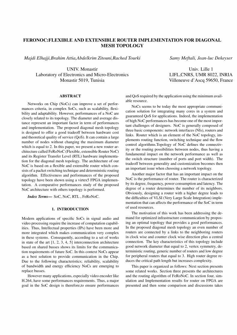
The proposed Mesh diagonal topology generalizes and im-proves performance of the well known STOctagon networkprocessor topology by a simple bidirectional ring with a cen-tral router. This network is constituted by (N+1) routers in-cluding a central element which is connected with all pe-ripheral routers via links. Each peripheral router providesfour input/output ports enable to connect left/right neighbors(routers), central router and the local IP. The central routercontains N ports for the connection of each peripheral routerand additional one permitting the connection with its local IPas is shown in figure 1:
Fig. 1. The NoC topology.
The communication packet used in our NoC is composedby three basic messages called flits which consist of:
• Header: composed by one bit (BOP)indicating the be-ginning of a packet,
• Body: contain the data to be transmitted on 32 bits,
• Tail: one bit indicating the end of a packet (EOP).
Both of the two kinds of routers composing the diagonalmesh topology use packet switching technique and Worm-hole flow control mechanism.In packet switching, packets aretransmitted without any need for connection establishmentprocedure.It requires the use of a switching mode, which de-fines how packets move through the switches.The describedrouter has a controlled logic and bidirectional ports. Each porthas an input buffer for temporary storage of information anda local port enabling communication between router and itslocal IP core. This module contains a set of components thatare described below. Figue 2 shows a general block diagramfor the router.
In the diagonal mesh, topology is presented in this work,each switch has a different number of ports, depending on itsperipheral position or central router.
3.1. Peripheral Routers
In our NoC, we used a synchronous router with four in-put/output ports (local, clockwise, counter clockwise andacross). Each port is connected to a bi-directional exchangebus. Each switch has a unique address and the switchingtechnique used is packet switching. The data flowing throughthe network is a Wormhole routing. We made this choice toreduced number of buffers required per node and the sim-plicity of the communication mechanism. The diagonal meshtopology uses credit based flow control strategies. This laterpresents interesting advantages over handshake. In credit-based protocol, when the receiver is free, the transmitter
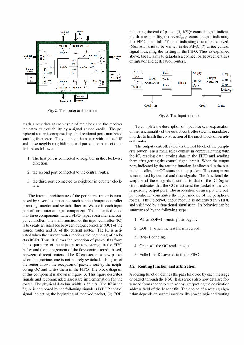
Fig. 2. The router architecture.
sends a new data at each cycle of the clock and the receiverindicates its availability by a signal named credit. The pe-ripheral router is composed by a bidirectional ports numberedstarting from zero. They connect the router with its local IPand these neighboring bidirectional ports. The connection isdefined as follows:
1. The first port is connected to neighbor in the clockwisedirection.
2. the second port connected to the central router.
3. the third port connected to neighbor in counter clock-wise.
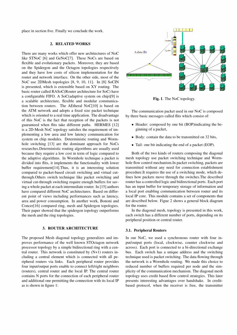
The internal architecture of the peripheral router is com-posed by several components, such as input/output controller), routing function and switch allocator. We use in each inputport of our router an input component. This latter is dividedinto three components named FIFO, input controller and out-put controller. The main function of the input controller (IC)is to create an interface between output controller (OC) of thesource router and IC of the current router. The IC is acti-vated when the current router receives the beginning of pack-ets (BOP). Thus, it allows the reception of packet flits fromthe output ports of the adjacent routers, storage in the FIFObuffer and the management of the flow control (credit based)between adjacent routers. The IC can accept a new packetwhen the previous one is not entirely switched. This part ofthe router allows the reception of packets sent by the neigh-boring OC and writes them in the FIFO. The block diagramof this component is shown in figure 3. This figure describessignals and recommended hardware implementation for therouter. The physical data bus width is 32 bits. The IC in thefigure is composed by the following signals: (1) BOP controlsignal indicating the beginning of received packet, (2) EOP:
indicating the end of packet;(3) REQ: control signal indicat-ing data availability, (4) creditout: control signal indicatingthat FIFO is not full; (5) data: indicating data to be received;(6)datain: data to be written in the FIFO, (7) write: controlsignal indicating the writing in the FIFO. Thus as explainedabove, the IC aims to establish a connection between entitiesof initiator and destination routers.
Fig. 3. The Input module.
To complete the description of input block, an explanationof the functionality of the output controller (OC) is mandatoryin order to finish the construction of the input block of periph-eral router.
The output controller (OC) is the last block of the periph-eral router. Their main roles consist in communicating withthe IC, reading data, storing data in the FIFO and sendingthem after getting the control signal credit. When the outputport, indicated by the routing function, is allocated in the out-put controller, the OC starts sending packet. This componentis composed by control and data signals. The functional de-scription of these signals is similar to that of the IC. SignalGrant indicates that the OC must send the packet to the cor-responding output port. The association of an input and out-put controller constitutes the input module of the peripheralrouter. The FeRoNoC input module is described in VHDLand validated by a functional simulation. Its behavior can besummarized by the following steps:
1. When BOP=1, sending flits begins.
2. EOP=1, when the last flit is received.
3. Req=1 Sending.
4. Credit=1, the OC reads the data.
5. Full=1 the IC saves data in the FIFO.
3.2. Routing function and arbitration
A routing function defines the path followed by each messageor packet through the NoC. It describes also how data are for-warded from sender to receiver by interpreting the destinationaddress field of the header flit. The choice of a routing algo-rithm depends on several metrics like power,logic and routing
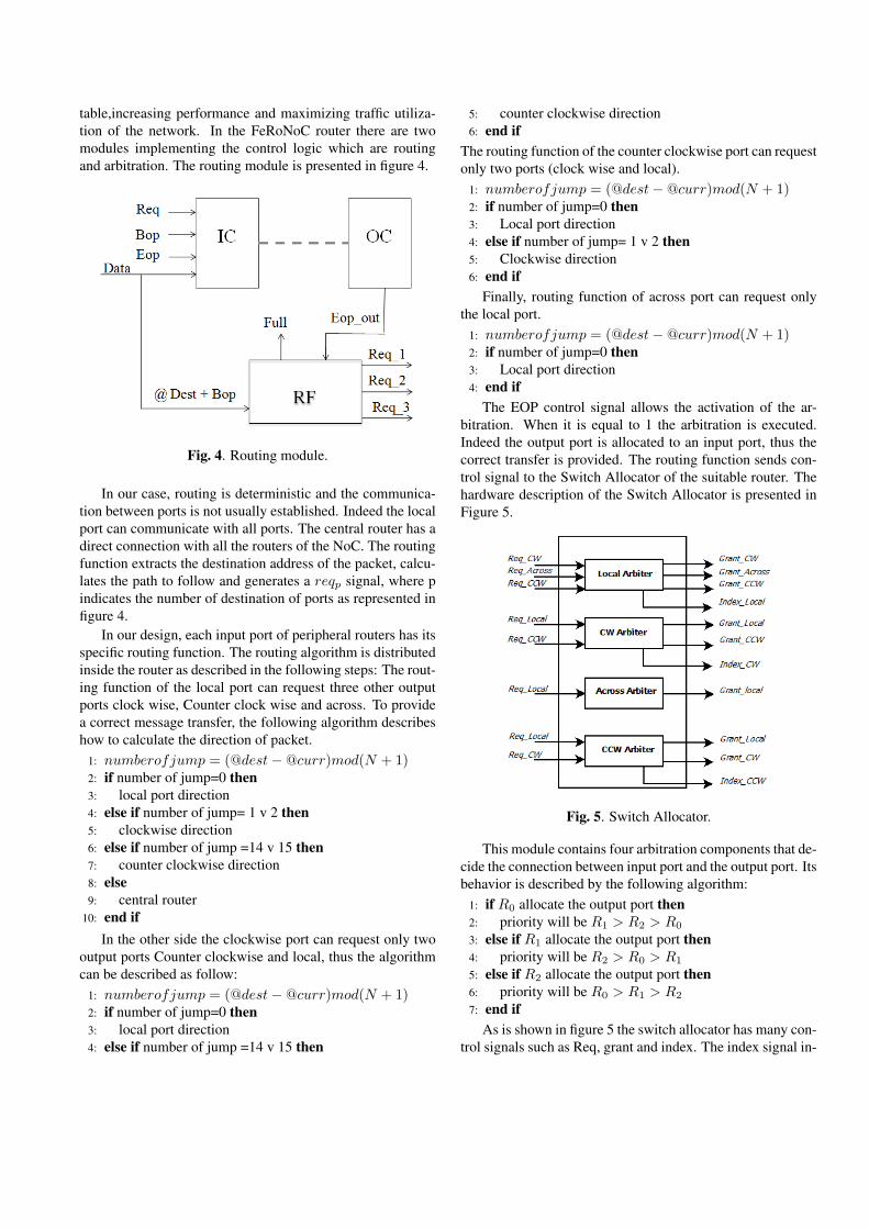
table,increasing performance and maximizing traffic utiliza-tion of the network. In the FeRoNoC router there are twomodules implementing the control logic which are routingand arbitration. The routing module is presented in figure 4.
Fig. 4. Routing module.
In our case, routing is deterministic and the communica-tion between ports is not usually established. Indeed the localport can communicate with all ports. The central router has adirect connection with all the routers of the NoC. The routingfunction extracts the destination address of the packet, calcu-lates the path to follow and generates a reqp signal, where pindicates the number of destination of ports as represented infigure 4.
In our design, each input port of peripheral routers has itsspecific routing function. The routing algorithm is distributedinside the router as described in the following steps: The rout-ing function of the local port can request three other outputports clock wise, Counter clock wise and across. To providea correct message transfer, the following algorithm describeshow to calculate the direction of packet.
1: numberofjump = (@dest−@curr)mod(N + 1)2: if number of jump=0 then3: local port direction4: else if number of jump= 1 v 2 then5: clockwise direction6: else if number of jump =14 v 15 then7: counter clockwise direction8: else9: central router
10: end ifIn the other side the clockwise port can request only two
output ports Counter clockwise and local, thus the algorithmcan be described as follow:
1: numberofjump = (@dest−@curr)mod(N + 1)2: if number of jump=0 then3: local port direction4: else if number of jump =14 v 15 then
5: counter clockwise direction6: end if
The routing function of the counter clockwise port can requestonly two ports (clock wise and local).
1: numberofjump = (@dest−@curr)mod(N + 1)2: if number of jump=0 then3: Local port direction4: else if number of jump= 1 v 2 then5: Clockwise direction6: end if
Finally, routing function of across port can request onlythe local port.
1: numberofjump = (@dest−@curr)mod(N + 1)2: if number of jump=0 then3: Local port direction4: end if
The EOP control signal allows the activation of the ar-bitration. When it is equal to 1 the arbitration is executed.Indeed the output port is allocated to an input port, thus thecorrect transfer is provided. The routing function sends con-trol signal to the Switch Allocator of the suitable router. Thehardware description of the Switch Allocator is presented inFigure 5.
Fig. 5. Switch Allocator.
This module contains four arbitration components that de-cide the connection between input port and the output port. Itsbehavior is described by the following algorithm:
1: if R0 allocate the output port then2: priority will be R1 > R2 > R0
3: else if R1 allocate the output port then4: priority will be R2 > R0 > R1
5: else if R2 allocate the output port then6: priority will be R0 > R1 > R2
7: end ifAs is shown in figure 5 the switch allocator has many con-
trol signals such as Req, grant and index. The index signal in-
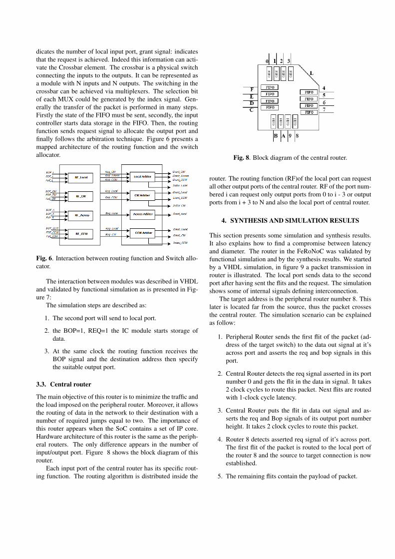
dicates the number of local input port, grant signal: indicatesthat the request is achieved. Indeed this information can acti-vate the Crossbar element. The crossbar is a physical switchconnecting the inputs to the outputs. It can be represented asa module with N inputs and N outputs. The switching in thecrossbar can be achieved via multiplexers. The selection bitof each MUX could be generated by the index signal. Gen-erally the transfer of the packet is performed in many steps.Firstly the state of the FIFO must be sent, secondly, the inputcontroller starts data storage in the FIFO. Then, the routingfunction sends request signal to allocate the output port andfinally follows the arbitration technique. Figure 6 presents amapped architecture of the routing function and the switchallocator.
Fig. 6. Interaction between routing function and Switch allo-cator.
The interaction between modules was described in VHDLand validated by functional simulation as is presented in Fig-ure 7:
The simulation steps are described as:
1. The second port will send to local port.
2. the BOP=1, REQ=1 the IC module starts storage ofdata.
3. At the same clock the routing function receives theBOP signal and the destination address then specifythe suitable output port.
3.3. Central router
The main objective of this router is to minimize the traffic andthe load imposed on the peripheral router. Moreover, it allowsthe routing of data in the network to their destination with anumber of required jumps equal to two. The importance ofthis router appears when the SoC contains a set of IP core.Hardware architecture of this router is the same as the periph-eral routers. The only difference appears in the number ofinput/output port. Figure 8 shows the block diagram of thisrouter.
Each input port of the central router has its specific rout-ing function. The routing algorithm is distributed inside the
Fig. 8. Block diagram of the central router.
router. The routing function (RF)of the local port can requestall other output ports of the central router. RF of the port num-bered i can request only output ports from 0 to i - 3 or outputports from i + 3 to N and also the local port of central router.
4. SYNTHESIS AND SIMULATION RESULTS
This section presents some simulation and synthesis results.It also explains how to find a compromise between latencyand diameter. The router in the FeRoNoC was validated byfunctional simulation and by the synthesis results. We startedby a VHDL simulation, in figure 9 a packet transmission inrouter is illustrated. The local port sends data to the secondport after having sent the flits and the request. The simulationshows some of internal signals defining interconnection.
The target address is the peripheral router number 8. Thislater is located far from the source, thus the packet crossesthe central router. The simulation scenario can be explainedas follow:
1. Peripheral Router sends the first flit of the packet (ad-dress of the target switch) to the data out signal at it’sacross port and asserts the req and bop signals in thisport.
2. Central Router detects the req signal asserted in its portnumber 0 and gets the flit in the data in signal. It takes2 clock cycles to route this packet. Next flits are routedwith 1-clock cycle latency.
3. Central Router puts the flit in data out signal and as-serts the req and Bop signals of its output port numberheight. It takes 2 clock cycles to route this packet.
4. Router 8 detects asserted req signal of it’s across port.The first flit of the packet is routed to the local port ofthe router 8 and the source to target connection is nowestablished.
5. The remaining flits contain the payload of packet.
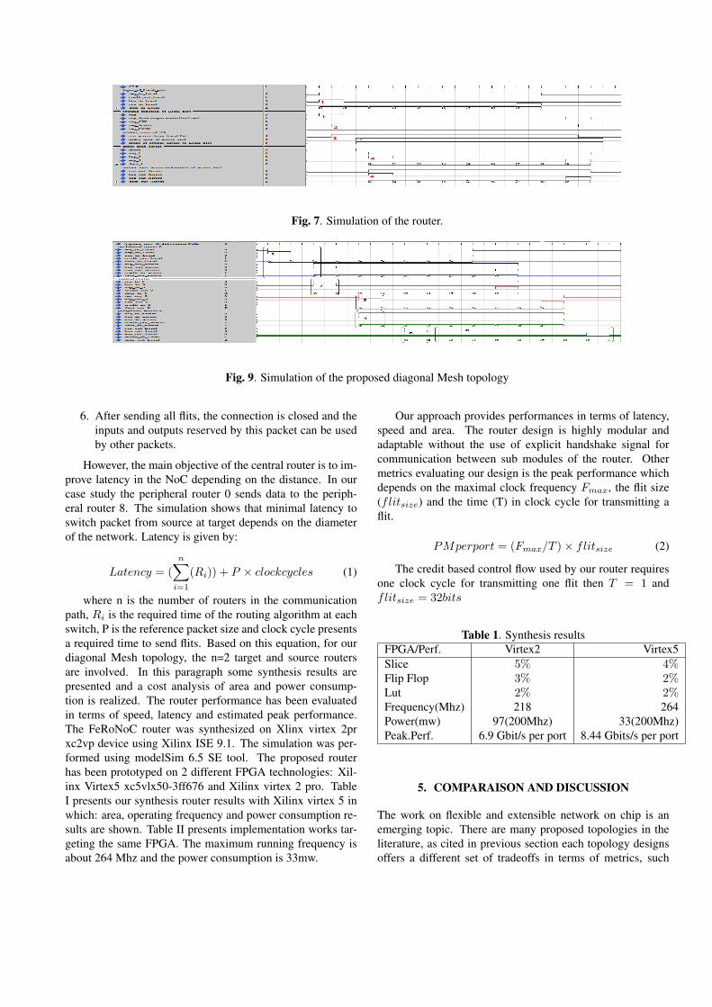
Fig. 7. Simulation of the router.
Fig. 9. Simulation of the proposed diagonal Mesh topology
6. After sending all flits, the connection is closed and theinputs and outputs reserved by this packet can be usedby other packets.
However, the main objective of the central router is to im-prove latency in the NoC depending on the distance. In ourcase study the peripheral router 0 sends data to the periph-eral router 8. The simulation shows that minimal latency toswitch packet from source at target depends on the diameterof the network. Latency is given by:
Latency = (n∑
i=1
(Ri)) + P × clockcycles (1)
where n is the number of routers in the communicationpath, Ri is the required time of the routing algorithm at eachswitch, P is the reference packet size and clock cycle presentsa required time to send flits. Based on this equation, for ourdiagonal Mesh topology, the n=2 target and source routersare involved. In this paragraph some synthesis results arepresented and a cost analysis of area and power consump-tion is realized. The router performance has been evaluatedin terms of speed, latency and estimated peak performance.The FeRoNoC router was synthesized on Xlinx virtex 2prxc2vp device using Xilinx ISE 9.1. The simulation was per-formed using modelSim 6.5 SE tool. The proposed routerhas been prototyped on 2 different FPGA technologies: Xil-inx Virtex5 xc5vlx50-3ff676 and Xilinx virtex 2 pro. TableI presents our synthesis router results with Xilinx virtex 5 inwhich: area, operating frequency and power consumption re-sults are shown. Table II presents implementation works tar-geting the same FPGA. The maximum running frequency isabout 264 Mhz and the power consumption is 33mw.
Our approach provides performances in terms of latency,speed and area. The router design is highly modular andadaptable without the use of explicit handshake signal forcommunication between sub modules of the router. Othermetrics evaluating our design is the peak performance whichdepends on the maximal clock frequency Fmax, the flit size(flitsize) and the time (T) in clock cycle for transmitting aflit.
PMperport = (Fmax/T )× flitsize (2)
The credit based control flow used by our router requiresone clock cycle for transmitting one flit then T = 1 andflitsize = 32bits
Table 1. Synthesis resultsFPGA/Perf. Virtex2 Virtex5Slice 5% 4%Flip Flop 3% 2%Lut 2% 2%Frequency(Mhz) 218 264Power(mw) 97(200Mhz) 33(200Mhz)Peak.Perf. 6.9 Gbit/s per port 8.44 Gbits/s per port
5. COMPARAISON AND DISCUSSION
The work on flexible and extensible network on chip is anemerging topic. There are many proposed topologies in theliterature, as cited in previous section each topology designsoffers a different set of tradeoffs in terms of metrics, such
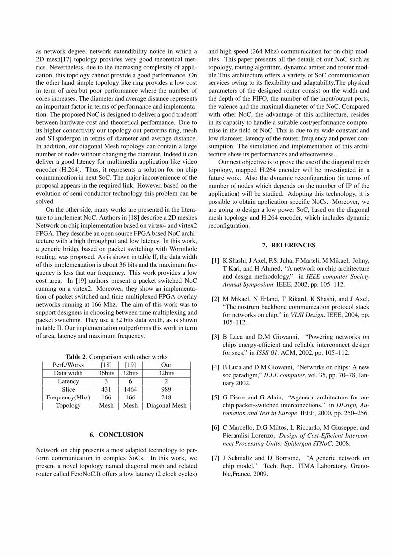
as network degree, network extendibility notice in which a2D mesh[17] topology provides very good theoretical met-rics. Nevertheless, due to the increasing complexity of appli-cation, this topology cannot provide a good performance. Onthe other hand simple topology like ring provides a low costin term of area but poor performance where the number ofcores increases. The diameter and average distance representsan important factor in terms of performance and implementa-tion. The proposed NoC is designed to deliver a good tradeoffbetween hardware cost and theoretical performance. Due toits higher connectivity our topology out performs ring, meshand STspidergon in terms of diameter and average distance.In addition, our diagonal Mesh topology can contain a largenumber of nodes without changing the diameter. Indeed it candeliver a good latency for multimedia application like videoencoder (H.264). Thus, it represents a solution for on chipcommunication in next SoC. The major inconvenience of theproposal appears in the required link. However, based on theevolution of semi conductor technology this problem can besolved.
On the other side, many works are presented in the litera-ture to implement NoC. Authors in [18] describe a 2D meshesNetwork on chip implementation based on virtex4 and virtex2FPGA. They describe an open source FPGA based NoC archi-tecture with a high throughput and low latency. In this work,a generic bridge based on packet switching with Wormholerouting, was proposed. As is shown in table II, the data widthof this implementation is about 36 bits and the maximum fre-quency is less that our frequency. This work provides a lowcost area. In [19] authors present a packet switched NoCrunning on a virtex2. Moreover, they show an implementa-tion of packet switched and time multiplexed FPGA overlaynetworks running at 166 Mhz. The aim of this work was tosupport designers in choosing between time multiplexing andpacket switching. They use a 32 bits data width, as is shownin table II. Our implementation outperforms this work in termof area, latency and maximum frequency.
Table 2. Comparison with other worksPerf./Works [18] [19] OurData width 36bits 32bits 32bits
Latency 3 6 2Slice 431 1464 989
Frequency(Mhz) 166 166 218Topology Mesh Mesh Diagonal Mesh
6. CONCLUSION
Network on chip presents a most adapted technology to per-form communication in complex SoCs. In this work, wepresent a novel topology named diagonal mesh and relatedrouter called FeroNoC.It offers a low latency (2 clock cycles)
and high speed (264 Mhz) communication for on chip mod-ules. This paper presents all the details of our NoC such astopology, routing algorithm, dynamic arbiter and router mod-ule.This architecture offers a variety of SoC communicationservices owing to its flexibility and adaptability.The physicalparameters of the designed router consist on the width andthe depth of the FIFO, the number of the input/output ports,the valence and the maximal diameter of the NoC. Comparedwith other NoC, the advantage of this architecture, residesin its capacity to handle a suitable cost/performance compro-mise in the field of NoC. This is due to its wide constant andlow diameter, latency of the router, frequency and power con-sumption. The simulation and implementation of this archi-tecture show its performances and effectiveness.
Our next objective is to prove the use of the diagonal meshtopology, mapped H.264 encoder will be investigated in afuture work. Also the dynamic reconfiguration (in terms ofnumber of nodes which depends on the number of IP of theapplication) will be studied. Adopting this technology, it ispossible to obtain application specific NoCs. Moreover, weare going to design a low power SoC, based on the diagonalmesh topology and H.264 encoder, which includes dynamicreconfiguration.
7. REFERENCES
[1] K Shashi, J Axel, P.S. Juha, F Marteli, M Mikael, Johny,T Kari, and H Ahmed, “A network on chip architectureand design methodology,” in IEEE computer SocietyAnnual Symposium. IEEE, 2002, pp. 105–112.
[2] M Mikael, N Erland, T Rikard, K Shashi, and J Axel,“The nostrum backbone communication protocol stackfor networks on chip,” in VLSI Design. IEEE, 2004, pp.105–112.
[3] B Luca and D.M Giovanni, “Powering networks onchips energy-efficient and reliable interconnect designfor socs,” in ISSS’01. ACM, 2002, pp. 105–112.
[4] B Luca and D.M Giovanni, “Networks on chips: A newsoc paradigm,” IEEE computer, vol. 35, pp. 70–78, Jan-uary 2002.
[5] G Pierre and G Alain, “Ageneric architecture for on-chip packet-switched interconections,” in DEsign, Au-tomation and Test in Europe. IEEE, 2000, pp. 250–256.
[6] C Marcello, D.G Miltos, L Riccardo, M Giuseppe, andPieramlisi Lorenzo, Design of Cost-Efficient Intercon-nect Processing Units: Spidergon STNoC, 2008.
[7] J Schmaltz and D Borrione, “A generic network onchip model,” Tech. Rep., TIMA Laboratory, Greno-ble,France, 2009.
[8] J Liang, A Laffely, S Srinivasan, and R Tessier, “Anarchitecture and compiler for scalable on-chip commu-nication,” IEEE transaction on very large scale integra-tion systems, vol. 12, pp. 711–726, July 2004.
[9] C.A Zeferino and A Susin, “A parametric and scalablenetwork-on-chip,” in 16th Symposium on integrated cir-cuits and system design. IEEE, 2003.
[10] K Goossens, J Dielissen, and A Radulescu, “Aetherealnetwork on chip: Concepts, architectures, and imple-mentations,” IEEE Design and Test of Computer, vol.22, pp. 414–421, September 2005.
[11] F Uriel and R Prabhakar, “Exact analysis of hot-potatorouting,” in 33rd Annual Symposium on Foundations OfComputer Science. IEEE, 192, pp. 553–562.
[12] K Goossens, J Dielissen, and A Radulescu, “Hermes:an infrastructure for low area overhead packet-switchingnetworks on chip,” VLSI journal, Elsevier, vol. 38, pp.69–93, March 2004.
[13] J Dally and C Seitz, “Deadlock-free message routing inmultiprocesor interconnection networks,” IEEE trans-action.
[14] J Dally and B Towles, “Route packets, not wires: On-chip interconnection networks,” in Design AutomationConference (DAC). ACM, 2001, pp. 683–689.
[15] P.P Partha, G Cristian, J Michael, I Andre, andS Resve, “Performance evaluation and design trade-offsfor network-on-chip interconnect architectures,” IEEEtransaction on Computers, vol. 54, pp. 1025–1040, Au-gust 2005.
[16] L Bononi and N Concer, “Simulation and analysis ofnetwork on chip architectures: Ring, spidergon and 2dmesh,” in DATE. IEEE, 2006, pp. 154–159.
[17] T.A Bartic, J.-Y Mignolet, V Nollet, T Marescaux,D Verkest, S Vernalde, and R Lauwereins, “Topologyadaptive network-on-chip design and implementation,”IEE Comput. Digit, vol. 152, pp. 467–452, July 2005.
[18] A Ehliar and D Liu, “An fpga based open sourcenetwork-on-chip architecture,” in Field ProgrammableLogic and Applications. IEEE, 2007, pp. 800–803.
[19] N Kapre, N Mehta, M deLorimier, R Rubin, H Barnor,M.J Wilson, M Wrighton, and A DeHon, “Packetswitched vs. time multiplexed fpga overlay networks,”in IEEE Symposium on Field-programmable CustomComputing Machines. IEEE, 2006, pp. 800–803.


