Embed Size (px)
Citation preview

Naval Education and Training Command
NAVEDTRA 10276-1 Saptember1988 0502-LP-211-7800
Training Manual (TRAMAN) and Nonresident Training Couree (NRTC)
Fire Controlman
Third Class
Only one answer sheet is included in the NRTC. Reproduce the required number of sheets you need or get answer sheets from your ESO or designated. ollicer.
DISTRIBUTION STATEMENf A: Approved for public release; distribution is unlimited.
Noafedenl aonmmeot penonnel wanting a copy ot this document mast Ule tile pan:baslng lastructlons on the lDslde cowr .
• 1111111111111 0502LP2117800
FIRE CONTROLMAN THIRD CLASS
NAVEDTRA 10276-1
1985 Edition Prepared by FTCM(SW) RobePt L. Haskell,
FTCS RobePt R. Revels, and FTMC �tchell Shelton
. ---- ----- ------- -------
CHAPTER 1
INTRODUCTION
This rate training manual has been prepared for men and women of the Navy and of the Naval Reserve who are studying for advancement to the rate of Fire Controlman Third Class. One of a series of rate training manuals, this manual is designed to give you background information necessary for the proper performance of duty at the third class level. The manual· is based on the professional qualifications for FC3, as listed in the Manual of Navy Enlisted Manpower and Personnel Classifications and Occupational Standards, NAVPERS 18068.
The military requirements for advancement in rating are discussed in Military Requirements for Petty Officer Third Class, NAVEDTRA 10044. A list of training manuals and other publications used in the preparation of advancement examinations is located in Bibliography for Advancement Examination Study, NAVEDTRA 10052. When you are studying for advancement, always make sure you have the latest edition of NA VEDTRA 10052 and 10044. Also, you should check with the Educational Services Office (ESO) of your command for possible changes to the requirements or references listed in these publications.
The purpose of this chapter is to introduce you to the Fire Controlman rating. The term "fire control" means the directing of various weapons so that they will hit a desired target. As you learn about fire control, you will realize that the Navy is only as strong as its fire power. For its fire power to be effective, it must be accurately controlled. This is where you, as a fire controlman, will play a vital part in making your ship an effective weapon against ships, planes, missiles, and shore installations. It will be your job to operate and maintain the many complex devices used in your ship's various fire control systems.
1-1
THE FIRE CONTROLMAN RATING
The fire controlman rating is a general rating. Specialty groups within the rating have been assigned Navy Enlisted Classification (NEC) codes. The NEC code numbers reflect special knowledge and skills of personnel. An NEC code is normally assigned to an individual after that person has satisfactorily completed the course on a related fire control system or component equipment at a class C school.
Normally, you will be assigned duty according to your NEC code. As an FC3, your assigned billet will probably call for an equipment specialist. This, nevertheless, does not relieve you of the need to acquire overall knowledge of fire control. This need for a generalist approach to fire control will become evident on your first advancement in rate examination.
The FC rating was formed in July 1985, by combining the Fire Control Technician Missiles (FTM) and the Fire Control Technician Guns (FTG) (surface) ratings. The Fire Control ratings have undergone considerable change since their original inception. The original FC rating was formed to maintain and operate the fire control computers and rangekeepers used with the gun systems. With the advent of radars and their application in fire control, the FT (Fire Control Technician) rating was formed to designate those assigned to operate and maintain the fire control radars. The FC and FT rating then evolved into the FT general rating with the emergency special ratings of FTA, FTM, FTU, and FTG (where A = automatic systems, M = manual systems, U = underwater systems, and G = guided missile systems). Following the Korean War era the rating went through another evolutionary stage where
FIRE CONTROLMAN THIRD CLASS
there were only the FTM and FTG ratings (where M = missiles and G = guns and underwater torpedo fire control). With the development of the POLARIS missile, the fire control general rating was amended with the specialty rating of FTB, where B is a symbol for the FTs who maintain the ballistic missile systems. The rating has now come full circle with the formation of the FC rating and retention of the FTB and FTG (underwater) ratings. These changes paralleled the development of fire control systems that you will now study.
HISTORY OF FIRE CONTROL
Warships in early and medieval times engaged in war on the seas by ramming, or by grappling the vessel and boarding it for hand-to-hand combat. Guns were not used on ships on a large scale until the fifteenth century, when a Spanish Fleet opened fire with cannon at point-blank range on the Turkish Fleet, who were quickly defeated.
Less than 200 years ago, naval guns were still fired at point-blank range. Gunnery was still an art, not a science, and fire control was largely a matter of skillful seamanship in steering the ship into position to enable the gunners to hit the target. The range and destructive power of guns continued to increase over the years, from an average effective range of 100 yards in the mid-1800s to more than 40,000 yards in the mid-1900s. These improvements in gun ranges could make guns effective only if the guns were accurately aimed. Methods of fire control in the modern sense were not developed until the nineteenth and twentieth centuries.
Gun Sights
The first concern of a fire control system is to provide an effective way of aiming. This is the function of the gun sights. Prior to 1800, there was no need for elaborate gun sighting systems, because the guns themselves were inaccurate except at close range. Guns were simply pointed at the target by eye.
Gun sights introduced early in the nineteenth century consisted of fixed front and rear sights mounted so that the line of sight across their tips was parallel to the bore of the gun. Toward the
1-2
TELESCOPE
SIGHTS
Figure 1-1.-Early telescope sigllts.
167.907
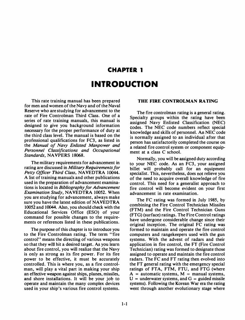
end of the nineteenth century, a sight telescope (fig. 1-1) was developed by a Navy lieutenant. It consisted of a simple telescope containing a pair of crosshairs that was mounted in such a way that the line of sight could be moved with respect to the axis of the gun to correct for some of the factors that affect the solution of the fire control problem.
Ranging Devices
Improvements in gun sighting systems alone were not enough. As the range and complexity of guns increased, it became necessary to develop other fire control instruments that could accurately and rapidly solve the fire control problem.
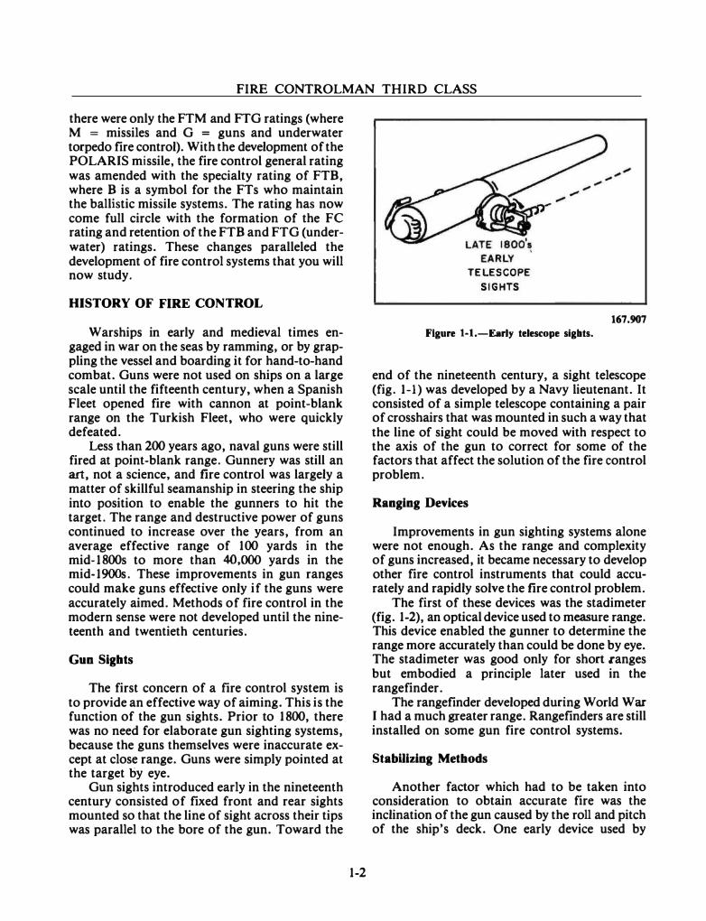
The first of these devices was the stadimeter (fig. 1-2), an optical device used to measure range. This device enabled the gunner to determine the range more accurately than could be done by eye. The stadimeter was good only for short canges but embodied a principle later used in the rangefinder.
The rangefinder developed during World War I had a much greater range. Rangefinders are still installed on some gun fire control systems.
StabUizing Methods
Another factor which had to be taken into consideration to obtain accurate fire was the inclination of the gun caused by the roll and pitch of the ship's deck. One early device used by
--- --- -- . -----
Chapter I-INTRODUCTION
167.908
Figure 1-2.-The stadimeter.
nautical gunners was a round shot suspended from a spar (fig. 1-3). The gunner watched this improvised pendulum and fired the gun just before it was parallel to the mast (when the deck was horizontal). This same principle was later incorporated in the "stable element" and the "ship's gyro." These devices act like a child's spinning top, because their axes always remain truly vertical, thus establishing a reference plane from which gun elevation angles can be measured.
Tracking Methods
The largest and most important corrections in fue control are to compensate for the relative motion between gun and target. In the old days, the positions of the gun and the target at the moment of impact of the projectile were predicted by eye. In the early 1900s, an improvement was brought about by marking the position of the target on paper (plotting) as it moved along its course. (This was done by measuring the distance and direction from the ship to the target.) It was then possible to determine the approximate course and future position of the target (fig. 1-4). This led to the development of the rangekeeper, a device that automatically corrected for changes in target range. The rangekeeper was refined and improved till it reached its present form, the fire control computer, and made possible the rapid solution of other factors in the fire control problem.
1-3
167.909
Figure 1-3.-Correcting for roll and pitclt.
PREDICTED I t t I
_POSITION • PLOTTED·-POSITIONS-.... ......... ? -
, ' ... / .,, ' � \ .
,,, - - --� \ -
r--�1? -- - ·
--� \ -- - - - - -- -- -- -- -- -- ' r- OWN -- --
SHIP - -- � -- -'
167.910
Figure 14.-Target plotting.
The most important World War II fire control innovation was radar, which made accurate fire control possible even when optical instruments were useless.
FIRE CONTROL TODAY
Today, fire control systems are used to control not only guns but also missiles, rockets, and torpedoes.
However, the basic idea of a gun or missile weapon system does not change. They all need certain components in order to operate as a complete system.
FIRE CONTROLMAN THIRD CLASS
Weapon Direction System
The Weapon Direction System (WDS) provides for the centralized control and monitoring of target engagements. It is used to initially evaluate targets, assign the targets to the fire control system, select and control the firing of guns and missiles, and evaluate the engagement results.
Radar /Director
The function of the radar I director is to locate the position of a target. You may think of it as the eyes of the fire control system. The radar/director tracks the target and provides precise position data to the computer.
Computer
Fire control computers are the brains of the system. When they are supplied with the data needed to solve the fire control problem, the computers yield solutions in the form of position and control signals for the weapons delivery unit.
Delivery Units
Broadly speaking, delivery units launch or project destructive units toward the target. Examples are guns, missile and rocket launchers, and torpedo tubes. Don't think of these devices as weapons. The term WEAPON is properly applied to the destructive unit that is launched or projected. Thus a guided missile launcher is not, strictly speaking, a weapon; the missile itself is the weapon.
To be effectively employed against their targets, all weapons must either be aimed at their targets or be programmed during flight; they may require both aiming and programming. Programming is the process of setting automatic equipment to perform operations in a predetermined step-by-step manner. Aiming and programming are done at or before the time of launching, either by or through the delivery device. This function is characteristic of all delivery devices, even the simplest. Aiming the destructive device (weapon) at the target may be done simply by positioning the delivery device (a gun barrel or launcher guide arm, for example).
1-4
Or it may be done without aiming the delivery device by placing program instructions in the weapon. Some missiles are programmed to start searching for the target after the launching phase is over. Examples of other programmed functions that could be performed in the weapon are (1) ignition of propulsion units and (2) arming of the warhead after a designated number of seconds in flight.
TYPES OF DELIVERY DEVICES.-There are two types of delivery devices of interest to FCs.
Guns.-Guns provide all the propulsion energy to their projectiles, and they direct (aim) the projectiles by positioning the gun barrels.
Missile Launchers.-Missile launchers retain and position missiles during the initial part of the launching phase and, by means of attachments to the launcher, feed steering, vertical reference, and program information into the missile up to the instant of launch.
Destructive Units
The end purpose of fire control is to cause the destruction unit to intercept or pass near the target. It is then the function of the destruction unit to destroy or inflict maximum damage on the target. Except for projectiles used in small arms and some of those used in calibers up to 20-mm, weapons used in combat are loaded with explosives and equipped with devices to set off their explosion at the proper time. For some weapons, the proper time is the instant the weapon makes physical contact with the target. For those designed to penetrate targets protected by armor or concrete, the proper time is after penetration. Still others are intended to explode when they reach the vicinity of the target.
Weapons of some types have their own propulsion systems; examples are guided missiles, torpedoes, and rockets. With the exception of rockets, weapons that have a propulsion system also contain guidance and control systems.
EVOLUTION OF THE GUIDED MISSILE
A MISSILE is any object that can be launched or thrown at a target. This includes
Chapter I-INTRODUCTION
stones or arrows as well as gun projectiles, bombs, torpedoes, and rockets. In current military use, the word MISSILE is becoming synonymous with GUIDED MISSILE. In this text, we will use the terms MISSILE and GUIDED MISSILE interchangeably.
The Purpose of Guided Missiles
The primary mission of the Navy is control of the seas. We propose to keep the sea-lanes open for our own and for friendly commerce. In time of war, we propose to deny the use of the sea to the enemy. With the advent of the POLARIS, POSEIDON, and TRIDENT missiles, we have an added use for the sea-a hiding place for our most potent seaborne strategic weapons.
Historically, the Navy's mission has been accomplished by the use of warships that were armed with the most advanced weapons of their time. When John Paul Jones challenged the British control of the seas, his warships carried guns that had an effective range of a few hundred yards. In the Civil War, the Union Navy maintained a blockade of southern ports with the help of guns that had a range of S to 10 miles.
When aircraft became more effective weapons delivery systems than guns in both range and striking power, they became the prime weapons systems of the Navy. The Battle of the Coral Sea, in 1942, was the first major naval battle in which ships did not exchange a single shot.
The development of missiles added a new dimension to the attack or defense mission. Missiles cannot perform all the functions of guns. But, they can extend the range and effectiveness with greater payloads. Even without control of the sea•s surface, missiles can be launched from submarines.
The effort to develop faster and better missiles will continue as 'long as the threat of war exists, or until some new and unforeseen weapon makes guided missiles obsolete.
Navy Surface Missile Systems
In 1944, the Navy assigned development of the Bumblebee project to the Applied Physics Laboratory of the Johns Hopkins University. This project has since produced TERRIER, TARTAR, STANDARD, and the now obsolete T ALOS
missiles. These surface-to-air missiles greatly improved the Navy's fleet antiaircraft defenses.
In the early 1960s, a need was recognized for a rapid reaction, lightweight surface-to-air missile system that could provide a self-defense capability against the fast growing threats of the future. (The TARTAR, TERRIER, and TALOS weapon systems were developed to provide protection of the area around fleet units.) A system was needed to protect the "point-or-origin" or an individual ship at close-in ranges. The NATO Sea Sparrow and Point Defense Missile Systems were developed to meet that need. These systems use a SPARROW III air-to-air missile which was modified for surface launch.
In the late 1970s the HARPOON antiship missile was introduced. It uses an over-the-horizon concept which further enhances fleet defense. All' of these missiles that are currently used by the Navy and their updated versions will be discussed in more detail in chapter 5.
New missiles are still being designed and tested for surface fleet use. Among these are the longrange cruise missile (TOMAHAWK) and the rolling airframe missile (RAM). The TOMAHAWK uses terrain matching or radar homing devices against land and ship targets, respectively. The RAM will provide quicker reacting, close-in selfdefense for vital fleet units. It uses dual-mode (infrared and rO homing and an automatic launching system.
A major development in fleet defense is the AEGIS weapon system, which is a fully automatic surface-to-air missile system. The heart of the system is the AN/SPY-I multifunction, phased array radar system. It simultaneously performs horizon search, hemispherical search, multiple target tracking, and multiple interceptor missile tracking. It also provides missile guidance commands and target kill evaluation. This computer controlled, automated system provides an unprecedented short reaction time and potent firepower. The AEGIS weapon system employs STANDARD missiles.
The Navy Tactical Data System (NTDS) has also been developed to coordinate fleet and ships weapons systems. Although Fire Controlmen are not primarily assigned responsibility for NTDS, they will be closely associated with it. In some equipment configurations, they will actually maintain all or part of the system.
FIRE CONTROLMAN THIRD CLASS
YOUR FUTURE AS A FIRE CONTROLMAN
Now that you have a better understanding of fire control, let's preview what your job is going to be.
DUTIES AND RESPONSIBILITIES
All ships include, as one of their main departments, a weapons or combat systems department. On some ships of special type, whose primary mission is something other than ordnance, this department may be subordinated to become part of the deck department. On combat ships, to which an FC is most likely to be assigned, a weapons or combat systems department is sure to be not only an independent but also a major department of the ship's organization.
The department is headed by the Weapons or Combat Systems Officer who is assisted in various areas by other officers. Among these officers will be a Fire Control Officer whose direct responsibility will be the maintenance and operation of gun and missile fire control systems. This is the department to which fire controlmen are regularly assigned. On some ships the organization may differ, but the job responsibility will be the same. Fire Controlmen who maint�in the 3-D search radars may be assigned to the operations department on ships whose primary mission is command and control or air control such as an aircraft carrier.
Your duties may be outlined briefly as follows:
l . You should be able to perform the general procedures necessary to operate and stand watch on all fire control equipment and related electronic units in your charge.
2. You should be able to maintain, test, align, calibrate, and troubleshoot all of this equipment. These duties include the following:
a. Perform all periodic cleaning, lubrication, and testing required by the equipment placed in your charge.
b. Use all tools and instruments, mechanical and electrical, necessary for the performance of your duties.
1-6
c. Read and use mechanical drawings, blueprints, schematics, and wiring layout diagrams.
d. Locate troubles and make necessary repairs.
3. You should be able to go through the procedures necessary to requisition and stow all parts and supplies required in your work. You must also be able to prepare work requests as needed.
4. You should be able to maintain fire control records according to the established format.
5. You should be able to boresight guns and align weapon systems.
6. You may be called upon to inspect and adjust optical instruments associated with fire control equipment.
7. You should be able, under supervision, to install fire control equipment and accessories and to make certain equipment changes of a limited nature.
Do not let this list of duties throw you. You will not have them piled on your shoulders all at once. Aboard ship you will find FCs who have been doing this job for some time. They will help you get started on the right foot.
TRAINING OPPORTUNITIES
You have elected to become one of a select group, the Fire Controlman. How far up the ladder of success you go depends entirely upon how much you are willing to apply yourself.
Class A School Training
As a Fire Controlman you will have. many opportunities for advanced electronics training. This training starts with the FC class A school for the basics of electricity and electronics. Unless you have had previous electronics training or you are an exceptionally sharp individual, FC class A school is almost mandatory for a good solid foundation in electronics.
Class C School Training
After completion of A school, a wide variety of C schools are available. These FC class C
Chapter I-INTRODUCTION
schools are devoted to teaching individual fire control equipments and systems. One C school may cover a computer complex or a fire control radar or even a whole fire control or weapons system. The requirements for assignment to C school will depend on your previous training. Your first C school can be on just about any equipment.
After the first C school, subsequent training will depend upon platform compatible training. For example, if your first school was for a Mk 68 Gun Fire Control System, any additional training would be for fire control equipment found on ships (platforms) with a Mk 68 GFCS (such as, an AN/SPS-48 search radar, a TARTAR or TERRIER missile fire control system, or the close-in weapons system). So your training opportunities are varied with a wide range of possibilities. Also, you should not stop with learning just one small component. You should learn how the component interacts with other fire control equipment and the operation of the whole ship's weapons system package.
The purpose for this approach is to eventually qualify you as a fire controlman for all the weapons systems on a ship by the time you have advanced to the E-7 or E-8 level. At this level, you would be assigned to the ship as the senior fire controlman with responsibility for all the fire control equipment on board. This concept is designed to enhance training possibilities for individual fire controlmen. Each training experience will then become a step toward the development of a trained and an experienced supervisor who is qualified in all components of a particular ship-type weapons system package. The senior fire controlman, the ESO, and Career Counselor aboard your command should be able to aid you in determining the qualifications for assignment to a particular C school and assist you in qualifying for that school or other schools.
Additional study in electronics, computers, electromechanical devices, precision instruments, and mathematics will be very beneficial to you in your paths to advancement. A wide variety of subject matter is available to you free of charge. A complete list of available courses is found in the List of Training Manuals, Correspondence Courses and Personnel Qualification Standards, NAVEDTRA 10061.
1-7
An additional source of course and study material to aid you in studying for advancement is the Bibliography for Advancement Examination Study, NAVEDTRA 100S2. This lists all the courses and publications used as references for preparation of advancement examinations. If you fully understand the material contained in the courses and publications listed in the bibliography, you should have very little problem passing the advancement examination.
As a Fire Controlman, traditionally, you are the Navy's best. The Fire Controlmen and technicians in the past have always been the best. They are respected for their technical expertise and professional attitude. The fire control systems are a vital part of the ship's ability to meet its primary missions and as such will have a very high importance placed on them. As a fire controlman, you will be required to uphold the tradition and keep the systems working their best at all times so that the ship can best fulfill its mission.
SUMMARY
This course is designed to help you become a Fire Controlman Third Class. Now that you have covered a little history of fire control and have learned some of the primary duties of a Fire Controlman, it is time to learn about the fire control problem. The fire control problem and its solution are the key to understanding how the components of a fire control system fit together and work together. After studying the fire control problem, you will learn about weapons systems concepts and then fire control system concepts. These concepts will provide you with the basic system requirements and how they work together. Then you will learn about the missiles and ordnance that frre controlmen work with and maintain. This is followed by data transmission between frre control system components through the fire control switchboard. Then you will learn about the support systems such as power distribution and cooling systems. The remainder of the course is devoted to general maintenance, safety, security, administrative, and supply requirements.
CHAPTER 2
THE FIRE CONTROL PROBLEM
You as an FC require a thorough working knowledge of the fire control problem. Your first question is undoubtedly, What is the fire control problem? Actually there are several fire control problems. The most generalized question of the fire control problem is, How can a weapon be directed so that it will cause destruction of the selected target? To further amplify this question, let us say that slightly different problems exist for different types of targets (aircraft, surface ship, submarine, and the like). Location of the weapon (ship, shore, and so forth) will also change the problem. The fundamental problem as far as you are concerned is, How can a ship, either underway or dead-inthe-water, destroy a stationary or moving target?
Many of the factors involved are common to more than one variation of the problem. In the material which follows, the discussion will deal primarily with the gun fire control problem. The missile problem is quite similar and will not be discussed in detail; only general aspects will be covered in the chapter on missiles and ordnance. As an aid to understanding the problem, you will study the mathematics required to solve the problem, the symbols used to denote the various quantities, and the various factors which affect the problem.
MATHEMATICS REVIEW
The mathematics required for solving the fire control problem is not difficult, and you
2-1
may have already learned all the mathematics you will need. However, in the material which follows, we will review some of the fundamentals of the mathematics that you will need to know to solve the fire control problem. Not only will you use this mathematics to solve the fire control problem, you will use it in other phases of fire control.
SIGN NUMBERS
In the mathematics you will use in fire control, the concept of "direction sense" of a number is very important. In introducing "direction sense," zero (0) is normally considered as the reference point. Numbers preceded by a (-) have a negative direction, and numbers preceded by a ( + ) have a positive direction. Such a series of numbers is shown as follows:
.. . -4, - 3, - 2, - I, 0, + 1, + 2, + 3, + 4 ...
As an example of how you may use sign numbers, consider your ship on the surface of the ocean to be at the zero reference. An airplane at 5000 feet has a height of + 5000, and a submarine 150 feet below the surface has a height of - 1 SO. If the reference is now shifted to the airplane, the height of the airplane is 0, the height of your ship is - 5000 feet, and the height of the submarine is -5150.
If you remember the following definitions and rules, you will not have any trouble with sign numbers.
FIRE CONTROLMAN THIRD CLASS
Addition
Definition: The symbol for addition is ( + ); the numbers to be added are the addends, and the result is the sum.
Rules:
1. For terms with like signs, sum the absolute values (the magnitude of a number disregarding the sign) and affiX the common sign. For example,
Note: An unsigned number is assumed positive ( + ).
7+4=11
(-4) + (-6) = -10
2. For terms with unlike signs, take the difference of the absolute values and affix the sign of the larger. For example,
Subtraction
4 + (-7)= -3
9 + ( -7) = 2
Definition: The symbol for subtraction is (- ); the first number is the minuend, the number being subtracted is called the subtrahend, and the answer is called the difference or remainder.
Rules: The process of subtraction becomes much easier when the operation is changed to addition; therefore, change the sign of operation and the sign of the subtrahend and proceed as in addition. For example,
(-4)- (-6) = (-4) + (6) = 2
(-6) - (6) = (-6) + (-6) = -12
MultlpUcation
Definition: The basic symbol for multiplication is ( x ); however, several other means will often be used to indicate multiplication. For example,
2 x 4 or 2 · 4 or (2)(4)
2-2
The numbers being multiplied are called the multiplicand and the multiplier, and the answer is the product.
Rules:
1. For terms with like signs, find the product of the absolute values and affix a ( +) sign. For example,
2X3=6
(-4)(-4) = 16
2. For terms with unlike signs, find the product of the absolute values and affix a (-) sign. For example,
(-7)(2) = - 14
Division
Definition: The symbol for division is ( + ); the numbers are the divisor and the dividend (the dividend is divided by the divisor), and the answer is the quotient.
Rules:
I. For terms with like signs, find the quotient of the absolute values and affiX a ( +) sign. For example,
( - 8) .;.. ( -2) = 4
2. For terms with unlike signs, find the quotient of the absolute values and affix a (-) sign. For example,
( -16) .;.. (4) = -4
FRACTIONS AND DECIMALS
The numbers considered up to now have been whole numbers. Many times it is necessary to indicate a partial number. One means of doing this is the fractional method (3/4) and the other is the decimal method (.75). Sometimes for the sake of accuracy, the fractional method is the best because it is impossible to derive a
Chapter 2 THE FIRE CONTROL PROBLEM
number exactly by the decimal method. For example,
j X 30 = 20
but (.666 ... ) x 30 will never be exactly equal to 20. Note that the decimal is found by dividing the numerator by the denominator.
Fractions
The rules which apply to signs of whole numbers also apply to fractions and decimals. Some special considerations are involved in dealing with either fractions or decimals. They will be illustrated in the examples that follow.
ADDITION AND SUBTRACTION .-In the fraction 3/4, the 3 is the numerator and the 4 is the denominator. Before fractions may be added or subtracted, the denominators must be the same. For example,
The first step is to find the least common denominator, LCD, (lowest number which is a whole multiple of each of the denominators); in this case 12. The next step is to convert each of the fractions to an equal fraction whose denominator is 12. Thus, 1/2 = 6/12, 2/3 = 8/12, and 3/4 = 9/12. The next step is to sum the numerators, place the sum over the LCD, and reduce the resulting fraction to its lowest form.
6+8+9_23_1
!.!. 12 - 12 - 12
M ULTIPL ICATION.-Multiplication of fractions is a simple matter of finding the products of the numerators and denominators and reducing the fraction. For example,
�xl-�-!. 3 4- 12- 2
DIVISION.-Division of fractions is easily accomplished by inverting the denominator
2-3
fraction and multiplying it by the numerator fraction. For example,
It should be noted that a negative number is never left in the denominator. The negative denominator may be removed by multiplying both the numerator and the denominator by a - 1. For example,
Decimals
3( -1) - .::1 (-8)( -I)- 8
Operations involving decimals follow the rules for sign numbers, and the only thing to watch is the placement of the decimal point. This will be illustrated in the following examples.
ADDITION AND SUBTRACTION .-Place the numbers in columns with the decimal points aligned. Now sum the columns. There must be as many digits to the right of decimal point in the answer as there are in any of the numbers which are being added. The last digit may be a 0, which is normally dropped after placing of the decimal point. Thus, .509 + 9.25 + 1.001 is aligned as follows:
.509 9.25 1.001
10.760 or 10.76
The same method is used for subtraction.
MULTIPLICATION.-The product is found by multiplying the absolute values of the numbers and placing the decimal point according to the following rule: The number of digits to the right of the decimal point in the product must be equal to the sum of the number of digits to the right of the decimal point in the multiplicand and the multiplier. For example,
.75 X .5 = .375
7.5 X 5 = 37.5
FIRE CONTROLMAN THIRD CLASS
It may be necessary to add zeros between the decimal point and the other digits in order to obtain the number of required positions. For example,
.J X .07 = .007
DIVISION.-The first step is to make the divisor a whole number by moving the decimal point to the right. The next step is to move the decimal point of the dividend the same number of digits and proceed with normal division. Note that it may be necessary to add zeros to the dividend to obtain the required number of decimal position. For example,
7 021.6 -� ii1S.S40.0
175 '--" ----s4
so 40 2S 15 0 15 0
EXPONENTS AND RADICALS
Many of the problems you will have to solve in fire control will involve exponents and radicals. Before the various rules for dealing with exponents and radicals are presented, a few terms will be defined.
Base: The number that serves as a starting point.
Exponent: The number that indicates the number of times the base is multiplied by itself.
Power: The number of times the base number itself is taken as a factor.
Raising a number to a power is a special case of multiplication in which the factors are all equal. For example,
53 = 5 X 5 X 5 = 125
In the example, 5 is the base, 3 is the exponent, which indicates the number of times the base is
2-4
multiplied by itself, and 125 is the third power of 5.
Root: The inverse operation of ra1smg a number to a power is finding a root of a number. This consists of finding one of the equal factors of a number. For example, 32
= 9 and (-3)2 = 9;
thus both + 3 and -3 are square roots of 9.
Radical sign: the desired root of a number can be indicated by placing a radical sign (\() over the number and showing the root desired by placing a small number within the crook of the radical sign. A radical sign by itself means the square root. For example,
v'J6 = ± 4 (Both + 4 and -4 are square roots of 16)
n = 2 (The cube root of 8 is + 2)
'116 = ± 2 (Both + 2 and - 2 are fourth roots of 16)
Laws of Exponents: You will have little difficulty with exponents if you remember the simple laws that follow.
Multiplication
To multiply two or more powers having the same base, add the exponents and raise the common base to that power. For example,
Division
In division of powers of the same base, the exponent of the quotient equals the exponent of the dividend minus the exponent of the divisor. For example,
Note that any number raised to the first power is equal to the number itself. The exponent 1 is usually not written but is understood.
Chapter 2 THE FIRE CONTROL PROBLEM
Note that any base raised to the 0 power is equal to I.
34 = 3<4- 6) = rl = L =! 36 3
2 9
Note that a number with a negative exponent is equal to 1 divided by the same number with a positive exponent; the absolute value of which is equal to the negative exponent.
To find the power of a power, multiply the exponents. For example,
(22
)3 = 2
6 = 64
The proof of this can be seen if you remember that an exponent indicates the number of times a number is multiplied by itself. Thus,
(22
)3
= (22)(2
2)(2
2) = 4 X 4 X 4 = 64
Powers of Ten: Many of the problems you will solve as an FC will have numbers that are either extremely large or extremely small. Use of the concept of powers of 10 will simplify the calculations. There is nothing new or complicated about this concept; it simply makes use of a few rules that you have already studied.
First of all you must consider that any number may be expressed as the product of two other numbers; i.e., 25 may be thought of as 5 x 5, 2 x 12.5, or 2.5 x 10. In using powers of ten, we will always consider 10 or the base 10 raised to some power as one of the numbers. Consider the base ten raised to various powers. When you apply the laws of exponents, you will find the following:
w-•
=. I
10-l = .01
10-l
= .001
w-• = .0001
10�5
= .00001
ro• = 10000
103
= 1000
102 = 100
101 = 10
Now consider the following problem:
XL = 2 X 3.14 X 20000 X .000007
2-5
The calculations are simplified if you use powers of ten. Thus, 20000 is 2 x 10⁴, and .000007 is 7 X 10⁻⁶• The problem is now:
xL = 2 x 3.14 x 2 x w• x 1 x w-6 = 87.92 x w-
2
or since 10-2 = .OJ
XL= .8792
Here is another typical problem:
Xc = 2 X 3.14 X 10000000 X .000000000002
Xc = 2 X 3.14 X J X 10
7 X 2 X JO
-(%
1 9 4 Xc = -5 = .7 X 10 12.56 X 10
Xc""' 7900
To determine the power of ten of any number, do the following:
1. To find the power of ten of any number greater than 1 , move the decimal point to the left so that only one digit remains to the left of the decimal point. The number of places the decimal point is moved is the ( + ) power of ten. For example,
1739.82 = 1.73982 X IQ3
2. To find the power of ten of any number less than 1, move the decimal point to the right until one digit other than zero is to the left of the decimal point. The number of places the decimal point is moved is the ( - ) power of ten. For example,
.00000639 = 6.39 X J0-6
Fractional Exponents: Whereas whole number exponents were used to indicate the power of a number, a fractional exponent is used to indicate the root of a number. For example,
41/2 = V4
12S 113 = V'125
FIRE CONTROLMAN THIRD CLASS
The denominator of the fractional exponent indicates the index of the root (square root, cube root, and so forth) and the numerator indicates the power of the number.
Radicals: You have already learned what a radical is. You will now learn the rules that govern operations with radicals. One of the first things you must remember when finding roots of a number is that an even root (square root, fourth root, and so on) may be either plus or minus. For example,
\[9 = ± 3 since 3 x 3 = 9 and - 3 x - 3 = 9
Combining radicals: In the expression 7 n. 7 is the coefficient, 3 is the index, and 8 is the radicand. Radicals with the same index and radicand are similar. Radicals with the same index are said to be of the same order. Operations with radicals follow the rules of sign numbers; however, a few additional rules must be observed.
Addition and Subtraction
Radicals may be added or subtracted if they are similar. For example,
1'[3 + sv'3 = Jsv'J
9\[7 - 6'10 = 3'10 7\{8 + 6'-fS cannot be combined in radical form because the index is different. 7VS -1:- 6...;-J cannot be combined in radical form because the radicands are different.
Multiplication and Division
Radicals of the same order may be multiplied or divided. For example,
Vl·V2=6 y'TI=Vl vs
Simplifying radicals: Many times it will make a problem easier to solve if radicals can be simplified. A radical is in its simpliest form when no factor can be removed from the radical, when there is no fraction under the radical sign,
2-6
and when the index of the root cannot be reduced.
Removing a Factor
A factor can be removed from the radical if it occurs a number of times equal to the index. For example,
v'"10 = v 25 X 2 = v 52 X 2 = 5-..j2
In some problems you may be required to find a root of a fraction. The normal procedure is to eliminate the fraction under the radical before the root is found. For example,
'/{=?
In this simple problem you may recognize that the answer is ± 1/2; however, in some cases you may not recognize the root. In cases of this type, you will follow the procedure that follows:
' rJ' may be written as � v 16 v 16 If you now consider only the positive root,
you will have 114. At this point, we will stop and define rational and irrational numbers.
A number is rational when it can be expressed as the quotient or ratio of two whole numbers. Rational numbers include fractions like 3/4, whole numbers, and radicals if the radical sign is removable. Any whole number is rational since it can be expressed as a quotient by dividing by 1; for example, 4/1. Likewise 16 is rational since it also can be expressed as 4/1 or - 4/1.
A number that cannot be expressed as the ratio of two numbers is irrational. For example,
I -..{2, 7 v'J, and '1/5
Now consider the problem llv'J =? The first step in solving this problem is to rationalize the demominator. This is done by multiplying both the numerator and denominator by the radical which will remove the denominator
d. 1 . VI v'3 v'3 T 1 h ra tea ; 1.e., v'3
x v'3
= 3· o comp ete t e
Chapter 2-THE FIRE CONTROL PROBLEM
solution, if further simplification is called for, you must find the square root of 3 and divide by 3. There are several ways in which you may find the square root of 3. One way of finding the root is by use of a root table. If you do not have a root table, you can calculate the root by the foUowing method.
Find the square root of 27348.29.
1. Mark off the number in sets of two from the decimal point.
2 73 48 . 29
2. Find the highest square in the first group.
12 73 48 . 29
3. Square the 1 , place it under the 2 and subtract. Carry down the next group.
1 2 73 48 . 29 1
173
4. Double that part of the root already found (1) and place it in front of the 173. Now find a new number so that the product of this number and the two digit number, formed by placing the new number after 2, is less than 173. (This is mostly a process of trial and error.) Place the product under the 173 and subtract.
1 6
12 73 48 . 29 I
26 173 156
17
5. Carry down the next group of numbers and proceed as in step 4.
1 6 5
1 2 73 48 . 29 I
26 173 156
325 1748 1625
123
6. Continue the process until the required number of digits after the decimal point are obtained. It may be necessary to add groups of zeros.
I 6 5 3 7
1 2 73 48 29 ()() I
26 173 156
325 1748 1625
3303 12329 9909
33067 242000 231469
10531 This is the remainder
A check on the problem is to square 165.37 and add the remainder to the square.
ALGEBRA
165.37 165.37
115759 49611
82685 99222
16537
27347.2369 1.0531
27348.2900
The branch of mathematics that treats the relations and properties of numbers by means of letters, signs of operation, and other symbols is called algebra. In fire control, you will use algebra to solve various equations in order to determine unknown quantities. The basic laws that govern operations in arithmetic also apply to algebraic operations.
Commutative Law of Addition
The sum of two or more addends is the same in whatever manner the addends are arranged. For example,
a+b+c=b+c+a=c+a+b
Associative Law of Addition
The sum of three or more addends is the same in whatever manner they are grouped. For example,
FIRE CONTROLMAN THIRD CLASS
Commutative Law of Multiplication
The product of two or more factors is the same in whatever manner the factors are arranged. For example,
abc = bac = cba = bca = cab
Associative Law of Multiplication
The product of three or more factors is the same in whatever manner the factors are grouped. For example,
a · b · c = (a · b)c = a(b · c)
Distributive Law Of MultipUcatlon
If the sum or difference of two or more numbers is multiplied by a third number, the product may be found by multiplying each of the numbers separately by the multiplier and connecting the results by the proper signs. For example,
a(b + c - d) = ab + ac - ad
Before we proceed, some of the terminology of algebra will be defined.
Algebraic expression: A combination of the signs and symbols of algebra which represent one number or quantity. For example,
a- 2b a - b, X, ab, x/y, and -3-
Terms: The parts of an algebraic expression separated by + or - signs are called terms. For example,
In the expression x2y - 3xy2 + y3, each grouping is a term-x2y, 3xy2, and y3•
Coefficient: Any factor or gro�p of factors of a term by which the remainder of the term is to be multiplied is called the coefficient. Thus, in the term 2xyz, 2xy is the coefficient of z, 2x is the coefficient of yz, and 2 is the coefficient of xyz. The 2 is the numerical coefficient, and
2-8
the algebraic symbols are literal coefficients. Normally the word coefficient is limited to mean the numerical coefficient.
Similar terms: Terms are similar if they contain the same literal factors affected by the same exponents. Similar terms may be combined. For example,
7x2yz - 3x2yz = 4x2yz; however, x2yz cannot be combined with xyz because the exponent of x is not the same.
In your career as an FC, you will use algebra in solving various equations. An equation is a statement that two expressions are equal. Thus, 5 + 7 = 12 and E = IR (Ohm's Law) are equations. For the most part, the problems you will be required to solve will involve manipulation of various formulas in order to determine unknown quantities. If you remember the following basic rule, you should have little trouble in manipulating formulas to suit your need.
If both members (terms on either side of the equal side are referred to as the left and right members) of an equation are increased, decreased, multiplied, or divided by the same number, the results will be equal. (Division by zero is excluded). For example,
In order to solve for R2, you must eliminate all of the other terms on the right side of the equal sign. You can see that subtracting R1 and R3 from the right side will do the job. Following the rule, you must also subtract the same from the left side. Thus,
If known values are now substituted for RT, R,, and R3, you can determine the value of R2.
Another example is XL = 2 n FL. Solve for L. Note that the "L" in the term XL is a subscript and not the same quantity as L. In this example, you will note that if both members of the equation are divided by 2 n F, you will obtain XL/2nF = L.
Chapter 2-THE FIRE CONTROL PROBLEM
Another example is Xc = 1/2 n FC. Solve for F. Note that the "C, in the term Xc is a subscript and not the same quantity as C. If you multiply both members of the equation by 2 n C, you will obtain 2 n CXc = 1 IF.
Note that 1 divided by any number or term is the reciprocal of that term. Thus, 1 /F is the reciprocal of F. Note also that such operations as finding the reciprocal, finding the square root, and raising to a power may be performed on both members of the equation without changing the equation. To continue the problem, therefore, you can take the reciprocal of both members of the equation. Thus,
I I I 2nCXc = T and F
2nCXc F
Transposition
Transposition is a short-cut means of solving an equation. We have demonstrated that equations could be manipulated by adding, subtracting, multiplying, or dividing both members of the equation by the same quantity without changing the equation. Once you understand the basic operation, you will find that transposition provides a short-cut for manipulating equations. For example, instead of adding a quantity to each member of the equation, you can move (transpose) a term from one side of the equal to the other by simply changing the sign. Thus, in LT = L1 + L2, you can solve for L1 simply by moving the L2 to the other side of the equal sign and giving it a (-)sign. LT- L2 = L1. Also, if the quantity you are solving for is part of a product, you simply transpose the other quantities of the term to the denominator of the other side of the equal sign. Note that this is the same as dividing both sides of the equation. For example, E = IR and solving for I you have E/R = I. Also in XL = 2 n FL, solving for F you have XL/2nL = F.
To solve an equation which requires transposition you should do the following:
1. Examine the equation to be solved or the formula to be used and note the terms containing the unknown.
2-9
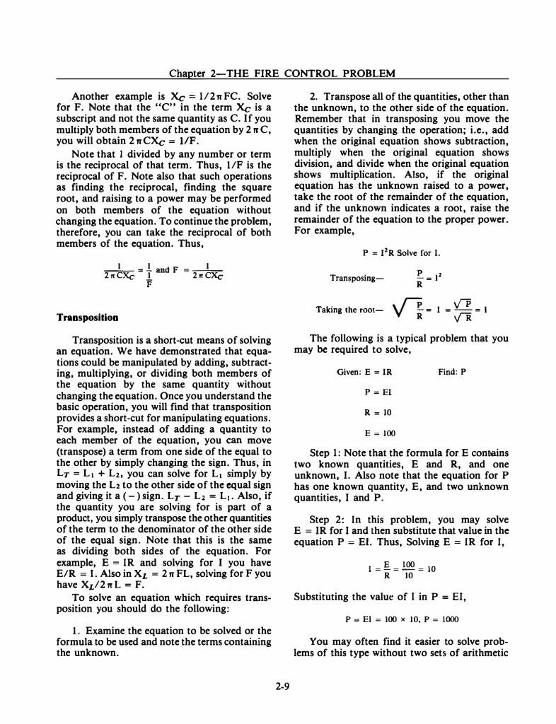
2. Transpose all of the quantities, other than the unknown, to the other side of the equation. Remember that in transposing you move the quantities by changing the operation; i.e., add when the original equation shows subtraction, multiply when the original equation shows division, and divide when the original equation shows multiplication. Also, if the original equation has the unknown raised to a power, take the root of the remainder of the equation, and if the unknown indicates a root, raise the remainder of the equation to the proper power. For example,
P :: eR Solve for I.
Transposing- � = 12 R
Taking the root- v'l- = I = � = I
The following is a typical problem that you may be required to solve,
Given: E = IR Find: P
P = El
R = 10
E = 100
Step 1: Note that the formula for E cont-ains two known quantities, E and R, and one unknown, I. Also note that the equation for P has one known quantity, E, and two unknown quantities, I and P.
Step 2: In this problem, you may solve E = IR for I and then substitute that value in the equation P = El. Thus, Solving E = IR for I,
E 100 1=-=-=10 R 10
Substituting the value of I in P = El,
p = El = 100 X 10, p = 1000
You may often find it easier to solve problems of this type without two sets of arithmetic
FIRE CONTROLMAN THIRD CLASS
calculations. You would accomplish this in the following manner:
Solve for E = IR for I = E/R and substitute this expression into the equation P = EI.. Thus, P = E x E/R = E2/R. Now substitute the values and compute P.
p = 100 X 100 = l{)()() 10
TRIGONOMETRY
This field of mathematics, which deals with the relationship between the sides and the angles of a right triangle, is extremely important in fire control. Trigonometry is required to solve the fire control problem and is also used in solving various electrical and electronic problems. Because angles are a vital part of trigonometry, a few basic definitions concerning angles will be presented to start the discussion.
An angle is formed whenever two lines meet at a point. To illustrate the generation or construction of various angles, assume the line OA as a reference. Using the end of the line marked 0 as a pivot, rotate the line to another position OB.
You can see that you effectively have two lines, OA and OB, which meet at point 0. Thus, you have an angle AOB. In dealing with angles, they will be most often referred to in terms of degrees. A circle contains 360 degrees ( 0) and in fire control applications, a degree is further divided into 60 minutes (') and each minute into
2-10
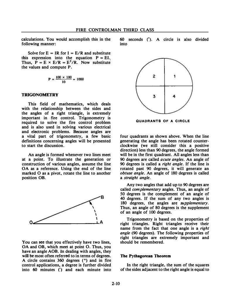
60 seconds ("). A circle is also divided into
QUADRANTS OF A CIRCLE
four quadrants as shown above. When the line generating the angle has been rotated counterclockwise (we still consider this a positive direction) less than 90 degrees, the angle formed will be in the first quadrant. All angles less than 90 degrees are called acute angles. An angle of 90 degrees is called a right angle. If the line is rotated past 90 degrees, it will generate an obtuse angle. An angle of 180 degrees is called a straight angle.
Any two angles that add up to 90 degrees are called complementary angles. Thus, an angle of 50 degrees is the complement of an angle of 40 degrees. If the sum of any two angles is 180 degrees, the angles are supplementary. Thus, an angle of 80 degrees is the supplement of an angle of 100 degrees.
Trigonometry is based on the properties of right triangles. Right triangles receive their name from the fact that one angle is a right angle (90 degrees). The following properties of right triangles are extremely important and should be remembered.
The Pythagorean Theorem
In the right triangle, the sum of the squares of the sides adjacent to the right angle is equal to
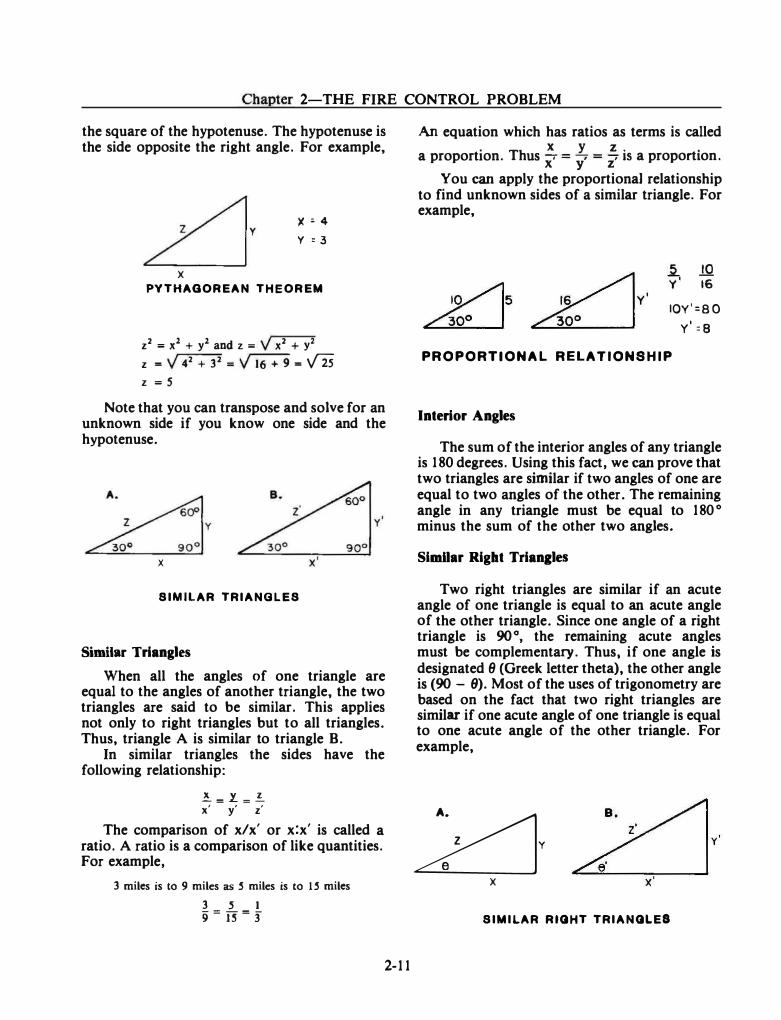
Chapter 2-THE FIRE CONTROL PROBLEM
the square of the hypotenuse. The hypotenuse is the side opposite the right angle. For example,
y
X
X� 4
y : 3
PYTHAGOREAN THEOREM
z2 = x2 + y2 and z = V x2 + y2
z = v 42 + 32 = v 16 + 9 = V2s z = s
Note that you can transpose and solve for an unknown side if you know one side and the hypotenuse.
X
SIMILAR TRIANGLES
Similar Triangles
When all the angles of one triangle are equal to the angles of another triangle, the two triangles are said to be similar. This applies not only to right triangles but to all triangles. Thus, triangle A is similar to triangle B.
In similar triangles the sides have the following relationship:
�=L=� x' y' z'
The comparison of x/x' or x:x' is called a ratio. A ratio is a comparison of like quantities. For example,
3 miles is to 9 miles as S miles is to 1 S miles 3 s 1 9=rr=3
2-11
An equation which has ratios as terms is called .
Th X y z . .
a proportion. us x' = y' = z' IS a proportion.
You can apply the proportionaJ relationship to find unknown sides of a similar triangle. For example,
10�5 �
���v' �
lQ 16
IOY'=80 v'=e
PROPORTIONAL RELATIONSHIP
Interior Angles
The sum of the interior angles of any triangle is 180 degrees. Using this fact, we can prove that two triangles are similar if two angles of one are equal to two angles of the other. The remaining angle in any triangle must be equal to 180° minus the sum of the other two angles.
SimDar Right Trianales
Two right triangles are similar if an acute angle of one triangle is equal to an acute angle of the other triangle. Since one angle of a right triangle is 90 o, the remaining acute angles must be complementary. Thus, if one angle is designated 8 (Greek letter theta), the other angle is (90 - 9). Most of the uses of trigonometry are based on the fact that two right triangles are similar if one acute angle of one triangle is equal to one acute angle of the other triangle. For example,
�y X
SIMILAR RIGHT TRIANGLES
FIRE CONTROLMAN THIRD CLASS
With 8 = 8', triangle A is similar to triangle B and x: x' = y: y' = z: z'. Note that x/x = y/y' may be written x/y = x' /y' without changing the relationship. Also y/z = y' /z' and x/z = x' /z'. These relationships are the main principle of trigonometry.
TRIGONOMETRIC TABLES.-Trigonometric tables are lists of the numerical values of the ratios of sides of right triangles (see Appendix II). The various relationships or ratios of the sides are given special names. These trigonometric functions are sine (sin), cosine (cos), tangent (tan), cosecant (esc), secant (sec), and cotangent (cot). The functions are illustrated in the following example,
OPPOSITE SIDE
ADJACENT SIDE
. Opposite Side sm 9 = ---=-:=---Hypotenuse
9 Adjacent Side cos = -=----
Hypotenuse
8 ....:.O.!:..;ppo!:....:..:.si....;te....;S....;id_e tan = Adjacent Side
esc 8 = Hypotenuse = _1_ Opposite Side sin 9
sec 9 = Hypotenuse = _1_
Adjacent Side cos 8
cot 8 = Adjacent Side = _1 _
Opposite Side tan 8
The form of trigonometric tables is varied. Some tables list the values of all six functions and others list only the sine, cosine, and tangent. Also, some tables express the angles in degrees and tenths of degrees and other tables express
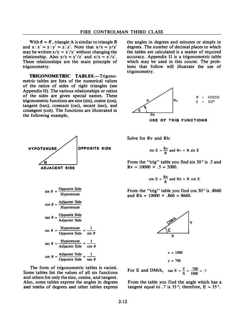
the angles in degrees and minutes or simply in degrees. The number of decimal places to which the tables are calculated is a matter of required accuracy. Appendix II is a trigonometric table which may be used in this course. The problems that follow will illustrate the use of trigonometry.
2-12
R Rv E :
Rh USE OF TRIG FUNCTIONS
Solve for Rv and Rh:
sin E = Rv and Rv = R sin E R
10000 30°
From the "trig" table you find sin 30° is .5 and Rv = 10000 x .5 = 5000.
Rh cos E = - and Rh = R cos E R
From the "trig" table you find cos 30 o is .8660 and Rh = 10000 x .866 = 8660.
For E and DMrh,
X= 1000
y=700
tan E = !. = 700 = . 7 X 1000
From the table you find the angle which has a tangent equal to . 7 is 35 °; therefore, E = 35 °.
Chapter 2-THE FIRE CONTROL PROBLEM
You can now find DMrh in several ways.
sin E • _l_ and DMrh =' __.!._ DMrh sinE
From the table you find sin 35 ° = .5736 and 700 DMrh =
.5736 = 1220
X X cos E "" -- and DMrh = --DMrh cos E
From the table you find cos 35 ° = .8192 and 1000 DMrh = .8192 = 1220
DMrh = V X2 + Y2 = V 1 x 10⁶ + 4.9 x 10⁵
DMrh ; V 1.49 x 106 = v 1.22 x 101
DMrh = 1220
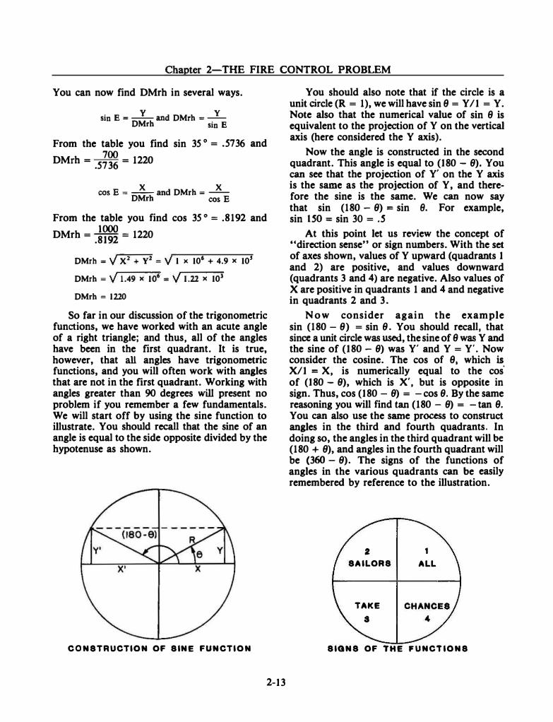
So far in our discussion of the trigonometric functions, we have worked with an acute angle of a right triangle; and thus, all of the angles have been in the first quadrant. It is true, however, that all angles have trigonometric functions, and you will often work with anales that are not in the first quadrant. Working with angles greater than 90 degrees will present no problem if you remember a few fundamentals. We will start off by using the sine function to illustrate. You should recall that the sine of an angle is equal to the side opposite divided by the hypotenuse as shown.
CONSTRUCTION OF SINE FUNCTION
2-13
You should also note that if the circle is a unit circle (R = 1), we will have sin 6 = Y /1 = Y. Note also that the numerical value of sin 6 is equivalent to the projection of Y on the vertical axis (here considered theY axis).
Now the angle is constructed in the second quadrant. This angle is equal to (180- 9). You can see that the projection of Y' on the Y axis is the same as the projection of Y, and therefore the sine is the same. We can now say that sin (180 - 9) = sin 8. For example, sin ISO = sin 30 = .S
At this point let us review the concept of "direction sense" or sign numbers. With the set of axes shown, values of Y upward (quadrants 1 and 2) are positive, and values downward (quadrants 3 and 4) are negative. Also values of X are positive in quadrants 1 and 4 and negative in quadrants 2 and 3.
N o w consider again the example sin (180- 9) = sin 9. You should recall, that since a unit circle was used, the sine of 6 was Y and the sine of (180 - 9) was Y' and Y = Y'. Now consider the cosine. The cos of 6, which is X/1 = X, is numerically equal to the cos· of (180 - 9), which is X', but is opposite in sign. Thus, cos (180 - 9) = -cos 9. By the same reasoning you will find tan ( 180 - 9) = -tan 6.
You can also use the same process to construct anales in the third and fourth quadrants. In doing so, the angles in the third quadrant will be (180 + 9), and angles in the fourth quadrant will be (360- 9). The signs of the functions of angles in the various quadrants can be easily remembered by reference to the illustration.
2 1 SAILORS ALL
TAKE s
SIGNS OF THE �UNCTIONS
FIRE CONTROLMAN THIRD CLASS
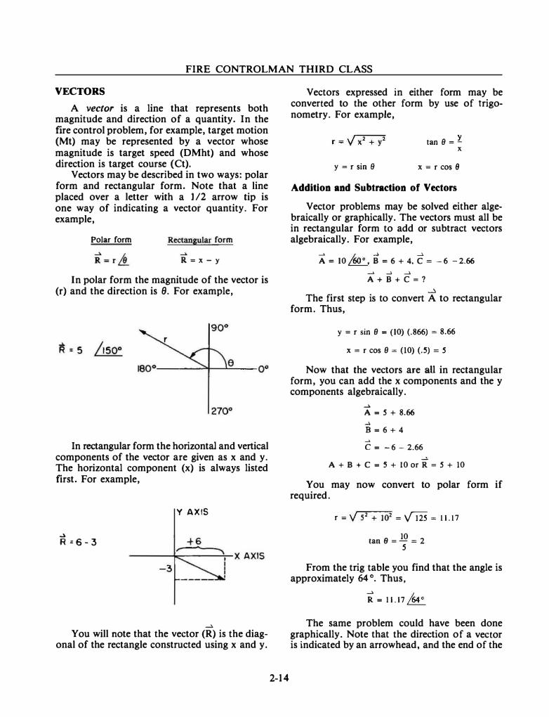
VECTORS
A vector is a line that represents both magnitude and direction of a quantity. In the fire control problem, for example, target motion (Mt) may be represented by a vector whose magnitude is target speed (DMht) and whose direction is target course (Ct).
Vectors may be described in two ways: polar form and rectangular form. Note that a line placed over a letter with a 1 /2 arrow tip is one way of indicating a vector quantity. For example,
Polar form Rectangular form
R=x-y
In polar form the magnitude of the vector is (r) and the direction is 9. For example,
In rectangular form the horizontal and vertical components of the vector are given as x and y. The horizontal component (x) is always listed frrst. For example,
Y AXIS
..J. R=6-3
� You will note that the vector (R) is the diag
onal of the rectangle constructed using x and y.
2-14
Vectors expressed in either form may be converted to the other form by use of trigonometry. For example,
tan () = l X
y = r sin 9 x=rcos9
Addition and Subtraction of Vectors
Vector problems may be solved either algebraically or graphically. The vectors must all be in rectangular form to add or subtract vectors algebraically. For example,
__. /,nn � __).
A = 10 �. B = 6 + 4, C = - 6 -2.66 _. ...... ..... A+B+C=?
...:. The first step is to convert A to rectangular
form. Thus,
y = r sin 8 = (10) (.866) = 8.66
x = r cos 8 = (10) (.5) = S
Now that the vectors are all in rectangular form, you can add the x components and the y components algebraically .
...... A= S + 8.66 � 8=6+4 ...... c = -6-2.66
..... A + B + C = 5 + 10 or R = S + 10
You may now convert to polar form if required.
r = v 52 + 102 = vm = ll.l7
tan 8 = 10 = 2 s
From the trig table you find that the angle is approximately 64 °. Thus,
R = ll.l7 /64°
The same problem could have been done graphically. Note that the direction of a vector is indicated by an arrowhead, and the end of the
Chapter 2-THE FIRE CONTROL PROBLEM
vector with the arrowhead is called the head. The other end of the vector is called the tail.
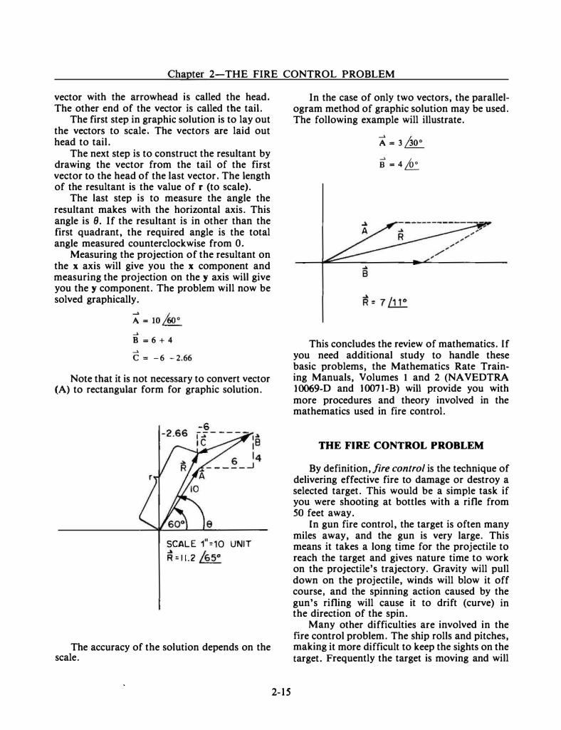
The first step in graphic solution is to lay out the vectors to scale. The vectors are laid out head to tail.
The next step is to construct the resultant by drawing the vector from the tail of the first vector to the head of the last vector. The length of the resultant is the value of r (to scale).
The last step is to measure the angle the resultant makes with the horizontal axis. This angle is 9. If the resultant is in other than the first quadrant, the required angle is the total angle measured counterclockwise from 0.
Measuring the projection of the resultant on the x axis will give you the x component and measuring the projection on the y axis will give you the y component. The problem will now be solved graphically.
A= 10/60° ..... B = 6 + 4 ..... c = -6 -2.66
Note that it is not necessary to convert vector (A) to rectangular form for graphic solution.
-6
SCALE 1"=10 UNIT R =11.2 /65°
The accuracy of the solution depends on the scale.
2-15
In the case of only two vectors, the parallelogram method of graphic solution may be used. The following example will illustrate.
A= 3 joo
o=4�
This concludes the review of mathematics. If you need additional study to handle these basic problems, the Mathematics Rate Training Manuals, Volumes 1 and 2 (NAVEDTRA 10069-D and 10071-B) will provide you with more procedures and theory involved in the mathematics used in fire control.
THE FIRE CONTROL PROBLEM
By definition, fire control is the technique of delivering effective fire to damage or destroy a selected target. This would be a simple task if you were shooting at bottles with a rifle from SO feet away.
In gun fire control, the target is often many miles away, and the gun is very large. This means it takes a long time for the projectile to reach the target and gives nature time to work on the projectile's trajectory. Gravity will pull down on the projectile, winds will blow it off course, and the spinning action caused by the gun's rifling will cause it to drift (curve) in the direction of the spin.
Many other difficulties are involved in the fire control problem. The ship rolls and pitches, making it more difficult to keep the sights on the target. Frequently the target is moving and will
FIRE CONTROLMAN THIRD CLASS
be far away from an anticipated point in space by the time the projectile arrives. Once the projectile has left the gun muzzle, nothing further can be done to affect its course. The gun's fire control problem must be solved before the gun is fired.
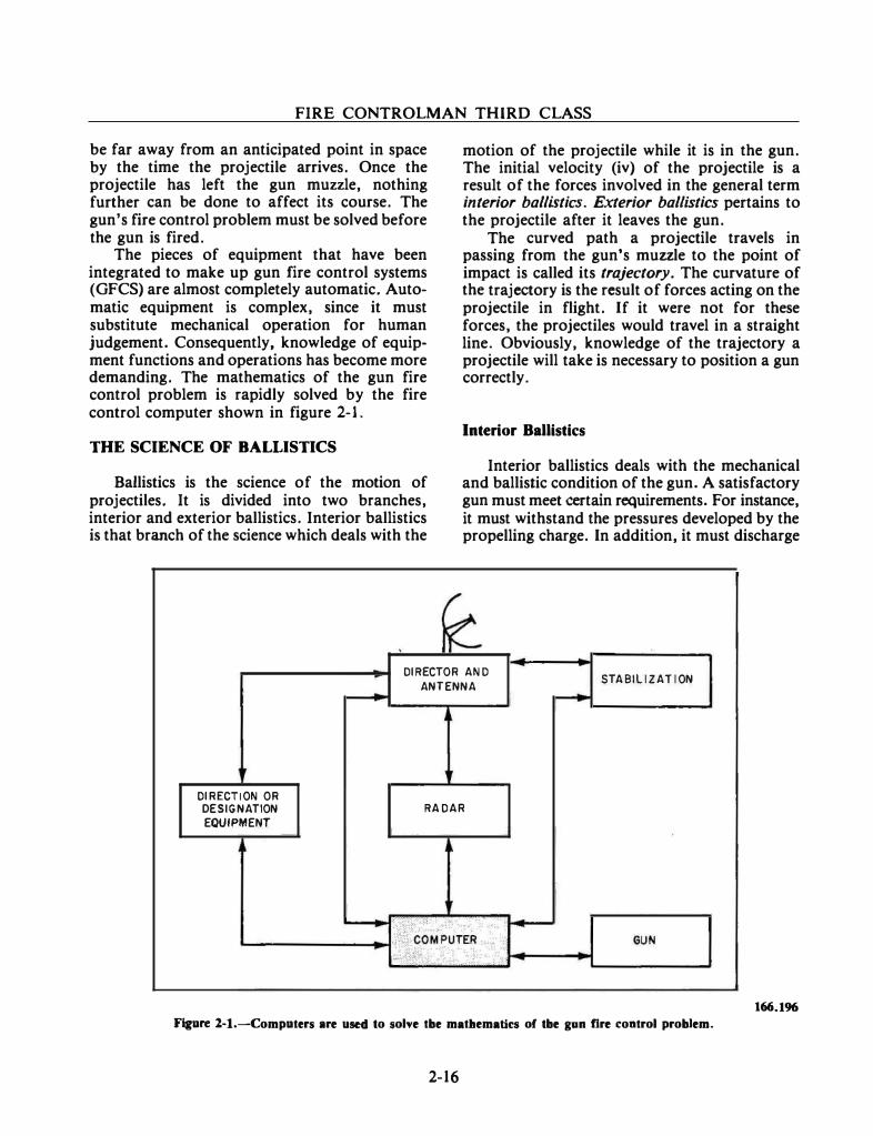
The pieces of equipment that have been integrated to make up gun fire control systems (GFCS) are almost completely automatic. Automatic equipment is complex, since it must substitute mechanical operation for human judgement. Consequently, knowledge of equipment functions and operations has become more demanding. The mathematics of the gun fire control problem is rapidly solved by the fire control computer shown in figure 2-1.
THE SCIENCE OF BALLISTICS
Ballistics is the science of the motion of projectiles. It is divided into two branches, interior and exterior ballistics. Interior ballistics is that branch of the science which deals with the
motion of the projectile while it is in the gun. The initial velocity (iv) of the projectile is a result of the forces involved in the general term interior ballistics. Exterior ballistics pertains to the projectile after it leaves the gun.
The curved path a projectile travels in passing from the gun's muzzle to the point of impact is called its trajectory. The curvature of the trajectory is the result of forces acting on the projectile in flight. If it were not for these forces, the projectiles would travel in a straight line. Obviously, knowledge of the trajectory a projectile will take is necessary to position a gun correctly.
Interior Ballistics
Interior ballistics deals with the mechanical and ballistic condition of the gun. A satisfactory gun must meet certain requirements. For instance, it must withstand the pressures developed by the propelling charge. In addition, it must discharge
DIRECTOR AND
ANTENNA STABILIZATION
DIRECTION OR
DESIGNATION
EQUIPMENT
RADAR
r--+ L-------'
Figure 2-1.-Computers are used to solve tbe matllematks of tbe gan fire control problem.
2-16
166.196
Chapter 2-THE FIRE CONTROL PROBLEM
REAR CYLINDER
SLIDE CYLINDER CHASE
BELL
84.135
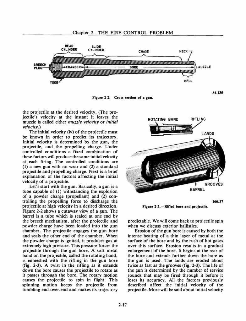
Figure l-2.-Cross section of a gun.
the projectile at the desired velocity. (The projectile's velocity at the instant it leaves the muzzle is called either muzzle velocity or initial velocity.)
The initial velocity (iv) of the projectile must be known in order to predict its trajectory. Initial velocity is determined by the gun, the projectile, and the propelling charge. Under controlled conditions a fixed combination of these factors will produce the same initial velocity at each firing. The controlled conditions are (1) a new gun with no wear and (2) a standard projectile and propelling charge. Next is a brief explanation of the factors affecting the initial velocity of a projectile.
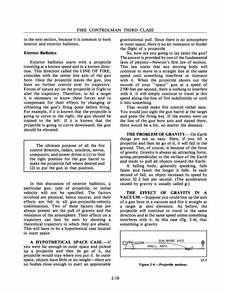
Let's start with the gun. Basically, a gun is a tube capable of (1) withstanding the explosion of a powder charge (propellant) and (2) controlling the propelling force to discharge the projectile at high velocity in a desired direction. Figure 2-2 shows a cutaway view of a gun. The barrel is a tube which is sealed at one end by the breech mechanism, after the projectile and powder charge have been loaded into the gun chamber. The projectile engages the gun bore and seals the other end of the chamber. When the powder charge is ignited, it produces gas at extremely high pressure. This pressure forces the projectile through the gun bore. A soft metal band on the projectile, called the rotating band, is enmeshed with the rifling in the gun bore (fig. 2-3). A twist in the rifling as it extends down the bore causes the projectile to rotate as it passes through the bore. The rotary motion causes the projectile to spin in flight. This spinning motion keeps the projectile from tumbling end-over-end and makes its trajectory
2-17
ROTATING BAND
-�· ·· RIFLING
LANDS
166.57
Figure 2-3.-Rified bore and projectile.
predictable. We will come back to projectile spin when we discuss exterior ballistics.
Erosion of the gun bore is caused by both the intense heating of a thin layer of metal at the surface of the bore and by the rush of hot gases over this surface. Erosion results in a gradual enlargement of the bore. It begins at the rear of the bore and extends farther down the bore as the gun is used. The lands are eroded about twice as fast as the grooves (fig. 2-3). The life of the gun is determined by the number of service rounds that may be fired through it before it loses its accuracy. All the factors previously described affect the initial velocity of the projectile. More will be said about initial velocity
FIRE CONTROLMAN THIRD CLASS
in the next section, because it is common to both interior and exterior ballistics.
Exterior BalUstics
Exterior ballistics starts with a projectile traveling at a known speed and in a known direction. This direction called the LINE OF FIRE, coincides with the center line axis of the gun bore. Once the projectile leaves the gun, you have no further control over its trajectory. Forces of nature act on the projectile in flight to alter the trajectory. Therefore, to hit a target it is necessary to know these forces and to compensate for their effects by changing or offsetting the gun's firing point before firing. For example, if it is known that the projectile is going to curve to the right, the gun should be trained to the left. If it is known that the projectile is going to curve downward, the gun should be elevated.
The ultimate purpose of all the fire control directors, radars, synchros, servos, computers, and power drives is (1) to find the right position for the gun barrel to make the projectile fall where desired and (2) to put the gun in that position.
In this discussion of exterior ballistics, a particular gun, type of projectile, or initial velocity will not be specified. The factors involved are physical, hence natural, and their effects are felt in all gun-projectile-velocity combinations. Two of these factors that are always present are the pull of gravity and the resistance of the atmosphere. Their effects on a trajectory can best be seen by showing a theoretical trajectory in which they are absent. This will have to be a hypothetical case located in outer space.
A HYPOTHETICAL SPACE CASE.-If you were far enough in outer space and picked up a projectile and then let go of it, the projectile would stay where you put it. In outer space, objects have little or no weight-there are no bodies close enough to exert an appreciable
2-18
gravitational pull. Since there is no atmosphere in outer space, there is no air resistance to hinder the flight of a projectile.
So, how are you going to lay (aim) the gun? The answer is provided by one of the fundamental laws of physics-Newton's first law of motion. This law states that any moving body will continue to move in a straight line at the same speed until something interferes or interacts with it. When the projectile shoots out the muzzle of your "space" gun at a speed of 2700 feet per second, there is nothing to interfere with it. It will simply continue to travel at this speed along the line of fire indefinitely or until it hits something.
That would make fire control rather easy. You would just sight the gun barrel at the target and press the firing key. If the enemy were on the line of the gun bore axis and stayed there, there would be a hit, no matter the distance.
THE PROBLEM OF GRAVITY .-On Earth things are not so easy. Here, if you lift a projectile and then let go of it, it will fall to the ground. This, of course, is because of the force of gravity. Gravity is always an attracting force, acting perpendicular to the surface of the Earth and tends to pull all objects toward the Earth.
A falling body, generally speaking, falls faster and faster the longer it falls. In each second of fall, an object increases its speed by about 32.2 feet per second. (The acceleration caused by gravity is usually called g.)
THE EFFECT OF GRAVITY IN A V ACUUM.-Suppose you could line up the axis of a gun bore in a vacuum and fire it straight at a target at zero elevation. As before, the projectile will continue to travel in the same direction and at the same speed unless ·something interferes with it. In this case (fig. 2-4), that something is gravity.
ll.l Figure l-4.-Projectile motions.
Chapter 2-THE FIRE CONTROL PROBLEM
As soon as the projectile leaves the gun it starts to fall, just like any other object. The projectile, however, is traveling forward and falling at the same time. The projectile has two forces acting on it: (l) the momentum imparted by the forward thrust of the gun's propulsion system and (2) the pull of gravity. The path of the projectile, as a result of these two forces, is a curved trajectory.
The forward momentum of the projectile tends to keep the trajectory in a straight line in accordance with Newton's first law of motion. Gravity, however, starts the projectile falling. The constant pull of gravity causes the falling motion to accelerate, and the downward slope of the trajectory to increase.
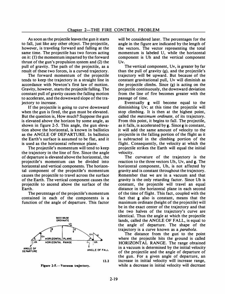
If the projectile is going to curve downward when the gun is fired, the gun must be elevated. But the question is, How much? Suppose the gun is elevated above the horizon by some angle, as shown in figure 2-5. This angle, the gun elevation above the horizontal, is known in ballistics as the ANGLE OF DEPARTURE. In ballistics the Earth's surface is assumed to be flat, and it is used as the horizontal reference plane.
The projectile's momentum will tend to keep the trajectory in the line of fire. Since the angle of departure is elevated above the horizontal, the projectile's momentum can be divided into horizontal and vertical components. The horizontal component of the projectile's momentum causes the projectile to travel across the surface of the Earth. The vertical component causes the projectile to ascend above the surface of the Earth.
The percentage of the projectile's momentum contained in each of the components is a function of the angle of departure. This factor
ANGLE OF DEPARTURE
Uv
MAXIMUM ORDINATE
HORIZONTAL PLANE HORIZONTAL RANGE
Figure l-5.-Vac:uum trajectory. ll.l
2-19
will be considered later. The percentages for the angle in the figure are indicated by the length of the vectors. The vector representing the total momentum is labeled U, while the horizontal component is Uh and the vertical component Uv.
The vertical component, Uv, is greater by. far than the pull of gravity (g), and the projectile's trajectory will be upward. But because of the constant gravitational pull, Uv will diminish as the projectile climbs. Since (g) is acting on the projectile continuously, the downward deviation from the line of fire becomes greater with the passage of time.
Eventually g will become equal to the diminishing Uv; at this time the projectile will stop climbing. It is then at the highest point, called the maximum ordinate, of its trajectory. From this point, it begins to fall. The projectile, as it falls, is accelerated by g. Since g is constant, it will add the same amount of velocity to the projectile in the falling portion of the flight as it is subtracted in the climbing portion of the flight. Consequently, the velocity at which the projectile strikes the Earth will equal the initial velocity.
The curvature of the trajectory is the reaction to the three vectors Uh, Uv, and g. The horizontal component, Uh, is not affected by gravity and is constant throughout the trajectory. Remember that we are in a vacuum and that gravity is the only retarding factor. Since Uh is constant, the projectile will travel an equal distance in the horizontal plane in each second of the time of flight. This fact, coupled with the fact that g also is constant, means that the maximum ordinate (height of the projectile) will be in the exact center of the trajectory and that the two halves of the trajectory's curve are identical. Thus the angle at which the projectile lands, called the ANGLE OF FALL, is equal to the angle of departure. The shape of the trajectory is a curve known as a parabola.
The distance from the gun· to the point where the projectile hits the ground is called HORIZONTAL RANGE. The range obtained in a vacuum is determined by the initial velocity of the projectile and the angle of departure of the gun. For a given angle of departure, an increase in initial velocity will increase range, while a decrease in initial velocity will decrease
FIRE CONTROLMAN THIRD CLASS
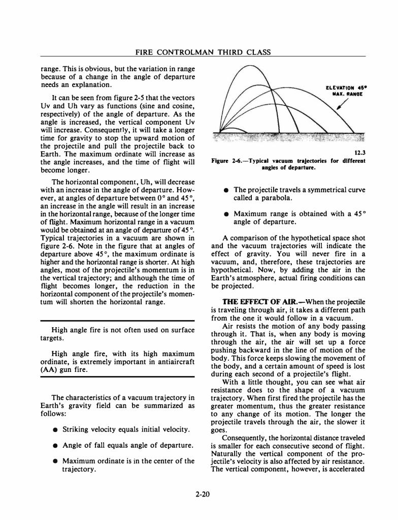
range. This is obvious, but the variation in range because of a change in the angle of departure needs an explanation.
It can be seen from figure 2-5 that the vectors Uv and Uh vary as functions (sine and cosine, respectively) of the angle of departure. As the angle is increased, the vertical component Uv will increase. Consequently, it will take a longer time for gravity to stop the upward motion of the projectile and pull the projectile back to Earth. The maximum ordinate will increase as the angle increases, and the time of flight will become longer.
The horizontal component, Uh, will decrease with an increase in the angle of departure. However, at angles of departure between 0 ° and 45 o, an increase in the angle will result in an increase in the horizontal range, because of the longer time of flight. Maximum horizontal range in a vacuum would be obtained at an angle of departure of 45 o. Typical trajectories in a vacuum are shown in figure 2-6. Note in the figure that at angles of departure above 45 °, the maximum ordinate is higher and the horizontal range is shorter. At high angles, most of the projectile's momentum is in the vertical trajectory; and although the time of flight becomes longer, the reduction in the horizontal component of the projectile's momen· tum will shorten the horizontal range.
High angle fire is not often used on surface targets.
High angle fire, with its high maximum ordinate, is extremely important in antiaircraft (AA) gun fire.
The characteristics of a vacuum trajectory in Earth's gravity field can be summarized as follows:
• Striking velocity equals initial velocity.
• Angle of fall equals angle of departure.
• Maximum ordinate is in the center of the trajectory.
2-20
ELEVATION 46• MAX. RANGE
/
12.3
Figure 2-6.-Typical vat:uum trajectories for dlffereat aagles of departltre.
• The projectile travels a symmetrical curve called a parabola.
• Maximum range is obtained with a 45 o angle of departure.
A comparison of the hypothetical space shot and the vacuum trajectories will indicate the effect of gravity. You will never fire in a vacuum, and, therefore, these trajectories are hypothetical. Now, by adding the air in the Earth's atmosphere, actual firing conditions can be projected.
THE EFFECT OF AIR.-When the projectile is traveling through air, it takes a different path from the one it would follow in a vacuum.
Air resists the motion of any body passing through it. That is, when any body is moving through the air, the air will set up a force pushing backward in the line of motion of the body. This force keeps slowing the movement of the body, and a certain amount of speed is lost during each second of a projectile's flight.
With a little thought, you can see what air resistance does to the shape of a vacuum trajectory. When first fired the projectile has the greater momentum, thus the greater resistance to any change of its motion. The longer the projectile travels through the air, the slower it goes.
Consequently, the horizontal distance traveled is smaller for each consecutive second of flight. Naturally the vertical component of the projectile's velocity is also affected by air resistance. The vertical component, however, is accelerated
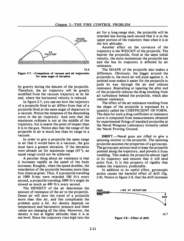
Chapter 2 THE FIRE CONTROL PROBLEM
12.4 Fiaure l-7.-Comparison of vacuum and air trajectories
for same anale of elevation.
by gravity during the descent of the projectile. Therefore, the air trajectory will be greatly modified from the vacuum trajectory at its far end, where the horizontal velocity is reduced.
In figure 2-7, you can see how the trajectory of a projectile fired in air differs from that of a projectile fired at the same angle of departure in a vacuum. Notice the steepness of the descending curve in the air trajectory. And note that the maximum ordinate is not at the middle of the trajectory, but is nearer the point of impact than it is to the gun. Notice also that the range of the projectile in air is much less than its range in a vacuum.
In order to give a projectile the same range in air that it would have in a vacuum, the gun must have a greater elevation. If the elevation were already set for maximum range (45 °), an equal range could not be achieved.
A peculiar thing about air resistance is that it increases rapidly as the speed of the body increases. Roughly, when the speed doubles, the retardation of the projectile becomes more than four times as great. Thus, if a projectile traveling at 1000 ftl sec were retarded 100 ft/ s every second, a projectile traveling 2000 ft/s might be slowed as much as 400 ft/s every second.
The DENSITY of the air determines the amount of resistance of the air to the projectile. Dense air will slow the travel of a projectile more than thin air, and this complicates the problem quite a bit. Air density depends on temperature and barometric pressure and these values are changing all the time. Moreover, the density is less at higher altitudes than it is at sea level. Since the trajectory rises high into the
2-21
air for a long-range shot, the projectile will be retarded less during each second that it is in the upper portion of the trajectory than when it is at the low altitudes.
Another effect on the curvature of the trajectory is the WEIGHT of the projectile. The heavier the projectile, fired at the same initial velocity, the more momentum the projectile has and the less its trajectory is affected by air resistance.
The SHAPE of the projectile also makes a difference. Obviously, the bigger around the projectile is, the more air will push against it. A pointed nose makes it easier for the projectile to push its way through the air and reduces resistance. Boattailing or tapering the after end of the projectile reduces the drag resulting from air turbulence behind the projectile, which also reduces resistance.
The effect of the air resistance resulting from the shape of the projectile is expressed by a quantity called the COEFFICIENT OF FORM. The data for such a drag coefficient or resistance curve is computed from measurements obtained by experimental firings of standard projectiles at the Naval Weapons Laboratory formerly called the Naval Proving Ground.
DRIFT.-Naval guns are rifled to give a spinning motion to the projectile. The spinning projectile assumes the properties of a gyroscope. The gyroscopic actions tend to keep the projectile pointed along the trajectory, and prevent it from tumbling. This makes the projectile almost rigid in its trajectory and ensures that it will land point first. It is this property of rigidity that makes the trajectory predictable.
In addition to its useful effect, gyroscopic action causes the harmful effect of drift (fig. 2-8). Notice in figure 2-8, that the drift increases
!;;§;;;;;�;• ;;;;;;;;aii ---.::.L.-1 N._:�_.... ·:.:.�·F.;,::· -.::-�.::�-:.:�A ::·�::-��� �-...... -..... • • • 4
DIUF
11.7 Figure l-3.-Effect of drift.
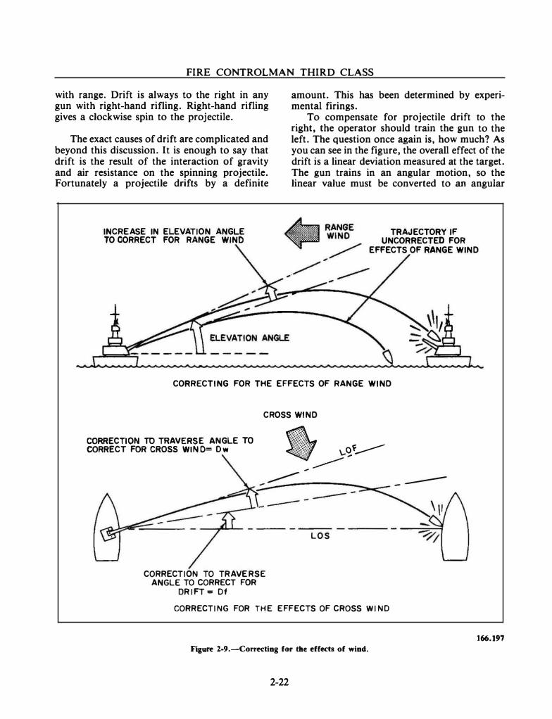
FIRE CONTROLMAN THIRD CLASS
with range. Drift is always to the right in any gun with right-hand rifling. Right-hand rifling gives a clockwise spin to the projectile.
The exact causes of drift are complicated and beyond this discussion. It is enough to say that drift is the result of the interaction of gravity and air resistance on the spinning projectile. Fortunately a projectile drifts by a definite
INCREASE IN ELEVATION ANGLE TO CORRECT FOR RANGE WINO
amount. This has been determined by experimental firings.
To compensate for projectile drift to the right, the operator should train the gun to the left. The question once again is, how much? As you can see in the figure, the overall effect of the drift is a linear deviation measured at the target. The gun trains in an angular motion, so the linear value must be converted to an angular
TRAJECTORY IF UNCORRECTED FOR
EFFECTS OF RANGE WIND
CORRECTING FOR THE EFFECTS OF RANGE WIND
CROSS WIND
gg��g�'l'�lln;rt�V���:�:LE TO "/�y-
CORRECTION TO TRAVERSE ANGLE TO CORRECT FOR
DRIFT • Of
----- ;
L O S
CORRECTING FOR THE EFFECTS OF CROSS WI NO
Fiaure 2-9.-Correcting for the effects of wind.
2-22
---
166.197
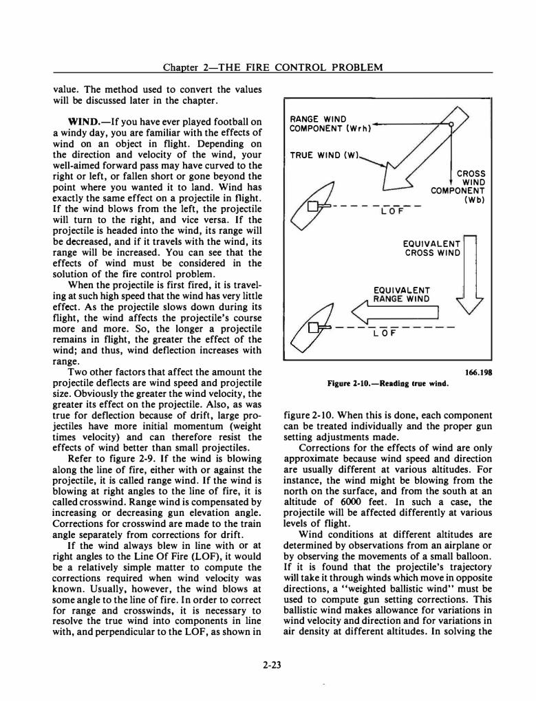
Chapter 2-THE FIRE CONTROL PROBLEM
value. The method used to convert the values will be discussed later in the chapter.
WIND.-If you have ever played football on a windy day, you are familiar with the effects of wind on an object in flight. Depending on the direction and velocity of the wind, your well-aimed forward pass may have curved to the right or left, or fallen short or gone beyond the point where you wanted it to land. Wind has exactly the same effect on a projectile in flight. If the wind blows from the left, the projectile will turn to the right, and vice versa. If the projectile is headed into the wind, its range will be decreased, and if it travels with the wind, its range will be increased. You can see that the effects of wind must be considered in the solution of the fire control problem.
When the projectile is first fired, it is traveling at such high speed that the wind has very little effect. As the projectile slows down during its flight, the wind affects the projectile's course more and more. So, the longer a projectile remains in flight, the greater the effect of the wind; and thus, wind deflection increases with range.
Two other factors that affect the amount the projectile deflects are wind speed and projectile size. Obviously the greater the wind velocity, the greater its effect on the projectile. Also, as was true for deflection because of drift, large projectiles have more initial momentum (weight times velocity) and can therefore resist the effects of wind better than small projectiles.
Refer to figure 2-9. If the wind is blowing along the line of fire, either with or against the projectile, it is called range wind. If the wind is blowing at right angles to the line of fire, it is called crosswind. Range wind is compensated by increasing or decreasing gun elevation angle. Corrections for crosswind are made to the train angle separately from corrections for drift.
If the wind always blew in line with or at right angles to the Line Of Fire (LOF), it would be a relatively simple matter to compute the corrections required when wind velocity was known. Usually, however, the wind blows at some angle to the line of fire. In order to correct for range and crosswinds, it is necessary to resolve the true wind into components in line with, and perpendicular to the LOF, as shown in
2-23
RANGE WIND COMPONENT {Wrh)
TRUE WIND (W)
CROSS WIND
COMPONENT (Wb)
EQUIVALENT CROSS WIND
EQUIVALENT < RANGE WIND
/nJ I v LOF
Figure 2·10.-Reading lrue wind. 166.198
figure 2-10. When this is done, each component can be treated individually and the proper gun setting adjustments made.
Corrections for the effects of wind are only approximate because wind speed and direction are usually different at various altitudes. For instance, the wind might be blowing from the north on the surface, and from the south at an altitude of 6000 feet. In such a case, the projectile will be affected differently at various levels of flight.
Wind conditions at different altitudes are determined by observations from an airplane or by observing the movements of a small balloon. If it is found that the projectile's trajectory will take it through winds which move in opposite directions, a "weighted ballistic wind" must be used to compute gun setting corrections. This ballistic wind makes allowance for variations in wind velocity and direction and for variations in air density at different altitudes. In solving the
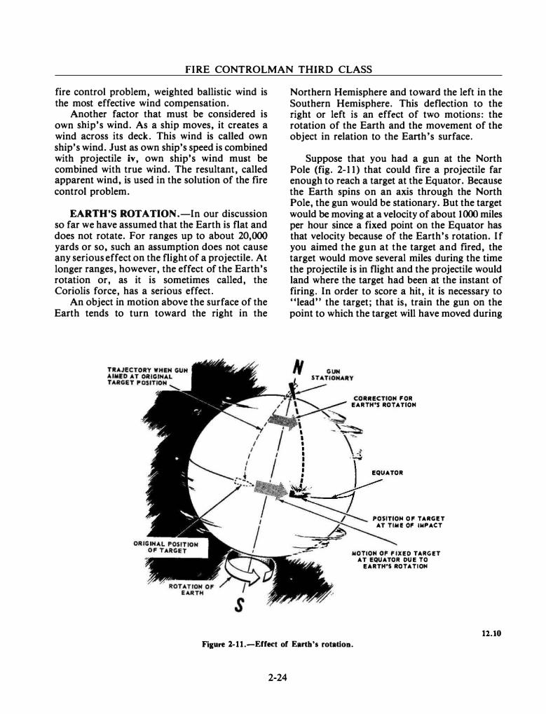
FIRE CONTROLMAN THIRD CLASS
fire control problem, weighted ballistic wind is the most effective wind compensation.
Another factor that must be considered is own ship's wind. As a ship moves, it creates a wind across its deck. This wind is called own ship's wind. Just as own ship's speed is combined with projectile iv, own ship's wind must be combined with true wind. The resultant, called apparent wind, is used in the solution of the fire control problem.
EARTH'S ROTATION .-In our discussion so far we have assumed that the Earth is flat and does not rotate. For ranges up to about 20,000 yards or so, such an assumption does not cause any serious effect on the flight of a projectile. At longer ranges, however, the effect of the Earth's rotation or, as it is sometimes called, the Coriolis force, has a serious effect.
An object in motion above the surface of the Earth tends to turn toward the right in the
Northern Hemisphere and toward the left in the Southern Hemisphere. This deflection to the right or left is an effect of two motions: the rotation of the Earth and the movement of the object in relation to the Earth's surface.
Suppose that you had a gun at the North Pole (fig. 2-11) that could fire a projectile far enough to reach a target at the Equator. Because the Earth spins on an axis through the North Pole, the gun would be stationary. But the target would be moving at a velocity of about 1000 miles per hour since a fixed point on the Equator has that velocity because of the Earth's rotation. If you aimed the gun at the target and fired, the target would move several miles during the time the projectile is in flight and the projectile would land where the target had been at the instant of firing. In order to score a hit, it is necessary to "lead" the target; that is, train the gun on the point to which the target will have moved during
'
' I
CORRECTION I'OR EARTH'S ROTATION
I , • :-i I --
� �l EQUATOR
� :_::::::::::; � POliTIOM OP TARGIT
h AT TIAII! 01' IMPACT
----:::;;;:;;:;i� MOTION 01' I'IXED TARGET
AT EQUATOR OUE TO EARTH'S ROTATIOH
12.10
Fixure l-11.-Effect of Earth's rotatiou.
2-24
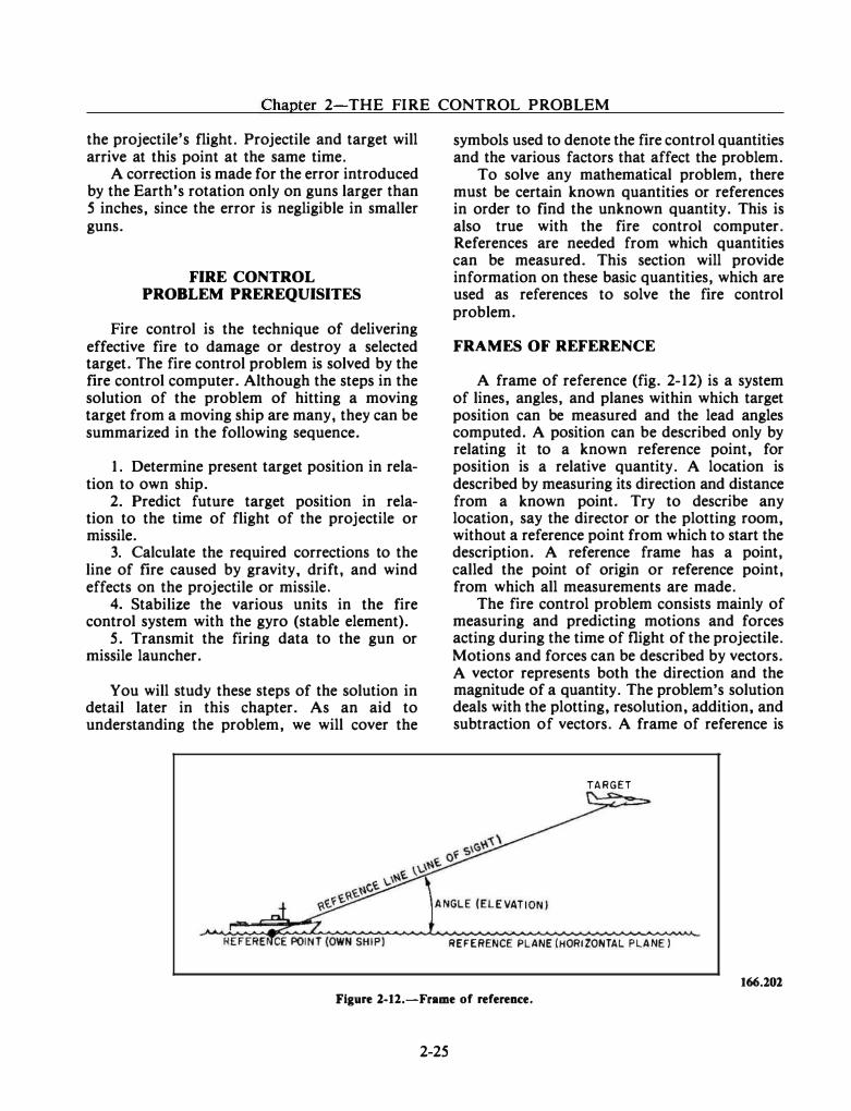
Chapter 2-THE FIRE CONTROL PROBLEM
the projectile's flight. Projectile and target will arrive at this point at the same time.
A correction is made for the error introduced by the Earth's rotation only on guns larger than 5 inches, since the error is negligible in smaller guns.
FIRE CONTROL PROBLEM PREREQUISITES
Fire control is the technique of delivering effective fire to damage or destroy a selected target. The fire control problem is solved by the fire control computer. Although the steps in the solution of the problem of hitting a moving target from a moving ship are many, they can be summarized in the following sequence.
1. Determine present target position in relation to own ship.
2. Predict future target position in relation to the time of flight of the projectile or missile.
3. Calculate the required corrections to the line of fire caused by gravity, drift, and wind effects on the projectile or missile.
4. Stabilize the various units in the fire control system with the gyro (stable element).
5. Transmit the firing data to the gun or missile launcher.
You will study these steps of the solution in detail later in this chapter. As an aid to understanding the problem, we will cover the
symbols used to denote the fire control quantities and the various factors that affect the problem.
To solve any mathematical problem, there must be certain known quantities or references in order to find the unknown quantity. This is also true with the fire control computer. References are needed from which quantities can be measured. This section will provide information on these basic quantities, which are used as references to solve the fire control problem.
FRAMES OF REFERENCE
A frame of reference (fig. 2-12) is a system of lines, angles, and planes within which target position can be measured and the lead angles computed. A position can be described only by relating it to a known reference point, for position is a relative quantity. A location is described by measuring its direction and distance from a known point. Try to describe any location, say the director or the plotting room, without a reference point from which to start the description. A reference frame has a point, called the point of origin or reference point, from which all measurements are made.
The fire control problem consists mainly of measuring and predicting motions and forces acting during the time of flight of the projectile. Motions and forces can be described by vectors. A vector represents both the direction and the magnitude of a quantity. The problem's solution deals with the plotting, resolution, addition, and subtraction of vectors. A frame of reference is
TARGET
REFERENCE PLANE (HORIZONTAL PLANE)
166.201
Figure 1.12.-Frame of reference.
2-25
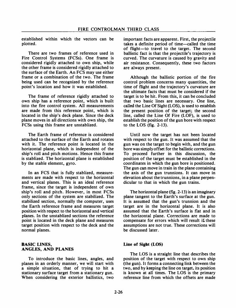
FIRE CONTROLMAN THIRD CLASS
established within which the vectors can be plotted.
There are two frames of reference used in Fire Control Systems (FCSs). One frame is considered rigidly attached to own ship, while the other frame is considered rigidly attached to the surface of the Earth. An FCS may use either frame or a combination of the two. The frame being used can be recognized by the reference point's location and how it was established.
The frame of reference rigidly attached to own ship has a reference point, which is built into the fire control system. All measurements are made from this reference point, which is located in the ship's deck plane. Since the deck plane moves in all directions with own ship, the FCSs using this frame are unstablized.
The Earth frame of reference is considered attached to the surface of the Earth and rotates with it. The reference point is located in the horizontal plane, which is independent of the ship's roll and pitch motions. Hence this frame is stablized. The horizontal plane is established by the stable element, gyro.
In an FCS that is fully stablized, measurements are made with respect to the horizontal and vertical planes. This is an ideal reference frame, since the target is independent of own ship's roll and pitch. However, in most FCSs only sections of the system are stabilized. The stabilized section, normally the computer, uses the Earth reference frame and measures target position with respect to the horizontal and vertical planes. In the unstablized sections the reference point is located in the deck plane and measures target position with respect to the deck and the normal planes.
BASIC LINES, ANGLES, AND PLANES
To introduce the basic lines, angles, and planes in an orderly manner, we will start with a simple situation, that of trying to hit a stationary surface target from a stationary gun. When considering the exterior ballistics, two
2-26
important facts are apparent. First, the projectile takes a definite period of time-called the time of flight-to travel to the target. The second ballistic fact is that the projectile's trajectory is curved. The curvature is caused by gravity and air resistance. Consequently, these two factors are always present.
Although the ballistic portion of the fire control problem concerns many quantities, the time of flight and the trajectory's curvature are the ultimate facts that must be considered if the target is to be hit. From this, it can be concluded that two basic lines are necessary. One line, called the Line Of Sight (LOS), is used to establish the present position of the target; the second line, called the Line Of Fire (LOF), is used to establish the position of the gun bore with respect to the LOS (fig. 2-13).
Until now the target has not been located with respect to the gun. It was assumed that the gun was on the target to begin with, and the gun bore was simply offset for the ballistic corrections. To proceed further in this discussion, the position of the target must be established in the coordinates in which the gun bore is positioned. The gun can move in train in the plane containing the axis of the gun trunnions. It can move in elevation about the trunnions, in a plane perpendicular to that in which the gun trains.
The horizontal plane (fig. 2-13) is an imaginary plane tangent to the Earth's surface at the gun. It is assumed that the gun's trunnion and the target are in the horizontal plane. It is also assumed that the Earth's surface is flat and in the horizontal plane. Corrections are made to compensate for errors which will result it:. these assumptions are not true. These corrections will be discussed later.
Line of Sigbt (LOS)
The LOS is a straight line that describes the position of the target with respect to own ship (the gun). It forms a connecting link between the two, and by keeping the line on target. its position is known at all times. The LOS is the primary reference line from which the offsets are made
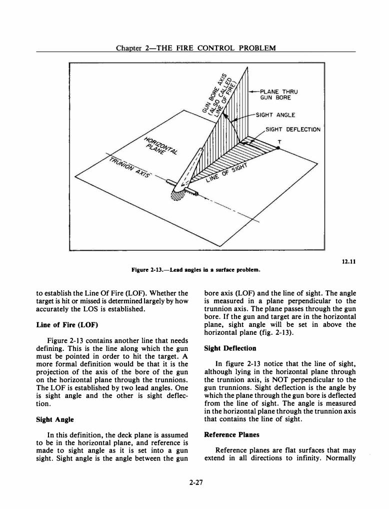
Chapter 2-THE FIRE CONTROL PROBLEM
DEFLECTION
12.11
Figure 2-13.-Lead angles Ia a surface problem.
to establish the Line Of Fire (LOF). Whether the target is hit or missed is determined largely by how accurately the LOS is established.
Line of Fire (LOF)
Figure 2-13 contains another line that needs defining. This is the line along which the gun must be pointed in order to hit the target. A more formal definition would be that it is the projection of the axis of the bore of the gun on the horizontal plane through the trunnions. The LOF is established by two lead angles. One is sight angle and the other is sight deflection.
Sight Angle
In this definition, the deck plane is assumed to be in the horizontal plane, and reference is made to sight angle as it is set into a gun sight. Sight angle is the angle between the gun
2-27
bore axis (LOF) and the line of sight. The angle is measured in a plane perpendicular to the trunnion axis. The plane passes through the gun bore. If the gun and target are in the horizontal plane, sight angle will be set in above the horizontal plane (fig. 2-13).
Sight Deflection
In figure 2-13 notice that the line of sight, although lying in the horizontal plane through the trunnion axis, is NOT perpendicular to the gun trunnions. Sight deflection is the angle by which the plane through the gun bore is deflected from the line of sight. The angle is measured in the horizontal plane through the trunnion axis that contains the line of sight.
Reference Planes
Reference planes are flat surfaces that may extend in all directions to infinity. Normally
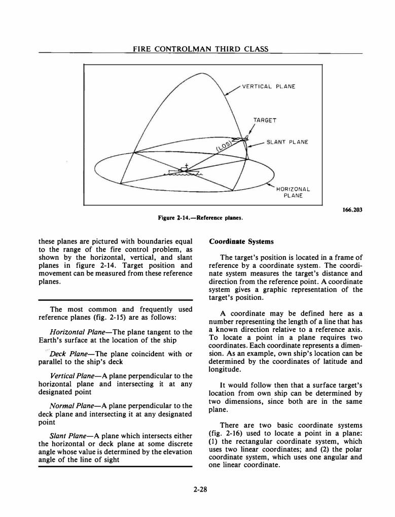
FIRE CONTROLMAN THIRD CLASS
VERTICAL PLANE
PLANE
HORIZONAL PLANE
166.203
Figure l-14.-Referenc:e planes.
these planes are pictured with boundaries equal to the range of the fire control problem, as shown by the horizontal, vertical, and slant planes in figure 2-14. Target position and movement can be measured from these reference planes.
The most common and frequently used reference planes (fig. 2-15) are as follows:
Horizontal Plane-The plane tangent to the Earth's surface at the location of the ship
Deck Plane-The plane coincident with or parallel to the ship's deck
Vertical Plane-A plane perpendicular to the horizontal plane and intersecting it at any designated point
Normal Plane-A plane perpendicular to the deck plane and intersecting it at any designated point
Slant Plane-A plane which intersects either the horizontal or deck plane at some discrete angle whose value is determined by the elevation angle of the line of sight
2-28
Coordinate Systems
The target's position is located in a frame of reference by a coordinate system. The coordinate system measures the target's distance and direction from the reference point. A coordinate system gives a graphic representation of the target's position.
A coordinate may be defined here as a number representing the length of a line that has a known direction relative to a reference axis. To locate a point in a plane requires two coordinates. Each coordinate represents a dimension. As an example, own ship's location can be determined by the coordinates of latitude and longitude.
It would follow then that a surface target's location from own ship can be determined by two dimensions, since both are in the same plane.
There are two basic coordinate systems (fig. 2-16) used to locate a point in a plane: (1) the rectangular coordinate system, which uses two linear coordinates; and (2) the polar coordinate system, which uses one angular and one linear coordinate.
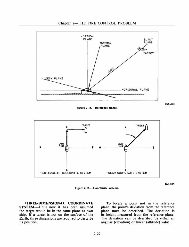
w
Chapter 2-THE FIRE CONTROL PROBLEM
N
VERTICAL PLANE
Figure 2·15.-Reference planes.
TARGET
OWN OWN
SLANT PLANE
____ S_H I_P+H ----- E w ____ -=.;SH"-'I�Pttt-----
s s RECTANGULAR COORDINATE SYSTEM POLAR COORDINATE SYSTEM
Flaure l-16.-Coordlnate systems.
166.204
E
166.205
THREE-DIMENSIONAL COORDINATE SYSTEM.-Until now it has been assumed the target would be in the same plane as own ship. If a target is not on the surface of the Earth, three dimensions are required to describe its position.
To locate a point not in the reference plane, the point's deviation from the reference plane must be described. The deviation is its height measured from the reference plane. The deviation can be described by either an angular (elevation) or linear (altitude) value.
2-29
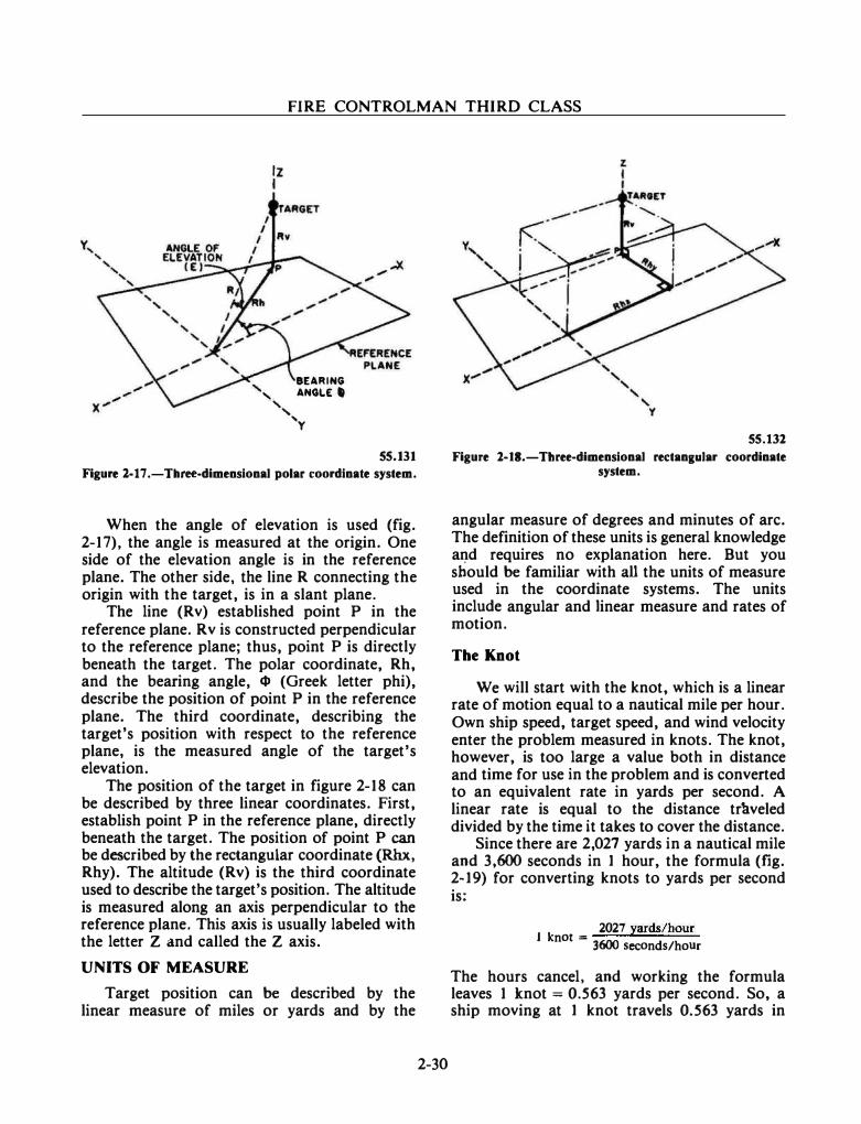
FIRE CONTROLMAN THIRD CLASS
tz I
BEARING ' ANGLE'
', 'y
55.131
Figure l-17 .-Tllree-dimensional polar coordinate system.
When the angle of elevation is used (fig. 2-17), the angle is measured at the origin. One side of the elevation angle is in the reference plane. The other side, the line R connecting the origin with the target, is in a slant plane.
The line (Rv) established point P in the reference plane. Rv is constructed perpendicular to the reference plane; thus, point P is directly beneath the target. The polar coordinate, Rh, and the bearing angle, <I» (Greek letter phi), describe the position of point P in the reference plane. The third coordinate, describing the target's position with respect to the reference plane, is the measured angle of the target's elevation.
The position of the target in figure 2-18 can be described by three linear coordinates. First, establish point P in the reference plane, directly beneath the target. The position of point P can be described by the rectangular coordinate (Rhx, Rhy). The altitude (Rv) is the third coordinate used to describe the target's position. The altitude is measured along an axis perpendicular to the reference plane. This axis is usually labeled with the letter Z and called the Z axis.
UNITS OF MEASURE
Target position can be described by the linear measure of miles or yards and by the
2-30
55.131
Figure 1-11.-Three-dimensional rectan1ular coordinate system.
angular measure of degrees and minutes of arc. The definition of these units is general knowledge and requires no explanation here. But you should be familiar with all the units of measure used in the coordinate systems. The units include angular and linear measure and rates of motion.
The Knot
We will start with the knot, which is a linear rate of motion equal to a nautical mile per hour. Own ship speed, target speed, and wind velocity enter the problem measured in knots. The knot, however, is too large a value both in distance and time for use in the problem and is converted to an equivalent rate in yards per second. A linear rate is equal to the distance tr�veled divided by the time it takes to cover the distance.
Since there are 2,027 yards in a nautical mile and 3,600 seconds in 1 hour, the formula (fig. 2-19) for converting knots to yards per second is:
2027 yards/hour 1 knot = 3600 seconds/hour
The hours cancel, and working the formula leaves 1 knot = 0.563 yards per second. So, a ship moving at 1 knot travels 0.563 yards in
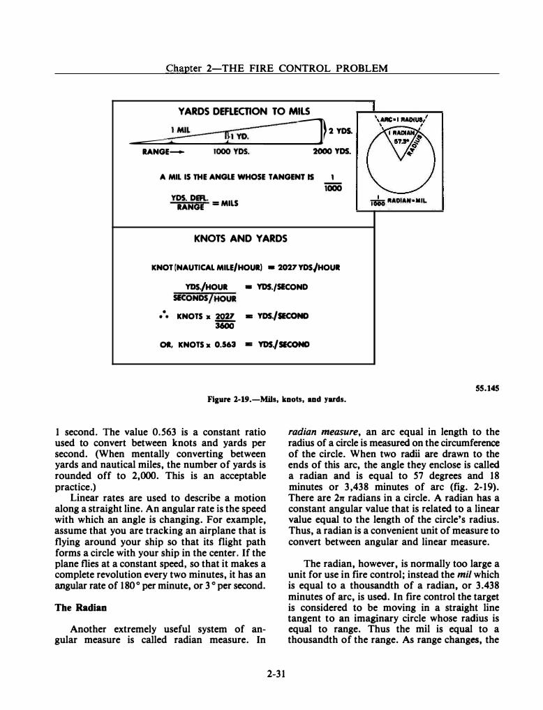
Chapter 2-THE FIRE CONTROL PROBLEM
YARDS DEFLECTION TO MILS
--��_.--------�------------�--� 2YD.l
RANGE- 2000 YDS.
A MIL IS THE ANGLE WHOSE TANGENT IS 1 iOOO
YOS. DEFI.. - MILS nsio RADIAN •MIL RANGE -
KNOTS AND YARDS
KNOT [NAUTICAL MILE/HOUR) • 2027YDS/HOUI
YDS./HOUR • YDS./SECOND SECONDS /HOUR
:. KNOTS x 2027 • YDS./SECOND 3600
OR, KNOTS x 0.563 • YDS./ SECOND
55.145
Figure l-19.-Mils, knots, and yards.
1 second. The value 0.563 is a constant ratio used to convert between knots and yards per second. (When mentally converting between yards and nautical miles, the number of yards is rounded off to 2,000. This is an acceptable practice.)
Linear rates are used to describe a motion along a straight line. An angular rate is the speed with which an angle is changing. For example, assume that you are tracking an airplane that is flying around your ship so that its flight path forms a circle with your ship in the center. If the plane flies at a constant speed, so that it makes a complete revolution every two minutes, it has an angular rate of 180° per minute, or 3 o per second.
The Radian
Another extremely useful system of angular measure is called radian measure. In
2-31
radian measure, an arc equal in length to the radius of a circle is measured on the circumference of the circle. When two radii are drawn to the ends of this arc, the angle they enclose is called a radian and is equal to 57 degrees and 18 minutes or 3,438 minutes of arc (fig. 2-19). There are 2n radians in a circle. A radian has a constant angular value that is related to a linear value equal to the length of the circle's radius. Thus, a radian is a convenient unit of measure to convert between angular and linear measure.
The radian, however, is normally too large a unit for use in fire control; instead the mil which is equal to a thousandth of a radian, or 3.438 minutes of arc, is used. In fire control the target is considered to be moving in a straight line tangent to an imaginary circle whose radius is equal to range. Thus the mil is equal to a thousandth of the range. As range changes, the
FIRE CONTROLMAN THIRD CLASS
linear value of the mil changes proportionally, but its angular value is constant (fig. 2-19).
Assume a target, with a linear bearing rate of 100 knots, is being tracked at a range of 10,000 yards. Since the line of sight moves angularly in bearing, the linear rate must be converted to an angular rate. First, convert the knots to yards per second by multiplying the 100 knots by the constant 0.563. This would give a rate of 56.3 yards per second. A mil at 10,000 yards range is equal to 10 yards. Therefore:
56·3 yards per second == 5.63 mils per second 10 yards per mil
A mil has an angular value and the answer is an angular rate. Note the ease of converting between linear and angular measure with the mil. Knowing the range to a target allows conversion. For this reason, most fire control systems use the mil as the unit of measure in deflection.
To express the rate of mils per second in minutes of arc per second, multiply the number of mils by 3.438, the number of minutes in a mil. The complete formula for converting the linear rate of knots to the angular rate in minutes of arc second is:
minutes of arc per second == knots x .563 x 3.438
range
1000
The three constants in the formula can be combined:
.563 X 3.438 X 1000 == 1936
This leaves the formula:
. knots x 1936 mmutes of arc per second = ==-___:.;::.=
range
Note that the angular rate is inversely proportiona! to range. Thus as range changes, the angular rate varies with it. Because range is continuously changing as a target is tracked, this presents definite disadvantages when there is a need to use the rate to predict the targeCs future position. Therefore, linear rates are used to predict target future position, while angular rates are used in the target-tracking section of the problem.
2-32
Polarity
Now that we have discussed the concepts of angular and linear motion, an additional factor is presented. This is the factor of assigning a polarity, positive or negative, to further define the direction of motion and to facilitate computations.
In fire control systems this motion is assigned a polarity by its direction in relationship to the line of sight and along the line of sight. Motion to the left of, and down from, the line of sight is assigned a negative value and motion to the right and up from the line of sight is assigned a positive value. Motion along the line of sight that would increase the range value is assigned a positive value, and the motion that would decrease the range along the line of sight Is assigned a negative value.
STANDARD FIRE CONTROL SYMBOLS
An .important step in understanding and solving a fire control problem is the identification of the quantities involved. The symbols used to identify the numerous quantities encountered
·in fire control are part of the
"language" of an FC (see Appendix I). Like any other language, you will become more familiar with it through usage. It is almost an impossible task to memorize all of the variations of the basic quantities. However, if you understand how the basic symbols are modified by symbol modifiers and quantity modifiers, you will be able to interpret new symbols when you encounter them.
In comparison to the English language, the basic symbols are the nouns, and the symbol modifiers and quantity modifiers are the adjectives. As you proceed with solving the basic fire control problem, you will begin to recognize certain quantities, and eventually, you will learn the language.
Introduction to Ordnance Publication (OP) 1700
OP 1700, "Standard Fire Control Symbols," establishes a system of symbols and definitions for the surface, antiaircraft, and underwater
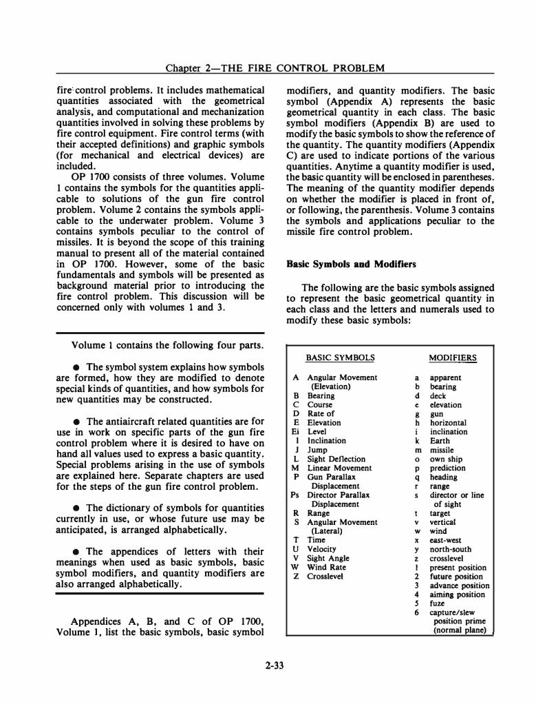
Chapter 2-THE FIRE CONTROL PROBLEM
fire: control problems. It includes mathematical quantities associated with the geometrical analysis, and computational and mechanization quantities involved in solving these problems by fire control equipment. Fire control terms (with their accepted definitions) and graphic symbols (for mechanical and electrical devices) are included.
OP 1700 consists of three volumes. Volume 1 contains the symbols for the quantities applicable to solutions of the gun fire control problem. Volume 2 contains the symbols applicable to the underwater problem. Volume 3 contains symbols peculiar to the control of missiles. It is beyond the scope of this training manual to present all of the material contained in OP 1700. However, some of the basic fundamentals and symbols will be presented as background material prior to introducing the fire control problem. This discussion will be concerned only with volumes 1 and 3.
Volume 1 contains the following four parts.
• The symbol system explains how symbols are formed, how they are modified to denote special kinds of quantities, and how symbols for new quantities may be constructed.
• The antiaircraft related quantities are for use in work on specific parts of the gun fire control problem where it is desired to have on hand all values used to express a basic quantity. Special problems arising in the use of symbols are explained here. Separate chapters are used for the steps of the gun fire control problem.
• The dictionary of symbols for quantities currently in use, or whose future use may be anticipated, is arranged alphabetically.
• The appendices of letters with their meanings when used as basic symbols, basic symbol modifiers, and quantity modifiers are also arranged alphabetically.
Appendices A, B, and C of OP 1700, Volume 1, list the basic symbols, basic symbol
modifiers, and quantity modifiers. The basic symbol (Appendix A) represents the basic geometrical quantity in each class. The basic symbol modifiers (Appendix B) are used to modify the basic symbols to show the reference of the quantity. The quantity modifiers (Appendix C) are used to indicate portions of the various quantities. Anytime a quantity modifier is used, the basic quantity will be enclosed in parentheses. The meaning of the quantity modifier depends on whether the modifier is placed in front of, or following, the parenthesis. Volume 3 contains the symbols and applications peculiar to the missile fire control problem.
Basic Symbols and Modifiers
The following are the basic symbols assigned to represent the basic geometrical quantity in each class and the letters and numerals used to modify these basic symbols:
BASIC SYMBOLS MODIFIERS
A Angular Movement a apparent (Elevation) b bearing
B Bearing d deck c Course e elevation D Rate of g gun E Elevation h horizontal
Ei Level i inclination l Inclination lc Earth J Jump m missile
L Sight Deflection 0 own ship M Linear Movement p prediction p Gun Parallax q heading
Displacement r ranae Ps Director Parallax s director or line
Displacement of sight R Range target s Angular Movement v vertical
(Lateral) w wind T Time X east-west u Velocity y north-south v Sight Angle z crosslevel
w Wind Rate 1 present position z Crosslevel 2 future position
3 advance position 4 aimina position s fuze 6 capture/slew
position prime (normal plane)
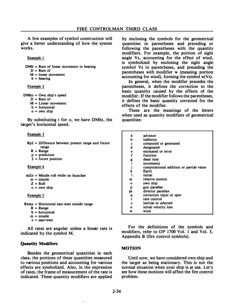
FIRE CONTROLMAN THIRD CLASS
A few examples of symbol construction will give a better understanding of how the system works.
Example 1
DMb = Rate of linear movement in bearing D =Rate of M = linear movement b =bearing
Example 2
DMho = Own ship's speed D =Rate of M = Linear movement
h = horizontal o =own ship
By substituting t for o, we have DMht, the target's horizontal speed.
Example 3
Rp2 = Difference between present range and future range
R =Range p = prediction 2 = future position
Example 4
mZo = Missile roll while on launcher m =missile Z =Roll o =own ship
Example 5
Rhmx = Horizontal east-west missile range R =Range b = horizontal
m =missile x = east/west
All rates are angular unless a linear rate is indicated by the symbol M.
Quantity Modifiers
Besides the geometrical quantities in each class, the portions of these quantities measured to various positions and accounting for various effects are symbolized. Also, in the expression of rates, the frame of measurement of the rate is indicated. These quantity modifiers are applied
2-34
by enclosing the symbols for the geometrical quantities in parentheses and preceding or following the parentheses with the quantity modifiers. For example, the portion of sight angle Vs, accounting for the effect of wind, is symbolized by enclosing the sight angle symbol Vs in parentheses, and preceding the parentheses with modifier w (meaning portion accounting for wind), forming the symbol w(Vs).
In general, when the modifier precedes the parentheses, it defines the correction to the basic quantity caused by the effects of the modifier. If the modifier follows the parentheses, it defmes the basic quantity corrected for the effects of the modifier.
These are the meanings of the letters when used as quantity modifiers of geometrical quantities:
a advance b ballistics c computed or generated d designated e estimated or error f function g dead time
increments j computational addition or partial value k Earth I initial
m relative motion 0 own ship p gun parallax
ps director parallax q correction input or spot r rate control s inertial or selected
u initial velocity loss w wind
For the definitions of the symbols and modifiers, refer to OP 1700 Vol. 1 and Vol. 3, Appendix B (fire control symbols).
MOTION
Until now, we have considered own ship and the target as being stationary. This is not the normal situation when your ship is at sea. Let's see how these motions will affect the fire control problem.
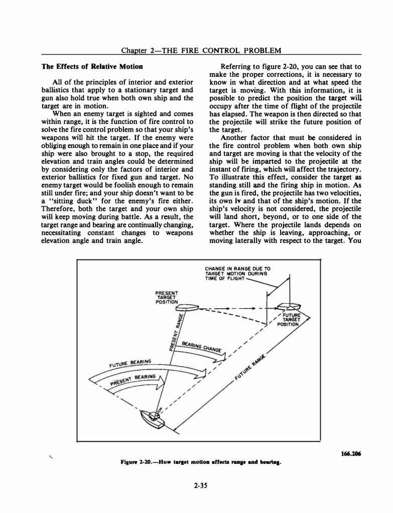
Chapter 2-THE FIRE CONTROL PROBLEM
The Effects of Relative Motion
All of the principles of interior and exterior ballistics that apply to a stationary target and gun also hold true when both own ship and the target are in motion.
When an enemy target is sighted and comes within range, it is the function of fire control to solve the fire control problem so that your ship's weapons will hit the target. If the enemy were obliging enough to remain in one place and if your ship were also brought to a stop, the required elevation and train angles could be determined by considering only the factors of interior and exterior ballistics for fixed gun and target. No enemy target would be foolish enough to remain still under fire; and your ship doesn't want to be a "sitting duck'" for the enemy's fire either. Therefore, both the target and your own ship will keep moving during battle. As a result, the target range and bearing are continually changing, necessitating constant changes to weapons elevation angle and train angle.
.....
Referring to figure 2-20, you can see that to make the proper corrections, it is necessary to know in what direction and at what speed the target is moving. With this information; it is possible to predict the position the target will occupy after the time of flight of the projectile has elapsed. The weapon is then directed so that the projectile will strike the future position of the target.
Another factor that must be considered in the fire control problem when both own ship and target are moving is that the velocity of the ship will be imparted to the projectile at the instant of firing, which will affect the trajectory. To illustrate this effect, consider the target as standing still and the firing ship in motion. As the gun is fired, the projectile has two velocities, its own lv and that of the ship's motion. If the ship's velocity is not considered, the projectile will land short, beyond, or to one side of the target. Where the projectile lands depends on whether the ship is leaving, approaching, or moving laterally with respect to the target. You
CHANGE IN RANGE DUE TO TARGET MOTION DURING TIME OF FLIGHT
/ /
/ /
/ /
/
Flaure 1-20.-How ta��et mot1011 affects raap IUid bearD&·
2-35
FIRE CONTROLMAN THIRD CLASS
can see that the effect of ship's speed and direction must be considered to obtain accurate fire.
The Effects of Deck Motion
Another factor that enters into the solution of the fire control problem on moving ships is the fact that the deck which supports the gun is very seldom perfectly level. A moving ship requires that corrections be made to gun orders to compensate for deck motion.
Deck motion can be resolved into two motions-roll and pitch. Roll is rotation of the ship from side to side in a plane perpendicular to the deck, across the ship's athwartship's axis. Pitch is rotation of the ship from bow to stem in a plane perpendicular to the deck, across the ship's centerline.
You can visualize that, as the ship rolls and pitches, the line of sight will be displaced. Before the fire control problems can be solved and gun orders computed, the effects of roll and pitch must be measured.
The effect of deck motion on elevation of the line of sight is called level. Level is the angle between the horizontal plane and the deck plane, measured in a vertical plane or a normal plane depending upon the type of stabilizing unit used. Level angle (Ei) is measured in the vertical plane through the line of sight. Level angle (Ei') is measured in the normal plane through the line of sight. Refer to OP 1700 for complete definitions.
The other effect of deck motion on the line of sight is called cross/eve/. Like level, the measurement of crosslevel depends upon the type of stabilizing unit. Cross/eve/ angles are measured between vertical and normal planes. Crosslevel (Z) is the angle between the vertical plane through the line of sight, and the normal plane through the intersection of the vertical plane through the line of sight and the horizontal plane, measured about the axis which is the intersection of the vertical plane through the line of sight and the horizontal plane. Refer to OP 1700 for complete definitions of crosslevel.
Because the directors, gun mounts, and launchers, are mounted in the deck plane, and therefore train and elevate with respect to the deck plane, the measurements of level and crosslevel are used to correct various data. These corrections include deck tilt, deck deflection, and trunnion tilt corrections.
2-36
Present target position, as measured by the director, is referenced to the deck plane. Ballistic computations are normally referenced to the horizontal plane. The use of level and crosslevel to correct the deck plane measurements to the horizontal plane for computational purposes is essentially known as deck tilt correction.
Deck deflection and trunnion tilt corrections are the use of level and crosslevel to correct ballistic computations in order to reorient gun orders to the deck plane. The formulas and methods used are quite complex and vary with the system. For this reason you will not study them at this point in your training.
Deck motion (own ship roll and pitch) is also assigned polarities as are motion along and across the line of sight. For Eio bow up is positive and bow down is negative. For Zo left side down is negative and left side up is positive.
Tbe Effects of Target Elevation
The antiaircraft problem, sometimes called the air problem, is another form or variation of the basic fire control problem. All of the factors that entered into the surface fire control problem must be considered in stating the air problem. The air problem is further complicated by the fact that the target is moving at high speed and may be either climbing or diving.
In the surface problem, the target elevation angle (between LOS and horizontal) was zero because both own ship and target were on the ocean's surface; and the LOS, for all practical purposes, was in the horizontal plane. Air targets, however, are ordinarily well above the ocean's surface, so that the LOS makes an appreciable angle with the horizontal. In addition, if the target is approaching or leaving own ship in a horizontal plane, the LOS must be elevated or depressed to keep the target in view. Thus, target elevation angle continually increases or decreases, and as it does so the gun elevation order must be correspondingly altered. This effect is shown in figure 2-21.
As shown in figure 2-22, target elevation angle is determined by measuring director elevation at the director and combining this with the level angle measured by the stable element.
If we continue to consider the air target approaching the ship in a horizontal plane, it can be seen in figure 2-23 that slant range from
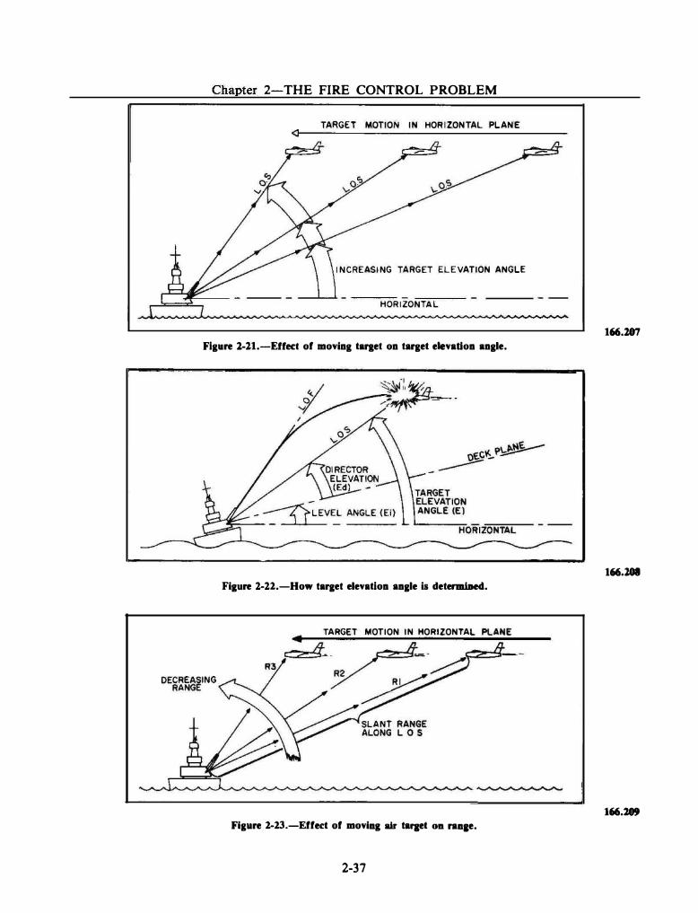
Chapter 2-THE FIRE CONTROL PROBLEM
TARGET MOTION IN HORIZONTAL PLANE
INCREASING TARGET ELEVATION ANGLE
HORIZONTAL
Figure l-11.-Effect of moviag tartet oa target elevatioa aagle.
Figure 1-12.-How target elevatioa aagle is detel"'lliiled.
TARGET MOTION IN HORIZONTAL
R3
Figure 2-23.-Effect of moviag air ta!Jet OD raaae.
2-37
166.107
166.1011
166.289
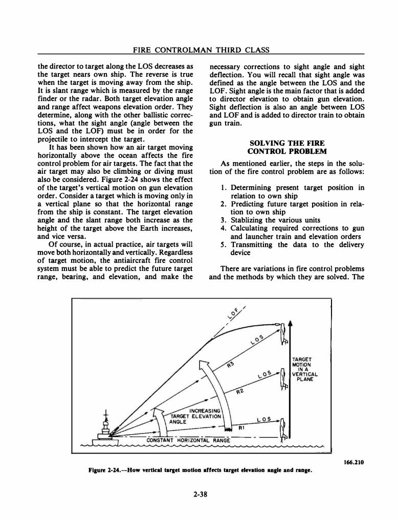
FIRE CONTROLMAN THIRD CLASS
the director to target along the LOS decreases as the target nears own ship. The reverse is true when the target is moving away from the ship. It is slant range which is measured by the range finder or the radar. Both target elevation angle and range affect weapons elevation order. They determine, along with the other ballistic corrections, what the sight angle (angle between the LOS and the LOF) must be in order for the projectile to intercept the target.
It has been shown how an air target moving horizontally above the ocean affects the fire control problem for air targets. The fact that the air target may also be climbing or diving must also be considered. Figure 2-24 shows the effect of the target's vertical motion on gun elevation order. Consider a target which is moving only in a vertical plane so that the horizontal range from the ship is constant. The target elevation angle and the slant range both increase as the height of the target above the Earth increases, and vice versa.
Of course, in actual practice, air targets will move both horizontally and vertically. Regardless of target motion, the antiaircraft fire control system must be able to predict the future target range, bearing, and elevation, and make the
necessary corrections to sight angle and sight deflection. You will recall that sight angle was defined as the angle between the LOS and the LOF. Sight angle is the main factor that is added to director elevation to obtain gun elevation. Sight deflection is also an angle between LOS and LOF and is added to director train to obtain gun train.
SOLVING THE FIRE CONTROL PROBLEM
As mentioned earlier, the steps in the solution of the fire control problem are as follows:
1. Determining present target position in relation to own ship
2. Predicting future target position in relation to own ship
3. Stablizing the various units 4. Calculating required corrections to gun
and launcher train and elevation orders 5. Transmitting the data to the delivery
device
There are variations in fire control problems and the methods by which they are solved. The
TARGET MOTION
IN A VERTICAL
PLANE
166.ll0 Fl&ure 1-l4.-How vertJcal tal'let motion affects target elevation aagle and range.
2-38
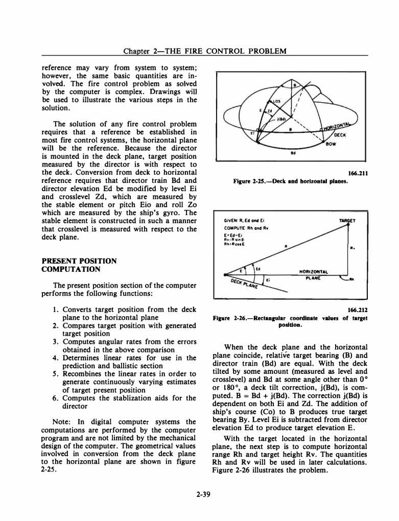
Chapter 2-THE FIRE CONTROL PROBLEM
reference may vary from system to system; however, the same basic quantities are involved. The fire control problem as solved by the computer is complex. Drawings will be used to illustrate the various steps in the solution.
The solution of any fire control problem requires that a reference be established in most fire control systems, the horizontal plane will be the reference. Because the director is mounted in the deck plane, target position measured by the director is with respect to t�e deck. Conversion from deck to horizontal reference requires that director train Bd and director elevation Ed be modified by level Ei and crosslevel Zd, which are measured by the stable element or pitch Eio and roll Zo which are measured by the ship's gyro. The stable element is constructed in such a manner that crosslevel is measured with respect to the deck plane.
PRESENT POSITION COMPUTATION
The present position section of the computer performs the following functions:
1. Converts target position from the deck plane to the horizontal plane
2. Compares target position with generated target position
3. Computes angular rates from the errors obtained in the above comparison
4. Determines linear rates for use in the prediction and ballistic section
5. Recombines the linear rates in order to generate continuously varying estimates of target present position
6. Computes the stablization aids for the director
Note: In digital computer systems the computations are performed by the computer program and are not limited by the mechanical design of the computer. The geometrical values involved in conversion from the deck plane to the horizontal plane are shown in figure 2-25.
2-39
Figure 1-15.-Deck and borizoatal planes.
GIVEN: R, Ed onct [I COMPUTE: Rll ond Rw E• Ed-Ei Av,Rsi"E Rh•AcooE
HORtZOffTAL
PLANE
166.111
Ito
166.111
Flaure 2-16.-RectaacuJar coordinate values of taraet posltioa.
When the deck plane and the horizontal plane coincide, relative target bearing (B) and director train (Bd) are equal. With the deck tilted by some amount (measured as level and crosslevel) and Bd at some angle other than 0 ° or 180°, a deck tilt correction, j(Bd), is computed. B = Bd + j(Bd). The correction j(Bd) is dependent on both Ei and Zd. The addition of ship's course (Co) to B produces true target bearing By. Level Ei is subtracted from director elevation Ed to produce target elevation E.
With the target located in the horizontal plane, the next step is to compute horizontal range Rh and target height Rv. The quantities Rh and Rv will be used in later calculations. Figure 2-26 illustrates the problem.
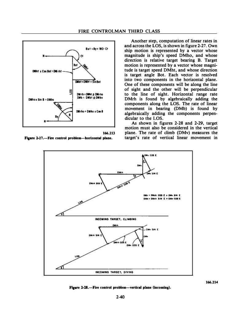
Dlllf 1 Cos Bot: DM rht
FIRE CONTROLMAN THIRD CLASS
Bot ,.Byt 180-Ct
OM rh = Dltllf ± Dlr�o DMb � Dllllbt .± Dllllbo
OM rho = Dllllho 1 C018
Another step, computation of linear rates in and across the LOS, is shown in figure 2-27. Own ship motion is represented by a vector whose magnitude is ship's speed DMho, and whose direction is relative target bearing B. Target motion is represented by a vector whose magnitude is target speed DMht, and whose direction is target angle Bot. Each vector is resolved into two components in the horizontal plane. One of these components will be along the line of sight and the other will be perpendicular to the line of sight. Horizontal range rate DMrh is found by algebraically adding the components along the LOS. The rate of linear movement in bearing (DMb) is found by algebraically adding the components perpendicular to the LOS.
166.213
Ftaure 2-17 .-Fire control problem-horizontal plane.
As shown in figures 2-28 and 2-29, target motion must also be considered in the vertical plane. The rate of climb (DMv) measures the target's rate of vertical linear movement in
INCOMING TARGET, CLIMBING
INCOMING TARGET, DIVING
Dlllr • Dtlr� COS E + DMw SIN [ Dllo • Ollr� liN [ + Dlllw COS I!
Flaure 2-11.-Fire control problem-vertical plane (incoming).
2-40
166.114
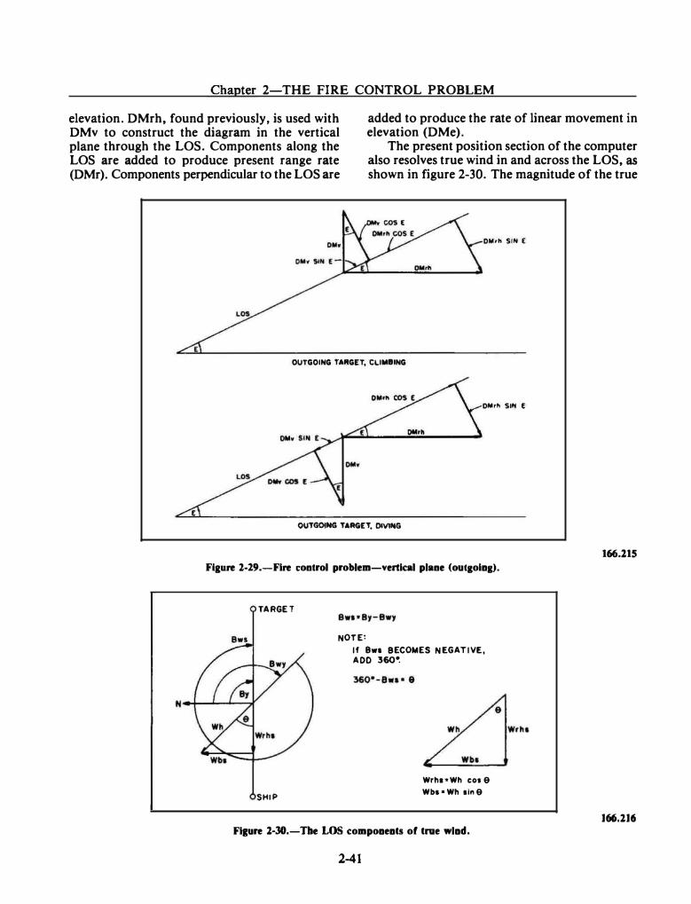
Chapter 2-THE FIRE CONTROL PROBLEM
elevation. DMrh, found previously, is used with DMv to construct the diagram in the vertical plane through the LOS. Components along the LOS are added to produce present range rate (DMr). Components perpendicular to the LOS are
added to produce the rate of linear movement in elevation (DMe).
The present position section of the computer also resolves true wind in and across the LOS, as
shown in figure 2-30. The magnitude of the true
DMrh SIN [
OUTGOING TAfiGET, CLIMBING
DMrll SIN f
OUTGOitfG TARGET, DIVING
166.115 Figure 1-29.-Fire control problem-vertical plane (out&oia&).
TARGET
Bws
SHIP
NOTE:
If 8w1 BECOMES NEGATIVE, ADD 360�
Wrha•Wh COl 9 Wbt•Wh tln9
Fi1ure 1-30.-Tbe LOS compoaeats of true wlad.
2-41
J66.1J6
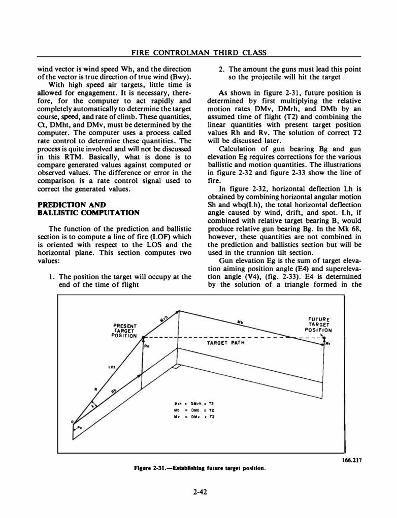
FIRE CONTROLMAN THIRD CLASS
wind vector is wind speed Wh, and the direction of the vector is true direction of true wind (Bwy).
With high speed air targets, little time is allowed for engagement. It is necessary, therefore, for the computer to act rapidly and completely automatically to determine the target course, speed, and rate of climb. These quantities, Ct, DMht, and DMv, must be determined by the computer. The computer uses a process called rate control to determine these quantities. The process is quite involved and will not be discussed in this RTM. Basically, what is done is to compare generated values against computed or observed values. The difference or error in the comparison is a rate control signal used to correct the generated values.
PREDICDON AND BALLISTIC COMPUTATION
The function of the prediction and ballistic section is to compute a line of fire (LOF) which is oriented with respect to the LOS and the horizontal plane. This section computes two values:
1. The position the target will occupy at the end of the time of flight
PRESENT TARGET
POSITION
2. The amount the guns must lead this point so the projectile will hit the target
As shown in figure 2-31, future position is determined by first multiplying the relative motion rates DMv, DMrh, and DMb by an assumed time of flight (T2) and combining the linear quantities with present target position values Rh and Rv. The solution of correct T2 will be discussed later.
Calculation of gun bearing Bg and gun elevation Eg requires corrections for the various ballistic and motion quantities. The illustrations in figure 2-32 and figure 2-33 show the line of fire.
In figure 2-32, horizontal deflection Lh is obtained by combining horizontal angular motion Sh and wbq(Lh), the total horizontal deflection angle caused by wind, drift, and spot. Lh, if combined with relative target bearing B, would produce relative gun bearing Bg. In the Mk 68, however, these quantities are not combined in the prediction and ballistics section but will be used in the trunnion tilt section.
Gun elevation Eg is the sum of target elevation aiming position angle (E4) and superelevation angle (V4), (fig. 2-33). E4 is determined by the solution of a triangle formed in the
FUTURE TARGET
POSITION " ----
Mrh • Dlllrh 1 T2 lib = Dllb 1 T2 lllv = Dlllv 1 T2
166.117
Flaure 1-31.-Establlslal•a fuc•re CllfleC posicion.
2-42
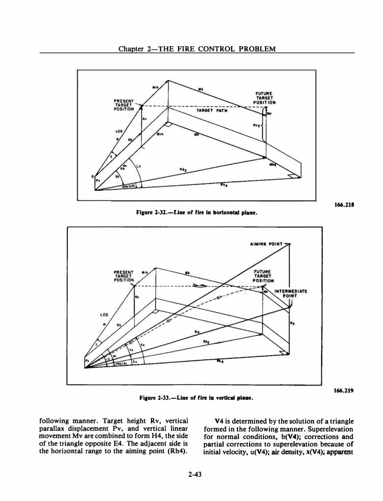
Chapter 2-THE FIRE CONTROL PROBLEM
166.111 Fiaure 1-31.-Uae of fire la horlzoaq) plaae.
166.119 Fiaure l-33.-U.ae of fire bt •ertlnl plue.
following manner. Target height Rv, vertical parallax displacement Pv, and vertical linear movement Mv are combined to form H4, the side of the triangle opposite E4. The adjacent side is the horizontal range to the aiming point (Rh4).
2-43
V 4 is determined by the solution of a triangle formed in the following manner. Superelevation for normal conditions, b(V4); corrections and partial corrections to superelevation because of initial velocity, u(V4); air density, x(V4); apparent
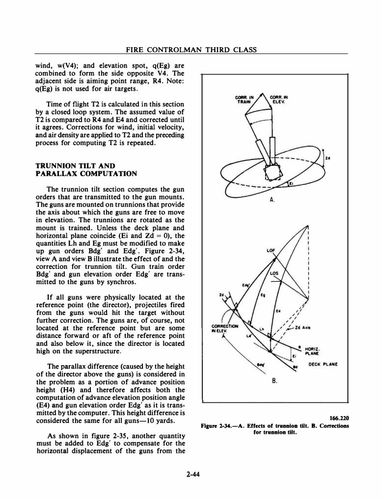
FIRE CONTROLMAN THIRD CLASS
wind, w(V4); and elevation spot, q(Eg) are combined to form the side opposite V4. The adjacent side is aiming point range, R4. Note: q(Eg) is not used for air targets.
Time of flight T2 is calculated in this section by a closed loop system. The assumed value of T2 is compared to R4 and E4 and corrected until it agrees. Corrections for wind, initial velocity, and air density are applied to T2 and the preceding process for computing T2 is repeated.
TRUNNION TILT AND PARALLAX COMPUTATION
The trunnion tilt section computes the gun orders that are transmitted to the gun mounts. The guns are mounted on trunnions that provide the axis about which the guns are free to move in elevation. The trunnions are rotated as the mount is trained. Unless the deck plane and horizontal plane coincide (Ei and Zd = 0), the quantities Lh and Eg must be modified to make up gun orders Bdg' and Edg'. Figure 2-34, view A and view B illustrate the effect of and the correction for trunnion tilt. Gun train order Bdg' and gun elevation order Edg' are transmitted to the guns by synchros.
If all guns were physically located at the reference point (the director), projectiles fired from the guns would hit the target without further correction. The guns are, of course, not located at the reference point but are some distance forward or aft of the reference point and also below it, since the director is located high on the superstructure.
The parallax difference (caused by the height of the director above the guns) is considered in the problem as a portion of advance position height (H4) and therefore affects both the computation of advance elevation position angle (E4) and gun elevation order Edg' as it is transmitted by the computer. This height difference is considered the same for all guns-10 yards.
As shown in figure 2-35, another quantity must be added to Edg' to compensate for the horizontal displacement of the guns from the
2-44
DECK PLANE
B.
166.220 Figure 1-34.-A. Effects of trunnioa tilt. B. Corrections
for trunnion tilt.
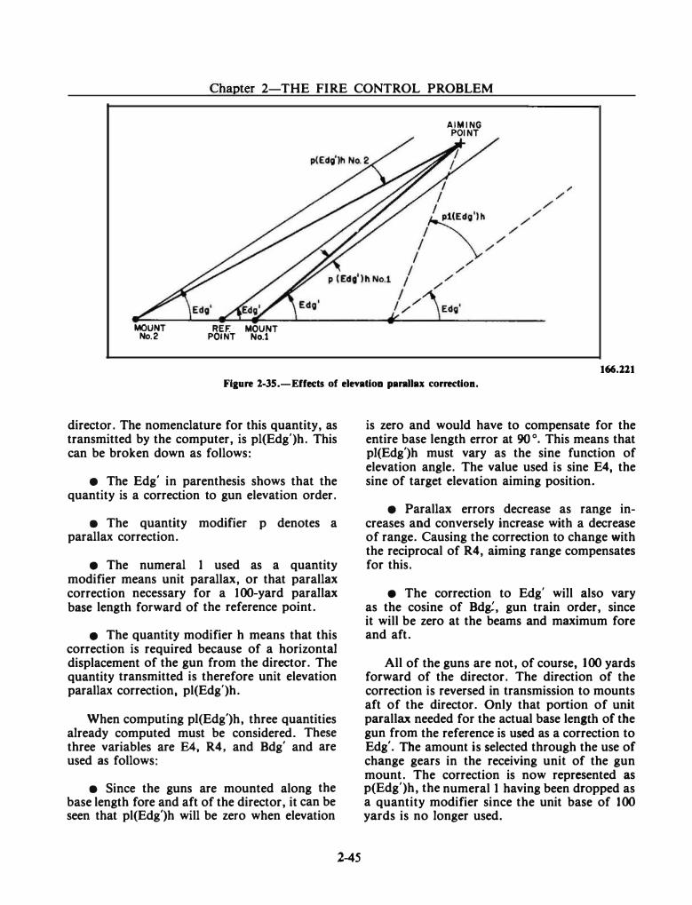
Chapter 2-THE FIRE CONTROL PROBLEM
MOUNT No.2
REF. MOUNT POINT No.1
AIMING POINT
166.2.2.1
Figure 2.-35.-Effeds of elevatioa parallax correc:tion.
director. The nomenclature for this quantity, as transmitted by the computer, is pl(Edg')h. This can be broken down as follows:
• The Edg' in parenthesis shows that the quantity is a correction to gun elevation order.
• The quantity modifier p denotes a parallax correction.
• The numeral 1 used as a quantity modifier means unit parallax, or that parallax correction necessary for a 100-yard parallax base length forward of the reference point.
• The quantity modifier h means that this correction is required because of a horizontal displacement of the gun from the director. The quantity transmitted is therefore unit elevation parallax correction, pl(Edg')h.
When computing pi(Edg')h, three quantities already computed must be considered. These three variables are E4, R4, and Bdg' and are used as follows:
• Since the guns are mounted along the base length fore and aft of the director, it can be seen that pl(Edg')h will be zero when elevation
2-45
is zero and would have to compensate for the entire base length error at 90 o. This means that pl(Edg')h must vary as the sine function of elevation angle. The value used is sine E4, the sine of target elevation aiming position.
• Parallax errors decrease as range increases and conversely increase with a decrease of range. Causing the correction to change with the reciprocal of R4, aiming range compensates for this.
• The correction to Edg' will also vary as the cosine of Bdg:, gun train order, since it will be zero at the beams and maximum fore and aft.
All of the guns are not, of course, 100 yards forward of the director. The direction of the correction is reversed in transmission to mounts aft of the director. Only that portion of unit parallax needed for the actual base length of the gun from the reference is used as a correction to Edg'. The amount is selected through the use of change gears in the receiving unit of the gun mount. The correction is now represented as p(Edg')h, the numeral 1 having been dropped as a quantity ·modifier since the unit base of 100 yards is no longer used.
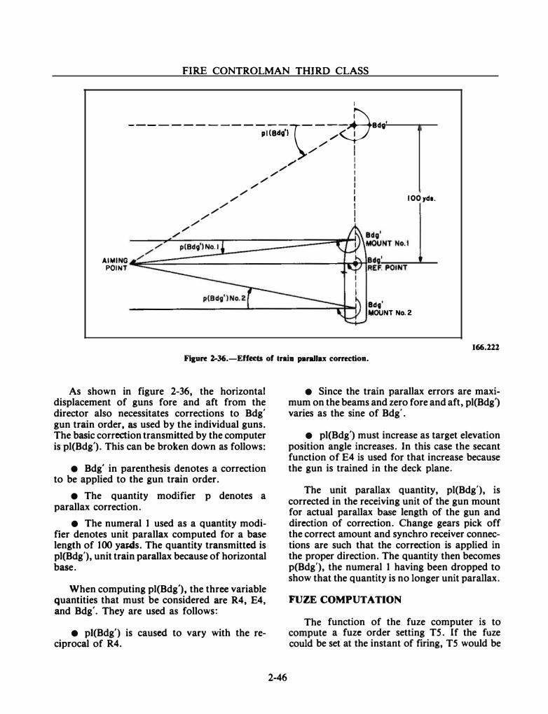
FIRE CONTROLMAN THIRD CLASS
I
------------; 1(8«19'}\;- _...d7··· /
I / I
/ I / I
/ I / I
/ I / I
IOOyds. / I / I
/ I /
/ I
AIMING POINT
/ /
:��::�p�(B�d�9'�)N�o�.l�========��::::�t:� BdG' MOUNT No.2
166.221 Fi&ure l-36.-Effects of lrai• parallu correction.
As shown in figure 2-36, the horizontal displacement of guns fore and aft from the director also necessitates corrections to Bdg' gun train order, as used by the individual guns. The basic correction transmitted by the computer is pl(Bdg'). This can be broken down as follows:
• Bdg' in parenthesis denotes a correction to be applied to the gun train order.
• The quantity modifier p denotes a parallax correction.
• The numeral 1 used as a quantity modifier denotes unit parallax computed for a base length of 100 yaMs. The quantity transmitted is pl(Bdg'), unit train parallax because of horizontal base.
When computing pl(Bdg'), the three variable quantities that must be considered are R4, E4, and Bdg'. They are used as follows:
• pi(Bdg') is caused to vary with the reciprocal of R4.
2-46
• Since the train parallax errors are maximum on the beams and zero fore and aft, pl(Bdg') varies as the sine of Bdg'.
• pl(Bdg') must increase as target elevation position angle increases. In this case the secant function of E4 is used for that increase because the gun is trained in the deck plane.
The unit parallax quantity, pl(Bdg'), is corrected in the receiving unit of the gun mount for actual parallax base length of the gun and direction of correction. Change gears pick off the correct amount and synchro receiver connections are such that the correction is applied in the proper direction. The quantity then becomes p(Bdg'), the numeral 1 having been dropped to show that the quantity is no longer unit parallax.
FUZE COMPUTATION
The function of the fuze computer is to compute a fuze order setting TS. If the fuze could be set at the instant of firing, TS would be
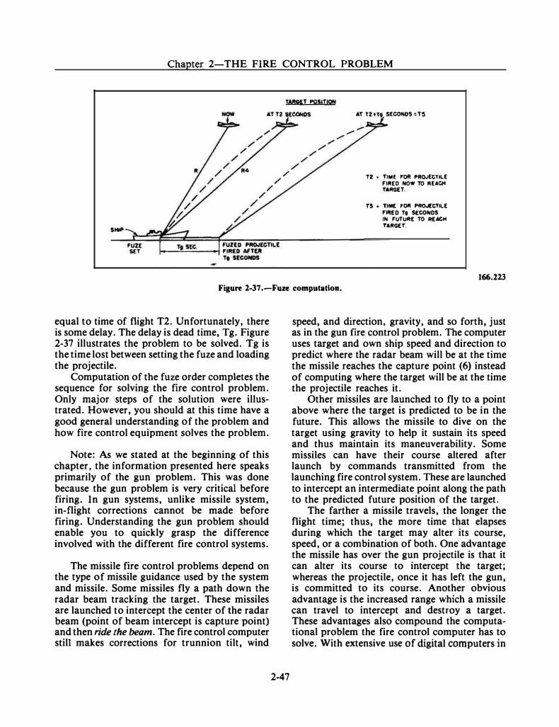
Chapter 2-THE FIRE CONTROL PROBLEM
TA!!GJ:T POSIT!Qfll
AT T2 KGONOS AT T2Ht Ucor.OS =T�
SHIP
I2 • TIME �Of' PROJECTILE FUUO NOW TO IIUCM
TAIIGET.
T!l • TIME FOI' PIIO.I(CTI\.E I'IIIE D Tt SECONDS IN FUTUII[ TO REACH TAIIGET.
166.123 Figure 2-37.-Fuze computation.
equal to time of flight T2. Unfortunately, there is some delay. The delay is dead time, Tg. Figure 2-37 illustrates the problem to be solved. Tg is the time lost between setting the fuze and loading the projectile.
Computation of the fuze order completes the sequence for solving the fire control problem. Only major steps of the solution were illustrated. However, you should at this time have a good general understanding of the problem and how fire control equipment .solves the problem.
Note: As we stated at the beginning of this chapter, the information presented here speaks primarily of the gun problem. This was done because the gun problem is very critical before firing. In gun systems, unlike missile system, in-flight corrections cannot be made before firing. Understanding the gun problem should enable you to quickly grasp the difference involved with the different fire control systems.
The missile fire control problems depend on the type of missile guidance used by the system and missile. Some missiles fly a path down the radar beam tracking the target. These missiles are launched to intercept the center of the radar beam (point of beam intercept is capture point) and then ride the beam. The fire control computer still makes corrections for trunnion tilt, wind
2-47
speed, and direction, gravity, and so forth, just as in the gun fire control problem. The computer uses target and own ship speed and direction to predict where the radar beam will be at the time the missile reaches the capture point (6) instead of computing where the target will be at the time the projectile reaches it.
Other missiles are launched to fly to a point above where the target is predicted to be in the future. This allows the missile to dive on the target using gravity to help it sustain its speed and thus maintain its maneuverability. Some missiles can have their course altered after launch by commands transmitted from the launching fire control system. These are launched to intercept an intermediate point along the path to the predicted future position of the target.
The farther a missile travels, the longer the flight time; thus, the more time that elapses during which the target may alter its course, speed, or a combination of both. One advantage the missile has over the gun projectile is that it can alter its course to intercept the target; whereas the projectile, once it has left the gun, is committed to its course. Another obvious advantage is the increased range which a missile can travel to intercept and destroy a target. These advantages also compound the computational problem the fire control computer has to solve. With extensive use of digital computers in
FIRE CONTROLMAN THIRD CLASS
missile fire control systems, these computations are made precisely and extremely fast.
The missile fire control problems are not discussed in this chapter or this manual in any detail. The various missiles and their guidance systems will be discussed in detail in chapter 5. Additional aspects of the missile fire control problem for each missile can be found in the Systems Publications and Program Documents for each system. You will also be able to get more general information on the missile fire control problems from OP 1700, Volume 3, as mentioned earlier.
SUMMARY
In this chapter you have been introduced to the fire control problem and how it is solved.
2-48
You have reviewed the basic mathematical requirements and how they apply to the geometry of the fire control problem. The better you know and understand the quantities, their symbols, and what they represent, the better you will understand how the fire control systems that you work on operate and function as a system. Fire control symbol.s are used extensively to identify functions and signals sent between components and used within the computers, radars, stablization, and weapons control systems. So the better you understand the fire control problem and the symbols, the easier it will be for you to operate and maintain the equipment and ensure that it serves the purpose of supporting your ship's mission.
The next chapter will introduce you to the concepts and components that make up the weapons systems on the ships you will most likely be assigned to.

CHAPTER 3
WEAPONS SYSTEMS
In chapter 2, you were introduced to the fire control problem. As a result of your study, you should know what the basic fire control problem is, how it is solved, how it applies to both missile and gun systems, and how the quantities are identified.
This chapter describes a basic shipboard weapons system. The system will be described in terms of the fire control problem, system functions, system components, information processing, and weapons control.
As a Fire Controlman, you should be thoroughly familiar with the functions performed by the weapons systems on your ship. You may be assigned to only one component of the system, but you should know how it interfaces with the other components and how they interact to destroy a target. The more knowledgeable you are about the system operation, the easier it will be for you to move into operation and maintenance of the other components.
WEAPONS SYSTEMS AND COMBAT SYSTEMS
The Navy's combatant ships are classified as weapons platforms. This is because of their design as a combatant. Their purpose is to carry weapons systems to counter air, surface, and/or subsurface threats. These weapons systems have the capability to acquire, track, and deliver or initiate delivery of a weapon and destroy a target.
When we lump all of the ship's weapons systems together, we form a combat system. The concept of a combat system is the coordination of all the ship's weapons systems to effectively counter any threat or combination of threats. You will encounter the term combat system in the operation and testing of the combined ship's
3-1
sensors, information processing, and weapons systems.
Most combatant ships are capable of engaging air, surface, and subsurface targets. The ability to counter air threats is called AntiAir Warfare (AA W). The ability to counter subsurface threats is called AntiSubmarine Warfare (ASW). The ability to counter other ships is called AntiSUrface-Warfare (ASUW). The ability to counter antiship missiles is called AntiShip Missile Defense (ASMO). These are the capabilities our surface combatant ships and weapons systems are designed to perform. Fire Controlmen maintain and operate fire control equipment in all but the ASW area.
The components that make up the ship's combat systems are comprised of four basic types of equipment based on their functions: (1) sensors for detecting and identifying contacts; (2) the information processing equipment to process multlsensor information; (3) the weapons control devices to control the ship's weapons; and (4) the weapon (destructive unit) that destroys the target.
WEAPONS SYSTEM COMPONENTS
The first thing that must happen so that a weapons system can perform its mission is the detection of a target. Before any weapons system actions can occur, you must first ascertain whether or not a target is out there. This is the function of the ship's sensors.
SENSORS
The operation of the ship's sensors initially provides information on target position, velocity, heading, type, and quantity. The quality of this data is determined by the individual capabilities
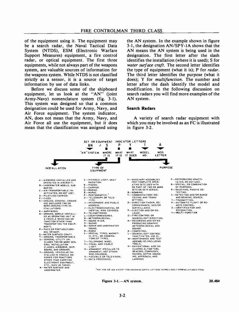
FIRE CONTROLMAN THIRD CLASS
of the equipment using it. The equipment may be a search radar, the Naval Tactical Data System (NTDS), ESM (Electronic Warfare Support Measures) equipment, a fire control radar, or optical equipment. The first three equipments, while not always part of the weapons system, are valuable sources of information for the weapons system. While NTDS is not classified strictly as a sensor, it is a source of target information by use of data links.
Before we discuss some of the shipboard equipment, let us look at the "AN" Uoint Army-Navy) nomenclature system (fig. 3-1). This system was designed so that a common designation could be used for Army, Navy, and Air Force equipment. The system indicator, AN, does not mean that the Army, Navy, and Air Force all use the equipment, but it does mean that the classification was assigned using
the AN system. In the example shown in figure 3-1, the designation AN/SPY-lA shows that the AN means the AN system is being used in the designation. The first letter after the slash identifies the installation (where it is used); S for water surface craft. The second letter identifies the type of equipment (what it is); P for radar. The third letter identifies the purpose (what it does); Y for multifunction. The number and letter after the dash identify the model and modification. In the following discussion on search radars you will find more examples of the AN system.
Search Radars
A variety of search radar equipment with which you may be involved as an FC is illustrated in figure 3-2.
SET OR EQUIPMENT I NDICATOR LE TTERS
$ INSTALLATION
A•• AIRBORNE IINSTALLED AND OPERATED IN AIRCRAFT).
I··UNDERWATER· MOBILE. SUB· MARINE.
C--AIR TRANSPORTABLE CIN· ACTIVATED, DO NOT USE).
D ··PILOTLESS CARRIER. f--FIXED. G--GROUND, GENERAL GROUND
USE (INCLUDE$ TWO OR loiORE GROUND-TYPE IN· STALLATIONS).
K •• A"PHIBIOUS. M .. GROUND, MOilLE (INST ALL•
ED AS OPERATING UNI1 IN A VEHICLE WHICH HAS NO fUNCTION OTHER THAN TRANSPORTING THE EQUIP• ME NT).
�--PACK OR PORTABLE (ANI• MAl OR MAN).
s .. wATER SURFACE CRAFT. T ·•GROUNO, TRANSPORTABLE. U•·GENERAL UTILITY (IN·
CLUDES TWO OR MORE GEN• ERAL INSTALLATION CLASSES, AIRBORNE. SHIP• BOARD, AND GROUND!.
V ··GROUND, VEHICULAR (INST ALL£0 IN VEHICLE DE• SIGNED FOR FUI'ICTIONS OTHER THAN CARRYING ELECTRONIC EOUIPMENT, ETC •• SUCH AS TAN KSJ.
W--WATER SURFACE AND UNDERWATER.
AN I s p y 1 A .,.... • • • � �
''AN" SYSTEM WHERE WHAT WHAT MODEL MOO. IT IS IT IS IT DOES NO. LETTER I I I
� 4 TYPE OF PURPOS E
EQUIPMENT
A --INVISIBLE LIGHT, HEAT RADIATION.
8 ··PIGEON. C --CARRIER. 0 •• RAOIAC. f··NUPAC. , .. PHOTOGRAPHiC. I G · · TELEGRAPH OR TELE•
TYPE. I ··"ITERPHONE AND PUBLIC
ADDRESS. J .. ELECTROMECHANICAL OR
INERTIAL WIRE COVERED. K .. TELEioiETERING. L ··COUNTERMEASUREL 114 ··METEOROLOGiCAL. N ,. SOUNO IN AIR. P ��MADAR. Q •• SON"'R AND UN DE RillA TEA
SOUND. A--RADIO S .. SPECIAL TYPES, lo!AGNET·
IC, ETC., OR COioiBINA• liONS Of TYPES.
T •• TELEPHONE (WIRE). V .. VISUAL AND VISIBLE
LtGHT. W •• ARMAMENT (PECULIAR TO
ARioiAMENT, NOT OTHER• WISE COVE A ED).
X·· FACSIMILE OR TELEVISION. Y ··OAT A PRDCBSII'IG.
A .. AUXILIARY ASSEMBLIES (NOT COMPLEH OPER· ATING SETS USED IIIlTH OR PART Of TwO OR MORE SETS OR SETS SERIES!.
I--BOMBING. C .. COMMUNICA liONS (RE·
CEIVING AND TRANS• MITTINGI.
D··DIRECTION FINDER, AE· CONNAISSAHCE, AND/OR SURVEILLANCE.
E • ·EJECTION AND/OR R E· LEAS!:.
G .. FIRE•COI'ITROl OR SEARCHLIGHT DIRECTING.
H--RECORDING AND/OR RE· PRODUCING !GRAPHIC METEOROLOGICAL AND SOUND).
K • • COMPUTING. L .. SEARCHLIGHT CONTROL
(INACTIVAHD, USE GJ. M-- MAINTENANCE AND TEST
A�SEMBLIES (INCLUDING TOOLS).
H • • NA.VICA TIOHAL AI OS (IN• CLUDII'IG Al TIME TEAS, BE ACOHS, COMPASSES, RACONS, DEPTH SOUND· lNG, APPROACH, AND LANDING).
P .. REPRODUCING (IIUCTI· VAT EO, 00 NOT USE).
Q--SPECIAL. OR COMBINATION OF PURPOSES.
A --RECEIVING, PASSIVE DE• TECTIHG.
S .. DETECTING AND/OR RANGE AND BEARING, SEARCH.
T •• TRAHSioliTTII'IG. W .. AUTOMATIC FLIGHT OR RE•
MOTE COI'ITROL. X·· IO(NTIFICA TION AND
RECOGNITION. Y---ULTI- fU"CTION
1N0l FOR US UH EXCEPT F01t ASSIGH�HC SUfFIX LfT'TERS TO PAEY10U$LY NOM!NClATUifEO ITE,.5.
Figure 3-1.-AN system.
3-2
20.484
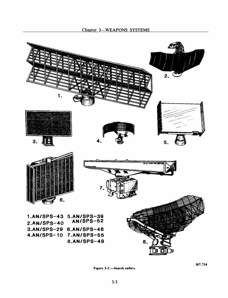
Chapter 3-WEAPONS SYSTEMS
4.
1.AN/SPS-43 S.AN/SPS-39 2.AN/SPS-40 AN/SPS-52
3.AN/SPS-29 6.AN/SPS-48 4.AN/SPS-1 0 7 .AN/SPS-55
S.AN/SPS-49
Figure 3-Z.-Search r1dars.
3-3
167.714

FIRE CONTROLMAN THIRD CLASS
THREE-COORDINATE RADARS.-A three-coordinate radar (such as, the AN/SPS-39, A�-SPS-48, AN-SPS-52, AN/SPY-I, or AN/ SPY -2) is normally the primary source of air target information for a weapons system. These radars provide precise air search data, consisting of range, bearing, and elevation angle, to the Naval Tactical Data System and/or weapons direction system. These radars also provide IFF data. IFF is an electronic system which provides positive identification of friendly targets. The air search data and synchronized Identification Friend or Foe (IFF) interrogation information are displayed on operator consoles in the Weapons Control Station and Combat Information Center (WCS/CIC) area for target engagement evaluation. Electronic counter-countermeasure (ECCM) features, controlled at the radar, improve the display when jamming environments are encountered.
TWO-COORDINATE RADARS.-An alternate source of air target information for a weapons system is a two-coordinate radar. Two-coordinate radars are the primary means for the detection of long-range air targets. These radars (AN/SPS-29, AN/SPS-37, AN/SPS-40, AN/SPS-43, or AN/SPS-49) provide coarse range and bearing information and IFF capabilities similar to those of the three-coordinate radars. They do not, however, provide elevation information.
SURFACE SEARCH/NAVIGATION RADARS.-Radar Sets AN/SPS-10, AN/ SPS-55, and the new AN/SPS-65 are short-range, two-coordinate, narrow-beam radars capable of good discrimination in range and bearing for surface search surveillance and low flying aircraft. These radars are becoming more important today because of their capability to detect low flying antiship missiles.
Electronic Warfare Support Measures (ESM)
Electronic Warfare Support Measures (ESM) equipment is used to detect, locate, analyze, and record electronic emissions throughout the electromagnetic spectrum. This provides your ship with the capability to gain tactical and
3-4
strategic intelligence on enemy electronic activity of all types, while remaining undetected by the enemy. The activity could be an enemy radar, which could then be identified according to its potential threat, or it could be an active guidance transmitter on an incoming enemy missile. In either case, the ESM capability is a factor in your ship's overall defensive capability.
The fundamental piece of equipment in an ESM system is the intercept receiver, either narrowband or wideband. The receiver detects enemy rf emissions as a function of frequency and provides selected signal outputs to displays, signal analyzers, recorders, and warning devices. Outputs may also be used to automatically gate Electronic Countermeasures (ECM) equipment, including deception repeaters and chaff launching devices.
INFORMATION PROCESSING AND COORDINATE SYSTEMS
With the numerous sources of sensor information and the speed at which aircraft and missiles travel, there is a need to assimilate and process the information rapidly and efficiently. Digital-data processing has solved the problems of rapid and efficient information processing.
The major uses of an information processing system is to take the sensor inputs and establish the target position, the target identification, and the target's relative threat to own ship. Then, convert this data into usable information for the various weapons control system components. One of the most widely used information processing systems is the Naval Tactical Data System.
Coordinate Systems
Target present position is located in a frame of reference by a coordinate system. The coordinate system measures target distance and direction from the reference point. A coordinate system gives a graphic representation of target present position.
We define a coordinate here as a number representing the length of a line that has a known direction relative to a reference axis. To locate a point in a plane, you need two coordinates. Each coordinate represents a dimension. As an example, own ship's location can be
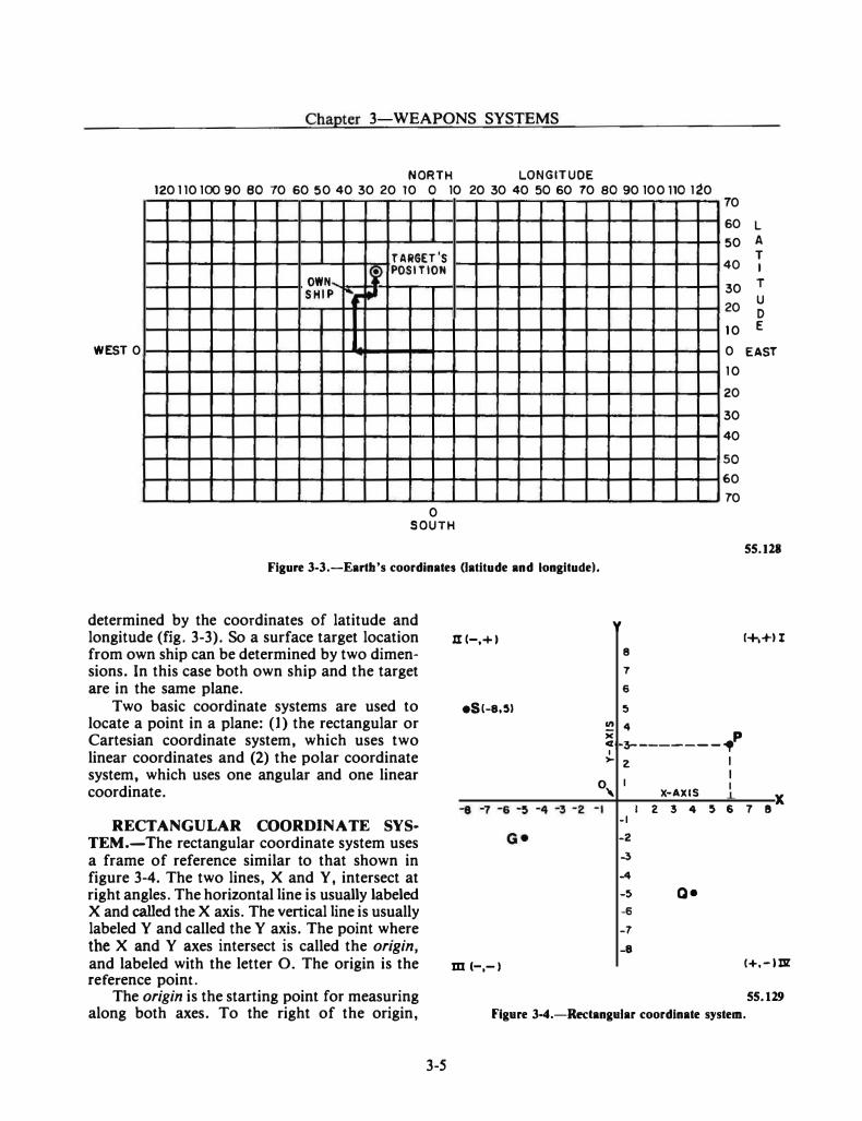
Chapter 3-WEAPONS SYSTEMS
NORTH LONGITUDE 120110100 90 eo 10 60 50 40 30 20 10 o 10 20 30 40 so 60 10 ao 90 100 no 120
OWN ... SHIP """
WEST 0
-� ..
TARGET'S POSITION
0 SOUTH
70
60 L
50 A
40 T I
30 T
20 u D
10 E
0 EAST
1 0
20
30
40
so
60
70
55.128
Figure 3-3.-Eartb's coordinates (latitude and longitude).
determined by the coordinates of latitude and longitude (fig. 3-3). So a surface target location from own ship can be determined by two dimensions. In this case both own ship and the target are in the same plane.
Two basic coordinate systems are used to locate a point in a plane: (l) th� rectangular or Cartesian coordinate system, which uses two linear coordinates and (2) the polar coordinate system, which uses one angular and one linear coordinate.
RECTANGULAR COORDINATE SYSTEM.-The rectangular coordinate system uses a frame of reference similar to that shown in figure 3-4. The two lines, X and Y, intersect at right angles. The horizontal line is usually labeled X and called the X axis. The vertical line is usually labeled Y and called the Y axis. The point where the X and Y axes intersect is called the origin, and labeled with the letter 0. The origin is the reference point.
The origin is the starting point for measuring along both axes. To the right of the origin,
3-5
.III-,+)
eS!-8,51
m h-I
y 8
7
6
5
!!! 4 )( p � 3---------. >- z I
I I
!+,+II
0 I ' X-AXIS
1 z 3 4 5 & 1 sx -I
-2
-3
-4
-5 Q• -6
-7 -8
1+.-lm
55.129
Figure 3-4.-Redangular coordinate system.
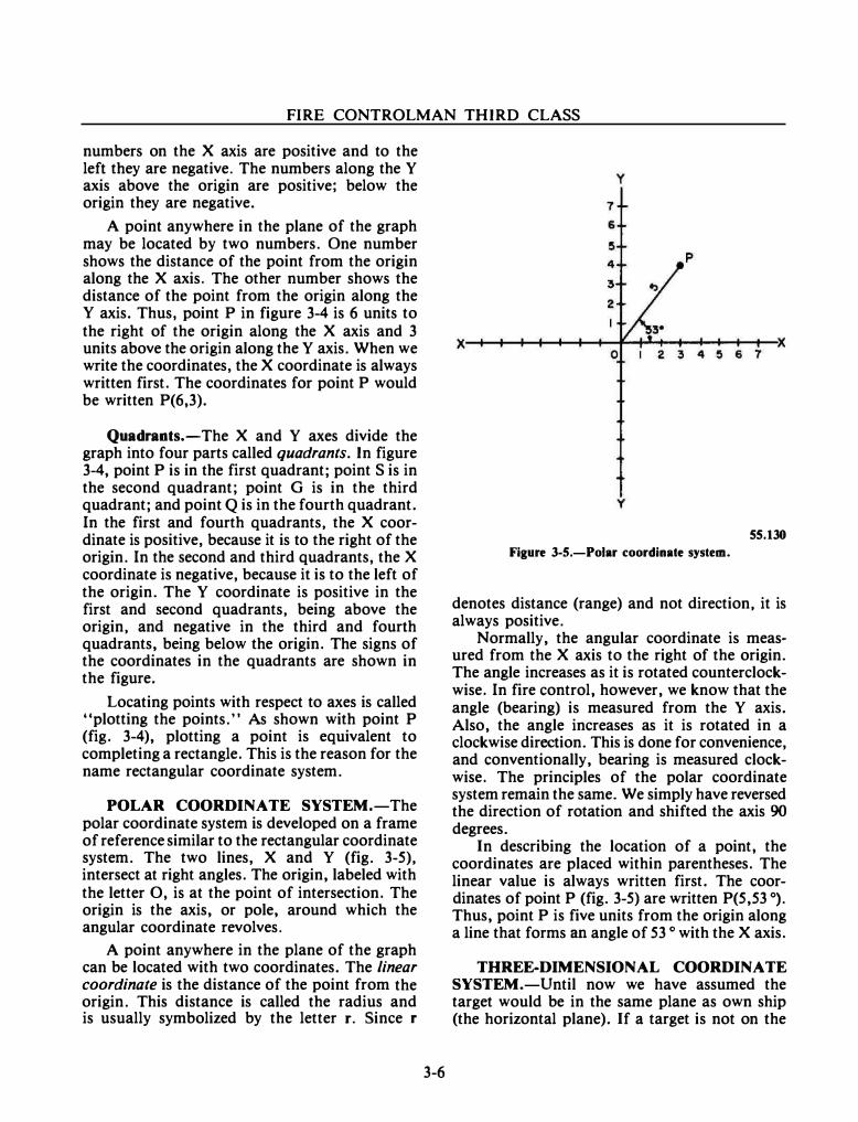
FIRE CONTROLMAN THIRD CLASS
numbers on the X axis are positive and to the left they are negative. The numbers along the Y axis above the origin are positive; below the origin they are negative.
A point anywhere in the plane of the graph may be located by two numbers. One number shows the distance of the point from the origin along the X axis. The other number shows the distance of the point from the origin along the
Y axis. Thus, point P in figure 3-4 is 6 units to the right of the origin along the X axis and 3 units above the origin along theY axis. When we write the coordinates, the X coordinate is always written first. The coordinates for point P would be written P(6,3).
Quadrants.-The X and Y axes divide the graph into four parts called quadrants. In figure 3-4, point P is in the first quadrant; point S is in the second quadrant; point G is in the third quadrant; and point Q is in the fourth quadrant. In the first and fourth quadrants, the X coordinate is positive, because it is to the right of the origin. In the second and third quadrants, the X coordinate is negative, because it is to the left of the origin. The Y coordinate is positive in the first and second quadrants, being above the origin, and negative in the third and fourth quadrants, being below the origin. The signs of the coordinates in the quadrants are shown in the figure.
Locating points with respect to axes is called "plotting the points." As shown with point P (fig. 3-4), plotting a point is equivalent to
completing a rectangle. This is the reason for the name rectangular coordinate system.
POLAR COORDINATE SYSTEM.-The polar coordinate system is developed on a frame of reference similar to the rectangular coordinate system. The two lines, X and Y (fig. 3-5), intersect at right angles. The origin, labeled with the letter 0, is at the point of intersection. The origin is the axis, or pole, around which the angular coordinate revolves.
A point anywhere in the plane of the graph can be located with two coordinates. The linear coordinate is the distance of the point from the origin. This distance is called the radius and is usually symbolized by the letter r. Since r
3-6
y
y
55.130
Figure 3-S.-Polar coordinate system.
denotes distance (range) and not direction, it is always positive.
Normally, the angular coordinate is measured from the X axis to the right of the origin. The angle increases as it is rotated counterclockwise. In fire control, however, we know that the angle (bearing) is measured from the Y axis. Also, the angle increases as it is rotated in a clockwise direction. This is done for convenience, and conventionally, bearing is measured clockwise. The principles of the polar coordinate system remain the same. We simply have reversed the direction of rotation and shifted the axis 90 degrees.
In describing the location of a point, the coordinates are placed within parentheses. The linear value is always written first. The coordinates of point P (fig. 3-5) are written P(5,53 °) .
Thus, point Pis five units from the origin along a line that forms an angle of 53 o with the X axis.
THREE-DIMENSIONAL COORDINATE SYSTEM.-Until now we have assumed the target would be in the same plane as own ship (the horizontal plane). If a target is not on the
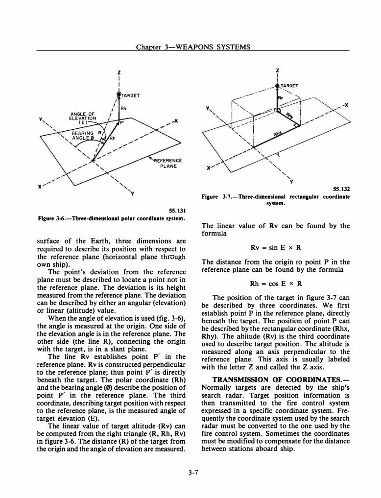
Chapter 3-WEAPONS SYSTEMS
z I I
55.131
Figure 3-6.-Tbree-dimeosiooal polar coordioate system.
surface of the Earth, three dimensions are required to describe its position with respect to the reference plane (horizontal plane thtuugh own ship).
The point's deviation from the reference plane must be described to locate a point not in the reference plane. The deviation is its height measured from the reference plane. The deviation can be described by either an angular (elevation) or linear (altitude) value.
When the angle of elevation is used (fig. 3-6), the angle is measured at the origin. One side of the elevation angle is in the reference plane. The other side (the line R), connecting the origin with the target, is in a slant plane.
The line Rv establishes point P' in the reference plane. Rv is constructed perpendicular to the reference·plane; thus point P' is directly beneath the target. The polar coordinate (Rh) and the bearing angle (0) describe the position of point P' in the reference plane. The third coordinate, describing target position with respect to the reference plane, is the measured angle of target elevation (E).
The linear value of target altitude (Rv) can be computed from the right triangle (R, Rh, Rv) in figure 3-6. The distance (R) of the target from the origin and the angle of elevation are measured.
3-7
z I I
55.132
Figure 3-7.-Three-dimensional rectangular coordinate system.
The linear value of Rv can be found by the formula
Rv =sin E x R
The distance from the origin to point P in the reference plane can be found by the formula
Rh =cos EX R
The position of the target in figure 3-7 can be described by three coordinates. We first establish point P in the reference plane, directly beneath the target. The position of point P can be described by the rectangular coordinate (Rhx, Rhy). The altitude (Rv) is the third coordinate used to describe target position. The altitude is measured along an axis perpendicular to the reference plane. This axis is usually labeled with the letter Z and called the Z axis.
TRANSMISSION OF COORDINATES.Normally targets are detected by the ship's search radar. Target position information is then transmitted to the fire control system expressed in a specific coordinate system. Frequently the coordinate system used by the search radar must be converted to the one used by the fire control system. Sometimes the coordinates must be modified to compensate for the distance between stations aboard ship.
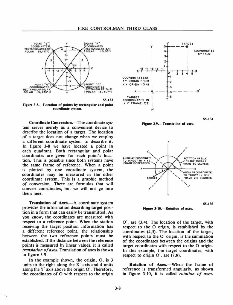
FIRE CONTROLMAN THIRD CLASS
55.133
Fiaure 3-8.-Locatlon of points by rectan&Diar and polar coordlaate system.
Coordinate Conversion.-The coordinate system serves merely as a convenient device to describe the location of a target. The location of a target does not change when we employ a different coordinate system to describe it. In figure 3-8 we have located a point in each quadrant. Both rectangular and polar coordinates are given for each point's location. This is possible since both systems have the same frame of reference. When a point is plotted by one coordinate system, the coordinates may be measured in the other coordinate system. This is a graphic method of conversion. There are formulas that will convert coordinates, but we will not go into them here.
Translation of Axes.-A coordinate system provides the information describing target position in a form that can easily be transmitted. As you know, the coordinates are measured with respect to a reference point. When the station receiving the target position information has a different reference point, the relationship between the two reference points must be established. If the distance between the reference points is measured by linear values, it is called translation of axes. Translation of axes is shown in figure 3-9.
In the example shown, the origin, 0, is 3 units to the right along the X' axis and 4 units along the Y' axis above the origin 0'. Therefore, the coordinates of 0 with respect to the origin
3-8
TARGET Y.' ----, I 4 1 I 3 I
COORDINATES XY (4,!5)
I z 1 I I I x--�5_-�q�-3�- z�-��-+.�����+-x
I 0 I z 3 4 !5 COORDINATESOF
I -I
X Y ORIGIN FROM -z -3
x'y' ORIGIN 13,4) I x·---,o:-- _4-----x'
TARGET I COORDINATES IN x'y' FRAME (7,9l
I y'
-5 y
Figure 3-9.-Traaslatlon of axes.
y
y' /
x· /
/
55.134
' ,..ANGULAR COORDINATE ' ,'' TO TARGET IN (X: Y') X F'RAMEISODEGREES ..........,/ "-
ROTATION OF' (X, Y) FRAME TO!x;Y')
FRAME 50 DEGREES x---�1--1-����----X
/ / '' ANGULAR COORDINATE
' TO TARGET IN (X,Y) TARGET/
/
x'
/ /
/
y
"- F'RAME 21D DEGREES '
' y'
55.135
Figure 3-10.-Rotatlon of axes.
0', are (3,4). The location of the target, with respect to the 0 origin, is established by the coordinates (4,5). The location of the target, with respect to the 0' origin, is the summation of the coordinates between the origins and the target coordinates with respect to the 0 origin. In this example, the target coordinates, with respect to origin 0', are (7 ,9).
Rotation of Axes.-When the frame of reference is transformed angularly, as shown in figure 3-10, it is called rotation of axes.
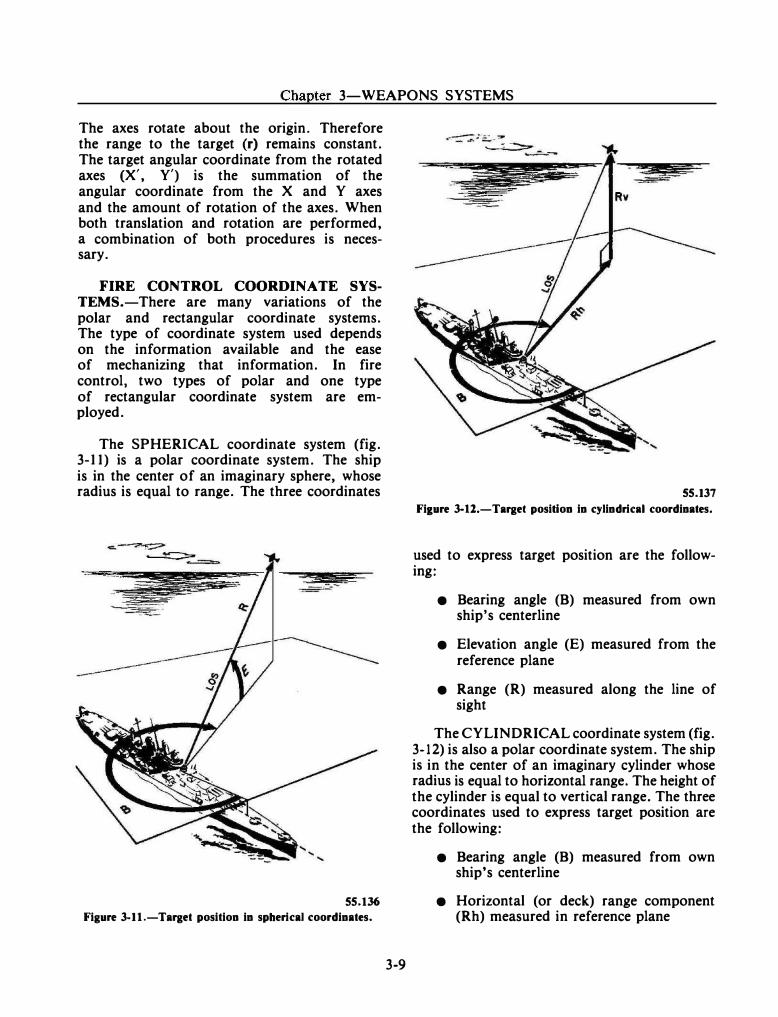
Chapter 3-WEAPONS SYSTEMS
The axes rotate about the origin. Therefore the range to the target (r) remains constant. The target angular coordinate from the rotated axes (X', Y') is the summation of the angular coordinate from the X and Y axes and the amount of rotation of the axes. When both translation and rotation are performed, a combination of both procedures is necessary.
FIRE CONTROL COORDINATE SYSTEMS.-There are many variations of the polar and rectangular coordinate systems. The type of coordinate system used depends on the information available and the ease of mechanizing that information. In fire control, two types of polar and one type of rectangular coordinate system are employed.
The SPHERICAL coordinate system (fig. 3-11) is a polar coordinate system. The ship is in the center of an imaginary sphere, whose radius is equal to range. The three coordinates
55.136
Figure 3-11.-Target position in spherical coordinates.
3-9
55.137
Fi1ure 3-11.-Target position in cylindrical coordinates.
used to express target position are the following:
• Bearing angle (B) measured from own ship's centerline
• Elevation angle (E) measured from the reference plane
• Range (R) measured along the line of sight
The CYLINDRICAL coordinate system (fig. 3-12) is also a polar coordinate system. The ship is in the center of an imaginary cylinder whose radius is equal to horizontal range. The height of the cylinder is equal to vertical range. The three coordinates used to express target position are the following:
• Bearing angle (B) measured from own ship's centerline
• Horizontal (or deck) range component (Rh) measured in reference plane
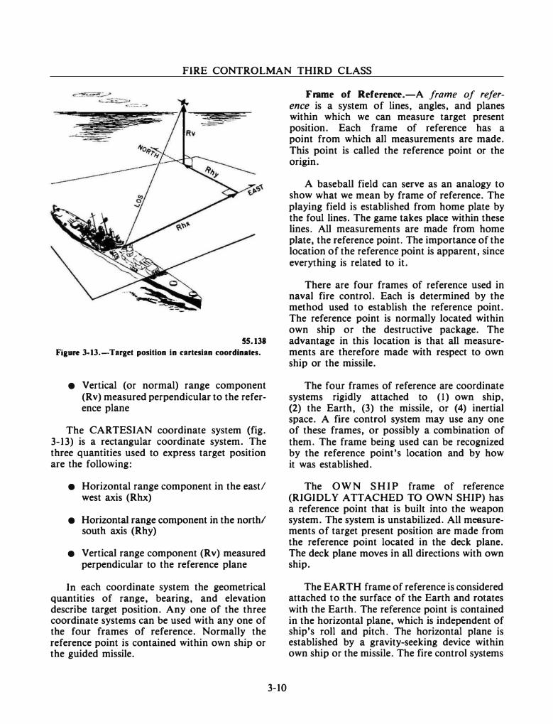
FIRE CONTROLMAN THIRD CLASS
55.138
Fiaure 3-13.-Target position in cartesian coordinates.
• Vertical (or normal) range component (Rv) measured perpendicular to the reference plane
The CARTESIAN coordinate system (fig. 3-13) is a rectangular coordinate system. The three quantities used to express target position are the following:
• Horizontal range component in the east/ west axis (Rhx)
• Horizontal range component in the north/ south axis (Rhy)
• Vertical range component (Rv) measured perpendicular to the reference plane
In each coordinate system the geometrical quantities of range, bearing, and elevation describe target position. Any one of the three coordinate systems can be used with any one of the four frames of reference. Normally the reference point is contained within own ship or the guided missile.
3-10
Frame of Reference.-A frame of reference is a system of lines, angles, and planes within which we can measure target present position. Each frame of reference has a point from which all measurements are made. This point is called the reference point or the origin.
A baseball field can serve as an analogy to show what we mean by frame of reference. The playing field is established from home plate by the foul lines. The game takes place within these lines. All measurements are made from home plate, the reference point. The importance of the location of the reference point is apparent, since everything is related to it.
There are four frames of reference used in naval fire control. Each is determined by the method used to establish the reference point. The reference point is normally located within own ship or the destructive package. The advantage in this location is that all measurements are therefore made with respect to own ship or the missile.
The four frames of reference are coordinate systems rigidly attached to (1) own ship, (2) the Earth, (3) the missile, or (4) inertial space. A fire control system may use any one of these frames, or possibly a combination of them. The frame being used can be recognized by the reference point's location and by how it was established.
The OWN SHIP frame of reference (RIGIDLY ATTACHED TO OWN SHIP) has a reference point that is built into the weapon system. The system is unstabilized. All measurements of target present position are made from the reference point located in the deck plane. The deck plane moves in all directions with own ship.
The EARTH frame of reference is considered attached to the surface of the Earth and rotates with the Earth. The reference point is contained in the horizontal plane, which is independent of ship's roll and pitch. The horizontal plane is established by a gravity-seeking device within own ship or the missile. The fire control systems
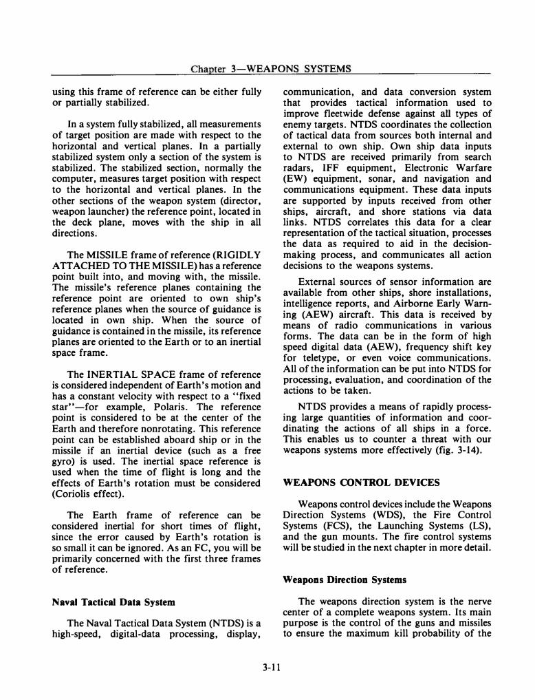
------ ---- - ·
Chapter 3-WEAPONS SYSTEMS
using this frame of reference can be either fully or partially stabilized.
In a system fully stabilized, all measurements of target position are made with respect to the horizontal and vertical planes. In a partially stabilized system only a section of the system is stabilized. The stabilized section, normally the computer, measures target position with respect to the horizontal and vertical planes. In the other sections of the weapon system (director, weapon launcher) the reference point, located in the deck plane, moves with the ship in all directions.
The MISSILE frame of reference (RIGIDLY ATTACHED TO THE MISSILE) has a reference point built into, and moving with, the missile. The missile's reference planes containing the reference point are oriented to own ship's reference planes when the source of guidance is located in own ship. When the source of guidance is contained in the missile, its reference planes are oriented to the Earth or to an inertial space frame.
The INERTIAL SPACE frame of reference is considered independent of Earth's motion and has a constant velocity with respect to a "fixed star" -for example, Polaris. The reference point is considered to be at the center of the Earth and therefore nonrotating. This reference point can be established aboard ship or in the missile if an inertial device (such as a free gyro) is used. The inertial space reference is used when the time of flight is long and the effects of Earth's rotation must be considered (Coriolis effect).
The Earth frame of reference can be considered inertial for short times of flight, since the error caused by Earth's rotation is so small it can be ignored. As an FC, you will be primarily concerned with the first three frames of reference.
Naval Tactical Data System
The Naval Tactical Data System (NTDS) is a high-speed, digital-data processing, display,
3-11
communication, and data conversion system that provides tactical information used to improve fleetwide defense against all types of enemy targets. NTDS coordinates the collection of tactical data from sources both internal and external to own ship. Own ship data inputs to NTDS are received primarily from search radars, IFF equipment, Electronic Warfare (EW) equipment, sonar, and navigation and communications equipment. These data inputs are supported by inputs received from other ships, aircraft, and shore stations via data links. NTDS correlates this data for a clear representation of the tactical situation, processes the data as required to aid in the decisionmaking process, and communicates all action decisions to the weapons systems.
External sources of sensor information are available from other ships, shore installations, intelligence reports, and Airborne Early Warning (AEW) aircraft. This data is received by means of radio communications in various forms. The data can be in the form of high speed digital data (AEW), frequency shift key for teletype, or even voice communications. All of the information can be put into NTDS for processing, evaluation, and coordination of the actions to be taken.
NTDS provides a means of rapidly processing large quantities of information and coordinating the actions of all ships in a force. This enables us to counter a threat with our weapons systems more effectively (fig. 3-14).
WEAPONS CONTROL DEVICES
Weapons control devices include the Weapons Direction Systems (WDS), the Fire Control Systems (FCS), the Launching Systems (LS), and the gun mounts. The fire control systems will be studied in the next chapter in more detail.
Weapons Direction Systems
The weapons direction system is the nerve center of a complete weapons system. Its main purpose is the control of the guns and missiles to ensure the maximum kill probability of the
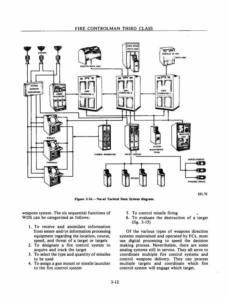
FIRE CONTROLMAN THIRD CLASS
MONtiOIINQ , ... fl
MISCILLANIOUS
SYNCNIO INI'UU
151.72
Figure 3-14.-Naval Tac:tlcal Data System diaaram.
weapons system. The six sequential functions of WDS can be categorized as follows:
1. To receive and assimilate information from sensor and/or information processing equipment regarding the location, course, speed, and threat of a target or targets
2. To designate a fire control system to acquire and track the target
3. To select the type and quantity of missiles to be used
4. To assign a gun mount or missile launcher to the fire control system
3-12
5. To control missile firing 6. To evaluate the destruction of a target
(fig. 3-15)
Of the various types of weapons direction systems maintained and operated by FCs, most use digital processing to speed the decision making process. Nevertheless, there are some analog systems still in service. They all serve to coordinate multiple fire control systems and control weapons delivery. They can process multiple targets and coordinate which fire control system will engage which target.
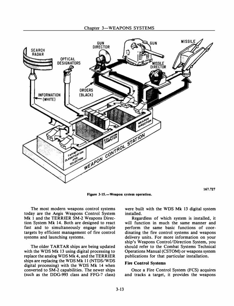
Chapter 3-WEAPONS SYSTEMS
167.727
Fiaure 3-15.-Weapon system operation.
The most modern weapons control systems today are the Aegis Weapons Control System Mk 1 and the TERRIER SM-2 Weapons Direction System Mk 14. Both are designed to react fast and to simultaneously engage multiple targets by efficient management of fire control systems and launching systems.
The older TARTAR ships are being updated with the WDS Mk 13 using digital processing to replace the analog WDS Mk 4, and the TERRIER ships are replacing the WDS Mk 11 (NTDS/WDS digital processing) with the WDS Mk 14 when converted to SM-2 capabilities. The newer ships (such as the DDG-993 class and FFG-7 class)
3-13
were built with the WDS Mk 13 digital system installed.
Regardless of which system is installed, it will function in much the same manner and perform the same basic functions of coordinating the fire control systems and weapons delivery units. For more information on your ship's Weapons Control/Direction System, you should refer to the Combat Systems Technical Operations Manual (CSTOM) or weapons system publications for that particular installation.
Fire Control Systems
Once a Fire Control System (FCS) acquires and tracks a target, it provides the weapons
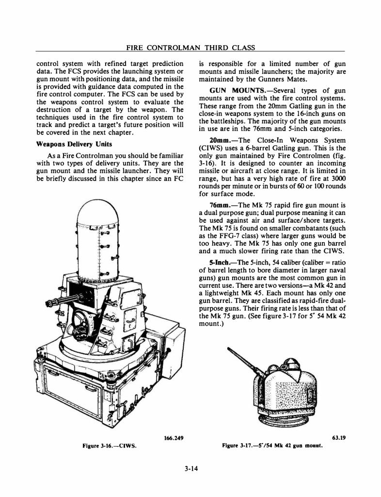
FIRE CONTROLMAN THIRD CLASS
control system with refined target prediction data. The FCS provides the launching system or gun mount with positioning data, and the missile is provided with guidance data computed in the fire control computer. The FCS can be used by the weapons control system to evaluate the destruction of a target by the weapon. The techniques used in the fire control system to track and predict a target's future position will be covered in the next chapter.
Weapons Delivery Units
As a Fire Controlman you should be familiar with two types of delivery units. They are the gun mount and the missile launcher. They will be briefly discussed in this chapter since an FC
166.249
Figure 3-16.-CIWS.
3-14
is responsible for a limited number of gun mounts and missile launchers; the majority are maintained by the Gunners Mates.
GUN MOUNTS.-Several types of gun mounts are used with the fire control systems. These range from the 20mm Gatling gun in the close-in weapons system to the 1 6-inch guns on the battleships. The majority of the gun mounts in use are in the 76mrn and 5-inch categories.
20mm.-The Close-In Weapons System (CIWS) uses a 6-barrel Gatling gun. This is the only gun maintained by Fire Controlmen (fig. 3-16). It is designed to counter an incoming missile or aircraft at close range. It is limited in range, but has a very high rate of fire at 3000 rounds per minute or in bursts of 60 or 100 rounds for surface mode.
76mm.-The Mk 75 rapid fire gun mount is a dual purpose gun; dual purpose meaning it can be used against air and surface/ shore targets. The Mk 75 is found on smaller combatants (such as the FFG-7 class) where larger guns would be too heavy. The Mk 75 has only one gun barrel and a much slower firing rate than the CIWS.
5-Incb.-The 5-inch, 54 caliber (caliber = ratio of barrel length to bore diameter in larger naval guns) gun mounts are the most common gun in current use. There are two versions-a Mk 42 and a lightweight Mk 45. Each mount has only one gun barrel. They are classified as rapid-fire dualpurpose guns. Their firing rate is less than that of the Mk 75 gun. (See figure 3-17 for 5* 54 Mk 42 mount.)
63.19
Figure 3-17.-s· /54 Mk 42 guo mo••t.
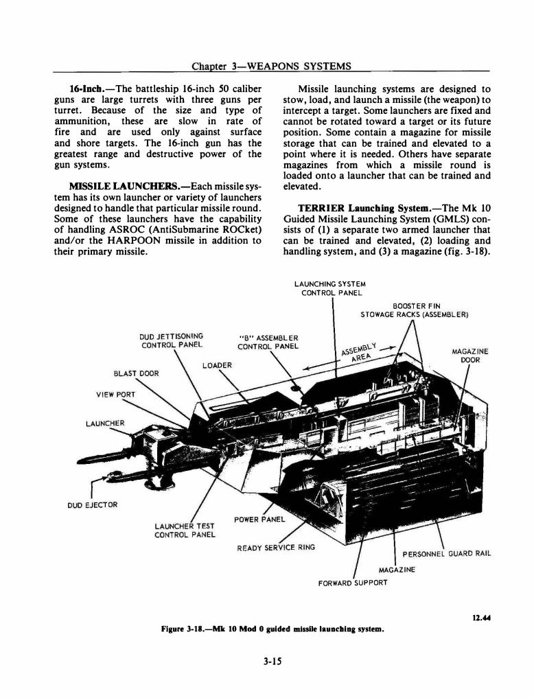
Chapter 3-WEAPONS SYSTEMS
16-lncb.-The battleship 16-inch 50 caliber guns are large turrets with three guns per turret. Because of the size and type of ammunition, these are slow in rate of fire and are used only against surface and shore targets. The 16-inch gun has the greatest range and destructive power of the gun systems.
MISSILE LAUNCHERS.-Each missile system has its own launcher or variety of launchers designed to handle that particular missile round. Some of these launchers have the capability of handling ASROC (AntiSubmarine ROCket) and/or the HARPOON missile in addition to their primary missile.
Missile launching systems are designed to stow, load, and launch a missile (the weapon) to intercept a target. Some launchers are fixed and cannot be rotated toward a target or its future position. Some contain a magazine for missile storage that can be trained and elevated to a point where it is needed. Others have separate magazines from which a missile round is loaded onto a launcher that can be trained and elevated.
TERRIER Launching System.-The Mk 10 Guided Missile Launching System (GMLS) consists of (1) a separate two armed launcher that can be trained and elevated, (2) loading and handling system, and (3) a magazine (fig. 3-18).
LAUNCHING SYSTEM
CONTROL PANEL
BOOSTER FIN STOWAGE RACKS (ASSEMBLER)
"B" ASSEMBLER
CONTROI�EL
MAGAZINE
FORWARD SUPPORT
Figure 3-18.-Mk 10 Mod 0 guided missile lauadllaa system.
3-15
12.44
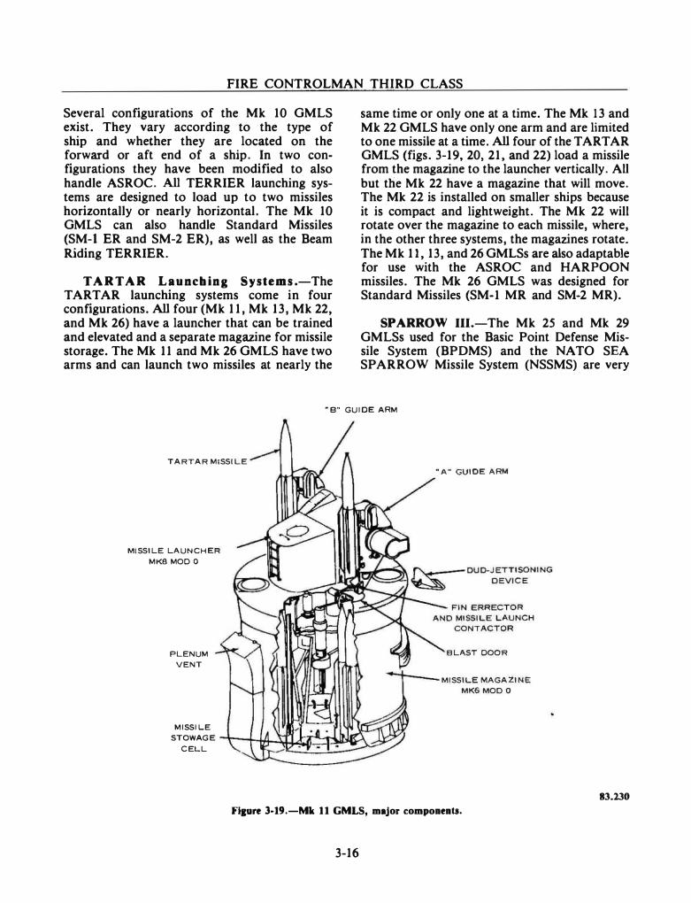
FIRE CONTROLMAN THIRD CLASS
Several configurations of the Mk 10 GMLS exist. They vary according to the type of ship and whether they are located on the forward or aft end of a ship. In two configurations they have been modified to also handle ASROC. All TERRIER launching systems are designed to load up to two missiles horizontally or nearly horizontal. The Mk 10 GMLS can also handle Standard Missiles (SM-1 ER and SM-2 ER), as well as the Beam Riding TERRIER.
TARTAR L a unching Systems.-The TARTAR launching systems come in four configurations. All four (Mk 11, Mk 13, Mk 22, and Mk 26) have a launcher that can be trained and elevated and a separate magazine for missile storage. The Mk 11 and Mk 26 GMLS have two arms and can launch two missiles at nearly the
same time or only one at a time. The Mk 13 and Mk 22 GMLS have only one arm and are limited to one missile at a time. All four of the TARTAR GMLS (figs. 3-19, 20, 21, and 22) load a missile from the magazine to the launcher vertically. All but the Mk 22 have a magazine that will move. The Mk 22 is installed on smaller ships because it is compact and lightweight. The Mk 22 will rotate over the magazine to each missile, where, in the other three systems, the magazines rotate. The Mk 11, 13, and 26 GMLSs are also adaptable for use with the ASROC and HARPOON missiles. The Mk 26 GMLS was designed for Standard Missiles (SM-1 MR and SM-2 MR).
SPARROW III.-The Mk 25 and Mk 29 GMLSs used for the Basic Point Defense Missile System (BPDMS) and the NATO SEA SPARROW Missile System (NSSMS) are very
"B" GUIDE ARM
TARTAR MISSILE
MISSILE LAUNCHER
MKS MOD 0
PLENUM
VENT
MISSILE
"A" GUIDE ARM
BLAST DOOR
MISSILE MAGAZINE
MK6 MOD 0
STOWAGE \__,.H:f--.:l��===P-1-�� CELL
83.230
Flture 3-19.-Mk 11 GMLS, major compoueuts.
3-16
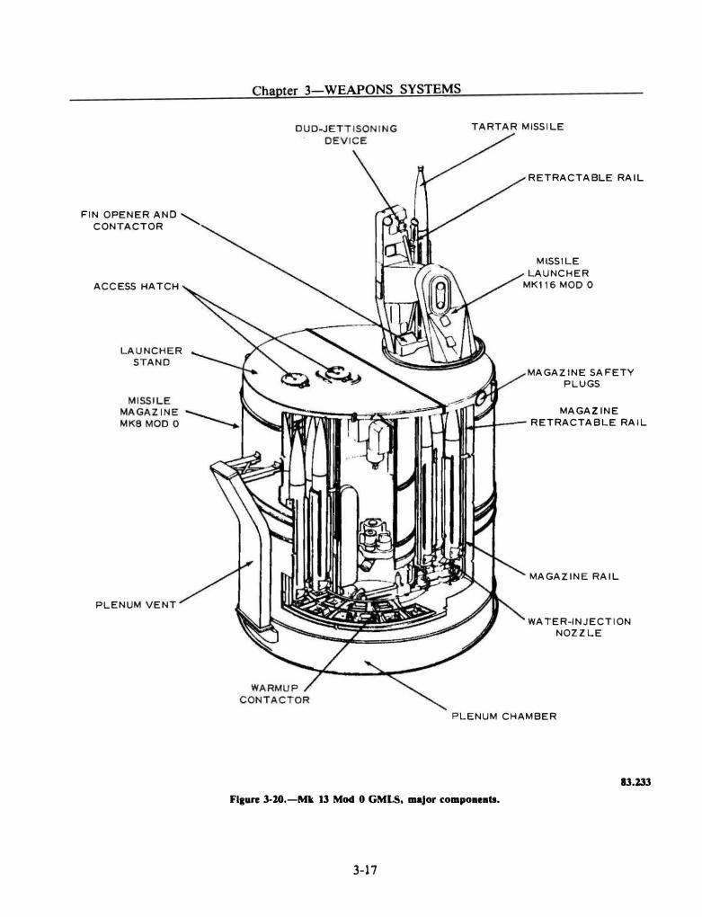
FIN OPENER AND ' CONTACTOR
ACCESS HATCH
LAUNCHER
STAND
PLENUM VENT
Chapter 3-WEAPONS SYSTEMS
TARTAR MISSILE
RETRACTABLE RAIL
MlSSILE
LAUNCHER
MK116 MOD 0
MAGAZINE SAFETY
PLUGS
MAGAZINE
\111.1---t--- RETRACTABLE RAIL
MAGAZINE RAIL
WATER-INJECTION
NOZZLE
PLENUM CHAMBER
13.133
Flaure 3-20.-Mk 13 Mod 0 GMLS, maJor compoaeatl.
3-17
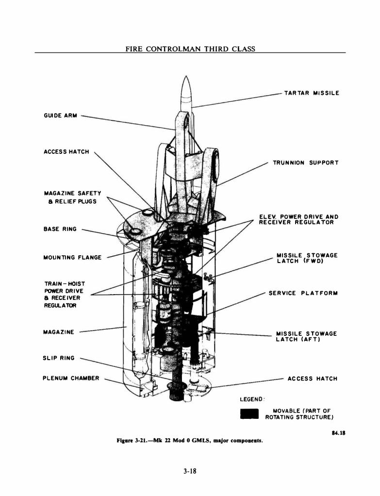
GUID E ARM
ACCESS HATCH
MAGAZINE SAFETY
a RELIEF PLUGS
BASE RING
MOUNTING FLANGE
TRAIN- HOIST POWER DRIVE a RECEIVER REGULATOR
MAGAZINE
SLIP RING
PLENU M CHAMBER
FIRE CONTROLMAN THIRD CLASS
T ARTAR MISSILE
TRUNNION SUPPORT
ELEV. POWER D RIVE AND RECEIVER REGULATOR
LEGEND:
-
Flaare 3-11.-Mk 11 Mod 0 GMLS, major compouats.
3-18
MISSILE STOWAGE LATCH (FWD)
SERVICE PLAT FORM
MISSILE STOWAGE LATCH (AFT)
ACCESS HATCH
MOVABLE (PART OF ROTAT ING STRUCTUREJ
14.18
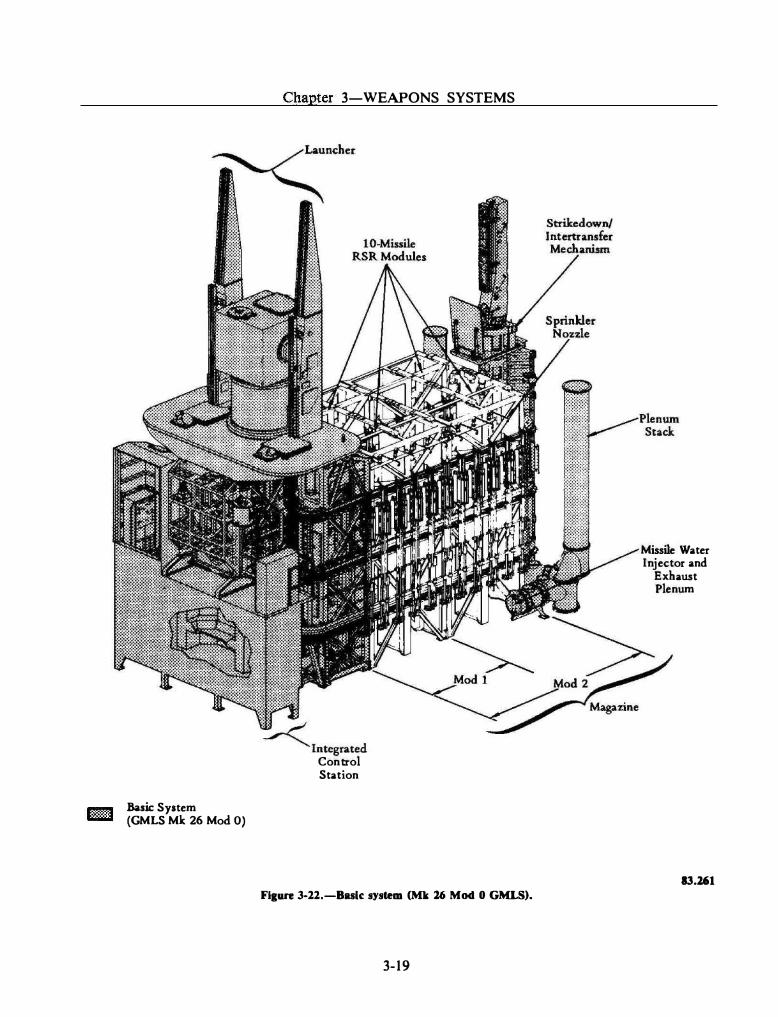
Basic System (GMLS Mit 26 Mod 0)
Chapter 3-WEAPONS SYSTEMS
� Integrated Control Station
Figure 3-22.-Bulc system (Mk 26 Mod 0 GMLS).
3-19
Missile Water Injector and
Exhaust Plenum
13.161
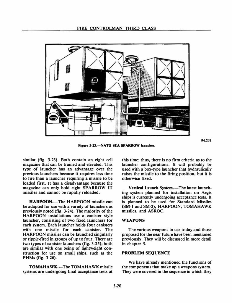
FIRE CONTROLMAN THIRD CLASS
94.101
Fig•re 3-13.-NATO SEA SPARROW la .. dter.
similar (fig. 3-23). Both contain an eight cell magazine that can be trained and elevated. This type of launcher has an advantage over the previous launchers because it requires less time to fire than a launcher requiring a missile to be loaded frrst. It bas a disadvantage because the magazine can only hold eight SPARROW III missiles and cannot be rapidly reloaded.
HARPOON.-The HARPOON missile can be adapted for use with a variety of launchers as previously noted (fig. 3-24). The majority of the HARPOON installations use a canister style launcher, consisting of two ftxed launchers for each system. Each launcher holds four canisters with one missile for each canister. The HARPOON missiles can be launched singularly or ripple-fired in groups of up to four. There are two types of canister launchers (fig. 3-2S); both are similar with one being of lightweight construction for use on small ships, such as the PHMs (fig. 3-26).
TOMAHAWK.-The TOMAHAWK missile systems are undergoing final acceptance tests at
3-20
this time; thus, there is no firm criteria as to the launcher configurations. It will probably be used with a box-type launcher that hydraulically raises the missile to the firing position, but it is otherwise ftxed.
Vertical Launch System.-The latest launching system planned for installation on Aegis ships is currently undergoing acceptance tests. It is planned to be used for Standard Missiles (SM-1 and SM-2), HARPOON, TOMAHAWK missiles, and ASROC.
WEAPONS
The various weapons in use today and those proposed for the near future have been mentioned previously. They will be discussed in more detail in chapter S.
PROBLEM SEQUENCE
We have already mentioned the functions of the components that make up a weapons system. They were covered in the sequence in which they
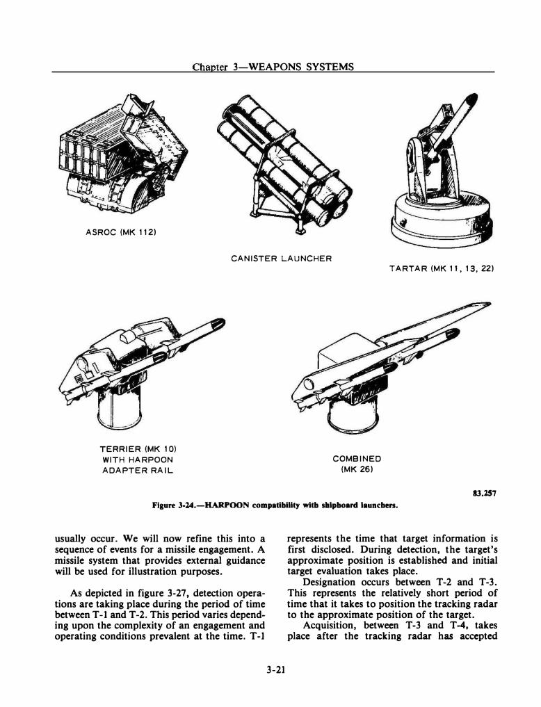
Chapter 3-WEAPONS SYSTEMS
ASROC (MK 112)
CANISTER LAUNCHER
TERRIER (MK 1 0) WITH HARPOON ADAPTER RAIL
COMBINED (MK 26)
TARTAR (MK 11, 13, 22)
13.257
Figure 3-14.-HARPOON comp•tibillty wltb shlpboud l•uncben.
usually occur. We will now refine this into a sequence of events for a missile engagement. A missile system that provides external guidance will be used for illustration purposes.
As depicted in figure 3-27, detection operations are taking place during the period of time between T-1 and T-2. This period varies depending upon the complexity of an engagement and operating conditions prevalent at the time. T-1
3-21
represents the time that target information is first disclosed. During detection, the target's approximate position is established and initial target evaluation takes place.
Designation occurs between T-2 and T-3. This represents the relatively short period of time that it takes to position the tracking radar to the approximate position of the target.
Acquisition, between T -3 and T -4, takes place after the tracking radar has accepted
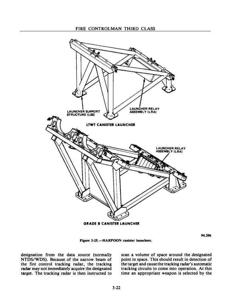
FIRE CONTROLMAN THIRD CLASS
LAUNCHER SUPPORT STRUCTURE ILSSJ
LTWT CANISTER LAUNCHER
GRADE I CANISTER LAUNCHER
94.106
Figure 3·25.-HARPOON canister lauocben.
designation from the data source (normally NTDS/WDS). Because of the narrow beam of the fire control tracking radar, the tracking radar may not immediately acquire the designated target. The tracking radar is then instructed to
3-22
scan a volume of space around the designated point in space. This should result in detection of the target and cause the tracking radar's automatic tracking circuits to come into operation. At this time an appropriate weapon is selected by the
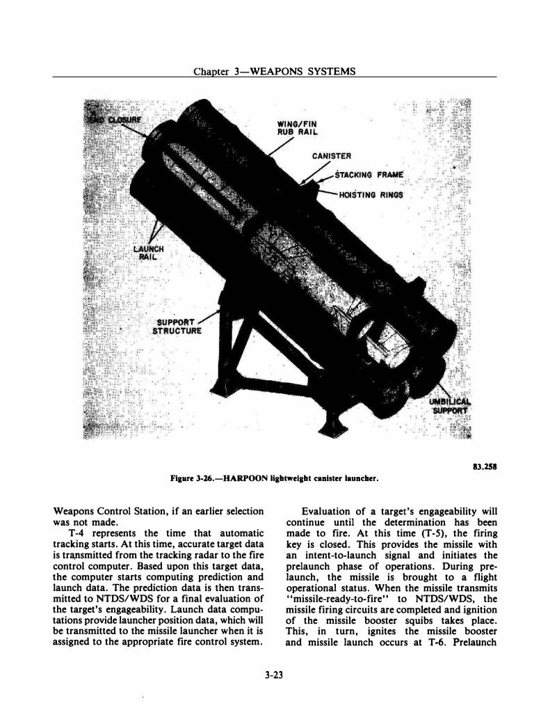
Chapter 3-WEAPONS SYSTEMS
83.158 Figure 3-16.-HARPOON llgbtweigbt canister launcher.
Weapons Control Station, if an earlier selection was not made.
T -4 represents the time that automatic tracking starts. At this time, accurate target data is tra,nsmitted from the tracking radar to the fire control computer. Based upon this target data, the computer starts computing prediction and launch data. The prediction data is then transmitted to NTDS/WDS for a final evaluation of the target's engageability. Launch data computations provide launcher position data, which will be transmitted to the missile launcher when it is assigned to the appropriate fire control system.
3-23
Evaluation of a targefs engageability will continue until the determination has been made to fire. At this time (T-5), the firing key is closed. This provides the missile with an intent-to-launch signal and initiates the prelaunch phase of operations. During prelaunch, the missile is brought to a flight operational status. When the missile transmits "missile-ready-to-fire" to NTDS/WDS, the missile firing circuits are completed and ignition of the missile booster squibs takes place. This, in turn, ignites the missile booster and missile launch occurs at T-6. Prelaunch
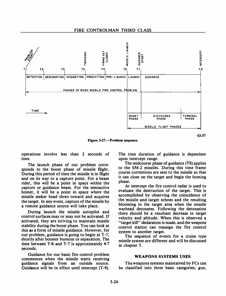
FIRE CONTROLMAN THIRD CLASS
:r u z :I
� >- c( 11.10 � IIJ
! ¥1&.1 IIJ u� ¥ �CII � za: u !3 iii
c(c( c( 0� a: g:(J (/) SCII � i4: i �
Tl T2
'I T3
-I T4
.I nl T6 T7 T 9
DETECTION I DESIGNATION I ACQUISITION I PRED ICTION I PRE-LAUNCH LAUNCH GUIDANCE
PHASES OF BASIC MISSILE FIRE CONTROL PROBLEM
TIME
T8l
BOOST MID COURSE I TERMINAL PHASE PHASE PHASE
MISSILE FLIGHT PHASES
63.57
Figure 3·17 .-Problem sequence.
operations involve less than 2 seconds of time.
The launch phase of our problem corresponds to the boost phase of missile flight. During this period of time the missile is in flight and on its way to a capture point. For a beam rider. this will be a point in space within the capture or guidance beam. For the semiactive homer, it will be a point in space where the missile seeker head slews toward and acquires the target. In any event, capture of the missile by a remote guidance source will take place.
During launch the missile autopilot and control surfaces may or may not be activated. If activated, they are striving to maintain missile stability during the boost phase. You can look at this as a form of missile guidance. However. for our problem, guidance is going to begin at T -7, shortly after booster burnout or separation. The time between T -6 and T • 7 is approximately 4-7 seconds.
Guidance for our basic fire control problem commences when the missile starts receiving guidance signals from an outside source. Guidance will be in effect until intercept (T-9).
3-24
The time duration of guidance is dependent upon intercept range.
The midcourse phase of guidance (T8) applies to the SM-2 missiles. During this time frame course corrections are sent to the missile so that it can close on the target and begin the homing phase.
At intercept the fire control radar is used to evaluate the destruction of the target. This is accomplished by observing the coincidence of the missile and target echoes and the resulting blooming in the target area when the missile warhead detonates. Following the detonation there should be a resultant decrease in target velocity and altitude. When this is observed a "target kill" declaration is made, and the weapons control station can reassign the fire control system to another target.
The sequence of events for a cruise type missile system are different and will be discussed in chapter 5.
WEAPONS SYSTEMS USES
The weapons systems maintained by FCs can be classified into three basic categories; gun,
Chapter 3-WEAPONS SYSTEMS
missile, and combination. Each category has a variety of uses depending on the type of weapon or weapons used. All combatant ships have at least one of these three categories.
GUN SYSTEMS
The gun systems are used primarily in AA W, ASUW, and ASMD operations. These systems include the 20mm CIWS, the 76mm, and the 5·54 gun systems. The 16-inch gun systems are used for ASUW and shore bombardment and cover a range from the ship out to about 24 miles.
MISSILE SYSTEMS
The missile systems are used primarily for AAW, ASMD, and ASUW. However, two of the missiles can be used for shore bombardment. The missile systems cover an area from close in to the ship, out to about 100 miles for AA W and ASMD. These include the STANDARD Missiles (SM-1 and SM-2, MR and ER) TARTAR, TERRIER, and SPARROW, with the TERRIER SM-2 ER having the greatest range capability, and the SPARROW III the least. The cruise missile systems are used primarily against surface targets with the TOMAHAWK also having a shore target capability. The HARPOON missile system can be used against surface targets out to about 60 miles and the TOMAHAWK out to
3-25
about 250 miles. The TOMAHAWK also can be used against land targets at 750 miles and 1350 miles, depending on the type of warhead.
COMBINATION SYSTEMS
The combination systems are gun and missile systems combined, such as the Mk 92 Fire Control System aboard the FFG-7 class. These systems cover a 20 mile radius from the ship using the 76mm gun and the TARTAR SM-1 MR missile.
SUMMARY
You have learned about the components that make up weapons systems from the sensors to the weapons themselves. You now know what each part of the weapon system should do. As a Fire Controlman it will be your job to see that all the components function properly and accurately. Initially, you may work on only one part of the system, but eventually you will become involved in more and more of the system components.
In the next chapter (chapter 4) you will learn about the key component of the weapons systems, the fire control system. And in chapter 5 you will learn more about the missiles and ordnance that you, as a Fire Controlman, will control.
CHAPTER 4
FIRE CONTROL SYSTEMS
In the previous chapter you learned about the components that make up the weapons systems in the fleet. A key component of the weapons system is the Fire Control System. As a Fire Controlman. your main job will be to operate and maintain the equipment components that comprise a fire control system. Several abbreviations are used in conjunction with fire control systems: FCS-Fire Control System; GFCS-Gun Fire Control System; GMFCS or MFCS-Guided Missile/Missile Fire Control System; DFCS-Digital Fire Control System .
FIRE CONTROL
Fire control is defined as the technique of delivering effective fire to damage or destroy a selected target. Since there is one basic fire control problem, you may assume that elements (basic quantities or factors) are common to all variations of the problem. The common elements are the basic functions of any FCS. Although the FCS does not usually come into the sequence of events until the Weapons Direction System (WDS) assigns the target to an FCS, some FCSs can be used to search and detect targets.
FCS FUNCTIONS
The basic problem can be divided into six fundamental sequential operations: (1) DETECTION, (2) ACQUISITION and TRACKING, (3) PREDICTION, (4) LAUNCHER/GUN POSITIONING, (S) GUIDANCE (missiles), and (6) EVALUATION (intercept and target destruction). Figure 4-1 illustrates the fire control problem sequence.
4-1
DETECTION
After a target has been detected, the next step is to obtain precise target position information. This information can be provided by the same source that detected the target, or it can be provided from some other source, such as another radar. In the majority of the cases, a second radar. a fiJ'e control radar, is used.
The search radar detects the target and establishes the target's initial position. The initial target information is transmitted (designated) to the fire control system.
ACQUISITION AND TRACKING
The fire control radar director/antenna is then aligned with the search radar's target position information until it locks on the reflected target signal (acquisition), and it is maintained in that alignment (track) by operator action or radar automatic control circuits while the ship and/or target is moving. In this way, continuous, accurate target position information is available to the weapon system for processing. Not only is the continuous present position of the target obtained, but its movement (course and speed) is also determined.
Data other than target data is equally important for weapon flight path (trajectory) determination. Wind, for example, could blow the weapon off its flight path. Appropriate corrections would require that wind direction and velocity be determined. The course and speed of the launching ship and its motion, because of the sea (pitch and roll), are also
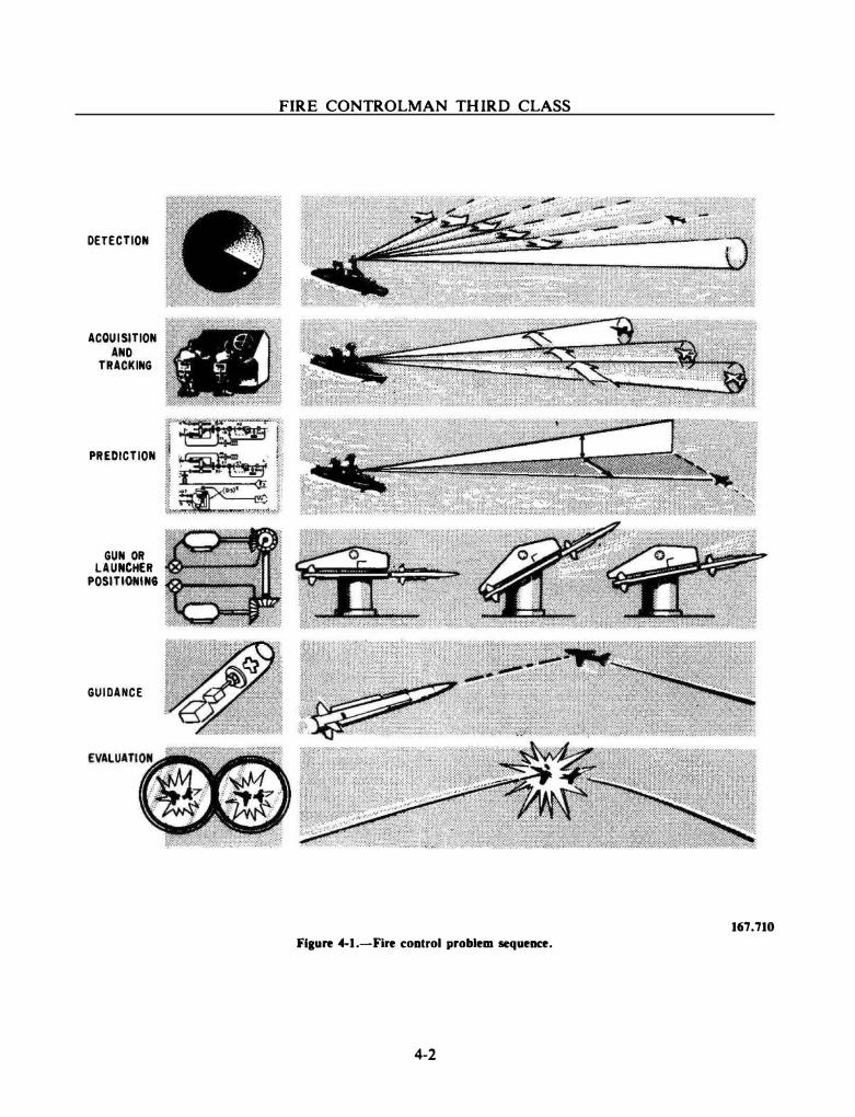
DETECTION
ACQUI SITION
AND
TRACKING
PREDICTION
GUN OR LAUNCH£R
POSITIONIN6
GUIDANCE
FIRE CONTROLMAN THIRD CLASS
167.710
Flaure 4-1.-Fire control problem sequence.
4-2
Chapter 4-FIRE CONTROL SYSTEMS
important considerations. If this type of data is not included in the flight path determinations, it could cause large errors in the flight path (trajectory).
Data of this nature, along with target data, is transmitted to the fire control system's computer. The computer performs the necessary calculations for computing the launcher or gun mount position angles and the weapon's flight path.
After target detection and target acquisition have occurred, the fire control system provides three operations for the tracking, computation (prediction), and positioning functions.
The first operation tracks the target and provides all necessary data on the target. The fire control radar performs this function by establishing a tracking Line Of Sight (LOS) along which it receives the returned or reflected energy from the target. It also provides accurate range data.
Since the speed of the propagated rf energy is about 186,000 miles per second (the same as the speed of light), and since the target ranges involved are relatively small, the time for the energy to travel to and from the target can be considered as instantaneous. Therefore, the radar indications of the target can be considered as instantaneous, present-target positions.
PREDICTION
The second operation of the fire control problem that must be performed is the computation of the gun/launcher positioning angle (line of fire) and the weapon flight path trajectory. This operation consists of two parts. The data that is received is processed into a usable form, and then the arithmetic operations are performed by the fire control computer to predict the future position of the target.
LAUNCHER/GUN POSITIONING
The third operation that must be performed is the positioning of the gun/launcher in accordance with the calculated line of fire to the
4-3
future target position. This amounts to offsetting the gun/launcher axis from the LOS by the amount of the predicted lead angle by means of the gun/launcher drive mechanism. In some cases, the missile is positioned (guided) in flight by the fire control system.
GUIDANCE (MISSILES)
For the GMFCS additional functions must be performed during the time the missile is in flight. Prior to launching, the fire control computer performs certain computations to provide the missile with information about the target and its own flight path. If the target maneuvers during the missile's flight, the computer could send course correction data to the missile via the fire control radar or the missile could correct itself. The various methods of missile guidance are discussed in the next chapter (chapter 5).
EVALUATION
The fire control radar displays (scopes}- are used to evaluate the weapon's destruction of the target. In the event of a miss or only minor damage, additional weapons can be used. In missile fire control, another missile is fired. In gun fire control, corrections are made to bring the fall of shot onto a target using the radar indicators, optical devices, or spotter corrections. Firing at a target will normally continue until it is evaluated as either destroyed or damaged to the point it is no longer a threat.
FIRE CONTROL SYSTEM CONCEPTS
For various reasons, components of fire control systems are located at many different areas throughout a ship. The higher a director or antenna is located, the farther it can see out on the horizon. The closer the stabilization unit is to the waterline of the ship, the more accurately it measures the ship's roll and pitch. The radar and computer are usually below deck for protection from the inclement weather often encountered at sea. All of these components
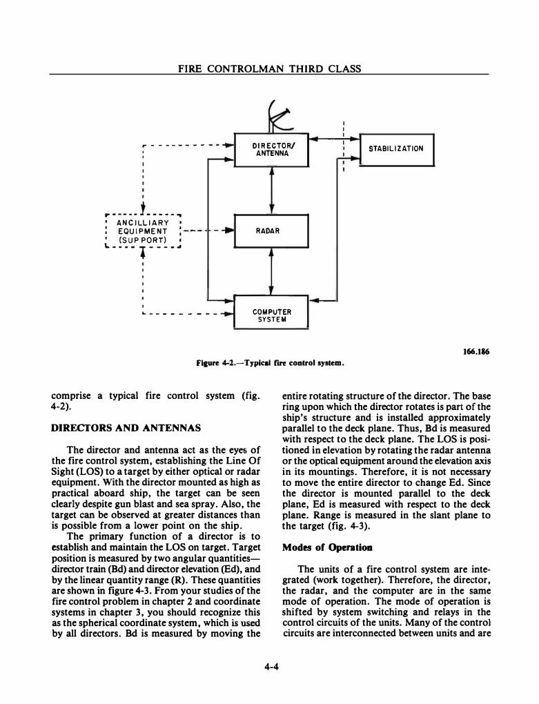
FIRE CONTROLMAN THIRD CLASS
�
� I I I --· DIRECTOR/ I I STABILIZATION
r - - - --- - -ANTENNA -+----
I
r·---- 1 ..... ..
-· RADAR I ANCILLIARY I ! EQUIPMEN T :
4 I (SUP PORT) I \. _ _ _ _ l _ __ _ ..
1 -�
I .... __ _ _ _ _ _ _ _ ...,. COMPUTER
SYSTEM
166.186
F'&ure 4-l.-Typical fire cootrol system.
comprise a typical fire control system (fig. 4-2).
DIRECI'ORS AND ANTENNAS
The director and antenna act as the eyes of the fire control system, establishing the Line Of Sight (LOS) to a target by either optical or radar equipment. With the director mounted as high as practical aboard ship. the target can be seen clearly despite gun blast and sea spray. Also, the target can be observed at greater distances than is possible from a lower point on the ship.
The primary function of a director is to establish and maintain the LOS on target. Target position is measured by two angular quantitiesdirector train (Bd) and director elevation (Ed), and by the linear quantity range (R). These quantities are shown in figure 4-3. From your studies of the fire control problem in chapter 2 and coordinate systems in chapter 3, you should recognize this as the spherical coordinate system, which is used by all directors. Bd is measured by moving the
4-4
entire rotating structure of the director. The base ring upon which the director rotates is part of the ship's structure and is installed approximately parallel to the deck plane. Thus, Bd is measured with respect to the deck plane. The LOS is positioned in elevation by rotating the radar antenna or the optical equipment around the elevation axis in its mountings. Therefore, it is not necessary to move the entire director to change Ed. Since the director is mounted parallel to the deck plane, Ed is measured with respect to the deck plane. Range is measured in the slant plane to the target (fig. 4-3).
Modes of Operation
The units of a fire control system are integrated (work together). The-refore, the director, the radar, and the computer are in the same mode of operation. The mode of operation is shifted by system switching and relays in the control circuits of the units. Many of the control circuits are interconnected between units and are
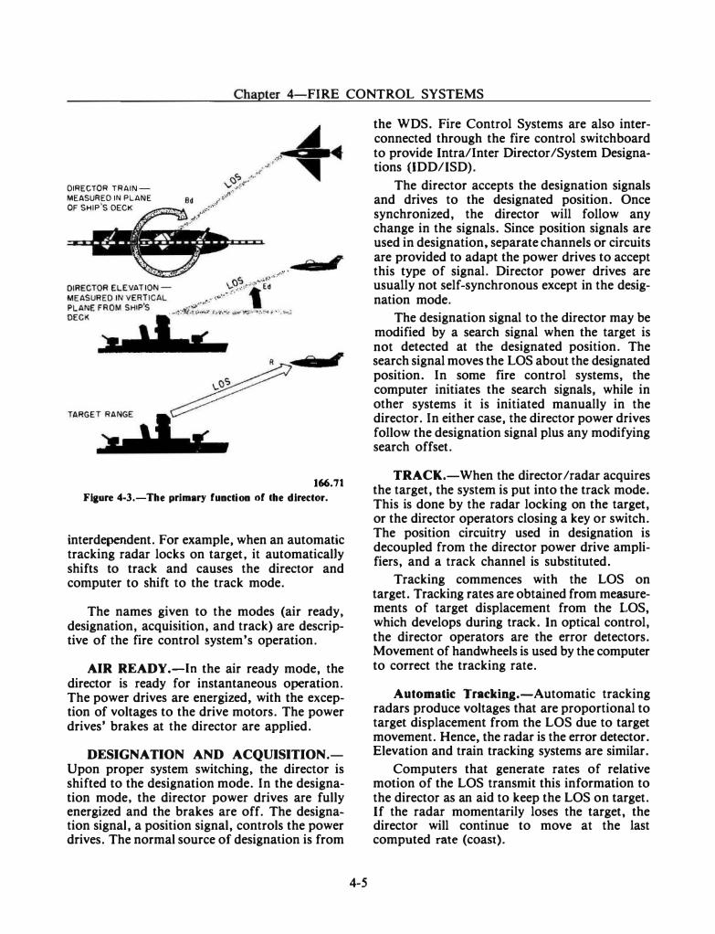
Chapter 4-FIRE CONTROL SYSTEMS
DIRECTOR TRAINMEASURED IN PLANE OF SHIP'S DECK
2 ,
'i ,
166.71
Fiaure 4-3.-The primary function of lhe director.
interdependent. For example, when an automatic tracking radar locks on target, it automaticalJy shifts to track and causes the director and computer to shift to the track mode.
The names given to the modes (air ready, designation, acquisition, and track) are descriptive of the fire control system's operation.
AIR READY.-In the air ready mode, the director is ready for instantaneous operation. The power drives are energized, with the exception of voltages to the drive motors. The power drives' brakes at the director are applied.
DESIGNATION AND ACQUISITION.Upon proper system switching, the director is shifted to the designation mode. In the designation mode, the director power drives are fully energized and the brakes are off. The designation signal, a position signal, controls the power drives. The normal source of designation is from
4-5
the WDS. Fire Control Systems are also interconnected through the fire control switchboard to provide Intra/Inter Director /System Designations (IDD/ISD).
The director accepts the designation signals and drives to the designated position. Once synchronized, the director will follow any change in the signals. Since position signals are used in designation, separate channels or circuits are provided to adapt the power drives to accept this type of signal. Director power drives are usually not self-synchronous except in the designation mode.
The designation signal to the director may be modified by a search signal when the target is not detected at the designated position. The search signal moves the LOS about the designated position. In some fire control systems, the computer initiates the search signals, while in other systems it is initiated manually in the director. In either case, the director power drives follow the designation signal plus any modifying search offset.
TRACK.-When the director /radar acquires the target, the system is put into the track mode. This is done by the radar locking on the target, or the director operators closing a key or switch. The position circuitry used in designation is decoupled from the director power drive amplifiers, and a track channel is substituted.
Tracking commences with the LOS on target. Tracking rates are obtained from measurements of target displacement from the LOS, which develops during track. In optical control, the director operators are the error detectors. Movement of hand wheels is used by the computer to correct the tracking rate.
Automatic Tracking.-Automatic tracking radars produce voltages that are proportional to target displacement from the LOS due to target movement. Hence, the radar is the error detector. Elevation and train tracking systems are similar.
Computers that generate rates of relative motion of the LOS transmit this information to the director as an aid to keep the LOS on target. If the radar momentarily loses the target, the director will continue to move at the last computed rate (coast).
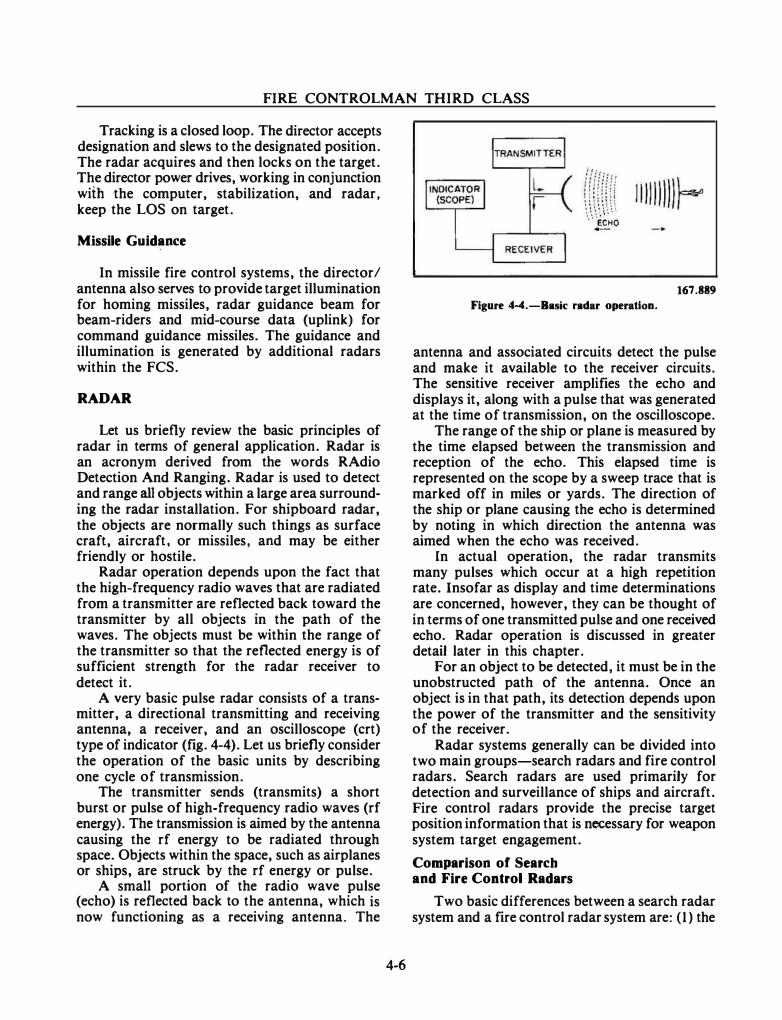
FIRE CONTROLMAN THIRD CLASS
Tracking is a closed loop. The director accepts designation and slews to the designated position. The radar acquires and then locks on the target. The director power drives, working in conjunction wiih the computer, stabilization, and radar, keep the LOS on target.
Missile Guidance
In missile fire control systems, the director/ antenna also serves to provide target illumination for homing missiles, radar guidance beam for beam-riders and mid-course data (uplink) for command guidance missiles. The guidance and illumination is generated by additional radars within the FCS.
RADAR
Let us briefly review the basic principles of radar in terms of general application. Radar is an acronym derived from the words RAdio Detection And Ranging. Radar is used to detect and range all objects within a large area surrounding the radar installation. For shipboard radar, the objects are normally such things as surface craft, aircraft, or missiles, and may be either friendly or hostile.
Radar operation depends upon the fact that the high-frequency radio waves that are radiated from a transmitter are reflected back toward the transmitter by all objects in the path of the waves. The objects must be within the range of the transmitter so that the reflected energy is of sufficient strength for the radar receiver to detect it.
A very basic pulse radar consists of a transmitter, a directional transmitting and receiving antenna, a receiver, and an oscilloscope (crt) type of indicator (fig. 4-4). Let us briefly consider the operation of the basic units by describing one cycle of transmission.
The transmitter sends (transmits) a short burst or pulse of high-frequency radio waves (rf energy). The transmission is aimed by the antenna causing the rf energy to be radiated through space. Objects within the space, such as airplanes or ships, are struck by the rf energy or pulse.
A small portion of the radio wave pulse (echo) is reflected back to the antenna, which is now functioning as a receiving antenna. The
4-6
167.889 Figure 4-4.-Bask radar operation.
antenna and associated circuits detect the pulse and make it available to the receiver circuits. The sensitive receiver amplifies the echo and displays it, along with a pulse that was generated at the time of transmission, on the oscilloscope.
The range of the ship or plane is measured by the time elapsed between the transmission and reception of the echo. This elapsed time is represented on the scope by a sweep trace that is marked off in miles or yards. The direction of the ship or plane causing the echo is determined by noting in which direction the antenna was aimed when the echo was received.
In actual operation, the radar transmits many pulses which occur at a high repetition rate. Insofar as display and time determinations are concerned, however, they can be thought of in terms of one transmitted pulse and one received echo. Radar operation is discussed in greater detail later in this chapter.
For an object to be detected, it must be in the unobstructed path of the antenna. Once an object is in that path, its detection depends upon the power of the transmitter and the sensitivity of the receiver.
Radar systems generally can be divided into two main groups-search radars and fire control radars. Search radars are used primarily for detection and surveillance of ships and aircraft. Fire control radars provide the precise target position information that is necessary for weapon system target engagement.
Comparison of Search and Fire Control Radars
Two basic differences between a search radar system and a fire control radar system are: (1) the
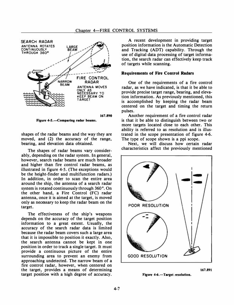
Chapter 4-FIRE CONTROL SYSTEMS
SEARCH RADAR ANTENNA ROTATES CONTINUOUSLY THROUGH 360°
' \
\ \ ' I
\ j_} �· ,,_..,.
------------
FIRE CONTROL RADAR
ANTENNA MOVES ONLY AS NECESSARY TO KEEP BEAM ON TARGET
167.890 Figure 4-5.-Comparing radar beams.
shapes of the radar beams and the way they are moved, and (2) the accuracy of the range, bearing, and elevation data obtained.
The shapes of radar beams vary considerably, depending on the radar system. In general, however, search radar beams are much broader and higher than fire control radar beams, as illustrated in figure 4-5. (The exceptions would be the height-finder and multifunction radars.) In addition, in order to scan the entire area around the ship, the antenna of a search radar system is rotated continuously through 360 °. On the other hand, a Fire Control (FC) radar antenna, once it is aimed at the target, is moved only as necessary to keep the radar beam on the target.
The effectiveness of the ship's weapons depends on the accuracy of the target position information to a great extent. Usually, the accuracy of the search radar data is limited because the radar beam covers such a large area that it is impossible to position it exactly. Also, the search antenna cannot be kept in one position in order to track a single target. It must provide a continuous picture of the entire surrounding area to prevent an enemy from approaching undetected. The narrow beam of a fire control radar, however, when centered on the target, provides a means of determining target position with a high degree of accuracy.
4-7
A recent development in providing target position information is the Automatic Detection and Tracking (ADT) capability. Through the use of digital data processing of target information, the search radar can effectively keep track of targets while scanning.
Requirements of Fire Control Radars
One of the requirements of a fire control radar, as we have indicated, is that it be able to provide precise target range,· bearing, and elevation information. As previously mentioned, this is accomplished by keeping the radar beam centered on the target and timing the return pulses.
Another requirement of a fire control radar is that it be able to distinguish between two or more targets located close to each other. This ability is referred to as resolution and is illustrated in the scope presentation of figure 4-6. The type of scope shown is a ppi scope.
Next, we will discuss how certain radar characteristics affect the previously mentioned
POOR RESOLUTION
GOOD RESOLUTION
167.891 Figure 4-6.-Targel resolution.
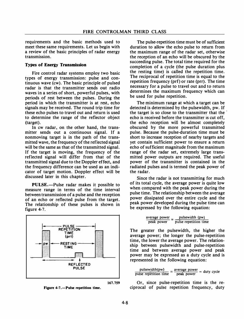
FIRE CONTROLMAN THIRD CLASS
requirements and the basic methods used to meet these same requirements. Let us begin with a review of the basic principles of radar energy transmission.
Types of Energy Transmission
Fire control radar systems employ two basic types of energy transmission: pulse and continuous wave (cw). The basic principle of pulsed radar is that the transmitter sends out radio waves in a series of short, powerful pulses, with periods of rest between the pulses. During the period in which the transmitter is at rest, echo signals may be received. The round trip time for these echo pulses to travel out and return is used to determine the range of the reflector object (target).
In cw radar, on the other hand, the transmitter sends out a continuous signal. If a nonmoving target is in the path of the transmitted wave, the frequency of the reflected signal will be the same as that of the transmitted signal. If the target is moving, the frequency of the reflected signal will differ from that of the transmitted signal due to the Doppler effect, and the frequency difference can be used as an indicator of target motion. Doppler effect will be discussed later in this chapter.
PULSE.-Pulse radar makes it possible to measure range in terms of the time interval between transmission of a pulse and the reception of an echo or reflected pulse from the target. The relationship of these pulses is shown in figure 4-7.
167.759 Fiaure 4-7.-Pulse repetition time.
4-8
The pulse-repetition time must be of sufficient duration to allow the echo pulse to return from the maximum range of the radar set, otherwise the reception of an echo will be obscured by the succeeding pulse. The total time required for the completion of a cycle (the pulse duration plus the resting time) is called the repetition time. The reciprocal of repetition time is equal to the repetition frequency (prf) or rate (prr). The time necessary for a pulse to travel out and to return determines the maximum frequency which can be used for pulse repetition.
The minimum range at which a target can be detected is determined by the pulsewidth, pw. If the target is so close to the transmitter that the ·
echo is received before the transmitter is cut off, the echo reception will be almost completely obscured by the more powerful transmitted pulse. Because the pulse-duration time must be short to increase reception of nearby targets and yet contain sufficient power to ensure a return echo of sufficient magnitude from the maximum range of the radar set, extremely large transmitted power outputs are required. The useful power of the transmitter is contained in the radiated pulses and is termed the peak power of the radar.
Since the radar is not transmitting for much of its total cycle, the average power is quite low when compared with the peak power during the pulse time. The relationship between the average power dissipated over the entire cycle and the peak power developed during the pulse time can be expressed by the following equation:
average power _ pulsewidth (pw)
peak power -
pulse repetition time
The greater the pulsewidth, the higher the average power; the longer the pulse-repetition time, the lower the average power. The relationship between pulsewidth and pulse-repetition time and between average power and peak power may be expressed as a duty cycle and is represented in the following equation:
pulsewidth(pw) _ average power _ d t 1 I . . . -
k - u y eye e
pu se repetition t1me pea power
Or, since pulse-repetition time is the reciprocal of puis� repetition frequency, duty
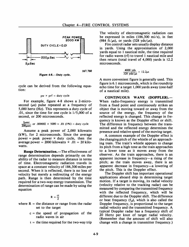
Chapter 4-FIRE CONTROL SYSTEMS
DUTY CYCLE: 0.01
167.760
Figure 4-8.-Duty cycle.
cycle can be derived from the following equation:
pw x prf = duty cycle For example, figure 4-8 shows a 2-micro
second (}.ts) pulse repeated at a frequency of 5,000 hertz (Hz). This represents a duty.cycle of .01, since the time for one cycle is 1/5,000 of a second, or 200 microseconds.
.,;:.,�c or .000002 x 5000 = .01 (I OJo) = duty cycle """',.sec Assume a peak power of 2,000 kilowatts
(kW), for 2 microseconds. Since the average power = peak power x duty cycle, then the average power= 2000 kilowatts x .01 = 20 kilowatts.
Range Determination.-The effectiveness of range determination depends primarily on the ability of the radar to measure distance in terms of time. Electromagnetic radiation travels in space at a constant velocity of 186,300 miles per second. When it is reflected, there is no loss of velocity but merely a redirecting of the energy path. Range is then determined by the time required for a two-way energy transmission. The determination of range can be made by using the equation
R = ct 2
where R = the distance or range from the radar set to the target
c = the speed of propagation of the radio waves in air
t = the time required for the two-way trip
4-9
The velocity of electromagnetic radiation can be expressed in miles (186,300 mils), in feet (984 ftltJS), or yards (328 yds/�-ts).
Fire control radar sets usually display distance in yards. Using the approximation of 2,000 yards equal to 1 nautical mile, the time required for radio waves (rf) to travel 1 nautical mile and then return (total travel of 4,000) yards is 12.2 microseconds.
4000 yds 328 yds/!-'5 = 12·21JS
A more convenient figure is generally used. This figure is 6.1 microseconds, which is the roundtrip echo time for a target 1,000 yards away (one-half of a nautical mile).
CONTINUOUS WAVE (DOPPLER).When radio-frequency energy is transmitted from a fixed point and continuously strikes an object that is moving toward or away from the source of the energy, the frequency of the reflected energy is changed. This change in frequency is known as the Doppler effect or shift . The difference in frequency between the transmitted and the reflected energy determines the presence and relative speed of the moving target.
A common example of the Doppler effect is the changing pitch of the whistle of an approaching train. The train's whistle appears to change its pitch from a high tone as the train approaches to a lower tone as it moves away from the observer. As the train approaches, there is an apparent increase in frequency-a rising of the pitch; as the train moves away, there is an apparent decrease in frequency-a lowering of the pitch. This is the Doppler effect.
The Doppler shift has important operational applications aboard ship in determining target motion. If a target is moving, its radial velocity (velocity relative to the tracking radar) can be measured by comparing the transmitted frequency with the reflected frequency, which will be different due to the Doppler shift. The difference or beat frequency (fd), which is also called the Doppler frequency, is proportional to the target radial velocity and the transmitted frequency. A typical Doppler radar has a frequency shift of 20 Hertz per knot of target radial velocity. (Remember that the amount of shift will also change with a change in transmitter frequency.)
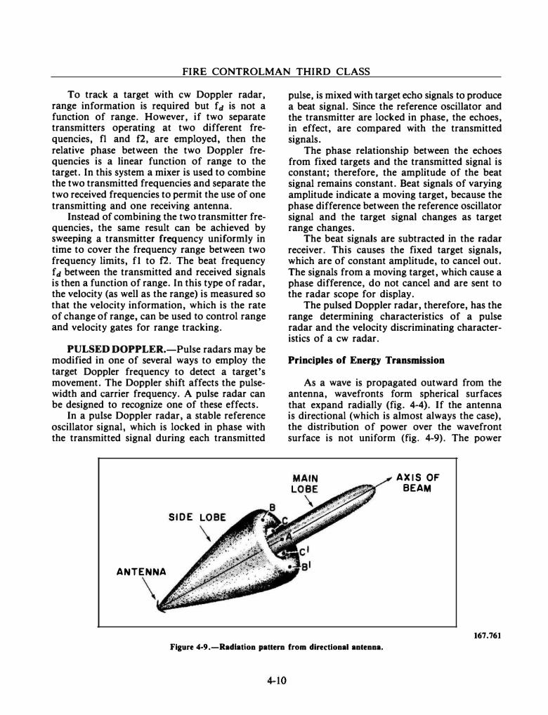
FIRE CONTROLMAN THIRD CLASS
To track a target with cw Doppler radar, range information is required but fd is not a function of range. However, if two separate transmitters operating at two different frequencies, f1 and f2, are employed, then the relative phase between the two Doppler frequencies is a linear function of range to the target. In this system a mixer is used to combine the two transmitted frequencies and separate the two received frequencies to permit the use of one transmitting and one receiving antenna.
Instead of combining the two transmitter frequencies, the same result can be achieved by sweeping a transmitter frequency uniformly in time to cover the frequency range between two frequency limits, f1 to f2. The beat frequency fd between the transmitted and received signals is then a function of range. In this type of radar, the velocity (as well as the range) is measured so that the velocity information, which is the rate of change of range, can be used to control range and velocity gates for range tracking.
PULSED DOPPLER.-Pulse radars may be modified in one of several ways to employ the target Doppler frequency to detect a target's movement. The Doppler shift affects the pulsewidth and carrier frequency. A pulse radar can be designed to recognize one of these effects.
In a pulse Doppler radar, a stable reference oscillator signal, which is locked in phase with the transmitted signal during each transmitted
SIDE
ANTENNA
\
pulse, is mixed with target echo signals to produce a beat signal. Since the reference oscillator and the transmitter are locked in phase, the echoes, in effect, are compared with the transmitted signals.
The phase relationship between the echoes from fixed targets and the transmitted signal is constant; therefore, the amplitude of the beat signal remains constant. Beat signals of varying amplitude indicate a moving target, because the phase difference between the reference oscillator signal and the target signal changes as target range changes.
The beat signals are subtracted in the radar receiver. This causes the fixed target signals, which are of constant amplitude, to cancel out. The signals from a moving target, which cause a phase difference, do not cancel and are sent to the radar scope for display.
The pulsed Doppler radar, therefore, has the range determining characteristics of a pulse radar and the velocity discriminating characteristics of a cw radar.
Principles of Energy Transmission
As a wave is propagated outward from the antenna, wavefronts form spherical surfaces that expand radially (fig. 4-4). If the antenna is directional (which is almost always the case), the distribution of power over the wavefront surface is not uniform (fig. 4-9). The power
AXIS OF BEAM
167.761 Figure 4-9.-Radlatlon pattern from directional antenna.
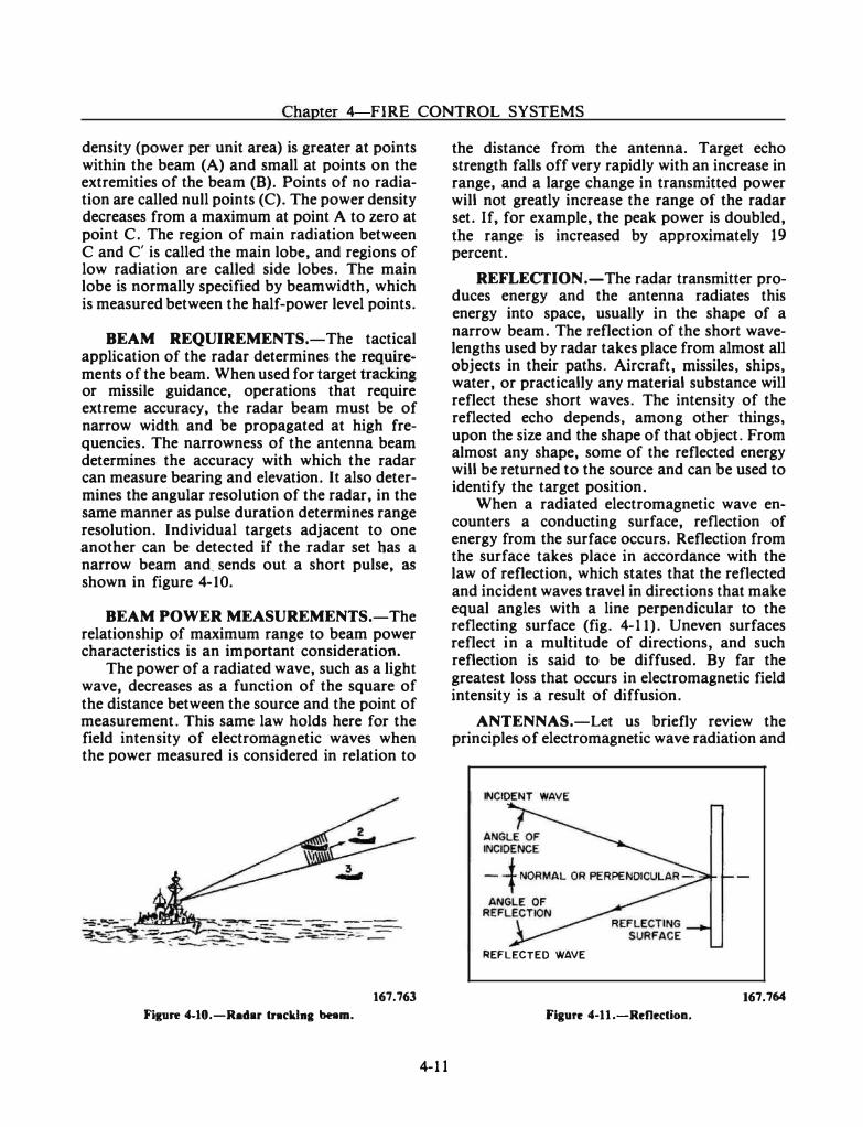
Chapter 4 FIRE CONTROL SYSTEMS
density (power per unit area) is greater at points within the beam (A) and small at points on the extremities of the beam (B). Points of no radiation are called null points (C). The power density decreases from a maximum at point A to zero at point C. The region of main radiation between C and C' is called the main lobe, and regions of low radiation are called side lobes. The main lobe is normally specified by beamwidth, which is measured between the half-power level points.
BEAM REQUIREMENTS.-The tactical application of the radar determines the requi!ements of the beam. When used for target trackmg or missile guidance, operations that require extreme accuracy, the radar beam must be of narrow width and be propagated at high frequencies. The narrowness of the antenna beam determines the accuracy with which the radar can measure bearing and elevation. It also determines the angular resolution of the radar, in the same manner as pulse duration determines range resolution. Individual targets adjacent to one another can be detected if the radar set bas a narrow beam and_ sends out a short pulse, as shown in figure 4-10.
BEAM POWER MEASUREMENTS.-The relationship of maximum range to beam power characteristics is an important consideration.
The power of a radiated wave, such as a light wave decreases as a function of the square of the distance between the source and the point of measurement. This same law holds here for the field intensity of electromagnetic waves when the power measured is considered in relation to
167.763 Fexure 4-10.-Radar tnck.l•a beam.
4-11
the distance from the antenna. Target echo strength falls off very rapidly with an increase in range, and a large change in transmitted power will not greatly increase the range of the radar set. If, for example, the peak power is doubled, the range is increased by approximately 19 percent.
REFLECTION.-The radar transmitter produces energy and the antenna radiates this energy into space, usually in the shape of a narrow beam. The reflection of the short wavelengths used by radar takes place from almost all objects in their paths. Aircraf�, missiles, ship�, water, or practically any matenal substance wdl reflect these short waves. The intensity of the reflected echo depends, among other things, upon the size and the shape of that object. From almost any shape, some of the reflected energy will be returned to the source and can be used to identify the target position.
When a radiated electromagnetic wave encounters a conducting surface, reflection of energy from the surface occurs. Reflection from the surface takes place in accordance with the law of reflection, which states that the reflected and incident waves travel in directions that make equal angles with a line perpendicular to the reflecting surface (fig. 4-11). Uneven surfaces reflect in a multitude of directions, and such reflection is said to be diffused. By far the greatest loss that occurs in electromagnetic field intensity is a result of diffusion.
ANTENNAS.-Let us briefly review the principles of electromagnetic wave radiation and
REFLECTED WAVE
167.764 Figure 4-11.-Renection.
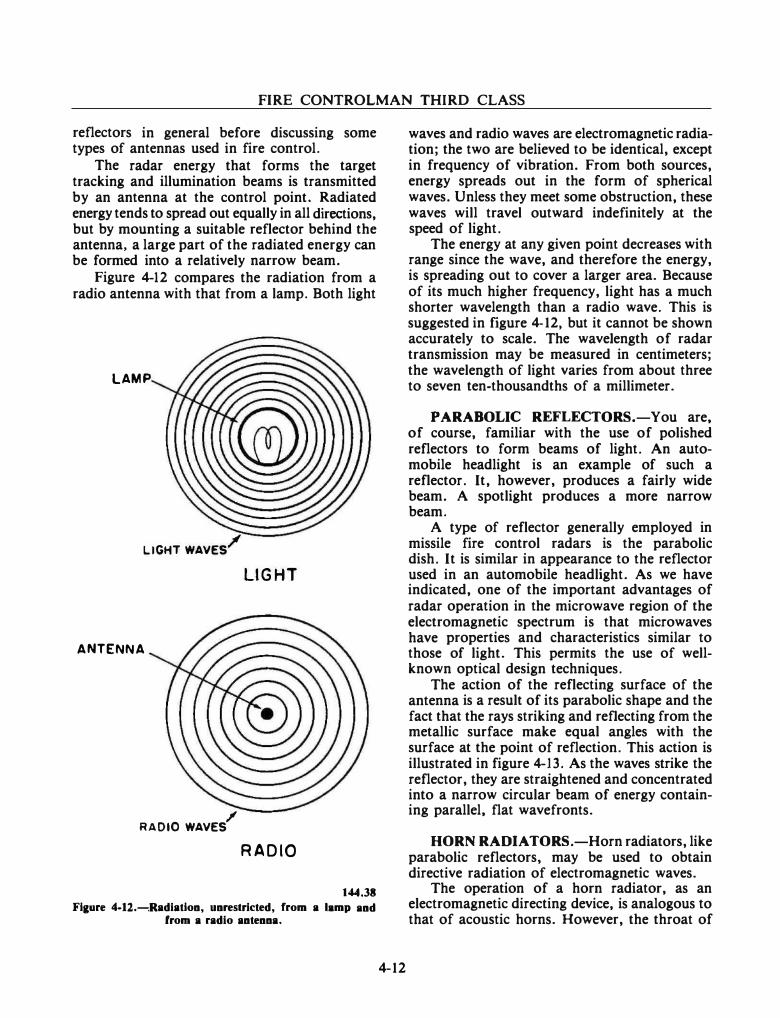
FIRE CONTROLMAN THIRD CLASS
reflectors in general before discussing some types of antennas used in fire control.
The radar energy that forms the target tracking and illumination beams is transmitted by an antenna at the control point. Radiated energy tends to spread out equally in all directions, but by mounting a suitable reflector behind the antenna, a large part of the radiated energy can be formed into a relatively narrow beam.
Figure 4-12 compares the radiation from a radio antenna with that from a lamp. Both light
LAMP
LIGHT WAVES/ LIGHT
ANTENNA
RADIO WAVES/ RADIO
144.38 Flaure 4-12.---,Radiatlon, unrestricted, from a lamp and
from a radio antenna.
4-12
waves and radio waves are electromagnetic radiation; the two are believed to be identical, except in frequency of vibration. From both sources, energy spreads out in the form of spherical waves. Unless they meet some obstruction, these waves will travel outward indefinitely at the speed of light.
The energy at any given point decreases with range since the wave, and therefore the energy, is spreading out to cover a larger area. Because of its much higher frequency, light has a much shorter wavelength than a radio wave. This is suggested in figure 4-12, but it cannot be shown accurately to scale. The wavelength of radar transmission may be measured in centimeters; the wavelength of light varies from about three to seven ten-thousandths of a millimeter.
PARABOLIC REFLECTORS.-You are, of course, familiar with the use of polished reflectors to form beams of light. An automobile headlight is an example of such a reflector. It, however, produces a fairly wide beam. A spotlight produces a more narrow beam.
A type of reflector generally employed in missile fire control radars is the parabolic dish. It is similar in appearance to the reflector used in an automobile headlight. As we have indicated, one of the important advantages of radar operation in the microwave region of the electromagnetic spectrum is that microwaves have properties and characteristics similar to those of light. This permits the use of wellknown optical design techniques.
The action of the reflecting surface of the antenna is a result of its parabolic shape and the fact that the rays striking and reflecting from the metallic surface make equal angles with the surface at the point of reflection. This action is illustrated in figure 4-13. As the waves strike the reflector, they are straightened and concentrated into a narrow circular beam of energy containing parallel, flat wavefronts.
HORN RADIA TORS.-Horn radiators, like parabolic reflectors, may be used to obtain directive radiation of electromagnetic waves.
The operation of a horn radiator, as an electromagnetic directing device, is analogous to that of acoustic horns. However, the throat of
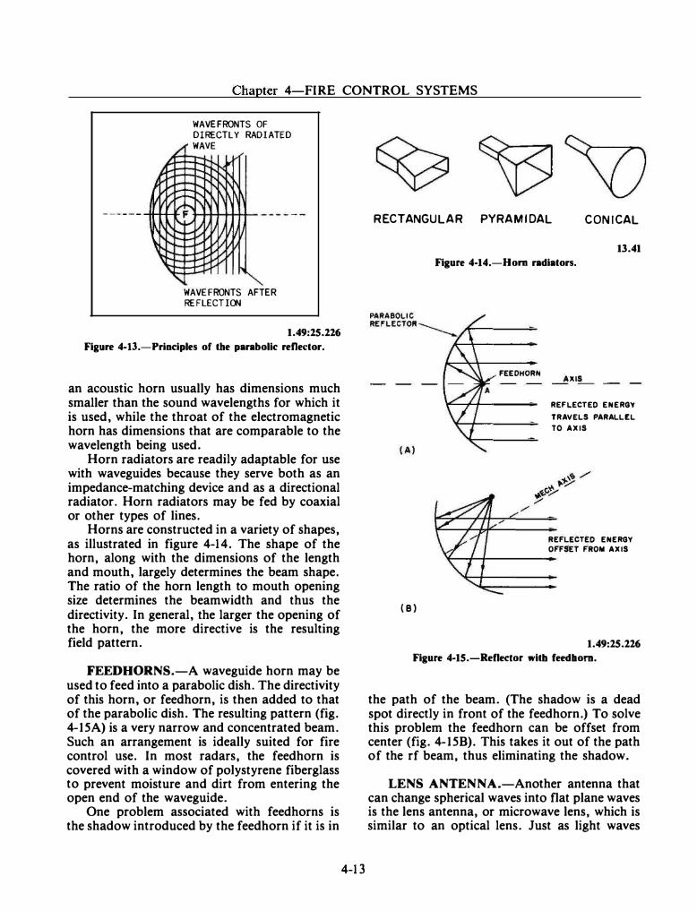
--- .,.. ---------------------- ----- -- --------
Chapter 4-FIRE CONTROL SYSTEMS
WAVEFRONTS OF DIRECTLY RADIATED
;' WAVE
� --- �r-. ... �::r-. \I\ "�-� \[\ 1�:--, F ,,,....I jll
':::::::: ...... --� � -- ...... '
WAVEFRONTS AFTER REFLECTIOO
1.49:15.116 Figure 4-13.-Principles of the parabolic refle�:tor.
an acoustic horn usually has dimensions much smaller than the sound wavelengths for which it is used, while the throat of the electromagnetic horn has dimensions that are comparable to the wavelength being used.
Horn radiators are readily adaptable for use with waveguides because they serve both as an impedance-matching device and as a directional radiator. Horn radiators may be fed by coaxial or other types of lines.
Horns are constructed in a variety of shapes, as illustrated in figure 4-14. The shape of the horn, along with the dimensions of the length and mouth, largely determines the beam shape. The ratio of the horn length to mouth opening size determines the beamwidth and thus the directivity. In general, the larger the opening of the horn, the more directive is the resulting field pattern.
FEEDHORNS.-A waveguide horn may be used to feed into a parabolic dish. The directivity of this horn, or feedhorn, is then added to that of the parabolic dish. The resulting pattern (fig. 4-15A) is a very narrow and concentrated beam. Such an arrangement is ideally suited for fire control use. In most radars, the feedhorn is covered with a window of polystyrene fiberglass to prevent moisture and dirt from entering the open end of the waveguide.
One problem associated with feedhorns is the shadow introduced by the feedhorn if it is in
4-13
RECTANGULAR PYRAMIDAL CONICAL
(B)
13.41 Figure 4-14.-Hom radiators.
FEEOHORN AXIS
REF�ECTEO ENERGY TRAVE�S PARA��E� TO AXIS
REF�ECTEO ENERGY OFFSET FROM AXIS
1.49:15.116 Figure 4-15.-Reflector with feedbom.
the path of the beam. (The shadow is a dead spot directly in front of the feedhorn.) To solve this problem the feedhorn can be offset from center (fig. 4-15B). This takes it out of the path of the rf beam, thus eliminating the shadow.
LENS ANTENNA.-Another antenna that can change spherical waves into flat plane waves is the lens antenna, or microwave lens, which is similar to an optical lens. Just as light waves
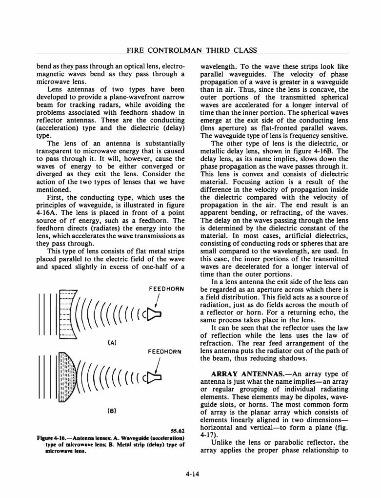
FIRE CONTROLMAN THIRD CLASS
bend as they pass through an optical lens, electromagnetic waves bend as they pass through a microwave lens.
Lens antennas of two types have been developed to provide a plane-wavefront narrow beam for tracking radars, while avoiding the problems associated with feedhorn shadow in reflector antennas. These are the conducting (acceleration) type and the dielectric (delay) type.
The lens of an antenna is substantially transparent to microwave energy that is caused to pass through it. It will, however, cause the waves of energy to be either converged or diverged as they exit the lens. Consider the action of the two types of lenses that we have mentioned.
First, the conducting type, which uses the principles of waveguide, is illustrated in figure 4-16A. The lens is placed in front of a point source of rf energy, such as a feedhorn. The feedhorn directs (radiates) the energy into the lens, which accelerates the wave transmissions as they pass through.
This type of lens consists of flat metal strips placed parallel to the electric field of the wave and spaced slightly in excess of one-half of a
FEED HORN ----�
�r (((((((((((c� (A)
FEEOHORN
((((((((((cJ (B)
55.62 Figure 4-16.-Aatenna lenses: A. Wavqulde (ac:c:eleratloa)
type of mlcrowne lens: B. Metal strip (delay) type of microwave lens.
4-14
wavelength. To the wave these strips look like parallel waveguides. The velocity of phase propagation of a wave is greater in a waveguide than in air. Thus, since the lens is concave, the outer portions of the transmitted spherical waves are accelerated for a longer interval of time than the inner portion. The spherical waves emerge at the exit side of the conducting lens (lens aperture) as flat-fronted parallel waves. The waveguide type of lens is frequency sensitive.
The other type of lens is the dielectric, or metallic delay lens, shown in figure 4-16B. The delay lens, as its name implies, slows down the phase propagation as the wave passes through it. This lens is convex and consists of dielectric material. Focusing action is a result of the difference in the velocity of propagation inside the dielectric compared with the velocity of propagation in the air. The end result is an apparent bending, or refracting, of the waves. The delay on the waves passing through the lens is determined by the dielectric constant of the material. In most cases, artificial dielectrics, consisting of conducting rods or spheres that are small compared to the wavelength, are used. In this case, the inner portions of the transmitted waves are decelerated for a longer interval of time than the outer portions.
In a lens antenna the exit side of the lens can be regarded as an aperture across which there is a field distribution. This field acts as a source of radiation, just as do fields across the mouth of a reflector or horn. For a returning echo, the same process takes place in the lens.
It can be seen that the reflector uses the law of reflection while the lens uses the law of refraction. The rear feed arrangement of the lens antenna puts the radiator out of the path of the beam, thus reducing shadows.
ARRAY ANTENNAS.-An array type of antenna is just what the name implies-an array or regular grouping of individual radiating elements. These elements may be dipoles, waveguide slots, or horns. The most common form of array is the planar array which consists of elements linearly aligned in two dimensionshorizontal and vertical-to form a plane (fig. 4-17).
Unlike the lens or parabolic reflector, the array applies the proper phase relationship to
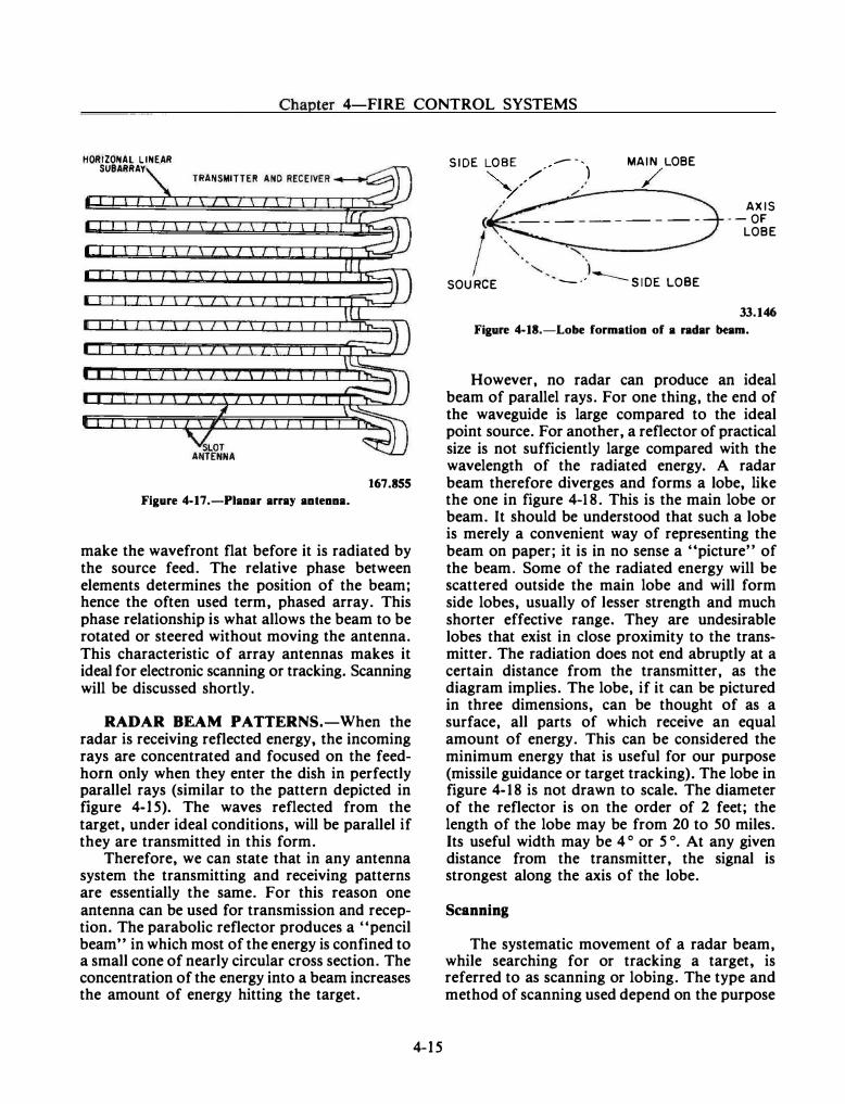
Chapter 4-FIRE CONTROL SYSTEMS
HORIZONAL LINEAR SUBARRAY
Figure 4-17.-Pianar array antenna.
167.855
make the wavefront flat before it is radiated by the source feed. The relative phase between elements determines the position of the beam; hence the often used term, phased array. This phase relationship is what allows the beam to be rotated or steered without moving the antenna. This characteristic of array antennas makes it ideal for electronic scanning or tracking. Scanning will be discussed shortly.
RADAR BEAM PATTERNS.-When the radar is receiving reflected energy, the incoming rays are concentrated and focused on the feedhom only when they enter the dish in perfectly parallel rays (similar to the pattern depicted in figure 4-15). The waves reflected from the target, under ideal conditions, will be parallel if they are transmitted in this form.
Therefore, we can state that in any antenna system the transmitting and receiving patterns are essentially the same. For this reason one antenna can be used for transmission and reception. The parabolic reflector produces a ''pencil beam" in which most of the energy is confined to a small cone of nearly circular cross section. The concentration of the energy into a beam increases the amount of energy hitting the target.
4-15
SIDE LOBE • - -, MAIN LOBE
'-.. ,/' ) /
SOURCE
� ----��--
....... ) --·
.......__SIDE LOBE
AXIS --OF
LOBE
33.146
Figure 4-18.-Lobe formation of a radar beam.
However, no radar can produce an ideal beam of parallel rays. For one thing, the end of the waveguide is large compared to the ideal point source. For another, a reflector of practical size is not sufficiently large compared with the wavelength of the radiated energy. A radar beam therefore diverges and forms a lobe, like the one in figure 4-18. This is the main lobe or beam. It should be understood that such a lobe is merely a convenient way of representing the beam on paper; it is in no sense a "picture" of the beam. Some of the radiated energy will be scattered outside the main lobe and will form side lobes, usually of lesser strength and much shorter effective range. They are undesirable lobes that exist in close proximity to the transmitter. The radiation does not end abruptly at a certain distance from the transmitter, as the diagram implies. The lobe, if it can be pictured in three dimensions, can be thought of as a surface, all parts of which receive an equal amount of energy. This can be considered the minimum energy that is useful for our purpose (missile guidance or target tracking). The lobe in figure 4-18 is not drawn to scale. The diameter of the reflector is on the order of 2 feet; the length of the lobe may be from 20 to 50 miles. Its useful width may be 4 o or 5°. At any given distance from the transmitter, the signal is strongest along the axis of the lobe.
Scanning
The systematic movement of a radar beam, while searching for or tracking a target, is referred to as scanning or lobing. The type and method of scanning used depend on the purpose
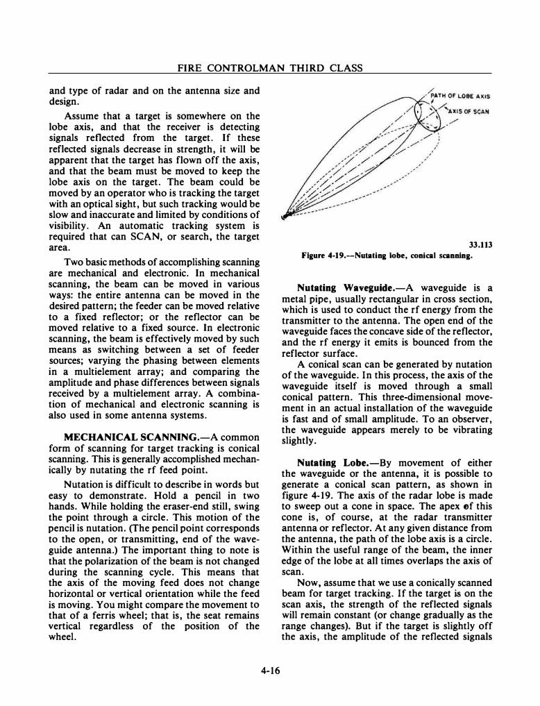
FIRE CONTROLMAN THIRD CLASS
and type of radar and on the antenna size and design.
Assume that a target is somewhere on the lobe axis, and that the receiver is detecting signals reflected from the target. If these reflected signals decrease in strength, it will be apparent that the target has flown off the axis, and that the beam must be moved to keep the lobe axis on the target. The beam could be moved by an operator who is tracking the target with an optical sight, but such tracking would be slow and inaccurate and limited by conditions of visibility. An automatic tracking system is required that can SCAN, or search, the target area.
Two basic methods of accomplishing scanning are mechanical and electronic. In mechanical scanning, the beam can be moved in various ways: the entire antenna can be moved in the desired pattern; the feeder can be moved relative to a fixed reflector; or the reflector can be moved relative to a fixed source. In electronic scanning, the beam is effectively moved by such means as switching between a set of feeder sources; varying the phasing between elements in a multielement array; and comparing the amplitude and phase differences between signals received by a multielement array. A combination of mechanical and electronic scanning is also used in some antenna systems.
MECHANICAL SCANNING.-A common form of scanning for target tracking is conical scanning. This is generally accomplished mechanically by nutating the rf feed point.
Nutation is difficult to describe in words but easy to demonstrate. Hold a pencil in two hands. While holding the eraser-end still, swing the point through a circle. This motion of the pencil is nutation. (The pencil point corresponds to the open, or transmitting, end of the waveguide antenna.) The important thing to note is that the polarization of the beam is not changed during the scanning cycle. This means that the axis of the moving feed does not change horizontal or vertical orientation while the feed is moving. You might compare the movement to that of a ferris wheel; that is, the seat remains vertical regardless of the position of the wheel.
4-16
33.113
Figure 4-19.-Nutating lobe, conical scanning.
Notating Waveguide.-A waveguide is a metal pipe, usually rectangular in cross section, which is used to conduct the rf energy from the transmitter to the antenna. The open end of the waveguide faces the concave side of the reflector, and the rf energy it emits is bounced from the reflector surface.
A conical scan can be generated by nutation of the waveguide. In this process, the axis of the waveguide itself is moved through a small conical pattern. This three-dimensional movement in an actual installation of the waveguide is fast and of small amplitude. To an observer, the waveguide appears merely to be vibrating slightly.
Notating Lobe.-By movement of either the waveguide or the antenna, it is possible to generate a conical scan pattern, as shown in figure 4-19. The axis of the radar lobe is made to sweep out a cone in space. The apex t�f this cone is, of course, at the radar transmitter antenna or reflector. At any given distance from the antenna, the path of the lobe axis is a circle. Within the useful range of the beam, the inner edge of the lobe at all times overlaps the axis of scan.
Now, assume that we use a conically scanned beam for target tracking. If the target is on the scan axis, the strength of the reflected signals will remain constant (or change gradually as the range changes). But if the target is slightly off the axis, the amplitude of the reflected signals
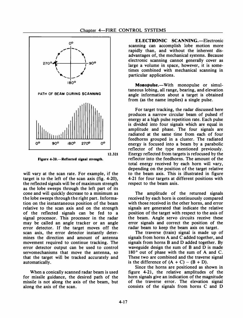
Chapter 4-FIRE CONTROL SYSTEMS
/,.. -- .... ...... , � .
I \ 270°'�---+----�;-90°
\ I \ ,/
... ...... _ - / 1 80° PATH OF BEAM DURING SCANNING
1800 27rfl
Figure 4-20.-Reflected signal strength.
12.321
will vary at the scan rate. For example, if the target is to the left of the scan axis (fig. 4-20), the reflected signals will be of maximum strength as the lobe sweeps through the left part of its cone and will quickly decrease to a minimum as the lobe sweeps through the right part. Information on the instantaneous position of the beam relative to the scan axis and on the strength of the reflected signals can be fed to a signal processor. This processor in the radar may be called an angle tracker or an angle error detector. If the target moves off the scan axis, the error detector instantly determines the direction and amount of antenna movement required to continue tracking. The error detector output can be used to control servomechanisms that move the antenna, so that the target will be tracked accurately and automatically.
When a conically scanned radar beam is used for missile guidance, the desired path of the missile is not along the axis of the beam, but along the axis of the scan.
4-17
ELECTRONIC SCANNING.-Electronic scanning can accomplish lobe motion more rapidly than, and without the inherent disadvantages of, the mechanical systems. Because electronic scanning cannot generally cover as large a volume in space, however, it is sometimes combined with mechanical scanning in particular applications .
Monopulse.-With monopulse or simultaneous lobing, all range, bearing, and elevation angle information about a target is obtained from (as the name implies) a single pulse.
For target tracking, the radar discussed here produces a narrow circular beam of pulsed rf energy at a high pulse repetition rate. Each pulse is divided into four signals which are equal in amplitude and phase. The four signals are radiated at the same time from each of four feedhorns grouped in a cluster. The radiated energy is focused into a beam by a parabolic reflector of the type mentioned previously. Energy reflected from targets is refocused by the reflector into the feedhorns. The amount of the total energy received by each horn will vary, depending on the position of the target relative to the beam axis. This is illustrated in figure 4-21 for four targets at different positions with respect to the beam axis.
The amplitude of the returned signals received by each horn is continuously compared with those received in the other horns, and error signals are generated that indicate the relative position of the target with respect to the axis of the beam. Angle servo circuits receive these error signals and correct the position of the radar beam to keep the beam axis on target.
The traverse (train) signal is made up of signals from horns A and C added together, and signals from horns B and D added together. By waveguide design the sum of B and D is made 180 o out of phase with the sum of A and C. These two are combined and the traverse signal is the difference of (A + C) - (B + D).
Since the horns are positioned as shown in figure 4-21, the relative amplitudes of the horn signals give an indication of the magnitude of the traverse error. The elevation signal consists of the signals from horns C and D
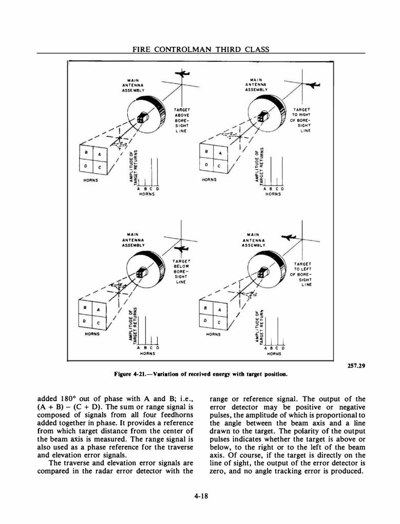
FIRE CONTROLMAN THIRD CLASS
M A I N
ANTENNA
ASSEII118LY
M A I N
ANTENNA
ASSEMBLY
HORNS
TARGET
ABOVE
BORE
S I GHT
l i NE
TARGET
BELOW
BORE
SIGHT
LINE
lolA I N A I H E N ... A
ASSEI.IBLY
M A I N
A N T E ... N A
A S S EMBLY
URGET
TO RIGH'T
OF BORE·
SIGHT
L I N E
TARGET
TO LEFT
OF BORE-
/ SIGHT
./ / I L I NE
/ / - -;:-�
rnl;;- "' I � � ��u HORNS � � .. �
A 8 C 0 HORNS
257.29
Figure 4-21.-Variation of received energy with target position.
added 180° out of phase with A and B; i.e., (A + B) - (C + D). The sum or range signal is composed of signals from all four feedhorns added together in phase. It provides a reference from which target distance from the center of the beam ws is measured. The range signal is also used as a phase reference for the traverse and elevation error signals.
The traverse and elevation error signals are compared in the radar error detector with the
4-18
range or reference signal. The output of the error detector may be positive or negative pulses, the amplitude of which is proportional to the angle between the beam axis and a line drawn to the target. The polarity of the output pulses indicates whether the target is above or below, to the right or to the left of the beam axis. Of course, if the target is directly on the line of sight, the output of the error detector is zero, and no angle tracking error is produced.
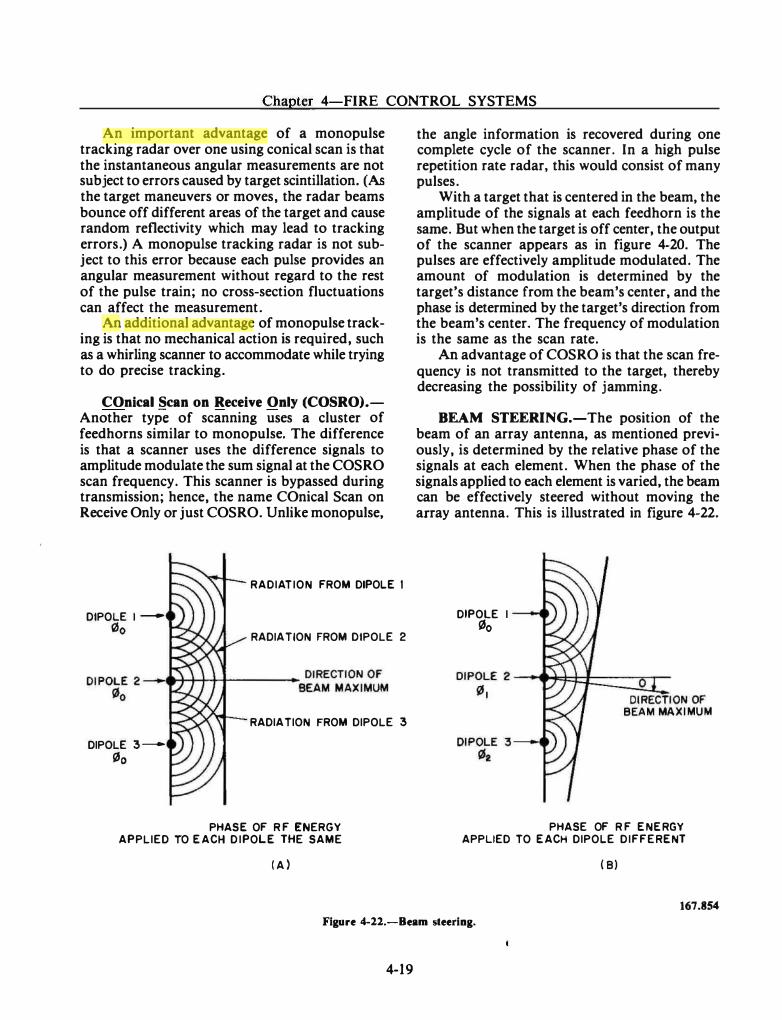
Chapter 4-FIRE CONTROL SYSTEMS
An important advantage of a monopulse tracking radar over one using conical scan is that the instantaneous angular measurements are not subject to errors caused by target scintillation. (As the target maneuvers or moves, the radar beams bounce off different areas of the target and cause random reflectivity which may lead to tracking errors.) A monopulse tracking radar is not subject to this error because each pulse provides an angular measurement without regard to the rest of the pulse train; no cross-section fluctuations can affect the measurement.
An additional advantage of monopulse tracking is that no mechanical action is required, such as a whirling scanner to accommodate while trying to do precise tracking.
COnical Scan on Receive Only (COSRO).Another type of scanning uses a cluster of feedhorns similar to monopulse. The difference is that a scanner uses the difference signals to amplitude modulate the sum signal at the COSRO scan frequency. This scanner is bypassed during transmission; hence, the name COnical Scan on Receive Only or just COSRO. Unlike monopulse,
DIPOLE l -0o
DIPOLE 3 -0o
RADIATION FROM DIPOLE I
RADIATION FROM DIPOLE 2
RADIATION FROM DIPOLE 3
PHASE OF R F ENERGY APPLIED TO EACH D IPOLE THE SAME
( A )
the angle information is recovered during one complete cycle of the scanner. In a high pulse repetition rate radar, this would consist of many pulses.
With a target that is centered in the beam, the amplitude of the signals at each feedhorn is the same. But when the target is off center, the output of the scanner appears as in figure 4-20. The pulses are effectively amplitude modulated. The amount of modulation is determined by the target's distance from the beam's center, and the phase is determined by the target's direction from the beam's center. The frequency of modulation is the same as the scan rate.
An advantage of COSRO is that the scan frequency is not transmitted to the target, thereby decreasing the possibility of jamming.
BEAM STEERING.-The position of the beam of an array antenna, as mentioned previously, is determined by the relative phase of the signals at each element. When the phase of the signals applied to each element is varied, the beam can be effectively steered without moving the array antenna. This is illustrated in figure 4-22.
DIPOLE I
0o
PHASE OF R F ENERGY APPLIED TO EACH DIPOLE DIFFERENT
( B)
167.854 Figure 4-22.-Beam steering.
4-19
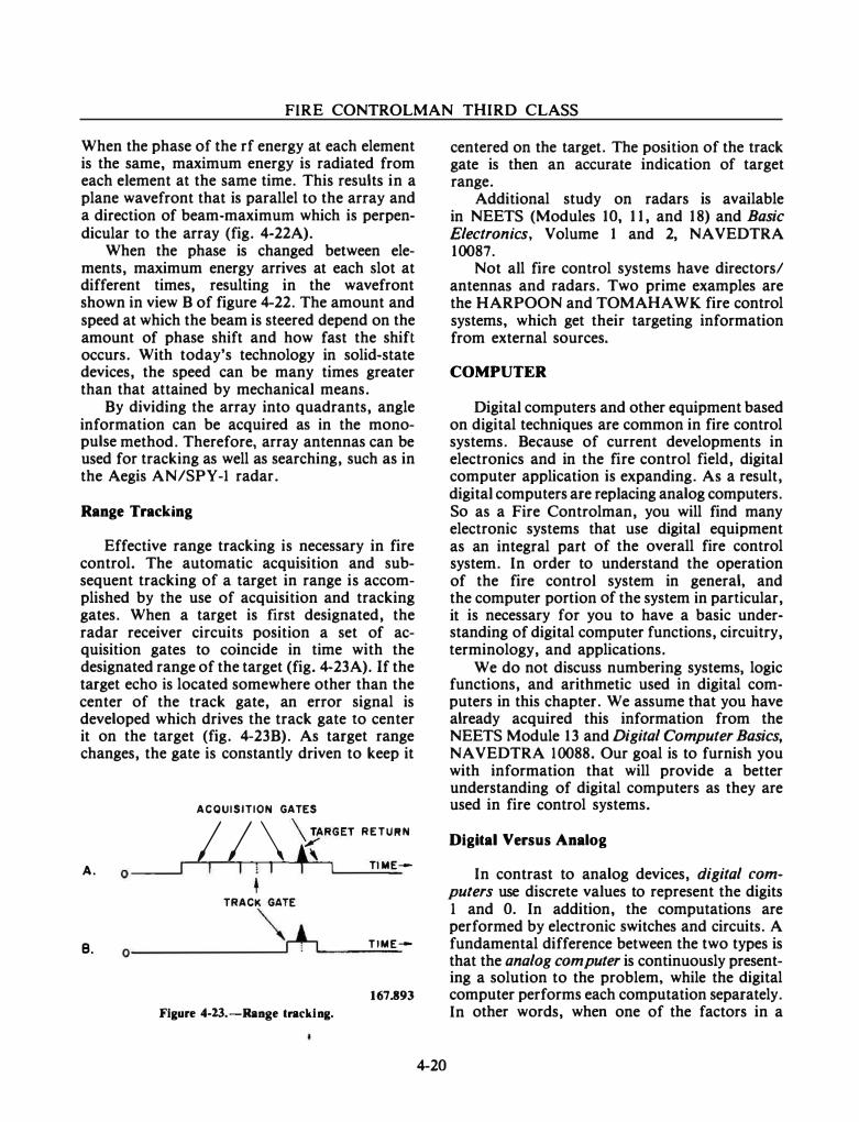
FIRE CONTROLMAN THIRD CLASS
When the phase of the rf energy at each element is the same, maximum energy is radiated from each element at the same time. This results in a plane wavefront that is parallel to the array and a direction of beam-maximum which is perpendicular to the array (fig. 4-22A).
When the phase is changed between elements, maximum energy arrives at each slot at different times, resulting in the wavefront shown in view B of figure 4-22. The amount and speed at which the beam is steered depend on the amount of phase shift and how fast the shift occurs. With today's technology in solid-state devices, the speed can be many times greater than that attained by mechanical means.
By dividing the array into quadrants, angle information can be acquired as in the monopulse method. Therefore, array antennas can be used for tracking as well as searching, such as in the Aegis AN/SPY-1 radar.
Range Tracking
Effective range tracking is necessary in fire control. The automatic acquisition and subsequent tracking of a target in range is accomplished by the use of acquisition and tracking gates. When a target is first designated, the radar receiver circuits position a set of acquisition gates to coincide in time with the designated range of the target (fig. 4-23A). If the target echo is located somewhere other than the center of the track gate, an error signal is developed which drives the track gate to center it on the target (fig. 4-23B). As target range changes, the gate is constantly driven to keep it
A.
B.
o ---'
0
ACQUISITION GATES
I I \ �RGET RETURN
I I l I + I Tl ME-
• TRACK GATE
""r+-, TIME--
167.893
Figure 4-23.-Range tracking.
4-20
centered on the target. The position of the track gate is then an accurate indication of target range.
Additional study on radars is available in NEETS (Modules 10, 11, and 18) and Basic Electronics, Volume 1 and 2, NAVEDTRA 10087.
Not all fire control systems have directors/ antennas and radars. Two prime examples are the HARPOON and TOMAHAWK fire control systems, which get their targeting information from external sources.
COMPUTER
Digital computers and other equipment based on digital techniques are common in fire control systems. Because of current developments in electronics and in the fire control field, digital computer application is expanding. As a result, digital computers are replacing analog computers. So as a Fire Controlman, you will find many electronic systems that use digital equipment as an integral part of the overall fire control system. In order to understand the operation of the fire control system in general, and the computer portion of the system in particular, it is necessary for you to have a basic understanding of digital computer functions, circuitry, terminology, and applications.
We do not discuss numbering systems, logic functions, and arithmetic used in digital computers in this chapter. We assume that you have already acquired this information from the NEETS Module 13 and Digital Computer Basics, NAVEDTRA 10088. Our goal is to furnish you with information that will provide a better understanding of digital computers as they are used in fire control systems.
Digital Versus Analog
In contrast to analog devices, digital computers use discrete values to represent the digits 1 and 0. In addition, the computations are performed by electronic switches and circuits. A fundamental difference between the two types is that the analog computer is continuously presenting a solution to the problem, while the digital computer performs each computation separately. In other words, when one of the factors in a
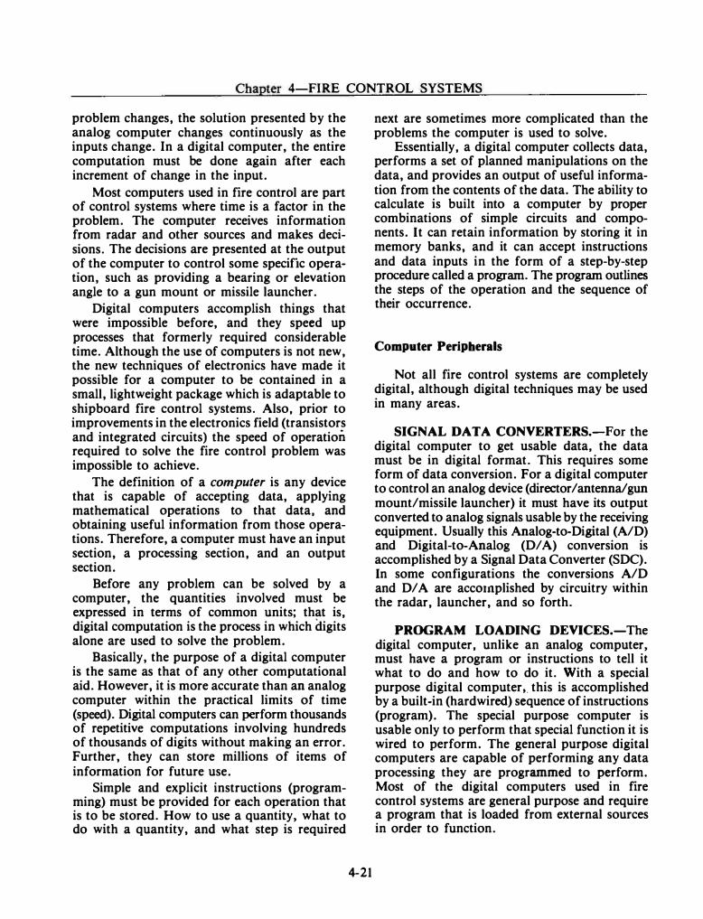
Chapter 4-FIRE CONTROL SYSTEMS
problem changes, the solution presented by the analog computer changes continuously as the inputs change. In a digital computer, the entire computation must be done again after each increment of change in the input.
Most computers used in fire control are part of control systems where time is a factor in the problem. The computer receives information from radar and other sources and makes decisions. The decisions are presented at the output of the computer to control some specific operation, such as providing a bearing or elevation angle to a gun mount or missile launcher.
Digital computers accomplish things that were impossible before, and they speed up processes that formerly required considerable time. Although the use of computers is not new, the new techniques of electronics have made it possible for a computer to be contained in a small, lightweight package which is adaptable to shipboard fire control systems. Also, prior to improvements in the electronics field (transistors and integrated circuits) the speed of operation required to solve the fire control problem was impossible to achieve.
The definition of a computer is any device that is capable of accepting data, applying mathematical operations to that data, and obtaining useful information from those operations. Therefore, a computer must have an input section, a processing section, and an output section.
Before any problem can be solved by a computer, the quantities involved must be expressed in terms of common units; that is, digital computation is the process in which digits alone are used to solve the problem.
Basically, the purpose of a digital computer is the same as that of any other computational aid. However, it is more accurate than an analog computer within the practical limits of time (speed). Digital computers can perform thousands of repetitive computations involving hundreds of thousands of digits without making an error. Further, they can store millions of items of information for future use.
Simple and explicit instructions (programming) must be provided for each operation that is to be stored. How to use a quantity, what to do with a quantity, and what step is required
4-21
next are sometimes more complicated than the problems the computer is used to solve.
Essentially, a digital computer collects data, performs a set of planned manipulations on the data, and provides an output of useful information from the contents of the data. The ability to calculate is built into a computer by proper combinations of simple circuits and components. It can retain information by storing it in memory banks, and it can accept instructions and data inputs in the form of a step-by-step procedure called a program. The program outlines the steps of the operation and the sequence of their occurrence.
Computer Peripherals
Not all fire control systems are completely digital, although digital techniques may be used in many areas.
SIGNAL DATA CONVERTERS.-For the digital computer to get usable data, the data must be in digital format. This requires some form of data conversion. For a digital computer to control an analog device (director/antenna/gun mount/missile launcher) it must have its output converted to analog signals usable by the receiving equipment. Usually this Analog-to-Digital (A/D) and Digital-to-Analog (D/ A) conversion is accomplished by a Signal Data Converter (SDC). In some configurations the conversions A/D and D/ A are acc01nplished by circuitry within the radar, launcher, and so forth.
PROGRAM LOADING DEVICES.-The digital computer, unlike an analog computer, must have a program or instructions to tell it what to do and how to do it. With a special purpose digital computer •. this is accomplished by a built-in (hardwired) sequence of instructions (program). The special purpose computer is usable only to perform that special function it is wired to perform. The general purpose digital computers are capable of performing any data processing they are programmed to perform. Most of the digital computers used in fire control systems are general purpose and require a program that is loaded from external sources in order to function.
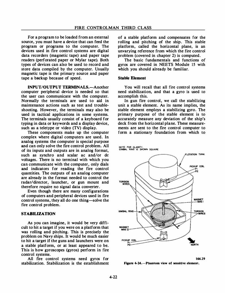
FIRE CONTROLMAN THIRD C LASS
For a program to be loaded from an external source, you must have a device that can feed the program or programs to the computer. The devices used in fire control systems are digital data recorders (magnetic tape) and paper tape readers (perforated paper or Mylar tape). Both types of devices can also be used to record and store data compiled by the computer. Usually magnetic tape is the primary source and paper tape a backup because of speed .
INPUT/OUTPUT TERMINALS.-Another computer peripheral device is needed so that the user can communicate with the computer. Normally the terminals are used to aid in maintenance actions such as test and troubleshooting. However, the terminals may also be used in tactical applications in some systems. The terminals usually consist of a keyboard for typing in data or keywords and a display device, such as a teletype or video (TV) display.
These components make up the computer complex where digital computers are used . In analog systems the computer is special purpose and can only solve the fire control problem. All of its inputs and outputs are in analog format, such as synchro and scalar ac and/ or de voltages. There is no terminal with which you can communicate with the computer, only dials and indicators for reading the fire control quantities. The outputs of an analog computer are already in the format needed to control the radar I director, launcher, or gun mount and therefore require no signal data converter.
Even though there are many configurations of computers and peripheral devices used in fire control systems, they all do one thing-solve the fire control problem.
STABILIZATION
As you can imagine, it would be very difficult to hit a target if you were on a platform that was rolling and pitching. This is precisely the problem on Navy ships. It would be much easier to hit a target if the guns and launchers were on a stable platform, or at least appeared to be. This is how gyroscopes (gyros) perform in fire control systems.
All fire control systems need gyros for stabilization. Stabilization is the establishment
4-22
of a stable platform and compensates for the rolling and pitching of the ship. This stable platform, called the horizontal plane, is an unvarying reference from which the fire control problem (covered in chapter 2) is computed .
The basic fundamentals and functions of gyros are covered in NEETS Module 15 with which you should already be familiar.
Stable Element
You will recall that all fire control systems need stabilization, and that a gyro is used to accomplish this.
In gun fire control, we call the stabilizing unit a stable element. As its name implies, the stable element employs a stabilizing gyro . The primary purpose of the stable element is to accurately measure any deviation of the ship's deck from the horizontal plane. These measurements are sent to the fire control computer to form a stationary foundation from which to
NOTE: FOR ClARITY, GJ� RING IS SHC1NN SQUARE
TANK
166.29 Ftaure 4-24.-Pbantom view of sensitive element.
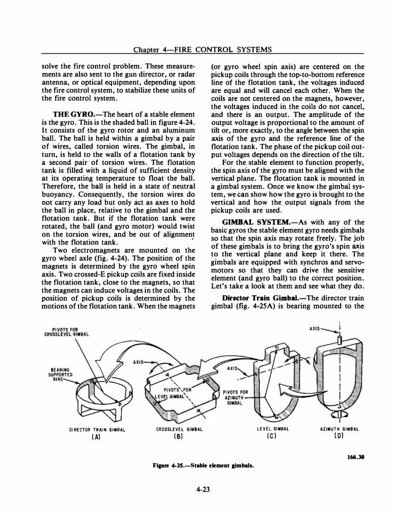
Chapter 4-FIRE CONTROL SYSTEMS
solve the fire control problem. These measurements are also sent to the gun director, or radar antenna, or optical equipment, depending upon the fire control system, to stabilize these units of the fire control system.
THE GYRO.-The heart of a stable element is the gyro. This is the shaded ball in figure 4-24. It consists of the gyro rotor and an aluminum ball. The ball is held within a gimbal by a pair of wires, called torsion wires. The gimbal, in turn, is held to the walls of a flotation tank by a second pair of torsion wires. The flotation tank is filled with a liquid of sufficient density at its operating temperature to float the ball. Therefore, the ball is held in a state of neutral buoyancy. Consequently, the torsion wires do not carry any load but only act as axes to hold the ball in place, relative to the gimbal and the flotation tank. But if the flotation tank were rotated, the ball (and gyro motor) would twist on the torsion wires, and be out of alignment with the flotation tank.
·
Two electromagnets are mounted on the gyro wheel axle (fig. 4-24). The position of the magnets is determined by the gyro wheel spin axis. Two crossed-E pickup coils are fixed inside the flotation tank, close to the magnets, so that the magnets can induce voltages in the coils. The position of pickup coils is determined by the motions of the flotation tank. When the magnets
DI RECTOR TRAIN GIMBAL CROSSLEVEL GIMBAL
( A) ( B)
(or gyro wheel spin axis) are centered on the pickup coils through the top-to-bottom reference line of the flotation tank, the voltages induced are equal and will cancel each other. When the coils are not centered on the magnets, however, the voltages induced in the coils do not cancel, and there is an output. The amplitude of the output voltage is proportional to the amount of tilt or, more exactly, to the angle between the spin axis of the gyro and the reference line of the flotation tank. The phase of the pickup coil output voltages depends on the direction of the tilt.
For the stable element to function properly, the spin axis of the gyro must be aligned with the vertical plane. The flotation tank is mounted in a gimbal system. Once we know the gimbal system, we can show how the gyro is brought to the vertical and how the output signals from the pickup coils are used.
GIMBAL SYSTEM.-As with any of the basic gyros the stable element gyro needs gimbals so that the spin axis may rotate freely. The job of these gimbals is to bring the gyro's spin axis to the vertical plane and keep it there. The gimbals are equipped with synchros and servomotors so that they can drive the sensitive element (and gyro ball) to the correct position. Let's take a look at them and see what they do.
Director Train Gimbal.-The director train gimbal (fig. 4-25A) is bearing mounted to the
LEVEL GI MBAL AZIMUTH GIMBAL
( C ) ( 01
166.38 Figure 4-25.-Stable element gimbals.
4-23
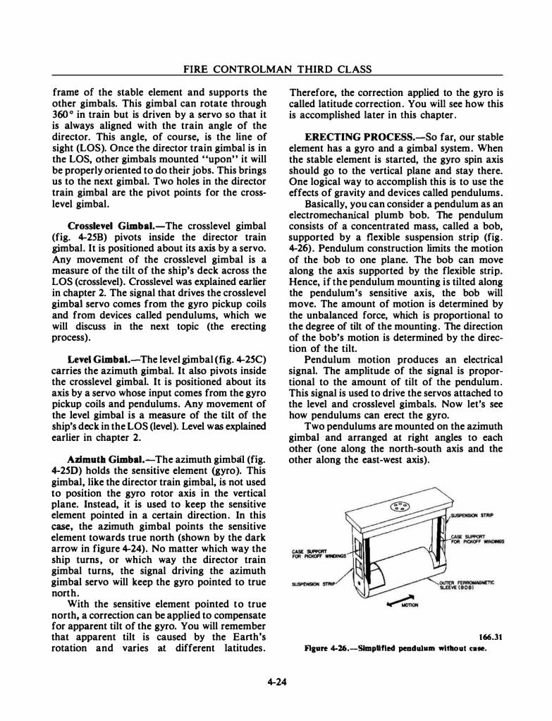
FIRE CONTROLMAN THIRD CLASS
frame of the stable element and supports the other gimbals. This gimbal can rotate through 360 o in train but is driven by a servo so that it is always aligned with the train angle of the director. This angle, of course, is the line of sight (LOS). Once the director train gimbal is in the LOS, other gimbals mounted "upon" it will be properly oriented to do their jobs. This brings us to the next gimbal. Two holes in the director train gimbal are the pivot points for the crosslevel gimbal.
Crosslevel Gimbal.-The crosslevel gimbal (fig. �25B) pivots inside the director train gimbal. It is positioned about its axis by a servo. Any movement of the crosslevel gimbal is a measure of the tilt of the ship's deck across the LOS (crosslevel). Crosslevel was explained earlier in chapter 2. The signal that drives the crosslevel gimbal servo comes from the gyro pickup coils and from devices called pendulums, which we will discuss in the next topic (the erecting process).
Level Gimbal.-The level gimbal (fig. �2SC) carries the azimuth gimbal. It also pivots inside the crosslevel gimbal. It is positioned about its axis by a servo whose input comes from the gyro pickup coils and pendulums. Any movement of the level gimbal is a measure of the tilt of the ship's deck in the LOS (level). Level was explained earlier in chapter 2.
Azimutb Gimbal.-The azimuth gimbal (fig. �2SD) holds the sensitive element (gyro). This gimbal, like the director train gimbal, is not used to position the gyro rotor axis in the vertical plane. Instead, it is used to keep the sensitive element pointed in a certain direction. In this case, the azimuth gimbal points the sensitive element towards true north (shown by the dark arrow in figure �24). No matter which way the ship turns, or which way the director train gimbal turns, the signal driving the azimuth gimbal servo will keep the gyro pointed to true north.
With the sensitive element pointed to true north, a correction can be applied to compensate for apparent tilt of the gyro. You will remember that apparent tilt is caused by the Earth's rotation and varies at different latitudes.
�24
Therefore, the correction applied to the gyro is called latitude correction. You will see how this is accomplished later in this chapter.
ERECTING PROCESS.-So far, our stable element has a gyro and a gimbal system. When the stable element is started, the gyro spin axis should go to the vertical plane and stay there. One logical way to accomplish this is to use the effects of gravity and devices called pendulums.
Basically, you can consider a pendulum as an electromechanical plumb bob. The pendulum consists of a concentrated mass, called a bob, supported by a flexible suspension strip (fig. �26) . Pendulum construction limits the motion of the bob to one plane. The bob can move along the axis supported by the flexible strip. Hence, if the pendulum mounting is tilted along the pendulum's sensitive axis, the bob will move. The amount of motion is determined by the unbalanced force, which is proportional to the degree of tilt of the mounting. The direction of the bob's motion is determined by the direction of the tilt.
Pendulum motion produces an electrical signal. The amplitude of the signal is proportional to the amount of tilt of the pendulum. This signal is used to drive the servos attached to the level and crosslevel gimbals. Now let's see how pendulums can erect the gyro.
Two pendulums are mounted on the azimuth gimbal and arranged at right angles to each other (one along the north-south axis and the other along the east-west axis).
166.31 Flaare 4-26.-Simpllfled peodubun wltllout caae.
Chapter 4-FIRE CONTROL SYSTEMS
Two additional pendulums are mounted on the level gimbal. These pendulums are also arranged at right angles to each other (one in the LOS, the other across the LOS).
These pendulums are the vertical-seeking devices of the stable element. If the gyro rotor axis is not in the vertical plane, it is because the azimuth and level gimbals are tilted. Being tilted, the pendulums will produce signals to drive the level and crosslevel gimbals into the horizontal plane, then the gyro spin axis will reach the vertical plane.
Because the gyro tends to remain fixed in space as the servomotors drive the gimbals, the torsion wires of the gyro suspension system become twisted and exert torque on the gyro. The gyro will precess at right angles to the applied torque, and its spin axis will follow a decreasing spiral path to the vertical plane.
Once the gyro spin axis is in the vertical plane, the pendulums on the level gimbal are cut off, and only the azimuth gimbal pendulums, along with the magnets and pickup coils of the sensitive element, are used to keep the gyro erected properly.
LATITUDE CORRECTION.-We have seen how the rotation of the Earth from west to east causes the gyro to precess westward away from the local vertical plane. This is called apparent tilt of the gyro. To prevent apparent tilt, a torque is applied to the gyro to cause an easterly precession. The precession rate depends on the latitude and is maximum at the equator.
A latitude correction voltage is introduced into the signal circuit of the north-south azimuth gimbal pendulum. The amount of voltage is determined by the setting of a potentiometer. The potentiometer has a dial that is scaled in degrees of latitude and is set to the ship's latitude position.
The introduced latitude correction voltage causes the level and crosslevel servos to drive to null the signal. If the azimuth gimbal is vertical and the gyro magnet is in the center of the pickup coils, the voltage will offset the gyro spin axis from the center of the pickup coils. The servos drive to eliminate the offset. Since the gyro is rigid, this results in the gyro's torsion wires being twisted. The wire twist will couple a torque to the north-south axis of the gyro and
4-25
cause a steady and constant precession of the gyro eastward. This is desired to correct for the Earth's rotation.
Other StabiUzation Devices
Newer gun fire control systems and the missile systems do not use the stable element. The ship's gyrocompass or Inertial Navigation System provide the stabilization necessary. Additionally, rate gyros are installed in most fire control directors to stabilize the LOS in both vertical and horizontal planes. The rate gyros in the directors sense motion about the LOS and generate error signals to compensate for this motion. The rate gyros are used in the tracking loop of these systems.
ANCILLARY EQUIPMENT
There is a wide selection of equipment in use to support FCS operation. Among these ancillary devices are closed circuit television systems, optical target designation devices, dry air systems, liquid coolant systems, and power distribution/ supply systems. These devices and systems will be discussed in chapter 7 (Support Systems).
CONFIGURATION VARIATIONS
With the numerous fire control systems in the fleet today, it would take considerable space to even briefly describe the components and their functions and even more space to describe the various configurations of each system. The scope of this course is to teach the basics of fire control and fire control systems, so the individual systems are mentioned briefly here. For additional study, the system and equipment publications available on board should provide you with detailed information on your ship's systems. Also the senior FCs may have experience with other FCSs not on board and would be able to discuss them with you.
SUMMARY
From your study in this chapter you have learned about the basic components of fire

FIRE CONTROLMAN THIRD CLASS
control systems. As a Fire Controlman, you should have extensive electronics knowledge because the FCS consists of a very wide range of equipment and circuits. The more knowledgeable you become, the easier your job, and the faster
4-26
you can advance. Learn all you can of the basic concepts, the equipment you work on, and the equipment it interfaces with. Your next area of study is the missiles and ordnance currently used in the fleet.
CHAPTER 5
ORDNANCE AND MISSILES
This chapter deals with the end result of a Fire Controlman's job. As you are aware, the job of an FC is to maintain and operate the equipment used to control the delivery of an explosive device to a position to damage or destroy a specific target. Ordnance and missiles are used to accomplish this task. (Ordnance can be broadly defined as cannon or artillery and military weapons of all kinds with their equipment and ammunition.)
This chapter discusses these weapons, whai makes them work, and how they work. The first part deals with explosives and propellants and how they are used in gun ammunition. The next part discusses missiles; what they are, how they work, and how they are controlled.
EXPLOSIVES
Broadly, and if used without further qualification, the term explosive includes all those substances that, when initiated by sparks, friction, shock, or other means, undergo a rapid chemical reaction that results in the formation of gases and the release of a great amount of stored energy. The reaction is accompanied by high pressure and usually by high heat.
In this sense the term explosive is broad enough to include all the substances described in this section. Note, however, that this usage of the term, though broad, excludes as explosive substances such things as high-pressure steam, which may burst a boiler, or high-pressure gas, when under certain circumstances, may rupture its container.
In strictly technical usage, the term explosive includes only those substances that detonate. This means that when their reaction is initiated,
5-1
release of all their stored energy is almost instantaneously with the formation of a shock wave. As it appears hereafter in this text, the term explosive will be used in this strict sense only when applied to chemical explosives.
High explosives are classified by their use into three broad groups:
• Primary (initiating) explosives
• Auxiliary (booster) explosives
• Bursting charges
Pr imary explosives are the most sensitive of high explosives and are used to initiate other charges. They are particularly sensitive to shock, heat, or other physical disturbances and are therefore used in initiating devices such as fuzes (described later in this chapter) to set off chemical reactions in less highly sensitive substances. Boosters are used to initiate explosive charges when the initiating explosion is not sufficient to cause a thorough (high-order) detonation of the main charge. Bursting charges are comparatively insensitive to heat; they are the explosive payload of the projectile or warhead initiated by the initiators or boosters. Burster charges damage the target by blast, heat, or fragments of the container such as projectile bodies and missile airframes.
Propelling charges or propellants (sometimes referred to as low explosives) are explosive-like substances that burn rather than detonate. The rate of burning, though rapid compared with the burning of common combustible materials, is much slower than detonation. For instance, a high explosive like TNT detonates at the rate of several thousand yards each second, while a
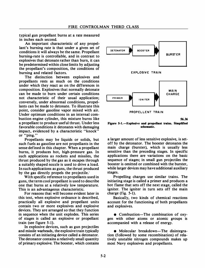
FIRE CONTROLMAN THIRD CLASS
typical gun propellant burns at a rate measured in inches each second.
An important characteristic of any propellant's burning rate is that under a given set of conditions it will always be the same. Propellant burning-rate is controllable, and in contrast to explosives that detonate rather than burn, it can be predetermined within close limits by adjusting the propellant's composition, the conditions of burning and related factors.
The distinction between explosives and propellants rests as much on the conditions under which they react as on the differences in composition. Explosives that normally detonate can be made to burn under certain conditions not characteristic of their usual application; conversely, under abnormal conditions, propellants can be made to detonate. To illustrate this point, consider gasoline vapor mixed with air. Under optimum conditions in an internal combustion engine cylinder, this mixture burns like a propellant to produce useful thrust. Under less favorable conditions it detonates with damaging impact, evidenced by a characteristic "knock" or "ping."
Propellants may be liquids or solids, but such fuels as gasoline are not propellants in the sense defined in this chapter. When a propellant burns, it produces hot, high-pressure gas. In such applications as rockets and missiles, the thrust produced by the gas as it escapes through a suitably shaped nozzle is used to drive a load. In such applications as guns, the thrust produced by the gas directly propels the projectile.'
With specific reference to propellants used in guns, the term cool propellant is used to describe one that burns at a relatively low temperature. This is an advantageous characteristic.
For reasons that will become evident later in this text, when explosive ordnance is described, practically all explosive and propellant units contain two or more explosives and explosive devices. They are arranged so that they function in sequence when the unit explodes. This series of stages is called an explosive or propellant train (see figure 5-l).
In explosive devices, such as gun projectiles and missile warheads, the explosive train typically consists of an initiating device called a detonator. The detonator contains a relatively small quantity of primary explosive. The booster, which contains
5-2
DETONATOR BOOSTER
EXPLOSIVE TRAIN
PRIMER IGNITER
PROPEL LENT TRA IN
BURSTER
MAIN CHARGE
56.36 Figure 5-1.-Exploslve aod propellant trains. Slmplif'ted
sc:bematlc.
a larger amount of less sensitive explosive, is setoff by the detonator. The booster detonates the main charge (burster), which is usually less sensitive than the preceding stages. In specific applications there are variations on the basic sequence of stages; in small gun projectiles the booster is omitted or combined with the burster, while larger devices may have additional auxiliary stages.
Propelling charges use similar trains. The initiating stage is called a primer and produces a hot flame that sets off the next stage, called the igniter. The igniter in turn sets off the main charge (fig. 5-l).
Basically, two kinds of chemical reactions account for the functioning of both propellants and explosives.
• Combustion-The combination of oxygen with other atoms or atomic groups is accompanied with a release of energy.
• Molecular breakdown-The disintegration (followed by some recombination) of relatively unstable nitrogen compounds makes up most Navy explosives and propellants.
Chapter 5-0RDNANCE AND MISSILES
In propellants, much of the energy developed by the reactions comes from oxidation; although an insignificant proportion of the oxygen comes from the atmosphere. The oxygen is part of the original composition and recombines with other elements when the composition breaks up.
With high explosives, oxidation is not so important a feature of the reaction, though it is usually present. The important energy source is in the breakup of the chemical bonds of the original composition and the recombination of the elements into simpler compounds.
The products of detonation and burning (in explosives and propellants respectively) include the usual products of complete combustion (for example, carbon dioxide, water vapor); products of incomplete combustion (for example, carbon monoxide, free hydrogen); products of molecular breakdown and partial recombination (for example, free nitrogen, oxides of nitrogen, methane, hydrogen cyanide); and unburned residues of the original composition. Some of these products are harmless, some are suffocating, some are combustible or even explosive, and some are dangerous poisons even in fairly low concentrations. These are dangerous substances, particularly in enclosed spaces (where, for example, a high-explosive-loaded projectile may have burst). They are also dangerous in enclosed gun mounts, which are therefore fitted with gas-expelling devices to eliminate the dangerous substances. When such gases are not promptly expelled, they may ignite while the gun is being reloaded, causing a burst of flame inside the mount called a flareback.
CHARACTERISTICS OF EXPLOSIVE AND PROPELLANT REACTIONS
e VELOCITY. An explosive reaction differs from propellant reaction in its velocity. The velocity of combustion of explosives and propellants may vary within rather wide limits, depending upon the type of substance and upon its physical state. The burning rate of powders used as propellants in modern guns is in the order of 24 centimeters (approximately 10 inches) per second (and up) at average gun pressures. The velocity of reaction of high explosives ranges from about 2,000 to 8,500 meters each second.
5-3
• HEAT. An explosive reaction is always accompanied by the rapid liberation of heat. The amount of heat represents the energy of the explosive and its potentiality for doing work. The quantity of heat given off by an explosive or propellant reaction is not as large as is popularly supposed. A pound of coal, for example, yields five times as much heat as a pound of nitroglycerine. However, coal cannot be used as an explosive, because it fails to liberate heat with sufficient rapidity and does not incorporate an oxidizing agent.
• GASES. The main material products (as distinct from energy products) of explosive or propellant reactions are hot gases and a small amount of solid residue. The pressure characteristics of the gases involved are discussed below; their composition was discussed earlier. In gun barrels, propellant gases have an additional erosive effect, which contributes significantly to the wear of the gun bore.
e PRESSURE AND SHOCK WAVE. The high pressure accompanying a propellant or explosive reaction is caused by the formation of gases, which are expanded by the heat liberated in the reaction. The work that the reaction is capable of performing depends upon the volume of the gases and the amount of heat liberated. The maximum pressure developed and the way in which the energy of the explosion is applied depend further upon the velocity of the reaction. When the reaction proceeds at a low velocity, the gases receive heat while being evolved, and the maximum pressure is attained comparatively late in the reaction. If, in the explosion of another substance, the same volume of gas is produced and the same amount of heat is liberated but at a greater velocity, then the maximum pressure will be reached sooner and will be quantitatively greater. Nevertheless, disregarding heat losses, the work done will be equal.
The rapidity with which an explosive develops its maximum pressure determines its brisance. A brisant explosive is one in which the maximum pressure is attained so rapidly that its shock wave shatters material surrounding it.
FIRE CONTROLMAN THIRD CLASS
INITIATION OF EXPLOSIVE AND PROPELLANT REACTIONS
Explosive and propellant reactions are initiated by the application of a stimulus that provides the energy required to get the reaction started. In general, propellant substances are commonly initiated by heat. The resulting reaction is a burning process, which occurs on the exposed surfaces of the substance and progresses through the mass as each layer is consumed. Nevertheless, some high explosives will react when sufficient heat is applied, especially if heat is applied suddenly throughout the mass. Initiation by percussion (direct blow) or by friction is a form of heat initiation derived from the energy of the blow or friction.
The amount of energy necessary to initiate the reaction is the measure of the sensitivity of the explosive or propellant. Sensitivity is important in selecting an explosive for a particular purpose. For example, the explosive in an armor-piercing projectile must be relatively insensitive or the shock of impact will detonate it before penetration. Too much sensitivity is also undesirable because minor shocks or temperature variations incident to normal handling would initiate the reaction.
Sensitivity has little relation to the power developed by a given weight of explosive. TNT, for example, is quite insensitive, but is pound for pound a more powerful explosive than mercury fulminate, an initiating compound of great sensitivity.
Stori111 Propellants
In storage, propellants must· be protected against high temperatures and sealed to prevent entrance of moisture and loss of volatiles. All magazines in which ammunition containing propellants is stored must be adequately insulated and ventilated and if necessary, refrigerated to protect against high temperatures. Moreover, recording or maximum-minimum thermometers are installed and read daily to verify that the ammunition is uniformly maintained at the lowest practicable temperatures.
Ammunition should be kept in sealed containers to protect against entrance of moisture and to prevent excessive loss of volatiles. The containers are not expendable; they must be
5-4
periodically inspected and repaired if necessary. They must not be opened when loaded except for inspection or if the ammunition is to be used. Like gun propelling charges, rockets must be stowed under conditions favorable to storage. Rocket motor magazines are ventilated, cooled, and inspected daily just like powder magazines (magazines used for stowing gun propellants). The critical temperature above which the rocket should not be fired is printed on many rocket motor tubes. A rocket motor should not be used if parts are missing, if the propellent grain is fractured, or if it is loose in the motor tube.
AMMUNITION
In a general sense, ammunition includes anything that is intended to be thrown at, or put in the path of, an enemy to deter, injure, or kill personnel or to destroy or damage materiel. In this book, the term is used in a much narrower and more technical sense. Ammunition includes any projectile or explosive weapon, as well as components or parts thereof, but not guns or weapon launchers and their parts. This discussion of ammunition is broken into two sections; first gun ammunition. then missiles.
Service ammunition is ammunition fit for service use and includes all explosive and propellant components. Inert (that is, lacking explosive and propellant components) and partially inert ammunition of several types is used for testing, training, and practice purposes. Dummy or drill ammunition (completely inert), which resembles service ammunition in appearance, size, and weight, may include functioning components that contain no explosive or propellant. It is used for training and test purposes. Cutaway ammunition (completely inert) has a section cut away to show inner construction and components; it is used for training and display purposes. Plaster-loaded or sand-loaded ammunition lacks the explosive burster charge but is otherwise not inert; it is used for target practice and for testing of launchers, and gun mounts.
Two miscellaneous types of ammunition deserve brief mention for the sake of completeness. They are trench-warfare ammunition and blank ammunition. Trench-warfare ammunition includes hand and rifle grenades, mortar projectiles. and similar infantry weapons (issued

Chapter 5-0RDNANCE AND MISSILES
to Marines and landing forces) for ground combat. Blank ammunition is a type of gun ammunition with propelling charges but no projectile; it is used for saluting batteries, signaling, and training.
TYPES AND COMPONENTS OF GUN AMMUNITION
Components of gun ammunition assemblies are classified as either primary or secondary. Primary components include items such as smokeless powder, primers, projectiles, cartridge
I'IIOJI!c:TILI
Pl!llll!l
cases and nose, aux det and base fuzes. Examples of secondary components are base fuze hole plugs, tracer hole plugs, cartridge plugs, and gas check seals. Ammunition details are accessories used in the packing, handling, and protecting of ammunition; for example, tanks, grommets, and waterproof caps. A complete round of ammunition comprises all the primary and secondary components needed to fire a gun once.
Gun ammunition is comprised of five types: fixed, semifixed, separated, separateloading (bag), and small arm (fig. S-2). In fixed
aiiAUOII STI!EL CAS!
C FIUD A...,..TIOM FOR 7e .... GUN
l�attAUTD�
· ----- --�
-
FOR •• , •• CAL. - I'IOJI!CTILJ III!TAL CASI!
CASI! PI!IICUUION f'lllll!l!
D 10 MM CAitTNDM
111!0 1Gtti11CIN PAD (CIIIITAIMS M.ACIC I'OWOI!IIIGMITI!tl)
Figure 5-1.-Complete rouuds of a•• ammullidoa: A. Bq; B. Separated; C. aad D. Fixed.
S-S
3.116
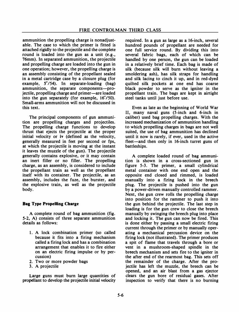
FIRE CONTROLMAN THIRD CLASS
ammunition the propelling charge is nonadjustable. The case to which the primer is fitted is attached rigidly to the projectile and the complete round is loaded into the gun as a unit (e.g., 76mm). In separated ammunition, the projectile and propelling charge are loaded into the gun in one operation; however, the propelling charge is an assembly consisting of the propellant sealed in a metal cartridge case by a closure plug (for example, s· /54). In separate-loading (bag) ammunition, the separate components-projectile, propelling charge and primer-are loaded into the gun separately (for example, 16" /50). Small-arms ammunition will not be discussed in this text.
The principal components of gun ammunition are propelling charges and projectiles. The propelling charge functions to develop thrust that ejects the projectile at the proper initial velocity or iv (defined as the velocity, generally measured in feet per second or fps, at which the projectile is moving at the instant it leaves the muzzle of the gun). The projectile generally contains explosive, or it may contain an inert filler or no filler. The propelling charge, as an assembly, is considered to include the propellant train as well as the propellant itself with its container. The projectile, as an assembly, includes the fuze, the burster, and the explosive train, as well as the projectile body.
Ba1 Type Propelling Charge
A complete round of bag ammunition (fig. S-2, A) consists of three separate ammunition details as follows:
1. A lock combination primer (so called because it fits into a firing mechanism called a firing lock and has a combination arrangement that enables it to fire either on an electric firing impulse or by percussion)
2. Two or more powder bags 3. A projectile
Large guns must burn large quantities of propellant to develop the projectile initial velocity
S-6
required. In a gun as large as a 16-inch, several hundred pounds of propellant are needed for one full service round. By dividing this into several fabric bags, each of which can be handled by one person, the gun can be loaded in a relatively brief time. Each bag is made of silk (because silk will burn without leaving a smoldering ash), has silk straps for handling and silk lacing to cinch it up, and in red-dyed quilted silk pockets at one end has coarse black powder to serve as the igniter in the propellant train. The bags are kept in airtight steel tanks until just before use.
Even as late as the beginning of World War II, many naval guns (5-inch and 6-inch in caliber) used bag propelling charges. With the increased mechanization of ammunition handling to which propelling charges in bags are not well suited, the use of bag ammunition has declined until it now is rarely. if ever, used in the active fleet-and then only in 16-inch turret guns of battleships.
A complete loaded round of bag ammunition is shown in a cross-sectioned gun in figure 5-3. The primer, a small cylindrical metal container with one end open and the opposite end closed and rimmed, is loaded manually into a firing lock in the breech plug. The projectile is pushed into the gun by a power-driven manually controlled rammer. Next, the gun crew rolls the propelling charge into position for the rammer to push it into the gun behind the projectile. The last step in loading is for the gun crew to close the breech manually by swinging the breech plug into place and locking it. The gun can now be fired. This is done either by passing a small electric firing current through the primer or by manually operating a mechanical percussion device on the firing lock (not illustrated). The primer produces a spit of flame that travels through a bore or vent in a mushroom-shaped spindle in the breech mechanism and sets fire to the igniter in the after end of the rearmost bag. This sets off the remainder of the charge. After the projectile has left the muzzle, the breech can be opened, and an air blast from a gas ejector clears the gun bore of residual gases. After inspection to verify that there is no burning
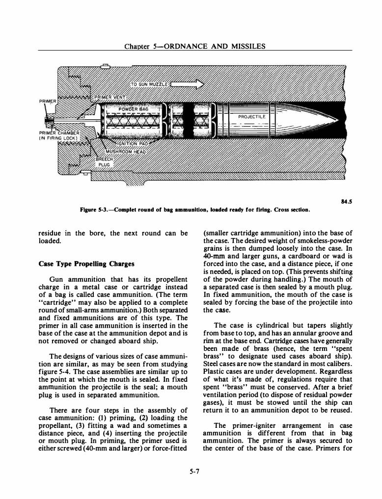
Chapter 5-0RDNANCE AND MISSILES
84.5 Figure 5-3.-Complet round of bag ammunition, loaded ready for firing. Cross section.
residue m the bore, the next round can be loaded.
Case Type Propelling Charges
Gun ammunition that has its propellent charge in a metal case or cartridge instead of a bag is called case ammunition. (The term "cartridge" may also be applied to a complete round of small-arms ammunition.) Both separated and fixed ammunitions are of this type. The primer in all case ammunition is inserted in the base of the case at the ammunition depot and is not removed or changed aboard ship.
The designs of various sizes of case ammunition are similar, as may be seen from studying figure 5-4. The case assemblies are similar up to the point at which the mouth is sealed. In fixed ammunition the projectile is the seal; a mouth plug is used in separated ammunition.
There are four steps in the assembly of case ammunition: (1) priming, (2) loading the propellant, (3) fitting a wad and sometimes a distance piece, and (4) inserting the projectile or mouth plug. In priming, the primer used is either screwed (40-mm and larger) or force-fitted
5-7
(smaller cartridge ammunition) into the base of the case. The desired weight of smokeless-powder grains is then dumped loosely into the case. In 40-mm and larger guns, a cardboard or wad is forced into the case, and a distance piece, if one is needed, is placed on top. (This prevents shifting of the powder during handling.) The mouth of a separated case is then sealed by a mouth plug. In fixed ammunition, the mouth of the case is sealed by forcing the base of the projectile into the case.
The case is cylindrical but tapers slightly from base to top, and has an annular groove and rim at the base end. Cartridge cases have generally been made of brass (hence, the term "spent brass" to designate used cases aboard ship). Steel cases are now the standard in most calibers. Plastic cases are under development. Regardless of what it's made of, regulations require that spent "brass" must be conserved. After a brief ventilation period (to dispose of residual powder gases), it must be stowed until the ship can return it to an ammunition depot to be reused.
The primer-igniter arrangement in case ammunition is different from that in bag ammunition. The primer is always secured to the center of the base of the case. Primers for
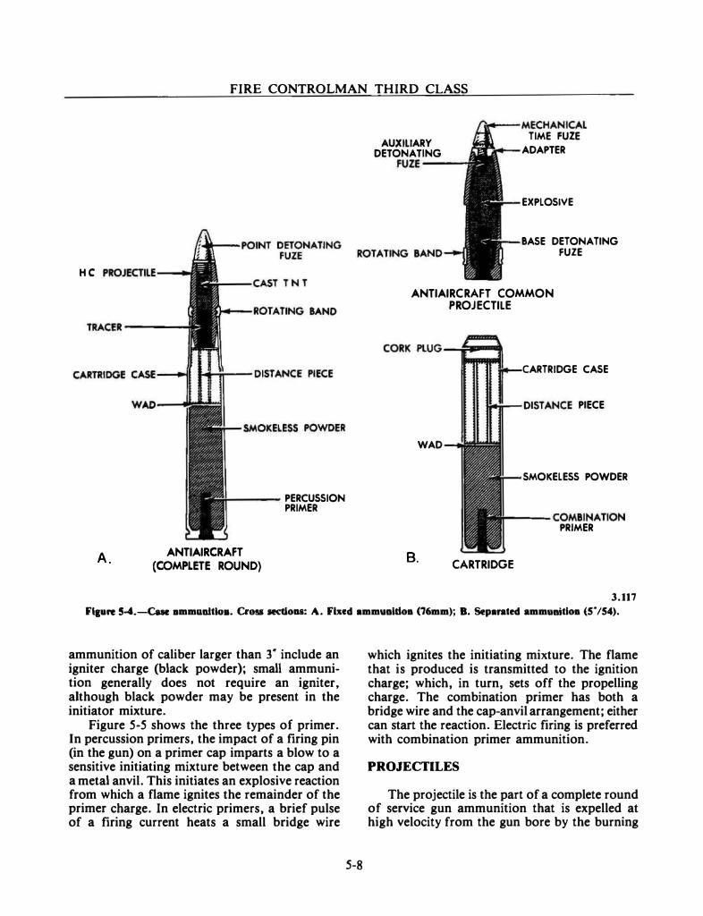
FIRE CONTROLMAN THIRD CLASS
HC
TRACER----
A.
---- PERCUSSION
ANTIAIRCRAFT (COMPLETE ROUND)
PRIMER
AUXILIARY DETONATING
FUZE ---
rrfiiii--MECHANICAL TIME FUZE
,._,_ __ ADAPTER
EXPLOSIVE
BASE DETONATING FUZE
ANTIAIRCRAFT COMMON PROJECTILE
CARTRIDGE CASE
...,.i--- OI:STANCE PIECE
WAD
SMOKELESS POWDER
---COMBINATION PRIMER
B. CARTRIDGE
3.117
Flpre �.-Cue ammanltio•. Cross sectloDS: A. Fixed ammuaJdoa (76mm); B. Separated ammanitioa (5. /54).
ammunition of caliber larger than r include an igniter charge (black powder); small ammunition generally does not require an igniter. although black powder may be present in the initiator mixture.
Figure 5-5 shows the three types of primer. In percussion primers. the impact of a firing pin (in the gun) on a primer cap imparts a blow to a sensitive initiating mixture between the cap and a metal anvil. This initiates an explosive reaction from which a flame ignites the remainder of the primer charge. In electric primers, a brief pulse of a firing current heats a small bridge wire
5-8
which ignites the initiating mixture. The flame that is produced is transmitted to the ignition charge; which, in turn. sets off the propelling charge. The combination primer has both a bridge wire and the cap-anvil arrangement; either can start the reaction. Electric firing is preferred with combination primer ammunition.
PROJECTILES
The projectile is the part of a complete round of service gun ammunition that is expelled at high velocity from the gun bore by the burning
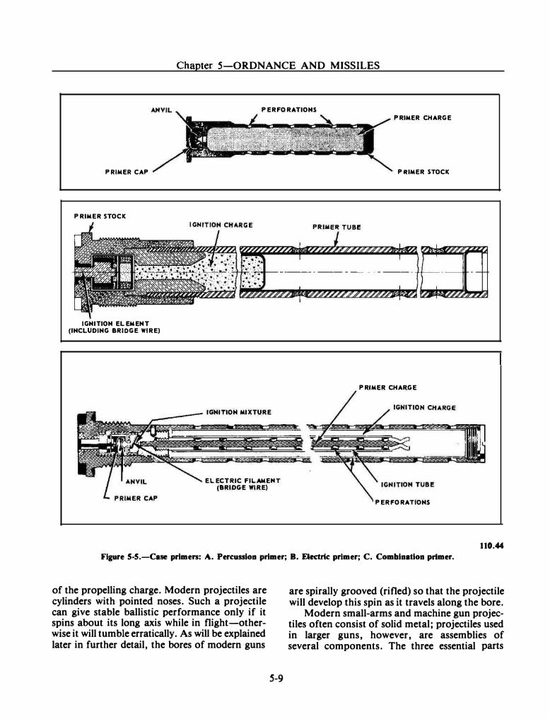
Chapter 5-0RDNANCE AND MISSILES
PERFORATIONS
PRIMER CAP
PRIMER STOCK
IGNITION ELEMENT (INCLUDING BRIDGE WIRE)
PRIMER CAP
IGNITION MIXTURE
ELECTRIC FILAMEHT (BRIDGE WIRE)
PRIMER CHARGE
PRIMER STOCK
PRIMER CHARGE
PERFORATIONS
110.44
Figure 5-5.-Case primen: A. Percussion primer; B. Electric primer; C. Combination primer.
of the propelling charge. Modern projectiles are cylinders with pointed noses. Such a projectile can give stable ballistic performance only if it spins about its long axis while in flight-otherwise it will tumble erratically. As will be explained later in further detail, the bores of modern guns
S-9
are spirally grooved (rifled) so that the projectile will develop this spin as it travels along the bore.
Modern small-arms and machine gun projectiles often consist of solid metal; projectiles used in larger guns, however, are assemblies of several components. The three essential parts
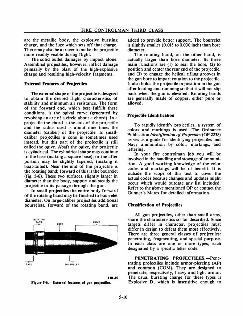
FIRE CONTROLMAN THIRD CLASS
are the metallic body, the explosive bursting charge, and the fuze which sets off that charge. There may also be a trace.r to make the projectile more readily visible during flight.
The solid bullet damages by impact alone. Assembled projectiles, however, inflict damage primarily by the blast of the high-explosive charge and resulting high-velocity fragments.
External Features of Projectiles
The external shape of the projectile is designed to obtain the desired flight characteristics of stability and minimum air resistance. The form of the forward end, which best fulfills these conditions, is the ogival curve (generated by revolving an arc of a circle about a chord). In a projectile the chord is the axis of the projectile and the radius used is about nine times the diameter (caliber) of the projectile. In smallcaliber projectiles a cone is sometimes used instead, but this part of the projectile is still called the ogive. Abaft the ogive, the projectile is cylindrical. The cylindrical shape may continue to the base (making a square base); or the after portion may be slightly tapered, (making it boat-tailed). Near the end of the projectile is the rotating band; forward of this is the bourrelet (fig. 5-6). These two surfaces, slightly larger in diameter than the body, support and steady the projectile in its passage through the gun.
In small projectiles the entire body forward of the rotating band may be finished to bourrelet diameter. On large-caliber projectiles additional bourrelets, forward of the rotating band, are
u u BASE BOUIIIIELET
110.45 Fiau� S-6.-Extemal features of gun projectiles.
5-10
added to provide better support. The bourrelet is slightly smaller (0.015 to 0.030 inch) than bore diameter.
The rotating band, on the other hand, is actually larger than bore diameter. Its three main functions are (1) to seal the bore, (2) to position and center the rear end of the projectile, and (3) to engage the helical rifling grooves in the gun bore to impart rotation to the projectile. It also holds the projectile in position in the gun after loading and ramming so that it will not slip back when the gun is elevated. Rotating bands are generally made of copper, either pure or alloyed.
Projectile Identification
To rapidly identify projectiles, a system of colors and markings is used. The Ordnance Publication Identification of Projectiles (OP 2238) serves as a guide for identifying projectiles and Navy ammunition by color, markings, and lettering.
In your fire controlman job you will be involved in the handling and stowage of ammunition. A good working knowledge of the color codes and markings will be of benefit. It is outside the scope of this text to cover the actual codes because changes and updates might occur which would outdate any list included. Refer to the above mentioned OP or contact the Gunner's Mates for detailed information.
Classification of Projectiles
All gun projectiles, other than small arms, share the characteristics so far described. Since targets differ in character, projectiles must differ in design to defeat them most effectively. There are three general classes of projectiles: penetrating, fragmenting, and special purpose. In each class are one or more types, each designated by a specific letter code.
PENETRATING PROJECfiLES.-Pene
trating projectiles include armor-piercing (AP) and common (COM). They are designed to penetrate, respectively, heavy and light armor. The usual bursting charge for these types is Explosive D, which is insensitive enough to
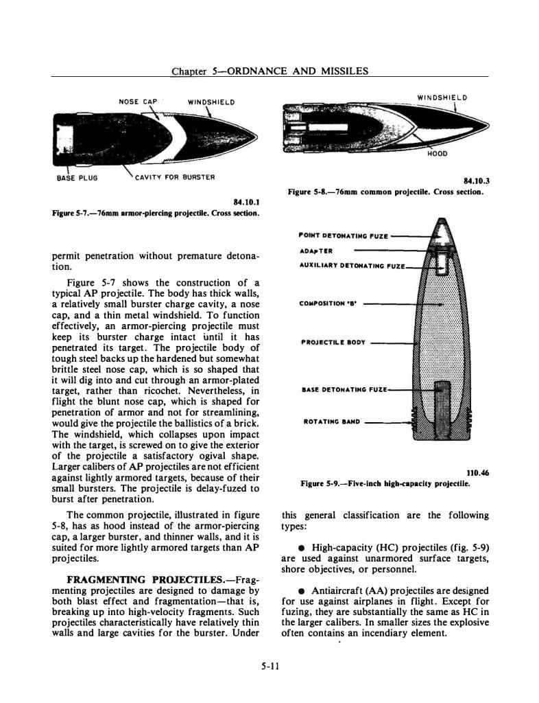
Chapter 5-0RDNANCE AND MISSILES
NOSE CAP . WINDSHIELD
CAVITY FOR BURSTER
84.10.1 Fiaure 5-7 .-76mm armor-piercing projectile. Cross section.
permit penetration without premature detonation.
Figure 5-7 shows the construction of a typical AP projectile. The body has thick walls, a relatively small burster charge cavity, a nose cap, and a thin metal windshield. To function effectively, an armor-piercing projectile must keep its burster charge intact until it has penetrated its target . The projectile body of tough steel backs up the hardened but somewhat brittle steel nose cap, which is so shaped that it will dig into and cut through an armor-plated target, rather than ricochet. Nevertheless, in flight the blunt nose cap, which is shaped for penetration of armor and not for streamlining, would give the projectile the ballistics of a brick. The windshield, which collapses upon impact with the target, is screwed on to give the exterior of the projectile a satisfactory ogival shape. Larger calibers of AP projectiles are not efficient against lightly armored targets, because of their small bursters. The projectile is delay-fuzed to burst after penetration.
The common projectile, illustrated in figure 5-8, has as hood instead of the armor-piercing cap, a larger burster, and thinner walls, and it is suited for more lightly armored targets than AP projectiles.
FRAGMENTING PROJECTILES.-Fragmenting projectiles are designed to damage by both blast effect and fragmentation-that is, breaking up into high-velocity fragments. Such projectiles characteristically have relatively thin walls and large cavities for the burster. Under
5-1 1
WINDSHIELD
84.10.3 Figure S-8.-76mm common projectile. Cross section.
ADAI"TER
AUXILIARY DETONATING rv••o:-����r��
COMPOSITION 'B'
BASI! DETONATING FUZE
ROTATING BAND ___ .......,
110.46 Figure 5-9.-Flve-inch high-capacity projectile.
this general classification are the following types:
• High-capacity (HC) projectiles (fig. 5-9) are used against unarmored surface targets, shore objectives, or personnel.
• Antiaircraft (AA) projectiles are designed for use against airplanes in flight . Except for fuzing, they are substantially the same as HC in the larger calibers. In smaller sizes the explosive often contains an incendiary element.
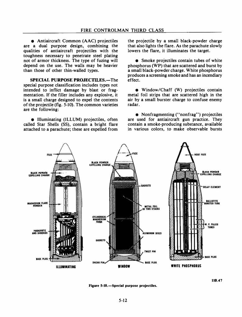
FIRE CONTROLMAN THIRD CLASS
• Antiaircraft Common (AAC) projectiles are a dual purpose design, combining the qualities of antiaircraft projectiles with the toughness necessary to penetrate steel plating not of armor thickness. The type of fuzing will depend on the use. The walls may be heavier than those of other thin-walled types.
SPECIAL PURPOSE PROJECTILES.-The special purpose classification includes types not intended to inflict damage by blast or fragmentation. If the filler includes any explosive, it is a small charge designed to expel the contents of the projectile (fig. 5-10). The common varieties are the following:
• Illuminating (ILLUM) projectiles, often called Star Shells (SS), contain a bright flare attached to a parachute; these are expelled from
IUCit POWD£1 UPlWMii CIIU&l
ILLUMIIIATIN&
ILACII. PDWOE. UPULING CHARGE
SHEAR I'IM
the projectile by a small black-powder charge that also lights the flare. As the parachute slowly lowers the flare, it illuminates the target.
• Smoke projectiles contain tubes of white phosphorus (WP) that are scattered and burst by a small black-powder charge. White phosphorus produces a screening smoke and has an incendiary effect.
• Window/Chaff (W) projectiles contain metal foil strips that are scattered high in the air by a small burster charge to confuse enemy radar.
• Nonfragmenting ("nonfrag") projectiles are used for antiaircraft gun practice. They contain a smoke-producing substance, available in various colors, to make observable bursts
DISCS
.INDOW
ILACII. POWD£1 EIHUIN6 CHU&E
DELAY ELEMENT
-1-1-�·W. P. FILLED TUIES
IlliTE PHOSPHORUS
110.47
Fiaure 5-10.-Spedal purpose projectiles.
5-12
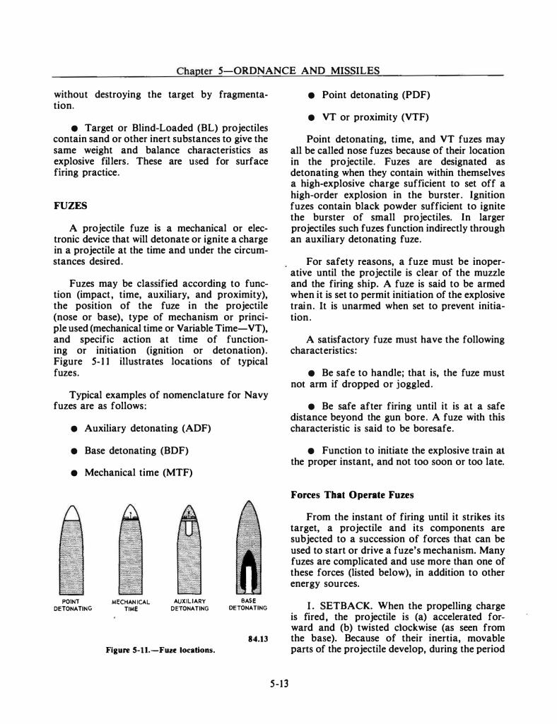
. . -· -·- - · ------· ·--- ------- - -··
Chapter 5-0RDNANCE AND MISSILES
without destroying the target by fragmenta� tion.
e Target or Blind�Loaded (BL) projectiles contain sand or other inert substances to give the same weight and balance characteristics as explosive fillers. These are used for surface firing practice.
FUZES
A projectile fuze is a mechanical or elec� tronic device that will detonate or ignite a charge in a projectile at the time and under the circumstances desired.
Fuzes may be classified according to func� tion (impact, time, auxiliary, and proximity), the position of the fuze in the projectile (nose or base), type of mechanism or principle used (mechanical time or Variable Time-VT), and specific action at time of functioning or initiation (ignition or detonation). Figure 5� 1 1 illustrates locations of typical fuzes.
Typical examples of nomenclature for Navy fuzes are as follows:
• Auxiliary detonating (ADF)
• Base detonating (BDF)
e Mechanical time (MTF)
POINT DETONATING
MECHANICAL TIME
AUXILIARY DETONATING
Figure S-11.-Fuze locations.
BASE DETONATING
84.13
5-13
• Point detonating (PDF)
• VT or proximity (VTF)
Point detonating, time, and VT fuzes may all be called nose fuzes because of their location in the projectile. Fuzes are designated as detonating when they contain within themselves a high-explosive charge sufficient to set off a high-order explosion in the burster. Ignition fuzes contain black powder sufficient to ignite the burster of small projectiles. In larger projectiles such fuzes function indirectly through an auxiliary detonating fuze.
For safety reasons, a fuze must be inoperative until the projectile is clear of the muzzle and the firing ship. A fuze is said to be armed when it is set to permit initiation of the explosive train. It is unarmed when set to prevent initiation.
A satisfactory fuze must have the following characteristics:
e Be safe to handle; that is, the fuze must not arm if dropped or joggled.
• Be safe after firing until it is at a safe distance beyond the gun bore. A fuze with this characteristic is said to be boresafe.
• Function to initiate the explosive train at the proper instant, and not too soon or too late.
Forces That Operate Fuzes
From the instant of firing until it strikes its target, a projectile and its components are subjected to a succession of forces that can be used to start or drive a fuze's mechanism. Many fuzes are complicated and use more than one of these forces (listed below), in addition to other energy sources.
I . SETBACK. When the propelling charge is fired, the projectile is (a) accelerated forward and (b) twisted clockwise (as seen from the base). Because of their inertia, movable parts of the projectile develop, during the period
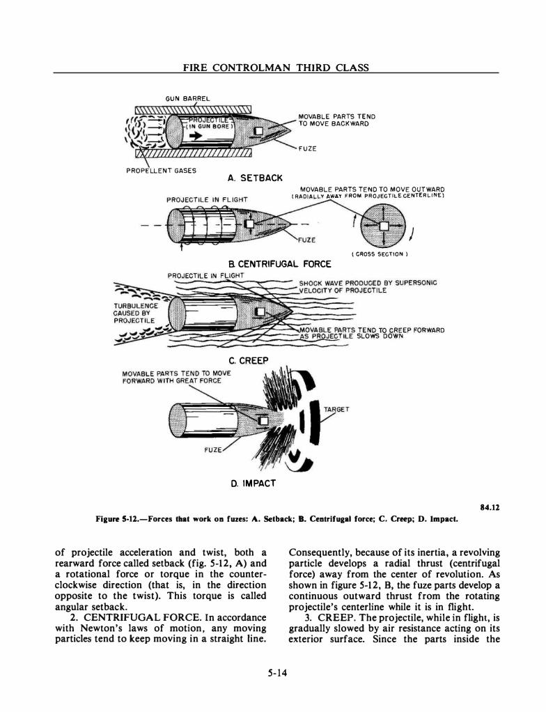
FIRE CONTROLMAN THIRD CLASS
GUN BARREL
PROPELLENT GASES
A. SETBACK
MOVABLE PARTS TEND TO MOVE BACKWARD
FUZE
MOVABLE PARTS TEND TO MOVE OUTWARD (RADIALLY FROM PROJECTILE CENTERLINE l
) ( CROSS SECTION l
a CENTRIFUGAL FORCE PROJECTILE IN
C. CREEP
0. IMPACT
TEND TO CREEP FORWARD SLOWS DOWN
84.12
Figure 5-11.-Forces that work on fuzes: A. Setback; B. Centrifugal force; C. Creep; D. Impact.
of projectile acceleration and twist, both a rearward force called setback (fig. 5-12, A) and a rotational force or torque in the counterclockwise direction (that is, in the direction opposite to the twist). This torque is called angular setback.
2. CENTRIFUGAL FORCE. In accordance with Newton's laws of motion, any moving particles tend to keep moving in a straight line.
5-14
Consequently, because of its inertia, a revolving particle develops a radial thrust (centrifugal force) away from the center of revolution. As shown in figure 5-12, B, the fuze parts develop a continuous outward thrust from the rotating projectile's centerline while it is in flight.
3. CREEP. The projectile, while in flight, is gradually slowed by air resistance acting on its exterior surface. Since the parts inside the
Chapter 5-0RDNANCE AND MISSILES
projectile are not in contact with the air and do not meet this resistance, they tend, because of inertia, to continue in motion at the same velocity. Thus as illustrated in figure 5-12, C, they exert a continuous forward thrust, called creep.
4. IMPACT. Because of inertia, a projectile's parts tend to continue moving forward when it strikes; this develops considerable force. Impact is generally used to initiate the explosive train (fig. 5-12, D).
S. TARGET CONTACT (not illustrated). When a firing plunger or other part of a projectile contacts the target, it is driven toward the rear with respect to the remainder of the projectile. Target contact is used to start the explosive train.
Types and Applications of Fuzes
Auxiliary detonating fuzes are used in conjunction with all types of nose fuzes in projectiles of 3-inch and greater caliber except some illuminating and special purpose projectiles. They prevent detonation if the nose fuze is accidentally actuated before the auxiliary detonating fuze is armed.
Base detonating fuzes are used alone in AP and COM projectiles and in combination with nose fuzes in dual purpose projectiles such as High Explosive Mechanical Time/Point Detonation (HEMT /PO) and HC. In the latter instance their functioning is completely independent of the nose and auxiliary fuzes. All base detonating fuzes function on impact; some, however, have a delay time (0.02 to 0.033 second) after the projectile hits, to allow time for armor penetration.
Mechanical time fuzes (MTF) are clockwork mechanisms that begin to function upon firing and initiate the explosive train at a selected time following firing. They are used in high explosive, illuminating, and various special purpose projectiles. When used in high explosive projectiles, these fuzes work in conjunction with auxiliary detonating fuzes. MTFs contain a gear train and an escapement mechanism that start to operate immediately after the inertial force of setback
5-15
has ceased. Centrifugal force acting on weights, with or without the aid of coiled springs, supplies the energy to run the clock mechanism. After the predetermined and preset time interval, a spring-loaded firing pin is released and strikes the initial element of the fuze explosive train.
MTFs are used in projectiles with high fragmentation qualities to provide air bursts. Air bursts are effective against personnel if they are timed to burst, say 50 feet above a trench or other occupied area. Gunfire support requirements call for these bursts to be 25 to SO feet above the target.
Even though they are designed for aircraft fire, MTFs are used often against surface or shore targets. The superiority of timed projectiles is obvious. Fragments are thrown in all directions, while others require target contact before detonation. A direct hit is improbable on a small, fast-moving target, but the 5· HEMT /PD projectile has been designed to increase the probability of a hit by using a timed air burst. An HEMT /PD projectile may have a base detonating fuze, auxiliary detonating fuze, and mechanical time fuze.
Point detonating fuzes are designed for function on impact. They are faster acting than BDFs and are used chiefly against lightly armored targets in gunfire support. Point detonating fuzes are found in high capacity (HC) and white phosphorous (smoke) projectiles. These fuzes are inserted into the projectile's nose in an unarmed condition; they are armed by centrifugal force after the projectile has been fired.
VT fuzes are proximity fuzes, used in all of the types of projectiles that can use mechanical time fuzes, except illuminating and window. The VT fuze is a self-contained radio transmitterreceiver which receives echoes of its transmission as reflected by a target. When the returning signal is of sufficient strength, the firing circuit closes as the projectile nears the target. The fuze is rugged and compact and fits into the nose of a projectile.
VTs are also effective against personnel ashore but are used mainly agahtst air targets. If
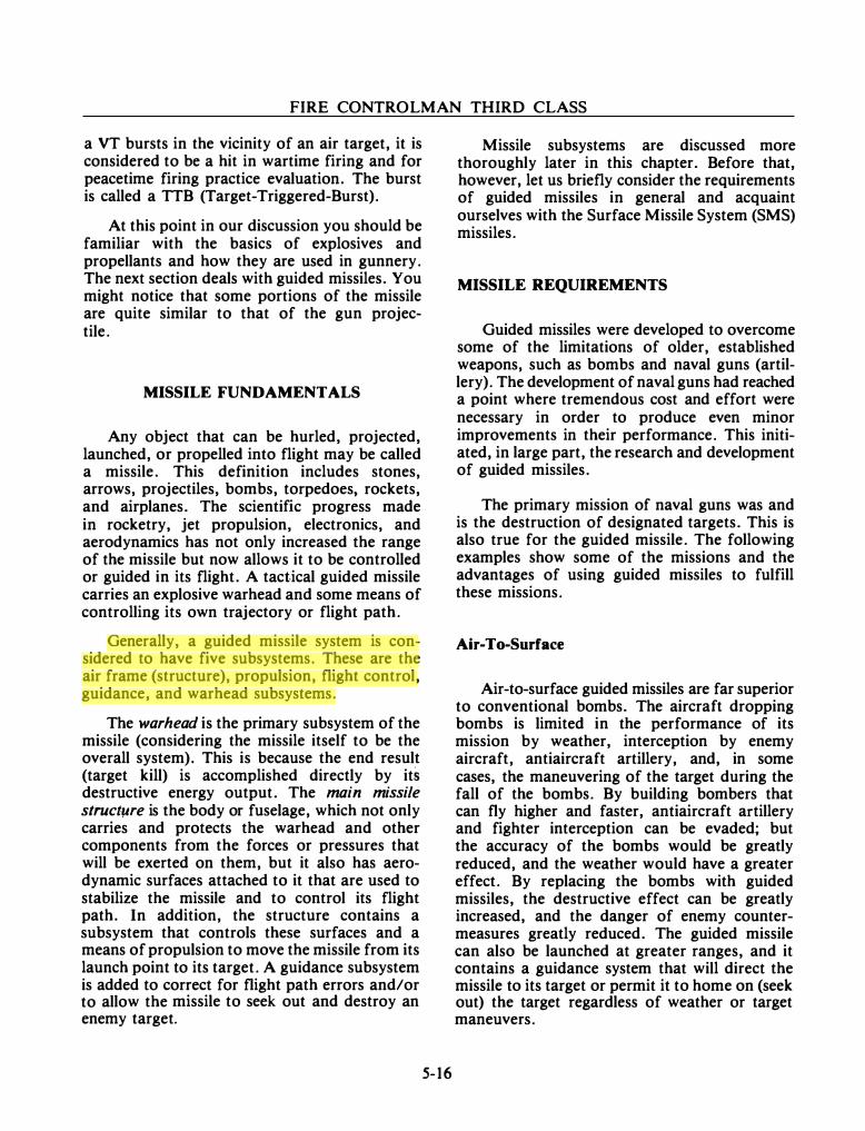
FIRE CONTROLMAN THIRD CLASS
a VT bursts in the vicinity of an air target, it is considered to be a hit in wartime firing and for peacetime firing practice evaluation. The burst is called a TTB (Target-Triggered-Burst).
At this point in our discussion you should be familiar with the basics of explosives and propellants and how they are used in gunnery. The next section deals with guided missiles. You might notice that some portions of the missile are quite similar to that of the gun projectile.
MISSILE FUNDAMENTALS
Any object that can be hurled, projected, launched, or propelled into flight may be called a missile. This definition includes stones, arrows, projectiles, bombs, torpedoes, rockets, and airplanes. The scientific progress made in rocketry, jet propulsion, electronics, and aerodynamics has not only increased the range of the missile but now allows it to be controlled or guided in its flight. A tactical guided missile carries an explosive warhead and some means of controlling its own trajectory or flight path.
Generally, a guided missile system is considered to have five subsystems. These are the air frame (structure), propulsion, flight control, guidance, and warhead subsystems.
The warhead is the primary subsystem of the missile (considering the missile itself to be the overall system). This is because the end result (target kill) is accomplished directly by its destructive energy output. The main missile structwe is the body or fuselage, which not only carries and protects the warhead and other components from the forces or pressures that will be exerted on them, but it also has aerodynamic surfaces attached to it that are used to stabilize the missile and to control its flight path. In addition, the structure contains a subsystem that controls these surfaces and a means of propulsion to move the missile from its launch point to its target. A guidance subsystem is added to correct for flight path errors and/or to allow the missile to seek out and destroy an enemy target.
5- 16
Missile subsystems are discussed more thoroughly later in this chapter. Before that, however, let us briefly consider the requirements of guided missiles in general and acquaint ourselves with the Surface Missile System (SMS) missiles.
MISSILE REQUIREMENTS
Guided missiles were developed to overcome some of the limitations of older, established weapons, such as bombs and naval guns (artillery). The development of naval guns had reached a point where tremendous cost and effort were necessary in order to produce even minor improvements in their performance. This initiated, in large part, the research and development of guided missiles.
The primary mission of naval guns was and is the destruction of designated targets. This is also true for the guided missile. The following examples show some of the missions and the advantages of using guided missiles to fulfill these missions.
Air-To-Surface
Air-to-surface guided missiles are far superior to conventional bombs. The aircraft dropping bombs is limited in the performance of its mission by weather, interception by enemy aircraft, antiaircraft artillery, and, in some cases, the maneuvering of the target during the fall of the bombs. By building bombers that can fly higher and faster, antiaircraft artillery and fighter interception can be evaded; but the accuracy of the bombs would be greatly reduced, and the weather would have a greater effect. By replacing the bombs with guided missiles, the destructive effect can be greatly increased, and the danger of enemy countermeasures greatly reduced. The guided missile can also be launched at greater ranges, and it contains a guidance system that will direct the missile to its target or permit it to home on (seek out) the target regardless of weather or target maneuvers.

Chapter 5 ORDNANCE AND MISSILES
Surface-To-Air
Now consider your side of the problem. As an FC, you are involved with missiles that are used primarily as surface-to-air weapons. Obviously, you want the operational capabilities of your ship's weapons to exceed those of the enemy. Aircraft, for example, must be destroyed before they reach their weapon-release range (called standoff range). Ship-launched guided missiles are greatly superior to antiaircraft guns in range, maximum altitude, and accuracy. As a result, they can destroy enemy aircraft beyond the range of a gun.
Air-To-Air
In air-to-air combat, guided missiles greatly increase the striking range and destructive power of aircraft.
The interceptor aircraft of the past relied primarily on its speed advantage to maneuver into a position where its short-range weapons were effective. Against modern jet bombers or missiles, interceptors lose their speed advantage, thus making it difficult, if not impossible, for them to maneuver into position for attack. By arming them with long-range missiles that travel at supersonic speeds, interceptors are capable of combating the high-speed, high-altitude weapons of modern warfare.
Surface-To-Surface
The average person, when thinking of a surface-to-surface missile, probably visualizes an intercontinental ballistic missile (ICBM), such as MINUTEMAN or the now obsolete TIT AN, with ranges in excess of 3000 nautical miles. The ICBMs are fine for their purpose. No one, however, would consider firing one at a target that was less than 50 miles away. A need, therefore, exists for a comparatively short-range surface-to-surface guided missile. The SMS missiles satisfy this need, as you will find out when SMS missile configurations are discussed at the end of this chapter. Until
5-17
then, let's look at a brief introduction to the missiles.
SURFACE LAUNCHED MISSILES
The missiles that you, as an FC, may be concerned with are the TARTAR, TERRIER, STANDARD (SM-1 and SM-2), SPARROW III, HARPOON, and TOMAHAWK. As you will discover in the section describing SMS missile configurations, the actual missile or missiles with which you will be directly involved will depend upon the class of ship to which you are assigned.
The HARPOON is an antiship missile capable of being launched from an aircraft, a ship, or a submarine. The others are primarily surface-toair missiles. They do, however, have surfaceto-surface capability and, in some cases, a surface-to-shore capability. As indicated earlier, these will be more fully discussed later in the chapter.
Now you know the names of the SMS missiles. This should prove beneficial because frequent reference is made to them throughout this chapter. Next is an explanation of how the missiles are identified.
MISSILE DESIGNATIONS
Military guided missiles of the United States are categorized according to the environment from which the missile is launched, the type of mission the missile is intended to perform, the missile type, the design number of the missile, and the series number of the missile. For example, when you refer to table 5-1 , you can determine that the RIM-2F is a ship-launched guided missile designed to intercept air targets. The missile design number is 2, and the F indicates that it is the sixth modification to that design.
Additional examples of missile designations are given in the section that describes SMS missile configurations. When you get to them, refer back to this table, and see if you can categorize the missiles designated.

FIRE CONTROLMAN THIRD CLASS
Table S-t.-Missile categories
LAUNCH ENVIRONMENT SYMBOLS W Weather V ehicles designed to observe, record, or relay meteorological data.
Letter Title Description
A B
c
H
L
M
p
R
u
D
E
G
Q
T
u
Air Multiple
Coffin
Silo Stored
Silo Launched
Mobile
Soft Pad
Ship
Underwater
Air launched. Capable of being launched from
more than one environment. Stored horizontally or at less
than a 45 degree angle in a protective enclosure (regardless of structural strength) and launched from the ground.
Vertically stored below ground level and lauriched from the ground.
Vertically stored and launched from below ground level.
Launched from a ground vehicle or movable platform.
Partially or nonprotected in storage and launched from the ground.
Launched from a surface vessel, such as ship, barge, etc.
Launched from a submarine or other underwater device.
MISSION S Y MBOLS
Decoy
Special Electronic
Surface Attack
InterceptAerial
Drone
Training
Vehicles designed or modified to c o n f u s e, deceive, or divert enemy defenses by simulating an attack vehicle.
Vehicles designed or modified with electronic equipment for c o m m u n i c a t i o n s , countermeasures, electronic radiation sounding, or other electronic recording or relay missions.
Vehicles designed to destroy land or sea targets.
Vehicles designed to intercept aerial targets, defensive or offensive roles.
Vehicles designed for target, reconnaissance, or surveillance purposes.
V e h i c l e s d e s i g n e d o r permanently m odified for training purposes.
Underwater V eh ic les designed to destroy Attack enemy submarines or other
underwater targets or to detonate underwater.
5-18
VEHICLE TYPE SYMBOLS
M
N
R
Guided Missile
Probe
Rocket
U n m a n n e d , self-propelled vehicles designed to move in a trajectory or flight path all or partially above the earth's surface and whose trajectory or course, while the vehicle is in motion, can be controlled r e m otely or b y homing systems, or by inertial and/or programmed guidance from within. This term does not include space vehicles, space boosters, or naval torpedoes, but does include target and reconnaissance drones.
N o n - o r b i t al instrumented vehicles not involved in space missions that are used to p e n e trate the aerospace e n v i ronment and report information.
�If-propelled vehicles without installed or remote control guidance mechanisms, whosetrajectory cannot be altereci after launch. Rocket systems designed for line of sight are not included.
The military designation of the ASROC missile is RUR·5A since it is a ship launched rocket designe-.1 to destroy enemy submarines. It is the first (A) of its assigned design number (5). If necessary, to denote a special status, one of the following letters is affixed before the military designation.
STATUS PREFIX SYMBOLS
J Special Test (Temporary)
N Special Test (Permanent)
X Experimental Y Prototype Z Planning
V e hi des especially conf"JgUred simply to accommodate test.
Vehicles so modified they will not be returned to original use.
Vehicles under development. Preproduction vehicles for test. Vehicles in planning stage.
167.702
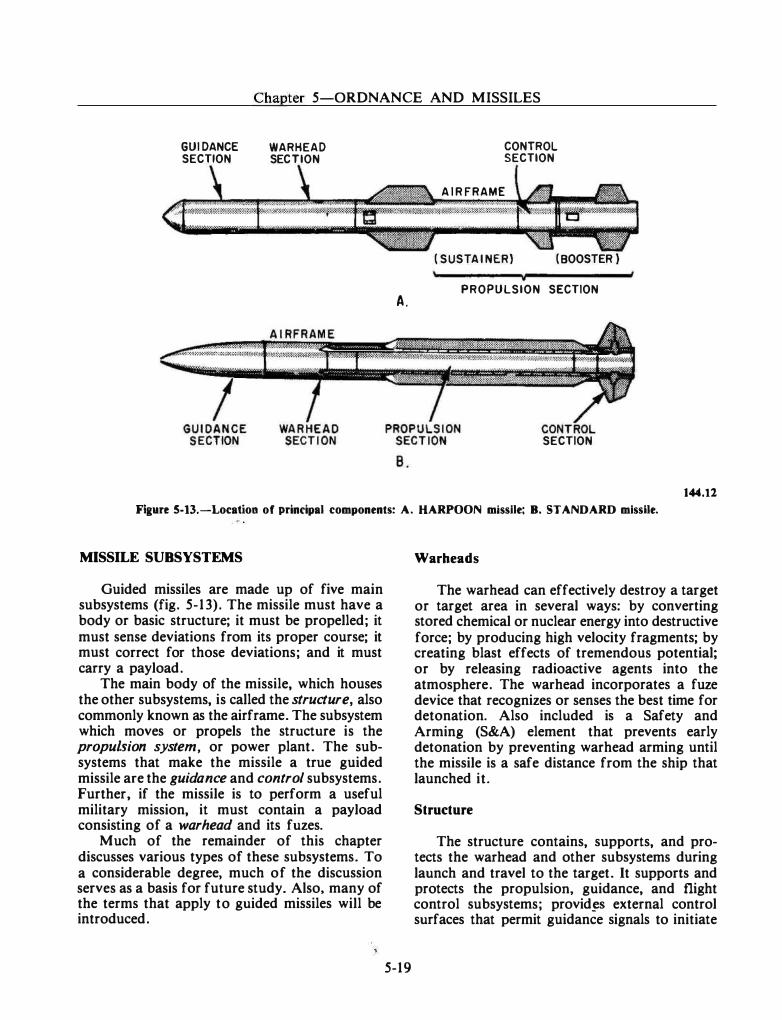
. . ------------------ - - - - · · -
Chapter 5-0RDNANCE AND MISSILES
GUI DANCE SECTION
WARHEAD SECTION
A .
CONTROL SECTION
A I R FRAME
( SUSTA I NER) ( BOOSTER }
PROPULSION SECTION
SECTION
144.12
Flaure 5-13.-Location of principal components: A. HARPOON missile; B. STANDARD missile.
MISSILE SUBSYSTEMS
Guided missiles are made up of five main subsystems (fig. 5-13). The missile must have a body or basic structure; it must be propelled; it must sense deviations from its proper course; it must correct for those deviations; and it must carry a payload.
The main body of the missile, which houses the other subsystems, is called the structure, also commonly known as the airframe. The subsystem which moves or propels the structure is the propulsion system, or power plant. The subsystems that make the missile a true guided missile are the guidance and control subsystems. Further, if the missile is to perform a useful military mission, it must contain a payload consisting of a warhead and its fuzes.
Much of the remainder of this chapter discusses various types of these subsystems. To a considerable degree, much of the discussion serves as a basis for future study. Also, many of the terms that apply to guided missiles will be introduced.
5-19
Warheads
The warhead can effectively destroy a target or target area in several ways: by converting stored chemical or nuclear energy into destructive force; by producing high velocity fragments; by creating blast effects of tremendous potential; or by releasing radioactive agents into the atmosphere. The warhead incorporates a fuze device that recognizes or senses the best time for detonation. Also included is a Safety and Arming (S&A) element that prevents early detonation by preventing warhead arming until the missile is a safe distance from the ship that launched it.
Structure
The structure contains, supports, and protects the warhead and other subsystems during launch and travel to the target. It supports and protects the propulsion, guidance, and flight control subsystems; provid� external control surfaces that permit guidance signals to initiate
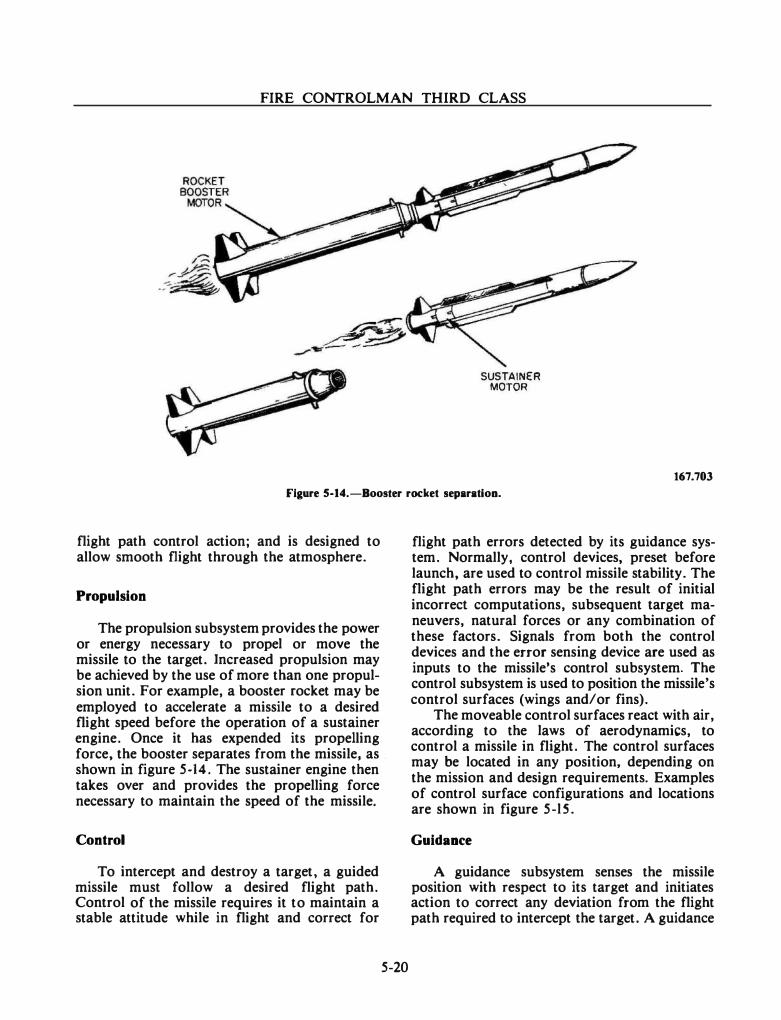
FIRE CONTROLMAN THIRD CLASS
SUSTAINER MOTOR
167.703
Figure 5-14.-Booster rocket separation.
flight path control action; and is designed to allow smooth flight through the atmosphere.
Propulsion
The propulsion subsystem provides the power or energy necessary to propel or move the missile to the target. Increased propulsion may be achieved by the use of more than one propulsion unit. For example, a booster rocket may be employed to accelerate a missile to a desired flight speed before the operation of a sustainer engine. Once it has expended its propelling force, the booster separates from the missile, as . shown in figure 5-14. The sustainer engine then takes over and provides the propelling force necessary to maintain the speed of the missile.
Control
To intercept and destroy a target, a guided missile must follow a desired flight path. Control of the missile requires it to maintain a stable attitude while in flight and correct for
5-20
flight path errors detected by its guidance system. Normally, control devices, preset before launch, are used to control missile stability. The flight path errors may be the result of initial incorrect computations, subsequent target maneuvers, natural forces or any combination of these factors. Signals from both the control devices and the error sensing device are used as inputs to the missile's control subsystem. The control subsystem is used to position the missile's control surfaces (wings and/or fins).
The moveable control surfaces react with air, according to the laws of aerodynamics, to control a missile in flight. The control surfaces may be located in any position, depending on the mission and design requirements. Examples of control surface configurations and locations are shown in figure 5-l S .
Guidance
A guidance subsystem senses the missile position with respect to its target and initiates action to correct any deviation from the flight path required to intercept the target. A guidance
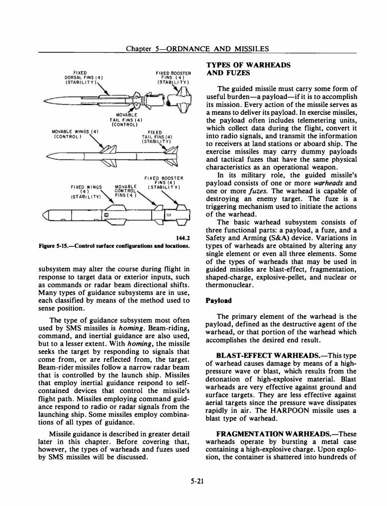
Chapter 5-0RDNANCE AND MISSILES
Fl XED FIXED BOOSTER DORSAL FINS ( 4 ) F INS ( 4 )
-
---1-ST_
A_B
�
I L
�
I=T=Y�
)
�������(��
�
�
S;� MOVABLE WINGS ( 4 l (CONTROL )
MOVABLE TAIL FINS ( 4 ) (CONTROL)
Fl X ED BOOSTER F INS (4 )
Fl XED W I NGS MOVABLE ( STAB IL l T Y ) ( 4 ) '\.. CONTROL
' (STABI L I TY) "FINS ( 4 ) '
144.2
Figure 5-15.-Control surface configurations and locations.
subsystem may alter the course during flight in response to target data or exterior inputs, such as commands or radar beam directional shifts. Many types of guidance subsystems are in use, each classified by means of the method used to sense position.
The type of guidance subsystem most often used by SMS missiles is homing. Beam-riding, command, and inertial guidance are also used, but to a lesser extent. With homing, the missile seeks the target by responding to signals that come from, or are reflected from, the target. Beam-rider missiles follow a narrow radar beam that is controlled by the launch ship. Missiles that employ inertial guidance respond to selfcontained devices that control the missile's flight path. Missiles employing command guidance respond to radio or radar signals from the launching ship. Some missiles employ combinations of all types of guidance.
Missile guidance is described in greater detail later in this chapter. Before covering that, however, the types of warheads and fuzes used by SMS missiles will be discussed.
5-21
TYPES OF WARHEADS AND FUZES
The guided missile must carry some form of useful burden-a payload-if it is to accomplish its mission. Every action of the missile serves as a means to deliver its payload. In exercise missiles, the payload often includes telemetering units, which collect data during the flight, convert it into radio signals, and transmit the information to receivers at land stations or aboard ship. The exercise missiles may carry dummy payloads and tactical fuzes that have the same physical characteristics as an operational weapon.
In its military role, the guided missile's payload consists of one or more warheads and one or more fuzes. The warhead is capable of destroying an enemy target. The fuze is a triggering mechanism used to initiate the actions of the warhead.
The basic warhead subsystem consists of three functional parts: a payload, a fuze, and a Safety and Arming (S&A) device. Variations in types of warheads are obtained by altering any single element or even all three elements. Some of the types of warheads that may be used in guided missiles are blast-effect, fragmentation, shaped-charge, explosive-pellet, and nuclear or thermonuclear.
Payload
The primary element of the warhead is the payload, defined as the destructive agent of the warhead, or that portion of the warhead which accomplishes the desired end result.
BLAST -EFFECT WARHEADS.-This type of warhead causes damage by means of a highpressure wave or blast, which results from the detonation of high-explosive material. Blast warheads are very effective against ground and surface targets. They are less effective against aerial targets since the pressure wave dissipates rapidly in air. The HARPOON missile uses a blast type of warhead.
FRAGMENTATION WARHEADS.-These warheads operate by bursting a metal case containing a high-explosive charge. Upon explosion, the container is shattered into hundreds of
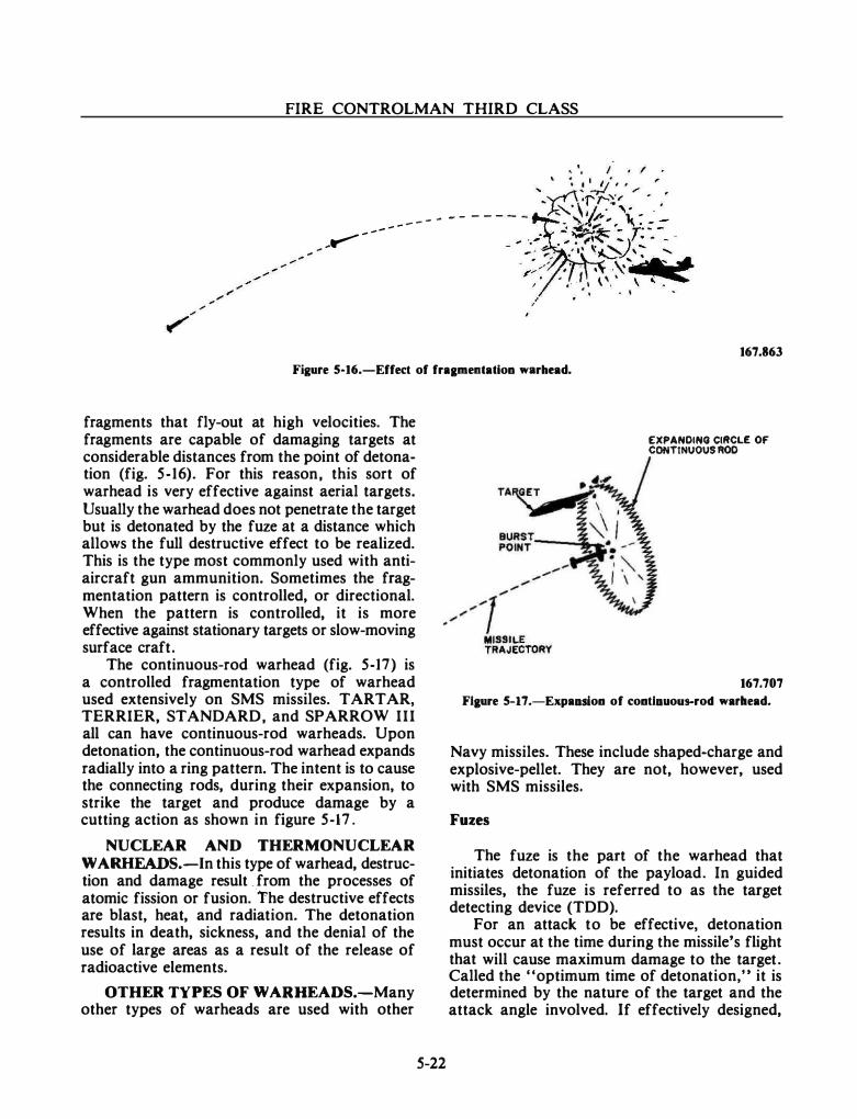
FIRE CONTROLMAN THIRD CLASS
• . .
- - - - - - - - - - -
,., - - - - -
. . /
167.863
Figure 5·16.-Effect of fraameotation warhead.
fragments that fly-out at high velocities. The fragments are capable of damaging targets at considerable distances from the point of detonation (fig. 5-16). For this reason, this sort of warhead is very effective against aerial targets. Usually the warhead does not penetrate the target but is detonated by the fuze at a distance which allows the full destructive effect to be realized. This is the type most commonly used with antiaircraft gun ammunition. Sometimes the fragmentation pattern is controlled, or directional. When the pattern is controlled, it is more effective against stationary targets or slow-moving surface craft.
The continuous-rod warhead (fig. 5-17) is a controlled fragmentation type of warhead used extensively on SMS missiles. TARTAR, TERRIER, STANDARD, and SPARROW III all can have continuous-rod warheads. Upon detonation, the continuous-rod warhead expands radially into a ring pattern. The intent is to cause the connecting rods, during their expansion, to strike the target and produce damage by a cutting action as shown in figure 5-17.
NUCLEAR AND THERMONUCLEAR W ARHEADS.-In this type of warhead, destruction and damage result . from the processes of atomic fission or fusion.
-The destructive effects
are blast, heat, and radiation. The detonation results in death, sickness, and the denial of the use of large areas as a result of the release of radioactive elements.
OTHER TYPES OF WARHEADS.-Many other types of warheads are used with other
S-22
EXPANDING ClltCLI! OF CONTINUOUS ROD
167.707
Flaure 5-17.-Expaasioo of cootlauous-rocl warllead.
Navy missiles. These include shaped-charge and explosive-pellet. They are not, however, used with SMS missiles.
Fuzes
The fuze is the part of the warhead that initiates detonation of the payload. In guided missiles, the fuze is referred to as the target detecting device (TDD).
For an attack to be effective, detonation must occur at the time during the missile's flight that will cause maximum damage to the target. Called the "optimum time of detonation," it is determined by the nature of the target and the attack angle involved. If effectively designed,
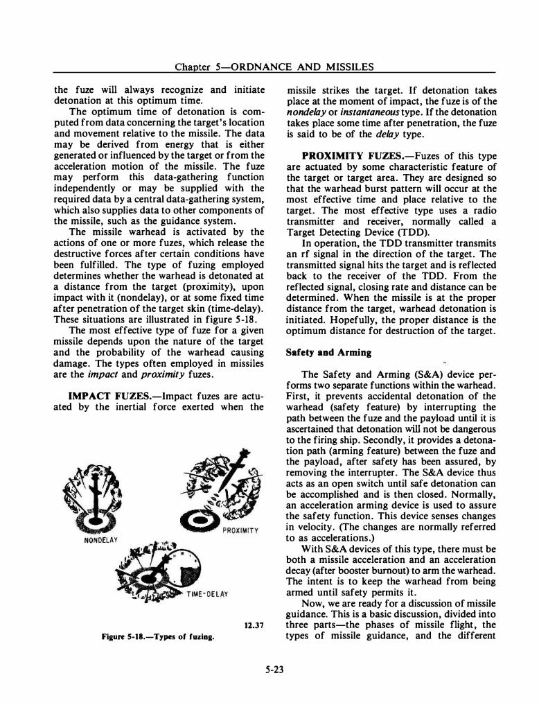
Chapter 5-0RDNANCE AND MISSILES
the fuze will always recognize and initiate detonation at this optimum time.
The optimum time of detonation is computed from data concerning the target's location and movement relative to the missile. The data may be derived from energy that is either generated or influenced by the target or from the acceleration motion of the missile. The fuze may perform this data-gathering function independently or may be supplied with the required data by a central data-gathering system, which also supplies data to other components of the missile, such as the guidance system.
The missile warhead is activated by the actions of one or more fuzes, which release the destructive forces after certain conditions have been fulfilled. The type of fuzing employed determines whether the warhead is detonated at a distance from the target (proximity), upon impact with it (nondelay), or at some fixed time after penetration of the target skin (time-delay). These situations are illustrated in figure 5-18.
The most effective type of fuze for a given missile depends upon the nature of the target and the probability of the warhead causing damage. The types often employed in missiles are the impact and proximity fuzes.
IMPACT FUZES.-Impact fuzes are actuated by the inertial force exerted when the
NONOELAY
11.37
Figure 5-18.-Types of fuzing.
5-23
missile strikes the target. If detonation takes place at the moment of impact, the fuze is of the nondelay or instantaneous type. If the detonation takes place some time after penetration, the fuze is said to be of the delay type.
PROXIMITY FUZES.-Fuzes of this type are actuated by some characteristic feature of the target or target area. They are designed so that the warhead burst pattern will occur at the most effective time and place relative to the target. The most effective type uses a radio transmitter and receiver, normally called a Target Detecting Device (TDD).
In operation, the TDD transmitter transmits an rf signal in the direction of the target. The transmitted signal hits the target and is reflected back to the receiver of the TDD. From the reflected signal, closing rate and distance can be determined. When the missile is at the proper distance from the target, warhead detonation is initiated. Hopefully, the proper distance is the optimum distance for destruction of the target.
Safety and Arming
The Safety and Arming (S&A) device performs two separate functions within the warhead. First, it prevents accidental detonation of the warhead (safety feature) by interrupting the path between the fuze and the payload until it is ascertained that detonation will not be dangerous to the firing ship. Secondly, it provides a detonation path (arming feature) between the fuze and the payload, after safety has been assured, by removing the interrupter. The S&A device thus acts as an open switch until safe detonation can be accomplished and is then closed. Normally, an acceleration arming device is used to assure the safety function. This device senses changes in velocity. (The changes are normally referred to as accelerations.)
With S&A devices of this type, there must be both a missile acceleration and an acceleration decay (after booster burnout) to arm the warhead. The intent is to keep the warhead from being armed until safety permits it.
Now. we are ready for a discussion of missile guidance. This is a basic discussion, divided into three parts-the phases of missile flight, the types of missile guidance, and the different
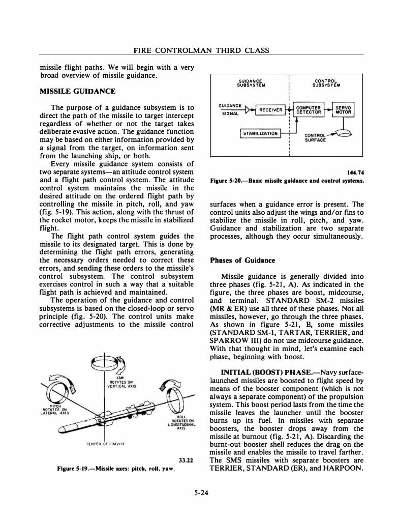
FIRE CONTROLMAN THIRD CLASS
missile flight paths. We will begin with a very broad overview of missile guidance.
MISSILE GUIDANCE
The purpose of a guidance subsystem is to direct the path of the missile to target intercept regardless of whether or not the target takes deliberate evasive action. The guidance function may be based on either information provided by a signal from the target, on information sent from the launching ship, or both.
Every missile guidance system consists of two separate systems-an attitude control system and a flight path control system. The attitude control system maintains the missile in the desired attitude on the ordered flight path by controlling the missile in pitch, roll, and yaw (fig. 5-19). This action, along with the thrust of the rocket motor, keeps the missile in stabilized flight.
The flight path control system guides the missile to its designated target. This is done by determining the flight path errors, generating the necessary orders needed to correct these errors, and sending these orders to the missile's control subsystem. The control subsystem exercises control in such a way that a suitable flight path is achieved and maintained.
The operation of the guidance and control subsystems is based on the closed-loop or servo principle (fig. 5-20). The control units make corrective adjustments to the missile control
CENTER OF GRAVITY
33.22
Fl1ure S-19.-Missile ues: pitch, roll, yaw.
5-24
GUIDANCE SUBSYSTEM
GUIDANCE
SIGNAL
STABILIZATION
CONTROL. SUBSYSTEM
144.74
Fiaure 5-20.-Baslc missile guidance and control systems.
surfaces when a guidance error is present. The control units also adjust the wings and/or fins to stabilize the missile in roll, pitch, and yaw. Guidance and stabilization are two separate processes, although they occur simultaneously.
Phases of Guidance
Missile guidance is generally divided into three phases (fig. 5-21 , A). As indicated in the figure, the three phases are boost, midcourse, and terminal. STANDARD SM-2 missiles (MR & ER) use all three of these phases. Not all missiles, however, go through the three phases. As shown in figure 5-21, B, some missiles (STANDARD SM-1, TARTAR, TERRIER, and SPARROW III) do not use midcourse guidance. With that thought in mind, let's examine each phase, beginning with boost.
INITIAL (BOOST) PHASE.-Navy surfacelaunched missiles are boosted to flight speed by means of the booster component (which is not always a separate component) of the propulsion system. This boost period lasts from the time the missile leaves the launcher until the booster burns up its fuel. In missiles with separate boosters, the booster drops away from the missile at burnout (fig. 5-2 1 , A). Discarding the burnt-out booster shell reduces the drag on the missile and enables the missile to travel farther. The SMS missiles with separate boosters are TERRIER, STANDARD (ER), and HARPOON.
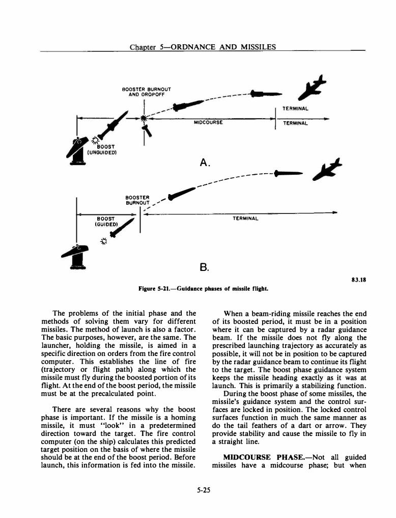
Chapter 5-0RDNANCE AND MISSILES
BOOSTER BURNOUT ANO OROPOFF
MIDCOURSE
A .
TERMINAL
- - - - - ---··--- -- -
BOOSTER _, �--
BURNOUT ,. "" ,
BOO���/
(GUID;.
'"" �.-
TERMINAL
B. 83.18
Figure S-21.-Guldance phases of missile fligbt.
The problems of the initial phase and the methods of solving them vary for different missiles. The method of launch is also a factor. The basic purposes, however, are the same. The launcher, holding the missile, is aimed in a specific direction on orders from the fire control computer. This establishes the line of fire (trajectory or flight path) along which the missile must fly during the boosted portion of its flight. At the end of the boost period, the missile must be at the precalculated point.
There are several reasons why the boost phase is important. If the missile is a homing missile, it must "look" in a predetermined direction toward the target. The fire control computer (on the ship) calculates this predicted target position on the basis of where the missile should be at the end of the boost period. Before launch, this information is fed into the missile.
5-25
When a beam-riding missile reaches the end of its boosted period, it must be in a position where it can be captured by a radar guidance beam. If the missile does not fly along the prescribed launching trajectory as accurately as possible, it will not be in position to be captured by the radar guidance beam to continue its flight to the target. The boost phase guidance system keeps the missile heading exactly as it was at launch. This is primarily a stabilizing function.
During the boost phase of some missiles, the missile's guidance system and the control surfaces are locked in position. The locked control surfaces function in much the same manner as do the tail feathers of a dart or arrow. They provide stability and cause the missile to fly in a straight line.
MIDCOURSE PHASE.-Not all guided missiles have a midcourse phase; but when
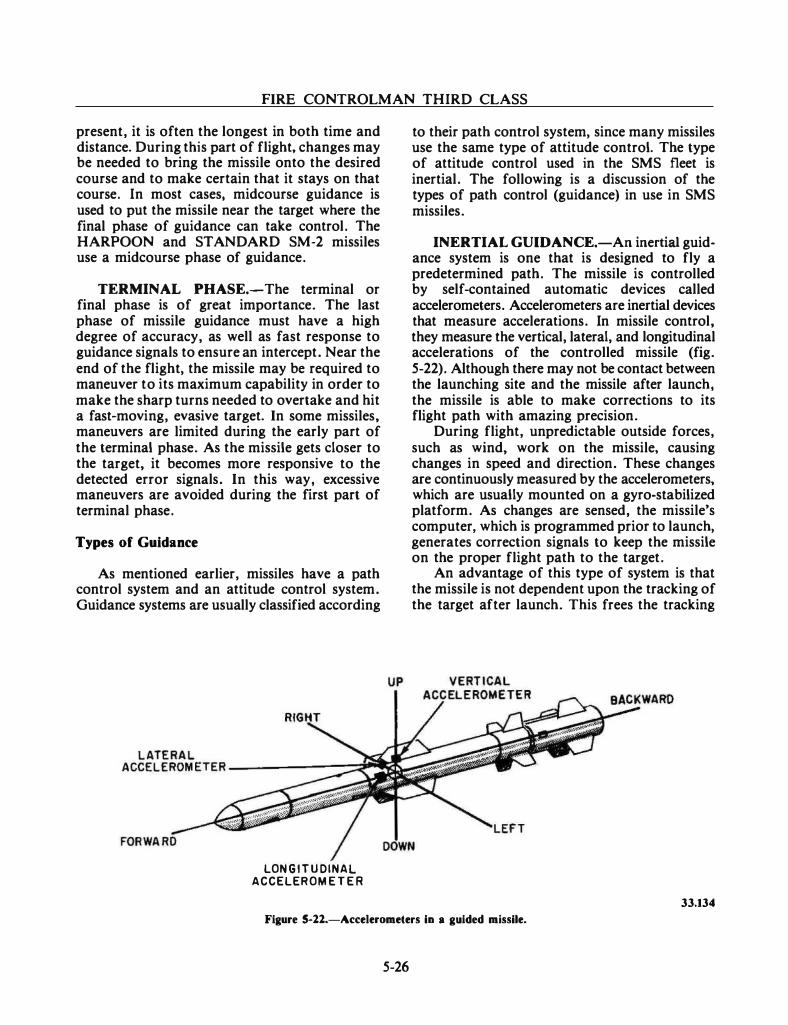
FIRE CONTROLMAN THIRD CLASS
present, it is often the longest in both time and distance. During this part of flight, changes may be needed to bring the missile onto the desired course and to make certain that it stays on that course. In most cases, midcourse guidance is used to put the missile near the target where the final phase of guidance can take control. The HARPOON and STANDARD SM-2 missiles use a midcourse phase of guidance.
TERMINAL PHASE.-The terminal or final phase is of great importance. The last phase of missile guidance must have a high degree of accuracy, as well as fast response to guidance signals to ensure an intercept. Near the end of the flight, the missile may be required to maneuver to its maximum capability in order to make the sharp turns needed to overtake and hit a fast-moving, evasive target. In some missiles, maneuvers are limited during the early part of the terminal phase. As the missile gets closer to the target, it becomes more responsive to the detected error signals. In this way, excessive maneuvers are avoided during the first part of terminal phase.
Types of Guidance
As mentioned earlier, missiles have a path control system and an attitude control system. Guidance systems are usually classified according
LON G I T U DINAL ACCELEROM E T E R
to their path control system, since many missiles use the same type of attitude control. The type of attitude control used in the SMS fleet is inertial. The following is a discussion of the types of path control (guidance) in use in SMS missiles.
INERTIAL GUIDANCE.-An inertial guidance system is one that is designed to fly a predetermined path. The missile is controlled by self-contained automatic devices called accelerometers. Accelerometers are inertial devices that measure accelerations. In missile control, they measure the vertical, lateral, and longitudinal accelerations of the controlled missile (fig. 5-22). Although there may not be contact between the launching site and the missile after launch, the missile is able to make corrections to its flight path with amazing precision.
During flight, unpredictable outside forces, such as wind, work on the missile, causing changes in speed and direction. These changes are continuously measured by the accelerometers. which are usually mounted on a gyro-stabilized platform. As changes are sensed, the missile's computer. which is programmed prior to launch, generates correction signals to keep the missile on the proper flight path to the target.
An advantage of this type of system is that the missile is not dependent upon the tracking of the target after launch. This frees the tracking
33.134
Figure 5-ll.-Accelerometers in a guided missile.
5-26
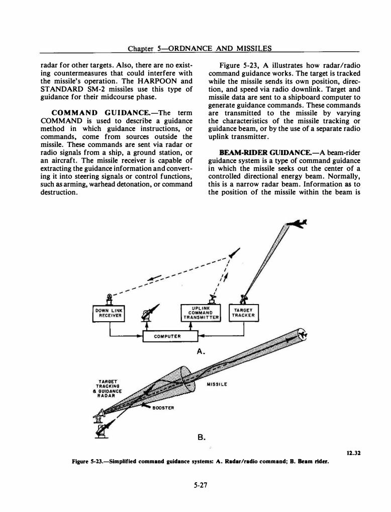
--- ·------· -----
Chapter 5-0RDNANCE AND MISSILES
radar for other targets. Also, there are no exist· ing countermeasures that could interfere with the missile's operation. The HARPOON and STANDARD SM-2 missiles use this type of guidance for their midcourse phase.
COMMAND GUIDANCE.-The term COMMAND is used to describe a guidance method in which guidance instructions, or commands, come from sources outside the missile. These commands are sent via radar or radio signals from a ship, a ground station, or an aircraft. The missile receiver is capable of extracting the guidance information and converting it into steering signals or control functions, such as arming, warhead detonation, or command destruction.
TARGET. TRACKING
& GUIDANCE R A D A R
.... .....
-
A.
B.
Figure 5-23, A illustrates how radar/radio command guidance works. The target is tracked while the missile sends its own position, direction, and speed via radio downlink. Target and missile data are sent to a shipboard computer to generate guidance commands. These commands are transmitted to the missile by varying the characteristics of the missile tracking or guidance beam, or by the use of a separate radio uplink transmitter.
BEAM-RIDER GUIDANCE.-A beam·rider guidance system is a type of command guidance in which the missile seeks out the center of a controlled directional energy beam. Normally, this is a narrow radar beam. Information as to the position of the missile within the beam is
12.32
Figure S-23.-Simpllfled command guidance systems: A. Radar/radio command; B. Beam rider.
5-27
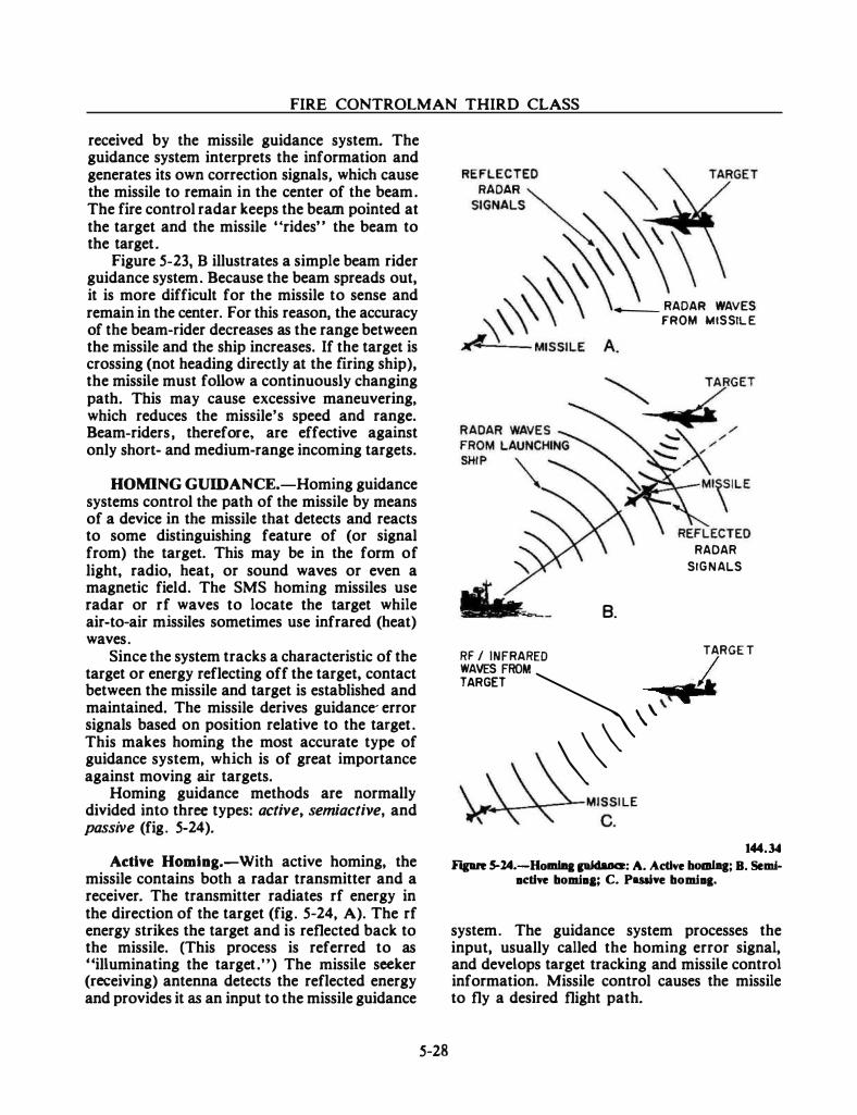
FIRE CONTROLMAN THIRD CLASS
received by the missile guidance system. The guidance system interprets the information and generates its own correction signals, which cause the missile to remain in the center of the beam. The fire control radar keeps the beam pointed at the target and the missile "rides" the beam to the target.
Figure 5-23, B illustrates a simple beam rider guidance system. Because the beam spreads out, it is more difficult for the missile to sense and remain in the center. For this reason, the accuracy of the beam-rider decreases as the range between the missile and the ship increases. If the target is crossing (not heading directly at the firing ship), the missile must follow a continuously changing path. This may cause excessive maneuvering, which reduces the missile's speed and range. Beam-riders, therefore, are effective against only short- and medium-range incoming targets.
HOMING GUIDANCE.-Homing guidance systems control the path of the missile by means of a device in the missile that detects and reacts to some distinguishing feature of (or signal from) the target. This may be in the form of light, radio, heat, or sound waves or even a magnetic field. The SMS homing missiles use radar or rf waves to locate the target while air-to-air missiles sometimes use infrared (heat) waves.
Since the system tracks a characteristic of the target or energy reflecting off the target, contact between the missile and target is established and maintained. The missile derives guidance- error signals based on position relative to the target. This makes homing the most accurate type of guidance system, which is of great importance against moving air targets.
Homing guidance methods are normally divided into three types: active, semiactive, and passive (fig. 5-24).
Active Homing.-With active homing, the missile contains both a radar transmitter and a receiver. The transmitter radiates rf energy in the direction of the target (fig. 5-24, A). The rf energy strikes the target and is reflected back to the missile. (This process is referred to as "illuminating the target.") The missile seeker (receiving) antenna detects the reflected energy and provides it as an input to the missile guidance
5-28
--- RADAR WAVES
B.
FROM MISSILE
RAOAR
SIGNALS
RF / INFRARED TARGE T
WAVES FROM I TARGET � �t
,t ,,
\\\ 144.34
Fipre 5-14.-HollliB& pidaace: A. Active boaiJq; B. Semiacdve bomia&; C. Paaive bomiaa.
system. The guidance system processes the input, usually called the homing error signal, and develops target tracking and missile control information. Missile control causes the missile to fly a desired flight path.
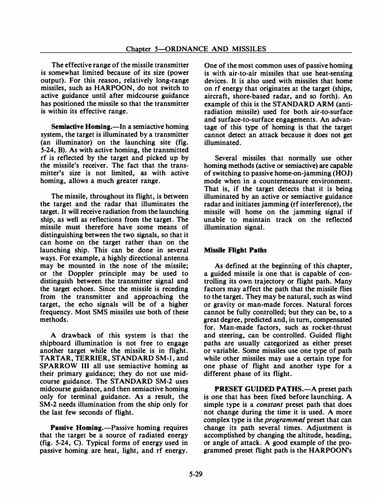
Chapter 5-0RDNANCE AND MISSILES
The effective range of the missile transmitter is somewhat limited because of its size (power output). For this reason, relatively long-range missiles, such as HARPOON, do not switch to active guidance until after midcourse guidance has positioned the missile so that the transmitter is within its effective range.
Semiactive Homing.-In a semiactive homing system, the target is illuminated by a transmitter (an illuminator) on the launching site (fig. 5-24, B). As with active homing, the transmitted rf is reflected by the target and picked up by the missile's receiver. The fact that the transmitter's size is not limited, as with active homing, allows a much greater range.
The missile, throughout its flight, is between the target and the radar that illuminates the target. It will receive radiation from the launching ship, as well as reflections from the target. The missile must therefore have some means of distinguishing between the two signals, so that it can home on the target rather than on the launching ship. This can be done in several ways. For example, a highly directional antenna may be mounted in the nose of the missile; or the Doppler principle may be used to distinguish between the transmitter signal and the target echoes. Since the missile is receding from the transmitter and approaching the target, the echo signals will be of a higher frequency. Most SMS missiles use both of these methods.
A drawback of this system is that the shipboard illumination is not free to engage another target while the missile is in flight. TARTAR, TERRIER, STANDARD SM-1, and SPARROW III all use semiactive homing as their primary guidance; they do not use midcourse guidance. The STANDARD SM-2 uses midcourse guidance, and then semiactive homing only for terminal guidance. As a result, the SM-2 needs illumination from the ship only for the last few seconds of flight.
Passive Homing.-Passive homing requires that the target be a source of radiated energy (fig. 5-24, C). Typical forms of energy used in passive homing are heat, light, and rf energy.
One of the most common uses of passive homing is with air�to-air missiles that use heat-sensing devices. It is also used with missiles that home on rf energy that originates at the target (ships, aircraft, shore-based radar, and so forth). An example of this is the STANDARD ARM (antiradiation missile) used for both air-to-surface and surface-to-surface engagements. An advantage of this type of homing is that the target cannot detect an attack because it does not get illuminated.
Several missiles that normally use other homing methods (active or semiactive) are capable of switching to passive home-on-jamming (HOJ) mode when in a countermeasure environment. That is, if the target detects that it is being illuminated by an active or semiactive guidance radar and initiates jamming (rf interference), the missile will home on the jamming signal if unable to maintain track on the reflected illumination signal.
Missile Flight Paths
As defined at the beginning of this chapter, a guided missile is one that is capable of controlling its own trajectory or flight path. Many factors may affect the path that the missile flies to the target. They may be natural, such as wind or gravity or man-made forces. Natural forces cannot be fully controlled; but they can be, to a great degree, predicted and, in turn, compensated for. Man-made factors, such as rocket-thrust and steering, can be controlled. Guided flight paths are usually categorized as either preset or variable. Some missiles use one type of path while other missiles may use a certain type for one phase of flight and another type for a different phase of its flight.
PRESET GUIDED PATHS.-A preset path is one that has been ftxed before launching. A simple type is a constant preset path that does not change during the time it is used. A more complex type is the programmed preset that can change its path several times. Adjustment is accomplished by changing the altitude, heading, or angle of attack. A good example of the programmed preset flight path is the HARPOON's
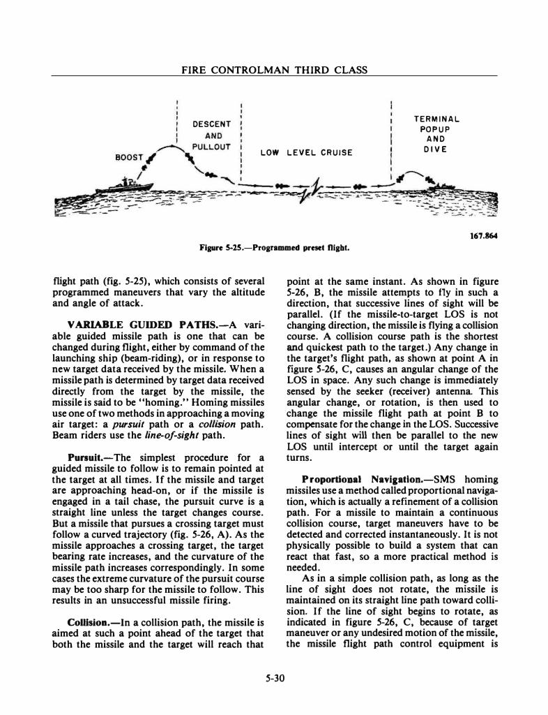
FIRE CONTROLMAN THIRD CLASS
DESCENT
LOW L E V E L C R U I S E
TERM I N A L
PO P U P A N D
D I V E
167.864
Fig11re 5-25.-Programmed preset flight.
flight path (fig. 5-25), which consists of several programmed maneuvers that vary the altitude and angle of attack.
VARIABLE GUIDED PATHS.-A variable guided missile path is one that can be changed during flight, either by command of the launching ship (beam-riding), or in response to new target data received by the missile. When a missile path is determined by target data received directly from the target by the missile, the missile is said to be "homing." Homing missiles use one of two methods in approaching a moving air target: a pursuit path or a collision path. Beam riders use the line-of-sight path.
Pursuit.-The simplest procedure for a guided missile to follow is to remain pointed at the target at all times. If the missile and target are approaching head-on, or if the missile is engaged in a tail chase, the pursuit curve is a straight line unless the target changes course. But a missile that pursues a crossing target must follow a curved trajectory (fig. 5-26, A). As the missile approaches a crossing target, the target bearing rate increases, and the curvature of the missile path increases correspondingly. In some cases the extreme curvature of the pursuit course may be too sharp for the missile to follow. This results in an unsuccessful missile firing.
ColHsion.-In a collision path, the missile is aimed at such a point ahead of the target that both the missile and the target will reach that
5-30
point at the same instant. As shown in figure 5-26, B, the missile attempts to fly in such a direction, that successive lines of sight will be parallel. (If the missile-to-target LOS is not changing direction, the missile is flying a collision course. A collision course path is the shortest and quickest path to the target.) Any change in the target's flight path, as shown at point A in figure S-26, C, causes an angular change of the LOS in space. Any such change is immediately sensed by the seeker (receiver) antenna. This angular change, or rotation, is then used to change the missile flight path at point B to compensate for the change in the LOS. Successive lines of sight will then be parallel to the new LOS until intercept or until the target again turns.
P roportional Naviaatlon.-SMS homing missiles use a method called proportional navigation, which is actually a refinement of a collision path. For a missile to maintain a continuous collision course, target maneuvers have to be detected and corrected instantaneously. It is not physically possible to build a system that can react that fast, so a more practical method is needed.
As in a simple collision path, as long as the line of sight does not rotate, the missile is maintained on its straight line path toward collision. If the line of sight begins to rotate, as indicated in figure 5-26, C, because of target maneuver or any undesired motion of the missile, the missile flight path control equipment is
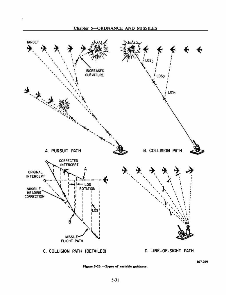
Chapter 5-0RDNANCE AND MISSILES
TARGET
�' *
A. PURSUIT PATH
CORRECTED INTERCEPT
ORIGINAL ·� LA
INTERCEP�·-· .J. _ .t:l� __ ,... � ' I 1-e.t t.- LOS
MISSILE�·, : t 11 ROTATION HEADING ' I I I
CORRECTION '· 1 11 I I
·�" � : :, ' 1 ILOS
I I I I 8 I 1
�I
MISSILE/ 'J FLIGHT PATH
C. COLLISION PATH (DETAILED)
8. COLLISION PATH
�'- � � � t � ', ', \ \ I ;
' ' ' � '
' ' \ "'I(\ I I ', ', ' \ ' ', ' 1 \ '
... , ' ' ' \ ', ' ' \ \ ' ', ' ' \ \ ' .. . ' \ ' .. , �' \ \ \ I , ): ' \ \ \ I ', \ \ \ l I \ ' \ \ l I , ' ' \ I I ... \ \ ' . , , , , , , ' ' ' ' \ I , ,,, , . .... ,
~ D. LINE-OF-SIGHT PATH
Fl1un: 5-26.-Types of variable 11ddaace.
5-31
167.709
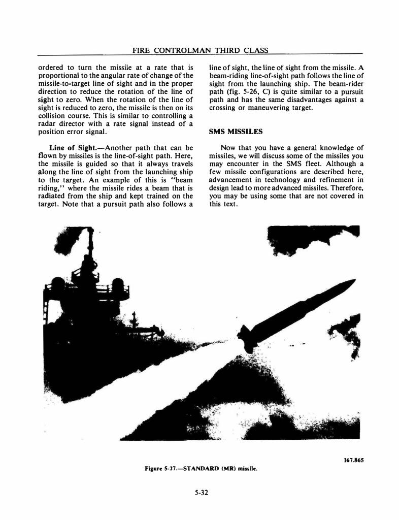
FIRE CONTROLMAN THIRD CLASS
ordered to turn the missile at a rate that is proportional to the angular rate of change of the missile-to-target line of sight and in the proper direction to reduce the rotation of the line of sight to zero. When the rotation of the line of sight is reduced to zero, the missile is then on its collision course. This is similar to controlling a radar director with a rate signal instead of a position error signal.
Line of Sigbt.-Another path that can be flown by missiles is the line-of-sight path. Here, the missile is guided so that it always travels along the line of sight from the launching ship to the target. An example of this is "beam riding,'' where the missile rides a beam that is radiated from the ship and kept trained on the target. Note that a pursuit path also follows a
line of sight, the line of sight from the missile. A beam-riding line-of-sight path follows the line of sight from the launching ship. The beam-rider path (fig. 5-26, C) is quite similar to a pursuit path and has the same disadvantages against a crossing or maneuvering target.
SMS MISSILES
Now that you have a general knowledge of missiles, we will discuss some of the missiles you may encounter in the SMS fleet. Although a few missile configurations are described here, advancement in technology and refinement in design lead to more advanced missiles. Therefore, you may be using some that are not covered in this text.
167.865
Figure 5-27.-STANDARD (MR) missile.
5-32
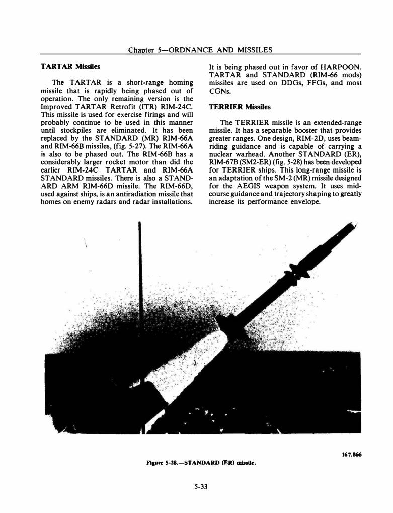
Chapter 5-0RDNANCE AND MISSILES
TARTAR Missiles
The TARTAR is a short-range homing missile that is rapidly being phased out of operation. The only remaining version is the Improved TARTAR Retrofit (ITR) RIM-24C. This missile is used for exercise firings and will probably continue to be used in this manner until stockpiles are eliminated. It has been replaced by the STANDARD (MR) RIM-66A and RIM-668 missiles, (fig. 5-27). The RIM-66A is also to be phased out. The RIM-66B has a considerably larger rocket motor than did the earlier RIM-24C TARTAR and RIM-66A STANDARD missiles. There is also a STANDARD ARM RIM-66D missile. The RIM-66D, used against ships, is an antiradiation missile that homes on enemy radars and radar installations.
It is being phased out in favor of HARPOON. TARTAR and STANDARD (RIM-66 mods) missiles are used on DOGs, FFGs, and most CONs.
TERRIER Missiles
The TERRIER missile is an extended-range missile. It has a separable booster that provides greater ranges. One design, RIM-20, uses beamriding guidance and is. capable of carrying a nuclear warhead. Another STANDARD (ER), RIM-67B (SM2-ER) (fig. 5-28) has been developed for TERRIER ships. This long-range missile is an adaptation of the SM-2 (MR) missile designed for the AEGIS weapon system. It uses midcourse guidance and trajectory shaping to greatly increase its performance envelope.
167.866 Fi&t�re 5-li.-STANDARD (ER) missile.
5-33
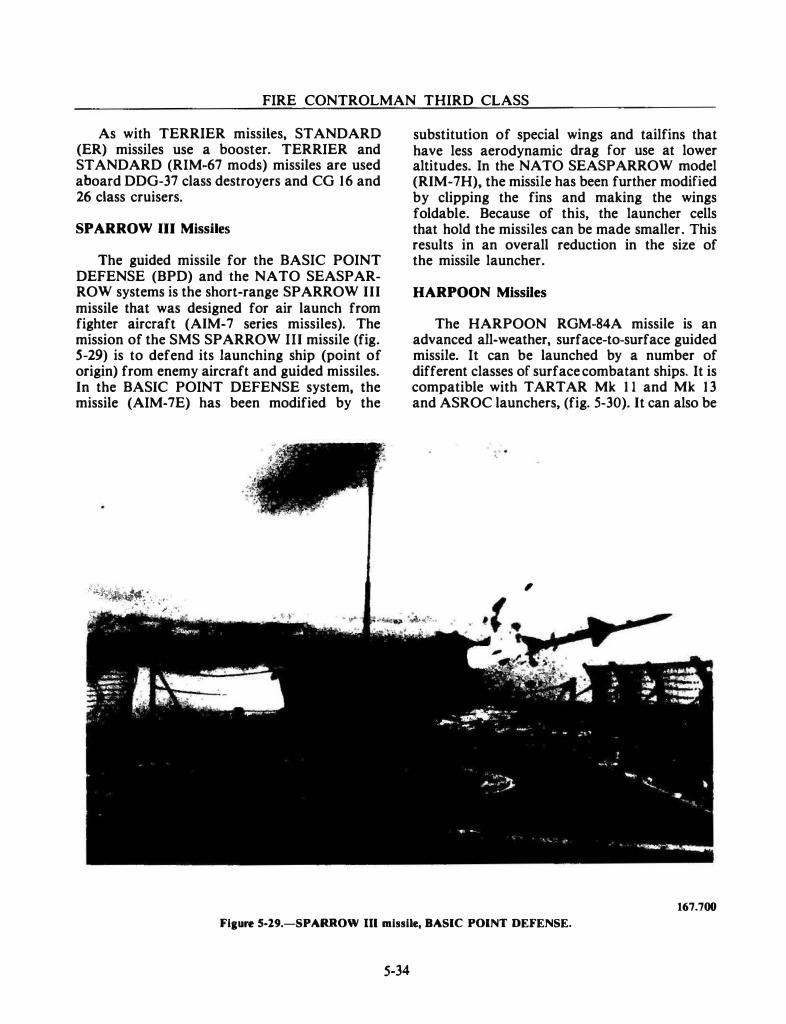
FIRE CONTROLMAN THIRD CLASS
As with TERRIER missiles, STANDARD (ER) missiles use a booster. TERRIER and STANDARD (RIM-67 mods) missiles are used aboard DDG-37 class destroyers and CG 16 and 26 class cruisers.
SPARROW Ill Missiles
The guided missile for the BASIC POINT DEFENSE (BPD) and the NATO SEASPARROW systems is the short-range SPARROW III missile that was designed for air launch from fighter aircraft (AIM-7 series missiles). The mission of the SMS SPARROW III missile (fig. S-29) is to defend its launching ship (point of origin) from enemy aircraft and guided missiles. In the BASIC POINT DEFENSE system, the missile (AIM-7E) has been modified by the
.::.�����·� ;•'' ' . � ..; . · · .
substitution of special wings and tailfins that have less aerodynamic drag for use at lower altitudes. In the NATO SEASPARROW model (RIM-7H), the missile has been further modified by clipping the fins and making the wings foldable. Because of this, the launcher cells that hold the missiles can be made smaller. This results in an overall reduction in the size of the missile launcher.
HARPOON Missiles
The HARPOON RGM-84A missile is an advanced all-weather, surface-to-surface guided missile. It can be launched by a number of different classes of surface combatant ships. It is compatible with TARTAR Mk 1 1 and Mk 1 3 and ASROC launchers, (fig. 5-30). It can also be
,
167.700
Fiaure 5-29.-SPARROW Ill missile, BASIC POINT DEFENSE.
5-34
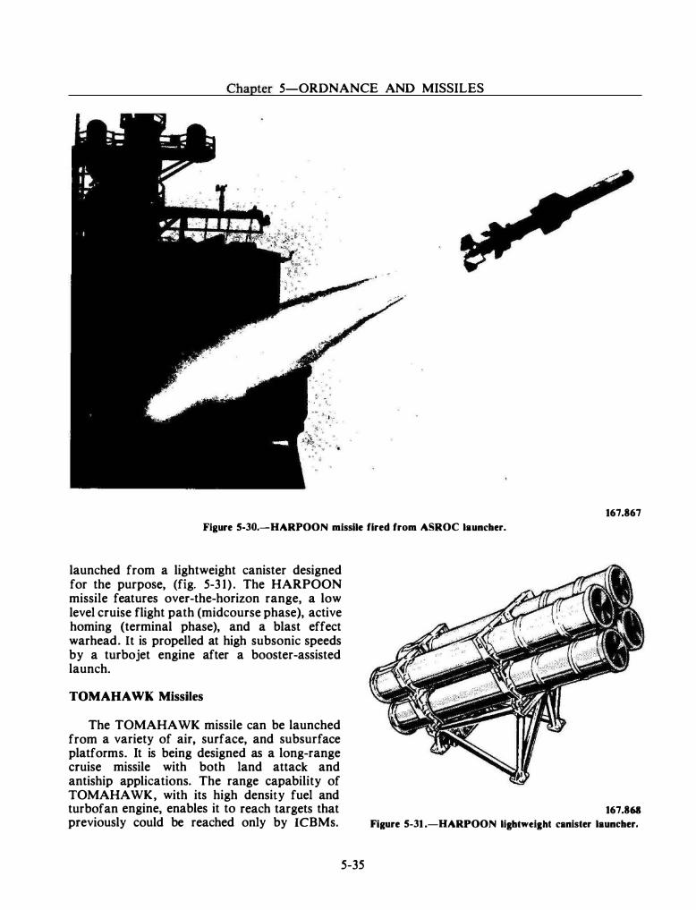
Chapter 5-0RDNANCE AND MISSILES
167.867
Figure 5-30.-HARPOON missile fired from ASROC launcher.
launched from a lightweight canister designed for the purpose, (fig. 5-3 1) . The HARPOON missile features over-the-horizon range, a low level cruise flight path (midcourse phase), active homing (terminal phase), and a blast effect warhead. It is propelled at high subsonic speeds by a turbojet engine after a booster-assisted launch.
TOMAHAWK Missiles
The TOMAHAWK missile can be launched from a variety of air, surface, and subsurface platforms. It is being designed as a long-range cruise missile with both land attack and antiship applications. The range capability of TOMAHAWK, with its high density fuel and turbofan engine, enables it to reach targets that previously could be reached only by ICBMs.
5-35
167.861
Fi1ure 5-31 .-HARPOON lill:btweight canister launcher.
FIRE CONTROLMAN THIRD CLASS
The missile's small size, high speed, and lowaltitude flight path make it virtually immune to enemy defenses.
The TOMAHAWK Land-Attack Missile uses a terrain matching guidance system, carries a nuclear warhead, and has a range of about 3 ,000 miles. The TOMAHAWK Antiship Missile uses a modified HARPOON guidance system, but its range is only about 350 miles because of the heavier conventional warhead.
NEW DEVELOPMENTS
Currently, work is progressing toward introducing new missiles and their associated weapons systems into the fleet. One of these is the Rolling Airframe Missile (RAM).
RoUiag Airframe Missile (RAM)
The Rolling Airframe Guided Missile XRIM-1 16A, commonly referred to as the RAM missile, is a moderate range surface-to-air self defense missile. The RAM missile uses passive dual-mode (IR/RF) homing guidance. It is
5-36
proposed to replace the BPDS on 14 ships (amphibious types) using its own launcher, which can store and fire 24 missiles.
Also being developed is a NATO SEA SPARROW/RAM ORDALT, which would use the NSSMS launcher with an adapter to place 10 RAM missiles into 2 of the 8 cells of the launcher.
SUMMARY
You have been introduced to the SMS family of guided missiles. The introduction has been of a fundamental nature, covering what a guided missile is, how it is classified, and to a degree, how it is guided, stabilized, and propelled.
A typical guided missile is made up of five subsystems-the air frame (structure), propulsion, control, guidance, and warhead. You should know how these subsystems are related to each other, insofar as the basic concept of mis�ile operation is concerned. Finally, you should know the SMS missiles by name and have some insight as to how and for what purposes they are used. The next section describes the data transmission systems used in fire control systems.
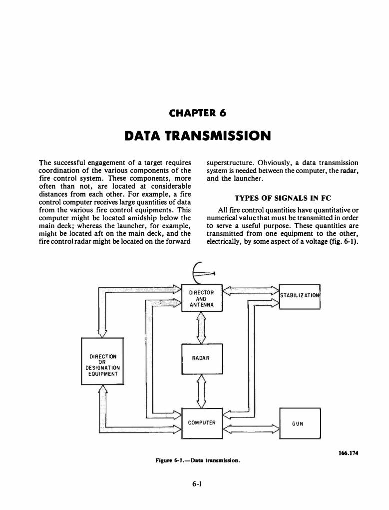
CHAPTER 6
DATA TRANSMISSION The successful engagement of a target requires coordination of the various components of the fire control system. These components, more often than not, are located at considerable distances from each other. For example, a fire control computer receives large quantities of data from the various fire control equipments. This computer might be located amidship below the main deck; whereas the launcher, for example, might be located aft on the main deck, and the fire control radar might be located on the forward
·. · .· ·.· . .
C_ \:
superstructure. Obviously, a data transmission system is needed between the computer, the radar, and the launcher.
TYPES OF SIGNALS IN FC
All fire control quantities have quantitative or numerical value that must be transmitted in order to serve a useful purpose. These quantities are transmitted from one equipment to the other, electrically, by some aspect of a voltage (fig. 6-1).
. , .-':) �=::-==��;��-·-: <:' -- -. . -� . � . DIRECTOR .;;, - STABILIZATION
AND •' .· �-" ., " :E) ANTENNA ;,.
!\ . . v \.
DIRECTION RADAR OR
DESIGNATION
EQUIPMENT 1\ A
\. . . ... � K ... COMPUTER GUN , . > K >
166.174 Figure 6-1.-Data transmission.
6-1
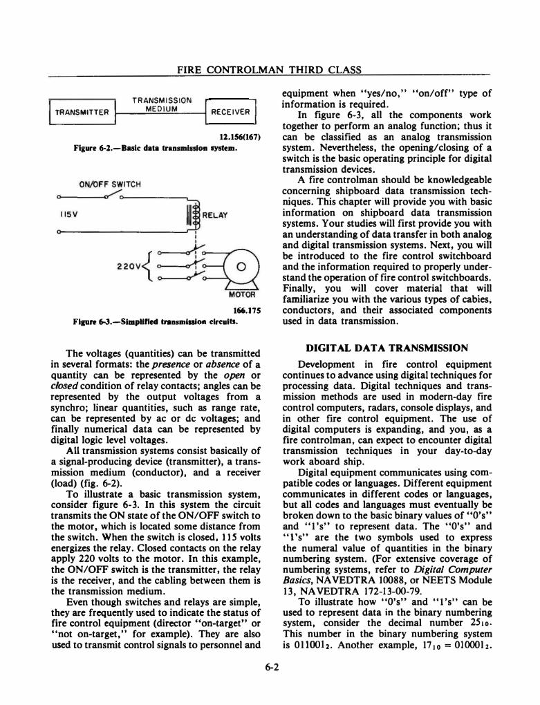
FIRE CONTROLMAN THIRD CLASS
I TRANSMITTER
TRANSMISSION
I I MEDIUM RECEIVER
11.156(167) Figure 6-l.-Butc data transmiiSIOD system.
166.175 Flpre 6-3.-SimpUfled transmluloa circuits.
The voltages (quantities) can be transmitted in several formats: the presence or absence of a quantity can be represented by the open or closed condition of relay contacts; angles can be represented by the output voltages from a synchro; linear quantities, such as range rate, can be represented by ac or de voltages; and finally numerical data can be represented by digital logic level voltages.
All transmission systems consist basically of a signal-producing device (transmitter), a transmission medium (conductor), and a receiver (load) (fig. 6-2).
To illustrate a basic transmission system, consider figure 6-3. In this system the circuit transmits the ON state of the ON/OFF switch to the motor, which is located some distance from the switch. When the switch is closed, 11 S volts energizes the relay. Closed contacts on the relay apply 220 volts to the motor. In this example, the ON/OFF switch is the transmitter. the relay is the receiver, and the cabling between them is the transmission medium.
Even though switches and relays are simple, they are frequently used to indicate the status of fire control equipment (director "on-target" or "not on-target," for example). They are also used to transmit control signals to personnel and
6-2
equipment when "yes/no," "on/off" type of information is required.
In figure 6-3, all the components work together to perform an analog function; thus it can be classified as an analog transmission system. Nevertheless, the opening/closing of a switch is the basic operating principle for digital transmission devices.
A fire controlman should be knowledgeable concerning shipboard data transmission techniques. This chapter will provide you with basic information on shipboard data transmission systems. Your studies will first provide you with an understanding of data transfer in both analog and digital transmission systems. Next. you will be introduced to the fire control switchboard and the information required to properly understand the operation of fire control switchboards. Finally, you will cover material that will familiarize you with the various types of cabies, conductors, and their associated components used in data transmission.
DIGITAL DATA TRANSMISSION
Development in fire control equipment continues to advance using digital techniques for processing data. Digital techniques and transmission methods are used in modern-day fire control computers, radars, console displays, and in other fire control equipment. The use of digital computers is expanding, and you, as a fire controlman, can expect to encounter digital transmission techniques in your day-to-day work aboard ship.
Digital equipment communicates using compatible codes or languages. Different equipment communicates in different codes or languages, but all codes and languages must eventually be broken down to the basic binary values of "O's'' and .. 1 's"' to represent data. The "O's" and "l's" are the two symbols used to express the numeral value of quantities in the binary numbering system. (For extensive coverage of numbering systems, refer to Digital Computer Basics, NAVEDTRA 10088, or NEETS Module 13 , NA VEDTRA 172-13-00-79.
To illustrate how .. O's'' and "l"s"' can be used to represent data in the binary numbering system, consider the decimal number 2510• This number in the binary numbering system is O llOOh. Another example, 17Jo = OlOOOlz.
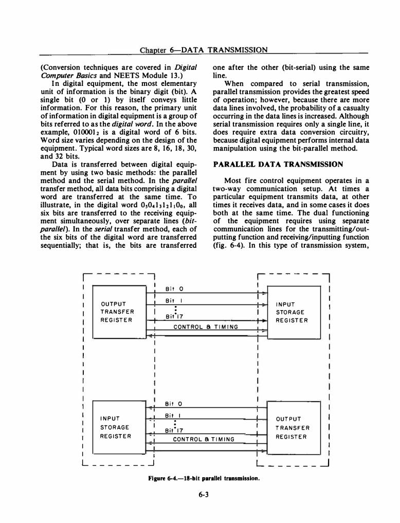
Chapter 6-DATA TRANSMISSION
(Conversion techniques are covered in Digital Computer Basics and NEETS Module 13 .)
In digital equipment, the most elementary unit of information is the binary digit (bit). A single bit (0 or 1) by itself conveys little information. For this reason, the primary unit of information in digital equipment is a group of bits referred to as the digital word. In the above example, 0100012 is a digital word of 6 bits. Word size varies depending on the design of the equipment. Typical word sizes are 8, 16, 18, 30, and 32 bits.
Data is transferred between digital equipment by using two basic methods: the parallel method and the serial method. In the parallel transfer method, all data bits comprising a digital word are transferred at the same time. To illustrate, in the digital word O,O.clJhltOo, all six bits are transferred to the receiving equipment simultaneously, over separate lines (bitparallel). In the serial transfer method, each of the six bits of the digital word are transferred sequentially; that is, the bits are transferred
- -, Bit 0
OUTPUT l Bit I . TRANSFER I . REGISTER
Bitl7
one after the other (bit-serial) using the same line.
When compared to serial transmission, parallel transmission provides the greatest speed of operation; however, because there are more data lines involved, the probability of a casualty occurring in the data lines is increased. Although serial transmission requires only a single line, it does require extra data conversion circuitry, because digital equipment performs internal data manipulation using the bit-parallel method.
PARALLEL DATA TRANSMISSION
Most fire control equipment operates in a two-way communication setup. At times a particular equipment transmits data, at other times it receives data, and in some cases it does both at the same time. The dual functioning of the equipment requires using separate communication lines for the transmitting/outputting function and receiving/inputting function (fig. 6-4). In this type of transmission system,
r-------, I
J I INPUT
I STORAGE
REGISTER
_1 CONTROL a TIMING :
I I
INPUT
STORAGE
REGISTER
I _j_ I
l I
I 1 L _______ _j
I
Bit 0 1
Bit I l OUTPUT . . I Bit17 I T RANSFER
CONTROL a TIMING I REGISTER
I L ______ _j
Figure 6-4.-18-bit parallel transmission.
6-3
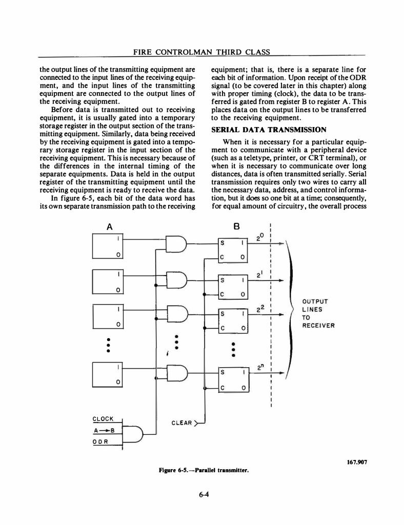
FIRE CONTROLMAN THIRD CLASS
the output lines of the transmitting equipment are connected to the input lines of the receiving equipment, and the input lines of the transmitting equipment are connected to the output lines of the receiving equipment.
Before data is transmitted out to receiving equipment, it is usually gated into a temporary storage register in the output section of the transmitting equipment. Similarly, data being received by the receiving equipment is gated into a temporary storage register in the input section of the receiving equipment. This is necessary because of the differences in the internal timing of the separate equipments. Data is held in the output register of the transmitting equipment until the receiving equipment is ready to receive the data.
In figure 6-5, each bit of the data word has its own separate transmission path to the receiving
A
• • •
CLOCK
ODR
0
0
0
;
0
CLEAR
equipment; that is, there is a separate line for each bit of information. Upon receipt of the ODR signal (to be covered later in this chapter) along with proper timing (clock), the data to be transferred is gated from register B to register A. This places data on the output lines to be transferred to the receiving equipment.
SERIAL DATA TRANSMISSION
When it is necessary for a particular equipment to communicate with a peripheral device (such as a teletype, printer, or CRT terminal), or when it is necessary to communicate over long distances, data is often transmitted serially. Serial transmission requires only two wires to carry all the necessary data, address, and control information, but it does so one bit at a time; consequently, for equal amount of circuitry, the overall process
B
0
167.907
Figure 6-5.-Parallel transmitter.
6-4
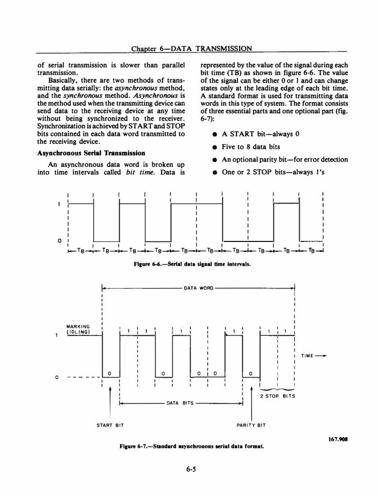
Chapter 6-DATA TRANSMISSION
of serial transmission is slower than parallel transmission.
Basically, there are two methods of transmitting data serially: the asynchronous method, and the synchronous method. Asynchronous is the method used when the transmitting device can send data to the receiving device at any time without being synchronized to the receiver. Synchronization is achieved by START and STOP bits contained in each data word transmitted to the receiving device.
Asynchronous Serial Tnnsmission
An asynchronous data word is broken up into time intervals called bit time. Data is
I
I I I I I
I I I I I
represented by the value of the signal during each bit time (TB) as shown in figure 6-6. The value of the signal can be either 0 or l and can change states only at the leading edge of each bit time. A standard format is used for transmitting data words in this type of system. The format consists of three essential parts and one optional part (fig. 6-7):
e A START bit-always 0
• Five to 8 data bits
• An optional parity bit-for error detection
• One or 2 STOP bits-always 1 's
I I I I I I I I I I
I I I I O 1 J 1 I I I I I I I I
�--o r8� Ta-t-- r8� r8_..._ re__._ Te� re.........__ Te--+-- Te-"- Te--l
MARKING (IDLING)
0 --- ---
FIJure 6-6.-Serlal data slpal time intervals.
14----------- DATA WORD -----------1
: 1 I 1 I I 1 I 1
0 0 0 0 0
1 1 ----2 STOP 91 TS
DATA BITS
START BIT PARITY BIT
Flaure 6-7 .-Standard uya�hronoas serial data format.
6-S
TIME-
167.901
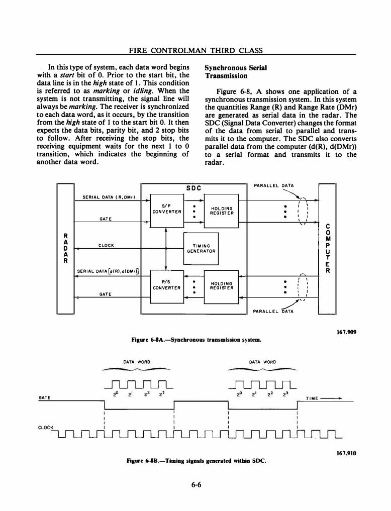
FIRE CONTROLMAN THIRD CLASS
In this type of system, each data word begins with a start bit of 0. Prior to the start bit, the data line is in the high state of 1. This condition is referred to as marking or idling. When the system is not transmitting, the signal line will always be marking. The receiver is synchronized to each data word, as it occurs, by the transition from the high state of 1 to the start bit 0. It then expects the data bits, parity bit, and 2 stop bits to follow. After receiving the stop bits, the receiving equipment waits for the next 1 to 0 transition, which indicates the beginning of another data word.
.....--- soc SERIAL DATA ( R,OMr)
S/P • CONVERTER •
GATE •
R
Synchronous Serial Transmission
Figure 6-8, A shows one application of a synchronous transmission system. In this system the quantities Range (R) and Range Rate (DMr) are generated as serial data in the radar. The SDC (Signal Data Converter) changes the format of the data from serial to parallel and transmits it to the computer. The SOC also converts parallel data from the computer (d(R), d(DMr)) to a serial format and transmits it to the radar.
PARALLEL DATA r---
��' I I
HOLDING • I I REGISTER • I I
• I I \ I
,, c 0 M A CLOCK T IMING p
D GENERATOR u A T R E SERIAL DATA [d(R),d(OMrD R
,-, I I P/S • HOLDING • I I I
CONVERTER • REGISTER • I I • • I I GATE I I
__/" L...-- PARALLEL DATA L...--
167.909
Figure 6-8A.-Synchronous transmission system.
DATA WORD DATA WORD
GATE TIME
167.910 Figure 6-88.-Timing signals generated within SOC.
6-6
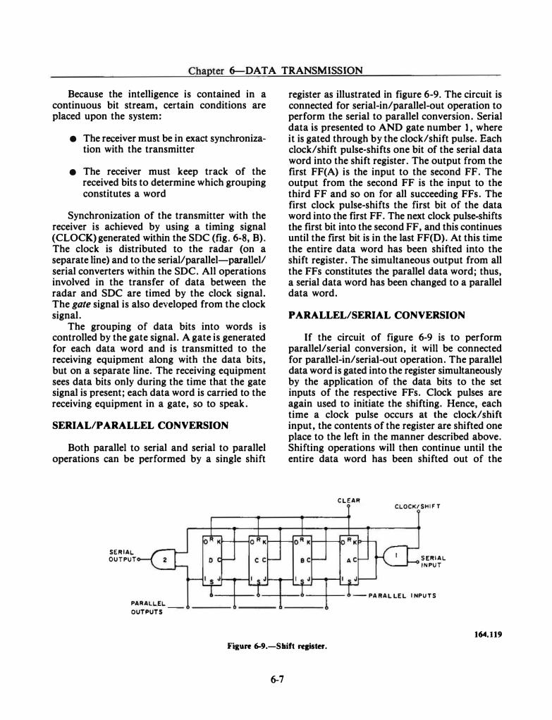
Chapter 6-DATA TRANSMISSION
Because the intelligence is contained in a continuous bit stream, certain conditions are placed upon the system:
• The receiver must be in exact synchronization with the transmitter
• The receiver must keep track of the received bits to determine which grouping constitutes a word
Synchronization of the transmitter with the receiver is achieved by using a timing signal (CLOCK) generated within the SDC (fig. 6-8, B). The clock is distributed to the radar (on a separate line) and to the serial/parallel-parallel/ serial converters within the SDC. All operations involved in the transfer of data between the radar and SOC are timed by the clock signal. The gate signal is also developed from the clock signal.
The grouping of data bits into words is controlled by the gate signal. A gate is generated for each data word and is transmitted to the receiving equipment along with the data bits, but on a separate line. The receiving equipment sees data bits only during the time that the gate signal is present; each data word is carried to the receiving equipment in a gate, so to speak.
SERIAL/PARALLEL CONVERSION
Both parallel to serial and serial to parallel operations can be performed by a single shift
SERIAL
OUTPUT
PARALLEL
OUTPUTS
register as illustrated in figure 6-9. The circuit is connected for serial-in/parallel-out operation to perform the serial to parallel conversion. Serial data is presented to AND gate number 1 , where it is gated through by the clock/shift pulse. Each clock/shift pulse-shifts one bit of the serial data word into the shift register. The output from the first FF(A) is the input to the second FF. The output from the second FF is the input to the third FF and so on for all succeeding FFs. The first clock pulse-shifts the first bit of the data word into the first FF. The next clock pulse-shifts the first bit into the second FF, and this continues until the first bit is in the last FF(D). At this time the entire data word has been shifted into the shift register. The simultaneous output from all the FFs constitutes the parallel data word; thus, a serial data word has been changed to a parallel data word.
PARALLEL/SERIAL CONVERSION
If the circuit of figure 6-9 is to perform parallel/serial conversion, it will be connected for parallel-in/serial-out operation. The parallel data word is gated into the register simultaneously by the application of the data bits to the set inputs of the respective FFs. Clock pulses are again used to initiate the shifting. Hence, each time a clock pulse occurs at the clock/shift input, the contents of the register are shifted one place to the left in the manner described above. Shifting operations will then continue until the entire data word has been shifted out of the
CLEAR CLOCK/SHIFT
SERIAL
INPUT
-PARALLEL INPUTS
164.119
F�gure 6-9.-Shilt rqister.
6-7
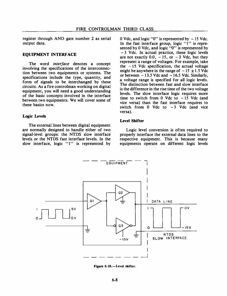
FIRE CONTROLMAN THIRD CLASS
register through AND gate number 2 as serial output data.
EQUIPMENT INTERFACE
The word interface denotes a concept involving the specifications of the interconnection between two equipments or systems. The specifications include the type, quantity, and form of signals to be interchanged by these circuits. As a fire controlman working on digital equipment, you will need a good understanding of the basic concepts involved in the interface between two equipments. We will cover some of these basics now.
Logic Levels
The external lines between digital equipment are normally designed to handle either of two signal-level groups: the NTDS slow interface levels or the NTDS fast interface levels. In the slow interface, logic "I" is represented by
0 Vdc, and logic "0" is represented by -15 Vdc. In the fast interface group, logic "1" is represented by 0 V de, and logic "0" is represented by -3 Vdc. In actual practice, these logic levels are not exactly 0.0, -15 , or - 3 Vdc, but they represent a range of voltages. For example, take the - l.S Vdc specification, the actual voltage might be anywhere in the range of -1 5 ± 1. 5 V de or between -13.5 Vdc and -16.5 Vdc. Similarly, a voltage range is specified for all logic levels. The distinction between fast and slow interface is the difference in the rise time of the two voltage levels. The slow interface logic requires more time to switch from 0 Vdc to -15 Vdc (and vice versa) than the fast interface requires to switch from 0 Vdc to -3 Vdc (and vice versa).
Level Shifter
Logic level conversion is often required to properly interface the external data lines to the respective equipment . This is because many equipments operate on different logic levels
EQUIPMENT l I I I I
, n n l sv
o J LJ U ov
-15V
Fieure 6-10.-Level sbifter.
6-8
I DATA LINE ov

Chapter 6-DATA TRANSMISSION
other than the standard NTDS interface logic levels. Certain equipment, for �ample, use the DTL (Diode Transistor Logic) level of + 5 V de = 1, 0 V de = 0. A typical level shifter is illustrated in figure 6-10. Operation of the circuit is as follows: when the input to Ql is a logic "1" (5 Vdc), Q�. conducts and its output goes to ground level.;·O Vdc (logic 1). When the input to Ql is a logic "0" (0 Vdc), Q3 conducts and its output goes to - 15 V de (logic 0).
Control Signals
Figure 6-5 illustrates a simplified circuit for transferring data to a receiving equipment. The ODR is shown as one of the signals necessary to gate data onto the output data lines. Actually, the ODR signal is one in a group of control signals used to control the transfer of data between equipments. The ODR and other control signals are illustrated in figure 6-11.
In this figure, the equipment is connected in the computer/peripheral mode. In this mode of operation, one of the units is the controlling equipment or master (computer), and the other unit is the slave (peripheral equipment).
Each communication path or channel has an output cable and an input cable. Each cable has data lines and control lines. The data lines are
used to carry the data to or from the computer, and the control lines serve as a means of identifying the type of data on the data lines and as a synchronizing control between the two units. The output cable control lines are labeled as follows:
• External Function Request (EFR)
• External Function Acknowledge (EF A)
• Output Data Request (ODR)
• Output Acknowledge (OA)
The input cable control lines are labeled as follows:
• External Interrupt Enable (EIE)
• External Interrupt Request (EIR)
• Input Data Request (IDR)
• Input Acknowledge (lA)
Notice the direction of information flow in figure 6-11. The data request signals are always sent from the external equipment to the computer.
• EXTERNA L FUNCTION REQUEST -EXTERNAb FUNCTION ACKNOWLEQliE ...
OUTPUT J • OUTPUT DATA REQUEST \ CABLE l OUTPUT ACKNOWLEDGE 1 ... ....
OUTPUT DATA LINES
PERIPHERAL COMPUTER
EXTERNAL INTERRUPT ENABLE EQUIPMENT r ...
• EXTERNAL INTERRUPT REQUEST .. -INPUT • INPI,!T QATA R!;;�E:iT
CABLE INPUT ACKNOWLEDGE ..A r ... INPUT DATA LINES
U6ENO. -- CONTROL LINES -DATA LINES
124.413
Ffture 6-11.--compuler lo perlpberal equlpmeat cabU•I·
6-9
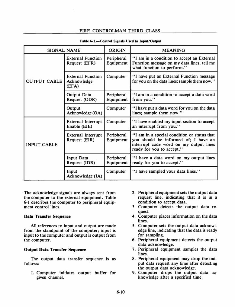
FIRE CONTROLMAN THIRD CLASS
Table 6·1.-Control Signals Used In Input/Output
SIGNAL NAME ORIGIN
External Function Peripheral Request (EFR) Equipment
External Function Computer OUTPUT CABLE Acknowledge
(EFA)
Output Data Peripheral Request (ODR) Equipment
Output Computer Acknowledge (OA)
External Interrupt Computer Enable (EJE)
External Interrupt Peripheral Request (EIR) Equipment
INPUT CABLE
Input Data Peripheral Request (IDR) Equipment
Input Computer Acknowledge (lA)
The acknowledge signals are always sent from the computer to the external equipment. Table 6·1 describes the computer to peripheral equip· ment control lines.
Data Transfer Sequence
All references to input and output are made from the standpoint of the computer; input is input to the computer and output is output from the computer.
Output Data Transfer Sequence
The output data transfer sequence is as follows:
I. Computer mittates output buffer for given channel.
6-10
MEANING
"I am in a condition to accept an External Function message on my data lines; tell me what function to perform."
"I have put an External Function message for you on the data lines; sample them now.''
1 'I am in a condition to accept a data word from you."
"I have put a data word for you on the data lines; sample them now.''
11 I have enabled my input section to accept an interrupt from you."
1 'I am in a special condition or status that you should be informed of; I have an interrupt code word on my output lines ready for you to accept."
"I have a data word on my output lines ready for you to accept."
"I have sampled your data lines."
2. Peripheral equipment sets the output data request line, indicating that it is in a condition to accept data.
3. Computer detects the output data request.
4. Computer places information on the data lines.
5. Computer sets the output data acknowledge line, indicating that the data is ready for sampling.
6. Peripheral equipment detects the output data acknowledge.
7. Peripheral equipment samples the data lines.
8. Peripheral equipment may drop the output data request any time after detecting the output data acknowledge.
9. Computer drops the output data acknowledge after a specified time.
Chapter 6-DATA TRANSMISSION
Steps 2 through 9 of this sequence are repeated for every data word until the computer has transferred the specified number of words.
Input Data Transfer Sequence
The input data transfer sequence is as follows:
1. Computer initiates an input buffer for a given channel.
2. Peripheral equipment places a data word on the data lines.
3. Peripheral equipment sets the input data request line to indicate that it has data ready for transmission.
4. Computer detects the input data request. 5. Computer samples the data lines. 6. Computer sets the input acknowledge
line indicating that it has sampled the data.
7. Peripheral equipment senses the input acknowledge line.
8. Peripheral equipment may drop the input data request line any time after detecting the input acknowledge.
9. Computer drops the input acknowledge line after a specified time.
Steps 2 through 9 of this sequence are repeated as necessary to transfer the specified number of words.
External Function Sequence
The external function sequence is as follows:
1. Computer initiates an external function buffer for a given channel.
2. Peripheral equipment sets the external function request line when it is ready to accept the external function code.
3. Computer detects the external function request.
4. Computer places the external function code on the data lines.
5. Computer sets the external function ac· knowledge line to indicate that the external function code is ready for sampling.
6-11
6. Peripheral equipment detects the external function acknowledge and samples the external function code.
7. Peripheral equipment may drop the external function request any time after detecting the external function acknowledge.
8. Computer drops the external function line after a specified time.
External Interrupt Sequence
The external interrupt sequence is as follows:
1. Computer sets the external interrupt enable when it is ready to accept an external interrupt for a given channel.
2. Peripheral equipment detects the external interrupt enable.
3. Peripheral equipment places the external interrupt word on the data lines.
4. Peripheral equipment sets the external interrupt request line to indicate that an external interrupt code is on the data lines.
5. Computer detects the external interrupt request signal and stores the external interrupt word.
6. Computer drops the external interrupt enable.
7 . Peripheral equipment detects the drop of the external interrupt enable and clears the external interrupt request line and the data lines. The input acknowledge to an external interrupt request will be initiated at the same time that the external interrupt enable is cleared. The simul· taneous occurrence of these conditions should be used by peripheral equipment to differentiate between an interrupt acknowledge and a data acknowledge.
Line Drivers/Line Receivers
In those cases where data is transmitted between equipment in digital form (electrical pulses), special circuits are used as line drivers and line receivers. For data transmission over short distances (such as between equipment located in the same compartment), standard logic circuits are adequate line drivers. But when data transmission is between equipment located
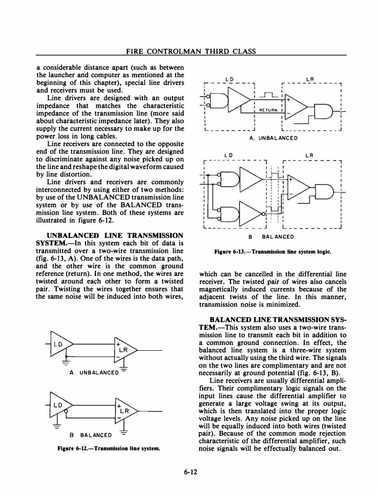
FIRE CONTROLMAN THIRD CLASS
a considerable distance apart (such as between the launcher and computer as mentioned at the beginning of this chapter), special line drivers and receivers must be used.
Line drivers are designed with an output impedance that matches the characteristic impedance of the transmission line (more said about characteristic impedance later). They also supply the current necessary to make up for the power loss in long cables.
Line receivers are connected to the opposite end of the transmission line. They are designed to discriminate against any noise picked up on the line and reshape the digital waveform caused by line distortion.
Line drivers and receivers are commonly interconnected by using either of two methods: by use of the UNBALANCED transmission line system or by use of the BALANCED transmission line system. Both of these systems are illustrated in figure 6-12.
UNBALANCED LINE TRANSMISSION SYSTEM.-In this system each bit of data is transmitted over a two-wire transmission line (fig. 6-13, A). One of the wires is the data path, and the other wire is the common ground reference (return). In one method, the wires are twisted around each other to form a twisted pair. Twisting the wires together ensures that the same noise will be induced into both wires,
A. UNBALANCED -
8 BALANCED
Figure 6-12.-Transmission line system.
6-12
LD LR i------ ----, 1 I
I ___I"l_ I
I I I
RETURN
I L ________ .J L __ _ __ _ ___ _ _ .J
A. UNBALANCED
LD LR r----- - - -- - ·1 r- ------- -, I
L __ _ _ _ _ _ __ J B BALANCED
Figure 6-13.-Transmission line ·system logic.
which can be cancelled in the differential line receiver. The twisted pair of wires also cancels magnetically induced currents because of the adjacent twists of the line. In this manner, transmission noise is minimized.
BALANCED LINE TRANSMISSION SYSTEM.-This system also uses a two-wire transmission line to transmit each bit in addition to a common ground connection. In effect, the balanced line system is a three-wire system without actually using the third wire. The signals on the two lines are complimentary and are not necessarily at ground potential (fig. 6-13, B).
Line receivers are usually differential amplifiers. Their complimentary logic signals on the input lines cause the differential amplifier to generate a large voltage swing at its output, which is then translated into the proper logic voltage levels. Any noise picked up on the line will be equally induced into both wires (twisted pair). Because of the common mode rejection characteristic of the differential amplifier, such noise signals will be effectually balanced out.

---- ·-------
Chapter 6-DATA TRANSMISSION
The balanced system is preferred over the unbalanced system for use in any of the follow� ing circumstances:
• Where the cabling is excessively long
• In extremely noisy environments
• Where the data transmission rate is extremely high
• Where the inversion of signals is needed
LINE IMPEDANCE.-The perfect trans� mission line transfers data from the line driver to the line receiver without any distortion at all. In reality, transmission lines are never perfect, and they do introduce some distortion to the signals traveling over them. Line impedance is a combination of capacitance, inductance, and resistance. Distortion of the digital pulses is caused by these components working together to form a low-pass filter that rounds the leading and trailing edge of the pulses. They also cause phase shift or delay which further distorts the digital pulses.
For a cable of given dimensions with uniform capacitance, inductance, and resistance per unit length of the cable, the line impedance is a constant value. This constant value is known as the characteristic impedance of the line. This means, for example, a 50 foot length of cable will have the same impedance as a 100 foot length of cable. Line impedance is not the same as line resistance. Line resistance is the opposition to de current, and it increases directly with the length of the cable. It affects the amount or amplitude of the signal arriving at the line receiver; whereas line impedance affects the quality shape of the signal. Both line impedance and line resistance must be considered in the design of line drivers and receivers.
Digital-To-Analog Converter
In certain fire control applications, digital devices must communicate with analog devices. Under these circumstances a digital�to�analog converter is needed to convert the digital data
6-13
""'f I '""' � .111;
124.121
Figure 6-14.-DigitaJ-to-analog conversion using operational amplifier and a series array of feedback resistors.
to an appropriate analog signal for input to the analog device. Such a circuit is illustrated in figure 6-14.
The circuit in figure 6�14 contains a series array of resistors (Rt through R4, of selected sizes) in the feedback loop of an operational amplifier. Each resistor is bypassed by a pair of relay contacts which represent zero (or OFF) in the closed position and one (or ON) in the open position. When all of the contacts are closed, there is zero resistance in the feed� back path, and the amplifier will not produce a voltage gain. When a 1 binary input is applied across any or all of the relay solenoids, the associated contacts open (as shown) causing series resistances to be added to the feed� back loop. The amount of increase in the amplifier gain is in direct proportion to the amount of resistance placed in the feedback loop by the opening of the relay contacts. The voltage (e0) therefore represents the analog value of a digital input.
ANALOG DATA TRANSMISSION
Digital devices determine the magnitude of quantities by counting; that is, they recognize the quantity as a number of basic units (the number of days on a calendar, the number of degrees in a circle, and so on). The output of a digital device is represented as discrete
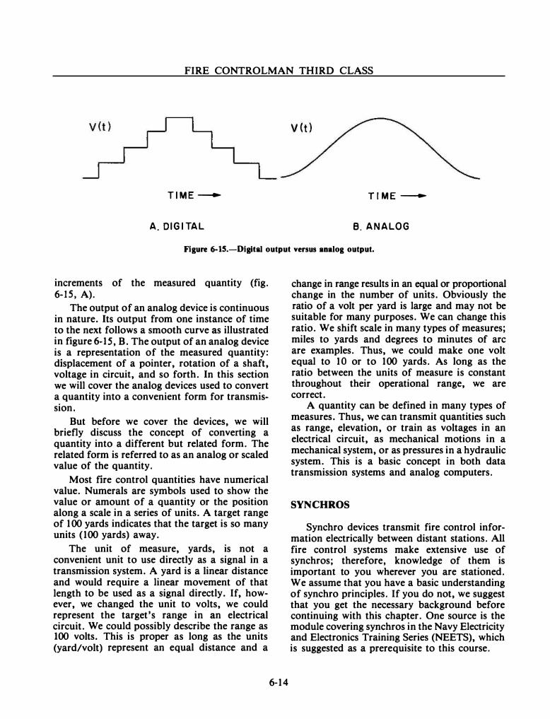
FIRE CONTROLMAN THIRD CLASS
v (t)
TIME----+- TIME---
A. DIGITAL B. ANALOG
Figure 6-15.-Digitlll output versus analog output.
increments of the measured quantity (fig. 6-15, A).
The output of an analog device is continuous in nature. Its output from one instance of time to the next follows a smooth curve as illustrated in figure 6-1 S, B. The output of an analog device is a representation of the measured quantity: displacement of a pointer, rotation of a shaft, voltage in circuit, and so forth. In this section we will cover the analog devices used to convert a quantity into a convenient form for transmission.
But before we cover the devices, we will briefly discuss the concept of converting a quantity into a different but related form. The related form is referred to as an analog or scaled value of the quantity.
Most fire control quantities have numerical value. Numerals are symbols used to show the value or amount of a quantity or the position along a scale in a series of units. A target range of 100 yards indicates that the target is so many units (100 yards) away.
The unit of measure, yards, is not a convenient unit to use directly as a signal in a transmission system. A yard is a linear distance and would require a linear movement of that length to be used as a signal directly. If, however, we changed the unit to volts, we could represent the target's range in an electrical circuit. We could possibly describe the range as 100 volts. This is proper as long as the units (yard/volt) represent an equal distance and a
6-14
change in range results in an equal or proportional change in the number of units. Obviously the ratio of a volt per yard is large and may not be suitable for many purposes. We can change this ratio. We shift scale in many types of measures; miles to yards and degrees to minutes of arc are examples. Thus, we could make one volt equal to 10 or to 100 yards. As long as the ratio between the units of measure is constant throughout their operational range, we are correct.
A quantity can be defined in many types of measures. Thus, we can transmit quantities such as range, elevation, or train as voltages in an electrical circuit, as mechanical motions in a mechanical system, or as pressures in a hydraulic system. This is a basic concept in both data transmission systems and analog computers.
SYNCHROS
Synchro devices transmit fire control information electrically between distant stations. All fire control systems make extensive use of synchros; therefore, knowledge of them is important to you wherever you are stationed. We assume that you have a basic understanding of synchro principles. If you do not, we suggest that you get the necessary background before continuing with this chapter. One source is the module covering synchros in the Navy Electricity and Electronics Training Series (NEETS), which is suggested as a prerequisite to this course.
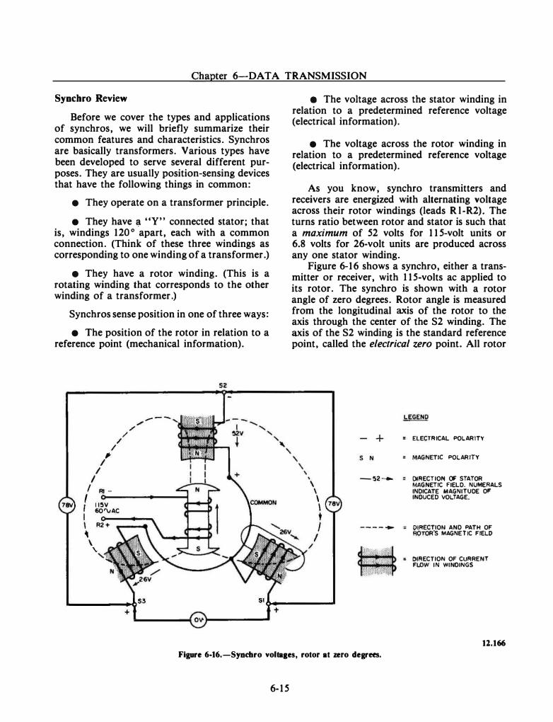
Chapter 6-DATA TRANSMISSION
Synchro Review
Before we cover the types and applications of synchros, we will briefly summarize their common features and characteristics. Synchros are basically transformers. Various types have been developed to serve several different purposes. They are usually position-sensing devices that have the following things in common:
• They operate on a transformer principle.
• They have ;,t "Y" connected stator; that is, windings 120° apart, each with a common connection. (Think of these three windings as corresponding to one winding of a transformer.)
• They have a rotor winding. (This is a rotating winding that corresponds to the other winding of a transformer.)
Synchros sense position in one of three ways:
• The position of the rotor in relation to a reference point (mechanical information).
/ "' I
I I
I Rl -
/ /
/ / -- --
I o---------4 I I I�V
&O'VAC I I R2+
� \
' '
52
e The voltage across the stator winding in relation to a predetermined reference voltage (electrical information).
• The voltage across the rotor winding in relation to a predetermined reference voltage (electrical information).
As you know, synchro transmitters and receivers are energized with alternating voltage across their rotor windings (leads R l-R2). The turns ratio between rotor and stator is such that a maximum of 52 volts for 11 5-volt units or 6.8 volts for 26-volt units are produced across any one stator winding.
Figure 6-16 shows a synchro, either a transmitter or receiver, with 115-volts ac applied to its rotor. The synchro is shown with a rotor angle of zero degrees. Rotor angle is measured from the longitudinal axis of the rotor to the axis through the center of the S2 winding. The axis of the S2 winding is the standard reference point, called the electrical zero point. All rotor
' \
/
\ \ \ t I
I
- + S N
- 52--
-----
: ELECTRICAL POLARITY
: MAGNETIC POLARITY
OIRECTIOfil OF STATOR MAGNETIC FIELD. NUMERALS INDICATE MAGNITUDE OF INDUCED VOLTAGE.
OIRECTION AND PATH OF ROTOR'S MAGNETIC FIELD
DIRECTION OF CURRENT FLDW IN WINDINGS
L...----�53 Slo------.....1 + +
11.166
Figure 6-16.-Syocbro voUa1es, rotor at zero degrees.
6-15
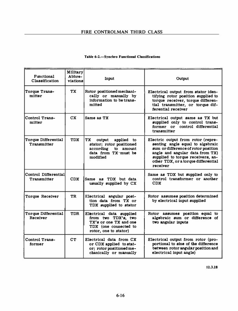
FIRE CONTROLMAN THIRD CLASS
TabJe 6-2.-Syncbro Functional Classifications
M111tary Functional Abbre- Input OUtput Classification viations
Torque Trans- T·x Rotor positioned mechani- Electrical output from stator iden-mitter cally or manually by titying rotor position supplied to
information to be trans- torque receiver, torque differen-mitted tial transmitter, or torque dif-
ferential receiver
Control Trans- ex Same as TX Electrical output same as TX but mitter supplied only to control trans-
former or control differential transmitter
Torque Differential TDX TX output applied to Electric output from rotor (repre-Transmitter stator; rotor positioned senting angle equal to algebraic
according to amowtt sum or difference of rotor position data from TX ·must be angle and angular data from TX) modi!ied supplied to torque receivers, an-
other TDX, or a torque differential receiver
Control Differential Same as TDX but supplied only to Transmitter CDX Same as TDX but data control transformer or another
usually supplied by ex CDX
Torque Receiver TR Electrical angular post- Rotor assumes position determined tlon data from TX or by electrical input supplied TDX supplied to stator
Torque Differential TDR Electrical data supplied Rotor assumes position equal to Receiver from two TDX's, two algebraic sum or difference of
TX's or one TX and one two angular inputs TDX (one connected to rotor, one to stator)
Control Trans- CT Electrical data from CX Electrical output from rotor (pro-former or CDX applied to stat- portional to sine of the difference
or; rotor positioned me- between rotor angular position and chanically or manually electrical input angle)
12.3.28
6-16
Chapter 6-DATA TRANSMISSION
angles are measured from this reference. The voltages on the stator windings at this position of the rotor are the reference values.
Classification of Syncbros
We can classify the more common synchros by their function, size, supply voltage, and frequency. As you know, synchros are part of a system. The function of the system determines the types of synchros in it. If the synchro system provides a mechanical output (torque) that does the actual positioning of a load, it is a torque system. If it provides an electrical output that is used to control the power that does the mechanical work, it is a control system. Synchros can be classified by the function they perform in the system. Table 6-2 lists the military abbreviation, inputs, and outputs of the more common functional classifications of synchros.
Identification of Syncbros
Synchros that you will most likely encounter in ordnance equipment can be grouped into two broad categories: military standard synchros and prestandard Navy synchros. Military standard synchros conform to specifications that are uniform throughout the armed services. New equipment uses synchros of this type. Prestandard synchros were made to meet Navy, rather than service-wide specifications. Each category has a designation code for identification.
MILITARY STANDARD DESIGNATION CODE.-This designation code identifies standard synchros by their physical size, functional purpose, and supply voltage characteristics. We will use two standard synchro designations, 18TR6 and 16CTB4a, as examples to explain the code. The first two digits indicate the diameter of the synchro in tenths of an inch or to the next higher tenth. Thus an actual dimension of 1.7S inches becomes 18. The first letter indicates the general function of the synchro and of the synchro system: C for control and T for torque.
6-17
The next letter indicates the specific function of the synchro as follows:
LETTER DEFINITION
D Differential
R Receiver
T Transformer
X Transmitter
The letter B following the preceding letters indicates that the synchro has a rotatable stator.
The number after the letters stands for the operating frequency:
6 for 60-Hz 4 for 400-flz
The lower case letter is a modification designation. Successive modifications are in alphabetical order.
Thus, the 18TR6 is a torque receiver with a 60-Hz supply voltage and a diameter of between 1.71 and 1.80 inches. The 16CTB4a is a control transformer for use in a 400-Hz system. It has a rotatable stator, and a diameter between 1.51 and 1.60 inches. The lower case "a" indicates that the synchro has been modified once.
Type designations for all standard synchros are assigned by this code. Synchros for use in circuits supplied by 26 volts are classified in the same way, except that the symbol 26 V is prefixed to their designator (26V16CX4 for example). Otherwise, a 115-volt source is assumed for the synchro system. Note that in table 6-2 only the functional designator is given. This is often the practice in Ordnance Publications (OPs) and in schematic diagrams. The complete identification is normally given in the physical description section of the OP.
NAVY PRESTANDARD DESIGNATION CODE.-This code identifies prestandard synchros as to their size and function by a number and letter combination. An example of a synchro identified by this code is a 5DG synchro. Unlike the standard code, the number does not directly
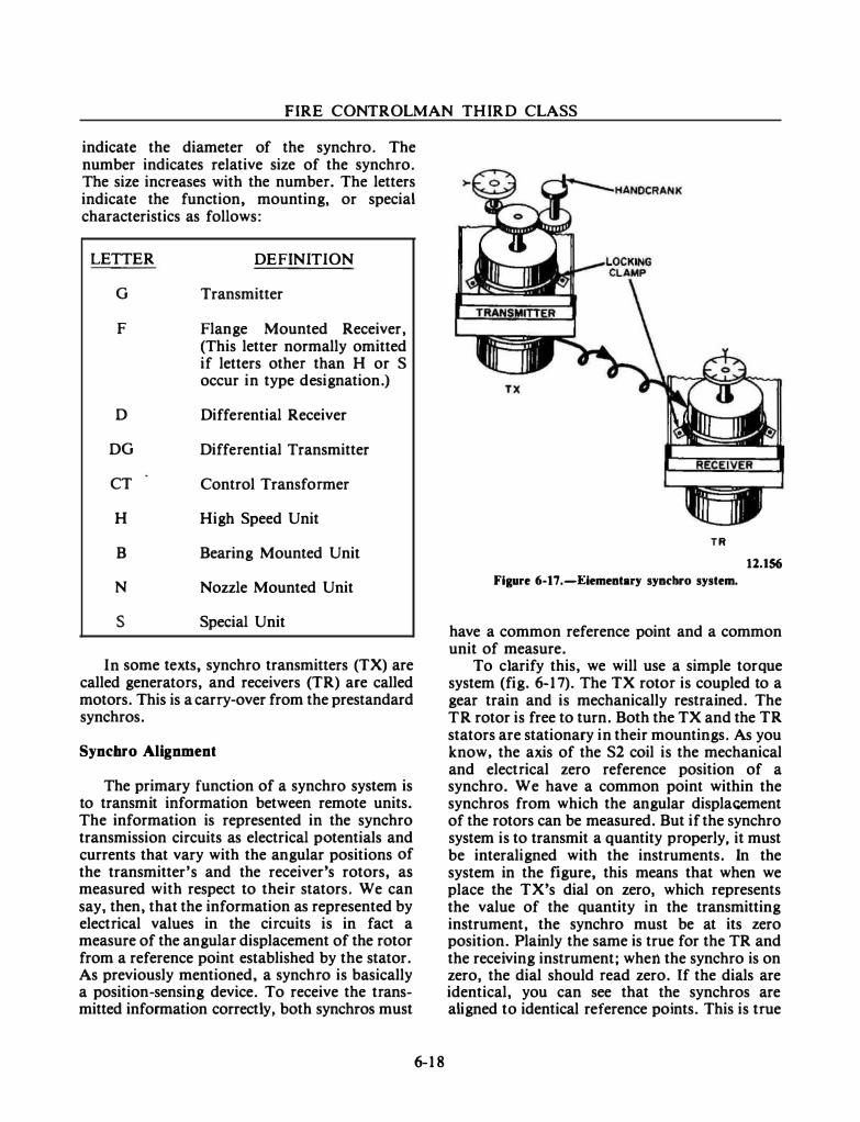
FIRE CONTROLMAN THIRD CLASS
indicate the diameter of the synchro. The number indicates relative size of the synchro. The size increases with the number. The letters indicate the function, mounting, or special characteristics as follows:
LETTER
G
F
D
DG
CT
H
B
N
s
DEFINITION
Transmitter
Flange Mounted Receiver, (This letter normally omitted if letters other than H or S occur in type designation.)
Differential Receiver
Differential Transmitter
Control Transformer
High Speed Unit
Bearing Mounted Unit
Nozzle Mounted Unit
Special Unit
In some texts, synchro transmitters (TX) are called generators, and receivers (TR) are called motors. This is a carry-over from the prestandard synchros.
Syncbro Alignment
The primary function of a synchro system is to transmit information between remote units. The information is represented in the synchro transmission circuits as electrical potentials and currents that vary with the angular positions of the transmitter's and the receiver's rotors, as measured with respect to their stators. We can say, then, that the information as represented by electrical values in the circuits is in fact a measure of the angular displacement of the rotor from a reference point established by the stator. As previously mentioned, a synchro is basically a position-sensing device. To receive the transmitted information correctly, both synchros must
6-18
TR 12.156
Figure 6-17.-Eiementary syncbro system.
have a common reference point and a common unit of measure.
To clarify this, we will use a simple torque system (fig. 6-17). The TX rotor is coupled to a gear train and is mechanically restrained. The TR rotor is free to turn. Both the TX and the TR stators are stationary in their mountings. As you know. the axis of the S2 coil is the mechanical and electrical zero reference position of a synchro. We have a common point within the synchros from which the angular displa<;ement of the rotors can be measured. But if the synchro system is to transmit a quantity properly. it must be interaligned with the instruments. In the system in the figure, this means that when we place the TX's dial on zero, which represents the value of the quantity in the transmitting instrument, the synchro must be at its zero position. Plainly the same is true for the TR and the receiving instrument; whert the synchro is on zero, the dial should read zero. If the dials are identical, you can see that the synchros are aligned to identical reference points. This is true
Chapter 6-DATA TRANSMISSION
although the receiver's reference is at some distance from the transmitter's reference. When these relationships have been established, the quantity on the TX dial can be transmitted correctly between the instruments by the synchro system.
Whatever the synchro system, either torque or control, the mechanical and electrical reference point must be aligned.
MECHANICAL ALIGNMENT.-Remember that the whole idea of a data transmission system is to get data from where-it-is to where-it-is needed. Therefore, the source of the data quantity (we will call it the transmitting instrument) and the receiver of the quantity (the receiving instrument) must be considered as parts of the system. Mechanical alignment is concerned with aligning the transmitting synchro to the transmitting instrument; aligning the receiving synchro to the receiving instrument; and aligning each synchro transmitter and receiver to its own common reference point.
As you have previously studied, the electrical axis of the S2 winding of a synchro is a reference from which the movement of its rotor is measured (fig. 6-16.). Thus, a synchro has a built-in reference, the position of the S2 winding, which is the connecting link between the mechanical alignment of the synchro with its instrument and the electrical alignment of the synchro system.
Every transmitting or receiving instrument has an assigned reference value or position for alignment purposes. This reference could be any value (or position), but it is normally the zero position of the quantity in the instrument.
We now have two references, one for synchros and the other for transmitting and receiving instruments. To visualize how they are used, let's go back to the TX part of figure 6-1 7 . (Note that the T R could also be used. The principles being applied are the same.)
You may consider that the dial and handcrank geared to the TX are parts of the transmitting instrument. Unlock the TX from the instrument's gears, and turn the handcrank until the dial reads the assigned reference value. Turn the TX rotor until it aligns with the S2 axis. When this is done and the two units are mechanically locked again, we can say that the
6-1 9
reference positions of the TX and the transmitting instrument are coincident-if the TX rotor is at its electrical zero.
Why coincident? Any quantity that can be made to vary linearly with the angular motion of a synchro rotor can be transmitted by a synchro system. (It doesn't matter that a quantity is basically linear, such as range and speed; only that a change in the quantity will change the synchro rotor position a proportional amount.) Thus, if the input from the transmitting instrument is at its reference and the synchro rotor is at its reference, then the positions are coincident.
If the synchro rotor is not at the electricalzero position, however, the synchro must be adjusted further. The alignment is not over yet.
ELECTRICAL ZERO.-Each type of synchro has a combination or rotor position and stator voltages that is called its electrical zero. The electrical-zero condition is the reference point for the alignment of the synchro. We have defined the electrical zero and the mechanical zero as the condition in which the axis of the rotor is lined up with the axis of the S2 winding. Look back at figure 6-16. You can see that two such positions, 180° apart, are possible. The rotor is shown at the electrical-zero position, but if it were turned 1 80 o, we could still say it is lined-up with the S2 winding. Let's see the electrical difference between these two rotor positions and expand our definition of electrical zero.
In both the o o position and the 180° position, the terminal voltage between S1 and S3 is zero. However, with an oscilloscope it can be seen that in the 0 ° position-the voltage from S2 to S3 or from S2 to Sl is in phase with the voltage from R l to R2, while in the 1 80 ° rotor position the voltage from S2 to S3 (or S1) is 1 80° out of phase with the rotor voltage.
The electrical-zero position is therefore completely defined as the position of the rotor in which the voltage between S l and S3 is zero, and the voltage from S2 to S3 (or S 1) is in phase with the voltage from Rl to R2.
ZEROING PROCEDURE.-The alignment of a synchro system logically starts at the origin of the quantity being transmitted. For example, assume that you wish to align the synchro system

FIRE CONTROLMAN THIRD CLASS
that transmits director train. Naturally you would start at the director where this quantity originates. The first step in the alignment would be to set the director exactly on zero degrees in train. Next you would set the director's train transmitters on their electrical-zero positions. With the transmitters on zero, you can now set each receiver to its electrical zero. Since director
train is a basic quantity, there will be many receivers in the system. But each receiver can be adjusted as an individual unit since the electrical-zero position is common to the whole system.
The specific procedure used to adjust a synchro to its electrical-zero position depends upon the tools you have and how the synchro is
0
"" �
/THESE 3 VOLTAGES AND PHASE RELATIONSHIPS
UNIQUELY ESTABLISH ROTOR ANGLE A T
I 30• PHYSICAL POSITION I 1-...J � ...J .. z o
90 7 8
i � a: (,) 45 "" z � >o cn 1- 1-' ...J cJ o z > 45 i ll) a: -� - 78 a: 90 0 1-.. l-en
I S I - S3 S l - 52 5 2 - 53
I ROTOR DISPLACEMENT FROM E L ECTRICAL ZERO POSITION
B
Flaure 6-11.-Syocbro electrical error.
6-20
I N PHASE
WITH R I - R2
ISO• OuT OF
PHASE WITH
R I - R 2
83.71
Chapter 6-DA TA TRANSMISSION
connected in the system. Each synchro is adjusted as an individual unit, but its interconnection with other units in the system must be considered. The Military Standardization Handbook: Synchros, Description and Operation, MIL-HDBK-225(AS), covers methods for adjusting all types of synchros under various conditions. The above handbook and background courses, such as NEETS, may be of benefit to you in refreshing your memory of electrical zeroing.
Synchro System Accuracy
A perfect synchro has never been made. Because a fire control system must be accurate, it is important that the system's synchros be made to operate within acceptable limits of accuracy. Certain design techniques and circuitry increase the accuracy of synchro system outputs. Your knowledge of these techniques and circuitry will help to prepare you for the many times you will be required to check the fire control system's accuracy and take corrective action if it is not acceptable.
SYNCHRO ERRORS.-Synchros will always cause some errors because of manufacturing inaccuracies and necessary assembly tolerances. You should remember that for each physical position of a synchro rotor, there is a corresponding set of electrical conditions. For example, if you were to put the rotor of a theoretically perfect synchro transmitter at 30 o, as shown in figure 6-18, the voltages you would read across the stator terminals would be as follows:
S 1-S2-90 volts and 180 o out of phase with R1-R2
Sl -S3-45 volts and in phase with Rl-R2
S2-S3-45 volts and in phase with R1-R2
These stator voltages and phase relationships are unique for 30° rotor position (fig. 6-18, B). You will not get these quantities at any other position of the rotor. But, as we said before, synchros are not perfect. Any difference between the actual physical position of the rotor and the electrical position is known as electrical error. (Sometimes the electrical error is called static accuracy.) It is possible, for example, to get the voltage readings and phase relationships listed above when the rotor of a real synchro is at, say,
6-21
30° and 18 minutes. Therefore, the synchro has an electrical error of 18 minutes. If this is fed to a servo, then the servo output will reflect the electrical error. Let's see how electrical errors show up in a synchro system.
The pictorial diagram in figure 6-19, A shows a control transmitter (CX) and control transformer (CT). We will assume that it is a perfect system. It has no electrical error. Notice particularly that all gear ratios are 1: 1. That is, if we turn the transmitter handcrank one revolution, the transmitter rotor will turn one revolution (360°). Similarly, if you turn the CT's handcrank one revolution, the control transformer rotor will turn one revolution. Furthermore, assume that the dials on both rotor gear faces are so accurate that we can read angular position of the respective rotor in minutes of arc as well as degrees of rotor angular position. The voltmeter is hooked across the R1-R2 leads of the CT. Remember that this voltage at any instant is a reflection of the data transmitted from the ex.
Since we have a theoretically perfect system, if we put the rotor of the CX on zero and turn the crank at the CT end until the voltmeter reads zero, then the dial on the CT will be at zeroshowing perfect alignment with the CX. If we turn the rotor of the transmitter to S 0, as read on the ex rotor dial, and then turn the control transformer handcrank until the voltmeter reads zero volts, a glance at the CT dial will show that it reads exactly S o. You can repeat this experiment for every position on the dial, and the result will be that when the transmitter rotor is at a selected position, the CT rotor will be at the same position when the voltmeter reads zero. In other words, we have perfect transmission of data.
But now look at what happens when we use actual synchro units in the system. The pictorial diagram in figure 6-19, B shows the same setup as we had before. But instead of perfect synchros, we have replaced them with more realistic ones that have an electrical error of 18 minutes apiece. If we put the dial of the transmitter at zero, we will transmit what we think is an electrical signal proportional to zero degrees. But to get a null (minimum or zero reading of the voltmeter), the CT rotor must be turned through an angle of 36 minutes. At null it is obvious that the two rotors
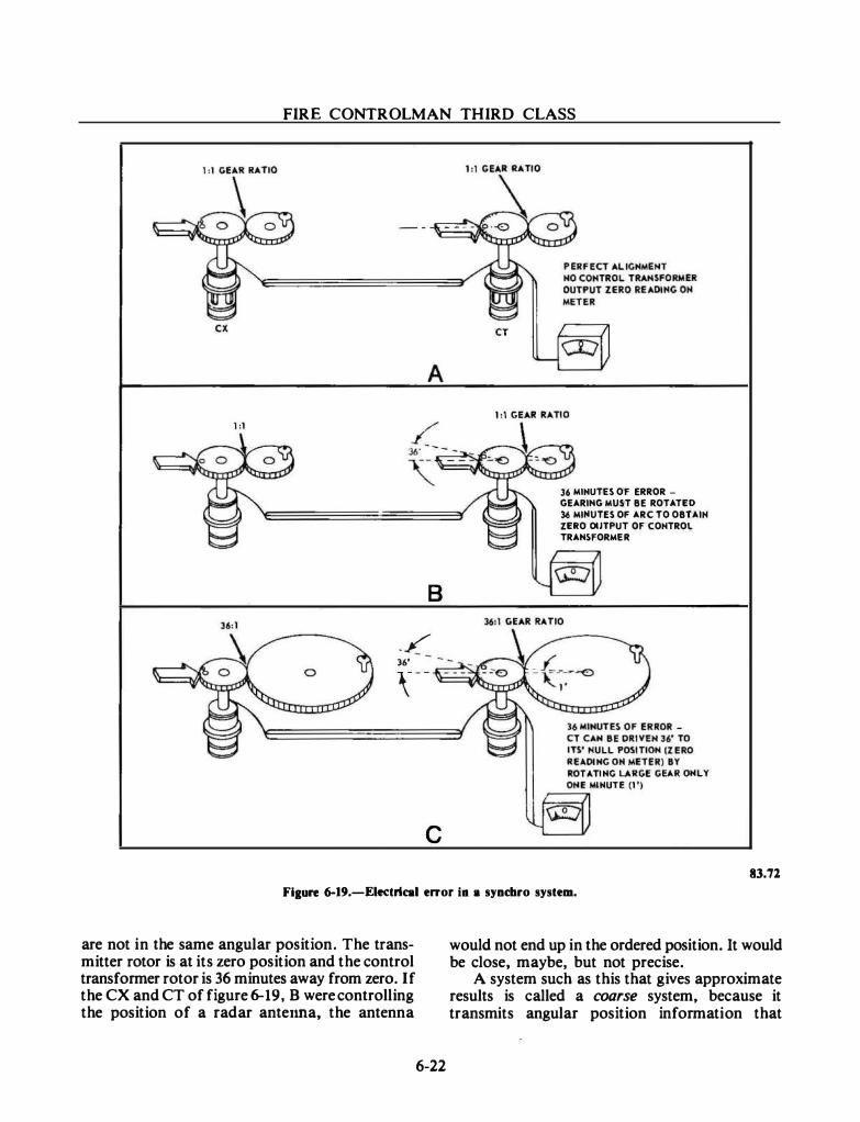
FIRE CONTROLMAN THIRD CLASS
1:1
8
_/ 36' - -
36 MINUTES OF ERROR -
GEARIHG MUST BE ROTA TEO
36 MINUTES OF ARC TO OBTAIN
ZERO OUTPUT OF CONTROL
TRAHSFORME R
\-- 'It=- -�- ��
c 83.71
Fiaure 6-19.-EI«trical enor i• a syncbro system.
are not in the same angular position. The transmitter rotor is at its zero position and the control transformer rotor is 36 minutes away from zero. If the CX and CT of figure 6-19, B were controlling the position of a radar anter:ma, the antenna
6-22
would not end up in the ordered position. It would be close, maybe, but not precise.
A system such as this that gives approximate results is called a coarse system, because it transmits angular position information that
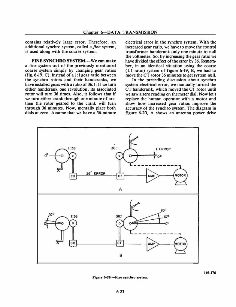
Chapter 6-DATA TRANSMISSION
contains relatively large error. Therefore, an additional synchro system, called a fine system, is used along with the coarse system.
FINE SYNCHRO SYSTEM.-We can make a fine system out of the previously mentioned coarse system simply by changing gear ratios (fig. 6-19, C). Instead of a 1 : 1 gear ratio between the synchro rotors and their handcranks, we have installed gears with a ratio of 36: 1 . If we turn either handcrank one revolution, its associated rotor will turn 36 times. Also, it follows that if we turn either crank through one minute of arc, then the rotor geared to the crank will turn through 36 minutes. Now, mentally place both dials at zero. Assume that we have a 36-minute
361 ERROR
A
8
electrical error in the synchro system. With the increased gear ratio, we have to move the control transformer handcrank only one minute to null the voltmeter. So, by increasing the gear ratio we have divided the effect of the error by 36. Remember, in an identical situation using the coarse (I: I ratio) system of figure 6-19, B, we had to move the CT rotor 36 minutes to get system null.
In the preceding discussion about synchro system electrical error, we manually turned the CT handcrank, which moved the CT rotor until we saw a zero reading on the meter dial. Now let's replace the human operator with a motor and show how increased gear ratios improve the accuracy of the synchro system. The diagram in figure 6-20, A shows an antenna power drive
l ' ERROR
- - - - - - - - - - - ....,
166.176
Fiaure 6-lO.-Fme syad1ro system.
6-23
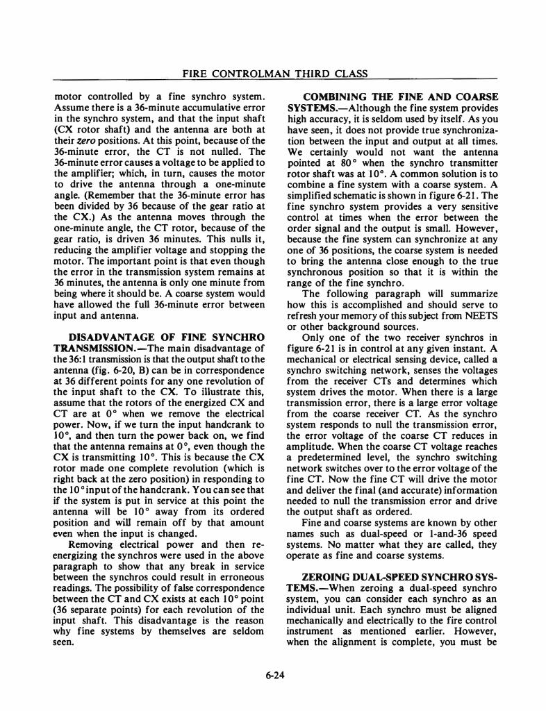
FIRE CONTROLMAN THIRD CLASS
motor controlled by a fine synchro system. Assume there is a 36-minute accumulative error in the synchro system, and that the input shaft (CX rotor shaft) and the antenna are both at their zero positions. At this point, because of the 36-minute error, the CT is not nulled. The 36-minute error causes a voltage to be applied to the amplifier; which, in tum, causes the motor to drive the antenna through a one-minute angle. (Remember that the 36-minute error has been divided by 36 because of the gear ratio at the eX.) As the antenna moves through the one-minute angle, the CT rotor, because of the gear ratio, is driven 36 minutes. This nulls it, reducing the amplifier voltage and stopping the motor. The important point is that even though the error in the transmission system remains at 36 minutes, the antenna is only one minute from being where it should be. A coarse system would have allowed the full 36-minute error between input and antenna.
DISADVANTAGE OF FINE SYNCHRO TRANSMISSION.-The main disadvantage of the 36: 1 transmission is that the output shaft to the antenna (fig. 6-20, B) can be in correspondence at 36 different points for any one revolution of the input shaft to the CX. To illustrate this, assume that the rotors of the energized ex and CT are at 0 ° when we remove the electrical power. Now, if we tum the input handcrank to 10°, and then turn the power back on, we find that the antenna remains at 0 o, even though the CX is transmitting 10 o. This is because the CX rotor made one complete revolution (which is right back at the zero position) in responding to the 10 o input of the handcrank. You can see that if the system is put in service at this point the antenna will be 10 o away from its ordered position and will remain off by that amount even when the input is changed.
Removing electrical power and then reenergizing the synchros were used in the above paragraph to show that any break in service between the synchros could result in erroneous readings. The possibility of false correspondence between the CT and ex exists at each 10° point (36 separate points) for each revolution of the input shaft. This disadvantage is the reason why fine systems by themselves are seldom seen.
6-24
COMBINING THE FINE AND COARSE SYSTEMS.-Although the fine system provides high accuracy, it is seldom used by itself. As you have seen, it does not provide true synchronization between the input and output at all times. We certainly would not want the antenna pointed at 80 o when the synchro transmitter rotor shaft was at 10°. A common solution is to combine a fine system with a coarse system. A simplified schematic is shown in figure 6-21 . The fine synchro system provides a very sensitive control at times when the error between the order signal and the output is small. However, because the fine system can synchronize at any one of 36 positions, the coarse system is needed to bring the antenna close enough to the true synchronous position so that it is within the range of the fine synchro.
The following paragraph will summarize how this is accomplished and should serve to refresh your memory of this subject from NEETS or other background sources.
Only one of the two receiver synchros in figure 6-21 is in control at any given instant. A mechanical or electrical sensing device, called a synchro switching network, senses the voltages from the receiver CTs and determines which system drives the motor. When there is a large transmission error, there is a large error voltage from the coarse receiver CT. As the synchro system responds to null the transmission error, the error voltage of the coarse CT reduces in amplitude. When the coarse eT voltage reaches a predetermined level, the synchro switching network switches over to the error voltage of the fine CT. Now the fine CT will drive the motor and deliver the final (and accurate) information needed to null the transmission error and drive the output shaft as ordered.
Fine and coarse systems are known by other names such as dual-speed or 1-and-36 speed systems. No matter what they are called, they operate as fine and coarse systems.
ZEROING DUAL-SPEED SYNCHRO SYSTEMS.-When zeroing a dual-speed synchro system, you can consider each synchro as an individual unit. Each synchro must be aligned mechanically and electrically to the fire control instrument as mentioned earlier. However, when the alignment is complete, you must be
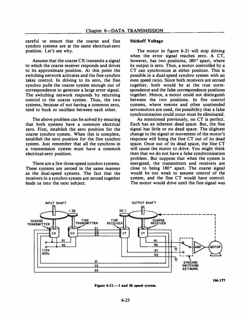
Chapter 6-DA TA TRANSMISSION
careful to ensure that the coarse and fine synchro systems are at the same electrical-zero position. Let's see why.
Assume that the coarse CX transmits a signal to which the coarse receiver responds and drives to its approximate position. At this point the switching network activates and the fine synchro takes control. In driving to its zero, the fine synchro pulls the coarse system enough out of correspondence to generate a large error signal. The switching network responds by returning control to the coarse system. Thus, the two systems, because of not having a common zero, tend to buck or oscillate between each other.
The above problem can be solved by ensuring that both systems have a common electrical zero. First, establish the zero position for the coarse synchro system. When this is complete, establish the zero position for the fine synchro system. Just remember that all the synchros in a transmission system must have a common electrical-zero position.
There are a few three-speed synchro systems. These systems are zeroed in the same manner as the dual-speed systems. The fact that the receivers in a synchro system are zeroed together leads us into the next subject.
INPUT SHAFT
1 15V 60Hz
Sl 52 S3
Stickoff Voltage
The motor in figure 6-21 will stop driving when the error signal reaches zero. A CT, however, has two positions, 180 o apart, where its output is zero. Thus, a motor controlled by a CT can synchronize at either position. This is possible in a dual-speed synchro system with an even speed ratio. Since both receivers are zeroed together, both would be at the true correspondence and the false correspondence positions together. Hence, a motor could not distinguish between the two positions. In fire control systems, where remote and often unattended servomotors are used, the possibility that a false synchronization could occur must be eliminated.
As mentioned previously, no CT is perfect. Each has an inherent dead space. But, the fine signal has little or no dead space. The slightest change in the signal or movement of the motor's response will bring the fine CT out of its dead space. Once out of its dead space, the fine CT will cause the motor to drive. You might think then that we do not have a false synchronization problem. But suppose that when the system is energized, the transmitters and receivers are close to being 180 o apart. The coarse signal would be too weak to assume control of the system, and the fine CT would have control. The motor would drive until the fine signal was
OUTPUT SHAFT
Rl R2 Rl R2
166.177
Figure 6-11.-1 and 36 speed system.
6-25
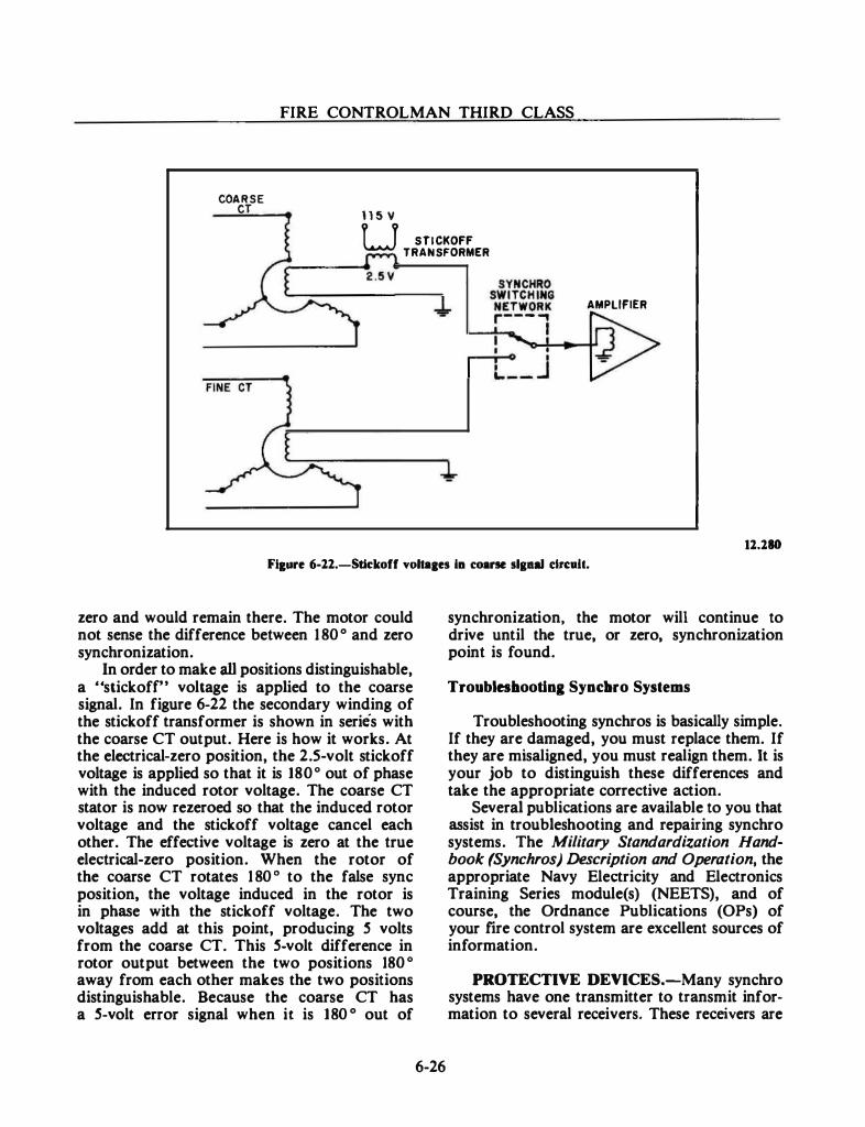
FIRE CONTROLMAN THIRD CLASS
COARSE CT 1 1 5 v u STICKOFF
TRANSFORMER
AMPLIFIER
11.180
Ff&ure 6-12.-Stkkoff voltaaes fa coarse slpal dn:.tt.
zero and would remain there. The motor could not sense the difference between 1 80 ° and zero synchronization.
In order to make all positions distinguishable, a "stickofr• voltage is applied to the coarse signal. In figure 6-22 the secondary winding of the stickoff transformer is shown in series with the coarse CT output. Here is how it works. At the electrical-zero position, the 2.5-volt stickoff voltage is applied so that it is 180 o out of phase with the induced rotor voltage. The coarse CT stator is now rezeroed so that the induced rotor voltage and the stickoff voltage cancel each other. The effective voltage is zero at the true electrical-zero position. When the rotor of the coarse CT rotates 1 80 ° to the false sync position, the voltage induced in the rotor is in phase with the stickoff voltage. The two voltages add at this point, producing 5 volts from the coarse CT. This 5-volt difference in rotor output between the two positions 180 o away from each other makes the two positions distinguishable. Because the coarse CT has a 5-volt error signal when it is 180 ° out of
6-26
synchronization, the motor will continue to drive until the true, or zero, synchronization point is found.
Troubleslaootina Synclno Systems
Troubleshooting synchros is basically simple. If they are damaged, you must replace them. If they are misaligned, you must realign them. It is your job to distinguish these differences and take the appropriate corrective action.
Several publications are available to you that assist in troubleshooting and repairing synchro systems. The Military Standardization Handbook (Synchros) Description and Operation, the appropriate Navy Electricity and Electronics Training Series module(s) (NEETS), and of course, the Ordnance Publications (OPs) of your fire control system are excellent sources of information.
PROTECTIVE DEVICES.-Many synchro systems have one transmitter to transmit information to several receivers. These receivers are
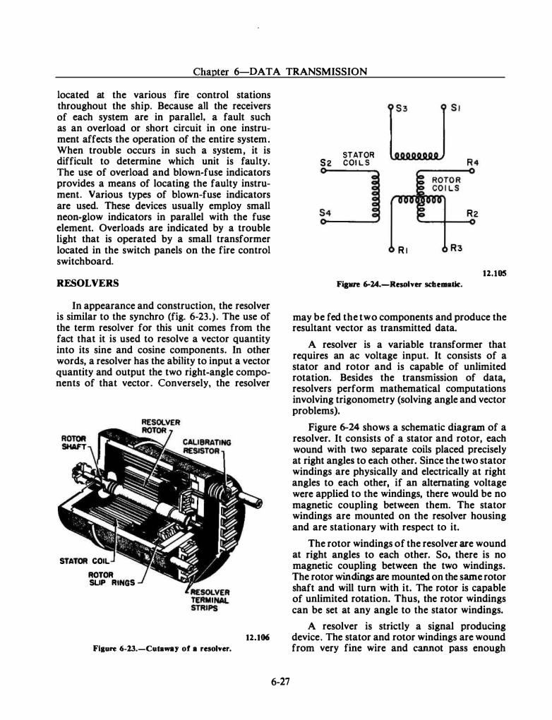
Chapter 6-DATA TRANSMISSION
located at the various fire control stations throughout the ship. Because all the receivers of each system are in parallel, a fault such as an overload or short circuit in one instrument affects the operation of the entire system. When trouble occurs in such a system, it is difficult to determine which unit is faulty. The use of overload and blown-fuse indicators provides a means of locating the faulty instrument. Various types of blown-fuse indicators are used. These devices usually employ small neon-glow indicators in parallel with the fuse element. Overloads are indicated by a trouble light that is operated by a small transformer located in the switch panels on the fire control switchboard.
RESOLVERS
In appearance and construction, the resolver is similar to the synchro (fig. 6-23.). The use of the term resolver for this unit comes from the fact that it is used to resolve a vector quantity into its sine and cosine components. In other words, a resolver has the ability to input a vector quantity and output the two right-angle components of that vector. Conversely, the resolver
STATOR COIL ROTOR SLIP RINGS
Fiaure 6-13.-Cuta .... ay of a resolver.
12.106
6-27
STATOR S 2 COI L S
R l R3
Fipre 6-24.-Resolver sc:bematk:.
R2
12.105
may be fed the two components and produce the resultant vector as transmitted data.
A resolver is a variable transformer that requires an ac voltage input. It consists of a stator and rotor and is capable of unlimited rotation. Besides the transmission of data, resolvers perform mathematical computations involving trigonometry (solving angle and vector problems).
Figure 6-24 shows a schematic diagram of a resolver. It consists of a stator and rotor, each wound with two separate coils placed precisely at right angles to each other. Since the two stator windings are physically and electrically at right angles to each other, if an alternating voltage were applied to the windings, there would be no magnetic coupling between them. The stator windings are mounted on the resolver housing and are stationary with respect to it.
The rotor windings of the resolver are wound at right angles to each other. So, there is no magnetic coupling between the two windings. The rotor windings are mounted on the same rotor shaft and will turn with it. The rotor is capable of unlimited rotation. Thus, the rotor windings can be set at any angle to the stator windings.
A resolver is strictly a signal producing device. The stator and rotor windings are wound from very fine wire and cannot pass enough
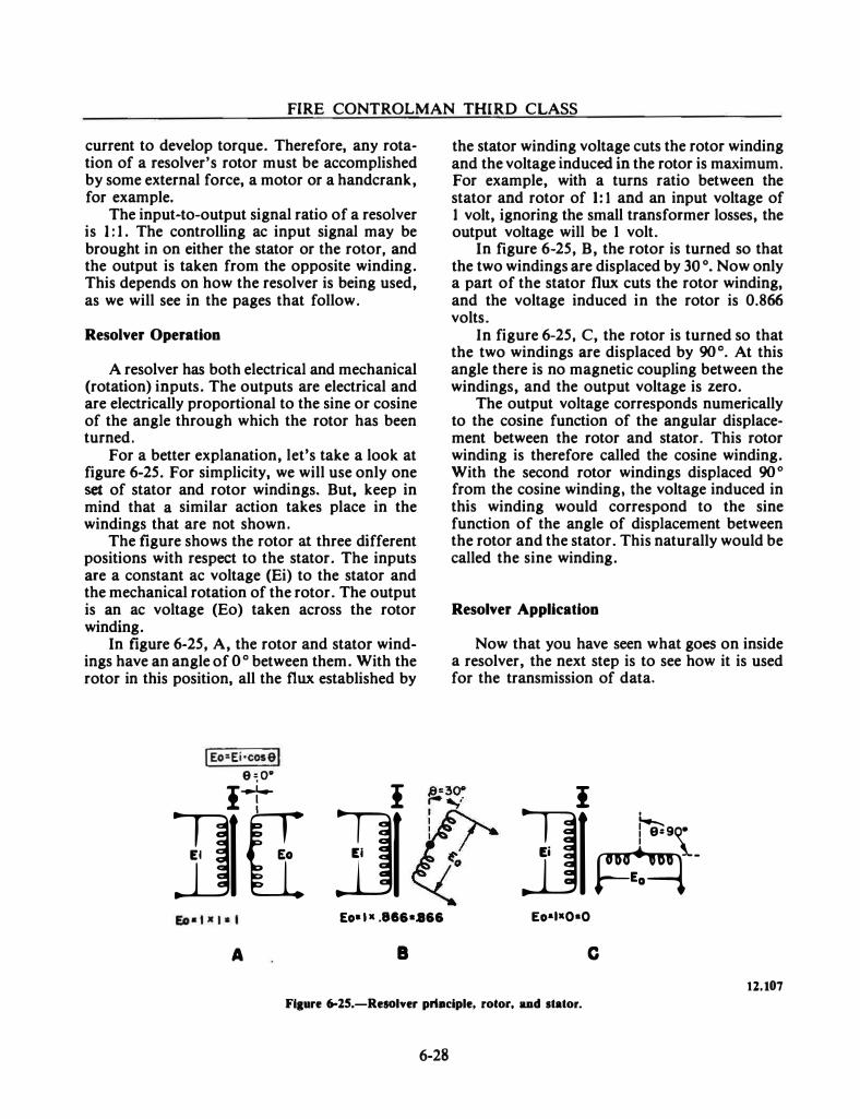
FIRE CONTROLMAN THIRD CLASS
current to develop torque. Therefore, any rotation of a resolver's rotor must be accomplished by some external force, a motor or a handcrank, for example.
The input-to-output signal ratio of a resolver is I : 1 . The controlling ac input signal may be brought in on either the stator or the rotor, and the output is taken from the opposite winding. This depends on how the resolver is being used, as we will see in the pages that follow.
Resolver Operation
A resolver has both electrical and mechanical (rotation) inputs. The outputs are electrical and are electrically proportional to the sine or cosine of the angle through which the rotor has been turned.
For a better explanation, let's take a look at figure 6-25. For simplicity, we will use only one set of stator and rotor windings. But, keep in mind that a similar action takes place in the windings that are not shown.
The figure shows the rotor at three different positions with respect to the stator. The inputs are a constant ac voltage (Ei) to the stator and the mechanical rotation of the rotor. The output is an ac voltage (Eo) taken across the rotor winding.
In figure 6-25, A, the rotor and stator windings have an angle of o o between them. With the rotor in this position, all the flux established by
I Eo::Ei·cosel e � oo
II I
JJIT 111 Eo• l • .816 •.866
A a
the stator winding voltage cuts the rotor winding and the voltage induced in the rotor is maximum. For example, with a turns ratio between the stator and rotor of 1: 1 and an input voltage of 1 volt, ignoring the small transformer losses, the output voltage will be 1 volt.
In figure 6-25, B, the rotor is turned so that the two windings are displaced by 30 o. Now only a part of the stator flux cuts the rotor winding, and the voltage induced in the rotor is 0.866 volts.
In figure 6-25, C, the rotor is turned so that the two windings are displaced by 90 o. At this angle there is no magnetic coupling between the windings, and the output voltage is zero.
The output voltage corresponds numerically to the cosine function of the angular displacement between the rotor and stator. This rotor winding is therefore called the cosine winding. With the second rotor windings displaced 90° from the cosine winding, the voltage induced in this winding would correspond to the sine function of the angle of displacement between the rotor and the stator. This naturally would be called the sine winding.
Resolver Application
Now that you have seen what goes on inside a resolver, the next step is to see how it is used for the transmission of data.
I
]J�-Eo•I•O•O
c 12.107
Fl1ure 6-15.-Resolver priaciple, rotor, aad stator.
6-28
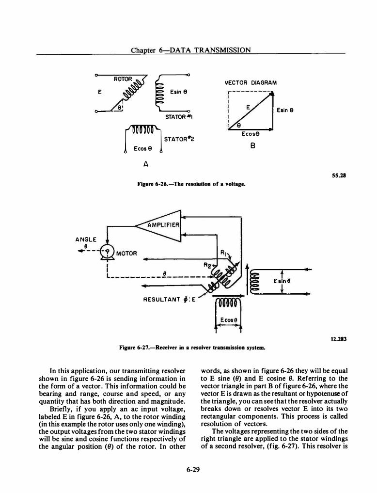
Chapter 6-DATA TRANSMISSION
E STATOR•t � STATOR"2
A
VECTOR DIAGRAM r - - - - - - ---1 I I 1 Esin 9 I I I
Ecose B
SS.ll
Figure 6-16.-Tbe resolution of • voltage.
ANGLE 9 ..,. _ _
I Rz I 8 li L-- ------ - - -- ------ �--·-
RESULTANT f : E ___ ..,.
� 12.283
Figure 6-2.7 .-Receiver in a resolver transmission system.
In this application, our transmitting resolver shown in figure 6-26 is sending information in the form of a vector. This information could be bearing and range, course and speed, or any quantity that has both direction and magnitude.
Briefly, if you apply an ac input voltage, labeled E in figure 6-26, A, to the rotor winding (in this example the rotor uses only one winding), the output voltages from the two stator windings will be sine and cosine functions respectively of the angular position (8) of the rotor. In other
6-29
words, as shown in figure 6-26 they will be equal to E sine (8) and E cosine 8. Referring to the vector triangle in part B of figure 6-26, where the vector E is drawn as the resultant or hypotenuse of the triangle, you can see that the resolver actually breaks down or resolves vector E into its two rectangular components. This process is called resolution of vectors.
The voltages representing the two sides of the right triangle are applied to the stator windings of a second resolver, (fig. 6-27). This resolver is
FIRE CONTROLMAN THIRD CLASS
located in a remote instrument and is what we would call a receiver in the transmission system. The two input voltages, E sin 9 and E cos 9, produce a resultant flux field. Voltages are induced in the two rotor windings, R l and R2, from the flux field. R2 is connected to a motor through an amplifier. The motor will drive the rotor until R2 is at right angles to the flux field. At this position of the rotor, its angle is equal to 6 and no voltage is induced into R2. The winding R l is cut by the entire flux field, and the voltage induced is proportional to voltage E (which represents the hypotenuse of the triangle.)
The resolver is at its null position with the rotor at angle 6 and its output voltage proportional to the triangle hypotenuse. If either of the stator input voltages change, the resultant flux field will change and a voltage will be induced into R2, which will feed a signal to the amplifier. The motor will drive until the signal is again nulled. At this point the induced voltage in R l represents the new hypotenuse and the rotor is at the new angle 9.
It can be seen from this discussion that there is a definite relationship between the mechanical input and the electrical outputs of a resolver. Therefore, we can use them to develop signal voltages in data transmission systems. Resolvers have this feature in common with synchros, but resolvers are more accurate and, as we will learn later, much more versatile.
Resolver Compensators
Voltage regulation is important because resolver voltages represent quantities in the fire control problem. If the voltage regulation is poor, the resolver will introduce errors into the problem. But resolvers are variable transformers, and changes in the angular position of the rotor will change the impedance or load as seen by the stator windings. Thus, the current in the resolver will vary and affect the magnitude and the phase of the resolver voltages.
The calibrating resistors shown in figure 6-23 are precision resistors that serve two purposes. First, they compensate for voltage inaccuracies in the winding and phase shifts introduced by load changes. Second, they are used to standardize the electrical characteristics of a resolver type.
6-30
To increase a resolver's accuracy, its input voltages are supplied through compensators. These are regulating circuits consisting of reactance (coils and capacitors) and resistance components in series with the resolver windings. Their purpose is to make the input voltages independent of the varying current in the circuit.
The resolver compensators that we have discussed so far are designed and internally installed by the manufacturer. Whenever you detect a malfunction in a resolver, you simply replace it.
Occasionally, you will find some compensator capacitors located on the outside of the resolver. These capacitors will be wired to the rotor and Stator terminals on the resolver. Whenever this type of resolver is replaced, the capacitors must be transferred from the old to the new resolver in the exact fashion they were previously in.
Booster Amplifiers
A booster amplifier is connected between the resolvers to reduce the voltage regulation troubles in circuits where the output of one resolver is the input to another resolver. The amplifier has a high input impedance and a low output impedance and acts as an isolation circuit. It is essentially a power amplifier with approximately unity voltage gain and a zero phase shift. Thus, the amplifier can supply an appreciable amount of power to its output circuit while drawing only a negligible amount of power from its input circuit. Consequently, variations in the load are compensated for in the amplifier, and the signal voltage to the receiver resolver has the correct magnitude and phase.
Complex or simple, however, there is one thing you will find in every booster amplifiernearly 100 percent negative feedback. This is what makes them voltage regulators. Negative feedback is used because of its ability to stabilize a circuit and maintain the gain constant under varying loads and de supply voltages.
Zeroing a Resolver
Before a resolver can transmit data, it must have a reference position from which the input values are measured. The reasons for this are the same as those previously studied under synchros.
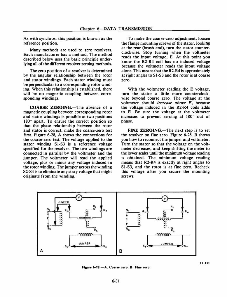
Chapter 6-DATA TRANSMISSION
As with synchros, this position is known as the reference position.
Many methods are used to zero resolvers. Each manufacturer has a method. The method described below uses the basic principle underlying all of the different resolver zeroing methods.
The zero position of a resolver is determined by the angular relationship between the rotor and stator windings. Each stator winding must be perpendicular to a corresponding rotor winding. When this relationship is established, there will be no magnetic coupling between corresponding windings.
COARSE ZEROING.-The absence of a magnetic coupling between corresponding rotor and stator windings is possible at two positions 1 80 ° apart. To ensure the correct position so that the phase relationship between . the rotor and stator is correct, make the coarse-zero test first. Figure 6-28, A shows the connections for the coarse-zero test. The voltage applied to the stator winding S 1-S3 is a reference voltage specified for the resolver. The two windings are connected in parallel by the voltmeter and the jumper. The voltmeter will read the applied voltage, plus or minus any voltage induced in the rotor winding. The jumper across the winding S2-S4 is to eliminate any stray voltage that might originate from the winding.
A
To make the coarse-zero adjustment, loosen the flange mounting screws of the stator, looking at the rear (brush end), turn the stator counterclockwise. Stop turning when the voltmeter reads the input voltage, E. At this point you know the R2-R4 coil has no induced voltage because the voltmeter reads the input voltage alone. This means that the R2-R4 is approximately at right angles to Sl-S3 and the rotor is at coarse zero.
With the voltmeter reading the E voltage, turn the stator a little more counterclockwise beyond coarse zero. The voltage at the voltmeter should increase above E, because the voltage induced in the R2-R4 coils adds to E. Be sure the voltage at the voltmeter increases to prevent zeroing at 180 o out of phase.
FINE ZEROING.-The next step is to set the resolver on fine zero. Figure 6-28, B shows you how to reconnect the jumper and voltmeter. Turn the stator so that the voltage on the voltmeter decreases, and keep shifting the meter to the lower scales until the minimum voltage reading is obtained. The minimum voltage reading means that R2-R4 is exactly at right angles to S1-S3, and the rotor is at fine zero. Recheck this voltage after you secure the mounting screws.
�---c0l----..
s , J o · s , [000000'
S _ J U M PER 1 1 ., s4
8
12.111 Figure 6-28.-A. Coarse zero; B. Fine zero.
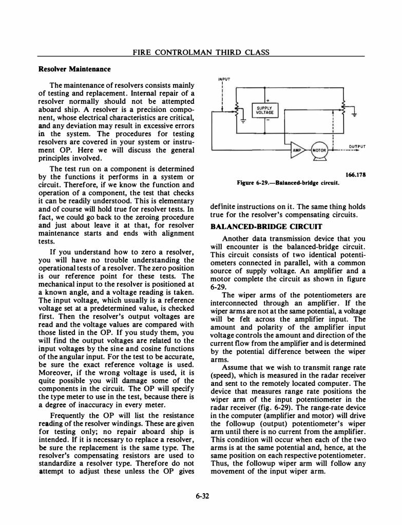
FIRE CONTROLMAN THIRD CLASS
Resolver Maintenance
The maintenance of resolvers consists mainly of testing and replacement. Internal repair of a resolver normally should not be attempted aboard ship. A resolver is a precision component, whose electrical characteristics are critical, and any deviation may result in excessive errors in the system. The procedures for testing resolvers are covered in your system or instrument OP. Here we will discuss the general principles involved.
The test run on a component is determined by the functions it performs in a system or circuit. Therefore, if we know the function and operation of a component, the test that checks it can be readily understood. This is elementary and of course will hold true for resolver tests. In fact, we could go back to the zeroing procedure and just about leave it at that, for resolver maintenance starts and ends with alignment tests.
If you understand how to zero a resolver, you will have no trouble understanding the operational tests of a resolver. The zero position is our reference point for these tests. The mechanical input to the resolver is positioned at a known angle, and a voltage reading is taken. The input voltage, which usually is a reference voltage set at a predetermined value, is checked first. Then the resolver's output voltages are read and the voltage values are compared with those listed in the OP. If you study them, you will find the output voltages are related to the input voltages by the sine and cosine functions of the angular input. For the test to be accurate, be sure the exact reference voltage is used. Moreover, if the wrong voltage is used, it is quite possible you will damage some of the components in the circuit. The OP will specify the type meter to use in the test, because there is a degree of inaccuracy in every meter.
Frequently the OP will list the resistance reading of the resolver windings. These are given for testing only; no repair aboard ship is intended. If it is necessary to replace a resolver, be sure the replacement is the same type. The resolver's compensating resistors are used to standardize a resolver type. Therefore do not attempt to adjust these unless the OP gives
6-32
INPUT I I I I I I
OUTPUT
166.178 FIJure 6-19.-BaJanced-brldge circuit.
definite instructions on it. The same thing holds true for the resolver's compensating circuits.
BALANCED-BRIDGE CIRCUIT
Another data transmission device that you will encounter is the balanced-bridge circuit. This circuit consists of two identical potentiometers connected in parallel, with a common source of supply voltage. An amplifier and a motor complete the circuit as shown in figure 6-29.
The wiper arms of the potentiometers are interconnected through an amplifier . If the wiper arms are not at the same potential, a voltage will be felt across the amplifier input. The amount and polarity of the amplifier input voltage controls the amount and direction of the current flow from the amplifier and is determined by the potential difference between the wiper arms.
Assume that we wish to transmit range rate (speed), which is measured in the radar receiver and sent to the remotely located computer. The device that measures range rate positions the wiper arm of the input potentiometer in the radar receiver (fig. 6-29). The range-rate device in the computer (amplifier and motor) will drive the followup (output) potentiometer's wiper arm until there is no current from the amplifier. This condition will occur when each of the two arms is at the same potential and, hence, at the same position on each respective potentiometer. Thus, the followup wiper arm will follow any movement of the input wiper arm.
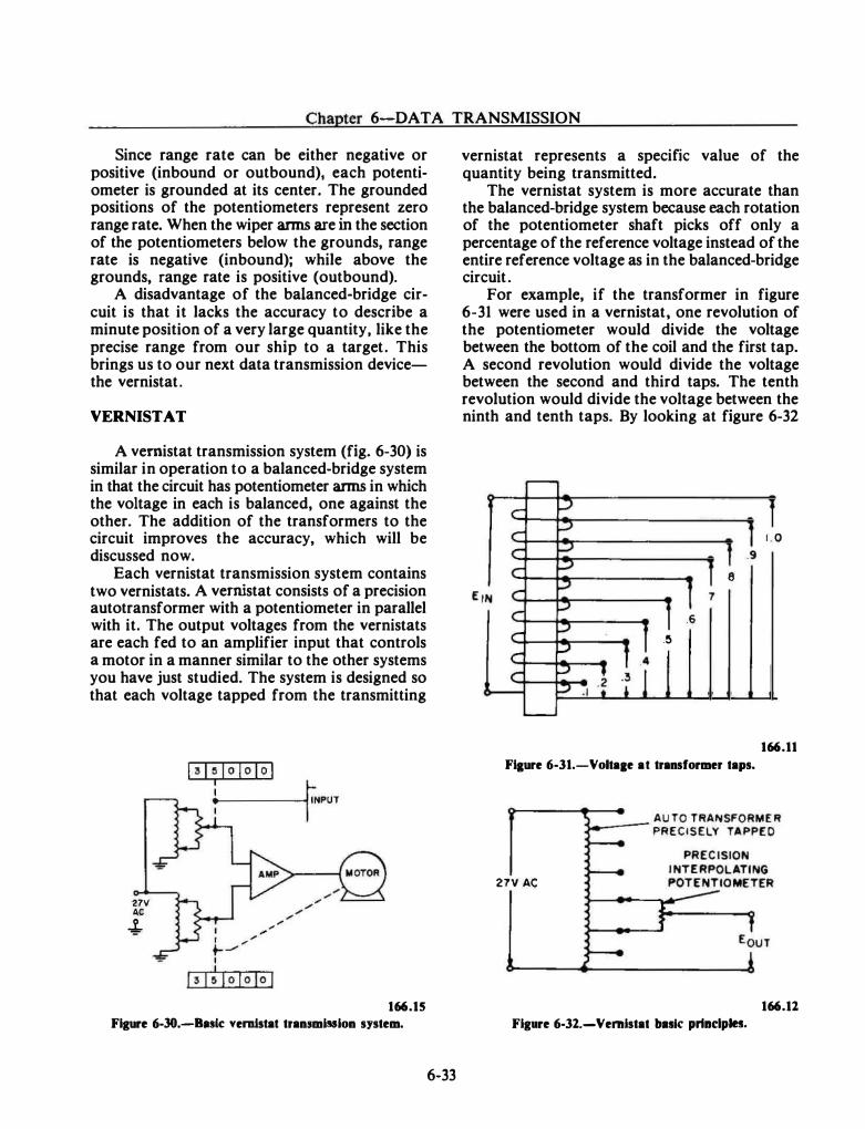
Chapter 6-DATA TRANSMISSION
Since range rate can be either negative or positive (inbound or outbound), each potentiometer is grounded at its center. The grounded positions of the potentiometers represent zero range rate. When the wiper arms are in the section of the potentiometers below the grounds. range rate is negative (inbound); while above the grounds, range rate is positive (outbound).
A disadvantage of the balanced-bridge circuit is that it lacks the accuracy to describe a minute position of a very large quantity, like the precise range from our ship to a target. This brings us to our next data transmission devicethe vernistat.
VERNISTAT
A vernistat transmission system (fig. 6-30) is similar in operation to a balanced-bridge system in that the circuit has potentiometer arms in which the voltage in each is balanced, one against the other. The addition of the transformers to the circuit improves the accuracy, which will be discussed now.
Each vernistat transmission system contains two vernistats. A vernistat consists of a precision autotransformer with a potentiometer in parallel with it. The output voltages from the vernistats are each fed to an amplifier input that controls a motor in a manner similar to the other systems you have just studied. The system is designed so that each voltage tapped from the transmitting
27V AC
4-
166.15
Figure 6-30.-Bufc vemlstat transmission system.
6-33
vernistat represents a specific value of the quantity being transmitted.
The vernistat system is more accurate than the balanced-bridge system because each rotation of the potentiometer shaft picks off only a percentage of the reference voltage instead of the entire reference voltage as in the balanced-bridge circuit.
For example, if the transformer in figure 6-31 were used in a vernistat. one revolution of the potentiometer would divide the voltage between the bottom of the coil and the first tap. A second revolution would divide the voltage between the second and third taps. The tenth revolution would divide the voltage between the ninth and tenth taps. By looking at figure 6-32
1 . 0 .9
8 7
.6 -�
166.11
FIJure 6-31.-Voltaae at transformer taps.
27V AC
166.11
Figure 6-32.-Vernistat balk prtndples.
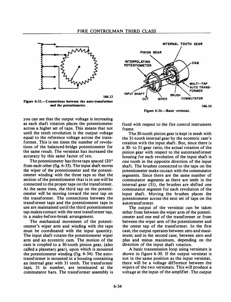
FIRE CONTROLMAN THIRD CLASS
166.13
Fi&uR 6-33.-CoanedJoas betweea tbe auto-transformer aDd the poteatiometer.
you can see that the output voltage is increasing as each shaft rotation places the potentiometer across a higher set of taps. This means that not until the tenth revolution is the output voltage equal to the reference voltage across the transformer. This is ten times the number of revolutions of the balanced-bridge potentiometer for the same result. The vemistat has increased the accuracy by this same factor of ten.
The potentiometer bas three taps spaced 120° from each other (fig. 6-33). The input shaft moves the wiper of the potentiometer and the potentiometer winding with the three taps so that the section of the potentiometer that is in use will be connected to the proper taps on the transformer. At the same time, the third tap on the potentiometer will be moving toward the next tap on the transformer. The connections between the transformer taps and the potentiometer taps in use are maintained until the third potentiometer tap makes contact with the next transformer tap, in a make-before-break arrangement.
The mechanical movement of the potentiometer's wiper arm and winding with the taps must be coordinated with the input quantity. The input shaft rotates the potentiometer wiper arm and an eccentric cam. The motion of the cam is coupled to a 30-tooth pinion gear, (also called a planetary gear), upon which is mounted the potentiometer winding (fig. 6-34). The autotransformer is mounted in a housing containing an internal gear with 3 1 teeth. The transformer taps, 3 1 in number, are terminated at the commutator bars. The transformer assembly is
6-34
INTERNAL TOOTH GEAA
166.14
FiguR 6-34.-Baslc vemistat.
fixed with respect to the fire control instrument frame.
The 30-tooth pinion gear is kept in mesh with the 31-tooth internal gear by the eccentric cam's rotation with the input shaft. But, since there is a 30- to 3 1-gear ratio, the actual rotation of the pinion gear with respect to the autotransformer housing for each revolution of the input shaft is one tooth in the opposite direction of the input shaft. The brushes connected to the taps on the potentiometer make COlitact with the commutator segments. Since there are the same number of commutator segments as there are teeth in the internal gear (31), the brushes are shifted one commutator segment for each revolution of the input shaft. Moving the brushes places the potentiometer across the next set of taps on the autotransformer.
The output of the vernistat can be taken either from between the wiper arm of the potentiometer and one end of the transformer or from between the wiper arm of the potentiometer and the center tap of the transformer. In the first case, the output operates between zero and maximum; and in the second case, between zero and plus and minus maximum, depending on the direction of the input shaft rotation.
A basic transmission loop using vernistats is shown in figure 6-30. If the output vernistat is not in the same position as the input vernistat, there will be a voltage difference between the wipers of the two vernistats. This will produce a voltage at the input of the amplifier. The output
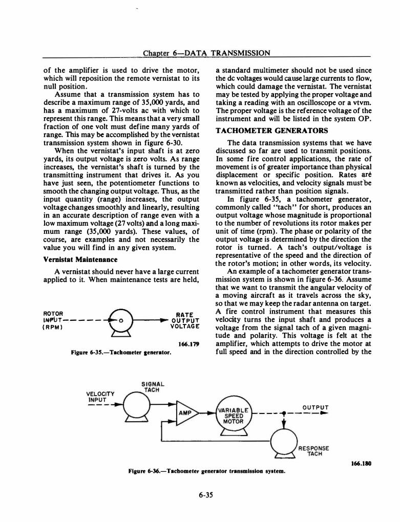
Chapter 6-DATA TRANSMISSION
of the amplifier is used to drive the motor, which will reposition the remote vernistat to its null position.
Assume that a transmission system has to describe a maximum range of 35,000 yards, and has a maximum of 27-volts ac with which to represent this range. This means that a very small fraction of one volt must define many yards of range. This may be accomplished by the vernistat transmission system shown in figure 6-30.
When the vernistat' s input shaft is at zero yards, its output voltage is zero volts. As range increases, the vernistaes shaft is turned by the transmitting instrument that drives it. As you have just seen, the potentiometer functions to smooth the changing output voltage. Thus, as the input quantity (range) increases, the output voltage changes smoothly and linearly, resulting in an accurate description of range even with a low maximum voltage (27 volts) and a long maximum range (35,000 yards). These values, of course, are examples and not necessarily the value you will find in any given system.
Vemistat Maintenance
A vernistat should never have a large current applied to it. When maintenance tests are held,
ROTOR lNPlJT-- - - ( R PM )
RATE ,__ __ ,._ O U T PUT VOLTAG E
166.179
Figure 6--35.-Tacltometer ceaerator.
VELOCITY INPUT
a standard multimeter should not be used since the de voltages would cause large currents to flow, which could damage the vernistat. The vernistat may be tested by applying the proper voltage and taking a reading with an oscilloscope or a vtvm. The proper voltage is the reference voltage of the instrument and will be listed in the system OP.
TACHOMETER GENERATORS
The data transmission systems that we have discussed so far are used to transmit positions. In some fire control applications, the rate of movement is of greater importance than physical displacement or specific position. Rates are known as velocities, and velocity signals must'be transmitted rather than position signals.
In figure 6-35, a tachometer generator, commonly called "tach. , for short, produces an output voltage whose magnitude is proportional to the number of revolutions its rotor makes per unit of time (rpm). The phase or polarity of the output voltage is determined by the direction the rotor is turned. A tach's output/voltage is representative of the speed and the direction of the rotor's motion; in other words, its velocity.
An example of a tachometer generator transmission system is shown in figure 6-36. Assume that we want to transmit the angular velocity of a moving aircraft as it travels across the sky, so that we may keep the radar antenna on target. A fire control instrument that measures this velocity turns the input shaft and produces a voltage from the signal tach of a given magnitude and polarity. This voltage is felt at tbe amplifier, which attempts to drive the motor at full speed and in the direction controlled by the
OUTPUT - - - � - - - -�
L------------------------�··�:g�·· 166.110
Flaure 6--36.-Tachometer aenerator t.ransmissioa syltem.
6-35
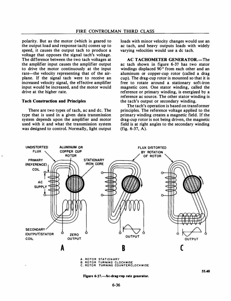
FIRE CONTROLMAN THIRD CLASS
polarity. But as the motor (which is geared to the output load and response tach) comes up to speed, it causes the output tach to produce a voltage that opposes the signal tach's voltage. The difference between the two tach voltages at the amplifier input causes the amplifier output to drive the motor continuously at the input rate-the velocity representing that of the airplane. If the signal tach were to receive an increased velocity signal, the effective amplifier input would be increased, and the motor would drive at the higher rate.
Tach Construction and Principles
There are two types of tach, ac and de. The type that is used in a given data transmission system depends upon the amplifier and motor used with it and what the transmission system was designed to control. Normally, light output
UNOISTORTED FLUX
PRIMARY (REFERENCE)
COIL
AC
SECONDARY (OUTPUT) STATOR COIL
A ZERO
OUTPUT
A . ROTOR STAT I O N ARY
loads with minor velocity changes would use an ac tach, and heavy outputs loads with widely varying velocities would use a de tach.
AC TACHOMETER GENERATOR.-The ac tach shown in figure 6-37 has two stator windings displaced 90 o from each other and an aluminum or copper-cup rotor (called a drag cup). The drag-cup rotor is mounted so that it is free to rotate around a stationary soft-iron magnetic core. One stator winding, called the reference or primary winding, is energized by a reference ac source. The other stator winding is the tach's output or secondary winding.
The tach's operation is based on transformer principles. The reference voltage applied to the primary winding creates a magnetic field. If the drag-cup rotor is not being driven, the magnetic field is at right angles to the secondary winding (fig. 6-37, A).
8
FLUX DISTORTED BY ROTATION
OF ROTOR
OUTPUT OUTPUT
( B. ROTOR TURNING CLOCKWISE C . ROTOR TURNING COUNTERCLOCKW ISE
55.40
Flgare 6-37.-Ac-dra&·np rate &eaerator.
6-36
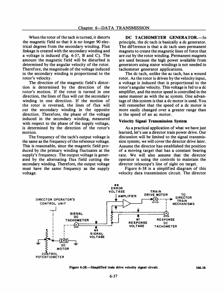
Chapter 6-DA TA TRANSMISSION
When the rotor of the tach is turned, it distorts the magnetic field so that it is no longer 90 electrical degrees from the secondary winding. Flux linkage is created with the secondary winding and a voltage is induced (fig. 6-37, B and C). The amount the magnetic field will be disturbed is determined by the angular velocity of the rotor. Therefore, the magnitude of the voltage induced in the secondary winding is proportional to the rotor's velocity.
The direction of the magnetic field's distortion is determined by the direction of the rotor's motion. If the rotor is turned in one direction, the lines of flux will cut the secondary winding in one direction. If the motion of the rotor is reversed, the lines of flux will cut the secondary winding in the opposite direction. Therefore, the phase of the voltage induced in the secondary winding, measured with respect to the phase of the supply voltage, is determined by the direction of the rotor's motion.
The frequency of the tach's output voltage is the same as the frequency of the reference voltage. This is reasonable, since the magnetic field produced by the primary winding fluctuates at the supply's frequency. The output voltage is generated by the alternating flux field cutting the secondary winding. Therefore, the output voltage must have the same frequency as the supply voltage.
• •
DC TACHOMETER GENERATOR.-In principle, the de tach is basically a de generator. The difference is that a de tach uses permanent magnets to create the magnetic lines of force that are cut by the rotor winding. Permanent magnets are used because the high power available from generators using stator windings is not needed in tachometer generator applications.
The de tach, unlike the ac tach, has a wound rotor. As the rotor is driven by the velocity input, a voltage is induced that is proportional to the rotor's angular velocity. This voltage is fed to a de amplifier, and the motor speed is controlled in the same manner as with the ac system. One advantage of this system is that a de motor is used. You will remember that the speed of a de motor is more easily changed over a greater range than is the speed of an ac motor.
Velocity Signal Transmission System
As a practical application of what we have just learned, let's use a director train power drive. Our discussion will be limited to the signal transmission system; we will cover the director drive later. Assume the director has established the position of a moving target that has a constant bearing rate. We will also assume that the director operator is using the controls to maintain the director telescope's line of sight on target.
Figure 6-38 is a simplified diagram of this velocity data transmission circuit. The director
E R R OR
DIRECTOR OPERATOR'S
CONTROL UNIT
CONTROL POTENTIOMETER
es S I GN A L
VOLTAGE
VOLTAGE
er R E S PONSE VOLTAGE
•
R E S PONSE DC
TACHOMETER
Figure 6--38.-Simpllfled train drive velocity signal circuit.
6-37
166.16
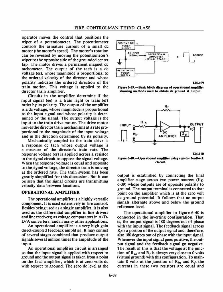
FIRE CONTROLMAN THIRD CLASS
operator moves the control that positions the wiper of a potentiometer. The potentiometer controls the armature current of a small de motor (the motor's speed). The motor's rotation can be reversed by moving the potentiometer's wiper to the opposite side of the grounded center tap. The motor drives a permanent magnet de tachometer. The output of the tach is a de voltage (es), whose magnitude is proportional to the ordered velocity of the director and whose polarity indicates the ordered direction of the train motion. This voltage is applied to the director train amplifier.
Circuits in the amplifier determine if the input signal (ee) is a train right or train left order by its polarity. The output of the amplifier is a de voltage, whose magnitude is proportional to the input signal and whose polarity is determined by the signal. The output voltage is the input to the train drive motor. The drive motor moves the director train mechanisms at a rate proportional to the magnitude of the input voltage and in the direction determined by its polarity.
Mechanically coupled to the train drive is a response de tach whose output voltage is a measure of the director's train rate. The response voltage (er) is applied across a resistor in the signal circuit to oppose the signal voltage. When the response voltage is equal and opposite to the signal voltage, the director train is moving at the ordered rate. The train system has been greatly simplified for this discussion. But it can be seen that the signal circuits are transmitting velocity data between locations.
OPERATIONAL AMPLIFIER
The operational amplifier is a highly versatile component. It is used extensively in fire control. Besides being used as a single amplifier, it is also used as the differential amplifier in line drivers and line receivers; as voltage comparators in A/DO/ A converters; and in many other applications.
An operational amplifier is a very high gain direct-coupled feedback amplifier. It may consist of several stages combined that produce output signals several million times the amplitude of the input.
An operational amplifier circuit is arranged so that the input signal is applied with respect to ground and the output signal is taken from a point on the final amplifier, which is at zero volts de with respect to ground. The zero de level at the
6-38
--9=FND
124.109
Flaure 6-39.-Buic block dlaanua of operational amplifier ••owlnc JDetbods u!led to obtala de aro••d at output.
124.110
Flaure 6-40.--0peratiOIIal amplifier uslaa resistor feedbtlck drealt.
output is established by connecting the final amplifier stage across two power sources (fig. 6-39) whose outputs are of opposite polarity to ground. The output terminal is connected to that point on the amplifier which is at the zero volt de ground potential. It follows that ac output signals alternate above and below the ground reference level.
The operational amplifier in figure 6-40 is connected in the inverting configuration. That is, the output signal is 180 degrees out of phase with the input signal. The feedback signal across Rt is a portion of the output signal and, therefore, also 180 degrees out of phase with the input signal. Whenever the input signal goes positive, the output signal and the feedback signal go negative. The result of this is that the voltage at the junction of R;" and Rt is always very close to 0 volts (virtual ground) with this configuration. To maintain 0 volts at the junction of R1" and R1, the currents in these two resistors are equal and
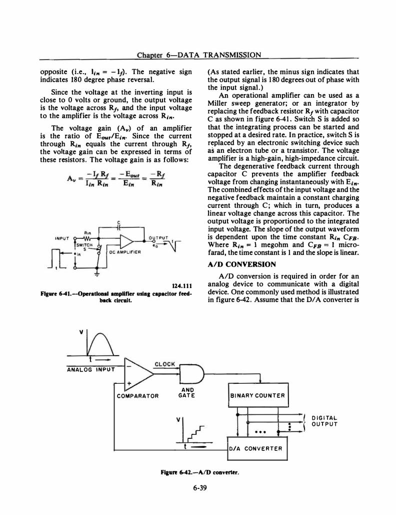
Chapter 6-DATA TRANSMISSION
opposite (i.e., l;,. = - 11). The negative sign indicates 180 degree phase reversal.
Since the voltage at the inverting input is close to 0 volts or ground, the output voltage is the voltage across R1, and the input voltage to the amplifier is the voltage across R;,..
The voltage gain (Av) of an amplifier is the ratio of EoutiE,,.. Since the current through R;,. equals the current through R1, the voltage gain can be expressed in terms of these resistors. The voltage gain is as follows:
c
124.1 1 1
Flg•re 6-41.-0peratloaal amplifier uslaa capacitor feed· back clrcw.lt.
v
t - �CLOCK ANALOG INPUT
-v AND COMPARATOR GAT E
(As stated earlier, the minus sign indicates that the output signal is 1 80 degrees out of phase with the input signal.)
An operational amplifier can be used as a Miller sweep generator; or an integrator by replacing the feedback resistor R1 with capacitor C as shown in figure 6-41 . Switch S is added so that the integrating process can be started and stopped at a desired rate. In practice, switch S is replaced by an electronic switching device such as an electron tube or a transistor. The voltage amplifier is a high-gain, high-impedance circuit.
The degenerative feedback current through capacitor C prevents the amplifier feedback voltage from changing instantaneously with E1,.. The combined effects of the input voltage and the negative feedback maintain a constant charging current through C; which in turn, produces a linear voltage change across this capacitor. The output voltage is proportioned to the integrated input voltage. The slope of the output waveform is dependent upon the time constant R1,. CFB· Where R;,. = 1 megohm and CFs = 1 microfarad, the time constant is 1 and the slope is linear.
AID CONVERSION
AID conversion is required in order for an analog device to communicate with a digital device. One commonly used method is illustrated in figure �42. Assume that the D/ A converter is
l B I NARY COU N T E R
]L • • •
• • •
t D IG I TAL
J O U T P U T
t - 0/A CONV E R T E R
Figure 6-42.-A/D coaverter.
6-39
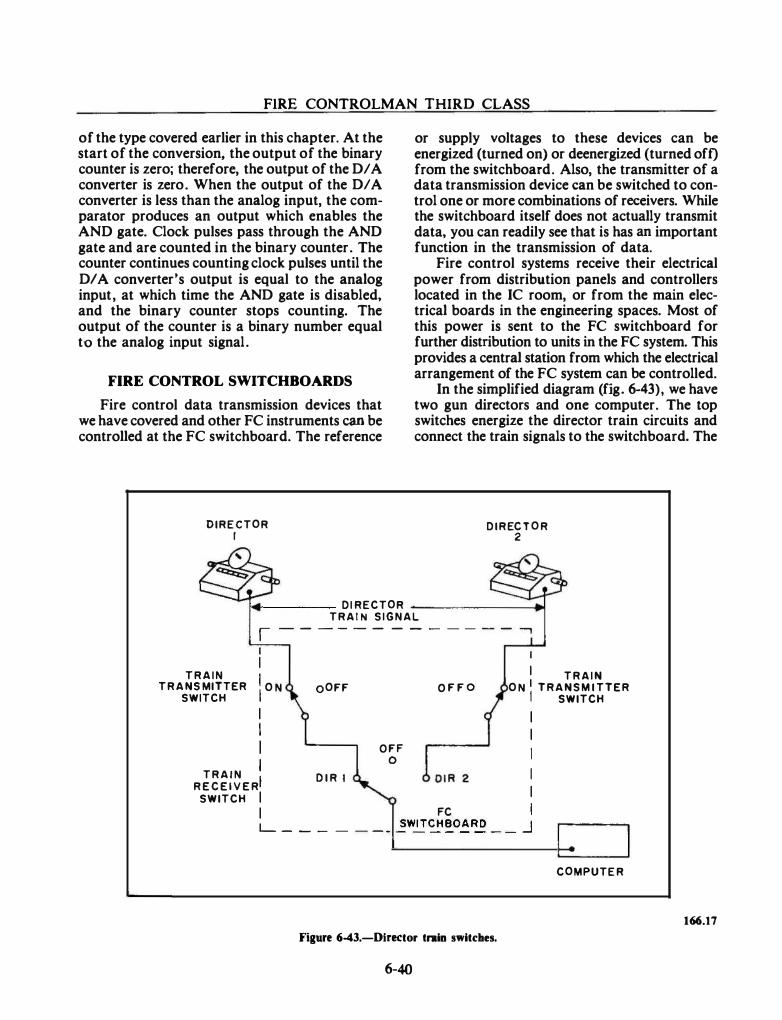
FIRE CONTROLMAN THIRD CLASS
of the type covered earlier in this chapter. At the start of the conversion, the output of the binary counter is zero; therefore, the output of the D/ A converter is zero. When the output of the D/ A converter is less than the analog input, the comparator produces an output which enables the AND gate. Clock pulses pass through the AND gate and are counted in the binary counter. The counter continues counting clock pulses until the Dl A converter's output is equal to the analog input, at which time the AND gate is disabled, and the binary counter stops counting. The output of the counter is a binary number equal to the analog input signal.
FIRE CONTROL SWITCHBOARDS
Fire control data transmission devices that we have covered and other FC instruments can be controlled at the FC switchboard. The reference
DIRECTOR I
or supply voltages to these devices can be energized (turned on) or deenergized (turned oft) from the switchboard. Also, the transmitter of a data transmission device can be switched to control one or more combinations of receivers. While the switchboard itself does not actually transmit data, you can readily see that is has an important function in the transmission of data.
Fire control systems receive their electrical power from distribution panels and controllers located in the IC room, or from the main electrical boards in the engineering spaces. Most of this power is sent to the FC switchboard for further distribution to units in the FC system. This provides a central station from which the electrical arrangement of the FC system can be controlled.
In the simplified diagram (fig. 6-43), we have two gun directors and one computer. The top switches energize the director train circuits and connect the train signals to the switchboard. The
DIREC T O R 2
!,..._ ____ DI RECTOR -------� TRAI N S IGNAL , - - - - - - - - - - - - - .....,
TRAIN TRANS MITTER
SWITCH
I I I
O N I I I I
TRAIN I R E C E I V E R!
SWITCH I I
oOFF
D I R I
OFF 0
O F F O
I I TRAIN
O N I TRANSM I TTER I SWITCH
I I I I I
FC I L_ _ _ _ _ _ _ _ �WITCH!!_O�RD _ _ .J
COMPUTE R
Figure 6-43.-Dinctor tntin switches.
6-40
166.17
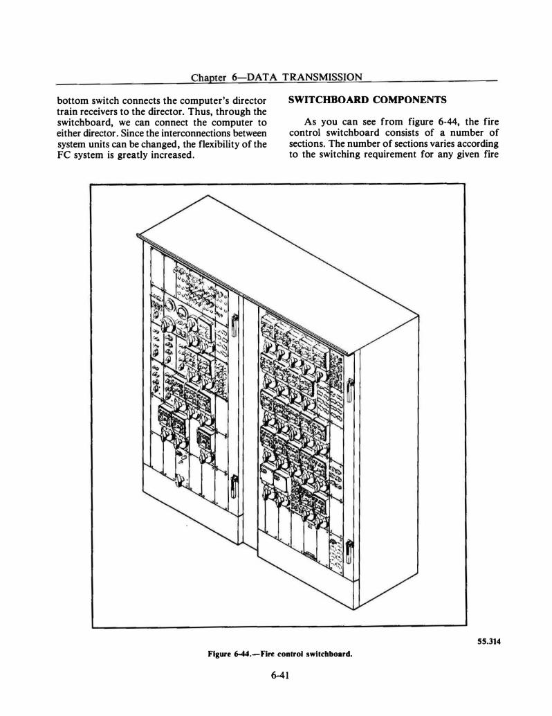
Chapter 6-DA T A TRANSMISSION
bottom switch connects the computer's director train receivers to the director. Thus, through the switchboard, we can connect the computer to either director. Since the interconnections between system units can be changed, the flexibility of the FC system is greatly increased.
SWITCHBOARD COMPONENTS
As you can see from figure 6·44, the fire control switchboard consists of a number of sections. The number of sections varies according to the switching requirement for any given fire
SS.314
Figure 6-44.-Fire control switchboard.
6-41
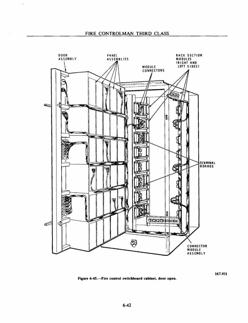
FIRE CONTROLMAN THIRD CLASS
B A C K S EC T I ON M O O U L ES
���'::?V#/ � I �� ® 1 11 C O N N ECTOR L 1_...V ----� I M O D U L E � --- A S S EM B L Y
Figure 6-45.-Flre control switchboard cabinet, door open.
6-42
167.911
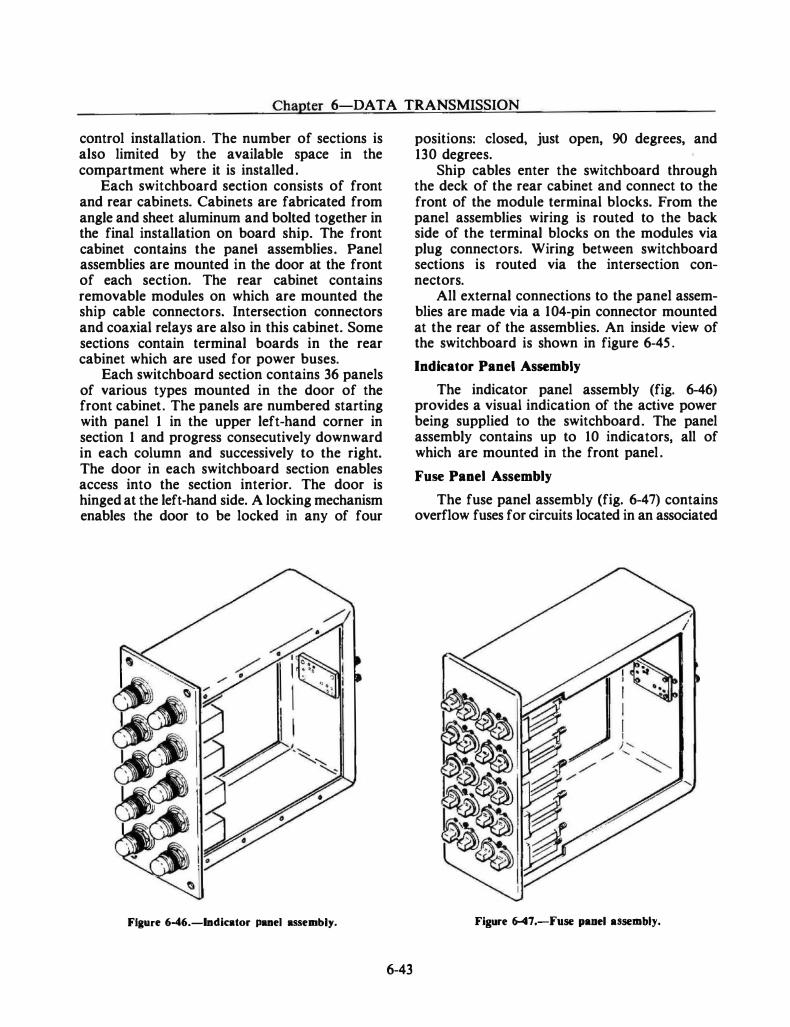
Chapter 6-DATA TRANSMISSION
control installation. The number of sections is also limited by the available space in the compartment where it is installed.
Each switchboard section consists of front and rear cabinets. Cabinets are fabricated from angle and sheet aluminum and bolted together in the final installation on board ship. The front cabinet contains the panel assemblies. Panel assemblies are mounted in the door at the front of each section. The rear cabinet contains removable modules on which are mounted the ship cable connectors. Intersection connectors and coaxial relays are also in this cabinet. Some sections contain terminal boards in the rear cabinet which are used for power buses.
Each switchboard section contains 36 panels of various types mounted in the door of the front cabinet. The panels are numbered starting with panel 1 in the upper left-hand corner in section 1 and progress consecutively downward in each column and successively to the right. The door in each switchboard section enables access into the section interior. The door is hinged at the left-hand side. A locking mechanism enables the door to be locked in any of four
Figure 6-46.-lndicator panel assembly.
6-43
positions: closed, just open, 90 degrees, and 130 degrees.
Ship cables enter the switchboard through the deck of the rear cabinet and connect to the front of the module terminal blocks. From the panel assemblies wiring is routed to the back side of the terminal blocks on the modules via plug connectors. Wiring between switchboard sections is routed via the intersection connectors.
All external connections to the panel assemblies are made via a 1 04-pin connector mounted at the rear of the assemblies. An inside view of the switchboard is shown in figure 6-45 .
Indicator Panel Assembly
The indicator panel assembly (fig. 6-46) provides a visual indication of the active power being supplied to the switchboard. The panel assembly contains up to 10 indicators, all of which are mounted in the front panel .
Fuse Panel Assembly
The fuse panel assembly (fig. 6-47) contains overflow fuses for circuits located in an associated
Figure 647.-Fuse panel assembly.
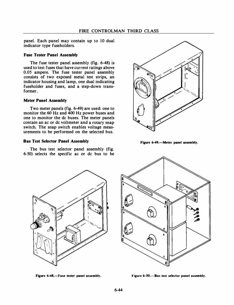
FIRE CONTROLMAN THIRD CLASS
panel. Each panel may contain up to 10 dual indicator type fuseholders.
Fuse Tester Panel Assembly
The fuse tester panel assembly (fig. 6-48) is used to test fuses that have current ratings above 0.05 ampere. The fuse tester panel assembly consists of two exposed metal test strips, an indicator housing and lamp, one dual indicating fuseholder and fuses, and a step-down transformer.
Meter Panel Assembly
Two meter panels (fig. 6-49) are used: one to monitor the 60 Hz and 400 Hz power buses and one to monitor the de buses. The meter panels contain an ac or de voltmeter and a rotary snap switch. The snap switch enables voltage measurements to be performed on the selected bus.
Bus Test Selector Panel Assembly
The bus test selector panel assembly (fig. 6-50) selects the specific ac or de bus to be
Figure 6�8.-Fuse tester panel assembly.
6-44
Figure 6�9.-Meter panel assembly.
Figure 6-50.-Bus test selector panel assembly.
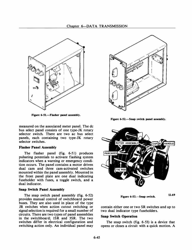
Chapter 6-DA T A TRANSMISSION
Figure 6-51.-Fiasher panel assembly.
measured on the associated meter panel. The de bus select panel consists of one type-JK rotary selector switch. There are two ac bus select panels, each containing two type-JK rotary selector switches.
Flasher Panel Assembly
The flasher panel (fig. 6-51) produces pulsating potentials to activate flashing system indicators when a warning or emergency condition occurs. The panel contains a motor driven dual cam and three cam-activated switches mounted within the panel assembly. Mounted in the front panel plate are one dual indicating fuseholder with fuses, a toggle switch, and a dual indicator.
Snap Switch Panel Assembly
The snap switch panel assembly (fig. 6-52) provides manual control of switchboard power buses. They are also used in place of the type JR switches when action cutout switching or signal selection is required for a smaU number of circuits. There are two types of panel assemblies in the switchboard; lSR and 3SR. The two switches differ in electrical configuration and switching action only. An individual panel may
6-45
Figure 6-52.-Snap switd1 panel assembly.
Figure 6-53.-Snap switch. 12.69
contain either one or two SR switches and up to two dual indicator type fuseholders.
Snap Switch Operation
The snap switch (fig. 6-53) is a device that opens or closes a circuit with a quick motion. A
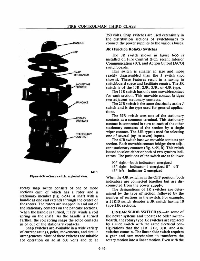
FIRE CONTROLMAN THIRD CLASS
140.1
Fiaure 6-54.-Snap switch, exploded view.
rotary snap switch consists of one or more sections each of which has a rotor and a stationary member (fig. 6-54). A shaft with a handle at one end extends through the center of the rotors. The rotors are snapped in and out of the stationary contacts on the pancake sections. When the handle is turned, it first winds a coil spring on the shaft . As the handle is turned farther, the coil spring snaps the rotor contacts in or out of the stationary contacts.
Snap switches are available in a wide variety of current ratings, poles, movements, and circuit arrangements. Most of these switches are suitable for operation on ac at 600 volts and de at
6-46
250 volts. Snap switches are used extensively in the distribution sections of switchboards to connect the power supplies to the various buses.
JR (Junction Rotary) Switches
The JR switch shown in figure 6-55 is installed on Fire Control (FC), recent Interior Communication (I C), and Action Cutout (ACO) switchboards.
This switch is smaller in size and more readily disassembled than the J switch (not shown). These features result in a saving in switchboard space and facilitate repairs. The JR switch is of the 1 JR, 2JR, 3JR, or 4JR type.
The 1 JR switch has only one movable contact for each section. This movable contact bridges two adjacent stationary contacts.
The 2JR switch is the same electrically as the J switch and is the type used for general applications.
The 3JR switch uses one of the stationary contacts as a common terminal. This stationary contact is connected in turn to each of the other stationary contacts of the section by a single wiper contact. The 3JR type is used for selecting one of several (up to seven) inputs.
The 4JR switch has two movable contacts per section. Each movable contact bridges three adjacent stationary contacts (fig. 6-55, B). This switch is used to select either or both of two synchro indicators. The positions of the switch are as follows:
90 ° right-both indicators energized 45 o right-indicator 1 energized 0 °-off 45 o left-indicator 2 energized
When the 4JR switch is in the OFF position, both indicators are connected together but are disconnected from the power supply.
The designations of JR switches are determined by the type of section followed by the number of sections in the switch. For example, a 2JRIO switch denotes a JR switch having 10 type-2JR sections.
LINEAR SLIDE SWITCHES.-In some of the newer systems and updates to older switchboards, the rotary type JR switches are replaced by a slide switch with the same electrical configurations that the lJR, 2JR, 3JR, and 4JR switches come in. The linear slide switch requires a gear and cam mechanism to transform the rotary motion into a linear motion. Even with the
Chapter 6-DAT A TRANSMISSION
Figure 6-55.-Type.4JR switch.
Figure 6-56.-Manually operated JR switch panel assembly.
Manually Operated JR Switch Panel Assembly
12.71
additional components, the linear slide switch still fits in the same size panel but takes up about half the space required for the rotary. The linear slide switch can also be installed in an automatic JR (AJR) panel.
The manually operated JR switch assembly (fig. 6-56) is used to provide manual switching
6-47
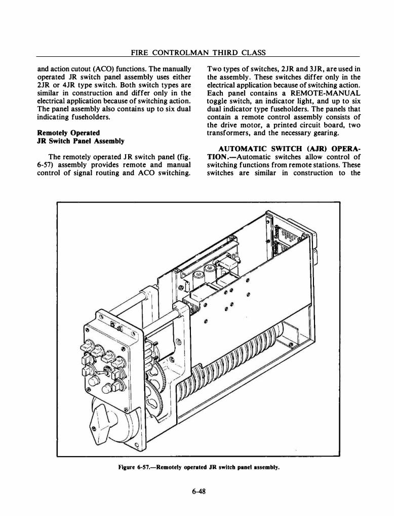
FIRE CONTROLMAN THIRD CLASS
and action cutout (ACO) functions. The manually operated JR switch panel assembly uses either 2JR or 4JR type switch. Both switch types are similar in construction and differ only in the electrical application because of switching action. The panel assembly also contains up to six dual indicating fuseholders.
Remotely Operated JR Switch Panel Assembly
The remotely operated JR switch panel (fig. 6-57) assembly provides remote and manual control of signal routing and ACO switching.
Two types of switches, 2JR and 3JR, are used in the assembly. These switches differ only in the electrical application because of switching action. Each panel contains a REMOTE-MANUAL toggle switch, an indicator light, and up to six dual indicator type fuseholders. The panels that contain a remote control assembly consists of the drive motor, a printed circuit board, two transformers, and the necessary gearing.
AUTOMATIC SWITCH (AJR) OPERATION .-Automatic switches allow control of switching functions from remote stations. These switches are similar in construction to the
Figure 6-57.-Remotely operated JR switch panel assembly.
6-48
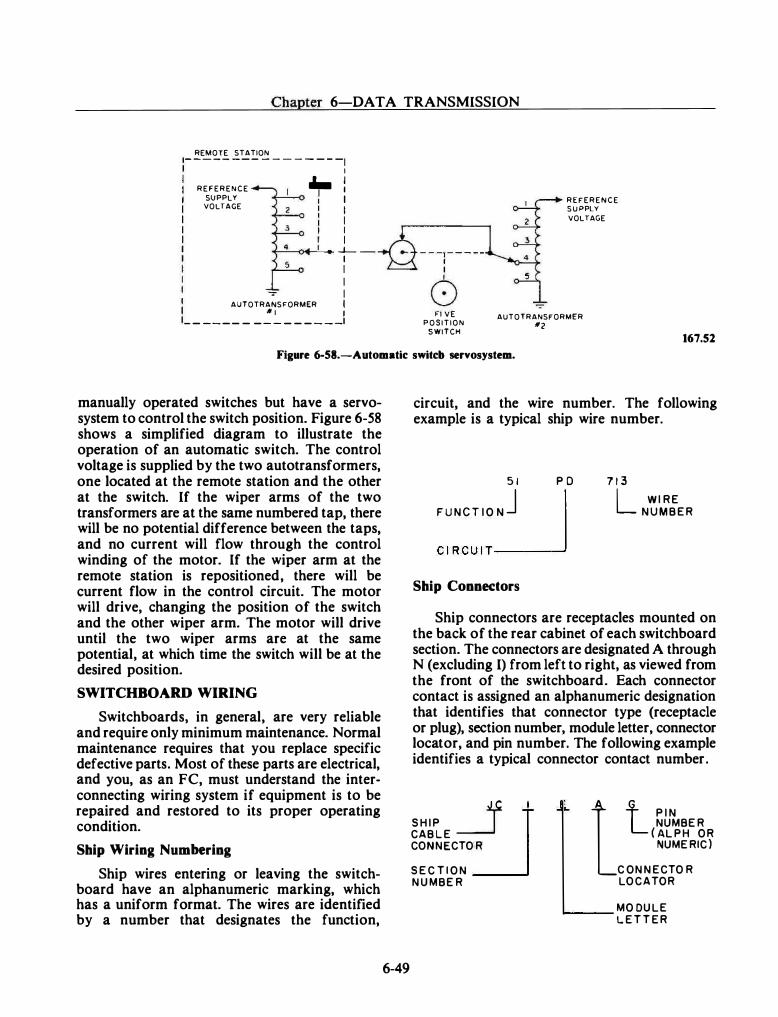
Chapter 6-DATA TRANSMISSION
REMOTE STATION - - - - - - - - - - - - - - - -1
R E F E R E N C E
SUPPLY VOLTAGE
I
� � I I I I I
��� ... _j__ -1 I I
-;- I AUTOTRANSFORMER I
'* I I - - - - - - - - - - - - - - - �
- - --, - - - --1 I
6 Fl V E
P O S I T I O N
SWITCH
R E F E R E N C E S U PPLY
VOLTAGE
AUTOTRANSFORMER
*2 167.52
Figure 6-58.-Automatic switcb servosystem.
manually operated switches but have a servosystem to control the switch position. Figure 6-58 shows a simplified diagram to illustrate the operation of an automatic switch. The control voltage is supplied by the two autotransformers, one located at the remote station and the other at the switch. If the wiper arms of the two transformers are at the same numbered tap, there will be no potential difference between the taps, and no current will flow through the control winding of the motor. If the wiper arm at the remote station is repositioned, there will be current flow in the control circuit. The motor will drive, changing the position of the switch and the other wiper arm. The motor will drive until the two wiper arms are at the same potential, at which time the switch will be at the desired position.
SWITCHBOARD WIRING
Switchboards, in general, are very reliable and require only minimum maintenance. Normal maintenance requires that you replace specific defective parts. Most of these parts are electrical, and you, as an FC, must understand the interconnecting wiring system if equipment is to be repaired and restored to its proper operating condition.
Ship Wiring Numbering
Ship wires entering or leaving the switchboard have an alphanumeric marking, which has a uniform format. The wires are identified by a number that designates the function,
6-49
circuit, and the wire number. The following example is a typical ship wire number.
5 1 P O
FUNCT IONJ I C IRCU I T__j
Ship Connectors
7 1 3 L WIRE NUMBER
Ship connectors are receptacles mounted on the back of the rear cabinet of each switchboard section. The connectors are designated A through N (excluding I) from left to right, as viewed from the front of the switchboard. Each connector contact is assigned an alphanumeric designation that identifies that connector type (receptacle or plug), section number, module letter, connector locator, and pin number. The following example identifies a typical connector contact number.
___f l SH IP
~ CABLE CONNECTOR
SECT ION NUMBER
l l P I N NUMBER
( ALPH OR NUMERIC)
CONNECTOR LOCATOR
�....-__ MODULE LETTER
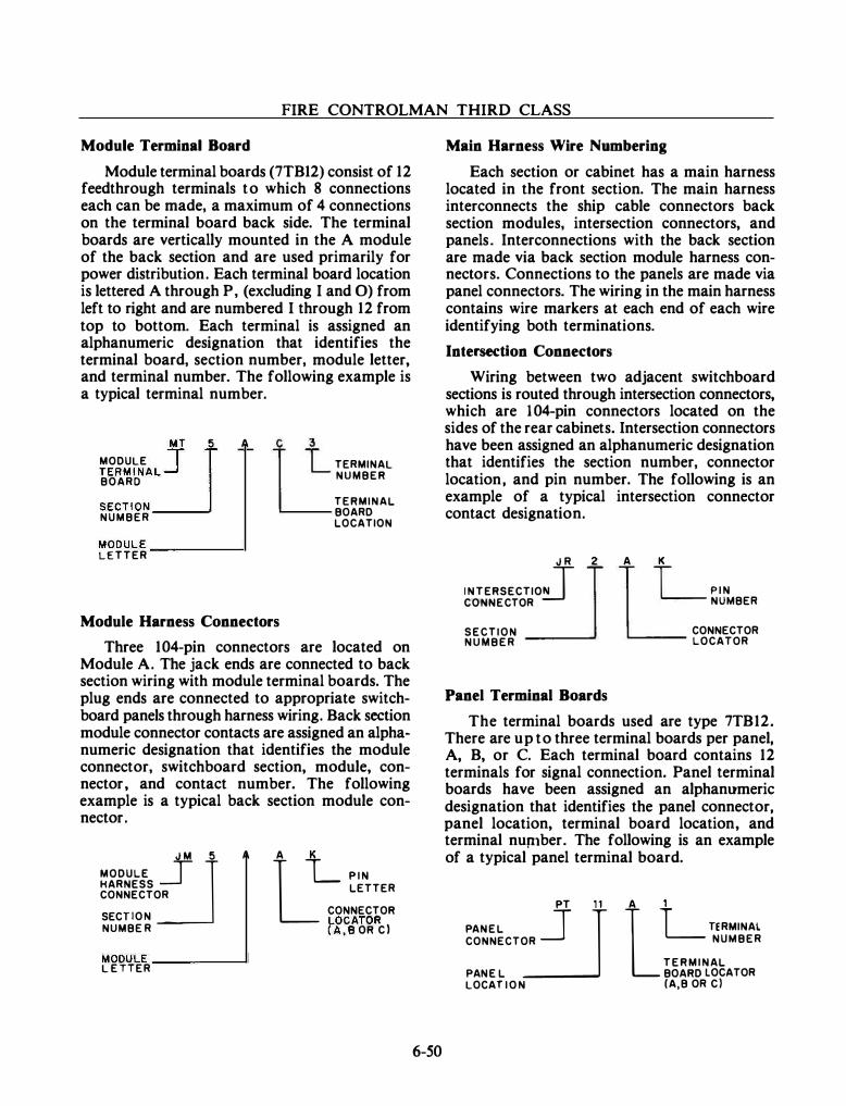
FIRE CONTROLMAN THIRD CLASS
Module Terminal Board
Module terminal boards (7TB12) consist of 12 feedthrough terminals to which 8 connections each can be made, a maximum of 4 connections on the terminal board back side. The terminal boards are vertically mounted in the A module of the back section and are used primarily for power distribution. Each terminal board location is lettered A through P, (excluding I and 0) from left to right and are numbered I through 12 from top to bottom. Each terminal is assigned an alphanumeric designation that identifies the terminal board, section number, module letter, and terminal number. The following example is a typical terminal number.
MODULE :JMT 5
TERMINAL ....J BOARD
SECTION NUMBER
A
MODULE __________ � LETTER
c 3
TERMINAL NUMBER
TERMINAL BOARD LOCATION
Module Harness Connectors
Three 1 04-pin connectors are located on Module A. The jack ends are connected to back section wiring with module terminal boards. The plug ends are connected to appropriate switchboard panels through harness wiring. Back section module connector contacts are assigned an alphanumeric designation that identifies the module connector, switchboard section, module, connector, and contact number. The following example is a typical back section module connector.
MODULE �J M 5
HARNESS CONNECTOR
SECT ION NUMBE R
A
MODULE __________ � L E TTER
LA L P I N LETTER
CONNECTOR l-OCATOR (A, B OR C l
6-50
Main Harness Wire Numbering
Each section or cabinet has a main harness located in the front section. The main harness interconnects the ship cable connectors back section modules, intersection connectors, and panels. Interconnections with the back section are made via back section module harness connectors. Connections to the panels are made via panel connectors. The wiring in the main harness contains wire markers at each end of each wire identifying both terminations.
Intersection Connectors
Wiring between two adjacent switchboard sections is routed through intersection connectors, which are 1 04-pin connectors located on the sides of the rear cabinets. Intersection connectors have been assigned an alphanumeric designation that identifies the section number, connector location, and pin number. The following is an example of a typical intersection connector contact designation.
J R 2
I N TERSECTIOJ J CONNECTOR
SECTION NUMBER
Panel Terminal Boards
A L P I N NUMBER
CONNECTOR LOCATOR
The terminal boards used are type 7TB12. There are up to three terminal boards per panel, A, B, or C. Each terminal board contains 12 terminals for signal connection. Panel terminal boards have been assigned an alphanumeric designation that identifies the panel connector, panel location, terminal board location, and terminal nup1ber. The following is an example of a typical panel terminal board.
PANEL
=-_}PT ll
CONNECTOR
PANE L LOCAT I O N
LA L TERMINAl
NUMBER
TERMINAL BOARD LOCATOR (A,B OR C)
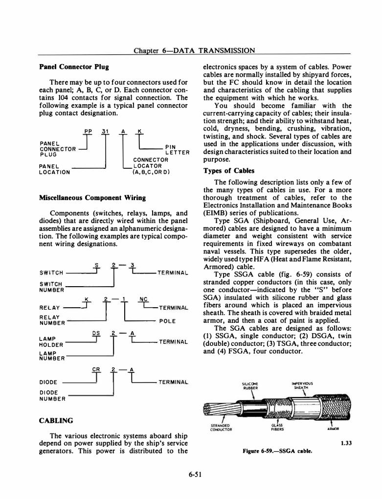
Chapter 6-DA TA TRANSMISSION
Panel Connector Plug
There may be up to four connectors used for each panel; A, B, C, or D. Each connector contains 104 contacts for signal connection. The following example is a typical panel connector plug contact designation.
PAN E L :Jpp 3 1 CONNECTOR _j P L U G
PA N E L LOCATION
l. L P I N L ETTER
CONNECTOR LOCATOR (A, B,C , OR D )
MisceUaneous Component Wiring
Components (switches, relays, lamps, and diodes) that are directly wired within the panel assemblies are assigned an alphanumeric designation. The following examples are typical component wiring designations.
S W I TC H
___
_
T_S _
___�J2 - i-._ ___ TERMINAL
S W ITCH _ NUM BER + 2 - 1 NC RELAY
- T T I TERMINAL
R E L AY _ NUMBER ____ __. POLE
LAMP HOLDER L A M P N U M B E R
DIODE
D I ODE N U M B E R
CABLING
O S T
CR
T
2 - A
J T .___ __ TERMI NAL
2 - A
J T ...___ __ TERMINAL
The various electronic systems aboard ship depend on power supplied by the ship's service generators. This power is distributed to the
6-5 1
electronics spaces by a system of cables. Power cables are normally installed by shipyard forces, but the FC should know in detail the location and characteristics of the cabling that supplies the equipment with which he works.
You should become familiar with the current-carrying capacity of cables; their insulation strength; and their ability to withstand heat, cold, dryness, bending, crushing, vibration, twisting, and shock. Several types of cables are used in the applications under discussion, with design characteristics suited to their location and purpose.
Types of Cables
The following description lists only a few of the many types of cables in use. For a more thorough treatment of cables, refer to the Electronics Installation and Maintenance Books (EIMB) series of publications.
Type SGA (Shipboard, General Use, Armored) cables are designed to have a minimum diameter and weight consistent with service requirements in fixed wireways on combatant naval vessels. This type supersedes the older, widely used type HFA (Heat and Flame Resistant, Armored) cable.
Type SSGA cable (fig. 6-59) consists of stranded copper conductors (in this case, only one conductor-indicated by the "S" before SGA) insulated with silicone rubber and glass fibers around which is placed an impervious sheath. The sheath is covered with braided metal armor, and then a coat of paint is applied.
The SGA cables are designed as follows: (1) SSGA, single conductor; (2) DSGA, twin (double) conductor; (3) TSGA, three conductor; and (4) FSGA, four conductor.
SlliCC»>E IMPERVIOU$
1.33
Figure 6-59.-SSGA cable.
FIRE CONTROLMAN THIRD CLASS
The HF A cables (also composed of stranded copper conductors) are designated as follows: ( l ) SHFA, single conductor; (2) DHFA, twin (double) conductor; (3) THF A, three conductor; (4) FHF A, four conductor; and (5) MHF A, multiconductor. Twisted-pair telephone cables are designated as TTHFW A.
Many applications aboard ship require cables that can be bent and twisted again and again without damaging the conductor insulation or the protective covering. For such applications, flexible cables are used.
Flexible cables have synthetic rubber or synthetic resin insulation and a flexible sheath that is resistant to water, oil, heat, and flame. However, these cables are not as heat and flame resistant as armored HFA and SGA cables. Flexible cables for general use are designated by the letters HOF; for example, DHOF, THOF, and FHOF. Flexible cables for limited use are designated by the letters COP; for example, DCOP, TCOP, and FCOP.
Other types of cables used in electronics work are as follows:
• DRHLA-Double conductor, radio, hightension, lead armored.
• FHFTA-Four conductor, heat and flame resistant thin-walled armor.
• MCSP-Multiple conductor, shielded pressure resistant (submarine applications).
• TTRSA-Twisted-pair telephone, radio shielded, armored (characteristic impedance approximately 76 ohms).
lJesignation of Conductor Size
Generally, when the size of the individual conductors contained in the cable is indicated in the cable designation, the numeral (or numerals) following the letter designation indicate the approximate cross-sectional area of the individual conductors in thousands of circular mils to the nearest thousand. For example, TSGA-60 is a 3-conductor armored cable for general shipboard use, with each conductor having a cross-sectional area of 60,090 circular mils. However, when the
6-52
numerals immediately following the letter designation indicate the number of conductors comprising the cable, the size of the individual conductors may be indicated by additional numerals enclosed in parenthesis. For example, MDGA-19(6) is a 1 9-conductor electrical power cable for shipboard nonflexing service, with each conductor having a cross-sectional area of 6,512 circular mils.
Multiple-Conductor Cable Designations
Multiple-conductor cable types and class designations are followed by a number that indicates the number of conductors. For example, MSCA-30 is a heat and flame resistant armored cable with 30 conductors.
For telephone cable, the number indicates twisted pairs. For example, TTHFW A-25 means that the cable contains 25 twisted pairs; TTRSA-4 means that the cable contains 4 pair individually shielded.
Selection and Installation of Cables
You, as an FC, should have some knowledge of the power cables feeding fire control equipment. There are at least five items that should be considered when power cables are installed: (1) the maximum connected load in amperes; (2) the possible added load because of future installations; (3) the demand factor (that is, the average demand in amperes over a IS-minute interval divided by the total connected load in amperes); (4) the cable service rating (the physical characteristics required for a given type of service); and (5) the maximum allowable voltage drop in the part of the circuit under consideration.
The current-carrying capacity and voltagedrop limitations determine the cable size for a particular application. The current capacity is dependent upon the type and size of the conductor, the permissible temperature rise, and the physical characteristics of the space in which the cable is installed. The allowable voltage drop depends on the type of load connected to the circuit.
All connections to cables are made in standard appliances and fittings; splice connections are not made. However, cable splices are permitted
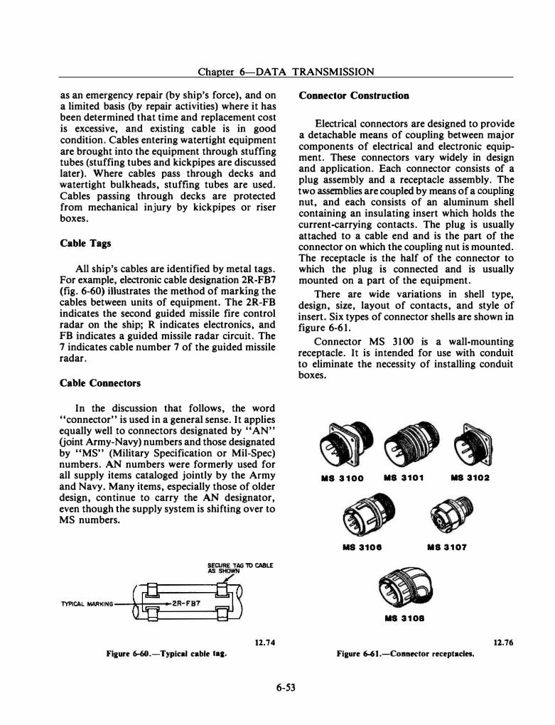
Chapter 6 DATA TRANSMISSION
as an emergency repair (by ship's force), and on a limited basis (by repair activities) where it has been determined that time and replacement cost is excessive, and existing cable is in good condition. Cables entering watertight equipment are brought into the equipment through stuffing tubes (stuffing tubes and kickpipes are discussed later). Where cables pass through decks and watertight bulkheads, stuffmg tubes are used. Cables passing through decks are protected from mechanical injury by kickpipes or riser boxes.
Cable Tags
All ship's cables are identified by metal tags. For example, electronic cable designation �R-FB7 (fig. 6-60) illustrates the method of marking the cables between units of equipment. The 2R-FB indicates the second guided missile fire control radar on the ship; R indicates electronics, and FB indicates a guided missile radar circuit. The 7 indicates cable number 7 of the guided missile radar.
Cable Connectors
In the discussion that follows, the word "connector" is used in a general sense. It applies equally well to connectors designated by "AN" (joint Army-Navy) numbers and those designated by "MS" (Military Specification or Mil-Spec) numbers. AN numbers were formerly used for all supply items cataloged jointly by the Army and Navy. Many items, especially those of older design, continue to carry the AN designator, even though the supply system is shifting over to MS numbers.
SECURE TAG ll) CA8L£
TYPICAL MARKING � o 2R-F97 �� 12.74
Figure 6-60.-Typical cable taa.
6-53
Connector Construction
Electrical connectors are designed to provide a detachable means of coupling between major components of electrical and electronic equipment. These connectors vary widely in design and application. Each connector consists of a plug assembly and a receptacle assembly. �he two assemblies are coupled by means of a coupling nut, and each consists of an aluminum shell containing an insulating insert which holds the current-carrying contacts. The plug is usually attached to a cable end and is the part of the connector on which the coupling nut is mounted. The receptacle is the half of the connector to which the plug is connected and is usually mounted on a part of the equipment.
There are wide variations in shell type, design, size, layout of contacts, and style ?f insert. Six types of connector shells are shown m figure 6-61 .
Connector MS 3100 is a wall-mounting receptacle. It is intended for use with conduit to eliminate the necessity of installing conduit boxes.
MS 3 1 00 MS 3101 MS 3102
MS 3108 MS 3 1 07
MS 3 1 08
11.76 Figure 6-61.-Coanedor receptacles.
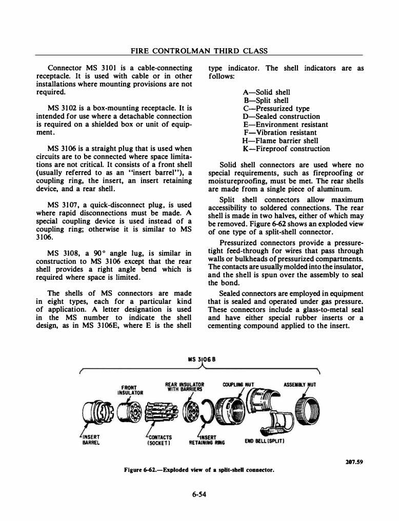
FIRE CONTROLMAN THIRD CLASS
Connector MS 3 101 is a cable-connecting receptacle. It is used with cable or in other installations where mounting provisions are not required.
MS 3 1 02 is a box-mounting receptacle. It is intended for use where a detachable connection is required on a shielded box or unit of equipment.
MS 3106 is a straight plug that is used when circuits are to be connected where space limitations are not critical. It consists of a front shell (usually referred to as an "insert barrel"), a coupling ring, the insert, an insert retaining device, and a rear shell.
MS 3 1 07, a quick-disconnect plug, is used where rapid disconnections must be made. A special coupling device is used instead of a coupling ring; otherwise it is similar to MS 3 106.
MS 3108, a 90 o angle lug, is similar in construction to MS 3106 except that the rear shell provides a right angle bend which is required where space is limited.
The shells of MS connectors are made in eight types, each for a particular kind of application. A letter designation is used in the MS number to indicate the shell design, as in MS 3 106E, where E is the shell
type indicator. The shell indicators are as follows:
A-Solid shell B-Split shell C-Pressurized type D-Sealed construction E-Environment resistant F-Vibration resistant
H-Flame barrier shell K-Fireproof construction
Solid shell connectors are used where no special requirements, such as fireproofing or moistureproofing, must be met. The rear shells are made from a single piece of aluminum.
Split shell connectors allow maximum accessibility to soldered connections. The rear shell is made in two halves, either of which may be removed. Figure 6-62 shows an exploded view of one type of a split-shell connector.
Pressurized connectors provide a pressuretight feed-through for wires that pass through walls or bulkheads of pressurized compartments. The contacts are usually molded into the insulator, and the shell is spun over the assembly to seal the bond.
Sealed connectors are employed in equipment that is sealed and operated under gas pressure. These connectors include a glass-to-metal seal and have either special rubber inserts or a cementing compound applied to the insert.
MS 3106 8
107.59 Figure 6-61.-Exploded view of a spUt-shell c:oaaector.
6-54
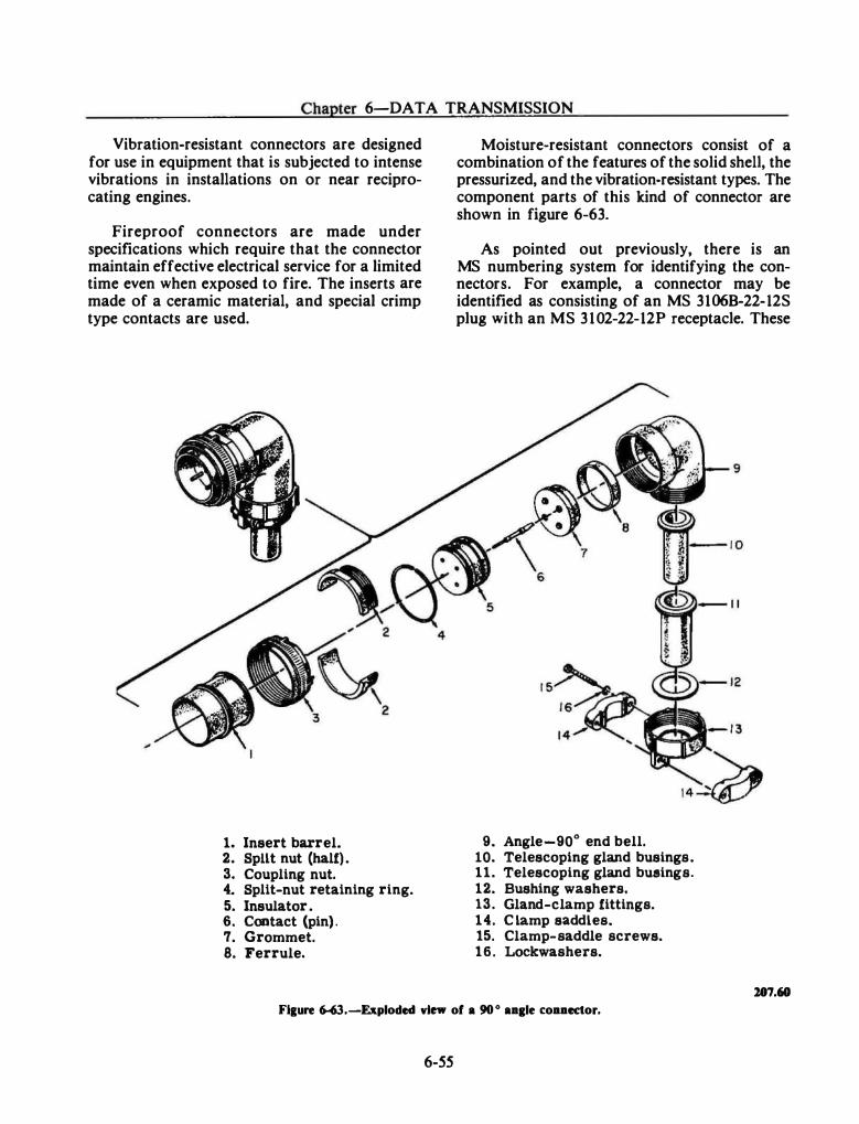
Chapter 6-DATA TRANSMISSION
Vibration-resistant connectors are designed for use in equipment that is subjected to intense vibrations in installations on or near reciprocating engines.
Fireproof connectors are made under specifications which require that the connector maintain effective electrical service for a limited time even when exposed to fire. The inserts are made of a ceramic material, and special crimp type contacts are used.
1. Insert barrel. 2. Spilt nut (half) . 3. Coupling nut. 4. Split-nut retaining ring. 5. Insulator . 6. Contact (pin) . 7. Grommet. 8. Ferrule.
Moisture-resistant connectors consist of a combination of the features of the solid shell, the pressurized, and the vibration-resistant types. The component parts of this kind of connector are shown in figure 6-63.
As pointed out previously, there is an MS numbering system for identifying the connectors. For example, a connector may be identified as consisting of an MS 3106B-22-12S plug with an MS 3102-22-12P receptacle. These
9. Angle-90° end bell. 10. Telescoping gland busings. 11. Telescoping gland busings. 12. Bushing washers. 13. Gland-clamp fittings. 14. C lamp saddles. 15. Clamp-saddle screws. 16. Lockwashers.
107.60 Fl&ure 6-63.-Exploded view of a 90 ° aa&le t:oaaector.
6-55
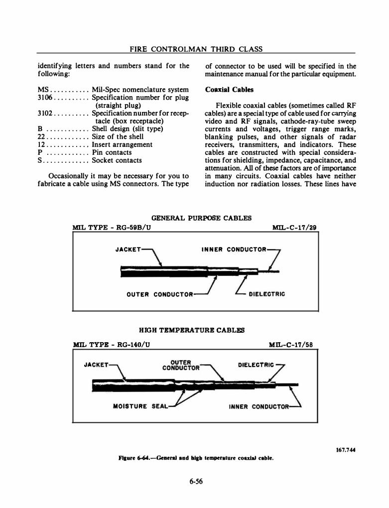
FIRE CONTROLMAN THIRD CLASS
identifying letters and numbers stand for the following:
MS . . . . . . . . . . . Mil-Spec nomenclature system 3106 . . . . . . . . . . Specification number for plug
(straight plug) 3 102 . . . . . . . . . . Specification number for recep-
tacle (box receptacle) B . . . . . . . . . . . . Shell design (slit type) 22 . . . . . . . . . . . . Size of the shell 12 . . . . . . . . . . . . Insert arrangement P . . . . . . . . . . . . Pin contacts S . . . . . . . . . . . . . Socket contacts
Occasionally it may be necessary for you to fabricate a cable using MS connectors. The type
of connector to be used will be specified in the maintenance manual for the particular equipment.
Coulal Cables
Flexible coaxial cables (sometimes called RF cables) are a special type of cable used for carrying video and RF signals, cathode-ray-tube sweep currents and voltages, trigger range marks, blanking pulses, and other signals of radar receivers, transmitters, and indicators. These cables are constructed with special considerations for shielding, impedance, capacitance, and attenuation. All of these factors are of importance in many circuits. Coaxial cables have neither induction nor radiation losses. These lines have
GENERAL PURPOSE CABLES
MIL TYPE - RG-59B/U MIL-C-17/29
JACKET I N N ER CONDtJCTOR
OUTER CONDUCTOR
HIGH TEMPERATURE CABLES
MIL TYPE - RG-140/U MIL-C-17/58
JA DIELECTRIC
MOISTURE
Flaare 6-64.--Geaeral aad 111&11 temperature coulal cable.
6-56
167.744
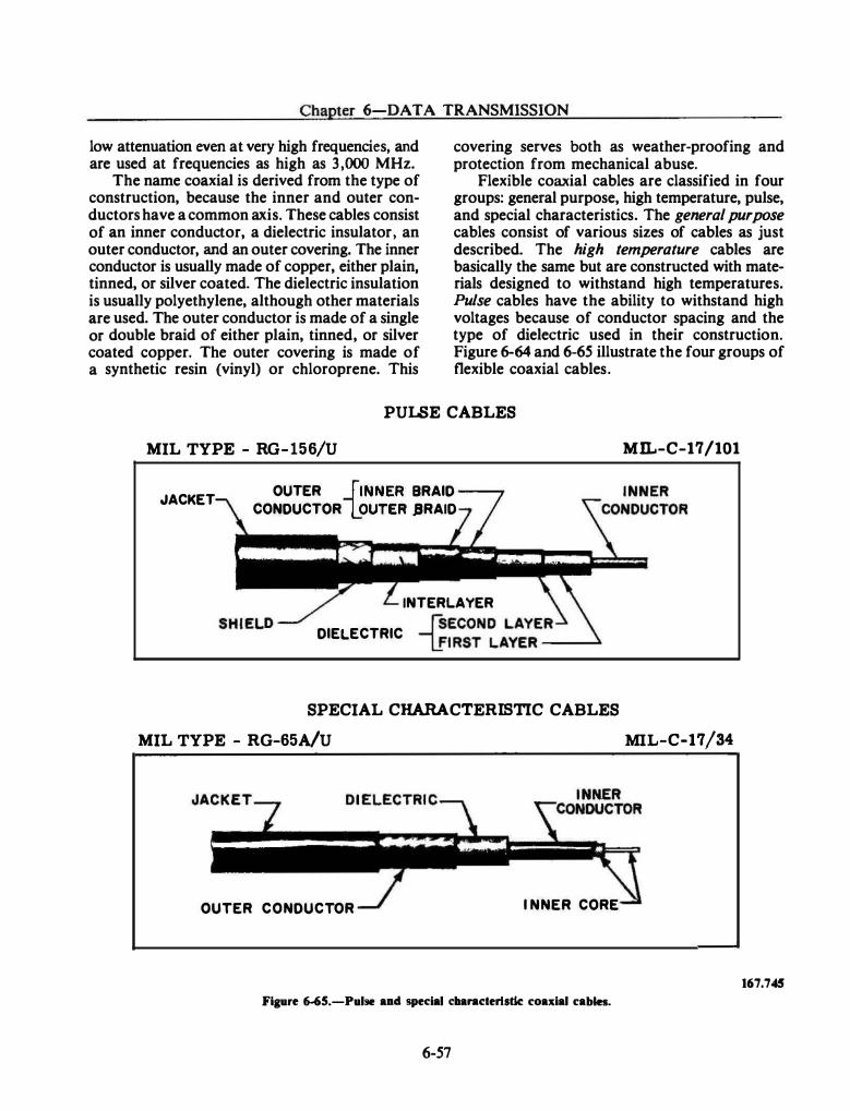
Chapter 6-DATA TRANSMISSION
low attenuation even at very high frequencies, and are used at frequencies as high as 3,000 MHz.
The name coaxial is derived from the type of construction, because the inner and outer conductors have a common axis. These cables consist of an inner conductor, a dielectric insulator, an outer conductor, and an outer covering. The inner conductor is usually made of copper, either plain, tinned, or silver coated. The dielectric insulation is usually polyethylene, although other materials are used. The outer conductor is made of a single or double braid of either plain, tinned, or silver coated copper. The outer covering is made of a synthetic resin (vinyl) or chloroprene. This
covering serves both as weather-proofing and protection from mechanical abuse.
Flexible coaxial cables are classified in four groups: general purpose, high temperature, pulse, and special characteristics. The general purpose cables consist of various sizes of cables as just described. The high temperature cables are basically the same but are constructed with materials designed to withstand high temperatures. Pulse cables have the ability to withstand high voltages because of conductor spacing and the type of dielectric used in their construction. Figure 6-64 and 6-65 illustrate the four groups of flexible coaxial cables.
PULSE CABLES
MIL TYPE - RG- 156/U MIL-C-17 /101
JACKET OUTER _ftNNER BRAID CONDUCTOR LOUTER JRAID
INTERLAYER
DIELECTRIC -{;���TN�A���
E-R-�
SPECIAL CHARACTERISTIC CABLES
MIL TYPE - RG-65A/U MIL-C-17/34
OUTER CONDUCTOR I NNER CORE
Figure �5.-Pul�e aad special c:ltanderlsdc coaxial cabin.
6-57
167.745
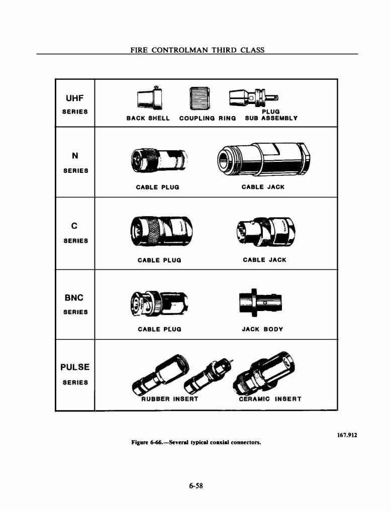
FIRE CONTROLMAN THIRD CLASS
UHF SERIES PLUG
BACK SHELL COUPLING RING SUB ASSEMBLY
N SERIES
CABLE PLUG CABLE JACK
c SERIES
CABLE PLUG CABLE JACK
BNC SERIES
CABLE PLUG JACK BODY
PULSE SERIES
167.912 Figure �.-Sevel'lll typical coaxial connectors.
6-58
Chapter 6-DATA TRANSMISSION
The special characteristics cables are made of various materials and sizes of inner conductor, outer conductor, dielectric, and outer covering. By varying these parts the capacitance, impedance, shielding, attenuation, voltage rating, and the ability to withstand weather and abuse are varied to fit special requirements.
·
With exception of the special characteristics type, these coaxial cables have an impedance in the order of 50 to 75 ohms. The impedance of the special characteristics type is often much higher. An example is the RG-65A/U which has an approximate impedance of 950 ohms and is used as a high impedance video cable. In replacing a coaxial cable, care should be exercised to use the correct replacement. Otherwise most of the advantages of coaxial cables are lost.
At frequencies near 3 ,000 MHz, flexible coaxial cables have appreciable losses. At these frequencies rigid coaxial cables are used with air as the dielectric. The inner conductor is supported by ceramic or polystyrene beads.
Coaxial Connectors
Coaxial connectors are divided into series. Each series consists of plugs, panel jacks, receptacles, and straight and right angle adapters. Some of the commonly used connectors are illustrated in figure 6-66.
Series UHF connectors are low-cost, general purpose connectors of nonconstant impedance. The small and large coaxial types are for use with small and medium size coaxial cables in applications where line imbalance or increased standing wave ratio is not important. Where impedance matching is necessary, C, N, or BNC series connectors are used. Both small and large series UHF connectors can be weatherproofed for outdoor use but most are nonweatherproof.
Series N connectors are the most popular constant impedance connectors for medium size coaxial cables. They can be used up through microwave frequencies with minimum line imbalance or increase in standing-wave ratio.
Although series N 50-ohm and 70-ohm connectors do not mate, 70-ohm cables may be used with 50-ohm series N connectors where impedance matching is not critical. Series N connectors are completely weatherproof.
6-59
Series C connectors are similar to 50-ohm series N connectors because they are used with the same cables, are weatherproof, and can be used up through microwave frequencies. However, they are mechanically and electrically superior to series N connectors. Series C connectors feature bayonet-lock type coupling for quick connect and disconnect, an improved cable clamping mechanism for better cable grip with minimum cable indentation, and are intended for use up to 1 ,000 volts.
Series BNC connectors are commonly used on small coaxial cables. All incorporate quick connect and disconnect bayonet-lock coupling and are weatherproof. Besides regular and modified low-voltage types of nonconstant impedance, improved series BNC connectors are available that have a constant 50-ohm impedance and yield excellent electrical performance up to 10,000 megahertz.
The pulse connectors are designed for highvoltage pulse or direct-current applications. They are nearly all weatherproof and available in three types-rubber-insert, ceramic-insert, triaxial. The rubber-insert type pulse connectors have a peak voltage rating of 5,000 volts. They are designed principally for use with cables having an insulated neoprene layer under the braid, such as RG-77 /U and -78/U.
They may be used with cables employing a conducting rubber under the braid (such as RG-25/U, -26/U, and -64/U) provided special care is taken in assembling the connectors to these. The ceramic-insert pulse connectors are available in small (type A) and large (type B) sizes. Type A connectors are designed for use with the 8,000-volt RG-25/U, -26/U and type B with the 15,000-volt RG-27/U, -28/U cables. (Special care is required when assembling connectors to these.) Pulse connectors tend to leak noise which may interfere with communications equipment. Triaxial connectors are used in transmission line applications where maximum rf shielding and minimum noise radiation are required. They are commercially available in sizes of the same diameter as the BNC series and C series (and possibly others). Some of these connectors have been used in military equipment and some within-series adapters are commercially available.
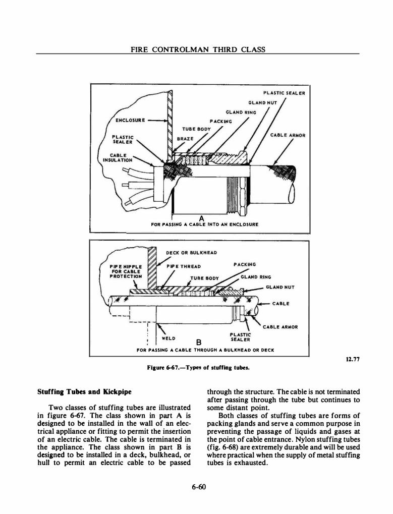
FIRE CONTROLMAN THIRD CLASS
A FOR PASSt,.G A CABLE INTO AN ENCLOSURE
CABLE
CABLE ARMOR
WELD 8 FOR PASSING A CABLE THROUGH A BULKHEAD OR DECK
11.77
Fl1ure 6-67.-Typn of stuffing tubes.
Stuffing Tubes and Kickpipe
Two classes of stuffing tubes are illustrated in figure 6-67. The class shown in part A is designed to be installed in the wall of an electrical appliance or fitting to permit the insertion of an electric cable. The cable is terminated in the appliance. The class shown in part B is desianed to be installed in a deck, bulkhead, or hull to permit an electric cable to be passed
6-60
through the structure. The cable is not terminated after passing through the tube but continues to some distant point.
Both classes of stuffing tubes are forms of packing glands and serve a common purpose in preventing the passage of liquids and gases at the point of cable entrance. Nylon stuffing tubes (fig. 6-68) are extremely durable and will be used where practical when the supply of metal stuffing tubes is exhausted.
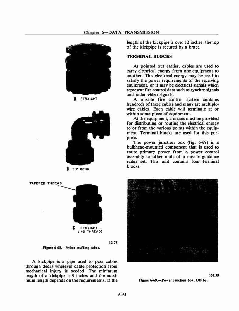
Chapter 6-DATA TRANSMISSION
A STRAIGHT
I 90• BEND
C STRAIGHT ( IPS THREAD)
11.71 Fiaure 6-68.-Nyloa stuffing tubes.
A kickpipe is a pipe used to pass cables through decks wherever cable protection from mechanical injury is needed. The minimum length of a kickpipe is 9 inches and the maximum length depends on the requirements. If the
6-61
length of the kickpipe is over 12 inches, the top of the kickpipe is secured by a brace.
TERMINAL BLOCKS
As pointed out earlier, cables are used to carry electrical energy from one equipment to another. This electrical energy may be used to satisfy the power requirements of the receiving equipment, or it may be electrical signals which represent fire control data such as synchro signals and radar video signals.
A missile fire control system contains hundreds of these cables and many are multiplewire cables. Each cable will terminate at or within some piece of equipment.
At the equipment, a means must be provided for distributing or routing the electrical energy to or from the various points within the equipment. Terminal blocks are used for this purpose.
The power junction box (fig. 6-69) is a bulkhead-mounted component that is used to route primary power from a power control assembly to other units of a missile guidance radar set. This unit contains four terminal blocks.
167.59
Ftaure 6-69.-Power J•DCtloa box, UD 61.
FIRE CONTROLMAN THIRD CLASS
The method of identifying a particular terminal connection requires knowledge of the equipment involved, the particular terminal board within the equipment, and the terminal number.
Missile fire control equipment has some form of equipment identification number. In this case it is Unit Designation (UD) 62. Every terminal block is assigned a number. The terminal block may or may not have an A or B side. Finally, the terminal point is assigned a number. We now have all that is necessary to identify a particular terminal point. Let us see how it is done. The expression, TB(62) 2A-6, tells you to go to equipment UD 62, find the A side of terminal block 2, count to the sixth connection
6-62
point. You are then at the designated terminal point.
SUMMARY
The fundamentals of data transmission have been presented in this chapter. This material was organized to show data transmission from the development of the signal in the transmitting device to the reception of the signal in the receiving device. In addition to studying analog and digital transmission devices, you have been introduced to the fire control switchboard and the interconnecting cabling between equipment. The knowledge you have gained in this chapter will help you in your study of the next chapter, which will cover the necessary support systems, without which your fire control system would not function.

CHAPTER 7
SUPPORT SYSTEMS When you think of weapons system equip
ment, you probably envision complex electronic circuitry, computers, radars, control consoles, and the latest electronic equipment. It is easy to forget that such equipment relies on other systems to work properly. These systems (called support systems) can provide electrical power, dry air, liquid cooling, or optical visual aids to the weapons systems. Some weapons systems may require all of the support systems, others need only a few.
As a Fire Controlman you should be aware of these support systems and understand their relationship to the weapons system equipment.
ELECTRICAL POWER
As an FC part of your routine duties will be to energize certain fire control equipment. This may occur every morning for daily tests or after a lengthy period of shutdown time for maintenance.
Nothing is quite as frustrating as not being able to "light off" your radar because of a missing power input. If you know where the power is supposed to come from, maybe you can help to restore it.
Let us now look at a typical ship's power distribution system. (The power system on your ship is probably similar in many ways.) We will briefly mention the overall power distribution system and then discuss the areas that are closely related to your equipment.
POWER DISTRIBUTION SYSTEM
Most ac power distribution systems in naval vessels are 450-volt, 60-Hz, 3-phase, 3-wire, ungrounded systems. The ac power distribution system consists of the power plant, the means to distribute the power, and the equipment which
7-1
uses the power (fig. 7-1). The power plant is either the ship's service turbine generator or the emergency generator (diesel and/or gas turbine).
The power is distributed through the ship's service distribution switchboards and power panels. Some large ships also use load centers which function as remote switchboards. Power is used by any equipment that requires electrical power for its operation (lights, motors, director power drives, radar equipment, weapon direction equipment, computers, etc.).
Emergency Power
In the event of failure of the ship's service distribution system, the emergency power distribution system supplies an immediate and automatic source of electric power to a limited number of selected loads that are vital to the safety of the ship. This system includes one or more emergency generators and switchboards. The emergency generator can be set to start automatically when a sensor detects the loss of normal power.
The operation of the ship's service generators, the emergency generators, and distribution switchboards is the responsibility of the ship's engineers (machinist's mates, electrician's mates, enginemen, etc.). You should not become involved within this are� of responsibility. There will be times, however, when you 'II be concerned because your electrical power requirements are not being met. For that reason, you should request that the appropriate engineering personnel provide you with assistance. Needless to say, it will be to your advantage if you can communicate in terms the engineering personnel understand.
Bus Transfer Equipment
Bus transfer equipment is installed on switchboards, at load centers, on power panels,
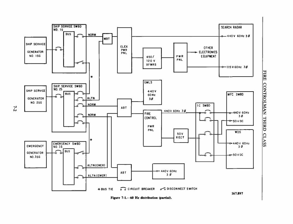
SHIP SERVICE SWBO NO. lS
BUS f-0"""' NORM B SHIP SERVICE
f-o"'o-ELEX OTHER I-- PWR f-- ELECTRONICS GENERATOR PNL
NO. lSG 450/ PWR EQUIPMENT
�o- 120 v PNL � XFMRS
* GMLS
SHIP SERVICE SWBO
-.J I
SHIP SERVICE NO. 25 4 4011
f-o� BUS �� � 60Hz GENERATOR I-- � ALTN 3iJ
NO. 2SG
f-o- NORM I C SWBD ABT N 4401/ 60Hz 3\1 -.....--- FIRE L� �- NORM
CONTROL �-o-o- 1-� L....- PWR
PNL � 501/ R ECT *
EMERGENCY SWBD EMERGENCY NO. 35 GENERATOR I--f-o� BUS ��-- "---<J-
N0.3SG
t-o--.. ALTN(EMERl ,__ ABT 4401/ 60Hz
1-o--- ALTN (EMER) 3 ¢
*BUS TIE �CIRCUIT BREAKER C7""'' DISCONNECT SWITCH
Figure 7-1.--60 Hz distribution (panial).
SEARCH RADAR
4 40 V GO Hz 3 {6
115 V 60Hz 3Ql
MFC SWBD
4401/ 60Hz 30
........ �501/DC
WDS
440V 60Hz 30
501/ DC
167.897
'Tl -:;Q m () 0 z -l :;Q 0 r � � � -:;Q 0 () t""' > V'J V'J
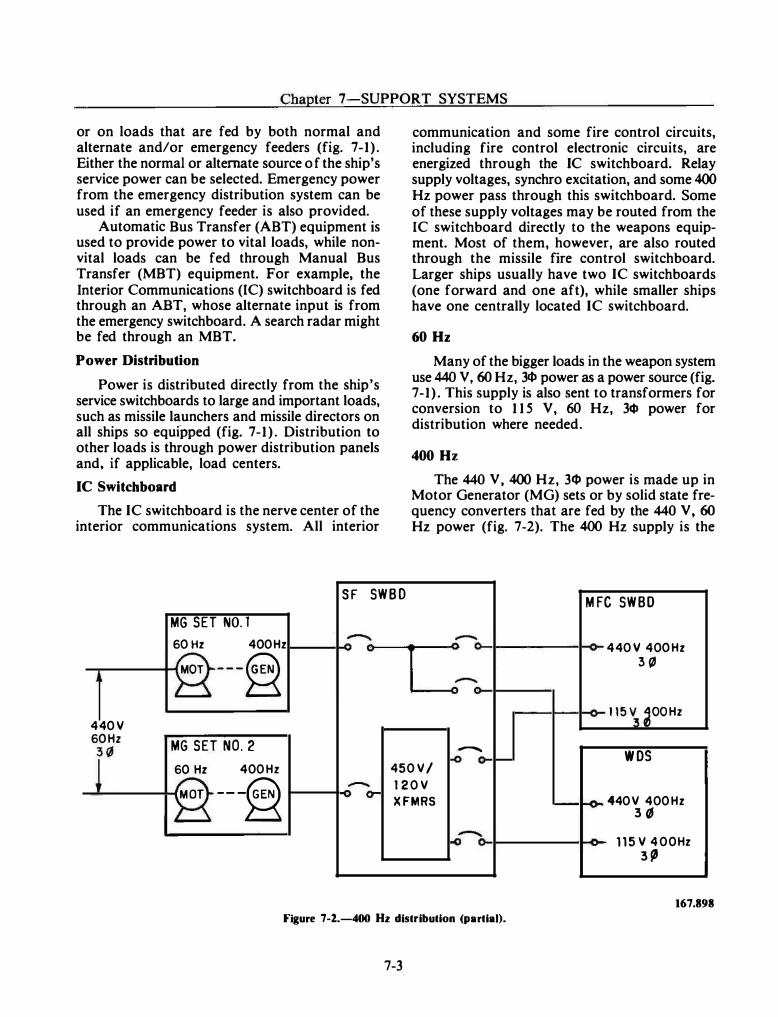
Chapter 7-SUPPORT SYSTEMS
or on loads that are fed by both normal and alternate and/or emergency feeders (fig. 7-1) . Either the normal or alternate source of the ship's service power can be selected. Emergency power from the emergency distribution system can be used if an emergency feeder is also provided.
Automatic Bus Transfer (ABT) equipment is used to provide power to vital loads, while nonvital loads can be fed through Manual Bus Transfer (MBT) equipment. For example, the Interior Communications (IC) switchboard is fed through an ABT, whose alternate input is from the emergency switchboard. A search radar might be fed through an MBT.
Power Distribution
Power is distributed directly from the ship's service switchboards to large and important loads, such as missile launchers and missile directors on all ships so equipped (fig. 7-1 ) . Distribution to other loads is through power distribution panels and, if applicable, load centers.
IC Switchboard
The IC switchboard is the nerve center of the interior communications system. All interior
communication and some fire control circuits, including fire control electronic circuits, are energized through the IC switchboard. Relay supply voltages, synchro excitation, and some 400 Hz power pass through this switchboard. Some of these supply voltages may be routed from the IC switchboard directly to the weapons equipment. Most of them, however, are also routed through the missile fire control switchboard. Larger ships usually have two IC switchboards (one forward and one aft), while smaller ships have one centrally located IC switchboard.
60Hz
Many of the bigger loads in the weapon system use 440 V, 60 Hz, 34» power as a power source (fig. 7-1) . This supply is also sent to transformers for conversion to 1 1 5 V, 60 Hz, 34J power for distribution where needed.
400Hz
The 440 V, 400 Hz, 34J power is made up in Motor Generator (MG) sets or by solid state frequency converters that are fed by the 440 V, 60 Hz power (fig. 7-2). The 400 Hz supply is the
SF SWBD MFC SWBO
MG SET N0.1
60Hz 400Hz
�=�
- 440V 400Hz -
MOT ---§ 3{1 . .,..
440V 115 �� �OOHz
60Hz MG SET NO.2
r - wos -o o-r--60 Hz 400Hz 450V/ MOT --� - 120V o- XFMRS � 440V 400Hz
3� �� � 115 V 400Hz
3{1
167.898 Figure 7-2.-400 Hz distribution (partial).
7-3
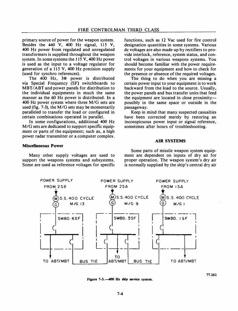
FIRE CONTROLMAN THIRD CLASS
primary source of power for the weapon system. Besides the 440 V, 400 Hz signal, 115 V, 400 Hz power from regulated and unregulated transformers is supplied throughout the weapon system. In some systems the 1 15 V, 400 Hz power is used as the input to a voltage regulator for generation of a 1 1 5 V, 400 Hz precision supply (used for synchro references).
The 400 Hz, 3«1> power is distributed via Special Frequency (SF) switchboards to MBT I ABT and power panels for distribution to the individual equipments in much the same manner as the 60 Hz power is distributed. In a 400 Hz power system where three M/G sets are used (fig. 7-3), the MIG sets may be momentarily paralleled to transfer the load or configured in certain combinations operated in parallel.
In some configurations, additional 400 Hz M/G sets are dedicated to support specific equipment or parts of the equipment; such as, a high power radar transmitter or a computer complex.
Miscellaneous Power
Many other supply voltages are used to support the weapons systems and subsystems. Some are used as reference voltages for specific
functions, such as 12 Vac used for fire control designation quantities in some systems. Various de voltages are also made up by rectifiers to provide interlock, reference, system status, and control voltages in various weapons systems. You should become familiar with the power requirements for your equipment and how to check for the presence or absence of the required voltages.
The thing to do when you are missing a certain power input to your equipment is to work backward from the load to the source. Usually, the power panels and bus transfer units that feed the equipment are located in close proximitypossibly in the same space or outside in the passageway.
Keep in mind that many suspected casualties have been corrected merely by restoring an inconspicuous power input or signal reference, sometimes after hours of troubleshooting.
AIR SYSTEMS
Some parts of missile weapon system equipment are dependent on inputs of dry air for proper operation. The weapon system's dry air is normally supplied by the ship's central dry air
POWER SUPPLY
FROM 2 SB
POWER SUPPLY
FROM 2SA
POWER SUPPLY
FROM I SA
S.S. 400 CYCLE
MIG 13
S.S. 400 CYCLE
MIG 9
: -- SWBD.
-
SSF I I c I ( L_
r- - - - - -l 1 swao. 1 sF I I
I I I I
�-----_j TO
TO ABT/MBT BUS Tl E ABT/MBT BUS Tl E L...-.-=...:...::... ___ ....;;;...._..J TO A8T/M8T
77.262 Figure 7-3.---400 Hz ship service system.
7-4
Chapter 7-SUPPORT SYSTEMS
system. This system produces high-pressure (hp) air and low-pressure (lp) dry air for distribution to user equipment. As an FC, your user equipment will most likely be a search or a fire control radar.
HIGH-PRESSURE AIR
The ship's service compressors supply the high-pressure air at 3 ,000 or 4,500 psi. In the missile weapon system, it is used only for the launching system's dud ejection system, where applicable. In an emergency, the high-pressure air, reduced in pressure, can be used to supplement the low-pressure air supply through the HP /LP cross-connect.
LOW -PRESSURE DRY AIR
A central dry air system is shown in figure 7-4. It includes the low-pressure air compressors and the dehydrators, which dry all low-pressure air supplied to the vital services air main. Also included are the priority valve, which automatically isolates vital users from nonvital users when required, and the ship service low-pressure air main, which supplies nonvital users.
Vital lp air users are defined as equipment or services essential to optimum ship performance. Examples include the engineroom and boiler room controls and the electronics dry air branch.
Examples of nonvital air users are pneumatic tools, laundry equipment, and gage test panels. Special attention is necessary for the electronics dry air branch of the vital services main because of its requirement for additional dehydration of low-pressure air.
Electronics Dry Air Branch
The electronics dry air branch is fed from the vital services main via the dehydrators (fig. 7-4). The purpose of the electronics dry air branch is to provide an effective electronic equipment
7-5
pressurization system with a mmtmum of material. Electronic components, such as waveguide, couplers, and cavities, operate at radio frequencies. They require dry air pressurization to prevent arcing and internal corrosion.
The electronics dry air branch must satisfy the dry air pressurization requirements of the electronic user equipment. Dry air of less than the required specifications will degrade performance and may necessitate major repairs, overhaul, or replacement of expensive electronic components.
Air Control Panel
The dry air distribution system delivers dry air to each user equipment's air control panel. The air control panels are used to control and regulate the dry air pressure to that required by the electronic user equipment.
The air control panel (fig. 7-5) provides a means of monitoring the dry air supply to the user equipment. The type of control panel used varies, depending on the outlet pressure and flow rate required.
There are provisions for monitoring the dew point (moisture content) and the flow of the lp dry air at the air control panel. Also, the dry air pressure can be monitored at the input to the control panel, at the input to the flow meter (whose accuracy is calibrated at a certain pressure), and at the output of the control panel. A filter is installed to trap particles that affect proper pressure regulation. A metering valve bypass and a pressure relief valve are provided in case of malfunctions. The metering valve bypass permits manual control of air pressure to the user equipment.
Electronic Equipment Dehydrators
Dehydrators or compressor-dehydrators are supplied as part of various radars. Many of them were provided prior to installation of properly configured central dry air systems. These are intended for emergency use in the event of the failure of the central dry air system. In a typical
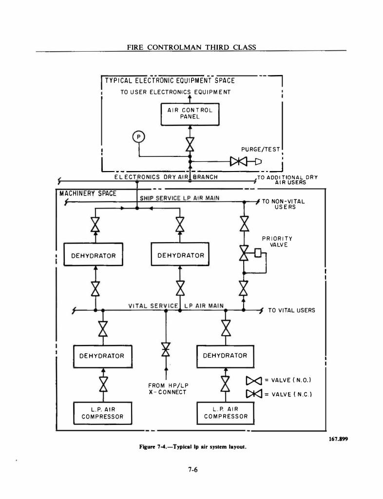
FIRE CONTROLMAN THIRD CLASS
I TYPICAL ELECYRONIC EOUIPMENYSPACE 1 TO USER ELECTRONICS EQUI PMENT I
AIR CONTROL PANEL
-----,
1 PURGE /TE ST I I
L_____ _ _____ _j E LE CTRONICS DRY AIR BRANCH TO ADDITIONAL DRY
AIR USERS
MACHINERY SPACE f--------.p;:;S.;.;H.;.;.lP....;S::;..:E::.;.R.;..;V;.;.IC=.:E::...;;.L.;....P...:..A;.:.IR;.;....;.;.M;.;.,;A;,;.:.IN.:..,.__.__-4 TO NON -VI TAL
DEHYDRATOR
DEHYDRATOR
L.P. AIR COMPRESSOR
DEHYDRATOR
DEHYDRATOR
USERS
PRIORITY VALVE
TO V I TAL USERS
FROM HP/LP X- CONNECT
[><) = VALVE ( N.O.)
[>KJ = VALVE (N.C.)
L.P. AIR
COMPRESSOR
Flgu� 7-4.-Typk:al lp air system layout.
7-6
167.899
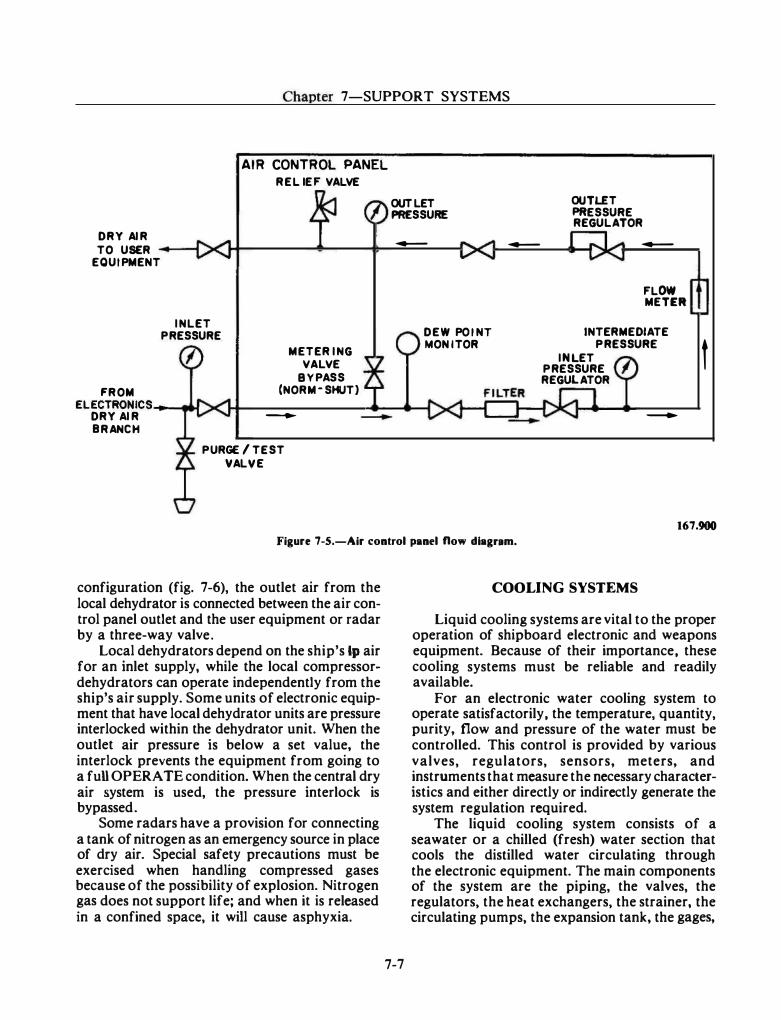
Chapter 7-SUPPORT SYSTEMS
DRY AIR TO USER ----1
EQUIPMENT
AIR CONTROL PANEL RELIEF VALVE
INLET PRESSURE
FRO M ELECTRONICS_ ...... t-4
DRY AIR BRANCH
METERING V A L V E
BYPASS (N ORM· SHUT}
-
PURGE /TEST VALVE
OUTLET PRESSURE
-
D EW POINT MONITOR
-
OUTLET PRESSURE REGULATOR
-
FLOW METER
INTERMEDIATE
INLET PRESSURE t
PRESSURE REGULATOR
-
167.900 Figure 7-S.-Air control panel now dlagnm.
configuration (fig. 7-6), the outlet air from the local dehydrator is connected between the air control panel outlet and the user equipment or radar by a three-way valve.
Local dehydrators depend on the ship's lp air for an inlet supply, while the local compressordehydrators can operate independently from the ship's air supply. Some units of electronic equipment that have local dehydrator units are pressure interlocked within the dehydrator unit. When the outlet air pressure is below a set value, the interlock prevents the equipment from going to a fuU OPERATE condition. When the central dry air system is used, the pressure interlock is bypassed.
Some radars have a provision for connecting a tank of nitrogen as an emergency source in place of dry air. Special safety precautions must be exercised when handling compressed gases because of the possibility of explosion. Nitrogen gas does not support life; and when it is released in a confined space, it will cause asphyxia.
7-7
COOLING SYSTEMS
Liquid cooling systems are vital to the proper operation of shipboard electronic and weapons equipment. Because of their importance, these cooling systems must be reliable and readily available.
For an electronic water cooling system to operate satisfactorily, the temperature, quantity, purity, flow and pressure of the water must be controlled. This control is provided by various valves, regulators, sensors, meters, and instruments that measure the necessary characteristics and either directly or indirectly generate the system regulation required.
The liquid cooling system consists of a seawater or a chilled (fresh) water section that cools the distilled water circulating through the electronic equipment. The main components of the system are the piping, the valves, the regulators, the heat exchangers, the strainer, the circulating pumps, the expansion tank, the gages,
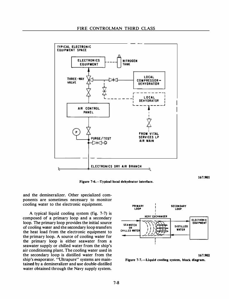
FIRE CONTROLMAN THIRD CLASS
TYPICAl ELECTRONIC EQUIP MENT SPACE
THREE·WAY VALVE
LOCAL COMPRESSOR-
I DEHYDRATOR
� r - - - - - - - -,
L I LOCAL ------
-: DEHYDRATOR r-------�------� L... ___ l ____ J AIR CONTROL
PANEL I I
g I I
FROM VITAL SERVICES LP
AIR MAIN
ELECTRONICS DRY AIR BRANCH
Figure 7�.-Typkal local dehydrator illterlace.
and the demineralizer. Other specialized components are sometimes necessary to monitor cooling water to the electronic equipment.
c
PAIMlRY LOOP
I
I r I HE T EXC M HA GEA
SEAWATER �--� \ \ \ t: OR I I 1·c HillED WATER I/ /�1(.,.___'7/ __.,_,_,_,_
I
SECOIIIOAAY LOOP
DISTILLED WATER
167.901
ELECT ROIIIC [QUII'M[IIIT
A typical liquid cooling system (fig. 7-7) is composed of a primary loop and a secondary loop. The primary loop provides the initial source of cooling water and the secondary loop transfers the heat load from the electronic equipment to the primary loop. A source of cooling water for the primary loop is either seawater from a seawater supply or chilled water from the ship's air conditioning plant. The cooling water used in the secondary loop is distilled water from the ship's evaporator. "Ultrapure" systems are maintained by a demineralizer and use double-distilled water obtained through the Navy supply system.
167.901 Figure 7-7 .-Liquid coollna system, block diqram.
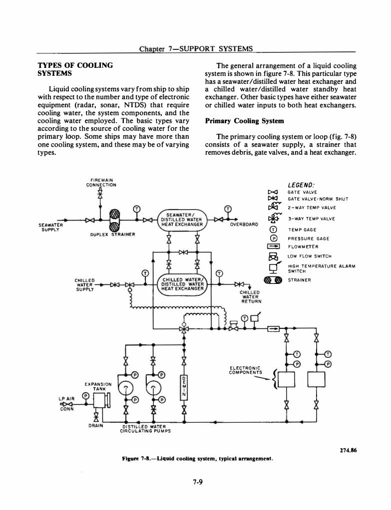
- - - -- � ------------- · ·---- �------ - --· --
Chapter 7-SUPPORT SYSTEMS
TYPES OF COOLING SYSTEMS
Liquid cooling systems vary from ship to ship with respect to the number and type of electronic equipment (radar, sonar, NTDS) that require cooling water, the system components, and the cooling water employed. The basic types vary according to the source of cooling water for the primary loop. Some ships may have more than one cooling system, and these may be of varying types.
SEAWATER SUPPLY
FIRE MAIN CONNECTION
CHILLED WATER SUPPLY
EXPANSION TANK
DISTILLED WATER CIRCULATING PUMPS
D E M I N
The general arrangement of a liquid cooling system is shown in figure 7-8. This particular type has a seawater I distilled water heat exchanger and a chilled water/distilled water standby heat exchanger. Other basic types have either seawater or chilled water inputs to both heat exchangers.
Primary Cooling System
The primary cooling system or loop (fig. 7-8) consists of a seawater supply, a strainer that removes debris, gate valves, and a heat exchanger.
LEGEND: t><J GATE VALVE
t>tc:3 GATE VALVE· NORM. SHUT
� 2 -WAY TEMP VALVE
� 3-WAY TEMP VALVE
G) TEMP GAGE
cv PRESSURE GAGE
,_, FLOWMETER
� LOW FLOW SWITCH
HIGH TEMPERATURE ALARM
SWITCH
G:D STRAINER
EL ECTRO N IC { COMPONENTS
----
274.86
Flcure 7-1.-Liquld cooHng system, typical arnngemeat.
7-9
FIRE CONTROLMAN THIRD CLASS
The seawater may be supplied from a seawater pump, often referred to as the ordnance cooling pump, or from the ship's firemain. A low flow switch may be in the seawater line that activates alarms in the electronic spaces concerned.
A duplicate heat exchanger is installed parallel to the main heat exchanger and is maintained in standby in the event of a malfunction in the main heat exchanger. As previously indicated, the standby heat exchanger in our example uses chilled water. Both heat exchangers may be operated if extremely warm seawater is encountered.
Secondary Cooling System
The secondary cooling system or loop is designed to transfer the heat from the electronic equipment being cooled to the primary cooling system. It usually consists of a distilled water circulating pump, a demineralizer, a three-way temperature controlled valve, an expansion tank, the electronic equipment being cooled, and the heat exchanger previously mentioned. A flowmeter, a low-flow switch, a high-temperature switch, and their associated alarms may also be included.
Some electronic coolant systems have an electric coolant heater. This allows the coolant and electronic equipment to reach operating temperature and stabilizes temperature-sensitive components. The electric coolant heater is usually energized by a preheat signal.
SYSTEM OPERATION
As cool primary system water flows through the tubes of the heat exchanger, secondary system coolant flows around these tubes. Heat that was absorbed from electronic components is transferred to the primary system water. A three-way temperature valve with a sensor in the distilled water loop is installed to bypass distilled water around the heat exchanger to control the distilled water temperature.
When chilled water is used as the primary supply, a two-way temperature valve is used to regulate the flow of chilled water through the heat exchanger. This action, in response to a sensor in the distilled water loop, helps maintain the required distilled water temperature.
7-10
The flow rate of the distilled water is monitored by a flowmeter after it passes through low-flow and high temperature alarm switches. The cooled distilled water is supplied to the various heat exchangers in the electronic equipment.
Either the liquid-to-air or the coolant-jacket type of heat exchanger is used in the electronic equipment. An example of the liquid-to-air heat exchanger is an equipment cabinet fan which circulates air across a heat exchanger. Coolantjackets may be found around klystrons or pulseforming networks.
From the electronic equipment, the distilled water is returned to the suction side of the circulating pump. On those systems where highpurity distilled water is required, a demineralizer is installed in a bypass line around the circulating pump. A flow regulator is designed to pass approximately 5 percent of the total system volume through the demineralizer each hour. The demineralizer is designed to remove solids, dissolved metals, carbon dioxide, and oxygen. In addition, a submicron filter is installed downstream of the demineralizer to prevent the carryover of chemicals into the system and to remove remaining impurities.
An expansion tank is provided in the distilled water system to compensate for changes in the coolant volume caused by thermal expansion. The expansion tank also provides a source of makeup water in the event of a system leak. The tank is installed in a branch line connected to the suction side of the circulating pump. When used as a gravity tank, the tank is located at or above the highest point in the system and vented to the atmosphere. Otherwise, the expansion tank is located in the vicinity of the circulating pump and charged with air pressure to achieve the required distilled water return line pressure.
Pressure gages and temperature gages are used to monitor component and system performance. A high-temperature switch, a low-flow switch, a low-level switch, and a low-purity alarm provide remote monitoring of the cooling system operation. The devices are usually connected to remote indicators (visual and audible alarms) or to interlocks that deenergize the electronic equipment.
Chapter 7-SUPPORT SYSTEMS
WATER PURITY
One of the most significant improvements in the operation of electronic cooling water systems can be achieved by using water of the appropriate purity. All electronic cooling water systems use distilled water, which flows through the equipment in the secondary cooling loops. The required purity of this water coolant will vary, from normal ship's distilled water to "ultrapure" water, depending on the requirements of the electronic equipment.
Before water is introduced into the cooling system, a determination must be made, using the appropriate technical manuals, regarding the quality of water used versus the purity of water required. Once the correct water has been introduced into the system and the desired purity attained, the purity must be monitored to assure that it stays within the requirements of the equipment.
Most purified electronic cooling systems have meters installed to determine the purity of the water. In addition to the routine observation of these meters and in systems where no meters are installed, a separate test of the water itself should be conducted periodically to check on the water purity and the accuracy and operation of installed meters.
The impurities found in distilled water are usually in the form of dissolved solids. The amount of dissolved solids in the distilled water can be determined by measuring the conductivity (micromhos/cm) or its reciprocal, resistivity, (megohms/em) of the distilled water. The purity meter on the demineralizer measures the resistivity of the water in megohms/em. The resistivity can be converted to conductivity by taking the reciprocal of the resistivity. The ideal condition is one of high resistivity which indicates that the demineralizer is maintaining a high degree of purity.
Although the purity required by different kinds of equipment varies, it should be noted that potable (drinking) water or treated boiler water is not to be used in any electronic cooling water system. (Even though the potable water comes from the distilling plant, its treatment with chlorine makes its use in the cooling system unacceptable.) Only untreated distilled water taken directly from the ship's evaporators is
7-1 1
suitable. Additives, such as rust preventatives, are not normally used in these electronic cooling systems, except where specifically authorized in the appropriate technical manuals for that particular system. Ethylene glycol (uninhibited) is normally used where extremely cold weather may be encountered.
CLOSED CIRCUIT TELEVISION
Closed Circuit Television (CCTV} systems are in wide use on board ship. They are not used solely for entertainment and training, but they are used in whole or part to support some of the weapons systems. The CCTV systems used by the Fire Controlman operate much the same as the commercial and ship's entertainment television systems you may be familiar with. TV type display devices are being used to provide computer terminal displays, data readouts, PPI (Planned Position Indicator) displays, and various other radar displays.
TELEVISION TERMINOLOGY
Many technical terms are used to describe the components and functions of a television system. Definitions of these terms are given in the glossary that follows.
• BLACK LEVEL-A voltage representing the color black. Usually it is not greater than 90 percent of the maximum signal amplitude. Black level in a receiver is adjusted by the brightness control.
• BLANKING-The process of applying negative voltage to the control grid of the cathoderay tube to cut off the electron beam during the retrace or flyback period.
e BLANKING LEVEL-The level of the blanking pulse (pedestal voltage).
e BLANKING WAVEFORM-The signal introduced into the complex video signal at or above the black level used to blank out video signals during the retrace or flyback time.
FIRE CONTROLMAN THIRD CLASS
e COMPOSITE VIDEO SIGNAL-The total video signal, consisting of picture information, blanking pulses, and sync pulses.
• FIELD-A scan, consisting usually of 262.5 horizontal lines, of the picture area.
• FRAME-One complete coverage, usually 525 horizontal lines, of the picture area. Two consecutive interlaced fields make up one frame.
e PICTURE ELEMENT-The smallest portion of a picture or scene that is individually converted into an electrical signal.
e PICTURE SIGNAL-also called the VIDEO SIGNAL-The electrical pulses resulting from scanning of successive elements of a visual scene by a scanning device.
• RASTER-The illuminated rectangular area scanned by the electron beam in a picture tube, visible when the brilliancy· control is turned up with no signal.
• SYNC-A short form of the word, synchronizing, which means to cause two elements of a system to coincide in speed, frequency, relative position, or time.
e SYNC GENERA TOR-Electronic equipment designed to produce the driving, blanking, and synchronizing pulses necessary to the operation of a television system.
• SYNC WAVEFORM-The waveform, as shown on an oscilloscope, produced by the sync generator.
e SYNCHRONIZING SIGNALS-Electrical pulses used to keep a television or facsimile receiving system in step with the transmitting system so that the picture or scene will be reconstructed properly.
TELEVISED INFORMATION
To understand how a TV system works, you should know what kind of information must be passed from the camera to the viewer. Four basic
7-12
kinds of information are required in a normal CCTV system:
• Video signal-the actual moment-tomoment information that tells the receiving set how light or dark each little spot in the picture should be. Unlike movies, in which an entire picture is flashed upon the screen every 1 /24th of a second, TV pictures are built up, line-by-line (525 horizontal lines per picture) and spot-by-spot within each line (approximately 426 spots per line). In TV, 30 complete pictures are produced every second.
• Blanking signals-signals which tell the camera and the receiving set when no video signal should be present (such as between the end of one line and the beginning of the next).
• Sync signals-Sync (synchronizing) signals are required to tell the receiving set exactly when to begin each picture (vertical sync) and when to begin each line within that picture (horizontal sync).
• Audio signals-the sound, or audible, portion of the total TV presentation (not used in fire control applications).
SYSTEM COMPONENTS
A closed circuit television consists of three basic units: a camera or pickup unit, a control unit, and a monitor. This section discusses the various circuits contained in the three basic units and the timing or scanning sequence used by a system.
Pickup Unit
The pickup unit, generally referred to as the camera, starts the sequence of events that occur in the CCTV system. A lens is used for focusing an image on a photosensitive (light) tube. The type of lens is determined by the size of the scene to be televised, and may be a normal, wide-angle, or telephoto lens. The size of the camera unit varies from small palm size mobiJe units to large units mounted on special platforms. One or more cameras can be connected into the system to receive the desired picture (video)
Chapter 7-SUPPORT SYSTEMS
and route it as an electronic signal to a control unit.
The camera tube provides a means of converting light rays from an object on which the camera is focused into electrical impulses. Light from the object is focused on the light sensitive surface (called the mosaic or photoconductive material) in the camera tube by a lens system. The camera tube contains an electron gun, which generates and controls a stream of electrons. The gun directs the narrow stream of electrons in such a manner that it traverses (scans) the mosaic line by line. As the beam strikes a spot in the mosaic, it generates a small electrical impulse which corresponds to the lightness or darkness of that particular tiny portion of the image. The electrical impulses generated in this manner are sent to the video amplifier.
Control Unit
The control unit, as the name implies, is the heart of the system. This unit connects all the other units of the system together. Drive pulses are generated and develop the sweep and blanking signals required by the camera. Synchronizing and blanking pulses are supplied to the receiver /monitor.
Video signals from the camera are amplified and distributed to the receiver /monitor. The output signals from the control unit contain vertical and horizontal blanking, sync, and video signals. The control unit consists of the following sections: video amplifier control amplifier, carrier, amplitude modulator, rf amplifier, sync generator, and the audio controls.
Video amplifiers are designed to amplify a wide range of frequencies, and the weak electrical impulses from the camera tube are built up by the amplifier and fed to a control amplifier.
The control amplifier combines the video, sync, and blanking signals, all in proper sequence into a single continuous output.
Circuits in the sync generator produce synchronizing (sync) and blanking pulses. These pulses are applied to the control amplifier and become a portion of the transmitted signal. Horizontal synchronization makes the horizontal scanning at the receive/monitor occur at the same relative time as the horizontal scanning at the camera. Vertical synchronization makes the
7-13
vertical scanning at the receiver keep in step with the vertical scanning at the camera.
Sync and blanking signals are also fed to the camera circuits, which develop the necessary control signals for the electron gun and the sweep voltages for the deflection coils (both horizontal and vertical).
Receiver Monitor
The picture producing unit is commonly referred to as the receiver /monitor unit. The receiver and the monitor differ basically only in the circuits contained in each unit. The media of transmission between the receiver and monitor units being different requires that the receiver employ additional circuits. (The media employed for the receiver is air, while the media for the monitor is normally direct via cables.) The standard TV receiver contains the same circuits as the monitor, and in addition contains the antenna system, tuner, rf amplifiers, and IF amplifiers to receive the transmitted signals.
After the IF stage of amplification, the receiver and monitor units are basically the same. Power supplies provide the various voltages needed for the circuits; audio amplification is basically the same as that used in standard radio receivers; synchronization is accomplished through the use of a sync circuit with horizontal and vertical sync signals used to control the horizontal and vertical sweep circuits; and video amplification is accomplished through the various video circuits.
SCANNING
If you examine a picture printed from a photoengraving (for example, a halftone picture in a newspaper) with a magnifying glass, you can easily determine that it is composed of a large number of dots. The lightness or darkness of the picture or areas within the picture are determined by the amount of separation between the individual dots. The dots are the elements that make up the picture.
A television picture is formed in a similar manner. There is, however, one important difference. In the picture made from the photoengraving, aU of the elements of the picture are viewed simultaneously. In the television picture,
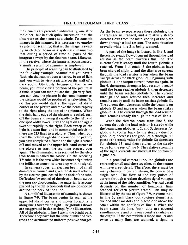
FIRE CONTROLMAN THIRD CLASS
the elements are presented individually, one after the other, but in such quick succession that the observer sees the picture as a whole. To transmit images in this manner, it is necessary to employ a system of scanning; that is, the image is swept by an electron beam in a systematic manner so that during a period of time all parts of the image are swept by the electron beam. Likewise, in the receiver where the image is reconstructed, a similar system of scanning is employed.
The principle of scanning can be illustrated by the following example. Assume that you have a flashlight that can produce a narrow beam of light and you wish to view a picture on the wall of a dark room. Obviously, because of the narrow beam, you must view a portion of the picture at a time. If you can manipulate the light very fast, you can view the picture in the same manner as the picture would be produced in television. To do this you would start at the upper left-hand corner of the picture and move the beam rapidly to the right along the top of the picture. When the right-hand edge of the picture is reached, turn off the beam and swing it rapidly to the left and one spot width lower. Turn the light on and again sweep it rapidly to the right. Each sweep of the light is a scan line, and in commercial television there are 525 lines to a picture. Thus, when you reach the bottom right-hand corner of the picture, you have completed a frame and the light is turned off and moved to the upper left-hand corner of the picture to start the scanning process over again. The illuminated area scanned by the electron beam is called the raster. On the receiving TV tube, it is the area which becomes bright when the brilliance control is turned up with no signal.
In camera tubes, an electron beam of small diameter is formed and given the desired velocity by the electron gun located in the neck of the tube. Deflection (sweeping) of the electron beam across the mosaic/photoconductive material is accomplished by the deflection coils that are positioned around the neck of the tube.
A simplified illustration of scanning is shown in figure 7-9. The beam begins its scan at the upper left-hand corner and moves horizontally along line 1 toward the right. The globules shown are exaggerated in size to simplify the illustration. All of the globules in line 1 are in the bright part. Therefore, they have lost the same number of electrons and accumulated uniform positive charges.
As the beam sweeps across these globules, the charges are neutralized, and a relatively steady current flows from the metal coating of the plate down through a load resistor. The same situation prevails while line 2 is being scanned.
A part of the image is located in line 3, and there is no steady flow of current through the load resistor as the beam traverses this line. The current flow is steady until the fourth globule is reached. From 4 through 13 the globules have been charged slightly, and the discharge current through the load resistor is less when the beam sweeps across the black globules. Beginning with globule 14, the output current increases again. In line 4, the current through a load resistor is stead'9 until the beam reaches globule 4, then decreases until the beam reaches globule 5 . The current through the load resistor then increases and remains steady until the beam reaches globule 13 . The current then decreases while the beam is on globule 13 and increases when the beam strikes globule 14. The current through the load resistor then remains steady through the rest of line 4.
When the electron beam scans line 5, the current through the load resistor is steady while the beam scans globules 1 , 2, and 3; decreases for globule 4; comes back to the steady value for globule 5; decreases for globules 6 through II; goes to the steady value for globule 12; decreases for globule 1 3; and then returns to the steady value for the rest of line 6. The relative strengths of the signal currents are shown at the bottom of figure 7-9.
In a practical camera tube, the globules are extremely small and close together, so the picture will have great detail. Therefore, there must be many changes in current during the course of a single scan. The flow of the tiny pulses of current through a resistor develops signal voltages at the input of the video amplifier. Vertical detail depends on the number of horizontal lines scanned for each picture frame. This may be illustrated by the use of figure 7-9. Assume that, in line 3 , each black dot (picture element) is divided into two dots and placed one above the other within the confines of line 3. When the beam scans the line, both dots are covered simultaneously and only one signal is available at the output. If the beam width is made smaller and twice as many lines are scanned, a signal is
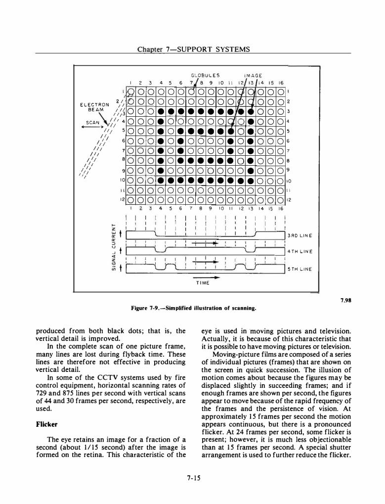
Chapter 7-SUPPORT SYSTEMS
GLOBULES IMAGE I 2 3 4 5 6 7/8 9 10 11 12, 13 14 15 16 )0
2/ ELECTRON ; I BEAM 111
I I 13 SCAN I I I 4
--4 I; I 11 5
�II I; I 6
I!; I I;
I I; I I;
7 a
I It I I I 'I
9 10
0 0 0 0 0 0 0 0 0
10 12 0
1-z t UJ ll:: ll:: :::l u ...J t <I z � <ll t
0 0 0 0 0 0 0 0 0 0 0 0
2
0 0 0 0 0 0 0 • • 0 • 0 0 • 0 0 • 0 0 • 0 0 • 0 0 • 0 0 • • 0 0 0 0 0 0
3 4 5
I I
\ I I I I \_)' I I I
Lri
0 IC5 0 0 • • 0 0 • • • 0 • 0 • • 0 0 • • 0 0 0 0
6 7
0 0 0 0 !G 'q 0 0 0 0 I� SJ • • • • I. ,e 0 0 0 lcJ 0 • • • • r• 0 • 0 0 0 • 0 • 0 0 0 • 0 • • • • • 0 • 0 ·o 0 0 0 • • • • • • • 0 0 0 0 0 0 0 0 0 0 0 0
8 9 10 I I 12 13
I I I
I J .,. I I
I I 'L..J
I I I I � ru TIME
0 0 0 0 0 0 0 0 0 0 0 0 0 0 0 0 0 0 0 0 0 0 0 0 0 0 0 0 0 0 0 0 0 0 0 0
14 15 16
2
3
4
5
6
7
8
9
10
II
12
3RD LINE
4TH LINE
5TH LINE
7.98 Figure 7-9.-Simplified illustration of scanning.
produced from both black dots; that is, the vertical detail is improved.
In the complete scan of one picture frame, many lines are lost during fly back time. These lines are therefore not effective in producing vertical detail.
In some of the CCTV systems used by fire control equipment, horizontal scanning rates of 729 and 875 lines per second with vertical scans of 44 and 30 frames per second, respectively, are used.
Flicker
The eye retains an image for a fraction of a second (about 1115 second) after the image is formed on the retina. This characteristic of the
7-15
eye is used in ·moving pictures and television. Actually, it is because of this characteristic that it is possible to have moving pictures or television.
Moving-picture films are composed of a series of individual pictures (frames) that are shown on the screen in quick succession. The illusion of motion comes about because the figures may be displaced slightly in succeeding frames; and if enough frames are shown per second, the figures appear to move because of the rapid frequency of the frames and the persistence of vision. At approximately 1 5 frames per second the motion appears continuous, but there is a pronounced flicker. At 24 frames per second, some flicker is present; however, it is much less objectionable than at 1 5 frames per second. A special shutter arrangement is used to further reduce the flicker.
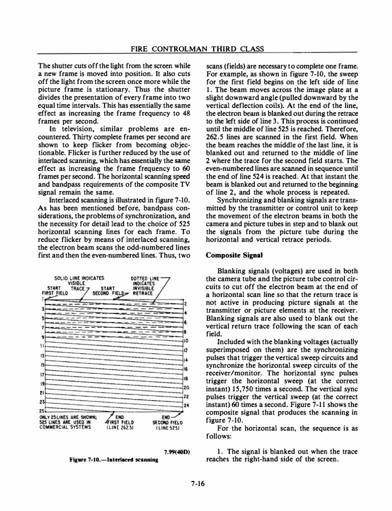
FIRE CONTROLMAN THIRD CLASS
The shutter cuts off the light from the screen while a new frame is moved into position. It also cuts off the light from the screen once more while the picture frame is stationary. Thus the shutter divides the presentation of every frame into two equal time intervals. This has essentially the same effect as increasing the frame frequency to 48 frames per second.
In television, similar problems are encountered. Thirty complete frames per second are shown to keep flicker from becoming objectionable. Flicker is further reduced by the use of interlaced scanning, which has essentially the same effect as increasing the frame frequency to 60 frames per second. The horizontal scanning speed and bandpass requirements of the composite TV signal remain the same.
Interlaced scanning is illustrated in figure 7-10. As has been mentioned before, bandpass considerations, the problems of synchronization, and the necessity for detail lead to the choice of 525 horizontal scanning lines for each frame. To reduce flicker by means of interlaced scanning, the electron beam scans the odd-numbered lines first and then the even-numbered lines. Thus, two
SO NO CATES VISIBLE INDICATES
F I
LID LINE I I DOTTED Ll7 START TRACE START INVISIBLE
I�IELD / SECOND F� RETRACE
3 5 7 9 I
13 15 17 19 2 23
I
--.. """'-
-- -
25 ON 525
LY 25 LINES ARE SHOWN; LINES ARE USED IN
COMMERCIAL SYSTEMS k!END END..../"
ST FIELD SECOMD FIELD I LINE 262.51 I LINE 5251
2 • 6
I I I I I
8 0 2 4 6 8
20 22 24
7.99(400) Figure 7-10.-laterlaced scanning
7-16
scans (fields) are necessary to complete one frame. For example, as shown in figure 7-10, the sweep for the first field begins on the left side of line 1 . The beam moves across the image plate at a slight downward angle (pulled downward by the vertical deflection coils). At the end of the line, the electron beam is blanked out during the retrace to the left side of line 3. This process is continued until the middle of line 525 is reached. Therefore, 262.5 lines are scanned in the first field. When the beam reaches the middle of the last line, it is blanked out and returned to the middle of line 2 where the trace for the second field starts. The even-numbered lines are scanned in sequence until the end of line 524 is reached. At that instant the beam is blanked out and returned to the beginning of line 2, and the whole process is repeated.
Synchronizing and blanking signals are transmitted by the transmitter or control unit to keep the movement of the electron beams in both the camera and picture tubes in step and to blank out the signals from the picture tube during the horizontal and vertical retrace periods.
Composite Signal
Blanking signals (voltages) are used in both the camera tube and the picture tube control circuits to cut off the electron beam at the end of a horizontal scan line so that the return trace is not active in producing picture signals at the transmitter or picture elements at the receiver . Blanking signals are also used to blank out the vertical return trace following the scan of each field.
Included with the blanking voltages (actually superimposed on them) are the synchronizing pulses that trigger the vertical sweep circuits and synchronize the horizontal sweep circuits of the receiver /monitor. The horizontal sync pulses trigger the horizontal sweep (at the correct instant) 1 5,750 times a second. The vertical sync pulses trigger the vertical sweep (at the correct instant) 60 times a second. Figure 7-1 1 shows the composite signal that produces the scanning in figure 7-10.
For the horizontal scan, the sequence is as follows:
1 . The signal is blanked out when the trace reaches the right-hand side of the screen.
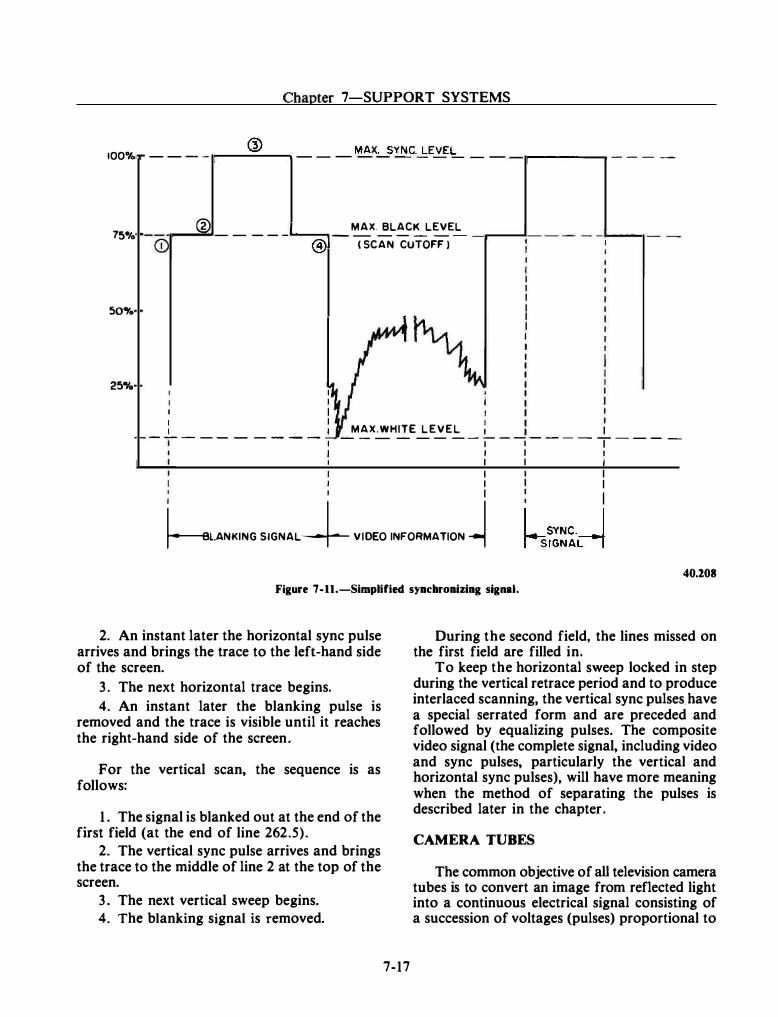
Chapter 7-SUPPORT SYSTEMS
® 100% _ _ _ _ ,...---....;;....-..., _ _ _ MAX:_SYNC.�EVE'=- _ _ -r-------, _ _ _ _
75� .. @ MAX. BLACK LEVEL - - _ _ _ .._____, _ _ - - - - - -r----'- - - - -L----.,
<D @) ( SCAN CUTOFF I
so,.
25,..
I I MAX.WHITE L E V E L : - - - - - - - - - -1 - - - - - - - - � - � - - - - T - - - -
I I I I I I I
I I I I I �l.ANKING SIGNAL+ VIDEO INFORMATION� hSYNC. I
SIGNArl 40.208
Figure 7-11.-Simplified synchronizing signal.
2. An instant later the horizontal sync pulse arrives and brings the trace to the left-hand side of the screen.
3. The next horizontal trace begins.
4. An instant later the blanking pulse is removed and the trace is visible until it reaches the right-hand side of the screen.
For the vertical scan, the sequence is as follows:
1 . The signal is blanked out at the end of the first field (at the end of line 262.5).
2. The vertical sync pulse arrives and brings the trace to the middle of line 2 at the top of the screen.
3. The next vertical sweep begins. 4. The blanking signal is removed.
7-17
During the second field, the lines missed on the first field are filled in.
To keep the horizontal sweep locked in step during the vertical retrace period and to produce interlaced scanning, the vertical sync pulses. have a special serrated form and are preceded and followed by equalizing pulses. The composite video signal (the complete signal, including video and sync pulses, particularly the vertical and horizontal sync pulses), will have more meaning when the method of separating the pulses is described later in the chapter.
CAMERA TUBES
The common objective of all television camera tubes is to convert an image from reflected light into a continuous electrical signal consisting of a succession of voltages (pulses) proportional to
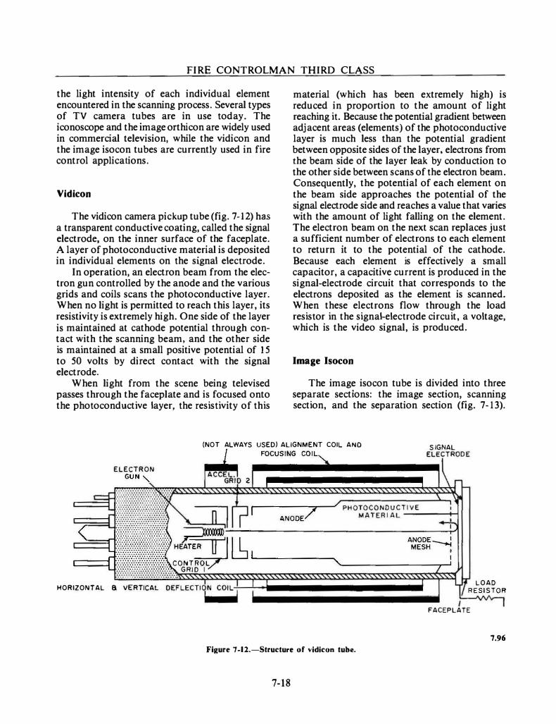
FIRE CONTROLMAN THIRD CLASS
the light intensity of each individual element encountered in the scanning process. Several types of TV camera tubes are in use today. The iconoscope and the image orthicon are widely used in commercial television, while the vidicon and the image isocon tubes are currently used in fire control applications.
Vidicon
The vidicon camera pickup tube (fig. 7- 1 2) has a transparent conductive coating, called the signal electrode, on the inner surface of the faceplate. A layer of photoconductive material is deposited in individual elements on the signal electrode.
In operation, an electron beam from the electron gun controlled by the anode and the various grids and coils scans the photoconductive layer. When no light is permitted to reach this layer, its resistivity is extremely high. One side of the layer is maintained at cathode potential through contact with the scanning beam. and the other side is maintained at a small positive potential of 1 5 to 50 volts by direct contact with the signal electrode.
When light from the scene being televised passes through the faceplate and is focused onto the photoconductive layer. the resistivity of this
material (which has been extremely high) is reduced in proportion to the amount of light reaching it. Because the potential gradient between adjacent areas (elements) of the photoconductive layer is much less than the potential gradient between opposite sides of the layer, electrons from the beam side of the layer leak by conduction to the other side between scans of the electron beam. Consequently, the potential of each element on the beam side approaches the potential of the signal electrode side and reaches a value that varies with the amount of light falling on the element. The electron beam on the next scan replaces just a sufficient number of electrons to each element to return it to the potential of the cathode. Because each element is effectively a small capacitor, a capacitive current is produced in the signal-electrode circuit that corresponds to the electrons deposited as the element is scanned. When these electrons flow through the load resistor in the signal-electrode circuit, a voltage, which is the video signal, is produced.
Image Isocon
The image isocon tube is divided into three separate sections: the image section. scanning section, and the separation section (fig. 7-13).
(NOT ALWAYS USED) ALIGNMENT COIL AND S IGNAL ELE
IC\TRODE 1 FOCUSING COIL
� ELECTRON
GUN '- ACC��·Ib 2 �------------· F:T��� ������������������r �
C�c:::::{:��u�,r��,]�;��!� h 1..----A-N
_O_O_E/........,. _ _,/rP-H-O-
�-�
C-TO-E�-
�-�-�-T�I
-V_E_-_-:
_:--f..,
:l
:-; \
< . . . . . . . . . . . . . . . . . . . . . � I I ::::::.·.·.·.·.·:::::::.·:. �
� ij-@l@!!lli HEATER � 'I � I ����� C::==1 ·:·:·:·>X·:·:·:·:·:·:·:·:·:-:·:·:·:·:·. CONTROL ...._-------...., ________ --r_. '-:::::::::::::::: :::::::::::::::::::::::::::::::: ... G R I 0 I
HORIZONTAL 8 VERTICAL OEFLECTI1N COIL-f;--;-: --------------������ lf LOAD RESISTOR ...1\,/\, I
FACEPLATE
7.96
Figure 7-12.-Structure of vidicon tube.
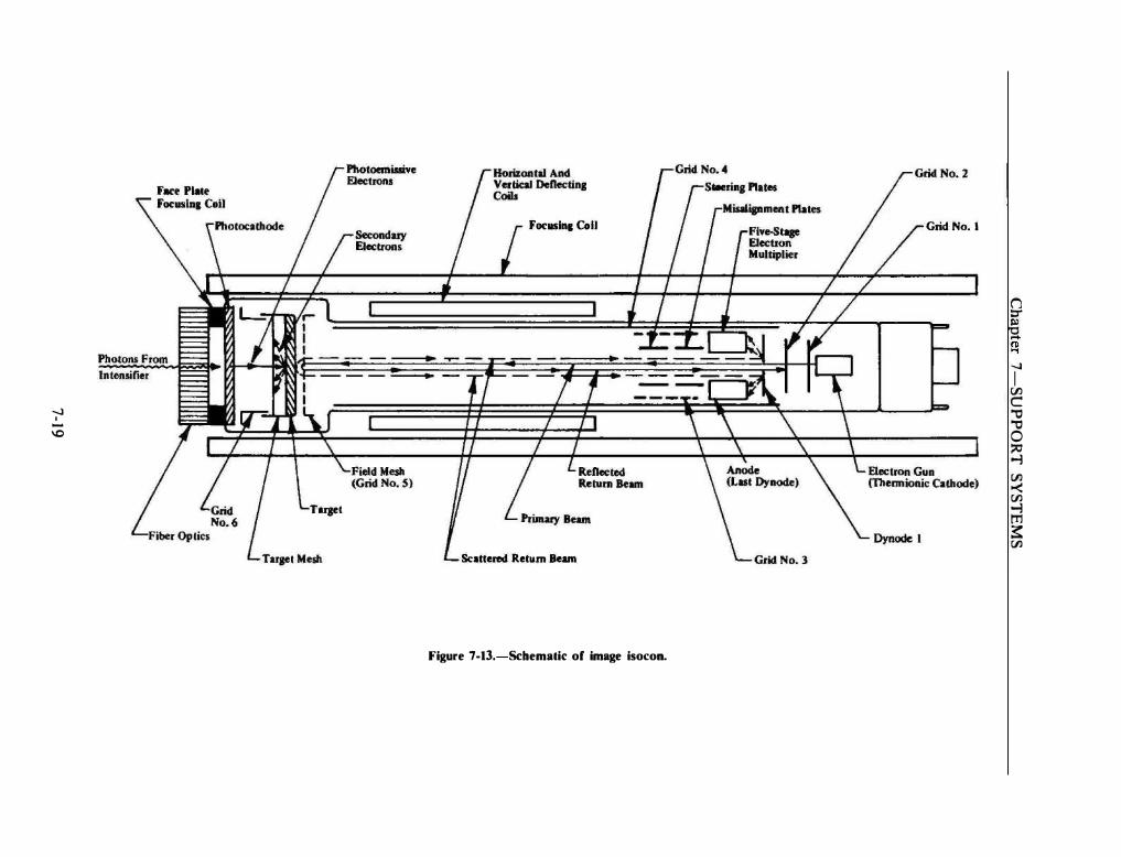
Focusln1 Coli
-...) I
-\0
Tarpt
Sc•ttered Return Beun
Figure 7-13.-Schematic: of image isoc:on.
Grid No. I
(j ::r � ..... (I) ..., -...) I V'J c
., ., 0 � .., t:ll -< Vl .., m � Vl
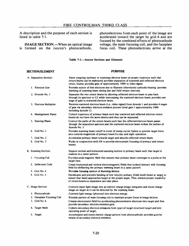
FIRE CONTROLMAN THIRD CLASS
A description and the purpose of each section is listed in table 7- J .
photoelectrons from each point of the image are accelerated toward the target by grid 6 and are focused by the combined effects of photocathode voltage, the main focusing coil, and the faceplate focus coil. These photoelectrons arrive at the
IMAGE SECTION.-When an optical image is formed on the isocon's photocathode,
SECTION/ELEMENT
A. Separation Section:
1 . Electron Gun
2. Dynode No. I
3. Electron MultipJjer
4. Misalignment Plates
s. Steering Plates
6. Grid No. I
7. Grid No. 2
8. Grid No. 3
B. Scanning Section:
I . Focusing Coil
2. Deflection Coils
3, Grid No. 4
4. Grid No. 5
c. Image Section:
1 . Photocathode
2. Faceplate Focusing Coil
3. Grid No. 6
4. Target Mesh
5. Target
Table 7-1.-lsocon Sections and Elements
PURPOSE
Starts outgoing (primary or scanning) electron beam on proper trajectory such that return beams can be separated; provides separation of scattered and reflected electron retun. beams; provides pin of approximately 1000 to video signal.
Provides source of free electrons due to filament (thennionic cathode) heating: provides blanking of scanning beam during line and field retrace intervals.
Separates the two return beams by allowing reflected electron beam to pass back through its aperture to G2 while intercepting the scattered electron beam; provides one stage of gain to scattered electron beam.
Receives scattered electron beam (i.e., video signal) from dynode I and provides 4 stages of gain via secondary electron emission process (total gain • approximately 1000 including dynode 1 ). Control trajectory of primary beam such that scattered and reflected electron return beams do not have the same centers and thus can be separated.
Control the paths of the return beams such that the reflected electron beam passes through the separation aperture and the scattered electron beam strikes the surface of dynode No. 1 . Provides scanning beam cutoff in event of sweep circuit failure to prevent target burn; also controls magnitude of primary beam for day and night operation.
Accelerates primary beam towards target and absorbs reflected return beam.
Works in conjunction with G4 to provide electrostatic focusing of primary and return beams.
Imparts vertical and horizontal scanning motion to primary beam such that target is readout in a raster pattern.
Provides axial magnetic fteld that ensures that primary beam converges to a point at the target face.
Create horizontal and vertical electromagnetic fields that (yokes) interact with focusing field for deflecting the primary scanning beam in a raster pattern.
Provides focusina control of scannina section.
Decelerates and prevents bending of low velocity primary (f�eld mesh) beam at target to ensure that beam approaches target at the proper angle. Thus, ensures proper traject�ry of return beams so separation can take place.
Converts input light Image into an electric charge image; integrates and stores charge image on target so it can be detected by the scanning beam.
Converts light energy (photons) into electron energy.
Extends pattern of main focusing coil to maintain proper focus in image section.
Creates electrostatic f�eld for accelerating photoemissive electrons into target and thus provide secondary electren emission gain.
CoUects secondary electron emissions from (part of target structure) target and sets operating point of target.
Accumulates and stores electric charge pattern from photocathode: provides g;.in by means of secondary electron emission.
7-20
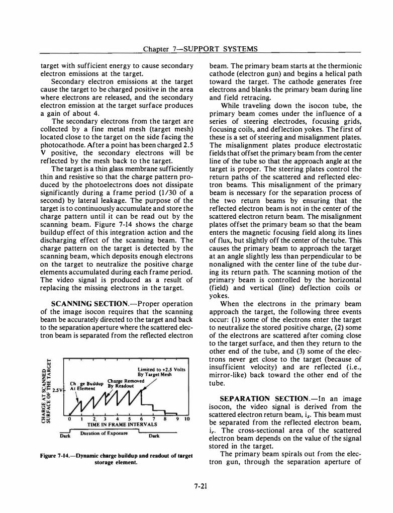
Chapter 7-SUPPORT SYSTEMS
target with sufficient energy to cause secondary electron emissions at the target.
Secondary electron emissions at the target cause the target to be charged positive in the area where electrons are released, and the secondary electron emission at the target surface produces a gain of about 4.
The secondary electrons from the target are collected by a fine metal mesh (target mesh) located close to the target on the side facing the photocathode. After a point has been charged 2.5 V positive, the secondary electrons will be reflected by the mesh back to the target.
The target is a thin glass membrane sufficiently thin and resistive so that the charge pattern produced by the photoelectrons does not dissipate significantly during a frame period (1 /30 of a second) by lateral leakage. The purpose of the target is to continuously accumulate and store the charge pattern until it can be read out by the scanning beam. Figure 7-14 shows the charge buildup effect of this integration action and the discharging effect of the scanning beam. The charge pattern on the target is detected by the scanning beam, which deposits enough electrons on the target to neutralize the positive charge elements accumulated during each frame period. The video signal is produced as a result of replacing the missing electrons in the·target.
SCANNING SECTION.-Proper operation of the image isocon requires that the scanning beam be accurately directed to the target and back to the separation aperture where the scattered electron beam is separated from the reflected electron
limited to +2.5 Volts By Tarset M�sh
Charge Buildup Charse RemoY�d At El�m�nt By Readout
\
Figure 7-14.-Dynamic charge buildup and readout of target storage element.
7-21
beam. The primary beam starts at the thermionic cathode (electron gun) and begins a helical path toward the target. The cathode generates free electrons and blanks the primary beam during line and field retracing.
While traveling down the isocon tube, the primary beam comes under the influence of a series of steering electrodes, focusing grids, focusing coils, and deflection yokes. The first of these is a set of steering and misalignment plates. The misalignment plates produce electrostatic fields that offset the primary beam from the center line of the tube so that the approach angle at the target is proper. The steering plates control the return paths of the scattered and reflected electron beams. This misalignment of the primary beam is necessary for the separation process of the two return beams by ensuring that the reflected electron beam is not in the center of the scattered electron return beam. The misalignment plates offset the primary beam so that the beam enters the magnetic focusing field along its lines of flux, but slightly off the center of the tube. This causes the primary beam to approach the target at an angle slightly less than perpendicular to be nonaligned with the center line of the tube during its return path. The scanning motion of the primary beam is controlled by the horizontal (field) and vertical (line) deflection coils or yokes.
When the electrons in the primary beam approach the target, the following three events occur: ( 1 ) some of the electrons enter the target to neutralize the stored positive charge, (2) some of the electrons are scattered after coming close to the target surface, and then they return to the other end of the tube, and (3) some of the electrons never get close to the target (because of insufficient velocity) and are reflected (i.e., mirror-like) back toward the other end of the tube.
SEPARATION SECTION .-In an image isocon, the video signal is derived from the scattered electron return beam, is. This beam must be separated from the reflected electron beam, ir. The cross-sectional area of the scattered electron beam depends on the value of the signal stored in the target.
The primary beam spirals out from the electron gun, through the separation aperture of
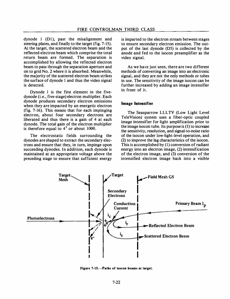
FIRE CONTROLMAN THIRD CLASS
dynode 1 (D 1 ), past the misalignment and steering plates, and finally to the target (fig. 7-15). At the target, the scattered electron beam and the reflected electron beam which comprise the total return beam are formed. The separation is accomplished by allowing the reflected electron beam to pass through the separation aperture and on to grid No. 2 where it is absorbed. Meanwhile, the majority of the scattered electron beam strikes the surface of dynode 1 and thus the video signal is detected.
Dynode 1 is the first element in the fivedynode (i.e., five-stage) electron multiplier. Each dynode produces secondary electron emissions when they are impacted by an energetic electron (fig. 7-16). This means that for each impinging electron, about four secondary electrons are liberated and thus there is a gain of 4 at each dynode. The total gain of the electron multiplier is therefore equal to 4 5 or about 1000.
The electrostatic fields surrounding the dynodes are shaped to extract the secondary electrons and ensure that they, in turn, impinge upon succeeding dynodes. In addition, each dynode is maintained at an appropriate voltage above the preceding stage to ensure that sufficient energy
is imparted to the electron stream between stages to ensure secondary electron emission. The output of the last dynode (05) is collected by the anode and fed to the isocon preamplifier as the video signal.
As we have just seen, there are two different methods of converting an image into an electronic signal, and they are not the only methods or tubes in use. The sensitivity of the image isocon can be further increased by adding an image intensifier in front of it.
Image Intensifier
The Seasparrow LLL TV (Low Light Level TeleVision) system uses a fiber-optic coupled image intensifier for light amplification prior to the image isocon tube. Its purpose is (I) to increase the sensitivity, resolution, and signal-to-noise ratio of the isocon under low-light-level operation, and (2) to improve the lag characteristics of the isocon. This is accomplished by ( 1 ) conversion of radiant energy into an electron image, (2) intensification of the electron image, and (3) conversion of the intensified electron image back into a visible
�Field Mesh GS
I Secondary Electrons I Conduction I Primary Beam Ip
Photoelectrons ...
I
Current �--_.----------��---------
I I
Scattered Electron Beam
Figure 7-15.-Paths of isocon beams at target.
7-22
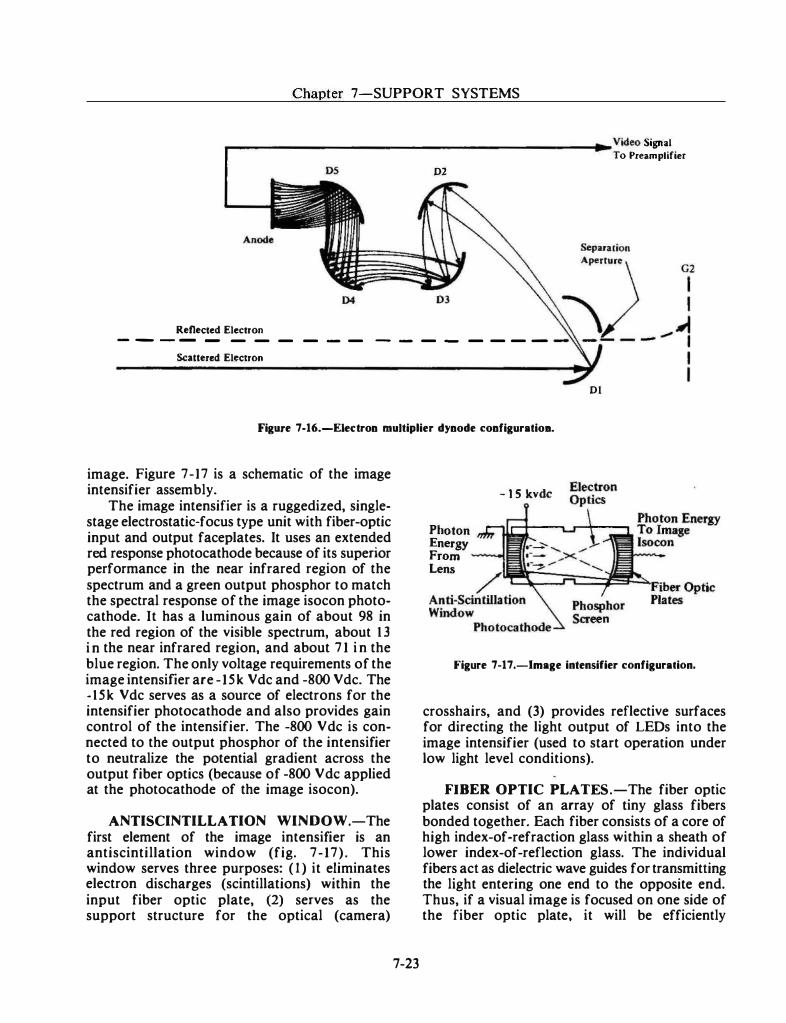
Chapter 7-SUPPORT SYSTEMS
r------------------------- Video Signal To Preamplifier
05 02
Renected Electron _ _ _ ....... ...... _ _ _ _ _ _ _ _ _ _ _ _ _ _
Scattered Electron
01
Figure 7-16.-Eiet:tron multiplier dynode configuratioa.
image. Figure 7-17 is a schematic of the image intensifier assembly.
The image intensifier is a ruggedized, singlestage electrostatic-focus type unit with fiber-optic input and output faceplates. It uses an extended red response photocathode because of its superior performance in the near infrared region of the spectrum and a green output phosphor to match the spectral response of the image isocon photocathode. It has a luminous gain of about 98 in the red region of the visible spectrum, about 1 3 i n the near infrared region, and about 7 1 i n the blue region. The only voltage requirements of the image intensifier are - 15k Vdc and -800 Vdc. The - 15k Vdc serves as a source of electrons for the intensifier photocathode and also provides gain control of the intensifier. The -800 V de is connected to the output phosphor of the intensifier to neutralize the potential gradient across the output fiber optics (because of -800 V de applied at the photocathode of the image isocon).
ANTISCINTILLATION WINDOW.-The first element of the image intensifier is an antiscintillation window (fig. 7-17) . This window serves three purposes: ( 1 ) it eliminates electron discharges (scintillations) within the input fiber optic plate, (2) serves as the support structure for the optical (camera)
7-23
Photon Energy From Lens
- 1 5 kvdc
Figure 7-17.-lmage intensifier configuration.
crosshairs, and (3) provides reflective surfaces for directing the light output of LEOs into the image intensifier (used to start operation under low light level conditions).
FIBER OPTIC PLATES .-The fiber optic plates consist of an array of tiny glass fibers bonded together. Each fiber consists of a core of high index-of-refraction glass within a sheath of lower index-of-reflection glass. The individual fibers act as dielectric wave guides for transmitting the light entering one end to the opposite end. Thus, if a visual image is focused on one side of the fiber optic plate, it will be efficiently
FIRE CONTROLMAN THIRD CLASS
transmitted through the plate with minimal lateral diffusion or scattering.
Fiber optic coupling in an electrostatically focused image intensifier satisfies the requirement that the inside face of the plates must be circular shaped to conform to the curved focal plane of the intensifier. The external faces are flat to provide an efficient couple between the lens and the image isocon, and the internal faces (on which the photocathode and phosphor materials are deposited) are convex.
PHOTOCATHODE.-The photocathode performs the basic function of converting radiant energy (photons) into electron energy. This process (called photoemission) consists of three stages: (1) excitation of photoelectrons within the photocathode material, (2) diffusion of these photoelectrons to the emitting surface, and (3) escape of the photoelectrons into the vacuum between the photocathode and the phosphor screen.
When light is absorbed in the input surface layers of the photoemissive materials, electrons are liberated and are emitted with nearly zero velocity. This emission of photoelectrons is a continuous process, provided that: ( 1 ) the input light is continuous, (2) that a relatively positive anode (i.e., phosphor screen) is present to collect the electrons, and (3) an electrical connection is made to the photocathode to replenish the electrons emitted to the anode.
The potential at the photocathode serves to accelerate the photoelectrons toward the phosphor screen and provides an electrostatic field for focusing the electrons on the input surface of the phosphor screen.
ELECTRON OPTICS.-The electron optics are formed by an electric field in the space between the photocathode and the phosphor screen. This electrostatic lens forms an electron image at the phosphor that is equal to the visual image that a glass lens forms. Distortion is reduced to a satisfactory level by the use of curved photocathode and phosphor screens, which are made possible by the use of fiber optic plates.
PHOSPHOR SCREEN.-The phosphor screen serves to convert the electron energy back
7-24
into radiant energy. It consists of a layer of many small-diameter phosphor crystals that emit light when bombarded by high-energy electrons. The photons of radiant energy are then coupled by the output fiber optic plates to the image isocon tube.
OPTICAL SYSTEMS
We previously discussed the development of fire control systems and the use of optical sights and range finders to sight the guns at a target. Today the range finder is being replaced by other means of determining range such as radars and lasers. The optical systems used are in the form of telescopes and lens systems for TV cameras. The telescopes are used for aligning antennas and weapons system elements and sighting in the manned director systems.
To further understand the optical systems, let us look at the characteristics of light and optical devices.
CHARACfERISTICS OF LIGHT
Light travels at a definite speed in any one medium. The speed of light is approximately 1 86,000 miles per second in a vacuum, is slightly lower in air, and is appreciably lower in water, glass, and other media. The velocity of light is related to its frequency and wavelength in a formula similar to that relating the velocity (v) of sound to its associated frequency. (t) and wavelength (.\).
A beam of light must cover a greater area as it moves farther from the source because the light from a point source spreads out in all directions. Thus, the intensity (brightness) .of light decreases with distance. The inverse-square law applies to this decrease in intensity with an increase. in distance-that is, the light intensity is inversely proportional to the square of the distance from the source. The eye cannot form a quantitative estimate of the degree of brightness because the iris opens or closes to receive more or less light according to the intensity of illumination.
Certain kinds of light produce the sensation of color. The color of light is produced by the
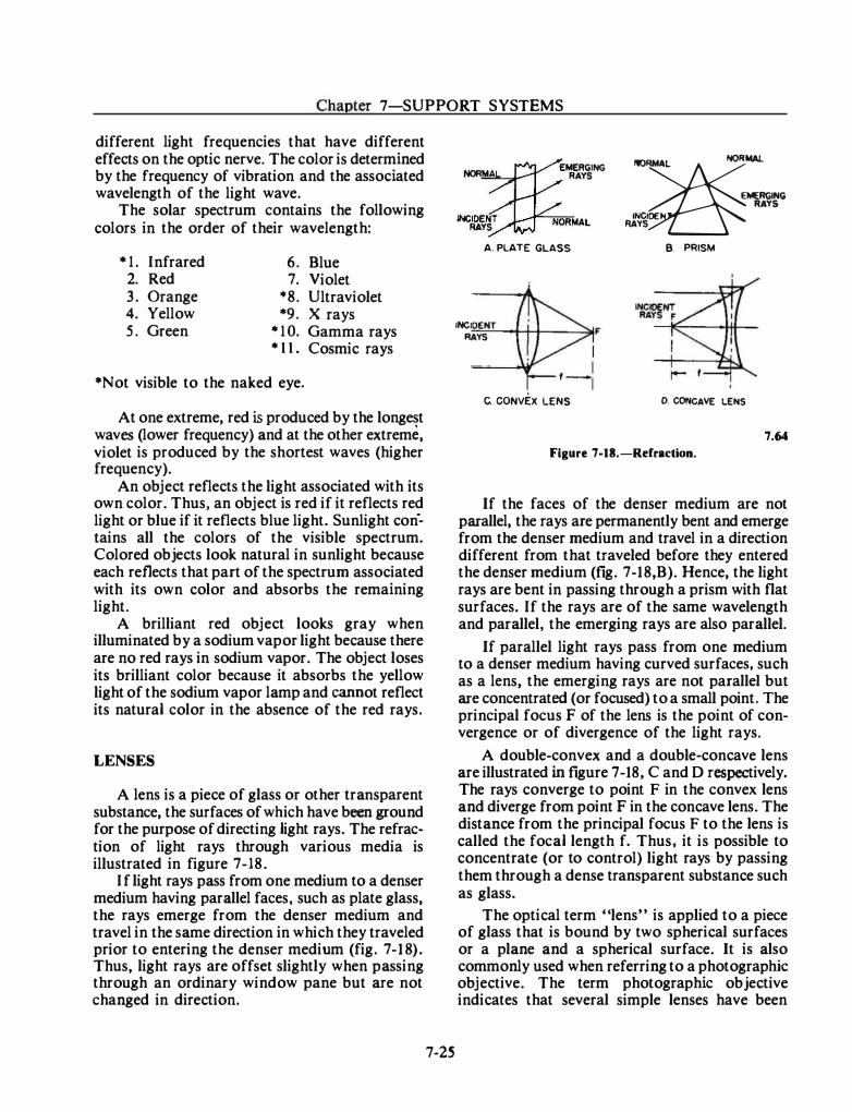
Chapter 7-SUPPORT SYSTEMS
different light frequencies that have different effects on the optic nerve. The color is determined by the frequency of vibration and the associated wavelength of the light wave.
The solar spectrum contains the following colors in the order of their wavelength:
*1. Infrared 6. Blue 2. Red 7. Violet 3 . Orange *8. Ultraviolet 4. Yellow *9. X rays 5 . Green *10. Gamma rays
* 1 1 . Cosmic rays
*Not visible to the naked eye.
At one extreme, red is produced by the longest waves (lower frequency) and at the other extreme, violet is produced by the shortest waves (higher frequency).
An object reflects the light associated with its own color. Thus, an object is red if it reflects red light or blue if it reflects blue light. Sunlight con·tains all the colors of the visible spectrum. Colored objects look natural in sunlight because each reflects that part of the spectrum associated with its own color and absorbs the remaining light.
A brilliant red object looks gray when illuminated by a sodium vapor light because there are no red rays in sodium vapor. The object loses its brilliant color because it absorbs the yellow light of the sodium vapor lamp and cannot reflect its natural color in the absence of the red rays.
LENSES
A lens is a piece of glass or other transparent substance, the surfaces of which have been ground for the purpose of directing light rays. The refraction of light rays through various media is illustrated in figure 7-18.
If light rays pass from one medium to a denser medium having parallel faces, such as plate glass, the rays emerge from the denser medium and travel in the same direction in which they traveled prior to entering the denser medium (fig. 7-1 8). Thus, light rays are offset slightly when passing through an ordinary window pane but are not changed in direction.
7-25
........,�EMERGI NG """""' RAYS
INC��T NORMAL
A. PLATE GLASS
INCID£HT F RAYS
c. CONVEX LENS
��� INCIOE RAYS B. PRISM
0. CONCAVE LENS
7.64 Figure 7-18.-Rdraction.
If the faces of the denser medium are not parallel, the rays are permanently bent and emerge from the denser medium and travel in a direction different from that traveled before they entered the denser medium (fig. 7-18,B). Hence, the light rays are bent in passing through a prism with flat surfaces. If the rays are of the same wavelength and parallel, the emerging rays are also parallel.
If parallel light rays pass from one medium to a denser medium having curved surfaces, such as a lens, the emerging rays are not parallel but are concentrated (or focused) to a small point. The principal focus F of the lens is the point of convergence or of divergence of the light rays.
A double-convex and a double-concave lens are illustrated in figure 7-18, C and D respectively. The rays converge to point F in the convex lens and diverge from point F in the concave lens. The distance from the principal focus F to the lens is called the focal length f. Thus, it is possible to concentrate (or to control) light rays by passing them through a dense transparent substance such as glass.
The optical term "lens" is applied to a piece of glass that is bound by two spherical surfaces or a plane and a spherical surface. It is also commonly used when referring to a photographic objective. The term photographic objective indicates that several simple lenses have been
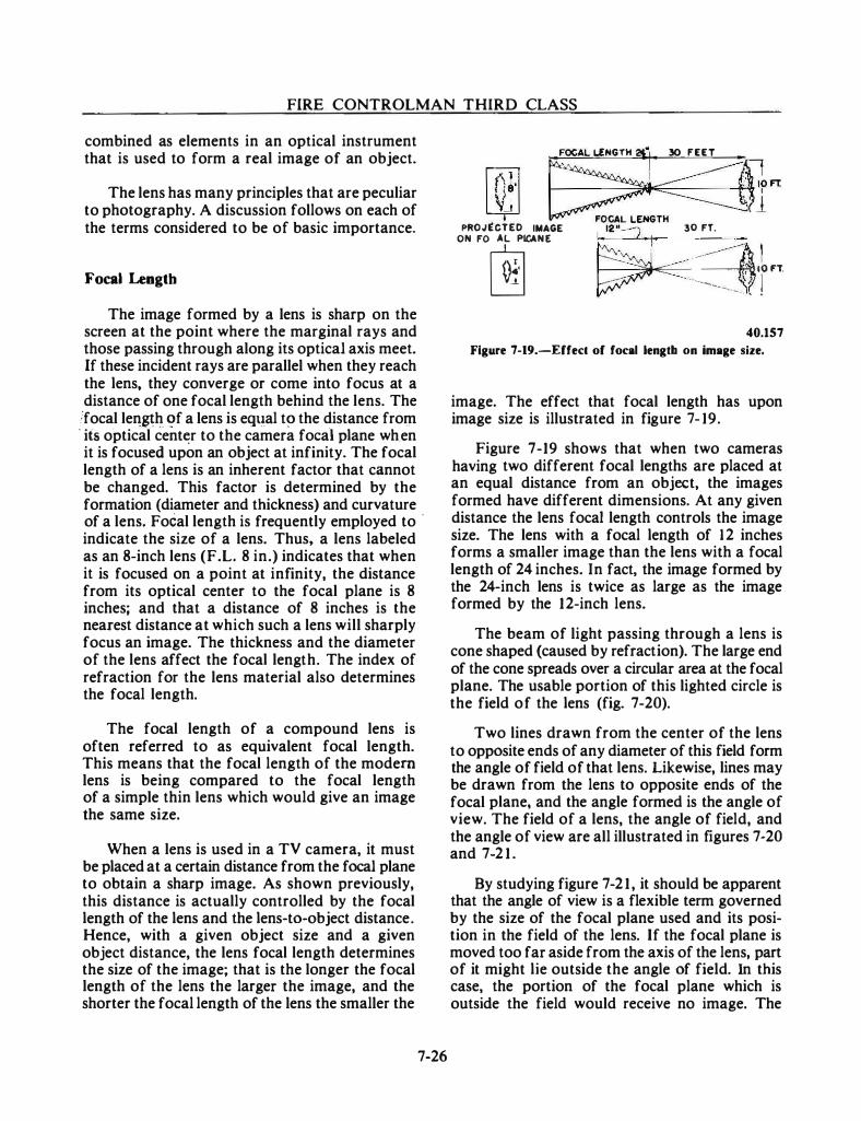
FIRE CONTROLMAN THIRD CLASS
combined as elements in an optical instrument that is used to form a real image of an object.
The lens has many principles that are peculiar to photography. A discussion follows on each of the terms considered to be of basic importance.
Focal Length
The image formed by a lens is sharp on the screen at the point where the marginal rays and those passing through along its optical axis meet. If these incident rays are parallel when they reach the lens, they converge or come into focus at a distance of one focal length behind the lens. The
!focal len�h . . �f a lens is eqt�:al t� the distance from · itS o·ptical cent�r to the camera focal plane wh.en it is focused upon an object at infinity. The focal length of a lens is an inherent factor that cannot be changed. This factor is determined by the formation (diameter and thickness) and curvature of a lens. Focal length is frequently employed to ·
indicate the size of a lens. Thus. a lens labeled as an 8-inch lens (F.L. 8 in.) indicates that when it is focused on a point at infinity, the distance from its optical center to the focal plane is 8 inches; and that a distance of 8 inches is the nearest distance at which such a lens will sharply focus an image. The thickness and the diameter of the lens affect the focal length. The index of refraction for the lens material also determines the focal length.
The focal length of a compound lens is often referred to as equivalent focal length. This means that the focal length of the modem lens is being compared to the focal length of a simple thin lens which would give an image the same size.
When a lens is used in a TV camera, it must be placed at a certain distance from the focal plane to obtain a sharp image. As shown previously, this distance is actually controlled by the focal length of the lens and the lens-to-object distance. Hence, with a given object size and a given object distance, the lens focal length determines the size of the image; that is the longer the focal length of the lens the larger the image, and the shorter the focal length of the lens the smaller the
7-26
�OCAL L£NGTH ?i"l, 30 FEET •
l?m �1" L¥ FOCAL LEHGTH PROJ�CTED IMAGE 12"-:J 30 FT. ON FO�CAL �ANE � 11 �< ...
- � lO FT. -·---- l -�-.. .
40.157
Figure 7-19.-Effec:t of focal lengtb on image s.ize.
image. The effect that focal length has upon image size is illustrated in figure 7- 19.
Figure 7-19 shows that when two cameras having two different focal lengths are placed at an equal distance from an object, the images formed have different dimensions. At any given distance the lens focal length controls the image size. The lens with a focal length of 12 inches forms a smaller image than the lens with a focal length of 24 inches. In fact, the image formed by the 24-inch lens is twice as large as the image formed by the 12-inch lens.
The beam of light passing through a lens is cone shaped (caused by refraction). The large end of the cone spreads over a circular area at the focal plane. The usable portion of this lighted circle is the field of the lens (fig. 7-20).
Two lines drawn from the center of the lens to opposite ends of any diameter of this field form the angle of field of that lens. Likewise, lines may be drawn from the lens to opposite ends of the focal plane, and the angle formed is the angle of view. The field of a lens, the angle of field, and the angle of view are all illustrated in figures 7-20 and 7-2 1 .
By studying figure 7-21 , it should be apparent that the angle of view is a flexible term governed by the size of the focal plane used and its position in the field of the lens. If the focal plane is moved too far aside from the axis of the lens, part of it might lie outside the angle of field. In this case, the portion of the focal plane which is outside the field would receive no image. The
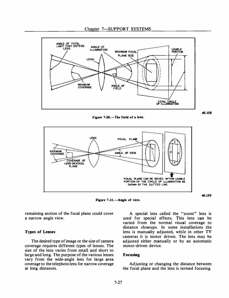
Chapter 7-SUPPORT SYSTEMS
TOTAL CIRCLE OF IL.LUMINAliON
40.151 Fiaure 7-20.-The field of a lens.
FOCAl PLAN£ CAN BE MOVED WITHW. USABLE PORTION OF THE CIRCL.E OF IL.LUMINATIOH AS
SHOWN BY THE DOTTED LINE
40.159 Figure 7-21.-An&le of view.
remaining section of the focal plane could cover a narrow angle view.
Types of Lenses
The desired type of image or the size of camera coverage requires different types of lenses. The size of the lens varies from small and short to large and long. The purpose of the various lenses vary from the wide-angle lens for large area coverage to the telephoto lens for narrow coverage at long distances.
7-27
A special lens called the "zoom .. lens is used for special effects. This lens can be varied from the normal visual coverage to distance closeups. In some installations the lens is manually adjusted, while in other TV cameras it is motor driven. The lens may be adjusted either manually or by an automatic motor-driven device.
Focusing
Adjusting or changing the distance between the focal plane and the lens is termed focusing.
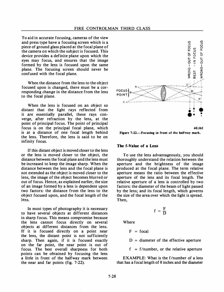
l..
FIRE CONTROLMAN THIRD CLASS
To aid in accurate focusing, cameras of the view and press type have a focusing screen which is a piece of ground glass placed at the focal plane of the camera on which the subject is focused. This device provides a definite plane upon which the eyes may focus, and ensures that the image formed by the lens is focused upon the same plane. The focusing screen should never be confused with the focal plane.
When the distance from the lens to the object focused upon is changed, there must be a corresponding change in the distance from the lens to the focal plane.
When the lens is focused on an object so distant that the light rays reflected from it are essentially parallel, these rays converge, after refraction by the lens, at the point of principal focus. The point of principal focus is on the principal focal plane, which is at a distance of one focal length behind the lens. Therefore, the lens is said to be on infinity focus.
If this distant object is moved closer to the lens or the lens is moved closer to the object, the distance between the focal plane and the lens must be increased to keep the image sharp. When the distance between the lens and the focal plane is not extended as the object is moved closer to the lens, the image of the object becomes blurred or out of focus. Hence, as explained earlier, the size of an image formed by a lens is dependent upon two factors: the distance from the lens to the object focused upon, and the focal length of the lens.
In most types of photography it is necessary to have several objects at different distances in sharp focus. This means compromise because the lens cannot focus directly on several objects at different distances from the lens. If it is focused directly on a point near the lens, the distant point is not sufficiently sharp. Then again, if it is focused exactly on the far point, the near point is out of focus. The best overall sharpness for both points can be obtained by focusing the lens a little in front of the halfway mark between the near and far points (fig. 7-22).
7-28
40.161
Figure 7-22.-Focusing in front of the halfway mark.
Tbe f-Value of a Lens
To use the lens advantageously, you should thoroughly understand the relation between the aperture and the brightness of the image produced at the focal plane. The term relative aperture means the ratio between the effective aperture of the lens and its focal length. The relative aperture of a lens is controlled by two factors: the diameter of the beam of light passed by the lens; and its focal length, which governs the size of the area over which the light is spread. Then,
Where
F = focal
F f :; D
D :; diameter of the effective aperture
f = f/number, or the relative aperture
EXAMPLE: What is the f/number of a lens that has a focal length of 8 inches and the diameter
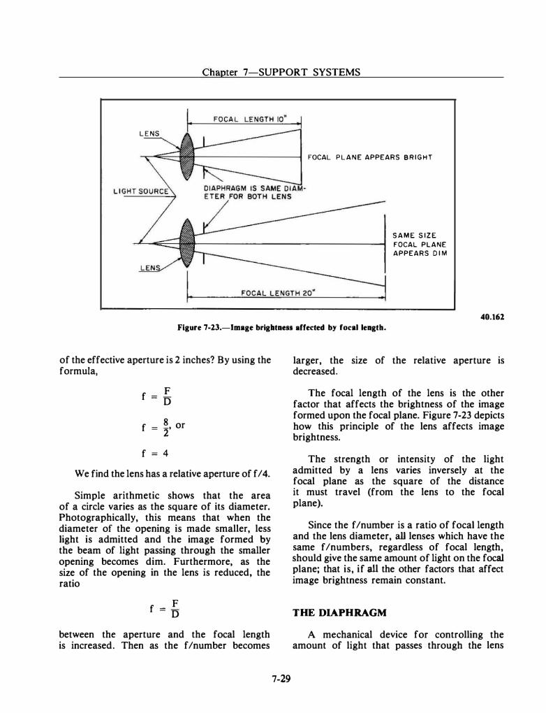
Chapter 7-SUPPORT SYSTEMS
L E NS
FOCAL PLANE APPEARS B R I G H T
S A M E S I Z E
FOCAL PLANE
APPEARS D I M
40.162
Figure 7-23.-lmage brightness affected by focal length.
of the effective aperture is 2 inches? By using the formula,
F f = D
8 f = 2' or
f = 4
We find the lens has a relative aperture of f/4.
Simple arithmetic shows that the area of a circle varies as the square of its diameter. Photographically, this means that when the diameter of the opening is made smaller, less light is admitted and the image formed by the beam of light passing through the smaller opening becomes dim. Furthermore, as the size of the opening in the lens is reduced, the ratio
F f = D
between the aperture and the focal length is increased. Then as the f/number becomes
7-29
larger, the size of the relative aperture is decreased.
The focal length of the lens is the other factor that affects the brightness of the image formed upon the focal plane. Figure 7-23 depicts how this principle of the lens affects image brightness.
The strength or intensity of the light admitted by a lens varies inversely at the focal plane as the square of the distance it must travel (from the lens to the focal plane).
Since the f/number is a ratio of focal length and the lens diameter, all lenses which have the same f/numbers, regardless of focal length, should give the same amount of light on the focal plane; that is, if all the other factors that affect image brightness remain constant.
THE DIAPHRAGM
A mechanical device for controlling the amount of light that passes through the lens
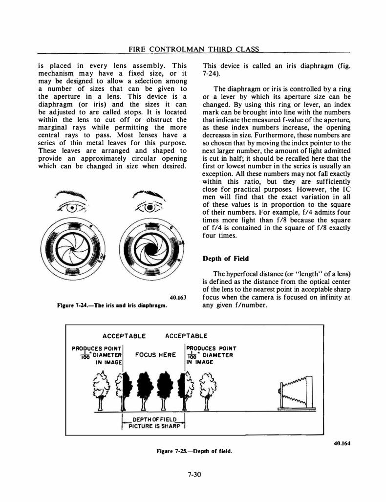
------ - - __ _ _ _ .._ _
FIRE CONTROLMAN THIRD CLASS
is placed in every lens assembly. This mechanism may have a fixed size, or it may be designed to allow a selection among a number of sizes that can be given to the aperture in a lens. This device is a diaphragm (or iris) and the sizes it can be adjusted to are called stops. It is located within the lens to cut off or obstruct the marginal rays while permitting the more central rays to pass. Most lenses have a series of thin metal leaves for this purpose. These leaves are arranged and shaped to provide an approximately circular opening which can be changed in size when desired.
-� - \ �>
Flaure 7·24.-TIIe iris and Iris diaphragm.
40.163
This device is called an iris diaphragm (fig. 7-24).
The diaphragm or iris is controlled by a ring or a lever by which its aperture size can be changed. By using this ring or lever, an index mark can be brought into line with the numbers that indicate the measured f-value of the aperture, as these index numbers increase, the opening decreases in size. Furthermore, these numbers are so chosen that by moving the index pointer to the next larger number, the amount of light admitted is cut in half; it should be recalled here that the first or lowest number in the series is usually an exception. All these numbers may not fall exactly within this ratio, but they are sufficiently close for practical purposes. However, the IC men will find that the exact variation in all of these values is in proportion to the square of their numbers. For example, f/4 admits four times more light than f/8 because the square of f/4 is contained in the square of f/8 exactly four times.
Depth of Field
The hyperfocal distance (or "length" of a lens) is defined as the distance from the optical center of the lens to the nearest point in acceptable sharp focus when the camera is focused on infinity at any given fin umber.
ACCEPTABLE ACCEPTABLE PRODUCES POl NT �· DIAMETER
IN IMAGE PRODUCES POINT
FOCUS HERE �· DIAMETER IN IMAGE
Figure 7-25.-Depth of field.
7-30
40.164
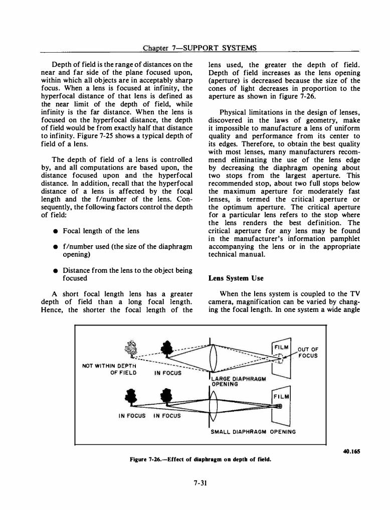
Chapter 7-SUPPORT SYSTEMS
Depth of field is the range of distances on the near and far side of the plane focused upon, within which all objects are in acceptably sharp focus. When a lens is focused at infinity, the hyperfocal distance of that lens is defined as the near limit of the depth of field, while infinity is the far distance. When the lens is focused on the hyperfocal distance, the depth of field would be from exactly half that distance to infinity. Figure 7-25 shows a typical depth of field of a lens.
The depth of field of a lens is controlled by, and all computations are based upon, the distance focused upon and the hyperfocal distance. In addition, recall that the hyperfocal distance of a lens is affected by the foe� length and the f/number of the lens. Consequently, the following factors control the depth of field:
• Focal length of the lens
• f/number used (the size of the diaphragm opening)
• Distance from the lens to the object being focused
A short focal length lens has a greater depth of field than a long focal length. Hence, the shorter the focal length of the
.!€-.. �� "'lC: -_ ... ... 4' - .,.
NOT WITHIN DEPTH-- -- - - - -- -
OF FIELD I N FOCUS
lens used, the greater the depth of field. Depth of field increases as the lens opening (aperture) is decreased because the size of the cones of light decreases in proportion to the aperture as shown in figure 7-26.
Physical limitations in the design of lenses, discovered in the laws of geometry, make it impossible to manufacture a lens of uniform quality and performance from its center to its edges. Therefore, to obtain the best quality with most lenses, many manufacturers recommend eliminating the use of the lens edge by decreasing the diaphragm opening about two stops from the largest aperture. This recommended stop, about two full stops below the maximum aperture for moderately fast lenses, is termed the critical aperture or the optimum aperture. The critical aperture for a particular lens refers to the stop where the lens renders the best definition. The critical aperture for any lens may be found in the manufacturer's information pamphlet accompanying the lens or in the appropriate technical manual.
Lens System Use
When the lens system is coupled to the TV camera, magnification can be varied by changing the focal length. In one system a wide angle
SMALL DIAPHRAGM OPENING
lJT OF FOCUS
40.165 Figure 7-16.-Effect of diaphragm on depth of field.
7-31
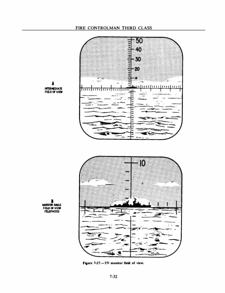
A INlERNIDIAlt FID.D Of VllW
I NARROW ANGU FID.D OF VIEW llWPttOTOJ
FIRE CONTROLMAN THIRD CLASS
� .-- ---· - ._......_-:._.__...,._ .
__ ..... ---""'._ --------
.:.- -----.. . _, _ - - ....,.,.__ . -----· -
--·
-- --� --=- -. · ..,__ -=- �-��
-- - ,_ - - -
- �-� ----
Fiaure 7-17.-TV monitor field of view.
7-32
Chapter 7 SUPPORT SYSTEMS
through a narrow angle field of view (telephoto) can be used (fig. 7-27).
SUMMARY
We have discussed a wide variety of support systems. The importance of each is dependent upon the individual weapons systems and its
7-33
requirements. As you advance and become involved with different fire control systems, you will probably encounter all of the support systems at some time. You may not work on each of the support systems, but how they work and support your equipment is important since you as the user would be the first to notice any improper operation. Now let us go on to the next chapter to learn about maintenance.
CHAPTER 8
MAINTENANCE
The effectiveness of your fire control equipment depends largely on the care you give it. For example, an improperly adjusted radar can reduce the accuracy of a perfectly aligned fire control system. An inoperative computer makes it impossible to effectively engage a target. In each case an action is required to cause the equipment to operate properly.
In any maintenance work, you will use knowledge and skills of two basic types. First, you will use specific information that applies only to the particular system or a part of that system, which you may be called upon to repair or keep in good condition. Second, you should possess and will use general skills and knowledge that apply to many kinds of equipment and to many types of work assignments.
The specific information required consists of the special procedures and detailed, step-by-step directions for maintenance. These are approved by the proper authority and recommended for a particular system or piece of equipment. These procedures and instructions are found on Maintenance Requirement Cards (MRCs) and in the system and equipment Ordnance Pamphlets (OPs) and Technical Manuals (TMs) of the fire control system to which you are assigned.
Because of the complexity of modern fire control systems equipment and the magnitude of maintenance requirements, it would be impractical for us to detail step-by-step procedures for specific maintenance actions. Nevertheless, the mechanics of maintenance procedures and trouble isolation are discussed. Many of the troubleshooting aids that have been developed over the years are reviewed so that you can take part in a useful maintenance program.
General maintenance techniques are also discussed. Emphasis is placed on those skills and
8-1
procedures that can be applied in all shipboard maintenance programs. The general maintenance skills and procedures are based on knowledge that is not contained in system or equipment OPs/TMs. The knowledge must be acquired on the job and from rate training manuals.
Specific safety precautions are listed on every Maintenance Requirement Card (MRC) where there is a chance of hazardous conditions developing. Safety summaries that cover general safety precautions are included in volume I of OPs and TMs.
The work you perform on equipment falls into two broad groups. First, there are actions you take to reduce failure and prolong the useful life of your equipment. Second, there are actions you take when a part has failed and the equipment is out of service. Therefore, we can think of the whole business of general maintenance as being of a preventive nature or of a corrective nature.
This form of maintenance consists mainly of cleaning, lubrication, and visual inspection of the equipment prior to and during its operation. Scheduled alignments and adjustments are also included in this category. Preventive maintenance procedures are provided by and scheduled according to the Planned Maintenance System.
When a defective part or improper operation is indicated, you will need to analyze the equipment malfunction, find the defective part or parts, and make the proper replacement or repair. In general, your analysis will be most effective if you follow a careful and logical step-by-step trouble shooting procedure.
Preventive maintenance, then, consists of the care, upkeep, and minor repairs and adjustments performed by you, the technician, to ensure the best condition of your equipment and to reduce the chance of sudden equipment failure or
--- - - ·-- -·-- .. ··- ------ -·---
FIRE CONTROLMAN THIRD CLASS
malfunction. Preventive maintenance aboard ship is accomplished by means of scheduled system and equipment performance tests, scheduled servicing procedures, and careful observation of system/ equipment performance during periods of operation. These schedules are posted weekly in each work center and act as the guide for maintenance actions.
When preventive maintenance or performance checks reveal that a casualty or malfunction exists in a system or a piece of equipment, some form of corrective maintenance is needed. Some action is required that will restore the system or equipment to its designed use. This includes the repair of damage resulting from wear, accident, or other cause.
THE PLANNED MAINTENANCE SYSTEM
Planned maintenance is based on the principle that readiness can be determined through testing, and thoroughness can be assured by proper scheduling. This maintenance program, known as the Planned Maintenance System (PMS), is incorporated in your system and equipment OPs.
SYSTEM MAINTENANCE
Some maintenance tests are conducted on a system level. If a fault appears, PMS troubleshooting procedures provide a means for positive and rapid identification of the exact equipment causing the trouble.
System maintenance uses quick tests to locate faults in a system; it also lists the methods and procedures needed to repair these faults. The Planned Maintenance System is designed so that experienced technicians can share the workload with less experienced personnel. Along with this, it has established that important tasks be grouped as scheduled maintenance events.
To see the value of system level testing, suppose that a misalignment exists between two sets of equipment, such as a search radar and a fire control radar. Individual equipment tests would probably indicate that both radars were operating properly. In actual operation, however, the fire control radar would be unable to acquire the
8-2
targets disclosed by the search radar because of the misalignment. System level testing, however, would consider one equipment's performance with respect to another's and provide you with the data that points out the alignment problem.
Those individual circuits and system modes that cannot be readily checked in the Daily System Operability Test (DSOT) are judged by conducting extra system tests and equipment tests. These, plus the standard servicing procedures, are also listed as scheduled maintenance events. The Planned Maintenance System requires the scheduling of these test and maintenance tasks into the ship's operating schedule according to a fixed management plan. Requirements for those recurring tests have been set up to provide the minimum testing necessary to ensure materiel readiness. The PMS program has done away with overtesting, relieved the excess workload imposed on technical personnel, and reduced needless wear on equipment. The intervals at which tests and other maintenance tasks are performed have been fixed in accordance with the CNO's Planned Maintenance System. These schedules are an integral part of the Planned Maintenance System.
The maintenance events are arranged by the ship's weapons or combat systems officer to fit the ship's operating schedule. This allows the appropriate maintenance procedures to be continued whether the ship is in port or at sea. The primary reason for conducting the tests is to determine the operability of the weapon's system. If a response should indicate a fault that prevents the system from operating at the required degree of combat readiness, PMS troubleshooting references are consulted. These references are pointed out by keys in the test procedures. These keys not only will lead to the exact location of trouble in the shortest possible time but also-will specify the corrective measures.
EQUIPMENT MAINTENANCE
Even though you, as an FC, will be an active participant in system maintenance procedures, your participation will normally be limited to the equipment area to which you are assigned. Therefore, it is mandatory that you become familiar with the details of equipment maintenance procedures. There is a separate Ordnance Pamphlet or Technical Manual (OP /TM) for each major
Chapter 8-MAINTENANCE
piece of equipment. This OP /TM contains a description of the equipment, its operating procedures, the maintenance tum-on procedures, and the equipment troubleshooting material. These equipment pubs have been specifically created to quickly isolate faults within the equipment. Direct referral to the troubleshooting section is from system fault directories and diagrams, and from the equipment turn-on procedures and troubleshooting index.
System tests as well as equipment test pro-• cedures are printed on Maintenance Requirement
Cards (MRCs). The format of the test is the same, but troubleshooting references listed are equipment-related vice system-related OPs/TMs. Next, we will discuss the most common types of equipment maintenance documents.
PUBLICATIONS
Many publications are used in the proper maintenance of fire control equipment. Technical publications issued by various systems commands and other departments of the Navy are sources of important information for every person in the Navy. Publications issued by the Naval Sea Systems Command (NA VSEA and the old NA VORD and NA VSHIPS pubs) are of main concern to fire controlmen. The most important pubs from these sources that you should be familiar with are discussed in this chapter.
ORDNANCE PAMPHLETS
The main source of technical information on the operation and maintenance of ordnance is the Ordnance Pamphlet (OP). NA VSEA publishes these technical manuals, each under its own OP number. (Some older OPs may still have the original NAVORD title.) They may be prepared by some other naval activity, by the manufacturer, by a commercial specialist in such publications, or by NAVSEA itself. Fire control system OPs are divided into two categories: system OPs and equipment OPs.
System OPs provide the information necessary to operate a shipboard weapon system in all modes. Information for performing routine maintenance and fault isolation to the level of a distinct functional area within an equipment is also provided.
8-3
Equipment OPs provide all the information required by Navy personnel to understand, operate, and maintain individual items of equipment. Equipment OPs are organized as follows: safety summary, introduction, physical description, functional description, circuit theory, operation, maintenance, troubleshooting, and parts list.
Another category of OPs. that you will find of interest are general OPs. General OPs take up a subject matter area rather than a specific item of ordnance equipment. Such OPs, of course, do not follow the system and equipment OP structure. But they are written and indexed to serve as a reference book for instruction and training. A good example of this type of OP is NA VORD OP 3000, Weapons Systems Fundamentals. This introduces and explains the basic principles of weapons and weapons system components.
The OP may someday be a thing of the past. New and revised pubs are now issued as technical manuals and will be described shortly.
ORDNANCE DATA
Ordnance Data publications (ODs) are limiteduse technical publications covering a wide range of subjects. These may include information concerning installation and overhaul procedures and manufacturer's test and alignment data.
TECHNICAL MANUALS
Technical Manuals (TMs) issued by NA VSEA (and formerly NA VSHIPS) provide information that is needed for the proper installation, operation, and maintenance of electrical and electronic equipment. Search radars and system support equipment are sustained by this type of pub.
TMINS
Currently, the Navy is converting to a new system of identifying technical publications. The new system is an alphanumeric system referred to as the "Technical Manual Identification Numbering System (TMINS)." It is being developed as a standard method of numbering and will apply to all technical pubs (OPs, 00s, TMs, etc.). As such, it will do away with many of the problems that now exist in the areas of shipping and data processing.
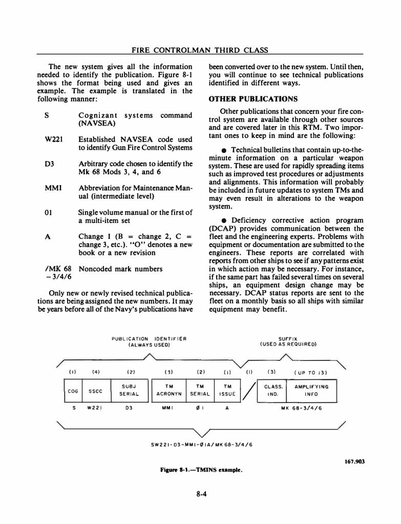
·-··- - --·· ---- ------
FIRE CONTROLMAN THIRD CLASS
The new system gives all the information needed to identify the publication. Figure 8�1 shows the format being used and gives an example. The example is translated in the following manner:
s
W221
D3
MMI
01
A
Cognizan t s y s t e ms command (NAVSEA)
Established NA VSEA code used to identify Gun Fire Control Systems
Arbitrary code chosen to identify the Mk 68 Mods 3, 4, and 6
Abbreviation for Maintenance Man� ual (intermediate level)
Single volume manual or the first of a multi-item set
Change 1 (B = change 2, C =
change 3, etc.). "0" denotes a new book or a new revision
/MK 68 Noncoded mark numbers -3/4/6
Only new or newly revised technical publications are being assigned the new numbers. It may be years before all of the Navy's publications have
PUBLICATION IDENTIFIER (ALWAYS USED)
been converted over to the new system. Until then, you will continue to see technical publications identified in different ways.
OTHER PUBLICATIONS
Other publications that concern your fire control system are available through other sources and are covered later in this RTM. Two important ones to keep in mind are the following:
• Technical bulletins that contain up-to-theminute information on a particular weapon system. These are used for rapidly spreading items such as improved test procedures or adjustments and alignments. This information will probably be included in future updates to system TMs and may even result in alterations to the weapon system.
• Deficiency corrective action program (DCAP) provides communication between the fleet and the engineering experts. Problems with equipment or documentation are submitted to the engineers. These reports are correlated with reports from other ships to see if any patterns exist in which action may be necessary. For instance, if the same part has failed several times on several ships, an equipment design change may be necessary. DCAP status reports are sent to the fleet on a monthly basis so all ships with similar equipment may benefit.
SUFFIX (USED AS REQUIRED)
r--------------���--------------� �----���--------� / v " (I) (4)
COG sscc
S W22)
(2) ( 3)
SUBJ TM
SERIAL ACRONYN
D3 MMI
(2)
TM
SERIAL
QJI
(I) (I)
TM
ISSUE I A
SW221- 03-MMI-ii! lA/ MK 68-3/4/6
Fi&ure 1-1.-TMINS example.
8-4
< 3l ( uP ro 13 >
CLASS.
IND.
AMPLIFYING
INFO
�----�---------� MK 68-3/4/6
167.903
Chapter 8-MAINTENANCE
TROUBLESHOOTING AIDS
Now, let us take a closer look at the contents of these pubs and how you can use them. Remember, these are your prime troubleshooting aids.
As mentioned earlier, the maintenance tum-on procedure and the troubleshooting index can be used to guide you to the correct area in the maintenance documents. The maintenance documents include but are not limited to signal flow diagrams, relay and lamp indexes, relay and lamp ladder diagrams, power distribution diagrams, and schematic diagrams.
Maintenance Turn-On
The maintenance turn·on procedure is a troubleshooting document that lists the step-bystep procedure used to energize the equipment. It lists the correct indication for each step and the troubleshooting references for out·of-tolerance observations. This procedure is performed prior to any other maintenance test and whenever the normal tum-on procedure indicates a problem. The maintenance turn.on procedure parallels the normal operation turn-on steps to ensure that faults occurring during normal tum-on are covered.
Troubleshooting Index
The troubleshooting index contains a list of the equipment's outputs. For each function, the associated columns indicate the fire control symbol (if one applies), the destination, and the related mode of operation. The index also con· tains references to direct the technician to the related signal flow, schematic, or relay and lamp ladder diagram.
Signal Flow Diagrams
Signal flow diagrams are a combination of schematic and block diagram types of drawings. They collectively show the functional development of equipment outputs in relation to the rest of the weapon system. This includes the outputs (scope displays) to the operator and the outputs (rf transmissions) to the selected target. These drawings are intended for use as training aids as
8-5
well as troubleshooting documents. The drawings show all test points with their ideal values and tolerances. They also point out the adjustable components and provide useful notes.
Some signal flow diagrams are drawn for a specified operating condition; for example, the track mode. These conditions are outlined under the heading General Notes, on page 1 of each drawing. All scope and meter indications would then conform to these dynamic conditions. The signal flow diagrams are limited in their use as troubleshooting aids since they show normal operation parameters and do not show parameters that would be obtained under troubleshooting or test conditions.
Signal flow diagrams are titled with a selected output function (selected because it covers the greatest amount of equipment circuitry). Where the selected output function has a multimode characteristic, it is so designated in the drawing title. The main signal path, outlined by heavy lines, is shown in the primary equipment mode of use.
The path of main signal flow is, with minor exceptions (such as feedback loops), from left to right on each drawing sheet with the primary out· put appearing at the right·hand side of sheet 1 . (In this case, the scope presentation is the output.)
All circuits which affect the signal being traced and which are not shown on the signal flow diagram are referenced to drawings on which they are illustrated in detail. This cross·referencing includes the following:
• References to power distribution diagrams
• References to other signal flow diagrams. Circuitry which is common to more than one output function is covered on one signal flow drawing and referenced on all affected signal flow diagrams.
• Specific references to the relay ladder diagrams for operation of relays that are not illustrated on the signal flow diagram
Signal flow diagrams are especially useful in tracing signal continuity between functional circuits. The complete signal path is traced on one diagram through below-deck and above-deck
FIRE CONTROLMAN THIRD CLASS
cabling, sliprings, cabinet backboards, connectors, and individual units.
One-Function Schematic Diagnm
The drawings show the internal and interconnecting circuitry between all parts of the weapon system. They depict, in a single diagram, all of the circuits involved in one particular function (quantity or signal) of a system. This eliminates the need for using many separate diagrams for each of the equipments involved in the particular function. Circuit information is displayed by functional flow from left to right. The unit in which the signal originates is on the left of the drawing, the unit that ultimately receives the signal is to the right. All major pieces of equipment, terminal boards, patch panels, indicators, plugs, and other electrical components are labeled.
These one-function diagrams are not only an aid in troubleshooting, but they provide a key to the understanding of the entire weapon system.
Data Functional Dlagnms
These diagrams show data transmission and functional circuits relevant to a weapon system's loops or modes of operation. Primary data flow is depicted as heavy lines. Each diagram emphasizes all alternate and test inputs and all points of data readout such as servodials, test points, and scope indications for a particular loop or mode. By tracing the primary data flow lines you can quickly determine which components are significant to fault isolation and functional understanding.
Control Functional Diagrams
These diagrams are provided only for the more complex control circuits. The diagrams show the time related, ON-OFF stages of lamps, relays, switches, and other control devices for the various control circuits, with primary data flow depicted as heavy lines. Use of these diagrams should enable you to quickly determine the desired ON-OFF stage of the various control or controlrelated devices. A comparison with the actual circuit indications should isolate a fauh to specific functional areas or to components in the control circuit.
8-6
Servicing Block Diagrams
This troubleshooting aid should enable the technician to see, in a general way, the course of each circuit. From it you can perceive the relationship between circuits and components. Also, you can determine the general location of the test points for checking the condition of the equipment. The servicing block diagram should aid you in localizing the trouble to a small segment of the equipment.
Schematic Diagrams
A schematic diagram shows how the parts of a circuit are connected for the operation of the equipment. It does not tell how the parts look or how they are constructed. Each component is illustrated by a symbol. A set of schematics enables the technician to trace the passage of energy throughout the entire equipment. The detail of each circuit is drawn. This enables the technician to determine, by test, the operating condition of each part and connection.
Voltage Distribution Diagrams
These diagrams trace the distribution of the supply voltages throughout the equipment. The diagrams show all the relays, contacts, switches, and access points for that particular voltage distribution.
Voltaae and Resistance Cbarts
These charts show the normal voltage and resistance values at the pins of connectors and tube sockets. Voltage and resistance charts are used to pinpoint the faulty element after it has been isolated through the use of troubleshooting charts and servicing diagrams. After isolating the source of trouble to a stage or area of a circuit, determine which chart you should use. Generally, there is one for each chassis in the equipment. Using servicing diagrams for reference, check the voltage in the circuit starting with the input stage and continuing until the output is reached. Repeat this procedure for resistance measurements. When an abnormal indication is observed, discontinue the procedure and check the component or components involved to pinpoint the trouble.
Chapter 8-MAINTENANCE
However, keep in mind that various controls will affect voltage and resistance readings; if a faulty reading is obtained, these controls should be checked for their proper setting.
Equipment Troubleshooting Pyramids
These pyramids deal with the interdependency of the subassemblies essential to each function of a piece of equipment. The pyramid starts with an output function and, for a given local test setup, lists the values and allowable tolerances of that function. Subsequent checks of the various inputs that affect the function are contained in blocks which radiate downward from the statement of the function. The blocks contain recommended corrective action if the check of the input is at fault. Each leg of the pyramid is terminated by an input and reference to other pyramids or related documents, or by a source assembly such as an oscillator. Thus, the equipment troubleshooting pyramids should enable you to quickly localize faults and to perform the necessary corrective action by referencing the associated material.
Relay and Lamp Indexes
The relay and lamp indexes list all of the lamps and relays shown on the troubleshooting diagrams. The indexes list, in unit designation sequence, all relay coils and related switches and indicator lamps. They cross-index by figure, sheet, and zone the location of the relay coil and indicator lamp energizing paths.
Relay and Lamp Ladder Diagrams
Relay and lamp ladder diagrams show the energizing paths for relays and indicator lamps that are not covered by signal flow diagrams. They are usually used along with relay and lamp indexes.
The relay and lamp ladder diagram traces the energizing path for the relay coil or indicator lamp from a common interface point appearing on both a power distribution diagram and the ladder diagram. It traces through the equipment, to the respective relay coil or indicator lamp, and to a common return power interface. The relay and
8-7
lamp ladder diagrams show cabling, terminal connections, relay contacts, switches, and lamps in the energizing path.
The relay and lamp ladder diagram is intended for use as a troubleshooting support document for the signal flow diagrams and the maintenance turn-on procedure. It is also to be used as the prime troubleshooting document for equipment switching problems.
TROUBLESHOOTING
Much of your time as a Fire Control Technician is spent troubleshooting the equipment to which you are assigned. Your job may be to maintain or help maintain a number of units within the fire control system. Some of them are quite complex and might seem, at a glance, beyond your ability to maintain. However, the most complex job usually becomes much simpler if it is first broken into successive steps. Any troubleshooting job should be performed in the following order:
1. Analyze the symptom. 2. Detect and isolate the trouble. 3. Correct the trouble and test the work.
BASIC TESTS
In troubleshooting, as in most other things, there is no substitute for common sense. In fact, the application of a little common sense, in many cases, will greatly simplify your problems. Consider the following situations.
If there is no input power present to the equipment, it may be assumed (temporarily) that the equipment is not at fault. Check all applicable switch positions, circuit breakers, fuses, and the like, then check for power at the bus which feeds the equipment. Check the tightness and physical condition of cable connections. Using the schematic diagrams in the OPs, check at successive connection points for continuity, short circuits, or grounds.
If a circuit breaker is tripped or if a fuse is blown, a circuit fault is indicated. Power to the circuit containing the "open" should be turned off and should not be reapplied until the fault is located and corrected. The most common causes of tripped or blown circuit protectors are short
FIRE CONTROLMAN THIRD CLASS
circuits, faulty grounds, or overload conditions. Nevertheless, circuit protectors sometimes fail because of age or transient conditions. If, after a thorough check, no apparent reason for the failure can be found, the breaker may be reset or the fuse replaced with another of the proper size and type, and the power reapplied. If the protector fails again, a fault is definitely indicated.
A common cause of equipment malfunction is a loss of power or signal to a circuit. Faults that may interrupt current through a circuit include broken wiring, loose or faulty terminal or plug connections, and faulty relays or switches. With the equipment turned off, continuity checks can usually locate this type of fault.
After a defective unit has been identified, it is also wise to try to find the reason for the failure of the unit. It is possible that the new unit may also be damaged if the original cause is not corrected.
After you replace the faulty unit, an operational check should be performed. During the operational check, any readjustments or calibrations should be made as required.
SIGNAL TRACING
Signal tracing is a very effective method for finding faulty stages in many types of electronic equipment. It is especially useful when servicing equipment which does not contain built-in meters. The signals are checked at various points in the equipment, unit, or circuit using test instruments such as vacuum tube voltmeters, oscilloscopes, or any suitable high impedance instrument, for signal tracing. The test instrument should have a high impedance so that it will not change the operation of the circuit to which it is applied.
When using the signal tracing technique to measure ac signals, be sure that the test instruments are adequately isolated from any de potentials present in the circuit. Some test instruments are equipped with special ac probes which include a capacitor in series with the input for this purpose. Before using any piece of test equipment, you must be familiar with the features
8·8
and proper use of the test equipment, as well as with the equipment under test.
The gain or loss of amplifiers can be measured using signal tracing methods. Sources of distortion and hum, noise, oscillation, or any other abnormal effect can also be isolated.
TFST PROBE SUBSTITUTION
Using a test probe with test equipment other than that for which it was designed may result in a sizable error. Any differences in the internal resistance of the probe and the input circuitry of the test equipment bring about a need for calibration. For example, the internal resistance of a 10: 1 probe is, in most cases, nine times higher than the input circuitry of the test equipment. It should be noted that 1 : 1 , 50: 1 , and 1 00: 1 probes are available, as well as 10:1 probes.
Test probes which are not recommended for specific test equipment should not be used, because they may not have enough capacitive adjustment to preserve the waveshape of the observed signal. A sound rule is to use a test probe only with the test equipment for which it was designed.
REPAIR
In spite of the greatly increased reliability of solid state circuitry, failures still occur. Special attention must be paid during the repair and replacement of these components. With the discrete miniature component (transistor, semiconductor, resistor, etc.), you can test individual circuit elements and determine the cause of failure, then repairs can be made by replacing the faulty component. With the Integrated Circuit (IC), replacement of an individual part is not always possible. The repair then becomes a matter of isolation and replacement of the defective "chip," Printed Circuit (PC) board, or module.
Modules
Solid state assemblies are more rugged than conventional circuits. They are, however,
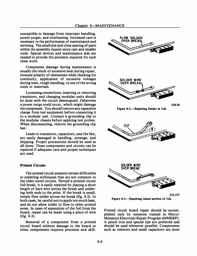
Chapter 8-MAINTENANCE
susceptible to damage from improper handling, power surges, and overheating. Increased care is necessary in the performance of maintenance and servicing. The small size and close spacing of parts within the assembly require more care and smaller tools. Special devices and maintenance aids are needed to provide the precision required for such close work.
Component damage during maintenance is usually the result of excessive heat during repair, reversed polarity of ohmmeters while checking for continuity, application of excessive voltages during tests, rough handling, or use of the wrong tools or materials.
Loosening connections, inserting or removing transistors, and changing modular units should be done with the circuit deenergized. Otherwise a power surge could occur, which might damage the component. You should remove any capacitive charge from test equipment before connecting it to a modular unit. Connect a grounding clip to the modular chassis before applying test probes. When disconnecting, remove the grounding clip last.
Leads to transistors, capacitors, and the like, are easily damaged in handling, stowage, and shipping. Proper precautions should be used at all times. These components and circuits can be repaired if adequate care and proper techniques are used.
Printed Circuits
The printed circuit presents certain difficulties in soldering techniques that are not common to the older wired circuits. Should a printed circuit foil break, it is easily repaired by placing a short length of bare wire across the break and solderM ing both ends to the print. If the break is small, simply flow solder across the break (fig. 8M2). In both cases, be careful not to apply too much heat, and do not allow solder to flow to other printed areas. In cases of separation of the foil from the board, repair can be made using a piece of wire (fig. 8-3).
Removal of a component from a printed circuit board without damage to the board or other components requires precision and skill.
8-9
228.18
Figure 8-2.-Repairlng breaks ia foU.
222.257
Figure 8-3.-Repairinl raised portJon of foU.
Printed circuit board repair should be accomplished only by someone trained in Micro/ Miniature Electronic Repair Program (MMERP). A pencil iron and special tips are preferred and should be used whenever possible. Components such as resistors and small capacitors are most
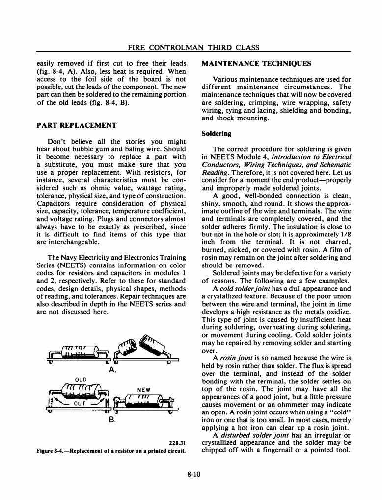
FIRE CONTROLMAN THIRD CLASS
easily removed if first cut to free their leads (fig. 8-4, A). Also, less heat is required. When access to the foil side of the board is not possible, cut the leads of the component. The new part can then be soldered to the remaining portion of the old leads (fig. 8-4, B).
PART REPLACEMENT
Don't believe all the stories you might hear about bubble gum and baling wire. Should it become necessary to replace a part with a substitute, you must make sure that you use a proper replacement. With resistors, for instance, several characteristics must be considered such as ohmic value, wattage rating, tolerance, physical size, and type of construction. Capacitors require consideration of physical size, capacity, tolerance, temperature coefficient, and voltage rating. Plugs and connectors almost always have to be exactly as prescribed, since it is difficult to find items of this type that are interchangeable.
The Navy Electricity and Electronics Training Series (NEETS) contains information on color codes for resistors and capacitors in modules 1 and 2, respectively. Refer to these for standard codes, design details, physical shapes, methods of reading, and tolerances. Repair techniques are also described in depth in the NEETS series and are not discussed here.
.�Uiiii: fh.2$n A.
OLD
_firr7rrr7L N E W
.Y��.��: �•�;ri�f �ret�·�. B.
228.31
Figure 8-4.-Replacement of a resistor on a printed circuit.
8-10
MAINTENANCE TECHNIQUES
Various maintenance techniques are used for different maintenance circumstances. The maintenance techniques that will now be covered are soldering, crimping, wire wrapping, safety wiring, tying and lacing, shielding and bonding, and shock mounting.
Soldering
The correct procedure for soldering is given in NEETS Module 4, Introduction to Electrical Conductors, Wiring Techniques, and Schematic Reading. Therefore, it is not covered here. Let us consider for a moment the end product-properly and improperly made soldered joints.
A good, well-bonded connection is clean, shiny, smooth, and round. It shows the approximate outline of the wire and terminals. The wire and terminals are completely covered, and the solder adheres firmly. The insulation is close to but not in the hole or slot; it is approximately 118 inch from the terminal. It is not charred, burned, nicked, or covered with rosin. A film of rosin may remain on the joint after soldering and should be removed.
Soldered joints may be defective for a variety of reasons. The following are a few examples.
A cold solder joint has a dull appearance and a crystaUized texture. Because of the poor union between the wire and terminal, the joint in time develops a high resistance as the metals oxidize. This type of joint is caused by insufficient heat during soldering, overheating during soldering, or movement during cooling. Cold solder joints may be repaired by removing solder and starting over.
A rosin joint is so named because the wire is held by rosin rather than solder. The flux is spread over the terminal, and instead of the solder bonding with the terminal, the solder settles on top of the rosin. The joint may have all the appearances of a good joint, but a little pressure causes movement or an ohmmeter may indicate an open. A rosin joint occurs when using a "cold" iron or one that is too small. In most cases, merely applying a hot iron can clear up a rosin joint.
A disturbed solder joint has an irregular or crystallized appearance and the solder may be chipped off with a fingernail or a pointed tool.
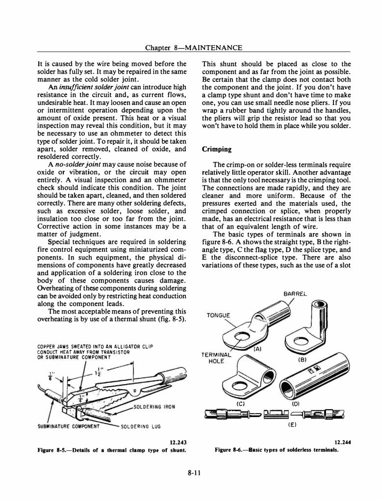
Chapter 8-MAINTENANCE
It is caused by the wire being moved before the solder has fully set. It may be repaired in the same manner as the cold solder joint.
An insufficient solder joint can introduce high resistance in the circuit and, as current flows, undesirable heat. It may loosen and cause an open or intermittent operation depending upon the amount of oxide present. This heat or a visual inspection may reveal this condition, but it may be necessary to use an ohmmeter to detect this type of solder joint. To repair it, it should be taken apart, solder removed, cleaned of oxide, and resoldered correctly.
A no-solder joint may cause noise because of oxide or vibration, or the circuit may open entirely. A visual inspection and an ohmmeter check should indicate this condition. The joint should be taken apart, cleaned, and then soldered correctly. There are many other soldering defects, such as excessive solder, loose solder, and insulation too close or too far from the joint. Corrective action in some instances may be a matter of judgment.
Special techniques are required in soldering fire control equipment using miniaturized components. In such equipment, the physical dimensions of components have greatly decreased and application of a soldering iron close to the body of these components causes damage. Overheating of these components during soldering can be avoided only by restricting heat conduction along the component leads.
The most acceptable means of preventing this overheating is by use of a thermal shunt (fig. 8-5).
COPPER JAWS SWEATED INTO AN ALLIGATOR CLIP CONDUCT HEAT AWAY FROM TRANSISTOR OR SUBMINATURE COMPONENT
1" 8
SOL DERING LUG
12.243
Figure 8-5.-Details of a thermal clamp type of shunt.
8-11
This shunt should be placed as close to the component and as far from the joint as possible. Be certain that the clamp does not contact both the component and the joint. If you don't have a clamp type shunt and don't have time to make one, you can use small needle nose pliers. If you wrap a rubber band tightly around the handles, the pliers will grip the resistor lead so that you won't have to hold them in place while you solder.
Crimping
The crimp-on or solder-less terminals require relatively little operator skill. Another advantage is that the only tool necessary is the crimping tool. The connections are made rapidly, and they are cleaner and more uniform. Because of the pressures exerted and the materials used, the crimped connection or splice, when properly made, has an electrical resistance that is less than that of an equivalent length of wire.
The basic types of terminals are shown in figure 8-6. A shows the straight type, B the rightangle type, C the flag type, D the splice type, and E the disconnect-splice type. There are also variations of these types, such as the use of a slot
BARREL
(C) (Dl
h,.. -!"'Q=tr-�- RC"lQ 9ljjlgfi¥ 6 (E)
12.244 Figure 8-6.-Basic types of solderless terminals.
FIRE CONTROLMAN THIRD CLASS
instead of a terminal hold, and three- and four-way splice types of connectors.
Various sizes of terminal or stud holes are found for each of the different wire sizes. A further refinement of the solderless terminal is the insulated terminal; the barrel of the terminal (fig. 8-6) is enclosed in an insulation material. The insulation is compressed along with the terminal barrel when crimping but is not damaged in the process. This eliminates the necessity of taping or tying an insulating sleeve over the joint.
The standard crimping tool (fig. 8-7) employs a double jaw to hold the terminal or splice. One side of the jaw applies crimping action to fasten the terminal to the bare wire when the terminal is inserted, as shown on the left in figure 8-7. When the tool is used correctly, a deep crimp is placed in the B area of terminal lugs and splices, as shown in the diagrams on the right in figure 8-7. A shallow crimp is applied to the portion of the terminal or splice which extends over the insulation of the wire, as indicated by the A area in each diagram. This clamping action is provided by a recessed portion in the other side of the divided jaw. A guard, which should be in the position shown when crimping terminals, aids in proper positioning of the terminal. Nevertheless, the guard must be moved out of the way when the tool is used for crimping splices.
Wire Wrapping
Basically, wire wrapping is simply winding a solid wire tightly around a stiff pin to provide a good junction. Equipment using the wire-wrap technique have long square pins at the rear of the female connectors used for logic card inserts. These pins are long enough to allow one, two, or even three wires to be wrapped on them individually in separate wraps. (A "wrap" is defined here as a series of turns of a single solid wire about a post.) The female connectors are then interconnected from pin to pin by small, solid, insulated wire. This insulated wire may or may not be color coded.
8·12
Machine-wrapped assemblies usually do not contain color coded wiring, while hand-wired assemblies do. (Color coded wire is an advantage in hand-wired assemblies, since each wire becomes more distinctive and fewer errors are likely to result.)
In addition, machine-wired assemblies are usually distinctive in their layouts. Wires do not always run point-to-point as usually occurs in hand-wired assemblies. The insulation used on some of the wiring has the undesirable trait of gradually flowing away from any point of continued pressure-a process described as "cold flow!' Insulated wire in contact with a pin may eventually result in an intennittent short occurring at that point. Other insulating material that is more resistive to cold flow but does not have the very high temperature characteristics has become more widely used because of the cold flow problem.
The 'principle behind wire wraps is a simple one. In order for proper conduction to occur between two metals, it is first necessary to penetrate the oxide coating that has formed on both surfaces. The pins used in the wire wraps are squared off, with corner edges that will penetrate the oxide coating of the wire when it is properly wound on the pin. The edges will also lose their oxide coating when they penetrate into the surface of the wire. The junction that is formed is strong, gas-tight (tight enough to seal out gases, in addition to liquids), and resistive to corrosion.
The technique in doing wire wraps is also fairly simple. First, a special solid conductor insulated wire is required. The wire is a composition of a silver alloy with a copper coating. Silver offers an advantage in that its oxide is almost as conductive as the pure metal. The use of solid conductor wire ensures that the coil will form tightly about the pin and remain that way without appreciable slippage.
A simple hand tool is required to coil the wire on the pin. A specific length of wire is first stripped of its insulation. The end of the wire is
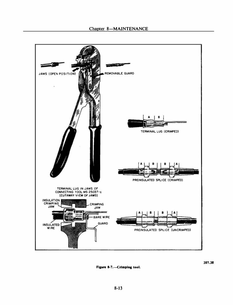
JAWS (OPEN POSITIO
Chapter 8-MAINTENANCE
• Q•pt REMOVABLE GUARD
a I �
TERMINAL LUG (CRIMPED)
TERMINAL LUG IN JAWS OF CONNECTING TOOL MS 25037-i
(CUTAWAY VIEW OF JAWS)
CRIMPING JAW
GUARD
PREINSULATED SPLICE (CRIMPED)
PREINSULATED SPLICE (UNCRIMF'EDI
Figure S..7.-Crlmpi11Jiool.
8-13
207.38
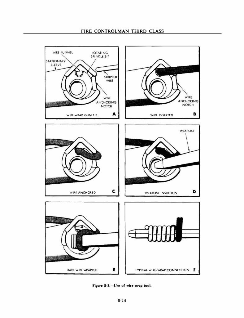
FIRE CONTROLMAN THIRD CLASS
WIRE fUNNEL ROTATING
SPINDLE BIT
WIRE
WIRE·WRAP GUN TIP
WIRE ANCHORED
A WIRE INSERTED
c WRAPOST INSERTION
B
D
BARE WIRE INRAPPED E TYPICAL WiRE-WRAP CONNECTION f
Flaure 8-8.-Use of wire-wrap lool.
8-14
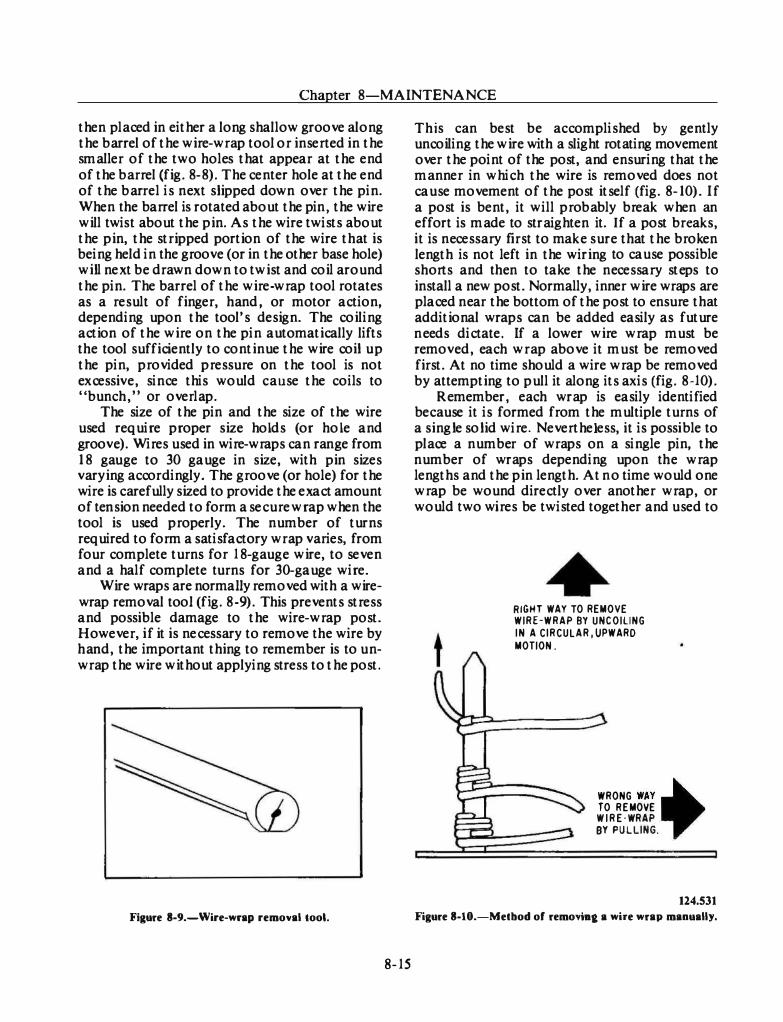
Chapter 8-MAINTENANCE
then placed in either a long shallow groove along the barrel of the wire-wrap tool or inserted in the smaller of the two holes that appear at the end of the barrel (fig. 8-8). The center hole at the end of the barrel is n ext slipped down over the pin. When the barrel is rotated about the pin, the wire will twist about the pin. As the wire twists about the pin, the stripped portion of the wire that is being held in the groove (or in the other base hole) will next be drawn down to twist and coil around the pin. The barrel of the wire-wrap tool rotates as a result of finger, hand, or motor action, depending upon the tool's design. The coiling action of the wire on the pin automatically lifts the tool sufficiently to continue the wire coil u p the pin, provided pressure on the tool is not excessive, since this would cause the coils to " bunch, " or overlap.
The size of the pin and the size of the wire used require proper size holds (or hole and groove). Wires used in wire-wraps can range from 1 8 gauge to 30 gauge in size, with pin sizes varying accordingly. The groove (or hole) for the wire is carefully sized to provide the exact amount of tension needed to form a secure wrap when the tool is used properly. The number of turns required to form a satisfactory wrap varies, from four complete turns for 1 8-gauge wire, to seven and a half complete turns for 30-gauge wire.
Wire wraps are normally removed with a wirewrap removal tool (fig. 8-9). This prevents stress and possible damage to the wire-wrap post. H owever, if it is necessary to remove the wire by h and, the important thing to remember is to unwrap the wire without applying stress to the post.
Figure 8-9.-Wire-wrap removal tool.
8-15
This can best be accomplished by gently uncoiling the wire with a slight rotating movement over the point of the post, and ensuring that the manner in which the wire is removed does not cause movement of the post itself (fig. 8-10). If a post is bent, it will probably break when an effort is made to straighten it. If a post breaks, it is n ecessary first to mak e sure that the broken length is not left in the wiring to cause possible shorts and then to take the n ecessary steps to install a new post. Normally, inner wire wraps are placed n ear the bottom of the post to ensure that additional wraps can be added easily as future n eeds dictate. If a lower wire wrap must be removed, each wrap above it must be removed first. At no time should a wire wrap be removed by attempting to pull it along its axis (fig. 8-10).
R emember, each wrap is easily identified because it is formed from the multiple turns of a single solid wire. Nevertheless, it is possi ble to place a number of wraps on a single pin, the number of wraps depending upon th e wrap lengths and the pin length. At n o time would one wrap be wound directly over another wrap, or would two wires be twisted together and used to
RIGHT WAY TO REMOVE WIRE-WRAP BY UNCOILING IN A CIRCULAR , UPWARD
MOTION .
WRONG WAY . TO REMOVE W I R E · WRAP BY PULLING.
.
124.531
Figure 8-10.-Metbod of removla& a wire wrap manually.
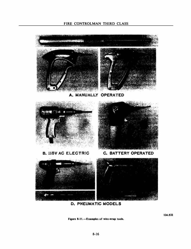
FIRE CONTROLMAN THIRD CLASS
S"' • e ,, • ,..,li � l " t•; -' � • ): .. ;;
-- �� •.f' · - · · �� ' ··f'' ' ' � � • • I -, • • "" -< �� ' ,,..
A. MANUALLY OPERATED
B. 116V AC El.ECTIRDC
� - .. -
� . .
C. BATTERY OPERATED
D. PNEUMATDC MODELS
Figure S.ll.-Examples of wire-wrap tools.
8- 16
1Z4.S31
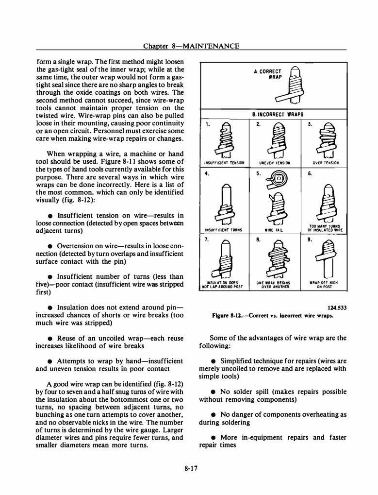
Chapter 8-MAINTENANCE
form a single wrap. The first method might loosen the gas-tight seal ofthe inner wrap; while at the same time, the outer wrap would not form a gas· tight seal since there are no sharp angles to break through the oxide coatings on both wires. The second method cannot succeed, since wire-wrap tools cannot maintain proper tension on the twisted wire. Wire-wrap pins can also be pulled loose in their mounting, causing poor continuity or an open circuit. Personnel must exercise some care when making wire-wrap repairs or changes.
When wrapping a wire, a machine or hand tool should be used. Figure 8- 1 1 shows some of the types of hand tools currently available for this purpose. There are several ways in which wire wraps can be done incorrectly. Here is a list of the most common, which can only be identified visually (fig. 8-12):
• Insufficient tension on wire-results in loose connection (detected by open spaces between adjacent turns)
• Overtension on wire-results in loose con· nection (detected by turn overlaps and insufficient surface contact with the pin)
• Insufficient number of turns (less than five)-poor contact (insufficient wire was stripped first)
e Insulation does not extend around pinincreased chances of shorts or wire breaks (too much wire was stripped)
• Reuse of an uncoiled wrap-each reuse increases likelihood of wire breaks
• Attempts to wrap by hand-insufficient and uneven tension results in poor contact
A good wire wrap can be identified (fig. 8-12) by four to seven and a half snug turns of wire with the insulation about the bottommost one or two turns, no spacing between adjacent turns, no bunching as one turn attempts to cover another, and no observable nicks in the wire. The number of turns is determined by the wire gauge. Larger diameter wires and pins require fewer turns, and smaller diameters mean more turns.
8-1 7
WRAP A. CORRE:j
B. INCORRECT WRAPS 1. J 2. ! 3. !
INSUFFICIEIH TEIISIOII UIIEYEII TENSION OYER TEIISIOII
4. 5. � 6.
p j � i TOO II ANY TURNS
INSUFFICIENT TURNS WIRE TAIL OF INSULATED WIRE
'·j 8.
~ .. f IIISULATIOII 00£5 OIIE WRAP 8[61NS WRAP SET IKH IIOT lAP AROUIID POST OVfR ANOTHER 011 POST
124.533
Flaure 8-ll.-Correc:t vs. Incorrect wire wraps.
Some of the advantages of wire wrap are the following:
• Simplified technique for repairs (wires are merely uncoiled to remove and are replaced with simple tools)
• No solder spill (makes repairs possible without removing components)
• No danger of components overheating as during soldering
• More in-equipment repairs and faster repair times
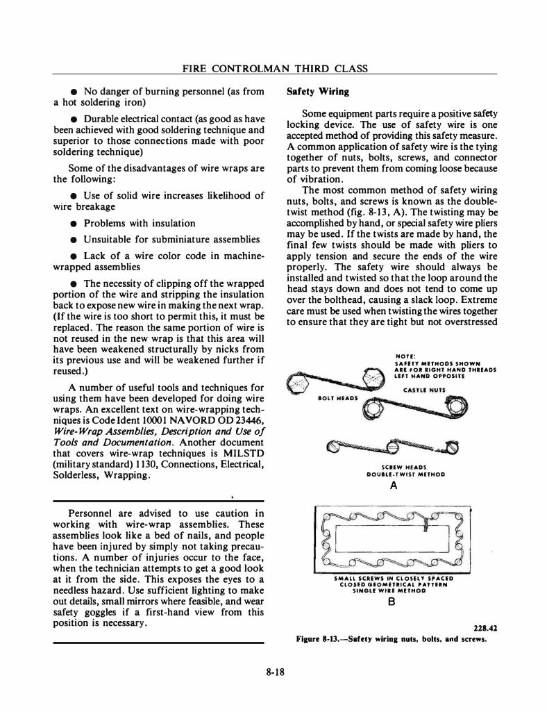
FIRE CONTROLMAN THIRD CLASS
• No danger of burning personnel (as from a hot soldering iron)
• Durable electrical contact (as good as have been achieved with good soldering technique and superior to those connections made with poor soldering technique)
Some of the disadvantages of wire wraps are the following:
• Use of solid wire increases likelihood of wire breakage
• Problems with insulation
• Unsuitable for subminiature assemblies
• Lack of a wire color code in machinewrapped assemblies
• The necessity of clipping off the wrapped portion of the wire and stripping the insulation back to expose new wire in making the next wrap. (If the wire is too short to permit this, it must be replaced. The reason the same portion of wire is not reused in the new wrap is that this area will have been weakened structurally by nicks from its previous use and will be weakened further if reused.)
A number of useful tools and techniques for using them have been developed for doing wire wraps. An excellent text on wire-wrapping techniques is Code Ident 1000 1 NA VORD OD 23446, Wire- Wrap Assemblies, Description and Use of Tools and Documentation. Another document that covers wire-wrap techniques is MILSTD (military standard) 1 1 30, Connections, Electrical, Solderless, Wrapping.
Personnel are advised to use caution in working with wire-wrap assemblies. These assemblies look like a bed of nails, and people have been injured by simply not taking precautions. A number of injuries occur to the face, when the technician attempts to get a good look at it from the side. This exposes the eyes to a needless hazard. Use sufficient lighting to make out details, small mirrors where feasible, and wear safety goggles if a first-hand view from this position is necessary.
8- 1 8
Safety Wiring
Some equipment parts require a positive safety locking device. The use of safety wire is one accepted method of providing this safety measure. A common application of safety wire is the tying together of nuts, bolts, screws, and connector parts to prevent them from coming loose because of vibration.
The most common method of safety wiring nuts, bolts, and screws is known as the doubletwist method (fig. 8-1 3 , A). The twisting may be accomplished by hand, or special safety wire pliers may be used. If the twists are made by hand, the final few twists should be made with pliers to apply tension and secure the ends of the wire properly. The safety wire should always be installed and twisted so that the loop around the head stays down and does not tend to come up over the bolthead, causing a slack loop. Extreme care must be used when twisting the wires together to ensure that they are tight but not overstressed
IOLT HIADS 0 NOH:
SAFETY MITHODS SHOWN All f O I liGHT HAND THUADS
LEfT HAND O"OSITt
SCIIW HEADS
DOUIU-TWIST MlTHOD
A
SMALL SCREWS IN CLOSELY SPACfD CLOUD GIOMfTIICAl PATTIIN
SINGU W i l l MfTHOD
B
228.41
Fiaure 8-13.-Safety wiriog nuts, bolts, and screws.
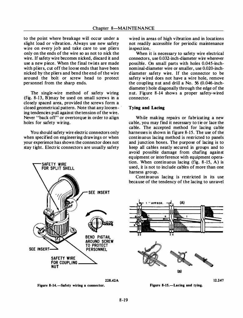
Chapter 8-MAINTENANCE
to the point where breakage will occur under a s light load or vibration. Always use new safety wire on every job and take care to use pliers only on the ends of the wire so as not to nick the wire. If safety wire becomes nicked, discard it and use a new piece. When the final twists are made with pliers, cut off the loose ends that have b een nicked by the pliers and bend the end of the wire around the bolt or screw head to protect personnel from the sharp ends.
The single-wire method of safety wmng (fig. 8-1 3 , B)may b e used on small s crews in a closely spaced area, provided the screws form a closed geometrical pattern. Note that any loosen- ·
ing tendencies pull against the tension of the wire. Never "back off" or overtorque in order to align holes for safety wiring.
You should safety wire electric connectors only when specified on engineering drawings or when your experience has shown the connector does not stay tight. Electric connectors are usually safety
SAFETY WIRE
SEE INSERT
BEND PIGTAIL AROUND SCREW TO PROTECT PERSONNEL
FOR COUPLING ---NUT
218.41A
Figure 8-14.-Safety wiring a connector.
8-19
wired in areas of high vibration and in locations not readily accessible for periodic maintenance inspection.
When i t is necessary to safety wire electrical connectors, use 0.032-inch-diameter wire wherever possible. On small parts with holes 0.045-inchnominal-diameter wire or smaller, use 0.020-inchdiameter safety wire. If the connector to be safety wired does not have a wire hole, remove the coupling nut and drill a No. 56 (0.046-inchdiameter) hole diagonally through the edge of the nut. Figure 8-14 shows a proper safety-wired connector.
Tying and Lacing
While making repairs or fabricating a new cable, you may find it necessary to tie or lace the cable. The accepted method for lacing cable harnesses is shown in figure 8- 15. The use of the continuous lacing method is restricted to panels and junction boxes. The purpose of lacing is to keep all cables neatly secured in groups and to avoid possible damage from chafing against equipment or interference with equipment operation. When continuous lacing (fig. 8-15, A) is used, it is not to include cables of more than one harness group.
Continuous lacing is restricted in its use because of the tendency of the lacing to unravel
(B)
12.147
Figure 8-15.-Lacing and tying.
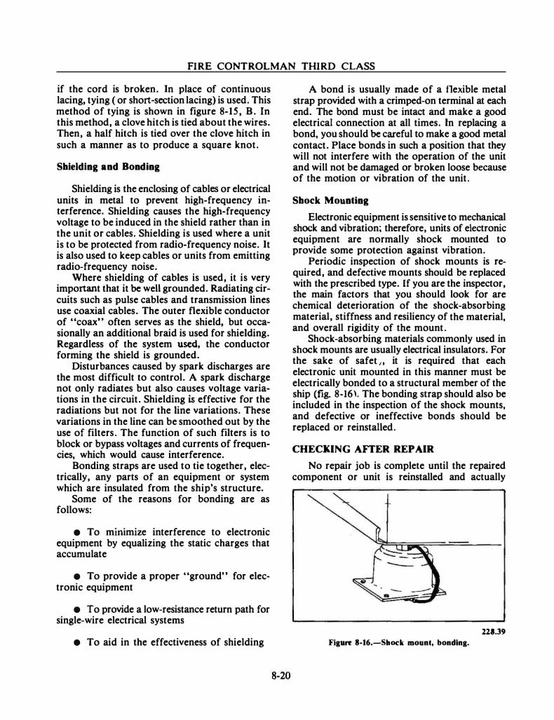
FIRE CONTROLMAN THIRD CLASS
if the cord is broken. In place of continuous lacing, tying ( or short-section lacing) is used. This method of tying is shown in figure 8-15, B. In this method, a clove hitch is tied about the wires. Then, a half hitch is tied over the clove hitch in such a manner as to produce a square knot.
Shielding and Bonding
Shielding is the enclosing of cables or electrical units in metal to prevent high-frequency interference. Shielding causes the high-frequency voltage to be induced in the shield rather than in the unit or cables. Shielding is used where a unit is to be protected from radio-frequency noise. It is also used to keep cables or units from emitting radio-frequency noise.
Where shielding of cables is used, it is very important that it be well grounded. Radiating circuits such as pulse cables and transmission lines use coaxial cables. The outer flexible conductor of "coax" often serves as the shield, but occasionally an additional braid is used for shielding. Regardless of the system used, the conductor forming the shield is grounded.
Disturbances caused by spark discharges are the most difficult to control. A spark discharge not only radiates but also causes voltage variations in the circuit. Shielding is effective for the radiations but not for the line variations. These variations in the line can be smoothed out by the use of filters. The function of such filters is to block or bypass voltages and currents of frequencies, which would cause interference.
Bonding straps are used to tie together, electrically, any parts of an equipment or system which are insulated from the ship's structure.
Some of the reasons for bonding are as follows:
• To mmamaze interference to electronic equipment by equalizing the static charges that accumulate
• To provide a proper "ground" for electronic equipment
• To provide a low-resistance return path for single-wire electrical systems
• To aid in the effectiveness of shielding
A bond is usually made of a flexible metal strap provided with a crimped-on terminal at each end. The bond must be intact and make a good electrical connection at all times. In replacing a bond, you should be careful to make a good metal contact. Place bonds in such a position that they will not interfere with the operation of the unit and will not be damaged or broken loose because of the motion or vibration of the unit.
Shock Mounting
Electronic equipment is sensitive to mechanical shock and vibration; therefore, units of electronic equipment are normally shock mounted to provide some protection against vibration.
Periodic inspection of shock mounts is required, and defective mounts should be replaced with the prescribed type. If you are the inspector, the main factors that you should look for are chemical deterioration of the shock-absorbing material, stiffness and resiliency of the material, and overall rigidity of the mount.
Shock-absorbing materials commonly used in shock mounts are usually electrical insulators. For the sake of safet,, it is required that each electronic unit mounted in this manner must be electrically bonded to a structural member of the ship (fig. 8-16). The bonding strap should also be included in the inspection of the shock mounts, and defective or ineffective bonds should be replaced or reinstalled.
CHECKING AnER REPAIR
No repair job is complete until the repaired component or unit is reinstalled and actually
221.39 Figure 8-16.-Shock mount, bonding.
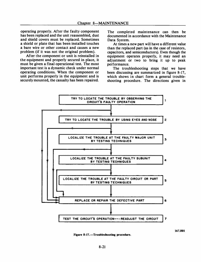
Chapter 8-MAINTENANCE
operating properly. After the faulty component has been replaced and the unit reassembled, dust and shield covers must be replaced. Sometimes a shield or plate that has been installed touches a bare wire or other contact and causes a new problem (if it was not the original problem).
After the component or unit is reinstalled in the equipment and properly secured in place, it must be given a final operational test. The most important test is a dynamic check under normal operating conditions. When the component or unit performs properly in the equipment and is securely mounted, the casualty has been repaired.
The completed maintenance can then be documented in accordance with the Maintenance Data System.
At times a new part will have a different value than the replaced part (as in the case of resistors, capacitors, and semiconductors). Even though the equipment operates properly, it may need an adjustment or two to bring it up to peak performance.
The troubleshooting steps that we have been discussing are summarized in figure 8-17, which shows in chart form a general troubleshooting procedure. The directions given in
I TRY TO LOCATE THE TROUBLE BY OBSERVING THE CIRCUIT'S FAULTY OPERATION
r TRY TO LOCATE THE TROUBLE BY USING EYES AND NOSE 2
r LOCALIZE THE TROUBLE AT THE FAULTY MAJOR UNIT BY TESTING TECHNIQUES
3
� LOCALIZE THE TROUBLE AT THE FAULTY SUBUNIT BY TESTING TECHNIQUES 4
I LOCALIZE THE TROUBLE AT THE FAULTY CIRCUIT OR PART
BY TESTING TECHNIQUES
� -r REPLACE OR REPAIR THE DEFECTIVE PART 6
r TEST THE CIRCUIT'S OPERATION--- READJUST THE CIRCUIT 7
167.801
Figure 8-17.-Troubleshooting procedure.
8-21
FIRE CONTROLMAN THIRD CLASS
blocks I through 5 are steps to be used in locati ng the trouble, and the directions given in blocks 6 and 7 are steps in repairing the equipment. (Steps 2, 3, 4, and/or 5 may sometimes be eliminated, but steps 6 and 7 should always be followed.)
GENERAL MAINTENANCE
At the beginning of this chapter, we noted that you must develop skills and knowledge of a general nature to perform your maintenance tasks. Lubrication, for example, is not explained in detai l in your system and equipment OPs, but there are many details with which you should be familiar to perform the task properly. Similarly there are other maintenance actions you will have to accomplish. Therefore, let us discuss some of these general mai ntenance tasks.
VISUAL INSPECTIONS
You should inspect equipment visually for loose leads, bad connections, damaged or broken components, and the like, before you apply power to the equipment. This applies mainly to equipment that is new, has returned from overhaul, has been stored for long periods of time, or has been exposed to the weather. You should also conduct a close visual inspection of 0-rings, gaskets, and other types of seals when the equipment under check is a pressurized component or is exposed to weather. This visual inspection often reveals defects that may be corrected at that time with a minimum amount of labor and parts. Such defects, if left uncorrected, might r esult in maj or maintenance problems.
A brief visual inspection should be performed following preventive and corrective maintenance. This might reveal forgotten tools, wires left unconnected after testing, open cover assemblies, and the like.
CLEANING
Cleaning the equipment consists of removing dust, grease, and other foreign matter from the covers, chassis, and operating pa rts. This includes the removal of corrosion, fungus, and all other types of matter which could cause failure of the
8-22
equipment. The methods used to clean the parts and units vary, but usually you can use a vacuum cleaner to remove the loose dust and foreign matter. Any remaining matter is then wiped or removed with a clean lint-free cloth. If it is necessary to remove grease or other oily deposits, the cloth may be moistened with a solvent. At times a specific cleaner or solvent may be recommended or a specific one may not be allowed because of its effect on the equipment. After removing the grease, you should either wipe the part or allow it to dry before you apply power.
LUBRICATION
The mechanical parts of electronic equipment are lubricated. Some equipment, such as unsealed bearings, antenna drives, rotating waveguide joints, and the like, may need periodic lubrication. You should lubricate this equipment as directed by the equipment's MRCs.
The specification number of a lubricant should be strictly followed. This is because the thickness of a lubricant changes with a change in operating temperature. That is, high operating temperatures cause lubricants to become thin, while low operating temperatures cause lubricants to thicken.
Detailed procedures for cleaning and lubricating as well as which solvents or lubricants are to be used are provided on MRCs for most applications. Cross-reference guides for solvents and lubricants are available for determining acceptable substitutes. Besides these, no others should be used.
CLEANING AND LUBRICATING ELECTROMECHANICAL COMPONENTS
Many devices used in fire control equipment are highly machined and are close tolerance mechanisms. The accuracy of the fire control system is often dependent upon the operation of these devices. Dirt, dust, or other foreign particles may cause the system to operate with some error. Moisture may cause corrosion which may also result in errors. Excessive wear can cause errors and shorten the life of the equipment. Thus, it can easily be seen that cleaning, lubricating, and drying of close tolerance parts is necessary to have accurate, effective equipment.
Chapter 8-MAINTENANCE
Most equipment is enclosed in a dustproof housing. If you use reasonable precautions, the dust problem in this equipment is small. Before you remove a cover, be sure the surrounding area is clean and that all likely sources of dust have been removed. A major source of dust is the ventilation system. When working on precision equipment that is susceptible to dirt and dust, the ventilation system should be secured. If you cannot secure it, cover the blower duct openings with cheesecloth or gauze.
If a unit is removed from its housing and taken to a shop or other working area, adequate provisions must be made to keep the mechanisms clean and dry. Before the unit is disassembled, all dirt, dust, grease, and other foreign matter must be removed from its outside surface. The working surfaces of the unit and the components to be worked on must be as clean and dry as circumstances permit. Whenever the unit · is disassembled, all components must be kept under lint-free dust covers (cloths) to protect them from foreign matter.
Even when the precautions just mentioned are taken, some dirt and other foreign matter may get into the equipment. Also, there may be a need to remove excess or old oil and grease. The usual way to remove unwanted oil or grease is with a solvent. Be careful; the correct solvent MUST be used, since some solvents may leave an unwanted residue or cause corrosion. Be sure to check the MRC for the right solvent to use.
Spraying or splashing the solvent must be avoided during cleaning. If the solvent were to fall upon a bearing surface, it would cut the lubricant or render it less effective. This could cause excessive wear. After the solvent has been used, the parts must always be wiped dry with a clean lint-free cloth.
Lubricants are used to reduce friction between moving parts. Occasionally, lubricants are used for the purpose of preventing rust, oxidation, and corrosion. The applicable MRC includes the lubrication instructions for a specific piece of equipment. However, no lubrication procedure is effective unless it is performed regularly. Different components must be lubricated at different intervals. The approved frequency of lubrication for each component is provided by PMS and must be observed.
Do not apply too much lubricant to your . equipment. Excess lubricant acts as an insulation and prevents the dissipation of heat. Overfilling or overheating may cause overflow into adjacent electrical equipment. Lubricants can break down electrical insulation.
8-23
Cleanliness is vital in lubrication. Dirt in a lubricant makes a damaging abrasive material. Plastic protective caps are provided for some types of grease fittings. Lubrication points must be cleaned prior to lubrication. If a cleaning solvent is used, the surface to which it is applied must be wiped dry before lubricant is applied.
ROTATING MACHINERY MAINTENANCE
Rotating machinery (motors, generators, and the like) should be inspected and cleaned according to maintenance schedules and whenever repairs to the machinery have been made. For cleaning and inspection, the following maintenance hints are provided:
• Remove dust and dirt from machine and end covers, using clean, dry, compressed air or a soft brush.
• Be careful not to nick or mar the edges of brushes during removal. Note the location and position from which each is removed so that it can be replaced in exactly the same manner.
• Check commutators or sliprings for excessive wear, pitting, dirt, thrown solder, or other defects. A highly polished commutator or slipring is desirable, but a dark-colored one should not be mistaken for a burned one. Avoid leaving finger marks on the commutator or slipring surface when cleaning.
SUprings
Sliprings are solid metal rings mounted on the rotor of alternating-current machines. They transfer the power to or from external circuits through brushes or wipers. Sliprings are also used on synchros, director connections, and stable element connections.
While they vary in size and type, the maintenance of sliprings is fairly uniform.
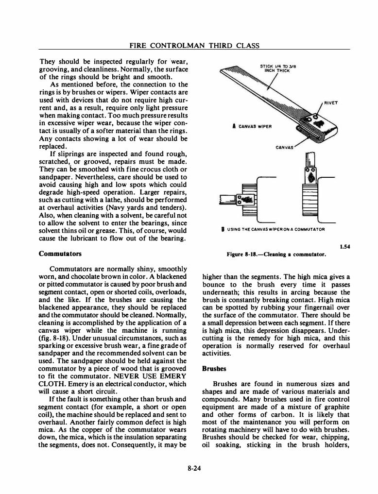
FIRE CONTROLMAN THIRD CLASS
They should be inspected regularly for ·wear, grooving, and cleanliness. Normally, the surface of the rings should be bright and smooth.
As mentioned before, the connection to the rings is by brushes or wipers. Wiper contacts are used with devices that do not require high current and, as a result, require only light pressure when making contact. Too much pressure results in excessive wiper wear, because the wiper contact is usually of a softer material than the rings. Any contacts showing a lot of wear should be replaced.
If sliprings are inspected and found rough, scratched, or grooved, repairs must be made. They can be smoothed wi.th fine crocus cloth or sandpaper. Nevertheless, care should be used to avoid causing high and low spots which could degrade high-speed operation. Larger repairs, such as cutting with a lathe, should be performed at overhaul activities (Navy yards and tenders). Also, when cleaning with a solvent, be careful not to allow the solvent to enter the bearings, since solvent thins oil or grease. This, of course, would cause the lubricant to flow out of the bearing.
Commutators
Commutators are normally shiny, smoothly worn, and chocolate brown in color. A blackened or pitted commutator is caused by poor brush and segment contact, open or shorted coils, overloads, and the like. If the brushes are causing the blackened appearance, they should be replaced and the commutator should be cleaned. NoRDally, cleaning is accomplished by the application of a canvas wiper while the machine is running (fig. 8-18). Under unusual circumstances, such as sparking or excessive brush wear, a fine grade of sandpaper and the recommended solvent can be used. The sandpaper should be held against the commutator by a piece of wood that is grooved to fit the commutator. NEVER USE EMERY CLOTH. Emery is an electrical conductor, which will cause a short circuit.
If the fault is something other than brush and segment contact (for example, a short or open coil), the machine should be replaced and sent to overhaul. Another fairly common defect is high mica. As the copper of the commutator wears down, the mica, which is the insulation separating the segments, does not. Consequently, it may be
8-24
A CANVAS WIPER
8 USING THE CANVAS WIPER ON A COMMUTATOR
1.54
Figure 8-18.-Cieaning a commutator.
higher than the segments. The high mica gives a bounce to the brush every time it passes underneath; this results in arcing because the brush is constantly breaking contact. High mica can be spotted by rubbing your fingernail over the surface of the commutator. There should be a small depression between each segment. If there is high mica, this depression disappears. Undercutting is the remedy for high mica, and this operation is normally reserved for overhaul activities.
Brusbes
Brushes are found in numerous sizes and shapes and are made of various materials and compounds. Many brushes used in fire control equipment are made of a mixture of graphite and other forms of carbon. It is likely that most of the maintenance you will perform on rotating machinery will have to do with brushes. Brushes should be checked for wear, chipping, oil soaking, sticking in the brush holders,
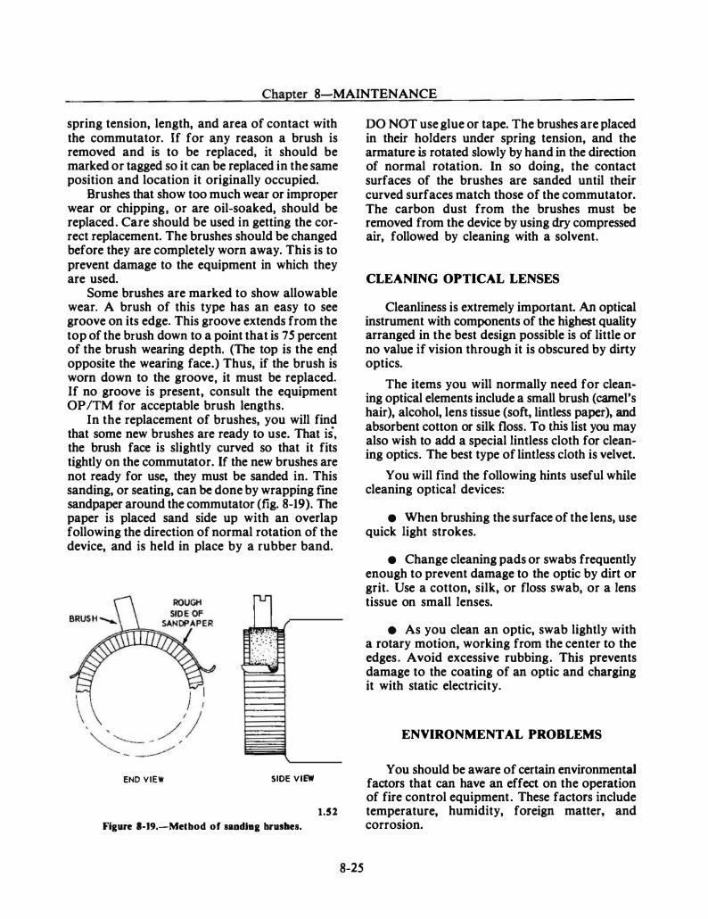
Chapter 8-MAINTENANCE
spring tension, length, and area of contact with the commutator. If for any reason a brush is removed and is to be replaced, it should be marked or tagged so it can be replaced in the same position and location it originally occupied.
Brushes that show too much wear or improper wear or chipping, or are oil-soaked, should be replaced. Care should be used in getting the correct replacement. The brushes should be changed before they are completely worn away. This is to prevent damage to the equipment in which they are used.
Some brushes are marked to show allowable wear. A brush of this type has an easy to see groove on its edge. This groove extends from the top of the brush down to a point that is 75 percent of the brush wearing depth. (The top is the en� opposite the wearing face.) Thus, if the brush is worn down to the groove, it must be replaced. If no groove is present, consult the equipment OP /TM for acceptable brush lengths.
In the replacement of brushes, you will find that some new brushes are ready to use. That is, the brush face is slightly curved so that it fits tightly on the commutator. If the new brushes are not ready for use, they must be sanded in. This sanding, or seating, can be done by wrapping fine sandpaper around the commutator (fig. 8-19). The paper is placed sand side up with an overlap following the direction of normal rotation of the device, and is held in place by a rubber band.
::t?r::.� �
END VIEW SIDE VIEW
1.52
Figure 1-19.-Metbod of saadlaa brushes.
8-25
DO NOT use glue or tape. The brushes are placed in their holders under spring tension, and the armature is rotated slowly by hand in the direction of normal rotation. In so doing, the contact surfaces of the brushes are sanded until their curved surfaces match those of the commutator. The carbon dust from the brushes must be removed from the device by using dry compressed air, followed by cleaning with a solvent.
CLEANING OPTICAL LENSES
Cleanliness is extremely important. An optical instrument with components of the highest quality arranged in the best design possible is of little or no value if vision through it is obscured by dirty optics.
The items you will normally need for cleaning optical elements include a small brush (camel's hair), alcohol, lens tissue (soft, lintless paper), and absorbent cotton or silk floss. To this list you may also wish to add a special lintless cloth for cleaning optics. The best type of lintless cloth is velvet.
You will find the following hints useful while cleaning optical devices:
• When brushing the surface of the lens, use quick light strokes.
• Change cleaning pads or swabs frequently enough to prevent damage to the optic by dirt or grit. Use a cotton, silk, or floss swab, or a lens tissue on small lenses.
e As you clean an optic, swab lightly with a rotary motion, working from the center to the edges. Avoid excessive rubbing. This prevents damage to the coating of an optic and charging it with static electricity.
ENVIRONMENTAL PROBLEMS
You should be aware of certain environmental factors that can have an effect on the operation of fire control equipment. These factors include temperature, humidity, foreign matter, and corrosion.
FIRE CONTROLMAN THIRD CLASS
TEMPERATURE
Extremely low temperatures may cause brittleness in certain types of metals, and loss of flexibility to rubber, insulation, and like materials. Extremely high temperatures may cause terminal boards, seals, insulation, and heat-sensitive devices to warp and become brittle. Rapid changes of temperature may be especially damaging to certain types of electronic components.
The cooling or heating of air spaces surrounding the components of electronic equipment is generally accomplished and controlled by blowers, fans, hot oil, water coolers, and the like. These methods are used to dissipate the heat generated by the equipment components or to control the temperature of the surrounding air. It does not matter what method is employed for the cooling or heating of spaces. If personnel neglect to keep the screens, filters, fans, ducts, and surface area of cooling and heating equipment free from foreign matter, the heating or cooling will be greatly affected. This may result in equipment damage, which you may have to correct.
HUMIDITY
Humidity, the measure of water content in the air, is a possible cause of equipment or component failure. High humidity (that is, a high water content in the air) provides a possible environment for corrosion and fungus growth. A high moisture content in the air also may cause a short circuit (arc) between points of high potential.
Arcing is likely to occur in waveguides. The waveguide and the components connected to it are pressurized with air to reduce the possibility of arcing. This air may be dried by passing it through silica-gel crystals or by the ship's dry-air system, as discussed in chapter 6 of this manual.
In certain cases, the removal of heat from equipment requires the use of external air. If this external air has a high moisture content, the cooling may be accomplished in one of two ways. The high humidity air may be directed through an air jacket which surrounds the equipment. In this case, the heat is removed without allowing the humid air to come in contact with the internal equipment components. In the second method, if the equipment requires direct air for heat removal, the direct air is passed through silica-gel
crystals, which absorb the moisture. Note that the second method is less troublesome, because the flrst may still cause corrosion within the air jacket.
Pressurization is usually not a big maintenance problem, but its loss may cause trouble. The troubles that do arise in the pressurized system are usually the result of poor preventive maintenance. All seals and gaskets (located at coupling points, waveguide joints, and case covers) must be very carefully installed to provide an airtight seal and a trouble-free pressurized system. When pressure troubles do occur, they may be hard to detect, since a small leak is all it takes to render the system inoperable. Before attempting to put the system under pressure to check for leaks, flrst consult the applicable equipment OP /TM. This is necessary, since each system has certain limits on the amount of pressure that may be safely applied to it. If too much pressure is applied, it could possibly rupture the seals or gaskets, or cause other damage to parts of the equipment.
FOREIGN MA TIER
Sand, dust, and other foreign substances which are abrasive in nature affect many components. Generally, these components are parts that are not sealed off from atmospheric conditions. In some equipment, however, the abrasive material is formed even though the unit is sealed. This is true in generators and motors that use brushes. Also, the protective coating on equipment may be removed by the movement of abrasive material in the air that is used for cooling and/or heating. Removal of this coating may allow the exposed metal to corrode.
The use of air conditioning systems with modern equipment minimizes the undesired effects of abrasives, as well as of temperature and humidity. The outside air is only used to cool a heat exchanger. The internal air that removes heat from the equipment then stays relatively clean.
CORROSION
The need for corrosion control has become a major concern in the maintenance of fire control systems. This is because corrosion, which destroys equipment, is active 24 hours a day.
Chapter 8-MAINTENANCE
Moisture Prevention
!he battle a�ainst moisture is never-ending. Moisture creeps mto even the smallest openings. Watertight covers must be kept watertight. When you remove a cover, check the condition of the gasket, the knife edge, and the securing bolts or dogs. Where possible, when checking an electrical circuit , pick a test point in a connection box that is located in a protected space. When moisture is discovered in an energized instrument or connection box, dry it out with a hot-air blower or an electric lamp after turning off the equipment.
A certain degree of protection against the accumulation of moisture is obtained by energizing the equipment daily. Changes in temperature cause air to be breathed through any opening or vent in the equipment. As the air cools, con'densation or sweating takes place. Electrical heaters are installed in some equipment to eliminate this source of moisture. The heater keeps the interior of the equipment at a temperature higher than that of the surrounding air. In some equipment, the circuit to the heater bypasses the power switch, and VOLT AGE MAY BE PRESENT EVEN THOUGH THE POWER SWITCH IS OFF. Remember this when working around the heater circuit.
Some equipment may use an air dryer or desiccant unit to remove moisture from the components. The equipment is sealed by dust covers and is airtight except for the connection to the air dryer. The air dryer consists of a unit that contains silica-gel crystals to absorb moisture from the air within the equipment.
Salt and Fungus Treatment
Salt and fungus found in your equipment should be removed at once. Salt, when moisture is present, corrodes metals and conducts electricity. Fungus growth causes decay, rapid breakdown of insulating materials, and shorts or grounds in electrical circuits. In some cases, you can use fresh water to remove the salt. After cleaning the equipment, however, make sure the water has completely evaporated. An approved cleaning solvent may be used to clean away salt or fungus. Pay particular attention to the listed procedures to be followed for the solvent's use. PMS cards and technical manuals will list the proper cleaning agent to be used.
8-27
GENERAL PURPOSE TEST EQUIPMENT
This topic covers some of the general purpose electrical and electronic test equipment and their use in the maintenance of fire control equipment. The theory of general purpose test equipment is covered in the NEETS Module 16, Introduction to Test Equipment. Therefore, this chapter concentrates on the operation of test equipment and the techniques of their use. You will fmd that there are various instruments that perform the same functions; so, a representative instrument has been selected for each type of general purpose test equipment discussed here.
MULTIMETER
The multimeter (fig. 8-20) is designed to permit the measurement of voltage, resistance, and current with a completely self-contained portable instrument. It can measure either ac or de voltage, de resistance, or direct current in a wide range of values. This capability covers the basic requirements for a portable tester of this type. All leads and accessories are stored in an accessory compartment built into the cover, which should remain with the instrument at all times. The cover forms a watertight seal when clamped over the face of the meter. While the instrument is in use, the cover clamps over the back of the meter keeping the accessory compartment convenient to the operator. Batteries are used with the multimeter, which make it extremely portable, especially in hard to get at places aboard ship.
The accessory compartment contains a pair of standard test leads (one red and one black), which are used for most applications of the instrument. These leads have elbow probes on one end to connect the lead into the circuit jacks on the instrume�t. They have probe tips on the other end, wh1ch have threaded shoulders to accept the alligator clips that are screwed on. The parts are used to make all measurements, except de voltages over 1 ,000 volts.
For measuring de voltages over 1 ,000 volts, a special high-voltage probe is provided and is used in conjunction with the standard black lead. One end of the lead has a threaded tip that screws on a post in the face of the meter (labeled 5,000 VDC MULTIPLIER). The other end of the lead
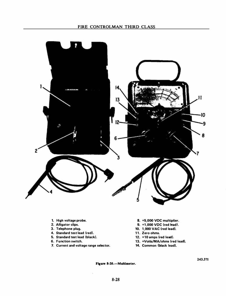
FIRE CONTROLMAN THIRD CLASS
1. High voltage probe. 8. +5,000 VDC multiplier. 2. Alligator clips. 9. +1 ,000 VDC (red lead I . 3. Telephone plug. 10. 1 ,000 VAC (red lead). 4. Standard test lead (red}. 1 1 . Zero ohms. 5. Standard test lead (black). 12. +10 amps (red lead). 6. Function switch. 13. +Volts/MA/ohms (red lead). 7. Current and voltage range selector. 14. Common (black lead).
143.371 Fi1ure 8-20.-Muldmeter.
8-28
Chapter 8-MAINTENANCE
has a high-voltage multiplier assembly made of red plastic with a clear plastic end and terminates in an alligator clip at the end of a short piece of flexible wire. The clear plastic end allows the operator to observe the glow of a neon lamp when there is high voltage present. There is a warning to the operator that there is high voltage present at the clip and that it should not be touched. The neon lamp is in series with a 100-megohm resistor within the housing. When a high voltage is being measured, the current passes through the lamp making it glow, through the resistor, and through the armature of the meter.
There are three controls on the face of the meter. One is a 10-position rotary switch in the lower left-hand comer which is used as a function switch. Five of the positions on this switch are used to set up different resistance scales. Two of the positions are for selection of de voltage measurement (direct and reverse). The normal position of the switch is in the DIRECT position. If a negative voltage is to be measured, the switch is moved to the REVERSE position. (NOTE: Never switch leads to read a reverse or negative voltage.) One position of the switch is marked ACV; in this position the meter may be used to read ac voltage. A rectifier in the instrument changes the ac voltage to an equivalent de value which is applied to the meter. One position is marked OUTPUT; in this position the ac portion of mixed ac and de voltage may be read. The last position of the switch is used when measuring direct current and is marked DC with three ranges (A, MA, AMPS) indicated to the right of the letters DC. In the lower right-hand corner is an eight-position switch used to select current and voltage ranges.
Near the center of the meter is a control marked ZERO OHMS. This control, which is a continuously variable adjustment, is used to zero the meter, thus compensating for battery aging in the ohmmeter circuits. This control is adjusted until the meter indicates full-scale deflection (indicating zero ohms) when the function switch is set at one of the resistance range positions and the meter probes are shorted together. To prevent erroneous readings when switching to a different position, you should check the meter zero indication.
8-29
The multimeter is designed to make the following electrical measurements:
• Measure direct current up to 10 amperes
• Measure resistances up to 300 megohms
• Measure de voltages up to .5,000 volts
• Measure ac voltages up to 1 ,000 volts
• Measure output voltages up to .500 volts
Input impedance for measuring de voltages is 20,000 ohms per volt and is accurate to within 3 percent of full scale (4 percent for the .5,000 Vdc scale). When measuring ac voltages, the input impedance is 1 ,000 ohms per volt and is accurate to within .S percent of full scale.
VACUUM TUBE VOLTMETER (VTVM)
The vtvm (many versions now use solid-state circuitry) is a portable, combination electronic instrument used for general servicing of electronic equipment. It is designed for use where precise voltage, current, and resistance measurements are required.
The vtvm is used primarily for the same purpose as the multimeter. Some characteristics of its operation, however, give it definite advantages over the multimeter. In the vtvm, the current and resistance measuring circuits function in a manner similar to the multimeter. The measurement of voltage, however, involves the use of an amplifier, which greatly increases the input impedance of the meter and reduces the loading effect on the circuit under test. (Less loading permits more accurate meter readings.)
Another advantage of the vtvm is its ability to accurately measure voltages at higher frequencies. Voltages at frequencies up to 50 megahertz, and sometimes even higher, can be measured accurately with this type of meter. A multirnetcr is accurate only in the audio-frequency range. This is because of the shunting effect across the meter's rectifier. caused by a relatively large capacitance at higher frequencies. In the vtvm, the ac is not rectified in the meter's circuit but in a special test probe.
FIRE CONTROLMAN THIRD CLASS
When ac voltages are measured, the signal is first rectified by a diode in the ac test probe. The signal must be rectified because the meter circuit is sensitive only to de voltages. When de voltages are measured, the ac probe containing the diode rectifier is not needed. Some probes may contain a switch to select either ac or de use.
The voltage to be measured is applied across a voltage divider network so that the total input impedance of the vtvm remains constant when the position of the range switch is changed for various levels of input voltage.
The meter is connected across a balanced bridge network. With no input, the bridge circuit is balanced and the meter reads zero. When the bridge is unbalanced by an input voltage, the meter pointer is deflected up-scale. The range switch is used to connect the necessary resistance into the circuit for each range. The resistance across the voltage divider networks reduces the input signal to a level suitable for application to the bridge. There are three voltage divider networks, one for each function, volts, ohms, and milliamperes.
The ohmmeter section also uses the bridge circuit. When an unknown resistance is measured, a bias voltage to the amplifier decreases in proportion to the unknown resistance. The value of the unknown resistance determines the degree to which the bridge is unbalanced and hence the magnitude of the meter pointer deflection. No battery supply is normally required for the vtvm ohmmeter circuitry.
The milliammeter function does not make use of the bridge circuit. The range switch connects various shunts across the meter to increase the range of current measurement.
ACIDC DIFFERENTIAL VOLTMETER
The ac/dc differential voltmeter is capable of being used as a conventional vtvm or as a precision potentiometer. It can also be used to measure the excursions of a voltage about some nominal value. One feature of a differential voltmeter is that no current is drawn from the unknown source for de measurements when balance is attained. Thus, the determination of the unknown de potential is independent of its source resistance.
8-30
An unknown voltage is measured in this type of voltmeter by comparing the unknown voltage to a known adjustable reference voltage with the aid of a built-in null detector. An accurate standard for measurement is obtained by setting the reference power supply with a standard battery cell or zener reference diode. The known adjustable reference voltage is provided by a highvoltage de power supply and decade resistor strings that are set accurately by voltage readout dials. In this way, the output from the highvoltage power supply can be precisely divided into increments as small as 10 microvolts. The unknown voltage is then simply read from the voltage dials. When used as an ac differential voltmeter, the ac input voltage is converted to a de voltage and measured in the same manner as an unknown de voltage.
One example of an ac/ de differential voltmeter which is commonly used is shown in figure 8-2 1 . This instrument is a solid-state differential voltmeter which provides nonloading de voltage measurements of ± 10 microvolts to ± 1 , 100 volts. With this instrument, ac voltages of 0.001 to 1 , 100 volts may be measured over a frequency range of S hertz to 100 kilohertz. It has four voltage readout dials which vary the resistance of the divider assembly as previously described.
MEGGERS
A Megger is an instrument that applies a high voltage to the component under test and measures the current leakage of the insulation. Thus, a capacitor or insulated cable can be checked for leakage under much higher voltages than an ohmmeter is capable of supplying. A Megger consists of a hand-driven, de generator and an indicating meter. The name Megger is derived from the fact that it measures resistances of many megohms.
The Megger illustrated in figure 8-22 is designed to measure insulation resistance from 0 to 1 ,000 megohms. The testing voltage is 500 volts de.
The meter pointer should read infinite resistance when there are no external connections to the output binding posts, L and GND. lf the pointer does not stand over the infinity mark, it is necessary to adjust the meter adjustment screw
Chapter 8-MAINTENANCE
1.411
Flaure 8-11.-An ac/dc differential voltmeter.
until the pointer does stand over the infinity mark. When the meter terminals are short-circuited and the crank is turned at normal operating speed (indicator buttons glowing steadily), the meter pointer should be over the zero mark.
The operation of the insulation test set is relatively simple:
1 . Be sure that the apparatus, line, or circuit to b� tested is disconnected from its power supply in accordance with safety instructions. Ground the apparatus, line, or circuit to be tested to discharge any capacitors connected to it.
2. Connect the spade terminal lug of the black lead to the GND binding post of the test set.
3 . Attach the alligator clip of the black test lead to the side of the circuit (under test) nearest ground potential.
8-31
4. Connect the spade terminal lug of the red lead to the L binding post of the test set.
S. Attach the alligator clip of the red test lead to the conductor to be tested.
6 . Turn the crank in either direction at the minimum speed required to provide steady illumination of the indicator buttons.
7. Read the megohms of resistance offered by the material being tested. If the resistance is more than J ,000 megohms at 500 volts de, the meter will remain at rest over the infinity mark (oo), indicating that the resistance of the insulation being tested is beyond the range of the meter. (Meggers should not be used on some equipment; when in doubt, check the equipment OP.)
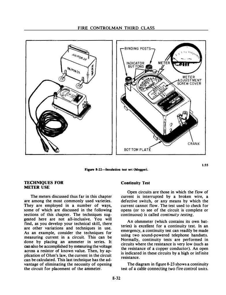
FIRE CONTROLMAN THIRD CLASS
BOT TOM PLATE
1.55
Fiture 8-21-luulatiou tnt set (Meger).
TECHNIQUES FOR METER USE
The meters discussed thus far in this chapter are among the most commonly used varieties. They are employed in a number of ways, some of which are discussed in the following sections of this chapter. The techniques suggested here are not all-inclusive. You will find, as you develop your technical skill, there are other variations and techniques in use. As an example, consider the techniques for measuring current in a circuit. This can be done by placing an ammeter in series. It can also be accomplished by measuring the voltage across a resistor of known value. Then, by application of Ohm's law, the current in the circuit can be calculated. This last technique has the advantage of eliminating the necessity of opening the circuit for placement of the ammeter.
8-32
Conti�uity Test
Open circuits are those in which the flow of current is interrupted by a broken wire, a defective switch, or any means by which the current cannot flow. The test used to check for opens (or to see of the circuit is complete or continuous) is called continuity testing.
An ohmmeter (which contains its own batteries) is excellent for a continuity test. In an emergency, a continuity test can readily be made using two sound-powered telephone handsets. Normally, continuity tests are performed in circuits where the resistance is very low (such as the resistance of a copper conductor). An open is indicated in these circuits by a high or infinite resistance.
The diagram in figure 8-23 shows a continuity test of a cable connecting two fire control units.
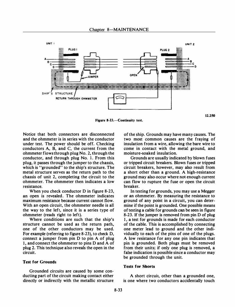
Chapter 8-MAINTENANCE
UNIT I UNIT 2
12.250
Figure 8-23.-Contlnuity test.
Notice that both connectors are disconnected and the ohmmeter is in series with the conductor under test. The power should be off. Checking conductors A, B, and C, the current from the ohmmeter flows through plug No. 2, through the conductor, and through plug No. 1 . From this plug, it passes through the jumper to the chassis, which is "grounded" to the ship's structure. The metal structure serves as the return path to the chassis of unit 2, completing the circuit to the ohmmeter. The ohmmeter then indicates a low resistance.
When you check conductor D in figure 8-23, an open is revealed . The ohmmeter indicates maximum resistance because current cannot flow. With an open circuit, the ohmmeter needle is all the way to the left, since it is a series type of ohmmeter (reads right to left).
Where conditions are such that the ship's structure cannot be used as the return path, one of the other conductors may be used. For example (referring to figure 8-23), to check D, connect a jumper from pin D to pin A of plug 1 , and connect the ohmmeter to pins D and A of plug 2. This technique also reveals the open in the circuit .
Test for Grounds
Grounded circuits are caused by some conducting part of the circuit making contact either directly or indirectly with the metallic structure
8-33
of the ship. Grounds may have many causes. The two most common causes are the fraying of insulation from a wire, allowing the bare wire to come in contact with the metal ground, and moisture-soaked insulation.
Grounds are usually indicated by blown fuses or tripped circuit breakers. Blown fuses or tripped circuit breakers, however, may also result from a short other than a ground. A high-resistance ground may also occur where not enough current can flow to rupture the fuse or open the circuit breaker.
In testing for grounds, you may use a Megger or an ohmmeter. By measuring the resistance to ground of any point in a circuit, you can determine if the point is grounded. One possible means of testing a cable for grounds can be seen in figure 8-23. If the jumper is removed from pin D of plug 1 , a test for grounds is made for each conductor of the cable. This is accomplished by connecting one meter lead to ground and the other individually to each of the pins of one of the plugs. A low resistance for any one pin indicates that pin is grounded. Both plugs must be removed from their units; if only one plug is removed, a false indication is possible since a conductor may be grounded through the unit.
Tests for Shorts
A short circuit, other than a grounded one, is one where two conductors accidentally touch
FIRE CONTROLMAN THIRD CLASS
each other directly or through another conducting element. Two conductors with frayed insulation may touch and cause a short. Too much solder on the pin of a connector may short to the adjacent pin. In a short circuit, enough current may flow to blow a fuse or open a circuit breaker. However, it is entirely possible to have a short between two cables carrying signals; such a short may not be indicated by a blown fuse.
For continuity checks, the device used for checking for a short is the ohmmeter. By measuring the resistance between two conductors, a short between them may be detected by a low resistance reading. A short test may be made by removing the jumper and disconnecting both plugs (fig. 8-23). This is performed by measuring the resistance between the two suspected conductors.
Shorts occur in many components, such as transformers, motor windings, capacitors, and the like. The major test method for detecting such components is taking a resistance measurement, and then comparing the indicated resistance with the resistance given on schematics or in the equipment OP.
Voltage Test
The voltage test must be made with the power applied; therefore, the prescribed safety precautions should be followed to prevent injury to personnel and damage to the equipment. You will find in your maintenance work that the voltage test is of utmost importance. It is used not only in isolating casualties to major components, but also in the maintenance of subassemblies, units, and circuits. Before checking a circuit voltage, a check on the voltage of the power source is made to be sure that the normal voltage is being impressed across the circuit .
Obviously, the voltmeter is used for voltage tests. In using the voltmeter, make certain that the meter used is designated for the type of current (ac or de) to be tested and has a scale of adequate range. Since defective parts in a circuit may cause higher than normal voltages to be present at the point of test, the highest voltmeter range available should be used at first . Once a reading has been obtained, determine if a lower scale can be employed without damaging the meter movement. If so, use the lower scale to obtain a more accurate reading.
8-34
Another consideration in the circuit voltage test is the resistance and current in the circuit. A low resistance in a high-current circuit would result in considerable voltage drop, whereas the same resistance in a low-current circuit might be negligible. Abnormal resistance in part of a circuit can be checked with either an ohmmeter or a voltmeter. Where practical, an ohmmeter should be used, because the test is then carried out with the circuit "dead."
The majority of the electronics circuits encountered in fire control equipment are lowcurrent circuits, and most voltage readings are direct current. Also, many of the schematics indicate the voltages at many test points. Thus, if a certain stage is suspected and a voltage check is desired, a voltmeter placed from the test point to ground or to the specified reference point should read the voltages as given on the schematic.
Some OPs also contain voltage charts where all the voltage measurements are tabulated. These charts usually indicate the sensitivity of the meter used to obtain the voltage readings for the chart. To obtain comparable results, use a voltmeter of the same sensitivity as that specified. Make certain that the voltmeter is not loading the circuit while taking a measurement. If the meter resistance is not considerably higher than the circuit resistance, the reading will be markedly lower than the true circuit voltage. (To calculate the meter resistance, multiply the rated ohms-pervolt sensitivity value of the meter by the scale in use. For example, a 1 ,000 ohms-per-voltmeter set to the 300-volt scale has a resistance of 300,000 ohms.)
Resistance Test
Before checking the resistance of a circuit or of a part, make certain that the power has been turned off and that the capacitors in the associated circuit are discharged. To check continuity, always employ the lower ohmmeter range. If a high range is used, the meter may indicate zero even though appreciable resistance is present in the circuit. Conversely, to check a high resistance, use the highest scale, since the low-range scale may indicate infinity though the resistance is less than a megohm.
In making resistance tests, take into account that other circuits that contain resistances and capacitance may be in parallel with the circuit to
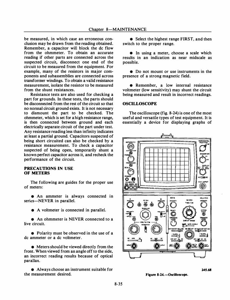
Chapter 8-MAINTENANCE
be measured, in which case an erroneous conclusion may be drawn from the reading obtained. Remember, a capacitor will block the de flow from the ohmmeter. To obtain an accurate reading if other parts are connected across the suspected circuit, disconnect one end of the circuit to be measured from the equipment. For example, many of the resistors in major components and subassemblies are connected across transfonner windings. To obtain a valid resistance measurement, isolate the resistor to be measured from the shunt resistances.
Resistance tests are also used for checking a part for grounds. In these tests, the parts should be disconnected from the rest of the circuit so that no nonnal circuit ground exists. It is not necessary to dismount the part to be checked. The ohmmeter, which is set for a high resistance range, is then connected between ground and each electrically separate circuit of the part under test. Any resistance reading less than infmity indicates at least a partial ground. Capacitors suspected of being short circuited can also be checked by a resistance measurement. To check a capacitor suspected of being open, temporarily shunt a known perfect capacitor across it, and recheck the performance of the circuit.
PRECAUTIONS IN USE OF METERS
The following are guides for the proper use of meters:
• An ammeter is always connected in serks-NEVER in parallel.
• A voltmeter is connected in parallel.
• An ohmmeter is NEVER connected to a live circuit.
• Polarity must be observed in the use of a de ammeter or a de voltmeter.
• Meters should be viewed directly from the front. When viewed from an angle off to the side, an incorrect reading results because of optical parallax.
• Always choose an instrument suitable for the measurement desired.
8-35
• Select the highest range FIRST, and then switch to the proper range.
• In using a meter, choose a scale which results in an indication as near midscale as possible.
• Do not mount or use instruments in the presence of a strong magnetic field.
• Remember, a low internal resistance voltmeter (low sensitivity) may shunt the circuit being measured and result in incorrect readings.
OSCILLOSCOPE
The oscilloscope (fig. 8-24) is one of the most useful and versatile types of test equipment. It is essentially a device for displaying graphs of
..n.
·-�· . .. ,..,
.,. � IC&ll
6 2:! , - - ...
D©©) • • -·- DC l&l -·-
0 ® ® ® 0 OtiP'f..AY
@ ...... .,.. =� u� @)
I'OLAIItlf" �•ult .... -oil' @)
01::0 � .. -c:::::4 o<
1oM� �'"""
L1
...0
�;�r.-ot•a.
d ..
•AGNI,I[fl o: .. -··
re·� &CCIII DC
(Xl IWPVT
� ....... O(LAYlO
...... MtX€0 .. _.
. 0 fiMf./CM
0
@ 111n ... , ...
0 "i ,._[ ..
0 () ' lwt<• - .
�IMk.( bf+IDDT(ht: ail DlliiY �dTU1'+10
� o. � an �� � ... � � .. ,· .. � .... IIIIIIIVl 0 O o:mtT e .-u,
CJ l45.68
Flaure 1-14--0sdlloscope.
FIRE CONTROLMAN THIRD CLASS
rapidly changing voltage or currents, but it is also capable of giving information concerning frequency values, phase differences, and voltage amplitude. It is used to trace signals through electronic circuits, to localize sources of distortion, and to isolate troubles to particular stages.
The voltage or current waveform is normally represented in a graphically displayed, twodimensional (horizontal and vertical) plane with no depth involved. The horizontal ("X") axis on the oscilloscope represents either elapsed time or waveform duration in either whole or parts of a second. The vertical ("Y") axis represents amplitude, quantity, or intensity of the subject waveform in either whole or parts of volts or amperes. Any portion of the waveform extending above the present horizontal (zero amplitude) reference line is considered positive, while any portion below the horizontal reference line is considered negative (opposite to the positive portion of the subject waveform).
Most oscilloscopes consist of a major unit and any one of several plug-in units. The major unit contains the power supplies, sweep circuits, calibration circuits, cathode-ray tube (crt), and controls associated with these circuits. The plug-in units are single-channel, multichannel, or special feature preamplifiers and are selected depending on the display desired; i.e., a multichannel plug-in unit provides two separate traces on the crt and thus allows two functions (signals) to be displayed simultaneously. An instruction manual is provided with each plug-in unit, giving detailed instructions for operating that specific plug-in unit in conjunction with the oscilloscope.
The oscilloscope shown in figure 8-24 is an example of the type of oscilloscope presently in use throughout the fleet. It is a direct-coupled, wideband oscilloscope that provides a visual display of simple and complex waveforms. In addition to displaying waveforms, the oscilloscope is capable of accurately measuring the rise time of a waveform, the waveform magnitude, the time difference between any two points on a displayed waveform, and the accurate time comparison of two separate waveforms. This oscilloscope consists of essentially three operating units, the oscilloscope assembly mainframe, a dual-trace, plug-in unit (bottom left), and a time base and delay plug-in unit (bottom right).
8-36
Basic Principles of Operation
As stated earlier, the oscilloscope is a test instrument that is capable of measuring voltage, determining frequencies, and visually displaying waveforms. Some oscilloscopes can also display two waveforms at the same time, making comparisons possible. The oscilloscope is commonly referred to as an 0-SCOPE or SCOPE.
Oscilloscopes vary from the simple to the complex. They are made in a number of sizes by many manufacturers. Therefore, there are many models, but they all have certain elements in common. First, all scopes have a cathode-ray tube which has a face, or screen, where waveshapes are visually displayed. Secondly, controls are provided to adjust the display so voltage, time, and frequency can be determined.
CONTROLS.-An important control, and one common to all scopes, is the INTENSITY control. Its proper use gives a good image and prevents burning a hole into the coating on the face of the crt.
The FOCUS control permits the adjustment of the sharpness of the dot or trace. In addition to this control some scopes may have an ASTIGMATISM control. It ensures that all parts of the waveform will be in focus at the same time.
The HORIZONTAL POSITION control permits the operator to position the dot, or waveshape, to the right or left on the scope face. When used with the VERTICAL POSITION control that positions the dot up and down, it is possible for the operator to move the dot to any point on the face of the scope.
A CALIBRATED A TTENUATOR control, for vertical deflection, reduces the vertical input signal amplitude. This circuit extends the range of the scope. Using it, a large input voltage can be reduced and measured. Without it the signal would extend off the scope, and damage to the scope could possibly result. Any voltage applied to the vertical plates causes the dot to extend up and down in proportion to the voltage applied.
INPUTS.-A vertical input jack is provided on the front of the scope. The signal to be viewed is normally brought in on fhe vertical input and goes to the vertical deflection plates. The normal input to the horizontal deflection plates is the
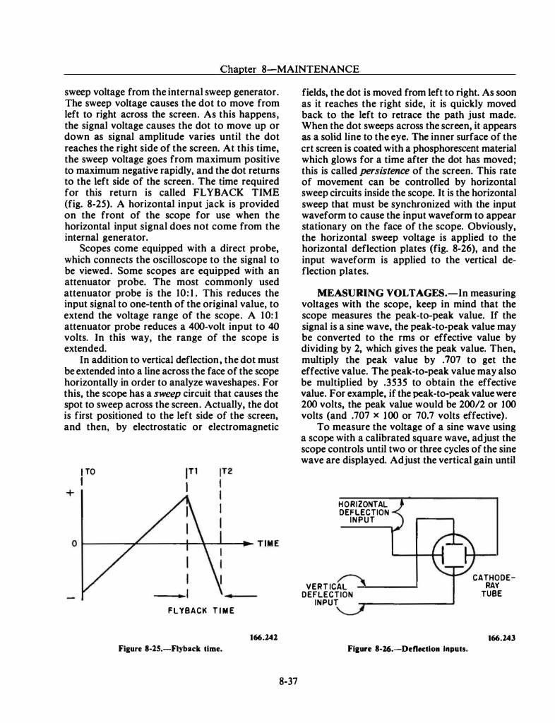
. . __ , _ - ·· · · ----
Chapter 8-MAINTENANCE
sweep voltage from the internal sweep generator. The sweep voltage causes the dot to move from left to right across the screen. As this happens, the signal voltage causes the dot to move up or down as signal amplitude varies until the dot reaches the right side of the screen. At this time, the sweep voltage goes from maximum positive to maximum negative rapidly, and the dot returns to the left side of the screen. The time required for this return is called FL YBACK TIME (fig. 8-25). A horizontal input jack is provided on the front of the scope for use when the horizontal input signal does not come from the internal generator.
Scopes come equipped with a direct probe, which connects the oscilloscope to the signal to be viewed. Some scopes are equipped with an attenuator probe. The most commonly used attenuator probe is the 10: 1 . This reduces the input signal to one-tenth of the original value, to extend the voltage range of the scope. A 1 0: 1 attenuator probe reduces a 400-volt input to 40 volts. In this way, the range of the scope is extended.
In addition to vertical deflection, the dot must be extended into a line across the face of the scope horizontally in order to analyze waveshapes. For this, the scope has a sweep circuit that causes the spot to sweep across the screen. Actually, the dot is first positioned to the left side of the ·screen, and then, by electrostatic or electromagnetic
+
I TO
I 1r1 I
FLYBACK T I M E
Figure 8-lS.-Fiyback time.
166.241
8-37
fields, the dot is moved from left to right. As soon as it reaches the right side, it is quickly moved back to the left to retrace the path just made. When the dot sweeps across the screen, it appears as a solid line to the eye. The inner surface of the crt screen is coated with a phosphorescent material which glows for a time after the dot has moved; this is called persistence of the screen. This rate of movement can be controlled by horizontal sweep circuits inside the scope. It is the horizontal sweep that must be synchronized with the input waveform to cause the input waveform to appear stationary on the face of the scope. Obviously, the horizontal sweep voltage is applied to the horizontal deflection plates (fig. 8-26), and the input waveform is applied to the vertical deflection plates.
MEASURING VOLTAGES.-In measuring voltages with the scope, keep in mind that the scope measures the peak-to-peak value. If the signal is a sine wave, the peak-to-peak value may be converted to the rms or effective value by dividing by 2, which gives the peak value. Then, multiply the peak value by . 707 to get the effective value. The peak-to-peak value may also be multiplied by .3535 to obtain the effective value. For example, if the peak-to-peak value were 200 volts, the peak value would be 20012 or l 00 volts (and .707 x 1 00 or 70.7 volts effective).
To measure the voltage of a sine wave using a scope with a calibrated square wave, adjust the scope controls until two or three cycles of the sine wave are displayed. Adjust the vertical gain until
HORIZONTAL DEFLECTION
INPUT
VERT ICAL DEFLECTION
INPUT �------------�
Fiaure 8-26.-Deflectlo• Inputs.
CATHODERAY
TUBE
166.243
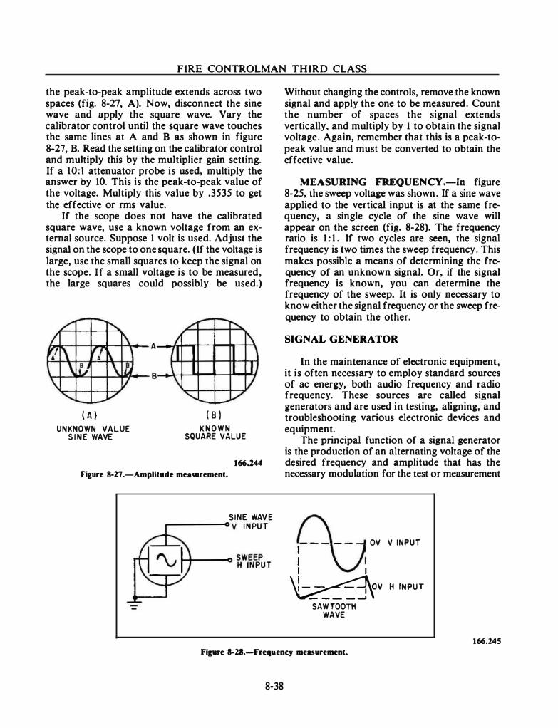
FIRE CONTROLMAN THIRD CLASS
the peak-to-peak amplitude extends across two spaces (fig. 8-27, A). Now, disconnect the sine wave and apply the square wave. Vary the calibrator control until the square wave touches the same lines at A and B as shown in figure 8-27, B. Read the setting on the calibrator control and multiply this by the multiplier gain setting. If a 10:1 attenuator probe is used, multiply the answer by 10. This is the peak-to-peak value of the voltage. Multiply this value by .3535 to get the effective or rms value.
If the scope does not have the calibrated square wave, use a known voltage from an external source. Suppose 1 volt is used. Adjust the signal on the scope to one square. (If the voltage is large, use the small squares to keep the signal on the scope. If a small voltage is to be measured, the large squares could possibly be used.)
( A ) UNKNOWN VALUE
S I N E WAVE
( 8 l K N O W N
SQUARE VALUE
166.244
Fiaure 3-27.-Amplllude met�surement.
SINE WAV E ,...------o y I N PU T
Without changing the controls, remove the known signal and apply the one to be measured. Count the number of spaces the signal extends vertically, and multiply by 1 to obtain the signal voltage. Again, remember that this is a peak-topeak value and must be converted to obtain the effective value.
MEASURING FREQUENCY.-In figure 8-25, the sweep voltage was shown. If a sine wave applied to the vertical input is at the same frequency, a single cycle of the sine wave will appear on the screen (fig. 8-28). The frequency ratio is 1 : 1 . If two cycles are seen, the signal frequency is two times the sweep frequency. This makes possible a means of determining the frequency of an unknown signal. Or, if the signal frequency is known, you can determine the frequency of the sweep. It is only necessary to know either the signal frequency or the sweep frequency to obtain the other.
SIGNAL GENERATOR
In the maintenance of electronic equipment, it is often necessary to employ standard sources of ac energy, both audio frequency and radio frequency. These sources are called signal generators and are used in testing, aligning, and troubleshooting various electronic devices and equipment.
The principal function of a signal generator is the production of an alternating voltage of the desired frequency and amplitude that has the necessary modulation for the test or measurement
I
l I I
OV V INPUT
�v H INPUT
SAW TOOTH WAVE
166.245
Figtue 8-21.-Freqaency meas•rement.
8-38
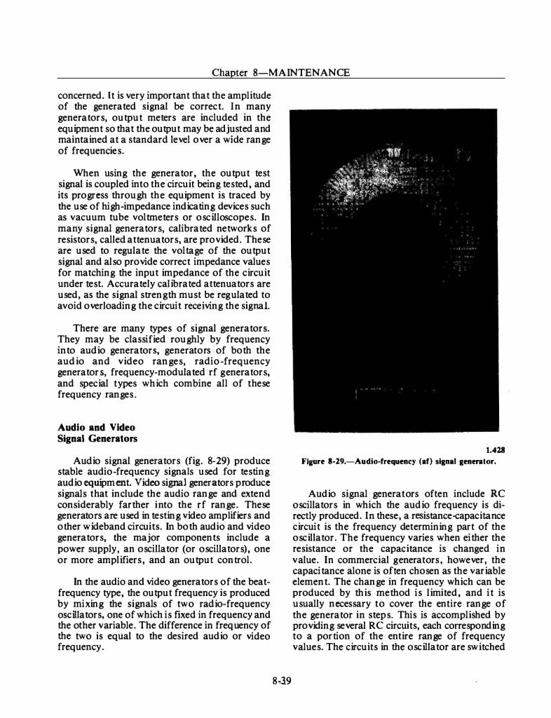
-- J.
Chapter 8-MAINTENANCE
concerned. It is very important that the amplitude of the generated signal be correct. I n many generators, output meters are included in the equipment so that the output may be adjusted and maintained at a standard level over a wi de range of frequencies.
When using the generator, the output test signal is coupled into the circuit being tested, and its progress through the equipment is traced by the use of high-impedance indicating devices such as vacuum tube voltmeters or oscilloscopes. In many signal generators, calibrated networks of resistors, called attenuators, are provided. These are used to regulate the voltage of the output signal and also provide correct impedance values for matching the input impedance of the circuit under test. Accurately calibrated attenuators are used, as the signal strength must be reg ulated to avoid overloading the circuit receiving the signal.
There are many types of signal generators. They may be classified roughly by frequency into audio generators, generators of both the audio and video ranges, radio-frequency generators, frequency-modulated rf g enerators, and special t ypes which combine all of these frequency ranges.
Audio and Video Signal Generators
Audio signal generators (fig. 8-29) produce stable audio-frequency signals used for testing audio equipment. Video signal generators produce signals that include the audio range and extend considerably farther i nto the rf range. These generators are used in testing video amplifiers and other wideband circuits. In both audio and video generators, the major components include a power supply, an oscillator (or oscillators), one or more amplifiers, and an output control.
In the audio and video generators of the beatfrequency type, the output frequency is produced by mixing the signals of two radio-frequency oscillators, one of which is fixed in frequency and the other variable. The difference in frequency of the two is equal to the desired audio or video frequency.
8'139
1.418
FIKure 8-29.-Audio-frequency (af) signal generator.
Audio signal generat ors often include RC oscillators in which the audio frequency is directly produced. I n these, a resistance-capacitance circuit is the frequency determining part of the oscillator. The frequency varies when either the resistance or the capacitance is changed in v alue. In commercial g enerators, however, the capacitance alone is often chosen as the variable element. The change in frequency which can be produced by this method is limited, and it is usually necessary t o cover the entire range of the generator in steps. This is accomplished by providing several RC circuits, each corresponding to a portion of the entire range of frequency values. The circuits in the oscillator are switched
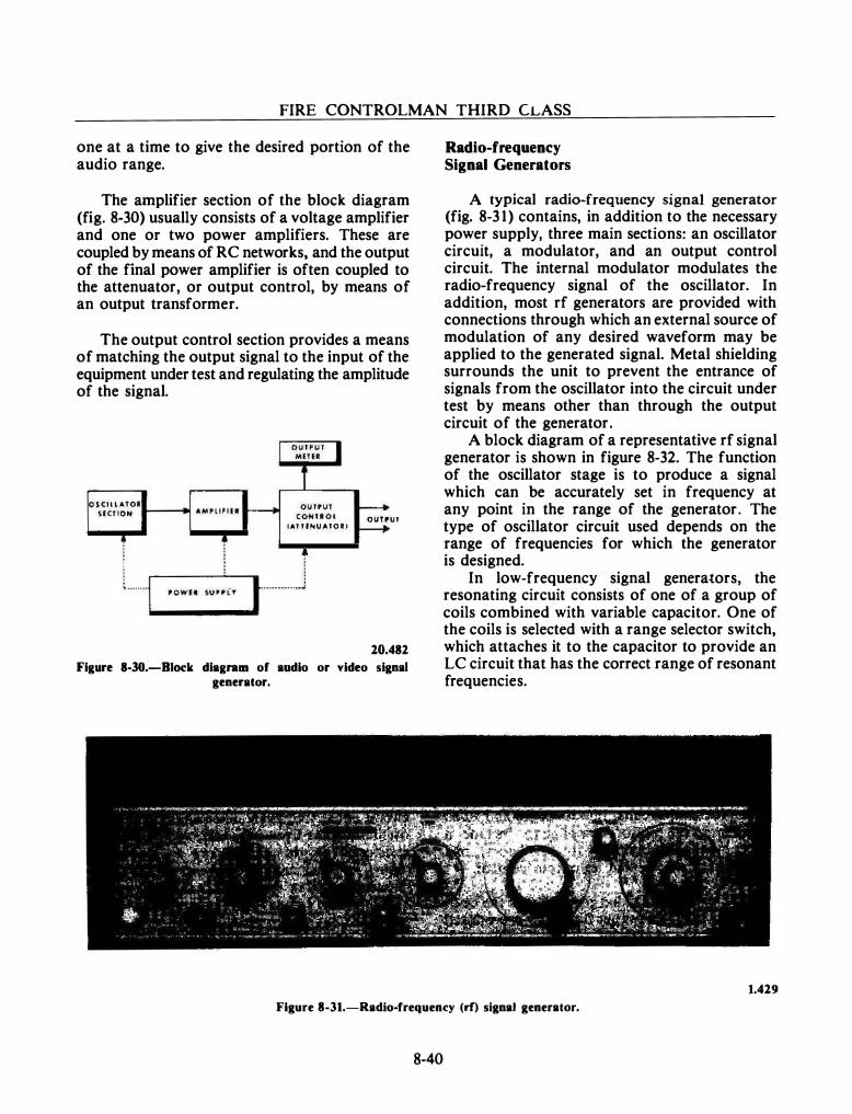
FIRE CONTROLMAN THIRD CLASS
one at a time to give the desired portion of the audio range.
The amplifier section of the block diagram (fig. 8-30) usually consists of a voltage amplifier and one or two power amplifiers. These are coupled by means of RC networks, and the output of the final power amplifier is often coupled to the attenuator, or output control, by means of an output transformer.
The output control section provides a means of matching the output signal to the input of the equipment under test and regulating the amplitude of the signal.
CAT T fNU ATO I ) OUYPUT
10.482
Figure 8-30.-Biock diagn�m of audio or video signal generator.
Radio-frequency Signal Generators
A typical radio-frequency signal generator (fig. 8-3 1 ) contains, in addition to the necessary power supply, three main sections: an oscillator circuit, a modulator, and an output control circuit. The internal modulator modulates the radio-frequency signal of the oscillator. In addition, most rf generators are provided with connections through which an external source of modulation of any desired waveform may be applied to the generated signal. Metal shielding surrounds the unit to prevent the entrance of signals from the oscillator into the circuit under test by means other than through the output circuit of the generator.
A block diagram of a representative rf signal generator is shown in figure 8-32. The function of the oscillator stage is to produce a signal which can be accurately set in frequency at any point in the range of the generator. The type of oscillator circuit used depends on the range of frequencies for which the generator is designed.
In low-frequency signal generators, the resonating circuit consists of one of a group of coils combined with variable capacitor. One of the coils is selected with a range selector switch, which attaches it to the capacitor to provide an LC circuit that has the correct range of resonant frequencies.
1.419
Figure 8-31.-Radio-frequen�y (rf) signal generator.
8-40
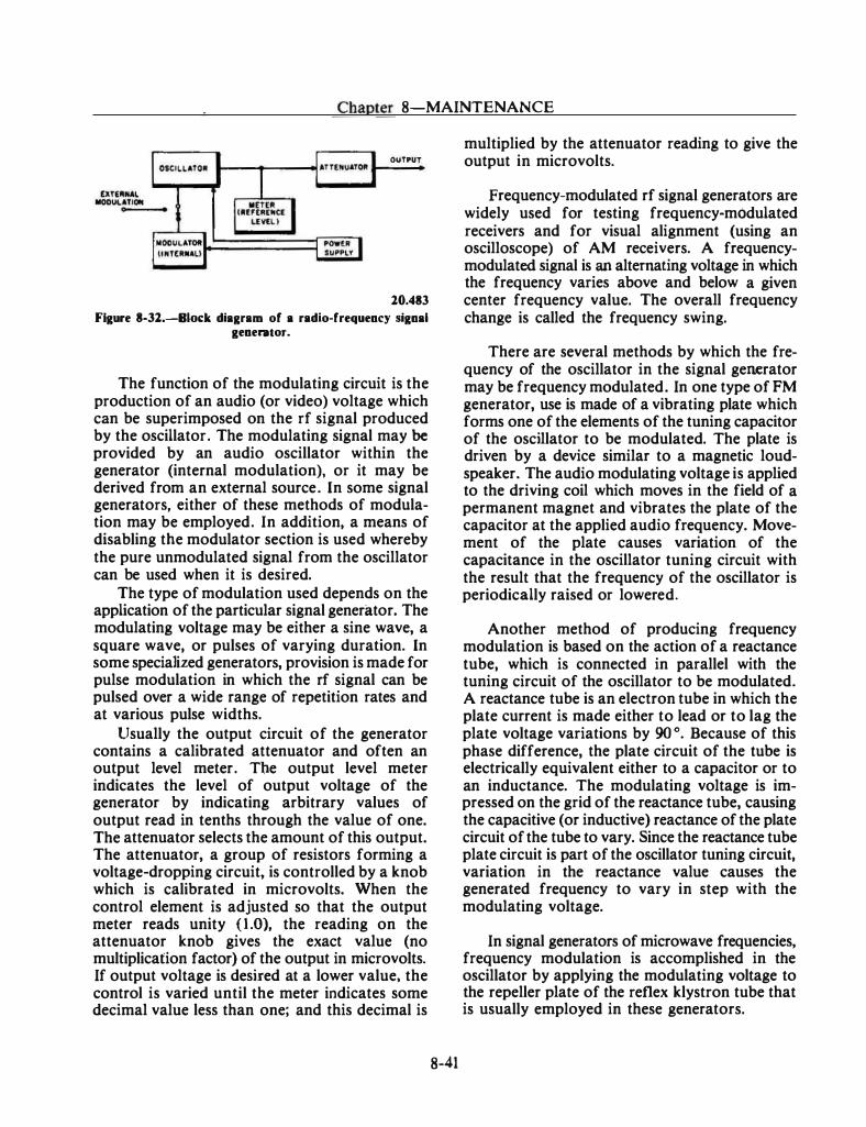
Chapter 8-MAINTENANCE
OUTPUT
10.483
Figure 8-Jl.-Bioc:k diagram of a radio-frequency signal generator.
The function of the modulating circuit is the production of an audio (or video) voltage which can be superimposed on the rf signal produced by the oscillator. The modulating signal may be provided by an audio oscillator within the generator (internal modulation), or it may be derived from an external source. In some signal generators, either of these methods of modulation may be employed. In addition, a means of disabling the modulator section is used whereby the pure unmodulated signal from the oscillator can be used when it is desired.
The type of modulation used depends on the application of the particular signal generator. The modulating voltage may be either a sine wave, a square wave, or pulses of varying duration. In some specialized generators, provision is made for pulse modulation in which the rf signal can be pulsed over a wide range of repetition rates and at various pulse widths.
Usually the output circuit of the generator contains a calibrated attenuator and often an output level meter. The output level meter indicates the level of output voltage of the generator by indicating arbitrary values of output read in tenths through the value of one. The attenuator selects the amount of this output. The attenuator, a group of resistors forming a voltage-dropping circuit, is controlled by a knob which is calibrated in microvolts. When the control element is adjusted so that the output meter reads unity (1.0), the reading on the attenuator knob gives the exact value (no multiplication factor) of the output in microvolts. If output voltage is desired at a lower value, the control is varied until the meter indicates some decimal value less than one; and this decimal is
8-41
multiplied by the attenuator reading to give the output in microvolts.
Frequency-modulated rf signal generators are widely used for testing frequency-modulated receivers and for visual alignment (using an oscilloscope) of AM receivers. A frequencymodulated signal is an alternating voltage in which the frequency varies above and below a given center frequency value. The overall frequency change is called the frequency swing.
There are several methods by which the frequency of the oscillator in the signal generator may be frequency modulated. In one type of FM generator, use is made of a vibrating plate which forms one of the elements of the tuning capacitor of the oscillator to be modulated. The plate is driven by a device similar to a magnetic loudspeaker. The audio modulating voltage is applied to the driving coil which moves in the field of a permanent magnet and vibrates the plate of the capacitor at the applied audio frequency. Movement of the plate causes variation of the capacitance in the oscillator tuning circuit with the result that the frequency of the oscillator is periodically raised or lowered.
Another method of producing frequency modulation is based on the action of a reactance tube, which is connected in parallel with the tuning circuit of the oscillator to be modulated. A reactance tube is an electron tube in which the plate current is made either to lead or to lag the plate voltage variations by 90 o. Because of this phase difference, the plate circuit of the tube is electrically equivalent either to a capacitor or to an inductance. The modulating voltage is impressed on the grid of the reactance tube, causing the capacitive (or inductive) reactance of the plate circuit of the tube to vary. Since the reactance tube plate circuit is part of the oscillator tuning circuit, variation in the reactance value causes the generated frequency to vary in step with the modulating voltage.
In signal generators of microwave frequencies, frequency modulation is accomplished in the oscillator by applying the modulating voltage to the repeller plate of the reflex klystron tube that is usually employed in these generators.
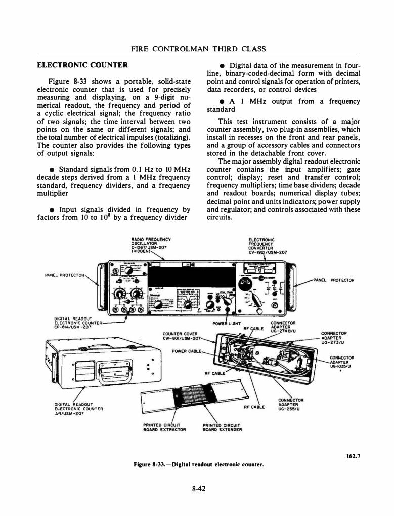
- · - - . . · - -------- - · - . --
FIRE CONTROLMAN THIRD CLASS
ELECTRONIC COUNTER
Figure 8-33 shows a portable, solid-state electronic counter that is used for precisely measuring and displaying, on a 9-digit numerical readout, the frequency and period of a cyclic electrical signal; the frequency ratio of two signals; the time interval between two points on the same or different signals; and the total number of electrical impulses (totalizing). The counter also provides the following types of output signals:
• Standard signals from 0. 1 Hz to 10 MHz decade steps derived from a 1 MHz frequency standard, frequency dividers, and a frequency multiplier
• Input signals divided in frequency by factors from 10 to 1 08 by a frequency divider
f'IIINEL PROTECTOR
DIGITAL READOUT ELECTRONIC COUNTER---CP-8 14/USIII -207
DIGITAL READOUT ELECTRONIC COUNTER AN/USM-207
• Digital data of the measurement in fourline, binary-coded-decimal form with decimal point and control signals for operation of printers, data recorders, or control devices
• A 1 MHz output from a frequency standard
This test instrument consists of a major counter assembly, two plug-in assemblies, which install in recesses on the front and rear panels, and a group of accessory cables and connectors stored in the detachable front cover.
The major assembly digital readout electronic counter contains the input amplifiers; gate control; display; reset and transfer control; frequency multipliers; time base dividers; decade and readout boards; numerical display tubes; decimal point and units indicators; power supply and regulator; and controls associated with these circuits.
PROT ECTOR
162.7
Figure 8-33.-Digltal readout electronic counter.
8-42
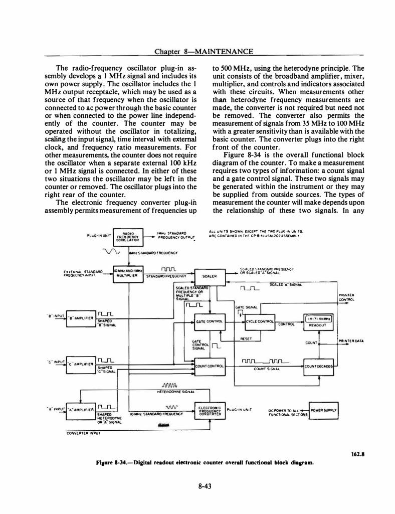
Chapter 8-MAINTENANCE
The radio-frequency oscillator plug-in assembly develops a 1 MHz signal and includes its own power supply. The oscillator includes the 1 MHz output receptacle, which may be used as a source of that frequency when the oscillator is connected to ac power through the basic counter or when connected to the power line independently of the counter. The counter may be operated without the oscillator in totalizing, scaling the input signal, time interval with external clock, and frequency ratio measurements. For other measurements, the counter does not require the oscillator when a separate external 1 00 kHz or 1 MHz signal is connected. In either of these two situations the oscillator may be left in the counter or removed. The oscillator plugs into the right rear of the counter.
The electronic frequency converter plug-in assembly permits measurement of frequencies up
[U[II .. AL STA,OARO FII[QUEf'ICY tt<Pl!T
SHAP£0 '---�·c"SIGHAL
COIOVEIITEII lltPUT
lltll<l 5TA,DAIID fiiEOUEI'ICY OUTPUT
STA .. OAIID FR(OU£,CY
HfTER00Y"E SIGitAl.
to 500 MHz, using the heterodyne principle. The unit consists of the broadband amplifier, mixer, multiplier, and controls and indicators associated with these circuits. When measurements other than heterodyne frequency measurements are made, the converter is not required but need not be removed. The convener also permits the measurement of signals from 35 MHz to 100 MHz with a greater sensitivity than is available with the basic counter. The converter plugs into the right front of the counter.
Figure 8-34 is the overall functional block diagram of the counter. To make a measurement requires two types of information: a count signal and a gate control signal. These two signals may be generated within the instrument or they may be supplied from outside sources. The types of measurement the counter will make depends upon the relationship of these two signals. In any
ALL U"ITS SHOWN, EXCEPT THE TWO PLUG·tN UNITS, ARE COPoTAIN[D IN THE CP·It4/USM·207ASSEioi8LY
SCALED STliNOAIIO FR[QUEI'ICY OR SCAl[O"A"StGNAL
PLUG-I" U"IT
COUitT Stu,.AL
DC POWER TO ALL FUNCTtCl'W.. St:CTIOI<S
PfiiNT(II CONTIIOL
162.8
Fiaure 8-34.-Digital readout electroak counter overall fuactioaal block dlaanam.
8-43
- -- - - - ··---·- - - --- -- .. - . .. -
FIRE CONTROLMAN THIRD CLASS
function, the instrument counts the count signal for a period of time determined by the gate control signal. Routing of these signals within the instrument is accomplished by logic circuits. These logic circuits are controlled by means of the front panel controls.
The radio-frequency oscillator generates a signal of precise frequency for use throughout the counter, or to provide a precise 1 MHz signal for use outside the equipment.
The electronic frequency converter accepts radio frequencies between 1 00 MHz and 500 MHz and converts them to radio frequencies between 5 MHz and 1 00 MHz for measurement by the basic counter.
The A amplifier amplifies the A input signal or the output of the converter for use throughout the counter.
The B amplifier amplifies and shapes the B input signal for use throughout the counter.
The C amplifier amplifies and shapes the C input signal for use throughout the counter.
The 10 MHz and 1 MHz multiplier multiplies the frequency and shapes the signal generated by the radio-frequency oscillator. It also provides precise timing signals to the various functional sections of the basic counter and to the frequency converter.
The scaler consists of a series of decade dividers and gating systems that provide divided standard frequencies and control signals depending on the type of measurement the instrument is making.
8-44
The gate control generates the gate control signal. This signal determines the length of time that the count decades count the count signal .
The count control provides the proper count signal to the count decades, as selected by the setting of the front panel switches.
The cycle control produces all signals necessary to display the measurement results on the readout and to recycle the counter.
The count decades count the count signal when permitted to do so by the gate control. The result of their counting becomes the final reading displayed by the readout at the end of each measurement.
The readout receives Binary-Coded-Decimal (BCD) data from the count decades, decodes this data into decimal form, and drives the readout indicator tubes. The readout also contains memory circuits which function when the counter is operated in the "Store" mode.
SUMMARY
This chapter has touched on some of the points concerning maintenance. This overview combined with experience should enable you to increase your skills as a technician. As with most technical endeavors, close attention to detail is the key to successful maintenance.

CHAPTER 9
SAFETY AND SECURITY
Promoting safety and security within your division, or on the ship in general, requires that you become more than just familiar with safety rules and security procedures. You should become safety and security "conscious" to the point that these matters are automatically part of your thinking process. In this chapter, we will cover basic safety and security fundamentals every FC is required to know.
SAFETY
Most accidents are preventable. However, through ignorance or misunderstanding, there is a common belief that they are the inevitable result of unchangeable circumstances or fate. This belief is untrue because it fails to consider the basic law of "cause and effect'' to which accidents are subject. In other words,· accidents do not occur without a cause. Most accidents are the direct result of some deviation from prescribed safe operating procedures.
One purpose of safety rules is to remind the individual of the dangers inherent in the work. Training in the observance of safety precautions can be instrumental in avoiding preventable accidents and in maintaining a work environment that
· is conducive to accident-free operation.
Operating procedures and work methods adopted with hazard prevention as a specific criteria do not expose personnel unnecessarily to injury or occupational health hazards. Accidents that are about to happen can be prevented if the "cause" is detected and appropriate remedial action is taken.
9-1
RESPONSIBILITY
Responsibility for the safety of personnel is vested in the commanding officer. The commanding officer may delegate authority to the safety officer and other subordinates to ensure that all prescribed safety precautions are understood and strictly enforced. The commanding officer ensures that the personnel are instructed and drilled in applicable safety precautions, requires that adequate warning signs be posted in dangerous areas, and establishes a force to see that such precautions are being observed.
Supervisory personnel should see that precautions are strictly followed in their own work area, since they are responsible to the commanding officer. Furthermore, individuals concerned should strictly observe all safety precautions applicable to their work or duty. Thus, it is obvious that accident prevention is the business of every individual-not just a delegated few.
You have a responsibility to yourself and to your shipmates to do your part in preventing accidents. You should always be alert to detect and report unsafe work practices and unsafe conditions so that they may be corrected before they cause accidents.
Each individual should do the following:
• Observe all posted operating instructions and safety precautions.
• Report any condition, equipment, or material that is considered to be unsafe.
• Warn others who are believed to be endangered by known hazards or by their failure to observe safety precautions.
FIRE CONTROLMAN THIRD CLASS
• Wear protective clothing or use protective equipment of the type approved for the safe performance of work or duty.
• Report to the supervisor any injury or evidence of impaired health occurring in the course of work or duty.
• Exercise reasonable caution as appropriate to the situation in the event of an emergency or other unforeseen hazardous condition.
Post accident investigations have revealed that the majority of accidents result from unsafe practices or acts. Most of these practices are known beforehand to be unsafe and in violation of safety practices, rules, regulations, or directives. Other human factors found to be the cause of accidents include fatigue, monotony, preoccupation at a critical moment (inattention), mental and/or physical problems, improper supervision, lack of motivation and such. Because of various factors, individuals do not always act (or react) as they were trained, instructed, or directed to act. Results of this condition, most probably, will be an accident because of "human error. "
Human error includes all the actions or inactions of an individual having a bearing on an accident or on an unsafe practice that can lead to an accident. To reduce human error as a predominant cause of accidents, all individuals should acquaint themselves with the environmental hazards surrounding them. They should condition themselves to be alert, both mentally and physically, so that they can protect themselves and others by avoiding exposure to hazards.
Accidents do not happen without a cause; when each individual can be made aware of the hazards involved with work, fewer accidents will result. Accident prevention must be a continuous effort in which each individual gains experience and knowledge through day-to-day association with coworkers who are aware of the hazards of their environment.
ELECTRIC SHOCK
Fundamentally, current rather than voltage causes shock intensity. The passage of even a very small current through a vital part of the human
body could cause death. The voltage necessary to produce the fatal current is dependent upon the resistance of the body, contact conditions, and the path through the body.
You should recognize that the resistance of the human body cannot be relied upon to prevent a fatal shock from 115 volts or less-fatalities from as low as 30 volts have been recorded. Tests have shown that body resistance under unfavorable conditions may be as low as 300 ohms. It could possibly be as low as 100 ohms from temple to temple if the skin is broken. Volt for volt, de potentials are normally not as dangerous as ac. This is true because the reasonable safe "let-go currents" for 60 hertz alternating current is 9.0 milliamperes for men and 6.0 milliamperes for women, while the corresponding values for direct current are 62.0 milliamperes for men and 41.0 milliamperes for women.
Symptoms Of Electric Shock
In the event of severe electric shock, the victim with light skin pigmentation is usually very pale or blue, and the victim with darker skin pigmentation is usually ashen or gray. The pulse is extremely weak or entirely absent, unconsciousness is complete, and burns are usually present. The victim's body may.become rigid or stiff in a few minutes. This condition can be caused by muscular reaction to shock, and it should not be considered as rigor mortis.
Artificial respiration should be administered immediately, regardless of body stiffness, because recovery from such a state is possible. Consequently, the symptom of rigor mortis should not be accepted as a positive sign of death.
Rescue Of Victims
The rescue of electric shock victims is dependent upon prompt administration of first aid.
WARNING
Do not attempt to administer first aid or come in physical contact witb an electric sbock victim before the power is sbut off; or, if the power cannot be shut off immediately, before the victim bas been removed from the live conductor.
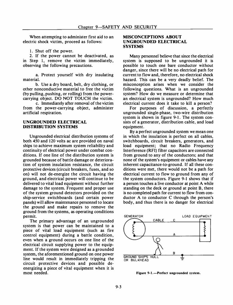
Chapter 9-SAFETY AND SECURITY
When attempting to administer first aid to an electric shock victim, proceed as follows:
1. Shut off the power. 2. If the power cannot be deactivated, as
in Step 1, remove the victim immediately, observing the following precautions.
a. Protect yourself with dry insulating material.
b. Use a dry board, belt, dry clothing, or other nonconductive material to free the victim (by pulling, pushing, or rolling) from the powercarrying object. DO NOT TOUCH the victim.
c. Immediately after removal of the victim from the power-carrying object, administer artificial respiration.
UNGROUNDED ELECTRICAL DISTRIBUTION SYSTEMS
Ungrounded electrical distribution systems of both 450 and 120 volts ac are provided on naval ships to achieve maximum system reliability and continuity of electrical power under combat conditions. If one line of the distribution system is grounded because of battle damage or deterioration of system insulation resistance, the circuit protective devices (circuit breakers, fuses, and so on) will not de-energize the circuit having the ground, and electrical power will continue to be delivered to vital load equipment without further damage to the system. Frequent and proper use of the system ground detectors provided on the ship-service switchboards (and certain power panels) will allow maintenance personnel to locate the ground and make repairs to remove the ground from the systems, as operating conditions permit.
The primary advantage of an ungrounded system is that power can be maintained to a piece of vital load equipment (such as fire control equipment) during a battle condition, even when a ground occurs on one line of the electrical circuit supplying power to the equipment. If the system were designed as a grounded system, the aforementioned ground on one power line would result in immediately tripping the circuit protective devices and possible deenergizing a piece of vital equipment when it is most needed.
9-3
MISCONCEPTIONS ABOUT UNGROUNDED ELECTRICAL SYSTEMS
Many personnel believe that since the electrical system is supposed to be ungrounded it is possible to touch one bare conductor without danger, since there will be no electrical path for current to flow and, therefore, no electrical shock hazard. This can be a very deadly belief. The misconception arises when we consider the following questions. What is an ungrounded system? How do we measure or determine that an electrical system is ungrounded? How much electrical current does it take to kill a person?
For purposes of discussion, a perfectly ungrounded single-phase, two-wire distribution system is shown in figure 9- 1 . The system consists of a generator, distribution cable, and load equipment.
By a perfect ungrounded system we mean one in which the insulation is perfect on all cables, switchboards, circuit breakers, generators, and load equipment; that no Radio Frequency Interference (RFI) filter capacitors are connected from ground to any of the conductors; and that none of the system's equipment or cables have any inherent capacitance-to-ground. If all these conditions were met, there would not be a path for electrical current to flow to ground from any of the system conductors. Figure 9-1 shows that if a person touches a live conductor at point A while standing on the deck or ground at point B , there is no completed path for current to flow from conductor A to conductor C through the person's body, and thus there is no danger for electrical
GENERATOR LOAD EQUIPMENT
Figure 9-1.-Perfect ungrounded system.
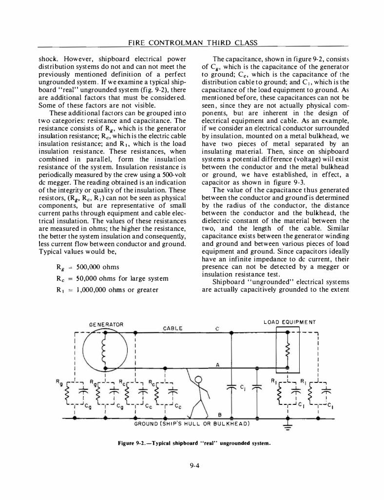
FIRE CONTROLMAN TH IRD CLASS
shock. However, shipboard electrical power distribution systems do not and can not meet the previously mentioned definition of a perfect ungrounded system . If we examine a typical shipboard "real" ungrounded system (fig. 9-2), there are additional factors that must be considered. Some of these factors are not visible.
These additional factors can be grouped into two categories: resistance and capacitance. The resistance consists of Rg. which is the generator insulation resistance; Rc, which is the electric cable insulation resistance; and R 1, which is the load insulation resistance. These resistances, when combined in parallel, form the insulation resistance of the system. Insulation resistance is periodically measured by the crew using a 500-volt de megger. The reading obtained is an indication of the integrity or quality of the insulation. These resistors, (R8, Rc, R1) can not be seen as physical components, but are representative of small current paths through equipment and cable electrical insulation. The values of these resistances are measured in ohms; the higher the resistance, the better the system insulation and consequently, less current flow between conductor and ground. Typical values would be,
Rg 500,000 ohms
Rc 50,000 ohms for large system
R 1 = J ,000,000 ohms or greater
The capacitance, shown in figure 9-2, consists of Cg, which is the capacitance of the generator to ground; Cc, which is the capacitance of the distribution cable to ground; and C 1, which is the capacitance of the load equipment to ground. As mentioned before, these capacitances can not be seen , since they are not actually physical components, but are inherent in the design of electrical equipment and cable. As an example, if we consider an electrical conductor surrounded by insulation, mounted on a metal bulkhead, we have two pieces of metal separated by an insulating material. Then, since on shipboard systems a potential difference (voltage) will exist between the conductor and the metal bulkhead or ground, we have established, in effect, a capacitor as shown in figure 9-3.
The value of the capacitance thus generated between the conductor and ground' is determined by the radius of the conductor, the distance between the conductor and the bulkhead, the dielectric constant of the material between the two, and the length of the cable. Similar capacitance exists between the generator winding and ground and between various pieces of load equipment and ground. Since capacitors ideally have an infinite impedance to de current, their presence can not be detected by a megger or insulation resistance test.
Shipboard "ungrounded" electrical systems are actually capacitively grounded to the extent
LOAD EQUIPMENT GENERATOR CABLE C
c:;i==�-..... --��:.=-.---��.-----+-• - -- ...,
A
c,
B
GROUND (SHIP'S HULL OR BULKHEAD)
Figure 9-2.-Typical shipboard "real" ungrounded system.
9-4
I I I I I I I
I I
·��-�� " ' �..J-:t t_I_...J c I t_l _ _.c, I I
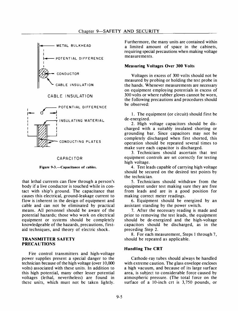
Chapter 9-SAFETY AND SECURITY
I r-
1--.-- METAL BULKHEAD
I I
� POTENTIAL DIFFERENCE
CONDUCTOR
CABLE INSULATION
CABLE INSULATION
� POTENTIAL DIFFERENCE
I
CONDUCTING PLATES
CAPACITOR
Figure 9-3.-Capacitance of cables.
that lethal currents can flow through a person's body if a live conductor is touched while in contact with ship's ground. The capacitance that causes this electrical, ground-leakage current to flow is inherent in the design of equipment and cable and can not be eliminated by practical means. All personnel should be aware of the potential hazards; those who work on electrical equipment or systems should be completely knowledgeable of the hazards, precautions, firstaid techniques, and theory of electric shock .
TRANSMITTER SAFETY PRECAUTIONS
Fire control transmitters and high-voltage power supplies present a special danger to the technician because of the high voltage (over 10,000 volts) associated with these units. In addition to this high potential, many other lesser potential voltages (lethal, nevertheless) are found in these units, which must not be taken lightly.
9-5
Furthermore, the many units are contained within a limited amount of space in the cabinets, requiring special precautions when making voltage measurements.
Measuring Voltages Over 300 Volts
Voltages in excess of 300 volts should not be measured by probing or holding the test probe in the hands. Whenever measurements are necessary on equipment employing potentials in excess of 300 volts or where rubber gloves cannot be worn, the following precautions and procedures should be observed:
1. The equipment (or circuit) should first be de-energized.
2. High voltage capacitors should be discharged with a suitably insulated shorting or grounding bar. Since capacitors may not be completely discharged when first shorted, this operation should be repeated several times to make sure each capacitor is discharged.
3. Technicians should ascertain that test equipment controls are set correctly for testing high voltage.
4. Test leads capable of carrying high voltage should be secured on the desired test points by the technician.
5. Technicians should withdraw from the equipment under test making sure they are free from leads and are in a good position for making correct meter readings.
6. Equipment should be energized by an assistant standing by the power switch.
7. After the necessary reading is made and prior to removing the test leads, the equipment should be de-energized and the high-voltage capacitors should be discharged, as in the preceding Step 2.
8. For each measurement , Steps 1 through 7 , should be repeated as applicable.
Handling The CRT
Cathode-ray tubes should always be handled with extreme caution. The glass envelope encloses a high vacuum, and because of its large surface area, is subject to considerable force caused by atmospheric pressure. (The total force on the surface of a 10-inch crt is 3, 750 pounds, or
FIRE CONTROLMAN THIRD CLASS
nearly 2 tons; over 1,000 pounds is exerted on its face alone.) Proper handling and disposal instructions for a crt are as follows:
• Avoid scratching or striking the surface.
• Do not use excessive force when removing or replacing the crt in its deflection yoke or its socket.
• Do not try to remove an electromagnetic crt from its yoke until the high voltage has been discharged from its anode connector (hole).
• Never hold the crt by its neck.
• Always set a crt with its face down on a thick piece of felt, rubber, or smooth cloth.
• Always handle the crt gently. Rough handling or a sharp blow on the service bench can displace the electrodes within the tube, causing faulty operation.
• Safety glasses and gloves should be worn when handling a crt.
Radioactive Electron Tubes
Electron tubes containing radioactive material are now commonly used. These tubes are known as Transmit-Receive (TR), antitransmit-receive (atr), spark-gap, voltage-regulator, gas-switching, and cold-cathode gas-rectifier tubes. Some of these tubes contain radioactive material and have intensity levels that are dangerous; they are so marked in accordance with military specifications.
So long as these electron tubes remain intact and are not broken, no great hazard exists. However, if these tubes are broken and the radioactive material is exposed or escapes from the confines of the electron tube, the radioactive material becomes a potential hazard.
The concentration of radioactivity in a normal collection of electron tubes in a maintenance shop does not approach a dangerous level, and the hazards of injury from exposure are slight. However, at major supply points, the storage of large quantities of radioactive electron tubes in a relatively small area may create a hazard. For this reason, personnel working with
9-6
equipment employing electron tubes containing radioactive material, or in areas where a large quantity of radioactive tubes is stored, should become thoroughly familiar with the safety practices contained in Radiation, Health, and Protection Manual, NAVMED P-5055. Strict compliance with the prescribed safety precautions and procedures of this manual will help you avoid accidents and maintain a work environment that i s conducive to good health.
The following precautions should be taken to ensure proper handling of radioactive electron tubes and safety of personnel:
1 . Radioactive tubes should not be removed from cartons until immediately prior to actual installation.
2. When a tube containing a radioactive material is removed from equipment, it should be placed in an appropriate carton to prevent possible breakage.
3. A radioactive tube should never be carried in your pocket, or elsewhere on your person, in such a manner that breakage could occur.
4. If breakage does occur during handling or removing of a radioactive electron tube, notify the cognizant authority and obtain the services of qualified radiological personnel immediately.
5. Isolate the immediate area of exposure to protect other personnel from possible contamination and exposure.
6. Follow the established procedures set forth in NA VMED P-5055.
7. Do not permit contaminated material to come in contact with any part of the body.
8. Take care to avoid breathing any vapor or dust that may be released by tube breakage.
9. Wear rubber or plastic gloves at all times during cleanup and decontamination procedures.
10. Use forceps for the removal of large fragments of a broken radioactive tube. The remaining small particles can be removed with a vacuum cleaner, using an approved disposal collection bag. If a vacuum cleaner is not available, use a wet cloth to wipe the affected area. In this case, be sure to make one stroke at a time. DO NOT use a back-and-forth motion. After each stroke, fold the cloth in half, always holding one clean side and using the other for the new stroke. (Dispose of the cloth in the manner stated in item 14.)
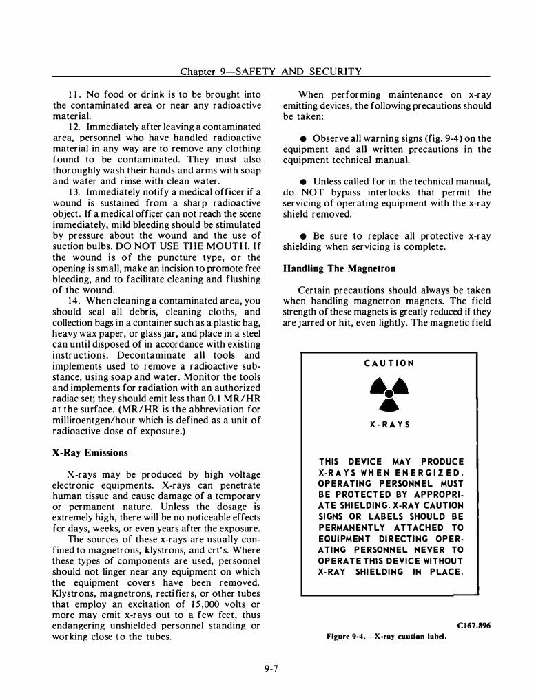
Chapter 9-SAFETY AND SECURITY
11. No food or drink is to be brought into the contaminated area or near any radioactive material.
12. Immediately after leaving a contaminated area, personnel who have handled radioactive material in any way are to remove any clothing found to be contaminated. They must also thoroughly wash their hands and arms with soap and water and rinse with clean water.
13. Immediately notify a medical officer if a wound is sustained from a sharp radioactive object. If a medical officer can not reach the scene immediately, mild bleeding should be stimulated by pressure about the wound and the use of suction bulbs. DO NOT USE THE MOUTH. If the wound is of the puncture type, or the opening is small, make an incision to promote free bleeding, and to facilitate cleaning and flushing of the wound.
14. When cleaning a contaminated area, you should seal all debris, cleaning cloths, and collection bags in a container such as a plastic bag, heavy wax paper, or glass jar, and place in a steel can until disposed of in accordance with existing instructions. Decontaminate all tools and implements used to remove a radioactive substance, using soap and water. Monitor the tools and implements for radiation with an authorized radiac set; they should emit less than 0. 1 MR/HR at the surface. (MR/HR is the abbreviation for milliroentgen/hour which is defined as a unit of radioactive dose of exposure.)
X-Ray Emissions
X-rays may be produced by high voltage electronic equipments. X-rays can penetrate human tissue and cause damage of a temporary or permanent nature. Unless the dosage is extremely high, there will be no noticeable effects for days, weeks, or even years after the exposure.
The sources of these x-rays are usually confined to magnetrons, klystrons, and crt's. Where these types of components are used, personnel should not linger near any equipment on which the equipment covers have been removed. Klystrons, magnetrons, rectifiers, or other tubes that employ an excitation of 15,000 volts or more may emit x-rays out to a few feet, thus endangering unshielded personnel standing or working close to the tubes.
9-7
When performing maintenance on x-ray emitting devices, the following precautions should be taken:
• Observe all warning signs (fig. 9-4) on the equipment and all written precautions in the equipment technical manual.
• Unless called for in the technical manual, do NOT bypass interlocks that permit the servicing of operating equipment with the x-ray shield removed.
• Be sure to replace all protective x-ray shielding when servicing is complete.
Handling The Magnetron
Certain precautions should always be taken when handling magnetron magnets. The field strength of these magnets is greatly reduced if they are jarred or hit, even lightly. The magnetic field
C A U T I O N
X-R A YS
THIS DEVICE MAY PRODUCE
X-R A YS W H E to! E to! E R G I ZE D .
OPERATING PERSONt-IEL MUST
BE PROTECTED BY APPROPRI
ATE SHIELDit-IG. X-RAY CAUTION
SIGt-IS OR LABELS SHOULD BE
PERMAt-IENTLY ATTACHED TO
EQUIPMEt-IT DIRECTING OPER
ATING PERSOtolt-IEL NEVER TO
OPERATE THIS DEVICE WITHOUT
X-RAY SHIELDING IN PLACE.
C167.896
Figure 9-4.-X-ray caution label.
FIRE CONTROLMAN THIRD CLASS
is very strong, and if magnetic tools are used when working close to the magnet, the strong field may pull them sharply against the magnet. In one test, which was made to determine the effect of allowing tools to strike a magnet, it was found that only one touch with a screwdriver reduced the magnetic field by 50 gausses. Two or three l ight taps on a magnet would seriously effect its performance. This difficulty can be avoided by the use of nonmagnetic tools. A nonmagnetic screwdriver is essential.
If magnetic tools must be used, special precautions must be taken to prevent them from jumping toward the magnet. A nonmagnetic cover such as cloth or tape, wrapped around the pole pieces to a depth of three-sixteenths inch, reduces the effect of touching a screwdriver to the magnet to about one-tenth of what it would be without the cover. In general, iron, nickel, or other magnetic objects should not be brought near the magnet.
When drilling or filing in the vicinity of the magnetron assembly, cover it completely to prevent any metal chips or filings from becoming attached to the magnet. During storage, care should be taken to prevent the interaction of the fields of two or more magnets. A safe rule is to allow not less than six inches between them. In addition, always store a magnet with the keeper in position.
Electrostatic Corona
The electrostatic corona occurs when the voltage potential between two adjacent metal surfaces is high enough to cause a breakdown of the dielectric between the two surfaces. The breakdown is indicated by a discharge of a pale, violet color near the metal surface. If the voltage is raised farther, a spark jumps from one electrode to the other.
Corona can form at sharp corners of highvoltage switches, bus bars, and so on. The radii of such parts are made large enough to prevent corona. Corona can have an injurious effect on fibrous insulation; the breakdown of which can start fires. The power loss involved in a corona discharge may be severe enough to affect the operation of your equipment.
9-8
SAFETY DEVICES
Safety devices are designed for the protection of personnel. In this subsection we will cover those devices that are designed exclusively for the protection of personnel working with or near electrical and electronic equipment.
Interlocks
Almost all modern fire control equipments are provided with various built-in safety devices (such as interlock switches) to prevent technical and maintenance personnel from accidently coming into contact with electrical potentials in excess of 70-volts RMS or de. Nevertheless, some of these protective devices are removed or destroyed by personnel who tamper with, block open, or otherwise "override" them. The foregoing practices are actions that must not be performed, unless the commanding officer has directed them for operational reasons; and, as a result, the equipment is properly tagged to notify personnel of the condition.
Interlocks and other safety devices, such as overload relays and fuses, should not be altered or disconnected, except for replacement. Also, safeguard circuits should not be modified without specific authority from the cognizant systems command. Periodic test and inspections shoOld be made to ensure that the above safety devices are functioning properly.
Fuses
Fuses should be removed and replaced only after their associated circuits have been completely de-energized. A burned-out fuse should be replaced with a fuse of the same amperage and voltage rating. Do not use replaceable link-type fuses. When practical, a circuit should be checked before replacing a burned-out fuse since such trouble is usually indicative of a circuit fault. Nonconducting fuse pullers should be used when removing knife or cartridge-type fuses from fuse holders.
.··"
Chapter 9-SAFETY AND SECURITY
If a fuse must be pulled from a live circuit, stand on a rubber blanket, which will insulate you from ground; use an approved fuse puller and don't touch a grounded object with your free hand. Always turn your head for protection against a flash and be sure to wear approved safety goggles.
Do not energize a circuit without first assuring yourself by personal investigation that no one is in a position to be injured. You should never bypass a blown fuze by shorting it out or use a fuse heavier than the capacity of the circuit.
Operating Circuit Breakers
While opening or closing circuit breakers follow these precautions:
• Use only one hand.
• Keep your hands clear of parts other than operating handles.
• In cases where positive and negative breakers have two handles, close one breaker at a time.
• Close the breaker first and then close the switch.
• Trip circuit breakers before opening switches.
• Never disable a Circuit breaker.
• Keep your face turned away while closing circuit breakers. Wearing of safety goggles is recommended while opening or closing nonclosed types of circuit breakers and switches.
Emergency-Off Switches
Emergency-off switches are located on transmitters and high-voltage power supply cabinets. They provide a means of securing power to the transmitter in the event of an emergency. You should become well acquainted with the location of emergency-off switches and be familiar with the circuitry that they control.
9-9
Battle Short Switches
When battle short switches are provided, they are normally located on the main operating console or assembly, and they function to by-pass all safety interlocks. You should use them in emergency operating conditions only.
Safety Shorting Probe
Technical and maintenance personnel who repair circuits that employ large capacitors, pulse forming networks, and the like, should use only an authorized safety shorting probe to discharge the circuits. Figure 9-5 shows an authorized probe, NSN 9N-5920-0l-029-4176.
Some certain electronic equipment are provided with a built-in special purpose safety shorting probes. These probes are not considered "general-purpose" and are to be used only with the equipment with which they are provided and only in a manner as directed by the technical manuals for the equipment. THEY SHOULD NOT BE REMOVED AND USED ELSEWHERE.
When using a general-purpose safety shorting probe, always be sure to connect the grounding clip to a good ground connection first (if necessary, scrape the paint of the grounding metal to make good contact). Then, while holding the safety shorting probe by the handle behind the protective shield, touch the end of metal rod to the point to be shorted-out. Touch each point to be shorted-out several times to make sure that the circuit is completely discharged.
Always be extremely careful and make absolutely sure that you do not touch any of the metal parts of the safety shorting probe while touching the probe to the exposed "hot" terminal.
Figure 9-5.-Safety shorting probe.
FIRE CONTROLMAN THIRD CLASS
It pays to be safe; use the safety shorting probe with care.
Deck Covering
To eliminate likely causes of accidents and to afford maximum protection to personnel from the hazards associated with electric shock, use only the approved floor matting for electric and electronic spaces. In many instances, after accidents occurred, investigations showed the operating locations and areas around electric and electronic equipment were covered with only generalpurpose floor matting. This type of matting should not be used because its electrical characteristics do not provide adequate insulating properties to protect personnel from the possibility of electric shock; also, the material used in the manufacture of this matting is not fireretardant.
For the protection of personnel, when work is being performed on electric and electronic equipment, steps should be taken to ensure that only the approved rubber floor matting (currently specified in Military Specification MIL-M-15562) is used. The approved matting is made of fireretardant material, some with a diamond-shaped surface. Use of this matting serves as a safety measure around electric and electronic equipment where electrical potentials up to but not exceeding 3000 volts may be encountered.
The careful design and fabrication of the floor matting material minimizes the possibility of accidents. Nevertheless, to ensure that the safety factors which were incorporated in the manufacture of the material are effective and that the matting is completely safe for use, operation and maintenance personnel should be certain that all foreign substances that could possibly contaminate or impair the dielectric properties of the matting material are promptly removed from its surface areas. For this reason, scheduled periodic visual inspection and cleaning practice procedures should be established. During visual inspections, personnel should make certain that the dielectric properties of the matting have not been impaired or destroyed by oil impregnation, piercing by metal chips, cracking, or other causes. If it is apparent that a section or the entire length of matting is defective for any reason, it should be removed and replaced immediately by new matting material.
9- 1 0
Rubber Gloves
Rubber insulating gloves are fabricated from natural rubber. Natural rubber is the best material available that combines the chemical, physical, and dielectric properties required. However, natural rubber is susceptible to attack by oxygen, ozone, and petroleum products. The usual antioxident additives used in compounded rubber will prevent oxygen attack for reasonable periods of time, but they are almost totally ineffective against ozone. Ozone may cause serious cracking of rubber compounds, especially if they are under strain because of binding or stretching. Ozone is often formed in the vicinity of electrical apparatus because of electrical discharge or ionization of the surrounding air. Further, exposure to petroleum products can cause rapid deterioration of the rubber material.
CARE OF RUBBER GLOVES.-Good maintenance of rubber gloves involves adherence to the following rules:
• Inspect frequently for glove damage
• After use, rinse gloves with fresh water inside and out.
• Store rubber gloves in suitable containers when gloves are not in use.
• Do not store rubber gloves in sunlight for prolonged periods of time.
• Do not store rubber gloves in the vicinity of petroleum products or ozone-producing equipment.
Goggles
Goggles provided by the Navy must be worn when chiseling, chipping, grinding, or when doing any kind of work in which there is danger from flying particles. This rule also applies to the intermittent use of chisels on so-called "small work."
Warning Signs
Warning signs and suitable guards should be provided for preventing personnel from accidentally coming in contact with dangerous voltages; for warning personnel of the possible pres�nce of explosive vapors and RF radiation; for warning personnel working aloft of poisonous effects of
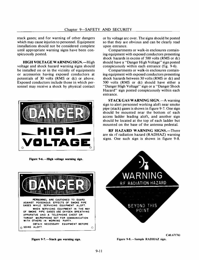
Chapter 9-SAFETY AND SECURITY
stack gases; and for warning of other dangers which may cause injuries to personnel. Equipment installations should not be considered complete until appropriate warning signs have been conspicuously posted.
HIGH VOLT AGE WARNING SIGN .-High voltage and shock hazard warning signs should be installed on or in the vicinity of equipments or accessories having exposed conductors at potentials of 30 volts (RMS or de) or above. Exposed conductors include those in which personnel may receive a shock by physical contact
-.......HII3"..........
VDLTAI3E 0 0
Figure 9-6.-Higb voltage warning sign.
PERSONNEL ARE CAUTIONED TO GUARD AGAINST POISONOUS EFFECTS OF SMOKE PIPE GASES WHILE SERVICING EQUIPMENT ALOFT.
WHEN SERVICING EQUIPMENT IN THE WAY OF SMOKE PIPE GASES USE OXYGEN BREATHING
APPARATUS AND A TELEPHONE CHEST OR
THIIIOAT MICROPHONE SET FOR COMMUNICATION WITH OTHERS IN WORKING PARTY.
OBTAIN NECESSARY EQUIPMENT BEFORE
0 GOING ALOFT.
Figure 9-7.-Stac:k gas warning sign.
0
9-11
or by voltage arc over. The signs should be posted so that they are obvious and can be clearly read upon entrance.
Compartments or walk-in enclosures containing equipment with exposed conductors presenting shock hazards in excess of 500 volts (RMS or de) should have a "Danger High Voltage" sign posted conspicuously within each entrance (fig_ 9-6).
Compartments or walk-in enclosures containing equipment with exposed conductors presenting shock hazards between 30 volts (RMS or de) and 500 volts (RMS or de) should have either a "Danger High Voltage" sign or a "Danger Shock Hazard" sign posted conspicuously within each entrance.
STACK GAS WARNING SIGN.-A warning sign to alert personnel working aloft near smoke pipe (stack) gases is shown in figure 9-7. One sign should be mounted near the bottom of each access ladder leading aloft, and another sign should be located at the top of each ladder but mounted on the base of the antenna pedestal.
RF HAZARD WARNING SIGNS.-There are six rf radiation hazard (RADHAZ) warning signs. One such sign is shown in figure 9-8.
C40.67(76)
Figure 9-8.-Sample RADHAZ sign.
FIRE CONTROLMAN THIRD CLASS
Requisitioning information is contained on the signs themselves. Consult with your leading petty officer (LPO) to obtain the appropriate signs if they are not posted in your work spaces.
ROTATION HAZARD WARNING.-Rotating directors present a serious danger to personnel near them. To guard against this hazard, ensure that the topside area in the vicinity of the directors is cleared of all personnel before energizing the directors. "DANGER ROTATION HAZARD" warnings should also be posted or painted in conspicuous places to alert unwary personnel.
WORKING ALOFT
Another hazard is inherent in working on radar antennas. As most radar antennas are located on masts or on other parts of the upper super-structure, you will be going aloft to work on them.
Hazards while working aloft include death or injury from falling, asphyxiation from stacl< gasses, and electric shock (either from the equipment being worked on or from induced voltages in guy wires and other ungrounded conductive materials because of radiation from radio and radar antennas). Also included are overexposure to radiation from high-powered radar antennas, contact with rotating or oscillating antennas or other moving machinery, and overexposure to inclement weather conditions.
In addition to the danger from electric shock because of energized equipment and induced voltages, there may also be a shock hazard because of static charges. Static charges are caused by electrically charged particles that exist naturally in the water . Under certain conditions these charged particles will collect on metallic objects such as wire antennas and produce a shock hazard. Grounding the objects concerned will eliminate the hazard. Shocks from static charges will not cause direct harm to the individual , but any unexpected shock while aloft may cause a person to fall.
Before going aloft , you should obtain permission from the officer of the deck, and all transmitters and machinery in the vicinity of the work area should be secured and tagged. Permission should also be obtained from the
9-12
engineering officer to ensure that boiler tubes will not be blown or boiler safeties set during the time the work is being done aloft. I f in port or at anchor, you must also obtain permission from the OOD of any ships moored alongside. Notify these ships when work is completed.
You should wear an approved parachute-type safety harness (fig. 9-9) at all times when working aloft. (The lineman-type safety belt is no longer authorized for Navy use.) Safety harnesses should be checked periodically in accordance with the Planned Maintenance System. Tools to be used on the job should be placed in a canvas bag and hauled up with a line to the job location. To guard against dropping tools and seriously injuring someone, we recommend that the tool being used be tied to the safety harness with a piece of line.
RF RADIATION HAZARDS
Radar peak power may reach a million watts or more. Rf radiation hazards exist in the vicinity of radar transmitting antennas. These hazards are present not only in front of an antenna but also to the sides and sometimes even behind it because of spillover and reflection. At some frequencies, exposure to excessive levels of radiation will not produce a noticeable sensation of pain or discomfort to give warning of injury. I f you suspect any injury, see your ship's doctor or corpsman. Be sure to acquaint yourself with the actual radiation hazard zones of the radars on your ship.
The following precautions should be observed to ensure that personnel are not exposed to harmful rf radiation:
• Visual inspection of feedhorns, open ends of waveguides, and any opening emitting rf energy should not be made unless the equipment is definitely secured for that purpose.
e All personnel should observe rf radiation hazard (RADHAZ) warning signs (fig. 9-8), which point out the existence of rf radiation hazards in a specific location or area.
• Ensure that radiation hazard warning signs are available and used.
• Ensure that those radar antennas that normally rotate are rotated continuously while radiating or are trained to a known safe bearing.
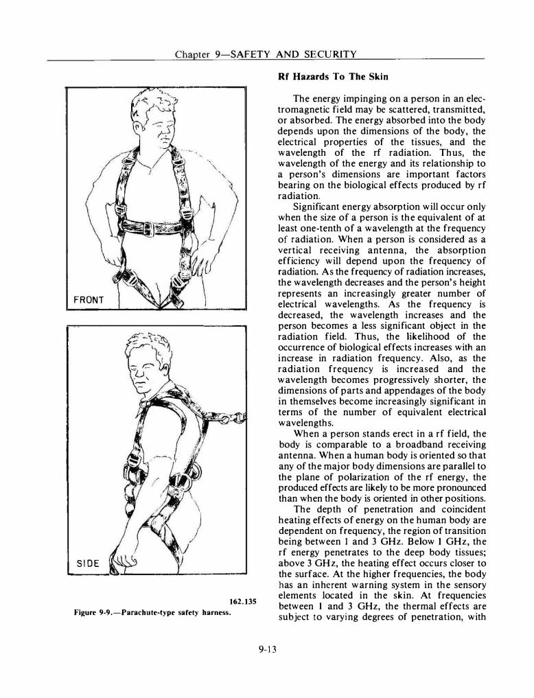
Chapter 9-SAFETY AND SECURITY
FRONT
SIDE
162.135
Figure 9-9.-Parachute-type safety harness.
9-13
Rf Hazards To The Skin
The energy impinging on a person in an electromagnetic field may be scattered, transmitted, or absorbed. The energy absorbed into the body depends upon the dimensions of the body, the electrical properties of the tissues, and the wavelength of the rf radiation. Thus, the wavelength of the energy and its relationship to a person's dimensions are important factors bearing on the biological effects produced by rf radiation.
Significant energy absorption will occur only when the size of a person is the equivalent of at least one-tenth of a wavelength at the frequency of radiation. When a person is considered as a vertical receiving antenna, the absorption efficiency will depend upon the frequency of radiation. As the frequency of radiation increases, the wavelength decreases and the person's height represents an increasingly greater number of electrical wavelengths. As the frequency is decreased, the wavelength increases and the person becomes a less significant object in the radiation field. Thus, the likelihood of the occurrence of biological effects increases with an increase in radiation frequency. Also, as the radiation frequency is increased and the wavelength becomes progressively shorter, the dimensions of parts and appendages of the body in themselves become increasingly significant in terms of the number of equivalent electrical wavelengths.
When a person stands erect in a rf field, the body is comparable to a broadband receiving antenna. When a human body is oriented so that any of the major body dimensions are parallel to the plane of polarization of the rf energy, the produced effects are likely to be more pronounced than when the body is oriented in other positions.
The depth of penetration and coincident heating effects of energy on the human body are dependent on frequency, the region of transition being between 1 and 3 GHz. Below 1 GHz, the rf energy penetrates to the deep body tissues; above 3 GHz, the heating effect occurs closer to the surface. At the higher frequencies, the body has an inherent warning system in the sensory elements located in the skin. At frequencies between 1 and 3 GHz, the thermal effects are subject to varying degrees of penetration, with
FIRE CONTROLMAN THIRD CLASS
the percentage of absorbed energy ranging from 20 to 100 percent of that incident on the body. The two microwave cooking oven frequencies fall close to this range. The lower frequency, 9 1 5 MHz, produces a deeper heating effect on roasts and is not as effective for surface cooking (browning) as the higher 2450 MHz.
The heat produced by rf radiation may adversely affect live tissue. If the organism cannot dissipate this heat energy as fast as it is produced, the internal temperature of the body will rise. This may result in damage to the tissue and, if the rise is sufficiently high, in death.
Rf Hazard To The Eyes
The transparent lens of the eye may be damaged by radiated energy, whether ionizing, infrared, or radio-frequency, causing the development of cataracts or opacities in the eyes. The lens of the eye is very susceptible to thermal damage, since it has an inefficient vascular system to circulate blood and exchange heat to the surrounding tissues. Unlike other cells of the body, the transparent lens cells of the eye cannot be replaced by regrowth. When the cells making up the lens die or become damaged, a cataract may form. The damaged cells may lose their transparency slowly and, as a result, depending upon the extent of damage, the individual suffers impaired vision. Apparently, the presence of even a relatively few damaged cells is believed to act upon other lens cells, either by releasing toxic substances or by preventing normal chemical transformation to take place within other cells.
The fact that the lens of the eye is transparent makes it possible to employ visual examination techniques to detect early changes in lens struct ure. Lens opacities or other changes can be ident ified promptly and their development investigated without the need for anesthesia. The slit lamp is an instrument that projects a narrow beam of light into the eye and provides sufficient magnification for a visual study of the various layers comprising the eye lens.
Rf Hazard To The Testicles
Testicular reaction to heat mjury resulting from excessive exposure to rf radiation appears to be the same as the reaction to a high fever
9- 1 4
associated with many illnesses. Although a condition of temporary sterility and damage to seminiferous tubules may occur, the condition does not appear to be of a permanent nature and will ultimately correct itself.
Shipboard Radiation Hazard Zones
Because of the danger of radiation hazards to personnel, the fire control radar is equipped with cutout switches t hat turn off t he transmitter for certain bearings and elevations of the director. The information concerning cutout zones for your particular installation is located in the radar OPs. You should know the cutout zones for your particular radar. The equipment OPs also give the radiation pattern and the minimum safe distance for personnel exposed to the mainbeam of the radar. The safe limits of radiation exposure to personnel as established by the Naval Medical Command are 1 0 mW/cm2 averaged over any one-tenth hour period. No exposure in a field with a power density in excess of 100 mW /cm2 is permitted.
Rf Hazard to Ordnance
Modern radio and radar transmitting equipment produces high intensity radio frequency (rf) fields. Such fields can cause premature actuation of sensitive electroexplosive devices (EEDs) contained in ordnance systems. The Hazards of Electromagnetic Radiation to Ordnance (HERO) problem was first recognized in 1958, and prime factors causing the problem have been increasing ever since. The use of EEDs in ordnance systems has become essential. At the same time, the power output and frequency ranges of radio and radar transmitting equipment are continually being extended.
Rf energy may enter an ordnance item through a hole or crack in its skin or may be conducted into it by firing leads, wires, screwdrivers, and so on. In general, ordnance systems that have proven to be susceptible to rf energy are most susceptible during assembly, disassembly, loading, unloading, and handling in rf electromagnetic fields.
The most likely effects of premature actuation are propellant ignition or reduction of reliability by dudding. Where out-of-line Safety and

Chapter 9-SAFETY AND SECURITY
Arming (S + A) devices are used; the actuation of EED may be undetectable without disassembly. In the absence of such S + A devices, or in the event rf energy bypasses the devices, a probability of warhead detonation exists.
To ensure the HERO safety and HERO reliability of ordnance systems, the Naval Sea Systems Command sponsors an extensive testing program to determine their susceptibility to rf energy. HERO requirements and precautions are specified and tabulated in NAVSEA OP 3565/NAVAIR 16-1 -529/NAVELEX 0967-LP-624-6010/TECHNICAL MANUAL ELECTROMAGNETIC RADIATION HAZARDS (U). The specific requirements for each ship is specified in the ship's HERO Emission Control (EMCON) bill.
It is the responsibility of the commanding officer of each ship or shore station to implement the HERO requirements specified in the previously mentioned publications. That person is required to establish a procedure whereby radiation from radio and radar antennas is positively controlled and coordinated among personnel handling ordnance and personnel controlling radio and radar transmitters, to ensure the observance of the operating restrictions prescribed. This will be accomplished by a command instruction based on the ship's mission and special features. This instruction will usually be found in the Ship's Organization Manual and will be the basis for department and division instructions.
ELECTRICAL FIRE
In case of an electrical fire, proceed as follows:
1. Deenergize the circuit or equipment affected and shift the load to stand-by circuits or equipment. In case no stand-by circuit or equipment is available, deenergize the circuit or equipment affected by the fire except in extreme emergency when the need for uninterrupted power is considered to be of such paramount importance as to outweigh the risk incurred by leaving it energized.
2. Report the fire. 3 . Extinguish the fire with carbon dioxide.
Care must be taken to avoid high concentrations of carbon dioxide in confined spaces since this is dangerous to personnel.
9- 1 5
I n electrical fires, you must remember that quick action is most needed for deenergizing the circuit. When this has been done, stop, look, and think, and then act fast to extinquish the fire before it spreads.
SECURITY
Security of the United States in general, and of naval operations in particular, depends in part upon success attained in safeguarding classified information. FCs must be security conscious to the point that they automatically exercise proper discretion in performing their duties and do not think of the security of information as something separate and apart from other matters. In this way, the security of classified information becomes a natural element of every task and not an additionally imposed burden.
During the daily work routine, the FC handles information of vital importance to the military and to the nation. This information which, if available to an enemy, might disclose the strength and intent of U.S . forces and reveal a wealth of technical information relating to procedures and operations of the United States Navy.
FCs use many official documents and publications that relate to such matters as frequencies, specifications, and procedures. These contents must be protected, because the more an enemy knows about these data, the better the chances of deriving intelligence from them.
Security is only as effective as it is made to be. Security is a basic part of the FC's duties. This personal responsibility of an FC to protect information cannot be transferred to any one else. Security is more than a matter of being careful; it requires both study and practice. Thorough understanding of this chapter will not provide full knowledge of all the finer points concerning security, but it will provide a good fundamental background upon which security is built. The basic reference for security is the OPNA VINST 55 1 0. 1 .
PURPOSE OF SECURITY PROGRAM
The security program deals basically with the safeguarding of information that should not be allowed to fall into the hands of foreign
FlRE CONTROLMAN THIRD CLASS
governments or foreign nationals because such information might be used to the detriment of the United States.
The Navy is a potential source of valuable information, and unceasing, systematic attempts to exploit that source are to be expected. The methods that may be used are many and varied. Planting agents within the naval establishment, photographing or stealing classified documents, tapping telephones and telegraph lines, employing electronic sensing devices which can be used from a distance, obtaining codes and ciphers, and analyzing naval personnel in their off-duty times are some of the procedures which might be used. Although information obtained through these means often appears innocuous, it proves to be of real value when subjected to expert, purposeful analysis and when combined with other fragments of information from various sources.
Information may be compromised through careless talk, improper handling of classified material, or in various other ways. Some of the ways in which military personnel may accidentally give away vital information are discussed in Basic Military Requirements, NA VEDTRA 10054.
The Department of Defense security formula is based on the premise of circulation control; i .e. , the control of dissemination of classified information. According to this policy, knowledge or possession of classified security information is permitted only to persons whose official duties require access in the interest of promoting national security and only if they are determined to be trustworthy.
SECURITY AREAS
Spaces containing classified matter are known as security areas. These security (or sensitive) areas have varying degrees of security interest, depending upon their purpose and the nature of the work and information or materials concerned. Consequently, the restrictions, controls, and protective measures required vary according to the degree of security importance. To meet different level of security sensitivity, there are three types of security areas-exclusion, limited, and controlled. All areas are clearly marked by signs reading "RESTRICTED AREA-KEEP OUT. AUTHORIZED PERSONNEL ONLY. "
9- 1 6
Exclusion Area
A space requiring the strictest control of access is designated an exclusion area and is so marked. This area contains classified matter of such a nature that, for all practical purposes, admittance to the area permits access to the material .
An exclusion area is fully enclosed by a perimeter barrier of solid construction. Exits and entrances are guarded or secured and alarm protected, and only those persons whose duties require access and who possess appropriate security clearances are authorized to enter.
Limited Area
A limited area is one in which the uncontrolled movement of personnel permits access to the classified information therein. Within the area, access may be prevented by escort and other internal controls.
The area is enclosed by a clearly defined perimeter barrier. Entrances and exits are either guarded by attendants to check personal identification or controlled by alarm protection.
Operating and maintenance personnel who require freedom of movement within a limited area must have a proper security clearance. The commanding officer may, however, authorize entrance of persons who do not have clearances. In such instances, escorts or attendants and other security precautions must be used to prevent access to information located within the area. The combat information center is classified a limited area.
Controlled Area
A controlled area does not contain classified information. I t serves as a buffer zone to provide greater administrative control and protection for the limited or exclusion areas. Thus, passageways or spaces surrounding or adjacent to limited or exclusion areas may be designated and marked contro/Jed areas.
Controlled areas require personnel identification and control systems adequate to limit admittance to those having bona fide need for access to the area.

Chapter 9-SAFETY AND SECURITY
CATEGORIES OF CLASSIFIED INFORMATION
Classified information from the Department of Defense relating to national security is protected against unauthorized disclosure by being designated in one of three classifications: Top Secret, Secret, or Confidential.
Top Secret
The Top Secret classification refers to national security information or material requiring the highest degree of protection. It is applied only to information or material of which the defense aspect is paramount and of which the unauthorized disclosure could reasonably be expected to cause EXCEPTIONALLY GRAVE DAMAGE to the nation; such as,
• A war, an armed attack against the United States or its allies, or disruption of foreign relations vitally affecting the national security of the United States
• The unauthorized disclosure of military or defense plans, intelligence operations, or scientific or technological developments vital to the national security
Secret
The Secret classification is limited to national security information or material that requires a substantial degree of protection and of which the unauthorized disclosure could reasonably be expected to cause SERIOUS DAMAGE to the nation; such as,
• Jeopardizing the international relations of the United States
• Endangering the effectiveness of a program or policy of vital importance to the national security
• Compromising important military or defense plans, or scientific developments important to national security
e Revealing important intelligence operations
9- 1 7
Confidential
The use of the Confidential classification is limited to national security information or material that requires protection and of which the unauthorized disclosure could reasonably be expected to cause IDENTIFIABLE DAMAGE to the national security; such as,
• Operational and battle reports that contain information of value to the enemy
• Intelligence reports
• Military radio-frequency and call sign allocations that are especially important or are changed frequently for security reasons
• Devices and material relating to communication security
• Information that reveals the strength of the land, air, or naval forces in the United States and overseas areas; identity or composition of the units; or detailed information relating to their equipment
• Documents and manuals contammg technical i n formation used for training, maintenance, and inspection of classified munitions of war
• Operational and tactical doctrine
• Research, development, production, and procurement of munitions of war
• Mobilization plans
• Personnel security investigations and other investigations, such as courts of inquiry, which require protection against unauthorized disclosure
• Matters and documents of a personal or disciplinary nature, which, if disclosed, could be prejudicial to the discipline and morale of the armed forces
• Documents used in connection with procurement, selection, or promotion of military personnel, the disclosure of which could violate the integrity of the competitive system
FIRE CONTROLMAN TH IRD CLASS
NOTE
Official information of the type described in the last three paragraphs is classified Confidential only if its unauthorized disclosure could reasonably be expected to cause damage to the security interests of the nation. I f such information does not relate strictly to defense, it must be safeguarded by means other than the Confidential classification as indicated i n the following text.
Special Markings
In addition to the security labels mentioned already, other markings also appear on classified material. Among these markings are such designations as "Restricted Data" and "For Official Use Only."
RESTRICTED DATA.-All data concerned with the (1) design, manufacture, or use of atomic weapons; (2) production of special nuclear material; or (3) use of special nuclear material in production of energy bear conspicuous "Restricted Data" markings. Restricted data, when declassified under the Atomic Energy Act of 1 9S4, must be marked "Formerly Restricted Data, Handle as Restricted Data in Foreigp Dissemination, Section 144b, Atomic Energy Act, 1954."
FOR OFFICIAL USE ONLY.-The term "For Official Use Only" (FOUO) is assigned to official information that requires some protection for the good of the public interest but is not safeguarded by classifications used in the interest of national security. An example of FOUO is your ship's Plan Of The Day (POD).
Preparation and Marking
Each document or piece of material is classified according to the importance of the information it contains or reveals. You should identify items of information that require protection and then consider whether compromise of the document or material as a whole would create a greater degree of damage than compromise of the items individually. The classification of the document or material must be the classification
9-1 8
that provides protection for the highest classified item of information or for the document or material as a whole, whichever is higher.
The markings required for classified material serve to record the proper classification, to inform recipients of the assigned classification, to indicate the level of protection required, to indicate the information that must be withheld from unauthorized persons, to provide a basis for derivative classification, and to facilitate downgrading and declassification actions.
Upon assignment of a classification category to information, it is immediately marked clearly and conspicuously on all documents. The classification marking of TOP SECRET, SECRET, or CONFIDENTIAL is stamped, printed, or written in capital letters that are larger than those in the text or the document. On other types of material, the classification marking is stamped, printed, written, painted, or affixed by means of a tag, sticker, decal, or similar device in a conspicuous manner. If marking on the material is not physically possible, written notice of the assigned classification is provided to recipients of the material.
Change In Classification
When classified information is determined to require a different level of protection th�m that presently assigned, or is determined to no longer require protection, it is regraded or declassified. A mandatory continuing program based on a time schedule has been established for automatically downgrading and declassifying documents originated within the Department of Defense.
The automatic downgrading and declassification system was instituted to ensure that all classified matter is available to the general public when secrecy is no longer necessary. It also relieves the originators of future concern for the classified aspects of documents or materials they have produced.
Depending on the contents on the material, classified information is placed into one of four groups. The assigned grouping indicates whether the material may be declassified automatically in the future. It also indicates when it may be declassified.
Chapter 9-SAFETY AND SECURITY
Rueipt Of Classified Material
Classified material is official material and not personal property. At all times it must be in the custody of authorized personnel and safeguarded in accordance with the requirements set forth in OPNA VINST 5510. 1 . Personnel retaining custody of classified material are required to sign receipts for such material. You should know who has custody of the classified material that you work with.
DESTRUCTION OF CLASSIFIED DOCUMENTS
When you need to destroy classified documents, the recommended methods are burning, shredding, pulping, or pulverizing.
Destruction is accomplished in the presence of one or two witnesses, according to the classification of the material. A witnessing official may be any military or civilian employee having a security clearance at least as high as the category of material being destroyed and be thoroughly familiar with the regulations and procedures for safeguarding classified information.
Routine Destruction
Destruction of superseded and obsolete classified materials that have served their purpose is termed routine destruction.
Every member of the burn detail should know exactly what is to be burned and should doublecheck each item before it is burned. Routine destruction of classified messages and trash in general is handled on a daily basis because of the rapid accumulation of these materials and the limited space available for storage.
Individual pages should be placed loosely into a burn bag prior to burning to facilitate the complete destruction of classified material. For example, bound documents should be torn apart, and the pages crumpled and fed to the fire a few pages at a time. All material must be watched until it is completely consumed. The ashes must be broken up and sifted through to ensure complete destruction. Following complete destruction of the classified matter, the burn log entry is made and the senior person present is required to inspect the ashes and sign as a witness to the destruction.
9-19
Upon this individual's approval the ashes are disposed of in accordance with command policy.
Emergency Destruction
Emergency destruction of classified material is authorized any time it is necessary to prevent its capture by an enemy.
Destruction plans call for the highest degree of individual initiative in preparing for and in actually commencing the required destruction. All personnel should understand that in emergencies subjecting classified material to compromise through capture, they must start necessary destruction under the plan without waiting for specific orders.
The order in which classified material is to be destroyed under emergency conditions should be determined in advance and the material so marked and stored. The effective edition of the OPNA V Instruction 55 10. 1 offers directions about the priority of destruction.
COMSEC material has the highest priority for emergency destruction. Insofar as humanly possible, it must not be permitted to fall into enemy hands. Other classified matter is destroyed in order of classification-highest classification first.
Destruction by fire is the traditional method for all combustible materials. Oil or chemicals may be used to facilitate burning. Classified equipment must be smashed beyond recognition and unclassified equipment should be demolished beyond repair.
A sufficient number of destruction toolsincluding sledge hammers, screwdrivers, axes, and wire cutters-are kept in electronics control and equipment spaces for use in emergency destruction. Written instructions regarding emergency destruction for electronics divisions must be included in the electronics doctrine and must detail procedures for destruction, location, and priority of destruction for software and hardware (using nameplate data), assignment of personnel and alternates by billet numbers, and specific location of destruction devices.
FIRE CONTROLMAN THIRD CLASS
STOWAGE OF CLASSIFIED MATERIAL
Keys or combinations to safes and lockers containing classified material are made available only to persons whose duties require access to them. Every 12 months, keys or combinations should be changed. They should also be changed whenever any person having knowledge of them is transferred from the organization and at any time the keys or combinations are suspected of being compromised. A key padlock should also be changed whenever a key is lost.
Any time you discover an unlocked and unattended safe or cabinet that contains classified material, report the condition immediately to the senior duty officer. The container or contents are not to be touched; they are to be guarded until the duty officer arrives. The duty officer then assumes responsibility for such further actions as locking the safe, recalling the responsible persons, and reporting the security violation to the commanding officer. The custodian must hold an immediate inventory of the contents of the safe and report any loss to the commanding officer.
COMMAND SECURITY PROGRAMS
Security is a means-not an end. Regulations that govern the security of classified material are comparable to electronic safety regulations. They do not guarantee protection, and they do not attempt to meet every conceivable situation. I f strictly adhered to, however, they will provide a satisfactory degree of security.
Each command formulates written security procedures to reflect the command 's particular requirements to ensure that the required security measures are implemented. These security procedures specify what is to be done, how it is to be done, who is to do it , and who is to supervise it. One such program of interest to the FC is the Personnel Reliability Program (PRP).
Personnel Reliability Program (PRP)
If your ship is nuclear-capable, that is, capable of employing nuclear weapons, then it is required by the Department of Defense to have a PRP program. The PRP is designed to assure the highest possible standards of individual
9-20
reliability in personnel performing duties associated with nuclear weapons and nuclear components. A PRP program is necessary because nuclear weapons require more concern and attention than conventional weapons because of their destructive power and the importance of their contribution to our strategic deterrent and tactical capability.
The overall objective of the PRP is to prevent the loss, theft, sabotage, unauthorized use, unauthorized destruction, accidental damage, or jettisoning of nuclear weapons. The specific objective is to minimize the possibility of personnel being assigned to or continued in duties under the PRP who do not meet specified reliability standards. This objective is accomplished through the careful screening and selection, education, continuing education of personnel assigned, and the prompt removal of personnel from the PRP who no longer meet the high standards prescribed.
Reliability Standards
You, as an FC and a member of the weapons department, might be considered for a position in the PRP program. Your selection will be based on the following reliability standards.
QUALIFYING.-All of the following traits or conduct are considered qualifying:
• Physical competence, mental alertness, and technical proficiency commensurate with job or duty requirements
• Evidence of dependability in (1) accepting responsibility, (2) effectively accomplishing duties in an approved manner, and (3) flexibility in adjusting to changes in working environment.
• Evidence of good social adjustment and emotional stability and ability to exercise sound judgment in meeting adverse or emergency situations
• Positive attitude toward nuclear weapon duty including the purpose of the PRP
DISQUALIFYING.-Any of the following traits or conduct is considered disqualifying,
Chapter 9-SAFETY AND SECURITY
unless overridden evidence of reliable duty performance exists:
• Alcohol abuse.
• Drug abuse. (It is not intended that isolated or experimental use of marijuana be automatically disqualifying. The certifying official must make a judgment as to whether or not such experimental or isolated use does in fact have an adverse impact on the individual's reliability .)
• Negligence or delinquency in performance of duty.
• Courts-martial or civil convictions of a serious nature or a pattern of behavior or actions which is reasonably indicative of a contemptuous attitude toward the law or other duly constituted authority.
• Any significant physical, mental, or character trait, or aberrant behavior, substantiated by competent medical authority. which in the judgment of the certifying official is prejudicial to reliable performance of the duties of a particular Critical or Controlled Position.
• Poor attitude or lack of motivation.
Refer to BUPERSINST 55 1 0. 1 1 D for detail coverage of the PRP.
EMISSION CONTROL (EMCON)
On some occasions the use of radiating equipment can be more dangerous than valuable. Using Electronic Warfare (EW) techniques to detect (intercept) our electromagnetic radiations, an enemy force may locate our force long before we are in a position to engage. Needless to say, such detection could seriously impair the mission of the force. Emission control is used mainly to deny intercept early warning to an enemy in order to reduce the chance of being detected.
Although the control of electromagnetic radiations does not fall specifically within the scope of electronics maintenance, basic aspects and considerations of EM CON are important because of their impact on the planning and safe accomplishment of maintenance. To accomplish emission control within the force, the Officer in Tactical
9-2 1
Command (OTC} imposes conditions of silence on transmitting equipment.
Conditions of electronic silence may range from complete silence to unrestricted use of transmitting equipment. Conditions of silence for various portions of the rf spectrum ordinarily apply to all equipment using the affected frequencies.
The EMCON plan may be imposed on particular frequency bands or on types of equipment. Restrictions imposed on one type of emission are accompanied by corresponding restrictions on other equipment using the same part of the frequency spectrum.
Various degrees of silence are defined for naval use. The unqualified term "silence" indicates that complete restrictions are in effect. By referring to ATP 1, Volume II , the Allied Naval Signal Book, proper signals can be issued restricting radiations below any designated frequency. Under certain conditions it may not hold true, but as a general rule the detectable range increases as the frequency becomes lower. The higher the frequency, the more closely the electromagnetic wave approaches a line-of-sight transmission.
Although surface ship radar waves might not be detected by a surfaced submarine at a distance of 75 miles, the force may be detected and tracked by high-flying aircraft. Such considerations are the basis for the commander's decision regarding EMCON condition.
At times, complete silence would work to the detriment of the force. For example, it is obvious that nothing is to be gained by maintaining silence when in actual contact with the enemy.
SUMMARY
This chapter has presented those safety and security measures you are expected to practice in your daily work. Remember, as an individual Fire Controlman, you have a responsibility to yourself, your shipmates, and your country to always be alert to detect and report hazardous work practices and conditions. You should also report any security violation to your commanding officer so that it can be corrected before it can cause serious consequences.
CHAPTER 10
ADMINISTRATION
The operational and maintenance policies established for your equipment are based in part on information obtained from the records and reports that you make. Thus, administration is a tool to aid you and is well worth the paperwor\c involved. The benefits you receive from administration is not always apparent, but the paperwork is. In the interest of getting a job done quickly, the paperwork that is necessary to record maintenance actions, parts used, and so forth, is sometimes not done. When this happens everyone
suffers because the required maintenance information is not available to the people responsible for making sure your equipment works in accordance with the policies established.
THE IMPORTANCE OF PAPERWORK
In a worldwide operation such as the Navy, administrative paperwork becomes very important. Ships of all sizes with many different types of equipment installed are involved, and personnel are constantly being transferred. The administrative organization of a fire control work center needs the equipment reports and records to determine its past operational status. This information is also needed as a reference check to determine if and when new equipment troubles occur. Then, replacement parts can be made available; alterations to improve the equipment made; training programs planned; and procedures of operation and maintenance are safer, quicker, and more effective.
The administrative organization starts within the FC gang and works its way up through the ship's weapons department to the captain. There it goes from the ship through the channels within
10-1
the fleet organization to the material commands. For each operation, replacement, or maintenance step taken on the equipment, there is paperwork involved which holds the chain of information together.
As an illustration of the paperwork involved, let us take a brief look at one subunit of a fire control system-a radar set. Initially, a list identifying all the component subunits in the radar set is needed. The identification includes such information as the name of the unit, its type, its mark and mod numbers, and its serial number. Any alteration made to a unit and any ordered alteration received but not performed must be recorded with the unit's record. This way we know exactly what the radar set consists of and what its designed capabilities are. Based on this information, performance, operation, and maintenance, standards are established for the radar set.
A record is kept of the operational performance and the results of the periodic tests run on the radar. This information is compared with the operating standards to keep a running record of the operability of the radar. Any maintenance performed must be recorded in detail. This information indicates the reliability and maintainability of the radar. It also shows whether a change in the replacement parts carried by the ship or a modification to the radar set is required to eliminate a source of recurring trouble. If a defective part must be replaced, you must initiate the paperwork necessary to obtain the replacement from the supply department. Finally, a record of the personnel assigned to operate and maintain the radar, their qualifications, training program, and planned replacements should be kept.
FIRE CONTROLMAN THIRD CLASS
This is but a rough sketch of the paperwork involved with one subunit in a system. It is sometimes difficult to associate the assistance obtained from administration with the records and reports made out in a daily routine.
Other than the military duties required of all petty officers, your primary professional duty as an FC is keeping the fire control equipment in top working order. As part of your overall duty of maintaining fire control equipment, certain record-keeping chores are involved.
PUBLICATIONS
In chapter 8 of this manual, we discussed those publications that were equipment related and those that assisted you in performing planned maintenance. In this chapter, we will cover some of the other publications, forms, and reports that you will use to perform your administrative duties.
INSTRUCTIONS AND NOTICES
The Navy has a program for issuing directives that prescribe policy, organization, methods or procedures, and give out information. Certain publications are excluded from the program; such as, established manuals, operation releases, technical publications, some classified matter, and those joint Army-Navy-Air Force publications which are numbered serially, but do not have separate Army or Air Force designation.
This program, called the Navy Directives Issuance System, provides a uniform plan for issuing and maintaining directives; conformance to the system is required of all activities and commands of the Navy. Two types of releases are authorized under the plan: instructions and notices.
Instructions are directives that contain information or require action of a continuing nature. An instruction has permanent reference value and is effective until the originator supersedes or cancels it.
Notices are directives of a one-time nature and contain information or require action that can be completed immediately. A notice does not have permanent reference value and contains provisions for its own cancellation.
10-2
For reasons of identification and accurate filing, all directives are identified by the originator's authorized abbreviation; the type of release (whether an instruction or notice); a subject classification number; and, in the case of instructions only, a consecutive number. This information is assigned by the originator and is placed on each page of the document. Because of its temporary nature, a consecutive number is not assigned to a notice.
The numbering and identifying of directives can be better understood by considering a typical identifier:
NAVSEA
(a)
INST --r
(b)
8300.1A --r-TT
(c) (d)(e)
(a) The authorized abbreviation of the originator of the directive is placed here.
(b) This part refers to the type of release, in this case an instruction.
(c) This is the subject matter number which is determined by the subject matter of the directive and is obtained from the List of Standard Subject Identification Codes, SECNAVINST 5210.11. In this example, the subject classification number 8300 concerns guns and mounts.
(d) Following the period is the consecutive number which is found only on instructions. An originator assigns consecutive numbers to those consecutive instructions with the same subject classification number. In the preceding example, .1 indicates the first instruction under this subject classification. If the originator issues additional instructions dealing with this subject, they will assign the numbers 8300.2, 8300.3, 8300.4, and so on.
(e) This part refers to revisions of the instruction. The A indicates the first revision, B is the second revision, and so on.
The List of Standard Subject Identification Codes contains a numerical and alphabetical listing of numbers with their related subjects. It is of considerable value for reference use when information or instructions of a particular nature are desired. This instruction contains all the necessary information for classifying documents by subject. The major numerical subject group, 8000-8999 (ordnance material), is of special interest to the Fire Controlman.
Chapter 1 0-ADMINISTRA TION
A permanent file of instructions that are applicable to the ship is kept in the ship's office. This is the master file of instructions. Specific or subject files are kept in the department offices. Thus, a copy of all the ordnance instructions should be in the weapons office along with a copy of the Consolidated Subject Index, NA VPUBNOTE 5215.
ORDNANCE ALTERATIONS
Alterations to ordnance equipment approved by NA VSEA are called ORDAL Ts. An ORDAL T instruction furnishes the necessary information to accomplish the ORDAL T, while an ORDAL T kit provides the material (hardware) needed for alteration. A metal ORDAL T plate is attached to each major piece of ordnance equipment. The ORDAL T plate is normally mounted next to the unit's nameplate. The number of a completed ORDAL T is stamped on the ORDAL T plate as a permanent record. The completion of an ORDAL T is also recorded in the maintenance history of the equipment.
ORDAL Ts are numbered consecutively without regard to the applicability of equipment or vessel. A publication called ORDAL T 00 is an index of all the ORDALTs that have been issued and that are under preparation. The issued ORDAL Ts are listed numerically and by the applicable equipment.
Alterations that affect the military characteristics of a ship may be approved only by the Chief of Naval Operations and are called NAVALTs. If a NAVAL T affects ordnance equipment, it is called a NAVALT ORDALT. Alterations to change design specifications of the ship's hull or machinery are called SHIP ALT.
OAR Program
The ORDAL T Accomplishment Requirement (OAR) is a list issued by NA VSEA about six months prior to the overhaul of a ship. It shows the ORDAL Ts in the order of priority of accomplishment, the estimated manhours required for the accomplishment, and the estimated cost of each. Within two weeks of receipt of the OAR list, shipyard personnel notify
10-3
NA VSEA and the overhaul activity of the following information:
1. ORDAL T material on hand. 2. ORDAL T material on order but not on
board. 3. When applicable, special conditions that
may exist to warrant installation of conditional ORDALTs.
4. ORDAL Ts planned for ship's force accomplishment prior to completion of the overhaul period. Shipboard personnel should refrain from requisitioning material for any ORDALT included on the OAR list unless ship's force accomplishment is planned. NA VSEA and the overhaul activity should be notified of any changes that occur which affect the original report.
Upon receipt of the OAR list and the ship's report of ORDALT material on board, the overhaul activity orders those ORDAL Ts to be accomplished during the overhaul period.
ORDALT Assistance
ORDAL T kits for equipment are procured and distributed under the control of the Naval Ship Weapon Systems Engineering Station (NSWSES). When feasible, ships are brought to a particular ORDALT configuration during a repair availability or shipyard overhaul period. Prior to these periods, NA VSEA may send ORDALT verification teams aboard ship to assist in determining the ship's ORDAL T status/ORDAL T requirements.
SHIP EQUIPMENT CONFIGURATION ACCOUNTING SYSTEM (SECAS)
SECAS is the designated system responsible for maintaining the configuration of a ship. SECAS, as established by the Chief of Naval Material, is the central authority within the Navy for integrating ship configuration status accounting information. Configuration status accounting is the recording and reporting of the information that is needed to manage configuration effectively. A ships' configuration is its structure and composition, defined in terms of its onboard systems/equipment. SECAS encompasses all ships systems (that is, HM&E, ELEX,
FIRE CONTROLMAN THIRD CLASS
and ORD) and covers the operational life cycle of the ship starting with the date of delivery to the Navy.
SECAS data is maintained in a central file, the Weapons System File (WSF) at SPCC, Mechanicsburg, P A. Supply, maintenance, and support managers depend on this file to provide support to the fleet. When the structure or composition of either the ship or a particular system or equipment on the ship is modified (that is, SHIPALTs, ORDAL Ts), the modification must be documented. This action will ensure proper accounting of configuration changes and will facilitate improved supply and maintenance support (that is, technical manuals, PMS coverage, COSAL) to the fleet.
The OPNAV Form 4790/CK, Ships' Configuration Change Form, is used to report configuration changes at the individual equipment level. Since a configuration change is also a maintenance action, the CK form also serves to document maintenance through the 3-M system. The instructions for documenting a configuration change can be found in OPNA VINST 4790.4.
You should recognize that reporting of configuration changes by the ship is absolutely essential to ensure that spare parts, technical manuals, MRCs, and test equipment are available when needed.
SECAS Validation
The data in the file is verified against the actual configuration of onboard systems/equipment to ensure that the ship's configuration data in the Weapons System File (WSF) is current and up-to-date prior to the ship's overhaul. Onsite verification is accomplished by visually inspecting nonexpendable ordnance and related fire control systems and equipment, including associated ordnance, special purpose test equipment, and applicable ORDAL T status.
There are two methods of conducting a SECAS validation. In one method (fullteam validation), Naval Sea Support Center (NA VSEACEN) personnel conduct the validation of all equipment with limited ships' force personnel involvement. The second method, engineered validation, is a validation of only the equipment that is suspected of being recorded in the central file improperly or of such importance
10-4
to the ship's mission that the file must be absolutely accurate.
The quality of overhauling, planning, logistics and maintenance support received by the ship is directly affected by the success of the SECAS validation. The success of the validation depends on both the technical expertise possessed by the SECAS validation team and the cooperation and assistance of shipboard personnel. Ship's force personnel are involved in the performance of validation, regardless of the method selected. Ship's force should assist by providing access to spares, opening equipment for alteration status verification, and providing technical documentation as requested by the validator team.
FORMS AND REPORTS
Forms are any printed labels, tags, placards, signs, decals, drawing formats, form letters, or any other duplicated or printed papers, which have blank spaces to fill in information to complete their meaning. Forms are used for requisitioning repair parts, recording information, and reporting. Completing a form requires careful reading and checking to make sure the answers are correct. However, it is much simpler and quicker than writing a narrative report. Also, it makes possible the accurate filing of results, which can be used at many levels.
Nonexpendable Equipment Status Log
All ships of the operating fleets equipped with surface missile systems should complete the original and one copy of the Nonexpendable Equipment Status Log, NA VSEA Form 4855/2 (fig. 10-1) for each piece of equipment applicable. The data on these forms is used to assess the performance of equipment. The assessments serve as the basis for identifying and correcting deficiencies in equipment and system reliability, maintainability, and availability. The originals of each week's logs are to be forwarded within seven working days after completion to Naval Weapons Station, Seal Beach, Corona, California. The log may be filled in by hand. The yellow copy of the 4855/2 is retained by the ship as its equipment rough log; no other log is required. The information recorded on the 4855/2 is not to repeat any maintenance action details that are normally
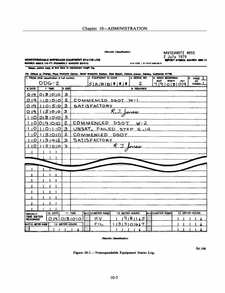
Chapter 10-ADMINISTRA TION
(Sec<A'Ifr a-�1 NAVSEANOTE 4855 2 July 1979
NOHIXJIINDAIILE IHIPIOARD EQUIPMENT STATUI LOG NAVRA 411111 (10..17) (FOMIUILY NAYOftD .. 1012)
.aiT lv.<IL NAVIU 4111·12 SIN coo 1 oue-u:-o.e-115!0
........ ,..._ IIGIIJ "' ... '"" 1ft ........ , rougll lag.
10: Ofllcler Ill a..e. "'"' AMiyM c.ne.r . ...... ....... ....... .... llleclt, c- AMell, c.-. Cellfomll 11710. 1. FROM (Ship cleuiiiCIIIotl & hul ��
ODG- 2
2. EOIM'MENT 10 CODE
Flaure 10-1.-Nonexpendable Equipment Status Log.
10-5
94.166
FIRE CONTROLMAN THIRD CLASS
reported on maintenance action form 4790/ZK. Use as many 485512 forms as necessary to record all information for a seven day period. Continue entries for the next day on the same sheet if space is available. Make at least one entry at the beginning of every day. This entry should show at least the date, time, and code in the appropriate columns. A final daily entry should show at least the date, time, status code, and signature of the person completing the form. Procedures for completing the 485512 are explained in NA VSEANOTE 4855. The security classification of the 4855/2 when filled in depends upon the content of the remarks section. If there are no classified remarks, then the form is unclassified and does not need to be marked. Examples of entries and how they may or may not classify the 4855/2 are as follows:
e Statement that a missile was fired is unclassified
e Statement of a missile firing with the results of the firing is Confidential
e Specific missile frequencies are Secret
• Routine operations of the equipment such as DSOTs, tracking operations, loading operations, or system testing, are unclassified
For the appropriate downgrading statement when the 485512 is classified, see OPNA VINST 5510 . 1 , Department of the Navy Security Program.
3-M Forms
Forms used iu the maintenance data system (MDS) are described in OPNA VINST 4790.4 and in Military Requirements for Petty Officer 3, NA VEDTRA 10044. All the forms described are of importance to you. As an FC3, you may be required to assist in the preparation of the weekly schedule, OPNAV Form 4790/ 1 5 .
The use of OPNA V Form 4790/2K i s also described in OPNA VINST 4790.4. This form is filled out when you are unable to complete the maintenance work on a certain piece of equipment, and it must be deferred until you can get parts and/or assistance from a repair facility.
10-6
OPNAV Form 4790/2K is also used to report completed maintenance actions on selected equipment unless a configuration change results. All details on this form must be carefully and accurately filled in. When used for deferred action, it may be several months before you can get repair assistance, and some important information could easily be forgotten in that time. Thus, timely and accurate completion of the form is essential. If a completed maintenance action does result in a configuration change, OPNA V Form 4790/CK is filled out.
CONAR
NAVSEAINST 8000 . 1 A, Commanding Officers Narrative Report (CONAR) provides a means for an assessment of the entire combat system. Unusual problems dealing with equipment operation, quality control, or poor design of parts can be reported. Recommendations concerning manpower and technical publications can also be made.
The CONAR is not meant to replace normal problem reporting methods but only to supplement them.
OTHER PUBLICATIONS
Various other publications from NAVSEA and other commands are of interest to the FC. Some of them are discussed here.
Surface Missile Systems (SMS) Technical Bulletins
SMS technical bulletins are an important source of information, containing up-to-theminute data on a particular weapon system. For example, the TERRIER, TARTAR, and BASIC POINT DEFENSE systems each have a bulletin source of data. The bulletins serve the need for the rapid spread of official NA VSEA approved material, such as new or revised test procedures, troubleshooting techniques, methods of alignment and adjustment, and other technical information on a system. The information is obtained from fleet commands and units, shore activities, and civilian contractors. The bulletins are then distributed to all activities concerned with the weapons system. This information may be
Chapter 10-ADMINISTRA TION
incorporated into the system publications and could result in an alteration to the weapons system.
Technical bulletins sometimes call attention to technical problems and refer to the specific procedures in related technical manuals which, if followed carefully, should greatly reduce or eliminate these problems. A technical bulletin may note a problem area for which a solution is being developed that will be covered in an official publication change as soon as the solution has been determined.
Technical bulletins should not be used in place of technical manuals or planned maintenance system documentation changes. Also, they should not be used in place of an ORDAL T to direct engineering changes or equipment alterations.
Deficiency Correction Action Program
The Deficiency Corrective Action Program (DCAP) provides a means of communication between the fleet technicians and their civilian counterparts, the engineering experts. These experts are ready to work on problems concerning equipment and documentation. The SMS related experts are located at the Naval Ship Weapon Systems Engineering Station (NSWSES) Port Hueneme, California.
Problems are reported via DCAP voluntary input forms (fig. 10-2), OPNAV 4790.2Ks, feedback reports, and the like. In the case of SMS related problems, NSWSES personnel read these reports, extract the problems, and forward the needed information to cognizant departments for action. Engineering personnel at NSWSES and, when required, other activities analyze the problems and develop solutions.
A problem solution often takes the form of an ORDAL T that must be procured and scheduled for installation. In this event, allowance parts lists must also be updated. In other cases, a procedural change is the best solution.
On a monthly or quarterly basis, NSWSES personnel assemble all problem data pertaining to a particular SMS DCAP status report (for example, AEGIS, TERRIER, TARTAR, BASIC POINT DEFENSE, NATO SEASPARROW, HARPOON, search radars, or system support/NTDS) and prepare the DCAP status reports for publication.
10-7
DCAP status reports are mailed to problem originators and to all similarly equipped units, closing the loop that began when the problem was first reported.
In this way, the DCAP is used to respond to your equipment and documentation problems in a timely manner and to make the problem and solution known to all concerned fleet units and shore stations.
Naval Ships' Technical Manual
The Naval Ships• Technical Manual (NSTM) contains guidance and instructions pertaining to classes of installed systems and equipment. The information is in accordance with what is regarded as the satisfactory and safe operation, test, and repair of the equipment. Since the information deals with classes of equipment, it is general information and can provide you with background knowledge additional to the data contained in equipment technical manuals and maintenance requirement cards. Chapter 400 of the NSTM is on electronic equipment and will be of special interest to you.
Electronics Installation And Maintenance Books (EIMB)
The Electronics Installation and Maintenance Books are published by NAVSEA to provide installation and maintenance information for naval electronic equipment. The books are intended to reduce time-consuming research on electronic equipment and circuit theory and contain a great deal of information of interest to the FC. The books are divided into several volumes; each volume can be ordered as an individual item.
Ship's Plan Index
The plans and diagrams <'f the fire control equipment are the road maps for maintenance. Generally speaking, there are two basic sources of this type of information-the Ship's Plan Index and ordnance drawings. The Ship's Plan Index (SPI) is prepared by the shipbuilding yard and is normally maintained aboard ship by the engineering office. The SPI lists the wiring diagrams of fire control circuits, and the general arrangement and installation plans of the fire
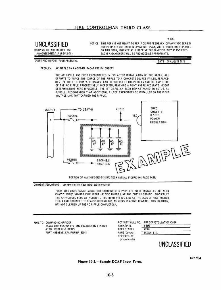
FIRE CONTROLMAN THIRD CLASS
V·OS43
UNCLASSIFIED DCAP VOLUNTARY INPUT FORM IINO·NSWSES�810/llA (REV. 5·78)
NOTICE: THIS FORM IS NOT MEANT TO REPlACE PMS FEEDBACK (OPNAV 4790/7 SERIES) FOR PURPOSES OUTLINED IN OPNAVINST 4790.4, VOL. I. PROBLEMS REPORTED ON THIS FORM, HOWEVER, WILL RECEIVE THE SAME SCRUTINY AS PMS FEED· BACKS AND ANSWERS WILL BE PROVIDED AS APPROPRIATE.
SHARE AND REPORT YOUR PROBLEMS DATE 28 AUGUST 1978
PROBLEM: AC RIPPLE ON AN/SPS·48A RADAR RSC RHI SWEEPS
J63804
THE AC RIPPLE WAS FIRST ENCOUNTERED IN 1976 AFTER INSTALlATION OF THE RADAR. ALL EFFORTS TO TRACE THE SOURCE OF THE RIPPLE TO A CONCRETE SOURCE FAILED. REPLACE· MENT OF THE FILTER CAPACITORS ALSO FAILED TO CORRECT THE PROBLEM AND THE AMPLITUDE OF THE AC RIPPLE PROGRESSIVELY INCREASED, REACHING A POINT WHERE ACCURATE HEIGHT DETERMINATIONS WERE IMPOSSIBLE. THE ITT GILFillAN TECH REP ATTACHED TO MOTU·5, AL RUSSELL, RECOMMENDEI) THAT ADDITIONAL FILTER CAPACITORS BE INSTALLED ON THE INPUT VOLTAGE LINE THAT CARRIED THE RIPPLE.
�----�-TO 28A7·0
F63B15
28 31C 28C5
CHASSIS 87100
POWER R EGULATION
COMMENTS/SOLUTIONS: (Use reverse side if additional space required)
FOUR (4) 60 MICRO FARAD CAPACITORS CONNECTED IN PARALLEL WERE INSTALLED BETWEEN CHASSIS SERIES NUMBER 53800 INPUT +40 VDC UNREG LINE AND CHASSIS GROUND. PHYSICALLY THE CAPACITORS WERE ATTACHED TO THE INPUT +40 VOC LINE 1\ T THE BACK OF FUSE HOLDER F63814 AND GROUNDED TO CHASSIS GROUND BUS, AS SHOWN IN ABOVE DRAWING. THIS SOLUTION, HAS NOT CLEARED UP THE AC RIPPLE COMPLETELY.
MAIL TO: COMMANDING OFFICER NAVAL SHIP WEAPON SYSTEMS ENGINEERING STATION ATTN: CODE 0752 !OCAP)
ACTIVITY/HULL NO. �U:;::SS�C:.::O:.:..: NS:!:E..:..: TE�L:::LA:.:..T!..!.IO::,:N:...;C�V�G.:.. 4 ---RANK/RATE FTMl
PORT HUENEME, CALIFORNIA 93043 WORK CENTER WFOS NAME (Optional) SLOAN, E.E. REVIEWED BY
(il applicable)
Figure 10-2.-Sample DCAP Input Form.
10-8
UNCLASSIFIED
167.904
Chapter 10-ADMINISTRA TION
control equipment for your ship. The list does not include diagrams of the equipment's internal arrangements and electrical circuits. Ordnance drawings deal with the internal diagrams.
Ordnance Drawings
A master list of drawings is prepared for each major piece of ordnance equipment. This list includes all components of the equipment. Each component is itemized by assemblies, subassemblies, and details on a separate List of Drawings (LD).
The identifying number for each component LD is given, together with the general arrangement drawing number, on the master list of drawings for the equipment. Each component list of drawings also shows the special tools required for servicing that component. By reference to the list of drawings and the drawings for the mark and mod of a given assembly or subasssembly, it is possible to work down to an individual part and to identify the correct nomenclature, drawing, piece number, design dimensions, tolerances, and all other necessary information.
Ships Technical Publication System (STEPS) Ordnance Index T0751-AD-1DX-010
STEPS (formerly NA VSEA OP-0) is a listing of all types of ordnance publications stocked for issue by NAVSEA. The Index is divided into two parts. The first part is a numerical listing according to the type of publication. This part is a complete numerical listing of all NA VSEA Ordnance Pamphlets (OPs), Ordnance Data (ODs), and Ordnance Supply Office Illustrated Parts Breakdowns (Ois). In addition, it includes current Army Field Manuals (FMs) and Army Technical Manuals (TMs) used by Navy activities. For OPs, ODs, and Ols, the active publications and associated data are listed first. Following this is a list of historic publications (those that are known to be canceled or obsolete).
For active publications, the latest published change and subsequent changes under preparation are shown. Publications in the history file are listed with the latest revision and latest change associated with the publication at the time it was canceled or superseded.
10-9
Part two of STEPS is a subject listing. This part lists the ordnance publications under the appropriate system, equipment, or general subject area nomenclature. Only publications with code, mark, and mod relationships or general application for shipboard use are addressed in this section. The contents and description of STEPS may sound confusing, but it is easy to use.
USE OF STEPS INDEX.-Assume that you are working on a Mk 86 Mod 4 GFCS and you want all the available publications on the system that help make your job easier.
STEPS is normally kept in the weapons office. Usually, the name and identification data of the equipment is known, rather than the number of a publication. Therefore, start with the name of the equipment (for example, Fire Control System, Gun Mk 86 Mod 4). The first step toward finding the OPs and ODs on. the system is to go to the Subject Listing (Part 2) and look under the equipment's title (Fire Control System, Gun Mk 86 Mod 4). Here you will find two ODs, 43792 and 45432, and six OPs, 3758, 3759, 4044, 4049, 4051, and 4055.
The next step is to find these numbers in the Numerical Listing (Part 1) of STEPS. The pertinent information of the OPs and ODs, such as, the title, the number of volumes, the number of revisions, and how many changes have been added is found in this listing.
CLASSIFIED PUBLICATIONS
Many fire control publications are classified, and much of this material is in the confidential category. The security measures required in the handling of classified material are covered in OPNA VINST 5510.1 titled Department of the Navy Information Security Program Regulation. Generally, the responsibility for handling classified matter involves the receipt of, accounting for, making changes to, and distribution of all such matters. Everyone who has access to classified material must be familiar with the information in this publication.
Safeguarding Classified Material
The security of the United States in general, and of naval operations in particular, depends in
• , r
FIRE CONTROLMAN THIRD CLASS
part upon the success attained in the safeguarding of classified information. Security is not a separate burden to be imposed on personnel, but it is a part of the routine duties performed by per� sonnet. The ideal to be sought by all personnel is that they automatically exercise proper caution in the performance of their duties and do not think of security as something separate and apart from their routine work. In this way, security of classified information becomes second nature and poses no additional burden. You will find some basic information on security in Basic Military Requirements, NAVEDTRA 10054.
Complete instructions on classified matters are found in OPNA VINST 5510.1F, Department of the Navy Information Security Program Regulation. This publication is one with which you should become familiar. Use it as the official source of reference whenever a question of security arises. Also, the above regulation is described in detail in Security of Classified lnfor� mation, NAVEDTRA 10975.
PUBLICATION CHANGES
NA VSEA publications are constantly reviewed to correct errors and keep them up to date. A vast amount of data on the operation, performance testing, and maintenance of ordnance equipment is received and processed routinely by NAVSEA. When new methods are developed after a publica� tion has been issued, a change to the publication is issued.
When changes are made to ordnance publica� tions, an entire page or section of the publication is changed. The change pages are provided, along with a change guide.
Changes to a publication are numbered consecutively and should be made in that order. When the changes to a publication become too extensive, a revised edition is issued. The indexes of ordnance publications list the latest revision and the number of changes to each publication.
Types Of Changes
Message Changes (MCs) are issued to correct conditions that are potentially hazardous to personnel, equipment, or ammunition because of faulty documentation. MCs provide NAVSEA with the means of rapidly disseminating urgent
change information; this type of change should be made immediately.
Advance Change Notices (ACNs) are informal (but technically complete) temporary changes to the publications; they are interim changes pending issuance of a formal change. ACN change pages do not replace a page in the manual, but they are inserted immediately ahead of a corrected page.
Formal Changes (CHs) are replacement pages that are used to correct technical manuals. They incorporate improvements resulting from ORDAL Ts and SHIPAL Ts and an accumulation of corrections c
.ontained in the MCs and ACNs.
A change guide provides detailed step-by-step instructions for entering a change. If you become involved in updating ordnance publications, you should accomplish changes as rapidly as possible and carefully follow the instructions of the change guide. You must also ensure that the change applies to your particular equipment configuration.
SUPPLY
Although the supply department is responsible for supplies, you need to know how to identify what you want to get, how to write out the request, and how to report on your use of the supplies. The publications containing the stock numbers are maintained in the supply department. Cooperation with supply personnel is essential in performing your own duties.
SUPPLY DUTIES OF THE FC
Small quantities of supplies are kept in the weapons department and within the divisions of the weapons department. Usually these are small repair parts that are frequently used. As the materials are used, the FC in charge of the supplies should make replacements. This person has to know how to fill out the request form that is taken to the supply department to requisition supplies. These forms are illustrated and explained
10-10
Chapter 10-ADMINISTRA TION
in Military Requirements for Petty Officer 3, NAVEDTRA 10044. This same text gives you information on the sources of identification numbers for materials and spare parts. The National Stock Number (NSN) is the most important identification number. All the NSNs are given in the supply catalogs, but you may not have to use those to look up a number because the NSN for your equipment is usually given in several other sources. One of these is the COSAL.
COSAL AND WHAT IT MEANS
The Coordinated Shipboard Allowance List (COSAL) is the list of operating equipment and equipage on board a particular ship. The accuracy of this document is dependent on the accuracy of the ship's configuration stored in the central file, the WSF. As stated previously, you must submit 4790/CK forms whenever a configuration change takes place to keep the file correct.
Each major equipment has an Allowance Parts List (APL). An APL contains detailed technical data on the equipment and lists the repair parts needed for that equipment.
Equipage items differ from equipment items because they are portable and/or high-cost items that are subject to theft. The items (such as binoculars, stopwatches, typewriters, and test sets) require increased control. The Allowance Equipage List (AEL) describes the range and quantity of equipage items needed to support a ship's mission.
The COSAL has three parts and uses the same format as that shown in your military requirements text. Parts of the COSAL are identified as follows:
Part I of the COSAL has two sections, Section A and Section B. Section A lists all equipment and equipage in alphabetical sequence by the name of the equipment. Section B lists each system and the name of each equipment that is in the system. The systems are listed in alphabetical order. Section A should be used to find the Allowance Parts List (APL) number
10-1 1
when you know the name of the equipment. Section B should be used when the system is known and when you are trying to find the APL of the equipment listed under that system.
Part II of the COSAL is divided into three sections: A, B, and C. Section A contains an A PL. You should use section A to find the National Stock Number (NSN) of the equipment. The APL shows you the part number of the item and the NSN that you should use in ordering the part from supply. When you have a part that has to be replaced in your equipment, you should go to Part I Section A of the COSAL to find the APL number of the equipment and then to Part II Section A (the APL) where you use the part number of the broken part to find the NSN assigned to that part. Section B is located in microfiche with the COSAL. It shows a breakdown of all significant maintenance parts in CSN (Circuit Symbol Number) sequence (or Part Number Sequence for some equipments such as Training Devices or Teletype). Section C contains the AEL. You should use it to find the NSNs for the equipage assigned to your work center.
Part III of the COSAL is called the Stock Number Sequence List (SNSL). This part of the COSAL also has two sections. Section A lists all the parts that are authorized to be in supply storerooms and are called Storeroom Items (SRI). SRI is listed by the National Item Identification Number (NIIN). An N liN is the last nine digits of the NSN. Section B of Part III lists the items allowed on board for the ship's work centers and is called Operating Space Items (OSI). This section is also listed in NIIN sequence. Part 111 Section B also has two subsections that identify the Ready Service Spares (RSS) or Maintenance Assistance Modules (MAMs) that you might rate for your equipment. RSSs that are authorized are listed in the CR Section of Part III B, and MAMs are listed in the CF Section.
SOURCES OF IDENTIFICATION
To request a repair part for your equipment, you must be able to identify that part in terms of the supply system. The following publications
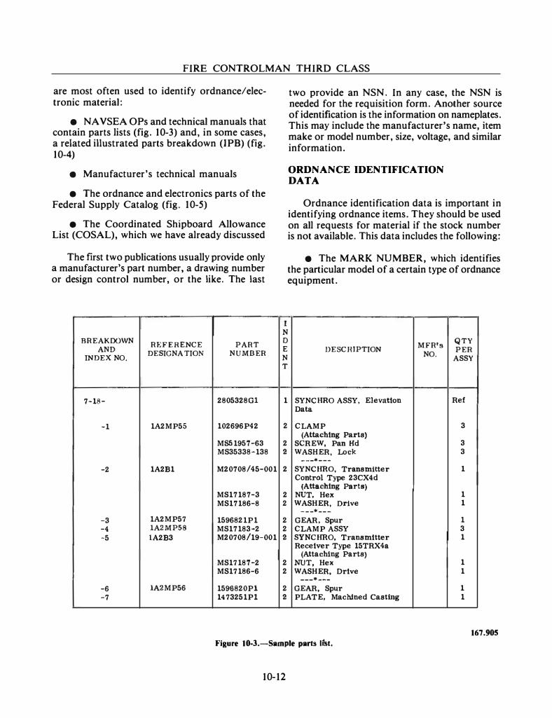
FIRE CONTROLMAN THIRD CLASS
are most often used to identify ordnance/electronic material:
• NAVSEA OPs and technical manuals that contain parts lists (fig. 10-3) and, in some cases, a related illustrated parts breakdown (IPB) (fig. 10-4)
e Manufacturer's technical manuals
• The ordnance and electronics parts of the Federal Supply Catalog (fig. 10-5)
• The Coordinated Shipboard Allowance List (COSAL), which we have already discussed
The first two publications usually provide only a manufacturer's part number, a drawing number or design control number, or the like. The last
BREAKDOWN REFERENCE PART
AND DESIGNATION NUMBER
INDEX NO.
7-18- 2805328Gl
-1 1A2MP55 102696P42
MS51957-63 MS35338-138
-2 1A2B1 M20708/45-001
MS17187-3 MS17186-8
-3 1A2MP57 1596821P1 -4 1A2MP58 MS17183-2 -5 1A2B3 M20708/19-001
MS17187-2 MS17186-6
-6 1A2MP56 1596820Pl -7 1473251Pl
two provide an NSN. In any case, the NSN is needed for the requisition form. Another source of identification is the information on nameplates. This may include the manufacturer's name, item make or model number, size, voltage, and similar information.
ORDNANCE IDENTIFICATION DATA
Ordnance identification data is important in identifying ordnance items. They should be used on all requests for material if the stock number is not available. This data includes the following:
e The MARK NUMBER, which identifies the particular model of a certain type of ordnance equipment.
r N 0
MFR 's QTY
E DESCHfPTION NO.
PER N ASSY T
1 SYNCHRO ASSY, Elevation Ref Data
2 CLAMP 3 (Attaching Parts)
2 SCREW, Pan Hd 3 2 WASHER, Lock 3
---• ---
2 SYNCHRO, Transmitter 1 Control Type 23CX4d
(Attaching Parts) 2 NUT, Hex 1 2 WASHER, Drive 1
- - -* ---
2 GEAR, Spur 1 2 CLAMP ASSY 3 2 SYNCHRO, Transmitter 1
Receiver Type 15TRX4a (Attaching Parts)
2 NUT, Hex 1 2 WASHER, Drive 1
---• ---
2 GEAR, Spur 1 2 PLATE, Machined Castlng 1
167.905 Figure 10-3.-Sample parts lt'st.
10-12
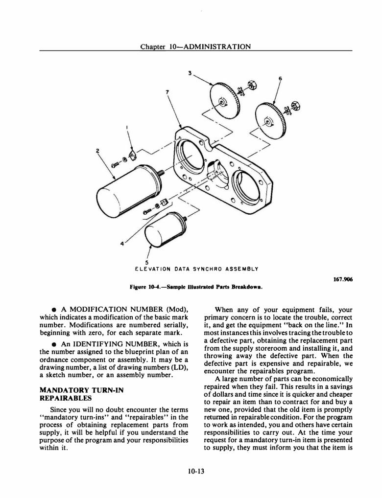
Chapter 10-ADMINISTRATION
5 E LE VAT ION DATA SYNCHRO ASSEMBLY
167.906
Fiaure 10-4.-Sample IJI•strated Parts Breakdowa.
e A MODIFICATION NUMBER (Mod), which indicates a modification of the basic mark number.
·Modifications are numbered serially,
beginning with zero, for each separate mark.
e An IDENTIFYING NUMBER, which is the number assigned to the blueprint plan of an ordnance component or assembly. It may be a drawing number, a list of drawing numbers (LD), a sketch number, or an assembly number.
MANDATORY TURN-IN REPAIRABLES
Since you will no doubt encounter the terms "mandatory turn-ins" and "repairables" in the process of obtaining replacement parts from supply, it will be helpful if you understand the purpose of the program and your responsibilities within it.
When any of your equipment fails, your primary concern is to locate the trouble, correct it, and get the equipment "back on the line." In most instances this involves tracing the trouble to a defective part, obtaining the replacement part from the supply storeroom and installing it, and throwing away the defective part. When the defective part is expensive and repairable, we encounter the repairables program.
A large number of parts can be economically repaired when they fail. This results in a savings of dollars and time since it is quicker and cheaper to repair an item than to contract for and buy a new one, provided that the old item is promptly returned in repairable condition. For the program to work as intended, you and others have certain responsibilities to carry out. At the time your request for a mandatory turn-in item is presented to supply, they must inform you that the item is
10-13
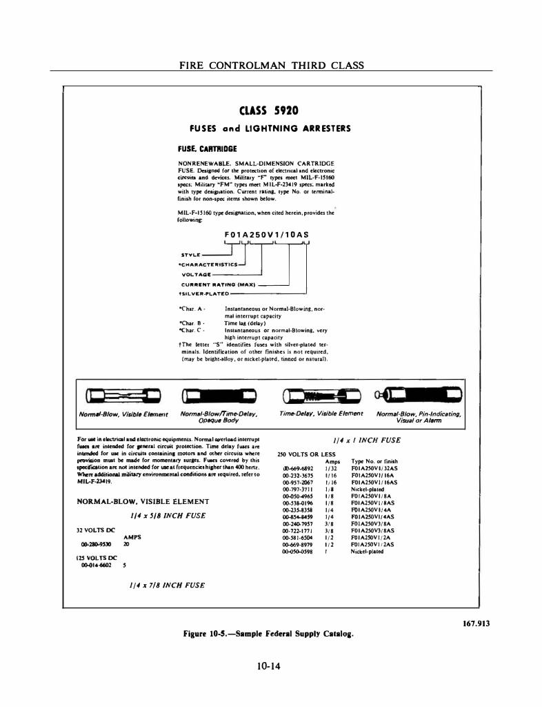
FIRE CONTROLMAN THIRD CLASS
CLASS 5920
FUSES and LIGHTNING ARRESTERS
(! ==t 1
FUSE. CARTRIDGE
NONRENEWABLE. SMALL-DIMENSION CARTRIDGE FUSE. Desi.,.ed fot the protec:tion of electrical and electronic ci!Cllill and clevias. Military �p types meet MIL-F-IS160 apec:s; Military �FM� types meet M IL-F-23419 specs; marked with type de1ip1ation. CW'rent ruina. type No. or tenni natfinish ror non-spec items shown below.
MIL-F-IH60 type daiption, when cited herein, provides the fol1o.,;na:
F01A250V1/10AS
STYL£ m1 [J •CHAitACT£1USTICS
\IOLTAQE
CUitiUNT lt"'TINO (MAX)
t51L\IEA-.. L"'TED ----------'
"Char. A-
<Char. 8 ·
Jnsrantaneous or Normal-Blow ins. normal interrupt capacity
Time lag (delay) "Char. C · Instantaneous or normal-81owina. very
high intenupt cap1city tThc leiter "S" identir.es fu,.s with silver-plated ter
minals. Identification of other finishes js not required. (mly be bri&ht·aUoy, or nicke1·plattd.tinncd or nllura1).
(I m !I Norm/11-8/ow, Vilibltt Elllmflflt Norm•I·Biowffim�DIIIIIy,
0f»qull8ody Tim�Del11y, Vilibfe Elemllflt Normiii-Biow, Pin-lndicttting,
Visu11/ or Al11rm
l/4 xI INCH FUSE For lilt in electrical and clcclroNc: equipmenll. Nonnal �etload interrupt f_. are intended for pMra1 circllit protection. Time delay ruaes arc intmdcd for usc in clrcwtt containin1 motors and other circuill where provilioa muat be made for mo!Mnlary suracs. Fuan co""rcd by this speW'"�e&tion arc not intended for uac at frequencies hiaher than 400 llertr. Wlteft ..Witiotlal military cnvironmonta1 cOIIditions arc required, refer to MIL-F·lJ.CI9.
2� VOLTS OR LESS
NORMAL-BLOW, VISIBLE ELEMENT
l/4 x 5/8 INCH FUSE
32 VOLTS DC
12.5 VOLTS DC GG-014-6602
AMPS 20
1/4 x 7/8 INCH FUSE
00-669-6892 00.232-3675 00-951-2061 00.797-3711 ()()..j)So-.96S 00-Sli-0196 00-23S.8351 00-854-14S9 00-240-79S7 00-722-1771 00-511-6� oo-669-8979 OO-O»>S98
Amps 1132 1!16 li16 Iii 1/8 l/8 It• 11• )[8 3/8 l/2 1/2 I
Type No. or finish FOIAl�VI./)21\S F01A2SOVI{16A FOIA2�V1/16AS Nickd·plated FOIA2�VI/8"1 FOIA2�VI/IAS F01A2.SOVI/4A F01A.2SOVI/.AS F01A2�V)/8A FOIA2.SOV3!8AS f'OIA2SOVI/2A FOIA.2.50VIi2AS Ni(�d-plated
Figure 10-5.-Sample Federal Supply Cataloa.
10-14
167.913
.. - - - _ __.___
Chapter 10-ADMINISTRATION
to be returned. At this point your responsibilities begin. You should do the following:
• Remove the defective part without damaging it
• Provide adequate protection to the part so that it will not be further damaged before it is turned in to supply. The most effective way for all concerned is to place the defective part in the same container in which you received the replacement part
• Return the defective part to supply as soon as practicable
When the needed part is not in the storeroom, supply must then take steps to obtain it. The failed part must still be returned and should be turned in prior to receiving the replacement part. This way the failed part can enter the repair cycle and
be available for reissue soon. The only exception is if the failed part permits limited operation of equipment until the replacement is received (remain-in-place item).
SUMMARY
As mentioned throughout this chapter, administration is a vital part of fire control. It is through administrative procedures that you requisition repair parts to keep your equipment operating and functioning properly. Administrative procedures also provide you with the means of reporting the status of your equipment to cognizant commands.
By following the proper administrative procedures, you wiU be doing your part to ensure that your fire control system is maintained in a high state of readiness.
10- 1 5
APPENDIX I
FIRE CONTROL SYMBOLS
PART A-BASIC SYMBOLS • . • • • • . • . • • • . . • • . . . . Al-2 PART I-BASIC SYMBOL MODIFIERS • . • . . • . . . • • • Al-5 PART (-QUANTITY MODIFIERS • • • • • • • • • • • . . . • Al-7
AI-l
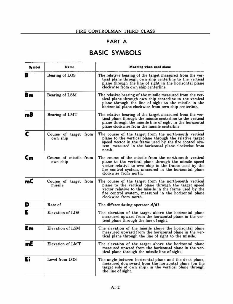
FIRE CONTROLMAN THIRD CLASS
PART A
BASIC SYMBOLS
s,.w Name Munlnl when uaed alone ----------------------------
I Bearing of LOS The relative bearing of the target measured from the ver-tical plane through own ship centerline to the vertical plane through the line of sight in the horizontal plane clockwise from own ship centerline .
... Bearing of LSM The relative bearing of the missile measured from the ver-tical plane through own ship centerline to the vertical �lane throufh the line of sight to the missile in the
orizontal p ane clockwise from own ship centerline .
.... Bearing of LMT The relative bearing of the tar�et measured from the ver-tical plane through the missi e centerline to the vertical plane through the missile line of sight in the horizontal plane clockwise from the missile centerline.
c Course of target from The course of the target from the north-south vertical own ship plane to the vertical plane through the relative target
speed vector in the frame used by the fire control sys-tern, measured in the horizontal plane clockwise from north.
Cm Course of missile from The course of the missile from the north-south vertical own ship plane to the vertical plane through the missile speed
vector relative to own ship in the frame used by the fire control system, measured in the horizontal plane clockwise from north.
mC Course of target from The course of the taJet from the north-south vertical missile plane to the vertica plane through the target speed
vector relative to the missile in the frame used by the fire control system, measured in the horizontal plane clockwise from north.
D Rate of The differentiating operator djdt. E Elevation of LOS The elevation of the target above the horizontal plane
measured upward from the horizontal plane in the ver-tical plane through the line of sight.
Em Elevation of LSM The elevation of the missile above the horizontal plane measured upward from the horizontal plane in the ver-tical plane through the line of sight to the missile.
mE Elevation of LMT The elevation of the target above the horizontal plane measured upward from the horizontal plane in the ver-tical plane through the missile line of stght.
Ei Level from LOS The angle between horizontal plane and the deck plane, measured downward from the horizontal plane (on the target side of own ship) in the vertical plane through the line of sight.
AI-2
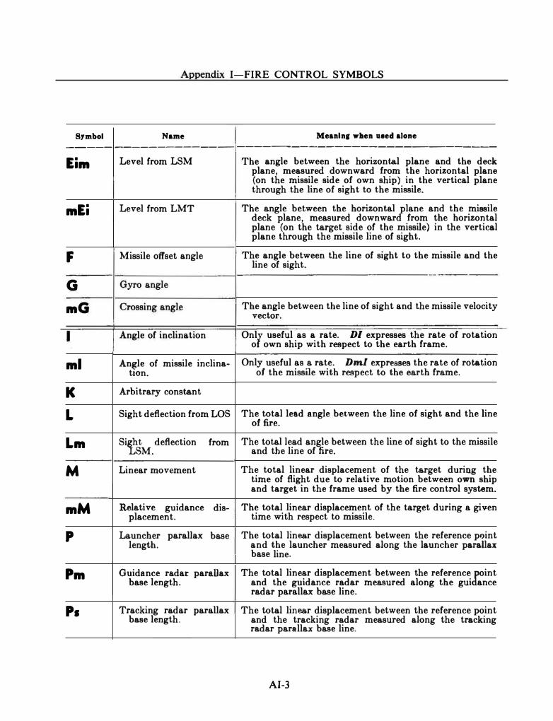
Appendix I-FIRE CONTROL SYMBOLS
Symbol Name Meanln( wben u1ed alone ----- ------·------ -------------------------·---
Eim Level from LSM The angle between the horizontal plane and the deck plane, measured downward from the horizontal plane (on the missile side of own ship) in the vertical plane through the line of sight to the missile.
mEi Level· from LMT The angle between the horizontal plane and the missile deck plane, measured downward from the horizontal plane (on the target side of the missile) in the vertical plane through the missile line of sight.
F Missile offset angle The angle between the line of sight to the missile and the line of sight.
-·-
G Gyro angle
mG Crossing angle The angle between the line of sight and the missile velocity vector.
I Angle of inclination Onll useful as a rate. DI expresses the rate of rotation o own ship with respect to the earth frame.
ml An�le of missile inclina-t10n.
Only useful as a rate. Dml expresses the rate of rotation of the missile with respect to the earth frame.
K Arbitrary constant
L Sight deflection from LOS The total lead angle between the line of sight and the line of fire.
Lm Si� deflection from The total lead angle between the line of sight to the missile M. and the line of fire.
M Linear movement The total linear displacement of the target during the time of flight due to relative motion between own ship and target in the frame used by the fire control system.
mM Relative guidance dis- The total linear displacement of the target during a given placement. time with respect to missile.
p Launcher parallax base The total linear displacement between the reference point length. and the launcher measured along the launcher parallax
base line.
Pm Guidance radar para.Uax base length.
The total linear displacement between the reference [.oint and the guidance radar measured along the gui ance radar parallax base line.
Ps Tracking radar parallax The total linear displacement between the reference point base length. and the tracking radar measured along the tracking
radar parallax base line.
AI-3
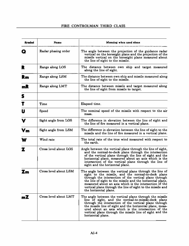
FIRE CONTROLMAN THIRD CLASS
s,.bol Name Meanlnll when uaed alone ---------------------------
Q Radar phasing order The angle between the rojection of the guidance radar vertical on the boresig t plane and the projection of the missile vertical on the boresight plane measured about the line of sight to the missile.
R Range along LOS The distance between own along the line of sight.
ship and target measured
Rm Range along LSM The distance between own ship and missile measured along the line of sight to the missile.
mR Range along LMT The distance between missile and target measured along the line of sight from missile to target.
s T Time Elapsed time.
u Speed The nominal speed of the missile with respect to the air mass.
v Sight angle from LOS The difference in elevation between the line of sight and the line of fire measured in a vertical plane.
Vm Sight angle from LSM The difference in elevation between the line of sight to the missile and the line of fire measured in a vertical plane.
w Wind rate The total rate of the true wind measured with respect to the earth.
z Cross level about LOS Angle between the vertical plane through the line of sight, and the normal-to-deck plane through the intersection of the vertical plane through the line of sight and the horizontal plane, measured about an axis which is the intersection of the vertical plane through the line of sight and the horizontal plane.
Zm Cross level about LSM The angle between the vertical �lane through the line of sight to the missile, and t e normal-to-deck plane through the intersection of the vertical plane through the line of sight to the missile and the horizontal plane, measured abOut an &..'�tis which is the intersection of the vertical plane through the line of sight to the missile and the horizontal plane.
mZ Cross level about LMT The angle between the vertical plane throu�h the missile line of sight, and the normal-to-missi e-deck plane thro�h the intersection of the vertical Jlane through the mtssile line of sight and the horizont plane, meas-ured about an axis which is the intersection of the vertical plane through the missile line of sight and the horizontal plane.
AI-4
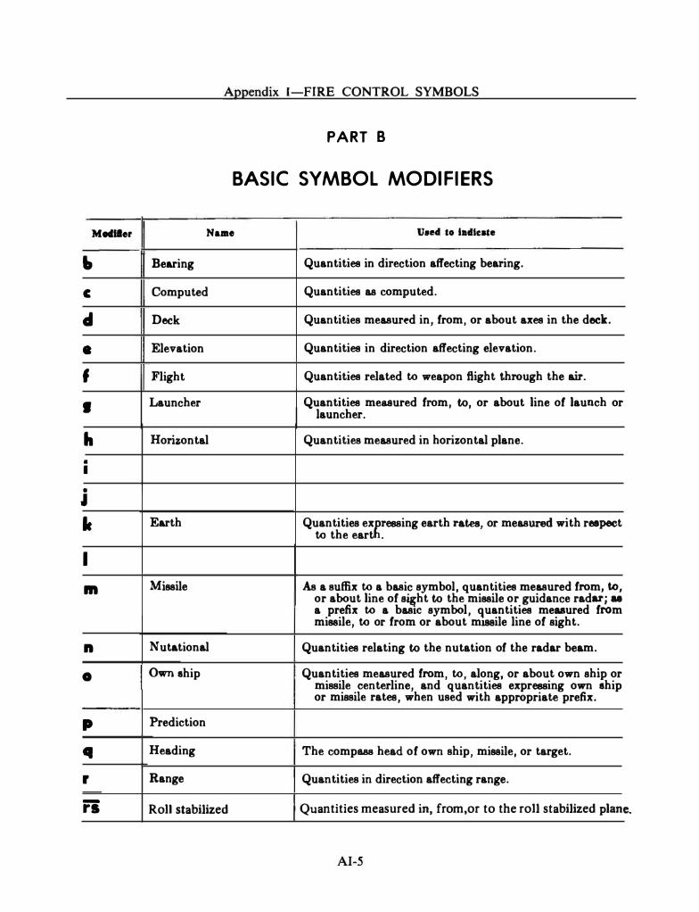
M .. ller
I» c
cl •
f I
h • I
•
J lc
I ...
n
0
p Cl r
-
rs
Appendix I-FIRE CONTROL SYMBOLS
PART B
BASIC SYMBOL MODIFIERS
Naae Uaed to la�ate
Bearing Quantities in direction affecting bearing.
Computed Quantities as computed.
Deck Quantities measured in, from, or about axes in the deck.
Elevation Quantities in direction affecting elevation.
Flight Quantities related to weapon ftight through the air.
Launcher Quantities measured from, to, or about line of launch or launcher.
Horizontal Quantities measured in horizontal plane.
Earth Quantities ex�ressing earth rates, or measured with reepeet to the eart .
Missile As a suffix to a basic symbol, quantities measured from, to, or about line of s�ht to the missile or guidance radar; u a prefix to a baste symbol, quantities measured from missile, to or from or about m188ile line of sight.
Nutational Quantities relating to the nutation of the radar beam.
Own ehip Quantities measured from, to, along, or about own ship or missile centerline, and quantities expressing own ehip or missile rates, when used with appropriate prefix.
Prediction
Heading The compass head of own ship, missile, or target.
Range Quantities in direction affecting range.
RoJJ stabilized Quantities measured in, from,or to the roll stabilized plan e.
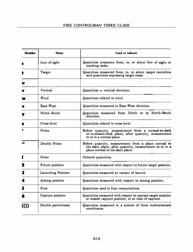
FIRE CONTROLMAN THIRD CLASS
Modller Name Uaed to Indicate
• Line of sight Quantities measured from, to, or about line tracking radar.
of sight or
t Target Quantities measured from, to, or about target centerline and quantities expressing target rates.
u -----
y Vertical Quantities 10 vertical direction.
w Wind Quantities related to wind.
X East-West Quantities measured in East-West direction.
y North-South Quantities measured from North or m N orth-8outh direction.
• Cross level Quantities related t.o cross level.
• Prime Before quantitJ. , measurement from a normal-to-deck or-to-missile- eck plane; after quantity, measurement to or in a normal plane.
•• Double Prime Before quantity, measurement from a plane normal to the slant plane; after quantity, measurement to or in & plane normal to the slant plane.
I Order Ordered quantities.
J Future position Quantities measured with respect to future target position.
3 Launching Position Quantities measured at instant of launch.
4 Aiming position Quantities measured with respect to aiming position.
5 Fuze Quantities used in fuze computations.
6 Capture position Quantities measured with respect to capture target position or missile capture position, or at time of capture.
(()) Double parentheses Quantities measured coordinates.
in a system of three indeterminate
A l-6
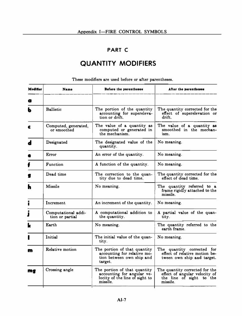
Appendix I-FIRE CONTROL SYMBOLS
PART C
QUANTITY MODIFIERS
These modifiers are used before or after parentheses.
Moclller Name Before the parenthe•e• Arter the p&rentlleHB ------------------------------------------------a
., Ballistic The portion of the quantity The quantity corrected for the accountin� for supereleva- effect of superelevation or tion or dnft. drift.
c Computed, generated, The value of a quantity as The value of a quantit� as or smoothed computed or generated in smoothed in the mec an-
the mechanism. 1sm.
cl Designated The designated value of the No meaning. quantity.
• Error An error of the quantity. No meaning.
f Function A function of the quantity. No meaning.
I Dead time The correction to the quan-tity due to dead time.
The quantity corrected for the effect of dead time.
h Missile No meaning. The quant� referred to a frame rigi y attached to the missile .
• Increment An increment of the quantity. No meaning. I
• Computational addi- A computational addition to A partial value of the quan-J tion or partial the quantity. tity.
lc Earth No meaning. The (hantity referred to the eart frame.
I Initial The initial value of the quan-tity.
No meaning.
m Relative motion The portion of that quantity The qua.ntit� corrected for accounting for relative mo- effect of re ative motion be-tion between own ship and tween own ship and target. target.
.... Crossing angle The portion of that quantity The quantity corrected for the accountin� for anfular ve- effect of anfular velocity of locitr. of t e line o sight to the line o sight to the misstle. missile.
AI-7
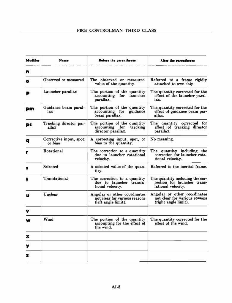
FIRE CONTROLMAN THIRD CLASS
Modller Name Berore tile parenthe•e• Arter tbe pareathe��e• ---- ------------ --------------- ---------------
n
0 Observed or measured The observed or measured Referred to a frame rigidly value of the quantity. attached to own ship.
p Launcher parallax The portion of the quantity The quantith corrected for the accounting for launcher effect of t e launcher pt.ral-parallax. lax.
pm Guidance beam paral- The portion of the quantity The quantity corrected for the lax accounting for guidance effect of guidance beam par-
beam parallax. all ax.
PI Tracking director par- The portion of the quantity The quantity corrected for all ax accounting for tracking effect of tracking director
director parallax. parallax.
q Corrective input, spot, A correcting input, spot, or No meaning. or bias bias to the quantity.
r Rotational The correction to a quantity The quantitk including the due to launcher rotational correction or launcher rota-velocity. tional velocity.
I Selected A selected value of the quan- Referred to the inertial frame. tity.
t Translational The correction to a quantity The quantity including the cor� due to launcher transla- rection for launcher trans-tional velocity. lational velocity.
u Unclear Angular or other coordinates Angular or other r,oordinatea not clear for various reasons not clear for various reasons (left angle limit). (right angle limit).
y
w Wind The portion of the quantity The quantit� corrected for the accounting for the effect of effect of t e wind. the wind.
X
y •
AI-8

APPENDIX II
MATHEMATICS TABLES NATURAL SINES, COSINES, AND TANGENTS
OF ANGLES FROM 0 o to 90 o
Dep. PUllet! aD o.o• 0.1° o.s• 0.1° 0., •. 1. 0.1° 0.1•
J O.T• •••• • •••
- 1-- 1-aiD 0.0000 0.0017 0.0035 0.0052 0.0070[ 0.0087 0.010$ 0.0122 0.0140 0.0157 0 eoa 1.0000 I. ()()()(I 1.0000 I 0000 I. 0000 1.0000 0.9999 0.9999 0. 9999 0.9999 tu 0.0000 0 0017 o.ooa5 0.0052 0.0070 0.0087 0.010$ 0.0122 0.0140 0.0157
IIID 0.0175 0.0192 0.0209 0.0227 0.0244 0.0262 0.0279 0.0297 0.0314 ·-�� 1 cue 0.9998 0.9998 0.9998 0.9997 0. 9997 0.9997 0.9996 0. 9996 0.9995 g:�m tu 0.0175 0.0192 0.0209 0.0227 0.02U 0.0262 0.0279 0.0297 0.0314
IIID O.oatD 0.0366 0.0384 O.otOI 0.0419 0.0�6 O.ot54 0 ot71 0.0488 0.0601' 2 ea. 0.9994 0.9993 0.9993 0.9992 0.9991 0.9990 0.9990 0.9989 0 9988 0.998j
tu 0.03t9 0.0367 0.0384 0.0402 0.0419 0.0437 0.04H 0.0472 0.0489 o.o:m
aiD 0.0523 .0.0541 0.0558 0.0576 0.0593 0.0610 0.0628 0.0645 0 0663 0 � 3 eoa 0.9986 0.9985 0.9984 0.9983 0.9982 0.9981 0.99!10 0.9979 0.9978 g:� ta.a 0.0524 0.0542 0.0559 0.0577 0.0594 0.0612 0.0629 0.06<17 0.0664
IIID 0.0698 0.0715 0.0732 0.0750 0.0767 0.0785 0.0802 0.0819 0.0837 g:;; 4 eo a 0.9976 0.9974 0.9973 0.9972 0.9971 0.9969 0.9968 0.9966 0.9965 ta.a 0.0699 0.0717 0.0734 0.0752 0.0769 0.0787 0.0805 0.0822 0.08to 0.085
aiD 0.0872 0.0889 0.0906 0.0924 0.0941 0.0958 0.0976 0.0993 0.1011 0.1�� 5 eo a 0.9962 0.9960 0.9959 0.9957 0.9956 0.9954 0.9952 0.9951 0.9949 O.PH
tu 0.0875 0.0892 0.0910 0.0928 0.0945 0.0963 0.0981 0.0998 0.1016 0.1033
aiD 0 1045 0.1063 0.1080 0.1097 0.1115 1 0.1132 0.1149 O.tl67 0.1184 g:� 6 co a 0.9945 0 9943 0.0942 0.9940 0.9938 0.9936 0.9934 0.9932 0.9930 ta.a 0.1051 0.1069 0.1086 0.1104 0.1122 o. Jl39 0.1157 0.1175 0.1192 O.J2l0 IIID 0.1219 0.1236 0.1253 0.1271 0.1288 0.1305 0.1623 0.13to 0.1�7 o:
TH! 7 co• 0.9925 0.9923 0.9921 0 9919 0.9917 0.99S. 0.9912 0.9910 0. 9907 o. ta.a 0.1228 0.1246 0.1263 0.1281 0.1299 o·.1ll17 0.1334 0.1352 0.1370 0.13 aiD 0.1392 O.lto9 O.U26 0 1444 0 1461 0 14� 0.1495 O.U13 0 1530 0 �=
8 ea. 0.9903 0 9900 0. 989S 0 9895 0.9893 0 98 0 9888 0.9885 0.11882 0 II laD 0.1605 0 1423 0 1441 0.14� 0.1477 0.14W5 0 1612 0.1530 0.1548 0.1 •ill 0.1564 0.1682 0 15119 0.1616 0 1633 0.1650 0.1668 0 1685 0.1702 0.17JS 9 coa 0.9877 0.11874 0.9871 0. 9869 0.9886 0.9863 0.9860 0.9857 0.11854 g:rru tu 0.1684 0.1602 0.1620 0.1638 0. 11166 o.t6Ja O.lijg1 0.1709 0.1727 odD 0.1736 0.1754 0.1771 0.1788 0.1805 0.1822 0.1840 0.1857 0.1874 ot:H 10 coa 0.11848 0.9865 0.9842 0.11839 0.11836 0.9Ba3 0.11829 0.11826 0.11823 0.11 laD 0.1763 0.1781 0.1799 0.1817 0.183li 0.1853 0.1871 0.1890 0.1908 0.1 aiD O.U08 0.1925 0.1Df2 0.1959 0.11177 O.IPH O.illll 0.2028 0.� X:� 11 coa O.UI6 0.11813 0.9810 0.9806 0.11803 0.97119 0.117841 0.1792 0.97� ta.a 0.1944 0.1962 0.1980 0.1998 0.2016 0.2035 0.3011S 0.3071 0.20811 0.21
12 aiD 0.2079 0.2096 0.2113 0.2130 0.2147 0.2164 0.2181 0.21118 0.2215 0.223 coa 0.9781 0.9778 0.11774 0.11770 0.11767 0.117� 0.117� 0.11765 0.9761 0-�� laD 0.2126 0.2144 0.2162 0.2180 0.2199 0.2217 0.2236 0.2254 0.2272 0.2 aiD 0.2250 0.2267 0.2284 0 2300 0.2318 0.2334 0.2351 0.2368 0.2386 g� 13 eo a 0.11744 0.117to 0.11736 0.11732 0.11728 0.11724 0.9720 0.1716 0 1171l ta.a 0.23011 0.2327 0.2346 0.2364 0.2382 0.2tol 0 24111 0.2438 0.2466 0.247
u aiD 0.24111 0.2436 0.2453 0.2470 0.2487 0.2504 0 2521 0 2538 0.:1454 0.2571 ca. 0 1703 0.8899 0.11694 0.11690 0.9686 0.11681 0.9677 0. 9673 0. tMI68 0.9664 .... 0.24U3 0.2512 0.2530 0.2549 0.2568 0.2M& 0. 211011 0 2623 0.2662 0.26e1
-- -- -- -- -- -- -- -- --1-!D .... r..ctloD •• I' 11' 11' .,. w II' U' "'' "'
AII-1
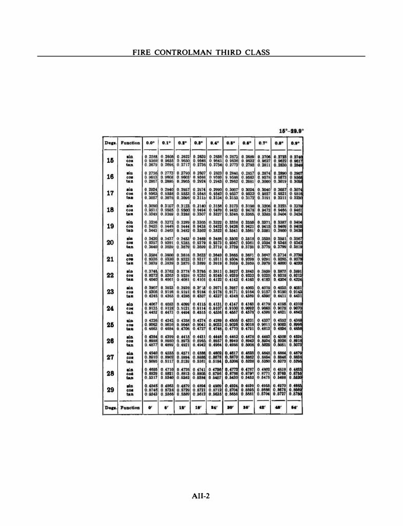
FIRE CONTROLMAN THIRD CLASS
1& co. taD
16 lia COl tall
17 llll COl tea
18 lla c..-tea
19 lla COl tall
20 lla COl taD
21 llll COl tea
22 liD COl tall
23 lill coa tea
24. lill COl tall
2& lla COl tall
28 lill COl taD
27 Ilia eol tall
28 lla COl taD
29 ....
AII-2
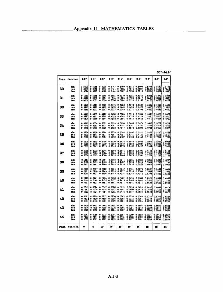
Dep. --
30
31
32
33
34
35
36
37
38
39 40
41
42
43
44 --
Dep.
Appendix II-MATHEMATICS TABLES
Function o.o• 0.1• 0.1" 0.3° 0.,. 0.11" o.s• O.'J• o.e• -- -- -- -- r-- -- -- --
aiD 0 6000 0.5015 0 5030 O.SIWS 0. 61100 0.5075 0.5090 0 5104 0.6120 coe 0. 8660 0.8662 0.8643 0 ijl\34 O.SG25 0 �tilti 0.8607 0.8699 0.8&90 tan 0.5774 0.5797 0.5820 0 �44 0 . .5867 0.5890 O.alllf 0.693g 0.&9111
aiD 0.5150 0.61115 0.5180 0.5195 0.5210 0.5225 0.6240 O.U66 0 5270 coe 0 8572 0.8663 o.gs54 0.>545 o.gssu 0.�.�26 0.11517 O.IISOii 0 84119 taD 0.6009 0.0032 0.6056 0 . OO!lO 0.6104 0.6128 0.6162 0, 0176 0.0200
aiD 0.5299 0.5314 0.5329 0.5344 0 5358 0.5373 0.5388 0.5402 0.6417 co• 0 11480 O.R471 0.11462 0.11453 0, R443 0. H434 0. 8425 O.l<415 0 �·06 taD 0.6249 0.6273 0. 6297 0 6322 O.ti3tfl 0.6371 0.0395 0.4i420 0.6445
•ln 0 5«6 0.6461 0.6476 0 5490 0.5505 0 5519 0 5534 0 .SMR 0 5563 coe 0.8387 0.8377 0. 8368 g :tl�� 0.1!348 0.1!339 0.1!32!1 0. 8320 0 8310 taD 0.6494 0.6519 0.6544 0.0594 0.111119 0.6644 0.6!11 9 0.�
•ln 0.559:1 0.56011 0.5621 0 5635 0.5650 O.MM 0.567H 0 5693 0.5707 coe 0 .ll290 O.S281 0.8271 0 R261 0.11251 0.�241 0.�231 O.R221 0.8211 tan 0.6745 0.6771 0.6796 O.tiX22 0. �8o47 0, 6873 0.6899 0.6�24 0.6950
aiD 0.5736 0.5750 0.5764 0. 577� 0.5793 0.5807 0.5821 0.5835 0.5� COl 0.8192 0 SIR! 0.8171 0. HIGI O.H151 0.�141 O.RI31 0.8121 0 8111 tao 0. 7002 0. 7028 0. 7044 0, 701!0 0.7107 0 7133 0. 71�0 0. 7186 0. 7212
aill 0 5878 0 5892 0.5906 0.5920 0.5034 0.5948 0.5902 J. 5976 0 5990 COl 0.8090 O.H080 0.8070 0 8050 0 8049 0 9039 0 8028 0 81118 0.8007 taD 0. 7265 0. 72V2 0. 7319 0 7346 0. 7373 0.7400 0. 7427 0.7454 0. 7481
eiD 0.6018 0.6032 0.60� 0.6060 0 6074 0.6088 0.6101 0.6115 0.6129 coe 0.7986 0.7970 0. 71165 0. 7955 0. 7944 0. 7034 0. 7923 0. 7912 0. 7902 taD 0 7536 o.n63 0. 7590 0. 761R 0. 7646 0. 7673 0 7701 0. 7729 0. 7757
aiD 0.0157 0.0170 0. OIR4 0.619N 0. 6211 0.0225 0.6239 0 6252 0.6266 COl 0 71180 0 7X6Q o0.7�9 0. 7X4H 0. 71!37 0. 7H26 o.1g1s 0 7804 0 7793 taD 0 7813 0 7841 0. 7869 0. 7K9H 0. 7920 0.7954 0. 7983 0 8012 0.8040
aiD 0. 0293 0. 6307 0.6320 0 6334 0 6347 0. 6.161 0. 6374 0.6388 0 6401 COl 0 7771 0.7760 0 774!1 0, 773� 0. 7727 0. 7716 0 7705 0 7694 0. 7683 taa 0.8098 0 8127 0 8156 O.SI!;S 0. H214 0.8243 O.RZ7J 0.8302 0.8332
aia 0. 042R 0 6441 0.64M 0.64611 O.G481 0.0404 0. 0508 0.6521 0. 65:14 coe 0 7HGU n W49 0. 7li38 0 7627 0. 7615 0 7004 0. 75�3 0.7551 0.7570 tao O.N:l!ll O.H421 0.8451 0.84RI 0. 8511 0. 8541 0.8571 0.8601 0.8632
aiD o. 6!ifil 0.6574 0.6587 0. 0000 0.6613 0.6026 0.0639 0 r.652 0.6665 coe 0 ;547 0. 7!;.1li 0 7524 0. 7513 0.7501 0.7490 0. 7478 0. 7466 0 7455 taD 0.8693 0 H724 0.�754 0.8785 O.!P!I6 0.�47 0.8/178 0.81110 0.8941
aiD 0 6691 (I 6704 0.6717 0.6730 0.6743 0. 675� 0.6769 0 6782 0. 6794 coe 0 7431 0 7420 0 740H 0.739ti 0. 7311.\ 0 7373 0, 7361 0. 7349 0 7337 taD 0.9004 0 90:\ti 0.9067 0.9009 0.9131 0.9163 0.91n5 0 022S 0.9260
aiD 0.6820 0.6R.'l3 0.684.� 0.6858 0.6�71 0.6R84 0 6890 0 6009 0.6921 coe 0. 7314 0. 7302 0.72!10 0. 727S 0.72titi 0. 7254 0, 7242 0, 7230 0. 721R taD 0. 9325 0.935� 0.93�1 0.9424 0.9457 0.9490 0. 9523 0.9556 0.9590
aiD 0.6947 0.6059 0.6972 0 69�4 0.6997 0. 7009 0 7022 0 7034 0 7046 coe 0, 7193 0.7181 0.7169 0 7157 0. 7!45 0 7133 0 7120 0 7108 0. 7096 taa 0 9657 0.9691 0.9725 0. 9759 0-9793 0.9827 0.9H61 0.9896 0. 91130
-- -- -- -- -- -- -- -- --
Puaetioa 0' •• 1:1' 11' U' 10' .,. u• u•
AII-3
0,1° --
0 61�� U�:t 0.&28ol 0 �� 0 !1224
0.5432 0 1!3�� 0.646
0 5577 g= g ���� 0.6976 0.61164
g ��� 0 6004 0. 7997 0. 7508
0 6143 0. 7891 0.7785
g ��: 0.8009
g �r; 0.8361
0.6547 0 7S.W 0.8862
0 6678
u:� g� 0.9293
8 ��� 0.9623
0.70$
8:�� --
H'
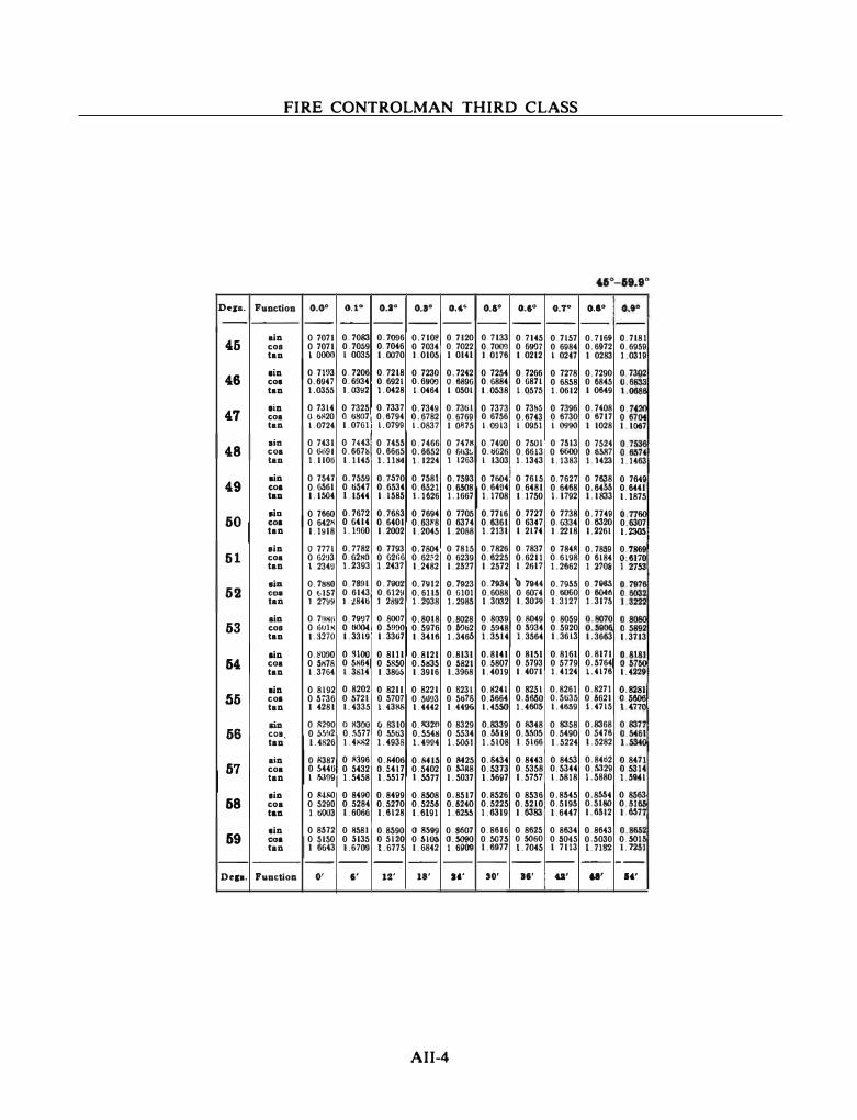
Des•-
46
46
47
48
49
60
til
62
63
64
56
66
57
68
69 --Del•·
FIRE CONTROLMAN THIRD CLASS
FuDctioD
ain cos taD
•in cos tan
•in co a tan
ain co a laD
•in coa taD
•ia. coa tan
•in coa tan
•ill coa tan
ain cos taD
a in coa tan
•in co a tan
mo COl. taD
ain coa tan
ala co a tan
sin co a tan
PuDction
o.o•
--0 7071 0 7071 I 0000
0 7193 0.6947 1.0355
0 7314 O.till20 1.0724 0 7431 0 0091 1.1100
0. 7547 0.6561 1.1504
0 7660 0 642S 1.1918
0 7771 0 62<J3 1. 234U
0. 7!ISO 0 til57 I 27W 0 7!1llli 0 IMS 1.:mo
0.�090 0 5H78 1.3764
0.8192 0 5736 I 4281 0 8290 0 �5H2 1.4826
0 H387 0 6440
O.t• o.a•
-- --0. 7083 0.7�6 0. 70S9 0. 7046 1 0035 1.0070
0. 7206 0. 7218 0.6934 0.6921 l. 0392 I. 0428
0 7325 o. 7337 o uso71 0.6794 1.07611 1.0799 0 74431 0. 7455 0.667� 0.66US 1.1145 l.llst
0. 7559 0 6547 I 1544 0. 7672 0.6414 I. 1960
0. 7782 0.62NO I. 2393
0. 7891
0.7.570 0.6534 1.1585
0. 7683 0.6401 1.2002
0. 7793 0 62fo6 I. 2437
0. 7902 0.6143 0.6129 I. �8461 1. 2892
0. 79'J7 0.8007 0 6004 0. S!JOO 1.3319' 1.33()7
O.SIOO 0.8111 0.51!64 0.5850 1 3814 1.38ti6 0.8202 0 8211 0 5721 0.5707 1.4335 1. 43!'8
() S300 0.8310 0.�577 0.5563 I. 4AA2 1.4938 0 ll.196 0.�06 0 5432 O.S417
1 1)3991 1.5458 I. 5517
0 841l0 0 84110 0.84119 0 5290 0 5284 0.5270 1.6003 1.6066 I. 6128
0 8572 0 ij58l 0.8590 0 5150 0 &135 0 5120 I 6643 I. 6700 1.6775
-- -- --0' I' 12'
o.a•
--0. 710� 0 7034 l. 0105
0 7230 0.69()!) l. 0464
0. 7349 0. 6782 1.0837
0.7466 0. 6652 I. 1224
0.7581 0.6.SZI I. 1626 0. 7694 0.6388 1.2045
0. 7804 0.62"2 1.2482
0.7YI2 0. 6115 I. 2938
0.8018 0.5976 1.3416
0.8121 0.5835 1.3916
0.8221 0.5003 1.4442 0. 8320 0.5548 1. 4W4
0.�15 0.5402 t.M77 0.8508 0.5256 1.6191
OM99 0&1� 1. 6842
--18'
0.,. --
0. 7120 0. 7022 I 0141
0. 7242 0 6896 1 0501
0. 7361 0.6769 I Oij75 0 747S 0 663� I 1263
0. 7593 0.6508 1.1667
0 7705 0.6374 1.2088
o. 7815 0.6239 1.2527
0. 7923 0.6101 1.2985
0.8028 o.S!Jo2 1. 346b
0.8131 0 5821 1.3968
0.6231 0.5678 I 4496 0 8329 0 5534 1.50.51 0 �25 0.53/18 I. 5037
0.8517 0.6240 1.62M
0.8607 O.S090 1.61109 --
•••
AII-4
o.a• 0.1° 0.7° -- -- --
0.7133 0. 7145 0. 7157 0 7009 0. 69'J7 0.61184 l. 0176 1.0212 1 02f7 0 7254 0. 7266 0 7278 0. 6884 0.6871 0 6858 1.0538 l. 0575 1.0612
0 7373 0.73� 0 7396 0.6756 0.6743 0 6730 1.�13 1.0951 1.0990 0 7400 0. 7501· 0 7513 0. 6626 0.6613 0 6600 1 1303 1.1343 1.1383
0. 76041 0 7615 0. 7627 0.6404 0.6481 0.6468 1.1708 1.1750 I. 1792
0.7716 0. 7727 0 7738 0.6361 0. 63f7 0. 6334 1.2131 1.2174 l. 2218
0. 7826 0. 7837 0 784R 0.6225 0.6211 0.6198 1.2572 1.2617 1.2662 0. 7934 '!1.7944 0. 7955 0.6088 0 6074 0.6060 I. 3032 1.30� I. 3127
0.8039 0.8049 0.8059 0.5948 0 6Q34 0.5920 1.3SI4 I. 3564 I. 3613
0.8141 0.81SI 0.8161 0.5807 0.5793 0.5779 1.4019 1.4071 1.4124
0.6241 0.8251 0.8261 0.5864 0.5650 0.5635 1.4550 1.4603 1.4859
0.8339 0 8348 0.8358 O.M19 O.MOS 0.5490 1.5108 I. 5166 I. 5224
0.8434 0. 8443 0.8453 0.5373 0.5358 0.5344 I. 66117 1.5757 1.6818
0. 8526 0 8536 0.8545 0.5225 0.5210 0.5195 I. 6319 1.6383 I. 6447
0.8616 0.8625 0 8634 0.5075 0.5060 0.5045 I. 6977 17045 I 7113
-- -- --SO' II' U'
o.e• O.t•
-- --0. 71611 o. 7181 0. 6972 0.6959 I 0283 1.0319
0. 7290 0. 7302 0 6845 t:: 1 0649
0. 7408 0 7?;, 0 6717 0.67 I 1028 I. 1007 0 7524 g�� O.M87 1.1423 1.1463
0. 76;18 0 76411 0.64M 0.6441 I. 1833 1.1875 0. 7749 0.7!� 0.6320 0.6307 1.2261 1.� 0, 7859 0. 78�� 0 6184 o-.61?� 1.2708 1 2753 0.7116S g-�1 0 60f8 1.3175 1.am
g:� 1.3663 g�w 1.3713
0.8171 g-gr� 0.5764 1.4176 1.4229 0.8271 0.� 0.6621 1.4715 � . m( 0.8368 0 837 0.5476 u�� 1.5282
0.84ti2 0 8471 0.5329 0 5314 I. 5880 1.5941
0.8M4 0 8563 0.5180 0 5!� 1.11612 1.1167
0.8643 0.865 0.5030 0.501 1. 7182 I. 7251
-- ---U' .,,

Dep. --
60
61
62
63
64
66
66
67
68
69
70
71
72
73
7'
r-Dep.
Appendix II-MATHEMATICS TABLES
so·-n.s·
Fun�tioll 0.0" 0.1°
-- --... 0.8660 0.8669 c:oa 0.5000 0.4985 tan 1.7321 I 7391
IliA 0. 8746 0.8755 �oa 0.4848 0.4833 tan I 8040 1.8115
lill 0.8829 0.8838 c:oe o_ 4695 0. 4679 tan I. 8807 I 8887
IliA 0.8910 0 8918 co• 0.4540 0 41124 tan I_ 9626 1.9711
IliA 0.8988 0.8996 CO& 0.4384 0.4388 tan 2.MOO 2 0594
lill 0.9063 0 9070 CO& 0.4226 0. 4210 tllll 2. 1445 2.1543
lill 0.9135 0 9143 c:oa 0.4067 0.4051 t81l 2 2460 2.2561!
IliA 0 9205 0.9212 co• 0 3907 0 3891 tan 2.3559 2.3673
lill 0.9272 0.9278 co• 0.3746 0.3730 tan '2.4751 2.4876
IliA 0.9336 0.9342 co• 0.3584 0.3567 tan 2.6051 2.6187
.m 0.9397 0.9403 co• 0.3420 0.3404 tan 2. 747.\ 2. 7825
8ill 0. 94.\5 0.9461 co• 0.3256 0.3239 tan 2.9042 2.9208
8ill 0.9511 0.9516 C08 0.3090 0.3074 tu 3.0777 3.0961
lliD 0.� 0.9588 - 0.2924 0.3907 to 3.2709 3.21114
IIIII O.HI3 O.HI7 - 0.2756 �:m: to 3.487.
--�- 0' ••
o.:a•
--0.8078 O.f970 I. 7481
0.8763 0.4818 I. 8190
0. 8846 0.4664 18967
o.a•
--0. 8686 0. 4955 !.7M2
0.8771 0 4802 1.826.5
O.S!!M 0. 404M 1. 9047
0. 8926" 0.8934 0. 4509 0. 4493 I_ 9797 1.9883
0 9003 0 9011 0.4352 0 4337 2.0886 2.0778
0. 9078 0 9085 0.4195 0.4179 2 1642 2.1742
0.9150 0 9157 0.4035 0 4019 2.2673 2.2781
0.9219 0. 9225 0.3875 0.3859 2.3789 2.3906
0,9285 0.9291 0.3714 0 3697 2 5002 2.5129
0.9348 0 9354 0.3551 0 3M5 2.8325 2.6464
0. 9409 0.9415 0.3387 U.331• 2. 7776 2. 7929
0. 9466 0.9472 0.3223 0.3206 2.9375 2.9544
0.9521 0.9527 0.3067 0.3040 3.1146 3.1334
0. 9573 0.9678 0.2890 0.2874 3.3122 3.3332
0.9622 0.9627 0.2723 0.2706 a.533u 3.6676
-- --11' 11'
0.6°
--0.8695 0. 4939 1.7603
0. 8780 0.4787 1.8.141
o_ 8862 0.4633 I. 9128
0 8942 0.4478 1. 9970
0.9018 0.4321 2 0872
0 9092 0.4163 2.1842
0 9164 0 4003 %.2889
0 9232 0.3843 2.4023
0.9298 0.3881 2.5257
0.9361 0.3518 2.6605
0.9421 0.3355 2.B083
O.Q478 0.3190 2.9714
0. 9532 0.3024 3.1524
0.951!3 0.2�7 3.3544
0.9832 0.2889 3.6816
--14'
AII-5
0.11°
--0.8704 0.4924 1 7675
0 8788 0.4772 1_8418
0.8870 0.4617 1. 9210
0.8949 0.4462 2.0057
0. 9026 0.4305 2.0985
0.9100 0:4147 2.1943
0.9171 0.3987 2.2998
0.9239 0.3827 2.'4142
0. 9304 0.3665 2.5386
0. 9367 0.3502 2.6746
0. 9426 0.3338 2.8239
0.9483 0.3173 2.9887
0. 9537 0.3007 3.1716
0.9588 0.2840 3.3759
0.9836 o.2sn 3.6059
--10'
o.a•
--0.8712 0.4909 1. 7747
0.8796 0 4756 1.8495
0. 8878 0.4602 I. 9292
0 8957 0 444R 2.0145
0.9033 0.4289 2 1060
0. 9107 0.4131 2.2045
0 9178 0.3971 2.3109
0 9245 0. 3811 2 4262
0.9311 0 3649 2.5517
0. 9373 0.3486 2.6889
0.9432 0.3322 2.8397
0.9489 0.3156 3.0061
0.9542 0.2990 3.1910
'0.9593 0.2823 3.3977
0.9641 0.2656 3.630S
--•••
0.'1°
--0.8721 0.4894 I. 7820
0.8805 0.4741 1.8572
0.8886 0.4586 I. 9375
0.8985 0 4431 2.0233
0.9041 0. 4274 2.1155
0. 9114 0.4115 2.2148
0.9184 0.3955 2.3220
0. 9252 0. 3795 2.4383
0.9317 0.3633 2.5649
0 9379 0.3469 2. 7034
0.11438 0.3305 2.8556
0. 0494 0.3140 3.0237
0.9548 0. 2974 3.2106
0. 9598 0. 2807 3.4197
0.9646 0.2639 3.8554
--61'
o.a• 0.1°
-- --0.8729 0.873 0 4879 0 4863 I. 7893 u96f 0 8813 0 8821 0.4726 0. 47H I 86.50 1.872
0 8894 om; 0 4571 0.4 1. 9468 1.954
0 8973 g�: 0 4415 2 0323 2 0413
0 9048 n�� 0 4258 2.1251 2 1348 0.9121 g :�� Ot099 2.2251 2.23s6 0 9191 0 91�� 0 3939 0 3923 2 3332 2.344
0 9259 g i�f. 0 3778 2.4504 2 462
0 9323 0�� 0 3616 0.3 2.5782 2. 5911
0. 9385 0 9391 0.34M 0 343 2 7179 2 7321
0 9444 0. 9449 0 3289 0.327 2.8716 2.887!
0.9500 0�� 0.3123 �:��� 3.0415
0. 9553
�:� 0. 2957 3.2305 3.
0.9603 0.�� 0 2790 0.2773 3.4420 3.464e
0 9650 0�= 0. 2622 0.2 3.6806 3.7
-- --48' IK'
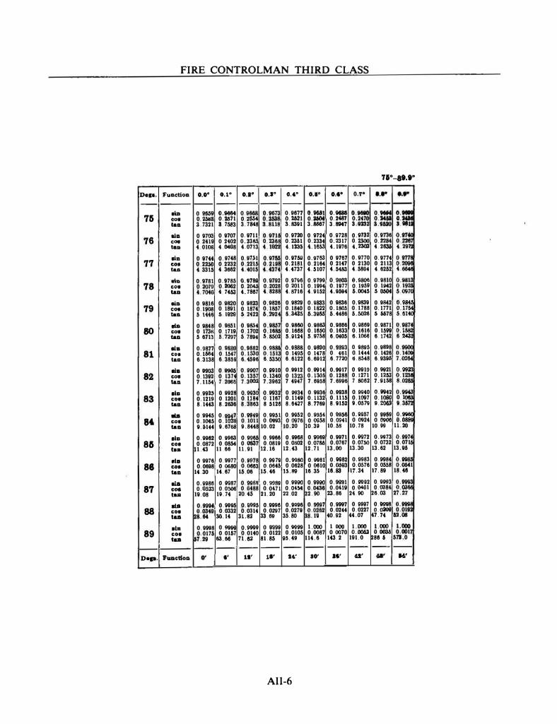
FIRE CONTROLMAN THIRD CLASS
71"-lt.t"
De11. Fuoctloo o.o• 0.1° •••• o.s• .. ,. • ••• • ••• 0.7° • ••• ....
-- -- -- -- -- -- - -- -- -- -
75 .u. 0 K$9 O.MM 0 H68 0.9673 0.9677 0.9681 O.llllll o:rn; 0.9111 •
:;; COl 0.25118 0.2671 0 26M urti O.Wl 0.:1604 0.2487 0.24� 0.1461 X: 1181 taD a.7321 3 751!3 3.7M8 S.8391 3.W7 3.SNT 3.8232 3.1120
76 UD 0 9703 0.8707 0. 8711 0 9716 0.9720 0.11724 0.8728 0.11732 0.11138 0.97� coe 0.2419 0.2402 0.2385 0.2368 0.23a1 0.2334 0.2317 0.2300 0.22M 0.228 tao 4 0108 4.0408 4.0713 4.1022 4.133$ 4.1M3 4.1870 4.2303 4.2636 4 297
77 liD 0 9744 0. 9748 0.9n1 0.9766 0.87&11 0.11753 0. 9707 0. 9770 0.9774
�= COl 0 2� 0 2232 0.2215 0.2U8 0.2181 0, 2164 0.2147 0. 2130 0.2113 tao 4.331� 4.3002 4.4015 4.4374 4.4737 4.�107 4.5483 4.5804 4.6262 4 .
78 .u. 0.9781 0.8785 �:�
0.9792 0.0786 0. 97911 o_gaoo O.G806 0.8810 g:�� COl 0.2079 0.2062 0.2028 0. 2011 0.11194 0.1877 0.11159 0.1842 tao 4 7040 4 7453 4. 7867 4 8288 4.8716 4.9152 4.96114 6.0045 5.� 5.097(
79 eiD 0.9816 0.9820 0 8823 0.9826 0.9829 0.8833 0.11836 0.9839 0.9M2 0.9� coe 0.1908 0 1891 0.1874 0.1857 0.1840 0.1822 0.1805 0.1188 0.1771 0.1;44j taD 6.1446 5.1m �-2422 6.21124 6.MM 6.3866 6.4486 6.5026 � 6678 5.61
80 IdA 0. 9848 0.9851 0.9864 0.8857 0.98e0 0.8883 0.9866 0.0869 0.9871 n� COl 0 173� 0 1719 0.1702 0.1685 0.1688 0.16$0 0.1833 0.1616 0.15119 taD 5.6713 5. 7297 5 7894 5.8502 5.0124 5. 9758 6.0405 0.106e 6.1742 6 243
81 •• 0.9877 0 8880 0.8882 g:�m 0.0886 0.8800 0.11893 0.0885 0.8888 �:� CDI 0.1664 0 1547 0.1530 0.1495 0.1478 0. 14&1 0. 1444 0. 1426 �:� tao 6.3138 6.3858 6.4506 6.5350 6.6122 6.6912 6.7720 11.8648 6.93�
82 •• 0 woo 0� 0.0007 0.0910 0. 9912 0.11914 0.91117 0.991D 0. 91121 0.9923 COl 0.1382 0 1374 0.1357 0.1340 0 1323 0.1305 0.1288 0.1271 0.1253 u: tao 7.1154 7.2000 7.3002 7.3962 7.4847 7.6858 7.6996 7.8062 7.11158 8.
83 ... 0.99" 0. 9928 0.91130 0.11932 0.11934 0.9936 O.IHI38 0.91140 O.t842 0.
� COl 0.1219 0.1201 0.1184 O.ll67 0.11411 0.1132 0.111� 0.1007 0.1080 0 I taD 8.1443 8.2636 8.3883 8 �128 8.0�7 8. 7769 8.11152 11.05� ��-� 11.36
.u. 0.91145 0.111147 0.8849 0.99�1 0 91152 0.11954 0. 91156 0.11967 0 91168 o: : M COl 0.1045 0.1028 0.1011 0.0993 0 0076 0.0058 0.0041 0 0924 0 0906 o.
taD 11.&144 11.67118 9.8448 10.02 10.20 10.311 10.58 10.78 10.119 11.20
... 0.9962 0.11963 0.9966 0.9966 0. 91168 0.11969 0.9971 0.11972 0.11973 0.11974 86 co• 0.0872 0.0864 0.0837 0.0819 0.0802 0.0786 0.0767 0.0750 0.0732 0.071
taa 1.43 11.68 11.111 12.16 12.43 12.71 13.00 13.30 13.62 13.86
86 ala 0 9976 0.9977 0.11978 0. 911711 0.91180 0.11981 0. 91182 0.9983 0.11984 g:=. COl 0.0698 0.0680 0.0663 0.0546 0.0628 0 0610 0.06113 0.0676 0.0553 taD 14.30 14.67 15.06 15.46 U.88 16.35 16.83 1,7.34 17.89 18.46
.u. 0.8986 0.11987 0. 911&1 0. 9988 0.9990 0.9990 0.9991 0.119112 0. 91193 o, := 87 coe 0.0523 0.0506 0 0488 0.0471 0.0454 ��-0436 0.04111 0.0401 0.0384 t�:27 taa 18.08 111.74 20.4� 2120 22.02 2.00 23.86 24.00 26.03
88 .u. 0.89114 0. 91195 0.119115 0.9996 0.9096 0.911117 0.9997 0. 119117 0.119118 0:� COl
�:0340 0.0332 0.0314 0.0297 0.0278 �:0262 0.0244 0.0227 o.oaov 0.01 taa M 30.14 :n.82 33.69 35.80 111 40.112 44.07 47.74 62.08
IUa 0.9998 0.111199 0.111199 0.111199 0.111199 1.000 1 000 1.000 1.000 1.000 89 COl 0.0176 0.0167 0.0140 0.0122 0.0105 0.0087 0 0070 0.0062 o.oooa 0.001
tu 67.211 63.66 71.62 81.85 9!.411 114.6 143.2 191.0 286 6 571.0 - -- -- -- -- -- -- -- -- --
D .... Fuctioo 0' •• lt' lt' 16' 10' H' 41' 61' 16'
All-6

APPENDIX I l l
GLOSSARY AA.-Abbreviation for AntiAircraft.
ACCELEROMETER.-An instrument that measures one or more components of the changes in speed of a moving body in which the instrument is contained.
ACQUISITION.-The location, lock-on, and commencement of automatic tracking of a target by a fire control radar.
AERODYNAMICS.-The science that deals with the motion of air and other gases and with the force acting on bodies moving through these gases.
AIRBURST.-An explosion of a projectile above the surface as distinguished from an explosion on contact with the surface or after penetration.
AIRFRAME.-The main structure of an aircraft or missile. It includes the framework and skin but not the engines or internal components.
ALPHANUMERIC.-Pertaining to a character set that contains both letters and digits.
ALTITUDE.-The vertical component of slant range.
ANGULAR VELOCITY .-A quantity related to rotational motion. Its instantaneous value is a vector whose magnitude is the rate of change of an angle 8, with respect to time t.
ASPHYXIA.-The lack of oxygen or excess of carbon dioxide that causes unconsciousness and subsequently, death.
ASPHYXIATION.-The loss of consciousness because of a lack of oxygen or an excess of carbon dioxide in the blood.
ASYNCHRONOUS.-Not relating to any particular frequency of the system to which it is connected.
ATTENUATION.-A decrease in magnitude in transmission from one point to another.
ATTITUDE, MISSILE.-The position of a missile as determined by the inclination of its axes to its designed frame of reference.
AUTOPILOT .-A system that detects deviations in the flight of an aircraft and applies the required corrections to the steering controls; also called automatic pilot.
BATTERY ALIGNMENT.-The alignment of weapons and fire control equipment to a common system of reference lines and planes under specified conditions.
BEACON.-A radar signal transmitter used to establish a reference point; commonly used for shore bombardment.
BEAM-RIDER.-A missile that follows a radar or other rf energy beam directed at the target.
BEAT FREQUENCY.-One of the two additional frequencies produced when two different frequencies are combined. One of these beat frequencies is the sum, and one is the difference of the two original frequencies.
AIII-I
FIRE CONTROLMAN THIRD CLASS
BIT .-Abbreviation for binary digit. A unit of information equal to one binary decision, or the designation of one of two possible and equally likely values or states (such as 1 or 0) of anything used to store or convey information. It may also mean "yes" or "no."
BOOSTER.-An auxiliary or initial propul� ·
sion system which travels with a missile or aircraft and which may or may not separate from that craft when its impulse has been delivered.
BOOST PHASE.-The initial portion of a missile's flight during which it attains its flight speed.
BUS.-A heavy rigid metallic conductor used to carry a large current or to make a common connection between several circuits; also called bus bar.
CANISTER (LAUNCHER).-A replaceable cylindrical shell structure that contains the launch rail and acts as a storage magazine.
CANNIBALIZE.-To remove usable parts from one piece of equipment for use in repairing another piece of equipment.
CARDIOPULMONARY RESUSCITATION (CPR).-The collective term for restoring breath� ing and/or the heartbeat of a person.
CHAFF.-Bits of radar reflective material, such as metal foil, that are released in the air to mask the flight of an aircraft or confuse and clutter the radar picture.
CHIP .-Another name for an integrated circuit.
CIRCULAR MIL.-A unit of area equal to the area of a circle whose diameter is 1 mil (0.001 inch). Used mainly in specifying cross� sectional areas of round conductors. Circular mil = 0. 7854 square mil.
CLOCK.-A device that generates periodic signals used for synchronization .
CLUTTER.-Radar return from rain, clouds, land, sea, or other unwanted objects.
COLLIMATION.-The precise alignment of the mechanical system of a radar an� tenna, by comparison with an optical device aligned on known points in bearing and elevation.
COMPUTER LANGUAGE.-The method or technique used to instruct a computer to perform various operations.
CONAR.-Acronym for Commanding Officer's Narrative Report.
CONICAL SCAN ON RECEIVE ONLY (COSRO).-A radar feature which, instead of physically scanning the antenna beam on transmission to derive target angle information, processes (or scans) the received signal to derive angle data.
CONTINUOUS WAVE ILLUMINATOR (CWI).-Provides target illumination for semiactive homing missiles. Continuous wave refers to the continuous transmission of the illumination beam.
CRUISE MISSILE.-A guided missile, the major portion of whose flight is at an approximately constant velocity.
DATA LINK.-Equipment for automatically transmitting and receiving information in digital form.
DCAP .-Acronym for Deficiency Corrective Action Program.
DESICCANT.-A drying agent (as silica gel or calcium chloride).
DESIGNATION, TARGET.-The selection of targets that are to be engaged and transmission of the position information required for acquisition by the fire control radar or radars.
DIELECTRIC.-The insulating material between the metallic elements of an electro� mechanical compound or any of a wide range of thermoplastics or thermosetting plastics.
AIII�2
Appendix Ill-GLOSSARY
DIFFERENTIAL AMPLIFIER.-An amplifier having two similar input circuits so connected that they respond to the difference between two voltages or currents, but effectively suppress like voltages or currents.
DIRECTIVE.-An instruction (order), notice (bulletin), or change transmittal. It prescribes or establishes policy, organization, conduct, methods, or procedures essential to the effective administration or operation of activities concerned.
DISH.-A parabolic reflector (slang).
DOPPLER EFFECT.-Frequency shift of a radiated signal (sound or radio) due to the relative motion between the source and the receiving point.
DOWN LINK.-Radio communication from a missile to its control or launching point. It normally contains flight information.
DSOT.-Abbreviation for Daily System Operability Test.
DUD/DUDDING.-Internal malfunctioning of a missile that prevents proper execution of aU phases of missile launching and flight.
DUMMY LOAD.-A device used at the end of a transmission line or waveguide that converts the rf energy into heat and dissipates it. In this way, no rf energy is radiated out nor reflected back to its source.
DUTY CYCLE.-Ratio of transmitted pulse width to pulse repetition period.
ECHO.-Signal received by a radar as a result of the reflection of a transmitted pulse from objects in the field of scan.
ELECTROMAGNETIC INTERFERENCE (EMI).-An effect usually generated internally, that can, either directly or indirectly, degrade the performance of an electronic receiver or system.
ELECTRONIC COUNTER-COUNTERMEASURES (ECCM).-Techniques used to minimize or eliminate the effects of electronic countermeasures.
E LECTR 0 NIC COUNTERMEASURES (ECM).-Methods of jamming or otherwise hindering the operation. of the enemy's electronic equipment.
ELECTRONIC WARFARE SUPPORT MEASURES (ESM).-Actions taken to search for, intercept, locate, record, and analyze enemy rf emissions in support of military operations.
ENGAGEMENT, TARGET .-Collectively, all actions taken to destroy an enemy (target). This may include, but not be limited to, tracking, illumination, and weapon launching and control.
EQUIPAGE.-Supply items that are not consumed in use and are essential to the ship's mission. They are usually portable and/or high cost items.
FAST TIME CONSTANT (FTC).-A differentiating circuit which attenuates long pulselike clutter or jamming signals by the use of a short time-constant network.
FEEDBACK.-In a transmission system or a section of it, the returning of a fraction of the output to the input.
FEEDHORN.-A horn type radiator that can be directed into a parabolic reflector.
FLUX.-The number of particles crossing a unit area per unit time.
FUZE.-A device des.igned to initiate a detonation of a weapon under the conditions desired, such as by impact, elapsed time, proximity, or command.
GATE.-(1) A circuit having two or more inputs and one output, depending upon the combination of logic signals at the inputs. (2) A signal used to trigger the passage of other signals through a circuit.
GUN TRAIN ORDER.-A · signal transmitted to the guns indicating the angle in the reference plane from own ship's bow clockwise to the perpendicular plane through the axis of the bore.
AIII-3

FIRE CONTROLMAN THIRD CLASS
HANG FIRE.-An accidental delayed ignition of primer, igniter, or propelling charge.
HARNESS.-Wires and cables arranged and tied together so they can be connected or disconnected as a unit.
HEIGHT-FINDER.-A radar set that measures and indicates the height of an airborne object.
HEMISPHERICAL SEARCH.-Another term for three-dimensional search (radar).
HOME ON JAM.-A missile mode of operation in which the target's jamming signal is used as the source of guidance information.
HOMING.-A guidance method by which the missile uses radiation from the target to establish a collision course.
HORIZONTAL PLANE.-A frame of measurement that is parallel to the Earth's surface at the point of origin.
HORN (ANTENNA).-A microwave antenna produced by flaring out the end of a circular or rectangular waveguide into the shape of a horn, for radiating radio waves.
IDENTIFICATION, FRIEND OR FOE (IFF).-A system of using electronic transmissions as a method of determining whether ships, aircraft, or ground forces are friendly or not friendly. When a signal is sent, friendly forces reply with coded pulses. Enemy forces, of course, do not know the coded pulses, so are readily identified as unfriendly.
ILLUMINATION.-The process of aiming rf energy at a target so that the reflected signal can be used by the missile for guidance information.
IMPEDANCE.-The total oppositional (i .e., resistance and reactance) a circuit offers to the flow of alternating current at a given frequency.
INERTIAL GUIDANCE.-A self-contained type of guidance in which the missile senses any deviation in direction, speed, or attitude and automatically compensates for it.
INFRARED.-Electromagnetic radiations (thermal) of wavelengths between that of visible light and microwaves. Guidance system that homes in on heat radiated by the target.
l N TERDI RECTOR DESIGNATION (IDD).-The transmission of repeatback information of a director to another director for the purpose of tracking the same target.
INTERFACE.-The interconnecting equipment, including wiring, data converters, switchboards, etc., that enable equipments to establish external communication with other equipments or systems.
INTERRUPT.-A method of stopping a process and identifying that a certain condition exists.
JAMMING.-The intentional disruption of the normal operation of a radar or radio system through the use of electromagnetic interference, mechanical devices, and/or deception.
KNOT.-A nautical mile (approx. 2,000 yd) or 1 . 1516 statute miles per hour. It is not a measure of distance, but of speed.
LINE OF FIRE (LOF).-An imaginary line along which a missile or other weapon is launched.
LINE OF SIGHT (LOS).-An imaginary line from radar or optical device to a target being tracked.
LOCK ON.-The moment at which tracking or target seeking system begins automatic tracking of a target in one or more coordinates.(e.g., range, bearing, elevation).
MAGAZINE.-The portion of a gun or missile launching system that provides for stowage.
MILLIROENTGEN. -A unit of radioactive dose equal to one-thousandth of a roentgen (see roentgen).
MINUTE.-A unit of angular measure equal to the 60th part of a degree and containing 60 seconds of arc.
AIII-4
Appendix III-GLOSSARY
MISFIRE.-The failure of a primer to ignite when firing action is initiated.
MODULATION.-The process by which some characteristic of one signal is varied in accordance with another signal.
NOISE.-Signals other than, and interfering with, the signal desired.
NULL.-A balanced condition which results in zero output from a device or system.
NUTATE.-To oscillate through a small angle in a specific pattern.
ORDALT.-Acronym for ORDnance ALTeration. This may consist of minor changes (such as wiring) or major changes (such as new equipment components).
ORDNANCE.-Weapons and equipment used in their control.
ORIGIN.-The point from which measurements are made, as from the intersection of references on a graph.
0-RING.-A ring (as rubber) used as a gasket.
OZONE.-An extremely reactive form of oxygen, normally occurring around electrical discharges and present in the atmosphere in small but active quantities.
PARABOLOID.-A reflecting surface formed by rotating a parabola about its axis of symmetry.
PARALLAX.-The angular difference which results from making observations or computations to one target from two different stations; normally measured in horizontal and vertical planes.
PARAMETER.-Any of a set of physical properties whose values determine the characteristic or behavior of something.
PAYLOAD.-The warhead section in a military missile.
PERFORMANCE ENVELOPE.-The area (range and altitude) that a missile or other weapon can effectively carry out its mission.
PERIODICITY.-The rate at which an event regularly recurs.
PERIPHERAL DEVICE.-Any instrument or machine that enables a computer to communicate with the outside world or that otherwise aids the operation of the computer but does not form part of the basic installation.
PITCH.-Angular displacement, measured in the vertical plane, of the centerline or longitudinal axis of a ship or aircraft.
POLARIZATION.-The direction of the electrical field as radiated from a transmitting antenna, usually either vertical or horizontal.
PRECESS.-To change the orientation of an axis of a gyroscope or other rotating body.
PROGRAMMING.-The process of setting automatic equipment to perform operation in a predetermined manner.
PROPORTIONAL NAVIGATION.-A homing guidance technique in which the missile turn rate is proportional to the turn rate of the missile-to-target line-of-sight.
PULSE REPETITION RATE (PRR).-The number of times per second that a pulse is transmitted; also called Pulse Repetition Frequency (PRF).
PULSEWIDTH.-The time duration of the transmission of the pulse of energy, usually measured in microseconds or in the equivalent distance in yards, miles, etc.; also called pulse duration and pulse length.
QUANTITY.-A constant, variable, function name, or expression.
RADAR HORIZON.-The point beyond which objects are not detectable by a radar due to the curvature of the Earth.
Alli-S
FIRE CONTROLMAN THIRD CLASS
RADAR SILENCE.-The period of time during which radar transmission is stopped, usually for security reasons.
RADIAL VELOCITY.-Another term for range rate or target speed relative to own ship.
RADIOACTIVITY.-A property exhibited by certain elements, the atomic nuclei of which spontaneously disintegrate and gradually transmute the original element into stable isotopes of that element or into another element with different chemical properties. The process is accompanied by the emission of alpha particles, beta particles, gamma rays, positrons, or similar radiations.
RANGE RATE.-The rate of change of range, usually in yards per second·, caused by relative motion of own ship and target.
RECIP ROCAL-Opposite or inversely related, as one of a pair of quantities whose product is one.
REFE RENCE PLANE.-An arbitrarily chosen plane from which quantities (usually angles) are measured.
REFRACTION.-Deflection from a straight path undergone by a light ray or energy wave in passing at an angle from one medium (as air) into another (as glass) in which its speed is different.
RELATIVE BEARING.-Directional coordinates referenced to the centerline of the ship with the bow designated as 000 degrees increasing in a clockwise direction through 360 degrees back to the bow.
RESOLUTION.-The minimum separation (in angle or range) between two targets at which they can be distinquished on the radar screen.
ROENTGEN.-The unit of radioactive dose of exposure. It is the amount of gamma radiation that will produce one electrostatic unit of charge in one cubic centimeter of air, which is surrounded by an infinite mass of air at standard temperature and pressure conditions.
ROLL.-The angular rotation of the centerline or longitudinal axis of a ship or aircraft measured in an athwartship vertical plane.
SCOPE.-A term often used to denote a crt type radar indicator or a test oscilloscope.
SEA RETURN.-Clutter on a radar due to reflection of signals by the sea; also called sea clutter.
SEEKER .. -A missile antenna or receiver that finds its target by means of heat, light, radio waves, sound or other radiation coming from the target.
SENSITIVITY TIME CONTROL (STC).A time-varied gain method of decreasing radar sensitivity at short ranges to reduce the intensity of sea clutter with only slight impairment of sensitivity at long ranges.
SHIPALT.-Acronym for a design change or alteration to nonordnance shipboard equipment.
SIDE LOBES.-Undesirable radiation lobes of a radar antenna. A number of these exist on each side of the main beam in all directions surrounding the main beam.
SLANT RANGE.-The distance between two points that are not at the same altitude; e.g., a ship and an aircraft.
SLIP RING.-A conducting ring mounted on, but insulated from, a rotating shaft, used with a stationary brush to join fixed and moving parts of a circuit (as in a director).
SOFTWARE.-The entire set of programs, procedures, and related documentation associated with a system, especially a computer system.
SPOOFING.-Jamming that deceives or misleads with target-like signals.
SQUIB.-A small pyrotechnic device used to fire the igniter in a rocket.
STA B I L I ZATION.-Maintenance of a desired orientation independent of the roll and pitch of a ship or aircraft.
AIII-6
Appendix I II-GLOSSARY
STABLE ELEMENT. -Gyroscopic device which maintains a reference horizontal plane.
SUPERELEVATION.-An offset to the launcher's elevation order to compensate for the effect of gravity.
SUST AINER.-A propulsion system that travels with and does not separate from the missile. The term is usually applied to solid propellant rocket motors when used as the principal propulsion system, as distinquished from an auxiliary motor or booster.
SWEEP .-The steady movement of the electron beam across the screen of a cathode-ray tube, producing a steady bright light when nQ signal is present.
SYNCHRONOUS.-In step or in phase, as applied to two devices or machines.
TELEMETRY.-The process of measuring a quantity, transmitting the result to a distant station, and there indicating or recording the quantity measured.
TERRAIN MATCHING.-Guidance of a missile by means of a radar altimeter recording previously obtained by a reconnaissance flight over the terrain, compared with altimeter readings received during the new flight; also known as mapmatching.
TMINS.-Abbreviation for the new "Technical Manual Identification Numbering System. "
TOLERANCE.-The allowable deviation from a specification.
TRACKING.-The monitoring or following of a target's movement, especially by radar.
TRAJECTORY.-The flight path of a projectile or missile.
TRANSMISSION CHECK.-In fire control system alignment, the process of verifying that the data transmission system is functioning with the required accuracy.
TRUE BEARING.-A bearing given in relation to true geographic north.
UPLINK.-Radio communication from a control point to a missile.
VELOCITY .-A vector quantity that includes both magnitude (speed) and direction in relation to a given frame of reference.
VERTICAL PLANE.-A plane perpendicular to the horizontal.
VIDEO.-Pertaining to the bandwidth and spectrum position of the signal resulting from radar or television scanning.
VIRTUAL GROUND.-A point in a circuit which is at ground potential (0 volts) but is NOT connected to ground.
WAVELENGTH. -The physical distance between cycles; the distance traveled by a wave in the time required for one cycle.
WEAPON-RELEASE RANGE.-The maximum range at which a bomber can launch or release its weapons and strike its target.
X-AXIS.-A horizontal axis in a system of rectangular coordinates; that line on which distances to the right or left (east or west) of the reference line are marked, especially on a map or chart.
X-RA YS.-Also called roentgen rays. Penetrating radiation similar to light, but having much shorter wavelengths (10-7 to 10
- 1 0cm). They are usually generated by bombarding a metal target with a stream of high-speed electrons.
YAW.-To turn by angular motion about the vertical axis as of a ship or aircraft.
Y-AXJS.-A vertical axis in a system of rectangular coordinates; that line on which distances above or below (north or south) the reference line are marked, especially on a map, chart, or graph.
AIII-7
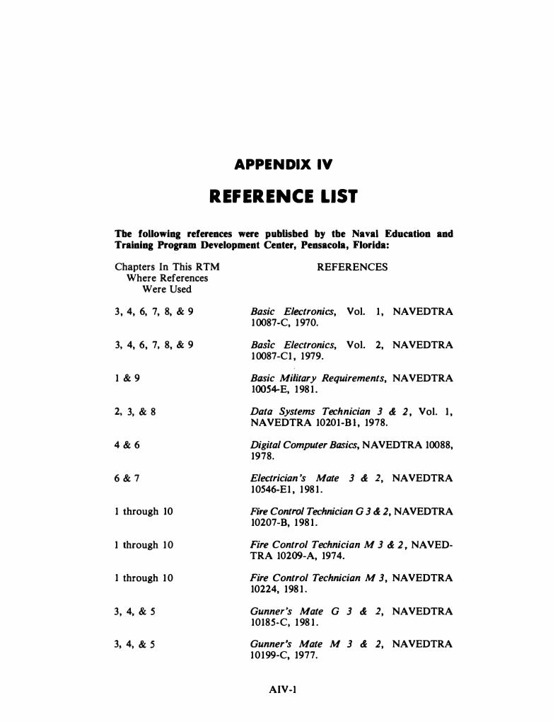
APPENDIX IV
REFERENCE LIST
Tbe following references were pubUsbed by tbe Naval Education and Training Program Development Center, Pensacola, Florida:
Chapters In This RTM Where References
Were Used
3, 4, 6, 7, 8, � 9
3, 4, 6, 7' 8, & 9
1 & 9
2, 3, � 8
4 & 6
6 & 7
1 through 10
1 through 10
1 through 10
3, 4, � 5
3, 4, & s
REFERENCES
Basic Electronics, Vol. 1 , NA VEDTRA 10087-C, 1970.
Basic Electronics, Vol. 2, NAVEDTRA 10087-C1 , 1979.
Basic Military Requirements, NA VEDTRA IOOS+E, 1981 .
Data Systems Technician 3 & 2 , Vol. 1 , NAVEDTRA 10201-Bl , 1978.
Digital Computer Basics, NA VEDTRA 10088, 1978.
Electrician 's Mate 3 & 2, NAVEDTRA 10546-E1 , 1981 .
Fire Control Technician G 3 & 2, NA VEDTRA 10207-B, 1981 .
Fire Control Technician M 3 & 2 , NA VEDTRA 10209-A, 1974.
Fire Control Technician M 3, NA VEDTRA 10224, 198 1 .
Gunner's Mate G 3 & 2, NAVEDTRA 10185-C, 198 1 .
Gunner's Mate M 3 & 2, NAVEDTRA 10199-C, 1977.
AIV-1
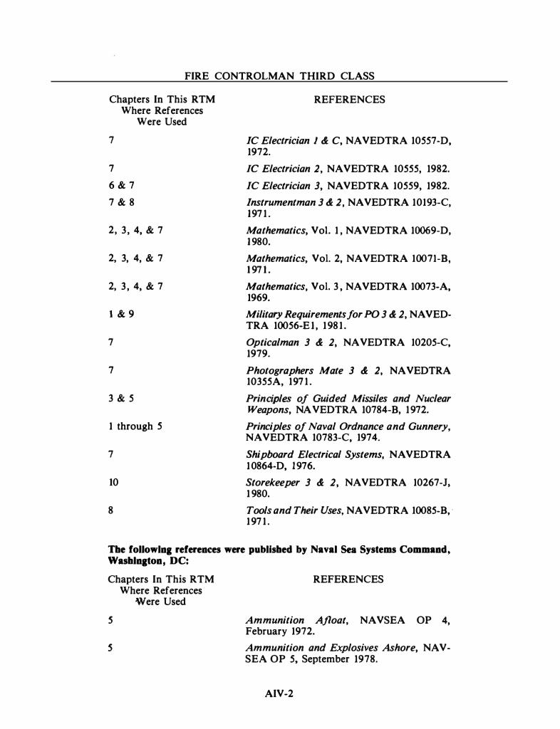
FIRE CONTROLMAN THIRD CLASS
Chapters In This RTM Where References
Were Used
7
7
6 & 7
7 & 8
2, 3 , 4, & 7
2, 3, 4, & 7
2, 3 , 4, & 7
1 & 9
7
7
3 & 5
1 through 5
7
10
8
REFERENCES
IC Electrician 1 & C, NAVEDTRA 10557-D, 1972.
IC Electrician 2, NAVEDTRA 10555, 1982.
IC Electrician 3, NA VEDTRA 10559, 1982.
lnstrumentman 3 & 2, NA VEDTRA 10193-C, 197 1 .
Mathematics, Vol. 1 , NAVEDTRA 10069-D, 1980.
Mathematics, Vol. 2, NAVEDTRA 10071-B, 1 97 1 .
Mathematics, Vol. 3 , NAVEDTRA 10073-A, 1969.
Military Requirements for PO 3 & 2, NA VEDTRA 10056-El , 1981 .
Opticalman 3 & 2, NA VEDTRA 10205-C, 1979.
Photographers Mate 3 & 2, NA VEDTRA 10355A, 197 1 .
Principles of Guided Missiles and Nuclear Weapons, NA VEDTRA 10784-B, 1972.
Principles of Naval Ordnance and Gunnery, NA VEDTRA 10783-C, 1974.
Shipboard Electrical Systems, NA VEDTRA 10864-D, 1976.
Storekeeper 3 & 2, NAVEDTRA 10267-J, 1 980.
Tools and Their Uses, NAVEDTRA 10085-B, ·
197 1 .
The followlna references were published by Naval Sea Systems Command, Washlnaton, DC:
Chapters In This RTM REFERENCES Where References
Were Used
s
s
Ammunition Afloat, NAVSEA OP 4, February 1972.
Ammunition and Explosives Ashore, NA VSEA OP 5, September 1978.
AIV-2
Appendix IV-REFERENCE LIST
Chapters In This RTM Where References
Were Used
3, 4, & 5
4 & 6
8, 9, & 10
8, 9, & 10
6, 8, & 10
6
8 & 9
5, 8, & 9
6
1 , 3, 4, & 5
6
8
7
7 & 9
REFERENCES
Close-In Weapons System Mk I5 Mods I Thru 6 (PHALANX), NA VSEA OP 4154 Vol. 2, March 1979.
Digital Computer Mk I 52 Series, NA VSEA OP 3514, January 1972.
EIMB, General, NAVSEA SEOOO-OO-EIM-100, April 1983.
EIMB, General Maintenance, NA VSEA SE000-00-E.M-160, April 1983.
EIMB, Installation Standards, NAVSEA SE000-00-EIM-110, April 1983.
EIMB, Reference Data, NA VSEA SE000-00-EIM-140, April 1983.
EIMB, Test Methods & Practices, NA VSEA SE000-00-EIM-130, April 1983.
Electromagnetic Radiation Hazards, Hazards to Personnel, Fuel and Other Flammable Materials, NA VSEA OP 3565/NA VAIR 16-1-529/NAVELEX 0967-LP-624-6010, Vol. 1 Fifth Revision, July 1982.
Fire Control Switchboard Mk I6 Mod I, NAVSEA SE671-Al-MM0-010/LHA-1 CL, February 1984.
Harpoon Weapon System, NAVSEA SW-261-AA-MM0-010/020, August 1980.
Integrated Combat Systems Switchboard Mk 59 Mod 0 & I, NAVSEA SE683-BOMM0-010/ICSS Mk 59, January 1982.
Miniature/Microminiature (2M) Electronic Repair Program, NA VSEA TEOOO-AA-HBK-010/020/030 2M, September 1982.
Nato Seasparrow Low Light Level Television System, NAVSEA OP 4053, April 1977.
Naval Ships' Technical Manual (NSTM), NA VSEA 59086-KC-STM-000/Ch-300 R1 Electric Plant General, April 1979.
AIV-3
FIRE CONTROLMAN THIRD CLASS
Chapters In This RTM Where References
Were Used
10
4 & 6
1 through 10
1 through 10
10
3 & 4
7
7
2
5
1 , 2, 3, 4, & 5
REFERENCES
Ships Electronics Configuration Accounting System, NA VSEA T0752-AA-MAN-040/ SECAS, Vol. 4, February 1982.
Signal Data Converter Mk 75 Mod 0, NA VSEA OP 4002, November 1976.
Standard Fire Control Symbols, NA VSEA OP 1700, Vol. 1 , February 1975.
Standard Fire Control Symbols for Missile Related Quantities, NA VSEA OP 1700, Vol. 3, February 1975.
STEPS Publication Master (formerly NA VSEA OP 0), NAVSEA T0751-AA-IDX-OOO, April 1983.
Surface Missile Systems Information for Fleet Operation Use, NA VSEA OP 3594, March 1983.
Technician's Handbook, Basic Liquid Cooling Systems for Shipboard Electronics, NA VSEA 0948-122-8010.
Television System Mk 5 Mod 0, NA VSEA OP 4127, May 1976.
Theory of Combat System Alignment, NA VSEA SW-225-AO-MMA-010/0P 762, July 1981 .
USN Ordnance Safety Precautions, NA VSEA OP 3347, February 1972.
Weapons Systems Fundamentals, NA VSEA OP 3000, Vol. 1 First Revision, January 1971 .
Tbe foUowing references were pubUsbed by various publishers:
Chapters In This RTM REFERENCES Where References
Were Used
9
9
Department of the Navy Information Security Program Regulation, OPNA VINST 5510. 1F, Office of the Chief of Naval Operations, Washington, DC, January 1982.
Electrical Characteristics of Digital Interface Circuits, DOD MIL-STD-188-144, Department of Defense, Washington, DC, March 1976.
AIV-4

Appendix IV-REFERENCE LIST
Chapters In This R TM Where References
Were Used
1 through 10
1 & 2
9
9
1 , 8, & 10
2 & 3
2, 3 , & 8
3, 4, 6, & 7
8
REFERENCES
IEEE Standard Dictionary of Electrical and Electronic Terms, IEEE Std 100-1977, The Institute of Electrical and Electronics Engineers, Inc., New York, 1977.
Introduction to Fire Control, Trainees Guide for Fire Control Technician Training, NAVPERS 93373, Bureau of Naval Personnel, Washington, DC, March 1966.
Navy Safety Precautions for Forces Afloat, OPNAVINST 5100.19A, Office of the Chief of Naval Operations, Washington, DC, 1 anuary 1983.
Nuclear Weapon Personnel Reliability Program (PRP), BUPERSINST 5510. 1D, Bureau of Naval Personnel, Washington, DC, July 1979.
Ships ' Maintenance and Material Management (3-M) Manual, OPNAVINST 4790.4, Office of the Chief of Naval Operations, Washington, DC, June 1983.
Skolinik, Merrill 1. , Introduction to Radar Systems, McGraw-Hill Book Company, Inc., New York, 1962.
Sofford, Edward L. Jr. , Modern Radar: Theory, Operation & · Maintenance, TAB Books Inc., Blue Ridge Summit, Pennsylvania, 198 1 .
Terman, Frederic Emmons, Electronic and Radio Engineering, McGraw-Hill Book Company, New York, 1955.
Wire- Wrap Assemblies, NA VORD OD 23446, Strategic Systems Project Office, Washington, DC, 1969.
AIV-5

INDEX
A
AAW, 3-1, 3-25 Ac/dc differential voltmeter, 8-30 Acquisition and tracking, 4-1 to 4-3 Active homing, 5-28 AID conversion, 6-39 to 6-40 Administration, 10-1 to 10-15
importance of paperwork, the, 10-1 to 10-2
publications, 10-2 to 10-10 classified publications, 10-9 to
10-10 safeguarding classified material,
l 0-9 to 10-10 CONAR, 10-6 forms and reports, 10-4
nonexpendable equipment status log, 10-4 to 10-6
3-M forms, 10-6 instructions and notices, 10-2 to
10-3 ordnance alterations, 10-3
OAR program, 10-3 ORDALT assistance, 10-3
other publications, 10-6 to 10-9 deficiency correction action
program, 10-7 Electronics Installation and
Maintenance Books (EIMB), 10-7
Naval Ships' Technical Manual, 10-7
ordnance drawings, 10-9 Ships' Plan Index, 10-7 to 10-9 Ships· Technical Publication
System (STEPS) Ordnance Index TO 751-AD-1DX-010, 10-9
1-1
Administration-Continued publications-Continued
other publications-Continued surface missile systems (SMS)
technical bulletins, 10-6 to 10-7
publication changes, 10-10 types of changes, 10-10
ship equipment configuration accounting system (SECAS), 10-3 to 10-4
SECAS validation, 10-4 summary, 10-15 supply, 10-10 to 10-15
COSAL and what it means, 10-11 mandatory turn -in repairables, 10-13
to 10-15 ordnance identification data, 10-12 to
10-13 sources of identification, 10-11 to
10-12 supply duties of the FC, 10-10 to
10-11 AEGIS, 1-5, 3-13, 5-33, 10-7 AEW, 3-11 Air systems, 7-4 to 7-7 Air-to-air, 5-17 Air-to -surface, 5-16 Algebra, 2-7 to 2-10 Allowance Equipage List, 10-11 Allowance Parts List, 10-11 Ammunition, 5-4 to 5-16 "AN" system, 3-2 Ancillary equipment, 4-25 Angle of departure, 2-19 Angle of fall, 2-19 Antennas and directors, 4-4 to 4-6 Apparent wind, 2-24 Arcing, 8-26

FIRE CONTROLMAN THIRD CLASS
Arming and safety, 5-23 to 5-24 Array antennas, 4-14 Artificial respiration, 9-2 ASMD, 3-1, 3-25 Asphyxia, 7-7 Asphyxiation, 9-12 ASROC, 3-15, 5-34 ASUW, 3-1, 3-25 ASW, 3-1 Asynchronous serial transmission, 6-5 to 6-6 Audio and video signal generators, 8-39 to
8-40 A verage power, 4-8
B
Bag type propelling charge, 5-6 to 5-7 Balanced bridge circuit, 6-32 to 6-33 Balanced Transmission Line, 6-12 Ballistics, the science of, 2-16 to 2-25 Basic lines, angles, and planes, 2-26 to 2-30 Basic Point Defense, 10-6 to 10-7 Basic tests, 8-7 to 8-8 Battle short switches, 9-9 Beam rider, 3-24, 4-6, 5-21, 5-27 Bit, 6-3 Bit time, 6-5 Black level, 7-11 Blanking, 7-11 Blanking level, 7-11 Blanking waveform, 7-11 Bonding and shielding, 8-20 Booster, 5-1, S-2, S-24 Bore erosion, 2-17 Brisance, brisant, 5-3 Brushes, 8-24 to 8-25 Bursting charges, 5-1 to 5-11
c
Cabling, 6-51 to 6-61 cable connectors, 6-53 cable tags, 6-53 coaxial cables, 6-56 to 6-59 coaxial connectors, 6-59 connector construction, 6-53 to 6-56 designation of conductor size, 6-52 multiple-conductor cable designations,
6-52
Cabling-Continued selection and installation of cables, 6-52
to 6-53 stuffing tubes and kickpipe, 6-60 to 6-61 types of cables, 6-51 to 6-52
Caliber, 3-14 Camera tubes, 7-17 to 7-24 Capacitance, 9-4 Capture point, 2-47, 3-24 Cartesian coordinate system, 3-10 Case type propelling charges, 5-7 to 5-8 Chaff, 5-12 Change in classification, 9-18 Characteristics of explosive and propellant
reactions, 5-3 Characteristics of light, 7-24 to 7-25 Checking after repair, 8-20 to 8-22 CIC, 3-4 Circuit breakers, 9-3 CIWS, 3-14, 3-25 Classified information, categories of, 9-17 to
9-19 Classified Publications, 10-9 to 10-10 Cleaning and lubricating electromechanical
components, 8-22 to 8-23 Cleaning optical lenses, 8-25 Clock signal, 6-7 Closed circuit television, 7-11 to 7-24 Coaxial cables, 8-20 Coefficient of form, 2-21 Combat systems and weapons systems, 3-1 Combination systems, 3-25 Command security programs, 9-20 to 9-21 Commutators, 8-24 Components and types of gun ammunition,
5-5 to 5-8 Components, weapons system, 3-1 to 3-24 Composite signal, 7-16 to 7-17 Composite video signal, 7-12 Computer, 4-20 to 4-22 CONAR, 10-6 Configuration variations, 4-25 Conical Scan on Receive Only (COSRO), 4-19 Continuous wave, 4-8 Control amplifier, 7-13 Control devices, weapons, 3-11 to 3-20 Control functional diagrams, 8-6 Control signals, 6-9 to 6-11 Control unit, 7-13 Cooling systems, 7-7 to 7-11
operation, system, 7-10

.I
INDEX
Coordinate and information processing systems, 3-4 to 3-11
Coordinate conversion, 3-7 Coordinate systems, 2-28 to 2-30, 3-4 Coriolis, 2-24 Coriolis effect, 3-11 Corrosion, 8-26 to 8-27
moisture prevention, 8-27 salt and fungus treatment, 8-27
COSAL and what it means, 10-11 Crimping, 8-11 to 8-12 Crosslevel, 2-36 CSTOM, 3-13 Cylindrical coordinate system, 3-9
D
Daily System Operability Test (DSOT), 8-2 Data functional diagrams, 8-6 Data transmission, 6-1 to 6-62
analog data transmission, 6-13 to 6-40 AID conversion, 6-39 to 6-40 balanced-bridge circuit, 6-32 to 6-33 operational amplifier, 6-38 to 6-39 resolvers, 6-27 to 6-32
booster amplifiers, 6-30 resolver application, 6-28 to 6-30 resolver compensators, 6-30 resolver maintenance, 6-32 resolver operation, 6-28 zeroing a resolver, 6-30 to 6-31
synchros, 6-14 to 6-27 classification of synchros, 6-17 identification of synchros, 6-17
to 6-18 stickoff voltage, 6-25 to 6-26 synchro alignment, 6-18 to 6-21 synchro review, 6-15 to 6-17 synchro system accuracy, 6-21 to
6-25 troubleshooting synchro systems,
6-26 to 6-27 tachometer generators, 6-35 to 6-38
tach construction and principles, 6-36 to 6-37
velocity signal transmission system, 6-37 to 6-38
vernistat, 6-33 to 6-35 vernistat maintenance, 6-35
1-3
Data transmission-Continued digital data transmission, 6-2 to 6-13
equipment interface, 6-8 to 6-13 control signals, 6-9 to 6-11 data transfer sequence, 6-10 digital-to-analog converter, 6-13 external function sequence, 6-11 external interrupt sequence, 6-11 input data transfer sequence,
6-11 level shifter, 6-8 to 6-9 line drivers/line receivers, 6-11
to 6-13 logic levels, 6-8 output data transfer sequence,
6-10 to 6-11 parallel data transmission, 6-3 to 6-4 parallel/serial conversion, 6-7 to 6-8 serial data transmission, 6-4 to 6-7
asynchronous serial transmission, 6-5 to 6-6
synchronous serial transmission, 6-6 to 6-7
serial/parallel conversion, 6-7 fire control switchboards, 6-40 to 6-62
cabling, 6-51 to 6-61 cable connectors, 6-53 cable tags, 6-53 coaxial cables, 6-56 to 6-59 coaxial connectors, 6-59 connector construction, 6-53 to
6-56 designation of conductor size,
6-52 multiple-conductor cable
designations, 6-52 selection and installation of
cables, 6-52 to 6-53 types of cables, 6-51 to 6-52
switchboard components, 6-41 to 6-49
bus test selector panel assembly, 6-44 to 6-45
flasher panel assembly, 6-45 fuse panel assembly, 6-43 to 6-44 fuse tester panel assembly, 6-44 indicator panel assembly, 6-43 JR Ounction rotary) switches,
6-46 to 6-47 manually operated JR switch
panel assembly, 6-47 to 6-48
FIRE CONTROLMAN THIRD CLASS
Data transmission-Continued fire control switchboards-Continued
switchboard components-Continued meter panel assembly, 6-44 remotely operated JR switch
panel assembly, 6-48 to 6-49 snap switch operation, 6-45 to
646 snap switch panel assembly,
6-45 switchboard wiring, 6-49 to 6-51
intersection connectors, 6-50 main harness wire numbering,
6-50 miscellaneous component wiring,
6-51 module harness connectors,
6-50 module terminal board,
6-50 panel connector plug, 6-51 panel terminal boards, 6-50 ship connectors, 6-49 ship wiring numbering, 6-49
terminal blocks, 6-61 to 6-62 summary, 6-62 types of signals in FC, 6-1 to 6-2
DCAP, 10-7 Decimals and fractions, 2-2 to 2-4 Deck covering, 9-10 Deck plane, 2-28 Deficiency corrective action program (DCAP),
8-4, 10-7 Delivery units, weapons, 3-14 to 3-20 Depth of field, 7-30 to 7-31 Designations, missile, 5-17 Destruction of classified documents, 9-19 Detection, 4-1 Detonator, 5-2, 5-11, 5-22 Devices, safety, 9-8 to 9-12 Diaphragm, the, 7-29 to 7-33 Digital data transmission, 6-2 to 6-13 Digital versus analog, 4-20 to 4-21 Digital word, 6-3 Digital-to-analog converter, 6-13 Diode Transistor Logic, 6-9 Direction systems, weapons, 3-11 to 3-13 Directors and antennas, 4-4 to 4-6 Doppler effect, 4-8 to 4-10 DSOT, 10-6 Duties and responsibilities, 1-6
1-4
E
ECCM, 3-4 Electric shock, 9-2 to 9-3
rescue of victims, 9-2 to 9-3 symptoms of electric shock, 9-2
Electrical fire, 9-15 Electrical power, 7-1 to 7-4 Electrical Zero, 6-19 Electroexplosive devices, 9-14 Electronic counter, 8-42 to 8-44 Electronic Warfare (EW), 9-21 Electronic warfare support measures (ESM),
3-4 Electronics Installation and Maintenance
Books, (EIMB), 10-7 Electrostatic corona, 9-8 Emergency-off switches, 9-9 Emission control (EMCON), 9-21 Energy transmission, 4-8 to 4-15
principles of, 4-10 to 4-15 types of, 4-8 to 4-10
Environmental problems, 8-25 to 8-27 Equipment maintenance, 8-2 to 8-3 Equipment troubleshooting pyramids, 8-7 ESM, 3-2, 3-4 Ethylene glycol, 7-11 Evaluation, 4-3 Evolution of the guided missile, 1-4 to 1-5 Expansion tank, 7-10 Explosives, 5-1 to 5-4 Exponents and radicals, 2-4 to 2-6 Exterior ballistics, 2-18 to 2-25 External function sequence, 6-11 External interrupt sequence, 6-11
F
FCS functions, 4-1 to 4-3 Feedhorns, 4-12 Fiber optic, 7-22 Field, 7-12
Fine Synchro System, 6-23 to 6-25 Fire control problem, the, 2-1 to 2-48
fire control problem prerequisites, 2-25 to 2-38
basic lines, angles, and planes, 2-26 to 2-30
coordinate systems, 2-28 to 2-30 line of fire (LOF), 2-27 line of sight (LOS), 2-26 to 2-27

INDEX
Fire control problem, the-Continued fire control problem prerequisites
Continued basic lines, angles, and planes-
Continued sight angle, 2-27 sight deflection, 2-27 reference planes, 2-27 to 2-28
frames of reference, 2- 25 to 2-26 motion, 2-34 to 2-38
effects of deck motion, the, 2-36 effects of relative motion, the,
2-35 to 2-36 effects of target evaluation, the,
2-36 to 2-38 standard fire control symbols, 2-32
to 2-34 basic symbols and modifiers,
2-33 to 2-34 introduction to Ordnance
Publication (OP) 1700, 2-32 to 2-33
quantity modifiers, 2-34 units of measure, 2-30 to 2-32
knot, the, 2-30 to 2-31 polarity, 2-32 radian, the, 2-31 to 2-32
fire control problem, the, 2-15 to 2-25
science of ballistics, the, 2-16 to 2-25
exterior ballistics, 2-18 to 2-25 interior ballistics, 2-16 to 2-18
mathematics review, 2-1 to 2-1 5 algebra, 2-7 to 2-10
associative law of addition, 2-7 associative law of multiplication,
2-8 commutative law of addition,
2-7 commutative law of multiplica
tion, 2-8 distributive law of multiplication,
2-8 to 2-9 transposition, 2-9 to 2-10
exponents and radicals, 2-4 to 2-6 addition and subtraction, 2-6 division, 2-4 to 2-6 multiplication and division, 2-6 multiplication, 2-4 removing a factor, 2-6
1-5
Fire control problem, the-Continued mathematics review-Continued
fractions and decimals, 2-2 to 2-4 decimals, 2-3 to 2-4 fractions, 2-3
sign numbers, 2-1 to 2-2 addition, 2-2 division, 2-2 multiplication, 2-2 subtraction, 2- 2
1 trigonometry, 2-10 interior angles, 2-11 Pythagorean theorem, the, 2-10
to 2-11 similar right trianges, 2-11 to
2-13 similar triangles, 2-11
vectors, 2-14 to 2-15 solving the fire control problem, 2-38 to
2-48 fuze computation, 2-46 to 2-48 prediction and ballistic computation,
2-42 to 2-44 present position computation, 2-39 to
2-41 trunnion tilt and parallax computa
tion, 2-44 to 2-46 summary, 2-48
Fire control symbols, AI-l to AI-8 Fire control systems, 3-13 to 3-14, 4-1 to
4-26 configuration variations, 4-25 FCS functions, 4-1 to 4-3
acquisition and tracking, 4-1 to 4-3 detection, 4-1 evaluation, 4-3 guidance (missiles), 4-3 launcher/gun positioning, 4-3 prediction, 4-3
fire control, 4-1 fire control system concepts, 4-3 to
4-25 ancillary equipment, 4-25 computer, 4-20 to 4-22
· computer peripherals, 4-21 to 4-22
digital versus analog, 4-20 to 4-21
directors and antennas, 4-4 to 4-6 missile guidance, 4-6 modes of operation, 4-4 to 4-6
FIRE CONTROLMAN THIRD CLASS
Fire control systems-Continued fire control system concepts-Continued
radar, 4-6 to 4-20 comparison of search and fire
control radars, 4-6 to 4-7 principles of energy transmission,
4-10 to 4-15 range tracking, 4-20 requirements of fire control
radars, 4-7 to 4-8 scanning, 4-15 to 4-20 types of energy transmission, 4-8
to 4-10 stabilization, 4-22 to 4-25
other stabilization devices, 4-25 stable element, 4-22 to 4-25
summary, 4-25 to 4-26 Fire control today, 1-3 to 1-4 Fire Controlman rating, the, 1-1 to 1-5 First aid, 9-2 to 9-3 Flareback, 5-3 Flicker, 7-15 to 7-16 Flight paths, missile, 5-29 to 5-32 Focal length, 7-26 to 7-27 Focusing, 7-27 to 7-28 Foreign matter, 8-26 Forms and reports, 10-4 Fractions and decimals, 2-2 to 2-4 Fragmenting projectiles, 5-11 Frame, 7-12 Frames of reference, 2-25 to 2-26, 3-10 Fuses, 9-3, 9-8 to 9-9 Fuze, S-1, 5-11 to 5-13 Fuze computation, 2-46 to 2-48 Fuzes, S-13 to 5-16, 5-22 to 5-23
G '
Gate signal, 6-7 General maintenance, 8-22 to 8-25 General purpose test equipment, 8-27 to 8-44 Gimbal, 4-23 Glossary, AI I I-1 to A I I I-7 Gravitational acceleration (g), 2-18 to 2-19 Guidance, misslle, 5-24 to 5-32 Guidance (missiles), 4-3 Guided missile, evolution of the, 1-4 to 1-5 Gun sights, 1-2 Gun systems, 3-25 Gyro, 4-23 to 4-24
I-6
H
Handling the CRT, 9-5 to 9-6 Handling the magnetron, 9-7 to 9-8 Harness, safety, 9-12
HARPOON, 1-5, 3-20, 3-25, 4-20, 5-24, S-26, 5-27, 5-29, 5-34 to 5-35, 10-7
Hazards of Electromagnetic Radiation to Ordnance, 9-14
Heterodyne principle, 8-43 High-pressure air, 7-5 Homing, 5-21, 5-28, 5-29 Horizontal plane, 2-26, 2-28 Horizontal range, 2-19 Horizontal synchronization, 7-13 Hom radiators, 4-12 Humidity, 8-26
I
Iconoscope, 7-18 Identifying number, 10-13 Igniter, 5-2 Image intensifier, 7-22 to 7-24 Image isocon, 7-18 to 7-22 Image orthicon, 7-18 Image section, 7-20 Importance of paperwork, the, 10-1 to 10-2 Inertial guidance, 5-21 Information processing and coordinate
systems, 3-4 to 3-11 Initial velocity (iv), 2-16, 2-17, 2-19, 2-24,
2-35, S-6 Initiation of explosive and propellant
reactions, 5-4
Input data transfer sequence, 6-11 Instructions and notices, 10-2 to 10-3 Interior ballistics, 2-16 to 2-18 Interior Communications, 7-3 Interlocks, 9-8 Introduction, 1-1 to 1-7
Fire Controlman rating, the, 1-1 to 1-5 evolution of the guided missile, 1-4
to 1-5 Navy surface missile systems, 1-5 purpose of guided missiles, the,
1-5 fire control today, 1-3 to 1-4
computer, 1-4 delivery units, 1-4

INDEX
Introduction-Continued M Fire Controlman rating, the-Continued
fire control today-Continued destructive units, 1-4 radar I director, 1-4
Maintenance, 8-1 to 8-44
weapon direction system, 1-4 history of fire control, 1-2
gun sights, 1-2 ranging devices, 1-2 stabilizing methods, 1-2 to 1-3 tracking methods, 1-3
summary, 1-7 your future as a Fire Controlman, 1 '-6 to
1-7 duties and responsibilities, 1-6 training opportunities, 1-6 to 1-7
class A school training, 1-6 class C school training, 1-6 to
1-7
K
Klystrons, 9-7 Knot, the, 2-30 to 2-31
L
Lacing and tying, 8-19 to 8-20 Lamp and relay indexes, 8-7 Latitude, 3-5 Launcher/gun positioning, 4-3 Lens antenna, 4-13 Lens, f-value of a, 7-28 to 7-29 Lens system use, 7-31 to 7-33 Lenses, 7-25 to 7-29 Level shifter, 6-8 to 6-9 Line drivers/line receivers, 6-11 to 6-13 Line Impedance, 6-13 Line of fire (LOF), 2-27 Line .of sight (LOS), 2-26 to 2-27, 4-3 to 4-6,
4-18, 4-24 to 4-25 Line Resistance, 6-13 List of Standard Subject Identification Codes,
10-2 Logic levels, 6-8 Longitude, 3-5 Low light level television, 7-22 Low-pressure air, 7-5 to 7-7
1-7
environmental problems, 8-25 to 8-27 corrosion, 8-26 to 8-27
moisture prevention, 8-27 salt and fungus treatment, 8-27
foreign matter, 8-26 humidity, 8-26 temperature, 8-26
general maintenance, 8-22 to 8-25 cleaning, 8-22 cleaning and lubricating electro
mechanical components, 8-22 to 8-23
cleaning optical lenses, 8-25 lubrication, 8-22 rotating machinery maintenance, 8-23
to 8-25 brushes, 8-24 to 8-25 commutators, 8-24 sliprings, 8-23 to 8-24
visual inspections, 8-22 general purpose test equipment, 8-27 to
8-44 ac/dc differential voltmeter, 8-30 electronic counter, 8-42 to 8-44 meggers, 8-30 to 8-31 multimeter, 8-27 to 8-29 oscilloscope, 8-35 to 8-38
basic principles of operation, 8-36 to 8-38
precautions in use of meters, 8-35 signal generator, 8 -38 to 8-41
audio and video signal generators, 8-39 to 8-40
radio-frequency signal generators, 8-40 to 8-41
techniques for meter use, 8-32 to 8-35
continuity test, 8-32 to 8-33 resistance test, 8-34 to 8-35 test for grounds, 8-33 tests for shorts, 8-33 to 8-34 voltage test, 8-34
vacuum tube voltmeter (VTVM), 8-29 to 8-30
Planned Maintenance System, the, 8-2 to 8-3
e quipment maintenance, 8-2 to 8-3 system maintenance, 8-2

FIRE CONTROLMAN THIRD CLASS
Maintenance-Continued publications, 8-3 to 8-7
ordnance data, 8-3 ordnance pamphlets, 8-3 other publications, 8-4 . technical manuals, 8-3 TMINS, 8-3 to 8-4 troubleshooting aids, 8-5 to 8-7
control functional diagrams, 8-6 data functional diagrams, 8-6 equipment troubleshooting
pyramids, 8-7 maintenance turn-on, 8-5 one-function schematic diagram,
8-6 relay and lamp indexes, 8-7 relay and lamp ladder diagrams,
8-7 schematic diagrams, 8-6 servicing block diagrams, 8-6 signal flow diagrams, 8-5 to 8-6 troubleshooting index, 8-5 voltage and resistance charts, 8-6
to 8-7 voltage distribution diagrams,
8-6 summary, 8-44 troubleshooting, 8-7 to 8-22
basic tests, 8-7 to 8-8 checking after repair, 8-20 to 8-22 maintenance techniques, 8-10 to 8-20
crimping, 8-11 to 8-12 safety wiring, 8-18 to 8-19 shielding and bonding, 8-20 shock mounting, 8-20 soldering, 8-10 to 8-11 tying and lacing, 8-19 to 8-20 wire wrapping, 8-12 to 8-18
part replacement, 8-10 repair, 8-8 to 8-10
modules, 8-8 to 8-9 printed circuits, 8-9 to 8-10
signal tracing, 8-8 test probe substitution, 8-8
Maintenance Assistance Modules, 10-11 Maintenance Requirement Cards (MRCs), 8-1
8-3, 8-22 to 8-23 Mandatory turn-in repairables, 10-13 to
10-15 Mark number, 10-12 Mathematics review, 2-1 to 2-15
1-8
Mathematics tables, AII-I to AII-6 Maximum ordinate, 2-19 Measuring voltages over 300 volts, 9-5 Meggers, 8-30 to 8-31, 9-4 Micro/miniature electronic repair program,
8-9 Military Specification, 6-53 to 6-56 Misconceptions about underground electrical
systems, 9-3 to 9-5 Missile guidance, 4-6 Missile systems, 3-25 Missiles and ordnance, 5-1 to 5-36 Modification number, 10-13 Mono pulse, 4-17, 4-19 Motion, 2-34 to 2-38 Motor Generator Sets, 7-3 to 7-4 MRL, 10-4 Multimeter, 8-27 to 8-29
N
National Item Identification Number, 10-11 National Stock Number, 10-11 Naval Ship Weapon Systems Engineering
Station, 10-3, 10-7 Naval Ships' Technical Manual, 10-7 Naval Tactical Data System, 3-11 N AV ALT, 10-3 Navy Directives Issuance System, 10-2 Navy surface missile systems, 1-5 Nitrogen gas, 7-7 Nonexpendable equipment status log, 10-4 to
10-6 Normal plane, 2-28 NTDS, 1-5, 3-2, 3-4, 3-11, 3-22 to 3-23, 6-8,
6-9, 7-9, 10-7 Nutation, 4-16
0
Ogival curve, 5-10 One-function schematic diagram, 8-6 Operating circuit breakers, 9-9 Operating Space Items, 10-11 Operational amplifier, 6-38 to 6-39 Optical systems, 7-24 to 7-33 Ordnance, 5-1 Ordnance alterations, 10-3

INDEX
Ordnance and missiles, 5-1 to 5-36 ammunition, 5-4 to 5-16
fuzes, 5-13 to 5-16 forces that operate fuzes, 5-13 to
5-15 types and applications of fuzes,
5-15 to 5-16 projectiles, 5-8 to 5-13
classification of projectiles, 5-10 to 5-13
external features of projectiles, 5-10
projectile identification, 5-10 types and components of gun
ammunition, 5-5 to 5-8 bag type propelling charge, 5-6
to 5-7 case type propelling charges, 5-7
to 5-8 explosives, 5-1 to 5-4
characteristics of explosive and propellant reactions, 5-3
initiation of explosive and propellant reactions, 5-4
storing propellants, 5-4 missile fundamentals, 5-16 to 5-36
missile designations, 5-17 missile guidance, 5-24 to 5-32
missile flight paths, 5-29 to 5-32 phases of guidance, 5-24 to
5-26 types of guidance, 5-26 to 5-29
missile requirements, 5-16 to 5-17 - air-to-air, 5-17
air-to-surface, 5-16 surface-to-air, 5-17 surface-to-surface, 5-17
missile subsystems, S-19 to 5-21 control, 5-20 guidance, 5-20 to 5-21 propulsion, 5-20 structure, 5-19 to 5-20 warheads, 5-19
new developments, 5-36 rolling airframe missile (RAM),
5-36 SMS missiles, 5-32 to 5-36
HARPOON missiles, 5-34 to 5-35
SPARROW Ill missiles, 5-34 TARTAR missiles, S-33
1-9
Ordnance and missiles-Continued missile fundamentals-Continued
SMS missiles-Continued TERRIER missiles, 5-33 to 5-34 TOMAHAWK missiles, 5-35 to
5-36 surface launched missiles, 5-17 types of warheads and fuzes, 5-21 to
5-24 fuzes, 5-22 to 5-23 payload, 5-21 to 5-22 safety and arming, 5-23 to 5-24
summary, 5-36 Ordnance data, 8-3 Ordnance drawings, 10-9 Ordnance identification data, 10-12 to 10-13 Ordnance Pamphlets (OPs), 8-1 to 8-2, 8-3 Ordnance Publications, 6-17 Oscilloscope, 8-35 to 8-38 Other publications, 10-6 to 10-9 Output data transfer sequence, 6-10 to 6-11
p
Paperwork, the importance of, 10-1 to 10-2 Parabolic reflectors, 4-12, 4-15 Parallax computation and trunnion tilt, 2-44
to 2-46 Parallel data transmission, 6-3 to 6-4 Parallel/serial conversion, 6-7 to 6-8 Part replacement, 8-10 Passive homing, 5-29 Payload, 5-21 to 5-22 Peak power, 4-8 Peak-to-peak value, 8-37 Penetrating projectiles, 5-10 Peripherals, computer, 4-21 to 4-22 Phases of guidance, 5-24 to 5-26 Photosensitive tube, 7-12 Pickup unit, 7-12 to 7-13 Picture element, 7-12 Picture signal, 7-12 Pitch, 2-36 Planned Maintenance System, the, 8-2 to 8-3 Planned Position Indicator, 7-11 Polar coordinate system, 3-6 Polarity, 2-32 Potable water, 7-11 Power distribution system, 7-1 to 7-4
FIRE CONTROLMAN THIRD CL ASS
PPI scope, 4-7 Precess, 4-25 Precautions in use of meters, 8-35 Prediction, 4-3 Prediciton and ballistic computation, 2-42 to
2-44 Present position computation, 2-39 to 2-41 Primary cooling system, 7-9 to 7-10 Primary explosives, 5-l, 5-2 Problem se quence, 3-20 to 3-24 Programming, 1-4 Projectiles, 5-8 to 5-13 Propellant train, 5-2 Propelling charges, 5-l Publication changes, 10-10 Publications, 8-3 to 8-7, 10-2 to 10-10 Pulsewidth, 4-8 Pythagorean theorem, the, 2-10 to 2-11
Q
Quadrants, 3-6
R
Radar, 4 -6 to 4-20 Radian, the, 2-31 to 2-32 Radicals and exponents, 2-4 to 2-6 Radioactive electron tubes, 9-6 to 9-7 Radio-fre quency signal generators, 8-40 to
8-41 RAM, 1-5 R AM (rolling airframe missile), 5-36 Range tracking, 4-20 Ranging devices, 1-2 Raster, 7-12, 7-14 Ready Service Spares, 10-11 Receipt of classified material, 9-19 Receiver monitor, 7-13 Rectangular coordinate system, 3-5 Reference list, A IV-1 to AIV-5 Reference planes, 2-27 to 2-28 Relay and lamp ladder diagrams, 8-7 Repair, 8-8 to 8-10 Reports and forms, 10-4 Re quirements of fire control radars, 4-7 to
4-8
1-10
Resolvers, 6-27 to 6-32 booster amplifiers, 6-30 resolver application, 6-28 to 6-30 resolver compensators, 6-30 resolver maintenance, 6-32 resolver operation, 6-28 zeroing a resolver, 6-30 to 6-31
Rf radiation hazards, 9-12 to 9-15 Ride the beam, 2-4 7 Rigor mortis, 9-2 Roll, 2-36 Rolling airframe missile (RAM), 5-36 Rotating machinery maintenance, 8-23 to
8-25 Rotation of axes, 3-7 Rubber gloves, 9-10
s
Safety and security, 9-1 to 9-21 safety, 9-1 to 9-15
electrical fire, 9-15 electric shock, 9-2 to 9-3
rescue of victims, 9-2 to 9-3 symptoms of electric shock,
9-2 misconceptions about underground
electrical systems, 9-3 to 9-5 responsibility, 9-1 to 9-2 rf radiation hazards, 9-12 to 9-1 S
rf hazard to the eyes, 9-14 rf hazard to ordnance, 9-14 to
9-15 rf hazard to the testicles,
9-14 rf hazards to the skin, 9-13 to
9-14 shipboard radiation hazard
zones, 9-14 safety devices, 9-8 to 9-12
battle short switches, 9-9 deck covering, 9-10 emergency-off switches, 9-9 fuses, 9-8 to 9-9 interlocks, 9-8 operating circuit breakers, 9-9 rubber gloves, 9.:.10 safety shorting probe, 9-9 to
9-10 warning signs, 9-10 to 9-12

INDEX
Safety and security-Continued safety-Continued
transmitter safety precautions, 9-5 to 9-8
electrostatic corona, 9-8 handling the CRT, 9-5 to 9-6 handling the magnetron, 9-7 to
9-8 measuring voltages over 300
volts, 9-5 radioactive electron tubes, 9-6 to
9-7 x-ray emissions, 9-7
ungrounded electrical distribution systems, 9-3
working aloft, 9-12 security, 9-15 to 9-21
categories of classified information, 9-17 to 9-19
change in classification, 9-18 confidential, 9-17 preparation and marking, 9-18-receipt of classified material, 9-19 secret, 9-17 special markings, 9-18 top secret, 9-17
command security programs, 9-20 to 9-21
personnel reliability program (PRP), 9-20
reliability standards, 9-20 destruction of classififed documents,
9-19 emergency destruction, 9-19 routine destruction, 9-19
emission control (EMCON), 9-21 purpose of security program, 9-15 to
9-16 security areas, 9-16
controlled area, 9-16 exclusion area, 9-16 limited area, 9-16
stowage of classified material, 9-20 summary, 9-21
Safety wiring, 8-18 to 8-19 Scanning, 4-15 to 4-20, 7-13 to 7-17 Scanning section, 7-21 Schematic diagrams, 8-6 Science of ballistics, the, 2-16 to 2-25 Search and frre control radars, comparison of,
4-6 to 4-7
Search radars, 3-2 to 3-4 Secondary cooling system, 7-10 Semiactive homer, 3-24 Semiactive homing, 5-29 Sensors, 3-l to 3-4 Separation section, 7-21 Serial data transmission, 6-4 to 6-7 Serial synchronous transmission, 6-6 to
6-7 Serial/parallel conversion, 6-7 Servicing block diagrams, 8-6 Shielding and bonding, 8-20 Ship equipment configuration accounting
system (SECAS), 10-3 to 10-4 SHIPALT, 10-3 Shipboard radiation hazard zones, 9-14 Ship's Configuration Change Form, 10-4 Ships' Plan Index, 10-7 to 10-9 Ships Technical Publication System (STEPS)
Ordnance Index T0751-AD-1DX-010, 10-9
Shock mounting, 8-20 Shorting probe, safety, 9-9 to 9-10 Sight angle, 2-27 Sight deflection, 2-27 Sign numbers, 2-1 to 2-2 Signal data converters, 4-21, 6-6 Signal flow diagram, 8-5 to 8-6 Signal generator, 8-38 to 8-41 Signal tracing, 8-8 Signals in FC, types of, 6-1 to 6-2 Slant plane, 2-28 Sliprings, 8-23 to 8-24 SMS missiles, 5-22, 5-29, 5-32 to 5-36 Soldering, 8-10 to 8-11 Sources of identification, 10-11 to 10-12 SPARROW Ill, 1-5, 3-16, 3-20, 3-25, 5-22,
5-24, 5-29, 5-34, 10-7 Special frequency switchboards, 7-4 Special purpose projectiles, 5-12 Spherical coordinate system, 3-9 Stabilization, 4-22 to 4-25 Stabilizing methods, 1-2 to 1-3 STANDARD, 5-22, 5-24, 5-29 Standard fire control symbols, 2-32 to
2-34 Stock Number Sequence List, 10-11 Storeroom ltems, 10-11 Storing propellants, 5-4 Stowage of classified material, 9-20 Stuffing tubes and kickpipe, 6-60 to 6-61
1-11·

FIRE CONTROLMAN THIRD CLASS
Subsystems, missile, 5-19 to 5-21 control, 5-20 guidance, 5-20 to 5-21 propulsion, 5-20 structure, 5-19 to 5-20 warheads, 5-19
Supply, 10-10 to 10-15 Supply duties of the FC, 10-10 to 10-11 Support systems, 7-1 to 7-33
air systems, 7-4 to 7-7 high-pressure air, 7-5 low-pressure air, 7-5 to 7-7
air control panel, 7-5 electronic equipment dehydrators,
7-5 to 7-7 electronics dry air branch, 7-5
closed circuit television, 7-11 to 7-24 .
camera tubes, 7-17 to 7-24 image intensifier, 7-22 to 7-24 image isocon, 7-18 to 7-22 vidicon, 7-18
scanning, 7-13 to 7-17 composite signal, 7-16 to 7-17 flicker, 7-15 to 7-16
system components, 7-12 to 7-13 control unit, 7-13 pickup unit, 7-12 to 7-13 receiver monitor, 7-13
televised information, 7-12 television terminology, 7-11 to 7-12
cooling systems, 7-7 to 7-11 system operation, 7-10 types of cooling systems, 7-9 to 7-10
primary cooling system, 7-9 to 7-10
secondary cooling system, 7-10 water purity, 7-11
electrical power, .7-1 to 7-4 power distribution system, 7-1 to 7-4
bus transfer equipment, 7-1 to 7-3 emergency power, 7-1 400 Hz, 7-3 to 7-4 IC switchboard, 7-3 miscellaneous power, 7-4 power distribution, 7-3 60Hz, 7-3
optical systems, 7-24 to 7-33 characteristics of light, 7-24 to 7-25 diaphragm, the, 7-29 to 7-33
depth of field, 7-30 to 7-31 lens system use, 7-31 to 7-33
1-12
Support systems-Continued optical systems-Continued
lenses, 7-25 to 7-29 f-value of a lens, the, 7-28 to
7-29 focal length, 7-26 to 7-27 focusing, 7-27 to 7-28 types of lenses, 7-27
summary, 7-33 Surface launched missiles, 5-17 Surface missile systems (SMS) technical
bulletins, 10-6 to 10-7 Surface-to-air, 5-17 Surface-to-surface, 5-17 Sync, 7-12 Sync generator, 7-12 to 7-13 Sync waveform, 7-12 Synchro references, 7-4 Synchronizing signals, 7-12 to 7-13 Synchros, 6-14 to 6-27
classification of synchros, 6-17 identification of synchros, 6-17 to 6-18 stickoff voltage, 6-25 to 6-26 synchro alignment, 6-18 to 6-21 synchro review, 6-15 to 6-17 synchro system accuracy, 6-21 to 6-25 troubleshooting synchro systems, 6-26 to
6-27 System concepts, fire control, 4-3 to 4-25 System maintenance, 8-2 Switchboard components, 6-41 to 6-49
bus test selector panel assembly, 6-44 to 6-45
flasher panel assembly, 6-45 fuse panel assembly, 6-43 to 6-44 fuse tester panel assembly, 6-44 indicator panel assembly, 6-43 JR (junction rotary) switches, 6-46 to
6-47 manually operated JR switch panel
assembly, 6-47 to 6-48 meter panel assembly, 6-44 remotely operated JR switch panel
assembly, 6-48 to 6-49 snap switch operation, 6-45 to 6-46 snap switch panel assembly, 6-45
Switchboard wiring, 6-49 to 6-51 intersection connectors, 6-50 main harness wire numbering, 6-50 misceUaneous component wiring, 6-51 module terminal board, 6-50

Switchboard wiring-Continued panel connector plug, 6-51 panel terminal boards, 6-50 ship connectors, 6-49 ship wiring numbering, 6-49
T
Tachometer generators, 6-35 to 6-38 Target detecting device, 5-22 to 5-23 TARTAR, 1-5, 3-13, 3-16, 3-25, 5-22, 5-24,
5-29, 5-33, 10-6 to 10-7 Technical manuals, 8-1 to 8-3 Techniques for meter use, 8-32 to 8-35 Televised information, 7-12 Television terminology, 7-11 to 7-12 Temperature, 8-26 Terminal blocks, 6-61 to 6-62 TERRIER, 1-5, 3-13, 3-16, 3-25, 5-22, 5-24,
5-29, 5-33 to 5-34, 10-6 to 10-7 Test probe substitution, 8-8 Thermionic cathode, 7-12 Three-dimensional coordinate system, 3-6 3-M forms, 10-6 3-M system, 10-4 TMINS, 8-3 to 8-4 TNT, 5-l , 5-4 TOMAHAWK, 1-5, 3-20, 3-25, 4-20, 5-35 to
5-36 Tracking methods, 1-3 Training opportunities, 1-6 to 1-7
class A school training, 1-6 class C school training, 1-6 to 1-7
Trajectory, 2-16, 2-19 Transmitter safety precautions, 9-5 to 9-8
electrostatic corona, 9-8 handling the CRT, 9-5 to 9-6 handling the magnetron, 9-7 to 9-8 measuring voltages over 300 volts, 9-5 radioactive electron tubes, 9-6 to 9-7 x-ray emissions, 9-7
Translation of axes, 3-7 Trigonometry, Z-10 Troubleshooting, 8-7 to 8-22 Troubleshooting aids, 8-5 to 8-7 Trunnion, 2-26, 2-27, 2-J6, 2-47 Trunnion tilt and parallax computation, 2-44
to 2-46 Tying and lacing, 8-19 to 8-20
INDEX
1-13
u
Unbalanced Transmission Line, 6-12 Ungrounded electrical distribution systems,
9-3 Unit Designation, 6-62 Units of measure, 2-30 to 2-32
v
Vacuum tube voltmeter (VTVM), 8-29 to 8-30 Vectors, 2-14 to 2-15 Vernistat, 6-33 to 6-35 Vertical plane, 2-28 Vertical synchronization, 7-13 Video amplifier, 7-13 Vidicon, 7-18 Visual inspections, 8-22 Voltage and resistance charts, 8-6 Voltage distribution diagrams, 8-6
w
Warhead, 5-16 Warheads and fuzes, types of, 5-21 to 5-24 Warning signs, 9-10 to 9-12 Water purity, 7-11 wcs, 3-4 Weapon, 1-4 Weapons System File, 10-4 Weapons systems, 3-1 to 3-25
summary, 3-25 weapons system components, 3-1 to 3-24
information processing and coordinate systems, 3-4 to 3-11
coordinate systems, 3-4 to 3-11 Naval Tactical Data System, 3-11
problem sequence, 3-20 to 3-24 sensors, 3-1 to 3-4
electronic warfare support measures (ESM), 3-4
search radars, 3-2 to 3-4 weapons, 3-20 weapons control devices, 3-11 to 3-20
fire control systems, 3-13 to 3-14 weapons delivery units, 3-14 to
3-20 weapons direction systems, 3-11
to 3-13

- ---- ----·· -·- -·
FIRE CONTROLMAN THIRD CLASS
Weapons systems-Continued weapons systems and combat systems, 3-1 weapons systems uses, 3-24 to 3-25
combination systems, 3-25 gun systems, 3-25 missile systems, 3-25
X-ray emissions, 9-7
X
y Wire wrapping, 8-12 to 8-18 Working aloft, 9-12 Your future as a Fire Controlman, 1-6 to 1-7
o U.S. GOVERNt.4ENT PRINTING OFFICE:1992-S31·080140114
I-14
FIRE CONTROLMAN THIRD CLASS
NAVEDTRA 1 0276-1
Prepared by the Naval Education and Training Program Management Support Activity, Pensacola, Florida
The text for this course is FIRE CONTROLMAN THIRD CLASS, NAVEDTRA 10276-1.
Congratulations! By enrolling in this course, you have demonstrated a desire to improve yourself and the Navy. Remember, however, this self-study course is only one part of the total Navy training program. Practical experience, schools, selected reading, and your desire to succeed are also necessary to successfully round out a fully meaningful training program, You have taken an important step in self-improvement. Keep up the good work.
HOW TO COMPLETE THIS COURSE SUCCESSFULLY
ERRATA: If ·an errata comes with this course, make all indicated changes or corrections before you start any assignment. Do not change or correct the Training Manual (RTM) or assignments in any other way, but make sure your ESO is aware of the errata in case it affects the grading of your answer sheets.
TEXTBOOK ASSIGNMENTS: The RTM pages that you are to study are listed at the beginning of each assignment. Study these pages carefully before attempting to answer the questions in the course. Pay close attention to tables and illustrations because they contain information that will help you understand the text. Read the learning objectives provided at the beginning of each chapter or topic in the text and/or preceding each set of questions in the course. Learning objectives state what you should be able to do after studying the material. Answering the questions correctly helps you accomplish the objectives.
SELECTING YOUR ANSWERS: After studying the text, you 'Should be ready to answer the questions in the assignment. Read each question carefully, then select the BEST answer. Be sure to select your answer from �he subject matter in the RTM. You may refer freely to the RTM and seek advice and information from others on problems that may arise in the course. However, the answers must be the result of your own work and decisions. You are prohibited from referr'ing to or copying the answers of others and from giving answers to anyone else taking the same course. Failure to follow these rules can result in suspension from the course and disciplinary act ion by the Commander, Nava 1 Military Personnel Command.
SUBMITTING COMPLETED ANSWER SHEETS: It is recommended that you complete all assignments as quickly as practicable to derive maximum benefit from the course. However, as a minimum, your schedule should provide for the completion of at least one assignment per month--a requirement established by the Chief of Naval Education and Training. Failure to meet this requirement could result in disenrollment from the course.
TYPES OF ANSWER SHEETS: If you received Automatic Data Processing (ADP) answer sheets with this course, the course is being administered by the Naval Education and Training Program Management Support Activity (NETPMSA), and you should follow the instructions in paragraph A below. If you did NOT receive ADP answer sheets with this course, you should use the manually scored answer sheets attached at the end of the course and follow the directions contained in paragraph B below.
A. ADP Answer Sheets
All courses administered by the NETPMSA include one blank ADP answer sheet for each assignment. For proper computer processing, use only the original AOP answer sheets. Reproductions are not acceptable.
Recording Information on the ADP Answer Sheets: Follow the "MARKING INSTRUCTIONS" on the answer sheet. Be sure that blocks 1, 2, and 3 are filled in correctly. This information is necessary for your course to be properly processed and for you to receive credit for your work.
As you work the course, be sure to mark your answers in the course booklet because your answer sheets will not be returned to

you. When you have completed an assignment, transfer your answers from the course booklet to the answer sheet.
Mailing the Completed ADP Answer Sheets: As you complete each assignment, mail the completed ADP answer sheet to:
Commanding Officer Naval Education and Training Program Management Support Activity Pensacola, FL 32559-5000
The answer sheets must be mailed in envelopes, which you must either provide yourself or get from the local Educational Services Officer (ESO). You may enclose more than one answer sheet in a single envelope. Remember, regardless of how many answer sheets you submit at a time, the NETPMSA should receive at least one a month. NOTE: DO NOT USE THE COURSE COMMENTS PAGE AS AN ENVELOPE FOR RETURNING ANSWER SHEETS OR OTHER COURSE MATERIALS.
Grading: The NETPMSA will grade your answer sheets and notify you by letter of any incorrect answers. The passing score for each assignment is 3.2. Should you get less than 3.2 on any assignment, a blank ADP answer sheet will be enclosed with the letter listing the questions incorrectly answered. You will be required to redo the assignment and resubmit a new completed answer sheet. The maximum score that can be given for a resubmitted assignment is 3.2.
course Completion: When you complete the last assignment, fill out the "Course Completion" form in the back of the course and enclose it with your last answer sheet. The NETPMSA will issue you a letter certifying that you satisfactorily completed the course. You should make sure that credit for the course is recorded in your service record.
Student Questions: Any questions concerning this course should be referred to the NETPMSA by mail using the address listed above or by telephone: P.UTOVON 922-1185, or commercial (904) 452-1185.
B. Manually Scored Answer Sheets
If you did not receive ADP answer sheets with this course, it is being administered by your local command and you must use the answer sheets attached at the end of the course booklet.
i i
Recording Information on the Manually Scored Answer Sheets: Fill in the appropriate blanks at the top of the answer sheet. This information is necessary for your course to be properly processed and for you.to receive credit for your work. As you work the course, be sure to mark your answers in the course booklet, because your answer sheets will not be returned to you. When you have completed an assignment, transfer your answers from the course booklet to the answer sheet.
Submitting the Completed Manually Scored Answer Sheets: As you complete each assignment, submit the completed answer sheet to your ESO for grading. You may submit more than one answer sheet at a time. Remember, you must submit at least one assignment a month.
Grading: Your ESO will grade the answer sheets and notify you of any incorrect answers. The passing score for each assignment is 3.2. Should you get less than 3.2 on any assignment, the ESO will not only list the questions incorrectly answered but will also give you a pink answer sheet marked "RESUBMIT." l{ou �o�ill be required to redo the assignment and complete the • RESUBMIT" answer sheet. The maximum score that can be given for a resubmitted assignment is 3.2.
Course Completion: After you have submitted all the answer sheets and have ear ned at least a 3 .2 on each assignment, your command will give you credit for this course by making the appropriate entry on Page 4 of your service record.
Student Questions: Any questions concerning the administration of this course should be referred to your ESO.
NAVAL RESERVE RETIREMENT CREDIT
This course is evaluated at 12 Naval Reserve retirement points, which will be credited upon satisfatory completion of the entire course. These points are creditable to personnel eligible to receive them under current directives governing retirement of Naval Reserve personnel,
COURSE OBJECTIVES
In completing this NRCC, you will demonstrate a knowledge of the subject matter by correctly answering questions on the following: the FC rating, fire control mathematics, fire control symbols, fire

control computations, weapons system com
ponents, weapon systems, fire control system
concepts, missile and ordnance designations
and types, fire control data transmission
devices and switchboards, power distribu
tions, air systems, cooling systems, CCTV, optical systems, preventive and corrective
maintenance, safety, security, administra
tion and supply.
; i i
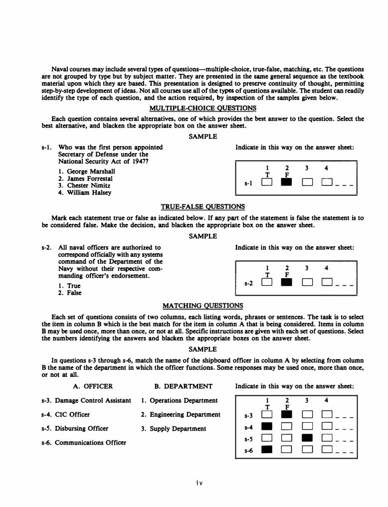
Naval courses may include several types of questions-multiple-choice, true-faLse, matching, etc. The questions are not grouped by type but by subject matter. They are presented in the same general sequence as the textbook material upon which they are based. This presentation is designed to preserve continuity of thought, permitting step-by-step development of ideas. Not all courses use all of the types of questions available. The student can readily identify the type of each question, and the action required, by inspection of the samples given below.
MULTIPLE-CHOICE QUESTIONS
Each question contains severat alternatives. one of which provides the best answer to the question. Select the best alternative, and blacken the appropriate box on the answer sheet.
s-1. Who was the first person appointed Secretary of Defense under the National Security Act of 19477
1. George Marshall 2. James Forrestal 3. Chester Nimitz 4. William Halsey
SAMPLE
Indicate in this way on the answer sheet:
s-1
1 T
D
2 F
•
3 �---1 D
TRUE-FALSE QUESTIONS
Mark each statement true or faLse as indicated below. If any part of the statement is faLse the statement is to be considered faLse. Make the decision, and blacken the appropriate box on the answer sheet.
s-2. All naval officers are authorized to correspond officially with any systems command of the Department of the Navy without their respective commanding officer's endorsement.
1. True 2. False
SAMPLE
Indicate in this way on the answer sheet:
1 2 T F
s-2 D •
3 �---1 D
MATCHING QUESTIONS
Each set of questions consists of two columns, each listing words, phrases or sentences. The task is to select the item in column B which is the best match for the item in column A that is being considered. Items in column B may be used once, more than once, or not at all. Specific instructions are given with each set of questions. Select the numbers identifying the answers and blacken the appropriate boxes on the answer sheet.
SAMPLE
In questions s-3 through s-6, match the name of the shipboard officer in column A by selecting from column B the name of the department in which the officer functions. Some responses may be used once, more than once, or not at all.
A. OFFICER B. DEPARTMENT
s-3. Damage Control Assistant 1. Operations Department
s-4. CIC Officer 2. Engineering Department
s-S. Disbursing Officer 3. Supply Department
s-6. Communications Officer
iv
Indicate in this way on the answer sheet:
1 2 3 4 T F
s-3 D • D D _ --
s-4 • D D D _ --
s-S D D • D_ --s-6 • D D o ___

Assignment 1
Textbook Assignment : "Introduction . " Pages 1-1 through 1-7 .
"The Fire Control Problem. " Pages 2-1 through 2- 7 .
Learning Objective : Describe the history of the FC rating.
1-1 . What is the primary purpose for NEC codes?
1. Replaces social security account numbers
2 . Indicates special knowledge or skills of personnel
3 . Provides ranking indicators for examinations
4 . Serves as a seniority number
1-2 . When is an NEC code normally assigned to an individual ?
1-5 . An FC3 with an NEC code will usually be assigned a billet as a/an
1. operator only 2 . equipment specialist 3 . repairman only 4. system analyst
1-6. The original FC rating was formed to provide maintenance for which of the following systems?
1 . Guns 2 . Missiles 3 . Guns and missiles 4 . Torpedoes
1 . Upon entrance into the Navy 1-7. What was the original rating that was formed to provide for the operation and maintenance of radars?
2 . After completing class "A" school
3. Upon assignment to a fleet unit 4. After completion of a class
"C" school
1-3. The FC rating combines which of the following FT specialty ratings?
1 . FTM and FTB 2 . FTM and FTG 3 . FTB and FTG 4 . FTA and FTU
1- 4 . Which of the following fire control specialty ratings maintain ballistic missile systems?
l . FTAs 2. FTMs 3. FTCs 4 . FTBs
1 - 8 .
1
l . FA 2 . FM 3 . FC 4. FT
When was the FTM designation established as a missile specialty rating?
1 . Following the Korean war 2 . Following the second World War 3 . During the Spanish War 4 . During the Viet Nam conflict
Learning Objective : Relate events that led to the development of modern fire control .
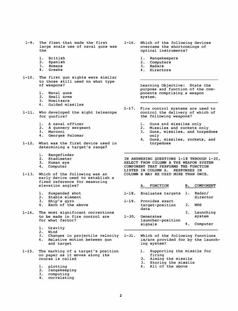
1-9. The fleet that made the first large scale use of naval guns was the
1. British 2. Spanish 3 . Romans 4 . Greeks
1-10. The first gun sights were similar to those still used on what type of weapons?
1. Naval guns 2. Small arms 3. Howitzers 4 . Guided missiles
1-11. Who developed the sight telescope for gunfire?
1. A naval officer 2. A gunnery sergeant 3. Marconi 4 . Georges Palomar
1-12. What was the first device used in determining a target's range?
1. Rangefinder 2. Stadimeter 3. Human eye 4. Computer
1-13. Which of the following was an early device used to establish a fixed reference for measuring elevation angles?
1. Suspended shot 2. Stable element 3. Ship's gyro 4 . Each of the above
1-14 . The most significant corrections to be made in fire control are for what factor?
1. Gravity 2. Wind 3 . Changes in projectile Yelocity 4 . Relative motion between gun
and target
l-15. The marking of a target's position on paper as it moves along its course is called
1. plotting 2. rangekeeping 3. computing 4. correlating
2
1-16. Which of the following devices overcame the shortcomings of optical instruments?
l. Rangekeepers 2 . Computers 3. Radars 4 . Directors
Learning Objective: State the purpose and function of the components comprising a weapon system.
1-17. Fire control systems are used to control the delivery of which of the following weapons?
1. Guns and missiles only 2. Missiles and rockets only 3 . Guns, missiles, and torpedoes
only 4. Guns, missiles, rockets, and
torpedoes
IN ANSWERING QUESTIONS l-18 THROUGH 1-20, SELECT FROM COLUMN B THE WEAPON SYSTEM COMPONENT THAT PERFORMS THE FUNCTION LISTED IN COLUMN A. RESPONSES IN COLUMN B MAY BE USED MORE THAN ONCE.
A . FUNCTION B. COMPONENT
1-18. Evaluates targets 1. Radar/ director
1-19 . Provides exact target-position 2. WDS data
3. Launching 1-20. Generates system
launcher-position signals 4 . Computer
1-21. Which of the following functions is/are provided for by the launching system?
1. Supporting the missile for firing
2. Aiming the missile 3. Storing the missile 4 . All of the above

1-22. Which of the following is considered to be a weapon combination?
1. Launcher/missile 2. Missile/gun 3. Gun/projectile 4. Missile/projectile
1-23. What is meant by programming a weapon?
1. Del ivering a weapon to a target
2. Giving a weapon predetermined step-by-step operating instructions
3. Directing the path of the weapon
4 . Accelerating the weapon to cruising speed
1-24 . Aiming a weapon at a target can be accomplished by which of the following methods ?
1. Steering the ship to maintain a constant line-ofsight to the target
2. Placing program instructions in the weapon
3. Positioning the delivery device
4. Both 2 and 3 above
Learning Objective: State the purpose for the development of guided missiles and list current developments in surface missile systems .
1-25. In mil itary usage , the term missile is synonymous with
1. rocket 2. torpedo 3. guided missile 4 . depth charge
l-2 6 . The Navy's first surface-to-air missiles were designed for what purpose?
1. Fleet-wide antiaircraft defense
2. Antiship missile defense 3. Long-range bombing 4 . Early warning
3
1-27. Which of the fol lowing missiles is used solely for self-defense at close-in range?
1. TARTAR 2. SPARROW I I I 3. HARPOON 4. TOMAHAWK
1-28. Which of the following is/are (an) antiship missile(s)?
1. SPARROW I I I 2. HARPOON only 3. TOMAHAWK only 4 . Both HARPOON and TOMAHAWK
1-29. What missile system is a fully automated, surface-to-air weapon system with short reaction time and high fire power ?
1. AEGI S 2. RAM 3. STANDARD 4. TOMAHAWK
1-30. Compared to guns, missiles have which of the following advantages?
1. Cheaper and smaller 2. Cheaper and increased range 3. Increased range and effective
ness 4 . Smaller and faster
1-31. Which of the following missiles can be operated in either the infrared or the rf mode?
1. TOMAHAWK 2. SPARROW I I I 3. TERRIER 4 . RAM
1-32. What missile uses terrain matching techniques against land targets?
1. TARTAR 2. TOMAHAWK 3. SPARROW I I I 4. RAM
Learning Objective : Describe the duties, responsibilities, and advancement opportunities of the FC.
1-33. To what department are FCs normally assigned?
1. Supply 2. Operations 3. Weapons 4. Engineering
1-34. What officer is responsible for the maintenance and operation of the ship's fire control systems?
1. Electronics maintenance officer
2. Fire control officer 3. Operations officer 4. Combat information center
officer
QUESTIONS 1-35 THROUGH 1-37 ARE TO BE JUDGED TRUE OR FALSE.
1-35. FCs are NOT required to maintain fire control records .
1. True 2. False
1-36. FCs are occasionally required to inspect and adj ust optical instruments associated with fire control equipment .
1-37.
1-38.
1. True 2. False
FCs do NOT require skills in using handtools and instruments in the performance of their duties.
1. True 2. False
Which of the following is a school
1-40. Which of the following publications provides a listing of all the courses used as references for preparation of advancement examinations?
1. Fire Contr>oZ.man Third Class, NAVEDTRA 10276
2. Bibliography for Aduanaement Examination Study, NAVEDTRA 10052
3. List of Tr>aining Manuals, Cor>r>espondenae Cour>ses, and Per>sonneZ. Qualifiaation Standards, NAVEDTRA 10061
4. Occupational. Standards, NAVPERS 18068
1-41. The FC's training experience is such that at the E7/E8 level, he should be knowledgeable of a l l shipboard
1-42.
1. weapons departmen.t deck equipment
2. combat systems equipment 3. communication equipment 4. fire control equipment
Learning Obj ective: State the rules and solve mathematical problems using integers.
Considering the concept of "direction sense, " what is the difference between -4 and +3?
1. -1 2. 1 3. 3 4. 7
that provides the FC with a basic 1-43. foundation in electronics?
What is the general rule for adding two or more negative numbers?
1. Class A school 2. Class B school 3. Class C school 4. Class D school
1-39. FCs receive training on individual fire control equipment from which of the following schools?
1. Class A school 2. Class B school 3 . Class C school
4
1. Find the sum of the numbers, disregarding the sign
2. Find the product of the absolute values of the numbers , taking the sign of the largest
3. Find the sum of the absolute values of the numbers , and place a minus sign before the result
4. Find the difference between the absolute values of the numbers , and place a minus sign before the result
1-44. What is the general rule for adding a positive and a negative number?
1 . Find the difference between the reciprocal values of the numbers, and place a plus sign before the result
2 . Find the difference between the absolute values of the numbers, and prefix the sign of the number having the larger absolute value
3 . Find the sum o f the absolute values of the numbers, and place a plus sign before the result
4 . Find the sum of the absolute values of the numbers, and prefix the sign of the number having the larger absolute value
1-4 5 . What result do you obtain when you take the sum of - 2 3 and + 1 8 ?
l . +41 2 . + 5 3 . - 5 4 . -41
1-46 . What is the result of subtracting +7 from -15?
l . - 2 2 2 . - 8 3 . + 8 4 . + 2 2
1-4 7 . What i s the result of the operation indicated by the expression (-5) - ( -7 ) ?
1 . +12 2 . +2 3 . -2 4 . - 1 2
1-48 . What i s the product of - 3 and -4?
l. +12 2 . + 7 3 . - 1 4 . -12
1-49 . What is the product of -3 and 4?
1 . +12 2 . +7 3 . - 1 4 . -12
5
1-5 0 . What is the general rule for determining the sign of the product of two numbers that are opposite in sign?
1 . The sign is negative when the larger number is positive and positive when the larger number is negative
2 . The sign is positive when the larger number is positive and negative when the larger number is negative
3 . The sign is always positive 4 . The sign is always negative
Learning Objective : State the rules and solve mathematical problems using fractions.
1- 5 1 . What is the quotient of 2 1 divided by -7?
l . +14 2 . +3 3 . - 3 4 . -14
1- 5 2 . What is the result of (6l�-4l
?
1 . -4 2 . - 3 3 . +3 4 . +4
1 - 5 3 . The person who states that 9 1 5 1 5 .
24 + 2 + 24 24 has fakled to
observe that
1 . to find the sum of two or more fractions, the numerators should be added to obtain the numerator and denominator
2 . fractions must be reduced to lowest terms before they are added
3 . fractions cannot be added without raising them to higher terms
4 . quantities to be added must be expressed in the same unit
1-54. Which of the following groups of fractions has the smallest least common denominator?
1. 2/ 3 , 5/9, 7/18 2 . 3/8 , 5/1 6, 3/4 3 . 5/6 , 4/1 2 , 2/3 4. 20/2 5 , 13/ 1 5 , 9/10
1-55. What is the result of 5/2 x 1/4 x 1-59. 2/3 when reduced to lowest terms?
The rule for placing the decimal point in multiplying decimals is the number of decimal places in the answer is equal to l. 5/8
2. 5/12 3. 10/24 4. 15/36
1-56. Which of the following statements is true about the fraction -�?
1. The sign of the 3 is negative; the 5 has no sign
2. The sign of the 5 is negative; the 3 has no sign
3. The sign of the 3 is negative; the s�gn of the 5 is negative; the s�gn of the fraction is negative
4. The sign of the 3 is positive; the sign of the 5 is positive; the sign of the fraction is negative
Learning Objective: State the rules and solve mathematical problems using decimals.
QUESTION 1-57 IS TO BE JUDGED TRUE OR FALSE.
1-57. In adding decimals, it is recommended that the digits be aligned from the right and that the decimal be located by estimation.
1. True 2. False
1-58. A feeler gage has blades 0.025, 0. 005, 0. 004, 0. 003, 0.0025, 0.002, and 0. 0015 inch thick. The blades that should be used to make a setting of . 0295 inch are the blades with thicknesses of
1. 0.025, 0. 004, and 0. 0015 in. 2. 0.025, 0. 003, and 0.0025 in. 3. 0. 025, 0. 0025, and 0. 002 in. 4. 0. 005, 0. 003, 0. 0025, and
0. 0015
6
1-60.
1. the number of decimal places in the multiplier
2. the number of decimal places in both the multiplier and the multiplicand
3. twice the number of decimal places in both the multiplier and the multiplicand
4. the number of decimal places in the multiplicand less the number of decimal places in the multiplier
The product of 33. 3 and . 14 is
1. 33.44 2. 4. 662 3. . 4662 4 . 46. 62
1-61. The quotient of . 00243 divided by 1. 8 is
l. 0.0000135 2 . 0. 000135 3. 0. 00135 4 . 0. 0135
1-62. Moving the decimal point two places to the right in the dividend and the divisor in the example
5.10 1. 25/6. 3810
is equ�valent to
1. dividing the quotient by 100 2 . multiplying the quotient by
100 3. dividing both 1. 25 and 6.381
by 100 4. multiplying both 1. 25 and
6.381 by 100
Learning Objective: Simplify and solve mathematical problems using exponents and radicals.
1-63. Which of the following numbers is equivalent to 3 raised to the fourth power?
1. 81 2 . 64 3. 27 4. 12
1-64. What base when raised to the fifth
1-69. What is the sum of 2110 plus
. 5/IO?
1. IIO
2. 2/IO + 5
3. 2. 5110
4. 2 . 5120
power gives an answer of 32? 1-70. The value of the expression
1 . 1 2. 2 3 . 4 4 . 8
1-65. Another name for the square root
sign cr-> is
1. extraction sign 2. radian sign 3. factor sign 4. radical sign
1-66. What root of 64 is indicated by
the expression 164?
1. The first root 2 . The cube root 3. The square root 4. The quadratic root
1-67. What is the decimal equivalent of
l0- 5?
1. 0. 01 2. 0. 001 3. 0. 0001 4. 0. 00001
1-68. Which of the following expressions represents an intermediate step
i . l"f . 718 X 0 . 0003 n 81mp 1 y1ng 0 . 0085 x 75,000 by using powers of 10?
1. (7 . 18 X 3) X (102 + 10
-4)
(8. 5
2. 7 . 18 8.5
3 . 7 . 18
8. 5
4. 7. 18
8 . 5
X 7. 5)
X 3 7.5 X X
X 102 X -4
X 10 X
X 102 X
X 10 3 X
X (10-4
+ 103
)
102 X 10-4 X 10-3
3 X 10⁻⁴
7. 5 X 10⁴
3 X 10⁻⁴
7. 5 X 10⁴
7
2 13 . 13 ���3�� in the most simplified
form is
1. 2
2. 2/3 -3-
3 . 213
4. 219 -3
-
1-71. What is the proper way to group digits of the number 418.796 when preparing to calculate its square root?
1 . 418. 796 2. 4 18 . 7 96 3. 41 8. 7 96 4. 04 18. 79 60
1-72. What is the square root of 324?
1. 17. 62 2. 17.94 3. 18. 00 4. 22.00

Assignment 2
Textbook Assignment: "The Fire Control Problem." Pages 2-7 through 2-32.
Learning Objective: State the laws and solve mathematical problems using algebra.
2-1. The commutative law for addition is illustrated by the equation
2-2.
2-3.
2-4.
l. ab = ba 2. a + a b + b 3. a + b b + a 4. a(b + c) = ab + ac
The associative law of mul tiplica-tion is illustrated by the equation
l. a + b . c = a + c . b b + c . a
2. a(b + c) = c(b + a) 3. a(b + c + d) = ab + ac + ad 4. a(b c) + a . b . c = (a . b)c
Which of the following statements correctly describes the term 17xyz?
1. 17 is the coefficient of xyz 2. 17x is the coefficient of yz 3. 17xy is the coefficient of z 4. Each of the above
2 What is the coefficient of x y in 2 the expression x y - ab?
1. 2. 3. 4.
1 2
2 X
y
2-5. What is the value of x in the equation ax + b = 0?
l. a - b 2. b - a 3. -b/ a 4. -a/b
8
2-6. What is the numerical value of y in the equation y/2 + 4 = y/3?
1. 12 2. 24 3. -12 4. -24
2-7. Assume that two resistors connected in parallel have a resistance of 240 ohms. The markings on R1 indicate that it has a resistance of 400 ohms. Overheating has burned off the markings of R2. The total resistance of two resistors connected in parallel is given by the formula
1/RT � l/R1 + 1/R2. What is the resistance of R2?
1. 600 ohms 2. 800 ohms 3. 1000 ohms 4. 1200 ohms
Learning Objective: Solve mathematical problems using trigonometry.
2-8. What is the hy potenuse of a right triangle whose sides are 5 and 12 units?
1. 13 2. 14 3. 15 4. 16
QUESTION 2-9 IS TO BE JUDGED TRUE OR FALSE.
2-9. The six trigonometric quantities, sin e, cos e, tan e, cot e, sec e, and esc e, represent ratios of the sides of right triangles.
1. True 2. False
2-10. The sine of an angle of 49 degrees, 48 minutes is
1. 0.6455 2. 0.7536 3. 0.7638 4. 1.1833
2-11. Solve for the vector R in polar
2-12.
.... . form when given A = 7.23 - 3 and
.... B = -24.64 + 8.
1. 18.11 � 2. 18.11 Ll§.!o 3. 1.811 �0 4. 1.811 �
4
Solve for vector R in rectangular
form when given A = 10L.!Q0 and �
B = -9 + 3.
1. 1. 34 + 9.43 2. -16.66 + 3.43 3. 16.66 + 3.43 4 . - 1. 34 + 9.43
Learning Objective: Identify the basic elements of interior and exterior ballistics and the forces that govern the movement of projectiles in a vacuum.
2-13. The curved path followed by a projectile in its flight from gun to first impact is called a
1. ballistic 2. trajectory 3. controlled flight 4. pattern
2-15. After the projectile and powder charge have been loaded into the gun, it is sealed by the
1. breech mechanism 2. projectile's nose 3. projectile's rotating band 4. gun bore rifling
2-16. The rifling of a gun bore causes the projectile, while in flight, to
2-17.
2-18.
1. spin 2. tumble 3. maintain a straight course 4. maintain a curved course
A spinning projectile causes its trajectory to be
1. curved 2. straight 3. predictable 4. unpredictable
You are inspecting a 5-inch gun for effects of erosion after a three month period of fairly consistent firing. Which of the following parts will show the greatest amount of wear?
1. The lands 2. The grooves 3. The breech opening 4. The muzzle opening
2-19. In ballistics, the direction along which the projectile leaves the gun is known as the
1. line of extension 2. gun axis line 3. line of fire 4. ballistics line
2-14. The initial velocity of a projec- 2-20.
tile is governed by the condition
Two factors of exterior ballistics that are always present are the effects of
of which of the following compo-nents?
1. The gun 2. The projectile 3. The propelling charge 4. All of the above
9
1. bore erosion and propelling charge
2. air and gravity 3. type of projectile and air 4. gravity and bore erosion
2-21 . A free-moving object in outer space has which of the following properties?
1 . Zero acceleration 2. zero i nertia 3. Decreasing velocity 4. Decreasing weight
2-22. An object moving through a vacuum on Earth is unlike one moving through outer space in that it has
1. velocity 2. i nertia 3 . mass 4. weight
2-23 . The amount a gun is elevated above the horizontal is called the
1. angle of projection 2. striking angle 3. angle of departure 4. fall angle
2-24. The percentage of projectile momentum contained in the horizontal (Uh) and vertical (Uv) components is a function of which of the following angles?
1 . The angle of departure 2. The striking angle 3. The angle of fall 4. The angle of projection
2-25. The highest point in the trajectory of a projectile is known
2-26.
as the
1. gravitational change point 2 . maximum ordinate 3. maximum velocity point 4. deviation ordinate
In a vacuum trajectory, which of the following angles are equal?
1. Departure and striking 2. Projection and fall 3 . Departure and fall 4. Projection and departure
IN ANSWERING QUESTIONS 2-27 THROUGH 2-30, SELECT FROM COLUMN B THE ANGLE OF DEPARTURE THAT AFFECTS THE TRAJECTORY AS DESCRIBED IN COLUMN A. RESPONSES IN COLUMN B MAY BE USED MORE THAN ONCE.
10
A. TRAJECTORY EFFECT
B. ANGLE OF DEPARTURE
2-27. Obtains the shortest horizontal component (Uh)
2-28. Obtains the longest horiz ontal component (Uh)
2-29. Obtains the shortest horizontal range
2-30. Obtains the longest horizontal range
1 .
2.
3.
4 .
0" only
45°
90° only
0" or 90"
2-31. I� whi�h of.
the.
following firing s1tuat1ons 1s h1gh angle fire most important?
1. AA fire 2. Surface fire 3 . Gunfire support enfilade fire 4 . Precaution calibration for
surface fire
2-32. Approximately how far along the line of flight of a shell from the gun to the point of impact i s the high point of a vacu�� trajectory?
1. 1/3 of the distance 2 . 1/2 of the distance 3 . 2/3 of the distance 4. 3/4 of the distance
2-33. Which of the following is a characteristic of a vacuum trajectory in Earth's gravity field?
1.
2 .
3 .
4.
The projectile travels a symmetrical curve The angle of fall equals angle of departure The striking velocity equals initial velocity Each of the above
Learning Objective: Identify the elements of exterior ballistics and the forces affecting a projectile's trajectory in air.
2-34 . Which of the following aspects of exterior ballistics has a large variation when the shot is through air rather than in a vacuum?
1 . Traj ectory 2 . Initial velocity 3 . Gravity compensation 4 . Line of departure
2-35 . During what portion of an air traj ectory will the air resistance offer the greatest retardation to a projectile?
1 . End 2 . Middle 3 . Beginning 4 . Apex
2-36 . During what port.ion of an air traj ectory will the maximum ordinate occur?
1 . Nearer the beginning 2. Nearer the end 3 . At the middle 4 . At the point of maximum air
resistance
2-37 . To achieve the same range with an air shot as with a vacuum shot, which, if any, of the fol lowing changes must be made?
1 . Increase angle of departure 2. Decrease angle of departure 3 . Decrease angle of fall 4 . No change is necessary
2-38 . During what portion of an air trajectory will the density of the air offer the least retardation to a projectile?
1. Beginning 2 . Lower portion 3 . Upper portion 4 . End
2-39 . Assuming that the alternatives listed all have an initial velocity of 2600 ft/sec, which of the following projectiles would be affected the most by air resistance?
1 . 5" projectile 2 . 8" proj ectile 3 . 3" projectile 4 . 1 6" proj ectile
11
2 - 4 0 . The effect of the projectile shape on the air resistance is quantitatively expressed by the
1. projectile diameter 2 . projectile circumference 3 . coefficient of form 4 . coefficient of rounding
2 - 4 1 . Why are modern naval guns ri fled?
1 . To counteract the effect of drift
2. To solve for wind effect on range and deflection computations
3 . To keep the projectile pointing along its trajectory
4 . To increase the striking velocity
2-4 2 . What harmful effect to a projectile's trajectory is caused by the rifl ing in a gun barrel?
1 . Drift 2. Rigidity 3 . Resistance 4 . Precession
2-43 . Which of the following ballistic factors causes the effects of wind upon a projectile to increase?
1 . Elevation 2. Initial velocity 3 . Range 4 . Angle of departure
2-4 4 . Which of the following projectiles would be LEAST affected by wind i f all had the same initial velocity?
1 . 5" 2 . 8" 3 . 3" 4 . 1 6"
2-45 . Wind that blows with or against the flight path of a projectile is called
1. head wind 2 . tail wind 3 . range wind 4 . cross wind
2-46. In order to make proper gun settings to compensate for the effects of wind, true wind must be resolved into which of the following components?
1 . I n line and perpendicular 2 . I n line and vertical 3 . Horizontal and vertical 4 . Vertical and perpendicular
2-47 . Which of the following types of wind is used to compensate a trajectory that passes through winds moving in opposite directions?
1. True wind 2. Range wind 3. Cross wind 4 . Weighted ballistic wind
2-48. The Earth's rotation noticeably affects projectiles with a range exceeding how many yards?
1 . 10,000 2. 15,000 3. 20,000 4. 25,000
2-49. Which of the following guns requires a correction for the effects of Coriolis force?
1 . 40 m/m 2 . 3 " 50 3. 5" 54 4 . 16"
Learning Objective : Identify the frames of reference (basic lines, angles, and planes), coordinate systems, and units of measure used in the gun fire control problem .
2-50. Target position is measured and lead angles are computed with i n a system o f lines, angles, and planes called a
1. frame of reference 2 . system of vectors 3 . geometric system 4 . rectangular frame
12
2-51 .
2-52 .
How can the size and direction of a quantity be represented?
1. A plane 2. A trajectory 3. A vector 4. A frame of reference
Which of the following conditions describe the frames of reference that are attached (a) to own ship and (b) to the Earth?
1. 2 . 3. 4 .
( a) Unstable ( a) Stable ( a) Unstable (a) Stable
( b) unstable (b) stable (b) stable (b) unstable
2-53 . With respect to what planes are measurements made for Earth frame of reference?
1. Horizontal and normal 2 . Horizontal and vertical 3 . Deck and vertical 4. Deck and normal
2-54 . Measurements for own ship frame of reference are made with respect to which of the following planes?
1. Horizontal and normal 2 . Horizontal and vertical 3. Deck and vertical 4. Deck and normal
2-55 . What are the two basic lines used to solve the ballistic portion of the fire control problem?
1. N-S and E-W axis lines 2 . Line of sight (LOS) and line
of fire ( LOF) 3 . Line of fire (LOF) and own
ship center line (OSCL) 4. Own ship center line (OSCL)
and line of sight ( LOS)
2-56. The term horizontal is used in naval ordnance for an imaginary plane that is tangent to the
1 . ship's deck at your gun's position
2. Earth's surface at your gun's position
3. gun bore axis at the ship's deck
4. surface of the ocean at the ship's position

2-57 . What basic angle or line is used as the primary reference in establishing the position of the gun?
1 . Angle of elevation 2 . Sight angle 3 . Line of fire 4 . Line of sight
2-58. When positioning a gun to hit a target, what total number of lead angles is/are used?
1 . One 2 . Two 3 . Three 4 . Four
2-5 9 . Sight angle as shown in figure 2-13 of the textbook is measured in which of the following reference frames?
1 . The horizontal plane that contains the trunnion axis and the LOS
2 . The horizontal plane that contains the trunnion axis the LOF
3 . A plane perpendicular to the trunnion axis and containing the LOS
4 . A plane perpendicular to the trunnion axis and containing the LOF
2- 6 0 . Sight deflection a s shown in figure 2-13 of the textbook is measured in which of the following reference frames?
1 . The horizontal plane which contains the trunnion axis and the LOS
2 . The horizontal plane which contains the trunnion axis and the LOr
3 . A plane perpendicular to the trunnion axis and containing the LOS
4. A plane perpendicular to the trunnion axis and containing the LOF
2-61. What total number of basic coordinate systems is/are used to locate a point in a plane?
1. One 2 . Two 3. Three 4. Four
13
2-62 . What types of coordinates are used in a rectangular coordinate system to determine the position of a surface target?
1 . One linear and one angular 2 . Two linear only 3 . Two linear and one angular 4 . Three linear
2-63 . Position of a surface target is determined in a polar coordinate system by the use of
1 . one linear and one angular coordinate
2 . two linear and one angular coordinates
3 . two linear coordinates only 4. three linear coordinates
2- 6 4 . What type of three-dimensional coordinate system is used when an angular value is used to describe a point's deviation from the reference plane?
1 . Linear 2 . Polar 3 . Rectangular 4 . Helical
2-65 . What type of three-dimensional coordinate system employs linear coordinates to describe a point's deviation from the reference plane ?
1 . Linear 2 . Polar 3 . Rectangular 4 . S�herical
2-66. In what units of measure are own ship speed, target speed, and wind velocity (a) received in a computer and (b) used within a computer?
1. (a) Knots (b ) Yards/hour
2 . (a ) Yards/hour· (b ) Knots
3 . (a ) Knots (b ) Yards/seconds
4 . (a ) Yards/hour (b ) Yards/seconds
2-67. What is the constant ratio used to convert knots to yards per second?
1 . 0.365 2. 0.536 3. 0. 563 4. 0.635
2-68. Which of the following units of measure is a convenient unit to use when converting between angular and linear measure?
1 . Knots 2. Yards per second 3. Radians 4. Degrees per second
2-69. The mil is equal to how many minutes of arc?
1. lOOQ.O 2 . 58.18 3. 5.718 4. 3.438
2-70. The linear value of the mil will vary due to changes in which of the following target parameters?
1 . Range 2. Bearing 3. Elevation 4. Speed
2-71. What is the linear value of a mil at a range of 5000 yards?
1. 0. 5 yards 2. 5. 0 yards 3 . 50.0 yards 4. 500.0 yards
14
2-72. Assume that a target being tracked at a range of 5,000 yards has a linear bearing rate of 50 knots. What will be the angular bearing rate?
1. 56.30 mils per second 2 . 5.63 mils per second 3 . 56 . 30 yards per second 4 . 5 . 63 yards per second
2-73. Assume that a target being tracked at a range of 10,000 yards has a linear bearing rate of 150 knots. What will be the angular bearing rate expressed in minutes of arc per second?
1 . 5. 63 2. 29.04 3. 56. 30 4 . 290.40
2-14. What units of measurement normally express the rates used to predict the target's future position?
1. Knots for all three coordinates
2. Knots, yards per second, and mils
3. Yards per second for all three coordinates
4. Mils for two coordinates and yards per second for one coordinate
2-75. What units of measurement are normally used for the rates involved in the coordinate system of the target-tracking section of the GFCS?
1 . Knots for all three coordinates
2 . Knots, yards per second, and mils
3 . Yards per second for all three coordinates
4. Mils for two coordinates and yards per second for one coordinate

Assignment 3
Textbook Assignment : "The Fire Control Problem." Pages 2-32 through 2-46.
"Weapons System. " Pages 3-l through 3-4.
3-1.
Learning Objective: Identify and interpret standard fire control symbols .
Which of the following publications provides a detailed coverage of the construction and definition of fire control symbols?
TO ANSWER QUESTIONS 3-5 THROUGH 3-7, SELECT FROM COLUMN B THE SYMBOL CONSTRUCTION WHICH CORRESPONDS TO THE GEOMETRICAL QUANTITY IN COLUMN A. RESPONSES IN COLUMN B MAY BE USED MORE THAN ONCE.
A. QUANTITIES B . SYMBOLS
1. NAVEDTRA 10052 (Series) 3-5. Apparent wind speed 1. w 2. OP 1700, Vols. 1, 2, and 3 3. NAVPERS 18068-C 3-6. Horizontal true 2. wa 4. Each of the above
3-2. What volume of the Standard Fire Control Symbols publication contains information that is primarily applicable to the gun fire control problem?
3-3.
1. Vol. 1 2. Vol. 2 3. Vol. 3 4. Vol. 4
The basic fire control symbol represents which of the following information in each class?
1. The system type 2 . The geometric quantity 3. The method used in problem
solution 4. The algebraic sum
QUESTION 3-4 IS TO BE JUDGED TRUE OR FALSE.
3-4. The quantity modifier in a fire control symbol may be placed either before or after the parentheses without affecting the meaning of the symbol.
1. True 2. False
15
wind speed 3. Wh
3-7. True wind speed 4. Wo
TO ANSWER QUESTIONS 3-8 THROUGH 3-10, SELECT FROM COLUMN B THE SYMBOL CONSTRUCTION WHICH CORRESPONDS TO THE GEOMETRICAL QUANTITY IN COLUMN A. RESPONSES IN COLUMN B MAY BE USED MORE THAN ONCE .
A. QUANTITIES B. SYMBOLS
3-8. Horizontal 1. Ed deflection
2. Lh 3-9. Director train
3. Bd 3-10. Target height
4. Rv
3-11. In the construction of fire control symbols, which of the following statements applies to the use of quantity modifiers?
1. The geometrical quantity is enclosed in parentheses
2 . The quantity modifier may preceed the geometrical quantity
3. The quantity modifier may follow the geometrical quantity
4. Each of the above
TO ANSWER QUESTIONS 3-12 THROUGH 3-14, SELECT FROM COLUMN B THE SYMBOL CONSTRUCTION WHICH CORRESPONDS TO THE GEOMETRICAL QUANTITY IN COLUMN A. RESPONSES IN COLUMN B MAY BE USED MORE THAN ONCE.
3-12.
3-13.
3-14.
A. QUANTITIES B. SYMBOLS
Deflection spot l. c(R)
Generated range 2. q(Ls)
Increments of 3 . pl(Edg') generated eleva-tion 4. ic(E)
Learning Objective: Solve the elements of the surface fire control problem affected by own ship and target motion.
3-15. When measured by the director, the present target position is referenced to which of the following planes?
1. The deck plane 2. The horizontal plane 3. The vertical plane 4. The normal plane
3-16. Which of the following planes is used to make deck tilt corrections needed for computation of the fire control problem?
1. The deck plane 2. The horizontal plane 3 . The vertical plane 4. The normal plane
16
3-17. What quantity is obtained when director elevation and level angle are combined?
1. Present target position 2 . Target rate of clime 3. Target bearing angle 4. Target elevation angle
3-18. How is slant range affected, if at all, by an inbound air target?
1. It increases 2 . It decreases 3. It is not affected 4. It cannot be determined
3-19. The angle between the LOS and the LOF is called the
1. sight angle 2 . level angle 3. crosslevel angle 4. trav�rse angle
3-20. Which of the following quantities is added to director train to obtain gun train?
1. Sight deflection 2. Sight angle 3 . Level angle 4 . Trunnion tilt
Learning Objective: Identify and define the geometric problems contained in the gun fire control problem.
3-21. What total number of basic steps are involved in the solution of the gun fire control problem?
1. Five 2. Two 3. Three 4. Four
3-2 2 . What is used as the basic reference in the solution of the gun fire control geometry problems?
1. The deck plane 2 . The reference director 3. The horiz ontal plane 4. The reference gun mount
3-23 . During which of the following computations is target position converted from deck to horizontal plane reference?
1 . Future position 2 . Ballistic 3 . Parallax 4 . Present position
3-24 . What quantities are computed from the errors obtained by comparing target position with generated target position?
1. Angular rates 2 . Linear rates 3 . Stabilization corrections 4 . Initial velocity corrections
3-25. Which of the fol lowing quantities is dependent on both Ei and Zd?
1. B 2 . Bd 3 . j (Bd) 4. By
3-26 . What quantity is produced by adding ship ' s course (Co) to relative bearing (B)?
1 . Bd 2 . By 3 . j (Bd) 4 . p ( Bd)
3-27. In and across what reference line are present position linear rates computed?
1. The LOS 2 . The LOF 3 . The OSCL 4 . The TCL
IN ANSWERING QUESTIONS 3-28 THROUGH 3- 3 0 , REFER TO FIGURE 2-27 OF THE TEXT.
3-28 . Which vector represents own ship motion?
1 . DMht 2. DMho 3 . DMrho 4 . DMrht
17
3-29. How
1 .
2 .
3 .
4 .
is target speed represented?
By the DMho By the DMho By the DMht By the DMht
direction
magnitude
direction
magnitude
of vector
of vector
of vector
of vector
3- 3 0. Which of the following quantities is found by algebraically adding the components in the figure that are perpendicular to the line of sight?
1 . DMrh 2 . DMb 3 . Bot 4 . By
3- 3 1 . Which of the fol lowing quantities represents the target's rate of vertical linear movement in elevation?
1 . Rh 2 . Rv 3 . DMv 4 . DMr
Learning Objective: Solve the element of the surface fire control problem that determines future target position .
3-32 . The first step in determining a target's future position is the multiplication of the relative motion rates DMv , DMrh , and DMb by which of the following quantities?
1 . Tl
2 . T2
3 . Rh 4 . Rv
IN ANSWERING QUESTION 3-33, REFER TO FIGURE 2-32 OF THE TEXT .
3- 3 3 . What quantity is produced when Sh and Wbg(Lh) are combined?
1 . Rh2
2 . Mb 3 . Mbg 4 . Lh
IN ANSWERING QUESTION 3-34, REFER TO FIGURE 2-33 OF THE TEXT.
3-34. What quantity is produced when angles E4 and V4 are combined?
1. Eg 2. Sh 3. Lh 4. Wbq (Lh)
3-35. In what section of a fire control computer are the gun orders compiled?
1. Present position 2. Future position 3. Trunnion tilt 4. Ballistic
3-36. Which of the following displacements is/are compensated for by parallax corrections?
1. Horizontal displacement of gun from director only
2. Vertical displacement of gun from director only
3. Horizontal and vertical displacements of gun from director
4. Displacement of director above the waterline
3-37. In what plane is horizontal base length measured?
1. Deck 2. Slant 3. Roller path 4. Horizontal
3-38. What base length is used for pl (Edg') h?
1. 5 yd 2. 10 yd 3. 50 yd 4. 100 yd
3-39. Horizontal parallax is affected by which of the following measurements?
1. Range 2. Bearing 3. Base length 4. All of the above
18
3-40. The output of the horizontal parallax computer must be adjusted by means of a gear ratio at receiving unit when which of the following situations exists?
1. When two directors are used 2. When base length is differ
ent from 100 yd 3. Bd instead of Bdg' is u�ed
for computing b' 4. Ei' and z are measured by a
director rather than by the stable vertical
3-41. What base length is used for pl(Bdg')?
1. 5 yd 2. 10 yd 3. so yd 4. 100 yd
Learning Objective: Identify the components that comprise a combat system and their functions.
3-42. Most Navy combatant ships carry weapons systems designed to counter what threat(s)?
1. Air 2. Surface 3. Subsurface 4. All of the above
3-43. What is the main purpose of a weapons system?
1. Search for targets 2. Destroy targets 3. Track targets 4. Acquire targets
3-44. What is the concept of coordinating all the ship's weapons systems called?
1. Weapons platforms 2. weapons systems disposal 3. Combat systems 4. Antiair warfare
3-45 . What is the ability to counter air threats called?
1 . AAW 2 . ASMD 3 . ASUW 4 . ASW
3- 4 6 . What is the ability to counter subsurface threats called?
1 . AAW 2 . ASMD 3 . ASUW 4 . ASW
3 - 4 7 . Fire Controlmen maintain and operate equipment in a l l but which of the following areas?
1 . AAW 2 . ASMD 3 . ASUW 4 . ASW
3-48. How many types of basic equipment make up the combat system?
1 . One 2 . Two 3 . Three 4 . Four
IN ANSWERING QUESTIONS 3 - 4 9 THROUGH 3-51, SELECT THE DESCRIPTION IN COLUMN B THAT MATCHES THE COMPONENT TITLE IN COLUMN A . NOT EVERY RESPONSE IN COLUMN B IS USED .
A . COMPONENT
3 - 4 9 . Weapons control device
B. DESCRIPTION
1 . Detect and identify
3-52 . What is the first thing that must happen in order for a weapons system to perform its mission?
1 . Launch a missile 2 . Fire a gun 3 . Detect a target 4 . Get shot at
3-53 . What information can be provided by a sensor?
1 . Target position 2. Target course and velocity 3 . Target type and quantity 4. Each of the above
3 -5 4 . Which of the following is NOT classified strictly as a sensor?
1 . Search radar 2. ESM 3 . NTDS 4 . Fire control radar
3-55 . In the AN system, which of the following is the designation for a shipboard digital data communications tracking receiver?
1 . AN/SPQ-9 2. AN/SKQ-3 3 . AN/SRS-10 4 . AN/SYR-1
3-56 . Which of the following equipment& is more than just a threecoordinate radar?
1 . AN/SPS-39 2 . AN/SPS-48 3 . AN/SPS-52 4 . AN/SPY-1
contacts 3-57 . Which of the following data can be provided by a three-coordinate radar?
3-50 . Sensor
3-5 1 . weapon 2 . Process
multi-sensor information
3 . Control the ships weapons
4 . Destroys the target
19
1 . Range 2 . Bearing 3 . Elevation 4 . Each of the above
3-58 . Which of the following devices provide(s) positive identification of friendly targets?
1 . IFF 2. ESM 3 . ECCM 4 . Each of the above

3-59. Which of the following data is NOT provided by two-coordinate search radars?
1. Range 2. Bearing 3. Elevation 4 . IFF
3-60. What is an important aspect of surface search/navigation radars?
1. Long range capability 2. Antiship missile detection 3. Two-coordinate target data 4. Electronic counter-counter
measures
3-61. Which of the following is a passive sensor?
1. ECM 2. ECCM 3. ESM 4 . IFF
20
3-62. Which of the following would an active deception repeater be classified as?
1. IFF 2. ESM 3. ECM 4 . ECCM
QUESTION 3-63 IS TO BE JUDGED TRUE OR FALSE.
3-63. One of the major uses of an information processing system is to establish the target's relative threat to own ship.
1. True 2. False
Assignment 4
Textbook Assignment : "Weapons Systems . " Pages 3 - 4 through 3-25 .
"Fire Control Systems . " Pages 4-1 through 4-7 .
Learning Objective: Identify the coordinate systems and their components .
QUESTION 4 - l IS TO BE JUDGED TRUE OR FALSE .
4 - 1. A coordinate system measures target
4-5. If a point were located in the third quadrant, the values of x and y would have what sign?
1 . Both positive 2 . Both negative 3 . x positive and y negative 4 . x negative and y positive
distance and direction from a 4 - 6 . I f the rectangular coordinates of a target are (-20, +20) then the polar coordinates would be what values ?
reference point.
1 . True 2 . False
4-2. What total number of coordinates is/are required to locate a point in a plane?
1 . One 2 . Two 3 . Three 4 . Four
4 - 3 . Which of the following coordinate systems locates a point in a plane using two linear coordinates?
1. Cartesian 2 . Polar 3 . Cylindrical 4 . Spherical
4 - 4 . Which of the following represents the origin in the rectangular coordinate system?
1. Target position in latitude and longitude
2 . Latitude of ownship 3 . Longitude of ownship 4 . The reference point
21
1. 2 . 3 . 4 .
( 40, 45°) ( 30, 135°) (28 1 135°) (20, 90°)
4 - 7 . To locate a point NOT in the horizontal reference plane requires what total number of coordinates?
1 . One 2 . Two 3 . Three 4 . Four
4-8 . The polar coordinate system uses two quantities that are the same as which of the following coordinate systems?
1 . Cartesian 2 . Cylindrical 3 . Circular 4 . Graphical plot
4 - 9. Which of the following formulas can be used to compute target altitude in the polar coordinate system?
l . R = tan E X Rh 2 . Rh cos E x R 3 . RV cos E X R 4 . Rv sin E x R

4-10. What quantity can be added to the rectangular coordinate system to locate a target NOT in the horizontal reference plane?
1. R 2. By 3. Rh 4. Rv
QUESTION 4-11 IS TO BE JUDGED TRUE OR FALSE.
4-11. The coordinate systems used by search radars do NOT need to be converted to be used by the fire control systems.
1. True 2. False
4-12. What is required to convert from one coordinate system to another?
1. A stationary target 2. The same frame of reference 3. A vertical plot board 4. A sliderule or calculator
4-13. The process of converting between coordinate systems, with a linear distance between their reference points, is called
1. rotation of axes 2. translation of axes 3. linear shifting 4. coordinate establishment
4-14. What is/are required for rotation of axes?
1. The same reference point 2. A linear shift in axes 3. Translation must be performed
first 4. All of the above
IN ANSWERING QUESTIONS 4-15 THROUGH 4-17,
4-15.
4-16.
4-17.
A. COORDINATE B. COORDINATES SYSTEM
Spherical 1. Three angular
Cylindrical 2. Three linear
Cartesian 3. One linear and two angular
4. Two linear and one angular
4-18. What are the four frames of reference used in Naval fire control?
1. Own ship, the Earth, the missile, the target
2. The Earth, inertial space, own ship, the missile
3. The missile, the target, the Earth, inertial space
4. Own ship, the missile, inertial space, the target
4-19. In what frame of reference used in fire control is the reference point considered to be located at the cen�er of the Earth?
1. Earth·frame 2. ��ssile frame 3. Own ship frame 4. Inertial space frame
Learning Objective: Describe the weapons control devices and their functions.
4-20. What input data supports own ship data inputs to NTDS?
1. Aircraft 2. Other ships 3. Shore stations 4. All of the above
SELECT FROM COLUMN B THE COORDINATES THAT 4-21. ARE USED IN THE COORDINATE SYSTEMS LISTED
Which of the following are classified as weapons control devices?
IN COLUMN A. NOT ALL OF THE COORDINATES IN COLUMN B ARE USED. 1. NTDS, WDS, FCS, GMLS
2. WDS, FCS, LS, gun mounts 3. ESM, WDS, NTDS, AEW 4. vms, gun mounts, ECCM
22
4-22. What information does WDS require regarding a target?
1. Target course and speed 2. Target position 3. Target identification 4. All of the above
4-23. What does the FCS do with a target that is designated to it by WDS?
1. Shoot at the target 2. Check for ECM 3. Acquire and track the target 4. All of the above
4-24. Which, if any, of the following is
IN QUESTIONS 4-29 THROUGH 4-34, SELECT FROM COLUMN B THE GUN MOUNT THAT MATCHES THE CHARACTERISTIC IN COLUMN A. THE RESPONSES IN COLUlffi B MAY BE USED MORE THAN ONCE.
A. CHARACTERISTIC
4-29. Has two versions, one lightweight
4-30. Used primarily for ASl'ill
4-31. Used on smaller combatant ships
B. GUN MOUNT
1. 20 mm
2. 76 mm
3. 5-inch
4. 16-inch
the last function that WDS performs 4-32. Has the highest in a sequence? rate of fire
1. Evaluate target destruction 2. Fire a missile or projectile 3. Assign a launcher or gun mount
to a FCS 4. None of the above
4-25. The weapons direction systems maintained by Fire Controlmen perform what functions?
1. Coordinate fire control systems 2. Control weapons delivery 3. Process multiple targets 4. All of the above
QUESTION 4-26 IS TO BE JUDGED TRUE OR FALSE.
4-26. All of the weapons control systems in use today are all digital systems.
1. True 2. False
4-27. Which of the following functions is performed by the fire control system?
1. Computes refined prediction data
2. Generates launcher/gun mount positioning data
3. Track a target 4. All of the above
4-28. Which of the following is a weapons delivery unit?
1. FCS 2. WDS 3. Gun mount 4. Missile
23
4-33 . Used against shore and surface targets
4-34. Has the greatest range
4-35. Which of the following functions does a missile launcher perform?
1. Stow and load missiles 2. Track targets 3. Guide missiles 4. Each of the above
4-36. What total number of missiles can the TERRIER launcher hold?
1. One 2. Two 3. Three 4. Eight
4-37. Which of the following TARTAR ��Ss has/have a fixed ( nonrotating) magazine?
1. Mk 1 1 2 . M k 13 3. Mk 22 4. Each of the above
4-38. Which of the following GMLSs has an eight-cell magazine that can be trained and elevated?
1. HARPOON 2. TERRIER 3. TARTAR 4. SPARROW I II
4-39. How many HARPOON missiles could a canister system equipped ship carry?
1. Four 2. Eight 3. Sixteen 4. Thirty-two
QUESTIONS 4-40 THROUGH 4-44 REFER TO THE SEQUENCE OF EVENTS, COVERED IN THE TEXT 1
FOR A MISSILE ENGAGEMENT.
4-40. At what time during the problem sequence does initial target evaluation occur?
4-41.
1. T-1 2. T-2 3. Between T-1 and T-2 4. Between T-2 and T-3
Acquisition occurs during time?
1. T-1 to T-2 2. T-2 to T-3 3. T-3 to T-4 4. T-4 to T-5
what
4-46. Which of the following missile systems are used for ASMD and AAW?
1. TOMAHAWK, HARPOON, and RAM 2. TERRIER, TARTAR, and
SPARROW III 3. SM-1, SM-2, and TOMAHAWK 4. STANDARD, TO�mHAWK, and
HARPOON
Learning Objective: Identify the fire control system components and their functions.
4-47. Which of the following is NOT a fire control system?
1. GMFCS 2. DFCS 3. GMLS 4. GFCS
IN ANSWERING QUESTIONS 4-48 THROUGH 4-50, SELECT THE OPERATION FROH COLm!N B THAT MATCHES THE SEQUENCE IN COLUMN A. NOT
4-42. At what time will launcher assign- ALL OF THE OPERATIONS IN COLU�� B ARE ment occur? USED.
1. At initial detection 2. Before designation 3. Before acquisition 4. After automatic tracking has
begun
4-43. Missile guidance will st.art at what time?
1. T-6 2. T-7 3. T-8 4. T-9
4-44. Evaluation of target destruction is usually made using which of the following equipment?
1. NTDS/WDS 2. GMLS 3. FCS
4-48.
4-49.
4-50.
4-51.
4. Missile transponder 4-52.
4-45. What categories of weapons systems are maintained by Fire ControLmen?
1. Combination, gun, and missile 2. AA'V'l, ASW, ASUW, and ASMD 3. Gun, Missile, and Torpedo 4. AA'V'7 1 ASUW 1 and ASMD
24
A. SEQUENCE B. OPERATION
First 1. Evaluation
Second 2. Acquisition/ Tracking
Third 3. Prediction
4. Detection
Precise target position information is obtained from what source?
1. ECM 2. Search radar 3. Fire control radar 4. Inertial navigation
Initial target information is designated to which of the following elements?
1. FCS 2. WDS 3. ECCl1 4. All of the above
4-53. Continuous present target position 4-58. data enables the determination of what data?
1. Target size 2. Target movement 3. Unambiguous target range 4. Estimated weapons release
range
4-54. Large errors in trajectory computa tions can occur unless what data is included?
1. Own ship course and speed, and 4-59. wind
4-55.
4 -56 .
2. Target size and relative threat
3. Target speed and weapons release range
4. Superimposed slant and vertical range
The fire control system provides what func tions after the acquisi-tion function?
1. I dentification , selection, and deployment
2. I den ti f.ica tion , prediction, and destruction
3. Tracking, identification, and firing
4. Tracking , prediction, and positioning
Why can radar representations of target position be considered instantaneous?
1. Radar travels faster than the speed of light
2. The speed of rf energy is about 186,000 miles per second
3. Target ranges are relatively small
4. Both 2 and 3 above
4-60.
4-61.
4-62.
Which of the following could be the result if the target were to change course during the missile's flight?
1 . The FCS could send course correc tions to the missile
2. The missile could correct its own course to intercept the target
3. Both 1 and 2 above 4. The missile would miss the
target
The evaluation phase lasts until what occurs?
1. The target is destroyed 2. The target changes course 3 . The target is no longer a
threat 4. All of the above
What happens the higher a fire control director is located on a ship?
1. Radar horizon is increased 2. Radar horizon is decreased 3. Weather protection is decreased 4. Weather protection is increased
What component of a fire control system is considered the eyes of the system?
1. The computer 2. The director/antenna 3. The s tabilization unit 4. The search radar
All fire control system directors use what coordinate system to measure target position?
1. Rectangular 2. Spherical 3. Cartesian 4. Cylindrical
4-57. The posi tioning operation of the fire control problem is based on what data, if any?
4-63. Which of the following would be correct if an automatic tracking radar were in the track mode?
1 . Past, present, and future target positions 1. The fire control system would
2. Positioning the radar to track be in track the target 2. The computer would be in track
3. Calculated line of fire to 3 . The director would be in track future target position 4. All of the above
4. None
25
4-64. When a f i re control system is i n the designation mode, what i s the normal source of designation?
1. WDS 2. NTDS 3. Search radar 4. Another f i re control radar
4-65. When a target is NOT detected a t a designated position, what does the fire control system do?
1. Returns to air ready 2. Initiates acquisition 3. Transitions to the track mode 4. Modifies the designation with
a search pattern
4-66. The f i re control system will NOT commence the track mode unless
4-69. A radar detects which of the following objects?
4-70.
1. Any unobstructed object in the beam's path only
2. Any object wi thin the transmitter's range only
3. Any unobstructed object within range and in the beam's path·
4. Any object that re flects radiowaves
In a radar system , the reflected pulse is detected by which of the following components?
l . Receiver 2. Antenna 3. Indicator 4. Transmitter
what occurs? 4-71. In a radar system , the distance of the reflecting object is obtained by 1. The designation is removed
2. The LOS is on target 3. Tracking rates are available 4. The computer locks on to the
target
4-67. Which of the following would occur i f an automatic tracking radar were to lose the target momentarily?
1. Track of the target would be lost
2. The computer would wait to generate new tracking errors
3. The f i re control system would go into coast
4. The fire control system would return to the air ready mode
Learning Objective: Define principles of radar and compare fire control with search radars.
4-68. What are shipboard radars used to detect?
1. E nemy aircraft only 2. Enemy surface targets only 3. Enemy and f riendly aircra f t
only 4. Enemy and f riendly craft
and missiles
26
1. measuring transmission t ime 2 . measuring elapsed time between
pulse transmission and reception of echo
3. measuring the size of the echo 4. counting the pulses between
echo
4-72. Search radars have which of the following characteristics?
1. Relatively broad beams 2. Continuous rotation through
360°
3. Relatively high beams 4. Each of the above
4-73. In comparison to a search radar , a fire control radar has which of the following characteristics?
1. v:ider beam 2. Longer scan time 3. Greater scan area 4. Greater accuracy
4-74. The feature that allows search radars to track tar�ets is known as
1. automatic detection and tracking
2. automatic target discrimina-tion
3. target track mode 4 . target processing mode

4- 75. The ability of a radar to distinguish between two close targe ts is known as
1. refraction 2. resolution 3 . discrimination 4 . diffraction
27
Assignment 5
Textbook Assignment: "Fire Control Systems." Pages 4-8 through 4-25.
Learning Objective : Specify basic types of radar energy transmissions.
5-l . What are the two basic types of energy transmission in radars?
1. Pulse and Doppler 2 . Pulse and short wave 3. Pulse and cw 4. Doppler and cw
5-2. If the reflected signal is the same frequency as the transmitted signal , which of the following facts is known about the target?
1. It is stationary 2 . I t is very slow 3. It is a ship
5-4. Which o f the following statements describes the peak power and average power of a pulse type radar set?
l. Average power expended is always greater than peak power
2. Average power should approximate peak power to obtain maximum range
3 . Peak power is the power expended during the transmission of a pulse, and average power is the power expended over the pulse repetition period
4 . Average power is the power expended during the transmission of a pulse, and peak power is the power expended over the pulse repetition period
4. It is a plane 5-5 . What determines the minimum range at which a target can be detected?
5-3. Pulse repetition time may be defined as the
1. reciprocal of pulse width 2. pulse repetition frequency
subtracted from the digit one 3 . period of time required for 5-6.
the pulse to travel to the target and return to the source
4. period of time from the beginning of one transmitted pulse to the beginning of the next
2 8
1. Pulsewidth 2. Peak power 3. Beamwidth 4 . Average power
Which of the following values can be increased and result in a decrease in average power?
1. Peak power 2. Pulsewidtll 3 . Repetition rate 4. Repetition time
5-7 . What i s the average power for a transmitter with the following parameter s : pulsewidth = 2 �sec; duty cycle = 0 . 001; PRT = 2 , 000 �sec; peak power 200 KW?
1. 0 . 02 KW 2. 0. 20 KW 3 . 2 . 00 KW 4 . 20.00 KW
5- 8 . When electromagnetic waves are reflected o f f a target, how, i f at all , i s their velocity changed?
1. I t i s increased an amount equal to target speed
2 . I t is decreased an amount equal to target speed
3 . It doubles 4 . I t does not change
5- 9. I n what total time does an rf wave travel one nautical mile?
1 . 3 . 05 �s 2. 6 . 1 ).IS 3 . 12.2 �s 4. 24 . 4 \.IS
5-10. What is the time required for twoway travel of an rf pulse i f the target is 65,600 yards from the radar?
1 . 200 \.IS 2 . 300 \.IS 3 . 400 \JS 4 . 500 ).IS
5- 1 1 . Which one of the following s tatements describes the Doppler effect?
1. The Doppler frequency is too small at radar frequencies to be usable until it is multiplied to a higher frequency
2 . The transmitted s ignal's frequency increases when the relative range is closing and decreases when the relative range is opening
3. The magnitude of frequency shift is inversely proportional to the relative range
5-12. The Doppler frequency, caused by the Doppler ef fect, is a measure of the target ' s
1. size 2 . height 3 . velocity 4 . range
5-13. Frequency modulated radars transmit a wave that is continuously changing in frequency about a center frequency . Using frequency modulation, the range to a target is determined by
1.
2 .
comparing the frequency of the s i gnal that i s presently being transmitted with the received frequency that has been reflected from the target comparing the magnitude of pulses that have been trans-mitted at one frequency with the magnitude of reflected pulses at a second frequency
3 . measuring the velocity o f the received energy and comparing it with the velocity of the energy being transmitted
4 . measuring the Doppler shift that has occurred in the returning signal
5- 1 4 . What characteristics of a reflected pulse are affected by the Doppler shift?
5-1 5 .
1 . Amplitude and polarity 2 . Amplitude and frequency 3. Pulse width and polarity 4 . Pulse width and frequency
The beat signals produced by the reference oscillator and moving target echo si gnals in a pulse Doppler radar are
1. locked in phase with the transmitted pulse
2 . canceled out in the radar receiver
3 . subtracted from the Doppler frequency
4 . displayed on the radar scope
4. The magnitude of frequency 5-16. A pulse Doppler radar measures (a) range and (b) velocity in the same way as what types of radar?
shift is small when the rela-tive range is opening and large when the relative range is closing
29
1. 2. 3.
4.
(a) Cw (a) Pulse (a) Pulse (a) Cw
(b) pulse (b) pulse (b) cw (b) cw

Learning Objective: Describe radar energy transmission in terms of beam shape, power, and reflection.
5-17. Where is the density of the transmitted rf energy normally measured in fire control radars?
1. At the extremities of the beam 2. At the null points of the
wavefront 3. Midway between the wavefront
extremities 4. Between the half-power points
of the beam width
5-18. The radiated rf beam from a fire control radar should possess which of the following characteristic shapes in order to determine accurate bearing angles to the target?
l. Wide 2. Square 3. Narrow 4. Trapezoidal
5-19. What determines a pulse radar's resolution in (a) range and (b) bearing and elevation?
1. (a) Pulse width (b) Beam width
2. (a) Peak power (b) Beam width
3. (a) Peak power (b) Antenna speed
4. (a) Doppler shift (b) Antenna speed
5-20. The intensity of a reflected pulse is dependent on which of the following characteristics of the target?
1. Size and speed 2. Size and shape 3. Direction and shape 4. Direction and speed
5-21. Uneven surfaces reflect in many directions at once. What is this type of reflection known as?
1. Refraction 2. Diffraction 3. Diffusion 4. Dillusion
30
5- 2 2 .
5-23.
Learning Objective: Point out the directional features of different radar antennas.
In describing light waves and radio waves, which of the following statements is NOT correct?
1. They travel at the same speed 2. They have the same frequency 3. They spread in all directions 4. They spread in a spherical
pattern
Which of the following actions permit(s) a parabolic reflector to produce a narrow rf beam?
1. Spherical wavefronts from the antenna are changed to plane wavefronts by the reflector
2 . Energy from the feedhorn is concentrated into a circular beam by the reflector
3. Striking and reflecting rays make equal angles with the reflector
4 . All of the above
5-24. Which of the following characteristics makes a horn radiator a good antenna device?
1. Matched impedance 2 . Small mouth area 3. Cbaxial output 4. Flexibility
5-25. Feedhorn shadows can be eliminated by
1. making the horn smaller 2 . making the reflector smaller 3 . offsetting the horn from the
center of the reflector 4. putting the horn behind the
reflector
5- 2 6 . Which of the following are types of lens antennas?
1. Optical and electro-optical 2. Conducting and dielectric 3 . Flatplane and spherical plane 4. Microwave and plane wave

5- 27. The acceleration or conducting 5-33. Which of the following radar elements is normally moved in conical scanning?
type of lens uses a principle also used in
1. waveguides 2. optics 3. feedhorns 4. reflectors
5-28. In a delay lens, the amount of delay is dependent on which of the following characteristics?
1. Thickness 2. Angle of incidence 3. Dielectric constant 4. Angle of reflection
5-29. Which of the following elements can be used in an array antenna?
1. Slots 2. Dipoles 3. Horns 4. Each of the above
5-30. In an array antenna, what determines the position of the beam?
1. Relative phase between elements
2. Relative amplitude between elements
3. Total amplitude of elements 4. Scan motor
5-31. Why can a radar NOT produce an ideal beam of parallel rays?
1. The feedhorn 2. The reflector 3. The array 4. Each of the above
5-34. During conical scanning, what, if anything, happens to the radar beam?
1. It shifts goo 2. It reverses 3 . It rotates with the feedhorn
rotation 4. It remains the same
5-35. In a conically scanned radar, what information does the angle error detector use to compute the direction and amount of correction for continuous target tracking?
1. Beam position relative to scan axis
2. Magnitude of received target signal
3. Beam position relative to scan axis and magnitude of received target signal
4. Magnitude of received target signal, beam position relative to scan axis, and return signal polarity of the highest and lowest part of the scan pattern
1. The point source is larger 5-36. In a monopulse radar, information on the target is obtained from what total number of (a) pulses and (b) feedhorns?
than the end of the waveguide 2. The reflector is smaller than
the wavelength of the radiated energy
3. The radar beam converges into a crossing pattern
4. The side lobes cancel out the main lobe
Learning Objective: Define common scanning methods and their characteristics.
5-32. Mechanical scanning involves moving which of the following parts of the radar?
1. The feedhorn 2. The reflector 3. The antenna 4. Each of the above
3 1
5-37.
1. 2. 3. 4.
(a) l (a) 1 (a) 4 (a) 4
(b) 1 (b) 4 (b) 1 (b) 4
Which of the following is/are the determining factor(s) in the amount of total return energy received by each of the four horns in a monopulse radar?
1. Microwave lens of the antenna system
2 . Target position relative to the beam axis
3 . Amount of energy being transmitted out of each horn
4. All of the above
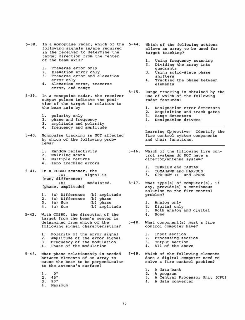
5-38. In a monopulse radar, which of the 5-44. following signals is/are required
Which of the following actions allows an array to be used for target tracking? in the receiver to determine the
target direction from the center of the beam axis?
1. Traverse error only 2 . Elevation error only 3 . Traverse error and elevation
error only 4. Elevation error, traverse
error, and range
5-39. In a monopulse radar, the receiver output pulses indicate the position of the target in relation to the beam axis by
1. polarity only 2. phase and frequency 3 . amplitude and polarity 4 . frequency and amplitude
5-40. Monopulse tracking is NOT affected by which of the following problems?
5-41.
5-42 .
1. Random reflectivity 2 . Whirling scans 3 . Multiple returns 4 . Zero tracking errors
In a COSRO scanner, the (a) signal is
(sum, difference) (b) modulated.
(phase, amplitude)
1. 2. 3. 4.
(a) Difference (a) Difference (a) Sum (a) Sum
(b) amplitude (b) phase (b) phase (b) amplitude
With COSRO, the direction of the target from the beam's center is det�rmined from which of the following signal characteristics?
1. Polarity of the error signal 2 . Amplitude of the error signal 3. Frequency of the modulation 4. Phase of the modulation
5-43. What phase relationship is needed between elements of an array to cause the beam to be perpendicular to the antenna's surface?
1. oo 2. 45° 3 . 90° 4 . Maximum
32
5-45 .
1. Using frequency scanning 2. Dividing the array into
quadrants 3. Using solid-state phase
shifters 4 . Tracking the phase between
elements
Range tracking is obtained by the use of which of the following radar features?
1. Designation error detectors 2. Acquisition and track gates 3 . Range detectors 4. Designation drivers
Learning �bjective: Identify the fire control system components and their functions.
5-46. Which of the following fire control systems do NOT have a director/antenna system?
5-47.
5-48.
1. TERRIER and TARTAR 2 • TOMAHAWK and HARPOON 3. SPARROW III and BPDMS
What type(s) of computer(s), if any, provide(s) a continuous solution to the fire control problem?
1. Analog only 2. Digital only 3 . Both analog and digital 4 . None
What component(s) must a fire control computer have?
1. Input section 2. Processing section 3 . output section 4 . All of the above
5-4 9 . Which of the following elements does a digital computer need to solve a fire control problem?
1 . A data bank 2. A program 3. A Central Processor Unit (CPU) 4. A data converter

5-50. A digital to analog data conversion i s usually accompli shed by what component?
l . The computer 2. The radar 3. The soc 4. The GMLS
5-51. Which of the following is an advantage of a general purpose computer over a special purpose computer?
1. The general purpose computer is smaller
2. The general purpose computer is able to perform any data proces sing for which it is programmed
3. The special purpose computer is slower
4. The special purpose computer is not as slow as the general purpose computer
5-52. Normally input/output terminals are used for what purpose?
1 . To load programs 2. To store data 3 . For testing and maintenance 4. For correcting alignment
errors
5-53 . Which, i f any, o f the following devices is used with an analog fire control computer?
1 . Input/output console 2. Digital data recorder 3. Signal data converter 4 . None of the above
5-55. What i s the purpose of the torsion wires in a flotation type of stable element gyro?
1 . To provide electrical input 2. To provide electrical output 3 . T o support the gyro case 4. To hold the gyro in a fixed
position
5-56. When the gyro has its spin axis centered through the top-to-bottom reference line of the flotation tank, how much output is available from the pick-up coils?
1. No output is available 2. Maximum output is available 3. Fifty percent of maximum out
put is available 4. Seventy-five percent of maxi
mum output i s available
5-57. The output of the gyro element is proportional to the
1 . angle between the gyro spin axis and the gimbal ring
2. input torque on the torsion wires
3. angle between the gyro spin axis and the tank reference line
4. velocity of the gyro rotor
5-58. What is the purpose of the stable gyro gimbals?
1. To restrain the gyro 2. To maintain gyro in the verti
cal plane 3. To prevent apparent precession 4. To maintain the gyro at a
constant spin velocity
Learning Obj ective: Identify the 5-59. operating principles and components
What gimbal i s mounted to the frame of the stable e lement?
of a basic stable element.
5-54. The primary purpose of a stable element is to measure what quantity?
1. The deviation of deck plane from horizontal plane
2. The deviation o f normal plane from the deck plane
3 . The pitch and roll rate of change
4. The level and crosslevel rate of change
33
1. The director train gimbal 2. The level gimbal 3. The azimuth gimbal 4. The cross level gimbal
5-60. The director train gimbal is always aligned with the
1. vertical plane 2. hori zontal plane 3. line-of- sight bearing 4. ship ' s true bearing
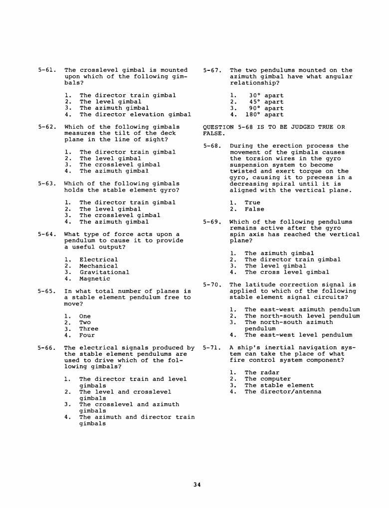
5-61. The crosslevel gimbal is mounted upon which of the following gimbals?
1. The director train gimbal 2. The level gimbal 3. The azimuth gimbal 4. The director elevation gimbal
5-62. Which of the following gimbals measures the tilt of the deck plane in the line of sight?
1. The director train gimbal 2 . The level gimbal 3. The crosslevel gimbal 4. The azimuth gimbal
5-63. \-lhich of the following gimbals holds the stable element gyro?
1. The director train gimbal 2. The level gimbal 3. The crosslevel gimbal 4. The azimuth gimbal
5-64. What type of force acts upon a pendulum to cause it to provide a useful output?
1. Electrical 2 . Mechanical 3. Gravitational 4. Magnetic
5-65. In what total number of planes is a stable element pendulum free to move?
1. One 2 . Two 3. Three 4. Four
5-67. The two pendulums mounted on the azimuth gimbal have what angular relationship?
1. 30° apart 2. 45° apart 3. 90° apart 4. 180° apart
QUESTION 5-68 IS TO BE JUDGED TRUE OR FALSE.
5-68. During the erection process the movement of the gimbals causes the torsion wires in the gyro suspension system to become twisted and exert torque on the gyro, causing it to precess in a decreasing spiral until it is aligned with the vertical plane.
1 . True 2. False
5-69. Which of the following pendulums remains active after the gyro spin axis has reached the vertical plane?
1. The azimuth gimbal 2. The director train gimbal 3. The level gimbal 4. The cross level gimbal
5-70. The latitude correction signal is applied to which of the following stable element signal circuits?
1. The east-west azimuth pendulum 2. The north-south level pendulum 3. The north-south azimuth
pendulum 4. The east-west level pendulum
5-66. The electrical signals produced by 5-71. the stable element pendulums are
A ship's inertial navigation system can take the place of what fire control system component? used to drive which of the fol-
lowing gimbals?
1. The director train and level gimbals
2 . The level and crosslevel gimbals
3. The crosslevel and azimuth gimbals
4. The azimuth and director train gimbals
34
1. The radar 2 . The computer 3. The stable element 4. The director/antenna

Assignment 6
Textbook Assignment: "Missiles and Ordnance." Pages 5-l through 5-26.
Learning Objective: State the technical meaning of the term "explosive"; and indicate the use, characteristics, and description of different classes of explosives and related materials.
6-1 . In a strict technical sense, the ter� "explosive" pertains to
1. substances that release their stored energy instantaneously producing a shockwave (detonate)
2. all substances which , when initiated by spark, friction, shock, or any other means, undergo a rapid chemical reaction that results in the release of a large amount of energy
3. only those substances which explode and release energy when initiated by shock
4. only those substances which explode and release energy when initiated by heat or friction
6-2. Primary explosives are used mainly for
1. destroying small targets 2. destroying sensitive equipment
in time of emergency 3. initiating chemical reactions
in less sensitive explosives 4. the main charge in projectiles
35
6-3. Which of the following statements pertaining to high explosives is true?
1. Boosters are used between the initiator and the main charge to ensure high-order detonation
2. Boosters are used as the main charge of small projectiles and bombs
3. Burster charges are the most sensitive of all high explosives
4. Burster charges are more sensitive than primary explosives but less sensitive than boosters
6-4. Which of the following is a characteristic peculiar to propellants?
1. They can be made to burn 2 . They can be made to detonate 3. They are very sensitive to
shock 4 . Their burning rate is con-
trollable and can be predetermined
6-5. The difference between explosives and propellants lies
1. primarily in the sensitivity of the substances only
2. primarily in the composition of the substances only
3. primarily in the conditions under which they react only
4. in the composition of the substances and the conditions under which they react
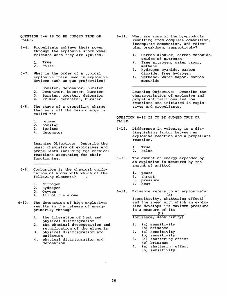
QUESTION 6 - 6 IS TO BE JUDGED TRUE OR FALSE.
6 - 6 . Propellants achieve their power through the explosive shock wave released when they are ignited .
1. True 2 . False
6 - 7 . What is the order of a typical explosive train used in e xplosive devices such as gun proj ectiles?
1. Booster, detonator, burster 2. Detonator, booster, burster 3 . Burster, booster, detonator 4. Primer, detonator, burster
6 - B . The stage of a propelling charge that sets off the main charge is called the
1. primer 2. booster 3 . igniter 4 . detonator
Learning Objective: Describe the basic chemistry of explosives and propellants including tqe chemical reactions accounting for their functioning.
6-9 . Combustion is the chemical unification of atoms with which of the following elements?
1. Nitrogen 2. Hydrogen 3 . Oxygen 4 . All of the above
6 - 1 0 . The detonation of high e xplosives results in the release of energy primarily through
1 . the libe ration of heat and physical disintegration
2 . the chemical decomposition and reunification of the elements
3. physical disintegration and oxidation
4 . physical disintegration and detonation
36
6 - 1 1 . What are some of the by- products resulting from complete combustion, incomplete combustion, and molecular breakdown, respectively?
1 . Carbon dioxide, carbon monoxide, oxides of nitrogen
2 . F ree nitrogen, water vapor, methane
3 . Hydrogen cyanide, carbon dioxide, free hydrogen
4. �ethane, water vapor, carbon monoxide
Learning Obj ective : Describe the characteristics of explosive and propellant reactions and how reactions are initiated in e xplosives and propellants.
QUESTION 6 - 1 2 IS TO BE JUDGED TRUE OR FALSE.
6 - 1 2 . Difference in velocity is a distinguishing factor between an explosive reaction and a propellant reaction.
1 . True 2. False
6 - 13 . The amount of energy e xpended by an explosion is measured by the amount of emitted
1 . power 2 . thrust 3 . pressure 4 . heat
6 - 14 . Brisance refers t o an explosive ' s ( a)
(sensitivity, shattering effect) and the speed with which an e xplosive develops its maximum pressure is a measure of its
(b) (brisance, sensitivity)
1 . ( a) sensitivity (b) brisance
2 . ( a) sensitivity (b) sensitivity
3 . (a) shattering effect (b) brisance
4 . ( a) shattering e f fect (b) sensitivity

6-1 5 . What i s the usual means o f initiating propellants and main charges of explosives, respectively?
1 . Heat, shock 2. Shock, heat 3 . Heat for both 4. Shock for both
6-16 . Sensitivity, as the term applies to explosives, pertains to the explos ive ' s
1 . maximum pressure 2. ease of igniting 3 . rate of burning 4. speed of heat liberation
6 - 1 7 . Which of the following is/are the requirement ( s ) for storing smokeless powder?
1 . A heated and air-conditioned magazine for controlling the inside temperature
2 . A magazine in which the humidity can be controlled
3 . A well-ventilated and i nsulated magazine
4. All of the above
QUESTION 6-18 I S TO BE JUDGED TRUE OR FALSE .
6 - 1 8 . The storage requirements for smokeles s powder also apply to rocket motors .
l . True 2. False
Learning Objective: Identify the types of naval ammunition with emphasis upon gun ammunition and its component parts .
6-19 . I n which of the following gun ammunition types is the propelling charge nonadjustable and sealed in a metal cartridge case as an as sembly independent of the projectile?
l . Fixed 2. Semifixed 3. Separated 4. Separate-loaded
37
6- 20. Which of the following phrases best describes drill ammunition?
1 . Ammunition lacking explos ives , propellants , and functioning components
2. Plaster-loaded partially inert ammunition without the explosive burster charge
3 . Ammunition which resembles service ammunition in appearance, has some functional component s , but lacks explosives and propellants
4. Sand-loaded partially inert ammunition which has the same functioning components as service ammunition
6-21 . Which of the following is the best description or definition of a complete round of ammunition?
l. A projectile and bursting charge
2. A group of explosive components permanently assembled to form a single unit
3 . All the primary and secondary components necessary to fire a gun once
4. Any explosive or propellant that constitutes an ammunition component such as a booster , burster, igniter, or main charge
6 - 2 2 . The projectile assembly o f a round of ammunition consists of the projectile body and which of the following components?
1. Fuze only 2. Fuze and burster only 3 . Burster and explosive train 4 . Fuze, burster, and explosive
train
Learning Objective : Describe the functional arrangement and use of the bag and case types of propelling charges for naval gun s .
6 - 23. A complete round of bag ammunition consits of which of the following elements?
l . A lock combination primer 2. Powder bags 3. A projectile 4. All of the above
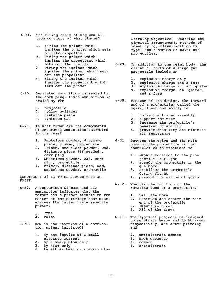
6-24. The firing chain of bag ammunition consists of what stages?
1 . Firing the primer which ignites the igniter which sets off the propellant
2. Firing the primer which ignites the propellant which
Learning Objective : Des cribe the physical arrangement, methods of identifying, classification by type, and function of naval gun projectiles .
sets off the igniter 6-29. In addition to the metal body, the essential parts of a large gun projectile include an
3 . Firing the igniter which ignites the primer which sets off the propellant
4. Firing the igniter which ignites the propellant which sets off the primer
6-25. S eparated ammunition is sealed by the cork plug; fixed ammunition is
l. 2. 3 . 4 .
explosive explosive explosive explosive and a fuze
charge only charge and a fuze charge and an igniter charge, an igniter,
sealed by the 6 - 3 0 . Because of its design, the forward end of a projectile , called the ogive, function s mainly to l. projectile
2 . hollow cylinder 3. distance piece 4 . ignition pad
6-26 . I n what order are the components of separated ammunition assembled to the case?
1. S mokeless powder, distance piece, primer, projectile
2. Primer, s mokeless powder, wad, distance piece ( if needed) , cork plug
3 . S mokeless powder , wad, cork plug, projectile
4. Primer, distance piece, wad, s mokeless powder , projectile
QUESTION 6-27 IS TO BE JUDGED TRUE OR FALSE.
6-27. A comparison 6£ case and bag ammunition indicates that the former has a primer secured to the center of the cartridge case bas e , whereas the latter has a separate primer.
1. True 2. False
6-28. How is the reaction of a combination primer initiated?
1. By the impulse of a s mall electric current
2. By a sharp blow only 3 . By heat only 4. By either heat or a sharp blow
38
1 . house the tracer assembly 2 . support the fuze 3 . increase the projectile ' s
penetrating ability 4. provide stability and minimize
air resistance
6 - 3 1 . Between the ogive and the main body of the projectile is the bourrelet which functions to
6 - 3 2 .
l. impart rotation to the projectile in flight
2. ste ady the projectile in the gun bore
3. stabilize the proj ectile during flight
4. prevent the e s cape of gases
What is the function of the rotating band of a proj ectile?
1 . Seal the bore 2 . Position and center the rear
end of the projectile 3. I mpart rotation 4 . All of the above
6 - 3 3 . The types of projectiles designed to penetrate heavy and light armor, respectively, are armor-piercing and
1 . antiaircraft common 2. high capacity 3 . common 4. antiaircraft
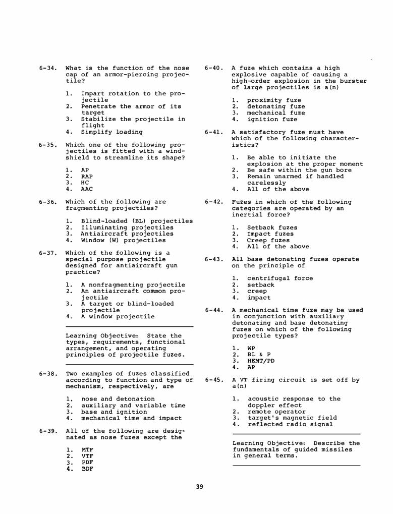
6-34. What is the function of the nose cap of an armor-piercing projectile?
1. Impart rotation to the pro-jectile
2. Penetrate the armor of its target
3 . Stabi lize the projectile in flight
4. Simplify loading
6-35 . Which one of the following projectiles is fitted with a windshield to streamline its shape?
1 . AP 2 . RAP 3 . HC 4. AAC
6-36. Which of the following are fragmenting projectiles?
1. Blind-loaded (BL) projectiles 2 . Il luminating projectiles 3 . Antiaircraft projectiles 4. Window (W) projectiles
6-37 . Which of the following is a special purpose projectile designed for antiaircraft gun practice?
1 . A nonfragmenting projectile 2. An antiaircraft common pro
jectile 3. A target or blind-loaded
projectile 4 . A window projectile
Learning Objective: State the types, requirements, functional arrangement, and operating principles of projectile fuzes .
6-38. Two examples of fuzes classified according to function and type of mechanism, respectively, are
1. nose and detonation 2. auxiliary and variable time 3 . base and ignition 4 . mechanical time and impact
6-39. All of the following are designated as nose fuzes except the
1. MTF 2 . VTF 3. PDF 4 . BDF
39
6-40. A fuze which contains a high explosive capable of causing a high-order explosion in the burster of large projectiles is a(n)
1. proximity fuze 2. detonating fuze 3 . mechanical fuze 4. ignition fuze
6-41. A satisfactory fuze must have which of the following characteristics?
1. Be able to ini tiate the explosion at the proper moment
2 . Be safe within the gun bore 3. Remain unarmed if handled
carelessly 4 . All of the above
6-42. Fuzes in which of the following categories are operated by an inertial force?
1. Setback fuzes 2 . Impact fuzes 3. Creep fuzes 4 . All of the above
6-43. All base detonating fuzes operate on the principle of
1. centrifugal force 2. setback 3 . creep 4 . impact
6-44. A mechanical time fuze may be used i n conjunction with auxiliary detonating and base detonating fuzes on which of the following projectile types?
1. WP 2. BL & P 3. HEMT/PD 4 . AP
6-45. A VT firing circuit is set off by a (n)
1. acoustic response to the doppler effect
2. remote operator 3. target ' s magnetic field 4. reflected radio signal
Learning Objective: Describe the fundamentals of guided missiles in general terms.

6 - 4 6 . A m i s s i l e , as defined in this chapter, refers to which o f the following objects?
1 . Stones 2 . Bombs 3 . Rockets 4 . Each o f the above
6 -4 7 . An unmanned vehicle that i s capable of altering its course during its f l ight i s classi fied as a/an
1 . self-propelled rocket 2 . guided m i s s i le 3 . projectile 4 . unguided m i s s i le
6- 4 8 . Which of the fol lowing i s NOT a subsys tem of a guided missile?
1. Flight control 2 . Guidance 3 . Electronics 4 . Propulsion
6 - 4 9 . The main m i s s i le structure is known a s which of the fol lowing terms?
1 . The airframe 2 . The body 3 . The fuse lage 4 , Each of the above
Learning Objective : List the basic requirements of a guided miss i le relating to SMS m i s s i les .
6 - 5 0 . Which o f the fol lowing i s the best description of an aircraft ' s standoff range?
1 . The maximum range a t which a guided m i s s i l e can destroy the aircraft
2 . The minimum range at which the aircraft can ef fectively deliver its weapons
3 . The maximum range at which the aircraft can e f fectively deliver its weapons
4 . The minimum range at which a guided missile can destroy the aircraft
QUESTION 6 - 5 1 I S TO BE JUDGED TRUE OR FALS E .
4 0
6 - 5 1 . SMS missi les include short-range surface-to-surface missiles.
1 . True 2 . False
6 - 5 2 . Which o f the following i s NOT used primarily as a surface-to-air m i s s i le?
1 . SPARROW I I I 2 . HARPOON 3 . SM-1 4 . SM-2
6 - 5 3 . The m i s s i l e designation RIM-7F indicates a
1 . rocket-launched guided missile 2 . rocket-launched torpedo 3 . ship- launched guided missile 4 . ship- launched rocket
6 - 5 4 . Which of the following missi les i s designed for use against a surface target?
1 . AIM-7E 2 . RIM- 6 6 D 3 . RGM- B 4A 4 . Each o f the above
6 - 5 5 . What type o f missile i s the AQM- 7 4 C ?
6 - 5 6 .
l . A trainer 2 . A surface-attack 3 . A drone 4 . An aerial-intercept
Learning Objective : List the five major m i s s i le subsystems and the purpose of each.
What subsystem of a guided m i s s i le ( a ) furnishes external control
surfaces for f light path control action and ( b ) contains the e lement for sensing the optimum time for detonation?
1 . 2 . 3 . 4 .
( a ) ( a ) ( a ) ( a )
Structure Control Propulsion Guidance
( b ) warhead ( b ) guidance ( b ) control ( b ) warhead

6 - 5 7 .
6-5 8 .
What guided missile subsystem ( a ) maintains the intended speed
of the missile and ( b ) restrains the missile to its flight path?
1. ( a ) Propu lsion ( b ) control 2. ( a ) Control ( b ) structure 3 . ( a ) Structure ( b ) guidance 4 . ( a ) Guidance ( b ) propulsion
What subsystem of the guided missile senses missile diversion from its guided flight path and starts the operation to rectify this error?
1 . Control 2 . Guidance 3 . Structure 4. Propulsion
6-59 . Which of the following types of guidance is used by most SMS missiles?
l . Beam rider 2. Homing 3 . Command 4 . Each of the above
Learning Objective : State the fundamental characteristics of payloads, fuzes , and safety and arming components used in guided missile warheads .
6-6 0 . Each warhead consists of a payload and what other functional parts?
l . Telemetering unit and fuze 2 . Telemetering unit and S&A
device 3 . Fuze and S&A device 4 . Fuze and self-destruct device
6- 6 1 . What type o f warhead i s NOT
6 - 6 2 .
6 - 6 3 .
Des tructive effect B results from the detonation of
1. explosive pellet warheads 2. incendiary warheads 3 . shaped-charge warheads 4 . blast-effect warheads
Which of the fol lowing �estructive effects is produced by a fragmentation warhead?
l . B 2 . c 3 . D 4 . E
6-6 4 . Des tructive effect D i s the major cause of damage resulting from the detonation of
1. atomic warheads 2 . incendiary warheads 3 . shaped-charge warheads 4 . fragmentation warheads
6-6 5 . What type o f warhead is most often used in SMS missiles?
l . Blast-effect 2. Uncontrolled- fragmentation 3 . Continuous-rod 4 . Contro lled-blast
6 - 6 6 . The best time for fuze detonation is determined by the location and movement of which of the fol lowing objects?
l . The firing ship and the target only
2. The firing ship and the missile only
3 . The missile and the target only
4 . The firing ship , the target, and the miss i le
generally used in guided missiles? 6 -6 7 . Which o f the following pairs of fuzes are of the impact type?
1 . Blast-effect 2 . Nuclear 3 . Thermonuclear 4. Incendiary
QUESTIONS 6-62 THROUGH 6 - 6 4 REFER TO THE FOLLOWING LIST OF DESTRUCTIVE EFFECTS OF MISS ILE WARHEADS .
A. VIOLENT BURNING B . A HIGH PRESSURE WAVE C . FLYING SHRAPNEL D . BLAST, HEAT , AND RADIATION E . BLAST PLUS EXPLOSIVE PELLETS
4 1
1. Delay and instantaneous 2. Delay and ground-controlled 3 . Ins tantaneous and ground
controlled 4 . Instantaneous and radio
controlled
6 -6 8 . The term TDD refers to which, i f any, o f the fol lowing types of fuzes?
l . Impact 2. Proximity 3 . Ground-controlled 4 . None of the above

6-69. What function does the S&A device provide in the warhead?
1 . Detonation path only 2 . Detonation interrupt only 3 . Detonation path and interrupt
only 4 . Detonation interrupt, path,
and amplifier stage
6-70. An acceleration arming device requires which of the following missile motions to arm the warhead?
1 . Acceleration only 2. Deceleration only 3 . Acceleration and deceleration 4 . Acceleration and acceleration
decay
Learning Objective: Indicate the functions occurring during the guidance flight phases for SMS missiles.
6-71. Determining flight-path errors and generating necessary correction signals are functions of the
1 . receiver 2 . control subsystem 3 . guidance subsystem 4 . control-sur
-face servos
6-7 2 . Which o f the following missile attitudes are the missile control units capable of controlling?
1 . Roll only 2. Pitch and yaw only 3 . Pitch and roll only 4 . Pitch, roll, and yaw
42
6-73. The main function of a missile booster is to
1 . provide guidance during the acceleration period
2 . propel the missile throughout its flight
3 . provide power t o accelerate the missile to operating speed
4 . propel the missile from the launcher
6-74. What is the function of the boost phase guidance system?
6-75.
1. To make the homing missile " look" toward the target
2 . To keep the missile on its launch heading
3 . To allow the missile to capture the guidance beam
4 . To help the missile predict where it will be at the end of the boost phase
During what phase of a missile ' s flight are most flight corrections made?
1. Launch 2. Midcourse 3 . Terminal 4 . Dump

Assignment 7
Textbook Assignment: "Missiles and Ordnance . " Pages 5-26 through 5-3 6 .
"Data Transmission." Pages 6-1 through 6-14.
Learning Objective: Identify the different kinds of missile guidance systems including their characteristic s .
7-1 . Missile attitude control is achieved through which of the following types of guidance?
1. Inertial 2. Command 3. Homing 4. Semihoming
7-2. The data from accelerometers is used by the inertial guidance system to
1. measure the distance the missile travels
2. detect changes in missile motion
3. indicate missile speed 4 . determine target position
QUESTIONS 7-3 THROUGH 7-5 ARE TO BE JUDGED TRUE OR FALSE.
7-3. Inertial guidance is used only during the boost phase .
1. True 2. False
7- 4 . With command guidance, the guidance instructions originate outside the missil e .
1. True 2 . False
7-5. With command guidance, the missile has direct electromagnetic contact with the target.
1. True 2 . False
43
7-6. The command guidance receiver can accept which of the following data?
1. Steering signals only 2. Steering and control signals
only 3. Fuze and control signals only 4. Steering, fuze, and control
signals
7-7. Command signal s are sent to the missile by which of the following methods?
1. Varying the missile tracking beam
2. Varying the guidance beam 3. Using a separate radio uplink 4. Each of the above
7-8. The beam rider missile is kept in the center of the beam by correction signals generated by which of the following devices ?
1. Fire control computer 2 . Fire control radar 3 . Missile itself 4 . Each of the above
7-9 . A missile guidance system that can detect and guide itself to a target is called
1. beam rider guidance 2. homing guidance 3. inertial guidance 4. pre-set guidance
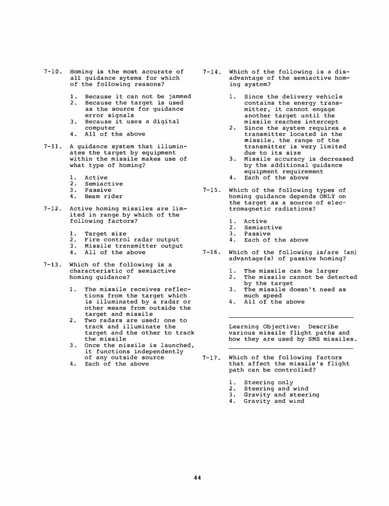
7-10. Homing is the most accurate of 7-14. all guidance sytems for which of the following reasons?
1. Because it can not be jammed 2. Because the target is used
as the source for guidance error signals
3. Because it uses a digital computer
4. All of the above
7-11. A guidance system that i l l uminates the target by equipment within the missile makes use of what type of homing?
1. Active 2. Semiactive 3. Passive 7-15. 4. Beam rider
7-12. Active homing missiles are limited i n range by which of the following factors?
1. Target size 2. Fire control radar output 3. Missile transmitter output 4. All of the above 7-16.
7-13. Which of the following is a characteristic of semiactive homing guidance?
1. The missile receives reflections from the target which is i l luminated by a radar o r other means from outside the target and missile
2. Two radars are used; one to track and i l l umi nate the target and the other to track the missile
3. Once the missile i s l aunched, it functions independently of any outside source 7-17.
4. Each of the above
4 4
Which o f the following i s a disadvantage of the semiactive homing system?
1.
2.
Since the delivery vehicle contains the energy transmitter, it cannot engage another target until the missile reaches intercept Since the system requires a transmitter located in the missile, the range of the transmitter is very limited due to its size
3. Missile accuracy is decreased by the additional guidance equipment requirement
4. Each of the above
Which of the following types of homing guidance depends ONLY on the target as a source of electromagnetic radiations?
1. Active 2. Semiactive 3. Passive 4. Each of the above
Which of the fol lowing is/are (an) advantage(s) of passive homing?
1. The missile can be larger 2. The missile cannot be detected
by the target 3. The missile doesn't need as
much speed 4. All of the above
Learning Objective: Describe various missile flight paths and how they are used by SMS mi ssi les.
Which of the fol lowing factors that affect the missile's flight path can be controlled?
1. Steering only 2. Steering and wind 3. Gravity and steering 4. Gravity and wind

7-18. Which of the following types of flight paths is used by the HARPOON missile?
1. Constant preset 2. Complex preset 3. Complex programmed 4. Programmed preset
7-19. What types of flight paths do (a) homing missiles and (b) beam rider missiles use?
1. (a) Pursuit (b) Collision
2. (a) Collision (b) Line of sight
3. (a) Pursuit (b) Collision
4. (a) Line of sight (b) Pursuit
7-20. Which of the following is/are (a) characteristic(s) of the pursuit curve?
1. At any instant the course of the missile is toward the target
2. A missile pursuing a crossing target flies a curved trajectory
3. Both 1 and 2 above 4. A missile will first climb to
altitude, then dive on the target
7-21. In which of the following ways does a homing missile that flies a collision course intercept a target?
1. By trying to maintain successive lines of sight parallel
2. By using sensor units to point the missile directly at the target
3. By calculating the speed of the target
4. All of the above
7-23. Proportional navigation means that the missile turns at a rate that is proportional to
1. missile speed 2. target speed 3. rate of change of the line of
sight 4. rate of change of the missile
speed
7-24. The beam rider missile follows what kind of path?
1. Line of sight 2. Pursuit 3. Collision 4. Proportional navigation
7-25. The beam rider path is similar to what kind of path?
1. Line of sight 2. Pursuit 3. Collision 4. Proportional navigation
Learning Objective: Classify the SMS missiles according to their characteristics.
7-26. The TARTAR missile was replaced by which of the following missiles?
1. RIM-24C 2. RIM-66A 3. RIM-66B 4. Both 2 and 3 above
7-27. The STANDARD RIM-660 missile has which of the following characteristics?
1. It is a beam rider 2. It uses active homing 3. It homes on enemy radars 4. All of the above
7-22. A collision course offers which of 7-28. the following advantages over a
Which of the following SMS missiles was originally designed for air launch? pursuit course?
1. Missile course curvature is 1. TARTAR decreased 2. TERRIER
2. Missile course curvature is 3. SPARROW III increased 4. STANDARD (ER)
3. Greater fuel economy is offered 4. Greater range is offered
45
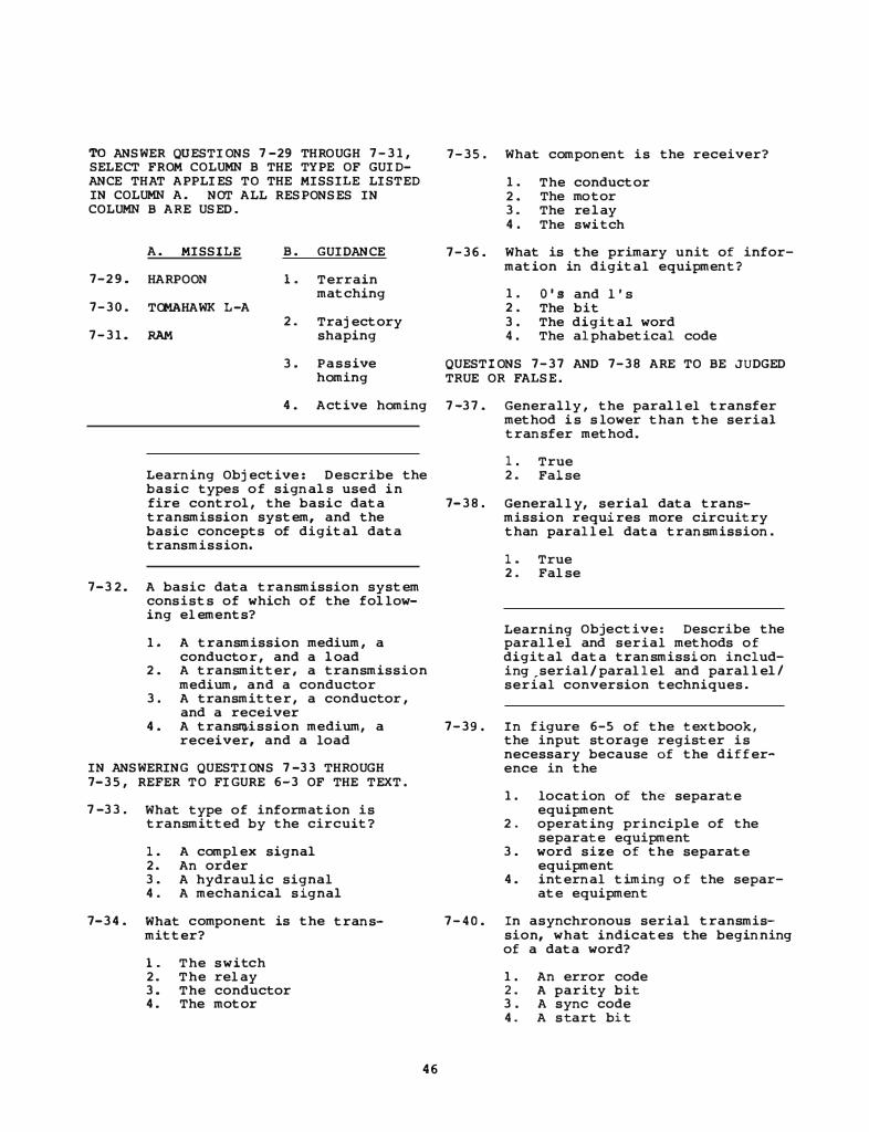
TO ANSWER QUESTIONS 7-29 THROUGH 7-31, SELECT FROM COLUMN B THE TYPE OF GUIDANCE THAT APPLIES TO THE MISSILE LISTED IN COLUMN A. NOT ALL RESPONSES IN COLUMN B ARE USED.
7-2 9 .
7-30.
7-31.
A. MISSILE B. GUIDANCE
HARPOON 1. Terrain matching
TOMAHAWK L-A 2 . Trajectory
RAM shaping
3. Passive homing
4 . Active homing
Learning Objective : Describe the basic types o f signals used i n
7-35 . What component is the receiver?
1. The conductor 2 . The motor 3. The re lay 4 . The swi tch
7-36. What is the primary unit of information in digital equipment?
1. O's and l's 2 . The bit 3. The digital word 4. The alphabetical code
QUESTIONS 7-37 AND 7-38 ARE TO BE JUDGED TRUE OR FALSE.
7-37. Generally , the parallel transfer method i s s lower than the serial transfer method.
1. True 2 . False
fire control, the basic data 7- 38. Generally, serial data transmission requires more circuitry than parallel data transmission.
transmission system, and the basic concepts of digital data trans mission.
7-32. A basic data transmission system consists of which of the following elements?
1. A transmission medium , a conducto r , and a load
2 . A transmitter, a transmission medium, and a conductor
3. A transmitte r , a conductor , and a receiver
1. True 2 . False
Learning Objective: Describe the parallel and serial methods of digital data transmission includi ng ,serial/parallel and parallel/ serial conversion techniques.
4 . A trans�ission medium, a 7-39. In figure 6-5 of the textbook, the input storage register is necessary because of the difference in the
receiver, and a load
IN ANSWERING QUESTIONS 7-33 THROUGH 7-35 , REFER TO FIGURE 6-3 OF THE TEXT.
7-33. What type of information is transmitted by the circuit?
1. A complex signal 2. An order 3. A hydraulic signal 4 . A mechanical s ignal
7-34 . What component is the transmitter?
1. The switch 2. The relay 3. The conductor 4. The motor
46
1. location of the separate equipment
2 . operating principle of the separate equipment
3. word size of the separate equipment
4 . internal timing o f the separate equipment
7-40. In asynchronous serial transmission, what indicates the beginning of a data word?
1. An error code 2. A parity bit 3. A sync code 4 . A s tart bit
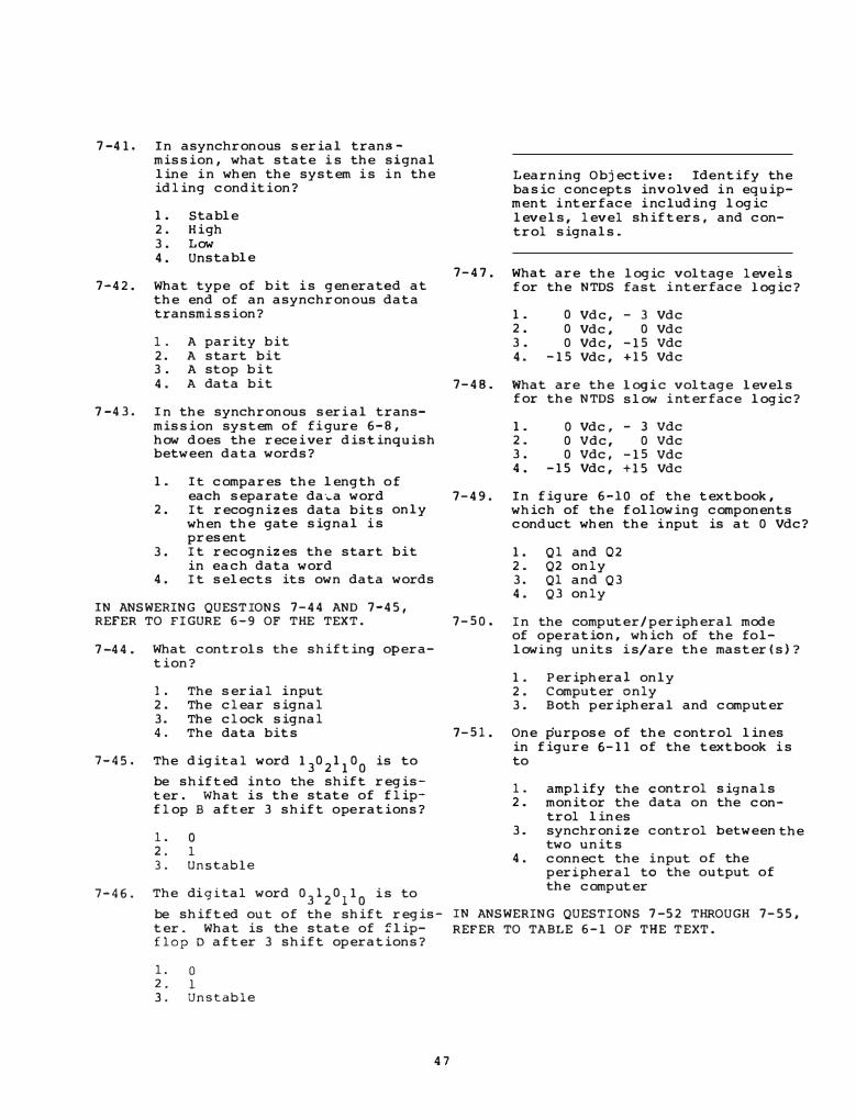
7-41. In asynchronous serial transmission, what state i s the signal line i n when the system i s i n the idling condition?
1. Stable 2 . H i gh 3 . Low 4. Unstable
7-42. What type of bit i s generated at the end of an asynchronous data transmi ssion?
7-43.
1. A parity bit 2. A start bit 3 . A stop b i t 4 . A data bit
In the synchronous seri al transmission system of fi gure 6-8, how does the rece i ve r distinquish between data words?
1. It compares the length o f
7-47.
7-48.
Learning Objective : Ide ntify the basic concepts involved i n equipment i nterface i ncluding logic leve ls, level shifters, and control signals.
What are the for the NTDS
1. 2. 3. 4.
What for
1. 2. 3. 4.
0 Vdc, 0 Vdc, 0 Vdc,
-15 Vdc,
are the the NTDS
0 Vdc, 0 Vdc, 0 Vdc,
-15 Vdc,
logic voltage fast i nterface
- 3 Vdc 0 Vdc
-15 Vdc +15 Vdc
logic voltage slow i nterface
- 3 Vdc 0 Vdc
-15 Vdc +15 Vdc
leve is logic?
levels logic?
each separate da�a word 7-49 . In figure 6-10 of the textbook, which of the following components conduct when the input is at 0 Vdc?
2. It recognizes data bits only when the gate signal i s present
3. It recognizes the start bit in each data word
4. It selects its own data words
IN ANSWERING QUESTIONS 7-44 AND 7-45,
1. Ql and 02 2. Q2 only 3. Ql and Q3 4. Q3 only
REFER TO FIGURE 6-9 OF THE TEXT. 7-50. In the computer/peripheral mode
7-44. What controls the shifting operation?
1. The serial i nput 2 . The clear signal 3. The clock signal 4. The data bits
7-45. The digital word 13
02
11
00
is to
be shifted i nto the shift register. What i s the state of flipflop B after 3 shift o pe rations?
7-46.
1. 0 2. 1 3. Unstable
The di gital word 03
12
0110
i s to
be shifted out of the shift register. What is the state of flipflop D after 3 shift operations?
1. 0 2. 1 3. Unstable
47
of o pe ration, which of the fo llowing units i s/are the master(s)?
1 . Periphera� only 2. Computer only 3. Both peripheral and computer
7-51. One purpose of the control lines in figure 6-11 of the textbook i s to
1. amplify the control signals 2. monitor the data on the con-
trol lines 3. synchroni ze control between the
two units 4 . connect the i nput of the
peripheral to the o utput of the computer
I N ANSWERING QUESTIONS 7-52 THROUGH 7-55, REFER TO TABLE 6-1 OF THE TEXT.
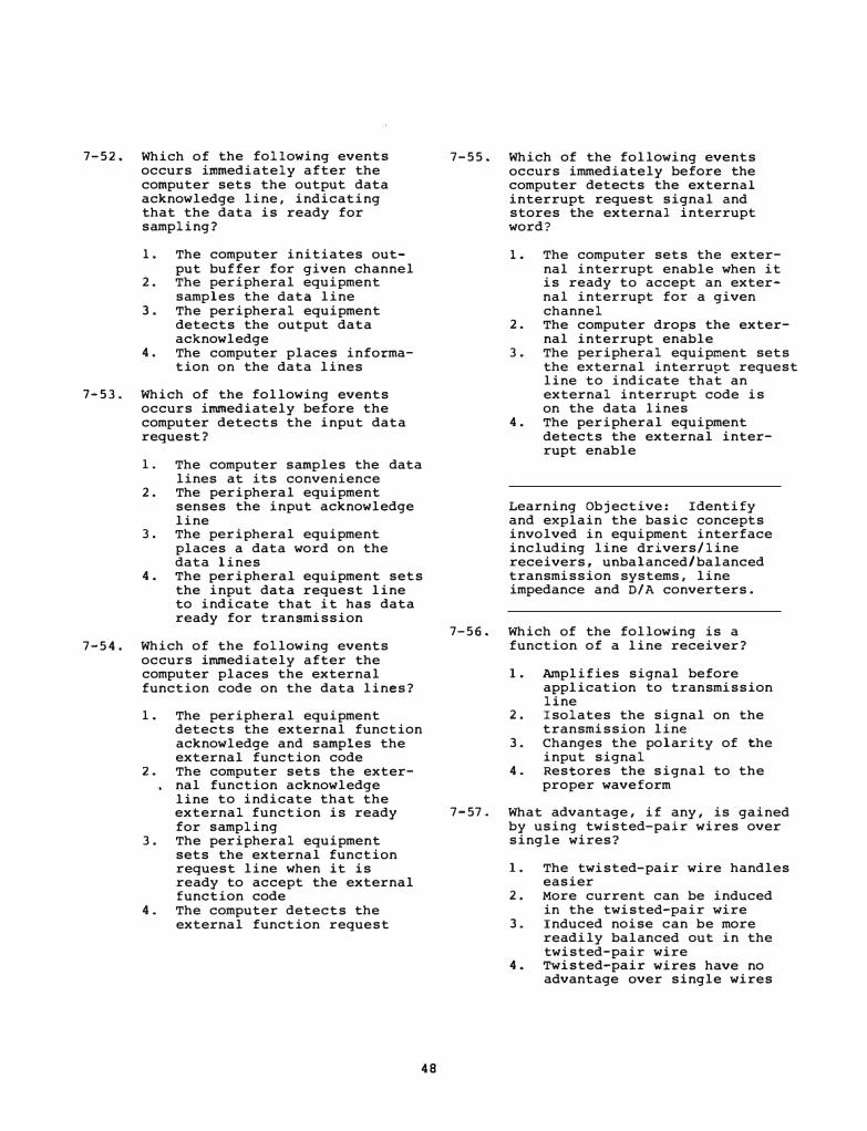
7-52. Which of the following events occurs immediately after the computer sets the output data acknowledge line, indicating that the data is ready for sampling?
1. The computer initiates output buffer for given channel
2. The peripheral equipment samples the data line
3. The peripheral equipment detects the output data acknowledge
4. The computer places information on the data lines
7-53. Which of the following events occurs immediately before the computer detects the input data request?
1. The computer samples the data lines at its convenience
2. The peripheral equipment senses the input acknowledge line
3. The peripheral equipment places a data word on the data lines
4. The peripheral equipment sets the input data request line to indicate that it has data ready for transmission
7-54. Which of the following events occurs immediately after the computer places the external function code on the data lines?
1. The peripheral equipment detects the external function acknowledge and samples the external function code
2. The computer sets the external function acknowledge line to indicate that the external function is ready for sampling
3. The peripheral equipment sets the external function request line when it is ready to accept the external function code
4 . The computer detects the external function request
48
7-55. Which of the following events occurs immediately before the computer detects the external interrupt request signal and stores the external interrupt word?
1. The computer sets the external interrupt enable when it is ready to accept an external interrupt for a given channel
2. The computer drops the external interrupt enable
3. The peripheral equipment sets the external interrupt request line to indicate that an external interrupt code is on the data lines
4. The peripheral equipment detects the external interrupt enable
Learning Objective: Identify and explain the basic concepts involved in equipment interface including line drivers/line receivers, unbalanced/balanced transmission systems, line impedance and D/A converters.
7-56. Which of the following is a function of a line receiver?
1. Amplifies signal before application to transmission line
2. Isolates the signal on the transmission line
3. Changes the polarity of the input signal
4. Restores the signal to the proper waveform
7-57. What advantage, if any, is gained by using twisted-pair wires over single wires?
1. The twisted-pair wire handles easier
2. More current can be induced in the twisted-pair wire
3. Induced noise can be more readily balanced out in the twisted-pair wire
4 . Twisted-pair wires have no advantage over single wires

7-58. Which of the follo wing character- 7-62. i stics is an a dvantage of the
7-59.
7-60.
7-61.
balanced line transmission sys-tem over the unbalanced line transmission system?
1.
2.
3 .
4.
Provides a faster data transmission rate Produces two complimentary outputs in respect to ground Yields a higher amplitu de output signal Uses a differential amplifier in the output
What i s the biggest advantage of using differential amplifiers as line receivers?
1.
2.
3 .
4 .
The common-mode rejection characteristic of differential ampli fiers cancels induced noise Differential amplifiers have higher gain than conventional ampli f i e r s Differential ampli fi e r s are more reliable than conventional amplifiers Differential ampli fiers are cheaper than conventional amplifi e r s
What are two adverse effects o f line impedance?
1. Ampli tude increase and stretching o f pu lses
2. Phase shift and distortion of pulses
. . 3. Rectification and f�lter�ng
of pulses 4. Frequency multiplication and
modulation of pulses
Which of the following i s the best description of the characteristic i mpedance of a cable?
1. Varies with the length of cable
2. Doe s not vary with the length o f cable
3 . Oppo ses de current 4. Is a direct function of the
line resistance
49
7- 63.
7-64.
7-65.
7-66.
7-67.
In figure 6-14 of the textbook, the output voltage e
0 of the cir-
cuit i s a direct function of what circuit characte ristic?
1. The ratio o f ein
to e 0
2 . The ratio o f Rin
to e . l.n
3. The amount o f resi stance the feedback path
4. The amount of resi stance the input loop
Learning Objecti ve : Identify general concepts involved i n analo g data transmi ssion.
in
in
The output of a digital device from one instant to the next occurs in
1. continuous motion 2. discontinuous motion 3. smooth steps 4. discrete steps
The output of an analog device from one instant to the next is
1. discrete 2. random 3. continuous 4. discontinuous
What is an analog?
1. A sample of a quantity . 2. A scaled value of a quant�ty
3. An equal amount of a qua �tity 4 . The loga rithm o f a quantl.ty
What are used to represent the value o f fire control quantities?
1. Displays 2. Marks 3 . Signs 4. Numerals
Which of the following analogs can be used to represent target range in an electric circuit?
1. Volts/yard 2. Yards/volt 3. Miles/sec 4. Sees/mile

Assignment 8
Textbook Assignment: "Data Transmission. " Pages 6-1 4 through 6-40.
Learning Obj ective: Describe the theory of operation and construction of synchro transmitters and receivers.
8-1. A shift in scale in types of measure (such a s miles to yards , degrees to minutes , and the like) is possible as long as which of the following relationships is true?
1. The shift causes a nonlinear change in results
2. The ratio between the units of measure is constant throughout their range
3. The ratio between the units o f measure varies throughout their range
4. The ratio between the units of mea s ure is nonproportional
8-2. Which of the following characteristics is common to all synchros?
1. Rotor windings 2. "Y"-connected s tators 3. Transformer principle operation 4. Each of the above
8-3. What is the maximum number of ways synchros can sense position?
l. Five 2. Two 3. Three 4. Four
8-4. What is the maximum voltage that can be induced across any one s tator winding o f a 115-volt synchro?
l. 0 vol t 2 . 2 6 volts 3. 52 volts 4. 78 volts
so
8-5. The angle of rotor displacement is measured from the center of what winding?
1. Sl windir.g 2 . 52 winding 3. 53 winding 4. Rotor winding
IN ANSWERING QUESTIONS 8-6 THROUGH 8-9 , REFER TO TABLE 6-2 OF THE TEXT.
TO ANSWER QUE STIONS 8-6 THROUGH 8-8, SELECT FROM COLUMN 8 THE SYNCHRO TYPE THAT IS DESCRIBED BY THE INPUT AND OUTPUT CIRCUIT ARRANGEMENTS IN COLUMN A. NOT ALL RESPONSES IN COLUMN B ARE USED.
A. ARRANGEMENT S B. TYPE
8-6. One mechanical l. Torque Trans-input and one mitter (TX) electrical output 2 . Torque Differ-
ential Trans-8-7. One electrical mitter (TDX)
input and one mechanical 3. Torque output Receiver (TR)
8-8. Two electrical 4. Torque Differ-inputs and one entia! Receiver mechanical (TDR) output
8- 9. Which of the following types of s ynchros has one electrical and one mechanical input with an electrical output?
1. Control Differential Transmit-ter (COX)
2. Control Transformer (CT) 3. Control Transmitter (CX) 4. Torque Diff erential Receiver
(TDR)

8-10. What i s the designation code of a standard synchro t hat i s 2 i nches in di ameter, i s a control transmitter using 400 cycles, and has had 2 modifi cations?
1. 2CT42 2. 2CX42 3 . 20CT4b 4. 20CX4b
8-11. To find the complete identification of a standard Navy synchro used in a piece of fire control equipment, you should look at which of the following references?
8-12.
8-13.
1 . Schemati c di agram of the equipment
2. Wiring di agram of the equipment
3. Isometric drawing of the equipment
4. Physical description section of the OP
Learning Objective: reasons for synchro describe methods of synchros.
State the ali gnment and zeroing
In order to fulfill i t s primary function of correctly transmitting i nformation between remote units, a synchro system must have which of the following charact eristics?
1 . A reference point common t o both units
2. A common unit of measure 3 . Both transmitting and receiv
ing systems ali gned to the same electrical and mechanical reference point
4. All of the above
The mechani cal and electrical zero reference position of a synchro i s the axis of what winding?
1. Sl winding 2. 52 winding 3. S3 winding 4. Rotor winding
51
8-14. What relationshi p must exist between a synchro system and the transmitting and receiving i nstruments the system serves?
1. They must b e electrically phase
2. They must be mechanically aligned
i n
3. They must be physically sepa-rated
4. The stator winding must b e coincident
8-15. What relationshi p must exist between the voltage from S2 to S3 or Sl and the voltage from Rl and R2 when a synchro i s at electrical zero a nd t he voltage from Sl to S3 i s zero?
1. In phase 2. Same value 3 . 180° out of phase 4. Twice the amplitude
8-16. Where would the ali gnment of a synchro system logically start?
1 . In the stator windi ngs 2. At the receiver for the trans
mitted quantity 3. I n the rotor windings 4. At the origin of the trans
mitted quantity
8-17. What does the term "electrical error" mean when used i n reference to a synchro?
1. The di fference between Sl and 53 voltages
2. The d ifference between Rl and S2 voltages
3. The difference between the actual physical position a nd the electrical posit i on of the rotor
4. The di fference between the physical position of the rotor and the reference stator
8-18. What i s the maximum possible accumulated electrical error of a synchro system consi sting of two synchros that have an electrical error of 18 minutes apiece?
1. 0 min 2. 18 min 3. 30 min 4. 36 min
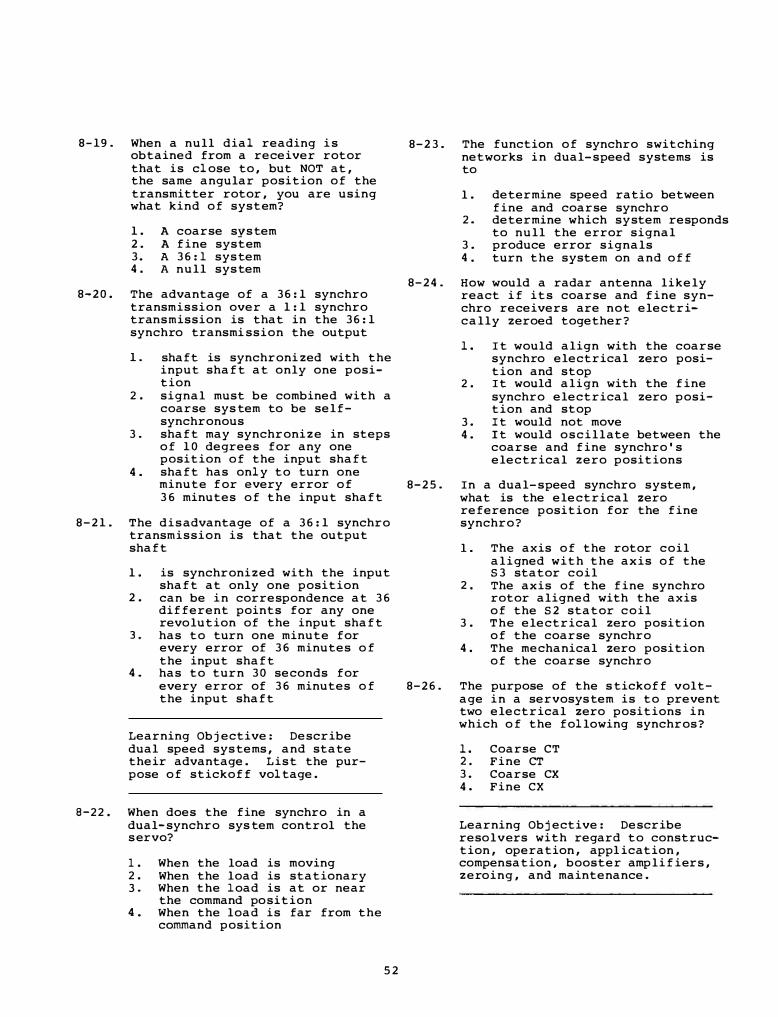
8-19. When a null dial reading i s obtained from a receiver rotor that is close to, but NOT at, the same angular position of the transmitter rotor, you are using what kind of system?
1. A coarse system 2. A fine system 3. A 36:1 system 4. A null system
8-20. The advantage of a 36:1 synchro transmission over a 1:1 synchro transmission is that in the 36:1 synchro transmi ssion the output
1. shaft is synchronized with the input shaft at only one position
2. signal must be combined with a coarse sys tem to be selfsynchronous
3. shaft may synchronize in steps of 10 degrees for any one position of the input shaft
4. shaft has only to turn one minute for every error of 36 minutes of the input shaft
8-21. The dis advantage of a 36:1 synchro transmission is that the output shaft
1. is synchronized with the input shaft at only one position
2. can be in correspondence at 36 different points for any one revolution of the input shaft
3. has to turn one minute for every error of 36 minutes o f the input shaft
4. has to turn 30 seconds for every error of 36 minutes o f the input shaft
Learning Objective: Describe dual speed systems, and state their advantage. List the purpose of stickoff voltage.
8-22. When does the fine synchro in a dual-synchro sys tem control the s ervo?
1. When the load is moving 2. When the load is stationary 3. When the load is at or near
the command position 4. When the load is far from the
command position
52
8-23. The function of synchro switching networks in dual-speed systems is to
l . determine speed ratio between fine and coarse synchro
2. determine which system responds to null the error signal
3. produce error signals 4. turn the system on and off
8-24. How would a radar antenna likely react if its coarse and fine synchro receivers are not electrically zeroed together?
1. It would align with the coarse synchro electrical zero position and stop
2. It would align with the fine synchro electrical zero position and stop
3. It would not move 4. It would oscillate between the
coarse and fine synchro's electrical zero positions
8-25. In a dual-speed synchro system, what is the electrical zero reference position for the fine synchro?
l . The axis of the rotor coil aligned with the axis of the S3 stator coil
2. The axis of the fine synchro rotor aligned with the axis of the S2 stator coil
3. The electrical zero position of the coarse synchro
4. The mechanical zero position of the coarse synchro
8-26. The purpose of the s tickoff voltage in a servosystem is to prevent two electrical zero positions in which o f the following synchros?
1. Coarse CT 2. Fine CT 3. Coarse CX 4. Fine ex
Learning Objective: Describe resolvers with regard to construction, operation, appl ication, compensation, booster amplifiers, zeroing, and maintenance.

8-27. What is the primary function of a resolver?
1. To resolve a vector quantity into sine and cosine components
2. To produce resultant vectors from two input components
3 . Both 1 and 2 above 4 . T o resolve geometric variables
QUESTION 8-28 I S TO BE JUDGED TRUE OR FALSE.
8-33 . Which of the following windi ngs are used when a resolver is used to resolve a single voltage into two (sine, cosine) components?
l. 1 rotor winding and l stator winding
2 . 1 rotor winding and 2 stator windings
3 . 2 rotor windings and 1 stator winding
4. 2 rotor windi ngs and 2 stator windings
8-28. A resolver i s a variable trans- 8-34. Refer to figure 6-27 of the text. The resultant flux field is produced by
8-29.
former capable o f both data transmission and mathematical computation involving trigonom-etry.
1. True 2. False
What angle describes the placement
1. the position of Rl 2. the position of R2 3. E sin e input voltage only 4. E sin 8 and E cos 9 input
voltages
of the stator windings in most 8-35. Which of the following is the purpose of the calibrating resistors in a resolver?
resolvers?
1 . oo 2 . 45°
3 . 90° 4 . 120°
8-30. What is the input-to-output signal ratio of a resolver?
8-31.
8-32.
1 . l : 1 2 . 1: 2 3 . 2 : 1 4 . 3: 1
The inputs to a resolver can be described as
l. electrical only 2. mechanical only 3 . electrical and mechanical 4. angular rotation
Refer to figure 6-25,8 of the text . Assume that Ei is 200 volts. What is the value of Eo?
1. 8 . 66 volts 2. 17. 32 volts 3 . 86. 6 volts 4. 173 . 2 volts
53
1. To compensate for voltage inaccuracies in the windings
2 . To prevent phase shifts when the load changes
3 . To standardize the electrical characteristics
4. Each of the above
8-36. In a resolver circuit, the compen-
8-37.
sators are connected in (a) (series,
_p_
a_r
_a� l�l�e-
l� ) with the resolver coils
in order to regulate the resolver's (b) voltages.
(output , input)
l. 2 . 3. 4 .
(a) series (a) series (a) parallel (a) parallel
(b) output (b) input (b) output (b) input
What type of amplifier is the booster amplifier in a resolver circuit?
1. Power amplifier 2. Voltage amplifier 3. Current amplifier 4. Phase shift amplifier

8-38. Booster amplifiers function as voltage regulators because of what design characteristic?
1. Unity gain 2. Regenerative feedback 3. Negative feedback 4. Variable gain
8-39. The zero position of a resolver i s
8-43. When setting a resolver on coarse zero (A) and fine zero (B), the voltmeter is connected across which of the foll owing points?
1. R4-S3(A) and R4-R2(B) 2. R4-Sl(A) and R4-Sl(B) 3. R2-Sl(A) and R4-S3(B) 4. R2-S3{A) and R2-S3(B)
determined by what angular rela- 8-44. Which of the following maintenance tasks for a resolver should be done on board ship?
tionship between a stator and its corresponding rotor?
1. Perpendicular 2. Acute 3. Paral l el 4. Obtuse
8-40. When the corres ponding stator and rotor of a resolver have an angular relationship of 90°, how much magnetic coupling, if any, exists between the two windings?
1. Maximum 2. 50% 3. 90% 4. None
1. Alignment tests and replacement of the resolver
2. Al ignment tests and replacement of the internal bearings
3. Adjustments to the compensating circuits and replacement of compensating resistors
4. Adjustments to the compensating circuits and replacement of the resolver
Learning Objective: Describe the operation of balanced bridge circuits and the vernistat.
8-41. The resolver coarse-zero test ensures that a proper phase relationship exists between what windings?
8-45. Refer to figure 6-29 of the text.
1. Rotor windings only 2. Stator windings only 3. Fine and coarse windings 4. Rotor and stator windings
IN ANSWERING QUESTIONS 8-42 AND 8-43, REFER TO FIGURE 6-28 OF THE TEXT.
8-42. What condition is indicated i f B-46. voltmeter V reads 20 volts when the rotor is set at course zero and 18 volts when the �nput angle is increased counterclockwise?
1. The s upply voltage is negative 2. The vol tmeter l eads are
improperly connected 3. The coil at right angles to
the energized stator coil is the cosine coil
4. The rotor has been zeroed in 8-47. reverse phase
54
The balanced bridge circuit consists of two identical potentiometers connected in
1. parall e l and ungrounded 2. para l l el with a grounded
center tap 3. series and ungrounded 4. series with a grounded center
tap
In the balanced bridge circuit, what determines the amount and direction of the current flow?
1. The potential difference between the wiper arms
2. The total resistance of the wiper arms
3. The voltage applied to the wiper arms
4. The common voltage supply
A zero data signal is represented by which, if any, of the following positions of the potentiometers in a balanced bridge circuit?
l. High end of the potentiometer 2. Low end of the potentiometer 3. At ground potential 4. None of the above
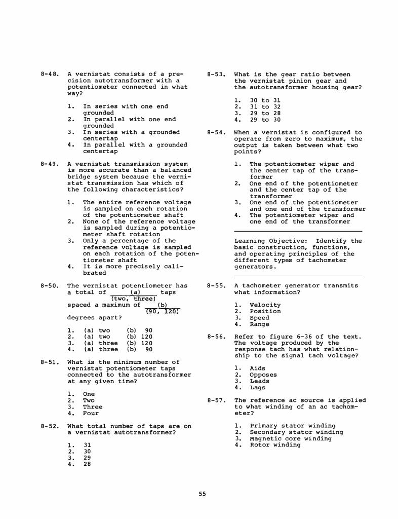
8-4 8 . A vernistat consists o f a precision autotransformer with a potentiometer connected in what way?
1 . In series with one end grounded
2. In parallel with one end grounded
3 . I n series with a grounded centertap
4 . In parallel with a grounded centertap
8-49 . A vernistat transmission system is more accurate than a balanced bridge system because the vernistat transmission has which o f the following characteristics?
1 . The entire reference voltage is sampled on each rotation of the potentiometer shaft
2. None of the reference voltage is sampled during a potentiometer shaft rotation
3. Only a percentage of the reference voltage is sampled on each rotation o f the potentiometer shaft
4. I t is more precisely calibrated
8-5 0 . The vernistat potentiometer has a total of (a) taps
(two , three) spaced a maximum of (b)
(9 0 , 120) degrees apart?
1. 2. 3. 4 .
(a) two (a) two (a) three (a) three
(b) 90 (b) 120 (b) 120 (b) 90
8-51 . What is the minimum number of vernistat potentiometer taps connected to the autotransformer at any given time?
1. One 2 . Two 3 . Three 4. Four
8-52. What total number of taps are on a vernistat autotransformer?
1 . 31 2. 30 3 . 29 4 . 28
55
8-53. What is the gear ratio between the vernistat pinion gear and the auto transformer housing gear?
l. 30 to 31 2. 31 to 32 3 . 29 to 28 4. 29 to 30
8-5 4 . When a vernistat i s configured to operate from zero to maximum, the output is taken between what two points?
1 . The potentiometer wiper and the center tap of the transformer
2. One end o f the potentiometer and the center tap o f the transformer
3 . One end of the potentiometer and one end of the transformer
4. The potentiometer wiper and one end of the transformer
Learning Objective: Identify the basic construction, func tions, and operating principles of the different types o f tachometer generators .
8 - 5 5 . A tachometer generator transmits what information?
1 . Velocity 2 . Position 3. Speed 4 . Range
8-5 6 . Refer to figure 6-36 o f the text. The voltage produced by the response tach has what relationship to the signal tach voltage?
1 . Aids 2. Opposes 3 . Leads 4 . Lags
8-57 . The reference ac source is applied to what winding of an ac tachometer?
1 . Primary stator winding 2. Secondary stator winding 3. Magnetic core winding 4 . Rotor winding
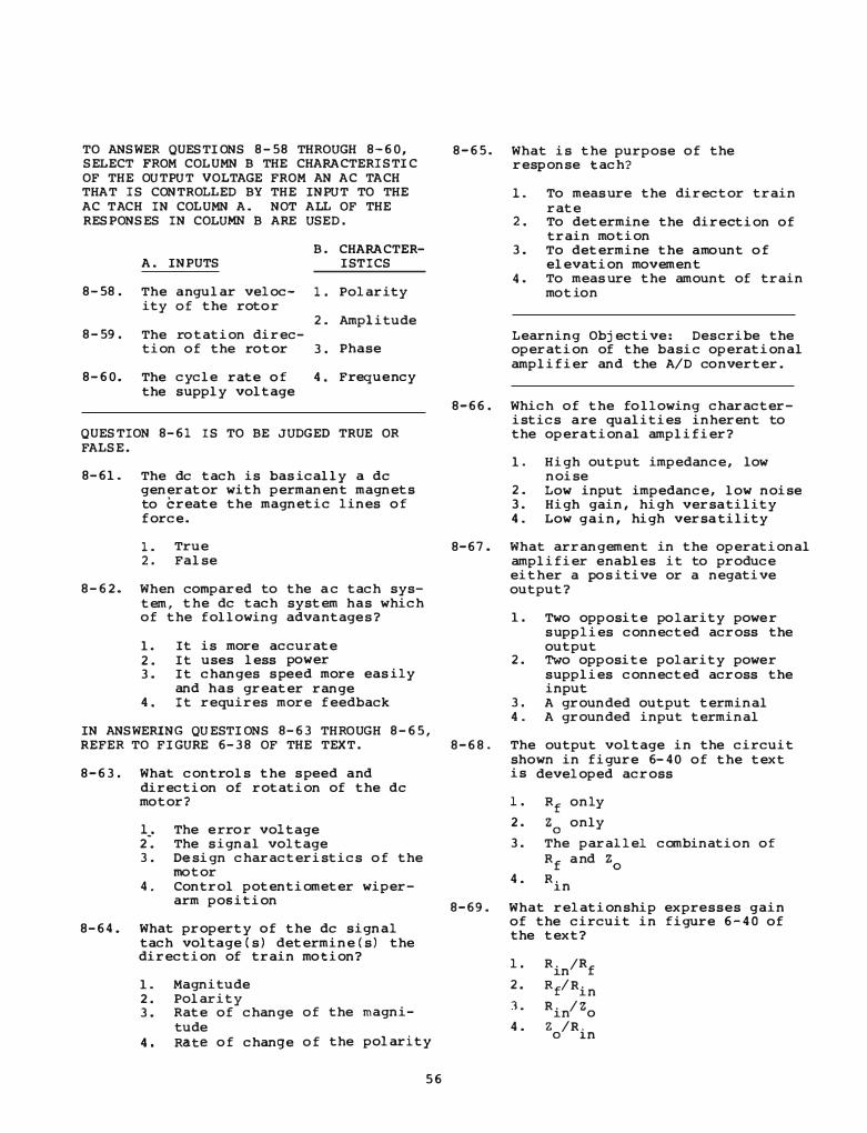
TO ANSWER QUESTIONS 8-58 THROUGH 8-60, SELECT FROM COLUMN B THE CHARACTERISTIC OF THE OUTPUT VOLTAGE FROM AN AC TACH THAT IS CONTROLLED BY THE INPUT TO THE AC T ACH I N COLUMN A. NOT ALL OF THE RESPONSES I N COLUMN B ARE USED.
B. CHARACTER-A. INPUTS IS TICS
8-58. The angular veloc- 1. Polarity ity of the roto r
2. Amplitude 8-59. The ro tation direc-
tion of the rotor 3. Phase
8-60. The cycle rate o f 4. Freque ncy the s upply voltage
QUESTION 8-61 IS TO BE JUDGED TRUE OR FALSE.
8-61. The de tach is bas ically a de generator with permanent magnets to create the magnetic lines o f force.
1. True 2. False
8-62. When compared to the a c tach system, the de tach system has which of the following adva ntages ?
1. It is more accurate 2. It uses less power 3. It changes s peed more eas ily
and has greater range 4. It requires more feedback
IN ANSWERING QUESTIONS 8-63 THROUGH 8-65, REFER TO FIGURE 6-38 OF THE TEXT.
8-63. What controls the s peed and direction of rotation of the de motor?
1_. The e rro r voltage 2 . The s ignal voltage 3. Design characteristics o f the
motor 4. Control potentiometer wiper
arm position
8-64. What property of the de signal tach voltage (s) determine(s) the direction of train motion?
1. Magnitude 2. Polarity 3. Rate of change of the magni-
tude 4. Rate o f change o f the polarity
5 6
8-65. What is the purpose of the response tach?
1 . To meas ure the director train rate
2. To determine the direction of train motion
3. To determine the a mo unt o f elevation movement
4. To meas ure the amount of train motion
Learning Objective: Describe the operation of the basic operational amplifier and the A/D co nverter.
8-66. Which of the following characteristics are qualities inherent to the opera tional amplifier?
1. High output impedance, low noise
2. Low input impedance, low noise 3. High gain, high versatility 4. Low gain, high versa tility
8-67. What arrangement in the operational amplifier enables it to produce either a pos itive or a negative output?
8-68.
8-69.
1. Two opposite polarity powe r s upplies connected across the output
2. Two opposite polarity power s upplies connected across the input
3. A grounded output terminal 4. A grounded input terminal
The output voltage in the circuit shown in figure 6- 40 of the text is developed across
l.
2.
3.
4.
Rf only
Z0
only
The parallel combinatio n of R
f a nd z0
R. �n
What relationship expresses gain of the circuit in figure 6-40 of the text?
l.
2.
).
4.
Rin
/Rf
Rf/Rin
Rin
/Zo
Z /R. o 1n
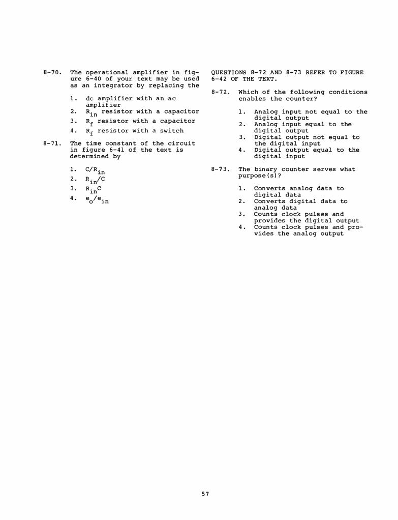
8-70. The operational ampl ifier in figure 6-40 of your text may be used as an integrator by replacing the
1. de amplifier with a n a c amplifier
2. R. �n resistor with a capacitor
3. Rf
resistor with a capacitor
4. Rf resistor with a switch
8-71. The time constant of the circuit in figure 6-41 of the text is determined by
1 .
2.
3 .
4 .
C/Rin R. /C
�n R. J.n
c
e /e. o J.n
5 7
QUESTIONS 8-72 AND 8-73 REFER TO FIGURE 6-42 OF THE TEXT .
8-72. Which of the following conditions enables the counter?
1 . Analog input not equal to the digital output
2. Analog input equal to the digital output
3 . Digital output not equal to the digital input
4 . Digital output equal to the digital input
8-73 . The binary counter serves what purpose (s) ?
1 . Converts analog data to digital data
2 . Converts digital data to analog data
3. Counts clock pulses and provides the digital output
4 . Counts clock pulses and provides the analog output
Assignment 9
Textbook Ass ignment: "Data Transmission." Pages 6-40 through 6-62.
"Support Systems . " Pages 7-l through 7-11.
Learning Obj ective: Identify the 9-4. suspected blown f us es can be verified at which of the following panel assemblies?
components of a fire control switchboard and the functions it performs as part of a data transmission system.
9-1. What is the primary f unction of a fire control switchboard in a data transmission system?
1. It transmits data 2 . I t stores data 3. It controls data transmiss ion 4. It switches data from one
format to another
9-2. In figure 6-43 of the text, (a) how are the signal sources of directors 1 and 2 connected to the switch-
9-5 .
1 . The fuse panel assembly 2 . The fuse tester panel assembly 3 . The meter indicator panel
ass embly 4. The indicator panel assembly
What panel ass embly provides a meas urement of the 400-Hz power entering the switchboard?
1. The 400 -Hz power panel assembly 2 . The power-availabl e panel
assembly 3. The indicator panel ass embly 4. The meter panel assembly
board, and (b) how is the computer 9-6. electrically connected to either
E mergency or warning indications are provided by which of the following panel assemblies? of the two directors at the switch
board?
1. 2. 3. 4.
(a) In parallel (a) In parallel (a) In s eries (a) In s eries
(b) in parallel (b) in series (b) in parallel (b) in s eries
9-3. What component of the switchboard provides visual indication of the applied power to the switchboard?
1. The fuse panel assembly 2 . The front panel assembly 3. The rear panel ass embly 4. The indicator panel assembly
58
1. The bus test selector panel a s s embly
2 . The emerg ency-warning panel assembly
3. The flasher panel assembly 4. The indicator panel assembly
9-7. What type of switch uses a coil s pring to provide the torque to engage the rotor contacts with the stationary contacts?
1. A toggle switch 2 . A snap switch 3. An ACO switch 4. A single pole single throw
switch
TO ANSl'lER QUESTIONS 9 - 8 THROUGH 9- 1 1 , 9 -14. SELECT FRm1 COLUMN B THE SWITCH THAT IS DESCRIBED BY FUNCTION IN COLUMN A . RESPONSES IN COLUMN B ARE USED ONLY ONCE .
..>WITCH A. FUNCTION ;;;.B..:...__..;;;....,__...;.=
9-B. Has the same 1 . electrical char-acteristics as 2 . the type J switch
3. 9-9 . Has only one mov
able contact per 4 . section
9 -10 . Selects either or both of two synchro indicators
9 -11. Can select up to
1 JR switch
2 JR switch
3 JR switch
4 JR swi tch
9-15 .
seven inputs 9-16.
9-12 . In the AJR operation, what condition must be present for the switch to change positions?
1 . Control voltage present at both autotransformers
2 . Control voltage not present at both autotransformers 9-17 .
3. Equal potentials at both autotransformers as measured by the motor
4. Different potentials at both autotransformer as measured by the motor
Learning Objective: Describe the numbering system used to identify the components in switchboard wiring.
�fuich of the following ship connector markings identifies pin H in the 4th connector on module F located on section 1 of the switchboard?
1 . JClDHF 2 . JClFHD 3. JClFDH 4. JClDFH
Which of the following alphanumeric markings identifies the 1 2 th ter-minal on terminal board location E in section
1 . JM5AE 1 2 2 . JM3AE12 3 . MT12AE3 4. MT3AE12
3 of the switchboard?
Which of the following designators describes the 4th terminal on terminal board B on panel 49 of the switchboard?
1. PP49B4 2 . PP4B49 3. PT49B4 4. PT4B49
Which of the following designators indicates the 5th diode connected to terminal B in panel 5 1 ?
1 . C R B 5 2 . C R 5 B 3 . OS 5 B 4. OS B 5
Learning Objective: Identify the types of cables and connectors used in fire control.
9 -1 3 . What type of marking is used to identify wires and components i n the fire control switchboard?
9 - 1 8 . What total number of conductors
1 . Numerical only 2 . Alphanumeric 3 . Alphabetical only 4. Symbolic
59
is contained in a type DSGA cable?
1 . One 2 . Two 3. Three 4 . Four

9-19. The letter designation HOF on a cable indicates that the cable is a
1. limi ted service armored cable 2. general service armored cable 3. general service flexible cable 4. limited service flexible cable
9-20. A four conductor SGA cable with a conductor cross-sectional area of 38,010 circular mils i s desi gnated
1. SGA-30 2. FSGA-38 3. FSGA-40 4. TSGA-40
9-21. What is the approximate crosssectional area of the conductors in a cable designated TTRSA-8(20)?
1. 20 circular mils 2. 2,000 circular mils 3. 8, 000 circular mi l s 4. 20,000 circular mils
9-22. What total number of pairs of individually shielded conductors does a TTRSA-16(20) cable contain?
1. 20 2. 16 3. 10 4. 8
9-23. What cable connections are a llowed
9-25. A size 22, solid shell, boxmounted receptacle having an insert pin arrangement, designation 11 would have the identification number
1. MS 3102A-22-11P 2. MS 3102B-22-11P 3. MS 3102A-22-11S 4. MS 3102B-ll-22P
TO ANSWER QUESTIONS 9-26 THROUGH 9-29, SELECT FROM COLUMN B THE TYPE OF CONNECTOR DESIGNED FOR EACH INTENDED USE LISTED IN COLUMN A. RESPONSES IN COLUMN B ARE USED ONLY ONCE.
A. INTENDED USES
9-26. To be installed where space is very l imited
9-27. To be used with conduit to eliminate conduit boxes
9-28. To be used where rapid disconnection from a unit of equipment is required
B. CONNECTORS
1. MS 3107
2. MS 3102
3. MS 3108
4. MS 3100
ONLY as temporary emergency 9-29. To be used where repairs? a detachable
1. Connections made within fittings
2. Connections made within appliances
3. Cable splices 4. Each of the above
9-24. Which of the fol lowing cable designations identifies the fifth cable connected to number three fire control radar?
1. 3R-FB3 2. 3R-FB5 3. 4R-FB3 4. 5R-FB5
60
connection is required on a shielded unit of equipment

TO ANSWER QUESTIONS 9-30 THROUGH 9-32, 9-36. Which of the following designations identifies a quick-disconnect coaxial connector designed for use with medium-si zed cables?
SELECT FROM COLUMN B THE TYPE OF CONNECTOR SHELL THAT I S DESIGNED FOR EACH OF THE APPLICATIONS LI STED IN COLUMN A. NOT ALL THE RESPONSES I N COLUMN B ARE USED .
A. APPLICATIONS
9-30. For installation on or near a reciprocating engine
9-31 . Provides a pressure tight feedthrough for wires passing through bulkheads from one pressurized compartment to another
9-32. Used on equipment that is sealed and operated under gas pressure
B. CONNECTOR SHELLS
1 . D
2. E
3. F
4 . c
1. c 2. N 3. HN 4 . BNC
9-37. What series of coaxial cables may be used for both high voltage pulse and direct-current applications?
1 . Pulse 2. SKL 3. TNC 4. LT
9-38 . What device is used to provide mechanical protection for cables that pass through decks?
1 . A coaxial connector 2. A packing gland 3. A stuffing tube 4 . A kickpipe
9-33. Which of the following is the best 9-39. description of the mechanical construction of coaxial cables?
Which of the following expressions identifies the e i ghth connection point of the B side o f terminal block 4 in power junction box
1 . A single conductor surrounded by and insulated from a metal outer conductor
2. A twisted inner pair of leads surrounded by a f lexible metal sheath
3. A twisted inner pair of leads surrounded by a rigid metal sheath
4 . A single conductor surrounded by an insulating sheath
9-34 . What type of coaxial cable is designed to withstand high voltage?
1 . General purpose cable 2. High temperature cable 3 . Pulse cable 4 . Special characteristics cable
9-35 . Flexible coaxial cables operate without an appreciable loss efficiently up to a frequency near
1 . 3 , 000 KHz 2 . 10 , 000 KH z 3. 3, 000 MHZ 4 . 10 ,000 MHZ
61
UD 62?
1 . TB (86) 2B-4 2. TB (62) 4B-B 3. TB (42) 6B- 8 4 . TB (24) BB-6
Learning Objective: Describe missile weapon system electrical power distribution and requirements.
9-40 . Which of the following electrical characteristics apply to most naval ac power distribution systems?
1 . 60 H z , 3�, ungrounded 2. 60 H z , 1�, grounded 3. 400 H z , 2S, ungrounded 4 . 400 H z , 10, ungrounded
9 - 4 1 . Load centers are used by some ships to provide which of the fo llowing functions?
1. Emergency switchboard 2. Distribution panel 3 . Remote switchboard 4 . Each of the above
9 - 42. After normal power is lost, when will an alternate source be available?
1. Upon notifying the electricians 2. Upon notifying the OOD 3. After resetting the switch
board 4. Immediately
9-43. Bus trans fe r units enable a sele ction between which of the following inputs/outputs?
1. Two inputs only 2. Two or more inputs 3. Two outputs only 4. Two o r more outputs
9 - 44. In figure 7-1 of the text, the guided missi le·launching system is fed 440 V, 60 Hz, 3g through which unit?
1. ABT only 2. ABT and power dis tribution
panel 3. MBT and powe r distribution
panel 4. MBT only
9 -45 . Which of the following voltages pass through the IC switchboard?
1. Relay s upplies , synchro supplie s , and all 400 Hz power
2. Relay s upplies and all IC and fire control circuits
3. Relay s upplies, synchro s upplies, and all IC ci rcui ts
4. All 400 Hz power and all f i re control circuits
9-46. Where does the 115V, 60 Hz powe r come from?
1. Turbines 2. Trans formers 3. Gene rators 4. Rectifiers
9-47. Precis ion 400 Hz voltage can be provided by which of the fol lowing sources?
1 . Double-filter rectifier 2. Matched trans formers 3. Voltage regulator 4. Motor generator
6 2
9-48. Your e quipment is missing a certain voltage input. Which of the following actions should you take first?
1 . Call an e lectrician's mate 2. Check the output o f the
switchboard 3. Energize the emergency
generator 4. Check the ABT/MBT and powe r
panel that feeds your equipment
Learning Objective : Name and compare the various sources of dry ai r for the weapon system.
9 -49 . What is the normal source of dry air for weapon system use?
1. Nitrogen bottles 2. A central system 3. The atmosphere 4. Local dehydrators
9 -5 0 . What i s the major difference between the ship service and vital service lp air mains?
1. Moisture content 2. Press ure 3. Type of dessicant 4. Priority
9-51. What is the difference between the.electroni cs branch requirements and those of the vital services main?
l . Priority 2. Pre s s ure 3. Type of dessicant 4. Mois ture content
9 - 5 2. Excessive mois ture in certain e lectroni c components can cause which of the fol lowing conditions?
1 . Arcing and corrosion 2. Degraded performance 3. A need for overhaul 4. Each of the a bove
9-53. What is the air control panel designed to control?
1. Flow 2. Press ure 3. P urity 4. All of the above
9-5 4 . The a i r control panel does NOT provide for monitoring of which o f the following dry air properties?
9-60. What determines the type of primary cooling system variation to be used?
1 . Flow 2 . P ressure 3 . Purity 4 . Dew point (humidity)
9-55 . What air control panel component provides for control of outlet air pressure when normal pressure regulators malfunction?
1 . Metering valve bypass 2 . Secondary regulator 3 . I ntermediate regulator
9 - 6 1 .
4 . Relief valve 9 - 6 2 .
9-5 6 . Which of the following units may be available as an emergency backup to the central dry air system?
1. Local dehydrator 2. Local compressor-dehydrator 3 . N i trogen tank 4 . Each of the above
Learning Objective: Identify the major units, requirements, and characteristics of the electronics liquid cooling system.
9-5 7 . Which of the following character-
9-63.
istics of cooling water for elec- 9 - 6 4 . tronic equipment must be carefully controlled?
1. Purity 2 . Pressure 3 . Quantity 4 . All of the above
9-58. Which of the following is NOT a main component o f the liquid cooling system? 9-65.
1. The expansion tank 2. The freon tank 3 . The circulating pumps 4 . The demineralizer
9-59 . Which of the following water resources is/are used for primary cooling?
1. Seawater only 2. Chilled water only 3. Seawater and chilled water 4. Potable water and seawater
63
1 . The location o f equipment 2. The equipment requirements 3. The temperature requirements 4 . The safety requirements
In figure 7-8 of the text, which unit is used ONLY in a primary cooling system?
1. The duplex strainer 2. The expansion tank 3 . The circulating pumps 4 . The demineralizer
Some cooling systems use which of the following units to help stabilize temperature sensitive compone nts?
1. The expansion tank 2. The temperature interlock 3 . The coolant heater 4 . The water level stabilizer
When a two-way temperatureregulating valve is used, it controls the flow of which of the fol lowing coola'nts?
1 . Primary 2. Secondary 3. seawater 4 . Distilled water
Some cooling water systems have i nstalled demineralizers . They are designed to maintain which of the following water characteris tics?
1 . Clarity 2. Purity 3. Specific gravity 4. All of the above
A demi neralizer is designed to remove which o f the following substances from cooling water?
1 . Dissolved metals 2 . Chlorine 3 . Waste 4 . Oil
9-66. Where would a gravity tank be located in a liquid cooling sys tem?
1. At the mid-point in the sys tem 2 . At the lowest point i n the
sys tem 3. At the highest point in the
system 4 . Below the circulating pump
9-67. Which of the following devices are used to protect and/or moni tor the liquid cooling system?
1. Switches and alarms 2. Remote indicators and gages 3. Interlocks and flow switches 4. All of the above
9-69. Which of the followi ng actions can be taken to ensure the proper purity level o f coolant water?
1. Separate water tests 2. Periodic tests of meters 3. Routine observation of
ins talled meters 4. Each of the above
9 -70. The purity cells in the demineralizer measure which of the following characteristics?
1. Acidity 2. Content 3. Resistivity or conductivity 4 . All o f the above
9-68. The desired purity level of the 9-71. Drinking water, even when it comes from the distilling plant, is unacceptable for cooling systems due to the presence of
coolant in the s econdary loop is determined by which of the follow-ing factors?
1. Piping material 2 . Size of the cooling sys tem 3. Requi rements of the electronic
equipment 4. All of the above
64
1. salt 2. chlorine 3. flouride 4. bacteria
Assignment 10
Textbook Assignment: " Support Systems . " Pages 7-11 through 7-3 0 .
"Maintenance. " Pages 8-l through 8-9.
Learning Obj ective: Describe basic principles and functions o f CCTV system� and components.
10-1. The process of cutting off the retrace portion of a video signal is called
l. blanking 2 . scanning 3 . streaking 4. synchronizing
10-2. The scanning pattern that is evident when there is no picture signal is called the
1. composite video signal 2. picture element 3. raster 4. synchronizing signal
10-3. Which of the fol lowing kinds of information are required in a fire control CCTV system?
1 . Audio , video , and blanking 2 . Video, blanking , and syncho
nizing 3. Video, blanking , and retrace 4. Blanking , synchronizing ,
and audio
QUESTION 10-4 IS TO BE JUDGED TRUE OR FALSE.
10 -4 . A closed circuit tel evision system can have no more than one camera input.
1. True 2. False
65
10-5. Which of the following units of a CCTV system uses a camera tube and lens to produce an electrical signal representing an optical scene?
1. The pickup unit 2 . The control unit 3 . The video amplifier unit 4. The monitor
10- 6 . Which o f the following units of a CCTV system is the heart o f the system?
1. The pickup unit 2. The control unit 3. The video amplifier unit 4. The monitor unit
10-7. Which of the following units of a CCTV system would contain a sync generator?
1. The pickup unit 2. The control unit 3. The video unit 4 . The monitor unit
10-8. Which of the following units would a TV receiver contain that a monitor for a CCTV system would NOT have to contain?
1. A camera tube and picture tube 2. Synchronization circuits 3. Horizontal and vertical sweep
circuits 4. A tuner and RF amplifier

10-9. With the method of TV picture presentation, how is it possible for the viewer to see an entire picture?
10-14. In a standard 525-line interlaced television system, what maximum number of picture fields is transmitted per frame?
1. Each e lement constitutes an entire picture
2. The e lements are presented in such rapid succession that they appear to be an entire picture 10-15.
3. The video portion of the signal is presented as a whole, while the synchronizing portions of the signal result from the scanning process
4. Each time the e lectron beam scans from one side of the image to the other, a l l the picture e l ements are scanned and presented as a whole
10-10. What wil l cause an increase in the amount of charge built up by the globules on the mosaic of a camera tube?
1. An increase in intensity of i llumination
2. An increase in duration of illumination
3. A decrease in intensity of illumination
4 . A decrease in duration of illumination
10-11. What determines the vertical detail in a CCTV system?
1. Vertical scan rate 2. Horizontal scan rate 3. Vertical line length 4. Horizontal line length
10-12. Decreasing the size of each picture element (dot) can cause
10-16.
what effect? 10-17.
1 . Increase in linearity 2. Decrease in linearity 3. Increase in vertical detail 4. Decre'ase in vertical detail
10-13. Interlaced scanning is commonly employed in television systems in order to accomplish what 10-18 . effect?
1. To decrease bandwidth require-ments
2. To improve horizontal detail 3. To increase picture contrast 4. To reduce flicker
6 6
l. 1/2 2 . 2 3. 262. 5 4. 525
Blanking signals are used to e liminate what element in a closed TV circuit?
1 . Horizontal sweep signals 2. Vertical return traces 3. Vertical and horizontal
return traces 4. Vertical and horizontal
sweeps
In TV scanning, what is the significance of the number 15,750?
1 . I t i s the number of lines the e lectron beam must sweep i n order to present a full picture
2. It is the number of globules in 30 picture frames and is the horizontal sweep frequency in hertz per second
3. It is the number of lines in each 30 picture frame increment that is lost due to retrace time and is twice the horizontal sweep frequency in hertz per second
4. It is the number of times per second that the e lectron beam sweeps from one side of the mosaic to the other and is the horizontal sweep frequency in hertz per second
Which of the following camera tubes are used in fire control applications?
1 . Orthicon and vidicon 2. Isocon and orthicon 3. Iconoscope and orthicon 4 . Isocon and vidicon
What happens to the resistivity of the photoconductive material of a vidicon tube when the i llumination on the face plate is increased?
1. It increases 2. It decreases 3. It remains high 4 . I t remains low

10-19 . What type of current is produced in the signal-electrode circuit and applied to the load resistor of the vidicon tube?
1 . Resistive 2 . Capacitive 3. I nductive 4 . Radiofrequency
10-20. Which of the following elements of an image isocon image section is read out by the scanning beam?
1 . The intensifier 2. The imager 3. The photocathode 4 . The target
1 0-21 . Which of the following elements controls the scanning motion of the primary beam in an image isocon?
1 . The deflection coils 2. The steering plates 3. The misalignment plates 4. The electron gun
10-22. In an image isocon the video s ignal is detected from which of the following beams?
1 . The primary 2. The reflected 3. The scattered 4 . The secondary
10-23 . The sensitivity of an image isocon can be increased by which of the following devices?
1. A photomultiplier 2. A dynode intensifier 3. A photocathode extender 4 . An image intensifier
10-24 . Fiber optics act much the same as what electronic devices?
1 . Waveguides 2. Vacuum tubes 3. Tunnel diodes 4 . Magnetrons
10-25 . A photocathode performs what basic function?
1. Amplification 2. Isolation 3. Photoemission 4 . Collection
67
10-26. The electron optics of an image intensifier are equivalent to what nonelectronic device?
1. Compressor 2. Glass lens 3. Photographic film 4 . None of the above
Learning Obj ective: Identify the characteristics of optical systems and light.
10-27 . The speed of light is the fastest in what medium?
1 . Vacuum 2. Air 3 . Water 4. Glass
QUESTION 10-28 IS TO BE JUDGED TRUE OR FALSE .
10-28. Light intensity is i nversely proportional to the square of the distance from the source .
1 . True 2 . False
1 0- 2 9 . Which of the following colors has the highest frequency?
1 . Red 2. Green 3 . Blue 4 . Violet
10-30. How is a lens' focal length defined?
1. As the ratio of its diameter to its thickness
2. As the ratio of the curvature of its surface to the focal plane
3. As the distance from the lens ' optical center to the most distant object which can be focused on the focal plane
4 . As the distance from the lens' optical center to the surface upon which it focuses an object viewed at infinity
10-31. What determines the size of an image formed by a lens?
1. Distance from lens to the focused object and focal length of the lens
2 . Focal l ength of the l ens and aperture opening
3. Diameter of the lens and amount of light involved
4. Focal length of the lens and amount of l ight invol ved
10-32. When a lens is focused at infinity, the focal plane is
1. at the maximum possible distance from the lens
2 . a t the minimum possible distance from the lens
3 . midway between the maximum and minimum possible distances from the lens
4. at a point s l ightly shorter than midway between the maximum and minimum possible distances from the lens
10-33. When focusing a lens on two objects at different distances, the best overal l focus can be obtained by focusing on what point?
1. The far object 2. The near object 3. Hal.fway between the two
objects 4. Slightly in front of the
halfway point between the two objects
10-34 . Consider the formula f = �-If D is increased and the distance to the subject remains the same, the f/nurnber
l . decreases and the depth of field decreases
2. decreases and the depth of field increases
3. increases and the depth of field increases
4. increases and the depth of field decreases
6 8
10-35. The mechanical device on a camera that controls the amount of l ight that passes through a lens may properly be called which of the following terms?
l . Stops 2 . An iris 3. A diaphragm 4. Each of the above
Learning Objective: State the importance of equipment maintenance and the use of troubleshooting aids provided for equipment maintenance.
10-36 . In which of the fol l owing publications can you find a special maintenance procedure for a computer?
l . The appropriate SMS guide 2. The appropriate OP 3 . The Ordnance Log 4. The COSAL
10-37. How does an FC normal l y acquire the knowledge required to skillfully perform general maintenance?
1. By OJT and attending "A" school
2. By attending "A" school and studying maintenance requirement cards
3. By OJT and studying rate training manuals
4 . By studying the appropriate equipment OPs
10-38. Which of the following is a source of the specific safety precautions to observe when you perform maintenance procedures?
l . The MRC 2. The SMS guide 3. The OP 4. The Ordnance Log
10,39. What term is applied to the systematic accomplishment of items necessary to reduce or eliminate failures and prolong the useful life of equipment?
1. Technical maintenance 2. Preventive maintenance 3. Equipment preservation 4 . Operational maintenance

10-40. Which of the following actions comes under the heading of corrective maintenance?
1. Retuning a radar receiver after a tube casualty
2. Inspecting a radio transmitter for a loose connection during transmission
3. Oiling the gimbal mechanism of a stable vertical during operation
4. Removing dust from the brushes of an operating generator
10-41. Which of the following is a characteristic of system level testing?
1 . Experienced technicians carry the workload
2 . Tasks are performed only when a system casualty occurs
3 . Equipment i s tested i n relation to other equipment in the system
4 . Individual equipment casualties cannot be detected
10-42. What is the standard used for scheduling in the Planned Maintenance System?
1 . Maximum testing as directed by the ship's captain
2 . Testing only prior to system operation
3. Testing only subsequent to system operation
4. Minimum testing that ensures material readiness
10-4 3. Which of the following individuals is responsible for scheduling shipboard preventive maintenance procedures?
1 . The CNO 2. The ship's captain 3 . The ship's weapons officer 4. The senior FC
10-44. Nhich of the following documents contain equipment test procedures?
1. MRCs 2. PMS manuals 3. System OPs 4. Equipment servicing manuals
69
10-45. Which of the following organizations may prepare OPs concerning ordnance equipment?
1 . NAVSEA 2. Equipment manufacturer 3 . Commercial publisher 4. Each of the above
10-4 6 . Which of the following publica� tions deal with the effective use of specific ordnance equipment?
1 . Equipment OPs 2. General OPs 3. Ordnance instructions 4 . Ordnance notices
10-47. Which of the following ordnance publications are designed to be a reference book for a subject matter area?
1 . Notices 2. Instructions 3 . General OPs 4. System OPs
10-48. Under a new system developed by the Navy, technical publications will have a standardized
1 . numbering system 2. contents format 3. construction 4. number of volumes
10-49. Which of the following publications are included under the new numbering system known as TMINS?
1. ;11.11 OPs 2. All TMs 3. Both 1 and 2 above 4. New or newly revised publica
tions
10-50. Which of the following is NOT a use of SMS technical bulletins?
1. Provide troubleshooting techniques
2. Provide ORDA�T instructions 3. Call attention to technical
problems 4. Call attention to new test
procedures

10-51. Which of the following documents are issue d to complete the DCAP information loop?
1. Periodical s tatus reports 2. ORDALT instructions 3. Updated allowance parts lists 4. Procedural changes
Learning Objective: State the importance of eq uipment maintenance and the use of troubleshooting aids provided for eq uipment maintenance.
10-52. Eq uipment troubleshooting aids do NOT include which of the following items?
1. A fault logic diagram 2. A troubleshooting index 3. A maintenance turn-on
procedure 4. A s ignal f low diagram
10-53. The troubleshooting a id in the equipment OP that indicates test po ints, test parameters, and adjus tments is known as a
10-54.
10-55.
1. maintenance turn-on proce-dure
2. signal flow diagram 3. troubleshooting index 4. adjustment index
You should always exercise ca ution when using the s ignal flow diagrams because these diagrams present only
1. sta tic o perating conditions 2. troubleshooting test condi
tion parameters 3. normal operating parameters 4. parameters without scope
dis plays
What is the normal method o f tracing main s ignal flow across a s ignal flow diagram?
1. From top to bottom 2. From lef t to right 3. From bottom to top 4. From right to lef t
70
10-56. Why do some s ignal flow diagrams reference other s ignal flow diagrams ?
1. The referenced s ignal flow diagrams show power distribution
2 . The signal flow diagrams are too small to show all details
3. The referenced s ignal flow diagrams are common to more than one o utput function
4. The s ignal flow diagrams have changed because of modif ications
10-57. Troub leshooting a suspected open circuit can best be accomplished by using the
1. signal flow diagrams 2. maintenance turn-on procedures 3. troubleshooting index 4. relay ladder
IN ANSWERING QUESTIONS 10-58 THROUGH 10-60, SELECT FROM C OLUMN B THE FUNCTION OF THE TROUBLESHOOTING AIDS LISTED IN COLUMN A. NOT ALL RESPONSES IN COLUMN B ARE USED.
10-58.
10-59.
10-60.
A. AIDS
One-function schematic diagram
Data f unctional diagram
Control f unctiona l diagram
B. FUNCTIONS
1. To enable determination of the des ired ON-OFF s tages of control devices
2. To show interconnecting c ircuits
3. To show circuits relevant to weapon sys tem loops
4. To determine the troubleshooting aids for the faults observed in the system tests
10-61. What troubleshooting aid may be used to determine the relationships between circuits and components?
1. Voltage distribution diagram 2. Service block diagram 3. Voltage chart 4. One-function schematic

10-62 . To increase your knowledge of the detailed circuitry in a weapons system's equipment, what should you study in your equipment OP?
1 . Relay ladder diagrams 2 . Isolation procedures 3. Schematic diagrams 4 . Maintenance turn-on
procedures
10-63. For which of the following troubleshooting steps are voltage and resistance charts used as a troubleshooting aid?
1. To isolate the unit within the system
2 . To isolate the stage(s) within the unit
3. To isolate the circuit(s) within the stage(s)
4 . To isolate the component(s) within the circuit(s)
10-64 . What basic troubleshooting diagram is used for equipment switching problems?
1 . Power distribution 2 . Schematic 3. Relay ladder 4 . Signal flow
10-65. Which of the following is a great aid to a technician in simplifying complex troubleshooting jobs?
1 . Specified test equipment 2 . General-purpose test equip
ment 3 . The replace-and-try system
of equipment elimination 4 . Proper troubleshooting
procedure and common sense
10-66. Which of the following conditions could cause the input power to a piece of equipment to be missing?
1 . A loose cable 2. An open circuit breaker 3 . A switch in the wrong
position 4 . Each of the above
7l
10-67. Assume that in troubleshooting a system on which there is a reported failure, you determine that the circuit breaker which protects the equipment in question is tripped, and after checking thoroughly, you find NO apparent short. What should be your next action?
1. Reset the circuit breaker and apply power
2 . Remove the system components for bench checking
3 . Replace the circuit breaker 4 . Unplug all system components,
reset the circuit breaker, and plug in the system components one at a time
10-68. Which of the following tests normally locates a faulty plug connection?
1 . Stress test 2. Continuity test 3. System test 4 . Megger test
10-69 . Besides repairing or replacing a faulty component, which of the following actions is/are also recommended?
10-70.
1. Find the cause of damage 2 . Perform operational checks 3 . Make needed adjustments 4 . All of the above
The probes of some test equipment have a capacitor in series with the input for the purpose of
1. creating a n infinite ac impedance between the probes and the circuit under test
2. minimizing signal loss due to mismatched impedances between the probes and the circuit under test
3 . preventing de from the circuit under test from being applied to the test equipment
4. preventing ac from test equipment from being applied to the circuit under test

10-71. Test probes should NOT be shifted from one type of test equipment to another because
1. the probe resistance may be wrong for the equipment under test
2. the current carrying capabil ity of the probe may be too small for the equipment under test
3. voltage ratings of the probes may be exceeded
10-73. Which of the following actions would likely result in a solid state component being damaged?
1. Applying a minimum of heat while soldering
2. Grounding a meter to the module chassis
3. Removing a module with power applied
4. Discharging a voltmeter before testing a PC
4. unmatched connector shield- 10-74. When repairing a broken foil on a PC board, which of the following actions would result in a bad repair?
ing may result in erroneous readings
10-72. Solid state assemblies can withstand considerable abuse i n usage; however, i t i s necess ary to take great care when performing maintenance on these parts for which of the following reasons?
1. Components used are susceptible to damage from heat during the soldering process
2. Components such as transistors are highly susceptible to damage by stray voltages from test equipment
3. Parts are smaller and closer together, making them more susceptible to injury when adjacent parts are being removed
4. All of the above
12
1. Use of a pencil iron 2. Replacement with a piece of
bare wire 3. Solder flow to other printed
areas 4. Lifting of foil from the
board
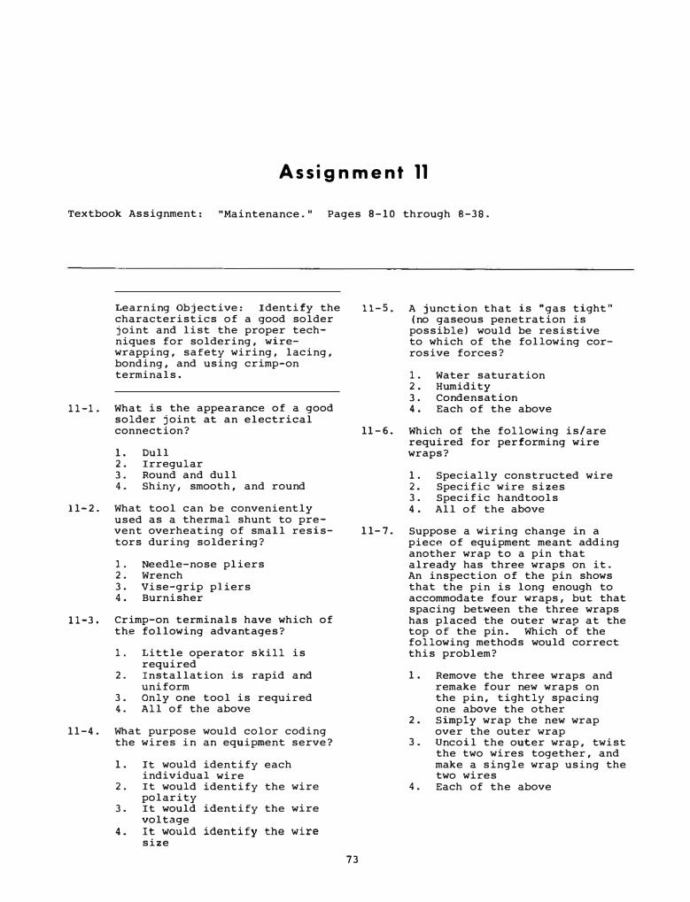
Assignment 11
Textbook Assignment: "Maintenance. " Pages 8 - 10 through B-38.
Learning Objective: Identify the characteristics of a good solder joint and list the proper techniques for soldering, wirewrapping, safety wiring, lacing, bonding, and using crimp-on terminals.
11-1. What is the appearance of a good solder joint at an electrical connection?
1. Dull 2. Irregular 3. Round and dull 4. Shiny, smooth, and round
11- 2 . What tool can b e conveniently used as a thermal shunt to prevent overheating of small resistors during soldering?
1. Needle-nose pliers 2. Wrench 3. Vise-grip pliers 4. Burnisher
11-3. Crimp-on terminals have which of the following advantages?
1. Little operator skill is required
2. Installation is rapid and uniform
3. Only one tool is required 4. All of the above
11-4 . What purpose would color coding the wires in an equipment serve?
1 . It would identify each individual wire
2. It would identify the wire polarity
3. It would identify the wire voltage
4. It would identify the wire size
73
11-5. A junction that is "gas tight" (no gaseous penetration is possible) would be resistive to which of the following corrosive forces?
1. Water saturation 2. Humidity 3. Condensation 4 . Each of the above
11- 6 . Which of the following is/are required for performing wire wraps?
1 . Specially constructed wire 2. Specific wire sizes 3. Specific handtools 4 . All of the above
11- 7 . Suppose a wiring change in a piec� of equipment meant adding another wrap to a pin that already has three wraps on it. An inspection of the pin shows that the pin is long enough to accommodate four wraps, but that spacing between the three wraps has placed the outer wrap at the top of the pin. Which of the following methods would correct this problem?
1 . Remove the three wraps and remake four new wraps on the pin, tightly spacing one above the other
2 . Simply wrap the new wrap over the outer wrap
3 . Uncoil the outer wrap, twist
4.
the two wires together, and make a single wrap using the two wires Each of the above

•
11-8. There are four wraps on a single pin (il is the outer wrap, a nd #4 is the i nner wrap ) . Which of the following wraps must be removed when removing t3?
1. u 2. i2 3. Both 1 and 2 above 4. 14
11- 9 . The identification o f either a good or bad wire wrap i s
1. usually done with an osci lloscope or multimeter
2. only possible with a signal tracing technique
ll-13.
11-14.
ll-15.
A. PURPOSES B . DEVICES
To prevent high 1. Filters frequency i nter-ference 2. Bonding
straps To block or by-pass undesirable 3. Safety e lectrical line wires variati ons
4. Shielding To electrically connect equip-ment or sys tems to the ship's s tructure
3. easy to verify by attempting 11-16. to dislodge the wrap
At what s tage is a repair job considered to be complete?
(twis ting, turning, pulling , etc.)
4 . possible with close visual i nspection
11- 10. Safety wiring is a method of protection against the effects of what common shipboard condition?
1. Shorts 2. Grounds 3. Arci ng 4. Vibration
11-11. What size safety wire is recommended for wiring e lectrical connectors?
1. 0 . 0 32-inch-diameter 2. 0 . 0 45- i nch-diameter 3. 0 . 00 32- i nch-diameter 4. 0 . 0 0 45-inch-diameter
11-12. What is the advantage of shortsection lacing over continuouscable lacing?
1. It remains tied even though the laci ng becomes broken at one point
2. It required less time to complete
3. It required ordinary cord 4. It provides better support
for the wiring harness
TO ANSWER QUESTIONS 11-13 THROUGH 11-15 SELECT FROM COLUMN B THE DEVICE WHICH SERVES THE PURPOSE DESCRIBED IN COLUMN A. NOT ALL RESPONSES IN COLUMN BE ARE USED.
74
1 . When a faulty component has been replaced
2. When shields a nd dust covers have been i nstalled
3. When a n operational test has been performed
4. When an operational check under normal operati ng conditions has been completed
11-17. Adjustment procedures are performed at which of the f ollowing times ?
1 . A t least a nnually 2. After a part replacement 3. Whenever scheduled 4. All of the above
Learning Objective: Describe various aspects of basic preventive mai ntenance tasks.
11-18. Grease on the chassis o f a fire control sys tem can be removed by wiping with a
1. clean, lint-free cloth moiste ned in solvent
2. soapy, clean, lint-free c loth 3 . clean, dry, lint-free c loth 4 . tissue paper

· - -----------
11-19 . The procedure for lubricating antenna rotating joints is outlined in the
1. pertinent MIL SPECs 2 . United States Navy Safety
Precautions 3 . equipment MRCs 4. pertinent Maintenance
Instructions Manual
11-20. Cross-reference substitution guides are available for which of the following procedures/ materials?
1. Test procedures 2 . Alignment procedures 3 . Cleaning cloths 4. Lubricants
11-21. Which of the following is a cause of errors in some fire control equipment?
1 . Dust and dirt 2. Wear 3 . Moisture 4. Each of the above
11-22. You remove a defective mechanical component to the ship' s repair shop and disassemble it . How are the disassembled parts stowed pending repair?
1 . I n rust-inhibiting oil baths 2 . On open shelves 3 . In ventilated bins 4. Under lint-free dust covers
11-23 . When using solvent , you should observe which of the following practices to prevent excessive wear of a mechanical component?
1. Avoid spraying it on 2 . wrap the component in plastic 3 . Spray from a long distance 4. Spray it in short bursts
only
Learning Objective: Describe general maintenance related to rotating machinery.
11-25 . Which of the following i s a correct maintenance procedure for brushes?
1 . Used brushes should not be reinserted after removal
2 . Brushes should be reinserted in their original location and position
3 . For maximum wear, brush locations should be rotated
4. For maximum use , brush positions should be reversed
11-26 . What is the ideal appearance of the surface of a slipring?
1 . Bright and smooth 2 . Rough matte finish 3 . Smooth matte finish 4. Slightly grooved
11-27. What is the normal appearance of a commutator?
1. Shiny and black 2. Dull and black 3 . Shiny and brown 4. Dull and brown
11-28 . Which of the following defects in a commutator would an FC normally repair aboard ship?
1. Faulty brush contact 2 . Open coil 3 . Shorted coil 4. High mica
11-29 . The condition called high mica is caused by
1. arcing from the brushes 2 . arcing between segments 3 . excessive brush wear 4. excessive copper wear
11-24 . Grease is used sparingly on fire 11-30 . control equipment because the heavy application of grease tends to
Under which of the following conditions should brushes be replaced?
1 . prevent the diss ipation of 1. When they are oil soaked heat 2. When they are chipped
2 . clog the mechanism 3 . When there is excessive wear 3 . speed up corrosion 4 . Each of the above 4. absorb dirt particles
75

11-31. When new brushes are sanded i n prior t o use, a good way to secure the sandpaper to the commutator is with
1. a small dab of glue 2. friction tape 3. rubber bands 4. transparent adhesive tape
11-32. When you clean dirt or grease from glass optics, the lens tissue should be dampened with
1. alcohol 2. an alkaline solution 3. plain water 4. soapy water
Learning Objective: Describe the environmental factors affecting fire control equipment and the correct methods for minimizing their effects.
11-33. What is the environmental condition that causes metal components to become brittle?
1. Extremely low temperatures 2. Extremely high temperatures 3. Low humidity 4. High atmospheric pressure
QUESTIONS 11-34 THROUGH 11-36 ARE TO BE JUDGED TRUE OR FALSE.
11-34. The effectiveness of heating and cooling equipment is NOT affected by the presence of dirt and dust on its outside surface.
1. True 2. False
11-35. Operating electronic equipment in a high-humidity environment may cause an arc between points of high potential.
1. True 2. False
11-36. Troubles with pressurized systems are usual l y caused by severe vibration.
1. True 2. False
76
11-37. Undesired environmental effects of temperature, humidity, arcover, and abrasive conditions are minimized by the use of
1. electric heaters 2. hot air blowers 3. air conditioning 4. s i lica gel crystals
11-38. Corrosion has an adverse effect on equipment at which of the following times?
1. Only when the equipment i s energized
2. Only when the equipment is deenergized
3. Whenever preventive mainte-nance is not done
4. Twenty-four hours a day
11-39. The preferred way to remove moisture from a connection box is with a
1. clean rag 2. lint-free cloth 3. hot-air blower 4 . vacuum cleaner
11-40 . What is the function of the s i lica gel crystal s in the desiccant unit of an SMS component?
1. To moisten the air inside the unit
2. To dry the air inside the unit
3. To filter the incoming air 4. To reduce the interior heat
11-41. Before reenergizing an equipm?nt where water has been used to remove salt, which of the following precautions should be observed?
1. Perform a salinity test 2. Go over the surface with a
solvent 3. Install a bag of silica-gel
crystals 4. Ensure that the water i s
completely evaporated
Learning Objective: Identify the functions and uses of electronic and nonelectronic rnult imeters.

IN ANSWERING QUESTIONS 1 1 - 4 2 THROUGH 1 1 - 4 4 , REFER TO FIGURE 8-20 OF THE TEXT.
1 1 - 4 2 . The ohmmeter section o f the multimeter receives power to activate the meter movement from what source?
1 1-43.
1 1 - 4 4 .
1. A n external battery 2 . The circuit being tested 3 . An internal battery 4. A generator
While using the i l lustrated multimeter and a special high voltage probe to make measurements in a +4 , 5 0 0 -volt circuit, the operator observes that the neon lamp i n the probe i s lighted. This is a n indication of what condition?
1 . The voltage a t the test point exceeds the range selected
2. The probe is connected to a dangerously high voltage
3 . The 1 0 0 -megohm multiplier is i n the circuit and the scale reading is not reliable
4. The 100-megohm multiplier is not i n the circuit and the scale reading must be multiplied by a factor of 10
What procedure do you use to adjust an ohmmeter to ensure an accurate reading?
1. Connect it to a low-voltage source and adjust the rheostat until the meter reads zero
2 . Connect i t t o a low-voltage source, adjust the rheostat until the meter reads maximum, and then short the test leads together
3 . Short the test leads together and adjust the rheostat until the meter reads zero
4. Short the test leads together and adjust the rheostat until the meter does not deflect
77
11-45. The loading effect of a vtvrn is small compared to that of a multimeter because of the
1 . high capacitance i n the vtvm' s vacuum tube rectifier
2. low capacitance in the vtvm's metallic-oxide rectifier
3. high input impedance of the vtvrn ' s input circuit
4 . low input impedance of the vtvm's input circuit
IN ANSWERING QUESTIONS 1 1-46 AND 11-47 , REFER TO FIGURE 8-21 OF THE TEXT.
1 1 - 46. Which of the following, if any , i s the smallest amount of de current that can be measured with the i l lustrated vtvm?
1 . 0.02 microamperes 2. 2 . 0 0 microamperes 3 . 0 . 2 0 microamperes 4 . None o f the above
11-47. What type of measurement made with the vtvm does NOT use the bridge circuit?
1 . De voltage 2 . Resistance 3. De current 4. Ac voltage
1 1 - 4 8 . How i s the differential voltmeter used to determine the value of an unknown voltage?
1. A switchi ng arrangement permits switching between the unknown voltage and testset voltage so that identical meter deflections can be observed
2 . A switching arrangement permits the unknown voltage to be read on one side of a center-zero meter and testset balancing voltage to be read on the other side
3. The unknown voltage is compared to an adjustable reference voltage supplied by the voltmeter and is read from the voltage dials
4. The unknown voltage is balanced out by voltage supplied by the test-set , and the value of test-set voltage thus required is read from a meter

11- 49. What instrument measures resistances of many megohms by applying high voltage to the component under test and measuring its leakage current?
1. A Megger 2 . A multimeter 3. A megohmmeter 4. A volt-ohm-mi l l iammeter
11-50. What reading will occur if a Megger is used to read a resistance that exceeds its range?
1. 0 ohms 2. Midscale 3. 1000 megohms 4 . Infinity
Learning Objective: Identify the procedures for testing circuits for continuity , grounds and shorts , voltage, and resistance .
11-51. A continuity test is performed on a piece of electronic equipment to discover what type of defect?
1. Low voltage 2. Weak tubes 3. Changes in component values 4. Open circuits
11-52. Which of the following meters is recommended for continuity tests?
1 • An ohmmeter 2. A Megger 3. A voltmeter 4. An ammeter
IN ANSWERING QUESTIONS 11-53 THROUGH 11-55, �EFER TO FIGURE 8-23 OF THE TEXT .
11-53. What resistance does the ohmmeter indicate when connected as shown?
1. 0 ohms 2. Maximum 3. Midscale 4. 100 ohms
78
11-54. The conductors between plug 1 and plug 2 can be tested for grounds by connecting one meter probe to ground anq the other probe to the conductors
Ia) (individually, collectively)
with the j umper (b)
(connected, removed)
1. (a) individually (b) removed
2. (a) individual l y (b) connected
3. (a) collectively (b) connected
4 . (a) collectively (b) removed
11-55. Assume that conductors A and B are shorted together between plug 1 and plug 2. To what points must an ohmmeter's probes be attached in order to detect the short?
1. Between conductor A and ground
2. Between conductor B and ground
3. Between conductor A and conductor B
4. Between conductor A and the j umper
11-56. What precaution must you observe before you test circuit voltages with a voltmeter?
1. Set the meter to the lowest range
2. Remove the suspected component from the circuit
3. See if the voltage coming from the power source is correct
4. Check current flow through the circuit with an ammeter
11-57. Why is it important to set the voltmeter on its highest range scale before starting a measurement?
1. To increase the sensitivity of the measurement
2. To protect the equipment being tested
3. To systematize the procedure 4 . To keep the meter from being
overloaded

11-58. If set to the 100-volt range and if its sensitivity is 2,000 ohms per volt, what is the resistance of a voltmeter?
1. 50, 000 ohms 2. 100,000 ohms 3. 200, 000 ohms 4. 300, 000 ohms
11-59. The low resistance range of an ohmmeter is used for checking which of the following conditions?
1. Leakage resistance of capacitors
2. Leakage resistance of cables
11-63. The horizontal axis of an oscilloscope represents what waveform characteristic?
11-64.
1. Amplitude 2. Intensity 3. Elapsed time 4. Quantity
The vertical axis of an oscilloscope represents what waveform characteristic?
1. Amplitude 2. Quantity 3. Intensity 4. Each of the above
3. Circuit continuity 11-65. The oscilloscope is capable of performing which of the following measurements on a given waveform?
4. Grounds
QUESTIONS 11-60 AND 11-61 ARE TO BE JUDGED TRUE OR FALSE.
11-60. When a resistor is connected across the winding of a transformer, a direct resistance reading of the resistor would be invalid.
1. True 2. False
11-61. A low internal resistance voltmeter shunts the circuit being measured and results in accurate readings.
1. True 2. False
Learning Objective: Identify the functions of the major sections of an oscilloscope.
11-62. What is the principal use of
1. The rise time 2. The magnitude 3. The time difference between
two points 4. Each of the above
11-66. The display of a large signal that extends off the face of the oscilloscope may be reduced to a usable amplitude by use of which of the following controls?
1. Volts/em calibrated attenu-ator
2. Horizontal position knob 3. Vertical position knob 4. Sweep mode control
11-67. The input to an oscilloscope is normally applied to what circuit?
1. The horizontal deflection 2. The vertical deflection 3. The time delay amplifier 4. The intensity amplifier
the oscilloscope? 11-68. The time required for the dot
1. Visual examination of waveforms of voltages or current
2. Location of radio interference
3. Measurement of UHF and microwave energy
4. Measurement of frequency response in audio equipment
79
to return to the point of origin is identified by what term?
1. Rise time 2. Negative deflection 3. Flyback time 4. Positive deflection
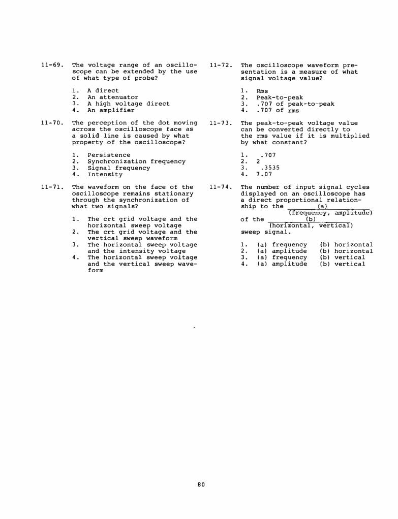
11-69. The voltage range of an oscilloscope can be extended by the use of what type of probe?
1. A direct 2. An attenuator 3. A high voltage direct 4. An amplifier
11-70. The perception of the dot moving across the oscilloscope face as a solid line i s caused by what property of the oscilloscope?
1. Persistence 2. Synchronization frequency 3. Signal frequency 4. Intensity
11-71. The waveform on the face of the oscilloscope remains stationary through the synchronization of what two signals?
1. The crt grid voltage and the horizontal sweep voltage
2. The crt grid voltage and the vertical sweep waveform
3. The horizontal sweep voltage and the intensity voltage
4. The horizontal sweep voltage and the vertical sweep waveform
80
11-72. The oscilloscope waveform presentation is a measure of what signal voltage value?
1. Rms 2. Peak-to-peak 3. .707 of peak-to-peak 4. . 707 of rms
11-73. The peak-to-peak voltage value can be converted directly to
11-74.
the rms value if it is multiplied by what constant?
1. . 707 2. 2 3. . 3535 4. 7.07
The number of input signal cycles displayed on an oscilloscope has a direct proportional relationship to the
��----�<a�>----
���-
(frequency, amplitude) of the (b)
(horizontal, vertical) sweep signal.
1. 2. 3. 4.
(a) frequency (a) amplitude (a) frequency (a) amplitude
(b) horizontal (b) horizontal (b) vertical (b) vertical

Assignment 12
Textbook Assignment: " Maintenance . " Pages 8-38 through 8-44 .
" Safety and Security. " Pages 9-l through 9-1 5 .
Learning Ob j e ctive : Identify the operational and functional characteri stics of signal generators.
12-1. The output of a signal generator is no rmally used for what purpose ( s) ?
1. To supply plate voltage to e lectronic equipmen t
2. To test, a l i gn , or trouble shoo t e le ctron i c equipment
3. To produce standa rd sources of de energy
4 . All of the above
12-2. Voltage ampli tude and impedance values are contro lled in many signal gene rators by
l. calibrated capaci tors 2. vacuum tubes 3. attenuators 4. va r i able re sistors
12-3. How is the output f requency of a beat-frequency type video signal generator produced?
l. By mixing the signals of a f i xed and a variable rf oscillator
2. By mixing the signals of two f i xed rf osci llato rs
3 . B y mixing the si gnals o f two vari able rf oscillators
4. By mixing the output of two audio-frequency osci llators
12- 4 . The f requency o f an audio-signal generator can be determined by which of the following devices?
1 . An attenuator 2. A resis tance ne twork 3 . A resi stan ce - capaci tan ce
ne twork 4. A re sistance-diode network
8 1
12-5. The output of the ampl i f i e r section of an audio si gnal generator is often coupled to the output control by whi ch of the fo llowing methods?
1 . An attenuator 2 . A tran sformer 3. An RC ne twork 4. An RL ne twork
12- 6 . A modulation signal for the output of the oscillator stage of an rf signal generator may be produced f rom which of the follo wing sources?
1 . A plug-in reodule 2 . An internal modulator 3 . An e xternal signal 4. Both 2 and 3 above
1 2- 7 . In low- f requency s i gn a l gene rators, the frequency ranges are changed by changing what component in the resonant ci rcui t?
1 . The capacitor 2. The coi l 3. The resistor 4 . The oscillator tube
1 2- 8 . The r f output o f a signal gene rator can be modulated by which of the following signal types?
1 . Sine wave 2. Square wave 3. Variable duration pulses 4. Each of the above
12- 9 . The output level o f a signal gene rato r is con trolled by what type o f device?
1 . An a ttenuator 2. A pote n tiometer 3. A rheostat 4. A vari able capaci tor
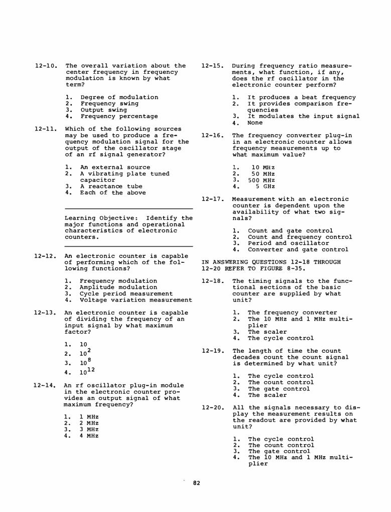
12-1 0 . The overall variation about the center frequency in frequency modulation is known by what term?
1. Degree of modulation 2 . Frequency swing 3. Output swing 4 . Frequency percentage
12-1 1 . Which of the following sources may be used to produce a frequency modulation signal for the output of the oscillator stage of an rf signal generator?
1 . An external source 2 . A vibrating plate tuned
capacitor 3. A reactance tube 4 . E ach of the above
Learning Objective : Identify the major functions and operational characteristics of electronic counters.
12-12 . An e lectronic counter is capable of performing which of the following functions?
1 . Frequency modulation 2 . Amplitude modulation 3. Cycle period measurement 4 . Voltage variation measurement
12-13. An electronic counter i s capable of dividing the frequency of an input signal by what maximum factor?
1 . 10
2 . 102
3. 10 B
4 . lo1 2
1 2 - 1 4 . An rf oscillator plug-in module in the e lectronic counter provides an output signal of what maximum frequency?
1 . 1 MHZ 2 . 2 MHZ 3. 3 MHZ 4. 4 MHZ
82
12-15 . During frequency ratio measurements, what function, i f any , does the rf osci llator in the electronic counter perform?
l. It produces a beat frequency 2 . It provides comparison fre
quencies 3. It modulates the input signal 4 . None
12-16. The frequency converter plug-in in an electronic counter a l lows frequency measurements up to what maximum value?
l . 1 0 MJI Z 2 . 5 0 MHZ 3. 5 0 0 MHZ 4 . 5 GHz
12-17. Measurement with an e lectronic counter is dependent upon the availability of what two signals?
1 . count and gate control 2 . Count and frequency control 3. Period and oscillator 4 . Converter and gate control
IN ANSWERING QUESTIONS 12-18 THROUGH 12-20 REFER TO FIGURE 8-35 .
12-18. The timing signals to the functional sections of the basic counter are supplied by what unit?
1 . The frequency converter 2 . The 10 MHZ and 1 MHZ multi
plier J. The scaler 4 . The cycle control
12-19. The length of time the count decades count the count signal is determined by what unit?
1 . The cycle control 2 . The count control 3. The gate control 4 . The scaler
12-20 . All the signals necessary to display the measurement results on the readout are provided by what unit?
1 . The cycle control 2 . The count control 3. The gate control 4 . The 10 MHz and 1 MHZ multi
plier
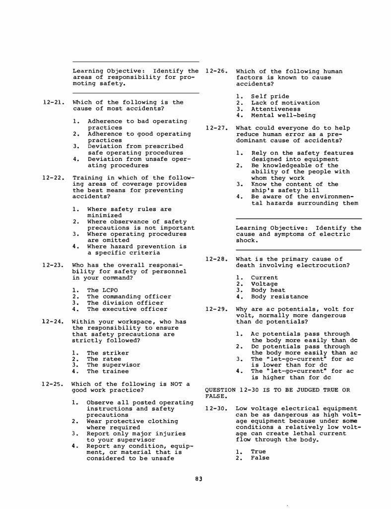
Learning Objective : Identify the 12-2 6 . areas of responsibility for pro-
Which of the following human factors is known to cause accidents? moting safety.
12-21. \'lhich of the fo l lowing is the cause of most accidents?
1. Adherence to bad operating practices
2 . Adherence to good operating practices
3 . Deviation from prescribed safe operating procedures
4. Deviation from unsafe operating procedures
12-22 . Training in which of the following areas of coverage provides the best means for preventing accidents?
1. Where safety rules are minimized
2. Where observance of safety precautions is not important
3 . Where operating procedures are omitted
4. Where hazard prevention is a specific criteria
12-23. Who has the overall responsibi lity for safety of personnel in your command?
1. The LCPO 2 . The commanding officer 3 . The division officer 4. The executive officer
12-24. Within your workspace , who has the responsibility to ensure that safety precautions are strictly fol lowed?
1. The striker 2 . The ratee 3 . The supervisor 4 . The trainee
12-25. Which of the following is NOT a good work practice?
1. Observe a l l posted operating ins tructions and safety precautions
2 . Wear protective clothing where required
3 . Report only major inj uries to your supervisor
4. Report any condition, equipment, or material that is considered to be unsafe
8 3
1 . S e l f pride 2 . Lack o f motivation 3 . Attentiveness 4. Mental well-being
12-27. What could everyone do to help reduce human error as a predominant cause of accidents?
1. Rely on the safety features designed into equipment
2 . Be knowledgeable o f the ability o f the people with whom they work
3. Know the content of the ship ' s safety bill
4. Be aware of the environmental hazards surrounding them
Learning Objective : Identify the cause and symptoms of electric shock .
12-2 8 . What i s the primary cause o f death involving e lectrocution?
1 . Current 2 . Voltage 3 . Body heat 4. Body resis tance
12- 2 9 . Why are a c potentials , volt for volt, normally more dangerous than de potentials?
1. Ac potentials pass through the body more easily than de
2 . De potentials pass through the body more easily than ac
3 . The " let-go-current" for ae i s lower than for de
4. The " let-go-current" for ac is higher than for de
QUESTION 12-30 IS TO BE JUDGED TRUE OR FALSE .
12-30. Low voltage electrical equipment can be as dangerous as high voltage equipment because under some conditions a relatively low voltage can create lethal current flow through the body.
1. True 2 . False
12-31 . Which of the following is the first s tep in rescuing a person who is in contact with an electric circuit and is unconscious?
1. Deenergize the circuit 2 . Use a rope or wooden stick
to separate the victim from the circuit without touching the victim
3. Both 1 and 2 above , depending on the circumstances
4 . Call the duty electrician
12-32. After removing the victim from the electricity , what should you do i f the person is unconscious and has s topped breathing as a result of electrical shock?
1 . Apply artificial respiration immediately
2 . Ascertain the amount o f current that passed through the body to proceed with proper treatment
3 . Wrap th e person in a blanket and take him to sick bay for treatment
4 . Determine i f his heart has stopped beating and , if not, apply artificial respiration
Learning Objective : Describe the ungrounded electrical distribution system.
12-33. Naval ships are equipped with ungrounded e lectrical distribution systems for
1. minimum operating cost 2 . minimum maintenance personnel
requirement 3. maximum sys tem reliability 4 . maximum system down time
QUESTION 12-34 IS TO BE JUDGED TRUE OR FALSE .
12-34 . The cables in your ship ' s electrical distribution system have perfect insulation.
1 . True 2 . False
84
1 2 - 35 . Your ship i s engaged in a target tracking exercise with the director locked on target. One of the lines supplying power to the director from the ship ' s 400-cycle power ungrounded electrical distribution system develops a ground at the time of missile firing. What effect, if any, should this have on the tracking exercise?
1 . The director tracks , the missile does not leave the rail
2 . The director does not track , the missile does not leave the rail
3. The director does not track , the missile leaves the rail
4 . None
12-36 . Which o f the following instruments i s used to measure insulation resistance?
1 . VTVM 2 . De megger 3. Frequency generator 4 . R f meter
1 2 - 37. Which of the following values is more desirable as the insulation resistance of R, in figure 9 - 2 of the text?
1 . 1 , 000, 000 ohms 2 . 2 , 000, 000 ohms 3 , 3 , 0 0 0 , 0 0 0 ohms 4 . 4 , 000, 000 ohms
12-38 . Touching a live conductor can be e�tremely dangerous , in spite of high insulation resis tance , because of the distributed cable
1 . capacitance 2 . resistance 3. inductance 4 . reluctance
Learning Objective : Observe prescribed safety precautions while working on fire control transmitters , high-voltage power supplie s , in the handling, s towage , and disposal of radioactive and cathode-ray tubes .
1 2-39. In making voltage measuremen ts, certain procedures should b e ob served . Which o f t h e following steps should you perform first?
1. Energi ze the equipment 2. set up the test instrument
for proper operati on 3 . S ecure th e test leads to
the equi pment 4. De- energize the equipment
12-40. While making a voltage measuremen t, which of the following steps should you perform last?
1 . Di scharge capaci tors an d remove the test leads
2. S ecure the test leads to the equipment
3 . D e- energize the equipment an d hook up the test leads
4. Energize the equipment and remove the test leads
QUESTIONS 1 2-41 AND 1 2-42 ARE TO BE J UDGED TRUE OR FALSE.
12-41. A crt i s subjected to tremendous external pressure on i ts surface area.
1 . True 2. False
12-42. A cr t may be removed from i ts yoke without fi rst di scharging the voltage on i ts anode.
1 . True 2. False
12-44. You are involved in an in ciden t where a r adioactive tub e i s broken . Which of the following methods can be used to clean up the b roken glass i f no vacuum cleaner i s avai lable?
1 . Wipe the affected area with a cloth, using a b ack-andforth motion
2. Use compressed air to b lowdown the are a
3 . t7ipe the affected area with a cloth, using a sing le stroke one-directi on moti on
4. S weep the area, using a broom and dust pan
12-45. What i s the proper soluti on to use to decontaminate tools and implemen ts used to remove radioactive substances?
1 . s oap and water 2. Benzene 3 . Alcohol 4. Cleaning solven t
12-46. \'lhich of the following i s an acceptable means of promoting b leeding in an inciden t where a cut i s sustained from a radioactive ob ject?
1 . S uck the wound with the mouth un ti l b lood flows freely
2. Make a small i ncisi on in the wound to facili tate bleeding
3 . Use a tourniquet on either side of the woun d
4. Puncture a vein in the vicinity of the wound
12-43. ��en a r adioactive tube i s broken 12-47. in the work space, which of th e following acti ons should b e
All o f the following tubes are sources of X-ray emission except the
taken?
1 . Isolate t h e area 2. Follow procedures in NAVMED
P-5055 3 . N otify cognizant authori ty 4 • All of the above
85
1. magnetron 2. klystron 3 . crt 4. cold cathode
12-48. \'� at device provides protecti on from X-ray emi tting devi ces?
1 . x-ray trap 2. x-ray suppressor 3 . x-ray shield 4. X-ray conductor

12-49. It i s necessary to guard against jarring or striking a magnetron. This is true because striking a magnetron can cause a/an
1 . excessive vibration o f electrons within the magnetron
2 . reduction i n the magnetic field s trength of the magnetron
3. increase in the magnetic field s trength of the magnetron
4 . explosion o f the magnetron
12-50. Tools used to work on magnetrons must have what property?
1. Non-magnetic 2 . Magnetic 3. Durabi l i ty 4. High tensile strength
12-51. What causes an electrostatic corona?
1. Contact between two highly charged surfaces
2 . A breakdown o f dielectric material separating two highly charged surfaces
3. Magnetic attraction between two highly charged surfaces
4. Electrostatic attraction between two highly charged surfaces
Learning Objective: State the purpose and use of safety devices
1 2 - 5 3. When , i f ever, should an interlock be tampered with?
1 . When the equipment i s malfunctioning
2 . When the commanding officer directs
3. When a better design is necessary
4 . Never
12-5 4 . What step should be taken first before a fuse i s pulled from its holder?
1 . Energize the circuit 2 . De-energize the circuit 3. Short-out one side of the
fuse 4 . Measure the res istance of
the fuse to ensure that it is open
12-5 5 . What type o f fuse puller should be used to remove knife or cartridge-type fuses from fuse holders?
1. Magnetic 2 . Non-magnetic 3. Conducting 4 . Non-conducting
12-56 . What is the purpose for battleshort switches?
l. Bypass all safety interlocks 2 . Open all safety interlocks 3. Short-out all bottle switches 4 . Open all bottle switches
used in Fire Contro l . 12-57. When using a shorting probe , you the technician should avoid
12-52 . h�ich of the following is the purpose of the interlock?
l. Allows maintenance personnel to work on energized circuits
2 . Deenergizes circuits when power fai lure occurs
3. Prevents maintenance personnel from coming in contact with electrical potentials
4 . Prevents power from being interrupted at an inconvenient time
86
1 . being careful with the probe 2 . touching the metal parts of
the probe 3. holding the probe by the
handle behind the protective shield
4 . using the right probe for the right job
12-58. One practical method of ensuring that deckmatting is safe for electrical work is to
1 . buff the deckmatting with a good wax solution
2. measure the resi stance of the deckmatting with a Megger
3 . perform a voltage test by placing 3000 volts across the deckmatting
4 . periodically inspect and clean the deckmatting
12- 5 9 . Which of the following can cause serious cracking of rubber glove s ?
1 . Soap and water 2. O zone or petroleum products 3 . Moderate light 4 . Humid air
QUESTIONS 12-60 AND 12-61 ARE TO BE JUDGED TRUE OR FALSE .
12-60. Goggles should be worn when doing any kind of work in which there is a danger to the eyes.
1 . True 2. False
12-61. Work spaces should be considered safe although appropriate warning s igns are not posted.
1 . True 2 . False
12-62. What is the minimum RMS voltage level for which shock hazard
·
warning signs are required?
1 . 30 volts 2 . 5 0 volts 3. 300 volts 4 . 500 volts
Learning Objective : State the hazards to personnel whi le working aloft, including rf hazard to personnel and ordnance .
12-63. When you are aloft, which of the following i tems may be hazardous to you?
1. S tatic electricity 2. Rotating antennas 3. Stack gases 4. Each of the above
12-64 . Whose permission must be obtained before going aloft?
1 . The XO and the operations officer
2. The XO and the electronics officer
3 . The electronics officer only 4 . The OOD and the engineering
officer
12-65 . Personnel may develop a false sense of security concerning exposure to radiation because
1 . r f hazards occur only at night 2. rf radiation is visible only
at night 3 . rf radiation does not always
produce pain 4 . only search radars are
hazardous
12-66. Which of the fol lowing is NOT a radiation hazard?
1 . Defective dummy loads 2. Unavai lability of warning
signs 3. Rotating search radars 4. Open wave guides
12-67. What relationship, if any, exists between the biological e f fects of radiation in a person ' s body to the frequency of the radiation?
1 . Biological effects increase directly with frequency
2 . Biological e f fects increase inversely with frequency
3. Biological effects increase as the square of frequency
4. Biological e f fects have no relationship to frequency
12-68. A person standing erect in an rf field will be affected more i f the polarization o f the radiation is in the
1 . horizontal plane 2. vertical plane 3 . circular plane 4. normal plane
12-69 . What e f fect does radiation produce in the body?
1 . Contraction of blood vessels 2. Thinning of the blood 3 . Heating o f body tissue 4 . Rigor mortis
87
12-70 . Which of the following i s the most likely result after receiving radi ation to the eyes?
1. Instant blindness 2 . Cataracts 3 . Perfect vision 4 . Pupil contraction
12-71. What is the maximum radi ation exposure limit set by the Naval Medical Command?
1. 10 mW/cm 2
2 . 100 mW/cm2
3 . 1 , 0 0 0 mW/cm 2
4 . 10 , 0 0 0 mW/cm 2
88
12- 7 2 . Ordnance systems that are s usceptible to rf ene rgy are most s usceptible during which of the following events?
1. Storage 2 . Transportation 3 . Firing 4 . Handling in rf fields
12- 7 3 . What document contains the speci fi c HERO requi rements for your ship?
1. EEDs bill 2 . EMCON b i 11 3 . Rf bill 4 . Ope ration bill
12- 7 4 . What is the preferred extinguishing agent for electrical fires?
1. Carbon dioxide 2 . Carbon monoxide 3 . Water 4 . PKP
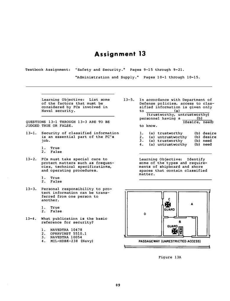
A s s i g n m e n t 1 3
Textbook Assignment : " Safety and Security . " Pages 9-15 through 9-21.
"Administration and Supply . " Pages 10-1 through 10-15 .
Learning Objective: List some of the factors that must be considered by FCs involved in Naval security .
QUESTIONS 13-1 THROUGH 13-3 ARE TO BE JUDGED TRUE OR FALSE .
13-1. Security of classified information is an essential part of the FC ' s j ob .
1 . True 2 . False
13 - 2 . FCs must take special care to protect matters such as frequencie s , technical specifications, and operating procedure s .
1 . True 2 . False
1 3 - 3 . Personal responsibility to protect information can be transferred from one person to another.
1 . True 2 . False
13-4 . What publication i s the basic reference for security?
1 . NAVEDTRA 104 7 8 2 . OPNAVINST 5510 . 1 3 . NAVEDTRA 10054 4 . MIL-HDBK-2 3 8 (Navy)
8 9
13- 5 . In accordance with Department of Defense policies, access to class i f ied informati on is given only
'
to ( a ) ( trustworthy, untrustworthy)
personnel having a (b) (des1.re, need)
to know .
1. ( a ) trustworthy 2 . ( a ) untrustworthy 3 . ( a ) trustworthy 4 . ( a ) untrustworthy
(b) desire (b) desire (b) need (b) need
Learning Objective: Identify some of the types and requirements of shipboard and shore spaces that contain classified matte r .
I I c
� A
GUARD D
L...; 8
GUARD
I � !: � ....___ �
PASSAGEWAY (UNRESTRICTED ACCESS)
Figure 13A
TO ANSWER QUESTIONS 13-6 THROUGH 1 3-8, REFER TO FIGURE 1 3 A .
1 3-6. Space D contains classified matter of such a nature that admittance to the area permits access to the matter. Space D is known as a/an
13-7.
1 . limited area 2. restricted area 3 . exclusion area 4. isolated area
Area A contains classified material. The commanding officer has authorized persons lacking security clearances to enter space A as long as they are escorted by cleared personnel . Area A is known as a
1. restricted space 2. limited area
13-10. Classified information is divided into which of the following categories?
13-11 .
1 . Top Secret , Secret , and For Official Use Only
2. Top Secre t , Confidential, and For Official Use Only
3. Top Secret, Secre� and Confidential
4. Top Secret, Secret, Confidential, and Restricted Data
The unauthorized disclosure of what classification of material could result in exceptionally grave damage to the United States?
1. secret 2. Top Secret 3 . Confidential 4. For Official Use Only
3. controlled area 13-12. What classification should be applied to material of a nature such that unauthorized disclosure could seriously damage the United States?
4. semirestricted area
13-8. Spaces B and C contain no classified material of any kind so they are most likely designated as
1. buffer zones 2 . safety zones 3 . threshold areas 4 . controlled areas
13-9. From the standpoint of security, the combat information center is classified as a/an
1. exclusion area 2. limited area 3 . controlled area 4. unrestricted area
Learning Obj ective: Identify some of the U. S . security classifications and markings and state the significance and meaning of special markings assigned to certain categories of material .
9 0
1. Secret 2 . Top Secret 3. Confidential 4 . For Official Use Only
1 3-13. What classification should be assigned to mobil ization plans of the United States?
1 . Secret 2. Top Secret 3. Confidential 4. For Official Use Only
13-14. What classification should be given to information which if disclosed could lead to a break in diplomatic relations affecting the defense of the United States?
1 . Secret 2 . Top Secret 3. Confidential 4 . For Official Use Only

13-1 5 . What classification should be assigned to devices and material related to communication security?
1 . secret 2 . Top Secret 3 . Confidential 4 . For Official Use Only
1 3 -1 6 . According to the information contained in your text, which of the following pieces of information is most likely to be classified as Secret?
1 . Documents concerning disciplinary action, the knowledge of which is to be safeguarded
2 . Frequency and call sign allocations
3 . An important intelligence operation
4 . Security investigations of naval officers
1 3 - 1 7 . Which of the fol lowing is the classi fication that should be assigned to material, which if disclosed could cause identifiable damage to the national security of the United States?
1 . Secret 2 . For Official Use Only 3 . Restricted Data 4 . Confidential
13- 1 8 . How should information regarding the size and composition of military units in the United States be classified?
1 . Restricted Data 2 . Confidential 3 . Secret 4 . Top Secret
1 3 - 1 9 . The marking "Restricted Data" normally refers to what type of equipment?
1 . Sophisticated radars 2 . Satellite communications 3 . Atomic weapons only 4 . Nuclear and atomic weapons
91
1 3-2 0 . A 2 00-page document that contains S O pages of Confidential material , 20 pages of Secret material , and 2 pages of Top Secret material would bear what marking?
1 . CONFIDENTIAL ( Secret/Top Secret)
2 . CONFIDENTIAL 3 . TOP SECRET ( Secret/
Confidential ) 4 . TOP SECRET
13-2 1 . �y was the automatic downgrad�ng and declassification system developed?
1 . To purge files 2 . To eliminate the chance o f
overclassifying a document 3 . To make material available
to the general public when secrecy is no longer necessary
4 . To allow the publication of classified material in unclassified publications
QUESTIONS 13-22 AND 13-23 ARE TO BE JUDGED TRUE OR FALSE .
13-2 2 . Burning i s the only approved method of destroying classified material .
1 . True 2 . False
13- 2 3 . The destruction o f classified material must be witnessed by two commissioned officers .
1 . True 2 . False
1 3 -2 4 . Which of the following materials has the highest emergency destruction priority?
1 . Restricted Data 2 . For Official Use Only 3 . COMSEC 4 . Special Handling Required,
Not Releaseable to Foreign Nationals

-··-·---- - . . . ···· ---
1 3-2 5 - You find a safe containing infrequently used classified material unlocked and unguarded. You first report this to the senior duty officer . What should you do then?
1 . Lock the safe and inform the security officer
2 . Guard the safe "as i s " until the duty officer arrives
3 . Check to see if any material is missing
4 . Notify the persons responsible for locking the safe
Learning Objective: Identify elements of the PRP program.
13-2 6 . Why i s a PRP program necessary?
1 . Conventional weapons require more concern than nuclear weapons
2 . Nuclear weapons require more concern than conventional weapons
3 . Weapon department personnel are inherently unreliable
4 . Conventional weapons have more strategic capab i l ity than nuclear weapons
13-27 . What i s the specific objective of the PRP?
1 . To identify personnel having a history of drug abuse
2 . To identify personnel having contemotuous attitude toward authority
3 . To ensure that only reliable personnel are assigned duties under the program
4. To ensure that only personnel with above-average intelligence are assigned duties under the program
QUESTIONS 1 3-28 AND 1 3 - 2 9 ARE TO BE JUDGED TRUE OR FALSE.
1 3 -2 8 . Social adjustment and emotional stability have no bearing on the PRP .
1 . True 2 . False
92
1 3-2 9 . A physical impairment might prevent your ass ignment to a billet in the PRP .
1 . True 2 . False
Learning Objective: Describe the purpose and elements of the EMCON plan .
13-30. Which of the following is the purpose of EMISSION CONTROL?
1 . T o keep down confusion within a squadron
2 . To provide a period for radar maintenance
3 . To deny an enemy information that could disclose your ship ' s position
4 . To fac i l itate ship-to-ship communication
1 3 -3 1 . Who imposes EMCON within a task force?
1 . The OTC 2. The CO 3 . The CNO 4. The 000
1 3-3 2 . Restrictions from the EMCON plan can be imposed on
1 . personnel 2. frequency bands only 3 . certain types o f equipment
only 4. frequency bands and certain
types of equipment
1 3-3 3 . As a general rule detection range increases as
1. frequency increases 2. frequency decreases 3 . the square of frequency 4 . the square root of frequency
Learning Objective: Identify and describe administrative documents related to fire control.
- _ ___ __,..
------ - - - - -
13-3 4 . Fire control equipment operation and maintenance policies are partially based on data obtained from records and reports submitted up the chain of command to
1 . CNO 2 . naval engineers 3 . material commands 4 . commanding officers
13-3 5 . The identification o f all the units and subunits within a specific piece of equipment, such as a radar set , is used to aid the establishment o f which of the following standards?
1 . Operation 2 . Performance 3. Maintenance 4 . Each o f the above
13- 3 6 . What program provides a uniform plan for issuing and maintaining directives?
1 . Navy I s suance and Compliance Program
2. Navy Directives and I ssuance System
3. Directive Validation System 4. .Uniform Policy Issue System
QUESTIONS 1 3-37 AND 1 3-38 ARE TO BE JUDGED TRUE OR FALSE.
13- 3 7 . Instructions are directives that contain information or require action of a continuing nature .
1 . True 2 . False
13-3 8 . Notices have permanent referenc.e value and can be cancelled ONLY by issuance o f a new notice .
1. True 2. False
13-3 9 . Who assigns information such as , type release and subject classification number to an instruction?
1 . The addressee 2. The CO 3 . The originator 4. The material commander
9 3
QUESTION 1 3 - 4 0 IS TO B E JUDGED TRUE OR FALSE.
1 3- 4 0 . Consecutive numbers are NOT found on instructions .
1 . True 2 . False
13- 4 1 . What publication contains a numerical listing of all ORDALTS that have been is sued?
1 . NAVSEA 5215 2. ORDALT 0 0 3 . OP 0 4 . OP 3 5 0 0
1 3- 4 2 . Which of the following alterations to a ship affects its military characteristics through changes to ordnance?
1 . SHIPALTS 2. NAVALT ORDALTS 3 . ORDALTS 4 . NAVALTS
1 3 - 4 3 . The ORDALT Accomplishment Requirement ( OAR) list has been received aboard your ship. Under what condition must information concerning the ORDALTS l isted in this form be supplied to the overhaul activity and NAVSEA?
1 . When the material i s onboard 2 . When the material i s not
onboard but on order 3 . When accomplishment by ship ' s
force i s planned prior to completi'on of overhaul period
4 . Each o f the above
1 3-44. Who control s the procurement and distribution o f ORDALT kits ?
1 . NAVALEX 2. NOSSO 3 . NSWSES 4 . NAVSEACEN·
1 3 - 4 5 . What accounting system i s responsible for maintaining ship ' s configuration data?
1 . ORDNANCE Accountability System
2. SECAS 3. MDS 4. Automated Accounting System

1 3-46. A ship ' s configuration consists of which of the following factors?
1 3-47.
1 3- 4 8 .
1 . The ship ' s length 2. The ship ' s size 3. The ship ' s onboard systems/
equipment 4 . The ship ' s displacement
Ship ' s configuration data is maintained in the ( a )
at ( b ) (WSF , PMS )
(SPCC, NAVSEA)
1 . (a) WSF 2 , ( a ) WSF 3 . ( a ) PMS 4. ( a ) PMS
(b) SPCC (b) NAVSEA ( b ) SPCC ( b ) NAVSEA
What form must be f i l led out to document a configuration change?
1. 4 7 9 0 / 2 R 2. 4 7 9 0 / 2K 3 . 4 7 9 0 /CK 4 . 4 7 9 0 / 2 L
1 3-49. What i s the purpose o f conducting a SECAS validation?
1 3- 5 1 . What form provides data that serves as a basis for identifying and correcting surface missile system deficiencies?
1. 5 5 1 0 / 1 2 . 4 8 5 5 / 2 3 . 4 8 5 5 / 2K 4. 4 7 9 0 / 2
TO ANSWER QUESTIONS 1 3 -52 THROUGH 1 3-54, SELECT FROM COLUMN B THE CLASSIFICATION THAT APPLIES TO THE LOG ENTRY IN COLUMN A . NOT EVERY RESPONSE IN COLUMN B IS USED.
A. LOG ENTRY B. CLASSIFICATION
1 3-52. Missile sys- l . Confidential ten test results 2 . Secret
1 3- 5 3 . Missile fir- 3. Unclassified ing results
4. Top Secret 1 3-5 4 . Missile fre-
quency
1 . To determine the ship ' s 1 3-55. Under which o f the fol lowing circumstances should an OPNAV 4 7 9 0 / 2 K be f i l led out?
personnel requirements 2 . To update ship ' s configura
tion data 3. To install applicable ORDALTs 4. To remove expendable equip
ment
1 3 - 5 0 . Which of the following are methods of conducting SECAS validations?
1 . Full-team and engineered 2 . Half-team and engineered 3. Direct and indirect 4 . Observed and unobserved
Learning Objective: Describe weapon system administrative forms/ reports, and identify their basic content.
9 4
1 . Inability to conplete a maintenance task
2 . Completion of maintenance on a selected equipment
3 . Deferral o f work for outside assistance
4 . Each of the above
1 3-56. You have corrected a unique problem in your equipment . Which of the fo llowing forms or reports should you use to report the problem and your corrective action?
1. OPNAV 4 7 9 0 / 2 K 2 . CONAR 3 . Both 1 and 2 above 4. 8 8 1 0 / 3
-- - - ·-- - - · _ __ _ __ __ __r
13-5 7 . Which o f the following publications provides up-to-the-minute information on maintenance problems and procedures for missile fire control equipment?
1 . OP 0 2 . OD 9 3 9 8 3 . SMS technical bulletin 4 . NAVPUBINST 5215 . 4B
13-5 8 . Which o f the following i s NOT a use of SMS technical bulletins?
1 . Provide troubleshooting techniques
2 . Provide ORDALT instructions 3 . Call attention to technical
problems 4 . Call attention to new test
procedures
13-59 . Which of the following doc�ents are used by engineering experts to report problems?
1 . CONARS 2 • DCAP forms 3 . OPNAV 4 7 9 0/2Ks 4 . Each of the above
13- 6 0 . Which o f the following documents are issued to complete the DCAP information loop?
1 . Periodical status reports 2 . ORDALT instructions 3 . Updated allowance parts lists 4 . Procedural changes
THIS SPACE LEFT BLANK INTENTIONALLY .
95
TO ANSWER QUESTIONS 13-61 THROUGH 1 3 -6 4 , SELECT FROM COLUMN B THE INFORMATION THAT IS FOUND IN THE PUBLICATION LISTED IN COLUMN A .
A . PUBLICATION
1 3-61 . Naval Ship ' s Technical !'.anual
13-62 . Electronic Installation and Maintenance Book
1 3 -6 3 . SMS DCAP status report
1 3-6 4 . Ship ' s Plan Index
B . INFORMATION
1 . Installation and maintenance information for naval electronic equipment
2 . Problem data pertaining to system support equipment
3 . Data and instructions pertaining to classes of installed machinery and equipment
4 . Wiring diagrams of fire control equipment
13-6 5 . Your leading petty officer assigns you to work on the Weapon Direction Equipment Mk 4 Mod 0 . To which publication do you refer for the number of the OP that pertains to this equipment?
1 . STEPS 2 . Cog 1 Index 3 . OD 9 3 9 8 4 . NAVPUBINST 5 2 1 5 . 4B
1 3 - 6 6 . The reference to use for questions of security in the Navy is
1 . Basic Military Requirements 2 . OPNAVINST 5 5 1 0 . 1 3 . Ship ' s Security Manual 4 . NAVSEA Security Manual
1 3-67 . What type of change does NAVSEASYSCOM use to disseminate urgent information concerning conditions hazardous to the fleet?
1 . 2 . 3. 4.
CH MC ACN FCH
13-68. What type o f change provides formal replacement pages that cover configuration changes ( ORDALTS and SHIPALTS) ?
1 . CH 2. MC 3 . ACN 4. FCH
Learning Objective: Identify and describe aspects o f the supply system pertinent to FCs.
13-69. Which o f the following types o f repair parts would most likely be stored in the work space?
1. Large expensive expendables 2. Large rarely used parts 3. Small frequently used parts 4. Small rarely used parts
1 3-70 . Which of the following publications lists equipment s , component� and repair parts needed to operate and maintain the ship?
1 . COSAL 2 . Federal Supply Catalog 3 . -IPB 4. SPCC
1 3 - 7 1 . Which of the fol lowing documents is used to find al lowed ordnance equipment repair parts?
1 . COSAL Part 1 2 . COSAL Part 2 3. COSAL Part 3 4. Federal Supply Catalog
9 6
1 3 -72. Which o f the fol lowing sections of the COSAL should you consult to find the allowed RSS for your equipment?
l. 2. 3 , 4 .
Part I Part I I Part I I I Part IV
Section A Section B Section B Section A
1 3- 7 3 . Which of the fol lowing information i s usually omitted from the manufacturer ' s nameplate?
1 . Manufacturer ' s name 2 . Model nu:nber 3 . Federal stock number 4. Voltage
1 3- 7 4 . Which o f the following ways should repairables be packaged for return to the supply department?
1 . I n an appropriately des igned container
2 . I n a plastic bag stuffed with wadded paper
3 . With all usable parts removed
4. With the defective component removed
13-75. When should "mandatory turn-in" items be returned to supply?
1. After cannibalizing necessary compcnents
2 . As soon as practicable 3. Before a new part is ordered 4. Immediately upon ordering a
new part
- _ _ _ _ ___ _ ....._, __