Embed Size (px)
Citation preview
Fire Pumps 101By Jeff Dunkel, PE, Fire Protection Engineer
NFSM TECHNICALLY SPEAKING
This year, the NFSA is providing a series of courses and articles involving the design installation and testing of fi re pumps. This article will be the fi rst installment. The intent of this article is to provide a general guide for the placement and arrangement of basic fi re pump components. Fire pump arrange-ments can vary greatly depending on the applica-tion and type of pump. However, for the purposes
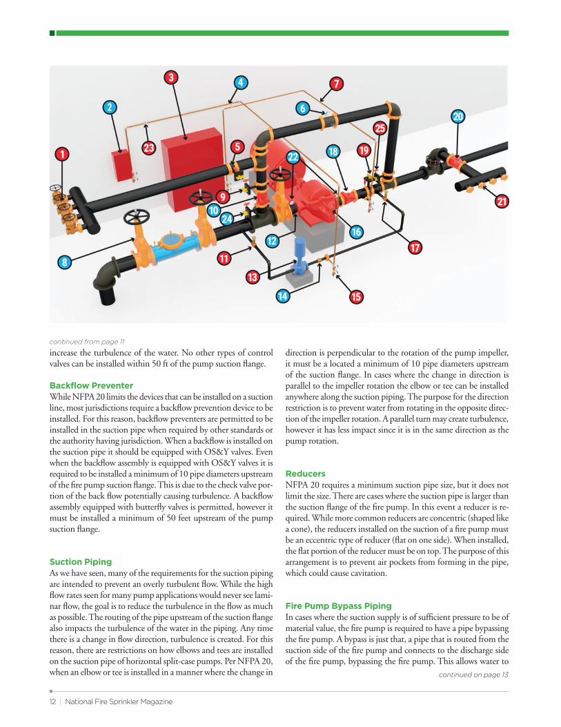
of this article, we are going to focus on the parts and pieces of a basic horizontal split-case fi re pump system. By walking through the basic components of a fi re pump system and identifying their purpose, we will provide a starting point to learning about fi re pumps and how to apply the requirements of NFPA 20, 2022 edition. The following diagram is only for reference. An actual fi re pump arrangement can vary depending on the parameters that surround the pump. The diagram is simply to provide a visual for what the article is describing. We will start at the beginning; the suction side of the fi re pump.
Suction Pipe and FittingsThe suction line consists of all the pipe, valves, and fi ttings from the pump suction fl ange to the connection to the public or private water service main, storage tank, or reservoir that feeds water to the pump. The primary goal in designing and sizing of the suction piping is to ensure the pump has suffi cient pressure at the suction fl ange and the water entering the pump is not overly turbulent. A horizontal split-case fi re pump can be fed from a public main, private main, suction tank, an elevated tank or a combination of water supplies. The source can impact the fi re pump design and will need to be considered at very early stages of the design.
Suction Sizing:Many requirements for the suction pipe are intended to minimize turbulent fl ow on the suction side of the fi re pump. The fi rst of which is the maximum suction water fl ow velocity. Table 4.28 provides a minimum pipe size based on rated fl ow of the fi re pump. These pipe sizes were derived to limit the fl ow velocity to 15 feet per second at 150 percent of the pump’s rated fl ow. This is one of the few times NFPA restricts velocity. The goal is to minimize turbulence. If the suction water is too turbulent it could create cavitation and damage the pump impeller.
Another item to consider for the fi re pump suction is the suction pressure. While NFPA 20 dictates a minimum suction
pipe size, if the suction pipe size creates too much friction loss, the suction pipe may need to be increased. As mentioned above, suction pipe sizing is based on 150 percent of the pump’s rated fl ow. By calculating the friction loss from the water supply to the fi re pump suction fl ange, the pressure available to the pump suction fl ange cannot be less than 0 psi at 150 percent of the fi re pump fl ow rate. It’s important to remember that while NFPA 20 allows for a suction pressure of 0 psi, it is not good practice to have a suction pressure that low, especially when the source is a public water supply. Many municipalities do not allow their system pressure to drop below 20 psi.
When being supplied by suction tank, with the lowest water level at or above of the pump discharge, the suction pressure can drop to a minimum of -3 psi at 150% of rated fl ow. The reason for this is to allow the use of all the water in the suction tank. Otherwise, since there is always friction loss in the suction pip-ing there would be a volume of water that would be considered not usable in the tank. This allowance is, in essence, limiting the pressure loss in the suction line to 3 psi. When the friction loss exceeds 3 psi, water can be added to increase the supply elevation and offset the loss. This added volume of water would be in ad-dition to the required capacity and not considered usable water for calculation purposes.
While not a good practice, there may be situations where the supply piping, such as a public water supply, is smaller than the dictated suction line sizing in NFPA 20. In these cases, the size pro-vided by table 4.28 must extend a minimum of 10 pipe diameters upstream of the fi re pump. Since the minimum sizes provided by NFPA 20 are intended to limit turbulence, the minimum 10 pipe diameters length would allow the water to streamline into a more laminar fl ow with a lower fl ow velocity. The minimum pressure to the fi re pump fl ange will still need to be met.
Suction Isolation ValvePer section 4.16.5.1, a listed outside screw and yoke (OS&Y) gate valve shall be installed in the suction pipe. This is another case where NFPA 20 is limiting the turbulence. For obvious reasons, this valve is required to isolate the fi re pump from the water sup-ply. However, the purpose behind the OS&Y requirement is to ensure an unimpeded water fl ow upstream of the fi re pump. An OS&Y valve is designed so the gate of the valve will lift completely out of the waterway. This is not the case with other valves such as a butterfl y valve, which would create an obstruction to fl ow and
continued on page 12
Because sometimes five to nine is more realistic than nine to five.You need a partner who is ready to get to work when you are. Viking SupplyNet is everything you need in fire protection from one name. Along with the trusted Viking device line, we offer thousands of products from the most reputable manufacturers in the industry. With 27 locations across the United States, we offer customized delivery — getting exactly what is needed from the warehouse to the job site — so you’re ready to get to work on your schedule.
www.supplynet.com
March/April 2022 | 11
12 | National Fire Sprinkler Magazine
increase the turbulence of the water. No other types of control valves can be installed within 50 ft of the pump suction fl ange.
Backfl ow Preventer While NFPA 20 limits the devices that can be installed on a suction line, most jurisdictions require a backfl ow prevention device to be installed. For this reason, backfl ow preventers are permitted to be installed in the suction pipe when required by other standards or the authority having jurisdiction. When a backfl ow is installed on the suction pipe it should be equipped with OS&Y valves. Even when the backfl ow assembly is equipped with OS&Y valves it is required to be installed a minimum of 10 pipe diameters upstream of the fi re pump suction fl ange. This is due to the check valve por-tion of the back fl ow potentially causing turbulence. A backfl ow assembly equipped with butterfl y valves is permitted, however it must be installed a minimum of 50 feet upstream of the pump suction fl ange.
Suction Piping As we have seen, many of the requirements for the suction piping are intended to prevent an overly turbulent fl ow. While the high fl ow rates seen for many pump applications would never see lami-nar fl ow, the goal is to reduce the turbulence in the fl ow as much as possible. The routing of the pipe upstream of the suction fl ange also impacts the turbulence of the water in the piping. Any time there is a change in fl ow direction, turbulence is created. For this reason, there are restrictions on how elbows and tees are installed on the suction pipe of horizontal split-case pumps. Per NFPA 20, when an elbow or tee is installed in a manner where the change in
continued from page 11
continued on page 13
direction is perpendicular to the rotation of the pump impeller, it must be a located a minimum of 10 pipe diameters upstream of the suction fl ange. In cases where the change in direction is parallel to the impeller rotation the elbow or tee can be installed anywhere along the suction piping. The purpose for the direction restriction is to prevent water from rotating in the opposite direc-tion of the impeller rotation. A parallel turn may create turbulence, however it has less impact since it is in the same direction as the pump rotation.
ReducersNFPA 20 requires a minimum suction pipe size, but it does not limit the size. There are cases where the suction pipe is larger than the suction fl ange of the fi re pump. In this event a reducer is re-quired. While more common reducers are concentric (shaped like a cone), the reducers installed on the suction of a fi re pump must be an eccentric type of reducer (fl at on one side). When installed, the fl at portion of the reducer must be on top. The purpose of this arrangement is to prevent air pockets from forming in the pipe, which could cause cavitation.
Fire Pump Bypass Piping In cases where the suction supply is of suffi cient pressure to be of material value, the fi re pump is required to have a pipe bypassing the fi re pump. A bypass is just that, a pipe that is routed from the suction side of the fi re pump and connects to the discharge side of the fi re pump, bypassing the fi re pump. This allows water to
March/April 2022 | 13
continued from page 12
flow from the water supply directly to the system. A bypass is not needed in cases where the water supply without the pump is of no value such as a suction tank. In the case of a suction tank, if the fire pump were to fail, then the water pressure provided by the tank is not sufficient for the fire protection systems, therefore a bypass would not provide any value. It’s often assumed the bypass is to allow for water supply to continue during pump maintenance. This is not the case; it is provided for the rare event of a pump failure. The minimum diameter for the bypass piping is based on the flow of the fire pump and is provided in Table 4.28.
Bypass Flow MeterA flow meter is just one method of measuring the flow rate of the fire pump. While not required to be installed on the pump bypass line, this is a common location. It must be in the flow path of the test header. Most manufacturers require a minimum length before and after the flow meter from any other fittings or valves on the piping. The bypass often provides enough space for this purpose. With the correct arrangement, the flow meter can be installed with a closed loop allowing for performance testing without flowing water out of the system. In a closed loop pump test the water will simply circulate back to the suction side of the fire pump. While a closed loop pump test is allowed, it is only allowed every two out of three years, per NFPA 25. Every third year a discharge performance test is required in which the water will flow through the fire pump test header.
Test HeaderThe test header provides a convenient means to measure the fire pump’s performance and compare to the rated capacity and previ-ous performance tests. This evaluation is needed to verify the pump is functioning as intended and continues to provide the required flow and pressure. The minimum test header pipe size, as well as the number and size of the hose valves required on the test header, are provided in Table 4.28. However, the test header pipe diameter is required to be increased by one pipe size when its length exceeds 15 feet. The 2022 edition of NFPA 20 also added a requirement that the test header pipe needs to be increase by one size when there are more than four fittings that change the direction of the flow. The test header pipe size can also be hydraulically calculated.
Discharge PipingThe discharge components consist of all piping, valves, and fittings between the discharge flange of the fire pump and the fire pump discharge control valve. Any components beyond the discharge control valve do not fall under NFPA 20. Piping and components located beyond the fire pump discharge control valve are required to comply with the NFPA 13, 14, 24 or any standard applicable to the system being supplied.
Check ValvesAs with any system, a sudden valve closure could create water hammer. To prevent water hammer, a listed check valve must be
continued on page 14
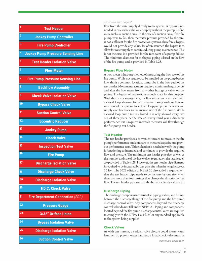
Test Header
Jockey Pump Controller
Fire Pump Controller
Jockey Pump Pressure Sensing Line
Test Header Isolation Valve
Check Valve Isolation Valve
Bypass Check Valve
Suction Control Valve
Eccentric Reducer
Backflow Assembly
Fire Pump Pressure Sensing Line
Flow Meter
Jockey Pump
Fire Pump
Discharge Isolation Valve
Inspection Test Valve
Check Valve
Discharge Check Valve
Discharge Isolation Valve
F.D.C. Check Valve
Fire Department Connection (FDC)
Pressure Guage
3/32” Oriface Union
Bypass Isolation Valve
Discharge Isolation Valve
Suction Control Valve
installed in the discharge side of the fi re pump. If water hammer or a pressure surge from the discharge side of the system were to occur, it can create a reverse fl ow in the fi re pump impeller and damage to the fi re pump. In systems with considerable fl ow, it may be warranted to install a listed anti-water-hammer backfl ow preventor. If a backfl ow preventor is installed on the discharge of the fi re pump, no check valve is needed.
Discharge Isolation ValveLike the suction portion of the fi re pump assembly, the discharge side also requires an isolation valve. However, in this case, since there is no concern of turbulence, the discharge isolation valve is not required to be an OS&Y valve. While an OS&Y valve is allowed on the discharge side, any listed gate or butterfl y valve is acceptable.
Discharge Pipe Sizing Like the suction pipe and other pump components, the sizing for the discharge portion of the fi re pump assembly can be found in Table 4.28. While suction pipe size is based on a maximum fl ow velocity of 15 feet per second, discharge pipe size is based on a maximum velocity of 20 feet per second when the pump is fl ow-ing 150% of the rated fl ow. For this reason, you may fi nd some instances where the discharge piping is smaller than the suction piping.
Pressure Maintenance Pump (Jockey Pump)A pressure maintenance pump, commonly called a jockey pump, is not directly required by NFPA 20. However, the standard does provide criteria for when they are provided. The intent of a jockey pump is to maintain a minimum pressure in the system piping and to prevent the fi re pump from starting unless there is a signifi cant fl ow of water. While systems are hydrostatically tested, they may lose pressure over time. Without the jockey pump maintaining the system pressure, the fi re pump could start when not required. Section 4.27.2.1 simply states the jockey pump shall be sized to replenish the fi re protection system pressure due to allowable leak-age and normal changes in pressure. It does not provide specifi c required jockey pump sizes. A general rule of thumb is the jockey pump should be rated at one percent (gpm) of the fi re pump rated fl ow and 10 psi higher than the fi re pumps pressure rating. Since jockey pumps are not specifi cally required and typically not considered a critical portion of the system, they are only required to be approved and are not required to be listed.
The jockey pump suction pipe is connected to the suction side of the fi re pump. Like the fi re pump suction pipe, it needs to be equipped with an isolation valve. This valve should meet the same requirements as the suction pipe of the fi re pump. The same criteria for the jockey pump discharge pipe also applies. This includes the required discharge check valve and isolation valve. The jockey pump discharge pipe connects to the discharge side of the fi re pump.
Pressure Sensing Lines Each pump (fi re pump and jockey pump) requires dedicated pressure sensing pipe. The pressure sensing pipe connects to the pump discharge piping to the pump controller. The controllers will monitor the system pressure and activate the pump upon pressure drop at the set start pressure. The pressure sensing pipe is required to be connected to the system on the discharge side of the pump it controls between the discharge check valve and the discharge control valve.
One unique aspect of the pressure sensing piping is that they are not meant for fl ow. As their name implies, they are only used to sense pressure changes. Pressure surges when the pump starts could damage the controllers. For this reason, devices need to be provided to allow the controller to monitor pressure changes and at the same time protect the controllers from sudden pressure surges. One option is to provide a diaphragm fi tting with a 3/32-inch orifi ce. In cases where the water supply is not “clean”, which could block the orifi ce, such as a raw water source, there is an option to provide two check valves, spaced fi ve feet apart, both with 3/32-inch holes drilled in the check valve clappers. These small orifi ces will limit the fl ow in the line, protecting the controller from sudden pressure increases while still allowing the controller to monitor the pressure in that line. An inspection test valve is required at each end of the pressure sensing line consisting of a tee, a valve and second tee with a one plugged outlet.
While this article is by no means a complete list of fi re pump requirements, the intent is to identify the basic components and shed light on the reasons why each piece is an important part of fi re pump systems. Future content will continue to focus on fi re pumps and their applications including fi re pump sizing, fi re pumps application for high-rise buildings, and fi re pumps with multiple water supplies.•
14 | National Fire Sprinkler Magazine
continued from page 13
Did you know NFSA's LinkedIn Group has more than 10,500 members? It's a great place to showcase your products and services.
Search "National Fire Sprinkler Association"in "groups" and join today!
Did you know NFSA's LinkedIn Group has more than 10,500 members? It's a great place to showcase your products and services.
Search "National Fire Sprinkler Association"in "groups" and join today!
Editor - Roland Asp, CET
#482
02/22/2022
This edition of Technotes was written by Jeff Dunkel, P.E., Fire Protection Engineer at the National
Fire Sprinkler Association.
Once it has been determined that a fire pump is needed to support a fire sprinkler or standpipe
system, it can often be challenging to “thread the needle” to properly size the fire pump without
exceeding the pressure limitations of the system components and doing so in a cost-effective
manner. This edition of TechNotes is intended to assist a designer with little to no fire pump design
experience learn the basics to sizing a fire pump. To start this process, we will begin by defining
some basic parameters of fire pump performance criteria. This review will focus primarily on
centrifugal fire pumps, however much of these requirements will apply to other types of fire pumps as
well. All references to NFPA 20 will be for the 2022 edition.
Rated Fire Pump Capacity
The term fire pump capacity refers to the rated flow of the fire pump or the Gallons Per Minute (GPM)
at which the fire pump is rated for. NFPA 20 dictates specific pump flow ratings ranging from 25 gpm
to 5,000 gpm listed in Table 4.10.2, pumps larger than 5,000 gpm are allowed however they must be
reviewed and approved by the Authority Having Jurisdiction or a Listing Laboratory. The rated
capacity is primarily used as reference point, a fire pumps rated capacity is not the only single flow
that pump is permitted to operate at, in fact a fire pump can support flows up to 150 percent of its
rated capacity. For example, a fire pump rated for 500 gpm can support system flows up to 750 gpm
and a fire pump rated for 1,000 gpm can support system flows up to 1,500 gpm. It is best practice
however to select a pump so that the system demand falls between 90 percent and 140 percent of
the rated capacity.
Rated Fire Pump Pressure
One often misunderstood aspect of pumps is that fire pumps do not create flow, if the water supply
does not have the capacity to supply the required flow a fire pump will provide no value. A fire pump
can only increase the pressure of the water supply. The rated pressure as defined by NFPA 20 as the
net pressure (differential pressure) at rated flow and rated speed as marked on the manufacturer
nameplate. Each fire pump will have a pressure at a rated flow, like the rated flow the rated pressure
is also used a reference point. The pressure of a fire pump is directly related to the flow of the fire
pump, as flow increases the pressure decreases, and as flow decreases the pressure increases.
While the pump pressure is a function of flow NFPA 20 does dictate some limitations on the pressure
output.
Maximum Churn Pressure
The fire pump pressure at no flow, often referred to shutoff or churn, cannot exceed 140 percent of
the rated fire pump pressure. For example, a fire pump rated for 130 psi at 500 gpm cannot exceed
182 psi when no water is flowing, this is the maximum pressure the fire pump is allowed to put out.
While the limit for all pumps is 140 percent of the rated pressure at churn the limit for centrifugal fire
pump was 120 percent at one point in history, for this reason you will find that most centrifugal fire
pumps available today still will not exceed 120 percent of the rated pressure at churn.
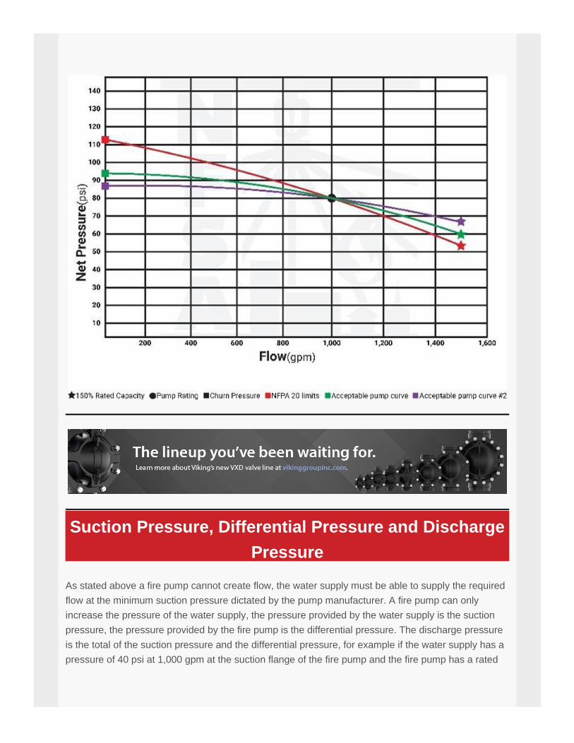
Minimum Fire Pump Pressure
In addition to limiting the churn pressure, NFPA 20 dictates the minimum pressure permitted from a
fire pump. Per NFPA 20 Section 6.2.1 pumps shall furnish not less than 150 percent of the rated
capacity at not less than 65 percent of the total rated head. This means at 150 percent of the fire
pumps rated flow the pressure must be at least 65 percent of the rated pressure. For example, a
pump rated for 130 psi at 500 gpm must be capable of producing a minimum of 84.5 psi at 750 gpm.
The pressure limitations are illustrated in the figure in this article.
Suction Pressure, Differential Pressure and Discharge
Pressure
As stated above a fire pump cannot create flow, the water supply must be able to supply the required
flow at the minimum suction pressure dictated by the pump manufacturer. A fire pump can only
increase the pressure of the water supply, the pressure provided by the water supply is the suction
pressure, the pressure provided by the fire pump is the differential pressure. The discharge pressure
is the total of the suction pressure and the differential pressure, for example if the water supply has a
pressure of 40 psi at 1,000 gpm at the suction flange of the fire pump and the fire pump has a rated
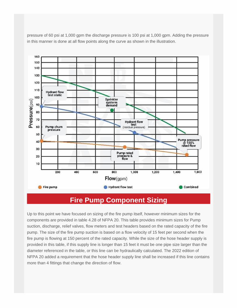
pressure of 60 psi at 1,000 gpm the discharge pressure is 100 psi at 1,000 gpm. Adding the pressure
in this manner is done at all flow points along the curve as shown in the illustration.
Fire Pump Component Sizing
Up to this point we have focused on sizing of the fire pump itself, however minimum sizes for the
components are provided in table 4.28 of NFPA 20. This table provides minimum sizes for Pump
suction, discharge, relief valves, flow meters and test headers based on the rated capacity of the fire
pump. The size of the fire pump suction is based on a flow velocity of 15 feet per second when the
fire pump is flowing at 150 percent of the rated capacity. While the size of the hose header supply is
provided in this table, if this supply line is longer than 15 feet it must be one pipe size larger than the
diameter referenced in the table, or this line can be hydraulically calculated. The 2022 edition of
NFPA 20 added a requirement that the hose header supply line shall be increased if this line contains
more than 4 fittings that change the direction of flow.
Threading the Needle
Choosing a fire pump that can adequately boost the supply pressure sufficiently to meet the needs of
the fire suppression system demand is only half the battle. There will always be a limit to the pressure
that fire suppression system can sustain. While high pressure fittings are available, 175 psi is the
most common maximum pressure rating for components on a fire suppression system, at times a
maximum pressure of 175 psi cannot be avoided. For example, ESFR sprinklers are only available
with a maximum pressure rating of 175 psi. The fire pump must not only sufficiently boost the
pressure to meet the demand, the churn pressure plus the static pressure of the water supply must
not exceed the maximum pressure rating of the system components. Depending on the situation this
can be challenging, some supplies are inadequate due to a steep curve, meaning the static pressure
is high and the residual pressure is low. With a combination of a steep supply curve and a high
demand from the suppression system it may not always be possible to use a standard, constant
speed fire pump.
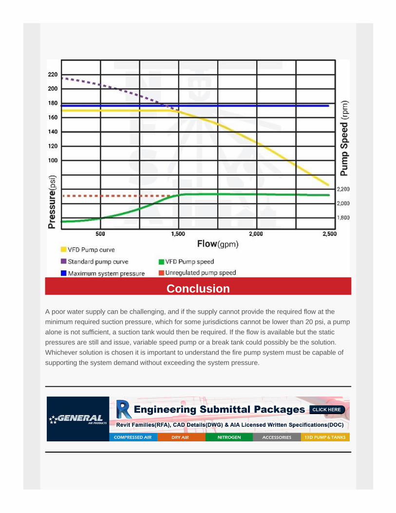
When a constant speed fire pump is not an option it may be possible to use a variable speed fire
pump. A variable speed fire pump adjusts the pump speed to reduce the pressures at lower flows,
providing a “flatter” curve and allow the use of a larger pump without the high static pressure. A
variable speed fire pump does have down sides, one of which is the size. For electric variable speed
fire pumps the controller must be equipped with a variable frequency drive (VFD), which can be very
larger. Along with a larger footprint variable speed fire pumps come with a considerably larger price
tag. A diesel variable speed pump has less of an impact on both size and price. A diesel pump
adjusts the speed by using a pressure limiting device (PLD), which does impact cost, but not to the
same degree as a VFD.
Conclusion
A poor water supply can be challenging, and if the supply cannot provide the required flow at the
minimum required suction pressure, which for some jurisdictions cannot be lower than 20 psi, a pump
alone is not sufficient, a suction tank would then be required. If the flow is available but the static
pressures are still and issue, variable speed pump or a break tank could possibly be the solution.
Whichever solution is chosen it is important to understand the fire pump system must be capable of
supporting the system demand without exceeding the system pressure.

Learning and Development
Layout Technician Training
The purpose of the layout technician course is to take a person with basic knowledge of math,
physical science and drafting skills and teach them to be productive basic sprinkler layout and
detailing technicians. All of the work elements necessary for NICET Level II Certification will be
covered by the course including sprinkler selection, sprinkler spacing and location, obstructions to
sprinklers, water supplies (public mains, tanks and pumps), hydraulic calculation of sprinkler systems,
and standpipe system layout and calculation.
Layout Technician Training
Virtual Training Class
March 22nd - April 14th, 2022
Registration ends March 4th, 2022
Layout Technician Blended Learning
Virtual Practicum
Last chance to complete the blended learning
LTTC!
(Seriously)
April 6th - 14th, 2022
Registration ends March 18th, 2022
Register Here
Register Here
National Fire Sprinkler Association
514 Progress Dr, Ste A,
Linthicum Heights, MD 21090
1-800-683-NFSA (6372)
Unsubscribe