Embed Size (px)
Citation preview
Feature Overview and Configuration Guide
Technical Guide
Firewall and Network Address Translation
IntroductionThis guide describes the firewall and NAT features on the Allied Telesis UTM Firewalls and Secure
VPN Routers (AR-Series firewalls) and how to configure them.
The firewall feature on the AR-Series firewalls offers security, flexibility and ease of use. Unlike a
traditional firewall, they will keep pace with rapid changes in Internet-based applications, enabling
enterprises to see the benefits of web-based technology without costly security issues.
The AR-Series firewalls also supports Network Address Translation (NAT), allowing a single device to
act as an agent between the public Internet and a local private network. With NAT, private (RFC1918)
IPv4 addresses can be configured on devices located on the private side of the firewall. When those
devices send traffic to the Internet, the firewall translates the private addresses to become one or
more publicly-valid addresses. When the firewall receives traffic that is destined for those devices, it
translates the public address back to the appropriate private address.
This document gives an overview of the firewall and NAT on AR-Series firewalls, followed by
examples illustrating how to configure them in various network situations.
x alliedtelesis.comC613-22012-00 REV H
ContentsIntroduction .........................................................................................................................................1
Products and software version that apply to this guide ...............................................................3
Related documents.......................................................................................................................4
Advanced Feature Licences .........................................................................................................4
The Firewall .........................................................................................................................................4
Firewall GUI .........................................................................................................................................6
Accessing the Firewall GUI ...........................................................................................................6
HTTP and HTTPS GUI listen ports................................................................................................7
Applications.........................................................................................................................................8
Application Layer Gateways (ALG)......................................................................................................8
Entities.................................................................................................................................................9
Default Flow with Firewall Enabled....................................................................................................10
Firewall Filtering and Logging ...........................................................................................................11
Default filtering behaviour ...........................................................................................................12
Connection tracking of permitted packets .................................................................................12
Configurable TCP established session timeout..........................................................................13
Flood protection filtering.............................................................................................................13
Default deny................................................................................................................................14
Logging for user-configured rules...............................................................................................14
Firewall log messages.................................................................................................................14
Firewall connection logging ........................................................................................................15
Network Address Translation (NAT)...................................................................................................17
Configuring Firewall and NAT Rules for Entities................................................................................19
Firewall with Dynamic IP Addressing ................................................................................................23
Configuring Firewall Rules with Update Manager .............................................................................23
Configuring Firewall Rules with Subscription Licensing ...................................................................25
Firewall with High Availability ............................................................................................................26
Configuring NAT Loopback with DMZ...............................................................................................26
Static ENAT rule ..........................................................................................................................29
Dynamic ENAT rule .....................................................................................................................29
Configuring Static NAT with Proxy ARP ............................................................................................30
Source-based NAT with Secondary IP Addresses ............................................................................31
Configuring Access to Multiple Internal Servers via PPPoE WAN ....................................................33
Server access with external DNS ...............................................................................................34
Server access with internal DNS ................................................................................................39
Introduction | Page 2
Diagnostics .................................................................................................................................41
Configuring Subnet-based NAT ........................................................................................................42
Allowing Partial Sessions through a Firewall .....................................................................................46
Products and software version that apply to this guide
This Guide applies to the AR-Series firewalls running AlliedWare Plus version 5.4.5 or later:
AR4050S UTM Firewall
AR3050S UTM Firewall
AR2050V Secure VPN Router
AR2010V Secure VPN Router
Most features described in this document are supported from AlliedWare Plus 5.4.5 or later.
This feature is supported in 5.4.8-0.x or later:
New firewall rule needed to allow TCP Update Manager packets through firewall with DPI and
provider procera configured.
This feature is supported in 5.4.7-2.4 or later:
Configurable HTTP and HTTPS ports
These features are supported in 5.4.7-1.x or later:
Firewall connection logging
Configurable TCP established session timeout
These features are available in version 5.4.7-0.1 or later:
Subnet-based NAT
Source and destination NAT
Allowing partial sessions through a firewall (no state enforcement)
This feature is available in version 5.4.6-2.1 or later:
Firewall with High Availability (VRRP)
Introduction | Page 3
Related documents
The following documents provide information about related features on AlliedWare Plus products:
Getting Started with the UTM Firewall GUI Feature Overview Guide
Getting Started with the VPN Firewall GUI Feature Overview Guide
Application Awareness Feature Overview and Configuration Guide
The product’s Datasheet
The product’s Command Reference
These documents are available from the links above or on our website at alliedtelesis.com
Advanced Feature Licences
Flexible subscription licensing options make it easy to choose the right combination of security
features to best meet your business needs. The Advanced Firewall license includes Application
Control, Web Control and URL Filtering. The Advanced Threat Protection (ATP) license includes IP
Reputation, stream-based Malware Protection and (on the AR4050S only) proxy-based Antivirus.
The FirewallA firewall, at its most basic level, controls traffic flow between a trusted network (such as a
corporate LAN) and an untrusted or public network (such as the Internet). The most commonly
deployed firewalls nowadays are port-based or packet filtering. These traditional firewalls determine
the allowed traffic versus the disallowed traffic based on many characteristics of the packets,
including their destination and source IP addresses and TCP/UDP port numbers. However,
traditional network security solutions have failed to keep pace with changes to applications, threats,
and the network landscape.
AR-Series firewalls are designed for the challenges facing modern networks. In contrast to
traditional firewalls that lack the intelligence to discern network traffic in a world where network
boundaries are disintegrating and Internet applications are exploding, AR-Series firewalls no longer
talk about packets, IP addresses and ports. Instead they focus on applications, users and content. It
classifies traffic by the application’s identity in order to enable visibility and control of all types of
application.
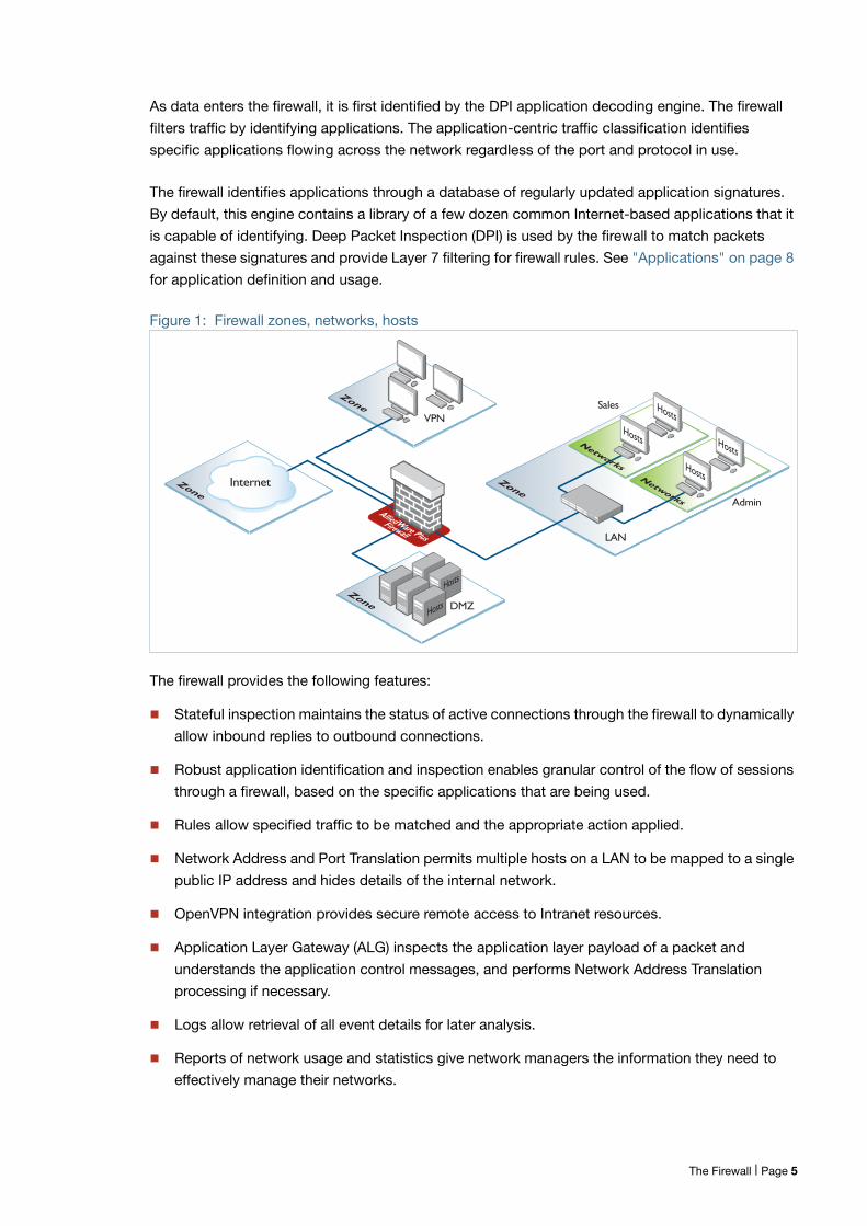
The AR-Series firewalls view the physical network in terms of zones, networks and hosts. Firewall
rules can be applied to any level of this hierarchy, as shown in Figure 1 on page 5. See "Entities" on
page 9 for entity definitions and usage.
When the firewall is enabled, its default policy is to drop all applications from anywhere to anywhere.
If no rule is explicitly configured, all traffic moving through the firewall is blocked.
The Firewall | Page 4
As data enters the firewall, it is first identified by the DPI application decoding engine. The firewall
filters traffic by identifying applications. The application-centric traffic classification identifies
specific applications flowing across the network regardless of the port and protocol in use.
The firewall identifies applications through a database of regularly updated application signatures.
By default, this engine contains a library of a few dozen common Internet-based applications that it
is capable of identifying. Deep Packet Inspection (DPI) is used by the firewall to match packets
against these signatures and provide Layer 7 filtering for firewall rules. See "Applications" on page 8
for application definition and usage.
Figure 1: Firewall zones, networks, hosts
The firewall provides the following features:
Stateful inspection maintains the status of active connections through the firewall to dynamically
allow inbound replies to outbound connections.
Robust application identification and inspection enables granular control of the flow of sessions
through a firewall, based on the specific applications that are being used.
Rules allow specified traffic to be matched and the appropriate action applied.
Network Address and Port Translation permits multiple hosts on a LAN to be mapped to a single
public IP address and hides details of the internal network.
OpenVPN integration provides secure remote access to Intranet resources.
Application Layer Gateway (ALG) inspects the application layer payload of a packet and
understands the application control messages, and performs Network Address Translation
processing if necessary.
Logs allow retrieval of all event details for later analysis.
Reports of network usage and statistics give network managers the information they need to
effectively manage their networks.
Internet
VPN
DMZ
LAN
Networks
Zone
Zone
Zone
Hosts
Firewall
AlliedWare Plus
Sales
Admin
Hosts
Hosts
Hosts
ZoneNetworks
Hosts
Hosts
The Firewall | Page 5
Firewall GUIIf you want to you can use the Firewall GUI to monitor and configure your firewall.
The firewall GUI provides setup of the firewall, enabling the configuration of entities (zones, networks
and hosts) and then creating firewall, NAT and traffic-control rules for managing traffic between
these entities. Features such as the Intrusion Prevention System (IPS) and URL Filtering help protect
the network, and manage website access.
The GUI also supports a DHCP server, interface management, VLAN management, system tools, a
CLI window and a dashboard for network monitoring. The dashboard shows interface and firewall
traffic, system and environmental information, and the security monitoring widget lets you view and
manage rules and security features.
Accessing the Firewall GUI
If your AR-Series firewall came with the GUI pre-installed, perform the following steps to browse to
the GUI:
1. Connect to any of the LAN switch ports
2. Open a web browser and browse to https://192.168.1.1. This is the pre-configured IP address ofVLAN1. The default username is manager and the default password is friend.
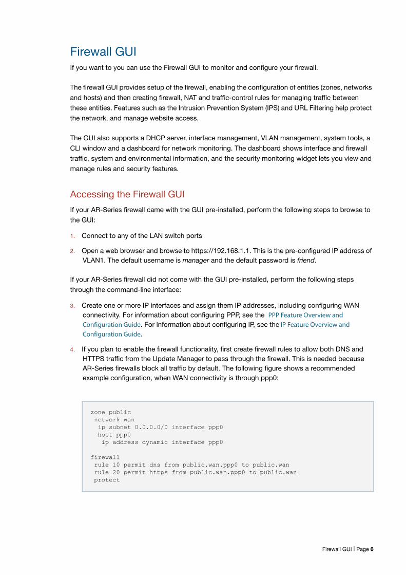
If your AR-Series firewall did not come with the GUI pre-installed, perform the following steps
through the command-line interface:
3. Create one or more IP interfaces and assign them IP addresses, including configuring WANconnectivity. For information about configuring PPP, see the PPP Feature Overview and Configuration Guide. For information about configuring IP, see the IP Feature Overview and Configuration Guide.
4. If you plan to enable the firewall functionality, first create firewall rules to allow both DNS andHTTPS traffic from the Update Manager to pass through the firewall. This is needed becauseAR-Series firewalls block all traffic by default. The following figure shows a recommendedexample configuration, when WAN connectivity is through ppp0:
zone public network wan ip subnet 0.0.0.0/0 interface ppp0 host ppp0 ip address dynamic interface ppp0
firewall rule 10 permit dns from public.wan.ppp0 to public.wan rule 20 permit https from public.wan.ppp0 to public.wan protect
Firewall GUI | Page 6
5. Use the following command to download and install the GUI:
awplus# update webgui now6. Enable the HTTP service:
awplus# configure terminalawplus(config)# service http
7. Log into the GUI.
Start a browser and browse to the firewall’s IP address, using HTTPS. You can access the GUIvia any reachable IP address on any interface.
The GUI starts up and displays a login screen. Log in with your username and password.
HTTP and HTTPS GUI listen ports
By default, the Firewall GUI uses the HTTP server listen port 80. The default HTTPS server listen port
is 443. You can change the HTTPS port. From AlliedWare Plus version 5.4.7-2.4 you can also
change the HTTP port, and disable listening on either the HTTP or HTTPS port.
This allows you to remap the GUI to use other ports and allow traffic using these HTTP (80) and
HTTPS (443) ports to be forwarded through the device to another server, if required, instead of being
terminated on the device. You may wish to change the HTTP port if port 80 needs to be used by
another service at the same IP address in your network.
To change or disable the HTTP listen port, use the command:
awplus(config)# http port {<1-65535>|none}
To restore the HTTP port to its default (port 80), use the command:
awplus(config)# no http port <1-65535>
To change or disable the HTTPS listen port, use the command:
awplus(config)# http secure-port {<1-65535>|none}
Setting the port to none disables HTTP or HTTPS management.
Note that changing or disabling the HTTPS trusted port is not supported when using Vista Manager.
If you are using Vista Manager EX and need to change the HTTPS trusted port, you must use
certificate-based authorization in Vista Manager EX. See the ‘Vista Manager EX Installation and User
Guide’ for instructions.
To restore the HTTPS port to its default (port 443), use the command:
awplus(config)# no http secure-port
To check the settings for the HTTP and HTTPS (secure) ports, use the command:
awplus# show http
Firewall GUI | Page 7
ApplicationsAn application is a high level abstraction for the classification of packets being transported by
network traffic. Traffic matching for applications can be achieved using several techniques, for
example, matching packets to port numbers or searching for application signatures in flows of
packets. The device recognizes the following kinds of applications:
You can configure source port, destination port, protocol, ICMP code and ICMP type for the
application. An application is invalid if its protocol, source or destination are not properly
configured, for example, if an application has no protocol configured, or source and destination
ports are applied to protocols that are not TCP, UDP or SCTP.
By default, there are a number of predefined applications with protocols, source and destinations
ports.
There is an built-in library of many more applications that can be identified in traffic if Deep Packet
Inspection (DPI) is enabled.
The extensive up-to-date library of applications maintained by Procera is available by
subscription. With DPI enabled, the device recognises these applications.
You can use the show application and show application detail commands to display the detail of
these applications.
If applications have the same name, precedence in all application-aware features is:
1. user-configured applications
2. applications identified by DPI
3. built-in predefined list
For information about applications and application awareness, see the Application Awareness
Feature Overview and Configuration Guide.
Application Layer Gateways (ALG)To determine the protocol associated with a given packet, the firewall typically looks at the IP
protocol number and/or the source and destination TCP/UDP port numbers. This works well for
most protocols. However, there are some protocols which use different port/IP protocol numbers at
different points during communication. An example of this is FTP, which uses the well-known port 21
for negotiation but either uses the well-known port 20 or ephemeral ports for the associated data
transfer.
The Application Layer Gateway (ALG) identifies data streams associated with these protocols to be
processed correctly by the firewall.
Applications | Page 8
The following protocols are supported by the ALG and are included in the default (predefined)
application list:
FTP
IRC
PPTP
The following protocols are supported by the ALG but are not included in the default application list:
SNMP, GRE, SCTP, TFTP, H323 and SIP.
The protocols not included on the default application list require that a custom application be
created for them (application command and associated commands, see step 4 in "Configuring
Firewall and NAT Rules for Entities" on page 19.)
Alternatively, with an Advanced Firewall subscription license, you can utilize the Application Control
feature which adds automatic support for thousands of applications to the application list.
EntitiesAllied Telesis UTM Firewalls and Secure VPN Routers support application and entity-based security
policies. For example, firewall and Network Address Translation (NAT) rules are applied to
applications among different zone entities.
An entity is a high level abstraction of an individual network device, an individual network, or a group
of networks or subnets. It is the instance that firewall and NAT policies can be applied to. There are
three types of entity:
Zone
Network
Host
Zone is a high level abstraction for a logical grouping or segmentation of physical networks. This is
the highest level of partitioning that firewall and NAT policy can be applied to. Zone establishes the
security border of your networks. A zone defines a boundary where traffic is subjected to policy
restrictions as it crosses to another region of your networks. The minimum zones normally
implemented would be a trusted zone for the private network behind the firewall and a untrusted
zone for the Internet. Other common zones are a Demilitarized Zone (DMZ) for publicly visible web
servers and a Virtual Private Network (VPN) zone for remote access users or tunnels to other
networks.
A network is a high level abstraction of a logical network in a zone. This consists of the IP subnets
and interfaces over which it is reachable. Subnets are grouped into networks to apply a common set
of rules among the subnets.
Entities | Page 9
Host is a high level abstraction of a single node in a network. This is commonly used if a particular
device, for example a server, has a static IP address that needs to be specified in a firewall policy.
In addition to supporting network address translation for TCP and UDP traffic, AR-Series firewalls
also support VPN pass-through. Network services that use the following protocols can traverse a
NAT device.
ESP (Encapsulation Security Payload)
PPTP (Point to Point Tunneling Protocol)
L2TP (Layer 2 Tunneling Protocol)
GRE (Generic Routing Encapsulation)
Default Flow with Firewall EnabledThe following section describes the default behaviors for various layer 2 and layer 3 data-plane and
control-plane protocols.
If the firewall is enabled by the protect command, a default deny policy drops all traffic that does
not match configured rules that is being processed via the firewall software.
L3 dataplane
All Layer 3 IP data plane messages are subject to AR-Series firewall screening, so if the firewall is
enabled and there are no firewall permit rules explicitly configured to allow the associated
applications, Layer 3 data plane messages are dropped. This includes protocols like ICMP, general
customer TCP, UDP and multicast network traffic.
L3 controlplane
By default, the AR-Series firewall blocks both reception and transmission of Layer 3 control plane
messages (L3CP) if corresponding firewall rules are not configured.This also include remote
management protocols like SSH and Telnet.
For IPv6 and IPv4 routing protocols to operate to allow transmission and reception via the reserved
multicast address range, corresponding firewall permit rules must be configured. This applies to
routing protocols such as PIM, BGP, OSPF, OSPFv3, RIP and RIPng.
L2 controlplane
However, Layer 2 control plane (L2CP) protocols (embedded within Ethernet frames) are processed
shortly after ingress, before being processed by the firewall, so associated firewall permit rules are
not required.
These L2CP frames include all of IEEE Std 802.1D and IEEE Std 802.1Q Reserved Addresses used
by LACP, STP, LLDP, and 802.1x MAC control. To remain IEEE802.1 compliant, they do not typically
ingress one interface and egress another. These protocols operate independently of the firewall—
they continue to be transmitted and received whether or not the firewall is enabled unless the Layer
2 feature is explicitly disabled in the device configuration. The individual features themselves are,
however, designed to detect and drop malformed control plane messages which might be used to
form some kind of DOS attack, so there is still some inherent protection provided.
Default Flow with Firewall Enabled | Page 10
AMFmessages
AMF messages are a special case, and the AR-Series firewall treats them as Layer 2 control plane
messages processed independently of the firewall. AMF virtual link messages are however
transported as IP UDP packets, so corresponding allow rules must be configured.
IPv4 ARPand IPv6
ND
With the firewall enabled, IPv4 ARP and IPv6 RA, RS, NA, and NS are all permitted without the need
to configure firewall rules.
VRRPmessages
From AlliedWare 5.4.6-2.x, VRRP behavior is under firewall control. High Availability uses VRRP. If
High Availability is used, then firewall permit rules must be configured to allow VRRP multicast
messages to be received. VRRP messages are still transmitted from the firewall without a
corresponding firewall permit rule, but the incoming VRRP control plane IPv4/IPv6 messages will be
blocked by the firewall before being processed by VRRP feature.
In AlliedWare Plus versions 5.4.6-1.x and earlier, incoming and outgoing VRRP messages bypass
the firewall, so no corresponding firewall permit rules are required.
L2 bridgedtraffic
Additionally, Layer2 bridged Ethernet frames (bridged from one interface to another) are also not
subject to the firewall application rules, so they will continue to flow unimpeded if the firewall is
enabled. The bridge itself does, however, inspect the embedded IP data fields contained in the
Layer 2 Ethernet frames, and so will also drop malformed packets if the encapsulated data is
corrupt.
Firewall Filtering and LoggingThis section describes the filtering and logging performed when the firewall feature on an AR-Series
firewall is enabled. A firewall rule specifies the action (Table 1) to take for traffic that matches other
parameters in the rule.
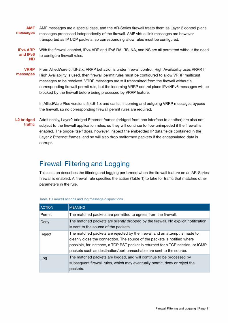
Table 1: Firewall actions and log message dispositions
ACTION MEANING
Permit The matched packets are permitted to egress from the firewall.
Deny The matched packets are silently dropped by the firewall. No explicit notification
is sent to the source of the packets
Reject The matched packets are rejected by the firewall and an attempt is made to
cleanly close the connection. The source of the packets is notified where
possible, for instance, a TCP RST packet is returned for a TCP session, or ICMP
packets such as destination/port unreachable are sent to the source.
Log The matched packets are logged, and will continue to be processed by
subsequent firewall rules, which may eventually permit, deny or reject the
packets.
Firewall Filtering and Logging | Page 11
Default filtering behaviour
When enabled, the firewall has some default attack protection and filtering rules installed that are
not configurable by the user. When packets are dropped by these default filters, log messages are
generated to record the reason for the drop. In order to prevent the device from being overloaded by
generating log messages in response to an attack, the generation of logs is rate-limited, depending
on the reason for the packet being dropped.
Smurf attack protection
The firewall has smurf attack protection enabled by default, and it cannot be disabled. A smurf
attack is an ICMP ping that is sent with a broadcast IP address as the destination IP address. The
firewall will silently discard all pings that are directed at the broadcast address and will not log the
packet.
Invalid TCP flags
The firewall, when enabled, protects against TCP packets with illegal flag combinations set. When
dropping these illegal packets, the firewall will generate at most one log message per second
regardless of the number of packets dropped by the rule. The logs generated for these illegal TCP
flag combinations will begin with the prefix:
Firewall: DENY probe <illegal-flags>
followed by the packet data.
The firewall will also drop new TCP connections that have not been properly started with a SYN flag
set. The prefix for these log messages is
Firewall: DENY no SYN
with a maximum logging rate of one per second.
Connection tracking of permitted packets
The firewall performs stateful packet inspection as part of its general filtering process. TCP, UDP or
ICMP packets that successfully match a PERMIT rule and are identified as matching an existing
ESTABLISHED connection or are part of a NEW connection are subjected to flood protection
filtering (see "Flood protection filtering" on page 13). If the permitted packets cannot be correctly
matched to an existing connection, are not related to an existing connection, are invalid for starting
a new connection, or invalid for another reason, the packets are considered to be invalid and will be
dropped. Dropped invalid packets will produce a log with the prefix:
Firewall: DENY INVALID
at a maximum rate of one log message per second.
Some criteria for packets to be considered invalid are:
The total maximum number of connections has been exceeded. The maximum for each
AR-Series firewall model is 100 000 connections.
Packet is short/truncated/malformed or has a bad checksum.
Firewall Filtering and Logging | Page 12
For TCP packets:
The sequence number is not as expected; for instance, an ACK is received for data that hasnot yet been transmitted.
The connection tracking has become out of sync with the actions of the client and server;marking the packets as invalid and dropping will force the client to initiate a new connection.
Configurable TCP established session timeout
By default, when a TCP session is successfully established through the AR-Series firewall, when the
session goes idle it automatically times out of the firewall connection tracking table after 3600
seconds. In some situations it may be beneficial to time out unused established TCP sessions
earlier.
For example, in a busy environment where there is an excessive number of sessions being
established, the firewall connection tracking table could become oversubscribed, with new
connections being blocked until older sessions are timed out.
From release 5.4.7-1.x onwards, the following command is available to set a non-default TCP
session timeout for established idle sessions:
ip tcp timeout established <1-31536000>
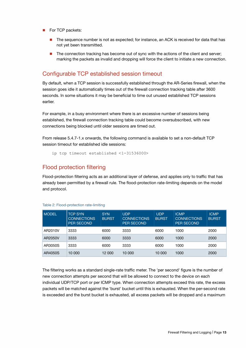
Flood protection filtering
Flood-protection filtering acts as an additional layer of defense, and applies only to traffic that has
already been permitted by a firewall rule. The flood-protection rate-limiting depends on the model
and protocol.
The filtering works as a standard single-rate traffic meter. The 'per second' figure is the number of
new connection attempts per second that will be allowed to connect to the device on each
individual UDP/TCP port or per ICMP type. When connection attempts exceed this rate, the excess
packets will be matched against the 'burst' bucket until this is exhausted. When the per-second rate
is exceeded and the burst bucket is exhausted, all excess packets will be dropped and a maximum
Table 2: Flood-protection rate-limiting
MODEL TCP SYNCONNECTIONSPER SECOND
SYNBURST
UDPCONNECTIONSPER SECOND
UDPBURST
ICMPCONNECTIONSPER SECOND
ICMPBURST
AR2010V 3333 6000 3333 6000 1000 2000
AR2050V 3333 6000 3333 6000 1000 2000
AR3050S 3333 6000 3333 6000 1000 2000
AR4050S 10 000 12 000 10 000 10 000 1000 2000
Firewall Filtering and Logging | Page 13
of one log message per second will be generated regardless of the number of packets dropped.
Logs generated when packets have been dropped by this process will be prefixed with one of:
DENY UDPLIMIT reach.
DENY SYNLIMIT reach.
DENY ICMPLIMIT reach.
for UDP, TCP or ICMP packets respectively.
Default deny
If a packet is processed by the firewall and does not match any of the permit, deny or reject action
rules, it will hit the final default deny rule, and produce a log with the prefix:
Firewall: DENY in policy
to a maximum rate of 20 log messages per second.
Logging for user-configured rules
There are two ways to log firewall events. The first is to configure the rule with the terminating log
parameter. When packets are logged in this way, the action (deny, permit, or reject) is applied and a
log message is also generated each time the rule is hit. The disposition for these log messages is
‘PERMIT’, ‘DENY’ or ‘REJECT’ according to the action of the rule.
The second way is to configure the firewall rule with log as the action. When packets are logged in
this way, they continue to be processed by subsequent firewall rules, which may eventually permit,
deny or reject the packets. The disposition for these log messages is ‘LOG’. Because this action
does not affect the traffic, it may be more useful for diagnostic purposes.
Note that it is possible to configure both methods in one rule, but this would result in duplicated log
messages.
Some log messages that should be generated when packets match these rules may be dropped by
the system under heavy traffic loads.
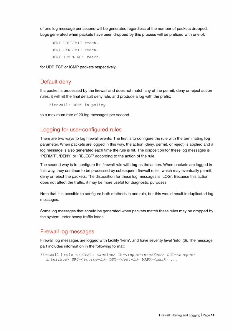
Firewall log messages
Firewall log messages are logged with facility ‘kern’, and have severity level ‘info’ (6). The message
part includes information in the following format:
Firewall [rule <rule>]: <action> IN=<input-interface> OUT=<output-interface> SRC=<source-ip> DST=<dest-ip> MARK=<mark> ...
Firewall Filtering and Logging | Page 14
Firewall connection logging
This feature is supported from AlliedWare Plus version 5.4.7-1.
Firewall connection logging can be enabled to provide additional logs that show the start and end of
connections passing through the firewall. These messages are assigned facility local5. They have
severity ‘info’ (6).
To enable logging of new connections, closed connections, or both passing through the firewall, use
the commands:
awplus# configure terminal
awplus(config)# connection-log events {new|end|all}
To show the configuration of firewall connection logging, use the following command:
awplus# show connection-log events
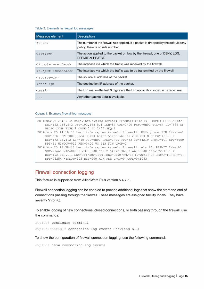
Table 3: Elements in firewall log messages
Message element Description
<rule> The number of the firewall rule applied. If a packet is dropped by the default denypolicy, there is no rule number.
<action> The action applied to the packet or flow by the firewall; one of DENY, LOG,PERMIT or REJECT.
<input-interface> The interface via which the traffic was received by the firewall.
<output-interface> The interface via which the traffic was to be transmitted by the firewall.
<source-ip> The source IP address of the packet.
<dest-ip> The destination IP address of the packet.
<mark> The DPI mark—the last 3 digits are the DPI application index in hexadecimal.
... Any other packet details available.
Output 1: Example firewall log messages
2016 Nov 28 23:26:34 kern.info awplus kernel: Firewall rule 10: PERMIT IN= OUT=eth0 SRC=192.168.5.2 DST=192.168.5.1 LEN=84 TOS=0x00 PREC=0x00 TTL=64 ID=7935 DF PROTO=ICMP TYPE=8 CODE=0 ID=2406 SEQ=1
2016 Nov 25 14:10:38 kern.info awplus kernel: Firewall: DENY probe FIN IN=vlan1 OUT=eth1 MAC=00:00:cd:38:00:bc:52:54:6b:6b:0f:1e:08:00 SRC=192.168.1.1 DST=172.16.1.2 LEN=40 TOS=0x00 PREC=0x00 TTL=63 ID=54219 PROTO=TCP SPT=6000 DPT=21 WINDOW=512 RES=0x00 UG PSH FIN URGP=0
2016 Nov 25 18:38:36 kern.info awplus kernel: Firewall rule 20: PERMIT IN=eth1 OUT=vlan1 MAC=00:00:cd:38:00:96:52:54:78:36:8f:a6:08:00 SRC=172.16.1.2 DST=192.168.1.1 LEN=239 TOS=0x00 PREC=0x00 TTL=63 ID=20563 DF PROTO=TCP SPT=80 DPT=46254 WINDOW=905 RES=000 ACK PSH URGP=0 MARK=0x1053
Firewall Filtering and Logging | Page 15
New connection log messages includes information in the following format for a newly started
firewall connection:
NEW proto={tcp|udp|icmp|...|<number>} orig_src={<ipv4-addr>|<ipv6-addr>} orig_dst={<ipv4-addr>|<ipv6-addr>} [orig_sport=<source-port>] [orig_dport=<dest-port>] reply_src={<ipv4-addr>|<ipv6-addr>} reply_dst={<ipv4-addr>|<ipv6-addr>} reply_sport=<source-port> reply_dport=<dest-port>
Closed connection log messages includes information in the following format for a firewall
connection that has ended:
END proto=[tcp|udp|icmp|...|<protocol-number>] orig_src={<ipv4-addr>|<ipv6-addr>} orig_dst={<ipv4-addr>|<ipv6-addr>} [orig_sport=<source-port>] [orig_dport=<dest-port>] orig_pkts=<packets> orig_bytes=<bytes> reply_src={<ipv4-addr>|<ipv6-addr>} reply_dst={<ipv4-addr>|<ipv6-addr>} reply_sport=<source-port> reply_dport=<dest-port> reply_pkts=<number> reply_bytes=<number>
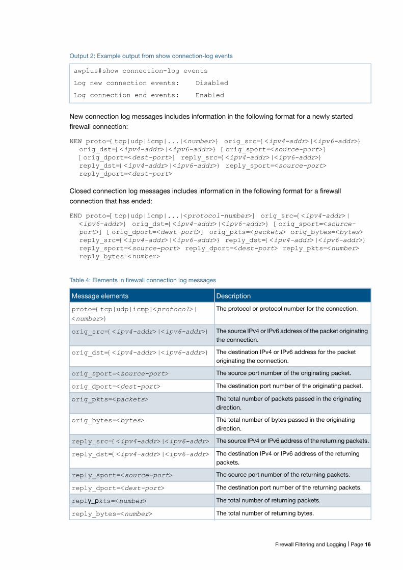
Output 2: Example output from show connection-log events
awplus#show connection-log events
Log new connection events: Disabled
Log connection end events: Enabled
Table 4: Elements in firewall connection log messages
Message elements Description
proto={tcp|udp|icmp|<protocol>|<number>}
The protocol or protocol number for the connection.
orig_src={<ipv4-addr>|<ipv6-addr>} The source IPv4 or IPv6 address of the packet originatingthe connection.
orig_dst={<ipv4-addr>|<ipv6-addr>} The destination IPv4 or IPv6 address for the packetoriginating the connection.
orig_sport=<source-port> The source port number of the originating packet.
orig_dport=<dest-port> The destination port number of the originating packet.
orig_pkts=<packets> The total number of packets passed in the originatingdirection.
orig_bytes=<bytes> The total number of bytes passed in the originatingdirection.
reply_src={<ipv4-addr>|<ipv6-addr> The source IPv4 or IPv6 address of the returning packets.
reply_dst={<ipv4-addr>|<ipv6-addr> The destination IPv4 or IPv6 address of the returningpackets.
reply_sport=<source-port> The source port number of the returning packets.
reply_dport=<dest-port> The destination port number of the returning packets.
reply_pkts=<number> The total number of returning packets.
reply_bytes=<number> The total number of returning bytes.
Firewall Filtering and Logging | Page 16
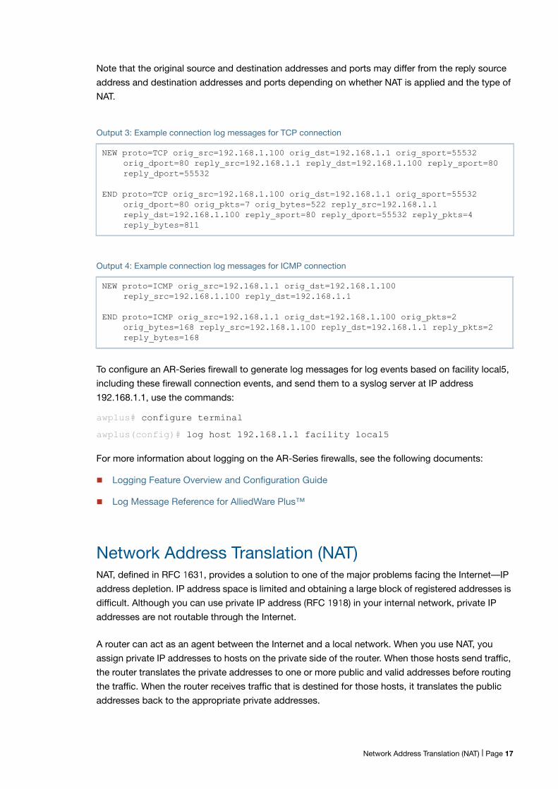
Note that the original source and destination addresses and ports may differ from the reply source
address and destination addresses and ports depending on whether NAT is applied and the type of
NAT.
To configure an AR-Series firewall to generate log messages for log events based on facility local5,
including these firewall connection events, and send them to a syslog server at IP address
192.168.1.1, use the commands:
awplus# configure terminal
awplus(config)# log host 192.168.1.1 facility local5
For more information about logging on the AR-Series firewalls, see the following documents:
Logging Feature Overview and Configuration Guide
Log Message Reference for AlliedWare Plus™
Network Address Translation (NAT)NAT, defined in RFC 1631, provides a solution to one of the major problems facing the Internet—IP
address depletion. IP address space is limited and obtaining a large block of registered addresses is
difficult. Although you can use private IP address (RFC 1918) in your internal network, private IP
addresses are not routable through the Internet.
A router can act as an agent between the Internet and a local network. When you use NAT, you
assign private IP addresses to hosts on the private side of the router. When those hosts send traffic,
the router translates the private addresses to one or more public and valid addresses before routing
the traffic. When the router receives traffic that is destined for those hosts, it translates the public
addresses back to the appropriate private addresses.
Output 3: Example connection log messages for TCP connection
NEW proto=TCP orig_src=192.168.1.100 orig_dst=192.168.1.1 orig_sport=55532 orig_dport=80 reply_src=192.168.1.1 reply_dst=192.168.1.100 reply_sport=80 reply_dport=55532
END proto=TCP orig_src=192.168.1.100 orig_dst=192.168.1.1 orig_sport=55532 orig_dport=80 orig_pkts=7 orig_bytes=522 reply_src=192.168.1.1 reply_dst=192.168.1.100 reply_sport=80 reply_dport=55532 reply_pkts=4 reply_bytes=811
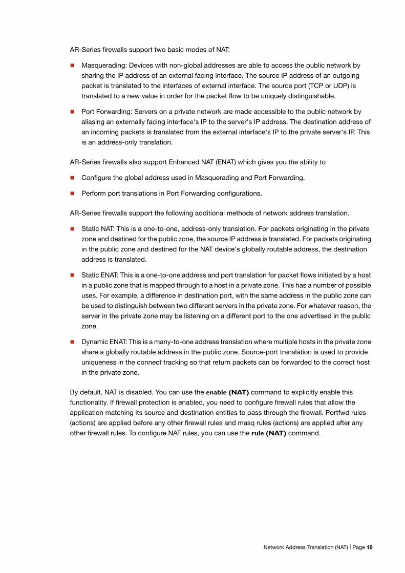
Output 4: Example connection log messages for ICMP connection
NEW proto=ICMP orig_src=192.168.1.1 orig_dst=192.168.1.100 reply_src=192.168.1.100 reply_dst=192.168.1.1
END proto=ICMP orig_src=192.168.1.1 orig_dst=192.168.1.100 orig_pkts=2 orig_bytes=168 reply_src=192.168.1.100 reply_dst=192.168.1.1 reply_pkts=2 reply_bytes=168
Network Address Translation (NAT) | Page 17
AR-Series firewalls support two basic modes of NAT:
Masquerading: Devices with non-global addresses are able to access the public network by
sharing the IP address of an external facing interface. The source IP address of an outgoing
packet is translated to the interfaces of external interface. The source port (TCP or UDP) is
translated to a new value in order for the packet flow to be uniquely distinguishable.
Port Forwarding: Servers on a private network are made accessible to the public network by
aliasing an externally facing interface's IP to the server's IP address. The destination address of
an incoming packets is translated from the external interface's IP to the private server's IP. This
is an address-only translation.
AR-Series firewalls also support Enhanced NAT (ENAT) which gives you the ability to
Configure the global address used in Masquerading and Port Forwarding.
Perform port translations in Port Forwarding configurations.
AR-Series firewalls support the following additional methods of network address translation.
Static NAT: This is a one-to-one, address-only translation. For packets originating in the private
zone and destined for the public zone, the source IP address is translated. For packets originating
in the public zone and destined for the NAT device's globally routable address, the destination
address is translated.
Static ENAT: This is a one-to-one address and port translation for packet flows initiated by a host
in a public zone that is mapped through to a host in a private zone. This has a number of possible
uses. For example, a difference in destination port, with the same address in the public zone can
be used to distinguish between two different servers in the private zone. For whatever reason, the
server in the private zone may be listening on a different port to the one advertised in the public
zone.
Dynamic ENAT: This is a many-to-one address translation where multiple hosts in the private zone
share a globally routable address in the public zone. Source-port translation is used to provide
uniqueness in the connect tracking so that return packets can be forwarded to the correct host
in the private zone.
By default, NAT is disabled. You can use the enable (NAT) command to explicitly enable this
functionality. If firewall protection is enabled, you need to configure firewall rules that allow the
application matching its source and destination entities to pass through the firewall. Portfwd rules
(actions) are applied before any other firewall rules and masq rules (actions) are applied after any
other firewall rules. To configure NAT rules, you can use the rule (NAT) command.
Network Address Translation (NAT) | Page 18
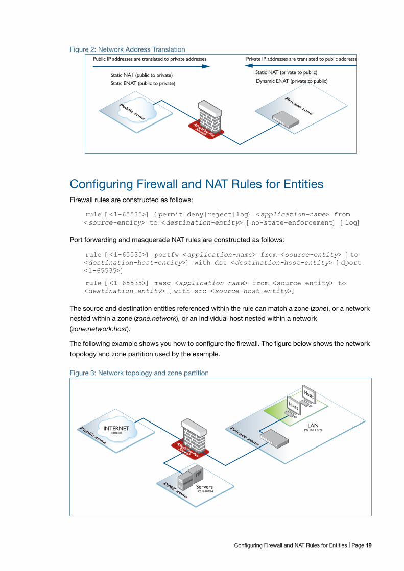
Figure 2: Network Address Translation
Configuring Firewall and NAT Rules for EntitiesFirewall rules are constructed as follows:
rule [<1-65535>] {permit|deny|reject|log} <application-name> from <source-entity> to <destination-entity> [no-state-enforcement] [log]
Port forwarding and masquerade NAT rules are constructed as follows:
rule [<1-65535>] portfw <application-name> from <source-entity> [to <destination-host-entity>] with dst <destination-host-entity> [dport <1-65535>]
rule [<1-65535>] masq <application-name> from <source-entity> to <destination-entity> [with src <source-host-entity>]
The source and destination entities referenced within the rule can match a zone (zone), or a network
nested within a zone (zone.network), or an individual host nested within a network
(zone.network.host).
The following example shows you how to configure the firewall. The figure below shows the network
topology and zone partition used by the example.
Figure 3: Network topology and zone partition
Public zone
Firewall
AlliedWare Plus
Private zone
Static NAT (public to private)
Static ENAT (public to private)
Static NAT (private to public)
Dynamic ENAT (private to public)
Public IP addresses are translated to private addresses Private IP addresses are translated to public addresse
Servers172.16.0.0/24
Public zone
DMZ zone
Hosts
Firewall
AlliedWare Plus
Hosts
FTP
Private zone
Web-Server
LAN192.168.1.0/24INTERNET
0.0.0.0/0
Configuring Firewall and NAT Rules for Entities | Page 19
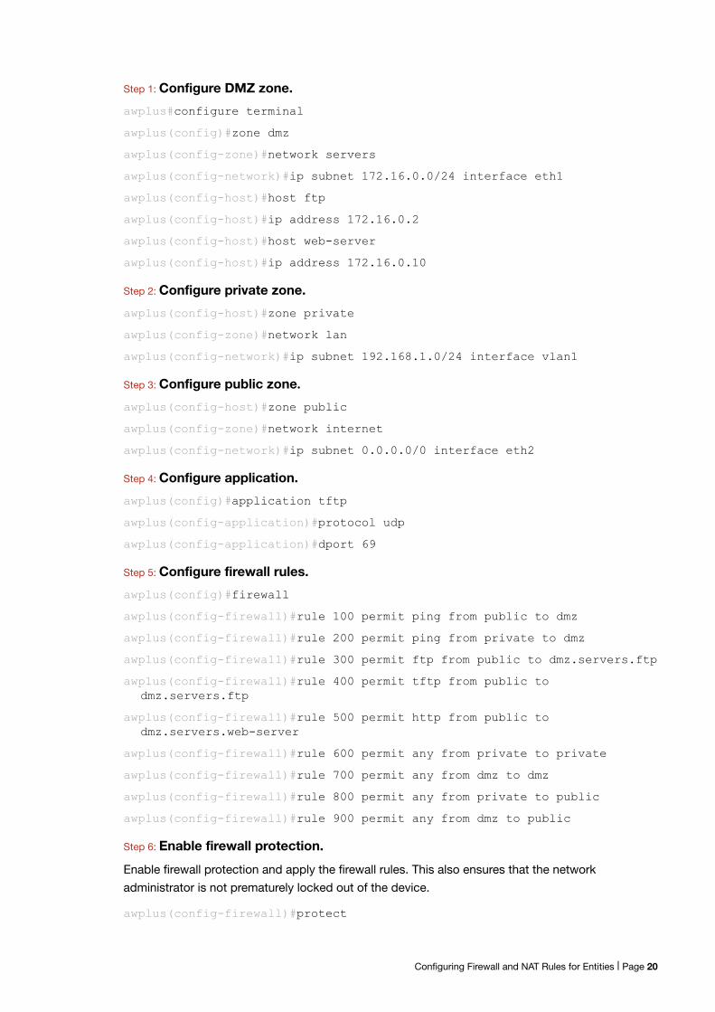
Step 1: Configure DMZ zone.
awplus#configure terminal
awplus(config)#zone dmz
awplus(config-zone)#network servers
awplus(config-network)#ip subnet 172.16.0.0/24 interface eth1
awplus(config-host)#host ftp
awplus(config-host)#ip address 172.16.0.2
awplus(config-host)#host web-server
awplus(config-host)#ip address 172.16.0.10
Step 2: Configure private zone.
awplus(config-host)#zone private
awplus(config-zone)#network lan
awplus(config-network)#ip subnet 192.168.1.0/24 interface vlan1
Step 3: Configure public zone.awplus(config-host)#zone public
awplus(config-zone)#network internet
awplus(config-network)#ip subnet 0.0.0.0/0 interface eth2
Step 4: Configure application.
awplus(config)#application tftp
awplus(config-application)#protocol udp
awplus(config-application)#dport 69
Step 5: Configure firewall rules.
awplus(config)#firewall
awplus(config-firewall)#rule 100 permit ping from public to dmz
awplus(config-firewall)#rule 200 permit ping from private to dmz
awplus(config-firewall)#rule 300 permit ftp from public to dmz.servers.ftp
awplus(config-firewall)#rule 400 permit tftp from public to dmz.servers.ftp
awplus(config-firewall)#rule 500 permit http from public to dmz.servers.web-server
awplus(config-firewall)#rule 600 permit any from private to private
awplus(config-firewall)#rule 700 permit any from dmz to dmz
awplus(config-firewall)#rule 800 permit any from private to public
awplus(config-firewall)#rule 900 permit any from dmz to public
Step 6: Enable firewall protection.
Enable firewall protection and apply the firewall rules. This also ensures that the network
administrator is not prematurely locked out of the device.
awplus(config-firewall)#protect
Configuring Firewall and NAT Rules for Entities | Page 20
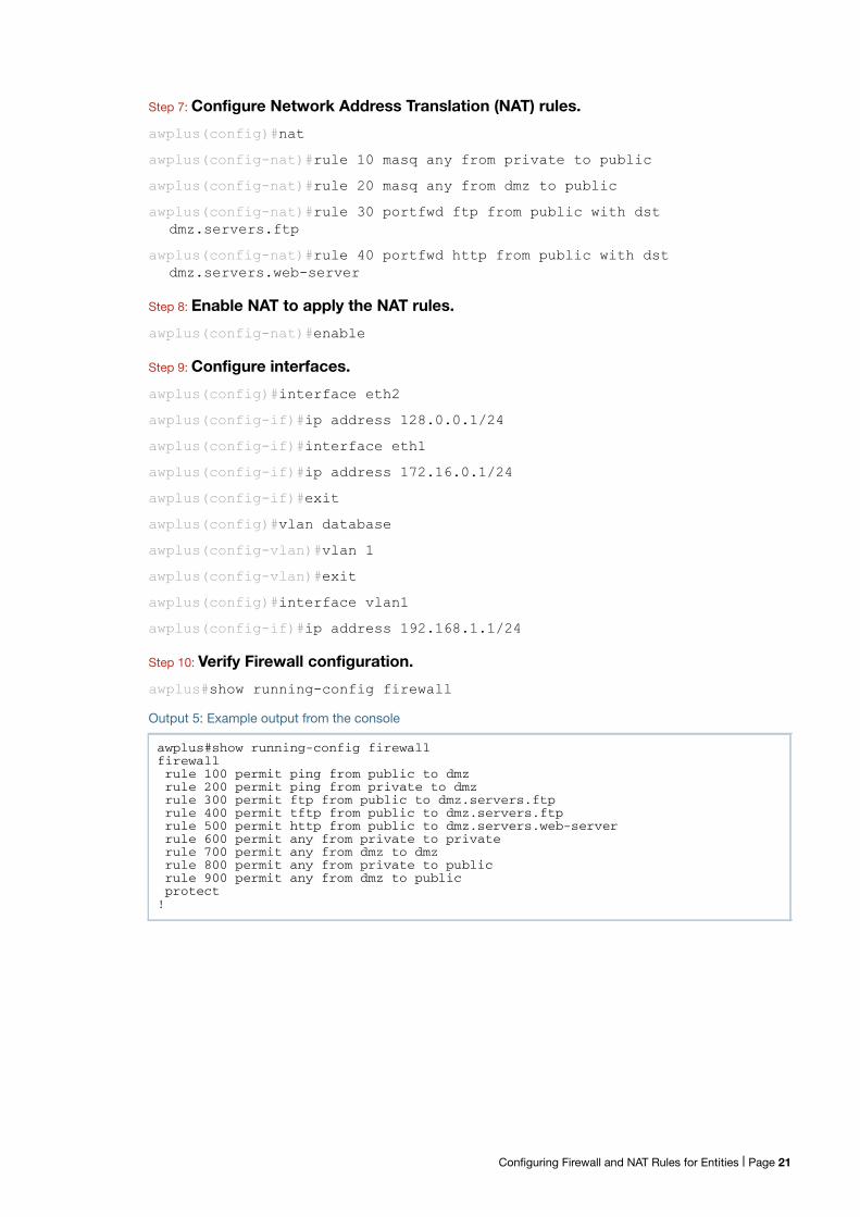
Step 7: Configure Network Address Translation (NAT) rules.
awplus(config)#nat
awplus(config-nat)#rule 10 masq any from private to public
awplus(config-nat)#rule 20 masq any from dmz to public
awplus(config-nat)#rule 30 portfwd ftp from public with dst dmz.servers.ftp
awplus(config-nat)#rule 40 portfwd http from public with dst dmz.servers.web-server
Step 8: Enable NAT to apply the NAT rules.
awplus(config-nat)#enable
Step 9: Configure interfaces.
awplus(config)#interface eth2
awplus(config-if)#ip address 128.0.0.1/24
awplus(config-if)#interface eth1
awplus(config-if)#ip address 172.16.0.1/24
awplus(config-if)#exit
awplus(config)#vlan database
awplus(config-vlan)#vlan 1
awplus(config-vlan)#exit
awplus(config)#interface vlan1
awplus(config-if)#ip address 192.168.1.1/24
Step 10: Verify Firewall configuration.
awplus#show running-config firewall
Output 5: Example output from the console
awplus#show running-config firewallfirewallrule 100 permit ping from public to dmzrule 200 permit ping from private to dmzrule 300 permit ftp from public to dmz.servers.ftprule 400 permit tftp from public to dmz.servers.ftprule 500 permit http from public to dmz.servers.web-serverrule 600 permit any from private to privaterule 700 permit any from dmz to dmzrule 800 permit any from private to publicrule 900 permit any from dmz to publicprotect
!
Configuring Firewall and NAT Rules for Entities | Page 21
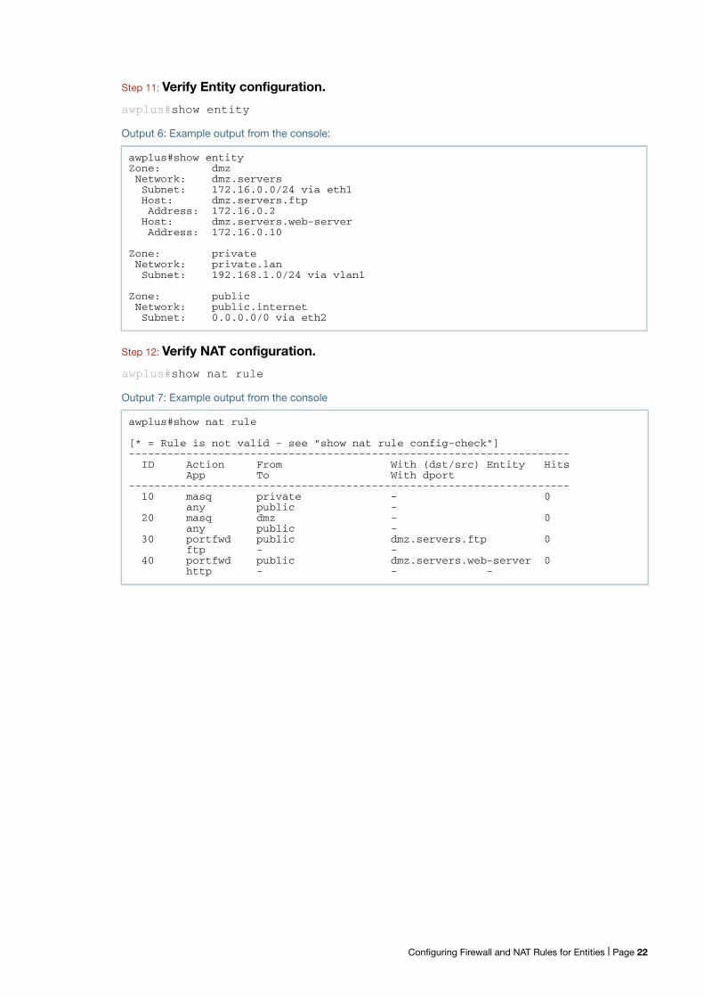
Step 11: Verify Entity configuration.
awplus#show entity
Output 6: Example output from the console:
Step 12: Verify NAT configuration.
awplus#show nat rule
Output 7: Example output from the console
awplus#show entityZone: dmzNetwork: dmz.serversSubnet: 172.16.0.0/24 via eth1Host: dmz.servers.ftpAddress: 172.16.0.2
Host: dmz.servers.web-serverAddress: 172.16.0.10
Zone: privateNetwork: private.lanSubnet: 192.168.1.0/24 via vlan1
Zone: publicNetwork: public.internetSubnet: 0.0.0.0/0 via eth2
awplus#show nat rule
[* = Rule is not valid - see "show nat rule config-check"]---------------------------------------------------------------------
ID Action From With (dst/src) Entity HitsApp To With dport
---------------------------------------------------------------------10 masq private - 0
any public -20 masq dmz - 0
any public -30 portfwd public dmz.servers.ftp 0
ftp - -40 portfwd public dmz.servers.web-server 0
http - - -
Configuring Firewall and NAT Rules for Entities | Page 22
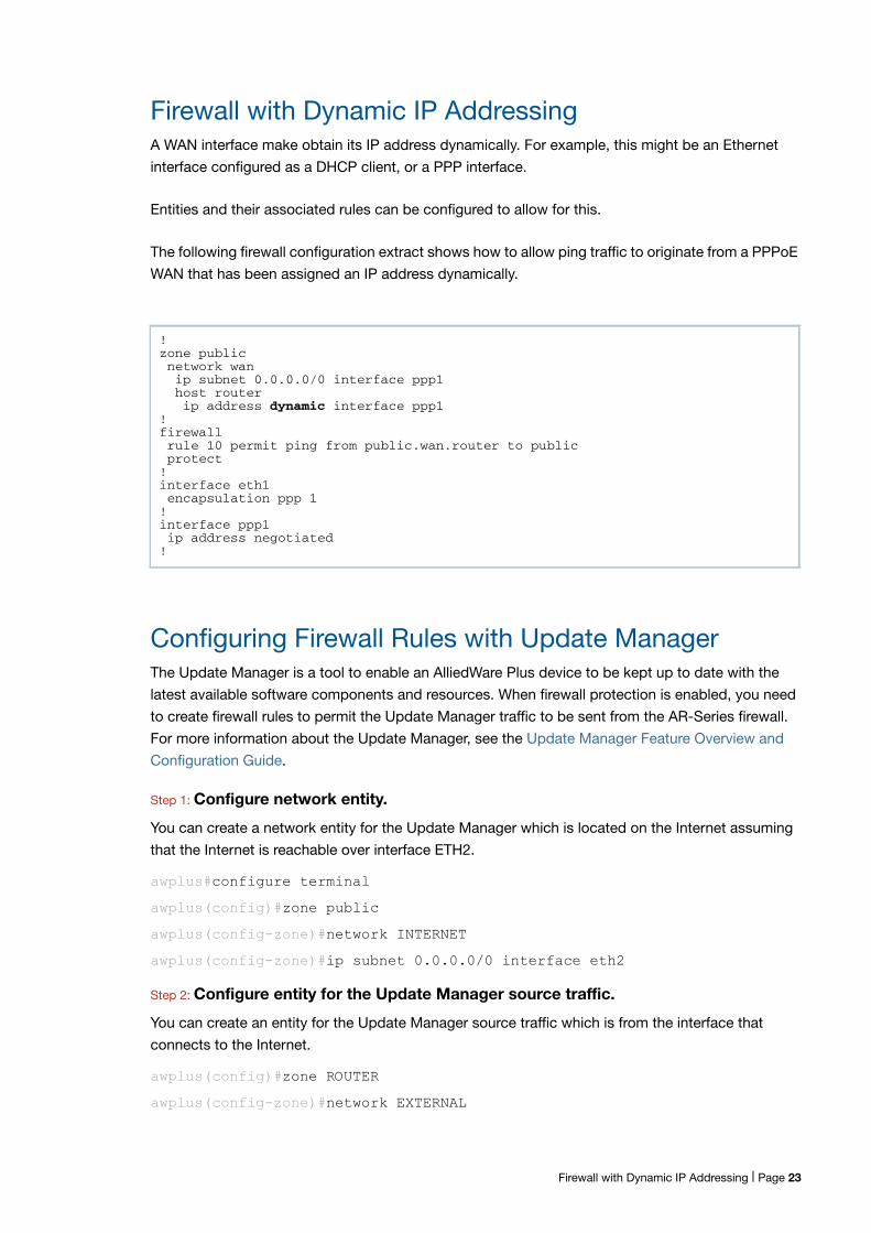
Firewall with Dynamic IP AddressingA WAN interface make obtain its IP address dynamically. For example, this might be an Ethernet
interface configured as a DHCP client, or a PPP interface.
Entities and their associated rules can be configured to allow for this.
The following firewall configuration extract shows how to allow ping traffic to originate from a PPPoE
WAN that has been assigned an IP address dynamically.
Configuring Firewall Rules with Update ManagerThe Update Manager is a tool to enable an AlliedWare Plus device to be kept up to date with the
latest available software components and resources. When firewall protection is enabled, you need
to create firewall rules to permit the Update Manager traffic to be sent from the AR-Series firewall.
For more information about the Update Manager, see the Update Manager Feature Overview and
Configuration Guide.
Step 1: Configure network entity.
You can create a network entity for the Update Manager which is located on the Internet assuming
that the Internet is reachable over interface ETH2.
awplus#configure terminal
awplus(config)#zone public
awplus(config-zone)#network INTERNET
awplus(config-zone)#ip subnet 0.0.0.0/0 interface eth2
Step 2: Configure entity for the Update Manager source traffic.
You can create an entity for the Update Manager source traffic which is from the interface that
connects to the Internet.
awplus(config)#zone ROUTER
awplus(config-zone)#network EXTERNAL
!zone publicnetwork wanip subnet 0.0.0.0/0 interface ppp1host routerip address dynamic interface ppp1
!firewallrule 10 permit ping from public.wan.router to publicprotect
!interface eth1encapsulation ppp 1
!interface ppp1ip address negotiated
!
Firewall with Dynamic IP Addressing | Page 23
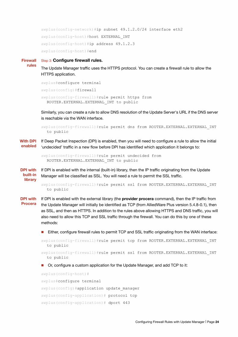
awplus(config-network)#ip subnet 49.1.2.0/24 interface eth2
awplus(config-host)#host EXTERNAL_INT
awplus(config-host)#ip address 49.1.2.3
awplus(config-host)#end
Firewallrules
Step 3: Configure firewall rules.
The Update Manager traffic uses the HTTPS protocol. You can create a firewall rule to allow the
HTTPS application.
awplus#configure terminal
awplus(config)#firewall
awplus(config-firewall)#rule permit https from ROUTER.EXTERNAL.EXTERNAL_INT to public
Similarly, you can create a rule to allow DNS resolution of the Update Server's URL if the DNS server
is reachable via the WAN interface.
awplus(config-firewall)#rule permit dns from ROUTER.EXTERNAL.EXTERNAL_INT to public
With DPIenabled
If Deep Packet Inspection (DPI) is enabled, then you will need to configure a rule to allow the initial
‘undecided’ traffic in a new flow before DPI has identified which application it belongs to:
awplus(config-firewall)#rule permit undecided from ROUTER.EXTERNAL.EXTERNAL_INT to public
DPI withbuilt-inlibrary
If DPI is enabled with the internal (built-in) library, then the IP traffic originating from the Update
Manager will be classified as SSL. You will need a rule to permit the SSL traffic.
awplus(config-firewall)#rule permit ssl from ROUTER.EXTERNAL.EXTERNAL_INT to public
DPI withProcera
If DPI is enabled with the external library (the provider procera command), then the IP traffic from
the Update Manager will initially be identified as TCP (from AlliedWare Plus version 5.4.8-0.1), then
as SSL, and then as HTTPS. In addition to the rules above allowing HTTPS and DNS traffic, you will
also need to allow this TCP and SSL traffic through the firewall. You can do this by one of these
methods:
Either, configure firewall rules to permit TCP and SSL traffic originating from the WAN interface:
awplus(config-firewall)#rule permit tcp from ROUTER.EXTERNAL.EXTERNAL_INT to public
awplus(config-firewall)#rule permit ssl from ROUTER.EXTERNAL.EXTERNAL_INT to public
Or, configure a custom application for the Update Manager, and add TCP to it:
awplus(config-host)#
awplus#configure terminal
awplus(config)#application update_manager
awplus(config-application)# protocol tcp
awplus(config-application)# dport 443
Configuring Firewall Rules with Update Manager | Page 24
awplus(config-application)#exit
awplus(config)#firewall
awplus(config-firewall)#rule permit update_manager from ROUTER.EXTERNAL.EXTERNAL_INT to public
For more information about Application Awareness and DPI, see Application Awareness Feature
Overview and Configuration Guide.
Configuring Firewall Rules with Subscription LicensingAlliedWare Plus devices configured with features such as AMF and OpenFlow use subscription-
based licensing. These devices could be located within a private firewall zone, accessing the
subscription service located in the Internet, via the AR-Series firewall.
In order to allow access to the subscription licensing services from a private zone to the Internet,
firewall allow rules need to be created. For more information about Subscription Licensing, see the
Licensing Feature Overview and Configuration Guide.
In order to allow the AR-Series firewall itself to access subscription licensing services, see
"Configuring Firewall Rules with Update Manager" on page 23.
Step 1: Configure an entity for the public zone attached to the Internet.
Configure a public zone attached to the Internet, where the Internet is reachable over interface eth2.
awplus#configure terminal
awplus(config)#zone public
awplus(config-zone)#network INTERNET
awplus(config-zone)#ip subnet 0.0.0.0/0 interface eth2
Step 2: Configure an entity for the private zone
You can create a private zone, which is associated with the internal network accessed via interface
vlan1
awplus(config)#zone private
awplus(config-zone)#network INTERNAL
awplus(config-network)#ip subnet 10.1.1.0/24 interface vlan1
Step 3: Configure firewall rules.
Subscription services are accessed using HTTPS protocol. You can create a firewall rule to allow
HTTPS application to flow through the AR-Series firewall from the private to public zones.
awplus(config-host)#end
awplus#configure terminal
awplus(config)#firewall
awplus(config-firewall)#rule permit https from private to public
Configuring Firewall Rules with Subscription Licensing | Page 25
Similarly, you can create a rule to allow DNS resolution of the subscription service URL if the DNS
server is reachable via the WAN interface from devices located within the private zone.
awplus(config-firewall)#rule permit dns from private to public
If the AR-Series firewall is also performing NAT, then corresponding NAT-based masquerade rules
for HTTPS and DNS will also need to be configured.
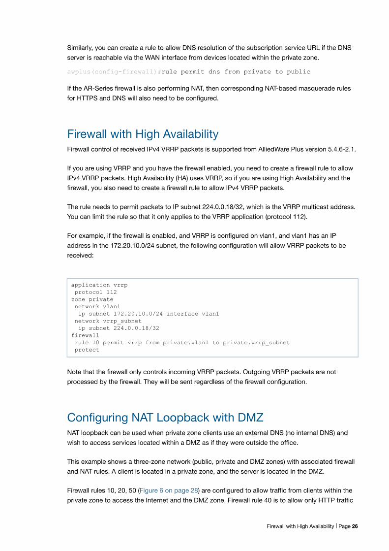
Firewall with High AvailabilityFirewall control of received IPv4 VRRP packets is supported from AlliedWare Plus version 5.4.6-2.1.
If you are using VRRP and you have the firewall enabled, you need to create a firewall rule to allow
IPv4 VRRP packets. High Availability (HA) uses VRRP, so if you are using High Availability and the
firewall, you also need to create a firewall rule to allow IPv4 VRRP packets.
The rule needs to permit packets to IP subnet 224.0.0.18/32, which is the VRRP multicast address.
You can limit the rule so that it only applies to the VRRP application (protocol 112).
For example, if the firewall is enabled, and VRRP is configured on vlan1, and vlan1 has an IP
address in the 172.20.10.0/24 subnet, the following configuration will allow VRRP packets to be
received:
Note that the firewall only controls incoming VRRP packets. Outgoing VRRP packets are not
processed by the firewall. They will be sent regardless of the firewall configuration.
Configuring NAT Loopback with DMZNAT loopback can be used when private zone clients use an external DNS (no internal DNS) and
wish to access services located within a DMZ as if they were outside the office.
This example shows a three-zone network (public, private and DMZ zones) with associated firewall
and NAT rules. A client is located in a private zone, and the server is located in the DMZ.
Firewall rules 10, 20, 50 (Figure 6 on page 28) are configured to allow traffic from clients within the
private zone to access the Internet and the DMZ zone. Firewall rule 40 is to allow only HTTP traffic
application vrrp protocol 112zone private network vlan1 ip subnet 172.20.10.0/24 interface vlan1 network vrrp_subnet ip subnet 224.0.0.18/32firewall rule 10 permit vrrp from private.vlan1 to private.vrrp_subnet protect
Firewall with High Availability | Page 26
from the Internet to reach the web server in the DMZ. Firewall rule 60 and 70 are included to allow
HTTP traffic initiated from the web server access to the private zone and the public zone. If traffic is
not initiated from the web server, then rules 60 and 70 are not required.
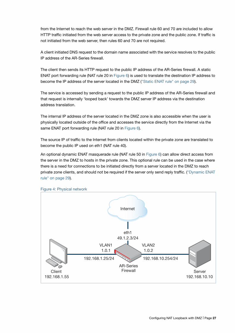
A client initiated DNS request to the domain name associated with the service resolves to the public
IP address of the AR-Series firewall.
The client then sends its HTTP request to the public IP address of the AR-Series firewall. A static
ENAT port forwarding rule (NAT rule 20 in Figure 6) is used to translate the destination IP address to
become the IP address of the server located in the DMZ ("Static ENAT rule" on page 29).
The service is accessed by sending a request to the public IP address of the AR-Series firewall and
that request is internally ‘looped back’ towards the DMZ server IP address via the destination
address translation.
The internal IP address of the server located in the DMZ zone is also accessible when the user is
physically located outside of the office and accesses the service directly from the Internet via the
same ENAT port forwarding rule (NAT rule 20 in Figure 6).
The source IP of traffic to the Internet from clients located within the private zone are translated to
become the public IP used on eth1 (NAT rule 40).
An optional dynamic ENAT masquerade rule (NAT rule 50 in Figure 6) can allow direct access from
the server in the DMZ to hosts in the private zone. This optional rule can be used in the case where
there is a need for connections to be initiated directly from a server located in the DMZ to reach
private zone clients, and should not be required if the server only send reply traffic. ("Dynamic ENAT
rule" on page 29).
Figure 4: Physical network
AR-SeriesFirewall
VLAN21.0.2
192.168.10.254/24
VLAN11.0.1
192.168.1.25/24
192.168.10.10192.168.1.55Client Server
eth149.1.2.3/24
Internet
Configuring NAT Loopback with DMZ | Page 27

Figure 5: AR-Series firewall entity map
Figure 6: Configuration: NAT loopback with DMZ
zone dmz network dmz ip subnet 192.168.10.0/24 interface vlan2 ip subnet 49.1.2.3/32 host http-server ip address 192.168.10.10 host router ip address 49.1.2.3 !zone private network lan ip subnet 192.168.1.0/24 interface vlan1!zone public network wan ip subnet 0.0.0.0/0 interface eth1!firewall rule 10 permit any from private.lan to public rule 20 permit any from private to private rule 40 permit http from public to dmz.dmz.http-server rule 50 permit any from private.lan to dmz.dmz #rule 60 permit http from dmz.dmz.http-server to private #rule 70 permit http from dmz.dmz.http-server to publicprotect!nat rule 20 portfwd http from public with dst dmz.dmz.http-server rule 40 masq any from private.lan to public rule 50 masq any from dmz.dmz to public enable!vlan database vlan 2 state enable!interface port1.0.2 switchport access vlan 2!interface eth1 ip address 49.1.2.3/24!interface vlan1 ip address 192.168.1.254/24!interface vlan2 ip address 192.168.10.254/24!ip route 0.0.0.0/0 49.1.2.100
Zone: PUBLIC
Network: WANIP Subnet:0.0.0.0/0
Zone: DMZ
Network: DMZIP Subnet:192.168.10.0/24
Host: http-serverIP Address:192.168.10.10
Host: routerIP Address:49.1.2.3
Zone: PRIVATE
Entity
Network: LANIP Subnet:192.168.1.0/24
VLAN2VLAN1 eth1
Configuring NAT Loopback with DMZ | Page 28
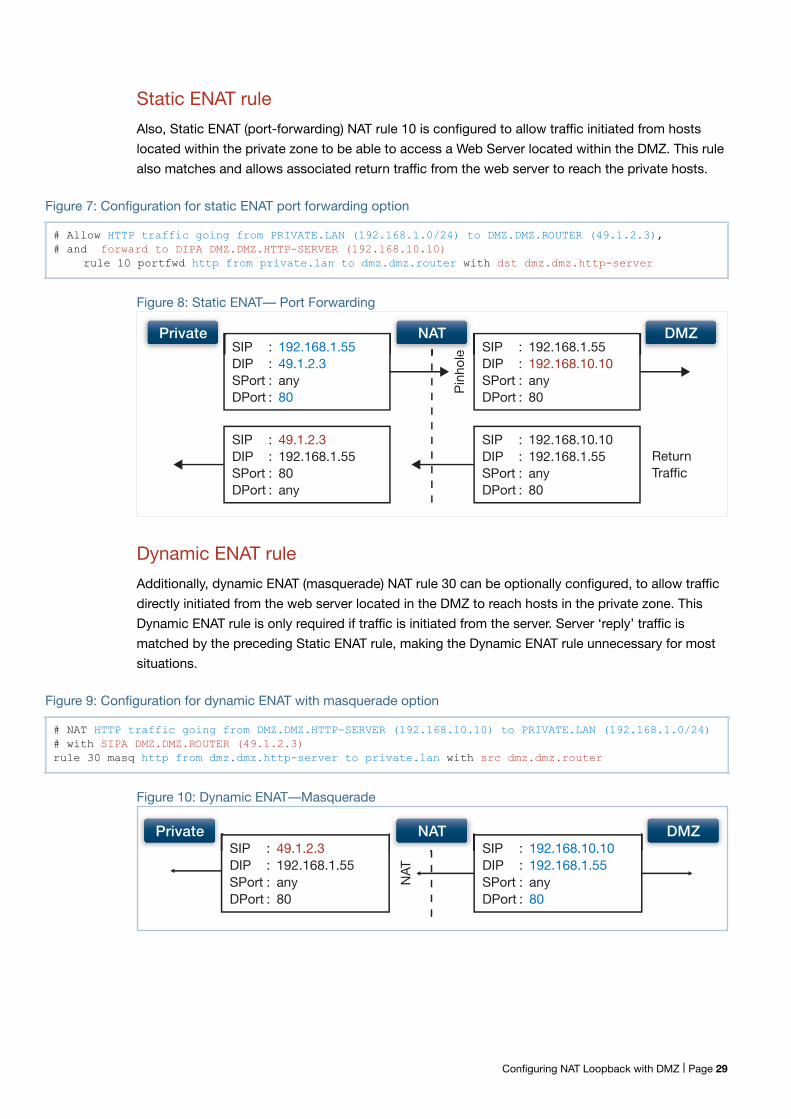
Static ENAT rule
Also, Static ENAT (port-forwarding) NAT rule 10 is configured to allow traffic initiated from hosts
located within the private zone to be able to access a Web Server located within the DMZ. This rule
also matches and allows associated return traffic from the web server to reach the private hosts.
Figure 7: Configuration for static ENAT port forwarding option
Figure 8: Static ENAT— Port Forwarding
Dynamic ENAT rule
Additionally, dynamic ENAT (masquerade) NAT rule 30 can be optionally configured, to allow traffic
directly initiated from the web server located in the DMZ to reach hosts in the private zone. This
Dynamic ENAT rule is only required if traffic is initiated from the server. Server ‘reply’ traffic is
matched by the preceding Static ENAT rule, making the Dynamic ENAT rule unnecessary for most
situations.
Figure 9: Configuration for dynamic ENAT with masquerade option
Figure 10: Dynamic ENAT—Masquerade
# Allow HTTP traffic going from PRIVATE.LAN (192.168.1.0/24) to DMZ.DMZ.ROUTER (49.1.2.3),# and forward to DIPA DMZ.DMZ.HTTP-SERVER (192.168.10.10)
rule 10 portfwd http from private.lan to dmz.dmz.router with dst dmz.dmz.http-server
SIP : 192.168.1.55DIP : 49.1.2.3SPort : anyDPort : 80
ReturnTraffic
SIP : 192.168.1.55DIP : 192.168.10.10SPort : anyDPort : 80Pi
nhol
eSIP : 49.1.2.3 DIP : 192.168.1.55SPort : 80DPort : any
SIP : 192.168.10.10DIP : 192.168.1.55SPort : anyDPort : 80
e
NATPrivate DMZ
# NAT HTTP traffic going from DMZ.DMZ.HTTP-SERVER (192.168.10.10) to PRIVATE.LAN (192.168.1.0/24) # with SIPA DMZ.DMZ.ROUTER (49.1.2.3)rule 30 masq http from dmz.dmz.http-server to private.lan with src dmz.dmz.router
SIP : 49.1.2.3DIP : 192.168.1.55SPort : anyDPort : 80
SIP : 192.168.10.10DIP : 192.168.1.55SPort : anyDPort : 80
NATPrivate DMZ
NAT
Configuring NAT Loopback with DMZ | Page 29
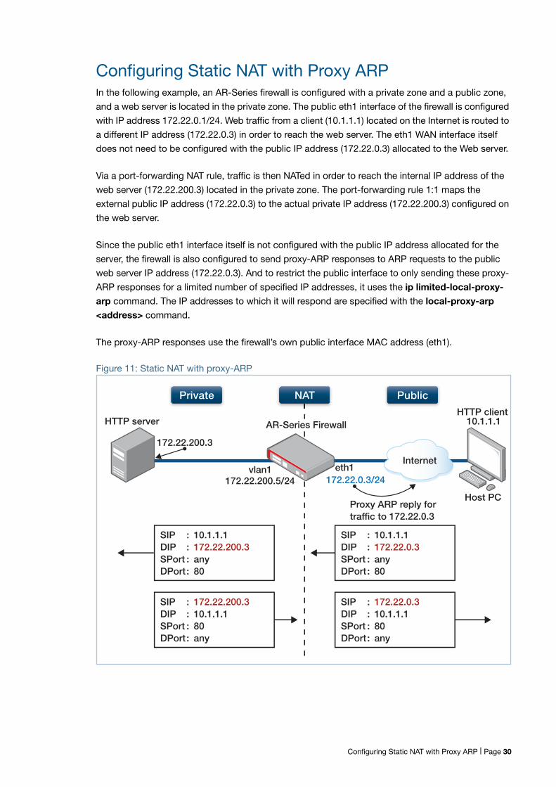
Configuring Static NAT with Proxy ARPIn the following example, an AR-Series firewall is configured with a private zone and a public zone,
and a web server is located in the private zone. The public eth1 interface of the firewall is configured
with IP address 172.22.0.1/24. Web traffic from a client (10.1.1.1) located on the Internet is routed to
a different IP address (172.22.0.3) in order to reach the web server. The eth1 WAN interface itself
does not need to be configured with the public IP address (172.22.0.3) allocated to the Web server.
Via a port-forwarding NAT rule, traffic is then NATed in order to reach the internal IP address of the
web server (172.22.200.3) located in the private zone. The port-forwarding rule 1:1 maps the
external public IP address (172.22.0.3) to the actual private IP address (172.22.200.3) configured on
the web server.
Since the public eth1 interface itself is not configured with the public IP address allocated for the
server, the firewall is also configured to send proxy-ARP responses to ARP requests to the public
web server IP address (172.22.0.3). And to restrict the public interface to only sending these proxy-
ARP responses for a limited number of specified IP addresses, it uses the ip limited-local-proxy-
arp command. The IP addresses to which it will respond are specified with the local-proxy-arp
<address> command.
The proxy-ARP responses use the firewall’s own public interface MAC address (eth1).
Figure 11: Static NAT with proxy-ARP
SIP : 10.1.1.1DIP : 172.22.200.3SPort : anyDPort : 80
SIP : 10.1.1.1DIP : 172.22.0.3SPort : anyDPort : 80
HTTP clientHTTP server
Host PC
SIP : 172.22.200.3 DIP : 10.1.1.1SPort : 80DPort : any
SIP : 172.22.0.3DIP : 10.1.1.1SPort : 80DPort : any
Interneteth1
Proxy ARP reply for traffic to 172.22.0.3
AR-Series Firewall
172.22.0.3/24vlan1
172.22.200.5/24
172.22.200.3
NATPrivate Public
10.1.1.1
Configuring Static NAT with Proxy ARP | Page 30
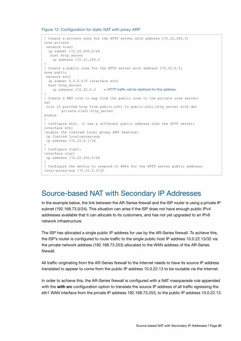
Figure 12: Configuration for static NAT with proxy-ARP
Source-based NAT with Secondary IP AddressesIn the example below, the link between the AR-Series firewall and the ISP router is using a private IP
subnet (192.168.73.0/24). This situation can arise if the ISP does not have enough public IPv4
addresses available that it can allocate to its customers, and has not yet upgraded to an IPv6
network infrastructure.
The ISP has allocated a single public IP address for use by the AR-Series firewall. To achieve this,
the ISP’s router is configured to route traffic to the single public host IP address 10.0.22.13/32 via
the private network address (192.168.73.253) allocated to the WAN address of the AR-Series
firewall.
All traffic originating from the AR-Series firewall to the Internet needs to have its source IP address
translated to appear to come from the public IP address 10.0.22.13 to be routable via the Internet.
In order to achieve this, the AR-Series firewall is configured with a NAT masquerade rule appended
with the with src configuration option to translate the source IP address of all traffic egressing the
eth1 WAN interface from the private IP address 192.168.73.253, to the public IP address 10.0.22.13.
! Create a private zone for the HTTP server with address 172.22.200.3:zone private network vlan1 ip subnet 172.22.200.0/24 host http_server ip address 172.22.200.3!! Create a public zone for the HTTP server with address 172.22.0.3:zone public network eth1 ip subnet 0.0.0.0/0 interface eth1 host http_server ip address 172.22.0.3 HTTP traffic will be destined for this address.! ! Create a NAT rule to map from the public zone to the private zone server:nat rule 10 portfwd http from public.eth1 to public.eth1.http_server with dst
private.vlan1.http_serverenable!! Configure eth1. It has a different public address than the HTTP server:interface eth1!enable the limited local proxy ARP feature: ip limited local-proxy-arp ip address 172.22.0.1/24!! Configure vlan1: interface vlan1 ip address 172.22.200.5/24!! Configure the device to respond to ARPs for the HTTP server public address:local-proxy-arp 172.22.0.3/32
Source-based NAT with Secondary IP Addresses | Page 31
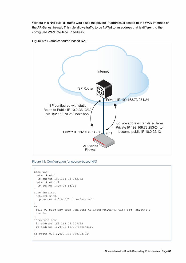
Without this NAT rule, all traffic would use the private IP address allocated to the WAN interface of
the AR-Series firewall. This rule allows traffic to be NATed to an address that is different to the
configured WAN interface IP address.
Figure 13: Example: source-based NAT
Figure 14: Configuration for source-based NAT
!zone wan network eth1 ip subnet 192.168.73.253/32 network eth1-1 ip subnet 10.0.22.13/32!zone internet network wan01 ip subnet 0.0.0.0/0 interface eth1!nat rule 90 masq any from wan.eth1 to internet.wan01 with src wan.eth1-1 enable!interface eth1 ip address 192.168.73.253/24 ip address 10.0.22.13/32 secondary!ip route 0.0.0.0/0 192.168.73.254!
ISP Router
AR-SeriesFirewall
eth1
Private IP 192.168.73.254/24
Private IP 192.168.73.253
Source address translated fromPrivate IP 192.168.73.253/24 to
become public IP 10.0.22.13
ISP configured with staticRoute to Public IP 10.0.22.13/32
via 192.168.73.253 next-hop
Internet
Source-based NAT with Secondary IP Addresses | Page 32
Configuring Access to Multiple Internal Servers viaPPPoE WANThis section provides two examples showing how to configure access to multiple internal
application servers via PPPoE WAN, protected by firewall with NAT. The topology uses an Allied
Telesis UTM Firewall or Secure VPN Router (AR-Series firewall) providing Internet access via a
PPPoE WAN link.
This topology uses firewall zones including:
The public 'internet' zone, with the PPP interface in it.
The ‘private’ zone, containing a LAN with host computers and a separate server network
containing application servers.
The configuration provides access to the servers from clients located in either the private zone or in
the Internet.
The two examples are:
"Server access with external DNS" on page 34—No internal DNS server is used within the private
customer network.
"Server access with internal DNS" on page 39—There is an internal DNS server in the private
zone that private clients can access directly without having to perform DNS requests to external
DNS servers in the Internet.
The network topology shown below is the same for both examples.
Configuring Access to Multiple Internal Servers via PPPoE WAN | Page 33
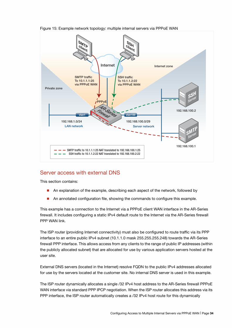
Figure 15: Example network topology: multiple internal servers via PPPoE WAN
Server access with external DNS
This section contains:
An explanation of the example, describing each aspect of the network, followed by
An annotated configuration file, showing the commands to configure this example.
This example has a connection to the Internet via a PPPoE client WAN interface in the AR-Series
firewall. It includes configuring a static IPv4 default route to the Internet via the AR-Series firewall
PPP WAN link.
The ISP router (providing Internet connectivity) must also be configured to route traffic via its PPP
interface to an entire public IPv4 subnet (10.1.1.0 mask 255.255.255.248) towards the AR-Series
firewall PPP interface. This allows access from any clients to the range of public IP addresses (within
the publicly allocated subnet) that are allocated for use by various application servers hosted at the
user site.
External DNS servers (located in the Internet) resolve FQDN to the public IPv4 addresses allocated
for use by the servers located at the customer site. No internal DNS server is used in this example.
The ISP router dynamically allocates a single /32 IPv4 host address to the AR-Series firewall PPPoE
WAN interface via standard PPP IPCP negotiation. When the ISP router allocates this address via its
PPP interface, the ISP router automatically creates a /32 IPv4 host route for this dynamically
Internet
Private zone
SMTPclient
SSHclient
SMTP trafficTo 10.1.1.1:25via PPPoE WAN
Internet zone
SSH trafficTo 10.1.1.2:22via PPPoE WAN
192.168.1.0/24 192.168.100.0/29
192.168.100.2
192.168.100.1
LAN network Server network
PPPoE
AR-SeriesFirewall
SMTP traffic to 10.1.1.1:25 NAT translated to 192.168.100.1:25SSH traffic to 10.1.1.2:22 NAT translated to 192.168.100.2:22
SSHServer
SMTPServer
vlan1 vlan100
Configuring Access to Multiple Internal Servers via PPPoE WAN | Page 34
allocated address, unless configured otherwise. You need to configure the PPP WAN interface of the
AR-Series firewall to be in a public ‘internet’ zone.
Note that:
You do not need to explicitly configure the PPP WAN interface of the AR-Series firewall itself for
addresses within the public IPv4 subnet 10.1.1.0/29 that the ISP routes to.
The /32 IPv4 host address that is dynamically allocated to the PPP WAN interface of the
AR-Series firewall can be within the same subnet that is allocated for use by the servers, or it can
be within a completely different subnet.
On the AR-Series firewall, you do not need to configure the public IP subnet or public IP
addresses allocated to each application server on the PPP WAN.
Basiczones and
rules
Physically, the application servers (SMTP and SSH servers used in this example) are located in a
private zone of the firewall, and you need to configure them with private IP addresses. Those private
IP addresses cannot therefore be directly accessed from clients located on the Internet.
Instead, you need to configure NAT port-forwarding rules so that the AR-Series firewall 1:1 statically
maps specific application traffic to specific public server IP addresses to the actual internal private
IP addresses that the network administrator has allocated to each server.
Via NAT port-forwarding rules, inbound application traffic flows from a client to each public server IP
address/application destination port has its destination IP translated to the private IP address of the
application server. When the TCP connection is established through to the internal application
server, the internal firewall connection tracker automatically tracks the associated state and details
of the TCP session (protocol, IP addresses, ports, NAT translations).
Associated reply traffic from the application server (back to the client) matches the incoming flow
originating from the client. And via connection flow association, the reply traffic automatically has its
source IP address translated back to the server’s public IP address via the same NAT port-
forwarding rules handling the inbound traffic flows.
You need to configure a VLAN within the ‘private’ zone, where the private client host computers are.
You may optionally (as in this example) configure the PPPoE WAN interface to obtain DNS
information via PPP IPCP negotiation from the ISP router. You need to configure DNS forwarding to
allow DNS lookups from private hosts to be proxied, cached (stored) and forwarded through the
AR-Series firewall to allow client DNS resolution.
PPPoptions &
DNS
Optionally (as in this example), you may configure the AR-Series firewall with static DNS primary and
secondary IP name-server addresses, if known. However, if ppp ipcp dns request is also
configured on the PPP interface, the firewall will automatically use the DNS server address
information (when learned via PPP) in preference to any static DNS address entries. The firewall will
keep using the dynamically learned DNS server information as long as the PPP connection remains
up.
To automatically detect if the PPP WAN connection to the ISP router fails, you can configure the
PPP interface keepalive option (which enables regular PPP LCP echo request messaging via the
Configuring Access to Multiple Internal Servers via PPPoE WAN | Page 35
PPP interface). This allows the PPP link to automatically re-establish after the firewall detects a link-
down event due to a failure to receive keepalive responses (PPP LCP echo responses) from the ISP
router.
You can configure TCP MSS clamping on the PPPoE connection (ip tcp adjust-mss <value>
command), to avoid unnecessary TCP fragmentation issues occurring due to the additional PPP/
PPPoE header encapsulations that are applied before transmission out the physical eth WAN
interface.
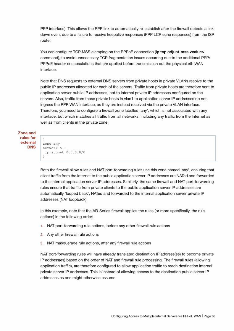
Note that DNS requests to external DNS servers from private hosts in private VLANs resolve to the
public IP addresses allocated for each of the servers. Traffic from private hosts are therefore sent to
application server public IP addresses, not to internal private IP addresses configured on the
servers. Also, traffic from those private hosts in vlan1 to application server IP addresses do not
ingress the PPP WAN interface, as they are instead received via the private VLAN interface.
Therefore, you need to configure a firewall zone labelled 'any', which is not associated with any
interface, but which matches all traffic from all networks, including any traffic from the Internet as
well as from clients in the private zone.
Zone andrules forexternal
DNS
Both the firewall allow rules and NAT port-forwarding rules use this zone named 'any', ensuring that
client traffic from the Internet to the public application server IP addresses are NATed and forwarded
to the internal application server IP addresses. Similarly, the same firewall and NAT port-forwarding
rules ensure that traffic from private clients to the public application server IP addresses are
automatically 'looped back', NATed and forwarded to the internal application server private IP
addresses (NAT loopback).
In this example, note that the AR-Series firewall applies the rules (or more specifically, the rule
actions) in the following order:
1. NAT port-forwarding rule actions, before any other firewall rule actions
2. Any other firewall rule actions
3. NAT masquerade rule actions, after any firewall rule actions
NAT port-forwarding rules will have already translated destination IP address(es) to become private
IP address(es) based on the order of NAT and firewall rule processing. The firewall rules (allowing
application traffic), are therefore configured to allow application traffic to reach destination internal
private server IP addresses. This is instead of allowing access to the destination public server IP
addresses as one might otherwise assume.
!zone anynetwork all ip subnet 0.0.0.0/0!
Configuring Access to Multiple Internal Servers via PPPoE WAN | Page 36
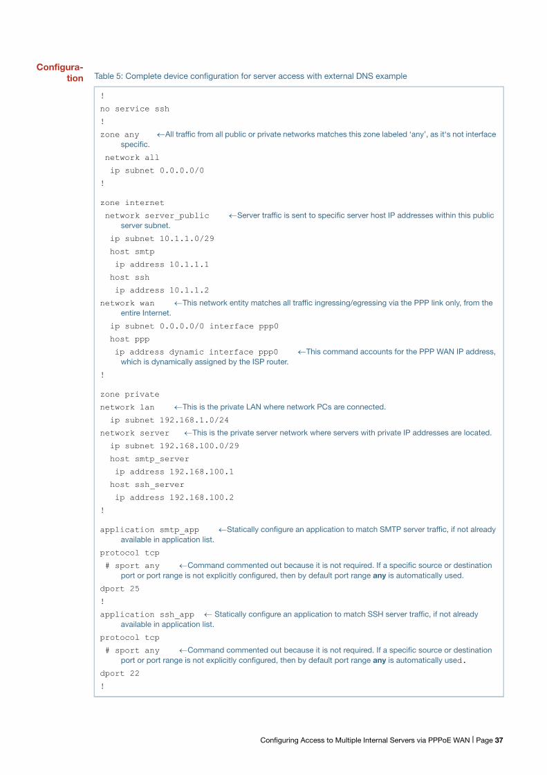
Configura-tion Table 5: Complete device configuration for server access with external DNS example
!
no service ssh
!
zone any All traffic from all public or private networks matches this zone labeled ‘any’, as it‘s not interfacespecific.
network all
ip subnet 0.0.0.0/0
!
zone internet
network server_public Server traffic is sent to specific server host IP addresses within this publicserver subnet.
ip subnet 10.1.1.0/29
host smtp
ip address 10.1.1.1
host ssh
ip address 10.1.1.2
network wan This network entity matches all traffic ingressing/egressing via the PPP link only, from theentire Internet.
ip subnet 0.0.0.0/0 interface ppp0
host ppp
ip address dynamic interface ppp0 This command accounts for the PPP WAN IP address,which is dynamically assigned by the ISP router.
!
zone private
network lan This is the private LAN where network PCs are connected.
ip subnet 192.168.1.0/24
network server This is the private server network where servers with private IP addresses are located.
ip subnet 192.168.100.0/29
host smtp_server
ip address 192.168.100.1
host ssh_server
ip address 192.168.100.2
!
application smtp_app Statically configure an application to match SMTP server traffic, if not alreadyavailable in application list.
protocol tcp
# sport any Command commented out because it is not required. If a specific source or destinationport or port range is not explicitly configured, then by default port range any is automatically used.
dport 25
!
application ssh_app Statically configure an application to match SSH server traffic, if not alreadyavailable in application list.
protocol tcp
# sport any Command commented out because it is not required. If a specific source or destinationport or port range is not explicitly configured, then by default port range any is automatically used.
dport 22
!
Configuring Access to Multiple Internal Servers via PPPoE WAN | Page 37
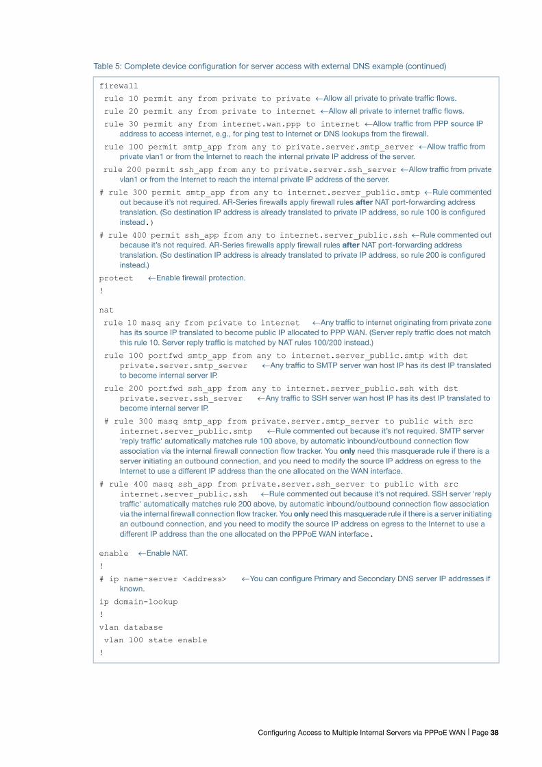
firewall
rule 10 permit any from private to private Allow all private to private traffic flows.
rule 20 permit any from private to internet Allow all private to internet traffic flows.
rule 30 permit any from internet.wan.ppp to internet Allow traffic from PPP source IPaddress to access internet, e.g., for ping test to Internet or DNS lookups from the firewall.
rule 100 permit smtp_app from any to private.server.smtp_server Allow traffic fromprivate vlan1 or from the Internet to reach the internal private IP address of the server.
rule 200 permit ssh_app from any to private.server.ssh_server Allow traffic from privatevlan1 or from the Internet to reach the internal private IP address of the server.
# rule 300 permit smtp_app from any to internet.server_public.smtp Rule commentedout because it’s not required. AR-Series firewalls apply firewall rules after NAT port-forwarding addresstranslation. (So destination IP address is already translated to private IP address, so rule 100 is configuredinstead.)
# rule 400 permit ssh_app from any to internet.server_public.ssh Rule commented outbecause it’s not required. AR-Series firewalls apply firewall rules after NAT port-forwarding addresstranslation. (So destination IP address is already translated to private IP address, so rule 200 is configuredinstead.)
protect Enable firewall protection.
!
nat
rule 10 masq any from private to internet Any traffic to internet originating from private zonehas its source IP translated to become public IP allocated to PPP WAN. (Server reply traffic does not matchthis rule 10. Server reply traffic is matched by NAT rules 100/200 instead.)
rule 100 portfwd smtp_app from any to internet.server_public.smtp with dst private.server.smtp_server Any traffic to SMTP server wan host IP has its dest IP translatedto become internal server IP.
rule 200 portfwd ssh_app from any to internet.server_public.ssh with dst private.server.ssh_server Any traffic to SSH server wan host IP has its dest IP translated tobecome internal server IP.
# rule 300 masq smtp_app from private.server.smtp_server to public with src internet.server_public.smtp Rule commented out because it’s not required. SMTP server'reply traffic' automatically matches rule 100 above, by automatic inbound/outbound connection flowassociation via the internal firewall connection flow tracker. You only need this masquerade rule if there is aserver initiating an outbound connection, and you need to modify the source IP address on egress to theInternet to use a different IP address than the one allocated on the WAN interface.
# rule 400 masq ssh_app from private.server.ssh_server to public with src internet.server_public.ssh Rule commented out because it’s not required. SSH server 'replytraffic' automatically matches rule 200 above, by automatic inbound/outbound connection flow associationvia the internal firewall connection flow tracker. You only need this masquerade rule if there is a server initiatingan outbound connection, and you need to modify the source IP address on egress to the Internet to use adifferent IP address than the one allocated on the PPPoE WAN interface.
enable Enable NAT.
!
# ip name-server <address> You can configure Primary and Secondary DNS server IP addresses ifknown.
ip domain-lookup
!
vlan database
vlan 100 state enable
!
Table 5: Complete device configuration for server access with external DNS example (continued)
Configuring Access to Multiple Internal Servers via PPPoE WAN | Page 38
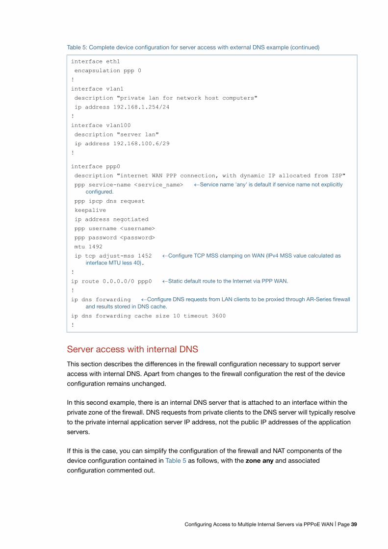
Server access with internal DNS
This section describes the differences in the firewall configuration necessary to support server
access with internal DNS. Apart from changes to the firewall configuration the rest of the device
configuration remains unchanged.
In this second example, there is an internal DNS server that is attached to an interface within the
private zone of the firewall. DNS requests from private clients to the DNS server will typically resolve
to the private internal application server IP address, not the public IP addresses of the application
servers.
If this is the case, you can simplify the configuration of the firewall and NAT components of the
device configuration contained in Table 5 as follows, with the zone any and associated
configuration commented out.
interface eth1
encapsulation ppp 0
!
interface vlan1
description "private lan for network host computers"
ip address 192.168.1.254/24
!
interface vlan100
description "server lan"
ip address 192.168.100.6/29
!
interface ppp0
description "internet WAN PPP connection, with dynamic IP allocated from ISP"
ppp service-name <service_name> Service name 'any' is default if service name not explicitlyconfigured.
ppp ipcp dns request
keepalive
ip address negotiated
ppp username <username>
ppp password <password>
mtu 1492
ip tcp adjust-mss 1452 Configure TCP MSS clamping on WAN (IPv4 MSS value calculated asinterface MTU less 40).
!
ip route 0.0.0.0/0 ppp0 Static default route to the Internet via PPP WAN.
!
ip dns forwarding Configure DNS requests from LAN clients to be proxied through AR-Series firewalland results stored in DNS cache.
ip dns forwarding cache size 10 timeout 3600
!
Table 5: Complete device configuration for server access with external DNS example (continued)
Configuring Access to Multiple Internal Servers via PPPoE WAN | Page 39
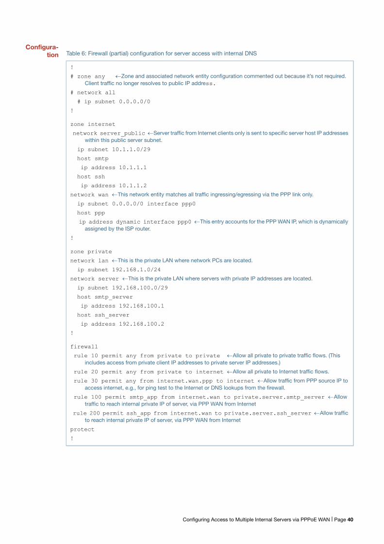
Configura-tion Table 6: Firewall (partial) configuration for server access with internal DNS
!
# zone any Zone and associated network entity configuration commented out because it’s not required.Client traffic no longer resolves to public IP address.
# network all
# ip subnet 0.0.0.0/0
!
zone internet
network server_public Server traffic from Internet clients only is sent to specific server host IP addresseswithin this public server subnet.
ip subnet 10.1.1.0/29
host smtp
ip address 10.1.1.1
host ssh
ip address 10.1.1.2
network wan This network entity matches all traffic ingressing/egressing via the PPP link only.
ip subnet 0.0.0.0/0 interface ppp0
host ppp
ip address dynamic interface ppp0 This entry accounts for the PPP WAN IP, which is dynamicallyassigned by the ISP router.
!
zone private
network lan This is the private LAN where network PCs are located.
ip subnet 192.168.1.0/24
network server This is the private LAN where servers with private IP addresses are located.
ip subnet 192.168.100.0/29
host smtp_server
ip address 192.168.100.1
host ssh_server
ip address 192.168.100.2
!
firewall
rule 10 permit any from private to private Allow all private to private traffic flows. (Thisincludes access from private client IP addresses to private server IP addresses.)
rule 20 permit any from private to internet Allow all private to Internet traffic flows.
rule 30 permit any from internet.wan.ppp to internet Allow traffic from PPP source IP toaccess internet, e.g., for ping test to the Internet or DNS lookups from the firewall.
rule 100 permit smtp_app from internet.wan to private.server.smtp_server Allowtraffic to reach internal private IP of server, via PPP WAN from Internet
rule 200 permit ssh_app from internet.wan to private.server.ssh_server Allow trafficto reach internal private IP of server, via PPP WAN from Internet
protect
!
Configuring Access to Multiple Internal Servers via PPPoE WAN | Page 40
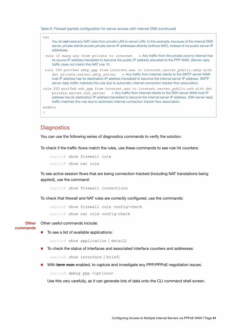
Diagnostics
You can use the following series of diagnostics commands to verify the solution.
To check if the traffic flows match the rules, use these commands to see rule hit counters:
awplus# show firewall rule
awplus# show nat rule
To see active session flows that are being connection-tracked (including NAT translations being
applied), use the command:
awplus# show firewall connections
To check that firewall and NAT rules are correctly configured, use the commands:
awplus# show firewall rule config-check
awplus# show nat rule config-check
Othercommands
Other useful commands include:
To see a list of available applications:
awplus# show application [detail]
To check the status of interfaces and associated interface counters and addresses:
awplus# show interface [brief]
With term mon enabled, to capture and investigate any PPP/PPPoE negotiation issues:
awplus# debug ppp <options>
Use this very carefully, as it can generate lots of data onto the CLI command shell screen.
nat You do not need any NAT rules from private LAN to server LAN. In this example, because of the internal DNSserver, private clients access private server IP addresses directly (without NAT), instead of via public server IPaddresses.
rule 10 masq any from private to internet Any traffic from the private zone to internet hasits source IP address translated to become the public IP address allocated to the PPP WAN. (Server replytraffic does not match this NAT rule 10.
rule 100 portfwd smtp_app from internet.wan to internet.server_public.smtp with dst private.server.smtp_server Any traffic from Internet clients to the SMTP server WANhost IP address has its destination IP address translated to become the internal server IP address. SMTPserver reply traffic matches this rule due to automatic internal connection tracker flow association.
rule 200 portfwd ssh_app from internet.wan to internet.server_public.ssh with dst private.server.ssh_server Any traffic from Internet clients to the SSH server WAN host IPaddress has its destination IP address translated to become the internal server IP address. SSH server replytraffic matches this rule due to automatic internal connection tracker flow association.
enable
!
Table 6: Firewall (partial) configuration for server access with internal DNS (continued)
Configuring Access to Multiple Internal Servers via PPPoE WAN | Page 41
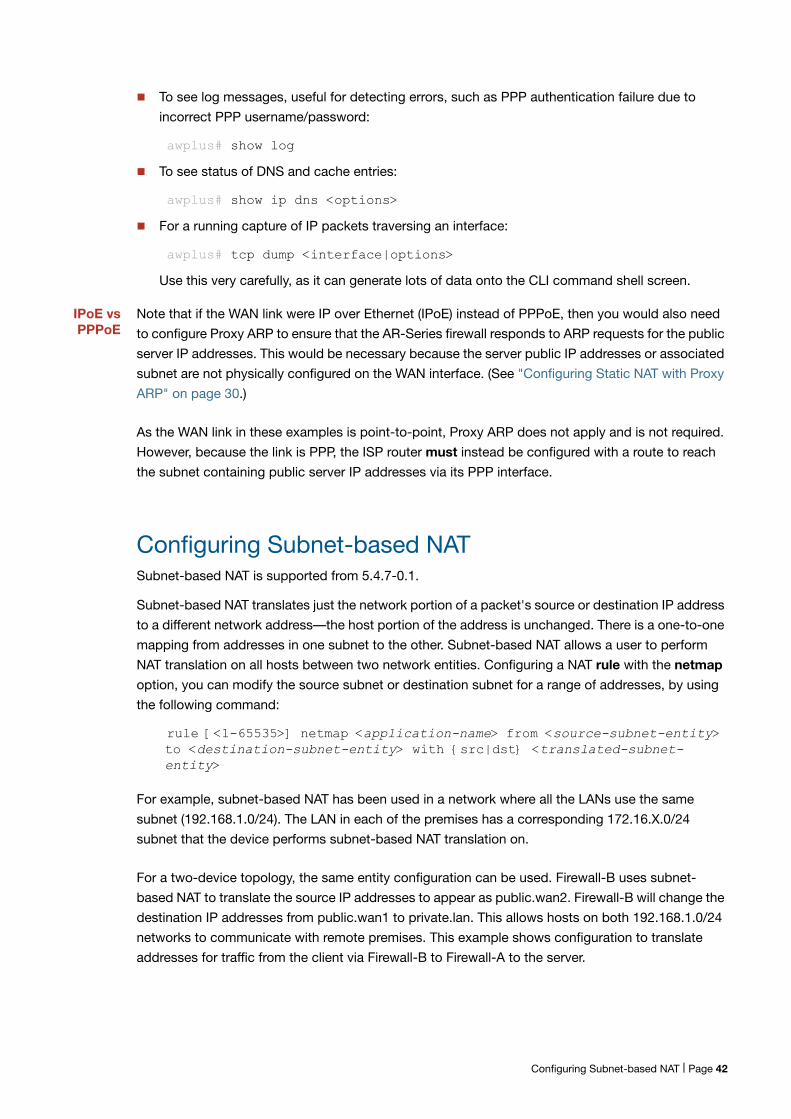
To see log messages, useful for detecting errors, such as PPP authentication failure due to
incorrect PPP username/password:
awplus# show log
To see status of DNS and cache entries:
awplus# show ip dns <options>
For a running capture of IP packets traversing an interface:
awplus# tcp dump <interface|options>
Use this very carefully, as it can generate lots of data onto the CLI command shell screen.
IPoE vsPPPoE
Note that if the WAN link were IP over Ethernet (IPoE) instead of PPPoE, then you would also need
to configure Proxy ARP to ensure that the AR-Series firewall responds to ARP requests for the public
server IP addresses. This would be necessary because the server public IP addresses or associated
subnet are not physically configured on the WAN interface. (See "Configuring Static NAT with Proxy
ARP" on page 30.)
As the WAN link in these examples is point-to-point, Proxy ARP does not apply and is not required.
However, because the link is PPP, the ISP router must instead be configured with a route to reach
the subnet containing public server IP addresses via its PPP interface.
Configuring Subnet-based NATSubnet-based NAT is supported from 5.4.7-0.1.
Subnet-based NAT translates just the network portion of a packet's source or destination IP address
to a different network address—the host portion of the address is unchanged. There is a one-to-one
mapping from addresses in one subnet to the other. Subnet-based NAT allows a user to perform
NAT translation on all hosts between two network entities. Configuring a NAT rule with the netmap
option, you can modify the source subnet or destination subnet for a range of addresses, by using
the following command:
rule [<1-65535>] netmap <application-name> from <source-subnet-entity> to <destination-subnet-entity> with {src|dst} <translated-subnet-entity>
For example, subnet-based NAT has been used in a network where all the LANs use the same
subnet (192.168.1.0/24). The LAN in each of the premises has a corresponding 172.16.X.0/24
subnet that the device performs subnet-based NAT translation on.
For a two-device topology, the same entity configuration can be used. Firewall-B uses subnet-
based NAT to translate the source IP addresses to appear as public.wan2. Firewall-B will change the
destination IP addresses from public.wan1 to private.lan. This allows hosts on both 192.168.1.0/24
networks to communicate with remote premises. This example shows configuration to translate
addresses for traffic from the client via Firewall-B to Firewall-A to the server.
Configuring Subnet-based NAT | Page 42
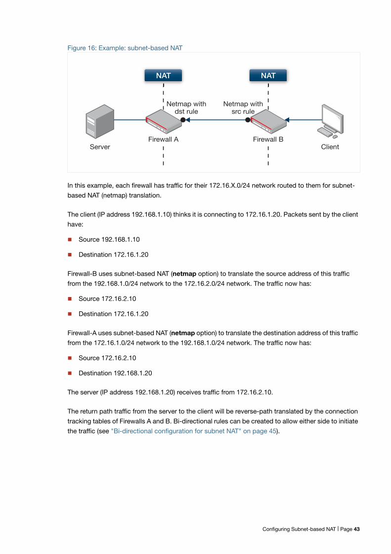
Figure 16: Example: subnet-based NAT
In this example, each firewall has traffic for their 172.16.X.0/24 network routed to them for subnet-
based NAT (netmap) translation.
The client (IP address 192.168.1.10) thinks it is connecting to 172.16.1.20. Packets sent by the client
have:
Source 192.168.1.10
Destination 172.16.1.20
Firewall-B uses subnet-based NAT (netmap option) to translate the source address of this traffic
from the 192.168.1.0/24 network to the 172.16.2.0/24 network. The traffic now has:
Source 172.16.2.10
Destination 172.16.1.20
Firewall-A uses subnet-based NAT (netmap option) to translate the destination address of this traffic
from the 172.16.1.0/24 network to the 192.168.1.0/24 network. The traffic now has:
Source 172.16.2.10
Destination 192.168.1.20
The server (IP address 192.168.1.20) receives traffic from 172.16.2.10.
The return path traffic from the server to the client will be reverse-path translated by the connection
tracking tables of Firewalls A and B. Bi-directional rules can be created to allow either side to initiate
the traffic (see "Bi-directional configuration for subnet NAT" on page 45).
Server ClientFirewall B
Netmap withsrc rule
Netmap withdst rule
NAT
Firewall A
NAT
Configuring Subnet-based NAT | Page 43
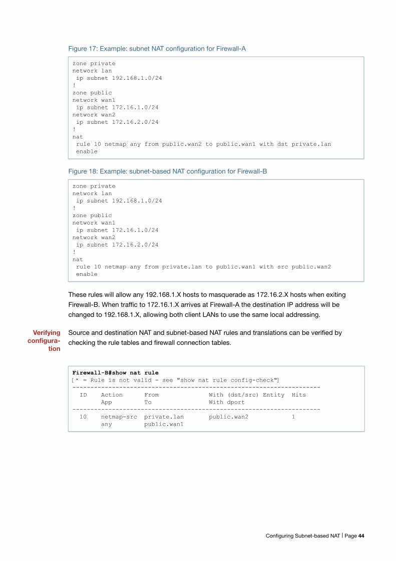
Figure 17: Example: subnet NAT configuration for Firewall-A
Figure 18: Example: subnet-based NAT configuration for Firewall-B
These rules will allow any 192.168.1.X hosts to masquerade as 172.16.2.X hosts when exiting
Firewall-B. When traffic to 172.16.1.X arrives at Firewall-A the destination IP address will be
changed to 192.168.1.X, allowing both client LANs to use the same local addressing.
Verifyingconfigura-
tion
Source and destination NAT and subnet-based NAT rules and translations can be verified by
checking the rule tables and firewall connection tables.
zone privatenetwork lan ip subnet 192.168.1.0/24!zone publicnetwork wan1 ip subnet 172.16.1.0/24network wan2 ip subnet 172.16.2.0/24!nat rule 10 netmap any from public.wan2 to public.wan1 with dst private.lan enable
zone privatenetwork lan ip subnet 192.168.1.0/24!zone publicnetwork wan1 ip subnet 172.16.1.0/24network wan2 ip subnet 172.16.2.0/24!nat rule 10 netmap any from private.lan to public.wan1 with src public.wan2 enable
Firewall-B#show nat rule[* = Rule is not valid - see "show nat rule config-check"]--------------------------------------------------------------------- ID Action From With (dst/src) Entity Hits App To With dport--------------------------------------------------------------------- 10 netmap-src private.lan public.wan2 1 any public.wan1
Configuring Subnet-based NAT | Page 44
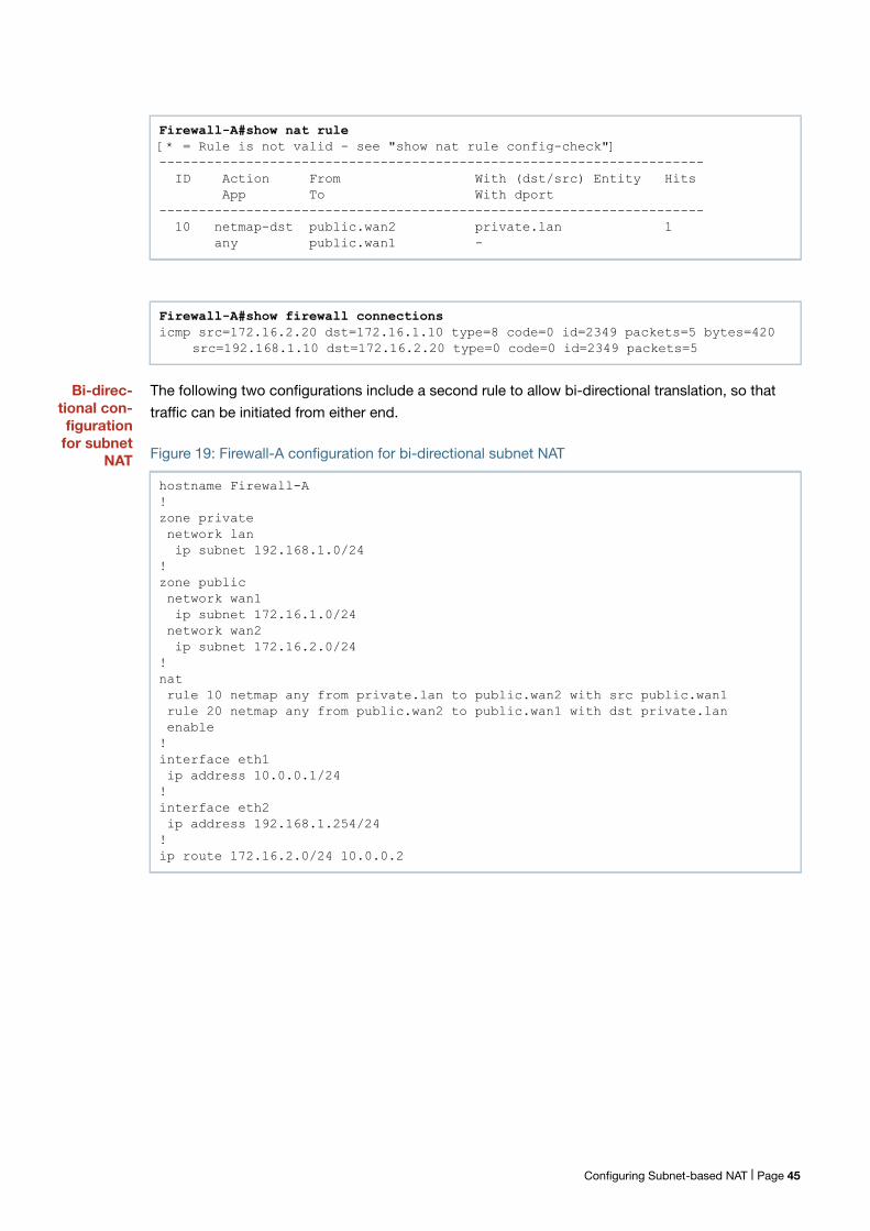
Bi-direc-tional con-figuration
for subnetNAT
The following two configurations include a second rule to allow bi-directional translation, so that
traffic can be initiated from either end.
Figure 19: Firewall-A configuration for bi-directional subnet NAT
Firewall-A#show nat rule[* = Rule is not valid - see "show nat rule config-check"]--------------------------------------------------------------------- ID Action From With (dst/src) Entity Hits App To With dport--------------------------------------------------------------------- 10 netmap-dst public.wan2 private.lan 1 any public.wan1 -
Firewall-A#show firewall connectionsicmp src=172.16.2.20 dst=172.16.1.10 type=8 code=0 id=2349 packets=5 bytes=420
src=192.168.1.10 dst=172.16.2.20 type=0 code=0 id=2349 packets=5
hostname Firewall-A!zone private network lan ip subnet 192.168.1.0/24!zone public network wan1 ip subnet 172.16.1.0/24 network wan2 ip subnet 172.16.2.0/24!nat rule 10 netmap any from private.lan to public.wan2 with src public.wan1 rule 20 netmap any from public.wan2 to public.wan1 with dst private.lan enable!interface eth1 ip address 10.0.0.1/24!interface eth2 ip address 192.168.1.254/24!ip route 172.16.2.0/24 10.0.0.2
Configuring Subnet-based NAT | Page 45
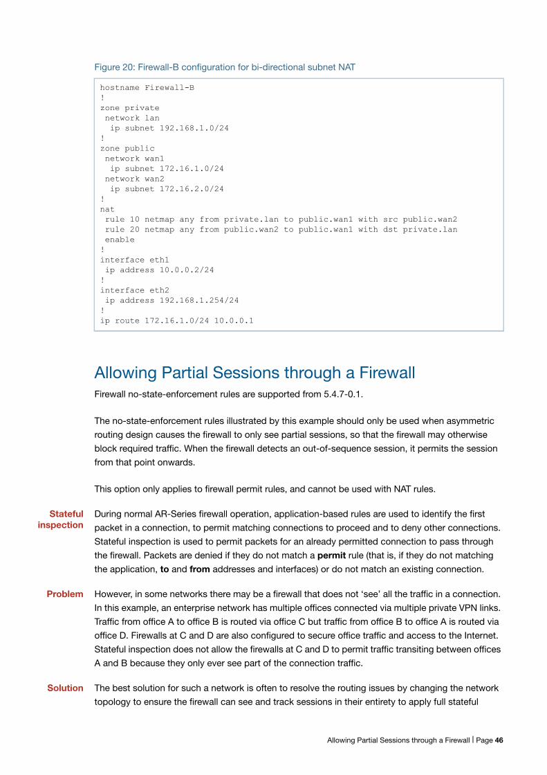
Figure 20: Firewall-B configuration for bi-directional subnet NAT
Allowing Partial Sessions through a FirewallFirewall no-state-enforcement rules are supported from 5.4.7-0.1.
The no-state-enforcement rules illustrated by this example should only be used when asymmetric
routing design causes the firewall to only see partial sessions, so that the firewall may otherwise
block required traffic. When the firewall detects an out-of-sequence session, it permits the session
from that point onwards.
This option only applies to firewall permit rules, and cannot be used with NAT rules.
Statefulinspection
During normal AR-Series firewall operation, application-based rules are used to identify the first
packet in a connection, to permit matching connections to proceed and to deny other connections.
Stateful inspection is used to permit packets for an already permitted connection to pass through
the firewall. Packets are denied if they do not match a permit rule (that is, if they do not matching
the application, to and from addresses and interfaces) or do not match an existing connection.
Problem However, in some networks there may be a firewall that does not ‘see’ all the traffic in a connection.
In this example, an enterprise network has multiple offices connected via multiple private VPN links.
Traffic from office A to office B is routed via office C but traffic from office B to office A is routed via
office D. Firewalls at C and D are also configured to secure office traffic and access to the Internet.
Stateful inspection does not allow the firewalls at C and D to permit traffic transiting between offices
A and B because they only ever see part of the connection traffic.
Solution The best solution for such a network is often to resolve the routing issues by changing the network
topology to ensure the firewall can see and track sessions in their entirety to apply full stateful
hostname Firewall-B!zone private network lan ip subnet 192.168.1.0/24!zone public network wan1 ip subnet 172.16.1.0/24 network wan2 ip subnet 172.16.2.0/24!nat rule 10 netmap any from private.lan to public.wan1 with src public.wan2 rule 20 netmap any from public.wan2 to public.wan1 with dst private.lan enable!interface eth1 ip address 10.0.0.2/24!interface eth2 ip address 192.168.1.254/24!ip route 172.16.1.0/24 10.0.0.1
Allowing Partial Sessions through a Firewall | Page 46
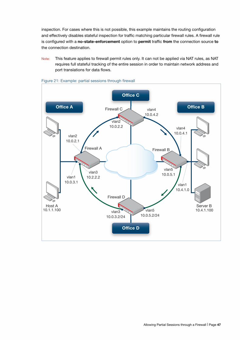
inspection. For cases where this is not possible, this example maintains the routing configuration
and effectively disables stateful inspection for traffic matching particular firewall rules. A firewall rule
is configured with a no-state-enforcement option to permit traffic from the connection source to
the connection destination.
Note: This feature applies to firewall permit rules only. It can not be applied via NAT rules, as NATrequires full stateful tracking of the entire session in order to maintain network address andport translations for data flows.
Figure 21: Example: partial sessions through firewall
vlan210.0.2.2
vlan410.0.4.2
vlan310.2.2.2vlan1
10.0.3.1
vlan210.0.2.1
Server BHost A
Firewall D
Firewall A
Firewall C
Firewall B
vlan310.0.3.2/24
vlan510.0.5.2/24
vlan510.0.5.1
vlan110.4.1.0
vlan410.0.4.1
Office C
Office D
Office BOffice A
10.4.1.10010.1.1.100
Allowing Partial Sessions through a Firewall | Page 47
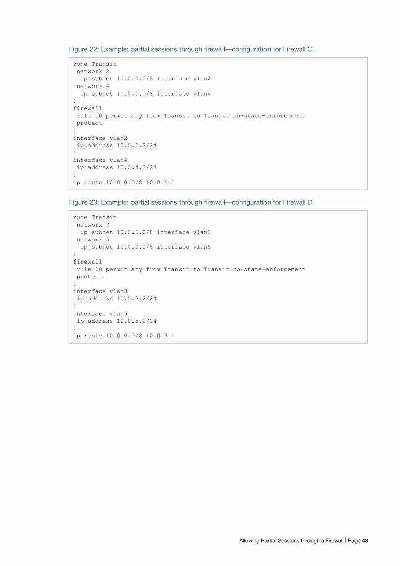
Figure 22: Example: partial sessions through firewall—configuration for Firewall C
Figure 23: Example: partial sessions through firewall—configuration for Firewall D
zone Transit network 2 ip subnet 10.0.0.0/8 interface vlan2 network 4 ip subnet 10.0.0.0/8 interface vlan4!firewall rule 10 permit any from Transit to Transit no-state-enforcement protect!interface vlan2 ip address 10.0.2.2/24!interface vlan4 ip address 10.0.4.2/24!ip route 10.0.0.0/8 10.0.4.1
zone Transit network 3 ip subnet 10.0.0.0/8 interface vlan3 network 5 ip subnet 10.0.0.0/8 interface vlan5!firewall rule 10 permit any from Transit to Transit no-state-enforcement protect!interface vlan3 ip address 10.0.3.2/24!interface vlan5 ip address 10.0.5.2/24!ip route 10.0.0.0/8 10.0.3.1
Allowing Partial Sessions through a Firewall | Page 48
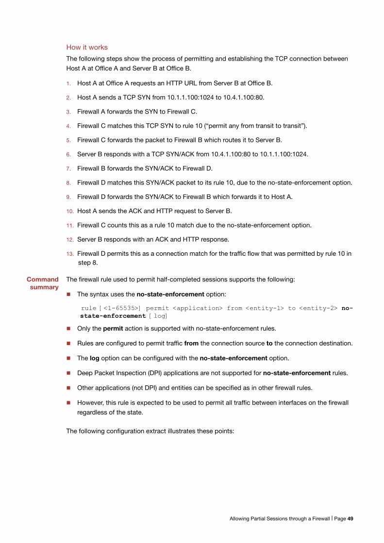
How it works
The following steps show the process of permitting and establishing the TCP connection between
Host A at Office A and Server B at Office B.
1. Host A at Office A requests an HTTP URL from Server B at Office B.
2. Host A sends a TCP SYN from 10.1.1.100:1024 to 10.4.1.100:80.
3. Firewall A forwards the SYN to Firewall C.
4. Firewall C matches this TCP SYN to rule 10 (“permit any from transit to transit”).
5. Firewall C forwards the packet to Firewall B which routes it to Server B.
6. Server B responds with a TCP SYN/ACK from 10.4.1.100:80 to 10.1.1.100:1024.
7. Firewall B forwards the SYN/ACK to Firewall D.
8. Firewall D matches this SYN/ACK packet to its rule 10, due to the no-state-enforcement option.
9. Firewall D forwards the SYN/ACK to Firewall B which forwards it to Host A.
10. Host A sends the ACK and HTTP request to Server B.
11. Firewall C counts this as a rule 10 match due to the no-state-enforcement option.
12. Server B responds with an ACK and HTTP response.
13. Firewall D permits this as a connection match for the traffic flow that was permitted by rule 10 instep 8.
Commandsummary
The firewall rule used to permit half-completed sessions supports the following:
The syntax uses the no-state-enforcement option:
rule [<1-65535>] permit <application> from <entity-1> to <entity-2> no-state-enforcement [log]
Only the permit action is supported with no-state-enforcement rules.
Rules are configured to permit traffic from the connection source to the connection destination.
The log option can be configured with the no-state-enforcement option.
Deep Packet Inspection (DPI) applications are not supported for no-state-enforcement rules.
Other applications (not DPI) and entities can be specified as in other firewall rules.
However, this rule is expected to be used to permit all traffic between interfaces on the firewall
regardless of the state.
The following configuration extract illustrates these points:
Allowing Partial Sessions through a Firewall | Page 49
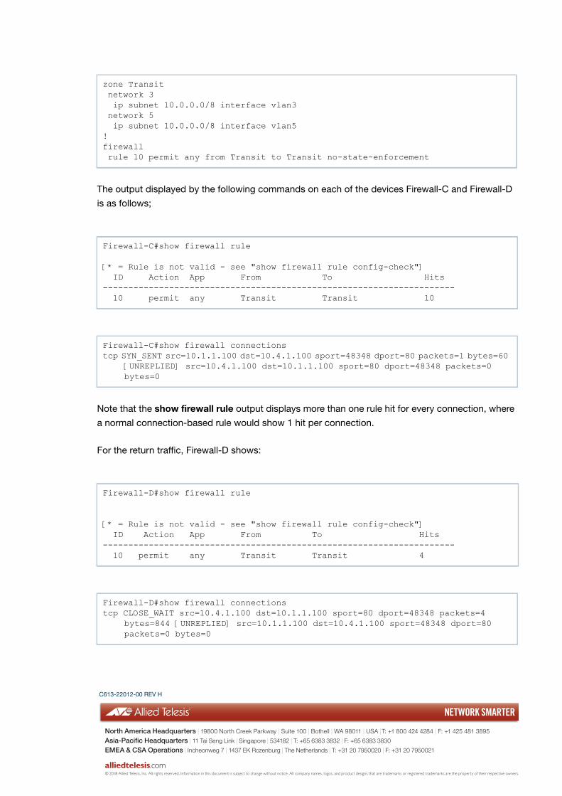
The output displayed by the following commands on each of the devices Firewall-C and Firewall-D
is as follows;
Note that the show firewall rule output displays more than one rule hit for every connection, where
a normal connection-based rule would show 1 hit per connection.
For the return traffic, Firewall-D shows:
zone Transit network 3 ip subnet 10.0.0.0/8 interface vlan3 network 5 ip subnet 10.0.0.0/8 interface vlan5!firewall rule 10 permit any from Transit to Transit no-state-enforcement
Firewall-C#show firewall rule
[* = Rule is not valid - see "show firewall rule config-check"] ID Action App From To Hits--------------------------------------------------------------------- 10 permit any Transit Transit 10
Firewall-C#show firewall connectionstcp SYN_SENT src=10.1.1.100 dst=10.4.1.100 sport=48348 dport=80 packets=1 bytes=60
[UNREPLIED] src=10.4.1.100 dst=10.1.1.100 sport=80 dport=48348 packets=0 bytes=0
Firewall-D#show firewall rule
[* = Rule is not valid - see "show firewall rule config-check"] ID Action App From To Hits--------------------------------------------------------------------- 10 permit any Transit Transit 4
Firewall-D#show firewall connectionstcp CLOSE_WAIT src=10.4.1.100 dst=10.1.1.100 sport=80 dport=48348 packets=4
bytes=844 [UNREPLIED] src=10.1.1.100 dst=10.4.1.100 sport=48348 dport=80 packets=0 bytes=0
C613-22012-00 REV H
NETWORK SMARTER
alliedtelesis.com
North America Headquarters | 19800 North Creek Parkway | Suite 100 | Bothell | WA 98011 | USA | T: +1 800 424 4284 | F: +1 425 481 3895
Asia-Pacific Headquarters | 11 Tai Seng Link | Singapore | 534182 | T: +65 6383 3832 | F: +65 6383 3830
EMEA & CSA Operations | Incheonweg 7 | 1437 EK Rozenburg | The Netherlands | T: +31 20 7950020 | F: +31 20 7950021
© 2018 Allied Telesis, Inc. All rights reserved. Information in this document is subject to change without notice. All company names, logos, and product designs that are trademarks or registered trademarks are the property of their respective owners.