Embed Size (px)
Citation preview

12/4/13 3:54 PMIEEE Xplore - HTML View
Pagina 1 di 11http://ieeexplore.ieee.org/xpls/icp.jsp?arnumber=5948402
Sign Out
Access provided by:Universita degli Studi di Roma LaSapienza
IEEE.org | IEEE Xplore Digital Library | IEEE Standards | IEEE Spectrum | More Sites
First Steps in the FTU Migration Towards a Modularand Distributed Real-Time Control Architecture Basedon MARTeThe Fusion Advanced Studies Torus (FAST) experiment is being proposed by the Italian laboratories as a Europeansatellite Tokamak that will enhance and facilitate the exploitation of ITER like scenarios and technologies. Its size andcomplexity is comparable to the largest fusion machine in the world: JET. As such, its real time control system will haveto meet basic requirements such as a modular and distributed architecture, where different control subsystems can beeasily integrated at different times and can operate either independently or in cooperation with other subsystems.Another important feature, which has to be taken into account, is the transparency regarding both the hardwareinterfacing and the adopted platform. As a test bed, we are currently planning to upgrade the architecture of theFrascati Tokamak Upgrade (FTU) real-time system in order to improve its flexibility and modularity and have decided toadopt the MARTe package to reach our goal. Currently, there are four systems under development at FTU: the LH-Power system; the gas puffing control system; the ODIN Equilibrium Reconstruction system; and the position andcurrent feedback control system (currently in a design phase). This paper will describe the current status and firstresults of the previously referred systems integration.
This paper appears in: Nuclear Science, IEEE Transactions on, Issue Date: Aug. 2011, Written by: Boncagni, L.;Sadeghi, Y.; Carnevale, D.; Mazzitelli, G.; Neto, A.; Pucci, D.; Sartori, F.; Piesco, F.; Sinibaldi, S.; Vitale, V.; Vitelli, R.;Zaccarian, L.; Monaco, S.; Zamborlini, G.
© 2011 IEEE
SECTION I
INTRODUCTION
SECTION II
BASELIB2 AND MARTe
A Tokamak control system should solve different issues, both during the experiment as well as in the configuration phase: it should stabilize the plasma dynamics,
reject disturbances, and generally help in the programming of the experiment as well. Moreover, as experimental Tokamaks evolve throughout their life and
diagnostics and actuators are progressively installed or enhanced, the system should be modular and easily upgradeable. Another requirement for the control system
of a large Tokamak is to be decentralized: thus, a real-time network becomes a necessity.
From the software point of view, the majority of those requirements is satisfied by the MARTe framework [1], which is being used on several fusion devices like JET,
COMPASS, and ISTTOK [2] to tackle different control issues. This framework provides “a clear boundary between algorithms, hardware interaction, system
configuration, leveraging reusability and maintainability” [3]. Moreover, as MARTe can run on many different OSes (mainly Wind River VxWorks, Linux,
Linux/RTAI, SOLARIS, MS Windows, and Mac OS X), the framework greatly helps in the decentralization of the control system. Due to the actual FTU software
environment and in order to be used in conjunction with RTNet, we choose the Linux-RTAI implementation of MARTe.
The first part of this paper describes the MARTe components and how we integrated them into the FTU COntrol and Data Acquisition System (CODAS) [4]. In the
second part, it reports the recent status of all the MARTe projects at FTU.
MARTe is a framework for real-time control system development. It is implemented on the top of a platform-agnostic C++ software library, called BaseLib2, which
hides to the programmer all the OS dependent details and provides tools and classes for the most common problems faced while developing control systems, such as
error reporting and managing, data and configuration parameters access and matrix operations.
BaseLib2 is heavily object-based and has been built from the ground up with flexibility in mind, making it possible to develop applications by juxtaposing objects and
making them cooperate via message passing (a concept taken from the Smalltalk programming language, and reimplemented in C++). This led to the creation of the
Multithreaded Application Realtime executor(MARTe), which basically consists of several objects whose interconnections realize the architecture of a control system.
Abstract Authors Figures Multimedia References Cited By Keywords
12/4/13 3:54 PMIEEE Xplore - HTML View
Pagina 2 di 11http://ieeexplore.ieee.org/xpls/icp.jsp?arnumber=5948402
SECTION III
MARTe FRAMEWORK AND FTU
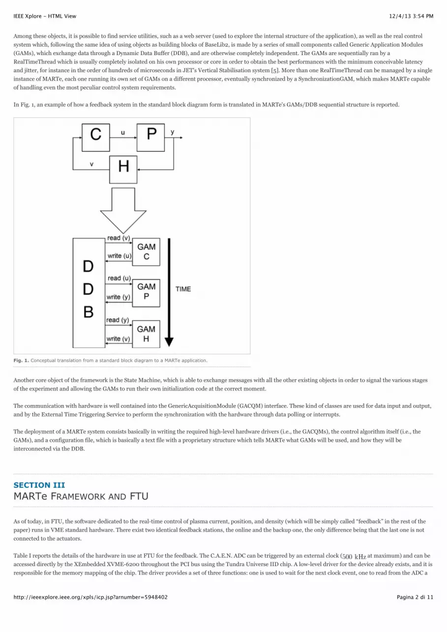
Among these objects, it is possible to find service utilities, such as a web server (used to explore the internal structure of the application), as well as the real control
system which, following the same idea of using objects as building blocks of BaseLib2, is made by a series of small components called Generic Application Modules
(GAMs), which exchange data through a Dynamic Data Buffer (DDB), and are otherwise completely independent. The GAMs are sequentially ran by a
RealTimeThread which is usually completely isolated on his own processor or core in order to obtain the best performances with the minimum conceivable latency
and jitter, for instance in the order of hundreds of microseconds in JET's Vertical Stabilisation system [5]. More than one RealTimeThread can be managed by a single
instance of MARTe, each one running its own set of GAMs on a different processor, eventually synchronized by a SynchronizationGAM, which makes MARTe capable
of handling even the most peculiar control system requirements.
In Fig. 1, an example of how a feedback system in the standard block diagram form is translated in MARTe's GAMs/DDB sequential structure is reported.
Fig. 1. Conceptual translation from a standard block diagram to a MARTe application.
Another core object of the framework is the State Machine, which is able to exchange messages with all the other existing objects in order to signal the various stages
of the experiment and allowing the GAMs to run their own initialization code at the correct moment.
The communication with hardware is well contained into the GenericAcquisitionModule (GACQM) interface. These kind of classes are used for data input and output,
and by the External Time Triggering Service to perform the synchronization with the hardware through data polling or interrupts.
The deployment of a MARTe system consists basically in writing the required high-level hardware drivers (i.e., the GACQMs), the control algorithm itself (i.e., the
GAMs), and a configuration file, which is basically a text file with a proprietary structure which tells MARTe what GAMs will be used, and how they will be
interconnected via the DDB.
As of today, in FTU, the software dedicated to the real-time control of plasma current, position, and density (which will be simply called “feedback” in the rest of the
paper) runs in VME standard hardware. There exist two identical feedback stations, the online and the backup one, the only difference being that the last one is not
connected to the actuators.
Table I reports the details of the hardware in use at FTU for the feedback. The C.A.E.N. ADC can be triggered by an external clock ( at maximum) and can be
accessed directly by the XEmbedded XVME-6200 throughout the PCI bus using the Tundra Universe IID chip. A low-level driver for the device already exists, and it is
responsible for the memory mapping of the chip. The driver provides a set of three functions: one is used to wait for the next clock event, one to read from the ADC a

12/4/13 3:54 PMIEEE Xplore - HTML View
Pagina 3 di 11http://ieeexplore.ieee.org/xpls/icp.jsp?arnumber=5948402
single channel, and the last to write to the DAC a single channel. This low-level driver can be safely used by the high-level GACQM driver for MARTe. The master-clock
and the start gate coming from the plant trigger the acquisition during the Fast Sequence Controller (FSC) phase of the FTU experiments. The Slow Control phase in
FTU (see Fig. 2) is activated by the supervisory level of the CODAS (Prometeo in the following) [4].
Fig. 2. FTU CODAS integration.
TABLE I THE FTU HARDWARE
At the start of each experiment, Prometeo sends the configuration parameter chosen for the current experiment to all systems and diagnostics, then it waits for 120 s
for a positive acknowledgment by the subsystems, and finally starts the Fast Sequence Controller (FSC) phase. During this phase, two hardware gates (synchronized
with the master-clock and its subfrequencies as well) rise up to signal -20 s and -10 s from the plasma zero (i.e., the time instant in which the plasma begins forming).
Each diagnostic can choose which gate and which subfrequency of the master-clock to use to make its own synchronization within the experiment. The feedback
system frequency is 2 kHz, and it waits in an idle state until the second gate raises up before starting the real-time control activities. After the FSC, the Prometeo
system continues its loop, acquiring measures from the subsystems and starting the post elaboration procedures. In the Slow Sequence Controller phase, the messages
Fig. 3. VMEDrv GenericAcqModule class diagram scheme.

12/4/13 3:54 PMIEEE Xplore - HTML View
Pagina 4 di 11http://ieeexplore.ieee.org/xpls/icp.jsp?arnumber=5948402
SECTION IV
LOWER HYBRID SATELLITE SYSTEMDESCRIPTION
Fig. 4. Deployed LHPP system.
exchanged by Prometeo and other systems are forwarded as TCP messages using a simple string made by a message and some basic information. The configuration
data is shared among nodes via AFS or NFS file systems.
In FTU, MARTe is being deployed using USB pendrives with a live Linux distribution. This allowed to test and deploy different systems without needing to reinstall
anything on the VME stations. Currently the GenericAcquisitionModule for the ADC and DAC, called VMEDrv, is being implemented. During the polling phase, the
VMEDrv resets (see Fig. 3) to zero the software time only if the experiment Start Gate is detected (for safety reason, if not present, the DAC output will be forced to
zero).
The same state machine in use at the JET Tokamak is being used, as the FTU sequence is quite similar. During the development phase, the MARTe Web Server is
being used to simulate the various state changes which happen during a real experiment, while the integration in the real CODAS system is realized by a simple
software named Feed2Marte which translates the Prometeo TCP messages into the corresponding HTTP ones and then forwards them to the MARTe system.
For data retrieval, the same software is being used: In fact, it is possible to retrieve the data collected by the CollectionGAMs using a simple HTTP GET. After
downloading and locally storing (for a finite time) the signals, Feed2MARTe transfers them to the official FTU archive using AFS access or some RPC call (depending
on how it is configured). The integration procedure is still work in progress.
Besides Joule effect, FTU plasmas are generally heated by radio frequencies, which, given the limited accesses, provides the most suitable tools. In particular, the FTU
is equipped with Electron Cyclotron Resonance Heating (ECRH) and Lower Hybrid (LH) systems. In this method, high frequency waves are
delivered via suitable antennas, and a part of the energy is absorbed by the plasma and transformed into heat via resonant modes of ions and electrons (or even hybrid
resonances). When LH heating is active, part of the launched waves are reflected by the plasma boundary. As the amount of reflected power is a convex or quasi-
convex function of the plasma/antenna distance, which can be affected by suitably adjusting the plasma horizontal position, extremum seeking techniques are being
applied [6].
The Extremum Seeking Algorithm requires as an input the fraction of power reflected by the plasma. This is computed as the ratio between the launched power and
the measured reflected power, and averaged among the eight central cells of the antenna (the antenna is made by a grill of 48 cells displaced in four rows of 12 cells
each). Note that, due to physical reasons, the fraction of reflected power is always greater than 5%. In the current FTU environment, this signal is an analog input to
the real-time feedback system that perform the horizontal control, and it is produced by a satellite station based on the VME standard, synchronized with the
experiment and with the main feedback control system. The satellite station is a very simple system that perform real-time calculation of the fraction of reflected
power and writes on a DAC channel the result waveform. For its simplicity, it was the first MARTe test system in the FTU real-time software environment.
The system consisted of one GAM and two IOGAMs to send and receive data from the DAC and ADC (see Fig. 4). LHTubeGAM, the core of the system, has 17 inputs
and 3 outputs. The inputs consists of time, 8 measurements for emitted power and 8 for the reflected power. The time signal is used to sample, for a time interval of a
specific duration, an average of the noise before processing. A different configuration file for debugging the algorithm has also been generated, substituting the ADC
and DAC GAMs with software generated signals taken from the FTU database.
Fig. 5 shows the cycle time (2 kHz) for the system, the reflected, emitted, and coupled power evaluated by the system.

12/4/13 3:54 PMIEEE Xplore - HTML View
Pagina 5 di 11http://ieeexplore.ieee.org/xpls/icp.jsp?arnumber=5948402
SECTION V
GAS PUFFING
Fig. 5. Cycle time, reflected, emitted and coupled power for the LHPP system.
The goal of this project is to develop a control algorithm for the plasma density in FTU. A similar control system is already implemented in the current feedback, but it
is set up for “fixed flow” (i.e., on/off) piezoelectric valves. Instead, a control algorithm for the new “variable flow” valves is desired and being developed.
The control should be active between -10 and 2 s (where 0 is the previously defined “plasma zero”). From -10 up to 0 s, the control should only act a “camera pre-fill”
following a pressure reference expressed in millibars, while from 0 up to 2 s, it must follow a reference value expressed in . The control must also
guarantee a small overshoot of the real density with respect to the preprogrammed one in order to avoid undesired instabilities, as the valve cannot extract excess gas
from the chamber. In the simulation phase, in order to test the control law, a set of mathematics models reproducing the behavior of the actuator, the chamber
pressure and plasma density evolution has been realized.
A. The MARTe Calibration System
The most important parameters of the model of the valve are its response time, 2 ms in this case, and its static characteristic flow/voltage. To estimate the
flow/voltage characteristic, a test environment was built, together with a MARTe stand-alone system (see Fig. 6) that implement the flow estimation procedure as
described in the following steps:
close the gate;
read initial pressure;
actuate a number of fixed voltage pulses of a fixed time duration on the valve;
read final pressure;
calculate
TeX Source
open the gate;
wait for the decrease of pressure to high vacuum ( millibar);
change the actuation voltage and goto (1).
1 2
3
1)
2)
3)
4)
5)
6)
7)
8)

12/4/13 3:54 PMIEEE Xplore - HTML View
Pagina 6 di 11http://ieeexplore.ieee.org/xpls/icp.jsp?arnumber=5948402
Fig. 6. Valve's flow evaluated by the MARTe Calibration System.
B. MARTe Simulation of the Control System
The proposed control law uses an anti-windup scheme by taking into account the nonlinearity caused by the saturation of the valve. The Fig. 7 show the online phase
of the MARTe Simulator System. The GasFluxControlGAM estimates the next requested flow for the valve using the error between the reference signal and the
simulated one given in feedback by the plasma model (DCNModelGAM).
To build the nonstationary linear plasma model (2), it was assumed that until the plasma zero is the number of electrons in the vacuum chamber, after the ones
confined in the plasma, is the corresponding electron density , is the chamber volume, or the plasma volume, is the confinement time, and
is the valve flow request.
Fig. 7. Closed-loop simulation in MARTe.
TeX Source
The transfer function of the controller of the system (3) is defined as
TeX Source
4

12/4/13 3:54 PMIEEE Xplore - HTML View
Pagina 7 di 11http://ieeexplore.ieee.org/xpls/icp.jsp?arnumber=5948402
SECTION VI
REAL-TIME EQUILIBRIUMRECONSTRUCTION-ODIN
and the values for in (5) were chosen using the root-locus method because it led to the absence of overshoot in the control.
The main equation to describe the plasma force balance is the Grad–Shafranov equation:
TeX Source
Fig. 8. The three phases of the development of the RT-ODIN system: debug (a), test with real signals(b), and data transfer via RTNet (c).
Equation (7) is a second-order partial differential equation, where the functions is the plasma pressure and is the current flux function which is related to
poloidal current density in an axial symmetric torus . The magnetic flux can be expanded in a series of toroidal multi-poles, by using the toroidal coordinate system
with the definition of and [7]. According to [7], the solution of the GS equation in toroidal coordinates correspond to
TeX Source
where and are Fock's functions given in terms of half integer order, first degree Legendre functions of the first and second kinds. and are internal and
external moments.
A. MARTe RT-ODIN Test and Development
The ODIN algorithm was decomposed in two GAMs: MomentsGAM and OdinGAM. The former evaluates the internal and external moments; the latter calculates a
least square approximation which fits the magnetic measurements, adjusts the moments according to this approximation, and computes a new guess for until the
difference between two subsequent iterations is less than a specified tolerance over the whole mesh. Finally, it also computes important quantities associated with the
equilibrium, such as the poloidal beta and the internal inductance . The algorithm runs with a cycle time of
The RT-ODIN system is a good example of the flexibility of the MARTe Framework. The two main GAMs of the system, MomentsGAM and OdinGAM, were written
once, debugged in a simulation environment using data stored from previous experiments, and then reused on a VME crate directly connected to the analog inputs
from the plant, as well as on a dedicated PC connected to the main feedback crate via RTNet.

12/4/13 3:54 PMIEEE Xplore - HTML View
Pagina 8 di 11http://ieeexplore.ieee.org/xpls/icp.jsp?arnumber=5948402
FOOTNOTES
REFERENCES
This work was supported by the European Community within the framework of the ENEA/EURATOM Association on Fusion Research. The views and opinions expressed herein do notnecessarily reflect those of the European Commission.
L. Boncagni, G. Mazzitelli, and V. Vitale are with the EURATOM–ENEA Fusion Association, Frascati Research Centre, Division of Fusion Physics, Rome, Frascati 00044, Italy (e-mail:[email protected])
Y. Sadeghi, D. Carnevale, S. Sinibaldi, R. Vitelli, and L. Zaccarian are with the Department of Computer Science, Systems and Production, University of Rome “Tor Vergata,” 00133Rome, Italy (e-mail: [email protected]).
D. Pucci, F. Piesco, S. Monaco, and G. Zamborlini are with the Faculty of Engineering, University of Rome “La Sapienza,” 00185 Rome, Italy.
F. Sartori is with the Fusion for Energy CODAC, 08019 Barcelona, Spain.
A. Neto is with the EURATOM–IST Nuclear Fusion Association, 1049-001 Lisbon, Portugal.
Color versions of one or more of the figures in this paper are available online at http://ieeexplore.ieee.org.
Using as feedback, the pressure measure, obtained from a PKR 251 full scale range.
Using as feedback, the measured density, obtained from interferometric measurements.
The test environment consists of a vacuum chamber, a pumping group (rotative plus turbo-molecolar pump), a controllable gate that isolate the chamber from the pumping group, thepiezoelectric valve to characterize plugged to an amplifier driven by the MARTe Calibration System that runs in a PC equipped with a NI 6024e ADC/DAC card.
In FTU, the experimentally estimated major and minor radius of plasma are 0.94 m, 0.27 m, respectively.
1. Marte: A multiplatform real-time framework
A. C. Neto, F. Sartori, F. Piccolo, R. Vitelli, G. D. Tommasi, L. Zabeo, A. Barbalace, H. Fernandes, D. F. Valcarcel and A. J. N. Batista
IEEE Trans. Nucl. Sci., vol. 57, no. 2, pp. 479-486, 2010
Quick Abstract | Show Context | Full Text: PDF
2. A survey of recent MARTe based systems
A. Neto, D. Alves, L. Boncagni, P. J. Carvalho, D. F. Valcarcel, A. Barbalace, G. D. Tommasi, H. Fernandes, F. Sartori, E. Vitale, R. Vitelli and L. Zabeo
IEEE Trans. Nucl. Sci., 2011
Quick Abstract | Show Context | Full Text: PDF
1
2
3
4
SECTION VII
CONCLUSION AND FUTURE WORK
In Fig. 8, the three phases of the evolution of the RT-ODIN system are shown. During development (phase A), a standard PC has been used to test the software, using
a waveform generator to produce the input signal for the ODIN algorithm by reading the FTU signals database. After the system was completely tested and error-free,
the MomentsGAM and ODINGAM were inserted on a MARTe system running on a VME crate connected to the analog inputs from the plant (phase B). The system
was then tested using real experimental data. After this phase, it was realized that, using RTNet, there was not any need to run the system on a VME crate, but that the
input data could be streamed via RTNet from the fast feedback system (running at ) which already had all the needed analog inputs and is being also ported to
MARTe. So a dedicated machine for ODIN was prepared and connected to the feedback system via a standard Ethernet cable (phase C, and current status of the
system), and a specific configuration file was prepared, avoiding the need to buy a new VME crate and to duplicate the input signals. It is important to stress that the
two GAMs where coded only once and never modified during all the tests and that switching between these three deeply different system configurations was just a
matter of modifying a text-only configuration file.
In this work, the essential components needed for a complete integration of the MARTe Framework in FTU have been shown, as well as some smaller MARTe systems
that were developed with the aim of acquiring skill on this environment. These systems are still work in progress; currently, the main objective is to port the actual
feedback control system to the MARTe framework, with the idea of uncovering the main issues arising during the development of a Tokamak Control System using
MARTe, and to check its scalability to larger fusion devices like Fusion Advanced Studies Torus “FAST,” a fusion project recently proposed by the Italian Association
on Fusion for a European satellite Tokamak in support of the ITER program [8].
ACKNOWLEDGMENT
The authors would like to thank the PPCC team for their generous help in carrying out this research.

12/4/13 3:54 PMIEEE Xplore - HTML View
Pagina 9 di 11http://ieeexplore.ieee.org/xpls/icp.jsp?arnumber=5948402
AUTHORS
3. ATCA control system hardware for the plasma vertical stabilization in the JET tokamak
A. J. N. Batista, A. Neto, M. Correia, A. M. Fernandes, B. B. Carvalho, J. C. Fortunato, J. Sousa, C. Varandas, F. Sartori and M. Jennison
IEEE Trans. Nucl. Sci., vol. 57, no. 2, pp. 583-588, 2010
Quick Abstract | Show Context | Full Text: PDF
4. Ftu operation
B. Angelini
Fusion Sci. Technol., vol. 45, pp. 437-458, 2004
Show Context
5. The PCU JET plasma vertical stabilization control system
F. Sartori, A. Barbalace, A. Batista, T. Bellizio, P. Card, G. D. Tommasi, P. M. Cullen, A. Neto, F. Piccolo, R. Vitelli and L. Zabeo
Fusion Eng. Des., vol. 85, no. 3-4, pp. 438-442, 2010
Show Context
6. A new extremum seeking technique and its application to maximize RF heating on FTU
D. Carnevale, A. Astolfi, C. Centioli, S. Podda, V. Vitale and L. Zaccarian
Fusion Eng. Des., vol. 84, pp. 554-558, 2009
Show Context
7. Analysis of MHD equilibria by toroidal multi-polar expansions
F. Alladio and F. Crisanti
Nucl. Fus., vol. 26, p. 1143, 1986
Show Context
8. The Fusion Advanced Studies Torus (FAST): A proposal for an ITER satellite facility in support of the development of fusion energy
A. Pizzuto
22nd IAEA Fusion Energy Conf., 2008
Show Context
Luca BoncagniNo Bio Available
Yahya SadeghiNo Bio Available
Daniele CarnevaleNo Bio Available
Giuseppe MazzitelliNo Bio Available
Andr NetoNo Bio Available
Daniele Pucci
12/4/13 3:54 PMIEEE Xplore - HTML View
Pagina 10 di 11http://ieeexplore.ieee.org/xpls/icp.jsp?arnumber=5948402
CITED BY
KEYWORDS
No Bio Available
Filippo SartoriNo Bio Available
Francesco PiescoNo Bio Available
Simone SinibaldiNo Bio Available
Vincenzo VitaleNo Bio Available
Riccardo VitelliNo Bio Available
Luca ZaccarianNo Bio Available
Salvatore MonacoNo Bio Available
Giorgio ZamborliniNo Bio Available
None
IEEE Keywords
Control systems, Hardware, Logic gates, Plasmas, Real time systems, Software, Valves

12/4/13 3:54 PMIEEE Xplore - HTML View
Pagina 11 di 11http://ieeexplore.ieee.org/xpls/icp.jsp?arnumber=5948402
Sign In | Create Account
IEEE Account
Change Username/Password
Update Address
Purchase Details
Payment Options
Order History
Access Purchased Documents
Profile Information
Communications Preferences
Profession and Education
Technical Interests
Need Help?
US & Canada: +1 800 678 4333
Worldwide: +1 732 981 0060
Contact & Support
About IEEE Xplore | Contact | Help | Terms of Use | Nondiscrimination Policy | Site Map | Privacy & Opting Out of Cookies
A not-for-profit organization, IEEE is the world's largest professional association for the advancement of technology.© Copyright 2013 IEEE - All rights reserved. Use of this web site signifies your agreement to the terms and conditions.
CORRECTIONS
INSPEC: Controlled Indexing
Tokamak devices, real-time systems
INSPEC: Non-Controlled Indexing
European satellite Tokamak, FAST experiment, FTU migration, Frascati Tokamak Upgrade, Fusion Advanced Studies Torus, MARTe package, ODIN Equilibrium Reconstruction system,distributed real-time control architecture, modular control architecture
Authors Keywords
Gas puffing, LHPP, MARTe, real-time control, rt-ODIN
None


