Embed Size (px)
Citation preview

180° Flat Bottom for a Wide Range of Applications Including Counterboring on Angled Surfaces
2ZDKFlat Bottom Drill
Smooth Chip Control and High Rigidity with Specialized Flute Design
High Precision Drilling Performance Improves True Positioning
Long Tool Life with Special Nano Coating Layer “MEGACOAT NANO”
NEW Short type Lineup Expansion up to ø20
Flat Bottom Drill 2ZDK

1
Coating Property
Internal Face Finishing
Burr Reduction
Flat Bottom Cutting in 1
Pass
Counterboring and Guide Hole Cutting with a Single End Mill
Flat Bottom Finishing after Drilling Counterboring on Slant Surface/Spotting for Secondary Process
Hole Counterboring Plunging on Thin Plate Turning in Automatic Lathes Hole Expanding
2ZDK180° Flat Bottom for a Wide Range of Applications
Available for High Precision Counterboring Optimal Tool for Improving Cost Reduction During Difficult Cutting Processes
Flat Bottom Drill
Good combination of smooth chip control and high rigidity due to the special flute shape
The special Multilayer Nano Coating prevents wear and chipping with high hardness (35GPa) and superior oxidation resistance (oxidation temperature: 1,150 °C)
Large Chip Pocket
Oxidation Resistance
40
35
30
25
20
15
10400 600 800 1,000 1,200 1,400
Low High
MEGACOATTiCN
TiNTiAIN
MEGACOAT NANO
Har
dnes
s (G
Pa)
Oxidation Temperature (°C)
180° Flat Bottom for a Wide Range of Applications1
Smooth Chip Evacuation2 Long Tool Life with “MEGACOAT NANO”3
2
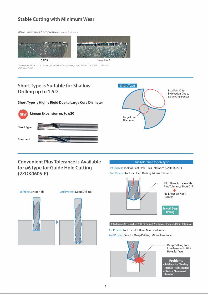
Short Type is Suitable for Shallow Drilling up to 1.5D
Convenient Plus Tolerance is Available for ø6 type for Guide Hole Cutting(2ZDK060S-P)
Stable Cutting with Minimum Wear
Wear Resistance Comparison (Internal Evaluation)
1st Process Tool for Pilot Hole: Plus Tolerance (2ZDK060S-P)
2nd Process Tool for Deep Drilling: Minus Tolerance
1st Process Tool for Pilot Hole: Minus Tolerance
2nd Process Tool for Deep Drilling: Minus Tolerance
Short Type is Highly Rigid Due to Large Core Diameter
Lineup Expansion up to ø20 NEW
1st Process Pilot Hole 2nd Process Deep Drilling
Cutting Conditions: n = 3,000 min-1, Vf = 420 mm/min, Cutting Depth 12 mm (1.5D), Wet Holes: 200Workpiece: S45C
2ZDK Competitor A
Plus Tolerance for ø6 Type
Interference Occurs when Both of 1st and 2nd Process Tools are Minus Tolerance
Smooth Deep Drilling
Pilot Hole Surface with Plus Tolerance Type Drill
No Effect on Next Process
Problems• Hole Distortion / Bending• Effects on Finished Surface• Effects on Dimension of
Diameter
Deep Drilling Tool Interferes with Pilot Hole Surface
Excellent Chip Evacuation Due to Large Chip Pocket
Large Core Diameter
Short Type
Short Type
Standard

3
• Number of Flutes (Z) = 2• Helix Angle is 20 °• The Cutting Depth Should be Less than 1.5D (1.5×Dc)
: Std. Stock MTO: Made to Order
Description StockDimensions (mm)
DrawingøDc Outside Dia.
Tolerance ℓ ℓ2 øDs L
2ZDK010S 1.0 0-0.010 3 4 4 50 Fig. 1
2ZDK011S MTO 1.1 0-0.010 3.5 4.5 4 50 Fig. 1
2ZDK012S MTO 1.2 0-0.010 3.5 4.5 4 50 Fig. 1
2ZDK013S MTO 1.3 0-0.010 4 5 4 50 Fig. 1
2ZDK014S MTO 1.4 0-0.010 4.5 5.5 4 50 Fig. 1
2ZDK015S 1.5 0-0.010 5 6 4 50 Fig. 1
2ZDK016S 1.6 0-0.010 5 6 4 50 Fig. 1
2ZDK017S MTO 1.7 0-0.010 5.5 6.5 4 50 Fig. 1
2ZDK018S MTO 1.8 0-0.010 6 7 4 50 Fig. 1
2ZDK019S MTO 1.9 0-0.010 6 7 4 50 Fig. 1
2ZDK020S 2.0 0-0.010 6 7 4 50 Fig. 1
2ZDK021S MTO 2.1 0-0.010 7 8 4 50 Fig. 1
2ZDK022S MTO 2.2 0-0.010 7 8 4 50 Fig. 1
2ZDK023S MTO 2.3 0-0.010 7 8 4 50 Fig. 1
2ZDK024S 2.4 0-0.010 8 9 4 50 Fig. 1
2ZDK025S 2.5 0-0.010 8 9 4 50 Fig. 1
2ZDK026S 2.6 0-0.010 8 9 4 50 Fig. 1
2ZDK027S 2.7 0-0.010 9 10 4 50 Fig. 1
2ZDK028S MTO 2.8 0-0.010 9 10 4 50 Fig. 1
2ZDK029S 2.9 0-0.010 9 10 4 50 Fig. 1
2ZDK030S 3.0 0-0.010 9 10 6 60 Fig. 1
2ZDK031S 3.1 0-0.012 10 11 6 60 Fig. 1
2ZDK032S MTO 3.2 0-0.012 10 11 6 60 Fig. 1
2ZDK033S 3.3 0-0.012 10 11 6 60 Fig. 1
2ZDK034S 3.4 0-0.012 11 12 6 60 Fig. 1
2ZDK035S 3.5 0-0.012 11 12 6 60 Fig. 1
Fig. 1
Fig. 3
Fig. 2
Description StockDimensions (mm)
DrawingøDc Outside Dia.
Tolerance ℓ ℓ2 øDs L
2ZDK036S MTO 3.6 0-0.012 11 12 6 60 Fig. 1
2ZDK037S 3.7 0-0.012 12 13 6 60 Fig. 1
2ZDK038S MTO 3.8 0-0.012 12 13 6 60 Fig. 1
2ZDK039S MTO 3.9 0-0.012 12 13 6 60 Fig. 1
2ZDK040S 4.0 0-0.012 12 13 6 60 Fig. 1
2ZDK041S 4.1 0-0.012 13 14 6 60 Fig. 1
2ZDK042S 4.2 0-0.012 13 14 6 60 Fig. 1
2ZDK043S 4.3 0-0.012 13 14 6 60 Fig. 1
2ZDK044S MTO 4.4 0-0.012 14 15 6 60 Fig. 1
2ZDK045S 4.5 0-0.012 14 15 6 60 Fig. 1
2ZDK046S MTO 4.6 0-0.012 14 15 6 60 Fig. 1
2ZDK047S MTO 4.7 0-0.012 15 16 6 60 Fig. 1
2ZDK048S 4.8 0-0.012 15 16 6 60 Fig. 1
2ZDK049S 4.9 0-0.012 15 16 6 60 Fig. 1
2ZDK050S 5.0 0-0.012 16 17 6 60 Fig. 1
2ZDK051S 5.1 0-0.012 16 17 6 60 Fig. 1
2ZDK052S 5.2 0-0.012 16 17 6 60 Fig. 1
2ZDK053S 5.3 0-0.012 16 17 6 60 Fig. 1
2ZDK054S MTO 5.4 0-0.012 17 18 6 60 Fig. 1
2ZDK055S 5.5 0-0.012 17 18 6 60 Fig. 1
2ZDK056S 5.6 0-0.012 17 18 6 60 Fig. 1
2ZDK057S MTO 5.7 0-0.012 18 19 6 60 Fig. 1
2ZDK058S 5.8 0-0.012 18 19 6 60 Fig. 1
2ZDK059S MTO 5.9 0-0.012 18 19 6 60 Fig. 1
2ZDK060S 6.0 0-0.012 19 (21) 6 60 Fig. 2
2ZDK060S-P 6.0 +0.0120 19 21 8 70 Fig. 1
Stock Items (Short Type)
ℓ (ℓ2)
ℓ
ℓ2
ℓ
øDc
øDc
øDc
L
L
L30
°
øDsh5
øDsh6
øDsh5

4
• Number of Flutes (Z) = 2• Helix Angle is 20 °• The Cutting Depth Should be Less than 1.5D (1.5×Dc)
Description StockDimensions (mm)
DrawingøDc Outside Dia.
Tolerance ℓ ℓ2 øDs L
2ZDK061S 6.1 0-0.015 19 21 8 70 Fig. 1
2ZDK062S 6.2 0-0.015 19 21 8 70 Fig. 1
2ZDK063S 6.3 0-0.015 20 22 8 70 Fig. 1
2ZDK064S 6.4 0-0.015 20 22 8 70 Fig. 1
2ZDK065S 6.5 0-0.015 20 22 8 70 Fig. 1
2ZDK066S 6.6 0-0.015 20 22 8 70 Fig. 1
2ZDK067S MTO 6.7 0-0.015 21 23 8 70 Fig. 1
2ZDK068S 6.8 0-0.015 21 23 8 70 Fig. 1
2ZDK069S MTO 6.9 0-0.015 21 23 8 70 Fig. 1
2ZDK070S 7.0 0-0.015 22 24 8 70 Fig. 1
2ZDK071S MTO 7.1 0-0.015 22 24 8 70 Fig. 1
2ZDK072S MTO 7.2 0-0.015 22 24 8 70 Fig. 1
2ZDK073S 7.3 0-0.015 23 25 8 70 Fig. 1
2ZDK074S MTO 7.4 0-0.015 23 25 8 70 Fig. 1
2ZDK075S 7.5 0-0.015 23 25 8 70 Fig. 1
2ZDK076S MTO 7.6 0-0.015 24 25 8 70 Fig. 1
2ZDK077S 7.7 0-0.015 24 25 8 70 Fig. 1
2ZDK078S 7.8 0-0.015 24 25 8 70 Fig. 1
2ZDK079S MTO 7.9 0-0.015 24 25 8 70 Fig. 1
2ZDK080S 8.0 0-0.015 25 (27) 8 70 Fig. 2
2ZDK081S MTO 8.1 0-0.015 25 27 10 80 Fig. 1
2ZDK082S 8.2 0-0.015 25 27 10 80 Fig. 1
2ZDK083S MTO 8.3 0-0.015 26 28 10 80 Fig. 1
2ZDK084S MTO 8.4 0-0.015 26 28 10 80 Fig. 1
2ZDK085S 8.5 0-0.015 26 28 10 80 Fig. 1
2ZDK086S MTO 8.6 0-0.015 27 29 10 80 Fig. 1
2ZDK087S 8.7 0-0.015 27 29 10 80 Fig. 1
2ZDK088S 8.8 0-0.015 27 29 10 80 Fig. 1
2ZDK089S MTO 8.9 0-0.015 28 30 10 80 Fig. 1
2ZDK090S 9.0 0-0.015 28 30 10 80 Fig. 1
2ZDK091S MTO 9.1 0-0.015 28 30 10 80 Fig. 1
2ZDK092S MTO 9.2 0-0.015 29 31 10 80 Fig. 1
2ZDK093S MTO 9.3 0-0.015 29 31 10 80 Fig. 1
2ZDK094S MTO 9.4 0-0.015 29 31 10 80 Fig. 1
2ZDK095S 9.5 0-0.015 29 31 10 80 Fig. 1
2ZDK096S MTO 9.6 0-0.015 30 32 10 80 Fig. 1
2ZDK097S MTO 9.7 0-0.015 30 32 10 80 Fig. 1
2ZDK098S 9.8 0-0.015 30 32 10 80 Fig. 1
• For 2ZDK160S and 2ZDK200S, the tolerance of the shank diameter is H6 : Std. Stock MTO: Made to Order
Description StockDimensions (mm)
DrawingøDc Outside Dia.
Tolerance ℓ ℓ2 øDs L
2ZDK099S MTO 9.9 0-0.015 31 33 10 80 Fig. 1
2ZDK100S 10.0 0-0.015 31 (33) 10 80 Fig. 2
2ZDK101S MTO 10.1 0-0.018 31 33 12 100 Fig. 1
2ZDK102S MTO 10.2 0-0.018 32 34 12 100 Fig. 1
2ZDK103S 10.3 0-0.018 32 34 12 100 Fig. 1
2ZDK104S MTO 10.4 0-0.018 32 34 12 100 Fig. 1
2ZDK105S 10.5 0-0.018 33 35 12 100 Fig. 1
2ZDK106S MTO 10.6 0-0.018 33 35 12 100 Fig. 1
2ZDK107S MTO 10.7 0-0.018 33 35 12 100 Fig. 1
2ZDK108S MTO 10.8 0-0.018 33 35 12 100 Fig. 1
2ZDK109S MTO 10.9 0-0.018 34 36 12 100 Fig. 1
2ZDK110S 11.0 0-0.018 34 36 12 100 Fig. 1
2ZDK111S MTO 11.1 0-0.018 34 36 12 100 Fig. 1
2ZDK112S MTO 11.2 0-0.018 35 37 12 100 Fig. 1
2ZDK113S MTO 11.3 0-0.018 35 37 12 100 Fig. 1
2ZDK114S MTO 11.4 0-0.018 35 37 12 100 Fig. 1
2ZDK115S 11.5 0-0.018 36 38 12 100 Fig. 1
2ZDK116S MTO 11.6 0-0.018 36 38 12 100 Fig. 1
2ZDK117S MTO 11.7 0-0.018 36 38 12 100 Fig. 1
2ZDK118S MTO 11.8 0-0.018 36 38 12 100 Fig. 1
2ZDK119S MTO 11.9 0-0.018 36 38 12 100 Fig. 1
2ZDK120S 12.0 0-0.018 37 (39) 12 100 Fig. 2
2ZDK125S 12.5 0-0.018 41 — 12 100 Fig. 3
2ZDK130S 13.0 0-0.018 43 — 12 100 Fig. 3
2ZDK135S 13.5 0-0.018 44 — 12 100 Fig. 3
2ZDK140S 14.0 0-0.018 45 — 12 100 Fig. 3
2ZDK145S 14.5 0-0.018 47 — 12 115 Fig. 3
2ZDK150S 15.0 0-0.018 48 — 12 115 Fig. 3
2ZDK155S 15.5 0-0.018 50 — 12 115 Fig. 3
2ZDK160S 16.0 0-0.018 52 (52) 16 115 Fig. 2
2ZDK165S 16.5 0-0.018 53 — 16 115 Fig. 3
2ZDK170S 17.0 0-0.018 54 — 16 115 Fig. 3
2ZDK175S 17.5 0-0.018 56 — 16 115 Fig. 3
2ZDK180S 18.0 0-0.018 57 — 16 115 Fig. 3
2ZDK185S 18.5 0-0.021 59 — 16 125 Fig. 3
2ZDK190S 19.0 0-0.021 60 — 16 125 Fig. 3
2ZDK195S 19.5 0-0.021 62 — 16 125 Fig. 3
2ZDK200S 20.0 0-0.021 63 (63) 20 125 Fig. 2

5
Description StockDimensions (mm)
DrawingøDc Outside Dia.
Tolerance ℓ ℓ2 øDs L
2ZDK070 7.0 0
-0.01532 33 8 70 Fig. 1
2ZDK075 7.5 0
-0.01534 35 8 70 Fig. 1
2ZDK080 8.0 0
-0.01536 (36) 8 70 Fig. 2
2ZDK085 8.5 0
-0.01538 39 10 80 Fig. 1
2ZDK088 8.8 0
-0.01539 40 10 80 Fig. 1
2ZDK090 9.0 0
-0.01540 41 10 80 Fig. 1
2ZDK095 9.5 0
-0.01542 43 10 80 Fig. 1
2ZDK100 10.0 0
-0.01545 (45) 10 80 Fig. 2
2ZDK103 10.3 0
-0.01846 47 12 100 Fig. 1
2ZDK105 10.5 0
-0.01847 48 12 100 Fig. 1
2ZDK110 11.0 0
-0.01851 52 12 100 Fig. 1
2ZDK115 11.5 0
-0.01853 54 12 100 Fig. 1
2ZDK120 12.0 0
-0.01854 (54) 12 100 Fig. 2
• Number of Flutes (Z) = 2• Helix Angle is 20 °• The cutting depth should be less than 2D (2×Dc)• Step machining is recommended when cutting depth is over 2D
: Std. Stock
Description StockDimensions (mm)
DrawingøDc Outside Dia.
Tolerance ℓ ℓ2 øDs L
2ZDK030 3.0 0
-0.01014 15 6 60 Fig. 1
2ZDK033 3.3 0
-0.01215 16 6 60 Fig. 1
2ZDK035 3.5 0
-0.01217 18 6 60 Fig. 1
2ZDK040 4.0 0
-0.01219 20 6 60 Fig. 1
2ZDK042 4.2 0
-0.01220 21 6 60 Fig. 1
2ZDK045 4.5 0
-0.01221 22 6 60 Fig. 1
2ZDK050 5.0 0
-0.01223 24 6 60 Fig. 1
2ZDK053 5.3 0
-0.01224 25 6 60 Fig. 1
2ZDK055 5.5 0
-0.01225 26 6 60 Fig. 1
2ZDK056 5.6 0
-0.01226 27 6 60 Fig. 1
2ZDK060 6.0 0
-0.01228 (28) 6 60 Fig. 2
2ZDK065 6.5 0
-0.01530 31 8 70 Fig. 1
2ZDK068 6.8 0
-0.01531 32 8 70 Fig. 1
Stock Items (Standard)
Fig. 2
ℓ(ℓ2)
øDc
L
øDsh5
Fig. 1
ℓ2
ℓ
øDc
L
30°
øDsh5

6
Material ApplicationOutside Dia. Dc
(mm)ø1 ø2 ø3 ø4 ø5 ø6 ø8 ø10 ø12 ø14 ø16 ø18 ø20
Structural Steel, Carbon SteelSS400, S45C
Plunge Milling
Spindle Revolution (min-1)
19,500 11,200 8,300 6,200 5,000 4,200 3,200 2,500 2,100 1,800 1,600 1,400 1,300
Feed Rate (mm/min)
300 380 520 520 520 520 520 450 450 450 450 450 450
Alloy SteelSCM, SNCM
Spindle Revolution (min-1)
19,000 10,000 7,200 5,400 4,400 3,600 2,700 2,200 1,800 1,500 1,350 1,200 1,100
Feed Rate (mm/min)
300 320 450 450 450 450 450 400 400 400 400 400 400
Pre-hardened SteelNAK
(30~45HRC)
Spindle Revolution (min-1)
16,000 8,000 3,900 2,900 2,300 1,900 1,500 1,200 1,000 850 750 650 600
Feed Rate (mm/min)
210 210 210 210 210 210 210 190 190 190 190 190 190
Nodular Cast IronFCD400
Spindle Revolution (min-1)
16,000 10,000 7,200 5,400 4,400 3,600 2,700 2,200 1,800 1,550 1,350 1,200 1,100
Feed Rate (mm/min)
200 300 390 390 390 390 390 340 340 340 340 340 340
Aluminum AlloyA7075
Spindle Revolution (min-1)
20,000 20,000 17,800 13,100 10,500 8,900 6,700 5,400 4,500 3,800 3,400 3,000 2,700
Feed Rate (mm/min)
500 850 1,270 1,270 1,270 1,270 1,270 1,270 1,270 1,270 1,270 1,270 1,270
Aluminum Alloy CastingAC, ADC
Spindle Revolution (min-1)
20,000 20,000 13,100 10,000 8,000 6,700 5,000 4,000 3,400 2,900 2,500 2,200 2,000
Feed Rate (mm/min)
450 750 820 820 820 820 820 820 820 820 820 820 820
Notes• This tool is specially designed for plunging and NOT recommended for traversing• Coolant is recommended• Adjust ap to suit machine rigidity• Use chuck and machine with the highest rigidity possible• Stainless steel cutting (SUS304/SUS316) is NOT recommended• Cutting condition modifications may be needed when cutting a slant surface, depending on the slant angle
(Right Figure) When workpiece slant is 30° or less, reduce the feed rate by 50% When workpiece slant is 30° or more, reduce the revolution by 70% and the feed rate by 30%
Standard Short Type
Cutting Depth2D (2×Dc) or less
θ
Outside Dia. (ø Dc)
θ
Outside Dia. (ø Dc)
Cutting Depth1.5D (1.5×Dc) or less
Cutting Conditions

© 2016 KYOCERA Corporation CP364
Case Studies
ø 8
1 4
ø 5.
590°
ø 80
Transmission Parts S35C
Valve Parts SUM22
n = 2,600 min-1 (Vc = 49 m/min), Vf = 130 mm/min (f = 0.05 mm/rev), WetNumber of Workpieces 100
Valve Parts SUS440C
Shaft SCr420H
n = 2,000 min-1 (Vc = 34 m/min), Vf = 200 mm/min (f = 0.08 mm/rev), WetNumber of Workpieces 30,000
Counterboring Before Oil Hole Drilling
n = 1,800 min-1
(Vc = 62 m/min)Vf = 270 mm/min (f = 0.15 mm/rev)Hole Depth 17.3 mmWet (Oil-based)2ZDK111S
Hole Counterboring with Drill in Automatic Lathe
2ZDK0552ZDK060
Stable Cutting with
Less Wear
Improved Yield Rate and Stable
Cutting
Competitor B caused chattering and fractures to occur on the cutting edge. 2ZDK maintained stable cutting with no chattering. Tool life was extended 1.6 times that of Competitor B. (User Evaluation)
(User Evaluation) (User Evaluation)
Number of Workpieces
4,500 pcs
2,700 pcs
1.6Times
Tool Life2ZDK
Competitor B
ø 15
17.3
n = 3,600 min-1
(Vc = 18 m/min)Vf = 70 mm/min (f = 0.02 mm/rev)Hole Depth 2 mmDry2ZDK016S
Tool life of Competitor C was unstable due to fracturing. 2ZDK maintained triple tool life with stable cutting performance.
(User Evaluation)
Number of Workpieces
2,700 pcs
900 pcs
3Times
Tool Life2ZDK
Competitor C
2
ø 35