Embed Size (px)
Citation preview
Central Washington University Central Washington University
ScholarWorks@CWU ScholarWorks@CWU
All Undergraduate Projects Undergraduate Student Projects
Spring 2020
Forge Burner Forge Burner
Caleb DesJardins Central Washington University, [email protected]
Follow this and additional works at: https://digitalcommons.cwu.edu/undergradproj
Part of the Heat Transfer, Combustion Commons, and the Manufacturing Commons
Recommended Citation Recommended Citation DesJardins, Caleb, "Forge Burner" (2020). All Undergraduate Projects. 120. https://digitalcommons.cwu.edu/undergradproj/120
This Undergraduate Project is brought to you for free and open access by the Undergraduate Student Projects at ScholarWorks@CWU. It has been accepted for inclusion in All Undergraduate Projects by an authorized administrator of ScholarWorks@CWU. For more information, please contact [email protected].
Forge Burner
Caleb DesJardins
Abstract 4
Introduction 5 Description 5 Motivation 5 Function Statement 5 Requirements 5 Engineering Merit 5 Scope of Effort 5 Success Criteria 6
Design and Analysis 6 Approach (RADD) 6 Design Description 6 Benchmark 6 Performance Predictions 6 Scope of Testing And Evaluation 7 Analyses 7 Device: Parts, Shapes and Conformation 7 Device Assembly, Attachments 7 Tolerances 7
Methods and Construction 8 Methods 8 Construction 8
Testing Methods 9
Budget 9
Schedule 10
Project Management 11
Discussion 11 Design Evolution / Performance Creep 11 Project Risk Analysis 12 Successful 12 Next Phase 13
Conclusion 13
1
Acknowledgment 13
References 14
Appendix A 15 A1: Flow rate of propane at 5psi gage. 15 A2: Flow rate of propane at 10psi gage. 16 A3: Flow rate of propane at 15psi gage. 17 A4: Flow rate of propane at 20psi gage. 18 A5: Flow rate of propane at 25psi gage. 19 A6: Flow rate of propane at 30psi gage. 20 A7: Flow rate of propane at 35psi gage. 21 A8: Flow rate of propane at 40 psi gage. 22 A9: Intake area as a function of valve height 23 A10: Required intake area for 10psi 24 A11: Required intake area for 20psi 25 A12: Required intake area for 30psi 26 A13: Required intake area for 40psi 27
Appendix B 28 20-0001 Burner Body 29 20-0002 Intake Valve 30 20-0003 Injector Bracket 31 20-0004 Burner Intake 32 20-0005 Burner Injector 33 10-0001 Burner Assembly 34 10-0002 Burner Assembly Exploded View 35
Appendix C 36 Parts List: 36
Appendix D 37
Appendix E 38
Appendix G 40 G1 40 G2 40 G3 Raw Data 40 G5 41
Appendix H 42
2

Appendix J 43
3
Abstract
Can small scale blacksmithing operations achieve a level of efficiency in their forge comparable to that of a large scale industry? The causes for the lack of efficiency needed to be pinpointed, and then the geometry of the existing design for the burner could be changed to fix the underlying issues, while still maintaining functionality. The problems with the previous design is the geometry of the intake giving an unknown air/fuel ratio, and the attachment of to the forge allowing the intake air to be contaminated by exhaust gasses. A burner needed to be designed that would solve these problems while maintaining the ability to output an oxidising flame for when an oxidised workpiece is desired. The final approach for finding the optimal intake geometry was based on a ratio between the propane injector outlet area and the air inlet area. This ratio was calculated based off of the desired air/fuel ratio and the density ratio between air and propane. This approach was compared with flow rate analysis at various propane pressure settings. The result of this calculation is that for any set propane pressure, the height of the intake opening needs to be .232 inches high. The input pressure of the propane does not affect this result. The intake valve was still designed to be adjustable so it could still produce an oxidising flame as desired. The optimized burner can be attached to a forge by a flange that prevents exhaust gasses from entering the intake.
4
Introduction
Description Propane forge burners are often made by professional and hobbyist blacksmiths to step
into an alternative to coal forges. A common theme among them is that they are built out of black iron pipe fittings. Making the burner out of pipe fittings makes it easy, however it results in a lack of efficiency due to the lack of precision in adjusting air/fuel ratio. High efficiency can be obtained by allowing excess air, but this puts more oxygen into the forge, making the metal inside oxidize too much. Burners are also usually attached with set screws holding them in a hole, which makes it difficult to remove the burner and allows the exhaust gas to get into the intake and make them run poorly. Motivation
The motivation behind this project is a need for easy operation of a forge and efficient use of fuel. Blacksmithing requires proper timing to avoid overheating the material and working the material before it gets cold, so a burner that is easy to operate mitigates distraction from the heat cycles. Function Statement
The Forge Burner is meant to burn propane more efficiently and with less excess oxygen than black iron pipe alternative. Requirements
● Burner must be detachable within seconds. ● Intake must be adjustable with specific settings optimized for different propane pressures
from 10 to 40 psi. ● Brings the forge floor up to 1000°F 20% faster than existing black iron pipe design. ● Forge exhaust must not be able to flow directly into the intake.
Engineering Merit
The merit behind engineering the burner is obtaining a specific efficiency. Fluid mechanics calculations are required to find the flow rates of the air and propane in order to optimize air-fuel ratio. The flow rate of air will have to be calculated for different intake settings to correspond with different propane pressures. Scope of Effort
The scope of the project is limited to the geometry of the burner, the intake adjustment and the attachment system to the forge. The forge itself is not designed as it is a control between the designed burner tests and benchmark burner tests.
5
Success Criteria At a given propane pressure, the burner would have to bring a forge up to temperature
faster than a black iron pipe burner and reach a higher ultimate temperature. For a successful test, the burner will reach temperature 20% faster than the benchmark burner, while consuming 20% less fuel per minute.
Design and Analysis Approach (RADD)
The burner is required to be 20% more efficient than the benchmark burner. This is done by analyzing the flow rates of air and propane and varying geometry to match stoichiometric ratio. Analyses are shown in appendix A. The design parameters are a flange on the body to block exhaust gasses and an adjustable intake with graduations to show the required valve setting for optimized air/fuel mixture for the current propane setting. The burner body with the flange is shown in appendix B 20-0001. Adjustable intake assembly is shown in appendix B 20-0002 through 20-0005. Design Description
The burner consists of three main parts/assemblies. The intake assembly is mounted at the top of the burner and has a propane injector suspended above a conical air intake where the flow of propane entrains the air for combustion. The air and propane enters the burner body, where turbulence causes them to mix along the length of the mixing tube. At the end of the mixing tube is a nozzle for the gas to expand into and combust. Basic design is based off of the benchmark burner, however it has the following additions to improve efficiency: To block the flow of exhaust gas, the burner body has a flange that covers the burner hole. To adjust the airflow, the intake has a disc that is threaded onto the propane injector, so it can be raised up, or lowered down by spinning it to adjust intake area. The side of the injector bracket is graduated to show the height needed for each propane pressure. Drawings of all parts are shown in appendix B. Benchmark
The benchmark is a black iron pipe burner and set screw attachment. The benchmark burner is based on a common design used by professional and hobbyist blacksmiths. There is no intake adjustment on the benchmark and attaching it to a forge with set screws allows for exhaust gasses to reach the intake. Performance Predictions
The improved efficiency of the burner will result in a more even burn of the propane and a less oxidising flame. Uneven burning of propane in the benchmark burner is apparent based on the sound of the burner, and the sound of the designed burner’s flame will be an even roar. Optimal air/fuel ratios will be achieved at any propane pressure setting within 10 psi increments as shown in appendix A10-A13. The exhaust gasses from the burner will not be allowed to
6
recirculate back into the intake as the burner port does not allow the gas to flow directly up. Air/fuel mixture is unknown for the benchmark burner, so exact improvement is unknown. Scope of Testing And Evaluation
Testing will be limited to the resulting performance of the burner to bring a forge up to working temperature and to limit oxidation of the workpiece. Analyses
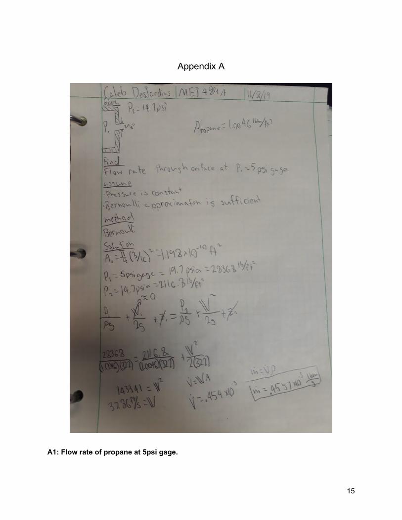
The objective of the analysis was to find the optimal intake area for stoichiometric combustion. Mass flow rates of propane through the ejector were calculated for various input pressures through Bernoulli approximation. These values were used to calculate required intake area for stoichiometric combustion based on the assumption that air and fuel velocities would be equal. From these analyses, it was concluded that the intake area would be the same for any input pressure. The final approach for finding the optimal intake geometry was based on a ratio between the propane ejector outlet area and the air inlet area. This approach was discovered in “A Simple Method for the Design of Gas Burner Injectors.” by CJ Lawn. This ratio was calculated based off of the desired air/fuel ratio and the density ratio between air and propane. This approach was compared with flow rate analysis at various propane pressure settings. The result of this calculation is that for any set propane pressure, the height of the intake opening needs to be .232 inches high. All green sheets for this analysis is shown in Appendix A. Device: Parts, Shapes and Conformation
The general shape of the internal geometry of the burner tapers to a small area in the intake to accelerate it into the mixing tube, and then tapers out in the nozzle for the gas to expand for combustion. The burner body has a flange with holes for press fitting pins to locate it on the Forge coupler. Device Assembly, Attachments
All parts will be threaded and bolted together in the configuration shown in appendix B 10-0001. The opening of the injector will be where the propane line and regulator will be attached. Tolerances
All tolerances are given in ANSI Y14.5 drawings shown in appendix B 20-00001 through 20-00005. Most parts are given standard tolerance so parts fit together without interference. Holes in the flange of the burner body are given tighter tolerance as they will be reamed for a pin to be press fit into.
7
Methods and Construction
Methods The components are constructed using the CWU machine lab.The burner body will be
bored and turned on a lathe, and then holes will be drilled and reamed on a mill. ● The Burner Body is made up of a threaded pipe with a flange. The pipe and the flange
will be machined separately and welded together in order to save time turning the whole thing out of cylindrical stock. Burner body drawing is shown in appendix B 20-0001.
● Internal geometry of the nozzle was bored out on a lathe. ● The Intake was the most difficult to manufacture as it had the most complicated features,
and the work holding was an issue as the outside was tapered. The cylindrical stock was first drilled out on the lathe to get a through-hole for boring the internal taper. An arbor then needed to be designed to mount the intake in a chuck or vise so the outside taper and the flats could be machined. This was made by turning a taper on a piece of round stock to match the internal taper of the intake. A hole was then drilled and tapped so the intake could be bolted to it. The arbor also makes it easier to tap the holes in the side to accept the socket head screws. The drawing or the Intake is shown in appendix B 20-0004.
● The inside of the injector was drilled out of threaded rod. Outer features were then turned on a lathe and the end was threaded to attach to the injector bracket and accept the propane line. Injector dimensions are shown in appendix B 20-0005. Later iterations may be machined with finer thread pitch for finer adjustability.
● The intake valve was knurled on the outside and drilled and tapped in the center to be threaded onto the injector. These operations were done on a longer piece of stock and then was parted off. Due to the long diameter being parted on the lathe, it had to be done in multiple “bites” to make a groove wider than the parting tool to reduce friction on the tool.
● The injector bracket was rough-cut on the bandsaw, and final dimensions were machined on the mill out of a flat plate with appropriate holes drilled and tapped shown in appendix B 20-0003. Graduations were stamped on the side of the brackets showing the corresponding intake setting for a certain propane pressure setting.
● The forge couple was not fully machined as it will be easier to buy a pipe coupler and drill two holes in it to accept locating pins on the burner body flange.
Construction
The burner body is threaded at both ends with a pipe threader for the intake and nozzle to be threaded at both ends. Original design used locating pins that were press-fit into the holes in the burner body flange. The pins were switched out for socket head screws so the burner is able to be screwed into the forge if so desired. The screws still allow for the original attachment plan as they can be used as locating pins. The injector bracket was then attached to the intake with fasteners. The injector and intake valves are then threaded together, and the propane lines
8
can then be attached to the injector. Propane fitting requires a 45 degree coupler attached to the injector, a brass pipe nipple to attach to a ball valve, and an adapter to connect the ball valve to the propane line. The propane line comes from a regulator at the propane tank. The drawing tree in appendix B shows all parts as they connect to each other. Full assembly is shown in appendix B 10-0001 and 10-0002.
Testing Methods
The desired outcomes of the burner are higher efficiency to heat up a forge more quickly without a lean burn causing the workpiece to oxidize too much. The burner is tested against the benchmark black iron pipe burner. The sound of the burner is also a component of the test, as a smoother sounding burn is an indication of a more efficient burn. The forge will start cold in the testing and both burners will be timed to reach 1000 °F. The tests will have to take place on different days to make sure the forge is fully cooled between tests. Weather will have to be taken into account as different temperatures of ambient air affects heating rate and density of intake air. Oxidation testing will be done by maintaining 15 psi of propane pressure and placing a piece of steel in for a given amount of time. Plain carbon steel will be used for the test as it has a higher affinity for oxidation.The responding variable for the oxidation test will be mostly visual as it will be difficult to measure. The air-fuel mixture of the benchmark burner is unknown, therefore it is unknown how the two burners compare. If the benchmark is running lean, then the new burner will improve the excel in the oxidation test but increases in the efficiency will be minimal. If the benchmark is running a rich mixture, the new burner will greatly improve efficiency.
One round of the testing for the benchmark burner was completed to verify if the testing setup was valid. For the first test, the thermocouple reached the maximum heat within minutes while the forge was not even at full temperature. This result is most likely the result of the thermocouple probing along the roof of the forge. This was originally done because most heat treating kilns probe the temperature from the roof. However, heat treating kilns are usually heated slowly with electric coils; as opposed to a propane forge which is heated as quickly as possible with a burner. To get a more accurate reading on the forge, the thermocouple was moved to the bottom of the forge to measure the ambient temperature rather than all the heat rising to the top. One round of testing was completed for the benchmark and the engineered burner with this setup and it got the same result as the previous probe location. The final time-to-heat test was completed with the thermocouple under the floor brick. This was successful because the criteria for a forge being “up to temperature” is based on the floor brick being saturated with heat.
Budget
All raw materials and fittings were bought from Mcmaster-Carr. Total expected cost came out to $137.53. Itemized budget is shown in appendix D. Mainly round stock was required
9
for the majority of the parts to be machined out of. All parts that show in the parts list in appendix C that are not shown in the budget were already owned. Labor was valued at $100 per hour with no outsourced labor. Tentative schedule as shown in appendix E predicts 150.4 hours of labor is required, making the total labor cost equal $15,040. Although labor is valued at $100 per hour, it will be completed by a willing engineer accepting $0 per hour, putting the total project cost at $137.53. Funding may be sourced from CWU, however if CWU does not accept the request, it will have to be funded by the engineer (regardless of his/her poor financial status).
After all the raw materials and pipe fittings were bought, the total cost came out to $140.27. This is close to what was budgeted as no deviations in the parts list has been made so far. All parts were ordered from McMaster-Carr as predicted and they all were delivered in a timely manner. All raw steel material ordered from McMaster-Carr was delivered within the tolerance specifications promised by the website. However, there are future plans to manufacture more nozzles out of ceramic so they can be used long-term instead of oxidizing away like the steel one. Machinable ceramic will be ordered from Maryland Lava Company. Pricing is not shown on the website, and scrap material will be requested to avoid going too far over budget.
Most of the unexpected expenditures came from the testing setup. It was assumed that the testing wouldn't cost anything since the forge was already owned. However, the forge required repairs before the testing could be done, so more insulation bricks were purchased. This added $62.87 to the final cost. A thermocouple also needed to be purchased to measure the forge temperature. The thermocouple cost $46.06, bringing the total testing cost to $108.93. After adding the cost of testing materials, the total material cost for the project was $249.20, this was 181.2% the predicted material cast for the project.
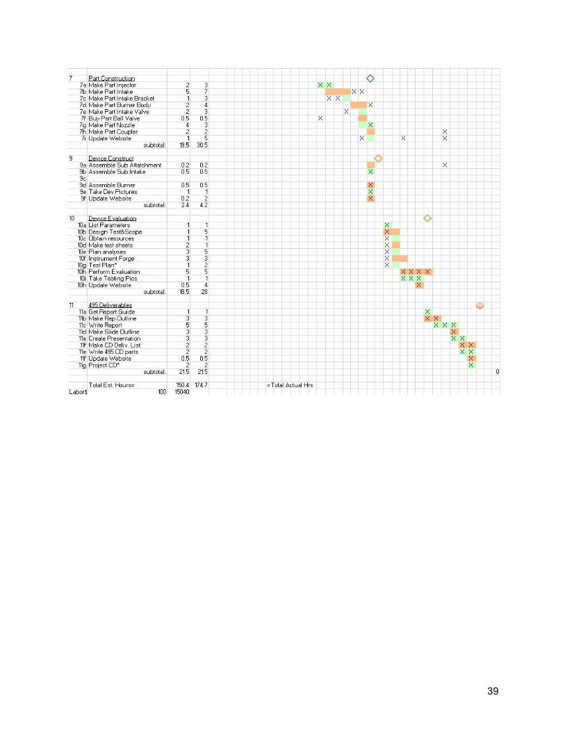
Schedule
The main deliverables for the project were the proposal with an initial design for the burner, parts that need machining, full assembly of device assembled with purchased parts, and a full test of the device with a testing report. The proposal for the project with the design is to be completed before December 6th, and all changes to design must be completed before the following January 7th. A fully assembled device must be completed before March 13th with various milestones for machined part completion in between. Testing began on March 31st and a full report of the test was completed before June 5th. All individual tasks were scheduled in appendix E with predicted time constraints for each task. Actual time spent is shown for only completed tasks.
The manufacturing process deviated from the original plan because the order of parts being manufactured needed to be changed. The original plan was designed so the most difficult part (the Intake) was made first. That way the hardest part is done first, and a lot of other parts attach to it, so they can be fit up as they are manufactured. The manufacturing order ended up being dictated by when raw material can be obtained. The injector was made first because the
10
stock could be bought at ACE, and the injector bracket was made next because it was made from scrap. The rest of the parts are made from raw material from McMaster-Carr. The intake, nozzle, and burner body flange were completed in respective order as they were all made from the same piece of cylindrical stock. The majority of the machining processes took longer than expected. The timeline of parts being completed did not fall behind schedule, the individual processes just took more hours. The final assembly was completed on March 9th.
The testing deviated from the plan as it required some preliminary tests to find the final method. After the thermocouple was acquired, it was originally placed near the top of the forge, and the heat rose to the top and caused the probe to overheat. A new prob needed to be purchased, delaying the testing by a week. The next week of testing was then occupied by testing where the optimal place to probe for heat would be. Once the thermocouple was set up in the right place,the benchmark test and engineered burner test were completed. These two tests had to be completed across two days as the forge needed to cool down between tests.
Project Management
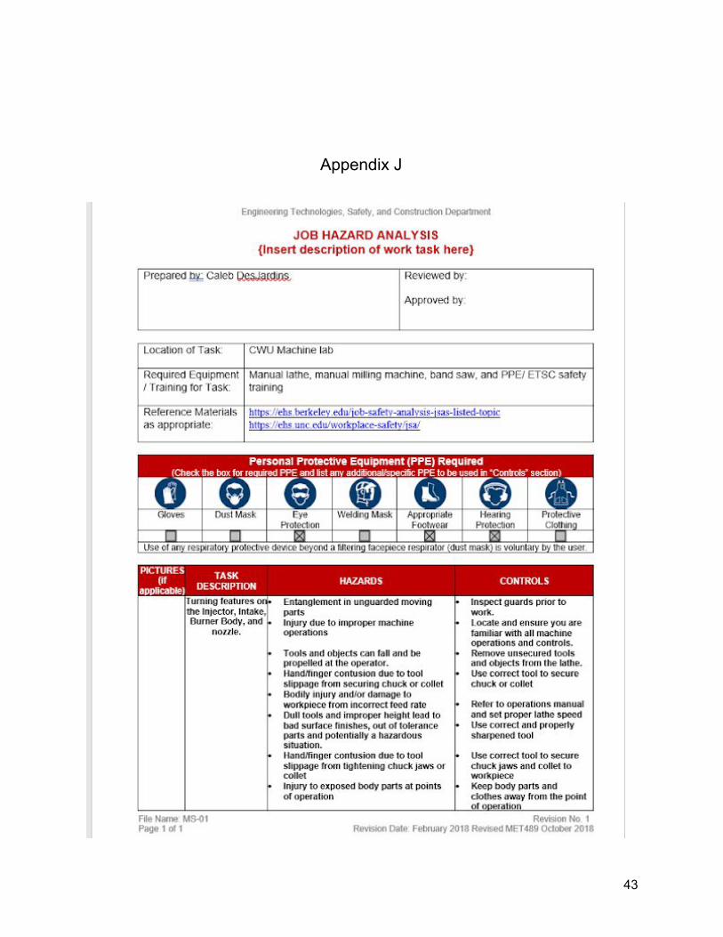
The project is overseen by Professor Charles Pringle, Dr. Craig Johnson, and Dr. John Choi. The success of the project will be facilitated by the guidance and expertise of the overseeing professors and machine lab support techs. Physical resources required are accessible in the CWU machine lab. Solidworks and AutoCAD are available on all CAD lab computers for designing the burner. Funding can be supported by the engineer, and funding from CWU will be requested. The project will be designed, built, and tested by the principal engineer. The engineer’s resume is shown in appendix J.
Discussion
Design Evolution / Performance Creep The burner was originally going to be designed with an electric blower to give forced
induction. This design was later overlooked as it would not give adjustability in the air flow. The burner body was originally two inches shorter, however in order for the nozzle to sit in the right position in the forge with the length of the forge coupler and the thickness of the forge insulation, the extra length was added. After measuring the distance from the mating surface to the entrance to the forge, the flange on the burner body had to be moved upward so the nozzle would sit at the right height. The first design of the injector bracket was 3 inches tall, however analyses showed that it could be shortened and still give desired adjustability. The original design had a one inch inner diameter in the burner body, and the intake and nozzle. However later approaches to solving the flow rate problem suggested that a ¾ inch would give better results. The smaller diameter would also prevent the fuel from combusting in the mixture tube. The Burner Body was originally meant to be a pipe with a flange welded on, however, ¾ inch
11
pipe actually has a bigger inner diameter than the nominal size for historical reasons. Therefore, it needed to be machined out of mild steel tubing. Some design modifications had to be made to make the manufacturing process easier. One of the secondary plans for the burner body was to turn it out of 2 inch cylindrical stock, however that would be way too much material to remove. For practicality, the manufacturing process was changed to turning and tapping a piece of tubing and welding the flange on. The press-fit locating pins were swapped out for socket head screws as they still work as locating pins, but also open up the ability for the burner to be screwed to the forge if needed. This also made manufacturing easier as tapping the holes took less time than reaming and pressing pins would. The original instrumentation for the testing involved a thermocouple at the top of the forge to measure the ambient temperature of the forge. However this was problematic because most of the hot air rose to the roof and overheated the thermocouple even though the forge was barely up to temperature. The thermocouple was then moved to the bottom of the forge near the floor. This gave a better reading for the ambient air temperature of the forge. This is still not the most accurate way to measure the temperature in the time-to-heat test because a propane forge is considered “at temperature” when the floor brick is saturated with heat, but the air temperature exceeds 2000°F long before the floor is up to temperature. The thermocouple was ultimately placed under the floor brick to indicate when it is saturated with heat. Project Risk Analysis
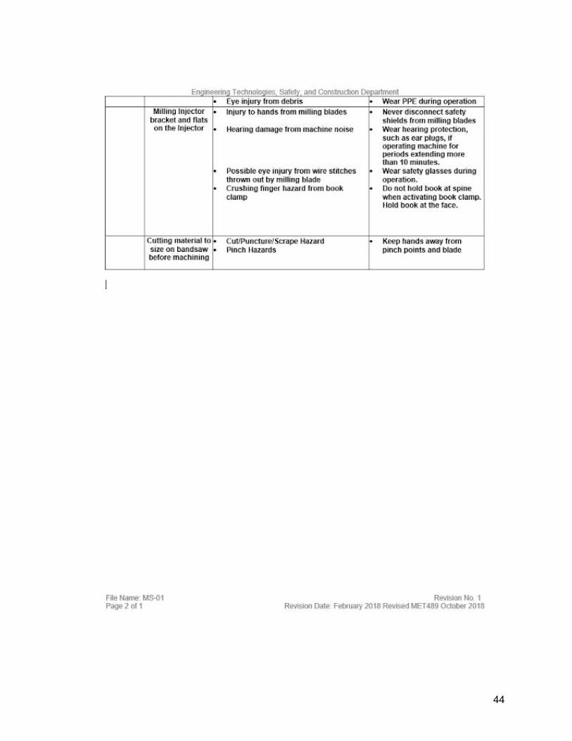
Significant risk is involved in the machining of parts and operation of the device. The engineer must receive required safety training for operation of the equipment being used to machine the parts for the device. Proper safety precautions must be taken when operating the device during use and testing. Specific risks and required precautions are shown in the job hazard analysis in appendix J. Successful
The final design of the burner is successful as it has the required geometry to achieve the requirements. However, most of the analyses may not be a success as different approaches were analyzed for solving the flow rates and are more accurate than the previous approach. Changes in flow rate analyses did not affect the overall design, however it will affect the graduations that will be stamped into the side of the injector bracket and it affected the inner diameter of the burner body. The final assembly after the manufacturing process was successful in incorporating all of the critical geometry. The testing indicated improvements to the benchmark in every aspect; which varied from the prediction as the forge burner was assumed to improve in only two of the three aspects. The forge burner was promising from the beginning based on the sound. The benchmark had a choppy burn at first and took a while to even out, whereas the engineered forge burner gave a smooth flame throughout the test. The time to heat test showed a 16.2% improvement which fell short of the projected 20%, but it was a significant improvement nonetheless. The propane consumption was a huge improvement as the engineered forge burner consumed 53.6% as much fuel per minute than the benchmark burner. The oxidation sample for the benchmark showed much more surface distortion than that of the engineered forge burner; samples are shown in Appendix G5.
12
Next Phase
Because of the complexity of the question being analyzed for the project, the analysis of the flow rates in the burner required various assumptions to make the variables solvable. In the future, different approaches will be made for solving for the flow rates with different sets of assumptions. The different analytical approaches will be compared and the approach with the least assumptions will be used. These different approaches will be compared to the final solution if the final solution does not yield the desired results during the testing phase. The injector bracket may need to be remade because a mistake in drilling the hole for the injector resulted in it sitting at a slight angle.
Conclusion
The Forge Burner is at a completed design and manufacturing stages and is ready to begin the testing process of the prototype. The analyses show that the geometry is optimized to facilitate the perfect air/fuel mixture for a variety of propane pressure settings.The testing phase will show if changes need to be made to the prototype. Optimal air/fuel ratios will be achieved at any propane pressure setting within 10 psi increments between 10 and 40 psi. Unlike the benchmark burner, the intake air will not be contaminated with exhaust gas. With this predictability, the designed burner was able to use 53.6% less fuel per minute and heat a forge 16.2% faster.
Acknowledgment
Professor Charles Pringle, Dr. Craig Johnson, and Dr. John Choi are to be acknowledged for facilitating the project and giving guidance for the engineer in completing the design. Dr. John Choi is especially responsible for helping with analyses with his expertise in fluid mechanics. Dr. John Choi contributed the most guidance for the proposal from weekly milestone checks.
13

References
“Carr.” McMaster, www.mcmaster.com/.
Lawn, C J. “A Simple Method for the Design of Gas Burner Injectors.” Proceedings of the
Institution of Mechanical Engineers, Part C: Journal of Mechanical Engineering Science,
vol. 217, no. 2, 2003, pp. 237–246., doi:10.1243/095440603762826558.
Çengel, Yunus A., et al. Fundamentals of Thermal-Fluid Sciences. McGraw-Hill Education,
2017.
14
Appendix A
A1: Flow rate of propane at 5psi gage.
15
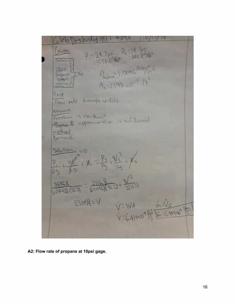
A2: Flow rate of propane at 10psi gage.
16
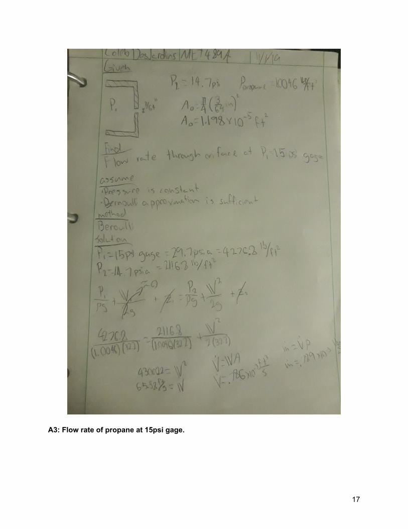
A3: Flow rate of propane at 15psi gage.
17
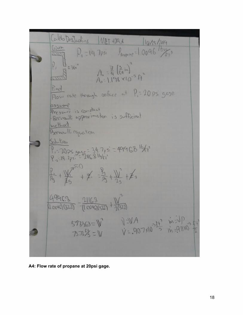
A4: Flow rate of propane at 20psi gage.
18
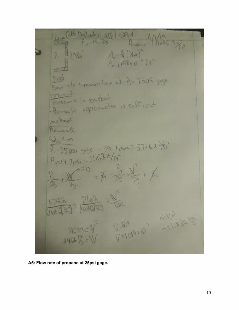
A5: Flow rate of propane at 25psi gage.
19
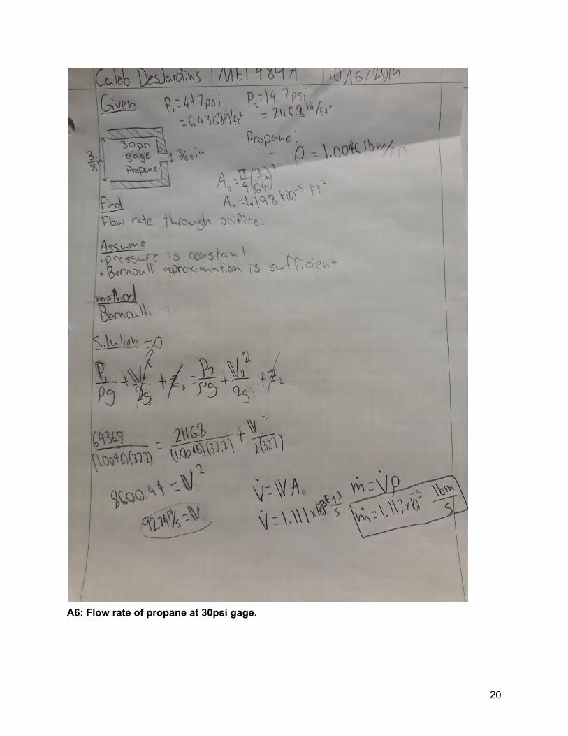
A6: Flow rate of propane at 30psi gage.
20
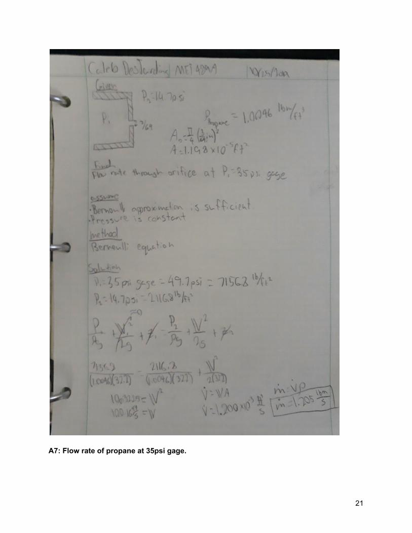
A7: Flow rate of propane at 35psi gage.
21
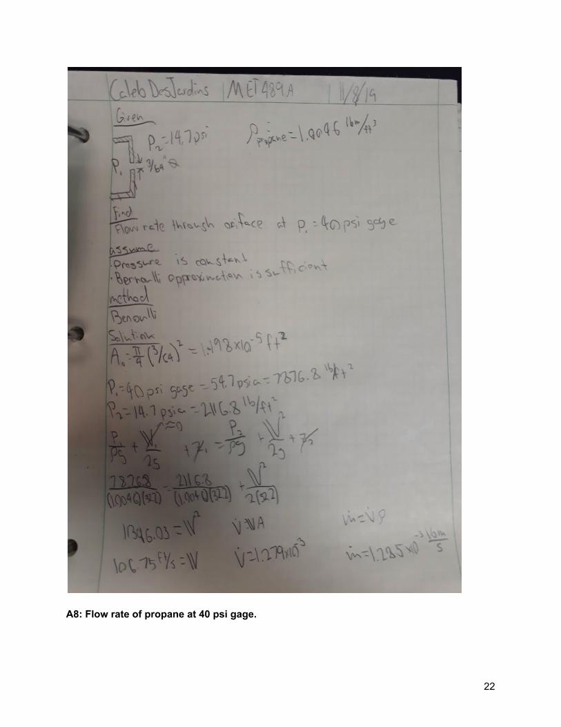
A8: Flow rate of propane at 40 psi gage.
22
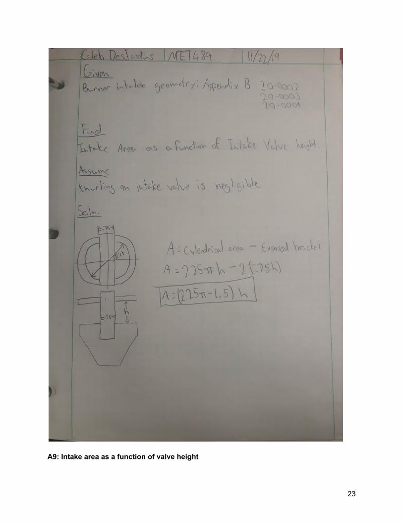
A9: Intake area as a function of valve height
23
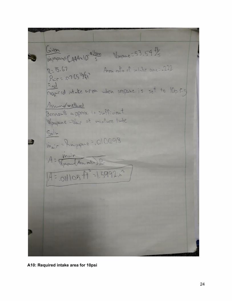
A10: Required intake area for 10psi
24
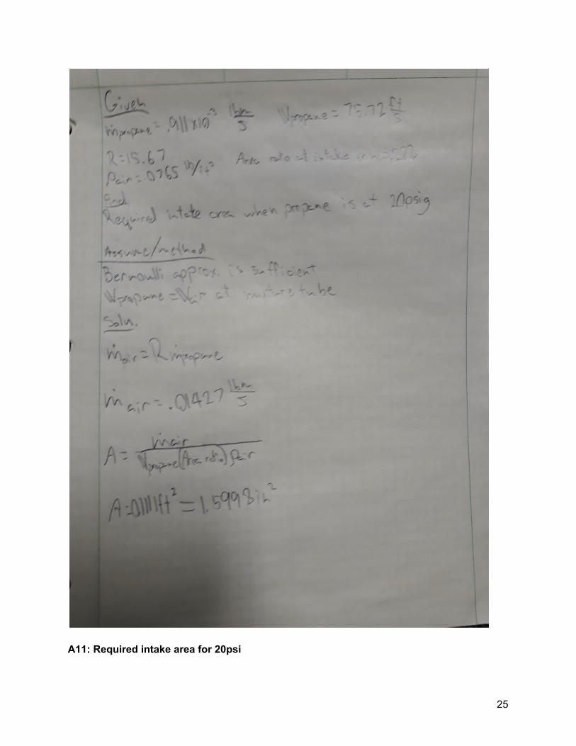
A11: Required intake area for 20psi
25
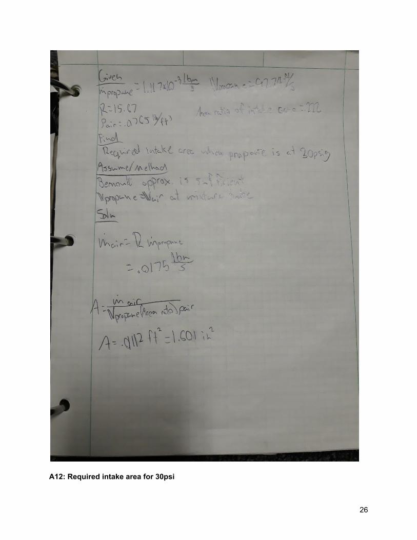
A12: Required intake area for 30psi
26
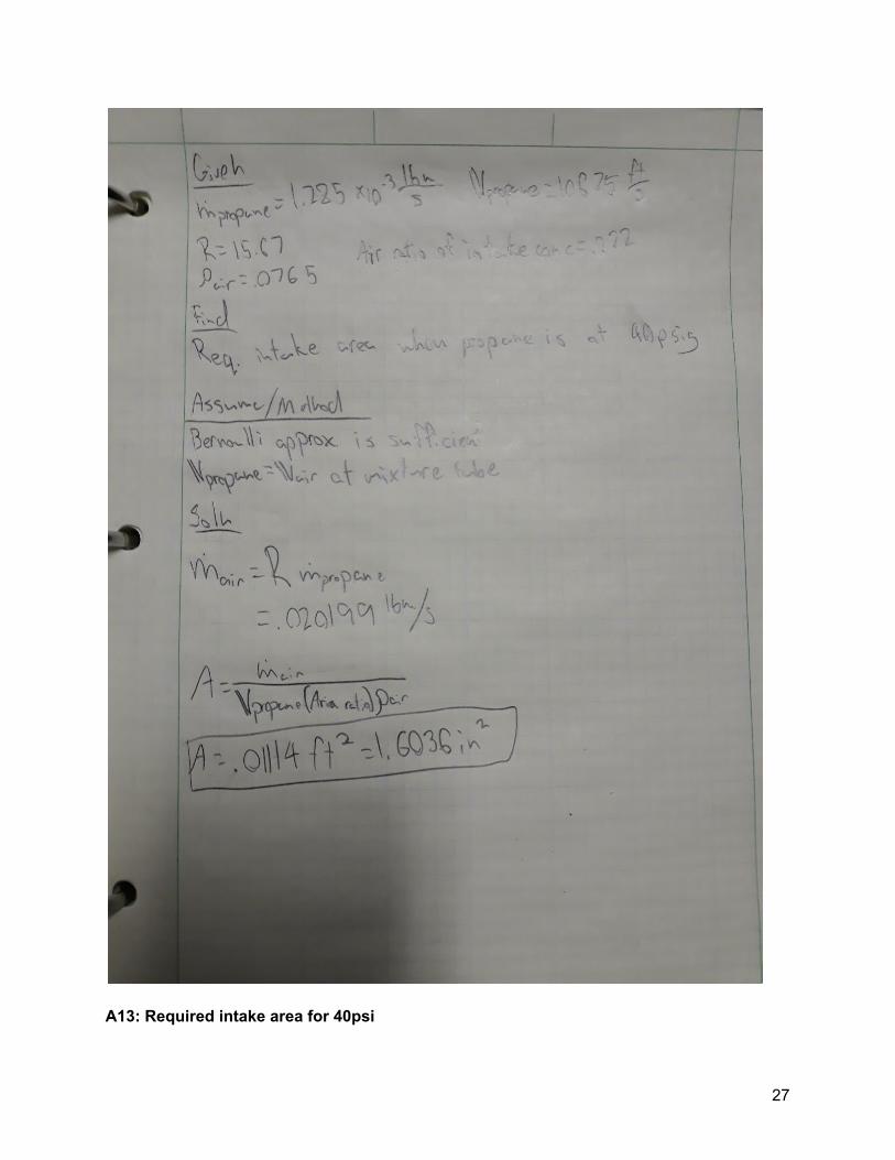
A13: Required intake area for 40psi
27

Appendix B
28
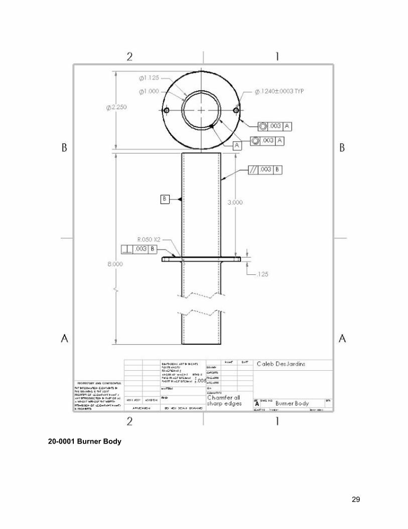
20-0001 Burner Body
29
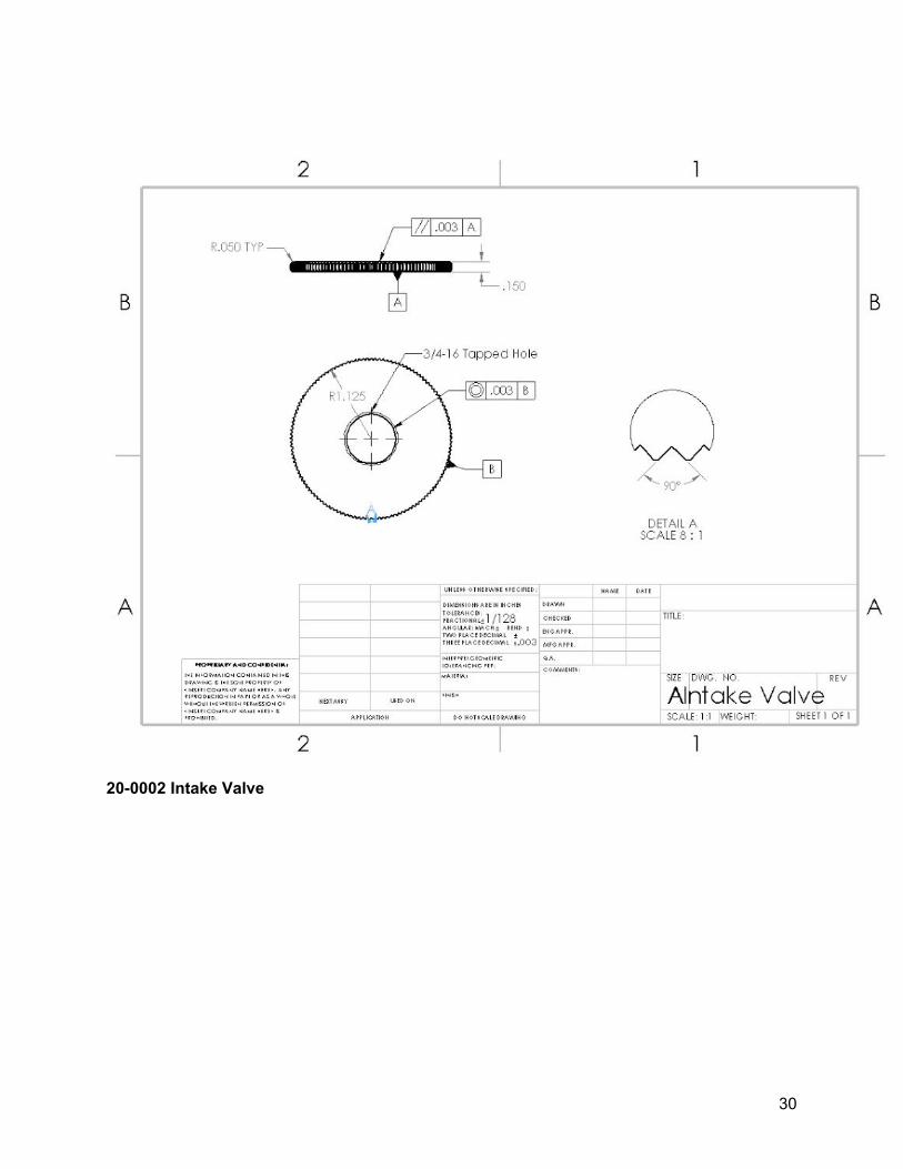
20-0002 Intake Valve
30
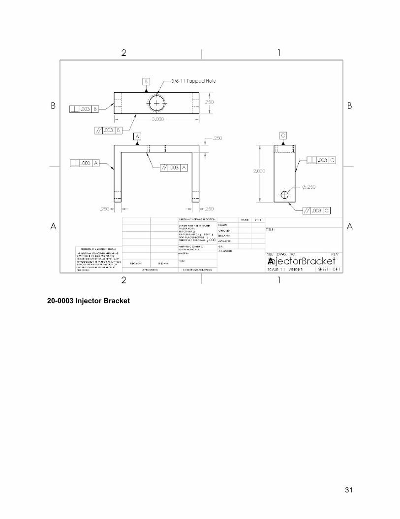
20-0003 Injector Bracket
31
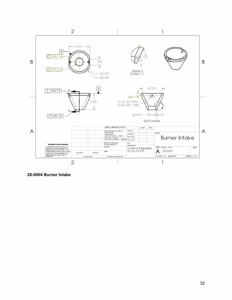
20-0004 Burner Intake
32
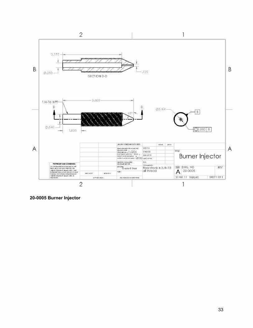
20-0005 Burner Injector
33
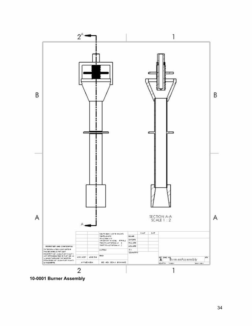
10-0001 Burner Assembly
34
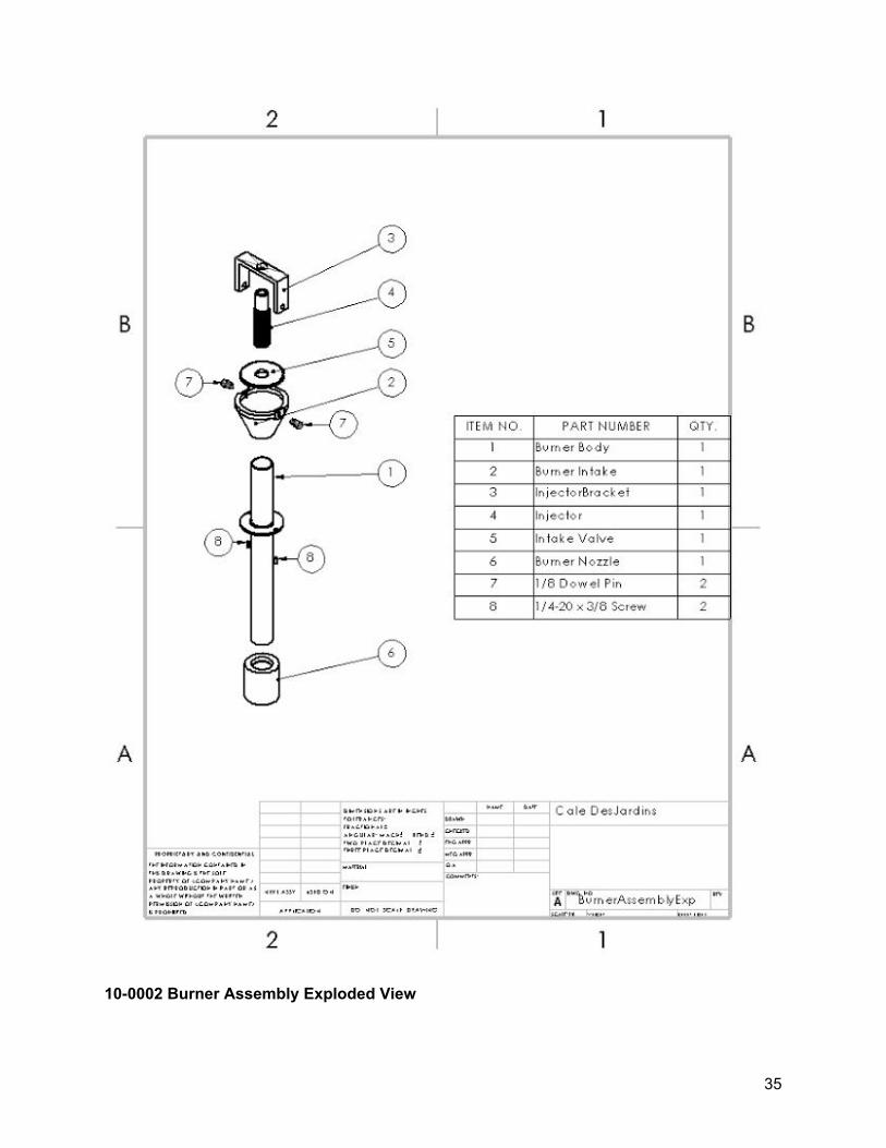
10-0002 Burner Assembly Exploded View
35

Appendix C
Parts List:
● Burner body (Machined from material from McMaster-Carr) ● Burner Intake (Machined from material from McMaster-Carr) ● Injector (Machined from material from McMaster-Carr) ● Injector Bracket (Machined from material from McMaster-Carr) ● Intake valve (Machined from material from McMaster-Carr) ● Pipe coupler (owned) ● Pins (owned) ● Brass pipe nipple (Part number 568K153 from McMaster-Carr) ● Brass ball valve (Part number 5754T31 from McMaster-Carr) ● Brass pipe adapter (owned) ● Propane line (owned) ● Propane regulator (owned) ● Propane tank (owned)
36
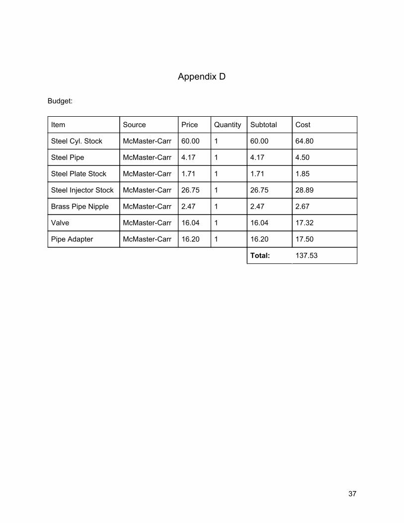
Appendix D
Budget:
Item Source Price Quantity Subtotal Cost
Steel Cyl. Stock McMaster-Carr 60.00 1 60.00 64.80
Steel Pipe McMaster-Carr 4.17 1 4.17 4.50
Steel Plate Stock McMaster-Carr 1.71 1 1.71 1.85
Steel Injector Stock McMaster-Carr 26.75 1 26.75 28.89
Brass Pipe Nipple McMaster-Carr 2.47 1 2.47 2.67
Valve McMaster-Carr 16.04 1 16.04 17.32
Pipe Adapter McMaster-Carr 16.20 1 16.20 17.50
Total: 137.53
37
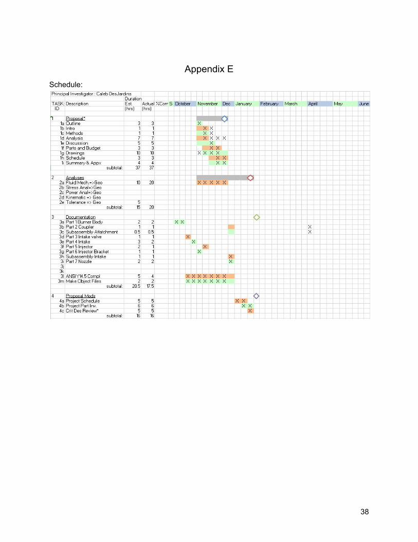
Appendix E Schedule:
38
39
Appendix G
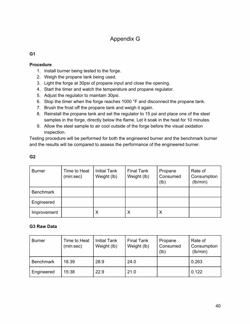
G1
Procedure 1. Install burner being tested to the forge. 2. Weigh the propane tank being used. 3. Light the forge at 30psi of propane input and close the opening. 4. Start the timer and watch the temperature and propane regulator. 5. Adjust the regulator to maintain 30psi. 6. Stop the timer when the forge reaches 1000 °F and disconnect the propane tank. 7. Brush the frost off the propane tank and weigh it again. 8. Reinstall the propane tank and set the regulator to 15 psi and place one of the steel
samples in the forge, directly below the flame. Let it soak in the heat for 10 minutes. 9. Allow the steel sample to air cool outside of the forge before the visual oxidation
inspection. Testing procedure will be performed for both the engineered burner and the benchmark burner and the results will be compared to assess the performance of the engineered burner. G2
Burner Time to Heat (min:sec)
Initial Tank Weight (lb)
Final Tank Weight (lb)
Propane Consumed (lb)
Rate of Consumption (lb/min)
Benchmark
Engineered
Improvement X X X
G3 Raw Data
Burner Time to Heat (min:sec)
Initial Tank Weight (lb)
Final Tank Weight (lb)
Propane Consumed (lb)
Rate of Consumption (lb/min)
Benchmark 18.39 28.9 24.0 0.263
Engineered 15:38 22.9 21.0 0.122
40
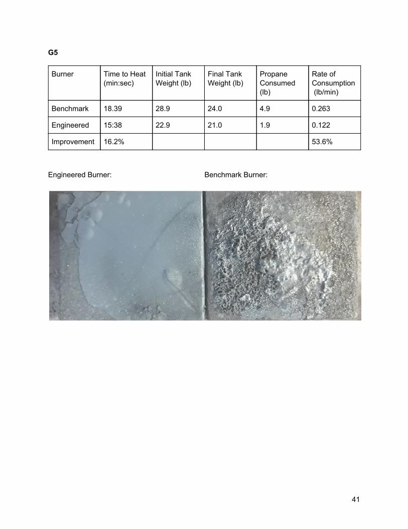
G5
Burner Time to Heat (min:sec)
Initial Tank Weight (lb)
Final Tank Weight (lb)
Propane Consumed (lb)
Rate of Consumption (lb/min)
Benchmark 18.39 28.9 24.0 4.9 0.263
Engineered 15:38 22.9 21.0 1.9 0.122
Improvement 16.2% 53.6%
Engineered Burner: Benchmark Burner:
41
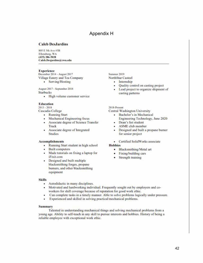
Appendix H
42
Appendix J
43
44