Embed Size (px)
Citation preview
(Added by RFPLetter_R1)
Fort Rucker, Alabama
Task Order Number W91278-11-9-CV03 Elementary School Volume 3 of 5: Specification Divisions 11 through 23 PN AM00048 January 2016
U.S. ARMY ENGINEER DISTRICT, SAVANNAH CORPS OF ENGINEERS
100 WEST OGLETHORPE AVENUE SAVANNAH, GEORGIA 31401-3640
US Army Corps of Engineers Savannah District
Elementary School 11-9-CV03 Ft. Rucker, AL
TABLE OF CONTENTS - 1 (Revised by RFPLetter_R4)
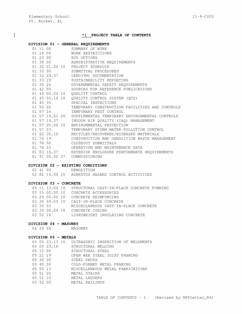
*1 PROJECT TABLE OF CONTENTS
DIVISION 01 - GENERAL REQUIREMENTS 01 11 00 SUMMARY OF WORK 01 14 00 WORK RESTRICTIONS 01 23 00 BID OPTIONS 01 30 00 ADMINISTRATIVE REQUIREMENTS 01 32 01.00 10 PROJECT SCHEDULE 01 33 00 SUBMITTAL PROCEDURES 01 33 29.37 LEED(TM) DOCUMENTATION 01 33 29 SUSTAINABILITY REPORTING 01 35 26 GOVERNMENTAL SAFETY REQUIREMENTS 01 42 00 SOURCES FOR REFERENCE PUBLICATIONS 01 45 00.00 10 QUALITY CONTROL 01 45 00.10 10 QUALITY CONTROL SYSTEM (QCS) 01 45 35 SPECIAL INSPECTIONS 01 50 00 TEMPORARY CONSTRUCTION FACILITIES AND CONTROLS 01 57 16 TEMPORARY PEST CONTROL 01 57 19.01 20 SUPPLEMENTAL TEMPORARY ENVIRONMENTAL CONTROLS 01 57 19.37 INDOOR AIR QUALITY (IAQ) MANAGEMENT 01 57 20.00 10 ENVIRONMENTAL PROTECTION 01 57 23 TEMPORARY STORM WATER POLLUTION CONTROL 01 62 35.10 RECYCLED/RECOVERED/BIOBASED MATERIALS 01 74 19 CONSTRUCTION AND DEMOLITION WASTE MANAGEMENT 01 78 00 CLOSEOUT SUBMITTALS 01 78 23 OPERATION AND MAINTENANCE DATA 01 83 16.37 EXTERIOR ENCLOSURE PERFORMANCE REQUIREMENTS 01 91 00.00 37 COMMISSIONING
DIVISION 02 - EXISTING CONDITIONS 02 41 00 DEMOLITION 02 82 14.00 10 ASBESTOS HAZARD CONTROL ACTIVITIES
DIVISION 03 - CONCRETE 03 11 13.00 10 STRUCTURAL CAST-IN-PLACE CONCRETE FORMING 03 15 00.00 10 CONCRETE ACCESSORIES 03 20 00.00 10 CONCRETE REINFORCING 03 30 00.00 10 CAST-IN-PLACE CONCRETE 03 30 53 MISCELLANEOUS CAST-IN-PLACE CONCRETE 03 39 00.00 10 CONCRETE CURING 03 52 16 LIGHTWEIGHT INSULATING CONCRETE
DIVISION 04 - MASONRY 04 20 00 MASONRY
DIVISION 05 - METALS 05 05 23.13 10 ULTRASONIC INSPECTION OF WELDMENTS 05 05 23.16 STRUCTURAL WELDING 05 12 00 STRUCTURAL STEEL 05 21 19 OPEN WEB STEEL JOIST FRAMING 05 30 00 STEEL DECKS 05 40 00 COLD-FORMED METAL FRAMING 05 50 13 MISCELLANEOUS METAL FABRICATIONS 05 51 00 METAL STAIRS 05 51 33 METAL LADDERS 05 52 00 METAL RAILINGS
Elementary School 11-9-CV03 Ft. Rucker, AL
TABLE OF CONTENTS - 2 (Revised by RFPLetter_R4)
DIVISION 06 - WOOD, PLASTICS, AND COMPOSITES 06 10 00 ROUGH CARPENTRY 06 20 00 FINISH CARPENTRY 06 41 16.00 10 LAMINATE CLAD ARCHITECTURAL CASEWORK 06 61 16 SOLID POLYMER (SOLID SURFACING) FABRICATIONS
DIVISION 07 - THERMAL AND MOISTURE PROTECTION 07 08 27.00 10 BUILDING AIR BARRIER SYSTEM TESTING FOR COMMISSIONING 07 17 00 BENTONITE WATERPROOFING 07 21 13 BOARD AND BLOCK INSULATION 07 21 16 MINERAL FIBER BLANKET INSULATION 07 27 00.45 10 FLUID APPLIED AIR & WATER BARRIER SYSTEM 07 27 10.00 10 BUILDING AIR BARRIER SYSTEM, CONSTRUCTION AND QUALITY
CONTROL 07 42 63 FABRICATED WALL PANEL ASSEMBLIES 07 52 00 MODIFIED BITUMINOUS MEMBRANE ROOFING 07 60 00 FLASHING AND SHEET METAL 07 81 00 SPRAY-APPLIED FIREPROOFING 07 84 00 FIRESTOPPING 07 92 00 JOINT SEALANTS
DIVISION 08 - OPENINGS 08 11 13 STEEL DOORS AND FRAMES 08 11 16 ALUMINUM DOORS AND FRAMES 08 14 00 WOOD DOORS 08 33 13 METAL ROLLING COUNTER DOORS 08 33 23 OVERHEAD COILING DOORS 08 34 73 SOUND CONTROL DOOR ASSEMBLIES 08 39 54 BLAST RESISTANT DOORS 08 41 13 ALUMINUM-FRAMED ENTRANCES AND STOREFRONTS 08 44 00 CURTAIN WALL AND GLAZED ASSEMBLIES 08 71 00 DOOR HARDWARE 08 81 00 GLAZING 08 91 00 METAL WALL LOUVERS
DIVISION 09 - FINISHES 09 06 90 COLOR SCHEDULE 09 22 00 SUPPORTS FOR GYPSUM BOARD
*3 09 26 14 VENEER PLASTER (MASONRY) 09 29 00 GYPSUM BOARD 09 30 13 CERAMIC TILING 09 51 00 ACOUSTICAL CEILINGS 09 65 00 RESILIENT FLOORING
*4 09 65 66 RESILIENT ATHLETIC FLOORING 09 68 00 CARPETING 09 83 13 ACOUSTICAL WALL TREATMENT 09 90 00 PAINTS AND COATINGS
DIVISION 10 - SPECIALTIES 10 10 00 VISUAL COMMUNICATIONS SPECIALTIES 10 14 00.20 INTERIOR SIGNAGE 10 14 01 EXTERIOR SIGNAGE 10 21 13 TOILET COMPARTMENTS
*3 10 21 23.16 CUBICLE TRACK, HARDWARE AND CURTAINS 10 22 39 OPERABLE GLASS PANEL PARTITIONS 10 22 39.10 OPERABLE PANEL PARTITIONS
Elementary School 11-9-CV03 Ft. Rucker, AL
TABLE OF CONTENTS - 3 (Revised by RFPLetter_R4)
10 26 13 CORNER GUARDS 10 28 13 TOILET ACCESSORIES 10 35 00 FLAGPOLES 10 44 16 FIRE EXTINGUISHER CABINETS 10 51 13 SOLID PLASTIC LOCKERS 10 56 26.13 MOBILE STORAGE SHELVING UNITS 10 73 26 ALUMINUM WALKWAY CANOPY
DIVISION 11 - EQUIPMENT 11 13 10 DOCK LEVELERS 11 30 00 RESIDENTIAL EQUIPMENT 11 40 00 FOOD SERVICE EQUIPMENT 11 65 00 GYMNASIUM EQUIPMENT 11 66 23.13 BASKETBALL EQUIPMENT 11 68 13 PLAYGROUND EQUIPMENT 11 95 05 KILN
DIVISION 12 - FURNISHINGS 12 21 00 WINDOW BLINDS 12 22 00 STAGE CURTAINS 12 93 00 SITE FURNISHINGS
DIVISION 13 - SPECIAL CONSTRUCTION 13 01 00 PRE-FABRICATED TEMPORARY MODULAR CLASSROOM BUILDINGS
DIVISION 14 - CONVEYING EQUIPMENT 14 24 00 HYDRAULIC ELEVATORS
DIVISION 21 - FIRE SUPPRESSION 21 13 13.00 10 WET PIPE SPRINKLER SYSTEM, FIRE PROTECTION
DIVISION 22 - PLUMBING 22 00 00 PLUMBING, GENERAL PURPOSE 22 05 48.00 20 MECHANICAL SOUND, VIBRATION, AND SEISMIC CONTROL
DIVISION 23 - HEATING, VENTILATING, AND AIR CONDITIONING 23 00 00 AIR SUPPLY, DISTRIBUTION, VENTILATION, AND EXHAUST SYSTEMS 23 05 15 COMMON PIPING FOR HVAC 23 05 93 TESTING, ADJUSTING, AND BALANCING FOR HVAC 23 07 00 THERMAL INSULATION FOR MECHANICAL SYSTEMS 23 09 23 LONWORKS DIRECT DIGITAL CONTROL FOR HVAC AND OTHER BUILDING
CONTROL SYSTEMS 23 11 25 FACILITY GAS PIPING 23 23 00 REFRIGERANT PIPING 23 25 00 CHEMICAL TREATMENT OF WATER FOR MECHANICAL SYSTEMS 23 52 00 HEATING BOILERS 23 64 10 WATER CHILLERS, VAPOR COMPRESSION TYPE 23 64 26 CHILLED, CHILLED-HOT, AND CONDENSER WATER PIPING SYSTEMS
DIVISION 26 - ELECTRICAL 26 20 00 INTERIOR DISTRIBUTION SYSTEM 26 23 00 SWITCHBOARDS AND SWITCHGEAR 26 28 01.00 10 COORDINATED POWER SYSTEM PROTECTION 26 31 00 SOLAR PHOTOVOLTAIC (PV) COMPONENTS 26 41 00 LIGHTNING PROTECTION SYSTEM 26 51 00 INTERIOR LIGHTING 26 56 00 EXTERIOR LIGHTING
Elementary School 11-9-CV03 Ft. Rucker, AL
TABLE OF CONTENTS - 4 (Revised by RFPLetter_R4)
DIVISION 27 - COMMUNICATIONS 27 10 00 BUILDING TELECOMMUNICATIONS CABLING SYSTEM 27 51 23.10 INTERCOMMUNICATION SYSTEM
DIVISION 28 - ELECTRONIC SAFETY AND SECURITY 28 20 01.00 10 ELECTRONIC SECURITY SYSTEM 28 31 76 INTERIOR FIRE ALARM AND MASS NOTIFICATION SYSTEM
DIVISION 31 - EARTHWORK 31 00 00 EARTHWORK 31 11 00 CLEARING AND GRUBBING 31 31 16 SOIL TREATMENT FOR SUBTERRANEAN TERMITE CONTROL 31 32 11 SOIL SURFACE EROSION CONTROL
DIVISION 32 - EXTERIOR IMPROVEMENTS 32 01 16.17 COLD MILLING OF BITUMINOUS PAVEMENTS 32 01 19 FIELD MOLDED SEALANTS FOR SEALING JOINTS IN RIGID PAVEMENTS 32 05 33 LANDSCAPE ESTABLISHMENT 32 11 23 GRADED-CRUSHED AGGREGATE BASE COURSE 32 12 10 BITUMINOUS TACK AND PRIME COATS 32 12 16 HOT-MIX ASPHALT (HMA) FOR ROADS 32 13 13.06 PORTLAND CEMENT CONCRETE PAVEMENT FOR ROADS AND SITE
FACILITIES 32 16 13 CONCRETE SIDEWALKS AND CURBS AND GUTTERS 32 17 23.00 20 PAVEMENT MARKINGS 32 18 16.13 PLAYGROUND PROTECTIVE SURFACING 32 31 13 CHAIN LINK FENCES AND GATES 32 92 19 SEEDING 32 92 23 SODDING 32 93 00 EXTERIOR PLANTS
DIVISION 33 - UTILITIES 33 11 00 WATER DISTRIBUTION 33 11 23 NATURAL GAS PIPING 33 30 00 SANITARY SEWERS 33 40 00 STORM DRAINAGE UTILITIES 33 46 16 SUBDRAINAGE SYSTEM
APPENDICES APPENDIX A ELEMENTARY SCHOOL ACM/HAZMAT REPORT APPENDIX B PRIMARY SCHOOL ACM/HAZMAT REPORT APPENDIX C PESTICIDE SAMPLING REPORT APPENDIX D DESIGN PHASE Cx PLAN APPENDIX E PRELIMINARY FUNCTIONAL TEST CHECKLISTS APPENDIX F PREFUNCTIONAL TEST CHECKLISTS
*3 APPENDIX G ASBESTOS ABATEMENT PROCEDURES AND FORMS *3 APPENDIX H GEOTECHNICAL REPORT *4 APPENDIX I FURNITURE SPECIFICATIONS
-- END OF PROJECT TABLE OF CONTENTS --
Elementary School 11-9-CV03Ft. Rucker, AL
SECTION TABLE OF CONTENTS
DIVISION 11 - EQUIPMENT
SECTION 11 13 10
DOCK LEVELERS
08/09
PART 1 GENERAL
1.1 REFERENCES 1.2 DEFINITIONS 1.2.1 Industrial Dock Leveler 1.2.2 Adjustable Loading Ramp 1.2.3 Fixed Type Industrial Dock Leveler 1.2.4 Velocity Fuse 1.2.5 Carrier 1.3 SUBMITTALS 1.4 QUALITY ASSURANCE 1.4.1 Manufacturer's Representative 1.4.2 Detail Drawings 1.4.3 Record Drawings 1.5 DELIVERY, STORAGE, AND HANDLING 1.6 EXTRA MATERIALS
PART 2 PRODUCTS
2.1 MATERIALS 2.1.1 Standard Products 2.1.2 Exposed Surfaces 2.1.3 Nameplate 2.2 LOADING DOCK LEVELERS (Edge of Dock (EOD) System 2.2.1 Design Requirements 2.2.2 Dock Leveler Extension and Retraction 2.2.3 Mechanical System 2.2.4 Dock Bumpers 2.2.5 Rated Capacity 2.2.6 Ramp Load Carrying Surface 2.3 OPERATION 2.3.1 Mechanical Control 2.4 CONSTRUCTION AND MATERIALS 2.5 ACCESSORIES 2.5.1 Dock Bumpers
PART 3 EXECUTION
3.1 EXAMINATION 3.2 INSTALLATION 3.3 CLEANING, TREATMENT AND PAINTING 3.3.1 Workmanship 3.3.2 Dissimilar Metals Protection 3.3.3 Finish Coat Color 3.4 FIELD TESTS 3.4.1 Roll-Over Load Tests
SECTION 11 13 10 Page 1 (Added by RFPLetter_R1)
Elementary School 11-9-CV03Ft. Rucker, AL
3.4.2 Drop Tests 3.4.3 Acceptance Tests 3.5 INSTRUCTION TO GOVERNMENT PERSONNEL 3.6 OPERATING MANUALS
-- End of Section Table of Contents --
SECTION 11 13 10 Page 2 (Added by RFPLetter_R1)
Elementary School 11-9-CV03Ft. Rucker, AL
SECTION 11 13 10
DOCK LEVELERS08/09
PART 1 GENERAL
1.1 REFERENCES
The publications listed below form a part of this specification to the extent referenced. The publications are referred to within the text by the basic designation only.
ASTM INTERNATIONAL (ASTM)
ASTM A123/A123M (2013) Standard Specification for Zinc (Hot-Dip Galvanized) Coatings on Iron and Steel Products
ASTM A143/A143M (2007; R 2014) Standard Practice for Safeguarding Against Embrittlement of Hot-Dip Galvanized Structural Steel Products and Procedure for Detecting Embrittlement
ASTM A153/A153M (2009) Standard Specification for Zinc Coating (Hot-Dip) on Iron and Steel Hardware
ASTM D2000 (2012) Standard Classification System for Rubber Products in Automotive Applications
NATIONAL FIRE PROTECTION ASSOCIATION (NFPA)
NFPA 70 (2014; AMD 1 2013; Errata 1 2013; AMD 2 2013; Errata 2 2013; AMD 3 2014; Errata 3-4 2014; AMD 4-6 2014) National Electrical Code
1.2 DEFINITIONS
1.2.1 Industrial Dock Leveler
A manufactured structure designed to span and compensate space and height differentials between a loading dock and freight carrier to facilitate safe, efficient, freight transfer.
1.2.2 Adjustable Loading Ramp
Synonym for Fixed Type Industrial Dock Leveler.
1.2.3 Fixed Type Industrial Dock Leveler
A dock leveler that is permanently affixed to the dock structure, and usually incorporating a mechanical system to position the dock leveler with respect to the freight carrier at the lip end while being fixed at the
SECTION 11 13 10 Page 3 (Added by RFPLetter_R1)
Elementary School 11-9-CV03Ft. Rucker, AL
opposite hinged end.
1.2.4 Velocity Fuse
A valve or similar device that goes into the hydraulic line. If the dock leveler becomes inadvertently or accidentally unsupported, this fuse will freeze the movement of dock leveler within 4 inches of the dock leveler original position.
1.2.5 Carrier
A wheeled, enclosed trailer or container that, when attached to a heavy-duty truck or van, is used to carry bulk freight over long distances.
1.3 SUBMITTALS
Government approval is required for submittals with a "G" designation; submittals not having a "G" designation are for information only. When used, a designation following the "G" designation identifies the office that will review the submittal for the Government. Submit the following in accordance with Section 01 33 00 SUBMITTAL PROCEDURES:
SD-02 Shop Drawings
Detail Drawings; G
SD-03 Product Data
Dock Bumpers
SD-04 Samples
Dock Bumpers
SD-07 Certificates
Hardware ItemsDock Bumpers
SD-10 Operation and Maintenance Data
Loading Dock Levelers; G
SD-11 Closeout Submittals
Record Drawings
1.4 QUALITY ASSURANCE
1.4.1 Manufacturer's Representative
Furnish services of Fixed Type Industrial Dock Leveler technicians, experienced in installation and operation of the type of system being provided, to supervise installation, testing, adjustment of system, and instruction to Government personnel.
SECTION 11 13 10 Page 4 (Added by RFPLetter_R1)
Elementary School 11-9-CV03Ft. Rucker, AL
1.4.2 Detail Drawings
Submit drawings depicting dimensions, tolerances, surface finishes, hardnesses, flush edge angles, method of mounting and anchoring, and control schematics and diagram. Show complete wiring, schematic diagrams, and any other details required to demonstrate that the system has been coordinated and will properly function as a unit. Show proposed layout and anchorage of equipment and appurtenances. Show the concrete pit details including flush edge angles, dock bumpers including fastening materials in compliance with ASTM A123/A123M and ASTM D2000, and sloped pit bottom; method of mounting and anchoring; and location of control stations and disconnect switches. Show all proposed dock bumper locations on drawings.
1.4.3 Record Drawings
Submit record as-built drawings depicting dimensions, tolerances, surface finishes, hardnesses, flush edge angles, method of mounting and anchoring, and control schematics and diagram, including mechanical and electrical components, testing and acceptance (one copy sepia transparency) for each industrial dock leveler.
1.5 DELIVERY, STORAGE, AND HANDLING
Matchmark and tag parts which are disassembled for shipment with metal tags. Provide waterproofed tags and markings. Protect the delivered equipment in storage from the weather, humidity and temperature variation, dirt and dust, or other contaminants.
1.6 EXTRA MATERIALS
After approval of the detail drawings, and not later than 1 month prior to the date of beneficial occupancy, provide spare parts data for each different item of material and equipment specified. Furnish a complete list of parts and supplies, with current unit prices and source of supply and a list of the parts recommended by the manufacturer to be replaced after 3 year(s) of service.
PART 2 PRODUCTS
2.1 MATERIALS
2.1.1 Standard Products
Submit data including a complete list of equipment and materials, manufacturer's descriptive and technical literature, performance charts and curves, catalog cuts, and installation instructions. Provide materials and equipment, which are the standard products of a manufacturer regularly engaged in the manufacture of the products, and that essentially duplicate items that have been in satisfactory use for at least 2 years prior to bid opening. Equipment shall be supported by a service organization that is, in the opinion of the Contracting Officer, reasonably convenient to the site.
Manufacturers:
1. Kelley Company, Inc. 2. Rite Hite Corporation 3. Advance Lifts, Inc. 4. Blue Giant Equipment Corp.
SECTION 11 13 10 Page 5 (Added by RFPLetter_R1)
Elementary School 11-9-CV03Ft. Rucker, AL
5. Pioneer Dock Equipment 6. Nova Technology
The use of manufacturers names and products do not preclude the use of other manufacturer's products of approved equal as long as all requirements in the technical sections are met.
2.1.2 Exposed Surfaces
All exposed metal surfaces and fastening materials shall fully comply with the minimum requirements of ASTM A123/A123M, ASTM A143/A143M, and ASTM A153/A153M.
2.1.3 Nameplate
Attach corrosion-resistant metal plate securely and legibly on the exterior surface of the dock leveler. Include the following information indented or embossed on the plate:
a. Description of the equipment: Describe procedures for operating and services equipment, and warnings or cautions of hazardous procedures.
b. Name of the manufacturer.
c. Serial and model number.
d. Rated capacity in pounds.
e. Shipping weight.
f. Date of manufacture (month and year).
2.2 LOADING DOCK LEVELERS (Edge of Dock (EOD) System
Provide loading dock leveler with mechanical type which is manually released at dock leveler and raises by spring action and is lowered by mechanical operator.
Provide an Edge of Dock (EOD) leveler.
2.2.1 Design Requirements
Design, fabricate, and finish loading ramp to permit washing with water and detergents, and operating in an ambient temperature from 0 to plus 110 degrees F.
2.2.2 Dock Leveler Extension and Retraction
Extend non-fixed end of the dock leveler from a retracted position behind the line of the loading dock platform bumpers to at least 12 inches beyond the forward edge of the dock platform bumpers so as to rest on the bed of the freight carrier. The difference in length of the platform from its fully retracted position to its fully extended position shall be practically constant throughout the ramp, including the ramp extension.
2.2.3 Mechanical System
SECTION 11 13 10 Page 6 (Added by RFPLetter_R1)
Elementary School 11-9-CV03Ft. Rucker, AL
Include a safety system to limit EOD fall to dock level . 2.2.4 Dock Bumpers
Submit certificates showing conformance with the referenced standards contained in this section. Provide ramp and load dock face with laminated rubber, tire-fabric, or equivalent dock bumpers recommended by the dock leveler manufacturer. Submit one typical Loading Dock Bumper completely assembled with supporting rods, end angles, bolts, and nuts. One section of 8 inches wide by full depth and height of bumper including one end angle with the opposite end exposed for inspection. Finish: Metal for dock bumpers, including hardware items, shall be hot-dip galvanized conforming to ASTM A123/A123M.
2.2.5 Rated Capacity
Minimum 20,000 pounds roll over capacity.
2.2.6 Ramp Load Carrying Surface
The live load carrying surface of the ramp shall be 6 feet plus or minus 3 inch wide and 6 feet plus or minus 9 inch long with the dock leveler lip retracted.
2.3 OPERATION
2.3.1 Mechanical Control
Mechanical chain-activated, with extension-spring operation and counter-balance non-manual, raising and lowering system. Once the freight carrier has departed, manually return the platform to the stored, level position. Ensure the ramp, in its stored position capable of being lowered below dock platform level without extending the lip of the ramp.
2.4 CONSTRUCTION AND MATERIALS
Construct all load carrying parts of forged or welded steel. The entire live load carrying surface of the ramp and rear attachment shall be not less than 1/4 inch thick, 55 ksi minimum yield strength, low alloy, nonskid steel tread plate. Provide minimum 5/8 inch vertical projections on the live load carrying surface. Bevel the lip or ramp extension. Design load carrying surfaces to permit free movement of powered hand or platform trucks, low lift pallet trucks, and fork lift trucks. Fabricate lip hinge of not less than 1/4 inch wall seamless steel tubing.
2.5 ACCESSORIES
2.5.1 Dock Bumpers
Provide bumpers capable of sustaining repeated impacts from trucks or trailers without damage to the dock, dock levelers, or bumpers.
PART 3 EXECUTION
3.1 EXAMINATION
After becoming familiar with all details of the work, verify all dimensions in the field, and advise the Contracting Officer of any discrepancy before performing the work.
SECTION 11 13 10 Page 7 (Added by RFPLetter_R1)
Elementary School 11-9-CV03Ft. Rucker, AL
3.2 INSTALLATION
Install and adjust in accordance with NFPA 70, manufacturer's approved detail drawings, and as-built system assembly drawings. Install controls so operator can see dock leveler while manipulating controls. Do not pour the pit for the adjustable loading ramp until the design and detail drawings have been approved. If the pit size is limited by construction conditions involved, alter the dock leveler equipment to fit the pit. Clearly indicate these alterations or modifications on the drawings. Check and verify the appropriate measurements at the building. Do not exceed 2 inch clearances between the ramp and pit.
3.3 CLEANING, TREATMENT AND PAINTING
In accordance with manufacturer's standard practice, shop clean, treat and paint ferrous surfaces including platform, lip, frame, cylinders, and any other non-cadmium plated or non-galvanized surface (but not including bearings, gear contact surfaces, parts protected by lubrication, or other surfaces not usually painted or coated). Clean ferrous surfaces and protect the base metal with an application of Rustoleum paint with a thickness of 2.5 to 3 mils followed by a final coat of standard primer with a thickness of 2.5 to 3 mils. Protect nonferrous parts against corrosion as necessary.
3.3.1 Workmanship
Conduct field touch-up work as to avoid damaging other surfaces and public property in the area. Do not apply field applied paint during foggy, damp, rainy weather, or the ambient temperatures below 45 degrees F and above 95 degrees F.
3.3.2 Dissimilar Metals Protection
Insulate control surfaces by electrolytically inactive materials.
3.3.3 Finish Coat Color
Brilliant yellow and black. Paint 3 inch wide black and yellow diagonal stripes on all vertical surfaces of pit, skirts, and platform edges exposed above adjacent surfaces at any ramp position. Paint similar stripes on top of ramp surfaces in 6 inch wide band around outside edges (except for fixed edge).
3.4 FIELD TESTS
Provide personnel, instruments, materials, and equipment, including test vehicles, for the administration and direction of the tests. Correct defects and repeat tests under the cognizance of the Contracting Officer and the dock leveler manufacturer. The Contracting Officer is responsible for certifying the test load.
3.4.1 Roll-Over Load Tests
Move roll-over load of 20,000 pounds over the dock leveler between the bed of a freight carrier and the building loading dock surface for 10 cycles. With the ramp extension retracted and the ramp platform leveled with the building loading dock surface, run a 20,000 pound roll-over load over the ramp in various directions for 20 cycles. Do not allow permanent deformation or hydraulic system leakage to occur subsequent to examination
SECTION 11 13 10 Page 8 (Added by RFPLetter_R1)
Elementary School 11-9-CV03Ft. Rucker, AL
after these roll-over tests.
3.4.2 Drop Tests
Twice, drop test the dock leveler at the indicated rated capacity as follows: With the load on the platform and the lip resting on a vehicle carrier bed not less than 10 inches above loading dock surface, pull the carrier or pull away from the lip, leaving the loading ramp unsupported. Do not exceed 4 inch for the measured vertical drop of the dock leveler taken at the point where the lip rests on the vehicle carrier during each of the drop tests. Inspect the loading ramp after each drop and ensure no damage or distortion to the mechanical or structural components. Do not allow leakage from the hydraulic system.
3.4.3 Acceptance Tests
Perform an acceptance test in the presence of the dock leveler manufacturer and the Contracting Officer subsequent to roll-over load tests and drop tests. Conduct operation of the equipment through all of its motions and specified checks as follows: (a) extend lip to rest on a variety of freight carriers with beds up 12 inch above and below dock level; (b) test 4 inch drop limitation with 7000 pound load on ramp, evenly distributed; (c) test level compensation with the ramp, loaded with a minimum of 7000 pounds; and (d) test proper compensation (float) for various compression of countersprings, with ramp loaded and unloaded.
3.5 INSTRUCTION TO GOVERNMENT PERSONNEL
Upon completion of the work and at a time designated by the Contracting Officer, provide the services of a competent Technician regularly employed or authorized by the manufacturer of the dock leveler to instruct Government personnel in the proper operation, maintenance, safety, and emergency procedures of the dock leveler. A minimum of one and no more than two eight-hour working days of instruction is required. Conduct the training at the job site or at any other location mutually satisfactory to the Government and the Contractor.
3.6 OPERATING MANUALS
Operating manuals shall detail the step-by-step procedures required for system startup, operation, and shutdown. Operating manuals shall include the manufacturer's name, model number, parts list, and brief description of all equipment and their basic operating features. List routine maintenance procedures, possible breakdowns and repairs, and troubleshooting guides in the maintenance manuals. Also include piping and equipment layout and simplified wiring and control diagrams of the system as installed.
-- End of Section --
SECTION 11 13 10 Page 9 (Added by RFPLetter_R1)
Elementary School 11-9-CV03Ft. Rucker, AL
SECTION TABLE OF CONTENTS
DIVISION 11 - EQUIPMENT
11 30 00
RESIDENTIAL EQUIPMENT
03/14
PART 1 GENERAL
1.1 Summary 1.2 SUBMITTALS 1.3 DELIVERY, STORAGE, AND HANDLING 1.4 WARRANTY 1.5 LEED REQUIREMENTS
PART 2 PRODUCTS
2.1 MANUFACTURERS 2.2 RESIDENTIAL EQUIPMENT 2.2.1 ADA Undercounter Refrigerator (Item 11.4) 2.2.2 Refrigerator with Ice Maker (Item 11.12) 2.2.3 Front Loading Electric Washer (Item 11.2) 2.2.4 Side by Side Refrigerator with Dispenser (Item 11.13) 2.2.5 Front Load Electric Dryer (Item 11.3) 2.2.6 Stack Washer/Dryer (Item 11.14) 2.2.7 Electric Range (Item 11.6) 2.2.8 Range Hood (Item 11.4) 2.2.9 Counter Top Microwave (Item 11.15) 2.2.10 Dishwasher (Item 11.1)
PART 3 EXECUTION
3.1 GENERAL INSTALLATION PROVISIONS 3.1.1 Inspection of Conditions: 3.1.2 Manufacturer's Instructions:
-- End of Section Table of Contents --
SECTION 11 30 00 Page 1 (Revised by RFPLetter_R4)
Elementary School 11-9-CV03Ft. Rucker, AL
11 30 00
RESIDENTIAL EQUIPMENT03/14
PART 1 GENERAL
1.1 Summary
Provide labor, materials, equipment necessary for complete installation of residential equipment specified herein. Types of residential equipment included are as follows:
a. Undercounter refrigeratorb. Refrigeratorc. Washerd. Dryere. Unitized washer/dryerf. Electric oven/rangeg. Vent hoodh. Microwavei. Dishwasher
Related Work Specified Elsewhere.
a. Plastic laminate faced casework millwork.
b. Final hook-ups and connections of residential equipment shall be by the appropriate Plumbing, Mechanical, and/or Electrical Contractors.
c. Division 23 - Mechanical
d. Division 26 - Electrical
1.2 SUBMITTALS
Government approval is required for submittals with a "G" designation; submittals not having a "G" designation are for information only. When used, a designation following the "G" designation identifies the office that will review the submittal for the Government. The following shall be submitted in accordance with Section 01 33 00 SUBMITTAL PROCEDURES:
SD-02 Shop Drawings
Submit shop drawings, and catalog brochures of types of equipment specified, in accordance with Division 01 requirements. Shop drawings shall indicate the model number and technical requirements of each unit as specified herein; G
*4SD-04 Samples
Submit color selections for Architect selection.
SD-08 Manufacturer's Instructions
Submit copies of manufacturers written installation instructions.
Indicate roughing-in dimension, and coordinate with other
SECTION 11 30 00 Page 2 (Revised by RFPLetter_R4)
Elementary School 11-9-CV03Ft. Rucker, AL
contractors.
Sample warranties*4
Submit warranty as specified herein.
LEED Submittal Requirements: Provide the following that represents some of the submittal requirements outlined in Section 01 33 29.37 "LEED Documentation". Refer to Section 01 33 29.37 for complete description of LEED goals and requirements:
Construction Waste Management - MR 2.1 and 2.2: Provide documentation for waste and excess materials taken off site and not disposed of in CM designated areas.
Comply with construction waste management procedures as indicated in Section 01 34 00 "LEED Documentation" to achieve LEED Project goals.
Materials and Resources - MR 4.1, MR 4.2, MR 5.1, and MR 5.2: Provide the following, either on Schedule of Values material cost breakdown or by separate written documentation:
Recycled Content - MR 4.1 and 4.2: Statement indicating material costs for each product.
Recycled Content - MR 4.1 and MR 4.2: Product Data or manufacturer's statement indicating percentages by weight of post-consumer and post-industrial recycled content. Provide separate totals for post-consumer and post-industrial recycled content.
Local / Regional Materials - MR 5.1 and 5.2: Address and phone number of location of manufacturer for each product.
Local / Regional Materials - MR 5.1 and 5.2: Manufacturer's statement indicating the locations where the base materials of each product were extracted, mined, quarried, harvested, etc.
Low-Emitting Materials:
EQ 4.1 - Sealants, Adhesives and/or Primers: Provide manufacturer's product data for sealants, adhesives, and/or primers. Include printed statement of volatile organic compound (VOC).
*4SD-11 Closeout Submittals
Warranty
1.3 DELIVERY, STORAGE, AND HANDLING
Deliver in manufacturers unopened containers and clearly indicate typed and model numbers on equipment packaging.
Store up off floor on wood skids.
SECTION 11 30 00 Page 3 (Revised by RFPLetter_R4)
Elementary School 11-9-CV03Ft. Rucker, AL
1.4 WARRANTY
Provide manufacturer's standard warranty from the Date of Substantial Completion for each item.
1.5 LEED REQUIREMENTS
Work performed and materials provided under this Section shall comply with Section 01 33 29.37, LEED DOCUMENTATION.
PART 2 PRODUCTS
2.1 MANUFACTURERS*4Products specified in Paragraph RESIDENTIAL EQUIPMENT, below, are based on those as manufactured by GE Appliances, General Electric Company, Louisville, Kentucky. Other manufacturers' products are acceptable if the products meet the requirements.
2.1.1 Basis of Design
Products specified are based on those as manufactured by GE Appliances, General Electric Company, Louisville, Kentucky.
The following manufacturers are also acceptable provided compliance with technical specifications of specified products and are acceptable if the products meet the requirements.
a. Hotpoint, Louisville, Kentuckyb. Magic Chef, Cleveland, Tennesseec. Frigidaire, Dublin, Ohiod. Amana/Speed Queen, Amana, Iowa
The use of manufacturers names and products do not preclude the use of other manufacturer's products of approved equal as long as all requirements in the technical sections are met.
2.2 RESIDENTIAL EQUIPMENT*42.2.1 Undercounter Refrigerator
a. GE# GCE06GGHBB. The use of manufacturers names and products do not preclude the use of other manufacturer's products of approved equal as long as all requirements in the technical sections are met. b. 35.6 cubic foot refrigerator capacity with two (2) adjustable tempered
glass shelves, as manufactured by GE.
(1) Products of other manufacturers will be considered for acceptance provided they equal or exceed the material requirements and functional qualities of the specified product. Requests for Architect's approval and complete technical data for evaluation must be received at least 10 days prior to bid due date. Additional approved manufacturers will be issued by Addendum.
c. Color as selected by Architect
SECTION 11 30 00 Page 4 (Revised by RFPLetter_R4)
Elementary School 11-9-CV03Ft. Rucker, AL
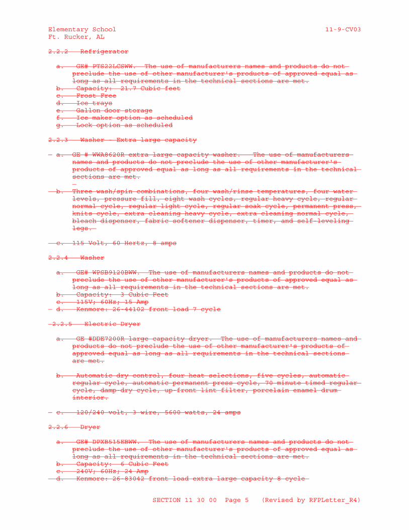
2.2.2 Refrigerator
a. GE# PTS22LCSWW. The use of manufacturers names and products do not preclude the use of other manufacturer's products of approved equal as long as all requirements in the technical sections are met.
b. Capacity: 21.7 Cubic feetc. Frost Freed. Ice trayse. Gallon door storagef. Ice maker option as scheduledg. Lock option as scheduled
2.2.3 Washer - Extra large capacity
a. GE # WWA8620R extra large capacity washer. The use of manufacturers names and products do not preclude the use of other manufacturer's products of approved equal as long as all requirements in the technical sections are met.
b. Three wash/spin combinations, four wash/rinse temperatures, four water levels, pressure fill, eight wash cycles, regular heavy cycle, regular normal cycle, regular light cycle, regular soak cycle, permanent press, knits cycle, extra cleaning heavy cycle, extra cleaning normal cycle, bleach dispenser, fabric softener dispenser, timer, and self-leveling legs.
c. 115 Volt, 60 Hertz, 8 amps
2.2.4 Washer
a. GE# WPSB9120BWW. The use of manufacturers names and products do not preclude the use of other manufacturer's products of approved equal as long as all requirements in the technical sections are met.
b. Capacity: 3 Cubic Feetc. 115V; 60Hz; 15 Amp
d. Kenmore: 26-44102 front load 7 cycle
2.2.5 Electric Dryer
a. GE #DDE7200R large capacity dryer. The use of manufacturers names and products do not preclude the use of other manufacturer's products of approved equal as long as all requirements in the technical sections are met.
b. Automatic dry control, four heat selections, five cycles, automatic regular cycle, automatic permanent press cycle, 70 minute timed regular cycle, damp-dry cycle, up-front lint filter, porcelain enamel drum interior.
c. 120/240 volt, 3 wire, 5600 watts, 24 amps
2.2.6 Dryer
a. GE# DPXB515EBWW. The use of manufacturers names and products do not preclude the use of other manufacturer's products of approved equal as long as all requirements in the technical sections are met.
b. Capacity: 6 Cubic Feetc. 240V; 60Hz; 24 Amp
d. Kenmore: 26-83042 front load extra large capacity 8 cycle
SECTION 11 30 00 Page 5 (Revised by RFPLetter_R4)
Elementary School 11-9-CV03Ft. Rucker, AL
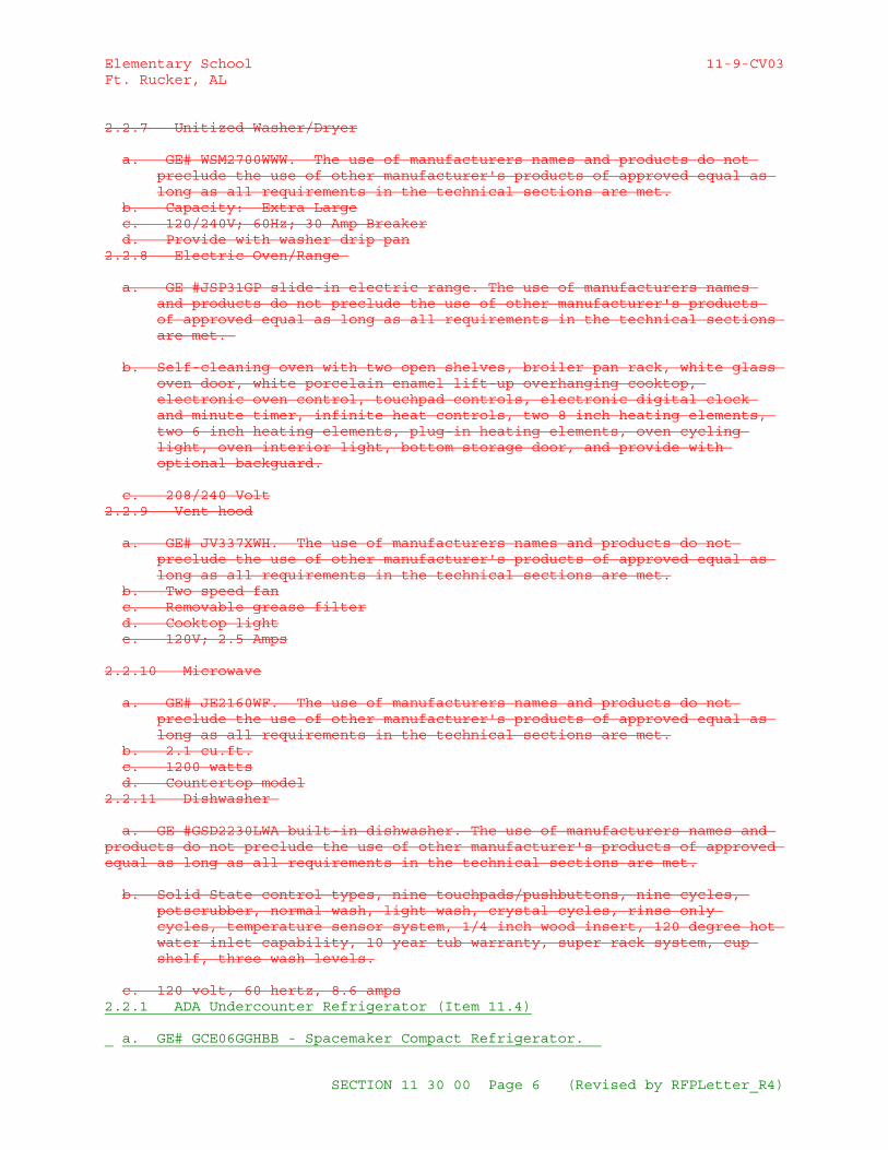
2.2.7 Unitized Washer/Dryer
a. GE# WSM2700WWW. The use of manufacturers names and products do not preclude the use of other manufacturer's products of approved equal as long as all requirements in the technical sections are met.
b. Capacity: Extra Largec. 120/240V; 60Hz; 30 Amp Breakerd. Provide with washer drip pan
2.2.8 Electric Oven/Range
a. GE #JSP31GP slide-in electric range. The use of manufacturers names and products do not preclude the use of other manufacturer's products of approved equal as long as all requirements in the technical sections are met.
b. Self-cleaning oven with two open shelves, broiler pan rack, white glass oven door, white porcelain enamel lift-up overhanging cooktop, electronic oven control, touchpad controls, electronic digital clock and minute timer, infinite heat controls, two 8 inch heating elements, two 6 inch heating elements, plug-in heating elements, oven cycling light, oven interior light, bottom storage door, and provide with optional backguard.
c. 208/240 Volt2.2.9 Vent hood
a. GE# JV337XWH. The use of manufacturers names and products do not preclude the use of other manufacturer's products of approved equal as long as all requirements in the technical sections are met.
b. Two speed fanc. Removable grease filterd. Cooktop lighte. 120V; 2.5 Amps
2.2.10 Microwave
a. GE# JE2160WF. The use of manufacturers names and products do not preclude the use of other manufacturer's products of approved equal as long as all requirements in the technical sections are met.
b. 2.1 cu.ft.c. 1200 wattsd. Countertop model
2.2.11 Dishwasher
a. GE #GSD2230LWA built-in dishwasher. The use of manufacturers names and products do not preclude the use of other manufacturer's products of approved equal as long as all requirements in the technical sections are met.
b. Solid State control types, nine touchpads/pushbuttons, nine cycles, potscrubber, normal wash, light wash, crystal cycles, rinse only cycles, temperature sensor system, 1/4 inch wood insert, 120 degree hot water inlet capability, 10 year tub warranty, super rack system, cup shelf, three wash levels.
c. 120 volt, 60 hertz, 8.6 amps2.2.1 ADA Undercounter Refrigerator (Item 11.4)
a. GE# GCE06GGHBB - Spacemaker Compact Refrigerator.
SECTION 11 30 00 Page 6 (Revised by RFPLetter_R4)
Elementary School 11-9-CV03Ft. Rucker, AL
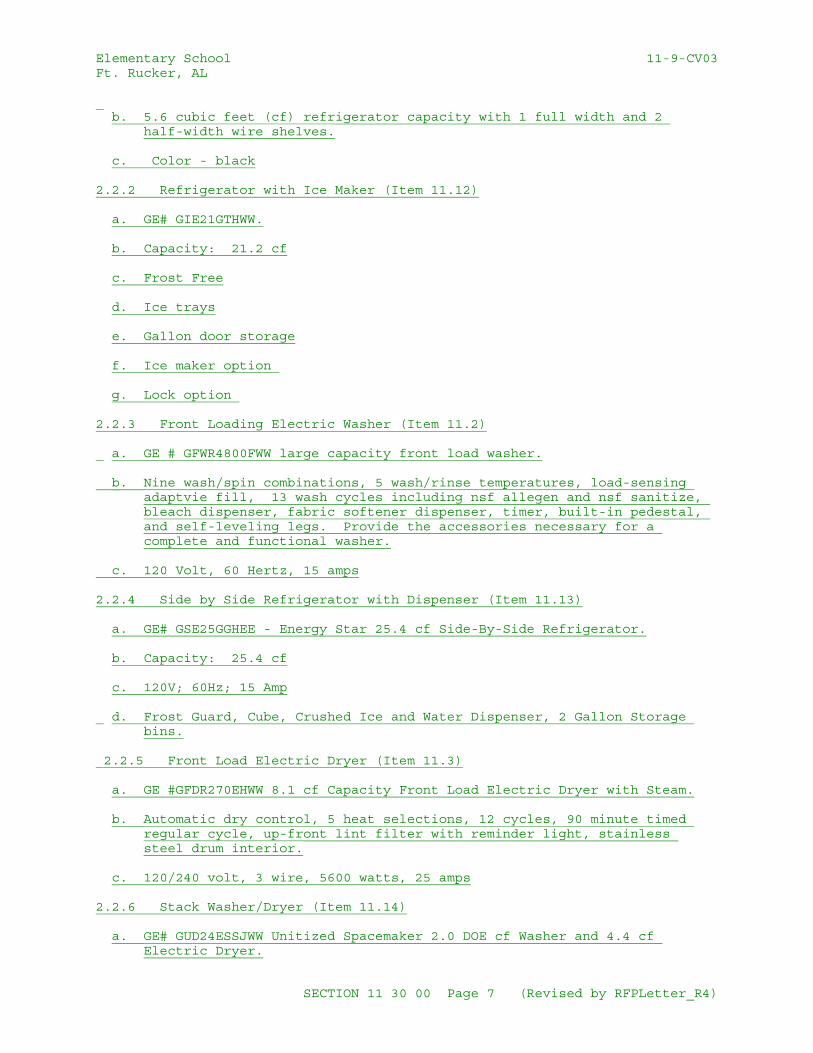
b. 5.6 cubic feet (cf) refrigerator capacity with 1 full width and 2
half-width wire shelves.
c. Color - black
2.2.2 Refrigerator with Ice Maker (Item 11.12)
a. GE# GIE21GTHWW.
b. Capacity: 21.2 cf
c. Frost Free
d. Ice trays
e. Gallon door storage
f. Ice maker option
g. Lock option
2.2.3 Front Loading Electric Washer (Item 11.2)
a. GE # GFWR4800FWW large capacity front load washer.
b. Nine wash/spin combinations, 5 wash/rinse temperatures, load-sensing adaptvie fill, 13 wash cycles including nsf allegen and nsf sanitize, bleach dispenser, fabric softener dispenser, timer, built-in pedestal, and self-leveling legs. Provide the accessories necessary for a complete and functional washer.
c. 120 Volt, 60 Hertz, 15 amps
2.2.4 Side by Side Refrigerator with Dispenser (Item 11.13)
a. GE# GSE25GGHEE - Energy Star 25.4 cf Side-By-Side Refrigerator.
b. Capacity: 25.4 cf
c. 120V; 60Hz; 15 Amp
d. Frost Guard, Cube, Crushed Ice and Water Dispenser, 2 Gallon Storage bins.
2.2.5 Front Load Electric Dryer (Item 11.3)
a. GE #GFDR270EHWW 8.1 cf Capacity Front Load Electric Dryer with Steam.
b. Automatic dry control, 5 heat selections, 12 cycles, 90 minute timed regular cycle, up-front lint filter with reminder light, stainless steel drum interior.
c. 120/240 volt, 3 wire, 5600 watts, 25 amps
2.2.6 Stack Washer/Dryer (Item 11.14)
a. GE# GUD24ESSJWW Unitized Spacemaker 2.0 DOE cf Washer and 4.4 cf Electric Dryer.
SECTION 11 30 00 Page 7 (Revised by RFPLetter_R4)
Elementary School 11-9-CV03Ft. Rucker, AL
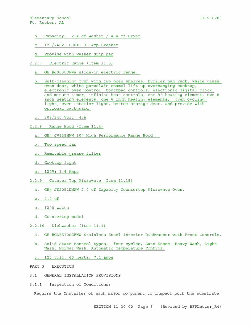
b. Capacity: 2.4 cf Washer / 4.4 cf Dryer
c. 120/240V; 60Hz; 30 Amp Breaker
d. Provide with washer drip pan
2.2.7 Electric Range (Item 11.6)
a. GE #JS630DFWW slide-in electric range.
b. Self-cleaning oven with two open shelves, broiler pan rack, white glass oven door, white porcelain enamel lift-up overhanging cooktop, electronic oven control, touchpad controls, electronic digital clock and minute timer, infinite heat controls, one 9" heating element, two 8 inch heating elements, one 6 inch heating elements, oven cycling light, oven interior light, bottom storage door, and provide with optional backguard.
c. 208/240 Volt, 40A
2.2.8 Range Hood (Item 11.4)
a. GE# JV535HWW 30" High Performance Range Hood.
b. Two speed fan
c. Removable grease filter
d. Cooktop light
e. 120V; 1.4 Amps
2.2.9 Counter Top Microwave (Item 11.15)
a. GE# JE2051DNWW 2.0 cf Capacity Countertop Microwave Oven.
b. 2.0 cf
c. 1200 watts
d. Countertop model
2.2.10 Dishwasher (Item 11.1)
a. GE #GDF570SGFWW Stainless Steel Interior Dishwasher with Front Controls.
b. Solid State control types, four cycles, Auto Sense, Heavy Wash, Light Wash, Normal Wash, Automatic Temperature Control.
c. 120 volt, 60 hertz, 7.1 amps
PART 3 EXECUTION
3.1 GENERAL INSTALLATION PROVISIONS
3.1.1 Inspection of Conditions:
Require the Installer of each major component to inspect both the substrate
SECTION 11 30 00 Page 8 (Revised by RFPLetter_R4)
Elementary School 11-9-CV03Ft. Rucker, AL
and conditions under which Work is to be performed. Do not proceed until unsatisfactory conditions have been corrected in an acceptable manner.
3.1.2 Manufacturer's Instructions:
Comply with manufacturer's installation instructions and recommendations, to the extent that those instructions and recommendations are more explicit or stringent than requirements contained in Contract Documents.
Where manufacturer's instructions and Government requirements conflict, consult the Contracting Officer's Representative for resolution.
Inspect materials or equipment immediately upon delivery and again prior to installation. Reject damaged and defective items.
Provide attachment and connection devices and methods necessary for securing Work. Secure Work true to line and level. Allow for expansion and building movement.
Recheck measurements and dimensions, before starting each installation.
-- End of Section --
SECTION 11 30 00 Page 9 (Revised by RFPLetter_R4)
Elementary School 11-9-CV03Ft. Rucker, AL
SECTION TABLE OF CONTENTS
DIVISION 11 - EQUIPMENT
SECTION 11 40 00
FOOD SERVICE EQUIPMENT
08/15
PART 1 GENERAL
1.1 REFERENCES 1.2 SUBMITTALS 1.2.1 Contractor 1.3 DESCRIPTION OF WORK 1.3.1 Scope 1.3.2 Related Work 1.3.2.1 Electrical 1.3.2.2 Plumbing 1.3.2.3 Ventilators and/or Hoods 1.3.2.4 Utility Distribution System/Utility Power Chases 1.3.2.5 Raised Concrete Floors and Floor Depressions. 1.3.2.6 Ceramic Tile 1.4 RESPONSIBILITY 1.5 QUALITY ASSURANCE 1.5.1 Subcontractors 1.5.2 Fabricator 1.5.3 Standard of Quality 1.5.3.1 Substitution Of Standards 1.5.4 Specified Items Availability 1.5.5 Value Engineering 1.6 STANDARDS 1.6.1 NSF Standards 1.6.2 UL Labels 1.6.3 ANSI Standards 1.6.4 NFPA Codes 1.6.5 ASME Boiler Code 1.7 REGULATORY REQUIREMENTS 1.8 DELIVERY, STORAGE AND HANDLING 1.9 WARRANTIES
PART 2 PRODUCTS
2.1 MATERIALS 2.1.1 Galvanized Steel 2.1.2 Stainless Steel 2.1.3 Steel Sheet 2.1.4 Stainless Steel Tube 2.1.5 GalvanizedSteel Pipe 2.1.6 Structural 2.1.7 Aluminum (ALM) 2.1.8 Plastics 2.1.8.1 Plastic Laminate 2.1.8.2 Plastic Materials Components (plst) 2.1.9 Hardwood Work Surface
SECTION 11 40 00 Page 1 (Revised by RFPLetter_R8)
Elementary School 11-9-CV03Ft. Rucker, AL
2.1.10 Insulation (INS) 2.1.10.1 Cooled-Component Insulation 2.1.10.2 Heated-Component Insulation 2.1.11 Joint Materials 2.1.12 Gaskets (GKT) 2.1.13 Paint and Coatings 2.1.13.1 General 2.1.13.2 Special Coating (SpCt) 2.1.13.3 Sound Deadening (SndDdn) 2.2 FABRICATED PRODUCTS 2.2.1 Fabricated Equipment 2.2.1.1 Metal Tops and Work Surfaces 2.2.1.2 Metal and Gauges 2.2.1.3 Drain Boards or Drain Tables 2.2.1.4 Sinks 2.2.1.5 Open Base Stands and Frames 2.2.1.6 Welding 2.2.1.7 Grinding, Polishing and Finishing 2.2.1.8 Protection Against Corrosion 2.2.1.9 Field Joints 2.2.1.10 Sound Deadening 2.2.1.11 Piping 2.2.1.12 Trim 2.2.1.13 Final Polishing 2.2.2 Casework 2.2.2.1 Enclosures, General 2.2.2.2 Support from Floor 2.2.2.3 Fixed Location Equipment 2.2.3 Casters 2.3 EQUIPMENT 2.3.1 Crowd Control Stanchions: (Items: #1, #7, and #23) 2.3.2 Mobile Cashier Station: (Item: 2) 2.3.3 Cash Register: (Item 3) 2.3.4 18 Gauge Stainless Steel Data Chase: (Item 4) 2.3.5 Mobile Tray/Silverware Stand: (Items 5, 24) 2.3.6 Front Service Milk Cooler: (Items: 6, 25) 2.3.7 Roll Towel Dispenser: (Items, 8, 34, 43, 61, 98, 125, 142, 151) 2.3.8 Hand Sink-Knee Operated w/Soap Dispenser: (Items: 8A, 34A,
43A, 61A, 98A, 125A, 142A, 151A) 2.3.9 Spare Numbers: (Items 9, 10, 19, 20, 29, 30, 39, 40, 49, 50,
59, 60, 69, 70, 79, 80, 89, 90, 99, 100, 110, 119, 120, 129, 130, 139, 140, 149, 150)
2.3.10 Three Tier Utility Carts: (Items: 11, 32, 36, 38, 44) 2.3.11 Built-In Warmer w/Water Fill: (Item: 12) 2.3.12 Drop-In Frost Top: (Item: 13) 2.3.13 Servery Counter (Item: 14 2.3.14 Mobile Oven Rack: (Items 15, 87, 93) 2.3.15 Combi-Heated Roll-In Cabinet: (Items 16, 86) 2.3.16 Single Door Roll-In Refrigerator: (Items: 17, 84) 2.3.17 Roll-In Utility Storage Racks: (Items: 18, 57, 85, 102, 118) 2.3.18 18 Gauge Stainless Steel Refrigeration Chase: (Items: 21,
65A, 76, 84A, 97A, 106A) 2.3.19 Built-In Warmer w/Water Fill: (Item: 26) 2.3.20 Drop-In Frost Top: (Item: 27) 2.3.21 Servery Counter (Item: 28) 2.3.22 Corner Guards: (31, 45, 47, 134, 138, 143) 2.3.23 Recessed Floor Drains w/ADA Grate: (Items 22, 33, 42, 46, 55,
64, 91, 105, 107, 137) 2.3.24 Cleaning Assembly Controls (Recessed): (35,41,58)
SECTION 11 40 00 Page 2 (Revised by RFPLetter_R8)
Elementary School 11-9-CV03Ft. Rucker, AL
2.3.25 Wall Mounted-Reel Cleaning Assembly: (35A. 41A, 58A) 2.3.26 30 Quart Floor Mixer: (Item 37) 2.3.27 Control Panel (Soiled Dish Table-Pulper): (Item: 48) 2.3.28 Pulper w/Trough Connection: (Item 48A) 2.3.29 18 Gauge Stainless Steel Chase-Waste System (Item 48B) 2.3.30 Counter Fire Door at Scrapping Table: (Item: 51) 2.3.31 Scrapping Dish Table: (Item 52) 2.3.32 Condensate Hood: (Item: 53) 2.3.33 Conveyor Dish Washer: (Item: 54) 2.3.34 Clean Dish Table: (Item: 56) 2.3.35 Control Panel (Grinder-Three Compartment Pot Sink): (Item:
62) 2.3.36 18 Gauge Stainless Steel Chase-Waste System (Item 62A) 2.3.37 Grinder-Sink Mounted Pulping System: (Item 62B) 2.3.38 Three Compartment Pot Sink: (Item: 63) 2.3.39 18 Gauge Stainless Steel Corner Guards (38, 61, 83, 95, 108, &
118) 2.3.40 Single Door Remote Pass-Thru Refrigerator (Items No. 65, 75) 2.3.41 Electric Can-Openers: (Items: 66, 81) 2.3.42 Electrical Drop-Cords: (Items: 67, 73, 78, 82) 2.3.43 Work Tables: (Items: 71, 74, 77, 83) 2.3.44 Digital Portion Control Scale: (Item: 68) 2.3.45 Food Processor: (Item: 72) 2.3.46 Cook Tables: (Item: 88) 2.3.47 25 Gallon Tilt Kettle: (Item: 91A) 2.3.48 Roll-In CombiMaster Oven: (Item: 92) 2.3.49 Double Combi-Oven: (Item: 94) 2.3.50 Exhaust Ventilator: (Item: 95) 2.3.51 Utility Distribution System: (Item: 96) 2.3.52 Reach-In Blast Chiller-Shock Freezer: (Item: 97) 2.3.53 Mobile Heated Cabinets: (Item: 101) 2.3.54 Mobile Ice Bin: (Item: 103) 2.3.55 Prep-Work Table: (Item: 104) 2.3.56 Water Treatment Unit (water Filter-Ice Maker): (Item: 106) 2.3.57 Air Cooled Remote Ice Maker: (Item 106B) 2.3.58 Ice storage Bin: (Item: 106C) 2.3.59 Bakery Dough Scale: (Item: 108) 2.3.60 Ingredient Bins (Item: 109) 2.3.61 Bakery Work Table: (Item: 111) 2.3.62 Portable Utility Tables: (Item: 112) 2.3.63 Automatic Food Slicer: (Item: 113) 2.3.64 Four Tier Storage Units: (Items: 114, 117, 121, 128, 132) 2.3.65 Dunnage Racks (115 & 133) 2.3.66 Walk-In Cooler/Freezer General Specifications 2.3.66.1 Panels 2.3.66.2 Floor Construction 2.3.66.3 Doors 2.3.66.4 Audio-Visual Alarm/Thermometer 2.3.66.5 Strip Curtains 2.3.66.6 Closure panels 2.3.66.7 Closure Strips 2.3.66.8 Mechanical Refrigeration 2.3.67 Walk-In Freezer: (Item: 116) 2.3.68 Low Temp Evaporator Coil: (Item: 116A) 2.3.69 Walk-In Cooler: (Item: 122) 2.3.70 Med Temp Evaporator Coil: (Item: 122A) 2.3.71 Control Panel (Grinder-Two Compartment Prep Sink): Item: 123) 2.3.72 18 Gauge Stainless Steel Chase-Waste System (Item 123A) 2.3.73 Grinder-Sink Mounted Pulping System: (Item 123B)
SECTION 11 40 00 Page 3 (Revised by RFPLetter_R8)
Elementary School 11-9-CV03Ft. Rucker, AL
2.3.74 Two Compartment Prep Sink: (Item: 124) 2.3.75 Four Tier Track Shelving: (Item: 126) 2.3.76 Table Top-Can Storage Rack: (Items: 127, 131) 2.3.77 Individual Purse Lockers: (Item: 135) 2.3.78 Stack Washer-Dryer: (Item 136) 2.3.79 Insect Control Fans: (Item: 141) 2.3.80 Floor Mounted Mop Sink: (Item: 144) 2.3.81 Wall Mounted Janitorial Faucet: (Item: 145) 2.3.82 Wall Mounted Broom/Mop Rack: (Item: 146) 2.3.83 Control Panel-Extractor: (Item: 147) 2.3.84 Extractor: (Item: 147A) 2.3.85 Compostable Waste Dehydrator: (Item: 147B) 2.3.86 Recessed Wash-down Station: (Item: 148) 2.3.87 Remote Refrigeration Rack System: (Item: 152) 2.3.88 Remote Refrigeration Condenser-Ice Maker): (Item: 153) 2.3.89 18 Gauge Stainless Steel Refrigeration Housing: (Item: 154) 2.4 EQUIPMENT CLARIFICATIONS 2.5 PLUMBING FITTINGS, TRIM AND ACCESSORIES 2.5.1 General 2.5.2 Water Outlets 2.6 ELECTRICAL MATERIALS 2.6.1 General 2.6.2 Controls and Signals 2.6.3 Connections 2.6.4 Motors 2.6.5 Nameplates 2.7 GREASE REMOVAL 2.8 LIGHT FIXTURES 2.9 SHOP PAINTING 2.10 PLASTIC LAMINATE CASEWORK 2.10.1 General
PART 3 EXECUTION
3.1 EXAMINATION AND PREPARATION 3.1.1 Rough-In Work 3.2 INSTALLATION 3.2.1 Service Lines and Equipment Connections 3.2.2 Equipment Placement 3.2.3 Field Assembly Joints 3.2.4 TPest Treatment 3.2.5 Closure Strips 3.2.6 Joint Sealants 3.3 CLEANING, RESTORING FINISHES 3.4 TESTING, START-UP AND INSTRUCTIONS 3.4.1 General 3.4.2 Test Each Item 3.4.3 Instruct Government's Operating Personnel 3.4.4 Final Cleaning 3.5 OPERATION AND MAINTENANCE MANUALS
-- End of Section Table of Contents --
SECTION 11 40 00 Page 4 (Revised by RFPLetter_R8)
Elementary School 11-9-CV03Ft. Rucker, AL
SECTION 11 40 00
FOOD SERVICE EQUIPMENT08/15
PART 1 GENERAL
1.1 REFERENCES
The publications listed below form a part of this specification to the extent referenced. The publications are referred to within the text by the basic designation only.
ASME INTERNATIONAL (ASME)
ASME A112.18.1/CSA B125.1 (2012) Plumbing Supply Fittings
ASTM INTERNATIONAL (ASTM)*6
ASTM A1011/A1011M (2014) Standard Specification for Steel, Sheet, and Strip, Hot-Rolled, Carbon, Structural, High-Strength Low-Alloy and High-Strength Low-Alloy with Improved Formability and Ultra-High Strength
ASTM A123/A123M (2013) Standard Specification for Zinc (Hot-Dip Galvanized) Coatings on Iron and Steel Products
ASTM A270/A270M (2010) Standard Specification for Seamless and Welded Austenitic Stainless Steel Sanitary Tubing
ASTM A53/A53M (2012) Standard Specification for Pipe, Steel, Black and Hot-Dipped, Zinc-Coated, Welded and Seamless
ASTM A554 (2010) Standard Specification for Welded Stainless Steel Mechanical Tubing
ASTM A653/A653M (2013) Standard Specification for Steel Sheet, Zinc-Coated (Galvanized) or Zinc-Iron Alloy-Coated (Galvannealed) by the Hot-Dip Process
ASTM B209 (2014) Standard Specification for Aluminum and Aluminum-Alloy Sheet and Plate
ASTM B221 (2014) Standard Specification for Aluminum and Aluminum-Alloy Extruded Bars, Rods, Wire, Profiles, and Tubes
ASTM E84 (2015a) Standard Test Method for Surface Burning Characteristics of Building Materials
SECTION 11 40 00 Page 5 (Revised by RFPLetter_R8)
Elementary School 11-9-CV03Ft. Rucker, AL
NATIONAL ELECTRICAL MANUFACTURERS ASSOCIATION (NEMA)
ANSI/NEMA LD 3 (2005) Standard for High-Pressure Decorative Laminates
NFPA 54 (2015) National Fuel Gas Code
NFPA 70 (2014; AMD 1 2013; Errata 1 2013; AMD 2 2013; Errata 2 2013; AMD 3 2014; Errata 3-4 2014; AMD 4-6 2014) National Electrical Code
NFPA 96 (2014) Standard for Ventilation Control and Fire Protection of Commercial Cooking Operations
NSF INTERNATIONAL(NSF)
NSF/ANSI 51 (2012) Food Equipment Materials
ANSI/UL 471 (2010) Commercial Refrigerators and Freezers
1.2 SUBMITTALS
1.2.1 Contractor
Government approval is required for submittals with a "G" designation; submittals not having a "G" designation are for information only. When used, a designation following the "G" designation identifies the office that will review the submittal for the Government. Submit the following in accordance with Section 01 33 00 SUBMITTAL PROCEDURES:
SD-02 Shop Drawings*4
Equipment; G, AERough-in drawings: A/EDimensioned Rough-in drawings shall be provided at ¼ inch scale showing ventilation ducts, floor and wall sleeves, plumbing and electrical lines. Provide separate sheets for Plumbing, Electrical and Ventilation. In addition, a plan indicating slab recesses, wall blocking and refrigeration shall be provided.
Shop Drawings: A/ESubmit detail drawings at ¾ inch and 1- ½ inch scale. Indicate dimensions, details or construction, installation, relation to adjoining and related work where cutting or close fitting is required. Verify at job site, all dimensions, mechanical, electrical and ventilation rough-in and sleeve location before fabrication. Indicate all reinforcements, anchorages and other work required by other trades for the complete installation of all items.
SD-03 Product Data
*4Equipment; G, AEProduct Data: A/EProvide manufacturer's detailed literature, catalog cuts and specifications for all equipment indicated in the food service Drawings, and/or drawings.
SECTION 11 40 00 Page 6 (Revised by RFPLetter_R8)
Elementary School 11-9-CV03Ft. Rucker, AL
SD-07 Certificates
Inspection certificates as required and submit 3 copies to the Contracting Officer's Representative (COR).
Prior to final acceptance, Contractor must submit for review a letter stating they will complete the above to full specifications.
Letter of compliance with full specifications
Contractor shall provide letter from the manufacturer that they will fully comply with the full specification above.
Letter of compliance with full specifications.
SD-08 Manufacturer's Instructions*4
Equipment; G, AEManufacturer's Instructions: Submit copies of manufacturers written installation instructions for all equipment indicated in the food service Drawings and/or drawings.
*4*6SD-10 Operation and Maintenance Data
Manufacturer's Instructions: Provide detailed application instructions for all equipment indicated in the food service Drawings and/or drawings.SD-10 Operation and Maintenance Data
Operation and Maintenance Manuals
SD-11 Closeout Submittals*4
Equipment; G, AERecord Drawings:Submit record drawings for each of the food service drawings in the construction submittal.
Warranties: Submit manufacturer's warranties as specified herein.Record Drawings
1.3 DESCRIPTION OF WORK
1.3.1 Scope
The extent of the Work covered by this Section of the Specifications shall include:
a. Furnishing all labor materials, equipment and services necessary for the completion of all food service equipment work covered by this section of the specifications;
b. Furnishing, delivering, and setting in place ready for connection to services by others all items of food service equipment, complete with all appurtenances and accessories necessary for complete and
SECTION 11 40 00 Page 7 (Revised by RFPLetter_R8)
Elementary School 11-9-CV03Ft. Rucker, AL
satisfactory operation, as indicated on the contract drawings and/or as herein specified.
c. Cut all holes and ferrules on equipment for piping, drains, Electric outlets, etc., required for the coordination and/or connection of the equipment covered by this section with the work of others.
d. Submittal of all brochures, shop drawings, rough in plans, and other submittal data specified herein.
e. Field checks all building and rough-in measurements.
f. Supervise and coordinated with the work of other trades in theinstallation of this equipment.
1.3.2 Related Work
1.3.2.1 Electrical
Refer to Division 26 Sections for electrical work, which shall include: by the drawings or as specified, and make final connections between.
a. Furnish and install all roughing-in wiring for all items of Food service equipment shown between roughing-in and points ofconnection on equipment.
b. Furnish and install all wall receptacles shown on the plan with receptacles to match plugs furnished as part of items of food service equipment.
c. Furnish and install all disconnect switches required by codebetween roughing in points and the points of connection on theequipment.
1.3.2.2 Plumbing
Refer to Division 22 Sections for plumbing work which shall include:
a. Furnish and install all plumbing roughing-in for all items of food service equipment shown between roughing-in and points ofconnection on equipment;
b. Furnish and install all hot and cold water piping betweenroughing-in and points of connection on equipment; install faucets (unless other- wise specified or noted), vacuum breakers and other devices furnished under this section of the specifications, at sinks, tables etc., and make final connections thereto;
c. Furnish and install all waste piping (both direct and indirect)and make final connections to drain outlets on sinks, disposers, dishwashers, etc.
1.3.2.3 Ventilators and/or Hoods
Except for exposed ducts specified as part of the equipment, all ventilation ductwork including final connections to hood and ventilators refer to section 23 00 00 AIR SUPPLY, DISTRIBUTION,VENTILATION AND EXHAUST SYSTEM.
SECTION 11 40 00 Page 8 (Revised by RFPLetter_R8)
Elementary School 11-9-CV03Ft. Rucker, AL
1.3.2.4 Utility Distribution System/Utility Power Chases
a. All equipment to be connected to the Utility Distribution Systems and Utility Power Chases to be performed by the proper trades.
b. When stated in the specification that the system will be totally engineered system, which does not exclude the proper trades from making the final connections to the equipment being furnished by the utility distribution system/power chases
c. When the Utility Distribution System is furnished with the mechanical and/or electrical solenoid(s). The solenoid(s) will be shipped loose, unless stated otherwise, and the plumbing contractor will be responsible to connect the solenoid(s) to the main gas line per code.
1.3.2.5 Raised Concrete Floors and Floor Depressions.
Refer to section 03 30 00.00 10 CAST-IN-PLACE CONCRETE.
1.3.2.6 Ceramic Tile
Refer to section 09 30 13 CERAMIC TILE, AND QUARRY TILE.
1.4 RESPONSIBILITY*6It is the Contractor's responsibility to coordinate and assign responsibility division.
Where the word "Contractor" appears in this section, this shall mean "Food Service Equipment Contractor and/or Dealer".
a. The work herein specified and/or shown on the drawings shall be carried on in conjunction with and shall be so arranged that its installation and operation will fit in with the work of the other trades. Work of this contract shall include proper coordination and cooperation with all other trades performing work on this project whose work affects, or is affected by, the work hereunder.
b. Contractor shall examine and become familiar with drawings and specifications for architectural and mechanical work with reference to work in this contract and shall be responsible for ensuring the correct fitting of all work in connection with related work. He shall become familiar with all job conditions, building measurements, and other conditions in order to coordinate the planning, design, delivery, storage and installation his work, all with proper consideration of the project progress schedule.
c. The Contractor will be held responsible for verifying the electric current characteristics. If any of the equipment to be supplied does not coincide with that which is indicated on the Schedule or Roughing Drawings, it will be the supplier's responsibility to call the discrepancy to the attention of the Government, prior to submitting the questionable item.
d. It shall be this Contractor's responsibility to visit the site And coordinate with other trades to preclude cutting and patching and in the event of units of equipment too large to pass through planned openings, arrange for access to the required areas ahead of time not to
SECTION 11 40 00 Page 9 (Revised by RFPLetter_R8)
Elementary School 11-9-CV03Ft. Rucker, AL
delay delivery schedule.
e. In addition to the requirements set forth in the Project Specifications, the Contractor shall be completely responsible for the fulfillment of all the requirements pertaining to the fabrication, assembly, and installation of all the items of this section including those of his subcontractors.
f. Provide all appurtenances which may not be specifically mentioned in the specifications or shown on the drawings, but which are required for the proper function and installation of the equipment.
1.5 QUALITY ASSURANCE
1.5.1 Subcontractors
The Contractor shall, upon demand, submit to the Government evidence of having executed contracts of size comparable to this, in a satisfactory manner.
1.5.2 Fabricator*4a. All fabrication shall be by one manufacturer and be of uniform design and Finish Approved. Separate Fabricators for Front of House and Back of House equipment will be acceptable.
b. Fabricated products shall conform to the Contract.
c. The Contractor will be totally responsible for providing and verifying field measurements to the job site conditions within a plus or minus 1/2 inch.
d. The Contractor must submit their proposed fabricator prior to the awarding of the food service bid to Total Design Consortium for approval.
1.5.3 Standard of Quality
Manufacturer names standard food service equipment made on a productionbasis and catalog number for the equipment list specified hereinafter and establishes the "Standard of Quality" required.
1.5.3.1 Substitution Of Standards
All proposals shall be based on the "Standards" specified unless.
a. The products of other manufacturers, which conform to the requirement of the specifications and plans, are approved in writing by the Government or Representative as a "Equal" to that specified.
b. The approval for substitution being secured from the Government or Representative prior to the submission of bids.
c. Any equipment offered as "An Approved Equal" to that specified must conform to the space limitations of the layout and match sizes of basis of design items, utilities being provided and the cost of any deviation from "An Approved Equal" item will be the responsibility of the bidder at no extra cost to the Government.
d. Where the phrase "approved for review only" the Government
SECTION 11 40 00 Page 10 (Revised by RFPLetter_R8)

Elementary School 11-9-CV03Ft. Rucker, AL
must approve the proposed alternate prior to the food service dealer submitting as part of bid. Do not assume that material, equipment, or the Government will approve methods as equal unless the item has specifically approved in writing by the Government.
e. Equipment, specialties, and similar items shall be checked forcompliance and fully approved prior to installation. The Kitchen Contractor is cautioned that work or equipment installed without approval is subject to condemnation and removal, with subsequent replacement with an approve item without extra remuneration.
Where in the Drawings and Specifications certain products, Manufacturer's trade name, or catalog numbers are given, it is done for the expressed purpose of establishing a basis of quality, durability, and efficiency of design in harmony with the work outlined and is not intended for limiting competition. Alternates meeting product specifications will be considered.
Do not substitute materials, equipment, or methods unless suchsubstitution has been specifically approved for this work by Government.
Products of submitted manufacturers will be considered for acceptance provides they equal or exceed the material requirements and functional qualities of the specified product. Requests Government approval and complete technical data for evaluation must be received at least 10 days prior to bid due date. Additional approved manufacturers will be issued by Addendum.
Where the questions of appearance, artistic effect, or harmony of design are concerned, the Government reserves the right to refuseapproval of substituted products proposed to be substituted for the specified.
a. If in Governments opinion the item to be substituted is notharmonious to the finished effect and appearance desired, as portrayed in the Drawings and Specifications.
b. The Government said refusal to approve, established by this paragraph, is final.
1.5.4 Specified Items Availability
It shall be the contractor's responsibility to verify the specified items will be available in time for installation during orderly and timely rogress of the work.
Costs of delays because of non-availability of specified items, when the Contractor could have avoided such delays, will be back charged as necessary and shall not be borne by the Government.
1.5.5 Value Engineering
The Government or Representative will approve no value engineering recommendation without proper back up information comparing what was specified to what is being replaced.
Should any value engineering recommendations be approved without the Government's or its representative approvals; the responsibility of equipment or system complying with the project characteristics and requirements will directly be the responsibility of the party to who
SECTION 11 40 00 Page 11 (Revised by RFPLetter_R8)
Elementary School 11-9-CV03Ft. Rucker, AL
approved the change. The Government and or its representative will not be held responsible and should the approved change result in a design change the Government will be compensated at his established hourly rate to complete the design change.
1.6 STANDARDS
1.6.1 NSF Standards
Comply with applicable National Sanitation Foundation standards and recommended criteria.
Provide each principal item of food service equipment with a "Seal of Approval" by NSF Food Equipment.
1.6.2 UL Labels
Where available, provide UL Labels on prime electrical components of food service equipment.
Provide UL "Recognized Marking" on other items with electricalcomponents, signifying listing by UL, where available.
1.6.3 ANSI Standards
Comply with applicable ANSI Standards for electric powered and gas-burning appliance for piping to compressed gas cylinders, and for plumbing fittings, including vacuum breakers and air gaps to prevent siphonage in water piping including ANSI/UL 471
1.6.4 NFPA Codes
Comply with NFPA 70 "National Electric Code", and with NFPA 96; "Removal of Smoke and Grease-Laden Vapors from Commercial Cooking Equipment", and with NFPA 54 "National Fuel Gas Code".
1.6.5 ASME Boiler Code
Construct steam generating and closed steam heated equipment to comply with Asme Boiler and Pressure Vessel Code; SECTION IV for units not exceeding 15 psig or 250 degree F. SECTION I for higher pressure/temperature rated units.
1.7 REGULATORY REQUIREMENTS
Obtain applicable permits and licenses and post as required. Obtain inspection certificates as required and submit 3 copies to the Contracting Officer's Representative (COR).
1.8 DELIVERY, STORAGE AND HANDLING
Deliver food service equipment into the building only when immediate concealment by other work is scheduled.
Store equipment and protect it from damage.
Protect equipment at all times against damage from the elements and cover equipment in storage to protect from damage by other trades
UN-crate, assemble, level and repair any damaged or abraded
SECTION 11 40 00 Page 12 (Revised by RFPLetter_R8)
Elementary School 11-9-CV03Ft. Rucker, AL
surfaces.
Set the custom fabricated and buy-out equipment temporarily in its final location, permitting the other trades involved to take necessary measurements for connection of the service.
Move the equipment sufficiently to permit the installation of service lines. After the lines are installed, realign, level and plum the equipment in its final position and location.
Provide six additional corrected brochures for distribution.
Contractor shall ensure that equipment delivery does not impede the construction schedule.
1.9 WARRANTIES
The Government will not accept the start of the warranty period on systems or equipment until Final Acceptance is issued to the Contractor for Governments occupancy of the building, in part or whole.
The Contractor shall make such provisions as required to extend the manufacturer's warranty from time of initial operation of systems or equipment until Substantial Completion is given in writing.
Repair or replace free of charge any work, equipment, parts, materials, and workmanship which becomes defective during the guarantee period, except to the extent except to the extent it has been subjected to abuse, misuse, or accidental damage as determined by the Government.
Include with warrantee a complete list of local servicing agents for all standard manufactured equipment with addresses and telephone numbers.
PART 2 PRODUCTS
2.1 MATERIALS
Each item of equipment shall be fabricated of full gauge thickness as specified indicating by name or abbreviations used under the "Drawings" hereinafter specified.
2.1.1 Galvanized Steel
a. Shall be Armco Copper Bearing Zinc Grip or Zinc Grip/Paint Grip.Galvanized steel joints shall be arc-welded and be free of pits and flaws. Galvanized sheets shall be washed with mineral spirits, primed with rust inhibiting primer and finish coated with baked enamel or color specified. Other manufacturers are acceptable if the products meet the requirements.
b. Where painted finish is indicated, provide mill-phosphates treatment in lieu of chemical treatment.
c. Where factory-applied finish of porcelain or baked-on synthetic enamel is indicated for exposed face of galvanized steel sheet, differentially coated sheet complying with ASTM A653/A653M; may be provided.
SECTION 11 40 00 Page 13 (Revised by RFPLetter_R8)
Elementary School 11-9-CV03Ft. Rucker, AL
2.1.2 Stainless Steel
a. Shall be austenitic steel allow; 18-8 8 percent nickel, 18 percent chrome; not more than 0.2 percent carbon; not more than 2.0 percent of any other alloying element; must meet the requirements of the American Iron and Steel Institute's designations for type 302 or type 304 stainless steel.
b. Type 316 stainless to be used in conjunction with Steamer and Tilt Kettles.
c. Type 430 stainless steel (all chrome-no nickel) will not be acceptable for custom fabricated equipment or manufacturer equipment, including ventilators.
d. All sheets shall have genuine mill finish of not less than commercial number 4 on all exposed side and not less than number 2B finish on all unexposed side
e. All stainless steel sheets must bear the manufacturers trademarkdesignating type and heat number.
f. All stainless steel sheets shall be stretchers leveled.
2.1.3 Steel Sheet
ASTM A1011/A1011M; hot-rolled carbon steel.
2.1.4 Stainless Steel Tube
a. Provide seamless or welded tubing complying with ASTM A270/A270M; finish 120. 180 or R, for food conveying piping.
b. Provide tubing complying with ASTM A653/A653M; for water anddrain/waste/vent service.
c. Grade H for water and Grade G for DWV; and complying with ASTM A554; for framing/structural support service.
d. AISI Type and Finish No. matching food service equipment at location of use, Type 304 with No. 4 directional polish where matching of other stainless steel work is not required.
2.1.5 GalvanizedSteel Pipe
ASTM A53/A53M; welded or seamless, schedule 40, galvanized.
2.1.6 Structural
Sheet members used for framing consisting of angles, bands, barschannels, etc., shall be ductile in quality, free of hard spots, runs,cracks, and other surface defects. They shall be smooth galvanized by the hot dip method with all surplus removed, and free of runs, blisters, excess splatter and uncoated spots or patches.
2.1.7 Aluminum (ALM)
ASTM B209; ASTM B221; sheet, plate and extrusions (as indicated); alloy, temper and finish as determined by manufacturer/fabricator, except .40-mill
SECTION 11 40 00 Page 14 (Revised by RFPLetter_R8)
Elementary School 11-9-CV03Ft. Rucker, AL
clear anodized finish on exposed work unless other finish is indicated.
2.1.8 Plastics
2.1.8.1 Plastic Laminate
ANSI/NEMA LD 3, general purpose high-pressure type, 0.05 inch thick except 0.042 inch for post-forming, smooth (non-textured) white unless other texture and color is indicated or selected by Government. Comply with NSF No. 35.
2.1.8.2 Plastic Materials Components (plst)
Except for plastic laminate as specified herein, provide plastic materials and components where indicated which comply with NSF/ANSI 51. Provide generic types indicated, including thermoplastic and thermoset types; and as recommended for the indicated application or service by the food service equipment unit manufacturer.
2.1.9 Hardwood Work Surface
Laminated edge-grained hard maple (Acer Saccharum), First Grade with knots, holes and other blemishes culled out, kiln dried at 8 percent or less moisture, waterproofs glue, machined, sanded, and finished with NSF approved oil sealer.
2.1.10 Insulation (INS)
2.1.10.1 Cooled-Component Insulation
Rigid, closed-cell polyurethane foam; either heat-aged slab stock foradhesive lamination with face sheets, or foamed-in-place using CFC FREEFreon expanding agent; k-valve or 0.15; not less than 1.7 lbs. per cubic foot density.
2.1.10.2 Heated-Component Insulation
Rigid board, semi-rigid blanket or adhesively applied blanket of glassfiber or other non-asbestos mineral fiber insulation, certified bymanufacturer to withstand long-term exposure to heat temperature rating of each insulated equipment item without deterioration; k-valve of not more than 0.30; density of not less than 1.5 lbs. per cubic foot.
2.1.11 Joint Materials
a. Sealants (SNT): One-part or 2-part, polyurethane or silicone based, liquid elastomeric sealant, non-solvent-release type, mildew resistant, Shore A hard-ness of 30 except 45 if subject to traffic or similar abuse.
b. Except for non-food contact surfaces, provide silicone-based sealant only.
c. BACK-ROD: Closed-cell polyethylene rod stock, larger than joint width.
2.1.12 Gaskets (GKT)
Solid or hollow (but not cellular) neoprene or polyvinyl chloride; light
SECTION 11 40 00 Page 15 (Revised by RFPLetter_R8)
Elementary School 11-9-CV03Ft. Rucker, AL
gray, minimum of 40 Shore Hardness, self-adhesive or prepared for either adhesive application of mechanical anchorage.
2.1.13 Paint and Coatings
2.1.13.1 General
Provide thermosetting types of painting and coating materials which, after drying, setting or curing, are suitable for use in conjunction with food service, and which are durable, non-toxic, non-dusting, and non-flaking, mildew resistant and comply with governing regulations and NSF recommendations for food service.
2.1.13.2 Special Coating (SpCt)
Where indicated in equipment listing as "Special coating", provide powdered epoxy or epoxy-polyester type thermosetting coating of 2.0 mils thickness.
2.1.13.3 Sound Deadening (SndDdn)
Heavy-Bodied resinous coating, filled with granulated cork or otherresilient material, compounded for permanent, non-flaking adhesion tometal in a 1/8 inch thick coating. Sound deadening to apply as noted on drawings only, all unapproved use will be not acceptable and fabricator will be required to replace at no charge to the Government.
2.2 FABRICATED PRODUCTS
2.2.1 Fabricated Equipment
a. Each item of equipment shall be constructed in a workmanlike and strong manner. This shall include all necessary reinforcing, bracing and welding the proper number and spacing of uprights and cross members for strength.
b. Wherever standard sheet sizes will permit, the tops of tables, shelves, exterior panels of fixtures and all drain boards shall be constructed of a single sheet of metal. Except where required being removable, all flat surfaces shall be secured to vertical and horizontal bracing members by welding or other suitable means to eliminate all buckle, warp, rattle and wobble.
2.2.1.1 Metal Tops and Work Surfaces
a. Reinforced metal at locations of hardware, anchorage's and accessory attachments where metal is less than 14-gauge or requires mortised application. Conceal reinforcements to greatest extent possible. Weld in place on concealed faces.
b. Where fasteners are permitted, provide Philips head, flat or oval head stainless steel machine screws. Cap threads with acorn nuts unless fully concealed in inaccessible construction; and provide nuts and lock-washers unless metal for tapping is a least 12 gauge. Match fastener head finish with finish of metal fastened.
c. Where components of fabricated metal work are indicated to be galvanized, and involve welding or machining of metal heavier than 16 gauge, complete the fabrication and provide hot-dip galvanizing of each component after fabrication, to greatest extent possible (de-pending
SECTION 11 40 00 Page 16 (Revised by RFPLetter_R8)
Elementary School 11-9-CV03Ft. Rucker, AL
upon available dip-tank sizes). Comply with ASTM A123/A123M.
d. Where hot-dip galvanizing after fabrication of welded work is not possible, solder over weld-damaged area of zinc coating. Apply high-temperature lead/tin solder on one side, followed by lower temperature lead/tin solder on reverse side of each welded seam.
e. Where vents are required for enclosed spaces, or for cabinet enclosures, provide removable stainless steel insect screens of 18 inch x 18 inch mesh. Locate vents to avoid moisture penetration during clean-cleaning of equipment.
e. Provide removable panels for access to mechanical and electrical service connections and operating components which are concealed behind or within food service equipment, but only where access is not possible and not indicated through other work.
2.2.1.2 Metal and Gauges
Except as otherwise indicated, fabricate exposed metal work of stainless steel; and fabricate and following components from gauge of metal indicated, and fabricate other components from not less than 20 gauge metal:
a. Table Tops 14 gaugeb. Counter Tops 14 gaugec. Shelves 16 gauged. Front Drawer 16 gaugee. Door Panels: 18 gauge (dbl.-pan type)f. Single Pan Doors 16 gaugeg. Drawer fronts 16 gaugeh. Enclosed Cab. Base 18 gaugei. Enclosed Cab. Wall 18 gaugej. Sinks/Drain boards 14 gaugek. Sink Compartment Covers 16 gaugel. Sink Compartment Enclosures Panels 18 gaugem. Exhaust Hoods 18 gauge (exterior/interior)n. Pan-type Insets and trays 16 gaugeo. Removable Covers Panels 18 gaugep. Skirts and Enclosure Panels 18 gaugeq. Closure and Trim Strips 18 gauger. Hardware Reinforcement: 12 gauges. Gusset Plates: 10 gauge
2.2.1.3 Drain Boards or Drain Tables
a. Shall be integral construction of 14 gauge stainless steel and integral with the sinks in the same unit, of length and width as specified or shown on the drawings.
b. Shall be sloped 1/8 inch per foot to the sink and shall be creased thereto to assure proper drainage into sink.
c. Intersection between drain board and integral splashes shall be coved to not less than 5/8 inch radius.
d. The underside of drain boards or drain tables being reinforced and sound deadened, unless otherwise specified in the item specification.
e. Free rims on drain tables or drain boards shall be 2 inch x
SECTION 11 40 00 Page 17 (Revised by RFPLetter_R8)
Elementary School 11-9-CV03Ft. Rucker, AL
180 degree rolled rims.
f. The exposed corners being bull nosed.
2.2.1.4 Sinks
a. Shall be integral construction with drain boards or table tops in which they occur and shall be constructed of 14 gauge stainless steel.
b. All internal intersections and corners, both horizontal and vertical, shall be coved to not less than 5/8 inch radius, verticals being formed or welded-solder or other filler material will not be acceptable.
c. All welds shall be ground and polished on all interior and exposed exterior joints.
d. The bottoms of each sink shall be sloped to and creased to lever-operated, rotary type, quick-opening waste having rear-wall connected overflow unless otherwise specified. Waste assembly shall be furnished and installed by the Food Service Equipment Supplier as part of the sink assembly.
2.2.1.5 Open Base Stands and Frames
a. Shall be constructed of 1 5/8 inch or 16 gauge tubular stainless steel fitted with adjustable sanitary bullet shaped stainless steel feet, and secured to top by closed cone shaped stainless steel gussets welded to the reinforcement under the top or to 12 gauge stainless steel gusset plate welded to underside of sink bottom.
b. Legs shall be cross-braced by welding 1 1/4 inch OD tubular 16-gauge stainless steel to the legs 11 inch above the finished floor, grinding and polishing the fillet welds between the legs and cross rails.
2.2.1.6 Welding
a. Shall be done in a thorough manner and welding rod of the same composition as the sheets or parts welded.
b. Welds shall be strong and ductile, shall have full penetration of the entire length of the joint and shall have no buckles, voids, or imperfections, with excess metal on exposed working surfaces ground off and joints finished smooth to match adjoining surfaces.
c. Welds shall be free of imperfections such as pits, runs, spatter, and cracks, and shall have the same color as the adjoining surfaces.
d. Some process other than carbon arc welding or any process that permits carbon pick-up shall weld joints in tops of counters, tables, drain boards, and sinks.
e. Butt welds made by welding straps under seams, by filling in with solder and by grinding will not be accepted.
f. Welded joints shall be homogeneous with the sheet metal.
g. In no case shall spot welding be substituted for full welding.
SECTION 11 40 00 Page 18 (Revised by RFPLetter_R8)
Elementary School 11-9-CV03Ft. Rucker, AL
h. Where sheet sizes necessitate a joint, such joining shall be welded.
i. Countertops, drain boards, and drain tables shall be factory fabricated with welded joints in as long lengths as practicable in order to reduce field joints to a minimum.
j. Wherever welds occur on surfaces not finished by grinding or polishing, such welds and the accompanying discoloration shall be suitably coated in the factory with a metallic-based paint in such a manner as to prevent the possibility of progressive corrosion on such joints.
2.2.1.7 Grinding, Polishing and Finishing
a. Exposed welded joints shall be ground flush with the adjoining material and neatly finished to harmonize therewith.
b. Wherever material has been depressed or sunken by a welding operation, such depression shall be suitably hammered and penned flush with the adjoining surface and, if necessary, again ground to eliminate low spots.
c. Ground surfaces shall be polished or buffed to match adjoining surfaces-faces to a degree consistent with good workmanship.
d. Grinding operations care should be exercised to avoid excessive heating of metal and metal discoloration.
e. Abrasives, wheels, and belts used in grinding shall be iron free and shall not have been used on carbon steel.
f. In all cases, the grain of rough grinding shall be removed by several successively finer polishing operations.
g. The texture of final polishing operation shall be uniform and smooth, consistent with reasonable care and good workmanship.
h. Butt joints and contact joints, wherever such joints occur, shall be close fitting and shall not require solder as filler.
i. Wherever brake bends occur, the bends shall be free of open texture or orange peel appearance. Where brake work does mar the appearance of the material, such marks shall be removed by suitable grind-grinding, polishing and finishing.
j. Sheared edges shall be free of burrs, projections and fins.
k. Edges of all rims shall be ground smooth and free of all sharp edges to prevent cutting of hands cleaning
l. Where miters or bull nosed corners occur, such miters or corners shall be neatly finished with the under edge of the material neatly ground to a uniform appearance and in no case will overlapping material be acceptable.
m. The equipment shall have a finish quality consistent with the highest grade of manufacturing practice of the industry.
SECTION 11 40 00 Page 19 (Revised by RFPLetter_R8)
Elementary School 11-9-CV03Ft. Rucker, AL
n. Exposed surfaces including the trim shall have a satin finish, unless otherwise specified. Exposed surfaces shall include all exterior surfaces exposed to view.
o. Underside of shelves shall have a ground finish, using no. 80 grit or finer, unless a satin finish is specifically required by the item specification listed hereinafter.
2.2.1.8 Protection Against Corrosion
a. Wherever a welding operation occurs on corrosion-resisting steel, the possibility of corrosion shall be eliminated.
b. Any accepted process that will minimize the possibility of Carbide precipitation may weld bolts and screws.
c. Welds in galvanized steel made after galvanizing, and the adjacent areas where galvanizing is injured shall be thoroughly cleaned and coated with galvanizing repair compound.
2.2.1.9 Field Joints
Shall be flush, hairline, watertight joints, completely welded, ground, and polished after the equipment is erected, leveled and completely installed. Field joints shall be held to a minimum.
2.2.1.10 Sound Deadening
Underside of all drain tables, drain boards, work surfaces and dish-tables Shall be sound deadened with sound deadening material, applied not less than 1/8 inch thick and allowed to dry thoroughly before being painted with two coats of aluminum paint.
2.2.1.11 Piping
a. All wastes, except from sinks, indicated as indirect and not connected to the sewage system shall be extended in copper tubing.
b. The drains being extended to drip over and into nearby floor drains; this copper tubing drain extension to be painted with chrome paint, Permit #7050.
2.2.1.12 Trim
a. Is not an acceptable substitute for accuracy and neatness;
b. When trim is required and accepted by the Government or representative in lieu of rejection of items of equipment, it shall be the responsibility of the Contractor and/or the Food Service Equipment Supplier for work under this section to provide it at no cost to the Government. At all pass-thru's and service windows 18 gauge stainless steel enclosure panels and/or strips are to be furnished by the Food Service Dealer to close off openings unless noted otherwise on the drawings.
2.2.1.13 Final Polishing
After completion of the installation work, polish and buff stainless steel to a perfect finish. Touch-up painted surfaces as necessary.
SECTION 11 40 00 Page 20 (Revised by RFPLetter_R8)
Elementary School 11-9-CV03Ft. Rucker, AL
2.2.2 Casework
2.2.2.1 Enclosures, General
a. Provide enclosures, including panels, housings and skirts for service lines, operating components and mechanical and electrical devices associated with food service equipment, except as specifically indicated or otherwise required to be "open".
b. Unless otherwise indicated, provide either box-type face framing or open-channel-type (complying with NSF requirements in either case).
c. Enclosure: Except as otherwise indicated, provide each unit of casework (base, wall, overhead and free-standing) with a complete-enclosure metal cabinet, including fronts, backs, tops, bottoms and sides.
d. Door and Drawer Fronts: Except where single pan construction is indicated, provide double pan type, not less than 5/8 inch thick, with seams on inside face. Weld hardware reinforcement to inside of inner pan. Sound deaden by either coating both pans or concealed face, or by inserting mineral wool insulation between pans.
e. Drawer Bodies: Except as otherwise indicated, draw-form drawer bodies from a single piece of metal to provide seamless construction. Flange top edge to protect slides from spillage.
f. Plastic Units: At Contractor's option, drawer inserts may be of molded plastic (seamless), and drawer bodies of less than 0.75 cu. ft. capacity may be of solid, molded seamless plastic construction.
g. Shelves: Except as otherwise indicated, provide stationary standards for positioning and support of shelves in casework. Turn back edge of shelf units up 2 inch and hem. Turn other edges down to form open channel. Reinforce shelf units to support 40 lbs. per sq. ft. loading, plus 100 percent impact loading.
h. Closed Base: Where casework is indicated to be located on a raised floor base, prepare casework for support without legs and for anchor-age and sealant application, as required for a completely enclosed and concealed base.
i. Cabinet Catches: Heavy duty magnetic type, except as otherwise indicated.
j. Drawer Slides: Ball bearing type, side mounting, self-closing, sized in accordance with slide manufacturer's recommendations for drawer size and indicated maximum drawer.
k. Sliding Door Hardware: Overhead track with tandem nylon wheel hangers for door leaves over 5 square foot area; roller less sanitary slides for smaller doors (comply with NSF standards).
2.2.2.2 Support from Floor
a. Equip floor supported mobile units with casters, and equip items indicated as "roll-out" units with manufacturer's standard one-directional rollers.
SECTION 11 40 00 Page 21 (Revised by RFPLetter_R8)
Elementary School 11-9-CV03Ft. Rucker, AL
b. Otherwise, and except for "closed base" units, provide pipe-or-Tube legs, with adjustable bullet design feet for floor supported items of fabricated metalwork. Provide 1 inch (+/-) adjustment of feet (concealed threading).
2.2.2.3 Fixed Location Equipment
Where equipment units supported on bullet type (and similar) feet areindicated to be "fixed" in location, drill 3/8 inch hole in bottom of each foot and equip with 5/16 inches diameter stainless steel floor dowel, 1.5 inches long.
2.2.3 Casters
a. General: Type and size indicated or, if not indicated, as recommended by caster manufacturer for type and weight of equipment supported.
b. But not less than 5 inch diameter with 1 1/2 inch tread width, with sealed self-lubricating ball bearings, cadmium plated steel disk wheels and solid polyurethane type tires.
c. Provide stainless steel horns and accessories.
d. Unless otherwise indicated, equip each item with 2 swivel type casters and 2 fixed casters, and provide foot brakes on 2 casters.
e. Caster Bumpers, unless equipment item is equipped with another form of all around protective bumper provide circular rotating bumper above each caster, 5 inch diameter polyurethane tire on cadmium plated disk.
2.3 EQUIPMENT*4a. Provide dimensioned rough-in drawings at 1/4 inch scale for each item. Drawings shall show ventilation ducts, floor and wall sleeves, plumbing and electrical lines. Provide separate sheets for plumbing, electrical, and ventilation. Provide a plan indicating slab recesses, wall blocking, and refrigeration.
b. Submit detail drawings at 3/4 inch and 1-1/2 inch scale for each item. Indicate dimensions, details of construction, installation, relation to adjoining and related work where cutting or close fitting is required. At the site, verify the dimensions; mechanical, electrical, and ventilation rough-in; and sleeve location before fabrication. Indicate reinforcements, anchorages, and other work required by other trades for complete installation of the items.
c. Provide manufacturer's detailed literature, catalog cuts, and specifications for the equipment.
d. Submit copies of manufacturers written installation instructions for all equipment indicated in the food service Drawings and/or drawings.
e. Submit record drawings for each of the food service drawings in the construction submittal.
Equipment numbers are noted on the Drawings. Provide shop drawings showing all items, as well as electrical, plumbing, mechanical, fire protection,
SECTION 11 40 00 Page 22 (Revised by RFPLetter_R8)
Elementary School 11-9-CV03Ft. Rucker, AL
and utility connections for all items under this section. Refer to the drawings for locations of each Item #. The following item numbers are not used 9, 10, 19, 20, 29, 30, 39, 40, 49, 50, 59, 60, 69, 70, 79, 80, 89, 90, 99, 100, 110, 119, 120, 129, 130, 139, 140, 149, 150
2.3.1 Crowd Control Stanchions: (Items: #1, #7, and #23)
Portable Style Crowd Control Stanchions w/Retractable Belt Post. Stainless Steel finish. Include Locking Mechanism. Standard accessories and finishes. Provide proper amount of post to provide the design as shown on drawings.
*8Basis of Design: Levi Industries, Model Number 40701, Brass Smith
2.3.2 Mobile Cashier Station: (Item: 2)
Fabricated Assembly, size and shape as shown on drawings. Working height of cashier station to be 36 inch aff. Details of construction as shown on Drawings and as specified in Paragraph "Fabricated Equipment above.
Top: Shall be 14-gauge stainless steel, reinforced with channel batons.Provide NSF standard turned down edges along all sides. Provide a 2 inch dia. opening in the top for the electrical cord from the P.O.S. terminals, item number 3. Mount 15 fl amp 120 volt single phase rated single gang/single faces electrical Box.
Base shall be fully 18-gauges stainless steel enclosed storage cabinet,details as shown on drawings. Exterior sides to match the color of theServery (color selection by the Government). Provide 16 gauges stainlesssteel pass-thru bottom shelf as shown. Provide 18 gauge stainless steel sliding doors on each side a shown. Mount at the top of unit, item number 4, stainless steel data chase.
Tray slide to be provided with three 1/4 inch high ridges along the top, constructed of 304 16-gauge stainless steel, and to be attached to cashier counter. At rear of tray slide, provide a 2 inch curved flanged up to top of cashier counter to close off any openings between the tray slide and cashier counter. Tray slide to be mounted at 34 inch aff and sound deadened.
Prepare the exterior of unit similar to servery counters w/color to match(color to be selected by the Government).
Base: Mount entire fixture on cabinet base on six inch Polyurethane Casters w/locks. Include enclosure panels.
2.3.3 Cash Register: (Item 3)
Government furnished, Contractor installed. Provide an extended electrical cord to allow the cashier station, item number 2 to move without unplugging the cash register.
2.3.4 18 Gauge Stainless Steel Data Chase: (Item 4)
Fabricated Assembly, size and shape as shown on Drawings and as specified in Pparagraph "Fabricated Equipment above.
Actual size of chase to be coordinated to actual job site conditions between the Contracto,Food Service Dealer and Fabricator. The purpose to house POS Register's data wiring to the ceiling.
SECTION 11 40 00 Page 23 (Revised by RFPLetter_R8)
Elementary School 11-9-CV03Ft. Rucker, AL
Constructed of 18 gauge stainless steel and polished to #4 finish. The chase to be mounted to cashier station as shown.
2.3.5 Mobile Tray/Silverware Stand: (Items 5, 24)
Provide a Mobile Tray/Silverware Stand (Delfield Model Number SCTS-28).
Exterior body is constructed of 18-gauge stainless steel side panels and14-gauge stainless steel bottom. All exterior side panels are reinforced with overlapping corners and are welded in place. Stress points are reinforced with 14-gauge stainless steel channel supports.
Exterior top is constructed of 14-gauge stainless steel, welded, ground andpolished into one integral unit. Top is fabricated with square exterior corners. Top has area for silverware with stepdown for trays.
Casters; unit is mounted on 5 inch diameter swivel casters with nonmarking polyolefin tires and plate brakes. Overall height of caster assembly is 6 inch.
Provide as part of unit, Stainless steel trim strips, Silverware cutouts with stainless silverware holder and Laminate exterior panels in lieu of stainless steel exterior panels (color selection by Government).
Basis of Design: Delfield, Model Number SCTS-28
2.3.6 Front Service Milk Cooler: (Items: 6, 25)
Provide a Self-Contained Milk Cooler with Air Curtain, Delfield ModelNumber NLFAC-8; 1/3 hp, 7.0 fl amps, 120 volts, single phase. Finish and color to match the servery counter (selection by Government). Provide Heavy duty casters, laminate panels, standard accessories and finish. The unit to be lockable.
Basis of Design: Delfield, Model Number NLFAC-8
2.3.7 Roll Towel Dispenser: (Items, 8, 34, 43, 61, 98, 125, 142, 151)
Wall Mounted Roll Towel Dispense. Include one fill of the proper sized towels along with reorder information. Unit to be mounted above the hand sink, as shown on drawings. Provide with standard accessories and finish.
Basis of Design: Bobrick, Model Number BOB87280
2.3.8 Hand Sink-Knee Operated w/Soap Dispenser: (Items: 8A, 34A, 43A, 61A, 98A, 125A, 142A, 151A)
Provide a Knee Operated Hand Sinks. Provide with standard accessories and finish. Food Service Dealer to verify that the hand sink is mounted at 36 inches AFF. Provide as part of this item: low-flow aerator water flow adaptor.
Basis of Design: Eagle Food Service Equipment Model Number HAS-1D-FX
SECTION 11 40 00 Page 24 (Revised by RFPLetter_R8)
Elementary School 11-9-CV03Ft. Rucker, AL
2.3.9 Spare Numbers: (Items 9, 10, 19, 20, 29, 30, 39, 40, 49, 50, 59, 60, 69, 70, 79, 80, 89, 90, 99, 100, 110, 119, 120, 129, 130, 139, 140, 149, 150)
2.3.10 Three Tier Utility Carts: (Items: 11, 32, 36, 38, 44)
Provide Three Tier Utility Cart, Stainless steel construction with three shelves w/reinforced edges. 8 inch front wheels.
Basis of Design: Lakeside, Model Number 744
2.3.11 Built-In Warmer w/Water Fill: (Item: 12)
Provide a Heated Drop-In 4-Food Wells w/Manifold Drains.
Construction - One-piece stainless steel top flange and heavy gauge, deep- drawn stainless steel warming pans are standard features on all models.
Insulation - Sides, front, back and bottom are fully insulated for energy savings, efficiency, quicker pre-heat and faster recovery. Controls & Heating- Individual controls for each well provide maximum versatility. Provide with infinite controls. High-limits prevent overheating. Temperature-ready indicator lights are standard on all control types. Powerful tubular heating elements are located under the warming pans for quick and efficient heating and for even heat distribution.
Include: Auto water-fill to maintain proper water level, Drains with manifolds, Adaptor tops for round insets, Drain screens, Drain value extension kit (if required), Optional 72 inch wiring (if required), Autofill model with double control panel
4.9 kw, 14.5 fl amps, 208 volts, three phase (double control panel). Provide unit with standard accessories and finishes. Food Service Dealer's Fabricator to conceal all wiring of unit thru the service counter. Unit to be set into Serving Counter, item number 14.
Basis of Design: Wells, Model Number MOD-400-DM
2.3.12 Drop-In Frost Top: (Item: 13)
Provide a Drop-In Frost-Top recessed 1/2 inch below counter surface.
Provide unit with Polyurethane foam insulation, On/off switch, Raised stainless steel top with full perimeter drain trough and 1/2 inch drain. Environmentally friendly HFC-404A refrigerant, Stainless steel louver provided Push-in perimeter gasket.
Size, length 45.63 inch (cut-out 44.63 inch x 25.00 inch). 1/4 hp, 7.5 fl amps, 120 volts, single phase. Provide with standard accessories and finish. Unit to be set into Serving Counter, Item Number 14.
Basis of Design: Delfield, Model Number N8245
2.3.13 Servery Counter (Item: 14
Provide a Fabricated Assembly, size and shape as shown on drawings. body 30 inch wide, tray slide 10 inch wide (mounted @ 34 inch aff)verify w/Government x 36 inch working height. Details of construction as shown on drawings and as specified herein and hereinbefore under "Fabricated Equipment".
SECTION 11 40 00 Page 25 (Revised by RFPLetter_R8)
Elementary School 11-9-CV03Ft. Rucker, AL
Top: Will be 14-gauge stainless steel, reinforced with channel batons.Provide NSF standard turned down edges along all sides. Provide cutouts inthe top for item numbers 12, hot food wells, and item numbers 13 frost top (recessed 1/2 inch below counter surface) and provide, as required, approximate 2 inch diameter openings for all electrical wiring down thru bottom shelf to floor mounted electrical outlets. The floor mounted electrical outlets must be less than 5 inch aff.
Provide length as required a single tier food protector guard at the hot food sections. Provide single tier food protector guard full length of the frost top. No electrical wiring to show.
Food Protector Guards: The Food Service Dealer's Fabricator and/ormanufacturer to work closely with the School District's Food ServiceDirector for the exact location for the food protective guards. Provide aStainless Steel Food Service Protective Food Guard's size and shape asshown on the drawings. Food protective guards to be adjustable from selfservice to full service. Successful manufacturer to provide equipment cutsheets and/or drawings for approval prior to providing. Shop drawings willbe required to finalize the appearance and shape of the food protectorguards. All food protector guards will be required to meet NSF-2requirement for protecting food being served. The finish to be Satin Stainless steel and the glass to be tempered. Installation shall be concealed surface mount w/adjustable heights. Finalize location and exact length of food protector to be determined during fabrication of the unit. Mounted at all the food protector guards LED type lighting full length of guard. The wiring to be concealed and connected to individual on/off control switches.
Base will be fully 18-gauges stainless steel enclosed storage cabinet withopen storage. Provide as shown an 18-gauge stainless steel under shelvingas shown. Include, as required, openings thru top and shelves for thedrains at hot food pans. All electrical wiring to be concealed within theunit. Provide 18-gauge removable stainless steel enclosure panels as shown on drawing.
Work shelf: Provide full length as shown an 8 inch wide 16 gauge stainless steel work shelf mounted at 36 inch aff.
Student Side: Provide a tray slide size and shape as shown matching thesame construction material as the top. 10 inch wide and to be mounted at 34inches aff (verify height with the Government). Prepare the front for theinstallation of Formica panel with color to be selected by the Government.Provide as shown removable leg enclosure panels.
Tray slide to be provided with three 1/4 inch high ridges along the top, constructed of 304 16-gauge stainless steel, and to be attached to service counter. At rear of tray slide, provide a 2 inch curved flanged up to top of service counter to close off any openings between the tray slide and service counter. Tray slide to be mounted at 34 inch aff and sound deadened.
Base: Mount entire fixture on cabinet base w/6 inch adjustable stainlesssteel bullet feet.
2.3.14 Mobile Oven Rack: (Items 15, 87, 93)
Provide a Mobile Oven Rack, Rack to be part of the Roll-In Combi Oven, item Number 92. Provide units with two each thermo-covers and with the standard
SECTION 11 40 00 Page 26 (Revised by RFPLetter_R8)
Elementary School 11-9-CV03Ft. Rucker, AL
accessories and finishes.
Basis of Design: Rational, Model Number 202
2.3.15 Combi-Heated Roll-In Cabinet: (Items 16, 86)
Provide a Roll-In Food Warming Cabinet (Designed to accommodate the roll-in racks for roll-in combi oven, item number 92). 3.6 kw, 17.2 fl amps, 208 volts, single phase (cord and plug). Include door vents, and transport latch. Standard accessories and finish.
Basis of Design: Food Warming Equipment (FWE) Model Number HHC-CC-202-SCCMW
2.3.16 Single Door Roll-In Refrigerator: (Items: 17, 84)
Provide a Single Door Remote Roll-In Refrigerator, (Continental Model Number DL-1RI-SS-RI-Remote). 1/3-hp compressor furnished thru item number 153), 9.6 fl amps, 120 volts, single phase (cord/plug). Refrigeration lines to be brought down from ceiling thru item number 21 & 84A refrigeration chase. Manufacturer to provide all the necessary equipment to accept a remote refrigeration system. Kitchen Dealer of Record refrigeration contractor will complete the refrigeration run and connection to this unit. Unit to be constructed of 304 #4 stainless steel (manufacture to provide a letter verifying providing the unit w/304 #4 stainless steel construction). finish back matching the front, and two-year parts and labor warranty.
Basis of Design: Continental Refrigeration, Model Number DL-1R!-SS-RI-Remote
2.3.17 Roll-In Utility Storage Racks: (Items: 18, 57, 85, 102, 118)
Provide a Universal Angle Utility Rack, Include pan stops, standard accessories, and finishes. Must fit roll-in Refrigeration units.
Basis of Design: Cres-Cor, Model Number 207-1818-C
2.3.18 18 Gauge Stainless Steel Refrigeration Chase: (Items: 21, 65A, 76, 84A, 97A, 106A)
Provide a Fabricated Assembly, size and shape as shown on drawings.Specified herein and hereinbefore under "Fabricated Equipment".Actual size of chase to be coordinated between the remote refrigerationcompany and the Kitchen Dealer of Record refrigeration contractor. Theactual required size is to provide safely the refrigeration lines down fromthe ceiling and to connect to the refrigerator.
Constructed of 18 gauge stainless steel and polished to #4 finish.
Unit to be mounted on top of refrigerator up to the ceiling as shown on thedrawing.
2.3.19 Built-In Warmer w/Water Fill: (Item: 26)
Provide a Heated Drop-In 4-Food Wells w/Manifold Drains.
Construction - One-piece stainless steel top flange and heavy gauge, deep- drawn stainless steel warming pans are standard features on all models.
SECTION 11 40 00 Page 27 (Revised by RFPLetter_R8)
Elementary School 11-9-CV03Ft. Rucker, AL
Insulation - Sides, front, back and bottom are fully insulated for energy savings, efficiency, quicker pre-heat and faster recovery. Controls & Heating- Individual controls for each well provide maximum versatility. Provide with infinite controls. High-limits prevent overheating. Temperature-ready indicator lights are standard on all control types. Powerful tubular heating elements are located under the warming pans for quick and efficient heating and for even heat distribution.
Include: Auto water-fill to maintain proper water level, Drains with manifolds, Adaptor tops for round insets, Drain screens, Drain value extension kit (if required), Optional 72 inch wiring (if required), Autofill model with double control panel
4.9 kw, 14.5 fl amps, 208 volts, three phase (double control panel). Provide unit with standard accessories and finishes. Food Service Dealer's Fabricator to conceal all wiring of unit thru the service counter. Unit to be set into Serving Counter, item number 28.
Basis of Design: Wells, Model Number MOD-400-DM
2.3.20 Drop-In Frost Top: (Item: 27)
Provide a Drop-In Frost-Top recessed 1/2 inch below counter surface.
Provide unit with Polyurethane foam insulation, On/off switch, Raised stainless steel top with full perimeter drain trough and 1/2 inch drain. Environmentally friendly HFC-404A refrigerant, Stainless steel louver provided Push-in perimeter gasket.
Size, length 45.63 inch (cut-out 44.63 inch x 25.00 inch). 1/4 hp, 7.5 fl amps, 120 volts, single phase. Provide with standard accessories and finish. Unit to be set into Serving Counter, Item Number 28.
Basis of Design: Delfield, Model Number N8245
Approved Manufacturers: Delfield and Eagle
2.3.21 Servery Counter (Item: 28)
Provide a Fabricated Assembly, size and shape as shown on drawings. body 30 inch wide, tray slide 10 inch wide (mounted @ 34 inch aff)verify w/Government x 36 inch working height. Details of construction as shown on drawings and as specified herein and hereinbefore under "Fabricated Equipment".
Top: Will be 14-gauge stainless steel, reinforced with channel batons.Provide NSF standard turned down edges along all sides. Provide cutouts inthe top for item numbers 26, hot food wells, and item numbers 27 frost top (recessed 1/2 inch below counter surface) and provide, as required, approximate 2 inch diameter openings for all electrical wiring down thru bottom shelf to floor mounted electrical outlets. The floor mounted electrical outlets must be less than 5 inch aff.
Provide length as required a single tier food protector guard at the hot food sections. Provide single tier food protector guard full length of the frost top. No electrical wiring to show.
Food Protector Guards: The Food Service Dealer's Fabricator and/ormanufacturer to work closely with the School District's Food Service
SECTION 11 40 00 Page 28 (Revised by RFPLetter_R8)
Elementary School 11-9-CV03Ft. Rucker, AL
Director for the exact location for the food protective guards. Provide aStainless Steel Food Service Protective Food Guard's size and shape asshown on the drawings. Food protective guards to be adjustable from selfservice to full service. Successful manufacturer to provide equipment cutsheets and/or drawings for approval prior to providing. Shop drawings willbe required to finalize the appearance and shape of the food protectorguards. All food protector guards will be required to meet NSF-2requirement for protecting food being served. The finish to be Satin Stainless steel and the glass to be tempered. Installation shall be concealed surface mount w/adjustable heights. Finalize location and exact length of food protector to be determined during fabrication of the unit. Mounted at all the food protector guards LED type lighting full length of guard. The wiring to be concealed and connected to individual on/off control switches.
Base Will be fully 18-gauges stainless steel enclosed storage cabinet withopen storage. Provide as shown an 18-gauge stainless steel under shelvingas shown. Include, as required, openings thru top and shelves for thedrains at hot food pans. All electrical wiring to be concealed within theunit. Provide 18-gauge removable stainless steel enclosure panels as shown on drawing.
Work shelf: Provide full length as shown an 8 inch wide 16 gauge stainless steel work shelf mounted at 36 inch aff.
Student Side: Provide a tray slide size and shape as shown matching thesame construction material as the top. 10 inch wide and to be mounted at 34inches aff (verify height with the Government). Prepare the front for theinstallation of Formica panel with color to be selected by the Government.Provide as shown removable leg enclosure panels.
Tray slide to be provided with three 1/4 inch high ridges along the top, constructed of 304 16-gauge stainless steel, and to be attached to service counter. At rear of tray slide, provide a 2 inch curved flanged up to top of service counter to close off any openings between the tray slide and service counter. Tray slide to be mounted at 34 inch aff and sound deadened.
Base: Mount entire fixture on cabinet base w/6 inch adjustable stainlesssteel bullet feet.
2.3.22 Corner Guards: (31, 45, 47, 134, 138, 143)
Provide a Fabricated Assembly, size and shape as shown on drawings.Specified herein and hereinbefore under "Fabricated Equipment".
Constructed of 16-gauge stainless steel and polished to #4 finish. Cornerguards to be right angle 4 inch wide x 48 inch in length with 3/4 inch radius. Mount starting at 6 inch above finished floor at the corners shown.
2.3.23 Recessed Floor Drains w/ADA Grate: (Items 22, 33, 42, 46, 55, 64, 91, 105, 107, 137)
Provide an Anti-Spill Floor Trough, size and shape as shown on drawings. Trough to be constructed of heavy-duty 14-gauge stainless steel type 304-18-8, completely welded and coved. All welds are ground and polished smooth. Troughs have built-in pitch towards wastes for complete drainage and anchor straps for securing. Trough to be fitted with special stainless steel waste cup with removable perforated stainless steel basket to accommodate up to 3 inch waste pipe. Furnish trough with ADA approved
SECTION 11 40 00 Page 29 (Revised by RFPLetter_R8)
Elementary School 11-9-CV03Ft. Rucker, AL
fiberglass grating to be 1 inch high polyester material with a non-slip grit surface full length of trough. It is the responsibility of the food service supplier to insure that the trough drain fit between the legs of the equipment and that the grate is removable. Fabrication of unit will not be acceptable.
2.3.24 Cleaning Assembly Controls (Recessed): (35,41,58)
Rinse Control Cabinet as part of the wall mounted cleaning assembly below.
a. Coated steel box.b. Approximate dimensions: 16 inches wide x 22 inches high x 5 inches deep.c. Shut off valve behind panel but operable from outside of closed cabinetd. Thermometere. Dual check valvesf. Water hammer arrestorg. Complies with ASME A112.18.1/CSA B125.1
Basis of Design: T&S Model Number B-7222-C01
2.3.25 Wall Mounted-Reel Cleaning Assembly: (35A. 41A, 58A)
Enclosed Wall Mounted Hose Reel, epoxy coated.
a. 1/2 inch hot and cold water connectionsb. 30 foot long hose, 3/8 inchc. High flow spray valved. Approximate dimensions: 17 inch diameter x 6-1/2 inches deepe. Back flow preventerf. Low-flow aerator water flow adaptor
Mount unit to keep hose above floor.
Basis of Design: T&S Model Number B-2339
2.3.26 30 Quart Floor Mixer: (Item 37)
Provide a 30 Quart Floor Mixer, 2.8 fl amps, 208 volts, three phase, provide cord and plug to reach to ceiling mounted electrical plug as shown on drawing. Include the standard accessories package, Provide standard accessories, finish, start up and demonstration.
Basis of Design: Hobart, Model Number HL-300
2.3.27 Control Panel (Soiled Dish Table-Pulper): (Item: 48)
Provide as part of Remote Pulper-Extractor Waste System consisting of the one Extractor Control Panel (item no. 147), two grinders, and one SP-50 pulpers. Item no. 48. The grinders are located at three compartment pot sink, item no. 62, and two compartment prep sink, item no 123. All listed control panels are to be inter-wired to the Remote Pulper-Extractor Waste System's Electrical Control Panel, item no. 147. Prewired control center located as shown on drawings. The Food Service Supplier to provide as required at all of the control centers, 18 gauge stainless steel chase down from the ceiling to the connections enclosing all exterior wiring of the units as well as exterior piping of the units. The Electrical Control Panel consists of all necessary electrical components required to allow the
SECTION 11 40 00 Page 30 (Revised by RFPLetter_R8)
Elementary School 11-9-CV03Ft. Rucker, AL
automatic operation and sequencing of the Extractor. Electric Control Panel includes a magnetic motor starter(s), a step-down transformer that provides 120-volt system control voltage and a water level control. Electrical Control Panel will be a NEMA-4 enclosure. Control panel to be inter-wired to the control panel at the pulper's and grinders as listed here and before as shown on drawings.
Basis of Design: Somat
2.3.28 Pulper w/Trough Connection: (Item 48A)
Provide a Remote Pulper Waste Pulping System, Model Number SP-50S-with a trough connection at soiled dish table, item number 52. The Pulper will be installed in conjunction with a Remote Extractor, item number 147-B, food grinders located at the two compartment prep sink, item numbers 123-B, and the three compartment pot sink, item number 62-B.
Pulper to have a 30 inch diameter opening, high polished stainless steel tank with water flushed feed tray and hinged lid with limit switch, 1/2 inch thick stainless steel slurry chamber, 3 hp TEFC direct drive motor, internal junk box and cutting mechanism. Cutting mechanism consists of a stainless steel 13-1/2 inch diameter impeller and stainless steel perforated sizing ring. Pulper to be provided with all valves required for proper operation (fresh water, tray flush and drain lines). Pulper to be inter-wired thru Som-A-Trol Control Panel. 15.0 fl amps, 460 volts, three phase.
Contractor shall verify the location of the equipment and coordination required for proper installation of the system. In addition, the contractor shall ensure that all components of the installation is being followed to full specifications. The Government, Design Team will not be held responsible for an improper installation of the system.
Pulper must be sent to Kitchen's Fabricator to coordinate the interfacing between pulper and scrapping table trough.
The Contractor will be responsible in providing a three (3) day training seminar of the school personnel to include but not limit to schools maintenance department and food service personnel that will be operating the equipment. Coordination that the training seminar to include all shifts.
Basis of Design: Somat
2.3.29 18 Gauge Stainless Steel Chase-Waste System (Item 48B)
Provide a Fabricated Assembly, size and shape as shown on drawings. Specified herein and hereinbefore under "Fabricated Equipment".
Actual size of chase to be coordinated between the Remote Waste System's Manufacturer's representative, Contractor and the Food Service Equipment Supplier the actual required size to provide safely the water and slurry lines down from the ceiling and to connect to the grinders located at three compartment pot sink item number 62A, two compartment prep sink item number 123B, pulper 48A.
Constructed of 18 gauge stainless steel and polished to #4 finish.
SECTION 11 40 00 Page 31 (Revised by RFPLetter_R8)
Elementary School 11-9-CV03Ft. Rucker, AL
2.3.30 Counter Fire Door at Scrapping Table: (Item: 51)
Furnished by Contractor.
2.3.31 Scrapping Dish Table: (Item 52)
Unit to be a custom fabricated assembly, size and shape as shown on the drawings. Length and width as shown x 2 feet-10 inch high at work surface. Details of construction as shown on drawings and as specified herein and hereinbefore under "Fabricated Equipment". All undersurfaces to be sound deaden.
Top must be 14 gauge stainless steel, reinforced, and sound deadened. Slope scrapping tabletop 1/8 inch per foot towards the scrapping trough and soak sink. left to right operation with a scrapping trough and soak sink as shown. Mount one (1) backsplash mounted pre-rinse hose assembly as shown (provide back-flow preventer) Bases of Design: T & S B-0114-01C. Units to be mounted ready for final connection by the Contractor. The tabletop to be extended as shown through the drop off window's opening providing a shelf. The drop off shelf edges to be provided with 2 inch non-spill marine edges. Width of the window opening to be verified. Provide as shown within the corner a circular 14-gauge stainless steel band to negotiate the left turn. Prior to welding down the stainless steel band, check out the in the field with glass racks to insure there is hang ups.
Scrapping Sink: Provide as shown a scrapping sink, size and shape as shown.
Scrapping Trough: Provide as shown a scrapping trough size and length as shown. Width of the trough to be 9 inch with the depth 4 inch to 6 inch going right to left. Connecting to the pulper, item number 48-A. Provide within the trough drain, inlet fitting.
Edges: Provide 3 inch high x 2 inch dia. semi-rolled rim edge at free edges; provide 10 inch high back splash with 3 inch turn back to wall, fully enclosed in rear and sealed to wall where shown. At opening see below for details regarding the drop off opening.
The Food Service Dealer to provide 18 gauge stainless steel enclosure strips around the drop off opening. The soiled dish table is to be sealed perfectly to the wall and all openings at the drop of windows to be closed off creating a smooth opening to slide trays into operator.
Provide 16 gauge stainless steel under shelves at locations shown.
Base: Mount entire fixture on stainless steel open frame base with adjustable bullet feet.
2.3.32 Condensate Hood: (Item: 53)
Provide a Single Sided wall Mounted Condensate Exhaust. Ventilator to be UL listed, factory mutual approved Condensate Exhaust and be in compliance with N.F.P.A. bulletin 96. Ventilator shall be Vapor Hood size and shape as shown on drawings. Location mounted above dishwasher, Item Number 54.
Construction: Canopy to be constructed of 18-gauge 304 stainless steel. In addition, unexposed surfaces are to be constructed of 18-gauge 304 stainless steel. Weld chamber, plenum, and external seams and joints to form a liquid tight construction. Polish stainless steel to a #4 finish.
SECTION 11 40 00 Page 32 (Revised by RFPLetter_R8)
Elementary School 11-9-CV03Ft. Rucker, AL
Controls: Furnish On/off controls mounted for ventilator fans to be mounted at the front of the ventilator at location shown. The on/off controls to be inter-wired with item number 54 dishwasher; dishwasher cannot operate without the condensate hood operating.
Exhaust Fan Units: All exhaust fans to be furnished and installed by Contractor in compliance with local and national codes. Fans should be induced draft, squirrel cage design, backward inclined blades, and sized to meet the Ventilator air volumes and static pressure drop for the total installation. Discharge ducts should be vertical and located away from air intakes.
Test and Balancing: Even though not the responsibility of the Food Service Equipment Supplier, the Equipment Supplier to work closely with the Contractor in coordination of the test and balance testing.
Enclosure Panels: Provide as required complete enclosure panels around canopy to ceiling. Enclosure panels to construct of the same material as the ventilator secured to top of hood and ceiling. Provide all necessary hanging rods for complete installation of the hood; ready for final connections by other trades.
WARRANTY: Provide two (2) years parts and labor warranty. Any equipment or material which proves defective in quality or workmanship or performance within twenty-four (24) months after completion of installation and start-up. Will be either repaired or replaced, including necessary labor, at no expense to the Governments unless caused by negligence, improper use, abuse or unauthorized modifications.
Basis of Design: Gaylord & Caddy.
Prior to final acceptance, Contractor must submit for review a letter stating they will complete the above to full specifications. Letter of compliance with full specifications.
2.3.33 Conveyor Dish Washer: (Item: 54)
Provide a Single Tank Conveyor, right to left operation. The dish machine to set between the clean dish table and the soiled dish table. Two electrical connections, 27.0 kw, 32.3 fl amps (booster heater) and 18.0 fl amps both at 480 volts, three phase. 2 hp, 1/6 hp. The dishwasher to be connected with 110-degree water with built in booster heater. Include the energy recovery system. Furnish dish machine with the following: single pt. electrical connection, auto shut down device, automatic fill common drain, and stainless steel front enclosure panel. Provide dishwasher with standard accessories and finish. Provide start up and demonstration.
Basis of Design: Hobart, Model Number C-44e Advansys
2.3.34 Clean Dish Table: (Item: 56)
Provide a Fabricated Assembly, size and shape as shown on drawings 6 feet-6 inch l x 2 feet-6 inch w x 2 feet-10 inch high at work surface. Details of construction as shown on drawings and as specified herein and hereinbefore under "Fabricated Equipment". All undersurfaces to be sound deaden.
Top must be 14 gauge stainless steel, reinforced and sound deadened. Slope 1/8 inch to a foot drain into dishwasher. Mount limit switch at rear of
SECTION 11 40 00 Page 33 (Revised by RFPLetter_R8)
Elementary School 11-9-CV03Ft. Rucker, AL
table as shown, to be pre-wired to dish machine.
Edges: Provide a 3 inch semi-rolled rim at free edges; 10 inch high backsplash with 3 inch turn back to wall totally enclosed in rear and sealed to wall by kitchen equipment supplier. End of table to be modified at dishwasher to fit snuggly and be sealed thereto. Mount at end of table limit switch inter-wired to the dishwasher.
Wall Shelf: To be constructed of 16 gauge stainless steel, size and shape as shown. Securely mounted to the wall 24 inch above work surface by the Food Service Equipment Supplier. Underneath to be sound deadened.
Under Shelf: To be constructed of 16-gauge stainless steel, size and shape as shown and sound deadened.
Base: Mount entire fixture on a stainless steel open frame base. All underneath surfaces to be sound deadened.
2.3.35 Control Panel (Grinder-Three Compartment Pot Sink): (Item: 62)
As part of Remote Pulper-Extractor Waste System consisting of the one Extractor Control Panel (item no. 147), two grinders, and one SP-50 pulpers. The grinders are located at three compartment pot sink, item no. 62, two compartment prep sink, item no 123, and SP-50 Pulper, item no 48. All listed control panels are to be inter-wired to the Extractor Waste System's Electrical Control Panel, item no. 147. Prewired control center located as shown on drawings. The Food Service Supplier to provide as required at all of the control centers, 18 gauge stainless steel chases down from the ceiling to the connections enclosing all exterior wiring of the units as well as exterior piping of the units. The Electrical Control Panel consists of all necessary electrical components required to allow the automatic operation and sequencing of the Extractor. Electric Control Panel includes a magnetic motor starter(s), a step-down transformer that provides 120-volt system control voltage and a water level control. Electrical Control Panel will be a NEMA-4 enclosure. Control panel to be inter-wired to the control panel at the pulper's and grinders as listed here and before as shown on drawings.
Basis of Design: Somat
2.3.36 18 Gauge Stainless Steel Chase-Waste System (Item 62A)
Provide a Fabricated Assembly, size and shape as shown on drawings. Specified herein and hereinbefore under "Fabricated Equipment".
Actual size of chase to be coordinated between the Remote Waste System's Manufacturer's representative, Contractor and the Food Service Equipment Supplier the actual required size to provide safely the water and slurry lines down from the ceiling and to connect to the grinders located at three compartment pot sink (item number 62A), two compartment prep sink (item number 123B), pulper (48A).
Constructed of 18 gauge stainless steel and polished to #4 finish.
2.3.37 Grinder-Sink Mounted Pulping System: (Item 62B)
Provide a Remote Waste Pulping System Grinder. Grinder to be mounted as shown at the three compartment pot sink, item number 62B. Grinder to be shipped to the Food Service Supplier's Fabricator for coordination in
SECTION 11 40 00 Page 34 (Revised by RFPLetter_R8)
Elementary School 11-9-CV03Ft. Rucker, AL
mounting grinder to sink. 3-hp hydra-extractor drive motor, 10.3 kw, 15 fl amps, 460 volts, three phase. The Grinder will be installed in conjunction and connected with the Remote Pulper, item numbers 48A; pulper-grinders: at the two compartment prep sink, item number 123B and three compartment pot sink, item number 62B.
Provide unit with standard accessories and finishes.
Somat to provide the following services: Verification of the location a must and to be coordinated between the Food Service Equipment Supplier, Contractor, and the Manufacturer. The manufacturer, Contractor and the required sub-contractors along with the Food Service Equipment Supplier to meet at job site prior to installation of the system to insure for proper installation of the system. In addition to the aforementioned pre construction meeting, the manufacturer is to schedule a minimum of three site visits during construction to insure that all components of the installation is being followed to full specifications. Failure to have these meetings and/or site inspections; the responsibility of the installation will be equally shared by all parties as noted above. The Government, Design Team will not be held responsible for an improper installation of the system.
The manufacturer will be responsible in providing a three (3) day training seminar of the school personnel to include but not limit to schools maintenance department and food service personnel that will be operating the equipment. Coordination that the training seminar to include all shifts.
Basis of Design: Somat Model Number D-5
2.3.38 Three Compartment Pot Sink: (Item: 63)
Unit to be a custom fabricated assembly, size and shape as shown on drawings; approximately 12 feet-0 inch l x 2 feet-6 inch w x 2 feet-10 inch high at work surface. Details of construction as shown on drawings and as specified herein and here-in-before under "Fabricated Equipment."
Drain boards/backsplash/rolled edges: Shall be 14 gauge stainless steel reinforced with channel batons and sound deadened; sloped 1/8 inch per foot towards sink. Provide 3 inch high x 2 inch dia. semi-rolled rim edge at front and side edges; provide 10" high back splash w/3 inch turn back to wall, fully enclosed in rear and sealed to wall. Provide holes within the back splash for two (2) T & S B-0291 faucet assemblies & T & S B-0114-01C rinse assembly.
Sinks and faucets: Install as shown three (3) sink compartments 30 inch x 24 inch x 14 inch deep. Sink construction shall be one piece 14 gauge stainless steel fully welded coved corners; all sinks to be provided with rotary waste with lever control, overflow assembly and to be manifold together to a single drain point ready for final connection by the Contractor. Provide and mount ready for final connection by the Contractor two (2) T & S B-0291 & B-0114-01C faucet assemblies.
Over-shelf/Pot Rack: Furnish and install one (1) 15 inch wide 16 gauge stainless steel over-shelf, length as shown mounted at 24 inch above the work surface.
Furnish and install one (1) 1/4 inch x 2 inch 16 gauge stainless steel flat
SECTION 11 40 00 Page 35 (Revised by RFPLetter_R8)
Elementary School 11-9-CV03Ft. Rucker, AL
bar pot rack at height as shown, providing 16 stainless hooks. Mounting both units on 1-5/8 inch OD stainless steel tubular supports extended through tabletop to frame cross rails below and be welded thereto.
Under-shelf: Furnish and install one- (1) 16 gauge stainless steel under-shelves, length and location as shown on drawing. Shelves to be sound deaden.
Grinder: Mount item number 62-B Grinder (part of waste system) under the third sink as shown. Grinder to ship to fabricator to insure proper installation of the grinder to the sink.
Provide complete 18-gauge stainless steel front skirting along the front of the sinks (no seams to show).
Mount entire fixture on a stainless steel open frame base w/crossing braces along the front and sides with the exception at the under-shelves.
All undersurfaces to be sound deaden including sinks, shelves and over-shelf. Provide adjustable stainless steel bullet feet.
2.3.39 18 Gauge Stainless Steel Corner Guards (38, 61, 83, 95, 108, & 118)
Provide a Fabricated Assembly, size and shape as shown on drawings.Specified herein and hereinbefore under "Fabricated Equipment".
Constructed of 16-gauge stainless steel and polished to #4 finish. Cornerguards to be right angle 4 inch wide x 48 inch in length with 3/4 inch radius. Mount starting at 6 inch above finished floor at the corners shown.
2.3.40 Single Door Remote Pass-Thru Refrigerator (Items No. 65, 75)
Provide a Single Door Remote Pass-Thru Refrigerator. 1/4-hp compressor furnished thru item number 152; 5.8 fl amps, 120 volts, single phase (cord/plug). Refrigeration lines to be brought down from ceiling thru stainless steel refrigeration chase. Manufacturer to provide all the necessary equipment to accept a remote refrigeration system. Food Service Equipment supplier's refrigeration contractor will complete the refrigeration run and connection to this unit. Unit to be constructed of 304 #4 stainless steel (manufacture to provide a letter verifying providing the unit w/304 #4 stainless steel construction). finish back matching the front, and two-year parts and labor warranty.
Basis of Design: Continental Designer Series, Model Number DL-1RE-SS-PT-REMOTE
2.3.41 Electric Can-Openers: (Items: 66, 81)
Provide a table model Electric Can-Opener. Capable of opening number 10 cans. 1.2 Amp, 120 volts, single phase (cord & Plug). 13-3/4 inch x 10-3/8 inch x 11-3/8 inch. Provide all standard accessories and finishes.
Basis of Design: Edlund, Model Number 270
2.3.42 Electrical Drop-Cords: (Items: 67, 73, 78, 82)
Provided by as indicated in the electrical Drawings.
SECTION 11 40 00 Page 36 (Revised by RFPLetter_R8)
Elementary School 11-9-CV03Ft. Rucker, AL
2.3.43 Work Tables: (Items: 71, 74, 77, 83)
Shall be a Fabricated Assembly, size and shape as shown on drawings. Per drawing 6 feet-0 inch l x 2 feet-6 inch w x 2 feet 10 inch high at work surface. Details of construction as shown on drawings and as specified herein and hereinbefore under "Fabricated Equipment".
Top: Shall be 14-gauge stainless steel, reinforced with channel batons. Top shall have standard 2 inch rolled down edges along sides and front.
Prove a single work drawers at location shown. Provide a standard work drawer lockable per Food Service Specifications mounted on the left side of table.
Over-shelf: Furnish and install one (1) 15 inch wide 16-gauge stainless steel over-shelf, length as shown mounted at 24 inch above the work surface. Mounting unit on 1-5/8 inch OD stainless steel tubular supports extended through tabletop to frame cross rails below and be welded thereto.
Provide a 16 gauge stainless steel under shelf as shown.
Base: Mount entire fixture on an open frame base with adjustable stainless steel bullet feet.
2.3.44 Digital Portion Control Scale: (Item: 68)
Provide a table model electric portion scale with its smooth, molded poly enclosure, lift-off stainless steel commodity tray, and sealed membrane keypad, is incredibly easy to clean and operate. Welded studs on the bottom of the tray fit tightly to the weighbridge. With a 0.8-inch high 5-digit LCD display and a 8.02 x 4.96 inch platform. Capacity: 7 lb x 0.1 oz, 112 oz x 0.1 oz, 112 oz x 1/8 oz, 3,000 g x 1 g, 7 lb x 0.005 lb. NSF certified. Include extended size tray for weighing larger items. 120 volts, single phase (cord & plug).
Basis of Design: Detecto. Model Number PS-7
2.3.45 Food Processor: (Item: 72)
Provide a table model electric food processor, 3 hp, 208 volts, single phase 2.6 fl amps. Designed to process all types of food and will mix, grind, chop, knead and puree with speed and efficiency, giving consistent high quality end-products in a few minutes for the longest preparation. Include standard finishes and accessories.
Basis of Design: Robot Coupe. Model Number R-6N
2.3.46 Cook Tables: (Item: 88)
Will be a Fabricated Assembly, size and shape as shown on drawings. Per drawing 10 feet-6 inch l x 3 feet-0 inch w x 2 feet 10 inch high at work surface. Details of construction as shown on drawings and as specified herein and hereinbefore under "Fabricated Equipment".
Top: Will be 14-gauge stainless steel, reinforced with channel batons. Top shall have standard 2 inch rolled down edges along sides and front.
Sinks and faucets: Install as shown one (1) sink compartments 15 inch x 18 inch x 12 inch deep. Sink construction will be one piece 14 gauge
SECTION 11 40 00 Page 37 (Revised by RFPLetter_R8)
Elementary School 11-9-CV03Ft. Rucker, AL
stainless steel fully welded coved corners; sinks to be provided with Waste with lever control over-flow assembly. Provide and mount ready for final connection by the Contractor one (1) T & S B-0325-WH-4 faucet assembly. Sound deaden under sinks only. Provide as part of this item: T&S low-flow aerator water flow adaptor, Model Number B-0199-01-F10.
Provide and mount to table top two NEMA-UL Listed Double Sided Electrical Boxes; Rated at 15 fl amps, 120 volts, single phase. Outlets ready for Contractor final wiring (all wiring to be concealed).
Prove two (2) single work drawers at location shown. Provide a standard work drawer lockable per Food Service Specifications mounted on the left side of table.
Over-shelf/Pot Rack: Furnish and install one (1) 15 inch wide 16 gauge stainless steel over-shelf, length as shown mounted at 24 inch above the work surface.
Furnish and install one (1) 1/4 inch x 2 inch 16 gauge stainless steel flat bar pot rack at height as shown, providing 16 stainless hooks. Mounting both units on 1-5/8 inch OD stainless steel tubular supports extended through tabletop to frame cross rails below and be welded thereto.
Provide a 16 gauge stainless steel under shelf as shown. Proved an opening thru shelf for sink's drain to floor sink.
Base: Mount entire fixture on an open frame base with adjustable stainless steel bullet feet.
2.3.47 25 Gallon Tilt Kettle: (Item: 91A)
Provide a 25 Gallon Tilt Kettle. 13.1 kw, 15.7 fl amps, 480 volts, three phase. All utilities to be provided thru utility distribution system (UDS), item number 96. UL listed electrical quick disconnects to be provided thru the UDS. Provide the following items spring assisted hinged rotatable, domed stainless steel cover; 2 inch diameter tangent draw-off valve, hot and cold water faucet (water connection via quick disconnect thru UDS), type 316 stainless steel construction of kettle's bowl, pan carrier, food strainers, cooking baskets and tri-basket support, kettle accessory, measuring strip, heat deflector shield, standard accessories, and finishes. Provide start up and demonstration for both food serviced and maintenance personal.
Basis of Design: Cleveland 25 Gallon Tilt Kettle, Model Number KEL-25-T
2.3.48 Roll-In CombiMaster Oven: (Item: 92)
Will be a Rational Self Cooking Center, Roll-In Combi Oven. 68.0 kw, 83.9 fl amps, 480 volts, three phase. Provide electrical service thru the Item Number 96, utility distribution system via electrical quick disconnect. (Electrical disconnect to be furnished thru UDS). Provide with standard accessories and finish. Include total training program of the system and delivery including the use of the quick chill unit.
Provide the following Options - Lockable control panel - Connection to energy optimizing systems "Sicotronic" + Potential free contact for operation indication included
SECTION 11 40 00 Page 38 (Revised by RFPLetter_R8)
Elementary School 11-9-CV03Ft. Rucker, AL
- Interface Ethernet - Safety door lock - Externally attached core temperature probe - 3 externally attached core temperature probes for iLevelControl applications - Mobile oven rack package - Control panel protection
Provide the following Accessories - GN Containers, Trays, Grids - Thermocover - Ramp for Mobile Oven Rack - Kitchen Management System - Eat shield for left hand side panel - Superspike (poultry grids), CombiGrill® - Special Cleaner tablets and care tabs - Grease drip container
Combi oven manufacturer in conjunction with the chiller manufacturer to provide an introduction session with the food service personnel in implementing the "Just in Time" cooking system (minimum of one day training session). Prior to opening of the operation Combi oven manufacturer to provide a minimum of three (3) day training and menu planning for the school kitchen staff. Training to include but not be limited to the school's maintenance personnel (all shifts). A scheduled refresher-training course for school staff to be provided every six months for the following two years.
Basis of Design: Rational Model Number SSC-WE-202-E Combi-Oven
2.3.49 Double Combi-Oven: (Item: 94)
Provide a Self-Cooking Center Combi-Oven.
Upper oven 23.8 fl amps, 21.1 kw, 480 volts, three phase; lower oven 48.6 fl amps, 37 kw, 480 volts, three phase. Provide electrical service thru the Item Number 96, utility distribution system via electrical quick disconnect. (Electrical disconnect to be furnished thru UDS). Provide with standard accessories and finish. Include total training program of the system and delivery including the use of the quick chill unit.
Provide the following Options - Integrated fat drain - Interface Ethernet - Safety door lock - Externally attached core temperature probe - 3 externally attached core temperature probes for iLevelControl applications - Control panel protection
Provide the following Accessories - GN Containers, Trays, Grids - Thermocover - Combi-Duo kits for 2 units stacked - Kitchen/Management System - Heat shield for left hand side panel - Superspike (poultry grids), CombiGrill® - Special Cleaner tablets and care tabs - Grease drip container
SECTION 11 40 00 Page 39 (Revised by RFPLetter_R8)
Elementary School 11-9-CV03Ft. Rucker, AL
Combi oven manufacturer in conjunction with the chiller manufacturer to provide an introduction session with the food service personnel in implementing the "Just in Time" cooking system (minimum of one day training session). Prior to opening of the operation Combi oven manufacturer to provide a minimum of three (3) day training and menu planning for the school kitchen staff. Training to include but not be limited to the school's maintenance personnel (all shifts). A scheduled refresher-training course for school staff to be provided every six months for the following two years.
Basis of Design: Rational Model Number 62/102-E
2.3.50 Exhaust Ventilator: (Item: 95)
Provide Utility Distribution System and Ventilator as one system by a single manufacturer. Provide a letter stating this job will be completed to full compliance of the specification listed below. Provide a Wall Mounted Single Sided Style Non Water-Wash Type Two Ventilator. Ventilator size: 5 feet-6 inch wide x 12 feet-0 inch long with a 1 foot-10 inch wide by 12 foot-0 inch long make-up air chamber that is flush with the ceiling. Install ventilator with bottom edge at 7 feet-0 inch AFF. Provide a 3-inch stand-off from the wall constructed of the same material has the ventilator.
Construction:
Construct ventilator canopy of 18-gauge, 304 stainless steel for exposed and unexposed surfaces with number four polished stainless steel finish. Weld extraction chamber, plenum, and external seams and joints to form liquid tight construction. Furnish the ventilator as part of the Utility Distribution System, Item Number 96. Provide interlock system so cooking equipment will not operate unless the ventilator is operating.
Provide a full-length trough pitched to drain from the exhaust plenum. Drain trough into a quarter gallon removable container for disposal. Construct exhaust plenum extraction chamber of 18-gauge 304 stainless steel, with full length of section at the back of each canopy. Install hinged, motorized fire damper full length at air inlet of ventilator. Design so damper opens when ventilator is in normal operation, acting as an extracting baffle, and closes when ventilator is turned off to allow thorough cleansing of extraction chamber interior. Design damper to automatically close, sealing interior of ventilator from fire when thermostat senses 325 degrees Fahrenheit.
Provide a fully welded duct collar complete with fire detection thermostat, in top of canopy within exhaust plenum area. Base size of duct collar on1800 feet per minute air velocity. Furnish integral make-up air at front of the ventilator and mount at the ceiling. Construct outside shell of 18-gauge 304 stainless steel integrated with canopy. Fit down face of chamber with full width 18-gauge 304 stainless steel perforated directional panels.
Design panels to distribute make up air downward at low velocity. Provide make up air chamber with an interior diffuser baffle designed to provide even air distribution across the perforated directional surface. Provide top of chamber fitted with rectangular duct collar. Sizes make up air duct collar to permit 80 percent supply air.
SECTION 11 40 00 Page 40 (Revised by RFPLetter_R8)
Elementary School 11-9-CV03Ft. Rucker, AL
Lights and Controls:
Provide UL listed, N.S.F. approved vapor proof recessed fluorescent lights (inter-wired for single connection). Locate on/off controls for lights and ventilator fans in the Ventilator control panel, located within Item number 96, Utility Distribution System. Provide electrical connection points to connect the building's fire and safety system to the kitchen's ventilator fire suppression system.
Exhaust Fan/Make Up Air Units:
Provide induced draft, squirrel cage design fans with backward inclined blades. Mount fan starter motors (exhaust and supply) within item number 96, Utility Distribution System. Equip supply fans with throwaway cleanable type filters. Electrically interlock exhaust and supply fans for simultaneous operation.
Test and Balancing:
Provide test and balance of the system.
Enclosure Panels:
Provide complete enclosure panels around canopy to ceiling. Construct enclosure panels of 18 gauge, 304 stainless steel with number four polish finish. Secure enclosure panels to the top of the hood and ceiling. Do not penetrate the exhaust plenum of the Ventilator when securing the ceiling tile. Provide hanging rod installation of the hood.
WARRANTY:
Provide two (2) years parts and labor warranty.
SUPERVISION: Provide factory supervised installation at job site including start up and training of personnel.
Provide the following services: Shop drawings; Site visit: Utility stub-ups at job site,
Contractor shall provide letter from the manufacturer that they will fully comply with the full specification above. Letter of compliance with full specifications.
Basis of Design: Gaylord Industries and Caddy
2.3.51 Utility Distribution System: (Item: 96)
Contractor shall Provide a letter stating this job will be completed to full compliance of the specification listed below.
Provide a complete pre-engineered Wall Mounted Utility Distribution System (UDS), 8 inch wide x 15 foot-6 inch long with two risers at each end extended to the ceiling. The UDS is a Wall Mounted Style unit, providing all the utilities for the food service equipment attached thereto, including the Ventilator, item number 95. Equipment being serviced by the Utility Distribution System must be set in place and connected by the
SECTION 11 40 00 Page 41 (Revised by RFPLetter_R8)
Elementary School 11-9-CV03Ft. Rucker, AL
Contractor. Provide the Utility Distribution System as part of a total system in connection with the Exhaust Ventilator. Construct the UDS system to the standards of the National Electric code, the National Electrical Manufacturer's Association, the American Gas Association (including 1991/1994 Standard Gas Code, Section 309.4 Drips and Grade Piping), and the National Fire Protection Association. All components must be UL Listed and Bureau of Mines rated. The UDS/Ventilator is interconnected with the cooking equipment. No cooking equipment can operate unless the Ventilator is operating.
CONSTRUCTION: 16-Gauge 304 stainless steel, number four polish.
Power pak(s) consist of an electrical distribution assembly and a mechanical manifold assembly enclosed within 16-gauge 304 stainless steel ducts. 18 gauge 304 stainless steel divider between electrical and mechanical sections.
Weld and polish all seams.
Pop-riveted construction is not acceptable.
Provide a vertical service and control riser(s) at each end of the UDS extending to the ceiling. Provide utilities down from the ceiling to the riser. Connect utilities to the food service equipment, and Ventilator.
Provide full-length removable access panels in risers, pedestals, and electrical and utility manifolds.
Panels must be watertight without the use of gaskets.
Mount all electrical components that are outside of the electrical manifold in 18 gauge 304 stainless steel watertight enclosures.
Secure all panels shut with 18 gauge 304 stainless steel screws or spring latches with locks.
Provide welded 18 gauge 304 stainless steel angle reinforcing frames on the interior of ducts
MECHANICAL MANIFOLD:
Provide a fully connected manifold for hot/cold water supply (cold water thru water filter). Provide a properly sized Everpure Kleensteam system water filter. All cold water requirements to be connected thru the provided water filter for the two combi-ovens and tilt kettle.
Install Scalehammer de-scalier at the cold water lines.
Provide automatic fire fuel shut off in compliance with Standard 96 of the National Fire Protection Association.
Provide copper hot and cold water lines.
Fully insulate each manifold line, including all joints; provide label
SECTION 11 40 00 Page 42 (Revised by RFPLetter_R8)
Elementary School 11-9-CV03Ft. Rucker, AL
outside of all insulation with description of item being transferred and direction of flow.
Provide pipe clamp assemblies for supporting mechanical manifolds. Provide 1/4 turn ball valve for each incoming main service connection point.
Provide each mechanical manifold with fittings to accommodate flexible hose connections per Drawings.
Provide double shut off quick-disconnects for hot water and cold water lines.
Provide flexible hoses for connection of appliances to the power pak(s). Provide stainless steel flexible hoses for water lines.
ELECTRICAL MANIFOLD
Provide electrical manifold point-of-use circuit breakers and receptacles mounted to connection plates and pre-wired full length copper busbar.
Provide a five conductor busbar at full amperage rated for the full length of the Power.
Provide incoming service wire-plugs.
Provide busbar with color-code and labels full length and mounted on insulators.
Provide stainless steel connection plates made for easy removal and re-placement.
Provide standard NEMA receptacles positively grounded to both receptacles connection plates and to power pak(s).
Provide all molded type circuit breakers with no external pins.
Provide ambient temperature sensing mechanism for breakers and have 10,000 ampere interrupting capacity.
Provide UL labeled electrical quick disconnect assemblies.
Provide plugs of twist lock type with stainless steel strain relief.
Provide a vertical panel over each connection plate giving voltage, phase, item number and description of equipment connected to receptacle.
Provide warning labels "CAUTION HIGH VOLTAGE" and "DO NOT DRILL INTO THE POWER-PAK (S)".
CONTROL RISER:
Provide 18 gauge 304 stainless steel control riser(s) at each end of the UDS extending to the ceiling.
Provide all utility service down from the ceiling.
SERVICE REQUIREMENTS:
SECTION 11 40 00 Page 43 (Revised by RFPLetter_R8)
Elementary School 11-9-CV03Ft. Rucker, AL
Provide the following utilities to the Utility Distribution System
a. Cold Water: Provide all cold water connections through the provided water filter. Connect to the two Combi Ovens and tilt kettle.
b. Hot Water: Provide connection to tilt kettle.
c. Electric: Provide two five-wire rated buss-bars with the following requirements: 4.2 kw, 20.2 fl amps, 120/208 volts, single phase; 208.0 kw, 250.0 fl amp, 277/480 volts, three phase.
Provide the following as part of the Utility Distribution System:
d. Construction:
e. Mechanical Manifold:
Provide and connect the main cold water line down from ceiling through a water filter and water descalier before connecting to the Utility Distribution System.
f. Electrical Manifold:
Provide each receptacle with a spring-hinged, weatherproof, protective cover.
Provide each circuit breaker with a spring-hinged, weatherproof, and protective cover.
Provide ground fault protection in accordance with the National Electric Code for all 120/208 volts and 277/480 volt, single & three phase receptacles up to and including 30 amperes.
Provide Ground Fault Sensing Relay Devices.
Provide and locate connection plates along peaked cap of power pak(s) with height of the connections not to exceed 48 inch aff.
Provide automatic Fire-Fuel Shut-Off at each connection plate for electric cooking equipment in accordance with the National Fire-Protection Standard.
Insulate busbar for full length.
Provide indicator lights at each connection plate to indicate status of power to that piece of equipment.
CONTROLS IN RISER: Provide numerically coded indicator lights indicating status of power to each piece of equipment.
Provide a breaker panel with a hinged Plexiglas cover.
Provide a main breaker disconnect in the control riser.
Provide a main breaker disconnect with shunt-trips in the control riser.
SECTION 11 40 00 Page 44 (Revised by RFPLetter_R8)
Elementary School 11-9-CV03Ft. Rucker, AL
Provide a manually operated emergency kill switch in the control riser.
Provide duplex convenience outlets with matching GFCI breakers.
Provide Ventilator Hood's Control Panel within the riser. Provide the exhaust and supply fan motors on/off and starter switches.
Provide exhaust and supply air fan malfunction horn for Ventilator as part of the Control Riser. Must connect the two (2) Ventilators
Provide all breakers and switches in the Control Riser with watertight see-through coves.
Provide the following services:
SUPERVISION:
Provide factory supervision of installation at job site.
Provide two days start up and training of food service and maintenance personnel.
Provide review coordination of utility stub-ups at job site,
WARRANTY:
Provide two (2) years parts and labor warranty.
Provide each mechanical manifold with fittings to accommodate flexible hose connections per Drawings.
Basis of Design: Gaylord Industries and Caddy
2.3.52 Reach-In Blast Chiller-Shock Freezer: (Item: 97)
Provide a Remote Reach-in Blast Chiller/Shock Freezer with the following characteristics: Capacity - (12) 18 inch x 26 inch full size sheet pans or (24) 12 inch x 20 inch x 2-1/2 inch steam table pans; controller-shall feature the following control paths: standard mode for chilling or freezing, dynamic mode for chilling or freezing (icon driven) and personalized modes for customer specific products; core probe-multi-sensor product score temperature probe with five (5) measuring points and "easy out" feature. multi-sensor product core temperature probe with five (5) measuring points and "easy-out" feature.
Include the following as standard:- (6) stainless steel wire shelves- All type 304 stainless steel construction- CFC-free high-density polyurethane insulation - Full width door with low-temperature resistant magnate gasket.- Die-stamped interior door liner to magnetically store core probe- Ergonomic edge-free stainless steel door handle- Removable stainless steel pan supports, adjustable spacing- Approved R404A refrigerant used in sealed system- High efficiency evaporators with multiple injection points- Magnetic lock front grille and magnetic coil filter for easy condensing cleaning.- Luminous display with intuitive work path controls - Thawing cycle and proofing cycle
SECTION 11 40 00 Page 45 (Revised by RFPLetter_R8)
Elementary School 11-9-CV03Ft. Rucker, AL
- Door hinged left (standard)- 4 inch stainless steel height-adjustable legs- End-of-cycle hold mode
Unique Design and Performance Feature:
- 4 standard cycles in standard mode, 112 product specific cycles; ability to record up to 38 replicable cycles.- Electronically controlled fans with automatic spee3d variation, low power consumption; open-door auto stop feature.- Indirect air distribution and special airflow pattern to ensure perfect temperature uniformity.- Easy access to clean evaporators, waterproof fans, and removable magnetic condenser filter.- Easy to use touch screen with n7 inch interface.- Low temperature cooking, thawing, proofing, regeneration, pasteurization, holding and chocolate melting cycles.- WIFI for data transfer to HACCP software- Core probe magnetically secured to door when not in use.
Provide the following options:
- Door hinged right- Four swivel casters, two with locks- SAIGEN sanitation system - Remote air cooled condensing unit, part of remote refrigeration rack, item number 152.- Two additional food probes- Liquid probe holder- Additional stainless steel wire shelves
One year parts and labor; five year warranty for compressor. 4 hp, 6.6 kw, 26.5 amps, 208 volts, three phase.
Basis of Design: Irinox Model Number: MF-70.1L-MYA
2.3.53 Mobile Heated Cabinets: (Item: 101)
Provide a Mobile Heated Cabinet, 13.75 fl amps. 120 volts, single phase.
CONSTRUCTION. Heliarc welded, single unit construction of stainless steel; 20-gauge polished exterior, 22-gauge stainless steel interior with easy-to-Clean coved corners. Welded tubular base frame shall be 1? square, heavy gauge stainless steel tubing, with 10-gauge stainless steel reinforcing stress plates at corners.
INSULATION. "Ultra-Guard" UG-26 high density fiberglass insulation throughout; top, back, bottom, sides and door(s). HANDLES. Form grip flush-in-wall hand grips recess mounted on each side of unit.
DOORS AND LATCHES. Flush mounted, stainless steel insulated doors. High temperature gasket sealed; gasket shall be cabinet mounted. Each door shall have two (2) heavy-duty edgemount die cast hinges. Door shall be field reversible, magnetic edgemounted, full grip and positive closing. The hinge and latch mountings are reinforced with stainless steel backing plates.
CASTERS. Maintenance free six inch x two inch polyurethane tire casters in a configuration of two (2) rigid and two (2) swivel with brake. MTU-4 shall
SECTION 11 40 00 Page 46 (Revised by RFPLetter_R8)
Elementary School 11-9-CV03Ft. Rucker, AL
have a caster configuration of four (4) swivel with brake. Casters shall have a reinforced yoke mounted to 10-gauge caster plate. The caster mounting plate shall be secured to a 10-gauge stainless steel reinforcing stress plate via welded in place stainless steel studs. The reinforcing stress plates shall be welded to the heavy gauge tubular frame of the unit.
TRAY SLIDES. Welded rod-style tray slides are stainless steel for greater durability and sanitation. Fully adjustable / removable and designed to give secure bottom tray support. Removable stainless steel uprights shall be punched on 1.5? (38) spacing, o.c., for easy tray adjustment, and shall easily lift off heavy-duty stainless steel brackets without the use of tools for cleaning.
MOISTURE-TEMP SYSTEM/CONTROLS. Built in humidified holding system shall include two (2) separate long life Incoloy nickel-chromium alloy heating elements per cavity; separate, adjustable controls shall be provided for each function. One to control the interior air temperature, and one to control the interior air moisture with hydro immersion waterbath. 12? x 20? stainless steel water reservoir shall be removable for ease of cleaning/sanitation. Built-in drip trough has removable drain plug. System shall have a Hi-Temp, self-lubricated, impedance protected fan-cooled blower motor for moist air distribution. Controls shall be up-front, recessed and eye-level for convenience and safety and shall include a full range thermostat adjustable to actual temperature. Thermostat shall include temperature scale marked in ten degree increments (F/C) from 90° to 190°F (30° to 90°C). An operational range thermometer, adjustable moisture control (moist to crisp), 20 amp ON/OFF power switch, humidity cycle light, and thermostat cycling light shall also be included.
Basis of Design: Food Warming Equipment, Model Number MTU-12
2.3.54 Mobile Ice Bin: (Item: 103)
Provide an ice transporting Mobile Ice Storage Bin.
FRAME AND BODY: The frame is constructed of all welded heavy gauge stainless steel. Exterior sides are 20 ga. stainless steel and the top is 16 ga. stainless steel. Interior liner is 20 ga. stainless steel with valve at one end. The entire unit is insulated. The unit is provided with insulated stainless steel sliding covers, a stainless steel tubular push handle with donut bumpers on each end, and a wrap-around, non-marking vinyl bumper.
DISPENSING MECHANISM: The self-leveling assembly consists of a 3 inch deep removable stainless steel ice pan mounted on a calibrated spring assembly. The pan is perforated for drainage. The entire assembly can be removed for cleaning.
CASTERS: The unit is mounted on four 5 inch diameter, swivel casters.
Basis of Design: Piper, Model Number ICE-1 Alternates: Win Holt
2.3.55 Prep-Work Table: (Item: 104)
Shall be a Fabricated Assembly, size and shape as shown on drawings. Per drawing 6 foot-0 inch l x 2 foot-6 inch w x 2 foot 10 inch inch high at work surface. Details of construction as shown on drawings and as specified herein and hereinbefore under "Fabricated Equipment".
SECTION 11 40 00 Page 47 (Revised by RFPLetter_R8)
Elementary School 11-9-CV03Ft. Rucker, AL
Top: Shall be 14-gauge stainless steel, reinforced with channel batons. Top shall have standard 2 inch rolled down edges along sides and front.
Sinks and faucets: Install as shown one (1) sink compartments 12 inch x 12 inch x 12 inch deep. Sink construction shall be one piece 14 gauge stainless steel fully welded coved corners; sinks to be provided with Waste with lever control over-flow assembly. Provide and mount ready for final connection by the Contractor one (1) T & S B-0325-WH-4 faucet assembly. Sound deaden under sinks only. Provide as part of this item: T&S low-flow aerator water flow adaptor, Model Number B-0199-01-F10.
Prove single work drawers at location shown. Provide a standard work drawer lockable per Food Service Specifications mounted on the left side of table.
Over-shelf: Furnish and install one (1) 15 inch wide 16 gauge stainless steel over-shelf, length as shown mounted at 24 inch above the work surface.
Provide a 16 gauge stainless steel under shelf as shown. Proved an opening thru shelf for sink's drain to floor sink.
Base: Mount entire fixture on an open frame base with adjustable stainless steel bullet feet.
2.3.56 Water Treatment Unit (water Filter-Ice Maker): (Item: 106)
Provide a Water Filter For the air cooled remote ice maker, item number 106B.
Single Unit to be mounted at location shown by food service equipment supplier as shown and inter-piped by plumbing contractor to Icemaker, Item No. 106B, ice maker.
Furnish with unit three (3) re-placement cartridges.
Basis of Design: Everpure Water Filter for Ice Maker, Model Number Insurice 9324-01
2.3.57 Air Cooled Remote Ice Maker: (Item 106B)
Provide for a Air Cooled Remote Ice Maker to set on top of item number 106C, ice bin. 11.3 fl amps, 120 volts, single phase, provide a 15 A breaker. Ice maker's remote condenser, item number 153, located at the remote refrigeration rack, item number 152.
Plumbing: - 3/8 inch ODcopper or equivalent independent potable water supply with 1/4 inch nominal ID minimum - 3/4 inch FPT water drain
OPERATING LIMITS: - Ambient Temp Range 45 - 100 degree F - Water Temp Range 45 - 90 degree F - Water Pressure 10 - 113psig - Voltage Range 104 - 127V
Construction: - Durable stainless steel exterior
SECTION 11 40 00 Page 48 (Revised by RFPLetter_R8)
Elementary School 11-9-CV03Ft. Rucker, AL
- Protected by H-GUARD Plus Antimicrobial Agent - Individual crescent cube - CycleSaverTM Design - EverCheckTM alert system - Stainless steel evaporator - R-404A Refrigerant-Remote system, item number 153 * ENERGY STAR qualified.
Installation of the ice maker and bin to be performed a licensed refrigeration contractor as part of the refrigeration rack system, item number 152.
Basis of Design: HOSHIZAKI AMERICA, INC, Model Number KM-515-MRH-Air Cooled, Remote
2.3.58 Ice storage Bin: (Item: 106C)
Provide Ice Storage Bin, 500 pound storage capacity, 30 inch width x 32-1/2 inch depth x 46 inch High. Item number 106B, ice maker to set on top. Stainless steel finish, Protected by H-GUARD Plus Antimicrobial Agent, Long lasting attractive appearance, Polyethylene bin liner for sanitary storage, Sturdy construction for side by side or stacked ice machine installation, Foamed-in-place polyurethane insulation, in all bin walls and bottom, provides dependable ice storage
Warranty: Two Year - Parts & Labor (Production prior to January 2012). Three Year - Parts & Labor (January 2012 production and after)
Installation of the ice maker and bin to be performed an licensed refrigeration contractor as part of the remote refrigeration rack system, item number 152.
Basis of Design: HOSHIZAKI AMERICA, INC, Model Number B-500-SF
2.3.59 Bakery Dough Scale: (Item: 108)
Provide a Bench Style Bakery Dough Scale. Mechanical Baker Dough Scales, capacities of 5 kg or 8 kg, and 8 lb or 16 lb, and with a seamless easy-to-clean plastic scoop to suit your weighing needs. Featuring USDA-approved white oven-baked enamel and a counterweight set. Furnished with 9 inch diameter plates. Include weights of 1, 2, & 4 pounds, 3/4 quart stainless steel bowl, plastic footed scoop standard accessories and finish.
Basis of Design: Deteco, Number 1001-TB
2.3.60 Ingredient Bins (Item: 109)
Provide under counter mobile Ingredient Bins, located as shown on drawing.
- Provide Store dry bulk ingredients such as flour and grain.- Hygienic clear sliding lid reduces handling and allows for quick content identification.- 3 inch (7,6 cm) casters feature excellent stability and weight bearing capability.- S-Hook included for hanging scoop conveniently in front.- Bin made of FDA-accepted material so no liners are needed13 inch x 30-1/4 inch x 28-3/4 inch 27 gal.
SECTION 11 40 00 Page 49 (Revised by RFPLetter_R8)
Elementary School 11-9-CV03Ft. Rucker, AL
Basis of Design Cambro Mobile Ingredient Bins, Model Number, IBSF-27-36.
2.3.61 Bakery Work Table: (Item: 111)
Will be a Fabricated Assembly, size and shape as shown on drawings. Per drawing 6 foot-0 inch l x 2 foot-6 inch w x 2 foot-10 inch high at work surface. Details of construction as shown on drawings and as specified herein and hereinbefore under "Fabricated Equipment".
Top: Will be 14-gauge stainless steel, reinforced with channel batons. Top will have standard 2 inch rolled down edges along front. Provide 8 inch high back splash w/2 inch turn back fully enclosed on sides and rear. Provide within at location shown, two NENA UL electrical outlets, 15 amps rated at 120 volts, single phase. Electrical outlets ready for final connection by the Contractor.
Three Drawer Work Assembly: Provide a standard work drawer lockable per Food Service Specifications mounted on the left side of table.
Over-shelf/Pot Rack: Furnish and install one (1) 15 inch wide 16-gauge stainless steel over-shelf, length as shown mounted at 24 inch above the work surface. Furnish and install one (1) 1/4 inch x 2 inch 16 gauge stainless steel flat bar pot rack at height as shown, providing 15 stainless hooks. Mounting both units on 1-5/8 inch OD stainless steel tubular supports extended through tabletop to frame cross rails below and be welded thereto.
Under-bracing: shall be 16-gauge stainless steel rear mounted bracing at location as shown on drawings. Opening for Item Number 109, Ingredient Bins.
Base: Mount entire fixture on a open frame base with adjustable stainless steel bullet feet.
2.3.62 Portable Utility Tables: (Item: 112)
Provide a Mobile Equipment Table, 30 inch x 30 inch x 28 1/2 inch high at work surface. 14 gauge stainless steel top with inverted vee edge on all sides with corners welded, ground and polished. Base 1-5/8 inch od 16 gauge stainless steel legs and cross rails welded and polished joints. Provide 16 gauge stainless steel under shelf. Mount the unit on 6 inch polyurethane casters with brakes. Include standard accessories and finish.
Basis of Design: Low Temp, Model Number PUS-2
2.3.63 Automatic Food Slicer: (Item: 113)
Provide automatic gravity feed slicer, ½ hp, 7.0 fl amps, 120 volts, single phase w/cord and plug. A sanitary one piece engineered polymer base and product table reduces seams and joints while providing an NSF approved surface for easy, effective cleaning. A removable and submersible table mounted sharpener with borazon stones for accurate sharpening. Completely mechanical, gauge plate interlock. Precise thickness control is achieved using a variable pitch barrel cam for fine adjustment and wafer thin slices. The index knob and operating controls are mounted outside of the drip zone for quick and easy access. The slicer can be automatically operated in three speeds, and with three different stroke lengths. A permanent ring guard protects the entire non-slicing portion of the knife during slicing and cleaning. A fence is included with the product table. An
SECTION 11 40 00 Page 50 (Revised by RFPLetter_R8)
Elementary School 11-9-CV03Ft. Rucker, AL
easy to use kick stand supports the slicer for easy access to clean under the slicer.
Basis of Design: Berkel Model Number X13A-PLUS
2.3.64 Four Tier Storage Units: (Items: 114, 117, 121, 128, 132)
Provide Four Tier Storage System. All shelving to be 24 inch wide with 74 inch high posts (length to be determined by layout). Each unit to have 4 shelves with the bottom shelf at 14 inch AFF and the remaining shelves evenly separated with the top shelf at 72 inch AFF. Longitudinal beams and posts are to be pultrusions-continuous glass fibers and thermoset resin composite. Exterior surfaces are hi-impact thermoplastic resin. End beams, adjustable foot and socket to be injection molded polyester thermoplastic resin with glass reinforcement. Mats to be slotted mineral reinforced polypropylene. Ledges, dividers and wedges are to be glass rein-forced polypropylene. Lock button, post cap, center beam cap to be high-density polyethylene. Tab hole plug to be food grade vinyl. Collar, "S" hook, lock cylinder to be 304 stainless steel. Bonding of longitudinal beams to end beams to be high temperature Polyamide adhesive. Kitchen Equipment Supplier as part of the shop drawing review is to provide a shelving layout for review. Standard accessories and finish.
Basis of Design: InterMetro Industries MetroMax Storage System
2.3.65 Dunnage Racks (115 & 133)
Provide Dunnage Racks, size and shape as shown on drawings. Longitudinal beams and posts are to be pultrusions-continuous glass fibers and thermoset resin composite. Exterior surfaces are hi-impact thermoplastic resin. End beams, adjustable foot and socket to be injection molded polyester thermo-plastic resin with glass reinforcement. Mats to be solid mineral reinforced polypropylene. Ledges, dividers, and wedges are to be glass reinforced polypropylene. Lock button, post cap, center beam cap to be high-density polyethylene. Tab hole plug to be food grade vinyl. Collar, lock cylinder to be 304 stainless steel. Bonding of longitudinal beams to end beams to be high temperature polyamide adhesive. Kitchen Equipment Supplier as part of the shop drawing review is to provide a shelving layout for review. Standard accessories and finish.
Basis of Design: InterMetro Industries MetroMax Dunnage Racks
2.3.66 Walk-In Cooler/Freezer General Specifications
The following specification relates to the overall requirements for furnishing the Fabricated Assembled Cold Storage Package (cooler: Item #122) and (freezer: Item #116); specific sizes, electrical utilities and special requirements refer to the specific Item Number. Walk Cooler-Freezer Assembly refrigeration system is being supported by item number 152, Remote Refrigeration System. Evaporator and Condenser are being provided by the Remote Refrigeration System.
These rooms will be listed by Factory Mutual and Underwriters Laboratories, National Sanitation Foundation approval and will carry labels Indicating all such listings or approvals.
2.3.66.1 Panels
Underwriters' Laboratories will certify the individual panels as aving
SECTION 11 40 00 Page 51 (Revised by RFPLetter_R8)
Elementary School 11-9-CV03Ft. Rucker, AL
flame spread 25 or lower and smoke generation of 450 or lower when tested in accordance with ASTM E84. They will also be approved by Factory Mutual as Class 1 building type. The panels will consist of interior and exterior metal skins precisely formed with steel dies and roll-form equipment and thoroughly checked gauges for accuracy. The metal skins shall be placed into steel molds and liquid "CFC FREE" urethane injected between them. For extra rigidity, the exteriors of all vertical panels, except corners, will have vertical groves spaced on 5-3/4 inch centers. "CFC FREE" Urethane will be foamed-in-place and, when completely heat-cured will bind tenaciously to the metal skins to form a rigid 4 inch thick insulated panel. The expanding agent shall be CFC FREE" Freon only, with an inherent pressure of 38 psi when foam is heated to 150 degree F. The thermal conductivity factor ("K") will not exceed 0.118 BTU per hour per square foot per degree Fahrenheit per inch. Overall coefficient of heat transfer ("U" factor) will not exceed .029 (R-34) for 4 inch thick walls. The insulation must retain dimensional stability in an operating temperature range of minus 90-degree F to plus 250 degree F dry heat (121.1 degree C). Panels will contain 100 percent "CFC FREE" urethane insulation and have no internal wood or metal structural members between the skins. To insure tight joints, panel edges must have foamed-in-place tongues and grooves with flexible vinyl gasket foamed-in-place on interior and exterior of all tongue edges. Gaskets will be resistant to damage from oil, fats, water, detergents and sunlight and must be NSF approved. All panels except corner panels will be made in 23 inch and 46 inch widths, fully interchangeable for fast, easy assembly; panels 11-1/2 inch or 34-1/2 inch wide are to be furnished only if required to fit the allocated space. To assure perfect alignment and maximum strength, corner panels will be 90-degree angles with exterior horizontal dimensions of 12 inch on each side. Panels will be equipped with interlock type joining devices. The distance between locks shall not exceed 46 inch. Each locking device will consist of a cam-action, hooked locking arm of a replaceable type. Placed in one panel, and steel rod precisely positioned in the adjoining panel, so that when the locking arm is rotated, the hook engages over the rod and draws the panels tightly together with cam-action. The locking arms and steel rods will be housed in individual steel pockets set into the panel. Pockets on one side of the panel will be connected to pockets on the other side, in width, by wide steel strap set into the insulation. When panels are joined together, these straps will form "perimeters of steel," with lock-to-lock-to-lock connections for extra strength. An aligning device will be provided in at least one lock pocket for every vertical panel. Press-fit caps will be provided to close wrench holes. The required locking wrench shall be supplied as part of the walk-in.
a. Exterior Panel Finishes: Non exposed areas: 0.40 Stucco embossed aluminum Exposed areas: 0.40 embossed aluminum with white polyester painted finish (no exception, off-white will not be acceptable).
b. Interior Panel Finishes: Interior walls and ceilings to be 0.40 embossed aluminum with whitePolyester painted finish (no exception, off-white will not be acceptable)
2.3.66.2 Floor Construction
Panels will be fabricated similar to other panels (aluminum) and designed to withstand uniformly distributed stationary loads of 600 pounds per square foot. The floor to be prepared for a quarry tile installation and will be recessed seven (7) inches below finish floor. Kitchen equipment supplier to coordinate with the Contractor to insure while flooring is being installed that no damage will occur to the walk-in assemblies'
SECTION 11 40 00 Page 52 (Revised by RFPLetter_R8)
Elementary School 11-9-CV03Ft. Rucker, AL
panels.
a. Floor Finish: Floor interior to be constructed of 16 gauge aluminum (no galvanize).
2.3.66.3 Doors
Entrance openings will be provided in 46 inch wide panels. The doors are to be an in-fitting flush-mounted type. Construction of both panel and doors will be stainless steel. A thermoplastic gasket with a magnetic core will be mounted on the top edge and along both sides of the door. The magnetic force of the gasket will keep and form a tight seal. The bottom edge of the door will contain a flexible, dual blade wiper gasket. Gaskets will be replaceable and resistant to damage from oil, fats, water, detergents and sunlight. All gaskets will be NSF approved. Construction of the door(s) to be stainless steel with the panel to include a heavy, "U" channel-type reinforced steel frame around the entire perimeter of the door opening to prevent racking or twisting. Anti-condensate heater wires shall be concealed behind the metal edge of the doorjambs on all four sides (cooler & freezer doors). An additional heater shall be concealed beneath the exterior edges of the door cap around its entire perimeter (cooler & freezer). Heaters will be connected to an adjustable "Energy Saver Condensate Control" switch to provide sufficient heat to eliminate condensation and frost under various humidity conditions (cooler/freezer doors). Each door panel will be provided with an incandescent vapor-proof lamp on the interior. A pilot light and toggle switch shall be mounted on the exterior. All interconnecting wires will be installed in rigid conduit. A junction box shall be provided for 120 volt, 60 cycle, single phase. inter-connecting the standard 100 watt light at door and as shown with the fluorescent light, both to be activated with same light switch. All junction boxes to be installed on top of the assembly and out of site view. The kitchen equipment supplier is responsible to insure this occurs. Kitchen equipment supplier will also be responsible to correct any exposed wiring and/or electrical junction boxes. Provide a common recessed mounted light switch at cooler door to operate all lights (unless otherwise noted on drawings and/or the assembly is provided with two (2) exterior doors). Each entrance door provided to be ADA compatible 36 inch (clear) x 84 inch (mounting height of doors and door frames with flush mounting to floor will be coordinated with Contractor and food service equipment supplier). The number of doors, their location, and direction of swing as shown on drawings. Each door to be provided with a 14 1/2 inch x 23 inch heated observation window.
a. Door Hardware: All doors' hardware will be chrome finished. Each door to be provided with three (3) hinges of the spring loaded, self-closing type, with plated steel pins and Delrin cam-type bearings. Door latches will be designed to open the door easily by breaking the magnetic force of the door gasket. The latch will have cylinder lock with provisions for pad locking. It will also include an inside safety release handle to prevent anyone from being locked inside A PANIC BAR (include a panic alarm button w/horn to be activated, should someone be locked in-side of unit).Include a Mortise Lock or equal; lock set will be factory installed (verify if Government requires the cooler/freezer to specially keyed). The door cap will be trimmed with heavy-gauge stainless steel plate in the lock zone, and pull handle will be mounted beneath the cylinder lock. A fingertip operated safety release will be provided on the interior of the door cap to prevent any entrapment of personnel. As added measure of security, stainless steel pins will engage the doorframe at the hinged
SECTION 11 40 00 Page 53 (Revised by RFPLetter_R8)
Elementary School 11-9-CV03Ft. Rucker, AL
side, making the complete installation highly resistant to tampering and break-in. Each door to be provided with a 1/8 inch thick aluminum diamond tread constructed kick plates installed both exteriorly and interiorly, installation as shown on drawings.
2.3.66.4 Audio-Visual Alarm/Thermometer
Provide one each recessed Audio-Visual Alarm/temperature system, modular for both the cooler and freezer (mounting both as shown @ cooler door). When the interior compartment temperature approaches the undesirable range, red indicator light goes on and a horn alarm sounds instantaneously. Alarm exterior will be smooth aluminum with illuminate digital read out. Thermometer will provide temperature readings in a range from minus 60 degrees F to plus 80 degrees F. The Walk-in Manufacturer to provide an alarm system that can be tied into the districts warning system. The walk in cooler-freezer alarm system and temperature controls to be HACCP compatible. Food Service Equipment Supplier to coordinate with the Contractor in implementing this requirement.
2.3.66.5 Strip Curtains
Polyester-reinforced strip curtains will be manufactured of clear extruded vinyl with rounded edges. The curtains shall be suitable for applications with temperatures as low as minus 20 degree F and constructed to fit properly for standard sizes of doors. Hang the curtains above door jam allowing for 3 inch to 4 inch off floor.
2.3.66.6 Closure panels
To be constructed of the same materials matching the exposed exterior of the structure (furnished by manufacturer). Installation to be between the top of the vertical panel sections and the finished ceiling. Installation to be flush mounted to the face of the walk-in assembly.
2.3.66.7 Closure Strips
Closure Strips will be constructed of the same material and to match the walk-in assembly. The closure strips shall be furnished wherever a space exists between the walls of walk-in and other walls or columns (furnished by manufacturer).Text
2.3.66.8 Mechanical Refrigeration
All refrigeration systems shall be supplied thru the remote refrigeration system, item number 152. Item number 152 Remote Refrigeration system installation: Shall be a Pre-Assembled Remote Refrigeration System, location as shown on drawings. Refrigeration Equipment System(s), to operate Item No. 116, walk-in freezer and Item No. 122, walk-in cooler. Manufacturer shall provide pre-assembled remote refrigeration equipment, which shall include all necessary components. All components shall be pre-wired, so that job site work is limited to making electrical and tubing connections between the assemblies.
The refrigeration and electrical contractors shall furnish all necessary electrical equipment and refrigeration tubing.
Refrigeration system to be completely HACCP compatible as well as provided to NAFEM protocols.
SECTION 11 40 00 Page 54 (Revised by RFPLetter_R8)
Elementary School 11-9-CV03Ft. Rucker, AL
Provide 18-gauge stainless steel enclosure chutes. Enclosing refrigeration and electrical component piping and wiring at the exterior portion of building to compressors.
Manufacturers' Installation Instructions to be provided to the kitchen equipment supplier. Kitchen equipment supplier will have the Walk-In Assembly along with the remote refrigeration rack installed by a Licensed Refrigeration Company capable of pulling permits and assembling unit ready for final connections by others (verified by a certified letter during the bid process).
Kitchen equipment supplier will furnish to Government instructions detailing assembly of the walk-in installation of the refrigeration equipment. To include wiring diagrams operating and maintenance instructions, and other data pertaining to proper upkeep and operation of walk in assembly.
Regulations and Codes: All work and materials will be in full accordance with local and/or state ordinances, and with any other prevailing rules and regulations regarding potentially hazardous equipment or locations.
Warranty: Ten-(10) year warranty to be provided for any part of the structure supplied by manufacturer except the refrigeration system and its related accessories free from defects in material or workmanship under normal use and service. The manufacturer will be obligated to repair or replace any part of this equipment covered by the warranty that proves to be defective within the period of ten years from the date of original installation. The warranty will not apply to equipment that has been subjected to any accident, alteration, abuse, misuse or improper installation and will not include any labor charges for replacement or repair of defective parts or refrigeration. Provide the five-(5) year guarantee warranty for the refrigeration assembly.
Walk-in Assembly to be wired to connect with emergency power provided by Contractor. Walk-in Assembly to be provided with the capabilities to connect with the Fort Rucker emergency notification system.
Basis of Design: Thermo-Kool
2.3.67 Walk-In Freezer: (Item: 116)
Refer to the general walk-in cooler/freezer assembly specifications and the Food Service Section 11400 covering Walk-In Cooler/Freezer Assemblies for the general construction and detail requirements.
Provide a walk-in freezer as shown, Item No. 116 as part of Item Number 122 walk-in cooler, creating a total walk-in assembly.
Freezer approximate size, 8 foot-6 inch l (centerline) x 13 foot-8 inch w (outside dimension) x 8 foot-6 inch high overall.
Make provisions for a single electrical connection: 7.0 kw, 33.7 fl amps (1 incandescent light/2 fluorescent light; digital alarm & thermometer; door & window heater), 120-208 volts, single phase, all to be inter-wired. Freezers' light switch and alarm/temperature are to be mounted As shown.
No exposed wiring will be acceptable. Refer to general specifications.
Provide as shown two 16 gauge stainless steel bumper rails: One mounted at
SECTION 11 40 00 Page 55 (Revised by RFPLetter_R8)
Elementary School 11-9-CV03Ft. Rucker, AL
12 inch aff/second one mounted at 42 inch aff @ center line. Size to be 4 foot x 4 foot w/angle top. The bumper rails to extend to the walls w/no gaps and to stop at the coolers door frame.
Assembly to be furnished with a floor (aluminum) recessed 7 inches and prepared for quarry tile.
Basis of Design: Thermo-Kool
2.3.68 Low Temp Evaporator Coil: (Item: 116A)
To be provided as part of the Remote Refrigeration system, item number 152.
2.3.69 Walk-In Cooler: (Item: 122)
Refer to the general walk-in cooler/freezer assembly specifications and the Food Service Section 11400 covering Walk-In Cooler/Freezer Assemblies for the general construction and detail requirements. Provide a walk-in cooler as shown, Item No. 122, as part of Item Number 116 walk-in freezer, creating a total walk-in assembly. Cooler approximate size, 15 foot-0 inch l (centerline) x 11 foot-10 inch w (outside dimension) x 8 foot-6 inch high overall.
Make provisions for a single electrical connection: 7.0 kw, 33.7 fl amps (1 incandescent light (@ doors)/2 fluorescent light & heater wires; digital alarm & thermometer; door & window heater).
No exposed wiring will be acceptable. Refer to General Specifications.Provide as shown two 16-gauge stainless steel bumper rails: One mounted at 12 inch aff/second one mounted at 42 inch aff @ center line. Size to be 4 inch x 4 inch w/angle top. The bumper rails to extend to the walls w/no gaps and to stop at the coolers door frame.
Assembly to be furnished with a floor (aluminum) recessed 7 inches and prepared for quarry tile.
Basis of Design: Thermo-Kool
2.3.70 Med Temp Evaporator Coil: (Item: 122A)
To be provided as part of the Remote Refrigeration system, item number 152.
2.3.71 Control Panel (Grinder-Two Compartment Prep Sink): Item: 123)
As part of Remote Pulper-Extractor Waste System consisting of the one Extractor Control Panel (item no. 147), two grinders, and one SP-50 pulpers. The grinders are located at three compartment pot sink, item no. 62, two compartment prep sink, item no 123, and SP-50 Pulper, item no 48. All listed control panels are to be inter-wired to the Extractor Waste System's Electrical Control Panel, item no. 147. Prewired control center located as shown on drawings. The Food Service Supplier to provide as required at all of the control centers, 18 gauge stainless steel chase down from the ceiling to the connections enclosing all exterior wiring of the units as well as exterior piping of the units. The Electrical Control Panel consists of all necessary electrical components required to allow the automatic operation and sequencing of the Extractor. Electric Control Panel includes a magnetic motor starter(s), a step-down transformer that provides 120-volt system control voltage and a water level control. Electrical Control Panel will be a NEMA-4 enclosure. Control panel to be
SECTION 11 40 00 Page 56 (Revised by RFPLetter_R8)
Elementary School 11-9-CV03Ft. Rucker, AL
inter-wired to the control panel at the pulper's and grinders as listed here and before as shown on drawings.
Basis of Design: Somat
2.3.72 18 Gauge Stainless Steel Chase-Waste System (Item 123A)
Provide a Fabricated Assembly, size and shape as shown on drawings. Specified herein and hereinbefore under "Fabricated Equipment".
Actual size of chase to be coordinated between the Remote Waste System's Manufacturer's representative, Contractor and the Food Service Equipment Supplier the actual required size to provide safely the water and slurry lines down from the ceiling and to connect to the grinders located at three compartment pot sink item number 62A, two compartment prep sink item number 123B, pulper 48A.
Constructed of 18 gauge stainless steel and polished to #4 finish.
2.3.73 Grinder-Sink Mounted Pulping System: (Item 123B)
Provide a Remote Pulper-Extractor Waste System Grinder. Grinder to be mounted as shown at the two compartment prep sink, item number 124. Grinder to be shipped to the Food Service Supplier's Fabricator for coordination in mounting grinder to sink. 3-hp hydra-extractor drive motor, 10.3 kw, 15 fl amps, 460 volts, three phase. The Grinder will be installed in conjunction and connected with the Remote Pulper, item numbers 48A; pulper-grinders: at the two compartment prep sink, item number 123B and three compartment pot sink, item number 62B.
Provide unit with standard accessories and finishes.
Somat to provide the following services: Verification of the location a must and to be coordinated between the Food Service Equipment Supplier, Contractor, and the Manufacturer. The manufacturer, Contractor and the required sub-contractors along with the Food Service Equipment Supplier to meet at job site prior to installation of the system to insure for proper installation of the system. In addition to the aforementioned pre construction meeting, the manufacturer is to schedule a minimum of three site visits during construction to insure that all components of the installation is being followed to full specifications. Failure to have these meetings and/or site inspections; the responsibility of the installation will be equally shared by all parties as noted above. The Government, Design Team will not be held responsible for an improper installation of the system.
The manufacturer will be responsible in providing a three (3) day training seminar of the school personnel to include but not limit to schools maintenance department and food service personnel that will be operating the equipment. Coordination that the training seminar to include all shifts.
Basis of Design: Somat Model Number D-5
2.3.74 Two Compartment Prep Sink: (Item: 124)
Unit to be a custom fabricated assembly, size and shape as shown on drawings; approximately 9 feet long x 2 feet-6 inchwa wide x 2 feet-10incges high. Details of construction as shown on drawings and as
SECTION 11 40 00 Page 57 (Revised by RFPLetter_R8)
Elementary School 11-9-CV03Ft. Rucker, AL
specified in paragraph 'Fabricated Equipment', above.
Drainboards/backsplash/rolled edges: Shall be 14 gauge stainless steel reinforced with channel batons; sloped 1/8 inch per foot towards sink. Provide two-inch marine non-spill edge along the front and provide 10 inch high back splash w/3 inch turn back fully enclosed on sides and rear.
Sinks and faucets: Install as shown 2 sink compartments 30 inch x 30 inch x 12 inch deep. Sink construction shall be one piece 14 gauge stainless steel fully welded coved corners; sinks to be provided with Rotary Waste with lever control over-flow assembly manifold together to a single drain point. Provide and mount ready for final connection by the plumbing contractor 1 T & S B-0289 faucet assembly. Sound deaden under sinks only. Install within the right side drain board Item Number 123B Grinder as part of the Remote Pulper-Extractor Waste System. Grinder to be shipped to fabricator to insure proper installation.
Mount at location shown the grinder's solenoid valve. Wall mounted Over-shelf: Furnish and install one 15 inch wide 16 gauge stainless steel over-shelf, length as shown and mounted at 24 inch above the work surface.
Under shelf: Provide 16-gauge stainless steel under-shelving at locations shown on drawings (under right side drain board).
Provide complete 18-gauge stainless steel front skirting along the front of the sinks (no seams to show).
Base: Mount entire fixture on a stainless steel open frame base w/crossing braces along the front and sides at sinks and disposer area.
2.3.75 Four Tier Track Shelving: (Item: 126)
Provide Track High-Density Heavy Duty Storage System, size and shape as shown on drawings. Provide two stationary units, one on each end. The units in-between are to be mounted on ceiling mounted track.
All shelving to be 24 inch wide w/74 inch high posts x length to be 48 inch. Each unit to have 4 shelves w/the bottom shelf at 14 inch aff and the remaining shelves evenly separated w/the top shelf at 72 inch aff. Longitudinal beams and posts are to be pultrusions-continuous glass fibers and thermoset resin composite. Exterior surfaces are hi-impact thermoplastic resin. End beams, adjustable foot and socket to be injection molded polyester thermoplastic resin with glass reinforcement. Mats to be slotted mineral rein-forced polypropylene. Ledges, dividers, and wedges are to be glass rein-forced polypropylene. Lock button, post cap, center beam cap to be high-density polyethylene. Tab hole plug to be food grade vinyl. Collar, "S" hook, lock cylinder to be 304 stainless steel. Bonding of longitudinal beams to end beams to be high temperature Polyamide adhesive.
Kitchen Equipment Supplier as part of the shop drawing review is to provide a shelving layout from Metro for review. Standard accessories and finish.
Basis of Design: InterMetro Industries MetroMax Track Shelving
2.3.76 Table Top-Can Storage Rack: (Items: 127, 131)
Provide a Table-top can storage rack
SECTION 11 40 00 Page 58 (Revised by RFPLetter_R8)
Elementary School 11-9-CV03Ft. Rucker, AL
Construction:- Base is constructed out of 1-1/2 inch x 2-3/4 inch x .070 inch wall tubing. 25 inch x 35 inch x 35 inch - Can guides are constructed out of 1-1/4 inch x 2-1/4 inch x .100 inch wall T-Bar. - top polytop.
CASTERS:- Equipped with four 5 inch platform type casters, two with swivel and brake and two rigid.
GUARANTEE:- Lifetime Guarantee against rust and corrosion.- Five-Year Guarantee against workmanship and material defects.
Basis of Design: New Age Industries, Model Number 1236
2.3.77 Individual Purse Lockers: (Item: 135)
Provided by Contractor as indicated on Architectural Drawings.
2.3.78 Stack Washer-Dryer: (Item 136)
Provide commercial Stack Washer-Dryer. 30/25 amps, 9/.033 kw, 1/4 hp, 120/208 volts, single phase. - ENERGY STAR®-rated Energy Advantage High Efficiency Combo Washer/Dryer- automatic detergent, softener and bleach dispenser- 1-touch cycle selection stainless steel drum- extra large door for simpler loading- Save an average of 18 gallons water/load 1,000-rpm spinning cycle (traditional machines spin aprox 500rpms)
Basis of Design: Maytag, Model Number MLE-19PD
2.3.79 Insect Control Fans: (Item: 141)
Wall mounted Environmental Unheated Insect Control fan. 1 hp, 5.0 amps, 208 volts, single phase. Provide unit with a door jamb micro switch.
Basis of Design: Mars, Model Number NH-242-1U
2.3.80 Floor Mounted Mop Sink: (Item: 144)
Provide a Floor Style Mop Sink. Sink to be constructed of 16-gauge #304 stainless steel, with integrated full-height apron welded to sink. Coved corners sink bowl on 1 inch radius and built-in pitch to 2 inch waste drain. Unit shall be fully welded, ground and polished smooth to satin finish.
Basis of Design: Eagle, Model Number F-1916
2.3.81 Wall Mounted Janitorial Faucet: (Item: 145)
Provide a Wall Mounted Janitorial Cleaning Faucet w/back flow preventer. Provide unit with 1/2 inch hw & cw connections.Provide as part of this item: T&S low-flow aerator water flow adaptor.
Basis of Design: T & S, Model Number B-0665-BSTP
SECTION 11 40 00 Page 59 (Revised by RFPLetter_R8)
Elementary School 11-9-CV03Ft. Rucker, AL
2.3.82 Wall Mounted Broom/Mop Rack: (Item: 146)
Provide a Wall Mounted Mop and Broom Hanger. Provide with standard accessorize and finish.
Basis of Design: Eagle, Model Number 321561
2.3.83 Control Panel-Extractor: (Item: 147)
Provide as part of Remote Pulper-Extractor Waste System consisting of the one Extractor Control Panel (item no. 147), two grinders, and one SP-50 pulpers. Item no. 48. The grinders are located at three compartment pot sink, item no. 62, and two compartment prep sink, item no 123. All listed control panels are to be inter-wired to the Remote Pulper-Extractor Waste System's Electrical Control Panel, item no. 147. Prewired control center located as shown on drawings. The Food Service Supplier to provide as required at all of the control centers, 18 gauge stainless steel chases down from the ceiling to the connections enclosing all exterior wiring of the units as well as exterior piping of the units. The Electrical Control Panel consists of all necessary electrical components required to allow the automatic operation and sequencing of the Extractor. Electric Control Panel includes a magnetic motor starter(s), a step-down transformer that provides 120-volt system control voltage and a water level control. Electrical Control Panel will be a NEMA-4 enclosure. Control panel to be inter-wired to the control panel at the pulper's and grinders as listed here and before as shown on drawings.
Basis of Design: Somat
2.3.84 Extractor: (Item: 147A)
Provide a Remote Pulper-Extractor Waste System, 10.3 kw, 15.0 fl amps, 5-hp hydra-extractor drive motor, 5 hp return pump, 460 volts, three phase. The Extractor will be installed in conjunction and connected with the Remote Pulper, item numbers 48A; two pulper-grinders: one at the two compartment prep sink, item number 123B and three compartment pot sink, item number 62B.
Hydra-extractor is a rigid stainless steel weldment with stainless steel legs, head assembly with 5 hp TEFC drive motor mounted to a 25:1 gear reducer, 28 inch long stainless steel discharge chute with limit switch. Chemical additive pump, automatic rinse system. Water extractor mechanism consists of 9 inch diameter stainless steel screw with nylon brush edge, stainless steel plug cutter and matching 9 inch diameter reinforced stainless steel screen. Extractor to be inter-wired thru Electrical Control Panel, item number 147. Furnish as part of the unit the following: Extended discharge chute into item number 147B, Dyhydrator (verify with job site conditions), hinged chute, extended stand (coordinate w/height of opening to Item Number 147B, Compostable Waste Dehydrator).
In coordination with the installation of the extractor, item number 122A verification of the location a must and to be coordinated between the Food Service Equipment Supplier, Contractor, and the Manufacturer. The manufacturer, Contractor, required sub-contractors and the Food Service Supplier to schedule a pre-construction meeting at the job site to insure that all parties are in sync with each other's responsibilities. Prior to the installation of the Extractor-Waste System a schedule meeting at job site with the manufacture, Contractor, required subs and Food Service Equipment Supplier prior to the installation of the system to insure for proper installation. The responsibility for scheduling these critical
SECTION 11 40 00 Page 60 (Revised by RFPLetter_R8)
Elementary School 11-9-CV03Ft. Rucker, AL
meetings will be the Contractor. The Failure to provide these meetings and/or site inspections; the responsibility of the installation will be equally shared by all parties as noted above. The Government, Design Team will not be held responsible for an improper installation of the system.
The manufacturer will be responsible in providing a three (3) day training seminar of the school personnel to include but not limit to schools maintenance department and food service personnel that will be operating the equipment. Training sessions will include a required maintenance program and the proper procedure for shutting down the system. In addition, the training procedures will include the preparation of the equipment during cold weather. Coordination that the training seminars to include all shifts. This will be part of the waste system and not additional site training sessions.
Manufacture to provide the following services:
Complete and timely shop drawings (1 week after receipt of order), review/ coordination of utility stub-ups @ job site, review/coordination of installation of system @ job site, complete check-out/start-up of system's operation and training session w/school's personnel and a two year parts and service warranty. Provide a Factory contact for phone support throughout the project.
Manufacture: Somat, Model Number Model Number HE-6S-Hydra-ExtractorAlternates: ITW Manufacturer (Somat/Hobart): ITW manufacturer both with Somat constructed for the remote engineer system/Hobart self-contained System.
2.3.85 Compostable Waste Dehydrator: (Item: 147B)
Provide a Compostable Waste Dehydrator, 5.7 kw, 15.9 fl amps, 208 volts, three phase. The entire system is constructed of 304 stainless steel and the dehydration chamber has means of mechanical agitation. The chamber has oil jack-doors so as to minimize energy consumption. The system is equipped with an odor management device to control odors associated with the dehydration process. The utility requirements will be electrical connection and a condensate drain line (provided); no venting or fresh water connections are required. The dehydrating chamber is capable of producing 180 degree F during the processing to insure that the end product is essentially oder free. The end product shall be considered a sterile biomass suitable for finish composting in a commercial composting facility. The system is capable of reducing compostable waste weight and volume by 80 percent to 90 percent. This varies depending on the waste input.
In coordination with the installation of the extractor, item number 147A verification of the location a must and to be coordinated between the Food Service Equipment Supplier, Contractor, and the Manufacturer. The manufacturer, Contractor, required sub-contractors and the Food Service Supplier to schedule a pre-construction meeting at the job site to insure that all parties are in sync with each other's responsibilities. Prior to the installation of the Dehydrator a schedule meeting at job site with the manufacture, Contractor, required subs and Food Service Equipment Supplier prior to the installation of the system to insure for proper installation. The responsibility for scheduling these critical meetings will be the Contractor. The Failure to provide these meetings and/or site inspections; the responsibility of the installation will be equally shared by all parties as noted above. The Government, Design Team will not be held
SECTION 11 40 00 Page 61 (Revised by RFPLetter_R8)
Elementary School 11-9-CV03Ft. Rucker, AL
responsible for an improper installation of the system. The manufacturer will be responsible in providing a three (3) day training seminar of the school personnel to include but not limit to schools maintenance department and food service personnel that will be operating the equipment. Training sessions will include a required maintenance program and the proper procedure for shutting down the system. In addition, the training procedures will include the preparation of the equipment during cold weather. Coordination that the training seminars to include all shifts. This will be part of the waste system and not additional site training sessions.
Manufacture to provide the following services:
Complete and timely shop drawings (1 week after receipt of order), review/ coordination of utility stub-ups @ job site, review/coordination of installation of system @ job site, complete check-out/start-up of system's operation and training session w/school's personnel and a two year parts and service warranty. Provide a Factory contact for phone support throughout the project.
Basis For Design: Somat, Model Number Somat Model Number DH-100W Alternates: ITW Manufacturer (Somat/Hobart): ITW manufacturer both with Somat constructed for the remote engineer system/Hobart self-contained System.
2.3.86 Recessed Wash-down Station: (Item: 148)
Provide a recessed Wash-down station. Recessed Cabinet and Wash-down Station w/ Thermometer, Mixing Valve with 3/4 inch NPT Male Thread Inlets, 50 Ft. Hose, Stainless Steel Water Gun & Hose Rack.
Basis of Design: T & S, Model Number MV-0771-12R Alternates: Fisher
2.3.87 Remote Refrigeration Rack System: (Item: 152)
Will be an engineer remote Air Cooler Outdoor refrigeration system located as shown on the drawings. The manufacturer is to provide all the necessary components to operate a remote refrigeration system.
The remote refrigeration system will provide as required all components to the following items:
Item Number 17 & 84, Single door roll-in RefrigeratorItem Number 65 & 76, Single Door Pass-Thru RefrigeratorItem Number 97, Reach-In ChillerItem Number 116-A, Walk-In Freezer's Evaporator CoilItem Number 122-A, Walk In Cooler's Evaporator CoilItem Number 106B Air Cooled Ice Maker's Condenser (item number 153)to ne mounted on rack.
All of the refrigeration that is being connected to the remote refrigeration system must provide their unit remote ready to be connected. Coordination will be required to size the stainless steel chases housing the refrigeration lines as well as the chase provided within the serving lines.
The remote refrigeration system will be housed in a weather protected compact structural steel frame. The entire housing shall be a brushed 304
SECTION 11 40 00 Page 62 (Revised by RFPLetter_R8)
Elementary School 11-9-CV03Ft. Rucker, AL
stainless steel. The system shall include a separate air-cooled aluminum fin cooper tube condenser designed to operate at 15 degrees TD. The exterior housing shall feature stainless steel one piece louvers. Entire tubular steel frame shall be pre-assembled, welded, cleaned and painted with two coats of polyurethane. Lifting rings shall be installed at each corner to facilitate installations. Condenser fan motors shall be mounted within the enclosure.
Refrigeration unit shall be equipped with the following components:
Provide R-404 Medium and Low Temperature CompressorsXC645CX Controller manufactured by Dixell.Receiver with Relief Valve and Liquid Level IndicatorUL Listed and labeled pre-wired control panels feature a single point electrical connection, individually fused circuits. Definite purpose contactors and breakers.
- Oil separator- Oil control system- Liquid line solenoids - Where required pressure regulator- Stainless steel super hose connection- Complete manifold system pre-piped and mounted with temperature control, electric solenoid and service valve as needed.- Large capacity, oversize receiver for remote condenser operation.- Pre-wired defrost panel (where electric defrost is required)- Oil Reservoir- Suction accumulator to prevent flood back- Liquid sight glass- Replaceable core suction filter- Replaceable Core liquid filter drier
Pre-Piping:
All refrigerant lines shall be extended to one side of the package in a neat and orderly manner. All tubing shall be securely supported ad anchored wth non corrosive coated clamps.
All joints must be welded, not soldered
All piping and controls shall be factory pressure-tested with nitrogen at 175 Psi.
Control Panel
The package shall have a factor-mounted and pre-wired control panel complete with main fused disconnect, circuit breakers, contractors wired for single point power connection.
General Information:
Refrigeration contractor along with RDT to verify all dimensions and coordinate with other trades.
Contractor shall prepare the platform, curbed openings and weatherproofing the unit after installation.
Refrigeration contractor must provide all copper tubing to be refrigerant grade. ACR or type L
SECTION 11 40 00 Page 63 (Revised by RFPLetter_R8)
Elementary School 11-9-CV03Ft. Rucker, AL
Welding should be used for all refrigerant piping. Soft solder is not acceptable.
All piping to be pressure tested with nitrogen at 300 PSI. After the condensing unit and coil have connected the balance of the system shall be leak tested with the valves open at 200 PSI.
The complete system shall be evacuated with a vacuum pump. Each shall be charged tested and adjusted to assure operation.
The refrigeration contractor should provide and install the drain-line heater in freezer. Heater shall be connected by electrical contractor.
Electrical Requirements:
23.5 kw, 65.0 fl amps, 208-230 volts three phase.
Ice Maker's Compressor even though not part of the remote refrigeration system, ice maker's condenser as shown will be mounted on the platform.
Refrigeration system to be completely HACCP compatible as well as provided to NAFEM protocols.
Food Service Equipment Supplier to provide 18-gauge stainless steel enclosure chutes. Enclosing refrigeration and electrical component piping and wiring at the exterior portion of building to compressors and within the kitchen area.
Manufacturers' Installation Instructions to be provided to the kitchen equipment supplier. Kitchen equipment supplier will have the Remote Refrigeration Assembly installed by a Licensed Refrigeration Company capable of pulling permits and assembling unit ready for final connections by others (verified by a certified letter during the bid process).
Kitchen equipment supplier will furnish to owner instructions detailing assembly of the remote refrigeration system. To include wiring diagrams operating and maintenance instructions, and other data pertaining to proper upkeep and operation of the remote refrigeration system.
Regulations and Codes:
All work and materials will be in full accordance with local and/or state ordinances, and with any other prevailing rules and regulations regarding potentially hazardous equipment or locations.
Warranty:
Five year warranty to be provided for any part of the structure supplied by for the remote refrigeration system.
Manufacturer to provide the following services: Complete and timely shop drawings (1 week after receipt of order),review/coordination of utility stub-ups @ job site, .review/coordination of installation of system @ job site.
Remote refrigeration Assembly to be provided with the capabilities to connect with the School District's emergency notification system
SECTION 11 40 00 Page 64 (Revised by RFPLetter_R8)
Elementary School 11-9-CV03Ft. Rucker, AL
Basis for Design: RDTAlternatives: Cold Zone, Cooltec Refrigeration Corp.
2.3.88 Remote Refrigeration Condenser-Ice Maker): (Item: 153)
Provide a Remote Refrigeration Condenser for item number 106B located as shown on drawing. Utilities furnished through Ice Maker, item number 106B.Unit to be mounted to Refrigeration Rack as shown, item number 152.
Remote condensers for KM Series Cubers Cubelets- Quiet operation- Improved efficiency; Energy savings- Weather resistant cabinet for longer life- For installations exceeding 55 feet, contact Factory Service Department
Installation of the ice maker and condenser to be performed a licensed refrigeration contractor as part of the refrigeration rack system, item number 152.
Basis of Design: HOSHIZAKI AMERICA, INC, Model Number URC-5F-Air Cooled Condenser, Remote Alternates: Manitowoc
2.3.89 18 Gauge Stainless Steel Refrigeration Housing: (Item: 154)
Provide a Fabricated Assembly, size and shape as shown on drawings.Specified herein and hereinbefore under "Fabricated Equipment".
Actual size of chase to be coordinated between the remote refrigerationcompany and the Kitchen Dealer of Record refrigeration contractor. Theactual required size is to provide safely the refrigeration lines down fromthe ceiling and to connect to the refrigerator.
Constructed of 18 gauge stainless steel and polished to #4 finish.
Unit to be mounted on service wall as shown from building to refrigeration rack and ice maker's condenser.
2.4 EQUIPMENT CLARIFICATIONS
a. "Approved Alternates For Review:" Should the contractor opt to use an alternative to the basis of design equipment, the contractor must submit the proposed equipment meeting the specifications for review and approval Ten (10) days prior to presenting the food service equipment bid.
b. All refrigeration furnished for this project must submit in writing they meet or exceed the new HACCP/N.S.F #7 regulation. In addition, all equipment must (if available) be provided with NAFEM protocol options.
c. Food Protective Guards provided are to be provided to NSF #2standards. A letter from the manufacturer must be submitted verifying that they will be provided at NSF #2 requirements.
d. It is the contractor's responsibility to verify the type of soap and size of towels used by the Government at hand sinks. The soap and towel dispenser at hand sink must comply with the Government's product.
e. Contractor must submit with their bid the
SECTION 11 40 00 Page 65 (Revised by RFPLetter_R8)
Elementary School 11-9-CV03Ft. Rucker, AL
qualifications of their kitchen fabricator, refrigeration company and equipment installer.
f. Walk-in Cooler/Freezer, Ventilators and Utility Distribution Systems: Contractor is to submit a letter from the manufacturer of these systems: The manufacturer understands and has received and reviewed the Food Service Specifications, received and reviewed the detail drawings and will comply 100 percent with specifications as written. Failure to provide the letter will not remove the total responsibility of the contractor to comply one hundred percent to specification at no additional cost to the Government.
g. . All utilities listed in the documents are based on manufacturer's catalog information. Should discrepancies arise with any equipment due to insufficient information or inaccurate information furnished within the manufacturer's catalog, it will be the contractor's responsibility to correct at no cost to the Government.
h. Color selection for the serveries will be made by the Government.
i. Approved Alternates for the Ventilator/Utility Distribution System are very specific and to shall be followed for approval.
j. Government Furnished Equipment: The Contractor will becompletely responsible for obtaining the complete information regarding the Government Furnished equipment. The Contractor will be responsible in obtaining the size and utilities of the equipment to be furnished including but not limited to Point of Sale items. The Contractor shall bring to the attention of the Contractor any discrepancies in complying with the design. Should there be any discrepancies found between the design and the Government Furnished equipment it will be the responsibility of the Government to pay for any change orders to comply with the design.
2.5 PLUMBING FITTINGS, TRIM AND ACCESSORIES
2.5.1 General
a. Where exposed or semi-exposed, provide bright chrome plated brassor polished stainless steel units.
b. Provide copper or brass where not exposed.
2.5.2 Water Outlets
a. At sinks and at other locations where water is supplied (by manual, automatic or remote control), provide commercial quality faucets, valves, dispensers or fill devices, of type and size indicated and as required to operate as indicated.
b. Include manual cut off valves and connecting stem pipes to permitoutlet servicing without shut down of water supply piping systems.
c. Vacuum Breakers, provide with food service equipment where required by governing regulations, including locations where water outlets are equipped for hose attachments.
SECTION 11 40 00 Page 66 (Revised by RFPLetter_R8)
Elementary School 11-9-CV03Ft. Rucker, AL
d. Back Flow Regulators, with all faucets/cleaning units etc. installed, provide with back flow regulators.
2.6 ELECTRICAL MATERIALS
2.6.1 General
a. Provide standard materials, devices and components as recommended by manufacturer/fabricator, selected and installed in accordance with NEMA standards and recommendations;
b. As required for safe and efficient use and operation of food service equipment without objectionable noise, vibration and unsanitary conditions.
2.6.2 Controls and Signals
a. Provide recognized commercial grade signals, "on-off" push buttons or switches, and other speed and temperature controls as required for operation of each item, complete with pilot lights and permanent signs and graphics to assist user of each item.
b. Provide stainless steel cover plates at controls and signals.
2.6.3 Connections
a. Equipment requiring electrical power with a terminal box either for permanent connection or cord and plug for interruptible connection, as indicated.
b. Provide standard light gray ground type plug and cord units, matching outlets specified in division 16 sections hereof.
2.6.4 Motors
a. Totally enclosed type, except drip proof type where not exposed to dust or moisture condition;
b. Ball bearings, except sleeve bearings on noncontiguous duty motors of 1/25 hp and less and on small timing motors; windings impregnated to resist moisture;
c. Horsepower and duty cycle ratings as required for the service indicated.
2.6.5 Nameplates
a. Where possible, locate nameplates and labels on manufactured items in assessable position, but not within customer's normal view.
b. Do not apply nameplates or labels on custom fabricated work, except as required for compliance with governing regulations, insurance requirements or operator performance.
2.7 GREASE REMOVAL
a. Provide type indicated (removable filters if not otherwise indicated), with drip channel gutters, drains and collection basins.
SECTION 11 40 00 Page 67 (Revised by RFPLetter_R8)
Elementary School 11-9-CV03Ft. Rucker, AL
2.8 LIGHT FIXTURES
a. Provide fluorescent fixtures outside the hood with sealed safety lenses flush with inside of hood; stainless steel exposed conduit for wiring.
b. Provide properly designed fluorescent fixtures for walk-ins (cooler and freezer); must be moisture proof, hinged covers and prewired at the factory for a single connection point for final connection by others.
2.9 SHOP PAINTING
a. Clean and prepare metal surfaces to be painted.
b. Remove rust and dirt.
c. Apply treatment to zinc-coated surfaces that have not beenmill-phosphatized.
d. Coat welded and abraded areas of zinc-coated surfaces with galvanized repair paint.
e. Apply manufacturer's standard metal enamel finish.
f. Bake primer (if any) and finish coatings in accordance with paintManufacture's instructions for a baked enamel finish.
2.10 PLASTIC LAMINATE CASEWORK
2.10.1 General
a. Fabricate plastic laminate casework (PL-Cswk) in the types and styles indicated, with hardware and accessories.
b. Provide exposed and semi-exposed surfaces and edges (self-edged) with plastic laminate covering on particleboard cores.
c. At fabricator's option, semi-exposed surfaces with exposures equivalent to no more than underside of shelves may be surfaced with plastic laminate backer sheet.
d. Provide painted plywood or hardboard for concealed panels.
e. Provide stationary standards for positioning and support of shelves.
f. Provide seamless rigid molded plastic drawer bodies or drawer liner inserts, white except as otherwise indicated.
g. Comply with applicable standards of Architectural Woodwork
h. At manufacturer's option, comply with applicable standards of woodwork institute of California for casework.
SECTION 11 40 00 Page 68 (Revised by RFPLetter_R8)
Elementary School 11-9-CV03Ft. Rucker, AL
PART 3 EXECUTION
3.1 EXAMINATION AND PREPARATION
3.1.1 Rough-In Work
a. Installer of the food service equipment must examine rough-inmechanical and electrical services, and installation of floors, walls, columns and ceilings, and conditions under which the work is to be installed.
b. Must verify dimensions of services and substrates before fabricating the work. Notify Contractor in writing of unsatisfactory locations and dimensions of other work and of unsatisfactory conditions for proper installation of the food service equipment. Refer to special conditions for Fabricators.
c. Do not proceed with fabrication and installation until unsatisfactory dimensions and conditions have been corrected in a manner acceptable to installer.
3.2 INSTALLATION
3.2.1 Service Lines and Equipment Connections
a. Comply with applicable requirements of Division 15 Sections for piping connections and piping systems.
b. Comply with applicable requirements of Division 16 Section forelectrical work including equipment connections.
3.2.2 Equipment Placement
a. Locae allnon-mobile and non-portable equipment securely in place, leveled and adjusted to correct height.
b. Anchor to supporting substrate where indicated and where required for sustained operation and use without shifting or dislocation.
c. Conceal anchorage's where possible.
d. Adjust counter tops and other work surfaces to a level tolerance of 1/16 inch maximum offset, and maximum variation from level or indicated slope of 1/6 inch per foot.
e. Where fabricated equipment with bullet type feet is indicated to be in a "fixed" position, drill holes to receive floor dowels, and grout dowels with epoxy/cement type compound, with 1/2 inch length extending above finished floor level.
3.2.3 Field Assembly Joints
Complete field assembly joints in the workby welding, bolting and gasketing or similar methods as indicated. Grind welds smooth and restore finish. Set or trim gaskets flush, except for "T" gaskets as indicated.
3.2.4 TPest Treatment
Treat all enclosed spaces by covering horizontal surfaces with powdered
SECTION 11 40 00 Page 69 (Revised by RFPLetter_R8)
Elementary School 11-9-CV03Ft. Rucker, AL
borax at a rate of 4 ounces per square feet.
3.2.5 Closure Strips
Install closure plates and strips where required, with joints coordinated with units of equipment.
3.2.6 Joint Sealants
a. Install sealants and gaskets all around each unit to make joints Airtight waterproof, vermin-proof and sanitary for cleaning purposes.
b. Make sealed joints not less than 1/8 inch wide and stuff with backer rod to shape sealant bead properly, at 1/4 inch depth.
c. Shape exposed surfaces of sealant slightly concave, with edges flush with faces of materials at joint.
d. At internal corner joints, apply sealant or gaskets to form sanitary cove, of not of less then 3/8 inch radius. Provide sealant filled or gasket joints up to 3/4 inch joint width; metal closure strips for wider joints, with sealant application each side of strips.
e. Anchor gaskets mechanically or with adhesives to prevent displacement.
3.3 CLEANING, RESTORING FINISHES
a. After completion of installation, and completion of other major work in the food service areas, remove protective coverings, if any;
b. Clean food service equipment, internally and externally.
c. Restore exposed and semi-exposed finishes to remove abrasions and other damages;
d. Polish exposed-metal surfaces and touch-up painted surfaces.
e. Replace work that cannot be successfully restore.
f. Prior to date of substantial completion of the food service equipment work, buff exposed stainless steel finishes lightly, using power buffer and polishing rouge or grit of No. 400 or finer.
3.4 TESTING, START-UP AND INSTRUCTIONS
3.4.1 General
a. Delay start-up of food service equipment until service lines have been tested, balanced and adjusted for pressure, voltage and similar considerations;
b. Until water and steam lines have been cleaned and treated forsanitation.
SECTION 11 40 00 Page 70 (Revised by RFPLetter_R8)
Elementary School 11-9-CV03Ft. Rucker, AL
3.4.2 Test Each Item
a. Operational equipment to demonstrate that it is operating properly, And that controls and safety devices are functioning.
b. Repair or replace equipment, which is found to be defective in its operation, including units which are below capacity or operating with excessive noise or vibration.
3.4.3 Instruct Government's Operating Personnel
In proper operation and maintenance procedures for each item of Operational food service equipment.
3.4.4 Final Cleaning
a. After testing and start-up, and before the time of substantialcompletion, clean and sanitize food service equipment, and leave in condition ready for use in food service.
b. Immediately after date of substantial completion (after inspections and tests have been completed), cover food service equipment with 4-mil polyurethane film as protective cover, taped and tied down to prevent dislocation.
*63.5 OPERATION AND MAINTENANCE MANUALS
Submit operation and maintenance information for the equipment listed in Paragraph EQUIPMENT, above, in accordance with Section 01 78 23 OPERATION AND MAINTENANCE DATA, Data Package 3.
-- End of Section --
SECTION 11 40 00 Page 71 (Revised by RFPLetter_R8)
Elementary School 11-9-CV03Ft. Rucker, AL
SECTION TABLE OF CONTENTS
DIVISION 11 - EQUIPMENT
SECTION 11 65 00
GYMNASIUM EQUIPMENT
09/15
PART 1 GENERAL
1.1 SUBMITTALS 1.2 QUALITY ASSURANCE 1.2.1 Manufacturer's Qualifications 1.2.2 Installer's Qualifications 1.3 DELIVERY, STORAGE, AND HANDLING 1.3.1 Delivery 1.3.2 Storage 1.3.3 Handling 1.4 WARRANTY
PART 2 PRODUCTS
2.1 INDOOOR VOLLEYBALL AND BADMINTON 2.1.1 Standards 2.1.2 Center Standards 2.1.3 Nets 2.1.4 Padding 2.2 ROCK CLIMBING WALL 2.2.1 Panels 2.2.2 Hand Holds
PART 3 EXECUTION
3.1 EXAMINATION 3.2 INSTALLATION 3.3 ADJUSTING 3.4 CLEANING 3.5 DEMONSTRATION 3.6 PROTECTION
-- End of Section Table of Contents --
SECTION 11 65 00 Page 1 (Added by RFPLetter_R1)
Elementary School 11-9-CV03Ft. Rucker, AL
SECTION 11 65 00
GYMNASIUM EQUIPMENT09/15
PART 1 GENERAL
1.1 SUBMITTALS
Government approval is required for submittals with a "G" designation; submittals not having a "G" designation are for information only. When used, a designation following the "G" designation identifies the office that will review the submittal for the Government. Submit the following in accordance with Section 01 33 00 SUBMITTAL PROCEDURES:
SD-11 Closeout Submittals
Warranty
1.2 QUALITY ASSURANCE
1.2.1 Manufacturer's Qualifications
Minimum of 5 consecutive years experience manufacturing gymnasium and play field equipment similar to that specified.
1.2.2 Installer's Qualifications
Trained and approved by manufacturer.
1.3 DELIVERY, STORAGE, AND HANDLING
1.3.1 Delivery
Deliver materials to site in manufacturer's original, unopened containers and packaging, with labels clearly identifying product name and manufacturer.
1.3.2 Storage
Store materials in clean, dry area indoors in accordance with manufacturer's instructions. Keep temporary protective coverings in place.
1.3.3 Handling
Protect materials and finish from damage during handling and installation.
1.4 WARRANTY
Provide 1-year warranty against defects in materials and workmanship, unless otherwise specified.
PART 2 PRODUCTS
2.1 INDOOOR VOLLEYBALL AND BADMINTON
Floor Sleeve: 3-inch diameter minimum heavy-wall steel tubing, indoor rated, extending 9 inches minimum into footing.
SECTION 11 65 00 Page 2 (Added by RFPLetter_R1)
Elementary School 11-9-CV03Ft. Rucker, AL
Cover Plate: Chrome plated. 5-inch O.D. by 1/2-inch thick recessed collar, cork gasket, and cover. Operation by key.
Swivel Retainer Pin in Collar: Prevent theft.
2.1.1 Standards
a. System: 1 winch post and 1 tie-off post.b. Standards: Mate securely with floor sleve.c. Winch: Ratchet-style reel for proper net tension.d. Hardware: Plated for indoor/outdoor use.e. Finish: Powder coated.
2.1.2 Center Standards
Winch post with attachments on both sides for double-court use.
2.1.3 Nets
Volleyball nets shall be 32 feet by 3 feet, with 45-foot rope inside top hem, 4-inch square black polyester twine mesh, 2-inch wide white reinforced vinyl top binding with tie cords, and grommets.
Badminton nets shall be 20 feet by 30 inches, 6-thread brown-treated netting, with 3/4-inch openings, white vinyl top binding, grommets, and tie cords.
2.1.4 Padding
Universal wrap-around wall pads shall extend to height of 6 feet, 1.5-inch thick urethane foam, with Velcro straps for easy attachment.
Basis of Design: "EcoVision" by Draper, Spiceland, IN. Porter Athletic Equipment, Champaign, IL, AALCO Manufacturing, St. Louis, MO, Performance Sports Systems, Noblesville, IN, or other products that meet the requirements may be used.
2.2 ROCK CLIMBING WALL
15 feet by 20 feet system - complete installed system including panels, handholds, mats and accessories.
2.2.1 Panels
Four feet by 4 feet, 7-ply solid cross-strand plywood, textured with polymer-based concrete with integral color. Each panel shall have 25 hand-hold "tee nut" attachment points. Panel weight: 44 pounds per panel. Color to be selected from manufacturer's standard range.
2.2.2 Hand Holds
Provide 7 color-coded urethane holds per panel.
PART 3 EXECUTION
3.1 EXAMINATION
Examine areas and supporting structure to receive gymnasium and play field
SECTION 11 65 00 Page 3 (Added by RFPLetter_R1)
Elementary School 11-9-CV03Ft. Rucker, AL
equipment. Notify Government in writing of conditions that would adversely affect installation or subsequent use. Do not proceed with installation until unsatisfactory conditions are corrected.
3.2 INSTALLATION
Install gymnasium and play field equipment in accordance with manufacturer's instructions at locations indicated on the Drawings.
Install equipment plumb, level, straight, square, accurately aligned, correctly located, to proper elevation, and secure.
Install equipment using manufacturer's supplied hardware and fasteners.
Wall Padding: Form or cutout panels for columns, electrical outlets, wall switches, and other items as required.
Repair minor damages to finish in accordance with manufacturer's instructions and as approved by the Government.
Remove and replace damaged components that cannot be successfully repaired, as determined by the Government.
3.3 ADJUSTING
Adjust operating equipment to function properly and for smooth operation without binding.
3.4 CLEANING
Clean gymnasium and play field equipment promptly after installation in accordance with manufacturer's instructions.
Remove labels and temporary protective coverings.
Do not use harsh cleaning materials or methods that would damage finish.
3.5 DEMONSTRATION
Demonstrate operation and maintenance of gymnasium and play field equipment to Government personnel. Furnish Government with keys to equipment after demonstration.
3.6 PROTECTION
Protect installed gymnasium and play field equipment to ensure equipment is without damage and deterioration at time of substantial completion.
-- End of Section --
SECTION 11 65 00 Page 4 (Added by RFPLetter_R1)
Elementary School 11-9-CV03Ft. Rucker, AL
SECTION TABLE OF CONTENTS
DIVISION 11 - EQUIPMENT
11 66 23.13
BASKETBALL EQUIPMENT
05/10
PART 1 GENERAL
1.1 REFERENCES 1.2 SUBMITTALS 1.3 SUMMARY 1.4 QUALITY ASSURANCE 1.5 WARRANTY
PART 2 PRODUCTS
2.1 MATERIALS 2.1.1 Structural Steel Tubing 2.1.2 Clamps 2.1.3 Extruded Aluminum 2.1.4 Aluminum Castings 2.1.5 Finish 2.2 BACKSTOP 2.2.1 Type 2.2.2 Distance 2.2.3 Main Frame 2.3 BACKBOARD 2.3.1 Type 2.3.2 Size 2.3.3 Construction 2.3.4 Finish 2.4 GOALS 2.4.1 Type 2.4.2 Support 2.4.3 Ring 2.4.4 Mounting Plate 2.4.5 Anti-whip Net 2.4.6 Mounting Hardware 2.5 HEIGHT ADJUSTER 2.5.1 Type 2.5.2 Adjustment Range 2.5.3 Construction 2.5.4 Operation 2.6 ACCESSORIES
PART 3 EXECUTION
3.1 COORDINATION 3.2 INSTALLATION 3.3 CLEANING AND COMPLETION
-- End of Section Table of Contents --
SECTION 11 66 23.13 Page 1 (Added by RFPLetter_R1)
Elementary School 11-9-CV03Ft. Rucker, AL
11 66 23.13
BASKETBALL EQUIPMENT05/10
PART 1 GENERAL
1.1 REFERENCES
The publications listed below form a part of this specification to the extent referenced. The publications are referred to within the text by the basic designation only.
ASTM INTERNATIONAL (ASTM)
ASTM A500 (2013) Standard Specification for Cold-Formed Welded and Seamless Carbon Steel Structural Tubing in Rounds and Shapes
ASTM B85 (2014) Standard Specification for Aluminum-Alloy Die Castings
ASTM B221 (2014) Standard Specification for Aluminum and Aluminum-Alloy Extruded Bars, Rods, Wire, Profiles, and Tubes
1.2 SUBMITTALS
Government approval is required for submittals with a "G" designation; submittals not having a "G" designation are for information only. When used, a designation following the "G" designation identifies the office that will review the submittal for the Government. Submit the following in accordance with Section 01 33 00 SUBMITTAL PROCEDURES:
List of proposed products and product data.
Shop drawings showing layout, elevations, dimensions, fabrication details, method of attachment, requirements for supplemental bracing or structural support members and necessary electrical wiring diagrams.
Manufacturer to provide calculations and reports for tests performed by an independent testing laboratory accredited by the American Association of Laboratory Accreditation (A2LA) that demonstrates compliance with minimum safety factors required by these specifications.
SD-05 Design Data
Vertical And Horizontal Loads
SD-08 Manufacturer's Instructions
Installation Instructions
SD-10 Operation and Maintenance Data
Operation And Maintenance Manuals
SECTION 11 66 23.13 Page 2 (Added by RFPLetter_R1)
Elementary School 11-9-CV03Ft. Rucker, AL
SD-11 Closeout Submittals
Warranty
1.3 SUMMARY
This Section includes ceiling suspended, stationary, basketball backstops with backboard, goal, height adjuster, backboard safety edge padding, and net.
1.4 QUALITY ASSURANCE
Backstops shall be designed, fabricated, and installed to comply with National Collegiate Athletic Association (NCAA) and National Federation of State High School Associations (NFHS) regulations.
1.5 WARRANTY
Provide a 25-year warranty for basketball backstop structure and a lifetime warranty against breakage for backboards installed with goal braces.
PART 2 PRODUCTS
2.1 MATERIALS
2.1.1 Structural Steel Tubing
Steel, mechanical, round tubing conforming to ASTM A500.
2.1.2 Clamps
a. Beam clamps: Split-A type with 7 square inches minimum beam flange contact area and secured with 2 all-thread bolts at each attachment point. Clamps shall be designed to be capable of supporting a minimum of 20,000 pounds (lbs) each. Superstructure shall be designed with a minimum of 4 attachment clamps to produce a combined minimum attachment point safety factor of 75 to 1. Superstructure tubes shall be reinforced with bridging and/or bracing when truss centers exceed 10 feet.
b. Component attachment clamps: Full surface type fabricated from 1/4 inch thick steel or saddle style utilizing serrated clamping surface and minimum 5/8 inch U-Bolt.
c. Goal brace: Type attaching behind goal mounting plate and directly to backstop main stem transferring load directly to structural frame.
2.1.3 Extruded Aluminum
ASTM B221, alloy 6063 Temper T5.
2.1.4 Aluminum Castings
ASTM B85.
2.1.5 Finish
Factory applied black powder coat for steel parts.
SECTION 11 66 23.13 Page 3 (Added by RFPLetter_R1)
Elementary School 11-9-CV03Ft. Rucker, AL
2.2 BACKSTOP
2.2.1 Type
End-court backstops shall be forward-fold, ceiling suspended, front braced basketball backstop. Side-court backstops shall be wall-mounted.
2.2.2 Distance
Distance from court floor to backstop attachment at roof and ceiling structure shall be as indicated on Drawings.
2.2.3 Main Frame
Rigid T design of back-to-back right triangles constructed by welding together steel tubing of the following outside diameters and gages. Parallelogram frames are not acceptable.
a. Main center stem: 6 inches diameter, 11 gage of length sufficient to allow backstop height adjustment of plus or minus 6 inches.
b. Top member of T frame: 4 inches diameter, 11 gage.
c. Front Brace: Fully adjustable constructed from 2-1/2 inches diameter, 13 gage outer tube and 2-1/4 inches diameter, 14 gage inner tube.
d. Diagonal side braces: 2-1/4 inches diameter, 13 gage.
2.3 BACKBOARD
2.3.1 Type
Fan shaped, fiberglass, official size backboard.
2.3.2 Size
54 inches wide by 39 inches high by 1-1/2 inches thick.
2.3.3 Construction
Impregnated honeycomb core with fiberglass front and back facings. Attachment holes made through solid plastic blocks in honeycomb. Equip with mounting brackets on back side and factory drill holes for goal mounting.
2.3.4 Finish
Factory applied, white, high gloss gel finish minimum 12 mils with molded-in orange border and target lines.
2.4 GOALS
2.4.1 Type
Heavy duty, front-mounted goal fabricated from steel rod and steel plate.
SECTION 11 66 23.13 Page 4 (Added by RFPLetter_R1)
Elementary School 11-9-CV03Ft. Rucker, AL
2.4.2 Support
Goal shall support 800 pounds at outer edge of ring and shall flex downward 2-3/4 inches without permanent damage.
2.4.3 Ring
Fabricated from 5/8 inch diameter high strength, cold drawn alloy steel rod formed into 18-inch inside diameter ring. Provide with 12 no-tie net attachment clips welded to ring. Rigidly brace ring with 5/8 inch diameter high strength steel rod welded to mounting plate. Finish: Official durable orange powder coat paint.
2.4.4 Mounting Plate
8 gage L-shaped steel plate bracket with mounting holes and designed to position inside of ring 6 inches from backboard.
2.4.5 Anti-whip Net
Top half made of durable fibers encased in nylon to prevent net from whipping up on rim. Lower half shall be nylon. Color shall be white.
2.4.6 Mounting Hardware
Zinc plated.
2.5 HEIGHT ADJUSTER
2.5.1 Type
Mechanism for manually adjusting height of fan shaped backboards and goal.
2.5.2 Adjustment Range
End court goals: 10 feet to 8 feet above court floor. Initial setting at 10 feet.
Side court goals: 8 feet to 6 feet above court floor. Initial setting at 8 feet.
2.5.3 Construction
Steel angle frame attaching to backboard, double slip tube guide assembly, and required attachment hardware.
2.5.4 Operation
Provide 3/4 inch acme threaded rod and nut assembly, Timken bearing, and crank for manual operation.
2.6 ACCESSORIES
Provide backstops with backstop hangers, clamps, brackets, fasteners, and all other hardware required for complete, functional, rigid assembly and installation.
SECTION 11 66 23.13 Page 5 (Added by RFPLetter_R1)
Elementary School 11-9-CV03Ft. Rucker, AL
PART 3 EXECUTION
3.1 COORDINATION
Coordinate provision of basketball backstops with construction of roof framing supporting basketball backstop to ensure proper support and method of attachment.
Coordinate support of backstops to ensure proper distribution of loads and adequacy of attachment points. Provide additional structural framing members as required.
Prior to installation, verify exact locations of backstops.
Submit calculations for actual vertical and horizontal loads to be transmitted to structural roof framing supporting backstop assemblies.
3.2 INSTALLATION
Install basketball backstops in accordance with approved shop drawings and manufacturer's installation instructions.
Install backstops, backboards, and goals plumb, level, and rigid. Attach to roof framing with anchors of size and type recommended by manufacturer.
Install the adjustable end court backboards such that goal is 10 feet above court floor at the highest adjustable height. After installing, verify that mounting height is correct.
Install the adjustable side court backboards such that goal is 8 feet above court floor at the highest adjustable height. After installing, verify that mounting height is correct.
3.3 CLEANING AND COMPLETION
Remove protective wrappings, wash surfaces, and attach nets.
Submit operation and maintenance manuals in accordance with Section 01 78 23 OPERATION AND MAINTENANCE DATA, Data Package 1.
-- End of Section --
SECTION 11 66 23.13 Page 6 (Added by RFPLetter_R1)
Elementary School 11-9-CV03Ft. Rucker, AL
SECTION TABLE OF CONTENTS
DIVISION 11 - EQUIPMENT
SECTION 11 68 13
PLAYGROUND EQUIPMENT
02/09
PART 1 GENERAL
1.1 REFERENCES 1.2 DEFINITIONS 1.2.1 Age-Appropriate 1.2.2 Composite Structure 1.2.3 Designated Play Surface 1.2.4 Guardrail 1.2.5 Maximum Equipment Height 1.2.6 Play Event 1.2.7 Protective Barrier 1.2.8 Protective Surfacing 1.2.9 Suspended Hazard 1.2.10 Tot 1.2.11 Use Zone 1.3 SYSTEM DESCRIPTION 1.3.1 Child Safety 1.3.2 Child Accessibility 1.3.3 Age Groups 1.3.3.1 Child Development Centers (CDC) 1.3.3.2 Playground Areas Other Than CDC 1.3.4 Equipment Identification 1.4 SUBMITTALS 1.5 QUALITY ASSURANCE 1.5.1 Manufacturer Qualification 1.5.2 Installer Qualification 1.5.3 Manufacturer's Representative 1.5.4 Technical Representative 1.5.4.1 Child Development Centers (CDC) 1.5.4.2 Playground Areas Other Than CDC 1.5.5 Prohibited Equipment 1.5.6 Shop Drawings 1.6 DELIVERY, STORAGE, AND HANDLING 1.7 WARRANTY 1.8 MAINTENANCE
PART 2 PRODUCTS
2.1 MATERIALS 2.1.1 Metal 2.1.1.1 Steel 2.1.1.2 Aluminum 2.1.1.3 Chain 2.1.1.4 Rope Cable 2.1.1.5 Hardware 2.1.1.6 Rails, Loops, and Hand bars
SECTION 11 68 13 Page 1 (Added by RFPLetter_R1)
Elementary School 11-9-CV03Ft. Rucker, AL
2.1.1.7 Anchors 2.1.2 Wood 2.1.2.1 Wood Treatment 2.1.2.2 Plywood 2.1.3 Plastic Components 2.1.3.1 Panels 2.1.3.2 Window 2.1.4 Recycled Plastic 2.1.4.1 High Density Polyethylene 2.1.4.2 Panel 2.1.4.3 Structural Component 2.1.4.4 Recycled Plastic Molded As Lumber 2.1.5 Coatings 2.1.5.1 Galvanized 2.1.5.2 Polyester Powder 2.1.5.3 Polyvinyl Chloride (PVC) 2.1.5.4 Concrete 2.1.5.5 Precast Concrete 2.1.5.6 Cast-In Place Concrete 2.1.6 Wood Sealants 2.1.6.1 Paint 2.1.6.2 Sealants 2.1.7 Color 2.2 EQUIPMENT 2.2.1 Configuration 2.2.2 Substitution 2.2.3 Platform Height 2.2.3.1 Pre-Toddler Age Group 2.2.3.2 Toddler Age Group 2.2.3.3 Pre-School Age Group 2.2.3.4 School-Age Age Group 2.2.3.5 Pre-Teen Age Group 2.2.4 Protective Barrier and Guardrail 2.2.4.1 Protective Barrier 2.2.4.2 Guardrail 2.2.5 Sand Table 2.2.6 Multiple-Axis (Rotating) Swing 2.2.7 Single-Axis (To-Fro) Swing 2.2.7.1 General Requirements 2.2.7.2 Full Bucket Swing Seat 2.2.8 Spring Rocking Equipment 2.2.9 Roofs 2.2.10 Sliding Poles 2.2.11 Plastic Slide 2.2.12 Play House or Enclosures
PART 3 EXECUTION
3.1 SITE PREPARATION 3.1.1 Finished Grade and Underground Utilities 3.1.2 Layout 3.1.2.1 General 3.1.2.2 Use Zone 3.1.3 Orientation 3.1.4 Obstructions Below Ground 3.2 INSTALLATION 3.2.1 Play Event Modification 3.2.2 Wood Finishes 3.2.3 Plastic Play Events
SECTION 11 68 13 Page 2 (Added by RFPLetter_R1)
Elementary School 11-9-CV03Ft. Rucker, AL
3.2.4 Footings 3.2.5 Multiple-Axis (Rotating) Swing 3.2.6 Single-Axis (To-Fro) Swing 3.2.7 Slide 3.2.8 Chain or Rope Ladder, Climber or Net Climber 3.2.9 Composite Structure 3.2.10 Fall Height 3.2.10.1 General 3.2.10.2 Measuring Fall Height 3.2.11 Signage 3.3 RESTORATION AND CLEAN UP 3.3.1 Clean Up 3.3.2 Protection 3.3.3 Disposal of Materials 3.4 CHILD SAFETY AND ACCESSIBILITY EVALUATION 3.5 RE-INSTALLATION
-- End of Section Table of Contents --
SECTION 11 68 13 Page 3 (Added by RFPLetter_R1)
Elementary School 11-9-CV03Ft. Rucker, AL
SECTION 11 68 13
PLAYGROUND EQUIPMENT02/09
PART 1 GENERAL
1.1 REFERENCES
The publications listed below form a part of this specification to the extent referenced. The publications are referred to within the text by the basic designation only.
ASTM INTERNATIONAL (ASTM)
ASTM A123/A123M (2013) Standard Specification for Zinc (Hot-Dip Galvanized) Coatings on Iron and Steel Products
ASTM A135/A135M (2009; R2014) Standard Specification for Electric-Resistance-Welded Steel Pipe
ASTM A153/A153M (2009) Standard Specification for Zinc Coating (Hot-Dip) on Iron and Steel Hardware
ASTM A500/A500M (2013) Standard Specification for Cold-Formed Welded and Seamless Carbon Steel Structural Tubing in Rounds and Shapes
ASTM A513/A513M (2014) Standard Specification for Electric-Resistance-Welded Carbon and Alloy Steel Mechanical Tubing
ASTM B108/B108M (2015) Standard Specification for Aluminum-Alloy Permanent Mold Castings
ASTM B117 (2011) Standard Practice for Operating Salt Spray (Fog) Apparatus
ASTM B179 (2014) Standard Specification for Aluminum Alloys in Ingot and Molten Forms for Castings from All Casting Processes
ASTM B221 (2014) Standard Specification for Aluminum and Aluminum-Alloy Extruded Bars, Rods, Wire, Profiles, and Tubes
ASTM B26/B26M (2014; E 2015) Standard Specification for Aluminum-Alloy Sand Castings
ASTM D1248 (2012) Standard Specification for Polyethylene Plastics Extrusion Materials for Wire and Cable
SECTION 11 68 13 Page 4 (Added by RFPLetter_R1)
Elementary School 11-9-CV03Ft. Rucker, AL
ASTM D173/D173M (2003; R 2011; E 2012) Bitumen-Saturated Cotton Fabrics Used in Roofing and Waterproofing
ASTM D2454 (2014) Determining the Effect of Overbaking on Organic Coatings
ASTM D2794 (1993; R 2010) Resistance of Organic Coatings to the Effects of Rapid Deformation (Impact)
ASTM D3359 (2009; E 2010; R 2010) Measuring Adhesion by Tape Test
ASTM D3363 (2005; E 2011; R 2011; E 2012) Film Hardness by Pencil Test
ASTM D6112 (2013) Compressive and Flexural Creep and Creep-Rupture of Plastic Lumber and Shapes
ASTM D648 (2007) Deflection Temperature of Plastics Under Flexural Load in the Edgewise Position
ASTM D822 (2001; R 2006) Filtered Open-Flame Carbon-Arc Exposures of Paint and Related Coatings
ASTM F1487 (2011) Playground Equipment for Public Use
ASTM F2373 (2011) Standard Consumer Safety Performance Specification for Public Use Play Equipment for Children 6 Months through 23 Months
CONSUMER PRODUCT SAFETY COMMISSION (CPSC)
CPSC Pub No 325 (2010) Handbook for Public Playground Safety
1.2 DEFINITIONS
1.2.1 Age-Appropriate
A term that describes equipment scale to include platform height, fall height and maximum equipment height, that allows safe and successful use by children of a specific chronological age; mental and physical ability; and anthropometric measurement. Maximum equipment height and complexity will not exceed a child's ability in that age group.
1.2.2 Composite Structure
Also "Composite Play Structure; Linked Structure". Two or more play events attached, directly adjacent or functionally linked, to create one integral unit that provides more than one play activity.
1.2.3 Designated Play Surface
Any elevated surface for standing, walking, sitting, or climbing; or a flat
SECTION 11 68 13 Page 5 (Added by RFPLetter_R1)
Elementary School 11-9-CV03Ft. Rucker, AL
surface a minimum 2 inches wide having up to a maximum 30 degree angle from horizontal. In some play events the platform surface will be the same as the designated play surface. However, the terms should not be interchanged as they do not define the same point of measurement in accordance with ASTM F1487.
1.2.4 Guardrail
A device around an elevated surface that prevents inadvertent falls from the elevated surface.
1.2.5 Maximum Equipment Height
The highest point on the equipment (i.e., roof ridge, top of support pole).
1.2.6 Play Event
A piece of manufactured playground equipment that supports one or more play activities.
1.2.7 Protective Barrier
An enclosing device around an elevated surface that prevents both inadvertent and deliberate attempts to pass through the device.
1.2.8 Protective Surfacing
Material to be used within the use zone that meets the fall attenuation requirements of Section 32 18 16.13 PLAYGROUND PROTECTIVE SURFACING.
1.2.9 Suspended Hazard
Cable, wire, rope or similar devices suspended up to a maximum 7 feet high between play events; or installed up to a maximum 45 degree angle from the ground to the play event.
1.2.10 Tot
A child under 4 years of age in the pre-toddler and toddler age group.
1.2.11 Use Zone
The area beneath and immediately adjacent to a play structure or equipment that is designated for unrestricted circulation around equipment, and on whose surface it is predicted that a user would land when falling from or exiting the equipment.
1.3 SYSTEM DESCRIPTION
1.3.1 Child Safety
Provide play events that meet the child safety performance requirements described in CPSC Pub No 325 and ASTM F1487. The requirements include the following: Head and neck entrapment; sharp points, edges, and protrusions; entanglement; pinch, crush, and shear points; suspended hazards; play event access and egress points; play event use zone perimeter; and design criteria. Since ASTM F1487 criteria is defined for the minimum user through the maximum user (2 through 12 years of age), the requirements for the infant or pre-toddler age group are not prescribed. This specification
SECTION 11 68 13 Page 6 (Added by RFPLetter_R1)
Elementary School 11-9-CV03Ft. Rucker, AL
and Section 32 18 16.13 PLAYGROUND PROTECTIVE SURFACING establish the requirements for the infant and pre-toddler age groups.
1.3.2 Child Accessibility
The accessibility requirement in accordance with ASTM F1487 includes the following: When the play event use zone consists of a protective surfacing rated as inaccessible, provide at least one accessible route from the use zone perimeter to the play event. When there is more than one of the same play activity provided, only one shall meet accessibility requirements (i.e., one swing seat or one spring rocking play event). When the access and egress points are not the same for a play event, provide an accessible route to both. The accessible route shall access all accessible play events and elements. The protective surfacing performance requirements shall be in accordance with Section 32 18 16.13 PLAYGROUND PROTECTIVE SURFACING.
1.3.3 Age Groups
Play areas are designed to provide challenging play activities by age group. Design playground equipment to be age appropriate for the age group designated to use it. There is no anthropometric or fall attenuation significance to the discrepancy for the school-age age group between paragraph CHILD DEVELOPMENT CENTERS (CDC) and paragraph PLAYGROUND AREAS OTHER THAN CDC as described below. The Army age groups are defined as follows:
1.3.3.1 Child Development Centers (CDC)
The age groups accommodated by the CDC program range from 6 weeks through 8 years of age defined as the following: infant age group (6 weeks through 12 months); pre-toddler age group (12 through 24 months); toddler age group (2 through 3 years of age); pre-school age group (3 through 5 years of age); and school-age age group (5 through 8 years of age).
1.3.3.2 Playground Areas Other Than CDC
The age groups accommodated at these areas range from less than 12 months through 12 years of age defined as the following: infant age group (less than 12 months); pre-toddler age group (12 through 24 months); composite toddler/pre-school age group (2 through 5 years of age); school-age age group (5 through 9 years of age); and pre-teen age group (9 through 12 years of age). A multi-age playground consists of the following age groups: infant, pre-toddler, and composite toddler/pre-school age groups.
1.3.4 Equipment Identification
Identify playground equipment with attached and durable label stating the age-group that the equipment is designed to accommodate. Provide permanent WARNING labels and manufacturer's identification labels, ASTM F1487. Submit a list to include part numbers of furnished play event and equipment materials and components.
1.4 SUBMITTALS
Government approval is required for submittals with a "G" designation; submittals not having a "G" designation are for information only. When used, a designation following the "G" designation identifies the office that will review the submittal for the Government. Submittals with an "S"
SECTION 11 68 13 Page 7 (Added by RFPLetter_R1)
Elementary School 11-9-CV03Ft. Rucker, AL
are for inclusion in the Sustainability Notebook, in conformance to Section 01 33 29 SUSTAINABILITY REPORTING. Submit the following in accordance with Section 01 33 00 SUBMITTAL PROCEDURES:
SD-02 Shop Drawings
ConfigurationShop DrawingsFall Height
SD-03 Product Data
Equipment; G, ROEquipment Identification; G, RODelivery, Storage and HandlingManufacturer QualificationSpare PartsMaterials
SD-04 Samples
Color; G, AE
SD-06 Test Reports
Recycled PlasticWood Finishes
SD-07 Certificates
MaterialsManufacturer QualificationInstaller QualificationManufacturer's RepresentativeSubstitutionPlay Event ModificationChild Safety and Accessibility Evaluation
SD-10 Operation and Maintenance Data
Maintenance Instructions;G, RO
1.5 QUALITY ASSURANCE
1.5.1 Manufacturer Qualification
Play events and equipment similar to those furnished shall have been installed in a minimum 10 sites and been in successful service for a minimum 5 year calendar period. The manufacturer shall provide a Certificate of Insurance AA rated for a minimum one million dollars covering both product and general liability. Submit name of the owner or user; service or preventive maintenance provider; date of the installation; point of contact and telephone number; and address for 10 sites.
1.5.2 Installer Qualification
The installer shall be certified by the manufacturer for training and experience installing the play events and equipment. Submit the installer's company name and address, and training and experience
SECTION 11 68 13 Page 8 (Added by RFPLetter_R1)
Elementary School 11-9-CV03Ft. Rucker, AL
certification.
1.5.3 Manufacturer's Representative
The manufacturer's certified playground safety inspector or the manufacturer's designated certified playground safety representative shall supervise the installation and adjustment of the play events and equipment to verify the installation meets the requirements of the manufacturer, this specification, and paragraph CHILD SAFETY AND ACCESSIBILITY STANDARDS. Submit the individual's name, company name and address, and playground safety training certificate.
1.5.4 Technical Representative
1.5.4.1 Child Development Centers (CDC)
The technical representative for outdoor play areas at CDC is the installation Child Development Services (CDS) Coordinator. Base the design of the CDC outdoor play area on the developmental play program for the age groups accommodated at the CDC. The play area is designed to support the CDC program and to provide a stage set for creative play. Developmental activities are selected which promote the intellectual, social, emotional and physical growth of the children. The developmental play program is developed by the MACOM CDS Director, installation CDS Coordinator and CDC Director. They are responsible for the developmental play program and the selection of play events to meet that program.
1.5.4.2 Playground Areas Other Than CDC
The technical representative for outdoor play areas on sites other than CDCs shall be the Director of Public Works or designated representative. Base the design of these outdoor play areas on the play program and the age groups to be accommodated as determined by the play area committee.
1.5.5 Prohibited Equipment
Equipment that does not meet the Army's developmental play program requirements and are prohibited on outdoor play areas include the following: chain balance beams; rotating equipment, such as merry-go-rounds, log rolls, whirls and may poles; fulcrum seesaws (teeter totters); spring rocking equipment intended for standing; animal figure swings; rope swings; multiple occupancy swings; swinging exercise and trapeze bars; swinging platforms; tire climbers; swinging dual exercise rings; roller slides; trampolines; swinging gates or doors; and new or used vehicle tires. Also play houses or enclosures made of horizontal posts or bars with space between them; wood components treated with creosote, pentachlorophenol, and tributyl tin oxide; and wood components coated with a finish containing pesticide.
1.5.6 Shop Drawings
When the use zone perimeter and play event configuration conflict with the requirements and paragraph CHILD SAFETY AND ACCESSIBILITY STANDARDS, submit scale drawings defining the revised use zone perimeters and play event layout and corrective measures to include the following: Adjustment to the play event with the use zone perimeter; use zone perimeter overlaps; hard surface area and pathway widths; structures; exterior plant material and planters; walls and fences; and bare or painted metal platform and slide bed orientation to the direct sun.
SECTION 11 68 13 Page 9 (Added by RFPLetter_R1)
Elementary School 11-9-CV03Ft. Rucker, AL
1.6 DELIVERY, STORAGE, AND HANDLING
Submit a delivery schedule and manufacturer's name at least 10 calendar days prior to the first day of delivery. Inspect playground equipment, upon arrival at the job site, for meeting age-appropriate requirements for the age-group that the equipment is designated to accommodate, and specified quality in accordance with paragraphs MATERIALS and CONFIGURATION. Equipment shall be delivered, handled, and stored in accordance with the manufacturer's recommendations. Remove from the job site prohibited or unacceptable equipment. The storage area shall be as designated. Store the materials in a dry, covered area until installed.
1.7 WARRANTY
Furnished play events and equipment shall have a minimum 1 year calendar period warranty.
1.8 MAINTENANCE
Submit two bound copies of the manufacturer's operation and maintenance manuals containing the Maintenance Instructions and describing the recommended preventive maintenance, inspection frequency and techniques, periodic adjustments, lubricants, and cleaning requirements. Furnish play event and equipment spare parts provided by the manufacturer.
PART 2 PRODUCTS
2.1 MATERIALS
Provide materials which are the standard products of a manufacturer regularly engaged in the manufacture of play event products. Submit results of assembled play event structural integrity tests; vertical load tests; and the maximum number of users that can be on the play event. Prior to the delivery of materials, submit certificates of compliance attesting that materials meet the specified requirements. Certified copies of the material certificates shall include composition and tests to which the material has been subjected.
2.1.1 Metal
Metal components shall have factory-drilled holes and be corrosion resistant. The components shall be free of excess weld and spatter. Metallic materials shall conform to Section 05 50 13 MISCELLANEOUS METAL FABRICATIONS. Components with extra holes not filled by hardware or covered by components shall be rejected.
2.1.1.1 Steel
Steel components shall comply with ASTM A135/A135M, ASTM A500/A500M, or ASTM A513/A513M. Minimum tensile strength shall be 45,000 psi. Minimum yield point shall be 33,000 psi.
2.1.1.2 Aluminum
Extruded aluminum components shall be type 6061-T6, 6062-T6, or 6063-T6, and shall conform to ASTM B221. Minimum tensile strength of extruded aluminum components shall be 39,000 psi, and the minimum yield shall be 36,500 psi. Cast aluminum alloy shall conform to ASTM B179, ASTM B26/B26M,
SECTION 11 68 13 Page 10 (Added by RFPLetter_R1)
Elementary School 11-9-CV03Ft. Rucker, AL
and ASTM B108/B108M.
2.1.1.3 Chain
Chain shall be a minimum size 4/0 and shall be corrosion resistant zinc plated. Polyvinyl chloride coating shall be as specified.
2.1.1.4 Rope Cable
Rope cable shall be composed of strands of steel cable with a polypropylene or Dacron synthetic covering that is UV stabilized. Cable ends shall be capped to prevent fraying.
2.1.1.5 Hardware
Hardware shall be corrosion resistant and consist of the following: aluminum, stainless steel, brass, zinc plated steel, zinc-chromate plated steel, or galvanized steel, ASTM A153/A153M. When secured, the hardware shall require a tool to prevent unauthorized loosening and removal.
2.1.1.6 Rails, Loops, and Hand bars
Rails, loops, and hand bars shall consist of corrosion resistant aluminum, powder-coated steel or galvanized steel. Polyvinyl chloride coating, if provided, shall be as specified.
2.1.1.7 Anchors
Anchors shall be in accordance with manufacturer's recommendations.
2.1.2 Wood
Wood components shall be exterior premium grade and free of knots, obtained from managed forests. Wood components shall have factory-drilled holes. Components with extra holes not filled by hardware or covered by other components will be rejected.
2.1.2.1 Wood Treatment
Treat wood components that are not naturally rot and insect resistant, by using standard treatment procedures. Any wood placed up to a maximum 6 inches above, or any portion below the top elevation of the protective surfacing, shall be treated after fabrication. Creosote, pentachlorophenol, and tributyl tin oxide are prohibited according to ASTM F1487.
2.1.2.2 Plywood
Provide plywood that is a minimum 3/4 inch thick exterior premium grade, and adhered with a waterproof glue that will not separate under conditions of prolonged freezing temperatures, extreme heat, or excessive moisture. Face layers shall be smooth, fine and tightly grained, free of knots, patches, or surface irregularities. Exposed surface shall consist of a material with high paint adhesion and retention characteristics. Edges shall be sanded smooth and eased to a minimum 1/8 inch radius. Fill voids at edges with epoxy prior to sanding.
SECTION 11 68 13 Page 11 (Added by RFPLetter_R1)
Elementary School 11-9-CV03Ft. Rucker, AL
2.1.3 Plastic Components
2.1.3.1 Panels
Plastic panels shall be molded of ultraviolet (UV) and color stabilized polyethylene or nylon with a minimum 3/16 inch thickness, ASTM F1487. Edges shall be a minimum 3/16 inch radius.
2.1.3.2 Window
Plastic windows shall be flat or molded into a bubble shape, consisting of clear polycarbonate plastic a minimum 3/16 inch thick before forming in accordance with ASTM D1248. Material shall be shatterproof and resistant to crazing, cracking, or fogging.
2.1.4 Recycled Plastic
Recycled plastic shall contain a minimum 85 percent of recycled post-consumer product conforming to EPA requirements in accordance with Section 01 33 29 SUSTAINABILITY REPORTING. Construct or manufacture recycled material with a maximum 1/4 inch deflection or creep in any member, ASTM D648 and ASTM D6112. Submit results of individual component and assembled unit structural integrity test; creep tolerance; deflection tolerance; and vertical load test results. The estimated percentage of recovered material content in the material and components. Life-cycle durability.
2.1.4.1 High Density Polyethylene
Mold components of ultraviolet (UV) and color stabilized polyethylene consisting of a minimum 75 percent plastic profile of high-density polyethylene, low-density polyethylene, and polypropylene raw material. The material shall be non-toxic, have no discernible contaminates such as paper, foil, or wood, and contain a maximum 3 percent air voids. The material shall be free of splinters, chips, peels, buckling, and cracks and be resistant to deformation from solar heat gain. Material shall have factory-drilled holes. Components with extra holes not filled by hardware or covered by other components will be rejected. The material shall not be painted.
2.1.4.2 Panel
Panels shall be a minimum 1/4 inch thick; exposed edges shall be smoothed, rounded, and free of burrs and points; and the material shall be shatterproof and resistant to fading, cracking, or fogging.
2.1.4.3 Structural Component
Recycled plastic materials will not be used as load bearing structural members.
2.1.4.4 Recycled Plastic Molded As Lumber
For deck or platform construction, the span of the structural support members shall be a maximum 12 inches on center and recycled plastic decking shall connect to a minimum three joists. Material used for decking shall have a non-slip texture surface. The assembly shall deflect a maximum 1/360 of the span of the frame when exposed to a uniform live load of 40 lbs/ft, ASTM D648. The product shall meet the structural integrity test
SECTION 11 68 13 Page 12 (Added by RFPLetter_R1)
Elementary School 11-9-CV03Ft. Rucker, AL
requirements, ASTM F1487 and ASTM D6112.
2.1.5 Coatings
2.1.5.1 Galvanized
Metal components shall be hot-dipped in zinc after fabrication according to ASTM A123/A123M. Remove tailings and sharp protrusions formed as a result of the hot-dip process; edges shall be burnished.
2.1.5.2 Polyester Powder
Powder-coated surfaces shall receive electrostatic zinc coating prior to painting. Powder coating shall be electrostatically applied and shall be oven cured. Polyester powder shall be in accordance with the following: ASTM D3359 for adhesion; ASTM D173/D173M for flexibility; ASTM D3363 for hardness; ASTM D2794 for impact; ASTM D2454 for overbake resistance; ASTM B117 for salt spray resistance; and ASTM D822 for weatherability.
2.1.5.3 Polyvinyl Chloride (PVC)
Prime PVC coating with a clear acrylic thermosetting solution. The primed parts shall be preheated prior to dipping. The liquid polyvinyl chloride shall be UV stabilized and mold-resistant. The coated parts shall be cured. The coating shall be a minimum 0.08 inch thick within a plus or minus 0.020 inch tolerance. The coating shall have an 85 durometer hardness, ASTM D3363. The finish shall be slip-resistant.
2.1.5.4 Concrete
Provide concrete conforming to Section 32 16 13 CONCRETE SIDEWALKS AND CURBS AND GUTTERS.
2.1.5.5 Precast Concrete
Provide precast concrete material conforming to industry standards.
2.1.5.6 Cast-In Place Concrete
Provide cast-in-place concrete material in conformance with Section 03 30 00.00 10 CAST-IN-PLACE ARCHITECTURAL CONCRETE.
2.1.6 Wood Sealants
Exposed wood surfaces shall have factory applied prime coat with a minimum 2 spray coats of two-component polyurethane or approved preservative that meets paragraph WOOD TREATMENT.
2.1.6.1 Paint
Paint shall be factory applied to a minimum of 2 coats. Paint shall comply with Section 09 90 00 PAINTS AND COATINGS. Paint shall be weather resistant, and resist cracking, peeling and fading.
2.1.6.2 Sealants
Seal all applied surfaces from air; sealants containing pesticide are prohibited.
SECTION 11 68 13 Page 13 (Added by RFPLetter_R1)
Elementary School 11-9-CV03Ft. Rucker, AL
2.1.7 Color
Color shall be as selected by the Landscape Architect. Submit 1 color charts displaying the colors and finishes.
2.2 EQUIPMENT
Submit manufacturer's descriptive data; catalog cuts; references; and the latest edition of ASTM F1487, ASTM F2373 and CPSC Pub No 325. Manufacturer's specifications, handling and storage requirements, installation procedures, and safety data sheets to include the following: bare or painted metal platform and slide bed orientation from the direct sun; warnings; and child safety performance standards.
2.2.1 Configuration
Provide play event configuration, platform height, fall height, and maximum equipment height as indicated. When the configuration varies from the play event shown, submit scale drawings defining the revised configuration to include the following: equipment layout with the use zone perimeter; designated play surface spot elevations; maximum equipment height spot elevations; platform spot elevations; protective barriers; guardrails; bare or painted metal platform and slide bed orientation; and play events in relationship to the playground layout.
2.2.2 Substitution
Substitutions will not be allowed and play events will not be selected without written approval from the technical representative. Evaluate manufacturer substitutions which increase the play event platform height or maximum equipment height. The increased height requires additional protective surfacing in accordance with paragraph FALL HEIGHT. Submit technical representative's written approval.
2.2.3 Platform Height
Platform height is used to define the age group for age appropriate play events and composite structures. To be age appropriate, the platform height shall meet the finished elevations of the age groups in the following paragraphs. For some play events, platform height and paragraph FALL HEIGHT are the same.
2.2.3.1 Pre-Toddler Age Group
Platforms designed for children 12 through 24 months of age shall have a finished elevation a maximum 36 inches above the finished elevation of the protective surfacing.
2.2.3.2 Toddler Age Group
Platforms designed for children 2 through 3 years of age shall have a finished elevation a maximum 48 inches above the finished elevation of the protective surfacing.
2.2.3.3 Pre-School Age Group
Platforms designed for children 3 through 5 years of age shall have a finished elevation a maximum 48 inches above the finished elevation of the protective surfacing.
SECTION 11 68 13 Page 14 (Added by RFPLetter_R1)
Elementary School 11-9-CV03Ft. Rucker, AL
2.2.3.4 School-Age Age Group
Platforms designed for children 5 through 8 years of age shall have a finished elevation a maximum 72 inches above the finished elevation of the protective surfacing.
2.2.3.5 Pre-Teen Age Group
Platforms designed for children 8 through 12 years of age shall have a finished elevation a maximum 72 inches above the finished elevation of the protective surfacing.
2.2.4 Protective Barrier and Guardrail
Provide protective barriers and guardrails in accordance with paragraph CHILD SAFETY AND ACCESSIBILITY STANDARDS. This specification establishes the protective barrier and guardrail requirements for the infant and pre-toddler age group.
2.2.4.1 Protective Barrier
The protective barrier for pre-toddler, toddler, and pre-school age groups shall be provided on elevated surfaces a minimum 30 inches above the protective surfacing. The protective barrier for school-age and pre-teen age groups shall be provided on elevated surfaces a minimum 48 inches above the protective surfacing. The protective barrier shall completely surround the elevated surface except for the access or egress route. As infants are not to be placed on an elevated surface, the protective barrier for the infant age group shall be the same as the crawl wall defined in paragraph MEASURING FALL HEIGHT.
2.2.4.2 Guardrail
The guardrail for pre-toddler, toddler, and pre-school age groups shall be provided on elevated surfaces a minimum 20 inches above the protective surfacing. The guardrail for school-age and pre-teen age groups shall be provided on elevated surfaces a minimum 30 inches above the protective surfacing. The guardrail shall completely surround the elevated surface except for the access or egress route. As infants are not to be placed on an elevated surface, the guardrail for the infant age group shall be the same as the crawl wall defined in paragraph MEASURING FALL HEIGHT.
2.2.5 Sand Table
The sand table with a cover shall be as shown. The cover shall not be attached to the table. The sand sieve size shall be provided as defined in Section 32 18 16.13 PLAYGROUND PROTECTIVE SURFACING.
2.2.6 Multiple-Axis (Rotating) Swing
The swivel mechanism shall contain a durable long life bearing to reduce friction and wear. A tire manufactured specifically for a multiple-axis swing shall be provided and shall weigh a maximum 35 lb. The tire shall be composed of rotationally molded, low density elastomer, and internally reinforced with a steel ring. The tire shall have no openings for insects or water. The multiple-axis swing shall not be confused with the multiple occupancy swing as they are not the same.
SECTION 11 68 13 Page 15 (Added by RFPLetter_R1)
Elementary School 11-9-CV03Ft. Rucker, AL
2.2.7 Single-Axis (To-Fro) Swing
2.2.7.1 General Requirements
The swing seat shall be molded of high quality rubber or polyurethane with an encapsulated steel reinforcement. The swing seat shall be designed to accommodate one user
2.2.7.2 Full Bucket Swing Seat
A full bucket swing seat is designed to accommodate children up to a maximum 4 years of age; the seat is used by a child with adult assistance. The swing seat shall be constructed of rubber with a tempered steel insert molded inside, shall be double-sided, shall be enclosed by rubber both front and back, and shall include a 360 degree waist enclosure and leg enclosures. Leg enclosures shall be sized to avoid head or neck entrapment. Finish shall be smooth and edges shall be rounded. These swing seats shall not be mixed with other swing seats within a bay.
2.2.8 Spring Rocking Equipment
Spring mechanisms shall conform to the requirements for pinch, crush, and shear points for a maximum 120 lb weight limit in accordance with ASTM F1487. Seats shall be designed to accommodate only the intended number of users.
2.2.9 Roofs
Roofs shall contain no designated play surface.
2.2.10 Sliding Poles
Sliding poles shall be a maximum 1.9 inch diameter and a continuous surface with no protruding welds or joints along the sliding area.
2.2.11 Plastic Slide
The slide shall be molded of UV stabilized polyethylene or nylon with minimum of 3/16 inch wall thickness. The edge shall be a minimum 3/16 inch radius, ASTM D1248, Type II, Class A, Grade G4.
2.2.12 Play House or Enclosures
Provide the play house with a shelf at the window. The play house and enclosures will be designed to provide other than direct outside visibility from a minimum 5 feet to all inside corners.
PART 3 EXECUTION
3.1 SITE PREPARATION
3.1.1 Finished Grade and Underground Utilities
Verify that finished grades are as indicated; the smooth grading has been completed in accordance with Section 31 00 00 EARTHWORK; installation of the underground utilities through the area has been completed in accordance with Section 31 00 00 EARTHWORK; and installation of the storm-drainage system through the area has been completed in accordance with Section 33 40 00 STORM DRAINAGE. The location of underground utilities and facilities in the area of the operation shall be verified. Damage to
SECTION 11 68 13 Page 16 (Added by RFPLetter_R1)
Elementary School 11-9-CV03Ft. Rucker, AL
underground utilities and facilities shall be repaired at the Contractor's expense.
3.1.2 Layout
3.1.2.1 General
The layout of the entire outdoor play area shall be staked before excavation begins to include the following: all play event configuration access and egress points; use zone perimeters; hard surface areas and pathway widths; exterior plant material and planters; walls and fences; and structures. Provide sufficient space between all adjacent play events and individual play events for play activities and circulation. Moving and rotating play events shall be located away from circulation to prevent collisions.
3.1.2.2 Use Zone
The use zone is associated with the following terms; "Clear Area," and "Fall Zone". The use zone shall be free of hard surfaces, objects or obstacles that a child could run into or fall on top of and be injured. The use zone shall consist of protective surfacing in accordance with the requirements of Section 32 18 16.13 PLAYGROUND PROTECTIVE SURFACING. Use zone perimeters shall not overlap hard surfaces. The use zone perimeter shall meet or exceed the requirements of paragraph CHILD SAFETY AND ACCESSIBILITY STANDARDS. Use zone perimeters shall not overlap except for certain play events as defined in ASTM F1487.
3.1.3 Orientation
Bare or painted metal platforms and slide beds shall be oriented from the direct sun; or shaded to reduce contact burn risk. Play events that require orientation to adjacent play events or to meet visibility requirements shall be properly oriented.
3.1.4 Obstructions Below Ground
When obstructions below ground affect the work, submit shop drawings showing proposed adjustments for approval.
3.2 INSTALLATION
Play events shall be installed according to the manufacturer's recommendations and as shown to meet the requirements of paragraph CHILD SAFETY AND ACCESSIBILITY STANDARDS.
3.2.1 Play Event Modification
Site modifications of play events affect the coverage provided in paragraph WARRANTY; therefore, play events and equipment shall not be modified without the written approval of the manufacturer. Submit manufacturer's written approval.
3.2.2 Wood Finishes
Field applied or touch up of wood finishes shall meet the same specifications as finishes applied at the factory.
SECTION 11 68 13 Page 17 (Added by RFPLetter_R1)
Elementary School 11-9-CV03Ft. Rucker, AL
3.2.3 Plastic Play Events
Plastic and recycled plastic components shall be connected by stainless steel hardware. The hardware shall be countersunk. Recycled plastic molded as lumber or wood-polymer lumber shall be installed in accordance with the manufacturer's recommendations.
3.2.4 Footings
The top elevation of play event footings will be installed at the subbase of the protective surfacing.
3.2.5 Multiple-Axis (Rotating) Swing
The multiple-axis (rotating) swing shall be located away from other play events and circulation. It shall not be attached to a composite structure.
3.2.6 Single-Axis (To-Fro) Swing
The single-axis (to-fro) swing shall be located on the perimeter of the outdoor play area. It shall not be attached to a composite structure.
3.2.7 Slide
The required exit region clear area shall be provided in accordance with ASTM F1487.
3.2.8 Chain or Rope Ladder, Climber or Net Climber
A chain or rope ladder; climber; net climber; and similar components shall be installed in the vertical position. Angled or arch positions are not accepted.
3.2.9 Composite Structure
The composite structure use zone perimeter shall be composed of the use zone perimeters of the play events that, when joined together, comprise the composite structure.
3.2.10 Fall Height
3.2.10.1 General
The fall height is defined as the vertical distance between the finished elevation of the designated play surface and the finished elevation of the protective surfacing beneath it. For some play events the fall height and paragraph PLATFORM HEIGHT are the same. For some play events the fall height and maximum equipment height are the same. When the furnished play event fall height varies from the play event shown, submit scale drawings defining the revised depth or type of protective surfacing to meet or exceed the requirements of Section 32 18 16.13 PLAYGROUND PROTECTIVE SURFACING shall be provided.
SECTION 11 68 13 Page 18 (Added by RFPLetter_R1)
Elementary School 11-9-CV03Ft. Rucker, AL
3.2.10.2 Measuring Fall Height
EQUIPMENT MEASURING FALL HEIGHT
Composite Structure For a platform surrounded by protective barriers, measure from the platform finished elevation.
For a platform surrounded by guardrails, measure from the guardrail top elevation.
Infant Crawl Area A maximum 24 inch height, measured from the crawl wall or barrier finished elevation.
Playhouse, Nonclimbable Measure from the designated play surface finished elevation.
Spring Rocking Equipment Measure from the seat top elevation.
Stationary Equipment, Climbable Measure from the maximum equipment height finished elevation.
Stationary Equipment, Nonclimbable Measure from the designated play surface finished elevation.
Swing Measure from the bottom of the pivot point.
3.2.11 Signage
For playground areas other than CDC, durable permanent signage shall be provided to identify the age group the equipment is designed to accommodate. Signage shall be in accordance with Section 10 14 01 EXTERIOR SIGNAGE.
3.3 RESTORATION AND CLEAN UP
When the operation has been completed, clean up and protect the site. Existing areas that have been damaged from the operation shall be restored to original condition at the Contractor's expense.
3.3.1 Clean Up
The site and play events shall be cleaned of all materials associated with the operation. Play events and surfaces shall be cleaned of dirt, stains, filings, and other blemishes occurring from shipment and installation. Cleaning methods and agents shall be as recommended by the manufacturer. Required labeling shall be undamaged and visible in accordance with paragraph EQUIPMENT IDENTIFICATION.
3.3.2 Protection
The area shall be protected as required or directed by providing barricades and signage. Signage shall be in accordance with Section 10 14 01 EXTERIOR SIGNAGE.
SECTION 11 68 13 Page 19 (Added by RFPLetter_R1)
Elementary School 11-9-CV03Ft. Rucker, AL
3.3.3 Disposal of Materials
Excess and waste material shall be removed and disposed off Government property.
3.4 CHILD SAFETY AND ACCESSIBILITY EVALUATION
a. When the protective surfacing is installed the play events and protective surfacing shall be thoroughly inspected and measured to verify the playground meets manufacturer's recommendations, paragraph CHILD SAFETY AND ACCESSIBILITY STANDARDS, and paragraph FALL HEIGHT.
b. The play events shall be age appropriate for the age group using them in accordance with paragraph PLATFORM HEIGHT. Determine 1) secure anchoring; 2) all hardware and connectors are tight; 3) all hardware and connectors require tools to loosen; 4) all hooks are closed; 5) head and neck entrapment; 6) sharp points, edges, and protrusions; 7) entanglement; 8) pinch, crush, and shear points; 9) suspended hazards; 10) all component holes are filled; and 11) recycled plastic components used as load bearing structural members.
c. Use zone distances shall be measured to determine the area is free of hard surfaces, objects or obstacles. Determine exceptions to use zone overlaps occur in accordance with paragraph USE ZONE. Play event fall height shall be measured and compared to critical height value for thickness of installed protective surfacing. The slide exit region shall have the required clear zone. Play events and surfaces shall be properly oriented. Chain, rope, net climbers or similar components shall be installed in a vertical position. Swing seat clearances shall be measured while occupied by a maximum user for the age group using the equipment. Warning labels and manufacturer identification labels shall be visible in accordance with paragraph EQUIPMENT IDENTIFICATION.
d. Play events that do not comply shall be reinstalled. Fasteners, anchors, hardware and labels that do not comply shall be replaced. Ensure positive drainage for the area and the lowest elevation of protective surfacing subgrade has been provided. A written report describing the results of the evaluation shall be provided.
e. Submit records of measurements and findings by the certified playground safety inspector. Submit verification stating that the installed play events and equipment meet manufacturer's recommendations and paragraph CHILD SAFETY AND ACCESSIBILITY STANDARDS.
3.5 RE-INSTALLATION
When re-installation is required, accomplish the following: Re-install the product as specified. Provide new replacement materials supplied by the manufacturer. Material acquisition of replacement parts is the responsibility of the Contractor. Damage caused by the failed installation shall be repaired at the Contractor's expense.
-- End of Section --
SECTION 11 68 13 Page 20 (Added by RFPLetter_R1)
Elementary School 11-9-CV03Ft. Rucker, AL
SECTION TABLE OF CONTENTS
DIVISION 11 - EQUIPMENT
11 95 05
KILN
03/14
PART 1 GENERAL
1.1 SUMMARY 1.2 SUBMITTALS 1.3 DELIVERY, STORAGE, AND HANDLING 1.4 WARRANTY
PART 2 PRODUCTS
2.1 MANUFACTURERS 2.2 KILN
PART 3 EXECUTION
3.1 INSTALLATION 3.2 OPERATION AND MAINTENANCE DATA
-- End of Section Table of Contents --
SECTION 11 95 05 Page 1 (Added by RFPLetter_R1)
Elementary School 11-9-CV03Ft. Rucker, AL
11 95 05
KILN03/14
PART 1 GENERAL
1.1 SUMMARY
Provide labor, materials, equipment necessary for complete installation of the kiln and accessories specified herein.
1.2 SUBMITTALS
Government approval is required for submittals with a "G" designation; submittals not having a "G" designation are for information only. When used, a designation following the "G" designation identifies the office that will review the submittal for the Government. The following shall be submitted in accordance with Section 01 33 00 SUBMITTAL PROCEDURES:
SD-03 Product Data
Kiln
SD-04 Samples
Kiln; G, RO
SD-05 Design Data
Kiln; G, RO
SD-08 Manufacturer's Instructions
Installation Instructions
SD-10 Operation and Maintenance Data
Operation And Maintenance Data
SD-11 Closeout Submittals
Warranty
1.3 DELIVERY, STORAGE, AND HANDLING
Deliver in manufacturers unopened containers and clearly indicate typed and model numbers on equipment packaging.
Store up off floor on wood skids.
1.4 WARRANTY
Provide manufacturers standard one year warranty from Date of Substantial Completion.
SECTION 11 95 05 Page 2 (Added by RFPLetter_R1)
Elementary School 11-9-CV03Ft. Rucker, AL
PART 2 PRODUCTS
2.1 MANUFACTURERS
Products specified are based on those as manufactured by Olympic Kiln, Flowery Branch, California. The use of manufacturers names and products do not preclude the use of other manufacturer's products of approved equal as long as all requirements in the technical sections are met.
2.2 KILN
Kiln Stand, pilot light, peephole plugs, stainless steel case, high, medium, low, and off position switches. Provide kiln with heat shield.
Electric with stainless steel case, 28 inches wide by 31 inches deep firing chamber with automatic shut-off.
a. Accessories
(1) 9 kiln shelves - 26 inches deep by 1/2 inches thick(2) 10 triangular kiln posts, 1-1/2 inches deep by 2 inches tall(3) 10 triangular kiln posts, 1-1/2 inches deep by 3 inches tall(4) 10 triangular kiln posts, 1-1/2 inches deep by 4 inches tall(5) 10 triangular kiln posts, 1-1/2 inches deep by 6 inches tall(6) Aosco kiln wash(7) Kiln stand
b. Electrical: 208V/50A/3P
Submit shop drawings and catalog brochures, indicating the model number and technical requirements as specified. Submit color samples for approval. Submit copies of manufacturer's written installation instructions. Submit design information, indicating roughing-in dimensions.
PART 3 EXECUTION
3.1 INSTALLATION
Install where indicated on the Drawings in strict accordance with manufacturer's written installation instructions.
3.2 OPERATION AND MAINTENANCE DATA
Submit operation and maintenance data to Government in accordance with Section 01 78 23 OPERATION AND MAINTENANCE DATA, Data Package 1.
-- End of Section --
SECTION 11 95 05 Page 3 (Added by RFPLetter_R1)
Elementary School 11-9-CV03Ft. Rucker, AL
SECTION TABLE OF CONTENTS
DIVISION 12 - FURNISHINGS
SECTION 12 21 00
WINDOW BLINDS
08/10
PART 1 GENERAL
1.1 REFERENCES 1.2 SUSTAINABILITY REQUIREMENTS 1.3 SUBMITTALS 1.4 SYSTEM DESCRIPTION 1.5 SUSTAINABLE DESIGN CERTIFICATION 1.6 DELIVERY, STORAGE, AND HANDLING 1.7 WARRANTY
PART 2 PRODUCTS
2.1 WINDOW BLINDS 2.1.1 Horizontal Blinds 2.1.1.1 Head Channel and Slats 2.1.1.2 Controls 2.1.1.3 Intermediate Brackets 2.1.1.4 Bottom Rail 2.1.1.5 Braided Ladders 2.1.1.6 Hold-Down Brackets 2.2 COLOR
PART 3 EXECUTION
3.1 EXAMINATION 3.2 WINDOW TREATMENT PLACEMENT SCHEDULE 3.3 INSTALLATION 3.4 CLEAN-UP
-- End of Section Table of Contents --
SECTION 12 21 00 Page 1 (Added by RFPLetter_R1)
Elementary School 11-9-CV03Ft. Rucker, AL
SECTION 12 21 00
WINDOW BLINDS08/10
PART 1 GENERAL
1.1 REFERENCES
The publications listed below form a part of this specification to the extent referenced. The publications are referred to in the text by basic designation only.
NATIONAL FIRE PROTECTION ASSOCIATION (NFPA)
NFPA 701 (2015) Standard Methods of Fire Tests for Flame Propagation of Textiles and Films
SCIENTIFIC CERTIFICATION SYSTEMS (SCS)
SCS Scientific Certification Systems (SCS)Indoor Advantage
U.S. GREEN BUILDING COUNCIL (USGBC)
LEED NC (2009) Leadership in Energy and Environmental Design(tm) New Construction Rating System
UL ENVIRONMENT (ULE)
ULE Greenguard UL Greenguard Certification Program
1.2 SUSTAINABILITY REQUIREMENTS
Materials in this technical specification may contribute towards contract compliance with sustainability requirements. See Section 01 33 29 LEED DOCUMENTATION for project LEED NC local/regional materials, recycled content, low emitting materials, light pollution reduction, ontrollability of systems - lighting, daylight, views, and rapidly renewable materials requirements.
1.3 SUBMITTALS
Government approval is required for submittals with a "G" designation; submittals not having a "G" designation are for information only. When used, a designation following the "G" designation identifies the office that will review the submittal for the Government. Submit the following in accordance with Section 01 33 00 SUBMITTAL PROCEDURES
SD-02 Shop Drawings
Installation
SD-03 Product Data
SECTION 12 21 00 Page 2 (Added by RFPLetter_R1)
Elementary School 11-9-CV03Ft. Rucker, AL
Window Blinds; GInstallationCertification
SD-04 Samples
Window Blinds
SD-06 Test Reports
Window Blinds
SD-08 Manufacturer's Instructions
Window Blinds; G
SD-10 Operation and Maintenance Data
Window Blinds; G
SD-11 Closeout Submittals
LEED Documentation
1.4 SYSTEM DESCRIPTION
Provide window treatment, conforming to NFPA 701, complete with necessary brackets, fittings, and hardware. Each window treatment type shall be a complete unit provided in accordance with paragraph WINDOW TREATMENT PLACEMENT SCHEDULE. Mount and operate equipment in accordance with manufacturer's instructions. Windows to receive a treatment shall be completely covered.
1.5 SUSTAINABLE DESIGN CERTIFICATION
Product shall be third party certified in accordance with ULE Greenguard, SCS Scientific Certification Systems Indoor Advantage or equal. Certification shall be performed annually and shall be current.
1.6 DELIVERY, STORAGE, AND HANDLING
Deliver components to the jobsite in the manufacturer's original packaging with the brand or company name, item identification, and project reference clearly marked. Store components in a dry location that is adequately ventilated and free from dust, water, or other contaminants and has easy access for inspection and handling. Store materials flat in a clean dry area with temperature maintained above 50 degrees F. Do not open containers until needed for installation unless verification inspection is required.
1.7 WARRANTY
Provide manufacturer's standard performance guarantees or warranties that extend beyond a 1 year period.
SECTION 12 21 00 Page 3 (Added by RFPLetter_R1)
Elementary School 11-9-CV03Ft. Rucker, AL
PART 2 PRODUCTS
2.1 WINDOW BLINDS
Provide each blind, including hardware, accessory items, mounting brackets and fastenings, as a complete unit produced by one manufacturer. All parts shall be one color, unless otherwise indicated, to match the color of the blind slat. Treat steel features for corrosion resistance. Submit samples of each type and color of window treatment. Provide aluminum horizontal louver blind slats 6 inch in length for each color. Provide 6 inch sample of horizontal blind slats in each color specified. Also submit results of Fire resistance, Flame Spread, and Smoke contribution tests.
2.1.1 Horizontal Blinds
Provide horizontal blinds with 1 inch slats. Blind units shall be capable of nominally 180 degree partial tilting operation and full-height raising. Blinds shall be inside mount. Tapes for 1 inch slats shall be braided polyester or nylon.
2.1.1.1 Head Channel and Slats
Provide head channel made of steel or aluminum with corrosion-resistant finish nominal 0.024 inch for 1 inch slats. Provide slats of aluminum, not less than 0.008 inch thick, and of sufficient strength to prevent sag or bow in the finished blind. Provide a sufficient amount of slats to ensure proper control, uniform spacing, and adequate overlap. Enclose all hardware in the headrail.
2.1.1.2 Controls
The slats shall be tilted by a transparent tilting wand, hung vertically by its own weight, and shall swivel for easy operation. Provide a tilter control of enclosed construction. Provide moving parts and mechanical drive made of compatible materials which do not require lubrication during normal expected life. The tilter shall tilt the slats to any desired angle and hold them at that angle so that any vibration or movement of ladders and slats will not drive the tilter and change the angle of slats. Include a mechanism to prevent over tightening. Provide a wand of sufficient length to reach to within 5 feet of the floor.
2.1.1.3 Intermediate Brackets
Provide intermediate brackets for installation, as recommended by the manufacturer, of blinds over 48 inch wide.
2.1.1.4 Bottom Rail
Provide bottom rail made of corrosion-resistant steel with factory applied finish. Provide closed oval shaped bottom rail with double-lock seam for maximum strength. Bottom rail and end caps to match slats in color.
2.1.1.5 Braided Ladders
Provide braided ladders of 100 percent polyester yarn, color to match the slat color. Space ladders 15.2 slats per foot of drop in order to provide a uniform overlap of the slats in a closed position.
SECTION 12 21 00 Page 4 (Added by RFPLetter_R1)
Elementary School 11-9-CV03Ft. Rucker, AL
2.1.1.6 Hold-Down Brackets
Provide universal type hold-down brackets for sill or jamb mount where indicated on placement list.
2.2 COLOR
Provide color, pattern and texture as indicated on the drawings or as selected by Architect. Color listed is not intended to limit the selection of equal colors from other manufacturers.
PART 3 EXECUTION
3.1 EXAMINATION
After becoming familiar with details of the work, verify all dimensions in the field, and advise the Contracting Officer of any discrepancy before performing the work.
3.2 WINDOW TREATMENT PLACEMENT SCHEDULE
Provide window covering as shown on the drawings.
3.3 INSTALLATION
Submit drawings showing fabrication and installation details. Show layout and locations of track, direction of draw, mounting heights, and details.
3.4 CLEAN-UP
Upon completion of the installation, free window treatments from soiling, damage or blemishes; and adjust them for form and appearance and proper operating condition. Repair or replace damaged units as directed by the Contracting Officer. Isolate metal parts from direct contact with concrete, mortar, or dissimilar metals. Ensure blinds installed in recessed pockets can be removable without disturbing the pocket. The entire blind, when retracted, shall be contained behind the pocket. For blinds installed outside the jambs and mullions, overlap each jamb and mullion 0.75 inch or more when the jamb and mullion sizes permit. Include all hardware, brackets, anchors, fasteners, and accessories necessary for a complete, finished installation.
-- End of Section --
SECTION 12 21 00 Page 5 (Added by RFPLetter_R1)
Elementary School 11-9-CV03Ft. Rucker, AL
SECTION TABLE OF CONTENTS
DIVISION 12 - FURNISHINGS
SECTION 12 22 00
STAGE CURTAINS
08/10
PART 1 GENERAL
1.1 REFERENCES 1.2 SUBMITTALS 1.3 Drawings 1.4 SYSTEM REQUIREMENTS 1.5 SUSTAINABLE DESIGN CERTIFICATION 1.6 DELIVERY, STORAGE, AND HANDLING
PART 2 PRODUCTS
2.1 MATERIALS 2.1.1 Fabrics 2.1.1.1 Drapery Fabric 2.1.1.2 Stage Curtains 2.1.1.3 Flame Resistance 2.1.2 Tracks 2.1.2.1 Track Sets 2.2 FABRICATION 2.2.1 Valances
PART 3 EXECUTION
3.1 EXAMINATION 3.2 INSTALLATION 3.2.1 Hardware
-- End of Section Table of Contents --
SECTION 12 22 00 Page 1 (Added by RFPLetter_R1)
Elementary School 11-9-CV03Ft. Rucker, AL
SECTION 12 22 00
STAGE CURTAINS08/10
PART 1 GENERAL
1.1 REFERENCES
The publications listed below form a part of this specification to the extent referenced. The publications are referred to within the text by the basic designation only.
ASTM INTERNATIONAL (ASTM)
ASTM D3691/D3691M (2009) Woven, Lace, and Knit Household Curtain and Drapery Fabrics
NATIONAL FIRE PROTECTION ASSOCIATION (NFPA)
NFPA 701 (2015) Standard Methods of Fire Tests for Flame Propagation of Textiles and Films
SCIENTIFIC CERTIFICATION SYSTEMS (SCS)
SCS Scientific Certification Systems (SCS)Indoor Advantage
UL ENVIRONMENT (ULE)
ULE Greenguard UL Greenguard Certification Program
1.2 SUBMITTALS
Government approval is required for submittals with a "G" designation; submittals not having a "G" designation are for information only. When used, a designation following the "G" designation identifies the office that will review the submittal for the Government. Submittals with an "S" are for inclusion in the Sustainability Notebook, in conformance to Section 01 33 29 SUSTAINABILITY REPORTING. Submit the following in accordance with Section 01 33 00 SUBMITTAL PROCEDURES:
SD-02 Shop Drawings
Drawings; G
SD-03 Product Data
Certification
SD-04 Samples
Drapery fabric; G
Submit a range of three samples, 36 by 36 inches or larger, to match the fabric quality, weight, pattern, and color shown or specified. Once selected, label approved samples to identify
SECTION 12 22 00 Page 2 (Added by RFPLetter_R1)
Elementary School 11-9-CV03Ft. Rucker, AL
locations for their use in the project. Maintain identification and approval markings until final acceptance of the work.
Motor and Controller; G
SD-06 Test Reports
Flame resistance
SD-08 Manufacturer's Instructions
Motor and Controller
Special fabrication
Before fabrication, submit the manufacturer's printed instructions for fabrics requiring special fabrication methods.
SD-10 Operation and Maintenance Data
Drapery system; G
Motor and Controller
Submit in accordance with Section 01 78 23 OPERATION AND MAINTENANCE DATA.
1.3 Drawings
Submit drawings indicating:
Windows and other locations requiring drapery extent of drapery, to ceiling or to specific height above windows; location of each different drapery fabric when more than one type, pattern or color is to be provided; width of window and width of drapery extension if bay window. indicate Motor and Controller location and any integrated components or accessories.
1.4 SYSTEM REQUIREMENTS
Submit data for completed drapery system in accordance with Section 01 78 23 OPERATION AND MAINTENANCE DATA. Include laundering and dry cleaning instructions for fabrics requiring special care. Furnish separate instruction sheet for each material (one for fiberglass, one for Verel, etc.). For fabrics which are not permanently or inherently flame resistant, furnish instruction to include frequency and process required for retreating the fabric to renew the effectiveness of the flame resistant treatment. Head each sheet with name and number of room or rooms in which each material is hung. In lieu of instruction sheets, provide instructions on small, permanent labels (either iron-on type or sewn-on) affixed to back of the heading of each panel.
1.5 SUSTAINABLE DESIGN CERTIFICATION
Product shall be third party certified in accordance with ULE Greenguard Gold, SCS Scientific Certification Systems Indoor Advantage Gold or equal. Certification shall be performed annually and shall be current.
SECTION 12 22 00 Page 3 (Added by RFPLetter_R1)
Elementary School 11-9-CV03Ft. Rucker, AL
1.6 DELIVERY, STORAGE, AND HANDLING
Deliver draperies and hardware to the site in sealed containers clearly labeled with manufacturer's name and contents. Store in a safe, dry, clean, and well ventilated area. Do not open containers until needed for installation, unless verification inspection is required.
PART 2 PRODUCTS
2.1 MATERIALS
2.1.1 Fabrics
2.1.1.1 Drapery Fabric
ASTM D3691/D3691M. Provide fabric manufactured from man-made or natural fibers. Fabric physical characteristics must be as follows:
a. Finished fabric weight: 25 ounces per square yard
b. Memorable velour
c. Color: as selected by Architect.
2.1.1.2 Stage Curtains
Curtains that have fullness sewn in shall be box-pleated 12 inches on center into 3 1/2" heavy LMC jute webbing. Provide No. 3 brass grommets at each pleat. Provide "S" hooks or tie lines as required for attaching to tracks or battens. On-stage and off-stage vertical hems of House Curtain and Traveler Curtains shall have 1/2 width hem turned back. All other vertical hems shall be 3 inches. All bottom hems of curtains that normally come to floor shall have 6 inch hems with heavy canvas chain pockets and No. 8 galvanized jack chain. Bottom hems of borders shall be 3 inches. Drapery dimensions are to be as shown on the Drawings.
The front curtain and front valance are to be similar and equal to 25 oz. memorable velour, as manufactured by K-M Fabrics. The use of manufacturers names and products do not preclude the use of other manufacturer's products of approved equal as long as all requirements in the technical sections are met. All other draperies to be Black Princess Velour as manufactured by K-M Fabrics, or approved equal. All fabric shall be flameproofed by the immersion process in accordance with the requirements of the NPFA 701 small scale test. All curtains shall have a minimum of 50% additional fabric fullness, sewn with box pleats.
SECTION 12 22 00 Page 4 (Added by RFPLetter_R1)
Elementary School 11-9-CV03Ft. Rucker, AL
2.1.1.3 Flame Resistance
NFPA 701. Treatment to enhance flame resistance must be permanent type.
2.1.2 Tracks
All operating curtain tracks shall be all-steel tracks, similar and equal to Automatic Devices Co., Model No. 280, or approved equal. Tracks to be complete with all necessary accessories, including five (5) inch diameter No. 2836 live end pulley, No. 2864 dead end pulley and No. 2833 back pack guides.
All curtain tracks shall be provided with a three (3) inch floor tension sheave from which shall be suspended a special canvas sand bag. The purpose of this bag is to keep on the track operating lines without physically attaching the tension block to the floor. Each bag shall be ten (10) inches square at top, and 12" high. It shall have an inner bag liner of lighter weight canvas. Both bags will have draw strings at top. The support of the bags shall be by means of a saddle, made of 3/4" nylon strap running through vertical corner pockets, crossing under the bottom of the bag, and spliced through a 2" steel ring. The sand bags shall be attached to the tension pulleys by means of an adjustable trim chain with snap. When in the operating position, the sand bag shall rest on the floor, shall hold lines taut and shall prevent twisting of the operating lines.
All tracks shall be attached to 1 1/2" diameter pipe battens with pipe clamps.
2.1.2.1 Track Sets
Include ceiling track, sliding or rolling carriers, and caps for stationary draperies; ceiling track, sliding or rolling carriers, master sliding or rolling carriers, ball bearing end pulleys, and traverse cord with cord tension pulleys for traverse draperies.
2.2 FABRICATION
Prior to cutting and fabrication, field measure each drapery location paying particular attention to field conditions affecting the work.
2.2.1 Valances
Rod-hung, fabricated in the same manner as stage curtains and of same material.
PART 3 EXECUTION
3.1 EXAMINATION
Ensure that work of other trades and cleaning operations are completed. Test completed installation to ensure smooth and continuous operation of all draperies, hardware and accessories.
3.2 INSTALLATION
Include all material indicated, specified, or necessary for a complete finished stage curtain installation. Contractor is responsible for the required quantities of draperies and hardware.
SECTION 12 22 00 Page 5 (Added by RFPLetter_R1)
Elementary School 11-9-CV03Ft. Rucker, AL
3.2.1 Hardware
Install in accordance with the manufacturer's printed instructions and as specified herein. -- End of Section --
SECTION 12 22 00 Page 6 (Added by RFPLetter_R1)
Elementary School 11-9-CV03Ft. Rucker, AL
SECTION TABLE OF CONTENTS
DIVISION 12 - FURNISHINGS
SECTION 12 93 00
SITE FURNISHINGS
02/09
PART 1 GENERAL
1.1 REFERENCES 1.2 SUBMITTALS 1.3 QUALITY ASSURANCE 1.3.1 Assembly Instruction Drawings 1.3.2 Primer Certificate 1.3.3 Powder Coatings Certificate 1.4 DELIVERY, STORAGE, AND HANDLING
PART 2 PRODUCTS
2.1 MATERIALS 2.1.1 Metals 2.1.2 Structural Tubing 2.1.3 Steel Pipe and Fittings 2.1.4 Gray Cast Iron 2.1.5 Cast Aluminum 2.1.6 Aluminum Alloy Products 2.1.7 Anchors and Hardware 2.1.7.1 Threaded Inserts and Expansion Anchors 2.1.7.2 Lag Screws and Bolts 2.1.7.3 Toggle Bolts 2.1.7.4 Bolts, Nuts, Studs and Rivets 2.1.7.5 Power Driven Fasteners 2.1.7.6 Screws 2.1.7.7 Washers 2.1.8 Ounce Metals 2.1.9 Concrete 2.1.10 Masonry 2.1.11 Plastics 2.1.12 Fiberglass 2.2 PRETREATMENT, PRIMING AND PAINTING 2.2.1 Nonferrous Metal Surfaces 2.2.2 Aluminum Surfaces 2.3 COATINGS AND FINISHES 2.3.1 Galvanizing 2.3.2 Polyester Powder 2.3.3 Polyvinyl-Chloride (PVC) 2.3.4 Finish 2.3.4.1 Wood Sealants 2.3.4.2 Paint 2.3.4.3 Color 2.4 SITE STANDARDS 2.5 BENCHES AND CHAIRS 2.5.1 Precast Units
SECTION 12 93 00 Page 1 (Added by RFPLetter_R1)
Elementary School 11-9-CV03Ft. Rucker, AL
2.5.1.1 Glass Fiber Reinforced Concrete (GFRC) Units 2.5.1.2 Precast Concrete/Cast Stone Units 2.5.1.2.1 Portland Cement 2.5.1.2.2 Aggregate 2.5.1.2.3 Reinforcing Steel 2.5.1.2.4 Galvanized Wire Mesh 2.5.1.2.5 Integral Color 2.5.1.2.6 Concrete Strength 2.5.1.2.7 Admixture 2.5.2 Fiberglass Benches 2.5.3 Steel Units 2.5.3.1 Perforated Steel 2.5.3.2 All-Welded Wire 2.5.4 Accessories 2.5.5 Fasteners 2.5.6 Anchoring Brackets 2.6 BICYCLE RACKS 2.6.1 Metal Pipe Bicycle Racks 2.7 WASTE RECEPTACLES 2.7.1 Height 2.7.2 Liners 2.7.3 Anchors 2.7.4 Openings 2.7.5 Ash Receptacles 2.7.6 Glass Fiber Reinforced Concrete (GFRC) Precast 2.7.6.1 Materials 2.7.6.1.1 Cement 2.7.6.1.2 Glass Fibers 2.7.6.1.3 Aggregates 2.7.6.1.4 Compressive Strength 2.7.6.1.5 Density 2.7.6.1.6 Polymer Admixture 2.7.6.2 Finishes 2.7.6.2.1 Cement 2.7.6.2.2 Facing Aggregates 2.7.6.2.3 Color 2.7.6.2.4 Applied Finishes 2.7.7 Precast Concrete/Cast Stone Planters 2.7.7.1 Portland Cement 2.7.7.2 Aggregate 2.7.7.3 Galvanized Steel Mesh 2.7.7.4 Integral Color 2.7.7.5 Concrete Strength 2.7.7.6 Admixture 2.7.8 Metal Planters 2.8 SHELTERS 2.8.1 Framing Systems 2.8.1.1 Aluminum 2.8.1.2 Steel 2.8.2 Roof Panels Decking 2.8.3 Glazing 2.9 TABLES 2.9.1 Height 2.9.2 Clearance 2.9.3 Top 2.9.4 Wheelchair Access 2.9.5 Precast Concrete Tables 2.9.6 Fiberglass Tables 2.9.7 Perforated Steel Tables
SECTION 12 93 00 Page 2 (Added by RFPLetter_R1)
Elementary School 11-9-CV03Ft. Rucker, AL
PART 3 EXECUTION
3.1 CHILDREN'S PLAY AREAS 3.2 INSTALLATION 3.2.1 Assembly and Erection of Components 3.2.2 Anchorage, Fastenings, and Connections 3.3 WELDING 3.4 TESTING 3.5 FINISHES 3.5.1 Field Finishes 3.5.2 Repair of Zinc-Coated Surfaces 3.6 BICYCLE RACKS 3.7 SHELTERS 3.7.1 Glazing 3.7.2 Roof 3.8 RESTORATION AND CLEAN UP 3.8.1 Clean Up 3.8.2 Protection 3.8.3 Disposal of Materials 3.9 RE-INSTALLATION
-- End of Section Table of Contents --
SECTION 12 93 00 Page 3 (Added by RFPLetter_R1)
Elementary School 11-9-CV03Ft. Rucker, AL
SECTION 12 93 00
SITE FURNISHINGS02/09
PART 1 GENERAL
1.1 REFERENCES
The publications listed below form a part of this specification to the extent referenced. The publications are referred to within the text by the basic designation only.
AMERICAN INSTITUTE OF STEEL CONSTRUCTION (AISC)
AISC 360 (2010) Specification for Structural Steel Buildings
AMERICAN SOCIETY OF SAFETY ENGINEERS (ASSE/SAFE)
ASSE/SAFE A10.3 (2013) Operations - Safety Requirements for Powder Actuated Fastening Systems
AMERICAN WELDING SOCIETY (AWS)
AWS D1.1/D1.1M (2015) Structural Welding Code - Steel
ASME INTERNATIONAL (ASME)
ASME B18.2.1 (2012; Errata 2013) Square and Hex Bolts and Screws (Inch Series)
ASME B18.2.2 (2010) Nuts for General Applications: Machine Screw Nuts, Hex, Square, Hex Flange, and Coupling Nuts (Inch Series)
ASME B18.21.1 (2009) Washers: Helical Spring-Lock, Tooth Lock, and Plain Washers (Inch Series)
ASME B18.6.2 (1998; R 2010) Slotted Head Cap Screws, Square Head Set Screws, and Slotted Headless Set Screws: Inch Series
ASME B18.6.3 (2013) Machine Screws, Tapping Screws, and Machine Drive Screws (Inch Series)
ASTM INTERNATIONAL (ASTM)
ASTM A1064/A1064M (2014) Standard Specification for Carbon-Steel Wire and Welded Wire Reinforcement, Plain and Deformed, for Concrete
ASTM A123/A123M (2013) Standard Specification for Zinc (Hot-Dip Galvanized) Coatings on Iron and Steel Products
SECTION 12 93 00 Page 4 (Added by RFPLetter_R1)
Elementary School 11-9-CV03Ft. Rucker, AL
ASTM A153/A153M (2009) Standard Specification for Zinc Coating (Hot-Dip) on Iron and Steel Hardware
ASTM A307 (2014) Standard Specification for Carbon Steel Bolts and Studs, 60 000 PSI Tensile Strength
ASTM A36/A36M (2012) Standard Specification for Carbon Structural Steel
ASTM A47/A47M (1999; R 2014) Standard Specification for Ferritic Malleable Iron Castings
ASTM A48/A48M (2003; R 2012) Standard Specification for Gray Iron Castings
ASTM A500/A500M (2013) Standard Specification for Cold-Formed Welded and Seamless Carbon Steel Structural Tubing in Rounds and Shapes
ASTM A501/A501M (2014) Standard Specification for Hot-Formed Welded and Seamless Carbon Steel Structural Tubing
ASTM A53/A53M (2012) Standard Specification for Pipe, Steel, Black and Hot-Dipped, Zinc-Coated, Welded and Seamless
ASTM A615/A615M (2015) Standard Specification for Deformed and Plain Carbon-Steel Bars for Concrete Reinforcement
ASTM A653/A653M (2013) Standard Specification for Steel Sheet, Zinc-Coated (Galvanized) or Zinc-Iron Alloy-Coated (Galvannealed) by the Hot-Dip Process
ASTM A780/A780M (2009) Standard Practice for Repair of Damaged and Uncoated Areas of Hot-Dip Galvanized Coatings
ASTM B108/B108M (2015) Standard Specification for Aluminum-Alloy Permanent Mold Castings
ASTM B209 (2014) Standard Specification for Aluminum and Aluminum-Alloy Sheet and Plate
ASTM B221 (2014) Standard Specification for Aluminum and Aluminum-Alloy Extruded Bars, Rods, Wire, Profiles, and Tubes
ASTM B26/B26M (2014; E 2015) Standard Specification for Aluminum-Alloy Sand Castings
ASTM B429/B429M (2010; E 2012) Standard Specification for Aluminum-Alloy Extruded Structural Pipe
SECTION 12 93 00 Page 5 (Added by RFPLetter_R1)
Elementary School 11-9-CV03Ft. Rucker, AL
and Tube
ASTM B62 (2009) Standard Specification for Composition Bronze or Ounce Metal Castings
ASTM C150/C150M (2012) Standard Specification for Portland Cement
ASTM C260/C260M (2010a) Standard Specification for Air-Entraining Admixtures for Concrete
ASTM C33/C33M (2013) Standard Specification for Concrete Aggregates
ASTM C94/C94M (2015) Standard Specification for Ready-Mixed Concrete
ASTM C979/C979M (2010) Pigments for Integrally Colored Concrete
ASTM D1187/D1187M (1997; E 2011; R 2011) Asphalt-Base Emulsions for Use as Protective Coatings for Metal
ASTM D2990 (2009) Tensile, Compressive, and Flexural Creep and Creep-Rupture of Plastics
ASTM D3451 (2006; R 2012) Testing Coating Powders and Powder Coatings
ASTM D4060 (2010) Abrasion Resistance of Organic Coatings by the Taber Abraser
ASTM D648 (2007) Deflection Temperature of Plastics Under Flexural Load in the Edgewise Position
ASTM E488/E488M (2010) Standard Test Methods for Strength of Anchors in Concrete and Masonry Elements
ASTM F1487 (2011) Playground Equipment for Public Use
PRECAST/PRESTRESSED CONCRETE INSTITUTE (PCI)
PCI MNL-117 (1996) Manual for Quality Control for Plants and Production of Architectural Precast Concrete Products, 3rd Edition
PCI MNL-128 (2001) Recommended Practice for Glass Fiber Reinforced Concrete Panels, 4th Edition
SOCIETY FOR PROTECTIVE COATINGS (SSPC)
SSPC Paint 25 (1997; E 2004) Zinc Oxide, Alkyd, Linseed Oil Primer for Use Over Hand Cleaned Steel, Type I and Type II
SECTION 12 93 00 Page 6 (Added by RFPLetter_R1)
Elementary School 11-9-CV03Ft. Rucker, AL
U.S. GENERAL SERVICES ADMINISTRATION (GSA)
CID A-A-1925 (Rev A; Notice 2) Shield Expansion (Nail Anchors)
1.2 SUBMITTALS
Government approval is required for submittals with a "G" designation; submittals not having a "G" designation are for Contractor Quality Control approval. Submittals with an "S" are for inclusion in the Sustainability Notebook, in conformance to Section 01 33 29 SUSTAINABILITY REPORTING. Submit the following in accordance with Section 01 33 00 SUBMITTAL PROCEDURES:
SD-03 Product Data
Benches and ChairsTablesSheltersBicycle RacksWaste Receptacles
SD-04 Samples
Finish; G
SD-07 Certificates
Primer certificatePowder coatings certificate
1.3 QUALITY ASSURANCE
Qualify welders in accordance with AWS D1.1/D1.1M using procedures, materials, and equipment of the type required for the work.
1.3.1 Assembly Instruction Drawings
Submit assembly instruction drawings showing layout(s), connections, bolting and anchoring details in accordance with manufacturer's standards. Submit drawings showing scaled details of proposed site furnishings, elevations for each type of site furnishing; dimensions, details, and methods of mounting or anchoring; shape and thickness of materials; and details of construction.
1.3.2 Primer Certificate
Submit a certificate from the manufacturer stating that the primer conforms to requirements of SSPC Paint 25.
1.3.3 Powder Coatings Certificate
Submit a certificate from the manufacturer stating that the powder coat conforms to ASTM D3451.
1.4 DELIVERY, STORAGE, AND HANDLING
Ship items knocked-down (KD) ready for site assembly. Packaged components shall be complete including all accessories and hardware. Materials shall
SECTION 12 93 00 Page 7 (Added by RFPLetter_R1)
Elementary School 11-9-CV03Ft. Rucker, AL
be delivered, handled, and stored in accordance with the manufacturer's recommendations. Site furnishings shall be inspected upon arrival at the job site for conformity to specifications and quality in accordance with paragraph MATERIALS. Protect from corrosion, staining, and other types of damage. Store items in designated area free from contact with soil and weather. Remove and replace damaged items with new items.
PART 2 PRODUCTS
2.1 MATERIALS
Provide materials which are the standard products of a manufacturer regularly engaged in the manufacture of such products. The materials provided shall be of a type with proven satisfactory usage for at least 2 years.
2.1.1 Metals
Metallic materials and products shall conform to Section 05 50 13 MISCELLANEOUS METAL FABRICATIONS. Furnish metal components with factory drilled holes and free of excess weld and spatter. Metal components with holes that will not be filled by hardware or hidden by other components will be rejected. Structural steel products shall conform to ASTM A36/A36M, ASTM A500/A500M and ASTM A501/A501M.
2.1.2 Structural Tubing
ASTM A500/A500M
2.1.3 Steel Pipe and Fittings
Steel pipe shall conform to ASTM A53/A53M, Type E or S, Grade B; standard malleable iron fittings shall conform to ASTM A47/A47M.
2.1.4 Gray Cast Iron
Gray cast iron shall conform to ASTM A48/A48M Class 35 or better. Provide castings manufactured true to pattern and component parts that fit together in a satisfactory manner. Castings shall be of uniform quality, free from blowholes, porosity, hard spots, shrinkage, distortion, or other defects. Smooth castings shall be well-cleaned by sand or shot blasting.
2.1.5 Cast Aluminum
Cast aluminum shall conform to ASTM B26/B26M and ASTM B108/B108M. Provide castings manufactured true to pattern and component parts that fit together in a satisfactory manner. Provide castings of uniform quality, free from blowholes, porosity, hard spots, shrinkage, distortion, or other defects. Smooth castings shall be well-cleaned by sand or shot blasting.
2.1.6 Aluminum Alloy Products
Conform to ASTM B209 for sheet plate, ASTM B221 for extrusions and ASTM B26/B26M or ASTM B108/B108M for castings, as applicable. Provide aluminum extrusions at least 1/8 inch thick and aluminum plate or sheet at least 0.050 inch thick.
SECTION 12 93 00 Page 8 (Added by RFPLetter_R1)
Elementary School 11-9-CV03Ft. Rucker, AL
2.1.7 Anchors and Hardware
Provide anchors, where necessary, for fastening site furnishings securely in place and in accordance with approved manufacturer's instructions. Anchoring devices that may be used, when no anchors are otherwise specified or indicated, include anchor bolts, slotted inserts, expansion shields for concrete; toggle bolts and through bolts for masonry; machine carriage bolts for steel; and lag bolts and screws for wood. Anchor bolts shall conform to ASTM A307. Hardware shall be stainless steel in accordance with ASTM A153/A153M and compatible with the material to which applied. All exposed hardware shall match in color and finish. Mounting hardware shall be concealed, recessed, and plugged.
2.1.7.1 Threaded Inserts and Expansion Anchors
Provide inserts recessed not less than 2.5 inches into concrete or masonry. Pullout 198 pounds in concrete with f'c of 3,000 psi, as tested in accordance with ASTM E488/E488M. Expansion shields shall conform to CID A-A-1925, group II, type 4, class 1. Provide embedment required by manufacturer.
2.1.7.2 Lag Screws and Bolts
ASME B18.2.1, type and grade best suited for the purpose.
2.1.7.3 Toggle Bolts
ASME B18.2.1.
2.1.7.4 Bolts, Nuts, Studs and Rivets
ASME B18.2.2 or ASTM A307.
2.1.7.5 Power Driven Fasteners
Follow safety provisions of ASSE/SAFE A10.3.
2.1.7.6 Screws
ASME B18.2.1, ASME B18.6.2, and ASME B18.6.3.
2.1.7.7 Washers
Provide plain washers to conform to ASME B18.21.1. Provide beveled washers for American Standard beams and channels, square or rectangular, tapered in thickness, and smooth. Provide lock washers to conform to ASME B18.21.1.
2.1.8 Ounce Metals
Bronze, copper, and other ounce metals shall conform to ASTM B62.
2.1.9 Concrete
Ready-mixed concrete shall conform to ASTM C94/C94M, using 3/4 inch maximum size aggregate, and having minimum compressive strength of 3000 psi at 28 days. Portland cement shall conform to ASTM C150/C150M. Cast-in-place concrete materials and products shall conform to Section 03 30 00.00 10 CAST-IN-PLACE CONCRETE. Precast concrete material and products shall conform to industry standards. Reinforcing steel shall conform to
SECTION 12 93 00 Page 9 (Added by RFPLetter_R1)
Elementary School 11-9-CV03Ft. Rucker, AL
ASTM A615/A615M. Welded wire fabric shall conform to ASTM A1064/A1064M.
2.1.10 Masonry
Masonry material and products shall conform to Section 04 20 00 MASONRY
2.1.11 Plastics
Recycled materials shall contain a minimum 85 percent recycled post-consumer product and shall conform to EPA requirements in accordance with Section 01 33 29 SUSTAINABILITY REPORTING. Recycled materials shall be constructed or manufactured with a maximum 1/4 inch deflection or creep in any member in conformance with ASTM D648 and ASTM D2990. Provide panels and components molded of ultraviolet (UV) and color stabilized polyethylene, with minimum 1/4 inch wall thickness; exposed edges shall be smoothed, rounded, and free of burrs and points; and the material shall be resistant to fading, cracking, fogging, and shattering. The material shall be non-toxic and have no discernible contaminates such as paper, foil, or wood. The material shall contain no more than 3 percent air voids and be resistant to deformation from solar radiation heat gain. Recycled materials to include plastic lumber will not be used as structural components of site furnishings. Submit a report of site furnishing parts consisting of recycled materials. Product specification data, providing test information for deflection and creep in accordance with ASTM D648 and ASTM D2990 for site furnishings which use plastic lumber as a component, shall be submitted. Provide data for comparison of deflection and creep measurements to other comparable materials.
2.1.12 Fiberglass
Fiberglass shall consist of at least 3 laminations of chopped glass fibers impregnated with polyester resin, with colors and textures molded into all exposed surfaces so that colors resist fading. Fiberglass shall be resistant to cleaners, fertilizers, high power spray and salt.
2.2 PRETREATMENT, PRIMING AND PAINTING
Apply pretreatment, primer, and paint in accordance with manufacturer's printed instructions. On surfaces concealed in the finished construction or not accessible for finish painting, apply an additional prime coat to a minimum dry film thickness of 1.0 mil. Tint additional prime coat with a small amount of tinting pigment.
2.2.1 Nonferrous Metal Surfaces
Protect by plating, anodic, or organic coatings.
2.2.2 Aluminum Surfaces
Before finishes are applied, remove roll marks, scratches, rolled-in scratches, kinks, stains, pits, orange peel, die marks, structural streaks, and other defects which will affect uniform appearance of finished surfaces.
2.3 COATINGS AND FINISHES
2.3.1 Galvanizing
Hot-dip galvanize items specified to be zinc-coated, after fabrication where practicable. Galvanizing shall conform to ASTM A123/A123M,
SECTION 12 93 00 Page 10 (Added by RFPLetter_R1)
Elementary School 11-9-CV03Ft. Rucker, AL
ASTM A153/A153M or ASTM A653/A653M, as applicable. Tailings and sharp protrusions formed as a result of the hot-dip process shall be removed and exposed edges burnished. Galvanize anchor bolts, grating fasteners, washers and parts or devices necessary for proper installation, unless otherwise indicated.
2.3.2 Polyester Powder
Powder-coated surfaces shall receive electrostatic zinc coating prior to painting. Powder coating shall be electrostatically applied and oven cured. Polyester powder coating shall be resistant to ultraviolet (UV) light.
2.3.3 Polyvinyl-Chloride (PVC)
PVC coating shall be primed with a clear acrylic thermosetting solution. The primed parts shall be preheated prior to dipping. The liquid polyvinyl chloride shall be ultraviolet (UV) stabilized and mold-resistant. The coated parts shall be cured. The coating shall be a minimum 2/25 inches thick plus or minus 0.020 inches and shall have an 85 durometer hardness with a slip-resistant finish.
2.3.4 Finish
Finish shall be as specified by the manufacturer or as indicated. Exposed surfaces and edges shall be rounded, polished, or sanded. Finish shall be non-toxic, non-glare, and resistant to corrosion. Exposed surfaces shall be smooth and splinter-free exposed surfaces. Submit two sets of color data for each furnishing displaying manufacturer's color selections and finishes, and identifying those colors and finishes proposed for use.
2.3.4.1 Wood Sealants
Exposed wood surfaces shall have, as a minimum, two shop coats of paint, varnish, sealer, or other approved preservative. Sealants shall seal all applied surfaces from air.
2.3.4.2 Paint
Paint shall be factory applied with a minimum of 2 coats. Paint shall be weather-resistant and resistant to cracking, peeling and fading.
2.3.4.3 Color
Color of site furnishing components shall be in accordance with Section 09 06 90 COLOR SCHEDULE.
2.4 SITE STANDARDS
Site furnishings shall be furnished with the dimensions and requirements indicated. Site furnishings placed in children's outdoor play areas shall meet the safety requirements of ASTM F1487 for entrapment; sharp points, edges, and protrusions; entanglement; pinch, crush, and shear points. Site furnishings to be included in children's outdoor play areas shall be free from sharp vertical edges and any protruding elements and designed with a minimum radius of 1/2 inch on all vertical edges; this includes, but is not limited to, seat walls, containment curbs and planters. Where practical, horizontal edges exposed to children's activities shall be rounded.
SECTION 12 93 00 Page 11 (Added by RFPLetter_R1)
Elementary School 11-9-CV03Ft. Rucker, AL
2.5 BENCHES AND CHAIRS
Furnish benches and chairs with no sharp edges or protruding hardware, at locations indicated on the drawings.
a. Height: The height above finished grade or specified surface shall be between 18-20 inches and level.
b. Seat: The seat surface shall be pitched or slotted to shed water; the seat depth shall be between 12-18 inches and pitched down at the back at a 0-5 degree angle. Seat shall have a minimum width of 24 inches per person, and shall overhang the support base by a minimum of 4 inches for heel space and to facilitate rising from a seating position.
c. Back Rest: When back rests are required, the height shall be between 15-18 inches from the top of the seat and the connection shall be at a 90-110 degree angle to the seat.
d. Arm Rest: When arm rests are required, a minimum of 6 inches height from the seat and a minimum arm rest width of 1-1/2 inches shall be provided.
e. Weight Limit: Seats shall support a minimum 300 lbs for each person they are designed to accommodate.
2.5.1 Precast Units
Design precast units in accordance with manufacturer's standards, size as indicated. Finish and color as indicated selected from manufacturer's standards.
2.5.1.1 Glass Fiber Reinforced Concrete (GFRC) Units
Provide glass fiber reinforced concrete (GFRC) units at locations indicated on the drawings. Comply with PCI MNL-128 recommended practice for glass fiber reinforced concrete, including Appendix G, Polymer Modified Glass Fiber Reinforced Concrete Panels.
a. Design precast benches to sustain a live load of not less than 200 pounds per square foot.
b. Provide ASTM C150/C150M cement, use only one brand and type of cement throughout project.
c. Provide alkali resistant (AR) glass fibers produced specifically for use in glass fiber reinforced concrete, minimum three percent glass fiber content.
d. Provide clear silica sand aggregate passing No. 16 sieve; washed, dried and free from deleterious materials. Provide type with successful history of uses in GFRC fabrication standard with the manufacturer.
e. Provide 3000 psi concrete, 28 day minimum compressive strength with approximately 120 pcf density; shell thickness of 3/8 to 5/8 inch.
f. Provide manufacturer's standard acrylic thermoplastic copolymer admixture.
g. Provide factory finished units standard with the manufacturer; texture
SECTION 12 93 00 Page 12 (Added by RFPLetter_R1)
Elementary School 11-9-CV03Ft. Rucker, AL
and color as selected.
(1) Provide white or grey cement consistent with final finish.
(2) Provide ASTM C33/C33M (less gradation) facing aggregates, clean, hard, durable, inert and free of staining and deleterious materials; as required to match approved samples.
(3) Provide color meeting ASTM C979/C979M, pure, non-fading mineral oxides, maximum ten percent cement weight; as required to match approved samples without impairing strength of GFRC.
(4) Apply finish meeting ASTM D4060 waterborne crosslinked acrylic 49.5 +/- two percent solids by weight providing 1000 cycles per 0.001 inch resistance to abrasion.
h. Prefabricate units within following maximum fabrication tolerances.
(1) Dimension: Plus or minus 1/8 inch in any direction, noncumulative.
(2) Material Thickness: Plus 1/4 inch and minus 0-inch.
(3) Total Unit Thickness: Plus 1/4 inch and minus 1/8 inch.
(4) Insert Locations: Plus or minus 1/4 inch.
2.5.1.2 Precast Concrete/Cast Stone Units
Provide reinforced precast concrete units consisting of a mixture of cement, aggregates and mineral colors suitable for exterior use, located as indicated. Design benches to sustain a live load of not less than 200 pounds per square foot.
2.5.1.2.1 Portland Cement
ASTM C150/C150M Type I II or III
2.5.1.2.2 Aggregate
ASTM C33/C33M, maximum size 3/4 inch
2.5.1.2.3 Reinforcing Steel
ASTM A615/A615M
2.5.1.2.4 Galvanized Wire Mesh
ASTM A1064/A1064M
2.5.1.2.5 Integral Color
ASTM C979/C979M, pure mineral oxide, limeproof and non-fading
2.5.1.2.6 Concrete Strength
Provide minimum 5000 psi 28 day compressive strength concrete, maximum five percent absorption.
SECTION 12 93 00 Page 13 (Added by RFPLetter_R1)
Elementary School 11-9-CV03Ft. Rucker, AL
2.5.1.2.7 Admixture
ASTM C260/C260M for air-entraining
2.5.2 Fiberglass Benches
Provide reinforced fiberglass benches molded with multiple laminations of glass fiber impregnated with polyester isophthalic thermosetting resins, minimum thickness of 1/8 inch and reinforced in accordance with manufacturer's standard practice.
a. Design bench to sustain a live load of not less than 200 pounds per square foot.
b. Provide manufacturer's finish, 12-15 mil color impregnated polyester gel coat, of color as selected from manufacturer's standard colors and finishes, smooth matte .
2.5.3 Steel Units
2.5.3.1 Perforated Steel
Provide 16 gauge perforated steel sheet, electrostatically coated with two component polyester enamel.
a. Design bench to sustain a live load of not less than 200 pounds per square foot.
b. Provide 3/8 inch thick by 4 inch wide hot rolled steel pedestals conforming to ASTM A653/A653M.
2.5.3.2 All-Welded Wire
Provide all-welded wire construction of 9 gauge, 11 gauge wire with 1/2 inch clear spacing and 5/16 inch wire with 2 1/2 inch spacing.
a. Design benches to sustain a live load of not less than 200 pounds per square foot.
b. Provide one inch O.D. by 18 gauge 1-1/2 inch O.D. by 16 gauge galvanized tubing for bench frames.
c. Provide 1-1/2 inch O.D. by 11 gauge galvanized tubing for armrest.
d. Provide cadmium or zinc plated hardware; nuts, bolts, screws, and lock washers with a clean chromate finish.
2.5.4 Accessories
Provide manufacturer's standard materials and accessories as required for assembly of units and as indicated on the assembly drawings. Provide unexposed aluminum, stainless steel or steel plates, angles and supports as required for complete assembly. Separate dissimilar materials to prevent electrolytic action.
2.5.5 Fasteners
Provide concealed fasteners except where specifically approved; types as required for specific usage.
SECTION 12 93 00 Page 14 (Added by RFPLetter_R1)
Elementary School 11-9-CV03Ft. Rucker, AL
2.5.6 Anchoring Brackets
Provide 1/4 inch zinc plated steel angle anchoring brackets, 1-7/8 inch wide by 2 inches deep by 2-1/2 inches high, pre-drilled for bolting benches to substrate.
2.6 BICYCLE RACKS
Design bicycle racks (stanchions) in accordance with manufacturer's standards and to meet design conditions indicated. Locate as shown on the drawings. Provide powder coat finish in color as selected from manufacturer's standards. Racks shall accommodate locking devices and secure, as a minimum, one wheel and part of the frame simultaneously. The spacing between racks shall be a minimum of 24 inches.
2.6.1 Metal Pipe Bicycle Racks
Provide ASTM A53/A53M schedule 40 steel pipe bicycle racks in configuration and of 3" OD inch pipe size. Type of mounting, bicycle rack capacity and height above the ground as shown on the drawings.
2.7 WASTE RECEPTACLES
Provide for waste receptacles domed tops and removable semi-rigid plastic liner insert. Waste receptacles shall be furnished with weather protection, odor containment, and insect/animal-proofing. Container size shall be as directed.
2.7.1 Height
Trash and litter deposit openings shall be between 30-40 inches above the ground.
2.7.2 Liners
Trash and litter receptacles shall be furnished with removable/reusable inner containers. Self-dumping type designs to include hinged bottom, top or sides will be rejected.
2.7.3 Anchors
Trash and litter receptacles that can be anchored to resist overturning by typical use, high winds, or animals shall be furnished and anchored in accordance with the manufacturer's recommendations.
2.7.4 Openings
Openings for trash and litter insertion shall be a minimum of 4 inches in diameter. Edges of the openings shall be crimped, rounded and smoothed.
2.7.5 Ash Receptacles
Provide ash receptacles with a fire-proof metal bowl or screen or sand-filled containers for ash containment. Ash receptacles shall have a minimum diameter of 8 inches; ash containers shall have a fire-proof metal bowl or screen and shall be easily removable for cleaning.
SECTION 12 93 00 Page 15 (Added by RFPLetter_R1)
Elementary School 11-9-CV03Ft. Rucker, AL
2.7.6 Glass Fiber Reinforced Concrete (GFRC) Precast
Provide glass fiber reinforced concrete (GFRC) precast waste receptacles at locations indicated on the drawings. Comply with PCI MNL-117 and PCI MNL-128.
2.7.6.1 Materials
Provide manufacturer's standard shell thickness of 3/8 to 5/8 inch.
2.7.6.1.1 Cement
ASTM C150/C150M, use only one brand and type of cement throughout the Project.
2.7.6.1.2 Glass Fibers
Alkali resistant (AR) glass fibers produced specifically for use in glass fiber reinforced concrete. Glass content of GFRC unit to be a minimum of three percent.
2.7.6.1.3 Aggregates
Clear silica sand passing No. 16 sieve; washed, dried, and free from deleterious materials; provide type with successful history of use in GFRC and as standard with the manufacturer.
2.7.6.1.4 Compressive Strength
Minimum 3000 psi 28 day strength
2.7.6.1.5 Density
Approximately 120 pcf
2.7.6.1.6 Polymer Admixture
Manufacturer's standard acrylic thermoplastic copolymer
2.7.6.2 Finishes
Provide factory finished units with manufacturer's standard texture or sandblasted finish as selected.
2.7.6.2.1 Cement
White or grey as consistent with final finish
2.7.6.2.2 Facing Aggregates
ASTM C33/C33M (less gradation), clean, hard, durable, inert, and free of staining and deleterious materials; as required to match approved samples
2.7.6.2.3 Color
ASTM C979/C979M, pure, non-fading mineral oxides which do not impair strength of GFRC; designed and mixed to provide color matching approved samples; maximum 10 percent cement weight
SECTION 12 93 00 Page 16 (Added by RFPLetter_R1)
Elementary School 11-9-CV03Ft. Rucker, AL
2.7.6.2.4 Applied Finishes
ASTM D4060 waterborne crosslinked acrylic 49.5 +/-2 percent solids by weight providing 1000 cycles per 0.001 inch resistance to abrasion
2.7.7 Precast Concrete/Cast Stone Planters
Provide reinforced precast concrete planters waste receptacles consisting of a mixture of cement, aggregates, and mineral colors suitable for exterior use as located on the drawings. Provide manufacturer's standard exposed aggregate or sandblast finish (with clear acrylic coating) as selected.
2.7.7.1 Portland Cement
ASTM C150/C150M, gray, Type I
2.7.7.2 Aggregate
ASTM C33/C33M, No. 8 crushed limestone and sand
2.7.7.3 Galvanized Steel Mesh
ASTM A1064/A1064M
2.7.7.4 Integral Color
ASTM C979/C979M, pure mineral oxide, limeproof and non-fading
2.7.7.5 Concrete Strength
4000 psi minimum compressive strength at 28 days
2.7.7.6 Admixture
ASTM C260/C260M for air-entraining
2.7.8 Metal Planters
Provide metal planters as indicated, fabricated from galvanized, zinc coated metal.
a. Metal thickness, width, and configuration shall be manufacturer's standard. Chemically clean and phosphate coat prior to final powdercoat.
2.8 SHELTERS
AISC 360. Provide prefabricated shelter systems to meet design conditions indicated. Shelter design shall conform to all applicable State and Local Building Codes and shall meet manufacturer's standards of construction and materials. Shelter systems shall be preglazed pre-drilled and pre-cut, shipped with all hardware and accessories necessary for complete field assembly.
2.8.1 Framing Systems
Framing system; columns, rafters, ridge, purlins and other structural
SECTION 12 93 00 Page 17 (Added by RFPLetter_R1)
Elementary School 11-9-CV03Ft. Rucker, AL
framing members shall be aluminum or steel as indicated. Manufacturer shall provide shop drawings and calculations prepared by a structural engineer.
2.8.1.1 Aluminum
Extruded aluminum alloy tubing shall conform to ASTM B429/B429M 6063-T5 or 3003-H14, medium bronze powder coat finish. Framing sizes and configurations shall be as required for size of structure indicated meeting manufacturer's standards and applicable building codes.
2.8.1.2 Steel
Structural steel shall conform to ASTM A36/A36M or ASTM A500/A500M, 36,000 psi yield strength and 58,000 psi tensile strength, factory finished with rust inhibited primer and powder coat conforming to ASTM D3451. Framing sizes and configurations shall be as required for size of structure indicated meeting manufacturer's standard and applicable building codes.
2.8.2 Roof Panels Decking
Provide manufacturer's standard high density polyethylene with ultra violet additives with reinforced edges as indicated. Materials shall be factory finished and shipped with all necessary fasteners and accessories as required for complete site assembly.
2.8.3 Glazing
Factory installed in separate structural window frames, gasketed and glazed in accordance with manufacturer's standard, interchangeable, glazing system. Provide 1/4 inch tempered glass , clear color.
2.9 TABLES
Picnic tables shall be furnished with attached benches that have no backrests. Table's exposed edges and corners shall be rounded, eased or chamfered.
2.9.1 Height
Between 29-48 inches from the finished grade to the lowest surface of the top, or as noted.
2.9.2 Clearance
A minimum vertical clearance of 9 inches between the seat top and the bottom edge of the table top shall be provided. A minimum of 18 inches of leg space under tables, measured from the inside edge of the seat top to the nearest table support, shall be provided. A minimum of 18 inches from the end of the table top to the nearest support leg shall be provided.
2.9.3 Top
Table top surfaces shall not contain recesses that might hold water or food particles. The table top width shall be a minimum of 18 inches when utilized from one side only, and a minimum of 36 inches when utilized from two sides. The table top length shall be a minimum of 24 inches per person.
SECTION 12 93 00 Page 18 (Added by RFPLetter_R1)
Elementary School 11-9-CV03Ft. Rucker, AL
2.9.4 Wheelchair Access
A minimum clear space of 29 inches from the finished grade to the underside of the table shall be provided for persons with disability to be able to pull a wheelchair beneath the table top at the end of the table; the minimum clear width shall be 34 inches.
2.9.5 Precast Concrete Tables
Provide reinforced precast concrete tables with smooth tops; minimum 4500 psi concrete, 28 day minimum compressive strength, consisting of a mixture of cement, aggregates, and mineral colors suitable for exterior use as located on the drawings. Provide manufacturer's standard exposed aggregate or sandblast finish with clear acrylic coating.
a. Portland cement: ASTM C150/C150M, gray, Type I.
b. Aggregate: ASTM C33/C33M, washed No. 8 limestone and sand.
c. Galvanized wire mesh: 14 gage, 2 by 2 inch.
d. Welded wire fabric: ASTM A1064/A1064M
e. Reinforcing steel: ASTM A615/A615M
f. Integral color: ASTM C979/C979M, pure mineral oxide, limeproof and non-fading
g. Admixture: ASTM C260/C260M for air-entraining.
2.9.6 Fiberglass Tables
Provide reinforced fiberglass table tops molded with multiple laminations of glass fiber impregnated with polyester isophthalic thermosetting resins, minimum thickness of 1/4 inch with 12-15 mil thickness color impregnated polyester gel coat, color as selected.
a. Steel pedestal base: ASTM A53/A53M Schedule 40 steel pipe, 2-3/8 inch O.D.
b. Mounting: Type as indicated.
c. Metal finish: Powder coating conforming to ASTM D3451 testing.
2.9.7 Perforated Steel Tables
Provide 14 gage perforated steel sheet table tops with solid metal edges in accordance with manufacturer's standard. Weld tops to base as required for frame support.
a. Steel pedestal base: ASTM A53/A53M Schedule 40 steel pipe, 2-3/8 inch O.D.
b. Mounting: Type as indicated.
c. Hardware: Zinc or cadmium plated nuts, bolts, screws, and lock washers.
d. Metal finish: Powder coating conforming to ASTM D3451 testing.
SECTION 12 93 00 Page 19 (Added by RFPLetter_R1)
Elementary School 11-9-CV03Ft. Rucker, AL
PART 3 EXECUTION
3.1 CHILDREN'S PLAY AREAS
Install the site furnishings outside the play structure use zone in accordance with ASTM F1487. Verify and mark the locations of the use zone. These zones are to be free from obstacles and hard surfaces. When child accessibility requirements are to be met, child anthropometric dimensions must be used and not adult anthropometric dimensions.
3.2 INSTALLATION
Verify that finished grades and other operations affecting mounting surfaces have been completed prior to the installation of site furnishings. Site furnishings shall be installed plumb and true, at locations indicated,in accordance with the approved manufacturer's instructions.
3.2.1 Assembly and Erection of Components
New parts shall be acquired from the manufacturer; substitute parts will not be accepted unless approved by the manufacturer. When the inspection of parts has been completed, the site furnishings shall be assembled and anchored according to manufacturer's instructions or as indicated. When site furnishings are assembled at the site, assembly shall not interfere with other operations or pedestrian and vehicular circulation.
3.2.2 Anchorage, Fastenings, and Connections
Furnish metal work, mounting bolts or hardware in ample time for securing into concrete or masonry as the work progresses. Provide anchorage where necessary for fastening furniture or furnishings securely in place. Provide, for anchorage not otherwise specified or indicated, slotted inserts, expansion shields, and power-driven fasteners, when approved for concrete; toggle bolts and through bolts for masonry; machine and carriage bolts for steel; through bolts, lag bolts, and screws for wood. Do not use wood plugs in any material. Provide non-ferrous attachments for non-ferrous metal. Make exposed fastenings of compatible materials, generally matching in color and finish the fastenings to which they are applied. Conceal fastenings where practicable.
3.3 WELDING
Perform welding, welding inspection, and corrective welding, in accordance with AWS D1.1/D1.1M. Use continuous welds on all exposed connections. Grind visible welds smooth in the finished installation.
3.4 TESTING
Test each site furnishing to ascertain a secure and correct installation. A correct installation shall be according to the manufacturer's recommendations and by the following procedure: Measure the physical dimensions and clearance of each installed site furnishing for compliance with manufacturer's recommendations and as indicated. Site furnishings which do not comply shall be reinstalled. Fasteners and anchors determined to be non-compliant shall be replaced. Submit a written report describing the results of the testing and a report of post-installation test results.
SECTION 12 93 00 Page 20 (Added by RFPLetter_R1)
Elementary School 11-9-CV03Ft. Rucker, AL
3.5 FINISHES
3.5.1 Field Finishes
Where indicated, field finishes shall be applied in accordance with Section 09 90 00 PAINTS AND COATINGS. Where dissimilar metals are in contact, protect surfaces with a coat conforming to SSPC Paint 25 to prevent galvanic or corrosive action. Where aluminum is in contact with concrete, mortar, masonry, wood, or absorptive materials subject to wetting, protect with ASTM D1187/D1187M, asphalt-base emulsion.
3.5.2 Repair of Zinc-Coated Surfaces
Repair damaged surfaces with galvanizing repair method and paint conforming to ASTM A780/A780M or by the application of stick or thick paste material specifically designed for repair of galvanizing, as approved by the Contracting Officer. Clean areas to be repaired and remove the slag from the welds. Heat surfaces to which stick or paste material is applied, with a torch to a temperature sufficient to melt the metallics in stick or paste; spread the molten material uniformly over surfaces to be coated and wipe the excess material off.
3.6 BICYCLE RACKS
Affix to base structure by flanges anchored to concrete or other existing masonry by expansion shields. Provide Series 300 stainless steel bolts to anchor aluminum alloy flanges, of a size appropriate to the standard product of the manufacturer. Where aluminum or alloy fittings or extrusions are to be in contact with dissimilar metals or concrete, give the contact surface a heavy coating of bituminous paint.
3.7 SHELTERS
Secure to the adjacent construction based on manufacturers instructions.
3.7.1 Glazing
Factory install windows into separate structural frame. Miter corners and connect internally by extruded aluminum corner keys or screw bosses with tamper-proof stainless steel screws. Provide continuous gasketing around windows set to metal frames. Provide 1/2 to 3/4 inch deep pocket for polycarbonate glazing. Fully gasket and frame in independent interchangeable factory assembled units. Affix to shelter frame with 3/16 inch shallow head aluminum rivets at approximately13-1/4 inches on centers for full 360 degrees, rivet from inside of shelter.
3.7.2 Roof
Provide manufacturer's standard roof system including facia assembly, ensuring a weather-tight seal and installation.
3.8 RESTORATION AND CLEAN UP
When the installation has been completed, clean up and protect the site. Existing areas that have been damaged from the installation operation shall be restored to original condition at Contractor's expense.
SECTION 12 93 00 Page 21 (Added by RFPLetter_R1)
Elementary School 11-9-CV03Ft. Rucker, AL
3.8.1 Clean Up
The site shall be cleaned of all materials associated with the installation. Site furnishing surfaces shall be cleaned of dirt, stains, filings, and other blemishes occurring from shipment and installation. Cleaning methods and agents shall be according to manufacturer's instructions or as indicated.
3.8.2 Protection
The area shall be protected as required or directed by providing barricades and signage. Signage shall be in accordance with Section 10 14 01 EXTERIOR SIGNAGE.
3.8.3 Disposal of Materials
Excess and waste material shall be removed and disposed off Government property .
3.9 RE-INSTALLATION
Where re-installation is required, the following shall be accomplished:
a. Re-install the product as specified. Material acquisition of replacement parts is the responsibility of the Contractor. Provide replacement materials that are new and supplied by the original manufacturer to match.
b. Damage caused by the failed installation shall be repaired.
-- End of Section --
SECTION 12 93 00 Page 22 (Added by RFPLetter_R1)
Elementary School 11-9-CV03Ft. Rucker, AL
SECTION TABLE OF CONTENTS
DIVISION 13 - SPECIAL CONSTRUCTION
SECTION 13 01 00
PRE-FABRICATED TEMPORARY MODULAR CLASSROOM BUILDINGS
06/99
PART 1 GENERAL
1.1 GENERAL REQUIREMENTS 1.1.1 Performance 1.2 REFERENCES 1.3 DESIGN REQUIREMENTS 1.3.1 Pre-Fabricated Modular Buildings 1.3.2 Accessibility 1.4 SUBMITTALS 1.5 QUALIFICATIONS 1.6 DELIVERY AND HANDLING 1.6.1 Coordination 1.7 MANUFACTURER'S SERVICES
PART 2 PRODUCTS
2.1 EXTERIOR MATERIALS 2.1.1 Siding 2.1.2 Skirting 2.1.3 Roof 2.1.4 Wood 2.2 INTERIOR MATERIALS 2.2.1 Ceiling 2.2.2 Walls 2.2.3 Floor and Base 2.3 STRUCTURE 2.3.1 Under Structure 2.3.2 Floor 2.3.3 Roof 2.3.4 Wall 2.3.5 Understructure/Foundation Support 2.4 INSULATION 2.4.1 Floor 2.4.2 Wall 2.4.3 Attic 2.5 MECHANICAL 2.6 ELECTRICAL 2.6.1 Lighting (Interior) 2.6.2 Convenience Outlets 2.6.3 Service 2.7 OPENINGS 2.7.1 Doors (Exterior) 2.7.2 Door (Interior) 2.7.3 Windows 2.7.3.1 Glazing 2.7.3.2 Window Frames
SECTION 13 01 00 Page 1 (Revised by RFPLetter_R8)
Elementary School 11-9-CV03Ft. Rucker, AL
2.8 FABRICATION 2.8.1 General 2.8.2 Size 2.8.3 Openings 2.8.4 Interior Partition 2.8.5 Attic 2.8.6 Electrical 2.8.7 Mechanical 2.8.8 Fire Protection 2.9 COLORS 2.10 SKIRTING 2.11 ABOVEGROUND SPRINKLER PIPING COMPONENTS 2.11.1 Steel Piping Components 2.11.1.1 Steel Pipe 2.11.1.2 Fittings for Non-Grooved Steel Pipe 2.11.1.3 Grooved Mechanical Joints and Fittings 2.11.1.4 Flanges 2.11.1.5 Bolts, Nut, and Washers 2.11.2 PLASTIC PIPING COMPONENTS 2.11.2.1 Plastic Pipe 2.11.2.2 Plastic Fittings
PART 3 EXECUTION
3.1 GENERAL 3.2 INSTALLATION 3.3 CLEANING 3.4 DAMAGE REPAIR 3.5 INSTALLATION TOLERANCES 3.6 OPERATION AND MAINTENANCE MANUALS 3.7 MAINTENANCE
-- End of Section Table of Contents --
SECTION 13 01 00 Page 2 (Revised by RFPLetter_R8)
Elementary School 11-9-CV03Ft. Rucker, AL
SECTION 13 01 00
PRE-FABRICATED TEMPORARY MODULAR CLASSROOM BUILDINGS06/99
PART 1 GENERAL
1.1 GENERAL REQUIREMENTS
Pre-fabricated temporary buildings shall be modular type, completely constructed and finished off-site. Buildings shall be moved to the site, located where indicated on the drawings and multi-section units joined together to form a single unit. Contractor shall permanently anchor building and make final connections for building electrical, communication, fire alarm, TV cable, intercom and data systems to Owner's source.
1.1.1 Performance
Materials, systems and final finishes indicated in PART 2 are intended to set minimum requirements and not to limit specific brands or materials/finishes as determined to be equal by the Contracting Officer. Buildings shall be manufactured of all new and unused materials. All applicable codes shall be met as required to satisfy the specific use of the buildings as classrooms and for their location on the property, proximity to each other and existing structures.
1.2 REFERENCES
The publications listed below form a part of this specification to the extent referenced. The publications are referred to in the text by basic designation only.
APA - THE ENGINEERED WOOD ASSOCIATION (APA)
APA E445 (2002) Performance Standards and Qualification Policy for Structural-Use Panels (APA PRP-108)
AMERICAN WOOD PROTECTION ASSOCIATION (AWPA)
AWPA C2 (2003) Lumber, Timber, Bridge Ties and Mine Ties - Preservative Treatment by Pressure Processes
AWPA P5 (2014) Standard for Waterborne Preservatives
*8
ASME INTERNATIONAL (ASME)
ASME B16.1 (2010) Gray Iron Pipe Flanges and Flanged Fittings Classes 25, 125, and 250
ASME B16.11 (2011) Forged Fittings, Socket-Welding and Threaded
ASME B16.21 (2011) Nonmetallic Flat Gaskets for Pipe Flanges
SECTION 13 01 00 Page 3 (Revised by RFPLetter_R8)
Elementary School 11-9-CV03Ft. Rucker, AL
ASME B16.3 (2011) Malleable Iron Threaded Fittings, Classes 150 and 300
ASME B16.4 (2011) Standard for Gray Iron Threaded Fittings; Classes 125 and 250
ASME B16.9 (2012) Standard for Factory-Made Wrought Steel Buttwelding Fittings
ASME B18.2.2 (2010) Nuts for General Applications: Machine Screw Nuts, Hex, Square, Hex Flange, and Coupling Nuts (Inch Series)
ASTM INTERNATIONAL (ASTM)
ASTM A135/A135M (2009; R2014) Standard Specification for Electric-Resistance-Welded Steel Pipe
ASTM A183 (2014) Standard Specification for Carbon Steel Track Bolts and Nuts
ASTM A449 (2014) Standard Specification for Hex Cap Screws, Bolts, and Studs, Steel, Heat Treated, 120/105/90 ksi Minimum Tensile Strength, General Use
ASTM A47/A47M (1999; R 2014) Standard Specification for Ferritic Malleable Iron Castings
ASTM A53/A53M (2012) Standard Specification for Pipe, Steel, Black and Hot-Dipped, Zinc-Coated, Welded and Seamless
ASTM A536 (1984; R 2014) Standard Specification for Ductile Iron Castings
ASTM A795/A795M (2013) Standard Specification for Black and Hot-Dipped Zinc-Coated (Galvanized) Welded and Seamless Steel Pipe for Fire Protection Use
ASTM F436 (2011) Hardened Steel Washers
ASTM F442/F442M (2013; E 2013) Standard Specification for Chlorinated Poly(Vinyl Chloride) (CPVC) Plastic Pipe (SDR-PR)
NATIONAL FIRE PROTECTION ASSOCIATION (NFPA)
NFPA 13 (2013; TIA 10-1; TIA 11-2; ERTA 2014; TIA 14-3) Standard for the Installation of Sprinkler Systems
*3
U.S. NATIONAL ARCHIVES AND RECORDS ADMINISTRATION (NARA)
36 CFR 1191 Americans with Disabilities Act (ADA) Accessibility Guidelines for Buildings and
SECTION 13 01 00 Page 4 (Revised by RFPLetter_R8)
Elementary School 11-9-CV03Ft. Rucker, AL
Facilities; Architectural Barriers Act (ABA) Accessibility Guidelines
*8
UNDERWRITERS LABORATORIES (UL)
UL Fire Prot Dir (2012) Fire Protection Equipment Directory
1.3 DESIGN REQUIREMENTS
1.3.1 Pre-Fabricated Modular Buildings
Floor, wall, roof and understructure system and all components shall be designed by a licensed and registered engineer in the State of Alabama in accordance with local live, wind and dead load requirements, including system of connecting multi-section building units together, anchoring complete building to the foundation system.
*3Submit detail drawings, indicating the size, type, location, spacing, and thickness of the materials incorporated; dimensions including overall dimensions and locations of features including doors, windows, electrical outlets and switches, heat pump unit, dry erase and tack boards; details indicating placement and relationship of modular buildings; details indicating field assembly requirements of unit; foundation system and means of anchoring; types and location of the welds, bolts, and other fastening devices.
Submit manufacturer's catalog information, indicating construction materials, finishes, equipment, and other items incorporated into the building. Include the manufacturer's catalog cut sheets for items such as dry erase boards, tack boards, vinyl floor tile, resilient base, door hardware, windows, insulated hollow metal doors, mini-blinds, light fixtures, electrical panel and heat pump unit.
Submt a statement by an engineer who is licensed and registered in the state of Alabama, attesting that the pre-fabricated modular buildings have been engineered to meet applicable standards, codes, and site conditions at their intended location and that the foundation design and anchoring system meet applicable standards, codes, and local site conditions.
Submit certificate from the modular building manufacturer that buildings are free of asbestos and lead-based products.
1.3.2 Accessibility*3All features of the pre-fabricated modular building classrooms shall fully comply with all ADA requirements.The pre-fabricated modular building classrooms shall fully comply with 36 CFR 1191. Submit certificates from the designer and installer that the elements and installation of the modular building meet 36 CFR 1191 requirements.
1.4 SUBMITTALS
Government approval is required for submittals with a "G" designation; submittals not having a "G" designation are for information only. When used, a designation following the "G" designation identifies the office that will review the submittal for the Government. The following shall be submitted in accordance with Section 01 33 00 SUBMITTAL PROCEDURES:
*3
SECTION 13 01 00 Page 5 (Revised by RFPLetter_R8)
Elementary School 11-9-CV03Ft. Rucker, AL
SD-01 Preconstruction Submittals
Schedule listing all components of door hardware and weatherstripping; complete with manufacturer's catalog cut sheets.
Site plan indicating location of temporary modular buildings in relation to foundation, buildings, utilities and sidewalks. Indicate required minor site grading to maintain positive slope.
Detail drawings shall indicate size, type, location, spacing and thickness of all materials incorporated; dimensions indicating over all dimensions and location of features including doors, windows, electrical outlets and switches, heat pump unit, dry erase and tack boards; details indicating placement and relationship of modular buildings ; details indicating field assembly requirements of unit; foundation system and means of anchoring; types and location of all welds, bolts and other fastening devices.
SD-03 Product Data
Manufacturer's catalog information indicating construction materials, finishes, equipment and other items incorporated into the building. Manufacturer's catalog cut sheets for items such as dry erase boards, tack boards, vinyl floor tile, resilient base, door hardware, windows, insulated hollow metal doors, mini-blinds, light fixtures, electrical panel and heat pump unit.
SD-04 Samples
Provide manufacturer's standard selection of colors and materials for exterior siding, exterior skirting, exterior trim colors, roofing materials, vinyl floor tile, resilient base, vinyl wall fabric, interior trim, doors and frames, dry erase boards, tack boards and mini-blinds.
SD-07 Certificates
Statement by an engineer who is licensed and registered in the state of Alabama attesting that the pre-fabricated modular buildings have been engineered to meet applicable standards, codes, and local site conditions at their intended location. Statement by an engineer who is licensed and registered in the State of Alabama attesting to the foundation design and anchoring system that it meets applicable standards, codes and local site conditions.
ADA Compliant
Certificate furnished by manufacturer of modular buildings certifying that buildings are free of asbestos or lead based products.
Certificate furnished by designer and installer that all elements and installation of the modular building meet and comply with ADA requirements for the proposed users.
SD-10 Operation and Maintenance Data
Heat Pump Unit
Three complete manuals listing step-by-step procedure required to operate and maintain the unit. Manual shall include the manufacturer's name, model number, parts list, simplified wiring and control diagram, trouble shooting
SECTION 13 01 00 Page 6 (Revised by RFPLetter_R8)
Elementary School 11-9-CV03Ft. Rucker, AL
guide and recommended service.
SD-01 Preconstruction Submittals
Pre-Fabricated Modular Buildings; G, AESite Plan; G, AE
SD-03 Product Data
Pre-Fabricated Modular Buildings; G, AE
SD-04 Samples
Colors; G, AE
SD-07 Certificates
Pre-Fabricated Modular Buildings; G, ROAccessibility; G, RO
SD-10 Operation and Maintenance Data
Operation and Maintenance Manuals
1.5 QUALIFICATIONS
Manufacturer shall specialize in manufacturing the types of pre-fabricated modular buildings specified and have a minimum of 10 years documented successful experience. Installer of modular buildings shall have a minimum of 5 years documented successful experience in installing buildings of similar size and scope.
1.6 DELIVERY AND HANDLING
Pre-fabricated modular buildings shall be delivered directly from the manufacturer to the site. Open sides of multi-section buildings shall be protected during transportation and set-up with temporary framing and sheeting to keep interior of building free from the elements of weather.
1.6.1 Coordination
Review intended route for moving and dimensional clearances of obstructions; coordinate with affected utility companies; address coordination with authorities for permits, traffic control and Contracting Officer.
1.7 MANUFACTURER'S SERVICES
Manufacturer's representative shall instruct the Contracting Officer and using agency representative in the operation, use and care of all equipment.
PART 2 PRODUCTS
2.1 EXTERIOR MATERIALS
2.1.1 Siding*8Painted fiber cement, pre-finished metal, engineered wood siding, or vinyl panel products with matching trim, terminations and accessories.
SECTION 13 01 00 Page 7 (Revised by RFPLetter_R8)
Elementary School 11-9-CV03Ft. Rucker, AL
2.1.2 Skirting
Painted fiber cement or pre-finished metal with ventilation provided by Code, complete with matching trim, termination, access panels and accessories.
2.1.3 Roof*8Manufacturer's standard prefinished architectural metal panel or aluminum zinc alloy metal panel. 45 mil EPDM, TPO or PVC single-ply membrane also acceptable.
2.1.4 Wood
Wood framing and trim material used in contact with concrete, masonry or exposed to the exterior landings and ramps shall be treated in accordance with AWPA C2 with waterborne preservative listed in AWPA P5 to a retention level of 0.25 pcf for above ground use.
2.2 INTERIOR MATERIALS
2.2.1 Ceiling*7Gypsum board 1/2" thick with taped and bedded joints receiving white, textured acoustical treatment or pre-finished 1/2" thick gypsum board with vinyl fabric and matching trim pieces, or 2 x 4 square edge, suspended acoustical ceiling tile in 9/16" T-grid suspension system. Minimum ceiling height shall be 8'-0" AFF. Minimum ceiling noise reduction coefficient shall be NRC 0.65.
2.2.2 Walls
Gypsum board 1/2" thick with prefinished vinyl fabric and matching trim pieces. In restrooms and Janitor's Closets, provide 4 foot wainscot on plumbing walls over 1/2" MR substrate. 1/2" vinyl covered gypsum board above wainscot and remaining walls.
2.2.3 Floor and Base
Vinyl composition tile, FS SS-T-321B(1), Type IV, composition 1, 1/8 inch thick, 12 by 12 inches square. Vinyl or rubber 4" high x 1/8" thick resilient base.
2.3 STRUCTURE
2.3.1 Under Structure
Four axles per module with steel wheels and pneumatic tires; I-beam shape steel main frame (longitudinal) and steel outriggers at 4'0" O.C. maximum spacing; detachable steel hitch and tongue. Hitches to be removed and stored under the modular building. Axles, wheels and tires may be removed and retained by the modujlar building provider.
2.3.2 Floor
Minimum 2 x 6 wood floor joists at 16" O.C.; 3/4 inch APA rated structural panel product deck, APA E445; standard bottom board. Size to meet structural criteria.
SECTION 13 01 00 Page 8 (Revised by RFPLetter_R8)
Elementary School 11-9-CV03Ft. Rucker, AL
2.3.3 Roof*7Engineered system of trusses to provide clear span from exterior wall to exterior wall; truss tie-down system; maximum spacing of 24" O.C.; minimum 3/4 inch APA rated panel product deck, APA E445; 3/12 roof slope 1/4 inch per 12 inches roof slope minimum.
2.3.4 Wall
Minimum 2 x 4 wood studs at 16" O.C.; 1/2" thick APA rated panel product exterior sheathing, APA E445.
2.3.5 Understructure/Foundation Support*7*8Engineered system of concrete masonry units (CMU) and steel plates on engineered concrete footings.Engineered system of concrete masonry units (CMU) on engineered concrete footings. Steel plates as required by the Engineer of Record.Provide an engineered system of concrete masonry units (CMU) and engineered concrete footings as required by the modular building Engineer of Record. Provide steel plates as required by the modular building Engineer of Record.
2.4 INSULATION
2.4.1 Floor
Minimum R-30 un-faced fiberglass batt.
2.4.2 Wall
Minimum R-11 un-faced fiberglass batt.
2.4.3 Attic
Minimum R-30 fiberglass batt.
2.5 MECHANICAL
Nominal 3 ton through-the-wall mounted heat pump unit with electric resistant heat backup; remote thermostat; 3 speed fan; two stage heating; provide adjustable motor operated damper to allow for 20cfm/student (min. 24 students) of outside air; disposable filters; external disconnect; 208V, three phase as required to work with existing electrical service.
2.6 ELECTRICAL
2.6.1 Lighting (Interior)
Provide surface mounted, 4 foot long fluorescent ceiling fixtures with prismatic lenses; provide 60 foot candles at 30" above floor; switch at exterior door to enable half of lights to be controlled by separate switching; battery pack style emergency lighting. Provide illuminated exit light with battery back-up at each exterior door.
2.6.2 Convenience Outlets*4Provide three 120 volt duplex outlets on each classroom wall; one outlet (for TV) mounted 12 inches below ceiling; weather proof 120 volt outlet
SECTION 13 01 00 Page 9 (Revised by RFPLetter_R8)
Elementary School 11-9-CV03Ft. Rucker, AL
near classroom entry; connect no more than three outlets per circuit and a minimum of three different circuits per wall.Provide convenience outlets as indicated on the Drawings. Connect no more than 3 outlets per circuit and a minimum of 3 different circuits per wall.
2.6.3 Service*8200 amp circuit breaker; recessed in wall and accessible from classroom; three phase as required to work with existing electrical service; size panel to provide 4 spare 20 amp breakers and minimum of 3 blank spaces. Single phase service also acceptable.Provide service as shown on the Drawings: surface-mounted on exterior of buildings for administration and classroom structures; surface-mounted on interior of building for shelter; recessed in wall and accessible from the interior for multipurpose and gym structures. Three phase or single phase as indicated on the Drawings; size the panel to provide 4 spare 20 amp breakers and minimum of 3 blank spaces.
2.7 OPENINGS
2.7.1 Doors (Exterior)
Steel door, painted minimum of 36" wide 80" high x 1 3/4" thick; with 10" x 10" window with tempered clear glass; rim type panic device with lever trim and deadlock; closer with hold open/stop; 1 1/2 pair of hinges, jamb and head weatherstripping; 4" aluminum threshold; door bottom sweep; closer and threshold to be handicap accessible; steel door frame. Lock to have removable Best core to match existing building and be master keyed to existing key system; provide 4 change keys per lock. All doors shall meet the Life Safety Code requirements. Doors shall be capable of being closed and locked quickly from inside by one person.
Locks shall not require the use of a key, tool or special knowledge or effort for operation from the inside IAW the NFPA 101, Life Safety Code, Locks, Latches and Alarm Device section. All doors shall have locking systems installed on hardware capable of single-handed locking and unlocking from inside with out the use of keys or tools.
2.7.2 Door (Interior)*4Prefinished solid core wood door; 36" x 80" x 1 3/8" thick; 1 1/2 pair of hinges. Pre-finished 18 ga. Steel KD frame or Timely type pre-finished steel frame, Lever, Grade 2, IC Cores, Tell or equal: Locksets in Offices, Janitor's Closets, Comm Room, Electrical Room, Single Restrooms / Passage in Classroom, Breakroom, Multi-Station Restrooms.
All doors shall meet the Life Safety Code requirements. Doors shall be capable of being closed and locked quickly from inside by one person.Locks shall not require the use of a key, tool, or special knowledge or effort for operation from the inside IAW the NFPA 101, Life Safety Code, Locks, Latches, and Alarm Device section. All doors shall have locking systems installed on hardware capable of single-handed locking and unlocking from the inside without the use of keys or tools.
2.7.3 Windows
Manufacturer's standard, operable units with locking devices. Minimum 2 units per classroom and as indicated on the drawings. Provide 1" white metal horizontal window blinds at all exterior windows.
SECTION 13 01 00 Page 10 (Revised by RFPLetter_R8)
Elementary School 11-9-CV03Ft. Rucker, AL
2.7.3.1 Glazing
Two 1/8 inch tempered panes. Insulated, low-E, tinted.
2.7.3.2 Window Frames
Provide window frames, mullions, and sashes of aluminum.
2.8 FABRICATION
2.8.1 General
Pre-fabricated modular buildings shall be fabricated and assembled off site to meet the following minimum requirements.
2.8.2 Size
Overall nominal exterior dimension shall result in a modular building as indicated on the drawings. The interior spaces shall provide classrooms and other spaces as indicated on the drawings, without free standing columns and minimum 8 foot high ceiling.Provide manufacturer's standard lease fleet modular buildings to provide the quantity of space, layout, and flow pattern indicated in the Drawings. The interior spaces shall be within a 10 percent tolerance of the areas indicated on the Drawings, without free-standing columns and with a minimum 8-foot high ceiling. Learning Studios/Classrooms shall be a minimum of 700 square feet (sf) of clear usable area.
2.8.3 Openings*8Each room will have one out swinging interior door, with the hinge side of the doors located as indicated on the drawings. Each classroom shall have minimum two windows, location as indicated on the drawings.Each room shall have one swinging interior door. Each classroom shall have at least 2 windows.
2.8.4 Interior Partition
Wall shall be constructed of 2 x 4 wood studs at 24" O.C., filled with 3 1/2 inch thick unfaced fiberglass batts and covered with prefinished 1/2" thick gypsum board with vinyl fabric and matching trim pieces. Wall shall be continuous from floor to bottom of roof deck.
2.8.5 Attic
Provide ventilation of attic space to allow air to enter through eaves, draw through attic space and exit through ridge vent.
2.8.6 Electrical*4Install one emergency light in each room. Provide one circuit breaker box for each modular building. Extend power from service point to each panel through existing underground conduit. Extend power from service point to each panel through new underground conduit to be provided by Contractor.
2.8.7 Mechanical
Provide one heat pump unit for each classroom.*8
SECTION 13 01 00 Page 11 (Revised by RFPLetter_R8)
Elementary School 11-9-CV03Ft. Rucker, AL
2.8.8 Fire Protection
Provide automatic wet pipe sprinkler system as indicated on the Drawings.
2.9 COLORS
All finish color selections will be made by using agency upon receipt of material and color sample selections which are exposed to view.
*3Provide manufacturer's standard selection of colors and materials for exterior siding, exterior skirting, exterior trim colors, roofing materials, vinyl floor tile, resilient base, vinyl wall fabric, interior trim, doors and frames, dry erase boards, tack boards and mini-blinds.
2.10 SKIRTING*3Provide manufacturer's standard metal prefinished or painted cement fiber panels of sufficient size and quantity.
*82.11 ABOVEGROUND SPRINKLER PIPING COMPONENTS
Aboveground piping shall be steel or plastic.
2.11.1 Steel Piping Components
2.11.1.1 Steel Pipe
Except as modified herein, steel pipe shall be black as permitted by NFPA 13 and shall conform to applicable provisions of ASTM A795/A795M, ASTM A53/A53M, or ASTM A135/A135M. Pipe in which threads or grooves are cut or rolled formed shall be Schedule 40 or shall be listed by Underwriters' Laboratories to have a corrosion resistance ratio (CRR) of 1.0 or greater after threads or grooves are cut or rolled formed. Pipe shall be marked with the name of the manufacturer, kind of pipe, and ASTM designation.
2.11.1.2 Fittings for Non-Grooved Steel Pipe
Fittings shall be cast iron conforming to ASME B16.4, steel conforming to ASME B16.9 or ASME B16.11, or malleable iron conforming to ASME B16.3. Fittings into which sprinklers, drop nipples, or riser nipples (sprigs) are screwed shall be threaded type. Do not use plain-end fittings with mechanical couplings, fittings that use steel gripping devices to bite into the pipe, and segmented welded fittings.
2.11.1.3 Grooved Mechanical Joints and Fittings
Joints and fittings shall be designed for not less than 175 psi service and shall be the product of the same manufacturer; segmented welded fittings shall not be used. Fitting and coupling houses shall be malleable iron conforming to ASTM A47/A47M, Grade 32510; ductile iron conforming to ASTM A536, Grade 65-45-12. Gasket shall be the flush type that fills the entire cavity between the fitting and the pipe. Nuts and bolts shall be heat-treated steel conforming to ASTM A183 and shall be cadmium-plated or zinc-electroplated.
2.11.1.4 Flanges
Flanges shall conform to NFPA 13 and ASME B16.1. Gaskets shall be
SECTION 13 01 00 Page 12 (Revised by RFPLetter_R8)
Elementary School 11-9-CV03Ft. Rucker, AL
non-asbestos compressed material in accordance with ASME B16.21, 1/16 inch thick, and full face or self-centering flat ring type.
2.11.1.5 Bolts, Nut, and Washers
Bolts shall conform to ASTM A449, Type 1, and shall extend no less than 3 full threads beyond the nut with bolts tightened to the required torque. Nuts shall be hexagon type conforming to ASME B18.2.2. Washers shall meet the requirements of ASTM F436. Provide flat circular washers under the bolt heads and nuts.
2.11.2 PLASTIC PIPING COMPONENTS
2.11.2.1 Plastic Pipe
Plastic pipe shall be chlorinated polyvinyl chloride (CPVC) conforming to ASTM F442/F442M, 175 psi rating and listed in UL Fire Prot Dir for use in wet pipe sprinkler systems.
2.11.2.2 Plastic Fittings
Plastic fitting shall be chlorinated polyvinyl chloride (CPVC) as listed in UL Fire Prot Dir for use in wet pipe sprinkler systems.
PART 3 EXECUTION
3.1 GENERAL
Verify availability and accessibility of all transport routes. Verify route load limits. Identify utility services and obstructions to be removed and replaced. Comply with requirements of Section 01 14 00 WORK RESTRICTIONS.
3.2 INSTALLATION
Locate and assemble modular building units at site. Provide weathertight connections. Install understructure support/foundation system, level and plumb. Shim as needed to ensure level floors, plumb walls, and proper operation of doors and windows. Anchor modular to each other and to existing foundation systems. Remove trailer tongue, hitch, and wheels. Store beneath building in crawl space. Install foundation flashing around perimeter of building. Install pre-engineered, pre-fabricated aluminum stair, ramps, and elevated walkways with covered canopy as indicated on the drawings.
*3Submit a site plan for approval, indicating the location of temporary modular buildings in relation to foundation, buildings, utilities, and sidewalks. Indicate minor site grading required to maintain positive slope.
3.3 CLEANING
Remove all temporary materials from building units used for bracing and protection during transportation. Thoroughly clean interior of buildings by vacuuming, dusting and cleaning glass. Remove all smudges and finger prints from doors, windows, walls and other surfaces. Remove from the site all debris created by installation.
3.4 DAMAGE REPAIR
Repair all damage incurred to modular units during move, both interior and
SECTION 13 01 00 Page 13 (Revised by RFPLetter_R8)
Elementary School 11-9-CV03Ft. Rucker, AL
exterior. Refinish repaired surfaces to match adjacent surfaces. Repair all damaged caused by moving operation to the existing site and improvements. Repair to match existing conditions.
3.5 INSTALLATION TOLERANCES
Maximum variation from level and plumb: 1/8 inch; maximum offset from true position: 1/4 inch.
*33.6 OPERATION AND MAINTENANCE MANUALS
Submit 3 complete manuals listing step-by-step procedure required to operate and maintain the heat pump. Manual shall include the manufacturer's name, model number, parts list, simplified wiring and control diagram, troubleshooting guide, and recommended service. Manuals shall comply with Section 01 78 23 OPERATION AND MAINTENANCE DATA, Data Package 3.
*43.7 MAINTENANCE
Maintain the temporary modular school buildings and covered walkways for the duration of their use on the project. This shall include but not be limited to: water/weather tightness of the building envelope, electrical, fire protection, plumbing and mechanical equipment and infrastructure, windows, doors, and the preventative maintenance as recommended by the maunfacturer.
Provide normal maintenance, not impacting the operation of the school, within 72 hours of notification of the issue. Maintenance for items impacting the normal operation of the school shall be corrected within 24 hours of notification of the issue. Routine maintenance shall be performed outside of normal school hours and coordinated with the school system facility manager.
-- End of Section --
SECTION 13 01 00 Page 14 (Revised by RFPLetter_R8)
Elementary School 11-9-CV03Ft. Rucker, AL
SECTION TABLE OF CONTENTS
DIVISION 13 - SPECIAL CONSTRUCTION
SECTION 13 31 33
FRAME SUPPORTED MEMBRANE STRUCTURE
01/16
PART 1 GENERAL
1.1 summary 1.2 REFERENCES 1.3 SCOPE 1.4 DESIGN AND DIMENSION 1.4.1 Exterior Dimensions 1.4.2 Clear Interior Volume 1.4.3 Structural Frame 1.4.4 PVC Coated Membrane Cladding System 1.5 1.6 OPERATION AND USE 1.6 1.7 ENGINEERING DESIGN CRITERIA 1.7 SUBMITTALS 1.8 DELIVERY AND HANDLING 1.9 WORKMANSHIP 1.10 MANUFACTURER
PART 2 PRODUCTS
2.1 CLADDING MEMBRANE 2.2 METAL 2.3 HARDWARE 2.4 WELDING 2.5 PIECE MARKING AND IDENTIFICATION 2.6 ACCESSORY SYSTEMS
PART 3 EXECUTION
3.1 FOUNDATION DESIGN
-- End of Section Table of Contents --
SECTION 13 31 33 Page 1 (Added by RFPLetter_R1)
Elementary School 11-9-CV03Ft. Rucker, AL
SECTION 13 31 33
FRAME SUPPORTED MEMBRANE STRUCTURE01/16
PART 1 GENERAL
1.1 summary
This Section specifies the provision of a structural frame-supported membrane fabric-covered roof and wall structure of the type described.This system includes the installation of structural framing and fabric membrane at roof and at walls to the extent shown on the Drawings.
1.2 REFERENCES
The publications listed below form a part of this specification to the extent referenced. The publications are referred to within the text by the basic designation only.
AMERICAN INSTITUTE OF STEEL CONSTRUCTION (AISC)
AISC 325 (2011) Steel Construction Manual
ASTM INTERNATIONAL (ASTM)
ASTM A123/A123M (2013) Standard Specification for Zinc (Hot-Dip Galvanized) Coatings on Iron and Steel Products
ASTM A36/A36M (2014) Standard Specification for Carbon Structural Steel
ASTM A500/A500M (2013) Standard Specification for Cold-Formed Welded and Seamless Carbon Steel Structural Tubing in Rounds and Shapes
ASTM D4533 (2011) Trapezoid Tearing Strength of Geotextiles
ASTM D751 (2006; R 2011) Coated Fabrics
ASTM E84 (2015a) Standard Test Method for Surface Burning Characteristics of Building Materials
ASTM G90 (2010) Standard Practice for Performing Accelerated Outdoor Weathering of Nonmetallic Materials Using Concentrated Natural Sunlight
AMERICAN SOCIETY OF CIVIL ENGINEERS (ASCE)
ASCE 7 (2010; Errata 2011; Supp 1 2013) Minimum Design Loads for Buildings and Other Structures
SECTION 13 31 33 Page 2 (Added by RFPLetter_R1)
Elementary School 11-9-CV03Ft. Rucker, AL
AMERICAN WELDING SOCIETY (AWS)
AWS D1.1/D1.1M (2015) Structural Welding Code - Steel
NATIONAL FIRE PROTECTION ASSOCIATION (NFPA)
NFPA 101 (2015; ERTA 2015) Life Safety Code
NFPA 701 (2015) Standard Methods of Fire Tests for Flame Propagation of Textiles and Films
1.3 SCOPE
This specification covers the design, manufacture, shipping and handling and erection of a relocatable, prefabricated, frame-supported, membrane structure.
The structure membrane shall be tensioned over the framework. The structure shall be rectangular in shape. The side and gable walls of the structure shall be vertical. The interior of the structure below the main arch shall be clear and free of structural members and shall provide unobstructed floor space.
Provide the accessories and items required for the scope and intended use, as specified. These may include:
a. Personnel access doorsb. Electrical systems including interior lightingc. Ventilation Systems
1.4 DESIGN AND DIMENSION
1.4.1 Exterior Dimensions
a. Width: 78 feet maximumb. Length: 110 feet maximumc. Wall Ht: 15 feet minimumd. Peak Ht: 18 feet minimum
1.4.2 Clear Interior Volume
Each interior bay of the structure shall provide, as a minimum, a clear unobstructed interior (usable cubic volume) of 65 feet wide at 15 feet above the finished floor with an overall clear interior length of 98 feet.
1.4.3 Structural Frame
a. Roof and Wall Surfaces: To provide for maximum compatibility with standard door, window, ventilation and other accessory and cladding systems, the structure shall be designed such that the roof and gable side wall surfaces form flat planes.
b. Purlin Spacing: To provide for structural stability, to minimize unsupported areas of membrane fabric in the roof and to provide for installation of accessory items, the main structural trusses shall be laterally braced by tubular purlins.
c. Wind and Frame Bracing: The structure shall be appropriately stabilized with main wind bracing cable or rod assemblies as well as any required
SECTION 13 31 33 Page 3 (Added by RFPLetter_R1)
Elementary School 11-9-CV03Ft. Rucker, AL
secondary node restraint assemblies so as to efficiently transfer wind, snow and seismic induced stresses to the foundation/anchoring system. Cable diameters for main wind bracing shall be a minimum of 3/8 inch diameter for structures under 130 feet span. The end bays of the structure shall be designed to be "X" braced early during installation to allow for permanent stability of the frame as early as practicable during the installation process. The structural frame shall be provided with engineered attachment clips or lugs for the main cable assemblies. These clips shall be a minimum 3/8 inch thick A36 steel and shall be designed to properly transfer wind bracing forces within the structural frame.
d. Connecting Joints: Connections for structural elements and PVC membrane shall be properly designed with required safety factors as to transfer the maximum forces present in a given joint. For spans less than or equal to 90 feet, a minimum of two 5/8 inch diameter A325 bolts or one 3/4 inch diameter A325 bolts shall be used at each main truss chord joint. For spans greater than 90 feet and less than or equal to 170 feet, a minimum of two 1 inch diameter A325 bolts shall be used at each main truss chord joint. For spans greater than 170 feet, a minimum of two 1 inch diameter A325 bolts shall be used at each main truss chord joint. Where sleeve joints are used, the material shall be appropriately sized and reinforced so as to avoid sheer failure of the material. Primary axial steel connections shall also be made with bolts of at least 5/8 inch diameter grade A325. Secondary purlins shall be secured by no less than 1/2 inch diameter bolts.
e. Mechanical Equipment Interface: The main structural roof trusses shall allow for installation of electrical and mechanical equipment between the inner and outer surfaces of the truss framework. Likewise, the structure shall accept penetrations through the membrane for access doors and mechanical services with minimal modification.
f. Alternative Cladding Materials: The structure shall be designed such that alternative covering materials such as metal roof and/or wall cladding can be added with minimal modification, if required.
g. Shipping: The main structural trusses shall be two dimensional, planar trusses which nest tightly together in order to minimize shipping and storage volume.
h. Ancillary Systems: The structure shall be designed such that it can be readily retrofitted with insulation systems and other ancillary systems such as lighting, sprinklers, HVAC, etc. as required.
1.4.4 PVC Coated Membrane Cladding System
a. Continuous, Weathertight Membrane: The structure membrane shall form a continuous, uninterrupted weathertight shell over the framework. To provide a good finished appearance and to ensure weathertightness, the gable wall PVC cladding shall be manufactured so as to be connected in one piece to the adjacent side wall and roof cladding without the use of catenary cables.
b. Cladding Section Joints: Adjacent PVC cladding sections shall either lace together with a minimum 1/4 inch white polyester rope or be provided with a mechanical tensioning system to maintain PVC tension along the length of the building. Proper gaps shall be maintained between sections to allow sufficient distance to enable full tensioning of the material.
c. Overlap Seams: The membrane system shall be designed such that the PVC
SECTION 13 31 33 Page 4 (Added by RFPLetter_R1)
Elementary School 11-9-CV03Ft. Rucker, AL
cladding panels can be supplied with optional overlap joints to allow adjacent panels to be field heat-sealed together.
d. Base Tensioning System: The PVC cladding shall be provided with a mechanical tensioning system that allows the PVC to be fully tensioned around the structure perimeter. The system shall be designed such that the membrane can be tightly and neatly secured over the structural frame and such that the system has remaining range of adjustment.
e. Membrane Seal at Openings and Base: Provide the materials and methods necessary to fully tension and seal the membrane material around the door, ventilation, and other openings as well as around the structure perimeter below the main tensioning system. This seal shall provide a neat, finished appearance and eliminate loose PVC cladding that could otherwise be damaged by flapping or abrasion. When a PVC base skirt is required, this shall be supplied separately from the main PVC cladding and attached at the base perimeter to allow a reasonable seal against air and water intrusion.
f. Design Safety Factor: The PVC membrane shall be designed to allow a design load safety factor of at least 3 times the theoretical design strength of the PVC material.
g. The structure membrane shall not be designed to function as a structural member such that, if damage to or penetrations of the membrane occur, the integrity of the structural framework shall not be affected.
1.5 1.6 OPERATION AND USE
a.The structure shall be designed to provide a minimum of 15 years operational use including, if necessary, one installation/disassembly cycle per year with appropriate inspection and maintenance.
b. The structure shall be capable of being assembled, operated, and dismantled in all ambient temperatures between minus 20 degrees F and degrees F.
c. The fabric material shall be designed to withstand a maximum temperature of 150 degreesF when stored in packing containers.
d. The structure shall be designed such that a crew of 5 persons working with a trained supervisor can unpack and assemble the basic structure at a rate of at least 2,000 square feet (sf) of surface area per day (35 sf of structure surface area per person hour) on a prepared surface. Disassembly shall be accomplished at a rate of at least 2,500 sf of surface area per day by a similar crew.
e. The structure shall be capable of being erected upon various surfaces such as natural ground, asphalt, or concrete and shall also be capable of accepting differential settlement up to 2.5 percent between truss positions.
1.6 1.7 ENGINEERING DESIGN CRITERIA
The structure shall be designed in accordance with appropriate building code standards using methodology from ASCE 7. Primary and secondary framing shall comply with applicable AISC, AISI, NEMA, and ASTM requirements. Structural members shall be designed using Allowable Stress Design (ASD) or Load Resistance Factored Design (LRFD) for the design loads given below. Appropriate safety factors to yield and ultimate shall be maintained. Wind load factors and coefficients used in design of
SECTION 13 31 33 Page 5 (Added by RFPLetter_R1)
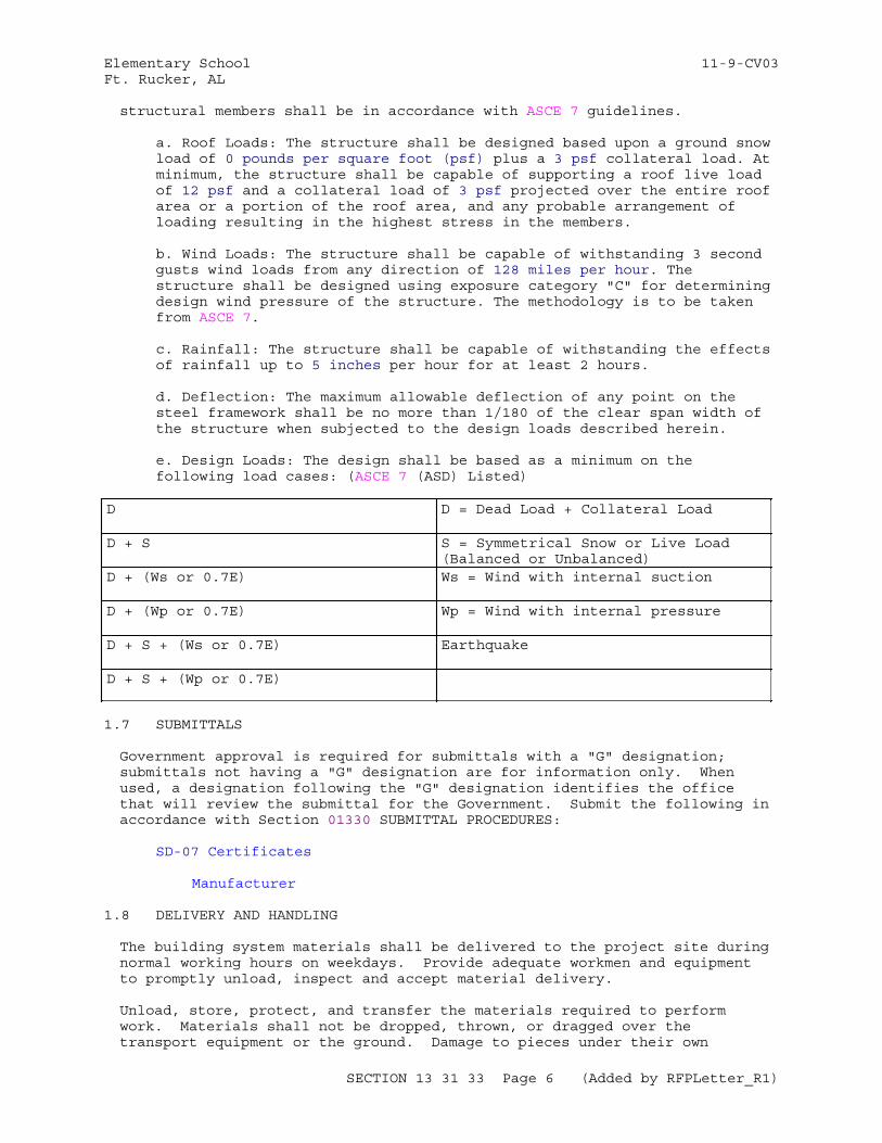
Elementary School 11-9-CV03Ft. Rucker, AL
structural members shall be in accordance with ASCE 7 guidelines.
a. Roof Loads: The structure shall be designed based upon a ground snow load of 0 pounds per square foot (psf) plus a 3 psf collateral load. At minimum, the structure shall be capable of supporting a roof live load of 12 psf and a collateral load of 3 psf projected over the entire roof area or a portion of the roof area, and any probable arrangement of loading resulting in the highest stress in the members.
b. Wind Loads: The structure shall be capable of withstanding 3 second gusts wind loads from any direction of 128 miles per hour. The structure shall be designed using exposure category "C" for determining design wind pressure of the structure. The methodology is to be taken from ASCE 7.
c. Rainfall: The structure shall be capable of withstanding the effects of rainfall up to 5 inches per hour for at least 2 hours.
d. Deflection: The maximum allowable deflection of any point on the steel framework shall be no more than 1/180 of the clear span width of the structure when subjected to the design loads described herein. e. Design Loads: The design shall be based as a minimum on the following load cases: (ASCE 7 (ASD) Listed)
D D = Dead Load + Collateral Load
D + S S = Symmetrical Snow or Live Load(Balanced or Unbalanced)
D + (Ws or 0.7E) Ws = Wind with internal suction
D + (Wp or 0.7E) Wp = Wind with internal pressure
D + S + (Ws or 0.7E) Earthquake
D + S + (Wp or 0.7E)
1.7 SUBMITTALS
Government approval is required for submittals with a "G" designation; submittals not having a "G" designation are for information only. When used, a designation following the "G" designation identifies the office that will review the submittal for the Government. Submit the following in accordance with Section 01330 SUBMITTAL PROCEDURES:
SD-07 Certificates
Manufacturer
1.8 DELIVERY AND HANDLING
The building system materials shall be delivered to the project site during normal working hours on weekdays. Provide adequate workmen and equipment to promptly unload, inspect and accept material delivery.
Unload, store, protect, and transfer the materials required to perform work. Materials shall not be dropped, thrown, or dragged over the transport equipment or the ground. Damage to pieces under their own
SECTION 13 31 33 Page 6 (Added by RFPLetter_R1)
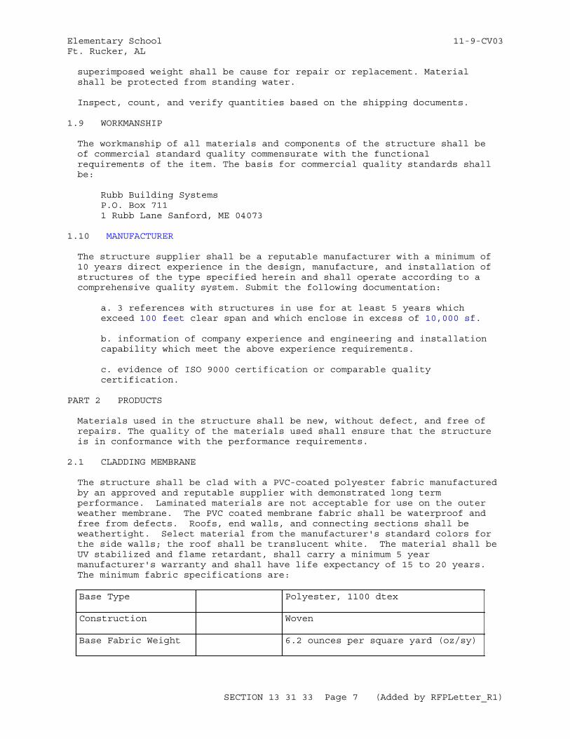
Elementary School 11-9-CV03Ft. Rucker, AL
superimposed weight shall be cause for repair or replacement. Material shall be protected from standing water.
Inspect, count, and verify quantities based on the shipping documents.
1.9 WORKMANSHIP
The workmanship of all materials and components of the structure shall be of commercial standard quality commensurate with the functional requirements of the item. The basis for commercial quality standards shall be:
Rubb Building SystemsP.O. Box 711 1 Rubb Lane Sanford, ME 04073
1.10 MANUFACTURER
The structure supplier shall be a reputable manufacturer with a minimum of 10 years direct experience in the design, manufacture, and installation of structures of the type specified herein and shall operate according to a comprehensive quality system. Submit the following documentation:
a. 3 references with structures in use for at least 5 years which exceed 100 feet clear span and which enclose in excess of 10,000 sf.
b. information of company experience and engineering and installation capability which meet the above experience requirements.
c. evidence of ISO 9000 certification or comparable quality certification.
PART 2 PRODUCTS
Materials used in the structure shall be new, without defect, and free of repairs. The quality of the materials used shall ensure that the structure is in conformance with the performance requirements.
2.1 CLADDING MEMBRANE
The structure shall be clad with a PVC-coated polyester fabric manufactured by an approved and reputable supplier with demonstrated long term performance. Laminated materials are not acceptable for use on the outer weather membrane. The PVC coated membrane fabric shall be waterproof and free from defects. Roofs, end walls, and connecting sections shall be weathertight. Select material from the manufacturer's standard colors for the side walls; the roof shall be translucent white. The material shall be UV stabilized and flame retardant, shall carry a minimum 5 year manufacturer's warranty and shall have life expectancy of 15 to 20 years. The minimum fabric specifications are:
Base Type Polyester, 1100 dtex
Construction Woven
Base Fabric Weight 6.2 ounces per square yard (oz/sy)
SECTION 13 31 33 Page 7 (Added by RFPLetter_R1)
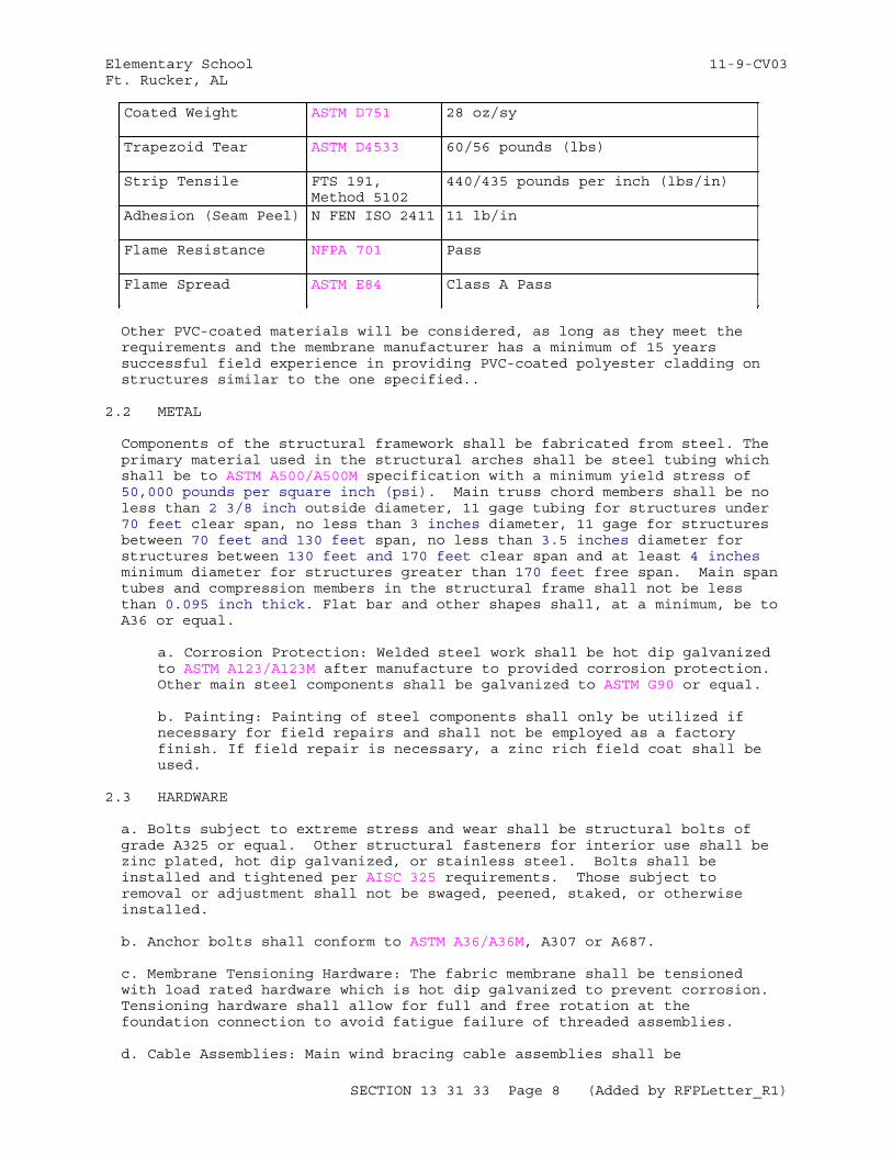
Elementary School 11-9-CV03Ft. Rucker, AL
Coated Weight ASTM D751 28 oz/sy
Trapezoid Tear ASTM D4533 60/56 pounds (lbs)
Strip Tensile FTS 191, Method 5102
440/435 pounds per inch (lbs/in)
Adhesion (Seam Peel) N FEN ISO 2411 11 lb/in
Flame Resistance NFPA 701 Pass
Flame Spread ASTM E84 Class A Pass
Other PVC-coated materials will be considered, as long as they meet the requirements and the membrane manufacturer has a minimum of 15 years successful field experience in providing PVC-coated polyester cladding on structures similar to the one specified..
2.2 METAL
Components of the structural framework shall be fabricated from steel. The primary material used in the structural arches shall be steel tubing which shall be to ASTM A500/A500M specification with a minimum yield stress of 50,000 pounds per square inch (psi). Main truss chord members shall be no less than 2 3/8 inch outside diameter, 11 gage tubing for structures under 70 feet clear span, no less than 3 inches diameter, 11 gage for structures between 70 feet and 130 feet span, no less than 3.5 inches diameter for structures between 130 feet and 170 feet clear span and at least 4 inches minimum diameter for structures greater than 170 feet free span. Main span tubes and compression members in the structural frame shall not be less than 0.095 inch thick. Flat bar and other shapes shall, at a minimum, be to A36 or equal.
a. Corrosion Protection: Welded steel work shall be hot dip galvanized to ASTM A123/A123M after manufacture to provided corrosion protection. Other main steel components shall be galvanized to ASTM G90 or equal.
b. Painting: Painting of steel components shall only be utilized if necessary for field repairs and shall not be employed as a factory finish. If field repair is necessary, a zinc rich field coat shall be used.
2.3 HARDWARE
a. Bolts subject to extreme stress and wear shall be structural bolts of grade A325 or equal. Other structural fasteners for interior use shall be zinc plated, hot dip galvanized, or stainless steel. Bolts shall be installed and tightened per AISC 325 requirements. Those subject to removal or adjustment shall not be swaged, peened, staked, or otherwise installed.
b. Anchor bolts shall conform to ASTM A36/A36M, A307 or A687.
c. Membrane Tensioning Hardware: The fabric membrane shall be tensioned with load rated hardware which is hot dip galvanized to prevent corrosion. Tensioning hardware shall allow for full and free rotation at the foundation connection to avoid fatigue failure of threaded assemblies.
d. Cable Assemblies: Main wind bracing cable assemblies shall be
SECTION 13 31 33 Page 8 (Added by RFPLetter_R1)
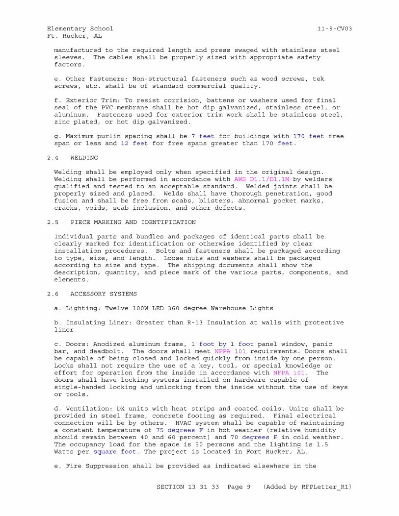
Elementary School 11-9-CV03Ft. Rucker, AL
manufactured to the required length and press swaged with stainless steel sleeves. The cables shall be properly sized with appropriate safety factors.
e. Other Fasteners: Non-structural fasteners such as wood screws, tek screws, etc. shall be of standard commercial quality.
f. Exterior Trim: To resist corrision, battens or washers used for final seal of the PVC membrane shall be hot dip galvanized, stainless steel, or aluminum. Fasteners used for exterior trim work shall be stainless steel, zinc plated, or hot dip galvanized.
g. Maximum purlin spacing shall be 7 feet for buildings with 170 feet free span or less and 12 feet for free spans greater than 170 feet.
2.4 WELDING
Welding shall be employed only when specified in the original design. Welding shall be performed in accordance with AWS D1.1/D1.1M by welders qualified and tested to an acceptable standard. Welded joints shall be properly sized and placed. Welds shall have thorough penetration, good fusion and shall be free from scabs, blisters, abnormal pocket marks, cracks, voids, scab inclusion, and other defects.
2.5 PIECE MARKING AND IDENTIFICATION
Individual parts and bundles and packages of identical parts shall be clearly marked for identification or otherwise identified by clear installation procedures. Bolts and fasteners shall be packaged according to type, size, and length. Loose nuts and washers shall be packaged according to size and type. The shipping documents shall show the description, quantity, and piece mark of the various parts, components, and elements.
2.6 ACCESSORY SYSTEMS
a. Lighting: Twelve 100W LED 360 degree Warehouse Lights
b. Insulating Liner: Greater than R-13 Insulation at walls with protective liner
c. Doors: Anodized aluminum frame, 1 foot by 1 foot panel window, panic bar, and deadbolt. The doors shall meet NFPA 101 requirements. Doors shall be capable of being closed and locked quickly from inside by one person. Locks shall not require the use of a key, tool, or special knowledge or effort for operation from the inside in accordance with NFPA 101. The doors shall have locking systems installed on hardware capable of single-handed locking and unlocking from the inside without the use of keys or tools.
d. Ventilation: DX units with heat strips and coated coils. Units shall be provided in steel frame, concrete footing as required. Final electrical connection will be by others. HVAC system shall be capable of maintaining a constant temperature of 75 degrees F in hot weather (relative humidity should remain between 40 and 60 percent) and 70 degrees F in cold weather. The occupancy load for the space is 50 persons and the lighting is 1.5 Watts per square foot. The project is located in Fort Rucker, AL.
e. Fire Suppression shall be provided as indicated elsewhere in the
SECTION 13 31 33 Page 9 (Added by RFPLetter_R1)
Elementary School 11-9-CV03Ft. Rucker, AL
Contract.
f. Provide cranes required for the erection of the building.
PART 3 EXECUTION
3.1 FOUNDATION DESIGN
Obtain a copy of the manufacturer's foundation/anchoring requirements and, if applicable, the anchor bolt plan, truss and leg truss line location and reactions. The anchor bolt plan shall show the anchor bolt(s), material, number, size location, embedment, projection and spacing. Design of the foundation and/or anchoring systems for the building shall be based on the maximum column/truss reactions as determined and provided by the building manufacturer.
-- End of Section --
SECTION 13 31 33 Page 10 (Added by RFPLetter_R1)
Elementary School 11-9-CV03Ft. Rucker, AL
SECTION TABLE OF CONTENTS
DIVISION 14 - CONVEYING EQUIPMENT
SECTION 14 24 00
HYDRAULIC ELEVATORS
08/10
PART 1 GENERAL
1.1 REFERENCES 1.2 SYSTEM DESCRIPTION 1.2.1 Miscellaneous Requirements 1.2.2 Provisions for Earthquake Protection 1.3 SUBMITTALS 1.4 QUALITY ASSURANCE 1.4.1 Elevator Specialist 1.4.2 Elevator Inspector 1.4.3 Welders' Qualifications 1.4.4 Detail Drawings 1.5 SCHEDULING 1.6 WARRANTY 1.7 MAINTENANCE AND REPAIR ACTION PLAN 1.7.1 Maintenance and Diagnostic Tools 1.7.2 Keys for Elevator Key Switches
PART 2 PRODUCTS
2.1 PASSENGER ELEVATORS 2.1.1 Basic Requirements 2.1.2 Cab Enclosures and Door Finishes 2.2 SPECIAL OPERATION AND CONTROL 2.2.1 Firefighters' Service 2.2.2 Smoke Detectors 2.2.3 Fire Sprinklers 2.2.4 Top-of-Car Operating Device 2.2.5 Hoistway Access Switches 2.2.6 Independent Service 2.2.7 Elevator Operation 2.2.7.1 Single, Two-Stop, Automatic Operation 2.2.8 Parking Switch 2.3 ELEVATOR DRIVE SYSTEM 2.3.1 Hydraulic Pump Unit 2.3.1.1 Pump Motor 2.3.2 Hydraulic Controls and Equipment 2.3.2.1 Hydraulic Control Valve 2.3.2.2 Hydraulic Overspeed Safety Valve 2.3.2.3 Hydraulic Oil Scavenger Pump 2.3.3 Hydraulic Piping and Accessories 2.3.3.1 Containment of Hydraulic Oil Supply Line 2.3.4 Hydraulic Elevator Type 2.3.4.1 Jack Cylinder 2.4 CONTROL EQUIPMENT 2.4.1 Motor Control Equipment
SECTION 14 24 00 Page 1 (Revised by RFPLetter_R8)
Elementary School 11-9-CV03Ft. Rucker, AL
2.4.1.1 Electrical Isolation Protection 2.4.2 Logic Control Equipment 2.4.2.1 On-Board Diagnostic Panel 2.4.2.2 External Port 2.4.2.3 Maintenance and Diagnostic Software 2.4.2.4 Acceptable Controller Suppliers 2.5 OPERATING PANELS, SIGNAL FIXTURES, AND COMMUNICATIONS CABINETS 2.5.1 Capacity and Data Plates 2.5.2 Car and Hall Buttons 2.5.3 Passenger Car-Operating Panel 2.6 PASSENGER CONTROLS 2.6.1 Passenger Car-Operating Panel 2.6.1.1 Service Controls 2.6.1.2 Certificate Window 2.6.2 Switches and Devices 2.6.3 In-Car Position and Direction Indicator and Signal 2.6.3.1 In-Car Position Indicator and Signal 2.6.3.2 In-Car Direction Indicator and Signal 2.6.4 Landing Position and Direction Indicator and Signal 2.6.4.1 Landing Position Indicator and Signal 2.6.4.2 Landing Direction Indicator and Signal 2.7 HOISTWAY AND CAR EQUIPMENT 2.7.1 Guide Rails and Fastenings 2.7.2 Car Buffers 2.7.3 Pit Equipment 2.7.3.1 Pit "STOP" Switch 2.7.3.2 Ladders 2.7.3.3 Lighting of Pits 2.8 TERMINAL STOPPING DEVICES 2.8.1 Wiring and Traveling Cables 2.8.2 Emergency Signaling Device 2.9 PASSENGER CAR AND HOISTWAY DOOR ACCESSORIES 2.10 PASSENGER ELEVATOR GUIDES, FRAME, PLATFORM, AND ENCLOSURE 2.10.1 Roller Guides 2.10.2 Car Enclosure, Car Door, and Car Illumination 2.10.2.1 Return Panels, Entrance Columns, Cove Base, and Transom 2.10.2.2 Car Top 2.10.2.3 Car Door 2.10.2.4 Car Entrance Sill 2.11 PASSENGER ELEVATOR HOISTWAY DOORS AND ENTRANCES 2.11.1 Hoistway Entrance Frames 2.11.2 Hoistway Entrance Sills 2.11.3 Hoistway Entrance Doors 2.11.4 Entrance Fascias and Dust Covers 2.11.5 Hoistway Ventilation 2.12 HANDICAPPED AND MEDICAL SERVICES ACCESS 2.12.1 Provision For Handicapped
PART 3 EXECUTION
3.1 INSTALLATION 3.1.1 Traveling Cables 3.1.2 Automatic Shutoff Valve 3.1.3 Structural Members 3.1.4 Safety Guards 3.1.5 Other Requirements 3.2 FIELD QUALITY CONTROL 3.2.1 Testing Materials and Instruments 3.2.2 Field Tests
SECTION 14 24 00 Page 2 (Revised by RFPLetter_R8)
Elementary School 11-9-CV03Ft. Rucker, AL
3.2.2.1 Endurance Tests 3.2.2.2 Automatic Shutoff Valve Tests 3.2.2.3 Speed Tests 3.2.2.4 Leveling Tests 3.2.2.5 Pressure Tests 3.2.2.6 Insulation Resistance Tests 3.2.2.7 Temperature Rise Tests 3.2.2.8 Motor Ampere Tests 3.3 OPERATION AND MAINTENANCE TRAINING
-- End of Section Table of Contents --
SECTION 14 24 00 Page 3 (Revised by RFPLetter_R8)
Elementary School 11-9-CV03Ft. Rucker, AL
SECTION 14 24 00
HYDRAULIC ELEVATORS08/10
PART 1 GENERAL
1.1 REFERENCES
The publications listed below form a part of this specification to the extent referenced. The publications are referred to within the text by the basic designation only.
AMERICAN WELDING SOCIETY (AWS)
AWS D1.1/D1.1M (2015) Structural Welding Code - Steel
ASME INTERNATIONAL (ASME)
ASME A17.1/CSA B44 (2013) Safety Code for Elevators and Escalators
ASME A17.2 (2010) Guide for Inspection of Elevators, Escalators, and Moving Walks Includes Inspection Procedures for Electric Traction and Winding Drum Elevators, Hydraulic Elevators, and Escalators and Moving Walks
ASME B16.11 (2011) Forged Fittings, Socket-Welding and Threaded
ASME B16.9 (2012) Standard for Factory-Made Wrought Steel Buttwelding Fittings
ASTM INTERNATIONAL (ASTM)
ASTM A106/A106M (2014) Standard Specification for Seamless Carbon Steel Pipe for High-Temperature Service
ASTM A53/A53M (2012) Standard Specification for Pipe, Steel, Black and Hot-Dipped, Zinc-Coated, Welded and Seamless
NATIONAL ELEVATOR INDUSTRY, INC. (NEII)
NEII-1 (2000; R thru 2010) Building Transportation Standards and Guidelines, including the Performance Standards Matrix for New Elevator Installation
SECTION 14 24 00 Page 4 (Revised by RFPLetter_R8)
Elementary School 11-9-CV03Ft. Rucker, AL
NATIONAL FIRE PROTECTION ASSOCIATION (NFPA)
NFPA 70 (2014; AMD 1 2013; Errata 1 2013; AMD 2 2013; Errata 2 2013; AMD 3 2014; Errata 3-4 2014; AMD 4-6 2014) National Electrical Code
U.S. NATIONAL ARCHIVES AND RECORDS ADMINISTRATION (NARA)
36 CFR 1191 Americans with Disabilities Act (ADA) Accessibility Guidelines for Buildings and Facilities; Architectural Barriers Act (ABA) Accessibility Guidelines
1.2 SYSTEM DESCRIPTION
Provide a pre-engineered elevator system, by manufacturer regularly engaged in the manufacture of elevator systems, that complies with ASME A17.1/CSA B44 and ASME A17.2 in their entirety, and additional requirements specified herein.
1.2.1 Miscellaneous Requirements
Submit one set of wiring diagrams, in plastic or glass cover, framed and mounted in elevator machine room for revised building electrical system, if needed, to make supplied elevator system function as specified. Deliver other sets to Contracting Officer. Coded diagrams are not acceptable unless adequately identified. Submit calculations for the Reaction Loadsimposed on the building by elevator systems that comply with ASME A17.1/CSA B44 and for total anticipated Heat Loads generated by all the elevator machine room equipment. Calculations shall be certified by a Registered Professional Engineer. Do not fabricate materials nor perform construction until approved.
1.2.2 Provisions for Earthquake Protection
The facility is located in Seismic Design Category C, see Structural drawings for Seismic Design Criteria , and shall comply with all ASME A17.1/CSA B44, Part 8.4 requirements.
1.3 SUBMITTALS
Government approval is required for submittals with a "G" designation; submittals not having a "G" designation are for information only. When used, a designation following the "G" designation identifies the office that will review the submittal for the Government. Submit the following in accordance with Section 01 33 00 SUBMITTAL PROCEDURES:
SD-02 Shop Drawings
Detail Drawings; ; A/E
SD-03 Product Data
Passenger Elevators; ; A/EField Quality Control Plan; ; A/ELogic Control; ; A/E
SD-05 Design Data
SECTION 14 24 00 Page 5 (Revised by RFPLetter_R8)
Elementary School 11-9-CV03Ft. Rucker, AL
Reaction LoadsHeat Loads
SD-06 Test Reports
Field Tests Reports
SD-07 Certificates
Welders' Qualifications
SD-10 Operation and Maintenance Data
Operation and Maintenance Manuals; ; A/EMaintenance and Diagnostic Tools; ; A/EMaintenance and Diagnostic SoftwareMaintenance and Repair Action Plan; ; A/EOperation and Maintenance Training; ; A/E
1.4 QUALITY ASSURANCE
1.4.1 Elevator Specialist
Perform work specified in this section under the direct guidance of the Elevator Specialist who is regularly engaged in the installation and maintenance of the type and complexity of elevator system specified in the contract documents, and who served in a similar capacity for at least three systems that have performed in the manner intended for a period of not less than 24 months. Provide endorsement letter from the elevator manufacturer certifying that the Elevator Specialist is acceptable to manufacturer. The Elevator Specialist oversees the acceptance inspections and tests, signs and certifies the successful results. Provide the Elevator Specialist's written certification that the installation is in accordance with the contract requirements, after completion of the acceptance inspections and tests. Bring any discrepancy to the attention of the Contracting Officer in writing, no later than three working days after the discrepancy is discovered.
1.4.2 Elevator Inspector
a. The Elevator Inspector shall be certified in accordance with the requirements of ASME A17.1/CSA B44and licensed by the State of Alabama in elevator repair. The Certified Elevator Inspector shall inspect the installation of the elevator(s) to ensure that the installation conforms with all contract requirements. The Elevator Inspector shall be directly employed by the Prime Contractor and be independent of the Elevator System Manufacturer and the Elevator Specialist, shall witness the acceptance inspections and tests, approve all results and shall sign and certify the successful results. The Elevator Inspector, after completion of the acceptance inspections and tests, shall certify in writing that the installation is in accordance with the contract requirements. Bring any discrepancy to the attention of the Contracting Officer in writing, no later than three working days after the discrepancy is discovered.The Elevator Inspector will be provided
by the Contractor to inspect the installation of the elevator(s) to ensure that the installation conforms to all contract requirements. The Elevator Inspector will witness the acceptance inspections and tests, approve all results, and shall sign and certify the successful results. The Elevator
SECTION 14 24 00 Page 6 (Revised by RFPLetter_R8)
Elementary School 11-9-CV03Ft. Rucker, AL
Inspector, after completion of the acceptance inspections and tests, will provide written certification that the installation is accordance with the contract requirements.
1.4.3 Welders' Qualifications
Comply with AWS D1.1/D1.1M, Section 4 Qualification. Provide certified copies of welders' qualifications. List welders'names with corresponding code marks to identify each welder's work. Submit a letter, no later than 14 days after the Notice to Proceed, providing the name and Statement of Qualifications, including ASME A17.1/CSA B44 Certificate and all required state and local licenses of the individual who will perform the duties specified herein for the Elevator Inspector. A letter of endorsement from the elevator manufacturer certifying that the Elevator Specialist is acceptable to manufacturer, no later than 14 days after the Notice to Proceed, providing the name and Statement of Qualifications of the individual who will perform the duties specified herein for the Elevator Specialist. Copies of certified welders' qualifications, demonstrating compliance with AWS D1.1/D1.1M, Section 4; list welders' names with corresponding code marks.
1.4.4 Detail Drawings
Submit detail drawings, including dimensioned layouts in plan and elevation showing the arrangement of elevator equipment, accessories, supporting systems, anchorage of equipment, clearances for maintenance and operation; and details on hoistway, doors and frames, operation and signal stations, controllers, motors, guide rails and brackets, holeless jacks, and points of interface with normal power, fire alarm system and HVAC or exhaust systems. Provide drawings to show any revised building electrical system required to make supplied elevator system function as specified. Prepare drawings with complete wiring diagrams showing electrical connections and other details required to demonstrate sequence of operations and functions of system devices. Include the appropriate sizing of electrical protective devices on the drawings, which are frequently different from National Electrical Code standard sizes.
1.5 SCHEDULING
Every six months, test systems for Firefighters' Service. Schedule to not interfere with building operations. For Firefighters' Service, test monthly in accordance with ASME A17.1/CSA B44, Section 8.6.10.1. Provide written results of each test operation to the Contracting Officer. Document all inspection and testing. Maintain copy of documentation in machine room.
1.6 WARRANTY
Provide routine warranty service in accord with manufacturer's warranty requirements, for a period of 12 months after the date of acceptance by Contracting Officer. Perform work during regular working hours. During the warranty service period, include 24-hour emergency service, with 1 hour response time, without additional cost to the Government. Include adjustments, greasing, oiling, and cleaning. Provide routine inspection and tests of elevators in accordance with ASME A17.1/CSA B44 Section 8.11.3 and ASME A17.2. Provide supplies and parts to keep elevator system in operation. Perform service only by factory trained personnel. Maintain a maintenance log of all service orders performed during the warranty period and submit it to the Contracting Officer 21 days prior to the end of the
SECTION 14 24 00 Page 7 (Revised by RFPLetter_R8)
Elementary School 11-9-CV03Ft. Rucker, AL
warranty period.
1.7 MAINTENANCE AND REPAIR ACTION PLAN
Provide plan of action prepared by the Elevator Specialist for emergency and routine maintenance in accordance with paragraph titled WARRANTY. Provide a list of phone numbers, personnel contacts, and all maintenance and diagnostic tools provided by paragraph "Maintenance and Diagnostic Tools", to the Contracting Officer.
1.7.1 Maintenance and Diagnostic Tools
Provide all special tools and software necessary to service and maintain each elevator delivered at time of final acceptance. Provide one of each tool per group of elevators. Include solid state or microprocessor diagnostic tools unavailable on the open market. Provide necessary diagnostic software in cases where the solid state or microprocessor diagnostic tools are available on the open market
1.7.2 Keys for Elevator Key Switches
Provide a minimum of twelve keys per unique cylinder used on all key switches for single elevator. If there is more than one elevator, additional keys are not required unless there are additional unique cylinders. Provide keys with brass or fiberglass tags marked 'PROPERTY OF THE U.S. GOVERNMENT' on one side with function of key or approved code number on other side.
PART 2 PRODUCTS
2.1 PASSENGER ELEVATORS
Manufacturers:
1. Otis Elevator Company 2. Schindler Elevator Company 3. Basis of Design: ThyssenKrupp Elevator "Endura B II" 4. Kone 5. Fujitech
The use of manufacturers names and products do not preclude the use of other manufacturer's products of approved equal as long as all requirements in the technical sections are met.
2.1.1 Basic Requirements
Submit information on motor, pump, gages, piston and cylinder, piping and valves, hall station, and buffer on elevators and accessories. For elevator supporting systems, include information on car control systems. On data sheets, provide document identification number or bulletin number, published or copyrighted prior to the date of contract bid opening. These requirements apply to Freight Elevators also.
a. Rated Load: 3,500 lbs.*8b. Rated Speed: 150 fpm 100 fpm.
c. Travel Length: as indicated on the Drawings.
SECTION 14 24 00 Page 8 (Revised by RFPLetter_R8)
Elementary School 11-9-CV03Ft. Rucker, AL
d. Number of Stops: 3
e. Number of Hoist Way Openings: 2 Front; 1 Rear
f. Car Inside Dimensions: 6-8 ft.-in..wide, 5-5.5 ft.-in. deep and 8-0 ft.-in. high.
h. Car Door Types: Single-speed side slide, horizontal sliding.
2.1.2 Cab Enclosures and Door Finishes
Provide finishes as listed below:
a. Floor; as indicated on the Drawings.
b. Walls; laminated plastic on particleboard . Provide each cab wall with equally spaced and equally sized wall panels. Conceal all fasteners. Wall trim; stainless steel. Accessories; hand rails.
c. Interior face of door(s); stainless steel.
d. Ceilings; supportedeggcrate. Ceiling frame; stainless steel.
e. Hoistway Doors and Frame Finishes; provide finishes on exterior of hoistway as follows:
(1) Frame; stainless steel.(2) Exterior face of door; stainless steel.
2.2 SPECIAL OPERATION AND CONTROL
Provide all special operations and control systems in accordance with ASME A17.1/CSA B44. Provide special operation key switches with 6 pin cylinder locks with removable cores an a key control lock for each operation system.
2.2.1 Firefighters' Service
Provide equipment and signaling devices. The designated level for Firefighters' key operated switch is the ground floor.
2.2.2 Smoke Detectors
Provide connections directly to elevator controls which will, when smoke is detected by any smoke detector, actuate Firefighters' Service and send each elevator to the correct floor as required by ASME A17.1/CSA B44. Provide dual-contact smoke detectors located in the elevator lobbies and the elevator machine room. Provide dual-contact smoke detector at top of hoistway. Include only these smoke detectors with the circuit for elevator controller actuation of Firefighters' Service. In lieu of dual-contact smoke detectors, use an addressable fire alarm system with listed smoke detectors in the above stated locations. Ensure that all smoke detectors are mounted on finished ceiling.
2.2.3 Fire Sprinklers
For each elevator, provide control wiring connecting the flow switch to the shunt trip equipped circuit breaker within the electrical panel serving the main line disconnect. Upon flow of water, equip flow switch to
SECTION 14 24 00 Page 9 (Revised by RFPLetter_R8)
Elementary School 11-9-CV03Ft. Rucker, AL
instantaneously send a signal to cause opening of shunt-trip equipped mainline circuit breaker, in compliance with ASME A17.1/CSA B44, Section 2.8.2, and send a signal to fire alarm control panel to indicate water flow condition. Provide machine room sprinkler flow switch actuation to shunt trip all elevator(s) served by the machine room. Provide hoistway sprinkler flow switch actuation to shunt trip all elevator(s) in the hoistway.
2.2.4 Top-of-Car Operating Device*8Provide operating device mounted on or from car crosshead, to permit operation of car at 150 fpm 150 fpm maximum for adjustment, maintenance, testing, and repair. Include integral or remote safety device, continuous pressure "UP" and "DOWN" switches or buttons, emergency stop switch, and inspection switch.
2.2.5 Hoistway Access Switches
Provide key-operated hoistway access switch to permit limited movement of car at terminal floors for car positioning, operative only when "INSPECTION" switch in car operating panel is in the "INSPECTION" position. Locate switch 6 feet above floor level, within 12 inches of hoistway entrance frame or with only ferrule exposed when located in entrance frame.
2.2.6 Independent Service
Provide exposed key-operated switch in car operating panel to enable independent service and simultaneously disable in-car signals and landing-call responses. Provide indicator lights that automatically illuminate during independent service.
2.2.7 Elevator Operation
2.2.7.1 Single, Two-Stop, Automatic Operation
Provide Single Two-Stop Automatic Operation. Provide illuminating push buttons.
2.2.8 Parking Switch
Provide two-position parking switch in car station service cabinet. One position causes car to remain parked at floor landing where last used; other position causes car to park at main floor.
2.3 ELEVATOR DRIVE SYSTEM
Provide hydraulic elevator drive system, including pump unit, piping, dual jack assembly, and associated equipment, which will operate at a maximum working pressure of 500 psi or less. Provide complete elevator system that meets or exceeds the NEII-1.
2.3.1 Hydraulic Pump Unit
Provide self-contained pump unit, including oil-hydraulic elevator pump, electric motor, suction-line oil strainer, oil-tight drip pan, and structural steel outer base with tank supports and isolation pads. Provide oil tank capacity for full jack displacement plus at least 10 gallons. Provide means to maintain oil temperature between 80 and 120 degrees F
SECTION 14 24 00 Page 10 (Revised by RFPLetter_R8)
Elementary School 11-9-CV03Ft. Rucker, AL
regardless of ambient temperature. Limit acoustic output in elevator machine room to 80 dbA.
2.3.1.1 Pump Motor
Provide intermittent-duty pump motor rated at 120 starts/hour. Provide motor that is sized so that the motor amperage does not exceed the motor data tag amperage in any operating condition, exclusive of acceleration and deceleration. Provide minimum of one megohm insulation resistance between conductors and motor frame. Provide motor and pump nameplate and data tags permanently mounted on the outside of the pump unit frame, with all data viewable without the use of mirrors or other tools.
2.3.2 Hydraulic Controls and Equipment
Provide control valve, overspeed (rupture) valve, blowout-proof muffler, and hydraulic pump discharge strainer in the hydraulic oil supply line. Provide 1/4 turn, manual shutoff ball-valves in the elevator machine room and in the hoistway pit. Provide scavenger pump in hoistway pit.
2.3.2.1 Hydraulic Control Valve
Provide constant-velocity, down-speed regulated, control valve. Down-speed regulated control valve allows the car to travel at the same speed in the down direction, regardless of the load on the elevator. In addition, the hydraulic control valve shall have built-in adjustment capability to operate the elevator at 140 percent of rated speed in the down direction to facilitate periodic testing of the overspeed safety valve.
2.3.2.2 Hydraulic Overspeed Safety Valve
Provide overspeed safety valve in hydraulic oil supply line, directly adjacent to the hydraulic cylinder. Provide threaded pipe connections between the hydraulic cylinder and the overspeed valve. Provide valve equipped with manufacturer's manual shutoff feature. Overspeed valve shall not be equipped with a manual lowering feature. Provide adjustable valve with means to seal adjustment after inspection and testing by certified elevator inspector.
2.3.2.3 Hydraulic Oil Scavenger Pump
Provide a scavenge oil reservoir with strainer and transfer pump. Provide a manual-reset pit flood switch to prevent pump operation if pit is flooded. Anchor pump and reservoir to pit floor.
2.3.3 Hydraulic Piping and Accessories
Provide ASTM A53/A53M or ASTM A106/A106M, Schedule 80, black steel piping with ASME B16.9 or ASME B16.11 fittings for supply piping. Extend schedule 80 piping from the pump control valve body, inside the pump unit, to the jacks in the hoistway. Provide welded or threaded forged pipe fittings for all fittings and components of the hydraulic oil supply line. For direct plunger cylinders, provide dielectric union or isolation couplings at each end of the hydraulic oil supply line. Provide hangers or supports for all piping and components.
2.3.3.1 Containment of Hydraulic Oil Supply Line
Protect all portions of hydraulic oil supply line that are installed below
SECTION 14 24 00 Page 11 (Revised by RFPLetter_R8)
Elementary School 11-9-CV03Ft. Rucker, AL
ground, including portions encapsulated in concrete or covered by construction, with continuous, Schedule 80, PVC. Inside diameter of PVC shall be 3 inches larger than the outside diameter of the hydraulic oil supply line pipe and couplings.
2.3.4 Hydraulic Elevator Type
Provide a holeless, dual jack hydraulic elevator. Do not utilize roped-hydraulic elevator design.
2.3.4.1 Jack Cylinder
Mount to car structure. Synchronization for Jack stages: Direct mechanical means to ensure elevator moves at steady speed and provides smooth ride.
2.4 CONTROL EQUIPMENT
2.4.1 Motor Control Equipment
Provide elevator motor controller with electronic, soft-start motor starter. Enclose control equipment in factory-primed and baked-enamel coated sheet-metal cabinets with removable or hinged doors with ventilation louvers.
2.4.1.1 Electrical Isolation Protection
Provide individual isolation transformers and individual choke reactors for each individual motor. Provide filtering to maintain harmonic distortion below IEEE standards as measured at the elevator machine room disconnect.
2.4.2 Logic Control Equipment
Provide a non-proprietary microprocessor controller for each individual elevator and group controller. Store all programming in non-volatile memory. Provide a microprocessor control system that includes all hardware and software required to service and maintain the elevator and a technical support service that is routinely provided to any elevator service provider.
2.4.2.1 On-Board Diagnostic Panel
a. Provide, for each individual elevator microprocessor controller, an on-board diagnostic control and LCD display panel that allows unrestricted access to the comprehensive range of adjustable parameters necessary to perform installation, adjusting, service, maintenance, and testing of the elevator.
b. For individual controllers, provide fault log capability to store all fault logs for up to 1 year of elevator service history. The on-board LCD display shall provide the capability to display and monitor any and all fault logs, trouble calls, and fault history for up to 1 year of elevator service history. The on-board LCD display shall also provide the capability to display and diagnose trouble calls, faults, and shutdowns.
2.4.2.2 External Port
For each individual elevator microprocessor controller, and elevator group microprocessor controller, provide a USB port or an RS 232 port that allows
SECTION 14 24 00 Page 12 (Revised by RFPLetter_R8)
Elementary School 11-9-CV03Ft. Rucker, AL
connection to an on-site or a remote portable laptop computer. Provide unrestricted access as specified in paragraph ON-BOARD DIAGNOSTIC PANEL.
2.4.2.3 Maintenance and Diagnostic Software
Provide three copies of the manufacturer's maintenance and service diagnostic software, with complete software documentation, that shall enable the same level of unrestricted access to all controllers of the same make and model, regardless of the installation date or location. Provide signed certification, from the manufacturer's corporate headquarters, that guarantees that the microprocessor software and access system will not terminate the unlimited and unrestricted access at any future date.
2.4.2.4 Acceptable Controller Suppliers
Provide microprocessor controller from one of the following controller manufacturers:
Elevator Controls Corporation3525 La Grande BoulevardSacramento, CA 95823
G.A.L. Manufacturing Corporation50 East 153rd StreetBronx, New York 10451
Motion Control Engineering, Inc.11354 Whiterock RoadRancho Cordova, CA 95742-6522
Virginia Controls, Inc.2513 Mechanicsville TurnpikeRichmond, Virginia 23223
2.5 OPERATING PANELS, SIGNAL FIXTURES, AND COMMUNICATIONS CABINETS
2.5.1 Capacity and Data Plates
Attach faceplates with spanner security screws. On car panel, provide stainless steel capacity and data plates, with name of elevator manufacturer.
2.5.2 Car and Hall Buttons
Provide recessed tamper-proof push buttons of minimum 3/4 inch size satin-finish stainless steel, with illuminating jewel center.
2.5.3 Passenger Car-Operating Panel
Provide each car with one car operating panel that contains operation controls and communication devices. Provide exposed, flush mounted buttons for the controls that must be passenger accessible. Provide service cabinet or keyed switches for those switches that should not be passenger accessible. Allow maximum 48 inch height between car floor and center line of top operating buttons. Allow 35 inch height between car floor and center line of bottom button. Use engraving and backfilling or photo etching for button and switch designations. Do not use attached signs.
SECTION 14 24 00 Page 13 (Revised by RFPLetter_R8)
Elementary School 11-9-CV03Ft. Rucker, AL
2.6 PASSENGER CONTROLS
2.6.1 Passenger Car-Operating Panel
a. Illuminating operating call buttons identified to correspond to landings served by elevator car.
b. "DOOR OPEN" and "DOOR CLOSE" buttons.
c. Keyed "STOP" switch in accordance with ASME A17.1/CSA B44, rule 2.26.2.
d. "ALARM" button in compliance with UFAS, ADA, and ASME A17.1/CSA B44, Rule 2.27.1. Furnish a red alarm button with engraved legend "ALARM." Allow alarm button to illuminate when pushed. Locate "ALARM" button at panel bottom.
e. "FIRE DEPARTMENT" key switch, with "OFF-HOLD-ON" positions, in that order with key to be removable in all positions. Provide fire sign or jewel, and audible signal device, in accordance with ASME A17.1/CSA B44 Section 2.27.3. Both visual and audible signals are activated when Phase I key switch in hall is activated or when smoke detector activates return of elevator to main fire response floor. Keep visual and audible signal activated until car has reached main or designated alternate fire response floor. Upon arrival at fire response floor visual signal remains illuminated and audible signal becomes silent.
f. Emergency two-way communication. Provide momentary pressure, single illuminating pushbutton operated communication device that complies with ASME A17.1/CSA B44, UFAS, and the Americans with Disabilities Act.
g. Sound-actuated firefighter phone jack.
2.6.1.1 Service Controls
a. Inspection switch that transfers car control to top-of-car inspection operating controls and prevents car operation from in-car control panel.
b. Independent service switch.
c. Two car light switches, one for light in car and one for lights on top and bottom of car frame.
d. Fan switch, two-speed.
e. 120-volt ac 60 Hz single-phase duplex electrical outlet of ground-fault-circuit-interrupt (GFCI) design.
f. Device for communication between car and elevator machine room.
2.6.1.2 Certificate Window
Provide 4 inch high by 6 inch wide certificate window in car operating panel for elevator inspection certificate.
2.6.2 Switches and Devices
Provide elevator manufacturer's standard grade for switches and devices on car operating panel. Legibly and indelibly identify each device and its
SECTION 14 24 00 Page 14 (Revised by RFPLetter_R8)
Elementary School 11-9-CV03Ft. Rucker, AL
operating positions. Locate car dispatching buttons in identical positions in car operating panels for corresponding floors.
2.6.3 In-Car Position and Direction Indicator and Signal
Include in-car direction indicator in the in-car position indicator fixture.
2.6.3.1 In-Car Position Indicator and Signal
Provide horizontal electrical or electronic digital position indicator located minimum of 84 inch above car floor. Arrange indicator to show floor position of car in hoistway and its traveling direction. Indicate position by illuminating of numeral or letter corresponding to landing at which car is passing or stopping. Provide audible signal to alert passenger that elevator is passing or stopping at a floor. Provide audible signals exceeding ambient noise level by at least 20 dbA with frequency not higher than 1500 Hz.
2.6.3.2 In-Car Direction Indicator and Signal
Provide visual and audible car direction indicators in car, indicating car traveling direction. For visual directional signal, provide arrow of minimum 2-1/2 inch in size. Use equilateral triangles for arrows, green for upward direction and red for downward direction. Provide audible signal that sounds once for upward direction and twice for downward direction.
2.6.4 Landing Position and Direction Indicator and Signal
Provide a single fixture containing the landing position and direction indicator.
2.6.4.1 Landing Position Indicator and Signal
Provide an electrical or electronic digital position indicator similar to the car position indicator. Arrange position indicator in wall horizontally above the door frame or vertically at the side of the door frame. Indicators to show floor position of car in hoistway. Indicate position by illumination of numeral or letter corresponding to landing at which car is passing or stopping.
2.6.4.2 Landing Direction Indicator and Signal
Provide landing direction indicator with visual and audible signal devices. Provide single direction indicator at terminal floors; "UP" and "DOWN" direction indicator at intermediate floors. Provide equilateral triangles minimum 2-1/2 inch in size, green for upward direction and red for downward direction. Provide electronic audible device that sounds once for upward direction and twice for downward direction. Provide audible signals exceeding ambient noise level by at least 20 decibels with frequency not higher than 1500 Hz.
2.7 HOISTWAY AND CAR EQUIPMENT
2.7.1 Guide Rails and Fastenings
Paint rail shanks with one coat black enamel. Only T-section type rail is acceptable.
SECTION 14 24 00 Page 15 (Revised by RFPLetter_R8)
Elementary School 11-9-CV03Ft. Rucker, AL
2.7.2 Car Buffers
Provide buffer data plate on each buffer.
2.7.3 Pit Equipment
2.7.3.1 Pit "STOP" Switch
Provide push/pull type pit "STOP" switch for stopping elevator motor, independent of regular operating device. Locate on same side of hoistway as ladder.
2.7.3.2 Ladders
Locate ladder on hoistway side wall closest to hoistway door opening.
2.7.3.3 Lighting of Pits
Locate pit light not less than 6 feet above pit floor. Locate switch on same side of hoistway as ladder. Provide GFCI duplex receptacle in each pit.
2.8 TERMINAL STOPPING DEVICES
Provide each elevator with a terminal stopping device.
2.8.1 Wiring and Traveling Cables
Suspend traveling cables by means of self-tightening webbed devices.
2.8.2 Emergency Signaling Device
Provide audible signaling device, operable from Car Operating Panel button marked "ALARM". Mount the audible signaling device in hoistway.
2.9 PASSENGER CAR AND HOISTWAY DOOR ACCESSORIES
ASME A17.1/CSA B44, Sections 2.12, 2.13, 2.14, and 3. Provide infra-red curtain unit (ICU) with multiple infra-red beams that protect to the full height of the door opening. Extend minimum coverage from 2 inches off the floor to 70 inch above floor level. Door operation must meet the requirements of ASME A17.1/CSA B44 Rule 2.27.1 and 2.13.5. Provide high-speed electric operator, safety interlocks for car and hoistway doors, and electric safety contact to prevent car operation unless doors are closed.
2.10 PASSENGER ELEVATOR GUIDES, FRAME, PLATFORM, AND ENCLOSURE
2.10.1 Roller Guides
Provide roller guide assemblies in adjustable mountings on each side of car in accurate alignment at top and bottom of car frame.
2.10.2 Car Enclosure, Car Door, and Car Illumination
Provide natural and forced ventilation, stainless steel hooks, with fire retardant pads.
SECTION 14 24 00 Page 16 (Revised by RFPLetter_R8)
Elementary School 11-9-CV03Ft. Rucker, AL
2.10.2.1 Return Panels, Entrance Columns, Cove Base, and Transom
Provide 14 gauge minimum non perforated steel. Apply sound-deadening mastic on car shell and all exterior components.
2.10.2.2 Car Top
Provide reinforced 12 gauge minimum steel with hinged emergency exit openable by hand from car top only. Provide electrical contact which prevents operation of elevator when emergency exit is open. Provide sound-deadening mastic on all exterior components.
2.10.2.3 Car Door
Provide 16 gauge minimum steel, sandwich construction without binder angles. Provide a minimum of 2 door guide assembles per door panel, one guide at leading and one at trailing door edge with guides in the sill groove their entire length of travel.
2.10.2.4 Car Entrance Sill
Provide one piece cast white bronze or nickel silver entrance sill. Set sills level and flush with floor finish. Use same material for hoistway and car entrance sills.
2.11 PASSENGER ELEVATOR HOISTWAY DOORS AND ENTRANCES
Provide hoistway entrance assemblies which have a minimum 1-1/2 hour fire rating.
2.11.1 Hoistway Entrance Frames
Frame of 14 gauge thick stainless steel. Solidly grout uprights of entrances to height of 5 feet.
2.11.2 Hoistway Entrance Sills
Provide one-piece cast solid white bronze or nickel silver entrance sills. After sill is set level and flush with finished floor height, solidly grout under full length of sill. Use same material for hoistway and car door sills.
2.11.3 Hoistway Entrance Doors
Provide hoistway entrance door constructed with hollow metal non-vision construction with flush surfaces on car and landing sides. Provide a minimum of 2 door guide assembles per door panel, one guide at leading edge and one at trailing door edge with guides in the sill groove the entire length of travel.
2.11.4 Entrance Fascias and Dust Covers
Provide sheet metal hoistway door track dust covers at each landing. Dust covers must cover door locks and door roller tracks and extend the full width of the door track and associated hardware.
2.11.5 Hoistway Ventilation
Provide hoistway ventilation directly to outside air by fixed louver
SECTION 14 24 00 Page 17 (Revised by RFPLetter_R8)
Elementary School 11-9-CV03Ft. Rucker, AL
through side wall of hoistway at top of hoistway. The net size of the louver shall be a minimum of 3.5 percent of the cross section of hoistway.
2.12 HANDICAPPED AND MEDICAL SERVICES ACCESS
2.12.1 Provision For Handicapped
Refer to 36 CFR 1191, Sections 4.10 for Elevators, 4.30 for Signage, and 4.31 for Telephones.
PART 3 EXECUTION
3.1 INSTALLATION
Install in accordance with manufacturer's instructions, ASME A17.1/CSA B44, 36 CFR 1191, and NFPA 70.
3.1.1 Traveling Cables
Do not allow abrupt bending of traveling cables.
3.1.2 Automatic Shutoff Valve
Locate in supply-return line, as close as possible to cylinder-plunger unit.
3.1.3 Structural Members
Do not cut or alter. Restore any damaged or defaced work to original condition.
3.1.4 Safety Guards
Completely enclose selector cables or tapes exposed to possibility of accidental contact in machine room with 16 gage thick sheet metal or expanded metal guards, both horizontally and vertically. Protect exposed gears, sprockets, and selector drums from accidental contact in accordance with ASME A17.1/CSA B44.
3.1.5 Other Requirements
Include recesses, cutouts, slots, holes, patching, grouting, and refinishing to accommodate elevator installation. Use core drilling to drill all new holes in concrete. Finish work to be straight, level, and plumb. During installation, protect machinery and equipment from dirt, water, or mechanical damage. At completion, clean all work, and spot paint. Completion of firefighters' service includes installation and wiring of all smoke detectors in accordance with ASME A17.1/CSA B44, Section 2.27.3.2. Coordinate smoke detector installation for firefighters' service.
3.2 FIELD QUALITY CONTROL
a. After completing elevators system installation, notify Contracting Officer that elevator system is ready for final inspection and acceptance test. In conjunction with the notification submit a plan detailing the testing procedures 30 days prior to performing the elevator tests.
b. Perform all required tests and demonstrate proper operation of each
SECTION 14 24 00 Page 18 (Revised by RFPLetter_R8)
Elementary School 11-9-CV03Ft. Rucker, AL
elevator system and prove that each system complies with contract requirements and ASME A17.1/CSA B44. Inspection procedures in ASME A17.2 form a part of this inspection and acceptance testing. Conduct all testing and inspections in the presence of both the Elevator Specialist and the Elevator Inspector. Demonstrate the proper operation of all equipment at various date settings, selected by the Elevator Inspector, ranging from the date of contract award through 1 January 2099.
c. The Elevator Inspector shall complete, sign and post the results of all tests and inspection results after successful completion of inspection and testing. The Contractor is responsible for all costs involved with reinspection and retesting required to correct discrepancies discovered during testing and the subsequent retesting required.
3.2.1 Testing Materials and Instruments
Provide testing materials and instruments required for final inspection. Include calibrated test weights, tachometer, 600-volt megohm meter, volt meter and ammeter, three Celsius calibrated thermometers, door pressure gage, spirit level, stop watch, hydraulic pressure test gauge, and a 100 foot tape measure.
3.2.2 Field Tests
Submit Field Tests Reports after completing each of the specified tests, as required in the Submittals paragraph.
3.2.2.1 Endurance Tests
Test each elevator for a period of one hour continuous run, with specified rated load in the car. Restart the one hour test period from beginning, following any shutdown or failure. During the test run, stop car at each floor in both directions of travel for standing period of 10 seconds per floor. The requirements for Rated Speed, Leveling, Temperature Rise, and Motor Amperes testing specified herein must be met throughout the duration of the Endurance test.
3.2.2.2 Automatic Shutoff Valve Tests
Test the automatic shutoff valve twice. Once at beginning of acceptance test and again at conclusion of one-hour Endurance test to ensure consistent performance of shutoff valve, regardless of temperature of equipment and oil.
3.2.2.3 Speed Tests
Determine actual speed of each elevator in both directions with rated load and with no load in elevator car. Make Speed tests before and immediately after Endurance test. Determine speed by tachometer reading, excluding accelerating and slow-down zones in accordance with ASME A17.2, Section 2.22.4. Minimum acceptable speed is the Rated Speed as specified. Maximum acceptable elevator speed is 110 percent of Rated Speed.
3.2.2.4 Leveling Tests
Test elevator car leveling devices for landing accuracy of plus or minus 1/4 inch at each floor with no load in car, symmetrical load in car, and with rated load in car in both directions of travel. Determine accuracy of
SECTION 14 24 00 Page 19 (Revised by RFPLetter_R8)
Elementary School 11-9-CV03Ft. Rucker, AL
floor landing both before and immediately after endurance tests.
3.2.2.5 Pressure Tests
Check operating pressure at pump and jacks under no load and rated load. Test pressure at which relief valve operates.
3.2.2.6 Insulation Resistance Tests
Perform tests to ensure wiring systems free from short circuits and grounds. Minimum acceptable insulation resistance for electrical conductors is one megohm between each conductor and ground and between each conductor and other conductors. Prior to megohm meter test, make provision to prevent damage to the electronic devices.
3.2.2.7 Temperature Rise Tests
Determine the temperature rise of the hydraulic pump motor during the full load test run for a minimum of one hour. Under these conditions, do not exceed maximum acceptable temperature rise indicated on the manufacturer's data plate. Start test only when equipment is within 5 degrees C of ambient temperature.
3.2.2.8 Motor Ampere Tests
Measure and record motor amperage when motor is running and elevator is lifting at rated load and speed. Measure and record motor amperage at the beginning and the end of Endurance test.
3.3 OPERATION AND MAINTENANCE TRAINING
The Elevator Specialist shall instruct Government personnel in care, adjustment, and maintenance of elevator equipment for a period of not less than 30 working days immediately following acceptance of system. Submit data package in accordance with Section 01 78 23 OPERATION AND MAINTENANCE DATA, three Operation and Maintenance Manuals, 28 days prior to the Operation and Maintenance Training, proposed Onsite Training schedule, submitted concurrently with the Operation and Maintenance Manuals. Include a list of phone numbers, personnel contacts, and all tools required for operation and maintenance.
-- End of Section --
SECTION 14 24 00 Page 20 (Revised by RFPLetter_R8)
Elementary School 11-9-CV03Ft. Rucker, AL
SECTION TABLE OF CONTENTS
DIVISION 21 - FIRE SUPPRESSION
SECTION 21 13 13.00 10
WET PIPE SPRINKLER SYSTEM, FIRE PROTECTION
05/09
PART 1 GENERAL
1.1 REFERENCES 1.2 SYSTEM DESCRIPTION 1.2.1 Hydraulic Design 1.2.1.1 Hose Demand 1.2.1.2 Basis for Calculations 1.2.1.3 Hydraulic Calculations 1.2.2 Sprinkler Coverage 1.3 SUBMITTALS 1.4 QUALITY ASSURANCE 1.4.1 Fire Protection Specialist 1.4.2 Sprinkler System Installer 1.4.3 Shop Drawings 1.5 DELIVERY, STORAGE, AND HANDLING 1.6 EXTRA MATERIALS
PART 2 PRODUCTS
2.1 STANDARD PRODUCTS 2.2 NAMEPLATES 2.3 REQUIREMENTS FOR FIRE PROTECTION SERVICE 2.4 UNDERGROUND PIPING COMPONENTS 2.4.1 Pipe 2.4.2 Fittings and Gaskets 2.4.3 Gate Valve and Indicator Posts 2.5 ABOVEGROUND PIPING COMPONENTS 2.5.1 Steel Piping Components 2.5.1.1 Steel Pipe 2.5.1.2 Fittings for Non-Grooved Steel Pipe 2.5.1.3 Grooved Mechanical Joints and Fittings 2.5.1.4 Flanges 2.5.1.5 Bolts, Nut, and Washers 2.5.2 Pipe Hangers 2.5.3 Valves 2.5.3.1 Control Valve and Gate Valve 2.5.3.2 Check Valve 2.5.3.3 Hose Valve 2.6 WATERFLOW ALARM 2.7 ALARM INITIATING AND SUPERVISORY DEVICES 2.7.1 Sprinkler Waterflow Indicator Switch, Vane-Type 2.7.2 Valve Supervisory (Tamper) Switch 2.8 FIRE DEPARTMENT CONNECTION 2.9 SPRINKLERS 2.9.1 Concealed Sprinkler 2.9.2 Recessed Sprinkler
SECTION 21 13 13.00 10 Page 1 (Added by RFPLetter_R1)
Elementary School 11-9-CV03Ft. Rucker, AL
2.9.3 Pendent Sprinkler 2.9.4 Upright Sprinkler 2.9.5 Sidewall Sprinkler 2.9.6 Dry Sprinkler Assembly 2.10 ACCESSORIES 2.10.1 Sprinkler Cabinet 2.10.2 Pendent Sprinkler Escutcheon 2.10.3 Pipe Escutcheon 2.10.4 Sprinkler Guard 2.10.5 Identification Sign 2.11 DOUBLE-CHECK VALVE BACKFLOW PREVENTION ASSEMBLY
PART 3 EXECUTION
3.1 FIELD MEASUREMENTS 3.2 INSTALLATION REQUIREMENTS 3.3 INSPECTION BY FIRE PROTECTION SPECIALIST 3.4 ABOVEGROUND PIPING INSTALLATION 3.4.1 Protection of Piping Against Earthquake Damage 3.4.2 Piping in Exposed Areas 3.4.3 Piping in Finished Areas 3.4.4 Pendent Sprinklers 3.4.5 Upright Sprinklers 3.4.6 Pipe Joints 3.4.7 Reducers 3.4.8 Pipe Penetrations 3.4.9 Escutcheons 3.4.10 Inspector's Test Connection 3.4.11 Drains 3.4.12 Installation of Fire Department Connection 3.4.13 Identification Signs 3.5 UNDERGROUND PIPING INSTALLATION 3.6 ELECTRICAL WORK 3.7 PIPE COLOR CODE MARKING 3.8 PRELIMINARY TESTS 3.8.1 Underground Piping 3.8.1.1 Flushing 3.8.1.2 Hydrostatic Testing 3.8.2 Aboveground Piping 3.8.2.1 Hydrostatic Testing 3.8.2.2 Backflow Prevention Assembly Forward Flow Test 3.8.3 Testing of Alarm Devices 3.8.4 Main Drain Flow Test 3.9 FINAL ACCEPTANCE TEST 3.10 ONSITE TRAINING
-- End of Section Table of Contents --
SECTION 21 13 13.00 10 Page 2 (Added by RFPLetter_R1)
Elementary School 11-9-CV03Ft. Rucker, AL
SECTION 21 13 13.00 10
WET PIPE SPRINKLER SYSTEM, FIRE PROTECTION05/09
PART 1 GENERAL
1.1 REFERENCES
The publications listed below form a part of this specification to the extent referenced. The publications are referred to within the text by the basic designation only.
AMERICAN SOCIETY OF SANITARY ENGINEERING (ASSE)
ASSE 1015 (2009) Performance Requirements for Double Check Backflow Prevention Assemblies and Double Check Fire Protection Backflow Prevention Assemblies - (ANSI approved 2010)
AMERICAN WATER WORKS ASSOCIATION (AWWA)
AWWA C104/A21.4 (2013) Cement-Mortar Lining for Ductile-Iron Pipe and Fittings for Water
AWWA C110/A21.10 (2012) Ductile-Iron and Gray-Iron Fittings for Water
AWWA C111/A21.11 (2012) Rubber-Gasket Joints for Ductile-Iron Pressure Pipe and Fittings
AWWA C151/A21.51 (2009) Ductile-Iron Pipe, Centrifugally Cast, for Water
AWWA C203 (2008) Coal-Tar Protective Coatings and Linings for Steel Water Pipelines - Enamel and Tape - Hot-Applied
ASME INTERNATIONAL (ASME)
ASME B16.1 (2010) Gray Iron Pipe Flanges and Flanged Fittings Classes 25, 125, and 250
ASME B16.11 (2011) Forged Fittings, Socket-Welding and Threaded
ASME B16.21 (2011) Nonmetallic Flat Gaskets for Pipe Flanges
ASME B16.3 (2011) Malleable Iron Threaded Fittings, Classes 150 and 300
ASME B16.4 (2011) Standard for Gray Iron Threaded Fittings; Classes 125 and 250
SECTION 21 13 13.00 10 Page 3 (Added by RFPLetter_R1)
Elementary School 11-9-CV03Ft. Rucker, AL
ASME B16.9 (2012) Standard for Factory-Made Wrought Steel Buttwelding Fittings
ASME B18.2.2 (2010) Nuts for General Applications: Machine Screw Nuts, Hex, Square, Hex Flange, and Coupling Nuts (Inch Series)
ASTM INTERNATIONAL (ASTM)
ASTM A135 (2009; R2014) Standard Specification for Electric-Resistance-Welded Steel Pipe
ASTM A183 (2014) Standard Specification for Carbon Steel Track Bolts and Nuts
ASTM A449 (2014) Standard Specification for Hex Cap Screws, Bolts, and Studs, Steel, Heat Treated, 120/105/90 ksi Minimum Tensile Strength, General Use
ASTM A47 (1999; R 2014) Standard Specification for Ferritic Malleable Iron Castings
ASTM A53 (2012) Standard Specification for Pipe, Steel, Black and Hot-Dipped, Zinc-Coated, Welded and Seamless
ASTM A536 (1984; R 2014) Standard Specification for Ductile Iron Castings
ASTM A795 (2013) Standard Specification for Black and Hot-Dipped Zinc-Coated (Galvanized) Welded and Seamless Steel Pipe for Fire Protection Use
ASTM F436 (2011) Hardened Steel Washers
FM GLOBAL (FM)
FM APP GUIDE (updated on-line) Approval Guide http://www.approvalguide.com/
MANUFACTURERS STANDARDIZATION SOCIETY OF THE VALVE AND FITTINGS INDUSTRY (MSS)
MSS SP-71 (2011; Errata 2013) Gray Iron Swing Check Valves, Flanged and Threaded Ends
NATIONAL FIRE PROTECTION ASSOCIATION (NFPA)
NFPA 13 (2013; TIA 10-1; TIA 11-2; ERTA 2014; TIA 14-3) Standard for the Installation of Sprinkler Systems
NFPA 1963 (2014) Standard for Fire Hose Connections
NFPA 24 (2013) Standard for the Installation of Private Fire Service Mains and Their Appurtenances
SECTION 21 13 13.00 10 Page 4 (Added by RFPLetter_R1)
Elementary School 11-9-CV03Ft. Rucker, AL
U.S. DEPARTMENT OF DEFENSE (DOD)
UFC 3-310-04 (2013) Seismic Design for Buildings
UFC 3-600-01 (2013) Fire Protection Engineering For Facilities, Change 3
UNDERWRITERS LABORATORIES (UL)
UL 668 (2004; Reprint Dec 2012) Hose Valves for Fire-Protection Service
UL Bld Mat Dir (2012) Building Materials Directory
UL Fire Prot Dir (2012) Fire Protection Equipment Directory
1.2 SYSTEM DESCRIPTION
Furnish piping offsets, fittings, and any other accessories as required to provide a complete installation and to eliminate interference with other construction. Install sprinkler system over and under ducts, piping and platforms when such equipment can negatively effect or disrupt the sprinkler discharge pattern and coverage. Provide wet pipe sprinkler system in all areas of the building. Except as modified herein, the system shall be designed and installed in accordance with NFPA 13. Pipe sizes which are not indicated on drawings shall be determined by hydraulic calculation. Design any portions of the sprinkler system that are not indicated on the drawings including locating sprinklers, piping and equipment, and size piping and equipment when this information is not indicated on the drawings or is not specified herein. The design of the sprinkler system shall be based on hydraulic calculations, and the other provisions specified herein.
1.2.1 Hydraulic Design
Hydraulically design the system to discharge a minimum density of 0.1gpm/square foot over the hydraulically most demanding 1,500 square feet of floor area for hazard category 1 occupancies; 0.20 gpm/square foot over the hydraulically most demanding 2,500 square feet of floor area for hazard category 2 occupancies; and 0.30 gpm/square foot over the hydraulically most demanding 2,500 square feet of floor area. For hazard category 1 occupancies with ceiling heights 30 feet and greater, the system shall discharge a minimum density of 0.20 gpm/square foot over the hydraulically more demanding 2,500 square feet of floor area for hazard category 3 occupancies. The minimum pipe size for branch lines in gridded systems shall be 1-1/4 inch. Hydraulic calculations shall be in accordance with the Area/Density Method of NFPA 13. Water velocity in the piping shall not exceed 20 ft/s.
1.2.1.1 Hose Demand
Add an allowance for exterior hose streams of 250 gpm to the sprinkler system demand for hazard category 1 and hazard category 2 occupancies. Add an allowance for exterior hose streams of 500 gpm to the system demand for hazard category 3 occupancies. Exterior hose stream allowances will be added at the fire hydrant shown on the drawings closest to the point where the water service enters the building.
SECTION 21 13 13.00 10 Page 5 (Added by RFPLetter_R1)
Elementary School 11-9-CV03Ft. Rucker, AL
1.2.1.2 Basis for Calculations
The design of the system shall be based upon a water supply with a static pressure of 74 psi, and a flow of 1,150 gpm at a residual pressure of 64 psi based on the hydrant flow test performed by Fisher Engineering on 10/22/2014. Water supply shall be presumed available at the test hydrant located at the corner of Boyce Lane and Faith Lane. The contractor shall perform a fire hydrant flow test to verify the existing water supply prior to design. Hydraulic calculations shall be based upon the Hazen-Williams formula with a "C" value of 120 for steel piping, 140 for new cement-lined ductile-iron piping, and 100 for existing underground piping.
1.2.1.3 Hydraulic Calculations
Submit hydraulic calculations, including a drawing showing hydraulic reference points and pipe segments and as outlined in NFPA 13, except that calculations shall be performed by computer using software intended specifically for fire protection system design using the design data shown on the drawings. Software that uses k-factors for typical branch lines is not acceptable. Calculations shall be based on the water supply data shown on the drawings to substantiate that the design area used in the calculations is the most demanding hydraulically. Water supply curves and system requirements shall be plotted on semi-logarithmic graph paper so as to present a summary of the complete hydraulic calculation. Provide a summary sheet listing sprinklers in the design area and their respective hydraulic reference points, elevations, actual discharge pressures and actual flows. Elevations of hydraulic reference points (nodes) shall be indicated. Documentation shall identify each pipe individually and the nodes connected thereto. Indicate the diameter, length, flow, velocity, friction loss, number and type fittings, total friction loss in the pipe, equivalent pipe length and Hazen-Williams coefficient for each pipe. For gridded systems, calculations shall show peaking of demand area friction loss to verify that the hydraulically most demanding area is being used. Also for gridded systems, a flow diagram indicating the quantity and direction of flows shall be included. Hydraulic calculations shall include a 12 pound per square inch or the manufacturer's listed pressure loss, which ever is greater, through the backflow prevention devices. The hydraulic calculations, shop drawings and product data shall be submitted concurrently for review. Partial submittals shall not be permitted.
1.2.2 Sprinkler Coverage
Sprinklers shall be uniformly spaced on branch lines. In buildings protected by automatic sprinklers, sprinklers shall provide coverage throughout 100 percent of the building. This includes, but is not limited to, telephone rooms, electrical equipment rooms, boiler rooms, switchgear rooms, transformer rooms, and other electrical and mechanical spaces. Coverage per sprinkler shall be in accordance with NFPA 13, but shall not exceed 100 square feet for hazard category 3 occupancies, 130 square feet for hazard category 2 occupancies, and 225 square feet hazard category 1 occupancies.
1.3 SUBMITTALS
Government approval is required for submittals with a "G" designation; submittals not having a "G" designation are for Contractor Quality Control approval. Submit the following in accordance with Section 01 33 00 SUBMITTAL PROCEDURES:
SECTION 21 13 13.00 10 Page 6 (Added by RFPLetter_R1)
Elementary School 11-9-CV03Ft. Rucker, AL
SD-02 Shop Drawings
Shop Drawings; GAs-Built Drawings
SD-03 Product Data
Fire Protection Related SubmittalsMaterials and Equipment; GSpare PartsPreliminary Tests; GFinal Acceptance Test; GOnsite Training; GFire Protection Specialist; GSprinkler System Installer; G
SD-05 Design Data
Sway Bracing; GHydraulic Calculations; G
SD-06 Test Reports
Preliminary Test ReportFinal Acceptance Test Report
SD-07 Certificates
Inspection by Fire Protection Specialist
SD-10 Operation and Maintenance Data
Operating and Maintenance Manuals; G
1.4 QUALITY ASSURANCE
Compliance with referenced NFPA standards is mandatory. This includes advisory provisions listed in the appendices of such standards, as though the word "shall" had been substituted for the word "should" wherever it appears. In the event of a conflict between specific provisions of this specification and applicable NFPA standards, this specification shall govern. Reference to "authority having jurisdiction" shall be interpreted to mean the Contracting Officer.
1.4.1 Fire Protection Specialist
Perform work specified in this section under the supervision of and certified by the Fire Protection Specialist who is an individual registered professional engineer who has passed the fire protection engineering written examination administered by the National Council of Examiners for Engineering and Surveys (NCEES) or in a related engineering discipline with a minimum of 5 years experience, dedicated to fire protection engineering that can be verified with documentation. Submit the name and documentation of certification of the proposed Fire Protection Specialists, no later than 14 days after the Notice to Proceed and prior to the submittal of the sprinkler system drawings and hydraulic calculations. The Fire Protection Specialist shall prepare and submit a list of the fire protection related submittals, no later than 7 days after the approval of the Fire Protection Specialist, from the Contract Submittal Register that relate to the
SECTION 21 13 13.00 10 Page 7 (Added by RFPLetter_R1)
Elementary School 11-9-CV03Ft. Rucker, AL
successful installation of the sprinkler systems(s). The submittals identified on this list shall be accompanied by a letter of approval signed and dated by the Fire Protection Specialist when submitted to the Government. The Fire Protection Specialist shall be regularly engaged in the design and installation of the type and complexity of system specified in the contract documents, and shall have served in a similar capacity for at least three systems that have performed in the manner intended for a period of not less than 6 months.
1.4.2 Sprinkler System Installer
Work specified in this section shall be performed by the Sprinkler System Installer who is regularly engaged in the installation of the type and complexity of system specified in the contract documents, and who has served in a similar capacity for at least three systems that have performed in the manner intended for a period of not less than 6 months. Submit the name and documentation of certification of the proposed Sprinkler System Installer, concurrent with submittal of the Fire Protection Specialist Qualifications.
1.4.3 Shop Drawings
Shop Drawings shall conform to the requirements established for working plans as prescribed in NFPA 13. Submit three copies of the Sprinkler System shop drawings, no later than 14 days prior to the start of sprinkler system installation. Drawings shall include plan and elevation views demonstrating that the equipment will fit the allotted spaces with clearance for installation and maintenance. Each set of drawings shall include the following:
a. Descriptive index of drawings in the submittal with drawings listed in sequence by drawing number. A legend identifying device symbols, nomenclature, and conventions used.
b. Floor plans drawn to a scale not less than 1/8" = 1'-0" which clearly show locations of sprinklers, risers, pipe hangers, seismic separation assemblies, sway bracing, inspector's test connections, drains, and other applicable details necessary to clearly describe the proposed arrangement. Each type of fitting used and the locations of bushings, reducing fittings, and welded joints shall be indicated.
c. Actual center-to-center dimensions between sprinklers on branch lines and between branch lines; from end sprinklers to adjacent walls; from walls to branch lines; from sprinkler feed mains, cross mains and branch lines to finished floor and roof or ceiling. A detail shall show the dimension from the sprinkler and sprinkler deflector to the ceiling in finished areas.
d. Longitudinal and transverse building sections showing typical branch line and cross main pipe routing as well as elevation of each typical sprinkler above finished floor.
e. Details of each type of riser assembly; pipe hanger; sway bracing for earthquake protection, and restraint of underground water main at point-of-entry into the building, and electrical devices and interconnecting wiring. Submit load calculations for sizing of sway bracing, for systems that are required to be protected against damage from earthquakes.
SECTION 21 13 13.00 10 Page 8 (Added by RFPLetter_R1)
Elementary School 11-9-CV03Ft. Rucker, AL
1.5 DELIVERY, STORAGE, AND HANDLING
All equipment delivered and placed in storage shall be housed in a manner to preclude any damage from the weather, humidity and temperature variations, dirt and dust, or other contaminants. Additionally, all pipes shall either be capped or plugged until installed.
1.6 EXTRA MATERIALS
Submit spare parts data for each different item of material and equipment specified. The data shall include a complete list of parts and supplies, with current unit prices and source of supply, and a list of parts recommended by the manufacturer to be replaced after 1-year and 3 years of service. Include a list of special tools and test equipment required for maintenance and testing of the products supplied.
PART 2 PRODUCTS
2.1 STANDARD PRODUCTS
Provide materials and equipment which are standard products of a manufacturer regularly engaged in the manufacture of such products and that essentially duplicate items that have been in satisfactory use for at least 2 years prior to bid opening.
2.2 NAMEPLATES
All equipment shall have a nameplate that identifies the manufacturer's name, address, type or style, model or serial number, and catalog number.
2.3 REQUIREMENTS FOR FIRE PROTECTION SERVICE
Provide Materials and Equipment that have been tested by Underwriters Laboratories, Inc. and are listed in UL Fire Prot Dir or approved by Factory Mutual and listed in FM APP GUIDE. Where the terms "listed" or "approved" appear in this specification, such shall mean listed in UL Fire Prot Dir or FM APP GUIDE. Submit manufacturer's catalog data included with the Sprinkler System Drawings for all items specified herein. The data shall be highlighted to show model, size, options, etc., that are intended for consideration. Data shall be adequate to demonstrate compliance with all contract requirements. In addition, provide a complete equipment list that includes equipment description, model number and quantity.
2.4 UNDERGROUND PIPING COMPONENTS
2.4.1 Pipe
Piping from a point 6 inches above the floor to the point of connection to the existing water mains shall be ductile iron with a rated working pressure of 150 psi conforming to AWWA C151/A21.51, with cement mortar lining conforming to AWWA C104/A21.4. Piping more than 5 feet outside the building walls shall comply with Section 33 11 00 WATER DISTRIBUTION.
2.4.2 Fittings and Gaskets
Fittings shall be ductile iron conforming to AWWA C110/A21.10 with cement mortar lining conforming to AWWA C104/A21.4. Gaskets shall be suitable in design and size for the pipe with which such gaskets are to be used.
SECTION 21 13 13.00 10 Page 9 (Added by RFPLetter_R1)
Elementary School 11-9-CV03Ft. Rucker, AL
Gaskets for ductile iron pipe joints shall conform to AWWA C111/A21.11.
2.4.3 Gate Valve and Indicator Posts
Gate valves for underground installation shall be of the inside screw type with counter-clockwise rotation to open. Where indicating type valves are shown or required, indicating valves shall be gate valves with an approved indicator post of a length to permit the top of the post to be located 3 feet above finished grade. Gate valves and indicator posts shall be listed in UL Fire Prot Dir or FM APP GUIDE.
2.5 ABOVEGROUND PIPING COMPONENTS
Aboveground piping shall be steel.
2.5.1 Steel Piping Components
2.5.1.1 Steel Pipe
Except as modified herein, steel pipe shall be black as permitted by NFPA 13 and shall conform to applicable provisions of ASTM A795, ASTM A53 or ASTM A135. Pipe in which threads or grooves are cut or rolled formed shall be Schedule 40 or shall be listed by Underwriters' Laboratories to have a corrosion resistance ratio (CRR) of 1.0 or greater after threads or grooves are cut or rolled formed. Pipe shall be marked with the name of the manufacturer, kind of pipe, and ASTM designation.
2.5.1.2 Fittings for Non-Grooved Steel Pipe
Fittings shall be cast-iron conforming to ASME B16.4, steel conforming to ASME B16.9 or ASME B16.11, or malleable iron conforming to ASME B16.3. Fittings into which sprinklers, drop nipples or riser nipples (sprigs) are screwed shall be threaded type. Plain-end fittings with mechanical couplings, fittings that use steel gripping devices to bite into the pipe and segmented welded fittings shall not be used. Side outlet tees using rubber gasket fittings shall not be used in accordance with UFC 3-600-01.
2.5.1.3 Grooved Mechanical Joints and Fittings
Joints and fittings shall be designed for not less than 175 psi service and shall be the product of the same manufacturer; segmented welded fittings shall not be used. Fitting and coupling houses shall be malleable iron conforming to ASTM A47, Grade 32510; ductile iron conforming to ASTM A536, Grade 65-45-12. Gasket shall be the flush type that fills the entire cavity between the fitting and the pipe. Nuts and bolts shall be heat-treated steel conforming to ASTM A183 and shall be cadmium plated or zinc electroplated.
2.5.1.4 Flanges
Flanges shall conform to NFPA 13 and ASME B16.1. Gaskets shall be non-asbestos compressed material in accordance with ASME B16.21, 1/16-inch thick, and full face or self-centering flat ring type.
2.5.1.5 Bolts, Nut, and Washers
Bolts shall be conform to ASTM A449, Type 1 and shall extend no less than three full threads beyond the nut with bolts tightened to the required torque. Nuts shall be hexagon type conforming to ASME B18.2.2 . Washers
SECTION 21 13 13.00 10 Page 10 (Added by RFPLetter_R1)
Elementary School 11-9-CV03Ft. Rucker, AL
shall meet the requirements of ASTM F436. Flat circular washers shall be provided under all bolt heads and nuts.
2.5.2 Pipe Hangers
Hangers shall be listed in UL Fire Prot Dir or FM APP GUIDE and of the type suitable for the application, construction, and pipe type and sized to be supported.
2.5.3 Valves
2.5.3.1 Control Valve and Gate Valve
Manually operated sprinkler control valve and gate valve shall be outside stem and yoke (OS&Y) type or butterfly type and shall be listed in UL Bld Mat Dir or FM APP GUIDE.
2.5.3.2 Check Valve
Check valve 2 inches and larger shall be listed in UL Bld Mat Dir or FM APP GUIDE. Check valves 4 inches and larger shall be of the swing type with flanged cast-iron body and flanged inspection plate, shall have a clear waterway and shall meet the requirements of MSS SP-71, for Type 3 or 4.
2.5.3.3 Hose Valve
Valve shall comply with UL 668 and shall have a minimum rating of 300 psi. Valve shall be non-rising stem, all bronze, 90 degree angle type, with 2 1/2-inch American National Standard Fire Hose Screw Thread (NH) male outlet in accordance with NFPA 1963. Hose valve shall be provided with 2 1/2-inch to 1 1/2-inch reducer. Hose valves shall be equipped with lugged cap with drip drain, cap gasket and chain. Valve finish shall be polished brass.
2.6 WATERFLOW ALARM
Electrically operated, exterior-mounted, waterflow alarm bell shall be provided and installed in accordance with NFPA 13. Waterflow alarm bell shall be rated 24 VDC and shall be connected to the Fire Alarm Control Panel(FACP) in accordance with Section 28 31 76 INTERIOR FIRE ALARM AND MASS NOTIFICATION SYSTEM.
2.7 ALARM INITIATING AND SUPERVISORY DEVICES
2.7.1 Sprinkler Waterflow Indicator Switch, Vane-Type
Switch shall be vane-type with a pipe saddle and cast-aluminum housing. The electro-mechanical device shall include a flexible, low-density polyethylene paddle conforming to the inside diameter of the fire protection pipe. The device shall sense water movements and be capable of detecting a sustained flow of 10 gpm or greater. The device shall contain a retard device adjustable from 0 to 90 seconds to reduce the possibility of false alarms caused by transient flow surges. The switch shall be tamper resistant and contain two SPDT (Form C) contacts arranged to transfer upon removal of the housing cover, and shall be equipped with a silicone rubber gasket to assure positive water seal and a dustproof cover and gasket to seal the mechanism from dirt and moisture.
SECTION 21 13 13.00 10 Page 11 (Added by RFPLetter_R1)
Elementary School 11-9-CV03Ft. Rucker, AL
2.7.2 Valve Supervisory (Tamper) Switch
Switch shall be suitable for mounting to the type of control valve to be supervised open. The switch shall be tamper resistant and contain one set of SPDT (Form C) contacts arranged to transfer upon removal of the housing cover or closure of the valve of more than two rotations of the valve stem.
2.8 FIRE DEPARTMENT CONNECTION
Fire department connection shall be projecting type with cast-brass body, matching wall escutcheon lettered "Auto Spkr" with a polished brass finish. The connection shall have two inlets with individual self-closing clappers, caps with drip drains and chains. Female inlets shall have 2 1/2-inch diameter American National Fire Hose Connection Screw Threads (NH) per NFPA 1963.
2.9 SPRINKLERS
Sprinklers with internal O-rings shall not be used. Sprinklers shall be used in accordance with their listed coverage limitations. Temperature classification shall be ordinary. Sprinklers in high heat areas including attic spaces or in close proximity to unit heaters shall have temperature classification in accordance with NFPA 13. Extended coverage sprinklers shall not be used.
2.9.1 Concealed Sprinkler
Concealed sprinkler shall be white polyester, quick-response type, and shall have a nominal 1/2-inch or 17/32-inch orifice.
2.9.2 Recessed Sprinkler
Recessed sprinkler shall be chrome-plated, quick-response type, and shall have a nominal 1/2-inch or 17/32 inch orifice.
2.9.3 Pendent Sprinkler
Pendent sprinkler shall be of the fusible strut or glass bulb type, quick-response type with nominal 1/2-inch, 17/32-inch, or 5/8-inch orifice. Pendent sprinklers shall have a polished chrome finish.
2.9.4 Upright Sprinkler
Upright sprinkler shall be brass, quick-response type, and shall have a nominal 1/2-inch, 17/32-inch, or 5/8-inch orifice.
2.9.5 Sidewall Sprinkler
Sidewall sprinkler shall have a nominal 1/2-inch orifice. Sidewall sprinkler shall have a polished chrome finish. Sidewall sprinkler shall be the quick-response type.
2.9.6 Dry Sprinkler Assembly
Dry sprinkler assembly shall be of the pendent, type as indicated. Assembly shall include an integral escutcheon. Maximum length shall not exceed maximum indicated in UL Fire Prot Dir. Sprinklers shall have a polished chrome finish.
SECTION 21 13 13.00 10 Page 12 (Added by RFPLetter_R1)
Elementary School 11-9-CV03Ft. Rucker, AL
2.10 ACCESSORIES
2.10.1 Sprinkler Cabinet
Spare sprinklers shall be provided in accordance with NFPA 13 and shall be packed in a suitable metal or plastic cabinet. Spare sprinklers shall be representative of, and in proportion to, the number of each type and temperature rating of the sprinklers installed. At least one wrench of each type required shall be provided. Include a list of sprinklers provided in accordance with NFPA 13.
2.10.2 Pendent Sprinkler Escutcheon
Escutcheon shall be one-piece metallic type with a depth of less than 3/4-inch and suitable for installation on pendent sprinklers. The escutcheon shall have a factory finish that matches the pendent sprinkler heads.
2.10.3 Pipe Escutcheon
Escutcheon shall be polished chromium-plated zinc alloy, or polished chromium-plated copper alloy. Escutcheons shall be either one-piece or split-pattern, held in place by internal spring tension or set screw.
2.10.4 Sprinkler Guard
Guard shall be a steel wire cage designed to encase the sprinkler and protect it from mechanical damage. Guards shall be provided on sprinklers located in areas subject to mechanical damage and where required by NFPA 13. Guards shall be listed for use with the specific sprinkler provided.
2.10.5 Identification Sign
Valve identification sign shall be minimum 6 inches wide by 2 inches high with enamel baked finish on minimum 18 gauge steel or 0.024-inch aluminum with red letters on a white background or white letters on red background. Wording of sign shall include, but not be limited to "main drain", "auxiliary drain", "inspector's test", "alarm test", "alarm line", and similar wording as required to identify operational components.
2.11 DOUBLE-CHECK VALVE BACKFLOW PREVENTION ASSEMBLY
Double-check backflow prevention assembly shall comply with ASSE 1015. The assembly shall have a bronze, cast-iron or stainless steel body with flanged ends. The assembly shall include pressure gauge test ports and OS&Y shutoff valves on the inlet and outlet, 2-positive-seating check valve for continuous pressure application, and four test cocks. Assemblies shall be rated for working pressure of 175 psi. The maximum pressure loss shall be 6 psi at a flow rate equal to the sprinkler water demand, at the location of the assembly. A test port for a pressure gauge shall be provided both upstream and downstream of the double-check backflow prevention assembly valves.
PART 3 EXECUTION
3.1 FIELD MEASUREMENTS
After becoming familiar with all details of the work, verify all dimensions in the field, and advise the Contracting Officer of any discrepancy before
SECTION 21 13 13.00 10 Page 13 (Added by RFPLetter_R1)
Elementary School 11-9-CV03Ft. Rucker, AL
performing the work.
3.2 INSTALLATION REQUIREMENTS
The installation shall be in accordance with the applicable provisions of NFPA 13, NFPA 24 and publications referenced therein.
3.3 INSPECTION BY FIRE PROTECTION SPECIALIST
Prior to ceiling installation and concurrent with the Final Acceptance Test Report, certification by the Fire Protection Specialist that the sprinkler system is installed in accordance with the contract requirements, including signed approval of the Preliminary and Final Acceptance Test Reports. The Fire Protection Specialist shall: 1) inspect the sprinkler system periodically during the installation to assure that the sprinkler system is being provided and installed in accordance with the contract requirements, 2) witness the preliminary and final tests, and sign the test results, 3) after completion of the system inspections and a successful final test, certify in writing that the system has been installed in accordance with the contract requirements. Any discrepancy shall be brought to the attention of the Contracting Officer in writing, no later than three working days after the discrepancy is discovered.
3.4 ABOVEGROUND PIPING INSTALLATION
3.4.1 Protection of Piping Against Earthquake Damage
Seismically protect the system piping against damage from earthquakes. This requirement is not subject to determination under NFPA 13. Install the seismic protection of the system piping in accordance with UFC 3-310-04, NFPA 13 and Annex A. Include the required features identified therein that are applicable to the specific piping system.
3.4.2 Piping in Exposed Areas
Install exposed piping without diminishing exit access widths, corridors or equipment access. Exposed horizontal piping, including drain piping, shall be installed to provide maximum headroom.
3.4.3 Piping in Finished Areas
In areas with suspended or dropped ceilings and in areas with concealed spaces above the ceiling, piping shall be concealed above ceilings. Piping shall be inspected, tested and approved before being concealed. Risers and similar vertical runs of piping in finished areas shall be concealed.
3.4.4 Pendent Sprinklers
Drop nipples to pendent sprinklers shall consist of minimum 1-inch pipe with a reducing coupling into which the sprinkler shall be threaded. Hangers shall be provided on armovers to drop nipples supplying pendent sprinklers when the armover exceeds 24 inches for steel pipe. Where sprinklers are installed below suspended or dropped ceilings, drop nipples shall be cut such that sprinkler ceiling plates or escutcheons are of a uniform depth throughout the finished space. The outlet of the reducing coupling shall not extend more than 1-inch below the underside of the ceiling. On pendent sprinklers installed below suspended or dropped ceilings, the distance from the sprinkler deflector to the underside of the ceiling shall not exceed 4 inches. Recessed pendent sprinklers shall be
SECTION 21 13 13.00 10 Page 14 (Added by RFPLetter_R1)
Elementary School 11-9-CV03Ft. Rucker, AL
installed such that the distance from the sprinkler deflector to the underside of the ceiling shall not exceed the manufacturer's listed range and shall be of uniform depth throughout the finished area. Pendent sprinklers in suspended ceilings shall be a minimum of 6 inches from ceiling grid.
3.4.5 Upright Sprinklers
Riser nipples or "sprigs" to upright sprinklers shall contain no fittings between the branch line tee and the reducing coupling at the sprinkler. Riser nipples exceeding 30 inches in length shall be individually supported.
3.4.6 Pipe Joints
Pipe joints shall conform to NFPA 13, except as modified herein. Not more than four threads shall show after joint is made up. Welded joints will be permitted, only if welding operations are performed as required by NFPA 13 at the Contractor's fabrication shop, not at the project construction site. Flanged joints shall be provided where indicated or required by NFPA 13. Grooved pipe and fittings shall be prepared in accordance with the manufacturer's latest published specification according to pipe material, wall thickness and size. Grooved couplings, fittings Very sweeand grooving tools shall be products of the same manufacturer. The diameter of grooves made in the field shall be measured using a "go/no-go" gauge, vernier or dial caliper, narrow-land micrometer, or other method specifically approved by the coupling manufacturer for the intended application. Groove width and dimension of groove from end of pipe shall be measured and recorded for each change in grooving tool setup to verify compliance with coupling manufacturer's tolerances. Grooved joints shall not be used in concealed locations, such as behind solid walls or ceilings, unless an access panel is shown on the drawings for servicing or adjusting the joint.
3.4.7 Reducers
Reductions in pipe sizes shall be made with one-piece tapered reducing fittings. The use of grooved-end or rubber-gasketed reducing couplings will not be permitted. When standard fittings of the required size are not manufactured, single bushings of the face type will be permitted. Where used, face bushings shall be installed with the outer face flush with the face of the fitting opening being reduced. Bushings shall not be used in elbow fittings, in more than one outlet of a tee, in more than two outlets of a cross, or where the reduction in size is less than 1/2-inch.
3.4.8 Pipe Penetrations
Cutting structural members for passage of pipes or for pipe-hanger fastenings will not be permitted. Pipes that must penetrate concrete or masonry walls or concrete floors shall be core-drilled and provided with pipe sleeves. Each sleeve shall be Schedule 40 galvanized steel, ductile iron or cast-iron pipe and shall extend through its respective wall or floor and be cut flush with each wall surface. Sleeves shall provide required clearance between the pipe and the sleeve per NFPA 13. The space between the sleeve and the pipe shall be firmly packed with mineral wool insulation. Where pipes penetrate fire walls, fire partitions, or floors, pipes shall be firestopped in accordance with Section 07 84 00 FIRESTOPPING. In penetrations that are not fire-rated or not a floor penetration, the space between the sleeve and the pipe shall be sealed at both ends with plastic waterproof cement that will dry to a firm but
SECTION 21 13 13.00 10 Page 15 (Added by RFPLetter_R1)
Elementary School 11-9-CV03Ft. Rucker, AL
pliable mass or with a mechanically adjustable segmented elastomer seal.
3.4.9 Escutcheons
Escutcheons shall be provided for pipe penetration of ceilings and walls. Escutcheons shall be securely fastened to the pipe at surfaces through which piping passes.
3.4.10 Inspector's Test Connection
Unless otherwise indicated, test connection shall consist of 1-inch pipe connected at the riser as a combination test and drain valve; a test valve located approximately 7 feet above the floor; a smooth bore brass outlet equivalent to the smallest orifice sprinkler used in the system; and a painted metal identification sign affixed to the valve with the words "Inspector's Test". The discharge orifice shall be located outside the building wall directed so as not to cause damage to adjacent construction or landscaping during full flow discharge. A concrete splash block shall be provided at the test connection discharge point.
3.4.11 Drains
Main drain piping shall be provided to discharge at a safe point outside the building within 18 inches of grade and shall be provided with a concrete splash block. Auxiliary drains shall be provided as required by NFPA 13.
3.4.12 Installation of Fire Department Connection
Connection shall be mounted on the exterior wall approximately 3 feet above finished grade. The piping between the connection and the check valve shall be provided with an automatic drip in accordance with NFPA 13 and arranged to drain to the outside.
3.4.13 Identification Signs
Signs shall be affixed to each control valve, inspector test valve, main drain, auxiliary drain, test valve, and similar valves as appropriate or as required by NFPA 13. Hydraulic design data nameplates shall be permanently affixed to each sprinkler riser as specified in NFPA 13.
3.5 UNDERGROUND PIPING INSTALLATION
The fire protection water main shall be laid, and joints anchored, in accordance with NFPA 24. Minimum depth of cover shall be 3 feet. The supply line shall terminate inside the building with a flanged piece, the bottom of which shall be set not less than 6 inches above the finished floor. A blind flange shall be installed temporarily on top of the flanged piece to prevent the entrance of foreign matter into the supply line. A concrete thrust block shall be provided at the elbow where the pipe turns up toward the floor. In addition, joints shall be anchored in accordance with NFPA 24 using pipe clamps and steel rods from the elbow to the flange above the floor and from the elbow to a pipe clamp in the horizontal run of pipe. Buried steel components shall be provided with a corrosion protective coating in accordance with AWWA C203. Piping more than 5 feet outside the building walls shall meet the requirements of Section 33 11 00 WATER DISTRIBUTION.3.6 ELECTRICAL WORK
Except as modified herein, electric equipment and wiring shall be in
SECTION 21 13 13.00 10 Page 16 (Added by RFPLetter_R1)
Elementary School 11-9-CV03Ft. Rucker, AL
accordance with Section 26 20 00 INTERIOR DISTRIBUTION SYSTEM. Alarm signal wiring connected to the building fire alarm control system shall be in accordance with Section 28 21 76 INTERIOR FIRE ALARM AND MASS NOTIFICATION SYSTEM. Wiring color code shall remain uniform throughout the system.
3.7 PIPE COLOR CODE MARKING
Color code mark piping as specified in Section 09 90 00 PAINTS AND COATINGS.
3.8 PRELIMINARY TESTS
The system, including the underground water mains, and the aboveground piping and system components, shall be tested to assure that equipment and components function as intended. Submit proposed procedures for Preliminary Tests, no later than 14 days prior to the proposed start of the tests and proposed date and time to begin the preliminary tests. The underground and aboveground interior piping systems and attached appurtenances subjected to system working pressure shall be tested in accordance with NFPA 13 and NFPA 24. Upon completion of specified tests, submit three copies of the completed Preliminary Test Report, no later than 7 days after the completion of the Tests. The Report shall include both the Contractor's Material and Test Certificate for Underground Piping and the Contractor's Material and Test Certificate for Aboveground Piping. All items in the Preliminary Tests Report shall be signed by the Fire Protection Specialist.
3.8.1 Underground Piping
3.8.1.1 Flushing
Underground piping shall be flushed in accordance with NFPA 24. This includes the requirement to flush the lead-in connection to the fire protection system at a flow rate not less that the calculated maximum water demand rate of the system.
3.8.1.2 Hydrostatic Testing
New underground piping shall be hydrostatically tested in accordance with NFPA 24. The allowable leakage shall be measured at the specified test pressure by pumping from a calibrated container. The amount of leakage at the joints shall not exceed 2 quarts per hour per 100 gaskets or joints, regardless of pipe diameter.
3.8.2 Aboveground Piping
3.8.2.1 Hydrostatic Testing
Aboveground piping shall be hydrostatically tested in accordance with NFPA 13 at not less than 200 psi or 50 psi in excess of maximum system operating pressure and shall maintain that pressure without loss for 2 hours. There shall be no drop in gauge pressure or visible leakage when the system is subjected to the hydrostatic test. The test pressure shall be read from a gauge located at the low elevation point of the system or portion being tested.
3.8.2.2 Backflow Prevention Assembly Forward Flow Test
Each backflow prevention assembly shall be tested at system flow demand,
SECTION 21 13 13.00 10 Page 17 (Added by RFPLetter_R1)
Elementary School 11-9-CV03Ft. Rucker, AL
including all applicable hose streams, as specified in NFPA 13. Provide all equipment and instruments necessary to conduct a complete forward flow test, including 2.5-inch diameter hoses, playpipe nozzles, calibrated pressure gauges, pitot tube gauge, plus all necessary supports to safely secure hoses and nozzles during the test. At the system demand flow, the pressure readings and pressure drop (friction) across the assembly shall be recorded. Provide a metal placard on the backflow prevention assembly that lists the pressure readings both upstream and downstream of the assembly, total pressure drop, and the system test flow rate. The pressure drop shall be compared to the manufacturer's data.
3.8.3 Testing of Alarm Devices
Each alarm switch shall be tested by flowing water through the inspector's test connection. Each water-operated alarm deviceit is shall be tested to verify proper operation.
3.8.4 Main Drain Flow Test
Following flushing of the underground piping, a main drain test shall be made to verify the adequacy of the water supply. Static and residual pressures shall be recorded on the certificate specified in paragraph SUBMITTALS. In addition, a main drain test shall be conducted each time after a main control valve is shut and opened.
3.9 FINAL ACCEPTANCE TEST
Begin the Final Acceptance Test only when the Preliminary Test Report has been approved. Submit proposed procedures for Final Acceptance Test, no later than 14 days prior to the proposed start of the tests, and proposed date and time to begin the Test, submitted with the procedures. Notification shall be provided at least 14 days prior to the proposed start of the test. Notification shall include a copy of the Contractor's Material & Test Certificates. The Fire Protection Specialist shall conduct the Final Acceptance Test and shall provide a complete demonstration of the operation of the system. This shall include operation of control valves and flowing of inspector's test connections to verify operation of associated waterflow alarm switches. After operation of control valves has been completed, the main drain test shall be repeated to assure that control valves are in the open position. Submit as-built shop drawings, at least 14 days after completion of the Final Tests, updated to reflect as-built conditions after all related work is completed. Drawings shall be on reproducible full-size mylar film. In addition, the representative shall have available copies of as-built drawings and certificates of tests previously conducted. The installation shall not be considered accepted until identified discrepancies have been corrected and test documentation is properly completed and received. Submit three copies of the completed Final Acceptance Test Report no later than 7 days after the completion of the Final Acceptance Tests. All items in the Final Acceptance Report shall be signed by the Fire Protection Specialist as specified.
3.10 ONSITE TRAINING
The Fire Protection Contractor shall conduct a training course for operating and maintenance personnel as designated by the Contracting Officer. Submit proposed schedule, at least 14 days prior to the start of related training. Training shall be provided for a period of 8 hours of normal working time and shall start after the system is functionally complete and after the Final Acceptance Test. Submit three Operating and
SECTION 21 13 13.00 10 Page 18 (Added by RFPLetter_R1)
Elementary School 11-9-CV03Ft. Rucker, AL
Maintenance Manuals listing step-by-step procedures required for system startup, operation, shutdown, and routine maintenance, at least 14 days prior to field training. The manuals shall include the manufacturer's name, model number, parts list, list of parts and tools that should be kept in stock by the owner for routine maintenance including the name of a local supplier, simplified wiring and controls diagrams, troubleshooting guide, and recommended service organization (including address and telephone number) for each item of equipment. Each service organization submitted shall be capable of providing 4-hour on-site response to a service call on an emergency basis. The Onsite Training shall cover all of the items contained in the approved manuals.
-- End of Section --
SECTION 21 13 13.00 10 Page 19 (Added by RFPLetter_R1)
Elementary School 11-9-CV03Ft. Rucker, AL
SECTION TABLE OF CONTENTS
DIVISION 22 - PLUMBING
SECTION 22 00 00
PLUMBING, GENERAL PURPOSE
11/11
PART 1 GENERAL
1.1 REFERENCES 1.2 SUBMITTALS 1.3 STANDARD PRODUCTS 1.3.1 Alternative Qualifications 1.3.2 Service Support 1.3.3 Manufacturer's Nameplate 1.3.4 Modification of References 1.3.4.1 Definitions 1.3.4.2 Administrative Interpretations 1.4 DELIVERY, STORAGE, AND HANDLING 1.5 PERFORMANCE REQUIREMENTS 1.5.1 Welding 1.6 REGULATORY REQUIREMENTS 1.7 PROJECT/SITE CONDITIONS 1.8 INSTRUCTION TO GOVERNMENT PERSONNEL 1.9 ACCESSIBILITY OF EQUIPMENT 1.10 COMMISSIONING REQUIREMENTS
PART 2 PRODUCTS
2.1 Materials 2.1.1 Pipe Joint Materials 2.1.2 Miscellaneous Materials 2.1.3 Pipe Insulation Material 2.2 PIPE HANGERS, INSERTS, AND SUPPORTS 2.3 VALVES 2.3.1 Backwater Valves 2.3.2 Wall Faucets 2.3.3 Wall Hydrants (Frostproof) 2.3.4 Relief Valves 2.3.5 Thermostatic Mixing Valves 2.4 FIXTURES 2.4.1 Lavatories 2.4.2 Flush Valve Water Closets 2.4.3 Flush Valve Urinals 2.4.4 No-Water Urinals 2.4.5 Wall Hung Lavatories 2.4.6 Countertop Lavatories 2.4.7 Kitchen Sinks 2.4.8 Service Sinks 2.4.9 Plastic Shower Stalls 2.4.10 Precast Terrazzo Mop Sinks 2.4.11 Emergency Eyewash and Shower 2.5 BACKFLOW PREVENTERS
SECTION 22 00 00 Page 1 (Added by RFPLetter_R1)
Elementary School 11-9-CV03Ft. Rucker, AL
2.6 DRAINS 2.6.1 Floor and Shower Drains 2.6.1.1 Metallic Shower Pan Drains 2.6.1.2 Drains and Backwater Valves 2.6.2 Bathtub and Shower Faucets and Drain Fittings 2.6.3 Area Drains 2.6.4 Floor Sinks 2.6.5 Boiler Room Drains 2.6.6 Pit Drains 2.6.7 Sight Drains 2.6.8 Roof Drains and Expansion Joints 2.7 SHOWER PAN 2.7.1 Sheet Copper 2.7.2 Plasticized Polyvinyl Chloride Shower Pan Material 2.7.3 Nonplasticized Polyvinyl Chloride (PVC) Shower Pan Material 2.8 TRAPS 2.9 WATER HEATERS 2.9.1 Automatic Storage Type 2.9.1.1 Gas-Fired Type 2.9.1.2 Electric Type 2.9.2 Electric Instantaneous Water Heaters (Tankless) 2.9.3 Phenolic Resin Coatings for Heater Tubes 2.9.3.1 Standard Product 2.10 PUMPS 2.10.1 Sump Pumps 2.10.2 Circulating Pumps 2.10.3 Booster Pumps 2.10.3.1 Centrifugal Pumps 2.10.3.2 Controls 2.10.4 Flexible Connectors 2.11 WATER PRESSURE BOOSTER SYSTEM 2.11.1 Constant Speed Pumping System 2.11.2 Variable Speed Pumping System 2.12 DOMESTIC WATER SERVICE METER 2.13 ELECTRICAL WORK 2.14 MISCELLANEOUS PIPING ITEMS 2.14.1 Escutcheon Plates 2.14.2 Pipe Sleeves 2.14.2.1 Sleeves in Masonry and Concrete 2.14.2.2 Sleeves Not in Masonry and Concrete 2.14.3 Pipe Hangers (Supports) 2.14.4 Nameplates 2.14.5 Labels
PART 3 EXECUTION
3.1 GENERAL INSTALLATION REQUIREMENTS 3.1.1 Water Pipe, Fittings, and Connections 3.1.1.1 Utilities 3.1.1.2 Cutting and Repairing 3.1.1.3 Protection of Fixtures, Materials, and Equipment 3.1.1.4 Mains, Branches, and Runouts 3.1.1.5 Pipe Drains 3.1.1.6 Expansion and Contraction of Piping 3.1.1.7 Thrust Restraint 3.1.1.8 Commercial-Type Water Hammer Arresters 3.1.2 Joints 3.1.2.1 Threaded 3.1.2.2 Mechanical Couplings
SECTION 22 00 00 Page 2 (Added by RFPLetter_R1)
Elementary School 11-9-CV03Ft. Rucker, AL
3.1.2.3 Unions and Flanges 3.1.2.4 Grooved Mechanical Joints 3.1.2.5 Cast Iron Soil, Waste and Vent Pipe 3.1.2.6 Copper Tube and Pipe 3.1.2.7 Plastic Pipe 3.1.2.8 Glass Pipe 3.1.2.9 Corrosive Waste Plastic Pipe 3.1.2.10 Polypropylene Pipe 3.1.2.11 Other Joint Methods 3.1.3 Dissimilar Pipe Materials 3.1.4 Pipe Sleeves and Flashing 3.1.4.1 Sleeve Requirements 3.1.4.2 Flashing Requirements 3.1.4.3 Waterproofing 3.1.4.4 Optional Counterflashing 3.1.4.5 Pipe Penetrations of Slab on Grade Floors 3.1.4.6 Pipe Penetrations 3.1.5 Fire Seal 3.1.6 Supports 3.1.6.1 General 3.1.6.2 Pipe Supports and Structural Bracing, Seismic Requirements 3.1.6.3 Pipe Hangers, Inserts, and Supports 3.1.6.4 Structural Attachments 3.1.7 Welded Installation 3.1.8 Pipe Cleanouts 3.2 WATER HEATERS AND HOT WATER STORAGE TANKS 3.2.1 Relief Valves 3.2.2 Installation of Gas- and Oil-Fired Water Heater 3.2.3 Heat Traps 3.2.4 Connections to Water Heaters 3.2.5 Expansion Tank 3.2.6 Direct Fired and Domestic Water Heaters 3.3 FIXTURES AND FIXTURE TRIMMINGS 3.3.1 Fixture Connections 3.3.2 Flushometer Valves 3.3.3 Height of Fixture Rims Above Floor 3.3.4 Shower Bath Outfits 3.3.5 Fixture Supports 3.3.5.1 Support for Solid Masonry Construction 3.3.5.2 Support for Concrete-Masonry Wall Construction 3.3.5.3 Support for Steel Stud Frame Partitions 3.3.5.4 Support for Wood Stud Construction 3.3.5.5 Wall-Mounted Water Closet Gaskets 3.3.6 Backflow Prevention Devices 3.3.7 Access Panels 3.3.8 Sight Drains 3.3.9 Traps 3.3.10 Shower Pans 3.3.10.1 General 3.3.10.2 Metal Shower Pans 3.3.10.3 Nonplasticized Chlorinated Polyethylene Shower Pans 3.4 VIBRATION-ABSORBING FEATURES 3.5 WATER METER REMOTE READOUT REGISTER 3.6 IDENTIFICATION SYSTEMS 3.6.1 Identification Tags 3.6.2 Pipe Color Code Marking 3.6.3 Color Coding Scheme for Locating Hidden Utility Components 3.7 ESCUTCHEONS 3.8 PAINTING
SECTION 22 00 00 Page 3 (Added by RFPLetter_R1)
Elementary School 11-9-CV03Ft. Rucker, AL
3.8.1 Painting of New Equipment 3.8.1.1 Factory Painting Systems 3.8.1.2 Shop Painting Systems for Metal Surfaces 3.9 TESTS, FLUSHING AND DISINFECTION 3.9.1 Plumbing System 3.9.1.1 Test of Backflow Prevention Assemblies 3.9.1.2 Shower Pans 3.9.2 Defective Work 3.9.3 System Flushing 3.9.3.1 During Flushing 3.9.3.2 After Flushing 3.9.4 Operational Test 3.9.5 Disinfection 3.9.6 OPTIONAL DISINFECTION METHOD 3.10 WASTE MANAGEMENT 3.11 POSTED INSTRUCTIONS 3.12 PERFORMANCE OF WATER HEATING EQUIPMENT 3.12.1 Storage Water Heaters 3.12.1.1 Electric 3.12.1.2 Gas 3.13 TABLES
-- End of Section Table of Contents --
SECTION 22 00 00 Page 4 (Added by RFPLetter_R1)
Elementary School 11-9-CV03Ft. Rucker, AL
SECTION 22 00 00
PLUMBING, GENERAL PURPOSE11/11
PART 1 GENERAL
1.1 REFERENCES
The publications listed below form a part of this specification to the extent referenced. The publications are referred to within the text by the basic designation only.
AMERICAN NATIONAL STANDARDS INSTITUTE (ANSI)
ANSI Z21.10.1/CSA 4.1 (2009; Addenda A 2009; Addenda B 2011) Gas Water Heaters Vol. I, Storage Water Heaters with Input Ratings of 75,000 Btu Per Hour or Less
ANSI Z21.10.3/CSA 4.3 (2013) Gas Water Heaters Vol.III, Storage Water Heaters With Input Ratings Above 75,000 Btu Per Hour, Circulating and Instantaneous
ANSI Z21.22/CSA 4.4 (1999; Addenda A 2000, Addenda B 2001; R 2014) Relief Valves for Hot Water Supply Systems
AMERICAN SOCIETY OF HEATING, REFRIGERATING AND AIR-CONDITIONING ENGINEERS (ASHRAE)
ASHRAE 90.1 - IP (2010; ERTA 2011-2013) Energy Standard for Buildings Except Low-Rise Residential Buildings
AMERICAN SOCIETY OF SANITARY ENGINEERING (ASSE)
ASSE 1001 (2008) Performance Requirements for Atmospheric Type Vacuum Breakers (ANSI approved 2009)
ASSE 1003 (2009) Performance Requirements for Water Pressure Reducing Valves for Domestic Water Distribution Systems - (ANSI approved 2010)
ASSE 1010 (2004) Performance Requirements for Water Hammer Arresters (ANSI approved 2004)
ASSE 1011 (2004; Errata 2004) Performance Requirements for Hose Connection Vacuum Breakers (ANSI approved 2004)
ASSE 1012 (2009) Performance Requirements for Backflow Preventer with an Intermediate Atmospheric Vent - (ANSI approved 2009)
SECTION 22 00 00 Page 5 (Added by RFPLetter_R1)
Elementary School 11-9-CV03Ft. Rucker, AL
ASSE 1013 (2011) Performance Requirements for Reduced Pressure Principle Backflow Preventers and Reduced Pressure Fire Protection Principle Backflow Preventers - (ANSI approved 2010)
ASSE 1018 (2001) Performance Requirements for Trap Seal Primer Valves - Potable Water Supplied (ANSI Approved 2002
ASSE 1019 (2011) Performance Requirements for Vacuum Breaker Wall Hydrants, Freeze Resistant, Automatic Draining Type (ANSI Approved 2004)
ASSE 1020 (2004; Errata 2004; Errata 2004) Performance Requirements for Pressure Vacuum Breaker Assembly (ANSI Approved 2004)
AMERICAN WATER WORKS ASSOCIATION (AWWA)
AWWA B300 (2010; Addenda 2011) Hypochlorites
AWWA B301 (2010) Liquid Chlorine
AWWA C203 (2008) Coal-Tar Protective Coatings and Linings for Steel Water Pipelines - Enamel and Tape - Hot-Applied
AWWA C606 (2011) Grooved and Shouldered Joints
AWWA C651 (2005; Errata 2005) Standard for Disinfecting Water Mains
AWWA C652 (2011) Disinfection of Water-Storage Facilities
AWWA C700 (2009) Standard for Cold Water Meters - Displacement Type, Bronze Main Case
AWWA C701 (2012) Standard for Cold-Water Meters - Turbine Type for Customer Service
AMERICAN WELDING SOCIETY (AWS)
AWS A5.8/A5.8M (2011; Amendment 2012) Specification for Filler Metals for Brazing and Braze Welding
AWS B2.2/B2.2M (2010) Specification for Brazing Procedure and Performance Qualification
ASME INTERNATIONAL (ASME)
ASME A112.1.2 (2012) Standard for Air Gaps in Plumbing Systems (For Plumbing Fixtures and Water-Connected Receptors)
SECTION 22 00 00 Page 6 (Added by RFPLetter_R1)
Elementary School 11-9-CV03Ft. Rucker, AL
ASME A112.14.1 (2003; R 2012) Backwater Valves
ASME A112.19.2/CSA B45.1 (2013) Standard for Vitreous China Plumbing Fixtures and Hydraulic Requirements for Water Closets and Urinals
ASME A112.19.3/CSA B45.4 (2008; R 2013) Stainless Steel Plumbing Fixtures
ASME A112.36.2M (1991; R 2012) Cleanouts
ASME A112.6.1M (1997; R 2012) Floor Affixed Supports for Off-the-Floor Plumbing Fixtures for Public Use
ASME A112.6.3 (2001; R 2007) Standard for Floor and Trench Drains
ASME A112.6.4 (2003: R 2012) Roof, Deck and Balcony Drains
ASME B1.20.1 (2013) Pipe Threads, General Purpose (Inch)
ASME B16.12 (2009; R 2014) Cast Iron Threaded Drainage Fittings
ASME B16.15 (2013) Cast Copper Alloy Threaded Fittings Classes 125 and 250
ASME B16.18 (2012) Cast Copper Alloy Solder Joint Pressure Fittings
ASME B16.21 (2011) Nonmetallic Flat Gaskets for Pipe Flanges
ASME B16.22 (2013) Standard for Wrought Copper and Copper Alloy Solder Joint Pressure Fittings
ASME B16.23 (2011) Cast Copper Alloy Solder Joint Drainage Fittings - DWV
ASME B16.29 (2012) Wrought Copper and Wrought Copper Alloy Solder Joint Drainage Fittings - DWV
ASME B16.3 (2011) Malleable Iron Threaded Fittings, Classes 150 and 300
ASME B16.34 (2013) Valves - Flanged, Threaded and Welding End
ASME B16.39 (2009) Standard for Malleable Iron Threaded Pipe Unions; Classes 150, 250, and 300
ASME B16.5 (2013) Pipe Flanges and Flanged Fittings: NPS 1/2 Through NPS 24 Metric/Inch Standard
ASME B16.50 (2013) Wrought Copper and Copper Alloy Braze-Joint Pressure Fittings
SECTION 22 00 00 Page 7 (Added by RFPLetter_R1)
Elementary School 11-9-CV03Ft. Rucker, AL
ASME B31.1 (2014; INT 1-47) Power Piping
ASME B31.5 (2013) Refrigeration Piping and Heat Transfer Components
ASME B40.100 (2013) Pressure Gauges and Gauge Attachments
ASME BPVC SEC IV (2010) BPVC Section IV-Rules for Construction of Heating Boilers
ASME BPVC SEC IX (2010) BPVC Section IX-Welding and Brazing Qualifications
ASME CSD-1 (2012) Control and Safety Devices for Automatically Fired Boilers
ASTM INTERNATIONAL (ASTM)
ASTM A105/A105M (2014) Standard Specification for Carbon Steel Forgings for Piping Applications
ASTM A183 (2014) Standard Specification for Carbon Steel Track Bolts and Nuts
ASTM A193/A193M (2014) Standard Specification for Alloy-Steel and Stainless Steel Bolting Materials for High-Temperature Service and Other Special Purpose Applications
ASTM A47/A47M (1999; R 2014) Standard Specification for Ferritic Malleable Iron Castings
ASTM A515/A515M (2010) Standard Specification for Pressure Vessel Plates, Carbon Steel, for Intermediate- and Higher-Temperature Service
ASTM A516/A516M (2010) Standard Specification for Pressure Vessel Plates, Carbon Steel, for Moderate- and Lower-Temperature Service
ASTM A53/A53M (2012) Standard Specification for Pipe, Steel, Black and Hot-Dipped, Zinc-Coated, Welded and Seamless
ASTM A536 (1984; R 2014) Standard Specification for Ductile Iron Castings
ASTM A733 (2003; E 2009; R 2009) Standard Specification for Welded and Seamless Carbon Steel and Austenitic Stainless Steel Pipe Nipples
ASTM A74 (2013a) Standard Specification for Cast Iron Soil Pipe and Fittings
ASTM A888 (2013a) Standard Specification for Hubless
SECTION 22 00 00 Page 8 (Added by RFPLetter_R1)
Elementary School 11-9-CV03Ft. Rucker, AL
Cast Iron Soil Pipe and Fittings for Sanitary and Storm Drain, Waste, and Vent Piping Applications
ASTM B117 (2011) Standard Practice for Operating Salt Spray (Fog) Apparatus
ASTM B152/B152M (2013) Standard Specification for Copper Sheet, Strip, Plate, and Rolled Bar
ASTM B306 (2013) Standard Specification for Copper Drainage Tube (DWV)
ASTM B32 (2008; R 2014) Standard Specification for Solder Metal
ASTM B370 (2012) Standard Specification for Copper Sheet and Strip for Building Construction
ASTM B584 (2014) Standard Specification for Copper Alloy Sand Castings for General Applications
ASTM B75/B75M (2011) Standard Specification for Seamless Copper Tube
ASTM B813 (2010) Standard Specification for Liquid and Paste Fluxes for Soldering of Copper and Copper Alloy Tube
ASTM B828 (2002; R 2010) Standard Practice for Making Capillary Joints by Soldering of Copper and Copper Alloy Tube and Fittings
ASTM B88 (2014) Standard Specification for Seamless Copper Water Tube
ASTM B88M (2013) Standard Specification for Seamless Copper Water Tube (Metric)
ASTM C564 (2014) Standard Specification for Rubber Gaskets for Cast Iron Soil Pipe and Fittings
ASTM C920 (2011) Standard Specification for Elastomeric Joint Sealants
ASTM D1004 (2013) Initial Tear Resistance of Plastic Film and Sheeting
ASTM D1248 (2012) Standard Specification for Polyethylene Plastics Extrusion Materials for Wire and Cable
ASTM D1785 (2012) Standard Specification for Poly(Vinyl Chloride) (PVC), Plastic Pipe, Schedules 40, 80, and 120
ASTM D2000 (2012) Standard Classification System for
SECTION 22 00 00 Page 9 (Added by RFPLetter_R1)
Elementary School 11-9-CV03Ft. Rucker, AL
Rubber Products in Automotive Applications
ASTM D2235 (2004; R 2011) Standard Specification for Solvent Cement for Acrylonitrile-Butadiene-Styrene (ABS) Plastic Pipe and Fittings
ASTM D2464 (2013) Standard Specification for Threaded Poly(Vinyl Chloride) (PVC) Plastic Pipe Fittings, Schedule 80
ASTM D2564 (2012) Standard Specification for Solvent Cements for Poly(Vinyl Chloride) (PVC) Plastic Piping Systems
ASTM D2657 (2007) Heat Fusion Joining Polyolefin Pipe and Fittings
ASTM D2665 (2014) Standard Specification for Poly(Vinyl Chloride) (PVC) Plastic Drain, Waste, and Vent Pipe and Fittings
ASTM D2737 (2012a) Polyethylene (PE) Plastic Tubing
ASTM D2822/D2822M (2005; E 2011; R 2011) Asphalt Roof Cement
ASTM D2846/D2846M (2009; E 2011) Chlorinated Poly(Vinyl Chloride) (CPVC) Plastic Hot- and Cold-Water Distribution Systems
ASTM D2855 (1996; R 2010) Standard Practice for Making Solvent-Cemented Joints with Poly(Vinyl Chloride) (PVC) Pipe and Fittings
ASTM D3122 (1995; R 2009) Solvent Cements for Styrene-Rubber (SR) Plastic Pipe and Fittings
ASTM D3138 (2004; R 2011) Solvent Cements for Transition Joints Between Acrylonitrile-Butadiene-Styrene (ABS) and Poly(Vinyl Chloride) (PVC) Non-Pressure Piping Components
ASTM D3139 (1998; R 2011) Joints for Plastic Pressure Pipes Using Flexible Elastomeric Seals
ASTM D3212 (2007; R 2013) Standard Specification for Joints for Drain and Sewer Plastic Pipes Using Flexible Elastomeric Seals
ASTM D3311 (2011) Drain, Waste, and Vent (DWV) Plastic Fittings Patterns
ASTM D4551 (2012) Poly(Vinyl Chloride) (PVC) Plastic Flexible Concealed Water-Containment Membrane
SECTION 22 00 00 Page 10 (Added by RFPLetter_R1)
Elementary School 11-9-CV03Ft. Rucker, AL
ASTM D638 (2010) Standard Test Method for Tensile Properties of Plastics
ASTM E1 (2014) Standard Specification for ASTM Liquid-in-Glass Thermometers
ASTM E96/E96M (2014) Standard Test Methods for Water Vapor Transmission of Materials
ASTM F1290 (1998a; R 2011) Electrofusion Joining Polyolefin Pipe and Fittings
ASTM F1760 (2001; R 2011) Coextruded Poly(Vinyl Chloride) (PVC) Non-Pressure Plastic Pipe Having Reprocessed-Recycled Content
ASTM F2389 (2010) Standard Specification for Pressure-rated Polypropylene (PP) Piping Systems
ASTM F409 (2012) Thermoplastic Accessible and Replaceable Plastic Tube and Tubular Fittings
ASTM F437 (2009) Standard Specification for Threaded Chlorinated Poly(Vinyl Chloride) (CPVC) Plastic Pipe Fittings, Schedule 80
ASTM F438 (2009) Standard Specification for Socket-Type Chlorinated Poly(Vinyl Chloride) (CPVC) Plastic Pipe Fittings, Schedule 40
ASTM F439 (2013) Standard Specification for Chlorinated Poly(Vinyl Chloride) (CPVC) Plastic Pipe Fittings, Schedule 80
ASTM F441/F441M (2013; E 2013) Standard Specification for Chlorinated Poly(Vinyl Chloride) (CPVC) Plastic Pipe, Schedules 40 and 80
ASTM F477 (2010) Standard Specification for Elastomeric Seals (Gaskets) for Joining Plastic Pipe
ASTM F493 (2010) Solvent Cements for Chlorinated Poly (Vinyl Chloride) (CPVC) Plastic Pipe and Fittings
ASTM F877 (2011a) Crosslinked Polyethylene (PEX) Plastic Hot- and Cold-Water Distribution Systems
ASTM F891 (2010) Coextruded Poly (Vinyl Chloride) (PVC) Plastic Pipe with a Cellular Core
CAST IRON SOIL PIPE INSTITUTE (CISPI)
CISPI 301 (2009) Hubless Cast Iron Soil Pipe and
SECTION 22 00 00 Page 11 (Added by RFPLetter_R1)
Elementary School 11-9-CV03Ft. Rucker, AL
Fittings for Sanitary and Storm Drain, Waste, and Vent Piping Applications
CISPI 310 (2011) Coupling for Use in Connection with Hubless Cast Iron Soil Pipe and Fittings for Sanitary and Storm Drain, Waste, and Vent Piping Applications
COPPER DEVELOPMENT ASSOCIATION (CDA)
CDA A4015 (2010) Copper Tube Handbook
CSA GROUP (CSA)
CSA B45.5-11/IAPMO Z124 (2011; Update 1 2012) Plastic Plumbing Fixtures - First Edition
INTERNATIONAL ASSOCIATION OF PLUMBING AND MECHANICAL OFFICIALS (IAPMO)
IAPMO PS 117 (2005b) Press Type Or Plain End Rub Gasketed W/ Nail CU & CU Alloy Fittings 4 Install On CU Tubing
INTERNATIONAL CODE COUNCIL (ICC)
ICC A117.1 (2009) Accessible and Usable Buildings and Facilities
ICC IPC (2012) International Plumbing Code
INTERNATIONAL SAFETY EQUIPMENT ASSOCIATION (ISEA)
ANSI/ISEA Z358.1 (2009) American National Standard for Emergency Eyewash and Shower Equipment
MANUFACTURERS STANDARDIZATION SOCIETY OF THE VALVE AND FITTINGS INDUSTRY (MSS)
MSS SP-110 (2010) Ball Valves Threaded, Socket-Welding, Solder Joint, Grooved and Flared Ends
MSS SP-25 (2013) Standard Marking System for Valves, Fittings, Flanges and Unions
MSS SP-44 (2010; Errata 2011) Steel Pipeline Flanges
MSS SP-58 (2009) Pipe Hangers and Supports - Materials, Design and Manufacture, Selection, Application, and Installation
MSS SP-67 (2011) Butterfly Valves
MSS SP-69 (2003; Notice 2012) Pipe Hangers and Supports - Selection and Application (ANSI Approved American National Standard)
MSS SP-70 (2011) Gray Iron Gate Valves, Flanged and
SECTION 22 00 00 Page 12 (Added by RFPLetter_R1)
Elementary School 11-9-CV03Ft. Rucker, AL
Threaded Ends
MSS SP-71 (2011; Errata 2013) Gray Iron Swing Check Valves, Flanged and Threaded Ends
MSS SP-72 (2010a) Ball Valves with Flanged or Butt-Welding Ends for General Service
MSS SP-78 (2011) Cast Iron Plug Valves, Flanged and Threaded Ends
MSS SP-80 (2013) Bronze Gate, Globe, Angle and Check Valves
MSS SP-83 (2006) Class 3000 Steel Pipe Unions Socket Welding and Threaded
MSS SP-85 (2011) Gray Iron Globe & Angle Valves Flanged and Threaded Ends
NATIONAL ELECTRICAL MANUFACTURERS ASSOCIATION (NEMA)
NEMA 250 (2014) Enclosures for Electrical Equipment (1000 Volts Maximum)
NEMA MG 1 (2014) Motors and Generators
NEMA MG 11 (1977; R 2012) Energy Management Guide for Selection and Use of Single Phase Motors
NATIONAL FIRE PROTECTION ASSOCIATION (NFPA)
NFPA 31 (2011) Standard for the Installation of Oil-Burning Equipment
NFPA 54 (2015) National Fuel Gas Code
NFPA 90A (2015) Standard for the Installation of Air Conditioning and Ventilating Systems
NSF INTERNATIONAL (NSF)
NSF 372 (2011) Drinking Water System Components - Lead Content
NSF/ANSI 14 (2014) Plastics Piping System Components and Related Materials
NSF/ANSI 61 (2014) Drinking Water System Components - Health Effects
PLASTIC PIPE AND FITTINGS ASSOCIATION (PPFA)
PPFA Fire Man (2010) Firestopping: Plastic Pipe in Fire Resistive Construction
PLUMBING AND DRAINAGE INSTITUTE (PDI)
PDI WH 201 (2010) Water Hammer Arresters Standard
SECTION 22 00 00 Page 13 (Added by RFPLetter_R1)
Elementary School 11-9-CV03Ft. Rucker, AL
SOCIETY OF AUTOMOTIVE ENGINEERS INTERNATIONAL (SAE)
SAE J1508 (2009) Hose Clamp Specifications
U.S. ENVIRONMENTAL PROTECTION AGENCY (EPA)
EPA SM 9223 (2004) Enzyme Substrate Coliform Test
Energy Star (1992; R 2006) Energy Star Energy Efficiency Labeling System (FEMP)
PL 93-523 (1974; A 1999) Safe Drinking Water Act
U.S. GREEN BUILDING COUNCIL (USGBC)
LEED NC (2009) Leadership in Energy and Environmental Design(tm) New Construction Rating System
U.S. NATIONAL ARCHIVES AND RECORDS ADMINISTRATION (NARA)
10 CFR 430 Energy Conservation Program for Consumer Products
40 CFR 141.80 National Primary Drinking Water Regulations; Control of Lead and Copper; General Requirements
PL 109-58 Energy Policy Act of 2005 (EPAct05)
UNDERWRITERS LABORATORIES (UL)
UL 174 (2004; Reprint Sep 2012) Household Electric Storage Tank Water Heaters
UL 499 (2014) Electric Heating Appliances
1.2 SUBMITTALS
Government approval is required for submittals with a "G" designation; submittals not having a "G" designation are for Contractor Quality Control approval. Submittals with an "S" are for inclusion in the Sustainability Notebook, in conformance to Section 01 33 29 SUSTAINABILITY REPORTING. Submit the following in accordance with Section 01 33 00 SUBMITTAL PROCEDURES:
SD-02 Shop Drawings
Plumbing System; G
Detail drawings consisting of schedules, performance charts, instructions, diagrams, and other information to illustrate the requirements and operations of systems that are not covered by the Plumbing Code. Detail drawings for the complete plumbing system including piping layouts and locations of connections; dimensions for roughing-in, foundation, and support points; schematic diagrams and wiring diagrams or connection and interconnection diagrams. Detail drawings shall indicate clearances required for
SECTION 22 00 00 Page 14 (Added by RFPLetter_R1)
Elementary School 11-9-CV03Ft. Rucker, AL
maintenance and operation. Where piping and equipment are to be supported other than as indicated, details shall include loadings and proposed support methods. Mechanical drawing plans, elevations, views, and details, shall be drawn to scale.
SD-03 Product Data
Fixtures; (LEED NC)
List of installed fixtures with manufacturer, model, and flow rate.
Flush valve water closets
Flush valve urinals
Wall hung lavatories
Countertop lavatories
Kitchen sinks
Service sinks
Plastic shower stallsWater heaters; G
Pumps; G
Backflow prevention assemblies; G
Shower Faucets; G
Welding
A copy of qualified procedures and a list of names and identification symbols of qualified welders and welding operators.
Vibration-Absorbing Features; G
Details of vibration-absorbing features, including arrangement, foundation plan, dimensions and specifications.
Plumbing System
Diagrams, instructions, and other sheets proposed for posting. Manufacturer's recommendations for the installation of bell and spigot and hubless joints for cast iron soil pipe.
SD-06 Test Reports
Tests, Flushing and Disinfection
Test reports in booklet form showing all field tests performed to adjust each component and all field tests performed to prove
SECTION 22 00 00 Page 15 (Added by RFPLetter_R1)
Elementary School 11-9-CV03Ft. Rucker, AL
compliance with the specified performance criteria, completion and testing of the installed system. Each test report shall indicate the final position of controls.
Test of Backflow Prevention Assemblies; G.
Certification of proper operation shall be as accomplished in accordance with state regulations by an individual certified by the state to perform such tests. If no state requirement exists, the Contractor shall have the manufacturer's representative test the device, to ensure the unit is properly installed and performing as intended. The Contractor shall provide written documentation of the tests performed and signed by the individual performing the tests.
SD-07 Certificates
Materials and Equipment
Where equipment is specified to conform to requirements of the ASME Boiler and Pressure Vessel Code, the design, fabrication, and installation shall conform to the code.
Bolts
Written certification by the bolt manufacturer that the bolts furnished comply with the specified requirements.
SD-10 Operation and Maintenance Data
Plumbing System; G.
Submit in accordance with Section 01 78 23 OPERATION AND MAINTENANCE DATA.
1.3 STANDARD PRODUCTS
Specified materials and equipment shall be standard products of a manufacturer regularly engaged in the manufacture of such products. Specified equipment shall essentially duplicate equipment that has performed satisfactorily at least two years prior to bid opening. Standard products shall have been in satisfactory commercial or industrial use for 2 years prior to bid opening. The 2-year use shall include applications of equipment and materials under similar circumstances and of similar size. The product shall have been for sale on the commercial market through advertisements, manufacturers' catalogs, or brochures during the 2 year period.
1.3.1 Alternative Qualifications
Products having less than a two-year field service record will be acceptable if a certified record of satisfactory field operation for not less than 6000 hours, exclusive of the manufacturer's factory or laboratory tests, can be shown.
1.3.2 Service Support
The equipment items shall be supported by service organizations. Submit a certified list of qualified permanent service organizations for support of
SECTION 22 00 00 Page 16 (Added by RFPLetter_R1)
Elementary School 11-9-CV03Ft. Rucker, AL
the equipment which includes their addresses and qualifications. These service organizations shall be reasonably convenient to the equipment installation and able to render satisfactory service to the equipment on a regular and emergency basis during the warranty period of the contract.
1.3.3 Manufacturer's Nameplate
Each item of equipment shall have a nameplate bearing the manufacturer's name, address, model number, and serial number securely affixed in a conspicuous place; the nameplate of the distributing agent will not be acceptable.
1.3.4 Modification of References
In each of the publications referred to herein, consider the advisory provisions to be mandatory, as though the word, "shall" had been substituted for "should" wherever it appears. Interpret references in these publications to the "authority having jurisdiction", or words of similar meaning, to mean the Contracting Officer.
1.3.4.1 Definitions
For the International Code Council (ICC) Codes referenced in the contract documents, advisory provisions shall be considered mandatory, the word "should" shall be interpreted as "shall." Reference to the "code official" shall be interpreted to mean the "Contracting Officer." For Navy owned property, references to the "owner" shall be interpreted to mean the "Contracting Officer." For leased facilities, references to the "owner" shall be interpreted to mean the "lessor." References to the "permit holder" shall be interpreted to mean the "Contractor."
1.3.4.2 Administrative Interpretations
For ICC Codes referenced in the contract documents, the provisions of Chapter 1, "Administrator," do not apply. These administrative requirements are covered by the applicable Federal Acquisition Regulations (FAR) included in this contract and by the authority granted to the Officer in Charge of Construction to administer the construction of this project. References in the ICC Codes to sections of Chapter 1, shall be applied appropriately by the Contracting Officer as authorized by his administrative cognizance and the FAR.
1.4 DELIVERY, STORAGE, AND HANDLING
Handle, store, and protect equipment and materials to prevent damage before and during installation in accordance with the manufacturer's recommendations, and as approved by the Contracting Officer. Replace damaged or defective items.
1.5 PERFORMANCE REQUIREMENTS
1.5.1 Welding
Piping shall be welded in accordance with qualified procedures using performance-qualified welders and welding operators. Procedures and welders shall be qualified in accordance with ASME BPVC SEC IX. Welding procedures qualified by others, and welders and welding operators qualified by another employer, may be accepted as permitted by ASME B31.1. The Contracting Officer shall be notified 24 hours in advance of tests, and the
SECTION 22 00 00 Page 17 (Added by RFPLetter_R1)
Elementary School 11-9-CV03Ft. Rucker, AL
tests shall be performed at the work site if practicable. Welders or welding operators shall apply their assigned symbols near each weld they make as a permanent record. Structural members shall be welded in accordance with Section STRUCTURAL WELDING. Structural members shall be welded in accordance with Section STRUCTURAL WELDING.
1.6 REGULATORY REQUIREMENTS
Unless otherwise required herein, plumbing work shall be in accordance with ICC IPC. Energy consuming products and systems shall be in accordance with PL 109-58 and ASHRAE 90.1 - IP
1.7 PROJECT/SITE CONDITIONS
The Contractor shall become familiar with details of the work, verify dimensions in the field, and advise the Contracting Officer of any discrepancy before performing any work.
1.8 INSTRUCTION TO GOVERNMENT PERSONNEL
When specified in other sections, furnish the services of competent instructors to give full instruction to the designated Government personnel in the adjustment, operation, and maintenance, including pertinent safety requirements, of the specified equipment or system. Instructors shall be thoroughly familiar with all parts of the installation and shall be trained in operating theory as well as practical operation and maintenance work.
Instruction shall be given during the first regular work week after the equipment or system has been accepted and turned over to the Government for regular operation. The number of man-days (8 hours per day) of instruction furnished shall be as specified in the individual section. When more than 4 man-days of instruction are specified, use approximately half of the time for classroom instruction. Use other time for instruction with the equipment or system.
When significant changes or modifications in the equipment or system are made under the terms of the contract, provide additional instruction to acquaint the operating personnel with the changes or modifications.
1.9 ACCESSIBILITY OF EQUIPMENT
Install all work so that parts requiring periodic inspection, operation, maintenance, and repair are readily accessible. Install concealed valves, expansion joints, controls, dampers, and equipment requiring access, in locations freely accessible through access doors.
1.10 COMMISSIONING REQUIREMENTS
Contractor responsible for support commissioning activities as described in specification section 01 91 00.00 37.
PART 2 PRODUCTS
2.1 Materials
Materials for various services shall be in accordance with TABLES I and II. PVC pipe shall contain a minimum of 25 percent recycled content in accordance with ASTM F1760. HDPE pipe shall contain a minimum of 100 percent post-consumer recycled content. Steel pipe shall contain a minimum
SECTION 22 00 00 Page 18 (Added by RFPLetter_R1)
Elementary School 11-9-CV03Ft. Rucker, AL
of 30 percent recycled content, with a minimum of 67 percent post-consumer recycled content. Pipe schedules shall be selected based on service requirements. Pipe fittings shall be compatible with the applicable pipe materials. Plastic pipe, fittings, and solvent cement shall meet NSF/ANSI 14 and shall be NSF listed for the service intended. Plastic pipe, fittings, and solvent cement used for potable hot and cold water service shall bear the NSF seal "NSF-PW." Polypropylene pipe and fittings shall conform to dimensional requirements of Schedule 40, Iron Pipe size and shall comply with NSF/ANSI 14, NSF/ANSI 61 and ASTM F2389. Polypropylene piping that will be exposed to UV light shall be provided with a Factory applied UV resistant coating. Pipe threads (except dry seal) shall conform to ASME B1.20.1. Grooved pipe couplings and fittings shall be from the same manufacturer. Material or equipment containing a weighted average of greater than 0.25 percent lead shall not be used in any potable water system intended for human consumption, and shall be certified in accordance with NSF/ANSI 61, Annex G or NSF 372. In line devices such as water meters, building valves, check valves, meter stops, valves, fittings and back flow preventers shall comply with PL 93-523 and NSF/ANSI 61, Section 8. End point devices such as drinking water fountains, lavatory faucets, kitchen and bar faucets, residential ice makers, supply stops and end point control valves used to dispense water for drinking must meet the requirements of NSF/ANSI 61, Section 9. Hubless cast-iron soil pipe shall not be installed underground, under concrete floor slabs, or in crawl spaces below kitchen floors. Cast-iron pipe shall contain a minimum of 100 percent recycled content. Plastic pipe shall not be installed in air plenums. Plastic pipe shall not be installed in a pressure piping system in buildings greater than three stories including any basement levels.
2.1.1 Pipe Joint Materials
Grooved pipe and hubless cast-iron soil pipe shall not be used under ground. Solder containing lead shall not be used with copper pipe. Cast iron soil pipe and fittings shall be marked with the collective trademark of the Cast Iron Soil Institute. Joints and gasket materials shall conform to the following:
a. Coupling for Cast-Iron Pipe: for hub and spigot type ASTM A74, AWWA C606. For hubless type: CISPI 310
b. Coupling for Steel Pipe: AWWA C606.
c. Couplings for Grooved Pipe: Ductile Iron ASTM A536 (Grade 65-45-12) . .
d. Flange Gaskets: Gaskets shall be made of non-asbestos material in accordance with ASME B16.21. Gaskets shall be flat, 1/16 inch thick, and contain Aramid fibers bonded with Styrene Butadiene Rubber (SBR) or Nitro Butadiene Rubber (NBR). Gaskets shall be the full face or self centering flat ring type. Gaskets used for hydrocarbon service shall be bonded with NBR.
e. Brazing Material: Brazing material shall conform to AWS A5.8/A5.8M, BCuP-5.
f. Brazing Flux: Flux shall be in paste or liquid form appropriate for use with brazing material. Flux shall be as follows: lead-free; have a 100 percent flushable residue; contain slightly acidic reagents; contain potassium borides; and contain fluorides.
SECTION 22 00 00 Page 19 (Added by RFPLetter_R1)
Elementary School 11-9-CV03Ft. Rucker, AL
g. Solder Material: Solder metal shall conform to ASTM B32.
h. Solder Flux: Flux shall be liquid form, non-corrosive, and conform to ASTM B813, Standard Test 1.
i. PTFE Tape: PTFE Tape, for use with Threaded Metal or Plastic Pipe.
j. Rubber Gaskets for Cast-Iron Soil-Pipe and Fittings (hub and spigot type and hubless type): ASTM C564.
k. Rubber Gaskets for Grooved Pipe: ASTM D2000, maximum temperature 230 degrees F.
l. Flexible Elastomeric Seals: ASTM D3139, ASTM D3212 or ASTM F477.
m. Bolts and Nuts for Grooved Pipe Couplings: Heat-treated carbon steel, ASTM A183.
n. Solvent Cement for Transition Joints between ABS and PVC Nonpressure Piping Components: ASTM D3138.
o. Plastic Solvent Cement for ABS Plastic Pipe: ASTM D2235.
p. Plastic Solvent Cement for PVC Plastic Pipe: ASTM D2564 and ASTM D2855.
q. Plastic Solvent Cement for CPVC Plastic Pipe: ASTM F493.
r. Flanged fittings including flanges, bolts, nuts, bolt patterns, etc., shall be in accordance with ASME B16.5 class 150 and shall have the manufacturer's trademark affixed in accordance with MSS SP-25. Flange material shall conform to ASTM A105/A105M. Blind flange material shall conform to ASTM A516/A516M cold service and ASTM A515/A515M for hot service. Bolts shall be high strength or intermediate strength with material conforming to ASTM A193/A193M.
s. Plastic Solvent Cement for Styrene Rubber Plastic Pipe: ASTM D3122.
t. Press fittings for Copper Pipe and Tube: Copper press fittings shall conform to the material and sizing requirements of ASME B16.18 or ASME B16.22 and performance criteria of IAPMO PS 117. Sealing elements for copper press fittings shall be EPDM, FKM or HNBR. Sealing elements shall be factory installed or an alternative supplied fitting manufacturer. Sealing element shall be selected based on manufacturer's approved application guidelines.
u. Copper tubing shall conform to ASTM B88, Type K, L or M.
v. Heat-fusion joints for polypropylene piping: ASTM F2389.
2.1.2 Miscellaneous Materials
Miscellaneous materials shall conform to the following:
a. Water Hammer Arrester: PDI WH 201. Water hammer arrester shall be piston type.
SECTION 22 00 00 Page 20 (Added by RFPLetter_R1)
Elementary School 11-9-CV03Ft. Rucker, AL
b. Copper, Sheet and Strip for Building Construction: ASTM B370.
c. Asphalt Roof Cement: ASTM D2822/D2822M.
d. Hose Clamps: SAE J1508.
e. Supports for Off-The-Floor Plumbing Fixtures: ASME A112.6.1M.
f. Metallic Cleanouts: ASME A112.36.2M.
g. Plumbing Fixture Setting Compound: A preformed flexible ring seal molded from hydrocarbon wax material. The seal material shall be nonvolatile nonasphaltic and contain germicide and provide watertight, gastight, odorproof and verminproof properties.
h. Coal-Tar Protective Coatings and Linings for Steel Water Pipelines: AWWA C203.
i. Hypochlorites: AWWA B300.
j. Liquid Chlorine: AWWA B301.
k. Gauges - Pressure and Vacuum Indicating Dial Type - Elastic Element: ASME B40.100.
l. Thermometers: ASTM E1. Mercury shall not be used in thermometers.
2.1.3 Pipe Insulation Material
Insulation shall be as specified in Section 23 07 00 THERMAL INSULATION FOR MECHANICAL SYSTEMS.
2.2 PIPE HANGERS, INSERTS, AND SUPPORTS
Pipe hangers, inserts, and supports shall conform to MSS SP-58 and MSS SP-69.
2.3 VALVES
Valves shall be provided on supplies to equipment and fixtures. Valves 2-1/2 inches and smaller shall be bronze with threaded bodies for pipe and solder-type connections for tubing. Valves 3 inches and larger shall have flanged iron bodies and bronze trim. Pressure ratings shall be based upon the application. Grooved end valves may be provided if the manufacturer certifies that the valves meet the performance requirements of applicable MSS standard. Valves shall conform to the following standards:
Description Standard
Butterfly Valves MSS SP-67
Cast-Iron Gate Valves, Flanged and Threaded Ends
MSS SP-70
Cast-Iron Swing Check Valves, Flanged and Threaded Ends
MSS SP-71
SECTION 22 00 00 Page 21 (Added by RFPLetter_R1)

Elementary School 11-9-CV03Ft. Rucker, AL
Ball Valves with Flanged Butt-Welding Ends for General Service
MSS SP-72
Ball Valves Threaded, Socket-Welding, Solder Joint, Grooved and Flared Ends
MSS SP-110
Cast-Iron Plug Valves, Flanged and Threaded Ends
MSS SP-78
Bronze Gate, Globe, Angle, and Check Valves
MSS SP-80
Steel Valves, Socket Welding and Threaded Ends
ASME B16.34
Cast-Iron Globe and Angle Valves, Flanged and Threaded Ends
MSS SP-85
Backwater Valves ASME A112.14.1
Vacuum Relief Valves ANSI Z21.22/CSA 4.4
Water Pressure Reducing Valves ASSE 1003
Water Heater Drain Valves ASME BPVC SEC IV, Part HLW-810: Requirements for Potable-Water Heaters Bottom Drain Valve
Trap Seal Primer Valves ASSE 1018
Temperature and Pressure Relief Valves for Hot Water Supply Systems
ANSI Z21.22/CSA 4.4
Temperature and Pressure Relief Valves for Automatically Fired Hot Water Boilers
ASME CSD-1Safety Code No., Part CW, Article 5
2.3.1 Backwater Valves
Backwater valves shall be either separate from the floor drain or a combination floor drain, P-trap, and backwater valve, as shown. Valves shall have cast-iron bodies with cleanouts large enough to permit removal of interior parts. Valves shall be of the flap type, hinged or pivoted, with revolving disks. Hinge pivots, disks, and seats shall be nonferrous metal. Disks shall be slightly open in a no-flow no-backwater condition. Cleanouts shall extend to finished floor and be fitted with threaded countersunk plugs.
SECTION 22 00 00 Page 22 (Added by RFPLetter_R1)
Elementary School 11-9-CV03Ft. Rucker, AL
2.3.2 Wall Faucets
Wall faucets with vacuum-breaker backflow preventer shall be brass with 3/4 inch male inlet threads, hexagon shoulder, and 3/4 inch hose connection. Faucet handle shall be securely attached to stem.
2.3.3 Wall Hydrants (Frostproof)
ASSE 1019 with vacuum-breaker backflow preventer shall have a nickel-brass or nickel-bronze wall plate or flange with nozzle and detachable key handle. A brass or bronze operating rod shall be provided within a galvanized iron casing of sufficient length to extend through the wall so that the valve is inside the building, and the portion of the hydrant between the outlet and valve is self-draining. A brass or bronze valve with coupling and union elbow having metal-to-metal seat shall be provided. Valve rod and seat washer shall be removable through the face of the hydrant. The hydrant shall have 3/4 inch exposed hose thread on spout and 3/4 inch male pipe thread on inlet.
2.3.4 Relief Valves
Water heaters and hot water storage tanks shall have a combination pressure and temperature (P&T) relief valve. The pressure relief element of a P&T relief valve shall have adequate capacity to prevent excessive pressure buildup in the system when the system is operating at the maximum rate of heat input. The temperature element of a P&T relief valve shall have a relieving capacity which is at least equal to the total input of the heaters when operating at their maximum capacity. Relief valves shall be rated according to ANSI Z21.22/CSA 4.4. Relief valves for systems where the maximum rate of heat input is less than 200,000 Btuh shall have 3/4 inch minimum inlets, and 3/4 inch outlets. Relief valves for systems where the maximum rate of heat input is greater than 200,000 Btuh shall have 1 inch minimum inlets, and 1 inch outlets. The discharge pipe from the relief valve shall be the size of the valve outlet.
2.3.5 Thermostatic Mixing Valves
Provide thermostatic mixing valve for lavatory faucets. Mixing valves, thermostatic type, pressure-balanced or combination thermostatic and pressure-balanced shall be line size and shall be constructed with rough or finish bodies either with or without plating. Each valve shall be constructed to control the mixing of hot and cold water and to deliver water at a desired temperature regardless of pressure or input temperature changes. The control element shall be of an approved type. The body shall be of heavy cast bronze, and interior parts shall be brass, bronze, corrosion-resisting steel or copper. The valve shall be equipped with necessary stops, check valves, unions, and sediment strainers on the inlets. Mixing valves shall maintain water temperature within 5 degrees F of any setting.
2.4 FIXTURES
Fixtures shall be water conservation type, in accordance with ICC IPC. Fixtures for use by the physically handicapped shall be in accordance with ICC A117.1. Vitreous China, nonabsorbent, hard-burned, and vitrified throughout the body shall be provided. Porcelain enameled ware shall have specially selected, clear white, acid-resisting enamel coating evenly applied on surfaces. No fixture will be accepted that shows cracks, crazes, blisters, thin spots, or other flaws. Fixtures shall be equipped
SECTION 22 00 00 Page 23 (Added by RFPLetter_R1)
Elementary School 11-9-CV03Ft. Rucker, AL
with appurtenances such as traps, faucets, stop valves, and drain fittings. Each fixture and piece of equipment requiring connections to the drainage system, except grease interceptors, shall be equipped with a trap. Brass expansion or toggle bolts capped with acorn nuts shall be provided for supports, and polished chromium-plated pipe, valves, and fittings shall be provided where exposed to view. Fixtures with the supply discharge below the rim shall be equipped with backflow preventers. Internal parts of flush and/or flushometer valves, shower mixing valves, shower head face plates, pop-up stoppers of lavatory waste drains, and pop-up stoppers and overflow tees and shoes of bathtub waste drains .
2.4.1 Lavatories
Vitreous china lavatories shall be provided with two integral molded lugs on the back-underside of the fixture and drilled for bolting to the wall in a manner similar to the hanger plate.
2.4.2 Flush Valve Water Closets
ASME A112.19.2/CSA B45.1, white vitreous china, siphon jet, elongated bowl, floor-mounted, floor outlet. Top of toilet seat height above floor shall be 14 to 15 inches, except 17 to 19 inches for wheelchair water closets. Provide wax bowl ring including plastic sleeve. Provide white solid plastic elongated open-front seat .
Water flushing volume of the water closet and flush valve combination shall not exceed1.28 gallons per flush.
Provide large diameter flush valve including angle control-stop valve, vacuum breaker, tail pieces, slip nuts, and wall plates; exposed to view components shall be chromium-plated or polished stainless steel. Flush valves shall be nonhold-open type. Mount flush valves not less than 11 inches above the fixture. Mounted height of flush valve shall not interfere with the hand rail in ADA stalls.
2.4.3 Flush Valve Urinals
ASME A112.19.2/CSA B45.1, white vitreous china, ,wall-mounted, wall outlet, siphon jet, integral trap, and extended side shields. Provide urinal with the rim 17 inches above the floor. Provide urinal with the rim 24 inches above the floor. Water flushing volume of the urinal and flush valve combination shall not exceed 0.125 gallons per flush. Provide ASME A112.6.1M concealed chair carriers with vertical steel pipe supports. Provide large diameter flush valve including angle control-stop valve, vacuum breaker, tail pieces, slip nuts, and wall plates; exposed to view components shall be chromium-plated or polished stainless steel. Flush valves shall be nonhold-open type. Mount flush valves not less than 11 inches above the fixture. Provide piston type, oil operated, flush valve and wall support for salt water service.
2.4.4 No-Water Urinals
White vitreous china, ,wall-mounted, wall outlet. Provide with urine trap and 100 percent biodegradable sealant liquid as approved by manufacturer. Provide urinal with the rim 17 inches above the floor.
2.4.5 Wall Hung Lavatories
ASME A112.19.2/CSA B45.1, white vitreous china, ,straight back type,
SECTION 22 00 00 Page 24 (Added by RFPLetter_R1)
Elementary School 11-9-CV03Ft. Rucker, AL
minimum dimensions of 19 inches, wide by 17 inches front to rear, with supply openings for use with top mounted centerset faucets, and openings for concealed arm carrier installation. Provide aerator with faucet. Water flow rate shall not exceed 0.5 gpm when measured at a flowing water pressure of 60 psi. Provide ASME A112.6.1M concealed chair carriers with vertical steel pipe supports and concealed arms for the lavatory. Mount lavatory with the front rim 34 inches above floor and with 29 inches minimum clearance from bottom of the front rim to floor. Provide top mounted washerless centerset lavatory faucets.
2.4.6 Countertop Lavatories
ASME A112.19.2/CSA B45.1, white vitreous china, ,self-rimming, minimum dimensions of 19 inches wide by 17 inches front to rear, with supply openings for use with top mounted centerset faucets. Furnish template and mounting kit by lavatory manufacturer. Provide aerator with faucet. Water flow rate shall not exceed 0.5 gpm when measured at a flowing water pressure of 60 psi. Mount counter with the top surface 34 inches above floor and with 29 inches minimum clearance from bottom of the counter face to floor. Provide top mounted washerless centerset lavatory faucets.
2.4.7 Kitchen Sinks
ASME A112.19.3/CSA B45.4, 20 gage stainless steel with integral mounting rim for flush installation, minimum dimensions of 33 inches wide by 21 inches front to rear, two compartments, with undersides fully sound deadened, with supply openings for use with top mounted washerless sink faucets with hose spray, and with 3.5 inch drain outlet. Provide aerator with faucet. Water flow rate shall not exceed 0.5 gpm when measured at a flowing water pressure of 60 psi. Provide stainless steel drain outlets and stainless steel cup strainers. Provide separate 1.5 inch P-trap and drain piping to vertical vent piping from each compartment. Provide top mounted washerless sink faucets with hose spray.
2.4.8 Service Sinks
ASME A112.19.2/CSA B45.1, vitreous china ASME A112.19.3/CSA B45.4 302 stainless steel with integral back and wall hanger supports, minimum dimensions of 22 inches wide by 20 inches front to rear, with two supply openings in 10 inch high back. Provide floor supported wall outlet cast iron P-trap and stainless steel rim guards as recommended by service sink manufacturer. Provide back mounted washerless service sink faucets with vacuum breaker and 0.75 inch external hose threads.
2.4.9 Plastic Shower Stalls
CSA B45.5-11/IAPMO Z124 four piece white solid acrylic pressure molded fiberglass reinforced plastic shower stalls. Shower stalls shall be scratch resistant, waterproof, and reinforced. Showerhead water flow rate shall not exceed 1.5 gpm when measured at a flowing water pressure of 80 psi. Provide recessed type shower stalls approximately 36 inches wide, 36 inches front to rear, 76 inches high, and 5 inch high curb with shower stall bottom or feet firmly supported by a smooth level floor. Provide PVC shower floor drains and stainless steel strainers. Shower stalls shall meet performance requirements of CSA B45.5-11/IAPMO Z124 and shall be labeled by NAHB Research Foundation, Inc. for compliance. Install shower stall in accordance with the manufacturer's written instructions. Finish installation by covering shower stall attachment flanges with dry-wall in accordance with shower stall manufacturer's recommendation. Provide smooth
SECTION 22 00 00 Page 25 (Added by RFPLetter_R1)
Elementary School 11-9-CV03Ft. Rucker, AL
100 percent silicone rubber white bathtub caulk between the top, sides, and bottom of shower stalls and bathroom walls and floors.
2.4.10 Precast Terrazzo Mop Sinks
Terrazzo shall be made of marble chips cast in white portland cement to produce 3000 psi minimum compressive strength 7 days after casting. Provide floor or wall outlet copper alloy body drain cast integral with terrazzo, with polished stainless steel strainers.
2.4.11 Emergency Eyewash and Shower
ANSI/ISEA Z358.1, floor supported free standing unit. Provide deluge shower head, stay-open ball valve operated by pull rod and ring or triangular handle. Provide eyewash and stay-open ball valve operated by foot treadle or push handle.
2.5 BACKFLOW PREVENTERS
Backflow prevention devices must be approved by the State or local regulatory agencies. If there is no State or local regulatory agency requirements, the backflow prevention devices must be listed by the Foundation for Cross-Connection Control & Hydraulic Research, or any other approved testing laboratory having equivalent capabilities for both laboratory and field evaluation of backflow prevention devices and assemblies.
Reduced pressure principle assemblies, double check valve assemblies, atmospheric (nonpressure) type vacuum breakers, and pressure type vacuum breakers shall be meet the above requirements.
Backflow preventers with intermediate atmospheric vent shall conform to ASSE 1012. Reduced pressure principle backflow preventers shall conform to ASSE 1013. Hose connection vacuum breakers shall conform to ASSE 1011. Pipe applied atmospheric type vacuum breakers shall conform to ASSE 1001. Pressure vacuum breaker assembly shall conform to ASSE 1020. Air gaps in plumbing systems shall conform to ASME A112.1.2.
2.6 DRAINS
2.6.1 Floor and Shower Drains
Floor and shower drains shall consist of a galvanized body, integral seepage pan, and adjustable perforated or slotted chromium-plated bronze, nickel-bronze, or nickel-brass strainer, consisting of grate and threaded collar. Floor drains shall be cast iron except where metallic waterproofing membrane is installed. Drains shall be of double drainage pattern for embedding in the floor construction. The seepage pan shall have weep holes or channels for drainage to the drainpipe. The strainer shall be adjustable to floor thickness. A clamping device for attaching flashing or waterproofing membrane to the seepage pan without damaging the flashing or waterproofing membrane shall be provided when required. Drains shall be provided with threaded connection. Between the drain outlet and waste pipe, a neoprene rubber gasket conforming to ASTM C564 may be installed, provided that the drain is specifically designed for the rubber gasket compression type joint. Floor and shower drains shall conform to ASME A112.6.3. Provide drain with trap primer connection, trap primer, and connection piping. Primer shall meet ASSE 1018.
SECTION 22 00 00 Page 26 (Added by RFPLetter_R1)
Elementary School 11-9-CV03Ft. Rucker, AL
2.6.1.1 Metallic Shower Pan Drains
Where metallic shower pan membrane is installed, polyethylene drain with corrosion-resistant screws securing the clamping device shall be provided. Polyethylene drains shall have fittings to adapt drain to waste piping. Polyethylene for floor drains shall conform to ASTM D1248. Drains shall have separate cast-iron "P" trap, circular body, seepage pan, and strainer, unless otherwise indicated.
2.6.1.2 Drains and Backwater Valves
Drains and backwater valves installed in connection with waterproofed floors or shower pans shall be equipped with bolted-type device to securely clamp flashing.
2.6.2 Bathtub and Shower Faucets and Drain Fittings
Provide single control pressure equalizing bathtub and shower faucets with body mounted from behind the wall with threaded connections. Provide ball joint self-cleaning shower heads. Provide shower heads which deliver a maximum of 2.2 GPM at 80 PSI per Energy Star requirements. Provide tubing mounted from behind the wall between bathtub faucets and shower heads and bathtub diverter spouts. Provide separate globe valves or angle valves with union connections in each supply to faucet. Provide trip-lever pop-up drain fittings for above-the-floor drain installations. The top of drain pop-ups, drain outlets, tub overflow outlet, and; control handle for pop-up drain shall be chromium-plated or polished stainless steel. Linkage between drain pop-up and pop-up control handle at bathtub overflow outlet shall be copper alloy or stainless steel. Provide 1.5 inch copper alloy adjustable tubing with slip nuts and gaskets between bathtub overflow and drain outlet; chromium-plated finish is not required. Provide bathtub and shower valve with ball type control handle.
2.6.3 Area Drains
Area drains shall be plain pattern with polished stainless steel perforated or slotted grate and bottom outlet. The drain shall be circular or square with a 12 inch nominal overall width or diameter and 10 inch nominal overall depth. Drains shall be cast iron with manufacturer's standard coating. Grate shall be easily lifted out for cleaning. Outlet shall be suitable for inside caulked connection to drain pipe. Drains shall conform to ASME A112.6.3.
2.6.4 Floor Sinks
Floor sinks shall be circular , with 12 inch nominal overall width or diameter and 10 inch nominal overall depth. Floor sink shall have an acid-resistant enamel interior finish with cast-iron body, aluminum sediment bucket, and perforated grate of cast iron in industrial areas and stainless steel in finished areas. The outlet pipe size shall be as indicated or of the same size as the connecting pipe.
2.6.5 Boiler Room Drains
Boiler room drains shall have combined drain and trap, hinged grate, removable bucket, and threaded brass cleanout with brass backwater valve. The removable galvanized cast-iron sediment bucket shall have rounded corners to eliminate fouling and shall be equipped with hand grips. Drain shall have a minimum water seal of 4 inches. The grate area shall be not
SECTION 22 00 00 Page 27 (Added by RFPLetter_R1)
Elementary School 11-9-CV03Ft. Rucker, AL
less than 100 square inches.
2.6.6 Pit Drains
Pit drains shall consist of a body, integral seepage pan, and nontilting perforated or slotted grate. Drains shall be of double drainage pattern suitable for embedding in the floor construction. The seepage pan shall have weep holes or channels for drainage to the drain pipe. Membrane or flashing clamping device shall be provided when required. Drains shall be cast iron with manufacturer's standard coating. Drains shall be circular and provided with bottom outlet suitable for inside caulked connection, unless otherwise indicated. Drains shall be provided with separate cast-iron "P" traps, unless otherwise indicated.
2.6.7 Sight Drains
Sight drains shall consist of body, integral seepage pan, and adjustable strainer with perforated or slotted grate and funnel extension. The strainer shall have a threaded collar to permit adjustment to floor thickness. Drains shall be of double drainage pattern suitable for embedding in the floor construction. A clamping device for attaching flashing or waterproofing membrane to the seepage pan without damaging the flashing or membrane shall be provided for other than concrete construction. Drains shall have a galvanized heavy cast-iron body and seepage pan and chromium-plated bronze, nickel-bronze, or nickel-brass strainer and funnel combination. Drains shall be provided with threaded connection and with a separate cast-iron "P" trap, unless otherwise indicated. Drains shall be circular, unless otherwise indicated. The funnel shall be securely mounted over an opening in the center of the strainer. Minimum dimensions shall be as follows:
Area of strainer and collar: 36 square inches
Height of funnel: 3-3/4 inches
Diameter of lower portion: 2 inches of funnel
Diameter of upper portion: 4 inches of funnel
2.6.8 Roof Drains and Expansion Joints
Roof drains shall conform to ASME A112.6.4, with dome and integral flange, and shall have a device for making a watertight connection between roofing and flashing. The whole assembly shall be galvanized heavy pattern cast iron. For aggregate surface roofing, the drain shall be provided with a gravel stop. On roofs other than concrete construction, roof drains shall be complete with underdeck clamp, sump receiver, and an extension for the insulation thickness where applicable. A clamping device for attaching flashing or waterproofing membrane to the seepage pan without damaging the flashing or membrane shall be provided when required to suit the building construction. Strainer openings shall have a combined area equal to twice that of the drain outlet. The outlet shall be equipped to make a proper connection to threaded pipe of the same size as the downspout. An expansion joint of proper size to receive the conductor pipe shall be provided. The expansion joint shall consist of a heavy cast-iron housing, brass or bronze sleeve, brass or bronze fastening bolts and nuts, and gaskets or packing. The sleeve shall have a nominal thickness of not less than 0.134 inch. Gaskets and packing shall be close-cell neoprene, O-ring packing shall be close-cell neoprene of 70 durometer. Packing shall be
SECTION 22 00 00 Page 28 (Added by RFPLetter_R1)
Elementary School 11-9-CV03Ft. Rucker, AL
held in place by a packing gland secured with bolts.
2.7 SHOWER PAN
Shower pan may be copper, or nonmetallic material.
2.7.1 Sheet Copper
Sheet copper shall be 16 ounce weight.
2.7.2 Plasticized Polyvinyl Chloride Shower Pan Material
Material shall be sheet form. The material shall be 0.040 inch minimum thickness of plasticized polyvinyl chloride or chlorinated polyethylene and shall be in accordance with ASTM D4551.
2.7.3 Nonplasticized Polyvinyl Chloride (PVC) Shower Pan Material
Material shall consist of a plastic waterproofing membrane in sheet form. The material shall be 0.040 inch minimum thickness of nonplasticized PVC and shall have the following minimum properties:
a. or ASTM D638:
Ultimate Tensile Strength: 2600 psiUltimate Elongation: 398 percent100 Percent Modulus: 445 psi
b. ASTM D1004:
Tear Strength: 300 pounds per inch
c. ASTM E96/E96M:
Permeance: 0.008 perms
d. Other Properties:
Specific Gravity: 1.29PVC Solvent: WeldableCold Crack: minus 53 degrees FDimensional stability
212 degrees F minus 2.5 percentHardness, Shore A: 89
2.8 TRAPS
Unless otherwise specified, traps shall be plastic per ASTM F409 or copper-alloy adjustable tube type with slip joint inlet and swivel. Traps shall be withouta cleanout. Provide traps with removable access panels for easy clean-out at sinks and lavatories. Tubes shall be copper alloy with walls not less than 0.032 inch thick within commercial tolerances, except on the outside of bends where the thickness may be reduced slightly in manufacture by usual commercial methods. Inlets shall have rubber washer and copper alloy nuts for slip joints above the discharge level. Swivel joints shall be below the discharge level and shall be of metal-to-metal or metal-to-plastic type as required for the application. Nuts shall have
SECTION 22 00 00 Page 29 (Added by RFPLetter_R1)
Elementary School 11-9-CV03Ft. Rucker, AL
flats for wrench grip. Outlets shall have internal pipe thread, except that when required for the application, the outlets shall have sockets for solder-joint connections. The depth of the water seal shall be not less than 2 inches. The interior diameter shall be not more than 1/8 inch over or under the nominal size, and interior surfaces shall be reasonably smooth throughout. A copper alloy "P" trap assembly consisting of an adjustable "P" trap and threaded trap wall nipple with cast brass wall flange shall be provided for lavatories. The assembly shall be a standard manufactured unit and may have a rubber-gasketed swivel joint.
2.9 WATER HEATERS
Water heater types and capacities shall be as indicated. Each water heater shall have replaceable anodes. Each primary water heater shall have controls with an adjustable range that includes 90 to 160 degrees F. Each gas-fired water heater and booster water heater shall have controls with an adjustable range that includes 120 to 180 degrees F. Hot water systems utilizing recirculation systems shall be tied into building off-hour controls. The thermal efficiencies and standby heat losses shall conform to TABLE III for each type of water heater specified. The only exception is that storage water heaters and hot water storage tanks having more than 500 gallons storage capacity need not meet the standard loss requirement if the tank surface area is insulated to R-12.5 and if a standing light is not used. Plastic materials polyetherimide (PEI) and polyethersulfone (PES) are forbidden to be used for vent piping of combustion gases. A factory pre-charged expansion tank shall be installed on the cold water supply to each water heater. Expansion tanks shall be specifically designed for use on potable water systems and shall be rated for 200 degrees F water temperature and 150 psi working pressure. The expansion tank size and acceptance volume shall be as indicated on schedule.
2.9.1 Automatic Storage Type
Heaters shall be complete with control system, temperature gauge, and pressure gauge, and shall have ASME rated combination pressure and temperature relief valve.
2.9.1.1 Gas-Fired Type
Gas-fired water heaters shall conform to ANSI Z21.10.1/CSA 4.1 when input is 75,000 BTU per hour or less or ANSI Z21.10.3/CSA 4.3 for heaters with input greater than 75,000 BTU per hour.
2.9.1.2 Electric Type
Electric type water heaters shall conform to UL 174 with dual heating elements. Each element shall be 4.5 KW. The elements shall be wired so that only one element can operate at a time.
2.9.2 Electric Instantaneous Water Heaters (Tankless)
UL 499 and UL listed flow switch activated, tankless electric instantaneous water heater for wall mounting below sink or lavatory.
2.9.3 Phenolic Resin Coatings for Heater Tubes
2.9.3.1 Standard Product
Provide a phenolic resin coating system that is a standard products of a
SECTION 22 00 00 Page 30 (Added by RFPLetter_R1)
Elementary School 11-9-CV03Ft. Rucker, AL
manufacturer regularly engaged in the manufacturing of products that are of a similar material, design and workmanship.
Standard products are defined as components and equipment that have been in satisfactory commercial or industrial use in similar applications of similar size for at least two years before bid opening.
Prior to this two year period, these standard products were sold on the commercial market using advertisements in manufacturers' catalogs or brochures. These manufacturers' catalogs, or brochures shall have been copyrighted documents or be identified with a manufacturer's document number.
2.10 PUMPS
2.10.1 Sump Pumps
Sump pumps shall be of capacities indicated. The pumps shall be of the automatic, electric motor-driven, submerged type, complete with necessary control equipment and with a split or solid cast-iron or steel cover plate. The pumps shall be direct-connected by an approved flexible coupling to a vertical electric motor having a continuous oiling device or packed bearings sealed against dirt and moisture. Motors shall be totally enclosed, fan-cooled of sizes as indicated and shall be equipped with an across-the-line magnetic controller in a NEMA 250, Type 1 enclosure. Integral size motors shall be the premium efficiency type in accordance with NEMA MG 1. Each pump shall be fitted with a high-grade thrust bearing mounted above the floor. Each shaft shall have an alignment bearing at each end, and the suction inlet shall be between 3 and 6 inches above the sump bottom. The suction side of each pump shall have a strainer of ample capacity. A float switch assembly, with the switch completely enclosed in a NEMA 250, Type 1 enclosure, shall start and stop each motor at predetermined water levels. Duplex pumps shall be equipped with an automatic alternator to change the lead operation from one pump to the other, and for starting the second pump if the flow exceeds the capacity of the first pump. The discharge line from each pump shall be provided with a union or flange, a nonclog swing check valve, and a stop valve in an accessible location near the pump.
2.10.2 Circulating Pumps
Domestic hot water circulating pumps shall be electrically driven, single-stage, centrifugal, with mechanical seals, suitable for the intended service. Pump and motor shall be integrally mounted on a cast-iron or steel subbase, close-coupled with an overhung impeller, or supported by the piping on which it is installed. The shaft shall be one-piece, heat-treated, corrosion-resisting steel with impeller and smooth-surfaced housing of bronze.
Motor shall be totally enclosed, fan-cooled and shall have sufficient horsepower for the service required. Each pump motor shall be equipped with an across-the-line magnetic controller in a NEMA 250, Type 1 enclosure with "START-STOP" switch in cover.
Integral size motors shall be premium efficiency type in accordance with NEMA MG 1. Pump motors smaller than 1 hp Fractional horsepower pump motors shall have integral thermal overload protection in accordance with Section 26 20 00 INTERIOR DISTRIBUTION SYSTEM. Guards shall shield exposed moving
SECTION 22 00 00 Page 31 (Added by RFPLetter_R1)
Elementary School 11-9-CV03Ft. Rucker, AL
parts.
2.10.3 Booster Pumps
2.10.3.1 Centrifugal Pumps
Horizontal split-case centrifugal-type booster pumps shall be furnished. The capacities shall be as shown, and the speed shall not exceed 1800 rpm. Pumps shall have a casing of close-grained iron or steel with smooth water passages. A gasket shall be provided between the upper and lower halves of the casing. Suction and discharge connections shall be flanged. Impellers shall be nonoverloading, bronze, balanced to eliminate vibration, and shall be keyed to corrosion-resisting steel shafts. The casings shall be fitted with bronze wearing or sealing rings. Bearings shall be cartridge type, enabling the entire rotating element to be removed without disturbing alignment or exposing the bearings to dirt, water, and other foreign matter. Pumps shall be provided with mechanical seals. Seal boxes shall be machined in the pump casing and at both sides of the pump, and shall be of sufficient depth to include a conventional bronze seal ring and rows of shaft packing. Bedplates shall be close-grain cast iron or steel with ribs and lugs, complete with foundation bolts, and shall have a drip lip with drain hole. Each pump shall be tested at the manufacturer's plant for operating characteristics at the rated capacity and under specified operating conditions. Test curves shall be furnished showing capacity in gpm, head in feet, efficiency, brake horsepower, and operation in parallel with similar pumps. Multiple pump installations shall have pump characteristics compatible for operation in parallel with similar pumps. The electric motor shall be sized for non-overload when operating at any point along the characteristic curve of the pump. Guards shall shield exposed belts and moving parts.
2.10.3.2 Controls
Each pump motor shall be provided with enclosed across-the-line-type magnetic controller complete in a NEMA 250 Type 1 enclosure with three position, "HAND-OFF-AUTOMATIC," selector switch in cover. Pumps shall be automatically started and stopped by float or pressure switches, as indicated. The pumps shall start and stop at the levels and pressures indicated. A multiposition sequence selector switch shall be provided so that any two pumps may be operated simultaneously beeping a third pump as a standby.
2.10.4 Flexible Connectors
Flexible connectors shall be provided at the suction and discharge of each pump that is 1 hp or larger. Connectors shall be constructed of neoprene, rubber, or braided bronze, with Class 150 standard flanges. Flexible connectors shall be line size and suitable for the pressure and temperature of the intended service.
2.11 WATER PRESSURE BOOSTER SYSTEM
2.11.1 Constant Speed Pumping System
Constant speed pumping system with pressure-regulating valves shall employ one lead pump for low flows, and one or more lag pumps for higher flows. Pressure-regulating valves shall be provided with nonslam check feature. The factory prepiped and prewired assembly shall be mounted on a steel frame, complete with pumps, motors, and automatic controls. The system
SECTION 22 00 00 Page 32 (Added by RFPLetter_R1)
Elementary School 11-9-CV03Ft. Rucker, AL
capacity and capacity of individual pumps shall be as indicated. Current sensing relays shall provide staging of the pumps. The pumps shall be protected from thermal buildup, when running at no-flow, by a common thermal relief valve. Pressure gauges shall be mounted on the suction and discharge headers. The control panel shall bear the UL listing label for industrial control panels and shall be in a NEMA 250, Type 1 enclosure. The control panel shall include the following: No-flow shutdown; 7-day time clock; audiovisual alarm; external resets; manual alternation; magnetic motor controllers; time delays; transformer; current relays; "HAND-OFF-AUTOMATIC" switches for each pump; minimum run timers; low suction pressure cutout; and indicating lights for power on, individual motor overload, and low suction pressure. The control circuit shall be interlocked so that the failure of any controller shall energize the succeeding controller.
2.11.2 Variable Speed Pumping System
Variable speed pumping system shall provide system pressure by varying speed and number of operating pumps. The factory prepiped and prewired assembly shall be mounted on a steel frame complete with pumps, variable speed drives, motors, and controls. The variable speed drives shall be the oil-filled type capable of power transmission throughout their complete speed range without vibration, noise, or shock loading. Each variable speed drive shall be run-tested by the manufacturer for rated performance, and the manufacturer shall furnish written performance certification. System shall have suppressors to prevent noise transmission over electric feed lines. Required electrical control circuitry and system function sensors shall be supplied by the variable speed drive manufacturer. The primary power controls and magnetic motor controllers shall be installed in the controls supplied by the drive manufacturer . The sensors shall be located in the system to control drive speed as a function of constant pump discharge pressure . Connection between the sensors and the variable speed drive controls shall be accomplished with hydraulic sensing lines . Controls shall be in NEMA 250, Type 1 enclosures.
2.12 DOMESTIC WATER SERVICE METER
Cold water meters 2 inches and smaller shall be positive displacement type conforming to AWWA C700. Cold water meters 2-1/2 inches and larger shall be turbine type conforming to AWWA C701. Meter register may be round or straight reading type, as provided by the local utility. Meter shall be provided with a pulse generator, remote readout register and all necessary wiring and accessories.
2.13 ELECTRICAL WORK
Provide electrical motor driven equipment specified complete with motors, motor starters, and controls as specified herein and in Section 26 20 00 INTERIOR DISTRIBUTION SYSTEM. Provide internal wiring for components of packaged equipment as an integral part of the equipment. Provide high efficiency type, single-phase, fractional-horsepower alternating-current motors, including motors that are part of a system, corresponding to the applications in accordance with NEMA MG 11. In addition to the requirements of Section 26 20 00 INTERIOR DISTRIBUTION SYSTEM, provide polyphase, squirrel-cage medium induction motors with continuous ratings, including motors that are part of a system, that meet the efficiency ratings for premium efficiency motors in accordance with NEMA MG 1. Provide motors in accordance with NEMA MG 1 and of sufficient size to drive the load at the specified capacity without exceeding the nameplate rating
SECTION 22 00 00 Page 33 (Added by RFPLetter_R1)
Elementary School 11-9-CV03Ft. Rucker, AL
of the motor.
Motors shall be rated for continuous duty with the enclosure specified. Motor duty requirements shall allow for maximum frequency start-stop operation and minimum encountered interval between start and stop. Motor torque shall be capable of accelerating the connected load within 20 seconds with 80 percent of the rated voltage maintained at motor terminals during one starting period. Motor bearings shall be fitted with grease supply fittings and grease relief to outside of the enclosure.
Controllers and contactors shall have auxiliary contacts for use with the controls provided. Manual or automatic control and protective or signal devices required for the operation specified and any control wiring required for controls and devices specified, but not shown, shall be provided. For packaged equipment, the manufacturer shall provide controllers, including the required monitors and timed restart.
Power wiring and conduit for field installed equipment shall be provided under and conform to the requirements of Section 26 20 00 INTERIOR DISTRIBUTION SYSTEM.
2.14 MISCELLANEOUS PIPING ITEMS
2.14.1 Escutcheon Plates
Provide one piece or split hinge metal plates for piping entering floors, walls, and ceilings in exposed spaces. Provide chromium-plated on copper alloy plates or polished stainless steel finish in finished spaces. Provide paint finish on plates in unfinished spaces.
2.14.2 Pipe Sleeves
Provide where piping passes entirely through walls, ceilings, roofs, and floors. Sleeves are not required where supply drain, waste, and vent (DWV) piping passes through concrete floor slabs located on grade, except where penetrating a membrane waterproof floor.
2.14.2.1 Sleeves in Masonry and Concrete
Provide steel pipe sleeves or schedule 40 PVC plastic pipe sleeves. Sleeves are not required where drain, waste, and vent (DWV) piping passes through concrete floor slabs located on grade. Core drilling of masonry and concrete may be provided in lieu of pipe sleeves when cavities in the core-drilled hole are completely grouted smooth.
2.14.2.2 Sleeves Not in Masonry and Concrete
Provide 26 gage galvanized steel sheet or PVC plastic pipe sleeves.
2.14.3 Pipe Hangers (Supports)
Provide MSS SP-58 and MSS SP-69, Type 1 with adjustable type steel support rods, except as specified or indicated otherwise. Attach to steel joists with Type 19 or 23 clamps and retaining straps. Attach to Steel W or S beams with Type 21, 28, 29, or 30 clamps. Attach to steel angles and vertical web steel channels with Type 20 clamp with beam clamp channel adapter. Attach to horizontal web steel channel and wood with drilled hole on centerline and double nut and washer. Attach to concrete with Type 18 insert or drilled expansion anchor. Provide Type 40 insulation protection
SECTION 22 00 00 Page 34 (Added by RFPLetter_R1)
Elementary School 11-9-CV03Ft. Rucker, AL
shield for insulated piping.
2.14.4 Nameplates
Provide 0.125 inch thick melamine laminated plastic nameplates, black matte finish with white center core, for equipment, gages, thermometers, and valves; valves in supplies to faucets will not require nameplates. Accurately align lettering and engrave minimum of 0.25 inch high normal block lettering into the white core. Minimum size of nameplates shall be 1.0 by 2.5 inches. Key nameplates to a chart and schedule for each system. Frame charts and schedules under glass and place where directed near each system. Furnish two copies of each chart and schedule.
2.14.5 Labels
Provide labels for sensor operators at flush valves and faucets. Include the following information on each label:
a. Identification of the sensor and its operation with written description.
b. Range of the sensor.
c. Battery replacement schedule.
PART 3 EXECUTION
3.1 GENERAL INSTALLATION REQUIREMENTS
Piping located in air plenums shall conform to NFPA 90A requirements. Piping located in shafts that constitute air ducts or that enclose air ducts shall be noncombustible in accordance with NFPA 90A. Installation of plastic pipe where in compliance with NFPA may be installed in accordance with PPFA Fire Man. The plumbing system shall be installed complete with necessary fixtures, fittings, traps, valves, and accessories. Water and drainage piping shall be extended 5 feet outside the building, unless otherwise indicated. A full port ball valve and drain shall be installed on the water service line inside the building approximately 6 inches above the floor from point of entry. Piping shall be connected to the exterior service lines or capped or plugged if the exterior service is not in place. Sewer and water pipes shall be laid in separate trenches, except when otherwise shown. Exterior underground utilities shall be at least 12 inches below the average local frost depth or as indicated on the drawings. If trenches are closed or the pipes are otherwise covered before being connected to the service lines, the location of the end of each plumbing utility shall be marked with a stake or other acceptable means. Valves shall be installed with control no lower than the valve body.
3.1.1 Water Pipe, Fittings, and Connections
3.1.1.1 Utilities
The piping shall be extended to fixtures, outlets, and equipment. The hot-water and cold-water piping system shall be arranged and installed to permit draining. The supply line to each item of equipment or fixture, except faucets, flush valves, or other control valves which are supplied with integral stops, shall be equipped with a shutoff valve to enable isolation of the item for repair and maintenance without interfering with operation of other equipment or fixtures. Supply piping to fixtures, faucets, hydrants, shower heads, and flushing devices shall be anchored to
SECTION 22 00 00 Page 35 (Added by RFPLetter_R1)
Elementary School 11-9-CV03Ft. Rucker, AL
prevent movement.
3.1.1.2 Cutting and Repairing
The work shall be carefully laid out in advance, and unnecessary cutting of construction shall be avoided. Damage to building, piping, wiring, or equipment as a result of cutting shall be repaired by mechanics skilled in the trade involved.
3.1.1.3 Protection of Fixtures, Materials, and Equipment
Pipe openings shall be closed with caps or plugs during installation. Fixtures and equipment shall be tightly covered and protected against dirt, water, chemicals, and mechanical injury. Upon completion of the work, the fixtures, materials, and equipment shall be thoroughly cleaned, adjusted, and operated. Safety guards shall be provided for exposed rotating equipment.
3.1.1.4 Mains, Branches, and Runouts
Piping shall be installed as indicated. Pipe shall be accurately cut and worked into place without springing or forcing. Structural portions of the building shall not be weakened. Aboveground piping shall run parallel with the lines of the building, unless otherwise indicated. Branch pipes from service lines may be taken from top, bottom, or side of main, using crossover fittings required by structural or installation conditions. Supply pipes, valves, and fittings shall be kept a sufficient distance from other work and other services to permit not less than 1/2 inch between finished covering on the different services. Bare and insulated water lines shall not bear directly against building structural elements so as to transmit sound to the structure or to prevent flexible movement of the lines. Water pipe shall not be buried in or under floors unless specifically indicated or approved. Changes in pipe sizes shall be made with reducing fittings. Use of bushings will not be permitted except for use in situations in which standard factory fabricated components are furnished to accommodate specific accepted installation practice. Change in direction shall be made with fittings, except that bending of pipe 4 inches and smaller will be permitted, provided a pipe bender is used and wide sweep bends are formed. The center-line radius of bends shall be not less than six diameters of the pipe. Bent pipe showing kinks, wrinkles, flattening, or other malformations will not be acceptable.
3.1.1.5 Pipe Drains
Pipe drains indicated shall consist of 3/4 inch hose bibb with renewable seat and full port ball valve ahead of hose bibb. At other low points, 3/4 inch brass plugs or caps shall be provided. Disconnection of the supply piping at the fixture is an acceptable drain.
3.1.1.6 Expansion and Contraction of Piping
Allowance shall be made throughout for expansion and contraction of water pipe. Each hot-water and hot-water circulation riser shall have expansion loops or other provisions such as offsets, changes in direction, etc., where indicated and/or required. Risers shall be securely anchored as required or where indicated to force expansion to loops. Branch connections from risers shall be made with ample swing or offset to avoid undue strain on fittings or short pipe lengths. Horizontal runs of pipe over 50 feet in length shall be anchored to the wall or the supporting
SECTION 22 00 00 Page 36 (Added by RFPLetter_R1)
Elementary School 11-9-CV03Ft. Rucker, AL
construction about midway on the run to force expansion, evenly divided, toward the ends. Sufficient flexibility shall be provided on branch runouts from mains and risers to provide for expansion and contraction of piping. Flexibility shall be provided by installing one or more turns in the line so that piping will spring enough to allow for expansion without straining. If mechanical grooved pipe coupling systems are provided, the deviation from design requirements for expansion and contraction may be allowed pending approval of Contracting Officer.
3.1.1.7 Thrust Restraint
Plugs, caps, tees, valves and bends deflecting 11.25 degrees or more, either vertically or horizontally, in waterlines 4 inches in diameter or larger shall be provided with thrust blocks, where indicated, to prevent movement. Thrust blocking shall be concrete of a mix not leaner than: 1 cement, 2-1/2 sand, 5 gravel; and having a compressive strength of not less than 2000 psi after 28 days. Blocking shall be placed between solid ground and the fitting to be anchored. Unless otherwise indicated or directed, the base and thrust bearing sides of the thrust block shall be poured against undisturbed earth. The side of the thrust block not subject to thrust shall be poured against forms. The area of bearing will be as shown. Blocking shall be placed so that the joints of the fitting are accessible for repair. Steel rods and clamps, protected by galvanizing or by coating with bituminous paint, shall be used to anchor vertical down bends into gravity thrust blocks.
3.1.1.8 Commercial-Type Water Hammer Arresters
Commercial-type water hammer arresters shall be provided on hot- and cold-water supplies and shall be located as generally indicated, with precise location and sizing to be in accordance with PDI WH 201. Water hammer arresters, where concealed, shall be accessible by means of access doors or removable panels. Commercial-type water hammer arresters shall conform to ASSE 1010. Vertical capped pipe columns will not be permitted.
3.1.2 Joints
Installation of pipe and fittings shall be made in accordance with the manufacturer's recommendations. Mitering of joints for elbows and notching of straight runs of pipe for tees will not be permitted. Joints shall be made up with fittings of compatible material and made for the specific purpose intended.
3.1.2.1 Threaded
Threaded joints shall have American Standard taper pipe threads conforming to ASME B1.20.1. Only male pipe threads shall be coated with graphite or with an approved graphite compound, or with an inert filler and oil, or shall have a polytetrafluoroethylene tape applied.
3.1.2.2 Mechanical Couplings
Mechanical couplings may be used in conjunction with grooved pipe for aboveground, ferrous or non-ferrous, domestic hot and cold water systems, in lieu of unions, brazed, soldered, welded, flanged, or threaded joints.
Mechanical couplings are permitted in accessible locations including behind access plates. Flexible grooved joints will not be permitted, except as vibration isolators adjacent to mechanical equipment. Rigid grooved joints
SECTION 22 00 00 Page 37 (Added by RFPLetter_R1)
Elementary School 11-9-CV03Ft. Rucker, AL
shall incorporate an angle bolt pad design which maintains metal-to-metal contact with equal amount of pad offset of housings upon installation to ensure positive rigid clamping of the pipe.
Designs which can only clamp on the bottom of the groove or which utilize gripping teeth or jaws, or which use misaligned housing bolt holes, or which require a torque wrench or torque specifications will not be permitted.
Rigid grooved pipe couplings shall be for use with grooved end pipes, fittings, valves and strainers. Rigid couplings shall be designed for not less than 125 psi service and appropriate for static head plus the pumping head, and shall provide a watertight joint.
Grooved fittings and couplings, and grooving tools shall be provided from the same manufacturer. Segmentally welded elbows shall not be used. Grooves shall be prepared in accordance with the coupling manufacturer's latest published standards. Grooving shall be performed by qualified grooving operators having demonstrated proper grooving procedures in accordance with the tool manufacturer's recommendations.
The Contracting Officer shall be notified 24 hours in advance of test to demonstrate operator's capability, and the test shall be performed at the work site, if practical, or at a site agreed upon. The operator shall demonstrate the ability to properly adjust the grooving tool, groove the pipe, and to verify the groove dimensions in accordance with the coupling manufacturer's specifications.
3.1.2.3 Unions and Flanges
Unions, flanges and mechanical couplings shall not be concealed in walls, ceilings, or partitions. Unions shall be used on pipe sizes 2-1/2 inches and smaller; flanges shall be used on pipe sizes 3 inches and larger.
3.1.2.4 Grooved Mechanical Joints
Grooves shall be prepared according to the coupling manufacturer's instructions. Grooved fittings, couplings, and grooving tools shall be products of the same manufacturer. Pipe and groove dimensions shall comply with the tolerances specified by the coupling manufacturer. The diameter of grooves made in the field shall be measured using a "go/no-go" gauge, vernier or dial caliper, narrow-land micrometer, or other method specifically approved by the coupling manufacturer for the intended application. Groove width and dimension of groove from end of pipe shall be measured and recorded for each change in grooving tool setup to verify compliance with coupling manufacturer's tolerances. Grooved joints shall not be used in concealed locations.
3.1.2.5 Cast Iron Soil, Waste and Vent Pipe
Bell and spigot compression and hubless gasketed clamp joints for soil, waste and vent piping shall be installed per the manufacturer's recommendations.
3.1.2.6 Copper Tube and Pipe
a. Brazed. Brazed joints shall be made in conformance with AWS B2.2/B2.2M, ASME B16.50, and CDA A4015 with flux and are acceptable for all pipe sizes. Copper to copper joints shall include the use of
SECTION 22 00 00 Page 38 (Added by RFPLetter_R1)
Elementary School 11-9-CV03Ft. Rucker, AL
copper-phosphorus or copper-phosphorus-silver brazing metal without flux. Brazing of dissimilar metals (copper to bronze or brass) shall include the use of flux with either a copper-phosphorus, copper-phosphorus-silver or a silver brazing filler metal.
b. Soldered. Soldered joints shall be made with flux and are only acceptable for piping 2 inches and smaller. Soldered joints shall conform to ASME B31.5 and CDA A4015. Soldered joints shall not be used in compressed air piping between the air compressor and the receiver.
c. Copper Tube Extracted Joint. Mechanically extracted joints shall be made in accordance with ICC IPC.
d. Press connection. Copper press connections shall be made in strict accordance with the manufacturer's installation instructions for manufactured rated size. The joints shall be pressed using the tool(s) approved by the manufacturer of that joint. Minimum distance between fittings shall be in accordance with the manufacturer's requirements.
3.1.2.7 Plastic Pipe
Acrylonitrile-Butadiene-Styrene (ABS) pipe shall have joints made with solvent cement. PVC and CPVC pipe shall have joints made with solvent cement elastomeric, threading, (threading of Schedule 80 Pipe is allowed only where required for disconnection and inspection; threading of Schedule 40 Pipe is not allowed), or mated flanged.
3.1.2.8 Glass Pipe
Joints for corrosive waste glass pipe and fittings shall be made with corrosion-resisting steel compression-type couplings with acrylonitrile rubber gaskets lined with polytetrafluoroethylene.
3.1.2.9 Corrosive Waste Plastic Pipe
Joints for polyolefin pipe and fittings shall be made by mechanical joint or electrical fusion coil method in accordance with ASTM D2657 and ASTM F1290. Joints for filament-wound reinforced thermosetting resin pipe shall be made in accordance with manufacturer's instructions. Unions or flanges shall be used where required for disconnection and inspection.
3.1.2.10 Polypropylene Pipe
Joints for polypropylene pipe and fittings shall be made by heat fusion welding socket-type or butt-fusion type fittings and shall comply with ASTM F2389.
3.1.2.11 Other Joint Methods
3.1.3 Dissimilar Pipe Materials
Connections between ferrous and non-ferrous copper water pipe shall be made with dielectric unions or flange waterways. Dielectric waterways shall have temperature and pressure rating equal to or greater than that specified for the connecting piping. Waterways shall have metal connections on both ends suited to match connecting piping. Dielectric waterways shall be internally lined with an insulator specifically designed to prevent current flow between dissimilar metals. Dielectric flanges shall meet the performance requirements described herein for dielectric
SECTION 22 00 00 Page 39 (Added by RFPLetter_R1)
Elementary School 11-9-CV03Ft. Rucker, AL
waterways. Connecting joints between plastic and metallic pipe shall be made with transition fitting for the specific purpose.
3.1.4 Pipe Sleeves and Flashing
Pipe sleeves shall be furnished and set in their proper and permanent location.
3.1.4.1 Sleeve Requirements
Unless indicated otherwise, provide pipe sleeves meeting the following requirements:
Secure sleeves in position and location during construction. Provide sleeves of sufficient length to pass through entire thickness of walls, ceilings, roofs, and floors.
A modular mechanical type sealing assembly may be installed in lieu of a waterproofing clamping flange and caulking and sealing of annular space between pipe and sleeve. The seals shall consist of interlocking synthetic rubber links shaped to continuously fill the annular space between the pipe and sleeve using galvanized steel bolts, nuts, and pressure plates. The links shall be loosely assembled with bolts to form a continuous rubber belt around the pipe with a pressure plate under each bolt head and each nut. After the seal assembly is properly positioned in the sleeve, tightening of the bolt shall cause the rubber sealing elements to expand and provide a watertight seal between the pipe and the sleeve. Each seal assembly shall be sized as recommended by the manufacturer to fit the pipe and sleeve involved.
Sleeves shall not be installed in structural members, except where indicated or approved. Rectangular and square openings shall be as detailed. Each sleeve shall extend through its respective floor, or roof, and shall be cut flush with each surface, except for special circumstances. Pipe sleeves passing through floors in wet areas such as mechanical equipment rooms, lavatories, kitchens, and other plumbing fixture areas shall extend a minimum of 4 inches above the finished floor.
Unless otherwise indicated, sleeves shall be of a size to provide a minimum of one inch clearance between bare pipe or insulation and inside of sleeve or between insulation and inside of sleeve. Sleeves in bearing walls and concrete slab on grade floors shall be steel pipe or cast-iron pipe. Sleeves in nonbearing walls or ceilings may be steel pipe, cast-iron pipe, galvanized sheet metal with lock-type longitudinal seam, or plastic.
Except as otherwise specified, the annular space between pipe and sleeve, or between jacket over insulation and sleeve, shall be sealed as indicated with sealants conforming to ASTM C920 and with a primer, backstop material and surface preparation as specified in Section 07 92 00 JOINT SEALANTS. The annular space between pipe and sleeve, between bare insulation and sleeve or between jacket over insulation and sleeve shall not be sealed for interior walls which are not designated as fire rated.
Sleeves through below-grade walls in contact with earth shall be recessed 1/2 inch from wall surfaces on both sides. Annular space between pipe and sleeve shall be filled with backing material and sealants in the joint between the pipe and concrete or masonry wall as specified above. Sealant selected for the earth side of the wall shall be compatible with dampproofing/waterproofing materials that are to be applied over the joint
SECTION 22 00 00 Page 40 (Added by RFPLetter_R1)
Elementary School 11-9-CV03Ft. Rucker, AL
sealant. Pipe sleeves in fire-rated walls shall conform to the requirements in Section 07 84 00 FIRESTOPPING.
3.1.4.2 Flashing Requirements
Pipes passing through roof shall be installed through a 16 ounce copper flashing, each within an integral skirt or flange. Flashing shall be suitably formed, and the skirt or flange shall extend not less than 8 inches from the pipe and shall be set over the roof or floor membrane in a solid coating of bituminous cement. The flashing shall extend up the pipe a minimum of 10 inches. For cleanouts, the flashing shall be turned down into the hub and caulked after placing the ferrule. Pipes passing through pitched roofs shall be flashed, using lead or copper flashing, with an adjustable integral flange of adequate size to extend not less than 8 inches from the pipe in all directions and lapped into the roofing to provide a watertight seal. The annular space between the flashing and the bare pipe or between the flashing and the metal-jacket-covered insulation shall be sealed as indicated. Flashing for dry vents shall be turned down into the pipe to form a waterproof joint. Pipes, up to and including 10 inches in diameter, passing through roof or floor waterproofing membrane may be installed through a cast-iron sleeve with caulking recess, anchor lugs, flashing-clamp device, and pressure ring with brass bolts. Flashing shield shall be fitted into the sleeve clamping device. Pipes passing through wall waterproofing membrane shall be sleeved as described above. A waterproofing clamping flange shall be installed.
3.1.4.3 Waterproofing
Waterproofing at floor-mounted water closets shall be accomplished by forming a flashing guard from soft-tempered sheet copper. The center of the sheet shall be perforated and turned down approximately 1-1/2 inches to fit between the outside diameter of the drainpipe and the inside diameter of the cast-iron or steel pipe sleeve. The turned-down portion of the flashing guard shall be embedded in sealant to a depth of approximately 1-1/2 inches; then the sealant shall be finished off flush to floor level between the flashing guard and drainpipe. The flashing guard of sheet copper shall extend not less than 8 inches from the drainpipe and shall be lapped between the floor membrane in a solid coating of bituminous cement. If cast-iron water closet floor flanges are used, the space between the pipe sleeve and drainpipe shall be sealed with sealant and the flashing guard shall be upturned approximately 1-1/2 inches to fit the outside diameter of the drainpipe and the inside diameter of the water closet floor flange. The upturned portion of the sheet fitted into the floor flange shall be sealed.
3.1.4.4 Optional Counterflashing
Instead of turning the flashing down into a dry vent pipe, or caulking and sealing the annular space between the pipe and flashing or metal-jacket-covered insulation and flashing, counterflashing may be accomplished by utilizing the following:
a. A standard roof coupling for threaded pipe up to 6 inches in diameter.
b. A tack-welded or banded-metal rain shield around the pipe.
3.1.4.5 Pipe Penetrations of Slab on Grade Floors
Where pipes, fixture drains, floor drains, cleanouts or similar items
SECTION 22 00 00 Page 41 (Added by RFPLetter_R1)
Elementary School 11-9-CV03Ft. Rucker, AL
penetrate slab on grade floors, except at penetrations of floors with waterproofing membrane as specified in paragraphs Flashing Requirements and Waterproofing, a groove 1/4 to 1/2 inch wide by 1/4 to 3/8 inch deep shall be formed around the pipe, fitting or drain. The groove shall be filled with a sealant as specified in Section 07 92 00 JOINT SEALANTS.
3.1.4.6 Pipe Penetrations
Provide sealants for all pipe penetrations. All pipe penetrations shall be sealed to prevent infiltration of air, insects, and vermin.
3.1.5 Fire Seal
Where pipes pass through fire walls, fire-partitions, fire-rated pipe chase walls or floors above grade, a fire seal shall be provided as specified in Section 07 84 00 FIRESTOPPING.
3.1.6 Supports
3.1.6.1 General
Hangers used to support piping 2 inches and larger shall be fabricated to permit adequate adjustment after erection while still supporting the load. Pipe guides and anchors shall be installed to keep pipes in accurate alignment, to direct the expansion movement, and to prevent buckling, swaying, and undue strain. Piping subjected to vertical movement when operating temperatures exceed ambient temperatures shall be supported by variable spring hangers and supports or by constant support hangers. In the support of multiple pipe runs on a common base member, a clip or clamp shall be used where each pipe crosses the base support member. Spacing of the base support members shall not exceed the hanger and support spacing required for an individual pipe in the multiple pipe run. Threaded sections of rods shall not be formed or bent.
3.1.6.2 Pipe Supports and Structural Bracing, Seismic Requirements
Piping and attached valves shall be supported and braced to resist seismic loads as specified. Structural steel required for reinforcement to properly support piping, headers, and equipment, but not shown, shall be provided. Material used for supports shall be as specified in Section 05 12 00 STRUCTURAL STEEL.
3.1.6.3 Pipe Hangers, Inserts, and Supports
Installation of pipe hangers, inserts and supports shall conform to MSS SP-58 and MSS SP-69, except as modified herein.
a. Types 5, 12, and 26 shall not be used.
b. Type 3 shall not be used on insulated pipe.
c. Type 18 inserts shall be secured to concrete forms before concrete is placed. Continuous inserts which allow more adjustment may be used if they otherwise meet the requirements for type 18 inserts.
d. Type 19 and 23 C-clamps shall be torqued per MSS SP-69 and shall have both locknuts and retaining devices furnished by the manufacturer. Field-fabricated C-clamp bodies or retaining devices are not acceptable.
SECTION 22 00 00 Page 42 (Added by RFPLetter_R1)
Elementary School 11-9-CV03Ft. Rucker, AL
e. Type 20 attachments used on angles and channels shall be furnished with an added malleable-iron heel plate or adapter.
f. Type 24 may be used only on trapeze hanger systems or on fabricated frames.
g. Type 39 saddles shall be used on insulated pipe 4 inches and larger when the temperature of the medium is 60 degrees F or higher. Type 39 saddles shall be welded to the pipe.
h. Type 40 shields shall:
(1) Be used on insulated pipe less than 4 inches.
(2) Be used on insulated pipe 4 inches and larger when the temperature of the medium is 60 degrees F or less.
(3) Have a high density insert for all pipe sizes. High density inserts shall have a density of 8 pcf or greater.
i. Horizontal pipe supports shall be spaced as specified in MSS SP-69 and a support shall be installed not over 1 foot from the pipe fitting joint at each change in direction of the piping. Pipe supports shall be spaced not over 5 feet apart at valves. Operating temperatures in determining hanger spacing for PVC or CPVC pipe shall be 120 degrees F for PVC and 180 degrees F for CPVC. Horizontal pipe runs shall include allowances for expansion and contraction.
j. Vertical pipe shall be supported at each floor, except at slab-on-grade, at intervals of not more than 15 feet nor more than 8 feet from end of risers, and at vent terminations. Vertical pipe risers shall include allowances for expansion and contraction.
k. Type 35 guides using steel, reinforced polytetrafluoroethylene (PTFE) or graphite slides shall be provided to allow longitudinal pipe movement. Slide materials shall be suitable for the system operating temperatures, atmospheric conditions, and bearing loads encountered. Lateral restraints shall be provided as needed. Where steel slides do not require provisions for lateral restraint the following may be used:
(1) On pipe 4 inches and larger when the temperature of the medium is 60 degrees F or higher, a Type 39 saddle, welded to the pipe, may freely rest on a steel plate.
(2) On pipe less than 4 inches a Type 40 shield, attached to the pipe or insulation, may freely rest on a steel plate.
(3) On pipe 4 inches and larger carrying medium less that 60 degrees F a Type 40 shield, attached to the pipe or insulation, may freely rest on a steel plate.
l. Pipe hangers on horizontal insulated pipe shall be the size of the outside diameter of the insulation. The insulation shall be continuous through the hanger on all pipe sizes and applications.
m. Where there are high system temperatures and welding to piping is not desirable, the type 35 guide shall include a pipe cradle, welded to the guide structure and strapped securely to the pipe. The pipe shall be separated from the slide material by at least 4 inches or by an amount
SECTION 22 00 00 Page 43 (Added by RFPLetter_R1)
Elementary School 11-9-CV03Ft. Rucker, AL
adequate for the insulation, whichever is greater.
n. Hangers and supports for plastic pipe shall not compress, distort, cut or abrade the piping, and shall allow free movement of pipe except where otherwise required in the control of expansion/contraction.
3.1.6.4 Structural Attachments
Attachment to building structure concrete and masonry shall be by cast-in concrete inserts, built-in anchors, or masonry anchor devices. Inserts and anchors shall be applied with a safety factor not less than 5. Supports shall not be attached to metal decking. Supports shall not be attached to the underside of concrete filled floor or concrete roof decks unless approved by the Contracting Officer. Masonry anchors for overhead applications shall be constructed of ferrous materials only.
3.1.7 Welded Installation
Plumbing pipe weldments shall be as indicated. Changes in direction of piping shall be made with welding fittings only; mitering or notching pipe to form elbows and tees or other similar type construction will not be permitted. Branch connection may be made with either welding tees or forged branch outlet fittings. Branch outlet fittings shall be forged, flared for improvement of flow where attached to the run, and reinforced against external strains. Beveling, alignment, heat treatment, and inspection of weld shall conform to ASME B31.1. Weld defects shall be removed and repairs made to the weld, or the weld joints shall be entirely removed and rewelded. After filler metal has been removed from its original package, it shall be protected or stored so that its characteristics or welding properties are not affected. Electrodes that have been wetted or that have lost any of their coating shall not be used.
3.1.8 Pipe Cleanouts
Pipe cleanouts shall be the same size as the pipe except that cleanout plugs larger than 4 inches will not be required. A cleanout installed in connection with cast-iron soil pipe shall consist of a long-sweep 1/4 bend or one or two 1/8 bends extended to the place shown. An extra-heavy cast-brass or cast-iron ferrule with countersunk cast-brass head screw plug shall be caulked into the hub of the fitting and shall be flush with the floor. Cleanouts in connection with other pipe, where indicated, shall be T-pattern, 90-degree branch drainage fittings with cast-brass screw plugs, except plastic plugs shall be installed in plastic pipe. Plugs shall be the same size as the pipe up to and including 4 inches. Cleanout tee branches with screw plug shall be installed at the foot of soil and waste stacks, at the foot of interior downspouts, on each connection to building storm drain where interior downspouts are indicated, and on each building drain outside the building. Cleanout tee branches may be omitted on stacks in single story buildings with slab-on-grade construction or where less than 18 inches of crawl space is provided under the floor. Cleanouts on pipe concealed in partitions shall be provided with chromium plated bronze, nickel bronze, nickel brass or stainless steel flush type access cover plates. Round access covers shall be provided and secured to plugs with securing screw. Square access covers may be provided with matching frames, anchoring lugs and cover screws. Cleanouts in finished walls shall have access covers and frames installed flush with the finished wall. Cleanouts installed in finished floors subject to foot traffic shall be provided with a chrome-plated cast brass, nickel brass, or nickel bronze cover secured to the plug or cover frame and set flush with the finished floor. Heads of
SECTION 22 00 00 Page 44 (Added by RFPLetter_R1)
Elementary School 11-9-CV03Ft. Rucker, AL
fastening screws shall not project above the cover surface. Where cleanouts are provided with adjustable heads, the heads shall be cast iron or plastic.
3.2 WATER HEATERS AND HOT WATER STORAGE TANKS
3.2.1 Relief Valves
No valves shall be installed between a relief valve and its water heater or storage tank. The P&T relief valve shall be installed where the valve actuator comes in contact with the hottest water in the heater. Whenever possible, the relief valve shall be installed directly in a tapping in the tank or heater; otherwise, the P&T valve shall be installed in the hot-water outlet piping. A vacuum relief valve shall be provided on the cold water supply line to the hot-water storage tank or water heater and mounted above and within 6 inches above the top of the tank or water heater.
3.2.2 Installation of Gas- and Oil-Fired Water Heater
Installation shall conform to NFPA 54 for gas fired and NFPA 31 for oil fired. Storage water heaters that are not equipped with integral heat traps and having vertical pipe risers shall be installed with heat traps directly on both the inlet and outlet. Circulating systems need not have heat traps installed. An acceptable heat trap may be a piping arrangement such as elbows connected so that the inlet and outlet piping make vertically upward runs of not less than 24 inches just before turning downward or directly horizontal into the water heater's inlet and outlet fittings. Commercially available heat traps, specifically designed by the manufacturer for the purpose of effectively restricting the natural tendency of hot water to rise through vertical inlet and outlet piping during standby periods may also be approved.
3.2.3 Heat Traps
Piping to and from each water heater and hot water storage tank shall be routed horizontally and downward a minimum of 2 feet before turning in an upward direction.
3.2.4 Connections to Water Heaters
Connections of metallic pipe to water heaters shall be made with dielectric unions or flanges.
3.2.5 Expansion Tank
A pre-charged expansion tank shall be installed on the cold water supply between the water heater inlet and the cold water supply shut-off valve. The Contractor shall adjust the expansion tank air pressure, as recommended by the tank manufacturer, to match incoming water pressure.
3.2.6 Direct Fired and Domestic Water Heaters
Notify the Contracting Officer when any direct fired domestic water heater over 400,000 BTU/hour is operational and ready to be inspected and certified.
3.3 FIXTURES AND FIXTURE TRIMMINGS
Polished chromium-plated pipe, valves, and fittings shall be provided where
SECTION 22 00 00 Page 45 (Added by RFPLetter_R1)
Elementary School 11-9-CV03Ft. Rucker, AL
exposed to view. Angle stops, straight stops, stops integral with the faucets, or concealed type of lock-shield, and loose-key pattern stops for supplies with threaded, sweat or solvent weld inlets shall be furnished and installed with fixtures. Where connections between copper tubing and faucets are made by rubber compression fittings, a beading tool shall be used to mechanically deform the tubing above the compression fitting. Exposed traps and supply pipes for fixtures and equipment shall be connected to the rough piping systems at the wall, unless otherwise specified under the item. Floor and wall escutcheons shall be as specified. Drain lines and hot water lines of fixtures for handicapped personnel shall be insulated and do not require polished chrome finish. Plumbing fixtures and accessories shall be installed within the space shown.
3.3.1 Fixture Connections
Where space limitations prohibit standard fittings in conjunction with the cast-iron floor flange, special short-radius fittings shall be provided. Connections between earthenware fixtures and flanges on soil pipe shall be made gastight and watertight with a closet-setting compound or neoprene gasket and seal. Use of natural rubber gaskets or putty will not be permitted. Fixtures with outlet flanges shall be set the proper distance from floor or wall to make a first-class joint with the closet-setting compound or gasket and fixture used.
3.3.2 Flushometer Valves
Flushometer valves shall be secured to prevent movement by anchoring the long finished top spud connecting tube to wall adjacent to valve with approved metal bracket. Flushometer valves for water closets shall be installed 39 inches above the floor, except at water closets intended for use by the physically handicapped where flushometer valves shall be mounted at approximately 30 inches above the floor and arranged to avoid interference with grab bars. In addition, for water closets intended for handicap use, the flush valve handle shall be installed on the wide side of the enclosure.
3.3.3 Height of Fixture Rims Above Floor
Lavatories shall be mounted with rim 31 inches above finished floor. Wall-hung drinking fountains and water coolers shall be installed with rim 42 inches above floor. Wall-hung service sinks shall be mounted with rim 28 inches above the floor. Installation of fixtures for use by the physically handicapped shall be in accordance with ICC A117.1.
3.3.4 Shower Bath Outfits
The area around the water supply piping to the mixing valves and behind the escutcheon plate shall be made watertight by caulking or gasketing.
3.3.5 Fixture Supports
Fixture supports for off-the-floor lavatories, urinals, water closets, and other fixtures of similar size, design, and use, shall be of the chair-carrier type. The carrier shall provide the necessary means of mounting the fixture, with a foot or feet to anchor the assembly to the floor slab. Adjustability shall be provided to locate the fixture at the desired height and in proper relation to the wall. Support plates, in lieu of chair carrier, shall be fastened to the wall structure only where it is not possible to anchor a floor-mounted chair carrier to the floor slab.
SECTION 22 00 00 Page 46 (Added by RFPLetter_R1)
Elementary School 11-9-CV03Ft. Rucker, AL
3.3.5.1 Support for Solid Masonry Construction
Chair carrier shall be anchored to the floor slab. Where a floor-anchored chair carrier cannot be used, a suitable wall plate shall be imbedded in the masonry wall.
3.3.5.2 Support for Concrete-Masonry Wall Construction
Chair carrier shall be anchored to floor slab. Where a floor-anchored chair carrier cannot be used, a suitable wall plate shall be fastened to the concrete wall using through bolts and a back-up plate.
3.3.5.3 Support for Steel Stud Frame Partitions
Chair carrier shall be used. The anchor feet and tubular uprights shall be of the heavy duty design; and feet (bases) shall be steel and welded to a square or rectangular steel tube upright. Wall plates, in lieu of floor-anchored chair carriers, shall be used only if adjoining steel partition studs are suitably reinforced to support a wall plate bolted to these studs.
3.3.5.4 Support for Wood Stud Construction
Where floor is a concrete slab, a floor-anchored chair carrier shall be used. Where entire construction is wood, wood crosspieces shall be installed. Fixture hanger plates, supports, brackets, or mounting lugs shall be fastened with not less than No. 10 wood screws, 1/4 inch thick minimum steel hanger, or toggle bolts with nut. The wood crosspieces shall extend the full width of the fixture and shall be securely supported.
3.3.5.5 Wall-Mounted Water Closet Gaskets
Where wall-mounted water closets are provided, reinforced wax, treated felt, or neoprene gaskets shall be provided. The type of gasket furnished shall be as recommended by the chair-carrier manufacturer.
3.3.6 Backflow Prevention Devices
Plumbing fixtures, equipment, and pipe connections shall not cross connect or interconnect between a potable water supply and any source of nonpotable water. Backflow preventers shall be installed where indicated and in accordance with ICC IPC at all other locations necessary to preclude a cross-connect or interconnect between a potable water supply and any nonpotable substance. In addition backflow preventers shall be installed at all locations where the potable water outlet is below the flood level of the equipment, or where the potable water outlet will be located below the level of the nonpotable substance. Backflow preventers shall be located so that no part of the device will be submerged. Backflow preventers shall be of sufficient size to allow unrestricted flow of water to the equipment, and preclude the backflow of any nonpotable substance into the potable water system. Bypass piping shall not be provided around backflow preventers. Access shall be provided for maintenance and testing. Each device shall be a standard commercial unit.
3.3.7 Access Panels
Access panels shall be provided for concealed valves and controls, or any
SECTION 22 00 00 Page 47 (Added by RFPLetter_R1)
Elementary School 11-9-CV03Ft. Rucker, AL
item requiring inspection or maintenance. Access panels shall be of sufficient size and located so that the concealed items may be serviced, maintained, or replaced. Access panels shall be as specified.
3.3.8 Sight Drains
Sight drains shall be installed so that the indirect waste will terminate 2 inches above the flood rim of the funnel to provide an acceptable air gap.
3.3.9 Traps
Each trap shall be placed as near the fixture as possible, and no fixture shall be double-trapped. Traps installed on cast-iron soil pipe shall be cast iron. Traps installed on steel pipe or copper tubing shall be recess-drainage pattern, or brass-tube type. Traps installed on plastic pipe may be plastic conforming to ASTM D3311. Traps for acid-resisting waste shall be of the same material as the pipe.
3.3.10 Shower Pans
Before installing shower pan, subfloor shall be free of projections such as nail heads or rough edges of aggregate. Drain shall be a bolt-down, clamping-ring type with weepholes, installed so the lip of the subdrain is flush with subfloor.
3.3.10.1 General
The floor of each individual shower, the shower-area portion of combination shower and drying room, and the entire shower and drying room where the two are not separated by curb or partition, shall be made watertight with a shower pan fabricated in place. The shower pan material shall be cut to size and shape of the area indicated, in one piece to the maximum extent practicable, allowing a minimum of 6 inches for turnup on walls or partitions, and shall be folded over the curb with an approximate return of 1/4 of curb height. The upstands shall be placed behind any wall or partition finish. Subflooring shall be smooth and clean, with nailheads driven flush with surface, and shall be sloped to drain. Shower pans shall be clamped to drains with the drain clamping ring.
3.3.10.2 Metal Shower Pans
When a shower pan of required size cannot be furnished in one piece, metal pieces shall be joined with a flintlock seam and soldered or burned. The corners shall be folded, not cut, and the corner seam shall be soldered or burned. Pans, including upstands, shall be coated on all surfaces with one brush coat of asphalt. Asphalt shall be applied evenly at not less than 1 gallon per 50 square feet. A layer of felt covered with building paper shall be placed between shower pans and wood floors. The joining surfaces of metal pan and drain shall be given a brush coat of asphalt after the pan is connected to the drain.
3.3.10.3 Nonplasticized Chlorinated Polyethylene Shower Pans
Corners of nonplasticized chlorinated polyethylene shower pans shall be folded against the upstand by making a pig-ear fold. Hot-air gun or heat lamp shall be used in making corner folds. Each pig-ear corner fold shall be nailed or stapled 1/2 inch from the upper edge to hold it in place. Nails shall be galvanized large-head roofing nails. On metal framing or studs, approved duct tape shall be used to secure pig-ear fold and
SECTION 22 00 00 Page 48 (Added by RFPLetter_R1)
Elementary School 11-9-CV03Ft. Rucker, AL
membrane. Where no backing is provided between the studs, the membrane slack shall be taken up by pleating and stapling or nailing to studding 1/2 inch from upper edge. To adhere the membrane to vertical surfaces, the back of the membrane and the surface to which it will be applied shall be coated with adhesive that becomes dry to the touch in 5 to 10 minutes, after which the membrane shall be pressed into place. Surfaces to be solvent-welded shall be clean. Surfaces to be joined with xylene shall be initially sprayed and vigorously cleaned with a cotton cloth, followed by final coating of xylene and the joining of the surfaces by roller or equivalent means. If ambient or membrane temperatures are below 40 degrees F the membrane and the joint shall be heated prior to application of xylene. Heat may be applied with hot-air gun or heat lamp, taking precautions not to scorch the membrane. Adequate ventilation and wearing of gloves are required when working with xylene. Membrane shall be pressed into position on the drain body, and shall be cut and fit to match so that membrane can be properly clamped and an effective gasket-type seal provided. On wood subflooring, two layers of 15 pound dry felt shall be installed prior to installation of shower pan to ensure a smooth surface for installation.
3.4 VIBRATION-ABSORBING FEATURES
Mechanical equipment, including compressors and pumps, shall be isolated from the building structure by approved vibration-absorbing features, unless otherwise shown. Each foundation shall include an adequate number of standard isolation units. Each unit shall consist of machine and floor or foundation fastening, together with intermediate isolation material, and shall be a standard product with printed load rating. Piping connected to mechanical equipment shall be provided with flexible connectors.
3.5 WATER METER REMOTE READOUT REGISTER
The remote readout register shall be mounted at the location indicated or as directed by the Contracting Officer.
3.6 IDENTIFICATION SYSTEMS
3.6.1 Identification Tags
Identification tags made of brass, engraved laminated plastic, or engraved anodized aluminum, indicating service and valve number shall be installed on valves, except those valves installed on supplies at plumbing fixtures. Tags shall be 1-3/8 inch minimum diameter, and marking shall be stamped or engraved. Indentations shall be black, for reading clarity. Tags shall be attached to valves with No. 12 AWG, copper wire, chrome-plated beaded chain, or plastic straps designed for that purpose.
3.6.2 Pipe Color Code Marking
Color code marking of piping shall be as specified in Section 09 90 00 PAINTS AND COATINGS.
3.6.3 Color Coding Scheme for Locating Hidden Utility Components
Scheme shall be provided in buildings having suspended grid ceilings. The color coding scheme shall identify points of access for maintenance and operation of operable components which are not visible from the finished space and installed in the space directly above the suspended grid ceiling. The operable components shall include valves, dampers, switches, linkages
SECTION 22 00 00 Page 49 (Added by RFPLetter_R1)
Elementary School 11-9-CV03Ft. Rucker, AL
and thermostats. The color coding scheme shall consist of a color code board and colored metal disks. Each colored metal disk shall be approximately 3/8 inch in diameter and secured to removable ceiling panels with fasteners. The fasteners shall be inserted into the ceiling panels so that the fasteners will be concealed from view. The fasteners shall be manually removable without tools and shall not separate from the ceiling panels when panels are dropped from ceiling height. Installation of colored metal disks shall follow completion of the finished surface on which the disks are to be fastened. The color code board shall have the approximate dimensions of 3 foot width, 30 inches height, and 1/2 inch thickness. The board shall be made of wood fiberboard and framed under glass or 1/16 inch transparent plastic cover. Unless otherwise directed, the color code symbols shall be approximately 3/4 inch in diameter and the related lettering in 1/2 inch high capital letters. The color code board shall be mounted and located in the mechanical or equipment room. The color code system shall be as indicated below:
Color System Item Location
3.7 ESCUTCHEONS
Escutcheons shall be provided at finished surfaces where bare or insulated piping, exposed to view, passes through floors, walls, or ceilings, except in boiler, utility, or equipment rooms. Escutcheons shall be fastened securely to pipe or pipe covering and shall be satin-finish, corrosion-resisting steel, polished chromium-plated zinc alloy, or polished chromium-plated copper alloy. Escutcheons shall be either one-piece or split-pattern, held in place by internal spring tension or setscrew.
3.8 PAINTING
Painting of pipes, hangers, supports, and other iron work, either in concealed spaces or exposed spaces, is specified in Section 09 90 00 PAINTS AND COATINGS.
3.8.1 Painting of New Equipment
New equipment painting shall be factory applied or shop applied, and shall be as specified herein, and provided under each individual section.
3.8.1.1 Factory Painting Systems
Manufacturer's standard factory painting systems may be provided subject to certification that the factory painting system applied will withstand 125 hours in a salt-spray fog test, except that equipment located outdoors shall withstand 500 hours in a salt-spray fog test. Salt-spray fog test shall be in accordance with ASTM B117, and for that test the acceptance criteria shall be as follows: immediately after completion of the test, the paint shall show no signs of blistering, wrinkling, or cracking, and no loss of adhesion; and the specimen shall show no signs of rust creepage beyond 0.125 inch on either side of the scratch mark.
The film thickness of the factory painting system applied on the equipment shall not be less than the film thickness used on the test specimen. If manufacturer's standard factory painting system is being proposed for use on surfaces subject to temperatures above 120 degrees F, the factory
SECTION 22 00 00 Page 50 (Added by RFPLetter_R1)
Elementary School 11-9-CV03Ft. Rucker, AL
painting system shall be designed for the temperature service.
3.8.1.2 Shop Painting Systems for Metal Surfaces
Clean, pretreat, prime and paint metal surfaces; except aluminum surfaces need not be painted. Apply coatings to clean dry surfaces. Clean the surfaces to remove dust, dirt, rust, oil and grease by wire brushing and solvent degreasing prior to application of paint, except metal surfaces subject to temperatures in excess of 120 degrees F shall be cleaned to bare metal.
Where more than one coat of paint is specified, apply the second coat after the preceding coat is thoroughly dry. Lightly sand damaged painting and retouch before applying the succeeding coat. Color of finish coat shall be aluminum or light gray.
a. Temperatures Less Than 120 Degrees F: Immediately after cleaning, the metal surfaces subject to temperatures less than 120 degrees F shall receive one coat of pretreatment primer applied to a minimum dry film thickness of 0.3 mil, one coat of primer applied to a minimum dry film thickness of one mil; and two coats of enamel applied to a minimum dry film thickness of one mil per coat.
b. Temperatures Between 120 and 400 Degrees F: Metal surfaces subject to temperatures between 120 and 400 degrees F shall receive two coats of 400 degrees F heat-resisting enamel applied to a total minimum thickness of 2 mils.
c. Temperatures Greater Than 400 Degrees F: Metal surfaces subject to temperatures greater than 400 degrees F shall receive two coats of 600 degrees F heat-resisting paint applied to a total minimum dry film thickness of 2 mils.
3.9 TESTS, FLUSHING AND DISINFECTION
3.9.1 Plumbing System
The following tests shall be performed on the plumbing system in accordance with ICC IPC, except that the drainage and vent system final test shall include the smoke test. The Contractor has the option to perform a peppermint test in lieu of the smoke test. If a peppermint test is chosen, the Contractor must submit a testing procedure to the Contracting Officer for approval.
a. Drainage and Vent Systems Test. The final test shall include a smoke test.
b. Building Sewers Tests.
c. Water Supply Systems Tests.
3.9.1.1 Test of Backflow Prevention Assemblies
Backflow prevention assembly shall be tested using gauges specifically designed for the testing of backflow prevention assemblies.
Backflow prevention assembly test gauges shall be tested annually for accuracy in accordance with the requirements of State or local regulatory
SECTION 22 00 00 Page 51 (Added by RFPLetter_R1)
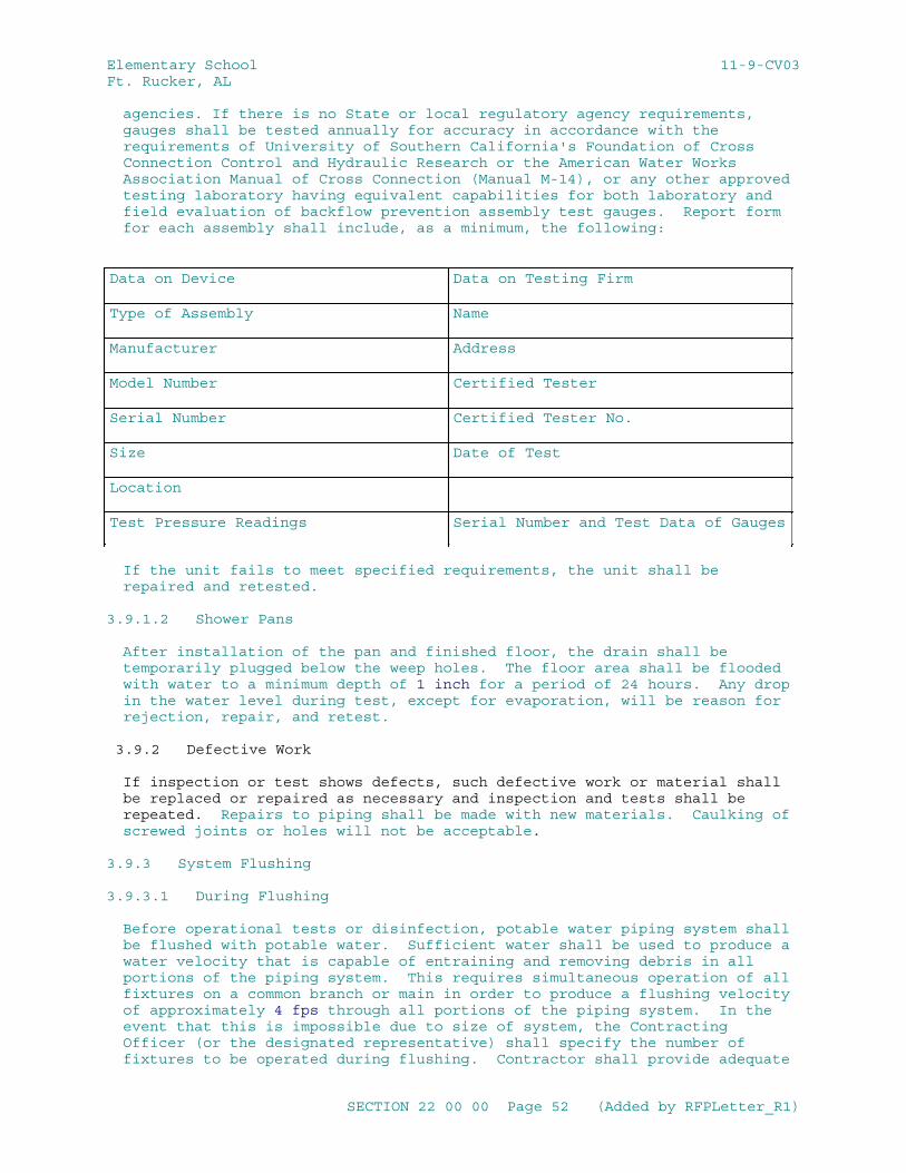
Elementary School 11-9-CV03Ft. Rucker, AL
agencies. If there is no State or local regulatory agency requirements, gauges shall be tested annually for accuracy in accordance with the requirements of University of Southern California's Foundation of Cross Connection Control and Hydraulic Research or the American Water Works Association Manual of Cross Connection (Manual M-14), or any other approved testing laboratory having equivalent capabilities for both laboratory and field evaluation of backflow prevention assembly test gauges. Report form for each assembly shall include, as a minimum, the following:
Data on Device Data on Testing Firm
Type of Assembly Name
Manufacturer Address
Model Number Certified Tester
Serial Number Certified Tester No.
Size Date of Test
Location
Test Pressure Readings Serial Number and Test Data of Gauges
If the unit fails to meet specified requirements, the unit shall be repaired and retested.
3.9.1.2 Shower Pans
After installation of the pan and finished floor, the drain shall be temporarily plugged below the weep holes. The floor area shall be flooded with water to a minimum depth of 1 inch for a period of 24 hours. Any drop in the water level during test, except for evaporation, will be reason for rejection, repair, and retest.
3.9.2 Defective Work
If inspection or test shows defects, such defective work or material shall be replaced or repaired as necessary and inspection and tests shall be repeated. Repairs to piping shall be made with new materials. Caulking of screwed joints or holes will not be acceptable.
3.9.3 System Flushing
3.9.3.1 During Flushing
Before operational tests or disinfection, potable water piping system shall be flushed with potable water. Sufficient water shall be used to produce a water velocity that is capable of entraining and removing debris in all portions of the piping system. This requires simultaneous operation of all fixtures on a common branch or main in order to produce a flushing velocity of approximately 4 fps through all portions of the piping system. In the event that this is impossible due to size of system, the Contracting Officer (or the designated representative) shall specify the number of fixtures to be operated during flushing. Contractor shall provide adequate
SECTION 22 00 00 Page 52 (Added by RFPLetter_R1)
Elementary School 11-9-CV03Ft. Rucker, AL
personnel to monitor the flushing operation and to ensure that drain lines are unobstructed in order to prevent flooding of the facility. Contractor shall be responsible for any flood damage resulting from flushing of the system. Flushing shall be continued until entrained dirt and other foreign materials have been removed and until discharge water shows no discoloration. All faucets and drinking water fountains, to include any device considered as an end point device by NSF/ANSI 61, Section 9, shall be flushed a minimum of 0.25 gallons per 24 hour period, ten times over a 14 day period.
3.9.3.2 After Flushing
System shall be drained at low points. Strainer screens shall be removed, cleaned, and replaced. After flushing and cleaning, systems shall be prepared for testing by immediately filling water piping with clean, fresh potable water. Any stoppage, discoloration, or other damage to the finish, furnishings, or parts of the building due to the Contractor's failure to properly clean the piping system shall be repaired by the Contractor. When the system flushing is complete, the hot-water system shall be adjusted for uniform circulation. Flushing devices and automatic control systems shall be adjusted for proper operation according to manufacturer's instructions. Comply with ASHRAE 90.1 - IP for minimum efficiency requirements. Unless more stringent local requirements exist, lead levels shall not exceed limits established by 40 CFR 141.80 (c)(1). The water supply to the building shall be tested separately to ensure that any lead contamination found during potable water system testing is due to work being performed inside the building.
3.9.4 Operational Test
Upon completion of flushing and prior to disinfection procedures, the Contractor shall subject the plumbing system to operating tests to demonstrate satisfactory installation, connections, adjustments, and functional and operational efficiency. Such operating tests shall cover a period of not less than 8 hours for each system and shall include the following information in a report with conclusion as to the adequacy of the system:
a. Time, date, and duration of test.
b. Water pressures at the most remote and the highest fixtures.
c. Operation of each fixture and fixture trim.
d. Operation of each valve, hydrant, and faucet.
e. Pump suction and discharge pressures.
f. Temperature of each domestic hot-water supply.
g. Operation of each floor and roof drain by flooding with water.
h. Operation of each vacuum breaker and backflow preventer.
i. Complete operation of each water pressure booster system, including pump start pressure and stop pressure.
SECTION 22 00 00 Page 53 (Added by RFPLetter_R1)
Elementary School 11-9-CV03Ft. Rucker, AL
3.9.5 Disinfection
After all system components are provided and operational tests are complete, the entire domestic hot- and cold-water distribution system shall be disinfected. Before introducing disinfecting chlorination material, entire system shall be flushed with potable water until any entrained dirt and other foreign materials have been removed.
Water chlorination procedure shall be in accordance with AWWA C651 and AWWA C652 as modified and supplemented by this specification. The chlorinating material shall be hypochlorites or liquid chlorine. The chlorinating material shall be fed into the water piping system at a constant rate at a concentration of at least 50 parts per million (ppm). Feed a properly adjusted hypochlorite solution injected into the system with a hypochlorinator, or inject liquid chlorine into the system through a solution-feed chlorinator and booster pump until the entire system is completely filled.
Test the chlorine residual level in the water at 6 hour intervals for a continuous period of 24 hours. If at the end of a 6 hour interval, the chlorine residual has dropped to less than 25 ppm, flush the piping including tanks with potable water, and repeat the above chlorination procedures. During the chlorination period, each valve and faucet shall be opened and closed several times.
After the second 24 hour period, verify that no less than 25 ppm chlorine residual remains in the treated system. The 24 hour chlorination procedure must be repeated until no less than 25 ppm chlorine residual remains in the treated system.
Upon the specified verification, the system including tanks shall then be flushed with potable water until the residual chlorine level is reduced to less than one part per million. During the flushing period, each valve and faucet shall be opened and closed several times.
Take addition samples of water in disinfected containers, for bacterial examination, at locations specified by the Contracting OfficerTest these samples for total coliform organisms (coliform bacteria, fecal coliform, streptococcal, and other bacteria) in accordance with EPA SM 9223 . The testing method used shall be EPA approved for drinking water systems and shall comply with applicable local and state requirements.
Disinfection shall be repeated until bacterial tests indicate the absence of coliform organisms (zero mean coliform density per 100 milliliters) in the samples for at least 2 full days. The system will not be accepted until satisfactory bacteriological results have been obtained.
3.9.6 OPTIONAL DISINFECTION METHOD
Disinfect new potable water piping and affected portions of existing potable water piping with geothermal water. Geothermal water shall be not less than 194 degrees F and contact time shall be not less than 30 minutes. After disinfection, thoroughly flush new portable water piping and affected portions of existing potable water piping with the chlorinated base water supply for a minimum of two hours.
SECTION 22 00 00 Page 54 (Added by RFPLetter_R1)
Elementary School 11-9-CV03Ft. Rucker, AL
3.10 WASTE MANAGEMENT
Place materials defined as hazardous or toxic waste in designated containers. Return solvent and oil soaked rags for contaminant recovery and laundering or for proper disposal. Close and seal tightly partly used sealant and adhesive containers and store in protected, well-ventilated, fire-safe area at moderate temperature. Place used sealant and adhesive tubes and containers in areas designated for hazardous waste. Separate copper and ferrous pipe waste in accordance with the Waste Management Plan and place in designated areas for reuse.
3.11 POSTED INSTRUCTIONS
Framed instructions under glass or in laminated plastic, including wiring and control diagrams showing the complete layout of the entire system, shall be posted where directed. Condensed operating instructions explaining preventive maintenance procedures, methods of checking the system for normal safe operation, and procedures for safely starting and stopping the system shall be prepared in typed form, framed as specified above for the wiring and control diagrams and posted beside the diagrams. The framed instructions shall be posted before acceptance testing of the systems.
3.12 PERFORMANCE OF WATER HEATING EQUIPMENT
Standard rating condition terms are as follows:
EF = Energy factor, minimum overall efficiency.
ET = Minimum thermal efficiency with 70 degrees F delta T.
SL = Standby loss is maximum (Btu/h) based on a 70 degrees F temperature difference between stored water and ambient requirements.
V = Rated volume in gallons
Q = Nameplate input rate in kW (Btu/h)
3.12.1 Storage Water Heaters
3.12.1.1 Electric
a. Storage capacity of 60 gallons shall have a minimum energy factor (EF) of 0.93 or higher per FEMP requirements.
b. Storage capacity of 60 gallons or more shall have a minimum energy factor (EF) of 0.91 or higher per FEMP requirements.
3.12.1.2 Gas
a. Storage capacity of 50 gallons or less shall have a minimum energy factor (EF) of 0.62 or higher per FEMP requirements.
b. Storage capacity of 20 gallons - or more and input rating of 75,000 Btu/h or less: minimum EF shall be 0.62 - 0.0019V per 10 CFR 430.
c. Rating of less than 22980 W: (75,000 Btu/h) ET shall be 80 percent; maximum SL shall be (0/800+100x(V^^1/2)), per ANSI Z21.10.3/CSA 4.3
SECTION 22 00 00 Page 55 (Added by RFPLetter_R1)
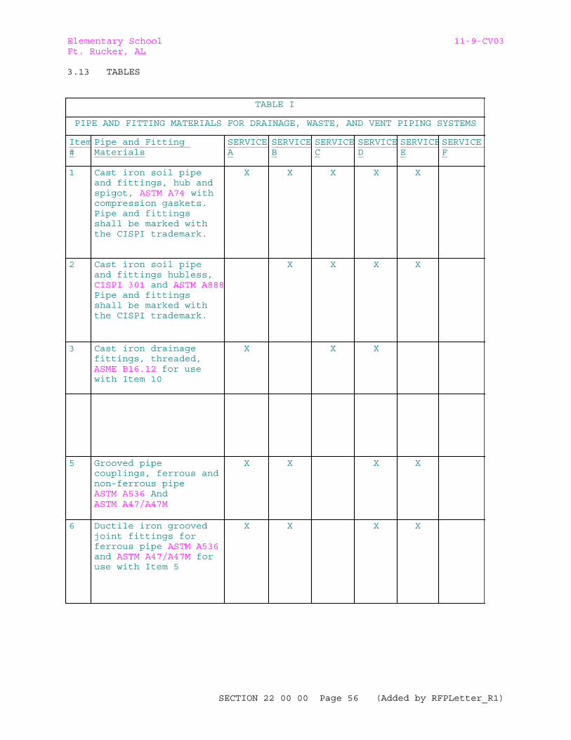
Elementary School 11-9-CV03Ft. Rucker, AL
3.13 TABLES
TABLE I
PIPE AND FITTING MATERIALS FOR DRAINAGE, WASTE, AND VENT PIPING SYSTEMS
Item#
Pipe and Fitting Materials
SERVICE A
SERVICE B
SERVICE C
SERVICED
SERVICEE
SERVICE F
1 Cast iron soil pipe and fittings, hub and spigot, ASTM A74 with compression gaskets. Pipe and fittings shall be marked with the CISPI trademark.
X X X X X
2 Cast iron soil pipe and fittings hubless, CISPI 301 and ASTM A888Pipe and fittings shall be marked with the CISPI trademark.
X X X X
3 Cast iron drainage fittings, threaded, ASME B16.12 for use with Item 10
X X X
5 Grooved pipe couplings, ferrous and non-ferrous pipe ASTM A536 And ASTM A47/A47M
X X X X
6 Ductile iron grooved joint fittings for ferrous pipe ASTM A536 and ASTM A47/A47M for use with Item 5
X X X X
SECTION 22 00 00 Page 56 (Added by RFPLetter_R1)
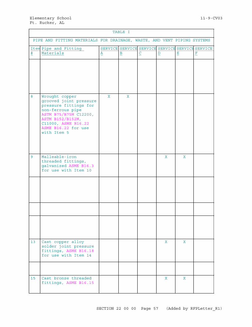
Elementary School 11-9-CV03Ft. Rucker, AL
TABLE I
PIPE AND FITTING MATERIALS FOR DRAINAGE, WASTE, AND VENT PIPING SYSTEMS
Item#
Pipe and Fitting Materials
SERVICE A
SERVICE B
SERVICE C
SERVICED
SERVICEE
SERVICE F
8 Wrought copper grooved joint pressure pressure fittings for non-ferrous pipe ASTM B75/B75M C12200, ASTM B152/B152M, C11000, ASME B16.22 ASME B16.22 for use with Item 5
X X
9 Malleable-iron threaded fittings, galvanized ASME B16.3 for use with Item 10
X X
13 Cast copper alloy solder joint pressure fittings, ASME B16.18for use with Item 14
X X
15 Cast bronze threaded fittings, ASME B16.15
X X
SECTION 22 00 00 Page 57 (Added by RFPLetter_R1)
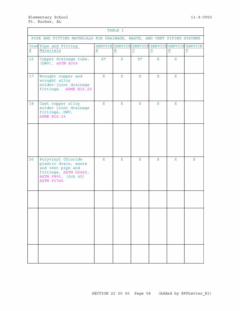
Elementary School 11-9-CV03Ft. Rucker, AL
TABLE I
PIPE AND FITTING MATERIALS FOR DRAINAGE, WASTE, AND VENT PIPING SYSTEMS
Item#
Pipe and Fitting Materials
SERVICE A
SERVICE B
SERVICE C
SERVICED
SERVICEE
SERVICE F
16 Copper drainage tube, (DWV), ASTM B306
X* X X* X X
17 Wrought copper and wrought alloy solder-joint drainage fittings. ASME B16.29
X X X X X
18 Cast copper alloy solder joint drainage fittings, DWV, ASME B16.23
X X X X X
20 Polyvinyl Chloride plastic drain, waste and vent pipe and fittings, ASTM D2665, ASTM F891, (Sch 40) ASTM F1760
X X X X X X
SECTION 22 00 00 Page 58 (Added by RFPLetter_R1)
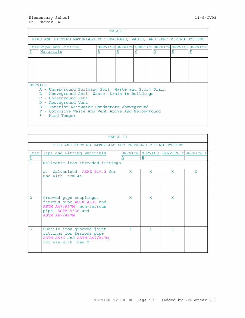
Elementary School 11-9-CV03Ft. Rucker, AL
TABLE I
PIPE AND FITTING MATERIALS FOR DRAINAGE, WASTE, AND VENT PIPING SYSTEMS
Item#
Pipe and Fitting Materials
SERVICE A
SERVICE B
SERVICE C
SERVICED
SERVICEE
SERVICE F
SERVICE: A - Underground Building Soil, Waste and Storm Drain B - Aboveground Soil, Waste, Drain In Buildings C - Underground Vent D - Aboveground Vent E - Interior Rainwater Conductors Aboveground F - Corrosive Waste And Vent Above And Belowground * - Hard Temper
TABLE II
PIPE AND FITTING MATERIALS FOR PRESSURE PIPING SYSTEMS
Item #
Pipe and Fitting Materials SERVICE A
SERVICE B
SERVICE C SERVICE D
1 Malleable-iron threaded fittings:
a. Galvanized, ASME B16.3 for use with Item 4a
X X X X
2 Grooved pipe couplings, ferrous pipe ASTM A536 and ASTM A47/A47M, non-ferrous pipe, ASTM A536 and ASTM A47/A47M
X X X
3 Ductile iron grooved joint fittings for ferrous pipe ASTM A536 and ASTM A47/A47M, for use with Item 2
X X X
SECTION 22 00 00 Page 59 (Added by RFPLetter_R1)
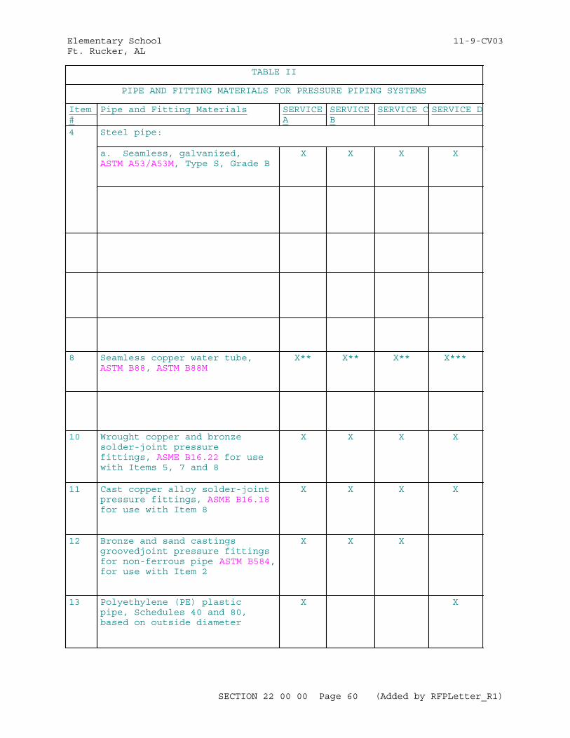
Elementary School 11-9-CV03Ft. Rucker, AL
TABLE II
PIPE AND FITTING MATERIALS FOR PRESSURE PIPING SYSTEMS
Item #
Pipe and Fitting Materials SERVICE A
SERVICE B
SERVICE C SERVICE D
4 Steel pipe:
a. Seamless, galvanized, ASTM A53/A53M, Type S, Grade B
X X X X
8 Seamless copper water tube, ASTM B88, ASTM B88M
X** X** X** X***
10 Wrought copper and bronze solder-joint pressure fittings, ASME B16.22 for use with Items 5, 7 and 8
X X X X
11 Cast copper alloy solder-joint pressure fittings, ASME B16.18 for use with Item 8
X X X X
12 Bronze and sand castings groovedjoint pressure fittings for non-ferrous pipe ASTM B584, for use with Item 2
X X X
13 Polyethylene (PE) plastic pipe, Schedules 40 and 80, based on outside diameter
X X
SECTION 22 00 00 Page 60 (Added by RFPLetter_R1)
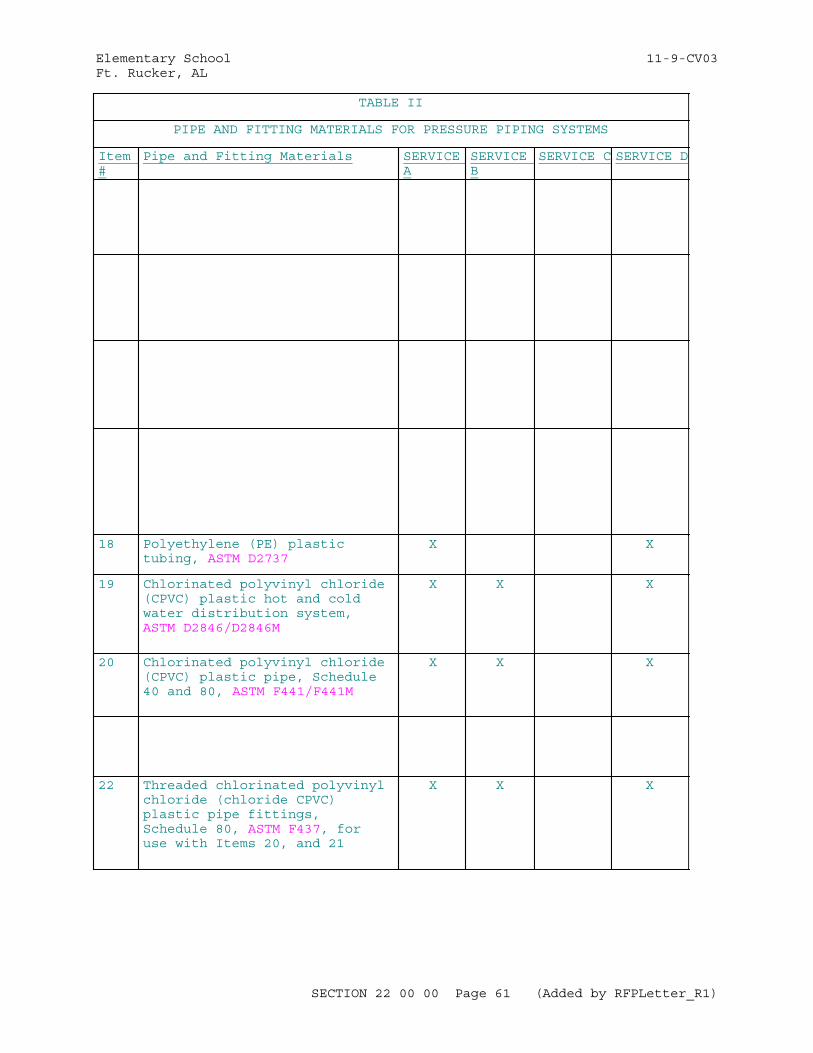
Elementary School 11-9-CV03Ft. Rucker, AL
TABLE II
PIPE AND FITTING MATERIALS FOR PRESSURE PIPING SYSTEMS
Item #
Pipe and Fitting Materials SERVICE A
SERVICE B
SERVICE C SERVICE D
18 Polyethylene (PE) plastic tubing, ASTM D2737
X X
19 Chlorinated polyvinyl chloride (CPVC) plastic hot and cold water distribution system, ASTM D2846/D2846M
X X X
20 Chlorinated polyvinyl chloride (CPVC) plastic pipe, Schedule 40 and 80, ASTM F441/F441M
X X X
22 Threaded chlorinated polyvinyl chloride (chloride CPVC) plastic pipe fittings, Schedule 80, ASTM F437, for use with Items 20, and 21
X X X
SECTION 22 00 00 Page 61 (Added by RFPLetter_R1)
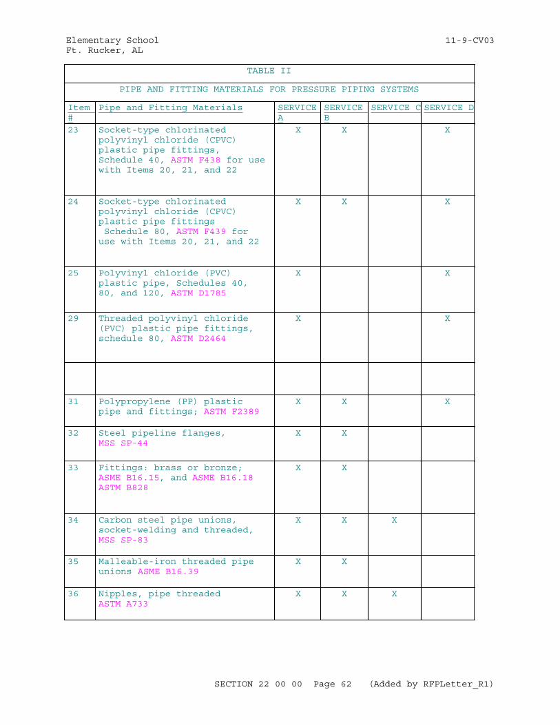
Elementary School 11-9-CV03Ft. Rucker, AL
TABLE II
PIPE AND FITTING MATERIALS FOR PRESSURE PIPING SYSTEMS
Item #
Pipe and Fitting Materials SERVICE A
SERVICE B
SERVICE C SERVICE D
23 Socket-type chlorinated polyvinyl chloride (CPVC) plastic pipe fittings, Schedule 40, ASTM F438 for use with Items 20, 21, and 22
X X X
24 Socket-type chlorinated polyvinyl chloride (CPVC) plastic pipe fittings Schedule 80, ASTM F439 for use with Items 20, 21, and 22
X X X
25 Polyvinyl chloride (PVC) plastic pipe, Schedules 40, 80, and 120, ASTM D1785
X X
29 Threaded polyvinyl chloride (PVC) plastic pipe fittings, schedule 80, ASTM D2464
X X
31 Polypropylene (PP) plastic pipe and fittings; ASTM F2389
X X X
32 Steel pipeline flanges, MSS SP-44
X X
33 Fittings: brass or bronze; ASME B16.15, and ASME B16.18 ASTM B828
X X
34 Carbon steel pipe unions, socket-welding and threaded, MSS SP-83
X X X
35 Malleable-iron threaded pipe unions ASME B16.39
X X
36 Nipples, pipe threaded ASTM A733
X X X
SECTION 22 00 00 Page 62 (Added by RFPLetter_R1)
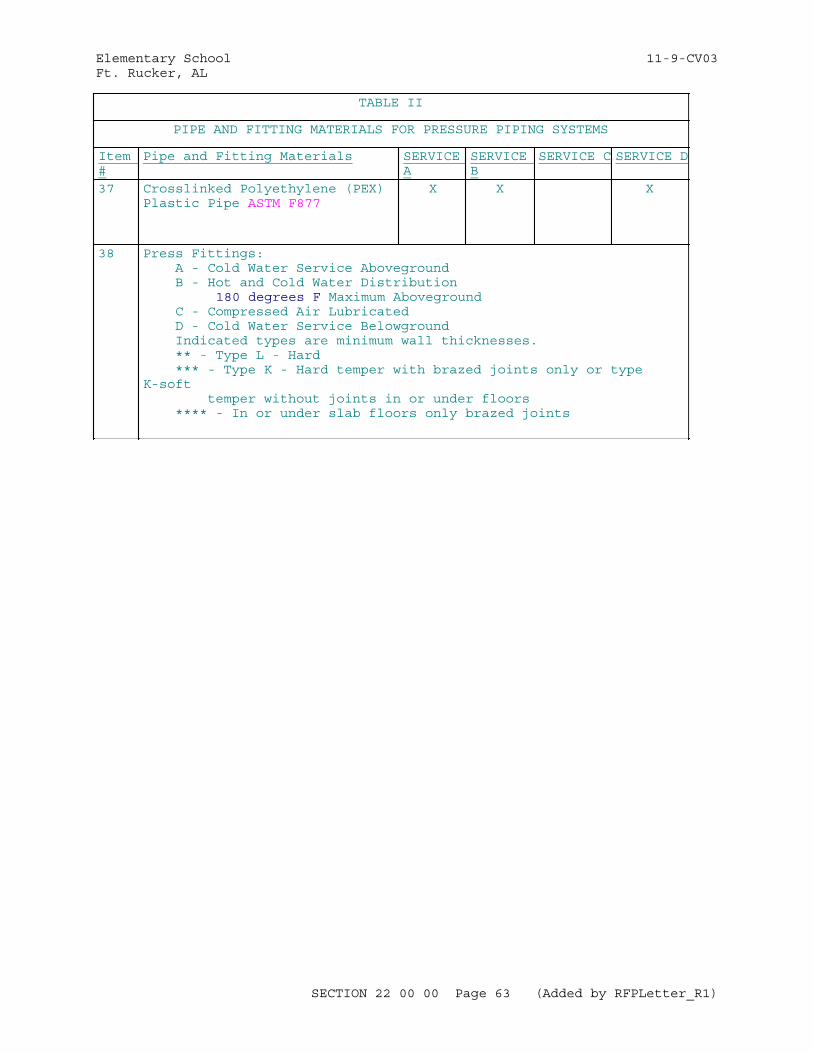
Elementary School 11-9-CV03Ft. Rucker, AL
TABLE II
PIPE AND FITTING MATERIALS FOR PRESSURE PIPING SYSTEMS
Item #
Pipe and Fitting Materials SERVICE A
SERVICE B
SERVICE C SERVICE D
37 Crosslinked Polyethylene (PEX) Plastic Pipe ASTM F877
X X X
38 Press Fittings: A - Cold Water Service Aboveground B - Hot and Cold Water Distribution 180 degrees F Maximum Aboveground C - Compressed Air Lubricated D - Cold Water Service Belowground Indicated types are minimum wall thicknesses. ** - Type L - Hard *** - Type K - Hard temper with brazed joints only or type K-soft temper without joints in or under floors **** - In or under slab floors only brazed joints
SECTION 22 00 00 Page 63 (Added by RFPLetter_R1)
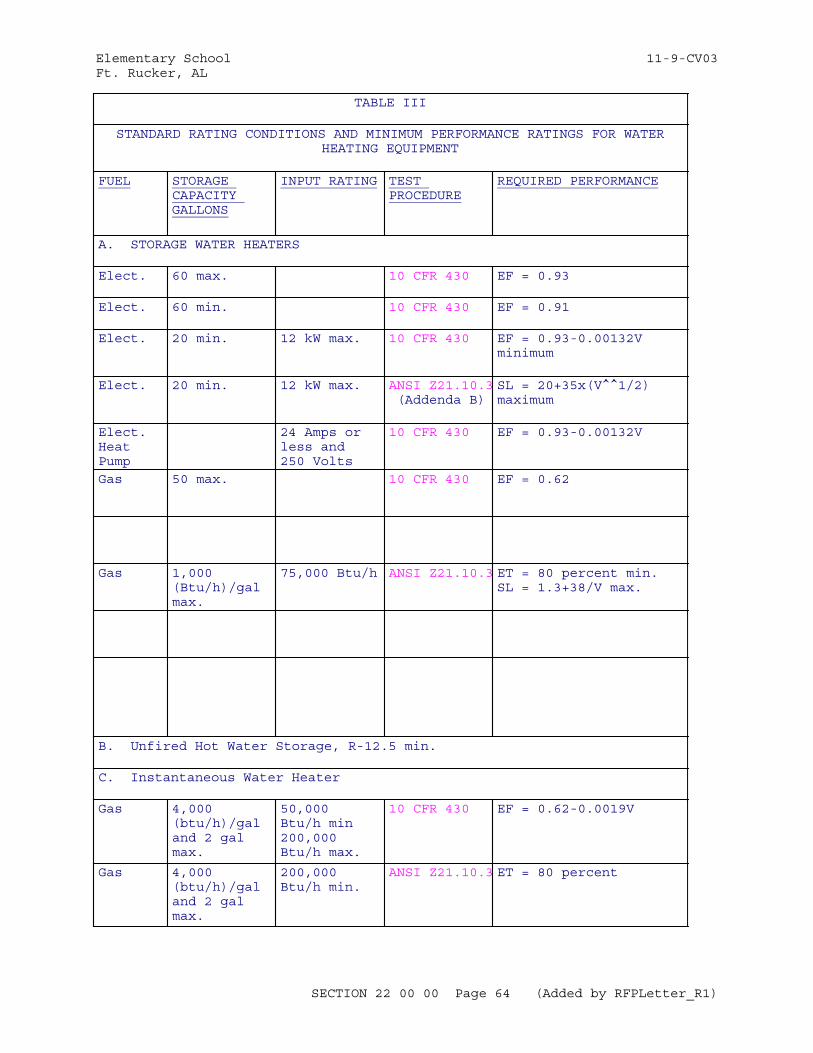
Elementary School 11-9-CV03Ft. Rucker, AL
TABLE III
STANDARD RATING CONDITIONS AND MINIMUM PERFORMANCE RATINGS FOR WATERHEATING EQUIPMENT
FUEL STORAGE CAPACITY GALLONS
INPUT RATING TEST PROCEDURE
REQUIRED PERFORMANCE
A. STORAGE WATER HEATERS
Elect. 60 max. 10 CFR 430 EF = 0.93
Elect. 60 min. 10 CFR 430 EF = 0.91
Elect. 20 min. 12 kW max. 10 CFR 430 EF = 0.93-0.00132V minimum
Elect. 20 min. 12 kW max. ANSI Z21.10.3 (Addenda B)
SL = 20+35x(V^^1/2) maximum
Elect. Heat Pump
24 Amps or less and 250 Volts
10 CFR 430 EF = 0.93-0.00132V
Gas 50 max. 10 CFR 430 EF = 0.62
Gas 1,000 (Btu/h)/gal max.
75,000 Btu/h ANSI Z21.10.3 ET = 80 percent min. SL = 1.3+38/V max.
B. Unfired Hot Water Storage, R-12.5 min.
C. Instantaneous Water Heater
Gas 4,000 (btu/h)/gal and 2 gal max.
50,000 Btu/h min200,000 Btu/h max.
10 CFR 430 EF = 0.62-0.0019V
Gas 4,000 (btu/h)/gal and 2 gal max.
200,000 Btu/h min.
ANSI Z21.10.3 ET = 80 percent
SECTION 22 00 00 Page 64 (Added by RFPLetter_R1)
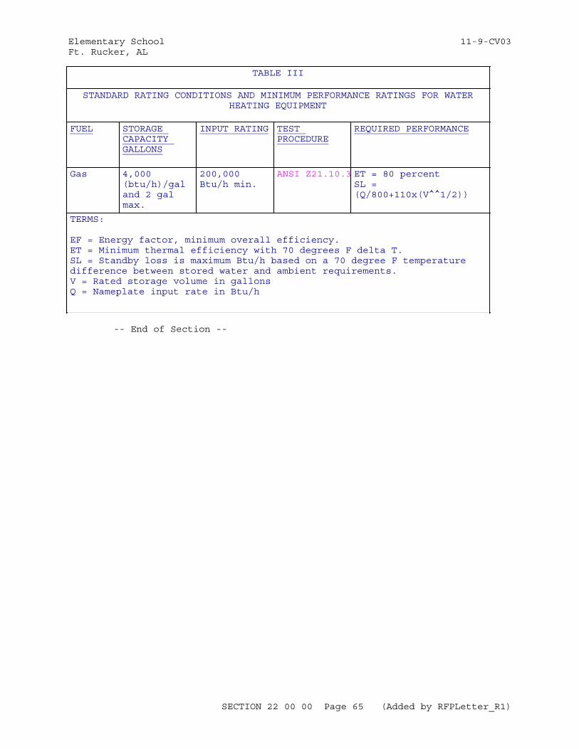
Elementary School 11-9-CV03Ft. Rucker, AL
TABLE III
STANDARD RATING CONDITIONS AND MINIMUM PERFORMANCE RATINGS FOR WATERHEATING EQUIPMENT
FUEL STORAGE CAPACITY GALLONS
INPUT RATING TEST PROCEDURE
REQUIRED PERFORMANCE
Gas 4,000 (btu/h)/gal and 2 gal max.
200,000 Btu/h min.
ANSI Z21.10.3 ET = 80 percentSL = (Q/800+110x(V^^1/2))
TERMS:
EF = Energy factor, minimum overall efficiency.ET = Minimum thermal efficiency with 70 degrees F delta T.SL = Standby loss is maximum Btu/h based on a 70 degree F temperature difference between stored water and ambient requirements.V = Rated storage volume in gallonsQ = Nameplate input rate in Btu/h
-- End of Section --
SECTION 22 00 00 Page 65 (Added by RFPLetter_R1)
Elementary School 11-9-CV03Ft. Rucker, AL
SECTION TABLE OF CONTENTS
DIVISION 22 - PLUMBING
SECTION 22 05 48.00 20
MECHANICAL SOUND, VIBRATION, AND SEISMIC CONTROL
04/06
PART 1 GENERAL
1.1 REFERENCES 1.2 RELATED REQUIREMENTS 1.3 DEFINITIONS 1.3.1 Decibels dB 1.3.2 Machinery 1.3.3 Manufacturer 1.3.4 Micropascal uPa 1.3.5 Picowatt pW 1.4 SYSTEM DESCRIPTION 1.4.1 Spring Isolator Data 1.4.2 Machinery Manufacturer's Sound Data 1.4.3 Machinery 1.4.4 Machinery Over 300 Pounds 1.4.5 Machinery Vibration Criteria 1.4.5.1 Vibration Isolation Mounts, Hangers and Restraints 1.4.5.2 Vibration Isolated Equipment Bases 1.4.5.3 Flexible Connectors for Pipes and Ducts 1.4.6 Machinery Airborne Sound Level Criteria 1.4.6.1 Basic Criteria 1.4.6.2 Sound Data Schedule 1.4.6.2.1 Fans 1.4.6.2.2 Air Handling Units 1.4.6.2.3 Variable Air Volume Terminal Units 1.4.7 Welding 1.5 SUBMITTALS 1.6 QUALITY ASSURANCE 1.6.1 Vibration Isolator Procurement 1.6.2 Unitized Machinery Assemblies 1.6.3 Manufacturer Responsibilities 1.7 STORAGE AND PROTECTION
PART 2 PRODUCTS
2.1 CORROSION PROTECTION FOR STEEL PARTS 2.2 NEOPRENE 2.3 FLOOR-MOUNTED ISOLATORS 2.3.1 Neoprene Isolation Pads 2.3.2 Neoprene Isolators 2.4 SPRING ISOLATORS AND PROTECTED SPRING ISOLATORS 2.4.1 Springs 2.4.2 Mounting and Adjustment 2.5 SUSPENSION ISOLATORS 2.5.1 Suspension Neoprene Isolators 2.5.2 Suspension Spring Isolators
SECTION 22 05 48.00 20 Page 1 (Added by RFPLetter_R1)
Elementary School 11-9-CV03Ft. Rucker, AL
2.6 MACHINERY BASES 2.7 INERTIA BASES 2.8 FLEXIBLE CONNECTORS FOR PIPING 2.8.1 Elastomeric Flexible Connectors 2.8.2 Metal Flexible Connectors 2.9 FLEXIBLE DUCT CONNECTORS 2.10 PIPE GUIDES 2.11 THRUST RESTRAINTS
PART 3 EXECUTION
3.1 INSPECTION 3.2 INSTALLATION 3.2.1 Vibration and Noise Isolation Components 3.2.1.1 Floor Mounted Equipment 3.2.1.2 General Equipment Isolation 3.2.1.3 Piping and Ductwork Isolation 3.2.2 Suspension Vibration Isolators 3.2.3 Vertical Stops 3.2.4 Thrust Restraints 3.2.5 Flexible Pipe and Duct Connectors 3.2.6 Seismic Snubbers 3.2.7 Machinery 3.2.7.1 Stability 3.2.7.2 Lateral Motion 3.2.7.3 Unbalanced Machinery 3.2.7.4 Nonrotating Machinery 3.2.8 Piping 3.2.8.1 Piping Connected to Vibration Isolated Machinery 3.2.8.2 Steam Pressure Reducing Valves 3.2.8.3 Condenser Water 3.2.8.4 Chilled, Hot, and Dual Temperature Piping 3.2.9 Water and Steam Distribution Piping Application 3.2.10 Pipe Hanger and Support Installation 3.2.10.1 Pipe Hangers 3.2.10.2 High Temperatures 3.2.10.3 Valves 3.2.10.4 Machinery Without Flexible Connections 3.2.10.5 Twelve Inch and Larger Pipe 3.2.10.6 Pipe Risers 3.2.10.7 Supports at Base of Pipe Risers 3.2.10.8 Pipe Anchors 3.2.11 Equipment Room Sound Isolation 3.2.11.1 Pipe Penetrations 3.2.11.2 Duct Penetrations 3.2.11.3 Ducts Passing Through Equipment Rooms 3.2.12 Machinery Foundations and Subbases 3.2.12.1 Machinery Subbases 3.2.12.2 Common Machinery Foundations 3.2.12.3 Foundation and Subbase Concrete 3.2.12.4 Anchor Bolts and Grout 3.2.13 Inertia Bases 3.2.14 Seismic Restraints for Piping and Ductwork 3.2.15 Suspended Machinery Platforms 3.2.16 Electrical Connections 3.2.17 Systems Not To Be Vibration Isolated 3.3 FIELD QUALITY CONTROL 3.3.1 Field Inspections 3.3.2 Spring Isolator Inspection
SECTION 22 05 48.00 20 Page 2 (Added by RFPLetter_R1)
Elementary School 11-9-CV03Ft. Rucker, AL
3.3.3 Tests 3.3.3.1 Equipment Vibration Tests 3.3.3.2 Equipment Sound Level Tests 3.4 ADJUST AND CLEAN 3.5 FINAL INSPECTION 3.5.1 Contractor Closeout
-- End of Section Table of Contents --
SECTION 22 05 48.00 20 Page 3 (Added by RFPLetter_R1)
Elementary School 11-9-CV03Ft. Rucker, AL
SECTION 22 05 48.00 20
MECHANICAL SOUND, VIBRATION, AND SEISMIC CONTROL04/06
PART 1 GENERAL
1.1 REFERENCES
The publications listed below form a part of this specification to the extent referenced. The publications are referred to within the text by the basic designation only.
AIR-CONDITIONING, HEATING AND REFRIGERATION INSTITUTE (AHRI)
AHRI 575 (2008) Method of Measuring Machinery Sound Within an Equipment Space
ANSI/AHRI 370 (2011) Sound Rating of Large Outdoor Refrigerating and Air-Conditioning Equipment
AMERICAN INSTITUTE OF STEEL CONSTRUCTION (AISC)
AISC 360 (2010) Specification for Structural Steel Buildings
AMERICAN WELDING SOCIETY (AWS)
AWS D1.1/D1.1M (2015) Structural Welding Code - Steel
ASTM INTERNATIONAL (ASTM)
ASTM A123/A123M (2013) Standard Specification for Zinc (Hot-Dip Galvanized) Coatings on Iron and Steel Products
ASTM A36/A36M (2012) Standard Specification for Carbon Structural Steel
ASTM C94/C94M (2015) Standard Specification for Ready-Mixed Concrete
ASTM D2240 (2005; R 2010) Standard Test Method for Rubber Property - Durometer Hardness
ASTM D471 (2012a) Standard Test Method for Rubber Property - Effect of Liquids
ASTM E84 (2015a) Standard Test Method for Surface Burning Characteristics of Building Materials
SHEET METAL AND AIR CONDITIONING CONTRACTORS' NATIONAL ASSOCIATION (SMACNA)
SMACNA 1403 (2008) Accepted Industry Practice for
SECTION 22 05 48.00 20 Page 4 (Added by RFPLetter_R1)
Elementary School 11-9-CV03Ft. Rucker, AL
Industrial Duct Construction, 2nd Edition
SMACNA 1981 (2008) Seismic Restraint Manual Guidelines for Mechanical Systems, 3rd Edition
1.2 RELATED REQUIREMENTS
The provisions of Section BASIC MECHANICAL MATERIALS AND METHODS apply to this section.
1.3 DEFINITIONS
1.3.1 Decibels dB
Measure of sound level. Decibels are referenced to either 20 uPa for sound pressure levels or one pW for sound power levels. dBA is the overall "A" weighted sound level.
1.3.2 Machinery
The vibration or noise producing equipment that must be isolated.
1.3.3 Manufacturer
The fabricator or supplier of vibration-isolation or seismic-protection materials and equipment. For mechanical equipment and machinery the term machinery manufacturer will be used.
1.3.4 Micropascal uPa
10 to the minus 6 power newtons per square meter.
1.3.5 Picowatt pW
10 to the minus 12 power watts.
1.4 SYSTEM DESCRIPTION
1.4.1 Spring Isolator Data
For each type and size of spring isolator, submit the spring outside diameter, deflection, operating spring height, unloaded spring height, solid spring height, the ratio of the outside diameter to the operating spring height, the load to deflection ratio of the springs, and weight and sizes of structural steel members.
1.4.2 Machinery Manufacturer's Sound Data
For each piece of indicated machinery to be vibration isolated, the calculated sound power test data or sound pressure test data as levels in dB in the eight octave bands between 63 and 8,000 Hz. Refer sound power levels to one pW and sound pressure levels to 20 uPa. Submit the overall "A" weighted scale sound pressure level in dB. Submit the standard test procedure used to obtain the sound power or pressure data for the applicable vibration isolation equipment size.
1.4.3 Machinery
For each item of machinery, compare spring static deflections with the
SECTION 22 05 48.00 20 Page 5 (Added by RFPLetter_R1)
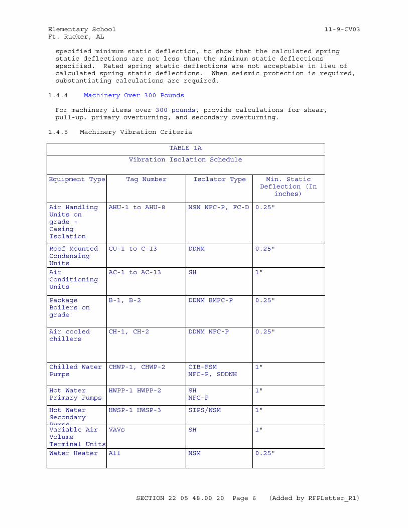
Elementary School 11-9-CV03Ft. Rucker, AL
specified minimum static deflection, to show that the calculated spring static deflections are not less than the minimum static deflections specified. Rated spring static deflections are not acceptable in lieu of calculated spring static deflections. When seismic protection is required, substantiating calculations are required.
1.4.4 Machinery Over 300 Pounds
For machinery items over 300 pounds, provide calculations for shear, pull-up, primary overturning, and secondary overturning.
1.4.5 Machinery Vibration Criteria
TABLE 1A
Vibration Isolation Schedule
Equipment Type Tag Number Isolator Type Min. StaticDeflection (In
inches)
Air Handling Units on grade - Casing Isolation
AHU-1 to AHU-8 NSN NFC-P, FC-D 0.25"
Roof Mounted Condensing Units
CU-1 to C-13 DDNM 0.25"
Air Conditioning Units
AC-1 to AC-13 SH 1"
Package Boilers on grade
B-1, B-2 DDNM BMFC-P 0.25"
Air cooled chillers
CH-1, CH-2 DDNM NFC-P 0.25"
Chilled Water Pumps
CHWP-1, CHWP-2 CIB-FSMNFC-P, SDDNH
1"
Hot Water Primary Pumps
HWPP-1 HWPP-2 SHNFC-P
1"
Hot Water Secondary Pumps
HWSP-1 HWSP-3 SIPS/NSM 1"
Variable Air Volume Terminal Units
VAVs SH 1"
Water Heater All NSM 0.25"
SECTION 22 05 48.00 20 Page 6 (Added by RFPLetter_R1)
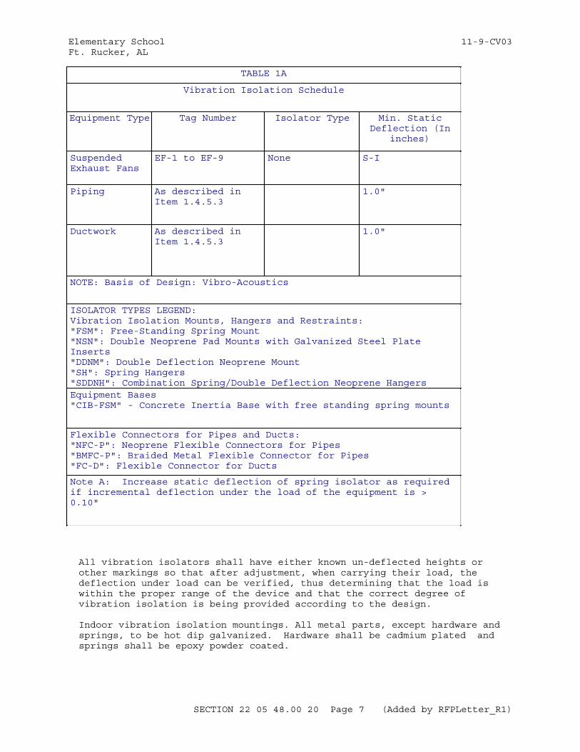
Elementary School 11-9-CV03Ft. Rucker, AL
TABLE 1A
Vibration Isolation Schedule
Equipment Type Tag Number Isolator Type Min. StaticDeflection (In
inches)
Suspended Exhaust Fans
EF-1 to EF-9 None S-I
Piping As described in Item 1.4.5.3
1.0"
Ductwork As described in Item 1.4.5.3
1.0"
NOTE: Basis of Design: Vibro-Acoustics
ISOLATOR TYPES LEGEND:Vibration Isolation Mounts, Hangers and Restraints:"FSM": Free-Standing Spring Mount"NSN": Double Neoprene Pad Mounts with Galvanized Steel Plate Inserts"DDNM": Double Deflection Neoprene Mount"SH": Spring Hangers"SDDNH": Combination Spring/Double Deflection Neoprene HangersEquipment Bases"CIB-FSM" - Concrete Inertia Base with free standing spring mounts
Flexible Connectors for Pipes and Ducts:"NFC-P": Neoprene Flexible Connectors for Pipes"BMFC-P": Braided Metal Flexible Connector for Pipes"FC-D": Flexible Connector for Ducts
Note A: Increase static deflection of spring isolator as required if incremental deflection under the load of the equipment is > 0.10"
All vibration isolators shall have either known un-deflected heights or other markings so that after adjustment, when carrying their load, the deflection under load can be verified, thus determining that the load is within the proper range of the device and that the correct degree of vibration isolation is being provided according to the design.
Indoor vibration isolation mountings. All metal parts, except hardware and springs, to be hot dip galvanized. Hardware shall be cadmium plated and springs shall be epoxy powder coated.
SECTION 22 05 48.00 20 Page 7 (Added by RFPLetter_R1)
Elementary School 11-9-CV03Ft. Rucker, AL
1.4.5.1 Vibration Isolation Mounts, Hangers and Restraints
A. Type "FSM" isolators shall be free-standing spring isolator mounts that are laterally stable without any housing and complete with a 1/4" thick neoprene acoustical friction pad between the baseplate and the support. All mountings shall have leveling bolts that must be rigidly bolted to the equipment. Installed and operating heights shall be equal. The ratio of the spring diameter to the loaded operating height shall be no less than 0.8. Springs shall have a minimum additional travel to solid equal to 50% of the rated deflection. Springs shall be designed and installed so that ends of springs remain parallel during and after loading. Spring mounts with springs welded to housing are not acceptable. Springs shall be non-resonant with equipment forcing frequencies or support structure natural frequencies. Type "FSM" isolators to be one of the following: Type FS (V.A), Type SLF (M.I.I.), Type FDS (K.N.C.), or Type AC (V.M.C).
B. Type "NSN" isolators shall be double neoprene pad mounts with galvanized steel plates between the neoprene pads. Holes to match through bolt support locations should be coordinated with the manufacturer. Neoprene grommet washers should be used where the equipment is bolted down to reduce vibration through the bolts. Type "NSN" mounts shall be one of the following: Type NSN (V.A.), Type WMSW (M.I.I.), Type NGS (K.N.C.), Type Shear-Flex (V.M.C.).
C. Type "SH" isolators shall be spring hanger rod isolators consisting of a spring element seated on a steel washer reinforced neoprene cup. The spring and neoprene cup shall be encased in a steel retainer box. The neoprene cup shall incorporate a neoprene bushing projecting through the lower rod hole of the steel retainer box to prevent steel-to-steel contact. The spring diameters and hanger box lower hole sizes shall be large enough to permit hanger rod to swing through a 30° arc before contacting the hole and short- circuiting the spring. Springs shall have an additional 50% travel to solid. Type "SH" isolators shall be one of the following: Type SHR (V.A.), Type 30 (M.I.I.),or products by K.N.C. or V.M.C. that meet the requirements listed above
D. Type "SDDNH" isolators shall be combination spring/double deflection neoprene hanger rod isolators consisting of spring and double deflection neoprene isolator elements in a steel box retainer. The spring and neoprene isolators shall have the same characteristics as described in Type "SH" and Type "DDNH" isolators, respectively. Springs shall be factory pre-loaded to 75% of the rated load for pre-compressed springs. Springs shall have an additional 50% travel to solid. Type "SDDNH" isolators shall be one of the following: Type SHRB (V.A.), Type 30N or PC30N for pre-compressed types (M.I.I.), or products by K.N.C. or V.M.C. that meet the requirements listed above.
E. Type "DDNM" isolators shall be double deflection neoprene mounts. Neoprene mounts shall include bolt holes for bolting to equipment base, bottom steel plates for bolting to sub-base as required, and a unit type design molded in black oil-resistant neoprene. All metal surfaces shall be neoprene covered. Neoprene to be not greater than 50 durometer. Double deflection neoprene mounts to have a rated minimum deflection of 0.25 inches. Type "DDNM" mounts shall be one of the following: Type RD (V.A.), Type ND (M.I.I.), Type RD (K.N.C.), or Type RD (V.M.C.).
1.4.5.2 Vibration Isolated Equipment Bases
A. A. Seismic Inline Pump Stands: Type SIPS - trapezoidal-shaped rigid
SECTION 22 05 48.00 20 Page 8 (Added by RFPLetter_R1)
Elementary School 11-9-CV03Ft. Rucker, AL
support stands made of high strength, low alloy steel designed to connect to pipe flanges which support vertical inline pumps. Stands shall include neoprene grommet washers for anchor bolts and be designed to provide adequate restraint for connected equipment to resist seismic loads. Install in pairs on inline pumps. Powder-coated enamel for corrosion protection for base. Provide vibration isolation pads under pump stands as shown on the schedule or details. Type NSN - Sandwich neoprene pad type isolators, with 3/8" (10 mm) minimum thick ribbed neoprene pads bonded to each side of a 10 ga (3.5 mm) minimum galvanized metal plate. Isolator pads shall be selected to ensure that deflection does not exceed 20% of isolator free height
B. Type "CIB-FSM" equipment bases shall be concrete inertia bases. Manufacturer to provide steel pouring forms for floating concrete bases. Bases for pumps shall be large enough to support the suction and discharge elbows. Forms shall include minimum concrete reinforcing as required to prevent flexure, misalignment of drive and driven unit or stress transferred into equipment. Forms shall be provided with steel templates to hold anchor bolt sleeves and anchor bolts while concrete is being placed. Base depth shall be a minimum of 1/12 of the longest dimension of the base, but not less than 6". Base depth need not exceed 12" unless specifically requested. Height saving brackets shall be employed in all mounting locations to maintain 2" clearance from the bottom of the base to the top of the floor. Bases shall incorporate Type "FSM" free-standing spring isolation mounts. Bases shall be ready for concrete pour; concrete weighing not less than 140 lbs per cubic foot by others. Type "CIB-FSM" equipment bases shall be one of the following: Type CIB (V.A.), BMK/KSL (M.I.I.), Type CIB-H or CIB-L (K.N.C).
1.4.5.3 Flexible Connectors for Pipes and Ducts
A. Type "NFC-P" flexible connectors for piping shall be constructed of neoprene with kevlar tire chord reinforcement. The raised face rubber flanges must encase solid steel rings to prevent pull out. Flexible cable wire is not acceptable. Sizes 1-1/2" through 14" shall have a ductile iron ring between two spheres. Sizes 16" through 24" may be single sphere. Minimum ratings shall be 200 psi at 220°F with minimum safety factor of 3:1. Size 12 inches and larger to employ control cables with end fittings isolated from anchor plates by means of 1/2-inch bridge bearing neoprene washer bushings designed for a maximum 1000 psi.. Type "NFC-P" connector shall be one of the following: Type SFDEJ (M.I.I.), EED (V.A.) or products by K.N.C. or V.M.C. that meet the requirements listed above.
B. Type "BMFC-P" flexible connectors for piping shall be braided flexible stainless steel hoses installed in pairs to accept movement in all directions. Pipe sizes less than 3" to be provided with male nipple fittings. 3-inch and larger pipe sizes to be provided with fixed steel flanges. Flexible connectors to be suitable for operating pressure with 4:1 minimum safety factor. Minimum length for given diameter of pipe shall be (pipe diameter in inches x length in inches): 1/2"x24", 3/4"x24", 1"x24", 1-1/4"x24", 1-1/2"x24", 2"x24", 2-1/2"x24", 3"x24", 4"x24", 5"x36", 6"x36", 8"x36", 10"x36", 12"x24", 14"x30", 16"x32". Type "BMFC-P" connectors shall be one of the following: Type MN or FFL (M.I.I.) or products by K.N.C. or V.M.C. that meet the requirements listed above.
C. Type "FC-D" flexible connectors for ducts shall be 30 ounce wovenglass fiber coated with neoprene, sewn together at the edges and joints. Connectors shall be 6" long and held in place with 3" wide bands of 24 ga. galvanized steel fastened per the manufacturer's written instructions.
SECTION 22 05 48.00 20 Page 9 (Added by RFPLetter_R1)
Elementary School 11-9-CV03Ft. Rucker, AL
Type "FC-D" flexible connectors shall be one of the following or equal: Ventglass (V.I.) or MF6N Super Metalfab (D.D.).
Provide vibration isolators and seismic snubbers for mechanical and electrical machinery and associated piping and ductwork as indicated, to minimize transmission of vibrations and structure borne noise to the building structure or spaces or from the building structure to the machinery. Comply with the following vibration schedule.
1. All mechanical and plumbing equipment, piping and ductwork as noted in this specification shall be supported by or suspended from vibration isolators to reduce the transmission of vibration and mechanically transmitted sound to the building structure. Vibration isolators shall be selected in accordance with the weight distribution of the equipment so as to produce reasonably uniform deflections and installed in accordance with the isolated equipment manufacturer's requirements.
2. All isolation materials shall be supplied by the same manufacturer, with the exception of internal fan isolation in air handling units, which may be supplied by the air handling unit manufacturer, and flexible connectors.
3. Any variance or non-compliance with these specification requirements shall be corrected by the contractor in an approved manner.
4. The work in this section includes, but is not limited to, the following: a. Vibration isolation mounts and hangers. b. Flexible connectors for pipes and ducts.
1.4.6 Machinery Airborne Sound Level Criteria
1.4.6.1 Basic Criteria
For each piece of machinery in the human work environment, do not exceed the maximum airborne sound levels 84 dB A-weighted scale, continuous or intermittent, or 140 dB peak sound pressure-level, impact or impulse, noise.
1.4.6.2 Sound Data Schedule
1.4.6.2.1 Fans
Manufacturer of return fans and exhaust fans to submit projected sound power levels of the units based on tests conducted in accordance with AMCA Standard 300, Reverberant Room Method for Sound Testing of Fans, under design operating conditions.
Submitted sound level data shall demonstrate compliance with the maximum allowable sound levels in the Exhaust Fan Acoustical Performance table below. Provide units with the following maximum inlet sound power levels in dB, re 10-12 W at the operating conditions stated in the following table:
SECTION 22 05 48.00 20 Page 10 (Added by RFPLetter_R1)
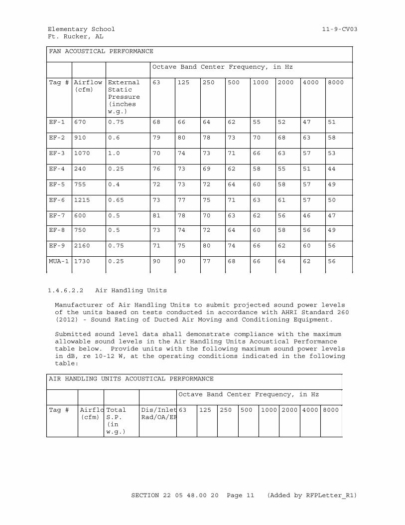
Elementary School 11-9-CV03Ft. Rucker, AL
FAN ACOUSTICAL PERFORMANCE
Octave Band Center Frequency, in Hz
Tag # Airflow (cfm)
External Static Pressure (inches w.g.)
63 125 250 500 1000 2000 4000 8000
EF-1 670 0.75 68 66 64 62 55 52 47 51
EF-2 910 0.6 79 80 78 73 70 68 63 58
EF-3 1070 1.0 70 74 73 71 66 63 57 53
EF-4 240 0.25 76 73 69 62 58 55 51 44
EF-5 755 0.4 72 73 72 64 60 58 57 49
EF-6 1215 0.65 73 77 75 71 63 61 57 50
EF-7 600 0.5 81 78 70 63 62 56 46 47
EF-8 750 0.5 73 74 72 64 60 58 56 49
EF-9 2160 0.75 71 75 80 74 66 62 60 56
MUA-1 1730 0.25 90 90 77 68 66 64 62 56
1.4.6.2.2 Air Handling Units
Manufacturer of Air Handling Units to submit projected sound power levels of the units based on tests conducted in accordance with AHRI Standard 260 (2012) - Sound Rating of Ducted Air Moving and Conditioning Equipment.
Submitted sound level data shall demonstrate compliance with the maximum allowable sound levels in the Air Handling Units Acoustical Performance table below. Provide units with the following maximum sound power levels in dB, re 10-12 W, at the operating conditions indicated in the following table:
AIR HANDLING UNITS ACOUSTICAL PERFORMANCE
Octave Band Center Frequency, in Hz
Tag # Airflo(cfm)
Total S.P. (in w.g.)
Dis/InletRad/OA/EF
63 125 250 500 1000 2000 4000 8000
SECTION 22 05 48.00 20 Page 11 (Added by RFPLetter_R1)
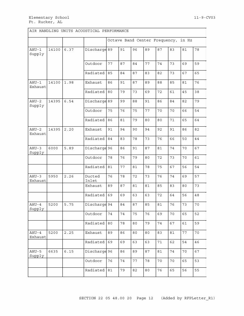
Elementary School 11-9-CV03Ft. Rucker, AL
AIR HANDLING UNITS ACOUSTICAL PERFORMANCE
Octave Band Center Frequency, in Hz
AHU-1Supply
14100 6.37 Discharge89 91 96 89 87 83 81 78
Outdoor 77 87 84 77 74 73 69 59
Radiated 85 84 87 83 82 73 67 65
AHU-1Exhaust
14100 1.98 Exhaust 86 91 87 89 88 85 81 76
Radiated 80 79 73 69 72 61 45 38
AHU-2Supply
14395 6.54 Discharge89 99 88 91 86 84 82 79
Outdoor 75 76 75 77 70 70 66 54
Radiated 86 81 79 80 80 71 65 64
AHU-2Exhaust
14395 2.20 Exhaust 91 94 90 94 92 91 86 82
Radiated 84 83 78 73 76 66 50 44
AHU-3Supply
6000 5.89 Discharge96 86 91 87 81 74 70 67
Outdoor 78 76 79 80 72 73 70 61
Radiated 81 77 81 78 75 67 56 54
AHU-3Exhaust
5950 2.26 Ducted Inlet
76 78 72 73 76 74 69 57
Exhaust 89 87 81 81 85 83 80 73
Radiated 69 69 63 63 72 64 56 48
AHU-4Supply
5200 5.75 Discharge94 84 87 85 81 76 73 70
Outdoor 74 74 75 76 69 70 65 52
Radiated 80 78 80 79 74 67 61 59
AHU-4 Exhaust
5200 2.25 Exhaust 89 86 80 80 83 81 77 70
Radiated 69 69 63 63 71 62 54 46
AHU-5Supply
6635 6.15 Discharge96 86 89 87 81 74 70 67
Outdoor 76 74 77 78 70 70 65 53
Radiated 81 79 82 80 76 65 56 55
SECTION 22 05 48.00 20 Page 12 (Added by RFPLetter_R1)
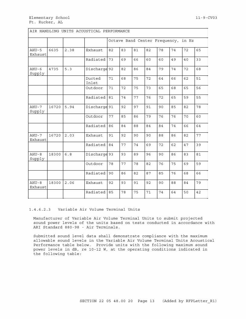
Elementary School 11-9-CV03Ft. Rucker, AL
AIR HANDLING UNITS ACOUSTICAL PERFORMANCE
Octave Band Center Frequency, in Hz
AHU-5Exhaust
6635 2.38 Exhaust 82 83 81 82 78 74 72 65
Radiated 73 69 66 60 60 49 40 33
AHU-6Supply
4735 5.3 Discharge92 82 86 84 79 74 72 68
Ducted Inlet
71 68 75 72 64 66 62 51
Outdoor 71 72 75 73 65 68 65 56
Radiated 81 74 77 76 72 65 59 55
AHU-7Supply
16720 5.94 Discharge91 92 97 91 90 85 82 78
Outdoor 77 85 86 79 76 76 70 60
Radiated 86 84 88 84 84 74 66 64
AHU-7Exhaust
16720 2.03 Exhaust 91 92 90 90 88 86 82 77
Radiated 84 77 74 69 72 62 47 39
AHU-8Supply
18300 6.8 Discharge93 93 89 96 90 86 83 81
Outdoor 78 77 78 82 76 75 69 59
Radiated 90 86 82 87 85 76 68 66
AHU-8Exhaust
18300 2.06 Exhaust 92 93 91 92 90 88 84 79
Radiated 85 78 75 71 74 64 50 42
1.4.6.2.3 Variable Air Volume Terminal Units
Manufacturer of Variable Air Volume Terminal Units to submit projected sound power levels of the units based on tests conducted in accordance with ARI Standard 880-98 - Air Terminals.
Submitted sound level data shall demonstrate compliance with the maximum allowable sound levels in the Variable Air Volume Terminal Units Acoustical Performance table below. Provide units with the following maximum sound power levels in dB, re 10-12 W, at the operating conditions indicated in the following table:
SECTION 22 05 48.00 20 Page 13 (Added by RFPLetter_R1)
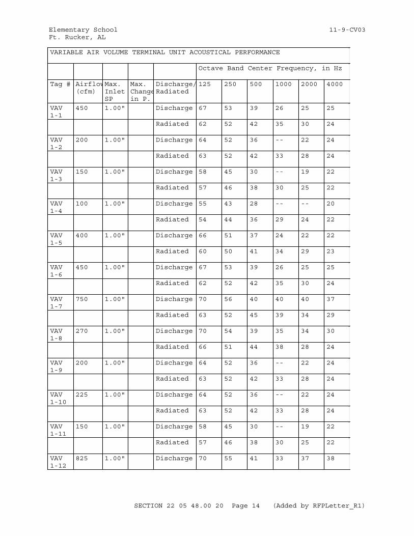
Elementary School 11-9-CV03Ft. Rucker, AL
VARIABLE AIR VOLUME TERMINAL UNIT ACOUSTICAL PERFORMANCE
Octave Band Center Frequency, in Hz
Tag # Airflow(cfm)
Max. Inlet SP
Max. Changein P.
Discharge/Radiated
125 250 500 1000 2000 4000
VAV 1-1
450 1.00" Discharge 67 53 39 26 25 25
Radiated 62 52 42 35 30 24
VAV 1-2
200 1.00" Discharge 64 52 36 -- 22 24
Radiated 63 52 42 33 28 24
VAV 1-3
150 1.00" Discharge 58 45 30 -- 19 22
Radiated 57 46 38 30 25 22
VAV 1-4
100 1.00" Discharge 55 43 28 -- -- 20
Radiated 54 44 36 29 24 22
VAV 1-5
400 1.00" Discharge 66 51 37 24 22 22
Radiated 60 50 41 34 29 23
VAV 1-6
450 1.00" Discharge 67 53 39 26 25 25
Radiated 62 52 42 35 30 24
VAV 1-7
750 1.00" Discharge 70 56 40 40 40 37
Radiated 63 52 45 39 34 29
VAV 1-8
270 1.00" Discharge 70 54 39 35 34 30
Radiated 66 51 44 38 28 24
VAV 1-9
200 1.00" Discharge 64 52 36 -- 22 24
Radiated 63 52 42 33 28 24
VAV 1-10
225 1.00" Discharge 64 52 36 -- 22 24
Radiated 63 52 42 33 28 24
VAV 1-11
150 1.00" Discharge 58 45 30 -- 19 22
Radiated 57 46 38 30 25 22
VAV 1-12
825 1.00" Discharge 70 55 41 33 37 38
SECTION 22 05 48.00 20 Page 14 (Added by RFPLetter_R1)

Elementary School 11-9-CV03Ft. Rucker, AL
VARIABLE AIR VOLUME TERMINAL UNIT ACOUSTICAL PERFORMANCE
Octave Band Center Frequency, in Hz
Radiated 59 51 44 40 35 31
VAV 1-13
1720 1.00" Discharge 70 56 47 44 49 49
Radiated 64 52 49 48 42 35
VAV 1-14
625 1.00" Discharge 69 55 41 34 33 34
Radiated 60 53 46 41 36 26
VAV 1-15
800 1.00" Discharge 70 56 40 40 40 37
Radiated 63 52 45 39 34 29
VAV 1-16
725 1.00" Discharge 70 56 40 40 40 37
Radiated 63 52 45 39 34 29
VAV 1-17
375 1.00" Discharge 66 51 37 24 22 22
Radiated 60 50 41 34 29 23
VAV 1-18
1325 1.00" Discharge 71 58 45 41 46 46
Radiated 65 53 46 43 40 36
VAV 1-19
750 1.00" Discharge 70 56 40 40 40 37
Radiated 63 52 45 39 34 29
VAV 1-20
650 1.00" Discharge 69 55 41 34 33 34
Radiated 60 53 46 41 36 26
VAV 1-21
650 1.00" Discharge 69 55 41 34 33 34
Radiated 60 53 46 41 36 26
VAV 1-22
650 1.00" Discharge 69 55 41 34 33 34
Radiated 60 53 46 41 36 26
VAV 1-23
670 1.00" Discharge 68 54 39 38 37 34
Radiated 61 50 43 37 32 28
VAV 1-24
400 1.00" Discharge 66 51 37 24 22 22
Radiated 60 50 41 34 29 23
SECTION 22 05 48.00 20 Page 15 (Added by RFPLetter_R1)

Elementary School 11-9-CV03Ft. Rucker, AL
VARIABLE AIR VOLUME TERMINAL UNIT ACOUSTICAL PERFORMANCE
Octave Band Center Frequency, in Hz
VAV 1-25
285 1.00" Discharge 70 54 39 35 34 30
Radiated 66 51 44 38 32 31
VAV 1-26
300 1.00" Discharge 70 54 39 35 34 30
Radiated 66 51 44 38 32 31
VAV 1-27
100 1.00" Discharge 55 43 28 -- -- 20
Radiated 54 44 36 29 24 22
VAV 2-1
650 1.00" Discharge 69 55 41 34 33 34
Radiated 60 53 46 41 36 26
VAV 2-2
650 1.00" Discharge 69 55 41 34 33 34
Radiated 60 53 46 41 36 26
VAV 2-3
600 1.00" Discharge 69 55 41 34 33 34
Radiated 60 53 46 41 36 26
VAV 2-4
600 1.00" Discharge 69 55 41 34 33 34
Radiated 60 53 46 41 36 26
VAV 2-5
650 1.00" Discharge 69 55 41 34 33 34
Radiated 60 53 46 41 36 26
VAV 2-6
1625 1.00" Discharge 70 56 47 44 49 49
Radiated 64 52 49 48 42 35
VAV 2-7
350 1.00" Discharge 70 54 39 35 34 30
Radiated 66 51 44 38 32 31
VAV 2-8
635 1.00" Discharge 69 55 41 34 33 34
Radiated 60 53 46 41 36 26
VAV 2-9
650 1.00" Discharge 69 55 41 34 33 34
Radiated 60 53 46 41 36 26
VAV 2-10
375 1.00" Discharge 66 51 37 24 22 22
SECTION 22 05 48.00 20 Page 16 (Added by RFPLetter_R1)
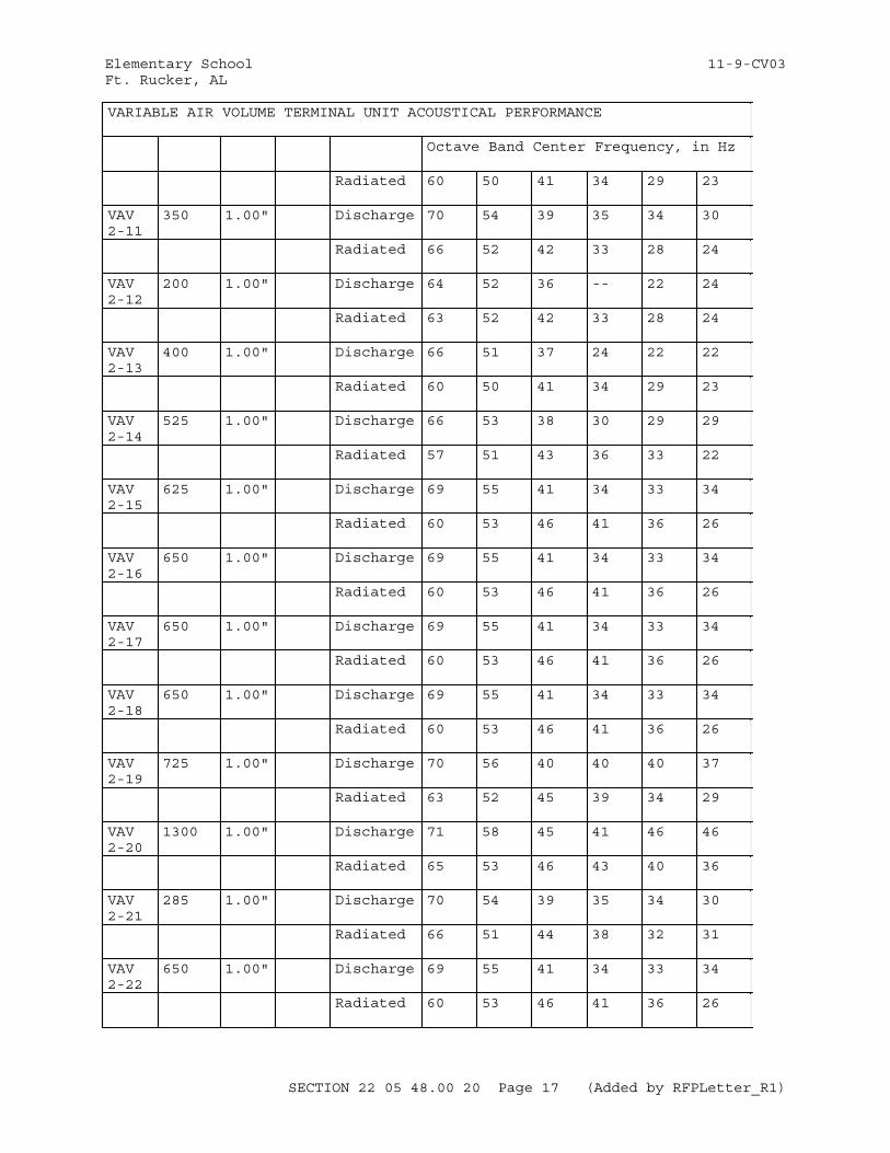
Elementary School 11-9-CV03Ft. Rucker, AL
VARIABLE AIR VOLUME TERMINAL UNIT ACOUSTICAL PERFORMANCE
Octave Band Center Frequency, in Hz
Radiated 60 50 41 34 29 23
VAV 2-11
350 1.00" Discharge 70 54 39 35 34 30
Radiated 66 52 42 33 28 24
VAV 2-12
200 1.00" Discharge 64 52 36 -- 22 24
Radiated 63 52 42 33 28 24
VAV 2-13
400 1.00" Discharge 66 51 37 24 22 22
Radiated 60 50 41 34 29 23
VAV 2-14
525 1.00" Discharge 66 53 38 30 29 29
Radiated 57 51 43 36 33 22
VAV 2-15
625 1.00" Discharge 69 55 41 34 33 34
Radiated 60 53 46 41 36 26
VAV 2-16
650 1.00" Discharge 69 55 41 34 33 34
Radiated 60 53 46 41 36 26
VAV 2-17
650 1.00" Discharge 69 55 41 34 33 34
Radiated 60 53 46 41 36 26
VAV 2-18
650 1.00" Discharge 69 55 41 34 33 34
Radiated 60 53 46 41 36 26
VAV 2-19
725 1.00" Discharge 70 56 40 40 40 37
Radiated 63 52 45 39 34 29
VAV 2-20
1300 1.00" Discharge 71 58 45 41 46 46
Radiated 65 53 46 43 40 36
VAV 2-21
285 1.00" Discharge 70 54 39 35 34 30
Radiated 66 51 44 38 32 31
VAV 2-22
650 1.00" Discharge 69 55 41 34 33 34
Radiated 60 53 46 41 36 26
SECTION 22 05 48.00 20 Page 17 (Added by RFPLetter_R1)
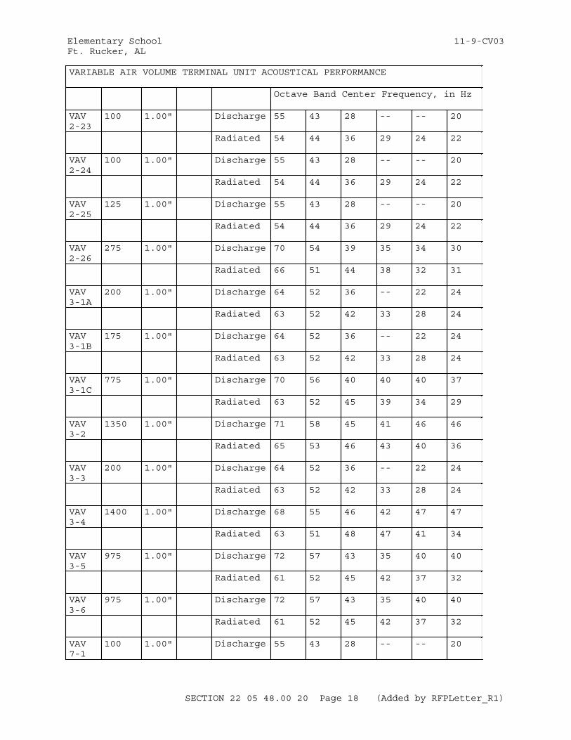
Elementary School 11-9-CV03Ft. Rucker, AL
VARIABLE AIR VOLUME TERMINAL UNIT ACOUSTICAL PERFORMANCE
Octave Band Center Frequency, in Hz
VAV 2-23
100 1.00" Discharge 55 43 28 -- -- 20
Radiated 54 44 36 29 24 22
VAV 2-24
100 1.00" Discharge 55 43 28 -- -- 20
Radiated 54 44 36 29 24 22
VAV 2-25
125 1.00" Discharge 55 43 28 -- -- 20
Radiated 54 44 36 29 24 22
VAV 2-26
275 1.00" Discharge 70 54 39 35 34 30
Radiated 66 51 44 38 32 31
VAV 3-1A
200 1.00" Discharge 64 52 36 -- 22 24
Radiated 63 52 42 33 28 24
VAV 3-1B
175 1.00" Discharge 64 52 36 -- 22 24
Radiated 63 52 42 33 28 24
VAV 3-1C
775 1.00" Discharge 70 56 40 40 40 37
Radiated 63 52 45 39 34 29
VAV 3-2
1350 1.00" Discharge 71 58 45 41 46 46
Radiated 65 53 46 43 40 36
VAV 3-3
200 1.00" Discharge 64 52 36 -- 22 24
Radiated 63 52 42 33 28 24
VAV 3-4
1400 1.00" Discharge 68 55 46 42 47 47
Radiated 63 51 48 47 41 34
VAV 3-5
975 1.00" Discharge 72 57 43 35 40 40
Radiated 61 52 45 42 37 32
VAV 3-6
975 1.00" Discharge 72 57 43 35 40 40
Radiated 61 52 45 42 37 32
VAV 7-1
100 1.00" Discharge 55 43 28 -- -- 20
SECTION 22 05 48.00 20 Page 18 (Added by RFPLetter_R1)

Elementary School 11-9-CV03Ft. Rucker, AL
VARIABLE AIR VOLUME TERMINAL UNIT ACOUSTICAL PERFORMANCE
Octave Band Center Frequency, in Hz
Radiated 54 44 36 29 24 22
VAV 7-2
750 1.00" Discharge 70 56 40 40 40 37
Radiated 63 52 45 39 34 29
VAV 7-3
775 1.00" Discharge 70 56 40 40 40 37
Radiated 63 52 45 39 34 29
VAV 7-4
250 1.00" Discharge 66 50 33 32 29 24
Radiated 60 45 38 31 26 25
VAV 7-5
1475 1.00" Discharge 68 55 46 42 47 47
Radiated 63 51 48 47 41 34
VAV 7-6
775 1.00" Discharge 70 56 40 40 40 37
Radiated 63 52 45 39 34 29
VAV 7-7
750 1.00" Discharge 70 56 40 40 40 37
Radiated 63 52 45 39 34 29
VAV 7-8
775 1.00" Discharge 70 56 40 40 40 37
Radiated 63 52 45 39 34 29
VAV 7-9
400 1.00" Discharge 66 51 37 24 22 22
Radiated 60 50 41 34 29 23
VAV 7-10
800 1.00" Discharge 70 56 40 40 40 37
Radiated 63 52 45 39 34 29
VAV 7-11
150 1.00" Discharge 58 45 30 -- 19 22
Radiated 57 46 38 30 25 22
VAV 7-12
235 1.00" Discharge 66 50 33 32 29 24
Radiated 60 45 38 31 26 25
VAV 7-13
785 1.00" Discharge 70 56 40 40 40 37
Radiated 63 52 45 39 34 29
SECTION 22 05 48.00 20 Page 19 (Added by RFPLetter_R1)
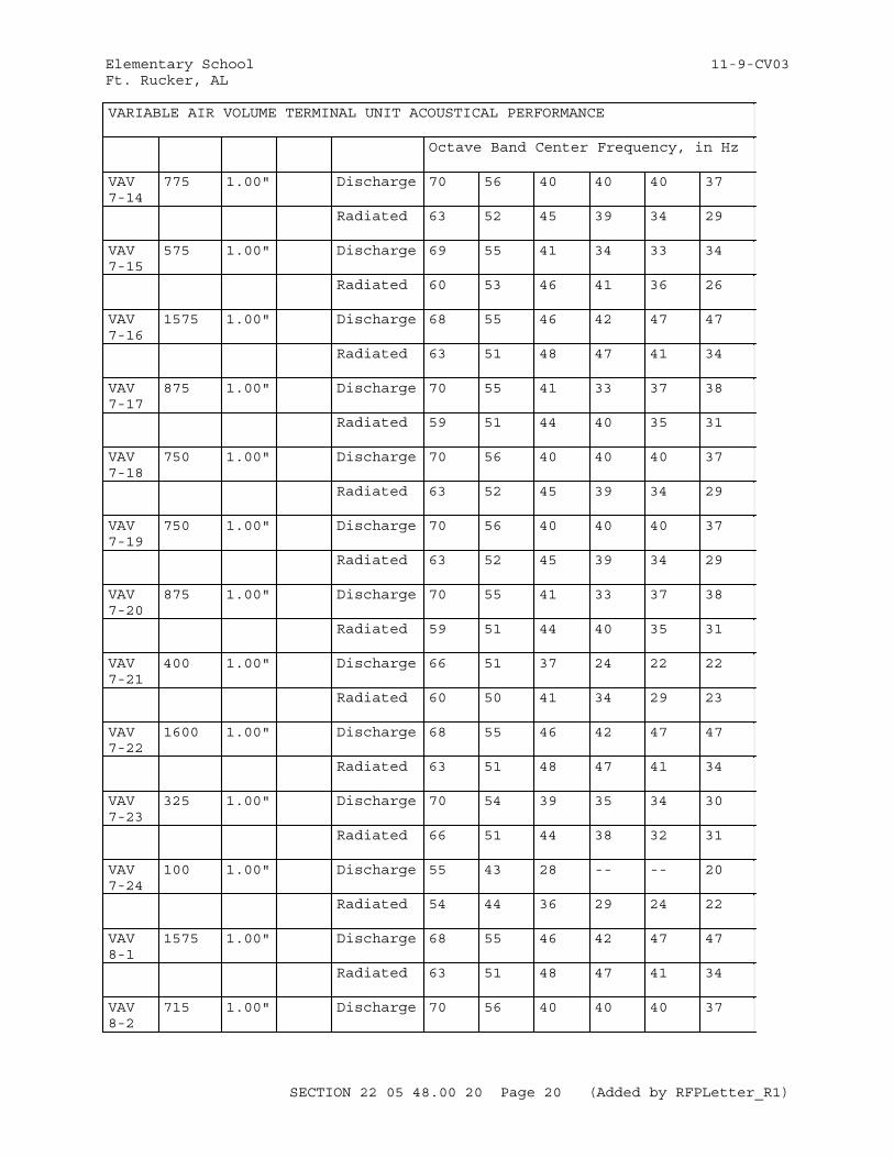
Elementary School 11-9-CV03Ft. Rucker, AL
VARIABLE AIR VOLUME TERMINAL UNIT ACOUSTICAL PERFORMANCE
Octave Band Center Frequency, in Hz
VAV 7-14
775 1.00" Discharge 70 56 40 40 40 37
Radiated 63 52 45 39 34 29
VAV 7-15
575 1.00" Discharge 69 55 41 34 33 34
Radiated 60 53 46 41 36 26
VAV 7-16
1575 1.00" Discharge 68 55 46 42 47 47
Radiated 63 51 48 47 41 34
VAV 7-17
875 1.00" Discharge 70 55 41 33 37 38
Radiated 59 51 44 40 35 31
VAV 7-18
750 1.00" Discharge 70 56 40 40 40 37
Radiated 63 52 45 39 34 29
VAV 7-19
750 1.00" Discharge 70 56 40 40 40 37
Radiated 63 52 45 39 34 29
VAV 7-20
875 1.00" Discharge 70 55 41 33 37 38
Radiated 59 51 44 40 35 31
VAV 7-21
400 1.00" Discharge 66 51 37 24 22 22
Radiated 60 50 41 34 29 23
VAV 7-22
1600 1.00" Discharge 68 55 46 42 47 47
Radiated 63 51 48 47 41 34
VAV 7-23
325 1.00" Discharge 70 54 39 35 34 30
Radiated 66 51 44 38 32 31
VAV 7-24
100 1.00" Discharge 55 43 28 -- -- 20
Radiated 54 44 36 29 24 22
VAV 8-1
1575 1.00" Discharge 68 55 46 42 47 47
Radiated 63 51 48 47 41 34
VAV 8-2
715 1.00" Discharge 70 56 40 40 40 37
SECTION 22 05 48.00 20 Page 20 (Added by RFPLetter_R1)
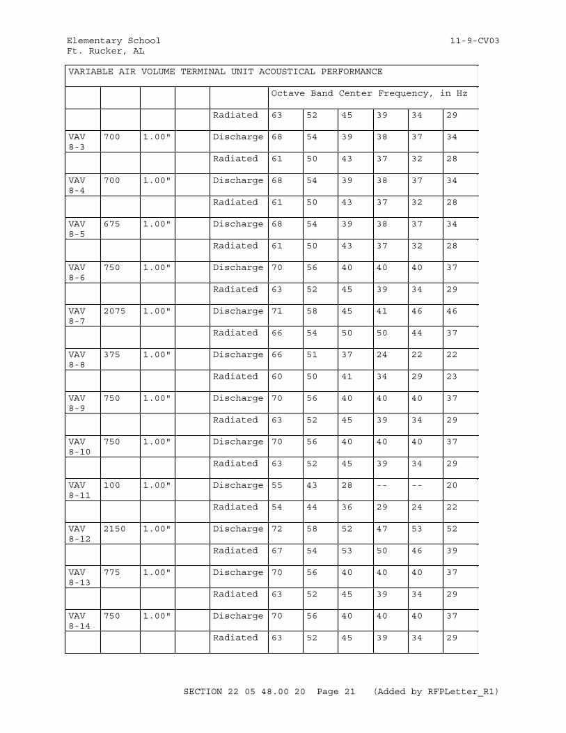
Elementary School 11-9-CV03Ft. Rucker, AL
VARIABLE AIR VOLUME TERMINAL UNIT ACOUSTICAL PERFORMANCE
Octave Band Center Frequency, in Hz
Radiated 63 52 45 39 34 29
VAV 8-3
700 1.00" Discharge 68 54 39 38 37 34
Radiated 61 50 43 37 32 28
VAV 8-4
700 1.00" Discharge 68 54 39 38 37 34
Radiated 61 50 43 37 32 28
VAV 8-5
675 1.00" Discharge 68 54 39 38 37 34
Radiated 61 50 43 37 32 28
VAV 8-6
750 1.00" Discharge 70 56 40 40 40 37
Radiated 63 52 45 39 34 29
VAV 8-7
2075 1.00" Discharge 71 58 45 41 46 46
Radiated 66 54 50 50 44 37
VAV 8-8
375 1.00" Discharge 66 51 37 24 22 22
Radiated 60 50 41 34 29 23
VAV 8-9
750 1.00" Discharge 70 56 40 40 40 37
Radiated 63 52 45 39 34 29
VAV 8-10
750 1.00" Discharge 70 56 40 40 40 37
Radiated 63 52 45 39 34 29
VAV 8-11
100 1.00" Discharge 55 43 28 -- -- 20
Radiated 54 44 36 29 24 22
VAV 8-12
2150 1.00" Discharge 72 58 52 47 53 52
Radiated 67 54 53 50 46 39
VAV 8-13
775 1.00" Discharge 70 56 40 40 40 37
Radiated 63 52 45 39 34 29
VAV 8-14
750 1.00" Discharge 70 56 40 40 40 37
Radiated 63 52 45 39 34 29
SECTION 22 05 48.00 20 Page 21 (Added by RFPLetter_R1)
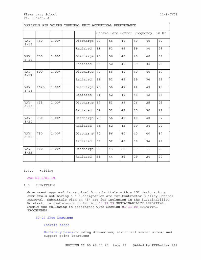
Elementary School 11-9-CV03Ft. Rucker, AL
VARIABLE AIR VOLUME TERMINAL UNIT ACOUSTICAL PERFORMANCE
Octave Band Center Frequency, in Hz
VAV 8-15
750 1.00" Discharge 70 56 40 40 40 37
Radiated 63 52 45 39 34 29
VAV 8-16
750 1.00" Discharge 70 56 40 40 40 37
Radiated 63 52 45 39 34 29
VAV 8-17
800 1.00" Discharge 70 56 40 40 40 37
Radiated 63 52 45 39 34 29
VAV 8-18
1625 1.00" Discharge 70 56 47 44 49 49
Radiated 64 52 49 48 42 35
VAV 8-19
435 1.00" Discharge 67 53 39 26 25 25
Radiated 62 52 42 35 30 24
VAV 8-20
750 1.00" Discharge 70 56 40 40 40 37
Radiated 63 52 45 39 34 29
VAV 8-21
750 1.00" Discharge 70 56 40 40 40 37
Radiated 63 52 45 39 34 29
VAV 8-22
100 1.00" Discharge 55 43 28 -- -- 20
Radiated 54 44 36 29 24 22
1.4.7 Welding
AWS D1.1/D1.1M.
1.5 SUBMITTALS
Government approval is required for submittals with a "G" designation; submittals not having a "G" designation are for Contractor Quality Control approval. Submittals with an "S" are for inclusion in the Sustainability Notebook, in conformance to Section 01 33 29 SUSTAINABILITY REPORTING. Submit the following in accordance with Section 01 33 00 SUBMITTAL PROCEDURES:
SD-02 Shop Drawings
Inertia bases
Machinery basesincluding dimensions, structural member sizes, and support point locations
SECTION 22 05 48.00 20 Page 22 (Added by RFPLetter_R1)
Elementary School 11-9-CV03Ft. Rucker, AL
SD-03 Product Data
Isolators
CompleteFlexible connectors details
Flexible duct connectors
Pipe guides
Vertical stops
Thrust restraints
Inertia bases
Machinery bases
Machinery foundations and subbases
Machinery manufacturer's sound data
SD-05 Design Data
Submit the following data, in a schedule, for approval, clearly identifying each item of equipment supported and the isolator to be installed at each point of support.
1. Horsepower of each motor, and rpm of both driven and driver, in each supported unit.2. Scheduled deflection of each isolator. Identification of each isolator selected by model number and spring color. Catalog cuts to reference isolator "Type" as called out in the specification.3. Isolator efficiency and deflection of each isolator under the calculated load, actual loaded and unloaded measurable spring height. All isolators shall operate in the linear portion of their load versus deflection curve. Load versus deflection curves shall be furnished by the manufacturer and shall be linear over a deflection range 50% above the design deflection.4. The loading at which each isolator would be fully compressed to solid.5. The isolated equipment manufacturer's instructions for the installation of vibration isolation devices.
Inertia bases
Machinery bases
Each item of machinery
SECTION 22 05 48.00 20 Page 23 (Added by RFPLetter_R1)
Elementary School 11-9-CV03Ft. Rucker, AL
Each item of machinery over 300 pounds
Submit design calculations for inertia bases, machinery bases, platforms, rails, and saddles, either by the machinery manufacturer for the recommended machinery mounting or by the vibration-isolation equipment manufacturer.
SD-06 Test Reports
Equipment vibration tests
Equipment sound level tests
Protected spring isolators
Submit seismic protection rating in three principal axes certified by an independent laboratory or analyzed by an independent licensed structural engineer.
SD-08 Manufacturer's Instructions
Vibration and noise isolation components
1.6 QUALITY ASSURANCE
1.6.1 Vibration Isolator Procurement
For each piece of machinery to be isolated from vibration, supply the inertia base, machinery base, platform, rails, saddles, vibration isolators, seismic snubbers, and other associated materials and equipment as a coordinated package by a single manufacturer or by the machinery manufacturer. Select isolators that provide uniform deflection even when machinery weight is not evenly distributed. This requirement does not include the flexible connectors or the hangers for the associated piping and ductwork.
1.6.2 Unitized Machinery Assemblies
Mounting of unitized assemblies directly on vibration isolation springs is acceptable if machinery manufacturer certifies that the end supports of the assemblies have been designed for such installation.
1.6.3 Manufacturer Responsibilities
Determine vibration isolation sizes and locations.Provide piping and equipment isolation systems as scheduled or specified.Guarantee specified isolation system deflection.Provide installation instructions and drawings.
1.7 STORAGE AND PROTECTION
Storage: Store vibration isolation equipment indoors in the manufacturer's original shipping containers. Preclude the entrance of construction dirt and debris. Vibration isolation equipment and bases, which show signs of
SECTION 22 05 48.00 20 Page 24 (Added by RFPLetter_R1)
Elementary School 11-9-CV03Ft. Rucker, AL
rust, cement or concrete fouling, dirt, and construction debris shall be disassembled and cleaned, approved or removed from the project site and replaced with new.
PART 2 PRODUCTS
All vibration isolation products described in this section shall be the product of a single manufacturer, with the exception of flexible duct connectors. Subject to compliance with requirements specified herein, provide vibration isolation materials, bases and systems by one of the following or approved equal:
1. Kinetics Noise Control, Incorporated, Dublin OH2. Mason Industries, Incorporated, Hauppauge, NY3. Vibration Mountings & Controls, Bloomindale, NJ4. Ventfabrics, Inc., Chicago, IL5. DuroDyne, Farmingdale, NY
Where listed, references are to Kinetics Noise Control, Inc. (K.N.C.), Mason Industries, Inc. (M.I.I), Vibration Mountings & Controls (V.M.C.), Ventfabrics, Inc. (VI), and DuroDyne (DD).
2.1 CORROSION PROTECTION FOR STEEL PARTS
ASTM A123/A123M hot-dipped galvanized, or equivalent manufacturer standard coatings. Where steel parts are exposed to the weather, provide galvanized coating of at least 2 ounces of zinc per square foot of surface. Coat springs with neoprene.
2.2 NEOPRENE
ASTM D471 and ASTM D2240, Grade Durometer 40, 50, or 60, and oil resistant.
2.3 FLOOR-MOUNTED ISOLATORS
2.3.1 Neoprene Isolation Pads
Provide pads at least 1/4 inch thick with cross-ribbed or waffle design. For concentrated loads, provide steel bearing plates bonded or cold cemented to the pads.
2.3.2 Neoprene Isolators
Provide molded neoprene isolators having steel base plates with mounting holes and, at the top, steel mounting plates with mounting holes or threaded inserts. Provide elements of type and size coded with molded letters or color-coded for capacity identification. Embed metal parts completely in neoprene.
2.4 SPRING ISOLATORS AND PROTECTED SPRING ISOLATORS
Provide spring isolators or protected spring isolators that are adjustable and laterally stable with free-standing springs of horizontal stiffness at minimum 80 percent of the vertical (axial) stiffness. For machine-attached and floor-attached restraining elements, separate from metal-to-metal contact by neoprene cushions 1/8 inch thick minimum. Provide neoprene acoustic friction pads at least 1/4 inch thick.
SECTION 22 05 48.00 20 Page 25 (Added by RFPLetter_R1)
Elementary School 11-9-CV03Ft. Rucker, AL
2.4.1 Springs
Provide springs with base and compression plates, to keep spring ends parallel during and after deflection to operating height. Provide outside coil diameters at least 0.8 of the operating height. At operating height, springs shall have additional travel to complete (solid) compression equal to at least 50 percent of the operating deflection.
2.4.2 Mounting and Adjustment
Provide base and compression plates with mounting holes or threaded fittings. Bolt leveling adjustment bolts to machinery or base.
2.5 SUSPENSION ISOLATORS
Provide hangers with suspension isolators encased in open steel brackets. Isolate hanger rods from isolator steel brackets with neoprene-lined opening.
2.5.1 Suspension Neoprene Isolators
Provide double-deflection elements with minimum 3/8 inch deflection.
2.5.2 Suspension Spring Isolators
Provide hangers with springs and molded neoprene elements in series. Provide isolators with adjustable spring-preloading devices where required to maintain constant pipe elevations during installation and when pipe operational loads are transferred to the springs.
2.6 MACHINERY BASES
ASTM A36/A36M and AISC 360.
2.7 INERTIA BASES
ASTM A36/A36M steel, ASTM C94/C94M ( 2,500 psi ) concrete.
2.8 FLEXIBLE CONNECTORS FOR PIPING
Straight or elbow flexible connectors rated for temperatures, pressures, and fluids to be conveyed. Provide flexible connectors with the strength 4 times operating pressure at highest system operating temperature. Provide elbow flexible connectors with a permanently set angle.
2.8.1 Elastomeric Flexible Connectors
Fabricated of multiple plies of tire cord fabric and elastomeric materials with integral reinforced elastomeric flanges with galvanized malleable iron back up rings.
2.8.2 Metal Flexible Connectors
Fabricated of Grade E phosphor bronze, monel or corrugated stainless steel tube covered with comparable bronze or stainless steel braid restraining and pressure cover.
SECTION 22 05 48.00 20 Page 26 (Added by RFPLetter_R1)
Elementary School 11-9-CV03Ft. Rucker, AL
2.9 FLEXIBLE DUCT CONNECTORS
Provide flexible duct connectors fabricated in accordance with SMACNA 1403 .
2.10 PIPE GUIDES
Factory-fabricated. Weld steel bar guides to the pipe at a maximum radial spacing of 60 degrees. The outside diameter around the guide bars shall be smaller than the inside diameter of the guide sleeve in accordance with standard field construction practice. For pipe temperatures below 60 degrees F, provide metal sleeve, minimum one pound per cubic foot density insulation.
2.11 THRUST RESTRAINTS
Adjustable spring thrust restraints, able to resist the thrust force with at least 25 percent unused capacity. The operating spring deflection shall be not less than 50 percent of the static deflection of the isolation supporting the machinery.
PART 3 EXECUTION
3.1 INSPECTION
Examine all work prepared by others to receive work of this Section and report problems or defects affecting installation to the General Contractor/Construction Manager for correction.
Inspect all accompaniments of the Work to insure no damage has occurred during shipment or storage.
3.2 INSTALLATION
3.2.1 Vibration and Noise Isolation Components
Install vibration-and-noise isolation materials and equipment as indicated and in accordance with machinery manufacturer's instructions.
3.2.1.1 Floor Mounted Equipment
Housekeeping pads of thickness indicated on drawings or in specifications:
A. Over entire floor area of supported equipment.B. Supporting all vibration isolation devices and bases.C. Keyed with hairpins as required to be integral with the structural slab.D. Thickness as indicated on the drawings.
Concrete per specification describing requirements.
3.2.1.2 General Equipment Isolation
Install all vibration isolators in strict accordance with the manufacturer's written installation instructions and all certified submittal data.
Electrical conduit connections to vibration isolated equipment shall be flexible conduit installed in a 360 loop to allow free motion of vibration isolated equipment.
SECTION 22 05 48.00 20 Page 27 (Added by RFPLetter_R1)
Elementary School 11-9-CV03Ft. Rucker, AL
Support rails between the equipment and vibration isolators should not be used. If supplementary steel is required between the isolators and the isolated equipment per the isolated equipment manufacturer's installation requirements for mounting equipment on vibration isolation devices, use approved equipment bases with integral vibration isolation mounts so that equipment rests directly on the isolation system or provide shop drawings showing supplementary steel per the isolated equipment manufacturer's requirements coordinated with the vibration isolators, per the isolator manufacturer's recommendations, for approval.
Verify all installed vibration isolators and mounting systems permit equipment motion in all directions.
Adjust or provide additional resilient restraints to limit startup equipment lateral motion to 1/4-inch.
Prior to startup, clean out all foreign matter between bases and equipment. Verify that there are no vibration isolation short circuits in the base or vibration isolators.
Position vibration isolation hangers:
A. Close to the building structure.B. Between building structure and supplementary steel if required.C. Not in contact with sound critical or sound rated partitions or slabs.
Suspend vibration isolation hangers from rigid and massive support points.
Adjust as required all vibration isolation hangers to eliminate all contact of the isolated rod with the hanger rod box retainer or short circuiting of the spring.
Size supplementary steel for a maximum deflection of 0.08 inches under the incremental load of the equipment when supporting vibration isolation hangers and equipment.
No rigid connections between rotating or vibrating equipment and building structure shall be made that degrades the vibration isolation system herein specified.
Coordinate work with other trades to avoid rigid contact with the "building". Other trades following the installation of vibration isolation devices, such as plastering, drywall, electrical or sheet metal, shall avoid any contact with the vibration isolation devices and vibration isolated equipment.
Bring to the Architect's attention immediately, prior to installation, any conflicts with other trades which will result in unavoidable rigid contact with equipment or piping as described herein, due to inadequate space or other unforeseen conditions. Corrective work necessitated by conflicts after installation shall be at the contractor's expense.
Correct, at no additional cost, all installations which are deemed defective in workmanship or material as a result of project completion inspection or subsequent inspections due to owner complaints within a period of one year following acceptance.
SECTION 22 05 48.00 20 Page 28 (Added by RFPLetter_R1)
Elementary School 11-9-CV03Ft. Rucker, AL
3.2.1.3 Piping and Ductwork Isolation
Isolate all hydronic piping greater than 2" in diameter in mechanical rooms and outside of mechanical rooms within 30 feet of the mechanical room enclosure with Type "SDDNH" isolators with a minimum static deflection under load of 1" for suspended pipes and with Type "FSM" isolators with a minimum static deflection under load of 1" for floor mounted pipes. Use factory pre-loading for the first four vibration isolation hangers from the equipment to which the piping is attached.
Isolate all ductwork with a cross sectional area of 2 ft2 or greater in mechanical equipment rooms and outside of mechanical equipment rooms within 30 feet of the mechanical equipment room enclosure with Type "SH" isolators with a minimum static deflection under load of 1" for suspended ducts and Type "FSM" isolators with a minimum static deflection under load of 1" for floor mounted ducts.
3.2.2 Suspension Vibration Isolators
Provide suspension isolation hangers for piping, suspended equipment, and suspended equipment platforms in mechanical equipment rooms, as indicated and as specified. For operating load static deflections of 1/4 inch or less, provide neoprene pads or single deflection neoprene isolators. For operating load static deflections over 5/16 to 3/8 inch, provide double-deflection neoprene element isolators. For operating load static deflections over 3/8 inch, provide isolators with spring and neoprene elements in series.
3.2.3 Vertical Stops
For machinery affected by wind pressure or having an operational weight different from installed weight, provide resilient vertical limit stops which prevent spring extension when weight is removed. Provide vertical stops for machinery containing liquid, such as water chillers, evaporative coolers, boilers, and cooling towers. Spring isolated or protected spring isolated machinery must rock and move freely within limits of stops or seismic restraint devices.
3.2.4 Thrust Restraints
Where required, provide pairs of thrust restraints, symmetrically installed on both sides of the steady state line of thrust.
3.2.5 Flexible Pipe and Duct Connectors
Install flexible connectors in accordance with the manufacturer's instructions. When liquid pulsation dampening is required, flexible connectors with spherical configuration may be used. Provide restraints for pipe connectors at pumps to prevent connector failure upon pump startup.
3.2.6 Seismic Snubbers
Provide snubbers as close as possible to each vibration isolator as indicated. After installing and leveling of the machinery, adjust snubbers in accordance with the snubber manufacturer's instructions.
3.2.7 Machinery
Provide vibration isolators, flexible connectors and seismic snubbers in
SECTION 22 05 48.00 20 Page 29 (Added by RFPLetter_R1)
Elementary School 11-9-CV03Ft. Rucker, AL
accordance with manufacturer's recommendations. Machinery with spring isolators or protected spring isolators shall rock or move freely within limits of stops or seismic snubber restraints.
3.2.7.1 Stability
Isolators shall be stable during starting and stopping of machinery without traverse and eccentric movement of machinery that would damage or adversely affect the machinery or attachments.
3.2.7.2 Lateral Motion
The installed vibration isolation system for each piece of floor or ceiling mounted machinery shall have a maximum lateral motion under machinery start up and shut down conditions of not more than 1/4 inch. Restrain motions in excess by approved spring mountings.
3.2.7.3 Unbalanced Machinery
Provide foundation suspension systems specifically designed to resist horizontal forces for machinery with large unbalanced horizontal forces. Vibration isolator systems shall conform to the machinery manufacturer's recommendations.
3.2.7.4 Nonrotating Machinery
Mount nonrotating machinery in systems which includes rotating or vibrating machinery on isolators having the same deflection as the hangers and supports for the pipe connected to.
3.2.8 Piping
Provide vibration isolation for piping . The isolator deflections shall be equal to or greater than the static deflection of the vibration isolators provided for the connected machinery as follows:
3.2.8.1 Piping Connected to Vibration Isolated Machinery
For a distance of 50 feet or 50 pipe diameters, whichever is greater.
3.2.8.2 Steam Pressure Reducing Valves
Connected piping for a distance of 50 feet or 50 pipe diameters, whichever is greater.
3.2.8.3 Condenser Water
For the full length of the piping.
3.2.8.4 Chilled, Hot, and Dual Temperature Piping
For risers from pumps and for the first 20 feet of the branch connection of the main supply and return piping at each floor.
3.2.9 Water and Steam Distribution Piping Application
Resiliently support piping with combination spring and neoprene isolation hangers. Provide spring elements with 5/8 inch static deflection; install the hanger with spacing so that the first harmonic natural frequency is not
SECTION 22 05 48.00 20 Page 30 (Added by RFPLetter_R1)
Elementary School 11-9-CV03Ft. Rucker, AL
less than 360 Hz. Provide double-deflection neoprene elements. For the first two isolation hangers from the rotating equipment of 3 1/2 inch and smaller piping systems, ensure a deflection equal to the equipment-isolation static deflection. For the first four piping isolation hanger supports from rotating equipment of 4 inch and larger piping systems, use resilient hanger-rod isolators at a fixed elevation regardless of load changes. Incorporate an adjustable preloading device to transfer the load to the spring element within the hanger mounting after the piping system has been filled with water.
3.2.10 Pipe Hanger and Support Installation
3.2.10.1 Pipe Hangers
Provide eye-bolts or swivel joints for pipe hangers to permit pipe thermal or mechanical movement without angular misalignment of hanger vibration isolator.
3.2.10.2 High Temperatures
Where neoprene elements of vibration isolator may be subjected to high pipe temperatures, above 160 degrees F, provide metal heat shields or thermal isolators.
3.2.10.3 Valves
Provide vibration isolation hangers and supports at modulating, pressure reducing, or control valves which will induce fluid pulsations. When required or indicated, isolate valves with flexible connectors.
3.2.10.4 Machinery Without Flexible Connections
When piping is not connected to vibrating machinery with flexible connectors, provide the first four hangers with isolation elements designed for deflections equal to equipment vibration isolator deflections (including static, operating, and start-up).
3.2.10.5 Twelve Inch and Larger Pipe
Suspend 12 inch and larger pipe vibration hangers from resilient hanger rod isolators. Resilient hanger rod isolators shall be capable of supporting pipe during installation at a fixed elevation regardless of load changes. Provide an adjustable preloading device to transfer the load to isolation element after operational load is applied. Provide 12 inch and larger pipe supports with unrestrained stable springs for one inch deflection and with built-in leveling device and resilient vertical limit stops to prevent spring elongation when partial load is removed. Provide isolators capable of providing rigid anchoring during erection of piping so that it can be erected at a fixed elevation.
3.2.10.6 Pipe Risers
Provide pipe riser supports with bearing plates and two layers of 1/4 inch thick ribbed or waffled neoprene pad loaded to not more than 50 psi. Separate isolation pads with 1/4 inch steel plate. Weld pipe riser clamps at anchor points to the pipe and to pairs of vertical acoustical pipe anchor mountings which shall be rigidly fastened to the steel framing.
SECTION 22 05 48.00 20 Page 31 (Added by RFPLetter_R1)
Elementary School 11-9-CV03Ft. Rucker, AL
3.2.10.7 Supports at Base of Pipe Risers
Piping isolation supports at the base of risers shall be two layers of 1/2 inch thick heavy-duty neoprene pad separated by 1/4 inch thick steel plate. Use bearing plates sized to provide a pad loading of not more than 500 psi. Weld the stanchion between the pipe and isolation support to the pipe and weld or bolt to the isolation support. Bolt isolation support to the floor slab with resilient sleeves and washers. Where supplementary steel is required to support piping, provide a maximum deflection of 0.08 inches at the mid-span of this steel under the load. Rigidly support piping from the supplementary steel with the supplementary steel isolated from the building structure with isolators.
3.2.10.8 Pipe Anchors
Attach each end of the pipe anchor to an omni-directional pipe isolator which in turn shall be rigidly fastened to the steel framing or structural concrete. Provide a telescoping pipe isolator of two sizes of steel tubing separated by a minimum 1/2 inch thick pad of heavy-duty neoprene or heavy-duty neoprene and canvas. Provide vertical restraints by similar material to prevent vertical travel in either direction. The load on the isolation material shall not exceed 500 psi.
3.2.11 Equipment Room Sound Isolation
Do not allow direct contact between pipe or ducts and walls, floor slabs, roofs, ceilings or partitions of equipment rooms.
3.2.11.1 Pipe Penetrations
Provide galvanized Schedule 40 pipe sleeves and tightly pack annular space between sleeves and pipe with insulation having a flame spread rating not more than 25 and a smoke developed rating not more than 50 when tested in accordance with ASTM E84, maximum effective temperature 1000 degrees F, bulk density 6 pounds/cu. ft. minimum. Provide uninsulated pipe with a one inch thick mineral fiber sleeve the full length of the penetration and seal each end with an interior or exterior and weather resistant non-hardening compound. Provide sealant and mineral-fiber sleeve of a flame spread rating not more than 25 and a smoke developed rating not more than 50 when tested in accordance with ASTM E84.
3.2.11.2 Duct Penetrations
Pack openings around ducts with mineral fiber insulation the full length of the penetration having a flame spread rating not more than 25 and a smoke developed rating not more than 50 when tested in accordance with ASTM E84. At each end of duct opening provide sealing collars and seal with an interior or exterior and weather resistant non-hardening compound.
3.2.11.3 Ducts Passing Through Equipment Rooms
Provide with sound insulation equal to the sound attenuation value of the wall, floor, or ceiling penetrated.
3.2.12 Machinery Foundations and Subbases
Provide cast in place anchor bolts as recommended by the machinery manufacturer.
SECTION 22 05 48.00 20 Page 32 (Added by RFPLetter_R1)
Elementary School 11-9-CV03Ft. Rucker, AL
3.2.12.1 Machinery Subbases
Provide concrete subbases at least 4 inches high for floor mounted equipment except elevators. Rest subbases on structural floor and reinforce with steel rods interconnected with floor reinforcing bars by tie bars hooked at both ends. Provide at least 2 inch clearance between subbases and inertia bases, steel bases, and steel saddles with machinery in operation.
3.2.12.2 Common Machinery Foundations
Mount electrical motors on the same foundations as driven machinery. Support piping connections, strainers, valves, and risers on the same foundation as the pumps.
3.2.12.3 Foundation and Subbase Concrete
Cast concrete foundations and subbases of ASTM C94/C94M 2500 psi concrete reinforced with steel bars as indicated or recommended by machinery manufacturer.
3.2.12.4 Anchor Bolts and Grout
Secure machinery to foundations and inertia bases with anchor bolts. Grout equipment with baseplates, the full area under baseplates with premixed non-shrinking grout. After grout has set, remove wedges, shims, and jack bolts and fill spaces with grout.
3.2.13 Inertia Bases
Install inertia bases in accordance with the recommendations of the machinery manufacturer or inertia base manufacturer, as applicable.
3.2.14 Seismic Restraints for Piping and Ductwork
Provide seismic restraints in accordance with SMACNA 1981.
3.2.15 Suspended Machinery Platforms
Provide with vibration-isolation hangers.
3.2.16 Electrical Connections
Provide flexible conduit or multiple conductor cable connections for machinery with sufficient extra length to permit 2 inch minimum displacement in any direction without damage.
3.2.17 Systems Not To Be Vibration Isolated
Do not provide vibration isolation for electrical raceways and conduits or for fire protection, storm, sanitary, and domestic water piping systems which do not include pumps or other vibrating, rotating, or pulsating equipment including control and pressure reducing valves.
3.3 FIELD QUALITY CONTROL
Provide equipment and apparatus required for performing inspections and tests. Notify Contracting Officer 14 days prior to machinery sound testing. Rebalance, adjust, or replace machinery with noise or vibration
SECTION 22 05 48.00 20 Page 33 (Added by RFPLetter_R1)
Elementary School 11-9-CV03Ft. Rucker, AL
levels in excess of those given in the machinery specifications, or machinery manufacturer's data.
3.3.1 Field Inspections
Prior to initial operation, inspect the vibration isolators and seismic snubbers for conformance to drawings, specifications, and manufacturer's data and instructions. Check for vibration and noise transmission through connections, piping, ductwork, foundations, and walls. Check connector alignment before and after filling of system and during operation. Correct misalignment without damage to connector and in accordance with manufacturer's recommendations.
3.3.2 Spring Isolator Inspection
After installation of spring isolators or protected spring isolators, and seismic restraint devices, the machinery shall rock freely on its spring isolators within limits of stops or seismic restraint devices. Eliminate or correct interferences.
3.3.3 Tests
Adjust, repair, or replace isolators as required to reduce vibration and noise transmissions to specified levels.
3.3.3.1 Equipment Vibration Tests
Perform vibration tests to determine conformance with vibration isolation schedule specified specified .
3.3.3.2 Equipment Sound Level Tests
Measure continuous or intermittent steady state noise with a sound level meter set for low response. Measure impact or impulse noise as dB peak sound pressure level (20 uPa) with an impact noise analyzer. Measure work distance from person to machinery noise center. Perform sound level tests to determine conformance with sound level schedule specified .
a. Interior Machinery Sound
In accordance with AHRI 575, measure the sound data for air conditioning and refrigeration machinery, such as fans, boilers, valves, engines, turbines, or transformers. Measure the sound pressure levels around mechanical and electrical machinery located in equipment spaces, 3 feet horizontally from the edge closest to the acoustical center of the machinery at points 3 feet and 5.5 feet above floor. Take measurements at the center of each side of the machinery. Locate the microphone at least 3 feet from the observer and measuring instruments. Observer shall not be between the machinery and the measuring instrument.
b. Exterior Machinery Sound
Measure sound data in accordance with ANSI/AHRI 370 for machinery radiating noise outside the building in such applications as grade installations,
SECTION 22 05 48.00 20 Page 34 (Added by RFPLetter_R1)
Elementary School 11-9-CV03Ft. Rucker, AL
area-ways, wall and roof installations for cooling towers, refrigerant condensers, engine driven generator sets, fans, air conditioning machinery, heat pumps, evaporative coolers, exhaust silencers, and air intakes.
3.4 ADJUST AND CLEAN
Check and adjust all isolators to insure there is no short circuiting such as:
A. Hanger rods touching boxes.B. Hold-down bolts not released.C. Bolts touching springs.D. Springs and/or neoprene overloaded.E. Bottom neoprene pads short circuited by welding bottom plate to structure.F. Isolation device touching adjacent structures.
3.5 FINAL INSPECTION
On completion of the installation of all vibration isolation devices herein specified, the local representative of the isolation materials manufacturer shall inspect the completed systems and report, in writing, any installation error, improperly selected isolation devices or other faults in the system that could affect the performance of the system. Contractor shall submit a report to the Architect, including the manufacturer's representative's final report, indicating all isolation reported as properly installed or requiring correction and include a report by the Contractor on steps taken to properly complete the isolation work.
The Acoustical Consultant will subsequently observe the systems for conformance to specifications. Contractor shall replace or repair, at his expense, any isolation devices that deviate from the specifications, approved shop drawings, and manufacturer's recommendations as a result of this inspection.
3.5.1 Contractor Closeout
At the completion of the installation, submit the following documents. submission of these documents shall be complete before final acceptance of the vibration isolation systems is given. Assistance from the vibration isolation equipment manufacturer may be required.
A complete tabulation showing the actual static deflection measured at the project and the specified minimum static deflection for each vibration isolator.
On completion of the installation of all vibration isolation devices herein specified, the local representative of the isolation materials manufacture shall inspect the completed systems and report, in writing, any installation error, improperly selected isolation devices or other faults in the system that could affect the performance of the system. Contractor shall submit a report to the Architect, including the manufacturer's representative's final report, indicating all isolation reported as properly installed or requiring correction and include a report by the Contractor on steps taken to properly complete the isolation work.
-- End of Section --
SECTION 22 05 48.00 20 Page 35 (Added by RFPLetter_R1)
Elementary School 11-9-CV03Ft. Rucker, AL
SECTION TABLE OF CONTENTS
DIVISION 23 - HEATING, VENTILATING, AND AIR CONDITIONING (HVAC)
SECTION 23 00 00
AIR SUPPLY, DISTRIBUTION, VENTILATION, AND EXHAUST SYSTEMS
08/10
PART 1 GENERAL
1.1 REFERENCES 1.2 SYSTEM DESCRIPTION 1.2.1 Mechanical Equipment Identification 1.2.1.1 Charts 1.2.1.2 Diagrams 1.2.2 Service Labeling 1.2.3 Color Coding 1.3 SUBMITTALS 1.4 QUALITY ASSURANCE 1.4.1 Prevention of Corrosion 1.4.2 Asbestos Prohibition 1.4.3 Ozone Depleting Substances Used as Refrigerants 1.4.4 Use of Ozone Depleting Substances, Other than Refrigerants 1.4.5 Detail Drawings 1.4.6 Test Procedures 1.4.7 Deleted 1.5 DELIVERY, STORAGE, AND HANDLING
PART 2 PRODUCTS
2.1 STANDARD PRODUCTS 2.2 STANDARD PRODUCTS 2.3 IDENTIFICATION PLATES 2.4 EQUIPMENT GUARDS AND ACCESS 2.5 ELECTRICAL WORK 2.6 ANCHOR BOLTS 2.7 SEISMIC ANCHORAGE 2.8 PAINTING 2.9 INDOOR AIR QUALITY 2.10 DUCT SYSTEMS 2.10.1 Metal Ductwork 2.10.1.1 Metallic Flexible Duct 2.10.1.2 Insulated Nonmetallic Flexible Duct Runouts 2.10.1.3 General Service Duct Connectors 2.10.1.4 Aluminum Ducts 2.10.1.5 Copper Sheets 2.10.1.6 Corrosion Resisting (Stainless) Steel Sheets 2.10.2 Duct Access Doors 2.10.3 Fire Dampers 2.10.4 Manual Balancing Dampers 2.10.5 Manual Balancing Dampers 2.10.5.1 Square or Rectangular Dampers 2.10.5.1.1 Duct Height 12 inches and Less 2.10.5.1.1.1 Frames
SECTION 23 00 00 Page 1 (Revised by RFPLetter_R8)
Elementary School 11-9-CV03Ft. Rucker, AL
2.10.5.1.1.2 Single Leaf Blades 2.10.5.1.1.3 Blade Axles 2.10.5.1.1.4 Axle Bearings 2.10.5.1.1.5 Control Shaft/Hand Quadrant 2.10.5.1.1.6 Finish 2.10.5.1.2 Duct Height Greater than 12 inches 2.10.5.1.2.1 Dampers 2.10.5.1.2.2 Frames 2.10.5.1.2.3 Blades 2.10.5.1.2.4 Blade Axles 2.10.5.1.2.5 Axle Bearings 2.10.5.1.2.6 Blade Actuator 2.10.5.1.2.7 Blade Actuator Linkage 2.10.5.1.2.8 Control Shaft/Hand Quadrant 2.10.5.1.2.9 Finish 2.10.5.2 Round Dampers 2.10.5.2.1 Frames 2.10.5.2.2 Blades 2.10.5.2.3 Blade Axles 2.10.5.2.4 Axle Bearings 2.10.5.2.5 Control Shaft/Hand Quadrant 2.10.5.2.6 Finish 2.10.6 Automatic Balancing Dampers 2.10.7 Automatic Smoke Dampers 2.10.8 Air Supply And Exhaust Air Dampers 2.10.9 Air Deflectors and Branch Connections 2.10.10 Plenums and Casings for Field-Fabricated Units 2.10.10.1 Plenum and Casings 2.10.10.2 Casing 2.10.10.3 Access Doors 2.10.10.4 Factory-Fabricated Insulated Sheet Metal Panels 2.10.10.5 Duct Liner 2.10.11 Sound Attenuation Equipment 2.10.11.1 Systems with total pressure above 4 Inches Water Gauge 2.10.11.2 System with total pressure of 4 Inch Water Gauge and Lower 2.10.11.3 Acoustical Duct Liner 2.10.12 Diffusers, Registers, and Grilles 2.10.12.1 Diffusers 2.10.12.2 Perforated Plate Diffusers 2.10.12.3 Linear Diffusers 2.10.12.4 Registers and Grilles 2.10.12.5 Registers 2.10.13 Louvers 2.10.14 Air Vents, Penthouses, and Goosenecks 2.10.15 Bird Screens and Frames 2.11 AIR SYSTEMS EQUIPMENT 2.11.1 Fans 2.11.1.1 Centrifugal Fans 2.11.1.2 In-Line Centrifugal Fans 2.11.1.3 Centrifugal Type Power Roof Ventilators 2.11.1.4 Air-Curtain Fans 2.11.2 Coils 2.11.2.1 Direct-Expansion Coils 2.11.2.2 Water Coils 2.11.3 Air Filters 2.11.3.1 Extended Surface Pleated Panel Filters 2.11.3.2 Cartridge Type Filters 2.12 AIR HANDLING UNITS 2.12.1 Field-Fabricated Air Handling Units
SECTION 23 00 00 Page 2 (Revised by RFPLetter_R8)
Elementary School 11-9-CV03Ft. Rucker, AL
2.12.2 Factory-Fabricated Air Handling Units 2.12.2.1 Casings 2.12.2.2 Heating and Cooling Coils 2.12.2.3 Air Filters 2.12.2.4 Fans 2.12.2.5 Access Sections and Filter/Mixing Boxes 2.13 TERMINAL UNITS 2.13.1 Coil Induction Units 2.13.1.1 Air Plenums 2.13.2 Variable Air Volume (VAV) and Dual Duct Terminal Units 2.13.2.1 Variable Volume, Single Duct Terminal Units 2.13.2.2 Reheat Units 2.13.2.2.1 Hot Water Coils 2.13.3 Unit Ventilators 2.13.3.1 Fans 2.13.3.2 Coils 2.13.3.3 Drain Pans 2.13.3.4 Filters 2.13.3.5 Dampers 2.13.3.6 Motors 2.13.3.7 Outside Air Intakes 2.14 ENERGY RECOVERY DEVICES 2.14.1 Rotary Wheel 2.15 FACTORY PAINTING 2.16 SUPPLEMENTAL COMPONENTS/SERVICES 2.16.1 Chilled, Condenser, or Dual Service Water Piping 2.16.2 Refrigerant Piping 2.16.3 Condensate Drain Lines 2.16.4 Backflow Preventers 2.16.5 Insulation 2.16.6 Controls
PART 3 EXECUTION
3.1 EXAMINATION 3.2 INSTALLATION 3.2.1 Condensate Drain Lines 3.2.2 Equipment and Installation 3.2.3 Access Panels 3.2.4 Flexible Duct 3.2.5 Metal Ductwork 3.2.6 Kitchen Exhaust Ductwork 3.2.6.1 Ducts Conveying Smoke and Grease Laden Vapors 3.2.6.2 Exposed Ductwork 3.2.7 Acoustical Duct Lining 3.2.8 Dust Control 3.2.9 Insulation 3.2.10 Duct Test Holes 3.2.11 Power Roof Ventilator Mounting 3.2.12 Power Transmission Components Adjustment 3.3 EQUIPMENT PADS 3.4 CUTTING AND PATCHING 3.5 CLEANING 3.6 PENETRATIONS 3.6.1 Sleeves 3.6.2 Framed Prepared Openings 3.6.3 Insulation 3.6.4 Closure Collars 3.6.5 Firestopping
SECTION 23 00 00 Page 3 (Revised by RFPLetter_R8)
Elementary School 11-9-CV03Ft. Rucker, AL
3.7 FIELD PAINTING OF MECHANICAL EQUIPMENT 3.7.1 Temperatures less than 120 degrees F 3.7.2 Temperatures between 120 and 400 degrees F 3.7.3 Temperatures greater than 400 degrees F 3.7.4 Finish Painting 3.7.5 Color Coding Scheme for Locating Hidden Utility Components 3.8 IDENTIFICATION SYSTEMS 3.9 DUCTWORK LEAK TEST 3.10 DUCTWORK LEAK TESTS 3.11 DAMPER ACCEPTANCE TEST 3.12 TESTING, ADJUSTING, AND BALANCING 3.13 PERFORMANCE TESTS 3.14 CLEANING AND ADJUSTING 3.15 OPERATION AND MAINTENANCE 3.15.1 Operation and Maintenance Manuals 3.15.2 Operation And Maintenance Training
-- End of Section Table of Contents --
SECTION 23 00 00 Page 4 (Revised by RFPLetter_R8)
Elementary School 11-9-CV03Ft. Rucker, AL
SECTION 23 00 00
AIR SUPPLY, DISTRIBUTION, VENTILATION, AND EXHAUST SYSTEMS08/10
PART 1 GENERAL
1.1 REFERENCES
The publications listed below form a part of this specification to the extent referenced. The publications are referred to within the text by the basic designation only.
AIR MOVEMENT AND CONTROL ASSOCIATION INTERNATIONAL (AMCA)
AMCA 201 (2002; R 2011) Fans and Systems
AMCA 210 (2007) Laboratory Methods of Testing Fans for Aerodynamic Performance Rating
AMCA 220 (2005) Test Methods for Air Curtain Units
AMCA 300 (2008) Reverberant Room Method for Sound Testing of Fans
AMCA 301 (2014) Methods for Calculating Fan Sound Ratings from Laboratory Test Data
AMCA 500-D (2012) Laboratory Methods of Testing Dampers for Rating
AIR-CONDITIONING, HEATING AND REFRIGERATION INSTITUTE (AHRI)
AHRI 260 I-P (2012) Sound Rating of Ducted Air Moving and Conditioning Equipment
AHRI 410 (2001; Addendum 1 2002; Addendum 2 2005; Addendum 3 2011) Forced-Circulation Air-Cooling and Air-Heating Coils
AHRI 430 (2009) Central-Station Air-Handling Units
AHRI 880 I-P (2011) Performance Rating of Air Terminals
AHRI 885 (2008; Addendum 2011) Procedure for Estimating Occupied Space Sound Levels in the Application of Air Terminals and Air Outlets
AHRI Guideline D (1996) Application and Installation of Central Station Air-Handling Units
AMERICAN BEARING MANUFACTURERS ASSOCIATION (ABMA)
ABMA 11 (2014) Load Ratings and Fatigue Life for Roller Bearings
SECTION 23 00 00 Page 5 (Revised by RFPLetter_R8)
Elementary School 11-9-CV03Ft. Rucker, AL
ABMA 9 (2015) Load Ratings and Fatigue Life for Ball Bearings
AMERICAN SOCIETY OF HEATING, REFRIGERATING AND AIR-CONDITIONING ENGINEERS (ASHRAE)
ASHRAE 52.2 (2012; Errata 2013; INT 1 2014; ADD A, B, AND D SUPP 2015; INT 3 2015; Errata 2 2015; ADD C 2015) Method of Testing General Ventilation Air-Cleaning Devices for Removal Efficiency by Particle Size
ASHRAE 62.1 (2010; Errata 2011; INT 3 2012; INT 4 2012; INT 5 2013) Ventilation for Acceptable Indoor Air Quality
ASHRAE 68 (1997) Laboratory Method of Testing to Determine the Sound Power In a Duct
ASHRAE 70 (2006; R 2011) Method of Testing for Rating the Performance of Air Outlets and Inlets
ASHRAE 84 (2013; Addenda A 2013) Method of Testing Air-to-Air Heat Exchangers
ASHRAE 90.1 - IP (2010; ERTA 2011-2013) Energy Standard for Buildings Except Low-Rise Residential Buildings
ASME INTERNATIONAL (ASME)
ASME A13.1 (2007; R 2013) Scheme for the Identification of Piping Systems
ASTM INTERNATIONAL (ASTM)
ASTM A123/A123M (2013) Standard Specification for Zinc (Hot-Dip Galvanized) Coatings on Iron and Steel Products
ASTM A167 (2011) Standard Specification for Stainless and Heat-Resisting Chromium-Nickel Steel Plate, Sheet, and Strip
ASTM A53/A53M (2012) Standard Specification for Pipe, Steel, Black and Hot-Dipped, Zinc-Coated, Welded and Seamless
ASTM A924/A924M (2014) Standard Specification for General Requirements for Steel Sheet, Metallic-Coated by the Hot-Dip Process
ASTM B117 (2011) Standard Practice for Operating Salt Spray (Fog) Apparatus
SECTION 23 00 00 Page 6 (Revised by RFPLetter_R8)
Elementary School 11-9-CV03Ft. Rucker, AL
ASTM B152/B152M (2013) Standard Specification for Copper Sheet, Strip, Plate, and Rolled Bar
ASTM B209 (2014) Standard Specification for Aluminum and Aluminum-Alloy Sheet and Plate
ASTM B280 (2013) Standard Specification for Seamless Copper Tube for Air Conditioning and Refrigeration Field Service
ASTM B766 (1986; R 2008) Standard Specification for Electrodeposited Coatings of Cadmium
ASTM C1071 (2012) Standard Specification for Fibrous Glass Duct Lining Insulation (Thermal and Sound Absorbing Material)
ASTM C553 (2013) Standard Specification for Mineral Fiber Blanket Thermal Insulation for Commercial and Industrial Applications
ASTM C916 (2014) Standard Specification for Adhesives for Duct Thermal Insulation
ASTM D1654 (2008) Evaluation of Painted or Coated Specimens Subjected to Corrosive Environments
ASTM D3359 (2009; E 2010; R 2010) Measuring Adhesion by Tape Test
ASTM D520 (2000; R 2011) Zinc Dust Pigment
ASTM E2016 (2011) Standard Specification for Industrial Woven Wire Cloth
ASTM E84 (2015a) Standard Test Method for Surface Burning Characteristics of Building Materials
NATIONAL ELECTRICAL MANUFACTURERS ASSOCIATION (NEMA)
NEMA MG 1 (2014) Motors and Generators
NEMA MG 10 (2013) Energy Management Guide for Selection and Use of Fixed Frequency Medium AC Squirrel-Cage Polyphase Induction Motors
NEMA MG 11 (1977; R 2012) Energy Management Guide for Selection and Use of Single Phase Motors
NATIONAL FIRE PROTECTION ASSOCIATION (NFPA)
NFPA 701 (2015) Standard Methods of Fire Tests for Flame Propagation of Textiles and Films
NFPA 90A (2015) Standard for the Installation of Air Conditioning and Ventilating Systems
SECTION 23 00 00 Page 7 (Revised by RFPLetter_R8)
Elementary School 11-9-CV03Ft. Rucker, AL
NFPA 96 (2014) Standard for Ventilation Control and Fire Protection of Commercial Cooking Operations
SHEET METAL AND AIR CONDITIONING CONTRACTORS' NATIONAL ASSOCIATION (SMACNA)
SMACNA 1819 (2002) Fire, Smoke and Radiation Damper Installation Guide for HVAC Systems, 5th Edition
SMACNA 1966 (2005) HVAC Duct Construction Standards Metal and Flexible, 3rd Edition
SMACNA 1972 CD (2012) HVAC Air Duct Leakage Test Manual - 2nd Edition
SMACNA 1981 (2008) Seismic Restraint Manual Guidelines for Mechanical Systems, 3rd Edition
U.S. DEPARTMENT OF DEFENSE (DOD)
UFC 4-010-01 (2012) DoD Minimum Antiterrorism Standards for Buildings
U.S. DEPARTMENT OF ENERGY (DOE)
PL-109-58 (1992; R 2005) Energy Efficient Procurement Requirements
U.S. NATIONAL ARCHIVES AND RECORDS ADMINISTRATION (NARA)
40 CFR 82 Protection of Stratospheric Ozone
UNDERWRITERS LABORATORIES (UL)
UL 181 (2013) Factory-Made Air Ducts and Air Connectors
UL 555 (2006; Reprint May 2014) Standard for Fire Dampers
UL 555S (2014) Smoke Dampers
UL 586 (2009; Reprint Sep 2014) Standard for High-Efficiency Particulate, Air Filter Units
UL 6 (2007; Reprint Nov 2014) Electrical Rigid Metal Conduit-Steel
UL 705 (2004; Reprint Dec 2013) Standard for Power Ventilators
UL 723 (2008; Reprint Aug 2013) Test for Surface Burning Characteristics of Building Materials
SECTION 23 00 00 Page 8 (Revised by RFPLetter_R8)
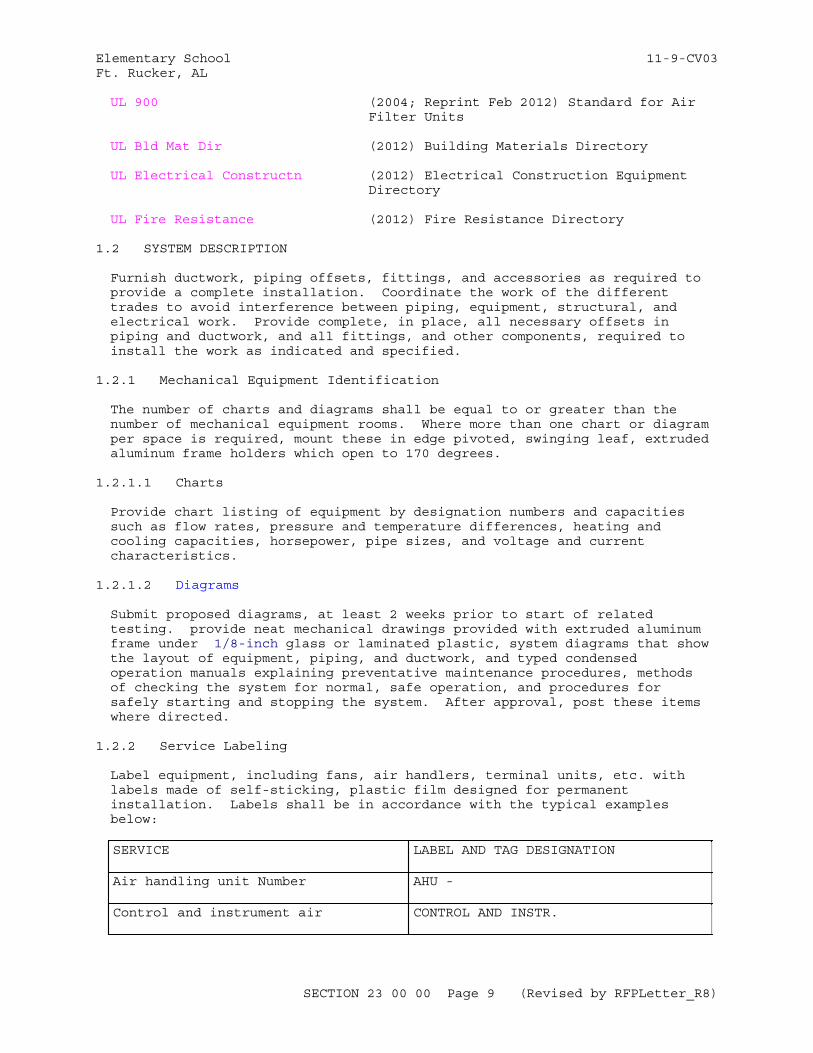
Elementary School 11-9-CV03Ft. Rucker, AL
UL 900 (2004; Reprint Feb 2012) Standard for Air Filter Units
UL Bld Mat Dir (2012) Building Materials Directory
UL Electrical Constructn (2012) Electrical Construction Equipment Directory
UL Fire Resistance (2012) Fire Resistance Directory
1.2 SYSTEM DESCRIPTION
Furnish ductwork, piping offsets, fittings, and accessories as required to provide a complete installation. Coordinate the work of the different trades to avoid interference between piping, equipment, structural, and electrical work. Provide complete, in place, all necessary offsets in piping and ductwork, and all fittings, and other components, required to install the work as indicated and specified.
1.2.1 Mechanical Equipment Identification
The number of charts and diagrams shall be equal to or greater than the number of mechanical equipment rooms. Where more than one chart or diagram per space is required, mount these in edge pivoted, swinging leaf, extruded aluminum frame holders which open to 170 degrees.
1.2.1.1 Charts
Provide chart listing of equipment by designation numbers and capacities such as flow rates, pressure and temperature differences, heating and cooling capacities, horsepower, pipe sizes, and voltage and current characteristics.
1.2.1.2 Diagrams
Submit proposed diagrams, at least 2 weeks prior to start of related testing. provide neat mechanical drawings provided with extruded aluminum frame under 1/8-inch glass or laminated plastic, system diagrams that show the layout of equipment, piping, and ductwork, and typed condensed operation manuals explaining preventative maintenance procedures, methods of checking the system for normal, safe operation, and procedures for safely starting and stopping the system. After approval, post these items where directed.
1.2.2 Service Labeling
Label equipment, including fans, air handlers, terminal units, etc. with labels made of self-sticking, plastic film designed for permanent installation. Labels shall be in accordance with the typical examples below:
SERVICE LABEL AND TAG DESIGNATION
Air handling unit Number AHU -
Control and instrument air CONTROL AND INSTR.
SECTION 23 00 00 Page 9 (Revised by RFPLetter_R8)
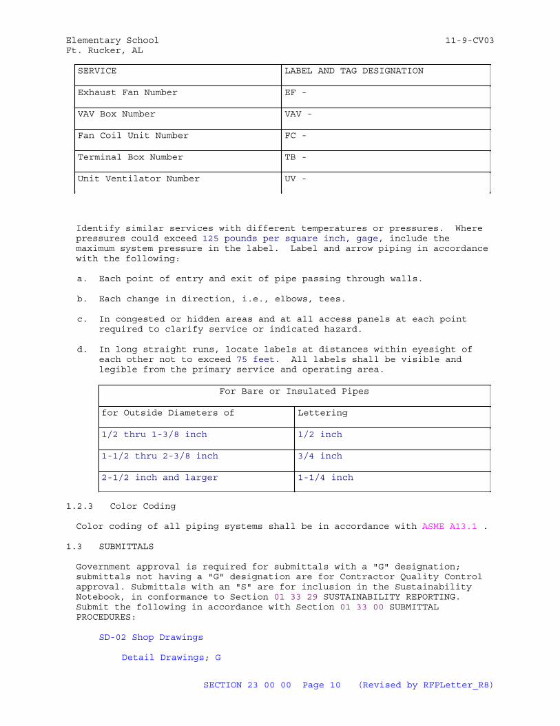
Elementary School 11-9-CV03Ft. Rucker, AL
SERVICE LABEL AND TAG DESIGNATION
Exhaust Fan Number EF -
VAV Box Number VAV -
Fan Coil Unit Number FC -
Terminal Box Number TB -
Unit Ventilator Number UV -
Identify similar services with different temperatures or pressures. Where pressures could exceed 125 pounds per square inch, gage, include the maximum system pressure in the label. Label and arrow piping in accordance with the following:
a. Each point of entry and exit of pipe passing through walls.
b. Each change in direction, i.e., elbows, tees.
c. In congested or hidden areas and at all access panels at each point required to clarify service or indicated hazard.
d. In long straight runs, locate labels at distances within eyesight of each other not to exceed 75 feet. All labels shall be visible and legible from the primary service and operating area.
For Bare or Insulated Pipes
for Outside Diameters of Lettering
1/2 thru 1-3/8 inch 1/2 inch
1-1/2 thru 2-3/8 inch 3/4 inch
2-1/2 inch and larger 1-1/4 inch
1.2.3 Color Coding
Color coding of all piping systems shall be in accordance with ASME A13.1 .
1.3 SUBMITTALS
Government approval is required for submittals with a "G" designation; submittals not having a "G" designation are for Contractor Quality Control approval. Submittals with an "S" are for inclusion in the Sustainability Notebook, in conformance to Section 01 33 29 SUSTAINABILITY REPORTING. Submit the following in accordance with Section 01 33 00 SUBMITTAL PROCEDURES:
SD-02 Shop Drawings
Detail Drawings; G
SECTION 23 00 00 Page 10 (Revised by RFPLetter_R8)
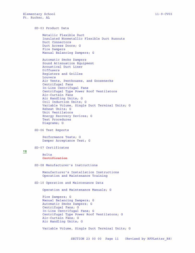
Elementary School 11-9-CV03Ft. Rucker, AL
SD-03 Product Data
Metallic Flexible DuctInsulated Nonmetallic Flexible Duct RunoutsDuct ConnectorsDuct Access Doors; GFire DampersManual Balancing Dampers; G
Automatic Smoke DampersSound Attenuation EquipmentAcoustical Duct LinerDiffusersRegisters and GrillesLouversAir Vents, Penthouses, and GoosenecksCentrifugal FansIn-Line Centrifugal FansCentrifugal Type Power Roof VentilatorsAir-Curtain FansAir Handling Units; GCoil Induction Units; GVariable Volume, Single Duct Terminal Units; GReheat Units; GUnit VentilatorsEnergy Recovery Devices; GTest ProceduresDiagrams; G
SD-06 Test Reports
Performance Tests; GDamper Acceptance Test; G
SD-07 Certificates*8
BoltsCertification
SD-08 Manufacturer's Instructions
Manufacturer's Installation InstructionsOperation and Maintenance Training
SD-10 Operation and Maintenance Data
Operation and Maintenance Manuals; G
Fire Dampers; GManual Balancing Dampers; GAutomatic Smoke Dampers; GCentrifugal Fans; GIn-Line Centrifugal Fans; GCentrifugal Type Power Roof Ventilators; GAir-Curtain Fans; GAir Handling Units; G
Variable Volume, Single Duct Terminal Units; G
SECTION 23 00 00 Page 11 (Revised by RFPLetter_R8)
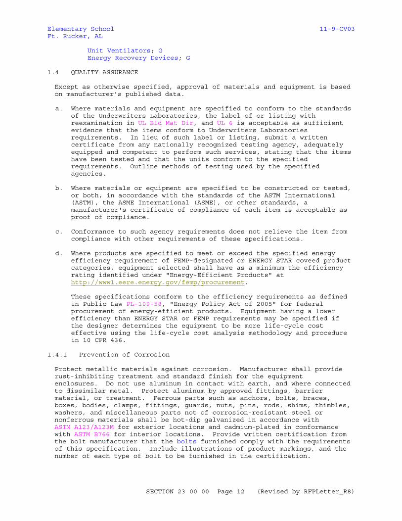
Elementary School 11-9-CV03Ft. Rucker, AL
Unit Ventilators; GEnergy Recovery Devices; G
1.4 QUALITY ASSURANCE
Except as otherwise specified, approval of materials and equipment is based on manufacturer's published data.
a. Where materials and equipment are specified to conform to the standards of the Underwriters Laboratories, the label of or listing with reexamination in UL Bld Mat Dir, and UL 6 is acceptable as sufficient evidence that the items conform to Underwriters Laboratories requirements. In lieu of such label or listing, submit a written certificate from any nationally recognized testing agency, adequately equipped and competent to perform such services, stating that the items have been tested and that the units conform to the specified requirements. Outline methods of testing used by the specified agencies.
b. Where materials or equipment are specified to be constructed or tested, or both, in accordance with the standards of the ASTM International (ASTM), the ASME International (ASME), or other standards, a manufacturer's certificate of compliance of each item is acceptable as proof of compliance.
c. Conformance to such agency requirements does not relieve the item from compliance with other requirements of these specifications.
d. Where products are specified to meet or exceed the specified energy efficiency requirement of FEMP-designated or ENERGY STAR coveed product categories, equipment selected shall have as a minimum the efficiency rating identified under "Energy-Efficient Products" at http://www1.eere.energy.gov/femp/procurement.
These specifications conform to the efficiency requirements as defined in Public Law PL-109-58, "Energy Policy Act of 2005" for federal procurement of energy-efficient products. Equipment having a lower efficiency than ENERGY STAR or FEMP requirements may be specified if the designer determines the equipment to be more life-cycle cost effective using the life-cycle cost analysis methodology and procedure in 10 CFR 436.
1.4.1 Prevention of Corrosion
Protect metallic materials against corrosion. Manufacturer shall provide rust-inhibiting treatment and standard finish for the equipment enclosures. Do not use aluminum in contact with earth, and where connected to dissimilar metal. Protect aluminum by approved fittings, barrier material, or treatment. Ferrous parts such as anchors, bolts, braces, boxes, bodies, clamps, fittings, guards, nuts, pins, rods, shims, thimbles, washers, and miscellaneous parts not of corrosion-resistant steel or nonferrous materials shall be hot-dip galvanized in accordance with ASTM A123/A123M for exterior locations and cadmium-plated in conformance with ASTM B766 for interior locations. Provide written certification from the bolt manufacturer that the bolts furnished comply with the requirements of this specification. Include illustrations of product markings, and the number of each type of bolt to be furnished in the certification.
SECTION 23 00 00 Page 12 (Revised by RFPLetter_R8)
Elementary School 11-9-CV03Ft. Rucker, AL
1.4.2 Asbestos Prohibition
Do not use asbestos and asbestos-containing products.
1.4.3 Ozone Depleting Substances Used as Refrigerants
Minimize releases of Ozone Depleting Substances (ODS) during repair, maintenance, servicing or disposal of appliances containing ODS's by complying with all applicable sections of 40 CFR 82 Part 82 Subpart F. Any person conducting repair, maintenance, servicing or disposal of appliances owned by NASA shall comply with the following:
a. Do not knowingly vent or otherwise release into the environment, Class I or Class II substances used as a refrigerant.
b. Do not open appliances without meeting the requirements of 40 CFR 82 Part 82.156 Subpart F, regarding required practices for evacuation and collection of refrigerant, and 40 CFR 82 Part 82.158 Subpart F, regarding standards of recycling and recovery equipment.
c. Only persons who comply with 40 CFR 82 Part 82.161 Subpart F, regarding technician certification, can conduct work on appliances containing refrigerant.
In addition, provide copies of all applicable certifications to the Contracting Officer at least 14 calendar days prior to initiating maintenance, repair, servicing, dismantling or disposal of appliances, including:
a. Proof of Technician Certification
b. Proof of Equipment Certification for recovery or recycling equipment.
c. Proof of availability of certified recovery or recycling equipment.
1.4.4 Use of Ozone Depleting Substances, Other than Refrigerants
The use of Class I or Class II ODS's listed as nonessential in 40 CFR 82 Part 82.66 Subpart C is prohibited. These prohibited materials and uses include:
a. Any plastic party spray streamer or noise horn which is propelled by a chlorofluorocarbon
b. Any cleaning fluid for electronic and photographic equipment which contains a chlorofluorocarbon; including liquid packaging, solvent wipes, solvent sprays, and gas sprays.
c. Any plastic flexible or packaging foam product which is manufactured with or contains a chlorofluorocarbon, including, open cell foam, open cell rigid polyurethane poured foam, closed cell extruded polystyrene sheet foam, closed cell polyethylene foam and closed cell polypropylene foam except for flexible or packaging foam used in coaxial cabling.
d. Any aerosol product or other pressurized dispenser which contains a chlorofluorocarbon, except for those listed in 40 CFR 82 Part 82.66 Subpart C.
Request a waiver if a facility requirement dictates that a prohibited
SECTION 23 00 00 Page 13 (Revised by RFPLetter_R8)
Elementary School 11-9-CV03Ft. Rucker, AL
material is necessary to achieve project goals. Submit the waiver request in writing to the Contracting Officer. The waiver will be evaluated and dispositioned.
1.4.5 Detail Drawings
Submit detail drawings showing equipment layout, including assembly and installation details and electrical connection diagrams; ductwork layout showing the location of all supports and hangers, typical hanger details, gauge reinforcement, reinforcement spacing rigidity classification, and static pressure and seal classifications. Include any information required to demonstrate that the system has been coordinated and functions properly as a unit on the drawings and show equipment relationship to other parts of the work, including clearances required for operation and maintenance. Submit drawings showing bolt-setting information, and foundation bolts prior to concrete foundation construction for all equipment indicated or required to have concrete foundations. Submit function designation of the equipment and any other requirements specified throughout this Section with the shop drawings.
1.4.6 Test Procedures
Submit proposed test procedures and test schedules for the ductwork leak test, and performance tests of systems, at least 2 weeks prior to the start of related testing.
*81.4.7 Sustainable Design CertificationDeleted
Product shall be third party certified in accordance with ULE Greenguard, SCS Scientific Certification Systems Indoor Advantageor equal. Certification shall be performed annually and shall be current.
1.5 DELIVERY, STORAGE, AND HANDLING
Protect stored equipment at the jobsite from the weather, humidity and temperature variations, dirt and dust, or other contaminants. Additionally, cap or plug all pipes until installed.
PART 2 PRODUCTS
2.1 STANDARD PRODUCTS
Provide components and equipment that are "standard products" of a manufacturer regularly engaged in the manufacturing of products that are of a similar material, design and workmanship. "Standard products" is defined as being in satisfactory commercial or industrial use for 2 years before bid opening, including applications of components and equipment under similar circumstances and of similar size, satisfactorily completed by a product that is sold on the commercial market through advertisements, manufacturers' catalogs, or brochures. Products having less than a 2-year field service record are acceptable if a certified record of satisfactory field operation, for not less than 6000 hours exclusive of the manufacturer's factory tests, can be shown. Provide equipment items that are supported by a service organization. In product categories covered by ENERGY STAR or the Federal Energy Management Program, provide equipment that is listed on the ENERGY STAR Qualified Products List or that meets or exceeds the FEMP-designated Efficiency Requirements.
SECTION 23 00 00 Page 14 (Revised by RFPLetter_R8)
Elementary School 11-9-CV03Ft. Rucker, AL
2.2 STANDARD PRODUCTS
Except for the fabricated duct, plenums and casings specified in paragraphs "Metal Ductwork" and "Plenums and Casings for Field-Fabricated Units", provide components and equipment that are standard products of manufacturers regularly engaged in the manufacturing of products that are of a similar material, design and workmanship. This requirement applies to all equipment, including diffusers, registers, fire dampers, and balancing dampers.
a. Standard products are defined as components and equipment that have been in satisfactory commercial or industrial use in similar applications of similar size for at least two years before bid opening.
b. Prior to this two year period, these standard products shall have been sold on the commercial market using advertisements in manufacturers' catalogs or brochures. These manufacturers' catalogs, or brochures shall have been copyrighted documents or have been identified with a manufacturer's document number.
c. Provide equipment items that are supported by a service organization. In product categories covered by ENERGY STAR or the Federal Energy Management Program, provide equipment that is listed on the ENERGY STAR Qualified Products List or that meets or exceeds the FEMP-designated Efficiency Requirements.
2.3 IDENTIFICATION PLATES
In addition to standard manufacturer's identification plates, provide engraved laminated phenolic identification plates for each piece of mechanical equipment. Identification plates are to designate the function of the equipment. Submit designation with the shop drawings. Identification plates shall be three layers, black-white-black, engraved to show white letters on black background. Letters shall be upper case. Identification plates 1-1/2-inches high and smaller shall be 1/16-inch thick, with engraved lettering 1/8-inch high; identification plates larger than 1-1/2-inches high shall be 1/8-inch thick, with engraved lettering of suitable height. Identification plates 1-1/2-inches high and larger shall have beveled edges. Install identification plates using a compatible adhesive.
2.4 EQUIPMENT GUARDS AND ACCESS
Fully enclose or guard belts, pulleys, chains, gears, couplings, projecting setscrews, keys, and other rotating parts exposed to personnel contact according to OSHA requirements. Properly guard or cover with insulation of a type specified, high temperature equipment and piping exposed to contact by personnel or where it creates a potential fire hazard. The requirements for catwalks, operating platforms, ladders, and guardrails are specified in Section MISCELLANEOUS METAL FABRICATIONS.
2.5 ELECTRICAL WORK
a. Provide motors, controllers, integral disconnects, contactors, and controls with their respective pieces of equipment, except controllers indicated as part of motor control centers. Provide electrical equipment, including motors and wiring, as specified in Section 26 20 00INTERIOR DISTRIBUTION SYSTEM. Provide manual or automatic control and protective or signal devices required for the operation specified and
SECTION 23 00 00 Page 15 (Revised by RFPLetter_R8)
Elementary School 11-9-CV03Ft. Rucker, AL
control wiring required for controls and devices specified, but not shown. For packaged equipment, include manufacturer provided controllers with the required monitors and timed restart.
b. For single-phase motors, provide high-efficiency type, fractional-horsepower alternating-current motors, including motors that are part of a system, in accordance with NEMA MG 11. Integral size motors shall be the premium efficiency type in accordance with NEMA MG 1.
c. For polyphase motors, provide squirrel-cage medium induction motors, including motors that are part of a system , and that meet the efficiency ratings for premium efficiency motors in accordance with NEMA MG 1. Select premium efficiency polyphase motors in accordance with NEMA MG 10.
d. Provide motors in accordance with NEMA MG 1 and of sufficient size to drive the load at the specified capacity without exceeding the nameplate rating of the motor. Provide motors rated for continuous duty with the enclosure specified. Provide motor duty that allows for maximum frequency start-stop operation and minimum encountered interval between start and stop. Provide motor torque capable of accelerating the connected load within 20 seconds with 80 percent of the rated voltage maintained at motor terminals during one starting period. Provide motor starters complete with thermal overload protection and other necessary appurtenances. Fit motor bearings with grease supply fittings and grease relief to outside of the enclosure.
e. Where two-speed or variable-speed motors are indicated, solid-state variable-speed controllers are allowed to accomplish the same function. Use solid-state variable-speed controllers for motors rated 10 hp or less and adjustable frequency drives for larger motors. Provide variable frequency drives for motors as specified.
2.6 ANCHOR BOLTS
Provide anchor bolts for equipment placed on concrete equipment pads or on concrete slabs. Bolts to be of the size and number recommended by the equipment manufacturer and located by means of suitable templates. Installation of anchor bolts shall not degrade the surrounding concrete.
2.7 SEISMIC ANCHORAGE
Anchor equipment in accordance with applicable seismic criteria for the area and as defined in SMACNA 1981
2.8 PAINTING
Paint equipment units in accordance with approved equipment manufacturer's standards unless specified otherwise. Field retouch only if approved. Otherwise, return equipment to the factory for refinishing.
2.9 INDOOR AIR QUALITY
Provide equipment and components that comply with the requirements of ASHRAE 62.1 unless more stringent requirements are specified herein.
SECTION 23 00 00 Page 16 (Revised by RFPLetter_R8)
Elementary School 11-9-CV03Ft. Rucker, AL
2.10 DUCT SYSTEMS
2.10.1 Metal Ductwork
Provide metal ductwork construction, including all fittings and components, that complies with SMACNA 1966, as supplemented and modified by this specification .
a. Ductwork shall be constructed meeting the requirements for the duct system static pressure specified in APPENDIX D of Section 23 05 93 TESTING, ADJUSTING AND BALANCING FOR HVAC.
b. Provide radius type elbows with a centerline radius of 1.5 times the width or diameter of the duct where space permits. Otherwise, elbows having a minimum radius equal to the width or diameter of the duct or square elbows with factory fabricated turning vanes are allowed.
b. Provide ductwork that meets the requirements of Seal Class A. Provide ductwork in VAV systems upstream of the VAV boxes that meets the requirements of Seal Class A.
c. Provide ductwork that meets the requirements of Seal Class A. Provide ductwork in VAV systems upstream of the VAV boxes that meets the requirements of Seal Class A.
d. Provide sealants that conform to fire hazard classification specified in Section 23 07 00 THERMAL INSULATION FOR MECHANICAL SYSTEMS and are suitable for the range of air distribution and ambient temperatures to which it is exposed. Do not use pressure sensitive tape as a sealant.
e. Make spiral lock seam duct, and flat oval with duct sealant and lock with not less than 3 equally spaced drive screws or other approved methods indicated in SMACNA 1966. Apply the sealant to the exposed male part of the fitting collar so that the sealer is on the inside of the joint and fully protected by the metal of the duct fitting. Apply one brush coat of the sealant over the outside of the joint to at least 2 inch band width covering all screw heads and joint gap. Dents in the male portion of the slip fitting collar are not acceptable. Fabricate outdoor air intake ducts and plenums with watertight soldered or brazed joints and seams.
2.10.1.1 Metallic Flexible Duct
a. Provide duct that conforms to UL 181 and NFPA 90A with factory-applied insulation, vapor barrier, and end connections. Provide duct assembly that does not exceed 25 for flame spread and 50 for smoke developed. Provide ducts designed for working pressures of 2 inches water gauge positive and 1.5 inches water gauge negative. Provide flexible round duct length that does not exceed 5 feet. Secure connections by applying adhesive for 2 inches over rigid duct, apply flexible duct 2 inches over rigid duct, apply metal clamp, and provide minimum of three No. 8 sheet metal screws through clamp and rigid duct.
b. Inner duct core: Provide interlocking spiral or helically corrugated flexible core constructed of zinc-coated steel, aluminum, or stainless steel; or constructed of inner liner of continuous galvanized spring steel wire helix fused to continuous, fire-retardant, flexible vapor barrier film, inner duct core.
SECTION 23 00 00 Page 17 (Revised by RFPLetter_R8)
Elementary School 11-9-CV03Ft. Rucker, AL
c. Insulation: Provide inner duct core that is insulated with mineral fiber blanket type flexible insulation, minimum of 1 inch thick. Provide insulation covered on exterior with manufacturer's standard fire retardant vapor barrier jacket for flexible round duct.
2.10.1.2 Insulated Nonmetallic Flexible Duct Runouts
Use flexible duct runouts only where indicated. Runout length is indicated on the drawings, and is not to exceed 5 feet. Provide runouts that are preinsulated, factory fabricated, and that comply with NFPA 90A and UL 181. Provide either field or factory applied vapor barrier. Provide not less than 20 ounce glass fabric duct connectors coated on both sides with neoprene. Where coil induction or high velocity units are supplied with vertical air inlets, use a streamlined, vaned and mitered elbow transition piece for connection to the flexible duct or hose. Provide a die-stamped elbow and not a flexible connector as the last elbow to these units other than the vertical air inlet type. Insulated flexible connectors are allowed as runouts. Provide insulated material and vapor barrier that conform to the requirements of Section 23 07 00 THERMAL INSULATION FOR MECHANICAL SYSTEMS. Do not expose the insulation material surface to the air stream.
2.10.1.3 General Service Duct Connectors
Provide a flexible duct connector approximately 6 inches in width where sheet metal connections are made to fans or where ducts of dissimilar metals are connected. For round/oval ducts, secure the flexible material by stainless steel or zinc-coated, iron clinch-type draw bands. For rectangular ducts, install the flexible material locked to metal collars using normal duct construction methods. Provide a composite connector system that complies with NFPA 701 and is classified as "flame-retardent fabrics" in UL Bld Mat Dir.
2.10.1.4 Aluminum Ducts
ASTM B209, alloy 3003-H14 for aluminum sheet and alloy 6061-T6 or equivalent strength for aluminum connectors and bar stock.
2.10.1.5 Copper Sheets
ASTM B152/B152M, light cold rolled temper.
2.10.1.6 Corrosion Resisting (Stainless) Steel Sheets
ASTM A167
2.10.2 Duct Access Doors
Provide hinged access doors conforming to SMACNA 1966 in ductwork and plenums where indicated and at all air flow measuring primaries, automatic dampers, fire dampers, coils, thermostats, and other apparatus requiring service and inspection in the duct system. Provide access doors upstream and downstream of air flow measuring primaries and heating and cooling coils. Provide doors that are a minimum 15 by 18 inches, unless otherwise shown. Where duct size does not accommodate this size door, make the doors as large as practicable. Equip doors 24 by 24 inches or larger with fasteners operable from inside and outside the duct. Use insulated type doors in insulated ducts.
SECTION 23 00 00 Page 18 (Revised by RFPLetter_R8)
Elementary School 11-9-CV03Ft. Rucker, AL
2.10.3 Fire Dampers
Use 1.5 hour rated fire dampers unless otherwise indicated. Provide fire dampers that conform to the requirements of NFPA 90A and UL 555. Perform the fire damper test as outlined in NFPA 90A. Provide a pressure relief door upstream of the fire damper. If the ductwork connected to the fire damper is to be insulated then provide a factory installed pressure relief damper. Provide automatic operating fire dampers with a dynamic rating suitable for the maximum air velocity and pressure differential to which it is subjected. Provide fire dampers approved for the specific application, and install according to their listing. Equip fire dampers with a steel sleeve or adequately sized frame installed in such a manner that disruption of the attached ductwork, if any, does not impair the operation of the damper. Equip sleeves or frames with perimeter mounting angles attached on both sides of the wall or floor opening. Construct ductwork in fire-rated floor-ceiling or roof-ceiling assembly systems with air ducts that pierce the ceiling of the assemblies in conformance with UL Fire Resistance. Provide curtain type with damper blades out of the air stream fire dampers. Install dampers that do not reduce the duct or the air transfer opening cross-sectional area. Install dampers so that the centerline of the damper depth or thickness is located in the centerline of the wall, partition or floor slab depth or thickness. Unless otherwise indicated, comply with the installation details given in SMACNA 1819 and in manufacturer's instructions for fire dampers. Perform acceptance testing of fire dampers according to paragraph Fire Damper Acceptance Test and NFPA 90A.
2.10.4 Manual Balancing Dampers
Furnish manual balancing dampers with accessible operating mechanisms. Use chromium plated operators (with all exposed edges rounded) in finished portions of the building. Provide manual volume control dampers that are operated by locking-type quadrant operators. Install dampers that are 2 gauges heavier than the duct in which installed. Unless otherwise indicated, provide opposed blade type multileaf dampers with maximum blade width of 12 inches. Provide access doors or panels for all concealed damper operators and locking setscrews. Provide stand-off mounting brackets, bases, or adapters not less than the thickness of the insulation when the locking-type quadrant operators for dampers are installed on ducts to be thermally insulated, to provide clearance between the duct surface and the operator. Stand-off mounting items shall be integral with the operator or standard accessory of the damper manufacturer.
2.10.5 Manual Balancing Dampers
a. Furnish manual balancing dampers with accessible operating mechanisms. Use chromium plated operators (with all exposed edges rounded) in finished portions of the building. Provide manual volume control dampers that are operated by locking-type quadrant operators.
b. Unless otherwise indicated, provide opposed blade type multileaf dampers with maximum blade width of 12 inches. Provide access doors or panels for all concealed damper operators and locking setscrews. Provide access doors or panels in hard ceilings, partitions and walls for access to all concealed damper operators and damper locking setscrews. Coordinate location of doors or panels with other affected contractors.
c. Provide stand-off mounting brackets, bases, or adapters not less than
SECTION 23 00 00 Page 19 (Revised by RFPLetter_R8)
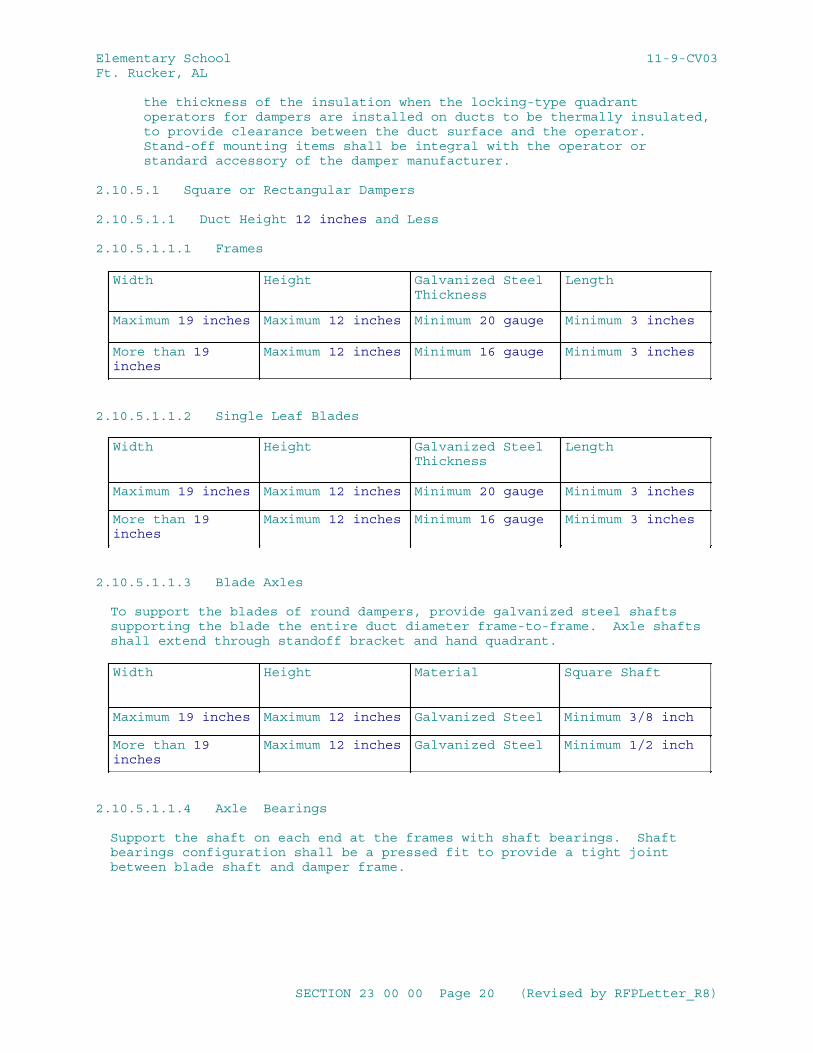
Elementary School 11-9-CV03Ft. Rucker, AL
the thickness of the insulation when the locking-type quadrant operators for dampers are installed on ducts to be thermally insulated, to provide clearance between the duct surface and the operator. Stand-off mounting items shall be integral with the operator or standard accessory of the damper manufacturer.
2.10.5.1 Square or Rectangular Dampers
2.10.5.1.1 Duct Height 12 inches and Less
2.10.5.1.1.1 Frames
Width Height Galvanized Steel Thickness
Length
Maximum 19 inches Maximum 12 inches Minimum 20 gauge Minimum 3 inches
More than 19 inches
Maximum 12 inches Minimum 16 gauge Minimum 3 inches
2.10.5.1.1.2 Single Leaf Blades
Width Height Galvanized Steel Thickness
Length
Maximum 19 inches Maximum 12 inches Minimum 20 gauge Minimum 3 inches
More than 19 inches
Maximum 12 inches Minimum 16 gauge Minimum 3 inches
2.10.5.1.1.3 Blade Axles
To support the blades of round dampers, provide galvanized steel shafts supporting the blade the entire duct diameter frame-to-frame. Axle shafts shall extend through standoff bracket and hand quadrant.
Width Height Material Square Shaft
Maximum 19 inches Maximum 12 inches Galvanized Steel Minimum 3/8 inch
More than 19 inches
Maximum 12 inches Galvanized Steel Minimum 1/2 inch
2.10.5.1.1.4 Axle Bearings
Support the shaft on each end at the frames with shaft bearings. Shaft bearings configuration shall be a pressed fit to provide a tight joint between blade shaft and damper frame.
SECTION 23 00 00 Page 20 (Revised by RFPLetter_R8)
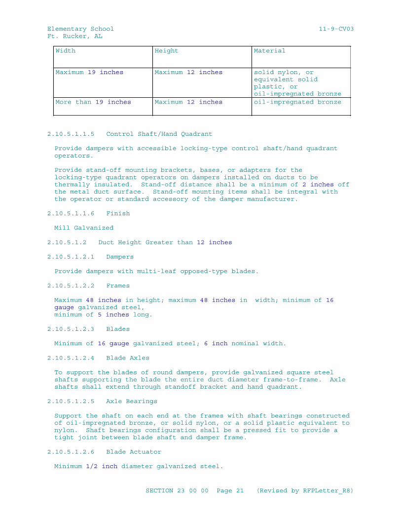
Elementary School 11-9-CV03Ft. Rucker, AL
Width Height Material
Maximum 19 inches Maximum 12 inches solid nylon, or equivalent solid plastic, or oil-impregnated bronze
More than 19 inches Maximum 12 inches oil-impregnated bronze
2.10.5.1.1.5 Control Shaft/Hand Quadrant
Provide dampers with accessible locking-type control shaft/hand quadrant operators.
Provide stand-off mounting brackets, bases, or adapters for the locking-type quadrant operators on dampers installed on ducts to be thermally insulated. Stand-off distance shall be a minimum of 2 inches off the metal duct surface. Stand-off mounting items shall be integral with the operator or standard accessory of the damper manufacturer.
2.10.5.1.1.6 Finish
Mill Galvanized
2.10.5.1.2 Duct Height Greater than 12 inches
2.10.5.1.2.1 Dampers
Provide dampers with multi-leaf opposed-type blades.
2.10.5.1.2.2 Frames
Maximum 48 inches in height; maximum 48 inches in width; minimum of 16 gauge galvanized steel,minimum of 5 inches long.
2.10.5.1.2.3 Blades
Minimum of 16 gauge galvanized steel; 6 inch nominal width. 2.10.5.1.2.4 Blade Axles
To support the blades of round dampers, provide galvanized square steel shafts supporting the blade the entire duct diameter frame-to-frame. Axle shafts shall extend through standoff bracket and hand quadrant.
2.10.5.1.2.5 Axle Bearings
Support the shaft on each end at the frames with shaft bearings constructed of oil-impregnated bronze, or solid nylon, or a solid plastic equivalent to nylon. Shaft bearings configuration shall be a pressed fit to provide a tight joint between blade shaft and damper frame.
2.10.5.1.2.6 Blade Actuator
Minimum 1/2 inch diameter galvanized steel.
SECTION 23 00 00 Page 21 (Revised by RFPLetter_R8)
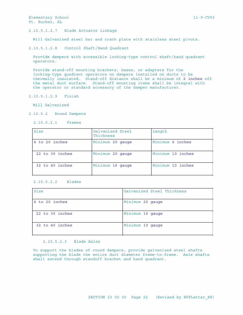
Elementary School 11-9-CV03Ft. Rucker, AL
2.10.5.1.2.7 Blade Actuator Linkage
Mill Galvanized steel bar and crank plate with stainless steel pivots. 2.10.5.1.2.8 Control Shaft/Hand Quadrant
Provide dampers with accessible locking-type control shaft/hand quadrant operators.
Provide stand-off mounting brackets, bases, or adapters for the locking-type quadrant operators on dampers installed on ducts to be thermally insulated. Stand-off distance shall be a minimum of 2 inches off the metal duct surface. Stand-off mounting items shall be integral with the operator or standard accessory of the damper manufacturer.
2.10.5.1.2.9 Finish
Mill Galvanized
2.10.5.2 Round Dampers
2.10.5.2.1 Frames
Size Galvanized Steel Thickness
Length
4 to 20 inches Minimum 20 gauge Minimum 6 inches
22 to 30 inches Minimum 20 gauge Minimum 10 inches
32 to 40 inches Minimum 16 gauge Minimum 10 inches
2.10.5.2.2 Blades
Size Galvanized Steel Thickness
4 to 20 inches Minimum 20 gauge
22 to 30 inches Minimum 16 gauge
32 to 40 inches Minimum 10 gauge
2.10.5.2.3 Blade Axles
To support the blades of round dampers, provide galvanized steel shafts supporting the blade the entire duct diameter frame-to-frame. Axle shafts shall extend through standoff bracket and hand quadrant.
SECTION 23 00 00 Page 22 (Revised by RFPLetter_R8)
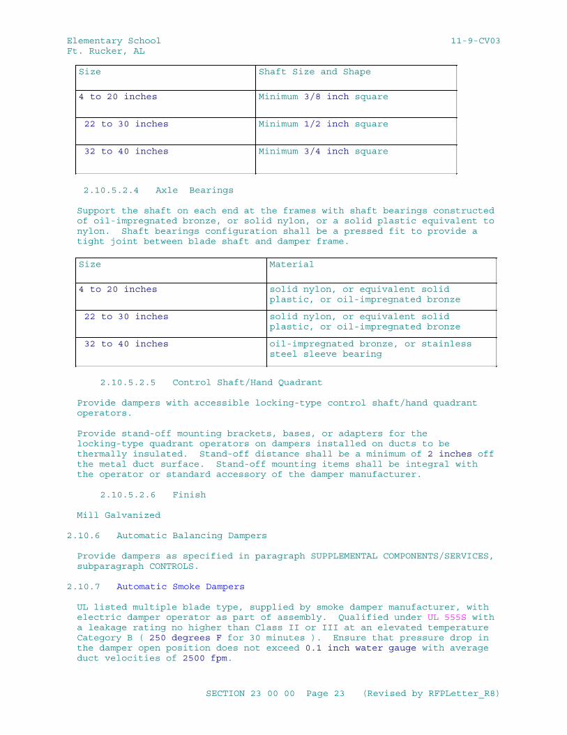
Elementary School 11-9-CV03Ft. Rucker, AL
Size Shaft Size and Shape
4 to 20 inches Minimum 3/8 inch square
22 to 30 inches Minimum 1/2 inch square
32 to 40 inches Minimum 3/4 inch square
2.10.5.2.4 Axle Bearings
Support the shaft on each end at the frames with shaft bearings constructed of oil-impregnated bronze, or solid nylon, or a solid plastic equivalent to nylon. Shaft bearings configuration shall be a pressed fit to provide a tight joint between blade shaft and damper frame.
Size Material
4 to 20 inches solid nylon, or equivalent solid plastic, or oil-impregnated bronze
22 to 30 inches solid nylon, or equivalent solid plastic, or oil-impregnated bronze
32 to 40 inches oil-impregnated bronze, or stainless steel sleeve bearing
2.10.5.2.5 Control Shaft/Hand Quadrant
Provide dampers with accessible locking-type control shaft/hand quadrant operators.
Provide stand-off mounting brackets, bases, or adapters for the locking-type quadrant operators on dampers installed on ducts to be thermally insulated. Stand-off distance shall be a minimum of 2 inches off the metal duct surface. Stand-off mounting items shall be integral with the operator or standard accessory of the damper manufacturer.
2.10.5.2.6 Finish
Mill Galvanized
2.10.6 Automatic Balancing Dampers
Provide dampers as specified in paragraph SUPPLEMENTAL COMPONENTS/SERVICES, subparagraph CONTROLS.
2.10.7 Automatic Smoke Dampers
UL listed multiple blade type, supplied by smoke damper manufacturer, with electric damper operator as part of assembly. Qualified under UL 555S with a leakage rating no higher than Class II or III at an elevated temperature Category B ( 250 degrees F for 30 minutes ). Ensure that pressure drop in the damper open position does not exceed 0.1 inch water gauge with average duct velocities of 2500 fpm.
SECTION 23 00 00 Page 23 (Revised by RFPLetter_R8)
Elementary School 11-9-CV03Ft. Rucker, AL
2.10.8 Air Supply And Exhaust Air Dampers
Where outdoor air supply and exhaust air dampers are required they shall have a maximum leakage rate when tested in accordance with AMCA 500-D as required by ASHRAE 90.1 - IP or UFC 4-010-01, including maximum Damper Leakage for:
a. Climate Zones 1,2,6,7,8 the maximum damper leakage at 1.0 inch w.g. for motorized dampers is 4 cfm per square foot of damper area and non-motorized dampers are not allowed.
b. All other Climate Zones the maximum damper leakage at 1.0 inch w.g. is 10 cfm per square foot and for non-motorized dampers is 20 cfm per square foot of damper area.
Dampers smaller than 24 inches in either direction may have leakage of 40 cfm per square foot.
2.10.9 Air Deflectors and Branch Connections
Provide air deflectors at all duct mounted supply outlets, at takeoff or extension collars to supply outlets, at duct branch takeoff connections, and at 90 degree elbows, as well as at locations as indicated on the drawings or otherwise specified. Conical branch connections or 45 degree entry connections are allowed in lieu of deflectors for branch connections. Furnish all air deflectors, except those installed in 90 degree elbows, with an approved means of adjustment. Provide easily accessible means for adjustment inside the duct or from an adjustment with sturdy lock on the face of the duct. When installed on ducts to be thermally insulated, provide external adjustments with stand-off mounting brackets, integral with the adjustment device, to provide clearance between the duct surface and the adjustment device not less than the thickness of the thermal insulation. Provide factory-fabricated air deflectors consisting of curved turning vanes or louver blades designed to provide uniform air distribution and change of direction with minimum turbulence or pressure loss. Provide factory or field assembled air deflectors. Make adjustment from the face of the diffuser or by position adjustment and lock external to the duct. Provide stand-off brackets on insulated ducts as described herein. Provide fixed air deflectors, also called turning vanes, in 90 degree elbows.
2.10.10 Plenums and Casings for Field-Fabricated Units
2.10.10.1 Plenum and Casings
Fabricate and erect plenums and casings as shown in SMACNA 1966, as applicable. Construct system casing of not less than 16 gauge galvanized sheet steel. Furnish cooling coil drain pans with 1 inch threaded outlet to collect condensation from the cooling coils. Fabricate drain pans from not lighter than 16 gauge steel, galvanized after fabrication or of 18 gauge corrosion-resisting sheet steel conforming to ASTM A167, Type 304, welded and stiffened. Thermally insulate drain pans exposed to the atmosphere to prevent condensation. Coat insulation with a flame resistant waterproofing material. Provide separate drain pans for each vertical coil section, and a separate drain line for each pan. Size pans to ensure capture of entrained moisture on the downstream-air side of the coil. Seal openings in the casing, such as for piping connections, to prevent air leakage. Size the water seal for the drain to maintain a pressure of at least 2 inch water gauge greater than the maximum negative pressure in the coil space.
SECTION 23 00 00 Page 24 (Revised by RFPLetter_R8)
Elementary School 11-9-CV03Ft. Rucker, AL
2.10.10.2 Casing
Terminate casings at the curb line and bolt each to the curb using galvanized angle, as indicated in SMACNA 1966.
2.10.10.3 Access Doors
Provide access doors in each section of the casing. Weld doorframes in place, gasket each door with neoprene, hinge with minimum of two brass hinges, and fasten with a minimum of two brass tension fasteners operable from inside and outside of the casing. Where possible, make doors 36 by 18 inches and locate them 18 inches above the floor. Where the space available does not accommodate doors of this size, use doors as large as the space accommodates. Swing doors so that fan suction or pressure holds doors in closed position, airtight. Provide a push-button station, located inside the casing, to stop the supply.
2.10.10.4 Factory-Fabricated Insulated Sheet Metal Panels
Factory-fabricated components are allowed for field-assembled units, provided all requirements specified for field-fabricated plenums and casings are met. Provide panels of modular design, pretested for structural strength, thermal control, condensation control, and acoustical control. Seal and insulate panel joints. Provide and gasket access doors to prevent air leakage. Provide panel construction that is not less than 20 gauge galvanized sheet steel, assembled with fasteners treated against corrosion. Provide standard length panels that deflect not more than 1/2 inch under operation. Construct details, including joint sealing, not specifically covered, as indicated in SMACNA 1966. Construct the plenums and casings to withstand the specified internal pressure of the air systems.
2.10.10.5 Duct Liner
Unless otherwise specified, duct liner is not permitted.
2.10.11 Sound Attenuation Equipment
2.10.11.1 Systems with total pressure above 4 Inches Water Gauge
Provide sound attenuators on the discharge duct of each fan operating at a total pressure above 4 inch water gauge, and, when indicated, at the intake of each fan system. Provide sound attenuators elsewhere as indicated. Provide factory fabricated sound attenuators, tested by an independent laboratory for sound and performance characteristics. Provide a net sound reduction as indicated. Maximum permissible pressure drop is not to exceed 0.63 inch water gauge. Construct traps to be airtight when operating under an internal static pressure of 10 inch water gauge. Provide air-side surface capable of withstanding air velocity of 10,000 fpm. Certify that the equipment can obtain the sound reduction values specified after the equipment is installed in the system and coordinated with the sound information of the system fan to be provided. Provide sound absorbing material conforming to ASTM C1071, Type I or II. Provide sound absorbing material that meets the fire hazard rating requirements for insulation specified in Section 23 07 00 THERMAL INSULATION FOR MECHANICAL SYSTEMS. For connection to ductwork, provide a duct transition section. Factory fabricated double-walled internally insulated spiral lock seam and round duct and fittings designed for high pressure air system can be provided if complying with requirements specified for factory fabricated sound
SECTION 23 00 00 Page 25 (Revised by RFPLetter_R8)
Elementary School 11-9-CV03Ft. Rucker, AL
attenuators, in lieu of factory fabricated sound attenuators. Construct the double-walled duct and fittings from an outer metal pressure shell of zinc-coated steel sheet, 1 inch thick acoustical blanket insulation, and an internal perforated zinc-coated metal liner. Provide a sufficient length of run to obtain the noise reduction coefficient specified. Certify that the sound reduction value specified can be obtained within the length of duct run provided. Provide welded or spiral lock seams on the outer sheet metal of the double-walled duct to prevent water vapor penetration. Provide duct and fittings with an outer sheet that conforms to the metal thickness of high-pressure spiral and round ducts and fittings shown in SMACNA 1966. Provide acoustical insulation with a thermal conductivity "k" of not more than 0.27 Btu/inch/square foot/hour/degree F at 75 degrees F mean temperature. Provide an internal perforated zinc-coated metal liner that is not less than 24 gauge with perforations not larger than 1/4 inch in diameter providing a net open area not less than 10 percent of the surface.
2.10.11.2 System with total pressure of 4 Inch Water Gauge and Lower
Use sound attenuators only where indicated. Provide factory fabricated sound attenuators that are constructed of galvanized steel sheets. Provide attenuator with outer casing that is not less than 22 gauge. Provide fibrous glass acoustical fill. Provide net sound reduction indicated. Obtain values on a test unit not less than 24 by 24 inches outside dimensions made by a certified nationally recognized independent acoustical laboratory. Provide air flow capacity as indicated or required. Provide pressure drop through the attenuator that does not exceed the value indicated, or that is not in excess of 15 percent of the total external static pressure of the air handling system, whichever is less. Acoustically test attenuators with metal duct inlet and outlet sections while under the rated air flow conditions. Include with the noise reduction data the effects of flanking paths and vibration transmission. Construct sound attenuators to be airtight when operating at the internal static pressure indicated or specified for the duct system, but in no case less than 2 inch water gauge.
2.10.11.3 Acoustical Duct Liner
Use fibrous glass designed or flexible elastomeric duct liner for lining ductwork and conforming to the requirements of ASTM C1071, Type I and II. Provide uniform density, graduated density, or dual density liner composition, as standard with the manufacturer. Provide not less than 1 inch thick coated lining. Where acoustical duct liner is used, provide the thermal equivalent of the insulation specified in Section 23 07 00 THERMAL INSULATION FOR MECHANICAL SYSTEMS for liner or combination of liner and insulation applied to the exterior of the ductwork. Increase duct sizes shown to compensate for the thickness of the lining used. In lieu of sheet metal duct with field-applied acoustical lining, provide acoustically equivalent lengths of fibrous glass duct, elastomeric duct liner or factory fabricated double-walled internally insulated duct with perforated liner.
2.10.12 Diffusers, Registers, and Grilles
Provide factory-fabricated units of steel or aluminum that distribute the specified quantity of air evenly over space intended without causing noticeable drafts, air movement faster than 50 fpm in occupied zone, or dead spots anywhere in the conditioned area. Provide outlets for diffusion, spread, throw, and noise level as required for specified performance. Certify performance according to ASHRAE 70. Provide sound
SECTION 23 00 00 Page 26 (Revised by RFPLetter_R8)
Elementary School 11-9-CV03Ft. Rucker, AL
rated and certified inlets and outlets according to ASHRAE 70. Provide sound power level as indicated. Provide diffusers and registers with volume damper with accessible operator, unless otherwise indicated; or if standard with the manufacturer, an automatically controlled device is acceptable. Provide opposed blade type volume dampers for all diffusers and registers, except linear slot diffusers. Provide linear slot diffusers with round or elliptical balancing dampers. Where the inlet and outlet openings are located less than 7 feet above the floor, protect them by a grille or screen according to NFPA 90A.
2.10.12.1 Diffusers
Provide diffuser types indicated. Furnish ceiling mounted units with anti-smudge devices, unless the diffuser unit minimizes ceiling smudging through design features. Provide diffusers with air deflectors of the type indicated. Provide air handling troffers or combination light and ceiling diffusers conforming to the requirements of UL Electrical Constructn for the interchangeable use as cooled or heated air supply diffusers or return air units. Install ceiling mounted units with rims tight against ceiling. Provide sponge rubber gaskets between ceiling and surface mounted diffusers for air leakage control. Provide suitable trim for flush mounted diffusers. For connecting the duct to diffuser, provide duct collar that is airtight and does not interfere with volume controller. Provide return or exhaust units that are similar to supply diffusers.
2.10.12.2 Perforated Plate Diffusers
Provide adjustable one-way, two-way, three-way, or four-way air pattern controls as indicated. Provide diffuser faceplates that do not sag or deflect when operating under design conditions.
2.10.12.3 Linear Diffusers
Make joints between diffuser sections that appear as hairline cracks. Provide alignment slots for insertion of key strips or other concealed means to align exposed butt edges of diffusers. Equip with plaster frames when mounted in plaster ceiling. Do not use screws and bolts in exposed face of frames or flanges. Metal-fill and ground smooth frames and flanges exposed below ceiling. Furnish separate pivoted or hinged adjustable air-volume-damper and separate air-deflection blades.
2.10.12.4 Registers and Grilles
Provide units that are four-way directional-control type, except provide return and exhaust registers that are fixed horizontal or vertical louver type similar in appearance to the supply register face. Furnish registers with sponge-rubber gasket between flanges and wall or ceiling. Install wall supply registers at least 6 inches below the ceiling unless otherwise indicated. Locate return and exhaust registers 6 inches above the floor unless otherwise indicated. Achieve four-way directional control by a grille face which can be rotated in 4 positions or by adjustment of horizontal and vertical vanes. Provide grilles as specified for registers, without volume control damper.
2.10.12.5 Registers
Double-deflection supply registers. Provide exhaust and return registers as specified for supply registers, except provide exhaust and return registers that have a single set of nondirectional face bars or vanes having the same
SECTION 23 00 00 Page 27 (Revised by RFPLetter_R8)
Elementary School 11-9-CV03Ft. Rucker, AL
appearance as the supply registers.
2.10.13 Louvers
Provide louvers for installation in exterior walls that are associated with the air supply and distribution system as specified in Section 07 60 00 FLASHING AND SHEET METAL .
2.10.14 Air Vents, Penthouses, and Goosenecks
Fabricate air vents, penthouses, and goosenecks from galvanized steel or aluminum sheets with galvanized or aluminum structural shapes. Provide sheet metal thickness, reinforcement, and fabrication that conform to SMACNA 1966. Accurately fit and secure louver blades to frames. Fold or bead edges of louver blades for rigidity and baffle these edges to exclude driving rain. Provide air vents, penthouses, and goosenecks with bird screen.
2.10.15 Bird Screens and Frames
Provide bird screens that conform to ASTM E2016, No. 2 mesh, aluminum or stainless steel. Provide "medium-light" rated aluminum screens. Provide "light" rated stainless steel screens. Provide removable type frames fabricated from either stainless steel or extruded aluminum.
2.11 AIR SYSTEMS EQUIPMENT
2.11.1 Fans
Test and rate fans according to AMCA 210. Calculate system effect on air moving devices in accordance with AMCA 201 where installed ductwork differs from that indicated on drawings. Install air moving devices to minimize fan system effect. Where system effect is unavoidable, determine the most effective way to accommodate the inefficiencies caused by system effect on the installed air moving device. The sound power level of the fans shall not exceed 85 dBA when tested according to AMCA 300 and rated in accordance with AMCA 301. Provide all fans with an AMCA seal. Connect fans to the motors either directly or indirectly with V-belt drive. Use V-belt drives designed for not less than 150 percent of the connected driving capacity. Provide variable pitch motor sheaves for 15 hp and below, and fixed pitch as defined by AHRI Guideline D (A fixed-pitch sheave is provided on both the fan shaft and the motor shaft. This is a non-adjustable speed drive.). Select variable pitch sheaves to drive the fan at a speed which can produce the specified capacity when set at the approximate midpoint of the sheave adjustment. When fixed pitch sheaves are furnished, provide a replaceable sheave when needed to achieve system air balance. Provide motors for V-belt drives with adjustable rails or bases. Provide removable metal guards for all exposed V-belt drives, and provide speed-test openings at the center of all rotating shafts. Provide fans with personnel screens or guards on both suction and supply ends, except that the screens need not be provided, unless otherwise indicated, where ducts are connected to the fan. Provide fan and motor assemblies with vibration-isolation supports or mountings as indicated. Use vibration-isolation units that are standard products with published loading ratings. Select each fan to produce the capacity required at the fan static pressure indicated. Provide sound power level as indicated. Obtain the sound power level values according to AMCA 300. Provide standard AMCA arrangement, rotation, and discharge as indicated. Provide power ventilators that conform to UL 705 and have a UL label.
SECTION 23 00 00 Page 28 (Revised by RFPLetter_R8)
Elementary School 11-9-CV03Ft. Rucker, AL
2.11.1.1 Centrifugal Fans
Provide fully enclosed, single-width single-inlet, or double-width double-inlet centrifugal fans, with AMCA Pressure Class I, II, or III as required or indicated for the design system pressure. Provide impeller wheels that are rigidly constructed and accurately balanced both statically and dynamically. Provide forward curved or backward-inclined airfoil design fan blades in wheel sizes up to 30 inches. Provide backward-inclined airfoil design fan blades for wheels over 30 inches in diameter. Provide fan wheels over 36 inches in diameter with overhung pulleys and a bearing on each side of the wheel. Provide fan wheels 36 inches or less in diameter that have one or more extra long bearings between the fan wheel and the drive. Provide sleeve type, self-aligning and self-oiling bearings with oil reservoirs, or precision self-aligning roller or ball-type with accessible grease fittings or permanently lubricated type. Connect grease fittings to tubing for serviceability from a single accessible point. Provide L50 rated bearing life at not less than 200,000 hours as defined by ABMA 9 and ABMA 11. Provide steel, accurately finished fan shafts, with key seats and keys for impeller hubs and fan pulleys. Provide fan outlets of ample proportions, designed for the attachment of angles and bolts for attaching flexible connections. Provide automatically operated inlet vanes on suction inlets. Provide automatically operated outlet dampers. Unless otherwise indicated, provide motors that do not exceed 1800 rpm and have totally enclosed enclosures. Provide across-the-line type motor starters with general-purpose or weather-resistant enclosure as required on Drawings. Provide remote manual switch with pilot indicating light where indicated.
2.11.1.2 In-Line Centrifugal Fans
Provide in-line fans with centrifugal backward inclined blades, stationary discharge conversion vanes, internal and external belt guards, and adjustable motor mounts. Mount fans in a welded tubular casing. Provide a fan that axially flows the air in and out. Streamline inlets with conversion vanes to eliminate turbulence and provide smooth discharge air flow. Enclose and isolate fan bearings and drive shafts from the air stream. Provide precision, self aligning ball or roller type fan bearings that are sealed against dust and dirt and are permanently lubricated. Provide L50 rated bearing life at not less than 200,000 hours as defined by ABMA 9 and ABMA 11. Provide motors with open enclosure. Provide magnetic motor starters across-the-line with general-purpose enclosures.
2.11.1.3 Centrifugal Type Power Roof Ventilators
Provide direct or V-belt driven centrifugal type fans with backward inclined, non-overloading wheel. Provide hinged or removable and weatherproof motor compartment housing, constructed of heavy gauge aluminum. Provide fans with birdscreen, disconnect switch, gravity dampers, roof curb. Provide dripproof type motor enclosure. Provide centrifugal type kitchen exhaust fans according to UL 705, fitted with V-belt drive, round hood, and windband upblast discharge configuration, integral residue trough and collection device, with motor and power transmission components located in outside positively air ventilated compartment. Use only lubricated bearings.
2.11.1.4 Air-Curtain Fans
Provide fans that conform to AMCA 220 with AMCA seal. Furnish air curtains
SECTION 23 00 00 Page 29 (Revised by RFPLetter_R8)
Elementary School 11-9-CV03Ft. Rucker, AL
with a weatherproof housing constructed of high impact plastic or minimum 18 gauge rigid welded steel. Provide backward curved, non-overloading, centrifugal type fan wheels, accurately balanced statically and dynamically. Provide motors with totally enclosed fan cooled enclosures. Provide remote manual type motor starters with weather-resistant enclosure actuated when the doorway served is open. Provide air curtains that attain the air velocities specified within 2 seconds following activation. Provide bird screens at air intake and discharge openings. Provide air curtain unit or a multiple unit installation that is at least as wide as the opening to be protected. Provide the air discharge openings to permit outward adjustment of the discharge air. Place installation and adjust according to the manufacturer's written recommendation. Furnish directional controls on air curtains for service windows for easy clean or convenient removal. Design air curtains to prevent the adjustment of the air velocities specified. Make the interior surfaces of the air curtain units accessible for cleaning. Provide certified test data indicating that the fan can provide the air velocities required when fan is mounted as indicated. Provide air curtains designed as fly fans unless otherwise indicated. Provide air curtains designed for use in service entranceways that develop an air curtain not less than 3 inches thick at the discharge nozzle. Provide air velocity that is not less than 1600 fpm across the entire entryway when measured 3 feet above the floor.
2.11.2 Coils
Provide fin-and-tube type coils constructed of seamless copper tubes and aluminum fins mechanically bonded or soldered to the tubes. Provide copper tube wall thickness that is a minimum of 0.016 inches.. Provide aluminum fins that are 0.0075 inch minimum thickness. Provide casing and tube support sheets that are not lighter than 16 gauge galvanized steel, formed to provide structural strength. When required, provide multiple tube supports to prevent tube sag. Test each coil at the factory under water at not less than 400 psi air pressure and make suitable for 200 psi working pressure and 300 degrees F operating temperature unless otherwise stated. Mount coils for counterflow service. Rate and certify coils to meet the requirements of AHRI 410.
2.11.2.1 Direct-Expansion Coils
Provide suitable direct-expansion coils for the refrigerant involved. Provide refrigerant piping that conforms to ASTM B280 and clean, dehydrate and seal. Provide seamless copper tubing suction headers or seamless or resistance welded steel tube suction headers with copper connections. Provide supply headers that consist of a distributor which distributes the refrigerant through seamless copper tubing equally to all circuits in the coil. Provide circuited tubes to ensure minimum pressure drop and maximum heat transfer. Provide circuiting that permits refrigerant flow from inlet to suction outlet without causing oil slugging or restricting refrigerant flow in coil. Provide field installed coils which are completely dehydrated and sealed at the factory upon completion of pressure tests.
2.11.2.2 Water Coils
Install water coils with a pitch of not less than 1/8 inch/foot of the tube length toward the drain end. Use headers constructed of cast iron, welded steel or copper. Furnish each coil with a plugged vent and drain connection extending through the unit casing. Provide removable water coils with drain pans.
SECTION 23 00 00 Page 30 (Revised by RFPLetter_R8)
Elementary School 11-9-CV03Ft. Rucker, AL
2.11.3 Air Filters
List air filters according to requirements of UL 900, except list high efficiency particulate air filters of 99.97 percent efficiency by the DOP Test method under the Label Service to meet the requirements of UL 586.
2.11.3.1 Extended Surface Pleated Panel Filters
Provide 2 inch depth, sectional, disposable type filters of the size indicated with a MERV of 8 when tested according to ASHRAE 52.2. Provide initial resistance at 500 fpm that does not exceed 0.36 inches water gauge. Provide UL Class 2 filters, and nonwoven cotton and synthetic fiber mat media. Attach a wire support grid bonded to the media to a moisture resistant fiberboard frame. Bond all four edges of the filter media to the inside of the frame to prevent air bypass and increase rigidity.
2.11.3.2 Cartridge Type Filters
Provide 12 inch depth, sectional, replaceable dry media type filters of the size indicated with a MERV of 13 when tested according to ASHRAE 52.2. Provide initial resistance at 500 fpm that does not exceed 0.56 inches, water gauge. Provide UL class 1 filters, and pleated microglass paper media with corrugated aluminum separators, sealed inside the filter cell to form a totally rigid filter assembly. Fluctuations in filter face velocity or turbulent airflow have no effect on filter integrity or performance. Install each filter with an extended surface pleated media panel filter as a prefilter in a factory preassembled side access housing, or a factory-made sectional frame bank, as indicated.
2.12 AIR HANDLING UNITS
2.12.1 Field-Fabricated Air Handling Units
Provide built-up units as specified in paragraph DUCT SYSTEMS. Provide fans, coils spray-coil dehumidifiers, and air filters as specified in paragraph AIR SYSTEMS EQUIPMENT for types indicated.
2.12.2 Factory-Fabricated Air Handling Units
Provide single-zone draw-through type units as indicated. Units shall include fans, coils, airtight insulated casing, prefilters, secondary filter sections, adjustable V-belt drives, belt guards for externally mounted motors, access sections where indicated, mixing box combination sectional filter-mixing box, vibration-isolators, and appurtenances required for specified operation. Provide vibration isolators as indicated. Physical dimensions of each air handling unit shall be suitable to fit space allotted to the unit with the capacity indicated. Provide air handling unit that is rated in accordance with AHRI 430 and AHRI certified for cooling.
2.12.2.1 Casings
Provide the following:
a. Casing sections 2 inch double wall type as indicated, constructed of a minimum 18 gauge galvanized steel, or 18 gauge corrosion-resisting sheet steel conforming to ASTM A167, Type 304.Inner casing of double-wall units that are a minimum 20 gauge solid galvanized steel or corrosion-resisting sheet steel conforming to ASTM A167, Type 304.
SECTION 23 00 00 Page 31 (Revised by RFPLetter_R8)
Elementary School 11-9-CV03Ft. Rucker, AL
Design and construct casing with an integral insulated structural galvanized steel frame such that exterior panels are non-load bearing.
b. Individually removable exterior panels with standard tools. Removal shall not affect the structural integrity of the unit. Furnish casings with access sections, according to paragraph AIR HANDLING UNITS, inspection doors, and access doors, all capable of opening a minimum of 90 degrees, as indicated.
c. Insulated, fully gasketed, double-wall type inspection and access doors, of a minimum 18 gauge outer and 20 gauge inner panels made of either galvanized steel or corrosion-resisting sheet steel conforming to ASTM A167, Type 304. Doors shall be rigid and provided with heavy duty hinges and latches. Inspection doors shall be a minimum 12 inches wide by 12 inches high. Access doors shall be a minimum 24 inches wide, the full height of the unit casing or a minimum of 6 foot, whichever is less. Install a minimum 8 by 8 inches sealed glass window suitable for the intended application, in all access doors.
d. Double-wall insulated type drain pan (thickness equal to exterior casing) constructed of 16 gauge corrosion resisting sheet steel conforming to ASTM A167, Type 304, conforming to ASHRAE 62.1. Construct drain pans water tight, treated to prevent corrosion, and designed for positive condensate drainage. When 2 or more cooling coils are used, with one stacked above the other, condensate from the upper coils shall not flow across the face of lower coils. Provide intermediate drain pans or condensate collection channels and downspouts, as required to carry condensate to the unit drain pan out of the air stream and without moisture carryover. Construct drain pan to allow for easy visual inspection, including underneath the coil without removal of the coil and to allow complete and easy physical cleaning of the pan underneath the coil without removal of the coil. Coils shall be individually removable from the casing.
e. Casing insulation that conforms to NFPA 90A. Single-wall casing sections handling conditioned air shall be insulated with not less than 1 inch thick, 1-1/2 pound density coated fibrous glass material having a thermal conductivity not greater than 0.23 Btu/hr-sf-F. Double-wall casing sections handling conditioned air shall be insulated with not less than 2 inches of the same insulation specified for single-wall casings. Foil-faced insulation is not an acceptable substitute for use with double wall casing. Double wall insulation shall be completely sealed by inner and outer panels.
f. Factory applied fibrous glass insulation that conforms to ASTM C1071, except that the minimum thickness and density requirements do not apply, and that meets the requirements of NFPA 90A. Make air handling unit casing insulation uniform over the entire casing. Foil-faced insulation is not an acceptable substitute for use on double-wall access doors and inspections doors and casing sections.
g. Duct liner material, coating, and adhesive that conforms to fire-hazard requirements specified in Section 23 07 00 THERMAL INSULATION FOR MECHANICAL SYSTEMS. Protect exposed insulation edges and joints where insulation panels are butted with a metal nosing strip or coat to meet erosion resistance requirements of ASTM C1071.
h. A latched and hinged inspection door, in the fan and coil sections. Plus additional inspection doors, access doors and access sections in
SECTION 23 00 00 Page 32 (Revised by RFPLetter_R8)
Elementary School 11-9-CV03Ft. Rucker, AL
each section required for maintenance.
2.12.2.2 Heating and Cooling Coils
Provide coils as specified in paragraph AIR SYSTEMS EQUIPMENT.
2.12.2.3 Air Filters
Provide air filters as specified in paragraph AIR SYSTEMS EQUIPMENT for types and thickness indicated.
2.12.2.4 Fans
Provide the following:
a. Fans that are double-inlet, centrifugal type with each fan in a separate scroll. Dynamically balance fans and shafts prior to installation into air handling unit, then after it has been installed in the air handling unit, statically and dynamically balance the entire fan assembly. Mount fans on steel shafts, accurately ground and finished.
b. Fan bearings that are sealed against dust and dirt and are precision self-aligning ball or roller type, with L50 rated bearing life at not less than 200,000 hours as defined by ABMA 9 and ABMA 11. Bearings shall be permanently lubricated or lubricated type with lubrication fittings readily accessible at the drive side of the unit. Support bearings by structural shapes, or die formed sheet structural members, or support plates securely attached to the unit casing. Do not fasten bearings directly to the unit sheet metal casing. Furnish fans and scrolls with coating indicated.
c. Fans that are driven by a unit-mounted, or a floor-mounted motor connected to fans by V-belt drive complete with belt guard for externally mounted motors. Furnish belt guards that are the three-sided enclosed type with solid or expanded metal face. Belt drives shall be designed for not less than a 1.3 service factor based on motor nameplate rating.
d. Motor sheaves that are variable pitch for 25 hp and below and fixed pitch above 25 hp as defined by AHRI Guideline D. Where fixed sheaves are required, the use of variable pitch sheaves is allowed during air balance, but replace them with an appropriate fixed sheave after air balance is completed. Select variable pitch sheaves to drive the fan at a speed that produces the specified capacity when set at the approximate midpoint of the sheave adjustment. Furnish motors for V-belt drives with adjustable bases, and with totally enclosed enclosures.
e. Motor starters of across-the-line type with general-purpose enclosure. Select unit fan or fans to produce the required capacity at the fan static pressure with sound power level as indicated. Obtain the sound power level values according to AMCA 300, ASHRAE 68, or AHRI 260 I-P.
2.12.2.5 Access Sections and Filter/Mixing Boxes
Provide access sections where indicated and furnish with access doors as shown. Construct access sections and filter/mixing boxes in a manner identical to the remainder of the unit casing and equip with access doors.
SECTION 23 00 00 Page 33 (Revised by RFPLetter_R8)
Elementary School 11-9-CV03Ft. Rucker, AL
Design mixing boxes to minimize air stratification and to promote thorough mixing of the air streams.
2.13 TERMINAL UNITS
2.13.1 Coil Induction Units
2.13.1.1 Air Plenums
Fabricate plenums from galvanized steel with interior acoustically baffled and lined with sound absorbing material to attenuate the sound power from the primary air supply to the room. Provide heat-resistant nozzles that are integral with or attached airtight to the plenum. Where coil induction units are supplied with vertical runouts, furnish a streamlined, vaned, mitered elbow transition piece for connection between the unit and ductwork. Provide an adjustable air-balancing damper in each unit.
2.13.2 Variable Air Volume (VAV) and Dual Duct Terminal Units
a. Provide VAV and dual duct terminal units that are the type, size, and capacity shown, mounted in the ceiling or wall cavity, plus units that are suitable for single or dual duct system applications. Provide actuators and controls as specified in paragraph SUPPLEMENTAL COMPONENTS/SERVICES, subparagraph CONTROLS. For each VAV terminal unit, provide a temperature sensor in the unit discharge ductwork.
b. Provide unit enclosures that are constructed of galvanized steel not lighter than 22 gauge or aluminum sheet not lighter than 18 gauge. Provide single or multiple discharge outlets as required. Units with flow limiters are not acceptable. Provide unit air volume that is factory preset and readily field adjustable without special tools. Provide reheat coils as indicated.
c. Attach a flow chart to each unit. Base acoustic performance of the terminal units upon units tested according to AHRI 880 I-P with the calculations prepared in accordance with AHRI 885. Provide sound power level as indicated. Show discharge sound power for minimum and 1-1/2 inches water gauge inlet static pressure. Provide acoustical lining according to NFPA 90A.
2.13.2.1 Variable Volume, Single Duct Terminal Units
Provide variable volume, single duct, terminal units with a calibrated air volume sensing device, air valve or damper, actuator, and accessory relays. Provide units that control air volume to within plus or minus 5 percent of each air set point volume as determined by the thermostat with variations in inlet pressures from 3/4 to 6 inch water gauge. Provide units with an internal resistance not exceeding 0.4 inch water gauge at maximum flow range. Provide external differential pressure taps separate from the control pressure taps for air flow measurement with a 0 to 1 inch water gauge range.
2.13.2.2 Reheat Units
2.13.2.2.1 Hot Water Coils
Provide fin-and-tube type hot-water coils constructed of seamless copper tubes and copper or aluminum fins mechanically bonded or soldered to the
SECTION 23 00 00 Page 34 (Revised by RFPLetter_R8)
Elementary School 11-9-CV03Ft. Rucker, AL
tubes. Provide headers that are constructed of cast iron, welded steel or copper. Provide casing and tube support sheets that are 16 gauge, galvanized steel, formed to provide structural strength. Provide tubes that are correctly circuited for proper water velocity without excessive pressure drop and are drainable where required or indicated. At the factory, test each coil at not less than 250 psi air pressure and provide coils suitable for 200 psi working pressure. Install drainable coils in the air handling units with a pitch of not less than 1/8 inch per foot of tube length toward the drain end. Coils shall conform to the provisions of AHRI 410.
2.13.3 Unit Ventilators
2.13.3.1 Fans
Provide fans that meet the requirements of ASHRAE 90.1 - IP as specified in paragraph AIR SYSTEMS EQUIPMENT. Provide galvanized steel or aluminum, multiblade, centrifugal type fans, dynamically and statically balanced. Equip fan housings with resilient mounted, self-aligning permanently lubricated ball bearings, sleeve bearings, or combination ball and sleeve bearings, capable of not less than 2000 hours of operation on one oiling. Provide direct-connected fans.
2.13.3.2 Coils
Provide coils that are circuited for a maximum water velocity of 8 fps without excessive pressure drop and are otherwise as specified for hot water coils in paragraph TERMINAL UNITS.
2.13.3.3 Drain Pans
Size and locate drain and drip pans to collect all condensed water dripping from any item within the unit enclosure. Provide drain pans constructed of not lighter than 18 gauge steel, galvanized after fabrication, and thermally insulated to prevent condensation. Provide insulation that is coated with a fire-resistant waterproofing material. In lieu of the above, drain pans constructed of die-formed 20 gauge steel is allowed, formed from a single sheet and galvanized after fabrication and insulated and coated as for the 18 gauge steel material, or of die-formed 18 gauge type 304 stainless steel insulated as specified above. Pitch drain pans to drain. Furnish drain connection unless otherwise indicated. Make the minimum connection 3/4 inch NDT or 5/8 inch OD.
2.13.3.4 Filters
Disposable type rated in accordance with ASHRAE 52.2, installed upstream of coil.
2.13.3.5 Dampers
Provide an outside air proportioning damper on each unit. In addition, provide a vane to prevent excessive outside air from entering unit and to prevent blow-through of outside air through the return air grille under high wind pressures. Where outside air and recirculated air proportioning dampers are provided on the unit, an additional vane is not required. Provide face and bypass dampers for each unit to ensure constant air volume at all positions of the dampers. Furnish each unit with a factory installed control cam assembly, pneumatic motor, or electric motor to
SECTION 23 00 00 Page 35 (Revised by RFPLetter_R8)
Elementary School 11-9-CV03Ft. Rucker, AL
operate the face and bypass dampers and outside air damper or outside air and recirculated air dampers in the sequence as specified in paragraph SUPPLEMENTAL COMPONENTS/SERVICES, subparagraph CONTROLS.
2.13.3.6 Motors
Provide permanent split-capacitor type motors with built-in thermal overload protection and automatic reset. Mount motor on a resilient mounting, isolated from the casing and suitable for operation on electric service available. Provide a manually operated motor switch that provides for 2 or 3 speeds and off, mounted on an identified plate inside the unit below or behind an access door or adjacent to the room thermostatas indicated. In lieu of speed control, provide a solid state variable speed controller having minimum speed reduction of 50 percent.
2.13.3.7 Outside Air Intakes
Provide the manufacturer's standard design outside air intakes furnished with 1/2 inch mesh bird screen or louvers on 1/2 inch centers.
2.14 ENERGY RECOVERY DEVICES
2.14.1 Rotary Wheel
Provide unit that is a factory fabricated and tested assembly for air-to-air energy recovery by transfer of sensible heat from exhaust air to supply air stream, with device performance according to ASHRAE 84 and that delivers an energy transfer effectiveness of not less than 85 percent with cross-contamination not in excess of 0.1 percent of exhaust airflow rate at system design differential pressure, including purging sector if provided with wheel. Provide exchange media that is chemically inert, moisture-resistant, fire-retardant, laminated, nonmetallic material which complies with NFPA 90A. Isolate exhaust and supply streams by seals which are static, field adjustable, and replaceable. Equip chain drive mechanisms with ratcheting torque limiter or slip-clutch protective device. Fabricate enclosure from galvanized steel and include provisions for maintenance access. Provide recovery control and rotation failure provisions as indicated.
2.15 FACTORY PAINTING
Factory paint new equipment, which are not of galvanized construction. Paint with a corrosion resisting paint finish according to ASTM A123/A123M or ASTM A924/A924M. Clean, phosphatize and coat internal and external ferrous metal surfaces with a paint finish which has been tested according to ASTM B117, ASTM D1654, and ASTM D3359. Submit evidence of satisfactory paint performance for a minimum of 125 hours for units to be installed indoors and 500 hours for units to be installed outdoors. Provide rating of failure at the scribe mark that is not less than 6, average creepage not greater than 1/8 inch. Provide rating of the inscribed area that is not less than 10, no failure. On units constructed of galvanized steel that have been welded, provide a final shop docket of zinc-rich protective paint on exterior surfaces of welds or welds that have burned through from the interior according to ASTM D520 Type I.
Factory painting that has been damaged prior to acceptance by the Contracting Officer shall be field painted in compliance with the requirements of paragraph FIELD PAINTING OF MECHANICAL EQUIPMENT.
SECTION 23 00 00 Page 36 (Revised by RFPLetter_R8)
Elementary School 11-9-CV03Ft. Rucker, AL
2.16 SUPPLEMENTAL COMPONENTS/SERVICES
2.16.1 Chilled, Condenser, or Dual Service Water Piping
The requirements for chilled, condenser, or dual service water piping and accessories are specified in Section 23 64 26 CHILLED, CHILLED-HOT, AND CONDENSER WATER PIPING SYSTEMS
2.16.2 Refrigerant Piping
The requirements for refrigerant piping are specified in Section 23 23 00 REFRIGERANT PIPING.
2.16.3 Condensate Drain Lines
Provide and install condensate drainage for each item of equipment that generates condensate in accordance with Section 22 00 00 PLUMBING, GENERAL PURPOSE except as modified herein.
2.16.4 Backflow Preventers
The requirements for backflow preventers are specified in Section 22 00 00 PLUMBING, GENERAL PURPOSE.
2.16.5 Insulation
The requirements for shop and field applied insulation are specified in Section 23 07 00 THERMAL INSULATION FOR MECHANICAL SYSTEMS.
2.16.6 Controls
The requirements for controls are specified in Section 23 05 93 TESTING, ADJUSTING, AND BALANCING OF HVAC SYSTEMS and Section 23 09 23 LONWORKS DIRECT DIGITAL CONTROL FOR HVAC AND OTHER LOCAL BUILDING SYSTEMS.
PART 3 EXECUTION
3.1 EXAMINATION
After becoming familiar with all details of the work, verify all dimensions in the field, and advise the Contracting Officer of any discrepancy before performing the work.
3.2 INSTALLATION
a. Install materials and equipment in accordance with the requirements of the contract drawings and approved manufacturer's installation instructions. Accomplish installation by workers skilled in this type of work. Perform installation so that there is no degradation of the designed fire ratings of walls, partitions, ceilings, and floors.
b. No installation is permitted to block or otherwise impede access to any existing machine or system. Install all hinged doors to swing open a minimum of 120 degrees. Provide an area in front of all access doors that clears a minimum of 3 feet. In front of all access doors to electrical circuits, clear the area the minimum distance to energized circuits as specified in OSHA Standards, part 1910.333 (Electrical-Safety Related work practices)and an additional 3 feet.
SECTION 23 00 00 Page 37 (Revised by RFPLetter_R8)
Elementary School 11-9-CV03Ft. Rucker, AL
c. Except as otherwise indicated, install emergency switches and alarms in conspicuous locations. Mount all indicators, to include gauges, meters, and alarms in order to be easily visible by people in the area.
3.2.1 Condensate Drain Lines
Provide water seals in the condensate drain from all units . Provide a depth of each seal of 2 inches plus the number of inches, measured in water gauge, of the total static pressure rating of the unit to which the drain is connected. Provide water seals that are constructed of 2 tees and an appropriate U-bend with the open end of each tee plugged. Provide pipe cap or plug cleanouts where indicated. Connect drains indicated to connect to the sanitary waste system using an indirect waste fitting. Insulate air conditioner drain lines as specified in Section 23 07 00 THERMAL INSULATION FOR MECHANICAL SYSTEMS.
3.2.2 Equipment and Installation
Provide frames and supports for tanks, compressors, pumps, valves, air handling units, fans, coils, dampers, and other similar items requiring supports. Floor mount or ceiling hang air handling units as indicated. Anchor and fasten as detailed. Set floor-mounted equipment on not less than 6 inch concrete pads or curbs doweled in place unless otherwise indicated. Make concrete foundations heavy enough to minimize the intensity of the vibrations transmitted to the piping, duct work and the surrounding structure, as recommended in writing by the equipment manufacturer. In lieu of a concrete pad foundation, build a concrete pedestal block with isolators placed between the pedestal block and the floor. Make the concrete foundation or concrete pedestal block a mass not less than three times the weight of the components to be supported. Provide the lines connected to the pump mounted on pedestal blocks with flexible connectors. Submit foundation drawings as specified in paragraph DETAIL DRAWINGS. Provide concrete for foundations as specified in Section 03 30 00.00 10 CAST-IN-PLACE CONCRETE.
3.2.3 Access Panels
Install access panels for concealed valves, vents, controls, dampers, and items requiring inspection or maintenance of sufficient size, and locate them so that the concealed items are easily serviced and maintained or completely removed and replaced. Provide access panels as specified in Section 05 50 13 MISCELLANEOUS METAL FABRICATIONS.
3.2.4 Flexible Duct
Install pre-insulated flexible duct in accordance with the latest printed instructions of the manufacturer to ensure a vapor tight joint. Provide hangers, when required to suspend the duct, of the type recommended by the duct manufacturer and set at the intervals recommended.
3.2.5 Metal Ductwork
Install according to SMACNA 1966 unless otherwise indicated. Install duct supports for sheet metal ductwork according to SMACNA 1966, unless otherwise specified. Do not use friction beam clamps indicated in SMACNA 1966. Anchor risers on high velocity ducts in the center of the vertical run to allow ends of riser to move due to thermal expansion. Erect supports on the risers that allow free vertical movement of the duct. Attach supports only to structural framing members and concrete
SECTION 23 00 00 Page 38 (Revised by RFPLetter_R8)
Elementary School 11-9-CV03Ft. Rucker, AL
slabs. Do not anchor supports to metal decking unless a means is provided and approved for preventing the anchor from puncturing the metal decking. Where supports are required between structural framing members, provide suitable intermediate metal framing. Where C-clamps are used, provide retainer clips.
3.2.6 Kitchen Exhaust Ductwork
3.2.6.1 Ducts Conveying Smoke and Grease Laden Vapors
Provide ducts conveying smoke and grease laden vapors that conform to requirements of NFPA 96. Make seams, joints, penetrations, and duct-to-hood collar connections with a liquid tight continuous external weld. Provide duct material that is a minimum 18 gauge, Type 304L or 316L, stainless steel minimum 16 gauge carbon steel. Include with duct construction an external perimeter angle sized in accordance with SMACNA 1966, except place welded joint reinforcement on maximum of 24 inch centers; continuously welded companion angle bolted flanged joints with flexible ceramic cloth gaskets where indicated; pitched to drain at low points; welded pipe coupling-plug drains at low points; welded fire protection and detergent cleaning penetration; steel framed, stud bolted, and flexible ceramic cloth gasketed cleaning access provisions where indicated. Make angles, pipe couplings, frames, bolts, etc., the same material as that specified for the duct unless indicated otherwise.
3.2.6.2 Exposed Ductwork
Provide exposed ductwork that is fabricated from minimum 18 gauge, Type 304L or 316L, stainless steel with continuously welded joints and seams. Pitch ducts to drain at hoods and low points indicated. Match surface finish to hoods.
3.2.7 Acoustical Duct Lining
Apply lining in cut-to-size pieces attached to the interior of the duct with nonflammable fire resistant adhesive conforming to ASTM C916, Type I, NFPA 90A, UL 723, and ASTM E84. Provide top and bottom pieces that lap the side pieces and are secured with welded pins, adhered clips of metal, nylon, or high impact plastic, and speed washers or welding cup-head pins installed according to SMACNA 1966. Provide welded pins, cup-head pins, or adhered clips that do not distort the duct, burn through, nor mar the finish or the surface of the duct. Make pins and washers flush with the surfaces of the duct liner and seal all breaks and punctures of the duct liner coating with the nonflammable, fire resistant adhesive. Coat exposed edges of the liner at the duct ends and at other joints where the lining is subject to erosion with a heavy brush coat of the nonflammable, fire resistant adhesive, to prevent delamination of glass fibers. Apply duct liner to flat sheet metal prior to forming duct through the sheet metal brake. Additionally secure lining at the top and bottom surfaces of the duct by welded pins or adhered clips as specified for cut-to-size pieces. Other methods indicated in SMACNA 1966 to obtain proper installation of duct liners in sheet metal ducts, including adhesives and fasteners, are acceptable.
3.2.8 Dust Control
To prevent the accumulation of dust, debris and foreign material during construction, perform temporary dust control protection. Protect the distribution system (supply and return) with temporary seal-offs at all
SECTION 23 00 00 Page 39 (Revised by RFPLetter_R8)
Elementary School 11-9-CV03Ft. Rucker, AL
inlets and outlets at the end of each day's work. Keep temporary protection in place until system is ready for startup.
3.2.9 Insulation
Provide thickness and application of insulation materials for ductwork, piping, and equipment according to Section 23 07 00 THERMAL INSULATION FOR MECHANICAL SYSTEMS. Externally insulate outdoor air intake ducts and plenums up to the point where the outdoor air mixes with the return air stream.
3.2.10 Duct Test Holes
Provide holes with closures or threaded holes with plugs in ducts and plenums as indicated or where necessary for the use of pitot tube in balancing the air system. Plug insulated duct at the duct surface, patched over with insulation and then marked to indicate location of test hole if needed for future use.
3.2.11 Power Roof Ventilator Mounting
Provide foamed 1/2 inch thick, closed-cell, flexible elastomer insulation to cover width of roof curb mounting flange. Where wood nailers are used, predrill holes for fasteners.
3.2.12 Power Transmission Components Adjustment
Test V-belts and sheaves for proper alignment and tension prior to operation and after 72 hours of operation at final speed. Uniformly load belts on drive side to prevent bouncing. Make alignment of direct driven couplings to within 50 percent of manufacturer's maximum allowable range of misalignment.
3.3 EQUIPMENT PADS
Provide equipment pads to the dimensions shown or, if not shown, to conform to the shape of each piece of equipment served with a minimum 3-inch margin around the equipment and supports. Allow equipment bases and foundations, when constructed of concrete or grout, to cure a minimum of 28 calendar days before being loaded.
3.4 CUTTING AND PATCHING
Install work in such a manner and at such time that a minimum of cutting and patching of the building structure is required. Make holes in exposed locations, in or through existing floors, by drilling and smooth by sanding. Use of a jackhammer is permitted only where specifically approved. Make holes through masonry walls to accommodate sleeves with an iron pipe masonry core saw.
3.5 CLEANING
Thoroughly clean surfaces of piping and equipment that have become covered with dirt, plaster, or other material during handling and construction before such surfaces are prepared for final finish painting or are enclosed within the building structure. Before final acceptance, clean mechanical equipment, including piping, ducting, and fixtures, and free from dirt, grease, and finger marks. When the work area is in an occupied space such as office, laboratory or warehouse protect all furniture and equipment
SECTION 23 00 00 Page 40 (Revised by RFPLetter_R8)
Elementary School 11-9-CV03Ft. Rucker, AL
from dirt and debris. Incorporate housekeeping for field construction work which leaves all furniture and equipment in the affected area free of construction generated dust and debris; and, all floor surfaces vacuum-swept clean.
3.6 PENETRATIONS
Provide sleeves and prepared openings for duct mains, branches, and other penetrating items, and install during the construction of the surface to be penetrated. Cut sleeves flush with each surface. Place sleeves for round duct 15 inches and smaller. Build framed, prepared openings for round duct larger than 15 inches and square, rectangular or oval ducts. Sleeves and framed openings are also required where grilles, registers, and diffusers are installed at the openings. Provide one inch clearance between penetrating and penetrated surfaces except at grilles, registers, and diffusers. Pack spaces between sleeve or opening and duct or duct insulation with mineral fiber conforming with ASTM C553, Type 1, Class B-2.
3.6.1 Sleeves
Fabricate sleeves, except as otherwise specified or indicated, from 20 gauge thick mill galvanized sheet metal. Where sleeves are installed in bearing walls or partitions, provide black steel pipe conforming with ASTM A53/A53M, Schedule 20.
3.6.2 Framed Prepared Openings
Fabricate framed prepared openings from 20 gauge galvanized steel, unless otherwise indicated.
3.6.3 Insulation
Provide duct insulation in accordance with Section 23 07 00 THERMAL INSULATION FOR MECHANICAL SYSTEMS continuous through sleeves and prepared openings except firewall penetrations. Terminate duct insulation at fire dampers and flexible connections. For duct handling air at or below 60 degrees F, provide insulation continuous over the damper collar and retaining angle of fire dampers, which are exposed to unconditioned air.
3.6.4 Closure Collars
Provide closure collars of a minimum 4 inches wide, unless otherwise indicated, for exposed ducts and items on each side of penetrated surface, except where equipment is installed. Install collar tight against the surface and fit snugly around the duct or insulation. Grind sharp edges smooth to prevent damage to penetrating surface. Fabricate collars for round ducts 15 inches in diameter or less from 20 gauge galvanized steel. Fabricate collars for square and rectangular ducts, or round ducts with minimum dimension over 15 inches from 18 gauge galvanized steel. Fabricate collars for square and rectangular ducts with a maximum side of 15 inches or less from 20 gauge galvanized steel. Install collars with fasteners a maximum of 6 inches on center. Attach to collars a minimum of 4 fasteners where the opening is 12 inches in diameter or less, and a minimum of 8 fasteners where the opening is 20 inches in diameter or less.
3.6.5 Firestopping
Where ducts pass through fire-rated walls, fire partitions, and fire rated chase walls, seal the penetration with fire stopping materials as specified
SECTION 23 00 00 Page 41 (Revised by RFPLetter_R8)
Elementary School 11-9-CV03Ft. Rucker, AL
in Section 07 84 00 FIRESTOPPING.
3.7 FIELD PAINTING OF MECHANICAL EQUIPMENT
Clean, pretreat, prime and paint metal surfaces; except aluminum surfaces need not be painted. Apply coatings to clean dry surfaces. Clean the surfaces to remove dust, dirt, rust, oil and grease by wire brushing and solvent degreasing prior to application of paint, except clean to bare metal on metal surfaces subject to temperatures in excess of 120 degrees F. Where more than one coat of paint is specified, apply the second coat after the preceding coat is thoroughly dry. Lightly sand damaged painting and retouch before applying the succeeding coat. Provide aluminum or light gray finish coat.
3.7.1 Temperatures less than 120 degrees F
Immediately after cleaning, apply one coat of pretreatment primer applied to a minimum dry film thickness of 0.3 mil, one coat of primer applied to a minimum dry film thickness of one mil; and two coats of enamel applied to a minimum dry film thickness of one mil per coat to metal surfaces subject to temperatures less than 120 degrees F.
3.7.2 Temperatures between 120 and 400 degrees F
Apply two coats of 400 degrees F heat-resisting enamel applied to a total minimum thickness of two mils to metal surfaces subject to temperatures between 120 and 400 degrees F.
3.7.3 Temperatures greater than 400 degrees F
Apply two coats of 315 degrees C 600 degrees F heat-resisting paint applied to a total minimum dry film thickness of two mils to metal surfaces subject to temperatures greater than 400 degrees F.
3.7.4 Finish Painting
The requirements for finish painting of items only primed at the factory, and surfaces not specifically noted otherwise, are specified in Section 09 90 00 PAINTS AND COATINGS.
3.7.5 Color Coding Scheme for Locating Hidden Utility Components
Use scheme in buildings having suspended grid ceilings. Provide color coding scheme that identifies points of access for maintenance and operation of components and equipment that are not visible from the finished space and are accessible from the ceiling grid, consisting of a color code board and colored metal disks. Make each colored metal disk approximately 3/8 inch diameter and secure to removable ceiling panels with fasteners. Insert each fastener into the ceiling panel so as to be concealed from view. Provide fasteners that are manually removable without the use of tools and that do not separate from the ceiling panels when the panels are dropped from ceiling height. Make installation of colored metal disks follow completion of the finished surface on which the disks are to be fastened. Provide color code board that is approximately 3 foot wide, 30 inches high, and 1/2 inches thick. Make the board of wood fiberboard and frame under glass or 1/16 inch transparent plastic cover. Make the color code symbols approximately 3/4 inch in diameter and the related lettering in 1/2 inch high capital letters. Mount the color code board in the mechanical or equipment room. Make the color code system as indicated
SECTION 23 00 00 Page 42 (Revised by RFPLetter_R8)
Elementary School 11-9-CV03Ft. Rucker, AL
below:
Color System Item Location
3.8 IDENTIFICATION SYSTEMS
Provide identification tags made of brass, engraved laminated plastic, or engraved anodized aluminum, indicating service and item number on all valves and dampers. Provide tags that are 1-3/8 inch minimum diameter with stamped or engraved markings. Make indentations black for reading clarity. Attach tags to valves with No. 12 AWG 0.0808-inch diameter corrosion-resistant steel wire, copper wire, chrome-plated beaded chain or plastic straps designed for that purpose.
3.9 DUCTWORK LEAK TEST
Perform ductwork leak test for the entire air distribution and exhaust system, including fans, coils, filters, etc. designated as static pressure Class 3 inch water gauge through Class 10 inch water gauge. Provide test procedure, apparatus, and report that conform to SMACNA 1972 CD. Complete ductwork leak test with satisfactory results prior to applying insulation to ductwork exterior.
3.10 DUCTWORK LEAK TESTS
The requirements for ductwork leak tests are specified in Section 23 05 93 TESTING, ADJUSTING AND BALANCING FOR HVAC.
3.11 DAMPER ACCEPTANCE TEST
Submit the proposed schedule, at least 2 weeks prior to the start of test. Operate all fire dampers and smoke dampers under normal operating conditions, prior to the occupancy of a building to determine that they function properly. Test each fire damper equipped with fusible link by having the fusible link cut in place. Test dynamic fire dampers with the air handling and distribution system running. Reset all fire dampers with the fusible links replaced after acceptance testing. To ensure optimum operation and performance, install the damper so it is square and free from racking.
3.12 TESTING, ADJUSTING, AND BALANCING
The requirements for testing, adjusting, and balancing are specified in Section 23 05 93 TESTING, ADJUSTING AND BALANCING FOR HVAC. Begin testing, adjusting, and balancing only when the air supply and distribution, including controls, has been completed, with the exception of performance tests.
3.13 PERFORMANCE TESTS
After testing, adjusting, and balancing is complete as specified, test each system as a whole to see that all items perform as integral parts of the system and temperatures and conditions are evenly controlled throughout the building. Record the testing during the applicable season. Make
SECTION 23 00 00 Page 43 (Revised by RFPLetter_R8)
Elementary School 11-9-CV03Ft. Rucker, AL
corrections and adjustments as necessary to produce the conditions indicated or specified. Conduct capacity tests and general operating tests by an experienced engineer. Provide tests that cover a period of not less than 7 days for each system and demonstrate that the entire system is functioning according to the specifications. Make coincidental chart recordings at points indicated on the drawings for the duration of the time period and record the temperature at space thermostats or space sensors, the humidity at space humidistats or space sensors and the ambient temperature and humidity in a shaded and weather protected area.
Submit test reports for the ductwork leak test, and performance tests in booklet form, upon completion of testing. Document phases of tests performed including initial test summary, repairs/adjustments made, and final test results in the reports.
3.14 CLEANING AND ADJUSTING
Provide a temporary bypass for water coils to prevent flushing water from passing through coils. Inside of coil-induction units, air terminal units, thoroughly clean ducts, plenums, and casing of debris and blow free of small particles of rubbish and dust and then vacuum clean before installing outlet faces. Wipe equipment clean, with no traces of oil, dust, dirt, or paint spots. Provide temporary filters prior to startup of all fans that are operated during construction, and install new filters after all construction dirt has been removed from the building, and the ducts, plenums, casings, and other items specified have been vacuum cleaned. Maintain system in this clean condition until final acceptance. Properly lubricate bearings with oil or grease as recommended by the manufacturer. Tighten belts to proper tension. Adjust control valves and other miscellaneous equipment requiring adjustment to setting indicated or directed. Adjust fans to the speed indicated by the manufacturer to meet specified conditions. Maintain all equipment installed under the contract until close out documentation is received, the project is completed and the building has been documented as beneficially occupied.
3.15 OPERATION AND MAINTENANCE
3.15.1 Operation and Maintenance Manuals
Submit six manuals at least 2 weeks prior to field training. Submit data complying with the requirements specified in Section 01 78 23 OPERATION AND MAINTENANCE DATA. Submit Data Package 3 for the items/units listed under SD-10 Operation and Maintenance Data
3.15.2 Operation And Maintenance Training
Conduct a training course for the members of the operating staff as designated by the Contracting Officer. Make the training period consist of a total of 16 hours of normal working time and start it after all work specified herein is functionally completed and the Performance Tests have been approved. Conduct field instruction that covers all of the items contained in the Operation and Maintenance Manuals as well as demonstrations of routine maintenance operations. Submit the proposed On-site Training schedule concurrently with the Operation and Maintenance Manuals and at least 14 days prior to conducting the training course.
-- End of Section --
SECTION 23 00 00 Page 44 (Revised by RFPLetter_R8)
Elementary School 11-9-CV03Ft. Rucker, AL
SECTION TABLE OF CONTENTS
DIVISION 23 - HEATING, VENTILATING, AND AIR CONDITIONING
SECTION 23 05 15
COMMON PIPING FOR HVAC
02/14
PART 1 GENERAL
1.1 REFERENCES 1.2 GENERAL REQUIREMENTS 1.3 SUBMITTALS 1.4 QUALITY ASSURANCE 1.4.1 Material and Equipment Qualifications 1.4.2 Alternative Qualifications 1.4.3 Service Support 1.4.4 Manufacturer's Nameplate 1.4.5 Modification of References 1.4.5.1 Definitions 1.4.5.2 Administrative Interpretations 1.5 DELIVERY, STORAGE, AND HANDLING 1.6 ELECTRICAL REQUIREMENTS 1.7 ELECTRICAL INSTALLATION REQUIREMENTS 1.7.1 New Work 1.7.2 High Efficiency Motors 1.7.2.1 High Efficiency Single-Phase Motors 1.7.2.2 High Efficiency Polyphase Motors 1.7.3 Three-Phase Motor Protection 1.8 INSTRUCTION TO GOVERNMENT PERSONNEL 1.9 ACCESSIBILITY
PART 2 PRODUCTS
2.1 ELECTRICAL HEAT TRACING 2.2 PIPE AND FITTINGS 2.2.1 Type GCS, Galvanized Carbon Steel 2.2.2 Type GCS-DWV, Galvanized Steel Drain, Waste and Vent 2.2.3 Type CISP-DWV, Cast-Iron Drain, Waste and Vent 2.2.4 Type CPR, Copper 2.2.4.1 Type CPR-A, Copper Above Ground 2.2.4.2 Type CPR-U, Copper Under Ground 2.2.4.3 Type CPR-INS, Copper Under Ground Insulated 2.2.5 Polypropylene Pipe 2.2.6 Grooved Pipe Couplings and Fittings 2.3 PIPING SPECIALTIES 2.3.1 Air/Dirt Separator 2.3.2 Air Vents 2.3.3 Compression Tank 2.3.4 Dielectric Connections 2.3.5 Expansion Vibration Isolation Joints 2.3.6 Flexible Pipe 2.3.7 Flexible Metallic Pipe 2.3.8 Metallic Expansion Joints
SECTION 23 05 15 Page 1 (Added by RFPLetter_R1)
Elementary School 11-9-CV03Ft. Rucker, AL
2.3.9 Hose Faucets 2.3.10 Pressure Gages 2.3.11 Sleeve Couplings 2.3.12 Thermometers 2.3.13 Pump Suction Strainers 2.3.14 Line Strainers, Water Service 2.4 VALVES 2.4.1 Ball and Butterfly Valves 2.4.2 Drain, Vent, and Gage Cocks 2.4.3 Gate Valves (GAV) 2.4.4 Globe and Angle Valves (GLV-ANV) 2.4.5 Standard Check Valves (SCV) 2.4.6 Nonslam Check Valves (NSV) 2.5 MISCELLANEOUS MATERIALS 2.5.1 Bituminous Coating 2.5.2 Bolting 2.5.3 Elastomer Caulk 2.5.4 Escutcheons 2.5.5 Flashing 2.5.6 Flange Gaskets 2.5.7 Grout 2.5.8 Pipe Thread Compounds 2.6 SUPPORTING ELEMENTS 2.6.1 Building Structure Attachments 2.6.1.1 Anchor Devices, Concrete and Masonry 2.6.1.2 Beam Clamps 2.6.1.3 C-Clamps 2.6.1.4 Inserts, Concrete 2.6.2 Horizontal Pipe Attachments 2.6.2.1 Single Pipes 2.6.2.2 Parallel Pipes 2.6.3 Vertical Pipe Attachments 2.6.4 Hanger Rods and Fixtures 2.6.5 Supplementary Steel
PART 3 EXECUTION
3.1 PIPE INSTALLATION 3.2 VALVES 3.3 SUPPORTING ELEMENTS INSTALLATION 3.4 PENETRATIONS 3.5 SLEEVES 3.6 ESCUTCHEONS 3.7 FLASHINGS 3.8 UNDERGROUND PIPING INSTALLATION 3.9 HEAT TRACE CABLE INSTALLATION 3.10 DISINFECTION 3.11 HEAT TRACE CABLE TESTS 3.12 OPERATION AND MAINTENANCE 3.13 PAINTING OF NEW EQUIPMENT 3.13.1 Factory Painting Systems 3.13.2 Shop Painting Systems for Metal Surfaces
-- End of Section Table of Contents --
SECTION 23 05 15 Page 2 (Added by RFPLetter_R1)
Elementary School 11-9-CV03Ft. Rucker, AL
SECTION 23 05 15
COMMON PIPING FOR HVAC02/14
PART 1 GENERAL
1.1 REFERENCES
The publications listed below form a part of this specification to the extent referenced. The publications are referred to within the text by the basic designation only.
AMERICAN INSTITUTE OF STEEL CONSTRUCTION (AISC)
AISC 325 (2011) Steel Construction Manual
AMERICAN WELDING SOCIETY (AWS)
AWS A5.8/A5.8M (2011; Amendment 2012) Specification for Filler Metals for Brazing and Braze Welding
AWS WHB-2.9 (2004) Welding Handbook; Volume 2, Welding Processes, Part 1
ASME INTERNATIONAL (ASME)
ASME A112.18.1/CSA B125.1 (2012) Plumbing Supply Fittings
ASME A112.19.2/CSA B45.1 (2013) Standard for Vitreous China Plumbing Fixtures and Hydraulic Requirements for Water Closets and Urinals
ASME B1.20.7 (1991; R 2013) Standard for Hose Coupling Screw Threads (Inch)
ASME B16.1 (2010) Gray Iron Pipe Flanges and Flanged Fittings Classes 25, 125, and 250
ASME B16.22 (2013) Standard for Wrought Copper and Copper Alloy Solder Joint Pressure Fittings
ASME B16.25 (2012) Standard for Buttwelding Ends
ASME B16.26 (2013) Standard for Cast Copper Alloy Fittings for Flared Copper Tubes
ASME B16.3 (2011) Malleable Iron Threaded Fittings, Classes 150 and 300
ASME B16.9 (2012) Standard for Factory-Made Wrought Steel Buttwelding Fittings
ASME B31.3 (2012) Process Piping
ASME B40.100 (2013) Pressure Gauges and Gauge Attachments
SECTION 23 05 15 Page 3 (Added by RFPLetter_R1)
Elementary School 11-9-CV03Ft. Rucker, AL
ASME BPVC SEC IX (2010) BPVC Section IX-Welding and Brazing Qualifications
ASME BPVC SEC VIII D1 (2010) BPVC Section VIII-Rules for Construction of Pressure Vessels Division 1
ASTM INTERNATIONAL (ASTM)
ASTM A126 (2004; R 2014) Standard Specification for Gray Iron Castings for Valves, Flanges, and Pipe Fittings
ASTM A183 (2014) Standard Specification for Carbon Steel Track Bolts and Nuts
ASTM A197/A197M (2000; R 2011) Standard Specification for Cupola Malleable Iron
ASTM A234/A234M (2013; E 2014) Standard Specification for Piping Fittings of Wrought Carbon Steel and Alloy Steel for Moderate and High Temperature Service
ASTM A276 (2013a) Standard Specification for Stainless Steel Bars and Shapes
ASTM A307 (2014) Standard Specification for Carbon Steel Bolts and Studs, 60 000 PSI Tensile Strength
ASTM A53/A53M (2012) Standard Specification for Pipe, Steel, Black and Hot-Dipped, Zinc-Coated, Welded and Seamless
ASTM A563 (2007a; R2014) Standard Specification for Carbon and Alloy Steel Nuts
ASTM A6/A6M (2014) Standard Specification for General Requirements for Rolled Structural Steel Bars, Plates, Shapes, and Sheet Piling
ASTM A74 (2013a) Standard Specification for Cast Iron Soil Pipe and Fittings
ASTM B117 (2011) Standard Practice for Operating Salt Spray (Fog) Apparatus
ASTM B32 (2008; R 2014) Standard Specification for Solder Metal
ASTM B370 (2012) Standard Specification for Copper Sheet and Strip for Building Construction
ASTM B62 (2009) Standard Specification for Composition Bronze or Ounce Metal Castings
ASTM B749 (2003; R 2009) Standard Specification for Lead and Lead Alloy Strip, Sheet and Plate
SECTION 23 05 15 Page 4 (Added by RFPLetter_R1)
Elementary School 11-9-CV03Ft. Rucker, AL
Products
ASTM B88 (2014) Standard Specification for Seamless Copper Water Tube
ASTM C109/C109M (2013) Standard Test Method for Compressive Strength of Hydraulic Cement Mortars (Using 2-in. or (50-mm) Cube Specimens)
ASTM C404 (2011) Standard Specification for Aggregates for Masonry Grout
ASTM C476 (2010) Standard Specification for Grout for Masonry
ASTM C553 (2013) Standard Specification for Mineral Fiber Blanket Thermal Insulation for Commercial and Industrial Applications
ASTM C564 (2014) Standard Specification for Rubber Gaskets for Cast Iron Soil Pipe and Fittings
ASTM C67 (2014) Standard Test Methods for Sampling and Testing Brick and Structural Clay Tile
ASTM C920 (2011) Standard Specification for Elastomeric Joint Sealants
ASTM D2000 (2012) Standard Classification System for Rubber Products in Automotive Applications
ASTM D2308 (2007; R 2013) Standard Specification for Thermoplastic Polyethylene Jacket for Electrical Wire and Cable
ASTM E1 (2014) Standard Specification for ASTM Liquid-in-Glass Thermometers
ASTM E814 (2013a) Standard Test Method for Fire Tests of Through-Penetration Fire Stops
ASTM E84 (2015a) Standard Test Method for Surface Burning Characteristics of Building Materials
ASTM F104 (2011) Standard Classification System for Nonmetallic Gasket Materials
ASTM F2389 (2010) Standard Specification for Pressure-rated Polypropylene (PP) Piping Systems
FLUID SEALING ASSOCIATION (FSA)
FSA-0017 (1995e6) Standard for Non-Metallic Expansion Joints and Flexible Pipe Connectors Technical Handbook
SECTION 23 05 15 Page 5 (Added by RFPLetter_R1)
Elementary School 11-9-CV03Ft. Rucker, AL
INSTITUTE OF ELECTRICAL AND ELECTRONICS ENGINEERS (IEEE)
IEEE 515 (2011) Standard for the Testing, Design, Installation, and Maintenance of Electrical Resistance Heat Tracing for Industrial Applications
IEEE C2 (2012; Errata 2012; INT 1-4 2012; INT 5-7 2013; INT 8 2014) National Electrical Safety Code
MANUFACTURERS STANDARDIZATION SOCIETY OF THE VALVE AND FITTINGS INDUSTRY (MSS)
MSS SP-125 (2010) Gray Iron and Ductile Iron In-Line, Spring-Loaded, Center-Guided Check Valves
MSS SP-58 (2009) Pipe Hangers and Supports - Materials, Design and Manufacture, Selection, Application, and Installation
MSS SP-67 (2011) Butterfly Valves
MSS SP-70 (2011) Gray Iron Gate Valves, Flanged and Threaded Ends
MSS SP-72 (2010a) Ball Valves with Flanged or Butt-Welding Ends for General Service
MSS SP-80 (2013) Bronze Gate, Globe, Angle and Check Valves
NATIONAL ELECTRICAL MANUFACTURERS ASSOCIATION (NEMA)
NEMA MG 1 (2014) Motors and Generators
NEMA MG 10 (2013) Energy Management Guide for Selection and Use of Fixed Frequency Medium AC Squirrel-Cage Polyphase Induction Motors
NEMA MG 11 (1977; R 2012) Energy Management Guide for Selection and Use of Single Phase Motors
NATIONAL FIRE PROTECTION ASSOCIATION (NFPA)
NFPA 70 (2014; AMD 1 2013; Errata 1 2013; AMD 2 2013; Errata 2 2013; AMD 3 2014; Errata 3-4 2014; AMD 4-6 2014) National Electrical Code
NSF INTERNATIONAL (NSF)
NSF/ANSI 14 (2014) Plastics Piping System Components and Related Materials
SECTION 23 05 15 Page 6 (Added by RFPLetter_R1)
Elementary School 11-9-CV03Ft. Rucker, AL
U.S. DEPARTMENT OF DEFENSE (DOD)
MIL-C-18480 (1982; Rev B; Notice 2 2009) Coating Compound, Bituminous, Solvent, Coal-Tar Base
MIL-DTL-17813 (2009; Rev H; Supp 1 2009; Notice 1 2013) Expansion Joints, Pipe, Metallic Bellows, General Specification for
U.S. GENERAL SERVICES ADMINISTRATION (GSA)
CID A-A-1922 (Rev A; Notice 2) Shield, Expansion (Caulking Anchors, Single Lead)
CID A-A-1923 (Rev A; Notice 2) Shield, Expansion (Lag, Machine and Externally Threaded Wedge Bolt Anchors)
CID A-A-1924 (Rev A; Notice 2) Shield, Expansion (Self Drilling Tubular Expansion Shell Bolt Anchors
CID A-A-1925 (Rev A; Notice 2) Shield Expansion (Nail Anchors)
CID A-A-55614 (Basic; Notice 2) Shield, Expansion (Non-Drilling Expansion Anchors)
CID A-A-55615 (Basic; Notice 2) Shield, Expansion (Wood Screw and Lag Bolt Self-Threading Anchors
UNDERWRITERS LABORATORIES (UL)
UL 1479 (2003; Reprint Oct 2012) Fire Tests of Through-Penetration Firestops
1.2 GENERAL REQUIREMENTS
Section 23 00 00 AIR SUPPLY, DISTRIBUTION, VENTILATION, AND EXHAUST SYSTEMS applies to work specified in this section
Submit Records of Existing Conditions consisting of the results of Contractor's survey of work area conditions and features of existing structures and facilities within and adjacent to the jobsite. Commencement of work constitutes acceptance of the existing conditions.
Include with Equipment Foundation Data for piping systems all plan dimensions of foundations and relative elevations, equipment weight and operating loads, horizontal and vertical loads, horizontal and vertical clearances for installation, and size and location of anchor bolts.
Submit Fabrication Drawings for pipes, valves and specialties consisting of fabrication and assembly details to be performed in the factory.
Submit Material, Equipment, and Fixture Lists for pipes, valves and specialties including manufacturer's style or catalog numbers,
SECTION 23 05 15 Page 7 (Added by RFPLetter_R1)
Elementary School 11-9-CV03Ft. Rucker, AL
specification and drawing reference numbers, warranty information, and fabrication site information. Provide a complete list of construction equipment to be used.
Submit Manufacturer's Standard Color Charts for pipes, valves and specialties showing the manufacturer's recommended color and finish selections.
Include with Listing of Product Installations for piping systems identification of at least 5 units, similar to those proposed for use, that have been in successful service for a minimum period of 5 years. Include in the list purchaser, address of installation, service organization, and date of installation.
Submit Record Drawings for pipes, valves and accessories providing current factual information including deviations and amendments to the drawings, and concealed and visible changes in the work.
Submit Connection Diagrams for pipes, valves and specialties indicating the relations and connections of devices and apparatus by showing the general physical layout of all controls, the interconnection of one system (or portion of system) with another, and internal tubing, wiring, and other devices.
Submit Coordination Drawings for pipes, valves and specialties showing coordination of work between different trades and with the structural and architectural elements of work. Detail all drawings sufficiently to show overall dimensions of related items, clearances, and relative locations of work in allotted spaces. Indicate on drawings where conflicts or clearance problems exist between various trades.
1.3 SUBMITTALS
Government approval is required for submittals with a "G" designation; submittals not having a "G" designation are for Contractor Quality Control approval. Submittals with an "S" are for inclusion in the Sustainability Notebook, in conformance to Section 01 33 29 SUSTAINABILITY REPORTING. Submit the following in accordance with Section 01 33 00 SUBMITTAL PROCEDURES:
SD-01 Preconstruction Submittals
Material, Equipment, and Fixture Lists; G
SD-02 Shop Drawings
Record Drawings; G
Connection Diagrams; G
Coordination Drawings; G
Fabrication Drawings; G
Installation Drawings; G
SD-03 Product Data
Pipe and Fittings; G
SECTION 23 05 15 Page 8 (Added by RFPLetter_R1)
Elementary School 11-9-CV03Ft. Rucker, AL
Piping Specialties; G
Valves; G
Miscellaneous Materials; G
Supporting Elements; G
Equipment Foundation Data; G
SD-04 Samples
Manufacturer's Standard Color Charts; G
SD-05 Design Data
Pipe and Fittings; G
Piping Specialties; G
Valves; G
SD-06 Test Reports
Hydrostatic Tests; G
Air Tests; G
Valve-Operating Tests; G
Drainage Tests; G
Pneumatic Tests; G
Non-Destructive Electric Tests; G
System Operation Tests; G
SD-07 Certificates
Record of Satisfactory Field Operation; G
List of Qualified Permanent Service Organizations; G
Listing of Product Installations; G
Records of Existing Conditions; G
Surface Resistance; G
Shear and Tensile Strengths; G
Temperature Ratings; G
Bending Tests; G
Flattening Tests; G
SECTION 23 05 15 Page 9 (Added by RFPLetter_R1)
Elementary School 11-9-CV03Ft. Rucker, AL
Transverse Guided Weld Bend Tests; G
SD-10 Operation and Maintenance Data
Operation and Maintenance Manuals; G
1.4 QUALITY ASSURANCE
1.4.1 Material and Equipment Qualifications
Provide materials and equipment that are standard products of manufacturers regularly engaged in the manufacture of such products, which are of a similar material, design and workmanship. Provide standard products in satisfactory commercial or industrial use for 2 years prior to bid opening. The 2-year use includes applications of equipment and materials under similar circumstances and of similar size. Ensure the product has been for sale on the commercial market through advertisements, manufacturers' catalogs, or brochures during the 2 year period.
1.4.2 Alternative Qualifications
Products having less than a two-year field service record are acceptable if a certified record of satisfactory field operation for not less than 6000 hours, exclusive of the manufacturer's factory or laboratory tests, can be shown.
1.4.3 Service Support
Ensure the equipment items are supported by service organizations. Submit a certified list of qualified permanent service organizations for support of the equipment which includes their addresses and qualifications. Select service organizations that are reasonably convenient to the equipment installation and able to render satisfactory service to the equipment on a regular and emergency basis during the warranty period of the contract.
1.4.4 Manufacturer's Nameplate
Provide a nameplate on each item of equipment bearing the manufacturer's name, address, model number, and serial number securely affixed in a conspicuous place; the nameplate of the distributing agent is not acceptable.
1.4.5 Modification of References
In each of the publications referred to herein, consider the advisory provisions to be mandatory, as though the word, "shall" had been substituted for "should" wherever it appears. Interpret references in these publications to the "authority having jurisdiction," or words of similar meaning, to mean the Contracting Officer.
1.4.5.1 Definitions
For the International Code Council (ICC) Codes referenced in the contract documents, advisory provisions are considered mandatory, the word "should" is interpreted as "shall." Reference to the "code official" is interpreted to mean the "Contracting Officer." For Navy owned property, interpret references to the "owner" to mean the "Contracting Officer." For leased facilities, references to the "owner" is interpreted to mean the "lessor." References to the "permit holder" are interpreted to mean the "Contractor."
SECTION 23 05 15 Page 10 (Added by RFPLetter_R1)
Elementary School 11-9-CV03Ft. Rucker, AL
1.4.5.2 Administrative Interpretations
For ICC Codes referenced in the contract documents, the provisions of Chapter 1, "Administrator," do not apply. These administrative requirements are covered by the applicable Federal Acquisition Regulations (FAR) included in this contract and by the authority granted to the Officer in Charge of Construction to administer the construction of this project. References in the ICC Codes to sections of Chapter 1, are applied as appropriate by the Contracting Officer and as authorized by his administrative cognizance and the FAR.
1.5 DELIVERY, STORAGE, AND HANDLING
Handle, store, and protect equipment and materials to prevent damage before and during installation in accordance with the manufacturer's recommendations, and as approved by the Contracting Officer. Replace damaged or defective items.
1.6 ELECTRICAL REQUIREMENTS
Furnish motors, controllers, disconnects and contactors with their respective pieces of equipment. Ensure motors, controllers, disconnects and contactors conform to and have electrical connections provided under Section 26 20 00 INTERIOR DISTRIBUTION SYSTEM. Furnish internal wiring for components of packaged equipment as an integral part of the equipment. Extended voltage range motors is not permitted. Provide controllers and contactors with a maximum of 120 volt control circuits, and auxiliary contacts for use with the controls furnished. When motors and equipment furnished are larger than sizes indicated, include the cost of additional electrical service and related work under the section that specified that motor or equipment. Provide power wiring and conduit for field installed equipment under and conform to the requirements of Section 26 20 00 INTERIOR DISTRIBUTION SYSTEM.
1.7 ELECTRICAL INSTALLATION REQUIREMENTS
Ensure electrical installations conform to IEEE C2, NFPA 70, and requirements specified herein.
1.7.1 New Work
Provide electrical components of mechanical equipment, such as motors, motor starters (except starters/controllers which are indicated as part of a motor control center), control or push-button stations, float or pressure switches, solenoid valves, integral disconnects, and other devices functioning to control mechanical equipment, as well as control wiring and conduit for circuits rated 100 volts or less, to conform with the requirements of the section covering the mechanical equipment. Extended voltage range motors are not permitted. Provide under Division 26, the interconnecting power wiring and conduit, control wiring rated 120 volts (nominal) and conduit, the motor control equipment forming a part of motor control centers, and the electrical power circuits, except internal wiring for components of package equipment is provided as an integral part of the equipment. When motors and equipment furnished are larger than sizes indicated, provide any required changes to the electrical service as may be necessary and related work as a part of the work for the section specifying that motor or equipment.
SECTION 23 05 15 Page 11 (Added by RFPLetter_R1)
Elementary School 11-9-CV03Ft. Rucker, AL
1.7.2 High Efficiency Motors
1.7.2.1 High Efficiency Single-Phase Motors
Unless otherwise specified, provide high efficiency single-phase fractional-horsepower alternating-current motors corresponding to the applications listed in NEMA MG 11.
1.7.2.2 High Efficiency Polyphase Motors
Unless otherwise specified, select polyphase motors based on high efficiency characteristics relative to the applications as listed in NEMA MG 10. Additionally, ensure polyphase squirrel-cage medium induction motors with continuous ratings meet or exceed energy efficient ratings in accordance with Table 12-6C of NEMA MG 1.
1.7.3 Three-Phase Motor Protection
Provide controllers for motors rated one one horsepower and larger with electronic phase-voltage monitors designed to protect motors from phase-loss, undervoltage, and overvoltage. Provide protection for motors from immediate restart by a time adjustable restart relay.
1.8 INSTRUCTION TO GOVERNMENT PERSONNEL
When specified in other sections, furnish the services of competent instructors to give full instruction to the designated Government personnel in the adjustment, operation, and maintenance, including pertinent safety requirements, of the specified equipment or system. Provide instructors thoroughly familiar with all parts of the installation and trained in operating theory as well as practical operation and maintenance work.
Give instruction during the first regular work week after the equipment or system has been accepted and turned over to the Government for regular operation. The number of man-days (8 hours per day) of instruction furnished is as specified in the individual section. When more than 4 man-days of instruction are specified, use approximately half of the time for classroom instruction. Use other time for instruction with the equipment or system.
When significant changes or modifications in the equipment or system are made under the terms of the contract, provide additional instruction to acquaint the operating personnel with the changes or modifications.
1.9 ACCESSIBILITY
Install all work so that parts requiring periodic inspection, operation, maintenance, and repair are readily accessible. Install concealed valves, expansion joints, controls, dampers, and equipment requiring access, in locations freely accessible through access doors.
PART 2 PRODUCTS
2.1 ELECTRICAL HEAT TRACING
Provide heat trace systems for pipes, valves, and fittings that are in accordance with IEEE 515 and be UL listed. System include all necessary components, including heaters and controls to prevent freezing.
SECTION 23 05 15 Page 12 (Added by RFPLetter_R1)
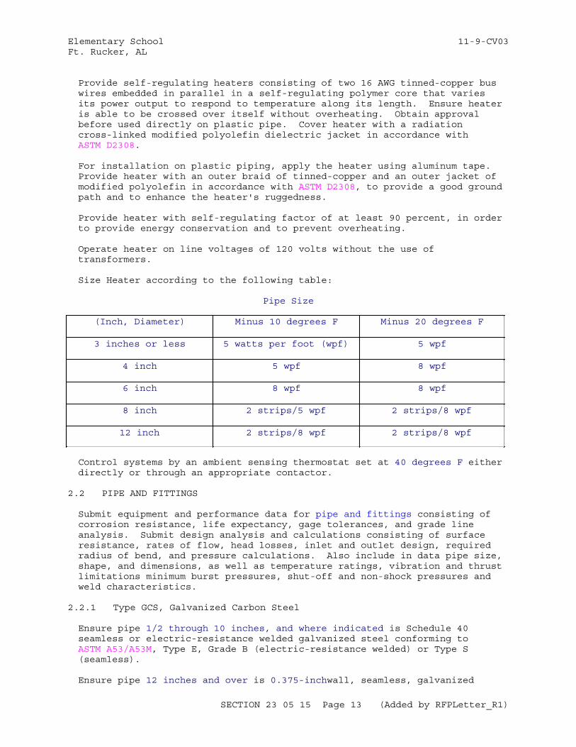
Elementary School 11-9-CV03Ft. Rucker, AL
Provide self-regulating heaters consisting of two 16 AWG tinned-copper bus wires embedded in parallel in a self-regulating polymer core that varies its power output to respond to temperature along its length. Ensure heater is able to be crossed over itself without overheating. Obtain approval before used directly on plastic pipe. Cover heater with a radiation cross-linked modified polyolefin dielectric jacket in accordance with ASTM D2308.
For installation on plastic piping, apply the heater using aluminum tape. Provide heater with an outer braid of tinned-copper and an outer jacket of modified polyolefin in accordance with ASTM D2308, to provide a good ground path and to enhance the heater's ruggedness.
Provide heater with self-regulating factor of at least 90 percent, in order to provide energy conservation and to prevent overheating.
Operate heater on line voltages of 120 volts without the use of transformers.
Size Heater according to the following table:
Pipe Size
(Inch, Diameter) Minus 10 degrees F Minus 20 degrees F
3 inches or less 5 watts per foot (wpf) 5 wpf
4 inch 5 wpf 8 wpf
6 inch 8 wpf 8 wpf
8 inch 2 strips/5 wpf 2 strips/8 wpf
12 inch 2 strips/8 wpf 2 strips/8 wpf
Control systems by an ambient sensing thermostat set at 40 degrees F either directly or through an appropriate contactor.
2.2 PIPE AND FITTINGS
Submit equipment and performance data for pipe and fittings consisting of corrosion resistance, life expectancy, gage tolerances, and grade line analysis. Submit design analysis and calculations consisting of surface resistance, rates of flow, head losses, inlet and outlet design, required radius of bend, and pressure calculations. Also include in data pipe size, shape, and dimensions, as well as temperature ratings, vibration and thrust limitations minimum burst pressures, shut-off and non-shock pressures and weld characteristics.
2.2.1 Type GCS, Galvanized Carbon Steel
Ensure pipe 1/2 through 10 inches, and where indicated is Schedule 40 seamless or electric-resistance welded galvanized steel conforming to ASTM A53/A53M, Type E, Grade B (electric-resistance welded) or Type S (seamless).
Ensure pipe 12 inches and over is 0.375-inchwall, seamless, galvanized
SECTION 23 05 15 Page 13 (Added by RFPLetter_R1)
Elementary School 11-9-CV03Ft. Rucker, AL
steel, conforming to ASTM A53/A53M, Grade B.
Ensure fittings 2 inches and under are 150-psig wsp banded galvanized malleable iron screwed, conforming to ASTM A197/A197M and ASME B16.3.
Ensure unions 2 inches and under are 150-psig wsp female, screwed, galvanized malleable iron with brass-to-iron seat and ground joint.
Ensure fittings 2-1/2 inches and over are 125-psig wsp cast-iron flanges and flanged fittings, conforming to ASTM A126, Class A and ASME B16.1.
Conform grooved pipe couplings and fittings in accordance with paragraph entitled, "Grooved Pipe Couplings and Fittings," of this section.
As an option, use 150-psig wsp banded galvanized malleable iron screwed fittings, conforming to ASTM A197/A197M and ASME B16.3.
2.2.2 Type GCS-DWV, Galvanized Steel Drain, Waste and Vent
Ensure pipe (all sizes) is Schedule 40 electric-resistance welded galvanized carbon steel, conforming to ASTM A53/A53M, Grade A.
Furnace butt weld pipe is acceptable for sizes less than 2 inches.
Provide risers 3 inches and larger are Type CISP-DWV.
Ensure fittings are galvanized, coated , screwed, cast iron, recessed pattern drainage fittings, conforming to ASTM A126.
Use long radius fittings wherever space permits. Short-turn tees, branches, and ells may be used for vent piping and connections of branch lines to battery fixtures, except wall-hung water closets.
2.2.3 Type CISP-DWV, Cast-Iron Drain, Waste and Vent
Provide soil pipe drain, waste, and vent bell-and-spigot type pipe cast iron, conforming to ASTM A74. Caulk and lead all joints in lines where necessary to provide proper leaktight support and alignment; other-wise joints may be two-gasket system type chloroprene, conforming to ASTM C564. Select the extra heavy (CISP-DWV-XH) pipe class.
2.2.4 Type CPR, Copper
2.2.4.1 Type CPR-A, Copper Above Ground
Ensure tubing 2 inches and under is seamless copper tubing, conforming to ASTM B88, Type L (hard-drawn for all horizontal and all exposed vertical lines, annealed for concealed vertical lines).
Ensure fittings 2 inches and under are 150-psig wsp wrought-copper solder joint fittings conforming to ASME B16.22.
Ensure unions 2 inches and under are 150-psig wsp wrought-copper solder joint, conforming to ASME B16.22.
Provide brazing rod with Classification BCuP-5, conforming to AWS A5.8/A5.8M.
Use solder, alloy Sb-5, conforming to ASTM B32.
SECTION 23 05 15 Page 14 (Added by RFPLetter_R1)
Elementary School 11-9-CV03Ft. Rucker, AL
2.2.4.2 Type CPR-U, Copper Under Ground
Provide Type K seamless copper tube piping, conforming to ASTM B88. Use wrought copper socket-joint fittings, conforming to ASME B16.22. Ensure fittings for connection to corporation cocks are cast bronze, flared-type, conforming to ASME B16.26. Braze the joints.
2.2.4.3 Type CPR-INS, Copper Under Ground Insulated
Provide insulated Type K seamless copper tube piping conforming to ASTM B88. Use wrought copper socket-joint fittings, conforming to ASME B16.22. Braze the joints.
Provide insulation not less than 2 inches thick, suitable for continuous service temperatures of not less than 250 degrees F. Use factory-molded, closed-cell polyurethane foam insulation of not less than 2.5 pounds per cubic foot density. Waterproof insulation with an extruded rigid Type II virgin polyvinylchloride, with minimum wall thickness of 60 mils through 4 inches outside diameter, 85 mils through 6.625 inches and 110 mils through 12.750 inches. Provide fitting covers fabricated from the same materials and thickness as adjacent pipe covering according to the manufacturer's directions.
2.2.5 Polypropylene Pipe
Pipe is manufactured from a PP-R resin meeting the short-term properties and long-term strength requirements of ASTM F2389 Pipe is made in a three layer extrusion process. Piping contains a fiber layer (faser) to restrict thermal expansion. Pipe complies with the rated pressure requirements of ASTM F 2389 Ensure layers are incorporated in the pipe wall to limit thermal expansion to 2 1/4-inches per 100 F per 100-ft. If the hydronic system includes ferrous components, an oxygen barrier is required in pipe wall.
Ensure pipe is certified by NSF International as complying with NSF/ANSI 14, and ASTM F2389
Ensure pipe wrap or insulation meets the requirements of ASTM E84. Ensure the system has a Flame Spread Classification of less than 25 and Smoke Development rating of less than 50.
Where pipe is exposed to direct UV light for more than 30 days, provide a Factory applied, UV-resistant coating or alternative UV protection.
2.2.6 Grooved Pipe Couplings and Fittings
Provide housing for all couplings, fabricated in two or more parts, of black, ungalvanized malleable iron castings. Ensure coupling gasket is molded synthetic rubber, conforming to ASTM D2000. Ensure coupling bolts are oval-neck, track-head type, with hexagonal heavy nuts conforming to ASTM A183.
Fabricate all pipe fittings used with couplings of black, ungalvanized malleable iron castings. Where a manufacturer's standard-size malleable iron fitting pattern is not available, approved fabricated fittings may be used.
Fabricate fittings from Schedule 40 or 0.75-inch wall ASTM A53/A53M, Grade B seamless steel pipe; long radius seamless welding fittings with wall
SECTION 23 05 15 Page 15 (Added by RFPLetter_R1)
Elementary School 11-9-CV03Ft. Rucker, AL
thickness to match pipe, conforming to ASTM A234/A234M and ASME B16.9.
2.3 PIPING SPECIALTIES
Submit equipment and performance data for piping specialties consisting of corrosion resistance, life expectancy, gage tolerances, and grade line analysis. Submit design analysis and calculations consisting of surface resistance, rates of flow, head losses, inlet and outlet design, required radius of bend, and pressure calculations. Also include in data pipe size, shape, and dimensions, as well as temperature ratings, vibration and thrust limitations minimum burst pressures, shut-off and non-shock pressures and weld characteristics.
2.3.1 Air/Dirt Separator
Air separated from converter discharge water is ejected by a reduced-velocity device vented to the compression tank.
Provide a commercially constructed separator, designed and certified to separate not less than 80 percent of entrained air on the first passage of water and not less than 80 percent of residual on each successive pass. Dirt separation efficiency shall be a minimum of 80% of all particles 30 micron and larger within 100 passes. Provide shop drawings detailing all piping connections proposed for this work.
2.3.2 Air Vents
Provide automatic air vents on pumps, mains, and where indicated using ball-float construction. Ensure the vent inlet is not less than 3/4-inch ips and the outlet not less than 1/4-inch ips. Orifice size is 1/8 inch. Provide corrosion-resistant steel trim conforming to ASTM A276 . Fit vent with try-cock. Ensure vent discharges air at any pressure up to 150 psi. Ensure outlet is copper tube routed.
2.3.3 Compression Tank
Provide compression tank designed, fabricated, tested, and stamped for a working pressure of not less than 125 psi in accordance with ASME BPVC SEC VIII D1. Ensure tank is hot-dip galvanized after fabrication to produce not less than 1.5 ounces of zinc coating per square foot of single-side surface.
Tank accessories include red-lined gage-glass complete with glass protectors and shutoff valves, air charger and drainer, and manual vent.
2.3.4 Dielectric Connections
Electrically insulate dissimlar pipe metals from each other by couplings, unions, or flanges commercially manufactured for that purpose and rated for the service pressure and temperature.
2.3.5 Expansion Vibration Isolation Joints
Construct single or multiple arch-flanged expansion vibration isolation joints of steel-ring reinforced chloroprene-impregnated cloth materials. Design joint to absorb the movement of the pipe sections in which installed with no detrimental effect on the pipe or connected equipment. Back flanges with ferrous-metal backing rings. Provide control rod assemblies to restrict joint movement. Coat all nonmetallic exterior surfaces of the
SECTION 23 05 15 Page 16 (Added by RFPLetter_R1)
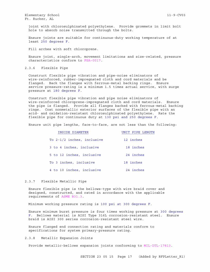
Elementary School 11-9-CV03Ft. Rucker, AL
joint with chlorosulphinated polyethylene. Provide grommets in limit bolt hole to absorb noise transmitted through the bolts.
Ensure joints are suitable for continuous-duty working temperature of at least 250 degrees F.
Fill arches with soft chloroprene.
Ensure joint, single-arch, movement limitations and size-related, pressure characteristics conform to FSA-0017.
2.3.6 Flexible Pipe
Construct flexible pipe vibration and pipe-noise eliminators of wire-reinforced, rubber-impregnated cloth and cord materials and be flanged. Back the flanges with ferrous-metal backing rings. Ensure service pressure-rating is a minimum 1.5 times actual service, with surge pressure at 180 degrees F.
Construct flexible pipe vibration and pipe noise eliminators of wire-reinforced chloroprene-impregnated cloth and cord materials. Ensure the pipe is flanged. Provide all flanges backed with ferrous-metal backing rings. Coat nonmetallic exterior surfaces of the flexible pipe with an acid- and oxidation-resistant chlorosulphinated polyethylene. Rate the flexible pipe for continuous duty at 130 psi and 250 degrees F.
Ensure unit pipe lengths, face-to-face, are not less than the following:
INSIDE DIAMETER UNIT PIPE LENGTH
To 2-1/2 inches, inclusive 12 inches
3 to 4 inches, inclusive 18 inches
5 to 12 inches, inclusive 24 inches
To 3 inches, inclusive 18 inches
4 to 10 inches, inclusive 24 inches
2.3.7 Flexible Metallic Pipe
Ensure flexible pipe is the bellows-type with wire braid cover and designed, constructed, and rated in accordance with the applicable requirements of ASME B31.3.
Minimum working pressure rating is 100 psi at 300 degrees F.
Ensure minimum burst pressure is four times working pressure at 300 degrees F. Bellows material is AISI Type 316L corrosion-resistant steel. Ensure braid is AISI 300 series corrosion-resistant steel wire.
Ensure flanged end connection rating and materials conform to specifications for system primary-pressure rating.
2.3.8 Metallic Expansion Joints
Provide metallic-bellows expansion joints conforming to MIL-DTL-17813.
SECTION 23 05 15 Page 17 (Added by RFPLetter_R1)
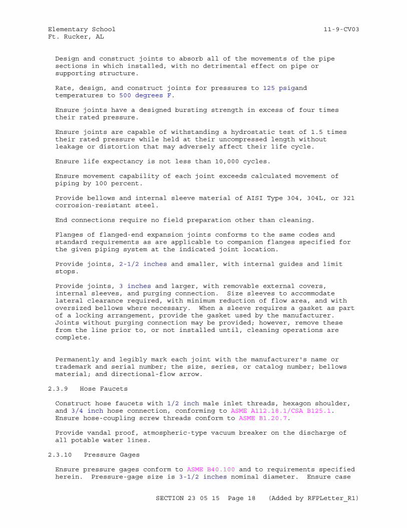
Elementary School 11-9-CV03Ft. Rucker, AL
Design and construct joints to absorb all of the movements of the pipe sections in which installed, with no detrimental effect on pipe or supporting structure.
Rate, design, and construct joints for pressures to 125 psigand temperatures to 500 degrees F.
Ensure joints have a designed bursting strength in excess of four times their rated pressure.
Ensure joints are capable of withstanding a hydrostatic test of 1.5 times their rated pressure while held at their uncompressed length without leakage or distortion that may adversely affect their life cycle.
Ensure life expectancy is not less than 10,000 cycles.
Ensure movement capability of each joint exceeds calculated movement of piping by 100 percent.
Provide bellows and internal sleeve material of AISI Type 304, 304L, or 321 corrosion-resistant steel.
End connections require no field preparation other than cleaning.
Flanges of flanged-end expansion joints conforms to the same codes and standard requirements as are applicable to companion flanges specified for the given piping system at the indicated joint location.
Provide joints, 2-1/2 inches and smaller, with internal guides and limit stops.
Provide joints, 3 inches and larger, with removable external covers, internal sleeves, and purging connection. Size sleeves to accommodate lateral clearance required, with minimum reduction of flow area, and with oversized bellows where necessary. When a sleeve requires a gasket as part of a locking arrangement, provide the gasket used by the manufacturer. Joints without purging connection may be provided; however, remove these from the line prior to, or not installed until, cleaning operations are complete.
Permanently and legibly mark each joint with the manufacturer's name or trademark and serial number; the size, series, or catalog number; bellows material; and directional-flow arrow.
2.3.9 Hose Faucets
Construct hose faucets with 1/2 inch male inlet threads, hexagon shoulder, and 3/4 inch hose connection, conforming to ASME A112.18.1/CSA B125.1. Ensure hose-coupling screw threads conform to ASME B1.20.7.
Provide vandal proof, atmospheric-type vacuum breaker on the discharge of all potable water lines.
2.3.10 Pressure Gages
Ensure pressure gages conform to ASME B40.100 and to requirements specified herein. Pressure-gage size is 3-1/2 inches nominal diameter. Ensure case
SECTION 23 05 15 Page 18 (Added by RFPLetter_R1)
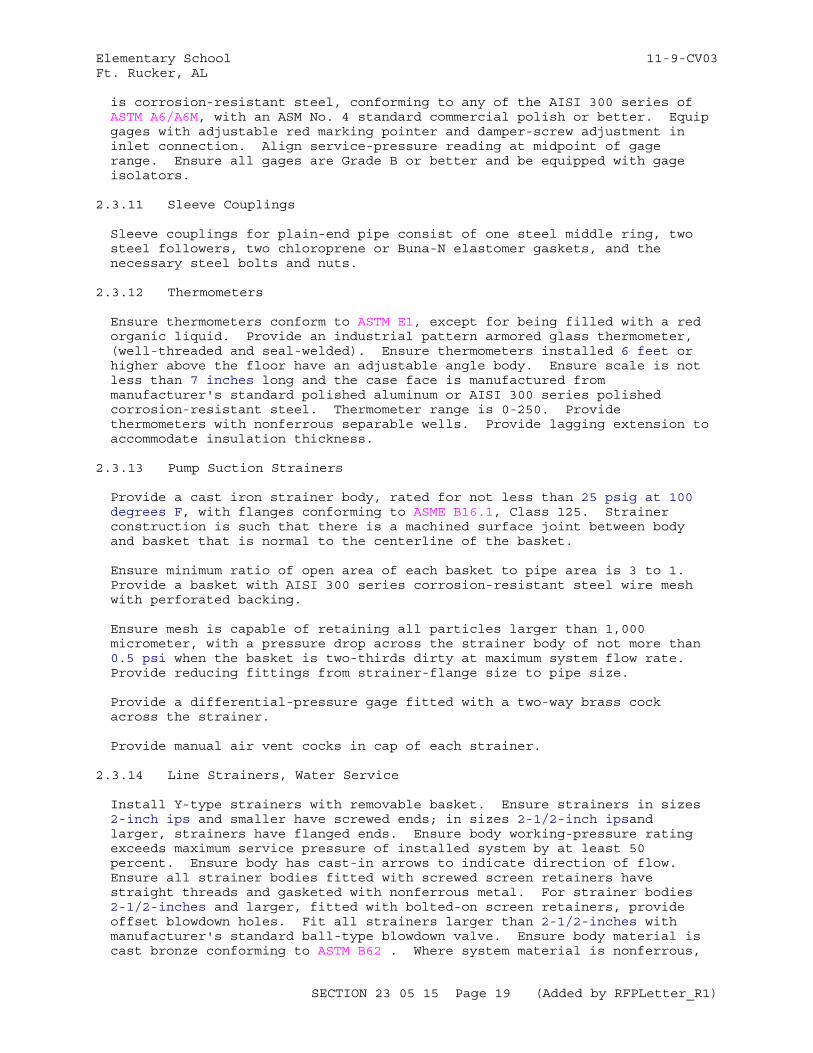
Elementary School 11-9-CV03Ft. Rucker, AL
is corrosion-resistant steel, conforming to any of the AISI 300 series of ASTM A6/A6M, with an ASM No. 4 standard commercial polish or better. Equip gages with adjustable red marking pointer and damper-screw adjustment in inlet connection. Align service-pressure reading at midpoint of gage range. Ensure all gages are Grade B or better and be equipped with gage isolators.
2.3.11 Sleeve Couplings
Sleeve couplings for plain-end pipe consist of one steel middle ring, two steel followers, two chloroprene or Buna-N elastomer gaskets, and the necessary steel bolts and nuts.
2.3.12 Thermometers
Ensure thermometers conform to ASTM E1, except for being filled with a red organic liquid. Provide an industrial pattern armored glass thermometer, (well-threaded and seal-welded). Ensure thermometers installed 6 feet or higher above the floor have an adjustable angle body. Ensure scale is not less than 7 inches long and the case face is manufactured from manufacturer's standard polished aluminum or AISI 300 series polished corrosion-resistant steel. Thermometer range is 0-250. Provide thermometers with nonferrous separable wells. Provide lagging extension to accommodate insulation thickness.
2.3.13 Pump Suction Strainers
Provide a cast iron strainer body, rated for not less than 25 psig at 100 degrees F, with flanges conforming to ASME B16.1, Class 125. Strainer construction is such that there is a machined surface joint between body and basket that is normal to the centerline of the basket.
Ensure minimum ratio of open area of each basket to pipe area is 3 to 1. Provide a basket with AISI 300 series corrosion-resistant steel wire mesh with perforated backing.
Ensure mesh is capable of retaining all particles larger than 1,000 micrometer, with a pressure drop across the strainer body of not more than 0.5 psi when the basket is two-thirds dirty at maximum system flow rate. Provide reducing fittings from strainer-flange size to pipe size.
Provide a differential-pressure gage fitted with a two-way brass cock across the strainer.
Provide manual air vent cocks in cap of each strainer.
2.3.14 Line Strainers, Water Service
Install Y-type strainers with removable basket. Ensure strainers in sizes 2-inch ips and smaller have screwed ends; in sizes 2-1/2-inch ipsand larger, strainers have flanged ends. Ensure body working-pressure rating exceeds maximum service pressure of installed system by at least 50 percent. Ensure body has cast-in arrows to indicate direction of flow. Ensure all strainer bodies fitted with screwed screen retainers have straight threads and gasketed with nonferrous metal. For strainer bodies 2-1/2-inches and larger, fitted with bolted-on screen retainers, provide offset blowdown holes. Fit all strainers larger than 2-1/2-inches with manufacturer's standard ball-type blowdown valve. Ensure body material is cast bronze conforming to ASTM B62 . Where system material is nonferrous,
SECTION 23 05 15 Page 19 (Added by RFPLetter_R1)
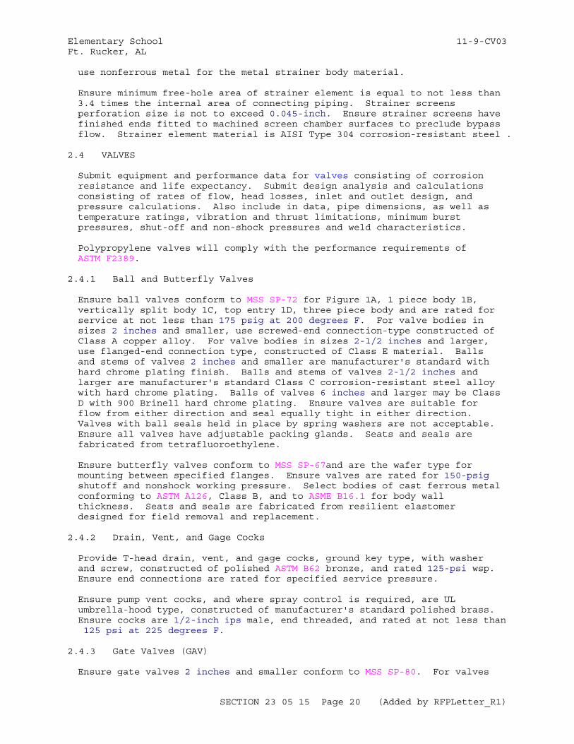
Elementary School 11-9-CV03Ft. Rucker, AL
use nonferrous metal for the metal strainer body material.
Ensure minimum free-hole area of strainer element is equal to not less than 3.4 times the internal area of connecting piping. Strainer screens perforation size is not to exceed 0.045-inch. Ensure strainer screens have finished ends fitted to machined screen chamber surfaces to preclude bypass flow. Strainer element material is AISI Type 304 corrosion-resistant steel .
2.4 VALVES
Submit equipment and performance data for valves consisting of corrosion resistance and life expectancy. Submit design analysis and calculations consisting of rates of flow, head losses, inlet and outlet design, and pressure calculations. Also include in data, pipe dimensions, as well as temperature ratings, vibration and thrust limitations, minimum burst pressures, shut-off and non-shock pressures and weld characteristics.
Polypropylene valves will comply with the performance requirements of ASTM F2389.
2.4.1 Ball and Butterfly Valves
Ensure ball valves conform to MSS SP-72 for Figure 1A, 1 piece body 1B, vertically split body 1C, top entry 1D, three piece body and are rated for service at not less than 175 psig at 200 degrees F. For valve bodies in sizes 2 inches and smaller, use screwed-end connection-type constructed of Class A copper alloy. For valve bodies in sizes 2-1/2 inches and larger, use flanged-end connection type, constructed of Class E material. Balls and stems of valves 2 inches and smaller are manufacturer's standard with hard chrome plating finish. Balls and stems of valves 2-1/2 inches and larger are manufacturer's standard Class C corrosion-resistant steel alloy with hard chrome plating. Balls of valves 6 inches and larger may be Class D with 900 Brinell hard chrome plating. Ensure valves are suitable for flow from either direction and seal equally tight in either direction. Valves with ball seals held in place by spring washers are not acceptable. Ensure all valves have adjustable packing glands. Seats and seals are fabricated from tetrafluoroethylene.
Ensure butterfly valves conform to MSS SP-67and are the wafer type for mounting between specified flanges. Ensure valves are rated for 150-psig shutoff and nonshock working pressure. Select bodies of cast ferrous metal conforming to ASTM A126, Class B, and to ASME B16.1 for body wall thickness. Seats and seals are fabricated from resilient elastomer designed for field removal and replacement.
2.4.2 Drain, Vent, and Gage Cocks
Provide T-head drain, vent, and gage cocks, ground key type, with washer and screw, constructed of polished ASTM B62 bronze, and rated 125-psi wsp. Ensure end connections are rated for specified service pressure.
Ensure pump vent cocks, and where spray control is required, are UL umbrella-hood type, constructed of manufacturer's standard polished brass. Ensure cocks are 1/2-inch ips male, end threaded, and rated at not less than 125 psi at 225 degrees F.
2.4.3 Gate Valves (GAV)
Ensure gate valves 2 inches and smaller conform to MSS SP-80. For valves
SECTION 23 05 15 Page 20 (Added by RFPLetter_R1)
Elementary School 11-9-CV03Ft. Rucker, AL
located in tunnels, equipment rooms, factory-assembled equipment, and where indicated use union-ring bonnet, screwed-end type. Make packing of non-asbestos type materials. Use rising stem type valves.
Ensure gate valves 2-1/2 inches and larger, are Type I, (solid wedge disc, tapered seats, steam rated); Class 125 (125-psig steam-working pressure at 353 degrees F saturation); and 200-psig, wog (nonshock), conforming to MSS SP-70 and to requirements specified herein. Select flanged valves, with bronze trim and outside screw and yoke (OS&Y) construction. Make packing of non-asbestos type materials.
2.4.4 Globe and Angle Valves (GLV-ANV)
Ensure globe and angle valves 2 inches and smaller, are 125-pound, 125-psi conforming to MSS SP-80 and to requirements specified herein. For valves located in tunnels, equipment rooms, factory-assembled equipment, and where indicated, use union-ring bonnet, screwed-end type. Ensure disc is free to swivel on the stem in all valve sizes. Composition seating-surface disc construction may be substituted for all metal-disc construction. Make packing of non-asbestos type materials. Ensure disk and packing are suitable for pipe service installed.
Ensure globe and angle valves, 2-1/2 inches and larger, are cast iron with bronze trim. Ensure valve bodies are cast iron conforming to ASTM A126, Class A, as specified for Class 1 valves under MSS SP-80. Select flanged valves in conformance with ASME B16.1. Valve construction is outside screw and yoke (OS&Y) type. Make packing of non-asbestos type materials.
2.4.5 Standard Check Valves (SCV)
Ensure standard check valves in sizes 2 inches and smaller are 125-psi swing check valves except as otherwise specified. Provide lift checks where indicated. Ensure swing-check pins are nonferrous and suitably hard for the service. Select composition type discs. Ensure the swing-check angle of closure is manufacturer's standard unless a specific angle is needed.
Use cast iron, bronze trim, swing type check valves in sizes 2-1/2 inches and larger. Ensure valve bodies are cast iron, conforming to ASTM A126, Class A and valve ends are flanged in conformance with ASME B16.1. Swing-check pin is AISI Type or approved equal corrosion-resistant steel. Angle of closure is manufacturer's standard unless a specific angle is needed. Ensure valves have bolted and gasketed covers.
Provide check valves with external spring-loaded , positive-closure devices and valve ends are flanged.
2.4.6 Nonslam Check Valves (NSV)
Provide check valves at pump discharges in sizes 2 inches and larger with nonslam or silent-check operation conforming to MSS SP-125. Select a valve disc or plate that closes before line flow can reverse to eliminate slam and water-hammer due to check-valve closure. Ensure valve is Class 125 rated for 200-psi maximum, nonshock pressure at 150 degrees F in sizes to 12 inches. Use valves that are wafer type to fit between flanges conforming to ASME B16.1 . Valve body may be cast iron, or equivalent strength ductile iron. Select disks using manufacturer's standard bronze, aluminum bronze, or corrosion-resistant steel. Ensure pins, springs, and miscellaneous trim are manufacturer's standard corrosion-resistant steel.
SECTION 23 05 15 Page 21 (Added by RFPLetter_R1)
Elementary School 11-9-CV03Ft. Rucker, AL
Disk and shaft seals are Buna-N elastomer tetrafluoroethylene.
2.5 MISCELLANEOUS MATERIALS
Submit equipment and performance data for miscellaneous materials consisting of corrosion resistance, life expectancy, gage tolerances, and grade line analysis.
2.5.1 Bituminous Coating
Ensure the bituminous coating is a solvent cutback, heavy-bodied material to produce not less than a 12-mil dry-film thickness in one coat, and is recommended by the manufacturer to be compatible with factory-applied coating and rubber joints.
For previously coal-tar coated and uncoated ferrous surfaces underground, use bituminous coating solvent cutback coal-tar type, conforming to MIL-C-18480.
2.5.2 Bolting
Ensure flange and general purpose bolting is hex-head and conforms to ASTM A307, Grade B (bolts, for flanged joints in piping systems where one or both flanges are cast iron). Heavy hex-nuts conform to ASTM A563. Square-head bolts and nuts are not acceptable. Ensure threads are coarse-thread series.
2.5.3 Elastomer Caulk
Use two-component polysulfide- or polyurethane-base elastomer caulking material, conforming to ASTM C920.
2.5.4 Escutcheons
Manufacture escutcheons from nonferrous metals and chrome-plated except when AISI 300 series corrosion-resistant steel is provided. Ensure metals and finish conforms to ASME A112.19.2/CSA B45.1.
Use one-piece escutcheons where mounted on chrome-plated pipe or tubing, and one-piece of split-pattern type elsewhere. Ensure all escutcheons have provisions consisting of internal spring-tension devices for maintaining a fixed position against a surface.
2.5.5 Flashing
Ensure sheetlead conforms to ASTM B749, UNS Alloy Number L50049 (intended for use in laboratories and shops in general application) .
Ensure sheet copper conforms to ASTM B370 and be not less than 16 ounces per square foot weight.
2.5.6 Flange Gaskets
Provide compressed non-asbestos sheets, conforming to ASTM F104, coated on both sides with graphite or similar lubricant, with nitrile composition, binder rated to 750 degrees F.
SECTION 23 05 15 Page 22 (Added by RFPLetter_R1)
Elementary School 11-9-CV03Ft. Rucker, AL
2.5.7 Grout
Provide shrink-resistant grout as a premixed and packaged metallic-aggregate, mortar-grouting compound conforming to ASTM C404 and ASTM C476.
Ensure shrink-resistant grout is a combination of pre-measured and packaged epoxy polyamide or amine resins and selected aggregate mortar grouting compound conforming to the following requirements:
Tensile strength 1,900 psi, minimum
Compressive strength ASTM C109/C109M 14,000 psi, minimum
Shrinkage, linear 0.00012 inch per inch, maximum
Water absorption ASTM C67 0.1 percent, maximum
Bond strength to 1,000 psi, minimum steel in shear minimum
2.5.8 Pipe Thread Compounds
Use polytetrafluoroethylene tape not less than 2 to 3 mils thick in potable and process water and in chemical systems for pipe sizes to and including 1-inch ips. Use polytetrafluoroethylene dispersions and other suitable compounds for all other applications upon approval by the Contracting Officer; however, do not use lead-containing compounds in potable water systems.
2.6 SUPPORTING ELEMENTS
Submit equipment and performance data for the supporting elements consisting of corrosion resistance, life expectancy, gage tolerances, and grade line analysis.
Provide all necessary piping systems and equipment supporting elements, including but not limited to: building structure attachments; supplementary steel; hanger rods, stanchions, and fixtures; vertical pipe attachments; horizontal pipe attachments; anchors; guides; and spring-cushion, variable, or constant supports. Ensure supporting elements are suitable for stresses imposed by systems pressures and temperatures and natural and other external forces normal to this facility without damage to supporting element system or to work being supported.
Ensure supporting elements conform to requirements of ASME B31.3, and MSS SP-58, except as noted.
Ensure attachments welded to pipe are made of materials identical to that of pipe or materials accepted as permissible raw materials by referenced code or standard specification.
Ensure supporting elements exposed to weather are hot-dip galvanized or stainless steel. Select materials of such a nature that their apparent and latent-strength characteristics are not reduced due to galvanizing process. Electroplate supporting elements in contact with copper tubing with copper.
Type designations specified herein are based on MSS SP-58. Ensure masonry
SECTION 23 05 15 Page 23 (Added by RFPLetter_R1)
Elementary School 11-9-CV03Ft. Rucker, AL
anchor group-, type-, and style-combination designations are in accordance with CID A-A-1922, CID A-A-1923, CID A-A-1924, CID A-A-1925 , CID A-A-55614, and CID A-A-55615. Provide support elements, except for supplementary steel, that are cataloged, load rated, commercially manufactured products.
2.6.1 Building Structure Attachments
2.6.1.1 Anchor Devices, Concrete and Masonry
Ensure anchor devices conform to CID A-A-1922, CID A-A-1923, CID A-A-1924, CID A-A-1925 , CID A-A-55614, and CID A-A-55615
For cast-in, floor mounted, equipment anchor devices, provide adjustable positions.
Provide built-in masonry anchor devices.
2.6.1.2 Beam Clamps
Ensure beam clamps are center-loading MSS SP-58 Type 30 .
When it is not possible to use center-loading beam clamps, eccentric-loading beam clamps, MSS SP-58 Type 20 may be used for piping sizes 2 inches and less and for piping sizes 2 through 10 inches provided two counterbalancing clamps are used per point of pipe support. Where more than one rod is used per point of pipe support, determine rod diameter in accordance with referenced standards.
2.6.1.3 C-Clamps
Do not use C-clamps.
2.6.1.4 Inserts, Concrete
Use concrete MSS SP-58 Type 18 inserts When applied to piping in sizes 2 inches ips and larger and where otherwise required by imposed loads, insert and wire a 1-foot length of 1/2-inch reinforcing rod through wing slots. Submit proprietary-type continuous inserts for approval.
2.6.2 Horizontal Pipe Attachments
2.6.2.1 Single Pipes
Support piping in sizes to and including 2-inch ips by MSS SP-58 Type 6 solid malleable iron pipe rings, except that, use split-band-type rings in sizes up to 1-inch ips.
Support piping in sizes through 8-inch ips inclusive by MSS SP-58 Type 1 attachments.
Use MSS SP-58 Type 1 and Type 6 assemblies on vapor-sealed insulated piping and have an inside diameter larger than pipe being supported to provide adequate clearance during pipe movement.
Where thermal movement of a point in a piping system 4 inches and larger would cause a hanger rod to deflect more than 4 degrees from the vertical or where a horizontal point movement exceeds 1/2 inch, use MSS SP-58 Type
SECTION 23 05 15 Page 24 (Added by RFPLetter_R1)
Elementary School 11-9-CV03Ft. Rucker, AL
44 through 46 pipe rolls.
Support piping in sizes larger than 8-inch ips with MSS SP-58 Type 44 through 46 pipe rolls.
Use MSS SP-58 Type 40 shields on all insulated piping. Ensure area of the supporting surface is such that compression deformation of insulated surfaces does not occur. Roll away longitudinal and transverse shield edges from the insulation.
Provide insulated piping without vapor barrier on roll supports with MSS SP-58 Type 39 saddles.
Provide spring supports as indicated.
2.6.2.2 Parallel Pipes
Use trapeze hangers fabricated from structural steel shapes, with U-bolts, in congested areas and where multiple pipe runs occur. Ensure structural steel shapes be of commercially available, proprietary design, rolled steel.
2.6.3 Vertical Pipe Attachments
Ensure vertical pipe attachments are MSS SP-58 Type 8.
Include complete fabrication and attachment details of any spring supports in shop drawings.
2.6.4 Hanger Rods and Fixtures
Use only circular cross section rod hangers to connect building structure attachments to pipe support devices. Use pipe, straps, or bars of equivalent strength for hangers only where approved by the Contracting Officer.
Provide turnbuckles, swing eyes, and clevises as required by support system to accommodate temperature change, pipe accessibility, and adjustment for load and pitch. Rod couplings are not acceptable.
2.6.5 Supplementary Steel
Where it is necessary to frame structural members between existing members or where structural members are used in lieu of commercially rated supports, design and fabricate such supplementary steel in accordance with AISC 325.
PART 3 EXECUTION
3.1 PIPE INSTALLATION
Submit certificates for pipes, valves and specialties showing conformance with test requirements as contained in the reference standards contained in this section. Provide certificates verifying Surface Resistance, Shear and Tensile Strengths, Temperature Ratings, Bending Tests, Flattening Tests and Transverse Guided Weld Bend Tests.
Provide test reports for Hydrostatic Tests, Air Tests, Valve-Operating Tests, Drainage Tests, Pneumatic Tests, Non-Destructive Electric Tests and System Operation Tests, in compliance with referenced standards contained within
SECTION 23 05 15 Page 25 (Added by RFPLetter_R1)
Elementary School 11-9-CV03Ft. Rucker, AL
this section.
Fabricate and install piping systems in accordance with ASME B31.3, MSS SP-58, and AWS WHB-2.9.
Submit Installation Drawings for pipes, valves and specialties. Drawings include the manufacturer's design and construction calculations, forces required to obtain rated axial, lateral, or angular movements, installation criteria, anchor and guide requirements for equipment, and equipment room layout and design. Ensure drawings specifically advise on procedures to be followed and provisions required to protect expansion joints during specified hydrostatic testing operations.
Ensure connections between steel piping and copper piping are electrically isolated from each other with dielectric couplings (or unions) rated for the service.
Make final connections to equipment with unions provided every 100 feet of straight run. Provide unions in the line downstream of screwed- and welded-end valves.
Ream all pipe ends before joint connections are made.
Make screwed joints with specified joint compound with not more than three threads showing after joint is made up.
Apply joint compounds to the male thread only and exercise care to prevent compound from reaching the unthreaded interior of the pipe.
Provide screwed unions, welded unions, or bolted flanges wherever required to permit convenient removal of equipment, valves, and piping accessories from the piping system for maintenance.
Securely support piping systems with due allowance for thrust forces, thermal expansion and contraction. Do not subject the system to mechanical, chemical, vibrational or other damage as specified in ASME B31.3.
Ensure field welded joints conform to the requirements of the AWS WHB-2.9, ASME B31.3, and ASME BPVC SEC IX.
Make piping systems butt weld joints with backing rings. Use compatible backing ring materials with materials being joined. Ensure joint configuration conforms to ASME B16.25.
For polyropylene pipe, make fusion-weld joints in accordance with the pipe and fitting manufacturer's specifications and product standards. Use fusion-weld tooling, welding machines, and electrofusion devices specified by the pipe and fittings manufacturer. Prior to joining, prepare the pipe and fittings in accordance with ASTM F2389 and the manufacturer's specifications. Ensure joint preparation, setting and alignment, fusion process, cooling times and working pressure are in accordance with the pipe and fitting manufacturer's specifications.
Accomplish preheat and postheat treatment of welds in accordance with ASME BPVC SEC IX and ASME B31.3.
Take all necessary precautions during installation of flexible pipe and hose including flushing and purging with water, steam, and compressed air to preclude bellows failure due to pipe line debris lodged in bellows.
SECTION 23 05 15 Page 26 (Added by RFPLetter_R1)
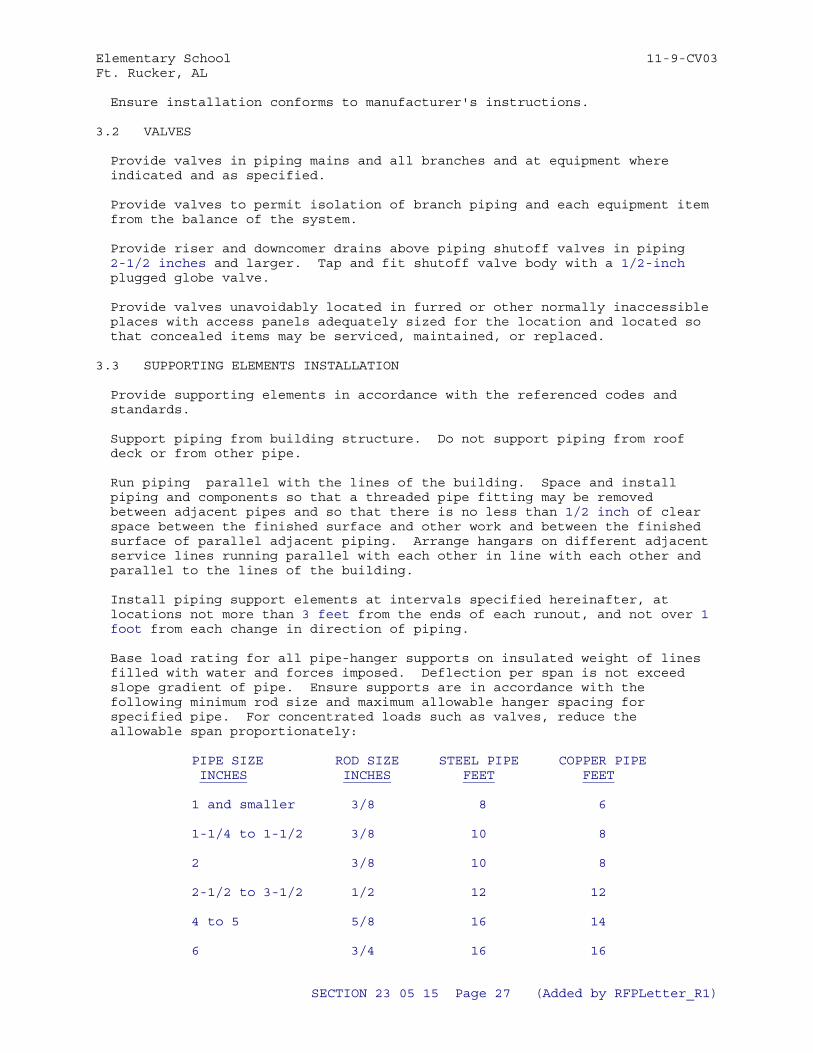
Elementary School 11-9-CV03Ft. Rucker, AL
Ensure installation conforms to manufacturer's instructions.
3.2 VALVES
Provide valves in piping mains and all branches and at equipment where indicated and as specified.
Provide valves to permit isolation of branch piping and each equipment item from the balance of the system.
Provide riser and downcomer drains above piping shutoff valves in piping 2-1/2 inches and larger. Tap and fit shutoff valve body with a 1/2-inch plugged globe valve.
Provide valves unavoidably located in furred or other normally inaccessible places with access panels adequately sized for the location and located so that concealed items may be serviced, maintained, or replaced.
3.3 SUPPORTING ELEMENTS INSTALLATION
Provide supporting elements in accordance with the referenced codes and standards.
Support piping from building structure. Do not support piping from roof deck or from other pipe.
Run piping parallel with the lines of the building. Space and install piping and components so that a threaded pipe fitting may be removed between adjacent pipes and so that there is no less than 1/2 inch of clear space between the finished surface and other work and between the finished surface of parallel adjacent piping. Arrange hangars on different adjacent service lines running parallel with each other in line with each other and parallel to the lines of the building.
Install piping support elements at intervals specified hereinafter, at locations not more than 3 feet from the ends of each runout, and not over 1 foot from each change in direction of piping.
Base load rating for all pipe-hanger supports on insulated weight of lines filled with water and forces imposed. Deflection per span is not exceed slope gradient of pipe. Ensure supports are in accordance with the following minimum rod size and maximum allowable hanger spacing for specified pipe. For concentrated loads such as valves, reduce the allowable span proportionately:
PIPE SIZE ROD SIZE STEEL PIPE COPPER PIPE INCHES INCHES FEET FEET
1 and smaller 3/8 8 6
1-1/4 to 1-1/2 3/8 10 8
2 3/8 10 8
2-1/2 to 3-1/2 1/2 12 12
4 to 5 5/8 16 14
6 3/4 16 16
SECTION 23 05 15 Page 27 (Added by RFPLetter_R1)
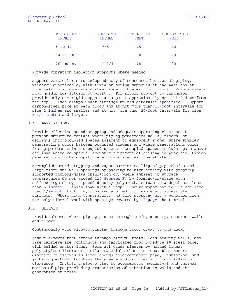
Elementary School 11-9-CV03Ft. Rucker, AL
PIPE SIZE ROD SIZE STEEL PIPE COPPER PIPE INCHES INCHES FEET FEET
8 to 12 7/8 20 20
14 to 18 1 20 20
20 and over 1-1/4 20 20
Provide vibration isolation supports where needed.
Support vertical risers independently of connected horizontal piping, whenever practicable, with fixed or spring supports at the base and at intervals to accommodate system range of thermal conditions. Ensure risers have guides for lateral stability. For risers subject to expansion, provide only one rigid support at a point approximately one-third down from the top. Place clamps under fittings unless otherwise specified. Support carbon-steel pipe at each floor and at not more than 15-foot intervals for pipe 2 inches and smaller and at not more than 20-foot intervals for pipe 2-1/2 inches and larger.
3.4 PENETRATIONS
Provide effective sound stopping and adequate operating clearance to prevent structure contact where piping penetrates walls, floors, or ceilings into occupied spaces adjacent to equipment rooms; where similar penetrations occur between occupied spaces; and where penetrations occur from pipe chases into occupied spaces. Occupied spaces include space above ceilings where no special acoustic treatment of ceiling is provided. Finish penetrations to be compatible with surface being penetrated.
Accomplish sound stopping and vapor-barrier sealing of pipe shafts and large floor and wall openings by packing to high density with properly supported fibrous-glass insulation or, where ambient or surface temperatures do not exceed 120 degrees F, by foaming-in-place with self-extinguishing, 2-pound density polyurethane foam to a depth not less than 6 inches. Finish foam with a rasp. Ensure vapor barrier is not less than 1/8-inch thick vinyl coating applied to visible and accessible surfaces. Where high temperatures and fire stopping are a consideration, use only mineral wool with openings covered by 16-gage sheet metal.
3.5 SLEEVES
Provide sleeves where piping passes through roofs, masonry, concrete walls and floors.
Continuously weld sleeves passing through steel decks to the deck.
Ensure sleeves that extend through floors, roofs, load bearing walls, and fire barriers are continuous and fabricated from Schedule 40 steel pipe, with welded anchor lugs. Form all other sleeves by molded linear polyethylene liners or similar materials that are removable. Ensure diameter of sleeves is large enough to accommodate pipe, insulation, and jacketing without touching the sleeve and provides a minimum 3/8-inch clearance. Install a sleeve size to accommodate mechanical and thermal motion of pipe precluding transmission of vibration to walls and the generation of noise.
SECTION 23 05 15 Page 28 (Added by RFPLetter_R1)
Elementary School 11-9-CV03Ft. Rucker, AL
Pack the space between a pipe, bare or insulated, and the inside of a pipe sleeve or a construction surface penetration solid with a mineral fiber conforming to ASTM C553 Type V (flexible blanket), (to 1,000 degrees F). Provide this packing wherever the piping passes through firewalls, equipment room walls, floors, and ceilings connected to occupied spaces, and other locations where sleeves or construction-surface penetrations occur between occupied spaces. Where sleeves or construction surface penetrations occur between conditioned and unconditioned spaces, fill the space between a pipe, bare or insulated, and the inside of a pipe sleeve or construction surface penetration with an elastomer caulk to a depth of 1/2 inch. Ensure all caulked surfaces are oil- and grease-free.
Ensure through-penetration fire stop materials and methods are in accordance with ASTM E814 and UL 1479.
Caulk exterior wall sleeves watertight with lead and oakum or mechanically expandable chloroprene inserts with mastic-sealed metal components.
Ensure sleeve height above roof surface is a minimum of 12 and a maximum of 18-inches.
3.6 ESCUTCHEONS
Provide escutcheons at all penetrations of piping into finished areas. Where finished areas are separated by partitions through which piping passes, provide escutcheons on both sides of the partition. Where suspended ceilings are installed, provide plates at the underside only of such ceilings. For insulated pipes, select plates large enough to fit around the insulation. Use chrome-plated escutcheons in all occupied spaces and of size sufficient to effectively conceal openings in building construction. Firmly attach escutcheons with setscrews.
3.7 FLASHINGS
Provide flashings at penetrations of building boundaries by mechanical systems and related work.
3.8 UNDERGROUND PIPING INSTALLATION
Prior to being lowered into a trench, clean all piping, visually inspected for apparent defects, and tapped with a hammer to audibly detect hidden defects.
Further inspect suspect cast-ferrous piping by painting with kerosene on external surfaces to reveal cracks.
Distinctly mark defective materials found using a road-traffic quality yellow paint; promptly remove defective material from the site.
After conduit has been inspected, and not less than 48 hours prior to being lowered into a trench, coat all external surfaces of cast ferrous conduit with a compatible bituminous coating for protection against brackish ground water. Apply a single coat, in accordance with the manufacturer's instructions, to result in a dry-film thickness of not less than 12 mils.
Ensure excavations are dry and clear of extraneous materials when pipe is being laid.
Use wheel cutters for cutting of piping or other machines designed
SECTION 23 05 15 Page 29 (Added by RFPLetter_R1)
Elementary School 11-9-CV03Ft. Rucker, AL
specifically for that purpose. Electric-arc and oxyacetylene cutting is not permitted.
Begin laying of pipe at the low point of a system. When in final acceptance position, ensure it is true to the grades and alignment indicated, with unbroken continuity of invert. Blocking and wedging is not permitted.
Point bell or grooved ends of piping upstream.
Make changes in direction with long sweep fittings.
Provide necessary socket clamping, piers, bases, anchors, and thrust blocking. Protect rods, clamps, and bolting with a coating of bitumen.
Support underground piping below supported or suspended slabs from the slab with a minimum of two supports per length of pipe. Protect supports with a coating of bitumen.
On excavations that occur near and below building footings, provide backfilling material consisting of 2,000-psi cured compressive-strength concrete poured or pressure-grouted up to the level of the footing.
Properly support vertical downspouts; soil, waste, and vent stacks; water risers; and similar work on approved piers at the base and provided with approved structural supports attached to building construction.
Provide cleanout, flushing, and observation risers.
3.9 HEAT TRACE CABLE INSTALLATION
Field apply heater tape and cut to fit as necessary, linearly along the length of pipe after piping has been pressure tested and approved by the Contracting Officer. Secure the heater to piping with cable ties . Label thermal insulation on the outside, "Electrical Heat Trace."
Install power connection, end seals, splice kits and tee kit components in accordance with IEEE 515 to provide a complete workable system. Terminate connection to the thermostat and ends of the heat tape in a junction box. Ensure cable and conduit connections are raintight.
3.10 DISINFECTION
Disinfect water piping, including all valves, fittings, and other devices, with a solution of chlorine and water. Ensure the solution contains not less than 50 parts per million (ppm) of available chlorine. Hold solution for a period of not less than 8 hours, after which the solution contains not less than 10 ppm of available chlorine or redisinfect the piping. After successful sterilization, thoroughly flush the piping before placing into service. Flushing is complete when the flush water contains less than 0.5 ppm of available chlorine. Water for disinfected will be furnished by the Government. Approve disposal of contaminated flush water in accordance with written instructions received from the Environmental authority having jurisdiction through the Contracting Officer and all local, State and Federal Regulations.
Flush piping with potable water until visible grease, dirt and other contaminants are removed (visual inspection).
SECTION 23 05 15 Page 30 (Added by RFPLetter_R1)
Elementary School 11-9-CV03Ft. Rucker, AL
3.11 HEAT TRACE CABLE TESTS
Test heat trace cable system in accordance with IEEE 515 after installation and before and after installation of the thermal insulation. Test heater cable using a 1000 vdc megger. Minimum insulation resistance is 20 to 1000 megohms regardless of cable length.
3.12 OPERATION AND MAINTENANCE
Provide Operation and Maintenance Manuals consistent with manufacturer's standard brochures, schematics, printed instructions, general operating procedures and safety precautions. Submit test data that is clear and readily legible.
3.13 PAINTING OF NEW EQUIPMENT
Factory or shop apply new equipment painting, as specified herein, and provided under each individual section.
3.13.1 Factory Painting Systems
Manufacturer's standard factory painting systems may be provided subject to certification that the factory painting system applied withstands 125 hours in a salt-spray fog test, except that equipment located outdoors withstand 500 hours in a salt-spray fog test. Conduct salt-spray fog test is in accordance with ASTM B117, and for that test the acceptance criteria is as follows: immediately after completion of the test, the inspected paint shows no signs of blistering, wrinkling, or cracking, and no loss of adhesion; and the specimen shows no signs of rust creepage beyond 0.125 inch on either side of the scratch mark.
Ensure the film thickness of the factory painting system applied on the equipment is not less than the film thickness used on the test specimen. If manufacturer's standard factory painting system is being proposed for use on surfaces subject to temperatures above 120 degrees F, design the factory painting system for the temperature service.
3.13.2 Shop Painting Systems for Metal Surfaces
Clean, pretreat, prime and paint metal surfaces; except aluminum surfaces need not be painted. Apply coatings to clean dry surfaces. Clean the surfaces to remove dust, dirt, rust, oil and grease by wire brushing and solvent degreasing prior to application of paint, except clean to bare metal, surfaces subject to temperatures in excess of 120 degrees F.
Where more than one coat of paint is specified, apply the second coat after the preceding coat is thoroughly dry. Lightly sand damaged painting and retouch before applying the succeeding coat. Selected color of finish coat is aluminum or light gray.
a. Temperatures Less Than 120 Degrees F: Immediately after cleaning, the metal surfaces subject to temperatures less than 120 degrees F receives one coat of pretreatment primer applied to a minimum dry film thickness of 0.3 mil, one coat of primer applied to a minimum dry film thickness of one mil; and two coats of enamel applied to a minimum dry film thickness of one mil per coat.
b. Temperatures Between 120 and 400 Degrees F: Metal surfaces subject to temperatures between 120 and 400 degrees F Receives two coats of 400
SECTION 23 05 15 Page 31 (Added by RFPLetter_R1)
Elementary School 11-9-CV03Ft. Rucker, AL
degrees F heat-resisting enamel applied to a total minimum thickness of 2 mils.
c. Temperatures Greater Than 400 Degrees F: Metal surfaces subject to temperatures greater than 400 degrees F receives two coats of 600 degrees F heat-resisting paint applied to a total minimum dry film thickness of 2 mils.
-- End of Section --
SECTION 23 05 15 Page 32 (Added by RFPLetter_R1)
Elementary School 11-9-CV03Ft. Rucker, AL
SECTION TABLE OF CONTENTS
DIVISION 23 - HEATING, VENTILATING, AND AIR CONDITIONING
SECTION 23 05 93
TESTING, ADJUSTING, AND BALANCING FOR HVAC
08/09
PART 1 GENERAL
1.1 REFERENCES 1.2 DEFINITIONS 1.2.1 Similar Terms 1.3 WORK DESCRIPTION 1.3.1 Air Distribution Systems 1.3.2 Water Distribution Systems 1.3.3 TAB SCHEMATIC DRAWINGS 1.3.4 Related Requirements 1.4 SUBMITTALS 1.5 QUALITY ASSURANCE 1.5.1 Independent TAB Agency and Personnel Qualifications 1.5.2 TAB Standard 1.5.3 Qualifications 1.5.3.1 TAB Firm 1.5.3.2 TAB Specialist 1.5.3.3 TAB Specialist Responsibilities 1.5.3.4 TAB Related HVAC Submittals 1.5.4 Responsibilities 1.5.4.1 Contractor 1.5.4.2 TAB Agency 1.5.4.3 TAB Team Supervisor 1.5.4.4 TAB Team Field Leader 1.5.5 Test Reports 1.5.5.1 Data from DALT Field Work 1.5.5.2 Certified TAB Reports 1.6 SEQUENCING AND SCHEDULING 1.6.1 DALT and TAB Submittal and Work Schedule 1.6.2 DALT and TAB Submittal and Work Schedule 1.6.2.1 Design Review Report 1.6.2.2 Pre-Field DALT Preliminary Notification 1.6.2.3 Pre-Field TAB Engineering Report 1.7 SUBCONTRACTOR SPECIAL REQUIREMENTS 1.8 WARRANTY
PART 2 PRODUCTS
PART 3 EXECUTION
3.1 WORK DESCRIPTIONS OF PARTICIPANTS 3.2 PRE-DALT/TAB MEETING 3.3 DALT PROCEDURES 3.3.1 Instruments, Consumables and Personnel 3.3.2 Advance Notice of Pre-Final DALT Field Work
SECTION 23 05 93 Page 1 (Added by RFPLetter_R1)
Elementary School 11-9-CV03Ft. Rucker, AL
3.3.3 Ductwork To Be DALT'd 3.3.4 DALT Testing 3.3.5 Pre-final DALT Report 3.3.6 Quality Assurance - COTR DALT Field Acceptance Testing 3.3.7 Additional COTR Field Acceptance Testing 3.3.8 Certified Final DALT Report 3.3.9 Prerequisite for TAB Field Work 3.4 TAB PROCEDURES 3.4.1 TAB Field Work 3.4.2 Preliminary Procedures 3.4.3 TAB Air Distribution Systems 3.4.3.1 Units With Coils 3.4.3.2 Air Handling Units 3.4.3.3 Heating and Ventilating Units 3.4.3.4 Makeup Air Units 3.4.3.5 Return Air Fans 3.4.3.6 Fan Coils 3.4.3.7 Exhaust Fans 3.4.4 TAB Water Distribution Systems 3.4.4.1 Chilled Water 3.4.4.2 Heating Hot Water 3.4.5 Sound Measurement Work 3.4.5.1 Areas To Be Sound Measured 3.4.5.2 Procedure 3.4.5.3 Timing 3.4.5.4 Meters 3.4.5.5 Calibration 3.4.5.6 Background Noise Correction 3.4.6 TAB Work on Performance Tests With Seasonal Limitations 3.4.6.1 Performance Tests 3.4.6.2 Season Of Maximum Load 3.4.6.3 Ambient Temperatures 3.4.6.4 Sound Measurements 3.4.6.5 Water Chillers 3.4.6.6 Refrigeration Units 3.4.6.7 Coils 3.4.7 Workmanship 3.4.8 Deficiencies 3.4.9 TAB Reports 3.4.10 Quality Assurance - COTR TAB Field Acceptance Testing 3.4.10.1 TAB Field Acceptance Testing 3.4.10.2 Additional COTR TAB Field Acceptance Testing 3.4.10.3 Prerequisite for Approval 3.5 MARKING OF SETTINGS 3.6 MARKING OF TEST PORTS 3.7 APPENDICES
-- End of Section Table of Contents --
SECTION 23 05 93 Page 2 (Added by RFPLetter_R1)
Elementary School 11-9-CV03Ft. Rucker, AL
SECTION 23 05 93
TESTING, ADJUSTING, AND BALANCING FOR HVAC08/09
PART 1 GENERAL
1.1 REFERENCES
The publications listed below form a part of this specification to the extent referenced. The publications are referred to within the text by the basic designation only.
ACOUSTICAL SOCIETY OF AMERICA (ASA)
ASA S1.11 (2004; Errata 2005; R 2009) Specification for Octave- Band and Fractional-Octave-Band Analog and Digital Filters (ASA 65)
ASA S1.4 (1983; Amendment 1985; R 2006) Specification for Sound Level Meters (ASA 47)
AIR MOVEMENT AND CONTROL ASSOCIATION INTERNATIONAL (AMCA)
AMCA 203 (1990; R 2011) Field Performance Measurements of Fan Systems
AMERICAN SOCIETY OF HEATING, REFRIGERATING AND AIR-CONDITIONING ENGINEERS (ASHRAE)
ASHRAE 62.1 (2010; Errata 2011; INT 3 2012; INT 4 2012; INT 5 2013) Ventilation for Acceptable Indoor Air Quality
ASHRAE HVAC APP IP HDBK (2011) HVAC Applications Handbook, I-P Edition
ASSOCIATED AIR BALANCE COUNCIL (AABC)
AABC MN-1 (2002; 6th ed) National Standards for Total System Balance
AABC MN-4 (1996) Test and Balance Procedures
NATIONAL ENVIRONMENTAL BALANCING BUREAU (NEBB)
NEBB MASV (2006) Procedural Standards for Measurements and Assessment of Sound and Vibration
NEBB PROCEDURAL STANDARDS (2005) Procedural Standards for TAB (Testing, Adjusting and Balancing) Environmental Systems
SECTION 23 05 93 Page 3 (Added by RFPLetter_R1)
Elementary School 11-9-CV03Ft. Rucker, AL
SHEET METAL AND AIR CONDITIONING CONTRACTORS' NATIONAL ASSOCIATION (SMACNA)
SMACNA 1780 (2002) HVAC Systems - Testing, Adjusting and Balancing, 3rd Edition
SMACNA 1858 (2004) HVAC Sound And Vibration Manual - First Edition
SMACNA 1972 CD (2012) HVAC Air Duct Leakage Test Manual - 2nd Edition
1.2 DEFINITIONS
a. AABC: Associated Air Balance Council.
b. COTR: Contracting Officer's Technical Representative.
c. DALT: Duct air leakage test
d. DALT'd: Duct air leakage tested
e. HVAC: Heating, ventilating, and air conditioning; or heating, ventilating, and cooling.
f. NEBB: National Environmental Balancing Bureau
g. Out-of-tolerance data: Pertains only to field acceptance testing of Final DALT or TAB report. When applied to DALT work, this phase means "a leakage rate measured during DALT field acceptance testing which exceeds the leakage rate allowed by SMACNA Leak Test Manual for an indicated duct construction and sealant class.""a leakage rate measured during DALT field acceptance testing which exceeds the leakage rate allowed by Appendix D REQUIREMENTS FOR DUCT AIR LEAK TESTING." When applied to TAB work this phase means "a measurement taken during TAB field acceptance testing which does not fall within the range of plus 5 to minus 5 percent of the original measurement reported on the TAB Report for a specific parameter."
h. Season of maximum heating load: The time of year when the outdoor temperature at the project site remains within plus or minus 30 degrees Fahrenheit of the project site's winter outdoor design temperature, throughout the period of TAB data recording.
i. Season of maximum cooling load: The time of year when the outdoor temperature at the project site remains within plus or minus 5 degrees Fahrenheit of the project site's summer outdoor design temperature, throughout the period of TAB data recording.
j. Season 1, Season 2: Depending upon when the project HVAC is completed and ready for TAB, Season 1 is defined, thereby defining Season 2. Season 1 could be the season of maximum heating load, or the season of maximum cooling load.
k. Sound measurements terminology: Defined in AABC MN-1, NEBB MASV, or SMACNA 1858 (TABB).
l. TAB: Testing, adjusting, and balancing (of HVAC systems).
SECTION 23 05 93 Page 4 (Added by RFPLetter_R1)
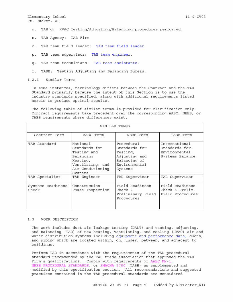
Elementary School 11-9-CV03Ft. Rucker, AL
m. TAB'd: HVAC Testing/Adjusting/Balancing procedures performed.
n. TAB Agency: TAB Firm
o. TAB team field leader: TAB team field leader
p. TAB team supervisor: TAB team engineer.
q. TAB team technicians: TAB team assistants.
r. TABB: Testing Adjusting and Balancing Bureau.
1.2.1 Similar Terms
In some instances, terminology differs between the Contract and the TAB Standard primarily because the intent of this Section is to use the industry standards specified, along with additional requirements listed herein to produce optimal results.
The following table of similar terms is provided for clarification only. Contract requirements take precedent over the corresponding AABC, NEBB, or TABB requirements where differences exist.
SIMILAR TERMS
Contract Term AABC Term NEBB Term TABB Term
TAB Standard National Standards for Testing and Balancing Heating, Ventilating, and Air Conditioning Systems
Procedural Standards for Testing, Adjusting and Balancing of Environmental Systems
International Standards for Environmental Systems Balance
TAB Specialist TAB Engineer TAB Supervisor TAB Supervisor
Systems Readiness Check
Construction Phase Inspection
Field Readiness Check & Preliminary Field Procedures
Field Readiness Check & Prelim. Field Procedures
1.3 WORK DESCRIPTION
The work includes duct air leakage testing (DALT) and testing, adjusting, and balancing (TAB) of new heating, ventilating, and cooling (HVAC) air and water distribution systems including equipment and performance data, ducts, and piping which are located within, on, under, between, and adjacent to buildings.
Perform TAB in accordance with the requirements of the TAB procedural standard recommended by the TAB trade association that approved the TAB Firm's qualifications. Comply with requirements of AABC MN-1, NEBB PROCEDURAL STANDARDS, or SMACNA 1780 (TABB) as supplemented and modified by this specification section. All recommendations and suggested practices contained in the TAB procedural standards are considered
SECTION 23 05 93 Page 5 (Added by RFPLetter_R1)
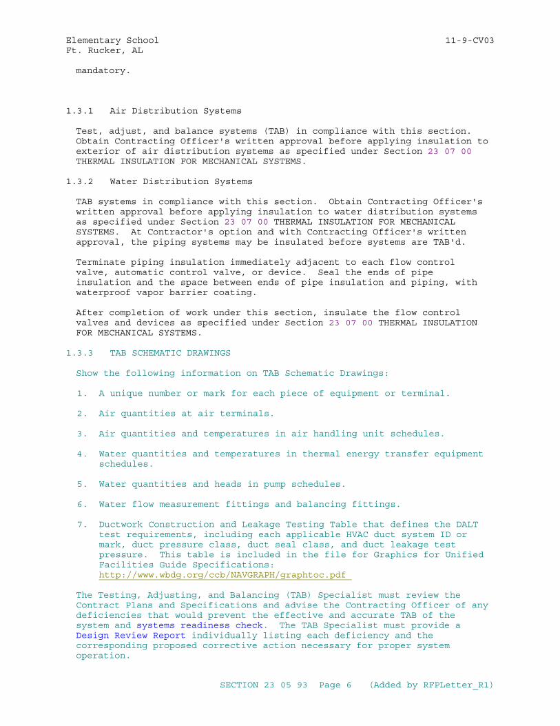
Elementary School 11-9-CV03Ft. Rucker, AL
mandatory.
1.3.1 Air Distribution Systems
Test, adjust, and balance systems (TAB) in compliance with this section. Obtain Contracting Officer's written approval before applying insulation to exterior of air distribution systems as specified under Section 23 07 00 THERMAL INSULATION FOR MECHANICAL SYSTEMS.
1.3.2 Water Distribution Systems
TAB systems in compliance with this section. Obtain Contracting Officer's written approval before applying insulation to water distribution systems as specified under Section 23 07 00 THERMAL INSULATION FOR MECHANICAL SYSTEMS. At Contractor's option and with Contracting Officer's written approval, the piping systems may be insulated before systems are TAB'd.
Terminate piping insulation immediately adjacent to each flow control valve, automatic control valve, or device. Seal the ends of pipe insulation and the space between ends of pipe insulation and piping, with waterproof vapor barrier coating.
After completion of work under this section, insulate the flow control valves and devices as specified under Section 23 07 00 THERMAL INSULATION FOR MECHANICAL SYSTEMS.
1.3.3 TAB SCHEMATIC DRAWINGS
Show the following information on TAB Schematic Drawings:
1. A unique number or mark for each piece of equipment or terminal.
2. Air quantities at air terminals.
3. Air quantities and temperatures in air handling unit schedules.
4. Water quantities and temperatures in thermal energy transfer equipment schedules.
5. Water quantities and heads in pump schedules.
6. Water flow measurement fittings and balancing fittings.
7. Ductwork Construction and Leakage Testing Table that defines the DALT test requirements, including each applicable HVAC duct system ID or mark, duct pressure class, duct seal class, and duct leakage test pressure. This table is included in the file for Graphics for Unified Facilities Guide Specifications:http://www.wbdg.org/ccb/NAVGRAPH/graphtoc.pdf
The Testing, Adjusting, and Balancing (TAB) Specialist must review the Contract Plans and Specifications and advise the Contracting Officer of any deficiencies that would prevent the effective and accurate TAB of the system and systems readiness check. The TAB Specialist must provide a Design Review Report individually listing each deficiency and the corresponding proposed corrective action necessary for proper system operation.
SECTION 23 05 93 Page 6 (Added by RFPLetter_R1)
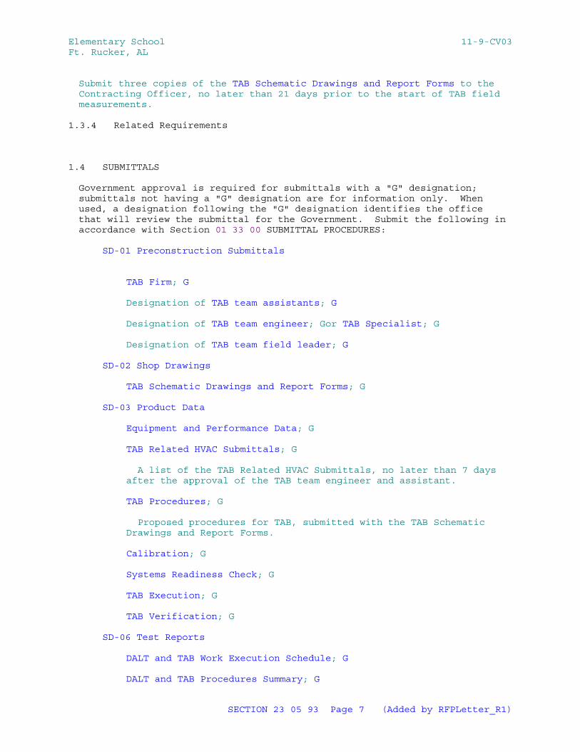
Elementary School 11-9-CV03Ft. Rucker, AL
Submit three copies of the TAB Schematic Drawings and Report Forms to the Contracting Officer, no later than 21 days prior to the start of TAB field measurements.
1.3.4 Related Requirements
1.4 SUBMITTALS
Government approval is required for submittals with a "G" designation; submittals not having a "G" designation are for information only. When used, a designation following the "G" designation identifies the office that will review the submittal for the Government. Submit the following in accordance with Section 01 33 00 SUBMITTAL PROCEDURES:
SD-01 Preconstruction Submittals
TAB Firm; G
Designation of TAB team assistants; G
Designation of TAB team engineer; Gor TAB Specialist; G
Designation of TAB team field leader; G
SD-02 Shop Drawings
TAB Schematic Drawings and Report Forms; G
SD-03 Product Data
Equipment and Performance Data; G
TAB Related HVAC Submittals; G
A list of the TAB Related HVAC Submittals, no later than 7 days after the approval of the TAB team engineer and assistant.
TAB Procedures; G
Proposed procedures for TAB, submitted with the TAB Schematic Drawings and Report Forms.
Calibration; G
Systems Readiness Check; G
TAB Execution; G
TAB Verification; G
SD-06 Test Reports
DALT and TAB Work Execution Schedule; G
DALT and TAB Procedures Summary; G
SECTION 23 05 93 Page 7 (Added by RFPLetter_R1)
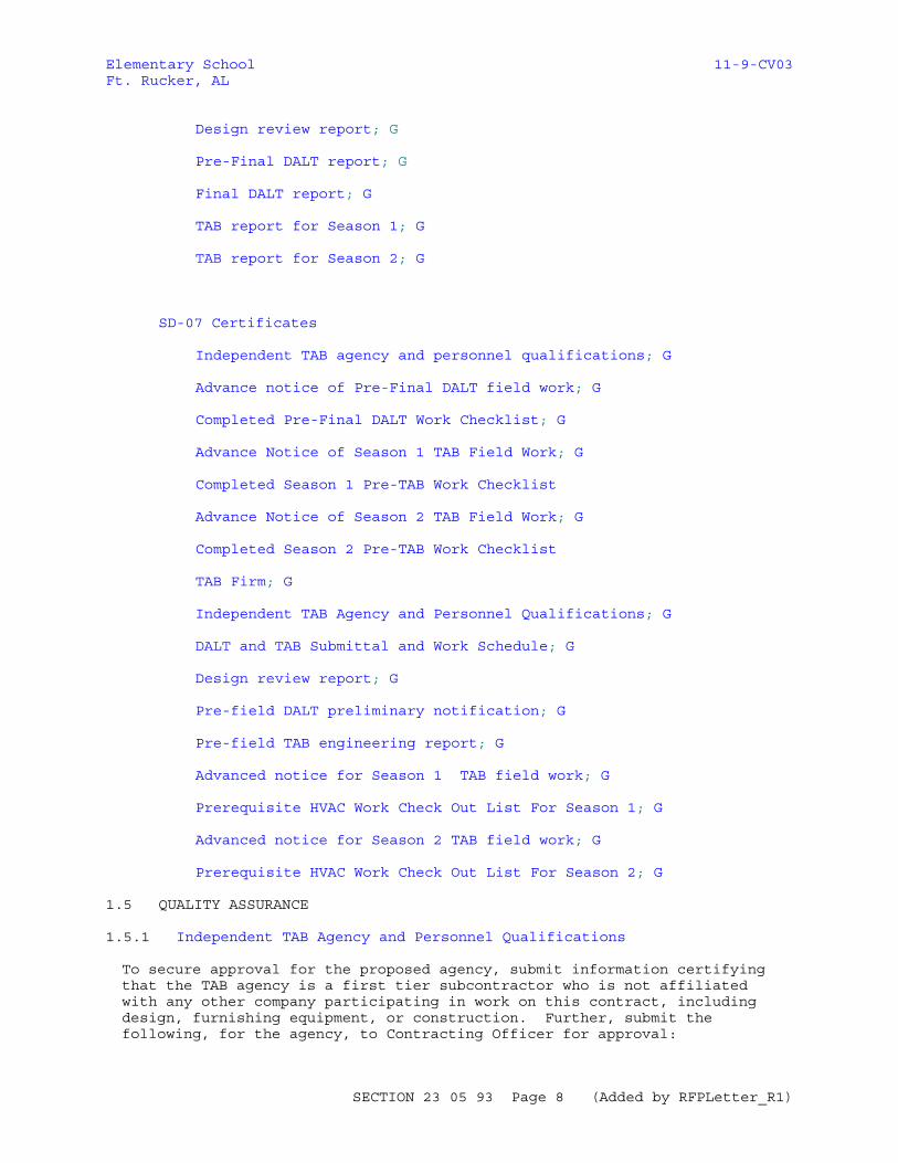
Elementary School 11-9-CV03Ft. Rucker, AL
Design review report; G
Pre-Final DALT report; G
Final DALT report; G
TAB report for Season 1; G
TAB report for Season 2; G
SD-07 Certificates
Independent TAB agency and personnel qualifications; G
Advance notice of Pre-Final DALT field work; G
Completed Pre-Final DALT Work Checklist; G
Advance Notice of Season 1 TAB Field Work; G
Completed Season 1 Pre-TAB Work Checklist
Advance Notice of Season 2 TAB Field Work; G
Completed Season 2 Pre-TAB Work Checklist
TAB Firm; G
Independent TAB Agency and Personnel Qualifications; G
DALT and TAB Submittal and Work Schedule; G
Design review report; G
Pre-field DALT preliminary notification; G
Pre-field TAB engineering report; G
Advanced notice for Season 1 TAB field work; G
Prerequisite HVAC Work Check Out List For Season 1; G
Advanced notice for Season 2 TAB field work; G
Prerequisite HVAC Work Check Out List For Season 2; G
1.5 QUALITY ASSURANCE
1.5.1 Independent TAB Agency and Personnel Qualifications
To secure approval for the proposed agency, submit information certifying that the TAB agency is a first tier subcontractor who is not affiliated with any other company participating in work on this contract, including design, furnishing equipment, or construction. Further, submit the following, for the agency, to Contracting Officer for approval:
SECTION 23 05 93 Page 8 (Added by RFPLetter_R1)
Elementary School 11-9-CV03Ft. Rucker, AL
a. Independent AABC or NEBB or TABB TAB agency:
TAB agency: AABC registration number and expiration date of current certification; or NEBB certification number and expiration date of current certification; or TABB certification number and expiration date of current certification.
TAB team supervisor: Name and copy of AABC or NEBB or TABB TAB supervisor certificate and expiration date of current certification.
TAB team field leader: Name and documented evidence that the team field leader has satisfactorily performed full-time supervision of TAB work in the field for not less than 3 years immediately preceding this contract's bid opening date.
TAB team field technicians: Names and documented evidence that each field technician has satisfactorily assisted a TAB team field leader in performance of TAB work in the field for not less than one year immediately preceding this contract's bid opening date.
Current certificates: Registrations and certifications are current, and valid for the duration of this contract. Renew Certifications which expire prior to completion of the TAB work, in a timely manner so that there is no lapse in registration or certification. TAB agency or TAB team personnel without a current registration or current certification are not to perform TAB work on this contract.
b. TAB Team Members: TAB team approved to accomplish work on this contract are full-time employees of the TAB agency. No other personnel is allowed to do TAB work on this contract.
c. Replacement of TAB team members: Replacement of members may occur if each new member complies with the applicable personnel qualifications and each is approved by the Contracting Officer.
1.5.2 TAB Standard
Perform TAB in accordance with the requirements of the standard under which the TAB Firm's qualifications are approved, i.e., AABC MN-1, NEBB PROCEDURAL STANDARDS, or SMACNA 1780 unless otherwise specified herein. All recommendations and suggested practices contained in the TAB Standard are considered mandatory. Use the provisions of the TAB Standard, including checklists, report forms, etc., as nearly as practical, to satisfy the Contract requirements. Use the TAB Standard for all aspects of TAB, including qualifications for the TAB Firm and Specialist and calibration of TAB instruments. Where the instrument manufacturer calibration recommendations are more stringent than those listed in the TAB Standard, adhere to the manufacturer's recommendations.
All quality assurance provisions of the TAB Standard such as performance guarantees are part of this contract. For systems or system components not covered in the TAB Standard, TAB procedures must be developed by the TAB Specialist. Where new procedures, requirements, etc., applicable to the Contract requirements have been published or adopted by the body responsible for the TAB Standard used (AABC, NEBB, or TABB), the requirements and recommendations contained in these procedures and requirements are considered mandatory, including the latest requirements of
SECTION 23 05 93 Page 9 (Added by RFPLetter_R1)
Elementary School 11-9-CV03Ft. Rucker, AL
ASHRAE 62.1.
1.5.3 Qualifications
1.5.3.1 TAB Firm
The TAB Firm must be either a member of AABC or certified by the NEBB or the TABB and certified in all categories and functions where measurements or performance are specified on the plans and specifications, including TAB of environmental systems .
Certification must be maintained for the entire duration of duties specified herein. If, for any reason, the firm loses subject certification during this period, the Contractor must immediately notify the Contracting Officer and submit another TAB Firm for approval. Any firm that has been the subject of disciplinary action by either the AABC, the NEBB, or the TABB within the five years preceding Contract Award is not be eligible to perform any duties related to the HVAC systems, including TAB. All work specified in this Section and in other related Sections to be performed by the TAB Firm will be considered invalid if the TAB Firm loses its certification prior to Contract completion and must be performed by an approved successor.
These TAB services are to assist the prime Contractor in performing the quality oversight for which it is responsible. The TAB Firm must be a prime subcontractor of the Contractor and be financially and corporately independent of the mechanical subcontractor, reporting directly to and paid by the Contractor.
1.5.3.2 TAB Specialist
The TAB Specialist must be either a member of AABC,an experienced technician of the Firm certified by the NEBB, or a Supervisor certified by the TABB. The certification must be maintained for the entire duration of duties specified herein. If, for any reason, the Specialist loses subject certification during this period, immediately notify the Contracting Officer and submit another TAB Specialist for approval. Any individual that has been the subject of disciplinary action by either the AABC, the NEBB, or the TABB within the five years preceding Contract Award is not eligible to perform any duties related to the HVAC systems, including TAB. All work specified in this Section and in other related Sections performed by the TAB Specialist will be considered invalid if the TAB Specialist loses its certification prior to Contract completion and must be performed by the approved successor.
1.5.3.3 TAB Specialist Responsibilities
TAB Specialist responsibilities include all TAB work specified herein and in related sections under his direct guidance. The TAB specialist is required to be onsite on a daily basis to direct TAB efforts. The TAB Specialist must participate in the commissioning process specified in Section 01 91 00.00 37 COMMISSIONING .
1.5.3.4 TAB Related HVAC Submittals
The TAB Specialist must prepare a list of the submittals from the Contract Submittal Register that relate to the successful accomplishment of all HVAC TAB. Accompany the submittals identified on this list with a letter of approval signed and dated by the TAB Specialist when submitted to the
SECTION 23 05 93 Page 10 (Added by RFPLetter_R1)
Elementary School 11-9-CV03Ft. Rucker, AL
Government. Ensure that the location and details of ports, terminals, connections, etc., necessary to perform TAB are identified on the submittals.
1.5.4 Responsibilities
The Contractor is responsible for ensuring compliance with the requirements of this section. The following delineation of specific work responsibilities is specified to facilitate TAB execution of the various work efforts by personnel from separate organizations. This breakdown of specific duties is specified to facilitate adherence to the schedule listed in paragraph entitled "TAB Submittal and Work Schedule."
1.5.4.1 Contractor
a. TAB personnel: Ensure that the DALT work and the TAB work is accomplished by a group meeting the requirements specified in paragraph entitled "TAB Personnel Qualification Requirements."
b. Pre-DALT/TAB meeting: Attend the meeting with the TAB Supervisor, and ensure that a representative is present for the sheetmetal contractor, mechanical contractor, electrical contractor, and automatic temperature controls contractor.
c. HVAC documentation: Furnish one complete set of the following HVAC-related documentation to the TAB agency:
(1) Contract drawings and specifications
(2) Approved submittal data for equipment
(3) Construction work schedule
(4) Up-to-date revisions and change orders for the previously listed items
d. Submittal and work schedules: Ensure that the schedule for submittals and work required by this section and specified in paragraph entitled "TAB Submittal and Work Schedule," is met.
e. Coordination of supporting personnel:
Provide the technical personnel, such as factory representatives or HVAC controls installer required by the TAB field team to support the DALT and the TAB field measurement work.
Provide equipment mechanics to operate HVAC equipment and ductwork mechanics to provide the field designated test ports to enable TAB field team to accomplish the DALT and the TAB field measurement work. Ensure these support personnel are present at the times required by the TAB team, and cause no delay in the DALT and the TAB field work.
Conversely, ensure that the HVAC controls installer has required support from the TAB team field leader to complete the controls check out.
f. Deficiencies: Ensure that the TAB Agency supervisor submits all Design/Construction deficiency notifications directly to the Contracting officer within 3 days after the deficiency is encountered.
SECTION 23 05 93 Page 11 (Added by RFPLetter_R1)
Elementary School 11-9-CV03Ft. Rucker, AL
Further, ensure that all such notification submittals are complete with explanation, including documentation, detailing deficiencies.
g. Prerequisite HVAC work: Complete check out and debugging of HVAC equipment, ducts, and controls prior to the TAB engineer arriving at the project site to begin the TAB work. Debugging includes searching for and eliminating malfunctioning elements in the HVAC system installations, and verifying all adjustable devices are functioning as designed. Include as prerequisite work items, the deficiencies pointed out by the TAB team supervisor in the design review report.
h. Prior to the TAB field team's arrival, ensure completion of the applicable inspections and work items listed in the TAB team supervisor's pre-field engineering report. Do not allow the TAB team to commence TAB field work until all of the following are completed.
(1) HVAC system installations are fully complete.
(2) HVAC prerequisite checkout work lists specified in the paragraph "Pre-Field TAB Engineering Report" are completed, submitted, and approved. Ensure that the TAB Agency gets a copy of the approved prerequisite HVAC work checklist.
(3) DALT field checks for all systems are completed.
(4) HVAC system filters are clean for both Season 1 and Season 2 TAB field work.
i. Advance notice: Furnish to the Contracting Officer with advance written notice for the commencement of the DALT field work and for the commencement of the TAB field work.
j. Insulation work: For required DALT work , ensure that insulation is not installed on ducts to be DALT'd until DALT work on the subject ducts is complete. Later, ensure that openings in duct and machinery insulation coverings for TAB test ports are marked, closed and sealed.
1.5.4.2 TAB Agency
Provide the services of a TAB team which complies with the requirements of paragraph entitled "Independent TAB Agency Personnel Qualifications". The work to be performed by the TAB agency is limited to testing, adjusting, and balancing of HVAC air and water systems to satisfy the requirements of this specification section.
1.5.4.3 TAB Team Supervisor
a. Overall management: Supervise and manage the overall TAB team work effort, including preliminary and technical DALT and TAB procedures and TAB team field work.
b. Pre-DALT/TAB meeting: Attend meeting with Contractor.
c. Design review report: Review project specifications and accompanying drawings to verify that the air systems and water systems are designed in such a way that the TAB engineer can accomplish the work in compliance with the requirements of this section. Verify the presence and location of permanently installed test ports and other devices needed, including gauge cocks, thermometer wells, flow control devices,
SECTION 23 05 93 Page 12 (Added by RFPLetter_R1)
Elementary School 11-9-CV03Ft. Rucker, AL
circuit setters, balancing valves, and manual volume dampers.
d. Support required: Specify the technical support personnel required from the Contractor other than the TAB agency; such as factory representatives for temperature controls or for complex equipment. Inform the Contractor in writing of the support personnel needed and when they are needed. Furnish the notice as soon as the need is anticipated, either with the design review report, or the pre-field engineering report, the during the DALT or TAB field work.
e. Pre-field DALT preliminary notification: Monitor the completion of the duct installation of each system and provide the necessary written notification to the Contracting Officer.
f. Pre-field engineering report: Utilizing the following HVAC-related documentation; contract drawings and specifications, approved submittal data for equipment, up-to-date revisions and change orders; prepare this report.
g. Prerequisite HVAC work checklist: Ensure the Contractor gets a copy of this checklist at the same time as the pre-field engineering report is submitted.
h. Technical assistance for DALT work.
(1) Technical assistance: Provide immediate technical assistance to TAB field team.
(2) DALT field visit: Near the end of the DALT field work effort, visit the contract site to inspect the HVAC installation and the progress of the DALT field work. Conduct a site visit to the extent necessary to verify correct procedures are being implemented and to confirm the accuracy of the Pre-final DALT Report data which has been reported. Also, perform sufficient evaluation to allow the TAB supervisor to issue certification of the final report. Conduct the site visit full-time for a minimum of two 8 hour workdays duration.
i. Final DALT report: Certify the DALT report. This certification includes the following work:
(1) Review: Review the Pre-final DALT report data. From these field reports, prepare the Certified Final DALT report.
(2) TAB Verification: Verify adherence, by the TAB field team, to the procedures specified in this section.
j. Technical Assistance for TAB Work: Provide immediate technical assistance to the TAB field team for the TAB work.
(1) TAB field visit: At the midpoint of the Season 1 and Season 2 TAB field work effort, visit the contract site to inspect the HVAC installation and the progress of the TAB field work. Conduct site visit full-time for a minimum of two 8 hour workdays duration.
(2) TAB field visit: Near the end of the TAB field work effort, visit the contract site to inspect the HVAC installation and the progress of the TAB field work. Conduct site visit full-time for a minimum of two 8 hour workdays duration. Review the TAB final
SECTION 23 05 93 Page 13 (Added by RFPLetter_R1)
Elementary School 11-9-CV03Ft. Rucker, AL
report data and certify the TAB final report.
k. Certified TAB report: Certify the TAB report. This certification includes the following work:
(1) Review: Review the TAB field data report. From this field report, prepare the certified TAB report.
(2) Verification: Verify adherence, by the TAB field team, to the TAB plan prescribed by the pre-field engineering report and verify adherence to the procedures specified in this section.
l. Design/Construction deficiencies: Within 3 working days after the TAB Agency has encountered any design or construction deficiencies, the TAB Supervisor must submit written notification directly to the Contracting Officer, with a separate copy to the Contractor, of all such deficiencies. Provide in this submittal a complete explanation, including supporting documentation, detailing deficiencies. Where deficiencies are encountered that are believed to adversely impact successful completion of TAB, the TAB Agency must issue notice and request direction in the notification submittal.
m. TAB Field Check: The TAB team supervisor must attend and supervise Season 1 and Season 2 TAB field check.
1.5.4.4 TAB Team Field Leader
a. Field manager: Manage, in the field, the accomplishment of the work specified in Part 3, "Execution."
b. Full time: Be present at the contract site when DALT field work or TAB field work is being performed by the TAB team; ensure day-to-day TAB team work accomplishments are in compliance with this section.
c. Prerequisite HVAC work: Do not bring the TAB team to the contract site until a copy of the prerequisite HVAC Checklist, with all work items certified by the Contractor to be working as designed, reaches the office of the TAB Agency.
1.5.5 Test Reports
1.5.5.1 Data from DALT Field Work
Report the data for the Pre-final DALT Report and Certified Final DALT Report in compliance the following requirements:
a. Report format: Submit report data on Air Duct Leakage Test Summary Report Forms as shown on Page 6-2 of SMACNA 1972 CD. In addition, submit in the report, a marked duct shop drawing which identifies each section of duct tested with assigned node numbers for each section. Include node numbers in the completed report forms to identify each duct section. The TAB supervisor must review and certify the report.
b. The TAB supervisor must include a copy of all calculations prepared in determining the duct surface area of each duct test section. In addition,provide the ductwork air leak testing (DALT) reports with a copy(s) of the calibration curve for each of the DALT test orifices
SECTION 23 05 93 Page 14 (Added by RFPLetter_R1)
Elementary School 11-9-CV03Ft. Rucker, AL
used for testing.
c. Instruments: List the types of instruments actually used to measure the data. Include in the listing each instrument's unique identification number, calibration date, and calibration expiration date. Instruments must have been calibrated within one year of the date of use in the field. Instrument calibration must be traceable to the measuring standards of the National Institute of Standards and Technology.
d. Certification: Include the typed name of the TAB supervisor and the dated signature of the TAB supervisor.
1.5.5.2 Certified TAB Reports
Submit: TAB Report for Season 1 and TAB Report for Season 2 in the following manner:
a. Report format: Submit the completed pre-field data forms approved in the pre-field TAB Engineering Report completed by TAB field team, reviewed and certified by the TAB supervisor. Bind the report with a waterproof front and back cover. Include a table of contents identifying by page number the location of each report. Report forms and report data must be typewritten. Handwritten report forms or report data are not acceptable.
b. Temperatures: On each TAB report form reporting TAB work accomplished on HVAC thermal energy transfer equipment, include the indoor and outdoor dry bulb temperature range and indoor and outdoor wet bulb temperature range within which the TAB data was recorded. Include in the TAB report continuous time versus temperature recording data of wet and dry bulb temperatures for the rooms, or zones, as designated in the following list:
(1) In all classrooms or educational spaces. Measure and compile data on a continuous basis for the period in which TAB work affecting those rooms is being done.
(2) Measure and record data only after the HVAC systems installations are complete, the systems fully balanced and the HVAC systems controls operating in fully automatic mode.
(3) Data may be compiled using direct digital controls trend logging where available. Otherwise, temporarily install calibrated time versus temperature/humidity recorders for this purpose. The HVAC systems and controls must be fully operational a minimum of 24 hours in advance of commencing data compilation. Include the specified data in the Season I and Season 2 TAB Report.
c. System Diagrams: Provide updated diagrams with final installed locations of all terminals and devices, any numbering changes, and actual test locations. Use a key numbering system on the diagram which identifies each outlet contained in the outlet airflow report sheets.
d. Static Pressure Profiles: Report static pressure profiles for all air duct systems. Report static pressure data for all supply, return, relief, exhaust and outside air ducts for the systems listed. Include the following in the static pressure report data, in addition to AABC/NEBB/TABB required data:
SECTION 23 05 93 Page 15 (Added by RFPLetter_R1)
Elementary School 11-9-CV03Ft. Rucker, AL
(1) Report supply fan, return fan, relief fan, and exhaust fan inlet and discharge static pressures.
(2) Report static pressure drop across chilled water coils, DX coils, hot water coils, steam coils, electric resistance heating coils and heat reclaim devices installed in unit cabinetry or the system ductwork.
(3) Report static pressure drop across outside air, return air, and supply air automatic control dampers, both proportional and two-position, installed in unit cabinetry.
(4) Report static pressure drop across acoustic silencers, air flow measuring stations or other pressure drop producing specialty items installed in unit cabinetry, or in the system ductwork. Examples of these specialty items are smoke detectors, white sound generators, RF shielding, wave guides, security bars, blast valves, small pipes passing through ductwork, and duct mounted humidifiers.
Do not report static pressure drop across duct fittings provided for the sole purpose of conveying air, such as elbows, transitions, offsets, plenums, manual dampers, and branch takes-offs.
(5) Report static pressure drop across outside air and relief/exhaust air louvers.
(6) Report static pressure readings of supply air, return air, exhaust/relief air, and outside air in duct at the point where these ducts connect to each air moving unit.and also at the following locations:
Main Duct: Take readings at four locations along the full length of the main duct, 25 percent, 50 percent, 75 percent, and 100 percent of the total duct length.
Floor Branch Mains: Take readings at floor branch mains served by a main duct vertical riser.
Branch Main Ducts: Take readings at branch main ducts.
VAV Terminals: Take readings at inlet static pressure at VAV terminal box primary air branch ducts.
e. Duct Traverses: Report duct traverses for main and branch main supply, return, exhaust, relief and outside air ducts. This includes all ducts, including those which lack 7 1/2 duct diameters upstream and 2 1/2 duct diameters downstream of straight duct unobstructed by duct fittings/offsets/elbows. The TAB Agency must evaluate and report findings on the duct traverses taken. Evaluate the suitability of the duct traverse measurement based on satisfying the qualifications for a pilot traverse plane as defined by AMCA 203, "Field Measurements", Section 8, paragraph 8.3, "Location of Traverse Plane."
f. Instruments: List the types of instruments actually used to measure the tab data. Include in the listing each instrument's unique identification number, calibration date, and calibration expiration
SECTION 23 05 93 Page 16 (Added by RFPLetter_R1)
Elementary School 11-9-CV03Ft. Rucker, AL
date.
Instrumentation, used for taking wet bulb temperature readings must provide accuracy of plus or minus 5 percent at the measured face velocities. Submit instrument manufacturer's literature to document instrument accuracy performance is in compliance with that specified.
g. Certification: Include the typed name of the TAB supervisor and the dated signature of the TAB supervisor.
h. Performance Curves: The TAB Supervisor must include, in the TAB Reports, factory pump curves and fan curves for pumps and fans TAB'd on the job.
i. Calibration Curves: The TAB Supervisor must include, in the TAB Reports, a factory calibration curve for installed flow control balancing valves, flow venturi's and flow orifices TAB'd on the job.
1.6 SEQUENCING AND SCHEDULING
1.6.1 DALT and TAB Submittal and Work Schedule
Comply with additional requirements specified in Appendix C: DALT AND TAB SUBMITTAL AND WORK SCHEDULE included at the end of this section
1.6.2 DALT and TAB Submittal and Work Schedule
Submit this schedule,and TAB Schematic Drawings, adapted for this particular contract, to the Contracting Officer (CO) for review and approval. Include with the submittal the planned calendar dates for each submittal or work item. Resubmit an updated version for CO approval every 90 calendar days days. Compliance with the following schedule is the Contractor's responsibility.
Qualify TAB Personnel: Within 45 calendar days after date of contract award, submit TAB agency and personnel qualifications.
Pre-DALT/TAB Meeting: Within 30 calendar days after the date of approval of the TAB agency and personnel, meet with the COTR.
Design Review Report: Within 60 calendar days after the date of the TAB agency personnel qualifications approval, submit design review report.
Pre-Field DALT Preliminary Notification: On completion of the duct installation for each system, notify the Contracting Officer in writing within 5 days after completion.
Ductwork Selected for DALT: Within 7 calendar days of Pre-Field DALT Preliminary Notification, the COTR will select which of the project ductwork must be DALT'd.
DALT Field Work: Within 48 hours of COTR's selection, complete DALT field work on selected.
Submit Pre-final DALT Report: Within one working day after completion of DALT field work, submit Pre-final DALT Report. Separate Pre-final DALT reports may be submitted to allow phased testing from system to system.
DALT Work Field Check: Upon approval of the Pre-final DALT Report,
SECTION 23 05 93 Page 17 (Added by RFPLetter_R1)
Elementary School 11-9-CV03Ft. Rucker, AL
schedule the COTR's DALT field check work with the Contracting Officer.
Submit Final DALT Report: Within 15 calendar days after completion of successful DALT Work Field Check, submit Season 1 TAB report.
Pre-Field TAB Engineering Report: Within 15 calendar days after approval of the TAB agency Personnel Qualifications, submit the Pre-Field TAB Engineering Report.
Prerequisite HVAC Work Check Out List For Season 1 and Advanced Notice For Season 1 TAB Field Work: At a minimum of 115 calendar days prior to CCD, submit Season 1 prerequisite HVAC work check out list certified as complete, and submit advance notice of commencement of Season 1 TAB field work.
Season 1 TAB Field Work: At a minimum of 90 calendar days prior to CCD, and when the ambient temperature is within Season 1 limits, accomplish Season 1 TAB field work.
Submit Season 1 TAB Report: Within 15 calendar days after completion of Season 1 TAB field work, submit Season 1 TAB report.
Season 1 TAB Field Check: 30 calendar days after Season 1 TAB report is approved by the Contracting Officer, conduct Season 1 field check.
Prerequisite HVAC Work Check Out List For Season 2 and Advanced Notice For Season 2 TAB Field Work: Within 150 calendar days after date of the commencement of the Season 1 TAB field work, submit the Season 2 prerequisite HVAC work check out list certified as complete and submit advance notice of commencement of Season 2 TAB field work.
Season 2 TAB Field Work: Within calendar days after date of commencement of the Season 1 TAB field work and when the ambient temperature is within Season 2 limits, accomplish Season 2 TAB field work.
Submit Season 2 TAB Report: Within 15 calendar days after completion of Season 2 TAB field work, submit Season 2 TAB report.
Season 2 TAB Field Check: 30 calendar days after the Season 2 TAB report is approved by the Contracting Officer, conduct Season 2 field check.
Complete Season 2 TAB Work: Within 15 calendar days after the completion of Season 2 TAB field data check, complete all TAB work.
1.6.2.1 Design Review Report
Submit typed report describing omissions and deficiencies in the HVAC system's design that would preclude the TAB team from accomplishing the duct leakage testing work and the TAB work requirements of this section. Provide a complete explanation including supporting documentation detailing the design deficiency. State that no deficiencies are evident if that is the case.
1.6.2.2 Pre-Field DALT Preliminary Notification
Notification: On completion of the installation of each duct system indicated to be DALT'd, notify the Contracting Officer in writing within 7
SECTION 23 05 93 Page 18 (Added by RFPLetter_R1)
Elementary School 11-9-CV03Ft. Rucker, AL
calendar days after completion. 1.6.2.3 Pre-Field TAB Engineering Report
Submit report containing the following information:
a. Step-by-step TAB procedure:
(1) Strategy: Describe the method of approach to the TAB field work from start to finish. Include in this description a complete methodology for accomplishing each seasonal TAB field work session.
(2) Air System Diagrams: Use the contract drawings and duct fabrication drawings if available to provide air system diagrams in the report showing the location of all terminal outlet supply, return, exhaust and transfer registers, grilles and diffusers. Use a key numbering system on the diagrams which identifies each outlet contained in the outlet airflow report sheets. Show intended locations of all traverses and static pressure readings.
(3) Procedural steps: Delineate fully the intended procedural steps to be taken by the TAB field team to accomplish the required TAB work of each air distribution system and each water distribution system. Include intended procedural steps for TAB work for subsystems and system components.
b. Pre-field data: Submit AABC or NEBB or SMACNA 1780 data report forms with the following pre-field information filled in:
(1) Design data obtained from system drawings, specifications, and approved submittals.
(2) Notations detailing additional data to be obtained from the contract site by the TAB field team.
(3) Designate the actual data to be measured in the TAB field work.
(4) Provide a list of the types of instruments, and the measuring range of each, which are anticipated to be used for measuring in the TAB field work. By means of a keying scheme, specify on each TAB data report form submitted, which instruments will be used for measuring each item of TAB data. If the selection of which instrument to use, is to be made in the field, specify from which instruments the choice will be made. Place the instrument key number in the blank space where the measured data would be entered.
c. Prerequisite HVAC work checkout list: Provide a list of inspections and work items which are to be completed by the Contractor. This list must be acted upon and completed by the Contractor and then submitted and approved by the Contracting Officer prior to the TAB team coming to the contract site.
At a minimum, a list of the applicable inspections and work items listed in the NEBB PROCEDURAL STANDARDS, Section III, "Preliminary TAB Procedures" under paragraphs titled, "Air Distribution System Inspection" and "Hydronic Distribution System Inspection" must be provided for each separate system to be TAB'd.
SECTION 23 05 93 Page 19 (Added by RFPLetter_R1)
Elementary School 11-9-CV03Ft. Rucker, AL
1.7 SUBCONTRACTOR SPECIAL REQUIREMENTS
Perform all work in this section in accordance with the paragraph entitled "Subcontractor Special Requirements" in Section 01 30 00 ADMINISTRATIVE REQUIREMENTS, stating that all contract requirements of this section must be accomplished directly by a first tier subcontractor. No work may be performed by a second tier subcontractor.
1.8 WARRANTY
Furnish workmanship and performance warranty for the DALT and TAB system work performed for a period not less than 1 years from the date of Government acceptance of the work; issued directly to the Government. Include provisions that if within the warranty period the system shows evidence of major performance deterioration, or is significantly out of tolerance, resulting from defective TAB or DALT workmanship, the corrective repair or replacement of the defective materials and correction of the defective workmanship is the responsibility of the TAB firm. Perform corrective action that becomes necessary because of defective materials and workmanship while system TAB and DALT is under warranty 7 days after notification, unless additional time is approved by the Contracting Officer. Failure to perform repairs within the specified period of time constitutes grounds for having the corrective action and repairs performed by others and the cost billed to the TAB firm. The Contractor must also provide a 1 year contractor installation warranty.
PART 2 PRODUCTS
Not Used
PART 3 EXECUTION
3.1 WORK DESCRIPTIONS OF PARTICIPANTS
Comply with requirements of this section as specified in Appendix A WORK DESCRIPTIONS OF PARTICIPANTS.
3.2 PRE-DALT/TAB MEETING
Meet with the Contracting Officer's technical representative (COTR) to develop a mutual understanding relative to the details of the DALT work and TAB work requirements. Ensure that the TAB supervisor is present at this meeting. Requirements to be discussed include required submittals, work schedule, and field quality control.
3.3 DALT PROCEDURES
3.3.1 Instruments, Consumables and Personnel
Provide instruments, consumables and personnel required to accomplish the DALT field work. Follow the same basic procedure specified below for TAB Field Work, including maintenance and calibration of instruments, accuracy of measurements, preliminary procedures, field work, workmanship and treatment of deficiencies. Calibrate and maintain instruments in accordance with manufacturer's written procedures.
3.3.2 Advance Notice of Pre-Final DALT Field Work
On completion of the installation of each duct system indicated to be
SECTION 23 05 93 Page 20 (Added by RFPLetter_R1)
Elementary School 11-9-CV03Ft. Rucker, AL
DALT'd, notify the Contracting Officer in writing prior to the COTR's duct selection field visit.
3.3.3 Ductwork To Be DALT'd
From each duct system indicated as subject to DALT, the COTR will randomly select sections of each completed duct system for testing by the Contractor's TAB Firm. The sections selected will not exceed 20 percent of the total measured linear footage of duct systems indicated as subject to DALT. Sections of duct systems subject to DALT will include 20 percent of main ducts, branch main ducts, branch ducts and plenums for supply, return, exhaust, and plenum ductwork.
It is acceptable for an entire duct system to be DALT'd instead of disassembling that system in order to DALT only the 20 percent portion specified above.
3.3.4 DALT Testing
Perform DALT on the HVAC duct sections of each system as selected by the COTR. Use the duct class, seal class, leakage class and the leak test pressure data indicated on the drawings, to comply with the procedures specified in SMACNA 1972 CD.
In spite of specifications of SMACNA 1972 CD to the contrary, DALT ductwork of construction class of 3-inch water gauge static pressure and below if indicated to be DALT'd. Complete DALT work on the COTR selected ductwork within 48 hours after the particular ductwork was selected for DALT. Separately conduct DALT work for large duct systems to enable the DALT work to be completed in 48 hours.
3.3.5 Pre-final DALT Report
After completion of the DALT work, prepare a Pre-final DALT Report meeting the additional requirements specified in Appendix B REPORTS - DALT and TAB. Data required by those data report forms shall be furnished by the TAB team. Prepare the report neatly and legibly; the Pre-final DALT report shall provide the basis for the Final DALT Report.
TAB supervisor shall review, approve and sign the Pre-Final DALT Report and submit this report within one day of completion of DALT field work. Verbally notify the COTR that the field check of the Pre-Final DALT Report data can commence.After completion of the DALT work, prepare a Pre-final DALT Report using the reporting forms specified. TAB team to furnish data required by those data report forms . Prepare the report neatly and legibly; the Pre-final DALT report is the basis for the Final DALT Report. TAB supervisor must review and certify the Pre-final DALT Report and submit this report within one day of completion of DALT field work. Verbally notify the COTR that the field check of the Pre-final DALT Report data can commence.
3.3.6 Quality Assurance - COTR DALT Field Acceptance Testing
In the presence of the COTR and TAB team field leader, verify for accuracy Pre-final DALT Report data selected by the COTR. For each duct system, this acceptance testing shall be conducted on a maximum of 50 percent of the duct sections DALT'd.
Further, if any data on the Pre-final DALT report form for a given duct
SECTION 23 05 93 Page 21 (Added by RFPLetter_R1)
Elementary School 11-9-CV03Ft. Rucker, AL
section is out-of-tolerance, then field acceptance testing shall be conducted on data for one additional duct section, preferably in the same duct system, in the presence of the COTR.
3.3.7 Additional COTR Field Acceptance Testing
If any of the duct sections checked for a given system are determined to have a leakage rate measured that exceeds the leakage rate allowed by SMACNA Leak Test Manual for an indicated duct construction class and sealant class, terminate data checking for that section. The associated Pre-final DALT Report data for the given duct system will be disapproved. Make the necessary corrections and prepare a revised Pre-final DALT Report. Reschedule a field check of the revised report data with the COTR.
3.3.8 Certified Final DALT ReportOn successful completion of all field checks of the Pre-final DALT Report data for all systems, the TAB Supervisor is to assemble, review, certify and submit the Final DALT Report to the Contracting Officer for approval.
On successful completion of all field checks of the Pre-Final DALT Report data for all systems, the TAB Supervisor shall assemble, review, approve, sign and submit the Final DALT Report in compliance with Appendix B REPORTS - DALT and TAB to the Contracting Officer for approval.
3.3.9 Prerequisite for TAB Field Work
Do not commence TAB field work prior to the completion and approval, for all systems, of the Final DALT Report.
3.4 TAB PROCEDURES
3.4.1 TAB Field Work
Test, adjust, and balance the HVAC systems until measured flow rates (air and water flow) are within plus or minus 5 percent of the design flow rates as specified or indicated on the contract documents.
That is, comply with the the requirements of AABC MN-1 , or SMACNA 1780 (TABB) and SMACNA 1858 (TABB),except as supplemented and modified by this section.
Provide instruments and consumables required to accomplish the TAB work. Calibrate and maintain instruments in accordance with manufacturer's written procedures.
Test, adjust, and balance the HVAC systems until measured flow rates (air and water flow) are within plus or minus 5 percent of the design flow rates as specified or indicated on the contract documents. Conduct TAB work, including measurement accuracy, and sound measurement work in conformance with the AABC MN-1 and AABC MN-4, or NEBB TABES and NEBB MASV, or SMACNA 1780 (used by TABB) and SMACNA 1858 sound measurement procedures, except as supplemented and modified by this section. The only water flow and air flow reporting which can be deferred until the Season 2 is that data which would be affected in terms of accuracy due to outside ambient conditions.
3.4.2 Preliminary Procedures
Use the approved pre-field engineering report as instructions and procedures for accomplishing TAB field work. TAB engineer is to locate, in
SECTION 23 05 93 Page 22 (Added by RFPLetter_R1)
Elementary School 11-9-CV03Ft. Rucker, AL
the field, test ports required for testing. It is the responsibility of the sheet metal contractor to provide and install test ports as required by the TAB engineer.
3.4.3 TAB Air Distribution Systems
3.4.3.1 Units With Coils
Report heating and cooling performance capacity tests for hot water, chilled water, DX and steam coils for the purpose of verifying that the coils meet the indicated design capacity. Submit the following data and calculations with the coil test reports:
a. For air handlers with capacities greater than 7.5 tons (90,000 Btu) cooling, such as factory manufactured units, central built-up units and rooftop units, conduct capacity tests in accordance with AABC MN-4, procedure 3.5, "Coil Capacity Testing."
Do not determine entering and leaving wet and dry bulb temperatures by single point measurement, but by the average of multiple readings in compliance with paragraph 3.5-5, "Procedures", (in subparagraph d.) of AABC MN-4, Procedure 3.5, "Coil Capacity Testing."
Submit part-load coil performance data from the coil manufacturer converting test conditions to design conditions; use the data for the purpose of verifying that the coils meet the indicated design capacity in compliance with AABC MN-4, Procedure 3.5, "Coil Capacity Testing," paragraph 3.5.7, "Actual Capacity Vs. Design Capacity" (in subparagraph c.).
b. For units with capacities of 7.5 tons (90,000 Btu) or less, such as fan coil units, duct mounted reheat coils associated with VAV terminal units, and unitary units, such as through-the-wall heat pumps:
Determine the apparent coil capacity by calculations using single point measurement of entering and leaving wet and dry bulb temperatures; submit the calculations with the coil reports.
3.4.3.2 Air Handling Units
Air handling unit systems including fans (air handling unit fans, exhaust fans and winter ventilation fans), coils, ducts, plenums, mixing boxes, terminal units, variable air volume boxes, and air distribution devices for supply air, return air, outside air, mixed air relief air, and makeup air.
3.4.3.3 Heating and Ventilating Units
Heating and ventilating unit systems including fans, coils, ducts, plenums, roof vents, registers, diffusers, grilles, and louvers for supply air, return air, outside air, and mixed air.
3.4.3.4 Makeup Air Units
Makeup air unit systems including fans, coils, ducts, plenums, registers, diffusers, grilles, and louvers for supply air, return air, outside air, and mixed air.
SECTION 23 05 93 Page 23 (Added by RFPLetter_R1)
Elementary School 11-9-CV03Ft. Rucker, AL
3.4.3.5 Return Air Fans
Return air fan system including fan ducts, plenums, registers, diffusers, grilles, and louvers for supply air, return air, outside air, and mixed air.
3.4.3.6 Fan Coils
Fan coil unit systems including fans, coils, ducts, plenums, and air distribution devices for supply air, return air, and outside air.
3.4.3.7 Exhaust Fans
Exhaust fan systems including fans, ducts, plenums, grilles, and hoods for exhaust air.
3.4.4 TAB Water Distribution Systems
3.4.4.1 Chilled Water
Chilled water systems including chillers, condensers, cooling towers, pumps, coils, system balance valves and flow measuring devices.
For water chillers, report data as required by AABC, NEBB and TABB standard procedures, including refrigeration operational data.
3.4.4.2 Heating Hot Water
Heating hot water systems including boilers, hot water converters (e.g., heat exchangers), pumps, coils, system balancing valves and flow measuring devices.
3.4.5 Sound Measurement Work
3.4.5.1 Areas To Be Sound Measured
In the following spaces, measure and record the sound power level for each octave band listed in ASHRAE HVAC APP IP HDBK Noise Criteria:
a. All HVAC mechanical rooms, including machinery spaces and other spaces containing HVAC power drivers and power driven equipment.
b. All spaces sharing a common barrier with each mechanical room, including rooms overhead, rooms on the other side of side walls, and rooms beneath the mechanical room floor.
3.4.5.2 Procedure
Measure sound levels in each room, when unoccupied except for the TAB team, with all HVAC systems that would cause sound readings in the room operating in their noisiest mode. Record the sound level in each octave band. Attempt to mitigate the sound level and bring the level to within the specified ASHRAE HVAC APP IP HDBK noise criteria goals, if such mitigation is within the TAB team's control. State in the report the ASHRAE HVAC APP IP HDBK noise criteria goals. If sound level cannot be brought into compliance, provide written notice of the deficiency to the Contractor for resolution or correction.
SECTION 23 05 93 Page 24 (Added by RFPLetter_R1)
Elementary School 11-9-CV03Ft. Rucker, AL
3.4.5.3 Timing
Measure sound levels at times prescribed by AABC or NEBB or TABB.
3.4.5.4 Meters
Measure sound levels with a sound meter complying with ASA S1.4, Type 1 or 2, and an octave band filter set complying with ASA S1.11. Use measurement methods for overall sound levels and for octave band sound levels as prescribed by NEBB.
3.4.5.5 Calibration
Calibrate sound levels as prescribed by AABC or NEBB or TABB, except that calibrators emitting a sound pressure level tone of 94 dB at 1000 hertz (Hz) are also acceptable.
3.4.5.6 Background Noise Correction
Determine background noise component of room sound (noise) levels for each (of eight) octave bands as prescribed by AABC or NEBB or TABB.
3.4.6 TAB Work on Performance Tests With Seasonal Limitations
3.4.6.1 Performance Tests
Accomplish proportionate balancing TAB work on the air distribution systems and water distribution systems, in other words, accomplish adjusting and balancing of the air flows and water flows, any time during the duration of this contract, subject to the limitations specified elsewhere in this section. However, accomplish, within the following seasonal limitations, TAB work on HVAC systems which directly transfer thermal energy.
3.4.6.2 Season Of Maximum Load
Visit the contract site for at least two TAB work sessions for TAB field measurements. Visit the contract site during the season of maximum heating load and visit the contract site during the season of maximum cooling load, the goal being to TAB the operational performance of the heating systems and cooling systems under their respective maximum outdoor environment-caused loading. During the seasonal limitations, TAB the operational performance of the heating systems and cooling systems.
3.4.6.3 Ambient Temperatures
On each tab report form used for recording data, record the outdoor and indoor ambient dry bulb temperature range and the outdoor and indoor ambient wet bulb temperature range within which the report form's data was recorded. Record these temperatures at beginning and at the end of data taking.
3.4.6.4 Sound Measurements
Comply with paragraph entitled "Sound Measurement Work," specifically, the requirement that a room must be operating in its noisiest mode at the time of sound measurements in the room. The maximum noise level measurements could depend on seasonally related heat or cooling transfer equipment.
SECTION 23 05 93 Page 25 (Added by RFPLetter_R1)
Elementary School 11-9-CV03Ft. Rucker, AL
3.4.6.5 Water Chillers
Water chillers: For water chillers,report data as required by NEBB Form TAB 15-83, NEBB PROCEDURAL STANDARDS, including refrigeration operational data.
3.4.6.6 Refrigeration Units
For refrigeration compressors/condensers/condensing units,report data as required by NEBB Form TAB 15-83, NEBB PROCEDURAL STANDARDS, including refrigeration operational data.
3.4.6.7 Coils
Report heating and cooling performance capacity tests for hot water, chilled water, and DX for the purpose of verifying that the coils meet the indicated design capacity. Submit the following data and calculations with the coil test reports:
a. For Central station air handlers with capacities greater than 7.5 tons (90,000 Btu) cooling, such as factory manufactured units, central built-up units and rooftop units, conduct capacity tests in accordance with AABC MN-4, procedure 3.5, "Coil Capacity Testing."
Entering and leaving wet and dry bulb temperatures are not determined by single point measurement, but by the average of multiple readings in compliance with paragraph 3.5-5, "Procedures", (in subparagraph d.) of AABC MN-4, Procedure 3.5, "Coil Capacity Testing."
Submit part-load coil performance data from the coil manufacturer converting test conditions to design conditions; use the data for the purpose of verifying that the coils meet the indicated design capacity in compliance with AABC MN-4, Procedure 3.5, "Coil Capacity Testing," paragraph 3.5.7, "Actual Capacity Vs. Design Capacity" (in subparagraph c.).
b. For units with capacities of 7.5 tons (90,000 Btu) or less, such as fan coil units, duct mounted reheat coils associated with VAV terminal units, and unitary units, such as through-the-wall heat pumps:
Determine the apparent coil capacity by calculations using single point measurement of entering and leaving wet and dry bulb temperatures; submit the calculations with the coil reports.
3.4.7 Workmanship
Conduct TAB work on the HVAC systems until measured flow rates are within plus or minus 5 percent of the design flow rates as specified or indicated on the contract documents. This TAB work includes adjustment of balancing valves, balancing dampers, and sheaves. Further, this TAB work includes changing out fan sheaves and pump impellers if required to obtain air and water flow rates specified or indicated. If, with these adjustments and equipment changes, the specified or indicated design flow rates cannot be attained, contact the Contracting Officer for direction.
3.4.8 Deficiencies
Strive to meet the intent of this section to maximize the performance of the equipment as designed and installed. However, if deficiencies in
SECTION 23 05 93 Page 26 (Added by RFPLetter_R1)
Elementary School 11-9-CV03Ft. Rucker, AL
equipment design or installation prevent TAB work from being accomplished within the range of design values specified in the paragraph entitled "Workmanship," provide written notice as soon as possible to the Contractor and the Contracting Officer describing the deficiency and recommended correction.
Responsibility for correction of installation deficiencies is the Contractor's. If a deficiency is in equipment design, call the TAB team supervisor for technical assistance. Responsibility for reporting design deficiencies to Contractor is the TAB team supervisor's.
3.4.9 TAB Reports
Additional requirements for TAB Reports are specified in Appendix B REPORTS - DALT and TABAfter completion of the TAB field work, prepare the TAB field data for TAB supervisor's review and certification, using the reporting forms approved in the pre-field engineering report. Data required by those approved data report forms is to be furnished by the TAB team. Except as approved otherwise in writing by the Contracting Officer, the TAB work and thereby the TAB report is considered incomplete until the TAB work is accomplished to within the accuracy range specified in the paragraph entitled "Workmanship."
3.4.10 Quality Assurance - COTR TAB Field Acceptance Testing
3.4.10.1 TAB Field Acceptance Testing
During the field acceptance testing, verify, in the presence of the COTR, random selections of data (water, air quantities, air motion, sound level readings) recorded in the TAB Report. Points and areas for field acceptance testing are to be selected by the COTR. Measurement and test procedures are the same as approved for TAB work for the TAB Report.
Field acceptance testing includes verification of TAB Report data recorded for the following equipment groups:
Group 1: All chillers, boilers, return fans, computer room units, and air handling units (rooftop and central stations).
Group 2: 25 percent of the VAV terminal boxes and associated diffusers and registers.
Group 3: 25 percent of the supply diffusers, registers, grilles associated with constant volume air handling units.
Group 4: 25 percent of the return grilles, return registers, exhaust grilles and exhaust registers.
Group 5: 25 percent of the supply fans, exhaust fans, and pumps.
Further, if any data on the TAB Report for Groups 2 through 5 is found not to fall within the range of plus 5 to minus 5 percent of the TAB Report data, additional group data verification is required in the presence of the COTR. Verify TAB Report data for one additional piece of equipment in that group. Continue this additional group data verification until out-of-tolerance data ceases to be found.
SECTION 23 05 93 Page 27 (Added by RFPLetter_R1)
Elementary School 11-9-CV03Ft. Rucker, AL
3.4.10.2 Additional COTR TAB Field Acceptance Testing
If any of the acceptance testing measurements for a given equipment group is found not to fall within the range of plus 5 to minus 5 percent of the TAB Report data, terminate data verification for all affected data for that group. The affected data for the given group will be disapproved. Make the necessary corrections and prepare a revised TAB Report. Reschedule acceptance testing of the revised report data with the COTR.Further, if any data on the TAB Report for a given field acceptance test group is out-of-tolerance, then field test data for one additional field test group as specified herein. Continue this increase field test work until out-of-tolerance data ceases to to be found. This additional field testing is up and above the original 25 percent of the of reported data entries to be field tested.
If there are no more similar field test groups from which to choose, additional field testing from another, but different, type of field testing group must be tested.
3.4.10.3 Prerequisite for Approval
Compliance with the field acceptance testing requirements of this section is a prerequisite for the final Contracting Officer approval of the TAB Report submitted.
3.5 MARKING OF SETTINGS
Upon the final TAB work approval, permanently mark the settings of HVAC adjustment devices including valves, gauges, splitters, and dampers so that adjustment can be restored if disturbed at any time. Provide permanent markings clearly indicating the settings on the adjustment devices which result in the data reported on the submitted TAB report.
3.6 MARKING OF TEST PORTS
The TAB team is to permanently and legibly mark and identify the location points of the duct test ports. If the ducts have exterior insulation, make these markings on the exterior side of the duct insulation. Show the location of test ports on the as-built mechanical drawings with dimensions given where the test port is covered by exterior insulation.
3.7 APPENDICES
Appendix A WORK DESCRIPTIONS OF PARTICIPANTSAppendix B REPORTS - DALT and TABAppendix C DALT AND TAB SUBMITTAL AND WORK SCHEDULEAppendix D REQUIREMENTS FOR DUCT AIR LEAK TESTING
SECTION 23 05 93 Page 28 (Added by RFPLetter_R1)
Elementary School 11-9-CV03Ft. Rucker, AL
Appendix A
WORK DESCRIPTIONS OF PARTICIPANTS
The Contractor is responsible for ensuring compliance with all requirements of this specification section. However, the following delineation of specific work items is provided to facilitate and co-ordinate execution of the various work efforts by personnel from separate organizations.
1. Contractor
a. HVAC documentation: Provide pertinent contract documentation to the TAB Firm, to include the following: the contract drawings and specifications; copies of the approved submittal data for all HVAC equipment, air distribution devices, and air/water measuring/balancing devices; the construction work schedule; and other applicable documents requested by the TAB Firm. Provide the TAB Firm copies of contract revisions and modifications as they occur.
b. Schedules: Ensure the requirements specified under the paragraph "DALT and TAB Schedule" are met.
c. Pre-DALT and TAB meeting: Arrange and conduct the Pre-DALT and TAB meeting. Ensure that a representative is present for the sheet metal contractor, the mechanical contractor, the electrical contractor, and the automatic temperature controls contractor.
d. Coordinate Support: Provide and coordinate support personnel required by the TAB Firm in order to accomplish the DALT and TAB field work. Support personnel may include factory representatives, HVAC controls installers, HVAC equipment mechanics, sheet metal workers, pipe fitters, and insulators. Ensure support personnel are present at the work site at the times required.
e. Correct Deficiencies: Ensure the notifications of Construction Deficiencies are provided as specified herein. Refer to the paragraph entitled "Construction Deficiencies." Correct each deficiency as soon as practical with the Contracting Officer, and submit revised schedules and other required documentation.
f. Pre-TAB Work Checklists: Complete check out and debugging of HVAC equipment, ducts, and controls prior to the TAB engineer arriving at the project site to begin the TAB work. Debugging includes searching for and eliminating malfunctioning elements in the HVAC system installations, and verifying all adjustable devices are functioning as designed. Include as pre-TAB work checklist items, the deficiencies pointed out by the TAB team supervisor in the design review report.
Prior to the TAB field team's arrival, ensure completion of the applicable inspections and work items listed in the TAB team supervisor's DALT and TAB Work Procedures Summary. Do not allow the TAB team to commence TAB field work until all of the following are completed.
g. Give Notice of Testing: Submit advance notice of TAB field work accompanied by completed prerequisite HVAC Work List
h. Insulation work: Ensure that no insulation is shall not be installed on ducts to be DALT'd until DALT work on the subject ducts is complete.
SECTION 23 05 93 Page 29 (Added by RFPLetter_R1)
Elementary School 11-9-CV03Ft. Rucker, AL
Ensure the duct and piping systems are properly insulated and vapor sealed upon the successful completion and acceptance of the DALT and TAB work.
2. TAB Team Supervisor
a. Overall management: Supervise and manage the overall TAB team work effort, including preliminary and technical DALT and TAB procedures and TAB team field work.
b. Schedule: Ensure the requirements specified under the paragraph "DALT and TAB Schedule" are met.
c. Submittals: Provide the submittals specified herein.
d. Pre-DALT/TAB meeting: Attend meeting with Contractor. Ensure TAB personnel that will be involved in the TAB work under this contract attend the meeting.
e. Design Review Report: Submit typed report describing omissions and deficiencies in the HVAC system's design that would preclude the TAB team from accomplishing the duct leakage testing work and the TAB work requirements of this section. Provide a complete explanation including supporting documentation detailing the design deficiency. State that no deficiencies are evident if that is the case.
f. Support required: Specify the technical support personnel required from the Contractor other than the TAB agency; such as factory representatives for temperature controls or for complex equipment. Inform the Contractor in writing of the support personnel needed and when they are needed. Furnish the notice as soon as the need is anticipated, either with the design review report, or the DALT and TAB Procedures Summary, the during the DALT or TAB field work.
Ensure the Contractor is properly notified and aware of all support personnel needed to perform the TAB work. Maintain communication with the Contractor regarding support personnel throughout the duration of the TAB field work, including the TAB field acceptance testing checking.
Ensure all inspections and verifications for the Pre-Final DALT and Pre-TAB Checklists are completely and successfully conducted before DALT and TAB field work is performed.
g. Advance Notice: Monitor the completion of the duct system installations and provide the Advance Notice for Pre-Final DALT field work as specified herein.
h. Technical Assistance: Provide technical assistance to the DALT and TAB field work.
i. Deficiencies Notification: Ensure the notifications of Construction Deficiencies are provided as specified herein. Comply with requirements of the paragraph entitled "Construction Deficiencies." Resolve each deficiency as soon as practical and submit revised schedules and other required documentation.
j. Procedures: Develop the required TAB procedures for systems or system components not covered in the TAB Standard.
SECTION 23 05 93 Page 30 (Added by RFPLetter_R1)
Elementary School 11-9-CV03Ft. Rucker, AL
3. TAB Team Field Leader
a. Field manager: Manage, in the field, the accomplishment of the work specified in Part 3, "Execution."
b. Full time: Be present at the contract site when DALT field work or TAB field work is being performed by the TAB team; ensure day-to-day TAB team work accomplishments are in compliance with this section.
c. Prerequisite HVAC work: Do not bring the TAB team to the contract site until a copy of the prerequisite HVAC work list, with all work items certified by the Contractor to be working as designed, reaches the office of the TAB Agency.
SECTION 23 05 93 Page 31 (Added by RFPLetter_R1)
Elementary School 11-9-CV03Ft. Rucker, AL
Appendix B
REPORTS - DALT and TAB
All submitted documentation must be typed, neat, and organized. All reports must have a waterproof front and back cover, a title page, a certification page, sequentially numbered pages throughout, and a table of contents. Tables, lists, and diagrams must be titled. Generate and submit for approval the following documentation:
1. DALT and TAB Work Execution Schedule
Submit a detailed schedule indicating the anticipated calendar date for each submittal and each portion of work required under this section. For each work entry, indicate the support personnel (such as controls provider, HVAC mechanic, etc.) that are needed to accomplish the work. Arrange schedule entries chronologically.
2. DALT and TAB Procedures Summary
Submit a detailed narrative describing all aspects of the DALT and TAB field work to be performed. Clearly distinguish between DALT information and TAB information. Include the following:
a. A list of the intended procedural steps for the DALT and TAB field work from start to finish. Indicate how each type of data measurement will be obtained. Include what Contractor support personnel are required for each step, and the tasks they need to perform.
b. A list of the project's submittals that are needed by the TAB Firm in order to meet this Contract's requirements.
c. The schematic drawings to be used in the required reports, which may include building floor plans, mechanical room plans, duct system plans, and equipment elevations. Indicate intended TAB measurement locations, including where test ports need to be provided by the Contractor.
d. The data presentation forms to be used in the report, with the preliminary information and initial design values filled in.
e. A list of DALT and TAB instruments to be used, edited for this project, to include the instrument name and description, manufacturer, model number, scale range, published accuracy, most recent calibration date, and what the instrument will be used for on this project.
f. A thorough checklist of the work items and inspections that need to be accomplished before DALT field work can be performed. The Contractor must complete, submit, and receive approval of the Completed Pre-Final DALT Work Checklist before DALT field work can be accomplished.
g. A thorough checklist of the work items and inspections that need to be accomplished before the Season 1 TAB field work can be performed. The Contractor must complete, submit, and receive approval of the Completed Season 1 Pre-TAB Work Checklist before the Season 1 TAB field work can be accomplished.
h. A thorough checklist of the work items and inspections that need to be
SECTION 23 05 93 Page 32 (Added by RFPLetter_R1)
Elementary School 11-9-CV03Ft. Rucker, AL
accomplished before the Season 2 TAB field work can be performed. The Contractor must complete, submit, and receive approval of the Completed Season 2 Pre-TAB Work Checklist before the Season 2 TAB field work can be accomplished.
i. The checklists specified above shall be individually developed and tailored specifically for the work under this contract. Refer to NEBB PROCEDURAL STANDARDS, Section III, "Preliminary TAB Procedures" under the paragraphs titled, "Air Distribution System Inspection" and "Hydronic Distribution System Inspection" for examples of items to include in the checklists.
3. Design Review Report
Submit report containing the following information:
a. Review the contract specifications and drawings to verify that the TAB work can be successfully accomplished in compliance with the requirements of this section. Verify the presence and location of permanently installed test ports and other devices needed, including gauge cocks, thermometer wells, flow control devices, circuit setters, balancing valves, and manual volume dampers.
b. Submit a typed report describing omissions and deficiencies in the HVAC system's design that would preclude the TAB team from accomplishing the DALT work and the TAB work requirements of this section. Provide a complete explanation including supporting documentation detailing the design deficiency. If no deficiencies are evident, state so in the report.
4. Pre-Final DALT Report for COTR DALT Field Checks
Report the data for the Pre-Final DALT Report meeting the following requirements:
a. Submit a copy of the approved DALT and TAB Procedures Summary: Provide notations describing how actual field procedures differed from the procedures listed.
b. Report format: Submit a comprehensive report for the DALT field work data using data presentation forms equivalent to the "Air Duct Leakage Test Summary Report Forms" located in the SMACNA 1972 CD. In addition, submit in the report, a marked duct shop drawing which identifies each section of duct tested with assigned node numbers for each section. Node numbers shall be included in the completed report forms to identify each duct section.
c. Calculations: Include a copy of all calculations prepared in determining the duct surface area of each duct test section. Include in the DALT reports copy(s) of the calibration curve for each of the DALT test orifices used for testing.
d. Instruments: List the types of instruments actually used to measure the data. Include in the listing each instrument's unique identification number, calibration date, and calibration expiration date. Instruments are to be calibrated within one year of the date of use in the field; instrument calibration is to be traceable to the measuring standards of the National Institute of Standards and Technology.
SECTION 23 05 93 Page 33 (Added by RFPLetter_R1)
Elementary School 11-9-CV03Ft. Rucker, AL
e. TAB Supervisor Approval: Include on the submitted report the typed name of the TAB supervisor and the dated signature of the TAB supervisor.
5. Final DALT Report
On successful completion of all COTR field checks of the Pre-final DALT Report data for all systems, the TABS Supervisor shall assemble, review, sign and submit the Final DALT Report to the Contracting Officer for approval.
6. TAB Reports: Submit TAB Report for Season 1 and TAB Report for Season 2 in the following manner:
a. Procedure Summary: Submit a copy of the approved DALT and TAB Procedures Summary. When applicable, provide notations describing how actual field procedures differed from the procedures listed.
b. Report format: Submit the completed data forms approved in the pre-field TAB Engineering Report completed by TAB field team, reviewed, approved and signed by the TAB supervisor. Bind the report with a waterproof front and back cover. Include a table of contents identifying by page number the location of each report. Report forms and report data shall be typewritten. Handwritten report forms or report data are not acceptable.
c. Temperatures: On each TAB report form reporting TAB work accomplished on HVAC thermal energy transfer equipment, include the indoor and outdoor dry bulb temperature range and indoor and outdoor wet bulb temperature range within which the TAB data was recorded. Include in the TAB report continuous time versus temperature recording data of wet and dry bulb temperatures for the rooms, or zones, as designated in the following list:
(1) Data shall be measured and compiled on a continuous basis for the period in which TAB work affecting those rooms is being done.
(2) Data shall be measured/recorded only after the HVAC systems installations are complete, the systems fully balanced and the HVAC systems controls operating in fully automatic mode. Provide a detailed explanation wherever a final measurement did not achieve the required value.
(3) Data may be compiled using direct digital controls trend logging where available. Otherwise, the Contractor shall temporarily install calibrated time versus temperature/humidity recorders for this purpose. The HVAC systems and controls shall have been fully operational a minimum of 24 hours in advance of commencing data compilation. The specified data shall be included in the Season I and Season 2 TAB Report.
d. Air System Diagrams: Provided updated diagrams with final installed locations of all terminals and devices, any numbering changes, and actual test locations.
e. Air Static Pressure Profiles: Report static pressure profiles for air
SECTION 23 05 93 Page 34 (Added by RFPLetter_R1)
Elementary School 11-9-CV03Ft. Rucker, AL
duct systems including: AHU-1. Report static pressure data for all supply, return, relief, exhaust and outside air ducts for the systems listed. The static pressure report data shall include, in addition to AABC or NEBB or TABB required data, the following:
(1) Report supply fan, return fan, relief fan, and exhaust fan inlet and discharge static pressures.
(2) Report static pressure drop across chilled water coils, DX coils, hot water coils, steam coils, electric resistance heating coils and heat reclaim devices installed in unit cabinetry or the system ductwork.
(3) Report static pressure drop across outside air, return air, and supply air automatic control dampers, both proportional and two-position, installed in unit cabinetry.
(4) Report static pressure drop across air filters, acoustic silencers, moisture eliminators, air flow straighteners, air flow measuring stations or other pressure drop producing specialty items installed in unit cabinetry, or in the system ductwork. Examples of these specialty items are smoke detectors, white sound generators, RF shielding, wave guides, security bars, blast valves, small pipes passing through ductwork, and duct mounted humidifiers.
Do not report static pressure drop across duct fittings provided for the sole purpose of conveying air, such as elbows, transitions, offsets, plenums, manual dampers, and branch takes-offs.
(5) Report static pressure drop across outside air and relief/exhaust air louvers.
(6) Report static pressure readings of supply air, return air, exhaust/relief air, and outside air in duct at the point where these ducts connect to each air moving unit.
f. Duct Transverses: Report duct traverses for main and branch main supply, return, exhaust, relief and outside air ducts. This shall include all ducts, including those which lack 7 1/2 duct diameters upstream and 2 1/2 duct diameters downstream of straight duct unobstructed by duct fittings/offsets/elbows. The TAB Agency shall evaluate and report findings on the duct traverses taken. Evaluate the suitability of the duct traverse measurement based on satisfying the qualifications for a pitot traverse plane as defined by AMCA 203, "Field Measurements", Section 8, paragraph 8.3, "Location of Traverse Plane".
g. Instruments: List the types of instruments actually used to measure the tab data. Include in the listing each instrument's unique identification number, calibration date, and calibration expiration date.
Instrumentation, used for taking wet bulb temperature readings shall provide accuracy of plus or minus 5 percent at the measured face velocities. Submit instrument manufacturer's literature to document instrument accuracy performance is in compliance with that specified.
h. Performance Curves: The TAB Supervisor shall include, in the TAB
SECTION 23 05 93 Page 35 (Added by RFPLetter_R1)
Elementary School 11-9-CV03Ft. Rucker, AL
Reports, factory pump curves and fan curves for pumps and fans TAB'd on the job.
i. Calibration Curves: The TAB Supervisor shall include, in the TAB Reports, a factory calibration curve for installed flow control balancing valves, flow venturis and flow orifices TAB'd on the job.
j. Data From TAB Field Work: After completion of the TAB field work, prepare the TAB field data for TAB supervisor's review and approval signature, using the reporting forms approved in the pre-field engineering report. Data required by those approved data report forms shall be furnished by the TAB team. Except as approved otherwise in writing by the Contracting Officer, the TAB work and thereby the TAB report shall be considered incomplete until the TAB work is accomplished to within the accuracy range specified in the paragraph entitled "Workmanship."
SECTION 23 05 93 Page 36 (Added by RFPLetter_R1)
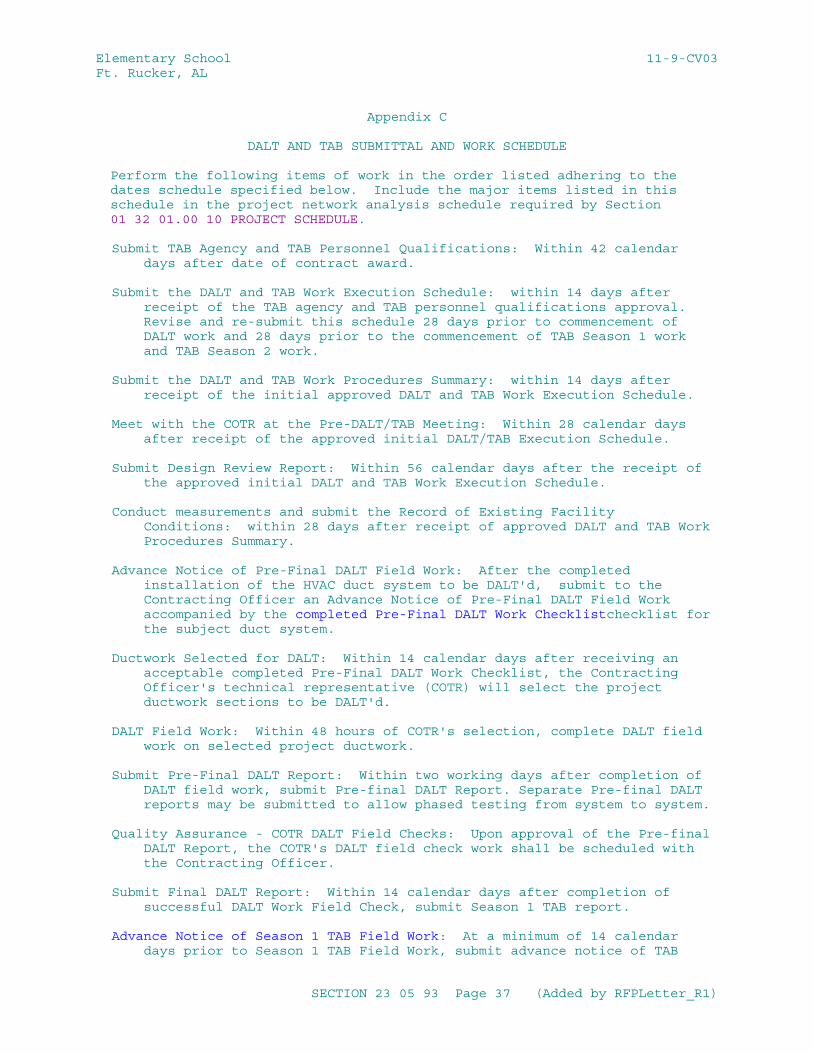
Elementary School 11-9-CV03Ft. Rucker, AL
Appendix C
DALT AND TAB SUBMITTAL AND WORK SCHEDULE
Perform the following items of work in the order listed adhering to the dates schedule specified below. Include the major items listed in this schedule in the project network analysis schedule required by Section 01 32 01.00 10 PROJECT SCHEDULE.
Submit TAB Agency and TAB Personnel Qualifications: Within 42 calendar days after date of contract award.
Submit the DALT and TAB Work Execution Schedule: within 14 days after receipt of the TAB agency and TAB personnel qualifications approval. Revise and re-submit this schedule 28 days prior to commencement of DALT work and 28 days prior to the commencement of TAB Season 1 work and TAB Season 2 work.
Submit the DALT and TAB Work Procedures Summary: within 14 days after receipt of the initial approved DALT and TAB Work Execution Schedule.
Meet with the COTR at the Pre-DALT/TAB Meeting: Within 28 calendar days after receipt of the approved initial DALT/TAB Execution Schedule.
Submit Design Review Report: Within 56 calendar days after the receipt of the approved initial DALT and TAB Work Execution Schedule.
Conduct measurements and submit the Record of Existing Facility Conditions: within 28 days after receipt of approved DALT and TAB Work Procedures Summary.
Advance Notice of Pre-Final DALT Field Work: After the completed installation of the HVAC duct system to be DALT'd, submit to the Contracting Officer an Advance Notice of Pre-Final DALT Field Work accompanied by the completed Pre-Final DALT Work Checklistchecklist for the subject duct system.
Ductwork Selected for DALT: Within 14 calendar days after receiving an acceptable completed Pre-Final DALT Work Checklist, the Contracting Officer's technical representative (COTR) will select the project ductwork sections to be DALT'd.
DALT Field Work: Within 48 hours of COTR's selection, complete DALT field work on selected project ductwork.
Submit Pre-Final DALT Report: Within two working days after completion of DALT field work, submit Pre-final DALT Report. Separate Pre-final DALT reports may be submitted to allow phased testing from system to system.
Quality Assurance - COTR DALT Field Checks: Upon approval of the Pre-final DALT Report, the COTR's DALT field check work shall be scheduled with the Contracting Officer.
Submit Final DALT Report: Within 14 calendar days after completion of successful DALT Work Field Check, submit Season 1 TAB report.
Advance Notice of Season 1 TAB Field Work: At a minimum of 14 calendar days prior to Season 1 TAB Field Work, submit advance notice of TAB
SECTION 23 05 93 Page 37 (Added by RFPLetter_R1)
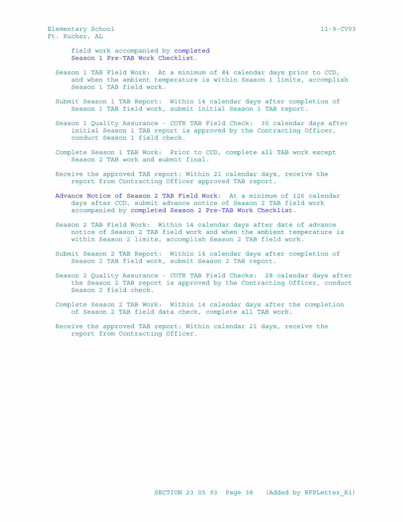
Elementary School 11-9-CV03Ft. Rucker, AL
field work accompanied by completed Season 1 Pre-TAB Work Checklist.
Season 1 TAB Field Work: At a minimum of 84 calendar days prior to CCD, and when the ambient temperature is within Season 1 limits, accomplish Season 1 TAB field work.
Submit Season 1 TAB Report: Within 14 calendar days after completion of Season 1 TAB field work, submit initial Season 1 TAB report.
Season 1 Quality Assurance - COTR TAB Field Check: 30 calendar days after initial Season 1 TAB report is approved by the Contracting Officer, conduct Season 1 field check.
Complete Season 1 TAB Work: Prior to CCD, complete all TAB work except Season 2 TAB work and submit final.
Receive the approved TAB report: Within 21 calendar days, receive the report from Contracting Officer approved TAB report.
Advance Notice of Season 2 TAB Field Work: At a minimum of 126 calendar days after CCD, submit advance notice of Season 2 TAB field work accompanied by completed Season 2 Pre-TAB Work Checklist.
Season 2 TAB Field Work: Within 14 calendar days after date of advance notice of Season 2 TAB field work and when the ambient temperature is within Season 2 limits, accomplish Season 2 TAB field work.
Submit Season 2 TAB Report: Within 14 calendar days after completion of Season 2 TAB field work, submit Season 2 TAB report.
Season 2 Quality Assurance - COTR TAB Field Checks: 28 calendar days after the Season 2 TAB report is approved by the Contracting Officer, conduct Season 2 field check.
Complete Season 2 TAB Work: Within 14 calendar days after the completion of Season 2 TAB field data check, complete all TAB work.
Receive the approved TAB report: Within calendar 21 days, receive the report from Contracting Officer.
SECTION 23 05 93 Page 38 (Added by RFPLetter_R1)
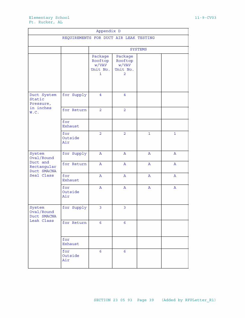
Elementary School 11-9-CV03Ft. Rucker, AL
Appendix D
REQUIREMENTS FOR DUCT AIR LEAK TESTING
SYSTEMS
PackageRooftopw/VAV
Unit No.1
PackageRooftopw/VAV
Unit No.2
Duct System Static Pressure, in inches W.C.
for Supply 4 4
for Return 2 2
for Exhaust
for Outside Air
2 2 1 1
System Oval/Round Duct and Rectangular Duct SMACNA Seal Class
for Supply A A A A
for Return A A A A
for Exhaust
A A A A
for Outside Air
A A A A
System Oval/Round Duct SMACNA Leak Class
for Supply 3 3
for Return 6 6
for Exhaust
for Outside Air
6 6
SECTION 23 05 93 Page 39 (Added by RFPLetter_R1)
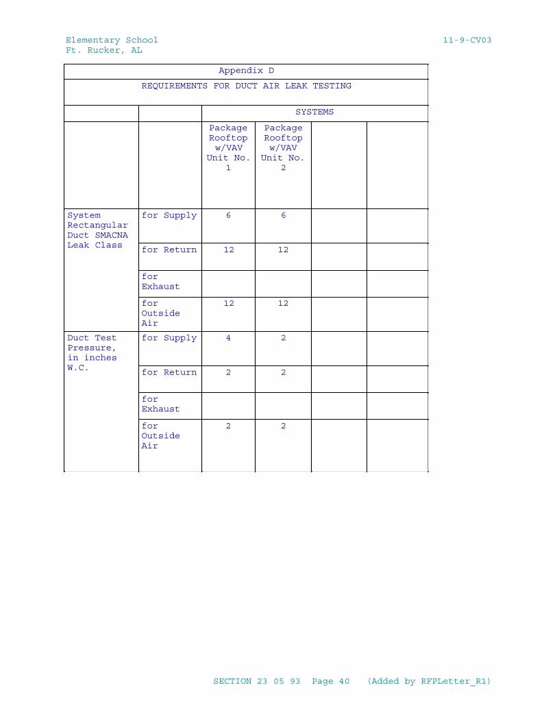
Elementary School 11-9-CV03Ft. Rucker, AL
Appendix D
REQUIREMENTS FOR DUCT AIR LEAK TESTING
SYSTEMS
PackageRooftopw/VAV
Unit No.1
PackageRooftopw/VAV
Unit No.2
System Rectangular Duct SMACNA Leak Class
for Supply 6 6
for Return 12 12
for Exhaust
for Outside Air
12 12
Duct Test Pressure, in inches W.C.
for Supply 4 2
for Return 2 2
for Exhaust
for Outside Air
2 2
SECTION 23 05 93 Page 40 (Added by RFPLetter_R1)
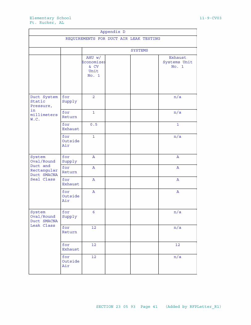
Elementary School 11-9-CV03Ft. Rucker, AL
Appendix D
REQUIREMENTS FOR DUCT AIR LEAK TESTING
SYSTEMS
AHU w/Economizer
& CVUnitNo. 1
ExhaustSystems Unit
No. 1
Duct System Static Pressure, in millimeters W.C.
for Supply
2 n/a
for Return
1 n/a
for Exhaust
0.5 1
for Outside Air
1 n/a
System Oval/Round Duct and Rectangular Duct SMACNA Seal Class
for Supply
A A
for Return
A A
for Exhaust
A A
for Outside Air
A A
System Oval/Round Duct SMACNA Leak Class
for Supply
6 n/a
for Return
12 n/a
for Exhaust
12 12
for Outside Air
12 n/a
SECTION 23 05 93 Page 41 (Added by RFPLetter_R1)
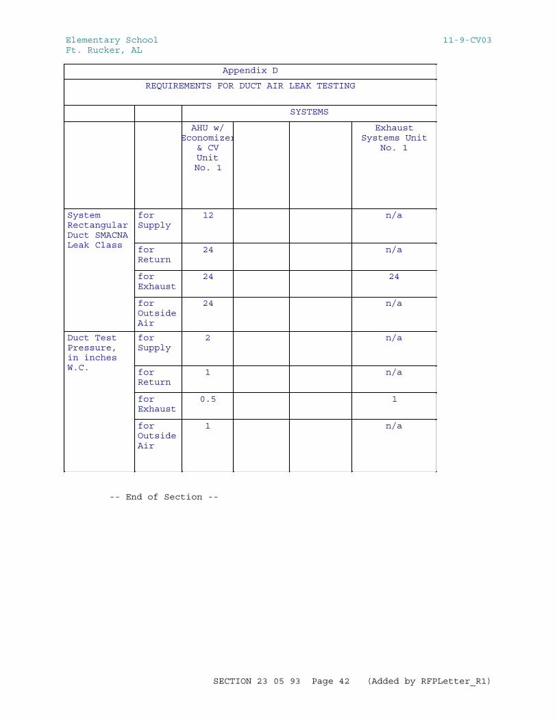
Elementary School 11-9-CV03Ft. Rucker, AL
Appendix D
REQUIREMENTS FOR DUCT AIR LEAK TESTING
SYSTEMS
AHU w/Economizer
& CVUnitNo. 1
ExhaustSystems Unit
No. 1
System Rectangular Duct SMACNA Leak Class
for Supply
12 n/a
for Return
24 n/a
for Exhaust
24 24
for Outside Air
24 n/a
Duct Test Pressure, in inches W.C.
for Supply
2 n/a
for Return
1 n/a
for Exhaust
0.5 1
for Outside Air
1 n/a
-- End of Section --
SECTION 23 05 93 Page 42 (Added by RFPLetter_R1)
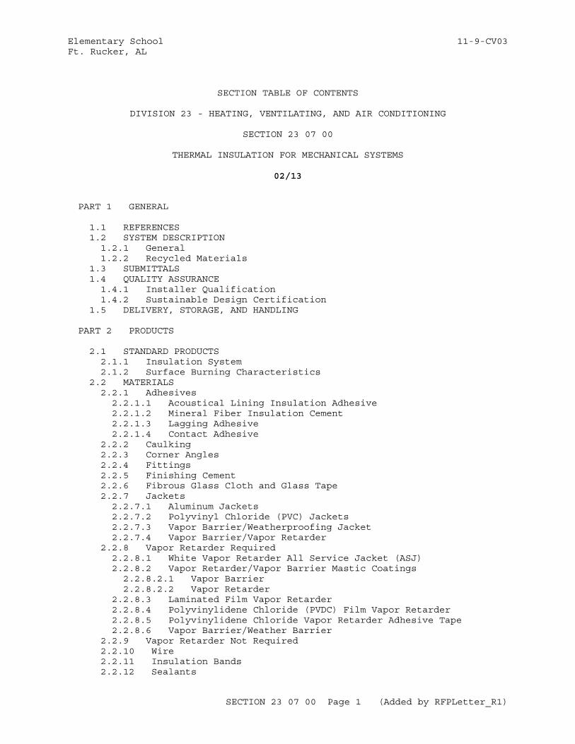
Elementary School 11-9-CV03Ft. Rucker, AL
SECTION TABLE OF CONTENTS
DIVISION 23 - HEATING, VENTILATING, AND AIR CONDITIONING
SECTION 23 07 00
THERMAL INSULATION FOR MECHANICAL SYSTEMS
02/13
PART 1 GENERAL
1.1 REFERENCES 1.2 SYSTEM DESCRIPTION 1.2.1 General 1.2.2 Recycled Materials 1.3 SUBMITTALS 1.4 QUALITY ASSURANCE 1.4.1 Installer Qualification 1.4.2 Sustainable Design Certification 1.5 DELIVERY, STORAGE, AND HANDLING
PART 2 PRODUCTS
2.1 STANDARD PRODUCTS 2.1.1 Insulation System 2.1.2 Surface Burning Characteristics 2.2 MATERIALS 2.2.1 Adhesives 2.2.1.1 Acoustical Lining Insulation Adhesive 2.2.1.2 Mineral Fiber Insulation Cement 2.2.1.3 Lagging Adhesive 2.2.1.4 Contact Adhesive 2.2.2 Caulking 2.2.3 Corner Angles 2.2.4 Fittings 2.2.5 Finishing Cement 2.2.6 Fibrous Glass Cloth and Glass Tape 2.2.7 Jackets 2.2.7.1 Aluminum Jackets 2.2.7.2 Polyvinyl Chloride (PVC) Jackets 2.2.7.3 Vapor Barrier/Weatherproofing Jacket 2.2.7.4 Vapor Barrier/Vapor Retarder 2.2.8 Vapor Retarder Required 2.2.8.1 White Vapor Retarder All Service Jacket (ASJ) 2.2.8.2 Vapor Retarder/Vapor Barrier Mastic Coatings 2.2.8.2.1 Vapor Barrier 2.2.8.2.2 Vapor Retarder 2.2.8.3 Laminated Film Vapor Retarder 2.2.8.4 Polyvinylidene Chloride (PVDC) Film Vapor Retarder 2.2.8.5 Polyvinylidene Chloride Vapor Retarder Adhesive Tape 2.2.8.6 Vapor Barrier/Weather Barrier 2.2.9 Vapor Retarder Not Required 2.2.10 Wire 2.2.11 Insulation Bands 2.2.12 Sealants
SECTION 23 07 00 Page 1 (Added by RFPLetter_R1)
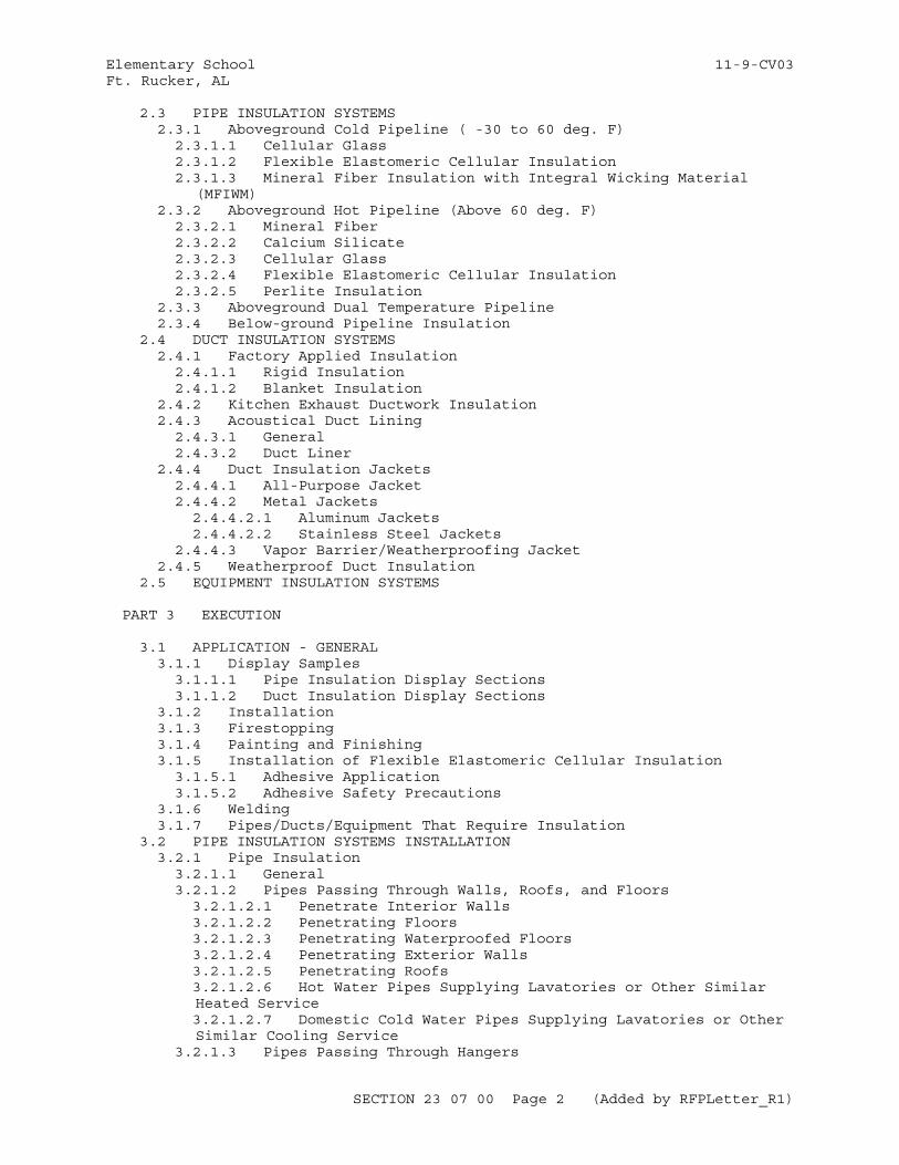
Elementary School 11-9-CV03Ft. Rucker, AL
2.3 PIPE INSULATION SYSTEMS 2.3.1 Aboveground Cold Pipeline ( -30 to 60 deg. F) 2.3.1.1 Cellular Glass 2.3.1.2 Flexible Elastomeric Cellular Insulation 2.3.1.3 Mineral Fiber Insulation with Integral Wicking Material
(MFIWM) 2.3.2 Aboveground Hot Pipeline (Above 60 deg. F) 2.3.2.1 Mineral Fiber 2.3.2.2 Calcium Silicate 2.3.2.3 Cellular Glass 2.3.2.4 Flexible Elastomeric Cellular Insulation 2.3.2.5 Perlite Insulation 2.3.3 Aboveground Dual Temperature Pipeline 2.3.4 Below-ground Pipeline Insulation 2.4 DUCT INSULATION SYSTEMS 2.4.1 Factory Applied Insulation 2.4.1.1 Rigid Insulation 2.4.1.2 Blanket Insulation 2.4.2 Kitchen Exhaust Ductwork Insulation 2.4.3 Acoustical Duct Lining 2.4.3.1 General 2.4.3.2 Duct Liner 2.4.4 Duct Insulation Jackets 2.4.4.1 All-Purpose Jacket 2.4.4.2 Metal Jackets 2.4.4.2.1 Aluminum Jackets 2.4.4.2.2 Stainless Steel Jackets 2.4.4.3 Vapor Barrier/Weatherproofing Jacket 2.4.5 Weatherproof Duct Insulation 2.5 EQUIPMENT INSULATION SYSTEMS
PART 3 EXECUTION
3.1 APPLICATION - GENERAL 3.1.1 Display Samples 3.1.1.1 Pipe Insulation Display Sections 3.1.1.2 Duct Insulation Display Sections 3.1.2 Installation 3.1.3 Firestopping 3.1.4 Painting and Finishing 3.1.5 Installation of Flexible Elastomeric Cellular Insulation 3.1.5.1 Adhesive Application 3.1.5.2 Adhesive Safety Precautions 3.1.6 Welding 3.1.7 Pipes/Ducts/Equipment That Require Insulation 3.2 PIPE INSULATION SYSTEMS INSTALLATION 3.2.1 Pipe Insulation 3.2.1.1 General 3.2.1.2 Pipes Passing Through Walls, Roofs, and Floors 3.2.1.2.1 Penetrate Interior Walls 3.2.1.2.2 Penetrating Floors 3.2.1.2.3 Penetrating Waterproofed Floors 3.2.1.2.4 Penetrating Exterior Walls 3.2.1.2.5 Penetrating Roofs 3.2.1.2.6 Hot Water Pipes Supplying Lavatories or Other Similar
Heated Service 3.2.1.2.7 Domestic Cold Water Pipes Supplying Lavatories or Other
Similar Cooling Service 3.2.1.3 Pipes Passing Through Hangers
SECTION 23 07 00 Page 2 (Added by RFPLetter_R1)
Elementary School 11-9-CV03Ft. Rucker, AL
3.2.1.3.1 Horizontal Pipes Larger Than 2 Inches at 16 Degrees C 60 Degrees F and Above
3.2.1.3.2 Horizontal Pipes Larger Than 2 Inches and Below 16 Degrees C 60 Degrees F
3.2.1.3.3 Vertical Pipes 3.2.1.3.4 Inserts 3.2.1.4 Flexible Elastomeric Cellular Pipe Insulation 3.2.1.5 Pipes in high abuse areas. 3.2.1.6 Pipe Insulation Material and Thickness 3.2.2 Aboveground Cold Pipelines 3.2.2.1 Insulation Material and Thickness 3.2.2.2 Factory or Field applied Jacket 3.2.2.3 Installing Insulation for Straight Runs Hot and Cold Pipe 3.2.2.3.1 Longitudinal Laps of the Jacket Material 3.2.2.3.2 Laps and Butt Strips 3.2.2.3.3 Factory Self-Sealing Lap Systems 3.2.2.3.4 Staples 3.2.2.3.5 Breaks and Punctures in the Jacket Material 3.2.2.3.6 Penetrations Such as Thermometers 3.2.2.3.7 Flexible Elastomeric Cellular Pipe Insulation 3.2.2.4 Insulation for Fittings and Accessories 3.2.2.5 Optional PVC Fitting Covers 3.2.3 Aboveground Hot Pipelines 3.2.3.1 General Requirements 3.2.3.2 Insulation for Fittings and Accessories 3.2.3.2.1 Precut or Preformed 3.2.3.2.2 Rigid Preformed 3.2.4 Piping Exposed to Weather 3.2.4.1 Aluminum Jacket 3.2.4.2 Insulation for Fittings 3.2.4.3 PVC Jacket 3.3 DUCT INSULATION SYSTEMS INSTALLATION 3.3.1 Duct Insulation Thickness 3.3.2 Insulation and Vapor Retarder/Vapor Barrier for Cold Air Duct 3.3.2.1 Installation on Concealed Duct 3.3.2.2 Installation on Exposed Duct Work 3.3.3 Insulation for Warm Air Duct 3.3.3.1 Installation on Concealed Duct 3.3.3.2 Installation on Exposed Duct 3.3.4 Ducts Handling Air for Dual Purpose 3.3.5 Duct Test Holes 3.3.6 Duct Exposed to Weather 3.3.6.1 Installation 3.3.6.2 Round Duct 3.3.6.3 Fittings 3.3.6.4 Rectangular Ducts 3.3.7 Kitchen Exhaust Duct Insulation 3.4 EQUIPMENT INSULATION SYSTEMS INSTALLATION 3.4.1 General 3.4.2 Insulation for Cold Equipment 3.4.2.1 Insulation Type 3.4.3 Insulation for Hot Equipment 3.4.3.1 Insulation 3.4.3.2 Insulation of Boiler Stack and Diesel Engine Exhaust Pipe 3.4.3.3 Insulation of Pumps 3.4.3.4 Other Equipment 3.4.4 Equipment Handling Dual Temperature Media 3.4.5 Equipment Exposed to Weather 3.4.5.1 Installation
SECTION 23 07 00 Page 3 (Added by RFPLetter_R1)
Elementary School 11-9-CV03Ft. Rucker, AL
3.4.5.2 Optional Panels
-- End of Section Table of Contents --
SECTION 23 07 00 Page 4 (Added by RFPLetter_R1)
Elementary School 11-9-CV03Ft. Rucker, AL
SECTION 23 07 00
THERMAL INSULATION FOR MECHANICAL SYSTEMS02/13
PART 1 GENERAL
1.1 REFERENCES
The publications listed below form a part of this specification to the extent referenced. The publications are referred to within the text by the basic designation only. At the discretion of the Government, the manufacturer of any material supplied will be required to furnish test reports pertaining to any of the tests necessary to assure compliance with the standard or standards referenced in this specification.
AMERICAN SOCIETY OF HEATING, REFRIGERATING AND AIR-CONDITIONING ENGINEERS (ASHRAE)
ASHRAE 90.1 - IP (2010; ERTA 2011-2013) Energy Standard for Buildings Except Low-Rise Residential Buildings
ASTM INTERNATIONAL (ASTM)
ASTM A167 (2011) Standard Specification for Stainless and Heat-Resisting Chromium-Nickel Steel Plate, Sheet, and Strip
ASTM A240/A240M (2014) Standard Specification for Chromium and Chromium-Nickel Stainless Steel Plate, Sheet, and Strip for Pressure Vessels and for General Applications
ASTM A580/A580M (2014) Standard Specification for Stainless Steel Wire
ASTM B209 (2014) Standard Specification for Aluminum and Aluminum-Alloy Sheet and Plate
ASTM C1126 (2013) Standard Specification for Faced or Unfaced Rigid Cellular Phenolic Thermal Insulation
ASTM C1136 (2012) Standard Specification for Flexible, Low Permeance Vapor Retarders for Thermal Insulation
ASTM C1290 (2011) Standard Specification for Flexible Fibrous Glass Blanket Insulation Used to Externally Insulate HVAC Ducts
ASTM C1710 (2011) Standard Guide for Installation of Flexible Closed Cell Preformed Insulation in Tube and Sheet Form
SECTION 23 07 00 Page 5 (Added by RFPLetter_R1)
Elementary School 11-9-CV03Ft. Rucker, AL
ASTM C195 (2007; R 2013) Standard Specification for Mineral Fiber Thermal Insulating Cement
ASTM C450 (2008) Standard Practice for Fabrication of Thermal Insulating Fitting Covers for NPS Piping, and Vessel Lagging
ASTM C533 (2013) Standard Specification for Calcium Silicate Block and Pipe Thermal Insulation
ASTM C534/C534M (2014) Standard Specification for Preformed Flexible Elastomeric Cellular Thermal Insulation in Sheet and Tubular Form
ASTM C547 (2012) Standard Specification for Mineral Fiber Pipe Insulation
ASTM C552 (2014) Standard Specification for Cellular Glass Thermal Insulation
ASTM C585 (2010) Standard Practice for Inner and Outer Diameters of Thermal Insulation for Nominal Sizes of Pipe and Tubing
ASTM C592 (2013) Standard Specification for Mineral Fiber Blanket Insulation and Blanket-Type Pipe Insulation (Metal-Mesh Covered) (Industrial Type)
ASTM C610 (2011) Standard Specification for Molded Expanded Perlite Block and Pipe Thermal Insulation
ASTM C612 (2010) Mineral Fiber Block and Board Thermal Insulation
ASTM C647 (2008) Properties and Tests of Mastics and Coating Finishes for Thermal Insulation
ASTM C795 (2008; R 2013) Standard Specification for Thermal Insulation for Use in Contact with Austenitic Stainless Steel
ASTM C916 (2014) Standard Specification for Adhesives for Duct Thermal Insulation
ASTM C920 (2011) Standard Specification for Elastomeric Joint Sealants
ASTM C921 (2010) Standard Practice for Determining the Properties of Jacketing Materials for Thermal Insulation
ASTM D2863 (2012) Measuring the Minimum Oxygen Concentration to Support Candle-Like Combustion of Plastics (Oxygen Index)
SECTION 23 07 00 Page 6 (Added by RFPLetter_R1)
Elementary School 11-9-CV03Ft. Rucker, AL
ASTM D5590 (2000; R 2010; E 2012) Standard Test Method for Determining the Resistance of Paint Films and Related Coatings to Fungal Defacement by Accelerated Four-Week Agar Plate Assay
ASTM D882 (2012) Tensile Properties of Thin Plastic Sheeting
ASTM E2231 (2009) Specimen Preparation and Mounting of Pipe and Duct Insulation Materials to Assess Surface Burning Characteristics
ASTM E2336 (2004; R 2013) Standard Test Methods for Fire Resistive Grease Duct Enclosure Systems
ASTM E84 (2015a) Standard Test Method for Surface Burning Characteristics of Building Materials
ASTM E96/E96M (2014) Standard Test Methods for Water Vapor Transmission of Materials
FM GLOBAL (FM)
FM APP GUIDE (updated on-line) Approval Guide http://www.approvalguide.com/
MANUFACTURERS STANDARDIZATION SOCIETY OF THE VALVE AND FITTINGS INDUSTRY (MSS)
MSS SP-69 (2003; Notice 2012) Pipe Hangers and Supports - Selection and Application (ANSI Approved American National Standard)
MIDWEST INSULATION CONTRACTORS ASSOCIATION (MICA)
MICA Insulation Stds (1999) National Commercial & Industrial Insulation Standards
NATIONAL FIRE PROTECTION ASSOCIATION (NFPA)
NFPA 90A (2015) Standard for the Installation of Air Conditioning and Ventilating Systems
NFPA 90B (2012) Standard for the Installation of Warm Air Heating and Air Conditioning Systems
NFPA 96 (2014) Standard for Ventilation Control and Fire Protection of Commercial Cooking Operations
SCIENTIFIC CERTIFICATION SYSTEMS (SCS)
SCS Scientific Certification Systems (SCS)Indoor Advantage
SECTION 23 07 00 Page 7 (Added by RFPLetter_R1)
Elementary School 11-9-CV03Ft. Rucker, AL
TECHNICAL ASSOCIATION OF THE PULP AND PAPER INDUSTRY (TAPPI)
TAPPI T403 OM (2010) Bursting Strength of Paper
U.S. DEPARTMENT OF DEFENSE (DOD)
MIL-A-24179 (1969; Rev A; Am 2 1980; Notice 1 1987) Adhesive, Flexible Unicellular-Plastic Thermal Insulation
MIL-A-3316 (1987; Rev C; Am 2 1990) Adhesives, Fire-Resistant, Thermal Insulation
MIL-PRF-19565 (1988; Rev C) Coating Compounds, Thermal Insulation, Fire- and Water-Resistant, Vapor-Barrier
UL ENVIRONMENT (ULE)
ULE Greenguard UL Greenguard Certification Program
UNDERWRITERS LABORATORIES (UL)
UL 723 (2008; Reprint Aug 2013) Test for Surface Burning Characteristics of Building Materials
UL 94 (2013) Standard for Tests for Flammability of Plastic Materials for Parts in Devices and Appliances
1.2 SYSTEM DESCRIPTION
1.2.1 General
Provide field-applied insulation and accessories on mechanical systems as specified herein; factory-applied insulation is specified under the piping, duct or equipment to be insulated. Field applied insulation materials required for use on Government-furnished items as listed in the SPECIAL CONTRACT REQUIREMENTS shall be furnished and installed by the Contractor.
1.2.2 Recycled Materials
Provide thermal insulation containing recycled materials to the extent practicable, provided that the materials meet all other requirements of this section. The minimum recycled material content of the following insulation are:
Rock Wool 75 percent slag of weight
Fiberglass 20-25 percent glass cullet by weight
Rigid Foam 9 percent recovered material
1.3 SUBMITTALS
Government approval is required for submittals with a "G" designation; submittals not having a "G" designation are for Contractor Quality Control
SECTION 23 07 00 Page 8 (Added by RFPLetter_R1)
Elementary School 11-9-CV03Ft. Rucker, AL
approval. Submit the following in accordance with Section 01 33 00 SUBMITTAL PROCEDURES:
Submit the three SD types, SD-02 Shop Drawings, SD-03 Product Data, and SD-08 Manufacturer's Instructions at the same time for each system.
SD-02 Shop Drawings
MICA Plates; GPipe Insulation Systems and Associated AccessoriesDuct Insulation Systems and Associated AccessoriesEquipment Insulation Systems and Associated Accessories
SD-03 Product Data
CertificationPipe Insulation Systems; GDuct Insulation Systems; GEquipment Insulation Systems; G
SD-04 Samples
Thermal Insulation; GDisplay Samples; G
SD-08 Manufacturer's Instructions
Pipe Insulation Systems; GDuct Insulation Systems; GEquipment Insulation Systems; G
1.4 QUALITY ASSURANCE
1.4.1 Installer Qualification
Qualified installers shall have successfully completed three or more similar type jobs within the last 5 years.
1.4.2 Sustainable Design Certification
Product shall be third party certified in accordance with ULE Greenguard Gold, SCS Scientific Certification Systems Indoor Advantage Gold or equal. Certification shall be performed annually and shall be current.
1.5 DELIVERY, STORAGE, AND HANDLING
Materials shall be delivered in the manufacturer's unopened containers. Materials delivered and placed in storage shall be provided with protection from weather, humidity, dirt, dust and other contaminants. The Contracting Officer may reject insulation material and supplies that become dirty, dusty, wet, or contaminated by some other means. Packages or standard containers of insulation, jacket material, cements, adhesives, and coatings delivered for use, and samples required for approval shall have manufacturer's stamp or label attached giving the name of the manufacturer and brand, and a description of the material, date codes, and approximate shelf life (if applicable). Insulation packages and containers shall be asbestos free.
SECTION 23 07 00 Page 9 (Added by RFPLetter_R1)
Elementary School 11-9-CV03Ft. Rucker, AL
PART 2 PRODUCTS
2.1 STANDARD PRODUCTS
Provide materials which are the standard products of manufacturers regularly engaged in the manufacture of such products and that essentially duplicate items that have been in satisfactory use for at least 2 years prior to bid opening. Submit a complete list of materials, including manufacturer's descriptive technical literature, performance data, catalog cuts, and installation instructions. The product number, k-value, thickness and furnished accessories including adhesives, sealants and jackets for each mechanical system requiring insulation shall be included. The product data must be copyrighted, have an identifying or publication number, and shall have been published prior to the issuance date of this solicitation. Materials furnished under this section shall be submitted together in a booklet and in conjunction with the MICA plates booklet (SD-02). Annotate the product data to indicate which MICA plate is applicable.
2.1.1 Insulation System
Provide insulation systems in accordance with the approved MICA National Insulation Standards plates as supplemented by this specification. Provide field-applied insulation for heating, ventilating, and cooling (HVAC) air distribution systems and piping systems that are located within, on, under, and adjacent to buildings; and for plumbing systems. Insulation shall be CFC and HCFC free.
2.1.2 Surface Burning Characteristics
Unless otherwise specified, insulation shall have a maximum flame spreadindex of 25 and a maximum smoke developed index of 50 when tested inaccordance with ASTM E84. Flame spread, and smoke developed indexes,shall be determined by ASTM E84 or UL 723. Insulation shall be tested inthe same density and installed thickness as the material to be used in theactual construction. Test specimens shall be prepared and mountedaccording to ASTM E2231.
2.2 MATERIALS
Provide insulation that meets or exceed the requirements of ASHRAE 90.1 - IP. Insulation exterior shall be cleanable, grease resistant, non-flaking and non-peeling. Materials shall be compatible and shall not contribute to corrosion, soften, or otherwise attack surfaces to which applied in either wet or dry state. Materials to be used on stainless steel surfaces shall meet ASTM C795 requirements. Calcium silicate shall not be used on chilled or cold water systems. Materials shall be asbestos free. Provide product recognized under UL 94 (if containing plastic) and listed in FM APP GUIDE.
2.2.1 Adhesives
2.2.1.1 Acoustical Lining Insulation Adhesive
Adhesive shall be a nonflammable, fire-resistant adhesive conforming to ASTM C916, Type I.
2.2.1.2 Mineral Fiber Insulation Cement
Cement shall be in accordance with ASTM C195.
SECTION 23 07 00 Page 10 (Added by RFPLetter_R1)
Elementary School 11-9-CV03Ft. Rucker, AL
2.2.1.3 Lagging Adhesive
Lagging is the material used for thermal insulation, especially around a cylindrical object. This may include the insulation as well as the cloth/material covering the insulation. To resist mold/mildew, lagging adhesive shall meet ASTM D5590 with 0 growth rating. Lagging adhesives shall be nonflammable and fire-resistant and shall have a maximum flame spread index of 25 and a maximum smoke developed index of 50 when tested in accordance with ASTM E84. Adhesive shall be MIL-A-3316, Class 1, pigmented white and be suitable for bonding fibrous glass cloth to faced and unfaced fibrous glass insulation board; for bonding cotton brattice cloth to faced and unfaced fibrous glass insulation board; for sealing edges of and bonding glass tape to joints of fibrous glass board; for bonding lagging cloth to thermal insulation; or Class 2 for attaching fibrous glass insulation to metal surfaces. Lagging adhesives shall be applied in strict accordance with the manufacturer's recommendations for pipe and duct insulation.
2.2.1.4 Contact Adhesive
Adhesives may be any of, but not limited to, the neoprene based, rubber based, or elastomeric type that have a maximum flame spread index of 25 and a maximum smoke developed index of 50 when tested in accordance with ASTM E84. The adhesive shall not adversely affect, initially or in service, the insulation to which it is applied, nor shall it cause any corrosive effect on metal to which it is applied. Any solvent dispersing medium or volatile component of the adhesive shall have no objectionable odor and shall not contain any benzene or carbon tetrachloride. The dried adhesive shall not emit nauseous, irritating, or toxic volatile matters or aerosols when the adhesive is heated to any temperature up to 212 degrees F. The dried adhesive shall be nonflammable and fire resistant. Flexible Elastomeric Adhesive: Comply with MIL-A-24179, Type II, Class I. Provide product listed in FM APP GUIDE.
2.2.2 Caulking
ASTM C920, Type S, Grade NS, Class 25, Use A.
2.2.3 Corner Angles
Nominal 0.016 inch aluminum 1 by 1 inch with factory applied kraft backing. Aluminum shall be ASTM B209, Alloy 3003, 3105, or 5005.
2.2.4 Fittings
Fabricated Fittings are the prefabricated fittings for flexible elastomeric pipe insulation systems in accordance with ASTM C1710. Together with the flexible elastomeric tubes, they provide complete system integrity for retarding heat gain and controlling condensation drip from chilled-water and refrigeration systems. Flexible elastomeric, fabricated fittings provide thermal protection (0.25 k) and condensation resistance (0.05 Water Vapor Transmission factor). For satisfactory performance, properly installed protective vapor retarder/barriers and vapor stops shall be used on high relative humidity and below ambient temperature applications to reduce movement of moisture through or around the insulation to the colder interior surface.
SECTION 23 07 00 Page 11 (Added by RFPLetter_R1)
Elementary School 11-9-CV03Ft. Rucker, AL
2.2.5 Finishing Cement
ASTM C450: Mineral fiber hydraulic-setting thermal insulating and finishing cement. All cements that may come in contact with Austenitic stainless steel must comply with ASTM C795.
2.2.6 Fibrous Glass Cloth and Glass Tape
Fibrous glass cloth, with 20X20 maximum mesh size, and glass tape shall have maximum flame spread index of 25 and a maximum smoke developed index of 50 when tested in accordance with ASTM E84. Tape shall be 4 inch wide rolls. Class 3 tape shall be 4.5 ounces/square yard. Elastomeric Foam Tape: Black vapor-retarder foam tape with acrylic adhesive containing an anti-microbial additive.
2.2.7 Jackets
2.2.7.1 Aluminum Jackets
Aluminum jackets shall be corrugated, embossed or smooth sheet, 0.016 inch nominal thickness; ASTM B209, Temper H14, Temper H16, Alloy 3003, 5005, or 3105. Corrugated aluminum jacket shall not be used outdoors. Aluminum jacket securing bands shall be Type 304 stainless steel, 0.015 inch thick, 1/2 inch wide for pipe under 12 inch diameter and 3/4 inch wide for pipe over 12 inch and larger diameter. Aluminum jacket circumferential seam bands shall be 2 by 0.016 inch aluminum matching jacket material. Bands for insulation below ground shall be 3/4 by 0.020 inch thick stainless steel, or fiberglass reinforced tape. The jacket may, at the option of the Contractor, be provided with a factory fabricated Pittsburgh or "Z" type longitudinal joint. When the "Z" joint is used, the bands at the circumferential joints shall be designed by the manufacturer to seal the joints and hold the jacket in place.
2.2.7.2 Polyvinyl Chloride (PVC) Jackets
Polyvinyl chloride (PVC) jacket and fitting covers shall have high impact strength, ultraviolet (UV) resistant rating or treatment and moderate chemical resistance with minimum thickness 0.030 inch.
2.2.7.3 Vapor Barrier/Weatherproofing Jacket
Vapor barrier/weatherproofing jacket shall be laminated self-adhesive, greater than 3 plies standard grade, silver, white, black and embossed or greater than 8 ply (minimum 2.9 mils adhesive); with 0.0000 permeability when tested in accordance with ASTM E96/E96M, using the water transmission rate test method; heavy duty, white or natural; and UV resistant. Flexible Elastomeric exterior foam with factory applied, UV Jacket made with a cold weather acrylic adhesive. Construction of laminate designed to provide UV resistance, high puncture, tear resistance and excellent Water Vapor Transmission (WVT) rate.
2.2.7.4 Vapor Barrier/Vapor Retarder
Apply the following criteria to determine which system is required.
a. On ducts, piping and equipment operating below 60 degrees F or located outside shall be equipped with a vapor barrier.
b. Ducts, pipes and equipment that are located inside and that always
SECTION 23 07 00 Page 12 (Added by RFPLetter_R1)
Elementary School 11-9-CV03Ft. Rucker, AL
operate above 60 degrees F shall be installed with a vapor retarder where required as stated in paragraph VAPOR RETARDER REQUIRED.
2.2.8 Vapor Retarder Required
ASTM C921, Type I, minimum puncture resistance 50 Beach units on all surfaces except concealed ductwork, where a minimum puncture resistance of 25 Beach units is acceptable. Minimum tensile strength, 35 pounds/inch width. ASTM C921, Type II, minimum puncture resistance 25 Beach units, tensile strength minimum 20 pounds/inch width. Jackets used on insulation exposed in finished areas shall have white finish suitable for painting without sizing. Based on the application, insulation materials that require manufacturer or fabricator applied pipe insulation jackets are cellular glass, when all joints are sealed with a vapor barrier mastic, and mineral fiber. All non-metallic jackets shall have a maximum flame spread index of 25 and a maximum smoke developed index of 50 when tested in accordance with ASTM E84. Flexible elastomerics require (in addition to vapor barrier skin) vapor retarder jacketing for high relative humidity and below ambient temperature applications.
2.2.8.1 White Vapor Retarder All Service Jacket (ASJ)
ASJ is for use on hot/cold pipes, ducts, or equipment indoors or outdoors if covered by a suitable protective jacket. The product shall meet all physical property and performance requirements of ASTM C1136, Type I, except the burst strength shall be a minimum of 85 psi. ASTM D2863 Limited Oxygen Index (LOI) shall be a minimum of 31.
In addition, neither the outer exposed surface nor the inner-most surface contacting the insulation shall be paper or other moisture-sensitive material. The outer exposed surface shall be white and have an emittance of not less than 0.80. The outer exposed surface shall be paintable.
2.2.8.2 Vapor Retarder/Vapor Barrier Mastic Coatings
2.2.8.2.1 Vapor Barrier
The vapor barrier shall be self adhesive (minimum 2 mils adhesive, 3 mils embossed) greater than 3 plies standard grade, silver, white, black and embossed white jacket for use on hot/cold pipes. Permeability shall be less than 0.02 when tested in accordance with ASTM E96/E96M. Products shall meet UL 723 or ASTM E84 flame and smoke requirements and shall be UV resistant.
2.2.8.2.2 Vapor Retarder
The vapor retarder coating shall be fire and water resistant and appropriately selected for either outdoor or indoor service. Color shall be white. The water vapor permeance of the compound shall be 0.013 perms or less at 43 mils dry film thickness as determined according to procedure B of ASTM E96/E96M utilizing apparatus described in ASTM E96/E96M. The coating shall be nonflammable, fire resistant type. To resist mold/mildew, coating shall meet ASTM D5590 with 0 growth rating. Coating shall meet MIL-PRF-19565 Type II (if selected for indoor service) and be Qualified Products Database listed. All other application and service properties shall be in accordance with ASTM C647.
SECTION 23 07 00 Page 13 (Added by RFPLetter_R1)
Elementary School 11-9-CV03Ft. Rucker, AL
2.2.8.3 Laminated Film Vapor Retarder
ASTM C1136, Type I, maximum moisture vapor transmission 0.02 perms, minimum puncture resistance 50 Beach units on all surfaces except concealed ductwork; where Type II, maximum moisture vapor transmission 0.02 perms, a minimum puncture resistance of 25 Beach units is acceptable. Vapor retarder shall have a maximum flame spread index of 25 and a maximum smoke developed index of 50 when tested in accordance with ASTM E84. Flexible Elastomeric exterior foam with factory applied UV Jacket. Construction of laminate designed to provide UV resistance, high puncture, tear resistance and an excellent WVT rate.
2.2.8.4 Polyvinylidene Chloride (PVDC) Film Vapor Retarder
The PVDC film vapor retarder shall have a maximum moisture vapor transmission of 0.02 perms, minimum puncture resistance of 150 Beach units, a minimum tensile strength in any direction of 30 lb/inch when tested in accordance with ASTM D882, and a maximum flame spread index of 25 and a maximum smoke developed index of 50 when tested in accordance with ASTM E84.
2.2.8.5 Polyvinylidene Chloride Vapor Retarder Adhesive Tape
Requirements must meet the same as specified for Laminated Film Vapor Retarder above.
2.2.8.6 Vapor Barrier/Weather Barrier
The vapor barrier shall be greater than 3 ply self adhesive laminate -white vapor barrier jacket- superior performance (less than 0.0000 permeability when tested in accordance with ASTM E96/E96M). Vapor barrier shall meet UL 723 or ASTM E84 25 flame and 50 smoke requirements; and UV resistant. Minimum burst strength 185 psi in accordance with TAPPI T403 OM . Tensile strength 68 lb/inch width (PSTC-1000). Tape shall be as specified for laminated film vapor barrier above.
2.2.9 Vapor Retarder Not Required
ASTM C921, Type II, Class D, minimum puncture resistance 50 Beach units on all surfaces except ductwork, where Type IV, maximum moisture vapor transmission 0.10, a minimum puncture resistance of 25 Beach units is acceptable. Jacket shall have a maximum flame spread index of 25 and a maximum smoke developed index of 50 when tested in accordance with ASTM E84.
2.2.10 Wire
Soft annealed ASTM A580/A580M Type 302, 304 or 316 stainless steel, 16 or 18 gauge.
2.2.11 Insulation Bands
Insulation bands shall be 1/2 inch wide; 26 gauge stainless steel.
2.2.12 Sealants
Sealants shall be chosen from the butyl polymer type, the styrene-butadiene rubber type, or the butyl type of sealants. Sealants shall have a maximum permeance of 0.02 perms based on Procedure B for ASTM E96/E96M, and a maximum flame spread index of 25 and a maximum smoke developed index of 50 when tested in accordance with ASTM E84.
SECTION 23 07 00 Page 14 (Added by RFPLetter_R1)
Elementary School 11-9-CV03Ft. Rucker, AL
2.3 PIPE INSULATION SYSTEMS
Insulation materials shall conform to Table 1. Insulation thickness shall be as listed in Table 2 and meet or exceed the requirements of ASHRAE 90.1 - IP. Insulation thickness shall be 1inch minimum. Comply with EPA requirements in accordance with Section 01 62 35.10 RECYCLED/RECOVERED/BIOBASED MATERIALS. Pipe insulation materials shall be limited to those listed herein and shall meet the following requirements:
2.3.1 Aboveground Cold Pipeline ( -30 to 60 deg. F)
Insulation for outdoor, indoor, exposed or concealed applications, shall be as follows:
2.3.1.1 Cellular Glass
ASTM C552, Type II, and Type III. Supply the insulation from the fabricator with (paragraph WHITE VAPOR RETARDER ALL SERVICE JACKET (ASJ)) ASJ vapor retarder and installed with all longitudinal overlaps sealed and all circumferential joints ASJ taped or supply the insulation unfaced from the fabricator and install with all longitudinal and circumferential joints sealed with vapor barrier mastic.
2.3.1.2 Flexible Elastomeric Cellular Insulation
Closed-cell, foam- or expanded-rubber materials containing anti-microbial additive, complying with ASTM C534/C534M, Grade 1, Type I or II. Type I, Grade 1 for tubular materials. Type II, Grade 1, for sheet materials. Type I and II shall have vapor retarder/vapor barrier skin on one or both sides of the insulation, and require an additional exterior vapor retarder covering for high relative humidity and below ambient temperature applications.
2.3.1.3 Mineral Fiber Insulation with Integral Wicking Material (MFIWM)
ASTM C547. Install in accordance with manufacturer's instructions. Do not use in applications exposed to outdoor ambient conditions in climatic zones 1 through 4.
2.3.2 Aboveground Hot Pipeline (Above 60 deg. F)
Insulation for outdoor, indoor, exposed or concealed applications shall meet the following requirements. Supply the insulation with manufacturer's recommended factory-applied jacket/vapor barrier.
2.3.2.1 Mineral Fiber
ASTM C547, Types I, II or III, supply the insulation with manufacturer's recommended factory-applied jacket.
2.3.2.2 Calcium Silicate
ASTM C533, Type I indoor only, or outdoors above 250 degrees F pipe temperature. Supply insulation with the manufacturer's recommended factory-applied jacket/vapor barrier.
SECTION 23 07 00 Page 15 (Added by RFPLetter_R1)
Elementary School 11-9-CV03Ft. Rucker, AL
2.3.2.3 Cellular Glass
ASTM C552, Type II and Type III. Supply the insulation with manufacturer's recommended factory-applied jacket.
2.3.2.4 Flexible Elastomeric Cellular Insulation
Closed-cell, foam- or expanded-rubber materials containing anti-microbial additive, complying with ASTM C534/C534M, Grade 1, Type I or II to 220 degrees F service. Type I for tubular materials. Type II for sheet materials.
2.3.2.5 Perlite Insulation
ASTM C610
2.3.3 Aboveground Dual Temperature Pipeline
Selection of insulation for use over a dual temperature pipeline system (Outdoor, Indoor - Exposed or Concealed) shall be in accordance with the most limiting/restrictive case. Find an allowable material from paragraph PIPE INSULATION MATERIALS and determine the required thickness from the most restrictive case. Use the thickness listed in paragraphs INSULATION THICKNESS for cold & hot pipe applications.
2.3.4 Below-ground Pipeline Insulation
For below-ground pipeline insulation, use cellular glass, ASTM C552, type II.
2.4 DUCT INSULATION SYSTEMS
2.4.1 Factory Applied Insulation
Provide factory-applied ASTM C552, cellular glass thermal insulation according to manufacturer's recommendations for insulation with insulation manufacturer's standard reinforced fire-retardant vapor barrier, with identification of installed thermal resistance (R) value and out-of-package R value.
2.4.1.1 Rigid Insulation
Rigid mineral fiber in accordance with ASTM C612, Class 2 (maximum surface temperature 400 degrees F), 3 pcf average, 1-1/2 inch thick, Type IA, IB, II, III, and IV. Alternately, minimum thickness may be calculated in accordance with ASHRAE 90.1 - IP.
2.4.1.2 Blanket Insulation
Blanket flexible mineral fiber insulation conforming to ASTM C585, Type 1, Class B-3, 3/4 pcf nominal, 2.0 inches thick or Type II up to 250 degrees F. Also ASTM C1290 Type III may be used. Alternately, minimum thickness may be calculated in accordance with ASHRAE 90.1 - IP.
2.4.2 Kitchen Exhaust Ductwork Insulation
Insulation thickness shall be a minimum of 2 inches, blocks or boards, either mineral fiber conforming to ASTM C612, Class 5, 20 pcf average or calcium silicate conforming to ASTM C533, Type II. Provide vapor barrier
SECTION 23 07 00 Page 16 (Added by RFPLetter_R1)
Elementary School 11-9-CV03Ft. Rucker, AL
for outside air connection to kitchen exhaust hood. The enclosure materials and the grease duct enclosure systems shall meet testing requirements of ASTM E2336 for noncombustibility, fire resistance, durability, internal fire, and fire-engulfment with a through-penetration fire stop.
2.4.3 Acoustical Duct Lining
2.4.3.1 General
For ductwork indicated or specified in Section 23 00 00 AIR SUPPLY, DISTRIBUTION, VENTILATION, AND EXHAUST SYSTEM to be acoustically lined, provide external insulation in accordance with this specification section and in addition to the acoustical duct lining. Do not use acoustical lining in place of duct wrap or rigid board insulation (insulation on the exterior of the duct).
2.4.3.2 Duct Liner
Flexible Elastomeric Acoustical and Conformable Duct Liner Materials: Flexible Elastomeric Thermal, Acoustical and Conformable Insulation Compliance with ASTM C534/C534M Grade 1, Type II; and NFPA 90A or NFPA 90B as applicable.
2.4.4 Duct Insulation Jackets
2.4.4.1 All-Purpose Jacket
Provide insulation with insulation manufacturer's standard reinforced fire-retardant jacket with or without integral vapor barrier as required by the service. In exposed locations, provide jacket with a white surface suitable for field painting.
2.4.4.2 Metal Jackets
2.4.4.2.1 Aluminum Jackets
ASTM B209, Temper H14, minimum thickness of 27 gauge ( 0.016 inch), with factory-applied polyethylene and kraft paper moisture barrier on inside surface. Provide smooth surface jackets for jacket outside dimension 8 inches and larger. Provide corrugated surface jackets for jacket outside dimension 8 inches and larger. Provide stainless steel bands, minimum width of 1/2 inch.
2.4.4.2.2 Stainless Steel Jackets
ASTM A167 or ASTM A240/A240M; Type 304, minimum thickness of 33 gauge ( 0.010 inch), smooth surface with factory-applied polyethylene and kraft paper moisture barrier on inside surface. Provide stainless steel bands, minimum width of 1/2 inch.
2.4.4.3 Vapor Barrier/Weatherproofing Jacket
Vapor barrier/weatherproofing jacket shall be laminated self-adhesive (minimum 2 mils adhesive, 3 mils embossed) less than 0.0000 permeability, (greater than 3 ply, standard grade, silver, white, black and embossed or greater than 8 ply (minimum 2.9 mils adhesive), heavy duty white or natural).
SECTION 23 07 00 Page 17 (Added by RFPLetter_R1)
Elementary School 11-9-CV03Ft. Rucker, AL
2.4.5 Weatherproof Duct Insulation
Provide ASTM C552, cellular glass thermal insulation , and weatherproofing as specified in manufacturer's instruction. Multi-ply, Polymeric Blend Laminate Jacketing: Construction of laminate designed to provide UV resistance, high puncture, tear resistance and an excellent WVT rate.
2.5 EQUIPMENT INSULATION SYSTEMS
Insulate equipment and accessories as specified in Tables 5 and 6. In outside locations, provide insulation 1/2 inch thicker than specified. Increase the specified insulation thickness for equipment where necessary to equal the thickness of angles or other structural members to make a smooth, exterior surface. Submit a booklet containing manufacturer's published installation instructions for the insulation systems in coordination with the submitted MICA Insulation Stds plates booklet. Annotate their installation instructions to indicate which product data and which MICA plate are applicable. The instructions must be copyrighted, have an identifying or publication number, and shall have been published prior to the issuance date of this solicitation. A booklet is also required by paragraphs titled: Pipe Insulation Systems and Duct Insulation Systems.
PART 3 EXECUTION
3.1 APPLICATION - GENERAL
Insulation shall only be applied to unheated and uncooled piping and equipment. Flexible elastomeric cellular insulation shall not be compressed at joists, studs, columns, ducts, hangers, etc. The insulation shall not pull apart after a one hour period; any insulation found to pull apart after one hour, shall be replaced.
3.1.1 Display Samples
Submit and display, after approval of materials, actual sections of installed systems, properly insulated in accordance with the specification requirements. Such actual sections must remain accessible to inspection throughout the job and will be reviewed from time to time for controlling the quality of the work throughout the construction site. Each material used shall be identified, by indicating on an attached sheet the specification requirement for the material and the material by each manufacturer intended to meet the requirement. The Contracting Officer will inspect display sample sections at the jobsite. Approved display sample sections shall remain on display at the jobsite during the construction period. Upon completion of construction, the display sample sections will be closed and sealed.
3.1.1.1 Pipe Insulation Display Sections
Display sample sections shall include as a minimum an elbow or tee, a valve, dielectric waterways and flanges, a hanger with protection shield and insulation insert, or dowel as required, at support point, method of fastening and sealing insulation at longitudinal lap, circumferential lap, butt joints at fittings and on pipe runs, and terminating points for each type of pipe insulation used on the job, and for hot pipelines and cold pipelines, both interior and exterior, even when the same type of insulation is used for these services.
SECTION 23 07 00 Page 18 (Added by RFPLetter_R1)
Elementary School 11-9-CV03Ft. Rucker, AL
3.1.1.2 Duct Insulation Display Sections
Display sample sections for rigid and flexible duct insulation used on the job. Use a temporary covering to enclose and protect display sections for duct insulation exposed to weather
3.1.2 Installation
Except as otherwise specified, material shall be installed in accordance with the manufacturer's written instructions. Insulation materials shall not be applied until tests and heat tracingspecified in other sections of this specification are completed. Material such as rust, scale, dirt and moisture shall be removed from surfaces to receive insulation. Insulation shall be kept clean and dry. Insulation shall not be removed from its shipping containers until the day it is ready to use and shall be returned to like containers or equally protected from dirt and moisture at the end of each workday. Insulation that becomes dirty shall be thoroughly cleaned prior to use. If insulation becomes wet or if cleaning does not restore the surfaces to like new condition, the insulation will be rejected, and shall be immediately removed from the jobsite. Joints shall be staggered on multi layer insulation. Mineral fiber thermal insulating cement shall be mixed with demineralized water when used on stainless steel surfaces. Insulation, jacketing and accessories shall be installed in accordance with MICA Insulation Stds plates except where modified herein or on the drawings.
3.1.3 Firestopping
Where pipes and ducts pass through fire walls, fire partitions, above grade floors, and fire rated chase walls, the penetration shall be sealed with fire stopping materials as specified in Section 07 84 00 FIRESTOPPING. The protection of ducts at point of passage through firewalls must be in accordance with NFPA 90A and/or NFPA 90B. All other penetrations, such as piping, conduit, and wiring, through firewalls must be protected with a material or system of the same hourly rating that is listed by UL, FM, or a NRTL.
3.1.4 Painting and Finishing
Painting shall be as specified in Section 09 90 00 PAINTS AND COATINGS.
3.1.5 Installation of Flexible Elastomeric Cellular Insulation
Install flexible elastomeric cellular insulation with seams and joints sealed with rubberized contact adhesive. Flexible elastomeric cellular insulation shall not be used on surfaces greater than 220 degrees F. Stagger seams when applying multiple layers of insulation. Protect insulation exposed to weather and not shown to have vapor barrier weatherproof jacketing with two coats of UV resistant finish or PVC or metal jacketing as recommended by the manufacturer after the adhesive is dry and cured.
3.1.5.1 Adhesive Application
Apply a brush coating of adhesive to both butt ends to be joined and to both slit surfaces to be sealed. Allow the adhesive to set until dry to touch but tacky under slight pressure before joining the surfaces. Insulation seals at seams and joints shall not be capable of being pulled apart one hour after application. Insulation that can be pulled apart one hour after installation shall be replaced.
SECTION 23 07 00 Page 19 (Added by RFPLetter_R1)
Elementary School 11-9-CV03Ft. Rucker, AL
3.1.5.2 Adhesive Safety Precautions
Use natural cross-ventilation, local (mechanical) pickup, and/or general area (mechanical) ventilation to prevent an accumulation of solvent vapors, keeping in mind the ventilation pattern must remove any heavier-than-air solvent vapors from lower levels of the workspaces. Gloves and spectacle-type safety glasses are recommended in accordance with safe installation practices.
3.1.6 Welding
No welding shall be done on piping, duct or equipment without written approval of the Contracting Officer. The capacitor discharge welding process may be used for securing metal fasteners to duct.
3.1.7 Pipes/Ducts/Equipment That Require Insulation
Insulation is required on all pipes, ducts, or equipment, except for omitted items as specified.
3.2 PIPE INSULATION SYSTEMS INSTALLATION
Install pipe insulation systems in accordance with the approved MICA Insulation Stds plates as supplemented by the manufacturer's published installation instructions.
3.2.1 Pipe Insulation
3.2.1.1 General
Pipe insulation shall be installed on aboveground hot and cold pipeline systems as specified below to form a continuous thermal retarder/barrier, including straight runs, fittings and appurtenances unless specified otherwise. Installation shall be with full length units of insulation and using a single cut piece to complete a run. Cut pieces or scraps abutting each other shall not be used. Pipe insulation shall be omitted on the following:
a. Pipe used solely for fire protection.
b. Chromium plated pipe to plumbing fixtures. However, fixtures for use by the physically handicapped shall have the hot water supply and drain, including the trap, insulated where exposed.
c. Sanitary drain lines.
d. Air chambers.
e. Adjacent insulation.
f. ASME stamps.
g. Access plates of fan housings.
h. Cleanouts or handholes.
SECTION 23 07 00 Page 20 (Added by RFPLetter_R1)
Elementary School 11-9-CV03Ft. Rucker, AL
3.2.1.2 Pipes Passing Through Walls, Roofs, and Floors
Pipe insulation shall be continuous through the sleeve.
An Aluminum jacket or vapor barrier/weatherproofingJacket or Vapor Barrier/Weatherproofing - self adhesive jacket (minimum 2 mils adhesive, 3 mils embossed) less than 0.0000 permeability, greater than 3 ply standard grade, silver, white, black and embossed with factory applied moisture retarder shall be provided over the insulation wherever penetrations require sealing.
3.2.1.2.1 Penetrate Interior Walls
The aluminum jacket or vapor barrier/weatherproofing - self adhesive jacket (minimum 2 mils adhesive, 3 mils embossed) less than 0.0000 permeability, greater than 3 plies standard grade, silver, white, black and embossed shall extend 2 inches beyond either side of the wall and shall be secured on each end with a band.
3.2.1.2.2 Penetrating Floors
Extend the aluminum jacket from a point below the backup material to a point 10 inches above the floor with one band at the floor and one not more than 1 inch from the end of the aluminum jacket.
3.2.1.2.3 Penetrating Waterproofed Floors
Extend the aluminum jacket rom below the backup material to a point 2 inches above the flashing with a band 1 inch from the end of the aluminum jacket.
3.2.1.2.4 Penetrating Exterior Walls
Continue the aluminum jacket required for pipe exposed to weather through the sleeve to a point 2 inches beyond the interior surface of the wall.
3.2.1.2.5 Penetrating Roofs
Insulate pipe as required for interior service to a point flush with the top of the flashing and sealed with flashing sealant. Tightly butt the insulation for exterior application to the top of flashing and interior insulation. Extend the exterior aluminum jacket 2 inches down beyond the end of the insulation to form a counter flashing. Seal the flashing and counter flashing underneath with metal jacketing/flashing sealant.
3.2.1.2.6 Hot Water Pipes Supplying Lavatories or Other Similar Heated Service
Terminate the insulation on the backside of the finished wall. Protect the insulation termination with two coats of vapor barrier coating with a minimum total thickness of 1/16 inch applied with glass tape embedded between coats (if applicable). Extend the coating out onto the insulation 2 inches and seal the end of the insulation. Overlap glass tape seams 1 inch. Caulk the annular space between the pipe and wall penetration with approved fire stop material. Cover the pipe and wall penetration with a properly sized (well fitting) escutcheon plate. The escutcheon plate shall overlap the wall penetration at least 3/8 inches.
SECTION 23 07 00 Page 21 (Added by RFPLetter_R1)
Elementary School 11-9-CV03Ft. Rucker, AL
3.2.1.2.7 Domestic Cold Water Pipes Supplying Lavatories or Other Similar Cooling Service
Terminate the insulation on the finished side of the wall (i.e., insulation must cover the pipe throughout the wall penetration). Protect the insulation with two coats of weather barrier mastic (breather emulsion type weatherproof mastic impermeable to water and permeable to air) with a minimum total thickness of 1/16 inch. Extend the mastic out onto the insulation 2 inches and shall seal the end of the insulation. The annular space between the outer surface of the pipe insulation and caulk the wall penetration with an approved fire stop material having vapor retarder properties. Cover the pipe and wall penetration with a properly sized (well fitting) escutcheon plate. The escutcheon plate shall overlap the wall penetration by at least 3/8 inches.
3.2.1.3 Pipes Passing Through Hangers
Insulation, whether hot or cold application, shall be continuous through hangers. All horizontal pipes 2 inches and smaller shall be supported on hangers with the addition of a Type 40 protection shield to protect the insulation in accordance with MSS SP-69. Whenever insulation shows signs of being compressed, or when the insulation or jacket shows visible signs of distortion at or near the support shield, insulation inserts as specified below for piping larger than 2 inches shall be installed, or factory insulated hangers (designed with a load bearing core) can be used.
3.2.1.3.1 Horizontal Pipes Larger Than 2 Inches at 60 Degrees F and Above
Supported on hangers in accordance with MSS SP-69, and Section 22 00 00 PLUMBING, GENERAL PURPOSE.
3.2.1.3.2 Horizontal Pipes Larger Than 2 Inches and Below 60 Degrees F
Supported on hangers with the addition of a Type 40 protection shield in accordance with MSS SP-69. An insulation insert of cellular glass, prefabricated insulation pipe hangers, or perlite above 80 degrees F shall be installed above each shield. The insert shall cover not less than the bottom 180-degree arc of the pipe. Inserts shall be the same thickness as the insulation, and shall extend 2 inches on each end beyond the protection shield. When insulation inserts are required in accordance with the above, and the insulation thickness is less than 1 inch, wooden or cork dowels or blocks may be installed between the pipe and the shield to prevent the weight of the pipe from crushing the insulation, as an option to installing insulation inserts. The insulation jacket shall be continuous over the wooden dowel, wooden block, or insulation insert.
3.2.1.3.3 Vertical Pipes
Supported with either Type 8 or Type 42 riser clamps with the addition of two Type 40 protection shields in accordance with MSS SP-69 covering the 360-degree arc of the insulation. An insulation insert of cellular glass or calcium silicate shall be installed between each shield and the pipe. The insert shall cover the 360-degree arc of the pipe. Inserts shall be the same thickness as the insulation, and shall extend 2 inches on each end beyond the protection shield. When insulation inserts are required in accordance with the above, and the insulation thickness is less than 1 inch, wooden or cork dowels or blocks may be installed between the pipe and the shield to prevent the hanger from crushing the insulation, as an option instead of installing insulation inserts. The insulation jacket shall be
SECTION 23 07 00 Page 22 (Added by RFPLetter_R1)
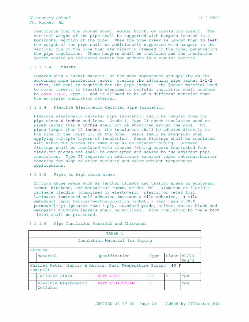
Elementary School 11-9-CV03Ft. Rucker, AL
continuous over the wooden dowel, wooden block, or insulation insert. The vertical weight of the pipe shall be supported with hangers located in a horizontal section of the pipe. When the pipe riser is longer than 30 feet, the weight of the pipe shall be additionally supported with hangers in the vertical run of the pipe that are directly clamped to the pipe, penetrating the pipe insulation. These hangers shall be insulated and the insulation jacket sealed as indicated herein for anchors in a similar service.
3.2.1.3.4 Inserts
Covered with a jacket material of the same appearance and quality as the adjoining pipe insulation jacket, overlap the adjoining pipe jacket 1-1/2 inches, and seal as required for the pipe jacket. The jacket material used to cover inserts in flexible elastomeric cellular insulation shall conform to ASTM C1136, Type 1, and is allowed to be of a different material than the adjoining insulation material.
3.2.1.4 Flexible Elastomeric Cellular Pipe Insulation
Flexible elastomeric cellular pipe insulation shall be tubular form for pipe sizes 6 inches and less. Grade 1, Type II sheet insulation used on pipes larger than 6 inches shall not be stretched around the pipe. On pipes larger than 12 inches, the insulation shall be adhered directly to the pipe on the lower 1/3 of the pipe. Seams shall be staggered when applying multiple layers of insulation. Sweat fittings shall be insulated with miter-cut pieces the same size as on adjacent piping. Screwed fittings shall be insulated with sleeved fitting covers fabricated from miter-cut pieces and shall be overlapped and sealed to the adjacent pipe insulation. Type II requires an additional exterior vapor retarder/barrier covering for high relative humidity and below ambient temperature applications.
3.2.1.5 Pipes in high abuse areas.
In high abuse areas such as janitor closets and traffic areas in equipment rooms, kitchens, and mechanical rooms, welded PVC , aluminum or flexible laminate cladding (comprised of elastomeric, plastic or metal foil laminate) laminated self-adhesive (minimum 2 mils adhesive, 3 mils embossed) vapor barrier/weatherproofing jacket, - less than 0.0000 permeability; (greater than 3 ply, standard grade, silver, white, black and embossed) aluminum jackets shall be utilized. Pipe insulation to the 6 foot level shall be protected.
3.2.1.6 Pipe Insulation Material and Thickness
TABLE 1
Insulation Material for Piping
Service
Material Specification Type Class VR/VB Req'd
Chilled Water (Supply & Return, Dual Temperature Piping, 40 F nominal)
Cellular Glass ASTM C552 II 2 Yes
Flexible Elastomeric Cellular
ASTM C534/C534M I Yes
SECTION 23 07 00 Page 23 (Added by RFPLetter_R1)
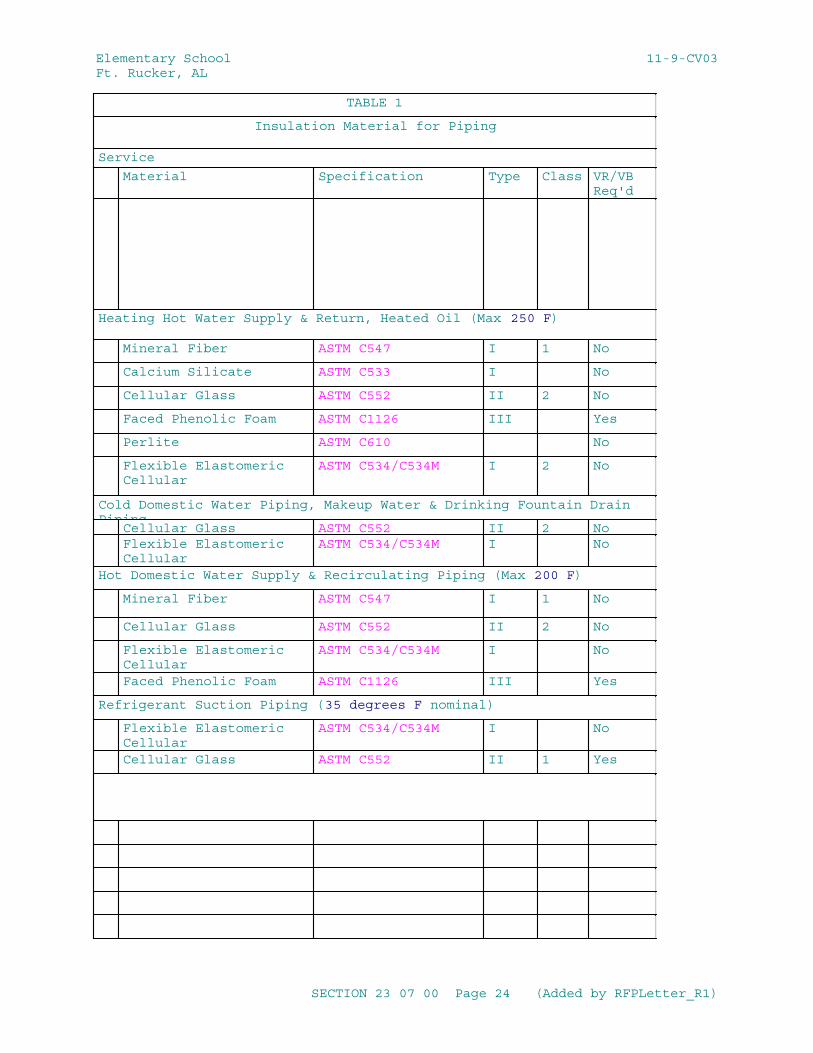
Elementary School 11-9-CV03Ft. Rucker, AL
TABLE 1
Insulation Material for Piping
Service
Material Specification Type Class VR/VB Req'd
Heating Hot Water Supply & Return, Heated Oil (Max 250 F)
Mineral Fiber ASTM C547 I 1 No
Calcium Silicate ASTM C533 I No
Cellular Glass ASTM C552 II 2 No
Faced Phenolic Foam ASTM C1126 III Yes
Perlite ASTM C610 No
Flexible Elastomeric Cellular
ASTM C534/C534M I 2 No
Cold Domestic Water Piping, Makeup Water & Drinking Fountain Drain Piping
Cellular Glass ASTM C552 II 2 NoFlexible Elastomeric Cellular
ASTM C534/C534M I No
Hot Domestic Water Supply & Recirculating Piping (Max 200 F)
Mineral Fiber ASTM C547 I 1 No
Cellular Glass ASTM C552 II 2 No
Flexible Elastomeric Cellular
ASTM C534/C534M I No
Faced Phenolic Foam ASTM C1126 III Yes
Refrigerant Suction Piping (35 degrees F nominal)
Flexible Elastomeric Cellular
ASTM C534/C534M I No
Cellular Glass ASTM C552 II 1 Yes
SECTION 23 07 00 Page 24 (Added by RFPLetter_R1)
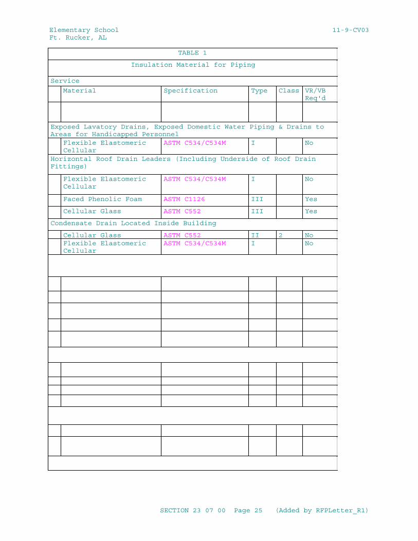
Elementary School 11-9-CV03Ft. Rucker, AL
TABLE 1
Insulation Material for Piping
Service
Material Specification Type Class VR/VB Req'd
Exposed Lavatory Drains, Exposed Domestic Water Piping & Drains to Areas for Handicapped Personnel
Flexible Elastomeric Cellular
ASTM C534/C534M I No
Horizontal Roof Drain Leaders (Including Underside of Roof Drain Fittings)
Flexible Elastomeric Cellular
ASTM C534/C534M I No
Faced Phenolic Foam ASTM C1126 III Yes
Cellular Glass ASTM C552 III Yes
Condensate Drain Located Inside Building
Cellular Glass ASTM C552 II 2 NoFlexible Elastomeric Cellular
ASTM C534/C534M I No
SECTION 23 07 00 Page 25 (Added by RFPLetter_R1)
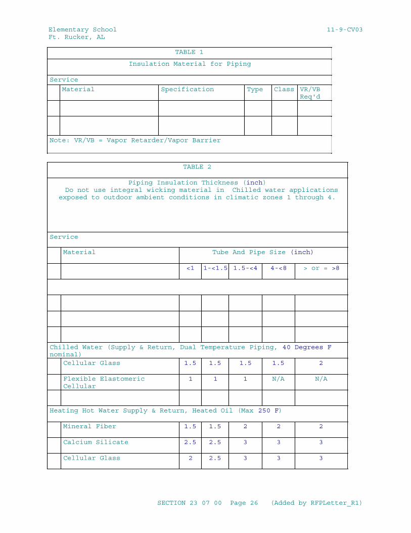
Elementary School 11-9-CV03Ft. Rucker, AL
TABLE 1
Insulation Material for Piping
Service
Material Specification Type Class VR/VB Req'd
Note: VR/VB = Vapor Retarder/Vapor Barrier
TABLE 2
Piping Insulation Thickness (inch) Do not use integral wicking material in Chilled water applicationsexposed to outdoor ambient conditions in climatic zones 1 through 4.
Service
Material Tube And Pipe Size (inch)
<1 1-<1.5 1.5-<4 4-<8 > or = >8
Chilled Water (Supply & Return, Dual Temperature Piping, 40 Degrees F nominal)
Cellular Glass 1.5 1.5 1.5 1.5 2
Flexible Elastomeric Cellular
1 1 1 N/A N/A
Heating Hot Water Supply & Return, Heated Oil (Max 250 F)
Mineral Fiber 1.5 1.5 2 2 2
Calcium Silicate 2.5 2.5 3 3 3
Cellular Glass 2 2.5 3 3 3
SECTION 23 07 00 Page 26 (Added by RFPLetter_R1)
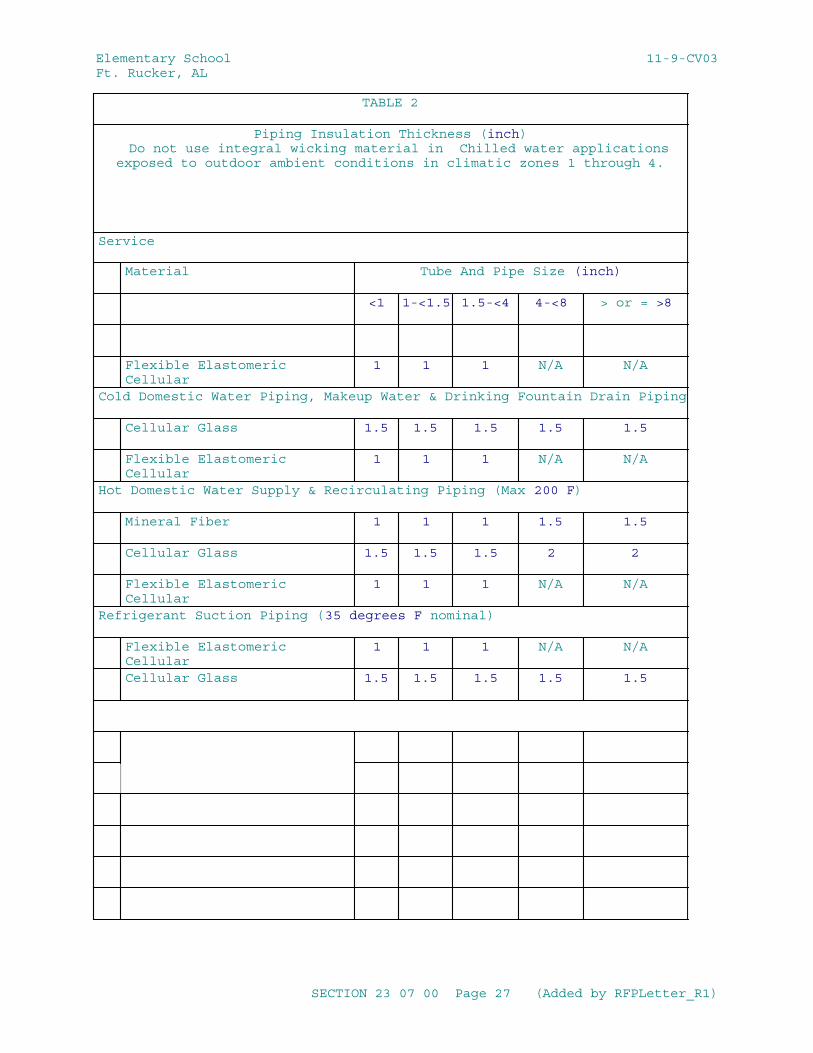
Elementary School 11-9-CV03Ft. Rucker, AL
TABLE 2
Piping Insulation Thickness (inch) Do not use integral wicking material in Chilled water applicationsexposed to outdoor ambient conditions in climatic zones 1 through 4.
Service
Material Tube And Pipe Size (inch)
<1 1-<1.5 1.5-<4 4-<8 > or = >8
Flexible Elastomeric Cellular
1 1 1 N/A N/A
Cold Domestic Water Piping, Makeup Water & Drinking Fountain Drain Piping
Cellular Glass 1.5 1.5 1.5 1.5 1.5
Flexible Elastomeric Cellular
1 1 1 N/A N/A
Hot Domestic Water Supply & Recirculating Piping (Max 200 F)
Mineral Fiber 1 1 1 1.5 1.5
Cellular Glass 1.5 1.5 1.5 2 2
Flexible Elastomeric Cellular
1 1 1 N/A N/A
Refrigerant Suction Piping (35 degrees F nominal)
Flexible Elastomeric Cellular
1 1 1 N/A N/A
Cellular Glass 1.5 1.5 1.5 1.5 1.5
SECTION 23 07 00 Page 27 (Added by RFPLetter_R1)
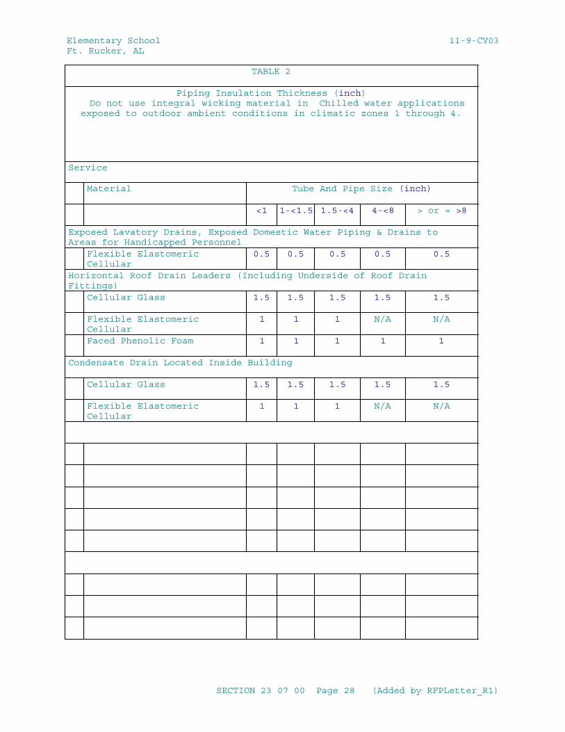
Elementary School 11-9-CV03Ft. Rucker, AL
TABLE 2
Piping Insulation Thickness (inch) Do not use integral wicking material in Chilled water applicationsexposed to outdoor ambient conditions in climatic zones 1 through 4.
Service
Material Tube And Pipe Size (inch)
<1 1-<1.5 1.5-<4 4-<8 > or = >8
Exposed Lavatory Drains, Exposed Domestic Water Piping & Drains to Areas for Handicapped Personnel
Flexible Elastomeric Cellular
0.5 0.5 0.5 0.5 0.5
Horizontal Roof Drain Leaders (Including Underside of Roof Drain Fittings)
Cellular Glass 1.5 1.5 1.5 1.5 1.5
Flexible Elastomeric Cellular
1 1 1 N/A N/A
Faced Phenolic Foam 1 1 1 1 1
Condensate Drain Located Inside Building
Cellular Glass 1.5 1.5 1.5 1.5 1.5
Flexible Elastomeric Cellular
1 1 1 N/A N/A
SECTION 23 07 00 Page 28 (Added by RFPLetter_R1)
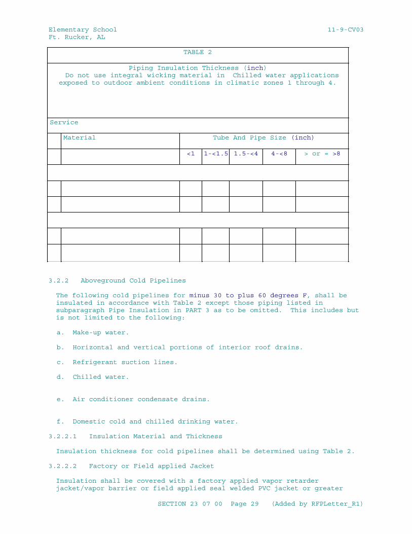
Elementary School 11-9-CV03Ft. Rucker, AL
TABLE 2
Piping Insulation Thickness (inch) Do not use integral wicking material in Chilled water applicationsexposed to outdoor ambient conditions in climatic zones 1 through 4.
Service
Material Tube And Pipe Size (inch)
<1 1-<1.5 1.5-<4 4-<8 > or = >8
3.2.2 Aboveground Cold Pipelines
The following cold pipelines for minus 30 to plus 60 degrees F, shall be insulated in accordance with Table 2 except those piping listed in subparagraph Pipe Insulation in PART 3 as to be omitted. This includes but is not limited to the following:
a. Make-up water.
b. Horizontal and vertical portions of interior roof drains.
c. Refrigerant suction lines.
d. Chilled water.
e. Air conditioner condensate drains.
f. Domestic cold and chilled drinking water.
3.2.2.1 Insulation Material and Thickness
Insulation thickness for cold pipelines shall be determined using Table 2.
3.2.2.2 Factory or Field applied Jacket
Insulation shall be covered with a factory applied vapor retarder jacket/vapor barrier or field applied seal welded PVC jacket or greater
SECTION 23 07 00 Page 29 (Added by RFPLetter_R1)
Elementary School 11-9-CV03Ft. Rucker, AL
than 3 ply laminated self-adhesive (minimum 2 mils adhesive, 3 mils embossed) vapor barrier/weatherproofing jacket - less than 0.0000 permeability, standard grade, sliver, white, black and embossed for use with Mineral Fiber, Cellular Glass, and Phenolic Foam Insulated Pipe. Insulation inside the building, to be protected with an aluminum jacket or greater than 3ply vapor barrier/weatherproofing self-adhesive (minimum 2 mils adhesive, 3 mils embossed) product, less than 0.0000 permeability, standard grade, Embossed Silver, White & Black, shall have the insulation and vapor retarder jacket installed as specified herein. The aluminum jacket or greater than 3ply vapor barrier/weatherproofing self-adhesive (minimum 2 mils adhesive, 3 mils embossed) product, less than 0.0000 permeability, standard grade, embossed silver, White & Black, shall be installed as specified for piping exposed to weather, except sealing of the laps of the aluminum jacket is not required. In high abuse areas such as janitor closets and traffic areas in equipment rooms, kitchens, and mechanical rooms, aluminum jackets or greater than 3ply vapor barrier/weatherproofing self-adhesive (minimum 2 mils adhesive, 3 mils embossed) product, less than 0.0000 permeability, standard grade, embossed silver, white & black, shall be provided for pipe insulation to the 6 ft level.
3.2.2.3 Installing Insulation for Straight Runs Hot and Cold Pipe
Apply insulation to the pipe with tight butt joints. Seal all butted joints and ends with joint sealant and seal with a vapor retarder coating, greater than 3 ply laminate jacket - less than 0.0000 perm adhesive tape or PVDC adhesive tape.
3.2.2.3.1 Longitudinal Laps of the Jacket Material
Overlap not less than 1-1/2 inches. Provide butt strips 3 inches wide for circumferential joints.
3.2.2.3.2 Laps and Butt Strips
Secure with adhesive and staple on 4 inch centers if not factory self-sealing. If staples are used, seal in accordance with paragraph STAPLES below. Note that staples are not required with cellular glass systems.
3.2.2.3.3 Factory Self-Sealing Lap Systems
May be used when the ambient temperature is between 40 and 120 degrees F during installation. Install the lap system in accordance with manufacturer's recommendations. Use a stapler only if specifically recommended by the manufacturer. Where gaps occur, replace the section or repair the gap by applying adhesive under the lap and then stapling.
3.2.2.3.4 Staples
coat all staples, including those used to repair factory self-seal lap systems, with a vapor retarder coating or PVDC adhesive tape or greater than 3 ply laminate jacket - less than 0.0000 perm adhesive tape. Coat all seams, except those on factory self-seal systems, with vapor retarder coating or PVDC adhesive tape or greater than 3 ply laminate jacket - less than 0.0000 perm adhesive tape.
SECTION 23 07 00 Page 30 (Added by RFPLetter_R1)
Elementary School 11-9-CV03Ft. Rucker, AL
3.2.2.3.5 Breaks and Punctures in the Jacket Material
Patch by wrapping a strip of jacket material around the pipe and secure it with adhesive, staple, and coat with vapor retarder coating or PVDC adhesive tape or greater than 3 ply laminate jacket - less than 0.0000 perm adhesive tape. Extend the patch not less than 1-1/2 inches past the break.
3.2.2.3.6 Penetrations Such as Thermometers
Fill the voids in the insulation and seal with vapor retarder coating or PVDC adhesive tape or greater than 3 ply laminate jacket - less than 0.0000 perm adhesive tape.
3.2.2.3.7 Flexible Elastomeric Cellular Pipe Insulation
Install by slitting the tubular sections and applying them onto the piping or tubing. Alternately, whenever possible slide un-slit sections over the open ends of piping or tubing. Secure all seams and butt joints and seal with adhesive. When using self seal products only the butt joints shall be secured with adhesive. Push insulation on the pipe, never pulled. Stretching of insulation may result in open seams and joints. Clean cut all edges. Rough or jagged edges of the insulation are not be permitted. Use proper tools such as sharp knives. Do not stretch Grade 1, Type II sheet insulation around the pipe when used on pipe larger than 6 inches. On pipes larger than 12 inches, adhere sheet insulation directly to the pipe on the lower 1/3 of the pipe.
3.2.2.4 Insulation for Fittings and Accessories
a. Pipe insulation shall be tightly butted to the insulation of the fittings and accessories. The butted joints and ends shall be sealed with joint sealant and sealed with a vapor retarder coating or PVDC adhesive tape or greater than 3 ply laminate jacket - less than 0.0000 perm adhesive tape.
b. Precut or preformed insulation shall be placed around all fittings and accessories and shall conform to MICA plates except as modified herein: 5 for anchors; 10, 11, and 13 for fittings; 14 for valves; and 17 for flanges and unions. Insulation shall be the same insulation as the pipe insulation, including same density, thickness, and thermal conductivity. Where precut/preformed is unavailable, rigid preformed pipe insulation sections may be segmented into the shape required. Insulation of the same thickness and conductivity as the adjoining pipe insulation shall be used. If nesting size insulation is used, the insulation shall be overlapped 2 inches or one pipe diameter. Elbows insulated using segments shall conform to MICA Tables 12.20 "Mitered Insulation Elbow'. Submit a booklet containing completed MICA Insulation Stds plates detailing each insulating system for each pipe, duct, or equipment insulating system, after approval of materials and prior to applying insulation.
(1) The MICA plates shall detail the materials to be installed and the specific insulation application. Submit all MICA plates required showing the entire insulating system, including plates required to show insulation penetrations, vessel bottom and top heads, legs, and skirt insulation as applicable. The MICA plates shall present all variations of insulation systems including locations, materials, vaporproofing, jackets and insulation accessories.
SECTION 23 07 00 Page 31 (Added by RFPLetter_R1)
Elementary School 11-9-CV03Ft. Rucker, AL
(2) If the Contractor elects to submit detailed drawings instead of edited MICA Plates, the detail drawings shall be technically equivalent to the edited MICA Plate submittal.
c. Upon completion of insulation installation on flanges, unions, valves, anchors, fittings and accessories, terminations, seams, joints and insulation not protected by factory vapor retarder jackets or PVC fitting covers shall be protected with PVDC or greater than 3 ply laminate jacket - less than 0.0000 perm adhesive tape or two coats of vapor retarder coating with a minimum total thickness of 1/16 inch, applied with glass tape embedded between coats. Tape seams shall overlap 1 inch. The coating shall extend out onto the adjoining pipe insulation 2 inches. Fabricated insulation with a factory vapor retarder jacket shall be protected with either greater than 3 ply laminate jacket - less than 0.0000 perm adhesive tape, standard grade, silver, white, black and embossed or PVDC adhesive tape or two coats of vapor retarder coating with a minimum thickness of 1/16 inch and with a 2 inch wide glass tape embedded between coats. Where fitting insulation butts to pipe insulation, the joints shall be sealed with a vapor retarder coating and a 4 inch wide ASJ tape which matches the jacket of the pipe insulation.
d. Anchors attached directly to the pipe shall be insulated for a sufficient distance to prevent condensation but not less than 6 inches from the insulation surface.
e. Insulation shall be marked showing the location of unions, strainers, and check valves.
3.2.2.5 Optional PVC Fitting Covers
At the option of the Contractor, premolded, one or two piece PVC fitting covers may be used in lieu of the vapor retarder and embedded glass tape. Factory precut or premolded insulation segments shall be used under the fitting covers for elbows. Insulation segments shall be the same insulation as the pipe insulation including same density, thickness, and thermal conductivity. The covers shall be secured by PVC vapor retarder tape, adhesive, seal welding or with tacks made for securing PVC covers. Seams in the cover, and tacks and laps to adjoining pipe insulation jacket, shall be sealed with vapor retarder tape to ensure that the assembly has a continuous vapor seal.
3.2.3 Aboveground Hot Pipelines
3.2.3.1 General Requirements
All hot pipe lines above 60 degrees F, except those piping listed in subparagraph Pipe Insulation in PART 3 as to be omitted, shall be insulated in accordance with Table 2. This includes but is not limited to the following:
a. Domestic hot water supply & re-circulating system.
b. Hot water heating.
SECTION 23 07 00 Page 32 (Added by RFPLetter_R1)
Elementary School 11-9-CV03Ft. Rucker, AL
c. Water defrost lines in refrigerated rooms.
Insulation shall be covered, in accordance with manufacturer's recommendations, with a factory applied Type I jacket or field applied aluminum where required or seal welded PVC.
3.2.3.2 Insulation for Fittings and Accessories
Pipe insulation shall be tightly butted to the insulation of the fittings and accessories. The butted joints and ends shall be sealed with joint sealant. Insulation shall be marked showing the location of unions, strainers, check valves and other components that would otherwise be hidden from view by the insulation.
3.2.3.2.1 Precut or Preformed
Place precut or preformed insulation around all fittings and accessories. Insulation shall be the same insulation as the pipe insulation, including same density, thickness, and thermal conductivity.
3.2.3.2.2 Rigid Preformed
Where precut/preformed is unavailable, rigid preformed pipe insulation sections may be segmented into the shape required. Insulation of the same thickness and conductivity as the adjoining pipe insulation shall be used. If nesting size insulation is used, the insulation shall be overlapped 2 inches or one pipe diameter. Elbows insulated using segments shall conform to MICA Tables 12.20 "Mitered Insulation Elbow".
3.2.4 Piping Exposed to Weather
Piping exposed to weather shall be insulated and jacketed as specified for the applicable service inside the building. After this procedure, a laminated self-adhesive (minimum 2 mils adhesive, 3 mils embossed) vapor barrier/weatherproofing jacket - less than 0.0000 permeability (greater than 3 ply, standard grade, silver, white, black and embossed aluminum jacket or PVC jacket shall be applied. PVC jacketing requires no factory-applied jacket beneath it, however an all service jacket shall be applied if factory applied jacketing is not furnished. Flexible elastomeric cellular insulation exposed to weather shall be treated in accordance with paragraph INSTALLATION OF FLEXIBLE ELASTOMERIC CELLULAR INSULATION in PART 3.
3.2.4.1 Aluminum Jacket
The jacket for hot piping may be factory applied. The jacket shall overlap not less than 2 inches at longitudinal and circumferential joints and shall be secured with bands at not more than 12 inch centers. Longitudinal joints shall be overlapped down to shed water and located at 4 or 8 o'clock positions. Joints on piping 60 degrees F and below shall be sealed with metal jacketing/flashing sealant while overlapping to prevent moisture penetration. Where jacketing on piping 60 degrees F and below abuts an un-insulated surface, joints shall be caulked to prevent moisture penetration. Joints on piping above 60 degrees F shall be sealed with a moisture retarder.
3.2.4.2 Insulation for Fittings
Flanges, unions, valves, fittings, and accessories shall be insulated and
SECTION 23 07 00 Page 33 (Added by RFPLetter_R1)
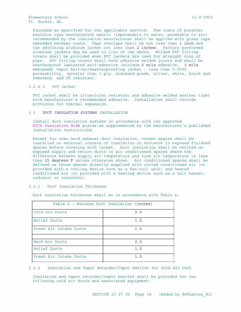
Elementary School 11-9-CV03Ft. Rucker, AL
finished as specified for the applicable service. Two coats of breather emulsion type weatherproof mastic (impermeable to water, permeable to air) recommended by the insulation manufacturer shall be applied with glass tape embedded between coats. Tape overlaps shall be not less than 1 inch and the adjoining aluminum jacket not less than 2 inches. Factory preformed aluminum jackets may be used in lieu of the above. Molded PVC fitting covers shall be provided when PVC jackets are used for straight runs of pipe. PVC fitting covers shall have adhesive welded joints and shall be weatherproof laminated self-adhesive (minimum 2 mils adhesive, 3 mils embossed) vapor barrier/weatherproofing jacket - less than 0.0000 permeability, (greater than 3 ply, standard grade, silver, white, black and embossed, and UV resistant.
3.2.4.3 PVC Jacket
PVC jacket shall be ultraviolet resistant and adhesive welded weather tight with manufacturer's recommended adhesive. Installation shall include provision for thermal expansion.
3.3 DUCT INSULATION SYSTEMS INSTALLATION
Install duct insulation systems in accordance with the approved MICA Insulation Stds plates as supplemented by the manufacturer's published installation instructions.
Except for oven hood exhaust duct insulation, corner angles shall be installed on external corners of insulation on ductwork in exposed finished spaces before covering with jacket. Duct insulation shall be omitted on exposed supply and return ducts in air conditioned spaces where the difference between supply air temperature and room air temperature is less than 15 degrees F unless otherwise shown. Air conditioned spaces shall be defined as those spaces directly supplied with cooled conditioned air (or provided with a cooling device such as a fan-coil unit) and heated conditioned air (or provided with a heating device such as a unit heater, radiator or convector).
3.3.1 Duct Insulation Thickness
Duct insulation thickness shall be in accordance with Table 4.
Table 4 - Minimum Duct Insulation (inches)
Cold Air Ducts 2.0
Relief Ducts 1.5
Fresh Air Intake Ducts 1.5
Warm Air Ducts 2.0
Relief Ducts 1.5
Fresh Air Intake Ducts 1.5
3.3.2 Insulation and Vapor Retarder/Vapor Barrier for Cold Air Duct
Insulation and vapor retarder/vapor barrier shall be provided for the following cold air ducts and associated equipment.
SECTION 23 07 00 Page 34 (Added by RFPLetter_R1)
Elementary School 11-9-CV03Ft. Rucker, AL
a. Supply ducts.
b. Return air ducts.
c. Relief ducts.
d. Flexible run-outs (field-insulated).
e. Plenums.
f. Coil casings.
g. Fresh air intake ducts.
h. Mixing boxes (field-insulated).
i. Supply fans (field-insulated).
j. Site-erected air conditioner casings.
k. Ducts exposed to weather.
l. Combustion air intake ducts.
Insulation for rectangular ducts shall be flexible type where concealed, minimum density 3/4 pcf, and rigid type where exposed, minimum density 3 pcf. Insulation for both concealed or exposed round/oval ducts shall be flexible type, minimum density 3/4 pcf or a semi rigid board, minimum density 3 pcf, formed or fabricated to a tight fit, edges beveled and joints tightly butted and staggered. Insulation for all exposed ducts shall be provided with either a white, paint-able, factory-applied Type I jacket or a field applied vapor retarder/vapor barrier jacket coating finish as specified, the total field applied dry film thickness shall be approximately 1/16 inch. Insulation on all concealed duct shall be provided with a factory-applied Type I or II vapor retarder/vapor barrier jacket. Duct insulation shall be continuous through sleeves and prepared openings except firewall penetrations. Duct insulation terminating at fire dampers, shall be continuous over the damper collar and retaining angle of fire dampers, which are exposed to unconditioned air and which may be prone to condensate formation. Duct insulation and vapor retarder/vapor barrier shall cover the collar, neck, and any un-insulated surfaces of diffusers, registers and grills. Vapor retarder/vapor barrier materials shall be applied to form a complete unbroken vapor seal over the insulation. Sheet Metal Duct shall be sealed in accordance with Section 23 00 00 AIR SUPPLY, DISTRIBUTION, VENTILATION, AND EXHAUST SYSTEM.
3.3.2.1 Installation on Concealed Duct
a. For rectangular, oval or round ducts, flexible insulation shall be attached by applying adhesive around the entire perimeter of the duct in 6 inch wide strips on 12 inch centers.
b. For rectangular and oval ducts, 24 inches and larger insulation shall be additionally secured to bottom of ducts by the use of mechanical fasteners. Fasteners shall be spaced on 16 inch centers and not more than 16 inches from duct corners.
SECTION 23 07 00 Page 35 (Added by RFPLetter_R1)
Elementary School 11-9-CV03Ft. Rucker, AL
c. For rectangular, oval and round ducts, mechanical fasteners shall be provided on sides of duct risers for all duct sizes. Fasteners shall be spaced on 16 inch centers and not more than 16 inches from duct corners.
d. Insulation shall be impaled on the mechanical fasteners (self stick pins) where used and shall be pressed thoroughly into the adhesive. Care shall be taken to ensure vapor retarder/vapor barrier jacket joints overlap 2 inches. The insulation shall not be compressed to a thickness less than that specified. Insulation shall be carried over standing seams and trapeze-type duct hangers.
e. Where mechanical fasteners are used, self-locking washers shall be installed and the pin trimmed and bent over.
f. Jacket overlaps shall be secured with staples and tape as necessary to ensure a secure seal. Staples, tape and seams shall be coated with a brush coat of vapor retarder coating or PVDC adhesive tape or greater than 3 ply laminate (minimum 2 mils adhesive, 3 mils embossed) - less than 0.0000 perm adhesive tape.
g. Breaks in the jacket material shall be covered with patches of the same material as the vapor retarder jacket. The patches shall extend not less than 2 inches beyond the break or penetration in all directions and shall be secured with tape and staples. Staples and tape joints shall be sealed with a brush coat of vapor retarder coating or PVDC adhesive tape or greater than 3 ply laminate (minimum 2 mils adhesive, 3 mils embossed) - less than 0.0000 perm adhesive tape.
h. At jacket penetrations such as hangers, thermometers, and damper operating rods, voids in the insulation shall be filled and the penetration sealed with a brush coat of vapor retarder coating or PVDC adhesive tape greater than 3 ply laminate (minimum 2 mils adhesive, 3 mils embossed) - less than 0.0000 perm adhesive tape.
i. Insulation terminations and pin punctures shall be sealed and flashed with a reinforced vapor retarder coating finish or tape with a brush coat of vapor retarder coating.. The coating shall overlap the adjoining insulation and un-insulated surface 2 inches. Pin puncture coatings shall extend 2 inches from the puncture in all directions.
j. Where insulation standoff brackets occur, insulation shall be extended under the bracket and the jacket terminated at the bracket.
3.3.2.2 Installation on Exposed Duct Work
a. For rectangular ducts, rigid insulation shall be secured to the duct by mechanical fasteners on all four sides of the duct, spaced not more than 12 inches apart and not more than 3 inches from the edges of the insulation joints. A minimum of two rows of fasteners shall be provided for each side of duct 12 inches and larger. One row shall be provided for each side of duct less than 12 inches. Mechanical fasteners shall be as corrosion resistant as G60 coated galvanized steel, and shall indefinitely sustain a 50 lb tensile dead load test perpendicular to the duct wall.
b. Form duct insulation with minimum jacket seams. Fasten each piece of rigid insulation to the duct using mechanical fasteners. When the height of projections is less than the insulation thickness, insulation
SECTION 23 07 00 Page 36 (Added by RFPLetter_R1)
Elementary School 11-9-CV03Ft. Rucker, AL
shall be brought up to standing seams, reinforcing, and other vertical projections and shall not be carried over. Vapor retarder/barrier jacket shall be continuous across seams, reinforcing, and projections. When height of projections is greater than the insulation thickness, insulation and jacket shall be carried over. Apply insulation with joints tightly butted. Neatly bevel insulation around name plates and access plates and doors.
c. Impale insulation on the fasteners; self-locking washers shall be installed and the pin trimmed and bent over.
d. Seal joints in the insulation jacket with a 4 inch wide strip of tape. Seal taped seams with a brush coat of vapor retarder coating.
e. Breaks and ribs or standing seam penetrations in the jacket material shall be covered with a patch of the same material as the jacket. Patches shall extend not less than 2 inches beyond the break or penetration and shall be secured with tape and stapled. Staples and joints shall be sealed with a brush coat of vapor retarder coating.
f. At jacket penetrations such as hangers, thermometers, and damper operating rods, the voids in the insulation shall be filled and the penetrations sealed with a flashing sealant.
g. Insulation terminations and pin punctures shall be sealed and flashed with a reinforced vapor retarder coating finish. The coating shall overlap the adjoining insulation and un-insulated surface 2 inches. Pin puncture coatings shall extend 2 inches from the puncture in all directions.
h. Oval and round ducts, flexible type, shall be insulated with factory Type I jacket insulation with minimum density of 3/4 pcf, attached as in accordance with MICA standards.
3.3.3 Insulation for Warm Air Duct
Insulation and vapor barrier shall be provided for the following warm air ducts and associated equipment:.
a. Supply ducts.
b. Return air ducts.
c. Relief air ducts
d. Flexible run-outs (field insulated).
e. Plenums.
i. Fresh air intake ducts.
n. Ducts exposed to weather.
Insulation for rectangular ducts shall be flexible type where concealed, and rigid type where exposed. Insulation on exposed ducts shall be provided with a white, paint-able, factory-applied Type II jacket, or finished with adhesive finish. Flexible type insulation shall be used for
SECTION 23 07 00 Page 37 (Added by RFPLetter_R1)
Elementary School 11-9-CV03Ft. Rucker, AL
round ducts, with a factory-applied Type II jacket. Insulation on concealed duct shall be provided with a factory-applied Type II jacket. Adhesive finish where indicated to be used shall be accomplished by applying two coats of adhesive with a layer of glass cloth embedded between the coats. The total dry film thickness shall be approximately 1/16 inch. Duct insulation shall be continuous through sleeves and prepared openings. Duct insulation shall terminate at fire dampers and flexible connections.
3.3.3.1 Installation on Concealed Duct
a. For rectangular, oval and round ducts, insulation shall be attached by applying adhesive around the entire perimeter of the duct in 6 inch wide strips on 12 inch centers.
b. For rectangular and oval ducts 24 inches and larger, insulation shall be secured to the bottom of ducts by the use of mechanical fasteners. Fasteners shall be spaced on 18 inch centers and not more than 18 inches from duct corner.
c. For rectangular, oval and round ducts, mechanical fasteners shall be provided on sides of duct risers for all duct sizes. Fasteners shall be spaced on 18 inch centers and not more than 18 inches from duct corners.
d. The insulation shall be impaled on the mechanical fasteners where used. The insulation shall not be compressed to a thickness less than that specified. Insulation shall be carried over standing seams and trapeze-type hangers.
e. Self-locking washers shall be installed where mechanical fasteners are used and the pin trimmed and bent over.
f. Insulation jacket shall overlap not less than 2 inches at joints and the lap shall be secured and stapled on 4 inch centers.
3.3.3.2 Installation on Exposed Duct
a. For rectangular ducts, the rigid insulation shall be secured to the duct by the use of mechanical fasteners on all four sides of the duct, spaced not more than 16 inches apart and not more than 6 inches from the edges of the insulation joints. A minimum of two rows of fasteners shall be provided for each side of duct 12 inches and larger and a minimum of one row for each side of duct less than 12 inches.
b. Duct insulation with factory-applied jacket shall be formed with minimum jacket seams, and each piece of rigid insulation shall be fastened to the duct using mechanical fasteners. When the height of projection is less than the insulation thickness, insulation shall be brought up to standing seams, reinforcing, and other vertical projections and shall not be carried over the projection. Jacket shall be continuous across seams, reinforcing, and projections. Where the height of projections is greater than the insulation thickness, insulation and jacket shall be carried over the projection.
c. Insulation shall be impaled on the fasteners; self-locking washers shall be installed and pin trimmed and bent over.
d. Joints on jacketed insulation shall be sealed with a 4 inch wide strip of tape and brushed with vapor retarder coating.
SECTION 23 07 00 Page 38 (Added by RFPLetter_R1)
Elementary School 11-9-CV03Ft. Rucker, AL
e. Breaks and penetrations in the jacket material shall be covered with a patch of the same material as the jacket. Patches shall extend not less than 2 inches beyond the break or penetration and shall be secured with adhesive and stapled.
f. Insulation terminations and pin punctures shall be sealed with tape and brushed with vapor retarder coating.
g. Oval and round ducts, flexible type, shall be insulated with factory Type I jacket insulation, minimum density of 3/4 pcf attached by staples spaced not more than 16 inches and not more than 6 inches from the degrees of joints. Joints shall be sealed in accordance with item "d." above.
3.3.4 Ducts Handling Air for Dual Purpose
For air handling ducts for dual purpose below and above 60 degrees F, ducts shall be insulated as specified for cold air duct.
3.3.5 Duct Test Holes
After duct systems have been tested, adjusted, and balanced, breaks in the insulation and jacket shall be repaired in accordance with the applicable section of this specification for the type of duct insulation to be repaired.
3.3.6 Duct Exposed to Weather
3.3.6.1 Installation
Ducts exposed to weather shall be insulated and finished as specified for the applicable service for exposed duct inside the building. After the above is accomplished, the insulation shall then be further finished as detailed in the following subparagraphs.
3.3.6.2 Round Duct
Laminated self-adhesive (minimum 2 mils adhesive, 3 mils embossed) vapor barrier/weatherproofing jacket - Less than 0.0000 permeability, (greater than 3 ply, standard grade, silver, white, black and embossed or greater than 8 ply, heavy duty, white and natural) membrane shall be applied overlapping material by 3 inches no bands or caulking needed - see manufacturer's recommended installation instructions. Aluminum jacket with factory applied moisture retarder shall be applied with the joints lapped not less than 3 inches and secured with bands located at circumferential laps and at not more than 12 inch intervals throughout. Horizontal joints shall lap down to shed water and located at 4 or 8 o'clock position. Joints shall be sealed with metal jacketing sealant to prevent moisture penetration. Where jacketing abuts an un-insulated surface, joints shall be sealed with metal jacketing sealant.
3.3.6.3 Fittings
Fittings and other irregular shapes shall be finished as specified for rectangular ducts.
SECTION 23 07 00 Page 39 (Added by RFPLetter_R1)
Elementary School 11-9-CV03Ft. Rucker, AL
3.3.6.4 Rectangular Ducts
Two coats of weather barrier mastic reinforced with fabric or mesh for outdoor application shall be applied to the entire surface. Each coat of weatherproof mastic shall be 1/16 inch minimum thickness. The exterior shall be a metal jacketing applied for mechanical abuse and weather protection, and secured with screws or vapor barrier/weatherproofing jacket less than 0.0000 permeability greater than 3 ply, standard grade, silver, white, black, and embossed or greater than 8 ply, heavy duty white and natural. Membrane shall be applied overlapping material by 3 inches. No bands or caulking needed-see manufacturing recommend installation instructions.
3.3.7 Kitchen Exhaust Duct Insulation
NFPA 96 for ovens, griddles, deep fat fryers, steam kettles, vegetable steamers, high pressure cookers, and mobile serving units. Provide insulation with 3/4 inch wide, minimum 0.15 inch thick galvanized steel bands spaced not over 12 inches o.c.; or 16 gauge galvanized steel wire with corner clips under the wire; or with heavy welded pins spaced not over 12 inches apart each way. Do not use adhesives.
3.4 EQUIPMENT INSULATION SYSTEMS INSTALLATION
Install equipment insulation systems in accordance with the approved MICA Insulation Stds plates as supplemented by the manufacturer's published installation instructions.
3.4.1 General
Removable insulation sections shall be provided to cover parts of equipment that must be opened periodically for maintenance including vessel covers, fasteners, flanges and accessories. Equipment insulation shall be omitted on the following:
a. Hand-holes.
b. Boiler manholes.
c. Cleanouts.
d. ASME stamps.
e. Manufacturer's nameplates.
f. Duct Test/Balance Test Holes.
3.4.2 Insulation for Cold Equipment
Cold equipment below 60 degrees F: Insulation shall be furnished on equipment handling media below 60 degrees F including the following:
a. Pumps.
g. Cold and chilled water pumps.
SECTION 23 07 00 Page 40 (Added by RFPLetter_R1)
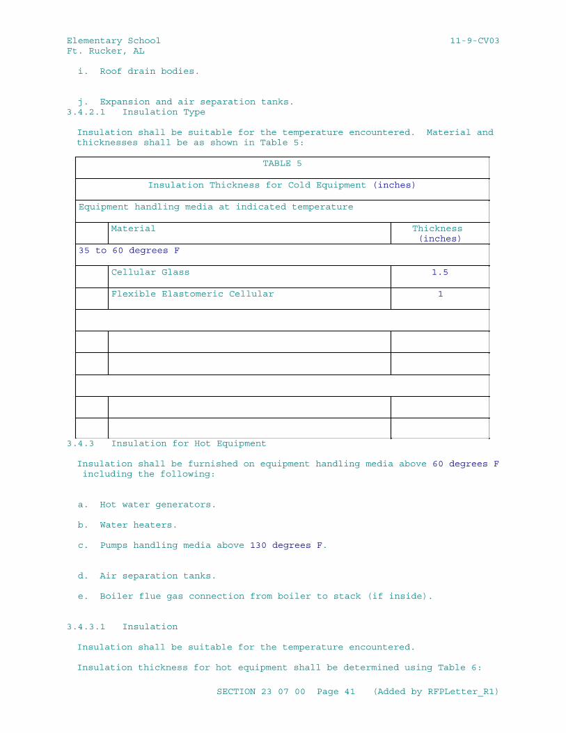
Elementary School 11-9-CV03Ft. Rucker, AL
i. Roof drain bodies.
j. Expansion and air separation tanks.3.4.2.1 Insulation Type
Insulation shall be suitable for the temperature encountered. Material and thicknesses shall be as shown in Table 5:
TABLE 5
Insulation Thickness for Cold Equipment (inches)
Equipment handling media at indicated temperature
Material Thickness (inches)
35 to 60 degrees F
Cellular Glass 1.5
Flexible Elastomeric Cellular 1
3.4.3 Insulation for Hot Equipment
Insulation shall be furnished on equipment handling media above 60 degrees F including the following:
a. Hot water generators.
b. Water heaters.
c. Pumps handling media above 130 degrees F.
d. Air separation tanks.
e. Boiler flue gas connection from boiler to stack (if inside).
3.4.3.1 Insulation
Insulation shall be suitable for the temperature encountered.
Insulation thickness for hot equipment shall be determined using Table 6:
SECTION 23 07 00 Page 41 (Added by RFPLetter_R1)
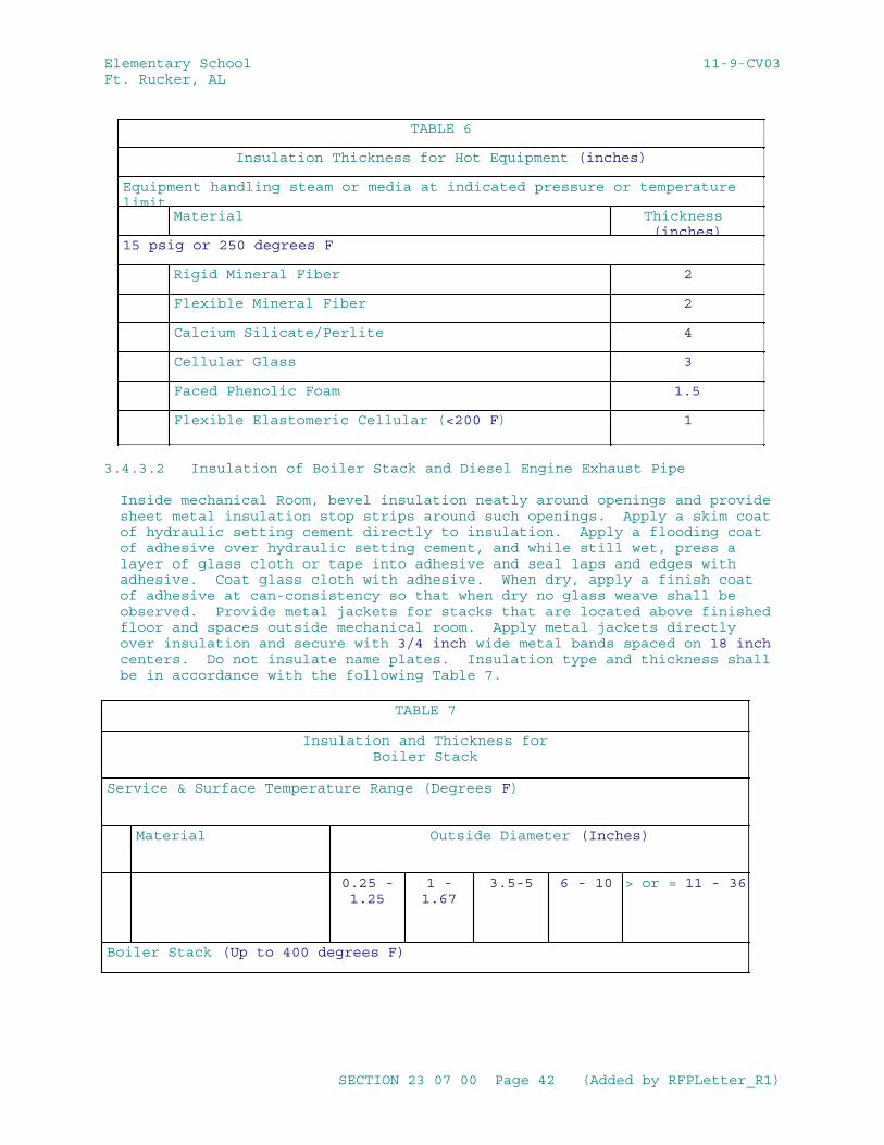
Elementary School 11-9-CV03Ft. Rucker, AL
TABLE 6
Insulation Thickness for Hot Equipment (inches)
Equipment handling steam or media at indicated pressure or temperature limit
Material Thickness (inches)
15 psig or 250 degrees F
Rigid Mineral Fiber 2
Flexible Mineral Fiber 2
Calcium Silicate/Perlite 4
Cellular Glass 3
Faced Phenolic Foam 1.5
Flexible Elastomeric Cellular (<200 F) 1
3.4.3.2 Insulation of Boiler Stack and Diesel Engine Exhaust Pipe
Inside mechanical Room, bevel insulation neatly around openings and provide sheet metal insulation stop strips around such openings. Apply a skim coat of hydraulic setting cement directly to insulation. Apply a flooding coat of adhesive over hydraulic setting cement, and while still wet, press a layer of glass cloth or tape into adhesive and seal laps and edges with adhesive. Coat glass cloth with adhesive. When dry, apply a finish coat of adhesive at can-consistency so that when dry no glass weave shall be observed. Provide metal jackets for stacks that are located above finished floor and spaces outside mechanical room. Apply metal jackets directly over insulation and secure with 3/4 inch wide metal bands spaced on 18 inch centers. Do not insulate name plates. Insulation type and thickness shall be in accordance with the following Table 7.
TABLE 7
Insulation and Thickness forBoiler Stack
Service & Surface Temperature Range (Degrees F)
Material Outside Diameter (Inches)
0.25 -1.25
1 -1.67
3.5-5 6 - 10 > or = 11 - 36
Boiler Stack (Up to 400 degrees F)
SECTION 23 07 00 Page 42 (Added by RFPLetter_R1)
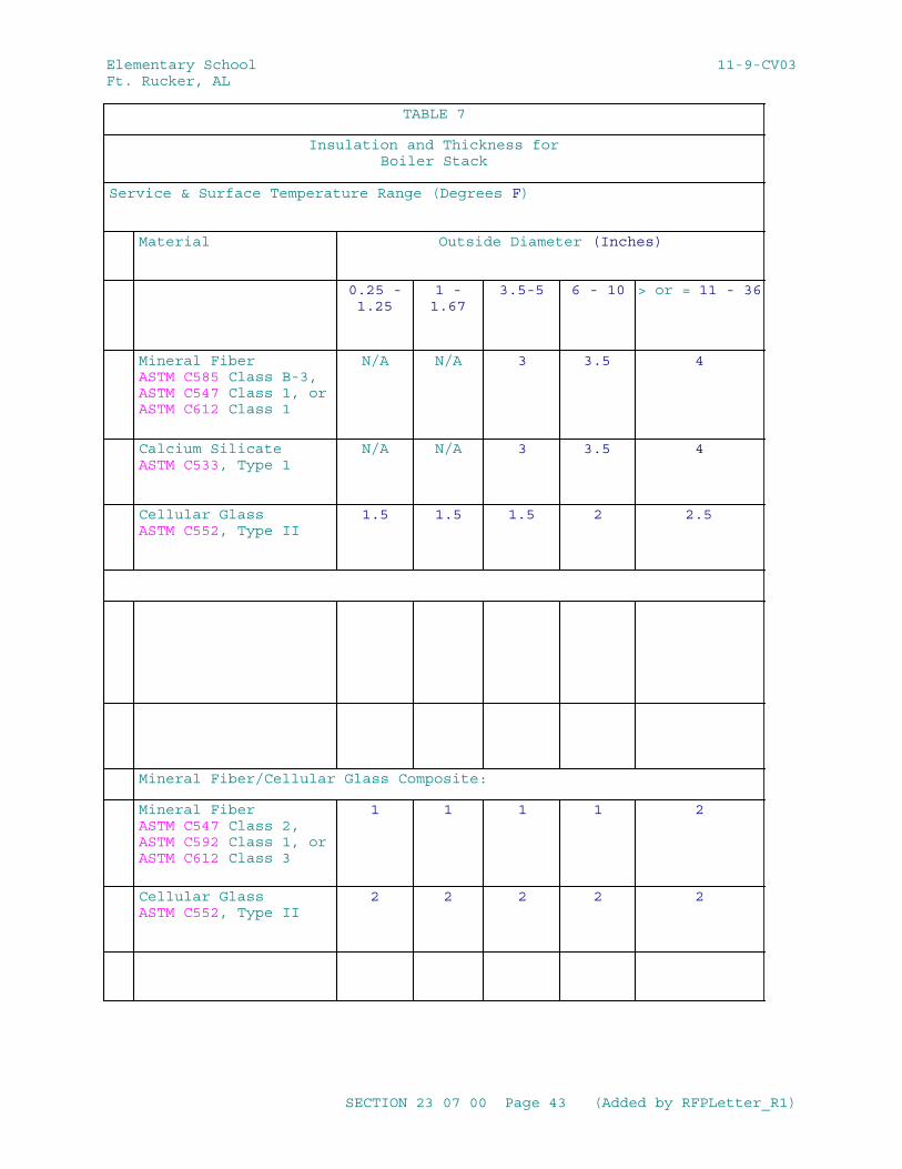
Elementary School 11-9-CV03Ft. Rucker, AL
TABLE 7
Insulation and Thickness forBoiler Stack
Service & Surface Temperature Range (Degrees F)
Material Outside Diameter (Inches)
0.25 -1.25
1 -1.67
3.5-5 6 - 10 > or = 11 - 36
Mineral FiberASTM C585 Class B-3,ASTM C547 Class 1, orASTM C612 Class 1
N/A N/A 3 3.5 4
Calcium SilicateASTM C533, Type 1
N/A N/A 3 3.5 4
Cellular GlassASTM C552, Type II
1.5 1.5 1.5 2 2.5
Mineral Fiber/Cellular Glass Composite:
Mineral FiberASTM C547 Class 2,ASTM C592 Class 1, orASTM C612 Class 3
1 1 1 1 2
Cellular GlassASTM C552, Type II
2 2 2 2 2
SECTION 23 07 00 Page 43 (Added by RFPLetter_R1)
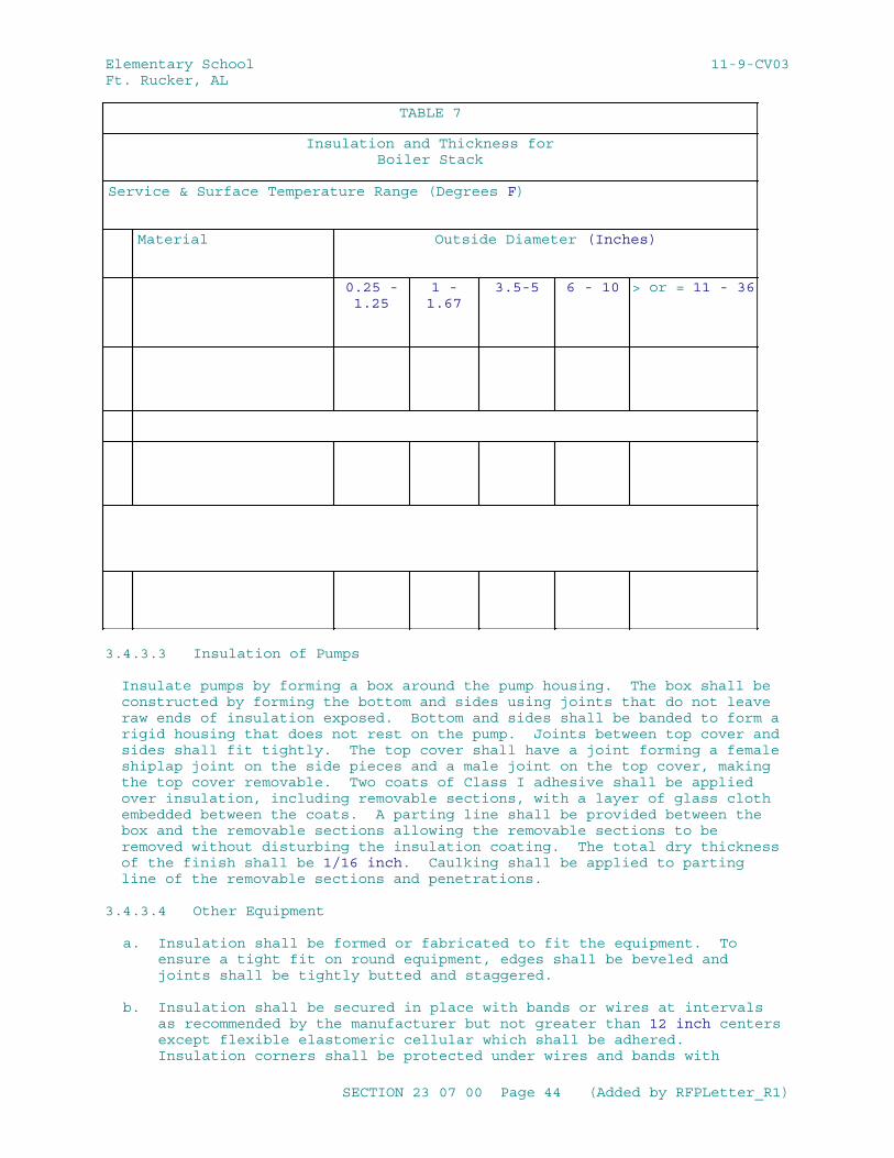
Elementary School 11-9-CV03Ft. Rucker, AL
TABLE 7
Insulation and Thickness forBoiler Stack
Service & Surface Temperature Range (Degrees F)
Material Outside Diameter (Inches)
0.25 -1.25
1 -1.67
3.5-5 6 - 10 > or = 11 - 36
3.4.3.3 Insulation of Pumps
Insulate pumps by forming a box around the pump housing. The box shall be constructed by forming the bottom and sides using joints that do not leave raw ends of insulation exposed. Bottom and sides shall be banded to form a rigid housing that does not rest on the pump. Joints between top cover and sides shall fit tightly. The top cover shall have a joint forming a female shiplap joint on the side pieces and a male joint on the top cover, making the top cover removable. Two coats of Class I adhesive shall be applied over insulation, including removable sections, with a layer of glass cloth embedded between the coats. A parting line shall be provided between the box and the removable sections allowing the removable sections to be removed without disturbing the insulation coating. The total dry thickness of the finish shall be 1/16 inch. Caulking shall be applied to parting line of the removable sections and penetrations.
3.4.3.4 Other Equipment
a. Insulation shall be formed or fabricated to fit the equipment. To ensure a tight fit on round equipment, edges shall be beveled and joints shall be tightly butted and staggered.
b. Insulation shall be secured in place with bands or wires at intervals as recommended by the manufacturer but not greater than 12 inch centers except flexible elastomeric cellular which shall be adhered. Insulation corners shall be protected under wires and bands with
SECTION 23 07 00 Page 44 (Added by RFPLetter_R1)
Elementary School 11-9-CV03Ft. Rucker, AL
suitable corner angles.
c. On high vibration equipment, cellular glass insulation shall be set in a coating of bedding compound as recommended by the manufacturer, and joints shall be sealed with bedding compound. Mineral fiber joints shall be filled with finishing cement.
d. Insulation on heads of heat exchangers shall be removable. The removable section joint shall be fabricated using a male-female shiplap type joint. Entire surface of the removable section shall be finished as specified.
e. Exposed insulation corners shall be protected with corner angles.
f. On equipment with ribs, such as boiler flue gas connection, draft fans, and fly ash or soot collectors, insulation shall be applied over 6 by 6 inch by 12 gauge welded wire fabric which has been cinched in place, or if approved by the Contracting Officer, spot welded to the equipment over the ribs. Insulation shall be secured to the fabric with J-hooks and 2 by 2 inch washers or shall be securely banded or wired in place on 12 inch (maximum) centers.
g. On equipment handling media above 600 degrees F, insulation shall be applied in two or more layers with joints staggered.
h. Upon completion of installation of insulation, penetrations shall be caulked. Two coats of adhesive shall be applied over insulation, including removable sections, with a layer of glass cloth embedded between the coats. The total dry thickness of the finish shall be 1/16 inch. Caulking shall be applied to parting line between equipment and removable section insulation.
3.4.4 Equipment Handling Dual Temperature Media
Below and above 60 degrees F: equipment handling dual temperature media shall be insulated as specified for cold equipment.
3.4.5 Equipment Exposed to Weather
3.4.5.1 Installation
Equipment exposed to weather shall be insulated and finished in accordance with the requirements for ducts exposed to weather in paragraph DUCT INSULATION INSTALLATION.
3.4.5.2 Optional Panels
At the option of the Contractor, prefabricated metal insulation panels may be used in lieu of the insulation and finish previously specified. Thermal performance shall be equal to or better than that specified for field applied insulation. Panels shall be the standard catalog product of a manufacturer of metal insulation panels. Fastenings, flashing, and support system shall conform to published recommendations of the manufacturer for weatherproof installation and shall prevent moisture from entering the insulation. Panels shall be designed to accommodate thermal expansion and to support a 250 pound walking load without permanent deformation or permanent damage to the insulation. Exterior metal cover sheet shall be aluminum and exposed fastenings shall be stainless steel or aluminum.
SECTION 23 07 00 Page 45 (Added by RFPLetter_R1)
Elementary School 11-9-CV03Ft. Rucker, AL
-- End of Section --
SECTION 23 07 00 Page 46 (Added by RFPLetter_R1)
Elementary School 11-9-CV03Ft. Rucker, AL
SECTION TABLE OF CONTENTS
DIVISION 23 - HEATING, VENTILATING, AND AIR CONDITIONING
SECTION 23 09 23
LONWORKS DIRECT DIGITAL CONTROL FOR HVAC AND OTHER BUILDING CONTROL SYSTEMS
05/11
PART 1 GENERAL
1.1 REFERENCES 1.2 DEFINITIONS 1.3 SYSTEM DESCRIPTION 1.3.1 System Requirements 1.3.2 Verification of Dimensions 1.3.3 Drawings 1.3.4 Data Packages/Submittals Requirements 1.4 SUBMITTALS 1.5 PROJECT SEQUENCING 1.6 QUALITY CONTROL (QC) CHECKLISTS 1.7 DELIVERY AND STORAGE 1.8 OPERATION AND MAINTENANCE (O&M) INSTRUCTIONS 1.9 SURGE PROTECTION 1.9.1 Power-Line Surge Protection 1.9.2 Surge Protection for Transmitter and Control Wiring 1.10 INPUT MEASUREMENT ACCURACY
PART 2 PRODUCTS
2.1 EQUIPMENT 2.1.1 General Requirements 2.1.2 Operation Environment Requirements 2.2 ENCLOSURES AND WEATHERSHIELDS 2.2.1 Enclosures 2.2.2 Weathershields 2.3 NETWORK HARDWARE 2.3.1 CEA-709.1-C Network Routers 2.3.2 CEA-709.1-C to IP Router 2.4 WIRE AND CABLE 2.4.1 Terminal Blocks 2.4.2 Control Network Wiring 2.4.3 Control Wiring for Binary Signals 2.4.4 Control Wiring for 120-Volt Circuits 2.4.5 Control Wiring for Analog Signals 2.4.6 Transformers 2.5 AUTOMATIC CONTROL VALVES 2.5.1 Ball Valves 2.5.2 Butterfly Valves 2.5.3 Two-Way Valves 2.5.4 Three-Way Valves 2.5.5 Duct-Coil and Terminal-Unit-Coil Valves 2.5.6 Valves for Chilled-Water, Condenser-Water, and Glycol Service 2.6 DAMPERS 2.6.1 Damper Assembly
SECTION 23 09 23 Page 1 (Added by RFPLetter_R1)
Elementary School 11-9-CV03Ft. Rucker, AL
2.6.2 Operating Linkages 2.6.3 Damper Types 2.6.3.1 Flow Control Dampers 2.6.3.2 Mechanical Rooms and Other Utility Space Ventilation Dampers 2.6.3.3 Smoke Dampers 2.7 SENSORS AND INSTRUMENTATION 2.7.1 Transmitters 2.7.2 Temperature Sensors 2.7.2.1 Sensor Ranges and Accuracy 2.7.2.2 Point Temperature Sensors 2.7.2.3 Averaging Temperature Sensors 2.7.2.4 Thermowells 2.7.3 Relative Humidity Sensor 2.7.4 Carbon Dioxide (CO2) Sensors 2.7.5 Differential Pressure Instrumentation 2.7.5.1 Differential Pressure Sensors 2.7.5.2 Differential Pressure Switch 2.7.6 Flow Sensors 2.7.6.1 Airflow Measurement Array (AFMA) 2.7.6.2 Orifice Plate 2.7.6.3 Flow Nozzle 2.7.6.4 Venturi Tube 2.7.6.5 Annular Pitot Tube 2.7.6.6 Insertion Turbine Flowmeter 2.7.6.7 Vortex Shedding Flowmeter 2.7.6.8 Positive Displacement Flow Meter 2.7.6.9 Flow Switch 2.7.6.10 Gas Utility Flow Meter 2.7.7 Electrical Instruments 2.7.7.1 Watt or Watthour Transducers 2.7.7.2 Watthour Revenue Meter (with and without Demand Register) 2.7.7.3 Current Transducers 2.7.7.4 Current Sensing Relays (CSRs) 2.7.7.5 Voltage Transducers 2.7.8 pH Sensor 2.7.9 Occupancy Sensors 2.7.9.1 Passive Infrared (PIR) Occupancy Sensors 2.7.10 Temperature Switch 2.7.10.1 Duct Mount Temperature Low Limit Safety Switch (Freezestat) 2.7.10.2 Pipe Mount Temperature Limit Switch (Aquastat) 2.7.11 Damper End Switches 2.8 INDICATING DEVICES 2.8.1 Thermometers 2.8.1.1 Piping System Thermometers 2.8.1.2 Air-Duct Thermometers 2.8.2 Pressure Gauges 2.8.3 Low Differential Pressure Gauges 2.9 OUTPUT DEVICES 2.9.1 Actuators 2.9.1.1 Valve Actuators 2.9.1.2 Damper Actuators 2.9.2 Relays 2.10 USER INPUT DEVICES 2.11 MULTIFUNCTION DEVICES 2.11.1 Current Sensing Relay Command Switch 2.11.2 Thermostats 2.12 DIRECT DIGITAL CONTROL (DDC) HARDWARE 2.12.1 General Requirements 2.12.2 Hardware Input-Output (I/O) Functions
SECTION 23 09 23 Page 2 (Added by RFPLetter_R1)
Elementary School 11-9-CV03Ft. Rucker, AL
2.12.3 Local Display Panel (LDP) 2.12.4 Application Specific Controller (ASC) 2.12.5 General Purpose Programmable Controller (GPPC) 2.12.6 Application Generic Controller (AGC)
PART 3 EXECUTION
3.1 CONTROL SYSTEM INSTALLATION 3.1.1 General Installation Requirements 3.1.1.1 HVAC Control System 3.1.1.2 Device Mounting Criteria 3.1.1.3 Labels and Tags 3.1.2 Building Control Network (BCN) 3.1.2.1 Building Control Network (BCN) Channel 3.1.2.2 Building Control Network (BCN) Backbone 3.1.2.3 Building Control Network (BCN) Installation 3.1.3 DDC Hardware 3.1.3.1 Local Display Panels 3.1.3.2 Overrides for GPPCs and AGCs 3.1.3.3 Overrides for ASCs 3.1.4 Gateways 3.1.5 Network Interface Jack 3.1.6 Room Instrument Mounting 3.1.7 Indication Devices Installed in Piping and Liquid Systems 3.1.8 Duct Smoke Detectors 3.1.9 Occupancy Sensors 3.1.10 Temperature Limit Switch 3.1.11 Averaging Temperature Sensing Elements 3.1.12 Air Flow Measurement Arrays (AFMA)) 3.1.13 Duct Static Pressure Sensors 3.1.14 Relative Humidity Sensors 3.1.15 Flowmeters 3.1.16 Dampers 3.1.16.1 Damper Actuators 3.1.16.2 Damper Installation 3.1.17 Valves 3.1.17.1 Ball Valves 3.1.17.2 Butterfly Valves 3.1.18 Local Gauges for Actuators 3.1.19 Wire and Cable 3.2 DRAWINGS AND CALCULATIONS 3.2.1 DDC Contractor Design Drawings 3.2.2 Draft As-Built Drawings 3.2.3 Final As-Built Drawings 3.3 CONTROLLER TUNING 3.4 START-UP AND START-UP TEST 3.4.1 Start-Up and Start-Up Testing Report 3.4.2 Draft LNS Database 3.5 PERFORMANCE VERIFICATION TEST (PVT) 3.5.1 PVT Procedures 3.5.1.1 Sensor Accuracy Checks 3.5.1.2 Temporary User Interface 3.5.1.3 Endurance Test 3.5.1.4 Network Peak Bandwidth Test 3.5.1.5 PVT Equipment List 3.5.2 PVT Execution 3.5.3 PVT Report 3.5.4 Final LNS Database 3.6 MAINTENANCE AND SERVICE
SECTION 23 09 23 Page 3 (Added by RFPLetter_R1)
Elementary School 11-9-CV03Ft. Rucker, AL
3.6.1 Description of Work 3.6.2 Personnel 3.6.3 Scheduled Inspections 3.6.4 Scheduled Work 3.6.5 Emergency Service 3.6.6 Operation 3.6.7 Records and Logs 3.6.8 Work Requests 3.6.9 System Modifications 3.7 TRAINING 3.7.1 Training Documentation 3.7.2 Training Course Content
-- End of Section Table of Contents --
SECTION 23 09 23 Page 4 (Added by RFPLetter_R1)
Elementary School 11-9-CV03Ft. Rucker, AL
SECTION 23 09 23
LONWORKS DIRECT DIGITAL CONTROL FOR HVAC AND OTHER BUILDING CONTROL SYSTEMS05/11
PART 1 GENERAL
1.1 REFERENCES
The publications listed below form a part of this specification to the extent referenced. The publications are referred to within the text by the basic designation only.
AIR MOVEMENT AND CONTROL ASSOCIATION INTERNATIONAL (AMCA)
AMCA 500-D (2012) Laboratory Methods of Testing Dampers for Rating
AMCA 511 (2013) Certified Ratings Program for Air Control Devices
AMERICAN SOCIETY OF HEATING, REFRIGERATING AND AIR-CONDITIONING ENGINEERS (ASHRAE)
ASHRAE FUN IP (2013; Addenda and Corrigendum 2013) Fundamentals Handbook, I-P Edition
ASME INTERNATIONAL (ASME)
ASME B16.15 (2013) Cast Copper Alloy Threaded Fittings Classes 125 and 250
ASME B16.34 (2013) Valves - Flanged, Threaded and Welding End
ASME B40.100 (2013) Pressure Gauges and Gauge Attachments
ASTM INTERNATIONAL (ASTM)
ASTM A536 (1984; R 2014) Standard Specification for Ductile Iron Castings
CONSUMER ELECTRONICS ASSOCIATION (CEA)
CEA-709.1-C (2010) Control Network Protocol Specification
CEA-709.3 (1999; R 2004) Free-Topology Twisted-Pair Channel Specification
CEA-852-B (2010) Tunneling Component Network Protocols Over Internet Protocol Channels
SECTION 23 09 23 Page 5 (Added by RFPLetter_R1)
Elementary School 11-9-CV03Ft. Rucker, AL
FLUID CONTROLS INSTITUTE (FCI)
FCI 70-2 (2013) Control Valve Seat Leakage
INSTITUTE OF ELECTRICAL AND ELECTRONICS ENGINEERS (IEEE)
IEEE 142 (2007; Errata 2014) Recommended Practice for Grounding of Industrial and Commercial Power Systems - IEEE Green Book
IEEE C62.41 (1991; R 1995) Recommended Practice on Surge Voltages in Low-Voltage AC Power Circuits
LONMARK INTERNATIONAL (LonMark)
LonMark Interoperability Guide (2005) LonMark Application-Layer Interoperability Guide and LonMark Layer 1-6 Interoperability Guide; Version 3.4
LonMark SCPT List (2003) LonMark SCPT Master List; Version 12
LonMark SNVT List (2003) LonMark SNVT Master List; Version 113
LonMark XIF Guide (2001) LonMark External Interface File Reference Guide; Revision 4.402
NATIONAL ELECTRICAL MANUFACTURERS ASSOCIATION (NEMA)
ANSI C12.1 (2008) Electric Meters Code for Electricity Metering
ANSI C12.20 (2010) Electricity Meters - 0.2 and 0.5 Accuracy Classes
NEMA 250 (2014) Enclosures for Electrical Equipment (1000 Volts Maximum)
NEMA/ANSI C12.10 (2011) Physical Aspects of Watthour Meters - Safety Standards
NATIONAL FIRE PROTECTION ASSOCIATION (NFPA)
NFPA 70 (2014; AMD 1 2013; Errata 1 2013; AMD 2 2013; Errata 2 2013; AMD 3 2014; Errata 3-4 2014; AMD 4-6 2014) National Electrical Code
NFPA 90A (2015) Standard for the Installation of Air Conditioning and Ventilating Systems
INTERNET ENGINEERING TASK FORCE (IETF)
IETF RFC 4361 (2006) Node-specific Client Identifiers for Dynamic Host Configuration Protocol Version Four (DHCPv4)
SECTION 23 09 23 Page 6 (Added by RFPLetter_R1)
Elementary School 11-9-CV03Ft. Rucker, AL
U.S. FEDERAL COMMUNICATIONS COMMISSION (FCC)
FCC Part 15 Radio Frequency Devices (47 CFR 15)
UNDERWRITERS LABORATORIES (UL)
UL 5085-3 (2006; Reprint Nov 20121) Low Voltage Transformers - Part 3: Class 2 and Class 3 Transformers
UL 555 (2006; Reprint May 2014) Standard for Fire Dampers
UL 555S (2014) Smoke Dampers
UL 916 (2007; Reprint Aug 2014) Standard for Energy Management Equipment
1.2 DEFINITIONS
The following list of definitions may contain terms not found elsewhere in the Section but are included here for completeness.
a. Application Generic Controller (AGC): A device that is furnished with a (limited) pre-established application that also has the capability of being programmed. Further, the ProgramID and XIF file of the device are fixed. The programming capability of an AGC may be less flexible than that of a General Purpose Programmable Controller (GPPC).
b. Application Specific Controller (ASC): A device that is furnished with a pre-established built in application that is configurable but not re-programmable. An ASC has a fixed factory-installed application program (i.e Program ID) with configurable settings.
c. Binary: A two-state system where an "ON" condition is represented by a high signal level and an "OFF" condition is represented by a low signal level. 'Digital' is sometimes used interchangeably with 'binary'.
d. Binding: The act of establishing communications between CEA-709.1-C devices by associating the output of a device to the input of another so that information is automatically (and regularly) sent.
e. Building Control Network (BCN): The CEA-709.1-C control network consisting of one or more TP/FT-10 channels, and possibly a single TP/XF-1250 channel, in doubly terminated bus topology.
f. Building Point of Connection (BPOC): The BPOC is the point of connection between the UMCS network backbone (an IP network) and the building control network backbone. The hardware at this location, that provides the connection is referred to as the BPOC Hardware. In general, the term "BPOC Location" means the place where this connection occurs, and "BPOC Hardware" means the device that provides the connection. Sometimes the term "BPOC" is used to mean either and its actual meaning (i.e. location or hardware) is determined by the context in which it is used.
g. Channel: A portion of the control network consisting of one or more segments connected by repeaters. Channels are separated by routers. The device quantity limitation is dependent on the topology/media and
SECTION 23 09 23 Page 7 (Added by RFPLetter_R1)
Elementary School 11-9-CV03Ft. Rucker, AL
device type. For example, a TP/FT-10 network with locally powered devices is limited to 128 devices per channel.
h. Commandable: See Overridable.
i. Configuration Property: Controller parameter used by the application which is usually set during installation/testing and seldom changed. For example, the P and I settings of a P-I control loop. Also see 'Standard Configuration Property Type (SCPT)'
j. Control Logic Diagram: A graphical representation of control logic for multiple processes that make up a system.
k. Domain: A grouping of up to 32,385 nodes that can communicate directly with each other. (Devices in different domains cannot communicate directly with each other.) See also Node Address.
l. Explicit Messaging: A non-standard and often vendor (application) specific method of communication between devices where each message contains a message code that identifies the type of message and the devices use these codes to determine the action to take when the message is received.
m. External Interface File (XIF): A file which documents a device's external interface, specifically the number and types of LonMark objects, the number, types, directions, and connection attributes of network variables, and the number of message tags.
n. Functional Profile: A standard description, defined by LonMark, of one or more LonMark Objects used to classify and certify devices.
o. Gateway: A device that translates from one protocol application data format to another. Devices that change only the transport mechanism of the protocol - "translating" from TP/FT-10 to Ethernet/IP for example - are not gateways as the underlying data format does not change. Gateways are also called Communications Bridges or Protocol Translators.
p. General Purpose Programmable Controller (GPPC): Unlike an ASC or AGC, a GPPC is not furnished with a fixed application program and does not have a fixed ProgramID or XIF file. A GPPC can be (re-)programmed, usually using vendor-supplied software. When a change to the program affects the external interface (and the XIF file) the ProgramID will change..
q. LonMark Object: A collection of network variables, configuration properties, and associated behavior defined by LonMark International and described by a Functional Profile. It defines how information is exchanged between devices on a network (inputs from and outputs to the network).
r. LNS Plug-in: Software which runs in an LNS compatible software tool, typically a network configuration tool. Device configuration plug-ins provide a 'user friendly' method to edit a device's configuration properties.
s. LonMark: See LonMark International. Also, a certification issued by LonMark International to CEA-709.1-C devices.
t. LonMark International: Standards committee consisting of numerous
SECTION 23 09 23 Page 8 (Added by RFPLetter_R1)
Elementary School 11-9-CV03Ft. Rucker, AL
independent product developers, system integrators and end users dedicated to determining and maintaining the interoperability guidelines for LonWorks. Maintains guidelines for the interoperability of CEA-709.1-C devices and issues the LonMark Certification for CEA-709.1-C devices.
u. LonMark Interoperability Association: See 'LonMark International'.
v. LonWorks: The term used to refer to the overall technology related to the CEA-709.1-C protocol (sometimes called "LonTalk"), (including the protocol itself, network management, interoperability guidelines and products.
w. LonWorks Network Services (LNS): A network management and database standard for CEA-709.1-C devices.
x. Monitoring and Control (M&C) Software: The UMCS 'front end' software which performs supervisory functions such as alarm handling, scheduling and data logging and provides a user interface for monitoring the system and configuring these functions.
y. Network Variable: See 'Standard Network Variable Type (SNVT)'.
z. Network Configuration Tool: The software used to configure the control network and set device configuration properties. This software creates and modifies the control network database (LNS Database).
aa. Node: A device that communicates using the CEA-709.1-C protocol and is connected to a CEA-709.1-C network.
bb. Node Address: The logical address of a node on the network, consisting of a Domain number, Subnet number and Node number. Note that the "Node number" portion of the address is the number assigned to the device during installation and is unique within a subnet. This is not the factory-set unique Node ID (see Node ID).
cc. Node ID: A unique 48-bit identifier assigned (at the factory) to each CEA-709.1-C device. Sometimes called the Neuron ID.
dd. Overridable: A point is overridable if its value can be changed using network variables outside of the normal sequence of operations where this change has priority over the sequence. Typically this override is from the Utility Monitoring and Control System (UMCS) Monitoring and Control (M&C) Software. Note that that this definition is not standard throughout industry; some refer to this capability as "commandable" and some use this term to refer to changing a value from a configuration tool.
ee. Polling: A device requesting data from another device.
ff. Program ID: An identifier (number) stored in the device (usually EEPROM) that identifies the node manufacturer, functionality of device (application & sequence), transceiver used, and the intended device usage.
gg. Repeater: A device that connects two control network segments and retransmits all information received on one side onto the other.
hh. Router: A device that connects two channels and controls traffic
SECTION 23 09 23 Page 9 (Added by RFPLetter_R1)
Elementary School 11-9-CV03Ft. Rucker, AL
between the channels by retransmitting signals received from one subnet onto the other based on the signal destination. Routers are used to subdivide a control network and to control bandwidth usage.
ii. Segment: A 'single' section of a control network that contains no repeaters or routers. There is generally a limit on the number of devices on a segment, and this limit is dependent on the topology/media and device type. For example, a TP/FT-10 network with locally powered devices is limited to 64 devices per segment.
jj. Service Pin: A hardware push-button on a device which causes the device to broadcast a message (over the control network) containing its Node ID and Program ID. This broadcast can also be initiated via software.
kk. Standard Configuration Property Type (SCPT): Pronounced 'skip-it'. A standard format type (maintained by LonMark International) for Configuration Properties.
ll. Standard Network Variable Type (SNVT): Pronounced 'snivet'. A standard format type (maintained by LonMark International) used to define data information transmitted and received by the individual nodes. The term SNVT is used in two ways. Technically it is the acronym for Standard Network Variable Type, and is sometimes used in this manner. However, it is often used to indicate the network variable itself (i.e. it can mean "a network variable of a standard network variable type"). In general, the intended meaning should be clear from the context.
mm. Subnet: Consists of a logical grouping of up to 127 nodes, where the logical grouping is defined by node addressing. Each subnet is assigned a number which is unique within the Domain. See also Node Address.
nn. TP/FT-10: A Free Topology Twisted Pair network defined by CEA-709.3. This is the most common media type for a CEA-709.1-C control network.
oo. TP/XF-1250: A high speed (1.25 Mbps) twisted pair, doubly-terminated bus network defined by the LonMark Interoperability Guidelines. This media is typically used only as a backbone media to connect multiple TP/FT-10 networks.
pp. UMCS Network: An IP network connecting multiple building control networks (BCNs) to the Monitoring and Control Software using the CEA-852-B standard.
qq. User-defined Configuration Property Type (UCPT): Pronounced 'u-keep-it'. A Configuration Property format type that is defined by the device manufacturer.
rr. User-defined Network Variable Type (UNVT): A network variable format defined by the device manufacturer. Note that UNVTs create non-standard communications (other vendor's devices may not correctly interpret it) and may close the system and therefore are not permitted by this specification.
1.3 SYSTEM DESCRIPTION
The Direct Digital Control (DDC) system shall be a complete system suitable for the control of the heating, ventilating and air conditioning (HVAC) and
SECTION 23 09 23 Page 10 (Added by RFPLetter_R1)
Elementary School 11-9-CV03Ft. Rucker, AL
other building-level systems as specified and shown.
1.3.1 System Requirements
Systems installed under this specification shall have the following characteristics:.
a. The control system shall be an open implementation of LonWorks technology using CEA-709.1-C as the communications protocol and using LonMark Standard Network Variable Types as defined in LonMark SNVT List exclusively for communication over the network.
b. LonWorks Network Services (LNS) shall be used for all network management including addressing and binding of network variables. Submit to the project site two copies of the complete, fully-commissioned, valid, as-built Final LNS database (including all LNS credits) for the complete control network provided under this specification as a Technical Data Package. Each copy shall be on optical disk and shall be clearly marked identifying it as the LNS Database for the work covered under this specification and with the date of the most recent database modification. The submitted LNS Database shall consist of the entire folder structure of the LNS database (e.g. c:\Lm\DB\{database name}. All devices shall be on-line and commissioned into the LNS database.
c. The hardware shall perform the control sequences as specified and shown and provide control of the equipment as specified and shown.
d. Control sequence logic shall reside in DDC hardware in the building. The building control network shall not be dependent upon connection to a Utility Monitoring and Control System (UMCS) for performance of control sequences in this specification. The hardware shall, to the greatest extent practical, perform the sequences without reliance on the building network.
e. The hardware shall be installed such that individual control equipment can be replaced by similar control equipment from other equipment manufacturers with no loss of system functionality.
f. All necessary documentation, configuration information, configuration tools, programs, drivers, and other software shall be licensed to and otherwise remain with the Government such that the Government or their agents are able to perform repair, replacement, upgrades, and expansions of the system without subsequent or future dependence on the Contractor.
g. Provide sufficient documentation and data, including rights to documentation and data, such that the Government or their agents can execute work to perform repair, replacement, upgrades, and expansions of the system without subsequent or future dependence on the Contractor.
h. Hardware shall be installed and configured such that the Government or their agents are able to perform repair, replacement, and upgrades of individual hardware without further interaction with the Contractor.
i. Control hardware shall be installed and configured to provide all input and output Standard Network Variables (SNVTs) as shown and as needed to meet the requirements of this specification.
SECTION 23 09 23 Page 11 (Added by RFPLetter_R1)
Elementary School 11-9-CV03Ft. Rucker, AL
j. All DDC devices installed under this specification shall communicate via CEA-709.1-C. The control system shall be installed such that a SNVT output from any node on the network can be bound to any other node in the domain.
1.3.2 Verification of Dimensions
After becoming familiar with all details of the work, verify all dimensions in the field, and shall advise the Contracting Officer of any discrepancy before performing any work.
1.3.3 Drawings
The Government will not indicate all offsets, fittings, and accessories that may be required on the drawings. Carefully investigate the mechanical, electrical, and finish conditions that could affect the work to be performed, arrange such work accordingly, and provide all work necessary to meet such conditions.
1.3.4 Data Packages/Submittals Requirements
Technical data packages consisting of technical data and computer software (meaning technical data which relates to computer software) which are specifically identified in this project and which may be defined/required in other specifications shall be delivered strictly in accordance with the CONTRACT CLAUSES and in accordance with the Contract Data Requirements List, DD Form 1423. Data delivered shall be identified by reference to the particular specification paragraph against which it is furnished. All submittals not specified as technical data packages are considered 'shop drawings' under the Federal Acquisition Regulation Supplement (FARS) and shall contain no proprietary information and be delivered with unrestricted rights.
1.4 SUBMITTALS
Government approval is required for submittals with a "G" designation; submittals not having a "G" designation are for information only. When used, a designation following the "G" designation identifies the office that will review the submittal for the Government. Submit the following in accordance with Section 01 33 00 SUBMITTAL PROCEDURES, and TABLE I. PROJECT SEQUENCING:
SD-02 Shop Drawings
DDC Contractor Design Drawings; GDraft As-Built Drawings; GFinal As-Built Drawings; G
SD-03 Product Data
Manufacturer's Catalog Data; GProgramming Software; GGPPC Application Programs; GAGC Application Programs; GXIF files; GDraft LNS Database; GFinal LNS Database; GLNS Plug-in; G
SECTION 23 09 23 Page 12 (Added by RFPLetter_R1)
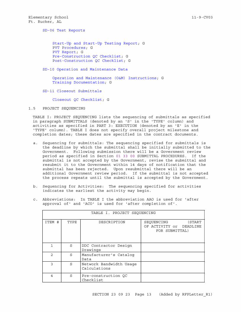
Elementary School 11-9-CV03Ft. Rucker, AL
SD-06 Test Reports
Start-Up and Start-Up Testing Report; GPVT Procedures; GPVT Report; GPre-Construction QC Checklist; GPost-Construction QC Checklist; G
SD-10 Operation and Maintenance Data
Operation and Maintenance (O&M) Instructions; GTraining Documentation; G
SD-11 Closeout Submittals
Closeout QC Checklist; G
1.5 PROJECT SEQUENCING
TABLE I: PROJECT SEQUENCING lists the sequencing of submittals as specified in paragraph SUBMITTALS (denoted by an 'S' in the 'TYPE' column) and activities as specified in PART 3: EXECUTION (denoted by an 'E' in the 'TYPE' column). TABLE I does not specify overall project milestone and completion dates; these dates are specified in the contract documents.
a. Sequencing for submittals: The sequencing specified for submittals is the deadline by which the submittal shall be initially submitted to the Government. Following submission there will be a Government review period as specified in Section 01 33 00 SUBMITTAL PROCEDURES. If the submittal is not accepted by the Government, revise the submittal and resubmit it to the Government within 14 days of notification that the submittal has been rejected. Upon resubmittal there will be an additional Government review period. If the submittal is not accepted the process repeats until the submittal is accepted by the Government.
b. Sequencing for Activities: The sequencing specified for activities indicates the earliest the activity may begin.
c. Abbreviations: In TABLE I the abbreviation AAO is used for 'after approval of' and 'ACO' is used for 'after completion of'.
TABLE I. PROJECT SEQUENCING
ITEM # TYPE DESCRIPTION SEQUENCING (STARTOF ACTIVITY or DEADLINE
FOR SUBMITTAL)
1 S DDC Contractor Design Drawings
2 S Manufacturer's Catalog Data
3 S Network Bandwidth Usage Calculations
4 S Pre-construction QC Checklist
SECTION 23 09 23 Page 13 (Added by RFPLetter_R1)
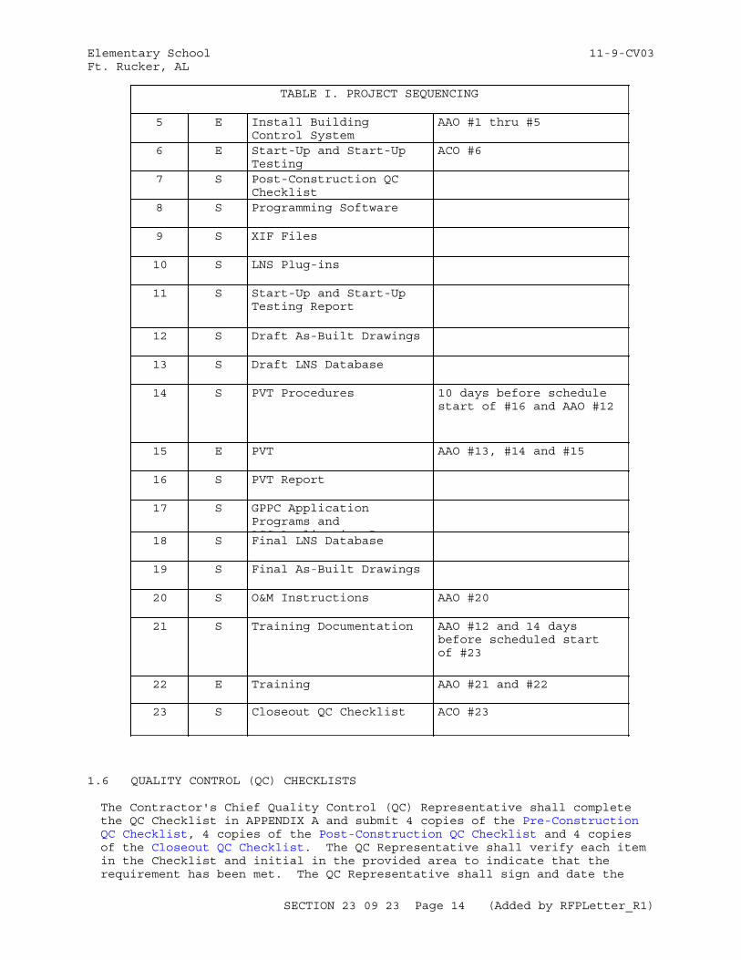
Elementary School 11-9-CV03Ft. Rucker, AL
TABLE I. PROJECT SEQUENCING
5 E Install Building Control System
AAO #1 thru #5
6 E Start-Up and Start-Up Testing
ACO #6
7 S Post-Construction QC Checklist
8 S Programming Software
9 S XIF Files
10 S LNS Plug-ins
11 S Start-Up and Start-UpTesting Report
12 S Draft As-Built Drawings
13 S Draft LNS Database
14 S PVT Procedures 10 days before schedule start of #16 and AAO #12
15 E PVT AAO #13, #14 and #15
16 S PVT Report
17 S GPPC Application Programs andAGC A li ti P18 S Final LNS Database
19 S Final As-Built Drawings
20 S O&M Instructions AAO #20
21 S Training Documentation AAO #12 and 14 days before scheduled start of #23
22 E Training AAO #21 and #22
23 S Closeout QC Checklist ACO #23
1.6 QUALITY CONTROL (QC) CHECKLISTS
The Contractor's Chief Quality Control (QC) Representative shall complete the QC Checklist in APPENDIX A and submit 4 copies of the Pre-Construction QC Checklist, 4 copies of the Post-Construction QC Checklist and 4 copies of the Closeout QC Checklist. The QC Representative shall verify each item in the Checklist and initial in the provided area to indicate that the requirement has been met. The QC Representative shall sign and date the
SECTION 23 09 23 Page 14 (Added by RFPLetter_R1)
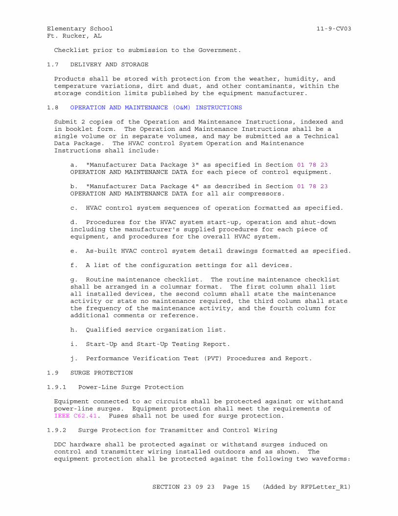
Elementary School 11-9-CV03Ft. Rucker, AL
Checklist prior to submission to the Government.
1.7 DELIVERY AND STORAGE
Products shall be stored with protection from the weather, humidity, and temperature variations, dirt and dust, and other contaminants, within the storage condition limits published by the equipment manufacturer.
1.8 OPERATION AND MAINTENANCE (O&M) INSTRUCTIONS
Submit 2 copies of the Operation and Maintenance Instructions, indexed and in booklet form. The Operation and Maintenance Instructions shall be a single volume or in separate volumes, and may be submitted as a Technical Data Package. The HVAC control System Operation and Maintenance Instructions shall include:
a. "Manufacturer Data Package 3" as specified in Section 01 78 23 OPERATION AND MAINTENANCE DATA for each piece of control equipment.
b. "Manufacturer Data Package 4" as described in Section 01 78 23 OPERATION AND MAINTENANCE DATA for all air compressors.
c. HVAC control system sequences of operation formatted as specified.
d. Procedures for the HVAC system start-up, operation and shut-down including the manufacturer's supplied procedures for each piece of equipment, and procedures for the overall HVAC system.
e. As-built HVAC control system detail drawings formatted as specified.
f. A list of the configuration settings for all devices.
g. Routine maintenance checklist. The routine maintenance checklist shall be arranged in a columnar format. The first column shall list all installed devices, the second column shall state the maintenance activity or state no maintenance required, the third column shall state the frequency of the maintenance activity, and the fourth column for additional comments or reference.
h. Qualified service organization list.
i. Start-Up and Start-Up Testing Report.
j. Performance Verification Test (PVT) Procedures and Report.
1.9 SURGE PROTECTION
1.9.1 Power-Line Surge Protection
Equipment connected to ac circuits shall be protected against or withstand power-line surges. Equipment protection shall meet the requirements of IEEE C62.41. Fuses shall not be used for surge protection.
1.9.2 Surge Protection for Transmitter and Control Wiring
DDC hardware shall be protected against or withstand surges induced on control and transmitter wiring installed outdoors and as shown. The equipment protection shall be protected against the following two waveforms:
SECTION 23 09 23 Page 15 (Added by RFPLetter_R1)
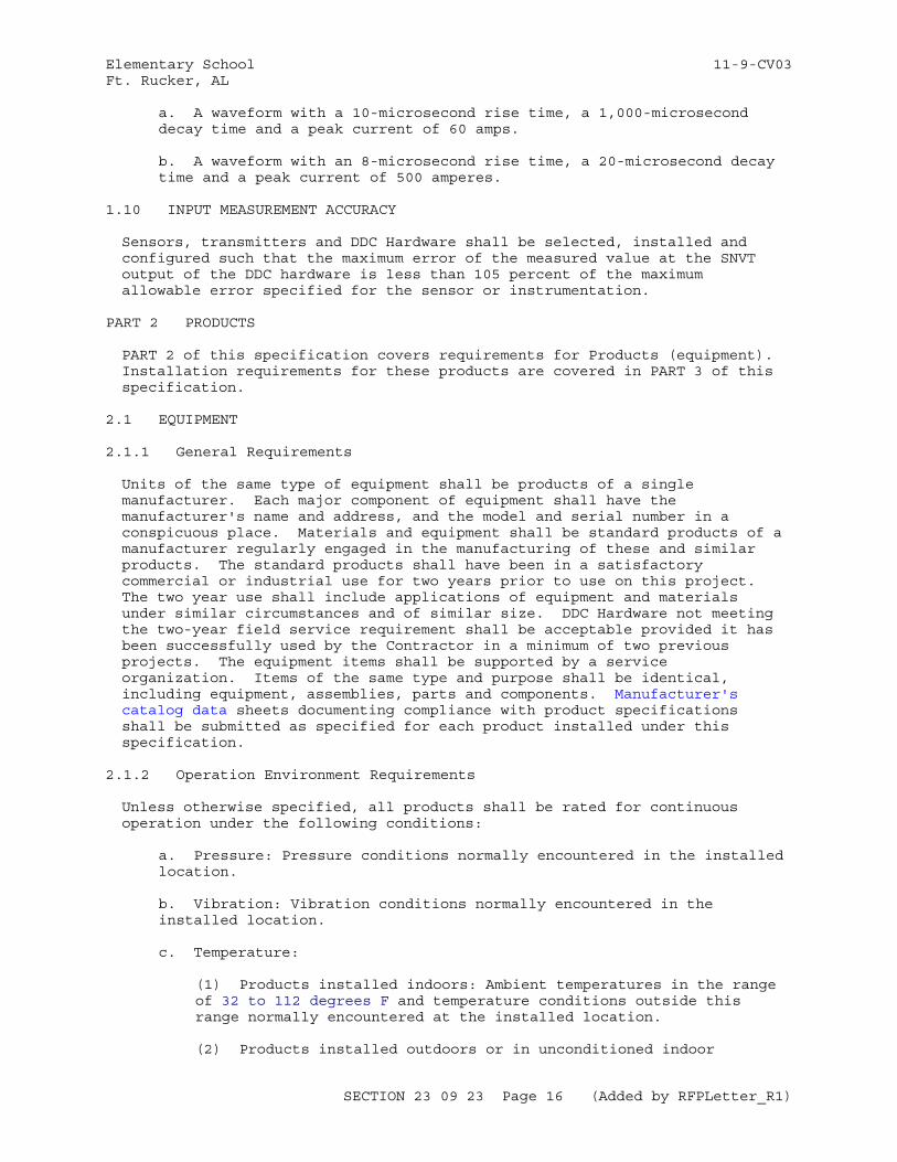
Elementary School 11-9-CV03Ft. Rucker, AL
a. A waveform with a 10-microsecond rise time, a 1,000-microsecond decay time and a peak current of 60 amps.
b. A waveform with an 8-microsecond rise time, a 20-microsecond decay time and a peak current of 500 amperes.
1.10 INPUT MEASUREMENT ACCURACY
Sensors, transmitters and DDC Hardware shall be selected, installed and configured such that the maximum error of the measured value at the SNVT output of the DDC hardware is less than 105 percent of the maximum allowable error specified for the sensor or instrumentation.
PART 2 PRODUCTS
PART 2 of this specification covers requirements for Products (equipment). Installation requirements for these products are covered in PART 3 of this specification.
2.1 EQUIPMENT
2.1.1 General Requirements
Units of the same type of equipment shall be products of a single manufacturer. Each major component of equipment shall have the manufacturer's name and address, and the model and serial number in a conspicuous place. Materials and equipment shall be standard products of a manufacturer regularly engaged in the manufacturing of these and similar products. The standard products shall have been in a satisfactory commercial or industrial use for two years prior to use on this project. The two year use shall include applications of equipment and materials under similar circumstances and of similar size. DDC Hardware not meeting the two-year field service requirement shall be acceptable provided it has been successfully used by the Contractor in a minimum of two previous projects. The equipment items shall be supported by a service organization. Items of the same type and purpose shall be identical, including equipment, assemblies, parts and components. Manufacturer's catalog data sheets documenting compliance with product specifications shall be submitted as specified for each product installed under this specification.
2.1.2 Operation Environment Requirements
Unless otherwise specified, all products shall be rated for continuous operation under the following conditions:
a. Pressure: Pressure conditions normally encountered in the installed location.
b. Vibration: Vibration conditions normally encountered in the installed location.
c. Temperature:
(1) Products installed indoors: Ambient temperatures in the range of 32 to 112 degrees F and temperature conditions outside this range normally encountered at the installed location.
(2) Products installed outdoors or in unconditioned indoor
SECTION 23 09 23 Page 16 (Added by RFPLetter_R1)
Elementary School 11-9-CV03Ft. Rucker, AL
spaces: Ambient temperatures in the range of -35 to +151 degrees F and temperature conditions outside this range normally encountered at the installed location.
d. Humidity: 10 to 95 percent relative humidity, noncondensing and humidity conditions outside this range normally encountered at the installed location.
2.2 ENCLOSURES AND WEATHERSHIELDS
2.2.1 Enclosures
Enclosures shall meet the following minimum requirements:
a. Outdoors: Enclosures located outdoors shall meet NEMA 250 Type 4 requirements.
b. Mechanical and Electrical Rooms: Enclosures located in mechanical or electrical rooms shall meet NEMA 250 Type 2 requirements.
c. Other Locations: Enclosures in other locations including but not limited to occupied spaces, above ceilings, and plenum returns shall meet NEMA 250 Type 1 requirements.
Enclosures supplied as an integral (pre-packaged) part of another product are acceptable.
2.2.2 Weathershields
Weathershields for sensors located outdoors shall prevent the sun from directly striking the sensor. The weathershield shall be provided with adequate ventilation so that the sensing element responds to the ambient conditions of the surroundings. The weathershield shall prevent rain from directly striking or dripping onto the sensor. Weathershields installed near outside air intake ducts shall be installed such that normal outside air flow does not cause rainwater to strike the sensor. Weathershields shall be constructed of galvanized steel painted white, unpainted aluminum, aluminum painted white, or white PVC.
2.3 NETWORK HARDWARE
2.3.1 CEA-709.1-C Network Routers
CEA-709.1-C Routers (including routers configured as repeaters) shall meet the requirements of CEA-709.1-C and shall provide connection between two or more CEA-709.3 TP/FT-10 channels or between two or more CEA-709.3 TP/FT-10 channels and a TP/XF-1250 channel..
2.3.2 CEA-709.1-C to IP Router
CEA-709.1-C to IP Routers shall perform layer 3 routing of CEA-709.1-C packets over an IP network in accordance with CEA-852-B. The router shall provide the appropriate connection to the IP network and connections to the CEA-709.3 TP/FT-10 or TP/XF-1250 network. CEA-709.1-C to IP Routers shall support the Dynamic Host Configuration Protocol (DHCP; IETF RFC 4361 for IP configuration and the use of an CEA-852-B Configuration Server (for CEA-852-B configuration), but shall not rely on these services for configuration. CEA-709.1-C to IP Routers shall be capable of manual configuration via a console RS-232 port.
SECTION 23 09 23 Page 17 (Added by RFPLetter_R1)
Elementary School 11-9-CV03Ft. Rucker, AL
2.4 WIRE AND CABLE
All wire and cable shall meet the requirements of NFPA 70 and NFPA 90A in addition to the requirements of this specification.
2.4.1 Terminal Blocks
Terminal blocks which are not integral to other equipment shall be insulated, modular, feed-through, clamp style with recessed captive screw-type clamping mechanism, shall be suitable for rail mounting, and shall have end plates and partition plates for separation or shall have enclosed sides.
2.4.2 Control Network Wiring
Control network wiring shall be twisted pair in accordance with CEA-709.3.
2.4.3 Control Wiring for Binary Signals
Control wiring for binary signals shall be 18 AWG copper and shall be rated for 300-volt service.
2.4.4 Control Wiring for 120-Volt Circuits
Wiring for 120-volt circuits shall be 18 AWG or thicker stranded copper and shall be rated for 600-volt service.
2.4.5 Control Wiring for Analog Signals
Control Wiring for Analog Signals shall be 18 AWG, copper, single- or multiple-twisted, minimum 2 inch lay of twist, 100 percent shielded pairs, and shall have a 300-volt insulation. Each pair shall have a 20 AWG tinned-copper drain wire and individual overall pair insulation. Cables shall have an overall aluminum-polyester or tinned-copper cable-shield tape, overall 20 AWG tinned-copper cable drain wire, and overall cable insulation.
2.4.6 Transformers
Transformers shall be UL 5085-3 approved. Transformers shall be sized so that the connected load is no greater than 80 percent of the transformer rated capacity.
2.5 AUTOMATIC CONTROL VALVES
Valves shall have stainless-steel stems and stuffing boxes with extended necks to clear the piping insulation. Valve bodies shall meet ASME B16.34 or ASME B16.15 pressure and temperature class ratings based on the design operating temperature and 150 percent of the system design operating pressure. Unless otherwise specified or shown, valve leakage shall meet FCI 70-2 Class IV leakage rating (0.01 percent of valve Kv). Unless otherwise specified or shown, valves shall have globe-style bodies. Unless otherwise specified:
a. bodies for valves smaller than 2 inches shall be brass or bronze, with threaded or union ends
b. bodies for 2 inch valves shall have threaded ends
SECTION 23 09 23 Page 18 (Added by RFPLetter_R1)
Elementary School 11-9-CV03Ft. Rucker, AL
c. for modulating applications, valve Kv (Cv) shall be within 100 to 125 percent of the Kv (Cv) shown.
d. for two position applications (where the two positions are full open and full closed) the Kv (Cv) shall be the largest available for the valve size.
e. valve and actuator combination shall be normally open or normally closed as shown.
2.5.1 Ball Valves
Balls shall be stainless steel or nickel plated brass. Valves shall have blow-out proof stems. In steam and high temperature hot water applications, the valve-to-actuator linkage shall provide a thermal break.
2.5.2 Butterfly Valves
Butterfly valves shall be threaded lug type suitable for dead-end service and modulation to the fully-closed position, with carbon-steel bodies or with ductile iron bodies in accordance with ASTM A536. Butterfly valves shall have non-corrosive discs, stainless steel shafts supported by bearings, and EPDM seats suitable for temperatures from -20 to +250 degrees F. The rated Kv (Cv) for butterfly valves shall be the value Kv (Cv) at 70 percent (60 degrees) open position. Valve leakage shall meet FCI 70-2 Class VI leakage rating.
2.5.3 Two-Way Valves
Two-way modulating valves used for liquids shall have an equal-percentage characteristic. Two-way modulating valves used for steam shall have a linear characteristic.
2.5.4 Three-Way Valves
Three-way modulating valves shall provide equal percentage flow control with constant total flow throughout full plug travel.
2.5.5 Duct-Coil and Terminal-Unit-Coil Valves
Control valves with either flare-type or solder-type ends shall be provided for duct or terminal-unit coils. Flare nuts shall be provided for each flare-type end valve.
2.5.6 Valves for Chilled-Water, Condenser-Water, and Glycol Service
Valve internal trim shall be Type 316 stainless steel. Valves 4 inches and larger shall be butterfly valves.
2.6 DAMPERS
2.6.1 Damper Assembly
A single damper section shall have blades no longer than 48 inch and shall be no higher than 72 inch. Maximum damper blade width shall be 8 inch. Larger sizes shall be made from a combination of sections. Dampers shall be steel, or other materials where shown. Flat blades shall be made rigid
SECTION 23 09 23 Page 19 (Added by RFPLetter_R1)
Elementary School 11-9-CV03Ft. Rucker, AL
by folding the edges. Blade-operating linkages shall be within the frame so that blade-connecting devices within the same damper section shall not be located directly in the air stream. Damper axles shall be 1/2 inch minimum, plated steel rods supported in the damper frame by stainless steel or bronze bearings. Blades mounted vertically shall be supported by thrust bearings. Pressure drop through dampers shall not exceed 0.04 inches water gauge at 1,000 ft/min in the wide-open position. Frames shall not be less than 2 inch in width. Dampers shall be tested in accordance with AMCA 500-D.
2.6.2 Operating Linkages
Operating links external to dampers, such as crank arms, connecting rods, and line shafting for transmitting motion from damper actuators to dampers, shall withstand a load equal to at least 300 percent of the maximum required damper-operating force without deforming. Rod lengths shall be adjustable. Links shall be brass, bronze, zinc-coated steel, or stainless steel. Working parts of joints and clevises shall be brass, bronze, or stainless steel. Adjustments of crank arms shall control the open and closed positions of dampers.
2.6.3 Damper Types
2.6.3.1 Flow Control Dampers
Outside air, return air, relief air, exhaust, face and bypass dampers shall be provided where shown and shall be parallel-blade or opposed blade type as shown on the Damper Schedule. Blades shall have interlocking edges. The channel frames of the dampers shall be provided with jamb seals to minimize air leakage. Unless otherwise shown, dampers shall meet AMCA 511 Class 1A requirements. Outside air damper seals shall be suitable for an operating temperature range of -40 to +167 degrees F. Dampers shall be rated at not less than 2000 ft/min air velocity.
2.6.3.2 Mechanical Rooms and Other Utility Space Ventilation Dampers
Utility space ventilation dampers shall be as shown. Unless otherwise shown, dampers shall be AMCA 511 class 3. Dampers shall be rated at not less than 1500 ft/min air velocity.
2.6.3.3 Smoke Dampers
Smoke-damper and actuator assembly shall meet the current requirements of NFPA 90A, UL 555, and UL 555S. Combination fire and smoke dampers shall be rated for 250 degrees F Class II leakage per UL 555S.
2.7 SENSORS AND INSTRUMENTATION
Unless otherwise specified, sensors and instrumentation shall incorporate an integral transmitter or be provided with a transmitter co-located with the sensor. Sensors and instrumentation, including their transmitters, shall meet the specified accuracy and drift requirements at the input of the connected DDC Hardware's analog-to-digital conversion. Sensors and instrumentation, including their transmitters, shall meet or exceed the specified range.
2.7.1 Transmitters
The transmitter shall match the characteristics of the sensor. Transmitters providing analog values shall produce a linear 4-20 mAdc, 0-10
SECTION 23 09 23 Page 20 (Added by RFPLetter_R1)
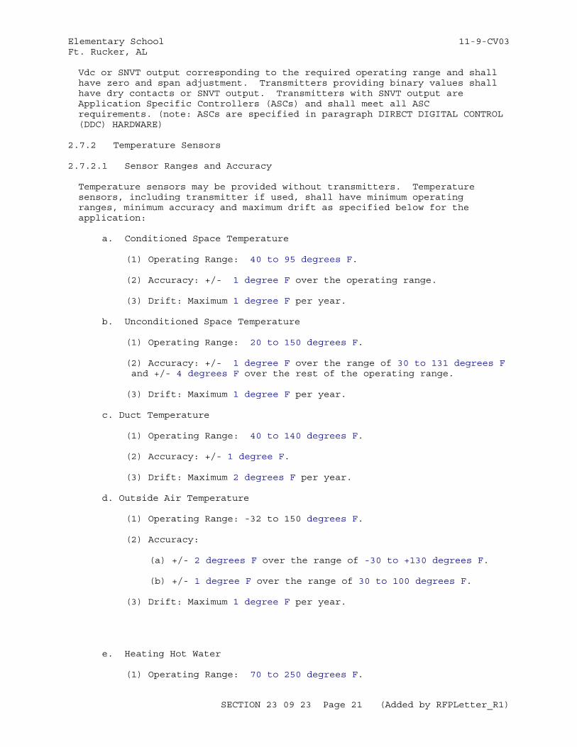
Elementary School 11-9-CV03Ft. Rucker, AL
Vdc or SNVT output corresponding to the required operating range and shall have zero and span adjustment. Transmitters providing binary values shall have dry contacts or SNVT output. Transmitters with SNVT output are Application Specific Controllers (ASCs) and shall meet all ASC requirements. (note: ASCs are specified in paragraph DIRECT DIGITAL CONTROL (DDC) HARDWARE)
2.7.2 Temperature Sensors
2.7.2.1 Sensor Ranges and Accuracy
Temperature sensors may be provided without transmitters. Temperature sensors, including transmitter if used, shall have minimum operating ranges, minimum accuracy and maximum drift as specified below for the application:
a. Conditioned Space Temperature
(1) Operating Range: 40 to 95 degrees F.
(2) Accuracy: +/- 1 degree F over the operating range.
(3) Drift: Maximum 1 degree F per year.
b. Unconditioned Space Temperature
(1) Operating Range: 20 to 150 degrees F.
(2) Accuracy: +/- 1 degree F over the range of 30 to 131 degrees F and +/- 4 degrees F over the rest of the operating range.
(3) Drift: Maximum 1 degree F per year.
c. Duct Temperature
(1) Operating Range: 40 to 140 degrees F.
(2) Accuracy: +/- 1 degree F.
(3) Drift: Maximum 2 degrees F per year.
d. Outside Air Temperature
(1) Operating Range: -32 to 150 degrees F.
(2) Accuracy:
(a) +/- 2 degrees F over the range of -30 to +130 degrees F.
(b) +/- 1 degree F over the range of 30 to 100 degrees F.
(3) Drift: Maximum 1 degree F per year.
e. Heating Hot Water
(1) Operating Range: 70 to 250 degrees F.
SECTION 23 09 23 Page 21 (Added by RFPLetter_R1)
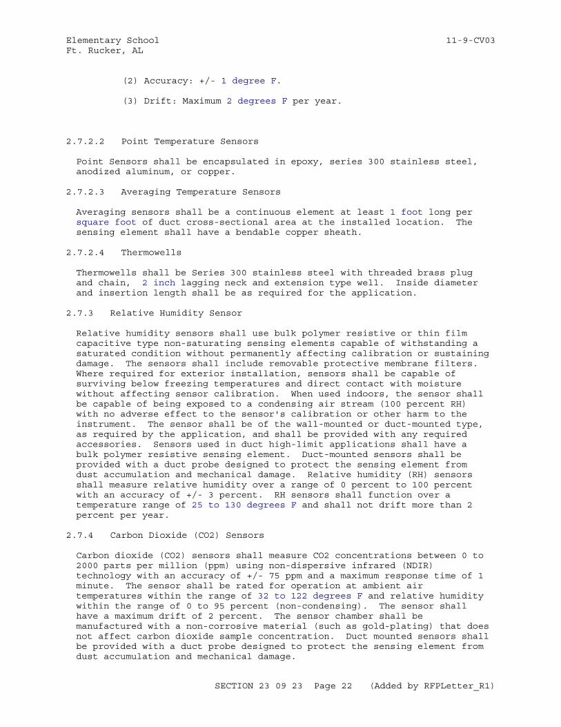
Elementary School 11-9-CV03Ft. Rucker, AL
(2) Accuracy: +/- 1 degree F.
(3) Drift: Maximum 2 degrees F per year.
2.7.2.2 Point Temperature Sensors
Point Sensors shall be encapsulated in epoxy, series 300 stainless steel, anodized aluminum, or copper.
2.7.2.3 Averaging Temperature Sensors
Averaging sensors shall be a continuous element at least 1 foot long per square foot of duct cross-sectional area at the installed location. The sensing element shall have a bendable copper sheath.
2.7.2.4 Thermowells
Thermowells shall be Series 300 stainless steel with threaded brass plug and chain, 2 inch lagging neck and extension type well. Inside diameter and insertion length shall be as required for the application.
2.7.3 Relative Humidity Sensor
Relative humidity sensors shall use bulk polymer resistive or thin film capacitive type non-saturating sensing elements capable of withstanding a saturated condition without permanently affecting calibration or sustaining damage. The sensors shall include removable protective membrane filters. Where required for exterior installation, sensors shall be capable of surviving below freezing temperatures and direct contact with moisture without affecting sensor calibration. When used indoors, the sensor shall be capable of being exposed to a condensing air stream (100 percent RH) with no adverse effect to the sensor's calibration or other harm to the instrument. The sensor shall be of the wall-mounted or duct-mounted type, as required by the application, and shall be provided with any required accessories. Sensors used in duct high-limit applications shall have a bulk polymer resistive sensing element. Duct-mounted sensors shall be provided with a duct probe designed to protect the sensing element from dust accumulation and mechanical damage. Relative humidity (RH) sensors shall measure relative humidity over a range of 0 percent to 100 percent with an accuracy of +/- 3 percent. RH sensors shall function over a temperature range of 25 to 130 degrees F and shall not drift more than 2 percent per year.
2.7.4 Carbon Dioxide (CO2) Sensors
Carbon dioxide (CO2) sensors shall measure CO2 concentrations between 0 to 2000 parts per million (ppm) using non-dispersive infrared (NDIR) technology with an accuracy of +/- 75 ppm and a maximum response time of 1 minute. The sensor shall be rated for operation at ambient air temperatures within the range of 32 to 122 degrees F and relative humidity within the range of 0 to 95 percent (non-condensing). The sensor shall have a maximum drift of 2 percent. The sensor chamber shall be manufactured with a non-corrosive material (such as gold-plating) that does not affect carbon dioxide sample concentration. Duct mounted sensors shall be provided with a duct probe designed to protect the sensing element from dust accumulation and mechanical damage.
SECTION 23 09 23 Page 22 (Added by RFPLetter_R1)
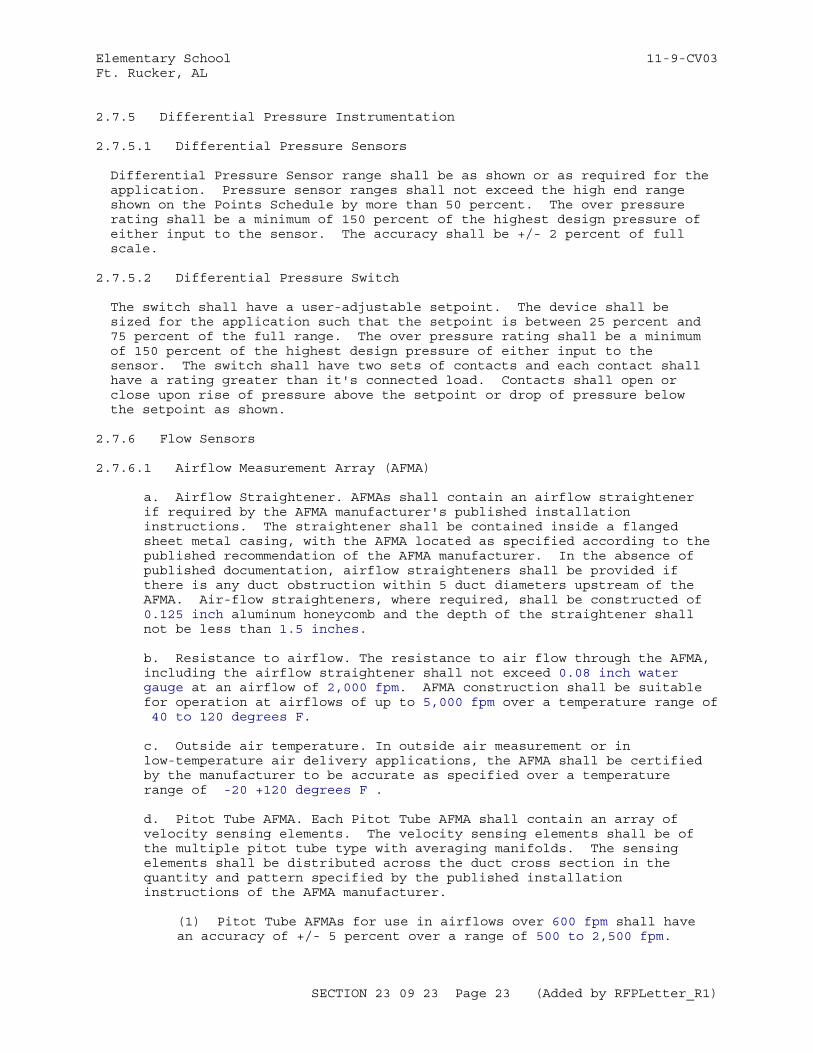
Elementary School 11-9-CV03Ft. Rucker, AL
2.7.5 Differential Pressure Instrumentation
2.7.5.1 Differential Pressure Sensors
Differential Pressure Sensor range shall be as shown or as required for the application. Pressure sensor ranges shall not exceed the high end range shown on the Points Schedule by more than 50 percent. The over pressure rating shall be a minimum of 150 percent of the highest design pressure of either input to the sensor. The accuracy shall be +/- 2 percent of full scale.
2.7.5.2 Differential Pressure Switch
The switch shall have a user-adjustable setpoint. The device shall be sized for the application such that the setpoint is between 25 percent and 75 percent of the full range. The over pressure rating shall be a minimum of 150 percent of the highest design pressure of either input to the sensor. The switch shall have two sets of contacts and each contact shall have a rating greater than it's connected load. Contacts shall open or close upon rise of pressure above the setpoint or drop of pressure below the setpoint as shown.
2.7.6 Flow Sensors
2.7.6.1 Airflow Measurement Array (AFMA)
a. Airflow Straightener. AFMAs shall contain an airflow straightener if required by the AFMA manufacturer's published installation instructions. The straightener shall be contained inside a flanged sheet metal casing, with the AFMA located as specified according to the published recommendation of the AFMA manufacturer. In the absence of published documentation, airflow straighteners shall be provided if there is any duct obstruction within 5 duct diameters upstream of the AFMA. Air-flow straighteners, where required, shall be constructed of 0.125 inch aluminum honeycomb and the depth of the straightener shall not be less than 1.5 inches.
b. Resistance to airflow. The resistance to air flow through the AFMA, including the airflow straightener shall not exceed 0.08 inch water gauge at an airflow of 2,000 fpm. AFMA construction shall be suitable for operation at airflows of up to 5,000 fpm over a temperature range of 40 to 120 degrees F.
c. Outside air temperature. In outside air measurement or in low-temperature air delivery applications, the AFMA shall be certified by the manufacturer to be accurate as specified over a temperature range of -20 +120 degrees F .
d. Pitot Tube AFMA. Each Pitot Tube AFMA shall contain an array of velocity sensing elements. The velocity sensing elements shall be of the multiple pitot tube type with averaging manifolds. The sensing elements shall be distributed across the duct cross section in the quantity and pattern specified by the published installation instructions of the AFMA manufacturer.
(1) Pitot Tube AFMAs for use in airflows over 600 fpm shall have an accuracy of +/- 5 percent over a range of 500 to 2,500 fpm.
SECTION 23 09 23 Page 23 (Added by RFPLetter_R1)
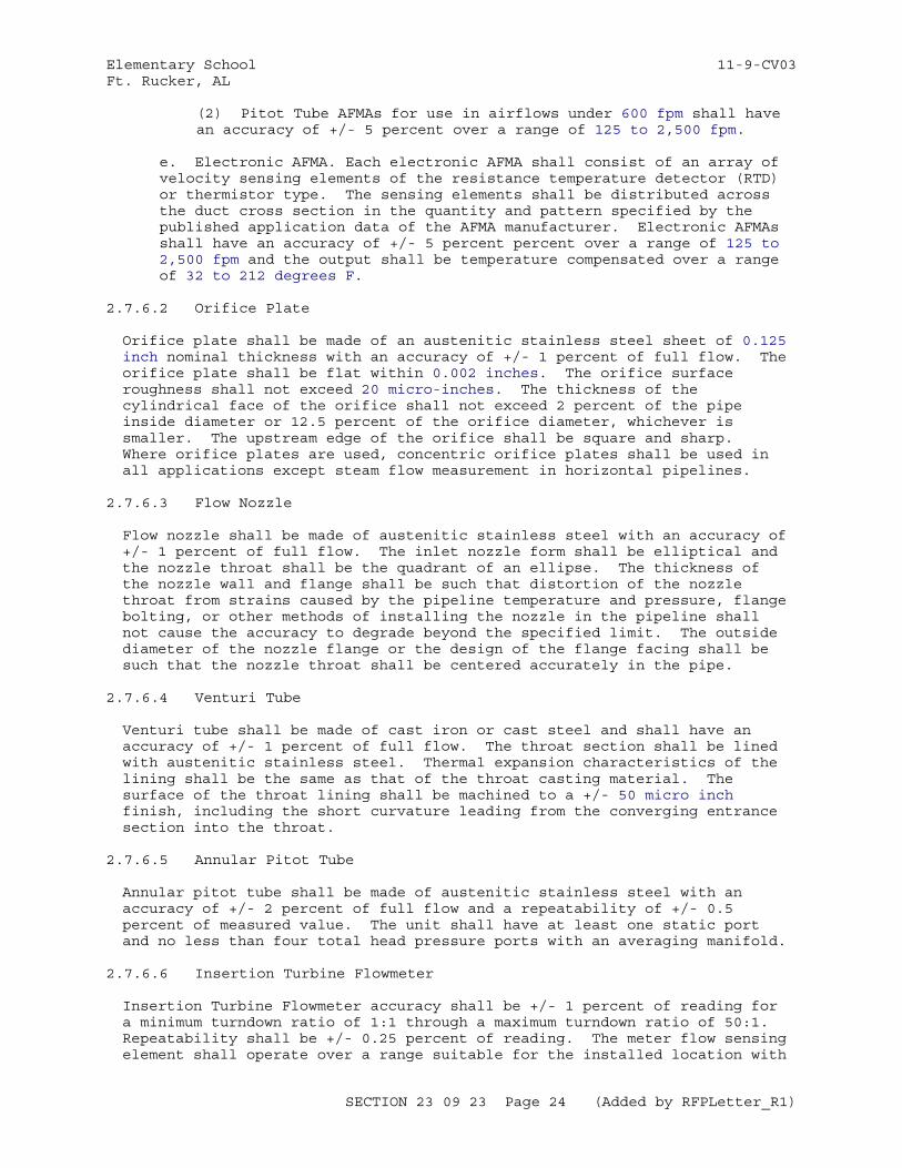
Elementary School 11-9-CV03Ft. Rucker, AL
(2) Pitot Tube AFMAs for use in airflows under 600 fpm shall have an accuracy of +/- 5 percent over a range of 125 to 2,500 fpm.
e. Electronic AFMA. Each electronic AFMA shall consist of an array of velocity sensing elements of the resistance temperature detector (RTD) or thermistor type. The sensing elements shall be distributed across the duct cross section in the quantity and pattern specified by the published application data of the AFMA manufacturer. Electronic AFMAs shall have an accuracy of +/- 5 percent percent over a range of 125 to 2,500 fpm and the output shall be temperature compensated over a range of 32 to 212 degrees F.
2.7.6.2 Orifice Plate
Orifice plate shall be made of an austenitic stainless steel sheet of 0.125 inch nominal thickness with an accuracy of +/- 1 percent of full flow. The orifice plate shall be flat within 0.002 inches. The orifice surface roughness shall not exceed 20 micro-inches. The thickness of the cylindrical face of the orifice shall not exceed 2 percent of the pipe inside diameter or 12.5 percent of the orifice diameter, whichever is smaller. The upstream edge of the orifice shall be square and sharp. Where orifice plates are used, concentric orifice plates shall be used in all applications except steam flow measurement in horizontal pipelines.
2.7.6.3 Flow Nozzle
Flow nozzle shall be made of austenitic stainless steel with an accuracy of +/- 1 percent of full flow. The inlet nozzle form shall be elliptical and the nozzle throat shall be the quadrant of an ellipse. The thickness of the nozzle wall and flange shall be such that distortion of the nozzle throat from strains caused by the pipeline temperature and pressure, flange bolting, or other methods of installing the nozzle in the pipeline shall not cause the accuracy to degrade beyond the specified limit. The outside diameter of the nozzle flange or the design of the flange facing shall be such that the nozzle throat shall be centered accurately in the pipe.
2.7.6.4 Venturi Tube
Venturi tube shall be made of cast iron or cast steel and shall have an accuracy of +/- 1 percent of full flow. The throat section shall be lined with austenitic stainless steel. Thermal expansion characteristics of the lining shall be the same as that of the throat casting material. The surface of the throat lining shall be machined to a +/- 50 micro inch finish, including the short curvature leading from the converging entrance section into the throat.
2.7.6.5 Annular Pitot Tube
Annular pitot tube shall be made of austenitic stainless steel with an accuracy of +/- 2 percent of full flow and a repeatability of +/- 0.5 percent of measured value. The unit shall have at least one static port and no less than four total head pressure ports with an averaging manifold.
2.7.6.6 Insertion Turbine Flowmeter
Insertion Turbine Flowmeter accuracy shall be +/- 1 percent of reading for a minimum turndown ratio of 1:1 through a maximum turndown ratio of 50:1. Repeatability shall be +/- 0.25 percent of reading. The meter flow sensing element shall operate over a range suitable for the installed location with
SECTION 23 09 23 Page 24 (Added by RFPLetter_R1)
Elementary School 11-9-CV03Ft. Rucker, AL
a pressure loss limited to 1 percent of operating pressure at maximum flow rate. Design of the flowmeter probe assembly shall incorporate integral flow, temperature, and pressure sensors. The turbine rotor assembly shall be constructed of Series 300 stainless steel and use Teflon seals.
2.7.6.7 Vortex Shedding Flowmeter
Vortex Shedding Flowmeter accuracy shall be within +/- 0.8 percent of the actual flow. The flow meter body shall be made of austenitic stainless steel. The vortex shedding flowmeter body shall not require removal from the piping in order to replace the shedding sensor.
2.7.6.8 Positive Displacement Flow Meter
The flow meter shall be a direct reading, gerotor, nutating disc or vane type displacement device rated for liquid service as shown. A counter shall be mounted on top of the meter, and shall consist of a non-resettable mechanical totalizer for local reading, and a pulse transmitter for remote reading. The totalizer shall have a six digit register to indicate the volume passed through the meter in gallons, and a sweep-hand dial to indicate down to 0.25 gallons. The pulse transmitter shall have a hermetically sealed reed switch which is activated by magnets fixed on gears of the counter. The meter shall have a bronze body with threaded or flanged connections as required for the application. Output accuracy shall be +/- 2 percent of the flow range. The maximum pressure drop at full flow shall be 5 psig.
2.7.6.9 Flow Switch
Flow switch shall have a repetitive accuracy of +/- 10 percent of actual flow setting. Switch actuation shall be adjustable over the operating flow range, and shall be sized for the application such that the setpoint is between 25 percent and 75 percent of the full range.. The switch shall have Form C snap-action contacts, rated for the application. The flow switch shall have non flexible paddle with magnetically actuated contacts and be rated for service at a pressure greater than the installed conditions. Flow switch for use in sewage system shall be rated for use in corrosive environments encountered.
2.7.6.10 Gas Utility Flow Meter
Gas utility flow meter shall be diaphragm or bellows type (gas positive displacement meters) for flows up to 2500 SCFH and axial flow turbine type for flows above 2500 SCFH, designed specifically for natural gas supply metering, and rated for the pressure, temperature, and flow rates of the installation. Meter shall have a minimum turndown ratio of 10 to 1 with an accuracy of +/- 1 percent of actual flow rate. The meter index shall include a direct reading mechanical totalizing register and electrical impulse dry contact output for remote monitoring. The electrical impulse dry contact output shall not require field adjustment or calibration. The electrical impulse dry contact output shall have a minimum resolution of 100 cubic feet of gas per pulse and shall not exceed 15 pulses per second at the design flow.
2.7.7 Electrical Instruments
Electrical Instruments shall have an input range as shown or sized for the application. Unless otherwise specified, AC instrumentation shall be suitable for 60 Hz operation.
SECTION 23 09 23 Page 25 (Added by RFPLetter_R1)
Elementary School 11-9-CV03Ft. Rucker, AL
2.7.7.1 Watt or Watthour Transducers
Watt transducers shall measure voltage and current and shall output kW or kWh or both kW and kWh as shown. kW outputs shall have an accuracy of +/- 0.25 percent over a power factor range of 0.1 to 1. kWh outputs shall be SNVT outputs or pulse outputs and shall have an accuracy of +/- 0.5 percent over a power factor range of 0.1 to 1.
2.7.7.2 Watthour Revenue Meter (with and without Demand Register)
All Watthour revenue meters shall measure voltage and current and shall be in accordance with ANSI C12.1 with an ANSI C12.20 Accuracy class of 0.5 and shall have pulse initiators for remote monitoring of Watthour consumption. Pulse initiators shall consist of form C contacts with a current rating not to exceed two amperes and voltage not to exceed 500 V, with combinations of VA not to exceed 100 VA, and a life rating of one billion operations. Meter sockets shall be in accordance with NEMA/ANSI C12.10. Watthour revenue meters with demand registers shall have an analog output or SNVT output for instantaneous demand in addition to the pulse initiators.
2.7.7.3 Current Transducers
Current transducers shall accept an AC current input and shall have an accuracy of +/- 0.5 percent of full scale. The device shall have a means for calibration.
2.7.7.4 Current Sensing Relays (CSRs)
Current sensing relays (CSRs) shall provide a normally-open contact with a voltage and amperage rating greater than its connected load. Current sensing relays shall be of split-core design. The CSR shall be rated for operation at 200 percent of the connected load. Voltage isolation shall be a minimum of 600 volts. The CSR shall auto-calibrate to the connected load.
2.7.7.5 Voltage Transducers
Voltage transducers shall accept an AC voltage input and have an accuracy of +/- 0.25 percent of full scale. The device shall have a means for calibration. Line side fuses for transducer protection shall be provided.
2.7.8 pH Sensor
The sensor shall be suitable for applications and chemicals encountered in water treatment systems of boilers, chillers and condenser water systems. Construction, wiring, fittings and accessories shall be corrosion and chemical resistant with fittings for tank or suspension installation. Housing shall be polyvinylidene fluoride with O-rings made of chemical resistant materials which do not corrode or deteriorate with extended exposure to chemicals. The sensor shall be encapsulated. Periodic replacement shall not be required for continued sensor operation. Sensors shall use a ceramic junction and pH sensitive glass membrane capable of withstanding a pressure of 100 psig at 150 degrees F. The reference cell shall be double junction configuration. Sensor range shall be 0 to 12 pH, stability 0.05, sensitivity 0.02, and repeatability of +/- 0.05 pH value, response of 90 percent of full scale in one second and a linearity of 99 percent of theoretical electrode output measured at 76 degrees F.
SECTION 23 09 23 Page 26 (Added by RFPLetter_R1)
Elementary School 11-9-CV03Ft. Rucker, AL
2.7.9 Occupancy Sensors
Occupancy sensors shall have occupancy-sensing sensitivity adjustment and an adjustable off-delay timer with a range encompassing 30 seconds to 15 minutes. Occupancy sensors shall be rated for operation in ambient air temperatures ranging from 40 to 95 degrees F or temperatures normally encountered in the installed location. Sensors integral to wall mount on-off light switches shall have an auto-off switch. Wall switch sensors shall be decorator style and shall fit behind a standard decorator type wall plate. All occupancy sensors, power packs, and slave packs shall be UL listed. In addition to any outputs required for lighting control, the occupancy sensor shall provide a dry contact output rated at 1A at 24 Vac or a SNVT output.
2.7.9.1 Passive Infrared (PIR) Occupancy Sensors
PIR occupancy sensors shall have a multi-level, multi-segmented viewing lens and a conical field of view with a viewing angle of 180 degrees and a detection of at least 20 feet unless otherwise shown or specified. PIR Sensors shall provide field-adjustable background light-level adjustment with an adjustment range suitable to the light level in the sensed area, room or space. PIR sensors shall be immune to false triggering from RFI and EMI.
2.7.10 Temperature Switch
2.7.10.1 Duct Mount Temperature Low Limit Safety Switch (Freezestat)
Duct mount temperature low limit switches (Freezestats) shall be manual reset, low temperature safety switches at least 1 foot long per square foot of coverage which shall respond to the coldest 18 inch segment with an accuracy of +/- 3.6 degrees F. The switch shall have a field-adjustable setpoint with a range of at least 30 to 50 degrees F. The switch shall have two sets of contacts, and each contact shall have a rating greater than its connected load. Contacts shall open or close upon drop of temperature below setpoint as shown and shall remain in this state until reset.
2.7.10.2 Pipe Mount Temperature Limit Switch (Aquastat)
Pipe mount temperature limit switches (aquastats) shall have a field adjustable setpoint between 60 and 90 degrees F, an accuracy of +/- 3.6 degrees F and a 10 degrees F fixed deadband. The switch shall have two sets of contacts, and each contact shall have a rating greater than its connected load. Contacts shall open or close upon change of temperature above or below setpoint as shown.
2.7.11 Damper End Switches
Each end switch shall be a hermetically sealed switch with a trip lever and over-travel mechanism. The switch enclosure shall be suitable for mounting on the duct exterior and shall permit setting the position of the trip lever that actuates the switch. The trip lever shall be aligned with the damper blade.
2.8 INDICATING DEVICES
All indicating devices shall display readings in English (inch-pound) units.
SECTION 23 09 23 Page 27 (Added by RFPLetter_R1)
Elementary School 11-9-CV03Ft. Rucker, AL
2.8.1 Thermometers
Thermometers shall not contain mercury. Unless otherwise specified, thermometers shall have an accuracy of +/- 3 percent of scale range. Thermometers shall have a range suitable for the application with an upper end of the range not to exceed 150 percent of the design upper limit.
2.8.1.1 Piping System Thermometers
Piping system thermometers shall have brass, malleable iron or aluminum alloy case and frame, clear protective face, permanently stabilized glass tube with indicating-fluid column, white face, black numbers, and a 9 inch scale. Piping system thermometers shall have an accuracy of +/- 1 percent of scale range. Thermometers for piping systems shall have rigid stems with straight, angular, or inclined pattern. Thermometer stems shall have expansion heads as required to prevent breakage at extreme temperatures. On rigid-stem thermometers, the space between bulb and stem shall be filled with a heat-transfer medium.
2.8.1.2 Air-Duct Thermometers
Air-duct thermometers shall have perforated stem guards and 45-degree adjustable duct flanges with locking mechanism.
2.8.2 Pressure Gauges
Gauges shall be suitable for field or panel mounting as required, shall have black legend on white background, and shall have a pointer traveling through a 270-degree arc. Gauge range shall be suitable for the application with an upper end of the range not to exceed 150 percent of the design upper limit. Accuracy shall be +/- 3 percent of scale range. Gauges shall meet requirements of ASME B40.100.
2.8.3 Low Differential Pressure Gauges
Gauges for low differential pressure measurements shall be a minimum of 3.5 inch (nominal) size with two sets of pressure taps, and shall have a diaphragm-actuated pointer, white dial with black figures, and pointer zero adjustment. Gauge range shall be suitable for the application with an upper end of the range not to exceed 150 percent of the design upper limit. Accuracy shall be plus or minus two percent of scale range.
2.9 OUTPUT DEVICES
Output Devices with SNVT input are ASCs and shall meet all ASC requirements in addition to the output device requirements. (Note: ASCs are specified in paragraph DIRECT DIGITAL CONTROL (DDC) HARDWARE.)
2.9.1 Actuators
Actuators shall be electric (electronic) . All actuators shall be normally open (NO), normally closed (NC) or fail-in-last-position (FILP) as shown. Normally open and normally closed actuators shall be of mechanical spring return type. Electric actuators shall have an electronic cut off or other means to provide burnout protection if stalled. Actuators shall have a visible position indicator. Electric actuators shall provide position feedback to the controller as shown. Actuators shall smoothly open or close the devices to which they are applied. Pneumatic actuators shall have a full stroke response time matching the connected Electric to Pneumatic
SECTION 23 09 23 Page 28 (Added by RFPLetter_R1)
Elementary School 11-9-CV03Ft. Rucker, AL
Transducer (EP). Electric actuators shall have a full stroke response time in both directions of 90 seconds or less at rated load. Electric actuators shall be of the foot-mounted type with an oil-immersed gear train or the direct-coupled type. Where multiple electric actuators operate from a common signal, the actuators shall provide an output signal identical to its input signal to the additional devices. All actuators shall be rated for their operating environment. Actuators used outdoors shall be designed and rated for outdoor use. Actuators under continuous exposure to water, such as those used in sumps, shall be submersible.
2.9.1.1 Valve Actuators
Valve actuators shall provide shutoff pressures and torques as shown on the Valve Schedule.
2.9.1.2 Damper Actuators
Damper actuators shall provide the torque necessary per damper manufacturer's instructions to modulate the dampers smoothly over its full range of operation and torque shall be at least 6 inch-pounds/1 square foot of damper area for opposed blade dampers and 9 inch-pounds/1 square foot of damper area for parallel blade dampers.
2.9.2 Relays
Control relay contacts shall have utilization category and ratings selected for the application, with a minimum of two sets of contacts enclosed in a dust proof enclosure. Each set of contacts shall incorporate a normally open (NO), normally closed (NC) and common contact. Relays shall be rated for a minimum life of one million operations. Operating time shall be 20 milliseconds or less. Relays shall be equipped with coil transient suppression devices to limit transients to 150 percent of rated coil voltage.
2.10 USER INPUT DEVICES
User Input Devices, including potentiometers, switches and momentary contact push-buttons with SNVT output are Application Specific Controllers (ASCs) and shall meet all ASC requirements. (Note: ASCs are specified in paragraph DIRECT DIGITAL CONTROL (DDC) HARDWARE). Potentiometers shall be of the thumb wheel or sliding bar type. Momentary Contact Push-Buttons may include an adjustable timer for their output. User input devices shall be labeled for their function.
2.11 MULTIFUNCTION DEVICES
Multifunction devices are products which combine the functions of multiple sensor, user input or output devices into a single product. Unless otherwise specified, the multifunction device shall meet all requirements of each component device. Where the requirements for the component devices conflict, the multifunction device shall meet the most stringent of the requirements.
2.11.1 Current Sensing Relay Command Switch
The Current Sensing Relay portion shall meet all requirements of the Current Sensing Relay input device. The Command Switch portion shall meet all requirements of the Relay output device except that it shall have at least one normally-open (NO) contact.
SECTION 23 09 23 Page 29 (Added by RFPLetter_R1)
Elementary School 11-9-CV03Ft. Rucker, AL
2.11.2 Thermostats
Thermostats shall be multifunction devices incorporating a temperature sensor and one or more of the following as specified and shown on the Thermostat Schedule:
a. A temperature indicating device.
b. A User Input Device which shall adjust a temperature setpoint output.
c. A User Input Momentary Contact Button and an output to the control system indicating zone occupancy.
Thermostats shall not contain mercury (Hg).
2.12 DIRECT DIGITAL CONTROL (DDC) HARDWARE
2.12.1 General Requirements
All DDC Hardware shall meet the following requirements:
a. It shall incorporate a "service pin" which, when pressed will cause the DDC Hardware to broadcast its 48-bit NodeID and its ProgramID over the network. The service pin shall be distinguishable and accessible.
b. It shall incorporate a light to indicate the device is receiving power.
c. It shall incorporate a TP/FT-10 transceiver in accordance with CEA-709.3 and connections for TP/FT-10 control network wiring.
d. It shall communicate on the network using only the CEA-709.1-C protocol.
e. It shall be capable of having network communications configured via LNS.
f. It shall be locally powered; link powered devices are not acceptable.
g. LonMark external interface files (XIF files), as defined in the LonMark XIF Guide, shall be submitted for each type of DDC Hardware. External interface files (XIF files) shall be submitted as a technical data package for each model of DDC Hardware provided under this specification. XIF files shall be submitted on optical disk.
h. Application programs and configuration settings shall be stored in a manner such that a loss of power does not result in a loss of the application program or configuration settings:
(1) Loss of power shall never result in the loss of application programs, regardless of the length of time power is lost (i.e. application programs shall be stored in non-volatile memory).
(2) Loss of power for less than 72 hours shall not result in the
SECTION 23 09 23 Page 30 (Added by RFPLetter_R1)
Elementary School 11-9-CV03Ft. Rucker, AL
loss of configuration settings.
i. It shall have all functionality specified and required to support the application (Sequence of Operation or portion thereof) in which it is used, including but not limited to:
(1) It shall provide input and output SNVTs as specified, as shown on the Points Schedule, and as otherwise required to support the sequence and application in which it is used. All SNVTs shall have meaningful names identifying the value represented by the SNVT. Unless a SNVT of an appropriate engineering type is not available, all network variables shall be of a standard network variable type with engineering units appropriate to the value the variable represents.
(2) It shall be configurable via standard configuration properties (SCPTs) as defined in the LonMark SCPT List, user-defined configuration properties (UCPTs), network configuration inputs (ncis) of a SNVT type as defined in the LonMark SNVT List, network configuration inputs (ncis) of a user defined network variable type, or hardware settings on the controller itself for all settings and parameters used by the application in which it is used.
j. It shall meet FCC Part 15 requirements and have UL 916 or equivalent safety listing.
k. In addition to these general requirements and the DDC HardwareInput-Output (I/O) Function requirements, all DDC Hardwareshall also meet the requirements of either a Local Display Panel (LDP), Application Specific Requirement (ASC), General Purpose Programmable Controller (GPPC), or Application Generic Controller (AGC). All pieces of DDC Hardware shall have their DDC Hardware Type identified in the Manufacturer's Catalog Data submittal. Where a single device meets the requirements of multiple types, select a single type for that specific device based on it's use. One model of DDC hardware may be submitted as different DDC Hardware types when used in multiple applications.
l. The user interface on all DDC Hardware with a user interface shall be password protected against changes.
2.12.2 Hardware Input-Output (I/O) Functions
DDC Hardware incorporating hardware input-output (I/O) functions shall meet the following requirements:
a. Analog Inputs: DDC Hardware analog inputs (AIs) shall perform analog to digital (A-to-D) conversion with a minimum resolution of 8 bits plus sign or better as needed to meet the accuracy requirements specified in paragraph INPUT MEASUREMENT ACCURACY. Signal conditioning including transient rejection shall be provided for each analog input. Analog inputs shall be capable of being individually calibrated for zero and span. The AI shall incorporate common mode noise rejection of at least 50 dB from 0 to 100 Hz for differential inputs, and normal mode noise rejection of at least 20 dB at 60 Hz from a source impedance of 10,000 ohms.
b. Analog Outputs: DDC Hardware analog outputs (AOs) shall perform digital to analog (D-to-A) conversion with a minimum resolution of 8
SECTION 23 09 23 Page 31 (Added by RFPLetter_R1)
Elementary School 11-9-CV03Ft. Rucker, AL
bits plus sign, and output a signal with a range of 4-20 mAdc or 0-10 Vdc. Analog outputs shall be capable of being individually calibrated for zero and span. DDC Hardware with Hand-Off-Auto (H-O-A) switches for analog outputs shall provide for overriding the output through the range of 0 percent to 100 percent
c. Binary Inputs: DDC Hardware binary inputs (BIs) shall accept contact closures and shall ignore transients of less than 5 milli-second duration. Isolation and protection against an applied steady-state voltage up to 180 Vac peak shall be provided.
d. Binary Outputs: DDC Hardware binary outputs (BOs) shall provide relay contact closures or triac outputs for momentary and maintained operation of output devices. DDC Hardware with H-O-A switches for binary outputs shall provide for overriding the output open or closed.
(1) Relay Contact Closures: Closures shall have a minimum duration of 0.1 second. Relays shall provide at least 180V of isolation. Electromagnetic interference suppression shall be provided on all output lines to limit transients to non-damaging levels. Minimum contact rating shall be one ampere at 24 Vac.
(2) Triac outputs: Triac outputs shall provide at least 180 V of isolation. Minimum contact rating shall be one ampere at 24 Vac.
e. Pulse Accumulator: DDC Hardware pulse accumulators shall have the same characteristics as the BI. In addition, a buffer shall be provided to totalize pulses. The pulse accumulator shall accept rates of at least 20 pulses per second. The totalized value shall be reset to zero upon operator's command.
2.12.3 Local Display Panel (LDP)
The Local Display Panels (LDPs) shall be DDC Hardware with a display and navigation buttons, and shall provide display and adjustment of SNVT inputs and SNVT outputs as shown on the Points Schedule and as specified. The adjustment of SNVTs shall be password protected.
2.12.4 Application Specific Controller (ASC)
Application Specific Controllers (ASCs) have a fixed factory-installed application program (i.e. ProgramID) with configurable settings and do not have the ability to be programmed for custom applications.. ASCs shall meet the following requirements in addition to the General DDC Hardware and DDC Hardware Input-Output (I/O) Function requirements:
a. ASCs shall be LonMark Certified.
b. Unless otherwise approved, all necessary Configuration Properties and network configuration inputs (ncis) for the sequence and application in which the ASC is used shall be fully configurable through an LNS plug-in. LNS Plug-ins for each Application Specific Controller and each Application Generic Controller shall be submitted as a Technical Data Package. LNS Plug-ins distributed under a license shall be licensed to the project site. Plug-ins shall be submitted on optical disk. Hard copy manuals, if available, shall be submitted for each plug-in provided. This plug-in shall be submitted for each type of ASC (manufacturer and model). (Note: configuration accomplished via hardware settings does not require configuration via plug-in.)
SECTION 23 09 23 Page 32 (Added by RFPLetter_R1)
Elementary School 11-9-CV03Ft. Rucker, AL
c. ASCs may be include an integral or tethered Local Display Panel
2.12.5 General Purpose Programmable Controller (GPPC)
A General Purpose Programmable Controller (GPPC) may or may not be furnished with a fixed factory-installed application program and must be programmed for the application. GPPCs shall meet the following requirements in addition to the general DDC Hardware requirements and Hardware Input-Output (I/O) Functions:
a. The programmed GPPC shall conform to the LonMark Interoperability Guide.
b. All programming software required to program the GPPC shall be delivered to and licensed to the project site. Submit the most recent version of the Programming software for each type (manufacturer and model) of General Purpose Programmable Controller (GPPC) as a Technical Data Package. Software shall be submitted on optical disk and 2 hard copies of the software user manual shall be submitted for each piece of software provided.
c. Submit copies of the installed GPPC application programs (all software that is not common to every controller of the same manufacturer and model) as source code compatible with the supplied programming software. The submitted GPPC application program shall be the complete application necessary for the GPPC to function as installed and be sufficient to allow replacement of the installed controller with a GPPC of the same type. All installed GPPC Application Programs shall be submitted on optical disk as a Technical Data Package. The optical disk shall include a list or table of contents clearly indicating which application program is associated with each device. Submit 2 copies of the GPPC Application Program's optical disk.
d. GPPCs may be include an integral or tethered Local Display Panel
2.12.6 Application Generic Controller (AGC)
An Application Generic Controller (AGC) has a fixed application program which includes the ability to be programmed for custom applications. AGCs shall meet the following requirements in addition to the general DDC Hardware requirements and Hardware Input-Output (I/O) Functions:
a. The programmed AGC shall conform to the LonMark Interoperability Guide.
b. The AGC shall have a fixed ProgramID and fixed XIF file.
c. Unless otherwise approved, the ACG shall be fully configurable and programmable for the application using one or more LNS plug-ins, all of which shall be submitted as specified for each type of AGC (manufacturer and model).
d. Submit copies of the installed AGC application programs as source code compatible with the supplied programming software LNS plug-in. The submitted AGC application program shall be the complete application program necessary for the AGC to function as installed and be sufficient to allow replacement of the installed controller with an AGC of the same type. All installed AGC Application Programs shall be submitted on optical disk as a Technical Data Package. The optical disk shall include a list or table of contents clearly indicating which
SECTION 23 09 23 Page 33 (Added by RFPLetter_R1)
Elementary School 11-9-CV03Ft. Rucker, AL
application program is associated with each device. Submit 2 copies of the AGC Application Program's optical disk.
e. AGCs may be include an integral or tethered Local Display Panel
PART 3 EXECUTION
3.1 CONTROL SYSTEM INSTALLATION
3.1.1 General Installation Requirements
3.1.1.1 HVAC Control System
The HVAC control system shall be completely installed, tested, commissioned, and ready for operation. Dielectric isolation shall be provided where dissimilar metals are used for connection and support. Penetrations through and mounting holes in the building exterior shall be made watertight. The HVAC control system installation shall provide clearance for control system maintenance by maintaining access space required to calibrate, remove, repair, or replace control system devices. The control system installation shall not interfere with the clearance requirements for mechanical and electrical system maintenance.
3.1.1.2 Device Mounting Criteria
All devices shall be installed in accordance with manufacturer's recommendations and as specified and shown. Control devices to be installed in piping and ductwork shall be provided with required gaskets, flanges, thermal compounds, insulation, piping, fittings, and manual valves for shutoff, equalization, purging, and calibration. Strap-on temperature sensing elements shall not be used except as specified. Spare thermowells shall be installed adjacent to each thermowell containing a sensor and as shown. Devices located outdoors shall have a weathershield.
3.1.1.3 Labels and Tags
Labels and tags shall be keyed to the unique identifiers shown on the As-Built drawings. All Enclosures and DDC Hardware shall be labeled. All sensors and actuators in mechanical rooms shall be tagged. Airflow measurement arrays shall be tagged to show flow rate range for signal output range, duct size, and pitot tube AFMA flow coefficient. Duct static pressure taps shall be tagged at the location of the pressure tap. Tags shall be plastic or metal and shall be mechanically attached directly to each device or attached by a metal chain or wire. Labels exterior to protective enclosures shall be engraved plastic and mechanically attached to the enclosure or DDC Hardware. Labels inside protective enclosures may attached using adhesive, but shall not be hand written.
3.1.2 Building Control Network (BCN)
Provide one or more Building Control Networks (BCNs) as required to connect all DDC hardware to a Building Control Network and to meet bandwidth requirements as specified. This requirement may result in multiple BCNs being installed, and unless otherwise specified or necessary to provide required functionality these BCNs may remain separate. Each building control network consists of one or more channels, one of which is the BCN backbone.
SECTION 23 09 23 Page 34 (Added by RFPLetter_R1)
Elementary School 11-9-CV03Ft. Rucker, AL
3.1.2.1 Building Control Network (BCN) Channel
Each BCN channel shall meet the following requirements:
a. Each channel shall be a TP/FT-10 channel in doubly terminated bus topology in accordance with CEA-709.3.
b. Each channel shall contain no more than 2/3 the maximum number of devices permitted by CEA-709.3.
c. Each channel shall contain no more than 2/3 the maximum number of devices permitted by the manufacturer of the device transceivers. When more than one type of transceiver is used on the same channel the channel shall contain no more than 2/3 of the maximum devices for the transceiver with the lowest maximum.
d. Physical layer repeaters shall not be used.
3.1.2.2 Building Control Network (BCN) Backbone
Each Building Control Network shall have a single BCN Backbone meeting the following requirements:
a. The BCN Backbone shall meet all requirements of a BCN channel except as specified here.
b. When a BCN consist of only a single channel, that channel shall be the Backbone.
c. When a BCN consists of multiple channels, one channel shall be the BCN Backbone, and this channel may be either TP/FT-10 or TP/XF-1250 in accordance with the LonMark Interoperability Guide. The BCN Backbone shall have no devices except CEA-709.1-C Routers connected to it. DDC Hardware shall not be connected to the BCN Backbone when more than one channel is provided.
3.1.2.3 Building Control Network (BCN) Installation
Each building control network shall meet the following requirements:
a. All DDC Hardware shall be connected to a BCN Channel
b. No DDC Hardware shall have more than two CEA-709.1-C Routers between it and a BCN Backbone
c.
d. The peak expected bandwidth usage for each and every channel shall be less than 70 percent, including device-to-device traffic and traffic to the Utility Monitoring and Control System (UMCS) as shown on the Points Schedule. Note that all network traffic to the UMCS is present on the BCN Backbone.
e. The BCN's backbone shall be tagged and labeled at the BPOC location with the expected bandwidth usage and the bandwidth usage measured during the PVT.
f. Where multiple pieces of DDC Hardware are used to execute one sequence all DDC Hardware executing that sequence shall be on a single channel.
SECTION 23 09 23 Page 35 (Added by RFPLetter_R1)
Elementary School 11-9-CV03Ft. Rucker, AL
3.1.3 DDC Hardware
DDC hardware shall not be connected to a BCN Backbone if that building control network has more than one channel. Except for DDC Hardware in suspended ceilings, install all DDC Hardware in an enclosure. All DDC Hardware shall be configured and commissioned on the Building Control Network via LNS using an LNS-based Network Configuration Tool. Controllers shall be Application Specific Controllers whenever an Application Specific Controller suitable for the application exists. When an Application Specific Controller suitable for the application does not exist use Application Generic Controllers, General Purpose Programmable Controllers or multiple Application Specific Controllers.
3.1.3.1 Local Display Panels
Local Display Panels shall be provided in each mechanical room containing an air handler and shall provide SNVT inputs for display and outputs for adjusting SNVT values as shown on the Points Schedule. Locate LDPs in the mechanical room closest to the equipment providing information displayed by the LDP.
3.1.3.2 Overrides for GPPCs and AGCs
Provide the capability to override points for all General Purpose Programmable Controllers and Application Generic Controllers as specified and as shown on the Points Schedule using one of the following methods:
a. Override SNVT of Same SNVT Type method:
(1) Use this method for all setpoint overrides and for overrides of inputs and outputs whenever practical.
(2) Provide a SNVT input to the DDC hardware containing the point to be overridden of the same SNVT type as the point to be overridden.
(3) Program and configure the DDC hardware such that:
(a) If the value of the SNVT on the override input is the Invalid Value defined for that SNVT by the LonMark SNVT List, then the point is not overridden (its value is determined from the sequence).
(b) If the value of the SNVT on the override input is not the Invalid Value defined for that SNVT by the LonMark SNVT List then set the value of the point to be overridden to the value of the SNVT on the override input.
b. HVAC Override SNVT method:
(1) Use this method for override of inputs and outputs when the "Override SNVT Shares SNVT Type" method is impractical.
(2) Provide a SNVT input to the DDC hardware containing the point to be overridden of SNVT type SNVT_hvac_overid. Show on the Points Schedule how to perform the specified override using this SNVT.
SECTION 23 09 23 Page 36 (Added by RFPLetter_R1)
Elementary School 11-9-CV03Ft. Rucker, AL
3.1.3.3 Overrides for ASCs
Whenever possible use the methods specified for General Purpose Programmable Controllers and Application Generic Controllers to perform overrides for all Application Specific Controllers. If neither the "Override SNVT of Same SNVT Type" method or "HVAC Override SNVT" method are supported by the Application Specific Controller show this on the Points Schedule and perform overrides as follows:
a. Provide one or more SNVT input(s) to the DDC hardware containing the point to be overridden. Document the number and type of each SNVT provided on the Points Schedule.
b. Configure the Application Specific Controller such that:
(1) For some specific combination or combinations of values at the SNVT override input(s) the point is not overridden, and its value is determined from the sequence as usual. Show on the Points Schedule the values required at the SNVT override input(s) to not override the point.
(2) For other specific combinations of SNVT override input(s), the value of the point to be overridden is determined from the value of the override input(s). Show on the Points Schedule the correlation between the SNVT override input(s) and the resulting value of the overridden point.
3.1.4 Gateways
Gateways are not permitted.
3.1.5 Network Interface Jack
Provide standard network interface jacks such that each node on the control network is within 10 ft of an interface jack. For terminal unit controllers with hardwired thermostats this network interface jack may instead be located at the thermostat. Locating the interface jack near the controller is preferred. If the network interface jack is other than a 1/8 inch phone jack, provide an interface cable with a standard 1/8 inch phone jack on one end and a connector suitable for mating with installed network interface jack on the other. No more than one type of interface cable shall be required to access all network interface jacks. Contractor shall furnish one interface cable(s).
3.1.6 Room Instrument Mounting
Room instruments, including but not limited to wall mounted thermostats and sensors located in occupied spaces shall be mounted 60 inches above the floor unless otherwise shown. Unless otherwise shown on the Thermostat Schedule:
a. All other Thermostats shall be wall mounted.
3.1.7 Indication Devices Installed in Piping and Liquid Systems
Gauges in piping systems subject to pulsation shall have snubbers. Gauges for steam service shall have pigtail fittings with cock. Thermometers and
SECTION 23 09 23 Page 37 (Added by RFPLetter_R1)
Elementary School 11-9-CV03Ft. Rucker, AL
temperature sensing elements installed in liquid systems shall be installed in thermowells.
3.1.8 Duct Smoke Detectors*1Duct smoke detectors will be provided in supply and return air ducts. Contractor shall connect the DDC System to the auxiliary contacts provided on the Smoke Detector as required for system safeties and to provide alarms to the DDC system.
3.1.9 Occupancy Sensors
A sufficient quantity of occupancy sensors shall be provided to provide complete coverage of the area (room or space). Occupancy sensors shall be installed in accordance with NFPA 70 requirements and the manufacturer's instructions. Occupancy sensors shall not be located within 6 feet of HVAC outlets or heating ducts. PIR and dual-technology PIR/ultrasonic sensors shall not be installed where they can "see" beyond any doorway. Ultrasonic sensors shall not be installed in spaces containing ceiling fans. Sensors shall detect motion to within 2 feet of all room entrances and shall not trigger due to motion outside the room. The off-delay timer shall be set to 15 minutes unless otherwise shown. All sensor adjustments shall be made prior to beneficial occupancy, but after installation of furniture systems, shelving, partitions, etc. Each controlled area shall have one hundred percent coverage capable of detecting small hand-motion movements, accommodating all occupancy habits of single or multiple occupants at any location within the controlled room.
3.1.10 Temperature Limit Switch
A temperature limit switch (freezestat) shall be provided to sense the temperature at the location shown. A sufficient number of temperature limit switches (freezestats) shall be installed to provide complete coverage of the duct section. Manual reset limit switches shall be installed in approved, accessible locations where they can be reset easily. The temperature limit switch (freezestat) sensing element shall be installed in a serpentine pattern and in accordance with the manufacturer's installation instructions.
3.1.11 Averaging Temperature Sensing Elements
Sensing elements shall be installed in a serpentine pattern located as shown.
3.1.12 Air Flow Measurement Arrays (AFMA))
Outside Air AFMAs shall be located downstream from the Outside Air filters, unless manufacturer of AFMA does not require..
3.1.13 Duct Static Pressure Sensors
The duct static pressure sensing tap shall be located at 75 percent to 100 percent of the distance between the first and last air terminal units. If the transmitter output is a 4-20 mA or 0-10Vdc signal, the transmitter shall be located in the same enclosure as the air handling unit (AHU) controller for the AHU serving the terminal units.
SECTION 23 09 23 Page 38 (Added by RFPLetter_R1)
Elementary School 11-9-CV03Ft. Rucker, AL
3.1.14 Relative Humidity Sensors
Relative humidity sensors in supply air ducts shall be installed at least 10 feet downstream of humidity injection elements.
3.1.15 Flowmeters
The minimum straight unobstructed piping for the flowmeter installation shall be at least 10 pipe diameters upstream and at least 5 pipe diameters downstream and in accordance with the manufacturer's installation instructions.
3.1.16 Dampers
3.1.16.1 Damper Actuators
Actuators shall not be mounted in the air stream. Multiple actuators shall not be connected to a common drive shaft. Actuators shall be installed so that their action shall seal the damper to the extent required to maintain leakage at or below the specified rate and shall move the blades smoothly.
3.1.16.2 Damper Installation
Dampers shall be installed straight and true, level in all planes, and square in all dimensions. Dampers shall move freely without undue stress due to twisting, racking (parallelogramming), bowing, or other installation error. Blades shall close completely and leakage shall not exceed that specified at the rated static pressure. Structural support shall be used for multi-section dampers. Acceptable methods include but are not limited to U-channel, angle iron, corner angles and bolts, bent galvanized steel stiffeners, sleeve attachments, braces, and building structure. Where multi-section dampers are installed in ducts or sleeves, they shall not sag due to lack of support. Jackshafts shall not be used to link more than three damper sections. Blade to blade linkages shall not be used. Outside and return air dampers shall be installed such that their blades direct their respective air streams towards each other to provide for maximum mixing of air streams.
3.1.17 Valves
3.1.17.1 Ball Valves
Two-position (open/closed) ball valves may only be used on chilled water, condenser water, hot water, or steam applications. Modulating ball valves may only be used for chilled water and condenser water applications (modulating ball valves shall not be used on steam or hot water applications). In modulating applications a characterizing equal-percentage disc shall be used.
3.1.17.2 Butterfly Valves
In two-way control applications, valve travel shall be limited to 70 percent (60 degrees) open position.
3.1.18 Local Gauges for Actuators
Pneumatic actuators shall have an accessible and visible pressure gauge installed in the tubing lines at the actuator as shown.
SECTION 23 09 23 Page 39 (Added by RFPLetter_R1)
Elementary School 11-9-CV03Ft. Rucker, AL
3.1.19 Wire and Cable
Wire and Cable shall be installed without splices between control devices and in accordance with NFPA 70 and NFPA 90A. Instrumentation grounding shall be installed per the device manufacturer's instructions and as necessary to prevent ground loops, noise, and surges from adversely affecting operation of the system. Test installed ground rods as specified in IEEE 142. Cables and conductor wires shall be tagged at both ends, with the identifier shown on the shop drawings. Electrical work shall be as specified in Section 26 20 00 INTERIOR DISTRIBUTION SYSTEM and as shown. Wiring external to enclosures shall be run in raceways, except low-voltage control and low-voltage network wiring may be installed as follows:s:
a. plenum rated cable in suspended ceilings over occupied spaces may be run without raceways
b. nonmetallic-sheathed cables or metallic-armored cables may be installed as permitted by NFPA 70.
3.2 DRAWINGS AND CALCULATIONS
Contractor shall prepare and submit shop drawings.
3.2.1 DDC Contractor Design Drawings
Drawings shall be on ISO A1 34 by 22 inchesorA3 17 by 11 inches sheets in the form and arrangement shown. The drawings shall use the same abbreviations, symbols, nomenclature and identifiers shown. Each control system element on a drawing shall be assigned a unique identifier as shown. DDC Contractor Design Drawings shall be submitted together as a complete submittal in hard copy and on optical disk in AutoCAD format. Deviations shall be approved by the Contracting Officer. DDC Contractor Design Drawings shall include the following:
a. Drawing Index and HVAC Design Drawing Legend: The HVAC Control System Drawing Index shall show the name and number of the building, military site, State or other similar designation, and Country. The Drawing Index shall list all Contractor Design Drawings, including the drawing number, sheet number, drawing title, and computer filename when used. The Design Drawing Legend shall show and describe all symbols, abbreviations and acronyms used on the Design Drawings.
b. Valve Schedule: The valve schedule shall contain each valve's unique identifier, size, flow coefficient Kv (Cv), pressure drop at specified flow rate, spring range, positive positioner range, actuator size, close-off pressure to torque data, dimensions, and access and clearance requirements data. The valve schedule shall contain actuator selection data supported by calculations of the force required to move and seal the valve, access and clearance requirements. A valve schedule shall be submitted for each HVAC system.
c. Damper Schedule: The damper schedule shall contain each damper's unique identifier, type (opposed or parallel blade), nominal and actual sizes, orientation of axis and frame, direction of blade rotation, actuator size and spring ranges, operation rate, positive positioner range, location of actuators and damper end switches, arrangement of sections in multi-section dampers, and methods of connecting dampers, actuators, and linkages. The Damper Schedule shall include the AMCA 511 maximum leakage rate at the operating static-pressure differential. A damper
SECTION 23 09 23 Page 40 (Added by RFPLetter_R1)
Elementary School 11-9-CV03Ft. Rucker, AL
schedule shall be submitted for each HVAC system.
d. Thermostat and Occupancy Sensor Schedule: The thermostat and occupancy sensor schedule shall contain each thermostat's unique identifier, room identifier and control features and functions as shown. A thermostat and occupancy sensor schedule shall be submitted for each HVAC system.
e. Equipment Schedule: The equipment schedule shall contain the unique identifier, manufacturer, model number, part number and descriptive name for each control device, hardware and component provided under this specification. An equipment schedule shall be submitted for each HVAC system.
f. Occupancy Schedule: The occupancy schedule drawing shall contain the same fields as the occupancy schedule Contract Drawing with Contractor updated information. An occupancy schedule shall be submitted for each HVAC system.
g. Points Schedule: The Points Schedule drawing shall contain the same fields as the Points Schedule Contract Drawing with Contractor updated information, and at a minimum shall contain: Device address and NodeID, Input and Output SNVTs including SNVT Name, Type and Description, Hardware I/O, including Type (AI, AO, BI, BO) and Description. A Points Schedule shall be submitted for each HVAC system.
h. Riser diagram of building control network: The Riser Diagram of the Building Control Network may be in tabular form, and shall show all DDC Hardware and all Network Hardware, including network terminators. For each item, provide the unique identifier, common descriptive name, physical sequential order (previous and next device on the network), room identifier and location within room. A single riser diagram shall be submitted for each building control network.
i. Control System Schematics: The control system schematics shall be in the same form as the control system schematic Contract Drawing with Contractor updated information. A control system schematic shall be submitted for each HVAC system.
j. Sequences of Operation: The HVAC control system sequence of operation and shall be in the same format as the Contract Drawings and shall refer to the devices by their unique identifiers. No operational deviations from specified sequences will be permitted without prior written approval of the Government. Sequences of operation shall be submitted for each HVAC control system.
k. Controller, Motor Starter and Relay Wiring Diagram: The controller wiring diagrams shall be functional wiring diagrams which show the interconnection of conductors and cables to each controller and to the identified terminals of input and output devices, starters and package equipment. The wiring diagrams shall show necessary jumpers and ground connections. The wiring diagrams shall show the labels of all conductors. Sources of power required for control systems and for packaged equipment control systems shall be identified back to the panel board circuit breaker number, controller enclosures, magnetic starter, or packaged equipment control circuit. Each power supply and transformer not integral to a controller, starter, or packaged equipment shall be shown. The connected volt-ampere load and the power supply volt-ampere rating shall be shown. Wiring diagrams shall be
SECTION 23 09 23 Page 41 (Added by RFPLetter_R1)
Elementary School 11-9-CV03Ft. Rucker, AL
submitted for each HVAC control system.
3.2.2 Draft As-Built Drawings
Update the Contractor Design Drawings with all as-built data and submit in hard copy and on optical disk in AutoCAD format.
3.2.3 Final As-Built Drawings
Update the Draft As-Built Drawings with all final as-built data and submit in hard copy and on optical disk in AutoCAD format.
3.3 CONTROLLER TUNING
Tune each controller in a manner consistent with that described in the ASHRAE FUN IP. Tuning shall consist of adjustment of the proportional, integral, and where applicable, the derivative (PID) settings to provide stable closed-loop control. Each loop shall be tuned while the system or plant is operating at a high gain (worst case) condition, where high gain can generally be defined as a low-flow or low-load condition. Upon final adjustment of the PID settings, in response to a change in controller setpoint, the controlled variable shall settle out at the new setpoint with no more than two (2) oscillations above and below setpoint. Upon settling out at the new setpoint the controller output shall be steady. With the exception of naturally slow processes such as zone temperature control, the controller shall settle out at the new setpoint within five (5) minutes. Set the controller to its correct setpoint and record and submit the final PID configuration settings with the O&M Instructions and on the associated Points Schedule. Controls contractor shall provide their controls proprietary software for the CA and TAB contractor to install on their computers so they are capable of controlling and viewing the control system.
3.4 START-UP AND START-UP TEST
Perform the following startup tests for each control system to ensure that the described control system components are installed and functioning per this specification.
a. General: Adjust, calibrate, measure, program, configure, set the time schedules, and otherwise perform all necessary actions to ensure that the systems function as specified and shown in the sequence of operation and other contract documents.
b. Systems Check: An item-by-item check shall be performed for each HVAC system;
(1) Step 1 - System Inspection: With the system in unoccupied mode and with fan hand-off-auto switches in the OFF position, it shall be verified that power and main air are available where required and that all output devices are in their failsafe and normal positions. Each local display panel and each M&C Client shall be inspected to verify that all displays indicate shutdown conditions.
(2) Step 2 - Calibration Accuracy Check: A two-point accuracy check of the calibration of each HVAC control system sensing element and transmitter shall be performed by comparing the value from the test instrument to the corresponding SNVT. Digital indicating test instruments shall be used, such as digital thermometers, motor-driven psychrometers, and tachometers. The test instruments
SECTION 23 09 23 Page 42 (Added by RFPLetter_R1)
Elementary School 11-9-CV03Ft. Rucker, AL
shall be at least twice as accurate as the specified sensor accuracy. The calibration of the test instruments shall be traceable to National Institute of Standards and Technology standards. The first check point shall be with the HVAC system in unoccupied mode with fan hand-off-auto switches in the OFF position, and the second check point shall be with the HVAC system in an operational condition. Calibration checks shall verify that the sensing element-to-DDC system readout accuracies at two points are within the specified product accuracy tolerances. If not, the device shall be recalibrated or replaced and the calibration check repeated.
(3) Step 3 - Actuator Range Check: With the system running, a signal shall be applied to each actuator through the DDC Hardware controller. Proper operation of the actuators and positioners for all actuated devices shall be verified and the signal levels shall be recorded for the extreme positions of each device. The signal shall be varied over its full range, and it shall be verified that the actuators travel from zero stroke to full stroke within the signal range. Where applicable, it shall be verified that all sequenced actuators move from zero stroke to full stroke in the proper direction, and move the connected device in the proper direction from one extreme position to the other.
c. Weather Dependent Test: Weather dependent test procedures shall be performed in the appropriate climatic season.
3.4.1 Start-Up and Start-Up Testing Report
Submit 4 copies of the Start-Up and Start-Up Testing Report. The report may be submitted as a Technical Data Package documenting the results of the tests performed and certifying that the system is installed and functioning per this specification, and is ready for the Performance Verification Test (PVT).
3.4.2 Draft LNS Database
Upon completion of the Start-Up Test, submit the Draft LNS Database reflecting the system as installed and configured at the completion of the Start-Up and Start-Up-Testing. Submit two copies of the fully commissioned, draft LNS Database (including all LNS credits) for the complete control network provided under this specification as a Technical Data Package. Each copy shall be on optical disk and shall be clearly marked identifying it as the LNS Database for the work covered under this specification and with the date of the most recent database modification. The submitted LNS Database shall consist of the entire folder structure of the LNS database (e.g. c:\Lm\DB\{database name}.
3.5 PERFORMANCE VERIFICATION TEST (PVT)
3.5.1 PVT Procedures
Prepare PVT Procedures based on Section Utility Monitoring and Control System Testing explaining step-by-step, the actions and expected results that will demonstrate that the control system performs in accordance with the sequences of operation, and other contract documents. Submit 4 copies of the PVT Procedures. The PVT Procedures may be submitted as a Technical Data Package.
SECTION 23 09 23 Page 43 (Added by RFPLetter_R1)
Elementary School 11-9-CV03Ft. Rucker, AL
3.5.1.1 Sensor Accuracy Checks
The PVT shall include inlet and outlet air temperature measurements for all AHU-dependent terminal units.
3.5.1.2 Temporary User Interface
A temporary user interface shall be installed for the duration of the PVT to provide user display of SNVTs and the ability to override SNVTs as shown on the Points Schedule.
3.5.1.3 Endurance Test
The PVT shall include a one-week endurance test during which the system is operated continuously.
b. The PVT Procedure shall describe a methodology to measure and trend the network bandwidth usage on all Building Control Network channels, including the backbone, during the endurance test to demonstrate that bandwidth usage is less than 70 percent on all channels.
3.5.1.4 Network Peak Bandwidth Test
The PVT shall include a test demonstrating that the building control network is capable of supporting poll requests for all points indicated on the Points Schedules as available to the UMCS within a 2 minute interval using the same methodology as the endurance test bandwidth testing.
3.5.1.5 PVT Equipment List
A control system performance verification test equipment list shall be included in the PVT Procedures that lists the equipment to be used during performance verification testing. The list shall include manufacturer name, model number, equipment function, the date of the latest calibration, and the results of the latest calibration.
3.5.2 PVT Execution
Demonstrate compliance of the control system with the contract documents. Using test plans and procedures approved by the Government, an LNS Network Configuration Tool software capable of reading and writing an LNS Database, and the approved Draft LNS Database, demonstrate all physical and functional requirements of the project. The performance verification test shall show, step-by-step, the actions and results demonstrating that the control systems perform in accordance with the sequences of operation. The performance verification test shall measure and trend the Network Bandwidth Usage and compare it to the Bandwidth Usage Calculation submittal. The performance verification test shall not be started until after receipt by the Contractor of written permission by the Government, based on Government approval of the PVT Plan and Draft As-Builts and completion of balancing. The tests shall not be conducted during scheduled seasonal off periods of base heating and cooling systems. If the system experiences any failures during the endurance test portion of the PVT the system shall be repaired and the endurance test portion of the PVT shall be repeated until the system operates continuously and without failure for the specified endurance test period.
SECTION 23 09 23 Page 44 (Added by RFPLetter_R1)
Elementary School 11-9-CV03Ft. Rucker, AL
3.5.3 PVT Report
Submit 4 copies of the PVT Report. The PVT Report may be submitted as a Technical Data Package documenting all tests performed during the PVT and their results. Failures and repairs shall be documented with test results.
3.5.4 Final LNS Database
Submit a Final LNS Database which shall be the complete, final, commissioned as-built database for the system.
3.6 MAINTENANCE AND SERVICE
Services, materials and equipment shall be provided as necessary to maintain the entire system in an operational state as specified for a period of one year after successful completion and acceptance of the Performance Verification Test. Impacts on facility operations shall be minimized.
The integration of the system specified in this section into a Utility Monitoring and Control System including the re-addressing of devices on the network, shall not, of itself, alter the requirement for the one year maintenance and service period.
The changing of device configuration properties or the binding of network variables for supervisory control shall not, of itself, alter the requirement for the one year maintenance and service period.
All work performed after the submission of the final as-built LNS Database shall be performed using a Government furnished LNS database, which may not be identical to the submitted as-built database due to changes in binding, configuration properties or device addressing as a result of system integration. Unless otherwise approved, do not use any other database to perform work on the system.
3.6.1 Description of Work
The adjustment and repair of the system shall include the manufacturer's required sensor and actuator (including transducer) calibration, span and range adjustment.
3.6.2 Personnel
Service personnel shall be qualified to accomplish work promptly and satisfactorily. The Government shall be advised in writing of the name of the designated service representative, and of any changes in personnel.
3.6.3 Scheduled Inspections
Two inspections shall be performed at six-month intervals and all work required shall be performed. Inspections shall be scheduled in July and January. These inspections shall include:
a. Visual checks and operational tests of equipment.
b. Clean control system equipment including interior and exterior surfaces.
c. Check and calibrate each field device. Check and calibrate 50 percent of the total analog inputs and outputs during the first inspection.
SECTION 23 09 23 Page 45 (Added by RFPLetter_R1)
Elementary School 11-9-CV03Ft. Rucker, AL
Check and calibrate the remaining 50 percent of the analog inputs and outputs during the second major inspection. Certify analog test instrumentation accuracy to be twice the specified accuracy of the device being calibrated. Randomly check at least 25 percent of all digital inputs and outputs for proper operation during the first inspection. Randomly check at least 25 percent of the remaining digital inputs and outputs during the second inspection.
d. Run system software diagnostics and correct diagnosed problems.
e. Resolve any previous outstanding problems.
3.6.4 Scheduled Work
This work shall be performed during regular working hours, Monday through Friday, excluding Federal holidays.
3.6.5 Emergency Service
The Government will initiate service calls when the system is not functioning properly. Qualified personnel shall be available to provide service to the system. A telephone number where the service supervisor can be reached at all times shall be provided. Service personnel shall be at the site within 24 hours after receiving a request for service. The control system shall be restored to proper operating condition as required per Section 01 78 00 CLOSEOUT SUBMITTALS.
3.6.6 Operation
Scheduled adjustments and repairs shall include verification of the control system operation as demonstrated by the applicable tests of the performance verification test.
3.6.7 Records and Logs
Dated records and logs shall be kept of each task, with cumulative records for each major component, and for the complete system chronologically. A continuous log shall be maintained for all devices. The log shall contain initial analog span and zero calibration values and digital points. Complete logs shall be kept and shall be available for inspection onsite, demonstrating that planned and systematic adjustments and repairs have been accomplished for the control system.
3.6.8 Work Requests
Each service call request shall be recorded as received and shall include its location, date and time the call was received, nature of trouble, names of the service personnel assigned to the task, instructions describing what has to be done, the amount and nature of the materials to be used, the time and date work started, and the time and date of completion. A record of the work performed shall be submitted within 5 days after work is accomplished.
3.6.9 System Modifications
Recommendations for system modification shall be submitted in writing. No system modifications, including operating parameters and control settings, shall be made without prior approval of the Government. Any modifications made to the system shall be incorporated into the Operations and
SECTION 23 09 23 Page 46 (Added by RFPLetter_R1)
Elementary School 11-9-CV03Ft. Rucker, AL
Maintenance Instructions and other documentation affected, and an updated copy of the LNS Database used to make the modifications shall be provided..
3.7 TRAINING
A training course shall be conducted for eight operating staff members designated by the Government in the maintenance and operation of the system, including specified hardware and software. 40 hours of training shall be conducted within 30 days after successful completion of the performance verification test. The training course shall be conducted at the project site and the Government reserves the right to make audio and visual recordings of the training sessions for later use. Audiovisual equipment and three sets of all other training materials and supplies shall be provided. A training day is defined as 8 hours of classroom instruction, including two 15 minute breaks and excluding lunchtime, Monday through Friday, during the daytime shift in effect at the training facility.
3.7.1 Training Documentation
Prepare training documentation consisting of:
a. Course Attendee List: A List of course attendees which shall be developed in coordination with and signed by the Controls shop supervisor.
b. Training Manuals: Training manuals shall include an agenda, defined objectives for each lesson, and a detailed description of the subject matter for each lesson. Where the Contractor presents portions of the course material by audiovisuals, copies of those audiovisuals shall be delivered to the Government as a part of the printed training manuals. Training manuals shall be delivered for each trainee with two additional copies delivered for archival at the project site. Training manuals shall be delivered for each trainee on the Course Attendee List with 2 additional copies delivered for archival at the project site. 2 copies of the Course Attendee List shall be delivered with the archival copies. The Training Documentation may be submitted as a Technical Data Package.
3.7.2 Training Course Content
For guidance in planning the required instruction, assume that attendees will have a high school education, and are familiar with HVAC systems. The training course shall cover all of the material contained in the Operating and Maintenance Instructions, the layout and location of each controller enclosure, the layout of one of each type of equipment and the locations of each, the location of each control device external to the panels, the location of the compressed air station, preventive maintenance, troubleshooting, diagnostics, calibration, adjustment, commissioning, tuning, repair procedures, use of LNS Plug-ins, use of AGC Programming software, and use of the GPPC Programming software. Typical systems and similar systems may be treated as a group, with instruction on the physical layout of one such system. The results of the performance verification test and the Start-Up and Start-Up Testing Report shall be presented as benchmarks of HVAC control system performance by which to measure operation and maintenance effectiveness.
SECTION 23 09 23 Page 47 (Added by RFPLetter_R1)
Elementary School 11-9-CV03Ft. Rucker, AL
APPENDIX A
QC CHECKLIST
This checklist is not all-inclusive of the requirements of this specification and should not be interpreted as such.
This checklist is for (check one:) Pre-Construction QC Checklist Submittal (Items 1-5) |____| Post-Construction QC Checklist Submittal (Items 1-12) |____|
Close-out QC Checklist Submittal (Items 1-19) |____|
Initial and date each item in the spaces provided verifying that each requirement has been met.
Items verified for Pre-Construction, Post-Construction and Closeout QC Checklists Submittal: 1 All DDC Hardware (nodes) are numbered on Control System |___|______| Schematic Drawings.
2 Signal lines on Control System Schematic are labeled with |___|______| the signal type.
3 Local Display Panel (LDP) Locations are shown on Control |___|______| System Schematic drawings.
4 Points Schedule drawings have been sub-divided by device |___|______| (DDC Hardware), including DDC Hardware node numbers.
Items verified for Post-Construction and Closeout QC Checklist Submittal:
5 All DDC Hardware is installed on a TP/FT-10 local control |___|______| bus.
6 All Application Specific Controllers (ASCs) are LonMark |___|______| certified.
7 Communication between DDC Hardware is only via CEA-709.1-C |___|______| using SNVTs. Other protocols and network variables other than SNVTs have not been used. 8 Explicit messaging has not been used. |___|______|
9 System Scheduler functionality has been installed for all |___|______| HVAC systems and default schedules have been configured at each System Scheduler.
10 All sequences are performed as specified using DDC Hardware.|___|______|
11 Training schedule and course attendee list has been |___|______| developed and coordinated with shops and submitted.
SECTION 23 09 23 Page 48 (Added by RFPLetter_R1)
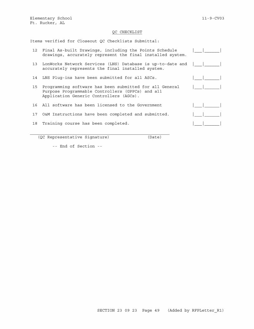
Elementary School 11-9-CV03Ft. Rucker, AL
QC CHECKLIST
Items verified for Closeout QC Checklists Submittal: 12 Final As-built Drawings, including the Points Schedule |___|______| drawings, accurately represent the final installed system.
13 LonWorks Network Services (LNS) Database is up-to-date and |___|______| accurately represents the final installed system. 14 LNS Plug-ins have been submitted for all ASCs. |___|______|
15 Programming software has been submitted for all General |___|______| Purpose Programmable Controllers (GPPCs) and all Application Generic Controllers (AGCs).
16 All software has been licensed to the Government |___|______|
17 O&M Instructions have been completed and submitted. |___|______| 18 Training course has been completed. |___|______|
________________________________________________________ (QC Representative Signature) (Date)
-- End of Section --
SECTION 23 09 23 Page 49 (Added by RFPLetter_R1)
Elementary School 11-9-CV03Ft. Rucker, AL
SECTION TABLE OF CONTENTS
DIVISION 23 - HEATING, VENTILATING, AND AIR CONDITIONING
SECTION 23 11 25
FACILITY GAS PIPING
11/08
PART 1 GENERAL
1.1 SUMMARY 1.2 REFERENCES 1.3 SYSTEM DESCRIPTION 1.3.1 Gas Facility System and Equipment Operation 1.3.2 Gas Facility System Maintenance 1.3.3 Gas Facility Equipment Maintenance 1.4 SUBMITTALS 1.5 QUALITY ASSURANCE 1.5.1 Welding Qualifications 1.5.2 Jointing Thermoplastic and Fiberglass Piping 1.5.3 Shop Drawings
PART 2 PRODUCTS
2.1 MATERIALS AND EQUIPMENT 2.2 GAS PIPING SYSTEM AND FITTINGS 2.2.1 Steel Pipe, Joints, and Fittings 2.2.2 Sealants for Steel Pipe Threaded Joints 2.2.3 Warning and Identification 2.2.4 Flange Gaskets 2.2.5 Pipe Threads 2.2.6 Escutcheons 2.2.7 Insulating Pipe Joints 2.2.7.1 Insulating Joint Material 2.2.7.2 Threaded Pipe Joints 2.2.8 Flexible Connectors 2.3 VALVES 2.3.1 Valves 2 Inches and Smaller 2.4 PIPE HANGERS AND SUPPORTS 2.5 REGULATORS AND SHUTOFF VALVES 2.6 AUTOMATIC GAS SHUT-OFF 2.7 BOLTING (BOLTS AND NUTS) 2.8 GASKETS 2.9 IDENTIFICATION FOR ABOVEGROUND PIPING
PART 3 EXECUTION
3.1 EXAMINATION 3.2 EXCAVATION AND BACKFILLING 3.3 GAS PIPING SYSTEM 3.3.1 Protection and Cleaning of Materials and Components 3.3.2 Workmanship and Defects 3.4 PROTECTIVE COVERING 3.4.1 Underground Metallic Pipe
SECTION 23 11 25 Page 1 (Added by RFPLetter_R1)
Elementary School 11-9-CV03Ft. Rucker, AL
3.4.2 Aboveground Metallic Piping Systems 3.4.2.1 Ferrous Surfaces 3.4.2.2 Nonferrous Surfaces 3.5 INSTALLATION 3.5.1 Metallic Piping Installation 3.5.2 Metallic Tubing Installation 3.5.3 Piping and Tubing Buried Under Buildings 3.5.4 Concealed Piping in Buildings 3.5.4.1 Piping and Tubing in Partitions 3.5.5 Aboveground Piping 3.5.6 Final Gas Connections 3.6 PIPE JOINTS 3.6.1 Threaded Metallic Joints 3.6.2 Welded Metallic Joints 3.6.3 Flared Metallic Tubing Joints 3.6.4 Solder or Brazed Joints 3.7 PIPE SLEEVES 3.8 PIPES PENETRATING WATERPROOFING MEMBRANES 3.9 FIRE SEAL 3.10 ESCUTCHEONS 3.11 SPECIAL REQUIREMENTS 3.12 BUILDING STRUCTURE 3.13 PIPING SYSTEM SUPPORTS 3.14 ELECTRICAL BONDING AND GROUNDING 3.15 SHUTOFF VALVE 3.16 PRESSURE REGULATOR 3.17 TESTING 3.17.1 Pressure Tests 3.17.2 Pressure Tests for Liquified Petroleum Gas 3.17.3 Test With Gas 3.17.4 Purging 3.17.5 Labor, Materials and Equipment 3.18 PIPE COLOR CODE MARKING
ATTACHMENTS:
CSA US 3-92 IAS U.S. Requirements 3-92 for Excess Flow Valves
-- End of Section Table of Contents --
SECTION 23 11 25 Page 2 (Added by RFPLetter_R1)
Elementary School 11-9-CV03Ft. Rucker, AL
SECTION 23 11 25
FACILITY GAS PIPING11/08
PART 1 GENERAL
1.1 SUMMARY
This specification section applies to incidental underground piping under building, above ground steel piping and corrugated stainless steel tubing (CSST) both outside (up to 5 feet beyond exterior walls) and within buildings in compliance with NFPA 54/AGA Z223.1NFPA 58, "Fuel Gas Piping".
1.2 REFERENCES
The publications listed below form a part of this specification to the extent referenced. The publications are referred to within the text by the basic designation only.
AMERICAN GAS ASSOCIATION (AGA)
AGA XR0603 (2006; 8th Ed) AGA Plastic Pipe Manual for Gas Service
AGA Z223.1 (2012) National Fuel Gas Code
AMERICAN NATIONAL STANDARDS INSTITUTE (ANSI)
ANSI Z21.1 (2010; Addenda A 2011; Addenda B 2012) Household Cooking Gas Appliances
ANSI Z21.15/CSA 9.1 (2009; Addenda A 2012) Manually Operated Gas Valves for Appliances, Appliance Connector Valves and Hose End Valves
ANSI Z21.18/CSA 6.3 (2007; Addenda A 2010; Addenda B 2012; R 2013) Gas Appliance Pressure Regulators
ANSI Z21.21/CSA 6.5 (2005; Addenda A 2010; Addenda B 2011) Automatic Valves for Gas Appliances
ANSI Z21.24/CSA 6.10 (2006; R 2011) Connectors for Gas Appliances
ANSI Z21.41/CSA 6.9 (2014) Quick-Disconnect Devices for Use with Gas Fuel Appliances
ANSI Z21.69/CSA 6.16 (2009; Addenda A 2012; R 2014) Connectors for Movable Gas Appliances
ANSI Z21.80/CSA 6.22 (2011; Addenda A 2012) Line Pressure Regulators
SECTION 23 11 25 Page 3 (Added by RFPLetter_R1)
Elementary School 11-9-CV03Ft. Rucker, AL
AMERICAN PETROLEUM INSTITUTE (API)
API RP 1110 (2013) Pressure Testing of Steel Pipelines for the Transportation of Gas, Petroleum Gas, Hazardous Liquids, Highly Volatile Liquids or Carbon Dioxide
API RP 2003 (2008; 7th Ed) Protection Against Ignitions Arising out of Static, Lightning, and Stray Currents
API RP 2009 (2002; R 2007; 7th Ed) Safe Welding, Cutting, and Hot Work Practices in Refineries, Gasoline Plants, and Petrochemical Plants
API Std 598 (2009) Valve Inspecting and Testing
API Std 607 (2010) Testing of Valves: Fire Test for Soft-Seated Quarter-Turn Valves
ASME INTERNATIONAL (ASME)
ASME A13.1 (2007; R 2013) Scheme for the Identification of Piping Systems
ASME B1.1 (2003; R 2008) Unified Inch Screw Threads (UN and UNR Thread Form)
ASME B1.20.1 (2013) Pipe Threads, General Purpose (Inch)
ASME B16.1 (2010) Gray Iron Pipe Flanges and Flanged Fittings Classes 25, 125, and 250
ASME B16.11 (2011) Forged Fittings, Socket-Welding and Threaded
ASME B16.21 (2011) Nonmetallic Flat Gaskets for Pipe Flanges
ASME B16.3 (2011) Malleable Iron Threaded Fittings, Classes 150 and 300
ASME B16.33 (2012) Manually Operated Metallic Gas Valves for Use in Gas Piping Systems Up to 125 psi, Sizes NPS 1/2 - NPS 2
ASME B16.39 (2009) Standard for Malleable Iron Threaded Pipe Unions; Classes 150, 250, and 300
ASME B16.5 (2013) Pipe Flanges and Flanged Fittings: NPS 1/2 Through NPS 24 Metric/Inch Standard
ASME B16.9 (2012) Standard for Factory-Made Wrought Steel Buttwelding Fittings
ASME B18.2.1 (2012; Errata 2013) Square and Hex Bolts and Screws (Inch Series)
SECTION 23 11 25 Page 4 (Added by RFPLetter_R1)
Elementary School 11-9-CV03Ft. Rucker, AL
ASME B18.2.2 (2010) Nuts for General Applications: Machine Screw Nuts, Hex, Square, Hex Flange, and Coupling Nuts (Inch Series)
ASME B31.9 (2011) Building Services Piping
ASME B36.10M (2004; R 2010) Standard for Welded and Seamless Wrought Steel Pipe
ASME BPVC SEC IX (2010) BPVC Section IX-Welding and Brazing Qualifications
ASME BPVC SEC VIII D1 (2010) BPVC Section VIII-Rules for Construction of Pressure Vessels Division 1
ASTM INTERNATIONAL (ASTM)
ASTM A105/A105M (2014) Standard Specification for Carbon Steel Forgings for Piping Applications
ASTM A193/A193M (2014) Standard Specification for Alloy-Steel and Stainless Steel Bolting Materials for High-Temperature Service and Other Special Purpose Applications
ASTM A194/A194M (2014) Standard Specification for Carbon and Alloy Steel Nuts for Bolts for High-Pressure or High-Temperature Service, or Both
ASTM A53/A53M (2012) Standard Specification for Pipe, Steel, Black and Hot-Dipped, Zinc-Coated, Welded and Seamless
CSA GROUP (CSA)
CSA/AM CSA/ANSI LC 1 (2005; Addenda 1B 2011) Fuel Gas Piping Systems Using Corrugated Stainless Steel Tubing (CSST)
MANUFACTURERS STANDARDIZATION SOCIETY OF THE VALVE AND FITTINGS INDUSTRY (MSS)
MSS SP-25 (2013) Standard Marking System for Valves, Fittings, Flanges and Unions
MSS SP-58 (2009) Pipe Hangers and Supports - Materials, Design and Manufacture, Selection, Application, and Installation
MSS SP-69 (2003; Notice 2012) Pipe Hangers and Supports - Selection and Application (ANSI Approved American National Standard)
NATIONAL FIRE PROTECTION ASSOCIATION (NFPA)
NFPA 54 (2015) National Fuel Gas Code
SECTION 23 11 25 Page 5 (Added by RFPLetter_R1)
Elementary School 11-9-CV03Ft. Rucker, AL
NFPA 58 (2014; TIA 13-1; TIA 13-2; Errata 13-1; TIA 13-3; Errata 14-2) Liquefied Petroleum Gas Code
NFPA 70 (2014; AMD 1 2013; Errata 1 2013; AMD 2 2013; Errata 2 2013; AMD 3 2014; Errata 3-4 2014; AMD 4-6 2014) National Electrical Code
SOCIETY FOR PROTECTIVE COATINGS (SSPC)
SSPC SP 6/NACE No.3 (2007) Commercial Blast Cleaning
U.S. DEPARTMENT OF DEFENSE (DOD)
MIL-STD-101 (2014; Rev C) Color Code for Pipelines and for Compressed Gas Cylinders
UNDERWRITERS LABORATORIES (UL)
UL FLAMMABLE & COMBUSTIBLE (2012) Flammable and Combustible Liquids and Gases Equipment Directory
1.3 SYSTEM DESCRIPTION
The gas piping system includes natural gas piping and appurtenances from point of connection with supply system, as indicated, to gas operated equipment within the facility. Submit operation and maintenance data in accordance with Section 01 78 23 OPERATION AND MAINTENANCE DATA, in three separate packages. Section 23 00 00 BASIC MECHANICAL MATERIALS AND METHODS applies to this section, with additions and modifications specified herein. Provide cathodically protected insulating joints connecting aboveground piping from the meter to the building, with lightning arrestors conforming to API RP 2003, installed where indicated.
1.3.1 Gas Facility System and Equipment Operation
Include shop drawings showing piping layout, locations of system valves, gas line markers and cathodic protection system; step-by-step procedures for system start up, operation and shutdown (index system components and equipment to the system drawings); isolation procedures including valve operation to shutdown or isolate each section of the system (index valves to the system maps and provide separate procedures for normal operation and emergency shutdown if required to be different). Submit Data package No. 4.
1.3.2 Gas Facility System Maintenance
Include maintenance procedures and frequency for system and equipment; identification of pipe materials and manufacturer by locations, pipe repair procedures, and jointing procedures at transitions to other piping material or material from a different manufacturer. Submit Data Package No.4.
1.3.3 Gas Facility Equipment Maintenance
Include identification of valves, shut-offs, disconnects, and other equipment by materials, manufacturer, vendor identification and location; maintenance procedures and recommended tool kits for valves and equipment; recommended repair methods (i.e., field repair, factory repair, or replacement) for each valve and piece of equipment; and preventive
SECTION 23 11 25 Page 6 (Added by RFPLetter_R1)
Elementary School 11-9-CV03Ft. Rucker, AL
maintenance procedures, possible failure modes and troubleshooting guide. Submit Data Package No. 3.
1.4 SUBMITTALS
Government approval is required for submittals with a "G" designation; submittals not having a "G" designation are for information only. When used, a designation following the "G" designation identifies the office that will review the submittal for the Government. Submit the following in accordance with Section 01 33 00 SUBMITTAL PROCEDURES:
SD-02 Shop Drawings
Gas Piping System; G
SD-03 Product Data
Gas equipment connectors; G
Gas Piping System; GPipe Coating Materials; GPressure regulators; G
Valves; GWarning and identification tape; G
SD-06 Test Reports
Testing; GPressure Tests; GPressure Tests for Liquified Petroleum Gas;GTest With Gas; G
SD-07 Certificates
Welders procedures and qualifications; Gassigned number, letter, or symbol; G
SD-08 Manufacturer's Instructions
PE pipe and fittings; Gpipe coating materials; G
SD-10 Operation and Maintenance Data
Gas facility system and equipment operation; GGas facility system maintenance; GGas facility equipment maintenance; G
1.5 QUALITY ASSURANCE
Submit manufacturer's descriptive data and installation instructions for approval for compression-type mechanical joints used in joining dissimilar materials and for insulating joints. Mark all valves, flanges and fittings in accordance with MSS SP-25.
SECTION 23 11 25 Page 7 (Added by RFPLetter_R1)
Elementary School 11-9-CV03Ft. Rucker, AL
1.5.1 Welding Qualifications
a. Weld piping in accordance with qualified procedures using performance qualified welders and welding operators in accordance with API RP 2009, ASME BPVC SEC IX, and ASME B31.9. Welding procedures qualified by others, and welders and welding operators qualified by another employer may be accepted as permitted by ASME B31.9. Notify the Contracting Officer at least 24 hours in advance of tests, and perform at the work site if practicable.
b. Submit a certified copy of welders procedures and qualifications metal and PE in conformance with ASME B31.9 for each welder and welding operator. Submit the assigned number, letter, or symbol that will be used in identifying the work of each welder to the Contracting Officer.
1.5.2 Jointing Thermoplastic and Fiberglass Piping
Perform all jointing of piping using qualified joiners and qualified procedures in accordance with AGA XR0603. Furnish the Contracting Officer with a copy of qualified procedures and list of and identification symbols of qualified joiners. Submit manufacturer's installation instructions and manufacturer's visual joint appearance chart, including all PE pipe and fittings.
1.5.3 Shop Drawings
Submit drawings for complete Gas Piping System, within 30 days of contract award, showing location, size and all branches of pipeline; location of all required shutoff valves; and instructions necessary for the installation of gas equipment connectors and supports. Include LP storage tank, pad, and mounting details.
PART 2 PRODUCTS
2.1 MATERIALS AND EQUIPMENT
Provide materials and equipment which are the standard products of a manufacturer regularly engaged in the manufacture of the products and that essentially duplicate items that have been in satisfactory use for at least 2 years prior to bid opening. Asbestos or products containing asbestos are not allowed. Submit catalog data and installation instructions for pipe, valves, all related system components, pipe coating materials and application procedures. Conform to NFPA 54NFPA 58 and with requirements specified herein. Provide supply piping to appliances or equipment at least as large as the inlets thereof.
2.2 GAS PIPING SYSTEM AND FITTINGS
2.2.1 Steel Pipe, Joints, and Fittings
a. Pipe: Black carbon steel in accordance with ASTM A53/A53M, Schedule 40 , threaded ends for sizes 2 inches and smaller; otherwise, plain end beveled for butt welding.
b. Threaded Fittings: ASME B16.3, black malleable iron.
c. Socket-Welding Fittings: ASME B16.11, forged steel.
d. Butt-Welding Fittings: ASME B16.9, with backing rings of
SECTION 23 11 25 Page 8 (Added by RFPLetter_R1)
Elementary School 11-9-CV03Ft. Rucker, AL
compatible material.
e. Unions: ASME B16.39, black malleable iron.
f. Flanges and Flanged Fittings: ASME B16.5 steel flanges or convoluted steel flanges conforming to ASME BPVC SEC VIII D1, with flange faces having integral grooves of rectangular cross sections which afford containment for self-energizing gasket material.
Provide steel pipe conforming to ASME B36.10M; and malleable-iron threaded fittings conforming to ASME B16.1 and ASME B16.3. Provide steel pipe flanges and flanged fittings, including bolts, nuts, and bolt pattern in accordance with ASME B16.5 and ASTM A105/A105M. Provide wrought steel buttwelding fittings conforming to ASME B16.9. Provide socket welding and threaded forged steel fittings conforming to ASME B16.11.
2.2.2 Sealants for Steel Pipe Threaded Joints
Provide joint sealing compound as listed in UL FLAMMABLE & COMBUSTIBLE, Class 20 or less. For taping, use tetrafluoroethylene tape conforming to UL FLAMMABLE & COMBUSTIBLE.
2.2.3 Warning and Identification
Provide pipe flow markings, warning and identification tape, and metal tags as required.
2.2.4 Flange Gaskets
Provide gaskets of nonasbestos compressed material in accordance with ASME B16.21, 1/16 inch thickness, full face or self-centering flat ring type, containing aramid fibers bonded with styrene butadiene rubber (SBR) or nitrile butadiene rubber (NBR) suitable for a maximum 600 degree F service, to be used for hydrocarbon service.
2.2.5 Pipe Threads
Provide pipe threads conforming to ASME B1.20.1.
2.2.6 Escutcheons
Provide chromium-plated steel or chromium-plated brass escutcheons, either one piece or split pattern, held in place by internal spring tension or set screw.
2.2.7 Insulating Pipe Joints
2.2.7.1 Insulating Joint Material
Provide insulating joint material between flanged or threaded metallic pipe systems where shown to control galvanic or electrical action.
2.2.7.2 Threaded Pipe Joints
Provide threaded pipe joints of steel body nut type dielectric unions with insulating gaskets.
SECTION 23 11 25 Page 9 (Added by RFPLetter_R1)
Elementary School 11-9-CV03Ft. Rucker, AL
2.2.8 Flexible Connectors
a. Provide flexible connectors for connecting gas utilization equipment to building gas piping conforming to ANSI Z21.24/CSA 6.10 or ANSI Z21.41/CSA 6.9 for quick disconnect devices, and flexible connectors for movable food service equipment conforming to ANSI Z21.69/CSA 6.16.
b. Do not install the flexible connector through the appliance cabinet face. Provide rigid metallic pipe and fittings to extend the final connection beyond the cabinet, except when appliance is provided with an external connection point.
2.3 VALVES
Provide lockable shutoff or service isolation valves as indicated in the drawings conforming to the following:
2.3.1 Valves 2 Inches and Smaller
Provide valves 2 inches and smaller conforming to ASME B16.33 of materials and manufacture compatible with system materials used. Provide manually operated household cooking gas appliance valves conforming to ANSI Z21.1 and ANSI Z21.15/CSA 9.1.
2.4 PIPE HANGERS AND SUPPORTS
Provide pipe hangers and supports conforming to MSS SP-58 and MSS SP-69.
2.5 REGULATORS AND SHUTOFF VALVES
Provide regulators conforming to ANSI Z21.18/CSA 6.3 for appliances , and ANSI Z21.80/CSA 6.22 for line pressure regulators. Provide shutoff valves conforming to ANSI Z21.15/CSA 9.1 for manually controlled gas shutoff valves and ANSI Z21.21/CSA 6.5 for automatic shutoff valves for gas appliances.
2.6 AUTOMATIC GAS SHUT-OFF
Provide low pressure automatic gas shutoff or excess flow valve (EFV) downstream of the point of delivery after the meter/regulator conforming to CSA US 3-92 IAS U.S. Requirements 3-92 for Excess Flow Valves and UL listed or CSA listed or International Association of Plumbing and Mechanical Officials (IAPMO) listed. The EFV may be either a bypass (automatic reset) or a non-bypass type (manual reset).Provide low pressure automatic gas shutoff or excess flow valve (EFV) at each branch to an appliance.
2.7 BOLTING (BOLTS AND NUTS)
Stainless steel bolting; ASTM A193/A193M, Grade B8M or B8MA, Type 316, for bolts; and ASTM A194/A194M, Grade 8M, Type 316, for nuts. Dimensions of bolts, studs, and nuts shall conform with ASME B18.2.1 and ASME B18.2.2 with coarse threads conforming to ASME B1.1, with Class 2A fit for bolts and studs and Class 2B fit for nuts. Bolts or bolt-studs shall extend through the nuts and may have reduced shanks of a diameter not less than the diameter at root of threads. Bolts shall have American Standard regular square or heavy hexagon heads; nuts shall be American Standard heavy semifinished hexagonal.
SECTION 23 11 25 Page 10 (Added by RFPLetter_R1)
Elementary School 11-9-CV03Ft. Rucker, AL
2.8 GASKETS
Fluorinated elastomer, compatible with flange faces.
2.9 IDENTIFICATION FOR ABOVEGROUND PIPING
MIL-STD-101 for legends and type and size of characters. For pipes 3/4 inch od and larger, provide printed legends to identify contents of pipes and arrows to show direction of flow. Color code label backgrounds to signify levels of hazard. Make labels of plastic sheet with pressure-sensitive adhesive suitable for the intended application. For pipes smaller than 3/4 inch od, provide brass identification tags 1 1/2 inches in diameter with legends in depressed black-filled characters.
PART 3 EXECUTION
3.1 EXAMINATION
After becoming familiar with all details of the work, verify all dimensions in the field, and advise the Contracting Officer of any discrepancy or areas of conflict before performing the work.
3.2 EXCAVATION AND BACKFILLING
Provide required excavation, backfilling, and compaction as specified in Section 31 00 00 EARTHWORK.
3.3 GAS PIPING SYSTEM
Provide a natural gas piping system from the point of delivery, defined as the outlet of the service regulator to the connections to each gas utilization device.
3.3.1 Protection and Cleaning of Materials and Components
Protect equipment, pipe, and tube openings by closing with caps or plugs during installation. At the completion of all work, thoroughly clean the entire system.
3.3.2 Workmanship and Defects
Piping, tubing and fittings shall be clear and free of cutting burrs and defects in structure or threading and shall be thoroughly brushed and chip-and scale-blown. Repair of defects in piping, tubing or fittings is not allowed; replace defective items when found.
3.4 PROTECTIVE COVERING
3.4.1 Underground Metallic Pipe
Protect buried metallic piping and tubing from corrosion by either: (1) applying protective coatings as specified; (2) encasement in a water tight plastic conduit; or (3) encasement in a protective system designed and listed by the manufacturer for this application. When dissimilar metals are joined underground, use gastight insulating fittings.
SECTION 23 11 25 Page 11 (Added by RFPLetter_R1)
Elementary School 11-9-CV03Ft. Rucker, AL
3.4.2 Aboveground Metallic Piping Systems
3.4.2.1 Ferrous Surfaces
Touch up shop primed surfaces with ferrous metal primer. Solvent clean surfaces that have not been shop primed . Mechanically clean surfaces that contain loose rust, loose mill scale and other foreign substances by power wire brushing or commercial sand blasted conforming to SSPC SP 6/NACE No.3 and prime with ferrous metal primer . Finish primed surfaces with two coats of exterior oil paint .
3.4.2.2 Nonferrous Surfaces
Except for aluminum alloy pipe, do not paint nonferrous surfaces. Paint surfaces of aluminum alloy pipe and fittings to protect against external corrosion where they contact masonry, plaster, insulation, or are subject to repeated wettings by such liquids as water, detergents or sewage. Solvent-clean the surfaces and treat with vinyl type wash coat. Apply a first coat of aluminum paint and a second coat of alkyd gloss enamel or silicone alkyd copolymer enamel.
3.5 INSTALLATION
Install the gas system in conformance with the manufacturer's recommendations and applicable provisions of NFPA 54NFPA 58 and AGA XR0603, and as indicated. Perform all pipe cutting without damage to the pipe, with an approved type of mechanical cutter, unless otherwise authorized. Use wheel cutters where practicable. On steel pipe 6 inches and larger, an approved gas cutting and beveling machine may be used. Cut thermoplastic and fiberglass pipe in accordance with AGA XR0603.
3.5.1 Metallic Piping Installation
Bury underground piping a minimum of 18 inches below grade. Make changes in direction of piping with fittings only; mitering or notching pipe to form elbows and tees or other similar type construction is not permitted. Branch connection may be made with either tees or forged branch outlet fittings. Provide branch outlet fittings which are forged, flared for improvement of flow where attached to the run, and reinforced against external strains. Do not use aluminum alloy pipe in exterior locations or underground.
3.5.2 Metallic Tubing Installation
Install metallic tubing using gas tubing fittings approved by the tubing manufacturer. CSST gas piping systems shall be installed by contractors who have completed the manufacturer's training program as indicated on a certification card. Make branch connections with tees. Prepare all tubing ends with tools designed for that purpose. Do not use aluminum alloy tubing in exterior locations or underground.
3.5.3 Piping and Tubing Buried Under Buildings
Run underground piping and tubing installed beneath buildings in a steel pipe casing protected from corrosion with protective coatings as specified or installed within a water tight plastic conduit or as part of a listed encasement system. Extend casing or encasement system at least 4 inches outside the building, and provide the pipe with spacers and end bushings to seal at both ends to prevent the entrance of water and/or the escape of
SECTION 23 11 25 Page 12 (Added by RFPLetter_R1)
Elementary School 11-9-CV03Ft. Rucker, AL
gas. Extend a vent line from the annular space above grade outside to a point where gas will not be a hazard, and terminate in a rain/insect-resistant fitting.
3.5.4 Concealed Piping in Buildings
Do not use combinations of fittings ( unions, tubing fittings, running threads, right- and left-hand couplings, bushings, and swing joints) to conceal piping within buildings.
3.5.4.1 Piping and Tubing in Partitions
Locate concealed piping and tubing in hollow, rather than solid, partitions. Protect tubing passing through walls or partitions against physical damage both during and after construction, and provide appropriate safety markings and labels. Provide protection of concealed pipe and tubing in accordance with CSA/AM CSA/ANSI LC 1.
3.5.5 Aboveground Piping
Run aboveground piping as straight as practicable along the alignment and elevation indicated, with a minimum of joints, and separately supported from other piping system and equipment. Install exposed horizontal piping no farther than 6 inches from nearest parallel wall and at an elevation which prevents standing, sitting, or placement of objects on the piping.
3.5.6 Final Gas Connections
Unless otherwise specified, make final connections with rigid metallic pipe and fittings. Make final connections to kitchen ranges using flexible connectors not less than 40 inch long, to afford access to coupling and to permit movement of equipment for cleaning. Flexible connectors may be used for final connections to gas utilization equipment. In addition to cautions listed in instructions required by ANSI standards for flexible connectors, insure that flexible connectors do not pass through equipment cabinet. Provide accessible gas shutoff valve and coupling for each gas equipment item.
3.6 PIPE JOINTS
Design and install pipe joints to effectively sustain the longitudinal pull-out forces caused by contraction of the piping or superimposed loads.
3.6.1 Threaded Metallic Joints
Provide threaded joints in metallic pipe with tapered threads evenly cut and made with UL approved graphite joint sealing compound for gas service or tetrafluoroethylene tape applied to the male threads only. Threaded joints up to 1-1/2 inches in diameter may be made with approved tetrafluoroethylene tape. Threaded joints up to 2 inches in diameter may be made with approved joint sealing compound. After cutting and before threading, ream pipe and remove all burrs. Caulking of threaded joints to stop or prevent leaks is not permitted.
3.6.2 Welded Metallic Joints
Conform beveling, alignment, heat treatment, and inspection of welds to NFPA 54. Remove weld defects and make repairs to the weld, or remove the weld joints entirely and reweld. After filler metal has been removed from
SECTION 23 11 25 Page 13 (Added by RFPLetter_R1)
Elementary School 11-9-CV03Ft. Rucker, AL
its original package, protect and store so that its characteristics or welding properties are not affected adversely. Do not use electrodes that have been wetted or have lost any of their coating.
3.6.3 Flared Metallic Tubing Joints
Make flared joints in metallic tubing with special tools recommended by the tubing manufacturer. Use flared joints only in systems constructed from nonferrous pipe and tubing, when experience or tests have demonstrated that the joint is suitable for the conditions, and when adequate provisions are made in the design to prevent separation of the joints. Do not use metallic ball sleeve compression-type tubing fittings for tubing joints.
3.6.4 Solder or Brazed Joints
Make all joints in metallic tubing and fittings with materials and procedures recommended by the tubing supplier. Braze joints with material having a melting point above 1000 degrees F, containing no phosphorous.
3.7 PIPE SLEEVES
Provide pipes passing through concrete or masonry walls or concrete floors or roofs with pipe sleeves fitted into place at the time of construction. Do not install sleeves in structural members except where indicated or approved. Make all rectangular and square openings as detailed. Extend each sleeve through its respective wall, floor or roof, and cut flush with each surface, except in mechanical room floors not located on grade where clamping flanges or riser pipe clamps are used. Extend sleeves in mechanical room floors above grade at least 4 inches above finish floor. Unless otherwise indicated, use sleeves large enough to provide a minimum clearance of 1/4 inch all around the pipe. Provide steel pipe for sleeves in bearing walls, waterproofing membrane floors, and wet areas . Provide sleeves in nonbearing walls, floors, or ceilings of steel pipe, galvanized sheet metal with lock-type longitudinal seam, or moisture-resistant fiber or plastic. For penetrations of fire walls, fire partitions and floors which are not on grade, seal the annular space between the pipe and sleeve with fire-stopping material and sealant that meet the requirement of Section 07 84 00 FIRESTOPPINGG.
3.8 PIPES PENETRATING WATERPROOFING MEMBRANES
Install pipes penetrating waterproofing membranes as specified in Section 22 00 00 PLUMBING, GENERAL PURPOSE.
3.9 FIRE SEAL
Fire seal all penetrations of fire rated partitions, walls and floors in accordance with Section 07 84 00 FIRESTOPPING.
3.10 ESCUTCHEONS
Provide escutcheons for all finished surfaces where gas piping passes through floors, walls, or ceilings except in boiler, utility, or equipment rooms.
3.11 SPECIAL REQUIREMENTS
Provide drips, grading of the lines, freeze protection, and branch outlet locations as shown and conforming to the requirements of NFPA 54NFPA 58.
SECTION 23 11 25 Page 14 (Added by RFPLetter_R1)
Elementary School 11-9-CV03Ft. Rucker, AL
3.12 BUILDING STRUCTURE
Do not weaken any building structure by the installation of any gas piping. Do not cut or notch beams, joists or columns. Attach piping supports to metal decking. Do not attach supports to the underside of concrete filled floors or concrete roof decks unless approved by the Contracting Officer.
3.13 PIPING SYSTEM SUPPORTS
Support gas piping systems in buildings with pipe hooks, metal pipe straps, bands or hangers suitable for the size of piping or tubing. Do not support any gas piping system by other piping. Conform spacing of supports in gas piping and tubing installations to the requirements of NFPA 54NFPA 58. Conform the selection and application of supports in gas piping and tubing installations to the requirements of MSS SP-69. In the support of multiple pipe runs on a common base member, use a clip or clamp where each pipe crosses the base support member. Spacing of the base support members is not to exceed the hanger and support spacing required for any of the individual pipes in the multiple pipe run. Rigidly connect the clips or clamps to the common base member. Provide a clearance of 1/8 inch between the pipe and clip or clamp for all piping which may be subjected to thermal expansion.
3.14 ELECTRICAL BONDING AND GROUNDING
Provide a gas piping system within the building which is electrically continuous and bonded to a grounding electrode as required by NFPA 70.
3.15 SHUTOFF VALVE
Install the main gas shutoff valve controlling the gas piping system to be easily accessible for operation, as indicated, protected from physical damage, and marked with a metal tag to clearly identify the piping system controlled. Install valves approximately at locations indicated. Orient stems vertically, with operators on top, or horizontally. Provide PE piping manufacturer bracket support assembly securely fastened to structure for valve connections to resist operating torque applied to PE pipes. Provide stop valve on service branch at connection to main and shut-off valve on riser outside of building.
3.16 PRESSURE REGULATOR
Provide plug cock ahead of regulator. Install regulator outside of building and 18 inches aboveground on riser. On outlet side of regulator , provide a union and a 3/8 inch gage tap with plug.
3.17 TESTING
Submit test procedures and reports in booklet form tabulating test and measurements performed; dated after award of this contract, and stating the Contractor's name and address, the project name and location, and a list of the specific requirements which are being certified. Test entire gas piping system to ensure that it is gastight prior to putting into service. Prior to testing, purge the system, clean, and clear all foreign material. Test each joint with an approved gas detector, soap and water, or an equivalent nonflammable solution. Inspect and test each valve in conformance with API Std 598 and API Std 607. Complete testing before any
SECTION 23 11 25 Page 15 (Added by RFPLetter_R1)
Elementary School 11-9-CV03Ft. Rucker, AL
work is covered, enclosed, or concealed, and perform with due regard for the safety of employees and the public during the test. Install bulkheads, anchorage and bracing suitably designed to resist test pressures if necessary, and as directed and or approved by the Contracting Officer. Do not use oxygen as a testing medium.
3.17.1 Pressure Tests
Submit test procedures and reports in booklet form tabulating test and measurements performed; dated after award of this contract, and stating the Contractor's name and address, the project name and location, and a list of the specific requirements which are being certified. Before appliances are connected, test by filling the piping systems with air or an inert gas to withstand a minimum pressure of 3 pounds gauge for a period of not less than 10 minutes as specified in NFPA 54as specified in NFPA 58 without showing any drop in pressure. Do not use Oxygen for test. Measure pressure with a mercury manometer, slope gauge, or an equivalent device calibrated to be read in increments of not greater than 0.1 pound. Isolate the source of pressure before the pressure tests are made.
3.17.2 Pressure Tests for Liquified Petroleum Gas
Pressure test system as described above. When appliances are connected to the piping system, use fuel gas for testing appliances to withstand a pressure of not less than 10.0 inches nor more than 14.0 inches water column ( 0.36 nor more than 0.51 pounds per square inch) for a period of not less than 10 minutes without showing any drop in pressure. Measure pressure with a water manometer or an equivalent device calibrated to be read in increments of not greater than 0.1 inch water column. Isolate the source of pressure before the pressure tests are made.
3.17.3 Test With Gas
Before turning on gas under pressure into any piping, close all openings from which gas can escape. Immediately after turning on the gas, check the piping system for leakage by using a laboratory-certified gas meter, an appliance orifice, a manometer, or equivalent device. Conform all testing to the requirements of NFPA 54NFPA 58. If leakage is recorded, shut off the gas supply, repair the leak , and repeat the tests until all leaks have been stopped.
3.17.4 Purging
After testing is completed, and before connecting any appliances, fully purge all gas piping. LPG piping tested using fuel gas with appliances connected does not require purging. Conform testing procedures to API RP 1110. Do not purge piping into the combustion chamber of an appliance. Do not purge the open end of piping systems into confined spaces or areas where there are ignition sources unless the safety precautions recommended in NFPA 54NFPA 58 are followed.
3.17.5 Labor, Materials and Equipment
Furnish all labor, materials and equipment necessary for conducting the testing and purging.
3.18 PIPE COLOR CODE MARKING
Provide color code marking of piping as specified in Section 09 90 00
SECTION 23 11 25 Page 16 (Added by RFPLetter_R1)

Elementary School 11-9-CV03Ft. Rucker, AL
PAINTS AND COATINGS, conforming to ASME A13.1.
-- End of Section --
SECTION 23 11 25 Page 17 (Added by RFPLetter_R1)
Elementary School 11-9-CV03Ft. Rucker, AL
SECTION TABLE OF CONTENTS
DIVISION 23 - HEATING, VENTILATING, AND AIR CONDITIONING
SECTION 23 23 00
REFRIGERANT PIPING
10/07
PART 1 GENERAL
1.1 REFERENCES 1.2 SUBMITTALS 1.3 QUALITY ASSURANCE 1.3.1 Qualifications 1.3.2 Contract Drawings 1.4 DELIVERY, STORAGE, AND HANDLING 1.5 MAINTENANCE 1.5.1 General 1.5.2 Extra Materials
PART 2 PRODUCTS
2.1 STANDARD COMMERCIAL PRODUCTS 2.2 ELECTRICAL WORK 2.3 REFRIGERANT PIPING SYSTEM 2.4 PIPE, FITTINGS AND END CONNECTIONS (JOINTS) 2.4.1 Copper Tubing 2.4.2 Solder 2.4.3 Brazing Filler Metal 2.5 VALVES 2.5.1 Refrigerant Stop Valves 2.5.2 Check Valves 2.5.3 Liquid Solenoid Valves 2.5.4 Expansion Valves 2.5.5 Safety Relief Valves 2.5.6 Evaporator Pressure Regulators, Direct-Acting 2.5.7 Refrigerant Access Valves 2.6 PIPING ACCESSORIES 2.6.1 Filter Driers 2.6.2 Sight Glass and Liquid Level Indicator 2.6.2.1 Assembly and Components 2.6.2.2 Gauge Glass 2.6.2.3 Bull's-Eye and Inline Sight Glass Reflex Lens 2.6.2.4 Moisture Indicator 2.6.3 Vibration Dampeners 2.6.4 Flexible Pipe Connectors 2.6.5 Strainers 2.6.6 Pressure and Vacuum Gauges 2.6.7 Pipe Hangers, Inserts, and Supports 2.6.8 Escutcheons 2.7 FABRICATION 2.7.1 Factory Coating
PART 3 EXECUTION
SECTION 23 23 00 Page 1 (Added by RFPLetter_R1)
Elementary School 11-9-CV03Ft. Rucker, AL
3.1 EXAMINATION 3.2 INSTALLATION 3.2.1 Directional Changes 3.2.2 Functional Requirements 3.2.3 Fittings and End Connections 3.2.3.1 Threaded Connections 3.2.3.2 Brazed Connections 3.2.3.3 Welded Connections 3.2.3.4 Flared Connections 3.2.3.5 Flanged Connections 3.2.4 Valves 3.2.4.1 General 3.2.4.2 Expansion Valves 3.2.4.3 Valve Identification 3.2.5 Vibration Dampers 3.2.6 Strainers 3.2.7 Filter Dryer 3.2.8 Sight Glass 3.2.9 Discharge Line Oil Separator 3.2.10 Accumulator 3.2.11 Flexible Pipe Connectors 3.2.12 Pipe Hangers, Inserts, and Supports 3.2.12.1 Hangers 3.2.12.2 Inserts 3.2.12.3 C-Clamps 3.2.12.4 Angle Attachments 3.2.12.5 Saddles and Shields 3.2.12.6 Horizontal Pipe Supports 3.2.12.7 Vertical Pipe Supports 3.2.12.8 Pipe Guides 3.2.12.9 Steel Slides 3.2.12.10 High Temperature Guides with Cradles 3.2.12.11 Multiple Pipe Runs 3.2.12.12 Structural Attachments 3.2.13 Pipe Alignment Guides 3.2.14 Pipe Anchors 3.2.15 Building Surface Penetrations 3.2.15.1 General Service Areas 3.2.15.2 Waterproof Penetrations 3.2.15.3 Fire-Rated Penetrations 3.2.15.4 Escutcheons 3.2.16 Access Panels 3.2.17 Field Applied Insulation 3.2.18 Field Painting 3.2.18.1 Color Coding 3.2.19 Identification Tags 3.3 CLEANING AND ADJUSTING 3.4 TRAINING COURSE 3.5 REFRIGERANT PIPING TESTS 3.5.1 Preliminary Procedures 3.5.2 Pneumatic Test 3.5.3 Evacuation Test 3.5.4 System Charging and Startup Test 3.5.5 Refrigerant Leakage 3.5.6 Contractor's Responsibility
-- End of Section Table of Contents --
SECTION 23 23 00 Page 2 (Added by RFPLetter_R1)
Elementary School 11-9-CV03Ft. Rucker, AL
SECTION 23 23 00
REFRIGERANT PIPING10/07
PART 1 GENERAL
1.1 REFERENCES
The publications listed below form a part of this specification to the extent referenced. The publications are referred to within the text by the basic designation only.
AIR-CONDITIONING, HEATING AND REFRIGERATION INSTITUTE (AHRI)
AHRI 710 I-P (2009) Performance Rating of Liquid-Line Driers
AHRI 720 (2002) Refrigerant Access Valves and Hose Connectors
ANSI/AHRI 750 (2007) Thermostatic Refrigerant Expansion Valves
ANSI/AHRI 760 (2007) Performance Rating of Solenoid Valves for Use With Volatile Refrigerants
AMERICAN SOCIETY OF HEATING, REFRIGERATING AND AIR-CONDITIONING ENGINEERS (ASHRAE)
ANSI/ASHRAE 15 & 34 (2010; Addenda A, B, C, D, E, F, G, H, I, J, K, L, N and O; Errata 2011; INT 1 2012; Errata 2012; Addenda AD, SD, AE and AF 2013) ANSI/ASHRAE Standard 15-Safety Standard for Refrigeration Systems and ANSI/ASHRAE Standard 34-Designation and Safety Classification of Refrigerants
ASHRAE 17 (2008) Method of Testing Capacity of Thermostatic Refrigerant Expansion Valves
AMERICAN WELDING SOCIETY (AWS)
AWS A5.8/A5.8M (2011; Amendment 2012) Specification for Filler Metals for Brazing and Braze Welding
AWS BRH (2007; 5th Ed) Brazing Handbook
AWS D1.1/D1.1M (2015) Structural Welding Code - Steel
AWS Z49.1 (2012) Safety in Welding and Cutting and Allied Processes
ASME INTERNATIONAL (ASME)
ASME B16.22 (2013) Standard for Wrought Copper and
SECTION 23 23 00 Page 3 (Added by RFPLetter_R1)
Elementary School 11-9-CV03Ft. Rucker, AL
Copper Alloy Solder Joint Pressure Fittings
ASME B16.26 (2013) Standard for Cast Copper Alloy Fittings for Flared Copper Tubes
ASME B31.1 (2014; INT 1-47) Power Piping
ASME B31.5 (2013) Refrigeration Piping and Heat Transfer Components
ASME B40.100 (2013) Pressure Gauges and Gauge Attachments
ASME BPVC SEC IX (2010) BPVC Section IX-Welding and Brazing Qualifications
ASTM INTERNATIONAL (ASTM)
ASTM A53/A53M (2012) Standard Specification for Pipe, Steel, Black and Hot-Dipped, Zinc-Coated, Welded and Seamless
ASTM A653/A653M (2013) Standard Specification for Steel Sheet, Zinc-Coated (Galvanized) or Zinc-Iron Alloy-Coated (Galvannealed) by the Hot-Dip Process
ASTM B117 (2011) Standard Practice for Operating Salt Spray (Fog) Apparatus
ASTM B280 (2013) Standard Specification for Seamless Copper Tube for Air Conditioning and Refrigeration Field Service
ASTM B32 (2008; R 2014) Standard Specification for Solder Metal
ASTM B62 (2009) Standard Specification for Composition Bronze or Ounce Metal Castings
ASTM B75/B75M (2011) Standard Specification for Seamless Copper Tube
ASTM B813 (2010) Standard Specification for Liquid and Paste Fluxes for Soldering of Copper and Copper Alloy Tube
ASTM D3308 (2012) PTFE Resin Skived Tape
ASTM D520 (2000; R 2011) Zinc Dust Pigment
MANUFACTURERS STANDARDIZATION SOCIETY OF THE VALVE AND FITTINGS INDUSTRY (MSS)
MSS SP-58 (2009) Pipe Hangers and Supports - Materials, Design and Manufacture, Selection, Application, and Installation
MSS SP-69 (2003; Notice 2012) Pipe Hangers and
SECTION 23 23 00 Page 4 (Added by RFPLetter_R1)
Elementary School 11-9-CV03Ft. Rucker, AL
Supports - Selection and Application (ANSI Approved American National Standard)
1.2 SUBMITTALS
Government approval is required for submittals with a "G" designation; submittals not having a "G" designation are for information only. When used, a designation following the "G" designation identifies the office that will review the submittal for the Government. Submit the following in accordance with Section 01 33 00 SUBMITTAL PROCEDURES:
SD-02 Shop Drawings
Refrigerant Piping System; G
SD-03 Product Data
Refrigerant Piping SystemSpare PartsQualifications; GRefrigerant Piping Tests; GDemonstrations; GVerification of Dimensions
SD-06 Test Reports
Refrigerant Piping Tests
SD-07 Certificates
Service Organization; G
SD-10 Operation and Maintenance Data
MaintenanceOperation and Maintenance Manuals
1.3 QUALITY ASSURANCE
1.3.1 Qualifications
Submit three copies of qualified procedures, and list of names and identification symbols of qualified welders and welding operators, prior to non-factory welding operations. Piping shall be welded in accordance with the qualified procedures using performance qualified welders and welding operators. Procedures and welders shall be qualified in accordance with ASME BPVC SEC IX. Welding procedures qualified by others, and welders and welding operators qualified by another employer may be accepted as permitted by ASME B31.1. Notify the Contracting Officer 24 hours in advance of tests to be performed at the work site, if practical. The welder or welding operator shall apply the personally assigned symbol near each weld made, as a permanent record. Structural members shall be welded in accordance with Section WELDING, STRUCTURAL .
1.3.2 Contract Drawings
Because of the small scale of the drawings, it is not possible to indicate all offsets, fittings, and accessories that may be required. Carefully investigate the plumbing, fire protection, electrical, structural and
SECTION 23 23 00 Page 5 (Added by RFPLetter_R1)
Elementary School 11-9-CV03Ft. Rucker, AL
finish conditions that would affect the work to be performed and arrange such work accordingly, furnishing required offsets, fittings, and accessories to meet such conditions.
1.4 DELIVERY, STORAGE, AND HANDLING
Protect stored items from the weather, humidity and temperature variations, dirt and dust, or other contaminants. Proper protection and care of all material both before and during installation is the Contractor's responsibility. Replace any materials found to be damaged at the Contractor's expense. During installation, cap piping and similar openings to keep out dirt and other foreign matter.
1.5 MAINTENANCE
1.5.1 General
Submit Data Package 2 plus operation and maintenance data complying with the requirements of Section 01 78 23 OPERATION AND MAINTENANCE DATA and as specified herein.
1.5.2 Extra Materials
Submit spare parts data for each different item of equipment specified, after approval of detail drawings and not later than three months prior to the date of beneficial occupancy. The data shall include a complete list of parts and supplies, with current unit prices and source of supply, a recommended spare parts list for 1 year of operation, and a list of the parts recommended by the manufacturer to be replaced on a routine basis.
PART 2 PRODUCTS
2.1 STANDARD COMMERCIAL PRODUCTS
a. Provide materials and equipment which are standard products of a manufacturer regularly engaged in the manufacturing of such products, that are of a similar material, design and workmanship and that have been in satisfactory commercial or industrial use for 2 years prior to bid opening.
b. The 2 year use shall include applications of equipment and materials under similar circumstances and of similar size. The 2 years experience shall be satisfactorily completed by a product which has been sold or is offered for sale on the commercial market through advertisements, manufacturer's catalogs, or brochures. Products having less than a 2 year field service record will be acceptable if a certified record of satisfactory field operation, for not less than 6000 hours exclusive of the manufacturer's factory tests, can be shown.
c. Products shall be supported by a service organization. System components shall be environmentally suitable for the indicated locations. Submit a certified list of qualified permanent service organizations for support of the equipment which includes their addresses and qualifications. The service organizations shall be reasonably convenient to the equipment installation and be able to render satisfactory service to the equipment on a regular and emergency basis during the warranty period of the contract.
d. Exposed equipment moving parts, parts that produce high operating
SECTION 23 23 00 Page 6 (Added by RFPLetter_R1)
Elementary School 11-9-CV03Ft. Rucker, AL
temperature, parts which may be electrically energized, and parts that may be a hazard to operating personnel shall be insulated, fully enclosed, guarded, or fitted with other types of safety devices. Install safety devices so that proper operation of equipment is not impaired. Welding and cutting safety requirements shall be in accordance with AWS Z49.1.
e. Manufacturer's standard catalog data, at least 5 weeks prior to the purchase or installation of a particular component, highlighted to show material, size, options, performance charts and curves, etc. in adequate detail to demonstrate compliance with contract requirements. Include in the data manufacturer's recommended installation instructions and procedures. Provide data for the following components as a minimum:
a. Piping and Fittingsb. Valvesc. Piping Accessoriesd. Pipe Hangers, Inserts, and Supports
2.2 ELECTRICAL WORK
Electrical equipment and wiring shall be in accordance with Section 26 20 00 INTERIOR DISTRIBUTION SYSTEM. Field wiring shall be in accordance with manufacturer's instructions.
2.3 REFRIGERANT PIPING SYSTEM
Refrigerant piping, valves, fittings, and accessories shall be in accordance with ANSI/ASHRAE 15 & 34 and ASME B31.5, except as specified herein. Refrigerant piping, valves, fittings, and accessories shall be compatible with the fluids used and capable of withstanding the pressures and temperatures of the service. Refrigerant piping, valves, and accessories used for refrigerant service shall be cleaned, dehydrated, and sealed (capped or plugged) prior to shipment from the manufacturer's plant. Submit drawings, at least 5 weeks prior to beginning construction, provided in adequate detail to demonstrate compliance with contract requirements. Drawings shall consist of:
a. Piping layouts which identify all valves and fittings.
b. Plans and elevations which identify clearances required for maintenance and operation.
2.4 PIPE, FITTINGS AND END CONNECTIONS (JOINTS)
2.4.1 Copper Tubing
Copper tubing shall conform to ASTM B280 annealed or hard drawn as required. Copper tubing shall be soft annealed where bending is required and hard drawn where no bending is required. Soft annealed copper tubing shall not be used in sizes larger than 1-3/8 inches. Joints shall be brazed except that joints on lines 7/8 inchand smaller may be flared. Cast copper alloy fittings for flared copper tube shall conform to ASME B16.26 and ASTM B62. Wrought copper and bronze solder-joint pressure fittings shall conform to ASME B16.22 and ASTM B75/B75M. Joints and fittings for brazed joint shall be wrought-copper or forged-brass sweat fittings. Cast sweat-type joints and fittings shall not be allowed for brazed joints. Brass or bronze adapters for brazed tubing may be used for connecting
SECTION 23 23 00 Page 7 (Added by RFPLetter_R1)
Elementary School 11-9-CV03Ft. Rucker, AL
tubing to flanges and to threaded ends of valves and equipment.
2.4.2 Solder
Solder shall conform to ASTM B32, grade Sb5, tin-antimony alloy for service pressures up to 150 psig. Solder flux shall be liquid or paste form, non-corrosive and conform to ASTM B813.
2.4.3 Brazing Filler Metal
Filler metal shall conform to AWS A5.8/A5.8M, Type BAg-5 with AWS Type 3 flux, except Type BCuP-5 or BCuP-6 may be used for brazing copper-to-copper joints.
2.5 VALVES
Valves shall be designed, manufactured, and tested specifically for refrigerant service. Valve bodies shall be of brass, bronze, steel, or ductile iron construction. Valves 1 inch and smaller shall have brazed or socket welded connections. Valves larger than 1 inch shall have tongue-and-groove flanged end connections. Threaded end connections shall not be used, except in pilot pressure or gauge lines where maintenance disassembly is required and welded flanges cannot be used. Internal parts shall be removable for inspection or replacement without applying heat or breaking pipe connections. Valve stems exposed to the atmosphere shall be stainless steel or corrosion resistant metal plated carbon steel. Direction of flow shall be legibly and permanently indicated on the valve body. Control valve inlets shall be fitted with integral or adapted strainer or filter where recommended or required by the manufacturer. Purge, charge and receiver valves shall be of manufacturer's standard configuration.
2.5.1 Refrigerant Stop Valves
Valve shall be the globe or full-port ball type with a back-seating stem especially packed for refrigerant service. Valve packing shall be replaceable under line pressure. Valve shall be provided with a handwheel operator and a seal cap. Valve shall be the straight or angle pattern design as indicated.
2.5.2 Check Valves
Valve shall be the swing or lift type as required to provide positive shutoff at the differential pressure indicated. Valve shall be provide with resilient seat.
2.5.3 Liquid Solenoid Valves
Valves shall comply with ANSI/AHRI 760 and be suitable for continuous duty with applied voltages 15 percent under and 5 percent over nominal rated voltage at maximum and minimum encountered pressure and temperature service conditions. Valves shall be direct-acting or pilot-operating type, packless, except that packed stem, seal capped, manual lifting provisions shall be furnished. Solenoid coils shall be moisture-proof, UL approved, totally encapsulated or encapsulated and metal jacketed as required. Valves shall have safe working pressure of 400 psi and a maximum operating pressure differential of at least 200 psi at 85 percent rated voltage. Valves shall have an operating pressure differential suitable for the refrigerant used.
SECTION 23 23 00 Page 8 (Added by RFPLetter_R1)
Elementary School 11-9-CV03Ft. Rucker, AL
2.5.4 Expansion Valves
Valve shall conform to ANSI/AHRI 750 and ASHRAE 17. Valve shall be the diaphragm and spring-loaded type with internal or external equalizers, and bulb and capillary tubing. Valve shall be provided with an external superheat adjustment along with a seal cap. Internal equalizers may be utilized where flowing refrigerant pressure drop between outlet of the valve and inlet to the evaporator coil is negligible and pressure drop across the evaporator is less than the pressure difference corresponding to 2 degrees F of saturated suction temperature at evaporator conditions. Bulb charge shall be determined by the manufacturer for the application and such that liquid will remain in the bulb at all operating conditions. Gas limited liquid charged valves and other valve devices for limiting evaporator pressure shall not be used without a distributor or discharge tube or effective means to prevent loss of control when bulb becomes warmer than valve body. Pilot-operated valves shall have a characterized plug to provide required modulating control. A de-energized solenoid valve may be used in the pilot line to close the main valve in lieu of a solenoid valve in the main liquid line. An isolatable pressure gauge shall be provided in the pilot line, at the main valve. Automatic pressure reducing or constant pressure regulating expansion valves may be used only where indicted or for constant evaporator loads.
2.5.5 Safety Relief Valves
Valve shall be the two-way type, unless indicated otherwise. Valve shall bear the ASME code symbol. Valve capacity shall be certified by the National Board of Boiler and Pressure Vessel Inspectors. Valve shall be of an automatically reseating design after activation.
2.5.6 Evaporator Pressure Regulators, Direct-Acting
Valve shall include a diaphragm/spring assembly, external pressure adjustment with seal cap, and pressure gauge port. Valve shall maintain a constant inlet pressure by balancing inlet pressure on diaphragm against an adjustable spring load. Pressure drop at system design load shall not exceed the pressure difference corresponding to a 2 degrees F change in saturated refrigerant temperature at evaporator operating suction temperature. Spring shall be selected for indicated maximum allowable suction pressure range.
2.5.7 Refrigerant Access Valves
Refrigerant access valves and hose connections shall be in accordance with AHRI 720.
2.6 PIPING ACCESSORIES
2.6.1 Filter Driers
Driers shall conform to AHRI 710 I-P. Sizes 5/8 inch and larger shall be the full flow, replaceable core type. Sizes 1/2 inch and smaller shall be the sealed type. Cores shall be of suitable desiccant that will not plug, cake, dust, channel, or break down, and shall remove water, acid, and foreign material from the refrigerant. Filter driers shall be constructed so that none of the desiccant will pass into the refrigerant lines. Minimum bursting pressure shall be 1,500 psi.
SECTION 23 23 00 Page 9 (Added by RFPLetter_R1)
Elementary School 11-9-CV03Ft. Rucker, AL
2.6.2 Sight Glass and Liquid Level Indicator
2.6.2.1 Assembly and Components
Assembly shall be pressure- and temperature-rated and constructed of materials suitable for the service. Glass shall be borosilicate type. Ferrous components subject to condensation shall be electro-galvanized.
2.6.2.2 Gauge Glass
Gauge glass shall include top and bottom isolation valves fitted with automatic checks, and packing followers; red-line or green-line gauge glass; elastomer or polymer packing to suit the service; and gauge glass guard.
2.6.2.3 Bull's-Eye and Inline Sight Glass Reflex Lens
Bull's-eye and inline sight glass reflex lens shall be provided for dead-end liquid service. For pipe line mounting, two plain lenses in one body suitable for backlighted viewing shall be provided.
2.6.2.4 Moisture Indicator
Indicator shall be a self-reversible action, moisture reactive, color changing media. Indicator shall be furnished with full-color-printing tag containing color, moisture and temperature criteria. Unless otherwise indicated, the moisture indicator shall be an integral part of each corresponding sight glass.
2.6.3 Vibration Dampeners
Dampeners shall be of the all-metallic bellows and woven-wire type.
2.6.4 Flexible Pipe Connectors
Connector shall be a composite of interior corrugated phosphor bronze or Type 300 Series stainless steel, as required for fluid service, with exterior reinforcement of bronze, stainless steel or monel wire braid. Assembly shall be constructed with a safety factor of not less than 4 at300 degrees F. Unless otherwise indicated, the length of a flexible connector shall be as recommended by the manufacturer for the service intended.
2.6.5 Strainers
Strainers used in refrigerant service shall have brass or cast iron body, Y-or angle-pattern, cleanable, not less than 60-mesh noncorroding screen of an area to provide net free area not less than ten times the pipe diameter with pressure rating compatible with the refrigerant service. Screens shall be stainless steel or monel and reinforced spring-loaded where necessary for bypass-proof construction.
2.6.6 Pressure and Vacuum Gauges
Gauges shall conform to ASME B40.100 and shall be provided with throttling type needle valve or a pulsation dampener and shut-off valve. Gauge shall be a minimum of 3-1/2 inches in diameter with a range from 0 psig to approximately 1.5 times the maximum system working pressure. Each gauge range shall be selected so that at normal operating pressure, the needle is within the middle-third of the range.
SECTION 23 23 00 Page 10 (Added by RFPLetter_R1)
Elementary School 11-9-CV03Ft. Rucker, AL
2.6.7 Pipe Hangers, Inserts, and Supports
Pipe hangers, inserts, guides, and supports shall conform to MSS SP-58 and MSS SP-69.
2.6.8 Escutcheons
Escutcheons shall be chromium-plated iron or chromium-plated brass, either one piece or split pattern, held in place by internal spring tension or set screws.
2.7 FABRICATION
2.7.1 Factory Coating
Unless otherwise specified, equipment and component items, when fabricated from ferrous metal, shall be factory finished with the manufacturer's standard finish, except that items located outside of buildings shall have weather resistant finishes that will withstand 125 hours exposure to the salt spray test specified in ASTM B117 using a 5 percent sodium chloride solution. Immediately after completion of the test, the specimen shall show no signs of blistering, wrinkling, cracking, or loss of adhesion and no sign of rust creepage beyond 1/8 inch on either side of the scratch mark. Cut edges of galvanized surfaces where hot-dip galvanized sheet steel is used shall be coated with a zinc-rich coating conforming to ASTM D520, Type I.
PART 3 EXECUTION
3.1 EXAMINATION
After becoming familiar with all details of the work, perform a verification of dimensions in the field. Submit a letter, at least 2 weeks prior to beginning construction, including the date the site was visited, conformation of existing conditions, and any discrepancies found before performing any work.
3.2 INSTALLATION
Pipe and fitting installation shall conform to the requirements of ASME B31.1. Pipe shall be cut accurately to measurements established at the jobsite, and worked into place without springing or forcing, completely clearing all windows, doors, and other openings. Cutting or other weakening of the building structure to facilitate piping installation will not be permitted without written approval. Pipe or tubing shall be cut square, shall have burrs removed by reaming, and shall permit free expansion and contraction without causing damage to the building structure, pipe, joints, or hangers.
3.2.1 Directional Changes
Changes in direction shall be made with fittings, except that bending of pipe 4 inches and smaller will be permitted, provided a pipe bender is used and wide weep bends are formed. Mitering or notching pipe or other similar construction to form elbows or tees will not be permitted. The centerline radius of bends shall not be less than 6 diameters of the pipe. Bent pipe showing kinks, wrinkles, flattening, or other malformations will not be accepted.
SECTION 23 23 00 Page 11 (Added by RFPLetter_R1)
Elementary School 11-9-CV03Ft. Rucker, AL
3.2.2 Functional Requirements
Piping shall be installed 1/2 inch/10 feet of pipe in the direction of flow to ensure adequate oil drainage. Open ends of refrigerant lines or equipment shall be properly capped or plugged during installation to keep moisture, dirt, or other foreign material out of the system. Piping shall remain capped until installation. Equipment piping shall be in accordance with the equipment manufacturer's recommendations and the contract drawings. Equipment and piping arrangements shall fit into space allotted and allow adequate acceptable clearances for installation, replacement, entry, servicing, and maintenance.
3.2.3 Fittings and End Connections
3.2.3.1 Threaded Connections
Threaded connections shall be made with tapered threads and made tight with PTFE tape complying with ASTM D3308 or equivalent thread-joint compound applied to the male threads only. Not more than three threads shall show after the joint is made.
3.2.3.2 Brazed Connections
Brazing shall be performed in accordance with AWS BRH, except as modified herein. During brazing, the pipe and fittings shall be filled with a pressure regulated inert gas, such as nitrogen, to prevent the formation of scale. Before brazing copper joints, both the outside of the tube and the inside of the fitting shall be cleaned with a wire fitting brush until the entire joint surface is bright and clean. Brazing flux shall not be used. Surplus brazing material shall be removed at all joints. Steel tubing joints shall be made in accordance with the manufacturer's recommendations. Joints in steel tubing shall be painted with the same material as the baked-on coating within 8 hours after joints are made. Tubing shall be protected against oxidation during brazing by continuous purging of the inside of the piping using nitrogen. Piping shall be supported prior to brazing and not be sprung or forced.
3.2.3.3 Welded Connections
Welded joints in steel refrigerant piping shall be fusion-welded. Branch connections shall be made with welding tees or forged welding branch outlets. Pipe shall be thoroughly cleaned of all scale and foreign matter before the piping is assembled. During welding the pipe and fittings shall be filled with an inert gas, such as nitrogen, to prevent the formation of scale. Beveling, alignment, heat treatment, and inspection of weld shall conform to ASME B31.1. Weld defects shall be removed and rewelded at no additional cost to the Government. Electrodes shall be stored and dried in accordance with AWS D1.1/D1.1M or as recommended by the manufacturer. Electrodes that have been wetted or that have lost any of their coating shall not be used.
3.2.3.4 Flared Connections
When flared connections are used, a suitable lubricant shall be used between the back of the flare and the nut in order to avoid tearing the flare while tightening the nut.
SECTION 23 23 00 Page 12 (Added by RFPLetter_R1)
Elementary School 11-9-CV03Ft. Rucker, AL
3.2.3.5 Flanged Connections
When steel refrigerant piping is used, union or flange joints shall be provided in each line immediately preceding the connection to each piece of equipment requiring maintenance, such as compressors, coils, chillers, control valves, and other similar items. Flanged joints shall be assembled square end tight with matched flanges, gaskets, and bolts. Gaskets shall be suitable for use with the refrigerants to be handled.
3.2.4 Valves
3.2.4.1 General
Refrigerant stop valves shall be installed on each side of each piece of equipment such as compressors condensers, evaporators, receivers, and other similar items in multiple-unit installation, to provide partial system isolation as required for maintenance or repair. Stop valves shall be installed with stems horizontal unless otherwise indicated. Ball valves shall be installed with stems positioned to facilitate operation and maintenance. Isolating valves for pressure gauges and switches shall be external to thermal insulation. Safety switches shall not be fitted with isolation valves. Filter dryers having access ports may be considered a point of isolation. Purge valves shall be provided at all points of systems where accumulated noncondensable gases would prevent proper system operation. Valves shall be furnished to match line size, unless otherwise indicated or approved.
3.2.4.2 Expansion Valves
Expansion valves shall be installed with the thermostatic expansion valve bulb located on top of the suction line when the suction line is less than 2-1/8 inches in diameter and at the 4 o'clock or 8 o'clock position on lines larger than 2-1/8 inches. The bulb shall be securely fastened with two clamps. The bulb shall be insulated. The bulb shall installed in a horizontal portion of the suction line, if possible, with the pigtail on the bottom. If the bulb must be installed in a vertical line, the bulb tubing shall be facing up.
3.2.4.3 Valve Identification
Each system valve, including those which are part of a factory assembly, shall be tagged. Tags shall be in alphanumeric sequence, progressing in direction of fluid flow. Tags shall be embossed, engraved, or stamped plastic or nonferrous metal of various shapes, sized approximately 1-3/8 inch diameter, or equivalent dimension, substantially attached to a component or immediately adjacent thereto. Tags shall be attached with nonferrous, heavy duty, bead or link chain, 14 gauge annealed wire, nylon cable bands or as approved. Tag numbers shall be referenced in Operation and Maintenance Manuals and system diagrams.
3.2.5 Vibration Dampers
Vibration damper shall be provided in the suction and discharge lines on spring mounted compressors. Vibration dampers shall be installed parallel with the shaft of the compressor and shall be anchored firmly at the upstream end on the suction line and the downstream end in the discharge line.
SECTION 23 23 00 Page 13 (Added by RFPLetter_R1)
Elementary School 11-9-CV03Ft. Rucker, AL
3.2.6 Strainers
Strainers shall be provided immediately ahead of solenoid valves and expansion devices. Strainers may be an integral part of an expansion valve.
3.2.7 Filter Dryer
A liquid line filter dryer shall be provided on each refrigerant circuit located such that all liquid refrigerant passes through a filter dryer. Dryers shall be sized in accordance with the manufacturer's recommendations for the system in which it is installed. Dryers shall be installed such that it can be isolated from the system, the isolated portion of the system evacuated, and the filter dryer replaced. Dryers shall be installed in the horizontal position except replaceable core filter dryers may be installed in the vertical position with the access flange on the bottom.
3.2.8 Sight Glass
A moisture indicating sight glass shall be installed in all refrigerant circuits down stream of all filter dryers and where indicated. Site glasses shall be full line size.
3.2.9 Discharge Line Oil Separator
Discharge line oil separator shall be provided in the discharge line from each compressor. Oil return line shall be connected to the compressor as recommended by the compressor manufacturer.
3.2.10 Accumulator
Accumulators shall be provided in the suction line to each compressor.
3.2.11 Flexible Pipe Connectors
Connectors shall be installed perpendicular to line of motion being isolated. Piping for equipment with bidirectional motion shall be fitted with two flexible connectors, in perpendicular planes. Reinforced elastomer flexible connectors shall be installed in accordance with manufacturer's instructions. Piping guides and restraints related to flexible connectors shall be provided as required.
3.2.12 Pipe Hangers, Inserts, and Supports
Pipe hangers, inserts, and supports shall conform to MSS SP-58 and MSS SP-69, except as modified herein. Pipe hanger types 5, 12, and 26 shall not be used. Hangers used to support piping 2 inches and larger shall be fabricated to permit adequate adjustment after erection while still supporting the load. Piping subjected to vertical movement, when operating temperatures exceed ambient temperatures, shall be supported by variable spring hangers and supports or by constant support hangers.
3.2.12.1 Hangers
Type 3 shall not be used on insulated piping. Type 24 may be used only on trapeze hanger systems or on fabricated frames.
3.2.12.2 Inserts
Type 18 inserts shall be secured to concrete forms before concrete is
SECTION 23 23 00 Page 14 (Added by RFPLetter_R1)
Elementary School 11-9-CV03Ft. Rucker, AL
placed. Continuous inserts which allow more adjustments may be used if they otherwise meet the requirements for Type 18 inserts.
3.2.12.3 C-Clamps
Type 19 and 23 C-clamps shall be torqued in accordance with MSS SP-69 and have both locknuts and retaining devices, furnished by the manufacturer. Field-fabricated C-clamp bodies or retaining devices are not acceptable.
3.2.12.4 Angle Attachments
Type 20 attachments used on angles and channels shall be furnished with an added malleable-iron heel plate or adapter.
3.2.12.5 Saddles and Shields
Where Type 39 saddle or Type 40 shield are permitted for a particular pipe attachment application, the Type 39 saddle, connected to the pipe, shall be used on all pipe 4 inches and larger when the temperature of the medium is 60 degrees F or higher. Type 40 shields shall be used on all piping less than 4 inches and all piping 4 inches and larger carrying medium less than 60 degrees F. A high density insulation insert of cellular glass shall be used under the Type 40 shield for piping 2 inches and larger.
3.2.12.6 Horizontal Pipe Supports
Horizontal pipe supports shall be spaced as specified in MSS SP-69 and a support shall be installed not over 1 foot from the pipe fitting joint at each change in direction of the piping. Pipe supports shall be spaced not over 5 feet apart at valves. Pipe hanger loads suspended from steel joist with hanger loads between panel points in excess of 50 pounds shall have the excess hanger loads suspended from panel points.
3.2.12.7 Vertical Pipe Supports
Vertical pipe shall be supported at each floor, except at slab-on-grade, and at intervals of not more than 15 feet not more than 8 feet from end of risers, and at vent terminations.
3.2.12.8 Pipe Guides
Type 35 guides using, steel, reinforced polytetrafluoroethylene (PTFE) or graphite slides shall be provided where required to allow longitudinal pipe movement. Lateral restraints shall be provided as required. Slide materials shall be suitable for the system operating temperatures, atmospheric conditions, and bearing loads encountered.
3.2.12.9 Steel Slides
Where steel slides do not require provisions for restraint of lateral movement, an alternate guide method may be used. On piping 4 inches and larger, a Type 39 saddle shall be used. On piping under 4 inches, a Type 40 protection shield may be attached to the pipe or insulation and freely rest on a steel slide plate.
3.2.12.10 High Temperature Guides with Cradles
Where there are high system temperatures and welding to piping is not desirable, then the Type 35 guide shall include a pipe cradle, welded to
SECTION 23 23 00 Page 15 (Added by RFPLetter_R1)
Elementary School 11-9-CV03Ft. Rucker, AL
the guide structure and strapped securely to the pipe. The pipe shall be separated from the slide material by at least 4 inches, or by an amount adequate for the insulation, whichever is greater.
3.2.12.11 Multiple Pipe Runs
In the support of multiple pipe runs on a common base member, a clip or clamp shall be used where each pipe crosses the base support member. Spacing of the base support members shall not exceed the hanger and support spacing required for an individual pipe in the multiple pipe run.
3.2.12.12 Structural Attachments
Attachment to building structure concrete and masonry shall be by cast-in concrete inserts, built-in anchors, or masonry anchor devices. Inserts and anchors shall be applied with a safety factor not less than 5. Supports shall not be attached to metal decking. Masonry anchors for overhead applications shall be constructed of ferrous materials only. Structural steel brackets required to support piping, headers, and equipment, but not shown, shall be provided under this section. Material used for support shall be as specified under Section 05 12 00 STRUCTURAL STEEL.
3.2.13 Pipe Alignment Guides
Pipe alignment guides shall be provided where indicated for expansion loops, offsets, and bends and as recommended by the manufacturer for expansion joints, not to exceed 5 feet on each side of each expansion joint, and in lines 4 inches or smaller not more than 2 feet on each side of the joint.
3.2.14 Pipe Anchors
Anchors shall be provided wherever necessary or indicated to localize expansion or to prevent undue strain on piping. Anchors shall consist of heavy steel collars with lugs and bolts for clamping and attaching anchor braces, unless otherwise indicated. Anchor braces shall be installed in the most effective manner to secure the desired results using turnbuckles where required. Supports, anchors, or stays shall not be attached where they will injure the structure or adjacent construction during installation or by the weight of expansion of the pipeline. Where pipe and conduit penetrations of vapor barrier sealed surfaces occur, these items shall be anchored immediately adjacent to each penetrated surface, to provide essentially zero movement within penetration seal. Detailed drawings of pipe anchors shall be submitted for approval before installation.
3.2.15 Building Surface Penetrations
Sleeves shall not be installed in structural members except where indicated or approved. Sleeves in nonload bearing surfaces shall be galvanized sheet metal, conforming to ASTM A653/A653M, Coating Class G-90, 20 gauge. Sleeves in load bearing surfaces shall be uncoated carbon steel pipe, conforming to ASTM A53/A53M, Schedule 30 . Sealants shall be applied to moisture and oil-free surfaces and elastomers to not less than 1/2 inch depth. Sleeves shall not be installed in structural members.
3.2.15.1 General Service Areas
Each sleeve shall extend through its respective wall, floor, or roof, and shall be cut flush with each surface. Pipes passing through concrete or
SECTION 23 23 00 Page 16 (Added by RFPLetter_R1)
Elementary School 11-9-CV03Ft. Rucker, AL
masonry wall or concrete floors or roofs shall be provided with pipe sleeves fitted into place at the time of construction. Sleeves shall be of such size as to provide a minimum of 1/4 inch all-around clearance between bare pipe and sleeves or between jacketed-insulation and sleeves. Except in pipe chases or interior walls, the annular space between pipe and sleeve or between jacket over-insulation and sleeve shall be sealed in accordance with Section 07 92 00 JOINT SEALANTS.
3.2.15.2 Waterproof Penetrations
Pipes passing through roof or floor waterproofing membrane shall be installed through a 17 ounce copper sleeve, or a 0.032 inch thick aluminum sleeve, each within an integral skirt or flange. Flashing sleeve shall be suitably formed, and skirt or flange shall extend not less than 8 inches from the pipe and be set over the roof or floor membrane in a troweled coating of bituminous cement. The flashing sleeve shall extend up the pipe a minimum of 2 inches above the roof or floor penetration. The annular space between the flashing sleeve and the bare pipe or between the flashing sleeve and the metal-jacket-covered insulation shall be sealed as indicated. Penetrations shall be sealed by either one of the following methods.
a. Waterproofing Clamping Flange: Pipes up to and including 10 inches in diameter passing through roof or floor waterproofing membrane may be installed through a cast iron sleeve with caulking recess, anchor lugs, flashing clamp device, and pressure ring with brass bolts. Waterproofing membrane shall be clamped into place and sealant shall be placed in the caulking recess.
b. Modular Mechanical Type Sealing Assembly: In lieu of a waterproofing clamping flange and caulking and sealing of annular space between pipe and sleeve or conduit and sleeve, a modular mechanical type sealing assembly may be installed. Seals shall consist of interlocking synthetic rubber links shaped to continuously fill the annular space between the pipe/conduit and sleeve with corrosion protected carbon steel bolts, nuts, and pressure plates. Links shall be loosely assembled with bolts to form a continuous rubber belt around the pipe with a pressure plate under each bolt head and each nut. After the seal assembly is properly positioned in the sleeve, tightening of the bolt shall cause the rubber sealing elements to expand and provide a watertight seal rubber sealing elements to expand and provide a watertight seal between the pipe/conduit seal between the pipe/conduit and the sleeve. Each seal assembly shall be sized as recommended by the manufacturer to fit the pipe/conduit and sleeve involved. The Contractor electing to use the modular mechanical type seals shall provide sleeves of the proper diameters.
3.2.15.3 Fire-Rated Penetrations
Penetration of fire-rated walls, partitions, and floors shall be sealed as specified in Section 07 84 00 FIRESTOPPING.
3.2.15.4 Escutcheons
Finished surfaces where exposed piping, bare or insulated, pass through floors, walls, or ceilings, except in boiler, utility, or equipment rooms, shall be provided with escutcheons. Where sleeves project slightly from floors, special deep-type escutcheons shall be used. Escutcheon shall be secured to pipe or pipe covering.
SECTION 23 23 00 Page 17 (Added by RFPLetter_R1)
Elementary School 11-9-CV03Ft. Rucker, AL
3.2.16 Access Panels
Access panels shall be provided for all concealed valves, vents, controls, and items requiring inspection or maintenance. Access panels shall be of sufficient size and located so that the concealed items may be serviced and maintained or completely removed and replaced. Access panels shall be as specified in Section 05 50 13 MISCELLANEOUS METAL FABRICATIONS.
3.2.17 Field Applied Insulation
Field installed insulation shall be as specified in Section 23 07 00 THERMAL INSULATION FOR MECHANICAL SYSTEMS, except as defined differently herein.
3.2.18 Field Painting
Painting required for surfaces not otherwise specified, and finish painting of items only primed at the factory are specified in Section 09 90 00 PAINTS AND COATINGS.
3.2.18.1 Color Coding
Color coding for piping identification is specified in Section 09 90 00 PAINTS AND COATINGS.
3.2.19 Identification Tags
Provide identification tags made of brass, engraved laminated plastic or engraved anodized aluminum indicating service and item number on all valves and dampers. Tags shall be 1-3/8 inch minimum diameter and marking shall be stamped or engraved. Indentations shall be black for reading clarity. Tags shall be attached to valves with No. 12 AWG copper wire, chrome-plated beaded chain or plastic straps designed for that purpose.
3.3 CLEANING AND ADJUSTING
Clean uncontaminated system(s) by evacuation and purging procedures currently recommended by refrigerant and refrigerant equipment manufacturers, and as specified herein, to remove small amounts of air and moisture. Systems containing moderate amounts of air, moisture, contaminated refrigerant, or any foreign matter shall be considered contaminated systems. Restoring contaminated systems to clean condition including disassembly, component replacement, evacuation, flushing, purging, and re-charging, shall be performed using currently approved refrigerant and refrigeration manufacturer's procedures. Restoring contaminated systems shall be at no additional cost to the Government as determined by the Contracting Officer. Water shall not be used in any procedure or test.
3.4 TRAINING COURSE
a. Submit a schedule, at least 2 weeks prior to the date of the proposed training course, which identifies the date, time, and location for the training. Conduct a training course for members of the operating staff as designated by the Contracting Officer. The training period shall consist of a total hours of normal working time and start after the system is functionally completed but prior to final acceptance tests.
SECTION 23 23 00 Page 18 (Added by RFPLetter_R1)
Elementary School 11-9-CV03Ft. Rucker, AL
b. The field posted instructions shall cover all of the items contained in the approved operation and maintenance manuals as well as demonstrations of routine maintenance operations.
c. Submit 6 complete copies of an operation manual in bound 8 1/2 by 11 inch booklets listing step-by-step procedures required for system startup, operation, abnormal shutdown, emergency shutdown, and normal shutdown at least 4 weeks prior to the first training course. The booklets shall include the manufacturer's name, model number, and parts list. The manuals shall include the manufacturer's name, model number, service manual, and a brief description of all equipment and their basic operating features.
d. Submit 6 complete copies of maintenance manual in bound 8 1/2 x 11 inch booklets listing routine maintenance procedures, possible breakdowns and repairs, and a trouble shooting guide. The manuals shall include piping layouts and simplified wiring and control diagrams of the system as installed.
3.5 REFRIGERANT PIPING TESTS
After all components of the refrigerant system have been installed and connected, subject the entire refrigeration system to pneumatic, evacuation, and startup tests as described herein. Submit a schedule, at least 2 weeks prior to the start of related testing, for each test. Identify the proposed date, time, and location for each test. Conduct tests in the presence of the Contracting Officer. Water and electricity required for the tests will be furnished by the Government. Provide all material, equipment, instruments, and personnel required for the test. Provide the services of a qualified technician, as required, to perform all tests and procedures indicated herein. Field tests shall be coordinated with Section 23 05 93 TESTING, ADJUSTING, AND BALANCING OF HVAC SYSTEMS. Submit 6 copies of the tests report in bound 8 1/2 by 11 inch booklets documenting all phases of the tests performed. The report shall include initial test summaries, all repairs/adjustments made, and the final test results.
3.5.1 Preliminary Procedures
Prior to pneumatic testing, equipment which has been factory tested and refrigerant charged as well as equipment which could be damaged or cause personnel injury by imposed test pressure, positive or negative, shall be isolated from the test pressure or removed from the system. Safety relief valves and rupture discs, where not part of factory sealed systems, shall be removed and openings capped or plugged.
3.5.2 Pneumatic Test
Pressure control and excess pressure protection shall be provided at the source of test pressure. Valves shall be wide open, except those leading to the atmosphere. Test gas shall be dry nitrogen, with minus 70 degree F dewpoint and less than 5 ppm oil. Test pressure shall be applied in two stages before any refrigerant pipe is insulated or covered. First stage test shall be at 10 psi with every joint being tested with a thick soap or color indicating solution. Second stage tests shall raise the system to the minimum refrigerant leakage test pressure specified in ANSI/ASHRAE 15 & 34 with a maximum test pressure 25 percent greater. Pressure above 100 psig shall be raised in 10 percent increments with a
SECTION 23 23 00 Page 19 (Added by RFPLetter_R1)
Elementary School 11-9-CV03Ft. Rucker, AL
pressure acclimatizing period between increments. The initial test pressure shall be recorded along with the ambient temperature to which the system is exposed. Final test pressures of the second stage shall be maintained on the system for a minimum of 24 hours. At the end of the 24 hour period, the system pressure will be recorded along with the ambient temperature to which the system is exposed. A correction factor of 0.3 psi will be allowed for each degree F change between test space initial and final ambient temperature, plus for increase and minus for a decrease. If the corrected system pressure is not exactly equal to the initial system test pressure, then the system shall be investigated for leaking joints. To repair leaks, the joint shall be taken apart, thoroughly cleaned, and reconstructed as a new joint. Joints repaired by caulking, remelting, or back-welding/brazing shall not be acceptable. Following repair, the entire system shall be retested using the pneumatic tests described above. The entire system shall be reassembled once the pneumatic tests are satisfactorily completed.
3.5.3 Evacuation Test
Following satisfactory completion of the pneumatic tests, the pressure shall be relieved and the entire system shall be evacuated to an absolute pressure of 300 micrometers. During evacuation of the system, the ambient temperature shall be higher than 35 degrees F. No more than one system shall be evacuated at one time by one vacuum pump. Once the desired vacuum has been reached, the vacuum line shall be closed and the system shall stand for 1 hour. If the pressure rises over 500 micrometers after the 1 hour period, then the system shall be evacuated again down to 300 micrometers and let set for another 1 hour period. The system shall not be charged until a vacuum of at least 500 micrometers is maintained for a period of 1 hour without the assistance of a vacuum line. If during the testing the pressure continues to rise, check the system for leaks, repair as required, and repeat the evacuation procedure. During evacuation, pressures shall be recorded by a thermocouple-type, electronic-type, or a calibrated-micrometer type gauge.
3.5.4 System Charging and Startup Test
Following satisfactory completion of the evacuation tests, the system shall be charged with the required amount of refrigerant by raising pressure to normal operating pressure and in accordance with manufacturer's procedures. Following charging, the system shall operate with high-side and low-side pressures and corresponding refrigerant temperatures, at design or improved values. The entire system shall be tested for leaks. Fluorocarbon systems shall be tested with halide torch or electronic leak detectors.
3.5.5 Refrigerant Leakage
If a refrigerant leak is discovered after the system has been charged, the leaking portion of the system shall immediately be isolated from the remainder of the system and the refrigerant pumped into the system receiver or other suitable container. Under no circumstances shall the refrigerant be discharged into the atmosphere.
3.5.6 Contractor's Responsibility
At all times during the installation and testing of the refrigeration system, take steps to prevent the release of refrigerants into the atmosphere. The steps shall include, but not be limited to, procedures
SECTION 23 23 00 Page 20 (Added by RFPLetter_R1)
Elementary School 11-9-CV03Ft. Rucker, AL
which will minimize the release of refrigerants to the atmosphere and the use of refrigerant recovery devices to remove refrigerant from the system and store the refrigerant for reuse or reclaim. At no time shall more than 3 ounces of refrigerant be released to the atmosphere in any one occurrence. Any system leaks within the first year shall be repaired in accordance with the requirements herein at no cost to the Government including material, labor, and refrigerant if the leak is the result of defective equipment, material, or installation.
-- End of Section --
SECTION 23 23 00 Page 21 (Added by RFPLetter_R1)
Elementary School 11-9-CV03Ft. Rucker, AL
SECTION TABLE OF CONTENTS
DIVISION 23 - HEATING, VENTILATING, AND AIR CONDITIONING
SECTION 23 25 00
CHEMICAL TREATMENT OF WATER FOR MECHANICAL SYSTEMS
11/08
PART 1 GENERAL
1.1 REFERENCES 1.2 SYSTEM DESCRIPTION 1.3 SUBMITTALS 1.4 QUALITY ASSURANCE 1.4.1 Safety 1.4.2 Drawings 1.5 DELIVERY, STORAGE, AND HANDLING 1.6 MAINTENANCE
PART 2 PRODUCTS
2.1 STANDARD PRODUCTS 2.2 NAMEPLATES 2.3 ELECTRICAL WORK 2.4 GAUGES 2.5 WATER ANALYSIS 2.6 CHILLED WATER SYSTEM 2.6.1 Chilled Water Treatment 2.6.2 Chilled Water Test Kits 2.7 LOW AND MEDIUM TEMPERATURE HOT WATER BOILERS AND HEAT EXCHANGERS 2.7.1 Chemical Feeder 2.7.2 Low and Medium Temperature Hot Water Treatment 2.7.3 Test Kit Requirements 2.8 SUPPLEMENTAL COMPONENTS/SERVICES
PART 3 EXECUTION
3.1 EXAMINATION 3.2 INSTALLATION 3.3 PIPING 3.4 TRAINING COURSE 3.5 TESTS 3.5.1 Chilled Water Testing (monthly) 3.5.2 Hot Water Boiler Water Quality Testing 3.5.2.1 Low and Medium Temperature Systems (monthly) 3.5.3 Quality Assurance Testing 3.5.3.1 Condenser Water QA Tests 3.5.3.2 Chilled Water Quality Assurance Testing (quarterly) 3.5.3.3 Hot Water Boiler Water Quality Assurance Testing 3.5.4 Corrosion Testers 3.6 INSPECTIONS 3.6.1 Inspection General Requirements 3.6.2 Boiler/Piping Test
SECTION 23 25 00 Page 1 (Added by RFPLetter_R1)
Elementary School 11-9-CV03Ft. Rucker, AL
-- End of Section Table of Contents --
SECTION 23 25 00 Page 2 (Added by RFPLetter_R1)
Elementary School 11-9-CV03Ft. Rucker, AL
SECTION 23 25 00
CHEMICAL TREATMENT OF WATER FOR MECHANICAL SYSTEMS11/08
PART 1 GENERAL
1.1 REFERENCES
The publications listed below form a part of this specification to the extent referenced. The publications are referred to within the text by the basic designation only.
ASME INTERNATIONAL (ASME)
ASME B40.100 (2013) Pressure Gauges and Gauge Attachments
ASTM INTERNATIONAL (ASTM)
ASTM D2688 (2011) Corrosivity of Water in the Absence of Heat Transfer (Weight Loss Methods)
ASTM D596 (2001; R 2011) Reporting Results of Analysis of Water
NATIONAL ELECTRICAL MANUFACTURERS ASSOCIATION (NEMA)
NEMA MG 1 (2014) Motors and Generators
1.2 SYSTEM DESCRIPTION
This section covers the provisions and installation procedures necessary for a complete and totally functional water system(s) chemical treatment. Provide and install the system with all necessary System Components, Accessories, Piping Components, and Supplemental Components/Services.
1.3 SUBMITTALS
Government approval is required for submittals with a "G" designation; submittals not having a "G" designation are for Contractor Quality Control approval. Submit the following in accordance with Section 01 33 00 SUBMITTAL PROCEDURES:
SD-03 Product Data
Water Analysis; GSpare PartsField InstructionsTests; GTraining Course; G
SD-06 Test Reports
Condenser Water QA Tests
SECTION 23 25 00 Page 3 (Added by RFPLetter_R1)
Elementary School 11-9-CV03Ft. Rucker, AL
SD-10 Operation and Maintenance Data
1.4 QUALITY ASSURANCE
1.4.1 Safety
Exposed moving parts, parts that produce high operating temperature, parts which may be electrically energized, and parts that may be a hazard to operating personnel shall be insulated, fully enclosed, guarded, or fitted with other types of safety devices. Install safety devices so that proper operation of equipment is not impaired.
1.4.2 Drawings
Because of the small scale of the drawings, it is not possible to indicate all offsets, fittings, and accessories that may be required. Carefully investigate the plumbing, fire protection, electrical, structural and finish conditions that would affect the work to be performed and arrange such work accordingly, furnishing required offsets, fittings, and accessories to meet such conditions.
1.5 DELIVERY, STORAGE, AND HANDLING
Protect all equipment delivered and placed in storage from the weather, humidity and temperature variations, dirt and dust, or other contaminants.
1.6 MAINTENANCE
Submit spare parts data for each different item of material and equipment specified, after approval of the detail drawings, not later than 1 months prior to the date of beneficial occupancy. The data shall include a complete list of parts and supplies, with source of supply
PART 2 PRODUCTS
2.1 STANDARD PRODUCTS
a. Provide materials and equipment which are standard products of a manufacturer regularly engaged in the manufacturing of such products, that are of a similar material, design and workmanship and that have been in satisfactory commercial or industrial use for two years prior to bid opening.
b. The two-year use shall include applications of equipment and materials under similar circumstances and of similar size. The two years experience shall have been satisfactorily completed by a product which has been sold or is offered for sale on the commercial market through advertisements, manufacturer's catalogs, or brochures. Products having less than a two-year field service record will be acceptable if a certified record of satisfactory field operation, for not less than 6000 hours exclusive of the manufacturer's factory tests, can be shown.
c. All products shall be supported by a service organization. Submit a certified list of qualified permanent service organizations for
SECTION 23 25 00 Page 4 (Added by RFPLetter_R1)
Elementary School 11-9-CV03Ft. Rucker, AL
support of the equipment, including their addresses and qualifications. These service organizations shall be reasonably convenient to the equipment installation and shall be able to render satisfactory service to the equipment on a regular and emergency basis during the warranty period of the contract.
d. The selected service organization shall provide the chemicals required, the concentrations required, and the water treatment equipment sizes and flow rates required. The company shall provide all chemicals required for the chilled water systems and fill the systems with chemicals to the levels specified. The chemical shall meet the requirements of this specification as well as the recommendations from the manufacturers of the condenser and cooling tower. Acid treatment chemicals shall not be used.
2.2 NAMEPLATES
Each major component of equipment shall have the manufacturer's name, address, type or style, and catalog or serial number on a plate securely attached to the item of equipment. Nameplates shall be provided for:
a. Pump(s)
b. Pump Motor(s)
2.3 ELECTRICAL WORK
Electrical equipment, motors, motor efficiencies, and wiring shall be in accordance with Section 26 20 00 INTERIOR DISTRIBUTION SYSTEM. Provide electrical motor driven equipment specified complete with motors, motor starters, and controls. Electrical characteristics and enclosure type shall be as shown, and unless otherwise indicated, all motors of 1 horsepower and above with open, dripproof, or totally enclosed fan cooled enclosures, shall be high efficiency type. Field wiring shall be in accordance with manufacturer's instructions. Each motor shall conform to NEMA MG 1 and be of sufficient size to drive the equipment at the specified capacity without exceeding the nameplate rating of the motor. All motors shall be continuous duty with the enclosure specified. Provide motor starters complete with thermal overload protection and other appurtenances necessary for the motor control indicated. Furnish motors with a magnetic across-the-line or reduced voltage type starter as required by the manufacturer. Motor starter shall be provided with NEMA 4X enclosures. Manual or automatic control and protective or signal devices required for the operation specified and any control wiring required for controls and devices specified, but not shown, shall be provided.
2.4 GAUGES
Gauges shall conform to ASME B40.100, Class 1, 2, or 3, Style X, Type I or III as required, 4-1/2 inches in diameter with phenolic or metal case.
2.5 WATER ANALYSIS
Conditions of make-up water to be supplied to the boilers, cooling towers and chilled water systems reported in accordance with ASTM D596 are as follows:
Date of Sample Temperature degrees C.
SECTION 23 25 00 Page 5 (Added by RFPLetter_R1)
Elementary School 11-9-CV03Ft. Rucker, AL
Silica (SiO 2) ppm (mg/L)Insoluble ppm (mg/L)Iron, total (Fe) ppm (mg/L)Aluminum (Al) ppm (mg/L)Calcium (Ca) ppm (mg/L)Magnesium (Mg) ppm (mg/L)Carbonate (HCO 3) ppm (mg/L)Sulfate (SO 4) ppm (mg/L)Chloride (Cl) ppm (mg/L)Nitrate (NO 3) ppm (mg/L)Turbidity ntupH Residual Chlorine ppm (mg/L)Total Alkalinity ppm (mg/L)Non-Carbonate Hardness ppm (mg/L)Total Hardness ppm (mg/L)Dissolved Solids ppm (mg/L)Conductivity micromho/cm
2.6 CHILLED WATER SYSTEM
A 5 gallon shot feeder shall be provided on the chilled water piping as indicated. The feeder shall be furnished with an air vent, gauge glass, funnel, valves, fittings, and piping.
2.6.1 Chilled Water Treatment
Treat chilled water with either a borax/nitrite type treatment or a molybdate type treatment. Both types of treatment can be used with glycol. Borax/nitrite treatment shall be maintained at the limits of 600 to 1000 ppm nitrite, 40 - 50 ppm copper corrosion inhibitor (TT or MBT), and pH of 8.5 to 9.5. Molybdate treatment shall be maintained at the limits of 100 to 125 ppm molybdate, 40 - 50 ppm copper corrosion inhibitor (TT or MBT), and pH of 8.0 to 9.0.
2.6.2 Chilled Water Test Kits
One test kit of each type required to determine the water quality as outlined within the operation and maintenance manuals shall be provided (e.g. pH and nitrite or molybdate).
2.7 LOW AND MEDIUM TEMPERATURE HOT WATER BOILERS AND HEAT EXCHANGERS
Low and medium temperature hot water boilers are defined as those operating below 350 degrees F, ( 250 degrees F for Low Temperature).
2.7.1 Chemical Feeder
A 2 gallon shot feeder shall be provided on the hot water piping as indicated. Size and capacity of feeder shall be based on local requirements and water analysis. The feeder shall be furnished with an air vent, gauge glass, funnel, valves, fittings, and piping.
2.7.2 Low and Medium Temperature Hot Water Treatment
Hot water shall be treated with either a borax/nitrite type treatment or a molybdate type treatment. Both types of treatment can be used with glycol. Borax/nitrite treatment shall be maintained at the limits of 600 to 1000 ppm nitrite, 40 - 50 ppm copper corrosion inhibitor (TT or MBT) and
SECTION 23 25 00 Page 6 (Added by RFPLetter_R1)
Elementary School 11-9-CV03Ft. Rucker, AL
pH of 8.5 to 9.5. Molybdate treatment shall be maintained at the limits of 100 to 125 ppm molybdate, 40 - 50 ppm copper corrosion inhibitor (TT or MBT) and pH of 8.0 to 9.0.
2.7.3 Test Kit Requirements
One test kit of each type required to determine the water quality as outlined within the operation and maintenance manuals shall be provided (e.g. pH and nitrite or molybdate).
2.8 SUPPLEMENTAL COMPONENTS/SERVICES
Drain and makeup water piping shall comply with the requirements of Section 22 00 00 PLUMBING, GENERAL PURPOSE. Drains which connect to sanitary sewer systems shall be connected by means of an indirect waste.
PART 3 EXECUTION
3.1 EXAMINATION
After becoming familiar with all details of the work, verify all dimensions in the field, and advise the Contracting Officer of any discrepancy, before performing any work.
3.2 INSTALLATION
Provide all chemicals, equipment and labor necessary to bring all system waters in conformance with the specified requirements. Perform all work in accordance with the manufacturer's published diagrams, recommendations, and equipment warranty requirements.
3.3 PIPING
Connections between dissimilar metals shall be made with a dielectric union.
3.4 TRAINING COURSE
Submit a schedule, at least 2 weeks prior to the date of the proposed training course, that identifies the date, time, and location for the training. Conduct a training course for the operating staff as designated by the Contracting Officer. The training period shall consist of a total 8 hours of normal working time and start after the system is functionally completed but prior to final acceptance tests. Submit field instructions, at least 2 weeks prior to construction completion, including equipment layout, wiring and control diagrams, piping, valves and control sequences, and typed condensed operation instructions. The condensed operation instructions shall include preventative maintenance procedures, methods of checking the system for normal and safe operation, and procedures for safely starting and stopping the system. The posted instructions shall be framed under glass or laminated plastic and posted where indicated by the Contracting Officer. The field instructions shall cover all of the items contained in the Operation and Maintenance Manuals as well as demonstrations of routine maintenance operations.
3.5 TESTS
If the waters of the mechanical systems are not in conformance with the specified requirements or in accordance with manufacturer's recommendations, the water treatment company shall take corrective action
SECTION 23 25 00 Page 7 (Added by RFPLetter_R1)
Elementary School 11-9-CV03Ft. Rucker, AL
to enable compliance. Daily operational tests shall be performed in the directed frequencies to maintain required control to prevent corrosion, scaling and damage to equipment during operation Submit test schedules, at least 2 weeks prior to the start of related testing, for the condenser/chilled/boiler/condensate/feedwater water quality tests. The schedules shall identify the date, time, frequency and collection location for each test.
3.5.1 Chilled Water Testing (monthly)
Once a month, the following tests will be performed on chilled water.
PH Nitrite or Molybdate ppm (mg/L)Conductivity micromho/cm
3.5.2 Hot Water Boiler Water Quality Testing
3.5.2.1 Low and Medium Temperature Systems (monthly)
Monthly testing shall be completed and recorded for the following parameters.
PH Nitrite or Molybdate ppm (mg/L)
3.5.3 Quality Assurance Testing
Conduct QA testing periodically by an independent water treatment lab/consultant to verify to managers that the mechanical and water treatment systems are being maintained properly. Provide the QA evaluation reports to the government COR.
3.5.3.1 Condenser Water QA Tests
Submit test reports in bound 8-1/2 by 11 inch booklets. The reports shall identify the chemical composition of the condenser water. The reports shall also include a comparison of the manufacturer's or chemical vendor's recommended operating conditions for the cooling tower and condenser in relation to the actual condition of the condenser water. Any required corrective action shall be documented within the report.
a. For cooling systems with capacities greater than 50 ton), the condenser water shall be analyzed a minimum of once a month for a period of one year by the water treatment company. The analysis shall include the following information recorded in accordance with ASTM D596.
Date of Sample Temperatures (before & after condenser) degrees C.pH Silica (SiO2) ppm (mg/L)Iron (total, as Fe(2)O(3)) ppm (mg/L)Copper (Cu) ppm (mg/L)Calcium Hardness(CaCO3) ppm (mg/L)Total Hardness (as CaCO3) ppm (mg/L)Chloride (Cl) ppm (mg/L)
SECTION 23 25 00 Page 8 (Added by RFPLetter_R1)
Elementary School 11-9-CV03Ft. Rucker, AL
Total Alkalinity (as CaCO3) ppm (mg/L)Conductivity micromho/cmTotal Dissolved Solids ppm (mg/L)Phosphonate (as PO4) ppm (mg/L)Zinc (if used) (Zn) ppm (mg/L)Molybdate (if used) (Mo) ppm (mg/L)Tolyltriazole (TT) ppm (mg/L)Biocide ppm (mg/L)Bacteria colony count colonies/mLMakeup water pH ppm (mg/L)Makeup water Iron ppm (mg/L)Makeup water Silica ppm (mg/L)Makeup water Calcium Hardness ppm (mg/L)Makeup water Total Hardness ppm (mg/L)Makeup water Total Alkalinity ppm (mg/L)Makeup water Chloride (Cl) ppm (mg/L)Makeup water Conductivity micromho/cmWritten evaluation summary
3.5.3.2 Chilled Water Quality Assurance Testing (quarterly)
Quarterly, the following tests shall be performed on chilled water.
PH Nitrite or Molybdate ppm (mg/L)Conductivity micromho/cmIron (total, as Fe(2)O(3)) ppm (mg/L)Written evaluation summary
3.5.3.3 Hot Water Boiler Water Quality Assurance Testing
a. Quarterly testing of Low and Medium Temperature Systems shall be completed and recorded for the following parameters.
PH Nitrite or Molybdate ppm (mg/L)Iron (total, as Fe(2)O(3)) ppm (mg/L)Written evaluation summary
b. The hot water boiler water shall be analyzed once a month for a period of 1 year by an independent consultant. The analysis shall include the following information recorded in accordance with ASTM D596.
PH Sulfite (Na2SO3) ppm (mg/L)Hardness(as CaCO3) ppm (mg/L)Iron (total, as Fe(2)O(3)) ppm (mg/L)Written evaluation summary
3.5.4 Corrosion Testers
Install corrosion coupon and rack systems to verify corrosion control in the systems. Testers or coupons are installed in flowing system water through a sidestream or rack system. Both mild steel and copper metal samples are to be tested in the corrosion testers in accordance with ASTM D2688. Samples are to be replaced and analyzed every 3 months. Rates of corrosion less than 3 mpy for steel and 0.2 mpy for copper are acceptable. Corrosion testers shall be installed on the piping systems of the following systems.
SECTION 23 25 00 Page 9 (Added by RFPLetter_R1)
Elementary School 11-9-CV03Ft. Rucker, AL
Chilled water systemHot water loopCondensate
3.6 INSPECTIONS
3.6.1 Inspection General Requirements
Thirty days after project completion, inspect the cooling tower and condenser for problems due to corrosion, scale, and biological growth. If the cooling tower and condenser are found not to conform to the manufacturer's recommended conditions, and the water treatment company recommendations have been followed; the water treatment company shall provide all chemicals and labor for cleaning or repairing the equipment as required by the manufacturer's recommendations.
3.6.2 Boiler/Piping Test
Thirty day after project completion, inspect the boiler and condensate piping for problems due to corrosion and scale. If the boiler is found not to conform to the manufacturer's recommendations, and the water treatment company recommendations have been followed, the water treatment company shall provide all chemicals and labor for cleaning or repairing the equipment as required by the manufacturer's recommendations. If corrosion is found within the condensate piping, proper repairs shall be made by the water treatment company.
-- End of Section --
SECTION 23 25 00 Page 10 (Added by RFPLetter_R1)

Elementary School 11-9-CV03Ft. Rucker, AL
SECTION TABLE OF CONTENTS
DIVISION 23 - HEATING, VENTILATING, AND AIR CONDITIONING
SECTION 23 52 00
HEATING BOILERS
04/08
PART 1 GENERAL
1.1 REFERENCES 1.2 SUBMITTALS 1.3 QUALITY ASSURANCE 1.4 DELIVERY, STORAGE, AND HANDLING 1.5 EXTRA MATERIALS
PART 2 PRODUCTS
2.1 MATERIALS AND EQUIPMENT 2.1.1 Standard Products 2.1.2 Asbestos Prohibition 2.1.3 Nameplates 2.2 BOILERS 2.2.1 Condensing Boiler 2.3 FUEL BURNING EQUIPMENT 2.3.1 Burners 2.3.1.1 Gas and Combination Gas-Oil Fired Burners and Controls 2.3.2 Draft Fans 2.3.2.1 Draft Fan Control 2.3.2.2 Draft Fan Drives 2.3.3 Ductwork 2.4 COMBUSTION CONTROL EQUIPMENT 2.4.1 Electrical controls 2.4.2 Water Temperature Controller 2.4.3 Boiler Plant Master Controller 2.4.4 Boiler Combustion Controls and Positioners 2.4.5 Combustion Safety Controls and Equipment 2.4.5.1 Low-water Cutoff 2.4.5.2 Water Flow Interlock 2.5 PUMPS 2.5.1 Hot Water and Boiler Circulating Pumps 2.6 COLD WATER CONNECTIONS 2.7 AIR HANDLING UNITS 2.8 FITTINGS AND ACCESSORIES 2.8.1 Continuous Emissions Monitoring 2.8.1.1 Flue Gas Flow Monitor 2.8.1.2 Particulate Matter Monitor 2.8.1.3 Wiring 2.8.2 Direct Vents 2.8.2.1 Combustion Air Intake Vent 2.8.2.2 Exhaust Vent 2.8.3 Expansion Tank 2.8.4 Air Separator 2.8.5 Filters
SECTION 23 52 00 Page 1 (Added by RFPLetter_R1)
Elementary School 11-9-CV03Ft. Rucker, AL
2.8.6 Foundation (Setting) Materials 2.8.6.1 Firebrick 2.8.6.2 Tile 2.8.6.3 Insulating Brick 2.8.6.4 Refractory Mortar 2.8.6.5 Castable Refractories 2.8.7 Steel Sheets 2.8.7.1 Galvanized Steel 2.8.7.2 Uncoated Steel 2.8.8 Gaskets 2.8.9 Steel Pipe and Fittings 2.8.9.1 Steel Pipe 2.8.9.2 Steel Pipe Fittings 2.8.9.3 Steel Flanges 2.8.9.4 Welded Fittings 2.8.9.5 Cast-Iron Fittings 2.8.9.6 Malleable-Iron Fittings 2.8.9.7 Unions 2.8.9.8 Threads 2.8.9.9 Grooved Mechanical fittings 2.8.10 Copper Tubing and Fittings 2.8.10.1 Copper Tubing 2.8.10.2 Solder-Joint Pressure Fittings 2.8.10.3 Flared Fittings 2.8.10.4 Adapters 2.8.10.5 Threaded Fittings 2.8.10.6 Brazing Material 2.8.10.7 Brazing Flux 2.8.10.8 Solder Material 2.8.10.9 Solder Flux 2.8.10.10 Grooved Mechanical Fittings 2.8.11 Dielectric Waterways and Flanges 2.8.12 Flexible Pipe Connectors 2.8.13 Pipe Supports 2.8.14 Pipe Expansion 2.8.14.1 Expansion Loops 2.8.14.2 Expansion Joints 2.8.15 Valves 2.8.15.1 Gate Valves 2.8.15.2 Globe Valves 2.8.15.3 Check Valves 2.8.15.4 Angle Valves 2.8.15.5 Ball Valves 2.8.15.6 Plug Valves 2.8.15.7 Grooved End Valves 2.8.15.8 Balancing Valves 2.8.15.9 Automatic Flow Control Valves 2.8.15.10 Butterfly Valves 2.8.15.11 Drain valves 2.8.15.12 Safety Valves 2.8.16 Strainers 2.8.17 Pressure Gauges 2.8.18 Thermometers 2.8.19 Air Vents 2.8.19.1 Manual Air Vents 2.8.19.2 Automatic Air Vents 2.9 ELECTRICAL EQUIPMENT 2.9.1 Motor Ratings 2.9.2 Motor Controls
SECTION 23 52 00 Page 2 (Added by RFPLetter_R1)
Elementary School 11-9-CV03Ft. Rucker, AL
2.10 INSULATION 2.11 TOOLS 2.11.1 Breeching Cleaner 2.11.2 Tube Cleaner 2.11.3 Tube Brush 2.11.4 Wrenches 2.12 BOILER WATER TREATMENT 2.12.1 Boiler Water Limits 2.12.2 Chemical Feed Pumps 2.12.3 Tanks 2.12.4 Injection Assemblies 2.12.5 Water Meter 2.12.6 Water Treatment Control Panel 2.12.7 Sequence of Operation 2.12.8 Chemical Shot Feeder 2.12.9 Chemical Piping 2.12.10 Test Kits
PART 3 EXECUTION
3.1 EXAMINATION 3.2 ERECTION OF BOILER AND AUXILIARY EQUIPMENT 3.3 PIPING INSTALLATION 3.3.1 Hot Water Piping and Fittings 3.3.2 Vent Piping and Fittings 3.3.3 Gauge Piping 3.3.4 Condensate Return Pipe and Fittings 3.3.5 Joints 3.3.5.1 Threaded Joints 3.3.5.2 Welded Joints 3.3.5.3 Grooved Mechanical Joints 3.3.5.4 Flared and Brazed Copper Pipe and Tubing 3.3.5.5 Soldered Joints 3.3.5.6 Copper Tube Extracted Joint 3.3.6 Flanges and Unions 3.3.7 Branch Connections 3.3.7.1 Branch Connections for Hot Water Systems 3.3.8 Flared, Brazed, and Soldered Copper Pipe and Tubing 3.3.9 Copper Tube Extracted Joint 3.3.10 Supports 3.3.10.1 Pipe Hangers, Inserts, and Supports 3.3.10.2 Multiple Pipe Runs 3.3.11 Anchors 3.3.12 Valves 3.3.13 Pipe Sleeves 3.3.13.1 Pipes Passing Through Waterproofing Membranes 3.3.13.2 Optional Modular Mechanical Sealing Assembly 3.3.13.3 Optional Counterflashing 3.3.13.4 Fire Seal 3.3.14 Balancing Valves 3.3.15 Thermometer Wells 3.3.16 Air Vents 3.3.17 Escutcheons 3.3.18 Drains 3.3.19 Strainer Blow-Down Piping 3.3.20 Direct Venting for Combustion Intake Air and Exhaust Air 3.4 GAS FUEL SYSTEM 3.5 COLOR CODE MARKING AND FIELD PAINTING 3.6 MANUFACTURER'S SERVICES
SECTION 23 52 00 Page 3 (Added by RFPLetter_R1)
Elementary School 11-9-CV03Ft. Rucker, AL
3.7 TEST OF BACKFLOW PREVENTION ASSEMBLIES 3.8 HEATING SYSTEM TESTS 3.8.1 Boiler/Piping Test 3.9 CLEANING 3.9.1 Boilers and Piping 3.10 FIELD TRAINING 3.11 FUEL SYSTEM TESTS 3.11.1 Gas System Test
-- End of Section Table of Contents --
SECTION 23 52 00 Page 4 (Added by RFPLetter_R1)
Elementary School 11-9-CV03Ft. Rucker, AL
SECTION 23 52 00
HEATING BOILERS04/08
PART 1 GENERAL
1.1 REFERENCES
The publications listed below form a part of this specification to the extent referenced. The publications are referred to within the text by the basic designation only.
AIR MOVEMENT AND CONTROL ASSOCIATION INTERNATIONAL (AMCA)
AMCA 801 (2001; R 2008) Industrial Process/Power Generation Fans: Specification Guidelines
AMERICAN NATIONAL STANDARDS INSTITUTE (ANSI)
ANSI Z21.13/CSA 4.9 (2010; Addenda A 2010; Addenda B 2012) Gas-Fired Low Pressure Steam and Hot Water Boilers
AMERICAN SOCIETY OF HEATING, REFRIGERATING AND AIR-CONDITIONING ENGINEERS (ASHRAE)
ASHRAE 52.2 (2012; Errata 2013; INT 1 2014; ADD A, B, AND D SUPP 2015; INT 3 2015; Errata 2 2015; ADD C 2015) Method of Testing General Ventilation Air-Cleaning Devices for Removal Efficiency by Particle Size
AMERICAN WATER WORKS ASSOCIATION (AWWA)
AWWA C606 (2011) Grooved and Shouldered Joints
AMERICAN WELDING SOCIETY (AWS)
AWS A5.8/A5.8M (2011; Amendment 2012) Specification for Filler Metals for Brazing and Braze Welding
AWS B2.2/B2.2M (2010) Specification for Brazing Procedure and Performance Qualification
ASME INTERNATIONAL (ASME)
ASME B1.20.1 (2013) Pipe Threads, General Purpose (Inch)
ASME B16.11 (2011) Forged Fittings, Socket-Welding and Threaded
ASME B16.15 (2013) Cast Copper Alloy Threaded Fittings Classes 125 and 250
ASME B16.18 (2012) Cast Copper Alloy Solder Joint
SECTION 23 52 00 Page 5 (Added by RFPLetter_R1)
Elementary School 11-9-CV03Ft. Rucker, AL
Pressure Fittings
ASME B16.20 (2007) Metallic Gaskets for Pipe Flanges - Ring-Joint, Spiral Wound, and Jacketed
ASME B16.22 (2013) Standard for Wrought Copper and Copper Alloy Solder Joint Pressure Fittings
ASME B16.26 (2013) Standard for Cast Copper Alloy Fittings for Flared Copper Tubes
ASME B16.3 (2011) Malleable Iron Threaded Fittings, Classes 150 and 300
ASME B16.34 (2013) Valves - Flanged, Threaded and Welding End
ASME B16.39 (2009) Standard for Malleable Iron Threaded Pipe Unions; Classes 150, 250, and 300
ASME B16.4 (2011) Standard for Gray Iron Threaded Fittings; Classes 125 and 250
ASME B16.5 (2013) Pipe Flanges and Flanged Fittings: NPS 1/2 Through NPS 24 Metric/Inch Standard
ASME B16.9 (2012) Standard for Factory-Made Wrought Steel Buttwelding Fittings
ASME B31.1 (2014; INT 1-47) Power Piping
ASME B31.5 (2013) Refrigeration Piping and Heat Transfer Components
ASME B40.100 (2013) Pressure Gauges and Gauge Attachments
ASME BPVC SEC IV (2010) BPVC Section IV-Rules for Construction of Heating Boilers
ASME BPVC SEC IX (2010) BPVC Section IX-Welding and Brazing Qualifications
ASME BPVC SEC VIII D1 (2010) BPVC Section VIII-Rules for Construction of Pressure Vessels Division 1
ASME CSD-1 (2012) Control and Safety Devices for Automatically Fired Boilers
ASTM INTERNATIONAL (ASTM)
ASTM A105/A105M (2014) Standard Specification for Carbon Steel Forgings for Piping Applications
ASTM A167 (2011) Standard Specification for Stainless and Heat-Resisting Chromium-Nickel Steel Plate, Sheet, and Strip
SECTION 23 52 00 Page 6 (Added by RFPLetter_R1)
Elementary School 11-9-CV03Ft. Rucker, AL
ASTM A183 (2014) Standard Specification for Carbon Steel Track Bolts and Nuts
ASTM A193/A193M (2014) Standard Specification for Alloy-Steel and Stainless Steel Bolting Materials for High-Temperature Service and Other Special Purpose Applications
ASTM A234/A234M (2013; E 2014) Standard Specification for Piping Fittings of Wrought Carbon Steel and Alloy Steel for Moderate and High Temperature Service
ASTM A515/A515M (2010) Standard Specification for Pressure Vessel Plates, Carbon Steel, for Intermediate- and Higher-Temperature Service
ASTM A516/A516M (2010) Standard Specification for Pressure Vessel Plates, Carbon Steel, for Moderate- and Lower-Temperature Service
ASTM A53/A53M (2012) Standard Specification for Pipe, Steel, Black and Hot-Dipped, Zinc-Coated, Welded and Seamless
ASTM A536 (1984; R 2014) Standard Specification for Ductile Iron Castings
ASTM A653/A653M (2013) Standard Specification for Steel Sheet, Zinc-Coated (Galvanized) or Zinc-Iron Alloy-Coated (Galvannealed) by the Hot-Dip Process
ASTM B32 (2008; R 2014) Standard Specification for Solder Metal
ASTM B62 (2009) Standard Specification for Composition Bronze or Ounce Metal Castings
ASTM B75/B75M (2011) Standard Specification for Seamless Copper Tube
ASTM B813 (2010) Standard Specification for Liquid and Paste Fluxes for Soldering of Copper and Copper Alloy Tube
ASTM B828 (2002; R 2010) Standard Practice for Making Capillary Joints by Soldering of Copper and Copper Alloy Tube and Fittings
ASTM B88 (2014) Standard Specification for Seamless Copper Water Tube
ASTM B88M (2013) Standard Specification for Seamless Copper Water Tube (Metric)
ASTM C155 (1997; R 2007) Standard Specification for
SECTION 23 52 00 Page 7 (Added by RFPLetter_R1)
Elementary School 11-9-CV03Ft. Rucker, AL
Insulating Firebrick
ASTM C27 (1998; R 2008) Fireclay and High-Alumina Refractory Brick
ASTM C34 (2012) Structural Clay Load-Bearing Wall Tile
ASTM C401 (2012) Alumina and Alumina-Silicate Castable Refractories
ASTM D1784 (2011) Standard Specification for Rigid Poly(Vinyl Chloride) (PVC) Compounds and Chlorinated Poly(Vinyl Chloride) (CPVC) Compounds
ASTM D2000 (2012) Standard Classification System for Rubber Products in Automotive Applications
ASTM F1097 (1991; R 2012) Mortar, Refractory (High-Temperature, Air-Setting)
COPPER DEVELOPMENT ASSOCIATION (CDA)
CDA A4015 (2010) Copper Tube Handbook
EXPANSION JOINT MANUFACTURERS ASSOCIATION (EJMA)
EJMA Stds (2011) EJMA Standards
HYDRONICS INSTITUTE DIVISION OF AHRI (HYI)
HYI-005 (2008) I=B=R Ratings for Boilers, Baseboard Radiation and Finned Tube (Commercial)
MANUFACTURERS STANDARDIZATION SOCIETY OF THE VALVE AND FITTINGS INDUSTRY (MSS)
MSS SP-25 (2013) Standard Marking System for Valves, Fittings, Flanges and Unions
MSS SP-58 (2009) Pipe Hangers and Supports - Materials, Design and Manufacture, Selection, Application, and Installation
MSS SP-69 (2003; Notice 2012) Pipe Hangers and Supports - Selection and Application (ANSI Approved American National Standard)
MSS SP-70 (2011) Gray Iron Gate Valves, Flanged and Threaded Ends
MSS SP-71 (2011; Errata 2013) Gray Iron Swing Check Valves, Flanged and Threaded Ends
MSS SP-72 (2010a) Ball Valves with Flanged or Butt-Welding Ends for General Service
SECTION 23 52 00 Page 8 (Added by RFPLetter_R1)
Elementary School 11-9-CV03Ft. Rucker, AL
MSS SP-78 (2011) Cast Iron Plug Valves, Flanged and Threaded Ends
MSS SP-80 (2013) Bronze Gate, Globe, Angle and Check Valves
MSS SP-85 (2011) Gray Iron Globe & Angle Valves Flanged and Threaded Ends
NATIONAL ELECTRICAL MANUFACTURERS ASSOCIATION (NEMA)
NEMA 250 (2014) Enclosures for Electrical Equipment (1000 Volts Maximum)
NEMA MG 1 (2014) Motors and Generators
NATIONAL FIRE PROTECTION ASSOCIATION (NFPA)
NFPA 54 (2015) National Fuel Gas Code
UNDERWRITERS LABORATORIES (UL)
UL 1738 (2010; Reprint May 2011) Venting Systems for Gas-Burning Appliances, Categories II, III and IV
UL 795 (2011; Reprint Sep 2012) Standard for Commercial-Industrial Gas Heating Equipment
UL FLAMMABLE & COMBUSTIBLE (2012) Flammable and Combustible Liquids and Gases Equipment Directory
1.2 SUBMITTALS
Government approval is required for submittals with a "G" designation; submittals not having a "G" designation are for information only. When used, a designation following the "G" designation identifies the office that will review the submittal for the Government. Submit the following in accordance with Section 01 33 00 SUBMITTAL PROCEDURES:
SD-02 Shop Drawings
Detail Drawings
SD-03 Product Data
Materials and EquipmentSpare PartsWater Treatment SystemBoiler Water TreatmentHeating System TestsFuel System TestsWeldingQualificationsField InstructionsTests
SD-06 Test Reports
SECTION 23 52 00 Page 9 (Added by RFPLetter_R1)
Elementary School 11-9-CV03Ft. Rucker, AL
Heating System TestsFuel System Tests
SD-07 Certificates
BoltsContinuous Emissions MonitoringEnergy Star
SD-10 Operation and Maintenance Data
Operation and Maintenance InstructionsWater Treatment System
1.3 QUALITY ASSURANCE
WELDING: Submit a copy of qualified welding procedures and a list of names and identification symbols of qualified welders and welding operators, at least 2 weeks prior to the start of welding operations. Boilers and piping shall be welded and brazed in accordance with qualified procedures using performance-qualified welders and welding operators. Procedures and welders shall be qualified in accordance with ASME BPVC SEC IX. Welding procedures qualified by others, and welders and welding operators qualified by another employer may be accepted as permitted by ASME B31.1. Notify the Contracting Officer 24 hours in advance of tests, and the tests shall be performed at the work site if practical. The welder or welding operator shall apply the personally assigned symbol near each weld made as a permanent record. Structural members shall be welded in accordance with Section 05 05 23.16 WELDING, STRUCTURAL.
1.4 DELIVERY, STORAGE, AND HANDLING
Protect equipment delivered and placed in storage from the weather, humidity and temperature variations, dirt and dust, and other contaminants.
1.5 EXTRA MATERIALS
Submit spare parts data for each different item of material and equipment specified, after approval of the detail drawings and no later than 2 months prior to the date of beneficial occupancy. Submit Detail Drawings consisting of equipment layout including installation details and electrical connection diagrams; combustion and safety control diagrams; ductwork layout showing the location of supports and hangers, typical hanger details, gauge reinforcement, reinforcement spacing rigidity classification, and static pressure and seal classifications; and piping layout showing the location of guides and anchors, the load imposed on each support or anchor (not required for radiant floor tubing), and typical support details. Include on the drawings any information required to demonstrate that the system has been coordinated and will properly function as a unit and to show equipment relationship to other parts of the work, including clearances required for operation and maintenance. Include in the data a complete list of parts and supplies, with current unit prices and source of supply, and a list of the parts recommended by the manufacturer to be replaced after 1 and 3 years of service.
SECTION 23 52 00 Page 10 (Added by RFPLetter_R1)
Elementary School 11-9-CV03Ft. Rucker, AL
PART 2 PRODUCTS
2.1 MATERIALS AND EQUIPMENT
2.1.1 Standard Products
Provide materials and equipment which are the standard products of a manufacturer regularly engaged in the manufacture of the products and that essentially duplicate items that have been in satisfactory use for at least 2 years prior to bid opening. Equipment shall be supported by a service organization that is, in the opinion of the Contracting Officer, reasonably convenient to the site. Submit manufacturer's catalog data included with the detail drawings for the following:
a. Data showing model, size, options, etc., that are intended for consideration. Data submitted shall be adequate to demonstrate compliance with contract requirements. Data shall include manufacturer's written installation instructions and manufacturer's recommendations for operation and maintenance clearances for the following:
1) Boilers
2) Combustion Control Equipment3) Pumps4) Fittings and Accessories
5) Water Treatment System
2.1.2 Asbestos Prohibition
Asbestos and asbestos-containing products will not be allowed.
2.1.3 Nameplates
Secure a plate to each major component of equipment containing the manufacturer's name, address, type or style, model or serial number, and catalog number. Also, display an ENERGY STAR label as applicable. Each pressure vessel shall have an approved ASME stamp.
2.2 BOILERS
Each boiler shall have the output capacity in British thermal units per hour (Btuh) as indicated when fired with the specified fuels. The boiler shall be furnished complete with the gas burning equipment, boiler fittings and trim, automatic controls, forced draft fan, electrical wiring, insulation, piping connections, and protective jacket. The boiler shall be completely assembled and tested at the manufacturer's plant. Boiler auxiliaries including fans, motors, drives, and similar equipment shall be provided with at least 10 percent excess capacity to allow for field variations in settings and to compensate for any unforeseen increases in pressure losses in appurtenant piping and ductwork. However, the boiler safety devices shall not be sized for a 10 percent excess capacity. The boiler and its accessories shall be designed and installed to permit ready accessibility for operation, maintenance, and service. Boilers shall be designed, constructed, and equipped in accordance with ASME BPVC SEC IV. Each boiler shall be of the condensing type and designed for water service
SECTION 23 52 00 Page 11 (Added by RFPLetter_R1)
Elementary School 11-9-CV03Ft. Rucker, AL
as specified herein. The boiler capacity shall be based on the ratings shown in HYI-005 or as certified by the American Boiler Manufacturers Association, or American Gas Association.
2.2.1 Condensing Boiler
Each boiler shall be a self-contained packaged type, complete with accessories, mounted on a structural steel base or a steel base which is integral to the boiler shell. Each boiler shall conform to the commercial design used by the manufacturer and shall permit free thermal expansion without placing undue stress on any part of the boiler. Each boiler which experiences the formation of condensate within the flue gas shall be specifically designed for condensing application. Each boiler shall withstand the corrosive effects of condensate for each part which may be in contact with the condensate at all possible operating conditions. Each boiler shall be provided with a separate air intake, exhaust, and condensate drain. Each boiler shall be designed to withstand the water temperature differentials anticipated at the required operating conditions without experiencing any damage due to thermal shock.
2.3 FUEL BURNING EQUIPMENT
Boiler shall be designed to burn gas . Each boiler shall comply with Federal, state, and local emission regulations. As a minimum, the following emission requirements shall be met:
NOx - parts per million (ppm) corrected to 3 percent 02.
SO2 - parts per million (ppm) corrected to 3 percent 02.
Particulate - parts per million (ppm) corrected to 3 percent 02.
2.3.1 Burners
2.3.1.1 Gas and Combination Gas-Oil Fired Burners and Controls
Burners shall be UL approved mechanical draft burners with all air necessary for combustion supplied by a blower where the operation is coordinated with the burner . Burner shall be provided complete with fuel supply system in conformance with the following safety codes or standards:
a. Gas-fired units with inputs greater than 400,000 Btuh per combustion chamber shall conform to UL 795. Gas fired units less than 12,500,000 Btuh input shall conform to ANSI Z21.13/CSA 4.9.
2.3.2 Draft Fans
Fans conforming to AMCA 801 forced-draft shall be furnished as an integral part of boiler design. Fans shall be centrifugal with backward-curved blades or axial flow type. Each fan shall be sized for output volume and static pressure rating sufficient for pressure losses, excess air requirements at the burner, leakages, temperature, and elevation corrections for worst ambient conditions, all at full combustion to meet net-rated output at normal firing conditions, plus an overall excess air volume of 10 percent against a 20 percent static overpressure. Noise levels for fans shall not exceed 85 decibels in any octave band at a 3 foot station. Forced draft fan bearings shall be air cooled.
SECTION 23 52 00 Page 12 (Added by RFPLetter_R1)
Elementary School 11-9-CV03Ft. Rucker, AL
2.3.2.1 Draft Fan Control
Forced-draft centrifugal fans shall have inlet vane controls or shall have variable speed control where indicated. Inlet vanes shall be suitable for use with combustion control equipment. Axial propeller fans shall have variable propeller pitch control.
2.3.2.2 Draft Fan Drives
Fans shall be driven by electric motors. Electric motor shall be totally enclosed nonventilated . Motor starter shall be magnetic across-the-line type with general purpose enclosure and shall be furnished with four auxiliary interlock contacts.
2.3.3 Ductwork
Air ducts connecting the forced-draft fan units with the plenum chamber shall be designed to convey air with a minimum of pressure loss due to friction. Ductwork shall be galvanized sheet metal conforming to ASTM A653/A653M. Ducts shall be straight and smooth on the inside with laps made in direction of air flow. Ducts shall have cross-break with enough center height to assure rigidity in the duct section, shall be angle iron braced, and shall be completely free of vibration. Access and inspection doors shall be provided as indicated and required, with a minimum of one in each section between dampers or items of equipment. Ducts shall be constructed with long radius elbows having a centerline radius 1-1/2 times the duct width, or where the space does not permit the use of long radius elbows, short radius or square elbows with factory-fabricated turning vanes may be used. Duct joints shall be substantially airtight and shall have adequate strength for the service, with 1-1/2 x 1-1/2 x 1/8 inch angles used where required for strength or rigidity. Duct wall thickness shall be 16 gauge ( 0.0598 inch) for ducts 60 inches or less and 12 gauge ( 0.1046 inch) for ducts larger than 60 inches in maximum dimension. Additional ductwork shall be in accordance with Section 23 00 00 AIR SUPPLY, DISTRIBUTION, VENTILATION, AND EXHAUST SYSTEM.
2.4 COMBUSTION CONTROL EQUIPMENT
Combustion control equipment shall be provided as a system by a single manufacturer. Field installed automatic combustion control system shall be installed in accordance with the manufacturer's recommendations and under the direct supervision of a representative of the control manufacturer. The boiler water temperature shall be controlled by a water temperature controller. The equipment shall operate either electrically or pneumatically. On multiple boiler installations, each boiler unit shall have a completely independent system of controls responding to the load and to a plant master controller. If recording instruments are provided, a 1 year supply of ink and 400 blank charts for each recorder shall be furnished.
2.4.1 Electrical controls
Electrical control devices shall be rated at 24 volts and shall be connected as specified in Section 26 20 00 INTERIOR DISTRIBUTION SYSTEM.
2.4.2 Water Temperature Controller
The controller shall be of sturdy construction and shall be protected
SECTION 23 52 00 Page 13 (Added by RFPLetter_R1)
Elementary School 11-9-CV03Ft. Rucker, AL
against dust and dampness. The thermostatic element shall be inserted in a separable socket installed in the boiler return piping. Modulating controllers shall control the fuel burning equipment to maintain set boiler water temperature within 2 percent. Controller shall be furnished with necessary equipment to automatically adjust the setting to suit the outside weather conditions. The outside air reset controller shall be operated in such a manner that the operating temperatures required by the boiler manufacturer are not compromised.
2.4.3 Boiler Plant Master Controller
A boiler plant master controller, sensitive to a temperature transmitter in the return water header for the boiler shall be furnished to provide anticipatory signals to all boiler controllers. Boiler controllers shall react to anticipatory signals from the plant master controller as necessary in response to the boiler temperature indication to maintain the preset temperature . An automatic-manual switch shall be provided to allow the sequence of boiler loading to be varied to distribute equal firing time on all boilers in the plant. The plant master controller shall load the boilers one at a time as the plant load increases.2.4.4 Boiler Combustion
Controls and Positioners
a. Gas boiler units shall be provided with modulating combustion controls with gas pilot or spark ignition. Modulating controls shall be provided with a means for manually controlling the firing rate.
b. Modulating control function shall be accomplished using positioning type controls. Air flow ratio and fuel control valve shall be controlled by relative positions of operative levers on a jackshaft responding to a water temperature controller . Positioning type combustion control equipment shall include draft controls with synchronized fuel feed and combustion air supply controls, while and shall maintain the proper air/fuel ratio. The desired furnace draft shall be maintained within 0.01 inch of water column.
c. High-low-off controls for boilers with capacities up to 2,000,000 Btuh shall use a water temperature controller in a temperature well in direct contact with the water .
2.4.5 Combustion Safety Controls and Equipment
Combustion safety controls and equipment shall be UL listed, microprocessor-based distributed process controller. The system shall include mounting hardware, wiring and cables, and associated equipment. The controller shall be mounted completely wired, programmed, debugged, and tested to perform all of its functions. The controller shall process the signals for complete control and monitoring of the boiler. This shall include maintaining boiler status, starting and stopping all control functions, sequencing control functions and signaling alarm conditions. The program shall be documented and include cross references in description of coils and contacts. Microprocessor shall be able to perform self diagnostics and contain a message center to provide operator with status and failure mode information. Controllers for each boiler shall be mounted on a separate, free standing panel adjacent to the boiler or for packaged boilers on the boiler supporting structure. Control systems and safety devices for automatically fired boilers shall conform to ASME CSD-1. Electrical combustion and safety controls shall be rated at 120 volts, single phase, 60 Hz and shall be connected as specified in Section 26 20 00
SECTION 23 52 00 Page 14 (Added by RFPLetter_R1)
Elementary School 11-9-CV03Ft. Rucker, AL
INTERIOR DISTRIBUTION SYSTEM. A 4 inch diameter alarm bell shall be provided and shall be located where indicated or directed. The alarm bell shall ring when the boiler is shut down by any safety control or interlock. Indicating lights shall be provided on the control panel. A red light shall indicate flame failure, and a green light shall indicate that the main fuel valve is open. The following shutdown conditions shall require a manual reset before the boiler can automatically recycle:
a. Flame failure.
b. Failure to establish pilot flame.
c. Failure to establish main flame.
d. Low-water cutoff.
e. High pressure cutoff.
2.4.5.1 Low-water Cutoff
Low water cutoff shall be float actuated switch or electrically actuated probe type low-water cutoff. Float chamber shall be provided with a blow-down connection. Cutoff shall cause a safety shutdown and sound an alarm when the boiler water level drops below a safe minimum level. A safety shutdown due to low water shall require manual reset before operation can be resumed and shall prevent recycling of the burner. The cutoff shall be in strict accordance to the latest version of code,ASME CSD-1 Controls and Safety Devices for Automatically Fired Boilers.
a. Feedwater Regulator with Low-Water Cutoff: Regulator shall be an approved design sized for the application. A regulator shall be provided for each boiler. The feeder shall be so arranged that water will be fed to the boiler automatically when the water level in the boiler drops below a preset point and will actuate the alarm bell when the water level reaches the low danger point. The boiler feeder shall be arranged so that the burner and forced-draft fan will stop whenever the water level drops below a preset danger point. The boiler feeder shall be constructed so that the feedwater valve and seat are isolated from the float chamber to prevent overheating of the feed water and precipitation of scale on either the valve or seat. Each float mechanism, valve, and seat shall be constructed of an approved, durable, corrosion-resistant steel alloy. Valve seats shall be removable and renewable. The regulator shall be equipped with a large, self-cleaning strainer. The drain valve on the regulator shall be the gate or other straight-through type.
b. Pump Controller with Low-Water Cutoff: Controller shall be a design approved by the boiler manufacturer. A pump controller shall be provided for each boiler which is used for space heating and process steam loads or long distribution lines. Pump controller shall control the operation of the burner, forced-draft fan, and pump. Pump controller and low-water cutoff shall have a float-operated mercury switch arranged to start and stop the pump at preset boiler water levels. If the water level in the boiler reaches the low danger point, a second mercury switch shall shut down the burner and actuate the alarm bell.
c. Supplementary Low-Water Cutoff: Supplementary low-water cutoff of the float activated type shall be provided in addition to the low-water
SECTION 23 52 00 Page 15 (Added by RFPLetter_R1)
Elementary School 11-9-CV03Ft. Rucker, AL
cutoff required above on each boiler. Supplementary low-water cutoff shall be mounted directly in the boiler shell and shall be set below the low-water cutoff required above.
2.4.5.2 Water Flow Interlock
Hot water boiler limit controls shall be provided to include protection for low boiler water flow and high boiler water temperature. The limit controls shall be interlocked with the combustion control system to effect boiler alarm and shutdown. The controls shall not allow boiler startup unless hot water flow is proven.
2.5 PUMPS
2.5.1 Hot Water and Boiler Circulating Pumps
Circulating pumps for hot water shall be electrically driven single-stage centrifugal type and have a capacity not less than indicated. Boiler circulating pumps shall be supported by the piping on which installed and shall be closed-coupled shaft . The boiler circulating pumps shall be horizontal split case type. Hot water circulating pumps shall be supported on a concrete foundation with a cast iron or structural steel base and shall have a closed-coupled shaft . type. The pump shaft shall be constructed of corrosion-resistant alloy steel, sleeve bearings and glands of bronze designed to accommodate a mechanical seal, and the housing of close-grained cast iron. Pump seals shall be capable of withstanding 240 degrees F temperature without external cooling. The motor shall have sufficient power for the service required, shall be of a type approved by the manufacturer of the pump, shall be suitable for the available electric service, and shall conform to the requirements of paragraph ELECTRICAL EQUIPMENT. Each pump suction and discharge connection shall be provided with a pressure gauge as specified. The boiler circulating pump discharge heater shall be provided with a flow switch . Flow switch unit shall be a self-contained swinging vane type to indicate fluid flow. Switch shall be a SPDT with 120-volt, 15-ampere rating.2.6 COLD WATER CONNECTIONS
Connections shall be provided which includes consecutively in line a strainer, reduced pressure principle backflow preventers, and water pressure regulator in that order in the direction of the flow. The reduced pressure principle backflow preventers shall be provided as indicated and in compliance with Section 22 00 00 PLUMBING, GENERAL PURPOSE. Cold water fill connections shall be made to the water supply system as indicated. Necessary pipe, fittings, and valves required for water connections between the boiler and cold water main shall be provided as shown. The pressure regulating valve shall be of a type that will not stick or allow pressure to build up on the low side. The valve shall be set to maintain a terminal pressure of approximately,lately 5 psi in excess of the static head on the system and shall operate within a 2 psi tolerance regardless of cold water supply piping pressure and without objectionable noise under any condition of operation.
2.7 AIR HANDLING UNITS
Air handling units and associated equipment shall be in accordance with Section 23 00 00 AIR SUPPLY, DISTRIBUTION, VENTILATION, AND EXHAUST SYSTEM.
2.8 FITTINGS AND ACCESSORIES
Boiler fittings and accessories shall be installed with each boiler in
SECTION 23 52 00 Page 16 (Added by RFPLetter_R1)
Elementary School 11-9-CV03Ft. Rucker, AL
accordance with ASME BPVC SEC IV, unless otherwise specified.
2.8.1 Continuous Emissions Monitoring
a. Continuous Emissions Monitoring System (CEMS) equipment shall be provided as a system by a single manufacturer. A CEMS, meeting the requirements of applicable federal, State of Georgia and local regulations, shall be provided for each boiler in accordance with manufacturer's recommendations and under the direct supervision of the CEMS equipment manufacturer. Before acceptance of the installation, the Contracting Officer shall be furnished a written test report which provides documentation that the CEMS equipment passed factory and field certification test required by federal, state, and local regulations. Submit written certification by the boiler manufacturer that each boiler furnished complies with Federal, state, and local regulations for emissions. The certification shall also include a description of applicable emission regulations. If any boiler is exempt from the emission regulations, the certification shall indicate the reason for the exemption.
b. The reported data shall include sulfur dioxide (SO2) oxides of nitrogen (NOX) carbon dioxide (CO2) and particulate matter (PM) and other information required by Federal, state, and local regulations. SO2 reporting shall be based on fuel flow and percent sulfur calculation. Nitrous oxides, carbon dioxide and particulate matter reporting shall be based on analyzers.
c. The CEMS equipment shall include the central processing unit, printer, hard disk drive, and floppy disk drive. The floppy disk drive shall function as a recorder. The manufacturer shall provide the software to generate the required reports in a format acceptable to the Federal, state and local regulatory agencies. The operator interface to the CEMS equipment shall be via CRT screen.
2.8.1.1 Flue Gas Flow Monitor
Flue gas flow monitor shall utilize the pitot tube principle to measure the flow. The probe shall be an across-the-duct-average pitot tube and shall be designed and located to obtain representative measurement. Differential pressure transmitters shall be used to sense the difference between he static and total pressure of the flowing gas steam. Calibrations shall be stable. Lines shall be arranged to prevent collection of condensate. A purge system shall be provided as required to keep the pitot pressure taps clear.
2.8.1.2 Particulate Matter Monitor
Particulate matter (opacity) monitor based on the principle of transmissometry shall be provided. The transmissometer shall include automatic simulation of zero opacity and upscale check of calibration while the boiler is in service without dismounting the unit. The calibration check shall include analyzer internal circuitry and electronic circuitry. An alarm horn and annunciator shall be provided to annunciate excess opacity and any system malfunction. Units shall be provided with fans to keep the sending and receiving lenses pressurized and blown clean at all times.
SECTION 23 52 00 Page 17 (Added by RFPLetter_R1)
Elementary School 11-9-CV03Ft. Rucker, AL
2.8.1.3 Wiring
The CEMS equipment shall be provided with plug-in prefabricated cable for interconnection between components. Power supply to the equipment shall be 2-wire, 120 volt nominal or less, 60 Hz, with one side grounded. Electrical devices shall be connected as specified in Section 26 20 00 INTERIOR DISTRIBUTION SYSTEM.
2.8.2 Direct Vents
Direct venting shall be used for condensing type boilers. Both the air intake and exhaust vents shall be sized and located as indicated on the drawings and as recommended by the boiler manufacturer. A separate combustion air intake vent and exhaust vent shall be provided for each boiler.
2.8.2.1 Combustion Air Intake Vent
The combustion air intake piping shall be constructed of Schedule 40 PVC in accordance with ASTM D1784. The vent shall be suitable for the temperature at the boiler combustion air intake connection point. Each intake shall be provided complete with bird screen.
2.8.2.2 Exhaust Vent
The exhaust vent piping shall be constructed of Schedule 40 CPVC or stainless steel conforming to UL 1738 and the boiler manufacturer's recommendations. Plastic materials polyetherimide (PEI) and polyethersulfone (PES) are forbidden to be used for vent piping of combustion gases. The exhaust vent shall be suitable for the maximum anticipated boiler exhaust temperature and shall withstand the corrosive effects of the condensate. A 0.3125 inch diameter hole shall be provided in the stack not greater than 6 inches from the boiler flue outlet for sampling of the exit gases. A method shall be provided to seal the hole to prevent exhaust gases from entering the boiler room when samples are not being taken. Each exhaust stack shall be provided complete with bird screen.
2.8.3 Expansion Tank
The hot water pressurization system shall include a diaphragm-type expansion tank which will accommodate the expanded water of the system generated within the normal operating temperature range, limiting the pressure increase at all components in the system to the maximum allowable pressure at those components. The only air in the system shall be the permanent sealed-in air cushion contained in the diaphragm-type tank. The sizes shall be as indicated. The expansion tank shall be welded steel, constructed, tested, and stamped in accordance with ASME BPVC SEC VIII D1 for a working pressure of 125 psi and precharged to the minimum operating pressure. The tank's air chamber shall be fitted with an air charging valve and pressure gauge. The tank shall be supported by steel legs or bases for vertical installation or steel saddles for horizontal installations. The tank shall have lifting rings and a drain connection. All components shall be suitable for a maximum operating temperature of 250 degrees F.
2.8.4 Air Separator
External air separation tank shall be steel, constructed, tested and
SECTION 23 52 00 Page 18 (Added by RFPLetter_R1)
Elementary School 11-9-CV03Ft. Rucker, AL
stamped in accordance with ASME BPVC SEC VIII D1 for a working pressure of 125 psi. The capacity of the air separation tank indicated is minimum.
2.8.5 Filters
Filters shall conform to ASHRAE 52.2.
2.8.6 Foundation (Setting) Materials
2.8.6.1 Firebrick
Firebrick shall be ASTM C27 class as recommended by boiler manufacturer.
2.8.6.2 Tile
Tile shall be ASTM C34, Grade LBX.
2.8.6.3 Insulating Brick
Insulating brick shall comply with ASTM C155.
2.8.6.4 Refractory Mortar
Refractory mortar shall comply with ASTM F1097.
2.8.6.5 Castable Refractories
Castable refractories shall be ASTM C401. The minimum modulus of rupture for transverse strength shall be not less than 600 psi after being heat soaked for 5 hours or more at a temperature in excess of 2500 degrees F.
2.8.7 Steel Sheets
2.8.7.1 Galvanized Steel
Galvanized steel shall be ASTM A653/A653M.
2.8.7.2 Uncoated Steel
Uncoated steel shall be composition, condition, and finish best suited to the intended use.
2.8.8 Gaskets
Gaskets shall be nonasbestos material in accordance with ASME B16.20, full face or self-centering type. The gaskets shall be of the spiral wound type with graphite filler material.
2.8.9 Steel Pipe and Fittings
2.8.9.1 Steel Pipe
Steel pipe shall be ASTM A53/A53M, Type E or S, Grade A or B, black steel, standard weight.
2.8.9.2 Steel Pipe Fittings
Fittings shall have the manufacturer's trademark affixed in accordance with MSS SP-25 so as to permanently identify the manufacturer.
SECTION 23 52 00 Page 19 (Added by RFPLetter_R1)
Elementary School 11-9-CV03Ft. Rucker, AL
2.8.9.3 Steel Flanges
Flanged fittings including flanges, bolts, nuts, bolt patterns, etc. shall be in accordance with ASME B16.5 class 150 and shall have the manufacturers trademark affixed in accordance with MSS SP-25. Flange material shall conform to ASTM A105/A105M. Flanges for high temperature water systems shall be serrated or raised-face type. Blind flange material shall conform to ASTM A516/A516M cold service and ASTM A515/A515M for hot service. Bolts shall be high strength or intermediate strength with material conforming to ASTM A193/A193M. Submit written certification by the bolt manufacturer that the bolts furnished comply with the requirements of this specification. The certification shall include illustrations of product markings, the date of manufacture, and the number of each type of bolt to be furnished based on this certification.
2.8.9.4 Welded Fittings
Welded fittings shall conform to ASTM A234/A234M with WPA marking. Buttwelded fittings shall conform to ASME B16.9, and socket-welded fittings shall conform to ASME B16.11.
2.8.9.5 Cast-Iron Fittings
Fittings shall be ASME B16.4, Class 125, type required to match connecting piping.
2.8.9.6 Malleable-Iron Fittings
Fittings shall be ASME B16.3, type as required to match connecting piping.
2.8.9.7 Unions
Unions shall be ASME B16.39, Class 150.
2.8.9.8 Threads
Pipe threads shall conform to ASME B1.20.1.
2.8.9.9 Grooved Mechanical fittings
Joints and fittings shall be designed for not less than 125 psig service and shall be the product of the same manufacturer. Fitting and coupling houses shall be ductile iron conforming to ASTM A536. Gaskets shall be molded synthetic rubber with central cavity, pressure responsive configuration and shall conform to ASTM D2000 for circulating medium up to 230 degrees F. Grooved joints shall conform to AWWA C606. Coupling nuts and bolts shall be steel and shall conform to ASTM A183.
2.8.10 Copper Tubing and Fittings
2.8.10.1 Copper Tubing
Tubing shall be ASTM B88, ASTM B88M, Type K or L. Adapters for copper tubing shall be brass or bronze for brazed fittings.
2.8.10.2 Solder-Joint Pressure Fittings
Wrought copper and bronze solder-joint pressure fittings shall conform to
SECTION 23 52 00 Page 20 (Added by RFPLetter_R1)
Elementary School 11-9-CV03Ft. Rucker, AL
ASME B16.22 and ASTM B75/B75M. Cast copper alloy solder-joint pressure fittings shall conform to ASME B16.18 and ASTM B828.
2.8.10.3 Flared Fittings
Cast copper alloy fittings for flared copper tube shall conform to ASME B16.26 and ASTM B62.
2.8.10.4 Adapters
Adapters may be used for connecting tubing to flanges and to threaded ends of valves and equipment. Extracted brazed tee joints produced with an acceptable tool and installed as recommended by the manufacturer may be used.
2.8.10.5 Threaded Fittings
Cast bronze threaded fittings shall conform to ASME B16.15.
2.8.10.6 Brazing Material
Brazing material shall conform to AWS A5.8/A5.8M.
2.8.10.7 Brazing Flux
Flux shall be in paste or liquid form appropriate for use with brazing material. Flux shall be as follows: lead-free; have a 100 percent flushable residue; contain slightly acidic reagents; contain potassium borides, and contain fluorides. Silver brazing materials shall be in accordance with AWS A5.8/A5.8M.
2.8.10.8 Solder Material
Solder metal shall conform to ASTM B32 95-5 tin-antimony.
2.8.10.9 Solder Flux
Flux shall be either liquid or paste form, non-corrosive and conform to ASTM B813.
2.8.10.10 Grooved Mechanical Fittings
Joints and fittings shall be designed for not less than 125 psig service and shall be the product of the same manufacturer. Fitting and coupling houses shall be ductile iron conforming to ASTM A536. Gaskets shall be molded synthetic rubber with central cavity, pressure responsible configuration and shall conform to ASTM D2000, for circulating medium up to 230 degrees F. Grooved joints shall conform to AWWA C606. Coupling nuts and bolts shall be steel and shall conform to ASTM A183.
2.8.11 Dielectric Waterways and Flanges
Dielectric waterways shall have temperature and pressure rating equal to or greater than that specified for the connecting piping. Waterways shall have metal connections on both ends suited to match connecting piping. Dielectric waterways shall be internally lined with an insulator specifically designed to prevent current flow between dissimilar metals. Dielectric flanges shall meet the performance requirements described herein for dielectric waterways.
SECTION 23 52 00 Page 21 (Added by RFPLetter_R1)
Elementary School 11-9-CV03Ft. Rucker, AL
2.8.12 Flexible Pipe Connectors
Flexible pipe connectors shall be designed for 125 psi or 150 psi service. Connectors shall be installed where indicated. The flexible section shall be constructed of rubber, tetrafluoroethylene resin, or corrosion-resisting steel, bronze, monel, or galvanized steel. Materials used and the configuration shall be suitable for the pressure, vacuum, and temperature medium. The flexible section shall be suitable for service intended and may have threaded, welded, soldered, flanged, or socket ends. Flanged assemblies shall be equipped with limit bolts to restrict maximum travel to the manufacturer's standard limits. Unless otherwise indicated, the length of the flexible connectors shall be as recommended by the manufacturer for the service intended. Internal sleeves or liners, compatible with circulating medium, shall be provided when recommended by the manufacturer. Covers to protect the bellows shall be provided where indicated.
2.8.13 Pipe Supports
Pipe supports shall conform to MSS SP-58 and MSS SP-69.
2.8.14 Pipe Expansion
2.8.14.1 Expansion Loops
Expansion loops and offsets shall provide adequate expansion of the main straight runs of the system within the stress limits specified in ASME B31.1. The loops and offsets shall be cold-sprung and installed where indicated. Pipe guides and anchors shall be provided as indicated.
2.8.14.2 Expansion Joints
Expansion joints shall provide for either single or double slip of the connected pipes, as required or indicated, and for not less than the transverse indicated. The joints shall be designed for a hot water working pressure not less than 125 psig and shall be in accordance with applicable requirements of EJMA Stds and ASME B31.1. End connection shall be flanged. Anchor bases or support bases shall be provided as indicated or required. Sliding surfaces and water wetted surfaces shall be chromium plated or fabricated of corrosion resistant steel. Initial setting shall be made in accordance with the manufacturer's recommendations to compensate for an ambient temperature at time of installation. Pipe alignment guides shall be installed as recommended by the joint manufacturer, but in any case shall not be more than 5 feet from expansion joint, except in lines 4 inches or smaller guides shall be installed not more than 2 feet from the joint. Service outlets shall be provided where indicated.
a. Bellows-type joints shall be flexible, guided expansion joints. The expansion element shall be stabilized corrosion resistant steel. Bellows-type expansion joints shall conform to the applicable requirements of EJMA Stds and ASME B31.1 with internal lines. Guiding of piping on both sides of expansion joint shall be in accordance with the published recommendations of the manufacturer of the expansion joint. The joints shall be designed for the working temperature and pressure suitable for the application but shall not be less than 150 psig.
b. Flexible ball joints shall be constructed of alloys as appropriate for
SECTION 23 52 00 Page 22 (Added by RFPLetter_R1)
Elementary School 11-9-CV03Ft. Rucker, AL
the service intended. The joints shall be threaded, grooved, flanged, or welded end as required and shall be capable of absorbing the normal operating axial, lateral, or angular movements or combination thereof. Balls and sockets shall be polished, chromium-plated when materials are not of corrosion-resistant steel. The ball type joint shall be designed and constructed in accordance with ASME B31.1 and EJMA Stds. Flanges shall conform to the diameter and drilling of ASME B16.5. Molded gaskets shall be suitable for the service intended.
c. Slip type expansion joints shall be EJMA Stds and ASME B31.1, Class 1 or 2. Type II joints shall be suitable for repacking under full line pressure.
2.8.15 Valves
Valves shall be Class 125 and shall be suitable for the application. Grooved ends in accordance with AWWA C606 may be used for water service only. Valves in nonboiler external piping shall meet the material, fabrication and operating requirements of ASME B31.1. The connection type of all valves shall match the same type of connection required for the piping on which installed.
2.8.15.1 Gate Valves
Gate valves 2-1/2 inches and smaller shall conform to MSS SP-80 bronze rising stem, threaded, solder, or flanged ends. Gate valves 3 inches and larger shall conform to MSS SP-70 cast iron bronze trim, outside screw and yoke, flanged, or threaded ends.
2.8.15.2 Globe Valves
Globe valves 2-1/2 inches and smaller shall conform to MSS SP-80, bronze, threaded, soldered, or flanged ends. Globe valves 3 inches and larger shall conform to MSS SP-85, cast iron, bronze trim, flanged, or threaded ends.
2.8.15.3 Check Valves
Check valves 2-1/2 inches and smaller shall conform to MSS SP-80, bronze, threaded, soldered, or flanged ends. Check valves 3 inches and larger shall conform to MSS SP-71, cast iron, bronze trim, flanged, or threaded ends.
2.8.15.4 Angle Valves
Angle valves 2-1/2 inches and smaller shall conform to MSS SP-80 bronze, threaded, soldered, or flanged ends. Angle valves 3 inches and larger shall conform to MSS SP-85, cast iron, bronze trim, flanged, or threaded ends.
2.8.15.5 Ball Valves
Ball valves 1/2 inch and larger shall conform to MSS SP-72 , ductile iron or bronze, threaded, soldered, or flanged ends.
2.8.15.6 Plug Valves
Plug valves 2 inch and larger shall conform to MSS SP-78. Plug valves smaller than 2 inch shall conform to ASME B16.34.
SECTION 23 52 00 Page 23 (Added by RFPLetter_R1)
Elementary School 11-9-CV03Ft. Rucker, AL
2.8.15.7 Grooved End Valves
Valves with grooved ends in accordance with AWWA C606 may be used if the valve manufacturer certifies that their performance meets the requirements of the standards indicated for each type of valve.
2.8.15.8 Balancing Valves
Balancing valves shall have meter connections with positive shutoff valves. An integral pointer shall register the degree of valve opening. Valves shall be calibrated so that flow rate can be determined when valve opening in degrees and pressure differential across valve is known. Each balancing valve shall be constructed with internal seals to prevent leakage and shall be supplied with preformed insulation. Valves shall be suitable for 250 degrees F temperature and working pressure of the pipe in which installed. Valve bodies shall be provided with tapped openings and pipe extensions with shutoff valves outside of pipe insulation. The pipe extensions shall be provided with quick connecting hose fittings for a portable meter to measure the pressure differential. One portable differential meter shall be furnished. The meter suitable for the operating pressure specified shall be complete with hoses, vent, and shutoff valves, and carrying case. In lieu of the balancing valve with integral metering connections, a ball valve or plug valve with a separately installed orifice plate or venturi tube may be used for balancing.
2.8.15.9 Automatic Flow Control Valves
In lieu of the specified balancing valves, automatic flow control valves may be provided to maintain constant flow and shall be designed to be sensitive to pressure differential across the valve to provide the required opening. Valves shall be selected for the flow required and provided with a permanent nameplate or tag carrying a permanent record of the factory-determined flow rate and flow control pressure levels. Valves shall control the flow within 5 percent of the tag rating. Valves shall be suitable for the maximum operating pressure of 125 psi or 150 percent of the system operating pressure, whichever is greater. Where the available system pressure is not adequate to provide the minimum pressure differential that still allows flow control, the system pump head capability shall be increased. Valves shall be suitable for 250 degrees F temperature service. Valve materials shall be same as specified for the heating system check, globe, angle, and gate valves. Valve operator shall be the electric motor type or pneumatic type as applicable. Valve operator shall be capable of positive shutoff against the system pump head. Valve bodies shall be provided with tapped openings and pipe extensions with shutoff valves outside of pipe insulation. The pipe extensions shall be provided with quick connecting hose fittings for a portable meter to measure the pressure differential across the automatic flow control valve. A portable meter shall be provided with accessory kit as recommended for the project by the automatic valve manufacturer.
2.8.15.10 Butterfly Valves
Butterfly valves shall be 2-flange type or lug wafer type, and shall be bubbletight at 150 psig. Valve bodies shall be cast iron, malleable iron, or steel. ASTM A167, Type 404 or Type 316, corrosion resisting steel stems, bronze, or corrosion resisting steel discs, and synthetic rubber seats shall be provided. Valves smaller than 8 inches shall have throttling handles with a minimum of seven locking positions. Valves 8
SECTION 23 52 00 Page 24 (Added by RFPLetter_R1)
Elementary School 11-9-CV03Ft. Rucker, AL
inches and larger shall have totally enclosed manual gear operators with adjustable balance return stops and position indicators. Valves in insulated lines shall have extended neck to accommodate insulation thickness.
2.8.15.11 Drain valves
Drain valves shall be provided at each drain point of blowdown as recommended by the boiler manufacturer. Piping shall conform to ASME BPVC SEC IVand ASTM A53/A53M.
2.8.15.12 Safety Valves
Safety valves shall have steel bodies and shall be equipped with corrosion-resistant trim and valve seats. The valves shall be properly guided and shall be positive closing so that no leakage can occur. Adjustment of the desired back-pressure shall cover the range between 2 and 10 psig. The adjustment shall be made externally, and any shafts extending through the valve body shall be provided with adjustable stuffing boxes having renewable packing. Boiler safety valves of proper size and of the required number, in accordance with ASME BPVC SEC IV, shall be installed so that the discharge will be through piping extended to a location as indicated. Each discharge pipe for hot water service shall be pitched away from the valve seat.
2.8.16 Strainers
Basket and "Y" type strainers shall be the same size as the pipelines in which they are installed. The strainer bodies shall be heavy and durable, fabricated of cast iron, and shall have bottoms drilled and tapped with a gate valve attached for blowdown purposes. Strainers shall be designed for 125 psig service and 200 degrees F. The bodies shall have arrows clearly cast on the sides indicating the direction of flow. Each strainer shall be equipped with an easily removable cover and sediment screen. The screen shall be made of 22 gauge thick brass sheet with small perforations numbering not less than 400/square inch to provide a net free area through the basket of at least 3.30 times that of the entering pipe. The flow shall be into the screen and out through the perforations.
2.8.17 Pressure Gauges
Gauges shall conform to ASME B40.100 and shall be provided with throttling type needle valve or a pulsation dampener and shutoff valve. Minimum dial size shall be 3-1/2 inches. A pressure gauge shall be provided for each boiler in a visible location on the boiler. Pressure gauges shall be provided with readings in psi. Pressure gauges shall have an indicating pressure range that is related to the operating pressure of the fluid in accordance with the following table:
Operating Pressure (kPA) Pressure Range (kPA)
519-1030 0-1400 105-518 0-690 14-104 0-210 (retard)
Operating Pressure (psi) Pressure Range (psi)
76-150 0-200 16-75 0-100
SECTION 23 52 00 Page 25 (Added by RFPLetter_R1)
Elementary School 11-9-CV03Ft. Rucker, AL
Operating Pressure (psi) Pressure Range (psi) 2-15 0-30 (retard)
2.8.18 Thermometers
Thermometers shall be provided with wells and separable corrosion-resistant steel sockets. Mercury shall not be used in thermometers. Thermometers for inlet water and outlet water for each hot water boiler shall be provided in a visible location on the boiler. Thermometers shall have brass, malleable iron, or aluminum alloy case and frame, clear protective face, permanently stabilized glass tube with indicating-fluid column, white face, black numbers, and a minimum 9 inch scale. The operating range of the thermometers shall be 32-212 degrees F. The thermometers shall be provided with readings in degrees F.
2.8.19 Air Vents
2.8.19.1 Manual Air Vents
Manual air vents shall be brass or bronze valves or cocks suitable for the pressure rating of the piping system and furnished with threaded plugs or caps.
2.8.19.2 Automatic Air Vents
Automatic air vents shall be 3/4 inch quick-venting float and vacuum air valves. Each air vent valve shall have a large port permitting the expulsion of the air without developing excessive back pressure, a noncollapsible metal float which will close the valve and prevent the loss of water from the system, an air seal that will effectively close and prevent the re-entry of air into the system when subatmospheric pressures prevail therein, and a thermostatic member that will close the port against the passage of steam from the system. The name of the manufacturer shall be clearly stamped on the outside of each valve. The air vent valve shall be suitable for the pressure rating of the piping system.
2.9 ELECTRICAL EQUIPMENT
Electric motor-driven equipment shall be provided complete with motors, motor starters, and necessary control devices. Electrical equipment, motor control devices, motor efficiencies and wiring shall be as specified in Section 26 20 00 INTERIOR DISTRIBUTION SYSTEM. Motors which are not an integral part of a packaged boiler and which are integral in size shall be the premium efficiency type in accordance with NEMA MG 1. Motors which are an integral part of the packaged boiler shall be the highest efficiency available by the manufacturer of the packaged boiler. Motor starters shall be provided complete with properly sized thermal overload protections and other appurtenances necessary for the motor control specified. Starters shall be furnished in general purpose enclosures. Manual or automatic control and protective or signal devices required for the operation specified and any control wiring required for controls and devices but not shown shall be provided.
2.9.1 Motor Ratings
Motors shall be suitable for the voltage and frequency provided. Motors 1/2 hp and larger shall be three-phase, unless otherwise indicated. Motors shall be of sufficient capacity to drive the equipment at the specified
SECTION 23 52 00 Page 26 (Added by RFPLetter_R1)
Elementary School 11-9-CV03Ft. Rucker, AL
capacity without exceeding the nameplate rating on the motor.
2.9.2 Motor Controls
Motor controllers shall be provided complete with properly sized thermal overload protection. Manual or automatic control and protective or signal devices required for the operation specified and any wiring required to such devices shall be provided. Where two-speed or variable-speed motors are indicated, solid-state variable-speed controllers may be provided to accomplish the same function. Solid state variable speed controllers shall be utilized for fractional through 10 hp ratings. Adjustable frequency drives shall be used for larger motors.
2.10 INSULATION
Shop and field-applied insulation shall be as specified in Section 23 07 00 THERMAL INSULATION FOR MECHANICAL SYSTEMS.
2.11 TOOLS
Special tools shall be furnished. Special tools shall include uncommon tools necessary for the operation and maintenance of boilers, burners, pumps, fans, controls, meters, special piping systems, and other equipment. Small hand tools shall be furnished within a suitable cabinet, mounted where directed.
2.11.1 Breeching Cleaner
A cleaner shall be provided to clean the breeching. The cleaner shall have a jointed handle of sufficient length to clean the breeching without dismantling.
2.11.2 Tube Cleaner
If a watertube boiler is being furnished, a water-driven tube cleaner with three rotary cutters and rotary wire brush complete with the necessary length of armored water hose, valves, and other appurtenances necessary for operation shall be provided. Tube cleaner and rotary brush shall be provided for each size of water tube in the boiler, with one extra set of cutters for each size cleaner. Necessary valves and fittings shall be provided to permit ready connection of the cleaner hose to a high-pressure pump for cold water supply to operate the cleaner.
2.11.3 Tube Brush
If a firetube boiler is being furnished, a tube brush, with steel bristles and jointed handle of sufficient length to clean full length of firetubes, shall be provided.
2.11.4 Wrenches
Wrenches shall be provided as required for specialty fittings such as manholes, handholes, and cleanouts. One set of extra gaskets shall be provided for all manholes and handholes, for pump barrels, and other similar items of equipment. Gaskets shall be packaged and properly identified.
SECTION 23 52 00 Page 27 (Added by RFPLetter_R1)
Elementary School 11-9-CV03Ft. Rucker, AL
2.12 BOILER WATER TREATMENT
Submit six complete copies of the proposed water treatment plan. The plan shall include a layout, control scheme, a list of the existing water conditions including the items listed in this paragraph, a list of all chemicals, the proportion of chemicals to be added, the final treated water conditions, and a description of environmental concerns for handling the chemicals. The water treatment system shall be capable of feeding chemicals and bleeding the system to prevent corrosion and scale within the boiler and piping distribution system. Submit 6 complete copies of operating and maintenance manuals for the step-by-step water treatment procedures, including procedures for testing the water quality. The water shall be treated to maintain the conditions recommended by the boiler manufacturer. Chemicals shall meet required federal, state, and local environmental regulations for the treatment of boilers and discharge to the sanitary sewer. The services of a company regularly engaged in the treatment of boilers shall be used to determine the correct chemicals and concentrations required for water treatment. The company shall maintain the chemical treatment and provide all chemicals required for a period of 1 year from the date of occupancy. Filming amines and proprietary chemicals shall not be used. The water treatment chemicals shall remain stable throughout the operating temperature range of the system and shall be compatible with pump seals and other elements of the system.
2.12.1 Boiler Water Limits
The boiler manufacturer shall be consulted for the determination of the boiler water chemical composition limits. The boiler water limits shall be as follows unless dictated differently by the boiler manufacturer's recommendations:
Causticity 20-200 ppmTotal Alkalinity (CACO3) 900-1200 ppmPhosphate 30-60 ppmTanin MediumDissolved Solids 3000-5000 ppmSuspended Solids 300 ppm MaxSodium Sulfite 20-40 ppm MaxSilica Less than 150 ppmDissolved Oxygen Less than 7 ppmIron 10 ppmpH (Condensate) 7 - 8Sodium Sulfite 20-40 ppmHardness Less than 2 ppmpH 9.3 - 9.9
2.12.2 Chemical Feed Pumps
One pump shall be provided for each chemical feed tank. The chemical feed pumps shall be positive displacement diaphragm type. The capacity of the pumps shall be adjustable from 0 to 100 percent while in operation. The discharge pressure of the pumps shall be not less than 1.5 times the pressure at the point of connection. The pumps shall be provided with a pressure relief valve and a check valve mounted in the pump discharge.
2.12.3 Tanks
The tanks shall be constructed of stainless steel with a hinged cover. The tanks shall have sufficient capacity to require recharging only once per 7
SECTION 23 52 00 Page 28 (Added by RFPLetter_R1)
Elementary School 11-9-CV03Ft. Rucker, AL
days during normal operation. A level indicating device shall be included with each tank. An electric agitator shall be provided for each tank.
2.12.4 Injection Assemblies
An injection assembly shall be provided at each chemical injection point located along the boiler piping as indicated. The injection assemblies shall be constructed of stainless steel. The discharge of the assemblies shall extend to the centerline of the piping. Each assembly shall include a shutoff valve and check valve at the point of entrance into the water line.
2.12.5 Water Meter
The water meter shall be provided with an electric contacting register and remote accumulative counter. The meter shall be installed within the makeup water line, as indicated.
2.12.6 Water Treatment Control Panel
The control panel shall be a NEMA 12, single door, wall-mounted box conforming with NEMA 250. The panel shall be constructed of stainless steel with a hinged door and lock. The panel shall contain, as a minimum, the following functions identified with a laminated plastic nameplate:
a. Main power switch and indicating light
b. MAN-OFF-AUTO selector switch
c. Indicating lamp for blow down
d. Indicating lamp for each chemical feed pump
e. Indicating lamp for the water softener
2.12.7 Sequence of Operation
The flow rate of chemical addition shall be based upon metering the makeup water. The boiler shall be provided with automatic blowdown based upon conductivity or boiler load. The required rate of chemical feed and boiler blowdown shall be determined by the water treatment company.
2.12.8 Chemical Shot Feeder
A shot feeder shall be provided as indicated. Size and capacity of feeder shall be based upon local requirements and water analysis. The feeder shall be furnished with an air vent, gauge glass, funnel, valves, fittings, and piping.
2.12.9 Chemical Piping
The piping and fittings shall be constructed of schedule 80 PVC .
2.12.10 Test Kits
One test kit of each type required to determine the water quality as outlined within the operation and maintenance manuals shall be provided.
SECTION 23 52 00 Page 29 (Added by RFPLetter_R1)
Elementary School 11-9-CV03Ft. Rucker, AL
PART 3 EXECUTION
3.1 EXAMINATION
After becoming familiar with details of the work, verify dimensions in the field, and advise the Contracting Officer of any discrepancy before performing any work or ordering any materials.
3.2 ERECTION OF BOILER AND AUXILIARY EQUIPMENT
Boiler and auxiliary equipment shall be installed in accordance with manufacturer's written instructions. Proper provision shall be made for expansion and contraction between boiler foundation and floor. This joint shall be packed with suitable nonasbestos rope and filled with suitable compound that will not become soft at a temperature of 100 degrees F. Boilers and firing equipment shall be supported from the foundations by structural steel completely independent of all brickwork. Boiler supports shall permit free expansion and contraction of each portion of the boiler without placing undue stress on any part of the boiler or setting. Boiler breeching shall be as indicated with full provision for expansion and contraction between all interconnected components.
3.3 PIPING INSTALLATION
Unless otherwise specified, nonboiler external pipe and fittings shall conform to the requirements of ASME B31.1. Pipe installed shall be cut accurately to suit field conditions, shall be installed without springing or forcing, and shall properly clear windows, doors, and other openings. Cutting or other weakening of the building structure to facilitate piping installation will not be permitted. Pipes shall be free of burrs, oil, grease and other foreign material and shall be installed to permit free expansion and contraction without damaging the building structure, pipe, pipe joints, or pipe supports. Changes in direction shall be made with fittings, except that bending of pipe 4 inches and smaller will be permitted provided a pipe bender is used and wide sweep bends are formed. The centerline radius of bends shall not be less than 6 diameters of the pipe. Bent pipe showing kinks, wrinkles, flattening, or other malformations will not be accepted. Vent pipes shall be carried through the roof as directed and shall be properly flashed. Unless otherwise indicated, horizontal supply mains shall pitch down in the direction of flow with a grade of not less than 1 inch in 40 feet. Open ends of pipelines and equipment shall be properly capped or plugged during installation to keep dirt or other foreign materials out of the systems. Pipe not otherwise specified shall be uncoated. Unless otherwise specified or shown, final connections to equipment shall be made with malleable-iron unions for steel pipe 2-1/2 inches or less in diameter and with flanges for pipe 3 inches or more in diameter. Unions for copper pipe or tubing shall be brass or bronze. Reducing fittings shall be used for changes in pipe sizes. In horizontal hot water lines, reducing fittings shall be eccentric type to maintain the top of the lines at the same level to prevent air binding.
3.3.1 Hot Water Piping and Fittings
Pipe shall be black steel or copper tubing. Fittings for steel piping shall be black malleable iron or cast iron to suit piping. Fittings adjacent to valves shall suit valve material. Grooved mechanical fittings will not be allowed for water temperatures above 230 degrees F.
SECTION 23 52 00 Page 30 (Added by RFPLetter_R1)
Elementary School 11-9-CV03Ft. Rucker, AL
3.3.2 Vent Piping and Fittings
Vent piping shall be black steel. Fittings shall be black malleable iron or cast iron to suit piping.
3.3.3 Gauge Piping
Piping shall be copper tubing.
3.3.4 Condensate Return Pipe and Fittings
Piping shall be black steel. Fittings shall be malleable iron, cast iron, or steel. Grooved mechanical fittings will not be allowed for condensate piping.
3.3.5 Joints
Joints between sections of steel pipe and between steel pipe and fittings shall be threaded, grooved, flanged or welded as indicated or specified. Except as otherwise specified, fittings 1 inch and smaller shall be threaded; fittings 1-1/4 inches and up to but not including 3 inches shall be either threaded, grooved, or welded; and fittings 3 inches and larger shall be either flanged, grooved, or welded. Pipe and fittings 1-1/4 inches and larger installed in inaccessible conduit or trenches beneath concrete floor slabs shall be welded. Connections to equipment shall be made with black malleable-iron unions for pipe 2-1/2 inches or smaller in diameter and with flanges for pipe 3 inchesinches or larger in diameter. Joints between sections of copper tubing or pipe shall be flared, soldered, or brazed.
3.3.5.1 Threaded Joints
Threaded joints shall be made with tapered threads properly cut and shall be made perfectly tight with a stiff mixture of graphite and oil or with polytetrafluoroethylene tape applied to the male threads only and in no case to the fittings.
3.3.5.2 Welded Joints
Welded joints shall be in accordance with paragraph GENERAL REQUIREMENTS unless otherwise specified. Changes in direction of piping shall be made with welding fittings only; mitering or notching pipe to form elbows and tees or other similar type construction will not be permitted. Branch connections may be made with either welding tees or forged branch outlet fittings, either being acceptable without size limitation. Branch outlet fittings, where used, shall be forged, flared for improved flow characteristics where attached to the run, reinforced against external strains, and designed to withstand full pipe bursting strength. Socket weld joints shall be assembled so that the space between the end of the pipe and the bottom of the socket is no less than 1/16 inch and no more than 1/8 inch.
3.3.5.3 Grooved Mechanical Joints
Grooved mechanical joints may be provided for hot water systems in lieu of unions, welded, flanged, or screwed piping connections in low temperature hot water systems where the temperature of the circulating medium does not exceed 230 degrees F. Grooves shall be prepared according to the coupling manufacturer's instructions. Pipe and groove dimensions shall comply with
SECTION 23 52 00 Page 31 (Added by RFPLetter_R1)
Elementary School 11-9-CV03Ft. Rucker, AL
the tolerances specified by the coupling manufacturer. The diameter of grooves made in the field shall be measured using a "go/no-go" gauge, vernier or dial caliper, narrow-land micrometer or other method specifically approved by the coupling manufacturer for the intended application. Groove width and dimension of groove from end of pipe shall be measured and recorded for each change in grooving tool setup to verify compliance with coupling manufacturer's tolerances. Grooved joints shall not be used in concealed locations. Mechanical joints shall use rigid mechanical pipe couplings, except at equipment connections. At equipment connections, flexible couplings may be used. Coupling shall be of the bolted type for use with grooved end pipes, fittings, valves, and strainers. Couplings shall be self-centering and shall engage in a watertight couple.
3.3.5.4 Flared and Brazed Copper Pipe and Tubing
Tubing shall be cut square, and burrs shall be removed. Both inside of fittings and outside of tubing shall be cleaned thoroughly with sand cloth or steel wire brush before brazing. Annealing of fittings and hard-drawn tubing shall not occur when making connections. Installation shall be made in accordance with the manufacturer's recommendations. Mitering of joints for elbows and notching of straight runs of pipe for tees will not be permitted. Brazed joints shall be made in conformance with AWS B2.2/B2.2M and CDA A4015 with flux. Copper-to-copper joints shall include the use of copper-phosphorous or copper-phosphorous-silver brazing metal without flux. Brazing of dissimilar metals (copper to bronze or brass) shall include the use of flux with either a copper-phosphorous, copper-phosphorous-silver or a silver brazing filler metal. Joints for flared fittings shall be of the compression pattern. Swing joints or offsets shall be provided in all branch connections, mains, and risers to provide for expansion and contraction forces without undue stress to the fittings or to short lengths of pipe or tubing. Flared or brazed copper tubing to pipe adapters shall be provided where necessary for joining threaded pipe to copper tubing.
3.3.5.5 Soldered Joints
Soldered joints shall be made with flux and are only acceptable for lines 2 inches and smaller. Soldered joints shall conform to ASME B31.5 and CDA A4015.
3.3.5.6 Copper Tube Extracted Joint
An extruded mechanical tee joint may be made in copper tube. Joint shall be produced with an appropriate tool by drilling a pilot hole and drawing out the tube surface to form a collar having a minimum height of three times the thickness of the tube wall. To prevent the branch tube from being inserted beyond the depth of the extracted joint, dimpled depth stops shall be provided. The branch tube shall be notched for proper penetration into fitting to assure a free flow joint. Extracted joints shall be brazed using a copper phosphorous classification brazing filler metal. Soldered joints will not be permitted.
3.3.6 Flanges and Unions
Flanges shall be faced true, provided with 1/16 inch thick gaskets, and made square and tight. Where steel flanges mate with cast-iron flanged fittings, valves, or equipment, they shall be provided with flat faces and full face gaskets. Union or flange joints shall be provided in each line
SECTION 23 52 00 Page 32 (Added by RFPLetter_R1)
Elementary School 11-9-CV03Ft. Rucker, AL
immediately preceding the connection to each piece of equipment or material requiring maintenance such as coils, pumps, control valves, and other similar items. Dielectric pipe unions shall be provided between ferrous and nonferrous piping to prevent galvanic corrosion. The dielectric unions shall have metal connections on both ends. The ends shall be threaded, flanged, or brazed to match adjacent piping. The metal parts of the union shall be separated so that the electrical current is below 1 percent of the galvanic current which would exist upon metal-to-metal contact. Gaskets, flanges, and unions shall be installed in accordance with manufacturer's recommendations.
3.3.7 Branch Connections
3.3.7.1 Branch Connections for Hot Water Systems
Branches from the main shall pitch up or down as shown to prevent air entrapment. Connections shall ensure unrestricted circulation, eliminate air pockets, and permit complete drainage of the system. Branches shall pitch with a grade of not less than 1 inch in 10 feet. When indicated, special flow fittings shall be installed on the mains to bypass portions of the water through each radiator. Special flow fittings shall be standard catalog products and shall be installed as recommended by the manufacturer.
3.3.8 Flared, Brazed, and Soldered Copper Pipe and Tubing
Copper tubing shall be flared, brazed, or soldered. Tubing shall be cut square, and burrs shall be removed. Both inside of fittings and outside of tubing shall be cleaned thoroughly with sand cloth or steel wire brush before brazing. Annealing of fittings and hard-drawn tubing shall not occur when making connections. Installation shall be made in accordance with the manufacturer's recommendations. Mitering of joints for elbows and notching of straight runs of pipe for tees will not be permitted. Joints for flared fittings shall be of the compression pattern. Swing joints or offsets shall be provided on branch connections, mains, and risers to provide for expansion and contraction forces without undue stress to the fittings or to short lengths of pipe or tubing. Pipe adapters shall be provided where necessary for joining threaded pipe to copper tubing. Brazed joints shall be made in conformance with CDA A4015. Copper-to-copper joints shall include the use of copper-phosphorous or copper-phosphorous-silver brazing metal without flux. Brazing of dissimilar metals (copper to bronze or brass) shall include the use of flux with either a copper-phosphorous, copper-phosphorous-silver, or a silver brazing filler metal. Soldered joints shall be made with flux and are only acceptable for lines 2 inches or smaller. Soldered joints shall conform to ASME B31.5 and shall be in accordance with CDA A4015.
3.3.9 Copper Tube Extracted Joint
An extracted mechanical tee joint may be made in copper tube. Joint shall be produced with an appropriate tool by drilling a pilot hole and drawing out the tube surface to form a collar having a minimum height of three times the thickness of the tube wall. To prevent the branch tube from being inserted beyond the depth of the extracted joint, dimpled depth stops shall be provided. The branch tube shall be notched for proper penetration into fitting to assure a free flow joint. Extracted joints shall be brazed using a copper phosphorous classification brazing filler metal. Soldered joints will not be permitted.
SECTION 23 52 00 Page 33 (Added by RFPLetter_R1)
Elementary School 11-9-CV03Ft. Rucker, AL
3.3.10 Supports
Hangers used to support piping 2 inches and larger shall be fabricated to permit adequate adjustment after erection while still supporting the load. Pipe guides and anchors shall be installed to keep pipes in accurate alignment, to direct the expansion movement, and to prevent buckling, swaying, and undue strain. Piping subjected to vertical movement when operating temperatures exceed ambient temperatures shall be supported by variable spring hangers and supports or by constant support hangers. Threaded rods which are used for support shall not be formed or bent. Supports shall not be attached to the underside of concrete filled floors or concrete roof decks unless approved by the Contracting Officer.
3.3.10.1 Pipe Hangers, Inserts, and Supports
Pipe hangers, inserts, and supports shall conform to MSS SP-58 and MSS SP-69, except as modified herein.
a. Types 5, 12, and 26 shall not be used.
b. Type 3 shall not be used on insulated pipe which has a vapor barrier. Type 3 may be used on insulated pipe that does not have a vapor barrier if clamped directly to the pipe, if the clamp bottom does not extend through the insulation, and if the top clamp attachment does not contact the insulation during pipe movement.
c. Type 18 inserts shall be secured to concrete forms before concrete is placed. Continuous inserts which allow more adjustment may be used if they otherwise meet the requirements for Type 18 inserts.
d. Type 19 and 23 C-clamps shall be torqued in accordance with MSS SP-69 and have both locknuts and retaining devices furnished by the manufacturer. Field fabricated C-clamp bodies or retaining devices are not acceptable.
e. Type 20 attachments used on angles and channels shall be furnished with an added malleable-iron heel plate or adapter.
f. Type 24 may be used only on trapeze hanger systems or on fabricated frames.
g. Horizontal pipe supports shall be spaced as specified in MSS SP-69 and a support shall be installed not over 1 foot from the pipe fitting joint at each change in direction of the piping. Pipe supports shall be spaced not over 5 feet apart at valves.
h. Vertical pipe shall be supported at each floor, except at slab-on-grade, and at intervals of not more than 15 feet, not more than 8 feet from end of risers, and at vent terminations.
i. Type 35 guides using steel, reinforced polytetrafluoroethylene (PTFE) or graphite slides shall be provided where required to allow longitudinal pipe movement. Lateral restraints shall be provided as required. Slide materials shall be suitable for the system operating temperatures, atmospheric conditions, and bearing loads encountered.
(1) Where steel slides do not require provisions for restraint of lateral movement, an alternate guide method may be used. On piping 4 inches and larger, a Type 39 saddle may be welded to the pipe
SECTION 23 52 00 Page 34 (Added by RFPLetter_R1)
Elementary School 11-9-CV03Ft. Rucker, AL
and freely rested on a steel plate. On piping under 4 inches, a Type 40 protection shield may be attached to the pipe or insulation and freely rested on a steel slide plate.
(2) Where there are high system temperatures and welding to piping is not desirable, the Type 35 guide shall include a pipe cradle welded to the guide structure and strapped securely to the pipe. The pipe shall be separated from the slide material by at least 4 inches or by an amount adequate for the insulation, whichever is greater.
j. Except for Type 3, pipe hangers on horizontal insulated pipe shall be the size of the outside diameter of the insulation.
k. Piping in trenches shall be supported as indicated.
l. Structural steel attachments and brackets required to support piping, headers, and equipment, but not shown, shall be provided under this section. Material and installation shall be as specified under Section 05 12 00 STRUCTURAL STEEL. Pipe hanger loads suspended from steel joist between panel points shall not exceed 50 pounds. Loads exceeding 50 pounds shall be suspended from panel points.
3.3.10.2 Multiple Pipe Runs
In the support of multiple pipe runs on a common base member, a clip or clamp shall be used where each pipe crosses the base support member. Spacing of the base support member shall not exceed the hanger and support spacing required for any individual pipe in the multiple pipe run. The clips or clamps shall be rigidly attached to the common base member. A clearance of 1/8 inch shall be provided between the pipe insulation and the clip or clamp for piping which may be subjected to thermal expansion.
3.3.11 Anchors
Anchors shall be provided where necessary to localize expansion or to prevent undue strain on piping. Anchors shall consist of heavy steel collars with lugs and bolts for clamping and attaching anchor braces, unless otherwise indicated. Anchor braces shall be installed in the most effective manner to secure the desired results, using turnbuckles where required. Supports, anchors, or stays shall not be attached where they will injure the structure or adjacent construction during installation or by the weight of expansion of the pipeline.
3.3.12 Valves
Valves shall be installed where indicated, specified, and required for functioning and servicing of the systems. Valves shall be safely accessible. Swing check valves shall be installed upright in horizontal lines and in vertical lines only when flow is in the upward direction. Gate and globe valves shall be installed with stems horizontal or above. Valves to be brazed shall be disassembled prior to brazing and all packing removed. After brazing, the valves shall be allowed to cool before reassembling.
3.3.13 Pipe Sleeves
Pipe passing through concrete or masonry walls or concrete floors or roofs shall be provided with pipe sleeves fitted into place at the time of
SECTION 23 52 00 Page 35 (Added by RFPLetter_R1)
Elementary School 11-9-CV03Ft. Rucker, AL
construction. A waterproofing clamping flange shall be installed as indicated where membranes are involved. Sleeves shall not be installed in structural members except where indicated or approved. Rectangular and square openings shall be as detailed. Each sleeve shall extend through its respective wall, floor, or roof. Sleeves through walls shall be cut flush with wall surface. Sleeves through floors shall be cut flush with floor surface . Sleeves through roofs shall extend above the top surface of roof at least 6 inches for proper flashing or finishing. Unless otherwise indicated, sleeves shall be sized to provide a minimum clearance of 1/4 inch between bare pipe and sleeves or between jacket over insulation and sleeves. Sleeves in waterproofing membrane floors, bearing walls, and wet areas shall be galvanized steel pipe or cast-iron pipe. Sleeves in nonbearing walls, floors, or ceilings may be galvanized steel pipe, cast-iron pipe, or galvanized sheet metal with lock-type longitudinal seam. Except in pipe chases or interior walls, the annular space between pipe and sleeve or between jacket over insulation and sleeve in nonfire rated walls shall be sealed as indicated and specified in Section 07 92 00 JOINT SEALANTS. Metal jackets shall be provided over insulation passing through exterior walls, firewalls, fire partitions, floors, or roofs.
a. Metal jackets shall not be thinner than 0.006 inch thick aluminum, if corrugated, and 0.016 inch thick aluminum, if smooth.
b. Metal jackets shall be secured with aluminum or stainless steel bands not less than 3/8 inch wide and not more than 8 inches apart. When penetrating roofs and before fitting the metal jacket into place, a 1/2 inch wide strip of sealant shall be run vertically along the inside of the longitudinal joint of the metal jacket from a point below the backup material to a minimum height of 36 inches above the roof. If the pipe turns from vertical to horizontal, the sealant strip shall be run to a point just beyond the first elbow. When penetrating waterproofing membrane for floors, the metal jacket shall extend from a point below the back-up material to a minimum distance of 2 inches above the flashing. For other areas, the metal jacket shall extend from a point below the backup material to a point 12 inches above material to a minimum distance of 2 inches above the flashing. For other areas, the metal jacket shall extend from a point below the backup material to a point 12 inches above the floor; when passing through walls above grade, the jacket shall extend at least 4 inches beyond each side of the wall.
3.3.13.1 Pipes Passing Through Waterproofing Membranes
In addition to the pipe sleeves referred to above, pipes passing through waterproofing membranes shall be provided with a 4 pound lead flashing or a 16 ounce copper flashing, each within an integral skirt or flange. Flashing shall be suitably formed, and the skirt or flange shall extend not less than 8 inches from the pipe and shall set over the membrane in a troweled coating of bituminous cement. The flashing shall extend above the roof or floor a minimum of 10 inches. The annular space between the flashing and the bare pipe or between the flashing and the metal-jacket-covered insulation shall be sealed as indicated. Pipes up to and including 10 inches in diameter which pass through waterproofing membrane may be installed through a cast-iron sleeve with caulking recess, anchor lugs, flashing clamp device, and pressure ring with brass bolts. Waterproofing membrane shall be clamped into place and sealant shall be placed in the caulking recess.
SECTION 23 52 00 Page 36 (Added by RFPLetter_R1)
Elementary School 11-9-CV03Ft. Rucker, AL
3.3.13.2 Optional Modular Mechanical Sealing Assembly
At the option of the Contractor, a modular mechanical type sealing assembly may be installed in the annular space between the sleeve and conduit or pipe in lieu of a waterproofing clamping flange and caulking and sealing specified above. The seals shall include interlocking synthetic rubber links shaped to continuously fill the annular space between the pipe/conduit and sleeve with corrosion-protected carbon steel bolts, nuts, and pressure plates. The links shall be loosely assembled with bolts to form a continuous rubber belt around the pipe with a pressure plate under each bolt head and each nut. After the seal assembly is properly positioned in the sleeve, tightening of the bolt shall cause the rubber sealing elements to expand and provide a watertight seal between the pipe/conduit and the sleeve. Each seal assembly shall be sized as recommended by the manufacturer to fit the pipe/conduit and sleeve involved.
3.3.13.3 Optional Counterflashing
As alternates to caulking and sealing the annular space between the pipe and flashing or metal-jacket-covered insulation and flashing, counterflashing may consist of standard roof coupling for threaded pipe up to 6 inches in diameter, lead flashing sleeve for dry vents with the sleeve turned down into the pipe to form a waterproof joint, or a tack-welded or banded-metal rain shield around the pipe, sealed as indicated.
3.3.13.4 Fire Seal
Where pipes pass through firewalls, fire partitions, or floors, a fire seal shall be provided as specified in Section 07 84 00 FIRESTOPPING.
3.3.14 Balancing Valves
Balancing valves shall be installed as indicated.
3.3.15 Thermometer Wells
A thermometer well shall be provided in each return line for each circuit in multicircuit systems.
3.3.16 Air Vents
Air vents shall be installed where shown or directed. Air vents shall be installed in piping at all system high points. The vent shall remain open until water rises in the tank or pipe to a predetermined level at which time it shall close tight. An overflow pipe from the vent shall be run to a point designated by the Contracting Officer's representative. The inlet to the air vent shall have a gate valve or ball valve.
3.3.17 Escutcheons
Escutcheons shall be provided at all finished surfaces where exposed piping, bare or insulated, passes through floors, walls, or ceilings except in boiler, utility, or equipment rooms. Escutcheons shall be fastened securely to pipe or pipe covering and shall be chromium-plated iron or chromium-plated brass, either one-piece or split pattern, held in place by internal spring tension or setscrews.
SECTION 23 52 00 Page 37 (Added by RFPLetter_R1)
Elementary School 11-9-CV03Ft. Rucker, AL
3.3.18 Drains
A drain connection with a 1 inch gate valve or 3/4 inch hose bib shall be installed at the lowest point in the return main near the boiler. In addition, threaded drain connections with threaded cap or plug shall be installed on the heat exchanger coil on each unit heater or unit ventilator and wherever required for thorough draining of the system.
3.3.19 Strainer Blow-Down Piping
Strainer blow-down connections shall be fitted with a black steel blow-down pipeline routed to an accessible location and provided with a blow-down valve.
3.3.20 Direct Venting for Combustion Intake Air and Exhaust Air
The intake air and exhaust vents shall be installed in accordance with NFPA 54 and boiler manufacturer's recommendations. The exhaust vent shall be sloped 1/4 inch/ft toward the boiler's flue gas condensate collection point.
3.4 GAS FUEL SYSTEM
Gas piping, fittings, valves, regulators, tests, cleaning, and adjustments shall be in accordance with the Section 23 11 25 FACILITY GAS PIPING. Submit proposed test schedules for the heating system and fuel system tests, at least 2 weeks prior to the start of related testing. NFPA 54 shall be complied with unless otherwise specified. Burners, pilots, and all accessories shall be listed in UL FLAMMABLE & COMBUSTIBLE. The fuel system shall be provided with a gas tight, manually operated, UL listed stop valve at the gas-supply connections, a gas strainer, a pressure regulator, pressure gauges, a burner-control valve, a safety shutoff valve suitable for size of burner and sequence of operation, and other components required for safe, efficient, and reliable operation as specified. Approved permanent and ready facilities to permit periodic valve leakage tests on the safety shutoff valve or valves shall be provided.
3.5 COLOR CODE MARKING AND FIELD PAINTING
Color code marking of piping shall be as specified in Section 09 90 00 PAINTS AND COATINGS. Ferrous metal not specified to be coated at the factory shall be cleaned, prepared, and painted as specified in Section 09 90 00 PAINTS AND COATINGS. Exposed pipe covering shall be painted as specified in Section 09 90 00 PAINTS AND COATINGS. Aluminum sheath over insulation shall not be painted.
3.6 MANUFACTURER'S SERVICES
Provide the services of a manufacturer's representative who is experienced in the installation, adjustment, and operation of the equipment specified to supervise the installing, adjusting, and testing of the equipment.
3.7 TEST OF BACKFLOW PREVENTION ASSEMBLIES
Backflow prevention assemblies shall be tested in accordance with Section 22 00 00 PLUMBING, GENERAL PURPOSE.
SECTION 23 52 00 Page 38 (Added by RFPLetter_R1)
Elementary School 11-9-CV03Ft. Rucker, AL
3.8 HEATING SYSTEM TESTS
Submit the Qualifications of the firms in charge of installation and testing as specified. Submit a statement from the firms proposed to prepare submittals and perform installation and testing, demonstrating successful completion of similar services of at least five projects of similar size or scope, at least 2 weeks prior to the submittal of any other item required by this section. Before any covering is installed on pipe or heating equipment, the entire heating system's piping, fittings, and terminal heating units shall be hydrostatically tested and proved tight at a pressure of 1.5 times the design working pressure, but not less than 100 psi. Submit proposed test procedures for the heating system tests and fuel system tests, at least 2 weeks prior to the start of related testing.
a. Before pressurizing system for test, items or equipment (e.g., vessels, pumps, instruments, controls, relief valves) rated for pressures below the test pressure shall be blanked off or replaced with spool pieces.
b. Before balancing and final operating test, test blanks and spool pieces shall be removed; and protected instruments and equipment shall be reconnected. With equipment items protected, the system shall be pressurized to test pressure. Pressure shall be held for a period of time sufficient to inspect all welds, joints, and connections for leaks, but not less than 2 hours. No loss of pressure will be allowed. Leaks shall be repaired and repaired joints shall be retested.
c. Repair joints shall not be allowed under the floor for floor radiant heating systems. If a leak occurs in tubing located under the floor in radiant heating systems, the entire zone that is leaking shall be replaced. If any repair is made above the floor for floor radiant heating systems, access shall be provided for the installed joint. Caulking of joints shall not be permitted.
d. System shall be drained and after instruments and equipment are reconnected, the system shall be refilled with service medium and maximum operating pressure applied. The pressure shall be held while inspecting these joints and connections for leaks. The leaks shall be repaired and the repaired joints retested.
Upon completion of hydrostatic tests and before acceptance of the installation, submit test reports for the heating system tests. Upon completion of testing complete with results, balance the heating system in accordance with Section 23 05 93 TESTING, ADJUSTING, AND BALANCING OF HVAC SYSTEMS and operating tests required to demonstrate satisfactory functional and operational efficiency. The operating test shall cover a period of at least 24 hours for each system, and shall include, as a minimum, the following specific information in a report, together with conclusions as to the adequacy of the system:
a. Certification of balancing.
b. Time, date, and duration of test.
c. Outside and inside dry bulb temperatures.
d. Temperature of hot water supply leaving boiler .
e. Temperature of heating return water from system at boiler inlet.
SECTION 23 52 00 Page 39 (Added by RFPLetter_R1)
Elementary School 11-9-CV03Ft. Rucker, AL
f. Quantity of water feed to boiler.
g. Boiler make, type, serial number, design pressure, and rated capacity.
h. Fuel burner make, model, and rated capacity; ammeter and voltmeter readings for burner motor.
i. Circulating pump make, model, and rated capacity, and ammeter and voltmeter readings for pump motor during operation.
j. Flue-gas temperature at boiler outlet.
k. Percent carbon dioxide in flue-gas.
l. Grade or type and calorific value of fuel.
m. Draft at boiler flue-gas exit.
n. Draft or pressure in furnace.
o. Quantity of water circulated.
p. Quantity of fuel consumed.
q. Stack emission pollutants concentration.
3.8.1 Boiler/Piping Test
At the conclusion of the 1 year period, the boiler and condensate piping shall be inspected for problems due to corrosion and scale. If the boiler is found not to conform to the manufacturer's recommendations, and the water treatment company recommendations have been followed, the water treatment company shall provide all chemicals and labor for cleaning or repairing the equipment as required by the manufacturer's recommendations. If corrosion is found within the condensate piping, proper repairs shall be made by the water treatment company.
3.9 CLEANING
3.9.1 Boilers and Piping
After the hydrostatic tests have been made and before the system is balanced and operating tests are performed, the boilers and piping shall be thoroughly cleaned by filling the system with a solution consisting of either 1 pound of caustic soda or 1 pound of trisodium phosphate per 50 gallons of water. The proper safety precautions shall be observed in the handling and use of these chemicals. The water shall be heated to approximately 150 degrees F and the solution circulated in the system for a period of 48 hours. The system shall then be drained and thoroughly flushed out with fresh water. Strainers and valves shall be thoroughly cleaned. Prior to operating tests, air shall be removed from all water systems by operating the air vents.
3.10 FIELD TRAINING
Conduct a training course for the operating staff as designated by the Contracting Officer. The training period shall consist of a total of 40
SECTION 23 52 00 Page 40 (Added by RFPLetter_R1)
Elementary School 11-9-CV03Ft. Rucker, AL
hours of normal working time and shall start after the system is functionally completed but prior to final acceptance tests.
a. The field instructions shall cover all of the items contained in the approved operation and maintenance manuals, as well as demonstrations of routine maintenance operations and boiler safety devices.
b. Submit system layout diagrams that show the layout of equipment, piping, and ductwork and typed condensed operation manuals explaining preventative maintenance procedures, methods of checking the system for normal, safe operation, and procedures for safely starting and stopping the system, framed under glass or laminated plastic, at least 2 weeks prior to the start of related testing. After approval, these items shall be posted where directed.
c. Submit six complete operation and maintenance instructions listing step-by-step procedures required for system startup, operation, shutdown, and routine maintenance, at least 2 weeks prior to field training. The manuals shall include the manufacturer's name, model number, parts list, simplified wiring and control diagrams, troubleshooting guide, and recommended service organization (including address and telephone number) for each item of equipment. Each service organization shall be capable of providing 4 hour onsite response to a service call on an emergency basis.
d. Notify the Contracting Officer at least 14 days prior to date of proposed conduction of the training course.
3.11 FUEL SYSTEM TESTS
Submit test reports for the fuel system tests, upon completion of testing complete with results.
3.11.1 Gas System Test
The gas fuel system shall be tested in accordance with the test procedures outlined in NFPA 54.
-- End of Section --
SECTION 23 52 00 Page 41 (Added by RFPLetter_R1)
Elementary School 11-9-CV03Ft. Rucker, AL
SECTION TABLE OF CONTENTS
DIVISION 23 - HEATING, VENTILATING, AND AIR CONDITIONING
SECTION 23 64 10
WATER CHILLERS, VAPOR COMPRESSION TYPE
08/08
PART 1 GENERAL
1.1 REFERENCES 1.2 SUBMITTALS 1.3 SAFETY REQUIREMENTS 1.4 DELIVERY, STORAGE, AND HANDLING 1.5 PROJECT REQUIREMENTS 1.5.1 Verification of Dimensions 1.6 Warranty 1.7 MANUFACTURER'S MULTI-YEAR COMPRESSOR WARRANTY 1.7.1 Indexed Notebook 1.7.2 Equipment Warranty Tags
PART 2 PRODUCTS
2.1 STANDARD COMMERCIAL PRODUCTS 2.2 MANUFACTURER'S STANDARD NAMEPLATES 2.3 ELECTRICAL WORK 2.4 SELF-CONTAINED WATER CHILLERS, VAPOR COMPRESSION TYPE 2.4.1 Scroll, Reciprocating, or Rotary Screw Type 2.5 CHILLER COMPONENTS 2.5.1 Refrigerant and Oil 2.5.2 Structural Base 2.5.3 Chiller Refrigerant Circuit 2.5.4 Controls Package 2.5.4.1 Operating Controls 2.5.4.2 Monitoring Capabilities 2.5.4.3 Safety Controls with Manual Reset 2.5.4.4 Safety Controls with Automatic Reset 2.5.4.5 Remote Alarm 2.5.4.6 Energy Management Control System (EMCS) Interface 2.5.5 Compressor(s) 2.5.5.1 Reciprocating Compressor(s) 2.5.5.2 Scroll Compressor(s) 2.5.5.3 Rotary Screw Compressor(s) 2.5.6 Compressor Driver, Electric Motor 2.5.7 Compressor Driver Connections 2.5.8 Water Cooler (Evaporator) 2.5.9 Air-Cooled Condenser Coil 2.5.10 Receivers 2.5.11 Chiller Purge System 2.5.12 Tools 2.6 ACCESSORIES 2.6.1 Refrigerant Recovery/Recycle System 2.6.2 Automatic Tube Brush Cleaning System 2.6.2.1 Brush and Basket Sets
SECTION 23 64 10 Page 1 (Added by RFPLetter_R1)
Elementary School 11-9-CV03Ft. Rucker, AL
2.6.2.2 Flow-Diverter Valve 2.6.2.3 Control Panel 2.6.3 Gaskets 2.6.4 Bolts and Nuts 2.7 FABRICATION 2.7.1 Factory Coating 2.7.2 Factory Applied Insulation 2.8 FACTORY TESTS 2.8.1 Chiller Performance Test 2.8.1.1 Temperature Adjustments 2.8.1.2 Test Instrumentation 2.8.1.3 Test Report 2.8.1.4 Equipment Adjustments 2.8.2 Chiller Sound Test 2.9 SUPPLEMENTAL COMPONENTS/SERVICES 2.9.1 Chilled and Condenser Water Piping and Accessories 2.9.2 Refrigerant Piping 2.9.3 Temperature Controls
PART 3 EXECUTION
3.1 INSTALLATION 3.1.1 Refrigeration System 3.1.1.1 Equipment 3.1.1.2 Field Refrigerant Charging 3.1.1.3 Oil Charging 3.1.2 Mechanical Room Ventilation 3.1.3 Field Applied Insulation 3.1.4 Field Painting 3.2 MANUFACTURER'S FIELD SERVICE 3.3 CLEANING AND ADJUSTING 3.4 FIELD ACCEPTANCE TESTING 3.4.1 Test Plans 3.4.2 Testing 3.5 SYSTEM PERFORMANCE TESTS 3.5.1 General Requirements 3.5.2 Test Report 3.6 DEMONSTRATIONS
-- End of Section Table of Contents --
SECTION 23 64 10 Page 2 (Added by RFPLetter_R1)
Elementary School 11-9-CV03Ft. Rucker, AL
SECTION 23 64 10
WATER CHILLERS, VAPOR COMPRESSION TYPE08/08
PART 1 GENERAL
1.1 REFERENCES
The publications listed below form a part of this specification to the extent referenced. The publications are referred to within the text by the basic designation only.
AIR-CONDITIONING, HEATING AND REFRIGERATION INSTITUTE (AHRI)
AHRI 550/590 I-P (2011) Performance Rating Of Water-Chilling and Heat Pump Water-Heating Packages Using the Vapor Compression Cycle
AHRI 575 (2008) Method of Measuring Machinery Sound Within an Equipment Space
AHRI 740 (1998) Refrigerant Recovery/Recycling Equipment
AMERICAN BEARING MANUFACTURERS ASSOCIATION (ABMA)
ABMA 11 (2014) Load Ratings and Fatigue Life for Roller Bearings
ABMA 9 (2015) Load Ratings and Fatigue Life for Ball Bearings
AMERICAN SOCIETY OF HEATING, REFRIGERATING AND AIR-CONDITIONING ENGINEERS (ASHRAE)
ANSI/ASHRAE 15 & 34 (2010; Addenda A, B, C, D, E, F, G, H, I, J, K, L, N and O; Errata 2011; INT 1 2012; Errata 2012; Addenda AD, SD, AE and AF 2013) ANSI/ASHRAE Standard 15-Safety Standard for Refrigeration Systems and ANSI/ASHRAE Standard 34-Designation and Safety Classification of Refrigerants
AMERICAN WELDING SOCIETY (AWS)
AWS Z49.1 (2012) Safety in Welding and Cutting and Allied Processes
ASME INTERNATIONAL (ASME)
ASME BPVC SEC VIII D1 (2010) BPVC Section VIII-Rules for Construction of Pressure Vessels Division 1
ASTM INTERNATIONAL (ASTM)
ASTM A307 (2014) Standard Specification for Carbon
SECTION 23 64 10 Page 3 (Added by RFPLetter_R1)
Elementary School 11-9-CV03Ft. Rucker, AL
Steel Bolts and Studs, 60 000 PSI Tensile Strength
ASTM B117 (2011) Standard Practice for Operating Salt Spray (Fog) Apparatus
ASTM D520 (2000; R 2011) Zinc Dust Pigment
ASTM E84 (2015a) Standard Test Method for Surface Burning Characteristics of Building Materials
ASTM F104 (2011) Standard Classification System for Nonmetallic Gasket Materials
NATIONAL ELECTRICAL MANUFACTURERS ASSOCIATION (NEMA)
NEMA MG 11 (1977; R 2012) Energy Management Guide for Selection and Use of Single Phase Motors
1.2 SUBMITTALS
Government approval is required for submittals with a "G" designation; submittals not having a "G" designation are for Contractor Quality Control approval. The following shall be submitted in accordance with Section 01 33 00 SUBMITTAL PROCEDURES:
SD-03 Product Data
Water Chiller; G
Manufacturer's standard catalog data, at least highlighted to show material, size, options, performance charts and curves, etc. in adequate detail to demonstrate compliance with contract requirements. Data shall include manufacturer's recommended installation instructions and procedures. Data shall be adequate to demonstrate compliance with contract requirements as specified within the paragraphs:
a. Water Chiller
b. Chiller Components
c. Accessories
If vibration isolation is specified for a unit, vibration isolator literature shall be included containing catalog cuts and certification that the isolation characteristics of the isolators provided meet the manufacturer's recommendations.
Posted Instructions
Posted instructions, including equipment layout, wiring and control diagrams, piping, valves and control sequences, and typed condensed operation instructions. The condensed operation instructions shall include preventative maintenance procedures, methods of checking the system for normal and safe operation, and procedures for safely starting and stopping the system. The posted instructions shall be framed under glass or laminated
SECTION 23 64 10 Page 4 (Added by RFPLetter_R1)
Elementary School 11-9-CV03Ft. Rucker, AL
plastic and be posted where indicated by the Contracting Officer.
Verification of Dimensions
A letter including the date the site was visited, conformation of existing conditions, and any discrepancies found.
Manufacturer's Multi-Year Compressor Warranty
Manufacturer's multi-year warranty for compressor(s) in air-cooled water chillers as specified.
Factory Tests
Schedules which identify the date, time, and location for each test. Schedules shall be submitted for both the Chiller Performance Test and the Chiller Sound Test. The Chiller Performance Test schedule shall also allow the witnessing of the test by a Government Representative.
System Performance Tests
A schedule, at least 2 weeks prior to the start of related testing, for the system performance tests. The schedules shall identify the proposed date, time, and location for each test.
Demonstrations
A schedule, at least 2 weeks prior to the date of the proposed training course, which identifies the date, time, and location for the training.
Water Chiller - field acceptance test plan
SD-06 Test Reports
Field Acceptance Testing
Water Chiller - field acceptance test report
Factory Tests
Six copies of the report shall be provided in bound 8 1/2 by 11 inch booklets. Reports shall certify the compliance with performance requirements and follow the format of the required testing standard for both the Chiller Performance Tests and the Chiller Sound Tests. Test report shall include certified calibration report of all test instrumentation. Calibration report shall include certification that all test instrumentation has been calibrated within 6 months prior to the test date, identification of all instrumentation, and certification that all instrumentation complies with requirements of the test standard. Test report shall be submitted 1 week after completion of the factory test.
System Performance Tests
Six copies of the report shall be provided in bound 8 1/2 by 11 inch booklets.
SECTION 23 64 10 Page 5 (Added by RFPLetter_R1)
Elementary School 11-9-CV03Ft. Rucker, AL
SD-07 Certificates
Refrigeration System; G
Where the system, components, or equipment are specified to comply with requirements of AGA, NFPA, ARI, ASHRAE, ASME, or UL, 1 copy of proof of such compliance shall be provided. The label or listing of the specified agency shall be acceptable evidence. In lieu of the label or listing, a written certificate from an approved, nationally recognized testing organization equipped to perform such services, stating that the items have been tested and conform to the requirements and testing methods of the specified agency may be submitted. When performance requirements of this project's drawings and specifications vary from standard ARI rating conditions, computer printouts, catalog, or other application data certified by ARI or a nationally recognized laboratory as described above shall be included. If ARI does not have a current certification program that encompasses such application data, the manufacturer may self certify that his application data complies with project performance requirements in accordance with the specified test standards.
SD-08 Manufacturer's Instructions
Water Chiller - Installation Instruction; G
SD-10 Operation and Maintenance Data
Operation and Maintenance Manuals; G
complete copies of an operation manual in bound 8 1/2 by 11 inch booklets listing step-by-step procedures required for system startup, operation, abnormal shutdown, emergency shutdown, and normal shutdown at least 4 weeks prior to the first training course. The booklets shall include the manufacturer's name, model number, and parts list. The manuals shall include the manufacturer's name, model number, service manual, and a brief description of all equipment and their basic operating features. Six complete copies of maintenance manual in bound 8 1/2 by 11 inch booklets listing routine maintenance procedures, possible breakdowns and repairs, and a trouble shooting guide. The manuals shall include piping and equipment layouts and simplified wiring and control diagrams of the system as installed.
1.3 SAFETY REQUIREMENTS
Exposed moving parts, parts that produce high operating temperature, parts which may be electrically energized, and parts that may be a hazard to operating personnel shall be insulated, fully enclosed, guarded, or fitted with other types of safety devices. Safety devices shall be installed so that proper operation of equipment is not impaired. Welding and cutting safety requirements shall be in accordance with AWS Z49.1.
1.4 DELIVERY, STORAGE, AND HANDLING
Stored items shall be protected from the weather, humidity and temperature variations, dirt and dust, or other contaminants. Proper protection and care of all material both before and during installation shall be the
SECTION 23 64 10 Page 6 (Added by RFPLetter_R1)
Elementary School 11-9-CV03Ft. Rucker, AL
Contractor's responsibility. Any materials found to be damaged shall be replaced at the Contractor's expense. During installation, piping and similar openings shall be capped to keep out dirt and other foreign matter.
1.5 PROJECT REQUIREMENTS
1.5.1 Verification of Dimensions
The Contractor shall become familiar with all details of the work, verify all dimensions in the field, and advise the Contracting Officer of any discrepancy before performing any work.
1.6 Warranty
In addition to the warranty requirements specification in Division 00, Contract Requirements, the following major components of the chiller shall be covered by a warranty of a duration period of five years: compressor.
1.7 MANUFACTURER'S MULTI-YEAR COMPRESSOR WARRANTY
The Contractor shall provide a 5 year parts and labor (includes refrigerant) manufacturer's warranty on the chiller compressor(s). This warranty shall be directly from the chiller manufacturer to the Government and shall be in addition to the standard one-year warranty of construction. The manufacturer's warranty shall provide for the repair or replacement of the chiller compressor(s) that become inoperative as a result of defects in material or workmanship within 5 years after the date of final acceptance. When the manufacturer determines that a compressor requires replacement, the manufacturer shall furnish new compressor(s) at no additional cost to the Government. Upon notification that a chiller compressor has failed under the terms of the warranty, the manufacturer shall respond in no more than 24 hours. Response shall mean having a manufacturer-qualified technician onsite to evaluate the extent of the needed repairs. The warranty period shall begin on the same date as final acceptance and shall continue for the full product warranty period.
1.7.1 Indexed Notebook
The Contractor shall furnish to the Contracting Officer a bound and indexed notebook containing a complete listing of all water chillers covered by a manufacturer's multi-year warranty. The chiller list shall state the duration of the warranty thereof, start date of the warranty, ending date of the warranty, location of the warranted equipment, and the point of contact for fulfillment of the warranty. This information shall be provided for each chiller and the recorded chiller serial numbers shall identify each chiller. Point of contact shall include the name of the service representative along with the day, night, weekend, and holiday phone numbers for a service call. The completed bound and indexed notebook shall be delivered to the Contracting Office prior to final acceptance of the facility.The Contractor shall furnish with each manufacturer's multi-year warranty the name, address, and telephone number (day, night, weekend, and holiday) of the service representative nearest to the location where the equipment is installed. Upon a request for service under the multi-year warranty, the service representative shall honor the warranty during the warranty period, and shall provide the services prescribed by the terms of the warranty.
SECTION 23 64 10 Page 7 (Added by RFPLetter_R1)
Elementary School 11-9-CV03Ft. Rucker, AL
1.7.2 Equipment Warranty Tags
At the time of installation, each item of manufacturer's multi-year warranted equipment shall be tagged with a durable, oil- and water-resistant tag, suitable for interior and exterior locations, resistant to solvents, abrasion, and fading due to sunlight. The tag shall be attached with copper wire or a permanent, pressure-sensitive, adhesive backing. The tag shall be installed in an easily noticed location attached to the warranted equipment. The tag for this equipment shall be similar to the following in format, and shall contain all of the listed information:
MANUFACTURER'S MULTI-YEAR WARRANTY EQUIPMENT TAGEquipment/Product Covered: ____________________Manufacturer:_______Model No.:_____Serial No.:__Warranty Period: From _________to _____________Contract No.: _________________________________Warranty Contact: _____________________________Name: _________________________________________Address: ______________________________________Telephone: ____________________________________ STATION PERSONNEL SHALL PERFORM PREVENTIVE MAINTENANCE AND OPERATIONAL MAINTENANCE
PART 2 PRODUCTS
2.1 STANDARD COMMERCIAL PRODUCTS
Materials and equipment shall be standard Commercial cataloged products of a manufacturer regularly engaged in the manufacturing of such products, which are of a similar material, design and workmanship.
These products shall have a two year record of satisfactory field service prior to bid opening. the two year record of service shall include applications of equipment and materials under similar circumstances and of similar size.
Products having less than a two year record of satisfactory field service shall be acceptable if a certified record of satisfactory field service for not less than 6000 hours can be shown. The 6000 hour service record shall not include any manufacturer's prototype or factory testing.
Satisfactory field service shall have been completed by a product that has been, and presently is being sold or offered for sale on the commercial market through the following copyrighted means: advertisements, manufacturer's catalogs, or brochures.
2.2 MANUFACTURER'S STANDARD NAMEPLATES
Major equipment including chillers, compressors, compressor drivers, condensers, water coolers, receivers, refrigerant leak detectors, heat exchanges, fans, and motors shall have the manufacturer's name, address, type or style, model or serial number, and catalog number on a plate secured to the item of equipment. Plates shall be durable and legible throughout equipment life. Plates shall be fixed in prominent locations with nonferrous screws or bolts.
Nameplates are required on major components if the manufacturer needs to provide specific engineering and manufacturing information pertaining to the particular component. Should replacement of this component be
SECTION 23 64 10 Page 8 (Added by RFPLetter_R1)
Elementary School 11-9-CV03Ft. Rucker, AL
required, nameplate information will insure correct operation of the unit after replacement of this component.
2.3 ELECTRICAL WORK
a. Provide motors, controllers, integral disconnects, contactors, and controls with their respective pieces of equipment, except controllers indicated as part of motor control centers. Provide electrical equipment, including motors and wiring, as specified in Section 26 20 00 INTERIOR DISTRIBUTION SYSTEM. Manual or automatic control and protective or signal devices required for controls and devices specified, but not shown, shall be provided. For packaged equipment, the manufacturer shall provide controllers including the required monitors and timed restart.
b. For single-phase motors, provide high-efficiency type, fractional-horsepower alternating-current motors, including motors that are part of a system, in accordance with NEMA MG 11.
c. For polyphase motors, provide squirrel-cage medium induction motors, including motors that are part of a system, and that meet the efficiency ratings for premium efficiency motors in accordance with NEMA MG 11.
d. Provide motors in accordance with NEMA MG 11 and of sufficient size to drive the load at the specified capacity without exceeding the nameplate rating of the motor. Motors shall be rated for continuous duty with the enclosure specified. Motor duty requirements shall allow for maximum frequency start-stop operation and minimum encountered interval between start and stop. Motor torque shall be capable of accelerating the connected load within 20 seconds with 80 percent of the rated voltage maintained at motor terminals during one starting period. Provide motor starters complete with thermal overload protection and other necessary appurtenances.
e. Provide inverter duty premium efficiency motors for use with variable frequency drives.
f. Where two-speed or variable-speed motors are indicated, solid-state variable-speed controllers may be provided to accomplish the same function. Use solid-state variable-speed controllers for motors rated 10 hp or less and variable frequency drives for larger motors.
2.4 SELF-CONTAINED WATER CHILLERS, VAPOR COMPRESSION TYPE
Unless necessary for delivery purposes, units shall be assembled, leak-tested, charged (refrigerant and oil), and adjusted at the factory. In lieu of delivery constraints, a chiller may be assembled, leak-tested, charged (refrigerant and oil), and adjusted at the job site by a factory representative. Unit components delivered separately shall be sealed and charged with a nitrogen holding charge. Parts weighing 50 pounds or more which must be removed for inspection, cleaning, or repair, such as motors, gear boxes, cylinder heads, casing tops, condenser, and cooler heads, shall have lifting eyes or lugs. Chiller shall be provided with a single point wiring connection for incoming power supply. Chiller's condenser and water cooler shall be provided with standard water boxes with flanged connections.
SECTION 23 64 10 Page 9 (Added by RFPLetter_R1)
Elementary School 11-9-CV03Ft. Rucker, AL
2.4.1 Scroll, Reciprocating, or Rotary Screw Type
Chiller shall be rated in accordance with AHRI 550/590 I-P. Chiller shall conform to ANSI/ASHRAE 15 & 34. As a minimum, chiller shall include the following components as defined in paragraph CHILLER COMPONENTS.
a. Refrigerant and oil
b. Structural base
c. Chiller refrigerant circuit
d. Controls package
e. Scroll, reciprocating, or rotary screw compressor
f. Compressor driver, electric motor
g. Compressor driver connection
h. Water cooler (evaporator)
i. Air-cooled condenser coil
j. Receiver
k. Tools
2.5 CHILLER COMPONENTS
2.5.1 Refrigerant and Oil
Refrigerants shall be one of the fluorocarbon gases. Refrigerants shall have number designations and safety classifications in accordance with ANSI/ASHRAE 15 & 34. Refrigerants shall have an Ozone Depletion Potential (ODP) of 0.055 or less. The ODP shall be in accordance with the "Montreal Protocol On Substances That Deplete The Ozone Layer," September 1987, as amended through 2000, sponsored by the United Nations Environment Programme.
2.5.2 Structural Base
Chiller and individual chiller components shall be provided with a factory-mounted structural steel base (welded or bolted) or support legs. Chiller and individual chiller components shall be isolated from the building structure by means of molded neoprene isolation pads.
2.5.3 Chiller Refrigerant Circuit
Chiller refrigerant circuit shall be completely piped and factory leak tested. For multicompressor units, not less than 2 independent refrigerant circuits shall be provided. Circuit shall include as a minimum a combination filter and drier, combination sight glass and moisture indicator, liquid-line solenoid valve for reciprocating, an electronic or thermostatic expansion valve with external equalizer, charging ports, compressor service valves for field-serviceable compressors, and superheat adjustment.
SECTION 23 64 10 Page 10 (Added by RFPLetter_R1)
Elementary School 11-9-CV03Ft. Rucker, AL
2.5.4 Controls Package
Chiller shall be provided with a complete factory-mounted , prewired electric or microprocessor based operating and safety control system. Controls package shall contain as a minimum a digital display or acceptable gauges, an on-auto-off switch, motor starters, disconnect switches, power wiring, and control wiring. Controls package shall provide operating controls, monitoring capabilities, programmable setpoints, safety controls, and EMCS interfaces as defined below.
2.5.4.1 Operating Controls
Chiller shall be provided with the following adjustable operating controls as a minimum.
a. Leaving chilled water temperature control
b. Adjustable timer or automated controls to prevent a compressor from short cycling
c. Automatic lead/lag controls (adjustable) for multi-compressor units
d. Load limiting
e. System capacity control to adjust the unit capacity in accordance with the system load and the programmable setpoints. Controls shall automatically re-cycle the chiller on power interruption.
f. Startup and head pressure controls to allow system operation at all ambient temperatures down to 40 degrees F
g. Fan sequencing for air-cooled condenser
2.5.4.2 Monitoring Capabilities
During normal operations, the control system shall be capable of monitoring and displaying the following operating parameters. Access and operation of display shall not require opening or removing any panels or doors.
a. Entering and leaving chilled water temperatures
b. Self diagnostic
c. Operation status
d. Operating hours
e. Number of starts
f. Compressor status (on or off)
g. Refrigerant discharge and suction pressures
h. Oil pressure
SECTION 23 64 10 Page 11 (Added by RFPLetter_R1)
Elementary School 11-9-CV03Ft. Rucker, AL
2.5.4.3 Safety Controls with Manual Reset
Chiller shall be provided with the following safety controls which automatically shutdown the chiller and which require manual reset.
a. Low chilled water temperature protection
b. High condenser refrigerant discharge pressure protection
c. Low evaporator pressure protection
d. Chilled water flow detection
e. High motor winding temperature protection
f. Low oil flow protection if applicable
g. Motor current overload and phase loss protection
2.5.4.4 Safety Controls with Automatic Reset
Chiller shall be provided with the following safety controls which automatically shutdown the chiller and which provide automatic reset.
a. Over/under voltage protection
b. Chilled water flow interlock
c.
2.5.4.5 Remote Alarm
During the initiation of a safety shutdown, a chiller's control system shall be capable of activating a remote alarm bell. In coordination with the chiller, the Contractor shall provide an alarm circuit (including transformer if applicable) and a minimum 4 inch diameter alarm bell. Alarm circuit shall activate bell in the event of machine shutdown due to the chiller's monitoring of safety controls. The alarm bell shall not sound for a chiller that uses low-pressure cutout as an operating control.
2.5.4.6 Energy Management Control System (EMCS) Interface
The control system shall be capable of communicating all data to a remote integrated DDC processor through a single shielded cable. The data shall include as a minimum all system operating conditions, capacity controls, and safety shutdown conditions. The control system shall also be capable of receiving at a minimum the following operating commands.
a. Remote Unit Start/Stop
b. Remote Chilled Water Reset
c.
2.5.5 Compressor(s)
2.5.5.1 Reciprocating Compressor(s)
Rotating parts shall be statically and dynamically balanced at the factory
SECTION 23 64 10 Page 12 (Added by RFPLetter_R1)
Elementary School 11-9-CV03Ft. Rucker, AL
to minimize vibration. Compressors shall be capable of operating at partial-load conditions without increased vibration over the normal vibration at full load operation and shall be capable of continuous operation down to the lowest step of unloading as specified. Compressors of size 10 horsepower and above shall have an oil lubrication system of the reversible, forced-feed type with oil strainer. Shaft seal in open-type units shall be mechanical type. Piston speed for open-type compressors shall not exceed the manufacturer's recommendation or 1200 fpm, whichever is less. Compressors shall include:
a. Vertical, V, W, or radial cylinder design
b. Oil lubrication
c. Integrally cast block of close-grained iron or cast aluminum block with hardened steel cylinder sleeves
d. Oil-level bull's eye
e. Cast cylinder heads
f. Cast-aluminum or forged-steel connecting rods
g. Cast iron or forged-steel crankshaft
h. Main bearings of the sleeve-insert type
i. Crankcase oil heaters controlled as recommended by the manufacturer
j. Suction and discharge refrigerant service valves that are flange connected, wrench operated, with cap
k. A strainer on the suction side of the compressor
l. A hot-gas muffler to reduce vibration and noise from pulsations
2.5.5.2 Scroll Compressor(s)
Compressors shall be of the hermetically sealed design. Compressors shall be mounted on vibration isolators to minimize vibration and noise. Rotating parts shall be statically and dynamically balanced at the factory to minimize vibration. Lubrication system shall be centrifugal pump type equipped with a means for determining oil level and an oil charging valve. Crankcase oil heater shall be provided if standard or if available as an option. If provided, the crankcase oil heater shall be controlled as recommended by the manufacturer.
2.5.5.3 Rotary Screw Compressor(s)
Compressors shall operate stably for indefinite time periods at any stage of capacity reduction without hot-gas bypass. Provision shall be made to insure proper lubrication of bearings and shaft seals on shutdown with or without electric power supply. Rotary screw compressors shall include:
a. An open or hermetic, positive displacement, oil-injected design directly driven by the compressor driver. Compressor shall allow access to internal compressor components for repairs, inspection, and replacement of parts.
SECTION 23 64 10 Page 13 (Added by RFPLetter_R1)
Elementary School 11-9-CV03Ft. Rucker, AL
b. Rotors shall be solid steel, possessing sufficient rigidity for proper operation.
c. A maximum rotor operating speed no greater than 3600 RPM. provide cast iron rotor housing
d. Casings of cast iron, precision machined for minimal clearance about periphery of rotors with minimal clearance at rotor tops and rotor ends.
e. A lubrication system of the forced-feed type that provides oil at the proper pressure to all parts requiring lubrication.
f. Bearing housing shall be conservatively loaded and rated for an L(10) life of not less than 200,000 hours. Shaft main bearings of the sleeve type with heavy duty bushings or rolling element type in accordance with ABMA 9 or ABMA 11.
g. A differential oil pressure or flow cutout to allow the compressor to operate only when the required oil pressure or flow is provided to the bearings.
h. A temperature- or pressure-initiated, hydraulically actuated, single-slide-valve, capacity-control system to provide minimum automatic capacity modulation from 100 percent to 15 percent.
i. An oil separator and oil return system to remove oil entrained in the refrigerant gas and automatically return the oil to the compressor.
j. Crankcase oil heaters controlled as recommended by the manufacturer.
2.5.6 Compressor Driver, Electric Motor
Motors, starters, variable speed drives, wiring, etc. shall be in accordance with paragraph ELECTRICAL WORK. Motor starter shall be unit mounted as indicated with starter type, wiring, and accessories coordinated with the chiller manufacturer.
2.5.7 Compressor Driver Connections
2.5.8 Water Cooler (Evaporator)
Cooler shall be of the shell-and-coil or shell-and-tube type design. Condenser's refrigerant side shall be designed and factory pressure tested to comply with ANSI/ASHRAE 15 & 34. Condenser's water side shall be designed and factory pressure tested for not less than 250 psi. Cooler shell shall be constructed of seamless or welded steel. Coil bundles shall be totally removable and arranged to drain completely. Tubes shall be seamless copper, plain, integrally finned with smooth bore or integrally finned with enhanced bore. Each tube shall be individually replaceable. Tubes shall be installed into carbon mild steel tube sheets by rolling. Tube baffles shall be properly spaced to provide adequate tube support and cross flow. Performance shall be based on a water velocity not less than 3 fps Performance shall be based on a water velocity not less than 3 fps nor more than 12 fps and a fouling factor of 0.0001 h(ft2)(degrees F)/Btu .
SECTION 23 64 10 Page 14 (Added by RFPLetter_R1)
Elementary School 11-9-CV03Ft. Rucker, AL
2.5.9 Air-Cooled Condenser Coil
Condenser coil shall be of the extended-surface fin-and-tube type and shall be constructed of seamless copper or aluminum tubes with compatible aluminum fins. Fins shall be soldered or mechanically bonded to the tubes and installed in a metal casing. Coils shall be circuited and sized for a minimum of 5 degrees F subcooling and full pumpdown capacity. Coil shall be factory leak and pressure tested after assembly in accordance with ANSI/ASHRAE 15 & 34. Coil shall be entirely coated with the manufacturer's standard epoxy or vinyl coating.
2.5.10 Receivers
Receiver shall bear a stamp certifying compliance with ASME BPVC SEC VIII D1 and shall meet the requirements of ANSI/ASHRAE 15 & 34. Inner surfaces shall be thoroughly cleaned by sandblasting or other approved means. Each receiver shall have a storage capacity not less than 20 percent in excess of that required for the fully-charged system. Each receiver shall be equipped with inlet, outlet drop pipe, drain plug, purging valve, relief valves of capacity and setting required by ANSI/ASHRAE 15 & 34, and two bull's eye liquid-level sight glasses. Sight glasses shall be in the same vertical plane, 90 degrees apart, perpendicular to the axis of the receiver, and not over 3 inches horizontally from the drop pipe measured along the axis of the receiver. In lieu of bull's eye sight glass, external gauge glass with metal glass guard and automatic closing stop valves may be provided.
2.5.11 Chiller Purge System
Chillers which operate at pressures below atmospheric pressure shall be provided with a purge system. Purge system shall automatically remove air, water vapor, and non-condensible gases from the chiller's refrigerant. Purge system shall condense, separate, and return all refrigerant back to the chiller. An oil separator shall be provided with the purge system if required by the manufacturer. Purge system shall not discharge to occupied areas, or create a potential hazard to personnel. Purge system shall include a purge pressure gauge, number of starts counter, and an elapsed time meter. Purge system shall include lights or an alarm which indicate excessive purge or an abnormal air leakage into chiller.
2.5.12 Tools
One complete set of special tools, as recommended by the manufacturer for field maintenance of the system, shall be provided. Tools shall be mounted on a tool board in the equipment room or contained in a toolbox as directed by the Contracting Officer.
2.6 ACCESSORIES
2.6.1 Refrigerant Recovery/Recycle System
A manually initiated refrigerant recovery/recycle system shall be provided, consisting of a motor-driven, air- or water-cooled, reciprocating condensing unit and a receiver of sufficient capacity to store the entire refrigerant charge of the largest water-chilling system. For refrigerants with atmospheric pressure boiling temperature below 68 degrees F the receiver shall be sized so that it is no more than 80 percent full at 90 degrees F. For refrigerants with atmospheric pressure boiling temperature above 68 degrees F, the receiver shall be sized so that it is no more than
SECTION 23 64 10 Page 15 (Added by RFPLetter_R1)
Elementary School 11-9-CV03Ft. Rucker, AL
90 percent full at 90 degrees F. The recovery/recycle system condensing unit shall be assembled as a complete unit and meet the requirements of ANSI/ASHRAE 15 & 34. The system components shall be portable and shall include all valves, connections, and controls required for operation. Receiver and relief devices shall conform to the requirements of ASME BPVC SEC VIII D1. The recovery/recycle system shall be tested and listed to conform to AHRI 740 for refrigerant recovery/recycle systems by a recognized national testing laboratory. For refrigerants with atmospheric pressure boiling temperature below 68 degrees F, the recovery/recycle unit shall have an AHRI 740 vapor refrigerant recovery rate of no less than 17.0 lb/minute. For refrigerants with atmospheric pressure boiling temperature above 68 degrees F, the recovery/recycle unit shall have an AHRI 740 vapor refrigerant recovery rate of no less than 2.2 lb/minute.
2.6.2 Automatic Tube Brush Cleaning System
2.6.2.1 Brush and Basket Sets
One brush and basket set (one brush and two baskets) shall be furnished for each condenser tube. Brushes shall be made of nylon bristles, with titanium wire. Baskets shall be polypropylene.
2.6.2.2 Flow-Diverter Valve
Each system shall be equipped with one flow-diverter valve specifically designed for the automatic tube brush cleaning system and have parallel flow connections. The flow-diverter valve shall be designed for a working pressure of 250 psig. End connections shall be flanged. Each valve shall be provided with an electrically operated air solenoid valve and position indicator.
2.6.2.3 Control Panel
The control panel shall provide signals to the diverter valve at a preset time interval to reverse water flow to drive the tube brushes down the tubes and then signal the valve to reverse the water flow to drive the brushes back down the tubes to their original position. The controller shall have the following features as a minimum:
a. Timer to initiate the on-load cleaning cycle.
b. Manual override of preset cleaning cycle.
c. Power-on indicator.
d. Diverter-position indicator.
e. Cleaning-cycle-time adjustment
f. Flow-switch bypass.
2.6.3 Gaskets
Gaskets shall conform to ASTM F104 - classification for compressed sheet with nitrile binder and acrylic fibers for maximum 700 degrees F service.
2.6.4 Bolts and Nuts
Bolts and nuts, except as required for piping applications, shall be in
SECTION 23 64 10 Page 16 (Added by RFPLetter_R1)
Elementary School 11-9-CV03Ft. Rucker, AL
accordance with ASTM A307. The bolt head shall be marked to identify the manufacturer and the standard with which the bolt complies in accordance with ASTM A307.
2.7 FABRICATION
2.7.1 Factory Coating
Unless otherwise specified, equipment and component items, when fabricated from ferrous metal, shall be factory finished with the manufacturer's standard finish, except that items located outside of buildings shall have weather resistant finishes that will withstand 500 hours exposure to the salt spray test specified in ASTM B117 using a 5 percent sodium chloride solution. Immediately after completion of the test, the specimen shall show no signs of blistering, wrinkling, cracking, or loss of adhesion and no sign of rust creepage beyond 1/8 inch on either side of the scratch mark. Cut edges of galvanized surfaces where hot-dip galvanized sheet steel is used shall be coated with a zinc-rich coating conforming to ASTM D520, Type I.
2.7.2 Factory Applied Insulation
Chiller shall be provided with factory installed insulation on surfaces subject to sweating including the water cooler, suction line piping, economizer, and cooling lines. Insulation on heads of coolers may be field applied, however it shall be installed to provide easy removal and replacement of heads without damage to the insulation. Where motors are the gas-cooled type, factory installed insulation shall be provided on the cold-gas inlet connection to the motor per manufacturer's standard practice. Factory insulated items installed outdoors are not required to be fire-rated. As a minimum, factory insulated items installed indoors shall have a flame spread index no higher than 75 and a smoke developed index no higher than 150. Factory insulated items (no jacket) installed indoors and which are located in air plenums, in ceiling spaces, and in attic spaces shall have a flame spread index no higher than 25 and a smoke developed index no higher than 50. Flame spread and smoke developed indexes shall be determined by ASTM E84. Insulation shall be tested in the same density and installed thickness as the material to be used in the actual construction. Material supplied by a manufacturer with a jacket shall be tested as a composite material. Jackets, facings, and adhesives shall have a flame spread index no higher than 25 and a smoke developed index no higher than 50 when tested in accordance with ASTM E84.
2.8 FACTORY TESTS
2.8.1 Chiller Performance Test
The Contractor and proposed chiller manufacturer shall be responsible for performing the chiller factory test to validate the specified full load capacity, full load EER, and IPLV in accordance with AHRI 550/590 I-P except as indicated. The Contractor and chiller manufacturer shall provide to the Government a certified chiller factory test report in accordance with AHRI 550/590 I-P to confirm that the chiller performs as specified. Tests shall be conducted in an ARI certified test facility in conformance with AHRI 550/590 I-P procedures and tolerances, except as indicated. At a minimum, chiller capacity shall be validated to meet the scheduled requirements indicated on the drawings. Tolerance or deviation shall be in strict accordance with AHRI 550/590 I-P. Stable operation at minimum load of 10 percent of total capacity shall be demonstrated during the factory
SECTION 23 64 10 Page 17 (Added by RFPLetter_R1)
Elementary School 11-9-CV03Ft. Rucker, AL
test.
2.8.1.1 Temperature Adjustments
Temperature adjustments shall adhere to AHRI 550/590 I-P to adjust from the design fouling factor to the clean tube condition. Test temperature adjustments shall be verified prior to testing by the manufacturer. There shall be no exceptions to conducting the test with clean tubes with the temperature adjustments per AHRI 550/590 I-P. The manufacturer shall clean the tubes, if necessary, prior to testing to obtain a test fouling factor of 0.0000.
2.8.1.2 Test Instrumentation
The factory test instrumentation shall be per AHRI 550/590 I-P and the calibration shall be traceable to the National Institute of Standards and Technology.
2.8.1.3 Test Report
A certified test report of all data shall be forwarded to the Government for approval prior to project acceptance. Calibration curves and information sheets for all instrumentation shall be provided.
2.8.1.4 Equipment Adjustments
If the equipment fails to perform within allowable tolerances, the manufacturer shall be allowed to make necessary revisions to his equipment and retest as required.
2.8.2 Chiller Sound Test
Chillers shall be sound tested at the factory prior to shipment to confirm the sound pressure level specified herein. Tests and data shall be conducted and measured in strict accordance with AHRI 575 at the full load system operating conditions. The chiller sound pressure level, in decibels (dB), with a reference pressure of 20 micropascals, shall not exceed scheduled value dB, A weighted. Ratings shall be in accordance with AHRI 575. No reduction of entering condenser water temperature or raising of leaving chilled water temperature shall be allowed. A minimum of 75 percent of the sound data points shall be taken along the length of the machine, and established as the minimum percentage of total possible points used to determine sound levels. In the event that the chiller does not meet the dBA sound pressure level, the manufacturer shall, at his expense, provide sufficient attenuation to the machine to meet the specified value. This attenuation shall be applied in such a manner that it does not hinder the operation or routine maintenance procedures of the chiller. The attenuation material, adhesives, coatings, and other accessories shall have surface burning characteristics as determined by ASTM E84.
2.9 SUPPLEMENTAL COMPONENTS/SERVICES
2.9.1 Chilled and Condenser Water Piping and Accessories
Chilled and condenser water piping and accessories shall be provided and installed in accordance with Section 23 64 26 CHILLED, CHILLED-HOT, AND CONDENSER WATER PIPING SYSTEMS.
SECTION 23 64 10 Page 18 (Added by RFPLetter_R1)
Elementary School 11-9-CV03Ft. Rucker, AL
2.9.2 Refrigerant Piping
Refrigerant piping for split-system water chillers shall be provided and installed in accordance with Section 23 23 00 REFRIGERANT PIPING.
2.9.3 Temperature Controls
Chiller control packages shall be fully coordinated with and integrated into the temperature control system specified in Section 23 00 00 AIR SUPPLY, DISTRIBUTION, VENTILATION, AND EXHAUST SYSTEM and 23 09 23 LONWORKS DIRECT DIGITAL CONTROL FOR HVAC AND OTHER BUILDING CONTROL SYSTEMS .
PART 3 EXECUTION
3.1 INSTALLATION
Installation of water chiller systems including materials, installation, workmanship, fabrication, assembly, erection, examination, inspection, and testing shall be in accordance with the manufacturer's written installation instructions, including the following:
1. Water chiller - installation instructions
3.1.1 Refrigeration System
3.1.1.1 Equipment
Refrigeration equipment and the installation thereof shall conform to ANSI/ASHRAE 15 & 34. Necessary supports shall be provided for all equipment, appurtenances, and pipe as required, including frames or supports for compressors, pumps, cooling towers, condensers, water coolers, and similar items. Compressors shall be isolated from the building structure. If mechanical vibration isolators are not provided, vibration absorbing foundations shall be provided. Each foundation shall include isolation units consisting of machine and floor or foundation fastenings, together with intermediate isolation material. Other floor-mounted equipment shall be set on not less than a 6 inch concrete pad doweled in place. Concrete foundations for floor mounted pumps shall have a mass equivalent to three times the weight of the components, pump, base plate, and motor to be supported. In lieu of concrete pad foundation, concrete pedestal block with isolators placed between the pedestal block and the floor may be provided. Concrete pedestal block shall be of mass not less than three times the combined pump, motor, and base weights. Isolators shall be selected and sized based on load-bearing requirements and the lowest frequency of vibration to be isolated. Isolators shall limit vibration to 50 percent at lowest equipment rpm. Lines connected to pumps mounted on pedestal blocks shall be provided with flexible connectors. Foundation drawings, bolt-setting information, and foundation bolts shall be furnished prior to concrete foundation construction for all equipment indicated or required to have concrete foundations. Concrete for foundations shall be as specified in Section 03 30 00.00 10 CAST-IN-PLACE CONCRETE. Equipment shall be properly leveled, aligned, and secured in place in accordance with manufacturer's instructions.
3.1.1.2 Field Refrigerant Charging
a. Initial Charge: Upon completion of all the refrigerant pipe tests, the vacuum on the system shall be broken by adding the required charge of dry refrigerant for which the system is designed, in accordance with
SECTION 23 64 10 Page 19 (Added by RFPLetter_R1)
Elementary School 11-9-CV03Ft. Rucker, AL
the manufacturer's recommendations. Contractor shall provide the complete charge of refrigerant in accordance with manufacturer's recommendations. Upon satisfactory completion of the system performance tests, any refrigerant that has been lost from the system shall be replaced. After the system is fully operational, service valve seal caps and blanks over gauge points shall be installed and tightened.
b. Refrigerant Leakage: If a refrigerant leak is discovered after the system has been charged, the leaking portion of the system shall immediately be isolated from the remainder of the system and the refrigerant shall be pumped into the system receiver or other suitable container. The refrigerant shall not be discharged into the atmosphere.
c. Contractor's Responsibility: The Contractor shall, at all times during the installation and testing of the refrigeration system, take steps to prevent the release of refrigerants into the atmosphere. The steps shall include, but not be limited to, procedures which will minimize the release of refrigerants to the atmosphere and the use of refrigerant recovery devices to remove refrigerant from the system and store the refrigerant for reuse or reclaim. At no time shall more than 3 ounces of refrigerant be released to the atmosphere in any one occurrence. Any system leaks within the first year shall be repaired in accordance with the specified requirements including material, labor, and refrigerant if the leak is the result of defective equipment, material, or installation.
3.1.1.3 Oil Charging
Except for factory sealed units, two complete charges of lubricating oil for each compressor crankcase shall be furnished. One charge shall be used during the performance testing period, and upon the satisfactory completion of the tests, the oil shall be drained and replaced with the second charge.
3.1.2 Mechanical Room Ventilation
Mechanical ventilation systems shall be in accordance with Section 23 00 00 AIR SUPPLY, DISTRIBUTION, VENTILATION, AND EXHAUST SYSTEM.
3.1.3 Field Applied Insulation
Field installed insulation shall be as specified in Section 23 07 00 THERMAL INSULATION FOR MECHANICAL SYSTEMS, except as defined differently herein.
3.1.4 Field Painting
Painting required for surfaces not otherwise specified, and finish painting of items only primed at the factory are specified in Section 09 90 00 PAINTS AND COATINGS.
3.2 MANUFACTURER'S FIELD SERVICE
The services of a factory-trained representative shall be provided for 2 days. The representative shall advise on the following:
a. Hermetic machines:
(1) Testing hermetic water-chilling unit under pressure for
SECTION 23 64 10 Page 20 (Added by RFPLetter_R1)
Elementary School 11-9-CV03Ft. Rucker, AL
refrigerant leaks; evacuation and dehydration of machine to an absolute pressure of not over 300 microns.
(2) Charging the machine with refrigerant.
(3) Starting the machine.
b. Open Machines:
(1) Erection, alignment, testing, and dehydrating.
(2) Charging the machine with refrigerant.
(3) Starting the machine.
3.3 CLEANING AND ADJUSTING
Equipment shall be wiped clean, with all traces of oil, dust, dirt, or paint spots removed. Temporary filters shall be provided for all fans that are operated during construction, and new filters shall be installed after all construction dirt has been removed from the building. System shall be maintained in this clean condition until final acceptance. Bearings shall be properly lubricated with oil or grease as recommended by the manufacturer. Belts shall be tightened to proper tension. Control valves and other miscellaneous equipment requiring adjustment shall be adjusted to setting indicated or directed. Fans shall be adjusted to the speed indicated by the manufacturer to meet specified conditions. At least one week before the official equipment warranty start date, all condenser coils on air-cooled water chillers and split-system water chillers shall be cleaned in accordance with the chiller manufacturer's instructions. This work covers two coil cleanings. The condenser coils shall be cleaned with an approved coil cleaner by a service technician, factory trained by the chiller manufacturer. The condenser coil cleaner shall not have any detrimental affect on the materials or protective coatings on the condenser coils. Testing, adjusting, and balancing shall be as specified in Section 23 05 93 TESTING, ADJUSTING, AND BALANCING FOR HVAC.
3.4 FIELD ACCEPTANCE TESTING
3.4.1 Test Plans
a. Manufacturer's Test Plans: Within 120 calendar days after contract award, submit the following plans:
(1) Water chiller - field acceptance test plan
Field acceptance test plans shall be developed by the absorption chiller manufacturer detailing recommended field test procedures for that particular type and size of equipment. Field acceptance test plans developed by the installing Contractor, or the equipment sales agency furnishing the equipment, will not be acceptable.
The Contracting Officer will review and approve the field acceptance test plan for each of the listed equipment prior to commencement of field testing of the equipment. The approved field acceptance tests of the absorption chiller and subsequent test reporting.
SECTION 23 64 10 Page 21 (Added by RFPLetter_R1)
Elementary School 11-9-CV03Ft. Rucker, AL
b. Coordinated testing: Indicate in each field acceptance test plan when work required by this section requires coordination with test work required by other specification sections. Furnish test procedures for the simultaneous or integrated testing of tower system controls which interlock and interface with controls factory prewired or external controls for the equipment provided under Section 23 09 23 LONWORKS DIRECT DIGITAL CONTROL FOR HVAC AND OTHER BUILDING CONTROL SYSTEMS .
c. Prerequisite testing: Absorption chillers for which performance testing is dependent upon the completion of the work covered by Section 23 05 93 TESTING, ADJUSTING, AND BALANCING FOR HVAC must have that work completed as a prerequisite to testing work under this section. Indicate in each field acceptance test plan when such prerequisite work is required.
d. Test procedure: Indicate in each field acceptance test plan each equipment manufacturers published installation, start-up, and field acceptance test procedures. Include in each test plan a detailed step-by-step procedure for testing automatic controls provided by the manufacturer.
Each test plan shall include the required test reporting forms to be completed by the Contractor's testing representatives. Procedures shall be structured to test the controls through all modes of control to confirm that the controls are performing with the intended sequence of control.
Controller shall be verified to be properly calibrated and have the proper set point to provide stable control of their respective equipment.
e. Performance variables: Each test plan shall list performance variables that are required to be measured or tested as part of the field test.
Include in the listed variables performance requirements indicated on the equipment schedules on the design drawings. Chiller manufacturer shall furnish with each test procedure a description of acceptable results that have been verified.
Chiller manufacturer shall identify the acceptable limits or tolerance within which each tested performance variable shall acceptably operate.
f. Job specific: Each test plan shall be job specific and shall address the particular cooling towers and particular conditions which exist in this contract. Generic or general preprinted test procedures are not acceptable.
g. Specialized components: Each test plan shall include procedures for field testing and field adjusting specialized components, such as hot gas bypass control valves, or pressure valves.
3.4.2 Testing
a. Each water chiller system shall be field acceptance tested in compliance with its approved field acceptance test plan and the resulting following field acceptance test report submitted for approval:
1. Water chiller - field acceptance test report
SECTION 23 64 10 Page 22 (Added by RFPLetter_R1)
Elementary School 11-9-CV03Ft. Rucker, AL
b. Manufacturer's recommended testing: Conduct the manufacturer's recommended field testing in compliance with the approved test plan. Furnish a factory trained field representative authorized by and to represent the equipment manufacturer at the complete execution of the field acceptance testing.
c. Operational test: Conduct a continuous 24 hour operational test for each item of equipment. Equipment shutdown before the test period is completed shall result in the test period being started again and run for the required duration. For the duration of the test period, compile an operational log of each item of equipment. Log required entries every two hours. Use the test report forms for logging the operational variables.
d. Notice of tests: Conduct the manufacturer's recommended tests and the operational tests; record the required data using the approved reporting forms. Notify the Contracting Officer in writing at least 15 calendar days prior to the testing. Within 30 calendar days after acceptable completion of testing, submit each test report for review and approval.
e. Report forms: Type data entries and writing on the test report forms. Completed test report forms for each item of equipment shall be reviewed, approved, and signed by the Contractor's test director. The manufacturer's field test representative shall review, approve, and sign the report of the manufacturer's recommended test. Signatures shall be accompanied by the person's name typed.
f. Deficiency resolution: The test requirements acceptably met; deficiencies identified during the tests shall be corrected in compliance with the manufacturer's recommendations and corrections retested in order to verify compliance.
3.5 SYSTEM PERFORMANCE TESTS
3.5.1 General Requirements
Before each refrigeration system is accepted, tests to demonstrate the general operating characteristics of all equipment shall be conducted by a registered professional engineer or an approved manufacturer's start-up representative experienced in system start-up and testing, at such times as directed. Tests shall cover a period of not less than 48 hours for each system and shall demonstrate that the entire system is functioning in accordance with the drawings and specifications. Corrections and adjustments shall be made as necessary and tests shall be re-conducted to demonstrate that the entire system is functioning as specified. Prior to acceptance, service valve seal caps and blanks over gauge points shall be installed and tightened. Any refrigerant lost during the system startup shall be replaced. If tests do not demonstrate satisfactory system performance, deficiencies shall be corrected and the system shall be retested. Tests shall be conducted in the presence of the Contracting Officer. Water and electricity required for the tests will be furnished by the Government. Any material, equipment, instruments, and personnel required for the test shall be provided by the Contractor. Field tests shall be coordinated with Section 23 05 93 TESTING, ADJUSTING, AND BALANCING FOR HVAC.
SECTION 23 64 10 Page 23 (Added by RFPLetter_R1)
Elementary School 11-9-CV03Ft. Rucker, AL
3.5.2 Test Report
The report shall document compliance with the specified performance criteria upon completion and testing of the system. The report shall indicate the number of days covered by the tests and any conclusions as to the adequacy of the system. The report shall also include the following information and shall be taken at least three different times at outside dry-bulb temperatures that are at least 5 degrees F apart:
a. Date and outside weather conditions.
b. The load on the system based on the following:
(1) The refrigerant used in the system.(2) Condensing temperature and pressure.(3) Suction temperature and pressure.(4) Running current, voltage and proper phase sequence for each phase
of all motors.(5) The actual on-site setting of all operating and safety controls.(6) Chilled water pressure, flow and temperature in and out of the
chiller.
3.6 DEMONSTRATIONS
Contractor shall conduct a training course for the operating staff as designated by the Contracting Officer. The training period shall consist of a total 96 hours of normal working time and start after the system is functionally completed but prior to final acceptance tests. The field posted instructions shall cover all of the items contained in the approved operation and maintenance manuals as well as demonstrations of routine maintenance operations.
-- End of Section --
SECTION 23 64 10 Page 24 (Added by RFPLetter_R1)
Elementary School 11-9-CV03Ft. Rucker, AL
SECTION TABLE OF CONTENTS
DIVISION 23 - HEATING, VENTILATING, AND AIR CONDITIONING
SECTION 23 64 26
CHILLED, CHILLED-HOT, AND CONDENSER WATER PIPING SYSTEMS
08/09
PART 1 GENERAL
1.1 REFERENCES 1.2 SYSTEM DESCRIPTION 1.3 SUBMITTALS 1.4 MODIFICATIONS TO REFERENCES 1.4.1 Definitions 1.4.2 Administrative Interpretations 1.5 SAFETY REQUIREMENTS 1.6 DELIVERY, STORAGE, AND HANDLING 1.7 PROJECT/SITE CONDITIONS 1.7.1 Verification of Dimensions 1.7.2 Drawings 1.7.3 Accessibility
PART 2 PRODUCTS
2.1 STANDARD COMMERCIAL PRODUCTS 2.2 STEEL PIPING 2.2.1 Pipe 2.2.2 Fittings and End Connections (Joints) 2.2.2.1 Threaded Connections 2.2.2.2 Flanged Connections 2.2.2.3 Welded Connections 2.2.2.4 Grooved Mechanical Connections For Steel 2.2.2.5 Dielectric Waterways and Flanges 2.3 COPPER TUBING 2.3.1 Tube 2.3.2 Fittings and End Connections (Solder and Flared Joints) 2.3.3 Grooved Mechanical Connections For Copper 2.3.4 Solder 2.3.5 Brazing Filler Metal 2.4 VALVES 2.4.1 Gate Valve 2.4.2 Globe and Angle Valve 2.4.3 Check Valve 2.4.4 Butterfly Valve 2.4.5 Plug Valve 2.4.6 Ball Valve 2.4.7 Calibrated Balancing Valves 2.4.8 Water Temperature Mixing Valve 2.4.9 Water Temperature Regulating Valves 2.4.10 Water Pressure Reducing Valve 2.4.11 Pressure Relief Valve 2.4.12 Drain Valves 2.4.13 Air Venting Valves
SECTION 23 64 26 Page 1 (Added by RFPLetter_R1)
Elementary School 11-9-CV03Ft. Rucker, AL
2.4.14 Vacuum Relief Valves 2.5 PIPING ACCESSORIES 2.5.1 Strainer 2.5.2 Cyclonic Separator 2.5.3 Combination Strainer and Pump Suction Diffuser 2.5.4 Flexible Pipe Connectors 2.5.5 Pressure and Vacuum Gauges 2.5.6 Temperature Gauges 2.5.6.1 Stem Cased-Glass 2.5.6.2 Bimetallic Dial 2.5.6.3 Liquid-, Solid-, and Vapor-Filled Dial 2.5.6.4 Thermal Well 2.5.7 Pipe Hangers, Inserts, and Supports 2.5.8 Escutcheons 2.5.9 Expansion Joints 2.5.9.1 Slip-Tube Type 2.5.9.2 Flexible Ball Type 2.5.9.3 Bellows Type 2.6 PUMPS 2.6.1 Construction 2.6.2 Mechanical Shaft Seals 2.6.3 Stuffing-Box Type Seals 2.7 EXPANSION TANKS 2.8 AIR SEPARATOR TANKS 2.9 WATER TREATMENT SYSTEMS 2.9.1 Chilled and Condenser Water 2.9.2 Chilled Water System 2.10 ELECTRICAL WORK 2.11 PAINTING OF NEW EQUIPMENT 2.11.1 Factory Painting Systems 2.11.2 Shop Painting Systems for Metal Surfaces 2.12 FACTORY APPLIED INSULATION 2.13 NAMEPLATES 2.14 RELATED COMPONENTS/SERVICES 2.14.1 Drain and Make-Up Water Piping 2.14.2 Field Applied Insulation 2.14.3 Field Applied Insulation 2.14.4 Field Painting 2.14.4.1 Color Coding
PART 3 EXECUTION
3.1 INSTALLATION 3.1.1 Welding 3.1.1.1 Employer's Record Documents (For Welding) 3.1.1.2 Welding Procedures and Qualifications 3.1.1.3 Examination of Piping Welds 3.1.1.4 Welding Safety 3.1.2 Directional Changes 3.1.3 Functional Requirements 3.1.4 Fittings and End Connections 3.1.4.1 Threaded Connections 3.1.4.2 Brazed Connections 3.1.4.3 Welded Connections 3.1.4.4 Grooved Mechanical Connections 3.1.4.5 Flared Connections 3.1.4.6 Flanges and Unions 3.1.5 Valves 3.1.6 Air Vents
SECTION 23 64 26 Page 2 (Added by RFPLetter_R1)
Elementary School 11-9-CV03Ft. Rucker, AL
3.1.7 Drains 3.1.8 Flexible Pipe Connectors 3.1.9 Temperature Gauges 3.1.10 Pipe Hangers, Inserts, and Supports 3.1.10.1 Hangers 3.1.10.2 Inserts 3.1.10.3 C-Clamps 3.1.10.4 Angle Attachments 3.1.10.5 Saddles and Shields 3.1.10.6 Horizontal Pipe Supports 3.1.10.7 Vertical Pipe Supports 3.1.10.8 Pipe Guides 3.1.10.9 Steel Slides 3.1.10.10 Multiple Pipe Runs 3.1.10.11 Structural Attachments 3.1.11 Pipe Alignment Guides 3.1.12 Pipe Anchors 3.1.13 Building Surface Penetrations 3.1.13.1 General Service Areas 3.1.13.2 Waterproof Penetrations 3.1.13.3 Fire-Rated Penetrations 3.1.13.4 Escutcheons 3.1.14 Access Panels 3.2 ELECTRICAL INSTALLATION 3.3 CLEANING AND ADJUSTING 3.4 FIELD TESTS 3.4.1 Equipment and Component Isolation 3.4.2 Pressure Tests 3.4.3 Related Field Inspections and Testing 3.4.3.1 Piping Welds 3.4.3.2 HVAC TAB 3.5 INSTRUCTION TO GOVERNMENT PERSONNEL
-- End of Section Table of Contents --
SECTION 23 64 26 Page 3 (Added by RFPLetter_R1)
Elementary School 11-9-CV03Ft. Rucker, AL
SECTION 23 64 26
CHILLED, CHILLED-HOT, AND CONDENSER WATER PIPING SYSTEMS08/09
PART 1 GENERAL
1.1 REFERENCES
The publications listed below form a part of this specification to the extent referenced. The publications are referred to within the text by the basic designation only.
AMERICAN NATIONAL STANDARDS INSTITUTE (ANSI)
ANSI Z21.22/CSA 4.4 (1999; Addenda A 2000, Addenda B 2001; R 2014) Relief Valves for Hot Water Supply Systems
AMERICAN SOCIETY OF SANITARY ENGINEERING (ASSE)
ASSE 1003 (2009) Performance Requirements for Water Pressure Reducing Valves for Domestic Water Distribution Systems - (ANSI approved 2010)
ASSE 1017 (2009) Performance Requirements for Temperature Actuated Mixing Valves for Hot Water Distribution Systems - (ANSI approved 2010)
AMERICAN WATER WORKS ASSOCIATION (AWWA)
AWWA C606 (2011) Grooved and Shouldered Joints
AMERICAN WELDING SOCIETY (AWS)
AWS A5.8/A5.8M (2011; Amendment 2012) Specification for Filler Metals for Brazing and Braze Welding
AWS BRH (2007; 5th Ed) Brazing Handbook
AWS D1.1/D1.1M (2015) Structural Welding Code - Steel
AWS Z49.1 (2012) Safety in Welding and Cutting and Allied Processes
ASME INTERNATIONAL (ASME)
ASME B1.20.1 (2013) Pipe Threads, General Purpose (Inch)
ASME B16.1 (2010) Gray Iron Pipe Flanges and Flanged Fittings Classes 25, 125, and 250
ASME B16.11 (2011) Forged Fittings, Socket-Welding and Threaded
SECTION 23 64 26 Page 4 (Added by RFPLetter_R1)
Elementary School 11-9-CV03Ft. Rucker, AL
ASME B16.18 (2012) Cast Copper Alloy Solder Joint Pressure Fittings
ASME B16.21 (2011) Nonmetallic Flat Gaskets for Pipe Flanges
ASME B16.22 (2013) Standard for Wrought Copper and Copper Alloy Solder Joint Pressure Fittings
ASME B16.26 (2013) Standard for Cast Copper Alloy Fittings for Flared Copper Tubes
ASME B16.3 (2011) Malleable Iron Threaded Fittings, Classes 150 and 300
ASME B16.39 (2009) Standard for Malleable Iron Threaded Pipe Unions; Classes 150, 250, and 300
ASME B16.9 (2012) Standard for Factory-Made Wrought Steel Buttwelding Fittings
ASME B31.9 (2011) Building Services Piping
ASME B40.100 (2013) Pressure Gauges and Gauge Attachments
ASME BPVC SEC IX (2010) BPVC Section IX-Welding and Brazing Qualifications
ASTM INTERNATIONAL (ASTM)
ASTM A106/A106M (2014) Standard Specification for Seamless Carbon Steel Pipe for High-Temperature Service
ASTM A183 (2014) Standard Specification for Carbon Steel Track Bolts and Nuts
ASTM A47/A47M (1999; R 2014) Standard Specification for Ferritic Malleable Iron Castings
ASTM A53/A53M (2012) Standard Specification for Pipe, Steel, Black and Hot-Dipped, Zinc-Coated, Welded and Seamless
ASTM A536 (1984; R 2014) Standard Specification for Ductile Iron Castings
ASTM A653/A653M (2013) Standard Specification for Steel Sheet, Zinc-Coated (Galvanized) or Zinc-Iron Alloy-Coated (Galvannealed) by the Hot-Dip Process
ASTM A733 (2003; E 2009; R 2009) Standard Specification for Welded and Seamless Carbon Steel and Austenitic Stainless Steel Pipe Nipples
SECTION 23 64 26 Page 5 (Added by RFPLetter_R1)
Elementary School 11-9-CV03Ft. Rucker, AL
ASTM B117 (2011) Standard Practice for Operating Salt Spray (Fog) Apparatus
ASTM B32 (2008; R 2014) Standard Specification for Solder Metal
ASTM B42 (2010) Standard Specification for Seamless Copper Pipe, Standard Sizes
ASTM B62 (2009) Standard Specification for Composition Bronze or Ounce Metal Castings
ASTM B75/B75M (2011) Standard Specification for Seamless Copper Tube
ASTM B813 (2010) Standard Specification for Liquid and Paste Fluxes for Soldering of Copper and Copper Alloy Tube
ASTM B88 (2014) Standard Specification for Seamless Copper Water Tube
ASTM D2000 (2012) Standard Classification System for Rubber Products in Automotive Applications
ASTM D3308 (2012) PTFE Resin Skived Tape
ASTM D520 (2000; R 2011) Zinc Dust Pigment
ASTM E84 (2015a) Standard Test Method for Surface Burning Characteristics of Building Materials
ASTM F1007 (1986; R 2007) Pipeline Expansion Joints of the Packed Slip Type for Marine Application
ASTM F1120 (1987; R 2010) Standard Specification for Circular Metallic Bellows Type Expansion Joints for Piping Applications
ASTM F1199 (1988; R 2010) Cast (All Temperatures and Pressures) and Welded Pipe Line Strainers (150 psig and 150 degrees F Maximum)
EXPANSION JOINT MANUFACTURERS ASSOCIATION (EJMA)
EJMA Stds (2011) EJMA Standards
HYDRAULIC INSTITUTE (HI)
HI 1.1-1.2 (2008) Rotodynamic (Centrifugal) Pump for Nomenclature and Definitions
MANUFACTURERS STANDARDIZATION SOCIETY OF THE VALVE AND FITTINGS INDUSTRY (MSS)
MSS SP-110 (2010) Ball Valves Threaded, Socket-Welding, Solder Joint, Grooved and
SECTION 23 64 26 Page 6 (Added by RFPLetter_R1)
Elementary School 11-9-CV03Ft. Rucker, AL
Flared Ends
MSS SP-25 (2013) Standard Marking System for Valves, Fittings, Flanges and Unions
MSS SP-58 (2009) Pipe Hangers and Supports - Materials, Design and Manufacture, Selection, Application, and Installation
MSS SP-67 (2011) Butterfly Valves
MSS SP-69 (2003; Notice 2012) Pipe Hangers and Supports - Selection and Application (ANSI Approved American National Standard)
MSS SP-70 (2011) Gray Iron Gate Valves, Flanged and Threaded Ends
MSS SP-71 (2011; Errata 2013) Gray Iron Swing Check Valves, Flanged and Threaded Ends
MSS SP-72 (2010a) Ball Valves with Flanged or Butt-Welding Ends for General Service
MSS SP-78 (2011) Cast Iron Plug Valves, Flanged and Threaded Ends
MSS SP-80 (2013) Bronze Gate, Globe, Angle and Check Valves
MSS SP-85 (2011) Gray Iron Globe & Angle Valves Flanged and Threaded Ends
NATIONAL ELECTRICAL MANUFACTURERS ASSOCIATION (NEMA)
NEMA 250 (2014) Enclosures for Electrical Equipment (1000 Volts Maximum)
NEMA MG 1 (2014) Motors and Generators
NEMA MG 11 (1977; R 2012) Energy Management Guide for Selection and Use of Single Phase Motors
NATIONAL FIRE PROTECTION ASSOCIATION (NFPA)
NFPA 90A (2015) Standard for the Installation of Air Conditioning and Ventilating Systems
1.2 SYSTEM DESCRIPTION
Provide the water systems having the minimum service (design) temperature-pressure rating indicated. Provision of the piping systems, including materials, installation, workmanship, fabrication, assembly, erection, examination, inspection, and testing shall be in accordance with the required and advisory provisions of ASME B31.9 except as modified or supplemented by this specification section or design drawings. This specification section covers the water systems piping which is located within, on, and adjacent to building(s) within the building(s) 5 foot line.
SECTION 23 64 26 Page 7 (Added by RFPLetter_R1)
Elementary School 11-9-CV03Ft. Rucker, AL
1.3 SUBMITTALS
Government approval is required for submittals with a "G" designation; submittals not having a "G" designation are for information only. When used, a designation following the "G" designation identifies the office that will review the submittal for the Government. Submit the following submitted in accordance with Section 01 33 00 SUBMITTAL PROCEDURES:
SD-03 Product Data
Grooved Mechanical Connections For Steel; G
Grooved Mechanical Connections For Copper; G
Calibrated Balancing Valves; G
Water Temperature Regulating Valves; G
Pressure Relief Valve
Expansion Joints; G
Pumps; G
Combination Strainer and Pump Suction Diffuser
Expansion Tanks
Air Separator Tanks
Water Treatment Systems; G
Proposed water treatment plan including a layout, control scheme, a list of existing make-up water conditions including the items listed in paragraph "Water Analysis", a list of chemicals, the proportion of chemicals to be added, the final treated water conditions, and a description of environmental concerns for handling the chemicals.
SD-06 Test Reports
Piping welds NDE report
Pressure tests reports; G
Report shall be provided in bound 8-1/2 by 11 inch booklets. In the reports, document all phases of the tests performed. Include initial test summaries, all repairs/adjustments made, and the final test results.
SD-07 Certificates
Employer's Record Documents (For Welding)
SECTION 23 64 26 Page 8 (Added by RFPLetter_R1)
Elementary School 11-9-CV03Ft. Rucker, AL
Welding Procedures and Qualifications
Certificates shall be submitted for the following items showing conformance with the referenced standards contained in this section.
SD-08 Manufacturer's Instructions
Lesson plan for the Instruction Course; G
SD-10 Operation and Maintenance Data
Requirements for data packages are specified Section 01 78 23 OPERATION AND MAINTENANCE DATA, except as supplemented and modified by this specification section.
Submit spare parts data for each different item of equipment specified, with operation and maintenance data packages. Include a complete list of parts and supplies, with current unit prices and source of supply, a recommended spare parts list for 1 year of operation, and a list of the parts recommended by the manufacturer to be replaced on a routine basis.
Submit a list of qualified permanent service organizations with operation and maintenance data packages. Include service organization addresses and service area or expertise. The service organizations shall be reasonably convenient to the equipment installation and be able to render satisfactory service to the equipment on a regular and emergency basis during the warranty period of the contract.
Water Treatment Systems; G
An operation manual in bound 8-1/2 by 11 inch booklets listing step-by-step procedures required for system startup, operation, abnormal shutdown, emergency shutdown, and normal shutdown. Include testing procedures used in determining water quality.
A maintenance manual in bound 8-1/2 by 11 inch booklets listing routine maintenance procedures, possible breakdowns and repairs, and a trouble shooting guide.
Calibrated Balancing Valves, Data Package 3; G
Water Temperature Mixing Valve, Data Package 3; G
Water Temperature Regulating Valves, Data Package 3; G
Water Pressure Reducing Valve, Data Package 3; G
Pressure Relief Valve, Data Package 2; G
Expansion Joints, Data Package 2; G
SECTION 23 64 26 Page 9 (Added by RFPLetter_R1)

Elementary School 11-9-CV03Ft. Rucker, AL
Pumps, Data Package 3; G
Combination Strainer and Pump Suction Diffuser, Data Package 2; G
Expansion Tanks, Data Package 2; G
Air Separator Tanks, Data Package 2; G
1.4 MODIFICATIONS TO REFERENCES
In each of the publications referred to herein, consider the advisory provisions to be mandatory, as though the word, "shall" had been substituted for "should" wherever it appears. Interpret references in these publications to the "authority having jurisdiction", or words of similar meaning, to mean the Contracting Officer.
1.4.1 Definitions
For the International Code Council (ICC) Codes referenced in the contract documents, advisory provisions shall be considered mandatory, the word "should" shall be interpreted as "shall." Reference to the "code official" shall be interpreted to mean the "Contracting Officer." For Navy owned property, references to the "owner" shall be interpreted to mean the "Contracting Officer." For leased facilities, references to the "owner" shall be interpreted to mean the "lessor." References to the "permit holder" shall be interpreted to mean the "Contractor."
1.4.2 Administrative Interpretations
For ICC Codes referenced in the contract documents, the provisions of Chapter 1, "Administrator," do not apply. These administrative requirements are covered by the applicable Federal Acquisition Regulations (FAR) included in this contract and by the authority granted to the Officer in Charge of Construction to administer the construction of this project. References in the ICC Codes to sections of Chapter 1, shall be applied appropriately by the Contracting Officer as authorized by his administrative cognizance and the FAR.
1.5 SAFETY REQUIREMENTS
Exposed moving parts, parts that produce high operating temperature, parts which may be electrically energized, and parts that may be a hazard to operating personnel shall be insulated, fully enclosed, guarded, or fitted with other types of safety devices. Safety devices shall be installed so that proper operation of equipment is not impaired.
1.6 DELIVERY, STORAGE, AND HANDLING
Protect stored items from the weather, humidity and temperature variations, dirt and dust, or other contaminants. Proper protection and care of all material both before and during installation shall be the Contractor's responsibility. Any materials found to be damaged shall be replaced at the Contractor's expense. During installation, cap piping and similar openings to keep out dirt and other foreign matter. Any porous materials found to be contaminated with mold or mildew will be replaced at the Contractor's expense. Non-porous materials found to be contaminated with mold or mildew will be disinfected and cleaned prior to installation.
SECTION 23 64 26 Page 10 (Added by RFPLetter_R1)
Elementary School 11-9-CV03Ft. Rucker, AL
1.7 PROJECT/SITE CONDITIONS
1.7.1 Verification of Dimensions
The Contractor shall become familiar with all details of the work, verify all dimensions in the field, and advise the Contracting Officer of any discrepancy before performing any work.
1.7.2 Drawings
Because of the small scale of the drawings, it is not possible to indicate all offsets, fittings, and accessories that may be required. The Contractor shall carefully investigate the plumbing, fire protection, electrical, structural and finish conditions that would affect the work to be performed and shall arrange such work accordingly, furnishing required offsets, fittings, and accessories to meet such conditions.
1.7.3 Accessibility
Install all work so that parts requiring periodic inspection, operation, maintenance, and repair are readily accessible. Install concealed valves, expansion joints, controls, dampers, and equipment requiring access, in locations freely accessible through access doors.
PART 2 PRODUCTS
2.1 STANDARD COMMERCIAL PRODUCTS
Materials and equipment shall be standard products of a manufacturer regularly engaged in the manufacturing of such products, which are of a similar material, design and workmanship. The standard products shall have been in satisfactory commercial or industrial use for 2 years prior to bid opening.
The two year use shall include applications of equipment and materials under similar circumstances and of similar size. The 2 years experience shall be satisfactorily completed by a product which has been sold or is offered for sale on the commercial market through advertisements, manufacturer's catalogs, or brochures.
Products having less than a 2 year field service record shall be acceptable if a certified record of satisfactory field operation, for not less than 6000 hours exclusive of the manufacturer's factory tests, can be shown. System components shall be environmentally suitable for the indicated locations.
The equipment items shall be supported by service organizations. These service organizations shall be reasonably convenient to the equipment installation and able to render satisfactory service to the equipment on a regular and emergency basis during the warranty period of the contract.
2.2 STEEL PIPING
Water piping shall be steel pipe or copper tubing. Provide steel piping with a ANSI/ASME Class 125 service rating, which for 150 degrees F, the pressure rating is 175 psig.
SECTION 23 64 26 Page 11 (Added by RFPLetter_R1)
Elementary School 11-9-CV03Ft. Rucker, AL
2.2.1 Pipe
Steel pipe, conform to ASTM A53/A53M, Schedule 40, Type E or S, Grades A or B. Do not use Type F pipe.
2.2.2 Fittings and End Connections (Joints)
Piping and fittings 1 inch and smaller shall have threaded connections. Piping and fittings larger than 1 inch and smaller than 3 inches shall have either threaded, grooved, or welded connections. Piping and fittings 3 inches and larger shall have grooved, welded, or flanged connections. The manufacturer of each fitting shall be permanently identified on the body of the fitting in accordance with MSS SP-25.
2.2.2.1 Threaded Connections
Use threaded valves and pipe connections conforming to ASME B1.20.1. Used threaded fitting conforming to ASME B16.3. Use threaded unions conforming to ASME B16.39. Use threaded pipe nipples conforming to ASTM A733.
2.2.2.2 Flanged Connections
Flanges shall conform to ASME B16.1, Class 125. Gaskets shall be nonasbestos compressed material in accordance with ASME B16.21, 1/16 inch thickness, full face or self-centering flat ring type. These gaskets shall contain aramid fibers bonded with styrene butadeine rubber (SBR) or nitrile butadeine rubber (NBR). Bolts, nuts, and bolt patterns shall conform to ASME B16.1.
2.2.2.3 Welded Connections
Welded valves and pipe connections (both butt-welds and socket-welds types) shall conform to ASME B31.9. Butt-welded fittings shall conform to ASME B16.9. Socket-welded fittings shall conform to ASME B16.11. Welded fittings shall be identified with the appropriate grade and marking symbol.
2.2.2.4 Grooved Mechanical Connections For Steel
Rigid grooved mechanical connections may only be used in serviceable aboveground locations where the temperature of the circulating medium does not exceed 230 degrees F. Flexible grooved connections shall be used only as a flexible connector with grooved pipe system. Unless otherwise specified, grooved piping components shall meet the corresponding criteria specified for the similar welded, flanged, or threaded component specified herein.
Each grooved mechanical joint shall be a system, including coupling housing, gasket, fasteners, all furnished by the same manufacturer. Joint installation shall be in compliance with joint manufacturer's written instructions.
Use fitting and coupling houses of malleable iron conforming to ASTM A47/A47M, Grade 32510; ductile iron conforming to ASTM A536, Grade 65-45-12; or steel conforming ASTM A106/A106M, Grade B or ASTM A53/A53M. Use gaskets of molded synthetic rubber with central cavity, pressure responsive configuration and conforming to ASTM D2000 Grade No. 2CA615A15B44F17Z for circulating medium up to 230 degrees F or Grade No. M3BA610A15B44Z for circulating medium up to 200 degrees F. Grooved mechanical connections shall conform to AWWA C606. Coupling nuts and bolts
SECTION 23 64 26 Page 12 (Added by RFPLetter_R1)
Elementary School 11-9-CV03Ft. Rucker, AL
shall be steel and shall conform to ASTM A183. Pipe connections and fittings shall be the product of the same manufacturer. Provide joint installation be in compliance with joint manufacturer's written instructions.
2.2.2.5 Dielectric Waterways and Flanges
Provide dielectric waterways with a water impervious insulation barrier capable of limiting galvanic current to 1 percent of short circuit current in a corresponding bimetallic joint. When dry, insulation barrier shall be able to withstand a 600-volt breakdown test. Provide dielectric waterways constructed of galvanized steel and have threaded end connections to match connecting piping. Dielectric waterways shall be suitable for the required operating pressures and temperatures. Provide dielectric flanges with the same pressure ratings as standard flanges and provide complete electrical isolation between connecting pipe and/or equipment as described herein for dielectric waterways.
2.3 COPPER TUBING
Provide copper tubing and fittings with a ANSI/ASME Class 125 service rating, which for 150 degrees F., the pressure rating is 175 psig.
2.3.1 Tube
Use copper tube conforming to ASTM B88, Type L or M for aboveground tubing, and Type K for buried tubing.
2.3.2 Fittings and End Connections (Solder and Flared Joints)
Wrought copper and bronze solder joint pressure fittings, including unions ands flanges, shall conform to ASME B16.22 and ASTM B75/B75M. Provide adapters as required. Cast copper alloy solder-joint pressure fittings , including unions and flanges, shall conform to ASME B16.18. Cast copper alloy fittings for flared copper tube shall conform to ASME B16.26 and ASTM B62. ASTM B42 copper pipe nipples with threaded end connections shall conform to ASTM B42.
Copper tubing of sizes larger than 4 inches shall have brazed joints.Brass or bronze adapters for brazed tubing may be used for connecting tubing to flanges and to threaded ends of valves and equipment.
Extracted brazed tee joints may be used if produced with an acceptable tool and installed in accordance with tool manufacturer's written procedures.
2.3.3 Grooved Mechanical Connections For Copper
Rigid grooved mechanical connections may only be used in serviceable aboveground locations where the temperature of the circulating medium does not exceed 230 degrees F. Flexible grooved connections shall be used only as a flexible connector with grooved pipe system. Unless otherwise specified, grooved piping components shall meet the corresponding criteria specified for the similar welded, flanged, or threaded component specified herein.
Each grooved mechanical joint shall be a system, including coupling housing, gasket, fasteners, all furnished by the same manufacturer. Joint installation shall be in compliance with joint manufacturer's written instructions.
SECTION 23 64 26 Page 13 (Added by RFPLetter_R1)
Elementary School 11-9-CV03Ft. Rucker, AL
Grooved fitting and mechanical coupling housing shall be ductile iron conforming to ASTM A536. Provide gaskets for use in grooved joints shall constructed of molded synthetic polymer of pressure responsive design and shall conform to ASTM D2000 for circulating medium up to 230 degrees F. Provide grooved joints in conformance with AWWA C606.
2.3.4 Solder
Provide solder in conformance with ASTM B32, grade Sb5, tin-antimony alloy. Solder flux shall be liquid or paste form, non-corrosive and conform to ASTM B813.
2.3.5 Brazing Filler Metal
Filler metal shall conform to AWS A5.8/A5.8M, Type BAg-5 with AWS Type 3 flux, except Type BCuP-5 or BCuP-6 may be used for brazing copper-to-copper joints.
2.4 VALVES
Provide valves with a ANSI/ASME Class 125 service rating, which for 150 degrees F, the pressure rating is 175 psig.
Valves in sizes larger than 1 inch and used on steel pipe systems, may be provided with rigid grooved mechanical joint ends. Such grooved end valves shall be subject to the same requirements as rigid grooved mechanical joints and fittings and, shall be furnished by the same manufacturer as the grooved pipe joint and fitting system.
2.4.1 Gate Valve
Gate valves 2-1/2 inches and smaller shall conform to MSS SP-80 Class 125 and shall be bronze with wedge disc, rising stem and threaded, soldered, or flanged ends. Gate valves 3 inches and larger shall conform to MSS SP-70, Class 125, cast iron with bronze trim, outside screw and yoke, and flanged or threaded ends.
2.4.2 Globe and Angle Valve
Globe and angle valves 2-1/2 inches and smaller shall conform to MSS SP-80, Class 125. Globe and angle valves 3 inches and larger shall conform to MSS SP-85, Class 125.
2.4.3 Check Valve
Check valves 2-1/2 inches and smaller shall conform to MSS SP-80. Check valves 3 inches and larger shall conform to MSS SP-71, Class 125.
2.4.4 Butterfly Valve
Butterfly valves shall conform to MSS SP-67, Type 1 and shall be either the wafer or lug type. Valves smaller than 8 inches shall have throttling handles with a minimum of two locking positions. Valves 8 inches and larger shall have totally enclosed manual gear operators with adjustable balance return stops and position indicators.
SECTION 23 64 26 Page 14 (Added by RFPLetter_R1)
Elementary School 11-9-CV03Ft. Rucker, AL
2.4.5 Plug Valve
Plug valves 2 inches and larger shall conform to MSS SP-78, have flanged or threaded ends, and have cast iron bodies with bronze trim. Valves 2 inches and smaller shall be bronze with NPT connections for black steel pipe and brazed connections for copper tubing. Valve shall be lubricated, non-lubricated, or tetrafluoroethylene resin-coated type. Valve shall be resilient, double seated, trunnion mounted with tapered lift plug capable of 2-way shutoff. Valve shall operate from fully open to fully closed by rotation of the handwheel to lift and turn the plug. Valve shall a weatherproof operators with mechanical position indicators. Valves 8 inches or larger shall be provided with manual gear operators with position indicators.
2.4.6 Ball Valve
Full port design. Ball valves 1/2 inch and larger shall conform to MSS SP-72 or MSS SP-110 and shall be cast iron or bronze with threaded, soldered, or flanged ends. Valves 8 inches or larger shall be provided with manual gear operators with position indicators. Ball valves may be provided in lieu of gate valves.
2.4.7 Calibrated Balancing Valves
Copper alloy or cast iron body, copper alloy or stainless internal working parts. Provide valve calibrated so that flow can be determined when the temperature and pressure differential across valve is known. Valve shall have an integral pointer which registers the degree of valve opening. Valve shall function as a service valve when in fully closed position. Valve shall be constructed with internal seals to prevent leakage and shall be supplied with preformed insulation.
Provide valve bodies with tapped openings and pipe extensions with positive shutoff valves outside of pipe insulation. The pipe extensions shall be provided with quick connecting hose fittings for a portable differential pressure meter connections to verify the pressure differential. Provide metal tag on each valve showing the gallons per minute flow for each differential pressure reading.
2.4.8 Water Temperature Mixing Valve
Valve, ASSE 1017 for water service.
2.4.9 Water Temperature Regulating Valves
Provide copper alloy body, direct acting, pilot operated, for the intended service.
2.4.10 Water Pressure Reducing Valve
Valve, ASSE 1003 for water service, copper alloy body.
2.4.11 Pressure Relief Valve
Valve shall prevent excessive pressure in the piping system when the piping system reaches its maximum heat buildup. Valve, ANSI Z21.22/CSA 4.4 and shall have cast iron bodies with corrosion resistant internal working parts. The discharge pipe from the relief valve shall be the size of the valve outlet unless otherwise indicated.
SECTION 23 64 26 Page 15 (Added by RFPLetter_R1)
Elementary School 11-9-CV03Ft. Rucker, AL
2.4.12 Drain Valves
Valves, MSS SP-80 gate valves. Valve shall be manually-operated, 3/4 inch pipe size and above with a threaded end connection. Provide valve with a water hose nipple adapter. Freeze-proof type valves shall be provided in installations exposed to freezing temperatures.
2.4.13 Air Venting Valves
Automatic type air venting shall be the ball-float type with brass/bronze or brass bodies, 300 series corrosion-resistant steel float, linkage and removable seat. Air venting valves on water coils shall have not less than 1/8 inch threaded end connections. Air venting valves on water mains shall have not less than 3/4 inch threaded end connections. Air venting valves on all other applications shall have not less than 1/2 inch threaded end connections.
2.4.14 Vacuum Relief Valves
ANSI Z21.22/CSA 4.4
2.5 PIPING ACCESSORIES
2.5.1 Strainer
Strainer, ASTM F1199, except as modified and supplemented in this specification. Strainer shall be the cleanable, basket or "Y" type, the same size as the pipeline. Strainer bodies shall be fabricated of cast iron with bottoms drilled, and tapped. Provide blowoff outlet with pipe nipple, gate valve, and discharge pipe nipple. The bodies shall have arrows clearly cast on the sides indicating the direction of flow.
Provide strainer with removable cover and sediment screen. The screen shall be made of minimum 22 gauge brass sheet, with small perforations numbering not less than 400 per square inch to provide a net free area through the basket of at least 3.30 times that of the entering pipe. The flow shall be into the screen and out through the perforations.
2.5.2 Cyclonic Separator
Metal- bodied, with removal capability of removing solids 45 microns/325 mesh in size and heavier than 1.20 specific gravity, maximum pressure drop of 5 psid, with cleanout connection.
2.5.3 Combination Strainer and Pump Suction Diffuser
Angle type body with removable strainer basket and internal straightening vanes, a suction pipe support, and a blowdown outlet and plug. Strainer shall be in accordance with ASTM F1199, except as modified and supplemented by this specification. Unit body shall have arrows clearly cast on the sides indicating the direction of flow.
Strainer screen shall be made of minimum 22 gauge brass sheet, with small perforations numbering not less than 400 per square inch to provide a net free area through the basket of at least 3.30 times that of the entering pipe. Flow shall be into the screen and out through the perforations. Provide an auxiliary disposable fine mesh strainer which shall be removed 30 days after start-up. Provide warning tag for operator indicating
SECTION 23 64 26 Page 16 (Added by RFPLetter_R1)
Elementary School 11-9-CV03Ft. Rucker, AL
scheduled date for removal.
Casing shall have connection sizes to match pump suction and pipe sizes, and be provided with adjustable support foot or support foot boss to relieve piping strains at pump suction. Provide unit casing with blowdown port and plug. Provide a magnetic insert to remove debris from system.
2.5.4 Flexible Pipe Connectors
Provide flexible bronze or stainless steel piping connectors with single braid. Equip flanged assemblies with limit bolts to restrict maximum travel to the manufacturer's standard limits. Unless otherwise indicated, the length of the flexible connectors shall be as recommended by the manufacturer for the service intended. Internal sleeves or liners, compatible with circulating medium, shall be provided when recommended by the manufacturer. Provide covers to protect the bellows where indicated.
2.5.5 Pressure and Vacuum Gauges
Gauges, ASME B40.100 with throttling type needle valve or a pulsation dampener and shut-off valve. Provide gauges with 4.5 inch dial, brass or aluminum case, bronze tube, and siphon. Gauge shall have a range from 0 psig to approximately 1.5 times the maximum system working pressure. Each gauge range shall be selected so that at normal operating pressure, the needle is within the middle-third of the range.
2.5.6 Temperature Gauges
Temperature gauges, shall be the industrial duty type and be provided for the required temperature range. Provide gauges with fixed thread connection, dial face gasketed within the case; and an accuracy within 2 percent of scale range. Gauges shall have Fahrenheit scale in 2 degree graduations scale (black numbers) on a white face. The pointer shall be adjustable. Rigid stem type temperature gauges shall be provided in thermal wells located within 5 feet of the finished floor. Universal adjustable angle type or remote element type temperature gauges shall be provided in thermal wells located 5 to 7 feet above the finished floor or in locations indicated. Remote element type temperature gauges shall be provided in thermal wells located 7 feet above the finished floor or in locations indicated.
2.5.6.1 Stem Cased-Glass
Stem cased-glass case shall be polished stainless steel or cast aluminum, 9 inches long, with clear acrylic lens, and non-mercury filled glass tube with indicating-fluid column.
2.5.6.2 Bimetallic Dial
Bimetallic dial type case shall be not less than 3-1/2 inches, stainless steel, and shall be hermetically sealed with clear acrylic lens. Bimetallic element shall be silicone dampened and unit fitted with external calibrator adjustment.
2.5.6.3 Liquid-, Solid-, and Vapor-Filled Dial
Liquid-, solid-, and vapor-filled dial type cases shall be not less than 3-1/2 inches, stainless steel or cast aluminum with clear acrylic lens. Fill shall be nonmercury, suitable for encountered cross-ambients, and
SECTION 23 64 26 Page 17 (Added by RFPLetter_R1)
Elementary School 11-9-CV03Ft. Rucker, AL
connecting capillary tubing shall be double-braided bronze.
2.5.6.4 Thermal Well
Thermal well shall be identical size, 1/2 or 3/4 inch NPT connection, brass or stainless steel. Where test wells are indicated, provide captive plug-fitted type 1/2 inch NPT connection suitable for use with either engraved stem or standard separable socket thermometer or thermostat. Mercury shall not be used in thermometers. Extended neck thermal wells shall be of sufficient length to clear insulation thickness by 1 inch.
2.5.7 Pipe Hangers, Inserts, and Supports
Pipe hangers, inserts, guides, and supports: to MSS SP-58 and MSS SP-69.
2.5.8 Escutcheons
Provide one piece or split hinge metal plates for piping entering floors, walls, and ceilings in exposed spaces. Secure plates in place by internal spring tension or set screws. Provide polished stainless steel plates or chromium-plated finish on copper alloy plates in finished spaces. Provide paint finish on metal plates in unfinished spaces.
2.5.9 Expansion Joints
2.5.9.1 Slip-Tube Type
Slip-tube expansion joints, ASTM F1007, Class I or II. Joints shall be provided with internally-externally alignment guides, injected semi-plastic packing, and service outlets. End connections shall be flanged or beveled for welding as indicated. Initial settings shall be made in accordance with the manufacturer's recommendations to compensate for ambient temperature at time of installation. Pipe alignment guides shall be installed as recommended by the joint manufacturer.
2.5.9.2 Flexible Ball Type
Flexible ball expansion joints shall be capable of 360 degrees rotation plus 15 degrees angular flex movement. Joints shall be constructed of carbon steel with the exterior spherical surface of carbon steel balls plated with a minimum 5 mils of hard chrome in accordance with EJMA Stds. Joint end connections shall be threaded for piping 2 inches or smaller. Joint end connections larger than 2 inches shall be grooved, flanged, or beveled for welding. Provide joint with pressure-molded composition gaskets suitable for continuous operation at twice design temperature.
2.5.9.3 Bellows Type
Bellows expansion type joints, ASTM F1120 with Type 304 stainless steel corrugated bellows, reinforced with equalizing rings, internal sleeves, and external protective covers. Joint end connections shall be grooved, flanged, or beveled for welding. Guiding of piping on both sides of expansion joint shall be in accordance with the published recommendations of the manufacturer of the expansion joint.
2.6 PUMPS
Pumps shall be the electrically driven, non-overloading, centrifugal type which conform to HI 1.1-1.2. Pumps shall be selected at or within 5
SECTION 23 64 26 Page 18 (Added by RFPLetter_R1)
Elementary School 11-9-CV03Ft. Rucker, AL
percent of peak efficiency. Pump curve shall rise continuously from maximum capacity to shutoff. Pump motor shall conform to NEMA MG 1, be totally enclosed, and have sufficient horsepower for the service required. Pump motor shall have the required capacity to prevent overloading with pump operating at any point on its characteristic curve. Pump speed shall not exceed 3,600 rpm, except where the pump head is less than 60 feet of water, the pump speed shall not exceed 1,750 rpm. Pump motor shall be equipped with an across-the-line magnetic controller in a NEMA 250, Type 1 enclosure with "START-STOP" switch in the cover.
2.6.1 Construction
Each pump casing shall be designed to withstand the discharge head specified plus the static head on system plus 50 percent of the total, but not less than 125 psig. Pump casing and bearing housing shall be close grained cast iron. High points in the casing shall be provided with manual air vents; low points shall be provided with drain plugs. Provide threaded suction and discharge pressure gage tapping with square-head plugs.
Impeller shall be statically and dynamically balanced. Impeller, impeller wearing rings, glands, casing wear rings, and shaft sleeve shall be bronze. Shaft shall be carbon or alloy steel, turned and ground. Bearings shall be ball-bearings, roller-bearings, or oil-lubricated bronze-sleeve type bearings, and be efficiently sealed or isolated to prevent loss of oil or entrance of dirt or water.
Pump and motor shall be mounted on a common cast iron base having lipped edges and tapped drainage openings or structural steel base with lipped edges or drain pan and tapped drainage openings.Pump shall be provided with steel shaft coupling guard. Base-mounted pump, coupling guard, and motor shall each be bolted to a fabricated steel base which shall have bolt holes for securing base to supporting surface. Pump shall be accessible for servicing without disturbing piping connections. Shaft seals shall be mechanical-seals or stuffing-box type.
2.6.2 Mechanical Shaft Seals
Seals shall be single, inside mounted, end-face-elastomer bellows type with stainless steel spring, brass or stainless steel seal head, carbon rotating face, and tungsten carbide or ceramic sealing face. Glands shall be bronze and of the water-flush design to provide lubrication flush across the face of the seal. Bypass line from pump discharge to flush connection in gland shall be provided, with filter or cyclone particle separator in line.
2.6.3 Stuffing-Box Type Seals
Stuffing box shall include minimum 4 rows of square, impregnated TFE (Teflon) or graphite cord packing and a bronze split-lantern ring. Packing gland shall be bronze interlocking split type.
2.7 EXPANSION TANKS
Tank shall be welded steel, constructed for, and tested to pressure-temperature rating of 125 psi at 150 degrees F. Provide tanks precharged to the minimum operating pressure. Tank shall have a replaceable polypropylene or butyl lined diaphragm which keeps the air charge separated from the water; shall be the captive air type.
Tanks shall accommodate expanded water of the system generated within the
SECTION 23 64 26 Page 19 (Added by RFPLetter_R1)
Elementary School 11-9-CV03Ft. Rucker, AL
normal operating temperature range, limiting this pressure increase at all components in the system to the maximum allowable pressure at those components. Each tank air chamber shall be fitted with a drain, fill, an air charging valve, and system connections. Tank shall be supported by steel legs or bases for vertical installation or steel saddles for horizontal installations. The only air in the system shall be the permanent sealed-in air cushion contained within the expansion tank.
2.8 AIR SEPARATOR TANKS
External air separation tank shall have an internal design constructed of stainless steel and suitable for creating the required vortex and subsequent air separation. Tank shall be steel, constructed for, and tested to pressure-temperature rating of 125 psi at 150 degrees F. Tank shall have tangential inlets and outlets connections, threaded for 2 inches and smaller and flanged for sizes 2-1/2 inches and larger. Air released from a tank shall be to the atmosphere . Tank shall be provided with a blow-down connection.
Design to separate air from water and to direct released air to automatic air vent. Unit shall be of one piece cast-iron construction with internal baffles and two air chambers at top of unit; one air chamber shall have outlet to expansion tank and other air chamber shall be provided with automatic air release device. Tank shall be steel, constructed for, and tested to a ANSI Class 125 pressure-temperature rating.
2.9 WATER TREATMENT SYSTEMS
When water treatment is specified, the use of chemical-treatment products containing equivalent chromium (CPR) is prohibited.
2.9.1 Chilled and Condenser Water
Water to be used in the chilled and condenser water systems shall be treated to maintain the conditions recommended by this specification as well as the recommendations from the manufacturers of the condenser and evaporator coils. Chemicals shall meet all required federal, state, and local environmental regulations for the treatment of evaporator coils and direct discharge to the sanitary sewer.
2.9.2 Chilled Water System
A shot feeder shall be provided on the chilled water piping as indicated. Size and capacity of feeder shall be based on local requirements and water analysis. The feeder shall be furnished with an air vent, gauge glass, funnel, valves, fittings, and piping.
2.10 ELECTRICAL WORK
Provide motors, controllers, integral disconnects, contactors, and controls with their respective pieces of equipment, except controllers indicated as part of motor control centers. Provide electrical equipment, including motors and wiring, as specified in Section 26 20 00 INTERIOR DISTRIBUTION SYSTEM. Manual or automatic control and protective or signal devices required for the operation specified and control wiring required for controls and devices specified, but not shown, shall be provided. For packaged equipment, the manufacturer shall provide controllers including the required monitors and timed restart.
SECTION 23 64 26 Page 20 (Added by RFPLetter_R1)
Elementary School 11-9-CV03Ft. Rucker, AL
Provide high efficiency type, single-phase, fractional-horsepower alternating-current motors, including motors that are part of a system, in accordance with NEMA MG 11.
Provide polyphase, squirrel-cage medium induction motors, including motors that are part of a system, that meet the efficiency ratings for premium efficiency motors in accordance with NEMA MG 1. Provide motors in accordance with NEMA MG 1 and of sufficient size to drive the load at the specified capacity without exceeding the nameplate rating of the motor.
Motors shall be rated for continuous duty with the enclosure specified. Motor duty requirements shall allow for maximum frequency start-stop operation and minimum encountered interval between start and stop. Motor torque shall be capable of accelerating the connected load within 20 seconds with 80 percent of the rated voltage maintained at motor terminals during one starting period. Provide motor starters complete with thermal overload protection and other necessary appurtenances. Motor bearings shall be fitted with grease supply fittings and grease relief to outside of the enclosure.
2.11 PAINTING OF NEW EQUIPMENT
New equipment painting shall be factory applied or shop applied, and shall be as specified herein, and provided under each individual section.
2.11.1 Factory Painting Systems
Manufacturer's standard factory painting systems may be provided. The factory painting system applied will withstand 125 hours in a salt-spray fog test, except that equipment located outdoors shall withstand 500 hours in a salt-spray fog test.
Salt-spray fog test shall be in accordance with ASTM B117, and for that test, the acceptance criteria shall be as follows: immediately after completion of the test, the paint shall show no signs of blistering, wrinkling, or cracking, and no loss of 0.125 inch on either side of the scratch mark. The film thickness of the factory painting system applied on the equipment shall not be less than the film thickness used on the test specimen.
If manufacturer's standard factory painting system is being proposed for use on surfaces subject to temperatures above 120 degrees F, the factory painting system shall be designed for the temperature service.
2.11.2 Shop Painting Systems for Metal Surfaces
Clean, retreat, prime and paint metal surfaces; except aluminum surfaces need not be painted. Apply coatings to clean dry surfaces. Clean the surfaces to remove dust, dirt, rust, oil and grease by wire brushing and solvent degreasing prior to application of paint, except metal surfaces subject to temperatures in excess of 120 degrees F shall be cleaned to bare metal.
Where hot-dip galvanized steel has been cut, resulting surfaces with no galvanizing shall be coated with a zinc-rich coating conforming to ASTM D520, Type I.
SECTION 23 64 26 Page 21 (Added by RFPLetter_R1)
Elementary School 11-9-CV03Ft. Rucker, AL
Where more than one coat of paint is specified, apply the second coat after the preceding coat is thoroughly dry. Lightly sand damaged painting and retouch before applying the succeeding coat. Color of finish coat shall be aluminum or light gray.
a. Temperatures Less Than 120 Degrees F: Immediately after cleaning, the metal surfaces subject to temperatures less than 120 degrees F shall receive one coat of pretreatment primer applied to a minimum dry film thickness of 0.3 mil, one coat of primer applied to a minimum dry film thickness of one mil; and two coats of enamel applied to a minimum dry film thickness of one mil per coat.
b. Temperatures Between 120 and 400 degrees F: Metal surfaces subject to temperatures between 120 and 400 degrees F shall receive two coats of 400 degrees F heat-resisting enamel applied to a total minimum thickness of 2 mils.
c. Temperatures Greater Than 400 degrees F: Metal surfaces subject to temperatures greater than 400 degrees F shall receive two coats of 600 degrees F heat-resisting paint applied to a total minimum dry film thickness of 2 mils.
2.12 FACTORY APPLIED INSULATION
Factory insulated items installed outdoors are not required to be fire-rated. As a minimum, factory insulated items installed indoors shall have a flame spread index no higher than 75 and a smoke developed index no higher than 150. Factory insulated items (no jacket) installed indoors and which are located in air plenums, in ceiling spaces, and in attic spaces shall have a flame spread index no higher than 25 and a smoke developed index no higher than 50. Flame spread and smoke developed indexes shall be determined by ASTM E84.
Insulation shall be tested in the same density and installed thickness as the material to be used in the actual construction. Material supplied by a manufacturer with a jacket shall be tested as a composite material. Jackets, facings, and adhesives shall have a flame spread index no higher than 25 and a smoke developed index no higher than 50 when tested in accordance with ASTM E84.
2.13 NAMEPLATES
Major equipment including pumps, pump motors, expansion tanks, and air separator tanks shall have the manufacturer's name, type or style, model or serial number on a plate secured to the item of equipment. The nameplate of the distributing agent will not be acceptable. Plates shall be durable and legible throughout equipment life and made of anodized aluminum. Plates shall be fixed in prominent locations with nonferrous screws or bolts.
2.14 RELATED COMPONENTS/SERVICES
2.14.1 Drain and Make-Up Water Piping
Requirements for drain and make-up water piping and backflow preventer is specified in Section 22 00 00 PLUMBING, GENERAL PURPOSE.
SECTION 23 64 26 Page 22 (Added by RFPLetter_R1)
Elementary School 11-9-CV03Ft. Rucker, AL
2.14.2 Field Applied Insulation
Requirements for field applied insulation is specified in Section 23 07 00 THERMAL INSULATION FOR MECHANICAL SYSTEMS.
2.14.3 Field Applied Insulation
Requirements for field installed insulation is specified in Section 23 07 00 THERMAL INSULATION FOR MECHANICAL SYSTEMS, except as supplemented and modified by this specification section.
2.14.4 Field Painting
Requirements for painting of surfaces not otherwise specified, and finish painting of items only primed at the factory, are specified in Section 09 90 00PAINTS AND COATINGS.
2.14.4.1 Color Coding
Requirements for color coding for piping identification are specified in Section 09 90 00 PAINTS AND COATINGS.
PART 3 EXECUTION
3.1 INSTALLATION
Cut pipe accurately to measurements established at the jobsite, and work into place without springing or forcing, completely clearing all windows, doors, and other openings. Cutting or other weakening of the building structure to facilitate piping installation is not permitted without written approval. Cut pipe or tubing square, remove burrs by reaming, and fashion to permit free expansion and contraction without causing damage to the building structure, pipe, joints, or hangers.
Notify the Contracting Officer in writing at least 15 calendar days prior to the date the connections are required. Obtain approval before interrupting service. Furnish materials required to make connections into existing systems and perform excavating, backfilling, compacting, and other incidental labor as required. Furnish labor and tools for making actual connections to existing systems.
3.1.1 Welding
Provide welding work specified this section for piping systems in conformance with ASME B31.9, as modified and supplemented by this specification section and the accompanying drawings. The welding work includes: qualification of welding procedures, welders, welding operators, brazers, brazing operators, and nondestructive examination personnel; maintenance of welding records, and examination methods for welds.
3.1.1.1 Employer's Record Documents (For Welding)
Submit for review and approval the following documentation. This documentation and the subject qualifications shall be in compliance with ASME B31.9.
a. List of qualified welding procedures that is proposed to be used to provide the work specified in this specification section.
SECTION 23 64 26 Page 23 (Added by RFPLetter_R1)
Elementary School 11-9-CV03Ft. Rucker, AL
b. List of qualified welders, brazers, welding operators, and brazing operators that are proposed to be used to provide the work specified in this specification section.
c. List of qualified weld examination personnel that are proposed to be used to provide the work specified in this specification section.
3.1.1.2 Welding Procedures and Qualifications
a. Specifications and Test Results: Submit copies of the welding procedures specifications and procedure qualification test results for each type of welding required. Approval of any procedure does not relieve the Contractor of the responsibility for producing acceptable welds. Submit this information on the forms printed in ASME BPVC SEC IX or their equivalent.
b. Certification: Before assigning welders or welding operators to the work, submit a list of qualified welders, together with data and certification that each individual is performance qualified as specified. Do not start welding work prior to submitting welder, and welding operator qualifications. The certification shall state the type of welding and positions for which each is qualified, the code and procedure under which each is qualified, date qualified, and the firm and individual certifying the qualification tests.
3.1.1.3 Examination of Piping Welds
Conduct non-destructive examinations (NDE) on piping welds and brazing and verify the work meets the acceptance criteria specified in ASME B31.9. NDE on piping welds covered by ASME B31.9 is visual inspection only. Submit a piping welds NDE report meeting the requirements specified in ASME B31.9.
3.1.1.4 Welding Safety
Welding and cutting safety requirements shall be in accordance with AWS Z49.1.
3.1.2 Directional Changes
Make changes in direction with fittings, except that bending of pipe 4 inches and smaller is permitted, provided a pipe bender is used and wide weep bends are formed. Mitering or notching pipe or other similar construction to form elbows or tees is not permitted. The centerline radius of bends shall not be less than 6 diameters of the pipe. Bent pipe showing kinks, wrinkles, flattening, or other malformations is not acceptable.
3.1.3 Functional Requirements
Pitch horizontal supply mains down in the direction of flow as indicated. The grade shall not be less than 1 inch in 40 feet. Reducing fittings shall be used for changes in pipe sizes. Cap or plug open ends of pipelines and equipment during installation to keep dirt or other foreign materials out of the system.
Pipe not otherwise specified shall be uncoated. Connections to appliances shall be made with malleable iron unions for steel pipe 2-1/2 inches or less in diameter, and with flanges for pipe 3 inches and above in diameter. Connections between ferrous and copper piping shall be
SECTION 23 64 26 Page 24 (Added by RFPLetter_R1)
Elementary School 11-9-CV03Ft. Rucker, AL
electrically isolated from each other with dielectric waterways or flanges.
Piping located in air plenums shall conform to NFPA 90A requirements. Pipe and fittings installed in inaccessible conduits or trenches under concrete floor slabs shall be welded. Equipment and piping arrangements shall fit into space allotted and allow adequate acceptable clearances for installation, replacement, entry, servicing, and maintenance. Electric isolation fittings shall be provided between dissimilar metals.
3.1.4 Fittings and End Connections
3.1.4.1 Threaded Connections
Threaded connections shall be made with tapered threads and made tight with PTFE tape complying with ASTM D3308 or equivalent thread-joint compound applied to the male threads only. Not more than three threads shall show after the joint is made.
3.1.4.2 Brazed Connections
Brazing, AWS BRH, except as modified herein. During brazing, the pipe and fittings shall be filled with a pressure regulated inert gas, such as nitrogen, to prevent the formation of scale. Before brazing copper joints, both the outside of the tube and the inside of the fitting shall be cleaned with a wire fitting brush until the entire joint surface is bright and clean. Do not use brazing flux. Surplus brazing material shall be removed at all joints. Steel tubing joints shall be made in accordance with the manufacturer's recommendations. Piping shall be supported prior to brazing and not be sprung or forced.
3.1.4.3 Welded Connections
Branch connections shall be made with welding tees or forged welding branch outlets. Pipe shall be thoroughly cleaned of all scale and foreign matter before the piping is assembled. During welding, the pipe and fittings shall be filled with an inert gas, such as nitrogen, to prevent the formation of scale. Beveling, alignment, heat treatment, and inspection of weld shall conform to ASME B31.9. Weld defects shall be removed and rewelded at no additional cost to the Government. Electrodes shall be stored and dried in accordance with AWS D1.1/D1.1M or as recommended by the manufacturer. Electrodes that have been wetted or that have lost any of their coating shall not be used.
3.1.4.4 Grooved Mechanical Connections
Prepare grooves in accordance with the coupling manufacturer's instructions. Pipe and groove dimensions shall comply with the tolerances specified by the coupling manufacturer. The diameter of grooves made in the field shall be measured using a "go/no-go" gauge, vernier or dial caliper, or narrow-land micrometer, or other method specifically approved by the coupling manufacturer for the intended application. Groove width and dimension of groove from end of pipe shall be measured and recorded for each change in grooving tool setup to verify compliance with coupling manufacturer's tolerances. Grooved joints shall not be used in concealed locations, such as behind solid walls or ceilings, unless an access panel is shown on the drawings for servicing or adjusting the joint.
SECTION 23 64 26 Page 25 (Added by RFPLetter_R1)
Elementary School 11-9-CV03Ft. Rucker, AL
3.1.4.5 Flared Connections
When flared connections are used, a suitable lubricant shall be used between the back of the flare and the nut in order to avoid tearing the flare while tightening the nut.
3.1.4.6 Flanges and Unions
Except where copper tubing is used, union or flanged joints shall be provided in each line immediately preceding the connection to each piece of equipment or material requiring maintenance such as coils, pumps, control valves, and other similar items. Flanged joints shall be assembled square end tight with matched flanges, gaskets, and bolts. Gaskets shall be suitable for the intended application.
3.1.5 Valves
Isolation gate or ball valves shall be installed on each side of each piece of equipment, at the midpoint of all looped mains, and at any other points indicated or required for draining, isolating, or sectionalizing purpose. Isolation valves may be omitted where balancing cocks are installed to provide both balancing and isolation functions. Each valve except check valves shall be identified. Valves in horizontal lines shall be installed with stems horizontal or above.
3.1.6 Air Vents
Air vents shall be provided at all high points, on all water coils, and where indicated to ensure adequate venting of the piping system.
3.1.7 Drains
Drains shall be provided at all low points and where indicated to ensure complete drainage of the piping. Drains shall be accessible, and shall consist of nipples and caps or plugged tees unless otherwise indicated.
3.1.8 Flexible Pipe Connectors
Connectors shall be attached to components in strict accordance with the latest printed instructions of the manufacturer to ensure a vapor tight joint. Hangers, when required to suspend the connectors, shall be of the type recommended by the flexible pipe connector manufacturer and shall be provided at the intervals recommended.
3.1.9 Temperature Gauges
Temperature gauges shall be located on coolant supply and return piping at each heat exchanger, on condenser water piping entering and leaving a condenser, at each automatic temperature control device without an integral thermometer, and where indicated or required for proper operation of equipment. Thermal wells for insertion thermometers and thermostats shall extend beyond thermal insulation surface not less than 1 inch.
3.1.10 Pipe Hangers, Inserts, and Supports
Pipe hangers, inserts, and supports shall conform to MSS SP-58 and MSS SP-69, except as supplemented and modified in this specification section. Pipe hanger types 5, 12, and 26 shall not be used. Hangers used to support piping 2 inches and larger shall be fabricated to permit adequate
SECTION 23 64 26 Page 26 (Added by RFPLetter_R1)
Elementary School 11-9-CV03Ft. Rucker, AL
adjustment after erection while still supporting the load. Piping subjected to vertical movement, when operating temperatures exceed ambient temperatures, shall be supported by variable spring hangers and supports or by constant support hangers.
3.1.10.1 Hangers
Type 3 shall not be used on insulated piping. Type 24 may be used only on trapeze hanger systems or on fabricated frames.
3.1.10.2 Inserts
Type 18 inserts shall be secured to concrete forms before concrete is placed. Continuous inserts which allow more adjustments may be used if they otherwise meet the requirements for Type 18 inserts.
3.1.10.3 C-Clamps
Type 19 and 23 C-clamps shall be torqued per MSS SP-69 and have both locknuts and retaining devices, furnished by the manufacturer. Field-fabricated C-clamp bodies or retaining devices are not acceptable.
3.1.10.4 Angle Attachments
Type 20 attachments used on angles and channels shall be furnished with an added malleable-iron heel plate or adapter.
3.1.10.5 Saddles and Shields
Where Type 39 saddle or Type 40 shield are permitted for a particular pipe attachment application, the Type 39 saddle, connected to the pipe, shall be used on all pipe 4 inches and larger when the temperature of the medium is 60 degrees F or higher. Type 40 shields shall be used on all piping less than 4 inches and all piping 4 inches and larger carrying medium less than 60 degrees F. A high density insulation insert of cellular glass shall be used under the Type 40 shield for piping 2 inches and larger.
3.1.10.6 Horizontal Pipe Supports
Horizontal pipe supports shall be spaced as specified in MSS SP-69 and a support shall be installed not over 1 foot from the pipe fitting joint at each change in direction of the piping. Pipe supports shall be spaced not over 5 feet apart at valves. Pipe hanger loads suspended from steel joist with hanger loads between panel points in excess of 50 pounds shall have the excess hanger loads suspended from panel points.
3.1.10.7 Vertical Pipe Supports
Vertical pipe shall be supported at each floor, except at slab-on-grade, and at intervals of not more than 15 feet, not more than 8 feet from end of risers, and at vent terminations.
3.1.10.8 Pipe Guides
Type 35 guides using, steel, reinforced polytetrafluoroethylene (PTFE) or graphite slides shall be provided where required to allow longitudinal pipe movement. Lateral restraints shall be provided as required. Slide materials shall be suitable for the system operating temperatures, atmospheric conditions, and bearing loads encountered.
SECTION 23 64 26 Page 27 (Added by RFPLetter_R1)
Elementary School 11-9-CV03Ft. Rucker, AL
3.1.10.9 Steel Slides
Where steel slides do not require provisions for restraint of lateral movement, an alternate guide method may be used. On piping 4 inches and larger, a Type 39 saddle shall be used. On piping under 4 inches, a Type 40 protection shield may be attached to the pipe or insulation and freely rest on a steel slide plate.
3.1.10.10 Multiple Pipe Runs
In the support of multiple pipe runs on a common base member, a clip or clamp shall be used where each pipe crosses the base support member. Spacing of the base support members shall not exceed the hanger and support spacing required for an individual pipe in the multiple pipe run.
3.1.10.11 Structural Attachments
Attachment to building structure concrete and masonry shall be by cast-in concrete inserts, built-in anchors, or masonry anchor devices. Inserts and anchors shall be applied with a safety factor not less than 5. Supports shall not be attached to metal decking. Supports shall not be attached to the underside of concrete filled floors or concrete roof decks unless approved by the Contracting Officer. Masonry anchors for overhead applications shall be constructed of ferrous materials only. Structural steel brackets required to support piping, headers, and equipment, but not shown, shall be provided under this section. Material used for support shall be as specified under Section 05 12 00 STRUCTURAL STEEL.
3.1.11 Pipe Alignment Guides
Pipe alignment guides shall be provided where indicated for expansion loops, offsets, and bends and as recommended by the manufacturer for expansion joints, not to exceed 5 feet on each side of each expansion joint, and in lines 4 inches or smaller not more than 2 feet on each side of the joint.
3.1.12 Pipe Anchors
Anchors shall be provided where indicated. Unless indicated otherwise, anchors shall comply with the requirements specified. Anchors shall consist of heavy steel collars with lugs and bolts for clamping and attaching anchor braces, unless otherwise indicated. Anchor braces shall be installed in the most effective manner to secure the desired results using turnbuckles where required.
Supports, anchors, or stays shall not be attached where they will injure the structure or adjacent construction during installation or by the weight of expansion of the pipeline. Where pipe and conduit penetrations of vapor barrier sealed surfaces occur, these items shall be anchored immediately adjacent to each penetrated surface, to provide essentially zero movement within penetration seal.
3.1.13 Building Surface Penetrations
Sleeves shall not be installed in structural members except where indicated or approved. Except as indicated otherwise piping sleeves shall comply with requirements specified. Sleeves in nonload bearing surfaces shall be galvanized sheet metal, conforming to ASTM A653/A653M, Coating Class G-90,
SECTION 23 64 26 Page 28 (Added by RFPLetter_R1)
Elementary School 11-9-CV03Ft. Rucker, AL
20 gauge. Sleeves in load bearing surfaces shall be uncoated carbon steel pipe, conforming to ASTM A53/A53M, Standard weight. Sealants shall be applied to moisture and oil-free surfaces and elastomers to not less than 1/2 inch depth. Sleeves shall not be installed in structural members.
3.1.13.1 General Service Areas
Each sleeve shall extend through its respective wall, floor, or roof, and shall be cut flush with each surface. Pipes passing through concrete or masonry wall or concrete floors or roofs shall be provided with pipe sleeves fitted into place at the time of construction. Sleeves shall be of such size as to provide a minimum of 1/4 inch all-around clearance between bare pipe and sleeves or between jacketed-insulation and sleeves. Except in pipe chases or interior walls, the annular space between pipe and sleeve or between jacket over-insulation and sleeve shall be sealed in accordance with Section 07 92 00 JOINT SEALANTS.
3.1.13.2 Waterproof Penetrations
Pipes passing through roof or floor waterproofing membrane shall be installed through a .17 ounce copper sleeve, or a 0.032 inch thick aluminum sleeve, each within an integral skirt or flange.
Flashing sleeve shall be suitably formed, and skirt or flange shall extend not less than 8 inches from the pipe and be set over the roof or floor membrane in a troweled coating of bituminous cement. The flashing sleeve shall extend up the pipe a minimum of 2 inches above the roof or floor penetration. The annular space between the flashing sleeve and the bare pipe or between the flashing sleeve and the metal-jacket-covered insulation shall be sealed as indicated. Penetrations shall be sealed by either one of the following methods.
a. Waterproofing Clamping Flange: Pipes up to and including 10 inches in diameter passing through roof or floor waterproofing membrane may be installed through a cast iron sleeve with caulking recess, anchor lugs, flashing clamp device, and pressure ring with brass bolts. Waterproofing membrane shall be clamped into place and sealant shall be placed in the caulking recess.
b. Modular Mechanical Type Sealing Assembly: In lieu of a waterproofing clamping flange, a modular mechanical type sealing assembly may be installed. Seals shall consist of interlocking synthetic rubber links shaped to continuously fill the annular space between the pipe/conduit and sleeve with corrosion protected carbon steel bolts, nuts, and pressure plates. Links shall be loosely assembled with bolts to form a continuous rubber belt around the pipe with a pressure plate under each bolt head and each nut.
After the seal assembly is properly positioned in the sleeve, tightening of the bolt shall cause the rubber sealing elements to expand and provide a watertight seal rubber sealing elements to expand and provide a watertight seal between the pipe/conduit seal between the pipe/conduit and the sleeve. Each seal assembly shall be sized as recommended by the manufacturer to fit the pipe/conduit and sleeve involved. The Contractor electing to use the modular mechanical type seals shall provide sleeves of the proper diameters.
SECTION 23 64 26 Page 29 (Added by RFPLetter_R1)
Elementary School 11-9-CV03Ft. Rucker, AL
3.1.13.3 Fire-Rated Penetrations
Penetration of fire-rated walls, partitions, and floors shall be sealed as specified in Section 07 84 00 FIRESTOPPING.
3.1.13.4 Escutcheons
Finished surfaces where exposed piping, bare or insulated, pass through floors, walls, or ceilings, except in boiler, utility, or equipment rooms, shall be provided with escutcheons. Where sleeves project slightly from floors, special deep-type escutcheons shall be used. Escutcheon shall be secured to pipe or pipe covering.
3.1.14 Access Panels
Access panels shall be provided where indicated for all concealed valves, vents, controls, and additionally for items requiring inspection or maintenance. Access panels shall be of sufficient size and located so that the concealed items may be serviced and maintained or completely removed and replaced. Access panels shall be as specified in Section 05 50 13 MISCELLANEOUS METAL FABRICATIONS.
3.2 ELECTRICAL INSTALLATION
Install electrical equipment in accordance with NFPA 70 and manufacturers instructions.
3.3 CLEANING AND ADJUSTING
Pipes shall be cleaned free of scale and thoroughly flushed of all foreign matter. A temporary bypass shall be provided for all water coils to prevent flushing water from passing through coils. Strainers and valves shall be thoroughly cleaned. Prior to testing and balancing, air shall be removed from all water systems by operating the air vents. Temporary measures, such as piping the overflow from vents to a collecting vessel shall be taken to avoid water damage during the venting process. Air vents shall be plugged or capped after the system has been vented. Control valves and other miscellaneous equipment requiring adjustment shall be adjusted to setting indicated or directed.
3.4 FIELD TESTS
Field tests shall be conducted in the presence of the QC Manager or his designated representative to verify systems compliance with specifications. Any material, equipment, instruments, and personnel required for the test shall be provided by the Contractor.
3.4.1 Equipment and Component Isolation
Prior to testing, equipment and components that cannot withstand the tests shall be properly isolated.
3.4.2 Pressure Tests
Each piping system , except for polypropylene piping, shall be hydrostatically tested at a pressure not less than 188 psig for period of time sufficient to inspect every joint in the system and in no case less than 2 hours. Test pressure shall be monitored by a currently calibrated
SECTION 23 64 26 Page 30 (Added by RFPLetter_R1)
Elementary School 11-9-CV03Ft. Rucker, AL
test pressure gauge. Leaks shall be repaired and piping retested until test requirements are met. No leakage or reduction in gage pressure shall be allowed.
Leaks shall be repaired by rewelding or replacing pipe or fittings. Caulking of joints will not be permitted. Concealed and insulated piping shall be tested in place before concealing.
Submit for approval pressure tests reports covering the above specified piping pressure tests; describe the systems tested, test results, defects found and repaired, and signature of the pressure tests' director. Obtain approval from the QC Manager before concealing piping or applying insulation to tested and accepted piping.
3.4.3 Related Field Inspections and Testing
3.4.3.1 Piping Welds
Examination of Piping Welds is specified in the paragraph above entitled "Examination of Piping Welds".
3.4.3.2 HVAC TAB
Requirements for testing, adjusting, and balancing (TAB) of HVAC water piping, and associated equipment is specified in Section 23 05 93 TESTING,ADJUSTING, AND BALANCING FOR HVAC. Coordinate with the TAB team, and provide support personnel and equipment as specified in Section 23 05 93 TESTING, ADJUSTING AND BALANCING FOR HVAC to assist TAB team to meet the TAB work requirements.
3.5 INSTRUCTION TO GOVERNMENT PERSONNEL
Furnish the services of competent instructors to give full instruction to the designated Government personnel in the adjustment, operation, and maintenance, including pertinent safety requirements, of the chilled water, . Instructors shall be thoroughly familiar with all parts of the installation and shall be instructed in operating theory as well as practical operation and maintenance work. Submit a lesson plan for the instruction course for approval. The lesson plan and instruction course shall be based on the approved operation and maintenance data and maintenance manuals.
Conduct a training course for the operating staff and maintenance staff selected by the Contracting Officer. Give the instruction during the first regular work week after the equipment or system has been accepted and turned over to the Government for regular operation. The number of man-days (8 hours per day) of instruction furnished shall be one man-day.. Use approximately half of the time for classroom instruction and the other time for instruction at the location of equipment or system.
When significant changes or modifications in the equipment or system are made under the terms of the contract, provide additional instruction to acquaint the operating personnel with the changes or modifications.
-- End of Section --
SECTION 23 64 26 Page 31 (Added by RFPLetter_R1)