Embed Size (px)
Citation preview
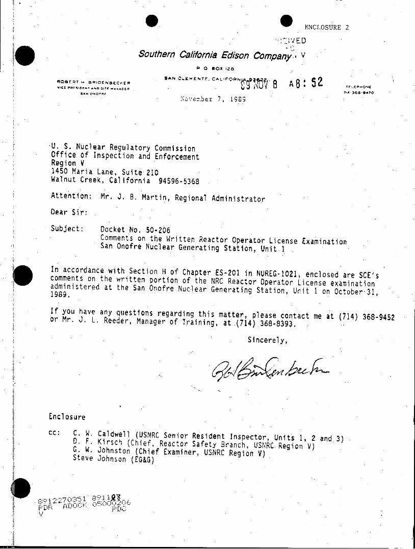
g O ENCLOSURE 2
;VED
Southern California Edison Company' V P 0. Box0 28
R08FQT BRIDCNBECK-ER SAN CLEME.NTF, CAL B A8 Tri EP 5 4-* Demo r 7,-GS 9470
Nov'eher 7, 1989
-U. S. Nuclear Regulatory Commission Office of Inspection and Enforcement Region V 1450 Maria Lane, Suite 210 Walnut Creek, California 94596-5368
Attention: Mr. J. B. Martin, Regional Administrator
Dear Sir:
Subject: Docket No. 50-206 Comments on the Written Reactor Operator License Examination San Onofre Nuclear Generating Station, Unit 1
In accordance with Section H of Chapter ES-201 in NUREG-1021, enclosed are SCE's comments on the written portion of the NRC Reactor Operator License examination administered at the San Onofre Nuclear Generating Station, Unit 1 on October-31, 1989.
If you have any questions regarding this matter, please contact me at (714) 368-9452 or Mr. J. L. Reeder, Manager of Training, at (714) 368-8393.
Sincerely,
Enclosure
cc: C. W. Caldwell (USNRC Senior Resident Inspector, Units 1, 2 and.3) D. F. Kirsch (Chief, Reactor Safety Branch, USNRC Region V) G. W. Johnston (Chief Examiner, USNRC Region V) Steve Johnson (EG&G)
III'
ENCLO$SURE
CONNMENTS ON -REACTOR OPERATOR-_ExAIiATION
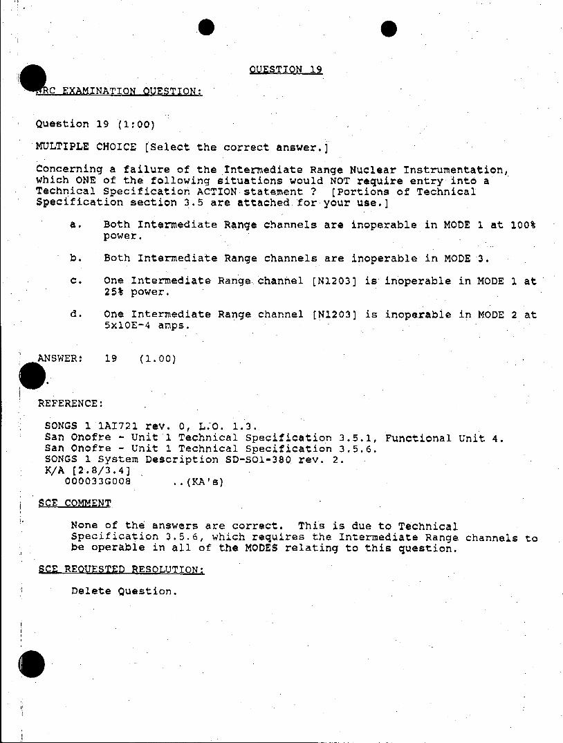
OUESTION_19 0k 0
cEXAMINATION.QUESTION:
Question 19 (1:00)
MULTIPLE CHOICE [Select the correct answer.)
Concerning a failure of the Intermediate Range Nuclear Instrumentation, which ONE of the following situations would NOT require entry into a Technical Specification ACTION statement ? (Portions of Technical Specification section 3.5 are attached for your use.)
a, Both Intermediate Range channels are inoperable in MODE 1 at 100% power.
b. Both Intermediate Range channels are inoperable in MODE 3.
c. One Intermediate Range channel [N1203] is inoperable in MODE 1 at 25% power.
d. One Intermediate Range channel [N1203] is inoperable in MODE 2 at 5x10E-4 amps.
ANSWER: 19 (1.00)
REFERENCE:
SONGS 1 1A1721 rev. 0, L.-O. 1.3. San Onofre - Unit 1 Technical Specification 3.5.1, Functional Unit 4. San Onofre - Unit 1 Technical Specification 3.5.6. SONGS 1 System Description SD-SOI-380 rev. 2. K/A (2.8/3.4)
000033G008 ..(KAs)
SCE COMMENT
None of the answers are correct. This is due to Technical Specification 3.5.6, which requires the Intermediate Range channels to be operable in all of the MODES relating to this question.
SCE REQUESTED RESQLUTION:
Delete Question.
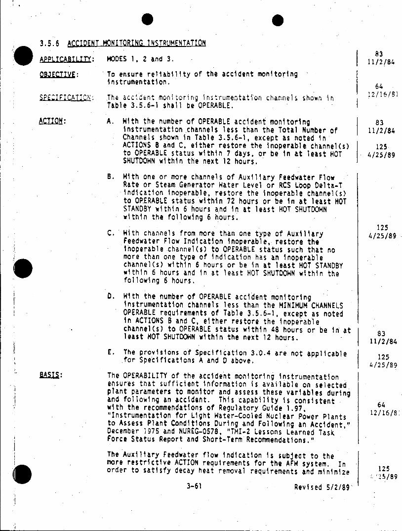
3.5.6 ACCIDENT MONITORING INSTRUMENTATION
APPLICABRITY: MODES 1, 2 and 3. 11//84
QBJECTI E: To ensure reliability of the accident monitoring instrumentation, 64
SPECIFICATION: The accident monitoring instrumentation channels shown in 2/16/81 Table 3.5.6-1 shall be OPERABLE.
ACION: A. With the number of OPERABLE accident monitoring 83 instrumentation channels less than the Total Number of 11/2/84 Channels shown in Table 3.5.6-1, except as noted in ACTIONS B and C, either restore the inoperable channel(s) 125 to OPERABLE status within 7 days, or be in at least HOT 4/25/89 SHUTDOWN within the next 12 hours.
B. With one or more channels of Auxiliary Feedwater Flow Rate or Steam Generator Hater Level or RCS Loop Delta-T indication inoperable, restore the inoperable channel(s) to OPERABLE status within 72 hours or be in at least HOT STANDBY within 6 hours and in at least HOT SHUTDOWN within the following 6 hours.
125 C. With channels from more than one type of Auxiliary 4/25/89
Feedwater Flow Indication inoperable, restore the inoperable channel(s) to OPERABLE status such that no more than one type of indication has an inoperable channel(s) within 6 hours or be in at least HOT STANDBY within 6 hours and in at least HOT SHUTDOWN within the following 6 hours.
0. With the number of OPERABLE accident monitoring instrumentation channels less than the MINIMUM CHANNELS OPERABLE requirements of Table 3.5.6-1, except as noted in ACTIONS B and C, either restore the inoperable channel(s) to OPERABLE status within 48 hours or be in at least HOT SHUTDOWN within the next 12 hours. 8
E. The provisions of Specification 3.0.4 are not applicable 125 for Specifications A and 0 above. 125
4/25/89 The OPERABILITY of the accident monitoring instrumentation ensures that sufficient information is available on selected plant parameters to monitor and assess these variables during and following an accident. This capability is consistent with the recommendations of Regulatory Guide 1.97, 6 "Instrumentation for Light Water-Cooled Nuclear Power Plants 12/16/8 to Assess Plant Conditions During and Following an Accident," December 1975 and NUREG-0578, "TMI-2 Lessons Learned Task Force Status Report and Short-Term Recommendations."
The Auxiliary Feedwater flow indication is subject to the more restrictive ACTION requirements for the AFW system. In 125 order to satisfy decay heat removal requirements and minimize 12
3-61 Revised 5/2/89
the potential for exceeding water hammer flow limits for a main feedwater line break upstream of the in-containment check valve, the OPERABILITY of AFN Train 8 is subject to the ability to equalize flow to the steam generators. Verification of equalization is provided by the AFW flow transmitters. If the capability to equalize flow or the ability to verify equalization is not available, Train A 125 would be utilized to provide the necessary decay heat removal 4/25/89 capability. AFHi Train A provides adequate flow for this scenario without reliance on operator action to equalize flow.(3) The steam generator wide range level indicators and the RCS loop delta-T indicators provide backup means for verification of auxiliary feedwater flow to the steam generators, and also provide alternate means for identification of a broken loop.
R-EFERENCES: (1) NRC letter dated July 2, 1980, from D. G. Eisenhut to all pressurized water reactor licensees.
(2) NRC letter dated November 1, 1983, from D. G. Eisenhut to 64 all Pressurized Hater Reactor Licensees, NUREG-0737 12/16/81 Technical Specification (Generic Letter No. 83-37).
(3) SCE letter dated November 6, 1987, from M. 0. Medford to 125 NRC Document Control Desk. 4/25/89
3-61a Revised 5/2/89
TABLE 3.5.6-1
ACCIDENT MONITORING INSTRUMENTATION
HININUM TOTAL NO. CHANNELS
I OF CHANNELS OPERABLE
Pressurizer Hater Level 3 2
Auxiliary Feedwater Flow Indication'
o Auxiliary Feedwater Flow Rate listeam generator i/steam generator o Steam Generator Hater Level (Wide Range) Iisteam generator I/steam generator o Reactor Coolant System Loop Delta-T Indication I/loop I/loop
Reactor Coolant System Subcooling Margin Monitor 2 I
POaV Position Indicator (Limit Switch) 1/valve I/valve
PORV Block Valve Position Indicator (Limlt Switch) 1/valve 1/valve
Safety Valve Position Indicator (Limit Switch) I/valve 1valve
Containment Pressure (Hide Range) 2 1
Refueling Water Storage Tank Level 2 1 124 C nae/8e Containment Sup Water Level (Narrow Range)" 2 1
Containment Water Level (Hide Range)
Neutron Flux (Hide Range) 2 1 117 12/13/,88
Auxiliary feedwater flow indication for each steam generator is provided by one channel of auxiliary feedwater flow rate (Train 0). one channel of environmental qualified steam generator 125
OD wide range level (Train A). and one channel of RCS Loop Delta-T Indication. These comprise the 4/25/89 three types of Indication of auxiliary feedwater flow for each steam generator.
Operation may continue up to 30 days with one less than the total number of channels OPERABLE.
QUESTIONS 23 AND 30
& RCEXAM1INATION QUESTIONS:
Question: 23 (1.00)
14ULTIPLE CHOICE (Select the correct answer.]
Which ONE of the following statements describes components that are DIRECTLY affected by the LOSS of DC Bus #2?
a. Diesel Generator #2 DG Control. Panel (DG non-functional) and Reactor Plant Annunciators
b. Diesel Generator #2 Emergency Lubricating Oil Pump and Inverter to Vital Bus #5
C. Diesel Generator #2 Exciter Field Flash and Stand-by Fuel Oil Pump
d. Diesel Generator #2 Starting Air Solenoids and RCP Thermal Barrier Cooling Water Pump
ANSWER: 23 (1.00)
*ANSWER eI. REFERENCE:
SONGS 1 LP 1XE205 rev. 0, P.O. 1.5. SONGS 1 LP IXD201 rev. 1, L.O. 3.1 and 3.3. SONGS 1 LP 1A1737 rev. 0, L.O. 1.1 Abnormal Operating Instruction SOl-2.6-4 rev. 1, "Loss Of DC Bus". Attachment 2, Section 5.0.
SONGS 1 System Description SD-SOl-140 rev. 2, "125 VDC System", sections 2.1.1.1 and 2.2.12.
X/A [3.4*/3.7) (3.5/3.9) 000058A203 000058K301 .. (KA s)
QUSTIONS 23 AND 30 (Continued)
*RC* UNTIN UESTONS:
Question 30 (1:00)
MULTIPLE CHOIC [Select the ccrrect answer.
The Auxiliary Air Compressor (-903) will start on LOW Redundant Air Header pressure to act as a back-up supply of air to selected loads. which ONE of the following is the power supply for the compressor?
a. 4 kV AC Bus 1A
b. 4 kV AC Dedicated Safe Shutdown Bus.A4
c. 480 V AC MCC 1
d. Dedicated diesel engine driver
ANSWER: 30 (1.00)
C.
REFERENCE:
No facility LP objective. .W SONGS 1 System Description SD-SO1-420 rev 1, sections 2.2.6 and 2.3.
A (3.3*/3.5*)] 078000K202 .. (KA's)
SWG COMENT:
Although not commented upon during the pre-examin ation review, SCE has always taken the position that Licensed Operators are not required to memorize specific power supplies for plant components.
SCE REOUESTED RESOLUTION:
In the future, do not require memorization of specific power supplies.
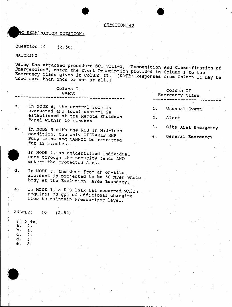
00ESTION 40
'~XMINATI1J QUESTION:
Question 40 (2.50)
MATCHING
Using the attached procedure SO1-VIII-1, "Recognition And Classification of Emergencies", match the Event Description provided in Column I to the Emergency Class given in Column II. [NOTE: Responses from Column II may be used more than once or not at all.)
Column I Column II Event Emergency Class -----------------------------------------
a. In MODE 6, the control room is 1. Unusual Event evacuated and local control is established at the Remote Shutdown 2. Alert Panel within 10 minutes.
3. Site Area Emergency b. In MODE 5 with the RCS in Mid-loop condition, the only OPERABLE RHR 4. General Emergency Pump trips and CANNOT be restarted for 12 minutes.
In MODE 4, an unidentified individual cuts through the security fence AND enters the protected Area.
d. In MODE 3, the dose from an on-site accident is projected to be 50 mrem whole body at the Exclusion Area Boundary.
e. In MODE 1, a RCS leak has occurred which requires 70 gpm of additional charging flow to maintain Pressurizer level.
ANSWER: 40 (2.50)
lo.5 eaj a. 2. b. 1. c. 2. d. 3. e. 2.
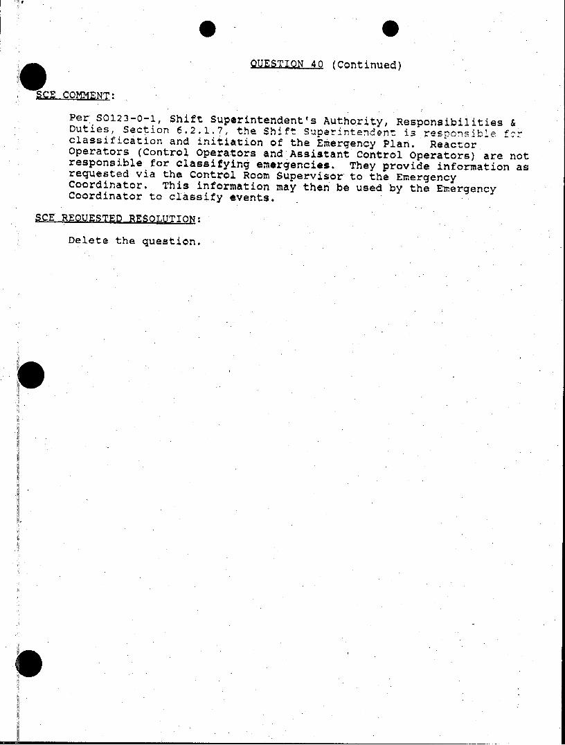
QUESTIQN 40 (Continued)
SCE COMMENT:
Per S0123-0-1, Shift Superintendent's Authority, Responsibilities & Duties, Section 6.2.1.7, the Shift Superintendent is responsible for classification and initiation of the Emergency Plan. Reactor Operators (Control Operators and Assistant Control Operators) are not responsible for classifying emergencies. They provide information as requested via the Control Room Supervisor to the Emergency Coordinator. This information may then be used by the Emergency Coordinator to classify events.
SCE REOUESTEp RESOLUTION:
Delete the question.
0j
di'
0S
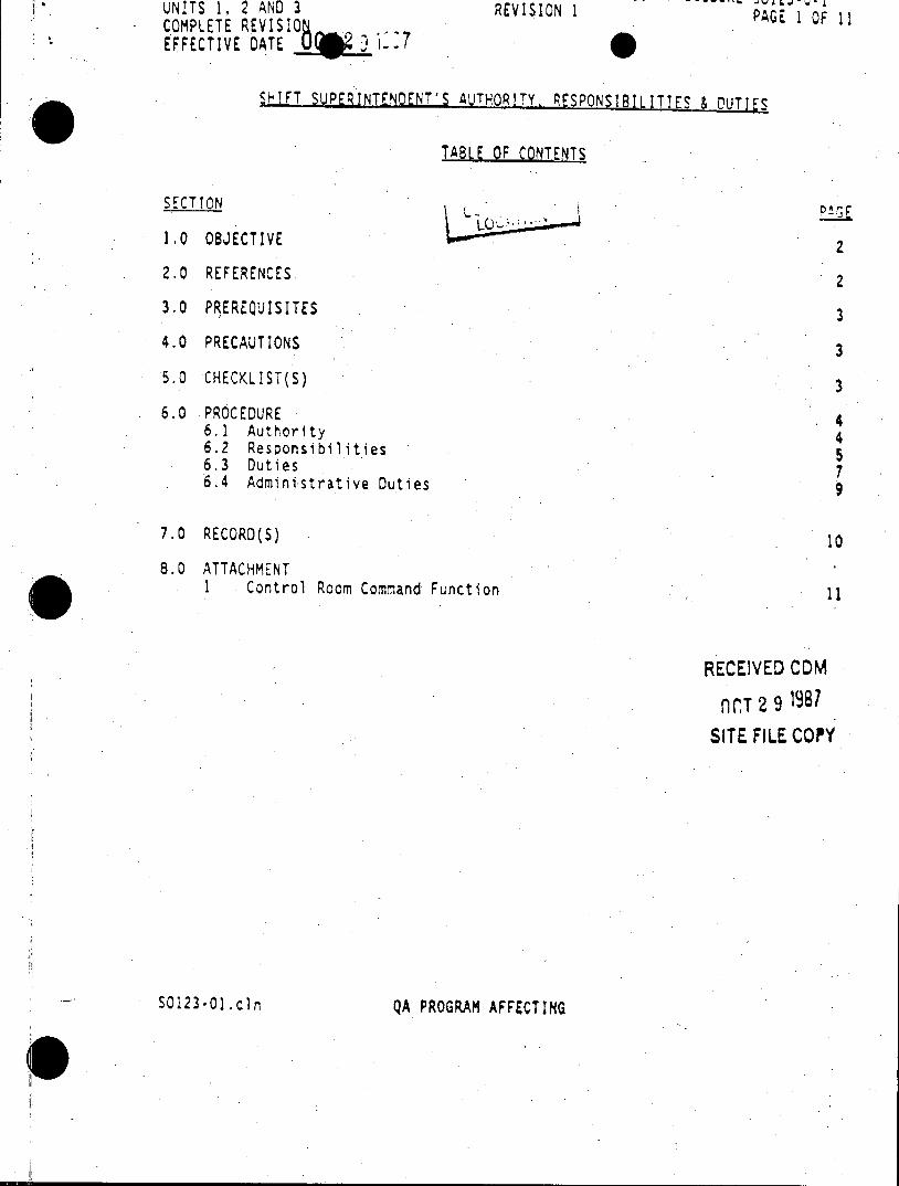
UNITS 1, 2 AND 3 REVISION 1 P COMPLETE REVISIO AG 1 OFG1 EFFECTIVE DATE
SHIT SUPERtNTENDENT'S AUTHORITY. RESPONSIBTLITIES
TABLE QF CONTENTS
SECTION
1.0 OBJECTIVE 2
2.0 REFERENCES 2
3.0 PREREQUISITES 3
4.0 PRECAUTIONS 3
5.0 CHECKLIST(S) 3
6.0 PROCEDURE 4 6.1 Authority 4 6.2 Responsibilities 5 6.3 Duties 7 6.4 Administrative Duties 9
7.0 RECORD(S) 10
8.0 ATTACHMENT 1 Control Room Command Function 11
RECEIVED CDM
lT 2 9 981
SITE FILE COPY
SO123-Ol.cln QA PROGRAM AFFECTING
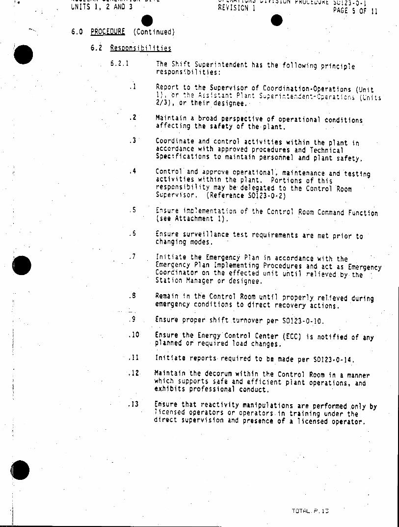
UNITS 1, 2 AND 3 REVISION 1 PAGE 5 OF 11
6.0 PROCEDURE (Continued)
6.2 Responsibilities
6.2.1 The Shift Superintendent has the following principle responsibilities:
.1 Report to the Supervisor of Coordination*Operations (Unit 1), or the Assistant Plant SuE rintendan-Operat ron (Units .2/3), or their designee.
.2 Maintain a broad perspective of operational conditions affecting the safety of the plant.
.3 Coordinate and control activities within the plant in accordance with approved procedures and Technical Specifications to maintain personnel and plant safety.
.4 Control and approve operational, maintenance and testing activities within the plant. Portions of this responsibility may be delegated to the Control Room Supervisor. (Reference S0123-0.2)
.5 Ensure implementation of the Control Room Command Function (see Attachment 1).
.6 Ensure surveillance test requirements are met prior to changing modes.
.7 Initiate the Emergency Plan in accordance with the Emergency Plan Implementing Procedures and act as Emergency Coordinator on the effected unit until relieved by the Station Manager or designee.
.8 Remain In the Control Room until properly relieved during emergency conditions to direct recovery actions.
.9 Ensure proper shift turnover per S0123-0-10.
.10 Ensure the Energy Control Center (ECC) is notified of any planned or required load changes.
.11 Initiate reports required to be made per S0123-0-14.
.12 Maintain the decorum within the Control Room in a manner which supports safe and efficient plant operations, and exhibits professional conduct.
.13 Ensure that reactivity manipulations are performed only by licensed operators or operators.in training under the direct supervision and presence of a licensed operator.
TOTL P.13
Enclosure 3
Resolution of Facility Comments
Facility Comment: Question 19 EPE Category
"None of the answers are correct. This is due to Technical Specification 3.5.6, which requires the Intermediate Range channels to be operable in all of the MODES relating to this question." Requested resolution is to delete the question.
Resolution:
The Chief Examiner will delete the question.
Facility Comment: Question 23 and 30 Plant Systems Category
"Although not commented on during the pre-examination review, SCE has always taken the position that Licensed Operators are not required to memorize specific pow'er supplies for plant components." Suggested resolution: "In the future do not require memorization of specific power supplies."
Resolution:
Since no request was made to change the key or delete the questions no change will be made. The Chief Examiner points out that the high Knowledges and Abilities importance factors (3.3 and 3.4 on a scale of 0 to 5 with the threshold at 2.5) for these two questions indicate that from the industry and NRC viewpoint these are important topics for examination purposes. If the facility were to provide facility specific K/A importance factors in a facility knowledges and abilities catalog below the threshold value of 2.5, then the questions would not have been included in the examination.
Facility Comment: Question 40 Plant Wide Generic Category
"Per 50123-0-1, Shift Superintendent's Authority, Responsibilities & Duties, Section 6.2.1.7, the Shift Superintendent is responsible for classification and initiation of the Emergency Plan." Reactor Operators (Control Operators and Assistant Control Operators) are not responsible for classifying emergencies. They provide information as requested via the Control Room Supervisor to the Emergency Coordinator. This information may then be used by the Emergency Coordinator to classify events." Suggested resolution is to delete the question.
Resolution:
The Chief Examiner will not delete the question. The reasoning is that the high K/A values (3.1 and 4.1 of the two identified Plant Wide Generic Knowledges and Abilities) are indicative of the importance of this question. The procedure itself and Lesson Plan 1RP723 seem to indicate that the Reactor Operators are capable of perforinig an advisory .function that includes assisting the Emergency Coordinator in classifying events. The candidates were only asked to utilize a procedure as provided, and were not asked to characterize an event.
III
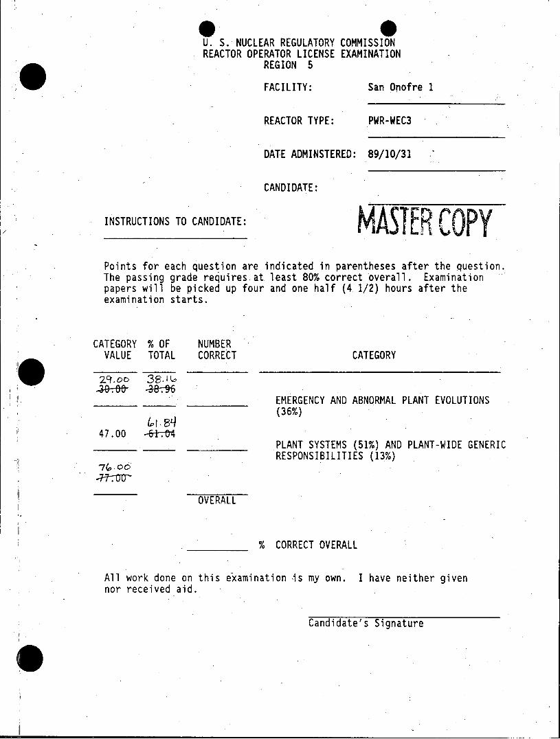
U. S. NUCLEAR REGULATORY COMMISSION REACTOR OPERATOR LICENSE EXAMINATION
REGION 5
FACILITY: San Onofre 1
REACTOR TYPE: PWR-WEC3
DATE ADMINSTERED: 89/10/31
CANDIDATE:
INSTRUCTIONS TO CANDIDATE:
Points for each question are indicated in parentheses after the question. The passing grade requires at least 80% correct overall. Examination papers will be picked up four and one half (4 1/2) hours after the examination starts.
CATEGORY % OF NUMBER VALUE TOTAL CORRECT CATEGORY
EMERGENCY AND ABNORMAL PLANT EVOLUTIONS
(36%)
47.00 -6tt4 PLANT SYSTEMS (51%) AND PLANT-WIDE GENERIC
RESPONSIBILITIES (13%)
OVERALL
% CORRECT OVERALL
All work done on this examination is my own. I have neither given nor received aid.
Candidate's Signature
III
NRC RULS AND GUIDELINES FOR LICENSE EXAMINATIONS
During the administration of this examination the following rules apply:
1. Cheating on the examination means an automatic denial of your application and could result in more severe penalties.
2. After the examination has been completed, you must sign the statement on the cover sheet indicating that the work is your own and you have not received or given assistance in completing the examination. This must be done after you complete the examination.
3. Restroom trips are to be limited and only one candidate at a time may leave. You must avoid all contacts with anyone outside the examination room to avoid even the appearance or possibility of cheating.
4. Use black ink or dark pencil only to facilitate legible reproductions.
5. Print your name in the blank provided in the upper right-hand corner of the examination cover sheet.
6. Fill in the date on the cover sheet of the examination (if necessary).
7. You may write your answers on the examination question page or on a separate sheet of paper. USE ONLY THE PAPER PROVIDED AND DO NOT WRITE ON THE BACK SIDE OF THE PAGE.
8. If you write your answers on the examination question page and you need more space to answer a specific question, use a separate sheet of the paper provided and insert it directly after the specific question. DO NOT WRITE ON THE BACK SIDE OF THE EXAMINATION QUESTION PAGE.
9. Print your name in the upper right-hand corner of the first page of each section of your answer sheets whether you use the examination question pages or separate sheets of paper. Initial each page.
10. Before you turn in your examination, consecutively number each answer sheet, including any additional pages inserted when writing your answers on the examination question page.
11. If you are using separate sheets, number each answer as to category and number (i.e. Plant Systems # 04, EPE # 10) and skip at least 3 lines between answers to allow space for grading.
12. Write "End of Category " at the end of your answers to a category.
13. Start each category on a new page.
14. Write "Last Page" on the last answer sheet.
15. Use abbreviations only if they are commonly used in facility literature. Avoid using symbols such as < or > signs to avoid a simple transposition error resulting in an incorrect answer. Write it out.
16. -The point value for each question is indicated in parentheses after the question. The amount of blank space on an examination question page is NOT an indication of the depth of answer required.
17. Show all calculations, methods, or assumptions used to obtain an answer.
18. Partial credit may be given. Therefore, ANSWER ALL PARTS OF THE QUESTION AND DO NOT LEAVE ANY ANSWER BLANK. NOTE: partial credit will NOT be given on multiple choice questions.
19. Proportional grading will be applied. Any additional wrong information that is provided may count against you. For example, if a question is worth one point and asks for four responses, each of which is worth 0.25 points, and you give five responses, each of your responses will be worth 0.20 points. If one of your five responses is incorrect, 0.20 will be deducted and your total credit for that question will be 0.80 instead of 1.00 even though you got the four correct answers.
20. If the intent of a question is unclear, ask questions of the examiner only.
21. When turning in your examination, assemble the completed examination with examination questions, examination aids and answer sheets. In addition, turn in all scrap paper.
22. To pass the examination, you must achieve an overall grade of 80% or greater.
23. There is a time limit of (4 1/2) hours for completion of the examination. (or some other time if less than the full examination is taken.)
24. When you are done and have turned in your examination, leave the examination area as defined by the examiner. If you are found in this area while the examination is still in progress, your license may be denied or revoked.
Ill
EMERGENCY AND A MAL PLANT EVOLUTIONS Page 4 (36%)
QUESTION: 01 (1.00)
MULTIPLE CHOICE [Select the correct answer.]
Which ONE of the following is an indication of a stuck or misaligned control rod that would direct the operator to section "E. Stuck Or Misaligned Control Rod" of Abnormal Operating Instruction SO1-2.3-1, "Control Rod System Malfunctions" ?
a. Reactor Coolant HIGH Tavg alarm annunciates.
b. A subgroup position of a control bank is NOT in agreement with other subgroups in the same bank as indicated by the step counters.
c. The rods fail to respond in automatic to an actual Tavg - Tref mismatch of + or - 2 degrees F.
d. Control Rod Shutdown Margin LOW alarm annunciates.
***** CATEGORY 2 CONTINUED ON NEXT PAGE *****
EMERGENCY AND A*ORMAL PLANT EVOLUTIONS Page 5 (36%).
QUESTION: 02 (1.00)
MULTIPLE CHOICE [Select the correct answer.]
Select the answer below that CORRECTLY completes the following statement:
A control rod is considered inoperable whenever the rod is found to be greater than steps misaligned from the step counter indicated
-bank position.
a. 28
b. 30
c. 33
d. 35
***** CATEGORY 2 CONTINUED ON NEXT PAGE *****
EMERGENCY AND AORMAL PLANT EVOLUTIONS Page 6 (36%)
QUESTION: 03 (1.00)
MULTIPLE CHOICE [Select the correct answer.]
Following a loss of the RCP's, the decision is made to commence a natural circulation cooldown in accordance with General Operating Instruction S01-3-6, "Plant Operation With Natural Circulation". During the cooldown, the procedural limit on cooldown rate is LESS THAN:
a. 10 degrees F per hour.
b. 25 degrees F per hour.
c. 50 degrees F per hour.
d. 125 degrees F per hour.
***** CATEGORY 2 CONTINUED ON NEXT PAGE *****
EMERGENCY AND A*RMAL PLANT EVOLUTIONS Page 7 (36%)
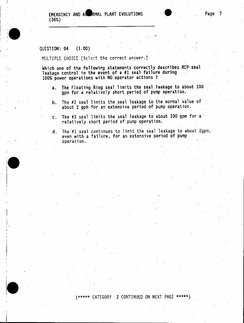
QUESTION: 04 (1.00)
MULTIPLE CHOICE [Select the correct. answer.]
Which one of the following statements correctly describes RCP-seal leakage control in the event of a #1 seal failure during 100% power operations with NO operator actions ?
a. The Floating Ring seal limits the seal leakage to about 100 gpm for a relatively short period of pump operation.
-b. The #2 seal limits the seal leakage to the normal value of about 2 gph for an extensive period of pump operation.
c. The #3 seal limits the seal leakage to about 100 gpm for a relatively short period of pump operation.
d. The #1 seal continues to limit the seal leakage to about 2gpm, even with a failure, for an extensive period of pump operation.
0
(***** CATEGORY 2 CONTINUED ON NEXT PAGE *****)
EMERGENCY AND ASRMAL PLANT EVOLUTIONS Page 8 (36%)
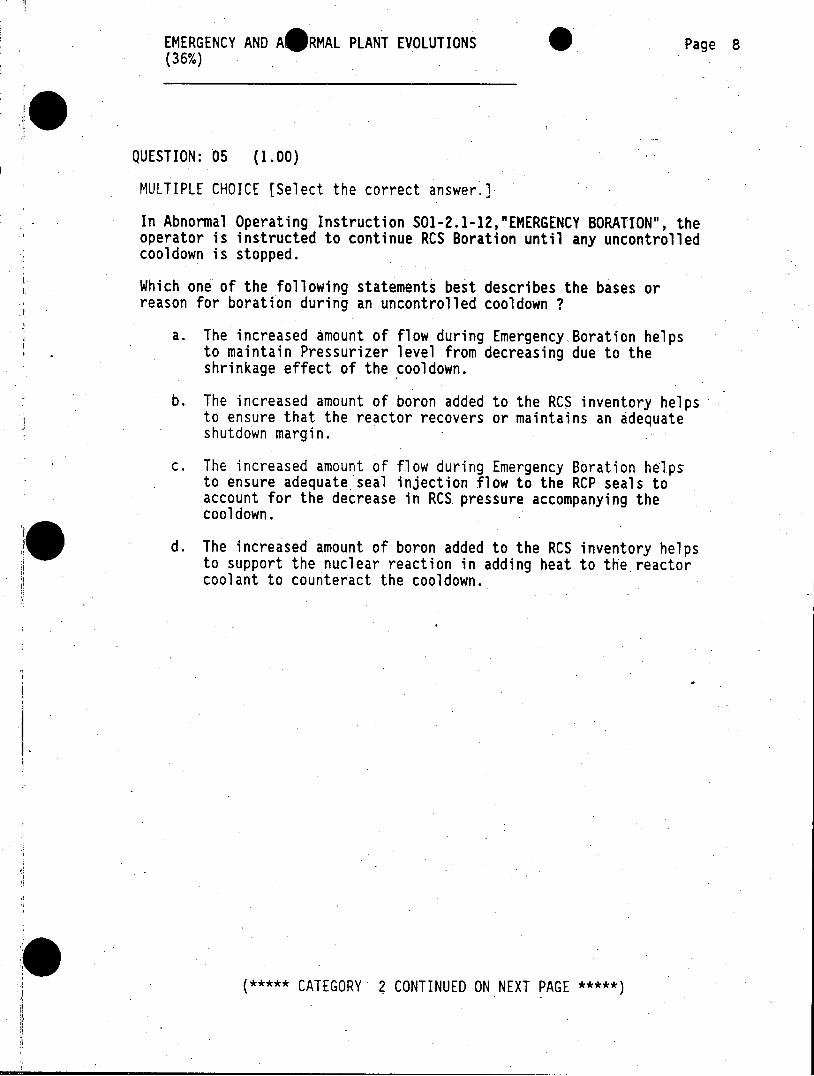
QUESTION: 05 (1.00)
MULTIPLE CHOICE [Select the correct answer.]
In Abnormal Operating Instruction SO1-2.1-12,"EMERGENCY BORATION", the operator is instructed to continue RCS Boration until any uncontrolled cooldown is stopped.
Which one of the following statements best describes the bases or reason for boration during an uncontrolled cooldown ?
a. The increased amount of flow during Emergency Boration helps to maintain Pressurizer level from decreasing due to the shrinkage effect of the cooldown.
b. The increased amount of boron added to the RCS inventory helps to ensure that the reactor recovers or maintains an adequate shutdown margin.
c. The increased amount of flow during Emergency Boration helps to ensure adequate seal injection flow to the RCP seals to account for the decrease in RCS pressure accompanying the cooldown.
d. The increased amount of boron added to the RCS inventory helps to support the nuclear reaction in adding heat to the reactor coolant to counteract the cooldown.
***** CATEGORY 2 CONTINUED ON NEXT PAGE *****
EMERGENCY AND ASRMAL PLANT EVOLUTIONS Page 9 (36%)
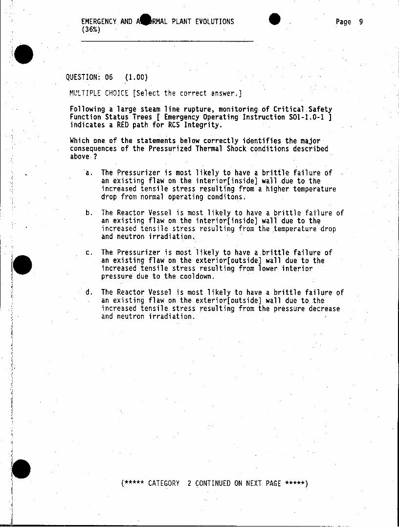
QUESTION: 06 (1.00)
MULTIPLE CHOICE [Select the correct answer.]
Following a large steam line rupture, monitoring of Critical .Safety Function Status Trees [ Emergency Operating Instruction S01-1.0-1 ] indicates a RED path for RCS Integrity.
Which one of the statements below correctly identifies the major consequences of the Pressurized Thermal Shock conditions described above ?
a. The Pressurizer is most likely to have a brittle failure of an existing flaw on the interior[inside] wall due to the increased tensile stress resulting from a higher temperature drop from normal operating conditons.
b. The Reactor Vessel is most likely to have a brittle failure of an existing flaw on the interior[inside] wall due to the increased tensile stress resulting from the temperature drop and neutron irradiation.
c. The Pressurizer is most likely to have a.brittle failure of an existing flaw on the exterior[outside] wall due to the increased tensile stress resulting from lower interior pressure due to the cooldown.
d. The Reactor Vessel is most likely to have a brittle failure of an existing flaw on the exterior[outside] wall due to the increased tensile stress resulting from the pressure decrease and neutron irradiation.
(***** CATEGORY 2 CONTINUED ON NEXT PAGE *****)
EMERGENCY AND A@RMAL PLANT EVOLUTIONS Page 10 (36%)
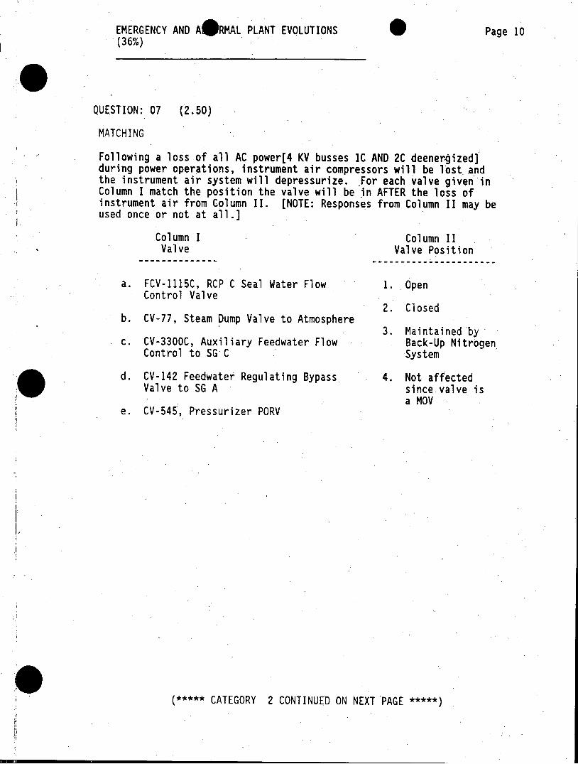
QUESTION: 07 (2.50)
MATCHING
Following a loss of all AC power[4 KV busses IC AND 2C deenergized] during power operations, instrument air compressors will be lost and the instrument air system will depressurize. For each valve given in Column I match the position the valve will be in AFTER the loss of instrument air from Column II. [NOTE: Responses from Column II may be used once or not at all.]
Column I Column II Valve Valve Position
a. FCV-1115C, RCP C Seal Water Flow 1. Open Control Valve
2. Closed b. CV-77, Steam Dump Valve to Atmosphere
3. Maintained by c. CV-3300C, Auxiliary Feedwater Flow Back-Up Nitrogen
Control to SG C System
d. CV-142 Feedwater Regulating Bypass 4. Not affected Valve to SG A since valve is
a MOV e. CV-545, Pressurizer PORV
***** CATEGORY 2 CONTINUED ON NEXT PAGE *****
EMERGENCY AND A@RMAL PLANT EVOLUTIONS Page 11 (36%)
QUESTION: 08 (1.00)
MULTIPLE CHOICE [Select the correct answer.]
Emergency Operating Instruction S01-1.0-60, "Loss Of All AC Power", includes steps for re-energizing the 4 KV busses from the switchyard.
Select the one combination below that correctly completes the following statement:
Efforts to energize 4 KV busses from the switchyard should be limited to minutes. This time limit is based on [1] transient analysis assuming no operator action during this time and [2] allows the operator sufficient time to .
a. 20, load the diesel generators and establish adequate AFW flow in the event of a Main Feedline Rupture.
b. 10, initiate the operation of the Dedicated Safe Shutdown System to provide adequate charging for normal RCS inventory control.
c. 10, load the diesel generators and establish adequate AFW flow in the event of a Main Feedline Rupture.
d. 20, initiate the operation of the Dedicated Safe Shutdown System to provide adequate charging for normal RCS inventory control.
***** CATEGORY 2 CONTINUED ON NEXT PAGE *****
EMERGENCY AND AORMAL PLANT EVOLUTIONS Page 12 (36%)
QUESTION: 09 (2.50)
MATCHING
Match the~ specific Dedicated Shutdown System [DSD] location given in Column I with the correct individual(s)in Column II, who is [are] responsible for initial reporting to that location in the event of a Control Room evacuation due to a fire. [NOTE: More than one individual may report to the same location.]
Column I Column II DSD Location Individual
a. Lower Radwaste Building 1. SS
b. DSD Switchgear Building 2. STA
c. Remote Shutdown Panel 3. CO
d. No. 2 Diesel Generator 4. Lead ACO
5. Lead PEO
***** CATEGORY 2 CONTINUED ON NEXT PAGE *****
EMERGENCY AND AEAMAL PLANT EVOLUTIONS Page 13 (36%)
QUESTION: 10 (1.00)
MULTIPLE CHOICE [Select the correct answer.]
As part of the Dedicated Safe Shutdown System, the Remote Shutdown Panel [C-38] has controls and instrumentation to allow for
* RCS reactivity control, * RCS inventory control, and * RCS pressure control.
Which one of the statements below describes the instrumentation and controls located ON THE REMOTE SHUTDOWN PANEL that provide for the above functions ?
a. NLI-1204A [Intermediate Range Nuclear Power Indication] FC-5112 [Charging system flow control FCV-1112) PC-430J [Pressurizer heater control]
b. NLI-1201 [Source Range Nuclear Power Indication] A451 [Power transfer switch for the north charging pump] HS-5546 [Pressurizer pressure control - CV-530; CV-546]
c. NLI-1201 [Source Range Nuclear Power Indication] A451 [Power transfer switch for the north charging pump] PC-430J [Pressurizer heater control]
d. NLI-1204A [Intermediate Range Nuclear Power Indication] FC-5112 [Charging system flow control FCV-1112] HS-5546 [Pressurizer pressure control - CV-530; CV-546]
***** CATEGORY 2 CONTINUED ON NEXT PAGE *****
EMERGENCY AND A60MAL PLANT EVOLUTIONS Page 14 (36%)
QUESTION: 11 (1. 00)
MULTIPLE CHOICE [Select the correct answer.]
With the plant in Mode 3, which ONE of the conditions described below requires entry into Abnormal Operating Instruction S01-2.1-6, "Loss Of Containment Integrity" ?
a. Pressurizer liquid sample isolation valve CV-992 fails to stroke OPEN.
b. Auxiliary Annunciator "SPHERE ACCESS INTERLOCK DISABLED" actuated.
c. Valve alignment performance shows Sphere Purge Air Supply POV-9 was NOT locked.
d. Penetration leak test for RCS Drain Tank vent CV-107 was NOT performed within specified time interval.
***** CATEGORY 2 CONTINUED ON NEXT PAGE *****
EMERGENCY AND ABIRMAL PLANT EVOLUTIONS Page 15 (36%)
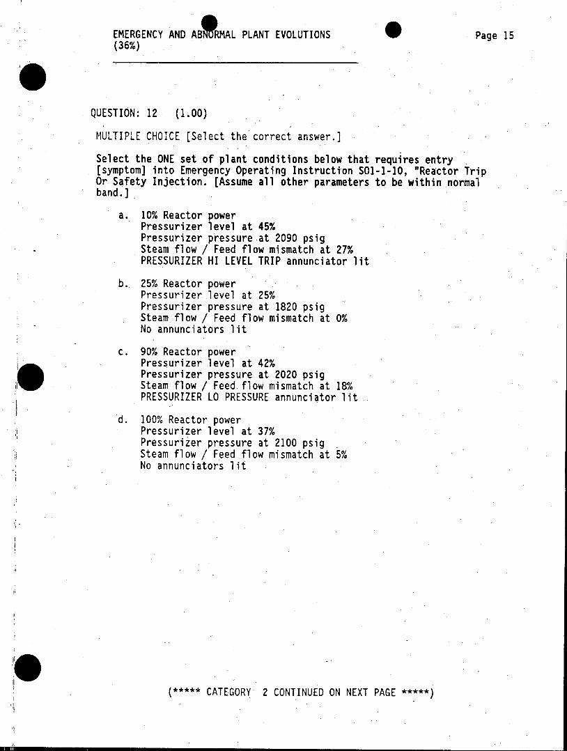
QUESTION: 12 (1.00)
MULTIPLE CHOICE [Select the correct answer.]
Select the ONE set of plant conditions below that requires entry [symptom] into Emergency Operating Instruction 501-1-10, "Reactor Trip Or Safety Injection. [Assume all other parameters to be within normal band.]
a. 10% Reactor power Pressurizer level at 45% Pressurizer pressure at 2090 psig Steam flow / Feed flow mismatch at 27% PRESSURIZER HI LEVEL TRIP annunciator lit
b. 25% Reactor power Pressurizer level at 25% Pressurizer pressure at 1820 psig Steam flow / Feed flow mismatch at 0% No annunciators lit
c. 90% Reactor power Pressurizer level at 42% Pressurizer pressure at 2020 psig Steam flow / Feed.flow mismatch at 18% PRESSURIZER LO PRESSURE annunciator lit
d. 100% Reactor power Pressurizer level at 37% Pressurizer pressure at 2100 psig Steam flow / Feed flow mismatch at 5% No annunciators lit
***** CATEGORY 2 CONTINUED ON NEXT PAGE *****
EMERGENCY AND A RMAL PLANT EVOLUTIONS Page 16 (36%)
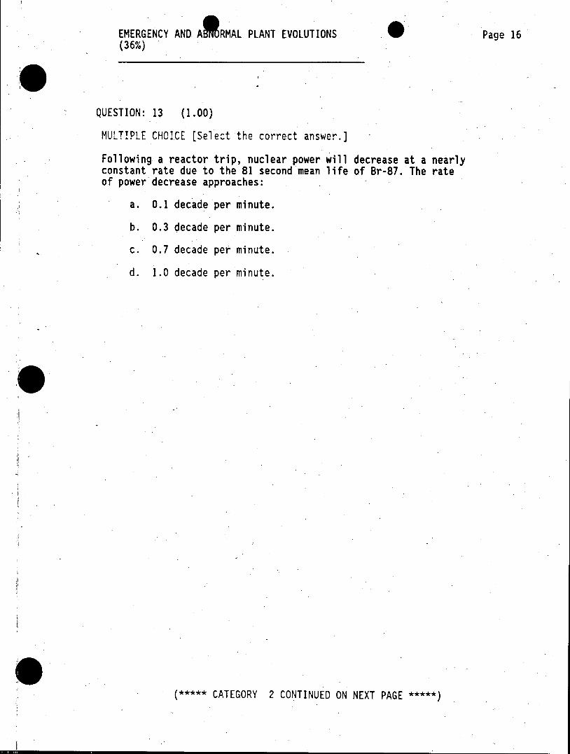
QUESTION: 13 (1.00)
MULTIPLE CHOICE [Select the correct answer.]
Following a reactor trip, nuclear power will decrease at a nearly constant rate due to the 81 second mean life of Br-87. The rate of power decrease approaches:
a. 0.1 decade per minute.
b. 0.3 decade per minute.
c. 0.7 decade per minute.
d. 1.0 decade per minute.
***** CATEGORY 2 CONTINUED ON NEXT PAGE *****
EMERGENCY AND AA MAL PLANT EVOLUTIONS, Page 17 (36%)
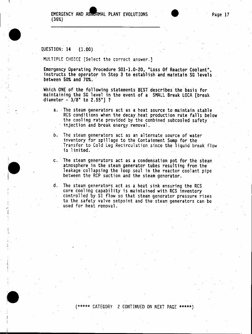
QUESTION: 14 (1.00)
MULTIPLE CHOICE [Select the correct answer.]
Emergency Operating Procedure S01-1.0-20, "Loss Of Reactor Coolant", instructs the operator in Step 3 to establish and maintain SG levels between 50% and 70%.
Which ONE of the following statements BEST describes the basis for maintaining the SG level in the event of a SMALL Break LOCA [break diameter - 3/8" to 2.55"] ?
a. The steam generators act as a heat source to maintain stable RCS conditions when the decay heat production rate falls below the cooling rate provided by the combined subcooled safety injection and break energy removal.
b. The steam- generators act as an alternate source of water inventory for spillage to the Containment Sump for the Transfer to Cold Leg Recirculation since the liquid break flow is limited.
c. The steam generators act as a condensation pot for the steam atmosphere in the steam generator tubes resulting from the leakage collapsing the loop seal in the reactor coolant pipe between the RCP suction and the steam generator.
d. The steam generators act as a heat sink ensuring the RCS core cooling capability is maintained with RCS inventory controlled by.SI flow so that steam generator pressure rises to the safety valve setpoint and the steam generators can be used for heat removal.
***** CATEGORY 2 CONTINUED ON NEXT PAGE *****
EMERGENCY AND A4 MAL PLANT EVOLUTIONS Page 18 (36%)
QUESTION: 15 (1.00)
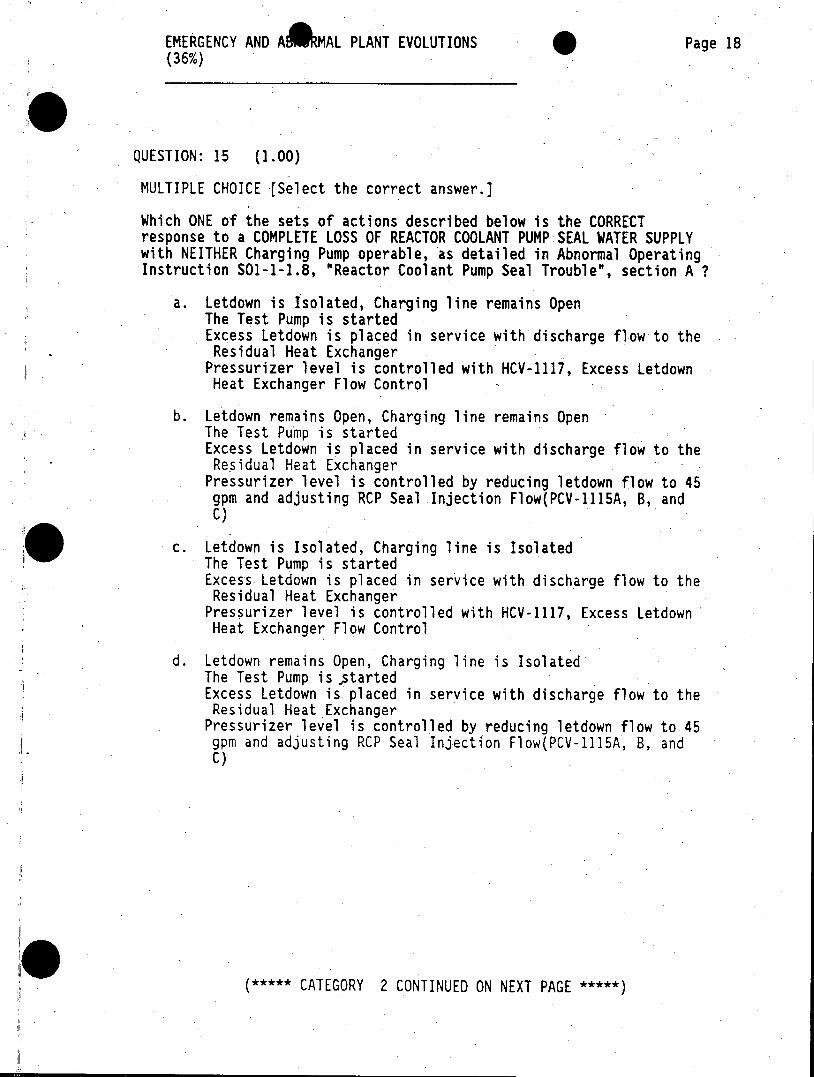
MULTIPLE CHOICE [Select the correct answer.]
Which ONE of the sets of actions described below is the CORRECT response to a COMPLETE LOSS OF REACTOR COOLANT PUMP SEAL WATER SUPPLY with NEITHER Charging Pump operable, as detailed in Abnormal Operating Instruction S01-1-1.8, "Reactor Coolant Pump Seal Trouble", section A ?
a. Letdown is Isolated, Charging Tine remains Open The Test Pump is started Excess Letdown is placed in service with discharge flow to the Residual Heat Exchanger
Pressurizer level is controlled with HCV-1117, Excess Letdown Heat Exchanger Flow Control
b. Letdown remains Open, Charging line remains Open The Test Pump is started Excess Letdown is placed in service with discharge flow to the Residual Heat Exchanger
Pressurizer level is controlled by reducing letdown flow to 45 gpm and adjusting RCP Seal Injection Flow(PCV-1115A, B, and C)
c. Letdown is Isolated, Charging line is Isolated The Test Pump is started Excess Letdown is placed in service with discharge flow to the Residual Heat Exchanger
Pressurizer level is controlled with HCV-1117, Excess Letdown Heat Exchanger Flow Control
d. Letdown remains Open, Charging line is Isolated The Test Pump is started Excess Letdown is placed in service with discharge flow to the Residual Heat Exchanger
Pressurizer level is controlled by reducing letdown flow to 45 gpm and adjusting RCP Seal Injection Flow(PCV-1115A, B, and C)
***** CATEGORY 2 CONTINUED ON NEXT PAGE *****
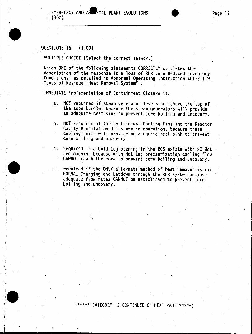
EMERGENCY AND A MAL PLANT EVOLUTIONS Page 19 - (36%)
QUESTION: 16 (1.00)
MULTIPLE CHOICE [Select the correct answer.]
Which ONE of the following statements CORRECTLY completes the. description of the response to a loss of RHR in a Reduced Inventory Conditions, as detailed in Abnormal Operating Instruction 501-2.1-9, "Loss of Residual Heat Removal System"
IMMEDIATE implementation of Containment Closure is:
a. NOT required if steam generator levels are above the top of the tube bundle, because the steam generators will provide an adequate heat sink to prevent core boiling and uncovery.
b. NOT required if the Containment Cooling Fans and the Reactor Cavity Ventilation Units are in operation, because these cooling units will provide an adequate heat sink to prevent core boiling and uncovery.
c. required if a Cold Leg opening in the RCS exists with NO Hot Leg opening because with Hot Leg pressurization cooling flow CANNOT reach the core to prevent core boiling and uncovery.
d. required if the ONLY alternate method of heat removal is via NORMAL Charging and Letdown through the RHR system because adequate flow rates CANNOT be established to prevent core boiling and uncovery.
***** CATEGORY 2 CONTINUED ON NEXT PAGE *****
EMERGENCY AND AIRMAL PLANT EVOLUTIONS Page 20 (36%)
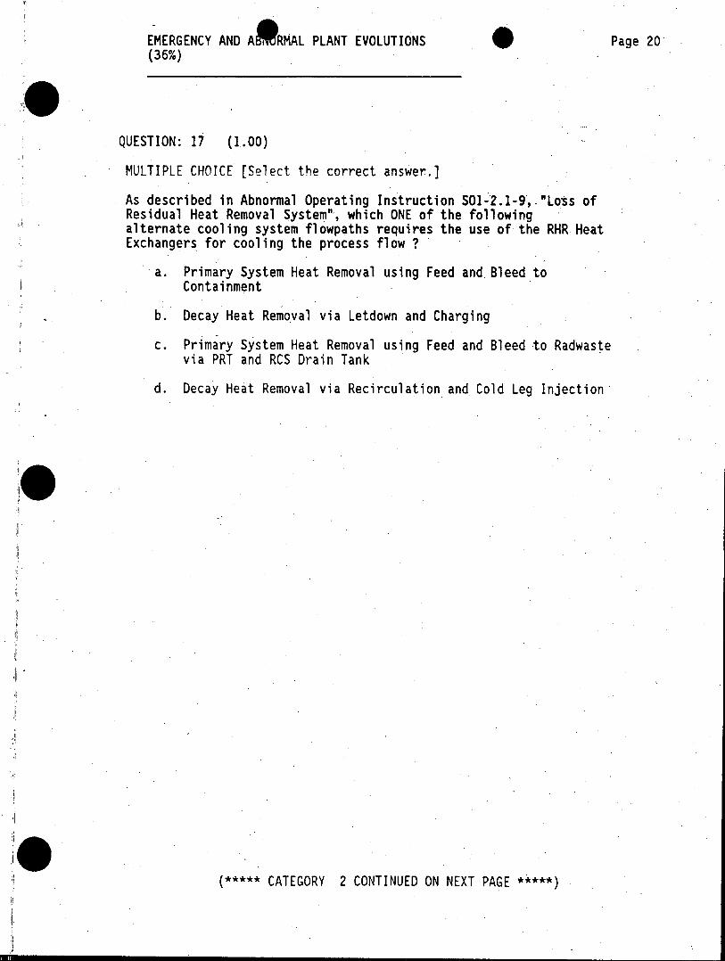
QUESTION: 17 (1.00)
MULTIPLE CHOICE [Select the correct answer.]
As described in Abnormal Operating Instruction S01-2.1-9,-"Loss of Residual Heat Removal System", which ONE of the following alternate cooling system flowpaths requires the use of the RHR Heat Exchangers for cooling the process flow ?
a. Primary System Heat Removal using Feed and Bleed to Containment
b. Decay Heat Removal via Letdown and Charging
c. Primary System Heat Removal using Feed and Bleed to Radwaste via PRT and RCS Drain Tank
d. Decay Heat Removal via Recirculation and Cold Leg Injection
***** CATEGORY 2 CONTINUED ON NEXT PAGE *****
EMERGENCY AND AB RMAL PLANT EVOLUTIONS Page 21 (36%)
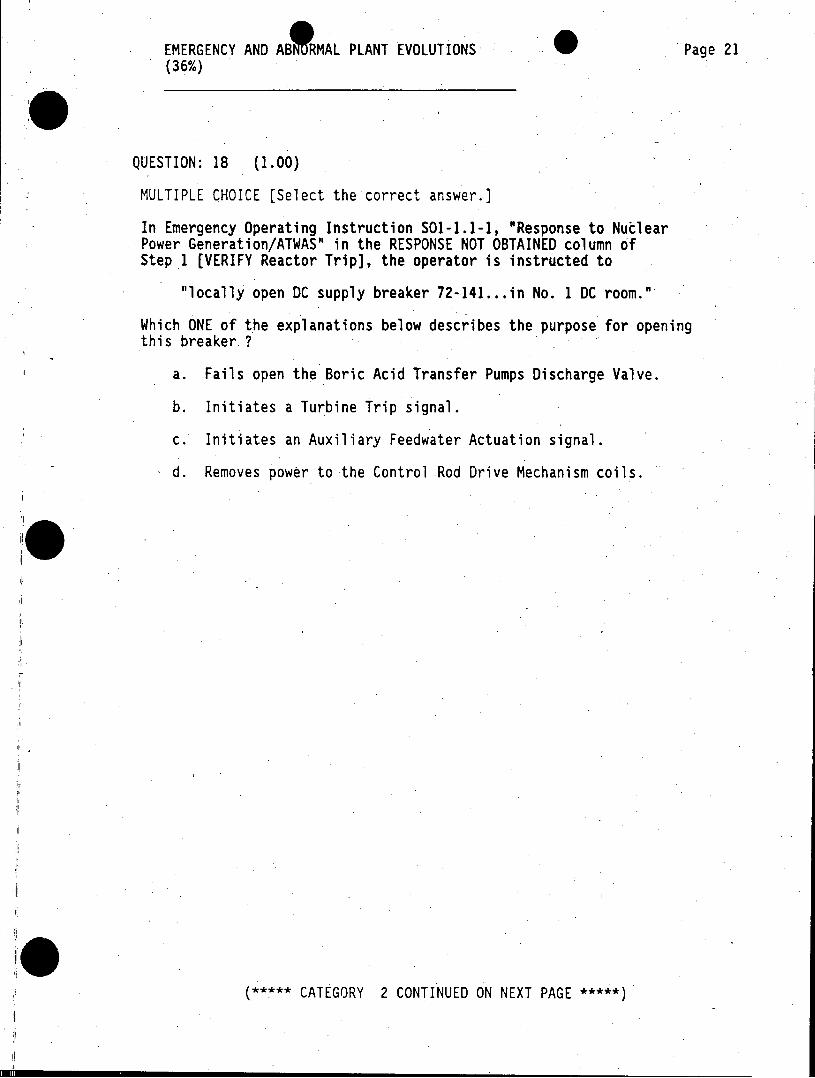
QUESTION: 18 (1.00)
MULTIPLE CHOICE [Select the correct answer.]
In Emergency Operating Instruction S01-1.1-1, "Response to Nuclear Power Generation/ATWAS" in the RESPONSE NOT OBTAINED column of Step 1 [VERIFY Reactor Trip], the operator is instructed to
"locally open DC supply breaker 72-141...in No. 1 DC room."
Which ONE of the explanations below describes the purpose for opening this breaker ?
a. Fails open the Boric Acid Transfer Pumps Discharge Valve.
b. Initiates a Turbine Trip signal.
c. Initiates an Auxiliary Feedwater Actuation signal.
d. Removes power to the Control Rod Drive Mechanism coils.
***** CATEGORY 2 CONTINUED ON NEXT PAGE *****
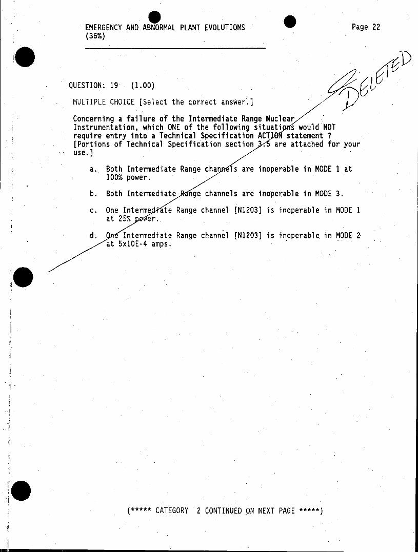
EMERGENCY AND ABNORMAL PLANT EVOLUTIONS Page 22 (36%)
QUESTION: 19 (1.00)
MULTIPLE CHOICE [Select the correct answer.]
Concerning a failure of the Intermediate Range Nuclear Instrumentation, which ONE of the following situati s would NOT require entry into a Technical Specification ACT statement ? [Portions of Technical Specification section . are attached for your use.]
a. Both Intermediate Range cha s are inoperable in MODE 1 at 100% power.
b. Both Intermediate nge channels are inoperable in MODE 3.
c. One Interme ' te Range channel [N1203] is inoperable in MODE 1 at 25% er.
d. Intermediate Range channel [N1203] is inoperable in MODE 2 at 5x10E-4 amps.
***CATEGORY 2 CONTINUED -ON NEXT PAGE***
-EMERGENCY AND ARMAL PLANT EVOLUTIONS Page 23 (36%)
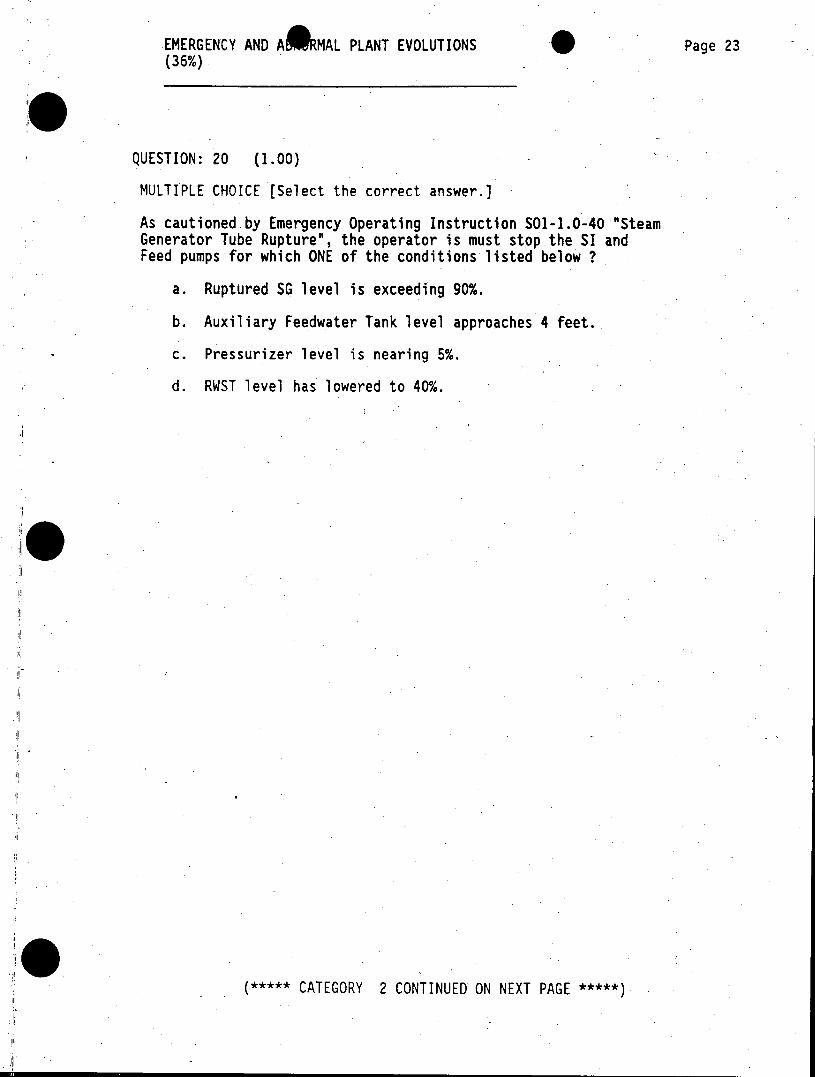
QUESTION: 20 (1.00)
MULTIPLE CHOICE [Select the correct answer.)
As cautioned by Emergency Operating Instruction S01-1.0-40 "Steam Generator Tube Rupture", the operator is must stop the SI and Feed pumps for which ONE of the conditions listed below ?
a. Ruptured SG level is exceeding 90%.
b. Auxiliary Feedwater Tank level approaches 4 feet.
c. Pressurizer level is nearing 5%.
d. RWST level has lowered to 40%.
***** CATEGORY 2 CONTINUED ON NEXT PAGE *****
EMERGENCY AND AIRMAL PLANT EVOLUTIONS Page 24 (36%)
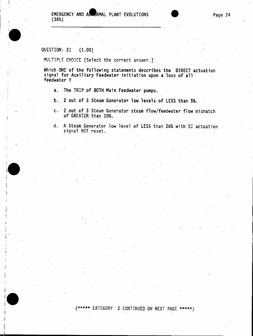
QUESTION: 21 (1.00)
MULTIPLE CHOICE [Select the correct answer.]
Which ONE of the following statements describes the DIRECT actuation signal for Auxiliary Feedwater initiation upon a loss of all feedwater ?
a. The TRIP of BOTH Main Feedwater pumps.
b. 2 out of 3 Steam Generator low levels of LESS than 5%.
c. 2 out of 3 Steam Generator steam flow/feedwater flow mismatch of GREATER than 10%.
d. A Steam Generator low level of LESS than 26% with SI actuation signal NOT reset.
***** CATEGORY 2 CONTINUED ON NEXT PAGE *****
EMERGENCY AND AO MAL PLANT EVOLUTIONS Page 25 (36%)
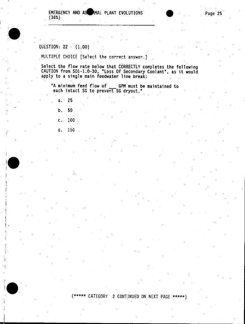
QUESTION: 22 (1.00)
MULTIPLE CHOICE [Select the correct answer.]
Select the flow rate below that CORRECTLY completes the following CAUTION from SO1-1.0-30, "Loss Of Secondary Coolant", as it would apply to a single main feedwater line break:
"A minimum feed flow of GPM must be maintained to each intact SG to prevent SG dryout."
a. 25
b. 50
c. 100
d. 150
***** CATEGORY 2 CONTINUED ON NEXT PAGE *****
EMERGENCY AND A1 RMAL PLANT EVOLUTIONS Page 26 (36%)
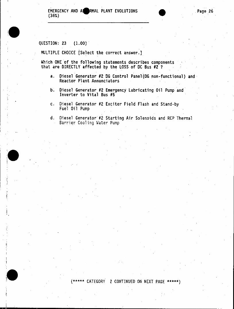
QUESTION: 23 (1.00)
MULTIPLE CHOICE [Select the correct answer.]
Which ONE of the following statements describes components that are DIRECTLY affected by the LOSS of DC Bus #2 ?
a. Diesel Generator #2 DG Control Panel(DG non-functional) and Reactor Plant Annunciators
b. Diesel Generator #2 Emergency Lubricating Oil Pump and Inverter to Vital Bus #5
c. Diesel Generator #2 Exciter Field Flash and Stand-by Fuel Oil Pump
d. Diesel Generator #2 Starting Air Solenoids and RCP Thermal Barrier Cooling Water Pump
***** CATEGORY 2 CONTINUED ON NEXT PAGE *****
EMERGENCY AND AA MAL PLANT EVOLUTIONS Page 27 (36%)
QUESTION: 24 (1.00)
MULTIPLE CHOICE [Select the correct answer.]
Select the ONE individual below that BEST completes the following:
In accordance with Abnormal Operating Instruction SO1-2-.2-2, "High Radiation Area Radiation Monitoring System", on a unexpected HIGH alarm condition on ANY of the instruments, the operator will notify the on-shift to verify the high radiation condition exists.
a. Instrumentation and Controls Technician
b. Health Physics Technician
c. Nuclear Chemical Technician
d. Nuclear Plant Equipment Operator
***** CATEGORY 2 CONTINUED ON NEXT PAGE *****
EMERGENCY AND A RMAL PLANT EVOLUTIONS Page 28 (36%)
QUESTION: 25 (1.00)
MULTIPLE CHOICE [Select the correct answer.]
Initially the following plant conditions exist:
Reactor power is at 50% Tavg is at 542 degrees F Pressurizer pressure is at 2085 psig Pressurizer level and level setpoint are at 30% All pertinent systems are in AUTOMATIC control except for Rod Control
An instrument failure occurs after 5 minutes such that the operator notes that Pressurizer level and its setpoint are increasing to a a new value of 36.5%.
Which ONE of the failures below would have caused this response assuming there was NO operator action taken ?
a. Pressurizer level channel LT430-failed HIGH.
b. Nuclear Power Range channel N1208 failed HIGH.
c. Pressurizer pressure channel PT431 failed HIGH.
d. Hot Leg RTD to Tavg TE401A failed HIGH.
***** CATEGORY 2 CONTINUED ON NEXT PAGE *****
EMERGENCY AND A4A MAL PLANT EVOLUTIONS Page 29 (36%)
QUESTION: 26 (1.00)
MULTIPLE CHOICE [Select the correct answer.J
During IRRADIATED fuel movement during a refueling outage, the assembly is NOT a radiation hazard to the personnel operating the Spent Fuel Bridge Crane as long as the assembly:
a. is under AT LEAST 12 feet of water.
b. is under AT LEAST 4 feet of water.
c. is covered with water just up to the nozzle block.
d. is covered halfway of its length with water.
II. (***** CATEGORY 2 CONTINUED ON NEXT PAGE *****)

EMERGENCY AND A4MAL PLANT EVOLUTIONS Page 30 (36%)
QUESTION: 27 (1.00)
MULTIPLE CHOICE (Select the correct answer.]
Which ONE of the following monitors would provide the operator indication for a fuel cladding failure resulting in HIGH acitivity in the Reactor Coolant System ?
a. Radwaste Building Area Monitor [R-1234]
b. Containment Sphere Area Monitor [R-1232]
c. Wide Range Gas Monitor [R-1254]
d. Gross Failed-Fuel Monitor [R-1241]
***** END OF CATEGORY 2 *****
PLANT SYSTEMS (@) AND PLANT-WIDE GENERIC Page 31 RESPONSIBILITIES (13%)
QUESTION: 01 (1.00)
MULTIPLE CHOICE [Select the correct answer.]
During normal power operation, the rod control system Overlap. Cutout Switch is used used as follows.
a. Position 1 - Control Bank 1 selected to move in either automatic or manual control and is the normal position for the Overlap Cutout Switch
b. Position 2 - Control Bank 2 selected to move in either automatic or manual control and is the normal position for the Overlap Cutout Switch
c. Position 1 - Overlap 1 & 2 (Auto) - Overlap is in service and is the normal position for the Overlap Cutout Switch
d. Position 2- Overlap 1 & 2 (Auto) - Overlap is in service and is the normal position for the Overlap Cutout Switch
***** CATEGORY 3 CONTINUED ON NEXT PAGE *****
PLANT SYSTEMS (0) AND PLANT-WIDE GENERIC Page 32 RESPONSIBILITIES (13%)
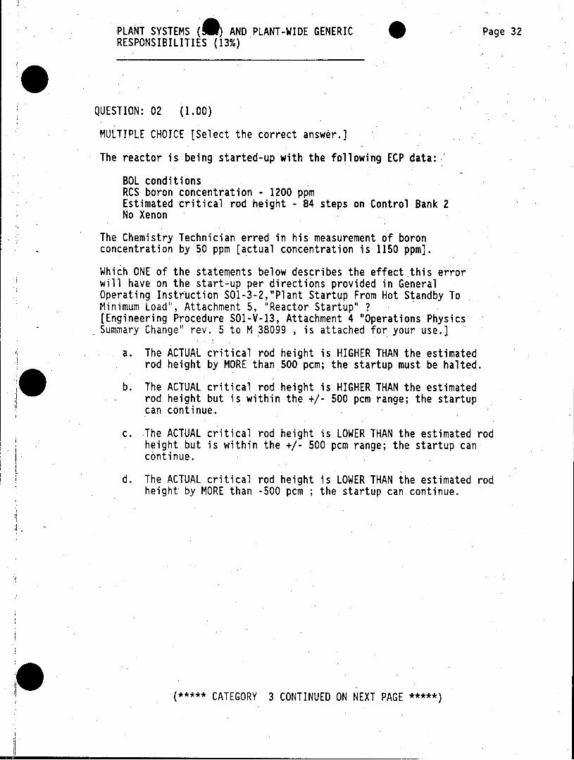
QUESTION: 02 (1.00)
MULTIPLE CHOICE [Select the correct answer.]
The reactor is being started-up with the following ECP data:
BOL conditions RCS boron concentration - 1200 ppm Estimated critical rod height - 84 steps on Control Bank 2 No Xenon
The Chemistry Technician erred in his measurement of boron concentration by 50 ppm [actual concentration is 1150 ppm].
Which ONE of the statements below describes the effect this error will have on the start-up per directions provided in General Operating Instruction SO1-3-2,"Plant Startup From Hot Standby To Minimum Load", Attachment 5, "Reactor Startup" ? [Engineering Procedure SO1-V-13, Attachment 4 "Operations Physics Summary Change" rev. 5 to M 38099 , is attached for your use.]
a. The ACTUAL critical rod height is HIGHER THAN the estimated rod height by MORE than 500 pcm; the startup must be halted.
b. The ACTUAL critical rod height is HIGHER THAN the estimated rod height but is within the +/- 500 pcm range; the startup can continue.
c. The ACTUAL critical rod height is LOWER THAN the estimated rod height but is within the +/- 500 pcm range; the startup can continue.
d. The ACTUAL critical rod height is LOWER THAN the estimated rod height by MORE than -500 pcm ; the startup can continue.
***** CATEGORY 3 CONTINUED ON NEXT PAGE *****
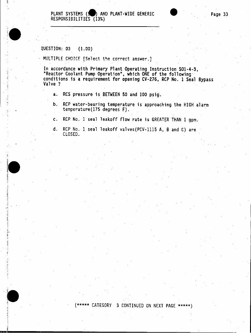
PLANT SYSTEMS AND PLANT-WIDE GENERIC Page 33 RESPONSIBILITIES (13%)
QUESTION: 03 (1.00)
MULTIPLE CHOICE [Select te correct answer.]
In accordance with Primary Plant Operating Instruction S01-4-3, "Reactor Coolant Pump Operation", which ONE of the following conditions is a requirement for opening CV-276, RCP No. 1 Seal Bypass Valve ?
a. RCS pressure is BETWEEN 50 and 100 psig.
b. RCP water-bearing temperature is approaching the HIGH alarm temperature(175 degrees F).
c. RCP No. I seal leakoff flow rate is GREATER THAN 1 gpm.
d. RCP No. 1 seal leakoff valves(PCV-1115 A, B and C) are CLOSED.
(***** CATEGORY 3 CONTINUED ON NEXT PAGE *****)
PLANT SYSTEMS ( ) AND PLANT-WIDE GENERIC Page 34 RESPONSIBILITIES (13%)
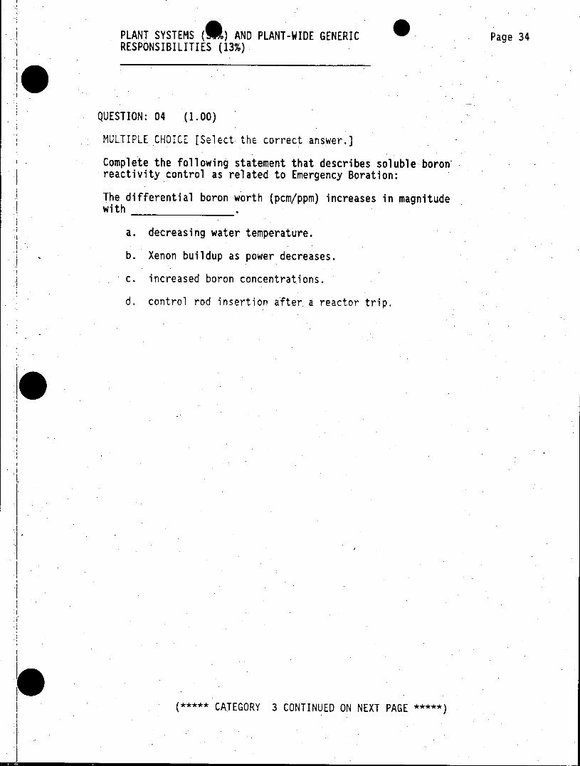
QUESTION: 04 (1.00)
MULTIPLE CHOICE [Select the correct answer.)
Complete the following statement that describes soluble boron reactivity control as related to Emergency Boration:
The differential boron worth (pcm/ppm) increases in magnitude with .
a. decreasing water temperature.
b. Xenon buildup as power decreases.
c. increased boron concentrations.
d. control rod insertion after a reactor trip.
***** CATEGORY 3 CONTINUED ON NEXT PAGE *****)
PLANT SYSTEMS (* AND PLANT-WIDE GENERIC Page 35 RESPONSIBILITIES (13%)
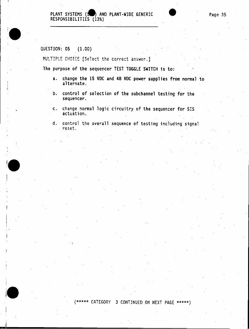
QUESTION: 05 (1.00)
MULTIPLE CHOICE [Select the correct answer.]
The purpose of the sequencer TEST TOGGLE SWITCH is to:
a. change the 15 VDC and 48 VDC power supplies from normal to alternate.
b. control of selection of the subchannel testing for the sequencer.
c. change normal logic circuitry of the sequencer for SIS actuation.
d. control the overall sequence of testing including signal reset.
***** CATEGORY 3 CONTINUED ON NEXT PAGE *****
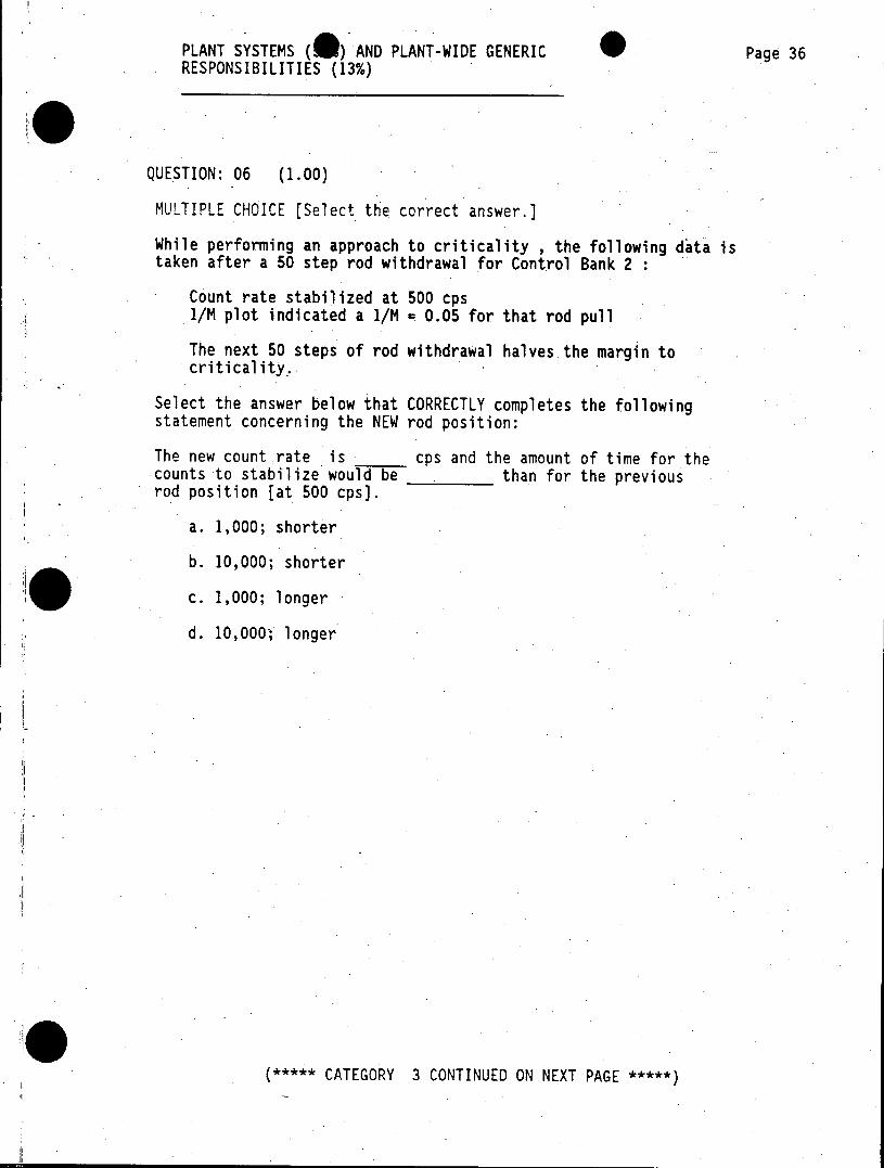
PLANT SYSTEMS (C ) AND PLANT-WIDE GENERIC Page 36 RESPONSIBILITIES (13%)
QUESTION: 06 (1.00)
MULTIPLE CHOICE [Select the correct answer.]
While performing an approach to criticality , the following data is taken after a 50 step rod withdrawal for Control Bank 2
Count rate stabilized at 500 cps 1/M plot indicated a 1/M = 0.05 for that rod pull
The next 50 steps of rod withdrawal halves the margin to criticality.
Select the answer below that CORRECTLY completes the following statement concerning the NEW rod position:
The new count rate is cps and the amount of time for the counts to stabilize would be than for the previous rod position [at 500 cps].
a. 1,000; shorter
b. 10,000; shorter
c. 1,000; longer
d. 10,000; longer
***** CATEGORY 3 CONTINUED ON NEXT PAGE *****
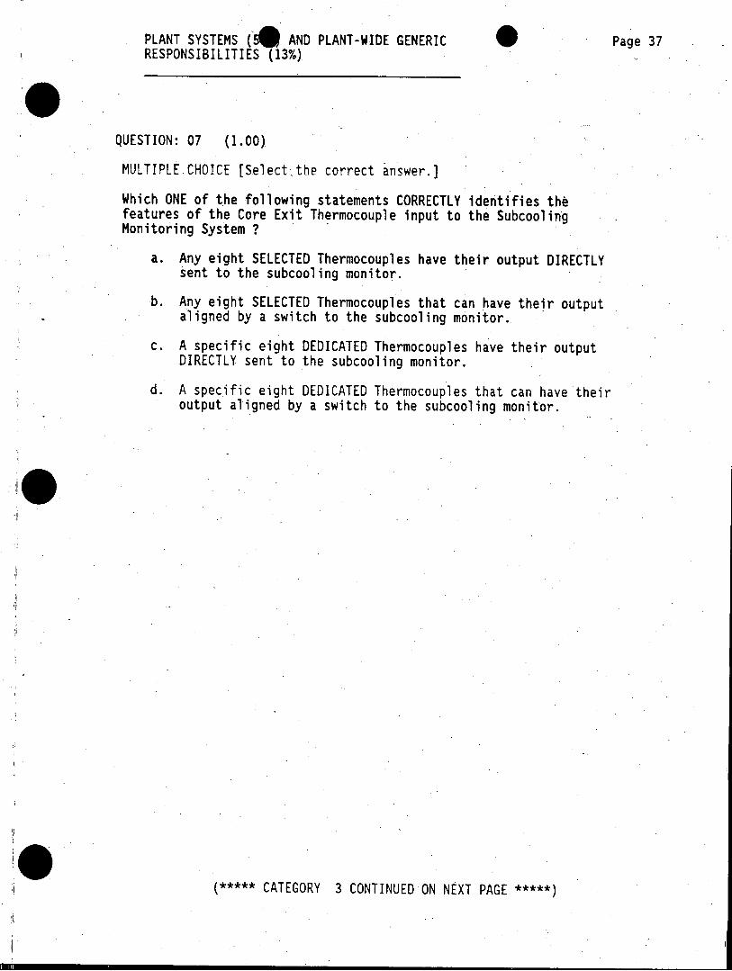
PLANT SYSTEMS (A AND PLANT-WIDE GENERIC Page 37 RESPONSIBILITIES (13%)
QUESTION: 07 (1.00).
MULTIPLE CHOICE [Select the correct answer.]
Which ONE of the following statements CORRECTLY identifies the features of the Core Exit Thermocouple input to the Subcooling Monitoring System ?
a. Any eight SELECTED Thermocouples have their output DIRECTLY sent to the subcooling monitor.
b. Any eight SELECTED Thermocouples that can have their output aligned by a switch to the subcooling monitor.
c. A specific eight DEDICATED Thermocouples have their output DIRECTLY sent to the subcooling monitor.
d. A specific eight DEDICATED Thermocouples that can have their output aligned by a switch to the subcooling monitor.
***** CATEGORY 3 CONTINUED ON NEXT PAGE *****
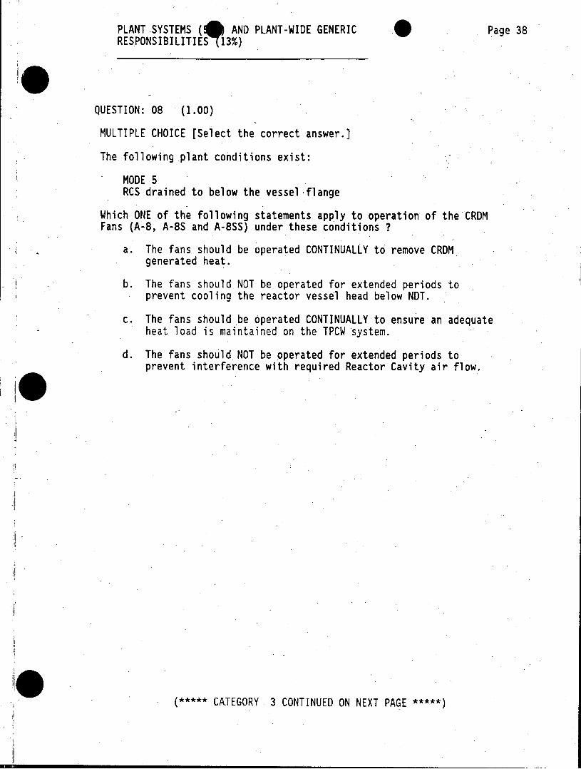
PLANT SYSTEMS (0 AND PLANT-WIDE GENERIC Page 38 RESPONSIBILITIES 13%)
QUESTION: 08 (1.00)
MULTIPLE CHOICE [Select the correct answer.]
The following plant conditions exist:
MODE 5. RCS drained to below the vessel 'flange
Which ONE of the following statements apply to operation of the CRDM Fans (A-8, A-8S and A-8SS) under these conditions ?
a. The fans should be operated CONTINUALLY to remove CRDM generated heat.
b. The fans should NOT be operated for extended periods to prevent cooling the reactor vessel head below NDT.
c. The fans should be operated CONTINUALLY to ensure an adequate heat load is maintained on the TPCW system.
d. The fans should NOT be operated for extended periods to prevent interference with required Reactor Cavity air flow.
***** CATEGORY 3 CONTINUED ON NEXT PAGE *****
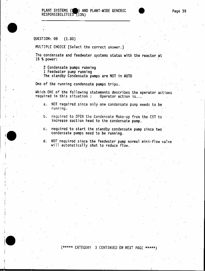
PLANT SYSTEMS ( ) AND PLANT-WIDE GENERIC Page 39 RESPONSIBILITIE 13%)
QUESTION: 09 (1.00)
MULTIPLE CHOICE [Select the correct answer.)
The condensate and feedwater systems status with the reactor at 15 % power:
2 Condensate pumps running I Feedwater pump running The standby Condensate pumps are NOT in AUTO
One of the running condensate pumps trips.
Which ONE of the following statements describes the operator actions required in this situation : Operator action is...
a. NOT required since only one condensate pump needs to be running.
b. required to OPEN the Condensate Make-up from the CST to increase suction head to the condensate pump.
c. required to start the standby condensate pump since two condensate pumps need to be running.
d. NOT required since the feedwater pump normal mini-flow valve will automatically shut to reduce flow.
***** CATEGORY 3 CONTINUED ON NEXT PAGE *****
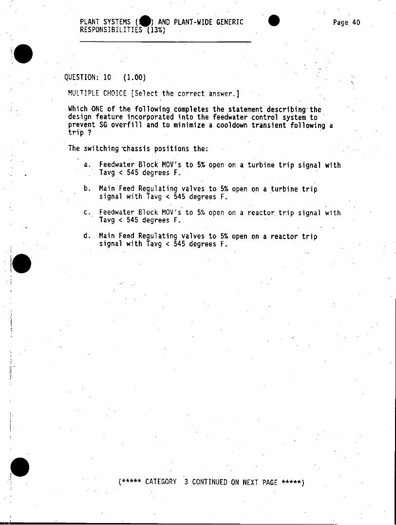
PLANT SYSTEMS (10) AND PLANT-WIDE GENERIC Page 40 RESPONSIBILITIES (13%)
QUESTION: 10 (1.00)
MULTIPLE CHOICE [Select the correct answer.]
Which ONE of the following completes the statement describing-the design feature incorporated into the feedwater control system to prevent SG overfill and to minimize a cooldown transient following a trip ?
The switching chassis positions the:
a. Feedwater Block MOV's to 5% open on a turbine trip signal with Tavg < 545 degrees F.
b. Main Feed Regulating valves to 5% open on a turbine trip signal with Tavg < 545 degrees F.
c. Feedwater Block MOV's to 5% open on a reactor trip signal with Tavg < 545 degrees F.
d. Main Feed Regulating valves to 5% open on a reactor trip signal with Tavg < 545 degrees F.
***** CATEGORY 3 CONTINUED ON NEXT PAGE *****
PLANT SYSTEMS (5S AND PLANT-WIDE GENERIC Page 41 RESPONSIBILITIES 3%)
QUESTION: 11 (2.00)
MATCHING
. For each auxiliary feedwater pump given in Column I match the attribute(s) given in Column II. [NOTE: More than one attribute can apply to each pump.]
Column I Column II AFW Pump Pump Attribute
----- ------------------------------ -------------------------
a. Motor-driven AFW Pump G-10W 1. Will trip on overspeed at 110% rated speed
b. Motor-driven AFW Pump G-10S 2. Can be powered from the
c. TUrbine-driven AFW Pump G-10 Dedicated safe Shutdown Bus A4
3. Is Train "B" related
4. Has a 40-second time delay in starting circuit
***** CATEGORY 3 CONTINUED ON NEXT PAGE *****)
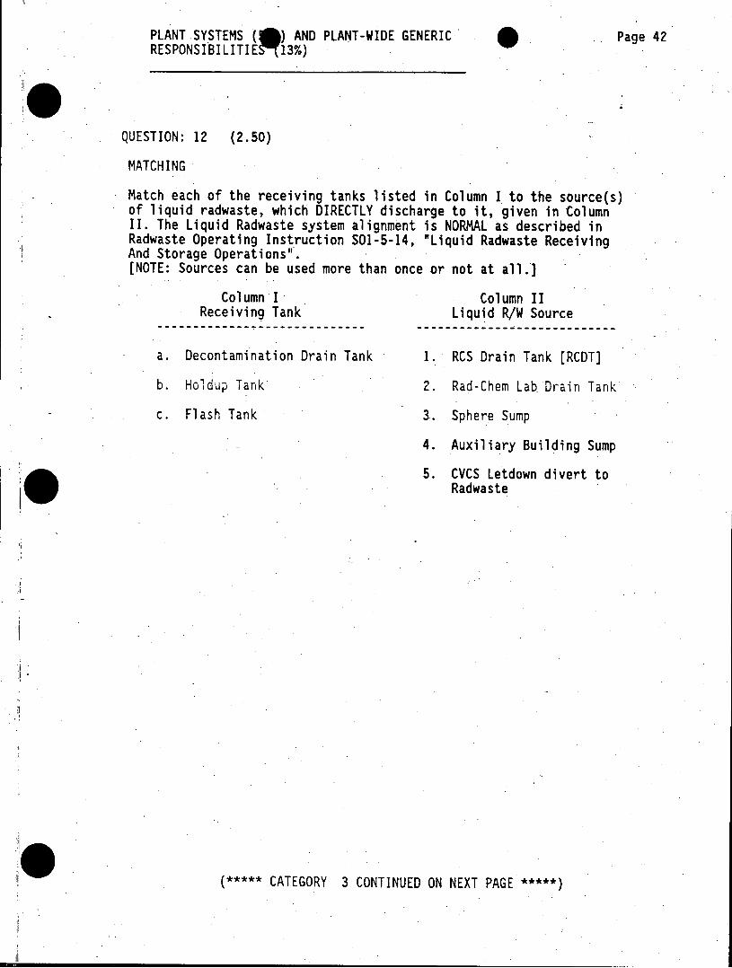
PLANT SYSTEMS (0) AND PLANT-WIDE GENERIC' Page 42 RESPONSIBILITIES 13%)
QUESTION: 12 (2.50)
MATCHING
Match each of the receiving tanks listed in Column I to the source(s) of liquid radwaste, which DIRECTLY discharge to it, given in Column II. The Liquid Radwaste system alignment is NORMAL as described in Radwaste Operating Instruction S01-5-14, "Liquid Radwaste Receiving And Storage Operations". [NOTE: Sources can be used more than once or not at all.]
Column I Column II Receiving Tank Liquid R/W Source
---- ----------------------------- ------------- -------------
a. Decontamination Drain Tank 1. RCS Drain Tank [RCDT]
b. Holdup Tank* 2. Rad-Chem Lab. Drain Tank
c. Flash Tank 3. Sphere Sump
4. Auxiliary Building Sump
5. CVCS Letdown divert to Radwaste
***** CATEGORY 3 CONTINUED ON NEXT PAGE *****
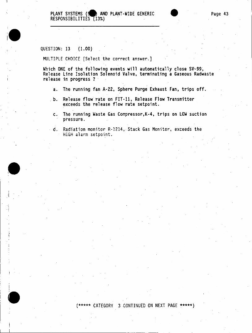
PLANT SYSTEMS AND PLANT-WIDE GENERIC Page 43 RESPONSIBILITIES (13%)
QUESTION: 13 (1.00)
MULTIPLE CHOICE [Select the correct answer.]
Which ONE of the following events will automatically close SV-99, Release Line Isolation Solenoid Valve, terminating a Gaseous Radwaste release in progress ?
a. The running fan A-22, Sphere Purge Exhaust Fan, trips off.
b. Release flow rate on FIT-11, Release Flow Transmitter exceeds the release flow rate setpoint.
c. The running Waste Gas Compressor,K-4, trips on LOW suction pressure.
d. Radiation monitor R-1214, Stack Gas Monitor, exceeds the HIGH alarm setpoint.
***** CATEGORY 3 CONTINUED ON NEXT PAGE *****
PLANT SYSTEMS (0) AND PLANT-WIDE GENERIC 'Page 44 RESPONSIBILITIES (13%)
QUESTION: 14 (1.00)
MULTIPLE CHOICE [Select the correct answer.)
Which ONE of the following methods is used to detect RCS coolant leakage past the 0-rings between the reactor vessel head and flange ?
a. A temperature sensor in the leakoff line that indicates high temperature.
b. A pressure sensor in the leakoff line that indicates high pressure.
c. A level sensor in the leakoff line that indicates high level.
d. A flow sensor in the leakoff line that indicates high flow.
0 (***** CATEGORY 3 CONTINUED ON NEXT PAGE *****)
PLANT SYSTEMS ( AND PLANT-WIDE GENERIC Page 45 RESPONSIBILITIE S 3%)
QUESTION: 15 (1.00)
MULTIPLE CHOICE [Select the correct answer.]
Which ONE of the following conditions will initiate an AUTOMATIC Safety Injection signal [SIS] ?
a. Steam header pressure sensor LESS THAN 400 psig
b. 2/3 containment pressure sensors GREATER THAN 1.4 psig
c. Undervoltage sensors on BOTH 4kV busses 1C and 2C LESS THAN 2912 V
d. 2/3 Pressurizer pressure sensors GREATER THAN 2200 psig
(***** CATEGORY 3 CONTINUED ON NEXT PAGE *****
PLANT SYSTEMS (@) AND PLANT-WIDE GENERIC Page 46 RESPONSIBILITIES (13%)
QUESTION: 16 (1.00)
MULTIPLE CHOICE [Select the correct answer.]
Which ONE of the listed alarms will annunciate in the control- room as a DIRECT result of Pressurizer Pressure Transmitter PT-430 failing LOW during normal operations?
a. PRESSURE TRANSIENTS IN PROGRESS
b. PRESSURIZER LO PRESS SAFETY INJECT TRAIN B CH I
c. PRESSURIZER VAR. LO PRESS REACTOR TRIP CHANNEL I
d. OVER POWER REACTOR TRIP PARTIAL TRIP
**
0~. (***** CATEGORY 3 CONTINUED ON NEXT PAGE ***
PLANT SYSTEMS (5@ AND PLANT-WIDE GENERIC Page 47 RESPONSIBILITIES (13%)
QUESTION: 17 (1.00)
MULTIPLE CHOICE [Select the correct answer.]
Which ONE of the following statements completes the description of conditions required for actuation of the Overpressure Mitigation System.
The PORVS are in AUTO and:
a. the OMS controls are in ACTIVE; RCS Wide Range pressure is GREATER THAN 480 psig.
b. the OMS controls are in ACTIVE; RHR discharge pressure is GREATER THAN 480 psig.
c. the OMS controls are in ENABLE; CVCS letdown pressure is GREATER THAN 420 psig.
d. the OMS controls are in ENABLE; Pressurizer pressure is GREATER THAN 420 psig.
(***** CATEGORY 3 CONTINUED ON NEXT PAGE *****
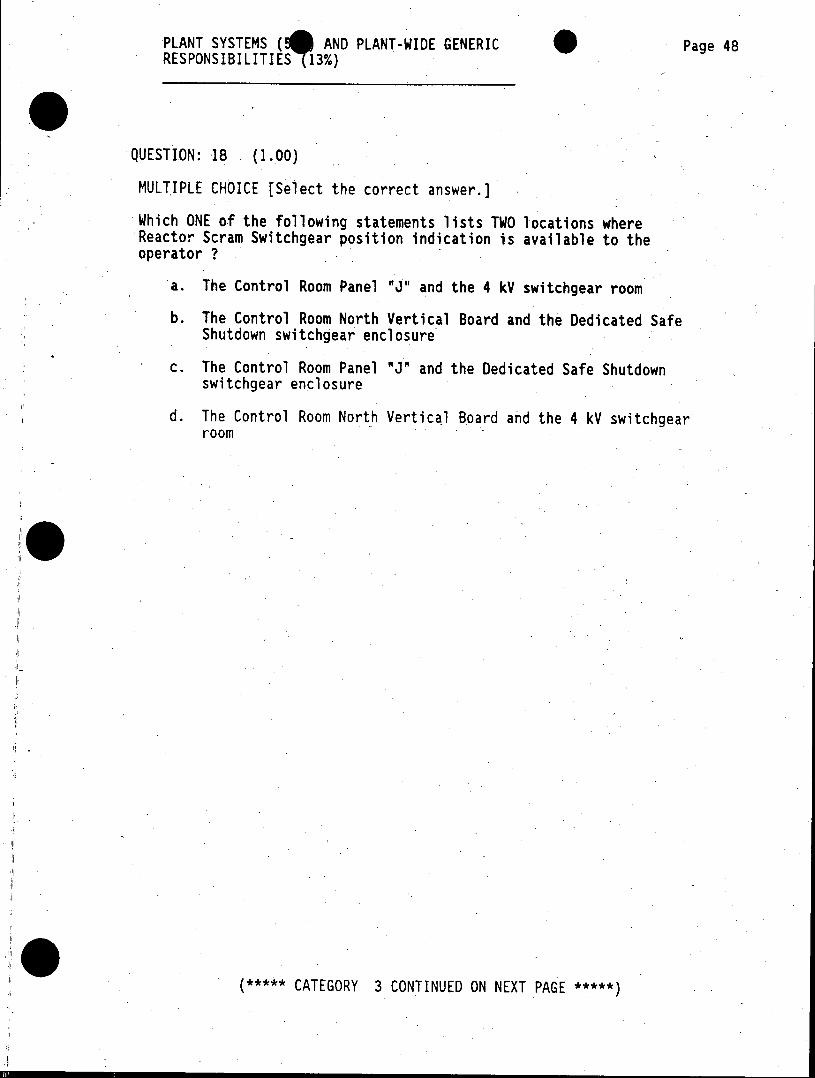
PLANT SYSTEMS AND PLANT-WIDE GENERIC Page 48 RESPONSIBILITIES (13%)
QUESTION: 18 (1.00)
MULTIPLE CHOICE [Select the correct answer.]
Which ONE of the following statements lists TWO locations where Reactor Scram Switchgear position indication is available to the operator ?
a. The Control Room Panel "J" and the 4 kV switchgear room
b. The Control Room North Vertical Board and the Dedicated Safe Shutdown switchgear enclosure
c. The Control Room Panel "J" and the Dedicated Safe Shutdown switchgear enclosure
d. The Control Room North Vertical Board and the 4 kV switchgear room
***** CATEGORY 3 CONTINUED ON NEXT PAGE *****
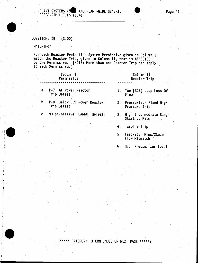
PLANT SYSTEMS (4 AND PLANT-WIDE GENERIC Page 49 RESPONSIBILITIES (13%)
QUESTION: 19 (3.00)
MATCHING
For each Reactor Protection System Permissive given in Column-I match the Reactor Trip, given in Column II, that is AFFECTED by the Permissive. (NOTE: More than one Reactor Trip can apply to each Permissive.]
Column I Column II Permissive- Reactor Trip
------------------------ ---------------------------
a. P-7, At Power Reactor 1. Two [RCS] Loop Loss Of Trip Defeat Flow
b. P-8, Below 50% Power Reactor 2. Pressurizer Fixed High Trip Defeat Pressure Trip
c. NO permissive [CANNOT defeat] 3. High Intermediate Range Start Up Rate
4. Turbine Trip
5. Feedwater Flow/Steam Flow Mismatch
6. High Pressurizer Level
(***** CATEGORY 3 CONTINUED ON NEXT PAGE *****
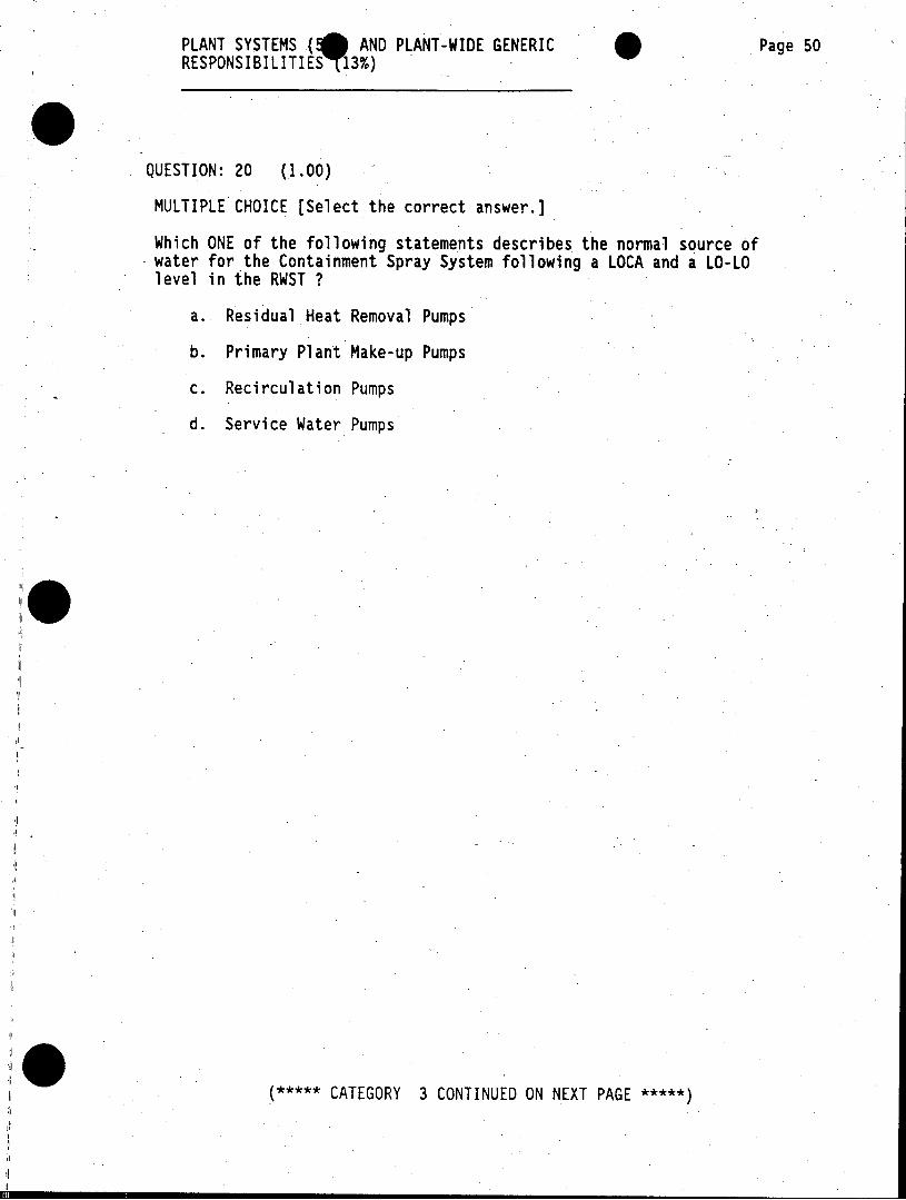
PLANT SYSTEMS ( AND PLANT-WIDE GENERIC Page 50 RESPONSIBILITIEST13%)
QUESTION: 20 (1.00)
MULTIPLE CHOICE [Select the correct answer.]
Which ONE of the following statements describes the normal source of water for the Containment Spray System following a LOCA and a LO-LO level in the RWST ?
a. Residual Heat Removal Pumps
b. Primary Plant Make-up Pumps
c. Recirculation Pumps
d. Service Water Pumps
***** CATEGORY 3 CONTINUED ON NEXT PAGE *****
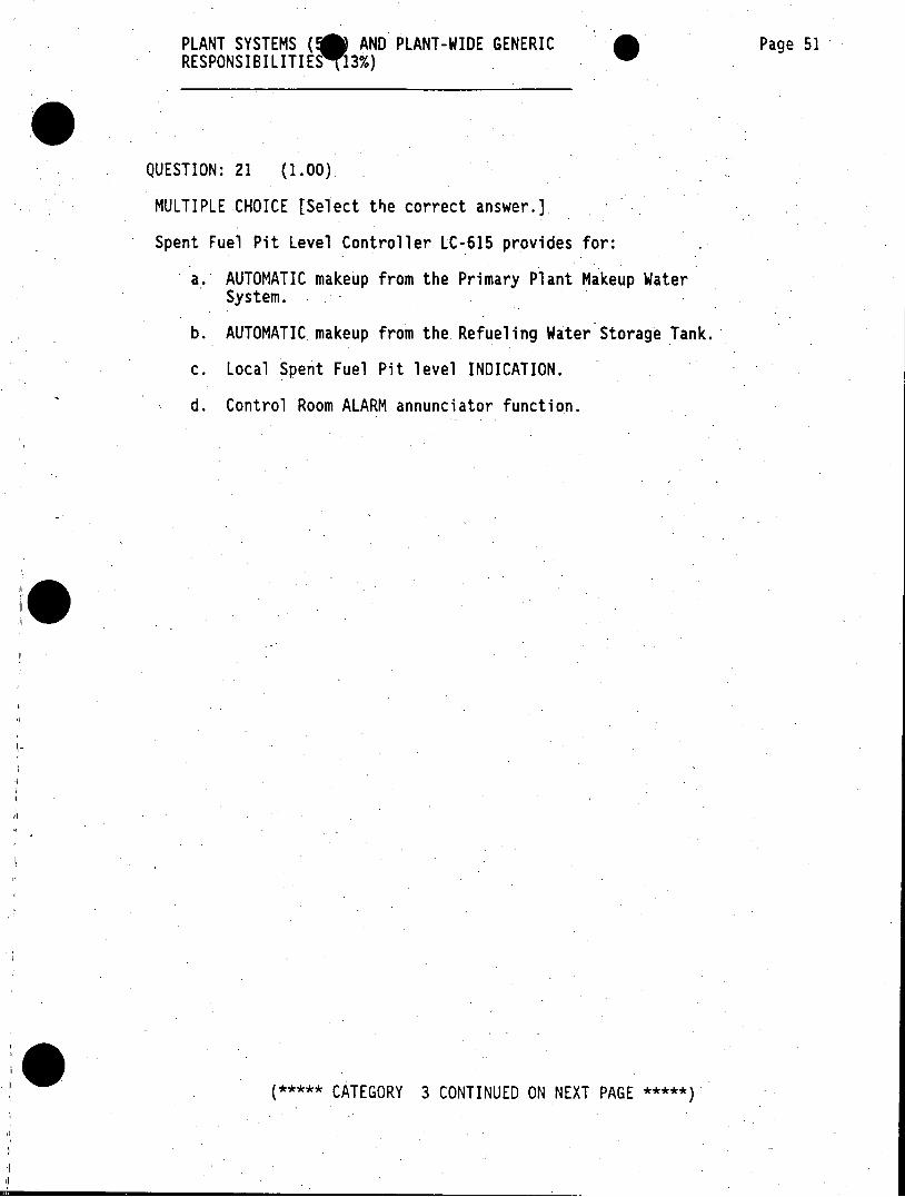
PLANT SYSTEMS ( AND PLANT-WIDE GENERIC Page 51 RESPONSIBILITIES T13%)
QUESTION: 21 (1.00)
MULTIPLE CHOICE [Select the correct answer.)
Spent Fuel Pit Level Controller LC-615 provides for:
a. AUTOMATIC makeup from the Primary Plant Makeup Water System.
b. AUTOMATIC makeup from the Refueling Water Storage Tank.
c. Local Spent Fuel Pit level INDICATION.
d. Control Room ALARM annunciator function.
***** CATEGORY 3 CONTINUED ON NEXT PAGE *****
PLANT SYSTEMS AND PLANT-WIDE GENERIC Page 52 RESPONSIBILITIES (13%)
QUESTION: 22 (1.00)
MULTIPLE-CHOICE [Select the correct answer.]
How many Atmospheric Steam Dump valves are located on each Relief Header on the Main Steam Lines ?
a. 1 per header
b. 2 per header
c. 4 per header
d. 5 per header
***** CATEGORY 3 CONTINUED ON NEXT PAGE *****
PLANT SYSTEMS (0) AND PLANT-WIDE GENERIC Page 53 RESPONSIBILITIE 13%)
QUESTION: 23 (1.00)
MULTIPLE CHOICE [Select the correct answer.)
Which ONE of the following sequences describes the response of the Diesel Generator [DG] and the output breaker to a Sequencer Loss Of Power [LOP] signal from a 4kV bus on which this DG is currently PARALLELED ?
a. The output breaker receives a trip signal; the DG continues to run.
b. The output breaker does NOT receive a trip signal; the DG receives a trip signal to shutdown.
c. The output breaker receives a trip signal; the DG receives a trip signal to shutdown.
d. The output breaker does NOT receive a trip signal; the DG continues to run.
***** CATEGORY 3 CONTINUED ON NEXT PAGE *****
PLANT SYSTEMS ( AND PLANT-WIDE GENERIC Page 54 RESPONSIBILITIES 13%)
QUESTION: 24 (1.00)
MULTIPLE CHOICE [Select the correct answer.]
Which ONE of the reasons below describes the purpose of the limit stops or "bumps" installed on the underside of the circulating water intake tunnel isolation gate [MOV-9] ?
a. allows continued unit operation with seawater temperatures LESS THAN 40 degrees F
b. ensures minimum required flow of seawater to Salt Water Cooling Pumps
c. limits Circulating Water Pump running amperage to LESS THAN 235 amps
d. aids the temperature rise for Heat Treating the Outfall Conduit
***** CATEGORY 3 CONTINUED ON NEXT PAGE *****
PLANT SYSTEMS (0) AND PLANT-WIDE GENERIC Page 55 RESPONSIBILITIESP 13%)
QUESTION: 25 (1.00)
MULTIPLE CHOICE [Select the correct answer.]
Technical Specifications state that in MODE 5, with all reactor coolant loops filled, at least one Residual Heat Removal (RHR) train shall be OPERABLE and in operation, except that that pump may be de-energized for up to one hour provided certain conditions are met. Which ONE of the following items describes ONE of these conditions ?
a. Two centrifugal charging pumps are OPERABLE and at least one is operating.
b. No operations are permitted that would cause a dilution of the RCS of GREATER THAN 0.5% delta k/k.
c. Core outlet temperature is maintained at least 40 degrees F below saturation temperature.
d. Pressurizer water level remains LESS THAN 80%.
(***** CATEGORY 3 CONTINUED ON NEXT PAGE *****
PLANT SYSTEMS (*) AND PLANT-WIDE GENERIC 'Page 56 RESPONSIBILITIES (13%)
QUESTION: 26 (1.00)
MULTIPLE CHOICE [Select the correct answer.)
Which ONE of the following statements CORRECTLY describes an indication in the Control Room that would FIRST alert the operator to a leaking PORV ?
a. Common tailpipe temperature HIGH
b. Pressurizer surge line temperature HIGH
c. Reactor Coolant Drain Tank temperature HIGH
d. Containment sump temperature HIGH
***** CATEGORY 3 CONTINUED ON NEXT PAGE *****)
PLANT SYSTEMS (@) AND PLANT-WIDE GENERIC Page 57 RESPONSIBILITIES (13%)
QUESTION: 27 (1.00)
MULTIPLE CHOICE [Select the correct answer.]
Which ONE of the following components is NOT provided with cooling water from the Component Cooling Water [CCW] system ?
a. Reactor Coolant Pumps
b. Recirculation Heat Exchanger
c. Radwaste Flash Tank
d. Reactor Shield Cooling Coils
***** CATEGORY 3 CONTINUED ON NEXT PAGE *****
PLANT SYSTEMS AND PLANT-WIDE GENERIC Page 58 RESPONSIBILITIES (13%)
QUESTION: 28 (1.00)
MULTIPLE CHOICE [Select the correct answer.]
Which ONE of the following choices CORRECTLY completes the following statement about the Hydrogen Recombiners.
In accordance with Operating Instruction S01-5-11, "Post-Accident Containment Hydrogen Control", the operator will adjust the Recombiner power from the Recombiner control panel located in the and VERIFY proper operation by monitoring
a. Technical Support Center; Recombiner power wattage
b. Diesel Generator Building mezzanine; Containment hydrogen concentration
c. Dedicated Safe Shutdown Switchgear Enclosure; Containment temperature
d. Main Control Room; Recombiner thermocouple temperature
***** CATEGORY 3 CONTINUED ON NEXT PAGE *****
PLANT SYSTEMS (5 AND PLANT-WIDE GENERIC Page 59 RESPONSIBILITIES 13%)
QUESTION: 29 (1.00)
MULTIPLE CHOICE [Select the correct answer.]
Which ONE of the conditions listed below will cause a turbinerunback during NORMAL plant operation at 100% power ?
a. FULLY dropped control rod
b. Loss of ALL electrical load
c. HIGH Governor oil pressure
d. LOW Generator output frequency
0I
I***** CATEGORY 3 CONTINUED ON NEXT PAGE *****
PLANT SYSTEMS ( AND PLANT-WIDE GENERIC Page 60 RESPONSIBILITIES (13%)
QUESTION: 30 (1.00)
MULTIPLE CHOICE [Select the correct answer.)
The Auxiliary Air Compressor (K-903) will start on LOW Redundant Air Header pressure to act as a back-up supply of air to selected loads. Which ONE of the following is the power supply for the compressor ?
a. 4 kV AC Bus 1A
b. 4 kV AC Dedicated Safe Shutdown Bus A4
c. 480-V AC MCC 1
d. Dedicated diesel engine driver
***** CATEGORY 3 CONTINUED ON NEXT PAGE *****
PLANT SYSTEMS AND PLANT-WIDE GENERIC Page 61 RESPONSIBILITIES (13%)
QUESTION: 31 (1.00)
MULTIPLE CHOICE [Select the correct answer.]
If San Onofre Units 2 & 3 Fire water pumps are incapable of of supplying the Fire Suppression Water Systems, which ONE of the following statements describes the required source of water for the San Onofre Unit I fire water pumps ?
a. Units 2 & 3 Service and Fire Water Storage Tanks
b. Unit 1 Condensate Storage Tank
c. Unit 1 Salt-Water Intake Structure
.d. Unit 1 Service Water reservoir
***** CATEGORY 3 CONTINUED ON NEXT PAGE *****
PLANT SYSTEMS (5 AND PLANT-WIDE GENERIC Page 62 RESPONSIBILITIES (13%)
QUESTION: 32 (1.00)
MULTIPLE CHOICE [Select the correct answer.]
Component Cooling Water Heat Exchanger outlet valves MOV-720A & -720B are interlocked with the controls for the North and South Salt Water Cooling Pumps [G-13A & -13B], respectively. Which ONE of the following statements describes this interlock ?
a. The valve will NOT remain CLOSED if the Salt Water Cooling Pump is running.
b. The valve will NOT remain OPEN if the Salt Water Cooling Pump is stopped.
c. The Salt Water Cooling Pump will NOT start until the valve has has stroked fully OPEN.
d. The Salt Water Cooling Pump will AUTO STOP if the valve stokes fully CLOSED.
***** CATEGORY 3 CONTINUED ON NEXT PAGE *****
PLANT SYSTEMS ( AND PLANT-WIDE GENERIC Page 63 RESPONSIBILITIES (13%)
QUESTION: 33 (1.00)
MULTIPLE CHOICE [Select the correct answer.]
Which ONE of the situations below, concerning an "Important-to-Safety" system,.requires Independent Verification as described in 50123-0-23, "Control Of System Alignments" ?
a. Manipulation of the Main Feed SI Recirculation valve CV-875A while in MODE 4.
b. Installation of a Temporary Facility Modification on the South Refueling Water Pump G-27S while in MODE 3.
c. Removal from service for maintenance of the West Hydrazine Addition Pump G-200B while in Mode 6.
d. Breifly OPEN SI system vent valve SIS-318 for East SI Pump discharge in MODE 1 to vent.
***** CATEGORY 3 CONTINUED ON NEXT PAGE *****
PLANT SYSTEMS (5 AND PLANT-WIDE GENERIC Page 64 RESPONSIBILITIES (13%)
QUESTION: 34 -(1.00)
MULTIPLE CHOICE [Select the correct'answer.]
Which ONE of the following statements describes the correct method for verifying manual valve CLOSURE when performing a Work Authortzation alignment ?
a. Rotate the valve operator to OPEN until the valve is FULLY open, then re-close.
b. Rotate the valve operator to OPEN until the position indicator begins to move, then re-close.
c. Attempt to rotate the valve operator to CLOSE using normal closing torque.
d. Observe the position indication ONLY; NO manipulation of the valve is allowed.
***** CATEGORY 3 CONTINUED ON NEXT PAGE *****
PLANT SYSTEMS ( AND PLANT-WIDE GENERIC Page 65 RESPONSIBILITIES (13%)
QUESTION: 35 (2.00)
FILL IN THE BLANKS
Fill in the exposure limits, for a Radiation Worker allowed SONGS INITIAL Administrative Exposure limits as detailed in S0123-VII-4, "Personnel Monitoring Program", AND 10 CFR 20 MAXIMUM limits. [Assume exposure history [NRC FORM 4] is on file with no previous noted individual exposure.]
AREA EXPOSED INITIAL'ADM LMT 10CFR20 LMT
Quarterly Whole Body a b [age >/= 25 years]
Yearly Whole Body c d
Quarterly Extremities e f [Hands and feet]
Quarterly Skin of whole g b__h body
***** CATEGORY 3 CONTINUED ON NEXT PAGE *****
PLANT SYSTEMS (5 AND PLANT-WIDE GENERIC Page 66 RESPONSIBILITIES (13%)
QUESTION: 36 (1.00)
MULTIPLE CHOICE [Select the correct answer.]
During which ONE of the listed plant conditions may the Control Operator [Licensed R.O.] assume the Control Room Command Function in the absence of the Control Room Supervisor and the Shift Superintendent, when authorized ?
a. Modes 1 less than 15% power, 2, 3 and 4.
b. Modes 3, 4, 5 and 6.
c. Modes 5 and 6.
d. Modes I and 2.
***** CATEGORY 3 CONTINUED ON NEXT PAGE *****)
PLANT SYSTEMS (5 AND PLANT-WIDE GENERIC Page 67 RESPONSIBILITIES (13%)
QUESTION: 37 (1.00)
MULTIPLE CHOICE (Select the correct answer.)
Which ONE of the following statements describes the equipmentavailable for use in the event of a toxic gas atmosphere in the Control Room ?
a. No special equipment is available; the Control Room must be evacuated.
b. Self-Sealing Hoods with airlines are available in the Control Room.
c. Self-Contained Breathing Apparatuses are available in the Control Room.
d. Full-View Air Mask with absorbent canisters are available in the Control Room.
III0 ***** CATEGORY 3 CONTINUED ON NEXT PAGE *****
PLANT SYSTEMS ( AND PLANT-WIDE GENERIC Page 68 RESPONSIBILITIES (13%)
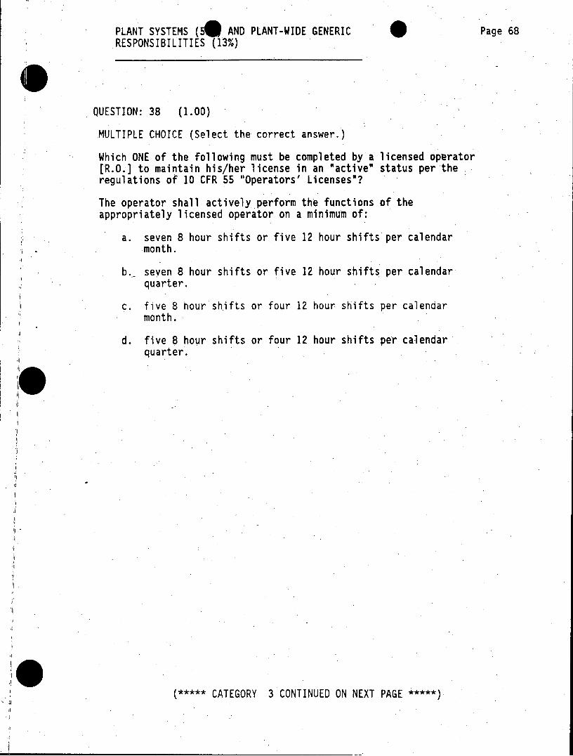
QUESTION: 38 (1.00)
MULTIPLE CHOICE (Select the correct answer.)
Which ONE of the following must be completed by a licensed operator [R.O.] to maintain his/her license in an "active" status per the regulations of 10 CFR 55 "Operators' Licenses"?
The operator shall actively perform the functions of the appropriately licensed operator on a minimum of:
a. seven 8 hour shifts or five 12 hour shifts per calendar month.
b._ seven 8 hour shifts or five 12 hour shifts per calendar quarter.
c. five 8 hour shifts or four 12 hour shifts per calendar month.
d. five 8 hour shifts or four 12 hour shifts per calendar quarter.
(***** CATEGORY 3 CONTINUED ON NEXT PAGE *****
PLANT SYSTEMS (B) AND PLANT-WIDE GENERIC Page 69 RESPONSIBILITIES (13%)
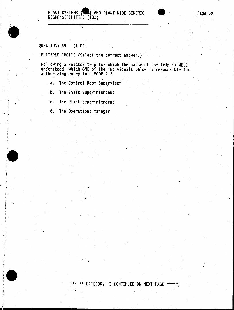
QUESTION: 39 (1.00)
MULTIPLE CHOICE (Select the correct answer.)
Following a reactor trip for which the cause of the trip is WELL understood, which ONE of the individuals below is responsible for authorizing entry into MODE 2 ?
a. The Control Room Supervisor
b. The Shift Superintendent
c. The Plant Superintendent
d. The Operations Manager
***** CATEGORY 3 CONTINUED ON NEXT PAGE ****
PLANT SYSTEMS ( ) AND PLANT-WIDE GENERIC Page 70 RESPONSIBILITIES (13%)
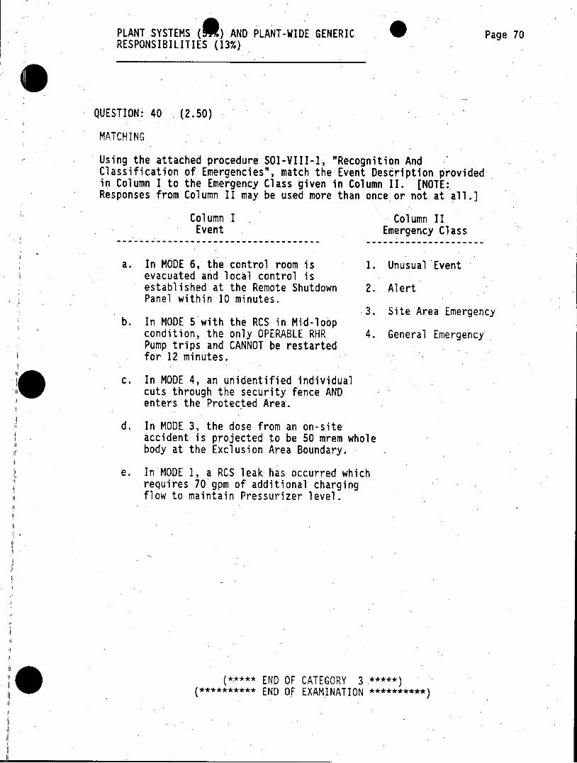
QUESTION: 40 (2.50)
MATCHING
Using the attached procedure SO1-VIII-I, "Recognition And Classification of Emergencies", match the Event Description provided in Column I to the Emergency Class given in Column II. [NOTE: Responses from Column II may be used more than once or not at all.]
Column I Column II Event Emergency Class
---- --------------------------------- ----------------------
a. In MODE 6, the control room is 1., Unusual Event evacuated and local control is established at the Remote Shutdown 2. Alert Panel within 10 minutes.
3. Site Area Emergency b. In MODE 5 with the RCS in Mid-loop
condition, the only OPERABLE RHR 4. General Emergency Pump trips and CANNOT be restarted for 12 minutes.
c. In MODE 4, an unidentified individual cuts through the security fence AND enters the Protected Area.
d. In MODE 3, the dose from an on-site accident is projected to be 50 mrem whole body at the Exclusion Area Boundary.
e. In MODE 1, a RCS leak has occurred which requires 70 gpm of additional charging flow to maintain Pressurizer level.
(***** END OF CATEGORY 3 *****) (********** END OF EXAMINATION **********
EMERGENCY AND A& MAL PLANT EVOLUTIONS Page 71 (36%)
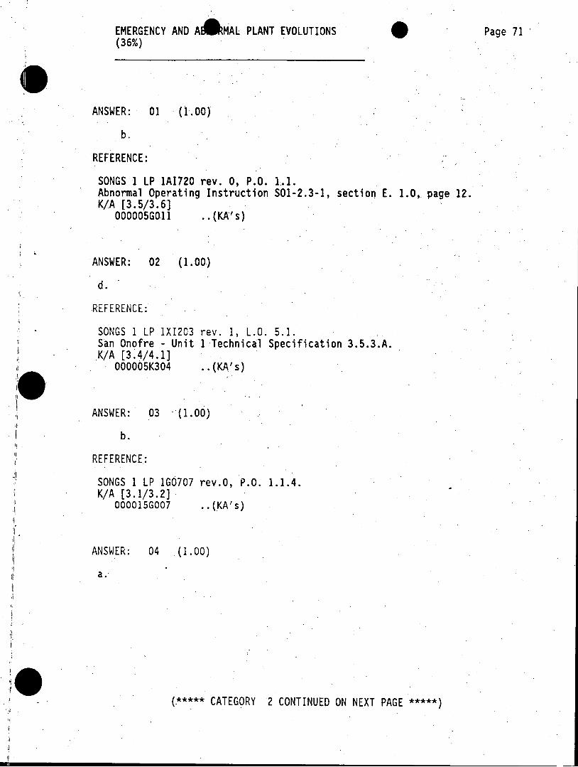
ANSWER: 01 (1.00)
b.
REFERENCE:
SONGS 1 LP 1A1720 rev. 0, P.O. 1.1. Abnormal Operating Instruction SO1-2.3-1, section E. 1.0, page 12. K/A [3.5/3.6]
000005G011 ..(KA's)
ANSWER: 02 (1.00)
d.
REFERENCE:
SONGS 1 LP 1XI203 rev. 1, L.O. 5.1. San Onofre - Unit 1 Technical Specification 3.5.3.A. K/A [3.4/4.1]
000005K304 ..(KA's)
ANSWER: 03 (1.00)
b.
REFERENCE:
SONGS 1 LP 1G0707 rev.0, P.O. 1.1.4. K/A [3.1/3.2]
000015G007 ..(KA's)
ANSWER: 04 (1.00)
a.
(***CATEGORY 2 CONTINUED ON NEXT PAGE ***
EMERGENCY AND ARMAL PLANT EVOLUTIONS Page 72 (16%),
REFERENCE:
SONGS I LP 1XA203 rev. 2, L.O. 1.1.3. SONGS 1 System Description SD-S01-300 rev. 2. K/A [2.9/2.91
000015K207 ..(KA's)
ANSWER: 05 (1.00)
b.
REFERENCE:
SONGS 1 LP 1A1713 rev. 0, L.O. 1.4. K/A [4.2/4.4]
000024K302 ..(KA's)
ANSWER: 06 (1.00)
b.
*10 REFERENCE:
SONGS 1 LP ITA710 rev. 1, E.O.'s 1.2, 2.1, and 4.2. Emergency Operating Instruction SO1-1.0-1 rev. 3. Emergency Operating Instruction SOI-1.0-10 rev. 5, step 24. Emergency Operating Instruction SO1-1.0-30.1 rev. 0, "Background Document to Loss Of Secondary Coolant".
K/A [4.1/4.4) 000040K101 ..(KA's)
ANSWER: 07 (2.50)
5[0.5 ea] . a. 1.(Open) cXor b. 3.(Maintained by Back-Up Nitrogen) C2. o c. 3.(Maintained by Back-Up Nitrogen) [ i \ Q e d. 2.(Closed) .takrNiognd. e. 3.(Maintained by Back-Up Nitrogen) L2.
(***** CATEGORY 2 CONTINUED ON NEXT PAGE *****
EMERGENCY AND AbRMAL PLANT EVOLUTIONS Page 73 (36%)
REFERENCE.
SONGS 1 LP 1XQ207 rev. 1, P.O. 5.3.3. SONGS 1 LP 1XA203 rev. 2, L.O. 1.1.2. SONGS 1 LP 1XP207 rev. 1, L.O. 2.3. SONGS 1 LP 1XP202 rev. 0, L.O. 2.4 and 2.5. SONGS 1 LP 1XI202 rev. 2, P.O. 2.5. Emergency Operating Instruction S01-1.0-60 rev. 6, Continuous Action Steps
Abnormal Operating Instruction SOI-2.4-2 rev. 1, Section C. K/A [3.4/3.7]
000055A201 ..(KA's)
ANSWER: 08 (1.00)
C.
REFERENCE:
SONGS 1 LP 1E1716 rev. 4, L.O.'s 1.1 and 1.1.3. Emergency Operating Instruction 1S0-1.0-60.1 rev. 0, "Background Document For Loss Of All AC Power".
K/A [3.9/4.7] ; [4.3/4.6] 000055K302 000055A203 .. (KA's)
ANSWER: 09 (2.50)
a. 4. (Lead ACO) [0.5] b. 1. (SS), 2. (STA) [0.5 ea]
[3. (CO) will be accepted without credit or penality] c. 3. (CO) [0.5] d. 5. (Lead PEO) [0.5]
REFERENCE:
SONGS 1 LP 1AI742 rev.1, LO 1.1.6. Abnormal Operating Instruction S01-2.7-2 rev. 0, steps 3.5.1 and 4.1. Abnormal Operating Instruction SO1-2.7-1 rev. 0. K/A [3.3/4.1]
000067K304 ..(KA's)
ANSWER: 10 (1.00)
d.
(***** CATEGORY 2 CONTINUED ON NEXT PAGE *****
EMERGENCY AND AA MAL PLANT EVOLUTIONS Page 74 (36%)
REFERENCE:
SONGS 1 LP 1XB209 rev.1, L.O. 1.1.2 and 1.2.1. SONGS 1 System Description SD-S01-680 rev. 2, section 2.2.7. K/A [3.9/4.0]
000068K201 ..(KA's)
ANSWER: 11 (1.00)
b.
REFERENCE:
SONGS 1 LP 1A1707 rev. 0, L.O. 1.1. SONGS 1 LP 1XA200 rev. 1, L.O. 2.3 and 2.4. SONGS 1 System Description SD-SO1-630 rev. 1. San Onofre - Unit 1 Technical Specification 3.6.2. K/A [4.0/4.2*]
000069G011 ..(KA's)
ANSWER: 12 (1.00) b. REFERENCE:
SONGS 1 LP 1E1703 rev. 1, L.O. 1.1.2. Emergency Operating Instruction SOI-1-10 rev. 5, PURPOSE and SYMPTOMS. Operating Instruction Annunciator Response SOI-13-6 rev. 1. K/A [4:1*/3.9*]
000007G011 .. (KA's)
ANSWER: 13 (1.00)
b.
REFERENCE:
SONGS 1 LP ONP207 rev. 0, E.O.'s 18 and 24. WESTINGHOUSE FUNDAMENTALS OF NUCLEAR REACTOR PHYSICS, Chapter 7, page 7-70.
K/A [3.6/3.9] 000007K104 ..(KA's)
(***** CATEGORY 2 CONTINUED ON NEXT PAGE *****)
EMERGENCY AND ARMAL PLANT EVOLUTIONS Page 75 (36%)
ANSWER: 14 (1.00)
d.
REFERENCE:
No facility LP objective Emergency Operating Procedure SOI-1.0-20.1 rev. O,"Background Document For Loss Of Reactor Coolant", section 3.2.3.
K/A [4.4/4.5] 000009K322 .. (KA's)
ANSWER: 15 (1.00)
C.
REFERENCE:
SONGS I LP 1A1709 rev. 0, L.O. 1.3. K/A [3.5/3.8]
000022K302 ..(KA's)
ANSWER: 16 (1.00)
C.
REFERENCE:
SONGS 1 LP 1A1710 rev.4, L.O. 1.3, 1.4 and 1.5. K/A [3.9/4.3]
000025K101 ..(KA's)
ANSWER: 17 (1.00)
b.
(***** CATEGORY 2 CONTINUED ON NEXT PAGE *****
EMERGENCY AND ABtRMAL PLANT EVOLUTIONS Page 76
REFERENCE:
SONGS 1 LP 1AI710 rev. 3, L.O. 1.3. SONGS 1 LP 1XB203 rev. 2, L.O. 2.2.e, 2.2.f, and 5.1. Abnormal Operating Instruction SO1-2.1-9 rev. 3, sections 4.12, 4.13, 4.14, and 4.17.
K/A [2.9/2.9] 000025K201 ... (KA's)
ANSWER: 18 (1.00)
d.
REFERENCE:
SONGS 1 LP 1X1203 rev. 4, L.O. 2.4 SONGS I System Description SD-SO1-400 rev. 2. K/A [2.9*/3.1*]
000029K206 ..(KA's)
REFE CE1
SONGS 1 721 rev.0, L.O. 1.3. San Onofre - it 1 Technical Specification 3.5.1, Functional Unit 4. San Onofre - Uni Technical Specification 3.5.6. SONGS 1 System Descri on SD-S01-380 rev. 2. K/A [2.8/3.4]
000033G008 ..(KA's)
ANSWER: 20 (1.00)
a .
(***CATEGORY 2 CONTINUED ON NEXT PAGE ***
EMERGENCY AND AAMAL PLANT EVOLUTIONS Page 77 (36%)
REFERENCE:
SONGS 1 LP 1E1715 rev. 3, L.O. 1.1.3 and 1.2. Emergency Operating Instruction S01-1.0-40 rev. 6, CAUTION prior to step 1.
K/A [4.1/4.5) 000038K309 ..(KA's)
ANSWER: 21 (1.00)
b.
REFERENCE:
SONGS 1 LP 1AI724 rev. 0, L.O. 1.1. SONGS 1 LP 1XP724 rev. 1, L.O. 3.4. Operating Instruction Annunciator Response S01-13-19 rev. 2, Windows 28, 29 and 30.
K/A [4.1/4.2] 000054A203 . .(KA's)
ANSWER: 22 (1.00)
a.
REFERENCE:
SONGS 1 LP 1EI 706 rev. 1, L.O. 1.1.3. Emergency Operating Instruction S01-1.0-30.1 rev. 0, "Background Document For Loss Of Secondary Coolant", page 64.
K/A [4.4/4.6] 000054K304 ..(KA's)
ANSWER: 23 (1.00)
c.
***** CATEGORY 2 CONTINUED ON NEXT PAGE *****
EMERGENCY AND AISRMAL PLANT EVOLUTIONS Page 78 (36%)
REFERENCE:
SONGS 1 LP 1XE205 rev. 0, P.O. 1.5. SONGS 1 LP 1XD201 rev. 1, L.O. 3.1 and 3.3. SONGS 1 LP 1A1737 rev. 0, L.O. 1.1. Abnormal Operating Instruction S01-2.6-4 rev. 1, "Loss Of DC Bus", Attachment 2, Sect-ion 5.0.
SONGS 1 System Description SD-SO1-140 rev. 2, "125 VDC System", sections 2.1.1.1 and 2.2.12.
K/A [3.4*/3.7] [3.5/3.9] 000058A203 000058K301 ..(KA's)
ANSWER: 24 (1.00)
b.
REFERENCE:
SONGS 1 LP 1A1719 rev.0, P.O. 1.3. K/A [+3.1/3.6]
000061G001 ..(KA's)
ANSWER: 25 (1.00)
d.
REFERENCE:
SONGS 1 LP 1AI723 rev. 0, P.O. 1.1. SONGS 1 LP 1XA202 rev. 1, L.O. 3.1 and 6.4. SONGS 1 LP 1X1202 rev. 2, P.O. 2.2, 3.2, and 3.3. Primary Plant Operating Instruction SO1-4-34 rev.2, "Reactor Plant Instrumentation", section A."Reactor Control And-Protection System Operations"
SONGS 1 System Description SD-SO1-390 rev. 1, "Primary Process Instrumentation System", section 2.2.13 through 2.2.17.
SONGS 1 System Description SD-SO1-280 rev. 2, "Reactor Coolant System".
K/A [3.4/3.8] 000028A202 ..(KA's)
ANSWER: 26 (1.00)
a.
***** CATEGORY 2 CONTINUED ON NEXT PAGE *****)
EMERGENCY AND ARMAL PLANT EVOLUTIONS Page 79 (36%)
REFERENCE:
SONGS 1 LP 1AI717 rev. 0, L.O. 1.5. Abnormal Operating Instruction 501-2.1-16 rev. 1, "Refueling Accidents", section B."Uncontrolled Loss Of Refueling Cavity Level or Spent Fuel Pool Level", CAUTION prior to step 4.4.1.
San Onofre - Unit 1 Technical Specification 3.8. K/A [3.5/4.1]
000036K101 ..(KA's)
ANSWER: 27 (1.00)
b.
REFERENCE:
SONGS 1 LP 1AI716 rev. 1, L.O. 1.1.3. Abnormal Operating-Instruction S01-2.1-15 rev. 3, "High Activity In The Reactor Coolant System", section 1.3, Symptom. K/A [3.2/3.4]
000076A104 .. (KA's)
***** END OF CATEGORY 2 *****
PLANT SYSTEMS ( AND PLANT-WIDE GENERIC Page 80 RESPONSIBILITIES (13%)
ANSWER: 01 (1.00)
b.
REFERENCE:
SONGS1 LP 1XI203 rev.1, L.O.'s 3.1 and 3.3. K/A [3.8/3.8]
001050K402 ..(KA's)
ANSWER: 02 (1.00)
C.
REFERENCE:
SONGS 1 LP 1G0703 rev. 1, P.O.'s 1.1.1.b, 1.1.4.b and 1.1.4.c. SONGS 1 LP ORT207 rev. 0, E.O.'s 13, 14, 16 and 17. K/A [3.6/4.2]
001010A207 ..(KA's)
ANSWER: 03 (1.00)
b.
REFERENCE:
SONGS 1 LP 1XA203 rev. 2, L.O. 1.7.1. Primary Plant Operating Instruction S01-4-3 rev. 4, section 6.2. K/A [3.3/3.6)
003000G010 ..(KA's)
ANSWER: 04 (1.00)
a.
(***CATEGORY 3 CONTINUED ON NEXT PAGE ***
PLANT SYSTEMS ( ) AND PLANT-WIDE GENERIC Page 81 RESPONSIBILITIES (13%)
REFERENCE:
SONGS 1 LP ORT202 rev. 0, E.O. 4. WESTINGHOUSE REACTOR CORE CONTROL, CHAPTER 5. K/A [3.8*/3.9]
004010A207 ..(KA's)
ANSWER: 05 (1.00)
C.
REFERENCE:
SONGS 1 LP 1XC207 rev. 1, L.0. 3.2. K/A [3.8*/3.8]
013000G007 ..(KA's)
ANSWER: 06 (1.00)
C. 1/M = 1-Keff; K1 = 0.95, K2 = 0.975 CR2 x [1-K2] = CR1 x [1-Kl]
REFERENCE:
SONGS LP ONP208 rev. 0, E.O.'s 6 and 7. WESTINGHOUSE FUNDAMENTALS OF NUCLEAR REACTOR PHYSICS, Chapter 8. K/A [3.4/3.7]
015000K506 ..(KA's)
ANSWER: 07 (1.00)
d.
REFERENCE:
SONGS LP 1XC201 rev. 1, L.O.'s 1.1, 3.1 and 5.1. SONGS 1 System Description SD-SO1-37 rev. 1,"Incore Instrumentation System", section 2.2.2.1.
K/A [3.4/3.7] 017020K401 ..(KA's)
(***** CATEGORY 3 CONTINUED ON NEXT PAGE *****
PLANT SYSTEMS (9.) AND PLANT-WIDE GENERIC Page 82 RESPONSIBILITIES (13%)
ANSWER: 08 (1.00)
b.
REFERENCE:
SONGS 1 LP 1XB200 rev. 1, L.O. 5.2. Primary Plant Operating Instruction SOI-4-25 rev. 2, "Ventilation System Operation", Section A, "Containment Ventilation System", Precaution 4.6.
K/A [3.2/3.4] 022000G010 ..(KA's)
ANSWER: 09 (1.00)
c.
REFERENCE:
SONGS 1 LP 1XP204 rev. 0, L.O.'s 5.2.4 and 5.3. Secondary Plant Operating Instruction 501-7-4 rev. 4,"Condensate System", section 6.1.6 Caution.
K/A [2.5/2.6] 056000G014 ..(KA's)
ANSWER: 10 (1.00)
b.
REFERENCE:
SONGS I LP 1X1206 rev. 2, LI0. 1.2.2. K/A [2.8*/3.0*]
059000K418 ..(KA's)
ANSWER: 11 (2.00)
a. 2., 3. [0.5 ea] b. 4. [0.5] c. 1. [0.5]
(***** CATEGORY 3 CONTINUED ON NEXT PAGE *****
PLANT SYSTEMS (S) AND PLANT-WIDE GENERIC Page 83 RESPONSIBILITIES (13%)
REFERENCE:
SONGS 1 LP 1XP207 rev. 1, L.O.'s 3.3, 3.5 and 5.2. SONGS 1 System Description SD-S01-620 rev. 2, sections 2.2.2, 2.2.3, 2.2.4 and 2.2.5
K/A [3.7*/3.7] [4.0*/4.2*] [3,.1*/3.3*] [4.2/4.2] 061000A301 061000K202 061000K406 061000K407 .. (KA's)
ANSWER: 12 (2.50)
a. 3., 4. [0.5 ea] b. 2. [0.5] c. 1., 5. [0.5 ea)
REFERENCE:
SONGS LP 1XR204 rev. 2, L.O.'s 2.1.2, 2.1.3, 2.1.4, 2.1.5, 2.1.6, 2.1.7 and 2.1.8.
SONGS 1 System Description SD-S01-520 rev. 1. K/A [2.7/2.9]
068000K107 .. (KA's)
ANSWER: 13 (1.00)
a.
REFERENCE:
SONGS LP 1XR206 rev. 1, L.O.'s 3.3 and 4.1. SONGS 1 System Description SD-SO1-530 rev. 2. K/A [2.9/3.4]
071000K404 ..(KA's)
ANSWER: 14 (1.00)
REFERENCE:
SONGS LP 1XA205 rev. 1, L.O.'s 2.2, 2.3 and 4.1. SONGS 1 System Description SD-SO1-290 rev. 1, section 2.2.1.2. K/A [3.8/4.2]
002000K405 ..(KA's)
***** CATEGORY 3 CONTINUED ON NEXT PAGE *****
PLANT SYSTEMS (.) AND PLANT-WIDE GENERIC Page 84 RESPONSIBILITIES (13%)
ANSWER: 15 (1.00)
b.
REFERENCE:
SONGS LP 1XA208 rev. 0, L.O. 6.4. K/A [4.3/4.4]
006000K405 ..(KA's)
ANSWER: 16 (1.00)
C.
REFERENCE:
SONGS LP 1X1202 rev. 2, L.O.'s 3.7.d and 3.9. SONGS 1 System Description SD-SO1-390 rev. 1. Operating Instructions Annunciator Response S01-13-6 rev. 1. Operating Instructions Annunciator Response SO1-13-7 rev. 1. K/A [3.5/3.5]
010000G008 ..(KA's)
ANSWER: 17 (1.00)
d.
REFERENCE:
SONGS LP 1XI202 rev. 2, L.O.'s 3.6 and 4.1. SONGS 1 System Description SD-SO1-390 rev. 1. SONGS 1 System Description SD-SO1-290 rev. 1. K/A [3.8/4.1] [2.7/3.1]
010000K601 010000K403 ..(KA's)
ANSWER: 18 (1.00)
a.
(***CATEGORY 3 CONTINUED ON NEXT PAGE ***
PLANT SYSTEMS (*) AND PLANT-WIDE GENERIC Page 85 RESPONSIBILITIES (13%)
REFERENCE:
SONGS LP 1XC204 rev. 1, L.O. 3.1. SONGS LP IX1203 rev. 1, L.O.'s 2.2, 3.2 and 3.5. SONGS LP 1XB209 rev. 1, L.O.'s 1.2.1 and 1.3.1. SONGS 1 System Description SD-SO1-400 rev. 2, Figure 12. SONGS 1 System Description SD-SO1-680 rev. 2, scetion 2.2.7 and Figure 11.
K/A [4.3/4.3] 012000A406 ..(KA's)
ANSWER: 19 (3.00)
a. 1., 3., 4. [0.5 ea] b. 5. [0.5]
[1. may also be accepted with no reward or penalty] c. 2., 6. [0.5 ea]
REFERENCE:
SONGS LP 1XB204 rev. 1, L.O.'s 4.1 and 4.2. SONGS 1 System Description SD-SO1-570 rev. 1. K/A [3.2/3.5]
012000K406 .. (KA's)
ANSWER: 20 (1.00)
C.
REFERENCE:
SONGS LP 1XA208 rev. 1, 1.0. 2.6. K/A [4.2/4.3)
026000K401 .. KA's)
ANSWER: 21 (1.00)
d.
(**** CATEGORY 3 CONTINUED ON NEXT PAGE *****)
PLANT SYSTEMS (B) AND PLANT-WIDE GENERIC Page86 RESPONSIBILITIES (13%)
REFERENCE:
SONGS LP 1XB204 rev. 0, L.O.'s 4.1, 4.3.1 and 5.1. K/A [2.9/3.2]
033000K401 .. (KA's)
ANSWER: 22 (1.00)
b.
REFERENCE:
SONGS LP 1XP202 rev. 0, L.O.'s 2.1 and 2.3. K/A [3.3/3.3]
039000K102 .. (KA's)
ANSWER: 23 (1.00)
a .
REFERENCE:
SONGS 1 LP 1XD201 rev. 1, L.O.'s 3.4.1 and 3.6. K/A [3.1/3.3)
064000A209 ..(KA's)
ANSWER: 24 (1.00)
b.
REFERENCE:
SONGS 1 LP 1XP201 rev. 1, L.O. 4.2. Secondary Plant Operating Instruction SO1-7-6 rev. 2,"Circulating Water System Operation", PRECAUTION 4.22. System Description SD-SO1-230 rev. 2, section 2.2.3.1. K/A [2.5/2.8]
075000K401 ..(KA's)
ANSWER: 25 (1.00)
C.
***** CATEGORY 3 CONTINUED ON NEXT PAGE *****
PLANT SYSTEMS (B) AND PLANT-WIDE GENERIC Page 87 RESPONSIBILITIES (13%)
REFERENCE:
SONGS I LP 1XB203 rev. 2, L.O. 7.2. Primary Plant Operating Instruction S01-4-9 rev. 5, "Residual Heat Removal System Operation", PRECAUTION 4.1.1.
San Onofre - Unit 1 Technical Specification 3.1.2.G.1. *[footnote] K/A [+3.5/3.6] [+3.2/3.8]
005000G005 005000G001 ..(KA's)
ANSWER: 26 (1.00)
a.,
REFERENCE:
SONGS 1 LP 1X1202 rev. 2, P.O. 2.3. K/A [3.6/3.8]
007000A410 ..(KA's)
ANSWER: 27 (1.00)
C.
REFERENCE:
SONGS 1 LP 1XB201 rev. 1, L.O.'s 4.1, 4.2, 4.3, 5.3, and 7.2. SONGS 1 System Description SD-S01-520 rev. 1, section 2.2.6. K/A [3.3/3.4]
008000K102 . .(KA's)
ANSWER: 28 (1.00)
d.
REFERENCE:
SONGS 1 LP 1XR202 rev. 1, L.O.'s 2.1 and 5.2. K/A [+3.2/3.4]
028000G009 ..(KA's)
***** CATEGORY 3 CONTINUED ON NEXT PAGE *****)
PLANT SYSTEMS (@) AND PLANT-WIDE GENERIC Page 88 RESPONSIBILITIES (13%)
ANSWER: 29 (1.00)
d.
?EFERENCE:
SONGS 1 LP 1XT204 rev. 1, L.O. 2.5. SONGS 1 System Description SD-SO1-270 rev. 2, sections 2.2.10 [page 19] and 2.12.4. Secondary Plant Operating Instruction 501-6-4 rev. 1,"Load Limit Operation". K/A [3.3/3.6]
045000K412 ..(KA's)
ANSWER: 30 (1.00)
C.
REFERENCE:
No facility LP objective SONGS 1 System Description SD-SO1-420 rev. 1, sections 2.2.6 and 2.3. K/A [3.3*/3.5*]
078000K202 ..(KA's)
ANSWER: 31 (1.00)
d.
REFERENCE:
SONGS 1 LP 1XF202 rev. 2, P.O. 1.6.3. San Onofre - Unit 1 Technical Specification 3.14. A.1.b. K/A [+3.0/3.6] [3.1/3.7]
086000G005 086000K401 ..(KA's)
ANSWER: 32 (1.00)
a.
(*****.CATEGORY 3 CONTINUED ON NEXT PAGE ***
e0 PLANT SYSTEMS (51%) AND PLANT-WIDE GENERIC Page 89 RESPONSIBILITIES (13%)
REFERENCE:
SONGS I LP 1XB202 rev. 2, L.O. 3.4. SONGS 1 System Description SD-SO1-340 rev. 1, "Salt Water Cooling System ", sec. 2.3.
SONGS 1 System Description SD-SO1-330 rev. 2, "Component Cooling Water System ", sec. 2.2.5.
K/A [2.9*/3.4*] 076000K403 . .(KA's)
ANSWER: 33 (1.00)
b.
REFERENCE:
SONGS 1 LP 1AP001 rev. 0, L.O. 37.7. S0123-0-23 rev. 0, "Control Of System Alignments", sections 6.5.1 and 6.5.2
K/A [+3.6/3.7] 194001K101 .. (KA's)
ANSWER: 34 (1.00)
C.
REFERENCE:
SONGS 1 LP 1APO0I rev. 0, L.O. 23.7. 50123-0-23.1 rev. 0, "Valve Operation", sections 6.5.2. S0123-0-21 rev. 1, "Equipment Status Control", section 6.16. K/A [+3.7/4.1]
194001K102 ..(KA's)
***** CATEGORY 3 CONTINUED ON NEXT PAGE *****
PLANT SYSTEMS (51%) AND PLANT-WIDE GENERIC Page 90 RESPONSIBILITIES (13%)
ANSWER: 35 (2.00)
[8 responses @ 0.25 each] a. 0.9 rem/qtr [or 900 mrem/qtr] b. 3.0 rem/qtr c. 2.5 rem/yr [or 2500 mrem/yr] d. 12.0 rem/yr e. 4.7 rem/qtr f. 18.75 rem/qtr g. 3.75 rem/qtr h. 7.5 rem/qtr
REFERENCE:
Health Physics Procedure S0123-VII-4 rev. 5, "Personnel Monitoring Program", sections 6.5 and 6.7.
10CFR20, section 20.101 K/A [+2.8/3.4]
194001K103 ..(KA's)
ANSWER: 36 (1.00)
C.
REFERENCE:
SONGS 1 LP 1AP001 rev. 0,.L.O. 1.3. Operating Division Procedure, 50123-0-15 rev. 0,"Control Room Access And Conduct", Attachment 1.
Operating Division Procedure, S0123-0-3 rev. 0,"Control Operator's Responsibilities And Duties", section 6.1.14.1.
K/A [+3.1/3.4*] 194001K105 .. (KA's)
ANSWER: 37 (1.00)
C.
***** CATEGORY 3 CONTINUED ON NEXT PAGE *****
PLANT SYSTEMS (51%) AND PLANT-WIDE GENERIC Page 91 RESPONSIBILITIES (13%)
REFERENCE:
No facility LP objective Abnormal Operating Instruction SO1-2.2-3 rev. 0, "Toxic Gas", NOTE on page 2.
K/A [+3.5/4.2*] 194001K116 ..(KA's)
ANSWER: 38 (1.00)
b.
REFERENCE:
SONGS 1 LP 1AP001 rev. 0, L.O. 10.7. Operations Division Porcedure S0123-0-7 rev. 1, "Operator Training Responsibilities", section 6.5.
10CFR55, section 55.53[e]. K/A [2.5/3.4]
194001A103 ..(KA's)
ANSWER: 39 (1.00)
d.
REFERENCE:
SONGS I LP 1AP001 rev. 0, L.0- 30.4. Operations Division Procedure S0123-0-25 rev. 0, "Trip/Transient Review", section 6.2.
K/A [+2.7/3.9*] 194001A109 ..(KA's)
ANSWER: 40 (2.50)
[0.5 ea , a. 2. b. 1. c. 2. d. 3. e. 2.
***** CATEGORY 3 CONTINUED ON NEXT PAGE *****
PLANT SYSTEMS (51%) AND PLANT-WIDE GENERIC Page 92 RESPONSIBILITIES (13%)
REFERENCE:
SONGS 1 LP 1RP723' rev. 0, P.O. 1.4. K/A [+3.1/4.4*] [4.1*/3.9]
194001A116 194001A102 ..(KA's)
(***** END OF CATEGORY 3 *****) (********** END OF EXAMINATION **********
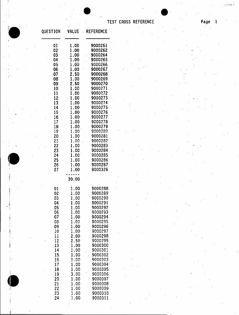
TEST CROSS REFERENCE Page 1
QUESTION VALUE REFERENCE
01 1.00 9000261 02 1.00 9000262 03 1.00 9000264 04 1.00 9000265 05 1.00 9000266 06 1.00 9000267 07 2.50 9000268 08 1.00 9000269 09 2.50 9000270 10 1.00 9000271 11 1.00 9000272 12 1.00 9000273 13 1.00 9000274 14 1.00 9000275 15 1.00 9000276 16 1.00 9000277 17 1.00 9000278 18 1.00 9000279 19 1.00 9000280 20 1.00 9000281 21 1.00 9000282
- 22 1.00 9000283 23 1.00 9000284 24 1.00 9000285 25 1.00 9000286 26 1.00 9000287 27 1.00 9000326
30.00
01 1.00 9000288 02 1.00 9000289 03 1.00 9000290 04 1.00 9000291 05 1.00 9000292 06 1.00 9000293 07 1.00 9000294 08 1.00 9000295 09 1.00 9000296 10 1.00 9000297 11 2.00 9000298 12 2.50 9000299 .13 1.00 9000300 14 1.00 9000301 15 1.00 9000302 .16 1.00 9000303 17 1.00 900030418 1.00 9000305 19 3.00 9000306 20 1.00 9000307 021 1.00 9000308 22 1.00 9000309 23 1.00 9000310 24 1.00 9000311
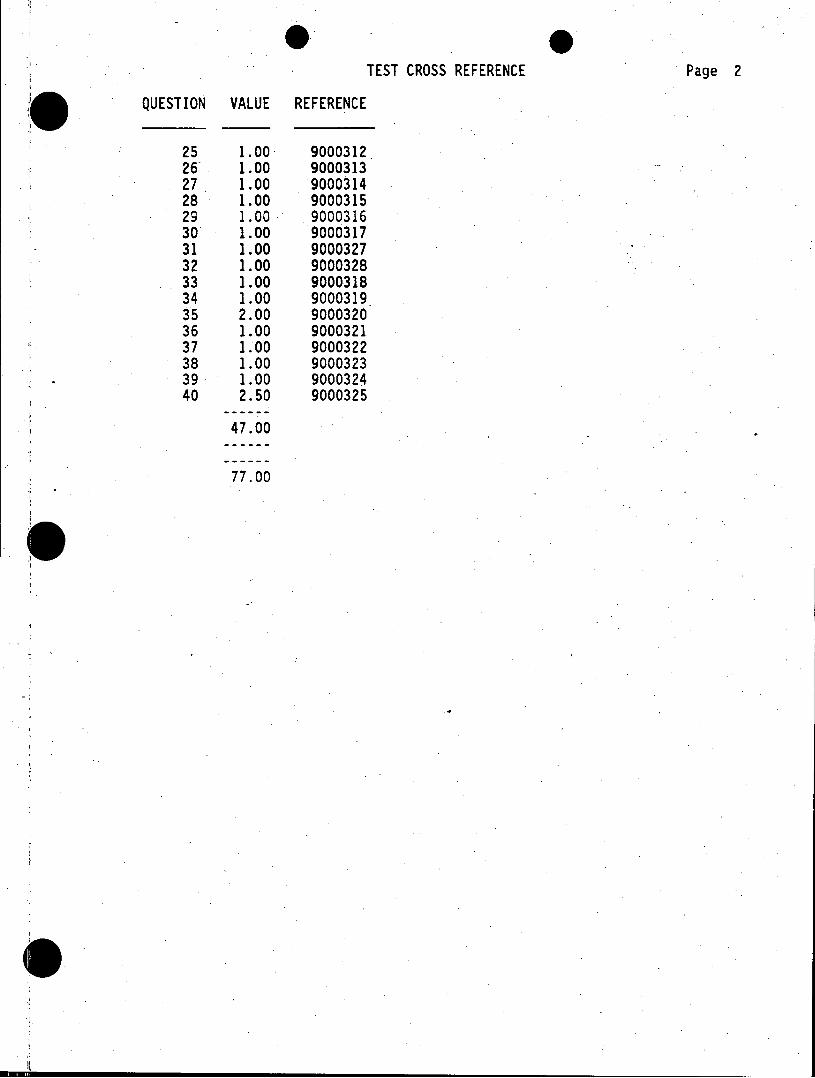
TEST CROSS REFERENCE Page 2
QUESTION VALUE REFERENCE
25 1.00 9000312 26- 1.00 9000313 27 1.00 9000314 28 1.00 9000315 29 1.00 9000316 30 1.00 9000317 31 1.00 9000327 32 1.00 9000328 33 1.00 9000318 34 1.00 9000319 35 2.00 9000320 36 1.00 9000321 37 1.00 9000322 38 1.00 9000323 39 1.00 9000324 40 2.50 9000325
47.00
77.00
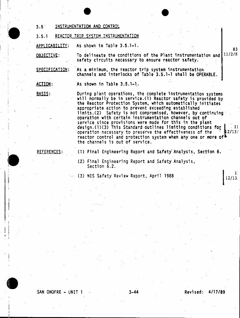
3.5 INSTRUMENTATION AND CONTROL
3.5.1 REACTOR TRIP SYSTEM INSTRUMENTATION
ALCAILITY: As shown in Table 3.5.1-1. 83
OBJECTIVE: To delineate the conditions of the Plant instrumentation and 11/2/8. safety circuits necessary to ensure reactor safety.
SPECIFICATION: As a minimum, the reactor trip system instrumentation. channels and interlocks of Table 3.5.1-1 shall be OPERABLE.
ACTION: As shown in Table 3.5.1-1.
BAI: During plant operations, the complete instrumentation systems will normally be in service.(1) Reactor safety is provided by the Reactor Protection System, which automatically initiates appropriate action to prevent exceeding established limits.(2) Safety is not compromised, however, by continuing operation with certain instrumentation channels out of service since provisions were made for this in the plant design.(1)(3) This Standard outlines limiting conditions for 11 operation necessary to preserve the effectiveness of the - 2/13/ reactor control and protection system when any one or more of the channels is out of service.
REFERENCES: (1) Final Engineering Report and Safety Analysis, Section 6.
(2) Final Engineering Report and Safety Analysis, Section 6.2.
1: (3) NIS Safety Review Report, April 1988 12/13,
II-I SAN ON0FRE - UNIT 1 3-44 Revised: 4/17/89
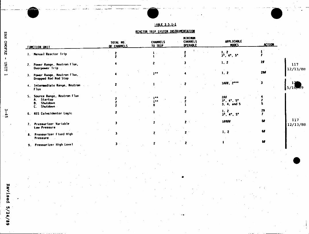
REACTOR TRIP SYSTEM INSTRUPNTATION
NININM 0 TOTAL NO. CHANNELS CHANNELS APPLICABLE
FUNTION UNIT OF CHANNEiS To TRIP OPERABLE ACTION
2 21. 2 1. Manual Reactor Trip 21 2 3 4.5* 1
2. Power Range. Neutron Flux. 4 2 3 1. 2 21 117 Overpower Trip 12/13/88
3. Power Range. Neutron Flux. 4 I* 4 1. 2 26
Dropped Rod Rod Stop
4. Intermediate Range. Neutron 2 1 2 1900, 2* 3 51 9 Flux 15/1 9
5. Source Range. Neutron Flux 200 4 A. Startup 2 I 2 , 4 B. Shutdown 2 0 2 3'. 5 5
C. Shutdown 2 0 1 3.4.and5 5
2I 2 1, 2 29 6. MIS Coincidentor Logic 2 2 . 5*
7. Pressurizer Variable 3 2 2 1 117 Low Pressure
8. Pressurizer Fixed High 3 2 2 1. 2 60
Pressure
9. Pressurizer High Level 3 2 2 1 60
00
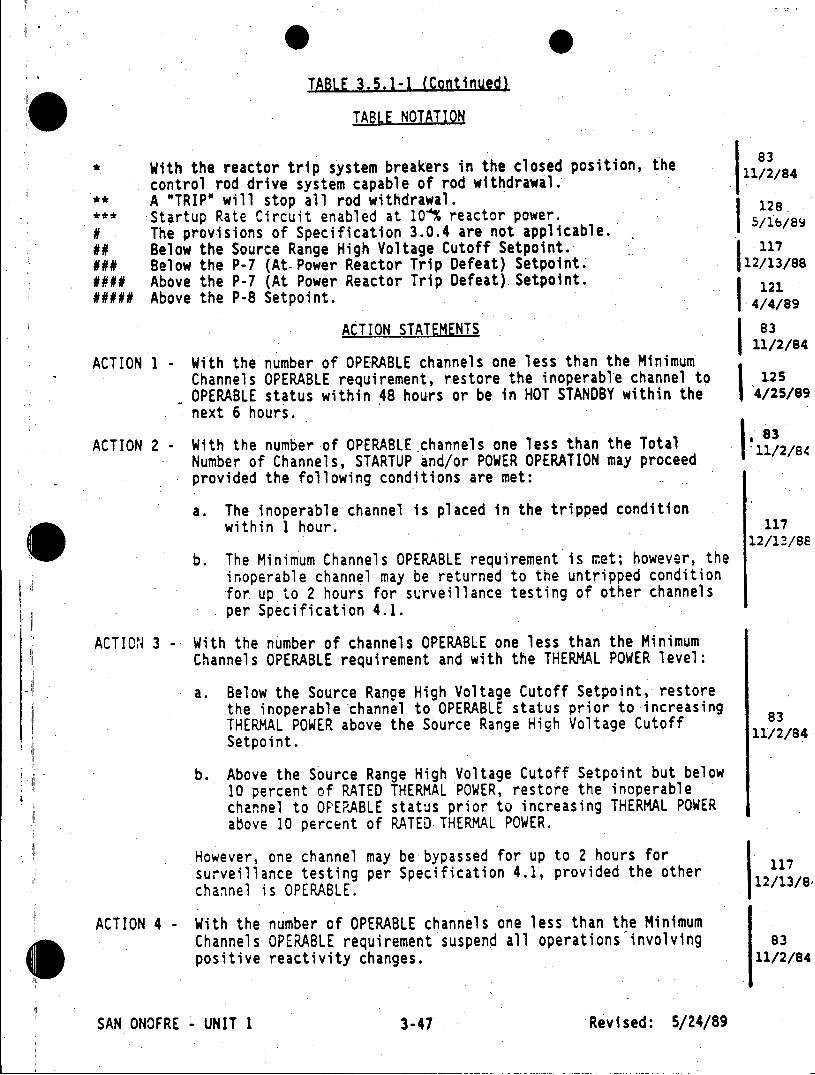
TABLE 3.5.1-1 (Continued)
*l TABLE NOTATION
83 * With the reactor trip system breakers in the closed position, the
control rod drive system capable of rod withdrawal. 11/2/84 A "TRIP" will stop all rod withdrawal. Startup Rate Circuit enabled at 10'% reactor power. 5/lb/BY
# The provisions of Specification 3.0.4 are not applicable. ## Below the Source Range High Voltage Cutoff Setpoint. 117 ### Below the P-7 (At-Power Reactor Trip Defeat) Setpoint. 12/13/88 #### Above the P-7 (At Power Reactor Trip Defeat) Setpoint. ##### Above the P-8 Setpoint. j4/4/89
ACTION STATEMENTS 83 11/2/84
ACTION 1 - With the number of OPERABLE channels one less than the Minimum Channels OPERABLE requirement, restore the inoperable channel to 125 OPERABLE status within 48 hours or be in HOT STANDBY within the 4/25/89 next 6 hours.
83 ACTION 2 - With the number of OPERABLE channels one less than the Total .11/2/84 Number of Channels, STARTUP and/or POWER OPERATION may proceed
provided the following conditions are met:
a. The inoperable channel is placed in the tripped condition within 1 hour. 117
12/13/88 b. The Minimum Channels OPERABLE requirement is met; however, the
inoperable channel may be returned to the untripped condition for up to 2 hours for surveillance testing of other channels per Specification 4.1.
ACTION 3 - With the number of channels OPERABLE one less than the Minimum Channels OPERABLE requirement and with the THERMAL POWER level:
a. Below the Source Range High Voltage Cutoff Setpoint, restore the inoperable channel to OPERABLE status prior to increasing THERMAL POWER above the Source Range High Voltage Cutoff 84 Setpoint.
b. Above the Source Range High Voltage Cutoff Setpoint but below 10 percent of RATED THERMAL POWER, restore the inoperable channel to OPERABLE status prior to increasing THERMAL POWER above 10 percent of RATED THERMAL POWER.
However, one channel may be bypassed for up to 2 hours for 117 surveillance testing per Specification 4.1, provided the other 11/ channel is OPERABLE. 1
ACTION 4- With the number of OPERABLE channels one less than the Minimum Channels OPERABLE requirement suspend all operations involving 83
positive reactivity changes.. 11/2/84
SAN ONOFRE - UNIT 1 3-47 Revised: 5/24/89
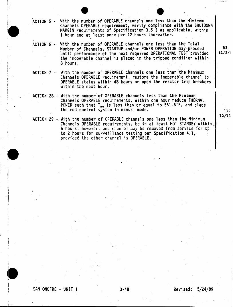
ACTION 5 - With the number of OPERABLE channels one less than the Minimum Channels OPERABLE requirement, verify compliance with the SHUTDOWN MARGIN requirements of Specification 3.5.2 as applicable, within 1 hour and at least once per 12 hours thereafter.
ACTION 6 - With the number of OPERABLE channels one less than the Total Number of Channels, STARTUP and/or POWER OPERATION may proceed 83 until performance of the next required OPERATIONAL TEST provided 11/2/1
the inoperable channel is placed in the tripped condition within 8 hours.
ACTION 7 - With the number of OPERABLE channels one less than the Minimum Channels OPERABLE requirement, restore the inoperable channel to OPERABLE status within 48 hours or open the reactor trip breakers within the next hour.
ACTION 28 - With the number of OPERABLE channels less than the Minimum Channels OPERABLE requirements, within one hour reduce THERMAL POWER such that T.. is less than or equal to 551.5'F, and place the rod control system in manual mode. 117
12/13 ACTION 29 With the number of OPERABLE channels one less than the Minimum
Channels OPERABLE requirements, be in at least HOT STANDBY within. 6 hours; however, one channel may be removed from service for up to 2 hours for surveillance testing per Specification 4.1, provided the other channel is OPERABLE.
SAN ONOFRE - UNIT 1 3-48 Revised: 5/24/89
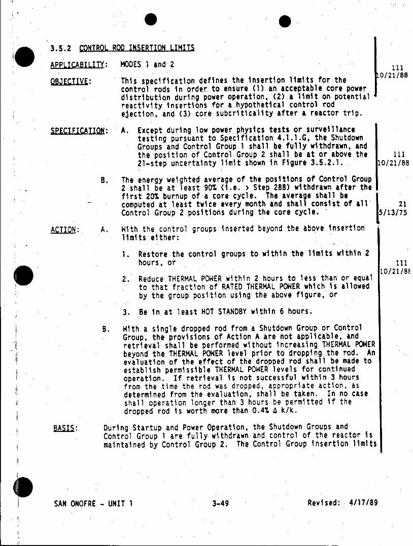
3.5.2 CONTROL ROD INSERTION LIMITS
APPLICABILITY: MODES 1 and 2 111
OBJECTIVE: This specification defines the insertion limits for-the 0/21/88 control rods in order to ensure (1) an acceptable core power distribution during power operation, (2) a limit on potential reactivity insertions for a hypothetical control rod ejection, and (3) core subcriticality after a reactor trip.
SPECIFICATION: A. Except during low power physics tests or surveillance testing pursuant to Specification 4.1.1.G, the Shutdown Groups and Control Group 1 shall be fully withdrawn, and the position of Control Group 2 shall be at or above the 111 21-step uncertainty limit shown in Figure 3.5.2.1. 10/21/88
B. The energy weighted average of the positions of Control Group 2 shall be at least 90% (i.e. > Step 288) withdrawn after the first 20% burnup of a core cycle. The average shall be computed at least twice every month and shall consist of all 21 Control Group 2 positions during the core cycle. 5/13/75
ACTION: A. With the control groups inserted beyond the above insertion limits either:
1. Restore the control groups to within the limits within 2 hours, or 111
10/21/88 2. Reduce THERMAL POWER within 2 hours to less than or equal
to that fraction of RATED THERMAL POWER which is allowed by the group position using the above figure, or
3. Be in at least HOT STANDBY within 6 hours.
B. With a single dropped rod from a Shutdown Group or Control Group, the provisions of Action A are not applicable, and retrieval shall be performed without increasing THERMAL POWER beyond the THERMAL POWER level prior to dropping the rod. An evaluation of the effect of the dropped rod shall be made to establish permissible THERMAL POWER levels for continued operation. If retrieval is not successful within 3 hours from the time the rod was dropped, appropriate action, as determined from the evaluation, shall be taken. In no case shall operation longer than 3 hours be permitted if the dropped rod is worth more than 0.4% A k/k.
BAIS: During Startup and Power Operation, the Shutdown Groups and Control Group 1 are fully withdrawn and control of the reactor is maintained by Control Group 2. The Control Group insertion limits
SAN ONOFRE - UNIT 1 3-49 Revised: 4/17/89
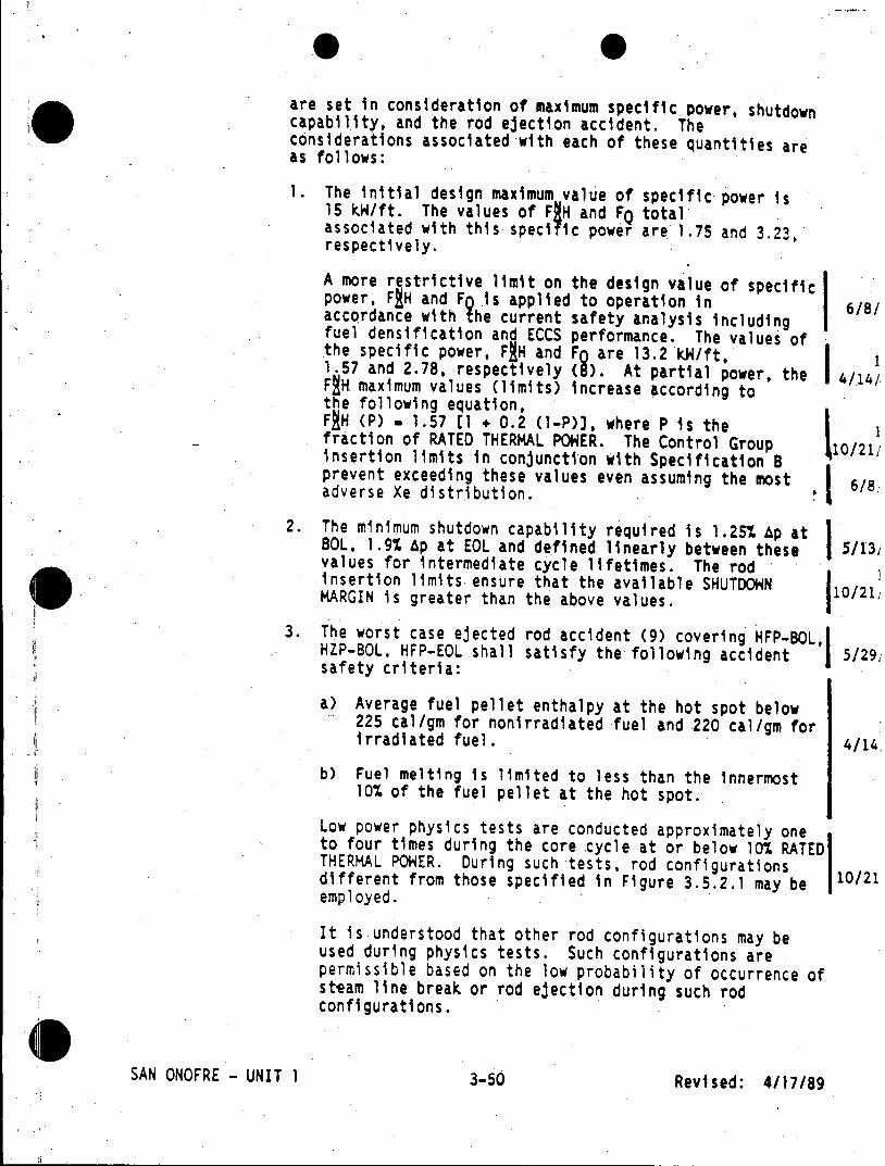
are set in consideration of maximum specific power, shutdown capability, and the rod ejection accident. The considerations associated with each of these quantities are as follows:
1. The initial design maximum value of specific power is 15 kW/ft. The values of F;H and FQ total associated with this specific power are 1.75 and 3.23, respectively.
A more restrictive limit on the design value of specific power, FJH and F .is applied to operation in 6/8/ accordance with he current safety analysis including fuel densification and ECCS performance. The values of the specific power, FJH and FO are 13.2 kH/ft, 1 1.57 and 2.78, respectively (8). At partial power, the I 4/14/ FgH maximum values (limits) increase according to the following equation, FJH (P) . 1.57 E1 + 0.2 (1-P)J, where P is the fraction of RATED THERMAL POWER. The Control Group 10/21/ insertion limits in conjunction with Specification B prevent exceeding these values even assuming the most 6/8. adverse Xe distribution.
2. The minimum shutdown capability required is 1.25% Ap at BOL, 1.9% Ap at EOL and defined linearly between these 5/131 values for intermediate cycle lifetimes. The rod insertion limits ensure that the available SHUTDOWN 1 MARGIN is greater than the above values. 10/21
3. The worst case ejected rod accident (9) covering HFP-BOL, HZP-BOL, HFP-EOL shall satisfy the following accident 5/291 safety criteria:
a) Average fuel pellet enthalpy at the hot spot below 225 cal/gm for nonirradiated fuel and 220 cal/gm for irradiated fuel. 4/14,
b) Fuel melting is limited to less than the innermost 10% of the fuel pellet at the hot spot.
Low power physics tests are conducted approximately one to four times during the core cycle at or below 10% RATED THERMAL POWER. During such tests, rod configurations different from those specified in Figure 3.5.2.1 may be 10/21 employed.
It is understood that other rod configurations may be used during physics tests. Such configurations are permissible based on the low probability of occurrence of steam line break or rod ejection during such rod configurations.
SAN ONOFRE - UNIT 1 3-50 Revised: 4/17/89
Operation of the reactor during cycle stretch out is conservative relative to the safety considerations of the control rod insertion limits, since the Positioning of the rods during stretch out results in an increasing net available SHUTDOWN MARGIN.
Compliance with Specification 8 prevents unfavorable axial power distributions due to operation for long intervals at deep control rod insertions.
The presence of a dropped rod leads to abnormal power distribution in the core. The location of the rod and its worth in reactivity determines its effect on the temperatures of nearby fuel. Under .certain conditions, continued operation could result in fuel damage, and it is the intent of ACTION B to avoid such damage. 10/21
References: (1) Final Engineering Report and Safety Analysis, revised July 28, 1970.
(2) Amendment No. 18 to Docket No. 50-206.
(3) Amendment No. 22 to Docket No. 50-206.
(4) Amendment No. 23 to Docket No. 90-206.
(5) Description and Safety Analysis, Proposed Change No. 7, dated October 22, 1971.
(6) Description and Safety Analysis Including Fuel Densification, San Onofre Nuclear Generating Station, Unit 1, Cycle 4, WCAP 8131, May, 1973.
(7) Description and Safety Analysis Including Fuel Densification, San Onofre Nuclear Generating Station, Unit 1, Cycle 5, January, 1975, Westinghouse Non-Proprietary Class 3.
*(8) Reload Safety Evaluation, San Onofre Nuclear Generating Station, Unit 1, Cycle 10, edited by J. Skaritka, 4/14 Revision 1, Westinghouse, March, 1989
(9) An Evaluation of the Rod Ejection Accident in Westinghouse Pressurized Water Reactors Using Spatial Kinetics Methods, WCAP-7588, Revision 1-A, January, 1975.
SAN ONOFRE - UNIT 1 3-51 Revised: 4/17/89
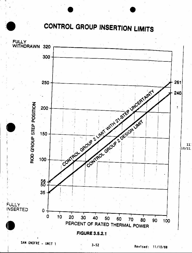
CONTROL GROUP INSERTION LIMITS
FULLY WITHDRAWN 320
300
261 250
240
0 200
0 5
010
wA
0 150 - ------
5650
35
FULLY INSERTED 0
0 10 20 30 40 50 60 70 80 90 100 PERCENT OF RATED THERMAL POWER
FIGURE 3.5.2.1
SAN ONOFRE - UNIT 1 3-52 Revised: 11/10/88
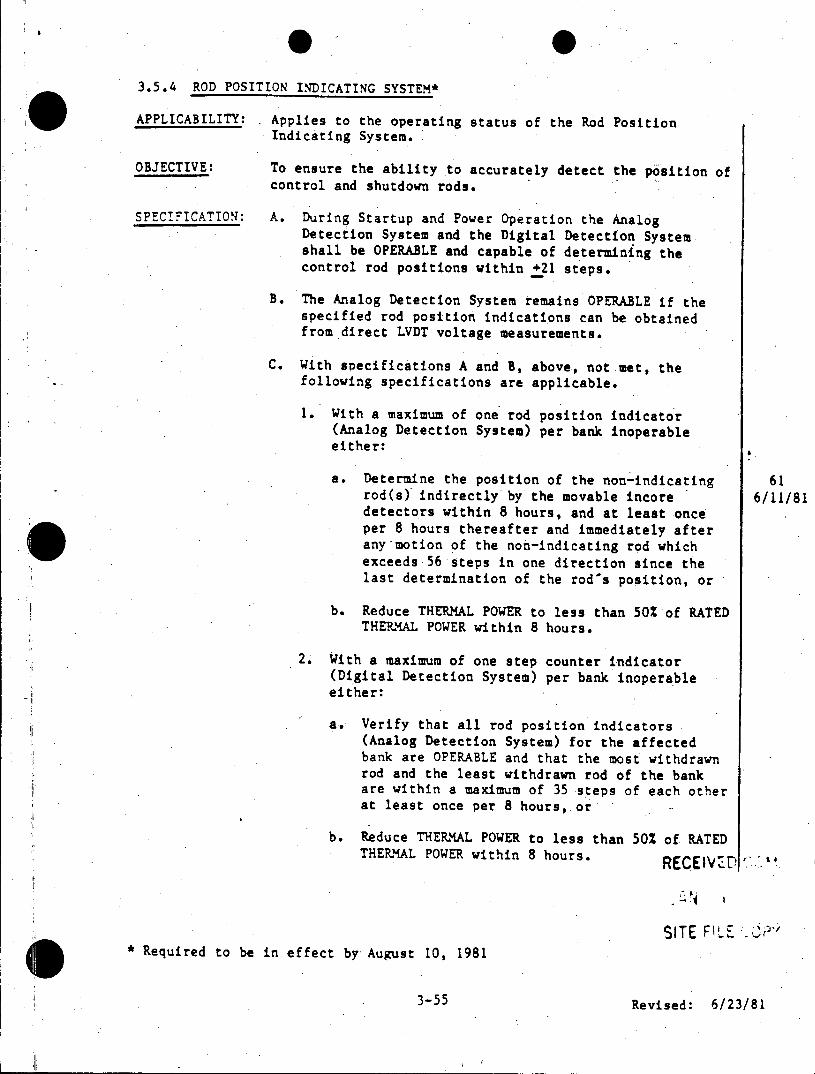
3.5.4 ROD POSITION INDICATING SYSTEM*
APPLICABILITY: Applies to the operating status of the Rod Position Indicating System.
OBJECTIVE: To ensure the ability to accurately detect the position of control and shutdown rods.
SPECIFICATION: A. During Startup and Power Operation the Analog Detection System and the Digital Detection System shall be OPERABLE and capable of determining the control rod positions within +21 steps.
B. The Analog Detection System remains OPERABLE if the specified rod position indications can be obtained from direct LVDT voltage measurements.
C. With specifications A and B, above, not met, the following specifications are applicable.
1. With a maximum of one rod position indicator (Analog Detection System) per bank inoperable either:
a. Determine the position of the non-indicating 61 rod(s) indirectly by the movable incore 6/11/81 detectors within 8 hours, and at least once per 8 hours thereafter and immediately after any-motion of the non-indicating rod which exceeds 56 steps in one direction since the last determination of the rod's position, or
b. Reduce THERMAL POWER to less than 50% of RATED THERMAL POWER within 8 hours.
2. With a maximum of one step counter indicator (Digital Detection System) per bank inoperable either:
a. Verify that all rod position indicators (Analog Detection System) for the affected bank are OPERABLE and that the most withdrawn rod and the least withdrawn rod of the bank are within a maximum of 35 steps of each other at least once per 8 hours, or
b. Reduce THERMAL POWER to less than 50% of RATED THERMAL POWER within 8 hours. RECEIVED
SITE FILE * Required to be in effect by August 10, 1981
3-55 Revised: 6/23/81
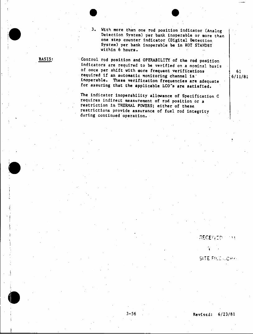
3. With more than one rod position indicator (Analog .0 Detection System) per bank inoperable or more than
one step counter indicator (Digital Detection System) per bank inoperable be in HOT STANDBY within 6 hours.
BASIS: Control rod position and OPERABILITY of the rod position indicators are required to be verified on a nominal basis of once per shift with more frequent verifications 61 required if an automatic monitoring channel is; 6/11/81 inoperable. These verification frequencies are adequate for assuring that the applicable.LCO's are satisfied.
The indicator inoperability allowance of Specification C requires indirect measurement of rod position or a restriction in THERMAL POWERS; either of these restrictions provide assurance of fuel rod integrity during continued operation.
3-T5 F!ve 6/3
3-56 Revised: 6/23/81
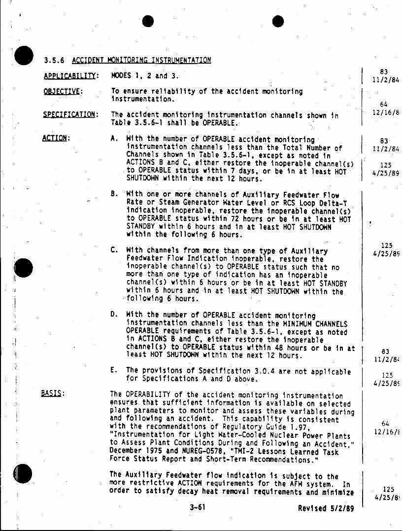
3.5.6 ACCIDENT MONITORING INSTRUMENTATION
APPLICABILITY: MODES 1. 2 and 3. 11/2/84 OBJECTIVE: To ensure reliability of the accident monitoring
instrumentation. 64
SPECIFICATION: The accident monitoring instrumentation channels shown In 12/16/8 Table 3.5.6-1 shall be OPERABLE.
ACTION: A. With the number of OPERABLE accident monitoring 83 instrumentation channels less than the Total Number of 11/2/84 Channels shown in Table 3.5.6-1, except as noted in ACTIONS 8 and C, either restore the inoperable channel(s) 125 to OPERABLE status within 7 days, or be in at least HOT 4/25/89 SHUTDOWN within the next 12 hours.
B. With one or more channels of Auxiliary Feedwater Flow Rate or Steam Generator Hater Level or RCS Loop Delta-T indication inoperable, restore the inoperable channel(s) to OPERABLE status within 72 hours or be in at least HOT STANDBY within 6 hours and in at least HOT SHUTDOWN within the following 6 hours.
125 C. With channels from more than one type of Auxiliary 4/25/80
Feedwater Flow Indication inoperable, restore the inoperable channel(s) to OPERABLE status such that no more than one type of indication has an inoperable channel(s) within 6 hours or be in at least HOT STANDBY within 6 hours and in at least HOT SHUTDOWN within the -following 6 hours.
D. With the number of OPERABLE accident monitoring instrumentation channels less than the MINIMUM CHANNELS OPERABLE requirements of Table 3.5.6-1, except as noted in ACTIONS B and C, either restore the inoperable channel(s) to OPERABLE status within 48 hours or be in at least HOT SHUTDOWN within the next 12 hours.
11/2/81
E. The provisions of Specification 3.0.4 are not applicable 125 for Specifications A and D above. 4/25/8S
BASI1: The OPERABILITY of the accident monitoring instrumentation ensures that sufficient information is available on selected plant parameters to monitor and assess these variables during and following an accident. This capability is consistent 64 with the recommendations of Regulatory Guide 1.97, "Instrumentation for Light Water-Cooled Nuclear Power Plants 12/16/ to Assess Plant Conditions During and Following an Accident," December 1975 and NUREG-0578, "TMI-2 Lessons Learned Task Force Status Report and Short-Term Recommendations."
The Auxiliary Feedwater flow indication is subject to the more restrictive ACTION requirements for the AFW system. In order to satisfy decay heat removal requirements and minimize 125
4/25/8 3-61 Revised 5/2/89
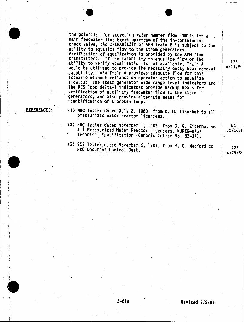
the potential for exceeding water hammer flow limits for a main feedwater line break upstream of the in-containment check valve, the OPERABILITY of AFH Train B is subject to the ability to equalize flow to the steam generators. Verification of equalization is provided by the AFH flow transmitters. If the capability to equalize flow or the ability to verify equalization is not available, Train A 125 would be utilized to provide the necessary decay heat removal 4/25/8 capability. AFH Train A provides adequate flow for this scenario without reliance on operator action to equalize flow.(3) The steam generator wide range level indicators and the RCS loop delta-T indicators provide backup means for verification of auxiliary feedwater flow to the steam generators, and also provide alternate means for identification of a broken loop.
REFERENCES: (1) NRC letter dated July 2, 1980, from D. G. Eisenhut to all pressurized water reactor licensees.
(2) NRC letter dated November 1, 1983, from D. G. Eisenhut to 64 all Pressurized Hater Reactor Licensees, NUREG-0737 12/16/E Technical Specification (Generic Letter No. 83-37).
(3) SCE letter dated November 6, 1987, from M. 0. Medford to 125 NRC Document Control Desk.
4/25/8R
3-61a Revised 5/289
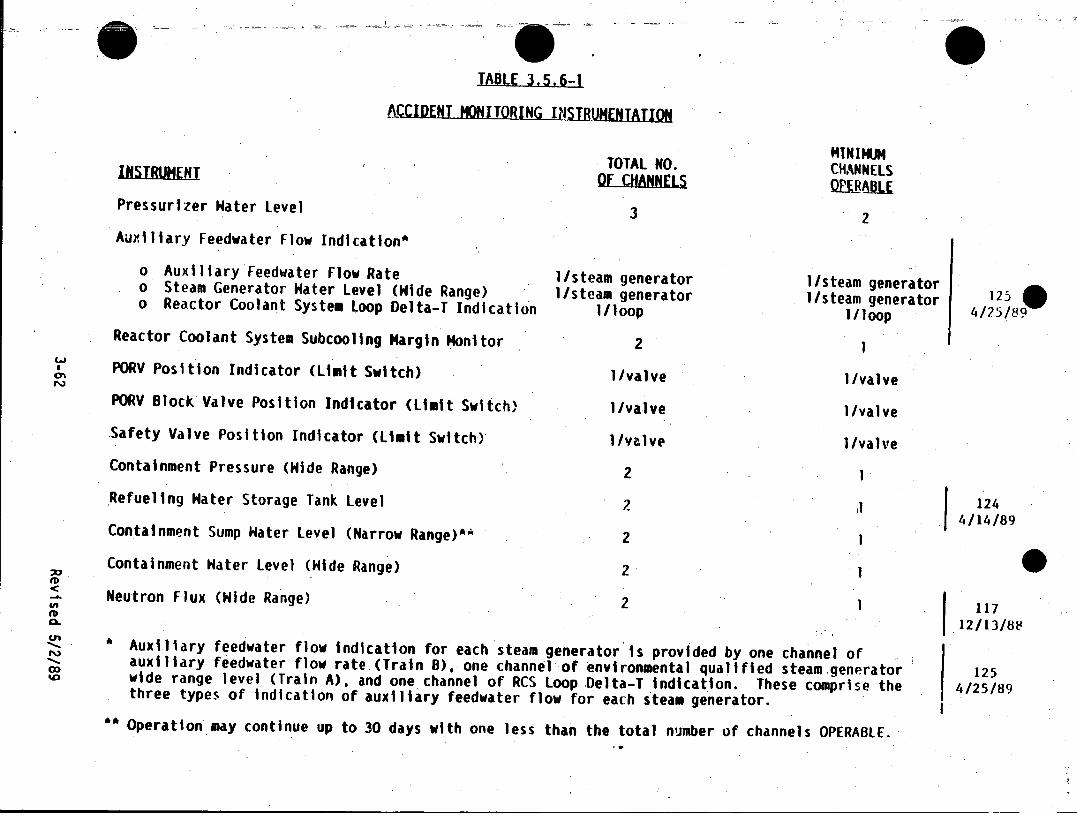
* . . g
TABLE 3.5.6-1
-ACCIDNT HONITORING I STRUMENTAION
MTNIMUM 1NS1RUMENT TOTAL NO. CHANNELS
Pressurizer Hater Level 3 2 Auxiliary Feedwater Flow Indication*
o Auxiliary Feedwater Flow Rate 1/steam generator o Steam Generator Hater Level (Hide Range) 1/steam generator I/steam generator 125 o Reactor Coolant System Loop Delta-T Indication I/loop 1/loop 4/25/89
Reactor Coolant System Subcooling Margin Monitor 2 PORV Position Indicator (Limit Switch) 1/valve 1/valve PORV Block Valve Position Indicator (Limit Switch) 1/valve 1/valve
Safety Valve Position Indicator (Limit Switch) 1/valve 1/valve Containment Pressure (Hide Range) 2 1
Refueling Hater Storage Tank Level 2 124 4/14/89
Containment Sump Hater Level (Narrow Range)*" 2 1
Containment Hater Level (Hide Range) 2 1
Neutron Flux (Hide Range) 2 1 117 12/13/88
I Auxiliary feedwater flow indication for each steam generator is provided by one channel of auxiliary feedwater flow rate (Train 8), one channel of environmental qualified steam generator 125 wide range level (Train A). and one channel of RCS Loop Delta-T indication. These comprise the 4/25/89 three types of indication of auxiliary feedwater flow for each steam generator.
Operation may continue up to 30 days with one less than the total number of channels OPERABLE.
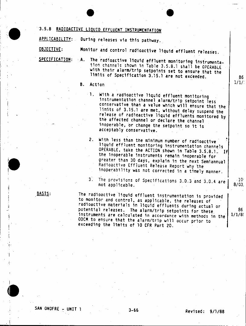
3.5.8 RADIOACTIVE LIQUID EFFLUENT INSTRUMENTATION
APPLICABILITY: During releases via this pathway.
OBJECTIVE: Monitor and control radioactive liquid effluent releases.
SPECIFICATION: A. The radioactive liquid effluent monitoring instrumentation channels shown in Table 3.5.8.1 shall be OPERABLE with their alarm/trip setpoints set to ensure that the limits of Specification 3.15.1 are not exceeded. 86
B. Action 1/1
1. With a radioactive liquid effluent monitoring instrumentation channel alarm/trip setpoint less conservative than a value which will ensure that the limits of 3.15.1 are met, without delay suspend the release of radioactive liquid effluents monitored by the affected channel or declare the channel inoperable, or change the setpoint so it is acceptably conservative.
2. With less than the minimum number of radioactive liquid effluent monitoring instrumentation channels OPERABLE, take the ACTION shown in Table 3.5.8.1. If the inoperable instruments remain inoperable for greater than 30 days, explain in the next Semiannual Radioactive Effluent Release Report why the inoperability was not corrected in a timely manner.
3. The provisions of Specifications 3.0.3 and 3.0.4 are 10 not applicable. 8/03i
BASIS: The radioactive liquid effluent instrumentation is provided to monitor and control, as applicable, the releases of radioactive materials in liquid effluents during actual or 86 potential releases. The alarm/trip setpoints for these. instruments are calculated in accordance with methods in the ODCM to ensure that the alarm/trip will occur prior to exceeding the limits of 10 CFR Part 20.
SAN ONOFRE - UNIT 1 3-66 Revised: 9/1/88
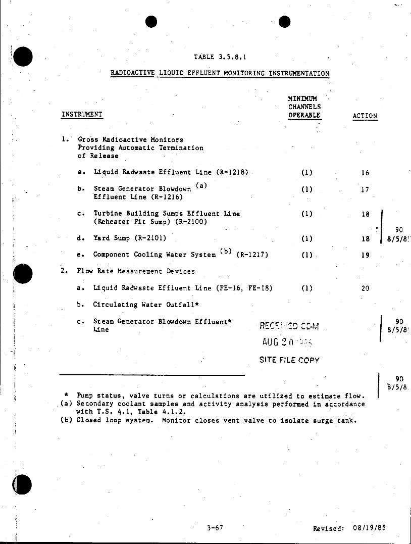
TABLE 3.5.8.1
RADIOACTIVE LIQUID EFFLUENT MONITORING INSTRUMENTATION
MINIMUM CHANNELS
INSTRUMENT OPERABLE ACTION
1. Gross Radioactive Monitors Providing Automatic Termination of Release
a. Liquid Radwaste Effluent Line (R-1218) (1) 16
b. Steam Generator Blowdown (a) (1) 17 Effluent Line (R-1216)
c. Turbine Building Sumps Effluent Line (1) 18 (Reheater Pit Sump) (R-2100)
90 d. Yard Sump (R-2101) (1) 18 8/5/8
e. Component Cooling Water System (b) (R-1217) (1) 19
2. Flow Rate Measurement Devices
a. Liquid Radwaste Effluent Line (FE-16, FE-18) (1) 20
b. Circulating Water Outfall*
c. Steam Generator Blowdown Effluent* I-90 Line " - 8/5/8'
SITE FILE COPY
90 8/5/8
* Pump status, valve turns or calculations are utilized to estimate flow. (a) Secondary coolant samples and activity analysis performed in accordance
with T.S. 4.1, Table 4.1.2. (b) Closed loop system. Monitor closes vent valve to isolate surge tank.
3-67 Revised: 08/19/85
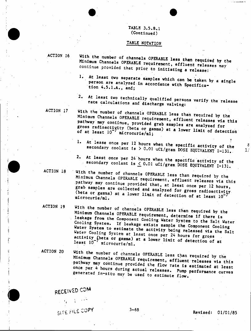
TABLE 3.5.8.1 (Continued)
TABLE NOTATION
ACTION 16 With the number of channels OPERABLE less than requie by the Minimum Channels OPERABLE requirement, effluent relae a continue provided that prior to initiating a release:
1. At least two separate samples which can be taken by a single person are analyzed in accordance with Specification 4 .5.1.A., and;
2. At least two technically qualified persons verify the release rate calculations and discharge valving:
ACTION 17 With the number of channels OPERABLE less than required by the Minimum Channels OPERABLE requirement, effluent releases via this pathway may continue, provided grab samples are analyzed for gross rad ioactity (beta or gamma) at a lower limit of detection of at least 10 microcurie/ml;
1. At lease once per 12 hours when the specific activity of the secondary coolant is > 0.01 uCi/gram DOSE EQUIVALENT 1-131. 2. At least once per 24 hours when the specific activity of the secondary coolant is < 0.01 uCi/gramDOSE EQUIVALENT 1-131.
ACTION 18 With thenumber of channels OPERABLE less than required by the Minimum Channels OPERABLE requirement, effluent releases via this pathway may continue provided that, at least once per12 hours, grab samples are collected and analyzed for gross radioactivi5y (beta or gamma) at a lower limit of detection of at least 10 microcurie/ml.
ACTION 19 With the number of channels OPERABLE less than required by the Minimum Channels OPERABLE requirement, determine if there is leakage from the Component Cooling Water System to the Salt Water Cooling System. If leakage exists sample the Component Cooling Water System to estimate the activity being released via the Salt Water Cooling System at least once per 24 hours for gross activity beta or gamma) at a lower limit of detection of at least 10 microcurie/ml.
ACTION 20 With the number of channels OPERABLE less than required by the Minimum Channels OPERARLE requirement, effluent releases via this pathway may continue provided the flow rate is estimated at least once per 4 hours during actual releases. Pump performance curves generated in-situ. may be used to estimate flow.
RECEIVD N
3-68 Revised: 01/01/85 IOp
NUCLEAR GENERATION OE ENGINEERIN ROCEDURE SOI-V-13 UNIT I REVISION 0 PAGE 10 OF 13
ATTACHMENT 4
APR 0 3 09 OPERATIONS PHYSICS SUMMARY CHANGE
DOCUMENT # M 38099 REVISION # 5
DATE 1 March 1989
DESCRIPTION OF REVISION Initial data for CYCLE X BOL
A LIVED CDM
APR 03 1989
AFFECTED PAGES Pages 1 through 13
Reference Document (if applicable:
PERFORMED BY:
REVIEWED BY: Core7Analysis Engineer
APPROVED 6Y: i A ?r ) Supervising Engineer
ACKNOWLEDGED BY: Opera ions
ATTACHMENTS
1) NEW PAGES
2) REFERENCE DOCUMENT
3) OTHER:
1-V-13.cln ATTACHMENT 4 PAGE 1 OF I
OPERATIONS
PHYSICS
SUMMARY
UNIT 1 CYCLE X
Core Analysis Engineer: _ _ _ _*
Andrew Eckhart
Document # M 38099
Revision: 5
M 38099 Revision: 5
OPERATIONS PHYSICS-SUMMARY
TABLE OF CONTENTS
SECTION PAGE
1. Power Defect at 100% Power (Figure 1) 1
2. Xenon Worth
2.1 Equilibrium Xenon Worth at 100% Power 2 (Figure 2) 2.2 Fractional Equilibrium Worth (0-100%) 3 (Figure 2-1) 2.3 Fractional Equilibrium Worth (83-93%) 4 (Figure 2-2) 2.4 Transient Xenon Worth (Figure 3) 5
3. Rod Worths
3.1 Rod Worths at Hot Zero Power (HZP) 6 -(Table 1) 3.2 Rod Worths at Hot Full Power (HFP) 7
(Table 2) 3.3 Total Rod Worths (Table 3) 8 3.4 Rod Worths at Cold Zero Power (CZP) 9
(Figure 4) &3.5 Worst Rod Stuck Out (WRSO) Worth 10
(Figure 5)
4. Differential Boron Worth (DBW) at HZP 11 (Figure 6)
5. Cooldown Reactivity (Figure 7) 12
6. Isothermal Temperature Coefficient (ITC) 13 (Figure 8)
0I
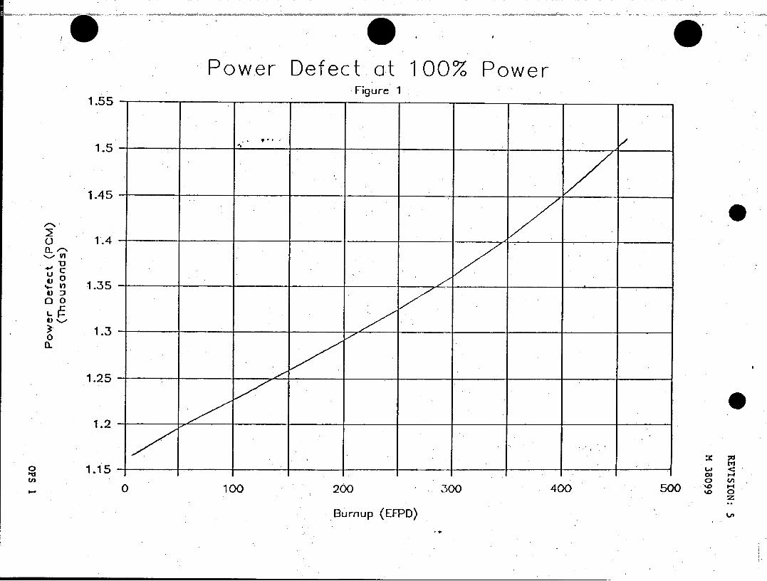
Power Defect at 100% Power Figure 1
1.5 -_ _ _
1.45 -_ _ _ _ _ __ _ _
o 1.40
U
V) 1.350 0
1.3
0 0.O
0 C fl 0 100 200 300 400 50 'a0
Burnup (EFPD)
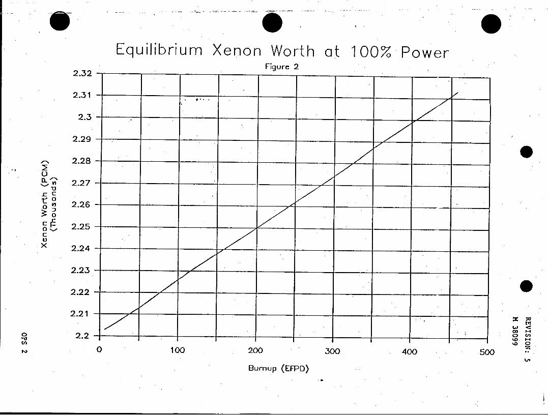
Equilibrium *Xenon Worth at 100% power ____ ___ ____ ___ ____ ___Figure 2
2.32 -_ _ _ _ _ _ _ _ _
2.31 - _ _ _ _ _ _
2.3
2.29 - _ _ _ _ _ __ _ _ _ _ __ _
2.28
A'2.27 0
.c
x 2.26
S2.25
X2.24
2.21_ _ l
0 100 200 300, 400 500 Ln
Burnup. (EFPD)
Fractional Equilibrium Xenon Worth Figure 2-1
1
0.9
0.8
0.7
0.6
C 0 0 0.6
0.3
0.2
0.1
0 4O 00
_0 20 40 60 80 100
Power (%) BOL Fraction
Fractional Equilibrium Xenon Worth ____ ___ ______________Figure 2-2
0.97 - _ _ _ _ _ _ _ _ _ _ _ _ _ _ _ _ _ __ _ _
0.9..
U0 .9 5 _ _ _ _ __ _ _ _ _ _ _ _ _
IL
u 0.95 0
U
0
0.0
0 0.93 _ __
10 CO
%0 f 83 85 87 89 91 .93 Z, 0
Power (7.) BOL Fraction
Figure 3
Transient Xenon Worth after Shutdown vs. Time SAN ONOFRE NUCLEAR GENERATING STATION UNIT 1 - CYCLE 10
( 100 ) y- 2.50EI+02
+50.0 -100
75 %+ +45.0 --
50% 0
+40.0 -- 25%
La +35.0 Cl
8URNUP =6.48EFPO +30.00.
-r +25.0 c: Va
0 c: +20.0 d)
0.o --WESTINGHOUSE
PROPRIETARY CLASS IH % -Cn % 0 +5.oo -02-27-199 13: 56: 53
+.00 - dx- 3.60E+00
+0.00 +14.40 +28.BO +43.20 +57.60 +72.00
Time (Hours)
REVISION: 5
M 38099
SAN ONOFRE NUCLEAR GENERATING STATION UNIT 1 - CYCLE .10
Bank 2 at BOL, HZP, No Xenon
Table 1
Bank 2 Bank Worth Position Differential Integral (Steps) (pcm/step) (pcm)
320 0.00 0 315 0.60 6 310 1.20 12 305 1.79 18 300 2.39 24 295 2.64 38 290 2.90 52 285 3.15 67 280 3.40 81 275 3.49 99 260 3.74 152 240 4.00 229 220 4.52 313 200 5.20 409 -180 6.28 523 160 7.65 661 140 9.76 834 120 12.59 1055 100 16.85 1347 80 22.03 1732 60 25.51 2203 40 14.47 2599 20 3.32 2775 0 0.38 2812
OPS 6
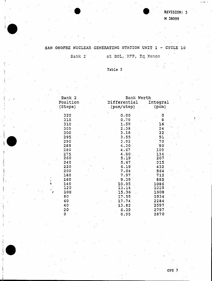
REVISION: 5
M 38099
SAN ONOFRE NUCLEAR GENERATING STATION UNIT 1 - CYCLE 10
Bank 2 at BOL, HFP, Eq Xenon
Table 2
Bank 2 Bank Worth Position Differential Integral (Steps) (pcm/step) (pcm)
320 0.00 0 315 0.79 8 310 1.59 16 305 2.38 24 300 3.18 32 295 3.55 51 290 3.92 70 285 4.30 90 280 4.67 109 275 4.80 134 260 5.19 207 240 5.67 315 220 6.19 432 200 7.04 564 180 7.97 712 160 9.39 885 140 10.95 1086 120 13.14 1325 100 15.36- 1608 80 17.55 1934 60 17.74 2284 40 13.82 2597 20 6.39 2797 0 0.95 2870
OPS 7
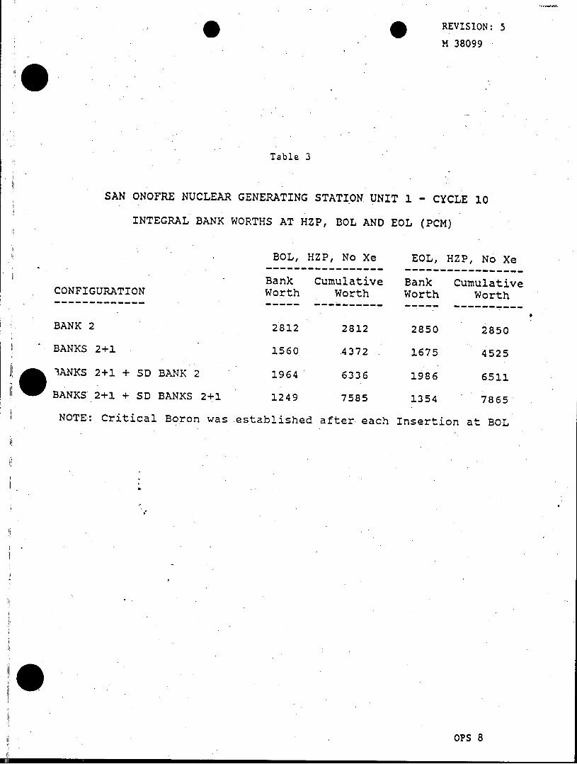
REVISION: 5 M 38099
Table 3
SAN ONOFRE NUCLEAR GENERATING STATION UNIT 1 - CYCLE 10
INTEGRAL BANK WORTHS AT HZP, BOL AND EOL (PCM)
BOL, HZP, No Xe EOL, HZP, No Xe ----------------- -----------------
Bank Cumulative Bank Cumulative CONFIGURATION Worth Worth Worth Worth
---------------------------- ----- ---------- ----- ----------
BANK 2 2812 2812 2850 2850
BANKS 2+1 1560 4372 . 1675 4525
IANKS 2+1 + SD BANK 2 1964 6336 1986 6511
BANKS 2+1 + SD BANKS 2+1 1249 7585 1354 7865
NOTE: Critical Boron was established after each Insertion at BOL
OPS 8
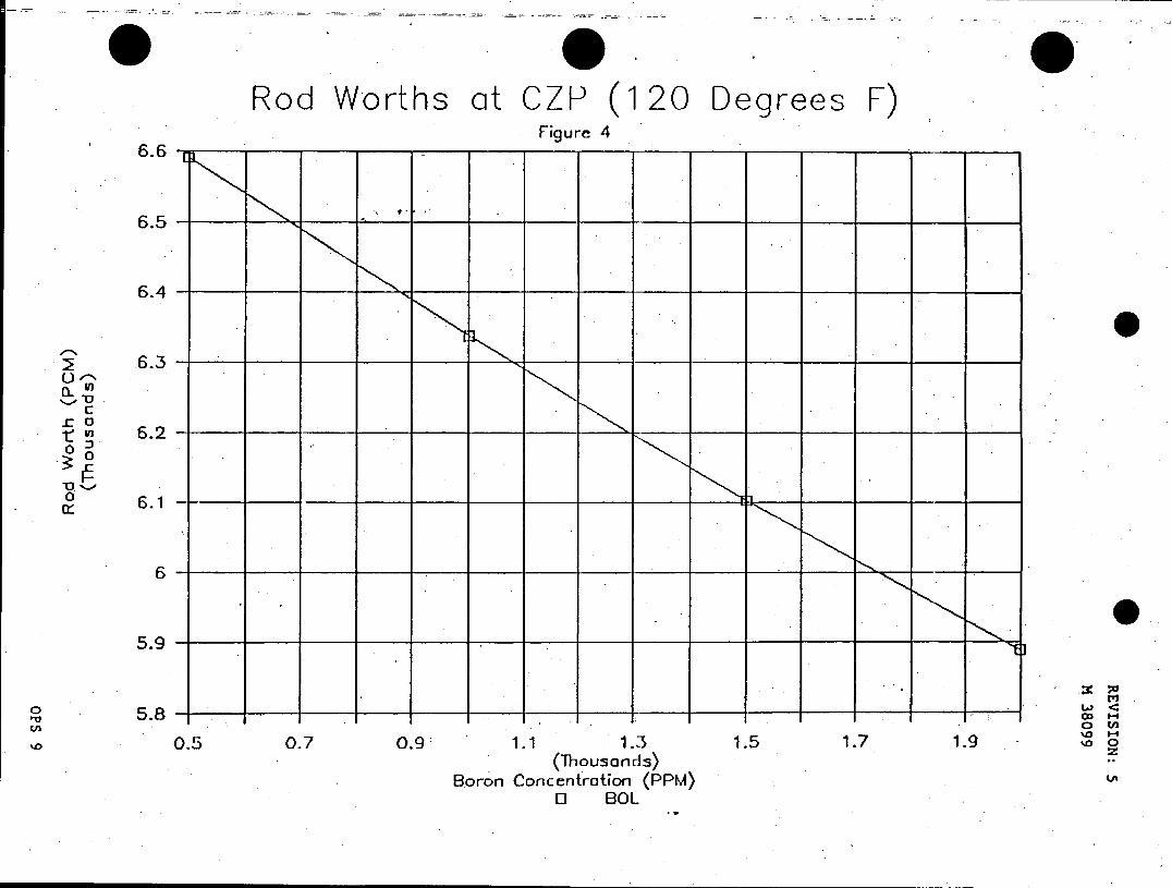
Rod Worths at CZP (120 Degrees F) Figure 4
6.6
G.5
6.4
6.3
'V
c t VI 6.2
0 ~a<
oj
I'd 5.8-C c 0.5 0.7 0.9 1.1 1.3 1.5 1.7 1.9 0 0
(Thousands) Boron Concentration (PPM)
0 BOL
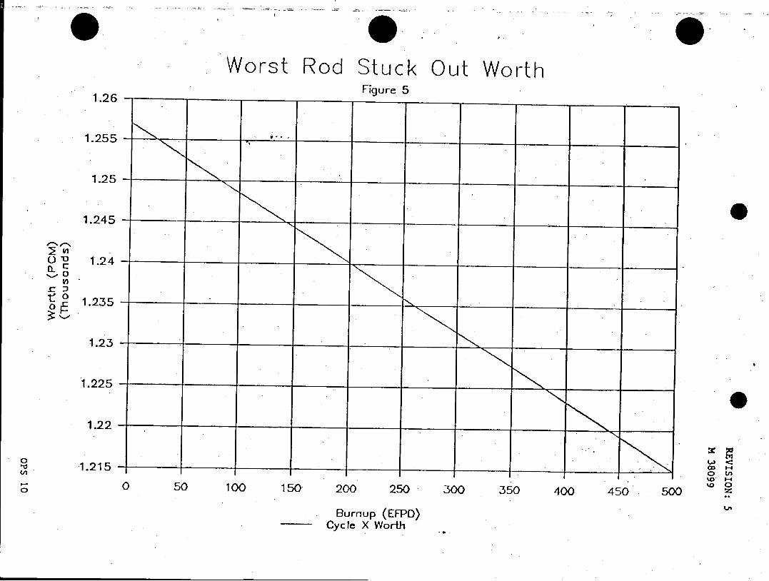
Worst Rod Stuck Out Worth ____ __ _ ____ ___ ___Figure 5
1.26 - _ _ _ _ _ _ _ _ _ _ _ _ _ _ _ _ _ _ _ _ _ _ _ _
1.255 -_ _ _ _ _ __ _ _ _ _ _ _ _ _
1.25 -_ _ _ _ _ _ _ _ _
1.245 _ _ - _ _ _ _ _ _ _ _ _ _ _ _ _ _ _
O 1.24
If)
0 O1.235~
1.225 _ _ __ _ _ __ _ _ _ _ _ _ _ _ _ _ _
1.22 - _ _ _ _ _ _ _ _ __ _ _ _ _ __ _ _
-1.215 -b__ _ _ _ _ _ _ _ _ _ _ _ _ _ _ _ _ _
%0 0 50 100 150. 200 2,50* 300 350 400 450k 500)
_____ Burnup (EFPD), Cyc le X Worth,
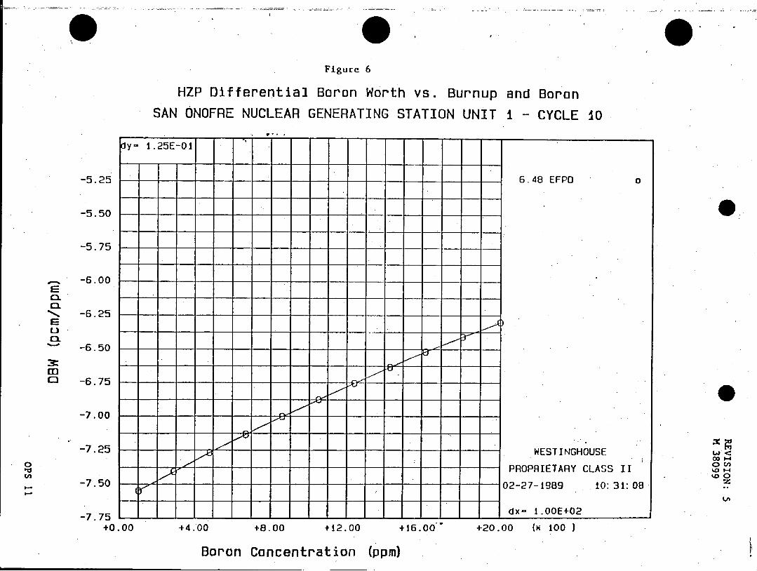
Figure 6
HZP Differential Boron Worth vs. Burnup and Boron SAN ONOFRE NUCLEAR GENERATING STATION UNIT i - CYCLE 10
dy- 1.25E-01
-5.25 6.48 EFPO
-5.50
-5.75
-8.00
CL -6.25
-6.50
M -6.75
-7.00
-7.25 ---- -------- -WESTINGHOUSE
PROPRIETARY CLASS II -7.50 - ----------- 02-27-1989 10: 31: 08
-7.75- dx- 1.00E+02
+0.00 +4.00 +8.00 +12.00 +16.00 +20.00 (K 100 )
Boron Concentration (ppm)
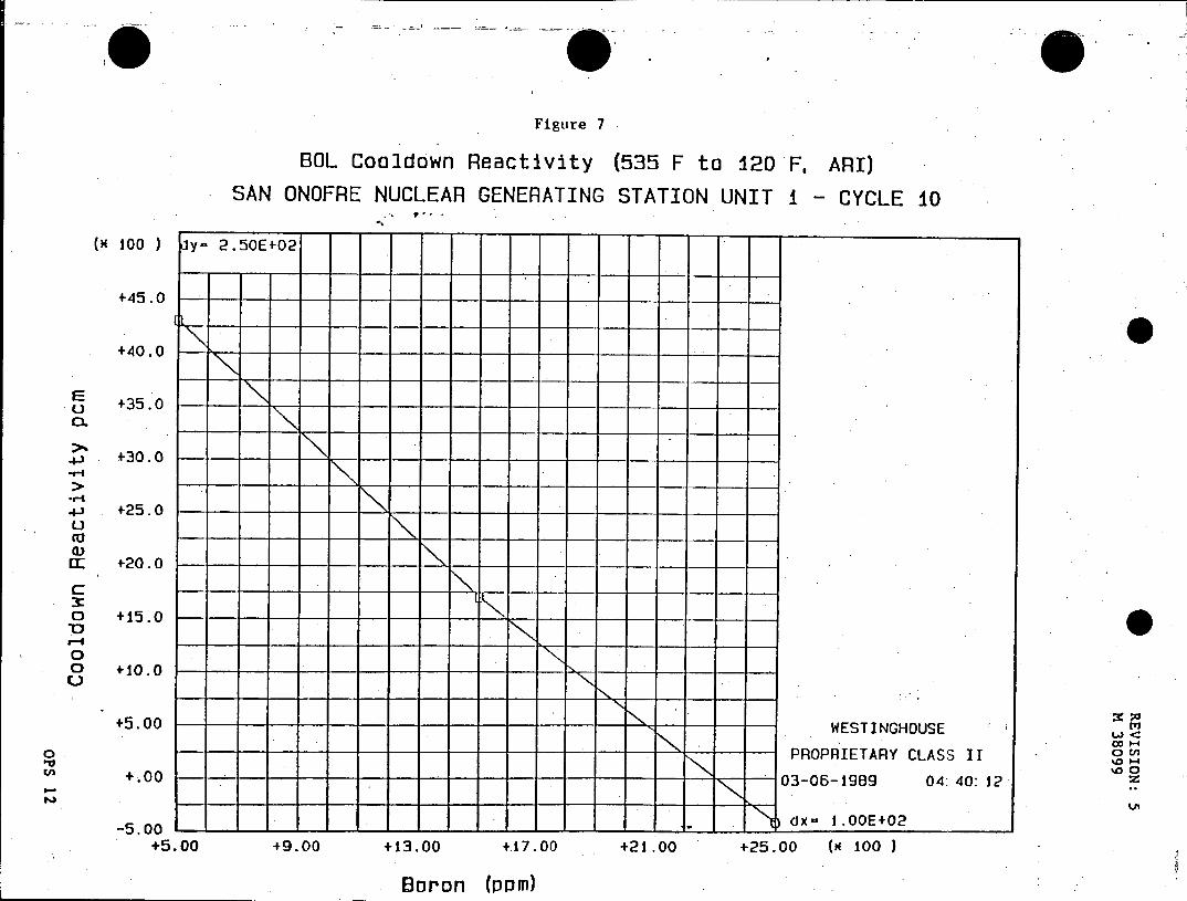
Figure 7
BOL Coo3down Reactivity (535 F to 120 F. ARI)
SAN ONOFRE NUCLEAR GENERATING STATION UNIT 1 - CYCLE 10
( 100 ) y- 2.50E+02
+45.0
+40.0 -
E o +35.0
. o
.4- +30.0
4j +25.0
CC+20.0-
C --
0
0 +0.0---
+5.00 -------------- ESTINGHOUSE
--------------- PROPRIETARYCLASS 1
+.00 ---------------- 03-06-1989 04: 40: 12
-5.00 - - dx- 1.OOE+02
+5.00 +9.00 +13.00 +17.00 +21.00 +25.00 (H 100 )
Boron (ppm)
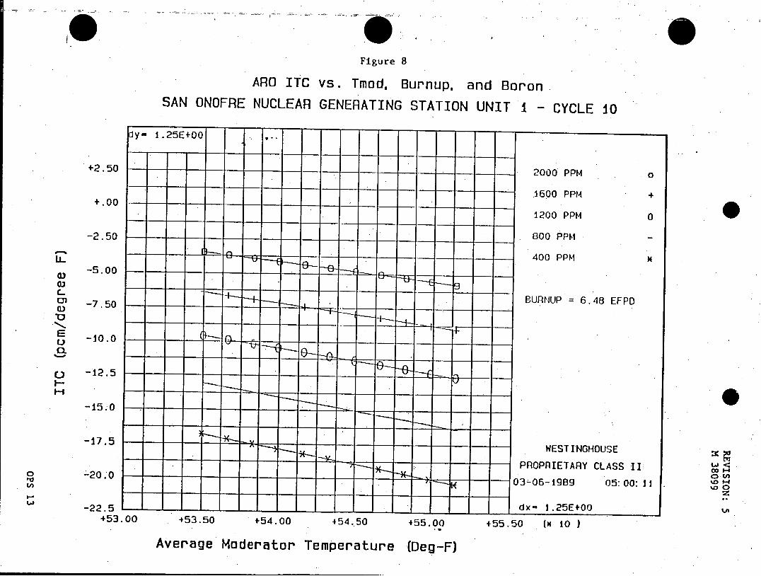
Figure 8
ARO ITC vs. Tmod, Burnup, and Boron SAN ONOFRE NUCLEAR GENERATING STATION UNIT 1 - CYCLE 10
y- 1.25E+00 -.
+2.50 2000 PPM
..oo 1600 PPM + +.00
1200 PPM 0
-2.50 800 PPM
400 PPM
0 --5.00
-7.50 -- BURNUP = 6.48 EFPD
S -10.0
-15.0
-17.5 -WESTINGHOUSE
PROPRIETARY CLASS II
--------- 03-06-19B9 05: 00: 11.
-22.5 -- dx- 1.25E+00
+53.00 +53.50 +54.00 +54.50 +55.00 +55.50 (H 10 )
Average Moderator Temperature (Deg-F)
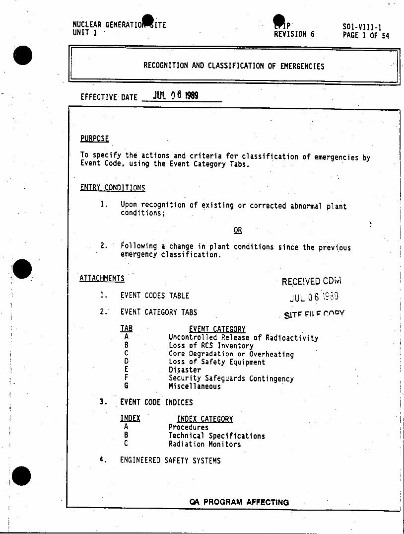
NUCLEAR GENERATIO ITE .P SOl-VIII-1 UNIT 1 REVISION 6 PAGE 1 OF 54
RECOGNITION AND CLASSIFICATION OF EMERGENCIES
EFFECTIVE DATE Jut 08 9
PURPOSE
To specify the actions and criteria for classification of emergencies by Event Code, using the Event Category Tabs.
ENTRY CONDITIONS
1. Upon recognition of existing or corrected abnormal plant conditions;
2. Following a change in plant conditions since the previous emergency classification.
ATTACHMENTS R CEIVED CDMvl 1. EVENT CODES TABLE JUL 06 1989
2. EVENT CATEGORY TABS SIT p1 rFI ov
TAB EVENT CATEGORY A Uncontrolled Release of Radioactivity B Loss of RCS Inventory C Core Degradation or Overheating D Loss of Safety Equipment E Disaster F Security Safeguards Contingency G Miscellaneous
3. EVENT CODE INDICES
INDEX INDEX CATEGORY A Procedures B Technical Specifications C Radiation Monitors
4. ENGINEERED SAFETY SYSTEMS
04 PROGRAM AFFECTING
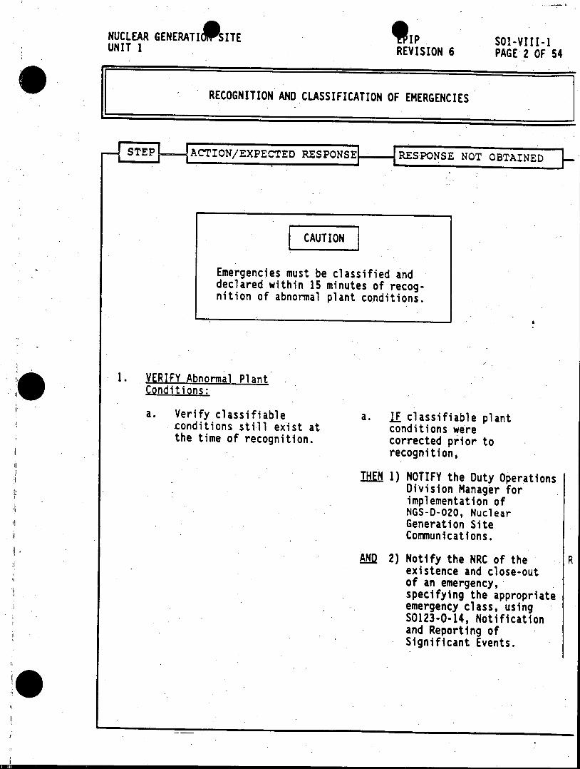
NUCLEAR GENERATIAITE IP sal-VIII-1 UNIT 1 REVISION 6 PAGE 2 OF 54
RECOGNITION AND CLASSIFICATION OF EMERGENCIES
STEP ACTION/EXPECTED RESPONSE - RESPONSE NOT OBTAINED
CAUTION
Emergencies must be classified and declared within 15 minutes of recognition of abnormal plant conditions.
1. VERIFY Abnormal Plant Conditions:
a. Verify classifiable a. LE classifiable plant conditions still exist at conditions were the time of recognition. corrected prior to
recognition,
THEN 1) NOTIFY the Duty Operations Division Manager for implementation of NGS-D-020, Nuclear Generation Site Communications.
ANQ 2) Notify the NRC of the R existence and close-out of an emergency, specifying the appropriate emergency class, using S0123-0-14, Notification and Reporting of Significant Events.
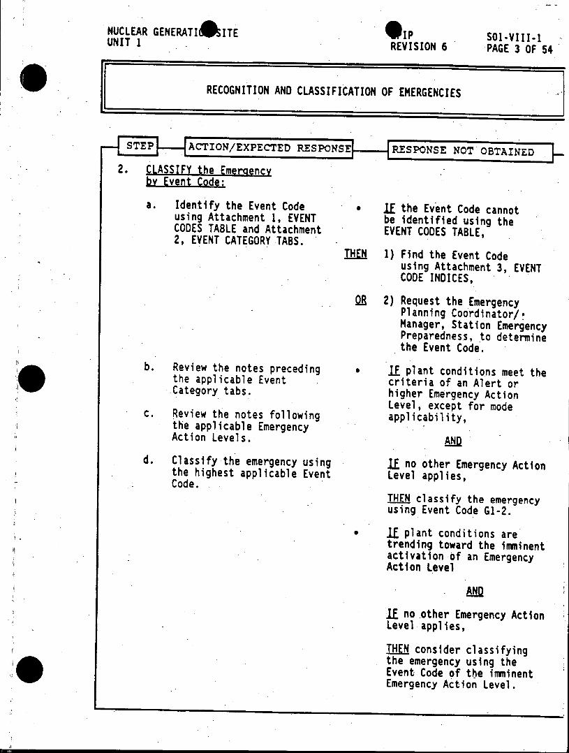
NUCLEAR GENERATIS ITE *IP SO1-VIII-1 UNIT 1 REVISION 6 PAGE 3 OF 54
RECOGNITION AND CLASSIFICATION OF EMERGENCIES
SE IACTION/EXPECTED RESPONSE RESPONSE NOT OBTAINED
2. CLASSIFY the Emergency by Event Code:
a. Identify the Event Code * If the Event Code cannot using Attachment 1, EVENT be identified using the CODES TABLE and Attachment EVENT CODES TABLE, 2, EVENT CATEGORY TABS.
18O 1) Find the Event Code using Attachment 3, EVENT CODE INDICES,
Q 2) Request the Emergency Planning Coordinator/* Manager, Station Emergency Preparedness, to determine the Event Code.
b. Review the notes preceding * IE plant conditions meet the the applicable Event criteria of an Alert or Category tabs. higher Emergency Action Level, except for mode c. Review the notes following applicability,
the applicable Emergency Action Levels. AND
d. Classify the emergency using If no other Emergency Action the highest applicable Event Level applies, Code.
THEN classify the emergency using Event Code G1-2.
If plant conditions are trending toward the imminent activation of an Emergency Action Level
If no other Emergency Action Level applies,
THEN consider classifying the emergency using the Event Code of the imminent Emergency Action Level.
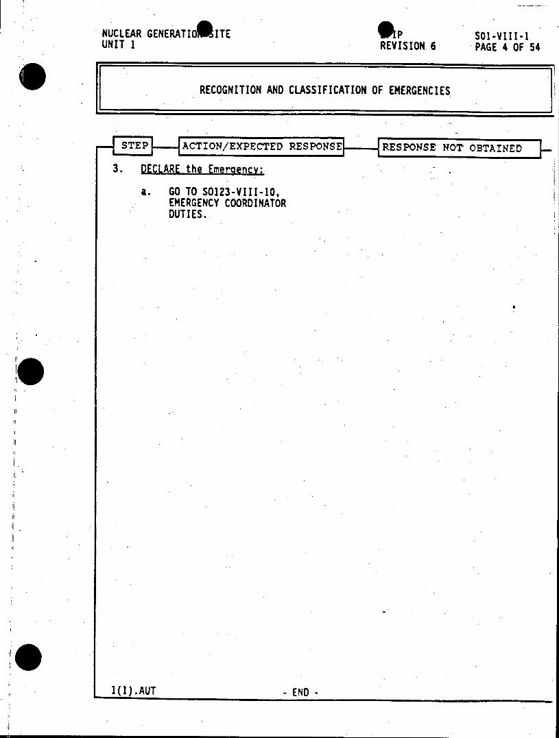
NUCLEAR GENERATIOWITE *P SOl-VIII-1 UNIT I REVISION 6 PAGE 4 OF 54
RECOGNITION AND CLASSIFICATION OF EMERGENCIES
STEP ACTION/EXPECTED RESPONSE RESPONSE NOT OBTAINED
3. DECLARE the Emergency:
a. GO TO 50123-VIII-10, EMERGENCY COORDINATOR DUTIES.
1(1).AUT - END -
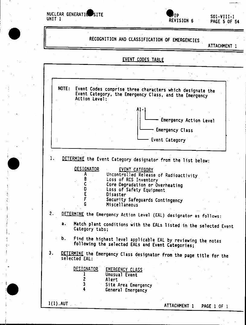
NUCLEAR GENERATI*SITE 1IP SO1-VIII-1 UNIT 1 REVISION 6 PAGE 5 OF 54
RECOGNITION AND CLASSIFICATION OF EMERGENCIES ATTACHMENT 1
EVENT CODES TABLE
NOTE: Event Codes comprise three characters which designate the Event Category, the Emergency Class, and the Emergency Action Level:
Emergency Action Level
Emergency Class
Event Category
1. DETERMINE the Event Category designator from the list below:
DESIGNATOR EVENT CATEGORY A Uncontrolled Release of Radioactivity 8 Loss of RCS Inventory C Core Degradation or Overheating D Loss of Safety Equipment E Disaster F Security Safeguards Contingency G Miscellaneous
2. DETERMINE the Emergency Action Level (EAL) designator as follows:
a. Match plant conditions with the EALs listed in the selected Event Category tabs;
b. Find the highest level applicable EAL by reviewing the notes following the selected EALs and Event Categories;
3. DETERMINE the Emergency Class designator from the page title for the selected EAL:
DESIGNATOR EMERGENCY CLASS 1 Unusual Event 2 Alert 3 Site Area Emergency 4 General Emergency
1(1).AUT ATTACHMENT 1 PAGE 1 OF 1
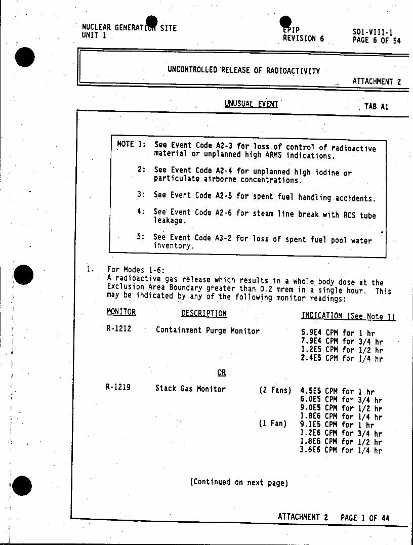
NUCLEAR GENERATE SITE 9 1P SOl-VIII-1 UNIT 1 REVISION 6 PAGE 6 OF 54
UNCONTROLLED RELEASE OF RADIOACTIVITY ATTACHMENT 2
UNUSUAL EVENT TAB Al
NOTE 1: See Event Code A2-3 for loss of control of radioactive material or unplanned high ARMS indications.
2: See Event Code A2-4 for unplanned high iodine or particulate airborne concentrations.
3: See Event Code A2-5 for spent fuel handling accidents.
4: See Event Code A2-6 for steam line break with RCS tube leakage.
5: See Event Code A3-2 for loss of spent fuel pool water inventory.
1. For Modes 1-6: A radioactive gas release which results in a whole body dose at the Exclusion Area Boundary greater than 0.2 mrem in a single hour. This may be indicated by any of the following monitor readings:
MONITOR DESCRIPTION INDICATION (See Note 1) R-1212 Containment Purge Monitor 5.9E4 CPM for 1 hr
7.9E4 CPM for 3/4 hr 1.2E5 CPM for 1/2 hr 2.4E5 CPM for 1/4 hr
0R R-1219 Stack Gas Monitor (2 Fans) 4.5E5 CPM for I hr
6.0E5 CPM for 3/4 hr 9.0E5 CPM for 1/2 hr 1.8E6 CPM for 1/4 hr
(1 Fan) 9.1E5 CPM for 1 hr 1.2E6 CPM for 3/4 hr 1.8E6 CPM for 1/2 hr 3.6E6 CPM for 1/4 hr
(Continued on next page)
ATTACHMENT 2 PAGE 1 OF 44
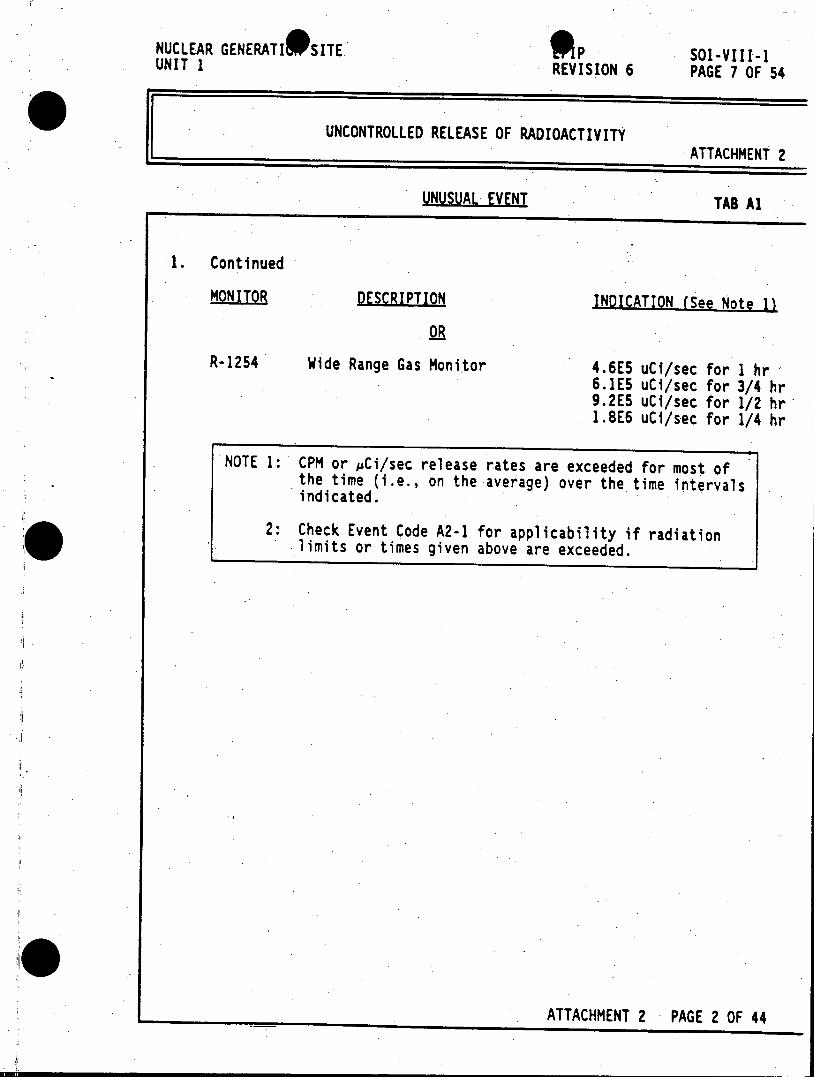
NUCLEAR GENERATIWSITE ,P SOl-VIII-1 UNIT 1 REVISION 6 PAGE 7 OF 54
UNCONTROLLED RELEASE OF RADIOACTIVITY ATTACHMENT 2
UNUSUAL EVENT TAB Al
1. Continued
MONITOR DESCRIPTION INDICATION (See Note 1)
R-1254 Wide Range Gas Monitor 4.6E5 uCi/sec for I hr 6.1E5 uCi/sec for 3/4 hr 9.2E5 uCi/sec for 1/2 hr 1.8E6 uCi/sec for 1/4 hr
NOTE 1: CPM or pCi/sec release rates are exceeded for most of -the time (i.e., on the average) over the time intervals indicated.
2: Check Event Code A2-1 for applicability if radiation limits or times given above are exceeded.
ATTACHMENT 2 PAGE 2 OF 44
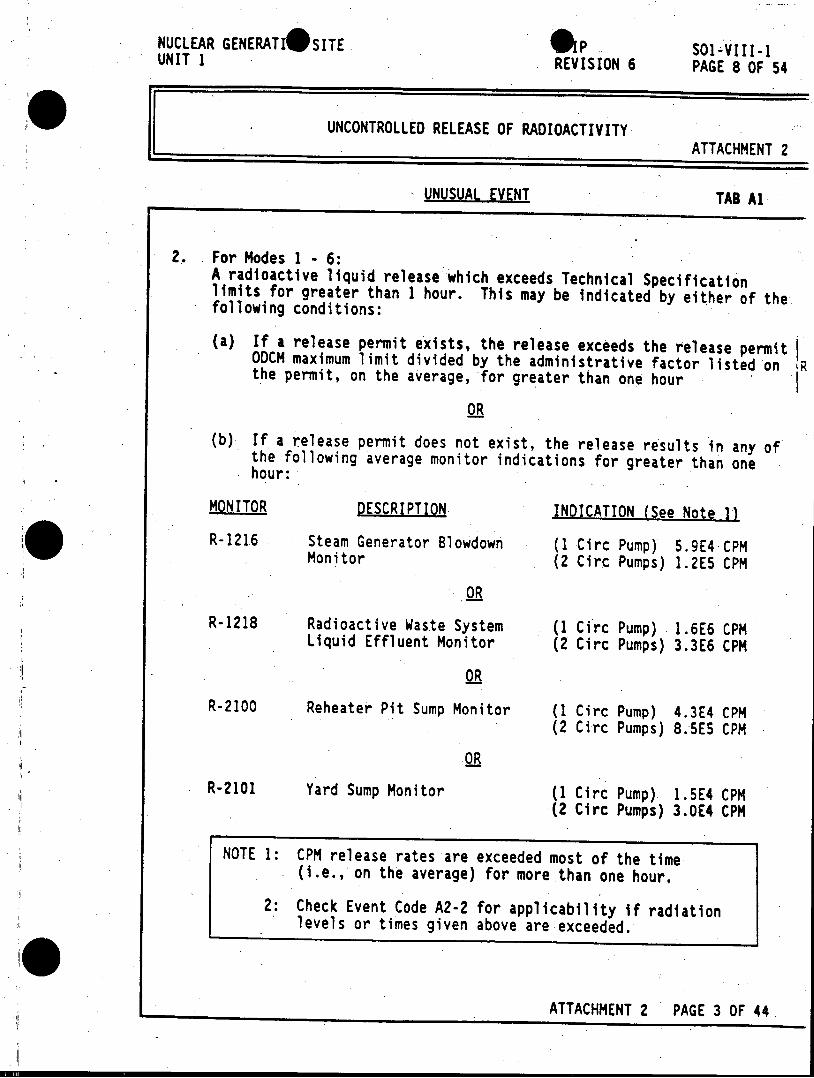
NUCLEAR GENERATI@SITE P 601-4III-1 UNIT I REVISION 6 PAGE 8 OF 54
UNCONTROLLED RELEASE OF RADIOACTIVITY ATTACHMENT 2
UNUSUAL EVENT TAB Al
2. For Modes 1 -6: A radioactive liquid release which exceeds Technical Specification limits for greater than 1 hour. This may be indicated by either of the following conditions:
(a) If a release permit exists, the release exceeds the release permit ODCM maximum limit divided by the administrative factor listed on R the permit, on the average, for greater than one hour
(b) If a release permit does not exist, the release results in any of the following average monitor indications for greater than one hour:
MONITOR DESCRIPTION INDICATION (See Note 1) R-1216 Steam Generator Blowdown (1 Circ Pump) 5.9E4 CPM
Monitor (2 Circ Pumps) 1.2E5 CPM
OR
R-1218 Radioactive Waste System (1 Circ Pump) 1.6E6 CPM Liquid Effluent Monitor (2 Circ Pumps) 3.3E6 CPM
OR
R-2100 Reheater Pit Sump Monitor (1 Circ Pump) 4.3E4 CPM (2 Circ Pumps) 8.5E5 CPM
OR
R-2101 Yard Sump Monitor (1 Circ Pump) 1.5E4 CPM (2 Circ Pumps) 3.0E4 CPM
NOTE 1: CPM release rates are exceeded most of the time (i.e., on the average) for more than one hour.
2: Check Event Code A2-2 for applicability if radiation levels or times given above are exceeded.
ATTACHMENT 2 PAGE 3 OF 44
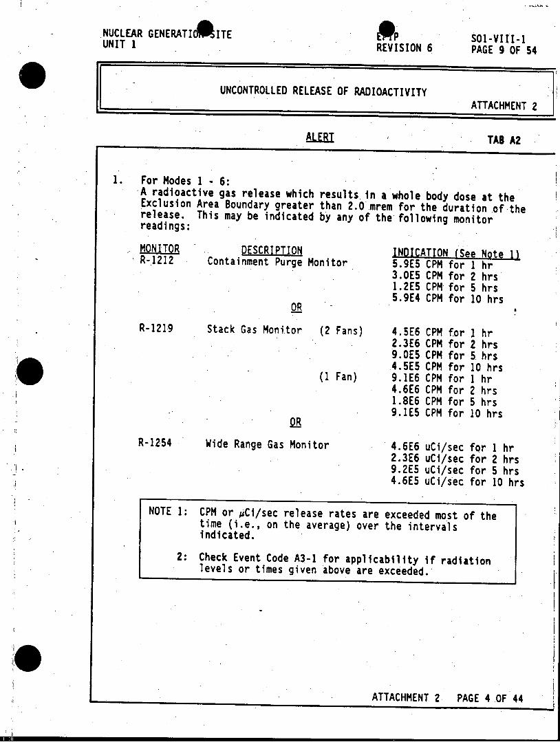
NUCLEAR GENERATIOAITE SOl-VIII-1 UNIT 1 REVISION 6 PAGE 9 OF 54
UNCONTROLLED RELEASE OF RADIOACTIVITY ATTACHMENT 2
ALiBI TAB A2
1. For Modes 1 - 6: A radioactive gas release which results in a whole body dose at the Exclusion Area Boundary greater than 2.0 mrem for the duration of the release. This may be indicated by any of the following monitor readings:
MONITOR DESCRIPTION INDICATION (See Note 11 R-1212 Containment Purge Monitor 5.9E5 CPM for 1 hr 3.0E5 CPM for 2 hrs 1.2E5 CPM for 5 hrs 5.9E4 CPM for 10 hrs
OR
R-1219 Stack Gas Monitor (2 Fans) 4.5E6 CPM for I hr 2.3E6 CPM for 2 hrs 9.0E5 CPM for 5 hrs 4.5E5 CPM for 10 hrs
(1 Fan) 9.1E6 CPM for 1 hr 4.6E6 CPM for 2 hrs 1.8E6 CPM for 5 hrs 9.1E5 CPM for 10 hrs
OR
R-1254 Wide Range Gas Monitor 4.6E6 uCi/sec for 1 hr 2.3E6 uCi/sec for 2 hrs 9.2E5 uCi/sec for 5 hrs 4.6E5 uCi/sec for 10 hrs
NOTE 1: CPM or pCi/sec release rates are exceeded most of the time (i.e., on the average) over the intervals indicated.
2: Check Event Code A3-1 for applicability if radiation levels or times given above are exceeded.
ATTACHMENT 2. PAGE 4 OF 44
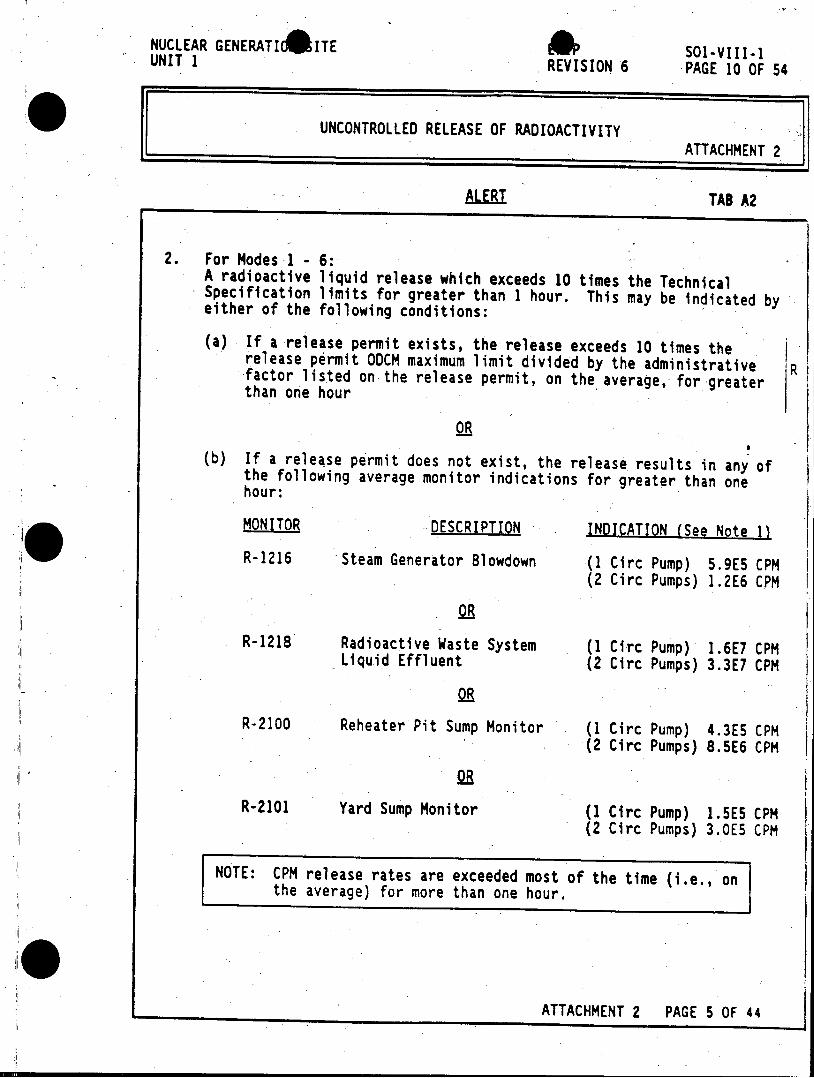
NUCLEAR GENERATId4ITE 4 SOl-VIII-1 UNIT 1 REVISION 6 PAGE 10 OF 54
UNCONTROLLED RELEASE OF RADIOACTIVITY ATTACHMENT 2
ALERT TAB A2
2. For Modes 1 - 6: A radioactive liquid release which exceeds 10 times the Technical Specification limits for greater than 1 hour. This may be indicated by either of the following conditions:
(a) If a release permit exists, the release exceeds 10 times the release permit 00CM maximum limit divided by the administrative R factor listed on the release permit, on the average, for greater than one hour
(b) If a release permit does not exist, the release results in any of the following average monitor indications for greater than one hour:
MONITOR DESCRIPTION INDICATION (See Note 1)
R-1216 Steam Generator Blowdown (1 Circ Pump) 5.9E5 CPM (2 Circ Pumps) 1.2E6 CPM
R-1218 Radioactive Waste System (1 Circ Pump) 1.6E7 CPM Liquid Effluent (2 Circ Pumps) 3.3E7 CPM
OR
R-2100 Reheater Pit Sump Monitor (1 Circ Pump) 4.3E5 CPM (2 Circ Pumps) 8.5E6 CPM
R-2101 Yard Sump Monitor (1 Circ Pump) 1.5E5 CPM (2 Circ Pumps) 3.0E5 CPM
NOTE: CPM release rates are exceeded most of the time (i.e., on the average) for more than one hour.
ATTACHMENT 2 PAGE 5 OF 44
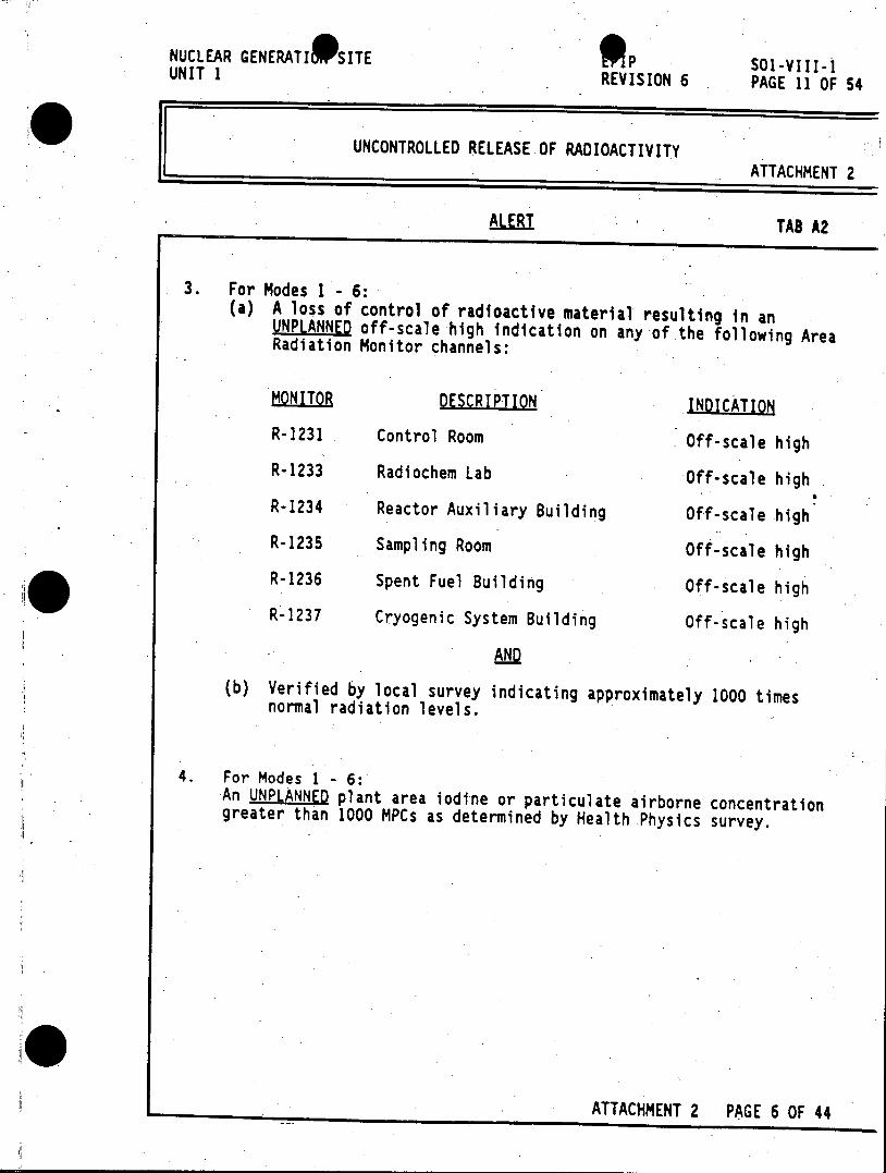
NUCLEAR GENERATI SITE p 51-VIII-1 UNIT 1 REVISION 6 PAGE 11 OF 54
UNCONTROLLED RELEASE OF RADIOACTIVITY ATTACHMENT 2
ALERT TAB A2
3. For Modes 1 - 6: (a) A loss of control of radioactive material resulting in an UNPLANNED off-scale high indication on any of the following Area Radiation Monitor channels:
MONITOR DESCRIPTION INDICATION
R-1231 Control Room Off-scale high
R-1233 Radiochem Lab Off-scale high
R-1234 Reactor Auxiliary Building Off-scale high R-1235 Sampling Room Off-scale high
R-1236 Spent Fuel Building Off-scale high
R-1237 Cryogenic System Building Off-scale high
AND
(b) Verified by local survey indicating approximately 1000 times normal radiation levels.
4. For Modes 1 - 6: An UNPLANNED plant area iodine or particulate airborne concentration greater than 1000 MPCs as determined by Health Physics survey.
ATTACHMENT 2 PAGE 6 OF 44
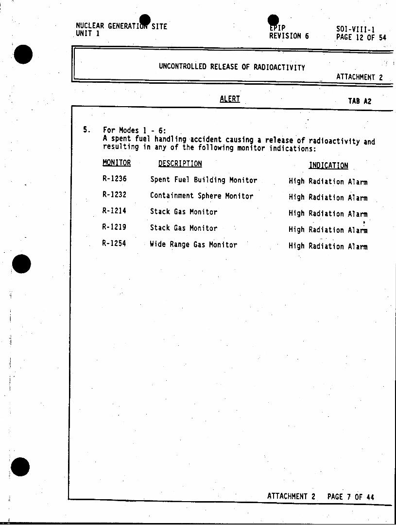
NUCLEAR GENERATI 9 SITE *IP SOl-VIII-1 UNIT 1 REVISION 6 PAGE 12 OF 54
UNCONTROLLED RELEASE OF RADIOACTIVITY ATTACHMENT 2
ALERT TAB A2
5. For Modes 1 6: A spent fuel handling accident causing a release of radioactivity and resulting in any of the following monitor indications:
MONITOR DESCRIPTION INDICATION
R-1236 Spent Fuel Building Monitor High Radiation Alarm
R-1232 Containment Sphere Monitor High Radiation Alarm
R-1214 Stack Gas Monitor High Radiation Alarm
R-1219 Stack Gas Monitor High Radiation Alarm
R-1254 Wide Range Gas Monitor High Radiation Alarm
ATTACHMENT 2 PAGE 7 OF 44
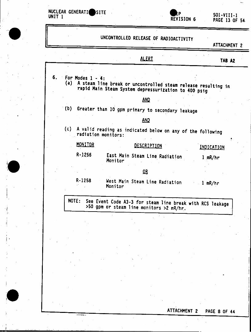
NUCLEAR GENERATIOSITE (p SOl-VIII-1 UNIT 1 REVISION 6 PAGE 13 OF 54.
UNCONTROLLED RELEASE OF RADIOACTIVITY ATTACHMENT 2
AILEBI TAB A2
6. For Nodes 1 - 4: (a) A steam line break or uncontrolled steam release resulting in rapid Main Steam System depressurization to 400 psig
(b) Greater than 10 gpm primary to secondary leakage
(c) A valid reading as indicated below on any of the following radiation monitors:
MONITOR DESCRIPTION INDICATION
R-1256 East Main Steam Line Radiation I mR/hr Monitor
OR
R-1258 West Main Steam Line Radiation 1 mR/hr Monitor
NOTE: See Event Code A3-3 for steam line break with RCS leakage >50 gpm or steam line monitors >2 mR/hr.
ATTACHMENT 2 PAGE 8 OF 44
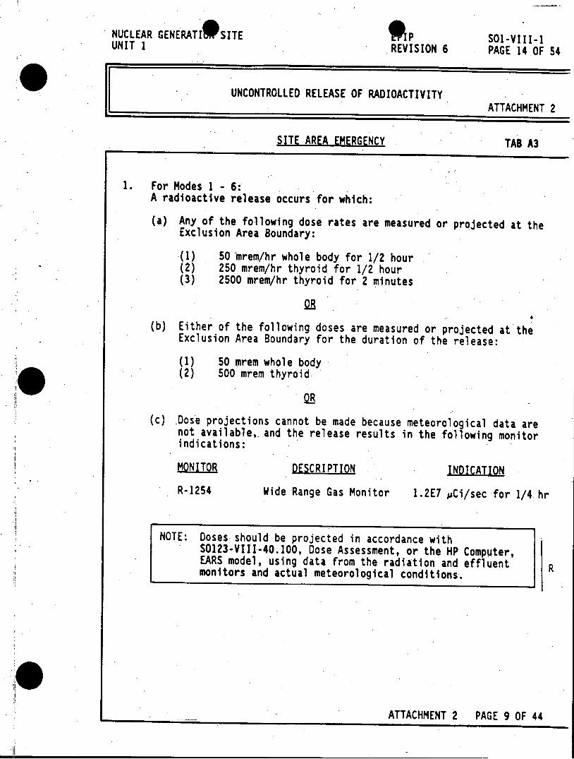
NUCLEAR GENERATI 9 SITE OP SO1-VIII-1 UNIT I REVISION 6 PAGE 14 OF 54
UNCONTROLLED RELEASE OF RADIOACTIVITY ATTACHMENT 2
SITE AREA EMERGENCY TAB A3
1. For Modes 1 - 6: A radioactive release occurs for which:
(a) Any of the following dose rates are measured or projected at the Exclusion Area Boundary:
(1) 50 mrem/hr whole body for 1/2 hour (2) 250 mrem/hr thyroid for 1/2 hour (3) 2500 mrem/hr thyroid for 2 minutes
OR
(b) Either of the following doses are measured or projected at the Exclusion Area Boundary for the duration of the release:
(1) 50 mrem whole body (2) 500 mrem thyroid
OR
(c) Dose projections cannot be made because meteorological data are not available, and the release results in the following monitor indications:
MONITOR DESCRIPTION INDICATION
R-1254 Wide Range Gas Monitor 1.2E7 pCi/sec for 1/4 hr
NOTE: Doses should be projected in accordance with 50123-VIII-40.100, Dose Assessment, or the HP Computer, EARS model, using data from the radiation and effluent monitors and actual meteorological conditions.
ATTACHMENT 2 PAGE 9 OF 44
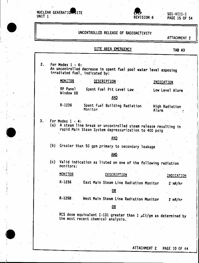
NUCLEAR GENERATIORITE So 1-VIII-1 UNIT 1 REVISION 6 PAGE 15 OF 54
UNCONTROLLED RELEASE OF RADIOACTIVITY ATTACHMENT 2
SITE AREA EMERGENCY TAB A3
2. For Modes 1 6: -An uncontrolled decrease in spent fuel pool water level exposing irradiated fuel, indicated by:
MONITOR DESCRIPTION- INDICATION
RP Panel Spent Fuel Pit Level Low Low Level Alarm Window 68
AND
R-1236 Spent Fuel Building Radiation High Radiation Monitor Alarm
3. For Modes 1- 4: (a) A steam line break or uncontrolled steam release resulting in
rapid Main Steam System depressurization to 400 psig
AND
(b) Greater than 50 gpm primary to secondary leakage
AND
(c) Valid indication as listed on one of the following radiation monitors:
MONITOR DESCRIPTION INDICATION
R-1256 East Main Steam Line Radiation Monitor 2 mR/hr
OR
R-1258 West Main Steam Line Radiation Monitor 2 mR/hr
2R RCS dose equivalent 1-131 greater than 1 pCi/gm as determined by the most recent chemical analysis.
ATTACHMENT 2 PAGE 10 OF 44
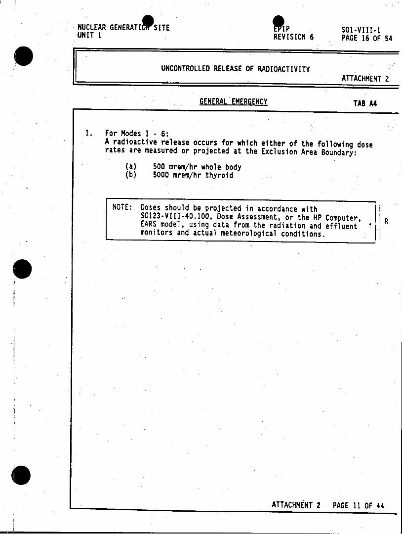
NUCLEAR GENERATI 9 SITE IP SOl-VIII-1 UNIT 1 REVISION 6 PAGE 16 OF 54
UNCONTROLLED RELEASE OF RADIOACTIVITY ATTACHMENT 2
GENERAL EMERGENCY TAB A4
1. For Modes 1 - 6: A radioactive release occurs for which either of the following dose rates are measured or projected at the Exclusion Area Boundary:
(a) 500 mrem/hr whole body (b) 5000 mrem/hr thyroid
NOTE: Doses should be projected in accordance with 50123-VIII-40.100, Dose Assessment, or the HP Computer, R EARS model, using data from the radiation and effluent monitors and actual meteorological conditions.
ATTACHMENT 2 PAGE 11 OF 44
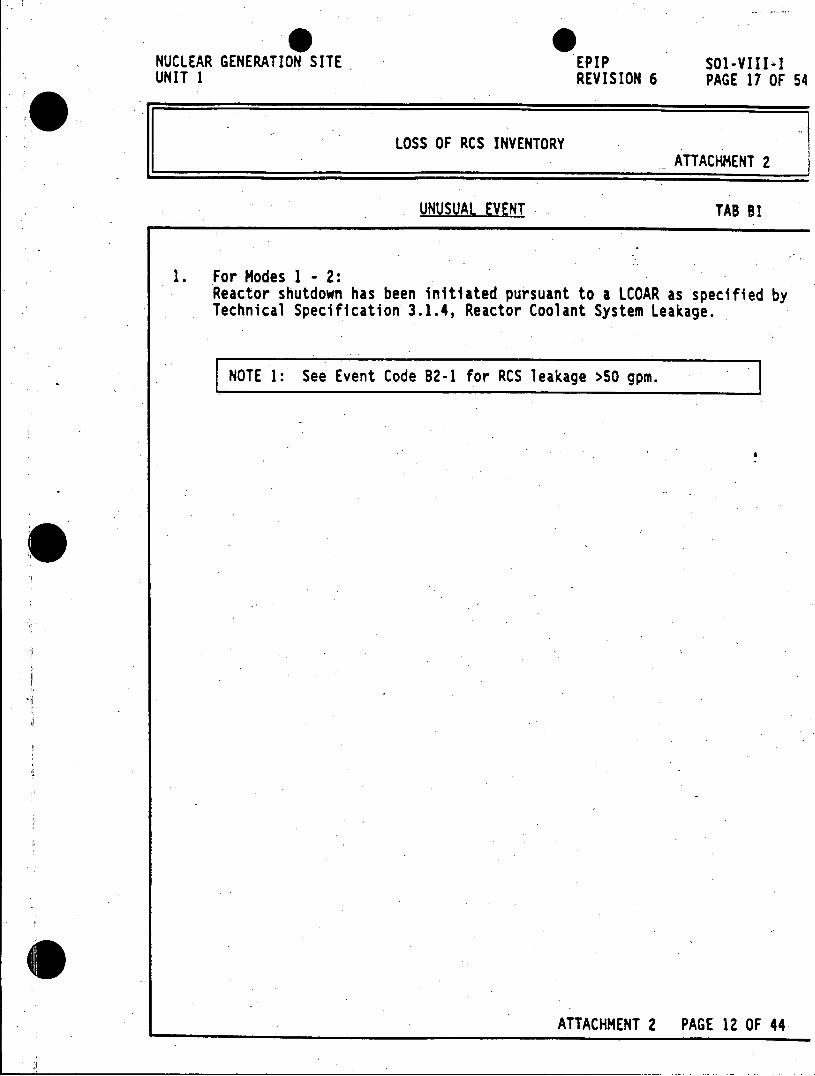
NUCLEAR GENERATION SITE EPIP SOl-VIII-1 UNIT 1 REVISION 6 PAGE 17 OF 54
LOSS OF RCS INVENTORY ATTACHMENT 2
UNUSUAL EVENT TAB BI
1. For Modes 1 - 2: Reactor shutdown has been initiated pursuant to a LCOAR as specified by Technical Specification 3.1.4, Reactor Coolant System Leakage.
NOTE 1: See Event Code B2-1 for RCS leakage >50 gpm.
ATTACHMENT 2 PAGE 12 OF 44
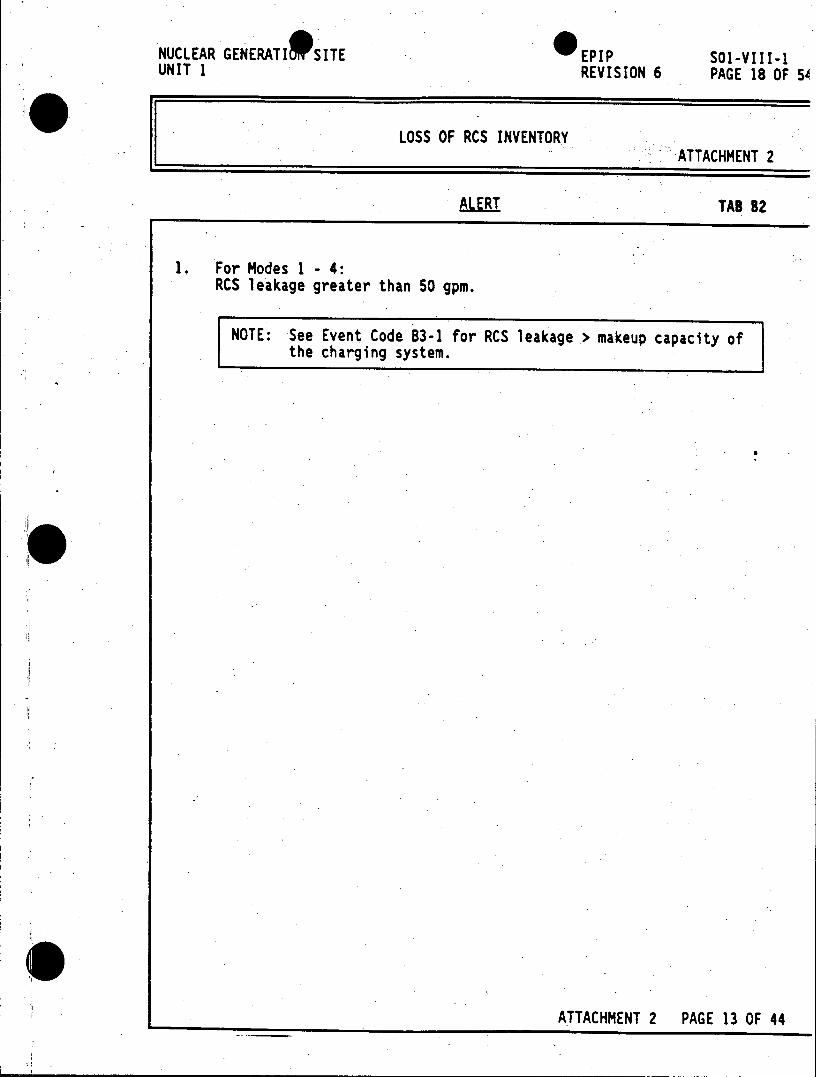
NUCLEAR GENERATI SITE EPIP SO1-VIII-1 UNIT 1 REVISION 6 PAGE 18 OF 54
LOSS OF RCS INVENTORY ATTACHMENT 2
ALERT TAB 82
1. For Modes 1 - 4: RCS leakage greater than 50 gpm.
NOTE: See Event Code B3-1 for RCS leakage > makeup capacity of the charging system.
ATTACHMENT 2 PAGE 13 OF 44
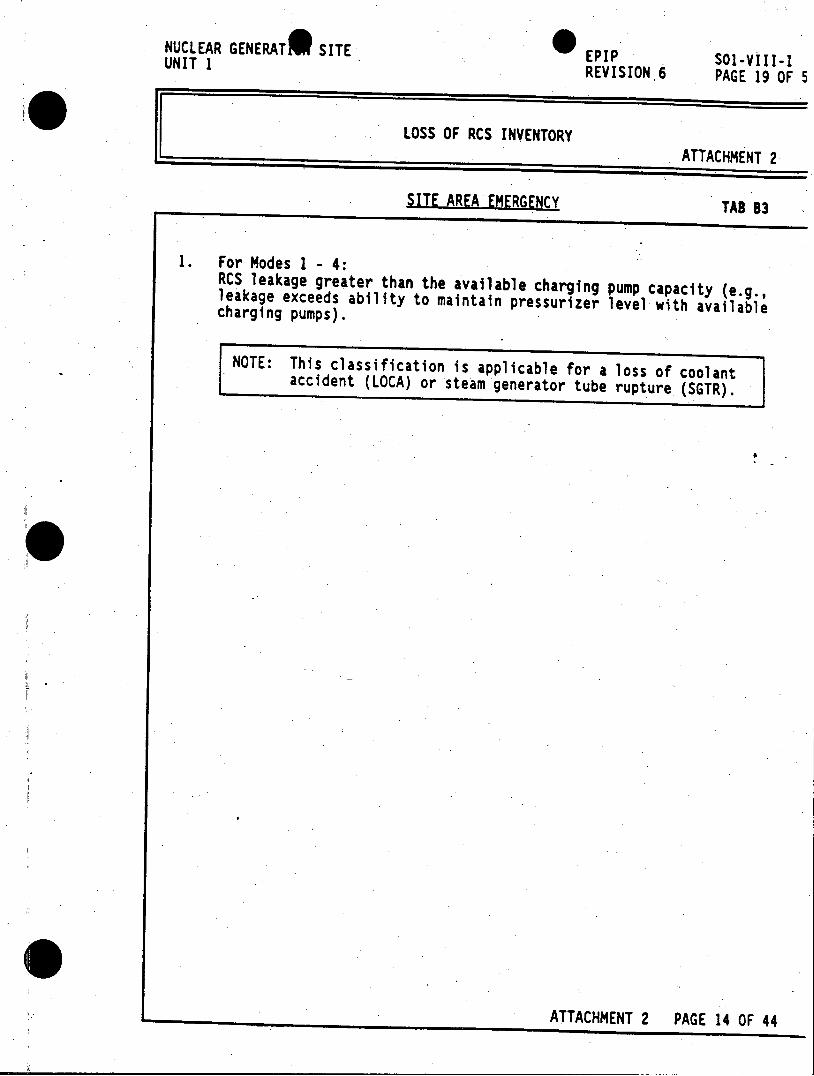
NUCLEAR GENERAT* SITE UNIT 1 EPIP 501-VIII-1
REVISION 6 PAGE 19 OF 5
LOSS OF RCS INVENTORY ATTACHMENT 2
SITE AREA EMERGENCY TAB B3
1. For Modes 1 - 4: RCS leakage greater than the available charging pump capacity (e.g., leakage exceeds ability to maintain pressurizer level with available charging pumps).
NOTE: This classification is applicable for a loss of coolant accident (LOCA) or steam generator tube rupture (SGTR).
0P
ATTACHMENT 2 PAGE 14 OF 44
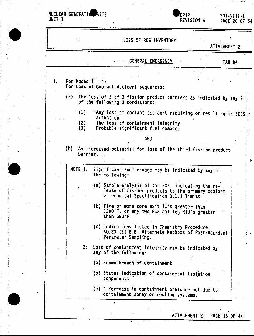
NUCLEAR GENERATI#SITE *EPIP SOl-VIII-1 UNIT 1 REVISION 6 PAGE 20 OF 54
LOSS OF RCS INVENTORY ATTACHMENT 2
GENERAL EMERGENCY TAB 84
1. For Modes 1 - 4: For Loss of Coolant Accident sequences:
(a) The loss of 2 of 3 fission product barriers as indicated by any 2 of the following 3 conditions:
(1) Any loss of coolant accident requiring or resulting in ECCS actuation
(2) The loss of containment integrity (3) Probable significant fuel damage.
AND
8
(b) An increased potential for loss of the third fission product barrier.
NOTE 1: Significant fuel damage may be indicated by any of the following:
(a) Sample analysis of the RCS, indicating the release of fission products to the primary coolant > Technical Specification 3.1.1 limits
(b) Five or more core exit TC's greater than 12006F, or any two RCS hot leg RTD's greater than 680'F
(c) Indications listed in Chemistry Procedure S0123-III-8.8, Alternate Methods of Post-Accident Parameter Sampling.
2: Loss of containment integrity may-be indicated by any of the following:
(a) Known breach of containment
(b) Status indication of containment isolation components
(c) A decrease in containment pressure not due to containment spray or cooling systems.
ATTACHMENT 2 PAGE 15 OF 44
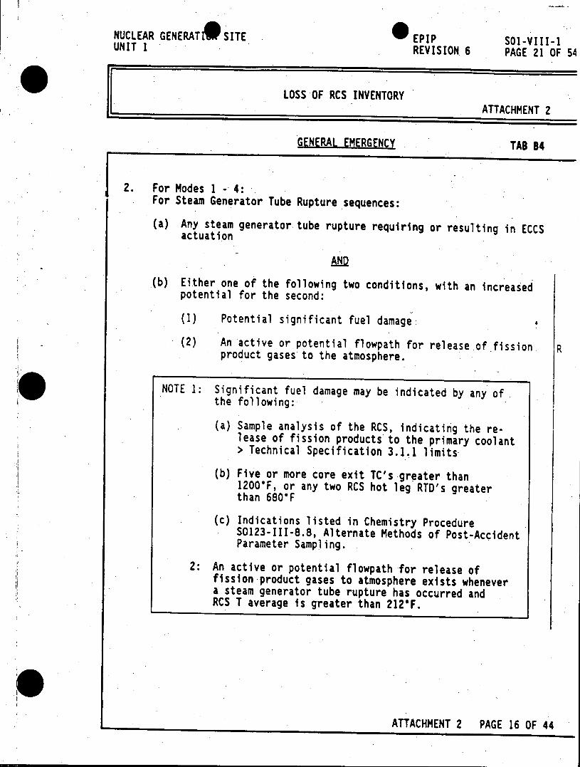
NUCLEAR GENERATD SITE EPIP SO1-VIII-1 UNIT 1 REVISION 6 PAGE 21 OF 54
LOSS OF RCS INVENTORY ATTACHMENT 2
GENERAL EMERGENCY TAB 84
2. For Modes 1 --4: For Steam Generator Tube Rupture sequences:
(a) Any steam generator-tube rupture requiring or resulting in ECCS actuation
AND
(b) Either one of the following two conditions, with an increased potential for the second:
(1) Potential significant fuel damage.
(2) An active or potential flowpath for release of fission R product gases to the atmosphere.
NOTE 1: Significant fuel damage may be indicated by any of the following:
(a) Sample analysis of the RCS, indicating the release of fission products to the primary coolant > Technical Specification 3.1.1 limits
(b) Five or more core exit TC's greater than 12000F, or any two RCS hot leg RTD's greater than 680*F
(c) Indications listed in Chemistry Procedure S0123-III-8.8, Alternate Methods of Post-Accident Parameter Sampling.
2: An active or potential flowpath for release of fission product gases to atmosphere exists whenever a steam generator tube rupture has occurred and RCS T average is greater than 212'F.
ATTACHMENT 2 PAGE 16 OF 44
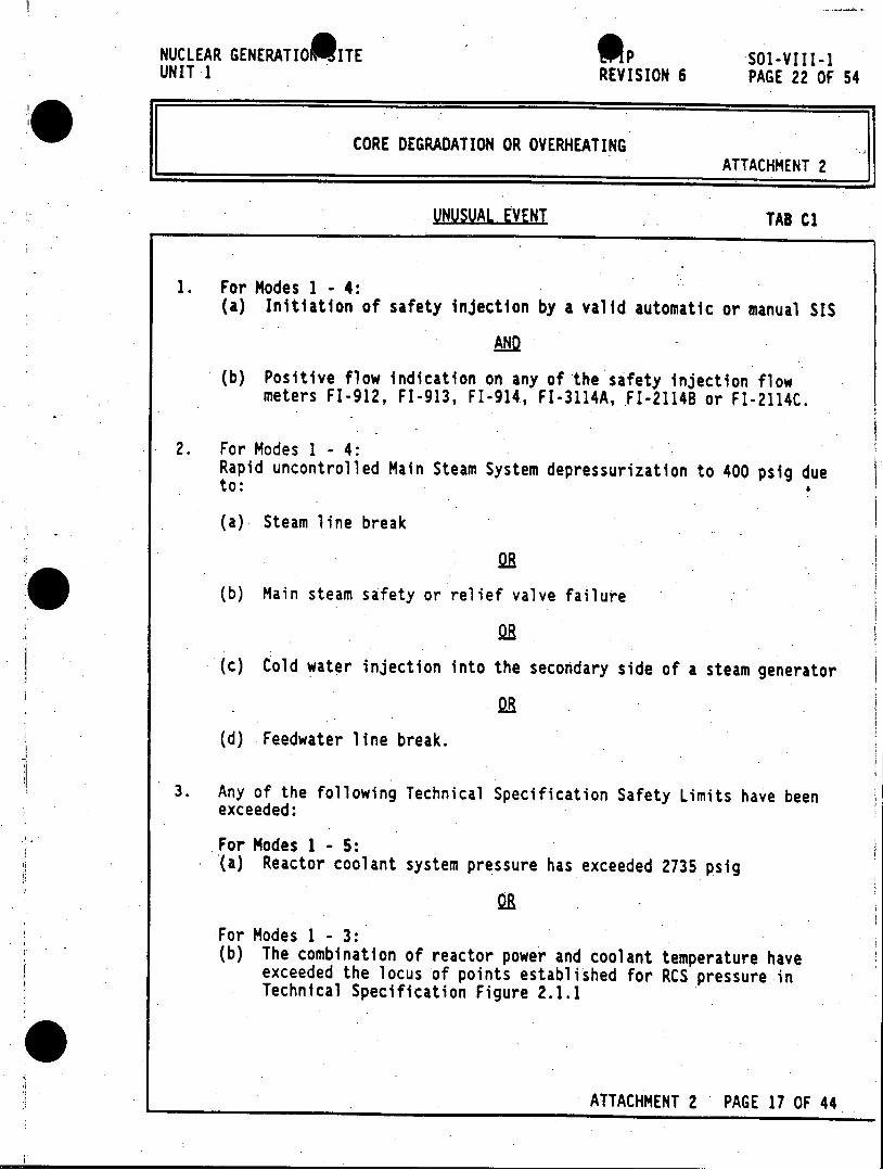
NUCLEAR GENERATIO ITE oP SOl-VIII-1 UNIT 1 REVISION 6 PAGE 22 OF 54
CORE DEGRADATION OR OVERHEATING ATTACHMENT 2
UNUSUAL EVENT TAB C1
1. For Modes 1 -4: (a) Initiation of safety injection by a valid automatic or manual SIS
AND
(b) Positive flow indication on any of the safety injection flow meters FI-912, FI-913, FI-914, FI-3114A, .FI-2114B or FI-2114C.
2. For Modes 1 - 4: Rapid uncontrolled Main Steam System depressurization to 400 psig due to:
(a) Steam line break
(b) Main steam safety or relief valve failure
(c) Cold water injection into the secondary side of a steam generator
(d) Feedwater line break.
3. Any of the following Technical Specification Safety Limits have been exceeded:
For Modes 1 -5: (a) Reactor coolant system pressure has exceeded 2735 psig
For Modes 1 - 3: (b) The combination of reactor power and coolant temperature have
exceeded the locus of points established for RCS pressure in Technical Specification Figure 2.1.1
ATTACHMENT 2 PAGE 17 OF 44
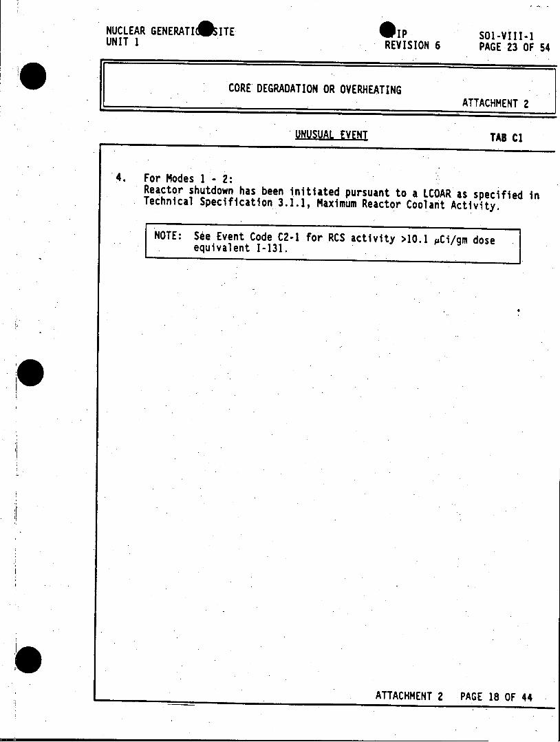
NUCLEAR GENERATIO ITE IP SOl-VIII-1 UNIT 1 REVISION 6 PAGE 23 OF 54
CORE DEGRADATION OR OVERHEATING ATTACHMENT 2
UNUSUAL EVENT TAB Cl
4. For Modes 1 2: Reactor shutdown has been initiated pursuant to a LCOAR as specified in Technical Specification 3.1.1, Maximum Reactor Coolant Activity.
NOTE: See Event Code C2-1 for RCS activity >10.1 pCi/gm dose equivalent 1-131.
ATTACHMENT 2 PAGE 18 OF 44
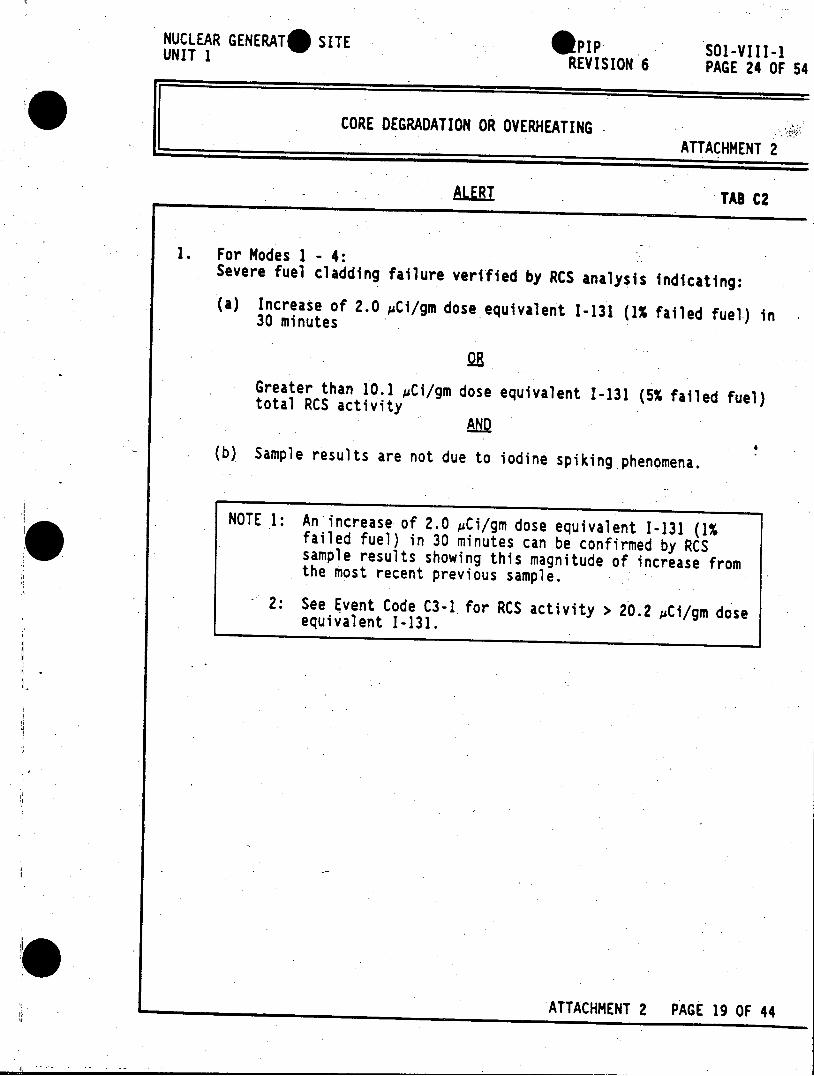
NUCLEAR GENERATSO SITE *pip So1-VIII-1 UNIT 1 REVISION 6 PAGE 24 OF 54
CORE DEGRADATION OR OVERHEATING ATTACHMENT 2
ALERI TAB C2
1. For Modes 1 - 4: Severe fuel cladding failure verified by RCS analysis indicating:
(a) Increase of 2.0 pCi/gm dose equivalent 1-131 (1% failed fuel) in 30 minutes
Greater than 10.1 pCi/gm dose equivalent 1-131 (5% failed fuel) total RCS activity AND
(b) Sample results are not due to iodine spiking phenomena.
NOTE 1: An increase of 2.0 pCi/gm dose equivalent 1-131 (1% failed fuel) in 30 minutes can be confirmed by RCS sample results showing this magnitude of increase from the most recent previous sample.
2: See Event Code C3-1 for RCS activity > 20.2 pCi/gm dose equivalent 1-131.
ATTACHMENT 2 PAGE 19 OF 44
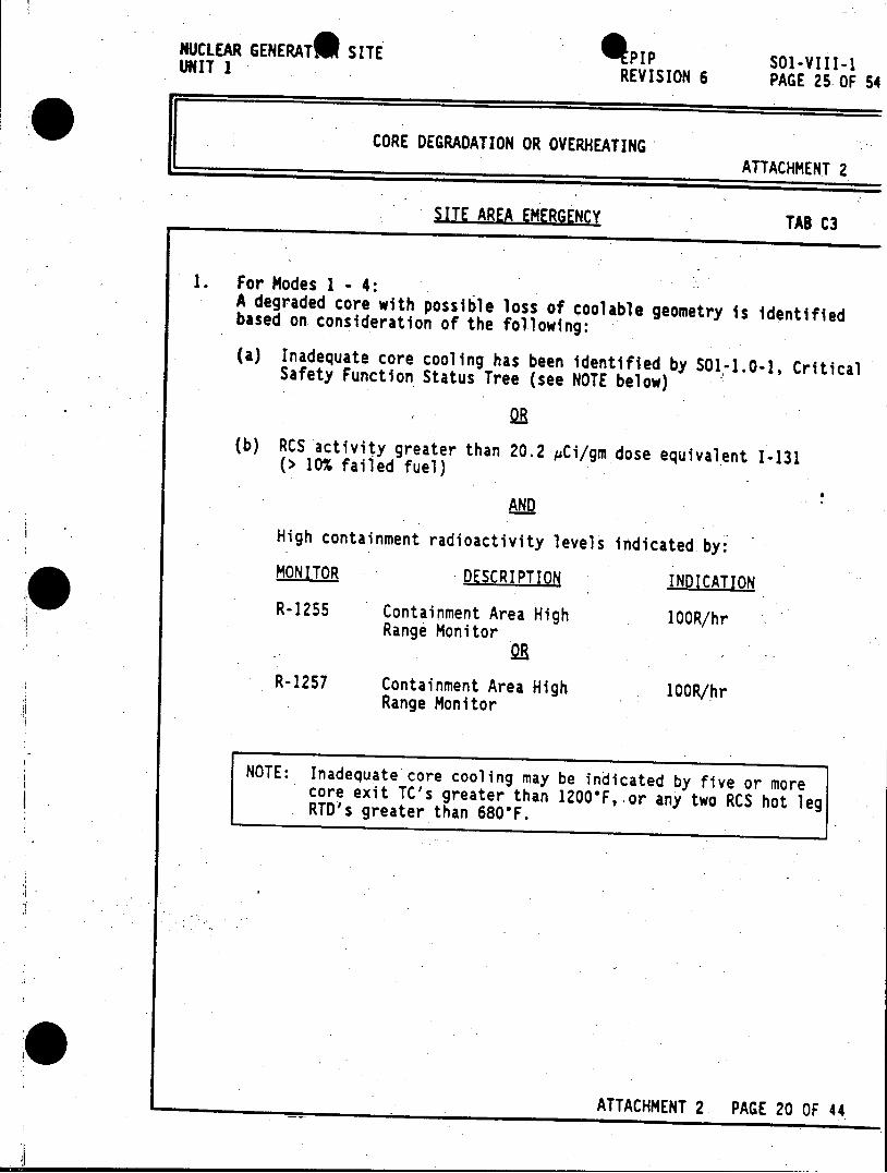
NUCLEAR GENERAT* SITE 4PIP SOl-VIII-l UNIT 1 PS1VI
REVISION 6 PAGE 25OF 54
CORE DEGRADATION OR OVERHEATING ATTACHMENT 2
SITE AREA EMERGENCY TAB C3
1. For Modes 1 - 4: A degraded core with possible loss of coolable geometry is identified based on consideration of the following:
(a) Inadequate core cooling has been identified by SO1-1.0-1, Critical Safety Function Status Tree (see NOTE below)
(b) RCS activity greater than 20.2 pCi/gm dose equivalent 1-131 (> 10% failed fuel)
AND
High containment radioactivity levels indicated by: MONITOR DESCRIPTION INDICATON
R-1255 Containment Area High 100R/hr Range Monitor
OR R-1257 Containment Area High 100R/hr
Range Monitor
NOTE: Inadequate core cooling may be indicated by five or more core exit TC's greater than 1200'F,-or any two RCS hot leg RTD's greater than 6800F.
ATTACHMENT 2 PAGE 20 OF 44
NUCLEAR GENERATO SITE S IP SOl-VIII-1 UNIT 1 REVISION 6 PAGE 26 OF 54
CORE DEGRADATION OR OVERHEATING ATTACHMENT 2
GENERAL EMERGENCY TAB C4
1. For Modes 1 - 4: For Loss of Coolant Accident sequences:
(a) The loss of 2 of 3 fission product barriers as indicated by any 2 of the following 3 conditions:
(1) Any loss of coolant accident requiring or resulting in ECCS' actuation (2) The loss of containment integrity (3) Probable significant fuel damage.
AND I
(b) An increased potential for loss of the third fission product barrier.
NOTE 1: Significant fuel damage may be indicated by any of the following:
(a) Sample analysis of the RCS, indicating the release of fission products to the primary coolant > Technical Specification 3.1.1 limits
(b) Five or more core exit TC's greater than 1200*F, or any two RCS hot leg RTD's greater than 680'F
(c) Indications listed in Chemistry Procedure S0123-III-8.8, Alternate Methods of Post-Accident Parameter Sampling.
2: Loss of containment integrity may be indicated by any of the following:
(a) Known breach of containment
(b) Status indication of containment isolation components
(c) A decrease in containment pressure not due to containment spray or cooling systems.
ATTACHMENT 2 PAGE 21 OF 44
NUCLEAR GENERSON SITE EPIP SOl-VIII-I UNIT 1 REVISION 6 PAGE 27 OF
CORE DEGRADATION OR OVERHEATING ATTACHMENT 2
GENERAL EMERGENCY TAB C4
2. For Modes 1 -4: For Steam Generator Tube Rupture sequences:
(a) Any steam generator tube rupture requiring or resulting in ECCS actuation
(b) Either one of the following two conditions, with an increased potential for the second:
(1) Potential significant fuel damage.
(2) An active or potential flowpath for release of fission product gases to the atmosphere.
NOTE 1: Significant fuel damage may be indicated by any of the following:
(a) Sample analysis of the RCS, indicating the release of fission products to the primary coolant > Technical Specification 3.1.1 limits
(b) Five or more core exit TC's greater than 1200'F, or any two RCS hot leg RTD's greater than 680'F
(c) Indications listed in Chemistry Procedure S0123-III-8.8, Alternate Methods of Post-Accident Parameter Sampling.
2: An active or potential flowpath for release of fission product gases to atmosphere exists whenever a steam generator tube rupture has occurred and RCS T average is greater than 212'F.
ATTACHMENT 2 PAGE 22 OF 44
NUCLEAR GENERATI SITE. IP 1-VIII-1 UNIT I REVISION 6 PAGE 28 OF 54
LOSS OF SAFETY EQUIPMENT ATTACHMENT 2
UNUSUAL EVENT TAB 01
NOTE 1: See Event Code 02-3 for loss of Control Room annunciators.
2: See Event Code 02-4 for Control Room evacuation.
3: See Event Code 02-5 for failure of reactor to trip.
4: See Event Code D2-6 for loss of shutdown margin.
1. For Modes 1 - 2: Reactor shutdown has been initiated pursuant to a LCOAR as specified in Technical Specification 3.7, Auxiliary Electrical Supply.
NOTE 1: See Event Code 02-1 for loss of both onsite and offsite power.
-2: See Event Code D2-2 for loss of vital DC power.
2. For Modes 1 - 2: Reactor shutdown has been initiated pursuant to a LCOAR as specified in Technical Specification 3.3, Safety Injection and Containment Spray Systems.
3. For Modes 1 - 2: Reactor shutdown has been initiated pursuant to a LCOAR as specified in Technical Specification 3.6, Containment Systems.
4. For Modes 1 - 2: Reactor shutdown has been initiated pursuant to a LCOAR as specified in Technical Specification 3.5.1, Reactor Trip System Instrumentation, 3.5.5, Containment Isolation Instrumentation, or 3.5.7, Auxiliary Feedwater Instrumentation.
ATTACHMENT 2 PAGE 23 OF 44
NUCLEAR GENERATI 9 SITE AIp SOl-VIII-1 UNIT 1 REVISION 6 PAGE 29 OF 54
LOSS OF SAFETY EQUIPMENT ATTACHMENT 2
UNUSUAL EVENT TAB 01
5. For Modes 4 - 6: Loss of RCS heat removal capability for greater than 10 minutes due to: (a) Inoperability of the Residual Heat Removal System
AND
(b) Inoperability of steam generators.
NOTE: See Event Code D2-7 for loss of shutdown heat removalcapability and RCS temperature increase above 2000F.
ATTACHMENT 2 PAGE 24 OF 44
NUCLEAR GENERATI SITE IPIP Sal-VIII-1 UNIT 1 REVISION 6 PAGE 30 OF 54
LOSS OF SAFETY EQUIPMENT ATTACHMENT 2
ALERT TAB D2
1. For Modes 1 - 4: (a) The loss of AC voltage on 4kv buses lA, 18, 1C and 2C
(b) The loss of operability of diesel generators DG-1 and DG-2
AND
(c) The buses remain de-energized for greater than 5 minutes.
NOTE: See Event Code 03-1 for loss greater than 15 minutes.
2. For Modes 1-4: Loss of vital DC power for greater than 5 minutes as indicated by:
(a) Low Voltage DC Bus No. 1 and 2 Alarms
AND
(b) Confirmed by both DC Bus voltmeters indicating less than 105 VDC.
NOTE: See Event Code D3-1 for loss greater than 15 minutes.
3. For Modes 1 - 2: All Control Room annunciators are inoperable for greater than 5 minutes.
NOTE: See Event Code 03-3 for loss of annunciators with unstable plant conditions.
ATTACHMENT 2 PAGE 25 OF 44
NUCLEAR GENERAT* SITE *PIP Sol-VIII-l UNIT 1 REVISION 6 PAGE 31 OF 54
LOSS OF SAFETY EQUIPMENT ATTACHMENT 2
ALERT TAB D2
4. For Modes 1 - 6: (a) Dedicated Safe Shutdown is directed by the Shift Superintendent/ A Emergency Coordinator
(b) The Control Room is evacuated
AND
Control of shutdown systems is established locally or at the Remote Shutdown Panel within 15 minutes.
NOTE: See Event Code 03-4 if control conditions not established.
5. For Modes 1 - 2: (a) The reactor remains critical following an automatic or manual trip signal
AND
(b) Plant conditions associated and the systems listed in Attachment 4 are stable or controlled.
NOTE: See Event Code 03-5 for unstable conditions.
6. For Modes 4 - 6: Keff > 0.95.
NOTE: See Event Code 03-6 for loss of shutdown margin in Modes 1 -3.
ATTACHMENT 2 PAGE 26 OF '44
NUCLEAR GENERAT* SITE pIP SO1-VIII-1 UNIT 1 REVISION 6 PAGE 32 OF 54
LOSS OF SAFETY EQUIPMENT ATTACHMENT 2
ALERI TAB D2
7. For Modes 4 - 6: Inoperability of steam generators or Residual Heat Removal System resulting in:
(a) Uncontrolled RCS temperature increase to > 200'F.
(b) Inability to maintain or reduce RCS temperature to < 200'F.
NOTE: See Event Code D3-7 for uncontrolled RCS temperature >.350'F.
ATTACHMENT 2 PAGE 27 OF 44
NUCLEAR GENERAT 9 SITE PIP So-VIII-1 UNIT 1 REVISION 6 PAGE 33 OF 54
LOSS OF SAFETY EQUIPMENT ATTACHMENT 2
SITE AREA EMERGENCY TAB D3
1. For Modes 1 - 4: (a) The loss of AC voltage on 4kv buses lA, 1, 1C and 2C
R AND~
(b) The loss of operability of diesel generators DG-1 and DG-2
AND
(c) The buses remain de-energized for greater than 15 minutes.
2. For Modes 1 - 4: The loss of vital DC power for greater than 15 minutes,.indicated by:
(a) DC Bus No. 1 and 2 Low Voltage Alarms
AND
(b) Confirmed by both DC Bus voltmeters indicating less than 105 VDC.
3. For Modes 1 - 2: (a) All Control Room annunciators are inoperable for greater than 5 minutes
AND
(b) Plant conditions associated with any of the systems listed in Attachment 4 are unstable and uncontrolled.
ATTACHMENT 2 PAGE 28 OF 44
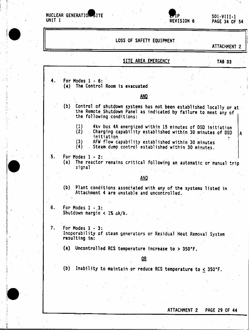
NUCLEAR GENERATI 0 ITE op SOl-VIII-1 UNIT I REVISION 6 PAGE 34 OF 54
LOSS OF SAFETY EQUIPMENT ATTACHMENT 2
SITE AREA EMERGENCY TAB 03
4. For Modes 1 - 6: (a) The Control Room is evacuated
ANDQ
(b) Control of shutdown systems has not been established locally or at the Remote Shutdown Panel as indicated by failure to meet any of the following conditions:
(1) 4kv bus 4A energized within 15 minutes of DSD initiation (2) Charging capability established within 30 minutes of DSD A
initiation (3) AFW flow capability established within 30 minutes (4) Steam dump control established within 30 minutes.
5. For Modes 1 - 2: (a) The reactor remains critical following an automatic or manual trip
signal
AND
(b) Plant conditions associated with any of the systems listed in Attachment 4 are unstable and uncontrolled.
6. For Modes 1 - 3: Shutdown margin < 1% Ak/k.
7. For Modes 1 - 3: Inoperability of steam generators or Residual Heat Removal System resulting in:
(a) Uncontrolled RCS temperature increase to > 350*F.
(b) Inability to maintain or reduce RCS temperature to < 3506F.
ATTACHMENT 2 PAGE 29 OF 44
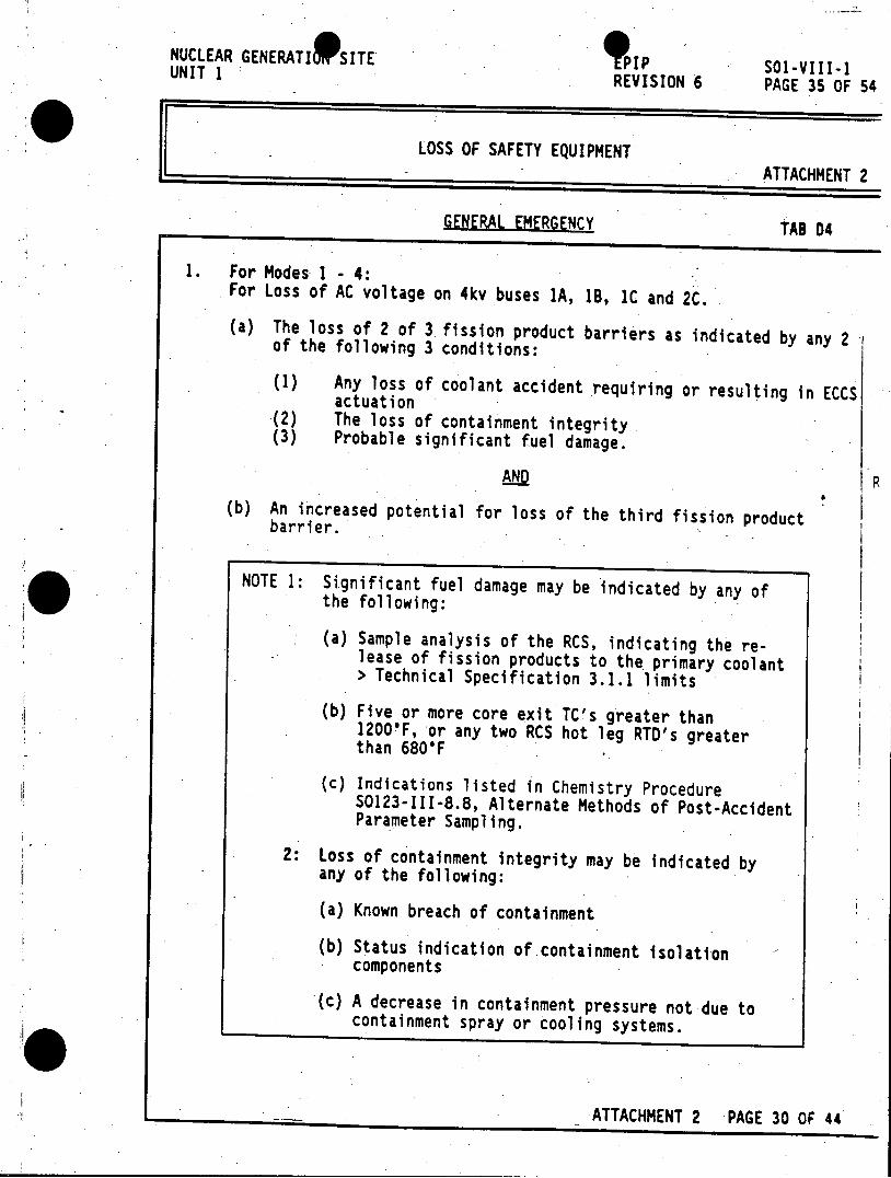
NUCLEAR GENERATI 9 SITE 9 PIP SO1-VIII-1 UNIT 1 REVISION 6 PAGE 35 OF 54
LOSS OF SAFETY EQUIPMENT ATTACHMENT 2
GENERAL EMERGENCY TAB D4
1. For Modes 1 - 4: For Loss of AC voltage on 4kv buses lA, IB, 1C and 2C.
(a) The loss of 2 of 3 fission product barriers as indicated by any 2 of the following 3 conditions:
(1) Any loss of coolant accident requiring or resulting in ECCS actuation (2) The loss of containment integrity (3) Probable significant fuel damage.
AND P (b) An increased potential for loss of the third fission product barrier.
NOTE 1: Significant fuel damage may be indicated by any of the following:
(a) Sample analysis of the RCS, indicating the release of fission products to the primary coolant > Technical Specification 3.1.1 limits
(b) Five or more core exit TC's greater than 1200'F, or any two RCS hot leg RTD's greater than 680'F
(c) Indications listed in Chemistry Procedure S0123-III-8.8, Alternate Methods of Post-Accident Parameter Sampling.
2: Loss of containment integrity may be indicated by any of the following:
(a) Known breach of containment
(b) Status indication of containment isolation components
(c) A decrease in containment pressure not due to containment spray or cooling systems.
ATTACHMENT 2 PAGE 30 OF 44
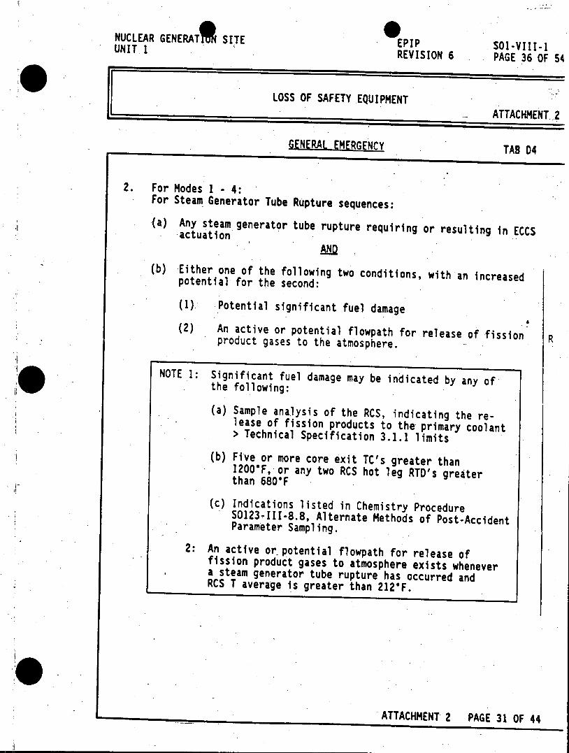
NUCLEAR GENERAT SITE UNIT.1 EPIP 501-VIII-1
REVISION 6 PAGE 36 OF 54
LOSS OF SAFETY EQUIPMENT ATTACHMENT 2
GENERAL EMERGENCY TAB D4
2. For Modes 1 - 4: For Steam Generator Tube Rupture sequences:
(a) Any steam generator tube rupture requiring or resulting in ECCS actuation AND
(b) Either one of the following two conditions, with an increased potential for the second:
(1) Potential significant fuel damage
(2) An active or potential flowpath for release of fission R product gases to the atmosphere.
NOTE 1: Significant fuel damage may be indicated by any of the following:
(a) Sample analysis of the RCS, indicating the release of fission products to the primary coolant > Technical Specification 3.1.1 limits (b) Five or more core exit TC's greater than
1200'F, or any two RCS hot leg RTD's greater than 680*F
(c) Indications listed in Chemistry Procedure S0123-III-8.8, Alternate Methods of Post-Accident Parameter Sampling.
2: An active or potential flowpath for release of fission product gases to atmosphere exists whenever a steam generator tube rupture has occurred and RCS T average is greater than 212*F.
ATTACHMENT 2 PAGE 31 OF 44
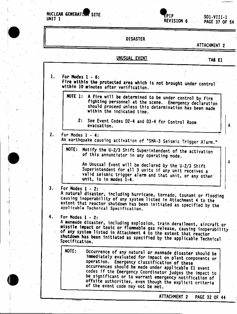
NUCLEAR GENERATE SITE piP SO1-VIII-1 UNIT 1 REVISION 6 PAGE 37 OF 54
DISASTER ATTACHMENT 2
UNUSUAL EVENT TAB El
1. For Modes 1 -6: Fire within the protected area which is not brought under control within 10 minutes after verification.
NOTE 1: A fire will be determined to be under control by fire fighting personnel at the scene. Emergency declaration should proceed unless this determination has been made within the indicated time.
2: See Event Codes D2-4 and 03-4 for Control Room A evacuation.
2. For Modes 1 - 4: An earthquake causing activation of "SMA-3 Seismic Trigger Alarm.N
NOTE: Notify the U-2/3 Shift Superintendent of the activation of this annunciator in any operating mode.
A An Unusual Event will be declared by the U-2/3 Shift Superintendent for all 3 units if any unit receives a valid seismic trigger alarm and that unit, or any other unit, is in modes 1-4.
3. For Modes 1 -2: A natural disaster, including hurricane, tornado, tsunami or flooding causing inoperability of any system listed in Attachment 4 to the extent that reactor shutdown has been initiated as specified by the applicable Technical Specification.
4. For Modes 1 - 2: A manmade disaster, including explosion, train derailment, aircraft or missile impact or toxic or flammable gas release, causing inoperability of any system listed in Attachment 4 to the extent that reactor shutdown has been initiated as specified by the applicable Technical Specification.
NOTE: Occurrence of any natural or manmade disaster should be immediately evaluated for impact on plant components or operation. Emergency classification of these occurrences should be made under applicable El event codes if the Emergency Coordinator judges the impact to be significant or to warrant emergency notification of offsite authorities, even though the explicit criteria of the event code may not be met.
ATTACHMENT 2 PAGE 32 OF 44
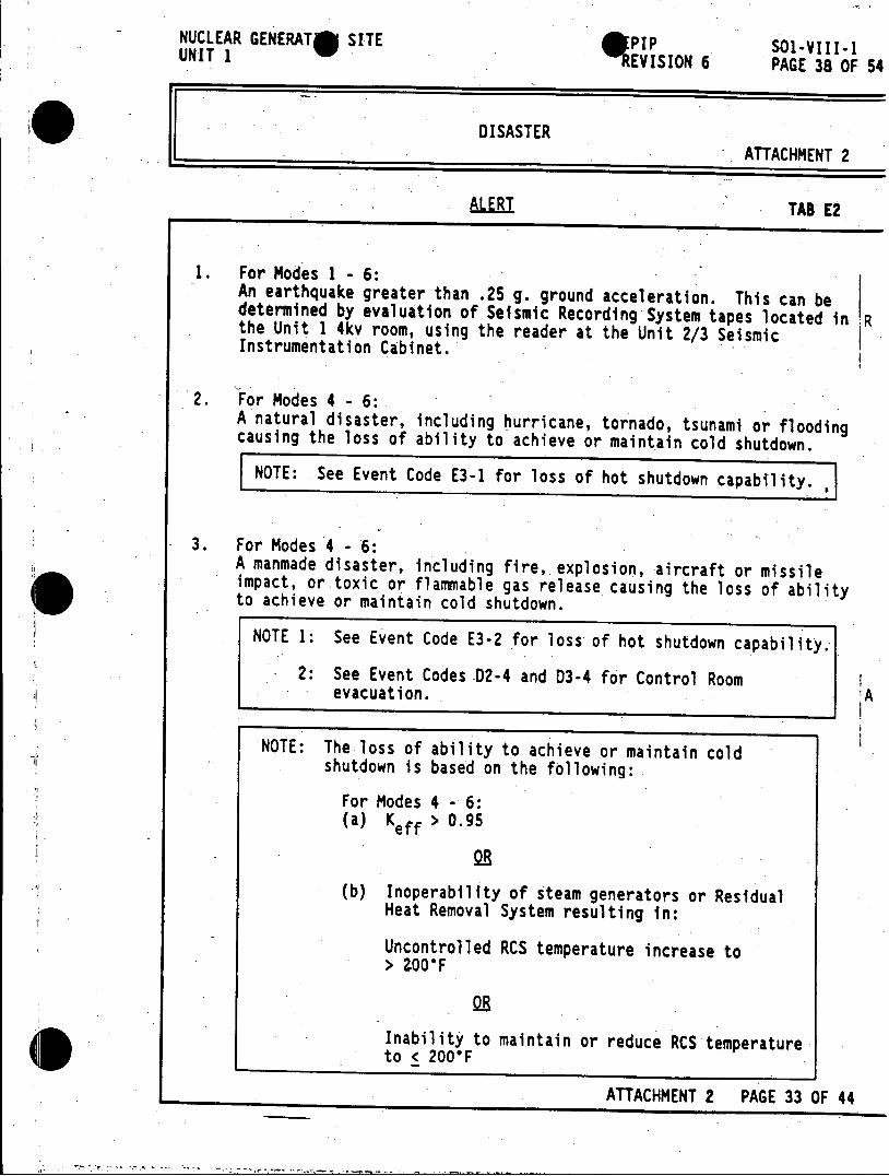
NUCLEAR GENERAT SITE PIP SO1-VIII-1 UNIT 1 REVISION 6 PAGE 38 OF 54
DISASTER ATTACHMENT 2
ALEi TAB E2
1. For Modes 1 - 6: An earthquake greater than .25 g. ground acceleration. This can be determined by evaluation of Seismic Recording System tapes located in R the Unit 1 4kv room, using the reader at the Unit 2/3 Seismic Instrumentation Cabinet.
2. For Modes 4 - 6: A natural disaster, including hurricane, tornado, tsunami or flooding causing the loss of ability to achieve or maintain cold shutdown.
NOTE: See Event Code E3-1 for loss of hot shutdown capability.
3. For Modes 4 - 6: A manmade disaster, including fire, explosion, aircraft or missile impact, or toxic or flammable gas release causing the loss of ability to achieve or maintain cold shutdown.
NOTE 1: See Event Code E3-2 for loss of hot shutdown capability.
2: See Event Codes 02-4 and D3-4 for Control Room evacuation. A
NOTE: The loss of ability to achieve or maintain cold shutdown is based on the following:
For Modes 4 - 6: (a) K > 0.95
OR
(b) Inoperability of steam generators or Residual Heat Removal System resulting in:
Uncontrolled RCS temperature increase to > ZOOF
OR
Inability to maintain or reduce RCS temperature to < 200*F ATTACHMENT 2 PAGE 33 OF 44
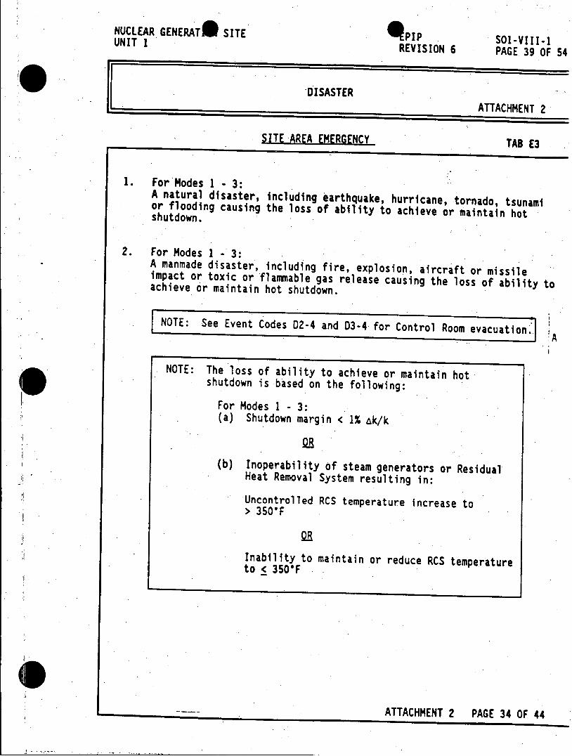
NUCLEAR GENERAT* SITE QPIP SOl-VIII-1 UNIT I1~-VIREVISION 6 PAGE 39 OF 54
DISASTER ATTACHMENT 2
SITE AREA EMERGENCY TAB E3
1. For Modes 1 - 3: A natural disaster, including earthquake, hurricane, tornado, tsunami or flooding causing the loss of ability to achieve or maintain hot shutdown.
2. For Modes 1 - 3: A manmade disaster, including fire, explosion, aircraft or missile impact or toxic or flammable gas release causing the loss of ability to achieve or maintain hot shutdown.
NOTE: See Event Codes D2-4 and D3-4 for Control Room evacuation- A
NOTE: The loss of ability to achieve or maintain hot shutdown is based on the following:
For Modes 1 - 3: (a) Shutdown margin < 1% Ak/k
OR
(b) Inoperability of steam generators or Residual Heat Removal System resulting in:
Uncontrolled RCS temperature increase to > 350'F
Inability to maintain or reduce RCS temperature to < 350'F
ATTACHMENT 2 PAGE 34 OF 44
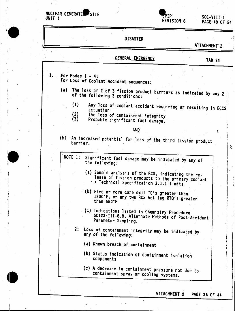
NUCLEAR GENERATI*SITE IP I-VIII-i UNIT 1 REVISION 6 PAGE 40 OF 54
DISASTER ATTACHMENT 2
GENERAL EMERGENCY TAB E4
1. For Modes 1 - 4: For Loss of Coolant Accident sequences:
(a) The loss of 2 of 3 fission product barriers as indicated by any 2 of the following 3 conditions:
(1) Any loss of coolant accident requiring-or resulting in ECCS actuation (2) The loss of containment integrity (3) Probable significant fuel damage.
AND
(b) An increased potential for loss of the third fission product barrier. R
NOTE 1: Significant fuel damage may be indicated by any of the following:
(a) Sample analysis of the RCS, indicating the release of fission products to the primary coolant > Technical Specification 3.1.1 limits (b) Five or more core exit TC's greater than
1200'F, or any two RCS hot leg RTD's greater than 680'F
(c) Indications listed in Chemistry Procedure S0123-III-8.8, Alternate Methods of Post-Accident Parameter Sampling.
2: Loss of containment integrity may be indicated by any of the following:
(a) Known breach of containment
(b) Status indication of containment isolation components
(c) A decrease in containment pressure not due to containment spray or cooling systems.
ATTACHMENT 2 PAGE 35 OF 44
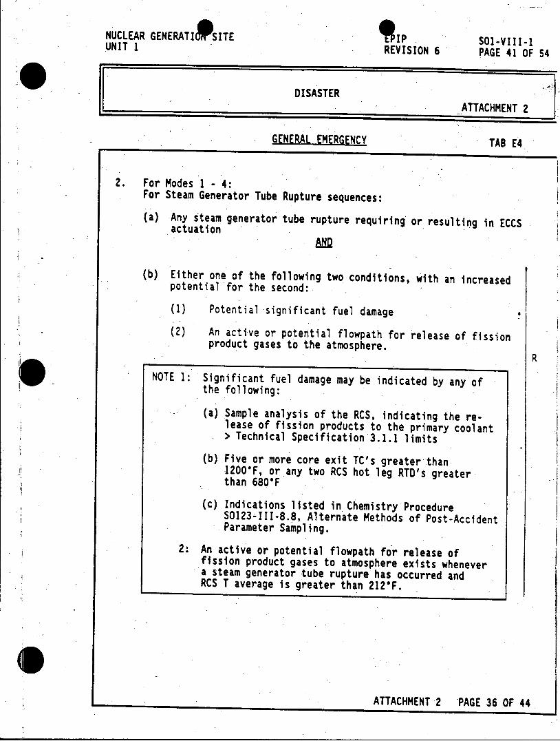
NUCLEAR GENERATIO 9 SITE lip SOl-VIII-1 UNIT 1 REVISION 6 PAGE 41 OF 54
DISASTER ATTACHMENT 2
GENERAL EMERGENCY TAB E4
2. For Modes 1 - 4: For Steam Generator Tube Rupture sequences:
(a) Any steam generator tube rupture requiring or resulting in ECCS actuation AND2
(b) Either one of the following two conditions, with an increased potential for the second:
(1) Potential significant fuel damage
(2) An active or potential flowpath for release of fission product gases to the atmosphere.
R
NOTE 1: Significant fuel damage may be indicated by any of the following:
(a) Sample analysis of the RCS, indicating the release of fission products to the primary coolant > Technical Specification 3.1.1 limits
(b) Five or more core exit TC's greater than 1200*F, or any two RCS hot leg RTD's greater than 680'F
(c) Indications listed in Chemistry Procedure SO123-1I1-8.8, Alternate Methods of Post-Accident Parameter Sampling.
2: An active or potential flowpath for release of fission product gases to atmosphere exists whenever a steam generator tube rupture has occurred and RCS T average is greater than 212*F.
ATTACHMENT 2 PAGE 36 OF 44
NUCLEAR GENERATI SITE IP SOl-VIII-1 UNIT 1 REVISION 6 PAGE 42 OF 54
SECURITY SAFEGUARDS CONTINGENCY ATTACHMENT 2
UNUSUAL EVENT TAB FI
1. For Modes 1 - 6: The Shift Commander/Security Leader reports a security threat, attempted entry, or attempted sabotage. This includes any of the following Safeguards Contingency Plan conditions:
(a) A credible threat to attack the protected or vital area has been received. (Contingency Threat Situation Al (SECON Yellow))
(b) A credible threat to bomb the protected or vital area has been received. (Contingency Threat Situation B1 (SECON Yellow))
(c) Tampering or unauthorized manipulation of safety-related equipment or security-related safeguards equipment, for the purpose of sabotage or protected or vital area entry, has been confirmed. (Contingency Threat Situation S1 (SECON Orange))
(d) An attempted introduction of prohibited items such as firearms, explosives or other devices into the protected or vital area, for the purpose of sabotage. (Contingency Threat Situation M3-A (SECON Orange))
(e) Tampering with a perimeter intrusion alarm, for the purpose of sabotage or protected or vital area entry, has been confirmed. (Contingency Threat Situation 11 (SECON Yellow))
NOTE: If the condition described by the Shift Commander/ Security Leader does not reasonably conform to one of the conditions above, declare an Unusual Event if the situation constitutes a security threat, attempted entry or attempted sabotage
ATTACHMENT 2 PAGE 37 OF 44
NUCLEAR GENERATIPSITE p a0l-VIII-i UNIT 1 REVISION 6 PAGE 43 OF 54
SECURITY SAFEGUARDS CONTINGENCY ATTACHMENT 2
ALERT TAB F2
1. For Modes 1 - 6: The Shift Commander/Security Leader reports an ongoing security compromise. This includes any of the following Safeguards Contingency Plan conditions: (a) A bomb or unauthorized explosive device is discovered within the protected or vital area.
(Contingency Threat Situation 82 (SECON Orange))
(b) An intrusion into the protected or vital area by an unauthorized individual has been confirmed. (Contingency Threat Situation 12 (SECON Orange))
(c) A forced entry through the protected or vital area perimeter barrier for the purpose of sabotage has been confirmed.. (Contingency Threat Situation 13 (SECON Orange))
(d) An introduction of prohibited items such as firearms, explosives or other devices into the protected or vital area, for the purpose of sabotage, has been confirmed. (Contingency Threat Situation M3-8 (SECON Orange))
(e) An adversary force has assaulted the site, but have not penetrated the protected area perimeter. (Contingency Threat Situation A4-A (SECON Red))
(f) A forceful assault on the protected or vital area by an adversary force is imminent. (Contingency Threat Situation A2 (SECON Orange))
(g) A bomb or other explosive device explodes, or a fire or explosion of suspicious origin occurs, which damages safety-related equipment or security-related safeguards equipment. (Contingency Threat Situation 83 (SECON Red))
(h) An act of sabotage has damaged safety-related equipment or security-related safeguards equipment. (Contingency Threat Situation S2-A (SECON Red))
NOTE: If the condition described by the Shift Commander/ Security Leader does not reasonably conform to one of the conditions above, declare an Alert if the situation constitutes an ongoing security compromise.
ATTACHMENT 2 PAGE 38 OF 44
NUCLEAR GENERATI SITE p SOl-VIII-1 UNIT I REVISION 6 PAGE 44 OF 54
SECURITY SAFEGUARDS CONTINGENCY ATTACHMENT 2
SITE AREA EMERGENCY TAB F3
For Modes 1 - 6: I. The Shift Commander/Security Leader reports the imminent loss of physical control of the protected area. This includes the following Safeguards Contingency Plan conditions:
(a) A forceful assault on the protected area barrier is occurring, or has succeeded and is continuing In the protected or vital area. (Contingency Threat Situation A3 (SECON Red))
NOTE: If the condition described by the Shift Commander/ Security Leader does not reasonably conform to one of the conditions above, declare a Site Area Emergency if the situation constitutes an imminent loss of. physical control of the protected area.
ATTACHMENT 2 PAGE 39 OF 44
NUCLEAR GENERATI SITE EPIP SOl-VIII-1 UNIT 1 REVISION 6 PAGE 45 OF 54
SECURITY SAFEGUARDS CONTINGENCY ATTACHMENT 2
GENERAL EMERGENCY TAB F4
For Modes 1 - 6: 1. The Shift Commander/Security Leader reports the loss of physical control of the protected area. This includes the following Safeguards -Contingency Plan conditions:
(a) An adversary force has penetrated the protected area and barricaded themselves within the protected area, with the possibility of having taken hostages. (Contingency Threat Situation A4-B (SECON Red))
(b) An act of sabotage has damaged safety-related equipment, and security has lost physical control of the protected area. (Contingency Threat Situation S2-8 (SECON Red))
NOTE: If the condition described by the Shift Commander/ Security Leader does not reasonably conform to one of the conditions above, declare a General Emergency if the situation constitutes a lQss of physical control of the protected area.
ATTACHMENT 2 PAGE 40 OF 44
NUCLEAR GENERATE SITE EPIP 501-VIII-1 UNIT 1 REVISION 6 PAGE 46 OF 54
MISCELLANEOUS ATTACHMENT 2
UNUSUAL EVENT TAB GI
1. For Modes 1 - 6: (a) Transportation of any injured personnel from San Onofre Nuclear Generation Site for treatment at a hospital who are externally contaminated above release limits
(b) An Emergency Services Officer acting as Incident Commander reports activation of the San Diego County Emergency Plan Annex D, Medical Multi-Casualty Plan, for the purpose of managing a multiple-victim injury emergency inside the protected area.
2. For Modes 1 - 6: (a) Plant conditions warrant emergency notification of plant personnel and local, state or federal offsite authorities
(b) Plant conditions meet the criteria of an Alert or higher Emergency Action Level, except for mode applicability,
ANDQ No other Emergency Action Level applies.
3. For Modes 1 - 2: (a) Reactor shutdown has been initiated in accordance with Technical Specification action statements
AND
(b) Plant conditions warrant emergency notification of local or state authorities.
ATTACHMENT 2 PAGE 41 OF 44
NUCLEAR GENERATI*SITE 9 IP UNIT I SOl-VIII-1
REVISION 6 PAGE 47 OF 54
MISCELLANEOUS ATTACHMENT 2
AL TAB 62
1. For Modes 1 - 6: Plant conditions indicate a significant trend leading to a degradation of safety.
ATTACHMENT 2 PAGE 42 OF 44
NUCLEAR GENERATIAITE IP 501-VIII-1 UNIT 1 REVISION 6 PAGE 48 OF 54
MISCELLANEOUS ATTACHMENT 2
SITE AREA EMERGENCY TAB G3
1. For Modes 1 - 6: Plant conditions indicate likely major failures of plant functions needed for protection of the public.
ATTACHMENT 2 PAGE 43 OF 44
NUCLEAR GENERATI*SITE IP So1-VIII-1 UNIT 1 REVISION 6 PAGE 49 OF 54
MISCELLANEOUS ATTACHMENT 2
GENERAL EMERGENCY TAB 64
1. For Modes 1 - 6: Plant conditions indicate iminent substantial core degradation with potential for loss of containment integrity.
1(1).AUT ATTACHMENT 2 PAGE 44 OF 44
NUCLEAR GENERAT SITE PIP 5 1-VIII-1 UNIT I REVISION 6 PAGE 50 OF 54
RECOGNITION AND CLASSIFICATION OF EMERGENCIES ATTACHMENT 3
EVENT CODES INDEX A - PROCEDURES
POTENTIAL EVENT CODE(S)
So1-1.0-1 Critical Safety Function Status Trees
Subcriticality 02-5, 02-6, 03-5, 03-6
Core Cooling Cl-3, 01-5, 02-7, C3-1, D3-7, C4-1, C4-2, 04-1, D4-2
Heat Sink 02-7, D3-7
RCS Integrity C1-3
Containment 01-3, 84-1, C4-1, D4-1, E4-1
RCS Inventory B3-1, 84-1, 84-2
SO1-1.0-10 Reactor Trip or Safety Cl-i, B3-1 Injection
SO-1.0-20 Loss of Reactor Coolant CI-1, B3-1 501-1.0-21 SI Termination Following 82-1
Loss of Reactor Coolant
S01-1.0-22 Post-LOCA Cooldown and B2-1, 83-1, Depressurization 84-1
SO1-1.0-23 Transfer to Cold Leg 82-1, 83-1, Injection and Recirculation B4-1
SO1-1.0-24 Transfer to Hot Leg 82-1, B3-1, Recirculation 84-1
SO1-1.0-30 Loss of Secondary Coolant C1-2, 01-5, A2-6, 02-7, A3-3, 03-7
ATTACHMENT 3 PAGE 1[OF 4
NUCLEAR GENERAT* SITE OPIP SOl-VIII-1 UNIT 1 REVISION 6 PAGE 51 OF 54
RECOGNITION AND CLASSIFICATION OF EMERGENCIES ATTACHMENT 3
EVENT CODES INDEX A - PROCEDURES (Continued)
POTENTIAL POEUTE EVENT CODE(S) So1-1.0-32 Loss of RHR due to Loss of D1-5, D2-7, Secondary Coolant in *D3-7 Containment
S01-1.0-40 Steam Generator Tube Rupture A2-6, A3-3, B3-1, B4-2
SO1-1.0-60 Loss of All AC Power D2-1, 03-1 501-1.1-1 Response to Nuclear Power D2-5, D2-6,
Generation/ATWS D3-5, D3-6 SO1-1.1-2 Response to Potential Loss of D2-6,.D3-6
Core Shutdown
501-1.2-1 Response to Inadequate Core Cooling D2-7, C3-1, D3-7, C4-1, C4-2, D4-1, D4-2
501-1.2-2 Response to Potential Loss of D1-5, D2-7, Core Cooling 03-7 SO-1.3-1 Response to Loss of Secondary D1-5, D2-7, Heat Sink D3-7 S01-1.5-1 Response to High Containment 84-1, C4-1,
Pressure 04-1, E4-1 S01-1.5-3 Response to High Containment C3-1, B4-1, Radiation Level C4-1, 04-1,
E4-1 SO1-1.6-2 Response to Low System Inventory 81-1, B2-1,
01-5
ATTACHMENT 3 PAGE 2 OF 4
NUCLEAR GENERATIO ITE O P SOl-VIII-1 UNIT 1 REVISION 6 PAGE 52 OF 54
RECOGNITION AND CLASSIFICATION OF EMERGENCIES ATTACHMENT 3
EVENT CODES INDEX 8 - TECHNICAL SPECIFICATIONS
POTENTIAL SPECIFICATION IILE EVENT CODELS 2.1 Reactor Core Limiting Combination C1-3
of Power, Pressure and Temperature
3.1.1 Maximum Reactor Coolant Activity C1-4
3.1.2 Operational Components E1-3, E1-4
3.1.4 Leakage 81-1
3.3 Safety Injection and Containment 01-2 Spray Systems
3.4.1 Turbine Cycle Operating Status - El-3, E1-4
3.4.3 Auxiliary Feedwater System E1-3, E1-4
3.5.1 Reactor Trip Instrumentation 01-4
3.5.5 Containment Isolation Instrumentation 01-3
3.5.7 Auxiliary Feedwater Instrumentation D1-4, E1-3, E1-4 A
3.6 Containment Systems 01-3
3.7 Auxiliary Electrical Systems 01-1, E1-3, E1-4
3.12 Control Room Emergency Air E1-3, E1-4 Treatment System
3.15.1 Liquid Effluents Concentration Al-2
ATTACHMENT 3 PAGE 3 OF 4
NUCLEAR GENERATI 9 SITE 9 PIP SOl-VIII-1 UNIT 1 REVISION 6 PAGE 53 OF 54
RECOGNITION AND CLASSIFICATION OF EMERGENCIES ATTACHMENT 3
EVENT CODES INDEX C - RADIATION MONITORS
_______POTENTIAL
MONITOR DESCRIPTION EVENT CODE(S) 1212 Containment Purge Monitor Al-1, A2-1 1216 Steam Generator Blowdown Monitor A1-2, A2-2 1218 Radwaste Liquid Effluent Monitor Al-2, A2-2 1219 Stack Gas Monitor Al-1, A2-1, A2-5 1231 Control Room Monitor A2-3 1232 Containment Sphere Monitor A2-5 1233 Radiochem Lab Monitor A2-3 1234 Reactor Auxiliary Building Monitor A2-3 1235 Sampling Room Monitor A2-3 1236 Spent Fuel Building Monitor A2-3, A3-2 1237 Cryogenic System Building Monitor A2-3 1254 Wide Range Gas Monitor Al-1, A2-1, A2-5,
A3-1 1255 Containment High Range Monitor C3-1 1256 East Main Steam Line Radiation Monitor A2-6, A3-3 1257 Containment High Range Monitor C3-1 1258 West Main Steam Line Radiation Monitor A2-6, A3-3 2100 Reheater Pit Sump Monitor Al-2, A2-2 2101 Yard Sump Monitor Al-2, A2-2
1(1). AUT ATTACHMENT 3 PAGE 4 OF 4
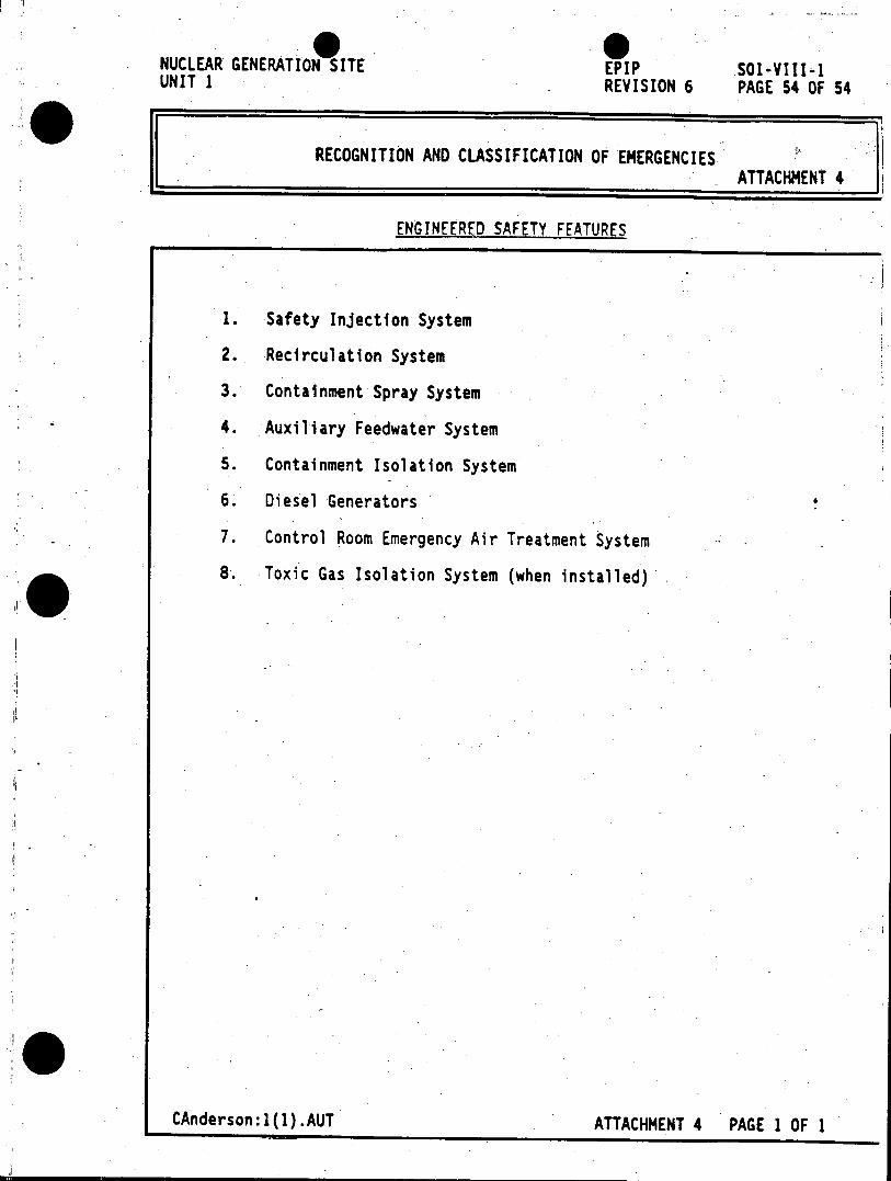
NUCLEAR GENERATION SITE EPIP SOl-VIII-1 UNIT 1 REVISION 6 PAGE 54 OF 54
RECOGNITION AND CLASSIFICATION OF EMERGENCIES ATTACHMENT 4
ENGINEERED SAFETY FEATURES
1. Safety Injection System
2. Recirculation System
3. Containment Spray System
4. Auxiliary Feedwater System
5. Containment Isolation System
6. Diesel Generators
7. Control Room Emergency Air Treatment System
8. Toxic Gas Isolation System (when installed)
CAnderson:1(1) .AUT ATTACHMENT 4 PAGE 1 OF 1


