Embed Size (px)
Citation preview
INVE
INVER
TERA
800-EFR
-A806-E IN
STRU
CTIO
N M
AN
UA
L (HA
RD
WA
RE)
B
HEAD OFFICE: TOKYO BUILDING 2-7-3, MARUNOUCHI, CHIYODA-KU, TOKYO 100-8310, JAPAN
IB(NA)-0600634ENG-B(1904)MEE Printed in Japan Specifications subject to change without notice.
FR-AFR-A80INSTR
FR-A846High fun
RTER800-E6-E (IP55/UCTION M
-00023(0.4K) tctionality and
INTRODUCTION1
INSTALLATION AND WIRING2
PRECAUTIONS FOR USE OFTHE INVERTER 3
PROTECTIVE FUNCTIONS4
PRECAUTIONS FORMAINTENANCE AND
INSPECTION5
SPECIFICATIONS6
UL Type 12 SPECIFICATIONS)ANUAL (HARDWARE)
o 03610(132K)-Ehigh performance
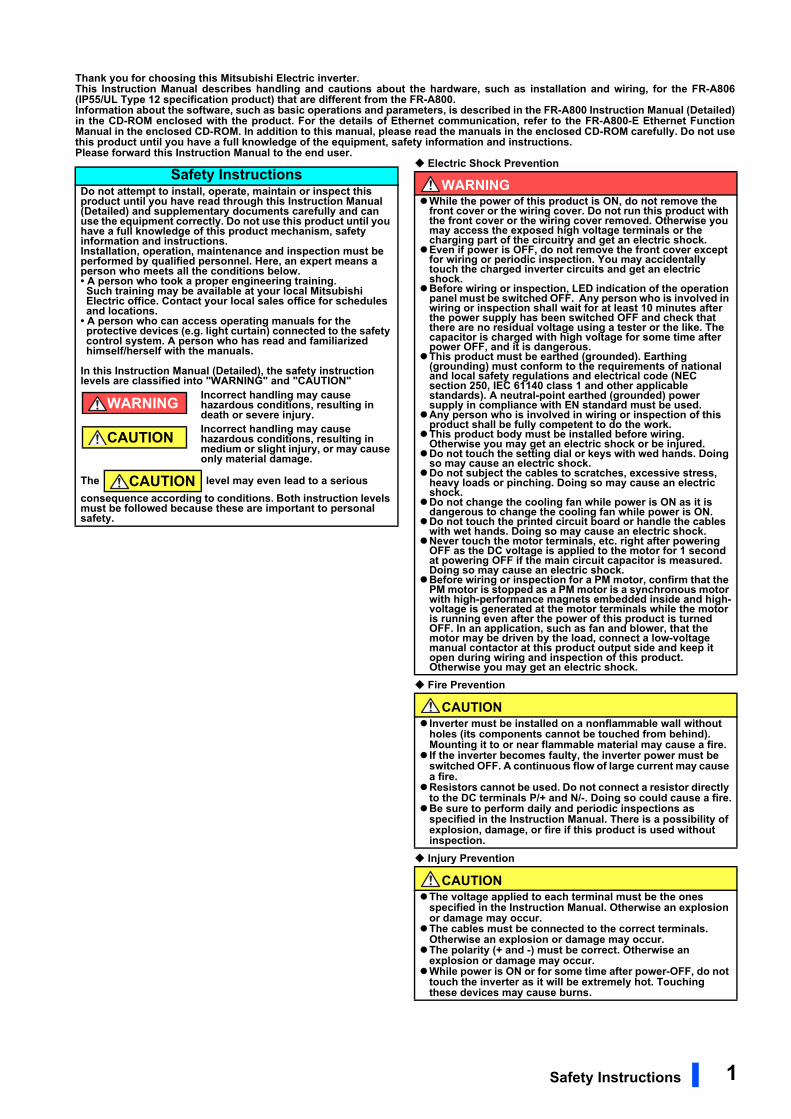
Thank you for choosing this Mitsubishi Electric inverter.This Instruction Manual describes handling and cautions about the hardware, such as installation and wiring, for the FR-A806(IP55/UL Type 12 specification product) that are different from the FR-A800.Information about the software, such as basic operations and parameters, is described in the FR-A800 Instruction Manual (Detailed)in the CD-ROM enclosed with the product. For the details of Ethernet communication, refer to the FR-A800-E Ethernet FunctionManual in the enclosed CD-ROM. In addition to this manual, please read the manuals in the enclosed CD-ROM carefully. Do not usethis product until you have a full knowledge of the equipment, safety information and instructions.Please forward this Instruction Manual to the end user.
Electric Shock Prevention
Fire Prevention
Injury Prevention
Safety InstructionsDo not attempt to install, operate, maintain or inspect this product until you have read through this Instruction Manual (Detailed) and supplementary documents carefully and can use the equipment correctly. Do not use this product until you have a full knowledge of this product mechanism, safety information and instructions.Installation, operation, maintenance and inspection must be performed by qualified personnel. Here, an expert means a person who meets all the conditions below.• A person who took a proper engineering training. Such training may be available at your local Mitsubishi Electric office. Contact your local sales office for schedules and locations.
• A person who can access operating manuals for the protective devices (e.g. light curtain) connected to the safety control system. A person who has read and familiarized himself/herself with the manuals.
In this Instruction Manual (Detailed), the safety instruction levels are classified into "WARNING" and "CAUTION"
Incorrect handling may cause hazardous conditions, resulting in death or severe injury.Incorrect handling may cause hazardous conditions, resulting in medium or slight injury, or may cause only material damage.
The level may even lead to a serious consequence according to conditions. Both instruction levels must be followed because these are important to personal safety.
WARNING
CAUTION
CAUTION
WARNINGWhile the power of this product is ON, do not remove the
front cover or the wiring cover. Do not run this product with the front cover or the wiring cover removed. Otherwise you may access the exposed high voltage terminals or the charging part of the circuitry and get an electric shock.Even if power is OFF, do not remove the front cover except
for wiring or periodic inspection. You may accidentally touch the charged inverter circuits and get an electric shock.Before wiring or inspection, LED indication of the operation
panel must be switched OFF. Any person who is involved in wiring or inspection shall wait for at least 10 minutes after the power supply has been switched OFF and check that there are no residual voltage using a tester or the like. The capacitor is charged with high voltage for some time after power OFF, and it is dangerous.This product must be earthed (grounded). Earthing
(grounding) must conform to the requirements of national and local safety regulations and electrical code (NEC section 250, IEC 61140 class 1 and other applicable standards). A neutral-point earthed (grounded) power supply in compliance with EN standard must be used.Any person who is involved in wiring or inspection of this
product shall be fully competent to do the work.This product body must be installed before wiring.
Otherwise you may get an electric shock or be injured.Do not touch the setting dial or keys with wed hands. Doing
so may cause an electric shock.Do not subject the cables to scratches, excessive stress,
heavy loads or pinching. Doing so may cause an electric shock.Do not change the cooling fan while power is ON as it is
dangerous to change the cooling fan while power is ON.Do not touch the printed circuit board or handle the cables
with wet hands. Doing so may cause an electric shock.Never touch the motor terminals, etc. right after powering
OFF as the DC voltage is applied to the motor for 1 second at powering OFF if the main circuit capacitor is measured. Doing so may cause an electric shock.Before wiring or inspection for a PM motor, confirm that the
PM motor is stopped as a PM motor is a synchronous motor with high-performance magnets embedded inside and high-voltage is generated at the motor terminals while the motor is running even after the power of this product is turned OFF. In an application, such as fan and blower, that the motor may be driven by the load, connect a low-voltage manual contactor at this product output side and keep it open during wiring and inspection of this product. Otherwise you may get an electric shock.
CAUTION Inverter must be installed on a nonflammable wall without
holes (its components cannot be touched from behind). Mounting it to or near flammable material may cause a fire. If the inverter becomes faulty, the inverter power must be
switched OFF. A continuous flow of large current may cause a fire.Resistors cannot be used. Do not connect a resistor directly
to the DC terminals P/+ and N/-. Doing so could cause a fire.Be sure to perform daily and periodic inspections as
specified in the Instruction Manual. There is a possibility of explosion, damage, or fire if this product is used without inspection.
CAUTIONThe voltage applied to each terminal must be the ones
specified in the Instruction Manual. Otherwise an explosion or damage may occur.The cables must be connected to the correct terminals.
Otherwise an explosion or damage may occur.The polarity (+ and -) must be correct. Otherwise an
explosion or damage may occur.While power is ON or for some time after power-OFF, do not
touch the inverter as it will be extremely hot. Touching these devices may cause burns.
Safety Instructions 1
Additional InstructionsThe following instructions must be also followed. If the product is handled incorrectly, it may cause unexpected fault, an injury, or an electric shock.
2.9 m/s2 or less for the FR-A846-01800(55K) or higher.
CAUTIONTransportation and installationTo prevent injury, wear cut-resistant gloves when opening
packaging with sharp tools.Use proper lifting techniques or a trolley when carrying
products. Failure to do so may lead to injuries.Do not stand or rest heavy objects on the product.Do not stack the boxes containing inverters higher than the
number recommended.When carrying the inverter, do not hold it by the front cover;
it may fall off or fail.During installation, caution must be taken not to drop the
inverter as doing so may cause injuries.The product must be installed on a surface that withstands
the weight of the inverter.Do not install the product on a hot surface.Ensure the mounting orientation of this product is correct.Ensure this product is mounted securely in its enclosure.Do not install or operate the inverter if it is damaged or has
parts missing.Foreign conductive objects must be prevented from
entering the inverter. That includes screws and metal fragments or other flammable substance such as oil.As the inverter is a precision instrument, do not drop or
subject it to impact.The ambient temperature must be between -10 and +40°C
(non-freezing). Otherwise the inverter may be damaged.The ambient humidity must be 95% RH or less (non-
condensing). Otherwise the inverter may be damaged. (Refer to page 18 for details.)The storage temperature (applicable for a short time, e.g.
during transit) must be between -20 and +65°C. Otherwise the inverter may be damaged.The inverter must be used indoors (without corrosive gas,
flammable gas, oil mist, dust and dirt etc.) Otherwise the inverter may be damaged.Do not use this product at an altitude above 2500 m.
Vibration should not exceed 2.9 m/s2 at 10 to 55 Hz in X, Y, and Z directions. Otherwise the inverter may be damaged. (For installation at an altitude above 1000 m, consider a 3% reduction in the rated current per 500 m increase in altitude.) If halogens (including fluorine, chlorine, bromine, and
iodine) contained in fumigants for wood packages enter this product, the product may be damaged. Prevent the entry of fumigant residuals or use an alternative method such as heat disinfection. Note that sterilization or disinfection of wood packages should be performed before packing the product.
WiringDo not install a power factor correction capacitor, surge
absorber, or radio noise filter on the output side of this product. These devices may overheat or burn out.The output terminals (terminals U, V, and W) must be
connected to a motor correctly. Otherwise the motor will rotate inversely.PM motor terminals (U, V, W) hold high-voltage while the PM
motor is running even after the power is turned OFF. Before wiring, the PM motor must be confirmed to be stopped. Otherwise you may get an electric shock.Never connect a PM motor to a commercial power supply.
Connecting a commercial power supply to the input terminals (U, V, W) of a PM motor will burn it out. The PM motor must be connected with the output terminals (U, V, W) of the inverter.
Test operationBefore starting operation, each parameter must be
confirmed and adjusted. Failure to do so may cause some machines to make unexpected motions.
WARNINGUsageStay away from the equipment when the retry function is set
as it will restart suddenly after a trip.Since pressing the STOP/RESET key may not stop output
depending on the function setting status, separate circuit and switch that make an emergency stop (power OFF, mechanical brake operation for emergency stop, etc.) must be provided.OFF status of the start signal must be confirmed before
resetting the inverter fault. Resetting inverter fault with the start signal ON restarts the motor suddenly.Do not use a PM motor for an application where the PM
motor is driven by its load and runs at a speed higher than the maximum motor speed.Use this inverter only with three-phase induction motors or
with a PM motor. Connection of any other electrical equipment to the inverter output may damage the equipment.Performing pre-excitation (LX signal and X13 signal) under
torque control (Real sensorless vector control) may start the motor running at a low speed even when the start command (STF or STR) is not input The motor may run also at a low speed when the speed limit value = 0 with a start command input. It must be confirmed that the motor running will not cause any safety problems before performing pre-excitation.Do not modify the equipment.Do not perform parts removal which is not instructed in this
manual. Doing so may lead to fault or damage of the product.
CAUTIONUsageThe electronic thermal relay function does not guarantee
protection of the motor from overheating. It is recommended to install both an external thermal and PTC thermistor for overheat protection.Do not repeatedly start or stop this product with a magnetic
contactor on its input side. Doing so may shorten the life of this product.The effect of electromagnetic interference must be reduced
by using a noise filter or by other means. Otherwise nearby electronic equipment may be affected.Appropriate precautions must be taken to suppress
harmonics. Otherwise power supply harmonics from the inverter may heat/damage the power factor correction capacitor and generator.When driving a 400 V class motor with this product, the
motor must be an insulation-enhanced motor or measures must be taken to suppress surge voltage. Otherwise surge voltage, which is attributed to the length and thickness of wire, may occur at the motor terminals, causing the motor insulation to deteriorate.When parameter clear or all parameter clear is performed,
the required parameters must be set again before starting operations because all parameters return to their initial values.The inverter can be easily set for high-speed operation.
Before changing its setting, the performances of the motor and machine must be fully examined.This product's brake function cannot be used as a
mechanical brake. Use a separate device instead.Perform an inspection and test operation of this product if it
has been stored for a long period of time.Static electricity in your body must be discharged before
you touch the product.Only one PM motor can be connected to an inverter.A PM motor must be used under PM sensorless vector
control. Do not use a synchronous motor, induction motor, or synchronous induction motor. Do not connect a PM motor in the induction motor control
settings (initial settings). Do not use an induction motor in the PM sensorless vector control settings. It will cause failure. In the system with a PM motor, the inverter power must be
turned ON before closing the contacts of the contactor at the output side. In order to protect the inverter and the system against
unauthorized access by external systems via network, take security measures including firewall settings.Depending on the network environment, the inverter may
not operate as intended due to delays or disconnection in communication. Carefully consider what type of environment this product will be used in and any safety issues related to its use.
2 Safety Instructions
IPX5 refers to protection of the inverter functions against water jets from
any direction when about 12.5-liter water is injected from a nozzle with
an inside diameter of 6.3 mm from the distance of about 3 m for at least 3
minutes.
IP5X refers to protection of the inverter functions and maintenance of
safety when the inverter is put into a stirring device containing dust of 75
µm or smaller in diameter, stirred for 8 hours, and then removed from the
device.
Water here refers to fresh water at room temperature (5 to 35°C).
Indoor here refers to the environments that are not affected by climate
conditions.
CAUTIONEmergency stopA safety backup such as an emergency brake must be
provided for devices or equipment in a system to prevent hazardous conditions in case of failure of this product or an external device controlling this product. If the breaker installed on the input side of this product
trips, check for wiring faults (short circuits etc.) and damage to internal parts of this product. The cause of the trip must be identified and removed before turning ON the power of the breaker.When a protective function activates, take an appropriate
corrective action, then reset the inverter, and resume the operation.
Maintenance, inspection and parts replacementDo not carry out a megger (insulation resistance) test on the
control circuit of the inverter. It will cause failure.DisposalThe inverter must be treated as industrial waste.
CAUTIONWaterproof and dustproof performancesThe inverter is rated with an IPX5 waterproof rating and an
IP5X dustproof rating when the operation panel (FR-DU08-01), the front cover, the wiring cover, and the cable glands are securely fixed with screws.The items enclosed with the inverter such as the Instruction
Manual or CD are not rated with the IPX5 waterproof or IP5X dustproof ratings.Although the inverter is rated with the IPX5 waterproof and
IP5X dustproof ratings, it is not intended for use in water. Also, the ratings do not guarantee protection of the inverter from needless submersion in water or being washed under strong running water such as a shower.Do not pour or apply the following liquids over the inverter:
water containing soap, detergent, or bath additives; sea water; swimming pool water; warm water; boiling water; etc.The inverter is intended for indoor installation and not for
outdoor installation. Avoid places where the inverter is subjected to direct sunlight, rain, sleet, snow, or freezing temperatures. If the operation panel (FR-DU08-01) is not installed, if the
screws of the operation panel are not tightened, or if the operation panel is damaged or deformed, the IPX5 waterproof performance and the IP5X dustproof performance are impaired. If any abnormalities are found on the operation panel, ask for an inspection and repair. If the screws of the front cover or the wiring cover are not
tightened, if any foreign matter (hair, sand grain, fiber, etc.) is stuck between the inverter and the gasket, if the gasket is damaged, or if the front cover or the wiring cover is damaged or deformed, the IPX5 waterproof performance and the IP5X dustproof performance are impaired. If any abnormalities are found on the front cover, wiring cover, or the gasket of the inverter, ask for an inspection and repair.Cable glands are important components to maintain the
waterproof and dustproof performances. Be sure to use cable glands of the recommended size and shape or equivalent. The standard protective bushes cannot sufficiently maintain the IPX5 waterproof performance and the IP5X dustproof performance. If a cable gland is damaged or deformed, the IPX5
waterproof performance and the IP5X dustproof performance are impaired. If any abnormalities are found on the cable glands, ask the manufacturer of the cable glands for an inspection and repair.To maintain the waterproof and dustproof performances of
the inverter, daily and periodic inspections are recommended regardless of the presence or absence of abnormalities.
General instructionMany of the diagrams and drawings in the Instruction
Manual show the product without a cover or partially open for explanation. Never operate the product in this manner. The cover must be always reinstalled and the instruction in the Instruction Manual must be followed when operating the product. For more details on the PM motor, refer to the Instruction Manual of the PM motor.
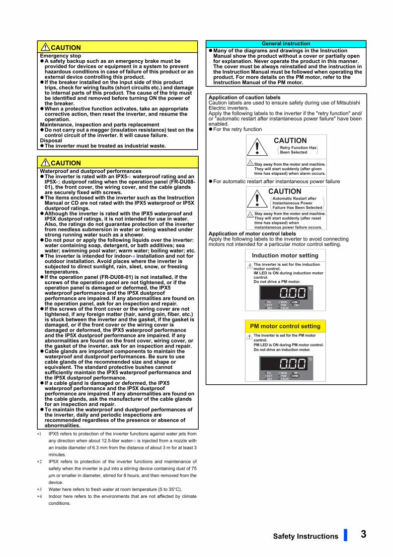
Application of caution labelsCaution labels are used to ensure safety during use of Mitsubishi Electric inverters.Apply the following labels to the inverter if the "retry function" and/or "automatic restart after instantaneous power failure" have been enabled.For the retry function
For automatic restart after instantaneous power failure
Application of motor control labelsApply the following labels to the inverter to avoid connecting motors not intended for a particular motor control setting.
CAUTIONRetry Function HasBeen Selected
Stay away from the motor and machine.They will start suddenly (after giventime has elapsed) when alarm occurs.
CAUTIONAutomatic Restart afterInstantaneous PowerFailure Has Been Selected
Stay away from the motor and machine.They will start suddenly (after reset time has elapsed) wheninstantaneous power failure occurs.
Induction motor settingThe inverter is set for the induction motor control.IM LED is ON during induction motor control.Do not drive a PM motor.
PM motor control settingThe inverter is set for the PM motor control.PM LED is ON during PM motor control.Do not drive an induction motor.
Safety Instructions 3
CONTENTS
1 INTRODUCTION 71.1 Product checking and accessories 8
1.2 Component names 9
1.3 About the related manuals 10
2 INSTALLATION AND WIRING 112.1 Peripheral devices 12
2.1.1 Inverter and peripheral devices ...................................................................................................................... 122.1.2 Peripheral devices.......................................................................................................................................... 14
2.2 Removal and reinstallation of the front cover 15
2.3 Installation of the inverter 18
2.3.1 Inverter installation environment .................................................................................................................... 182.3.2 Amount of heat generated by the inverter ...................................................................................................... 202.3.3 Inverter installation ......................................................................................................................................... 21
2.4 Terminal connection diagrams 22
2.5 Main circuit terminals 26
2.5.1 Details on the main circuit terminals............................................................................................................... 262.5.2 Terminal layout of the main circuit terminals, wiring of power supply and the motor ..................................... 262.5.3 Wiring method ................................................................................................................................................ 272.5.4 Applicable cables and the wiring length ......................................................................................................... 312.5.5 Earthing (grounding) precautions ................................................................................................................... 33
2.6 Control circuit 34
2.6.1 Details on the control circuit terminals............................................................................................................ 342.6.2 Control logic (sink/source) change ................................................................................................................. 382.6.3 Wiring of control circuit ................................................................................................................................... 402.6.4 Wiring precautions.......................................................................................................................................... 422.6.5 When supplying 24 V external power to the control circuit............................................................................. 432.6.6 Safety stop function........................................................................................................................................ 45
2.7 Operation panel (FR-DU08-01) 47
2.7.1 Differences with the FR-DU08........................................................................................................................ 472.7.2 Components of the operation panel (FR-DU08-01) ....................................................................................... 482.7.3 Basic operation of the operation panel........................................................................................................... 49
2.8 Communication connectors and terminals 50
2.8.1 PU connector.................................................................................................................................................. 502.8.2 Ethernet connector ......................................................................................................................................... 512.8.3 USB connector ............................................................................................................................................... 52
2.9 Connection of motor with encoder (vector control) 54
2.10 Parameter settings for a motor with encoder 60
2.11 Connection of stand-alone option units 63
2.11.1 Connection of the brake unit (FR-BU2) .......................................................................................................... 63
4 CONTENTS
2.11.2 Connection of the brake unit (FR-BU) ............................................................................................................652.11.3 Connection of the brake unit (BU type)...........................................................................................................662.11.4 Connection of the high power factor converter (FR-HC2) ..............................................................................672.11.5 Connection of the multifunction regeneration converter (FR-XC)...................................................................672.11.6 Connection of the power regeneration common converter (FR-CV) ..............................................................712.11.7 Connection of the power regeneration converter (MT-RC).............................................................................72
2.12 Installing a communication option 73
3 PRECAUTIONS FOR USE OF THE INVERTER 753.1 Electro-magnetic interference (EMI) and leakage currents 76
3.1.1 Leakage currents and countermeasures ........................................................................................................763.1.2 Countermeasures against inverter-generated EMI.........................................................................................783.1.3 Built-in EMC filter ............................................................................................................................................80
3.2 Power supply harmonics 82
3.2.1 Power supply harmonics.................................................................................................................................823.2.2 Harmonic suppression guidelines in Japan ....................................................................................................83
3.3 Installation of a reactor 85
3.4 Power-OFF and magnetic contactor (MC) 86
3.5 Countermeasures against deterioration of the 400 V class motor insulation 87
3.6 Checklist before starting operation 88
3.7 Failsafe system which uses the inverter 91
4 PROTECTIVE FUNCTIONS 934.1 Inverter fault and alarm indications 94
4.2 Reset method for the protective functions 94
4.3 Fault history and the list of fault displays 95
5 PRECAUTIONS FOR MAINTENANCE AND INSPECTION 97
5.1 Inspection item 98
5.1.1 Daily inspection...............................................................................................................................................985.1.2 Periodic inspection..........................................................................................................................................985.1.3 Daily and periodic inspection ..........................................................................................................................995.1.4 Checking the inverter and converter modules ..............................................................................................1015.1.5 Cleaning........................................................................................................................................................1015.1.6 Replacement of parts....................................................................................................................................1025.1.7 Removal and reinstallation of the control circuit terminal block ....................................................................121
5.2 Measurement of main circuit voltages, currents, and powers 123
CONTENTS 5

5.2.1 Measurement of powers............................................................................................................................... 1255.2.2 Measurement of voltages ............................................................................................................................. 1255.2.3 Measurement of currents ............................................................................................................................. 1255.2.4 Measurement of inverter input power factor................................................................................................. 1255.2.5 Measurement of converter output voltage (across terminals P and N) ........................................................ 1255.2.6 Measurement of inverter output frequency................................................................................................... 1255.2.7 Insulation resistance test using megger ....................................................................................................... 1265.2.8 Pressure test ................................................................................................................................................ 126
6 SPECIFICATIONS 1276.1 Inverter rating 128
6.2 Common specifications 129
6.3 Inverter outline dimension drawings 131
APPENDIX 135Appendix 1 Differences and compatibility with the FR-A840....................................................................... 136
Appendix 2 Instructions for compliance with the EU Directives................................................................... 137
Appendix 3 Instructions for UL and cUL ...................................................................................................... 141
Appendix 4 Instructions for EAC.................................................................................................................. 143
Appendix 5 Restricted Use of Hazardous Substances in Electronic and Electrical Products...................... 144
Appendix 6 Referenced Standard (Requirement of Chinese standardized law) ......................................... 144
6 CONTENTS

INTRODUCTION 7
1
1 INTRODUCTION
This contents described in this chapter must be read before using thisproduct.Always read the instructions before using the equipment.
1.1 Product checking and accessories.........................................81.2 Component names....................................................................91.3 About the related manuals.......................................................10<Abbreviations>
Operation panel ......................................... Operation panel (FR-DU08-01) and LCD operation panel (FR-LU08-01)
Parameter unit ........................................... Parameter unit (FR-PU07)
DU ............................................................. Operation panel (FR-DU08-01)
PU ............................................................. Operation panel (FR-DU08-01) and parameter unit (FR-PU07)
Inverter ...................................................... Mitsubishi Electric inverter FR-A800-E series (IP55 compatible
model)
Ethernet board .......................................... Ethernet communication board (FR-A8ETH)
Vector control compatible option .............. FR-A8AP/FR-A8AL/FR-A8APA/FR-A8APR/FR-A8APS (plug-in
option), FR-A8TP (control terminal option)
Pr. ............................................................. Parameter number (Number assigned to function)
PU operation ............................................. Operation using the PU (operation panel / parameter unit)
External operation ..................................... Operation using the control circuit signals
Combined operation ................................. Combined operation using the PU (operation panel / parameter unit)
and External operation
Mitsubishi Electric standard motor ............ SF-JR
Mitsubishi Electric constant-torque motor . SF-HRCA
Vector control dedicated motor ................. SF-V5RU
Mitsubishi Electric IPM motor ................... MM-CF
<Trademarks>
• Ethernet is a registered trademark of Fuji Xerox Co., Ltd.
<Notes on descriptions in this Instruction Manual>
• Connection diagrams in this Instruction Manual suppose that the control logic of the input terminal is the sink
logic, unless otherwise specified. (For the control logic, refer to page 38.)
Harmonic Suppression Guidelines
All the models of the inverters used by specific consumers are covered by "the Harmonic Suppression
Guidelines for Consumers Who Receive High Voltage or Special High Voltage". (For details, refer to page 83.)
Product checking and accessories
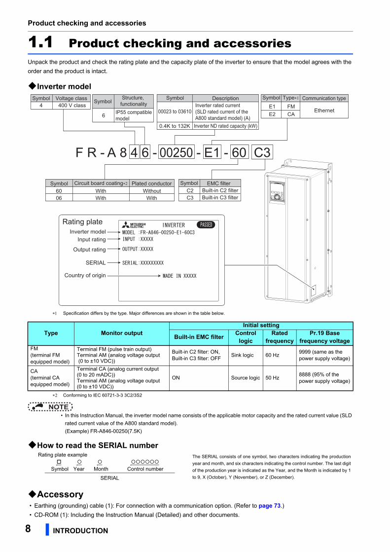
1.1 Product checking and accessoriesUnpack the product and check the rating plate and the capacity plate of the inverter to ensure that the model agrees with the
order and the product is intact.
Inverter model
Specification differs by the type. Major differences are shown in the table below.
Conforming to IEC 60721-3-3 3C2/3S2
NOTE • In this Instruction Manual, the inverter model name consists of the applicable motor capacity and the rated current value (SLD
rated current value of the A800 standard model).
(Example) FR-A846-00250(7.5K)
How to read the SERIAL number
Accessory • Earthing (grounding) cable (1): For connection with a communication option. (Refer to page 73.)
• CD-ROM (1): Including the Instruction Manual (Detailed) and other documents.
Type Monitor outputInitial setting
Built-in EMC filter Control logic
Rated frequency
Pr.19 Base frequency voltage
FM(terminal FM equipped model)
Terminal FM (pulse train output)Terminal AM (analog voltage output (0 to ±10 VDC))
Built-in C2 filter: ON, Built-in C3 filter: OFF
Sink logic 60 Hz9999 (same as the power supply voltage)
CA(terminal CA equipped model)
Terminal CA (analog current output (0 to 20 mADC))Terminal AM (analog voltage output (0 to ±10 VDC))
ON Source logic 50 Hz8888 (95% of the power supply voltage)
Rating plate example The SERIAL consists of one symbol, two characters indicating the production
year and month, and six characters indicating the control number. The last digit
of the production year is indicated as the Year, and the Month is indicated by 1
to 9, X (October), Y (November), or Z (December).
Symbol Year Month Control number
SERIAL
Rating plate
F R - A 8 4 6 - 00250 - E1 - 60 C3
400 V classSymbol Voltage class
4
CA
Symbol Type∗1
FME2E1
Symbol Description
0.4K to 132K Inverter ND rated capacity (kW)
00023 to 03610Inverter rated current(SLD rated current of the A800 standard model) (A)
SymbolStructure,
functionalityIP55 compatible model6
Built-in C3 filterC3C2
EMC filterSymbolBuilt-in C2 filter
Symbol Circuit board coating∗2
WithWith
Plated conductor
WithWithout
0660
Communication type
Ethernet
Input rating
Output rating
SERIAL
Inverter model
Country of origin
8 INTRODUCTION
Component names
1
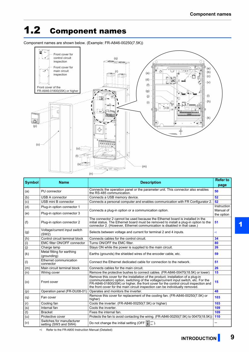
1.2 Component namesComponent names are shown below. (Example: FR-A846-00250(7.5K))
Refer to the FR-A800 Instruction Manual (Detailed)
Symbol Name Description Refer to page
(a) PU connector Connects the operation panel or the parameter unit. This connector also enables the RS-485 communication. 50
(b) USB A connector Connects a USB memory device. 52(c) USB mini B connector Connects a personal computer and enables communication with FR Configurator 2. 52(d) Plug-in option connector 1
Connects a plug-in option or a communication option.Instruction Manual of the option(e) Plug-in option connector 3
(f) Plug-in option connector 2The connector 2 cannot be used because the Ethernet board is installed in the initial status. The Ethernet board must be removed to install a plug-in option to the connector 2. (However, Ethernet communication is disabled in that case.)
51
(g)Voltage/current input switch (SW2)
Selects between voltage and current for terminal 2 and 4 inputs.
(h) Control circuit terminal block Connects cables for the control circuit. 34(i) EMC filter ON/OFF connector Turns ON/OFF the EMC filter. 80(j) Charge lamp Stays ON while the power is supplied to the main circuit. 26
(k)Metal fitting for earthing (grounding)
Earths (grounds) the shielded wires of the encoder cable, etc. 59
(l) Ethernet communication connector Connect the Ethernet dedicated cable for connection to the network. 51
(m) Main circuit terminal block Connects cables for the main circuit. 26(n) Wiring cover Remove the protective bushes to connect cables. (FR-A846-00470(18.5K) or lower) 15
(o) Front cover
Remove this cover for the installation of the product, installation of a plug-in (communication) option, switching of the voltage/current input switch, etc. For the FR-A846-01800(55K) or higher, the front cover for the control circuit inspection and the front cover for the main circuit inspection can be individually removed.
15
(p) Operation panel (FR-DU08-01) Operates and monitors the inverter. 48
(q) Fan cover Remove this cover for replacement of the cooling fan. (FR-A846-00250(7.5K) or higher) 103
(r) Cooling fan Cools the inverter. (FR-A846-00250(7.5K) or higher) 103(s) Internal fan Cools the inverter. 109(t) Bracket Fixes the internal fan. 109(u) Protective cover Protects the fan to avoid contacting the wiring. (FR-A846-00250(7.5K) to 00470(18.5K)) 110
(v) Switches for manufacturer setting (SW3 and SW4) Do not change the initial setting (OFF ).
(s)
(t)
(u)
(m)
(n)
(a)
(f)
(g)
(j)
(i)
(e)
(o)
(p)
(r)
(q)
(b)(c)
(v)
(h)
(l)
(k)
(d)
Front cover for control circuit inspection
Front cover for main circuit inspection
Front cover of the FR-A846-01800(55K) or higher
OFFON
INTRODUCTION 9

About the related manuals
1.3 About the related manualsThe manuals related to FR-A806-E are shown below.
Manual name Manual numberFR-A800 Instruction Manual (Detailed) IB-0600503ENG
FR-A800-E Ethernet Function Manual IB-0600628ENG
FR Configurator 2 Instruction Manual IB-0600516ENG
FR-A800/F800 PLC function programming manual IB-0600492ENG
FR-A800 Safety stop function instruction manual BCN-A23228-001
10 INTRODUCTION
INSTALLATION AND WIRING 11
2
2 INSTALLATION AND WIRING
This chapter explains the "INSTALLATION" and the "WIRING" of thisproduct.Always read the instructions before using the equipment.
2.1 Peripheral devices ....................................................................122.2 Removal and reinstallation of the front cover........................152.3 Installation of the inverter ........................................................182.4 Terminal connection diagrams................................................222.5 Main circuit terminals ...............................................................262.6 Control circuit ...........................................................................342.7 Operation panel (FR-DU08-01).................................................472.8 Communication connectors and terminals ............................502.9 Connection of motor with encoder (vector control) ..............542.10 Parameter settings for a motor with encoder ........................602.11 Connection of stand-alone option units .................................632.12 Installing a communication option..........................................73
Peripheral devices
2.1 Peripheral devices
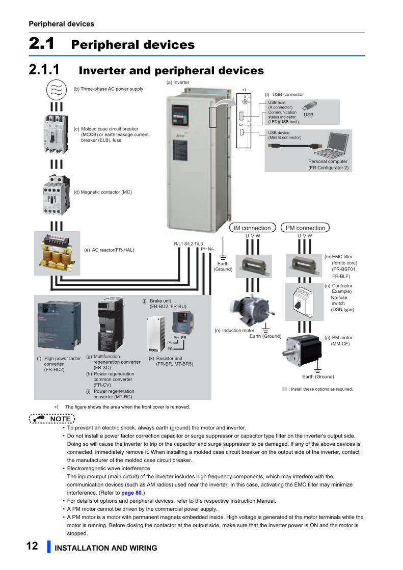
2.1.1 Inverter and peripheral devices
The figure shows the area when the front cover is removed.
NOTE • To prevent an electric shock, always earth (ground) the motor and inverter.
• Do not install a power factor correction capacitor or surge suppressor or capacitor type filter on the inverter's output side.
Doing so will cause the inverter to trip or the capacitor and surge suppressor to be damaged. If any of the above devices is
connected, immediately remove it. When installing a molded case circuit breaker on the output side of the inverter, contact
the manufacturer of the molded case circuit breaker.
• Electromagnetic wave interference
The input/output (main circuit) of the inverter includes high frequency components, which may interfere with the
communication devices (such as AM radios) used near the inverter. In this case, activating the EMC filter may minimize
interference. (Refer to page 80.)
• For details of options and peripheral devices, refer to the respective Instruction Manual.
• A PM motor cannot be driven by the commercial power supply.
• A PM motor is a motor with permanent magnets embedded inside. High voltage is generated at the motor terminals while the
motor is running. Before closing the contactor at the output side, make sure that the inverter power is ON and the motor is
stopped.
Earth(Ground)
R/L1 S/L2 T/L3N/-P/+
: Install these options as required.
U
Earth (Ground)
V WIM connection PM connection
(c) Molded case circuit breaker (MCCB) or earth leakage current breaker (ELB), fuse
(l) USB connector
(m) EMC filter (ferrite core)(FR-BSF01,
FR-BLF)
U V W
Earth (Ground)(n) Induction motor
(o) ContactorExample)
No-fuseswitch
(DSN type)
(p) PM motor (MM-CF)
(d) Magnetic contactor (MC)
(a) Inverter(b) Three-phase AC power supply
Personal computer(FR Configurator 2)
USB host(A connector)Communicationstatus indicator(LED)(USB host)
USB device(Mini B connector)
USB
(e) AC reactor(FR-HAL)
∗1
P/+P/+
PR
PR
(f) High power factor converter (FR-HC2)
(k) Resistor unit(FR-BR, MT-BR5)
(j) Brake unit (FR-BU2, FR-BU)
(g) Multifunction regeneration converter (FR-XC)
(h) Power regeneration common converter (FR-CV)
(i) Power regeneration converter (MT-RC)
12 INSTALLATION AND WIRING
Peripheral devices
2
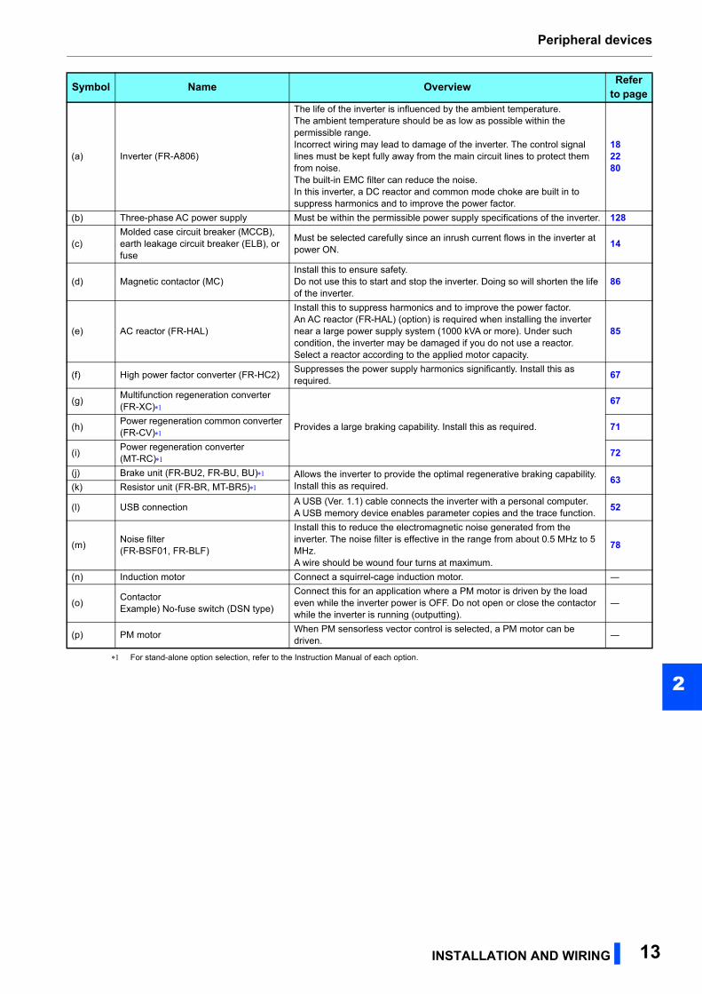
For stand-alone option selection, refer to the Instruction Manual of each option.Symbol Name OverviewRefer
to page
(a) Inverter (FR-A806)
The life of the inverter is influenced by the ambient temperature.The ambient temperature should be as low as possible within the permissible range.Incorrect wiring may lead to damage of the inverter. The control signal lines must be kept fully away from the main circuit lines to protect them from noise.The built-in EMC filter can reduce the noise.In this inverter, a DC reactor and common mode choke are built in to suppress harmonics and to improve the power factor.
182280
(b) Three-phase AC power supply Must be within the permissible power supply specifications of the inverter. 128
(c)Molded case circuit breaker (MCCB), earth leakage circuit breaker (ELB), or fuse
Must be selected carefully since an inrush current flows in the inverter at power ON.
14
(d) Magnetic contactor (MC)Install this to ensure safety.Do not use this to start and stop the inverter. Doing so will shorten the life of the inverter.
86
(e) AC reactor (FR-HAL)
Install this to suppress harmonics and to improve the power factor.An AC reactor (FR-HAL) (option) is required when installing the inverter near a large power supply system (1000 kVA or more). Under such condition, the inverter may be damaged if you do not use a reactor.Select a reactor according to the applied motor capacity.
85
(f) High power factor converter (FR-HC2)Suppresses the power supply harmonics significantly. Install this as required.
67
(g)Multifunction regeneration converter (FR-XC)
Provides a large braking capability. Install this as required.
67
(h)Power regeneration common converter (FR-CV)
71
(i)Power regeneration converter(MT-RC)
72
(j) Brake unit (FR-BU2, FR-BU, BU) Allows the inverter to provide the optimal regenerative braking capability. Install this as required.
63(k) Resistor unit (FR-BR, MT-BR5)
(l) USB connectionA USB (Ver. 1.1) cable connects the inverter with a personal computer.A USB memory device enables parameter copies and the trace function.
52
(m)Noise filter(FR-BSF01, FR-BLF)
Install this to reduce the electromagnetic noise generated from the inverter. The noise filter is effective in the range from about 0.5 MHz to 5 MHz.A wire should be wound four turns at maximum.
78
(n) Induction motor Connect a squirrel-cage induction motor. ―
(o)ContactorExample) No-fuse switch (DSN type)
Connect this for an application where a PM motor is driven by the load even while the inverter power is OFF. Do not open or close the contactor while the inverter is running (outputting).
―
(p) PM motorWhen PM sensorless vector control is selected, a PM motor can be driven.
―
INSTALLATION AND WIRING 13
Peripheral devices
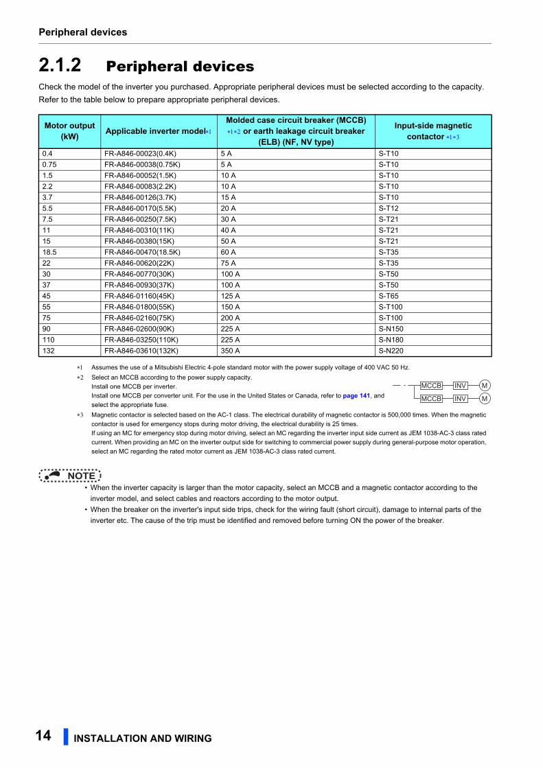
2.1.2 Peripheral devicesCheck the model of the inverter you purchased. Appropriate peripheral devices must be selected according to the capacity.
Refer to the table below to prepare appropriate peripheral devices.
NOTE • When the inverter capacity is larger than the motor capacity, select an MCCB and a magnetic contactor according to the
inverter model, and select cables and reactors according to the motor output.
• When the breaker on the inverter's input side trips, check for the wiring fault (short circuit), damage to internal parts of the
inverter etc. The cause of the trip must be identified and removed before turning ON the power of the breaker.
Motor output (kW) Applicable inverter model
Molded case circuit breaker (MCCB) or earth leakage circuit breaker
(ELB) (NF, NV type)
Input-side magnetic contactor
0.4 FR-A846-00023(0.4K) 5 A S-T10
0.75 FR-A846-00038(0.75K) 5 A S-T10
1.5 FR-A846-00052(1.5K) 10 A S-T10
2.2 FR-A846-00083(2.2K) 10 A S-T10
3.7 FR-A846-00126(3.7K) 15 A S-T10
5.5 FR-A846-00170(5.5K) 20 A S-T12
7.5 FR-A846-00250(7.5K) 30 A S-T21
11 FR-A846-00310(11K) 40 A S-T21
15 FR-A846-00380(15K) 50 A S-T21
18.5 FR-A846-00470(18.5K) 60 A S-T35
22 FR-A846-00620(22K) 75 A S-T35
30 FR-A846-00770(30K) 100 A S-T50
37 FR-A846-00930(37K) 100 A S-T50
45 FR-A846-01160(45K) 125 A S-T65
55 FR-A846-01800(55K) 150 A S-T100
75 FR-A846-02160(75K) 200 A S-T100
90 FR-A846-02600(90K) 225 A S-N150
110 FR-A846-03250(110K) 225 A S-N180
132 FR-A846-03610(132K) 350 A S-N220
Assumes the use of a Mitsubishi Electric 4-pole standard motor with the power supply voltage of 400 VAC 50 Hz.
Select an MCCB according to the power supply capacity.
Install one MCCB per inverter.
Install one MCCB per converter unit. For the use in the United States or Canada, refer to page 141, and
select the appropriate fuse.
Magnetic contactor is selected based on the AC-1 class. The electrical durability of magnetic contactor is 500,000 times. When the magnetic
contactor is used for emergency stops during motor driving, the electrical durability is 25 times.
If using an MC for emergency stop during motor driving, select an MC regarding the inverter input side current as JEM 1038-AC-3 class rated
current. When providing an MC on the inverter output side for switching to commercial power supply during general-purpose motor operation,
select an MC regarding the rated motor current as JEM 1038-AC-3 class rated current.
MCCB INV
MCCB INV
M
M
14 INSTALLATION AND WIRING
Removal and reinstallation of the front cover
2
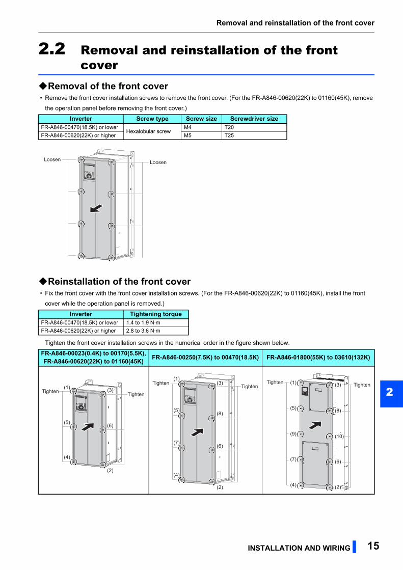
2.2 Removal and reinstallation of the front cover
Removal of the front cover • Remove the front cover installation screws to remove the front cover. (For the FR-A846-00620(22K) to 01160(45K), remove
the operation panel before removing the front cover.)
Reinstallation of the front cover • Fix the front cover with the front cover installation screws. (For the FR-A846-00620(22K) to 01160(45K), install the front
cover while the operation panel is removed.)
Tighten the front cover installation screws in the numerical order in the figure shown below.
Inverter Screw type Screw size Screwdriver sizeFR-A846-00470(18.5K) or lower
Hexalobular screwM4 T20
FR-A846-00620(22K) or higher M5 T25
Inverter Tightening torqueFR-A846-00470(18.5K) or lower 1.4 to 1.9 N·m
FR-A846-00620(22K) or higher 2.8 to 3.6 N·m
FR-A846-00023(0.4K) to 00170(5.5K),FR-A846-00620(22K) to 01160(45K) FR-A846-00250(7.5K) to 00470(18.5K) FR-A846-01800(55K) to 03610(132K)
LoosenLoosenLoosenLoosenLoosenLoosen
TightenTightenTightenTightenTightenTighten(1)
(5)
(4)
(2)
(6)
(3)TightenTightenTightenTightenTightenTighten
(1)(3)
(8)
(6)
(2)
(5)
(7)
(4)
(3)(1)
(5)
(9)
(7)
(4)
(8)
(10)
(6)
(2)
TightenTightenTighten TightenTightenTighten
INSTALLATION AND WIRING 15

Removal and reinstallation of the front cover
Removal of the front cover for control circuit inspection and the front cover for main circuit inspection (FR-A846-01800(55K) or higher)
• Remove the installation screws to remove the front cover for control circuit inspection and/or the front cover for main circuit
inspection.
Installation of the front cover for control circuit inspection and the front cover for main circuit inspection (FR-A846-01800(55K) or higher)
• Fix the covers with the installation screws.
To install the front cover for control circuit inspection and/or the front cover for main circuit inspection, tighten the installation
screws in the numerical order in the figure shown below.
Front cover Screw type Screw size Screwdriver sizeFor control circuit inspection
Hexalobular screw M5 T25For main circuit inspection
Front cover Tightening torqueFor control circuit inspection
2.8 to 3.6 N·mFor main circuit inspection
LoosenLoosenLoosenLoosenLoosenLoosen
TightenTightenTighten
TightenTightenTighten
TightenTightenTighten
TightenTightenTighten(1)
(5)
(4) (2)
(3)
(1)
(4) (2)
(3)
(6)
16 INSTALLATION AND WIRING
Removal and reinstallation of the front cover
2
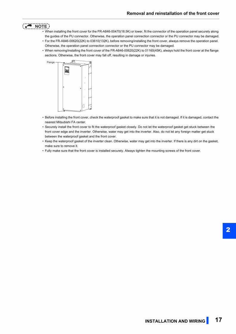
NOTE • When installing the front cover for the FR-A846-00470(18.5K) or lower, fit the connector of the operation panel securely along
the guides of the PU connector. Otherwise, the operation panel connection connector or the PU connector may be damaged.
• For the FR-A846-00620(22K) to 03610(132K), before removing/installing the front cover, always remove the operation panel.
Otherwise, the operation panel connection connector or the PU connector may be damaged.
• When removing/installing the front cover of the FR-A846-00620(22K) to 01160(45K), always hold the front cover at the flange
sections. Otherwise, the front cover may fall off, resulting in damage or injuries.
• Before installing the front cover, check the waterproof gasket to make sure that it is not damaged. If it is damaged, contact the
nearest Mitsubishi FA center.
• Securely install the front cover to fit the waterproof gasket closely. Do not let the waterproof gasket get stuck between the
front cover edge and the inverter. Otherwise, water may get into the inverter. Also, do not let any foreign matter get stuck
between the waterproof gasket and the front cover.
• Keep the waterproof gasket of the inverter clean. Otherwise, water may get into the inverter. If there is any dirt on the gasket,
make sure to remove it.
• Fully make sure that the front cover is installed securely. Always tighten the mounting screws of the front cover.
FlangeFlangeFlange
INSTALLATION AND WIRING 17
Installation of the inverter
2.3 Installation of the inverterAn inverter unit uses many semiconductor devices. To ensure higher reliability and long period of operation, operate the
inverter in the ambient environment that completely satisfies the equipment specifications.
2.3.1 Inverter installation environmentThe following table lists the standard specifications of the inverter installation environment. Using the inverter in an
environment that does not satisfy the conditions deteriorates the performance, shortens the life, and causes a failure. Refer to
the following points, and take adequate measures.
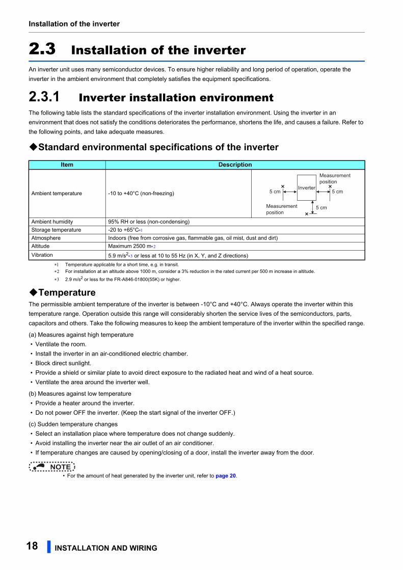
Standard environmental specifications of the inverter
Temperature applicable for a short time, e.g. in transit.
For installation at an altitude above 1000 m, consider a 3% reduction in the rated current per 500 m increase in altitude.
2.9 m/s2 or less for the FR-A846-01800(55K) or higher.
TemperatureThe permissible ambient temperature of the inverter is between -10°C and +40°C. Always operate the inverter within this
temperature range. Operation outside this range will considerably shorten the service lives of the semiconductors, parts,
capacitors and others. Take the following measures to keep the ambient temperature of the inverter within the specified range.
(a) Measures against high temperature
• Ventilate the room.
• Install the inverter in an air-conditioned electric chamber.
• Block direct sunlight.
• Provide a shield or similar plate to avoid direct exposure to the radiated heat and wind of a heat source.
• Ventilate the area around the inverter well.
(b) Measures against low temperature
• Provide a heater around the inverter.
• Do not power OFF the inverter. (Keep the start signal of the inverter OFF.)
(c) Sudden temperature changes
• Select an installation place where temperature does not change suddenly.
• Avoid installing the inverter near the air outlet of an air conditioner.
• If temperature changes are caused by opening/closing of a door, install the inverter away from the door.
NOTE • For the amount of heat generated by the inverter unit, refer to page 20.
Item Description
Ambient temperature -10 to +40°C (non-freezing)
Ambient humidity 95% RH or less (non-condensing)
Storage temperature -20 to +65°C
Atmosphere Indoors (free from corrosive gas, flammable gas, oil mist, dust and dirt)
Altitude Maximum 2500 m
Vibration 5.9 m/s2 or less at 10 to 55 Hz (in X, Y, and Z directions)
Measurement position
Measurement position
Inverter5 cm 5 cm
5 cm
18 INSTALLATION AND WIRING

Installation of the inverter
2
HumidityOperate the inverter within the ambient air humidity of usually 45 to 90%. Too high humidity will pose problems of reduced
insulation and metal corrosion. On the other hand, too low humidity may cause a spatial electrical breakdown.
The insulation distance defined in JEM 1103 "Control Equipment Insulator" is humidity of 45 to 85%.
(a) Measures against high humidity
• Provide dry air into the room from outside.
• Use a dehumidifier.
(b) Measures against low humidity
Air with proper humidity can be blown into the room from outside. Also when installing or inspecting the unit, discharge your
body (static electricity) beforehand, and keep your body away from the parts and patterns.
(c) Measures against condensation
Condensation may occur if frequent operation stops change the in-room temperature suddenly or if the outside air
temperature changes suddenly.
Condensation causes such faults as reduced insulation and corrosion.
• Take the measures against high humidity in (a).
• Do not power OFF the inverter. (Keep the start signal of the inverter OFF.)
Dust, dirt, oil mistDust and dirt will cause faults such as poor contacts, reduction in insulation and cooling effect due to accumulation of
moisture-absorbed dust and dirt, and equipment internal temperature rise due to a clogged ventilation filter in the room where
the equipment is installed. In an atmosphere where conductive powder floats, dust and dirt will cause such faults as
malfunction, deteriorated insulation and short circuit in a short time.
Since oil mist will cause similar conditions, it is necessary to take adequate measures.
Countermeasure
• Purge air.
Pump clean air from outside to make the in-enclosure air pressure higher than the outside air pressure.
Corrosive gas, salt damageIf the inverter is exposed to corrosive gas or to salt near a beach, the printed board patterns and parts will corrode or the
relays and switches will result in poor contact.
In such a place, take the countermeasures described in "Dust, dirt, oil mist" above.
Explosive, flammable gasesAs the inverter is non-explosion proof, it must be contained in an explosion-proof enclosure. In places where explosion may
be caused by explosive gas, dust or dirt, an enclosure cannot be used unless it structurally complies with the guidelines and
has passed the specified tests. This makes the enclosure itself expensive (including the test charges). The best way is to
avoid installation in such places and install the inverter in a non-hazardous place.
High altitudeUse the inverter at an altitude of within 2500 m. For the installation at an altitude above 1000 m, derate the rated current 3%
per 500 m.
If it is used at a higher place, it is likely that thin air will reduce the cooling effect and low air pressure will deteriorate dielectric
strength.
Vibration, impactThe vibration resistance of the inverter is up to 5.9 m/s2 (2.9 m/s2 or less for the FR-A846-01800(55K) or higher) at 10 to 55
Hz frequency and 1 mm amplitude for the directions of X, Y, Z axes. Applying vibration and impacts for a long time may loosen
the structures and cause poor contacts of connectors, even if those vibration and impacts are within the specified values.
Especially when impacts are applied repeatedly, caution must be taken because such impacts may break the installation feet.
Countermeasure
• Strengthen the structure to prevent the installation surface from resonance.
• Install the inverter away from the sources of the vibration.
INSTALLATION AND WIRING 19
Installation of the inverter
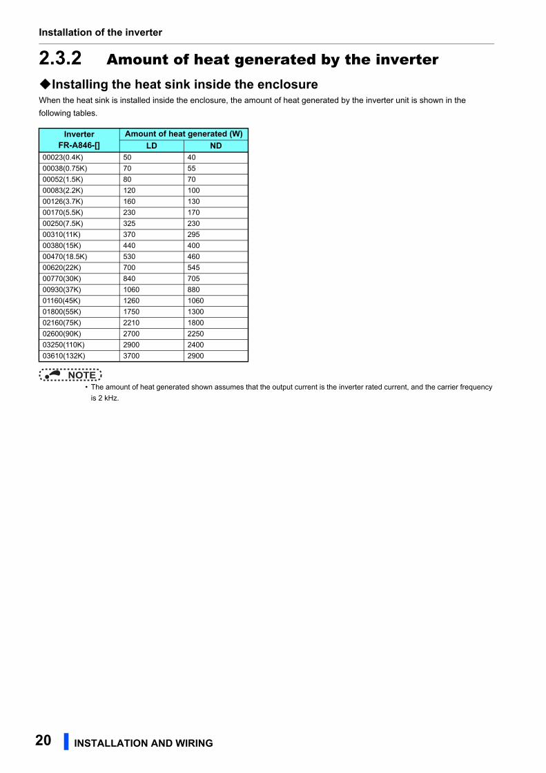
2.3.2 Amount of heat generated by the inverterInstalling the heat sink inside the enclosureWhen the heat sink is installed inside the enclosure, the amount of heat generated by the inverter unit is shown in the
following tables.
NOTE • The amount of heat generated shown assumes that the output current is the inverter rated current, and the carrier frequency
is 2 kHz.
InverterFR-A846-[]
Amount of heat generated (W)LD ND
00023(0.4K) 50 40
00038(0.75K) 70 55
00052(1.5K) 80 70
00083(2.2K) 120 100
00126(3.7K) 160 130
00170(5.5K) 230 170
00250(7.5K) 325 230
00310(11K) 370 295
00380(15K) 440 400
00470(18.5K) 530 460
00620(22K) 700 545
00770(30K) 840 705
00930(37K) 1060 880
01160(45K) 1260 1060
01800(55K) 1750 1300
02160(75K) 2210 1800
02600(90K) 2700 2250
03250(110K) 2900 2400
03610(132K) 3700 2900
20 INSTALLATION AND WIRING
Installation of the inverter
2
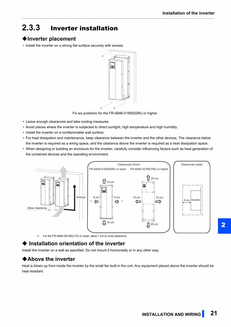
2.3.3 Inverter installationInverter placement • Install the inverter on a strong flat surface securely with screws.
• Leave enough clearances and take cooling measures.
• Avoid places where the inverter is subjected to direct sunlight, high temperature and high humidity.
• Install the inverter on a nonflammable wall surface.
• For heat dissipation and maintenance, keep clearance between the inverter and the other devices. The clearance below
the inverter is required as a wiring space, and the clearance above the inverter is required as a heat dissipation space.
• When designing or building an enclosure for the inverter, carefully consider influencing factors such as heat generation of
the contained devices and the operating environment.
For the FR-A846-00126(3.7K) or lower, allow 1 cm or more clearance.
Installation orientation of the inverterInstall the inverter on a wall as specified. Do not mount it horizontally or in any other way.
Above the inverterHeat is blown up from inside the inverter by the small fan built in the unit. Any equipment placed above the inverter should be
heat resistant.
Fix six positions for the FR-A846-01800(55K) or higher.
Clearances (side)Clearances (front)
10 cm
10 cm
5 cm5 cm
Allow clearance.
Inverter5 cmVertical
FR-A846-01800(55K) or lower
10 cm 10 cm
20 cm
20 cm
FR-A846-02160(75K) or higher
INSTALLATION AND WIRING 21
Terminal connection diagrams
2.4 Terminal connection diagrams
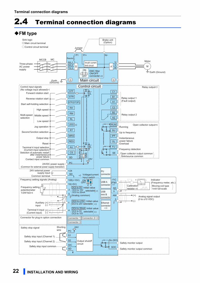
FM type
Three-phaseAC powersupply
MCCBR/L1S/L2T/L3
PC24VDC power supply(Common for external power supply transistor)
Forward rotation start
Reverse rotation start
Start self-holding selection
Middle speed
High speed
Low speed
Jog operation
Second function selection
Output stop
ResetTerminal 4 input selection
(Current input selection)Selection of automatic restart
after instantaneouspower failure
Frequency setting signals (Analog) 10E(+10V)
10(+5V)
2
(Analog common)
23
1
Auxiliaryinput
Terminal 4 input(Current input)
1
4
Frequency settingpotentiometer1/2W1kΩ∗4
Running
Up to frequency
Instantaneouspower failureOverload
Frequency detection
Open collector output common Sink/source common
F/C(FM)
SD
Control input signals (No voltage input allowed)∗1
Motor
Relay output 1(Fault output)
C1
B1
A1
UVW
P1
Indicator(Frequency meter, etc.)
+ -
(-)
(+) Analog signal output(0 to ±10 VDC)
Earth(Ground)
AM
5
DC0 to ±5V selectableDC0 to ±10V
Multi-speedselection
Open collector output∗6
Moving-coil type1mA full-scale
Contact input common
Calibrationresistor ∗8
Main circuit terminalControl circuit terminal
DC0 to 5VDC0 to 10V selectable
MC
Main circuit
C2
B2
A2Relay output 2
Relay output∗5
M
DC0 to 20mA
DC0 to 5VDC0 to 10V
selectableDC4 to 20mA
PUconnector
USB A connector
USBmini Bconnector
SIN
K
SO
UR
CE
∗2
∗3
∗3
∗7
∗3
∗3
Connector for plug-in option connection
STF
STR
STP(STOP)
RH
RM
RL
JOG
RT
MRS
RES
AU
CS
SD
RUN
SU
IPF
OL
FU
SE
(+)(-)
5
EMC filterON/OFFconnecter
ON
OFF
+2424V external powersupply input SD
Common terminal
(+)(-)
Sink logic
Earth (Ground)
Connector 1 Connector 2
Connector 3
N/-P/+
Control circuit
Initial value
Initial value
Initial value
ON
42OFF
Voltage/currentinput switch
Brake unit(Option)
Safety monitor output
Safety monitor output common
So (SO)
SOC
S1
S2
PC
SDSIC
Safety stop signal
Safety stop input (Channel 1)
Shortingwire
Safety stop input common
Safety stop input (Channel 2)
Jumper
∗9
∗10
Ethernet connector
∗10
24V
Inrush currentlimit circuit
24V
Output shutoffcircuit
Reactor
22 INSTALLATION AND WIRING
Terminal connection diagrams
2
The function of these terminals can be changed with the input terminal assignment (Pr.178 to Pr.189). (Refer to the FR-A800 Instruction Manual
(Detailed).)
Terminal JOG is also used as a pulse train input terminal. Use Pr.291 to choose JOG or pulse.
Terminal input specifications can be changed by analog input specification switchover (Pr.73, Pr.267). To input a voltage, set the voltage/current
input switch OFF. To input a current, set the voltage/current input switch ON. Terminals 10 and 2 are also used as a PTC input terminal. (Pr.561) (Refer to the FR-A800 Instruction Manual (Detailed).)
It is recommended to use 2 W 1 k when the frequency setting signal is changed frequently.
The function of these terminals can be changed with the output terminal assignment (Pr.195, Pr.196). (Refer to the FR-A800 Instruction Manual
(Detailed).)
The function of these terminals can be changed with the output terminal assignment (Pr.190 to Pr.194). (Refer to the FR-A800 Instruction
Manual (Detailed).)
Terminal FM can be used to output pulse trains as open collector output by setting Pr.291.
Not required when calibrating the scale with the operation panel.
Do not change the initially set ON (enabled) position of the EMC filter ON/OFF connector in the case of the inverter with a built-in C2 filter. The
Class C2 compatibility condition is not satisfied with the EMC filter OFF. The FR-A846-00250(7.5K)-C2 to FR-A846-00470(18.5K)-C2 are not
provided with the EMC filter ON/OFF connector. The EMC filter is always ON.
The option connector 2 cannot be used because the Ethernet board is installed in the initial status. The Ethernet board must be removed to
install a plug-in option to the option connector 2. (However, Ethernet communication is disabled in that case.)
NOTE • To prevent a malfunction due to noise, keep the signal cables 10 cm or more away from the power cables. Also, separate the
main circuit cables at the input side from the main circuit cables at the output side.
• After wiring, wire offcuts must not be left in the inverter.
Wire offcuts can cause an alarm, failure or malfunction. Always keep the inverter clean.
When drilling mounting holes in a wall or the side of the enclosure etc., take caution not to allow chips and other foreign
matters to enter the inverter.
• Set the voltage/current input switch correctly. Incorrect setting may cause a fault, failure or malfunction.
INSTALLATION AND WIRING 23
Terminal connection diagrams
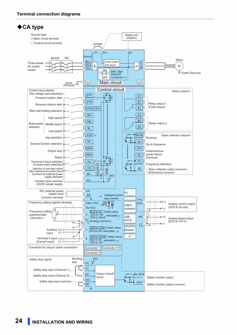
CA type
Analog current output(DC0 to 20 mA)
F/C(CA)
Three-phaseAC powersupply
MCCBR/L1S/L2T/L3
PC24VDC power supply
Forward rotation start
Reverse rotation start
Start self-holding selection
Middle speed
High speed
Low speed
Jog operation
Second function selection
Output stop
ResetTerminal 4 input selection
(Current input selection)Selection of automatic restart
after instantaneous power failure
Frequency setting signals (Analog) 10E(+10V)
10(+5V)
2
(Analog common)
23
1
Auxiliaryinput
Terminal 4 input(Current input)
1
4
Frequency settingpotentiometer1/2W1kΩ∗4
Running
Up to frequency
Instantaneouspower failureOverload
Frequency detection
Open collector output commonSink/source common
Control input signals (No voltage input allowed)∗1
Motor
Relay output 1(Fault output)
C1
B1
A1
UVW
P1
(-)
(+)
(-)
(+)
Analog signal output
Earth(Ground)
AM
5
DC0 to ±5V selectableDC0 to ±10V
(DC0 to ±10 V)
Multi-speedselection
Open collector output∗6
Contact input common
Main circuit terminalControl circuit terminal
DC0 to 5VDC0 to 10V selectable
MC
Main circuit
C2
B2
A2Relay output 2
Relay output∗5
M
DC0 to 20mA
DC0 to 5VDC0 to 10V
selectableDC4 to 20mA
PUconnector
USB A connector
USBmini Bconnector
SIN
K
SO
UR
CE
∗2
∗3
∗3
∗3
∗3
Connector for plug-in option connection
STF
STR
STP(STOP)
RH
RM
RL
JOG
RT
MRS
RES
AU
CS
SD
RUN
SU
IPF
OL
FU
SE
(+)(-)
5
EMC filterON/OFFconnecter
ON
OFF
+2424V external powersupply input
(+)(-)
Source logic
Earth (Ground)
Connector 1 Connector 2
Connector 3
N/-P/+
Control circuit
Initial value
Initial value
Initial value
ON
42OFF
Voltage/currentinput switch
Brake unit(Option)
Safety monitor output
Safety monitor output common
So (SO)
SOC
Safety stop signal
Safety stop input (Channel 1)
Shortingwire
Safety stop input common
Safety stop input (Channel 2)
S1
S2
PC
SDSIC
SD
Jumper
Common for external powersupply transistor
∗7
∗8
Ethernetconnector
∗8
Output shutoffcircuit
24V
Inrush currentlimit circuit
Common terminal
24V
Reactor
24 INSTALLATION AND WIRING
Terminal connection diagrams
2
The function of these terminals can be changed with the input terminal assignment (Pr.178 to Pr.189). (Refer to the FR-A800 Instruction Manual
(Detailed).)
Terminal JOG is also used as a pulse train input terminal. Use Pr.291 to choose JOG or pulse.
Terminal input specifications can be changed by analog input specification switchover (Pr.73, Pr.267). To input a voltage, set the voltage/current
input switch OFF. To input a current, set the voltage/current input switch ON. Terminals 10 and 2 are also used as a PTC input terminal. (Pr.561) (Refer to the FR-A800 Instruction Manual (Detailed).)
It is recommended to use 2 W 1 k when the frequency setting signal is changed frequently.
The function of these terminals can be changed with the output terminal assignment (Pr.195, Pr.196). (Refer to the FR-A800 Instruction Manual
(Detailed).)
The function of these terminals can be changed with the output terminal assignment (Pr.190 to Pr.194). (Refer to the FR-A800 Instruction
Manual (Detailed).)
Do not change the initially set ON (enabled) position of the EMC filter ON/OFF connector in the case of the inverter with a built-in C2 filter. The
Class C2 compatibility condition is not satisfied with the EMC filter OFF. The FR-A846-00250(7.5K)-C2 to FR-A846-00470(18.5K)-C2 are not
provided with the EMC filter ON/OFF connector. The EMC filter is always ON.
The option connector 2 cannot be used because the Ethernet board is installed in the initial status. The Ethernet board must be removed to
install a plug-in option to the option connector 2. (However, Ethernet communication is disabled in that case.)
NOTE • To prevent a malfunction due to noise, keep the signal cables 10 cm or more away from the power cables. Also, separate the
main circuit cables at the input side from the main circuit cables at the output side.
• After wiring, wire offcuts must not be left in the inverter.
Wire offcuts can cause an alarm, failure or malfunction. Always keep the inverter clean.
When drilling mounting holes in a wall or the side of the enclosure etc., take caution not to allow chips and other foreign
matters to enter the inverter.
• Set the voltage/current input switch correctly. Incorrect setting may cause a fault, failure or malfunction.
INSTALLATION AND WIRING 25
Main circuit terminals
2.5 Main circuit terminals
2.5.1 Details on the main circuit terminals
Available when used in the common bus regeneration mode
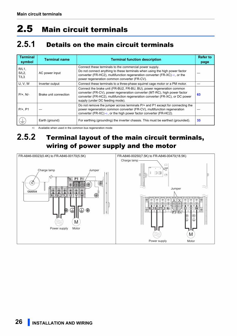
2.5.2 Terminal layout of the main circuit terminals, wiring of power supply and the motor
Terminal symbol Terminal name Terminal function description Refer to
page
R/L1,S/L2,T/L3
AC power input
Connect these terminals to the commercial power supply.Do not connect anything to these terminals when using the high power factor converter (FR-HC2), multifunction regeneration converter (FR-XC) , or the power regeneration common converter (FR-CV).
—
U, V, W Inverter output Connect these terminals to a three-phase squirrel cage motor or a PM motor. —
P/+, N/- Brake unit connection
Connect the brake unit (FR-BU2, FR-BU, BU), power regeneration common converter (FR-CV), power regeneration converter (MT-RC), high power factor converter (FR-HC2), multifunction regeneration converter (FR-XC), or DC power supply (under DC feeding mode).
63
P/+, P1 —Do not remove the jumper across terminals P/+ and P1 except for connecting the power regeneration common converter (FR-CV), multifunction regeneration converter (FR-XC) , or the high power factor converter (FR-HC2).
—
Earth (ground) For earthing (grounding) the inverter chassis. This must be earthed (grounded). 33
FR-A846-00023(0.4K) to FR-A846-00170(5.5K) FR-A846-00250(7.5K) to FR-A846-00470(18.5K)
M
R/L1 S/L2 T/L3
N/- P/+
MotorPower supply
JumperCharge lamp
MMotorPower supply
R/L1 S/L2 T/L3 N/-P/+
Jumper
Charge lamp
26 INSTALLATION AND WIRING
Main circuit terminals
2
NOTE • Make sure the power cables are connected to the R/L1, S/L2, and T/L3. (Phase need not be matched.) Never connect the
power cable to the U, V, and W of the inverter. Doing so will damage the inverter.
• Connect the motor to U, V, and W. The phase need to be matched.
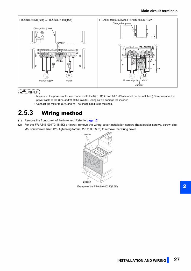
2.5.3 Wiring method(1) Remove the front cover of the inverter. (Refer to page 15)
(2) For the FR-A846-00470(18.5K) or lower, remove the wiring cover installation screws (hexalobular screws, screw size:
M5, screwdriver size: T25, tightening torque: 2.8 to 3.6 N·m) to remove the wiring cover.
FR-A846-00620(22K) to FR-A846-01160(45K) FR-A846-01800(55K) to FR-A846-03610(132K)
M
R/L1 S/L2 T/L3 N/-
P/+
MotorPower supply
Jumper
Charge lamp
MotorPower supply
M
R/L1 S/L2 T/L3
P/+
Jumper
Charge lamp
N/-
LoosenLoosenLoosen
Example of the FR-A846-00250(7.5K)Example of the FR-A846-00250(7.5K)Example of the FR-A846-00250(7.5K)
LoosenLoosenLoosen
INSTALLATION AND WIRING 27
Main circuit terminals
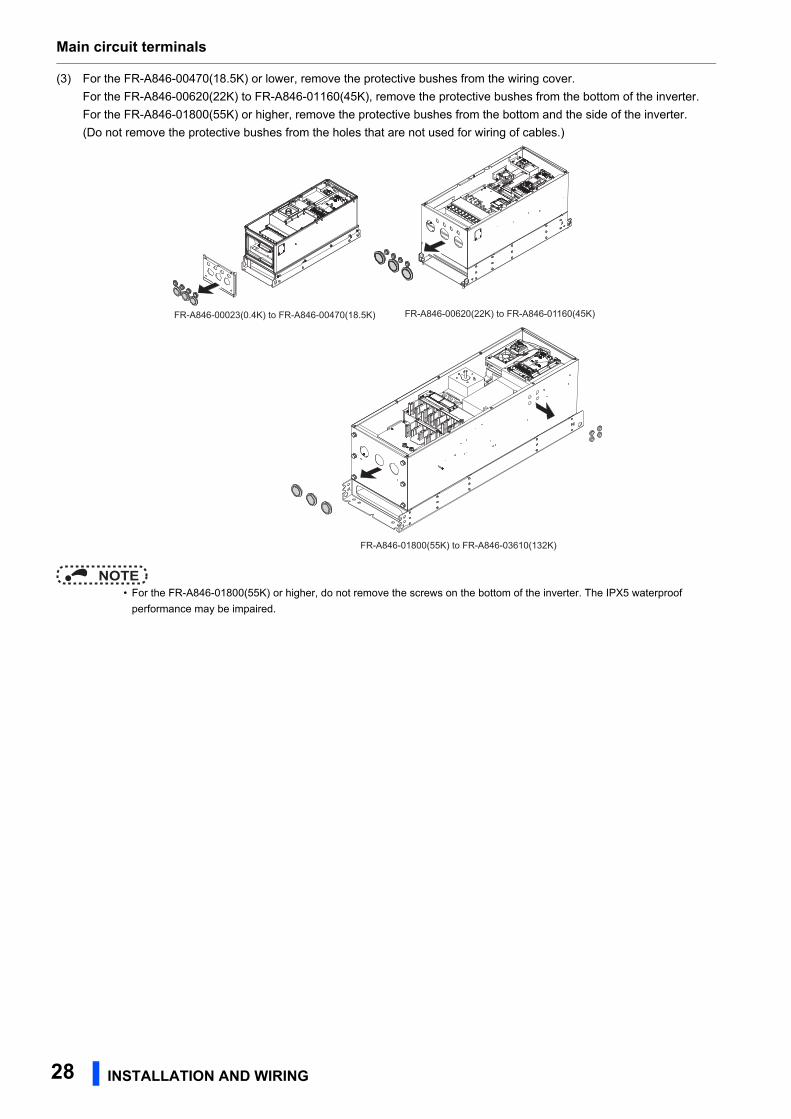
(3) For the FR-A846-00470(18.5K) or lower, remove the protective bushes from the wiring cover.
For the FR-A846-00620(22K) to FR-A846-01160(45K), remove the protective bushes from the bottom of the inverter.
For the FR-A846-01800(55K) or higher, remove the protective bushes from the bottom and the side of the inverter.
(Do not remove the protective bushes from the holes that are not used for wiring of cables.)
NOTE • For the FR-A846-01800(55K) or higher, do not remove the screws on the bottom of the inverter. The IPX5 waterproof
performance may be impaired.
FR-A846-00023(0.4K) to FR-A846-00470(18.5K) FR-A846-00620(22K) to FR-A846-01160(45K)
FR-A846-01800(55K) to FR-A846-03610(132K)
28 INSTALLATION AND WIRING
Main circuit terminals
2
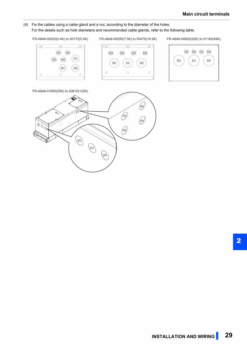
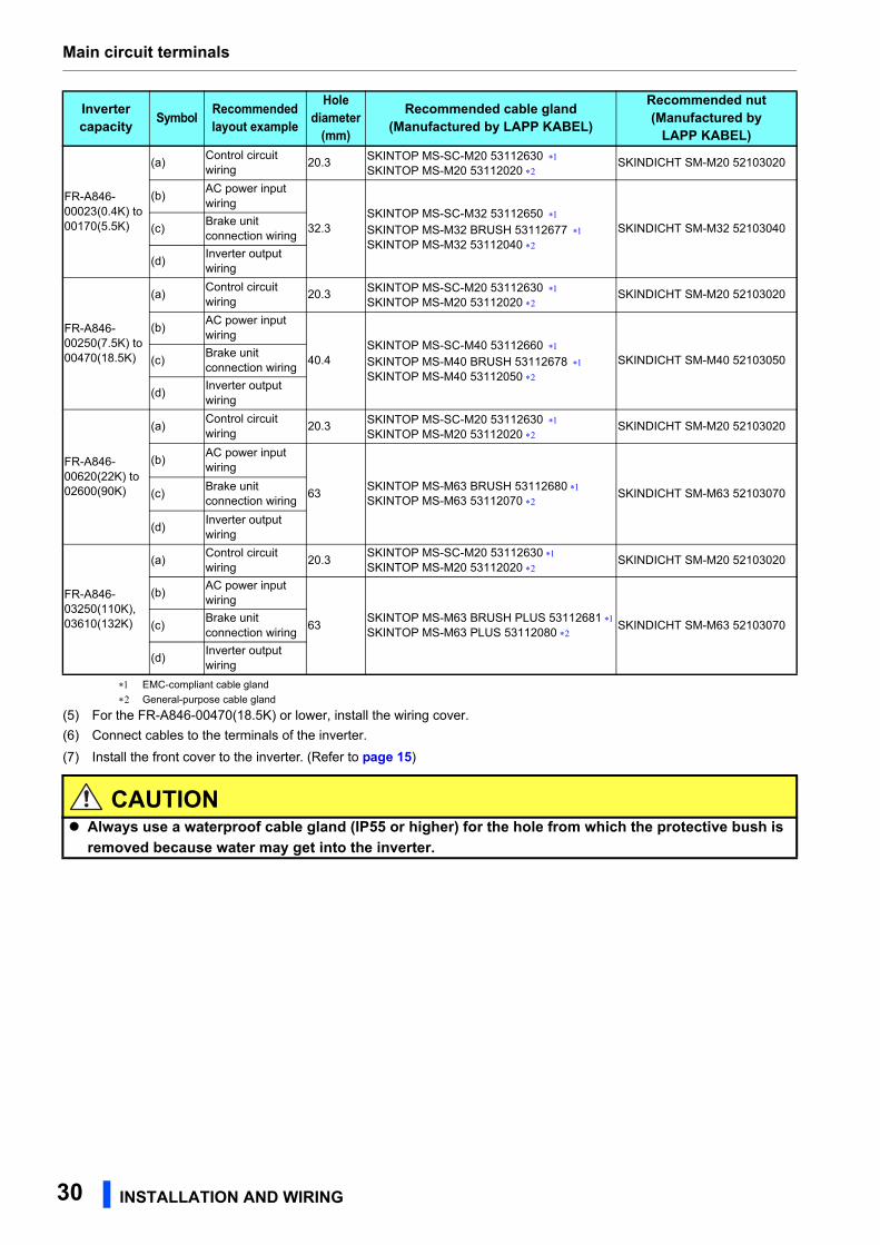
(4) Fix the cables using a cable gland and a nut, according to the diameter of the holes.
For the details such as hole diameters and recommended cable glands, refer to the following table.
(a) (a)
(a) (a) (c)
(b) (d)
(a)
(b) (c) (d)
(a) (a) (a)
FR-A846-00250(7.5K) to 00470(18.5K)FR-A846-00023(0.4K) to 00170(5.5K) FR-A846-00620(22K) to 01160(45K)
(a)
(b) (c) (d)
(a) (a) (a)
FR-A846-01800(55K) to 03610(132K)
(b)
(c)
(d)
(a)
(a)
(a)
(a)
INSTALLATION AND WIRING 29
Main circuit terminals
EMC-compliant cable gland
General-purpose cable gland
(5) For the FR-A846-00470(18.5K) or lower, install the wiring cover.
(6) Connect cables to the terminals of the inverter.
(7) Install the front cover to the inverter. (Refer to page 15)
Inverter capacity Symbol Recommended
layout example
Hole diameter
(mm)
Recommended cable gland(Manufactured by LAPP KABEL)
Recommended nut(Manufactured by
LAPP KABEL)
FR-A846-00023(0.4K) to 00170(5.5K)
(a)Control circuit wiring
20.3SKINTOP MS-SC-M20 53112630 SKINTOP MS-M20 53112020
SKINDICHT SM-M20 52103020
(b)AC power input wiring
32.3SKINTOP MS-SC-M32 53112650 SKINTOP MS-M32 BRUSH 53112677 SKINTOP MS-M32 53112040
SKINDICHT SM-M32 52103040(c)Brake unit connection wiring
(d)Inverter output wiring
FR-A846-00250(7.5K) to 00470(18.5K)
(a)Control circuit wiring
20.3 SKINTOP MS-SC-M20 53112630 SKINTOP MS-M20 53112020
SKINDICHT SM-M20 52103020
(b)AC power input wiring
40.4SKINTOP MS-SC-M40 53112660 SKINTOP MS-M40 BRUSH 53112678 SKINTOP MS-M40 53112050
SKINDICHT SM-M40 52103050(c)Brake unit connection wiring
(d)Inverter output wiring
FR-A846-00620(22K) to 02600(90K)
(a)Control circuit wiring
20.3SKINTOP MS-SC-M20 53112630 SKINTOP MS-M20 53112020
SKINDICHT SM-M20 52103020
(b)AC power input wiring
63SKINTOP MS-M63 BRUSH 53112680 SKINTOP MS-M63 53112070
SKINDICHT SM-M63 52103070(c)Brake unit connection wiring
(d)Inverter output wiring
FR-A846-03250(110K), 03610(132K)
(a)Control circuit wiring
20.3SKINTOP MS-SC-M20 53112630 SKINTOP MS-M20 53112020
SKINDICHT SM-M20 52103020
(b)AC power input wiring
63SKINTOP MS-M63 BRUSH PLUS 53112681 SKINTOP MS-M63 PLUS 53112080
SKINDICHT SM-M63 52103070(c)Brake unit connection wiring
(d)Inverter output wiring
CAUTION Always use a waterproof cable gland (IP55 or higher) for the hole from which the protective bush is
removed because water may get into the inverter.
30 INSTALLATION AND WIRING
Main circuit terminals
2
2.5.4 Applicable cables and the wiring lengthSelect a recommended cable size to ensure that the voltage drop will be 2% or less.
If the wiring distance is long between the inverter and motor, the voltage drop in the main circuit wires will cause the motor
torque to decrease especially at a low speed.
The following table indicates inverter/cable combinations for a wiring length of 20 m.
• 400 V class (440 V input power supply (with 150% rated current for one minute))
For the FR-A846-01800(55K) or lower, it is the gauge of a cable with the continuous maximum permissible temperature of 75°C (HIV cable (600
V grade heat-resistant PVC insulated wire), etc.). It assumes a surrounding air temperature of 50°C or lower and the wiring distance of 20 m or
shorter.
For the FR-A846-02160(75K) or higher, it is the gauge of the cable with the continuous maximum permissible temperature of 90°C or higher.
(LMFC (heat resistant flexible cross-linked polyethylene insulated cable), etc.). It assumes a surrounding air temperature of 50°C or lower.
For the FR-A846-01160(45K) or lower, it is the gauge of a cable with the continuous maximum permissible temperature of 75°C (THHW cable).
It assumes a surrounding air temperature of 40°C or lower and the wiring distance of 20 m or shorter.
For the FR-A846-01800(55K) or higher, it is the gauge of a cable with the continuous maximum permissible temperature of 90°C (THHN cable).
It assumes a surrounding air temperature of 40°C or lower.
(For the use in the United States or Canada, refer to page 141.)
For the FR-A846-01160(45K) or lower, it is the gauge of a cable with the continuous maximum permissible temperature of 70°C (PVC cable). It
assumes a surrounding air temperature of 40°C or lower and the wiring distance of 20 m or shorter.
For the FR-A846-01800(55K) or higher, it is the gauge of a cable with the continuous maximum permissible temperature of 90°C (XLPE cable).
It assumes a surrounding air temperature of 40°C or lower. (Selection example for use mainly in Europe.)
The terminal screw size indicates the size of terminal screw for R/L1, S/L2, T/L3, U, V, W, P/+, N/-, P1, and a screw for earthing (grounding).
The line voltage drop can be calculated by the following formula:
Line voltage drop [V]=
Use a larger diameter cable when the wiring distance is long or when it is desired to decrease the voltage drop (torque
reduction) in the low speed range.
NOTE • Tighten the terminal screw to the specified torque.
A screw that has been tightened too loosely can cause a short circuit or malfunction.
A screw that has been tightened too tightly can cause a short circuit or malfunction due to the unit breakage.
• Use crimping terminals with insulation sleeves to wire the power supply and motor.
Applicable inverter model
FR-A846-[ ]
Terminal screwsize
Tightening torqueN·m
Crimp terminal
Cable gaugeHIV cables, etc. (mm2) AWG/MCM PVC cables, etc. (mm2)
R/L1, S/L2, T/L3
U, V, W
R/L1, S/L2, T/L3
U, V, W P/+
Earthing (grounding)
cable
R/L1, S/L2, T/L3
U, V, W
R/L1, S/L2, T/L3
U, V, W
Earthing (grounding)
cable00023(0.4K) to 00126(3.7K)
M4 1.5 2-4 2-4 2 2 2 2 14 14 2.5 2.5 2.5
00170(5.5K) M4 1.5 2-4 2-4 2 2 3.5 3.5 12 14 2.5 2.5 4
00250(7.5K) M6 4.4 5.5-6 5.5-6 3.5 3.5 3.5 3.5 12 12 4 4 4
00310(11K) M6 4.4 5.5-6 5.5-6 5.5 5.5 5.5 5.5 10 10 6 6 10
00380(15K) M6 4.4 5.5-6 5.5-6 5.5 5.5 8 5.5 10 10 6 6 10
00470(18.5K) M6 4.4 8-6 8-6 8 8 14 8 8 8 10 10 16
00620(22K) M6 4.4 14-6 14-6 14 14 22 14 6 6 16 16 16
00770(30K) M6 4.4 22-6 22-6 22 22 22 14 4 4 25 25 16
00930(37K) M8 7.8 22-8 22-8 22 22 22 14 4 4 25 25 16
01160(45K) M8 7.8 38-8 38-8 38 38 38 22 2 2 50 50 25
01800(55K) M10 14.7 60-10 60-10 60 60 60 22 1/0 1/0 50 50 25
02160(75K) M10 14.7 60-10 60-10 60 60 60 22 1/0 1/0 50 50 25
02600(90K) M10 14.7 60-10 60-10 60 60 80 22 3/0 3/0 50 50 25
03250(110K) M10 14.7 80-10 80-10 80 80 80 38 3/0 3/0 70 70 35
03610(132K) M10 14.7 100-10 100-10 100 100 100 38 4/0 4/0 95 95 50
× wire resistance [mΩ/m] × wiring distance [m] × current [A]1000
INSTALLATION AND WIRING 31
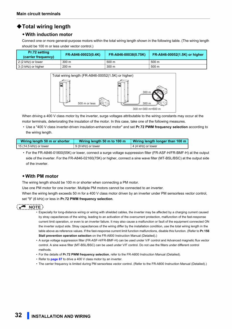
Main circuit terminals
Total wiring lengthWith induction motorConnect one or more general-purpose motors within the total wiring length shown in the following table. (The wiring length
should be 100 m or less under vector control.)
When driving a 400 V class motor by the inverter, surge voltages attributable to the wiring constants may occur at the
motor terminals, deteriorating the insulation of the motor. In this case, take one of the following measures.
• Use a "400 V class inverter-driven insulation-enhanced motor" and set Pr.72 PWM frequency selection according to
the wiring length.
• For the FR-A846-01800(55K) or lower, connect a surge voltage suppression filter (FR-ASF-H/FR-BMF-H) at the output
side of the inverter. For the FR-A846-02160(75K) or higher, connect a sine wave filter (MT-BSL/BSC) at the output side
of the inverter.
With PM motorThe wiring length should be 100 m or shorter when connecting a PM motor.
Use one PM motor for one inverter. Multiple PM motors cannot be connected to an inverter.
When the wiring length exceeds 50 m for a 400 V class motor driven by an inverter under PM sensorless vector control,
set "9" (6 kHz) or less in Pr.72 PWM frequency selection.
NOTE • Especially for long-distance wiring or wiring with shielded cables, the inverter may be affected by a charging current caused
by stray capacitances of the wiring, leading to an activation of the overcurrent protection, malfunction of the fast-response
current limit operation, or even to an inverter failure. It may also cause a malfunction or fault of the equipment connected ON
the inverter output side. Stray capacitances of the wiring differ by the installation condition, use the total wiring length in the
table above as reference values. If the fast-response current limit function malfunctions, disable this function. (Refer to Pr.156 Stall prevention operation selection on the FR-A800 Instruction Manual (Detailed).)
• A surge voltage suppression filter (FR-ASF-H/FR-BMF-H) can be used under V/F control and Advanced magnetic flux vector
control. A sine wave filter (MT-BSL/BSC) can be used under V/F control. Do not use the filters under different control
methods.
• For the details of Pr.72 PWM frequency selection, refer to the FR-A800 Instruction Manual (Detailed).
• Refer to page 87 to drive a 400 V class motor by an inverter.
• The carrier frequency is limited during PM sensorless vector control. (Refer to the FR-A800 Instruction Manual (Detailed).)
Pr.72 setting(carrier frequency) FR-A846-00023(0.4K) FR-A846-00038(0.75K) FR-A846-00052(1.5K) or higher
2 (2 kHz) or lower 300 m 500 m 500 m
3 (3 kHz) or higher 200 m 300 m 500 m
Total wiring length (FR-A846-00052(1.5K) or higher)
Wiring length 50 m or shorter Wiring length 50 m to 100 m Wiring length longer than 100 m15 (14.5 kHz) or lower 9 (9 kHz) or lower 4 (4 kHz) or lower
300 m+300 m=600 m
500 m or less
300 m
300 m
32 INSTALLATION AND WIRING

Main circuit terminals
2
2.5.5 Earthing (grounding) precautionsAlways earth (ground) the motor and inverter.
Purpose of earthing (grounding)Generally, an electrical apparatus has an earth (ground) terminal, which must be connected to the ground before use.
An electrical circuit is usually insulated by an insulating material and encased. However, it is impossible to manufacture an
insulating material that can shut off a leakage current completely, and actually, a slight current flows into the case. The
purpose of earthing (grounding) the case of an electrical apparatus is to prevent operators from getting an electric shock from
this leakage current when touching it.
To avoid the influence of external noises, this earthing (grounding) is important to audio equipment, sensors, computers and
other apparatuses that handle low-level signals or operate very fast.
Earthing (grounding) methods and earthing (grounding) workAs described previously, earthing (grounding) is roughly classified into an electrical shock prevention type and a noise-
influenced malfunction prevention type. Therefore, these two types should be clearly distinguished, and the following work
must be done to prevent the leakage current having the inverter's high frequency components from entering the malfunction
prevention type earthing (grounding):
• Whenever possible, use the independent earthing (grounding) for the inverter.
If independent earthing (grounding) (I) is not available, use (II) common earthing (grounding) in the figure below where the
inverter is connected with the other equipment at an earthing (grounding) point. Do not use the other equipment's earthing
(grounding) cable to earth (ground) the inverter as shown in (III).
A leakage current containing many high frequency components flows into the earthing (grounding) cables of the inverter
and peripheral devices. Because of this, the inverter must be earthed (grounded) separately from EMI-sensitive devices.
In a high building, it may be effective to use the EMI prevention type earthing (grounding) connecting to an iron structure
frame, and electric shock prevention type earthing (grounding) with the independent earthing (grounding) together.
• This inverter must be earthed (grounded). Earthing (Grounding) must conform to the requirements of national and local
safety regulations and electrical codes. (NEC section 250, IEC 61140 class 1 and other applicable standards).
A neutral-point earthed (grounded) power supply in compliance with EN standard must be used.
• Use the thickest possible earthing (grounding) cable. The earthing (grounding) cable should be the size indicated in the
table on page 31.
• The earthing (grounding) point should be as close as possible to the inverter, and the earth (ground) wire length should be
as short as possible.
• Run the earthing (grounding) cable as far away as possible from the I/O wiring of equipment sensitive to noises and run
them in parallel in the minimum distance.
NOTE • To be compliant with the EU Directive (Low Voltage Directive), refer to page 137.
InverterOther
equipment
(I) Independent earthing (grounding).......Good
InverterOther
equipment
(II) Common earthing (grounding).......Good
InverterOther
equipment
(III) Common earthing (grounding) cable.......Not allowed
INSTALLATION AND WIRING 33
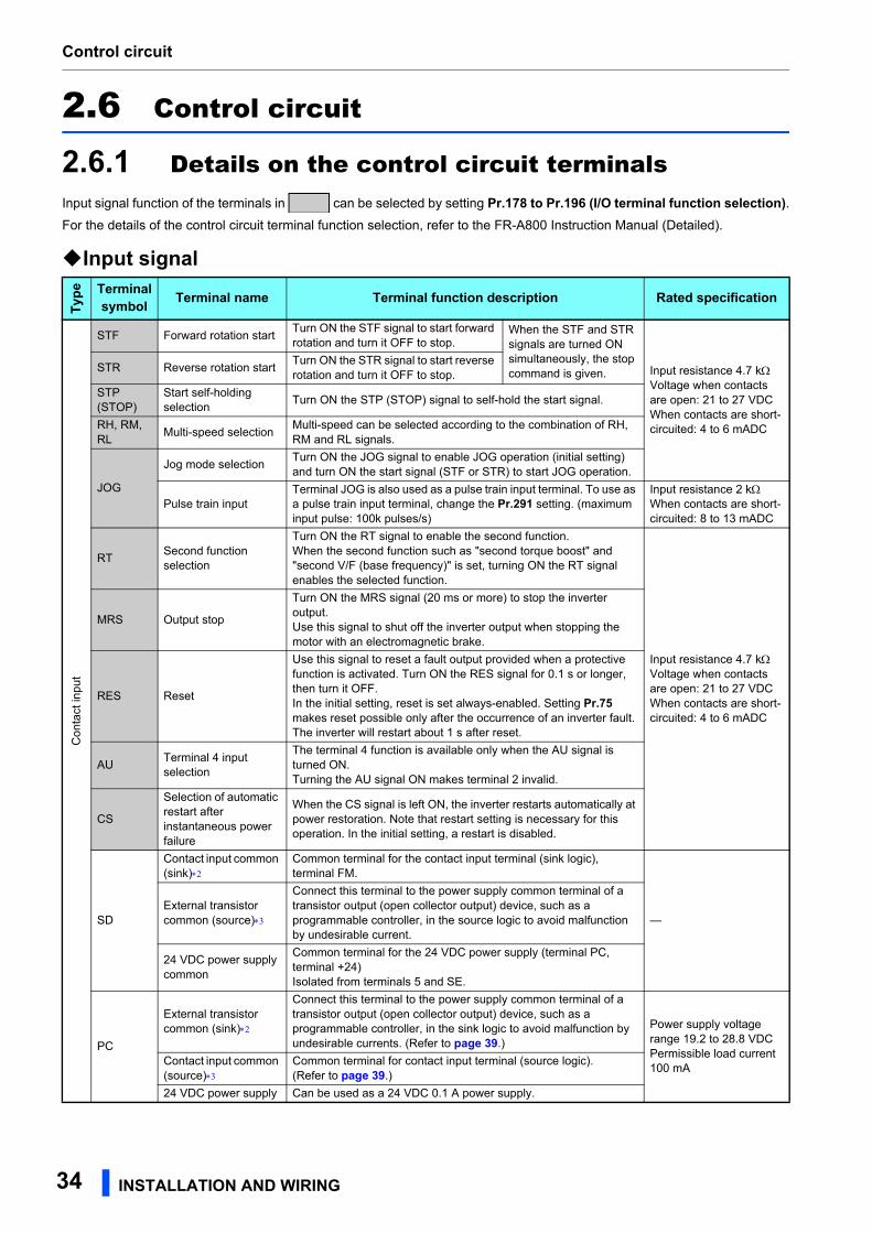
Control circuit
2.6 Control circuit
2.6.1 Details on the control circuit terminalsInput signal function of the terminals in can be selected by setting Pr.178 to Pr.196 (I/O terminal function selection).For the details of the control circuit terminal function selection, refer to the FR-A800 Instruction Manual (Detailed).
Input signal
Type Terminal
symbol Terminal name Terminal function description Rated specification
Con
tact
inpu
t
STF Forward rotation startTurn ON the STF signal to start forward rotation and turn it OFF to stop.
When the STF and STR signals are turned ON simultaneously, the stop command is given. Input resistance 4.7 k
Voltage when contacts are open: 21 to 27 VDCWhen contacts are short-circuited: 4 to 6 mADC
STR Reverse rotation startTurn ON the STR signal to start reverse rotation and turn it OFF to stop.
STP (STOP)
Start self-holding selection
Turn ON the STP (STOP) signal to self-hold the start signal.
RH, RM, RL
Multi-speed selectionMulti-speed can be selected according to the combination of RH, RM and RL signals.
JOG
Jog mode selectionTurn ON the JOG signal to enable JOG operation (initial setting) and turn ON the start signal (STF or STR) to start JOG operation.
Pulse train inputTerminal JOG is also used as a pulse train input terminal. To use as a pulse train input terminal, change the Pr.291 setting. (maximum input pulse: 100k pulses/s)
Input resistance 2 kWhen contacts are short-circuited: 8 to 13 mADC
RTSecond function selection
Turn ON the RT signal to enable the second function.When the second function such as "second torque boost" and "second V/F (base frequency)" is set, turning ON the RT signal enables the selected function.
Input resistance 4.7 kVoltage when contacts are open: 21 to 27 VDCWhen contacts are short-circuited: 4 to 6 mADC
MRS Output stop
Turn ON the MRS signal (20 ms or more) to stop the inverter output.Use this signal to shut off the inverter output when stopping the motor with an electromagnetic brake.
RES Reset
Use this signal to reset a fault output provided when a protective function is activated. Turn ON the RES signal for 0.1 s or longer, then turn it OFF.In the initial setting, reset is set always-enabled. Setting Pr.75 makes reset possible only after the occurrence of an inverter fault. The inverter will restart about 1 s after reset.
AUTerminal 4 input selection
The terminal 4 function is available only when the AU signal is turned ON.Turning the AU signal ON makes terminal 2 invalid.
CS
Selection of automatic restart after instantaneous power failure
When the CS signal is left ON, the inverter restarts automatically at power restoration. Note that restart setting is necessary for this operation. In the initial setting, a restart is disabled.
SD
Contact input common (sink)
Common terminal for the contact input terminal (sink logic), terminal FM.
—External transistor common (source)
Connect this terminal to the power supply common terminal of a transistor output (open collector output) device, such as a programmable controller, in the source logic to avoid malfunction by undesirable current.
24 VDC power supply common
Common terminal for the 24 VDC power supply (terminal PC, terminal +24)Isolated from terminals 5 and SE.
PC
External transistor common (sink)
Connect this terminal to the power supply common terminal of a transistor output (open collector output) device, such as a programmable controller, in the sink logic to avoid malfunction by undesirable currents. (Refer to page 39.)
Power supply voltage range 19.2 to 28.8 VDCPermissible load current 100 mA
Contact input common (source)
Common terminal for contact input terminal (source logic).(Refer to page 39.)
24 VDC power supply Can be used as a 24 VDC 0.1 A power supply.
34 INSTALLATION AND WIRING
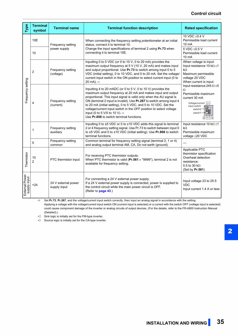
Control circuit
2
Set Pr.73, Pr.267, and the voltage/current input switch correctly, then input an analog signal in accordance with the setting.
Applying a voltage with the voltage/current input switch ON (current input is selected) or a current with the switch OFF (voltage input is selected)
could cause component damage of the inverter or analog circuits of output devices. (For the details, refer to the FR-A800 Instruction Manual
(Detailed).)
Sink logic is initially set for the FM-type inverter.
Source logic is initially set for the CA-type inverter.
Fre
quen
cy s
ettin
g
10EFrequency setting power supply
When connecting the frequency setting potentiometer at an initial status, connect it to terminal 10.Change the input specifications of terminal 2 using Pr.73 when connecting it to terminal 10E.
10 VDC 0.4 VPermissible load current 10 mA
105 VDC 0.5 VPermissible load current 10 mA
2Frequency setting (voltage)
Inputting 0 to 5 VDC (or 0 to 10 V, 0 to 20 mA) provides the maximum output frequency at 5 V (10 V, 20 mA) and makes input and output proportional. Use Pr.73 to switch among input 0 to 5 VDC (initial setting), 0 to 10 VDC, and 0 to 20 mA. Set the voltage/current input switch in the ON position to select current input (0 to 20 mA).
When voltage is input:Input resistance 10 k1 kMaximum permissible voltage 20 VDCWhen current is input:Input resistance 245 5 Permissible maximum current 30 mA
4Frequency setting (current)
Inputting 4 to 20 mADC (or 0 to 5 V, 0 to 10 V) provides the maximum output frequency at 20 mA and makes input and output proportional. This input signal is valid only when the AU signal is ON (terminal 2 input is invalid). Use Pr.267 to switch among input 4 to 20 mA (initial setting), 0 to 5 VDC, and 0 to 10 VDC. Set the voltage/current input switch in the OFF position to select voltage input (0 to 5 V/0 to 10 V). Use Pr.858 to switch terminal functions.
1Frequency setting auxiliary
Inputting 0 to ±5 VDC or 0 to ±10 VDC adds this signal to terminal 2 or 4 frequency setting signal. Use Pr.73 to switch between input 0 to ±5 VDC and 0 to ±10 VDC (initial setting). Use Pr.868 to switch terminal functions.
Input resistance 10 k 1 kPermissible maximum voltage 20 VDC
5Frequency setting common
Common terminal for frequency setting signal (terminal 2, 1 or 4) and analog output terminal AM, CA. Do not earth (ground).
—
The
rmis
tor
102
PTC thermistor inputFor receiving PTC thermistor outputs.When PTC thermistor is valid (Pr.561 "9999"), terminal 2 is not available for frequency setting.
Applicable PTC thermistor specificationOverheat detection resistance:0.5 to 30 k(Set by Pr.561)
Ext
erna
l Pow
er
supp
ly in
put
+2424 V external power supply input
For connecting a 24 V external power supply.If a 24 V external power supply is connected, power is supplied to the control circuit while the main power circuit is OFF.(Refer to page 43.)
Input voltage 23 to 25.5 VDCInput current 1.4 A or less
Type Terminal
symbol Terminal name Terminal function description Rated specification
Voltage/currentinput switch
2 4
switch1switch2
INSTALLATION AND WIRING 35
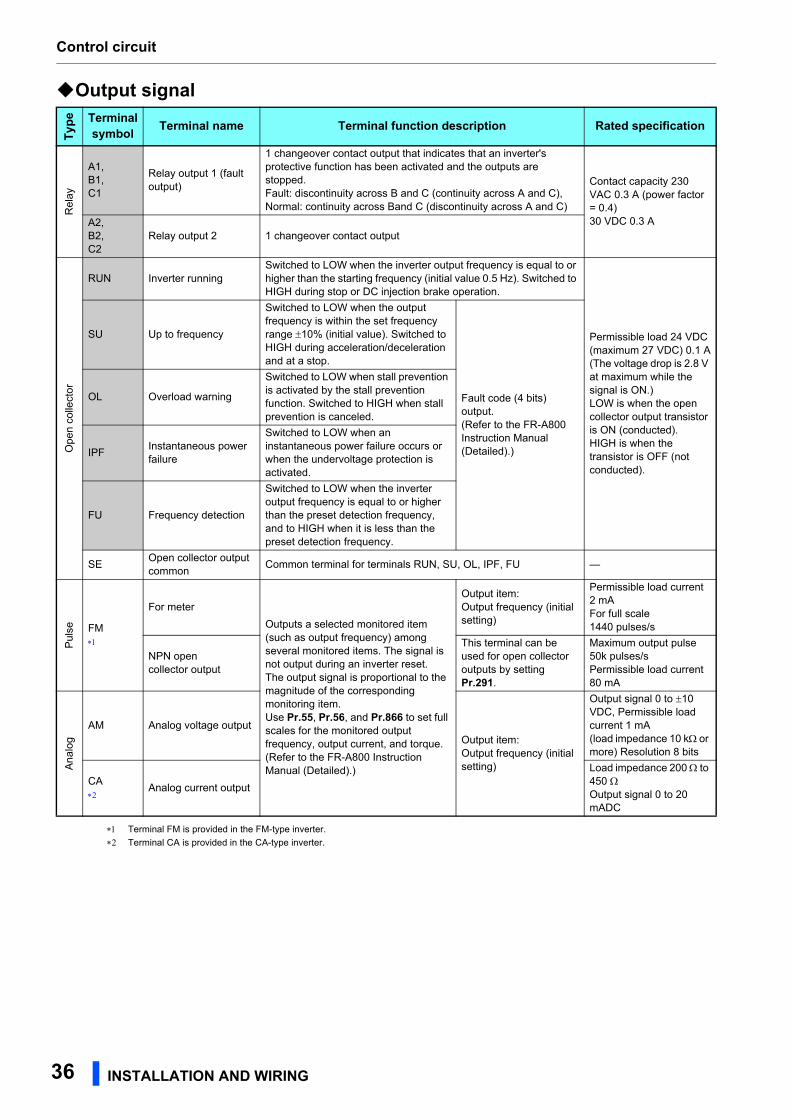
Control circuit
Output signal
Terminal FM is provided in the FM-type inverter.
Terminal CA is provided in the CA-type inverter.
Type Terminal
symbol Terminal name Terminal function description Rated specification
Rel
ay
A1,B1,C1
Relay output 1 (fault output)
1 changeover contact output that indicates that an inverter's protective function has been activated and the outputs are stopped.Fault: discontinuity across B and C (continuity across A and C), Normal: continuity across Band C (discontinuity across A and C)
Contact capacity 230 VAC 0.3 A (power factor = 0.4)30 VDC 0.3 AA2,
B2,C2
Relay output 2 1 changeover contact output
Ope
n c
olle
ctor
RUN Inverter runningSwitched to LOW when the inverter output frequency is equal to or higher than the starting frequency (initial value 0.5 Hz). Switched to HIGH during stop or DC injection brake operation.
Permissible load 24 VDC (maximum 27 VDC) 0.1 A(The voltage drop is 2.8 V at maximum while the signal is ON.)LOW is when the open collector output transistor is ON (conducted).HIGH is when the transistor is OFF (not conducted).
SU Up to frequency
Switched to LOW when the output frequency is within the set frequency range 10% (initial value). Switched to HIGH during acceleration/deceleration and at a stop.
Fault code (4 bits) output. (Refer to the FR-A800 Instruction Manual (Detailed).)
OL Overload warning
Switched to LOW when stall prevention is activated by the stall prevention function. Switched to HIGH when stall prevention is canceled.
IPFInstantaneous power failure
Switched to LOW when an instantaneous power failure occurs or when the undervoltage protection is activated.
FU Frequency detection
Switched to LOW when the inverter output frequency is equal to or higher than the preset detection frequency, and to HIGH when it is less than the preset detection frequency.
SEOpen collector output common
Common terminal for terminals RUN, SU, OL, IPF, FU —
Pul
se FM
For meter
Outputs a selected monitored item (such as output frequency) among several monitored items. The signal is not output during an inverter reset.The output signal is proportional to the magnitude of the corresponding monitoring item.Use Pr.55, Pr.56, and Pr.866 to set full scales for the monitored output frequency, output current, and torque.(Refer to the FR-A800 Instruction Manual (Detailed).)
Output item:Output frequency (initial setting)
Permissible load current 2 mAFor full scale1440 pulses/s
NPN open collector output
This terminal can be used for open collector outputs by setting Pr.291.
Maximum output pulse 50k pulses/sPermissible load current 80 mA
An
alog
AM Analog voltage outputOutput item:Output frequency (initial setting)
Output signal 0 to 10 VDC, Permissible load current 1 mA(load impedance 10 k or more) Resolution 8 bits
CA
Analog current output
Load impedance 200 to 450 Output signal 0 to 20 mADC
36 INSTALLATION AND WIRING
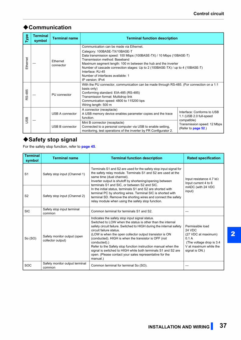
Control circuit
2
Communication
Safety stop signalFor the safety stop function, refer to page 45.
Type Terminal
symbol Terminal name Terminal function description
Eth
erne
t
—Ethernet connector
Communication can be made via Ethernet.
Category: 100BASE-TX/10BASE-TData transmission speed: 100 Mbps (100BASE-TX) / 10 Mbps (10BASE-T)Transmission method: BasebandMaximum segment length: 100 m between the hub and the inverterNumber of cascade connection stages: Up to 2 (100BASE-TX) / up to 4 (10BASE-T)Interface: RJ-45Number of interfaces available: 1IP version: IPv4
RS
-485
— PU connector
With the PU connector, communication can be made through RS-485. (For connection on a 1:1 basis only)Conforming standard: EIA-485 (RS-485)Transmission format: Multidrop linkCommunication speed: 4800 to 115200 bpsWiring length: 500 m
US
B
—
USB A connectorA connector (receptacle)A USB memory device enables parameter copies and the trace function.
Interface: Conforms to USB 1.1 (USB 2.0 full-speed compatible)Transmission speed: 12 Mbps(Refer to page 52.)USB B connector
Mini B connector (receptacle)Connected to a personal computer via USB to enable setting, monitoring, test operations of the inverter by FR Configurator 2.
Terminalsymbol Terminal name Terminal function description Rated specification
S1 Safety stop input (Channel 1)
Terminals S1 and S2 are used for the safety stop input signal for the safety relay module. Terminals S1 and S2 are used at the same time (dual channel).Inverter output is shutoff by shortening/opening between terminals S1 and SIC, or between S2 and SIC.In the initial status, terminals S1 and S2 are shorted with terminal PC by shorting wires. Terminal SIC is shorted with terminal SD. Remove the shorting wires and connect the safety relay module when using the safety stop function.
Input resistance 4.7 kInput current 4 to 6 mADC (with 24 VDC input)
S2 Safety stop input (Channel 2)
SICSafety stop input terminal common
Common terminal for terminals S1 and S2. —
So (SO)Safety monitor output (open collector output)
Indicates the safety stop input signal status.Switched to LOW when the status is other than the internal safety circuit failure. Switched to HIGH during the internal safety circuit failure status.(LOW is when the open collector output transistor is ON (conducted). HIGH is when the transistor is OFF (not conducted).)Refer to the Safety stop function instruction manual when the signal is switched to HIGH while both terminals S1 and S2 are open. (Please contact your sales representative for the manual.)
Permissible load24 VDC (27 VDC at maximum)0.1 A (The voltage drop is 3.4 V at maximum while the signal is ON.)
SOCSafety monitor output terminal common
Common terminal for terminal So (SO). —
INSTALLATION AND WIRING 37
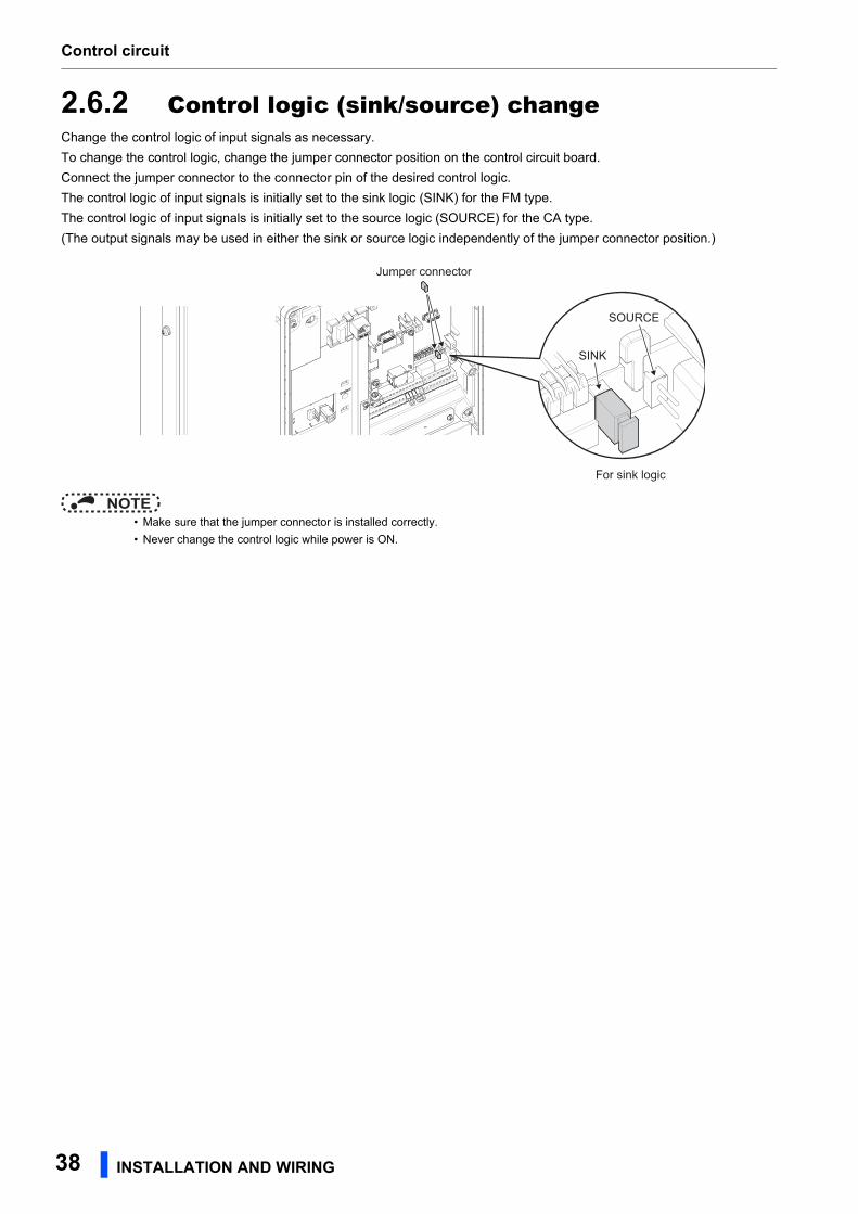
Control circuit
2.6.2 Control logic (sink/source) changeChange the control logic of input signals as necessary.
To change the control logic, change the jumper connector position on the control circuit board.
Connect the jumper connector to the connector pin of the desired control logic.
The control logic of input signals is initially set to the sink logic (SINK) for the FM type.
The control logic of input signals is initially set to the source logic (SOURCE) for the CA type.
(The output signals may be used in either the sink or source logic independently of the jumper connector position.)
NOTE • Make sure that the jumper connector is installed correctly.
• Never change the control logic while power is ON.
SOURCE
SINK
For sink logic
Jumper connector
38 INSTALLATION AND WIRING
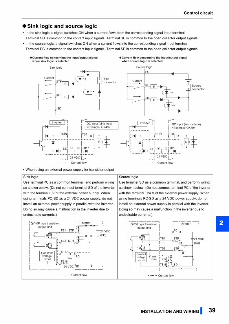
Control circuit
2
Sink logic and source logic • In the sink logic, a signal switches ON when a current flows from the corresponding signal input terminal.
Terminal SD is common to the contact input signals. Terminal SE is common to the open collector output signals.
• In the source logic, a signal switches ON when a current flows into the corresponding signal input terminal.
Terminal PC is common to the contact input signals. Terminal SE is common to the open collector output signals.
• When using an external power supply for transistor output
Sink logic
Use terminal PC as a common terminal, and perform wiring
as shown below. (Do not connect terminal SD of the inverter
with the terminal 0 V of the external power supply. When
using terminals PC-SD as a 24 VDC power supply, do not
install an external power supply in parallel with the inverter.
Doing so may cause a malfunction in the inverter due to
undesirable currents.)
Source logic
Use terminal SD as a common terminal, and perform wiring
as shown below. (Do not connect terminal PC of the inverter
with the terminal +24 V of the external power supply. When
using terminals PC-SD as a 24 VDC power supply, do not
install an external power supply in parallel with the inverter.
Doing so may cause a malfunction in the inverter due to
undesirable currents.)
Current
PC
STF R
STR R
Source logic
Sourceconnector
Current
SD
STFR
STR R
Sinkconnector
Sink logic
Current flow concerning the input/output signal when sink logic is selected
Current flow concerning the input/output signal when source logic is selected
DC input (source type)<Example: QX80>
24 VDC
RUN
SE
TB1
TB18
R
Inverter
R
Current flow
+ -+-
DC input (sink type)<Example: QX40>
Inverter
24 VDC
RUN
SE
TB1
TB17
R
R
Current flow
QY40P type transistor output unit
TB1
TB2
TB17
TB18
24 VDC SD
PC
STR
STF
Inverter
24 VDC(SD)
Current flow
Constant voltage circuit
QY80 type transistor output unit
Constant voltage circuit
PC
TB1
TB2
TB17Fuse
TB18
STF
STR
SD
Inverter
24 VDC(SD)
24 V
DC
Current flow
INSTALLATION AND WIRING 39
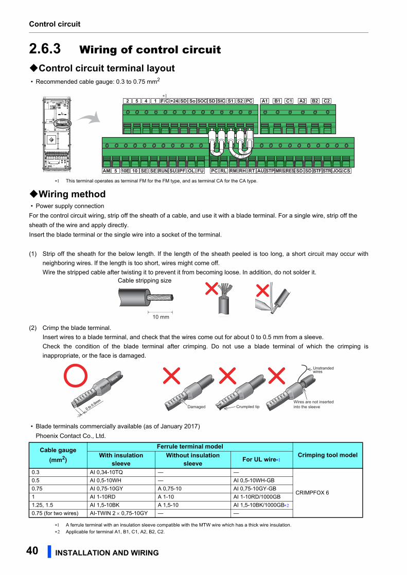
Control circuit
2.6.3 Wiring of control circuitControl circuit terminal layout • Recommended cable gauge: 0.3 to 0.75 mm2
This terminal operates as terminal FM for the FM type, and as terminal CA for the CA type.
Wiring method • Power supply connection
For the control circuit wiring, strip off the sheath of a cable, and use it with a blade terminal. For a single wire, strip off the
sheath of the wire and apply directly.
Insert the blade terminal or the single wire into a socket of the terminal.
(1) Strip off the sheath for the below length. If the length of the sheath peeled is too long, a short circuit may occur with
neighboring wires. If the length is too short, wires might come off.
Wire the stripped cable after twisting it to prevent it from becoming loose. In addition, do not solder it.
(2) Crimp the blade terminal.
Insert wires to a blade terminal, and check that the wires come out for about 0 to 0.5 mm from a sleeve.
Check the condition of the blade terminal after crimping. Do not use a blade terminal of which the crimping is
inappropriate, or the face is damaged.
• Blade terminals commercially available (as of January 2017)
Phoenix Contact Co., Ltd.
A ferrule terminal with an insulation sleeve compatible with the MTW wire which has a thick wire insulation.
Applicable for terminal A1, B1, C1, A2, B2, C2.
Cable stripping size
Cable gauge (mm2)
Ferrule terminal modelCrimping tool modelWith insulation
sleeveWithout insulation
sleeve For UL wire
0.3 AI 0,34-10TQ — —
CRIMPFOX 6
0.5 AI 0,5-10WH — AI 0,5-10WH-GB
0.75 AI 0,75-10GY A 0,75-10 AI 0,75-10GY-GB
1 AI 1-10RD A 1-10 AI 1-10RD/1000GB
1.25, 1.5 AI 1,5-10BK A 1,5-10 AI 1,5-10BK/1000GB
0.75 (for two wires) AI-TWIN 2 0,75-10GY — —
AM
2 5 4 1 F/C +24 SD SD S1 S2 PC A1 B1 C1 A2 B2 C2SICSo SOC
5 10E 10 SE SE SURUN IPF OL FU PC RL RM RH RT AU SD SD CSSTP MRS RES STF STR JOG
∗1
10 mm
Crumpled tipWires are not insertedinto the sleeve
Unstrandedwires
Damaged
WireWire
SleeveSleeve
0 to 0.5mm
0 to 0.5mm
40 INSTALLATION AND WIRING
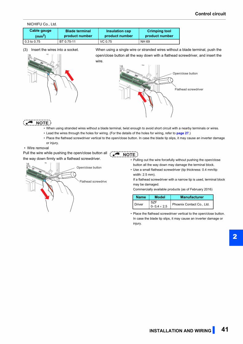
Control circuit
2
NICHIFU Co., Ltd.
NOTE • When using stranded wires without a blade terminal, twist enough to avoid short circuit with a nearby terminals or wires.
• Lead the wires through the holes for wiring. (For the details of the holes for wiring, refer to page 27.)
• Place the flathead screwdriver vertical to the open/close button. In case the blade tip slips, it may cause an inverter damage
or injury.
• Wire removal
Cable gauge (mm2)
Blade terminal product number
Insulation cap product number
Crimping toolproduct number
0.3 to 0.75 BT 0.75-11 VC 0.75 NH 69
(3) Insert the wires into a socket. When using a single wire or stranded wires without a blade terminal, push the
open/close button all the way down with a flathead screwdriver, and insert the
wire.
Pull the wire while pushing the open/close button all
the way down firmly with a flathead screwdriver.NOTE
• Pulling out the wire forcefully without pushing the open/close
button all the way down may damage the terminal block.
• Use a small flathead screwdriver (tip thickness: 0.4 mm/tip
width: 2.5 mm).
If a flathead screwdriver with a narrow tip is used, terminal block
may be damaged.
Commercially available products (as of February 2016)
• Place the flathead screwdriver vertical to the open/close button.
In case the blade tip slips, it may cause an inverter damage or
injury.
Flathead screwdriver
Open/close button
Flathead screwdrive
Open/close button
Name Model Manufacturer
DriverSZF 0- 0,4 2,5
Phoenix Contact Co., Ltd.
INSTALLATION AND WIRING 41
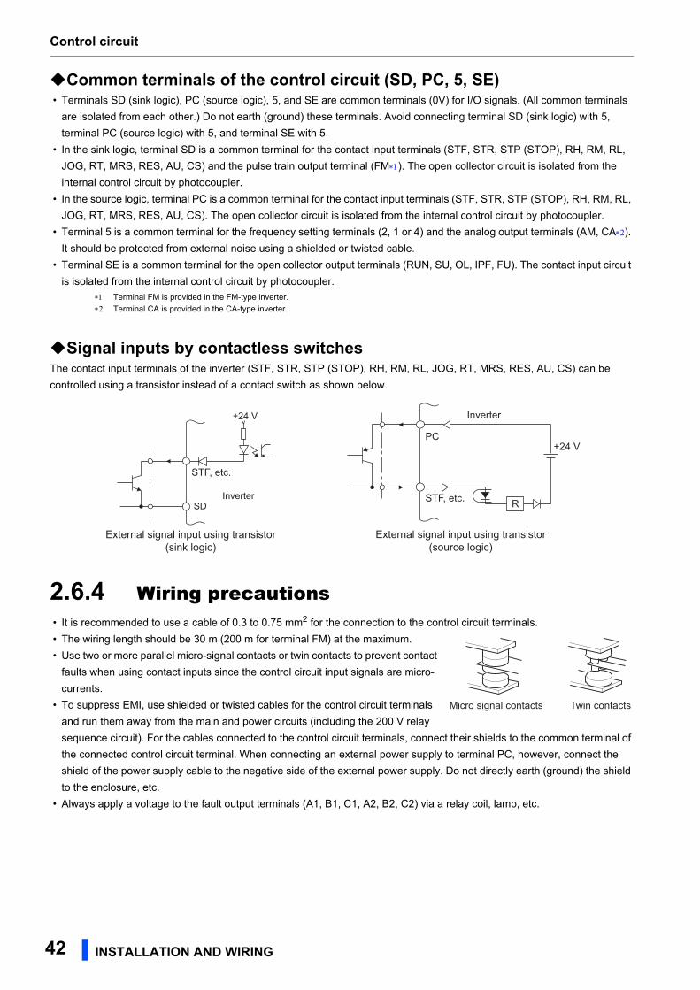
Control circuit
Common terminals of the control circuit (SD, PC, 5, SE) • Terminals SD (sink logic), PC (source logic), 5, and SE are common terminals (0V) for I/O signals. (All common terminals
are isolated from each other.) Do not earth (ground) these terminals. Avoid connecting terminal SD (sink logic) with 5,
terminal PC (source logic) with 5, and terminal SE with 5.
• In the sink logic, terminal SD is a common terminal for the contact input terminals (STF, STR, STP (STOP), RH, RM, RL,
JOG, RT, MRS, RES, AU, CS) and the pulse train output terminal (FM). The open collector circuit is isolated from the
internal control circuit by photocoupler.
• In the source logic, terminal PC is a common terminal for the contact input terminals (STF, STR, STP (STOP), RH, RM, RL,
JOG, RT, MRS, RES, AU, CS). The open collector circuit is isolated from the internal control circuit by photocoupler.
• Terminal 5 is a common terminal for the frequency setting terminals (2, 1 or 4) and the analog output terminals (AM, CA).
It should be protected from external noise using a shielded or twisted cable.
• Terminal SE is a common terminal for the open collector output terminals (RUN, SU, OL, IPF, FU). The contact input circuit
is isolated from the internal control circuit by photocoupler.
Terminal FM is provided in the FM-type inverter.
Terminal CA is provided in the CA-type inverter.
Signal inputs by contactless switchesThe contact input terminals of the inverter (STF, STR, STP (STOP), RH, RM, RL, JOG, RT, MRS, RES, AU, CS) can be
controlled using a transistor instead of a contact switch as shown below.
2.6.4 Wiring precautions • It is recommended to use a cable of 0.3 to 0.75 mm2 for the connection to the control circuit terminals.
• The wiring length should be 30 m (200 m for terminal FM) at the maximum.
• Use two or more parallel micro-signal contacts or twin contacts to prevent contact
faults when using contact inputs since the control circuit input signals are micro-
currents.
• To suppress EMI, use shielded or twisted cables for the control circuit terminals
and run them away from the main and power circuits (including the 200 V relay
sequence circuit). For the cables connected to the control circuit terminals, connect their shields to the common terminal of
the connected control circuit terminal. When connecting an external power supply to terminal PC, however, connect the
shield of the power supply cable to the negative side of the external power supply. Do not directly earth (ground) the shield
to the enclosure, etc.
• Always apply a voltage to the fault output terminals (A1, B1, C1, A2, B2, C2) via a relay coil, lamp, etc.
+24 V
STF, etc.
SDInverter
External signal input using transistor(sink logic)
PC
RSTF, etc.
+24 V
Inverter
External signal input using transistor(source logic)
Micro signal contacts Twin contacts
42 INSTALLATION AND WIRING
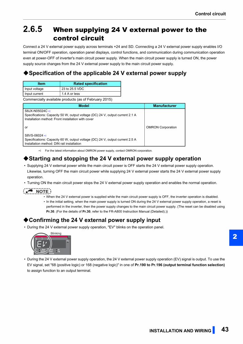
Control circuit
2
2.6.5 When supplying 24 V external power to the control circuit
Connect a 24 V external power supply across terminals +24 and SD. Connecting a 24 V external power supply enables I/O
terminal ON/OFF operation, operation panel displays, control functions, and communication during communication operation
even at power-OFF of inverter's main circuit power supply. When the main circuit power supply is turned ON, the power
supply source changes from the 24 V external power supply to the main circuit power supply.
Specification of the applicable 24 V external power supply
Commercially available products (as of February 2015)
For the latest information about OMRON power supply, contact OMRON corporation.
Starting and stopping the 24 V external power supply operation • Supplying 24 V external power while the main circuit power is OFF starts the 24 V external power supply operation.
Likewise, turning OFF the main circuit power while supplying 24 V external power starts the 24 V external power supply
operation.
• Turning ON the main circuit power stops the 24 V external power supply operation and enables the normal operation.
NOTE • When the 24 V external power is supplied while the main circuit power supply is OFF, the inverter operation is disabled.
• In the initial setting, when the main power supply is turned ON during the 24 V external power supply operation, a reset is
performed in the inverter, then the power supply changes to the main circuit power supply. (The reset can be disabled using
Pr.30. (For the details of Pr.30, refer to the FR-A800 Instruction Manual (Detailed).))
Confirming the 24 V external power supply input • During the 24 V external power supply operation, "EV" blinks on the operation panel.
• During the 24 V external power supply operation, the 24 V external power supply operation (EV) signal is output. To use the
EV signal, set "68 (positive logic) or 168 (negative logic)" in one of Pr.190 to Pr.196 (output terminal function selection) to assign function to an output terminal.
Item Rated specificationInput voltage 23 to 25.5 VDC
Input current 1.4 A or less
Model ManufacturerS8JX-N05024C Specifications: Capacity 50 W, output voltage (DC) 24 V, output current 2.1 AInstallation method: Front installation with cover
or
S8VS-06024 Specifications: Capacity 60 W, output voltage (DC) 24 V, output current 2.5 AInstallation method: DIN rail installation
OMRON Corporation
Blinking
INSTALLATION AND WIRING 43
Control circuit
Operation while the 24 V external power is supplied • Fault history and parameters can be read and parameters can be written (when the parameter write from the operation
panel is enabled) using the operation panel keys.
• The safety stop function is invalid during the 24 V external power supply operation.
• During the 24 V external power supply operation, monitored items and signals related to inputs to main circuit power supply,
such as output current and converter output voltage are invalid.
• The faults, which have occurred when the main circuit power supply is ON, continue to be output after the power supply is
changed to the 24 V external power supply. Perform the inverter reset or turn OFF then ON the power to reset the faults.
• If the power supply changes from the main circuit power supply to the 24 V external power supply while measuring the main
circuit capacitor's life, the measurement completes after the power supply changes back to the main circuit power supply
(Pr.259 = "3").
• The output data is retained when "1 or 11" is set in Pr.495 Remote output selection.
NOTE • Inrush current equal to or higher than the 24 V external power supply specification may flow at power-ON. Confirm that the
power supply and other devices are not affected by the inrush current and the voltage drop caused by it. Depending on the
power supply, the inrush current protection may be activated and disable the power supply. Select the power supply and
capacity carefully.
• When the wiring length between the external power supply and the inverter is long, the voltage often drops. Select the
appropriate wiring size and length to keep the voltage in the rated input voltage range.
• In a serial connection of several inverters, the current increases when it flows through the inverter wiring near the power
supply. The increase of the current causes voltage to drop further. When connecting different inverters to different power
supplies, use the inverters after confirming that the input voltage of each inverter is within the rated input voltage range.
Depending on the power supply, the over current protection may be activated and disable the power supply. Select the power
supply and capacity carefully.
• "E.SAF or E.P24" may appear when the start-up time of the 24 V power supply is too long (less than 1.5 V/s) in the 24 V
external power supply operation.
• "E.P24" may appear when the 24 V external power supply input voltage is low. Check the external power supply input.
• Do not touch the control circuit terminal block (circuit board) during the 24 V power supply operation (when conducted).
Otherwise you may get an electric shock or burn.
44 INSTALLATION AND WIRING
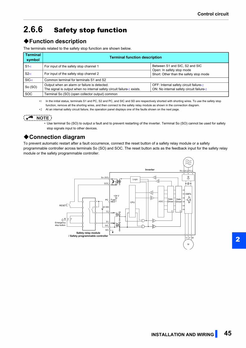
Control circuit
2
2.6.6 Safety stop functionFunction descriptionThe terminals related to the safety stop function are shown below.
In the initial status, terminals S1 and PC, S2 and PC, and SIC and SD are respectively shorted with shorting wires. To use the safety stop
function, remove all the shorting wires, and then connect to the safety relay module as shown in the connection diagram.
At an internal safety circuit failure, the operation panel displays one of the faults shown on the next page.
NOTE • Use terminal So (SO) to output a fault and to prevent restarting of the inverter. Terminal So (SO) cannot be used for safety
stop signals input to other devices.
Connection diagramTo prevent automatic restart after a fault occurrence, connect the reset button of a safety relay module or a safety programmable controller across terminals So (SO) and SOC. The reset button acts as the feedback input for the safety relay module or the safety programmable controller.
Terminal symbol Terminal function description
S1 For input of the safety stop channel 1 Between S1 and SIC, S2 and SICOpen: In safety stop modeShort: Other than the safety stop modeS2 For input of the safety stop channel 2
SIC Common terminal for terminals S1 and S2
So (SO)Output when an alarm or failure is detected.The signal is output when no internal safety circuit failure exists.
OFF: Internal safety circuit failureON: No internal safety circuit failure
SOC Terminal So (SO) (open collector output) common
R/L1 S/L2 T/L3
U V W
M
So (SO)
SOC
S1
S2 G G
ASIC
Inverter
SIC
SD
Logic
RESET
Emergency stop button
Safety relay module/ Safety programmable controller
PC GateDriver
GateDriver
IGBTs
Fuse
24 VDC
CPU
+24 V
INSTALLATION AND WIRING 45
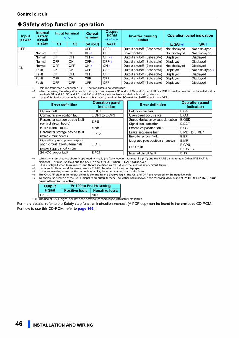
Control circuit
Safety stop function operation
ON: The transistor is conducted. OFF: The transistor is not conducted. When not using the safety stop function, short across terminals S1 and PC, S2 and PC, and SIC and SD to use the inverter. (In the initial status,
terminals S1 and PC, S2 and PC, and SIC and SD are respectively shorted with shorting wires.) If any of the faults shown in the following table occurs, terminal So (SO) and the SAFE signal turns OFF.
When the internal safety circuit is operated normally (no faults occurs), terminal So (SO) and the SAFE signal remain ON until "E.SAF" is displayed. Terminal So (SO) and the SAFE signal turn OFF when "E.SAF" is displayed.
SA is displayed when terminals S1 and S2 are identified as OFF due to the internal safety circuit failure. If another fault occurs at the same time as E.SAF, the other fault can be displayed. If another warning occurs at the same time as SA, the other warning can be displayed. The ON/OFF state of the output signal is the one for the positive logic. The ON and OFF are reversed for the negative logic. To assign the function of the SAFE signal to an output terminal, set either value shown in the following table in any of Pr.190 to Pr.196 (Output
terminal function selection).
The use of SAFE signal has not been certified for compliance with safety standards.
For more details, refer to the Safety stop function instruction manual. (A PDF copy can be found in the enclosed CD-ROM. For how to use this CD-ROM, refer to page 146.)
Input power
Internal safety circuit status
Input terminal,
Output terminal
Output signal,,
Inverter running status
Operation panel indication
S1 S2 So (SO) SAFE E.SAF SAOFF ― ― ― OFF OFF Output shutoff (Safe state) Not displayed Not displayed
ON
Normal ON ON ON OFF Drive enabled Not displayed Not displayedNormal ON OFF OFF OFF Output shutoff (Safe state) Displayed DisplayedNormal OFF ON OFF OFF Output shutoff (Safe state) Displayed DisplayedNormal OFF OFF ON ON Output shutoff (Safe state) Not displayed DisplayedFault ON ON OFF OFF Output shutoff (Safe state) Displayed Not displayedFault ON OFF OFF OFF Output shutoff (Safe state) Displayed DisplayedFault OFF ON OFF OFF Output shutoff (Safe state) Displayed DisplayedFault OFF OFF OFF OFF Output shutoff (Safe state) Displayed Displayed
Output signal
Pr.190 to Pr.196 settingPositive logic Negative logic
SAFE 80 180
Error definition Operation panel indication
Option fault E.OPTCommunication option fault E.OP1 to E.OP3Parameter storage device fault (control circuit board)
E.PE
Retry count excess E.RETParameter storage device fault (main circuit board)
E.PE2
Operation panel power supply short circuit/RS-485 terminals power supply short circuit
E.CTE
24 VDC power fault E.P24
Safety circuit fault E.SAFOverspeed occurrence E.OSSpeed deviation excess detection E.OSDSignal loss detection E.ECTExcessive position fault E.ODBrake sequence fault E.MB1 to E.MB7Encoder phase fault E.EPMagnetic pole position unknown E.MP
CPU faultE.CPUE.5 to E.7
Internal circuit fault E.13
Error definition Operation panel indication
46
IN STALLATION AND WIRING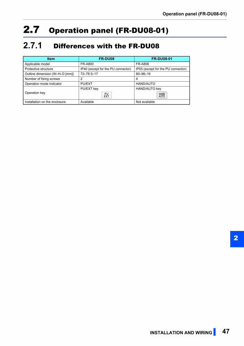
Operation panel (FR-DU08-01)
2
2.7 Operation panel (FR-DU08-01)
2.7.1 Differences with the FR-DU08
Item FR-DU08 FR-DU08-01Applicable model FR-A800 FR-A806
Protective structure IP40 (except for the PU connector) IP55 (except for the PU connector)
Outline dimension (WHD [mm]) 7278.517 809619
Number of fixing screws 2 4
Operation mode indicator PU/EXT HAND/AUTO
Operation keyPU/EXT key HAND/AUTO key
Installation on the enclosure Available Not available
INSTALLATION AND WIRING 47
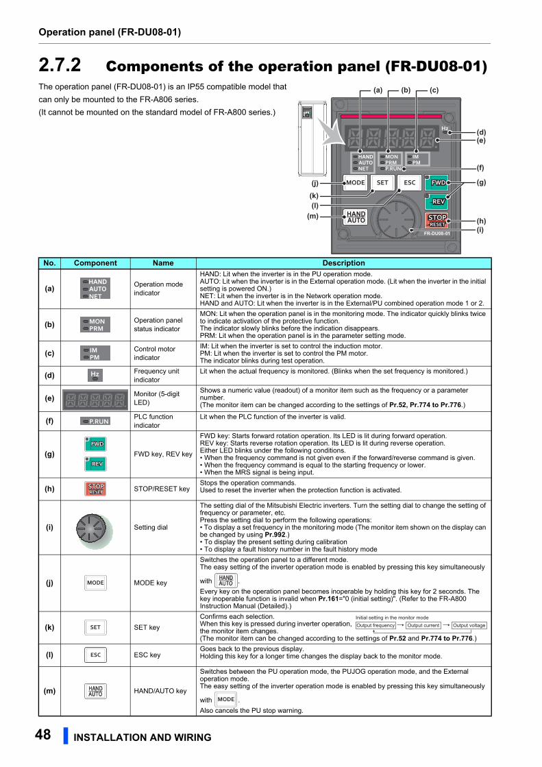
Operation panel (FR-DU08-01)
2.7.2 Components of the operation panel (FR-DU08-01)The operation panel (FR-DU08-01) is an IP55 compatible model that
can only be mounted to the FR-A806 series.
(It cannot be mounted on the standard model of FR-A800 series.)
No. Component Name Description
(a) Operation mode indicator
HAND: Lit when the inverter is in the PU operation mode.AUTO: Lit when the inverter is in the External operation mode. (Lit when the inverter in the initial setting is powered ON.)NET: Lit when the inverter is in the Network operation mode.HAND and AUTO: Lit when the inverter is in the External/PU combined operation mode 1 or 2.
(b) Operation panel status indicator
MON: Lit when the operation panel is in the monitoring mode. The indicator quickly blinks twice to indicate activation of the protective function.The indicator slowly blinks before the indication disappears.PRM: Lit when the operation panel is in the parameter setting mode.
(c) Control motor indicator
IM: Lit when the inverter is set to control the induction motor.PM: Lit when the inverter is set to control the PM motor.The indicator blinks during test operation.
(d) Frequency unit indicator
Lit when the actual frequency is monitored. (Blinks when the set frequency is monitored.)
(e) Monitor (5-digit LED)
Shows a numeric value (readout) of a monitor item such as the frequency or a parameter number.(The monitor item can be changed according to the settings of Pr.52, Pr.774 to Pr.776.)
(f) PLC function indicator
Lit when the PLC function of the inverter is valid.
(g) FWD key, REV key
FWD key: Starts forward rotation operation. Its LED is lit during forward operation.REV key: Starts reverse rotation operation. Its LED is lit during reverse operation.Either LED blinks under the following conditions.• When the frequency command is not given even if the forward/reverse command is given.• When the frequency command is equal to the starting frequency or lower.• When the MRS signal is being input.
(h) STOP/RESET keyStops the operation commands.Used to reset the inverter when the protection function is activated.
(i) Setting dial
The setting dial of the Mitsubishi Electric inverters. Turn the setting dial to change the setting of frequency or parameter, etc.Press the setting dial to perform the following operations:• To display a set frequency in the monitoring mode (The monitor item shown on the display can be changed by using Pr.992.)• To display the present setting during calibration• To display a fault history number in the fault history mode
(j) MODE key
Switches the operation panel to a different mode.The easy setting of the inverter operation mode is enabled by pressing this key simultaneously
with .
Every key on the operation panel becomes inoperable by holding this key for 2 seconds. The key inoperable function is invalid when Pr.161="0 (initial setting)". (Refer to the FR-A800 Instruction Manual (Detailed).)
(k) SET key
Confirms each selection.When this key is pressed during inverter operation, the monitor item changes.(The monitor item can be changed according to the settings of Pr.52 and Pr.774 to Pr.776.)
(l) ESC keyGoes back to the previous display.Holding this key for a longer time changes the display back to the monitor mode.
(m) HAND/AUTO key
Switches between the PU operation mode, the PUJOG operation mode, and the External operation mode.The easy setting of the inverter operation mode is enabled by pressing this key simultaneously
with .
Also cancels the PU stop warning.
(a)
(d)(e)
(g)
(f)
(h)(i)
(j)(k)(l)
(m)
(b) (c)
Output frequencyInitial setting in the monitor mode
Output current Output voltage
48 INSTALLATION AND WIRING
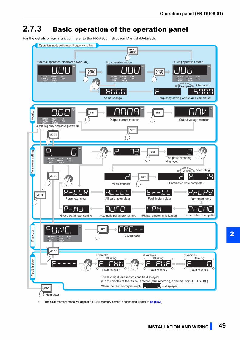
Operation panel (FR-DU08-01)
2
2.7.3 Basic operation of the operation panelFor the details of each function, refer to the FR-A800 Instruction Manual (Detailed).
The USB memory mode will appear if a USB memory device is connected. (Refer to page 52.)
Operation mode switchover/Frequency setting
Func
tion
Mon
itor
Para
met
er s
ettin
gFa
ult h
isto
ry Blinking Blinking Blinking
External operation mode (At power-ON)
Output frequency monitor (At power-ON)
PU operation mode PU Jog operation mode
Output current monitor Output voltage monitor
Value change
(Example)
Frequency setting written and complete!!
Alternating
The last eight fault records can be displayed.(On the display of the last fault record (fault record 1), a decimal point LED is ON.)
The present settingdisplayed
Value change Parameter write complete!!
Alternating(Example)
(Example) (Example) (Example)
Parameter copy
Initial value change listIPM parameter initialization
Parameter clear All parameter clear Fault history clear
Automatic parameter setting
Trace function
∗1
Fault record 1 Fault record 2 Fault record 8
When the fault history is empty, is displayed.
Group parameter setting
Hold down
INSTALLATION AND WIRING 49
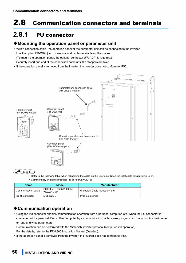
Communication connectors and terminals
2.8 Communication connectors and terminals
2.8.1 PU connectorMounting the operation panel or parameter unit • With a connection cable, the operation panel or the parameter unit can be connected to the inverter.
Use the option FR-CB2[ ], or connectors and cables available on the market.
(To mount the operation panel, the optional connector (FR-ADP) is required.)
Securely insert one end of the connection cable until the stoppers are fixed.
• If the operation panel is removed from the inverter, the inverter does not conform to IP55.
NOTE • Refer to the following table when fabricating the cable on the user side. Keep the total cable length within 20 m.
• Commercially available products (as of February 2015)
Communication operation • Using the PU connector enables communication operation from a personal computer, etc. When the PU connector is
connected with a personal, FA or other computer by a communication cable, a user program can run to monitor the inverter
or read and write parameters.
Communication can be performed with the Mitsubishi inverter protocol (computer link operation).
For the details, refer to the FR-A800 Instruction Manual (Detailed).
• If the operation panel is removed from the inverter, the inverter does not conform to IP55.
STF FWD PU
Parameter unit connection cable(FR-CB2[ ]) (option)
Operation panel(FR-DU08-01)
Parameter unit(FR-PU07) (option)
Operation panel connection connector(FR-ADP) (option)
Operation panel(FR-LU08-01) (option)
Name Model Manufacturer
Communication cableSGLPEV-T (Cat5e/300 m) 24AWG 4P
Mitsubishi Cable Industries, Ltd.
RJ-45 connector 5-554720-3 Tyco Electronics
50 INSTALLATION AND WIRING
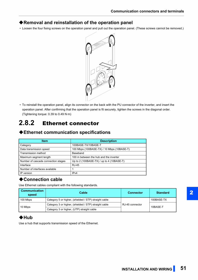
Communication connectors and terminals
2
Removal and reinstallation of the operation panel • Loosen the four fixing screws on the operation panel and pull out the operation panel. (These screws cannot be removed.)
• To reinstall the operation panel, align its connector on the back with the PU connector of the inverter, and insert the
operation panel. After confirming that the operation panel is fit securely, tighten the screws in the diagonal order.
(Tightening torque: 0.39 to 0.49 N·m)
2.8.2 Ethernet connectorEthernet communication specifications
Connection cableUse Ethernet cables compliant with the following standards.
HubUse a hub that supports transmission speed of the Ethernet.
Item DescriptionCategory 100BASE-TX/10BASE-T
Data transmission speed 100 Mbps (100BASE-TX) / 10 Mbps (10BASE-T)
Transmission method Baseband
Maximum segment length 100 m between the hub and the inverter
Number of cascade connection stages Up to 2 (100BASE-TX) / up to 4 (10BASE-T)
Interface RJ-45
Number of interfaces available 1
IP version IPv4
Communication speed Cable Connector Standard
100 Mbps Category 5 or higher, (shielded / STP) straight cable
RJ-45 connector
100BASE-TX
10 MbpsCategory 3 or higher, (shielded / STP) straight cable
10BASE-TCategory 3 or higher, (UTP) straight cable
INSTALLATION AND WIRING 51
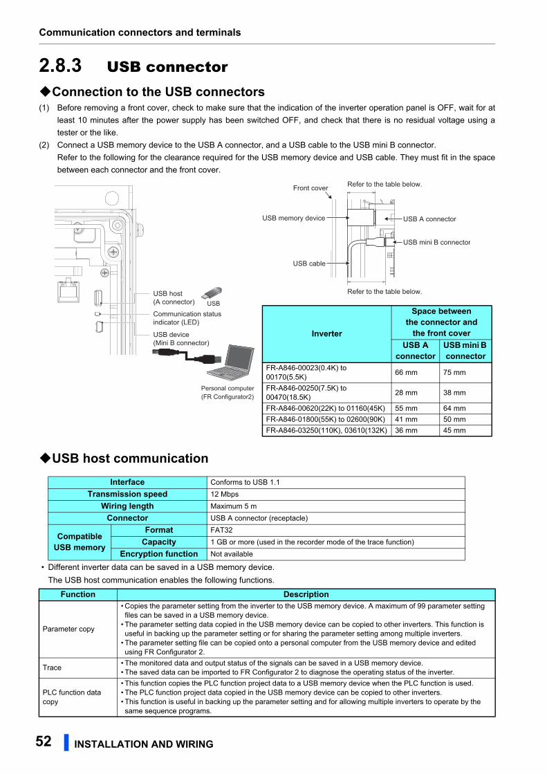
Communication connectors and terminals
2.8.3 USB connectorConnection to the USB connectors(1) Before removing a front cover, check to make sure that the indication of the inverter operation panel is OFF, wait for at
least 10 minutes after the power supply has been switched OFF, and check that there is no residual voltage using a
tester or the like.
(2) Connect a USB memory device to the USB A connector, and a USB cable to the USB mini B connector.
Refer to the following for the clearance required for the USB memory device and USB cable. They must fit in the space
between each connector and the front cover.
USB host communication
• Different inverter data can be saved in a USB memory device.
The USB host communication enables the following functions.
Interface Conforms to USB 1.1
Transmission speed 12 Mbps
Wiring length Maximum 5 m
Connector USB A connector (receptacle)
Compatible USB memory
Format FAT32
Capacity 1 GB or more (used in the recorder mode of the trace function)
Encryption function Not available
Function Description
Parameter copy
• Copies the parameter setting from the inverter to the USB memory device. A maximum of 99 parameter setting files can be saved in a USB memory device.
• The parameter setting data copied in the USB memory device can be copied to other inverters. This function is useful in backing up the parameter setting or for sharing the parameter setting among multiple inverters.
• The parameter setting file can be copied onto a personal computer from the USB memory device and edited using FR Configurator 2.
Trace• The monitored data and output status of the signals can be saved in a USB memory device.• The saved data can be imported to FR Configurator 2 to diagnose the operating status of the inverter.
PLC function data copy
• This function copies the PLC function project data to a USB memory device when the PLC function is used.• The PLC function project data copied in the USB memory device can be copied to other inverters.• This function is useful in backing up the parameter setting and for allowing multiple inverters to operate by the same sequence programs.
USB mini B connector
USB cable
USB memory device
Front cover
USB A connector
Refer to the table below.
Refer to the table below.USB host(A connector)
USB device(Mini B connector)
Communication status indicator (LED)
Personal computer (FR Configurator2)
USB
Inverter
Space between the connector and
the front coverUSB A
connectorUSB mini B connector
FR-A846-00023(0.4K) to 00170(5.5K)
66 mm 75 mm
FR-A846-00250(7.5K) to 00470(18.5K)
28 mm 38 mm
FR-A846-00620(22K) to 01160(45K) 55 mm 64 mm
FR-A846-01800(55K) to 02600(90K) 41 mm 50 mm
FR-A846-03250(110K), 03610(132K) 36 mm 45 mm
52 INSTALLATION AND WIRING
Communication connectors and terminals
2
• When the inverter recognizes the USB memory device without any problem, " " is briefly displayed on the
operation panel.
• When the USB memory device is removed, " " is briefly displayed on the operation panel.
• The operating status of the USB host can be checked on the LED display of the inverter.
• When a device such as a USB battery charger is connected to the USB connector and an excessive current (500 mA or
more) flows, USB host error " " (UF warning) is displayed on the operation panel.
• When the UF warning appears, the USB error can be canceled by removing the USB device and setting Pr.1049 = "1". (The
UF warning can also be canceled by resetting the inverter power or resetting with the RES signal.)
NOTE • Do not connect devices other than a USB memory device to the inverter.
• If a USB device is connected to the inverter via a USB hub, the inverter cannot recognize the USB memory device properly.
• For the details of the usage of the USB connector, refer to the FR-A800 Instruction Manual (Detailed).
USB device communicationThe inverter can be connected to a personal computer with a USB (Ver. 1.1) cable.
Parameter setting and monitoring can be performed by FR Configurator 2.
NOTE • For the details of FR Configurator 2, refer to the Instruction Manual of FR Configurator 2.
LED display status Operating statusOFF No USB connection.
ON The communication is established between the inverter and the USB device.
Blinking rapidly The USB memory device is being accessed. (Do not remove the USB memory device.)
Blinking slowly Error in the USB connection.
Interface Conforms to USB 1.1
Transmission speed 12 Mbps
Wiring length Maximum 5 m
Connector USB mini B connector (receptacle)
Power supply Self-powered
WARNING While power is ON or when the inverter is running, do not open the front cover. Otherwise you may
get an electric shock.
INSTALLATION AND WIRING 53
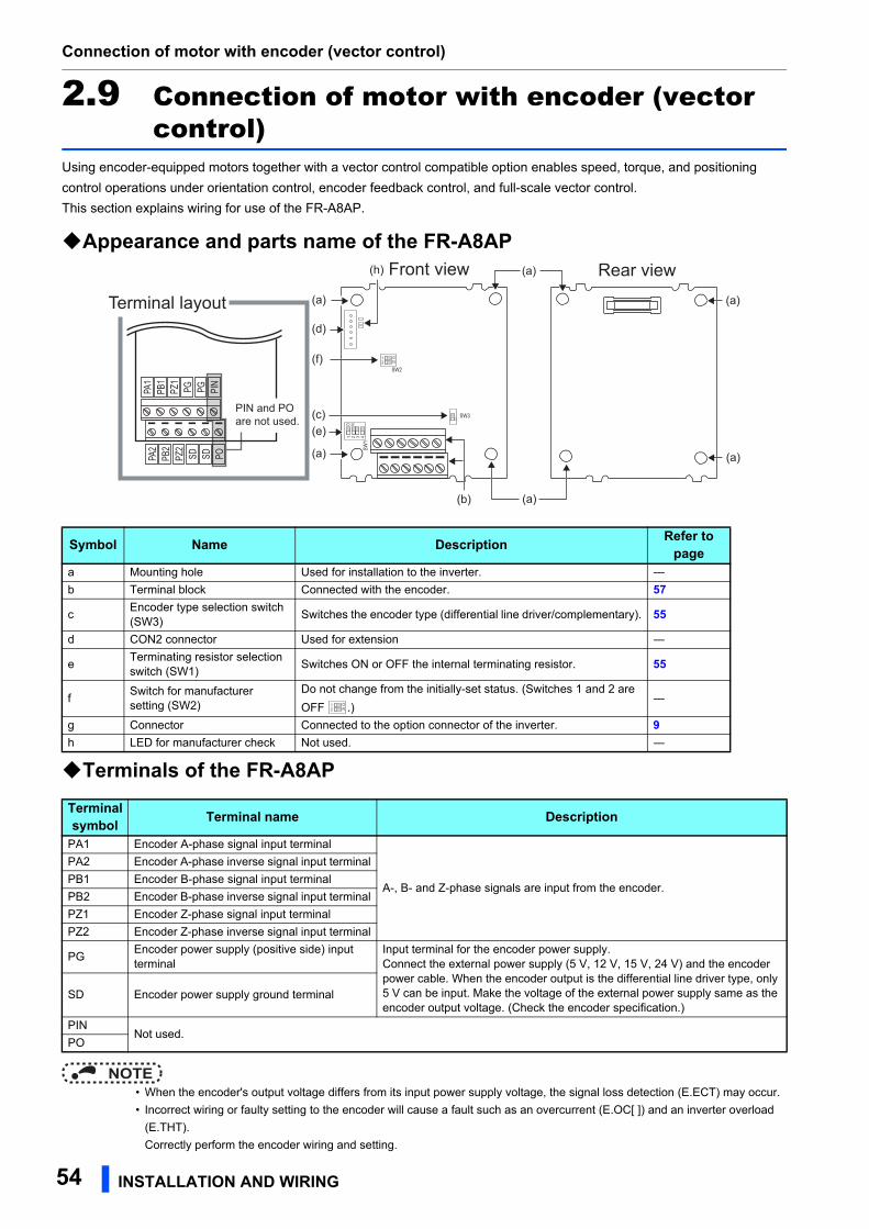
Connection of motor with encoder (vector control)
2.9 Connection of motor with encoder (vector control)
Using encoder-equipped motors together with a vector control compatible option enables speed, torque, and positioning
control operations under orientation control, encoder feedback control, and full-scale vector control.
This section explains wiring for use of the FR-A8AP.
Appearance and parts name of the FR-A8AP
Terminals of the FR-A8AP
NOTE • When the encoder's output voltage differs from its input power supply voltage, the signal loss detection (E.ECT) may occur.
• Incorrect wiring or faulty setting to the encoder will cause a fault such as an overcurrent (E.OC[ ]) and an inverter overload
(E.THT).
Correctly perform the encoder wiring and setting.
Symbol Name Description Refer to page
a Mounting hole Used for installation to the inverter. ―
b Terminal block Connected with the encoder. 57
cEncoder type selection switch (SW3)
Switches the encoder type (differential line driver/complementary). 55
d CON2 connector Used for extension ―
eTerminating resistor selection switch (SW1)
Switches ON or OFF the internal terminating resistor. 55
fSwitch for manufacturer setting (SW2)
Do not change from the initially-set status. (Switches 1 and 2 are
OFF .)―
g Connector Connected to the option connector of the inverter. 9h LED for manufacturer check Not used. ―
Terminal symbol Terminal name Description
PA1 Encoder A-phase signal input terminal
A-, B- and Z-phase signals are input from the encoder.
PA2 Encoder A-phase inverse signal input terminal
PB1 Encoder B-phase signal input terminal
PB2 Encoder B-phase inverse signal input terminal
PZ1 Encoder Z-phase signal input terminal
PZ2 Encoder Z-phase inverse signal input terminal
PGEncoder power supply (positive side) input terminal
Input terminal for the encoder power supply.Connect the external power supply (5 V, 12 V, 15 V, 24 V) and the encoder power cable. When the encoder output is the differential line driver type, only 5 V can be input. Make the voltage of the external power supply same as the encoder output voltage. (Check the encoder specification.)
SD Encoder power supply ground terminal
PINNot used.
PO
Front view Rear view
Terminal layout
PA2
PB2
PZ2
SD SD PO
PA1
PB1
PZ1
PG PG PIN
PIN and PO are not used.
1 2 3 4
O N12
ON
SW2
SW3
SW1
(a)
(a)
(a)(b)
(a)(a)
(a)
(e)
(d)
(f)
(c)
(h)
12
ON
54 INSTALLATION AND WIRING
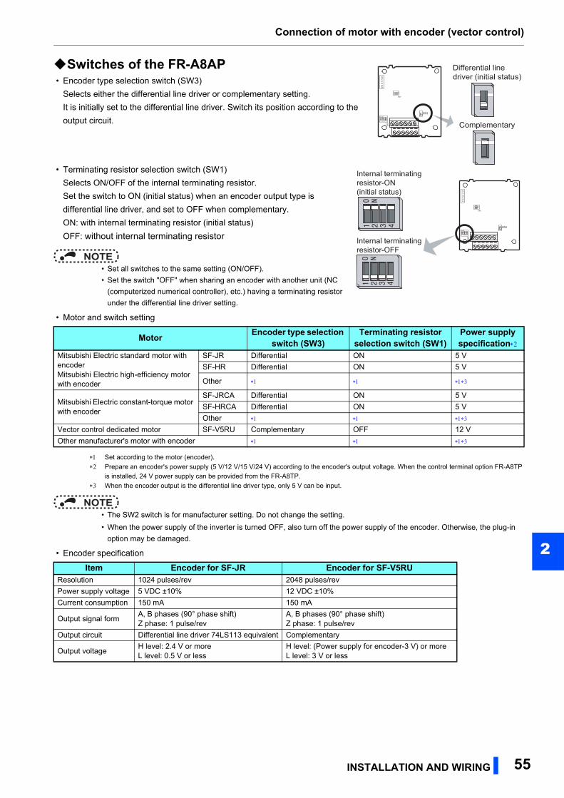
Connection of motor with encoder (vector control)
2
Switches of the FR-A8AP • Encoder type selection switch (SW3)
Selects either the differential line driver or complementary setting.
It is initially set to the differential line driver. Switch its position according to the
output circuit.
• Terminating resistor selection switch (SW1)
Selects ON/OFF of the internal terminating resistor.
Set the switch to ON (initial status) when an encoder output type is
differential line driver, and set to OFF when complementary.
ON: with internal terminating resistor (initial status)
OFF: without internal terminating resistor
NOTE • Set all switches to the same setting (ON/OFF).
• Set the switch "OFF" when sharing an encoder with another unit (NC
(computerized numerical controller), etc.) having a terminating resistor
under the differential line driver setting.
• Motor and switch setting
Set according to the motor (encoder).
Prepare an encoder's power supply (5 V/12 V/15 V/24 V) according to the encoder's output voltage. When the control terminal option FR-A8TP
is installed, 24 V power supply can be provided from the FR-A8TP.
When the encoder output is the differential line driver type, only 5 V can be input.
NOTE • The SW2 switch is for manufacturer setting. Do not change the setting.
• When the power supply of the inverter is turned OFF, also turn off the power supply of the encoder. Otherwise, the plug-in
option may be damaged.
• Encoder specification
Motor Encoder type selection switch (SW3)
Terminating resistor selection switch (SW1)
Power supply specification
Mitsubishi Electric standard motor with encoderMitsubishi Electric high-efficiency motor with encoder
SF-JR Differential ON 5 V
SF-HR Differential ON 5 V
Other
Mitsubishi Electric constant-torque motor with encoder
SF-JRCA Differential ON 5 V
SF-HRCA Differential ON 5 V
Other
Vector control dedicated motor SF-V5RU Complementary OFF 12 V
Other manufacturer's motor with encoder
Item Encoder for SF-JR Encoder for SF-V5RUResolution 1024 pulses/rev 2048 pulses/rev
Power supply voltage 5 VDC ±10% 12 VDC ±10%
Current consumption 150 mA 150 mA
Output signal formA, B phases (90° phase shift)Z phase: 1 pulse/rev
A, B phases (90° phase shift)Z phase: 1 pulse/rev
Output circuit Differential line driver 74LS113 equivalent Complementary
Output voltageH level: 2.4 V or moreL level: 0.5 V or less
H level: (Power supply for encoder-3 V) or moreL level: 3 V or less
Complementary
Differential linedriver (initial status)
1 2 3 4
O N
12
ON
SW2
SW3
SW1
Internal terminatingresistor-ON(initial status)
Internal terminating resistor-OFF
1 2 3 4
O N
12
ON
SW2
SW3
SW1
INSTALLATION AND WIRING 55
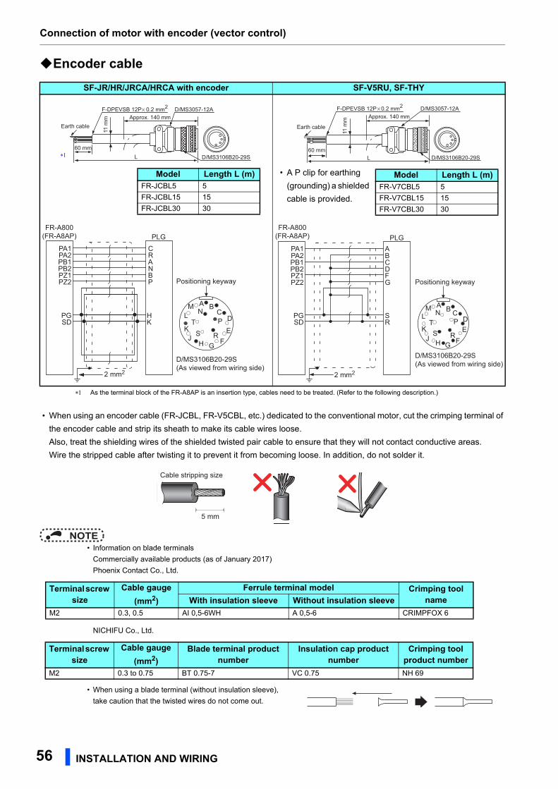
Connection of motor with encoder (vector control)
Encoder cable
As the terminal block of the FR-A8AP is an insertion type, cables need to be treated. (Refer to the following description.)
• When using an encoder cable (FR-JCBL, FR-V5CBL, etc.) dedicated to the conventional motor, cut the crimping terminal of
the encoder cable and strip its sheath to make its cable wires loose.
Also, treat the shielding wires of the shielded twisted pair cable to ensure that they will not contact conductive areas.
Wire the stripped cable after twisting it to prevent it from becoming loose. In addition, do not solder it.
NOTE • Information on blade terminals
Commercially available products (as of January 2017)
Phoenix Contact Co., Ltd.
NICHIFU Co., Ltd.
• When using a blade terminal (without insulation sleeve),
take caution that the twisted wires do not come out.
SF-JR/HR/JRCA/HRCA with encoder SF-V5RU, SF-THY
F-DPEVSB 12P 0.2 mm2
Earth cableApprox. 140 mm
60 mmL
D/MS3057-12A
D/MS3106B20-29S
11 m
m
Model Length L (m)FR-JCBL5 5
FR-JCBL15 15
FR-JCBL30 30
PZ2PZ1PB2PB1PA2PA1
PGSD
PBNARC
HK
PLG
2 mm2
A BC
D
EK
FGHJ
LM
S
N
R
PT
D/MS3106B20-29S(As viewed from wiring side)
Positioning keyway
FR-A800(FR-A8AP)
Earth cable
F-DPEVSB 12P 0.2 mm2
L D/MS3106B20-29S
D/MS3057-12A
11 m
m
60 mm
Approx. 140 mm
Model Length L (m)FR-V7CBL5 5
FR-V7CBL15 15
FR-V7CBL30 30
• A P clip for earthing
(grounding) a shielded
cable is provided.
PZ2PZ1PB2PB1PA2PA1
SDPG
GFDCBA
RS
PLG
2 mm2
FR-A800(FR-A8AP)
A B CDEK
FGHJ
LM
S
N
R
PT
D/MS3106B20-29S(As viewed from wiring side)
Positioning keyway
5 mm
Cable stripping size
Terminal screw size
Cable gauge (mm2)
Ferrule terminal model Crimping tool nameWith insulation sleeve Without insulation sleeve
M2 0.3, 0.5 AI 0,5-6WH A 0,5-6 CRIMPFOX 6
Terminal screw size
Cable gauge (mm2)
Blade terminal product number
Insulation cap product number
Crimping tool product number
M2 0.3 to 0.75 BT 0.75-7 VC 0.75 NH 69
56 INSTALLATION AND WIRING
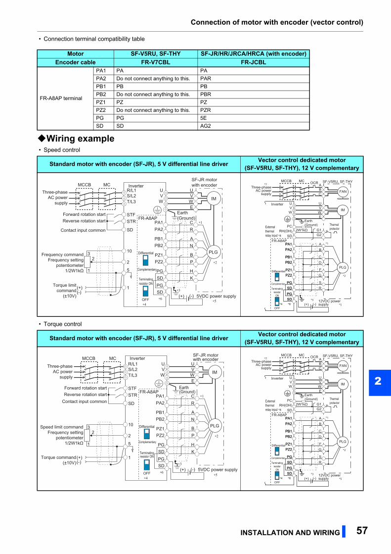
Connection of motor with encoder (vector control)
2
• Connection terminal compatibility table
Wiring example • Speed control
• Torque control
Motor SF-V5RU, SF-THY SF-JR/HR/JRCA/HRCA (with encoder)Encoder cable FR-V7CBL FR-JCBL
FR-A8AP terminal
PA1 PA PA
PA2 Do not connect anything to this. PAR
PB1 PB PB
PB2 Do not connect anything to this. PBR
PZ1 PZ PZ
PZ2 Do not connect anything to this. PZR
PG PG 5E
SD SD AG2
Standard motor with encoder (SF-JR), 5 V differential line driver Vector control dedicated motor (SF-V5RU, SF-THY), 12 V complementary
Standard motor with encoder (SF-JR), 5 V differential line driver Vector control dedicated motor (SF-V5RU, SF-THY), 12 V complementary
Three-phaseAC power
supply
MCCB MCR/L1S/L2T/L3
SF-JR motorwith encoder
UVW
UVWE
C
∗3
∗1
∗2
∗4∗6
RPA1
FR-A8AP
PA2
PB1PB2
PZ1PZ2
PG
PGSD
SD
Differential
Terminatingresistor ON
OFF
Complementary
AN
BP
HK
IM
Forward rotation startReverse rotation start
Contact input common
STFSTR
SD
PLG
Earth(Ground)
Inverter
10
22
3
1
Torque limitcommand
(±10V)
1
Frequency commandFrequency setting
potentiometer1/2W1kΩ 5
(+)(-)
5VDC power supply(+) (-)∗5
*4 *6*3
PA1FR-A8AP
PA2
PB1PB2
PZ1PZ2
PG
PGSD
SD
*1
Differential
Terminatingresistor
ON
OFF
Complementary
SF-V5RU, SF-THY
UVW
U
ABC
VWE
G1G2
A
Earth(Ground)
*2
Three-phaseAC power
supply
MCCB MC OCR
BPA1PA2
PB1PB2
PZ1PZ2
PG
PGSD
SD
CD
FG
SR
IM
FAN
PLG
Externalthermalrelay input *8
Thermalprotector
*7
RH(OH)SD
Inverter
PC2W1kΩ
12VDC power supply(+) (-) *5
R/L1S/L2T/L3
SF-JR motorwith encoder
UVW
UVWE
C
∗3
∗1
∗2
∗4∗6
RPA1
FR-A8AP
PA2
PB1PB2
PZ1PZ2
PG
PGSD
SD
Differential
Terminatingresistor ON
OFF
Complementary
AN
BP
HK
IM
Forward rotation startReverse rotation start
Contact input common
STFSTR
SD
PLG
Earth(Ground)
Inverter
5VDC power supply(+) (-)∗5
10
22
3
1
Torque command(±10V)
1
Speed limit commandFrequency setting
potentiometer1/2W1kΩ 5
(+)(-)
Three-phaseAC power
supply
MCCB MC
*4 *6*3
PA1FR-A8AP
PA2
PB1PB2
PZ1PZ2
PG
PGSD
SD
*1
Differential
Terminatingresistor
ON
OFF
Complementary
SF-V5RU, SF-THY
UVW
U
ABC
VWE
G1G2
A
Earth(Ground)
*2
Three-phaseAC power
supply
MCCB MC OCR
BPA1PA2
PB1PB2
PZ1PZ2
PG
PGSD
SD
CD
FG
SR
IM
FAN
PLG
Externalthermalrelay input *8
Thermalprotector
*7
RH(OH)SD
Inverter
PC2W1kΩ
12VDC power supply(+) (-) *5
INSTALLATION AND WIRING 57
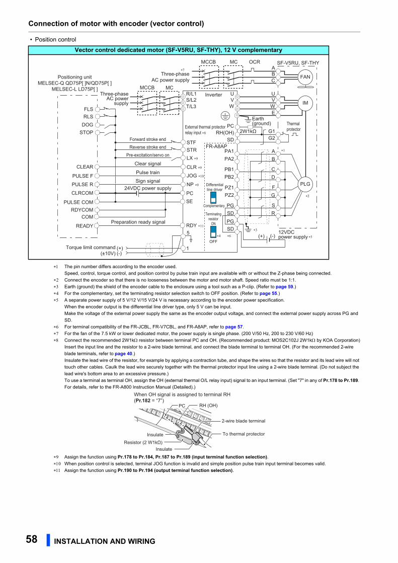
Connection of motor with encoder (vector control)
• Position control
The pin number differs according to the encoder used.
Speed, control, torque control, and position control by pulse train input are available with or without the Z-phase being connected.
Connect the encoder so that there is no looseness between the motor and motor shaft. Speed ratio must be 1:1.
Earth (ground) the shield of the encoder cable to the enclosure using a tool such as a P-clip. (Refer to page 59.)
For the complementary, set the terminating resistor selection switch to OFF position. (Refer to page 55.)
A separate power supply of 5 V/12 V/15 V/24 V is necessary according to the encoder power specification.
When the encoder output is the differential line driver type, only 5 V can be input.
Make the voltage of the external power supply the same as the encoder output voltage, and connect the external power supply across PG and
SD.
For terminal compatibility of the FR-JCBL, FR-V7CBL, and FR-A8AP, refer to page 57.
For the fan of the 7.5 kW or lower dedicated motor, the power supply is single phase. (200 V/50 Hz, 200 to 230 V/60 Hz)
Connect the recommended 2W1k resistor between terminal PC and OH. (Recommended product: MOS2C102J 2W1k by KOA Corporation)
Insert the input line and the resistor to a 2-wire blade terminal, and connect the blade terminal to terminal OH. (For the recommended 2-wire
blade terminals, refer to page 40.)
Insulate the lead wire of the resistor, for example by applying a contraction tube, and shape the wires so that the resistor and its lead wire will not
touch other cables. Caulk the lead wire securely together with the thermal protector input line using a 2-wire blade terminal. (Do not subject the
lead wire's bottom area to an excessive pressure.)
To use a terminal as terminal OH, assign the OH (external thermal O/L relay input) signal to an input terminal. (Set "7" in any of Pr.178 to Pr.189.
For details, refer to the FR-A800 Instruction Manual (Detailed).)
Assign the function using Pr.178 to Pr.184, Pr.187 to Pr.189 (input terminal function selection). When position control is selected, terminal JOG function is invalid and simple position pulse train input terminal becomes valid.
Assign the function using Pr.190 to Pr.194 (output terminal function selection).
Vector control dedicated motor (SF-V5RU, SF-THY), 12 V complementary
Torque limit command(±10V)
1
5
(+)(-)
Three-phaseAC power
supply
MCCBR/L1S/L2T/L3
∗4 ∗6
∗3
PA1FR-A8AP
PA2
PB1PB2
PZ1PZ2
PG
PGSD
SD
Forward stroke endReverse stroke end
Pre-excitation/servo on
Clear signal
Pulse train
Sign signal
Preparation ready signal
STFSTRLX ∗9
CLR ∗9CLEAR
JOG ∗10
NP ∗9
∗1
Differentialline driver
Terminatingresistor
ON
OFF
SF-V5RU, SF-THY
UVW
U
ABC
VWE
G1G2
A
Earth(ground)
∗2
Three-phaseAC power supply
MCCB MC OCR
B
CD
FG
SR
IM
FAN
PLG
External thermal protectorrelay input ∗8
Thermalprotector
∗7
RH(OH)SD
Inverter
Positioning unitMELSEC-Q QD75P[ ]N/QD75P[ ]
MELSEC-L LD75P[ ]
PC2W1kΩ
12VDC power supply(+) (-) ∗5
PULSE F
PULSE R
PULSE COM
CLRCOM
RDYCOM
READY
PC
RDY ∗11
SE
FLSRLS
DOGSTOP
COM
24VDC power supply
MC
Complementary
PC
Resistor (2 W1kΩ)Insulate
Insulate
RH (OH)
To thermal protector
2-wire blade terminal
When OH signal is assigned to terminal RH(Pr.182 = “7”)
58 INSTALLATION AND WIRING
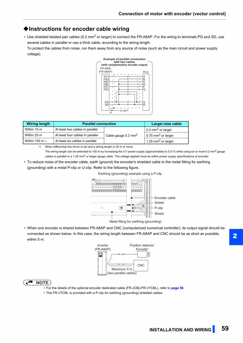
Connection of motor with encoder (vector control)
2
Instructions for encoder cable wiring • Use shielded twisted pair cables (0.2 mm2 or larger) to connect the FR-A8AP. For the wiring to terminals PG and SD, use
several cables in parallel or use a thick cable, according to the wiring length.
To protect the cables from noise, run them away from any source of noise (such as the main circuit and power supply
voltage).
When differential line driver is set and a wiring length is 30 m or more.
The wiring length can be extended to 100 m by increasing the 5 V power supply (approximately to 5.5 V) while using six or more 0.2 mm2 gauge
cables in parallel or a 1.25 mm2 or larger gauge cable. The voltage applied must be within power supply specifications of encoder.
• To reduce noise of the encoder cable, earth (ground) the encoder's shielded cable to the metal fitting for earthing
(grounding) with a metal P-clip or U-clip. Refer to the following figure.
• When one encoder is shared between FR-A8AP and CNC (computerized numerical controller), its output signal should be
connected as shown below. In this case, the wiring length between FR-A8AP and CNC should be as short as possible,
within 5 m.
NOTE • For the details of the optional encoder dedicated cable (FR-JCBL/FR-V7CBL), refer to page 56.
• The FR-V7CBL is provided with a P-clip for earthing (grounding) shielded cables.
Wiring length Parallel connection Larger-size cableWithin 10 m At least two cables in parallel
Cable gauge 0.2 mm2
0.4 mm2 or larger
Within 20 m At least four cables in parallel 0.75 mm2 or larger
Within 100 m At least six cables in parallel 1.25 mm2 or larger
PZ2PZ1
PA1PA2FB1FB2
SDPG
GFDCBA
RS
PLG
2 mm2
FR-A800(FR-A8AP)
Example of parallel connectionwith two cables
(with complementary encoder output)
Metal fitting for earthing (grounding)
Earthing (grounding) example using a P-clip
Encoder cableShieldP-clip
Shield
Maximum 5 m(two parallel cables)
CNC
Inverter(FR-A8AP)
Position detectorEncoder
INSTALLATION AND WIRING 59
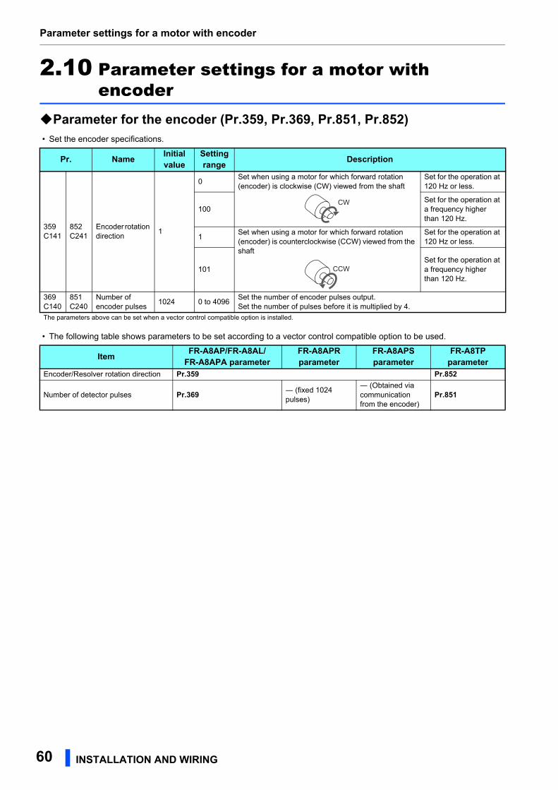
Parameter settings for a motor with encoder
2.10 Parameter settings for a motor with encoder
Parameter for the encoder (Pr.359, Pr.369, Pr.851, Pr.852) • Set the encoder specifications.
• The following table shows parameters to be set according to a vector control compatible option to be used.
Pr. Name Initial value
Setting range Description
359C141
852C241
Encoder rotation direction
1
0Set when using a motor for which forward rotation (encoder) is clockwise (CW) viewed from the shaft
Set for the operation at 120 Hz or less.
100Set for the operation at a frequency higher than 120 Hz.
1Set when using a motor for which forward rotation (encoder) is counterclockwise (CCW) viewed from the shaft
Set for the operation at 120 Hz or less.
101Set for the operation at a frequency higher than 120 Hz.
369C140
851C240
Number of encoder pulses
1024 0 to 4096Set the number of encoder pulses output.Set the number of pulses before it is multiplied by 4.
The parameters above can be set when a vector control compatible option is installed.
Item FR-A8AP/FR-A8AL/FR-A8APA parameter
FR-A8APRparameter
FR-A8APSparameter
FR-A8TPparameter
Encoder/Resolver rotation direction Pr.359 Pr.852
Number of detector pulses Pr.369 ― (fixed 1024 pulses)
― (Obtained via communication from the encoder)
Pr.851
CW
CCW
60 INSTALLATION AND WIRING
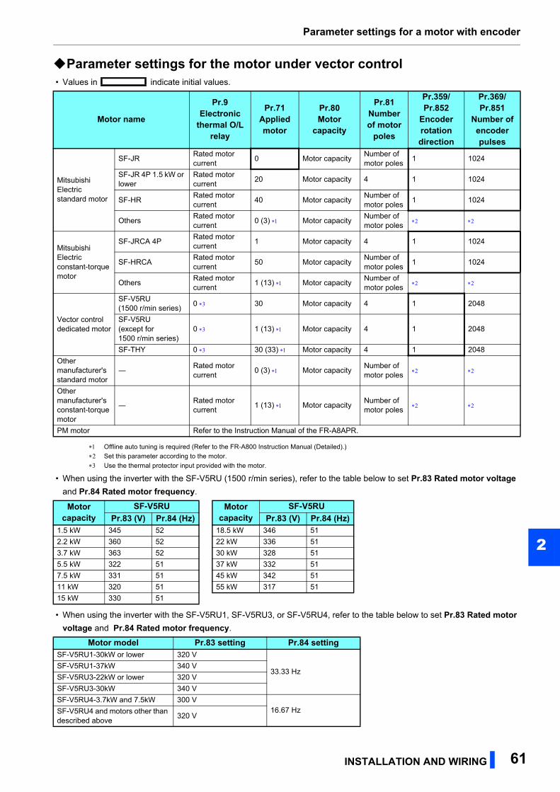
Parameter settings for a motor with encoder
2
Parameter settings for the motor under vector control • Values in indicate initial values.
Offline auto tuning is required (Refer to the FR-A800 Instruction Manual (Detailed).)
Set this parameter according to the motor.
Use the thermal protector input provided with the motor.
• When using the inverter with the SF-V5RU (1500 r/min series), refer to the table below to set Pr.83 Rated motor voltage
and Pr.84 Rated motor frequency.
• When using the inverter with the SF-V5RU1, SF-V5RU3, or SF-V5RU4, refer to the table below to set Pr.83 Rated motor voltage and Pr.84 Rated motor frequency.
Motor name
Pr.9 Electronic
thermal O/L relay
Pr.71 Applied motor
Pr.80 Motor
capacity
Pr.81 Number of motor
poles
Pr.359/Pr.852
Encoder rotation direction
Pr.369/Pr.851
Number of encoder pulses
Mitsubishi Electric standard motor
SF-JRRated motor current
0 Motor capacityNumber of motor poles
1 1024
SF-JR 4P 1.5 kW or lower
Rated motor current
20 Motor capacity 4 1 1024
SF-HRRated motor current
40 Motor capacityNumber of motor poles
1 1024
OthersRated motor current
0 (3) Motor capacityNumber of motor poles
Mitsubishi Electric constant-torque motor
SF-JRCA 4PRated motor current
1 Motor capacity 4 1 1024
SF-HRCARated motor current
50 Motor capacityNumber of motor poles
1 1024
OthersRated motor current
1 (13) Motor capacityNumber of motor poles
Vector control dedicated motor
SF-V5RU(1500 r/min series)
0 30 Motor capacity 4 1 2048
SF-V5RU(except for 1500 r/min series)
0 1 (13) Motor capacity 4 1 2048
SF-THY 0 30 (33) Motor capacity 4 1 2048
Other manufacturer's standard motor
―Rated motor current
0 (3) Motor capacityNumber of motor poles
Other manufacturer's constant-torque motor
―Rated motor current
1 (13) Motor capacityNumber of motor poles
PM motor Refer to the Instruction Manual of the FR-A8APR.
Motor capacity
SF-V5RU Motor capacity
SF-V5RUPr.83 (V) Pr.84 (Hz) Pr.83 (V) Pr.84 (Hz)
1.5 kW 345 52 18.5 kW 346 51
2.2 kW 360 52 22 kW 336 51
3.7 kW 363 52 30 kW 328 51
5.5 kW 322 51 37 kW 332 51
7.5 kW 331 51 45 kW 342 51
11 kW 320 51 55 kW 317 51
15 kW 330 51
Motor model Pr.83 setting Pr.84 setting SF-V5RU1-30kW or lower 320 V
33.33 HzSF-V5RU1-37kW 340 V
SF-V5RU3-22kW or lower 320 V
SF-V5RU3-30kW 340 V
SF-V5RU4-3.7kW and 7.5kW 300 V16.67 HzSF-V5RU4 and motors other than
described above320 V
INSTALLATION AND WIRING 61
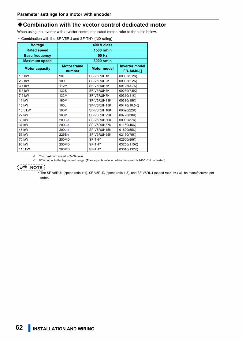
Parameter settings for a motor with encoder
Combination with the vector control dedicated motorWhen using the inverter with a vector control dedicated motor, refer to the table below.
• Combination with the SF-V5RU and SF-THY (ND rating)
The maximum speed is 2400 r/min.
80% output in the high-speed range. (The output is reduced when the speed is 2400 r/min or faster.)
NOTE • The SF-V5RU1 (speed ratio 1:1), SF-V5RU3 (speed ratio 1:3), and SF-V5RU4 (speed ratio 1:4) will be manufactured per
order.
Voltage 400 V classRated speed 1500 r/min
Base frequency 50 HzMaximum speed 3000 r/min
Motor capacity Motor frame number Motor model Inverter model
FR-A846-[]1.5 kW 90L SF-V5RUH1K 00083(2.2K)
2.2 kW 100L SF-V5RUH2K 00083(2.2K)
3.7 kW 112M SF-V5RUH3K 00126(3.7K)
5.5 kW 132S SF-V5RUH5K 00250(7.5K)
7.5 kW 132M SF-V5RUH7K 00310(11K)
11 kW 160M SF-V5RUH11K 00380(15K)
15 kW 160L SF-V5RUH15K 00470(18.5K)
18.5 kW 180M SF-V5RUH18K 00620(22K)
22 kW 180M SF-V5RUH22K 00770(30K)
30 kW 200L SF-V5RUH30K 00930(37K)
37 kW 200L SF-V5RUH37K 01160(45K)
45 kW 200L SF-V5RUH45K 01800(55K)
55 kW 225S SF-V5RUH55K 02160(75K)
75 kW 250MD SF-THY 02600(90K)
90 kW 250MD SF-THY 03250(110K)
110 kW 280MD SF-THY 03610(132K)
62 INSTALLATION AND WIRING
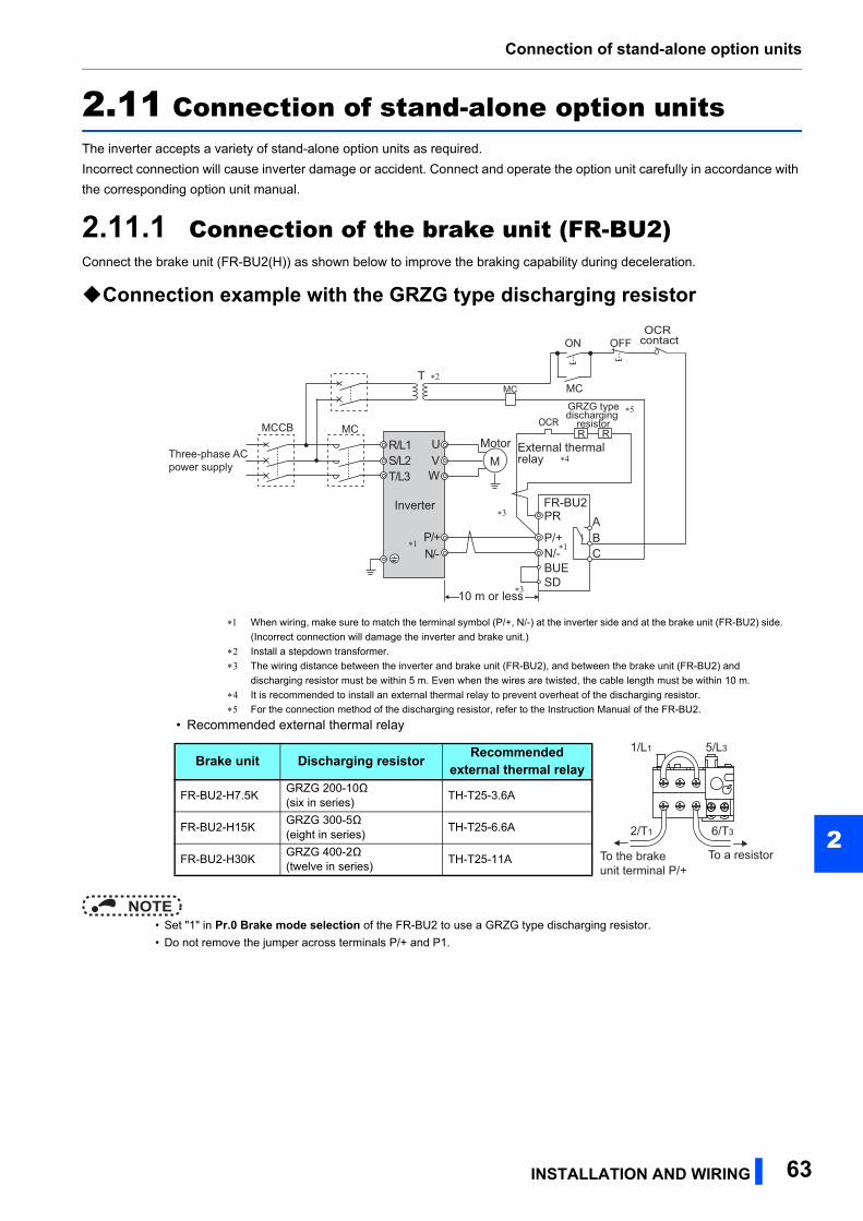
Connection of stand-alone option units
2
2.11 Connection of stand-alone option unitsThe inverter accepts a variety of stand-alone option units as required.
Incorrect connection will cause inverter damage or accident. Connect and operate the option unit carefully in accordance with
the corresponding option unit manual.
2.11.1 Connection of the brake unit (FR-BU2)Connect the brake unit (FR-BU2(H)) as shown below to improve the braking capability during deceleration.
Connection example with the GRZG type discharging resistor
NOTE • Set "1" in Pr.0 Brake mode selection of the FR-BU2 to use a GRZG type discharging resistor.
• Do not remove the jumper across terminals P/+ and P1.
When wiring, make sure to match the terminal symbol (P/+, N/-) at the inverter side and at the brake unit (FR-BU2) side.
(Incorrect connection will damage the inverter and brake unit.)
Install a stepdown transformer.
The wiring distance between the inverter and brake unit (FR-BU2), and between the brake unit (FR-BU2) and
discharging resistor must be within 5 m. Even when the wires are twisted, the cable length must be within 10 m.
It is recommended to install an external thermal relay to prevent overheat of the discharging resistor.
For the connection method of the discharging resistor, refer to the Instruction Manual of the FR-BU2.
• Recommended external thermal relay
∗4
∗1
∗3
∗5
UVW
P/+N/-
R/L1S/L2T/L3
MotorM
InverterPR
N/-BUESD
P/+ABC
FR-BU2
GRZG typedischarging
resistorRR
Three-phase ACpower supply
MCCB MC
OFFON
MCT
10 m or less
OCR contact
MC
External thermalrelay
OCR
∗2
∗1
∗3
Brake unit Discharging resistor Recommended external thermal relay
FR-BU2-H7.5KGRZG 200-10Ω (six in series)
TH-T25-3.6A
FR-BU2-H15KGRZG 300-5Ω (eight in series)
TH-T25-6.6A
FR-BU2-H30KGRZG 400-2Ω (twelve in series)
TH-T25-11A To the brakeunit terminal P/+
To a resistor
1/L1 5/L3
2/T1 6/T3
INSTALLATION AND WIRING 63
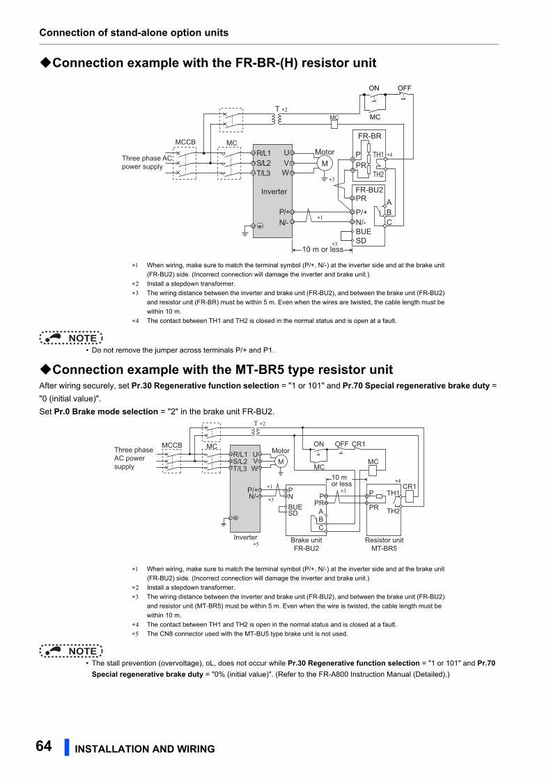
Connection of stand-alone option units
Connection example with the FR-BR-(H) resistor unit
NOTE • Do not remove the jumper across terminals P/+ and P1.
Connection example with the MT-BR5 type resistor unitAfter wiring securely, set Pr.30 Regenerative function selection = "1 or 101" and Pr.70 Special regenerative brake duty =
"0 (initial value)".
Set Pr.0 Brake mode selection = "2" in the brake unit FR-BU2.
NOTE • The stall prevention (overvoltage), oL, does not occur while Pr.30 Regenerative function selection = "1 or 101" and Pr.70
Special regenerative brake duty = "0% (initial value)". (Refer to the FR-A800 Instruction Manual (Detailed).)
When wiring, make sure to match the terminal symbol (P/+, N/-) at the inverter side and at the brake unit
(FR-BU2) side. (Incorrect connection will damage the inverter and brake unit.)
Install a stepdown transformer.
The wiring distance between the inverter and brake unit (FR-BU2), and between the brake unit (FR-BU2)
and resistor unit (FR-BR) must be within 5 m. Even when the wires are twisted, the cable length must be
within 10 m.
The contact between TH1 and TH2 is closed in the normal status and is open at a fault.
When wiring, make sure to match the terminal symbol (P/+, N/-) at the inverter side and at the brake unit
(FR-BU2) side. (Incorrect connection will damage the inverter and brake unit.)
Install a stepdown transformer.
The wiring distance between the inverter and brake unit (FR-BU2), and between the brake unit (FR-BU2)
and resistor unit (MT-BR5) must be within 5 m. Even when the wire is twisted, the cable length must be
within 10 m.
The contact between TH1 and TH2 is open in the normal status and is closed at a fault.
The CN8 connector used with the MT-BU5 type brake unit is not used.
UVW
P/+N/-
R/L1S/L2T/L3
MotorM
InverterPR
N/-BUESD
P/+
P
ABC
FR-BU2
FR-BR
TH2
TH1PR
Three phase ACpower supply
MCCB MC
OFFON
MCT ∗2
∗1
10 m or less
MC
∗3
∗3
∗4
MCR/L1 Motor
M
Inverter
S/L2T/L3
UV
P/+N/- P
PR
10 m or less
W
Three phase AC power supply
MCCB
TH1
TH2
MC
CR1
OFFON
MC
CR1
Τ ∗2
∗3∗1
∗3
∗5
∗4
PNBUESD
PPR
Brake unitFR-BU2
Resistor unitMT-BR5
ABC
64 INSTALLATION AND WIRING
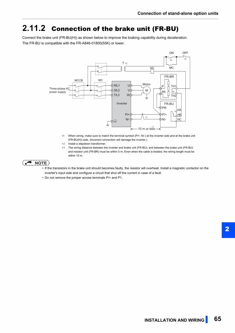
Connection of stand-alone option units
2
2.11.2 Connection of the brake unit (FR-BU)Connect the brake unit (FR-BU(H)) as shown below to improve the braking capability during deceleration.
The FR-BU is compatible with the FR-A846-01800(55K) or lower.
NOTE • If the transistors in the brake unit should becomes faulty, the resistor will overheat. Install a magnetic contactor on the
inverter's input side and configure a circuit that shut off the current in case of a fault.
• Do not remove the jumper across terminals P/+ and P1.
When wiring, make sure to match the terminal symbol (P/+, N/-) at the inverter side and at the brake unit
(FR-BU(H)) side. (Incorrect connection will damage the inverter.)
Install a stepdown transformer.
The wiring distance between the inverter and brake unit (FR-BU), and between the brake unit (FR-BU)
and resistor unit (FR-BR) must be within 5 m. Even when the cable is twisted, the wiring length must be
within 10 m.
UVW
P/+N/-
R/L1S/L2T/L3
Motor
M
Inverter
10 m or less
PR
N/-P/+
P
HAHBHC
FR-BU
FR-BR
TH2
TH1
PRThree-phase ACpower supply
MCCB MC
MC
OFFON
MCT ∗2
∗1
∗3
INSTALLATION AND WIRING 65
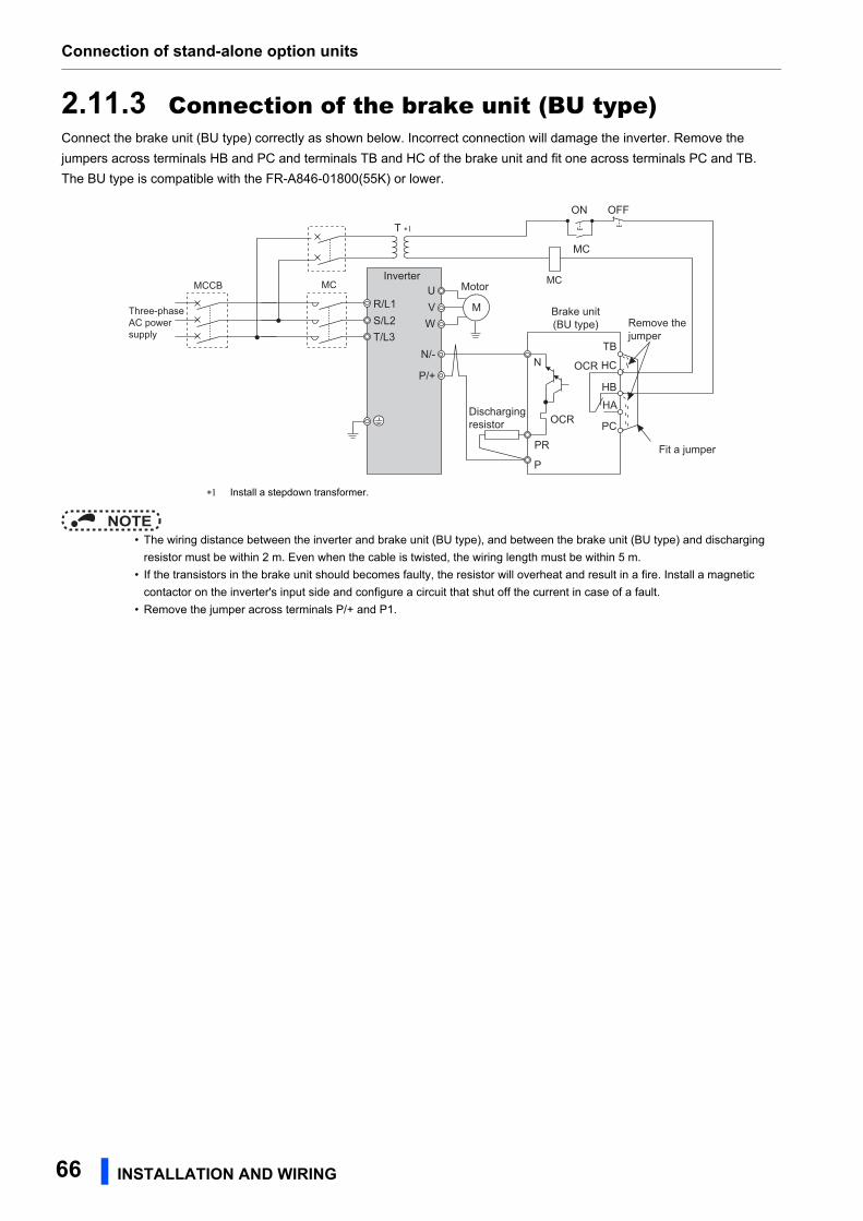
Connection of stand-alone option units
2.11.3 Connection of the brake unit (BU type)Connect the brake unit (BU type) correctly as shown below. Incorrect connection will damage the inverter. Remove the
jumpers across terminals HB and PC and terminals TB and HC of the brake unit and fit one across terminals PC and TB.
The BU type is compatible with the FR-A846-01800(55K) or lower.
NOTE • The wiring distance between the inverter and brake unit (BU type), and between the brake unit (BU type) and discharging
resistor must be within 2 m. Even when the cable is twisted, the wiring length must be within 5 m.
• If the transistors in the brake unit should becomes faulty, the resistor will overheat and result in a fire. Install a magnetic
contactor on the inverter's input side and configure a circuit that shut off the current in case of a fault.
• Remove the jumper across terminals P/+ and P1.
Install a stepdown transformer.
UVW
Motor
M
Inverter
Brake unit(BU type)
Dischargingresistor
R/L1S/L2T/L3
N/-
P/+
Three-phaseAC powersupply
MCCB MC
P
PR
OCR
N
Fit a jumper
Remove thejumper
HC
HB
HA
TB
OCR
PC
MC
OFFON
MC
T ∗1
66 INSTALLATION AND WIRING
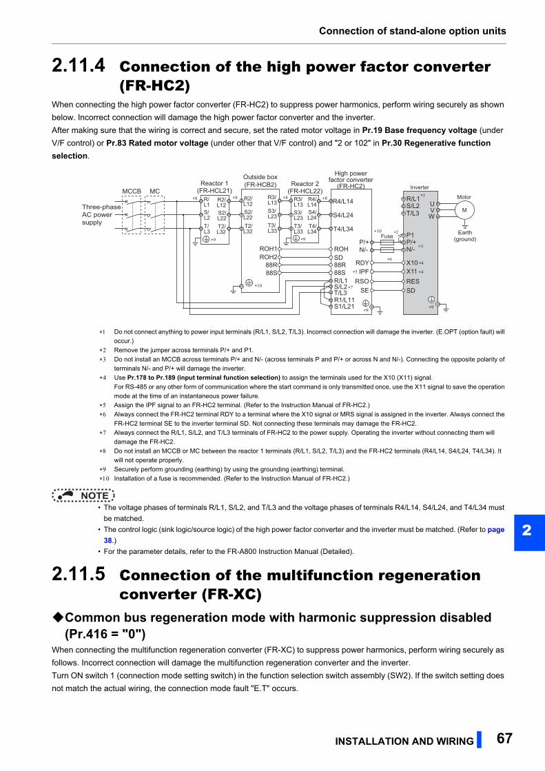
Connection of stand-alone option units
2
2.11.4 Connection of the high power factor converter (FR-HC2)
When connecting the high power factor converter (FR-HC2) to suppress power harmonics, perform wiring securely as shown
below. Incorrect connection will damage the high power factor converter and the inverter.
After making sure that the wiring is correct and secure, set the rated motor voltage in Pr.19 Base frequency voltage (under
V/F control) or Pr.83 Rated motor voltage (under other that V/F control) and "2 or 102" in Pr.30 Regenerative function selection.
NOTE • The voltage phases of terminals R/L1, S/L2, and T/L3 and the voltage phases of terminals R4/L14, S4/L24, and T4/L34 must
be matched.
• The control logic (sink logic/source logic) of the high power factor converter and the inverter must be matched. (Refer to page 38.)
• For the parameter details, refer to the FR-A800 Instruction Manual (Detailed).
2.11.5 Connection of the multifunction regeneration converter (FR-XC)
Common bus regeneration mode with harmonic suppression disabled (Pr.416 = "0")
When connecting the multifunction regeneration converter (FR-XC) to suppress power harmonics, perform wiring securely as
follows. Incorrect connection will damage the multifunction regeneration converter and the inverter.
Turn ON switch 1 (connection mode setting switch) in the function selection switch assembly (SW2). If the switch setting does
not match the actual wiring, the connection mode fault "E.T" occurs.
Do not connect anything to power input terminals (R/L1, S/L2, T/L3). Incorrect connection will damage the inverter. (E.OPT (option fault) will
occur.)
Remove the jumper across terminals P/+ and P1.
Do not install an MCCB across terminals P/+ and N/- (across terminals P and P/+ or across N and N/-). Connecting the opposite polarity of
terminals N/- and P/+ will damage the inverter.
Use Pr.178 to Pr.189 (input terminal function selection) to assign the terminals used for the X10 (X11) signal.
For RS-485 or any other form of communication where the start command is only transmitted once, use the X11 signal to save the operation
mode at the time of an instantaneous power failure.
Assign the IPF signal to an FR-HC2 terminal. (Refer to the Instruction Manual of FR-HC2.)
Always connect the FR-HC2 terminal RDY to a terminal where the X10 signal or MRS signal is assigned in the inverter. Always connect the
FR-HC2 terminal SE to the inverter terminal SD. Not connecting these terminals may damage the FR-HC2.
Always connect the R/L1, S/L2, and T/L3 terminals of FR-HC2 to the power supply. Operating the inverter without connecting them will
damage the FR-HC2.
Do not install an MCCB or MC between the reactor 1 terminals (R/L1, S/L2, T/L3) and the FR-HC2 terminals (R4/L14, S4/L24, T4/L34). It
will not operate properly.
Securely perform grounding (earthing) by using the grounding (earthing) terminal.
Installation of a fuse is recommended. (Refer to the Instruction Manual of FR-HC2.)
ROH2ROH1
Outside box(FR-HCB2) Inverter
High powerfactor converter
(FR-HC2)Reactor 2(FR-HCL22)
Motor
M
Reactor 1(FR-HCL21)
P/+P/+N/-N/-
X10X11
SD
RDY
RSOSE
R/L1
Earth(ground)
S/L2T/L3
Three-phaseAC powersupply
UVW
R1/L11S1/L21
88R88R88S88S
ROHSD
MCCB MCR4/L14 R4/L14S4/L24 S4/L24T4/L34 T4/L34
R3/L13 R3/
L13S3/L23
S3/L23
T3/L33
T3/L33
R2/L12
R2/L12
S2/L22
S2/L22
T2/L32
T2/L32
R/L1S/L2T/L3
R/L1S/L2T/L3
RESIPF
Fuse
∗4
∗6∗4
∗3
∗5
∗10
∗8∗8
∗7
∗9∗9
∗8 ∗8
∗10
∗1
∗9∗9P1∗2
INSTALLATION AND WIRING 67
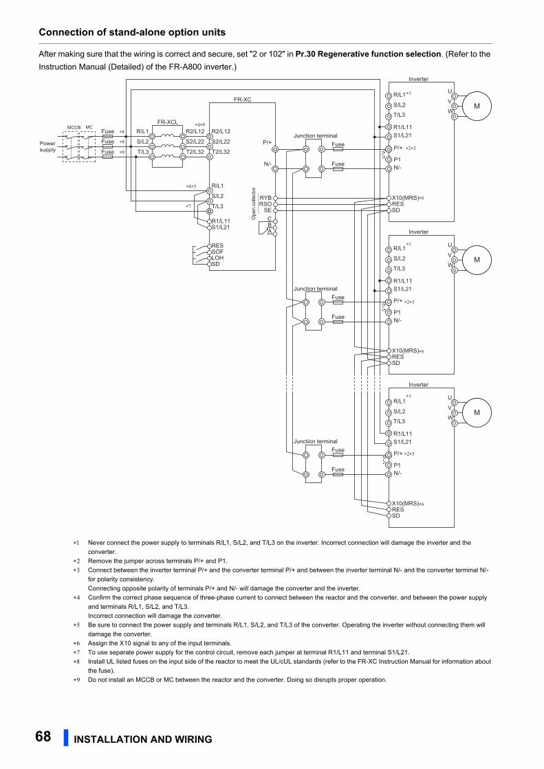
Connection of stand-alone option units
After making sure that the wiring is correct and secure, set "2 or 102" in Pr.30 Regenerative function selection. (Refer to the
Instruction Manual (Detailed) of the FR-A800 inverter.)
Never connect the power supply to terminals R/L1, S/L2, and T/L3 on the inverter. Incorrect connection will damage the inverter and the
converter.
Remove the jumper across terminals P/+ and P1.
Connect between the inverter terminal P/+ and the converter terminal P/+ and between the inverter terminal N/- and the converter terminal N/-
for polarity consistency.
Connecting opposite polarity of terminals P/+ and N/- will damage the converter and the inverter.
Confirm the correct phase sequence of three-phase current to connect between the reactor and the converter, and between the power supply
and terminals R/L1, S/L2, and T/L3.
Incorrect connection will damage the converter.
Be sure to connect the power supply and terminals R/L1, S/L2, and T/L3 of the converter. Operating the inverter without connecting them will
damage the converter.
Assign the X10 signal to any of the input terminals.
To use separate power supply for the control circuit, remove each jumper at terminal R1/L11 and terminal S1/L21.
Install UL listed fuses on the input side of the reactor to meet the UL/cUL standards (refer to the FR-XC Instruction Manual for information about
the fuse).
Do not install an MCCB or MC between the reactor and the converter. Doing so disrupts proper operation.
Powersupply
MCCB MCFR-XCL
N/-
FR-XC
R/L1
S/L2
T/L3 RSOSE
CBA
RYB
IM
P/+
R2/L12
S2/L22
T2/L32
R2/L12
S2/L22
T2/L32P/+Fuse
R/L1
N/-
Inverter
MS/L2
T/L3
Fuse
RESSD
X10(MRS)
IMR/L1
N/-
Inverter
MS/L2
T/L3
RESSD
X10(MRS)
IMR/L1
N/-
Inverter
MS/L2
T/L3
RESSD
X10(MRS)
R1/L11S1/L21
LOHSD
RESSOF
Ope
n co
llect
or
Junction terminal
Fuse
Fuse
Junction terminal
Fuse
Fuse
Junction terminal
∗1
∗1
∗1
∗4∗5
∗4∗9
∗6
∗6
∗6
U
V
W
U
V
W
U
V
W
R1/L11S1/L21
R1/L11S1/L21
R1/L11S1/L21
R/L1
S/L2
T/L3
∗7
Fuse
Fuse
Fuse
∗8
∗8
∗8
P1
∗2∗3
P/+
P1
P/+
P1
∗2∗3
∗2∗3
68 INSTALLATION AND WIRING
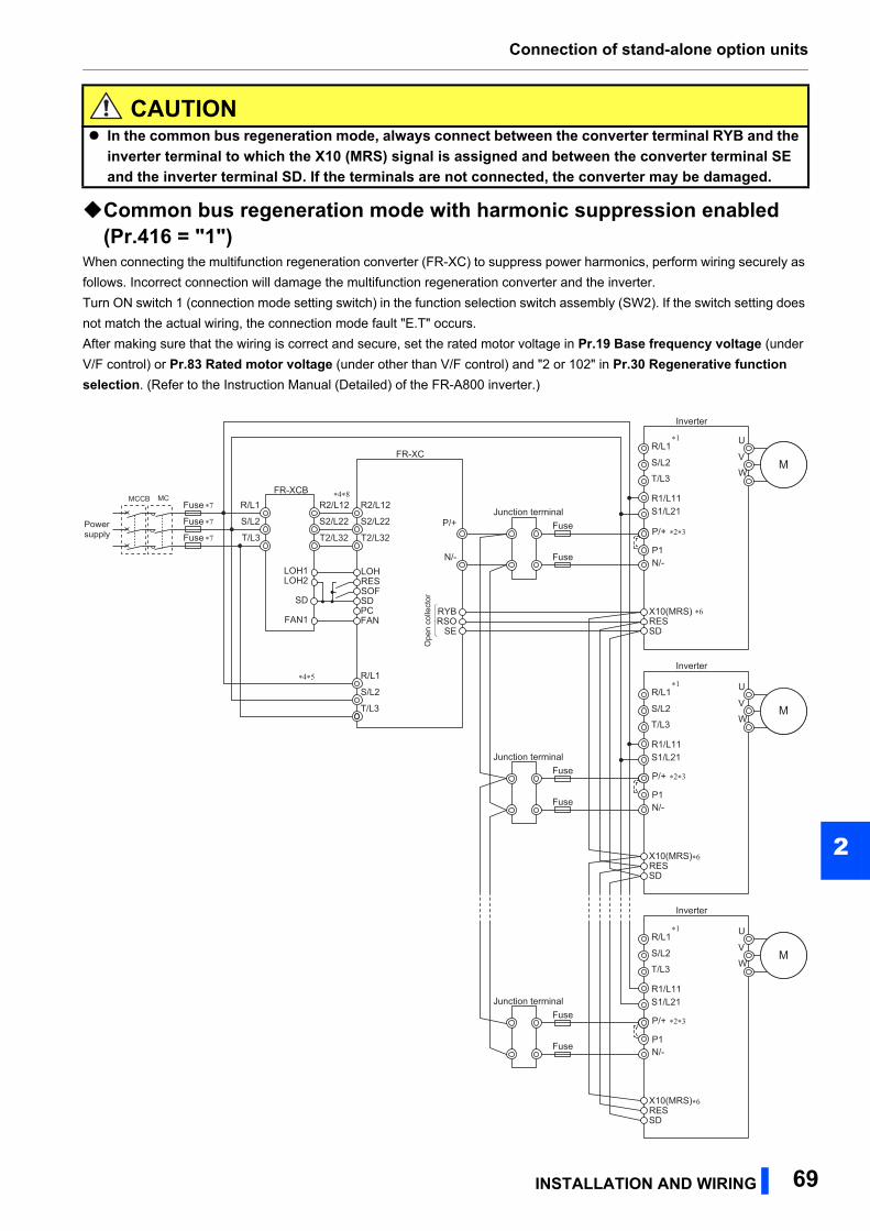
Connection of stand-alone option units
2
Common bus regeneration mode with harmonic suppression enabled (Pr.416 = "1")
When connecting the multifunction regeneration converter (FR-XC) to suppress power harmonics, perform wiring securely as
follows. Incorrect connection will damage the multifunction regeneration converter and the inverter.
Turn ON switch 1 (connection mode setting switch) in the function selection switch assembly (SW2). If the switch setting does
not match the actual wiring, the connection mode fault "E.T" occurs.
After making sure that the wiring is correct and secure, set the rated motor voltage in Pr.19 Base frequency voltage (under
V/F control) or Pr.83 Rated motor voltage (under other than V/F control) and "2 or 102" in Pr.30 Regenerative function selection. (Refer to the Instruction Manual (Detailed) of the FR-A800 inverter.)
CAUTION In the common bus regeneration mode, always connect between the converter terminal RYB and the
inverter terminal to which the X10 (MRS) signal is assigned and between the converter terminal SE and the inverter terminal SD. If the terminals are not connected, the converter may be damaged.
Powersupply
MCCB MCFR-XCB
N/-
FR-XC
R/L1
S/L2
T/L3
RSOSE
RYB
IM
P/+
R2/L12
S2/L22
T2/L32
R2/L12
S2/L22
T2/L32Fuse
R/L1
N/-
Inverter
MS/L2
T/L3
Fuse
RESSD
X10(MRS)
IMR/L1
N/-
Inverter
MS/L2
T/L3
RESSD
X10(MRS)
IMR/L1
N/-
Inverter
MS/L2
T/L3
RESSD
X10(MRS)
Ope
n co
llect
or
Junction terminal
Fuse
Fuse
Junction terminal
Fuse
Fuse
Junction terminal
∗1
∗1
∗1
∗4∗8
∗4∗5
∗6
∗6
∗6
U
V
W
U
V
W
U
V
W
R1/L11S1/L21
R1/L11S1/L21
R1/L11S1/L21
R/L1
S/L2
T/L3
FAN1
SD
LOH1LOH2
SOF
LOHRES
SDPCFAN
Fuse ∗7
Fuse ∗7
Fuse ∗7
P1
P1
P/+
P1
∗2∗3
P/+ ∗2∗3
P/+ ∗2∗3
INSTALLATION AND WIRING 69
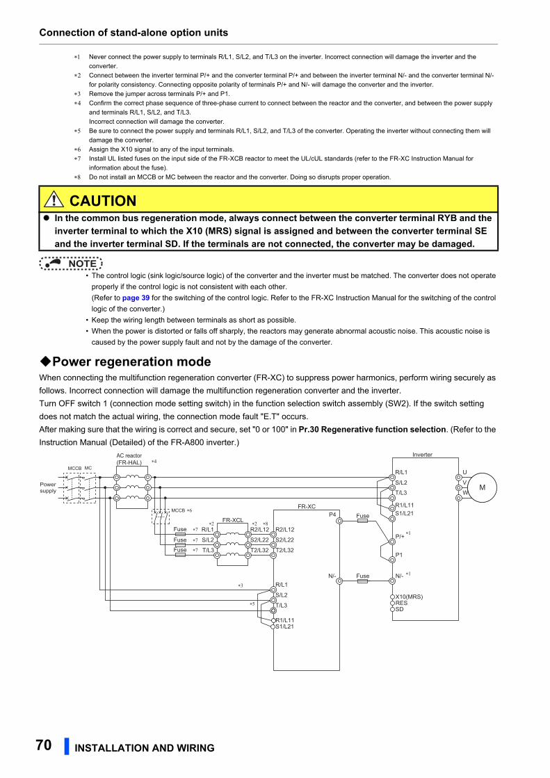
Connection of stand-alone option units
Never connect the power supply to terminals R/L1, S/L2, and T/L3 on the inverter. Incorrect connection will damage the inverter and the
converter.
Connect between the inverter terminal P/+ and the converter terminal P/+ and between the inverter terminal N/- and the converter terminal N/-
for polarity consistency. Connecting opposite polarity of terminals P/+ and N/- will damage the converter and the inverter.
Remove the jumper across terminals P/+ and P1.
Confirm the correct phase sequence of three-phase current to connect between the reactor and the converter, and between the power supply
and terminals R/L1, S/L2, and T/L3.
Incorrect connection will damage the converter.
Be sure to connect the power supply and terminals R/L1, S/L2, and T/L3 of the converter. Operating the inverter without connecting them will
damage the converter.
Assign the X10 signal to any of the input terminals.
Install UL listed fuses on the input side of the FR-XCB reactor to meet the UL/cUL standards (refer to the FR-XC Instruction Manual for
information about the fuse).
Do not install an MCCB or MC between the reactor and the converter. Doing so disrupts proper operation.
NOTE • The control logic (sink logic/source logic) of the converter and the inverter must be matched. The converter does not operate
properly if the control logic is not consistent with each other.
(Refer to page 39 for the switching of the control logic. Refer to the FR-XC Instruction Manual for the switching of the control
logic of the converter.)
• Keep the wiring length between terminals as short as possible.
• When the power is distorted or falls off sharply, the reactors may generate abnormal acoustic noise. This acoustic noise is
caused by the power supply fault and not by the damage of the converter.
Power regeneration modeWhen connecting the multifunction regeneration converter (FR-XC) to suppress power harmonics, perform wiring securely as
follows. Incorrect connection will damage the multifunction regeneration converter and the inverter.
Turn OFF switch 1 (connection mode setting switch) in the function selection switch assembly (SW2). If the switch setting
does not match the actual wiring, the connection mode fault "E.T" occurs.
After making sure that the wiring is correct and secure, set "0 or 100" in Pr.30 Regenerative function selection. (Refer to the
Instruction Manual (Detailed) of the FR-A800 inverter.)
CAUTION In the common bus regeneration mode, always connect between the converter terminal RYB and the
inverter terminal to which the X10 (MRS) signal is assigned and between the converter terminal SE and the inverter terminal SD. If the terminals are not connected, the converter may be damaged.
Powersupply
MCCB MC
FR-XCLP4
N/-
FR-XC
R/L1
S/L2
T/L3
IM
R2/L12
S2/L22
T2/L32
P/+
Fuse
R/L1
N/-
Inverter
MS/L2
T/L3
Fuse
RESSD
X10(MRS)
R1/L11S1/L21
∗1
∗1
∗6
∗8
∗3
R1/L11S1/L21
R2/L12
S2/L22
T2/L32
R/L1
S/L2
T/L3
U
V
W
P1
∗5
Fuse ∗7
Fuse ∗7
Fuse ∗7
MCCB
∗2 ∗2
AC reactor(FR-HAL) ∗4
70 INSTALLATION AND WIRING
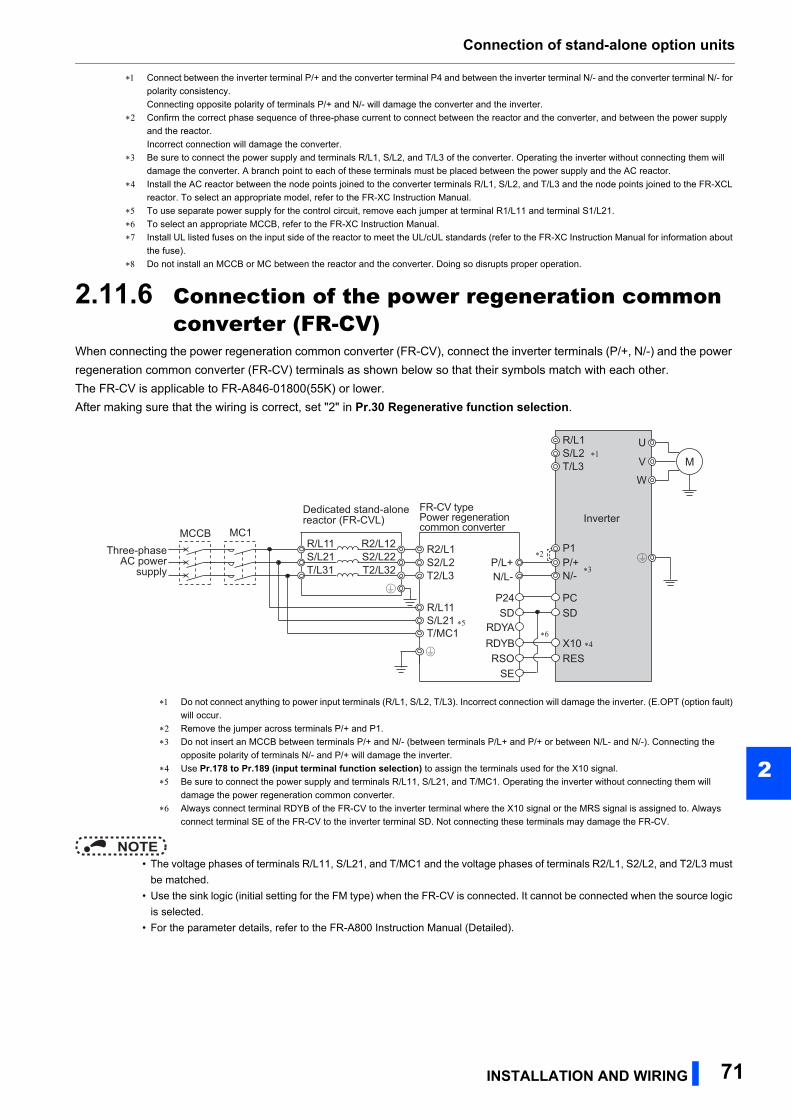
Connection of stand-alone option units
2
Connect between the inverter terminal P/+ and the converter terminal P4 and between the inverter terminal N/- and the converter terminal N/- for
polarity consistency.
Connecting opposite polarity of terminals P/+ and N/- will damage the converter and the inverter.
Confirm the correct phase sequence of three-phase current to connect between the reactor and the converter, and between the power supply
and the reactor.
Incorrect connection will damage the converter.
Be sure to connect the power supply and terminals R/L1, S/L2, and T/L3 of the converter. Operating the inverter without connecting them will
damage the converter. A branch point to each of these terminals must be placed between the power supply and the AC reactor.
Install the AC reactor between the node points joined to the converter terminals R/L1, S/L2, and T/L3 and the node points joined to the FR-XCL
reactor. To select an appropriate model, refer to the FR-XC Instruction Manual.
To use separate power supply for the control circuit, remove each jumper at terminal R1/L11 and terminal S1/L21.
To select an appropriate MCCB, refer to the FR-XC Instruction Manual.
Install UL listed fuses on the input side of the reactor to meet the UL/cUL standards (refer to the FR-XC Instruction Manual for information about
the fuse).
Do not install an MCCB or MC between the reactor and the converter. Doing so disrupts proper operation.
2.11.6 Connection of the power regeneration common converter (FR-CV)
When connecting the power regeneration common converter (FR-CV), connect the inverter terminals (P/+, N/-) and the power
regeneration common converter (FR-CV) terminals as shown below so that their symbols match with each other.
The FR-CV is applicable to FR-A846-01800(55K) or lower.
After making sure that the wiring is correct, set "2" in Pr.30 Regenerative function selection.
NOTE • The voltage phases of terminals R/L11, S/L21, and T/MC1 and the voltage phases of terminals R2/L1, S2/L2, and T2/L3 must
be matched.
• Use the sink logic (initial setting for the FM type) when the FR-CV is connected. It cannot be connected when the source logic
is selected.
• For the parameter details, refer to the FR-A800 Instruction Manual (Detailed).
Do not connect anything to power input terminals (R/L1, S/L2, T/L3). Incorrect connection will damage the inverter. (E.OPT (option fault)
will occur.
Remove the jumper across terminals P/+ and P1.
Do not insert an MCCB between terminals P/+ and N/- (between terminals P/L+ and P/+ or between N/L- and N/-). Connecting the
opposite polarity of terminals N/- and P/+ will damage the inverter.
Use Pr.178 to Pr.189 (input terminal function selection) to assign the terminals used for the X10 signal.
Be sure to connect the power supply and terminals R/L11, S/L21, and T/MC1. Operating the inverter without connecting them will
damage the power regeneration common converter.
Always connect terminal RDYB of the FR-CV to the inverter terminal where the X10 signal or the MRS signal is assigned to. Always
connect terminal SE of the FR-CV to the inverter terminal SD. Not connecting these terminals may damage the FR-CV.
R/L11S/L21T/L31
R2/L12S2/L22T2/L32
R2/L1S2/L2T2/L3
R/L11S/L21T/MC1
P/L+
U
V
W
M
FR-CV typePower regeneration common converter
Inverter
PCSD
X10 ∗4
RES
P24SD
RDYBRSO
SE
RDYA
N/L-∗3
∗6∗5
R/L1S/L2T/L3
P/+N/-
∗1
Three-phaseAC power
supply
MCCB MC1
Dedicated stand-alonereactor (FR-CVL)
P1∗2
INSTALLATION AND WIRING 71
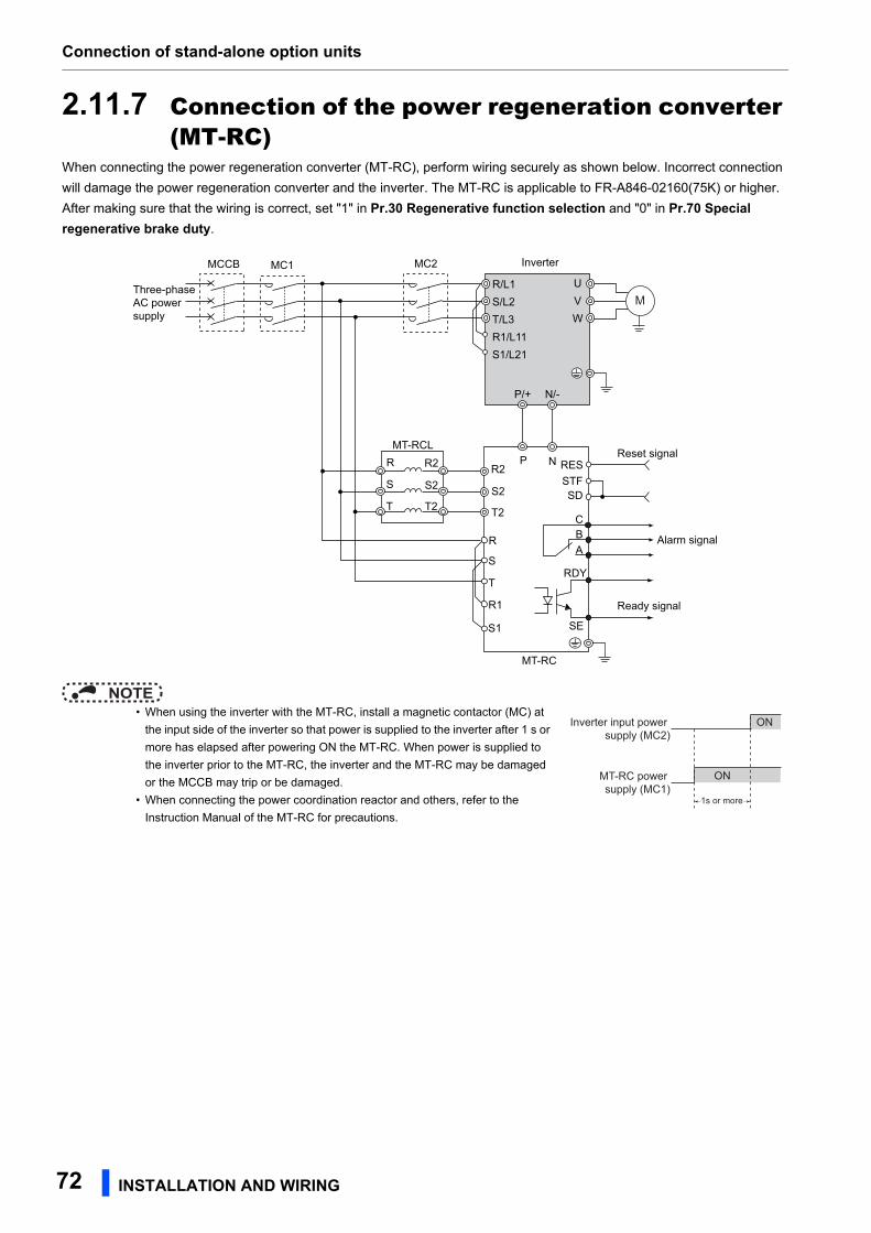
Connection of stand-alone option units
2.11.7 Connection of the power regeneration converter (MT-RC)
When connecting the power regeneration converter (MT-RC), perform wiring securely as shown below. Incorrect connection
will damage the power regeneration converter and the inverter. The MT-RC is applicable to FR-A846-02160(75K) or higher.
After making sure that the wiring is correct, set "1" in Pr.30 Regenerative function selection and "0" in Pr.70 Special regenerative brake duty.
NOTE • When using the inverter with the MT-RC, install a magnetic contactor (MC) at
the input side of the inverter so that power is supplied to the inverter after 1 s or
more has elapsed after powering ON the MT-RC. When power is supplied to
the inverter prior to the MT-RC, the inverter and the MT-RC may be damaged
or the MCCB may trip or be damaged.
• When connecting the power coordination reactor and others, refer to the
Instruction Manual of the MT-RC for precautions.
R/L1S/L2T/L3R1/L11S1/L21
R R2 RES
UVW
Inverter
MT-RCL
P/+ N/-
P N
RDY
SE
MT-RC
Reset signal
Ready signal
Three-phaseAC powersupply
MCCB MC2MC1
M
STFSD
S
T
S2
T2
R2
S2
T2
R
S
T
R1
S1
C
Alarm signalBA
MT-RC power supply (MC1)
Inverter input power supply (MC2)
ON
ON
1s or more
72 INSTALLATION AND WIRING
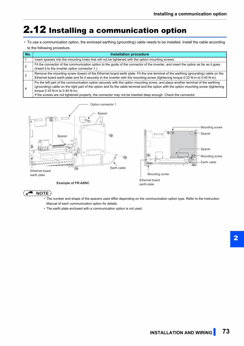
Installing a communication option
2
2.12 Installing a communication option • To use a communication option, the enclosed earthing (grounding) cable needs to be installed. Install the cable according
to the following procedure.
NOTE • The number and shape of the spacers used differ depending on the communication option type. Refer to the Instruction
Manual of each communication option for details.
• The earth plate enclosed with a communication option is not used.
No. Installation procedure1 Insert spacers into the mounting holes that will not be tightened with the option mounting screws.
2Fit the connector of the communication option to the guide of the connector of the inverter, and insert the option as far as it goes. (Insert it to the inverter option connector 1.)
3Remove the mounting screw (lower) of the Ethernet board earth plate. Fit the one terminal of the earthing (grounding) cable on the Ethernet board earth plate and fix it securely to the inverter with the mounting screw (tightening torque 0.33 N·m to 0.40 N·m).
4
Fix the left part of the communication option securely with the option mounting screw, and place another terminal of the earthing (grounding) cable on the right part of the option and fix the cable terminal and the option with the option mounting screw (tightening torque 0.33 N·m to 0.40 N·m).If the screws are not tightened properly, the connector may not be inserted deep enough. Check the connector.
Ethernet boardearth plate
Ethernet boardearth plate
Spacer
Spacer
Option connector 1
Example of FR-A8NC
Spacer
Spacer
Mounting screw
Mounting screw
Mounting screw
Earth cable
Earth cable
INSTALLATION AND WIRING 73

MEMO
74
PRECAUTIONS FOR USE OF THE INVERTER 75
3
3 PRECAUTIONS FOR USE OF THE INVERTER
This chapter explains the precautions for use of this product.Always read the instructions before using the equipment.
3.1 Electro-magnetic interference (EMI) and leakage currents ..763.2 Power supply harmonics .........................................................823.3 Installation of a reactor ............................................................853.4 Power-OFF and magnetic contactor (MC) ..............................863.5 Countermeasures against deterioration of the 400 V class
motor insulation........................................................................873.6 Checklist before starting operation ........................................883.7 Failsafe system which uses the inverter ................................91
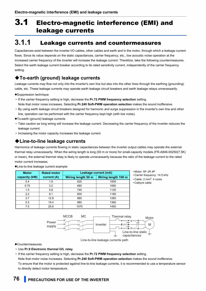
Electro-magnetic interference (EMI) and leakage currents
3.1 Electro-magnetic interference (EMI) and leakage currents
3.1.1 Leakage currents and countermeasuresCapacitances exist between the inverter I/O cables, other cables and earth and in the motor, through which a leakage current
flows. Since its value depends on the static capacitances, carrier frequency, etc., low acoustic noise operation at the
increased carrier frequency of the inverter will increase the leakage current. Therefore, take the following countermeasures.
Select the earth leakage current breaker according to its rated sensitivity current, independently of the carrier frequency
setting.
To-earth (ground) leakage currentsLeakage currents may flow not only into the inverter's own line but also into the other lines through the earthing (grounding)
cable, etc. These leakage currents may operate earth leakage circuit breakers and earth leakage relays unnecessarily.
Suppression technique
• If the carrier frequency setting is high, decrease the Pr.72 PWM frequency selection setting.
Note that motor noise increases. Selecting Pr.240 Soft-PWM operation selection makes the sound inoffensive.
• By using earth leakage circuit breakers designed for harmonic and surge suppression in the inverter's own line and other
line, operation can be performed with the carrier frequency kept high (with low noise).
To-earth (ground) leakage currents
• Take caution as long wiring will increase the leakage current. Decreasing the carrier frequency of the inverter reduces the
leakage current.
• Increasing the motor capacity increases the leakage current.
Line-to-line leakage currentsHarmonics of leakage currents flowing in static capacitances between the inverter output cables may operate the external
thermal relay unnecessarily. When the wiring length is long (50 m or more) for small-capacity models (FR-A846-00250(7.5K)
or lower), the external thermal relay is likely to operate unnecessarily because the ratio of the leakage current to the rated
motor current increases.
Line-to-line leakage current example
Countermeasures
• Use Pr.9 Electronic thermal O/L relay.
• If the carrier frequency setting is high, decrease the Pr.72 PWM frequency selection setting.
Note that motor noise increases. Selecting Pr.240 Soft-PWM operation selection makes the sound inoffensive.
To ensure that the motor is protected against line-to-line leakage currents, it is recommended to use a temperature sensor
to directly detect motor temperature.
Motor capacity (kW)
Rated motor current (A)
Leakage current (mA)Wiring length 50 m Wiring length 100 m
0.4 1.8 620 1000
0.75 3.2 680 1060
1.5 5.8 740 1120
2.2 8.1 800 1180
3.7 12.8 880 1260
5.5 19.4 980 1360
7.5 25.6 1070 1450
• Motor: SF-JR 4P• Carrier frequency: 14.5 kHz
• Cable: 2 mm2, 4 cores• Cabtyre cable
Powersupply
Thermal relay
Line-to-line static capacitances
MCCB MC
Line-to-line leakage currents path
Motor
Inverter M
76 PRECAUTIONS FOR USE OF THE INVERTER
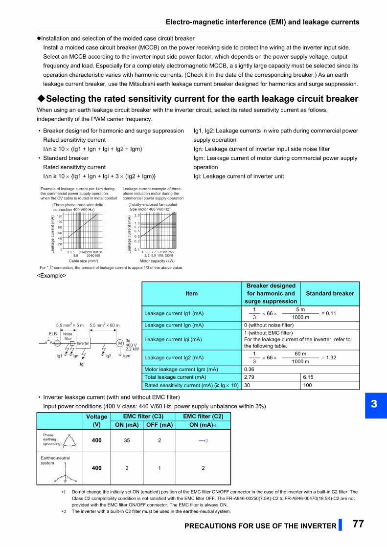
Electro-magnetic interference (EMI) and leakage currents
3
Installation and selection of the molded case circuit breaker
Install a molded case circuit breaker (MCCB) on the power receiving side to protect the wiring at the inverter input side.
Select an MCCB according to the inverter input side power factor, which depends on the power supply voltage, output
frequency and load. Especially for a completely electromagnetic MCCB, a slightly large capacity must be selected since its
operation characteristic varies with harmonic currents. (Check it in the data of the corresponding breaker.) As an earth
leakage current breaker, use the Mitsubishi earth leakage current breaker designed for harmonics and surge suppression.
Selecting the rated sensitivity current for the earth leakage circuit breakerWhen using an earth leakage circuit breaker with the inverter circuit, select its rated sensitivity current as follows,
independently of the PWM carrier frequency.
<Example>
• Inverter leakage current (with and without EMC filter)
Input power conditions (400 V class: 440 V/60 Hz, power supply unbalance within 3%)
Do not change the initially set ON (enabled) position of the EMC filter ON/OFF connector in the case of the inverter with a built-in C2 filter. The
Class C2 compatibility condition is not satisfied with the EMC filter OFF. The FR-A846-00250(7.5K)-C2 to FR-A846-00470(18.5K)-C2 are not
provided with the EMC filter ON/OFF connector. The EMC filter is always ON.
The inverter with a built-in C2 filter must be used in the earthed-neutral system.
• Breaker designed for harmonic and surge suppression
Rated sensitivity current
In ≥ 10 (Ig1 + Ign + Igi + Ig2 + Igm)
• Standard breaker
Rated sensitivity current
In ≥ 10 Ig1 + Ign + Igi + 3 (Ig2 + Igm)
Ig1, Ig2: Leakage currents in wire path during commercial power
supply operation
Ign: Leakage current of inverter input side noise filter
Igm: Leakage current of motor during commercial power supply
operation
Igi: Leakage current of inverter unit
ItemBreaker designed for harmonic and
surge suppressionStandard breaker
Leakage current Ig1 (mA)1
66 5 m
= 0.113 1000 m
Leakage current Ign (mA) 0 (without noise filter)
Leakage current Igi (mA)1 (without EMC filter)For the leakage current of the inverter, refer to the following table.
Leakage current Ig2 (mA)1
66 60 m
= 1.323 1000 m
Motor leakage current Igm (mA) 0.36
Total leakage current (mA) 2.79 6.15
Rated sensitivity current (mA) (≥ Ig 10) 30 100
Voltage(V)
EMC filter (C3) EMC filter (C2)ON (mA) OFF (mA) ON (mA)
400 35 2 ―
400 2 1 2
Motor capacity (kW)
For " " connection, the amount of leakage current is appox.1/3 of the above value.
(Three-phase three-wire delta connection 400 V60 Hz)
Example of leakage current per 1km during the commercial power supply operation when the CV cable is routed in metal conduit
Leakage current example of three-phase induction motor during the commercial power supply operation
(Totally-enclosed fan-cooled type motor 400 V60 Hz)
0
20
40
60
80
100
120
Leak
age
curr
ent (
mA
)
Leak
age
curr
ent (
mA
)
2 3.55.5
8 14223038
6080100
150
Cable size (mm2)
0. 1
0. 20. 3
0. 50. 71. 0
2. 0
1. 5 3. 72. 2
7. 5 152211
3730
55455.5 18. 5
Noise filter
Inverter
ELB
Ig1 Ign
Igi
Ig2 Igm
M
5.5 mm2 5 m 5.5 mm2 60 m
400 V2.2 kW
3φ
Phase earthing(grounding)
Earthed-neutral system
PRECAUTIONS FOR USE OF THE INVERTER 77
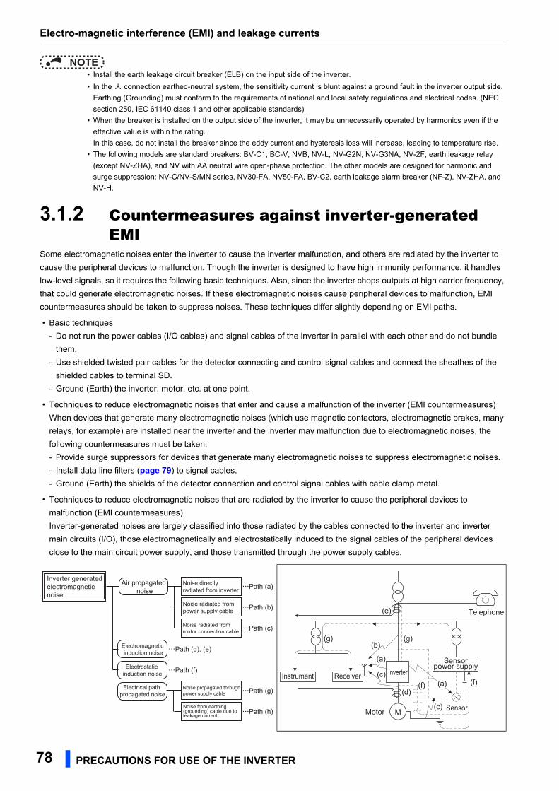
Electro-magnetic interference (EMI) and leakage currents
NOTE • Install the earth leakage circuit breaker (ELB) on the input side of the inverter.
• In the connection earthed-neutral system, the sensitivity current is blunt against a ground fault in the inverter output side.
Earthing (Grounding) must conform to the requirements of national and local safety regulations and electrical codes. (NEC
section 250, IEC 61140 class 1 and other applicable standards)
• When the breaker is installed on the output side of the inverter, it may be unnecessarily operated by harmonics even if the
effective value is within the rating.
In this case, do not install the breaker since the eddy current and hysteresis loss will increase, leading to temperature rise.
• The following models are standard breakers: BV-C1, BC-V, NVB, NV-L, NV-G2N, NV-G3NA, NV-2F, earth leakage relay
(except NV-ZHA), and NV with AA neutral wire open-phase protection. The other models are designed for harmonic and
surge suppression: NV-C/NV-S/MN series, NV30-FA, NV50-FA, BV-C2, earth leakage alarm breaker (NF-Z), NV-ZHA, and
NV-H.
3.1.2 Countermeasures against inverter-generated EMI
Some electromagnetic noises enter the inverter to cause the inverter malfunction, and others are radiated by the inverter to
cause the peripheral devices to malfunction. Though the inverter is designed to have high immunity performance, it handles
low-level signals, so it requires the following basic techniques. Also, since the inverter chops outputs at high carrier frequency,
that could generate electromagnetic noises. If these electromagnetic noises cause peripheral devices to malfunction, EMI
countermeasures should be taken to suppress noises. These techniques differ slightly depending on EMI paths.
• Basic techniques
- Do not run the power cables (I/O cables) and signal cables of the inverter in parallel with each other and do not bundle
them.
- Use shielded twisted pair cables for the detector connecting and control signal cables and connect the sheathes of the
shielded cables to terminal SD.
- Ground (Earth) the inverter, motor, etc. at one point.
• Techniques to reduce electromagnetic noises that enter and cause a malfunction of the inverter (EMI countermeasures)
When devices that generate many electromagnetic noises (which use magnetic contactors, electromagnetic brakes, many
relays, for example) are installed near the inverter and the inverter may malfunction due to electromagnetic noises, the
following countermeasures must be taken:
- Provide surge suppressors for devices that generate many electromagnetic noises to suppress electromagnetic noises.
- Install data line filters (page 79) to signal cables.
- Ground (Earth) the shields of the detector connection and control signal cables with cable clamp metal.
• Techniques to reduce electromagnetic noises that are radiated by the inverter to cause the peripheral devices to
malfunction (EMI countermeasures)
Inverter-generated noises are largely classified into those radiated by the cables connected to the inverter and inverter
main circuits (I/O), those electromagnetically and electrostatically induced to the signal cables of the peripheral devices
close to the main circuit power supply, and those transmitted through the power supply cables.
Noise propagated through power supply cable
Path (c)
Path (b)
Path (a)Noise directly radiated from inverter
Path (d), (e)
Air propagated noise
Path (f)
Electrical path propagated noise
Path (h)
Path (g)
Inverter generatedelectromagnetic noise
Electromagnetic induction noise
Electrostatic induction noise
Noise radiated from power supply cable
Noise radiated from motor connection cable
Noise from earthing (grounding) cable due to leakage current
Instrument Receiver
M
Sensorpower supply
Motor
Telephone
Sensor
(a)
(b)
(c)
(c)
(f)
(g)
(e)
(g)
(d)(f)
Inverter(a)
78 PRECAUTIONS FOR USE OF THE INVERTER
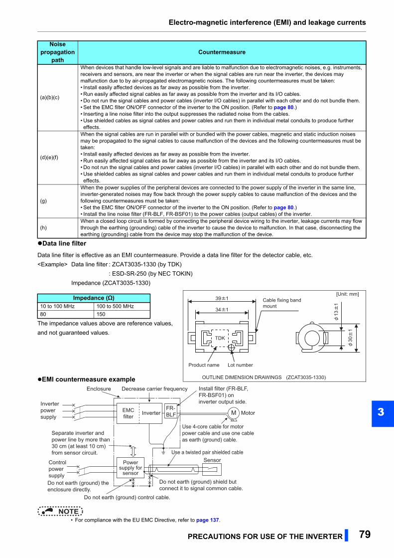
Electro-magnetic interference (EMI) and leakage currents
3
Data line filter
Data line filter is effective as an EMI countermeasure. Provide a data line filter for the detector cable, etc.
<Example> Data line filter : ZCAT3035-1330 (by TDK)
: ESD-SR-250 (by NEC TOKIN)
Impedance (ZCAT3035-1330)
The impedance values above are reference values,
and not guaranteed values.
EMI countermeasure example
NOTE • For compliance with the EU EMC Directive, refer to page 137.
Noise propagation
pathCountermeasure
(a)(b)(c)
When devices that handle low-level signals and are liable to malfunction due to electromagnetic noises, e.g. instruments, receivers and sensors, are near the inverter or when the signal cables are run near the inverter, the devices may malfunction due to by air-propagated electromagnetic noises. The following countermeasures must be taken:• Install easily affected devices as far away as possible from the inverter.• Run easily affected signal cables as far away as possible from the inverter and its I/O cables.• Do not run the signal cables and power cables (inverter I/O cables) in parallel with each other and do not bundle them.• Set the EMC filter ON/OFF connector of the inverter to the ON position. (Refer to page 80.)• Inserting a line noise filter into the output suppresses the radiated noise from the cables.• Use shielded cables as signal cables and power cables and run them in individual metal conduits to produce further effects.
(d)(e)(f)
When the signal cables are run in parallel with or bundled with the power cables, magnetic and static induction noises may be propagated to the signal cables to cause malfunction of the devices and the following countermeasures must be taken:• Install easily affected devices as far away as possible from the inverter.• Run easily affected signal cables as far away as possible from the inverter and its I/O cables.• Do not run the signal cables and power cables (inverter I/O cables) in parallel with each other and do not bundle them.• Use shielded cables as signal cables and power cables and run them in individual metal conduits to produce further effects.
(g)
When the power supplies of the peripheral devices are connected to the power supply of the inverter in the same line, inverter-generated noises may flow back through the power supply cables to cause malfunction of the devices and the following countermeasures must be taken:• Set the EMC filter ON/OFF connector of the inverter to the ON position. (Refer to page 80.)• Install the line noise filter (FR-BLF, FR-BSF01) to the power cables (output cables) of the inverter.
(h)When a closed loop circuit is formed by connecting the peripheral device wiring to the inverter, leakage currents may flow through the earthing (grounding) cable of the inverter to cause the device to malfunction. In that case, disconnecting the earthing (grounding) cable from the device may stop the malfunction of the device.
Impedance (Ω)10 to 100 MHz 100 to 500 MHz
80 15034 1
TDK
39 1
Product name Lot number
301
Cable fixing band mount
131
OUTLINE DIMENSION DRAWINGS (ZCAT3035-1330)
[Unit: mm]
Inverter
SensorUse a twisted pair shielded cable
Enclosure Decrease carrier frequency
MotorMFR-BLF
Do not earth (ground) control cable.
Inverter power supply
Install filter (FR-BLF, FR-BSF01) on inverter output side.
Separate inverter and power line by more than 30 cm (at least 10 cm) from sensor circuit.
Control power supplyDo not earth (ground) the enclosure directly.
Power supply for
sensor
Use 4-core cable for motor power cable and use one cable as earth (ground) cable.
Do not earth (ground) shield but connect it to signal common cable.
EMC filter
PRECAUTIONS FOR USE OF THE INVERTER 79
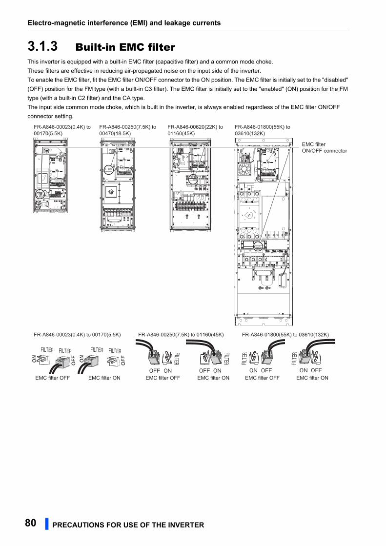
Electro-magnetic interference (EMI) and leakage currents
3.1.3 Built-in EMC filterThis inverter is equipped with a built-in EMC filter (capacitive filter) and a common mode choke.
These filters are effective in reducing air-propagated noise on the input side of the inverter.
To enable the EMC filter, fit the EMC filter ON/OFF connector to the ON position. The EMC filter is initially set to the "disabled"
(OFF) position for the FM type (with a built-in C3 filter). The EMC filter is initially set to the "enabled" (ON) position for the FM
type (with a built-in C2 filter) and the CA type.
The input side common mode choke, which is built in the inverter, is always enabled regardless of the EMC filter ON/OFF
connector setting.
FILTER
OFF ON
FILTER
OFF ON
FILTER FILTER
OFFON
FILTER FILTER
OFFON
FILTER
OFFON
FILTER
OFFONEMC filter OFF EMC filter ONEMC filter OFF EMC filter ON EMC filter ONEMC filter OFF
FR-A846-00250(7.5K) to 00470(18.5K)
FR-A846-00250(7.5K) to 01160(45K)
FR-A846-00023(0.4K) to 00170(5.5K)
FR-A846-00023(0.4K) to 00170(5.5K)
FR-A846-00620(22K) to 01160(45K)
FR-A846-01800(55K) to 03610(132K)
FR-A846-01800(55K) to 03610(132K)
EMC filter ON/OFF connector
80 PRECAUTIONS FOR USE OF THE INVERTER
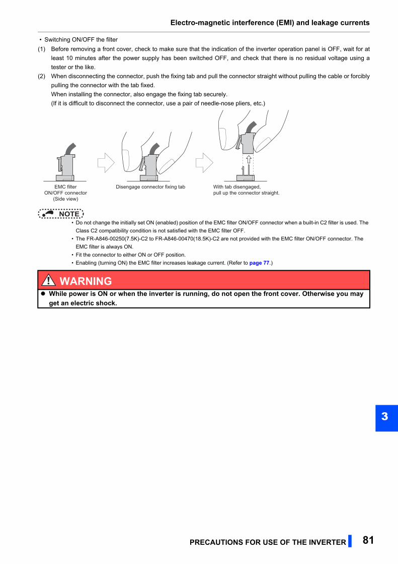
Electro-magnetic interference (EMI) and leakage currents
3
• Switching ON/OFF the filter
(1) Before removing a front cover, check to make sure that the indication of the inverter operation panel is OFF, wait for at
least 10 minutes after the power supply has been switched OFF, and check that there is no residual voltage using a
tester or the like.
(2) When disconnecting the connector, push the fixing tab and pull the connector straight without pulling the cable or forcibly
pulling the connector with the tab fixed.
When installing the connector, also engage the fixing tab securely.
(If it is difficult to disconnect the connector, use a pair of needle-nose pliers, etc.)
NOTE • Do not change the initially set ON (enabled) position of the EMC filter ON/OFF connector when a built-in C2 filter is used. The
Class C2 compatibility condition is not satisfied with the EMC filter OFF.
• The FR-A846-00250(7.5K)-C2 to FR-A846-00470(18.5K)-C2 are not provided with the EMC filter ON/OFF connector. The
EMC filter is always ON.
• Fit the connector to either ON or OFF position.
• Enabling (turning ON) the EMC filter increases leakage current. (Refer to page 77.)
WARNING While power is ON or when the inverter is running, do not open the front cover. Otherwise you may
get an electric shock.
EMC filterON/OFF connector
(Side view)
Disengage connector fixing tab With tab disengaged,pull up the connector straight.
PRECAUTIONS FOR USE OF THE INVERTER 81
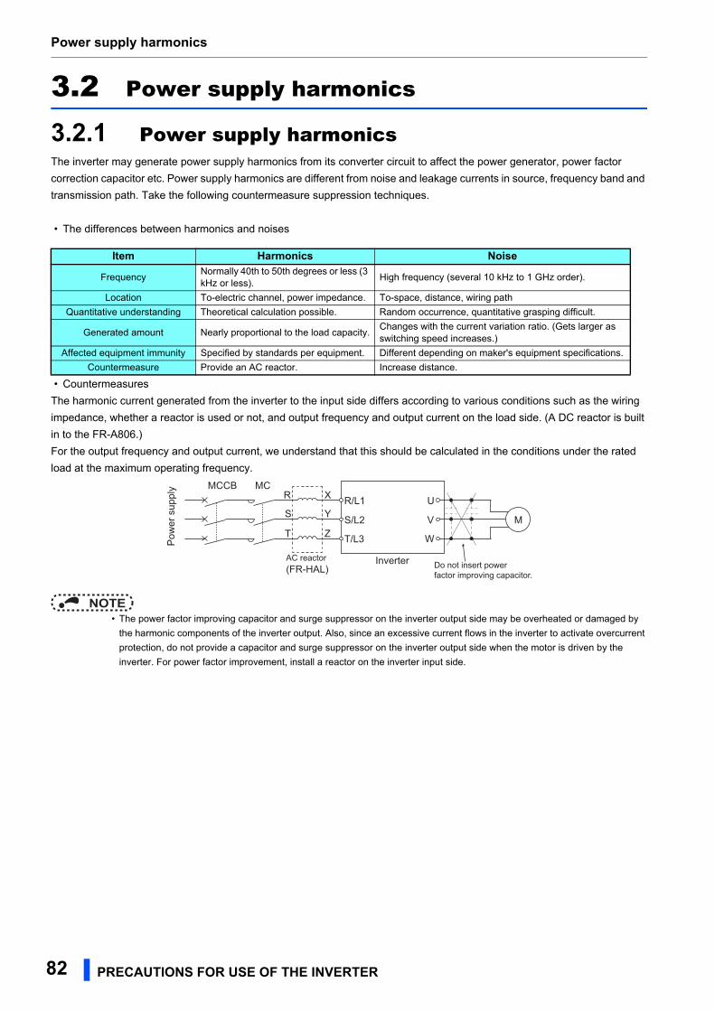
Power supply harmonics
3.2 Power supply harmonics
3.2.1 Power supply harmonicsThe inverter may generate power supply harmonics from its converter circuit to affect the power generator, power factor
correction capacitor etc. Power supply harmonics are different from noise and leakage currents in source, frequency band and
transmission path. Take the following countermeasure suppression techniques.
• The differences between harmonics and noises
• Countermeasures
The harmonic current generated from the inverter to the input side differs according to various conditions such as the wiring
impedance, whether a reactor is used or not, and output frequency and output current on the load side. (A DC reactor is built
in to the FR-A806.)
For the output frequency and output current, we understand that this should be calculated in the conditions under the rated
load at the maximum operating frequency.
NOTE • The power factor improving capacitor and surge suppressor on the inverter output side may be overheated or damaged by
the harmonic components of the inverter output. Also, since an excessive current flows in the inverter to activate overcurrent
protection, do not provide a capacitor and surge suppressor on the inverter output side when the motor is driven by the
inverter. For power factor improvement, install a reactor on the inverter input side.
Item Harmonics Noise
FrequencyNormally 40th to 50th degrees or less (3 kHz or less).
High frequency (several 10 kHz to 1 GHz order).
Location To-electric channel, power impedance. To-space, distance, wiring path
Quantitative understanding Theoretical calculation possible. Random occurrence, quantitative grasping difficult.
Generated amount Nearly proportional to the load capacity.Changes with the current variation ratio. (Gets larger as switching speed increases.)
Affected equipment immunity Specified by standards per equipment. Different depending on maker's equipment specifications.
Countermeasure Provide an AC reactor. Increase distance.
AC reactor(FR-HAL) Do not insert power
factor improving capacitor.
MCCB MC
Inverter
Pow
er s
uppl
y
R
S
T Z
Y
X U
V
W
R/L1
S/L2
T/L3
M
82 PRECAUTIONS FOR USE OF THE INVERTER
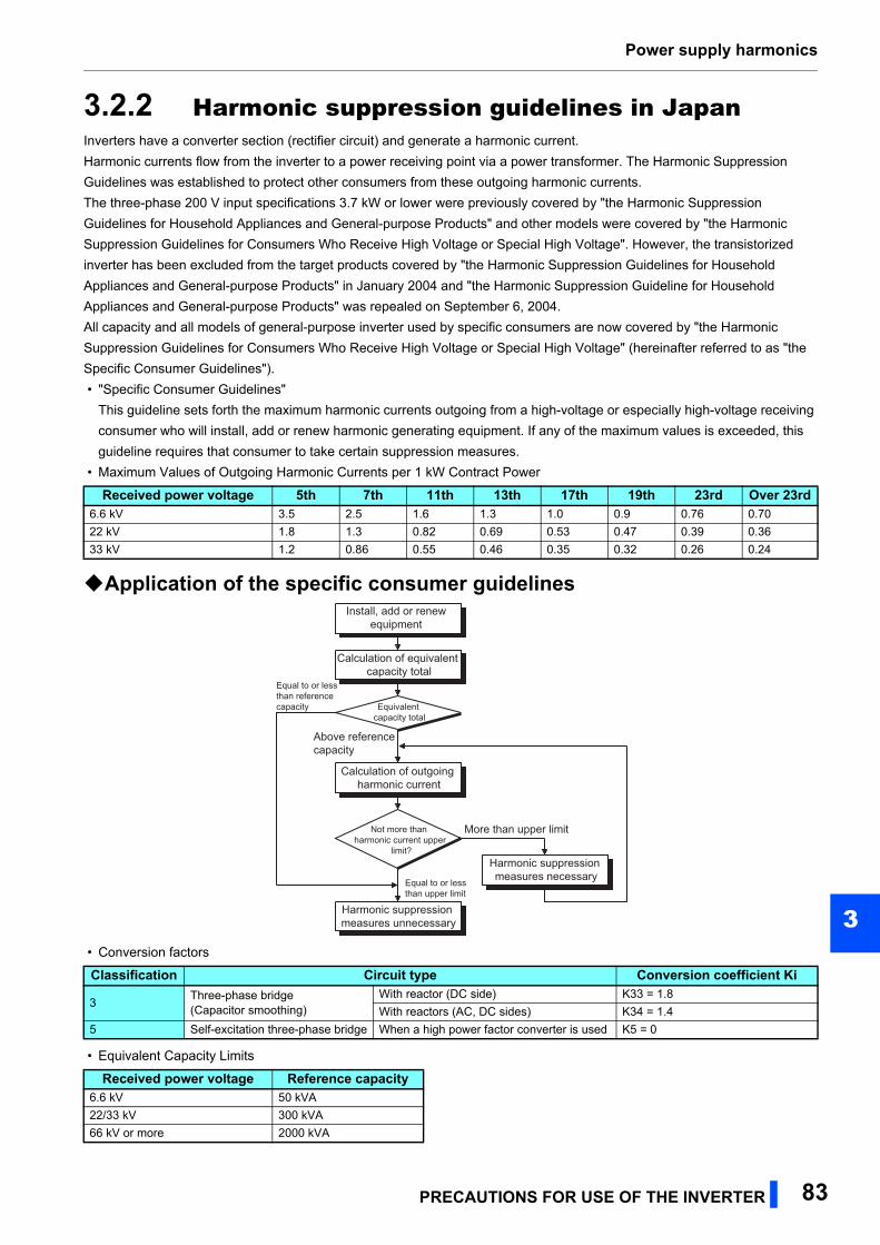
Power supply harmonics
3
3.2.2 Harmonic suppression guidelines in JapanInverters have a converter section (rectifier circuit) and generate a harmonic current.
Harmonic currents flow from the inverter to a power receiving point via a power transformer. The Harmonic Suppression
Guidelines was established to protect other consumers from these outgoing harmonic currents.
The three-phase 200 V input specifications 3.7 kW or lower were previously covered by "the Harmonic Suppression
Guidelines for Household Appliances and General-purpose Products" and other models were covered by "the Harmonic
Suppression Guidelines for Consumers Who Receive High Voltage or Special High Voltage". However, the transistorized
inverter has been excluded from the target products covered by "the Harmonic Suppression Guidelines for Household
Appliances and General-purpose Products" in January 2004 and "the Harmonic Suppression Guideline for Household
Appliances and General-purpose Products" was repealed on September 6, 2004.
All capacity and all models of general-purpose inverter used by specific consumers are now covered by "the Harmonic
Suppression Guidelines for Consumers Who Receive High Voltage or Special High Voltage" (hereinafter referred to as "the
Specific Consumer Guidelines").
• "Specific Consumer Guidelines"
This guideline sets forth the maximum harmonic currents outgoing from a high-voltage or especially high-voltage receiving
consumer who will install, add or renew harmonic generating equipment. If any of the maximum values is exceeded, this
guideline requires that consumer to take certain suppression measures.
• Maximum Values of Outgoing Harmonic Currents per 1 kW Contract Power
Application of the specific consumer guidelines
• Conversion factors
• Equivalent Capacity Limits
Received power voltage 5th 7th 11th 13th 17th 19th 23rd Over 23rd6.6 kV 3.5 2.5 1.6 1.3 1.0 0.9 0.76 0.70
22 kV 1.8 1.3 0.82 0.69 0.53 0.47 0.39 0.36
33 kV 1.2 0.86 0.55 0.46 0.35 0.32 0.26 0.24
Classification Circuit type Conversion coefficient Ki
3Three-phase bridge(Capacitor smoothing)
With reactor (DC side) K33 = 1.8
With reactors (AC, DC sides) K34 = 1.4
5 Self-excitation three-phase bridge When a high power factor converter is used K5 = 0
Received power voltage Reference capacity6.6 kV 50 kVA
22/33 kV 300 kVA
66 kV or more 2000 kVA
Install, add or renew equipment
Calculation of equivalent capacity total
Equivalent capacity total
Calculation of outgoing harmonic current
Not more than harmonic current upper
limit?
Harmonic suppression measures unnecessary
Harmonic suppression measures necessaryEqual to or less
than upper limit
More than upper limit
Above reference capacity
Equal to or less than reference capacity
PRECAUTIONS FOR USE OF THE INVERTER 83
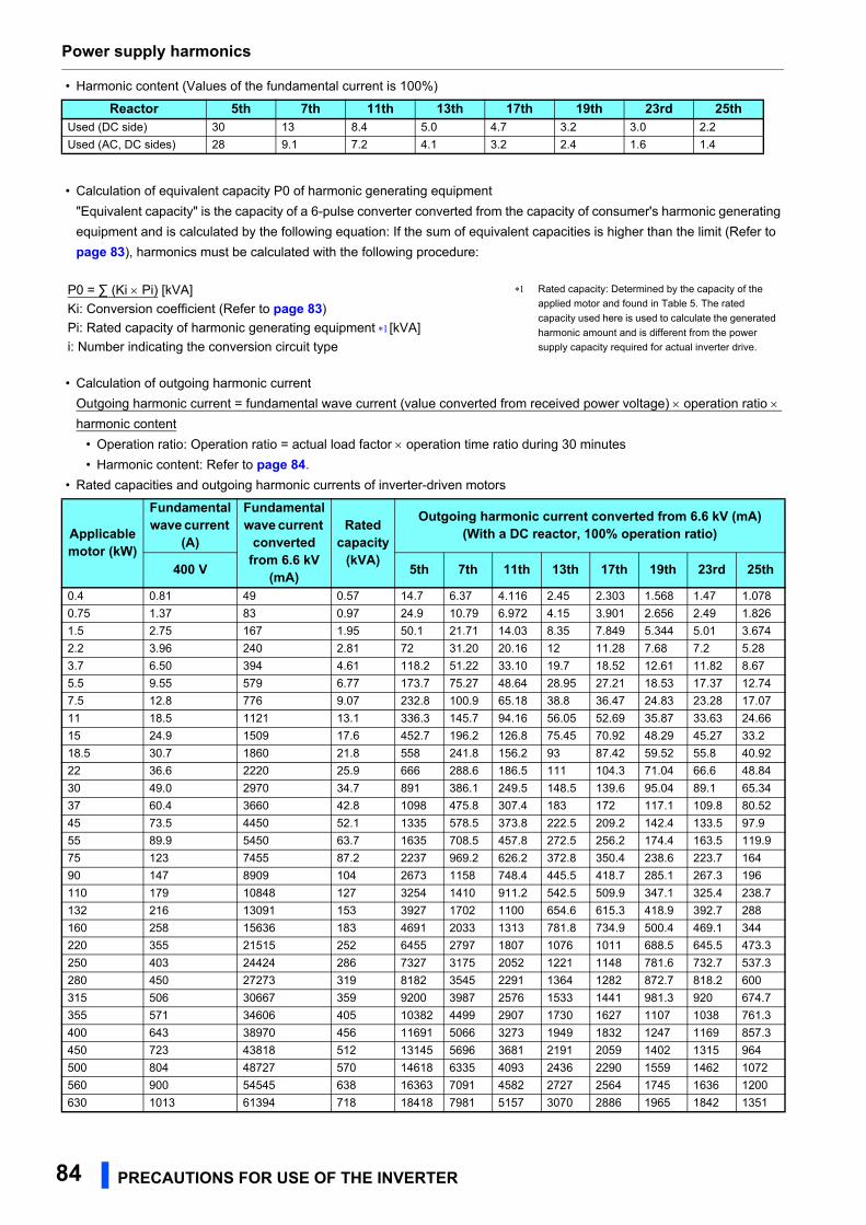
Power supply harmonics
• Harmonic content (Values of the fundamental current is 100%)
• Calculation of equivalent capacity P0 of harmonic generating equipment
"Equivalent capacity" is the capacity of a 6-pulse converter converted from the capacity of consumer's harmonic generating
equipment and is calculated by the following equation: If the sum of equivalent capacities is higher than the limit (Refer to
page 83), harmonics must be calculated with the following procedure:
• Calculation of outgoing harmonic current
Outgoing harmonic current = fundamental wave current (value converted from received power voltage) operation ratio
harmonic content
• Operation ratio: Operation ratio = actual load factor operation time ratio during 30 minutes
• Harmonic content: Refer to page 84.
• Rated capacities and outgoing harmonic currents of inverter-driven motors
Reactor 5th 7th 11th 13th 17th 19th 23rd 25thUsed (DC side) 30 13 8.4 5.0 4.7 3.2 3.0 2.2
Used (AC, DC sides) 28 9.1 7.2 4.1 3.2 2.4 1.6 1.4
P0 = ∑ (Ki Pi) [kVA] Rated capacity: Determined by the capacity of the
applied motor and found in Table 5. The rated
capacity used here is used to calculate the generated
harmonic amount and is different from the power
supply capacity required for actual inverter drive.
Ki: Conversion coefficient (Refer to page 83)
Pi: Rated capacity of harmonic generating equipment [kVA]
i: Number indicating the conversion circuit type
Applicablemotor (kW)
Fundamental wave current
(A)
Fundamental wave current
converted from 6.6 kV
(mA)
Rated capacity
(kVA)
Outgoing harmonic current converted from 6.6 kV (mA)(With a DC reactor, 100% operation ratio)
400 V 5th 7th 11th 13th 17th 19th 23rd 25th
0.4 0.81 49 0.57 14.7 6.37 4.116 2.45 2.303 1.568 1.47 1.078
0.75 1.37 83 0.97 24.9 10.79 6.972 4.15 3.901 2.656 2.49 1.826
1.5 2.75 167 1.95 50.1 21.71 14.03 8.35 7.849 5.344 5.01 3.674
2.2 3.96 240 2.81 72 31.20 20.16 12 11.28 7.68 7.2 5.28
3.7 6.50 394 4.61 118.2 51.22 33.10 19.7 18.52 12.61 11.82 8.67
5.5 9.55 579 6.77 173.7 75.27 48.64 28.95 27.21 18.53 17.37 12.74
7.5 12.8 776 9.07 232.8 100.9 65.18 38.8 36.47 24.83 23.28 17.07
11 18.5 1121 13.1 336.3 145.7 94.16 56.05 52.69 35.87 33.63 24.66
15 24.9 1509 17.6 452.7 196.2 126.8 75.45 70.92 48.29 45.27 33.2
18.5 30.7 1860 21.8 558 241.8 156.2 93 87.42 59.52 55.8 40.92
22 36.6 2220 25.9 666 288.6 186.5 111 104.3 71.04 66.6 48.84
30 49.0 2970 34.7 891 386.1 249.5 148.5 139.6 95.04 89.1 65.34
37 60.4 3660 42.8 1098 475.8 307.4 183 172 117.1 109.8 80.52
45 73.5 4450 52.1 1335 578.5 373.8 222.5 209.2 142.4 133.5 97.9
55 89.9 5450 63.7 1635 708.5 457.8 272.5 256.2 174.4 163.5 119.9
75 123 7455 87.2 2237 969.2 626.2 372.8 350.4 238.6 223.7 164
90 147 8909 104 2673 1158 748.4 445.5 418.7 285.1 267.3 196
110 179 10848 127 3254 1410 911.2 542.5 509.9 347.1 325.4 238.7
132 216 13091 153 3927 1702 1100 654.6 615.3 418.9 392.7 288
160 258 15636 183 4691 2033 1313 781.8 734.9 500.4 469.1 344
220 355 21515 252 6455 2797 1807 1076 1011 688.5 645.5 473.3
250 403 24424 286 7327 3175 2052 1221 1148 781.6 732.7 537.3
280 450 27273 319 8182 3545 2291 1364 1282 872.7 818.2 600
315 506 30667 359 9200 3987 2576 1533 1441 981.3 920 674.7
355 571 34606 405 10382 4499 2907 1730 1627 1107 1038 761.3
400 643 38970 456 11691 5066 3273 1949 1832 1247 1169 857.3
450 723 43818 512 13145 5696 3681 2191 2059 1402 1315 964
500 804 48727 570 14618 6335 4093 2436 2290 1559 1462 1072
560 900 54545 638 16363 7091 4582 2727 2564 1745 1636 1200
630 1013 61394 718 18418 7981 5157 3070 2886 1965 1842 1351
84 PRECAUTIONS FOR USE OF THE INVERTER
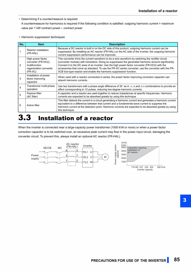
Installation of a reactor
3
• Determining if a countermeasure is required
A countermeasure for harmonics is required if the following condition is satisfied: outgoing harmonic current > maximum
value per 1 kW contract power contract power
• Harmonic suppression techniques
3.3 Installation of a reactorWhen the inverter is connected near a large-capacity power transformer (1000 kVA or more) or when a power factor
correction capacitor is to be switched over, an excessive peak current may flow in the power input circuit, damaging the
converter circuit. To prevent this, always install an optional AC reactor (FR-HAL).
No. Item Description
1Reactor installation(FR-HAL)
Because a DC reactor is built in on the DC side of this product, outgoing harmonic current can be suppressed. By installing an AC reactor (FR-HAL) on the AC side of the inverter, the outgoing harmonic current suppression performance can be improved.
2
High power factorconverter (FR-HC2),multifunction regeneration converter (FR-XC)
This converter trims the current waveform to be a sine waveform by switching the rectifier circuit (converter module) with transistors. Doing so suppresses the generated harmonic amount significantly. Connect it to the DC area of an inverter. Use the high power factor converter (FR-HC2) with the accessories that come as standard. To use the FR-XC series converter, use the converter with the FR-XCB box-type reactor and enable the harmonic suppression function.
3Installation of power factor improving capacitor
When used with a reactor connected in series, the power factor improving correction capacitor can absorb harmonic currents.
4Transformer multi-phase operation
Use two transformers with a phase angle difference of 30˚ as in -∆ and ∆-∆ combinations to provide an effect corresponding to 12 pulses, reducing low-degree harmonic currents.
5Passive filter(AC filter)
A capacitor and a reactor are used together to reduce impedances at specific frequencies. Harmonic currents are expected to be absorbed greatly by using this technique.
6 Active filter
This filter detects the current in a circuit generating a harmonic current and generates a harmonic current equivalent to a difference between that current and a fundamental wave current to suppress the harmonic current at the detection point. Harmonic currents are expected to be absorbed greatly by using this technique.
MCCB MCInverterAC reactor
(FR-HAL)
Power supply
R
S
T Z
Y
X U
V
W
R/L1
S/L2
T/L3
M
50005300
4000
3000
2000
1000
110165 247 330 420 550 kVA
Capacities requiring installation of AC reactor
Inverter capacity
Pow
er s
uppl
y sy
stem
ca
paci
ty
(kVA)
PRECAUTIONS FOR USE OF THE INVERTER 85
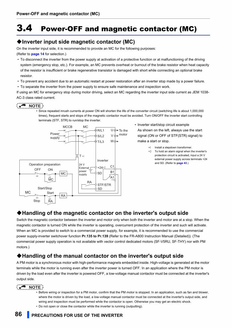
Power-OFF and magnetic contactor (MC)
3.4 Power-OFF and magnetic contactor (MC)
Inverter input side magnetic contactor (MC)On the inverter input side, it is recommended to provide an MC for the following purposes:
(Refer to page 14 for selection.)
• To disconnect the inverter from the power supply at activation of a protective function or at malfunctioning of the driving
system (emergency stop, etc.). For example, an MC prevents overheat or burnout of the brake resistor when heat capacity
of the resistor is insufficient or brake regenerative transistor is damaged with short while connecting an optional brake
resistor.
• To prevent any accident due to an automatic restart at power restoration after an inverter stop made by a power failure.
• To separate the inverter from the power supply to ensure safe maintenance and inspection work.
If using an MC for emergency stop during motor driving, select an MC regarding the inverter input side current as JEM 1038-
AC-3 class rated current.
NOTE • Since repeated inrush currents at power ON will shorten the life of the converter circuit (switching life is about 1,000,000
times), frequent starts and stops of the magnetic contactor must be avoided. Turn ON/OFF the inverter start controlling
terminals (STF, STR) to run/stop the inverter.
Handling of the magnetic contactor on the inverter's output sideSwitch the magnetic contactor between the inverter and motor only when both the inverter and motor are at a stop. When the
magnetic contactor is turned ON while the inverter is operating, overcurrent protection of the inverter and such will activate.
When an MC is provided to switch to a commercial power supply, for example, it is recommended to use the commercial
power supply-inverter switchover function Pr.135 to Pr.139 (Refer to the FR-A800 Instruction Manual (Detailed)). (The
commercial power supply operation is not available with vector control dedicated motors (SF-V5RU, SF-THY) nor with PM
motors.)
Handling of the manual contactor on the inverter's output sideA PM motor is a synchronous motor with high-performance magnets embedded inside. High-voltage is generated at the motor
terminals while the motor is running even after the inverter power is turned OFF. In an application where the PM motor is
driven by the load even after the inverter is powered OFF, a low-voltage manual contactor must be connected at the inverter's
output side.
NOTE • Before wiring or inspection for a PM motor, confirm that the PM motor is stopped. In an application, such as fan and blower,
where the motor is driven by the load, a low-voltage manual contactor must be connected at the inverter's output side, and
wiring and inspection must be performed while the contactor is open. Otherwise you may get an electric shock.
• Do not open or close the contactor while the inverter is running (outputting).
• Inverter start/stop circuit example
As shown on the left, always use the start
signal (ON or OFF of STF(STR) signal) to
make a start or stop.
Install a stepdown transformer.
To hold an alarm signal when the inverter's
protection circuit is activated, input a 24 V
external power supply across terminals +24
and SD. (Refer to page 43.)
Powersupply
MCCB
RA
U
V
A1
B1
C1
W
To themotor
Inverter
SD
MC
STF/STR
R/L1
S/L2
T/L3
+24
SDOFF ON
MC
Stop
Start
RA
MC
Operation preparation
Start/Stop
RA
MC
24 VExternalpowersupply
T ∗1
∗2
86 PRECAUTIONS FOR USE OF THE INVERTER
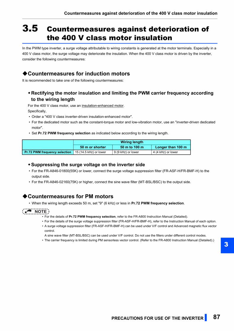
Countermeasures against deterioration of the 400 V class motor insulation
3
3.5 Countermeasures against deterioration of the 400 V class motor insulation
In the PWM type inverter, a surge voltage attributable to wiring constants is generated at the motor terminals. Especially in a
400 V class motor, the surge voltage may deteriorate the insulation. When the 400 V class motor is driven by the inverter,
consider the following countermeasures:
Countermeasures for induction motorsIt is recommended to take one of the following countermeasures:
Rectifying the motor insulation and limiting the PWM carrier frequency according to the wiring length
For the 400 V class motor, use an insulation-enhanced motor.
Specifically,
• Order a "400 V class inverter-driven insulation-enhanced motor".
• For the dedicated motor such as the constant-torque motor and low-vibration motor, use an "inverter-driven dedicated
motor".
• Set Pr.72 PWM frequency selection as indicated below according to the wiring length.
Suppressing the surge voltage on the inverter side • For the FR-A846-01800(55K) or lower, connect the surge voltage suppression filter (FR-ASF-H/FR-BMF-H) to the
output side.
• For the FR-A846-02160(75K) or higher, connect the sine wave filter (MT-BSL/BSC) to the output side.
Countermeasures for PM motors • When the wiring length exceeds 50 m, set "9" (6 kHz) or less in Pr.72 PWM frequency selection.
NOTE • For the details of Pr.72 PWM frequency selection, refer to the FR-A800 Instruction Manual (Detailed).
• For the details of the surge voltage suppression filter (FR-ASF-H/FR-BMF-H), refer to the Instruction Manual of each option.
• A surge voltage suppression filter (FR-ASF-H/FR-BMF-H) can be used under V/F control and Advanced magnetic flux vector
control.
A sine wave filter (MT-BSL/BSC) can be used under V/F control. Do not use the filters under different control modes.
• The carrier frequency is limited during PM sensorless vector control. (Refer to the FR-A800 Instruction Manual (Detailed).)
Wiring length50 m or shorter 50 m to 100 m Longer than 100 m
Pr.72 PWM frequency selection 15 (14.5 kHz) or lower 9 (9 kHz) or lower 4 (4 kHz) or lower
PRECAUTIONS FOR USE OF THE INVERTER 87
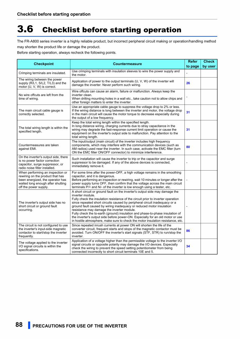
Checklist before starting operation
3.6 Checklist before starting operationThe FR-A800 series inverter is a highly reliable product, but incorrect peripheral circuit making or operation/handling method
may shorten the product life or damage the product.
Before starting operation, always recheck the following points.
Checkpoint Countermeasure Refer to page
Check by user
Crimping terminals are insulated.Use crimping terminals with insulation sleeves to wire the power supply and the motor.
-
The wiring between the power supply (R/L1, S/L2, T/L3) and the motor (U, V, W) is correct.
Application of power to the output terminals (U, V, W) of the inverter will damage the inverter. Never perform such wiring.
26
No wire offcuts are left from the time of wiring.
Wire offcuts can cause an alarm, failure or malfunction. Always keep the inverter clean.When drilling mounting holes in a wall etc., take caution not to allow chips and other foreign matters to enter the inverter.
-
The main circuit cable gauge is correctly selected.
Use an appropriate cable gauge to suppress the voltage drop to 2% or less.If the wiring distance is long between the inverter and motor, the voltage drop in the main circuit will cause the motor torque to decrease especially during the output of a low frequency.
31
The total wiring length is within the specified length.
Keep the total wiring length within the specified length.In long distance wiring, charging currents due to stray capacitance in the wiring may degrade the fast-response current limit operation or cause the equipment on the inverter's output side to malfunction. Pay attention to the total wiring length.
31
Countermeasures are taken against EMI.
The input/output (main circuit) of the inverter includes high frequency components, which may interfere with the communication devices (such as AM radios) used near the inverter. In such case, activate the EMC filter (turn ON the EMC filter ON/OFF connector) to minimize interference.
80
On the inverter's output side, there is no power factor correction capacitor, surge suppressor, or radio noise filter installed.
Such installation will cause the inverter to trip or the capacitor and surge suppressor to be damaged. If any of the above devices is connected, immediately remove it.
-
When performing an inspection or rewiring on the product that has been energized, the operator has waited long enough after shutting off the power supply.
For some time after the power-OFF, a high voltage remains in the smoothing capacitor, and it is dangerous.Before performing an inspection or rewiring, wait 10 minutes or longer after the power supply turns OFF, then confirm that the voltage across the main circuit terminals P/+ and N/- of the inverter is low enough using a tester, etc.
-
The inverter's output side has no short circuit or ground fault occurring.
A short circuit or ground fault on the inverter's output side may damage the inverter module.Fully check the insulation resistance of the circuit prior to inverter operation since repeated short circuits caused by peripheral circuit inadequacy or a ground fault caused by wiring inadequacy or reduced motor insulation resistance may damage the inverter module.Fully check the to-earth (ground) insulation and phase-to-phase insulation of the inverter's output side before power-ON. Especially for an old motor or use in hostile atmosphere, make sure to check the motor insulation resistance, etc.
-
The circuit is not configured to use the inverter's input-side magnetic contactor to start/stop the inverter frequently.
Since repeated inrush currents at power ON will shorten the life of the converter circuit, frequent starts and stops of the magnetic contactor must be avoided. Turn ON/OFF the inverter's start signals (STF, STR) to run/stop the inverter.
86
The voltage applied to the inverter I/O signal circuits is within the specifications.
Application of a voltage higher than the permissible voltage to the inverter I/O signal circuits or opposite polarity may damage the I/O devices. Especially check the wiring to prevent the speed setting potentiometer from being connected incorrectly to short circuit terminals 10E and 5.
34
88 PRECAUTIONS FOR USE OF THE INVERTER
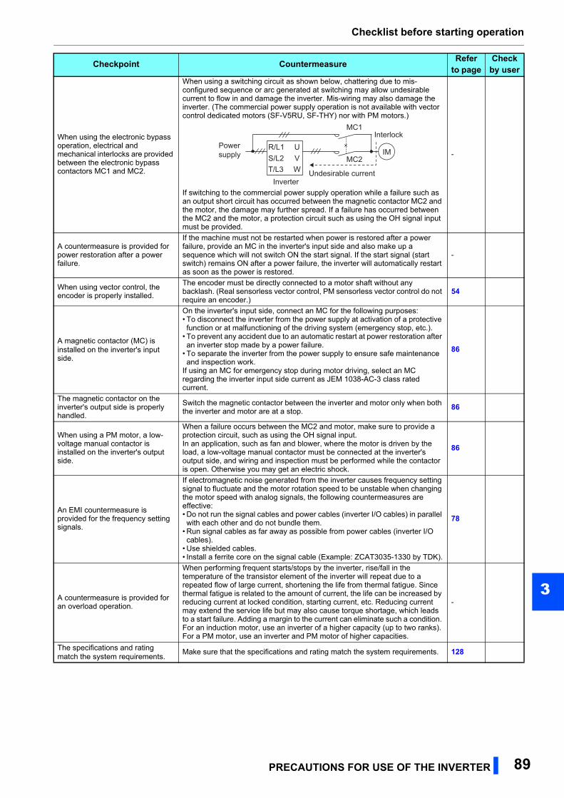
Checklist before starting operation
3
When using the electronic bypass operation, electrical and mechanical interlocks are provided between the electronic bypass contactors MC1 and MC2.
When using a switching circuit as shown below, chattering due to mis-configured sequence or arc generated at switching may allow undesirable current to flow in and damage the inverter. Mis-wiring may also damage the inverter. (The commercial power supply operation is not available with vector control dedicated motors (SF-V5RU, SF-THY) nor with PM motors.)
If switching to the commercial power supply operation while a failure such as an output short circuit has occurred between the magnetic contactor MC2 and the motor, the damage may further spread. If a failure has occurred between the MC2 and the motor, a protection circuit such as using the OH signal input must be provided.
-
A countermeasure is provided for power restoration after a power failure.
If the machine must not be restarted when power is restored after a power failure, provide an MC in the inverter's input side and also make up a sequence which will not switch ON the start signal. If the start signal (start switch) remains ON after a power failure, the inverter will automatically restart as soon as the power is restored.
-
When using vector control, the encoder is properly installed.
The encoder must be directly connected to a motor shaft without any backlash. (Real sensorless vector control, PM sensorless vector control do not require an encoder.)
54
A magnetic contactor (MC) is installed on the inverter's input side.
On the inverter's input side, connect an MC for the following purposes:• To disconnect the inverter from the power supply at activation of a protective function or at malfunctioning of the driving system (emergency stop, etc.).
• To prevent any accident due to an automatic restart at power restoration after an inverter stop made by a power failure.
• To separate the inverter from the power supply to ensure safe maintenance and inspection work.
If using an MC for emergency stop during motor driving, select an MC regarding the inverter input side current as JEM 1038-AC-3 class rated current.
86
The magnetic contactor on the inverter's output side is properly handled.
Switch the magnetic contactor between the inverter and motor only when both the inverter and motor are at a stop.
86
When using a PM motor, a low-voltage manual contactor is installed on the inverter's output side.
When a failure occurs between the MC2 and motor, make sure to provide a protection circuit, such as using the OH signal input.In an application, such as fan and blower, where the motor is driven by the load, a low-voltage manual contactor must be connected at the inverter's output side, and wiring and inspection must be performed while the contactor is open. Otherwise you may get an electric shock.
86
An EMI countermeasure is provided for the frequency setting signals.
If electromagnetic noise generated from the inverter causes frequency setting signal to fluctuate and the motor rotation speed to be unstable when changing the motor speed with analog signals, the following countermeasures are effective:• Do not run the signal cables and power cables (inverter I/O cables) in parallel with each other and do not bundle them.
• Run signal cables as far away as possible from power cables (inverter I/O cables).
• Use shielded cables.• Install a ferrite core on the signal cable (Example: ZCAT3035-1330 by TDK).
78
A countermeasure is provided for an overload operation.
When performing frequent starts/stops by the inverter, rise/fall in the temperature of the transistor element of the inverter will repeat due to a repeated flow of large current, shortening the life from thermal fatigue. Since thermal fatigue is related to the amount of current, the life can be increased by reducing current at locked condition, starting current, etc. Reducing current may extend the service life but may also cause torque shortage, which leads to a start failure. Adding a margin to the current can eliminate such a condition. For an induction motor, use an inverter of a higher capacity (up to two ranks). For a PM motor, use an inverter and PM motor of higher capacities.
-
The specifications and rating match the system requirements.
Make sure that the specifications and rating match the system requirements. 128
Checkpoint Countermeasure Refer to page
Check by user
Power supply
InverterUndesirable current
MC2
MC1Interlock
UVW
R/L1S/L2T/L3
IM
PRECAUTIONS FOR USE OF THE INVERTER 89

Checklist before starting operation
Countermeasures are taken against electrical corrosion on the motor bearing.
When a motor is driven by the inverter, axial voltage is generated on the motor bearing, which may cause electrical corrosion of the bearing in rare cases depending on: condition of the grease used for the bearing, wiring, load, operating conditions of the motor, or specific inverter settings (high carrier frequency, EMC filter ON).Contact your sales representative to take appropriate countermeasures for the motor.The following shows examples of countermeasures for the inverter.• Decrease the carrier frequency.• Turn OFF the EMC filter.• Provide a common mode choke on the output side of the inverter. (This is effective regardless of the EMC filter ON/OFF connector setting.)
Recommended common mode choke: FT-3KM F series FINEMET® common mode choke cores manufactured by Hitachi Metals, Ltd.FINEMET is a registered trademark of Hitachi Metals, Ltd.
-
Checkpoint Countermeasure Refer to page
Check by user
90 PRECAUTIONS FOR USE OF THE INVERTER
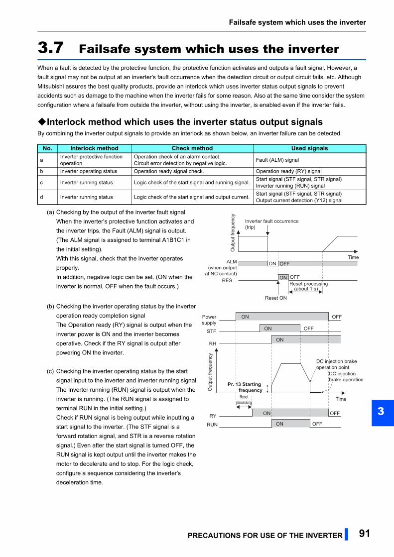
Failsafe system which uses the inverter
3
3.7 Failsafe system which uses the inverterWhen a fault is detected by the protective function, the protective function activates and outputs a fault signal. However, a
fault signal may not be output at an inverter's fault occurrence when the detection circuit or output circuit fails, etc. Although
Mitsubishi assures the best quality products, provide an interlock which uses inverter status output signals to prevent
accidents such as damage to the machine when the inverter fails for some reason. Also at the same time consider the system
configuration where a failsafe from outside the inverter, without using the inverter, is enabled even if the inverter fails.
Interlock method which uses the inverter status output signalsBy combining the inverter output signals to provide an interlock as shown below, an inverter failure can be detected.
No. Interlock method Check method Used signals
aInverter protective function operation
Operation check of an alarm contact.Circuit error detection by negative logic.
Fault (ALM) signal
b Inverter operating status Operation ready signal check. Operation ready (RY) signal
c Inverter running status Logic check of the start signal and running signal.Start signal (STF signal, STR signal)Inverter running (RUN) signal
d Inverter running status Logic check of the start signal and output current.Start signal (STF signal, STR signal)Output current detection (Y12) signal
(a) Checking by the output of the inverter fault signal
When the inverter's protective function activates and
the inverter trips, the Fault (ALM) signal is output.
(The ALM signal is assigned to terminal A1B1C1 in
the initial setting).
With this signal, check that the inverter operates
properly.
In addition, negative logic can be set. (ON when the
inverter is normal, OFF when the fault occurs.)
(b) Checking the inverter operating status by the inverter
operation ready completion signal
The Operation ready (RY) signal is output when the
inverter power is ON and the inverter becomes
operative. Check if the RY signal is output after
powering ON the inverter.
(c) Checking the inverter operating status by the start
signal input to the inverter and inverter running signal
The Inverter running (RUN) signal is output when the
inverter is running. (The RUN signal is assigned to
terminal RUN in the initial setting.)
Check if RUN signal is being output while inputting a
start signal to the inverter. (The STF signal is a
forward rotation signal, and STR is a reverse rotation
signal.) Even after the start signal is turned OFF, the
RUN signal is kept output until the inverter makes the
motor to decelerate and to stop. For the logic check,
configure a sequence considering the inverter's
deceleration time.
ON
(about 1 s)
OFF
Reset ON
Out
put f
requ
ency
ALM(when output
at NC contact)RES
Inverter fault occurrence(trip)
TimeOFF
ONReset processing
Time
Powersupply
Out
put f
requ
ency
STF
RH
RY
Resetprocessing
Pr. 13 Starting frequency
ON OFF
ON OFF
ON OFF
ON
DC injection brakeoperation point
DC injectionbrake operation
RUN ON OFF
PRECAUTIONS FOR USE OF THE INVERTER 91
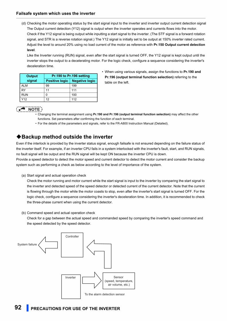
Failsafe system which uses the inverter
NOTE • Changing the terminal assignment using Pr.190 and Pr.196 (output terminal function selection) may affect the other
functions. Set parameters after confirming the function of each terminal.
• For the details of the parameters and signals, refer to the FR-A800 Instruction Manual (Detailed).
Backup method outside the inverterEven if the interlock is provided by the inverter status signal, enough failsafe is not ensured depending on the failure status of
the inverter itself. For example, if an inverter CPU fails in a system interlocked with the inverter's fault, start, and RUN signals,
no fault signal will be output and the RUN signal will be kept ON because the inverter CPU is down.
Provide a speed detector to detect the motor speed and current detector to detect the motor current and consider the backup
system such as performing a check as below according to the level of importance of the system.
(a) Start signal and actual operation check
Check the motor running and motor current while the start signal is input to the inverter by comparing the start signal to
the inverter and detected speed of the speed detector or detected current of the current detector. Note that the current
is flowing through the motor while the motor coasts to stop, even after the inverter's start signal is turned OFF. For the
logic check, configure a sequence considering the inverter's deceleration time. In addition, it is recommended to check
the three-phase current when using the current detector.
(b) Command speed and actual operation check
Check for a gap between the actual speed and commanded speed by comparing the inverter's speed command and
the speed detected by the speed detector.
(d) Checking the motor operating status by the start signal input to the inverter and inverter output current detection signal
The Output current detection (Y12) signal is output when the inverter operates and currents flows into the motor.
Check if the Y12 signal is being output while inputting a start signal to the inverter. (The STF signal is a forward rotation
signal, and STR is a reverse rotation signal.) The Y12 signal is initially set to be output at 150% inverter rated current.
Adjust the level to around 20% using no load current of the motor as reference with Pr.150 Output current detection level.Like the Inverter running (RUN) signal, even after the start signal is turned OFF, the Y12 signal is kept output until the
inverter stops the output to a decelerating motor. For the logic check, configure a sequence considering the inverter's
deceleration time.
• When using various signals, assign the functions to Pr.190 and Pr.196 (output terminal function selection) referring to the
table on the left.
Output signal
Pr.190 to Pr.196 settingPositive logic Negative logic
ALM 99 199
RY 11 111
RUN 0 100
Y12 12 112
Inverter
Controller
System failure
To the alarm detection sensor
Sensor(speed, temperature,
air volume, etc.)
92 PRECAUTIONS FOR USE OF THE INVERTER

PROTECTIVE FUNCTIONS 93
4
4 PROTECTIVE FUNCTIONS
This chapter explains the "PROTECTIVE FUNCTIONS" that operates inthis product.Always read the instructions before using the equipment.
4.1 Inverter fault and alarm indications ........................................944.2 Reset method for the protective functions.............................944.3 Fault history and the list of fault displays..............................95
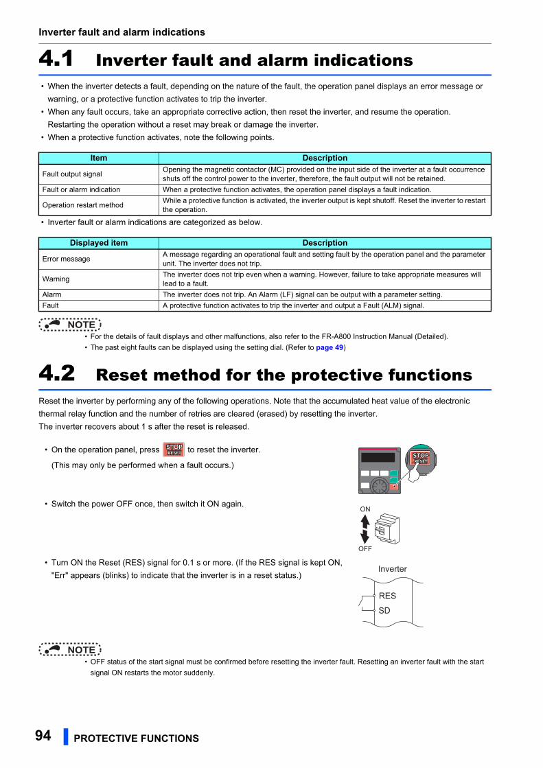
Inverter fault and alarm indications
94 PROTECTIVE FUNCTIONS
4.1 Inverter fault and alarm indications • When the inverter detects a fault, depending on the nature of the fault, the operation panel displays an error message or
warning, or a protective function activates to trip the inverter.
• When any fault occurs, take an appropriate corrective action, then reset the inverter, and resume the operation.
Restarting the operation without a reset may break or damage the inverter.
• When a protective function activates, note the following points.
• Inverter fault or alarm indications are categorized as below.
NOTE • For the details of fault displays and other malfunctions, also refer to the FR-A800 Instruction Manual (Detailed).
• The past eight faults can be displayed using the setting dial. (Refer to page 49)
4.2 Reset method for the protective functionsReset the inverter by performing any of the following operations. Note that the accumulated heat value of the electronic
thermal relay function and the number of retries are cleared (erased) by resetting the inverter.
The inverter recovers about 1 s after the reset is released.
NOTE • OFF status of the start signal must be confirmed before resetting the inverter fault. Resetting an inverter fault with the start
signal ON restarts the motor suddenly.
Item Description
Fault output signalOpening the magnetic contactor (MC) provided on the input side of the inverter at a fault occurrence shuts off the control power to the inverter, therefore, the fault output will not be retained.
Fault or alarm indication When a protective function activates, the operation panel displays a fault indication.
Operation restart methodWhile a protective function is activated, the inverter output is kept shutoff. Reset the inverter to restart the operation.
Displayed item Description
Error messageA message regarding an operational fault and setting fault by the operation panel and the parameter unit. The inverter does not trip.
WarningThe inverter does not trip even when a warning. However, failure to take appropriate measures will lead to a fault.
Alarm The inverter does not trip. An Alarm (LF) signal can be output with a parameter setting.
Fault A protective function activates to trip the inverter and output a Fault (ALM) signal.
• On the operation panel, press to reset the inverter.
(This may only be performed when a fault occurs.)
• Switch the power OFF once, then switch it ON again.
• Turn ON the Reset (RES) signal for 0.1 s or more. (If the RES signal is kept ON,
"Err" appears (blinks) to indicate that the inverter is in a reset status.)
ON
OFF
SD
Inverter
RES
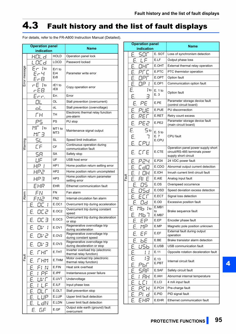
Fault history and the list of fault displays
4
4.3 Fault history and the list of fault displaysFor details, refer to the FR-A800 Instruction Manual (Detailed).
Operation panel indication Name
Err
or m
essa
ge
HOLD Operation panel lock
LOCD Password locked
to Er1 to Er4Er8
Parameter write error
to rE1 to rE8
Copy operation error
Err. Error
Wa
rnin
g
OL Stall prevention (overcurrent)
oL Stall prevention (overvoltage)
THElectronic thermal relay function pre-alarm
PS PU stop
to MT1 to MT3
Maintenance signal output
SL Speed limit indication
CFContinuous operation during communication fault
SA Safety stop
UF USB host error
HP1 Home position return setting error
HP2 Home position return uncompleted
HP3Home position return parameter setting error
EHR Ethernet communication fault
Ala
rm FN Fan alarm
FN2 Internal-circulation fan alarm
Fau
lt
E.OC1 Overcurrent trip during acceleration
E.OC2Overcurrent trip during constant speed
E.OC3Overcurrent trip during deceleration or stop
E.OV1Regenerative overvoltage trip during acceleration
E.OV2Regenerative overvoltage trip during constant speed
E.OV3Regenerative overvoltage trip during deceleration or stop
E.THTInverter overload trip (electronic thermal relay function)
E.THMMotor overload trip (electronic thermal relay function)
E.FIN Heat sink overheat
E.IPF Instantaneous power failure
E.UVT Undervoltage
E.ILF Input phase loss
E.OLT Stall prevention stop
E.LUP Upper limit fault detection
E.LDN Lower limit fault detection
E.GFOutput side earth (ground) fault overcurrent
Fa
ult
E. SOT Loss of synchronism detection
E.LF Output phase loss
E.OHT External thermal relay operation
E.PTC PTC thermistor operation
E.OPT Option fault
E.OP1 Communication option fault
to E. 1 to E. 3
Option fault
E.PEParameter storage device fault (control circuit board)
E.PUE PU disconnection
E.RET Retry count excess
E.PE2Parameter storage device fault (main circuit board)
toE. 5 to E. 7E.CPU
CPU fault
E.CTEOperation panel power supply short circuit/RS-485 terminals power supply short circuit
E.P24 24 VDC power fault
E.CDO Abnormal output current detection
E.IOH Inrush current limit circuit fault
E.AIE Analog input fault
E.OS Overspeed occurrence
E.OSD Speed deviation excess detection
E.ECT Signal loss detection
E.OD Excessive position fault
to E.MB1 to E.MB7
Brake sequence fault
E.EP Encoder phase fault
E.MP Magnetic pole position unknown
E.EFExternal fault during output operation
E.BE Brake transistor alarm detection
E.USB USB communication fault
E.11 Opposite rotation deceleration fault
E.13E.PBT
Internal circuit fault
E.SAF Safety circuit fault
E.IAH Abnormal internal temperature
E.LCI 4 mA input fault
E.PCH Pre-charge fault
E.PID PID signal fault
E.EHR Ethernet communication fault
Operation panel indication Name
PROTECTIVE FUNCTIONS 95

Fault history and the list of fault displays
If faults other than the above appear, contact your sales
representative.
Fau
lt to E.16 to E.20
User definition error by the PLC function
Oth
ers
E---- Fault history
E.0 No fault records
EV24 V external power supply operation
RD Backup in progress
WR Restoration in progress
Operation panel indication Name
96 PROTECTIVE FUNCTIONS

PRECAUTIONS FOR MAINTENANCE AND INSPECTION 97
5
5 PRECAUTIONS FOR MAINTENANCE AND INSPECTION
This chapter explains the "PRECAUTIONS FOR MAINTENANCE AND INSPECTION" for this product.Always read the instructions before using the equipment.
5.1 Inspection item..........................................................................985.2 Measurement of main circuit voltages, currents, and powers .123
Inspection item
The inverter is a static unit mainly consisting of semiconductor devices. Daily inspection must be performed to prevent any
fault from occurring due to the adverse effects of the operating environment, such as temperature, humidity, dust, dirt and
vibration, changes in the parts with time, service life, and other factors.
Precautions for maintenance and inspection
When accessing the inverter for inspection, wait for at least 10 minutes after the power supply has been switched OFF, and
then make sure that the voltage across the main circuit terminals P/+ and N/- of the inverter is not more than 30 VDC using a
tester, etc.
5.1 Inspection item
5.1.1 Daily inspectionBasically, check for the following faults during operation.
• Motor operation fault
• Improper installation environment
• Cooling system fault
• Abnormal vibration, abnormal noise
• Abnormal overheat, discoloration
5.1.2 Periodic inspectionCheck the areas inaccessible during operation and requiring periodic inspection.
Consult us for periodic inspection.
• Check and clean the cooling system ................Clean the air filter, etc.
• Check the tightening and retighten ...................The screws and bolts may become loose due to vibration, temperature
changes, etc. Check and tighten them.
Tighten them according to the specified tightening torque. (Refer to page31.)
• Check the conductors and insulating materials for corrosion and damage
• Measure the insulation resistance
• Check and change the cooling fan, internal fan and relay
• Check for condensation ....................................A sudden temperature change may cause water droplets (condensation) to
form inside the inverter. Using the inverter with condensation inside may
cause a failure.
• Check for ingress of water or dust .................... If the waterproof or dustproof performance is impaired, water or dust may
get into the inverter. Using the inverter with water or dust remaining inside
may cause a failure.
• Inspection and replacement of the gasket ........Changes such as in temperature may cause aging degradation of the
gasket rubber material, which may impair the waterproof and dustproof
performances.
NOTE • When using the safety stop function, periodic inspection is required to confirm that safety function of the safety system
operates correctly.
For more details, refer to the Safety stop function instruction manual.
98 PRECAUTIONS FOR MAINTENANCE AND INSPECTION
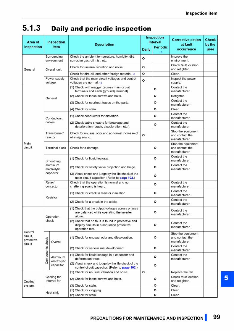
Inspection item
5
5.1.3 Daily and periodic inspection
Area of inspection
Inspection item Description
Inspection interval Corrective action
at fault occurrence
Check by the userDaily Periodic
General
Surrounding environment
Check the ambient temperature, humidity, dirt, corrosive gas, oil mist, etc.
Improve the environment.
Overall unitCheck for unusual vibration and noise.
Check fault location and retighten.
Check for dirt, oil, and other foreign material. Clean.
Power supply voltage
Check that the main circuit voltages and control voltages are normal.
Inspect the power supply.
Main circuit
General
(1) Check with megger (across main circuit terminals and earth (ground) terminal).
Contact the manufacturer.
(2) Check for loose screws and bolts. Retighten.
(3) Check for overheat traces on the parts. Contact the manufacturer.
(4) Check for stain. Clean.
Conductors, cables
(1) Check conductors for distortion. Contact the manufacturer.
(2) Check cable sheaths for breakage and deterioration (crack, discoloration, etc.).
Contact the manufacturer.
Transformer/reactor
Check for unusual odor and abnormal increase of whining sound.
Stop the equipment and contact the manufacturer.
Terminal block Check for a damage. Stop the equipment and contact the manufacturer.
Smoothing aluminum electrolytic capacitor
(1) Check for liquid leakage. Contact the manufacturer.
(2) Check for safety valve projection and bulge. Contact the manufacturer.
(3) Visual check and judge by the life check of the main circuit capacitor. (Refer to page 102.)
Relay/contactor
Check that the operation is normal and no chattering sound is heard.
Contact the manufacturer.
Resistor(1) Check for crack in resistor insulation.
Contact the manufacturer.
(2) Check for a break in the cable. Contact the manufacturer.
Control circuit,protective circuit
Operation check
(1) Check that the output voltages across phases are balanced while operating the inverter alone.
Contact the manufacturer.
(2) Check that no fault is found in protective and display circuits in a sequence protective operation test.
Contact the manufacturer.
Com
pone
nts
chec
k
Overall(1) Check for unusual odor and discoloration.
Stop the equipment and contact the manufacturer.
(2) Check for serious rust development. Contact the manufacturer.
Aluminum electrolyticcapacitor
(1) Check for liquid leakage in a capacitor and deformation trace.
Contact the manufacturer.
(2) Visual check and judge by the life check of the control circuit capacitor. (Refer to page 102.)
Cooling system
Cooling fanInternal fan
(1) Check for unusual vibration and noise. Replace the fan.
(2) Check for loose screws and bolts. Check fault location and retighten.
(3) Check for stain. Clean.
Heat sink(1) Check for clogging. Clean.
(2) Check for stain. Clean.
PRECAUTIONS FOR MAINTENANCE AND INSPECTION 99
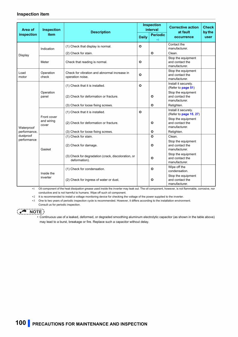
Inspection item
Oil component of the heat dissipation grease used inside the inverter may leak out. The oil component, however, is not flammable, corrosive, nor
conductive and is not harmful to humans. Wipe off such oil component.
It is recommended to install a voltage monitoring device for checking the voltage of the power supplied to the inverter.
One to two years of periodic inspection cycle is recommended. However, it differs according to the installation environment.
Consult us for periodic inspection.
NOTE • Continuous use of a leaked, deformed, or degraded smoothing aluminum electrolytic capacitor (as shown in the table above)
may lead to a burst, breakage or fire. Replace such a capacitor without delay.
Display
Indication(1) Check that display is normal.
Contact the manufacturer.
(2) Check for stain. Clean.
Meter Check that reading is normal. Stop the equipment and contact the manufacturer.
Loadmotor
Operation check
Check for vibration and abnormal increase in operation noise.
Stop the equipment and contact the manufacturer.
Waterproof performance,dustproof performance
Operation panel
(1) Check that it is installed. Install it securely.(Refer to page 51)
(2) Check for deformation or fracture. Stop the equipment and contact the manufacturer.
(3) Check for loose fixing screws. Retighten.
Front cover and wiring cover
(1) Check that it is installed. Install it securely.(Refer to page 15, 27)
(2) Check for deformation or fracture. Stop the equipment and contact the manufacturer.
(3) Check for loose fixing screws. Retighten.
Gasket
(1) Check for stain. Clean.
(2) Check for damage. Stop the equipment and contact the manufacturer.
(3) Check for degradation (crack, discoloration, or deformation).
Stop the equipment and contact the manufacturer.
Inside the inverter
(1) Check for condensation. Wipe off the condensation.
(2) Check for ingress of water or dust. Stop the equipment and contact the manufacturer.
Area of inspection
Inspection item Description
Inspection interval Corrective action
at fault occurrence
Check by the userDaily Periodic
100 PRECAUTIONS FOR MAINTENANCE AND INSPECTION
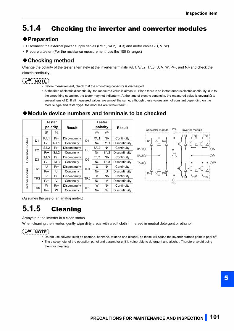
Inspection item
5
5.1.4 Checking the inverter and converter modulesPreparation • Disconnect the external power supply cables (R/L1, S/L2, T/L3) and motor cables (U, V, W).
• Prepare a tester. (For the resistance measurement, use the 100 Ω range.)
Checking methodChange the polarity of the tester alternately at the inverter terminals R/L1, S/L2, T/L3, U, V, W, P/+, and N/- and check the
electric continuity.
NOTE • Before measurement, check that the smoothing capacitor is discharged.
• At the time of electric discontinuity, the measured value is almost. When there is an instantaneous electric continuity, due to
the smoothing capacitor, the tester may not indicate . At the time of electric continuity, the measured value is several Ω to
several tens of Ω. If all measured values are almost the same, although these values are not constant depending on the
module type and tester type, the modules are without fault.
Module device numbers and terminals to be checked
(Assumes the use of an analog meter.)
5.1.5 CleaningAlways run the inverter in a clean status.
When cleaning the inverter, gently wipe dirty areas with a soft cloth immersed in neutral detergent or ethanol.
NOTE • Do not use solvent, such as acetone, benzene, toluene and alcohol, as these will cause the inverter surface paint to peel off.
• The display, etc. of the operation panel and parameter unit is vulnerable to detergent and alcohol. Therefore, avoid using
them for cleaning.
Tester polarity Result
Tester polarity Result
Con
vert
er m
odul
e
D1R/L1 P/+ Discontinuity
D4R/L1 N/- Continuity
P/+ R/L1 Continuity N/- R/L1 Discontinuity
D2S/L2 P/+ Discontinuity
D5S/L2 N/- Continuity
P/+ S/L2 Continuity N/- S/L2 Discontinuity
D3T/L3 P/+ Discontinuity
D6T/L3 N/- Continuity
P/+ T/L3 Continuity N/- T/L3 Discontinuity
Inve
rter
mod
ule TR1
U P/+ DiscontinuityTR4
U N/- Continuity
P/+ U Continuity N/- U Discontinuity
TR3V P/+ Discontinuity
TR6V N/- Continuity
P/+ V Continuity N/- V Discontinuity
TR5W P/+ Discontinuity
TR2W N/- Continuity
P/+ W Continuity N/- W Discontinuity
Converter module Inverter module
D1 D2 D3
D4 D5 D6
TR1 TR3 TR5
TR4 TR6 TR2
U
V
W
R/L1
S/L2
T/L3
C
P/+
N/−
PRECAUTIONS FOR MAINTENANCE AND INSPECTION 101
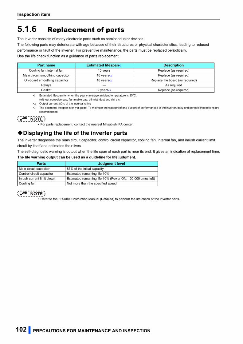
Inspection item
5.1.6 Replacement of partsThe inverter consists of many electronic parts such as semiconductor devices.
The following parts may deteriorate with age because of their structures or physical characteristics, leading to reduced
performance or fault of the inverter. For preventive maintenance, the parts must be replaced periodically.
Use the life check function as a guidance of parts replacement.
Estimated lifespan for when the yearly average ambient temperature is 35°C.
(without corrosive gas, flammable gas, oil mist, dust and dirt etc.)
Output current: 80% of the inverter rating
The estimated lifespan is only a guide. To maintain the waterproof and dustproof performances of the inverter, daily and periodic inspections are
recommended.
NOTE • For parts replacement, contact the nearest Mitsubishi FA center.
Displaying the life of the inverter partsThe inverter diagnoses the main circuit capacitor, control circuit capacitor, cooling fan, internal fan, and inrush current limit
circuit by itself and estimates their lives.
The self-diagnostic warning is output when the life span of each part is near its end. It gives an indication of replacement time.
The life warning output can be used as a guideline for life judgment.
NOTE • Refer to the FR-A800 Instruction Manual (Detailed) to perform the life check of the inverter parts.
Part name Estimated lifespan DescriptionCooling fan, internal fan 10 years Replace (as required)
Main circuit smoothing capacitor 10 years Replace (as required)
On-board smoothing capacitor 10 years Replace the board (as required)
Relays ― As required
Gasket 2 years Replace (as required)
Parts Judgment levelMain circuit capacitor 85% of the initial capacity
Control circuit capacitor Estimated remaining life 10%
Inrush current limit circuit Estimated remaining life 10% (Power ON: 100,000 times left)
Cooling fan Not more than the specified speed
102 PRECAUTIONS FOR MAINTENANCE AND INSPECTION
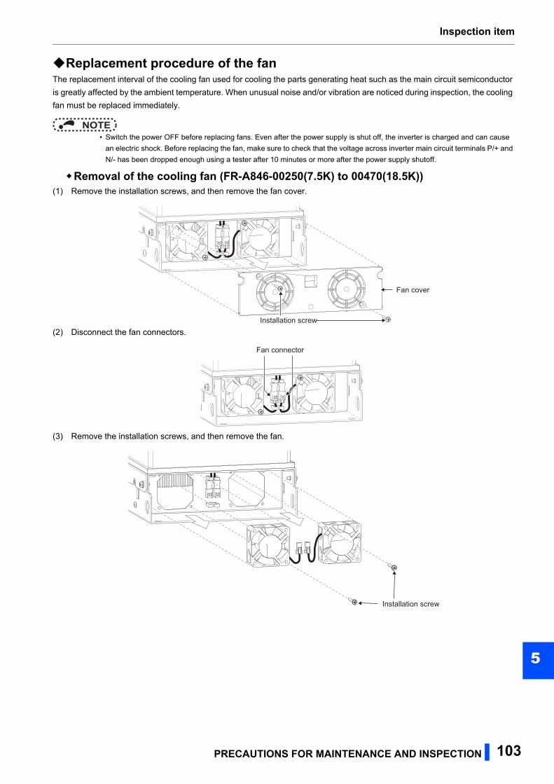
Inspection item
5
Replacement procedure of the fanThe replacement interval of the cooling fan used for cooling the parts generating heat such as the main circuit semiconductor
is greatly affected by the ambient temperature. When unusual noise and/or vibration are noticed during inspection, the cooling
fan must be replaced immediately.
NOTE • Switch the power OFF before replacing fans. Even after the power supply is shut off, the inverter is charged and can cause
an electric shock. Before replacing the fan, make sure to check that the voltage across inverter main circuit terminals P/+ and
N/- has been dropped enough using a tester after 10 minutes or more after the power supply shutoff.
Removal of the cooling fan (FR-A846-00250(7.5K) to 00470(18.5K))(1) Remove the installation screws, and then remove the fan cover.
(2) Disconnect the fan connectors.
(3) Remove the installation screws, and then remove the fan.
Installation screw
Fan cover
Fan connector
Installation screw
PRECAUTIONS FOR MAINTENANCE AND INSPECTION 103
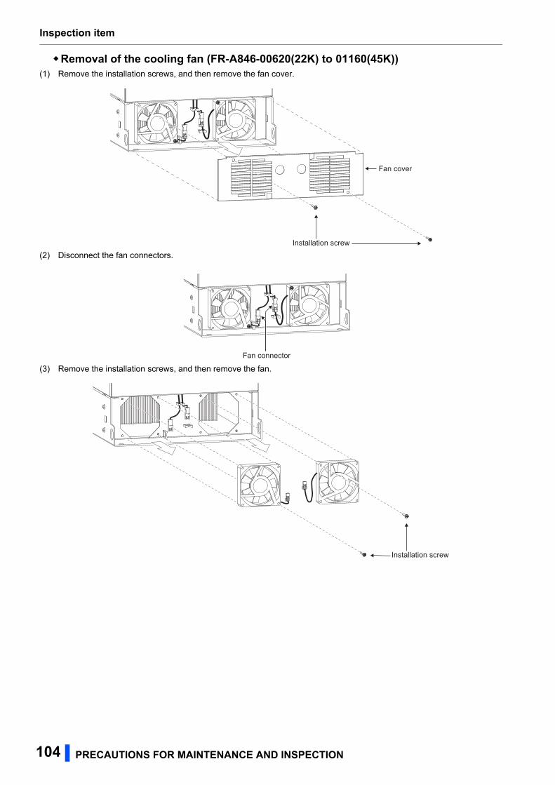
Inspection item
Removal of the cooling fan (FR-A846-00620(22K) to 01160(45K))(1) Remove the installation screws, and then remove the fan cover.
(2) Disconnect the fan connectors.
(3) Remove the installation screws, and then remove the fan.
Installation screw
Fan cover
Fan connector
Installation screw
104 PRECAUTIONS FOR MAINTENANCE AND INSPECTION
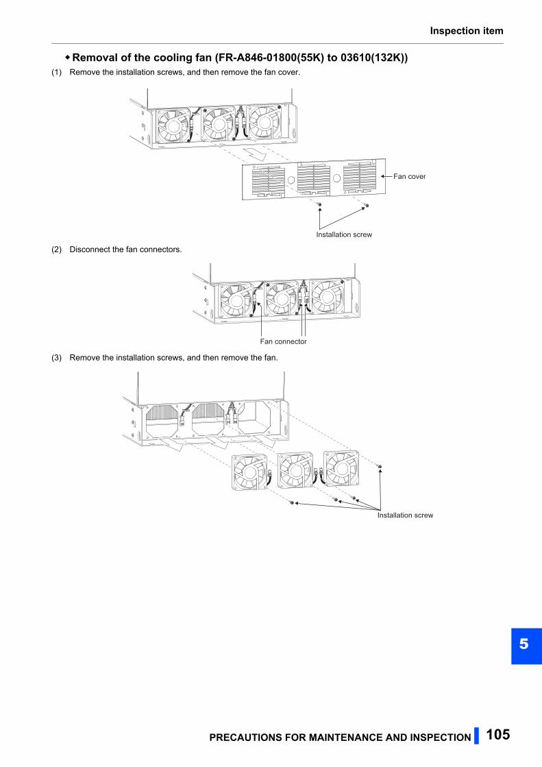
Inspection item
5
Removal of the cooling fan (FR-A846-01800(55K) to 03610(132K))(1) Remove the installation screws, and then remove the fan cover.
(2) Disconnect the fan connectors.
(3) Remove the installation screws, and then remove the fan.
Fan cover
Installation screw
Fan connector
Installation screw
PRECAUTIONS FOR MAINTENANCE AND INSPECTION 105
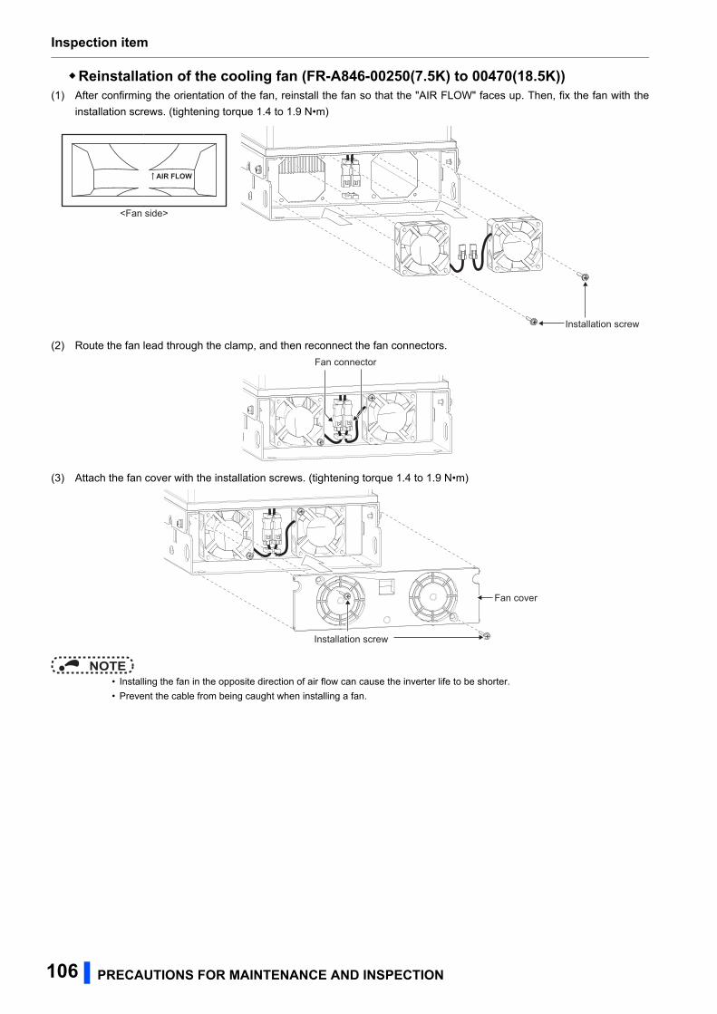
Inspection item
Reinstallation of the cooling fan (FR-A846-00250(7.5K) to 00470(18.5K))(1) After confirming the orientation of the fan, reinstall the fan so that the "AIR FLOW" faces up. Then, fix the fan with the
installation screws. (tightening torque 1.4 to 1.9 N•m)
(2) Route the fan lead through the clamp, and then reconnect the fan connectors.
(3) Attach the fan cover with the installation screws. (tightening torque 1.4 to 1.9 N•m)
NOTE • Installing the fan in the opposite direction of air flow can cause the inverter life to be shorter.
• Prevent the cable from being caught when installing a fan.
AIR FLOW
<Fan side>
Installation screw
Fan connector
Fan cover
Installation screw
106 PRECAUTIONS FOR MAINTENANCE AND INSPECTION
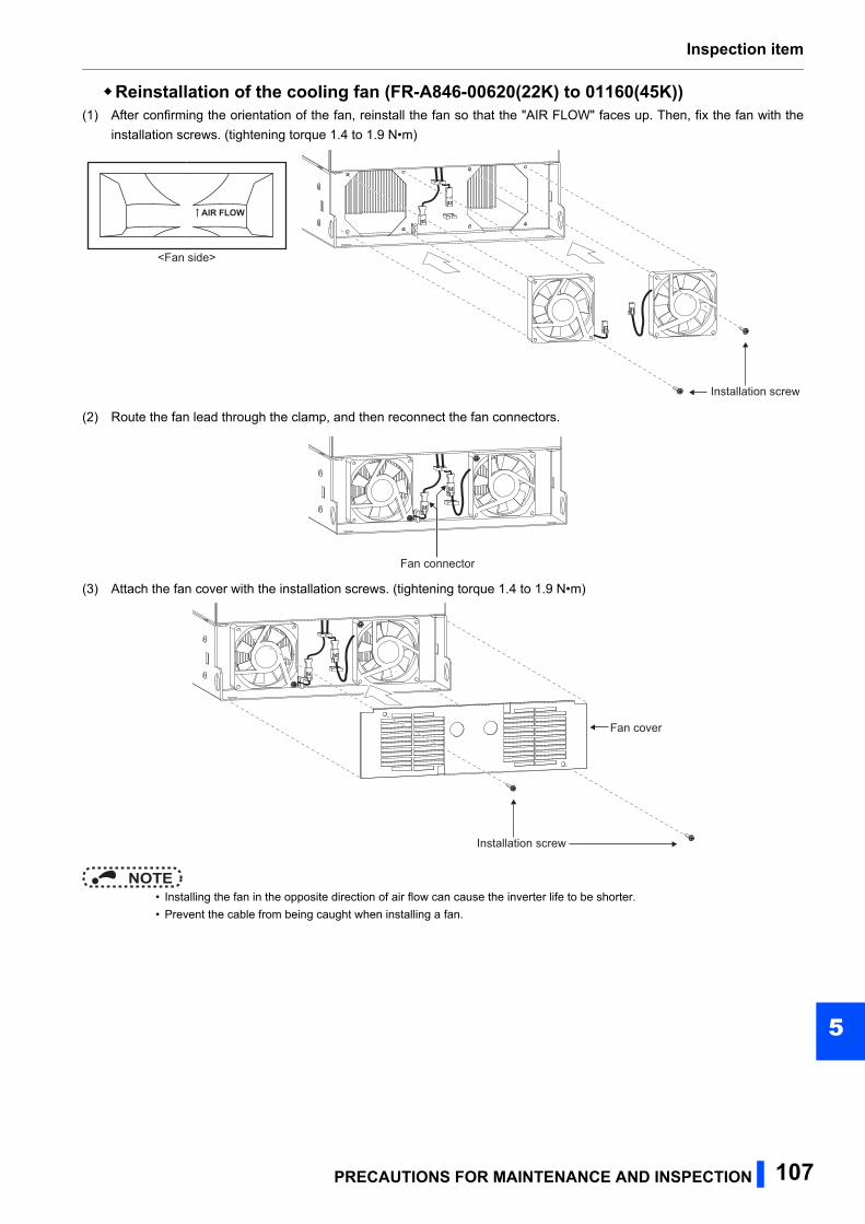
Inspection item
5
Reinstallation of the cooling fan (FR-A846-00620(22K) to 01160(45K))(1) After confirming the orientation of the fan, reinstall the fan so that the "AIR FLOW" faces up. Then, fix the fan with the
installation screws. (tightening torque 1.4 to 1.9 N•m)
(2) Route the fan lead through the clamp, and then reconnect the fan connectors.
(3) Attach the fan cover with the installation screws. (tightening torque 1.4 to 1.9 N•m)
NOTE • Installing the fan in the opposite direction of air flow can cause the inverter life to be shorter.
• Prevent the cable from being caught when installing a fan.
AIR FLOW
<Fan side>
Installation screw
Fan connector
Fan cover
Installation screw
PRECAUTIONS FOR MAINTENANCE AND INSPECTION 107
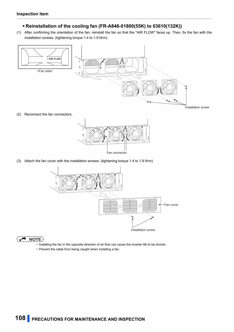
Inspection item
Reinstallation of the cooling fan (FR-A846-01800(55K) to 03610(132K))(1) After confirming the orientation of the fan, reinstall the fan so that the "AIR FLOW" faces up. Then, fix the fan with the
installation screws. (tightening torque 1.4 to 1.9 N•m)
(2) Reconnect the fan connectors.
(3) Attach the fan cover with the installation screws. (tightening torque 1.4 to 1.9 N•m)
NOTE • Installing the fan in the opposite direction of air flow can cause the inverter life to be shorter.
• Prevent the cable from being caught when installing a fan.
AIR FLOW
<Fan side>
Installation screw
Fan connector
Fan cover
Installation screw
108 PRECAUTIONS FOR MAINTENANCE AND INSPECTION
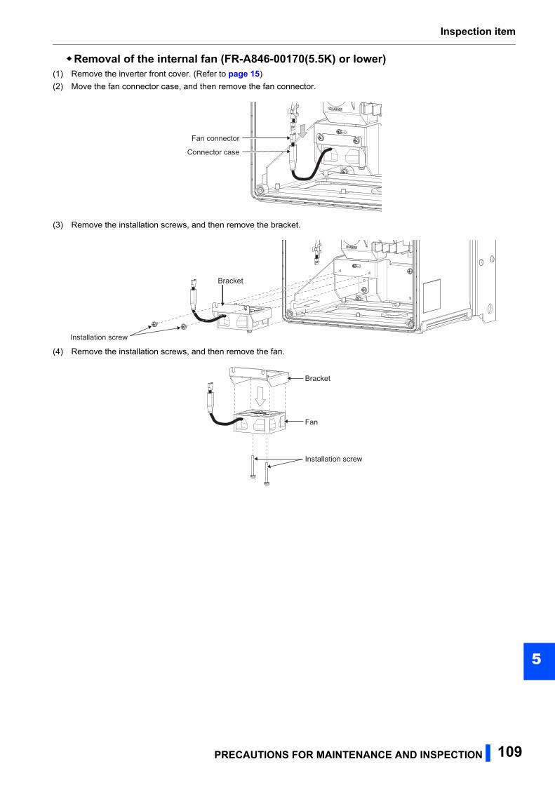
Inspection item
5
Removal of the internal fan (FR-A846-00170(5.5K) or lower)(1) Remove the inverter front cover. (Refer to page 15)
(2) Move the fan connector case, and then remove the fan connector.
(3) Remove the installation screws, and then remove the bracket.
(4) Remove the installation screws, and then remove the fan.
Fan connector
Connector case
Bracket
Installation screw
Bracket
Fan
Installation screw
PRECAUTIONS FOR MAINTENANCE AND INSPECTION 109
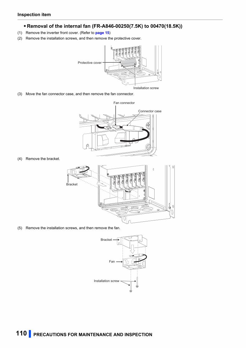
Inspection item
Removal of the internal fan (FR-A846-00250(7.5K) to 00470(18.5K))(1) Remove the inverter front cover. (Refer to page 15)
(2) Remove the installation screws, and then remove the protective cover.
(3) Move the fan connector case, and then remove the fan connector.
(4) Remove the bracket.
(5) Remove the installation screws, and then remove the fan.
Installation screw
Protective cover
Fan connector
Connector case
Bracket
Bracket
Fan
Installation screw
110 PRECAUTIONS FOR MAINTENANCE AND INSPECTION
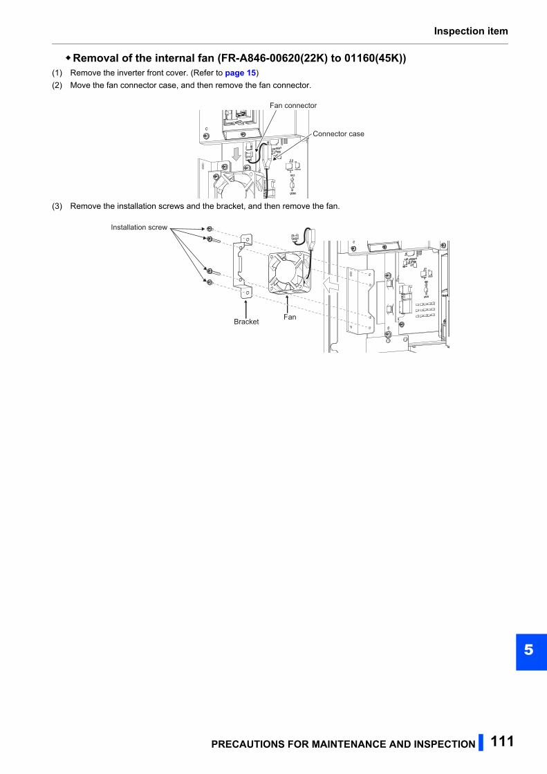
Inspection item
5
Removal of the internal fan (FR-A846-00620(22K) to 01160(45K))(1) Remove the inverter front cover. (Refer to page 15)
(2) Move the fan connector case, and then remove the fan connector.
(3) Remove the installation screws and the bracket, and then remove the fan.
Fan connector
Connector case
Bracket Fan
Installation screw
PRECAUTIONS FOR MAINTENANCE AND INSPECTION 111
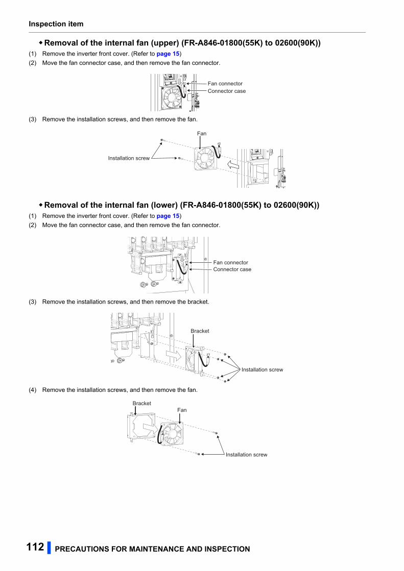
Inspection item
Removal of the internal fan (upper) (FR-A846-01800(55K) to 02600(90K))(1) Remove the inverter front cover. (Refer to page 15)
(2) Move the fan connector case, and then remove the fan connector.
(3) Remove the installation screws, and then remove the fan.
Removal of the internal fan (lower) (FR-A846-01800(55K) to 02600(90K))(1) Remove the inverter front cover. (Refer to page 15)
(2) Move the fan connector case, and then remove the fan connector.
(3) Remove the installation screws, and then remove the bracket.
(4) Remove the installation screws, and then remove the fan.
Fan connectorConnector case
Fan
Installation screw
Fan connectorConnector case
Bracket
Installation screw
BracketFan
Installation screw
112 PRECAUTIONS FOR MAINTENANCE AND INSPECTION
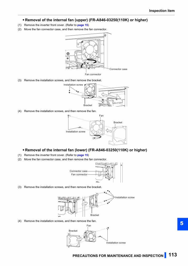
Inspection item
5
Removal of the internal fan (upper) (FR-A846-03250(110K) or higher)(1) Remove the inverter front cover. (Refer to page 15)
(2) Move the fan connector case, and then remove the fan connector.
(3) Remove the installation screws, and then remove the bracket.
(4) Remove the installation screws, and then remove the fan.
Removal of the internal fan (lower) (FR-A846-03250(110K) or higher)(1) Remove the inverter front cover. (Refer to page 15)
(2) Move the fan connector case, and then remove the fan connector.
(3) Remove the installation screws, and then remove the bracket.
(4) Remove the installation screws, and then remove the fan.
Fan connector
Connector case
Bracket
Installation screw
Installation screw
Fan
Bracket
Fan connectorConnector case
Bracket
Installation screw
Installation screw
Fan
Bracket
PRECAUTIONS FOR MAINTENANCE AND INSPECTION 113
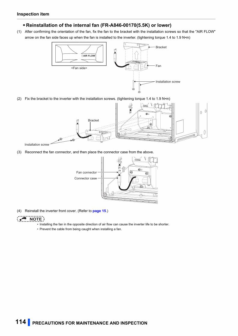
Inspection item
Reinstallation of the internal fan (FR-A846-00170(5.5K) or lower)(1) After confirming the orientation of the fan, fix the fan to the bracket with the installation screws so that the "AIR FLOW"
arrow on the fan side faces up when the fan is installed to the inverter. (tightening torque 1.4 to 1.9 N•m)
(2) Fix the bracket to the inverter with the installation screws. (tightening torque 1.4 to 1.9 N•m)
(3) Reconnect the fan connector, and then place the connector case from the above.
(4) Reinstall the inverter front cover. (Refer to page 15.)
NOTE • Installing the fan in the opposite direction of air flow can cause the inverter life to be shorter.
• Prevent the cable from being caught when installing a fan.
AIR FLOW
<Fan side>
Bracket
Fan
Installation screw
Bracket
Installation screw
Fan connector
Connector case
114 PRECAUTIONS FOR MAINTENANCE AND INSPECTION
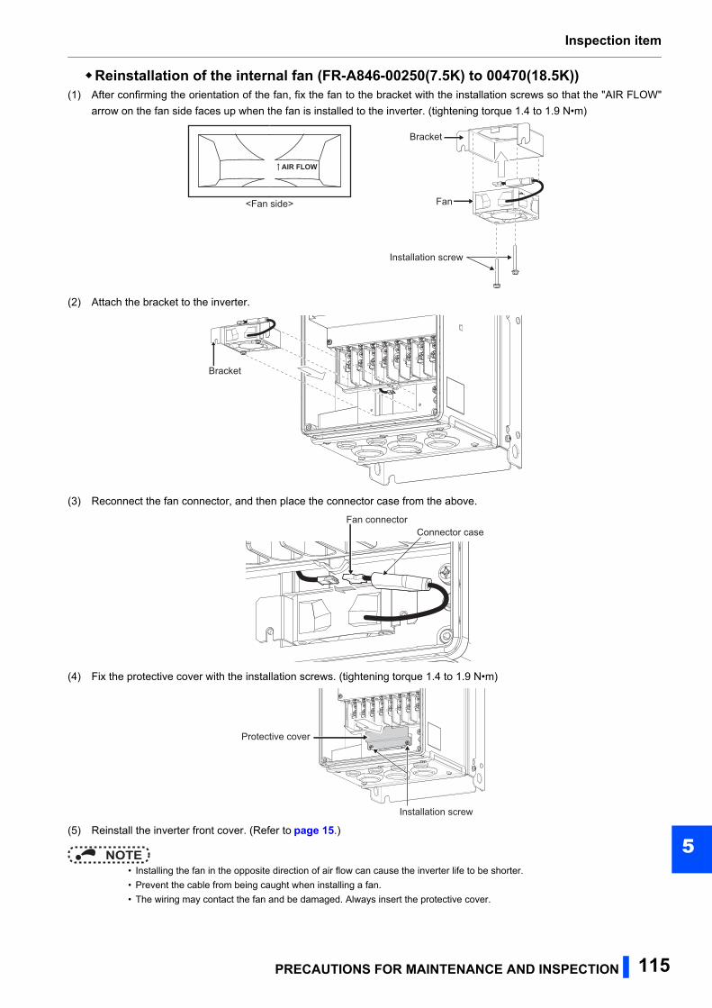
Inspection item
5
Reinstallation of the internal fan (FR-A846-00250(7.5K) to 00470(18.5K))(1) After confirming the orientation of the fan, fix the fan to the bracket with the installation screws so that the "AIR FLOW"
arrow on the fan side faces up when the fan is installed to the inverter. (tightening torque 1.4 to 1.9 N•m)
(2) Attach the bracket to the inverter.
(3) Reconnect the fan connector, and then place the connector case from the above.
(4) Fix the protective cover with the installation screws. (tightening torque 1.4 to 1.9 N•m)
(5) Reinstall the inverter front cover. (Refer to page 15.)
NOTE • Installing the fan in the opposite direction of air flow can cause the inverter life to be shorter.
• Prevent the cable from being caught when installing a fan.
• The wiring may contact the fan and be damaged. Always insert the protective cover.
Bracket
Fan
Installation screw
AIR FLOW
<Fan side>
Bracket
Fan connectorConnector case
Installation screw
Protective cover
PRECAUTIONS FOR MAINTENANCE AND INSPECTION 115
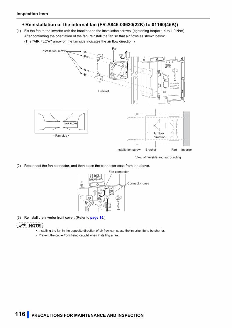
Inspection item
Reinstallation of the internal fan (FR-A846-00620(22K) to 01160(45K))(1) Fix the fan to the inverter with the bracket and the installation screws. (tightening torque 1.4 to 1.9 N•m)
After confirming the orientation of the fan, reinstall the fan so that air flows as shown below.
(The "AIR FLOW" arrow on the fan side indicates the air flow direction.)
(2) Reconnect the fan connector, and then place the connector case from the above.
(3) Reinstall the inverter front cover. (Refer to page 15.)
NOTE • Installing the fan in the opposite direction of air flow can cause the inverter life to be shorter.
• Prevent the cable from being caught when installing a fan.
AIR FLOW
<Fan side>
Installation screw
Bracket
Fan
Fan InverterBracketInstallation screw
View of fan side and surrounding
Air flow direction
Fan connector
Connector case
116 PRECAUTIONS FOR MAINTENANCE AND INSPECTION
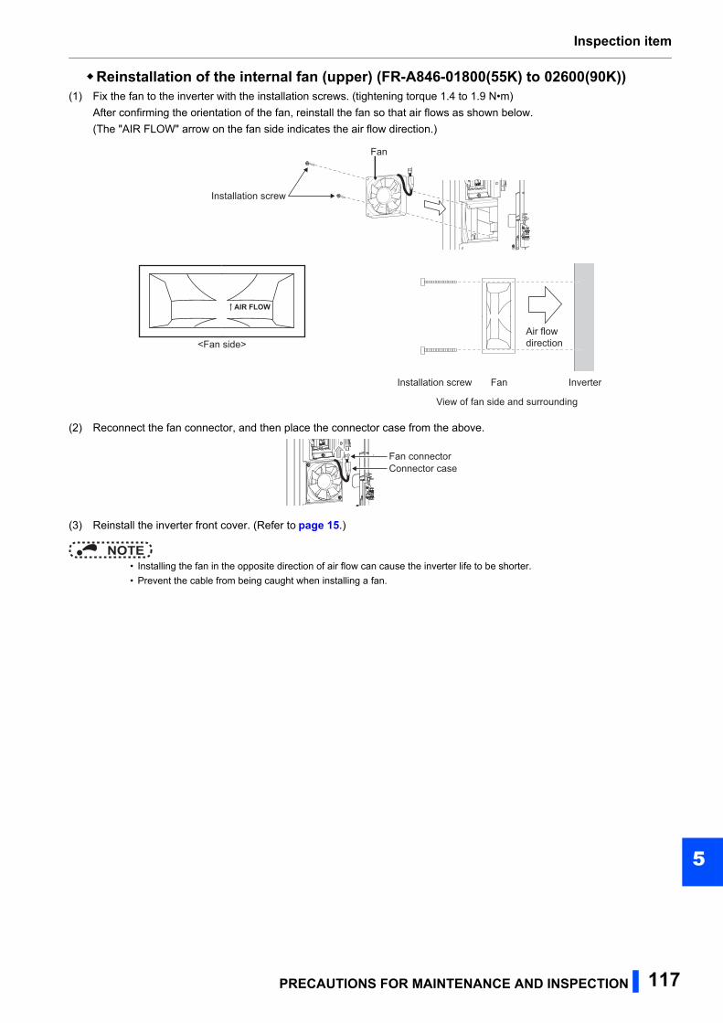
Inspection item
5
Reinstallation of the internal fan (upper) (FR-A846-01800(55K) to 02600(90K))(1) Fix the fan to the inverter with the installation screws. (tightening torque 1.4 to 1.9 N•m)
After confirming the orientation of the fan, reinstall the fan so that air flows as shown below.
(The "AIR FLOW" arrow on the fan side indicates the air flow direction.)
(2) Reconnect the fan connector, and then place the connector case from the above.
(3) Reinstall the inverter front cover. (Refer to page 15.)
NOTE • Installing the fan in the opposite direction of air flow can cause the inverter life to be shorter.
• Prevent the cable from being caught when installing a fan.
AIR FLOW
<Fan side>
Fan
Installation screw
Fan Inverter
Air flow direction
Installation screw
View of fan side and surrounding
Fan connectorConnector case
PRECAUTIONS FOR MAINTENANCE AND INSPECTION 117
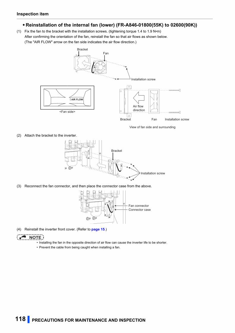
Inspection item
Reinstallation of the internal fan (lower) (FR-A846-01800(55K) to 02600(90K))(1) Fix the fan to the bracket with the installation screws. (tightening torque 1.4 to 1.9 N•m)
After confirming the orientation of the fan, reinstall the fan so that air flows as shown below.
(The "AIR FLOW" arrow on the fan side indicates the air flow direction.)
(2) Attach the bracket to the inverter.
(3) Reconnect the fan connector, and then place the connector case from the above.
(4) Reinstall the inverter front cover. (Refer to page 15.)
NOTE • Installing the fan in the opposite direction of air flow can cause the inverter life to be shorter.
• Prevent the cable from being caught when installing a fan.
AIR FLOW
<Fan side>
BracketFan
Installation screw
FanBracket
Air flow direction
Installation screw
View of fan side and surrounding
Bracket
Installation screw
Fan connectorConnector case
118 PRECAUTIONS FOR MAINTENANCE AND INSPECTION
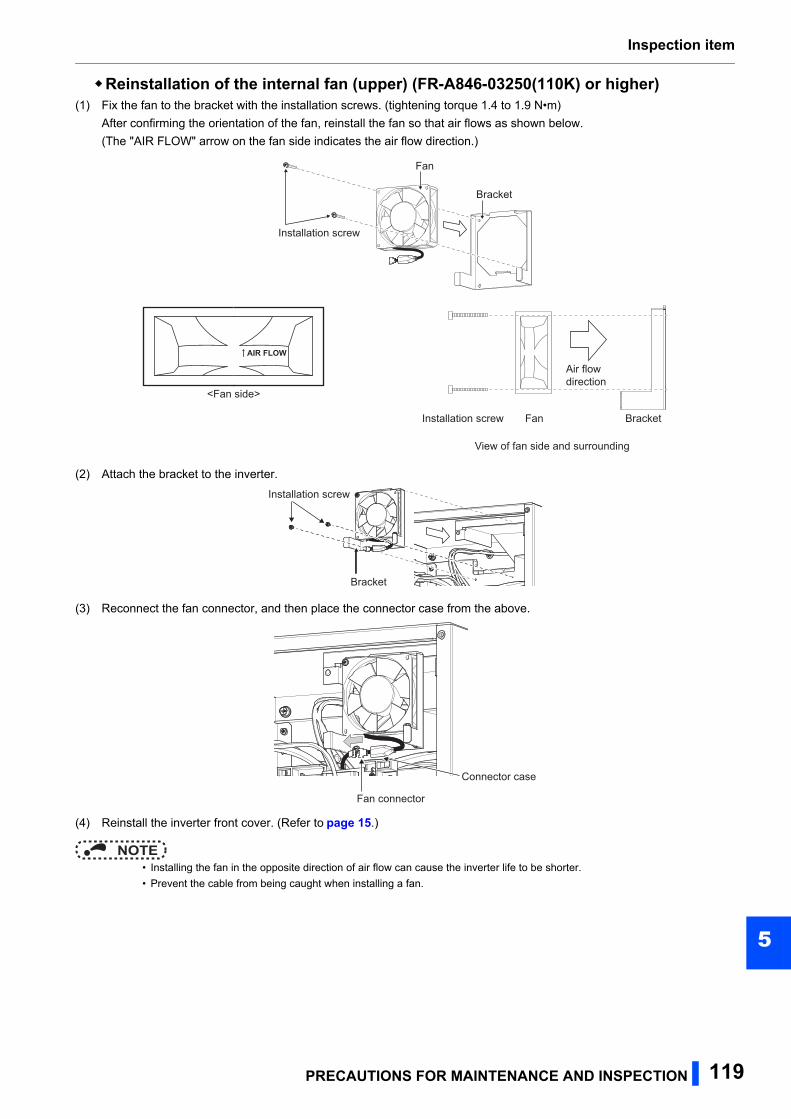
Inspection item
5
Reinstallation of the internal fan (upper) (FR-A846-03250(110K) or higher)(1) Fix the fan to the bracket with the installation screws. (tightening torque 1.4 to 1.9 N•m)
After confirming the orientation of the fan, reinstall the fan so that air flows as shown below.
(The "AIR FLOW" arrow on the fan side indicates the air flow direction.)
(2) Attach the bracket to the inverter.
(3) Reconnect the fan connector, and then place the connector case from the above.
(4) Reinstall the inverter front cover. (Refer to page 15.)
NOTE • Installing the fan in the opposite direction of air flow can cause the inverter life to be shorter.
• Prevent the cable from being caught when installing a fan.
AIR FLOW
<Fan side>
Installation screw
Fan
Bracket
Fan Bracket
Air flow direction
Installation screw
View of fan side and surrounding
Bracket
Installation screw
Fan connector
Connector case
PRECAUTIONS FOR MAINTENANCE AND INSPECTION 119
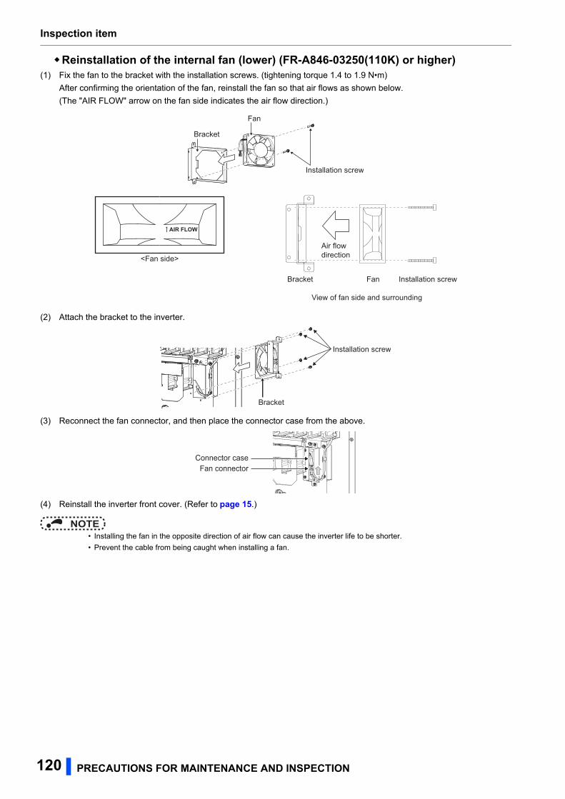
Inspection item
Reinstallation of the internal fan (lower) (FR-A846-03250(110K) or higher)(1) Fix the fan to the bracket with the installation screws. (tightening torque 1.4 to 1.9 N•m)
After confirming the orientation of the fan, reinstall the fan so that air flows as shown below.
(The "AIR FLOW" arrow on the fan side indicates the air flow direction.)
(2) Attach the bracket to the inverter.
(3) Reconnect the fan connector, and then place the connector case from the above.
(4) Reinstall the inverter front cover. (Refer to page 15.)
NOTE • Installing the fan in the opposite direction of air flow can cause the inverter life to be shorter.
• Prevent the cable from being caught when installing a fan.
AIR FLOW
<Fan side>
Installation screw
Fan
Bracket
FanBracket
Air flow direction
Installation screw
View of fan side and surrounding
Bracket
Installation screw
Fan connectorConnector case
120 PRECAUTIONS FOR MAINTENANCE AND INSPECTION
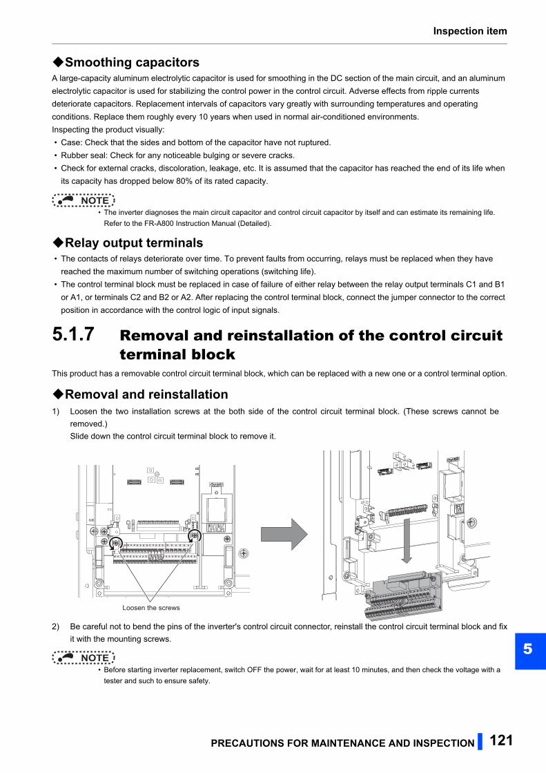
Inspection item
5
Smoothing capacitorsA large-capacity aluminum electrolytic capacitor is used for smoothing in the DC section of the main circuit, and an aluminum
electrolytic capacitor is used for stabilizing the control power in the control circuit. Adverse effects from ripple currents
deteriorate capacitors. Replacement intervals of capacitors vary greatly with surrounding temperatures and operating
conditions. Replace them roughly every 10 years when used in normal air-conditioned environments.
Inspecting the product visually:
• Case: Check that the sides and bottom of the capacitor have not ruptured.
• Rubber seal: Check for any noticeable bulging or severe cracks.
• Check for external cracks, discoloration, leakage, etc. It is assumed that the capacitor has reached the end of its life when
its capacity has dropped below 80% of its rated capacity.
NOTE • The inverter diagnoses the main circuit capacitor and control circuit capacitor by itself and can estimate its remaining life.
Refer to the FR-A800 Instruction Manual (Detailed).
Relay output terminals • The contacts of relays deteriorate over time. To prevent faults from occurring, relays must be replaced when they have
reached the maximum number of switching operations (switching life).
• The control terminal block must be replaced in case of failure of either relay between the relay output terminals C1 and B1
or A1, or terminals C2 and B2 or A2. After replacing the control terminal block, connect the jumper connector to the correct
position in accordance with the control logic of input signals.
5.1.7 Removal and reinstallation of the control circuit terminal block
This product has a removable control circuit terminal block, which can be replaced with a new one or a control terminal option.
Removal and reinstallation1) Loosen the two installation screws at the both side of the control circuit terminal block. (These screws cannot be
removed.)
Slide down the control circuit terminal block to remove it.
2) Be careful not to bend the pins of the inverter's control circuit connector, reinstall the control circuit terminal block and fix
it with the mounting screws.
NOTE • Before starting inverter replacement, switch OFF the power, wait for at least 10 minutes, and then check the voltage with a
tester and such to ensure safety.
Loosen the screws
PRECAUTIONS FOR MAINTENANCE AND INSPECTION 121
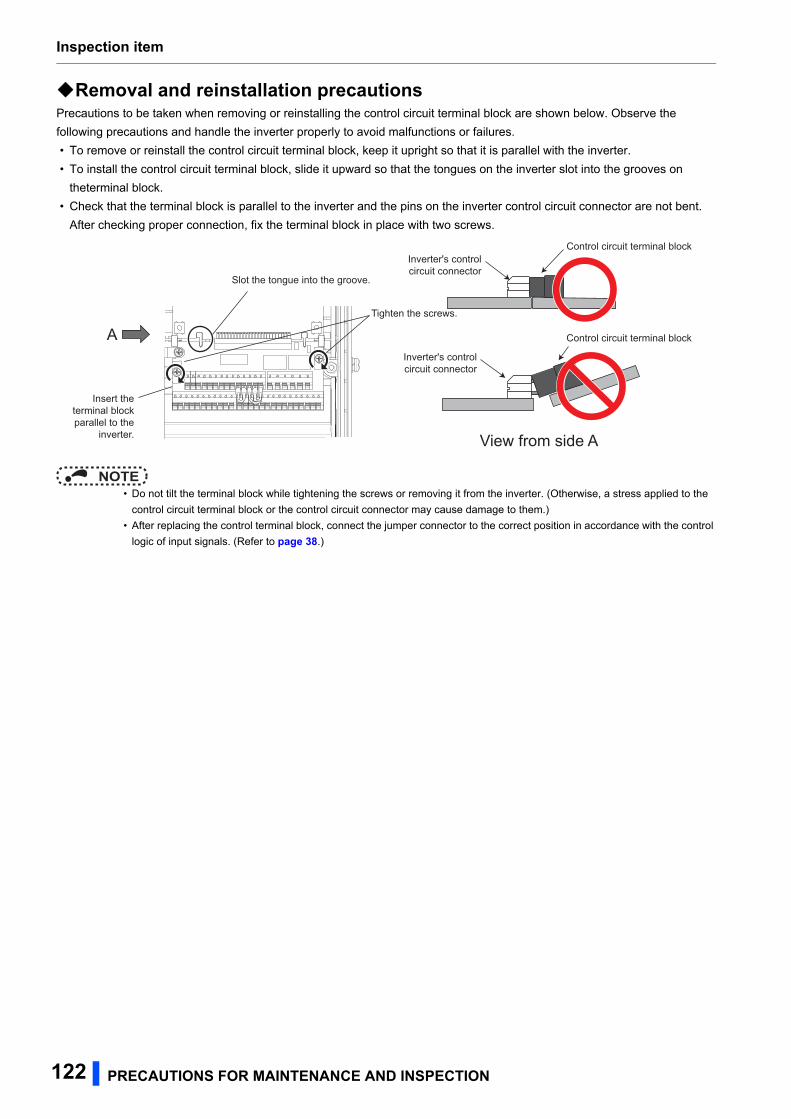
Inspection item
Removal and reinstallation precautionsPrecautions to be taken when removing or reinstalling the control circuit terminal block are shown below. Observe the
following precautions and handle the inverter properly to avoid malfunctions or failures.
• To remove or reinstall the control circuit terminal block, keep it upright so that it is parallel with the inverter.
• To install the control circuit terminal block, slide it upward so that the tongues on the inverter slot into the grooves on
theterminal block.
• Check that the terminal block is parallel to the inverter and the pins on the inverter control circuit connector are not bent.
After checking proper connection, fix the terminal block in place with two screws.
NOTE • Do not tilt the terminal block while tightening the screws or removing it from the inverter. (Otherwise, a stress applied to the
control circuit terminal block or the control circuit connector may cause damage to them.)
• After replacing the control terminal block, connect the jumper connector to the correct position in accordance with the control
logic of input signals. (Refer to page 38.)
Tighten the screws.
Control circuit terminal block
Inverter's controlcircuit connector
A
Slot the tongue into the groove.
Insert theterminal blockparallel to the
inverter. View from side A
Control circuit terminal blockInverter's controlcircuit connector
122 PRECAUTIONS FOR MAINTENANCE AND INSPECTION
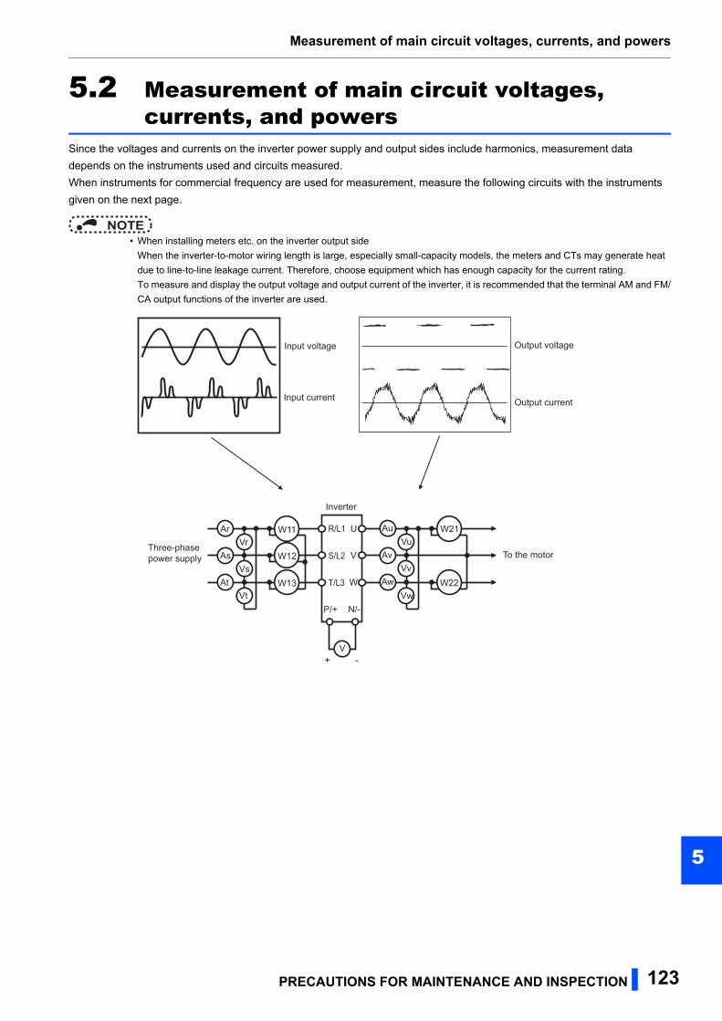
Measurement of main circuit voltages, currents, and powers
5
5.2 Measurement of main circuit voltages, currents, and powers
Since the voltages and currents on the inverter power supply and output sides include harmonics, measurement data
depends on the instruments used and circuits measured.
When instruments for commercial frequency are used for measurement, measure the following circuits with the instruments
given on the next page.
NOTE • When installing meters etc. on the inverter output side
When the inverter-to-motor wiring length is large, especially small-capacity models, the meters and CTs may generate heat
due to line-to-line leakage current. Therefore, choose equipment which has enough capacity for the current rating.
To measure and display the output voltage and output current of the inverter, it is recommended that the terminal AM and FM/
CA output functions of the inverter are used.
+ -
Ar
As
At
Vr
Vs
Vt
Au
Av
Aw
Vu
Vv
Vw
W21
V
U
V
W
Inverter
Three-phase power supply To the motor
Input voltage
Input current
Output voltage
Output current
R/L1
S/L2
T/L3
P/+ N/-
W11
W12
W13 W22
PRECAUTIONS FOR MAINTENANCE AND INSPECTION 123
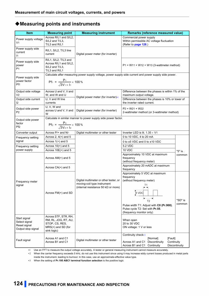
Measurement of main circuit voltages, currents, and powers
Measuring points and instruments
Use an FFT to measure the output voltage accurately. A tester or general measuring instrument cannot measure accurately.
When the carrier frequency exceeds 5 kHz, do not use this instrument since using it may increase eddy current losses produced in metal parts
inside the instrument, leading to burnout. In this case, use an approximate-effective value type.
When the setting of Pr.195 ABC1 terminal function selection is the positive logic
Item Measuring point Measuring instrument Remarks (reference measured value)
Power supply voltageV1
Across R/L1 and S/L2,S/L2 and T/L3,T/L3 and R/L1
Digital power meter (for inverter)
Commercial power supplyWithin permissible AC voltage fluctuation(Refer to page 128.)
Power supply side currentI1
R/L1, S/L2, T/L3 line current
Power supply side powerP1
R/L1, S/L2, T/L3 andAcross R/L1 and S/L2,S/L2 and T/L3,T/L3 and R/L1
P1 = W11 + W12 + W13 (3-wattmeter method)
Power supply side power factorPf1
Calculate after measuring power supply voltage, power supply side current and power supply side power.
Output side voltageV2
Across U and V, V and W, and W and U
Digital power meter (for inverter)
Difference between the phases is within 1% of the maximum output voltage.
Output side currentI2
U, V and W line currents
Difference between the phases is 10% or lower of the inverter rated current.
Output side powerP2
U, V, W andacross U and V, V and W
Digital power meter (for inverter)P2 = W21 + W222-wattmeter method (or 3-wattmeter method)
Output side power factorPf2
Calculate in similar manner to power supply side power factor.
Converter output Across P/+ and N/- Digital multimeter or other tester Inverter LED is lit. 1.35 V1
Frequency setting signal
Across 2, 4(+) and 5
Digital multimeter or other tester, or moving-coil type instrument(internal resistance 50 kΩ or more)
0 to 10 VDC, 4 to 20 mA
"5" is .common
Across 1(+) and 5 0 to ±5 VDC and 0 to ±10 VDC
Frequency setting power supply
Across 10(+) and 5 5.2 VDC
Across 10E(+) and 5 10 VDC
Frequency meter signal
Across AM(+) and 5Approximately 10 VDC at maximum frequency(without frequency meter)
Across CA(+) and 5Approximately 20 mADC at maximum frequency
Across FM(+) and SD
Approximately 5 VDC at maximum frequency(without frequency meter)
Pulse width T1: Adjust with C0 (Pr.900).Pulse cycle T2: Set with Pr.55.(frequency monitor only)
"SD" iscommon
Start signalSelect signalReset signalOutput stop signal
Across STF, STR, RH, RM, RL, JOG, RT, AU, STOP, CS, RES, MRS(+) and SD (for sink logic)
When open20 to 30 VDCON voltage: 1 V or less
Fault signalAcross A1 and C1Across B1 and C1
Digital multimeter or other tester
Continuity check[Normal] [Fault]
Across A1 and C1 Discontinuity ContinuityAcross B1 and C1 Continuity Discontinuity
Pf1P1
3V1 I 1
------------------------ 100= %
Pf2P2
3V2 I2------------------------ 100= %
8 VDC
T1
T2
124 PRECAUTIONS FOR MAINTENANCE AND INSPECTION
Measurement of main circuit voltages, currents, and powers
5
5.2.1 Measurement of powersUse digital power meters (for inverter) for the both of inverter input and output side.
5.2.2 Measurement of voltagesInverter input sideUse digital power meters (for inverters) for the input side voltage.
Inverter output sideWhen using a measuring instrument, use a digital power meter for inverters as the inverter outputs PWM-controlled square
wave voltage. The value monitored on the operation panel is the inverter-controlled voltage itself. Monitoring values via the
operation panel or by outputting the analog signal is recommended as these values are accurate.
5.2.3 Measurement of currentsUse digital power meters (for inverter) both on the inverter's input and output sides.
Since the inverter input current tends to be unbalanced, measurement of three phases is recommended. The correct value
cannot be obtained by measuring only one or two phases. On the other hand, the unbalanced ratio of each phase of the
output current should be within 10%.
The inverter output current can be monitored on the operation panel. The value displayed on the operation panel is accurate
even if the output frequency varies. Hence, it is recommended to monitor values on the operation panel.
5.2.4 Measurement of inverter input power factorCalculate using effective power and apparent power. A power-factor meter cannot indicate an exact value.
5.2.5 Measurement of converter output voltage (across terminals P and N)
The output voltage of the converter is output across terminals P and N, and can be measured with a voltmeter such as a
digital multimeter. Although the voltage varies according to the power supply voltage, approximately 540 VDC to 600 VDC is
output when no load is connected and voltage decreases during driving load operation.
When energy is regenerated from the motor during deceleration, for example, the converter output voltage rises to nearly 800
VDC to 900 VDC maximum.
5.2.6 Measurement of inverter output frequencyIn the initial setting of the FM-type inverter, a pulse train proportional to the output frequency is output across the pulse train
output terminals FM and SD of the inverter. This pulse train output can be counted by a frequency counter, or a digital
multimeter can be used to read the mean value of the pulse train output voltage. When a meter is used to measure the output
frequency, approximately 5 VDC is indicated at the maximum frequency.
For detailed specifications of the pulse train output terminal FM, refer to the FR-A800 Instruction Manual (Detailed).
In the initial setting of the CA-type inverter, a pulse train proportional to the output frequency is output across the analog
current output terminals CA and 5 of the inverter. Measure the current using a digital multimeter.
For detailed specifications of the analog current output terminal CA, refer to the FR-A800 Instruction Manual (Detailed).
Total power factor of the inverter =Effective power
Apparent power
=Three-phase input power found by the 3-wattmeter method
V (power supply voltage) I (input current effective value)√3
PRECAUTIONS FOR MAINTENANCE AND INSPECTION 125
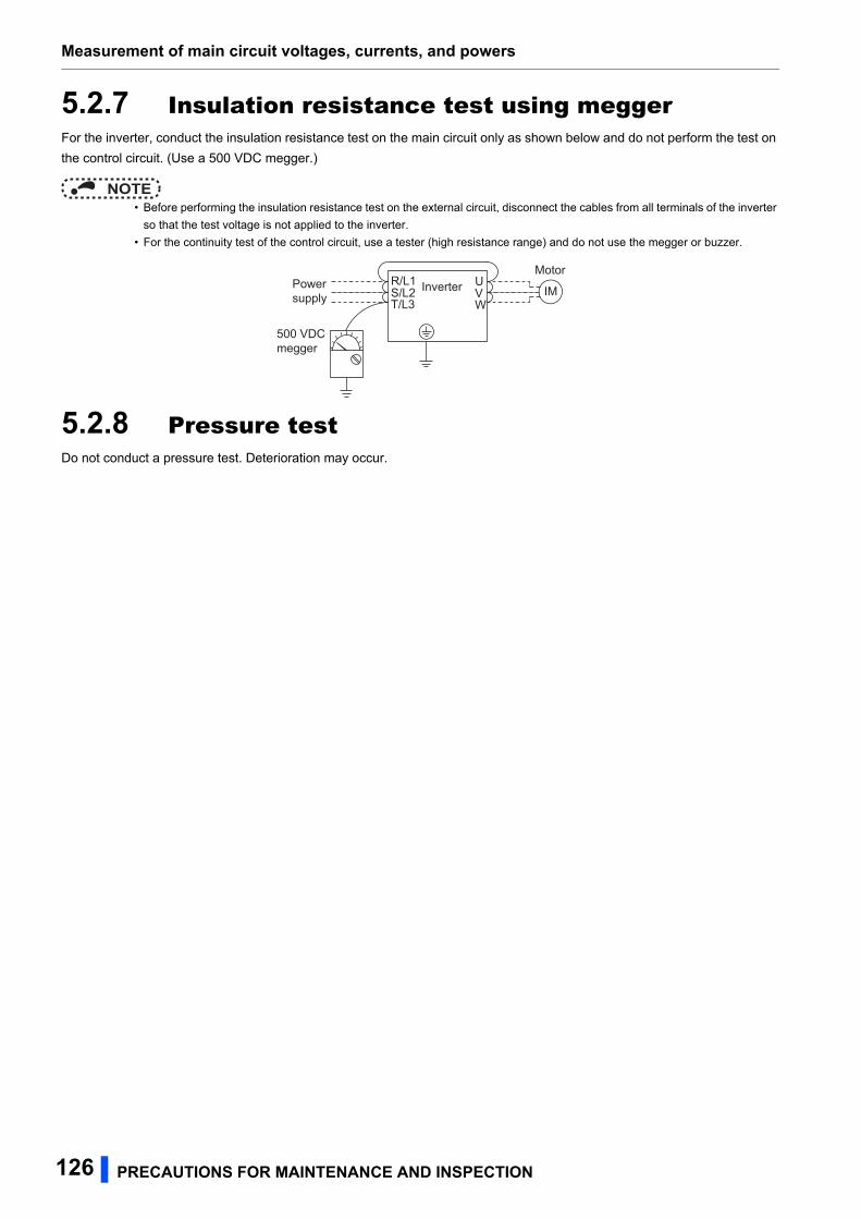
Measurement of main circuit voltages, currents, and powers
5.2.7 Insulation resistance test using meggerFor the inverter, conduct the insulation resistance test on the main circuit only as shown below and do not perform the test on
the control circuit. (Use a 500 VDC megger.)
NOTE • Before performing the insulation resistance test on the external circuit, disconnect the cables from all terminals of the inverter
so that the test voltage is not applied to the inverter.
• For the continuity test of the control circuit, use a tester (high resistance range) and do not use the megger or buzzer.
5.2.8 Pressure testDo not conduct a pressure test. Deterioration may occur.
UVW
Inverter
500 VDC megger
Power supply IM
MotorR/L1S/L2T/L3
126 PRECAUTIONS FOR MAINTENANCE AND INSPECTION

SPECIFICATIONS 127
6
6 SPECIFICATIONS
This chapter explains the "SPECIFICATIONS" of this product.Always read the instructions before using the equipment.
6.1 Inverter rating............................................................................1286.2 Common specifications ...........................................................1296.3 Inverter outline dimension drawings ......................................131
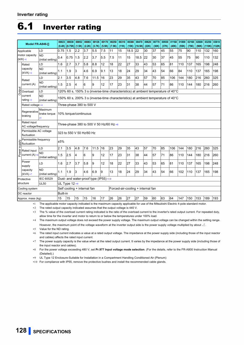
Inverter rating
6.1 Inverter rating
The applicable motor capacity indicated is the maximum capacity applicable for use of the Mitsubishi Electric 4-pole standard motor.
The rated output capacity indicated assumes that the output voltage is 440 V.
The % value of the overload current rating indicated is the ratio of the overload current to the inverter's rated output current. For repeated duty,
allow time for the inverter and motor to return to or below the temperatures under 100% load.
The maximum output voltage does not exceed the power supply voltage. The maximum output voltage can be changed within the setting range.
However, the maximum point of the voltage waveform at the inverter output side is the power supply voltage multiplied by about .
Value for the ND rating.
The rated input current indicates a value at a rated output voltage. The impedance at the power supply side (including those of the input reactor
and cables) affects the rated input current.
The power supply capacity is the value when at the rated output current. It varies by the impedance at the power supply side (including those of
the input reactor and cables).
For the power voltage exceeding 480 V, set Pr.977 Input voltage mode selection. (For the details, refer to the FR-A800 Instruction Manual
(Detailed).)
UL Type 12 Enclosure-Suitable for Installation in a Compartment Handling Conditioned Air (Plenum)
For compliance with IP55, remove the protective bushes and install the recommended cable glands.
Model FR-A846-[]00023(0.4K)
00038(0.75K)
00052(1.5K)
00083(2.2K)
00126(3.7K)
00170(5.5K)
00250(7.5K)
00310(11K)
00380(15K)
00470(18.5K)
00620(22K)
00770(30K)
00930(37K)
01160(45K)
01800(55K)
02160(75K)
02600(90K)
03250(110K)
03610(132K)
Applicable
motor capacity
(kW)
LD 0.75 1.5 2.2 3.7 5.5 7.5 11 15 18.5 22 30 37 45 55 75 90 110 132 160
ND
(initial setting)0.4 0.75 1.5 2.2 3.7 5.5 7.5 11 15 18.5 22 30 37 45 55 75 90 110 132
Out
put
Rated
capacity
(kVA)
LD 1.6 2.7 3.7 5.8 8.8 12 18 22 27 33 43 53 65 81 110 137 165 198 248
ND
(initial setting)1.1 1.9 3 4.6 6.9 9.1 13 18 24 29 34 43 54 66 84 110 137 165 198
Rated
current (A)
LD 2.1 3.5 4.8 7.6 11.5 16 23 29 35 43 57 70 85 106 144 180 216 260 325
ND
(initial setting)1.5 2.5 4 6 9 12 17 23 31 38 44 57 71 86 110 144 180 216 260
Overload
current
rating
LD 120% 60 s, 150% 3 s (inverse-time characteristics) at ambient temperature of 40°C
ND
(initial setting)150% 60 s, 200% 3 s (inverse-time characteristics) at ambient temperature of 40°C
Rated voltage Three-phase 380 to 500 V
Regenerative
braking
Maximum
brake torque
10% torque/continuous
Po
we
r su
pply
Rated input
AC voltage/frequencyThree-phase 380 to 500 V 50 Hz/60 Hz
Permissible AC voltage
fluctuation323 to 550 V 50 Hz/60 Hz
Permissible frequency
fluctuation±5%
Rated input
current (A)
LD 2.1 3.5 4.8 7.6 11.5 16 23 29 35 43 57 70 85 106 144 180 216 260 325
ND
(initial setting)1.5 2.5 4 6 9 12 17 23 31 38 44 57 71 86 110 144 180 216 260
Power
supply
capacity
(kVA)
LD 1.6 2.7 3.7 5.8 9 12 18 22 27 33 43 53 65 81 110 137 165 198 248
ND
(initial setting)1.1 1.9 3 4.6 6.9 9 13 18 24 29 34 43 54 66 102 110 137 165 198
Protective
structure
IEC 60529 Dust- and water-proof type (IP55)
UL50 UL Type 12
Cooling system Self cooling + internal fan Forced-air-cooling + internal fan
DC reactor Built-in
Approx. mass (kg) 15 15 15 15 16 17 26 26 27 27 59 60 63 64 147 150 153 189 193
128 SPECIFICATIONS
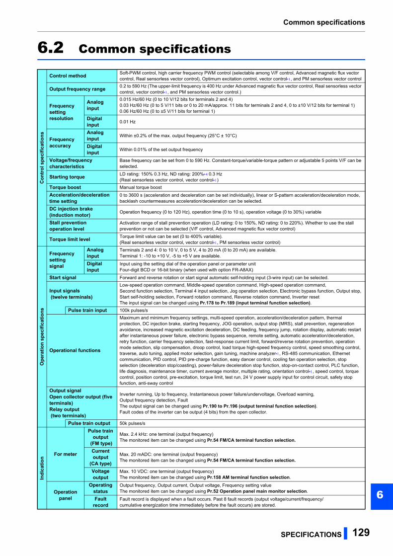
Common specifications
6
6.2 Common specificationsC
ontr
ol s
peci
ficat
ions
Control method Soft-PWM control, high carrier frequency PWM control (selectable among V/F control, Advanced magnetic flux vector control, Real sensorless vector control), Optimum excitation control, vector control, and PM sensorless vector control
Output frequency range 0.2 to 590 Hz (The upper-limit frequency is 400 Hz under Advanced magnetic flux vector control, Real sensorless vector control, vector control, and PM sensorless vector control.)
Frequency settingresolution
Analog input
0.015 Hz/60 Hz (0 to 10 V/12 bits for terminals 2 and 4)0.03 Hz/60 Hz (0 to 5 V/11 bits or 0 to 20 mA/approx. 11 bits for terminals 2 and 4, 0 to ±10 V/12 bits for terminal 1)0.06 Hz/60 Hz (0 to ±5 V/11 bits for terminal 1)
Digital input 0.01 Hz
Frequency accuracy
Analog input Within ±0.2% of the max. output frequency (25°C ± 10°C)
Digital input Within 0.01% of the set output frequency
Voltage/frequency characteristics
Base frequency can be set from 0 to 590 Hz. Constant-torque/variable-torque pattern or adjustable 5 points V/F can be selected.
Starting torque LD rating: 150% 0.3 Hz, ND rating: 200% 0.3 Hz(Real sensorless vector control, vector control)
Torque boost Manual torque boost
Acceleration/deceleration time setting
0 to 3600 s (acceleration and deceleration can be set individually), linear or S-pattern acceleration/deceleration mode, backlash countermeasures acceleration/deceleration can be selected.
DC injection brake (induction motor) Operation frequency (0 to 120 Hz), operation time (0 to 10 s), operation voltage (0 to 30%) variable
Stall prevention operation level
Activation range of stall prevention operation (LD rating: 0 to 150%, ND rating: 0 to 220%). Whether to use the stall prevention or not can be selected (V/F control, Advanced magnetic flux vector control)
Torque limit level Torque limit value can be set (0 to 400% variable).(Real sensorless vector control, vector control, PM sensorless vector control)
Ope
ratio
n sp
ecifi
catio
ns
Frequency setting signal
Analog input
Terminals 2 and 4: 0 to 10 V, 0 to 5 V, 4 to 20 mA (0 to 20 mA) are available.Terminal 1: -10 to +10 V, -5 to +5 V are available.
Digital input
Input using the setting dial of the operation panel or parameter unitFour-digit BCD or 16-bit binary (when used with option FR-A8AX)
Start signal Forward and reverse rotation or start signal automatic self-holding input (3-wire input) can be selected.
Input signals (twelve terminals)
Low-speed operation command, Middle-speed operation command, High-speed operation command, Second function selection, Terminal 4 input selection, Jog operation selection, Electronic bypass function, Output stop, Start self-holding selection, Forward rotation command, Reverse rotation command, Inverter resetThe input signal can be changed using Pr.178 to Pr.189 (input terminal function selection).
Pulse train input 100k pulses/s
Operational functions
Maximum and minimum frequency settings, multi-speed operation, acceleration/deceleration pattern, thermal protection, DC injection brake, starting frequency, JOG operation, output stop (MRS), stall prevention, regeneration avoidance, increased magnetic excitation deceleration, DC feeding, frequency jump, rotation display, automatic restart after instantaneous power failure, electronic bypass sequence, remote setting, automatic acceleration/deceleration, retry function, carrier frequency selection, fast-response current limit, forward/reverse rotation prevention, operation mode selection, slip compensation, droop control, load torque high-speed frequency control, speed smoothing control, traverse, auto tuning, applied motor selection, gain tuning, machine analyzer, RS-485 communication, Ethernet communication, PID control, PID pre-charge function, easy dancer control, cooling fan operation selection, stop selection (deceleration stop/coasting), power-failure deceleration stop function, stop-on-contact control, PLC function, life diagnosis, maintenance timer, current average monitor, multiple rating, orientation control, speed control, torque control, position control, pre-excitation, torque limit, test run, 24 V power supply input for control circuit, safety stop function, anti-sway control
Output signalOpen collector output (five terminals)Relay output (two terminals)
Inverter running, Up to frequency, Instantaneous power failure/undervoltage, Overload warning, Output frequency detection, FaultThe output signal can be changed using Pr.190 to Pr.196 (output terminal function selection).Fault codes of the inverter can be output (4 bits) from the open collector.
Pulse train output 50k pulses/s
Indi
catio
n
For meter
Pulse train output
(FM type)
Max. 2.4 kHz: one terminal (output frequency)The monitored item can be changed using Pr.54 FM/CA terminal function selection.
Current output
(CA type)
Max. 20 mADC: one terminal (output frequency)The monitored item can be changed using Pr.54 FM/CA terminal function selection.
Voltage output
Max. 10 VDC: one terminal (output frequency)The monitored item can be changed using Pr.158 AM terminal function selection.
Operation panel
Operating status
Output frequency, Output current, Output voltage, Frequency setting valueThe monitored item can be changed using Pr.52 Operation panel main monitor selection.
Fault record
Fault record is displayed when a fault occurs. Past 8 fault records (output voltage/current/frequency/cumulative energization time immediately before the fault occurs) are stored.
SPECIFICATIONS 129
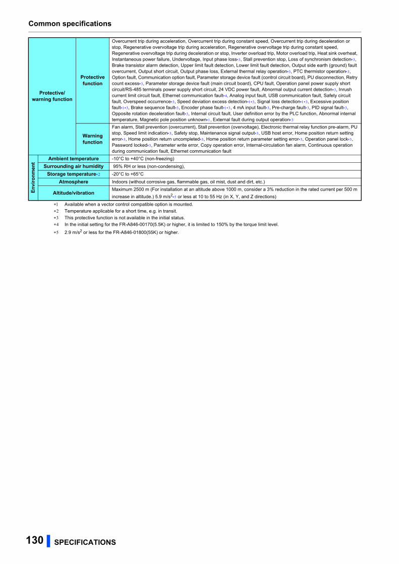
Common specifications
Available when a vector control compatible option is mounted.
Temperature applicable for a short time, e.g. in transit.
This protective function is not available in the initial status.
In the initial setting for the FR-A846-00170(5.5K) or higher, it is limited to 150% by the torque limit level.
2.9 m/s2 or less for the FR-A846-01800(55K) or higher.
Protective/warning function
Protective function
Overcurrent trip during acceleration, Overcurrent trip during constant speed, Overcurrent trip during deceleration or stop, Regenerative overvoltage trip during acceleration, Regenerative overvoltage trip during constant speed, Regenerative overvoltage trip during deceleration or stop, Inverter overload trip, Motor overload trip, Heat sink overheat, Instantaneous power failure, Undervoltage, Input phase loss, Stall prevention stop, Loss of synchronism detection, Brake transistor alarm detection, Upper limit fault detection, Lower limit fault detection, Output side earth (ground) fault overcurrent, Output short circuit, Output phase loss, External thermal relay operation, PTC thermistor operation, Option fault, Communication option fault, Parameter storage device fault (control circuit board), PU disconnection, Retry count excess, Parameter storage device fault (main circuit board), CPU fault, Operation panel power supply short circuit/RS-485 terminals power supply short circuit, 24 VDC power fault, Abnormal output current detection, Inrush current limit circuit fault, Ethernet communication fault, Analog input fault, USB communication fault, Safety circuit fault, Overspeed occurrence, Speed deviation excess detection, Signal loss detection, Excessive position fault, Brake sequence fault, Encoder phase fault, 4 mA input fault, Pre-charge fault, PID signal fault, Opposite rotation deceleration fault, Internal circuit fault, User definition error by the PLC function, Abnormal internal temperature, Magnetic pole position unknown, External fault during output operation
Warning function
Fan alarm, Stall prevention (overcurrent), Stall prevention (overvoltage), Electronic thermal relay function pre-alarm, PU stop, Speed limit indication, Safety stop, Maintenance signal output, USB host error, Home position return setting error, Home position return uncompleted, Home position return parameter setting error, Operation panel lock, Password locked, Parameter write error, Copy operation error, Internal-circulation fan alarm, Continuous operation during communication fault, Ethernet communication fault
Envi
ronm
ent
Ambient temperature -10°C to +40°C (non-freezing)
Surrounding air humidity 95% RH or less (non-condensing),
Storage temperature -20°C to +65°C
Atmosphere Indoors (without corrosive gas, flammable gas, oil mist, dust and dirt, etc.)
Altitude/vibrationMaximum 2500 m (For installation at an altitude above 1000 m, consider a 3% reduction in the rated current per 500 m
increase in altitude.) 5.9 m/s2 or less at 10 to 55 Hz (in X, Y, and Z directions)
130 SPECIFICATIONS
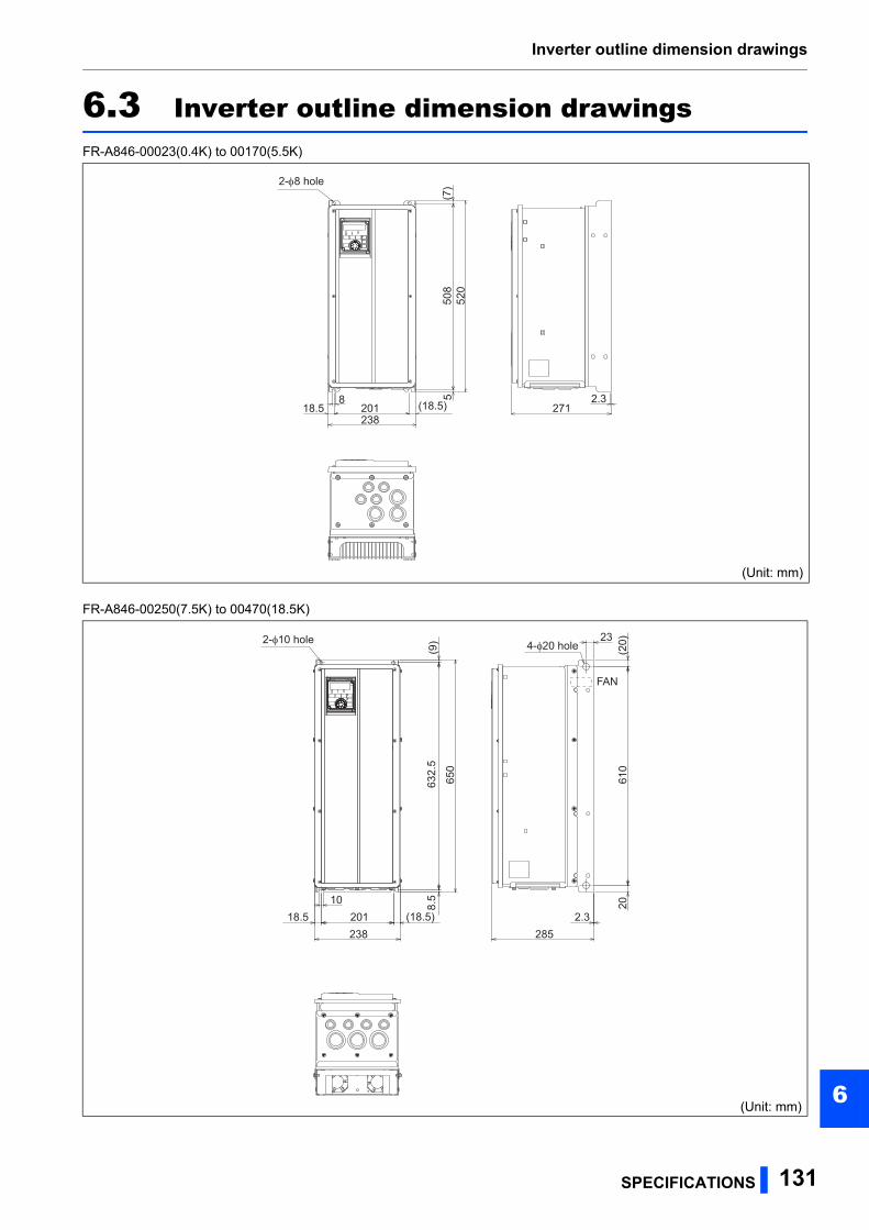
Inverter outline dimension drawings
6
6.3 Inverter outline dimension drawingsFR-A846-00023(0.4K) to 00170(5.5K)
FR-A846-00250(7.5K) to 00470(18.5K)
(Unit: mm)
(Unit: mm)
520
238271
2.3
508
5
20118.58
(7)
(18.5)
2-8 hole
650
238 285
2361
020
2.3
632.
58.
5
20118.510
(20)
(9)
(18.5)
2-φ10 hole 4-φ20 hole
FAN
SPECIFICATIONS 131
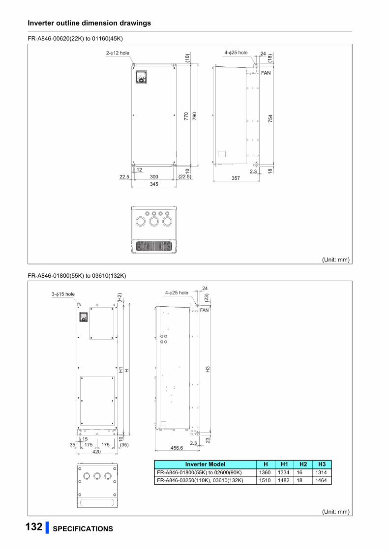
Inverter outline dimension drawings
FR-A846-00620(22K) to 01160(45K)
FR-A846-01800(55K) to 03610(132K)
(Unit: mm)
(Unit: mm)
34510
30022.512
(22.5)
(10)
790
770
357
24
754
182.3
(18)
FAN
2-φ12 hole 4-φ25 hole
42035 175 175 (35)
15 10H
1(H
2)H
2.3456.6
23H
3(2
3)
243-φ15 hole 4-φ25 hole
FAN
Inverter Model H H1 H2 H3FR-A846-01800(55K) to 02600(90K) 1360 1334 16 1314
FR-A846-03250(110K), 03610(132K) 1510 1482 18 1464
132 SPECIFICATIONS
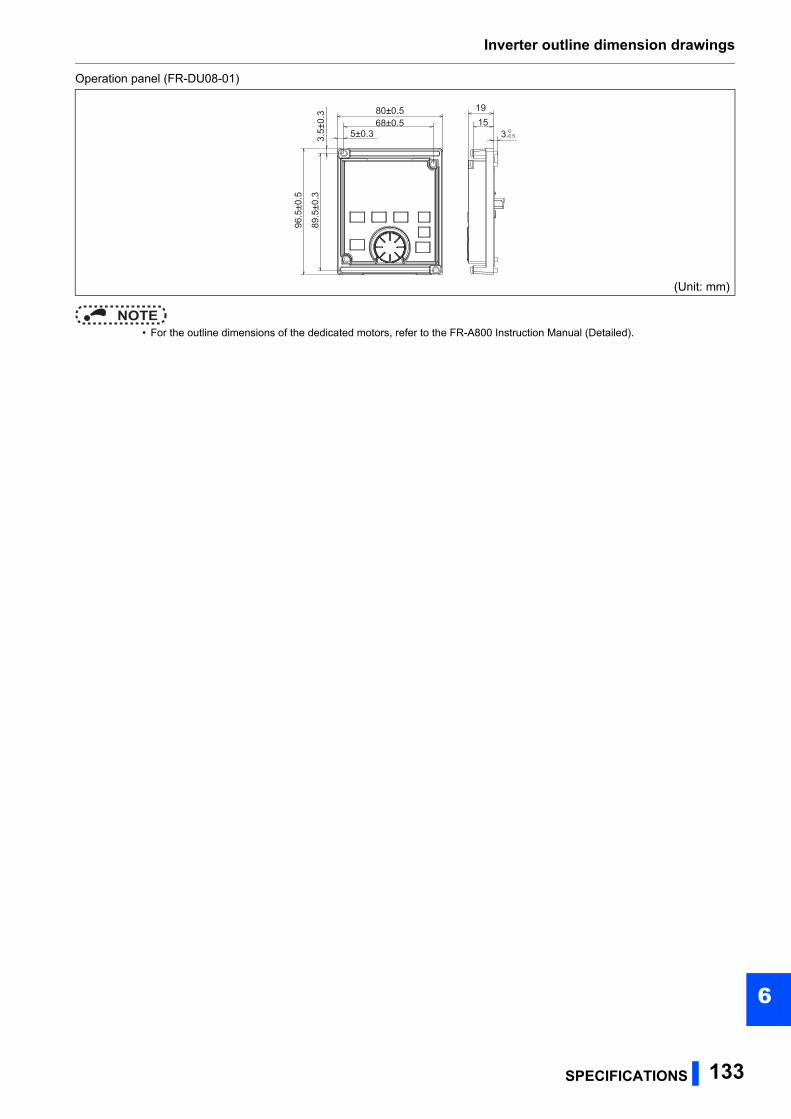
Inverter outline dimension drawings
6
Operation panel (FR-DU08-01)
NOTE • For the outline dimensions of the dedicated motors, refer to the FR-A800 Instruction Manual (Detailed).
(Unit: mm)
1980±0.5
3.5±
0.3
96.5
±0.5
89.5
±0.3
68±0.55±0.3
153 0
-0.5
SPECIFICATIONS 133

MEMO
134

APPENDIX 135
APPENDIX
APPENDIX provides the reference information for use of this product.Refer to APPENDIX as required.
Appendix 1 Differences and compatibility with the FR-A840 .......136Appendix 2 Instructions for compliance with the EU Directives..137Appendix 3 Instructions for UL and cUL ........................................141Appendix 4 Instructions for EAC.....................................................143Appendix 5 Restricted Use of Hazardous Substances in
Electronic and Electrical Products .............................144Appendix 6 Referenced Standard (Requirement of Chinese
standardized law) .........................................................144
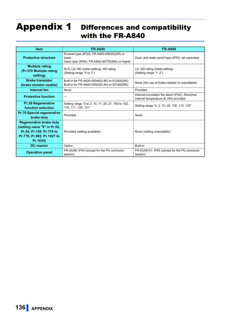
Appendix 1 Differences and compatibility with the FR-A840
Item FR-A840 FR-A846
Protective structureEnclose type (IP20): FR-A840-00620(22K) or lowerOpen type (IP00): FR-A840-00770(30K) or higher
Dust- and water-proof type (IP55): all capacities
Multiple rating(Pr.570 Multiple rating
setting)
SLD, LD, ND (initial setting), HD rating(Setting range “0 to 3”)
LD, ND rating (initial setting)(Setting range “1, 2”)
Brake transistor(brake resistor usable)
Built in for FR-A820-00046(0.4K) to 01250(22K)Built in for FR-A840-00023(0.4K) to 03160(55K)
None (the use of brake resistor is unavailable)
Internal fan None Provided
Protective function ―Internal-circulation fan alarm (FN2), Abnormal internal temperature (E.IAH) provided
Pr.30 Regenerative function selection
Setting range “0 to 2, 10, 11, 20, 21, 100 to 102, 110, 111, 120, 121”
Setting range “0, 2, 10, 20, 100, 110, 120”
Pr.70 Special regenerative brake duty Provided None
Regenerative brake duty(setting value "9" in Pr.52,
Pr.54, Pr.158, Pr.774 to Pr.776, Pr.992, Pr.1027 to
Pr.1034)
Provided (setting available) None (setting unavailable)
DC reactor Option Built-in
Operation panel FR-DU08: IP40 (except for the PU connector section)
FR-DU08-01: IP55 (except for the PU connector section)
136 APPENDIX

Appendix 2 Instructions for compliance with the EU Directives
The EU Directives are issued to standardize different national regulations of the EU Member States and to facilitate free
movement of the equipment, whose safety is ensured, in the EU territory.
Since 1996, compliance with the EMC Directive that is one of the EU Directives has been legally required. Since 1997,
compliance with the Low Voltage Directive, another EU Directive, has been also legally required. When a manufacturer
confirms its equipment to be compliant with the EMC Directive and the Low Voltage Directive, the manufacturer must declare
the conformity and affix the CE marking.
• The authorized representative in the EU
The authorized representative in the EU is shown below.
Name: Mitsubishi Electric Europe B.V.
Address: Mitsubishi-Electric-Platz 1, 40882 Ratingen, Germany
EMC DirectiveWe declare that this inverter conforms with the EMC Directive and affix the CE marking on the inverter.
• EMC Directive: 2014/30/EU
• Standard(s): EN 61800-3:2004+A1:2012 (First environment / PDS Category "C2", Second environment / PDS Category
"C3")
The applicable standard depends on the built-in EMC filter.
• Please ensure you choose the right inverter for the intended environment. Ensure the inverter is suitable for the
environment in which it is to be used when using it in residential areas.
• The installer shall provide a guide for installation and use, including recommended mitigation devices.
Note:
First environment
Environment including buildings/facilities which are directly connected to a low voltage main supply which also supplies
residential buildings. Directly connected means that there is no intermediate transformer between these buildings.
Second environment
Environment including all buildings/facilities which are not directly connected to a low voltage main supply which also supplies
residential buildings.
APPENDIX 137
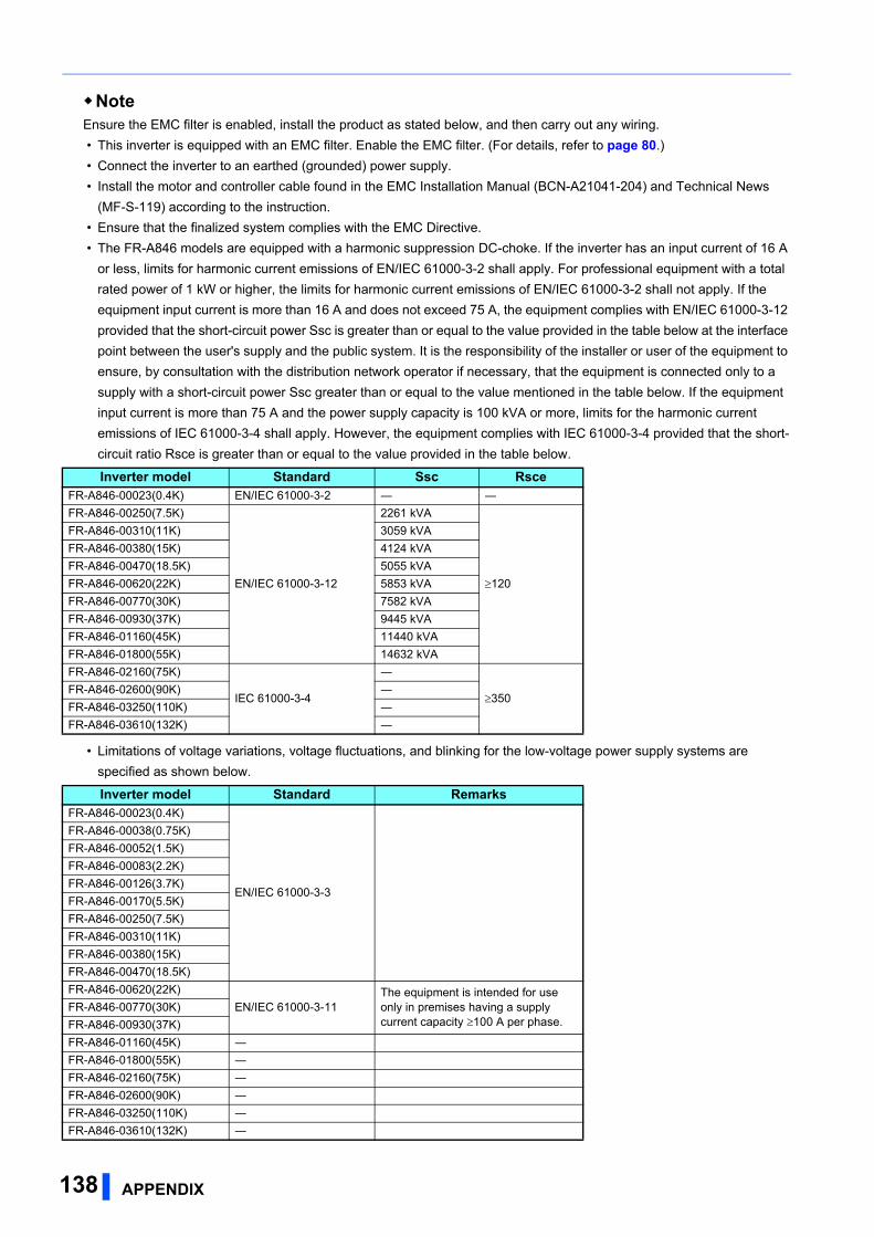
NoteEnsure the EMC filter is enabled, install the product as stated below, and then carry out any wiring.
• This inverter is equipped with an EMC filter. Enable the EMC filter. (For details, refer to page 80.)
• Connect the inverter to an earthed (grounded) power supply.
• Install the motor and controller cable found in the EMC Installation Manual (BCN-A21041-204) and Technical News
(MF-S-119) according to the instruction.
• Ensure that the finalized system complies with the EMC Directive.
• The FR-A846 models are equipped with a harmonic suppression DC-choke. If the inverter has an input current of 16 A
or less, limits for harmonic current emissions of EN/IEC 61000-3-2 shall apply. For professional equipment with a total
rated power of 1 kW or higher, the limits for harmonic current emissions of EN/IEC 61000-3-2 shall not apply. If the
equipment input current is more than 16 A and does not exceed 75 A, the equipment complies with EN/IEC 61000-3-12
provided that the short-circuit power Ssc is greater than or equal to the value provided in the table below at the interface
point between the user's supply and the public system. It is the responsibility of the installer or user of the equipment to
ensure, by consultation with the distribution network operator if necessary, that the equipment is connected only to a
supply with a short-circuit power Ssc greater than or equal to the value mentioned in the table below. If the equipment
input current is more than 75 A and the power supply capacity is 100 kVA or more, limits for the harmonic current
emissions of IEC 61000-3-4 shall apply. However, the equipment complies with IEC 61000-3-4 provided that the short-
circuit ratio Rsce is greater than or equal to the value provided in the table below.
• Limitations of voltage variations, voltage fluctuations, and blinking for the low-voltage power supply systems are
specified as shown below.
Inverter model Standard Ssc RsceFR-A846-00023(0.4K) EN/IEC 61000-3-2 ― ―
FR-A846-00250(7.5K)
EN/IEC 61000-3-12
2261 kVA
120
FR-A846-00310(11K) 3059 kVA
FR-A846-00380(15K) 4124 kVA
FR-A846-00470(18.5K) 5055 kVA
FR-A846-00620(22K) 5853 kVA
FR-A846-00770(30K) 7582 kVA
FR-A846-00930(37K) 9445 kVA
FR-A846-01160(45K) 11440 kVA
FR-A846-01800(55K) 14632 kVA
FR-A846-02160(75K)
IEC 61000-3-4
―
350FR-A846-02600(90K) ―
FR-A846-03250(110K) ―
FR-A846-03610(132K) ―
Inverter model Standard RemarksFR-A846-00023(0.4K)
EN/IEC 61000-3-3
FR-A846-00038(0.75K)
FR-A846-00052(1.5K)
FR-A846-00083(2.2K)
FR-A846-00126(3.7K)
FR-A846-00170(5.5K)
FR-A846-00250(7.5K)
FR-A846-00310(11K)
FR-A846-00380(15K)
FR-A846-00470(18.5K)
FR-A846-00620(22K)
EN/IEC 61000-3-11The equipment is intended for use only in premises having a supply current capacity 100 A per phase.
FR-A846-00770(30K)
FR-A846-00930(37K)
FR-A846-01160(45K) ―
FR-A846-01800(55K) ―
FR-A846-02160(75K) ―
FR-A846-02600(90K) ―
FR-A846-03250(110K) ―
FR-A846-03610(132K) ―
138 APPENDIX
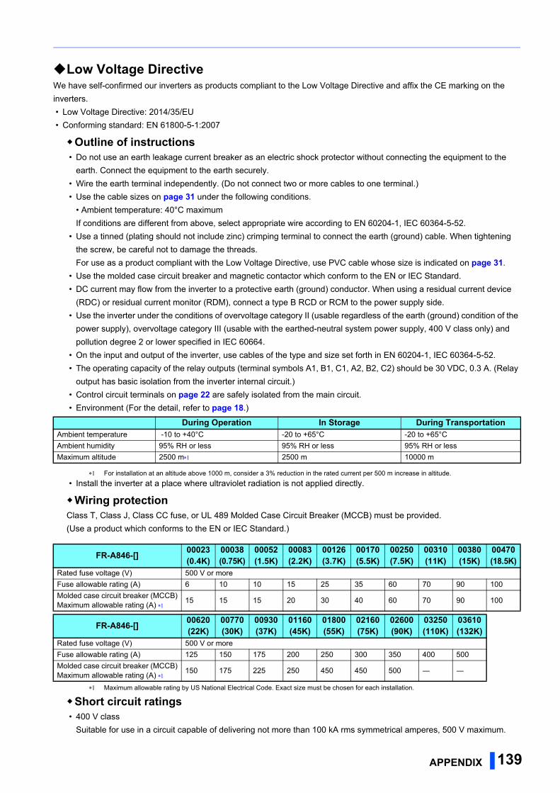
Low Voltage DirectiveWe have self-confirmed our inverters as products compliant to the Low Voltage Directive and affix the CE marking on the
inverters.
• Low Voltage Directive: 2014/35/EU
• Conforming standard: EN 61800-5-1:2007
Outline of instructions • Do not use an earth leakage current breaker as an electric shock protector without connecting the equipment to the
earth. Connect the equipment to the earth securely.
• Wire the earth terminal independently. (Do not connect two or more cables to one terminal.)
• Use the cable sizes on page 31 under the following conditions.
• Ambient temperature: 40°C maximum
If conditions are different from above, select appropriate wire according to EN 60204-1, IEC 60364-5-52.
• Use a tinned (plating should not include zinc) crimping terminal to connect the earth (ground) cable. When tightening
the screw, be careful not to damage the threads.
For use as a product compliant with the Low Voltage Directive, use PVC cable whose size is indicated on page 31.
• Use the molded case circuit breaker and magnetic contactor which conform to the EN or IEC Standard.
• DC current may flow from the inverter to a protective earth (ground) conductor. When using a residual current device
(RDC) or residual current monitor (RDM), connect a type B RCD or RCM to the power supply side.
• Use the inverter under the conditions of overvoltage category II (usable regardless of the earth (ground) condition of the
power supply), overvoltage category III (usable with the earthed-neutral system power supply, 400 V class only) and
pollution degree 2 or lower specified in IEC 60664.
• On the input and output of the inverter, use cables of the type and size set forth in EN 60204-1, IEC 60364-5-52.
• The operating capacity of the relay outputs (terminal symbols A1, B1, C1, A2, B2, C2) should be 30 VDC, 0.3 A. (Relay
output has basic isolation from the inverter internal circuit.)
• Control circuit terminals on page 22 are safely isolated from the main circuit.
• Environment (For the detail, refer to page 18.)
For installation at an altitude above 1000 m, consider a 3% reduction in the rated current per 500 m increase in altitude.
• Install the inverter at a place where ultraviolet radiation is not applied directly.
Wiring protectionClass T, Class J, Class CC fuse, or UL 489 Molded Case Circuit Breaker (MCCB) must be provided.
(Use a product which conforms to the EN or IEC Standard.)
Maximum allowable rating by US National Electrical Code. Exact size must be chosen for each installation.
Short circuit ratings • 400 V class
Suitable for use in a circuit capable of delivering not more than 100 kA rms symmetrical amperes, 500 V maximum.
During Operation In Storage During TransportationAmbient temperature -10 to +40°C -20 to +65°C -20 to +65°C
Ambient humidity 95% RH or less 95% RH or less 95% RH or less
Maximum altitude 2500 m 2500 m 10000 m
FR-A846-[] 00023(0.4K)
00038(0.75K)
00052(1.5K)
00083(2.2K)
00126(3.7K)
00170(5.5K)
00250(7.5K)
00310(11K)
00380(15K)
00470(18.5K)
Rated fuse voltage (V) 500 V or more
Fuse allowable rating (A) 6 10 10 15 25 35 60 70 90 100
Molded case circuit breaker (MCCB)Maximum allowable rating (A)
15 15 15 20 30 40 60 70 90 100
FR-A846-[] 00620(22K)
00770(30K)
00930(37K)
01160(45K)
01800(55K)
02160(75K)
02600(90K)
03250(110K)
03610(132K)
Rated fuse voltage (V) 500 V or more
Fuse allowable rating (A) 125 150 175 200 250 300 350 400 500
Molded case circuit breaker (MCCB)Maximum allowable rating (A)
150 175 225 250 450 450 500 ― ―
APPENDIX 139
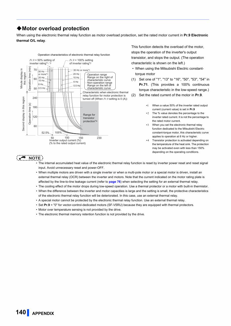
Motor overload protectionWhen using the electronic thermal relay function as motor overload protection, set the rated motor current in Pr.9 Electronic thermal O/L relay.
NOTE • The internal accumulated heat value of the electronic thermal relay function is reset by inverter power reset and reset signal
input. Avoid unnecessary reset and power-OFF.
• When multiple motors are driven with a single inverter or when a multi-pole motor or a special motor is driven, install an
external thermal relay (OCR) between the inverter and motors. Note that the current indicated on the motor rating plate is
affected by the line-to-line leakage current (refer to page 76) when selecting the setting for an external thermal relay.
• The cooling effect of the motor drops during low-speed operation. Use a thermal protector or a motor with built-in thermistor.
• When the difference between the inverter and motor capacities is large and the setting is small, the protective characteristics
of the electronic thermal relay function will be deteriorated. In this case, use an external thermal relay.
• A special motor cannot be protected by the electronic thermal relay function. Use an external thermal relay.
• Set Pr.9 = "0" for vector-control-dedicated motors (SF-V5RU) because they are equipped with thermal protectors.
• Motor over temperature sensing is not provided by the drive.
• The electronic thermal memory retention function is not provided by the drive.
Operation characteristics of electronic thermal relay function
This function detects the overload of the motor,
stops the operation of the inverter's output
transistor, and stops the output. (The operation
characteristic is shown on the left.)
• When using the Mitsubishi Electric constant-
torque motor
(1) Set one of "1", "13" to "16", "50", "53", "54" in
Pr.71. (This provides a 100% continuous
torque characteristic in the low-speed range.)
(2) Set the rated current of the motor in Pr.9.
When a value 50% of the inverter rated output
current (current value) is set in Pr.9
The % value denotes the percentage to the
inverter rated current. It is not the percentage to
the rated motor current.
When you set the electronic thermal relay
function dedicated to the Mitsubishi Electric
constant-torque motor, this characteristic curve
applies to operation at 6 Hz or higher.
Transistor protection is activated depending on
the temperature of the heat sink. The protection
may be activated even with less than 150%
depending on the operating conditions.
Range for transistor protection*4
230
52.5% 105%
50 100 150
60
120
180
240
50
60
70
6 Hz
20 Hz10 Hz
6 Hz
0.5 Hz
30 Hz or more*3
20 Hz10 Hz
0.5 Hz
Pr.9 = 50% setting of inverter rating*1, *2
Pr.9 = 100% setting of inverter rating*2
Sec
ond
disp
lay
in th
is re
gion
Min
ute
disp
lay
inth
is re
gion
Ope
ratio
n tim
e (m
in)
Ope
ratio
n tim
e (s
)
Characteristic when electronic thermal relay function for motor protection is turned off (When Pr.9 setting is 0 (A))
30 Hz or more*3
Inverter output current (%) (% to the rated output current)
Operation range Range on the right of characteristic curve Non-operation range Range on the left of characteristic curve
140 APPENDIX

Appendix 3 Instructions for UL and cUL(Standard to comply with: UL 508C, CSA C22.2 No.274-13)
General precautionCAUTION - Risk of Electric Shock -
The bus capacitor discharge time is 10 minutes. Before starting wiring or inspection, switch power off, wait for more than 10
minutes.
ATTENTION - Risque de choc électrique -
La durée de décharge du condensateur de bus est de 10 minutes. Avant de commencer le câblage ou l’inspection, mettez
l’appareil hors tension et attendez plus de 10 minutes.
InstallationThe below types of inverter have been approved as products for a UL type 12 enclosure that is suitable for Installation in a
Compartment Handling Conditioned Air (Plenum).
Install the inverter so that the ambient temperature, humidity and ambience of the inverter will satisfy the specifications. (Refer
to page 18.)
The drive must be installed in clean air according to enclosure classification.
Cooling air must be clean, free from corrosive materials and electrically conductive dust regarding the UL Type 12 enclosure.
This enclosure provides protection from airborne dust and light sprays or splashing water from all directions.
Branch circuit protectionFor installation in the United States, Class T, Class J, or Class CC fuses, or UL 489 Molded Case Circuit Breaker (MCCB)
must be provided, in accordance with the National Electrical Code and any applicable local codes.
For installation in Canada, Class T, Class J, or Class CC fuses, or UL 489 Molded Case Circuit Breaker (MCCB) must be
provided, in accordance with the Canadian Electrical Code and any applicable local codes.
Maximum allowable rating by the US National Electrical Code. Exact size must be chosen for each installation.
Select an appropriate molded case circuit breaker with a rating that is suitable for the size of the cable.
Wiring to the power supply and the motorRefer to the National Electrical Code (Article 310) regarding the allowable current of the cable. Select the cable size for 125%
of the rated current according to the National Electrical Code (Article 430).
For wiring the input (R/L1, S/L2, T/L3) and output (U, V, W) terminals of the inverter, use the UL listed copper, stranded wires
(rated at 75°C) and round crimping terminals. Crimp the crimping terminals with the crimping tool recommended by the
terminal maker.
Short circuit ratings • 400 V class
Suitable for use in a circuit capable of delivering not more than 100 kA rms symmetrical amperes, 500 V maximum.
FR-A846-[] 00023(0.4K)
00038(0.75K)
00052(1.5K)
00083(2.2K)
00126(3.7K)
00170(5.5K)
00250(7.5K)
00310(11K)
00380(15K)
00470(18.5K)
Rated fuse voltage (V) 500 V or more
Fuse allowable rating (A) 6 10 10 15 25 35 60 70 90 100
Molded case circuit breaker (MCCB)Maximum allowable rating (A)
15 15 15 20 30 40 60 70 90 100
FR-A846-[] 00620(22K)
00770(30K)
00930(37K)
01160(45K)
01800(55K)
02160(75K)
02600(90K)
03250(110K)
03610(132K)
Rated fuse voltage (V) 500 V or more
Fuse allowable rating (A) 125 150 175 200 250 300 350 400 500
Molded case circuit breaker (MCCB)Maximum allowable rating (A)
150 175 225 250 450 450 500 ― ―
APPENDIX 141
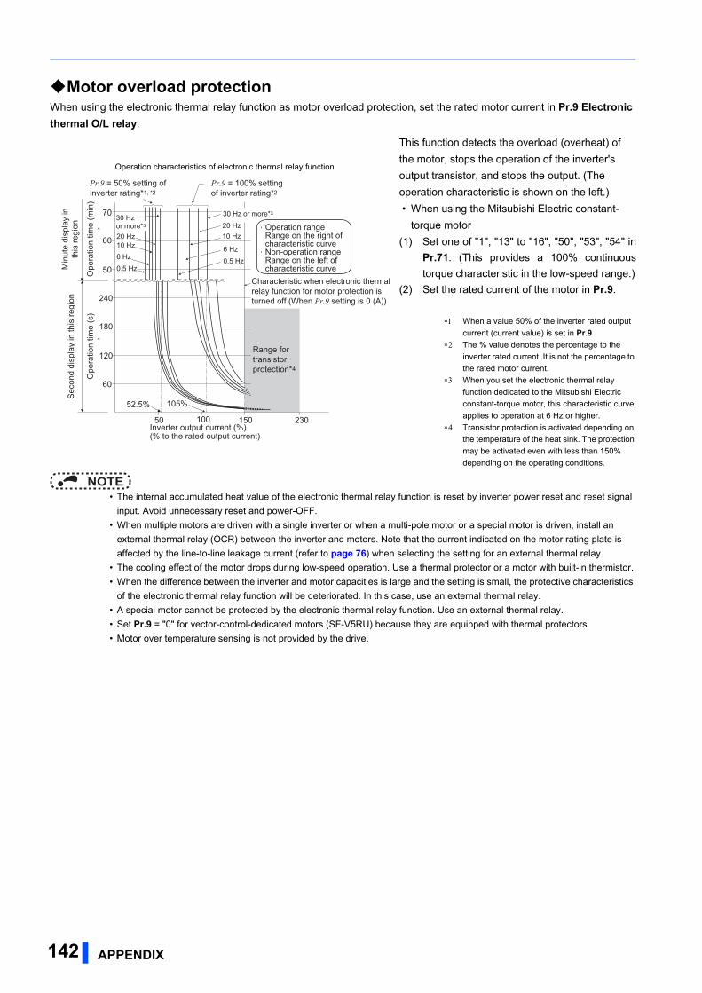
Motor overload protectionWhen using the electronic thermal relay function as motor overload protection, set the rated motor current in Pr.9 Electronic thermal O/L relay.
NOTE • The internal accumulated heat value of the electronic thermal relay function is reset by inverter power reset and reset signal
input. Avoid unnecessary reset and power-OFF.
• When multiple motors are driven with a single inverter or when a multi-pole motor or a special motor is driven, install an
external thermal relay (OCR) between the inverter and motors. Note that the current indicated on the motor rating plate is
affected by the line-to-line leakage current (refer to page 76) when selecting the setting for an external thermal relay.
• The cooling effect of the motor drops during low-speed operation. Use a thermal protector or a motor with built-in thermistor.
• When the difference between the inverter and motor capacities is large and the setting is small, the protective characteristics
of the electronic thermal relay function will be deteriorated. In this case, use an external thermal relay.
• A special motor cannot be protected by the electronic thermal relay function. Use an external thermal relay.
• Set Pr.9 = "0" for vector-control-dedicated motors (SF-V5RU) because they are equipped with thermal protectors.
• Motor over temperature sensing is not provided by the drive.
Operation characteristics of electronic thermal relay function
This function detects the overload (overheat) of
the motor, stops the operation of the inverter's
output transistor, and stops the output. (The
operation characteristic is shown on the left.)
• When using the Mitsubishi Electric constant-
torque motor
(1) Set one of "1", "13" to "16", "50", "53", "54" in
Pr.71. (This provides a 100% continuous
torque characteristic in the low-speed range.)
(2) Set the rated current of the motor in Pr.9.
When a value 50% of the inverter rated output
current (current value) is set in Pr.9
The % value denotes the percentage to the
inverter rated current. It is not the percentage to
the rated motor current.
When you set the electronic thermal relay
function dedicated to the Mitsubishi Electric
constant-torque motor, this characteristic curve
applies to operation at 6 Hz or higher.
Transistor protection is activated depending on
the temperature of the heat sink. The protection
may be activated even with less than 150%
depending on the operating conditions.
Range for transistor protection*4
230
52.5% 105%
50 100 150
60
120
180
240
50
60
70
6 Hz
20 Hz10 Hz
6 Hz
0.5 Hz
30 Hz or more*3
20 Hz10 Hz
0.5 Hz
Pr.9 = 50% setting of inverter rating*1, *2
Pr.9 = 100% setting of inverter rating*2
Sec
ond
disp
lay
in th
is re
gion
Min
ute
disp
lay
inth
is re
gion
Ope
ratio
n tim
e (m
in)
Ope
ratio
n tim
e (s
)
Characteristic when electronic thermal relay function for motor protection is turned off (When Pr.9 setting is 0 (A))
30 Hz or more*3
Inverter output current (%) (% to the rated output current)
Operation range Range on the right of characteristic curve Non-operation range Range on the left of characteristic curve
142 APPENDIX

APPENDIX 143
Appendix 4 Instructions for EAC
The product certified in compliance with the Eurasian Conformity has the EAC marking.
Note: EAC marking
In 2010, three countries (Russia, Belarus, and Kazakhstan) established a Customs Union for the purposes of revitalizing the
economy by forming a large economic bloc by abolishing or reducing tariffs and unifying regulatory procedures for the
handling of articles.
Products to be distributed over these three countries of the Customs Union must comply with the Customs Union Technical
Regulations (CU-TR), and the EAC marking must be affixed to the products.
For information on the country of origin, manufacture year and month, and authorized sales representative (importer) in the
CU area of this product, refer to the following:
• Country of origin indication
Check the rating plate of the product. (Refer to page 8.)
Example: MADE IN JAPAN
• Manufactured year and month
Check the SERIAL number indicated on the rating plate of the product. (Refer to page 8.)
• Authorized sales representative (importer) in the CU area
The authorized sales representative (importer) in the CU area is shown below.
Name: Mitsubishi Electric (Russia) LLC
Address: 52, bld 1 Kosmodamianskaya Nab 115054, Moscow, Russia
Phone: +7 (495) 721-2070
Fax: +7 (495) 721-2071
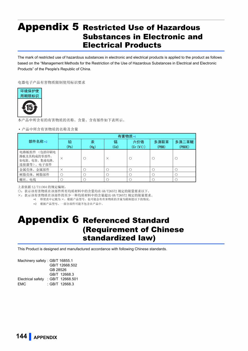
144 APPENDIX
Appendix 5 Restricted Use of Hazardous Substances in Electronic and Electrical Products
The mark of restricted use of hazardous substances in electronic and electrical products is applied to the product as follows
based on the “Management Methods for the Restriction of the Use of Hazardous Substances in Electrical and Electronic
Products” of the People's Republic of China.
电器电子产品有害物质限制使用标识要求
本产品中所含有的有害物质的名称、含量、含有部件如下表所示。
• 产品中所含有害物质的名称及含量
上表依据 SJ/T11364 的规定编制。 :表示该有害物质在该部件所有均质材料中的含量均在 GB/T26572 规定的限量要求以下。
×:表示该有害物质在该部件的至少一种均质材料中的含量超出 GB/T26572 规定的限量要求。 即使表中记载为 ×,根据产品型号,也可能会有有害物质的含量为限制值以下的情况。
根据产品型号,一部分部件可能不包含在产品中。
Appendix 6 Referenced Standard (Requirement of Chinese standardized law)
This Product is designed and manufactured accordance with following Chinese standards.
Machinery safety : GB/T 16855.1GB/T 12668.502GB 28526GB/T 12668.3
Electrical safety : GB/T 12668.501EMC : GB/T 12668.3
环境保护使
用期限标识
部件名称
有害物质
铅
(Pb)
汞
(Hg)
镉
(Cd)
六价铬
(Cr(VI))
多溴联苯
(PBB)
多溴二苯醚
(PBDE)
电路板组件 (包括印刷电
路板及其构成的零部件,
如电阻、电容、集成电路、连接器等)、电子部件
× ×
金属壳体、金属部件 ×
树脂壳体、树脂部件
螺丝、电线
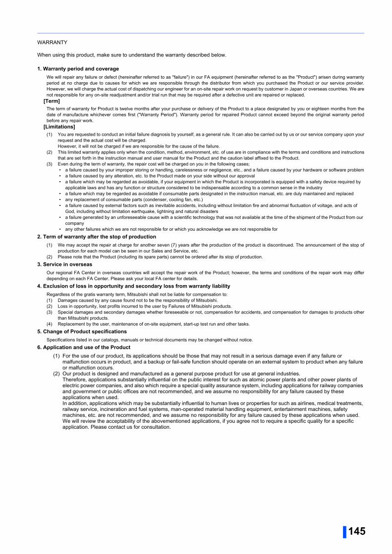
145
WARRANTY
When using this product, make sure to understand the warranty described below.
1. Warranty period and coverageWe will repair any failure or defect (hereinafter referred to as "failure") in our FA equipment (hereinafter referred to as the "Product") arisen during warrantyperiod at no charge due to causes for which we are responsible through the distributor from which you purchased the Product or our service provider.However, we will charge the actual cost of dispatching our engineer for an on-site repair work on request by customer in Japan or overseas countries. We arenot responsible for any on-site readjustment and/or trial run that may be required after a defective unit are repaired or replaced.
[Term]The term of warranty for Product is twelve months after your purchase or delivery of the Product to a place designated by you or eighteen months from thedate of manufacture whichever comes first ("Warranty Period"). Warranty period for repaired Product cannot exceed beyond the original warranty periodbefore any repair work.
[Limitations](1) You are requested to conduct an initial failure diagnosis by yourself, as a general rule. It can also be carried out by us or our service company upon your
request and the actual cost will be charged.However, it will not be charged if we are responsible for the cause of the failure.
(2) This limited warranty applies only when the condition, method, environment, etc. of use are in compliance with the terms and conditions and instructionsthat are set forth in the instruction manual and user manual for the Product and the caution label affixed to the Product.
(3) Even during the term of warranty, the repair cost will be charged on you in the following cases; • a failure caused by your improper storing or handling, carelessness or negligence, etc., and a failure caused by your hardware or software problem • a failure caused by any alteration, etc. to the Product made on your side without our approval • a failure which may be regarded as avoidable, if your equipment in which the Product is incorporated is equipped with a safety device required by
applicable laws and has any function or structure considered to be indispensable according to a common sense in the industry • a failure which may be regarded as avoidable if consumable parts designated in the instruction manual, etc. are duly maintained and replaced • any replacement of consumable parts (condenser, cooling fan, etc.) • a failure caused by external factors such as inevitable accidents, including without limitation fire and abnormal fluctuation of voltage, and acts of
God, including without limitation earthquake, lightning and natural disasters • a failure generated by an unforeseeable cause with a scientific technology that was not available at the time of the shipment of the Product from our
company • any other failures which we are not responsible for or which you acknowledge we are not responsible for
2. Term of warranty after the stop of production(1) We may accept the repair at charge for another seven (7) years after the production of the product is discontinued. The announcement of the stop of
production for each model can be seen in our Sales and Service, etc.(2) Please note that the Product (including its spare parts) cannot be ordered after its stop of production.
3. Service in overseasOur regional FA Center in overseas countries will accept the repair work of the Product; however, the terms and conditions of the repair work may differdepending on each FA Center. Please ask your local FA center for details.
4. Exclusion of loss in opportunity and secondary loss from warranty liabilityRegardless of the gratis warranty term, Mitsubishi shall not be liable for compensation to:(1) Damages caused by any cause found not to be the responsibility of Mitsubishi.(2) Loss in opportunity, lost profits incurred to the user by Failures of Mitsubishi products.(3) Special damages and secondary damages whether foreseeable or not, compensation for accidents, and compensation for damages to products other
than Mitsubishi products.(4) Replacement by the user, maintenance of on-site equipment, start-up test run and other tasks.
5. Change of Product specificationsSpecifications listed in our catalogs, manuals or technical documents may be changed without notice.
6. Application and use of the Product(1) For the use of our product, its applications should be those that may not result in a serious damage even if any failure or
malfunction occurs in product, and a backup or fail-safe function should operate on an external system to product when any failure or malfunction occurs.
(2) Our product is designed and manufactured as a general purpose product for use at general industries.Therefore, applications substantially influential on the public interest for such as atomic power plants and other power plants of electric power companies, and also which require a special quality assurance system, including applications for railway companies and government or public offices are not recommended, and we assume no responsibility for any failure caused by these applications when used.In addition, applications which may be substantially influential to human lives or properties for such as airlines, medical treatments, railway service, incineration and fuel systems, man-operated material handling equipment, entertainment machines, safety machines, etc. are not recommended, and we assume no responsibility for any failure caused by these applications when used.We will review the acceptability of the abovementioned applications, if you agree not to require a specific quality for a specific application. Please contact us for consultation.
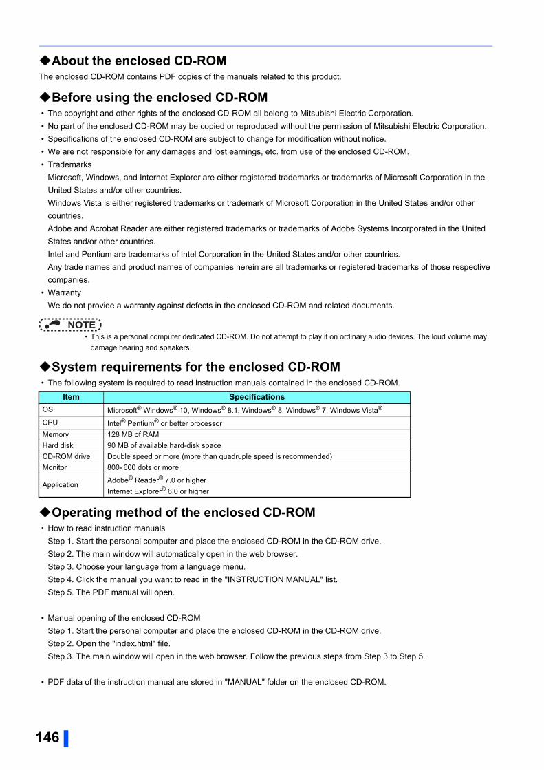
146
About the enclosed CD-ROMThe enclosed CD-ROM contains PDF copies of the manuals related to this product.
Before using the enclosed CD-ROM • The copyright and other rights of the enclosed CD-ROM all belong to Mitsubishi Electric Corporation.
• No part of the enclosed CD-ROM may be copied or reproduced without the permission of Mitsubishi Electric Corporation.
• Specifications of the enclosed CD-ROM are subject to change for modification without notice.
• We are not responsible for any damages and lost earnings, etc. from use of the enclosed CD-ROM.
• Trademarks
Microsoft, Windows, and Internet Explorer are either registered trademarks or trademarks of Microsoft Corporation in the
United States and/or other countries.
Windows Vista is either registered trademarks or trademark of Microsoft Corporation in the United States and/or other
countries.
Adobe and Acrobat Reader are either registered trademarks or trademarks of Adobe Systems Incorporated in the United
States and/or other countries.
Intel and Pentium are trademarks of Intel Corporation in the United States and/or other countries.
Any trade names and product names of companies herein are all trademarks or registered trademarks of those respective
companies.
• Warranty
We do not provide a warranty against defects in the enclosed CD-ROM and related documents.
NOTE • This is a personal computer dedicated CD-ROM. Do not attempt to play it on ordinary audio devices. The loud volume may
damage hearing and speakers.
System requirements for the enclosed CD-ROM • The following system is required to read instruction manuals contained in the enclosed CD-ROM.
Operating method of the enclosed CD-ROM • How to read instruction manuals
Step 1. Start the personal computer and place the enclosed CD-ROM in the CD-ROM drive.
Step 2. The main window will automatically open in the web browser.
Step 3. Choose your language from a language menu.
Step 4. Click the manual you want to read in the "INSTRUCTION MANUAL" list.
Step 5. The PDF manual will open.
• Manual opening of the enclosed CD-ROM
Step 1. Start the personal computer and place the enclosed CD-ROM in the CD-ROM drive.
Step 2. Open the "index.html" file.
Step 3. The main window will open in the web browser. Follow the previous steps from Step 3 to Step 5.
• PDF data of the instruction manual are stored in "MANUAL" folder on the enclosed CD-ROM.
Item SpecificationsOS Microsoft® Windows® 10, Windows® 8.1, Windows® 8, Windows® 7, Windows Vista®
CPU Intel® Pentium® or better processor
Memory 128 MB of RAM
Hard disk 90 MB of available hard-disk space
CD-ROM drive Double speed or more (more than quadruple speed is recommended)
Monitor 800600 dots or more
ApplicationAdobe® Reader® 7.0 or higher
Internet Explorer® 6.0 or higher

MEMO
147

148
REVISIONS
*The manual number is given on the bottom left of the back cover.
Revision date *Manual Number RevisionMay 2016 IB(NA)-0600634ENG-A First edition
Apr. 2019 IB(NA)-0600634ENG-B Addition• Referenced Standard (Requirement of Chinese standardized law)
• Removal and reinstallation precautions of the control circuit terminal block
IB(NA)-0600634ENG-B
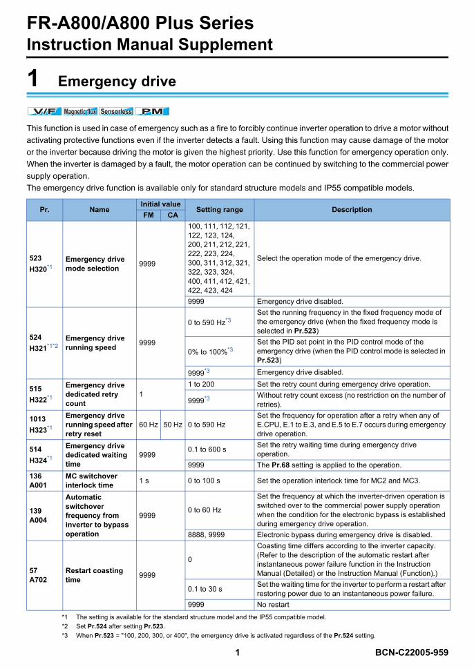
1 BCN-C22005-959
FR-A800/A800 Plus SeriesInstruction Manual Supplement
1 Emergency drive
This function is used in case of emergency such as a fire to forcibly continue inverter operation to drive a motor withoutactivating protective functions even if the inverter detects a fault. Using this function may cause damage of the motoror the inverter because driving the motor is given the highest priority. Use this function for emergency operation only.When the inverter is damaged by a fault, the motor operation can be continued by switching to the commercial powersupply operation.The emergency drive function is available only for standard structure models and IP55 compatible models.
*1 The setting is available for the standard structure model and the IP55 compatible model.*2 Set Pr.524 after setting Pr.523.*3 When Pr.523 = "100, 200, 300, or 400", the emergency drive is activated regardless of the Pr.524 setting.
Pr. NameInitial value
Setting range DescriptionFM CA
523H320*1
Emergency drive mode selection 9999
100, 111, 112, 121, 122, 123, 124,200, 211, 212, 221, 222, 223, 224,300, 311, 312, 321, 322, 323, 324,400, 411, 412, 421, 422, 423, 424
Select the operation mode of the emergency drive.
9999 Emergency drive disabled.
524H321*1*2
Emergency drive running speed 9999
0 to 590 Hz*3Set the running frequency in the fixed frequency mode of the emergency drive (when the fixed frequency mode is selected in Pr.523)
0% to 100%*3Set the PID set point in the PID control mode of the emergency drive (when the PID control mode is selected in Pr.523)
9999*3 Emergency drive disabled.
515H322*1
Emergency drive dedicated retry count
11 to 200 Set the retry count during emergency drive operation.
9999*3 Without retry count excess (no restriction on the number of retries).
1013H323*1
Emergency drive running speed after retry reset
60 Hz 50 Hz 0 to 590 HzSet the frequency for operation after a retry when any of E.CPU, E.1 to E.3, and E.5 to E.7 occurs during emergency drive operation.
514H324*1
Emergency drive dedicated waiting time
99990.1 to 600 s Set the retry waiting time during emergency drive
operation.9999 The Pr.68 setting is applied to the operation.
136A001
MC switchover interlock time 1 s 0 to 100 s Set the operation interlock time for MC2 and MC3.
139A004
Automatic switchover frequency from inverter to bypass operation
99990 to 60 Hz
Set the frequency at which the inverter-driven operation is switched over to the commercial power supply operation when the condition for the electronic bypass is established during emergency drive operation.
8888, 9999 Electronic bypass during emergency drive is disabled.
57A702
Restart coasting time 9999
0
Coasting time differs according to the inverter capacity. (Refer to the description of the automatic restart after instantaneous power failure function in the Instruction Manual (Detailed) or the Instruction Manual (Function).)
0.1 to 30 s Set the waiting time for the inverter to perform a restart after restoring power due to an instantaneous power failure.
9999 No restart
V/FV/FV/F Magnetic fluxMagnetic fluxMagnetic flux SensorlessSensorlessSensorless PMPMPM
BCN-C22005-959_ENG.fm 1 ページ 2021年4月28日 水曜日 午後3時0分
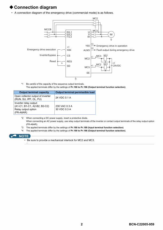
2 BCN-C22005-959
Connection diagram• A connection diagram of the emergency drive (commercial mode) is as follows.
*1 Be careful of the capacity of the sequence output terminals.The applied terminals differ by the settings of Pr.190 to Pr.196 (Output terminal function selection).
*2 When connecting a DC power supply, insert a protective diode.When connecting an AC power supply, use relay output terminals of the inverter or contact output terminals of the relay output option(FR-A8AR).
*3 The applied terminals differ by the settings of Pr.180 to Pr.189 (Input terminal function selection)*4 The applied terminals differ by the settings of Pr.190 to Pr.196 (Output terminal function selection).
NOTE• Be sure to provide a mechanical interlock for MC2 and MC3.
Output terminal capacity Output terminal permissible loadOpen collector output of inverter(RUN, SU, IPF, OL, FU) 24 VDC 0.1 A
Inverter relay output(A1-C1, B1-C1, A2-B2, B2-C2)Relay output option(FR-A8AR)
230 VAC 0.3 A30 VDC 0.3 A
Emergency drive execution
IMR/L1S/L2T/L3
X84
Emergency drive in operation
Fault output during emergency drive
CS
RES
SD
UVW
Y65
MC2
SE
MC3
MC2 24VDC
Reset
MC3
Inverter/bypass
MCCB
MC2
MC3
MC2
MC3
ALM3
BCN-C22005-959_ENG.fm 2 ページ 2021年4月28日 水曜日 午後3時0分
3 BCN-C22005-959
Emergency drive execution sequence
• When the X84 signal is ON for 3 seconds, the emergency drive is activated.• The Y65 signal turns ON during emergency drive operation.• "ED" appears on the operation panel during emergency drive operation.• The ALM3 signal turns ON when a fault occurs during emergency drive operation.
• To activate the emergency drive, the X84 signal needs to be ON for three seconds while all the followingconditions are satisfied.
• When the "retry" (Pr.523 = "2[][], 3[][]") is selected, it is recommended to use the automatic restart afterinstantaneous power failure function at the same time.
• Parameter setting is not available during emergency drive operation.• To return to the normal operation during emergency drive operation, do the following. (The operation will not be
returned to normal only by turning OFF the X84 signal.)Reset the inverter, or turn the power supply OFF.Clear a fault by turning ON the X51 signal while the sequence function is enabled (when the protective functionis activated).
• The operation is switched over to the commercial power supply operation in case of the following duringemergency drive operation while the commercial mode or the retry / commercial mode is selected.24 V external power supply operation, power failure status or operation with the power supplied through R1/S1(except when the DC feeding mode 1 or 2 is selected), undervoltage
• To input the X84 signal, set "84" in any of Pr.178 to Pr.189 (Input terminal function selection) to assign thefunction.
• For the terminal used for the Y65 signal output, assign the function by setting "65 (positive logic)" or "165(negative logic)" in any of Pr.190 to Pr.196 (Output terminal function selection). For the terminal used for theALM3 signal output, assign the function by setting "66 (positive logic)" or "166 (negative logic)" in any of Pr.190to Pr.196 (Output terminal function selection).
• The X84 signal input is valid either through the external terminal or via network regardless of the Pr.338 andPr.339 settings (Selection of control source in Network operation mode).
• During emergency drive operation, the operation is performed as Pr.502 Stop mode selection atcommunication error = "0 (initial value)" and communication errors (such as E.SER) do not occur. (A protectivefunction is performed according to its operation during emergency drive operation.)
Item ConditionEmergency drive parameter settings
Pr.523 ≠ "9999"Pr.524 ≠ "9999" (Setting is not required when Pr.523 = "100, 200, 300, or 400".)
Control method
Either of the following control methods is selected (when Pr.800 = "9, 10, 20, 109, or 110" or Pr.451 = "10, 20, 110, or 9999")• V/F control• Advanced magnetic flux vector control• Real sensorless vector control (speed control)• PM sensorless vector control (speed control)• PM sensorless vector control test operation
Contradictory condition
None of the following conditions are satisfied.• Enabling the electronic bypass sequence function• Enabling the brake sequence function• Using the FR-A8NS (option)• During offline auto tuning• Supplying power through terminals R1 and S1• Pr.30 = "2, 102"
BCN-C22005-959_ENG.fm 3 ページ 2021年4月28日 水曜日 午後3時0分
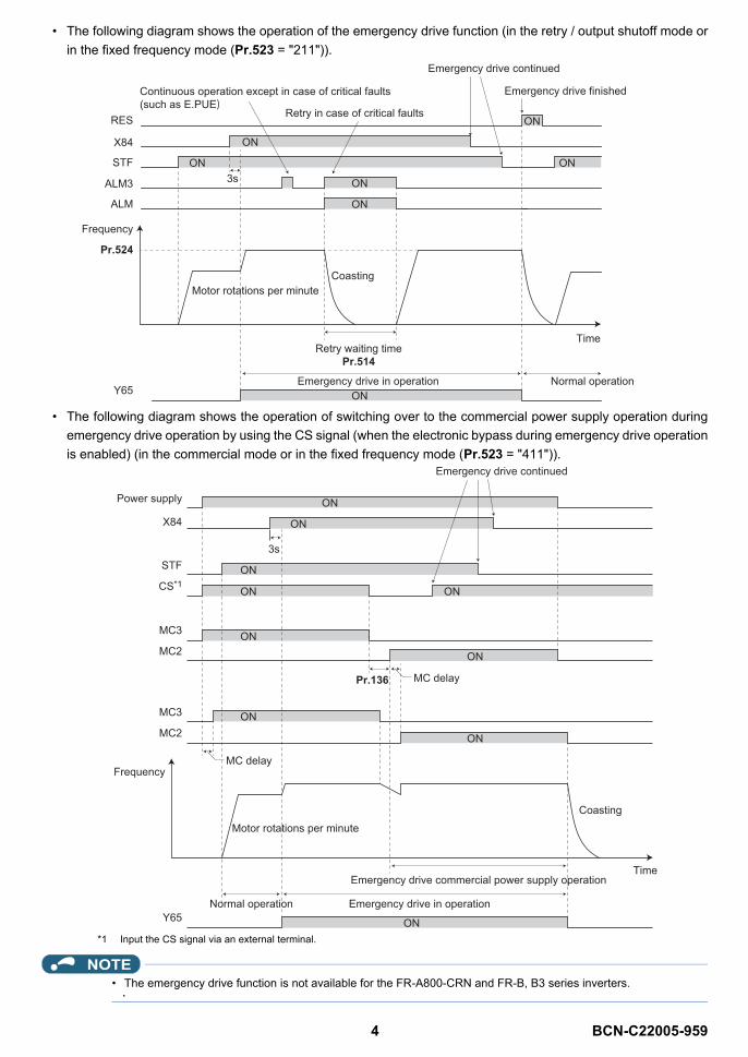
4 BCN-C22005-959
• The following diagram shows the operation of the emergency drive function (in the retry / output shutoff mode orin the fixed frequency mode (Pr.523 = "211")).
• The following diagram shows the operation of switching over to the commercial power supply operation duringemergency drive operation by using the CS signal (when the electronic bypass during emergency drive operationis enabled) (in the commercial mode or in the fixed frequency mode (Pr.523 = "411")).
*1 Input the CS signal via an external terminal.
NOTE• The emergency drive function is not available for the FR-A800-CRN and FR-B, B3 series inverters.
Continuous operation except in case of critical faults (such as E.PUE)
Coasting
RES
X84
STF
ALM3
Time
Motor rotations per minute
Retry waiting timePr.514
Emergency drive in operationY65
Retry in case of critical faults
Normal operation
Emergency drive continued
ALM
Frequency
Pr.524
3s
Emergency drive finished
ON
ON
ON
ON
ON
ON
ON
3s
Emergency drive continued
Normal operation
Coasting
Power supply
STF
X84
CS*1
MC3
MC2
MC3
MC2
Frequency
Pr.136
Time
Motor rotations per minute
Emergency drive commercial power supply operation
Emergency drive in operationY65
MC delay
MC delay
ON
ON
ON
ON
ON
ON
ON
ON
ON
ON
BCN-C22005-959_ENG.fm 4 ページ 2021年4月28日 水曜日 午後3時0分
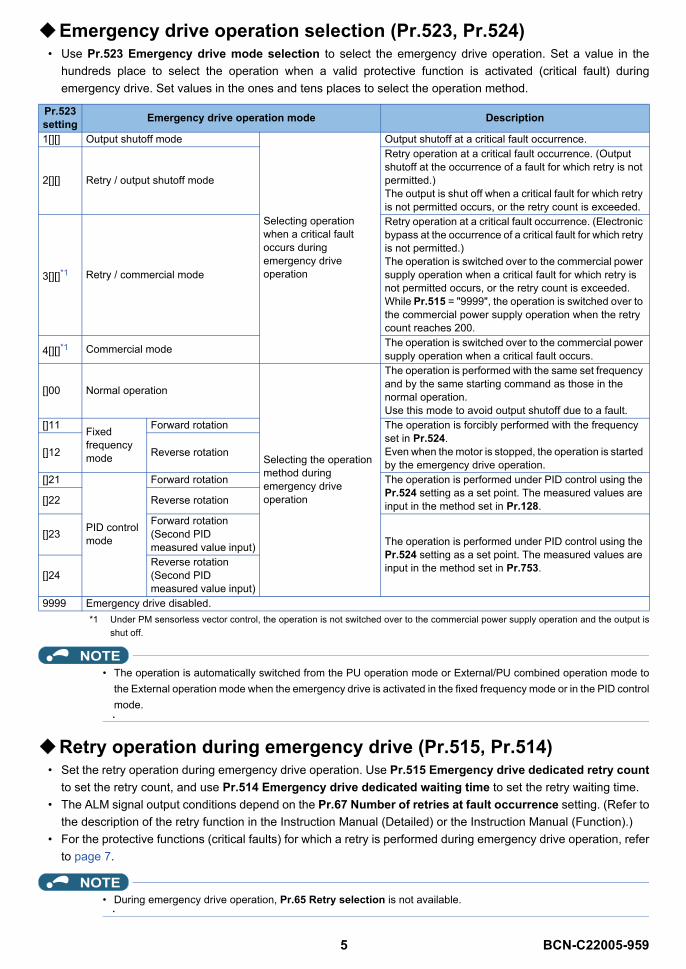
5 BCN-C22005-959
Emergency drive operation selection (Pr.523, Pr.524)• Use Pr.523 Emergency drive mode selection to select the emergency drive operation. Set a value in the
hundreds place to select the operation when a valid protective function is activated (critical fault) duringemergency drive. Set values in the ones and tens places to select the operation method.
*1 Under PM sensorless vector control, the operation is not switched over to the commercial power supply operation and the output isshut off.
NOTE• The operation is automatically switched from the PU operation mode or External/PU combined operation mode to
the External operation mode when the emergency drive is activated in the fixed frequency mode or in the PID controlmode.
Retry operation during emergency drive (Pr.515, Pr.514)• Set the retry operation during emergency drive operation. Use Pr.515 Emergency drive dedicated retry count
to set the retry count, and use Pr.514 Emergency drive dedicated waiting time to set the retry waiting time.• The ALM signal output conditions depend on the Pr.67 Number of retries at fault occurrence setting. (Refer to
the description of the retry function in the Instruction Manual (Detailed) or the Instruction Manual (Function).)• For the protective functions (critical faults) for which a retry is performed during emergency drive operation, refer
to page 7.
NOTE• During emergency drive operation, Pr.65 Retry selection is not available.
Pr.523 setting Emergency drive operation mode Description
1[][] Output shutoff mode
Selecting operation when a critical fault occurs during emergency drive operation
Output shutoff at a critical fault occurrence.
2[][] Retry / output shutoff mode
Retry operation at a critical fault occurrence. (Output shutoff at the occurrence of a fault for which retry is not permitted.)The output is shut off when a critical fault for which retry is not permitted occurs, or the retry count is exceeded.
3[][]*1 Retry / commercial mode
Retry operation at a critical fault occurrence. (Electronic bypass at the occurrence of a critical fault for which retry is not permitted.)The operation is switched over to the commercial power supply operation when a critical fault for which retry is not permitted occurs, or the retry count is exceeded. While Pr.515 = "9999", the operation is switched over to the commercial power supply operation when the retry count reaches 200.
4[][]*1 Commercial mode The operation is switched over to the commercial power supply operation when a critical fault occurs.
[]00 Normal operation
Selecting the operation method during emergency drive operation
The operation is performed with the same set frequency and by the same starting command as those in the normal operation. Use this mode to avoid output shutoff due to a fault.
[]11 Fixed frequency mode
Forward rotation The operation is forcibly performed with the frequency set in Pr.524. Even when the motor is stopped, the operation is started by the emergency drive operation.
[]12 Reverse rotation
[]21
PID control mode
Forward rotation The operation is performed under PID control using the Pr.524 setting as a set point. The measured values are input in the method set in Pr.128.[]22 Reverse rotation
[]23Forward rotation(Second PID measured value input) The operation is performed under PID control using the
Pr.524 setting as a set point. The measured values are input in the method set in Pr.753.
[]24Reverse rotation(Second PID measured value input)
9999 Emergency drive disabled.
BCN-C22005-959_ENG.fm 5 ページ 2021年4月28日 水曜日 午後3時0分
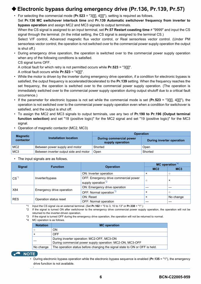
6 BCN-C22005-959
Electronic bypass during emergency drive (Pr.136, Pr.139, Pr.57)• For selecting the commercial mode (Pr.523 = "3[][], 4[][]"), setting is required as follows.
Set Pr.136 MC switchover interlock time and Pr.139 Automatic switchover frequency from inverter tobypass operation and assign MC2 and MC3 signals to output terminals.When the CS signal is assigned to an input terminal, set Pr.57 Restart coasting time ≠ "9999" and input the CSsignal through the terminal. (In the initial setting, the CS signal is assigned to the terminal CS.)Select V/F control, Advanced magnetic flux vector control, or Real sensorless vector control. (Under PMsensorless vector control, the operation is not switched over to the commercial power supply operation the outputis shut off.)
• During emergency drive operation, the operation is switched over to the commercial power supply operationwhen any of the following conditions is satisfied.CS signal turns OFF.A critical fault for which retry is not permitted occurs while Pr.523 = "3[][]".A critical fault occurs while Pr.523 = "4[][]".
• While the motor is driven by the inverter during emergency drive operation, if a condition for electronic bypass issatisfied, the output frequency is accelerated/decelerated to the Pr.139 setting. When the frequency reaches theset frequency, the operation is switched over to the commercial power supply operation. (The operation isimmediately switched over to the commercial power supply operation during output shutoff due to a critical faultoccurrence.)
• If the parameter for electronic bypass is not set while the commercial mode is set (Pr.523 = "3[][], 4[][]"), theoperation is not switched over to the commercial power supply operation even when a condition for switchover issatisfied, and the output is shut off.
• To assign the MC2 and MC3 signals to output terminals, use any two of Pr.190 to Pr.196 (Output terminalfunction selection) and set "18 (positive logic)" for the MC2 signal and set "19 (positive logic)" for the MC3signal.
• Operation of magnetic contactor (MC2, MC3)
• The input signals are as follows.
*1 Input the CS signal via an external terminal. (Set Pr.162 = "0 to 3, 10 to 13" or Pr.338 = "1".)*2 If the signal is turned ON after switchover to the emergency drive commercial power supply operation, the operation will not be
returned to the inverter-driven operation.*3 If the signal is turned OFF during the emergency drive operation, the operation will not be returned to normal.*4 MC operation is as follows.
NOTE• During electronic bypass operation while the electronic bypass sequence is enabled (Pr.135 = "1"), the emergency
drive function is not available.
Magnetic contactor Installation location
OperationDuring commercial power
supply operation During inverter operation
MC2 Between power supply and motor Shorted OpenMC3 Between inverter output side and motor Open Shorted
Signal Function Operation MC operation*4
MC2 MC3
CS*1 Inverter/bypassON: Inverter operation × OFF: Emergency drive commercial power supply operation*2 ×
X84 Emergency drive operationON: Emergency drive operation — —
OFF: Normal operation*3 ×
RES Operation status resetON: Reset × No changeOFF: Normal operation — —
Notation MC operation ON× OFF
— During inverter operation: MC2-OFF, MC3-ONDuring commercial power supply operation: MC2-ON, MC3-OFF
No change The operation status before changing the signal state to ON or OFF is held.
BCN-C22005-959_ENG.fm 6 ページ 2021年4月28日 水曜日 午後3時0分
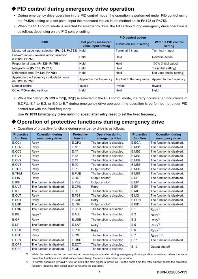
7 BCN-C22005-959
PID control during emergency drive operation• During emergency drive operation in the PID control mode, the operation is performed under PID control using
the Pr.524 setting as a set point. Input the measured values in the method set in Pr.128 or Pr.753.• When the PID control mode is selected for emergency drive, the PID action during emergency drive operation is
as follows depending on the PID control setting.
• While the "retry" (Pr.523 = "22[], 32[]") is selected in the PID control mode, if a retry occurs at an occurrence ofE.CPU, E.1 to E.3, or E.5 to E.7 during emergency drive operation, the operation is performed not under PIDcontrol but with the fixed frequency.Use Pr.1013 Emergency drive running speed after retry reset to set the fixed frequency.
Operation of protective functions during emergency drive• Operation of protective functions during emergency drive is as follows.
*1 While the switchover to the commercial power supply operation during emergency drive operation is enabled, when the sameprotective function is activated twice consecutively, the retry is attempted up to twice.
*2 In normal operation (Pr.523 = "200 or 300"), the start signal is turned OFF at the same time the retry function resets the protectivefunction. Input the start signal again to resume the operation.
ItemPID control action
Set point / measured value input setting Deviation input setting Without PID control
settingMeasured value input selection (Pr.128, Pr.753) Held Terminal 4 input Terminal 4 inputForward action / reverse action selection (Pr.128, Pr.753) Held Held Reverse action
Proportional band (Pr.129, Pr.756) Held Held 100% (initial value)Integral time (Pr.130, Pr.757) Held Held 1 s (initial setting)Differential time (Pr.134, Pr.758) Held Held Not used (initial setting)Applied to the frequency / calculation only (Pr.128, Pr.753) Applied to the frequency Applied to the frequency Applied to the frequency
Dancer control Invalid Invalid InvalidOther PID-related settings Held Held Held
Protective function
Operation during emergency drive
Protective function
Operation during emergency drive
Protective function
Operation during emergency drive
E.OC1 Retry E.OP3 The function is disabled. E.ECA The function is disabled.E.OC2 Retry E.16 The function is disabled. E.MB1 The function is disabled.E.OC3 Retry E.17 The function is disabled. E.MB2 The function is disabled.E.OV1 Retry E.18 The function is disabled. E.MB3 The function is disabled.E.OV2 Retry E.19 The function is disabled. E.MB4 The function is disabled.E.OV3 Retry E.20 The function is disabled. E.MB5 The function is disabled.E.THT Retry E.PE Output shutoff E.MB6 The function is disabled.E.THM Retry E.PUE The function is disabled. E.MB7 The function is disabled.E.FIN Retry E.RET Output shutoff E.EP The function is disabled.E.IPF The function is disabled. E.PE2 Output shutoff E.MP The function is disabled.E.UVT The function is disabled. E.CPU Retry E.EF The function is disabled.E.ILF The function is disabled. E.CTE The function is disabled. E.IAH The function is disabled.E.OLT Retry E.P24 The function is disabled. E.LCI The function is disabled.E.SOT Retry E.CDO Retry E.PCH The function is disabled.E.LUP The function is disabled. E.IOH Output shutoff E.PID The function is disabled.E.LDN The function is disabled. E.SER The function is disabled. E.1 Retry*2
E.BE Retry*1 E.AIE The function is disabled. E.2 Retry*2
E.GF Retry E.USB The function is disabled. E.3 Retry*2
E.LF The function is disabled. E.SAF Retry*1 E.5 Retry*2
E.OHT Retry E.PBT Retry*1 E.6 Retry*1*2
E.PTC Retry E.OS The function is disabled. E.7 Retry*1*2
E.OPT The function is disabled. E.OSD The function is disabled. E.11 The function is disabled.E.OP1 The function is disabled. E.ECT The function is disabled.
E.13 Output shutoffE.OP2 The function is disabled. E.OD The function is disabled.
BCN-C22005-959_ENG.fm 7 ページ 2021年4月28日 水曜日 午後3時0分
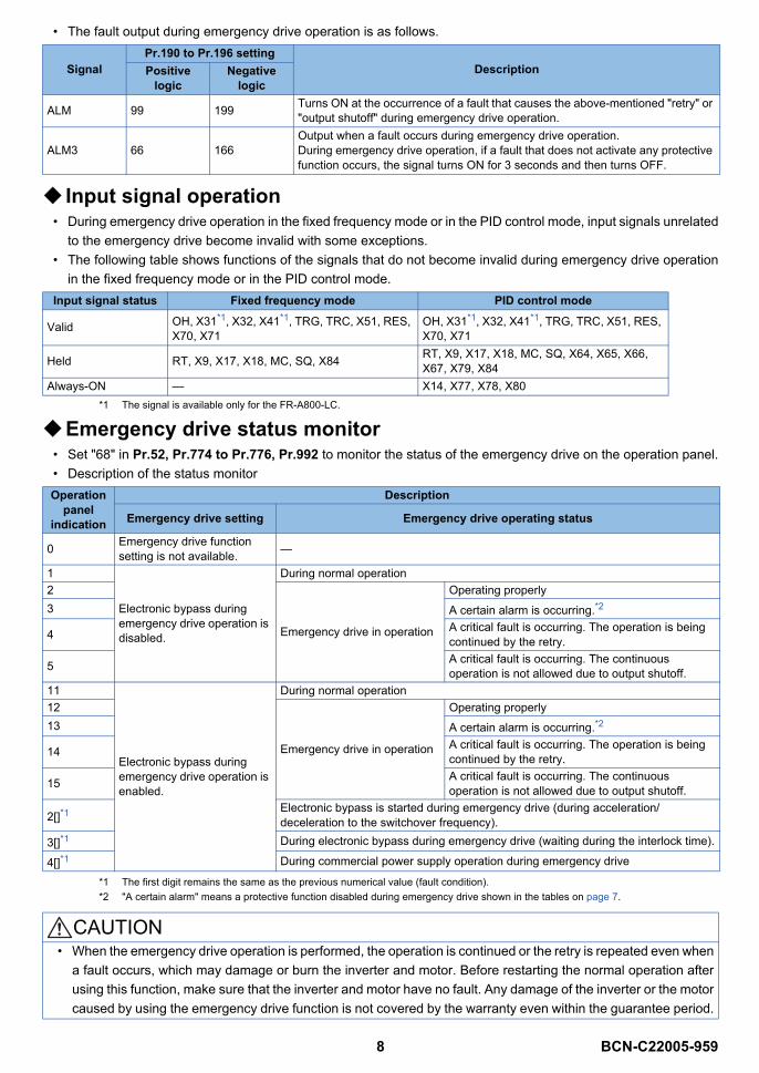
8 BCN-C22005-959
• The fault output during emergency drive operation is as follows.
Input signal operation• During emergency drive operation in the fixed frequency mode or in the PID control mode, input signals unrelated
to the emergency drive become invalid with some exceptions.• The following table shows functions of the signals that do not become invalid during emergency drive operation
in the fixed frequency mode or in the PID control mode.
*1 The signal is available only for the FR-A800-LC.
Emergency drive status monitor• Set "68" in Pr.52, Pr.774 to Pr.776, Pr.992 to monitor the status of the emergency drive on the operation panel.• Description of the status monitor
*1 The first digit remains the same as the previous numerical value (fault condition).*2 "A certain alarm" means a protective function disabled during emergency drive shown in the tables on page 7.
SignalPr.190 to Pr.196 setting
DescriptionPositive logic
Negative logic
ALM 99 199 Turns ON at the occurrence of a fault that causes the above-mentioned "retry" or "output shutoff" during emergency drive operation.
ALM3 66 166Output when a fault occurs during emergency drive operation. During emergency drive operation, if a fault that does not activate any protective function occurs, the signal turns ON for 3 seconds and then turns OFF.
Input signal status Fixed frequency mode PID control mode
Valid OH, X31*1, X32, X41*1, TRG, TRC, X51, RES, X70, X71
OH, X31*1, X32, X41*1, TRG, TRC, X51, RES, X70, X71
Held RT, X9, X17, X18, MC, SQ, X84 RT, X9, X17, X18, MC, SQ, X64, X65, X66, X67, X79, X84
Always-ON — X14, X77, X78, X80
Operation panel
indication
Description
Emergency drive setting Emergency drive operating status
0 Emergency drive function setting is not available. —
1
Electronic bypass during emergency drive operation is disabled.
During normal operation2
Emergency drive in operation
Operating properly3 A certain alarm is occurring.*2
4 A critical fault is occurring. The operation is being continued by the retry.
5 A critical fault is occurring. The continuous operation is not allowed due to output shutoff.
11
Electronic bypass during emergency drive operation is enabled.
During normal operation12
Emergency drive in operation
Operating properly13 A certain alarm is occurring.*2
14 A critical fault is occurring. The operation is being continued by the retry.
15 A critical fault is occurring. The continuous operation is not allowed due to output shutoff.
2[]*1Electronic bypass is started during emergency drive (during acceleration/deceleration to the switchover frequency).
3[]*1 During electronic bypass during emergency drive (waiting during the interlock time).
4[]*1 During commercial power supply operation during emergency drive
CAUTION• When the emergency drive operation is performed, the operation is continued or the retry is repeated even when
a fault occurs, which may damage or burn the inverter and motor. Before restarting the normal operation afterusing this function, make sure that the inverter and motor have no fault. Any damage of the inverter or the motorcaused by using the emergency drive function is not covered by the warranty even within the guarantee period.
BCN-C22005-959_ENG.fm 8 ページ 2021年4月28日 水曜日 午後3時0分

9 BCN-C22005-959
2 Forward rotation output (Y30) signal and Reverse rotation output (Y31) signal
The Forward rotation output (Y30) signal and Reverse rotation output (Y31) signal become available under encoderfeedback control.
• Under Vector control or encoder feedback control, the Forward rotation output (Y30) signal or the Reverserotation output (Y31) signal is output according to the actual rotation direction of the motor.
NOTE• For the details on the Y30 and Y31 signals, refer to the Instruction Manual (Detailed) or the Instruction Manual
(Function).
BCN-C22005-959_ENG.fm 9 ページ 2021年4月28日 水曜日 午後3時0分
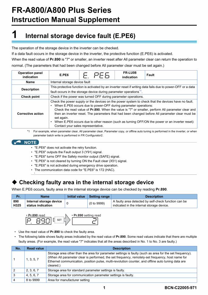
1 BCN-C22005-971
FR-A800/A800 Plus SeriesInstruction Manual Supplement
1 Internal storage device fault (E.PE6)The operation of the storage device in the inverter can be checked.If a data fault occurs in the storage device in the inverter, the protective function (E.PE6) is activated.When the read value of Pr.890 is "7" or smaller, an inverter reset after All parameter clear can return the operation tonormal. (The parameters that had been changed before All parameter clear must be set again.)
*1 For example, when parameter clear, All parameter clear, Parameter copy, or offline auto tuning is performed in the inverter, or whenparameter batch write is performed in FR Configurator2.
NOTE• "E.PE6" does not activate the retry function.• "E.PE6" outputs the Fault output 3 (Y91) signal.• "E.PE6" turns OFF the Safety monitor output (SAFE) signal.• "E.PE6" is not cleared by turning ON the Fault clear (X51) signal.• "E.PE6" is not activated during emergency drive operation.• The communication data code for "E.PE6" is 172 (HAC).
Checking faulty area in the internal storage deviceWhen E.PE6 occurs, faulty area in the internal storage device can be checked by reading Pr.890.
• Use the read value of Pr.890 to check the faulty area.• The following table shows faulty areas indicated by the read value of Pr.890. Some read values indicate that there are multiple
faulty areas. (For example, the read value "7" indicates that all the areas described in No. 1 to No. 3 are faulty.)
Operation panel indication E.PE6 FR-LU08
indication Fault
Name Internal storage device fault
DescriptionThis protective function is activated by an inverter reset if writing data fails due to power-OFF or a data fault occurs in the storage device during parameter operations*1.
Check point Check if the power was turned OFF during parameter operations.
Corrective action
Check the power supply or the devices on the power system to check that the devices have no fault.• When E.PE6 occurs due to power-OFF during parameter operations:
Check the read value of Pr.890. When the value is "7" or smaller, perform All parameter clear andthen an inverter reset. The parameters that had been changed before All parameter clear must beset again.
• When E.PE6 occurs due to other reason (such as turning OFF/ON the power or an inverter reset):Contact your sales representative.
Pr. Name Initial value Setting range Description890H325
Internal storage device status indication 0 (0 to 9999) A faulty area detected by self-check function can be
indicated in the internal storage device.
No. Read value Description
1 1, 3, 5, 7
Storage area other than the area for parameter settings is faulty (such as area for the set frequency). (When All parameter clear is performed, the set frequency, remotely-set frequency, host name for Ethernet communication, position pulse, multi-revolution counter, and offline auto tuning data are cleared.)
2 2, 3, 6, 7 Storage area for standard parameter settings is faulty.3 4, 5, 6, 7 Storage area for communication parameter settings is faulty.4 8 to 9999 Area for manufacturer setting
• Pr.890 read • Pr.890 setting read
BCN-C22005-971_ENG.fm 1 ページ 2021年9月7日 火曜日 午前10時35分
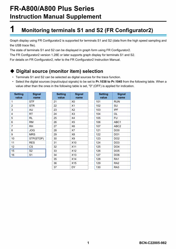
1 BCN-C22005-982
FR-A800/A800 Plus SeriesInstruction Manual Supplement
1 Monitoring terminals S1 and S2 (FR Configurator2)Graph display using FR Configurator2 is supported for terminals S1 and S2 (data from the high speed sampling andthe USB trace file).The state of terminals S1 and S2 can be displayed in graph form using FR Configurator2.The FR Configurator2 version 1.28E or later supports graph display for terminals S1 and S2.For details on FR Configurator2, refer to the FR Configurator2 Instruction Manual.
Digital source (monitor item) selection• Terminals S1 and S2 can be selected as digital sources for the trace function.• Select the digital sources (input/output signals) to be set to Pr.1038 to Pr.1045 from the following table. When a
value other than the ones in the following table is set, "0" (OFF) is applied for indication.
Setting value
Signal name
Setting value
Signal name
Setting value
Signal name
1 STF 21 X0 101 RUN2 STR 22 X1 102 SU3 AU 23 X2 103 IPF4 RT 24 X3 104 OL5 RL 25 X4 105 FU6 RM 26 X5 106 ABC17 RH 27 X6 107 ABC28 JOG 28 X7 121 DO09 MRS 29 X8 122 DO110 STP(STOP) 30 X9 123 DO211 RES 31 X10 124 DO312 CS 32 X11 125 DO415 S2 33 X12 126 DO516 S1 34 X13 127 DO6
35 X14 128 RA136 X15 129 RA237 DY 130 RA3
BCN-C22005-982_ENG.fm 1 ページ 2022年4月20日 水曜日 午前11時5分

INVERTER
INVER
TERA
800-EFR
-A806-E IN
STRU
CTIO
N M
AN
UA
L (HA
RD
WA
RE)
B
INTRODUCTION1
INSTALLATION AND WIRING2
PRECAUTIONS FOR USE OFTHE INVERTER 3
PROTECTIVE FUNCTIONS4
PRECAUTIONS FORMAINTENANCE AND
INSPECTION5
SPECIFICATIONS6
HEAD OFFICE: TOKYO BUILDING 2-7-3, MARUNOUCHI, CHIYODA-KU, TOKYO 100-8310, JAPAN
IB(NA)-0600634ENG-B(1904)MEE Printed in Japan Specifications subject to change without notice.
FR-A800-EFR-A806-E (IP55/UL Type 12 SPECIFICATIONS)INSTRUCTION MANUAL (HARDWARE)
FR-A846-00023(0.4K) to 03610(132K)-EHigh functionality and high performance


