Embed Size (px)
Citation preview

FRACTIONAL-DERIVATIVE MAXWELL M O D E L
FOR Viscous DAMPERS
By Nicos Makris1 and M. C. Constantinou,2 Associate Member, ASCE
ABSTRACT: A fractional-derivative Maxwell model is proposed for viscous dampers, which are used for vibration isolation of piping systems, forging hammers, and other industrial equipment, as well as for vibration and seismic isolation of building structures. The development and calibration of the model is based on experimentally observed dynamic characteristics. The proposed model is validated by dynamic testing and very good agreement between predicted and experimental results is obtained. Numerical algorithms for the solution of the constitutive relation in either the frequency or the time domain are presented. Some analytical results for a single-degree-of-freedom viscodamper system are presented. These results are useful to the design of vibration-isolation systems. Furthermore, an equivalent viscous oscillator is defined whose response is essentially the same as that of the viscodamper isolator. Finally, the model is employed in the analysis of a base-isolated model structure that has been tested on a shake table.
INTRODUCTION
Viscous dampers are devices for dissipating energy. They are used in the reduction of vibration in pipework systems and together with helical steel springs in the vibration isolation of massive industrial equipment such as presses and forging hammers. More recently they have been proposed for seismic isolation of buildings (Huffmann 1985). Two residential buildings have recently been constructed in Los Angeles, California, on isolation systems, consisting of helical steel springs and viscous dampers, for earthquake protection.
Viscous dampers typically consist of a moving part immersed in highly viscous fluid. In the applications just described, the moving part is in the form of a hollow cylinder (piston). Fig. 1 shows the construction of an experimental cylindrical damper tested by the writers (Makris and Constantinou 1990). The damper piston can move in all directions and damping forces develop as a result of shearing action and displacement in the fluid. Dampers of different geometry than the one shown in Fig. 1 have been used in combination with elastomeric bearings in a seismic-isolated building in Japan (Higashino et al. 1988; Kelly 1988). The dampers consisted of circular plates that were positioned on top of viscous fluid within a container. Damping forces develop by shearing of the fluid during motion of the plate.
The dynamic characteristics of a viscous damper depend primarily on the properties of the viscous fluid and secondarily on the geometry of the device. Two types of damper fluid are used: (1) Temperature-dependent fluids, which can be adapted to the operating temperature of a particular application; and (2) nearly temperature-independent fluids. The fluid used in the tests re-
'Res. Asst., Dept. of Civ. Engrg., School of Engrg. and Appl. Sci., 212 Ketter Hall, State Univ. of New York, Buffalo, NY 14260.
2Assoc. Prof., Dept. of Civ. Engrg., School of Engrg. and Appl. Sci., 212 Ketter Hall, State Univ. of New York, Buffalo, NY.
Note. Discussion open until February 1, 1992. To extend the closing date one month, a written request must be filed with the ASCE Manager of Journals. The manuscript for this paper was submitted for review and possible publication on September 24, 1990. This paper is part of the Journal of Structural Engineering, Vol. 117, No. 9, September, 1991. ©ASCE, ISSN 0733-9445/91/0009-2708/$1.00 + $.15 per page. Paper No. 26157.
2708
J. S
truc
t. E
ng. 1
991.
117:
2708
-272
4.D
ownl
oade
d fr
om a
scel
ibra
ry.o
rg b
y W
alte
r Se
rial
s Pr
oces
s on
08/
08/1
2. F
or p
erso
nal u
se o
nly.
No
othe
r us
es w
ithou
t per
mis
sion
. Cop
yrig
ht (
c) 2
012.
Am
eric
an S
ocie
ty o
f C
ivil
Eng
inee
rs. A
ll ri
ghts
res
erve
d.

k////////////////////^^^^
• t^/ / / *w^^^^^^
• 266 mm -
FIG. 1. Geometry of Tested Damper
ported herein is a form of silicon gel with nearly temperature-independent properties in the range of —40-130° C. It was supplied by a manufacturer of viscous dampers ("Pipework" 1986). It is known that viscous dampers exhibit viscoelastic behavior, that is, behavior that incorporates both elastic and viscous characteristics. Furthermore, the properties of viscous dampers are strongly frequency dependent, e.g., for the tested dampers the damping coefficient showed a tenfold decrease within the frequency range of 0-50 Hz. Nevertheless, mathematical models used for these devices have been limited to that of the simple linear viscous dashpot ("Pipework" 1986; Hi-gashino et al. 1988).
Herein, the concept of fractional derivative (Oldham and Spanier 1974) is employed in the development of a force-displacement relationship for viscous dampers. Fractional derivatives within the context of viscoelasticity were used as early as 1936 by Gemant, (1936) and recently by Koh and Kelly (1990), who proposed a fractional Kelvin model for elastomeric bearings. Earlier experiments with viscous dampers (Schwahn et al. 1988) have demonstrated that the classical two- and three-parameter models of viscoelasticity were incapable of describing the behavior of the dampers with a sufficient degree of accuracy. The writers of the present paper observed that the frequency dependency of the mechanical properties of the tested dampers varied as frequency was raised to fractional rather integer powers. This suggests that differentials of fractional order could be used in modeling of the dampers. Similar observations prompted Gemant (1936) to first propose fractional-derivative models for viscoelastic materials. The foregoing reasons motivated the study reported herein.
FRACTIONAL DERIVATIVE MAXWELL MODEL
The shear stress-strain relationship in the fractional-derivative Maxwell model is
2709
J. S
truc
t. E
ng. 1
991.
117:
2708
-272
4.D
ownl
oade
d fr
om a
scel
ibra
ry.o
rg b
y W
alte
r Se
rial
s Pr
oces
s on
08/
08/1
2. F
or p
erso
nal u
se o
nly.
No
othe
r us
es w
ithou
t per
mis
sion
. Cop
yrig
ht (
c) 2
012.
Am
eric
an S
ocie
ty o
f C
ivil
Eng
inee
rs. A
ll ri
ghts
res
erve
d.

T + \Dr[r] = (juD"[7] (1)
in which T = shear stress; 7 = shear strain; X and \i = generalized material constants; Dr[f(t)] = fractional derivative of order r of the time-dependent function / . A definition of the fractional derivative of a function satisfying the condition/(?) = 0 for t < 0 is via the following series, which was given by Grunwald (Oldham and Spanier 1974):
dj{t) JUJ N^F(j-r) I t\\ £»r[/(0] = -JA1 = lim I S — -f( t-j-)\ (2)
df N^ ln-r) p0 T(j+l)J\ JNj) where T = gamma function. The writers prefer the foregoing definition to the more commonly used integral representation of Riemann-Liouville (Oldham and Spanier 1974) because (2) involves only evaluations of the function itself and not of its derivatives and integrals.
The model of (1) is a special case of the more general model of Bagley and Torvik (1983). It may be seen that the model of (1) collapses to the conventional Maxwell model when r = q — 1, in which case X and |x become the relaxation time and dynamic viscosity, respectively. The four parameters of the model were determined by a fit of the rate-dependent and frequency-dependent mechanical properties of the fluid damper (silicon gel). First, the cone-and-plate method in steady shear flow (Bird et al. 1987) was used to obtain measurements of the dynamic viscosity. The experiments gave a value of viscosity of 1,930 Pa-sec (19,300 poise), which was independent of the shear-strain rate in the range of 0-2/sec. Accordingly, parameters q and u, are q = 1; u. = 1,930 Pa-sec. Parameters r and X were determined by least-square fit of the storage and loss shear moduli of the material, which were obtained in oscillatory shear flow experiments using the cone-and-plate method (Bird et al. 1987). The parameters are X = 0.26 (sec)0565; r = 0.565. Experiments were performed at shear strains of 0.05 and 0.1 and the model produced a very satisfactory fit in both cases [see Makris and Constantinou (1990)]. Furthermore, the tests were run at temperatures in the range of 10-30° C, which is the range of interest in most of the applications of viscous dampers. Temperature in this range had no effect on the mechanical properties of the fluid.
Attempts were made by the writers [see Makris and Constantinou (1990)] to fit the viscoelastic properties of the viscous fluid with conventional models of viscoelasticity. It was found that conventional models were worse than the proposed fractional-derivative model and valid only in a small range of frequencies. For example, the conventional Maxwell model could fit well only the data on the loss modulus within a frequency range 50 times smaller than that in the fractional-derivative Maxwell model.
Dynamic tests of the viscous damper of Fig. 1 were conducted by imposing sinusoidal motion of specified amplitude and frequency to the piston of the damper. The testing apparatus, which involved a complicated arrangement of load cells and very-low-friction roller bearings, is described in the report by Makris and Constantinou (1990). From records of the force needed to maintain the imposed motion, the mechanical properties of the damper were determined under conditions of steady-state motion. The mechanical properties measured were the storage, loss, and elastic stiffnesses (defined
2710
J. S
truc
t. E
ng. 1
991.
117:
2708
-272
4.D
ownl
oade
d fr
om a
scel
ibra
ry.o
rg b
y W
alte
r Se
rial
s Pr
oces
s on
08/
08/1
2. F
or p
erso
nal u
se o
nly.
No
othe
r us
es w
ithou
t per
mis
sion
. Cop
yrig
ht (
c) 2
012.
Am
eric
an S
ocie
ty o
f C
ivil
Eng
inee
rs. A
ll ri
ghts
res
erve
d.

exactly as the corresponding moduli in a stress-strain relationship) and the phase angle between the in-phase and out-of-phase components of the force. Tests were conducted with motion in the vertical and horizontal directions. All tests were conducted at room temperature (about 25° C).
For motion in the vertical direction we observe that the damper fluid is primarily subjected to shearing action. Accordingly, the force-displacement relationship in vertical motion is expressed as
P + \Dr[P] = C0D"[u\ (3)
in which P = force; and u = displacement. The expectation is that q equals unity and X and r are very close to the values obtained for the stress-strain relationship of the fluid. For q — 1, constant C0 attains physical interpretation. It is the damping coefficient at zero frequency that could be measured in an oscillatory test at very low frequency (0.01 Hz in this study).
The relationship between force amplitude P(u>) and displacement amplitude w(o)) is obtained by employing the Fourier transform to (3)
P(a>) = [*,(«) + tf:2(a>)]fl(co) (4)
where i = imaginary unit; and Kt and K2 = storage and loss stiffnesses
C0co? cos qtt
K,=
n 7
1 + \ G / cos I — + C0X.(i)9+r sin qir
(5)
C0<x>q s i n
K,
qn 1 + Xo/ cos I — - C0Xco,+rsin ( — j cos ( —
(6)
d = 1 + X V 2X(i/ cos vu (7)
A total of 26 tests were conducted with motion in the vertical direction and frequency in the range of 0.01-50 Hz. Parameter q was set equal to unity, and parameters X and r were determined in a least-square fit of the elastic stiffness curve (defined as the square root of the sum of squares of Kx and K2). Constant C0 was then found by fitting the damping-coefficient curve. The damping coefficient is defined by
C(o) = K2(o>)
(8)
so that the force developed at the piston of the damper in steady-state harmonic motion is
P(t) = A'1((O)M(0 + C(a))ii(0 (9)
In (9), u = velocity of the piston. The parameters of the model are q = 1; C0 = 15,000 Ns /m; r = 0.6; and X = 0.3 (sec)06. Indeed, parameters X and r are very close to those of the stress-strain relationship of the fluid. Figs. 2 and 3 demonstrate the very good agreement between the model and the mechanical properties of storage modulus (Ki) and damping coefficient (C).
2711
J. S
truc
t. E
ng. 1
991.
117:
2708
-272
4.D
ownl
oade
d fr
om a
scel
ibra
ry.o
rg b
y W
alte
r Se
rial
s Pr
oces
s on
08/
08/1
2. F
or p
erso
nal u
se o
nly.
No
othe
r us
es w
ithou
t per
mis
sion
. Cop
yrig
ht (
c) 2
012.
Am
eric
an S
ocie
ty o
f C
ivil
Eng
inee
rs. A
ll ri
ghts
res
erve
d.

CO CO Ld
10
10
p 10 i CO
Ld o < 1
O I— CO
10 _1
0
* * • * Experimental Fractional Maxwell Model
C0 = 15000 N s / m \ = 03sr, r=0.6, q=l
1 r-
40 10 20 30 40 50 FREQUENCY Hz
FIG. 2. Fitting of Storage Stiffness of Tested Damper by Fractional Maxwel l Mode l
The mechanical properties of the damper for motion of the piston in the horizontal direction were determined by the same procedure, resulting in q = 1; C0 = 6,000 Ns/m; A. = 0.15 (sec)07; and r = 0.7.
Verification tests were conducted with transient input motion of the dam-
• * * * Experimental Fractional Maxwell Model
C0 = 15000 N s / m \ = 03sr, r=0.6, q=l
20 30 FREQUENCY Hz
50
FIG. 3. Fitting of Damping Coefficient of Tested Damper by Fractional Maxwell Model
2712
J. S
truc
t. E
ng. 1
991.
117:
2708
-272
4.D
ownl
oade
d fr
om a
scel
ibra
ry.o
rg b
y W
alte
r Se
rial
s Pr
oces
s on
08/
08/1
2. F
or p
erso
nal u
se o
nly.
No
othe
r us
es w
ithou
t per
mis
sion
. Cop
yrig
ht (
c) 2
012.
Am
eric
an S
ocie
ty o
f C
ivil
Eng
inee
rs. A
ll ri
ghts
res
erve
d.

X!
Ld O
O
150
100-
50-
-50 -
-100-
-150-
DISPLACEMENT mm 3.18 -1.59 0.00 1.59 3.18
i I i l i I i
EXPERIMENTAL — D F T
-0.125 -0.075 -0.025 0.025
DISPLACEMENT 0.075
in.
0.67
0.33
•0.00
J * :
LxJ O
o
-0.33
0.125 -0.67
FIG. 4. Comparison of Analytically Predicted and Recorded Force-Displacement Loop in Test with Time-Varying Amplitude and Frequency
per piston. The calibrated model of (3) was used to predict the force needed to maintain the imposed motion. Numerical schemes in the time domain for the solution of fractional-differential equations are available and extensively discussed in Oldham and Spanier (1974). However, numerical schemes in the frequency domain are much more convenient to use. For this, we recognize that expression £\(a>) + iK2(u>) in (4) represents the amplitude and phase angle of the steady-state force in the damper for a harmonic displacement input of unit amplitude. Accordingly, the time history of force is expressed as
Pit) 2-U J_c
[JSTJ((O) + (X2(w)]w(o))eto'rfo) (10)
where M(«) represents the Fourier transform of the imposed motion. The computation of the force is thus easily obtained by the discrete Fourier transform (DFT) approach in combination with fast Fourier transform (FFT) algorithms (Veletsos and Ventura 1985).
Figs. 4 and 5 demonstrate very good agreement between the model prediction and recorded force-displacement loops in tests with vertical motion. In Fig. 4, the motion consists of a sinusoidal wave in which amplitude decreases and frequency increases with time. The frequency increases linearly from 0 to 4.5 Hz in 2 seconds. In Fig. 5, the motion is a four-cycle beat.
2713
J. S
truc
t. E
ng. 1
991.
117:
2708
-272
4.D
ownl
oade
d fr
om a
scel
ibra
ry.o
rg b
y W
alte
r Se
rial
s Pr
oces
s on
08/
08/1
2. F
or p
erso
nal u
se o
nly.
No
othe
r us
es w
ithou
t per
mis
sion
. Cop
yrig
ht (
c) 2
012.
Am
eric
an S
ocie
ty o
f C
ivil
Eng
inee
rs. A
ll ri
ghts
res
erve
d.
DISPLACEMENT mm
_Q
o o
-100-I
-0.3 DISPLACEMENT in.
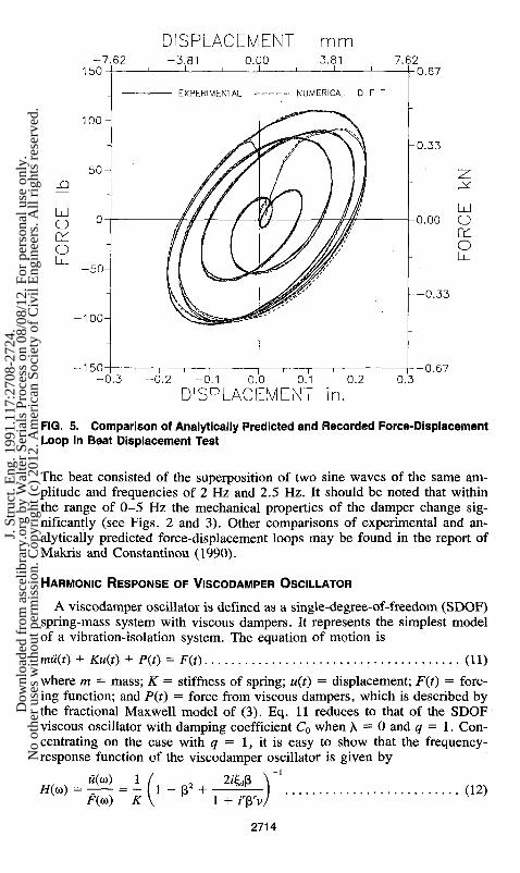
FIG. 5. Comparison of Analytically Predicted and Recorded Force-Displacement Loop in Beat Displacement Test
The beat consisted of the superposition of two sine waves of the same amplitude and frequencies of 2 Hz and 2.5 Hz. It should be noted that within the range of 0-5 Hz the mechanical properties of the damper change significantly (see Figs. 2 and 3). Other comparisons of experimental and analytically predicted force-displacement loops may be found in the report of Makris and Constantinou (1990).
HARMONIC RESPONSE OF VISCODAMPER OSCILLATOR
A viscodamper oscillator is defined as a single-degree-of-freedom (SDOF) spring-mass system with viscous dampers. It represents the simplest model of a vibration-isolation system. The equation of motion is
mu(t) + Ku{t) + P(t) = F(t) (11)
where m = mass; K = stiffness of spring; u(t) = displacement; F(t) = forcing function; and P(t) = force from viscous dampers, which is described by the fractional Maxwell model of (3). Eq. 11 reduces to that of the SDOF viscous oscillator with damping coefficient C0 when X = 0 and q = 1. Concentrating on the case with q = 1, it is easy to show that the frequency-response function of the viscodamper oscillator is given by
#(o>) F((o) K
1 - p-5 + 1 + fprv
(12)
2714
J. S
truc
t. E
ng. 1
991.
117:
2708
-272
4.D
ownl
oade
d fr
om a
scel
ibra
ry.o
rg b
y W
alte
r Se
rial
s Pr
oces
s on
08/
08/1
2. F
or p
erso
nal u
se o
nly.
No
othe
r us
es w
ithou
t per
mis
sion
. Cop
yrig
ht (
c) 2
012.
Am
eric
an S
ocie
ty o
f C
ivil
Eng
inee
rs. A
ll ri
ghts
res
erve
d.

where
W
P = — (13) w0
K\l/2
<»o = I - I (14)
^ = 2 ^ ( 1 5 )
v = Xw0 (16)
and w(w) and F(w) represent the Fourier amplitudes of u(t) and F(t), respectively. It should be noted that (12) reduces to the equation for a SDOF viscous oscillator with natural frequency w0 and damping ratio ^ when v = 0; w0 represents the undamped natural frequency of the oscillator without the stiffening effect of the viscous damper; and ^ represents a fictitious damping ratio used in defining constant C0 of the viscous damper.
For a harmonic forcing function F(t) = F0 sin wf, the steady-state displacement response is given by
F0 u(t) = — D sin (u>t - 6) (17) K
_ f (1 + Prvc)2 + ( P W | 1 / 2
D " Ui - p2)2(i + prvc)2 + [(i - p2)pr™ + 2ys]2J ( 1 8 )
2 ^ ( 1 + prvc)
(1 - p2)[(l + prvc)2 + (fi'vsf] + 2^p1+rw tan 6 = ; ; —— (19)
In (18) and (19), c and s stand for the cosine and sine of rfi/2. Furthermore, D represents the dynamic magnification factor, and 8 represents the phase angle. They are the amplitude and phase of the complex frequency response function (12), respectively. Eq. (17) is, of course, valid in the limit of large times and provided that a sinusoidal force acting on the viscodamper oscillator produces a sinusoidal displacement after transients have died out. Analytic proof for this behavior is essential for the validity of the presented model and solutions. Such analytic proof was presented in the report of Mak-ris and Constantinou (1990); it is very lengthy and entirely beyond the scope of this paper to be presented herein.
The maximum force exerted against the base of the oscillator by the spring and viscous damper upon division by the amplitude of the driving force, F0, gives the absolute transmissibility
TR = f (1 + Vvc)2 + (P r^ ) 2 + ( 2 ^P ) 2 + 4^1+rys } m (2Q)
1(1 - p2)2(l + p'vc)2 + [(1 - p2)prv* + 2^p]2J
Eqs. (18)-(20) reduce to those of a SDOF viscous oscillator with natural frequency w0 and damping ratio £, when v = 0.
Plots of the dynamic magnification factor D, phase angle 0, and transmissibility TR are shown in Figs. 6-8 for a system with/0 = W0/2TT = 5 Hz; v = 2.374; and r = 0.6. It is assumed that viscous dampers of different
2715
J. S
truc
t. E
ng. 1
991.
117:
2708
-272
4.D
ownl
oade
d fr
om a
scel
ibra
ry.o
rg b
y W
alte
r Se
rial
s Pr
oces
s on
08/
08/1
2. F
or p
erso
nal u
se o
nly.
No
othe
r us
es w
ithou
t per
mis
sion
. Cop
yrig
ht (
c) 2
012.
Am
eric
an S
ocie
ty o
f C
ivil
Eng
inee
rs. A
ll ri
ghts
res
erve
d.

£°o.o
f0 = S Hz, v = 2374, r = 0.6
0.5 1.0 1.5 2.0 3.0
FIG. 6. Dynamic Magnification Factor Plot of Viscodamper Oscillator
sizes have the same values for parameters \ and r and that only constant C0 is different. This constant is conveniently expressed in terms of the dimen-sionless fictitious damping ratio i,d. The actual damping ratio of the viscodamper oscillator is always less than £rf because of the stiffening effect of
180
FIG. 7. Phase Angle Plot of Viscodamper Oscillator
2716
J. S
truc
t. E
ng. 1
991.
117:
2708
-272
4.D
ownl
oade
d fr
om a
scel
ibra
ry.o
rg b
y W
alte
r Se
rial
s Pr
oces
s on
08/
08/1
2. F
or p
erso
nal u
se o
nly.
No
othe
r us
es w
ithou
t per
mis
sion
. Cop
yrig
ht (
c) 2
012.
Am
eric
an S
ocie
ty o
f C
ivil
Eng
inee
rs. A
ll ri
ghts
res
erve
d.

= 0.2 5
I—
i6 ' CO 005-
to „
<
t - 3 -
Ld
o CO CD <
f<) = 5 Hz, v = 2.374, r = 0.6
0.5
/0.75
— i 1 1 1 1 1 1 1 1 1 1 1
0.0 0.5 1.0 1.5 2.0 2.5 3.0 (3=C0/Cdo
FIG. 8. Absolute Transmissibllity Plot of Viscodamper Oscillator
the viscous damper (see Fig. 2 for storage modulus) and because of the decrease of the damping coefficient with increasing frequency (see Fig. 3). For example, a system with f0 = 5 Hz and ^ = 1 has an actual damping ratio of about 0.25. For this, observe in Fig. 3 that the ratio of damping coefficient C at frequency of 5 Hz is about four times less than C0. The following significant features of the steady-state response of the viscodamper oscillator can be observed in Figs. 6-8.
1. The peak value of the dynamic magnification factor occurs for values of P larger than unity, whereas in the SDOF viscous oscillator this peak occurs at values of p less than unity. This phenomenon is caused by the stiffening effect of the viscous damper.
2. At resonance (P = 1) the phase angle 6 is equal to nr/2. 3. The phase angle 6 does not increase monotonically with increasing fre
quency ratio p. Rather, it exhibits a peak value, which is always less than IT, at a value of p larger than unity. Beyond this value, 6 decreases. Again, this result is caused by the stiffening effect of the viscous damper.
4. The curves of transmissibility do not pass through the same point as in the SDOF viscous oscillator. Damping ratio ^ tends to reduce the effectiveness of an isolation system for frequency ratio p greater than a certain value that, unlike the SDOF viscous oscillator, is not fixed but rather depends on the system's parameters.
The presented results on the harmonic steady-state response of the viscodamper oscillator may be used in constructing design charts for vibration-isolation systems consisting of springs and viscous dampers.
2717
J. S
truc
t. E
ng. 1
991.
117:
2708
-272
4.D
ownl
oade
d fr
om a
scel
ibra
ry.o
rg b
y W
alte
r Se
rial
s Pr
oces
s on
08/
08/1
2. F
or p
erso
nal u
se o
nly.
No
othe
r us
es w
ithou
t per
mis
sion
. Cop
yrig
ht (
c) 2
012.
Am
eric
an S
ocie
ty o
f C
ivil
Eng
inee
rs. A
ll ri
ghts
res
erve
d.

TRANSIENT RESPONSE OF VISCODAMPER OSCILLATOR
The response of the viscodamper oscillator to general dynamic loading is most conveniently determined by the DFT approach. Alternatively, time-domain algorithms may be used, but they are computationally intensive. One such algorithm is presented later in this paper in conjunction with the analysis of a nonlinear isolation system.
The response of the viscodamper oscillator to general dynamic loading and for zero initial conditions is
u(t) = — 2tr J_„
i/(a))F(a))e'wrf(o (21)
where i/(co) = complex frequency response function (12); and F(co) = Fourier transform of load F(t). The application of the DFT approach is directly analogous to that of the SDOF viscous oscillator.
The transient response of the viscodamper oscillator is compared to the response of an equivalent SDOF viscous oscillator. This oscillator is defined as one whose response is essentially the same as that of the viscodamper oscillator. In the equivalent oscillator, the frequency dependency of the parameters of the viscous damper is neglected so that the equation of motion is
mil + C(ft)w + [K + ^ ( a ) ] « = F(t) (22)
where Ki(fl) and C(Q,) = storage stiffness and damping coefficient, respectively, of the viscous damper evaluated at frequency O. This frequency could be the natural frequency of the equivalent oscillator.
More conveniently, (22) is rewritten
, F(t) u + 2%eis>eu + u>eu = (23)
m
where we and %e = natural frequency and damping factor, respectively, of the equivalent viscous oscillator. These parameters are determined from the expressions for the storage stiffness and damping coefficient of viscous dampers, which are given by (5)-(8).
2&xn , + rs 11 / 2
1 (24) u>e = o>0 1 oj0(l + \ W + 2XOrc).
f = ^— (25) o),(i + \2n2r + 2\nr
c) ' where again c and s stand for the cosine and sine of angle n r / 2 .
The validity of the equivalent oscillator is studied in two interesting applications of viscous dampers.
Impulsive Loading Use with forging hammers is one application of viscous dampers in which
impulsive loading is involved. Forging hammers are massive machines, with mass equal to about 60,000 Kg. The ram of the machine has a mass of about 3,000 Kg, with an impact velocity of 5.5 m / s . On impact, the hammer-
2718
J. S
truc
t. E
ng. 1
991.
117:
2708
-272
4.D
ownl
oade
d fr
om a
scel
ibra
ry.o
rg b
y W
alte
r Se
rial
s Pr
oces
s on
08/
08/1
2. F
or p
erso
nal u
se o
nly.
No
othe
r us
es w
ithou
t per
mis
sion
. Cop
yrig
ht (
c) 2
012.
Am
eric
an S
ocie
ty o
f C
ivil
Eng
inee
rs. A
ll ri
ghts
res
erve
d.

Ld O < _ l 0-
Q
10-
8-
6-
4-
2-
0-
-2 -
-4-
-6 -
-10-0.0
HALF SINE IMPULSE, td = 10 msec, V0 = 0.4 m/sec
•- EQUIVALENT OSCILLATOR co„ = 41.56 rad/sec, 5 , = 0.25 -VISCODAMPER OSCILLATOR ou0 = 31.42 rad/sec, ? d = 1.52
v = 2.374, r = 0.6
0.1 — r 0.2 0.3
TIME sec 0.4 0.5
FIG. 9. Comparison of Time Histories of Response of Viscodamper and Equivalent Viscous Oscillators When Subjected to Impulsive Loading
response velocity is approximately 0.4 m/s. The load on the machine has 5-15 milliseconds duration, and is approximately a half-sine impulse.
A commonly used support system for forging hammers consists of helical steel springs and viscous dampers. This vibration isolation system substantially reduces the transmission of vibration to the surroundings and prevents settling and tilting of the hammer. Damping in the isolation system is large so that vibrations of the hammer are eliminated within a very short time interval. Typically, the isolation system is designed to give a vertical frequency of free vibration of about 5 Hz with an effective damping ratio of about 0.25.
Fig. 9 shows a time history of displacement of a hammer for a half-sine impulse load of 10 msec duration. The amplitude of the load is determined so that / F{t)dt/m = V0 = 0.4 m/s. The response was evaluated by applying DFT to (21). The exact response of the viscodamper oscillator is compared to that of the equivalent viscous oscillator with parameters <ae and £,e, as given by equations (24) and (25). The quantity £1 was selected to be the natural frequency of the equivalent oscillator, fl = u>e. In evaluating <x>e and ^e, an iterative procedure is required, starting from O, = co0. The parameters of the isolation system were selected to be w0 = 31.42 rad/s (/0 = o)0/2ir = 5 Hz); X = 0.3 (sec)r; r = 0.6; and ^ = 1.52. The parameters of the equivalent oscillator were we = 41.56 rad/s; and £, = 0.25. The stiffening effect of viscous dampers is evident in the difference between frequencies w0 and u>e. The response of the equivalent oscillator closely follows the exact response, capturing the correct content in frequency but underestimating the peak displacement. This is explained considering that the peak displacement is reached in very short time, when the response exhibits strong low-frequency components. In this short time, the viscodamper oscillator exhibits a stiffness
2719
J. S
truc
t. E
ng. 1
991.
117:
2708
-272
4.D
ownl
oade
d fr
om a
scel
ibra
ry.o
rg b
y W
alte
r Se
rial
s Pr
oces
s on
08/
08/1
2. F
or p
erso
nal u
se o
nly.
No
othe
r us
es w
ithou
t per
mis
sion
. Cop
yrig
ht (
c) 2
012.
Am
eric
an S
ocie
ty o
f C
ivil
Eng
inee
rs. A
ll ri
ghts
res
erve
d.

2000
1500 -
O O m. E
1000'
UJ
500-
HALF SINE IMPULSE, td = 10 msec, V0 = 0.4 m/sec
1 oo 0 = 15.71 rad/sec, v = 1.566, r = 0.6 2 O D 0 = 31.42rad/sec, v = 2374,r = 0.6 3 CJO0 = 62.83 rad/sec, v = 3.598, r = 0.6
EQUIVALENT VISCOUS OSCILLATOR VISCODAMPER OSCILLATOR
— i 1 1 1 1 1 1 1 1 1 1 1 0.25 0.50 0.75 1.00 1.25 1.50 1.75
FIG. 10. Time Needed for Displacement Response to Impulsive Loading to Reduce to 5% of Peak Value
close to K, whereas the equivalent oscillator has a higher stiffness, equal to K + Ki(Q).
The role of viscous dampers in isolation systems for forging hammers is to provide energy dissipation so that vibrations are eliminated within a very short time interval. Fig. 10 shows the time needed for the displacement to reduce to 5% of its peak value as a function of parameter £, in three isolation systems for forging hammers. The equivalent viscous oscillator predicts results in good agreement with the exact.
The plots of Fig. 10 represent a useful design tool. Consider for example that an isolation system for a 60,000 Kg forging hammer is to be designed for the impulsive loading shown in the figure. The design criterion is that vibration should be reduced to 5% of the peak value within 250 msec. From Fig. 10 we determine that two possibilities exist: u>0 = 62.83 r/s and &, = 1.12; or w0 = 31.42 r/s and &, = 1.42. The latter solution gives a total spring constant K = 59.218 kN/m, and a total damping coefficient C0 = 5,353 kNs/m [using (14) and (15)].
Earthquake Loading Applications of viscous dampers in which earthquake loading is involved
are in seismic isolation of equipment and structures. Two such applications were discussed in the introduction of this paper.
The equation of motion of a seismically excited SDOF viscodamper oscillator is given by (3) and (11), with F{t) = -mug(t). The quantity ug(t) is the ground acceleration, and u(t) represents the relative displacement. Again, the solution is derived by application of the DFT approach. Fig. 11 presents displacement response spectra of viscodamper oscillators for the 1940 El Centra earthquake (Imperial Valley, component SOOE, peak ground accel-
2720
J. S
truc
t. E
ng. 1
991.
117:
2708
-272
4.D
ownl
oade
d fr
om a
scel
ibra
ry.o
rg b
y W
alte
r Se
rial
s Pr
oces
s on
08/
08/1
2. F
or p
erso
nal u
se o
nly.
No
othe
r us
es w
ithou
t per
mis
sion
. Cop
yrig
ht (
c) 2
012.
Am
eric
an S
ocie
ty o
f C
ivil
Eng
inee
rs. A
ll ri
ghts
res
erve
d.

I_ 0.25 z UJ
j ^O.20
o Q_ 0.15 GO O
I 0.10 < a: i — O 0.05 H
CL 00
0.00 0.0
1940 ELCENTRO SOOE EQUIVALENT VISCOUS OSCILLATOR VISCODAMPER OSCILLATOR
0.05
n 1 r 2.0 2.5 0.5 1.0 1.5 2.0 2.5 3.0
PERIOD To (sec ) 3.5
FIG. 11. Comparison of Displacement Response Spectra of Viscodamper and Equivalent Viscous Oscillators
eration of 0.348 g). The oscillators are defined by parameters T0 = 2TT/O)0; X = 0.3 (sec)r; r = 0.6; and equivalent damping ratio £e, from (25), in which il is taken equal to coe. The equivalent viscous oscillator, defined by parameters coe and £e, from (24) and (25), gives results in very good agreement with the exact. Response spectra for other earthquake motions are presented in the report by Makris and Constantinou (1990). The comparison between the results of the viscodamper and equivalent viscous oscillators is qualitatively the same as that in Fig. 11.
APPLICATION OF VISCOUS DAMPERS IN SLIDING ISOLATION SYSTEM
Sliding isolation systems have been used for the seismic protection of structures. They are more stable and have lower bearing displacements than elastomeric isolation systems, at the expense, however, of higher structural accelerations. One such sliding system was tested on a shake table using a six-story, quarter scale, 230 kN model structure (Constantinou et al. 1991). The isolation system consisted of Teflon sliding bearings and restoring-force devices in the form of helical steel springs.
The restoring force device in the tested system had a spring constant of 470 N/mm and the coefficient of friction in the sliding bearings was dependent on the velocity of sliding. Its maximum value, mobilized at large velocity of sliding, was in the range of 0.16-0.17. In a series of tests, the model structure was excited by the 1985 Mexico City motion (SCT building, component N90W). This is a long-period motion with peak ground acceleration of 0.18 g. In one of the tests the motion was scaled up to an acceleration of 0.21 g. The recorded bearing-displacement history is shown in Fig. 12 (test SB4HSOVD). The system was essentially driven at resonance, resulting in large displacements. The dashed line in Fig. 12 shows the an-
2721
J. S
truc
t. E
ng. 1
991.
117:
2708
-272
4.D
ownl
oade
d fr
om a
scel
ibra
ry.o
rg b
y W
alte
r Se
rial
s Pr
oces
s on
08/
08/1
2. F
or p
erso
nal u
se o
nly.
No
othe
r us
es w
ithou
t per
mis
sion
. Cop
yrig
ht (
c) 2
012.
Am
eric
an S
ocie
ty o
f C
ivil
Eng
inee
rs. A
ll ri
ghts
res
erve
d.

75-
50-
v — 25-
I—
UJ „
2 °-LU CJ ^ - 2 5 -Q_ <S) Q - 5 0 -
75'
50-
E E
25
UJ
o CL (/) °-50H
-75-
(b) 10
SB4HS0VD: MEXICO CirC N90W PTA = 0.21 g
EXPERIMENTAL . ANALYTICAL
„--f̂ r—V^
W 10 15 20 25 — I 1 1 1 1 —
30 35 40 Is" 50
SB4HS4VD: MEXICO CITY N90W PTA = 0.21 g
EXPERIMENTAL ANALYTICAL
,.fV \ j ^
- i 1— 15
- i 1 r-30 20 25 30 35
TIME (sec)
-i 1 r-40
— I — 45 50
FIG. 12. Comparison of Recorded and Analytically Predicted Time Histories of Displacement of Sliding Isolation System (a) without and (£>) with Viscous Dampers
alytically determined history of displacement. The mathematical model used in the analysis was described in Constantinou et al. (1991). It is seen that the analytical prediction is good.
The same test was repeated with four viscous dampers added to the isolation system. These dampers were identical to the one tested. They provided damping by movement of their piston in the horizontal direction. The recorded response is shown in Fig. 12 (test SB4HS4VD). Evidently, the dampers were effective in reducing the bearing displacement by about 20% (from a peak of 53.8 mm to 43.5 mm). This reduction in bearing displacement
2722
J. S
truc
t. E
ng. 1
991.
117:
2708
-272
4.D
ownl
oade
d fr
om a
scel
ibra
ry.o
rg b
y W
alte
r Se
rial
s Pr
oces
s on
08/
08/1
2. F
or p
erso
nal u
se o
nly.
No
othe
r us
es w
ithou
t per
mis
sion
. Cop
yrig
ht (
c) 2
012.
Am
eric
an S
ocie
ty o
f C
ivil
Eng
inee
rs. A
ll ri
ghts
res
erve
d.

was associated with a slight increase in the peak interstory drift of the structure above the isolation system (from 0.414% of the story height to 0.419% of the story height).
For the analytical prediction of the response of the system with viscous dampers, the mathematical model presented by Constantinou et al. (1991) is used. In the equations of motion, the force from the four viscous dampers is accounted for by the model of (3), with the experimentally determined parameters for motion in the horizontal direction: # = l ; r = 0 .7 ; \ = 0.15 (sec)0,7; and C0 = 24,000 Ns/m. The analysis was performed in the time domain so that the nonlinearity of the isolation system (friction) could be included. The evaluation of the damper force, (3), was based on a modification of the Gl algorithm (Oldham and Spanier 1974). In this algorithm, the fractional derivative is generated from the definition of (2) by omitting the N —> oo operation. However, in evaluating the fractional derivative Dr[P(t)], the value of P at time t is needed, which is unknown. This value is assumed and iteration is used until (3) is satisfied. This modified algorithm we term the "G1FP algorithm." More details may be found in the report of Makris and Constantinou (1990). The analysis results are compared in Fig. 12 to the experimental results and the agreement is good.
CONCLUSIONS
The fractional derivative Maxwell model was found to fit the viscoelastic properties of a type of viscous damper consisting of a piston moving in a highly viscous gel. This damper is used in vibration-isolation systems for pipeworks and industrial machines and in seismic-isolation systems for structures.
A SDOF viscodamper oscillator, consisting of a mass, a linear spring, and a fractional-derivative Maxwell element is used in the representation of an isolation system. The dynamic magnification factor, phase angle, and absolute transmissibility of the oscillator in steady-state harmonic motion are derived. These quantities are useful in the design of vibration-isolation systems.
An equivalent SDOF viscous oscillator is defined whose response is essentially the same as that of the viscodamper isolator. The equivalent oscillator has the combined stiffness of the spring and storage stiffness of the fractional Maxwell element and the damping coefficient of the fractional Maxwell element. The storage stiffness and damping coefficient are evaluated at the fundamental frequency of the oscillator. The equivalent oscillator is found to predict well the dynamic response of the SDOF viscodamper oscillator when subjected to general dynamic loading.
Numerical procedures for the analysis of the viscodamper oscillator are briefly discussed. Most convenient is the analysis in the frequency domain by the DFT approach in combination with FFT algorithms. For this, the complex frequency response function of the oscillator was derived. For the analysis in the time domain, an algorithm termed "G1FP" was presented. This algorithm was employed in the analysis of a seismic isolated model structure that was tested on a shake table.
ACKNOWLEDGMENTS
Financial support was provided by the National Science Foundation, Grant
2723
•
J. S
truc
t. E
ng. 1
991.
117:
2708
-272
4.D
ownl
oade
d fr
om a
scel
ibra
ry.o
rg b
y W
alte
r Se
rial
s Pr
oces
s on
08/
08/1
2. F
or p
erso
nal u
se o
nly.
No
othe
r us
es w
ithou
t per
mis
sion
. Cop
yrig
ht (
c) 2
012.
Am
eric
an S
ocie
ty o
f C
ivil
Eng
inee
rs. A
ll ri
ghts
res
erve
d.
No. BCS8857080, and GERB Vibration Control, Inc., Westmont, Illinois. The shake-table testing of the sliding-isolation system with viscous dampers was supported by the National Center for Earthquake Engineering Research, contract No. 892101. Computer time on Cornell University's supercomputer was made available by the National Center for Earthquake Engineering Research.
APPENDIX. REFERENCES
Bagley, R. L., and Torvic, P. J. (1983). "Fractional calculus—a different approach to the analysis of viscoelastically damped structures." AIAA J., 21(5), 741-748.
Bird, B., Armstrong, R., and Hassager, O. (1987). Dynamics of polymeric liquids. John Wiley and Sons, New York, N.Y.
Constantinou, M. C , Mokha, A., and Reinhorn, A. M. (1991). "Study of a sliding bearing and helical steel spring isolation system." J. Struct. Engrg., ASCE, 117(4), 1257-1275.
Gemant, A. (1936). "A method of analyzing experimental results obtained from elasto-viscous bodies." Physics, 7(8), 311-317.
Higashino, M., Aizawa, S., and Hayamizu, Y. (1988). "The study of base isolation system for actual use." Proc, 9th World Conf. on Earthquake Engrg., International Association for Earthquake Engineering, Tokyo, Japan, V705-V710.
Huffmann, G. (1985). "Full base isolation for earthquake protection by helical springs and viscodampers." Nuclear Engrg. and Design, 84, 331-338.
Koh, C. G., and Kelly, J. M. (1990). "Application of fractional derivatives to seismic analysis of base-isolated models." Earthquake Engrg. and Struct. Dynamics, 19(2), 229-241.
Makris, N., and Constantinou, M. C. (1990). "Viscous dampers: Testing, modeling and application in vibration and seismic isolation." Report No. NCEER-90-0028, National Center for Earthquake Engineering Research, State University of New York, Buffalo, N.Y.
Oldham, K. B., and Spanier, J. (1974). The fractional calculus: Mathematics in science and engineering, Vol. III. Academic Press, New York, N.Y.
"Pipework dampers." (1986). Tech. Report, GERB Vibration Control, Westmont, 111.
Schwahn, K. J., Reinsch, K. H., and Weber, F. M. (1988). "Description of the features of viscous dampers on the basis of equivalent rheological models, presented for pipework dampers." Proc, Pressure, Vessel and Piping Conference, Seismic Engineering, American Society of Mechanical Engineers, New York, N.Y., Vol. 127, 477-484.
Veletsos, A. S., and Ventura, C. E. (1985). "Dynamic analysis of structures by the DFT method." J. Struct. Engrg., ASCE, 111(2), 2625-2642.
2724
J. S
truc
t. E
ng. 1
991.
117:
2708
-272
4.D
ownl
oade
d fr
om a
scel
ibra
ry.o
rg b
y W
alte
r Se
rial
s Pr
oces
s on
08/
08/1
2. F
or p
erso
nal u
se o
nly.
No
othe
r us
es w
ithou
t per
mis
sion
. Cop
yrig
ht (
c) 2
012.
Am
eric
an S
ocie
ty o
f C
ivil
Eng
inee
rs. A
ll ri
ghts
res
erve
d.