Embed Size (px)
Citation preview

International Journal of Automotive Technology, Vol. 15, No. 2, pp. 229−235 (2014)
DOI 10.1007/s12239−014−0024−8
Copyright © 2014 KSAE/ 076−06
pISSN 1229−9138/ eISSN 1976−3832
229
FREE PISTON ENGINE GENERATOR: TECHNOLOGY REVIEW AND
AN EXPERIMENTAL EVALUATION WITH HYDROGEN FUEL
Y. WOO and Y. J. LEE*
Department of Energy Efficiency, KIER, 152 Gajeong-ro, Yuseong-gu, Daejeon 305-343, Korea
(Received 26 October 2013; Revised 5 November 2013; Accepted 31 December 2013)
ABSTRACT−Free piston engine generators which utilize a free piston engine and a linear generator are under investigation
by a number of research groups around the world. Free piston engines give power output in a more efficient way when
compared to conventional crankshaft engines, because the former do not have a crank mechanism which brings about
additional mechanical loss. However, for the reliable and stable operation of the free piston engine generators, it is required
to have a viable control system to address the uncertainty of piston motion. In this paper, most of the successful free piston
engine generator developments were reviewed and a recent experimental result on a prototype free piston system was also
presented with regard to engine performance with different mixture preparation strategies.
KEY WORDS : Free piston engine, Generator, Hydrogen, Two-stroke engine, Scavenging efficiency, Port-valve overlap
NOMENCLATURE
ATDC : after the top dead center
BDC : bottom dead center
HCCI : homogeneous charge compression ignition
IMEP : indicated mean effective pressure
IVO : intake valve opening
NOx
: nitric oxcides
SOI : start of fuel injection
TDC : top dead center
VVA : variable valve actuation
1. INTRODUCTION
A free piston engine directly utilizes reciprocating piston
motion, which is unlike the conventional crankshaft
engines that converting it into a rotary motion with a slider-
crank mechanism. The piston motion is determined only by
the pressure difference developed at both ends of the
piston. The piston is not restricted by any mechanical
linkages and exhibits a different stroke at every movement,
which consists of variable compression ratios by nature.
The free piston engine generator consists of a free piston
engine coupled to a linear electric generator. The main
operation principle is to minimize the transformation of the
chemical energy of the fuel into mechanical energy and
then into electricity. For the combustion chamber in the
free piston engine, both the single and dual cylinder types
have been reported. A bounce chamber may be applied in
the single cylinder engine to push the piston back and allow
the device to operate consecutively. A two-stroke engine is
usually used because it requires a power stroke once per
each stroke. This is especially used for the dual cylinder
type engine without a bouncing system. Implementation of
appropriate power electronics may allow the use of the electric
generator in motoring mode to start the engine and control the
piston (Mikalsen and Roskilly, 2007; Lee et al., 2010).
There are a few advantages in the free piston concept over
the conventional crank engine such as low friction loss,
inherently variable compression ratio, efficient transient
operation, short piston residence at TDC, and cost savings
(Csaba and Nigel, 2005; Goldsborough and Blarigan, 1999,
2003).
The structural simplicity allows the free piston engine to
have a higher power density because it requires fewer
moving parts, which lead to less weight and space.
Moreover, the friction loss is lower and the piston has no
side forces, which are induced by the crank mechanism.
Though the larger part of the friction losses are attributed to
the piston assembly, approximately 20 percent of the
friction is still responsible for the crankshaft at 1500 rpm
which is observed as approximately 25 Hz in the free
piston engine (Woo et al., 2009).
The free piston configuration allows the stroke length or
compression ratio to vary almost instantaneously cycle-by-
cycle and enables the optimization of the compression ratio
with different fuels or different operation conditions. Thus,
a variety of alternative fuels can be applied to the engine
without major hardware modifications (Goldsborough and
Blarigan, 2003; Mikalsen and Roskilly, 2007).
In addition, the free piston engine offers some inherent*Corresponding author. e-mail: [email protected]

230 Y. WOO and Y. J. LEE
efficiency and cold start emissions benefits during engine
startup. Its small mechanical inertia and ability to achieve
its target speed almost on the first piston stroke and, against
a lower friction, make startup transients comparatively
short and more efficient (Brusstar et al., 2005).
Goldsborough et al. stated that with the same stroke and
piston frequency, there are a few differences between the
piston motions from a free piston engine and a crankshaft
driven engine. As shown in Figure 2, the free piston spends
less time at TDC (Top dead center) relative to the
crankshaft-driven piston. This shorter residence time at
TDC for the free piston could be advantageous in terms of
heat transfer losses and NOx formation because shorter
exposure to a higher temperature environment is desirable
(Goldsborough and Blarigan, 1999).
However, the lack of a crank mechanism creates the
following disadvantages as well: the control system
including the piston position pickup has to be more
complicated than in the conventional engines, the
compression ratio is indefinite and depends on the pressure
balance at both ends of the piston in each stroke, and the
varying piston position at every stroke requires a different
control strategy to determine when to inject fuel or to ignite
the mixture apart from a sophisticated scavenging process.
In a two stroke engine, the gas exchange process or
charge preparation is inferior to a four stroke engine
because both the exhaust and the intake take place at the
same time; this causes both charges to mix up and results in
lower efficiency, loss of some fuel without burning and
charge dilution in the scavenging process. Without
sufficient scavenging, charge strength gets lower and leads
to low heat release and increased cyclic variation at part
load condition. On the other hand, at high load condition, a
large amount of fuel is rarely trapped within the cylinder
effectively without losing it along with the exhaust charge.
Thus, it is strongly required to obtain high scavenging
efficiency and to minimize unburned fuel loss for the
mixture preparation in the free piston engine.
The free piston engine generator was first developed
around 1930, and the technology is still currently being
explored by a number of research groups worldwide as an
alternative to conventional engine generators. This study
reviews the history of the free piston engine generators and
investigates the potential of free piston engines as an
alternative to conventional technology. This study is the
result of an extensive background study on the subject and
will be followed up by the recent development of a
prototype engine generator from the Korea Institute of
Energy Research.
2. REPORTED FREE PISTON ENGINE
GENERATORS APPLICATIONS
2.1. Sandia National Laboratories
Van Blarigan previously presented the design of a dual
cylinder free piston engine generator with 40 kw electric
power output through the DOE (Department of Energy)
funded project. The engine employs a homogeneous charge
compression ignition (HCCI) and is aimed to operate on a
variety of hydrogen-containing fuels. Test results from a
compression–expansion machine showed a nearly constant
volume combustion with hydrogen, bio-gas, and ammonia
at equivalence ratios of approximately 0.3.
The target efficiency is 50% overall considering 56%
engine thermal efficiency and 96% generator efficiency.
The Sandia research team states that operation on lean
mixtures with low mean effective pressures is possible
without efficiency penalties because of the low frictional
losses in the free piston engine.
In 2008, the twin cylinder engine configuration changed
into the opposed piston type to utilize the self-balance
effect, which occurs when the two pistons act together
while the combustion occurs in between them. Currently,
the research team is looking into the prototype to assess
piston synchronization, thermal response, and compression
ratio control. They have plans to perform combustion
experiments and measure the indicated thermal efficiency
and emissions at various compression ratios and equivalence
ratios with hydrogen and, resources permitting, natural gas
Figure 1. Sandia free piston engine generator research
prototype.
Figure 2. Free piston engine generator from the West
Virginia University (1. Cylinder, 2. Piston, 3. Con-rod, 4.
Injector, 5. Intake port, 6. Exhaust Port, 7. Motoring coil, 8.
Linear alternator, 9. Frame, 10. Spark plug, 11. Throttle).

FREE PISTON ENGINE GENERATOR: TECHNOLOGY REVIEW AND AN EXPERIMENTAL EVALUATION 231
(DOE/EE-0872, 2012).
2.2. West Virginia University
Researchers at West Virginia University describe the
development of a spark ignited dual piston engine
generator. They have thoroughly documented their work
and findings in a number of publications, which concern
linear alternator design, design and operation of the
combustion engine and analysis of the combined system.
An engine prototype is reported to have achieved 316 W
power output at 23.1 Hz, with 36.5 mm bore and 50 mm
maximum stroke. High cycle-to-cycle variations were
reported, particularly at low loads.
This group of researchers has been the most successful
within academia regarding free piston engine generator
research. They are one of very few that have reported the
successful development of a running prototype (see figure
2). More recentrly, they aims to develop a 10 kW direct
injection compression ignition free piston engine for a
hybrid vehicle (Clark et al., 1998; Atkinson et al., 1999;
Shoukry et al., 2002).
2.3. KTH
A research group from the Royal Institute of Technology
(KTH) in Sweden, has published a number of articles
evaluating different electrical machine possibilities for a
free piston engine generator. They state that the permanent
magnet, transverse-flux machine is the most promising
candidate for the generator. In addition, they also
developed a dynamic free piston model and used it for the
comparative study on the electric power pulsation and
proposed different generator force profiles to suppress the
pulsation. Regarding the free piston engine start-up issue,
they optimized the amplitude of the generator force to
minimize energy consumption (Hansson, 2006).
2.4. Innas B.V.
The Dutch company innas B.V. is among the research
leaders in free piston technology today. They have
developed a single piston, diesel powered, hydraulic free
piston engine, which is intended to be as an alternative to
the conventional engine and hydraulic pump systems used
in off-highway vehicles since 1987. They claim that
reduced exhaust emissions and lower fuel consumption can
be achieved with the engine because of the mechanically
less complex design and high operational flexibility.
The Innas free piston engine has a 17 kw power output
and indicated efficiencies of approximately 50% are
reported . The construction of the engine is shown in figure
3 and utilizes a complex hydraulic control system. Fuel
consumption is reported to be approximately 20% lower
than a conventional engine-pump unit, and at low loads, it
is even 50% lower (Vael et al., 2000).
Innas was also involved in a free piston engine generator
project, under a European Union program that involved
eight industries and universities from Sweden, Netherland,
France, and England. The final targets of the program are a
25 kW power output, 0.6 kW/kg in energy density, and the
Euro V emission level. The prototype engine energy
converter which is a twin cylinder two stroke diesel engine
with 1 liter for each chamber was investigated to achieve
HCCI combustion to obtain 46% of the fuel-to-electricity
efficiency.
2.5. Pempek Systems Pty. Ltd.
Pempek Systems Pty. Ltd., an Australian company, is one
of the research leaders for this field. The conceptual target
of their free piston engine generator is a series type hybrid
vehicle which runs as fast as 160 km/h, requires only 5.4
sec for zero to 100 km/h in acceleration, and is equipped
with a brake recovery system. For their target, they
designed a 25 kW free piston engine generator which
shows 50% engine thermal efficiency and higher than 93%
of the generator efficiency.
FP3, their third prototype engine generator, has a unique
structure in which the engine is incorporated into the linear
generator so that the magnet mover has two parts radially
that act as a piston with its inner part and compressor with
its outer part at each end. Moreover, the mover acts as an
intake air compressor with its outer part while its inner part
compresses the charge within the combustion chamber.
The compressed air passes to the other cylinder through its
specially designed gas passages in the mover cavity which
is shown in Figure 4 (Carter et al., 2003).
They succeeded to run the engine with definite piston
movements which is controlled with the aid of the
motoring mode operation of the generator. However, at the
moment, the unique structure has a critical issue which is
the sealing problem through the clearance between the
mover and stator.
2.6. FEV Engine Technology
A German company, FEV Engine Technology, analyzed
several power packs for hybrid powertrains and concluded
that both supercapacitors and free piston engines with a
linear generator can be a future candidate for an alternative
to fuel cells in terms of efficiency and cost benefits. They
developed a conceptual design for a free piston engine
generator in which electrically controlled poppet valves
were incorporated to form uni-flow scavenging in the two
stroke direct injection compression ignition engine. They
also investigated the engine performance prediction with
Figure 3. Free piston energy converter from Innas.
232 Y. WOO and Y. J. LEE
the effect on the design parameters (Brusstar et al., 2005).
3. AN EXPERIMENTAL EVALUATION
Even though there have been several suggestions for free
piston configurations in the referred literature, many of
them are only for the computational approaches prior to the
demonstration or just for the introduction of their own
prototypes which are far from the completion of stable
operation. This is because there are still many technical
difficulties and this makes the goal for the stable and more
efficient free piston engine combustion nearly unattainable.
For an free piston engine generator system to be
commercially available, it is essential to show a high
efficiency and stable operation apart from the low cost
benefit. In this study, a prototype of a free piston engine
and a linear generator were tested to evaluate the
performance to obtain higher efficiency and lower
emissions than the conventional generation systems.
In a free piston engine, two stoke engines are usually
applied because it is required to have piston power in every
stroke to have consecutive linear piston motion. The
formation of a combustible mixture is more complicated
and difficult to have sufficient strength in two stroke
engines than in four stroke engines. The scavenging
process is not as efficient as the gas exchange process
which comprises intake and exhaust process separately in
the four stroke engines. If the scavenging efficiency is not
reserved to have sufficiently high value, the heat release
drastically decreases with low mixture strength to give high
cyclic variations at part loads and it is not easy to trap large
amount of fuel within the cylinder without sacrificing the
unburned fuel. As a result, it is quite crucial to lead high
scavenging efficiency and keep fuel from going out without
burning to obtain a high thermal efficiency in the two stroke
free piston engines.
In this study, a new prototype free piston engine was
developed to have so-called reverse uni-flow scavenging
from previously loop or uni-flow scavenging. In addition,
the mover weight is significantly reduced by utilizing
strengthened materials and the vibration of the system was
also improved by applying slide engine mounting. After the
engine was constructed, the performance and combustion
characteristics were evaluated to have a high efficiency and
operational stability.
3.1. Experimental Setup and Method
All the experiments were conducted with the prototype test
engine generator incorporated with the electronic control
unit, data acquisition system, motoring circuit device, and
load bank. Figure 6 shows the photograph of the test engine
system.
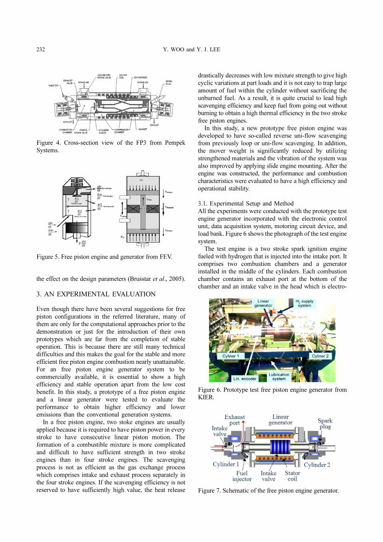
The test engine is a two stroke spark ignition engine
fueled with hydrogen that is injected into the intake port. It
comprises two combustion chambers and a generator
installed in the middle of the cylinders. Each combustion
chamber contains an exhaust port at the bottom of the
chamber and an intake valve in the head which is electro-
Figure 4. Cross-section view of the FP3 from Pempek
Systems.
Figure 5. Free piston engine and generator from FEV.
Figure 6. Prototype test free piston engine generator from
KIER.
Figure 7. Schematic of the free piston engine generator.

FREE PISTON ENGINE GENERATOR: TECHNOLOGY REVIEW AND AN EXPERIMENTAL EVALUATION 233
hydraulically controlled. The two pistons are directly
connected to both ends of the rotor, with the mover magnet
inside the cylindrical generator which has five poles in the
rotor and nine coils in the stator.
As the combustion occurs in the two cylinders one after
another, the magnets moves back and forth passing the
stator coils which generate electricity. During the start of
the engine, the generator motors the engine and controls
the positions of the mover. The specifications of the test
engine are given in Table 1.
An absolute position encoder is connected in the rotor
and generates signals to detect the exact piston position for
the engine control. The engine control signals are
synchronized with the piston encoder to inject the fuel and
ignite the fuel-air mixture at the right piston position.
The test conditions are given in Table 2 including fuel
injection timing (SOI; Start of injection) and intake valve
open timing (IVO). The fuel injection timing and intake
valve opening were carefully chosen with respect to the
exhaust port open time and the cylinder pressure was
acquired every 0.1 ms and utilized to obtain the cycle
analysis. The open time of the intake valve is set after the
exhaust valve opening which is mechanically fixed in order
to keep the fresh mixture from so-called backfiring that is
burning of the combustible mixture without entering the
cylinder.
3.2. Mixture Preparation Strategy
The indefinite piston movement of a free piston engine
significantly affects both the compression process and the
subsequent combustion of the other cylinder of the engine
at the same time. Moreover, a free piston engine does not
have any mechanism to preserve inertial energy to continue
the piston motion such as a flywheel in a conventional
rotational engine. Thus, it is an operational difficulty that a
single misfire from one of the cylinders could be a cause of
the critical loss of piston movement resulting in the engine
stopping. Figure 8 shows an example of an abnormal
combustion encountered during a test (Woo et al., 2009).
To overcome the risk of misfire and draw out high
efficiency from the test engine, the intake valve and fuel
injection timing was carefully chosen as suggested in
Figure 9. This figure describes two main approaches: all
the burned gas should sufficiently be expelled, and at the
same time, all the fuel should be trapped without losing it
through the exhaust port. To reach this goal, the port-valve
overlap needs to be minimized and the fuel is induced into
the cylinder as late as possible. This would lead to another
advantage because axial fuel stratification along the
cylinder would arise and help the flame to propagate fast
even with low charge strength, resulting from an inadequate
stroke or inefficient scavenging.
3.3. Results and Discussion
The test free piston engine was operated at a frequency of
approximately 25 Hz, and the pressure volume diagram
and indicated mean effective pressure (IMEP) are given in
Figure 10 under the several test conditions (Woo et al.,
2012).
In cases I to III, which correspond to relatively early fuel
Table 1. Specifications of the test engine.
Bore (mm) 77
Stroke (mm) 85
Displacement (cc) 395.8 × 2
Compression ratio 9.796
Intake valve open timing (mm ATDC) 78/85/92
Exhaust port open timing (mm ATDC) 75
Fuel injection timing (mm ATDC) 70/82
Mass of mover (kg) 8.91
Table 2. Test conditions (unit: mm ATDC).
CASE SOI IVO
I
70
78
II 85
III 92
IV
82
78
V 85
VI 92
Figure 8. Abnormal combustion phenomena.
Figure 9. Proposed mixture preparation strategy.

234 Y. WOO and Y. J. LEE
injection, the best power output was observed with the
intake valve opening near BDC. An intake valve opening
any earlier than BDC can cause fuel to go out to the
exhaust port before the combustion starts. On the contrary,
a later intake valve opening chould cause some injected
fuel not to enter the cylinder and remain in the intake port
and then discharge to the exhaust port without burning in
the next cycle as unburned fuel.
In cases IV to VI, which corresponds to a relatively late
fuel injection, the power output increases with the delay of
the intake valve opening as shown in Figure 10. Opening of
the intake valve too early leads to an excessive increase in
the port-valve overlap and makes it difficult for the
cylinder to trap fuel effectively, allowing some fuel to go
out along with the burned mixture from the previous cycle.
Thus, to trap fuel effectively within the cylinder, it is
required to minimize the port-valve overlap in case of late
fuel injection.
4. CONCLUSION
Free piston engine generators are under investigation by a
number of research groups around the world, and most of
the successful free piston engine generator developments
were reviewed in this paper. For the reliable and stable
operation of free piston engine generators, it is required to
have a viable control system to address the uncertainty of
piston motion. After that, most of the potential advantages
of the free piston engine would be utilized to present better
efficiency and bring about wide spread use in the future.
In this study, the prototype free piston engine generator
was also successfully operated at approximately 25 Hz
under different fuel injection timings and intake valve
opening conditions and the following results were
concluded:
(1) The scavenging process was improved with a uni-flow
implementation from the intake valve to the exhaust
port compared with the previous loop scavenging and
the test engine generator was operated at a frequency of
approximately 25 Hz.
(2) The key scavenging strategy is that the overall gas
exchange relies on the opening of the intake valve with
respect to the fuel injection timing, while the open
overlap period of the exhaust port and intake valve
must be kept from being enlarged excessively. The case
in which the fuel is injected before the exhaust port
opens and then the intake valve opens at BDC shows
the best power output of above 13 MPa of IMEP.
ACKNOWLEDGEMENT–This research was performed under
the financial support of MSIP and HERC through the 21st
Century Frontier Research Program and the authors would like to
thank for the opportunity.
REFERENCES
Atkinson, C. M., Petreanu, S., Clark, N. N., Atkinson, R. J.,
McDaniel, T. I., Nandkumar, S. and Famouri, P. (1999).
Numerical simulation of a two-stroke linear engine-
alternator combination. SAE Paper No. 1999-01-0921.
Brusstar, M., Gray Jr., C., Jaffri, K., McCarthy, P. and
Marc, P. (2005). Design, development and testing of
multi-cylinder hydraulic free piston engines. SAE Paper
No. 2005-01-1167.
Carter, D. and Wechner, E. (2003). The free piston power
pack: Sustainable power for hybrid electric vehicles.
SAE Paper No. 2003-01-3277.
Clark, N. N., Nandkumar, S. and Famouri, P. (1998).
Fundamental analysis of a linear two-cylinder internal
combustion engine. SAE Paper No. 982692.
Department of Energy (2012). FY 2012 Progress Report
for Advanced Combustion Engine Research and
Development. DOE/EE-0872, II-66−II-70.
Goldsborough, S. S. and Van Blarigan, P. (1999). A
numerical study of a free piston IC engine operating on
homogeneous charge compression ignition combustion.
SAE Paper No. 1999-01-0619.
Goldsborough, S. S. and Van Blarigan, P. (2003). Optimizing
the scavenging system for a two-stroke cycle, free piston
engine for high efficiency and low emissions: A
computational approach. SAE Paper No. 2003-01-0001.
Hansson, J. (2006). Analysis and Control of a Hybrid
Vehicle Powered by a Free Piston Energy Converter.
The School of Electrical Engineering of KTH.
Lee, Y., Lee, Y. and Woo, Y. (2010). Development of
hydrogen fueled linear power generation system. Auto J.
KSAE 32, 4, 58−62.
Figure 10. P-V diagrams and IMEP with different mixture
preparation strategies.

FREE PISTON ENGINE GENERATOR: TECHNOLOGY REVIEW AND AN EXPERIMENTAL EVALUATION 235
Mikalsen, R. and Roskilly, A. P. (2007). A review of free
piston engine history and applications. Applied Thermal
Engineering, 27, 2339−2352.
Shoukry, E., Taylor, S., Clark, N. and Famouri, P. (2002).
Numerical simulation for parametric study of a two-
stroke direct injection linear engine. SAE Paper No.
2002-01-1739.
Tóth-Nagy, C. and Clark, N. N. (2005). The Linear Engine
in 2004. SAE Paper No. 2005-01-2140.
Vael, G. E. M., Achten, P. A. J. and Fu, Z. (2000). The innas
hydraulic transformer the key to the hydrostatic common
pressure rail. SAE Paper No. 2000-01-2561.
Woo, Y., Jang, J. Y., Lee, J.-H., Lee, Y. and Lee, Y. J.
(2012). Performance of a hydrogen fueled free piston
engine generator with the fuel-air supply strategy. Proc.
KSAE Daejeon-Chungcheong Division Fall Conf. (in
Korean), 63−67.
Woo, Y., Kwon, O., Lee, J.-H., Lee, Y. and Lee, Y. J.
(2009). Performance characteristics of a hydrogen
fuelled free piston engine generator system. Proc. KSAE
Spring Conf. (in Korean), 125−130.
Woo, Y., Lee, Y. and Lee, Y. J. (2009). The performance
characteristics of a hydrogen fuelled free piston internal
combustion engine and linear generator system. Int. J.
Low Carbon Technology, 4, 36−41.


