Embed Size (px)
Citation preview
Issue
40 • D
ec 20
15
raspberrypi.org/magpi The official Raspberry Pi magazine Issue 40 Christmas 2015
Issue 40 • Dec 2015 • £5.99
12
9 772051 998001
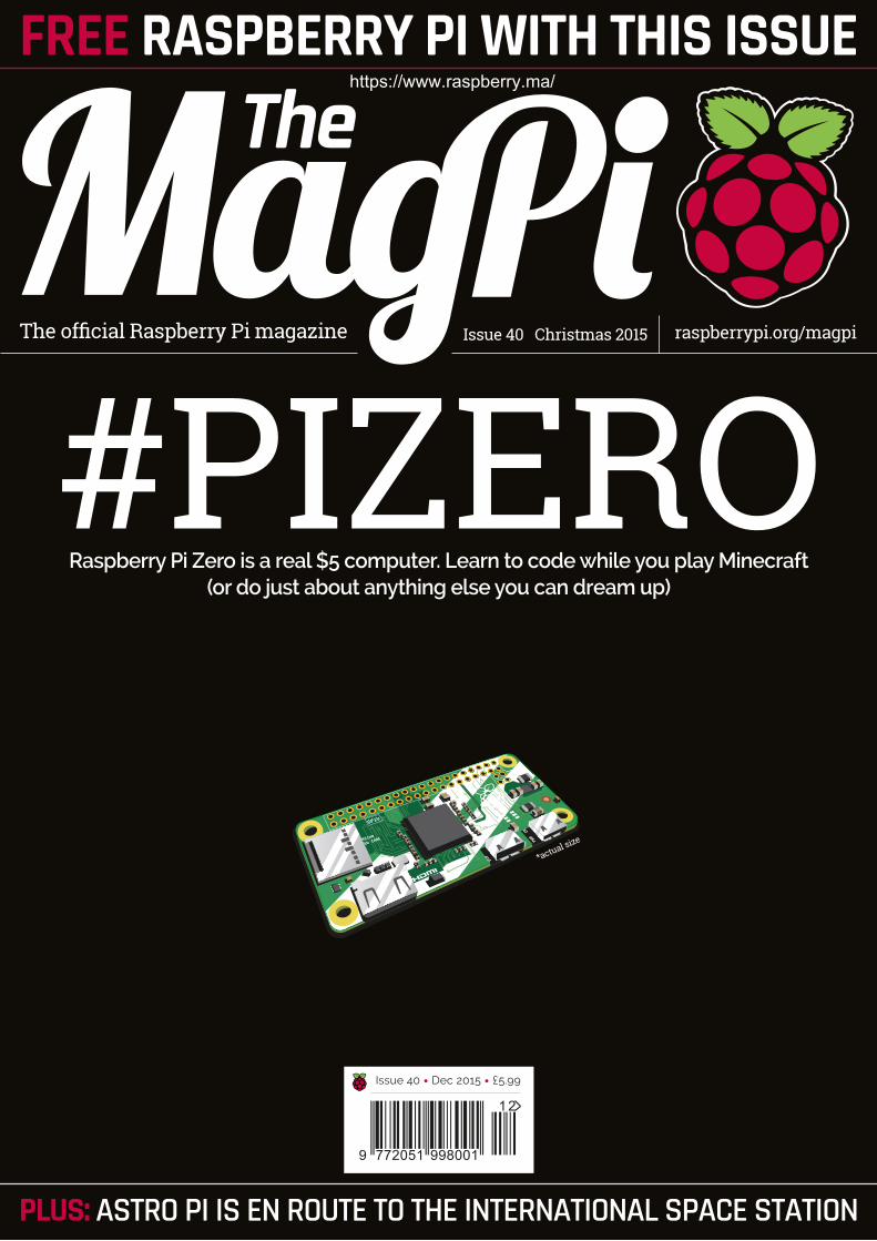
FREE RASPBERRY PI WITH THIS ISSUE
PLUS: ASTRO PI IS EN ROUTE TO THE INTERNATIONAL SPACE STATION
*actual size
Raspberry Pi Zero is a real $5 computer. Learn to code while you play Minecraft (or do just about anything else you can dream up)
https://www.raspberry.ma/
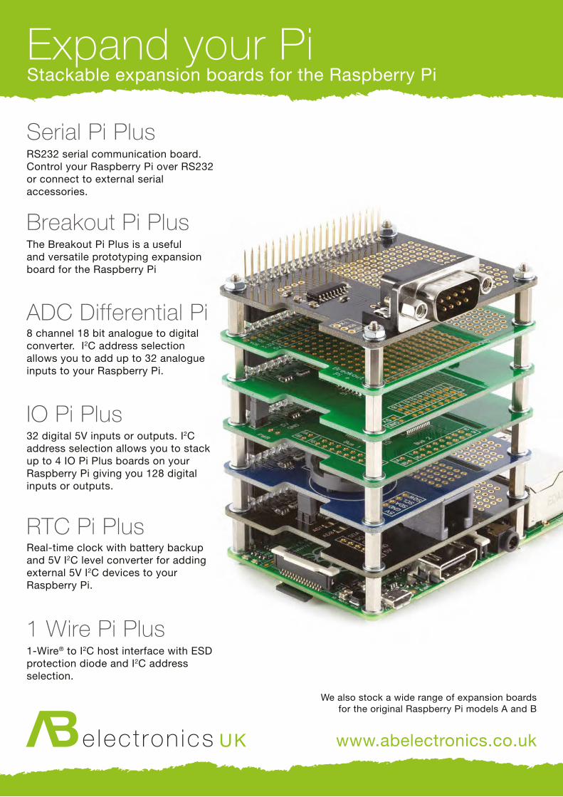
We also stock a wide range of expansion boardsfor the original Raspberry Pi models A and B
www.abelectronics.co.uk
Expand your PiStackable expansion boards for the Raspberry Pi
Serial Pi PlusRS232 serial communication board. Control your Raspberry Pi over RS232 or connect to external serial accessories.
Breakout Pi PlusThe Breakout Pi Plus is a useful and versatile prototyping expansion board for the Raspberry Pi
ADC Differential Pi8 channel 18 bit analogue to digital converter. I2C address selection allows you to add up to 32 analogue inputs to your Raspberry Pi.
IO Pi Plus32 digital 5V inputs or outputs. I2C address selection allows you to stack up to 4 IO Pi Plus boards on your Raspberry Pi giving you 128 digital inputs or outputs.
RTC Pi PlusReal-time clock with battery backup and 5V I2C level converter for adding external 5V I2C devices to your Raspberry Pi.
1 Wire Pi Plus1-Wire® to I2C host interface with ESD protection diode and I2C address selection.
S
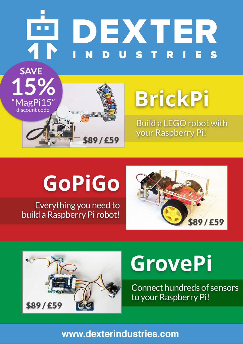
BrickPi
GoPiGo
GrovePi
www.dexterindustries.com
Build a LEGO robot with your Raspberry Pi!
$89 / £59
$89 / £59
Everything you need to build a Raspberry Pi robot!
$89 / £59
Connect hundreds of sensors to your Raspberry Pi!
15%“MagPi15”
discount code
SAVE
raspberrypi.org/magpi 3March 2015
FREECABLEBUNDLEFOR SUBSCRIBERS!PAGE 42
SEE PAGE 42 FOR DETAILS
raspberrypi.org/magpi 3
Welcome
RASPBERRY PI ZERO: ACCESS TO TOOLS
EDITORIAL Managing Editor: Russell [email protected] +44 (0)7904 766523Features Editor: Rob Zwetsloot Technical Editor: David Whale Sub Editors: Laura Clay, Phil King, Lorna Lynch
DESIGNCritical Media: criticalmedia.co.uk Head of Design: Dougal MatthewsDesigners: Lee Allen, Mike Kay Illustrator: Sam Alder
PUBLISHINGFor advertising & licensing: [email protected] +44 (0)7904 766523 Publisher: Liz UptonCEO: Eben Upton
The MagPi magazine is published by Raspberry Pi (Trading) Ltd., Mount Pleasant House, Cambridge, CB3 0RN. The publisher, editor and contributors accept no responsibility in respect of any omissions or errors relating to goods, products or services referred to or advertised in the magazine. Except where otherwise noted, content in this magazine is licensed under a Creative Commons Attribution-NonCommercial-ShareAlike 3.0 Unported (CC BY-NC-SA 3.0). ISSN: 2051-9982.
y first computer, a second-hand BBC Micro with its built-in BASIC, cost me £220 in 1989. That’s £500 in today’s money. My
Amiga was a little cheaper, costing £200 in 1993, but I had to save for three more months to buy the software and documentation I needed to program it. Throughout my childhood, cost limited my access to the tools I needed to learn. This is why, of all the work that we do at Raspberry Pi, driving down the cost of computing is the single thing that matters most to me.
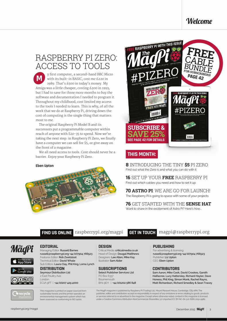
The original Raspberry Pi Model B and its successors put a programmable computer within reach of anyone with $20-35 to spend. Now we’re taking the next step: in Raspberry Pi Zero, we finally have a computer we can sell for $5, or give away on the front of a magazine.
We all need access to tools. Cost should never be a barrier. Enjoy your Raspberry Pi Zero.
Eben Upton
M
CONTRIBUTORSSam Aaron, Mike Cook, David Crookes, Gareth Halfacree, Lucy Hattersley, Richard Hayler, Dave Honess, Phil King, Simon Monk, Rachel Rayns, Matt Richardson, Richard Smedley & Sean Tracey
GET IN TOUCH
THIS MONTH:
8 INTRODUCING THE TINY $5 PI ZEROFind out what the Zero is and what you can do with it
16 SET UP YOUR FREE RASPBERRY PIFind out which cables you need and how to set it up
70 ASTRO PI: WE ARE GO FOR LAUNCH!The Raspberry Pi is going to space with some of your projects
76 GET STARTED WITH THE SENSE HATWant to share in the excitement of Astro Pi? Here’s how…
[email protected] US ONLINE raspberrypi.org/magpi
This magazine is printed on paper sourced from sustainable forests and the printer operates an environmental management system which has been assessed as conforming to ISO 14001.
DISTRIBUTION Seymour Distribution Ltd2 East Poultry AveLondonEC1A 9PT | +44 (0)207 429 4000
SUBSCRIPTIONSSelect Publisher Services LtdPO Box 6337BournemouthBH1 9EH | +44 (0)1202 586 848
December 2015
raspberrypi.org/magpi 4 December 2015
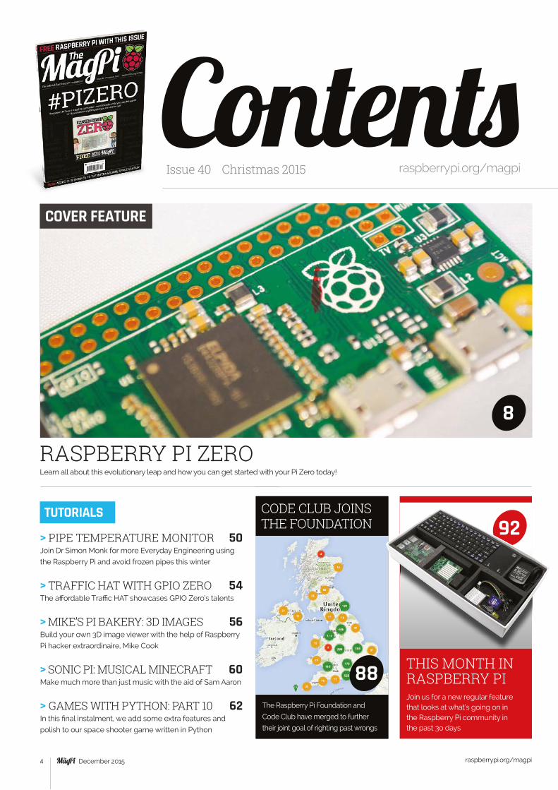
RASPBERRY PI ZERO Learn all about this evolutionary leap and how you can get started with your Pi Zero today!
ContentsIssue 40 Christmas 2015 raspberrypi.org/magpi
COVER FEATURE
TUTORIALS
8
Join us for a new regular feature that looks at what’s going on in the Raspberry Pi community in the past 3o days
Raspberry Pi’s own Simon Long gives us the lowdown on the latest tweaks and changes
THIS MONTH IN RASPBERRY PI
92> PIPE TEMPERATURE MONITOR 50Join Dr Simon Monk for more Everyday Engineering using
the Raspberry Pi and avoid frozen pipes this winter
> TRAFFIC HAT WITH GPIO ZERO 54The affordable Traffic HAT showcases GPIO Zero’s talents
> MIKE’S PI BAKERY: 3D IMAGES 56 Build your own 3D image viewer with the help of Raspberry
Pi hacker extraordinaire, Mike Cook
> SONIC PI: MUSICAL MINECRAFT 60Make much more than just music with the aid of Sam Aaron
> GAMES WITH PYTHON: PART 10 62In this final instalment, we add some extra features and
polish to our space shooter game written in Python
The Raspberry Pi Foundation and
Code Club have merged to further
their joint goal of righting past wrongs
CODE CLUB JOINS THE FOUNDATION
88

THE BIG FEATURE
SEEMORE This Pi-powered parallel processing sculpture will take your breath away
Take a long look in the mirror. You need to shape up if you want to build a project of this quality!
46
MAGIC MIRROR 44
YOUR PROJECTS
Contents
raspberrypi.org/magpi 5December 2015
> PI-TOP 82 Has this Raspberry Pi laptop delivered on its promise?
> DIGITAL SOLDERING STATIONS 84We look at Tenma’s new adjustable soldering iron
> BOOK REVIEWS 86 The best computing reads evaluated for your pleasure
REVIEWS
COMMUNITY> CODE CLUB & PI JOIN FORCES 88We speak to Raspberry Pi and Code Club bosses
> EVENTS 90Find a community gathering near you in the coming weeks
> THIS MONTH IN PI 92What’s been happening in the community & crowdfunding
Astro Pi’s mission aboard the ISS is starting. We find out more
and show you how to join in the fun with the Sense HAT70
95
Matt Richardson talks about Pi Zero, the tiny computer with a big impact…
96
THE FINAL WORD
WORTH: £300 / $450
42…to get a free Pi Zero cable bundle!
SUBSCRIBE TODAY!
Tutorial WALKTHROUGH
raspberrypi.org/magpi 6 December 2015
NEVERBEFOREPRINTEDAll the best articles from issues 31-35
Tutorial
raspberrypi.org/magpi 7December 2015
THE Official
RASPBERRY PIPROJECTS BOOK
Amazing hacking and making projectsfrom the makers of magazine
200 pages of Raspberry Pi
£12.99
Inside: How to get started with Raspberry Pi
The most inspirational community projects
Essential tutorials, guides and ideas
Expert reviews and buying advice
Availablenow
SWAG.RASPBERRYPI.ORGand from all good newsagents
Feature
raspberrypi.org/magpi 8 December 2015 raspberrypi.org/magpi 8 December 2015
Feature
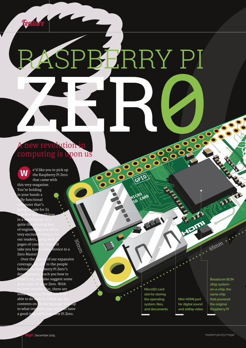
A new revolution in computing is upon us
e’d like you to pick up the Raspberry Pi Zero that came with
this very magazine. You’re holding in your hands a fully functional computer that’s going on sale for $5 and that you could lose in a small purse. It’s quite the amazing feat of engineering and we’re very excited to bring it to our readers, along with 32 pages of content that will take you from a Zero Novice to a Zero Master.
Over the course of our expansive coverage, we talk to the people behind the Raspberry Pi Zero’s development, teach you how to hook it up, and also suggest some great uses for your Zero. With its even smaller size, there are some amazing things you’ll be able to do with it. Check out the contents on the facing page to jump to what interests you, and just have a good time with your new Pi Zero.
W
RASPBERRY PI
ZER030m
m 65mm
MicroSD card
slot for storing
the operating
system, files,
and documents
Mini-HDMI port
for digital sound
and 1080p video
Broadcom BCM
2835 system-
on-a-chip, the
same chip
that powered
the original
Raspberry Pi

Feature
raspberrypi.org/magpi 9December 2015
RASPBERRY PI ZERO
raspberrypi.org/magpi 9December 2015
CONTENTSSIZE MATTERSHow big is a Pi Zero? We’ve been
comparing them to all sorts of things…
> 10
THE STORY OF ZEROWe talk to Eben Upton and Mike
Stimson about Zero’s development
> 12
SET UP YOUR PI ZEROLearn how to get your Pi Zero
hooked up
> 16
HOW IS THE PI ZERO?A quick tour around the Raspberry Pi
Zero and the operating system
> 18
ESSENTIAL TIPSLearn five techniques that will make
using Pi Zero much easier
> 20
QUICK PROJECTSSome quick taster projects that
improve traditional Raspberry Pi uses
> 22
SOLDER A GPIO PORTWant to access the GPIO pins? Here’s
our guide to soldering them on
> 23
ZERO PROJECTSGet started straight away with your Pi
Zero with these great projects
> 24
3D PRINTED CASELearn how to 3D print your own custom
MagPi case for your new Pi Zero
> 41
Unpopulated
RUN mode pins
which can be
used to add a
reset button to
the Pi Zero
Unpopulated
RCA composite
video out pins so
you can connect
to an old TV
CPU: BCM 2835 (same as the original Raspberry Pi), 1GHz single core ARM11
RAM: 512MB
Storage: Via microSD
Power: Micro-USB connector
Video out: Mini-HDMI
Connectivity: 1× micro-USB, unpopulated 40-pin GPIO connector, unpopulated Composite Video Out
Dimensions: 65mm × 30mm × 5mm Weight: 9g
THE SPECS
Micro USB port
for connecting to
keyboards, mice,
WiFi, USB sticks,
and more
Micro-USB port
for power – the
same kind that
charges Android
mobile phones
Power and
activity LED – this
lets you know the
Pi Zero is on and
working away
40-pin
unpopulated
GPIO port for
connecting to
your electronic
circuits
10 December 2015
Feature
raspberrypi.org/magpi
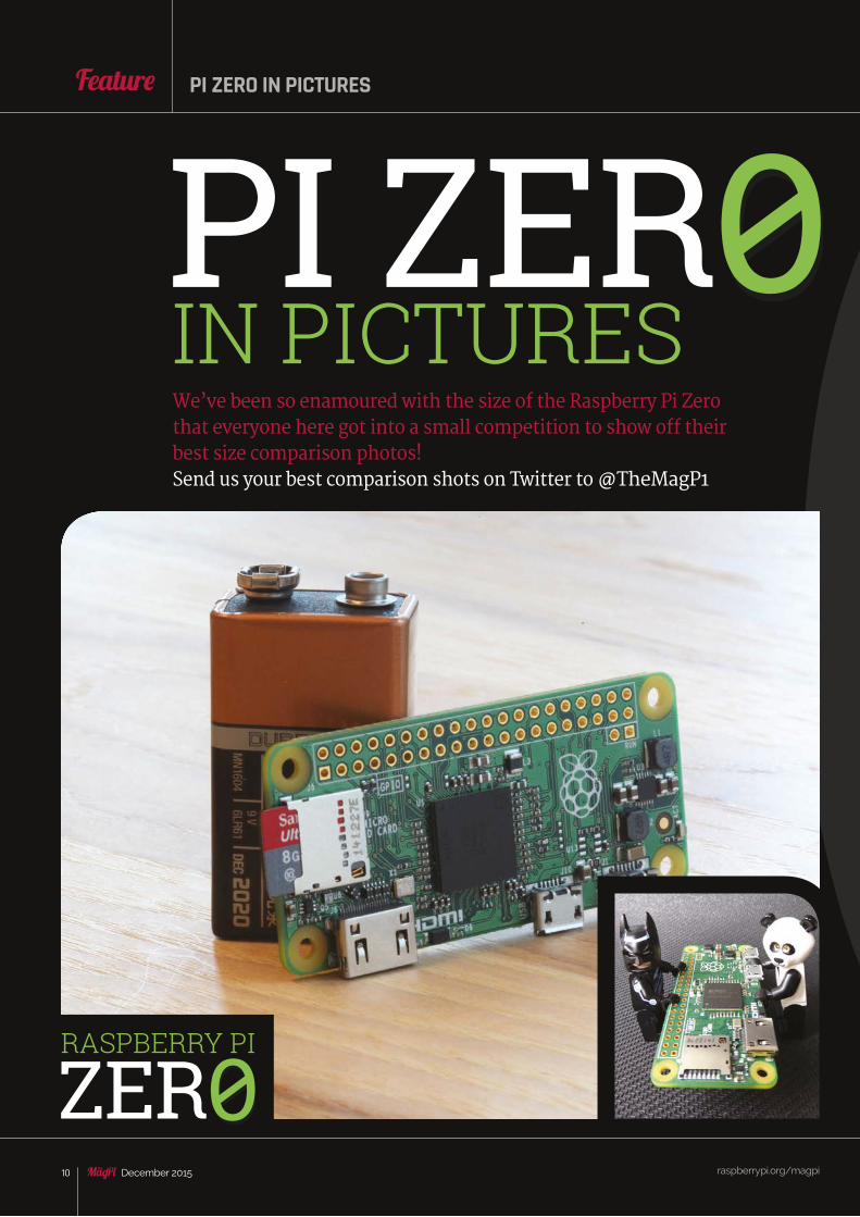
IN PICTURES0PI ZER
We’ve been so enamoured with the size of the Raspberry Pi Zero that everyone here got into a small competition to show off their best size comparison photos!Send us your best comparison shots on Twitter to @TheMagP1
RASPBERRY PI
ZER0
PI ZERO IN PICTURES
raspberrypi.org/magpi 11December 2015
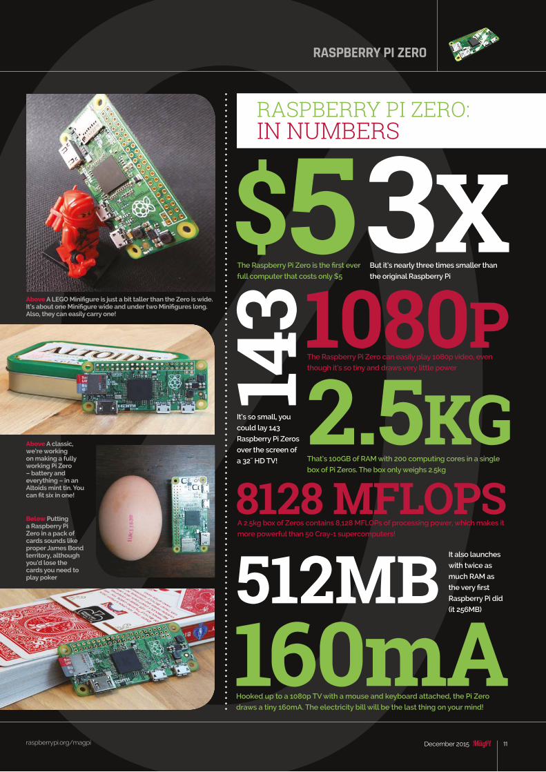
$53X14
3
512MB160mA
1080P
8128 MFLOPS2.5KG
The Raspberry Pi Zero is the first ever
full computer that costs only $5
But it’s nearly three times smaller than
the original Raspberry Pi
The Raspberry Pi Zero can easily play 1080p video, even
though it’s so tiny and draws very little power
A 2.5kg box of Zeros contains 8,128 MFLOPs of processing power, which makes it
more powerful than 50 Cray-1 supercomputers!
That’s 100GB of RAM with 200 computing cores in a single
box of Pi Zeros. The box only weighs 2.5kg
Hooked up to a 1080p TV with a mouse and keyboard attached, the Pi Zero
draws a tiny 160mA. The electricity bill will be the last thing on your mind!
It’s so small, you
could lay 143
Raspberry Pi Zeros
over the screen of
a 32˝ HD TV!
It also launches
with twice as
much RAM as
the very first
Raspberry Pi did
(it 256MB)
IN PICTURES
RASPBERRY PI ZERO: IN NUMBERS
Below Putting a Raspberry Pi Zero in a pack of cards sounds like proper James Bond territory, although you’d lose the cards you need to play poker
Above A classic, we’re working on making a fully working Pi Zero – battery and everything – in an Altoids mint tin. You can fit six in one!
Above A LEGO Minifigure is just a bit taller than the Zero is wide. It’s about one Minifigure wide and under two Minifigures long. Also, they can easily carry one!
RASPBERRY PI ZERO
raspberrypi.org/magpi 12 December 2015
Feature
raspberrypi.org/magpi 12 December 2015
Feature INTERVIEW
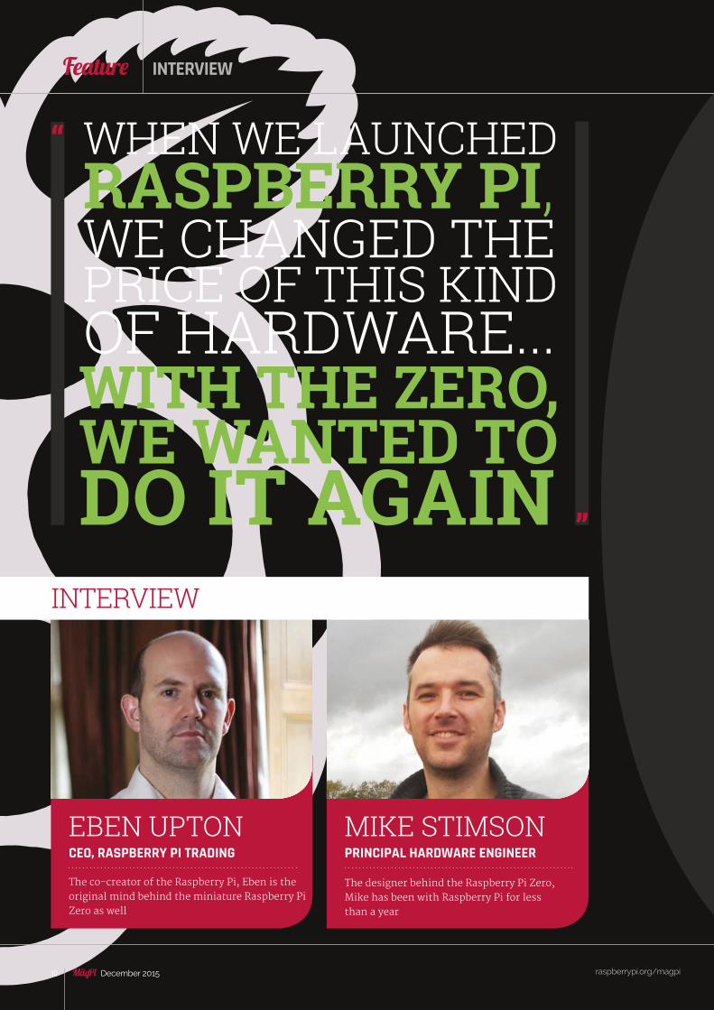
The co-creator of the Raspberry Pi, Eben is the original mind behind the miniature Raspberry Pi Zero as well
MIKE STIMSONPRINCIPAL HARDWARE ENGINEER
The designer behind the Raspberry Pi Zero, Mike has been with Raspberry Pi for less than a year
EBEN UPTONCEO, RASPBERRY PI TRADING
INTERVIEW
WHEN WE LAUNCHED RASPBERRY PI, WE CHANGED THE PRICE OF THIS KIND OF HARDWARE...WITH THE ZERO, WE WANTED TO DO IT AGAIN
raspberrypi.org/magpi 13December 2015
FeatureRASPBERRY PI ZERO
raspberrypi.org/magpi 13December 2015
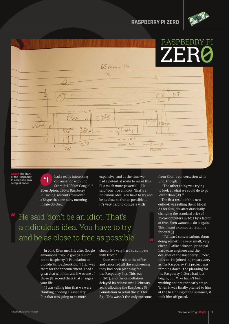
Above The start of the Raspberry Pi Zero’s life on a scrap of paper
had a really interesting conversation with Eric Schmidt [CEO of Google],”
Eben Upton, CEO of Raspberry Pi Trading, recounts to us over a Skype chat one rainy morning in late October.
In 2013, Eben met Eric after Google announced it would give $1 million to the Raspberry Pi Foundation to provide Pis to schoolkids. “[Eric] was there for the announcement. I had a great chat with him and it was one of those 45-second chats that changes your life.
“I was telling him that we were thinking of doing a Raspberry Pi 2 that was going to be more
expensive, and at the time we had a potential route to make this Pi 2 much more powerful… He said ‘don’t be an idiot. That’s a ridiculous idea. You have to try and be as close to free as possible… it’s very hard to compete with
cheap; it’s very hard to compete with free’.”Eben went back to the office
and cancelled all the engineering they had been planning for the Raspberry Pi 2. This was in 2013, and the cancellation delayed its release until February 2015, allowing the Raspberry Pi Foundation to retail the Pi 2 for $35. This wasn’t the only outcome
“I from Eben’s conversation with Eric, though:
“The other thing was trying to look at what we could do to go lower than $25.”The first result of this new
outlook was selling the Pi Model A+ for $20, but after drastically changing the standard price of microcomputers in 2012 by a factor of five, Eben wanted to do it again. This meant a computer retailing for only $5.
“I’d heard conversations about doing something very small, very cheap,” Mike Stimson, principal hardware engineer and the designer of the Raspberry Pi Zero, tells us. He joined in January 2015 as the Raspberry Pi 2 project was ramping down. The planning for the Raspberry Pi Zero had just begun, but Mike hadn’t begun working on it at that early stage. When it was finally pitched to him at the beginning of the summer, it took him off guard.
He said ‘don’t be an idiot. That’s a ridiculous idea. You have to try and be as close to free as possible’
RASPBERRY PI
ZER0
Feature
raspberrypi.org/magpi 14 December 2015
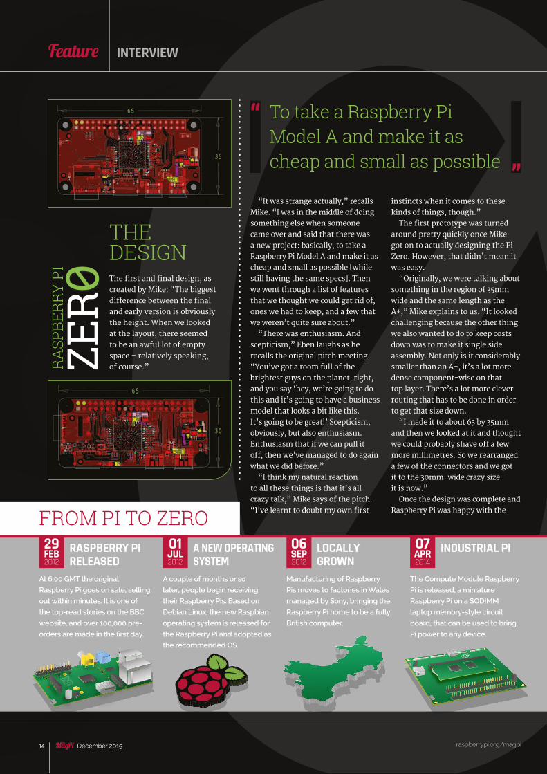
The first and final design, as created by Mike: “The biggest difference between the final and early version is obviously the height. When we looked at the layout, there seemed to be an awful lot of empty space – relatively speaking, of course.”
THE DESIGN
raspberrypi.org/magpi 14 December 2015
Feature INTERVIEW
“It was strange actually,” recalls Mike. “I was in the middle of doing something else when someone came over and said that there was a new project: basically, to take a Raspberry Pi Model A and make it as cheap and small as possible [while still having the same specs]. Then we went through a list of features that we thought we could get rid of, ones we had to keep, and a few that we weren’t quite sure about.”
“There was enthusiasm. And scepticism,” Eben laughs as he recalls the original pitch meeting. “You’ve got a room full of the brightest guys on the planet, right, and you say ‘hey, we’re going to do this and it’s going to have a business model that looks a bit like this. It’s going to be great!’ Scepticism, obviously, but also enthusiasm. Enthusiasm that if we can pull it off, then we’ve managed to do again what we did before.”
“I think my natural reaction to all these things is that it’s all crazy talk,” Mike says of the pitch. “I’ve learnt to doubt my own first
instincts when it comes to these kinds of things, though.”The first prototype was turned
around pretty quickly once Mike got on to actually designing the Pi Zero. However, that didn’t mean it was easy.
“Originally, we were talking about something in the region of 35mm wide and the same length as the A+,” Mike explains to us. “It looked challenging because the other thing we also wanted to do to keep costs down was to make it single side assembly. Not only is it considerably smaller than an A+, it’s a lot more dense component-wise on that top layer. There’s a lot more clever routing that has to be done in order to get that size down.
“I made it to about 65 by 35mm and then we looked at it and thought we could probably shave off a few more millimetres. So we rearranged a few of the connectors and we got it to the 30mm-wide crazy size it is now.”
Once the design was complete and Raspberry Pi was happy with the
RASPBERRY PI RELEASED
At 6:00 GMT the original
Raspberry Pi goes on sale, selling
out within minutes. It is one of
the top-read stories on the BBC
website, and over 100,000 pre-
orders are made in the first day.
FROM PI TO ZEROINDUSTRIAL PI
The Compute Module Raspberry
Pi is released, a miniature
Raspberry Pi on a SODIMM
laptop memory-style circuit
board, that can be used to bring
Pi power to any device.
A NEW OPERATING SYSTEM
A couple of months or so
later, people begin receiving
their Raspberry Pis. Based on
Debian Linux, the new Raspbian
operating system is released for
the Raspberry Pi and adopted as
the recommended OS.
LOCALLY GROWN
Manufacturing of Raspberry
Pis moves to factories in Wales
managed by Sony, bringing the
Raspberry Pi home to be a fully
British computer.
29FEB2012
01JUL2012
06SEP2012
07APR2014
To take a Raspberry Pi Model A and make it as cheap and small as possible
RA
SPBE
RRY
PI
ZER 0

Feature
raspberrypi.org/magpi 15December 2015
RASPBERRY PI ZERO
raspberrypi.org/magpi 15December 2015
prototypes, they began the process of making sure there would be enough Raspberry Pi Zeros available for launch.
“We spent a couple of months, June and July, getting manufacturing quotes. We were very pleased to see that UK manufacturing was very competitive. It was by far the cheapest way of making it. Then we committed orders in August and manufacturing started [on] 27 October – mass volume manufacturing. The first 10,000 are for The MagPi, so the Pi Zero you hold in your hand may very well be being manufactured as I speak.”
FROM ZERO TO HERO
The Zero is launched, with the first
10,000 units being stuck to the
front of The MagPi in newsagents
across the UK. It’s a $5 computer
that will hopefully further change
the computing landscape.
A CHEAPER RASPBERRY PI
The Raspberry Pi A+ is announced,
a much smaller version of the
Raspberry Pi Model A that is also
even cheaper at $20. Much like
the B+. there are no changes in
the spec, although it does lose
one of its output ports.
A NEW RASPBERRY PI
The Raspberry Pi 2 is announced,
completely shocking the
community. With much improved
power and memory, the
Raspberry Pi finally reaches its
full potential and leads to better
making and educating.
10NOV2014
02FEB2015
26NOV2015
From inception in January to people’s hands in November, the Raspberry Pi Zero didn’t take very long at all, especially when you compare it to six years for the original Pi and over two years for the Pi 2.
“It’s quite fast for us; it’s being helped by the fact it is a real Raspberry Pi,” Eben tells us. “So there’s no significant software engineering involved in doing it… it is quite an aggressive schedule, but it’s good!”Commenting on the final
product, both Eben and Mike seem very pleased with it, both in terms of the technological feat they’ve accomplished and the aesthetics of the Pi Zero as well.
“I just hope people like it,” Eben says. “I hope that it helps the education mission a lot. It’s great to make computers and stuff, but all the money is going back into the charity, so we kind of hope that the existence of this cheap thing will let even more people in the door. And maybe that’s not even people in the UK any more, but also people in the developing world.
“Having cheap, open, general-purpose computing – that’s got to be good for something. We’re building 100k of them at first, but I’m just hoping it will have a life after that.”
“The final product has the
composite signal brought out
to a 0.1 inch pad, so if you want
to solder an RCA cable onto it
you can.
“We’re psyched about the
idea of people being able to
take it and solder it inside an old
television – you know, get an old
television and crack it open. Turn
your television into a computer.
We think that’s really good for
developing world applications.”
ON THE COVERWe’re the first ever magazine in the world to give away a real computer on the cover. Here are some other notable covermount firsts through the years...
SATIRE ON RECORDSome issues of satirical magazine Private Eye would
have covermounted floppy 7˝ vinyls which had
comedy recordings on them. In classic Private Eye
style, they all had punny titles which we won’t subject
you to here.
FLEXI-DISC MUSICWith the popularisation of these ‘flexi-discs’ on covers,
pop music mags began mounting samples and songs
on the front of their covers. NME did this a lot in the
Seventies with plenty of rock vinyls.
NEW HARDWARE As computer magazines took off, so did shareware
software attached to the front. It started with floppy
disks, but as CDs became much cheaper, magazine
covers began appearing with data CDs on the cover.
DEMO DISCSWhen video games moved to discs with the advent of
CD-ROM drives and the PlayStation, cover discs with
game demos were big business.
DVDS FOR ALLAs prices for optical media fell, any magazine with an idea
for disc content would have a covermounted DVD. Film
trailers, software, art assets, commentary, instructional
videos, and much more made their way to magazine
covers the world over.
A COMPUTER ON THE COVERThe MagPi is the first magazine to give you hardware
on its cover. The Raspberry Pi Zero is the world’s first
covermounted computer – it’s never been done before.
1960S
1970S
1980S
A BETTER RASPBERRY PI
The Raspberry Pi B+ is
announced by the Foundation, a
redesign of the Raspberry Pi that
contains more USB ports and a
better layout of its components.
The form factor will lead the way
for the Raspberry Pi.
14JUL2014
1990S
2000S
2015
WHAT IS THE RCA VIDEO OUT CONNECTOR FOR?
Feature
16 December 2015
Feature ZERO UNBOXED
UNBOXED
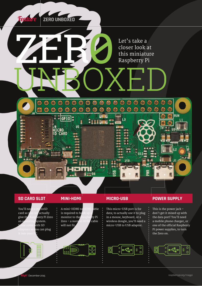
SD CARD SLOT
You’ll need a microSD card so you can actually give the Raspberry Pi Zero an operating system. Some come with SD adaptors so you can plug it into your PC.
MINI-HDMI
A mini-HDMI to HDMI cable is required to hook up a monitor to the Raspberry Pi Zero – a normal HDMI cable will not fit.
MICRO-USB
This micro-USB port is for data; to actually use it to plug in a mouse, keyboard, or a wireless dongle, you’ll need a micro-USB to USB adaptor.
POWER SUPPLY
This is the power jack – don’t get it mixed up with the data port! You’ll need a mobile phone charger, or one of the official Raspberry Pi power supplies, to turn the Zero on.
ZER0 Let’s take a closer look at this miniature Raspberry Pi
raspberrypi.org/magpi
raspberrypi.org/magpi 17December 2015
RASPBERRY PI ZERO
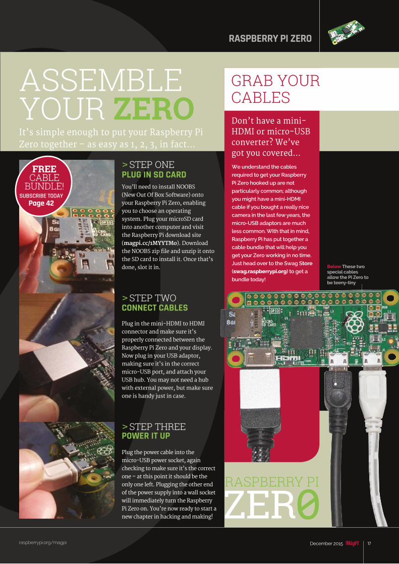
ASSEMBLE YOUR ZEROIt’s simple enough to put your Raspberry Pi Zero together – as easy as 1, 2, 3, in fact…
> STEP ONEPLUG IN SD CARDYou’ll need to install NOOBS (New Out Of Box Software) onto your Raspberry Pi Zero, enabling you to choose an operating system. Plug your microSD card into another computer and visit the Raspberry Pi download site (magpi.cc/1MYYTMo). Download the NOOBS zip file and unzip it onto the SD card to install it. Once that’s done, slot it in.
> STEP TWOCONNECT CABLES Plug in the mini-HDMI to HDMI connector and make sure it’s properly connected between the Raspberry Pi Zero and your display.Now plug in your USB adaptor, making sure it’s in the correct micro-USB port, and attach your USB hub. You may not need a hub with external power, but make sure one is handy just in case.
> STEP THREEPOWER IT UP
Plug the power cable into the micro-USB power socket, again checking to make sure it’s the correct one – at this point it should be the only one left. Plugging the other end of the power supply into a wall socket will immediately turn the Raspberry Pi Zero on. You’re now ready to start a new chapter in hacking and making!
FREECABLE
BUNDLE!SUBSCRIBE TODAY
Page 42
GRAB YOURCABLESDon’t have a mini-HDMI or micro-USB converter? We’ve got you covered…
We understand the cables
required to get your Raspberry
Pi Zero hooked up are not
particularly common; although
you might have a mini-HDMI
cable if you bought a really nice
camera in the last few years, the
micro-USB adaptors are much
less common. With that in mind,
Raspberry Pi has put together a
cable bundle that will help you
get your Zero working in no time.
Just head over to the Swag Store
(swag.raspberrypi.org) to get a
bundle today!
RASPBERRY PI
ZER0
Below These two special cables allow the Pi Zero to be teeny-tiny

raspberrypi.org/magpi 18 December 2015
Feature
Whether this is your first ever Raspberry Pi, or you want to know more about how the Zero actually performs, let’s get to know it...
raspberrypi.org/magpi 18 December 2015
ETHERNET ADAPTORWhile Raspbian and the Pi Zero work just fine with WiFi, if you want a slightly more stable connection, you might want to try a USB Ethernet adaptor. There are a few around, and we’ve even heard rumours of some that plug straight into micro-USB ports; however, you’ll have more luck finding one that will plug into a micro-USB to USB adaptor, or straight into a USB hub.
GET TO KNOW RASPBIAN
The Raspbian interface should be familiar to almost anyone who has used computers
All the programs in Raspbian are kept in the program menu. All the software available on the original Pi and Pi 2 are still here for Zero
Start or continue to learn to code with the excellent resources available in Raspbian
Run commands the old-fashioned way in the terminal or via the command-line interface, on the Pi Zero or remotely over the network
CASEThe Pi Zero is a sensitive electronic device, so it’s probably best to not have it just on a table gathering dust. At the time of writing, there aren’t any cases just yet for the Raspberry Pi Zero, but they’ll soon come. For the moment, we suggest you head over to page 41 to find out how you can 3D-print your own custom Pi Zero keyring case.
GET TO KNOW PI ZER0
MORE COMPONENTS FOR YOUR ZERO
Browse the internet on the Pi Zero if you connect a wireless dongle, making for a great low-profile web kiosk or smart TV
RASPBERRY PI
ZER0
raspberrypi.org/magpi 19December 2015
FeatureTHE RASPBERRY PI ZERO
raspberrypi.org/magpi 19December 2015
DESKTOP SETUP
ow you’ve got your Pi Zero hooked up, using it with Raspbian should feel very
familiar. That’s because the OS works in exactly the same way as it does on any other Raspberry Pi.
This shouldn’t come as any surprise really if you’ve been following the story so far. On the other hand, you’ll be in for a bit of a shock if you’ve become used to the extra speed that the Raspberry Pi 2 offers you. Going back to original Raspberry Pi speeds really highlights how much more powerful the 2 is; however, the Raspberry Pi Zero is also the size of a large thumb, so you’d expect some concessions.
If this is your first time using a Raspberry Pi, then you’ll be looking around Raspbian for the first time too. As the operating system for the Raspberry Pi, it’s built quite simply to make it easy for people to use. It has a standard program menu (much like the Windows Start menu), where you access all your programs, and it has a lot of the standard pieces of software you’d need already installed. There’s a web browser, an email client, and office software called LibreOffice. They’re all optimised for use on the low-power Raspberry Pi, and even though there’s a much more powerful Raspberry Pi alternative, they all work absolutely fine on the Raspberry Pi Zero.
LibreOffice especially was a concern as it’s a very new piece of software for Raspbian, but it
runs flawlessly on the Pi Zero without any performance issues. The rest of the basic software also works extremely well, although web browsing can get a little slow if you’re doing some really tab-heavy work.
You can always overclock the Pi Zero to give it a bit more power. It’s not been fully tested, though, so you should probably use it sparingly. To find the controls for increasing the power of the CPU, select Preferences from the menu, then Raspberry Pi Configuration. You’ll find the Overclock option under the Performance tab. In the System tab, you’ll also find the option for whether or not to have the Pi start in the command-line or desktop. See our performance tests on this page to see if booting to command line would better for you: it would use less power (our initial tests have shown incredibly low power consumption) and you’d still be able to connect to it remotely via SSH. This low power usage and remote capabilities open the Zero up to be used for many purposes which we’ll cover throughout the rest of this feature.
If you had any doubts, then, that the Raspberry Pi Zero would be a very stripped-back version of even the original Raspberry Pi, you have nothing to fear. At least on a software level, it will run the same code and programs in the same way with the same performance as before. It’s now just the size of a stick of gum.
N
Want to set up the Raspberry Pi Zero as a desktop replacement? It’s really quite simple – most of the hard work has been done for you already…
First of all, there’s the hardware setup. To make the Pi Zero a desktop PC, you need the basic components: a monitor, keyboard, mouse, and wireless dongle. Connecting the monitor is easiest, as you just need to get a mini-HDMI to HDMI cable that can plug into a monitor with a HDMI port. For the rest of the components, you’ll need to first look into getting a USB hub that can be powered if need be – plug it into a micro-USB to USB adaptor and then plug in your keyboard, mouse, and WiFi dongle. If you have a spare port, you can now use that for a USB stick.
Lastly, you’ll need to install Raspbian. This is dead easy: plug a microSD card into your normal computer (via an SD adaptor if needed) and unzip NOOBS to it, which you can download from: raspberrypi.org/downloads. Insert the microSD card into the Pi Zero, plug it in with a phone charger or an official Raspberry Pi power supply, and then choose to install Raspbian Jessie.
WIRELESS KEYBOARD AND MOUSE COMBOA good way to save USB space on a hub, there are plenty of good and cheap mini keyboard and mouse accessories that work great with the Raspberry Pi. It also means you can keep the Pi Zero hidden away in any little nook or cranny you can find and not have too many cables signifying its presence.
RASPBERRY PI 2Boot to command line:
Boot to desktop:
RASPBERRY PI ZEROBoot to command line:
Boot to desktop:
RASPBERRY PI ZERO TURBO OVERCLOCKBoot to command line:
Boot to desktop:
14.50 SEC.
18.00 SEC.
27.00 SEC.
43.00 SEC.
23.00 SEC.
33.00 SEC.
NEED FOR SPEEDWe compared the boot time of the Raspberry Pi Zero to the Raspberry Pi 2. How does it fare?
raspberrypi.org/magpi 20 December 2015
Feature
raspberrypi.org/magpi 20 December 2015
REMOTE ACCESS
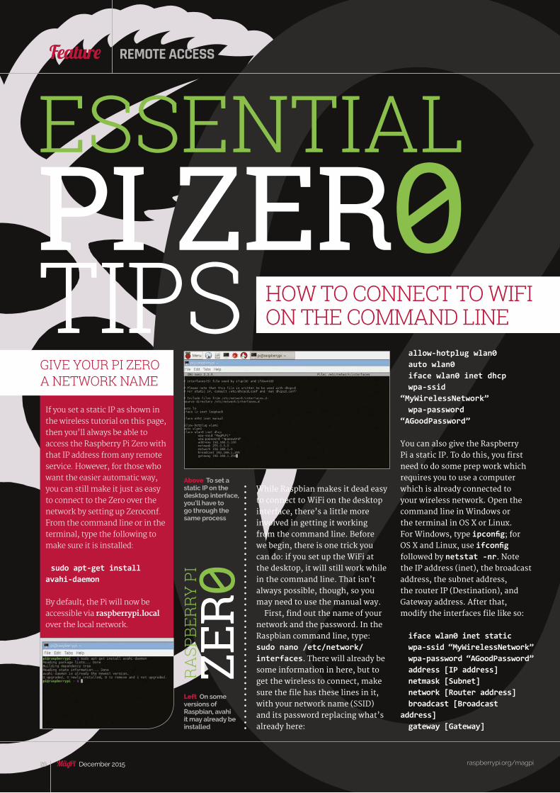
While Raspbian makes it dead easy to connect to WiFi on the desktop interface, there’s a little more involved in getting it working from the command line. Before we begin, there is one trick you can do: if you set up the WiFi at the desktop, it will still work while in the command line. That isn’t always possible, though, so you may need to use the manual way.
First, find out the name of your network and the password. In the Raspbian command line, type: sudo nano /etc/network/interfaces. There will already be some information in here, but to get the wireless to connect, make sure the file has these lines in it, with your network name (SSID) and its password replacing what’s already here:
If you set a static IP as shown in the wireless tutorial on this page, then you’ll always be able to access the Raspberry Pi Zero with that IP address from any remote service. However, for those who want the easier automatic way, you can still make it just as easy to connect to the Zero over the network by setting up Zeroconf. From the command line or in the terminal, type the following to make sure it is installed:
sudo apt-get install avahi-daemon
By default, the Pi will now be accessible via raspberrypi.local over the local network.
TIPS
ESSENTIALPI ZER0
HOW TO CONNECT TO WIFI ON THE COMMAND LINE
GIVE YOUR PI ZERO A NETWORK NAME
RA
SPBE
RRY
PI
ZER 0
allow-hotplug wlan0auto wlan0iface wlan0 inet dhcpwpa-ssid
“MyWirelessNetwork”wpa-password
“AGoodPassword”
You can also give the Raspberry Pi a static IP. To do this, you first need to do some prep work which requires you to use a computer which is already connected to your wireless network. Open the command line in Windows or the terminal in OS X or Linux. For Windows, type ipconfig; for OS X and Linux, use ifconfig followed by netstat -nr. Note the IP address (inet), the broadcast address, the subnet address, the router IP (Destination), and Gateway address. After that, modify the interfaces file like so:
iface wlan0 inet staticwpa-ssid “MyWirelessNetwork”wpa-password “AGoodPassword”address [IP address]netmask [Subnet]network [Router address]broadcast [Broadcast
address]gateway [Gateway]
Above To set a static IP on the desktop interface, you’ll have to go through the same process
Left On some versions of Raspbian, avahi it may already be installed
raspberrypi.org/magpi 21December 2015
FeatureTHE RASPBERRY PI ZERO
raspberrypi.org/magpi 21December 2015
Thanks to a piece of software called RealVNC, you don’t even need to plug your Pi Zero into a monitor to use its desktop; you can simply control it from another computer. First of all, go to magpi.cc/PiVNC and download RealVNC onto your Raspberry Pi. Also obtain a free licence key (magpi.cc/1O8Hz4J), as you’ll be needing it.
Once the file is on your Pi, open the terminal, use cd to navigate to the file in Downloads (cd Downloads should do) and use the following two commands, replacing the square brackets with the appropriate names:
tar xvf [VNC file name].tar.gzsudo dpkg -i [VNC Server
package name].deb [VNC Viewer package name].deb
Copy the licence key you got and then run sudo vnclicense
Via the SSH protocol, you can access the Raspberry Pi from any other computer on your home network. SSH should be activated by default, but to make sure it is on, you can go to Raspberry Pi Configuration from the Preferences category in the Menu (or by typing sudo raspi-config from the command line) and ensure SSH is turned on in the Interfaces tab (or under the Advanced menu in the command-line version). If SSH was disabled, enable it and reboot.In OS X and Linux, you can use SSH from the terminal; in Windows, however, you’ll need to download PuTTY (magpi.cc/1Mm5Npi).
SHARE FILES ON YOUR NETWORK WITH SAMBA
USE YOUR RASPBERRY PI FROM ANOTHER COMPUTER
ACCESS YOUR PI REMOTELY FROM THE COMMAND LINE
Above On some versions of Raspbian, Avahi may already be installed
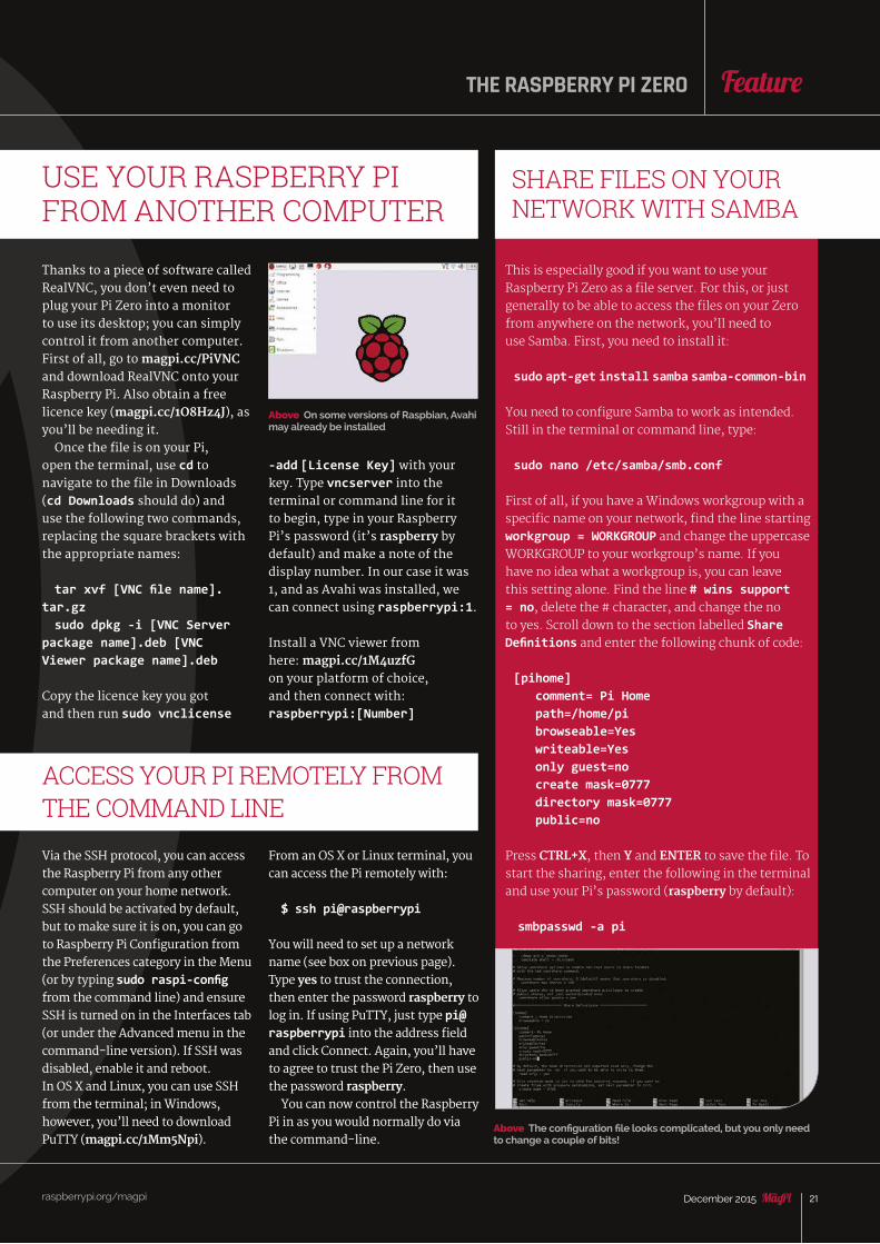
Above The configuration file looks complicated, but you only need to change a couple of bits!
-add [License Key] with your key. Type vncserver into the terminal or command line for it to begin, type in your Raspberry Pi’s password (it’s raspberry by default) and make a note of the display number. In our case it was 1, and as Avahi was installed, we can connect using raspberrypi:1.
Install a VNC viewer from here: magpi.cc/1M4uzfG on your platform of choice, and then connect with: raspberrypi:[Number]
From an OS X or Linux terminal, you can access the Pi remotely with:
$ ssh pi@raspberrypi
You will need to set up a network name (see box on previous page). Type yes to trust the connection, then enter the password raspberry to log in. If using PuTTY, just type pi@raspberrypi into the address field and click Connect. Again, you’ll have to agree to trust the Pi Zero, then use the password raspberry.
You can now control the Raspberry Pi in as you would normally do via the command-line.
This is especially good if you want to use your Raspberry Pi Zero as a file server. For this, or just generally to be able to access the files on your Zero from anywhere on the network, you’ll need to use Samba. First, you need to install it:
sudo apt-get install samba samba-common-bin
You need to configure Samba to work as intended. Still in the terminal or command line, type:
sudo nano /etc/samba/smb.conf
First of all, if you have a Windows workgroup with a specific name on your network, find the line starting workgroup = WORKGROUP and change the uppercase WORKGROUP to your workgroup’s name. If you have no idea what a workgroup is, you can leave this setting alone. Find the line # wins support = no, delete the # character, and change the no to yes. Scroll down to the section labelled Share Definitions and enter the following chunk of code:
[pihome] comment= Pi Home path=/home/pi browseable=Yes writeable=Yes only guest=no create mask=0777 directory mask=0777 public=no
Press CTRL+X, then Y and ENTER to save the file. To start the sharing, enter the following in the terminal and use your Pi’s password (raspberry by default):
smbpasswd -a pi

raspberrypi.org/magpi 22 December 2015
Feature
n HTPC (home theater PC) is an excellent use for the Raspberry Pi, and a very popular one thanks to the existence of Kodi – the media
centre software – and operating systems that utilise it, such as OpenELEC and OSMC. Whereas before you could set up the Raspberry Pi as a very mini set-top box, the Raspberry Pi Zero can be stored covertly behind the television with a custom mounting or a good bit of Blu-Tack.
If you’re sticking it behind a television and want to keep wiring to a very minimum, you can get away with just having a wireless dongle attached to a USB adaptor. This not only allows the Pi to connect online to watch streamed content, and to your network to play local media, it also opens it up to be controlled by the standard web controls.
While the web controls can be used from a browser as original intended, you can also get remote control apps for smartphones and tablets (just search for Kodi or XBMC remote on your app store, there’s loads
Turbocharge your TV with nothing more than an HDMI cable and a wireless dongle
A
to choose from!) that make use of this web access to the HTPC.
We recommend setting up the web access on a Pi Zero or normal Pi with keyboard and mouse connected, just to make it slightly easier. Head over to the Settings menu, then go to Services, Webserver and enable ‘Allow control of Kodi via HTTP’. Make a note of the IP address it gives itself, and use that to connect from your phone or browser.
raspberrypi.org/magpi 22 December 2015
Projects
WEB-CONTROLLED HTPCEASY PROJECTS
ULTRA-LOW PROFILE FILE SERVER
CATEGORY:Entertainment
DIFFICULTY:Easy
Project data
CATEGORY:Utility
DIFFICULTY:Easy
Project data
Upgrade your network-attached storage by making it much, much smaller
The Raspberry Pi is the perfect low-power file server for your home, requiring very little wattage to keep running when idle, while also being very easy to access remotely via SSH over the network. With an original Raspberry Pi, it was a small setup, but now with a Pi Zero you can basically have a NAS box that is no bigger than the actual storage itself. Get a small USB hub, a portable USB hard drive, and a tiny USB dongle and you’ve got yourself a complete NAS box that can be controlled from anywhere on your local network.
INCOGNITO COMPUTERKeep your Raspberry Pi Zero hidden and safe in an inconspicuous tin of mintsWhile you wait to get a case for your Raspberry Pi Zero, there’s a few things you can do to keep it safe from a normal dusty environment; you could keep it in an anti-static bag, the blister packet it came with on top of this magazine, or you could keep it hidden inside an Altoids tin.
All you’d need to do is affix it to the tin, either with Blu-Tack or some carefully measured and drilled screw mounts, and cut a few holes to allow for connecting the normal cables to it. Quick, simple, and it makes you feel like a spy.
CATEGORY:Fun
DIFFICULTY:Easy
Project data
RA
SPBE
RRY
PI
ZER 0
raspberrypi.org/magpi 23December 2015
FeatureTHE RASPBERRY PI ZERO
raspberrypi.org/magpi 23December 2015
Projects
The Pi Zero comes with a full-size GPIO header – but no pins. Even if you’ve never touched a soldering iron before, don’t panic: fitting the pin header block can be a quick and easy job
PI ZERO GPIO SOLDERING
f you’re planning a project around the Pi Zero which involves general-purpose input-output (GPIO), then you have a decision to make: you
can solder your wires directly to the unpopulated GPIO header and dedicate the Pi Zero to the job, or you can solder a header block and make it easily detachable - just like on the Zero’s bigger siblings.
PreparationBefore you plug your iron in, get your workspace ready. That means making sure that it’s free from anything breakable or flammable, that you’ve put something protective down on the surface to guard against scorching from solder splashes, and that you’ve laid everything out where you can easily get to it.
The GPIO header blocks themselves, technically known as 2.54mm male pin headers, will also need some preparation. They’re typically supplied in rows of 36 or more, while the Pi’s GPIO block is laid out in two rows of 20. That’s easy to rectify: count 20 pins out, then put your fingernails in the divot between pins 20 and 21 before snapping the excess off with a twist of your fingers. Do this twice and you’ll have the precise number of pins required.
I
> 2.54mm Male Pin Headers magpi.cc/ 1PCpMVa
> Soldering Iron and Solder magpi.cc/ 1Oa5ksX
> Blu-Tack (optional)
> HAT (optional)
You’ll Need
CATEGORY:Utility
DIFFICULTY:Medium
Project data
Finally, moisten your sponge, plug the iron in, and clean the tip by melting a small amount of solder directly to the metal before wiping it on the sponge.
SolderingPutting the iron back in its stand for now, begin by putting the pins through the GPIO block of the Pi Zero, with the short ends sticking through and the black plastic blocks resting on the circuit board. You’ll need a way to hold these in place while you flip the Pi Zero: try a blob of Blu-Tack – or, if you have one, insert the long ends of the pins into a HAT or other accessory with a female GPIO header.
Flip the Pi Zero over to expose the short pins, and begin soldering. Making sure the pins are properly lined up, target the bottom-right pin first. Place the heated iron against both the leg of the pin and the copper-coloured soldering point, and wait a couple of seconds for it to heat. Then, without removing the iron, touch the solder to the base of the pin. It should melt, then be quickly ‘sucked’ into the hole to make a conical connection; if not, reposition your iron and try again.
With one down, it’s now merely a question of repetition: keep soldering each pin in turn, making sure not to use too much solder and cause a short, until they are all complete. Clean your iron’s tip, allow the Pi Zero to cool, and you’re ready to attach some GPIO hardware – or, optionally, wash off the soldering residue with ‘flux cleaner’ fluid for a neater finish.
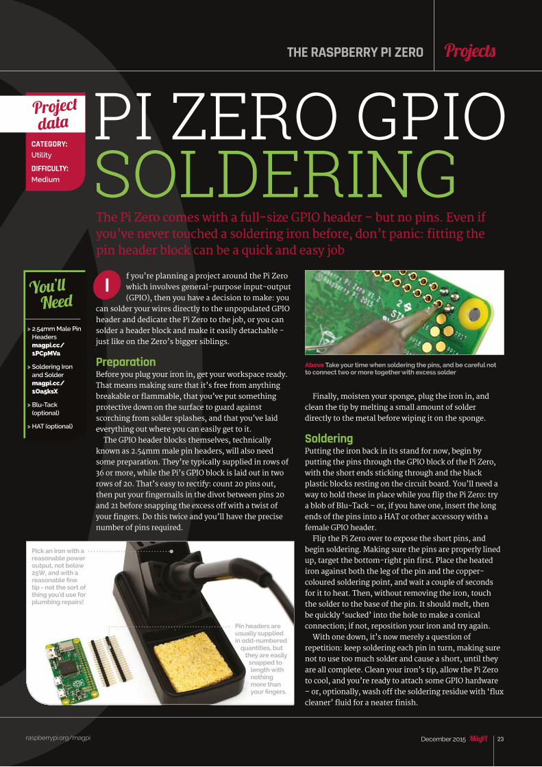
Pick an iron with a reasonable power output, not below 25W, and with a reasonable fine tip - not the sort of thing you’d use for plumbing repairs!
Pin headers are usually supplied in odd-numbered
quantities, but they are easily
snapped to length with nothing more than your fingers.
Above Take your time when soldering the pins, and be careful not to connect two or more together with excess solder
raspberrypi.org/magpi 24 December 2015
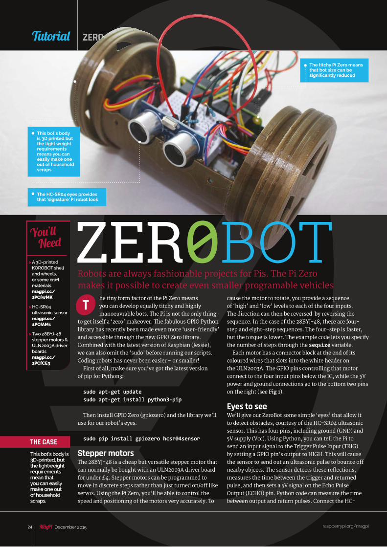
he tiny form factor of the Pi Zero means you can develop equally titchy and highly manoeuvrable bots. The Pi is not the only thing
to get itself a ‘zero’ makeover. The fabulous GPIO Python library has recently been made even more ‘user-friendly’ and accessible through the new GPIO Zero library. Combined with the latest version of Raspbian (Jessie), we can also omit the ‘sudo’ before running our scripts. Coding robots has never been easier – or smaller!
First of all, make sure you’ve got the latest version of pip for Python3:
sudo apt-get updatesudo apt-get install python3-pip
Then install GPIO Zero (gpiozero) and the library we’ll use for our robot’s eyes.
sudo pip install gpiozero hcsr04sensor
Stepper motors The 28BYJ-48 is a cheap but versatile stepper motor that can normally be bought with an ULN2003A driver board for under £4. Stepper motors can be programmed to move in discrete steps rather than just turned on/off like servos. Using the Pi Zero, you’ll be able to control the speed and positioning of the motors very accurately. To
Robots are always fashionable projects for Pis. The Pi Zero makes it possible to create even smaller programable vehicles
T
raspberrypi.org/magpi 24 December 2015
Tutorial ZERO PROJECTS
> A 3D-printed KOROBOT shell and wheels, or some craft materials magpi.cc/ 1PCfwMK
> HC-SR04 ultrasonic sensor magpi.cc/ 1PCfAMs
> Two 28BYJ-48 stepper motors & ULN2003A driver boards magpi.cc/ 1PCfCE3
You’ll Need
THE CASEThis bot’s body is 3D-printed, but the lightweight requirements mean that you can easily make one out of household scraps.
ZER0BOT
The titchy Pi Zero means that bot size can be significantly reduced
The HC-SR04 eyes provides that ‘signature’ Pi robot look
This bot’s body is 3D printed but the light weight requirements means you can easily make one out of household scraps
cause the motor to rotate, you provide a sequence of ‘high’ and ‘low’ levels to each of the four inputs. The direction can then be reversed by reversing the sequence. In the case of the 28BYJ-48, there are four-step and eight-step sequences. The four-step is faster, but the torque is lower. The example code lets you specify the number of steps through the seqsize variable.
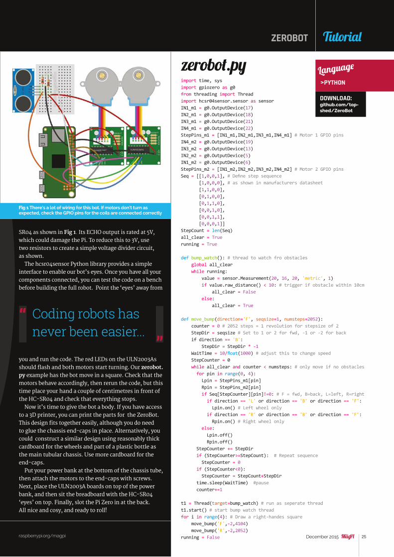
Each motor has a connector block at the end of its coloured wires that slots into the white header on the ULN2003A. The GPIO pins controlling that motor connect to the four input pins below the IC, while the 5V power and ground connections go to the bottom two pins on the right (see Fig 1).
Eyes to see We’ll give our ZeroBot some simple ‘eyes’ that allow it to detect obstacles, courtesy of the HC-SR04 ultrasonic sensor. This has four pins, including ground (GND) and 5V supply (Vcc). Using Python, you can tell the Pi to send an input signal to the Trigger Pulse Input (TRIG) by setting a GPIO pin’s output to HIGH. This will cause the sensor to send out an ultrasonic pulse to bounce off nearby objects. The sensor detects these reflections, measures the time between the trigger and returned pulse, and then sets a 5V signal on the Echo Pulse Output (ECHO) pin. Python code can measure the time between output and return pulses. Connect the HC-
raspberrypi.org/magpi 25December 2015
import time, sysimport gpiozero as g0from threading import Threadimport hcsr04sensor.sensor as sensorIN1_m1 = g0.OutputDevice(17)IN2_m1 = g0.OutputDevice(18)IN3_m1 = g0.OutputDevice(21)IN4_m1 = g0.OutputDevice(22)StepPins_m1 = [IN1_m1,IN2_m1,IN3_m1,IN4_m1] # Motor 1 GPIO pinsIN4_m2 = g0.OutputDevice(19)IN3_m2 = g0.OutputDevice(13)IN2_m2 = g0.OutputDevice(5)IN1_m2 = g0.OutputDevice(6)StepPins_m2 = [IN1_m2,IN2_m2,IN3_m2,IN4_m2] # Motor 2 GPIO pinsSeq = [[1,0,0,1], # Define step sequence [1,0,0,0], # as shown in manufacturers datasheet [1,1,0,0], [0,1,0,0], [0,1,1,0], [0,0,1,0], [0,0,1,1], [0,0,0,1]]StepCount = len(Seq)all_clear = Truerunning = True
def bump_watch(): # thread to watch fro obstacles global all_clear while running: value = sensor.Measurement(20, 16, 20, 'metric', 1) if value.raw_distance() < 10: # trigger if obstacle within 10cm all_clear = False else: all_clear = True
def move_bump(direction='F', seqsize=1, numsteps=2052): counter = 0 # 2052 steps = 1 revolution for stepsize of 2 StepDir = seqsize # Set to 1 or 2 for fwd, -1 or -2 for back if direction == 'B': StepDir = StepDir * -1 WaitTime = 10/float(1000) # adjust this to change speed StepCounter = 0 while all_clear and counter < numsteps: # only move if no obstacles for pin in range(0, 4): Lpin = StepPins_m1[pin] Rpin = StepPins_m2[pin] if Seq[StepCounter][pin]!=0: # F = fwd, B=back, L=left, R=right if direction == 'L' or direction == 'B' or direction == 'F': Lpin.on() # Left wheel only if direction == 'R' or direction == 'B' or direction == 'F': Rpin.on() # Right wheel only else: Lpin.off() Rpin.off() StepCounter += StepDir if (StepCounter>=StepCount): # Repeat sequence StepCounter = 0 if (StepCounter<0): StepCounter = StepCount+StepDir time.sleep(WaitTime) #pause counter+=1
t1 = Thread(target=bump_watch) # run as seperate threadt1.start() # start bump watch threadfor i in range(4): # Draw a right-handes square move_bump('F',-2,4104) move_bump('R',-2,2052)running = False
zerobot.py
ZEROBOT
raspberrypi.org/magpi
Tutorial
SR04 as shown in Fig 1. Its ECHO output is rated at 5V, which could damage the Pi. To reduce this to 3V, use two resistors to create a simple voltage divider circuit, as shown.
The hcsr04sensor Python library provides a simple interface to enable our bot’s eyes. Once you have all your components connected, you can test the code on a bench before building the full robot. Point the ‘eyes’ away from
you and run the code. The red LEDs on the ULN2003As should flash and both motors start turning. Our zerobot.py example has the bot move in a square. Check that the motors behave accordingly, then rerun the code, but this time place your hand a couple of centimetres in front of the HC-SR04 and check that everything stops.
Now it’s time to give the bot a body. If you have access to a 3D printer, you can print the parts for the ZeroBot. This design fits together easily, although you do need to glue the chassis end-caps in place. Alternatively, you could construct a similar design using reasonably thick cardboard for the wheels and part of a plastic bottle as the main tubular chassis. Use more cardboard for the end-caps.
Put your power bank at the bottom of the chassis tube, then attach the motors to the end-caps with screws. Next, place the ULN2003A boards on top of the power bank, and then sit the breadboard with the HC-SR04 ‘eyes’ on top. Finally, slot the Pi Zero in at the back. All nice and cosy, and ready to roll!
Fig 1 There’s a lot of wiring for this bot. If motors don’t turn as expected, check the GPIO pins for the coils are connected correctly
Language
>PYTHON
DOWNLOAD: github.com/top-shed/ZeroBot
Coding robots has never been easier...
raspberrypi.org/magpi 26 December 2015
Feature
hen the machine-to-machine communications industry branched out into consumer products and became
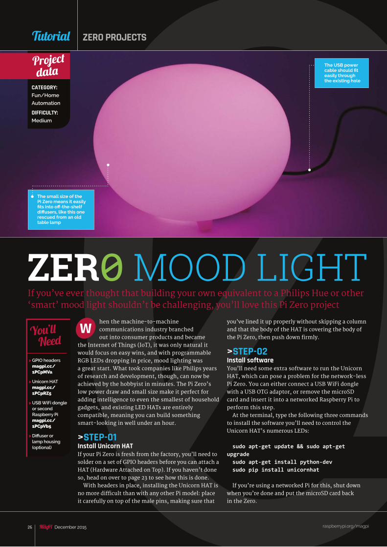
the Internet of Things (IoT), it was only natural it would focus on easy wins, and with programmable RGB LEDs dropping in price, mood lighting was a great start. What took companies like Philips years of research and development, though, can now be achieved by the hobbyist in minutes. The Pi Zero’s low power draw and small size make it perfect for adding intelligence to even the smallest of household gadgets, and existing LED HATs are entirely compatible, meaning you can build something smart-looking in well under an hour.
>STEP-01Install Unicorn HATIf your Pi Zero is fresh from the factory, you’ll need to solder on a set of GPIO headers before you can attach a HAT (Hardware Attached on Top). If you haven’t done so, head on over to page 23 to see how this is done.
With headers in place, installing the Unicorn HAT is no more difficult than with any other Pi model: place it carefully on top of the male pins, making sure that
If you’ve ever thought that building your own equivalent to a Philips Hue or other ‘smart’ mood light shouldn’t be challenging, you’ll love this Pi Zero project
Wyou’ve lined it up properly without skipping a column and that the body of the HAT is covering the body of the Pi Zero, then push down firmly.
>STEP-02Install softwareYou’ll need some extra software to run the Unicorn HAT, which can pose a problem for the network-less Pi Zero. You can either connect a USB WiFi dongle with a USB OTG adaptor, or remove the microSD card and insert it into a networked Raspberry Pi to perform this step.
At the terminal, type the following three commands to install the software you’ll need to control the Unicorn HAT’s numerous LEDs:
sudo apt-get update && sudo apt-get upgradesudo apt-get install python-devsudo pip install unicornhat
If you’re using a networked Pi for this, shut down when you’re done and put the microSD card back in the Zero.
raspberrypi.org/magpi 26 December 2015
Tutorial
ZER0 MOOD LIGHT
CATEGORY:Fun/Home
Automation
DIFFICULTY:Medium
Project data
> GPIO headers magpi.cc/ 1PCpMVa
> Unicorn HAT magpi.cc/ 1PCpRZ5
> USB WiFi dongle or second Raspberry Pi magpi.cc/ 1PCpVb5
> Diffuser or lamp housing (optional)
You’ll Need
ZERO PROJECTS
The small size of the Pi Zero means it easily fits into off-the-shelf diffusers, like this one rescued from an old table lamp
The USB power cable should fit easily through the existing hole
raspberrypi.org/magpi 27December 2015
Feature
#!/usr/bin/env pythonimport unicornhat as unicornimport time, math, colorsys
print("Reticulating splines")time.sleep(.5)print("Enabled unicorn poop module!")time.sleep(.5)print("Pooping rainbows...")
unicorn.brightness(0.1)
i = 0.0offset = 30while True: i = i + 0.3 for y in range(8): for x in range(8): r = 0#x * 32 g = 0#y * 32 xy = x + y / 4 r = (math.cos((x+i)/2.0) + math.cos((y+i)/2.0)) * 64.0 + 128.0 g = (math.sin((x+i)/1.5) + math.sin((y+i)/2.0)) * 64.0 + 128.0 b = (math.sin((x+i)/2.0) + math.cos((y+i)/1.5)) * 64.0 + 128.0 r = max(0, min(255, r + offset)) g = max(0, min(255, g + offset)) b = max(0, min(255, b + offset)) unicorn.set_pixel(x,y,int(r),int(g),int(b)) unicorn.show() time.sleep(0.01)
rainbow.py
MOOD LIGHT
raspberrypi.org/magpi 27December 2015
Tutorial
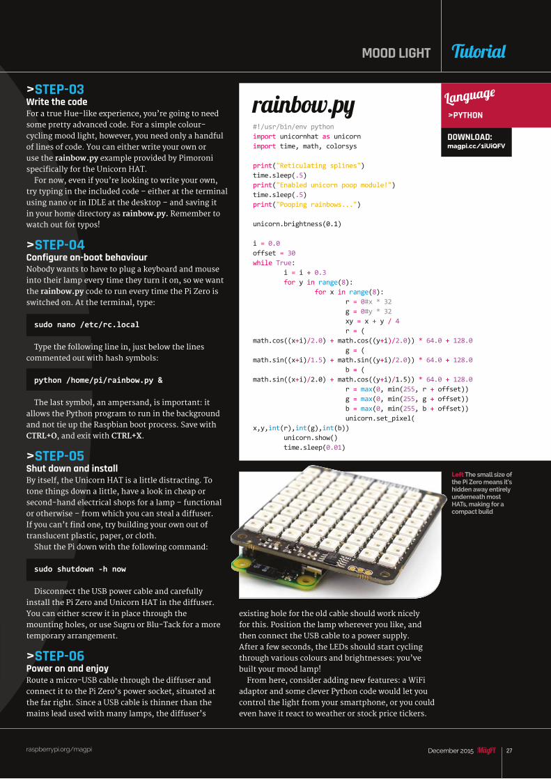
Left The small size of the Pi Zero means it’s hidden away entirely underneath most HATs, making for a compact build
>STEP-03Write the codeFor a true Hue-like experience, you’re going to need some pretty advanced code. For a simple colour-cycling mood light, however, you need only a handful of lines of code. You can either write your own or use the rainbow.py example provided by Pimoroni specifically for the Unicorn HAT.
For now, even if you’re looking to write your own, try typing in the included code – either at the terminal using nano or in IDLE at the desktop – and saving it in your home directory as rainbow.py. Remember to watch out for typos!
>STEP-04Configure on-boot behaviourNobody wants to have to plug a keyboard and mouse into their lamp every time they turn it on, so we want the rainbow.py code to run every time the Pi Zero is switched on. At the terminal, type:
sudo nano /etc/rc.local
Type the following line in, just below the lines commented out with hash symbols:
python /home/pi/rainbow.py &
The last symbol, an ampersand, is important: it allows the Python program to run in the background and not tie up the Raspbian boot process. Save with CTRL+O, and exit with CTRL+X.
>STEP-05Shut down and installBy itself, the Unicorn HAT is a little distracting. To tone things down a little, have a look in cheap or second-hand electrical shops for a lamp – functional or otherwise – from which you can steal a diffuser. If you can’t find one, try building your own out of translucent plastic, paper, or cloth.
Shut the Pi down with the following command:
sudo shutdown -h now
Disconnect the USB power cable and carefully install the Pi Zero and Unicorn HAT in the diffuser. You can either screw it in place through the mounting holes, or use Sugru or Blu-Tack for a more temporary arrangement.
>STEP-06Power on and enjoyRoute a micro-USB cable through the diffuser and connect it to the Pi Zero’s power socket, situated at the far right. Since a USB cable is thinner than the mains lead used with many lamps, the diffuser’s
existing hole for the old cable should work nicely for this. Position the lamp wherever you like, and then connect the USB cable to a power supply. After a few seconds, the LEDs should start cycling through various colours and brightnesses: you’ve built your mood lamp!
From here, consider adding new features: a WiFi adaptor and some clever Python code would let you control the light from your smartphone, or you could even have it react to weather or stock price tickers.
Language
>PYTHON
DOWNLOAD: magpi.cc/1iUiQFV
raspberrypi.org/magpi 28 December 2015
sing off-the-shelf components and a Raspberry Pi Zero, you can create a small and inexpensive GPS location logging device to
take hiking, kayaking, or in the car. And since the Raspberry Pi is a full computer, you can even connect a monitor, keyboard, and mouse to it so that you can view your routes on a map and analyse the data you’ve collected. In this project, you’ll learn about how GPS devices deliver location information over serial, and how you can use Python to parse and save that stream of data to a file.
Track yourself anywhere on Earth by making your own tiny, hackable GPS logger and map viewer
U
raspberrypi.org/magpi 28 December 2015
Tutorial ZERO PROJECTS
ZER0 GPS LOGGER
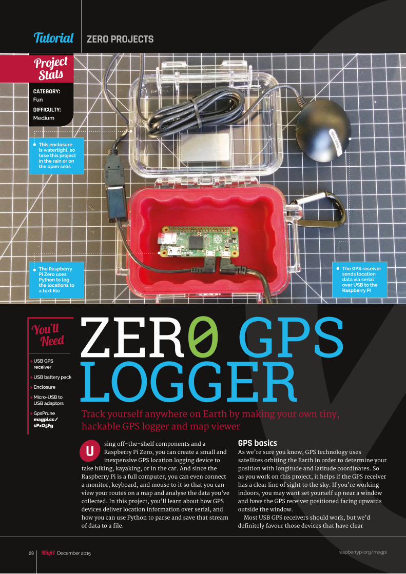
This enclosure is watertight, so take this project in the rain or on the open seas
GPS basicsAs we’re sure you know, GPS technology uses satellites orbiting the Earth in order to determine your position with longitude and latitude coordinates. So as you work on this project, it helps if the GPS receiver has a clear line of sight to the sky. If you’re working indoors, you may want set yourself up near a window and have the GPS receiver positioned facing upwards outside the window.
Most USB GPS receivers should work, but we’d definitely favour those devices that have clear
> USB GPS receiver
> USB battery pack
> Enclosure
> Micro-USB to USB adaptors
> GpsPrune magpi.cc/ 1PxO5Fg
You’ll Need
CATEGORY:Fun
DIFFICULTY:Medium
Project Stats
The Raspberry Pi Zero uses Python to log the locations to a text file
The GPS receiver sends location data via serial over USB to the Raspberry Pi
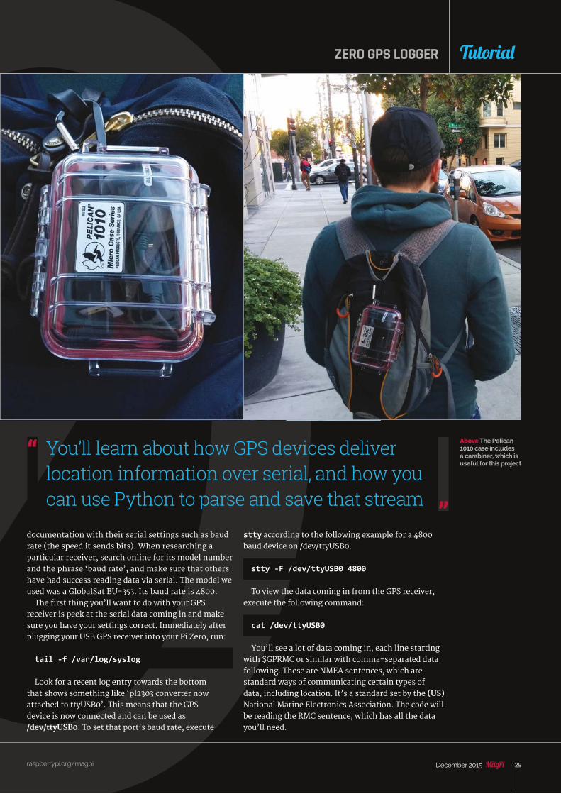
raspberrypi.org/magpi 29December 2015
ZERO GPS LOGGER
raspberrypi.org/magpi
Tutorial
documentation with their serial settings such as baud rate (the speed it sends bits). When researching a particular receiver, search online for its model number and the phrase ‘baud rate’, and make sure that others have had success reading data via serial. The model we used was a GlobalSat BU-353. Its baud rate is 4800.
The first thing you’ll want to do with your GPS receiver is peek at the serial data coming in and make sure you have your settings correct. Immediately after plugging your USB GPS receiver into your Pi Zero, run:
tail -f /var/log/syslog
Look for a recent log entry towards the bottom that shows something like ‘pl2303 converter now attached to ttyUSB0’. This means that the GPS device is now connected and can be used as /dev/ttyUSB0. To set that port’s baud rate, execute
You’ll learn about how GPS devices deliver location information over serial, and how you can use Python to parse and save that stream
Above The Pelican 1010 case includes a carabiner, which is useful for this project
stty according to the following example for a 4800 baud device on /dev/ttyUSB0.
stty -F /dev/ttyUSB0 4800
To view the data coming in from the GPS receiver, execute the following command:
cat /dev/ttyUSB0
You’ll see a lot of data coming in, each line starting with $GPRMC or similar with comma-separated data following. These are NMEA sentences, which are standard ways of communicating certain types of data, including location. It’s a standard set by the (US) National Marine Electronics Association. The code will be reading the RMC sentence, which has all the data you’ll need.
raspberrypi.org/magpi 30 December 2015
Feature
import serialimport os
firstFixFlag = False # will go true at first fixfirstFixDate = ""
# Set up serial:ser = serial.Serial( port='/dev/ttyUSB0',\ baudrate=4800,\ parity=serial.PARITY_NONE,\ stopbits=serial.STOPBITS_ONE,\ bytesize=serial.EIGHTBITS,\ timeout=1)
# Helper function to take HHMM.SS, # Hemisphere and make it decimal:def degrees_to_decimal(data, hemisphere):
try: decimalPointPosition = data.index('.') degrees = float(data[:decimalPointPosition-2])
minutes = float(data[decimalPointPosition-2:])/60 output = degrees + minutes if hemisphere is 'N' or hemisphere is 'E': return output if hemisphere is 'S' or hemisphere is 'W': return -output except: return ""
# Helper function to take a $GPRMC sentence, # and turn it into a Python dictionary.# This also calls degrees_to_decimal and stores # the decimal values as well.def parse_GPRMC(data): data = data.split(',') dict = { 'fix_time': data[1], 'validity': data[2], 'latitude': data[3],
raspberrypi.org/magpi 30 December 2015 raspberrypi.org/magpi 30 December 2015
Tutorial ZERO PROJECTS
Here’s an RMC sentence from my unit:
$GPRMC,204311.602,A,3747.3392,N,12223.8954,W,0.50,324.18,061115,,,A*7A
The fields you’ll be interested in are in Fig 1.The other fields describe speed, course, magnetic
variation, and the final field is a checksum. We won’t be using them for this project.
Press CTRL+C to get back to the command line and proceed if you’ve confirmed the path of the serial port and the baud rate.
Parsing the data and saving itWhile there are drivers and code libraries for working with GPS devices, we decided to parse the NMEA sentences manually in Python, since that language is especially good for working with text. The main purpose of the Python script is to log the latitude and longitude to a text file with comma-separated values. That’s what it does in the main loop at the bottom of the code. You might notice that it will only log to file when there’s a valid fix. You can tell if there’s a valid fix when the status field has the letter A.
The code has two helper functions. The first helper function takes the full NMEA sentence and creates a Python dictionary out of the data. This just makes the data easier to work with in case you want to enhance the script for your project.
The other helper function takes the degrees-minutes and hemisphere data that the GPS outputs and converts it into decimal degrees. Working with decimal degrees will be easier if you want to enhance the project to
gps.pyDOWNLOAD: magpi.cc/1PxP0pi
Language
>PYTHON
Above GpsPrune runs on the Raspberry Pi and lets you view the data on a map
Fig 1 The key fields of an NMEA RMC sentence
W Eastern / Western
Hemisphere indicator
E or W
N Northern / Southern
Hemisphere indicator
N or S
DATA DESCRIPTION
$GPRMC
204311.602
A
Time (UTC)
Status
Protocol header
FORMAT
hhmmss.sss
A (valid) or V (not valid)
–
3747.3392 Latitude ddmm.mmmm
12223.8954 Longitude ddmm.mmmm
061115 Date ddmmyy
raspberrypi.org/magpi 31December 2015
Feature
raspberrypi.org/magpi 31December 2015
ZERO GPS LOGGER
raspberrypi.org/magpi
Tutorial
'latitude_hemisphere' : data[4], 'longitude' : data[5], 'longitude_hemisphere' : data[6], 'speed': data[7], 'true_course': data[8], 'fix_date': data[9], 'variation': data[10], 'variation_e_w' : data[11], 'checksum' : data[12] }
dict['decimal_latitude'] = degrees_to_decimal(dict['latitude'], dict['latitude_hemisphere']) dict['decimal_longitude'] = degrees_to_decimal(dict['longitude'], dict['longitude_hemisphere']) return dict
# Main program loop:while True: line = ser.readline() if "$GPRMC" in line: # This will exclude other NMEA # sentences the GPS provides.
gpsData = parse_GPRMC(line) # Turn a GPRMC sentence # into a Python dictionary called gpsData if gpsData['validity'] == "A": # If the sentence shows that there's a # fix, then we can log the line if firstFixFlag is False: # If we haven't found a fix before, set # the filename prefix with GPS date & time. firstFixDate = gpsData['fix_date'] + "-" gpsData['fix_time'] firstFixFlag = True else: # write the data to a simple log file and # then the raw data as well: with open("/home/pi/gps_experimentation/" + firstFixDate +"-simple-log.txt", "a") as myfile: myfile.write(gpsData['fix_date'] + "," + gpsData['fix_time'] + "," + str(gpsData['decimal_latitude']) + "," + str(gpsData['decimal_longitude']) +"\n") with open("/home/pi/gps_experimentation/" + firstFixDate +"-gprmc-raw-log.txt", "a") as myfile: myfile.write(line)
check if you’re within a certain boundary. Also, a lot of mapping tools such as Google Maps use decimal degrees.
After you clone the GitHub repository, edit gps.py with the port name and baud rate for your device. Also, adjust any file names and paths as you see fit. To get it to boot on startup:
sudo nano /etc/rc.local
…And add this line before exit 0:
python /home/pi/gps_experimentation/gps.py &
Now, whenever you boot your Raspberry Pi Zero, the project will log all valid GPS location fixes to a file.
Viewing the dataTo view your logged data, plug the Raspberry Pi into a keyboard, monitor, and mouse and boot it up. Install GpsPrune from the command line with:
sudo apt-get install gpsprune
Launch it by typing gpsprune. Within GpsPrune, click File > Open, and choose the log file. The default options should work just fine. Now you’ll be able to view the GPS data overlaid on the map!
This is a very basic GPS project and hopefully gives you enough of an idea how to work with GPS data. You can start here and enhance the project in order to do much cooler stuff. For example, you can make a ‘reverse geocache’, which is a box that only unlocks when it’s in a certain part of the world.
raspberrypi.org/magpi 32 December 2015
Feature
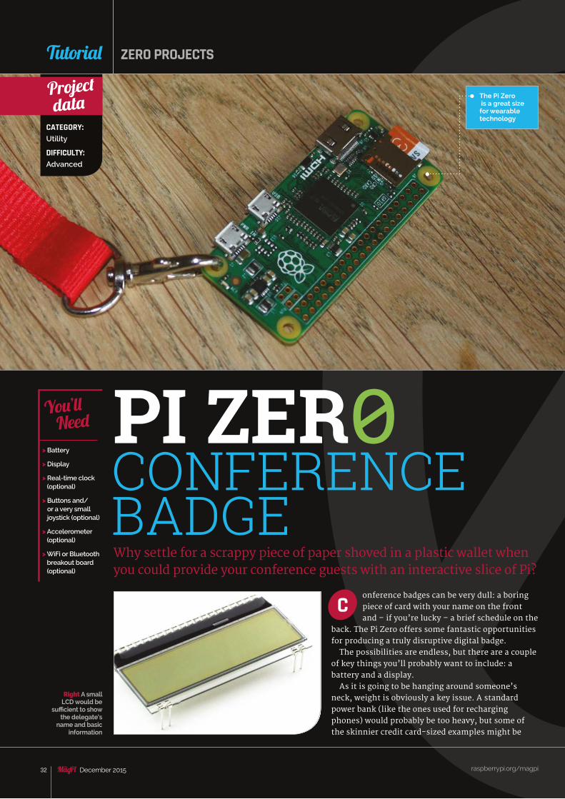
The Pi Zero is a great size for wearable technology
Why settle for a scrappy piece of paper shoved in a plastic wallet when you could provide your conference guests with an interactive slice of Pi?
onference badges can be very dull: a boring piece of card with your name on the front and – if you’re lucky – a brief schedule on the
back. The Pi Zero offers some fantastic opportunities for producing a truly disruptive digital badge.
The possibilities are endless, but there are a couple of key things you’ll probably want to include: a battery and a display.
As it is going to be hanging around someone’s neck, weight is obviously a key issue. A standard power bank (like the ones used for recharging phones) would probably be too heavy, but some of the skinnier credit card-sized examples might be
raspberrypi.org/magpi 32 December 2015
Tutorial
CONFERENCE BADGE
CATEGORY:Utility
DIFFICULTY:Advanced
Project data
> Battery
> Display
> Real-time clock (optional)
> Buttons and/or a very small joystick (optional)
> Accelerometer (optional)
> WiFi or Bluetooth breakout board (optional)
You’ll Need
ZERO PROJECTS
C
Right A small LCD would be
sufficient to show the delegate’s
name and basic information
PI ZER0
raspberrypi.org/magpi 33December 2015
FeatureZER0 CONFERENCE BADGE
raspberrypi.org/magpi 33December 2015
Tutorial
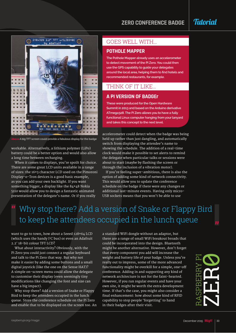
Above A big TFT screen could provide a fabulous display for the badge
workable. Alternatively, a lithium polymer (LiPo) battery could be a better option and would also allow a long time between recharging.
When it comes to displays, you’re spoilt for choice. There are some great LCD units available in a range of sizes: the 16×3 character LCD used on the Pimoroni Display-o-Tron devices is a good basic example, as you can add your own backlight. If you want something bigger, a display like the 84×48 Nokia 5110 would allow you to design a fantastic animated presentation of the delegate’s name. Or if you really
want to go to town, how about a Seeed 128×64 LCD (which uses the handy I2C bus) or even an Adafruit 2.2˝ 18-bit colour TFT LCD?
What about interactivity? Obviously, with the Pi Zero you could just connect a regular keyboard and talk to the Pi Zero that way. But why not make it easier by adding some buttons and a small digital joystick (like the one on the Sense HAT)? A simple on-screen menu could allow the delegate to customise their display (even seemingly tiny modifications like changing the font and size can have a big impact).
Why stop there? Add a version of Snake or Flappy Bird to keep the attendees occupied in the lunch queue. Store the conference schedule on the Pi Zero and enable that to be displayed on the screen too. An
accelerometer could detect when the badge was being held up rather than just dangling, and automatically switch from displaying the attendee’s name to showing the schedule. The addition of a real-time clock would make it possible to set alerts to remind the delegate when particular talks or sessions were about to start (maybe by flashing the screen or through the inclusion of a vibration motor).
If you’re feeling super-ambitious, there is also the option of adding some kind of network connectivity. This would allow you to update the conference schedule on the badge if there were any changes or additional last-minute events. Having only micro-USB sockets means that you won’t be able to use
a standard WiFi dongle without an adaptor, but there are a range of small WiFi breakout broads that could be incorporated into the design. Bluetooth might be another alternative. However, don’t forget that every component you add will increase the weight and battery life of your badge. Unless you’re really out to impress, some of the more advanced functionality might be overkill for a simple, one-off conference. Adding in and supporting any kind of network architecture is not for the faint-hearted. However, if you run regular events and have your own site, it might be worth the extra development time. If that’s the case, you might also consider a final enhancement: how about some kind of RFID capability to stop people ‘forgetting’ to hand in their badges after their visit.
POTHOLE MAPPERThe Pothole Mapper already uses an accelerometer
to detect movement of the Pi Zero. You could then
use the GPS capability to guide your delegates
around the local area, helping them to find hotels and
recommended restaurants, for example.
A PI VERSION OF BADGErThese were produced for the Open Hardware
Summit in 2013 and based on the Arduino derivative
ATmega328. The Pi Zero allows you to have a fully
functional Linux computer hanging from your lanyard
and takes this concept to the next level.
GOES WELL WITH…
THINK OF IT LIKE…
Why stop there? Add a version of Snake or Flappy Bird to keep the attendees occupied in the lunch queue
RA
SPBE
RRY
PI
ZER 0
raspberrypi.org/magpi 34 December 2015
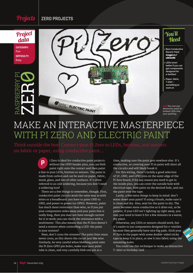
Feature
i Zero is ideal for conductive paint projects: without the GPIO header pins, you can blob paint right onto the contact and then paint
a line to your LEDs, buttons or sensors. The paint is made from carbon and can be used on paper, fabric, wood, glass, and lots of other surfaces. It’s often referred to as cold soldering, because you don’t need a soldering iron!
There are a few things to remember, though. First, conductive paint circuits work the same way as with wires or a breadboard: you have to paint GND to GND, and power to power (or GPIO). However, paint has much more resistance than wire, so if you put your components miles away and your paint line is really long, then you may not have enough current for it to work; you can check the resistance with a multimeter. This also means that the Pi Zero doesn’t need a resistor when controlling a LED: the paint is your resistor!
Next, don’t cross the streams! The paint lines must never cross, as this shorts the circuit just like wire. Similarly, be very careful when blobbing paint onto the Pi Zero GPIO pin holes; make sure your paint tube is clean, and very carefully blob one pin at a
Think outside the box! Connect your Pi Zero to LEDs, buttons, and sensors on fabric or paper, using conductive paint...
P time, making sure the paint gets nowhere else. It’s conductive, so covering your Pi in paint will short all the circuits and will likely break it.
For this wiring, there’s luckily a good selection of 5V, GND, and GPIO pins on the outer edge of the Pi Zero board; if for any reason you need to get to the inside pins, you can cover the outside hole with electrical tape, blob paint on the desired hole, and run the paint over the tape.
Lastly, a few extra things to keep in mind: don’t water down your paint! If using a brush, make sure it is clean and dry. Also, wait for the paint to dry. The paint becomes more conductive as it dries out, so be patient; if your LED isn’t lighting up right away, you may just need to leave it for a few minutes in a warm, dry place.
Otherwise, any LEDs or sensors should work, but it’s easier to use components designed for e-textiles because they generally have nice big pads. Stick your Pi Zero to the paper with some double-sided sticky tape to keep it in place, or sew it into fabric using the mounting holes.
You could use this technique to make an interactive T-shirt or birthday card.
raspberrypi.org/magpi 34 December 2015
Projects
Left You can use electronic paint to embed LEDs into your painting
ZERO PROJECTS
> Bare Conductive Electric Paint magpi.cc/ 1SKZeRE
> LEDs (even better if you can get components designed for e-textiles)
> Paper, fabric, T-shirt – something to work on
You’ll Need
MAKE AN INTERACTIVE MASTERPIECE WITH PI ZERO AND ELECTRIC PAINT
CATEGORY:Fun
DIFFICULTY:Easy
Project data
RA
SPBE
RRY
PI
ZER 0
raspberrypi.org/magpi
Feature
35December 2015
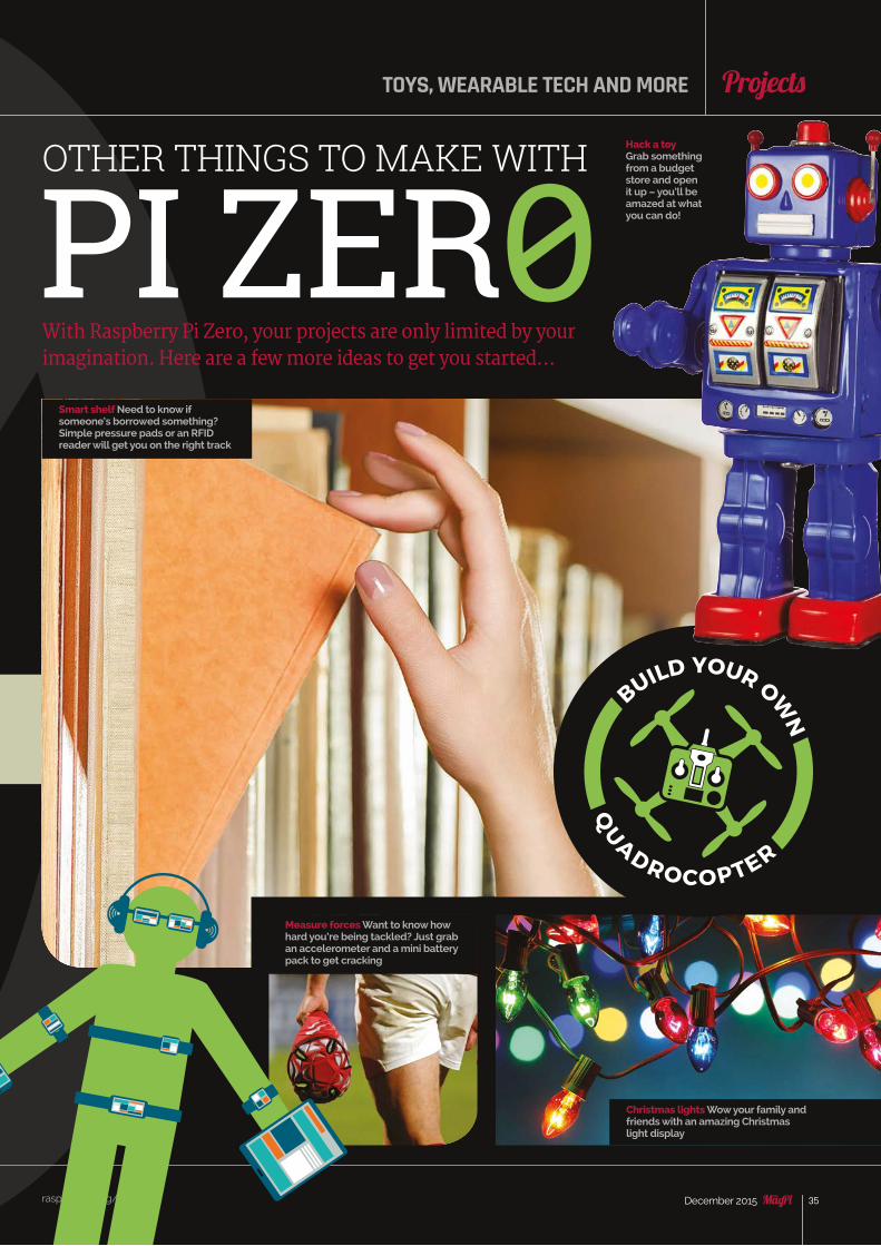
With Raspberry Pi Zero, your projects are only limited by your imagination. Here are a few more ideas to get you started…
TOYS, WEARABLE TECH AND MORE
raspberrypi.org/magpi 35December 2015
Projects
OTHER THINGS TO MAKE WITH
PI ZER0Smart shelf Need to know if someone’s borrowed something? Simple pressure pads or an RFID reader will get you on the right track
Hack a toyGrab something from a budget store and open it up – you’ll be amazed at what you can do!
Measure forces Want to know how hard you’re being tackled? Just grab an accelerometer and a mini battery pack to get cracking
Christmas lights Wow your family and friends with an amazing Christmas light display
raspberrypi.org/magpi 36 December 2015
Tutorial ZERO PROJECTS
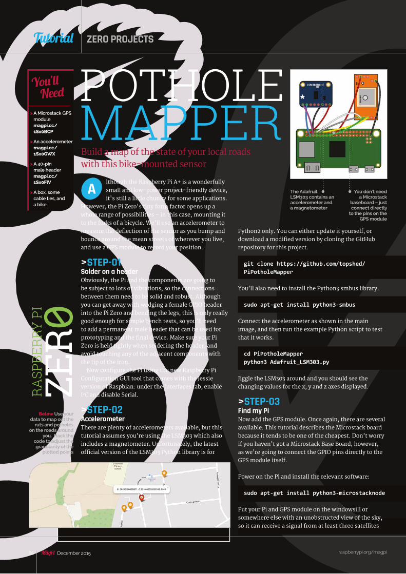
POTHOLE MAPPERBuild a map of the state of your local roads with this bike-mounted sensor
The Adafruit LSM303 contains an accelerometer and a magnetometer
> A Microstack GPS module magpi.cc/ 1Sx0BCP
> An accelerometer magpi.cc/ 1Sx0GWX
> A 40-pin male header magpi.cc/ 1Sx0FlV
> A box, some cable ties, and a bike
You’ll Need
You don't need a Microstack
baseboard – just connect directly
to the pins on the GPS module
Python2 only. You can either update it yourself, or download a modified version by cloning the GitHub repository for this project.
git clone https://github.com/topshed/ PiPotholeMapper
You’ll also need to install the Python3 smbus library.
sudo apt-get install python3-smbus
Connect the accelerometer as shown in the main image, and then run the example Python script to test that it works.
cd PiPotholeMapperpython3 Adafruit_LSM303.py
Jiggle the LSM303 around and you should see the changing values for the x, y and z axes displayed.
>STEP-03Find my PiNow add the GPS module. Once again, there are several available. This tutorial describes the Microstack board because it tends to be one of the cheapest. Don’t worry if you haven’t got a Microstack Base Board, however, as we’re going to connect the GPIO pins directly to the GPS module itself.
Power on the Pi and install the relevant software:
sudo apt-get install python3-microstacknode
Put your Pi and GPS module on the windowsill or somewhere else with an unobstructed view of the sky, so it can receive a signal from at least three satellites
lthough the Raspberry Pi A+ is a wonderfully small and low-power project-friendly device, it's still a little chunky for some applications.
However, the Pi Zero's tiny form factor opens up a whole range of possibilities – in this case, mounting it to the forks of a bicycle. We’ll use an accelerometer to measure the deflection of the sensor as you bump and bounce around the mean streets of wherever you live, and use a GPS module to record your position.
>STEP-01Solder on a header Obviously, the Pi and the components are going to be subject to lots of vibrations, so the connections between them need to be solid and robust. Although you can get away with wedging a female GPIO header into the Pi Zero and bending the legs, this is only really good enough for simple bench tests, so you’ll need to add a permanent male header that can be used for prototyping and the final device. Make sure your Pi Zero is held tightly when soldering the header, and avoid touching any of the adjacent components with the tip of the iron.
Now configure the Pi using the new Raspberry Pi Configuration GUI tool that comes with the Jessie version of Raspbian: under the Interfaces tab, enable I2C and disable Serial.
>STEP-02AccelerometerThere are plenty of accelerometers available, but this tutorial assumes you’re using the LSM303 which also includes a magnetometer. Unfortunately, the latest official version of the LSM303 Python library is for
A
Below Use your data to map out the
ruts and potholes on the roads around
you. Hack the code to adjust the granularity of the
plotted points
RA
SPBE
RRY
PI
ZER 0
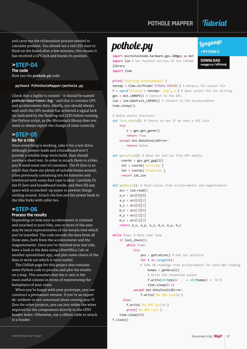
raspberrypi.org/magpi 37December 2015
TutorialPOTHOLE MAPPER
import microstacknode.hardware.gps.l80gps as mstimport lsm # Our Python3 version of the LSM303 libraryimport time
print('Starting potholemapper')tmstmp = time.strftime("%Y%m%d-%H%M%S") # Detao;s for output filef = open('pothole'+ tmstmp+'.log','w') # Open output file for writinggps = mst.L80GPS() # Connect to the GPSlsm = lsm.Adafruit_LSM303() # Connect to the accelerometertime.sleep(1)
# Define useful functionsdef lock_check(): # Checks to see if we have a GPS lock try: x = gps.get_gprmc() return True except mst.DataInvalidError: return False
def getLatLon(): # Read lat and lon from GPS module coords = gps.get_gpgll() lat = coords['latitude'] lon = coords['longitude'] return lat,lon
def getAccel(): # Read values from accelerometer and magnetometer acc = lsm.read() a_x = acc[0][0] a_y = acc[0][1] a_z = acc[0][2] m_x = acc[1][0] m_y = acc[1][1] m_z = acc[1][2] return a_x, a_y, a_z, m_x, m_y, m_z
while True: # Main code loop if lock_check(): while True: try: pos = getLatLon() # Get our position for t in range(10): # Take 10 readings from accelerometer for each GPS reading bumps = getAccel() # Write CSV formatted output f.write(str(pos)+ ',' + str(bumps) + '\n') time.sleep(0.1) except mst.DataInvalidError: f.write('No GPS lock\n') else: f.write('No GPS lock\n') print('No GPS Lock') time.sleep(60)f.close()
pothole.py Language
>PYTHON 3
and carry out the trilateration process needed to calculate position. You should see a red LED start to flash on the board after a few minutes; this means it has received a GPS lock and knows its position.
>STEP-04The codeNow run the pothole.py code:
python3 PiPotholeMapper/pothole.py
Check that a logfile is created - it should be named pothole<date+time>.log - and that it contains GPS and accelerometer data. Ideally, you should always wait until the GPS module has achieved a signal lock (as indicated by the flashing red LED) before running the Python script, as the Microstack library does not seem to always report the change of state correctly.
>STEP-05Go for a rideOnce everything is working, take it for a test drive. Although jumper leads and a breadboard won’t provide a reliable long-term build, they should survive a short test. In order to attach them to a bike, you’ll need some sort of container. The Pi Zero is so small that there are plenty of suitable boxes around; a box previously containing ten AA batteries and reinforced with some duct tape is ideal. Carefully fit the Pi Zero and breadboard inside, and then fill any space with scrunched-up paper to prevent things rattling around. Attach the box and the power bank to the bike forks with cable ties.
>STEP-06Process the resultsDepending on how your accelerometer is oriented and attached to your bike, one or more of the axes may be most representative of the terrain over which you've travelled. The code records the data from all three axes, both from the accelerometer and the magnetometer. Once you’ve finished your test ride, have a look at the data using LibreOffice Calc or another spreadsheet app, and plot some charts of the data to work out which is most useful.
The GitHub page for this project also contains some Python code to process and plot the results on a map. This assumes that the x-axis is the most useful column in terms of representing the bumpiness of your route.
When you’re happy with your prototype, you can construct a permanent version. If you’re an expert de-solderer or not concerned about reusing your Pi Zero for other projects, you can just solder the wires required for the components directly to the GPIO header holes. Otherwise, use a ribbon cable to attach to a header.
DOWNLOAD: magpi.cc/1PKzk0j
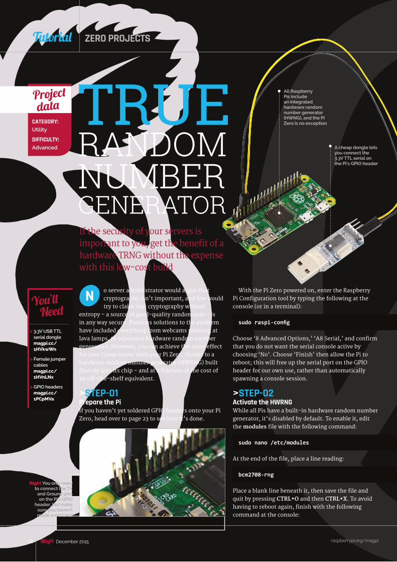
raspberrypi.org/magpi 38 December 2015
Tutorial ZERO PROJECTS
If the security of your servers is important to you, get the benefit of a hardware TRNG without the expense with this low-cost build
> 3.3V USB TTL serial dongle magpi.cc/ 1HVkwWn
> Female jumper cables magpi.cc/ 1HVnLNx
> GPIO headers magpi.cc/ 1PCpMVa
You’ll Need
With the Pi Zero powered on, enter the Raspberry Pi Configuration tool by typing the following at the console (or in a terminal):
sudo raspi-config
Choose ‘8 Advanced Options,’ ‘A8 Serial,’ and confirm that you do not want the serial console active by choosing ‘No’. Choose ‘Finish’ then allow the Pi to reboot; this will free up the serial port on the GPIO header for our own use, rather than automatically spawning a console session.
>STEP-02Activate the HWRNGWhile all Pis have a built-in hardware random number generator, it’s disabled by default. To enable it, edit the modules file with the following command:
sudo nano /etc/modules
At the end of the file, place a line reading:
bcm2708-rng
Place a blank line beneath it, then save the file and quit by pressing CTRL+O and then CTRL+X. To avoid having to reboot again, finish with the following command at the console:
o server administrator would argue that cryptography isn't important, and few would try to claim that cryptography without
entropy - a source of good-quality randomness - is in any way secure. Previous solutions to the problem have included everything from webcams pointing at lava lamps, to expensive hardware random number generators. However, you can achieve the same effect for your Linux server with your Pi Zero, thanks to a hardware random number generator (HWRNG) built directly into its chip - and at a fraction of the cost of an off-the-shelf equivalent.
>STEP-01Prepare the PiIf you haven’t yet soldered GPIO headers onto your Pi Zero, head over to page 23 to see how it’s done.
N
CATEGORY:Utility
DIFFICULTY:Advanced
Project data TRUE
RANDOMNUMBERGENERATOR
All Raspberry Pis include an integrated hardware random number generator (HWNG), and the Pi Zero is no exception
A cheap dongle lets you connect the 3.3V TTL serial on the Pi’s GPIO header
Right You only need to connect the TX
and Ground pins on the Pi’s GPIO
header, but make sure you haven’t made a mistake!
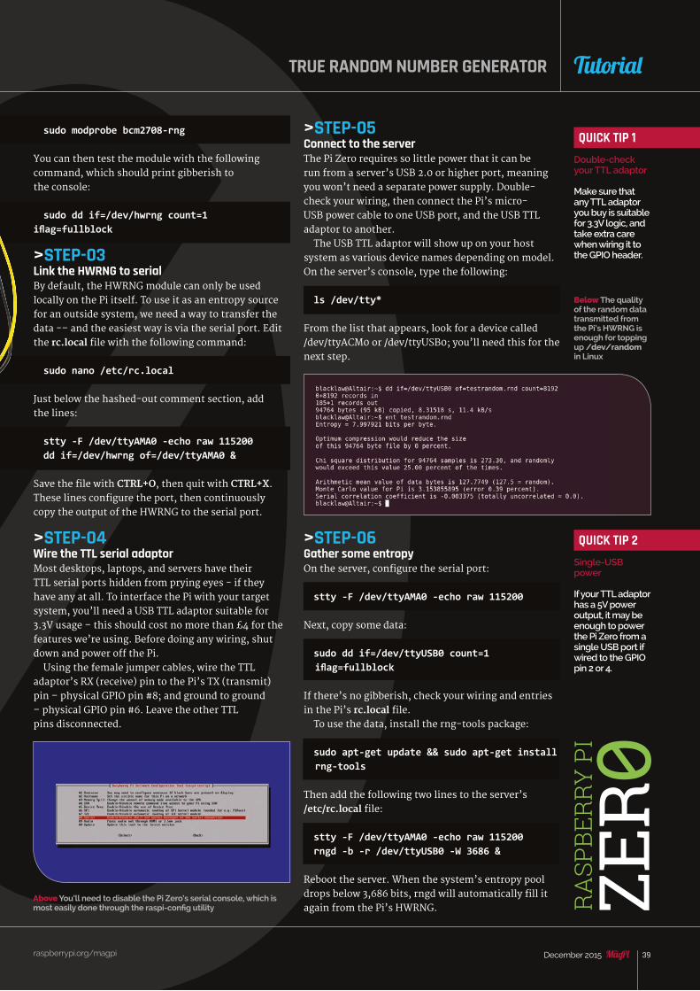
raspberrypi.org/magpi 39December 2015
TutorialTRUE RANDOM NUMBER GENERATOR
sudo modprobe bcm2708-rng
You can then test the module with the following command, which should print gibberish to the console:
sudo dd if=/dev/hwrng count=1 iflag=fullblock
>STEP-03Link the HWRNG to serialBy default, the HWRNG module can only be used locally on the Pi itself. To use it as an entropy source for an outside system, we need a way to transfer the data -– and the easiest way is via the serial port. Edit the rc.local file with the following command:
sudo nano /etc/rc.local
Just below the hashed-out comment section, add the lines:
stty -F /dev/ttyAMA0 -echo raw 115200dd if=/dev/hwrng of=/dev/ttyAMA0 &
Save the file with CTRL+O, then quit with CTRL+X. These lines configure the port, then continuously copy the output of the HWRNG to the serial port.
>STEP-04Wire the TTL serial adaptorMost desktops, laptops, and servers have their TTL serial ports hidden from prying eyes - if they have any at all. To interface the Pi with your target system, you’ll need a USB TTL adaptor suitable for 3.3V usage – this should cost no more than £4 for the features we’re using. Before doing any wiring, shut down and power off the Pi.
Using the female jumper cables, wire the TTL adaptor’s RX (receive) pin to the Pi’s TX (transmit) pin – physical GPIO pin #8; and ground to ground – physical GPIO pin #6. Leave the other TTL pins disconnected.
RA
SPBE
RRY
PI
ZER 0
QUICK TIP 1Double-check your TTL adaptor
Make sure that any TTL adaptor you buy is suitable for 3.3V logic, and take extra care when wiring it to the GPIO header.
QUICK TIP 2Single-USB power
If your TTL adaptor has a 5V power output, it may be enough to power the Pi Zero from a single USB port if wired to the GPIO pin 2 or 4.
>STEP-05Connect to the serverThe Pi Zero requires so little power that it can be run from a server’s USB 2.0 or higher port, meaning you won’t need a separate power supply. Double-check your wiring, then connect the Pi’s micro-USB power cable to one USB port, and the USB TTL adaptor to another.
The USB TTL adaptor will show up on your host system as various device names depending on model. On the server’s console, type the following:
ls /dev/tty*
From the list that appears, look for a device called /dev/ttyACM0 or /dev/ttyUSB0; you’ll need this for the next step.
>STEP-06Gather some entropyOn the server, configure the serial port:
stty -F /dev/ttyAMA0 -echo raw 115200
Next, copy some data:
sudo dd if=/dev/ttyUSB0 count=1 iflag=fullblock
If there’s no gibberish, check your wiring and entries in the Pi’s rc.local file.
To use the data, install the rng-tools package:
sudo apt-get update && sudo apt-get install rng-tools
Then add the following two lines to the server’s /etc/rc.local file:
stty -F /dev/ttyAMA0 -echo raw 115200rngd -b -r /dev/ttyUSB0 -W 3686 &
Reboot the server. When the system’s entropy pool drops below 3,686 bits, rngd will automatically fill it again from the Pi’s HWRNG.
Above You’ll need to disable the Pi Zero’s serial console, which is most easily done through the raspi-config utility
Below The quality of the random data transmitted from the Pi’s HWRNG is enough for topping up /dev/random in Linux

raspberrypi.org/magpi 40 December 2015
Tutorial
NES CONSOLE-TROLLERSlip a Raspberry Pi Zero into the casing of a USB NES controller and you’ve got yourself a fully working NES emulator in ultra-compact form
Once all the hardware is complete, you can then set up RetroPie (magpi.cc/1HVgNba) on a microSD card. If you have a spare Raspberry Pi lying around, it might be best to get the initial setup sorted on there first before plugging it into your NES controller to set the buttons. Remember that you only have the buttons which exist on an NES, so make sure any games you put on there don’t require more than you have.
Finally, plug it into a TV and have some fun!
hile we’re big fans of the educational mission of the Raspberry Pi project, and we fully support it of course, we’d be lying if we
said we don’t love to use the Pi for entertainment as well. Whether it’s the Pi we have stuck to the back of the TV for streaming media, or gaming with RetroPie, the Pi is well suited to these uses. So when we first heard of the Pi Zero, we thought of all of the great hacks that Ben Heck has done over the years, and we realised that the Pi Zero could perfectly slot into a USB NES controller. With a bit of creative wiring, it could be made into a fully functional games console that exists entirely in the controller itself.
The USB NES controllers all have a standard USB cable; this provides enough power to the controller so that the individual button presses can be registered. In order to repurpose the controller, begin by snipping off the original USB cable that pokes out of the rear of the unit. You can now solder the wire to a male micro-USB port. This way, you can use the hole for the trailing USB cable for the mini-HDMI cable. You’ll need to find a cable that has a relatively short connector. Alternatively, you could drill the hole larger to accommodate it.
The only thing remaining to make the whole thing work is to give the Raspberry Pi power. You’ll either have to drill a second hole so that you can plug the power cable in, or you may be able to use the original hole depending on the design of the USB NES controller you have and how the mini-HDMI is mounted. Alternatively, you could try binding the USB and HDMI cables together; in this case you will need to use a television with a USB port that will provide adequate power.
CATEGORY:Entertainment
DIFFICULTY:Advanced
Project data
> USB NES controller
> Micro-USB male connector
> Solder
> Drill
> RetroPie magpi.cc/ 1HVgNba
You’ll Need
WBelow We bought this NES controller from eBay: we had
to file down the plastic a little bit to slot in the Zero
THINK OF IT LIKE…Atari Plug ‘n’ Play TV games
The originator of the ‘console in a controller’ concept – popular at Christmas, but a bit limited once you’ve played every possible variation of Pong and Asteroids
NES CONSOLE-TROLLER
raspberrypi.org/magpi 41December 2015
Tutorial
NESCONSOLE-TROLLER
3D PI ZERO CASE
e’ve taken the liberty of designing and preparing a 3D-printable Raspberry Pi Zerocase for all our readers. It’s quite simple, but
gives you access to all the important ports to get to get it working, and it will handily slot onto a keyring so you can take it with you.
Find all the 3D printable files in the GitHub repository (magpi.cc/ZeroCase) and then plug them into your own 3D printer, get one printed at your nearest makerspace, or use 3D Hubs (3dhubs.com) to find a local printer who will get it printed for you. Enjoy the rest of the issue!
W
PRINT YOURSELF API ZER0CASEGet a 3D-printed case today for your brand new Raspberry Pi Zero with our pre-designed, printable case!
Below Print your own Pi Zero case with our design: it has our name on it!
Get the3D printable
files here! magpi.cc/ZeroCase

Tutorial WALKTHROUGH
raspberrypi.org/magpi 42 December 2015
SUBSCRIBE TODAY!Subscribe to the Official Raspberry Pi mag today for a whole host of benefits
Subscription benefits Save up to 25% on the price
Free delivery to your door
Never miss a single issue
#40 free Zero cable bundle
SAVEUP TO
25%
FREE ZEROCABLES
WITH YOUR SUBSCRIPTION

Tutorial
raspberrypi.org/magpi 43December 2015
RETURN THIS FORM TO:MagPi Magazine Subscriptions, Select Publisher Services Ltd, PO Box 6337, Bournemouth BH1 9EH
Please tick this box if you DO NOT want to receive any other information from Select Publisher Services Ltd.
Please tick this box if you DO NOT want to receive any other information from other companies.
Please tick this box if you DO NOT want to subscribe to The MagPi newsletter.
This subscription is: n For me n A gift for someone*
YOUR DETAILS Mr n Mrs n Miss n Ms nFirst name ........................................... Surname .......................................................
Address .......................................................................................................................
....................................................................................................................................
Postcode .............................................. Email ............................................................
Daytime phone .................................... Mobile ...........................................................
*If giving The MagPi as a gift, please complete both your own details (above) and the recipient’s (below).
GIFT RECIPIENT’S DETAILS ONLY Mr n Mrs n Miss n Ms nFirst name ........................................... Surname .......................................................
Address .......................................................................................................................
Postcode .................................................... Email ..................................................................
SUBSCRIPTION FORMYES! I’d like to subscribe to The MagPi magazine & save money
PAYMENT OPTIONS
1 DIRECT DEBIT PAYMENT £12.99 every 3 issues (UK only)Instruction to your bank or building society to pay by Direct Debit
Please fill in the form and send to: The MagPi, Select Publisher Services Ltd, PO Box 6337, Bournemouth BH1 9EH
Name and full postal address of your bank or building society:
To: The Manager Bank/building society ......................................................................
Address ..........................................................................................................................
........................................................................................................................................
..................................................................................... Postcode ...................................
Name(s) of account holder(s) ...........................................................................................
Branch sort code n n n n n n Account number n n n n n n n nReference n n n n n n n n n n n n n n n n n (Official use only)
Instruction to your bank or building societyPlease pay Select Publisher Services Ltd Direct Debits from the account detailed in this instruction subject to the safeguards assured by the Direct Debit Guarantee. I understand that this instruction may remain with Select Publisher Services Ltd and, if so, details will be passed electronically to my bank/building society.
Signature .................................................................... Date n n /n n/n nBanks and building societies may not accept Direct Debit instructions for some types of account.
SUBSCRIPTION PRICING WHEN PAYING BY CHEQUE OR CREDIT/DEBIT CARD
6 ISSUES n UK £30 n Europe £45 n Rest of world £50
12 ISSUES n UK £55 n Europe £80 n Rest of world £90
2 CHEQUE I enclose a cheque for .............................. (made payable to Select Publisher Services Ltd)
3 CREDIT/DEBIT CARD n Visa n MasterCard n Maestro n Switch
Card number n n n n n n n n n n n n n n n nExpiry date n n n n Valid from n n n n (if shown)
Issue number n n (if shown) Security number n n n(last 3 digits on the back of the card)
Signature .................................................................... Date n n /n n/n n
I would like my subscription to begin from issue ........................................... (month + year)
Service user number 8 3 8 7 7 3
Mag#40
Subscription benefitsSave up to 25% on the price
Free delivery to your door
Never miss a single issue
#40 free Zero cable bundle
PricingGet six issues:
£30 (UK)
£45 (EU)
$69 (US)
£50 (Rest of World)
Subscribe for a year:
£55 (UK)
£80 (EU)
$129 (US)
£90 (Rest of World)
Direct Debit£12.99 (UK) (quarterly)
How to subscribe:
magpi.cc/Subs1 (UK - ROW)
imsnews.com/magpi (US)
Call +44 (0)1202 586848
Use the form to the right
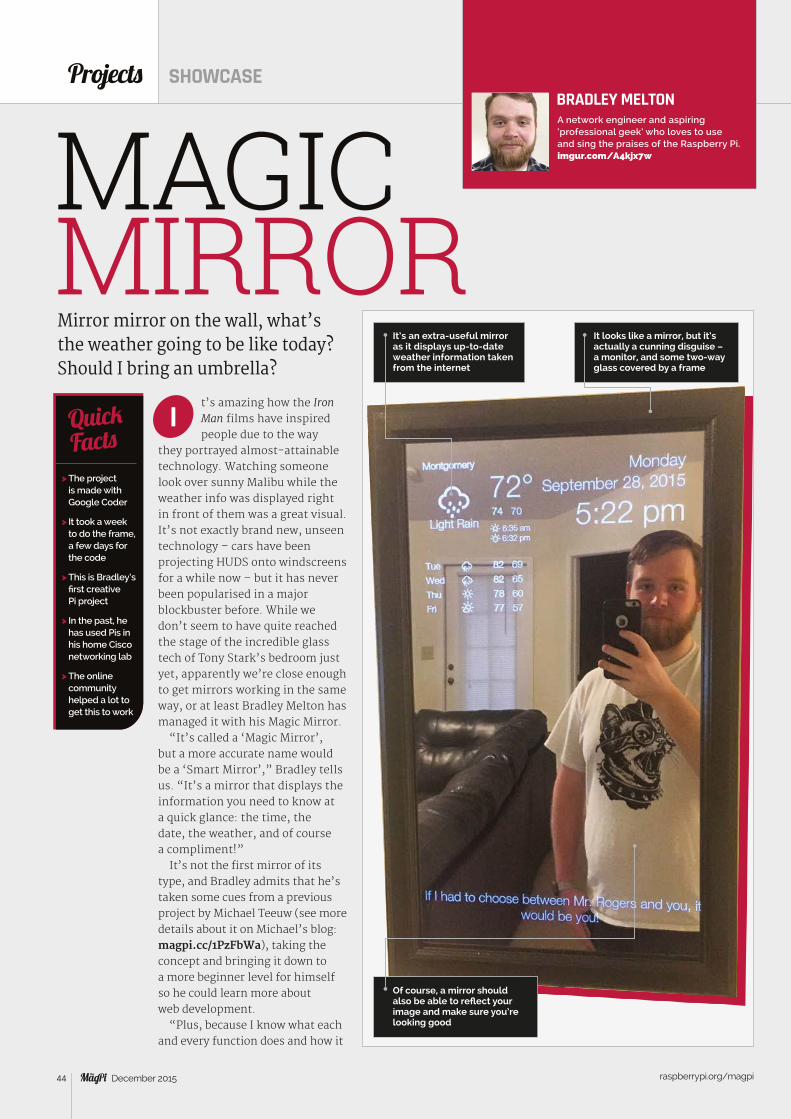
raspberrypi.org/magpi 44 December 2015
t’s amazing how the Iron Man films have inspiredpeople due to the way
they portrayed almost-attainable technology. Watching someone look over sunny Malibu while the weather info was displayed right in front of them was a great visual. It’s not exactly brand new, unseen technology – cars have been projecting HUDS onto windscreens for a while now – but it has never been popularised in a major blockbuster before. While we don’t seem to have quite reached the stage of the incredible glass tech of Tony Stark’s bedroom just yet, apparently we’re close enough to get mirrors working in the same way, or at least Bradley Melton has managed it with his Magic Mirror.
“It’s called a ‘Magic Mirror’, but a more accurate name would be a ‘Smart Mirror’,” Bradley tells us. “It’s a mirror that displays the information you need to know at a quick glance: the time, the date, the weather, and of course a compliment!”
It’s not the first mirror of its type, and Bradley admits that he’s taken some cues from a previous project by Michael Teeuw (see more details about it on Michael’s blog: magpi.cc/1PzFbWa), taking the concept and bringing it down to a more beginner level for himself so he could learn more about web development.
“Plus, because I know what each and every function does and how it
Projects SHOWCASE
Mirror mirror on the wall, what’s the weather going to be like today? Should I bring an umbrella?
> The project is made with Google Coder
> It took a week to do the frame, a few days for the code
> This is Bradley’s first creative Pi project
> In the past, he has used Pis in his home Cisco networking lab
> The online community helped a lot to get this to work
QuickFacts
It’s an extra-useful mirror as it displays up-to-date weather information taken from the internet
I
BRADLEY MELTONA network engineer and aspiring ‘professional geek’ who loves to use and sing the praises of the Raspberry Pi. imgur.com/A4kjx7wMAGIC
MIRRORIt looks like a mirror, but it’s actually a cunning disguise – a monitor, and some two-way glass covered by a frame
Of course, a mirror should also be able to reflect your image and make sure you’re looking good
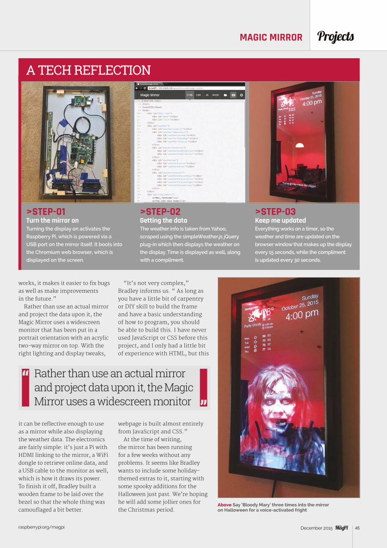
raspberrypi.org/magpi 45December 2015
ProjectsMAGIC MIRROR
Above Say ‘Bloody Mary’ three times into the mirror on Halloween for a voice-activated fright
>STEP-01Turn the mirror onTurning the display on activates the
Raspberry Pi, which is powered via a
USB port on the mirror itself. It boots into
the Chromium web browser, which is
displayed on the screen.
>STEP-02Getting the dataThe weather info is taken from Yahoo,
scraped using the simpleWeather.js jQuery
plug-in which then displays the weather on
the display. Time is displayed as well, along
with a compliment.
>STEP-03Keep me updatedEverything works on a timer, so the
weather and time are updated on the
browser window that makes up the display
every 15 seconds, while the compliment
is updated every 30 seconds.
A TECH REFLECTION
works, it makes it easier to fix bugs as well as make improvements in the future.”
Rather than use an actual mirror and project the data upon it, the Magic Mirror uses a widescreen monitor that has been put in a portrait orientation with an acrylic two-way mirror on top. With the right lighting and display tweaks,
it can be reflective enough to use as a mirror while also displaying the weather data. The electronics are fairly simple: it’s just a Pi with HDMI linking to the mirror, a WiFi dongle to retrieve online data, and a USB cable to the monitor as well, which is how it draws its power. To finish it off, Bradley built a wooden frame to be laid over the bezel so that the whole thing was camouflaged a bit better.
“It’s not very complex,” Bradley informs us. “ As long as you have a little bit of carpentry or DIY skill to build the frame and have a basic understanding of how to program, you should be able to build this. I have never used JavaScript or CSS before this project, and I only had a little bit of experience with HTML, but this
webpage is built almost entirely from JavaScript and CSS.”
At the time of writing, the mirror has been running for a few weeks without any problems. It seems like Bradley wants to include some holiday-themed extras to it, starting with some spooky additions for the Halloween just past. We’re hoping he will add some jollier ones for the Christmas period.
Rather than use an actual mirror and project data upon it, the Magic Mirror uses a widescreen monitor
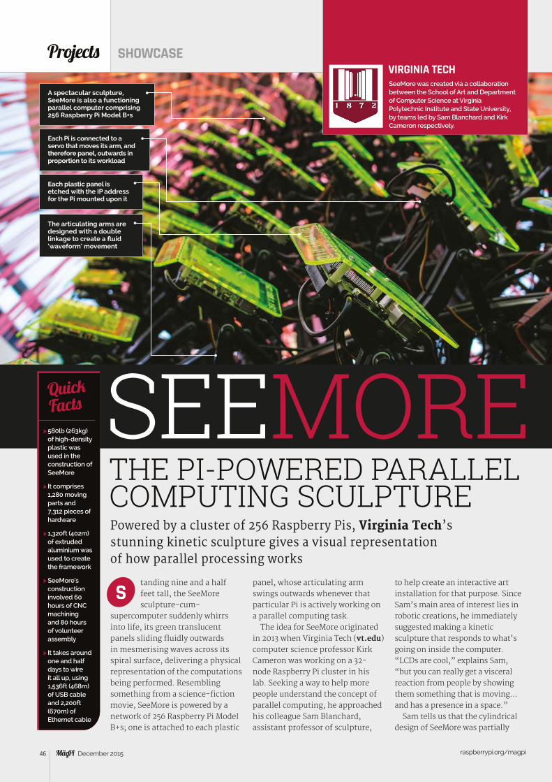
raspberrypi.org/magpi 46 December 2015
tanding nine and a half feet tall, the SeeMore sculpture-cum-
supercomputer suddenly whirrs into life, its green translucent panels sliding fluidly outwards in mesmerising waves across its spiral surface, delivering a physical representation of the computations being performed. Resembling something from a science-fiction movie, SeeMore is powered by a network of 256 Raspberry Pi Model B+s; one is attached to each plastic
Projects SHOWCASE
Powered by a cluster of 256 Raspberry Pis, Virginia Tech’s stunning kinetic sculpture gives a visual representation of how parallel processing works
> 580lb (263kg) of high-density plastic was used in the construction of SeeMore
> It comprises 1,280 moving parts and 7,312 pieces of hardware
> 1,320ft (402m) of extruded aluminium was used to create the framework
> SeeMore’s construction involved 60 hours of CNC machining and 80 hours of volunteer assembly
> It takes around one and half days to wire it all up, using 1,536ft (468m) of USB cable and 2,200ft (670m) of Ethernet cable
QuickFacts
A spectacular sculpture, SeeMore is also a functioning parallel computer comprising 256 Raspberry Pi Model B+s
SEEMORE
S
VIRGINIA TECHSeeMore was created via a collaboration between the School of Art and Department of Computer Science at Virginia Polytechnic Institute and State University, by teams led by Sam Blanchard and Kirk Cameron respectively.
THE PI-POWERED PARALLEL COMPUTING SCULPTURE
panel, whose articulating arm swings outwards whenever that particular Pi is actively working on a parallel computing task.
The idea for SeeMore originated in 2013 when Virginia Tech (vt.edu) computer science professor Kirk Cameron was working on a 32-node Raspberry Pi cluster in his lab. Seeking a way to help more people understand the concept of parallel computing, he approached his colleague Sam Blanchard, assistant professor of sculpture,
to help create an interactive art installation for that purpose. Since Sam’s main area of interest lies in robotic creations, he immediately suggested making a kinetic sculpture that responds to what’s going on inside the computer. “LCDs are cool,” explains Sam, “but you can really get a visceral reaction from people by showing them something that is moving… and has a presence in a space.”
Sam tells us that the cylindrical design of SeeMore was partially
Each Pi is connected to a servo that moves its arm, and therefore panel, outwards in proportion to its workload
Each plastic panel is etched with the IP address for the Pi mounted upon it
The articulating arms are designed with a double linkage to create a fluid ‘waveform’ movement
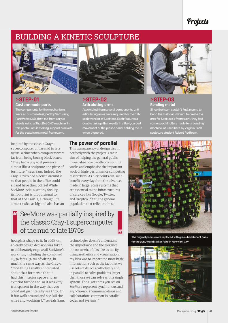
raspberrypi.org/magpi 47December 2015
Projects
>STEP-01Custom-made partsThe components for the mechanisms
were all custom-designed by Sam using
PartWorks CAD, then cut from acrylic
sheets using a ShopBot CNC machine. In
this photo Sam is making support brackets
for the sculpture’s metal framework.
>STEP-02Articulating armsAssembled from several components, 256
articulating arms were required for the full-
scale version of SeeMore. Each features a
double linkage that results in a fluid, curved
movement of the plastic panel holding the Pi
when triggered.
>STEP-03Bending metalSince the team couldn’t find anyone to
bend the T-slot aluminium to create the
arcs for SeeMore’s framework, they had
some special rollers made for a bending
machine, as used here by Virginia Tech
sculpture student Robert Redfearn.
BUILDING A KINETIC SCULPTURE
inspired by the classic Cray-1 supercomputer of the mid to late 1970s, a time when computers were far from being boring black boxes. “They had a physical presence, almost like a sculpture or a piece of furniture,” says Sam. Indeed, the Cray-1 even had a bench around it so that people in the office could sit and have their coffee! While SeeMore lacks a seating facility, its footprint is proportional to that of the Cray-1, although it’s almost twice as big and also has an
hourglass shape to it. In addition, an early design decision was taken to deliberately expose all SeeMore’s workings, including the combined 2,736 feet (834m) of wiring, in much the same way as the Cray-1. “One thing I really appreciated about that form was that it had this interior space and an exterior facade and so it was very transparent in the way that you could not just literally see through it but walk around and see [all the wires and workings],” reveals Sam.
The power of parallelThis transparency of design ties in perfectly with the project’s main aim of helping the general public to visualise how parallel computing works and emphasise the important work of high-performance computing researchers. As Kirk points out, we all benefit every day from the advances made in large-scale systems that are essential to the infrastructures of services like Google, Twitter, and Dropbox. “Yet, the general population that relies on these
technologies doesn’t understand the importance and the elegance innate to what folks like us do. By using aesthetics and visualisation, my idea was to impart the most basic information such as the fact that we use lots of devices collectively and in parallel to solve problems larger than those we can solve with a single system. The algorithms you see on SeeMore represent synchronous and asynchronous communications and collaborations common in parallel codes and systems.”
SeeMore was partially inspired by the classic Cray-1 supercomputer of the mid to late 1970s
The original panels were replaced with green translucent ones
for the 2015 World Maker Faire in New York City
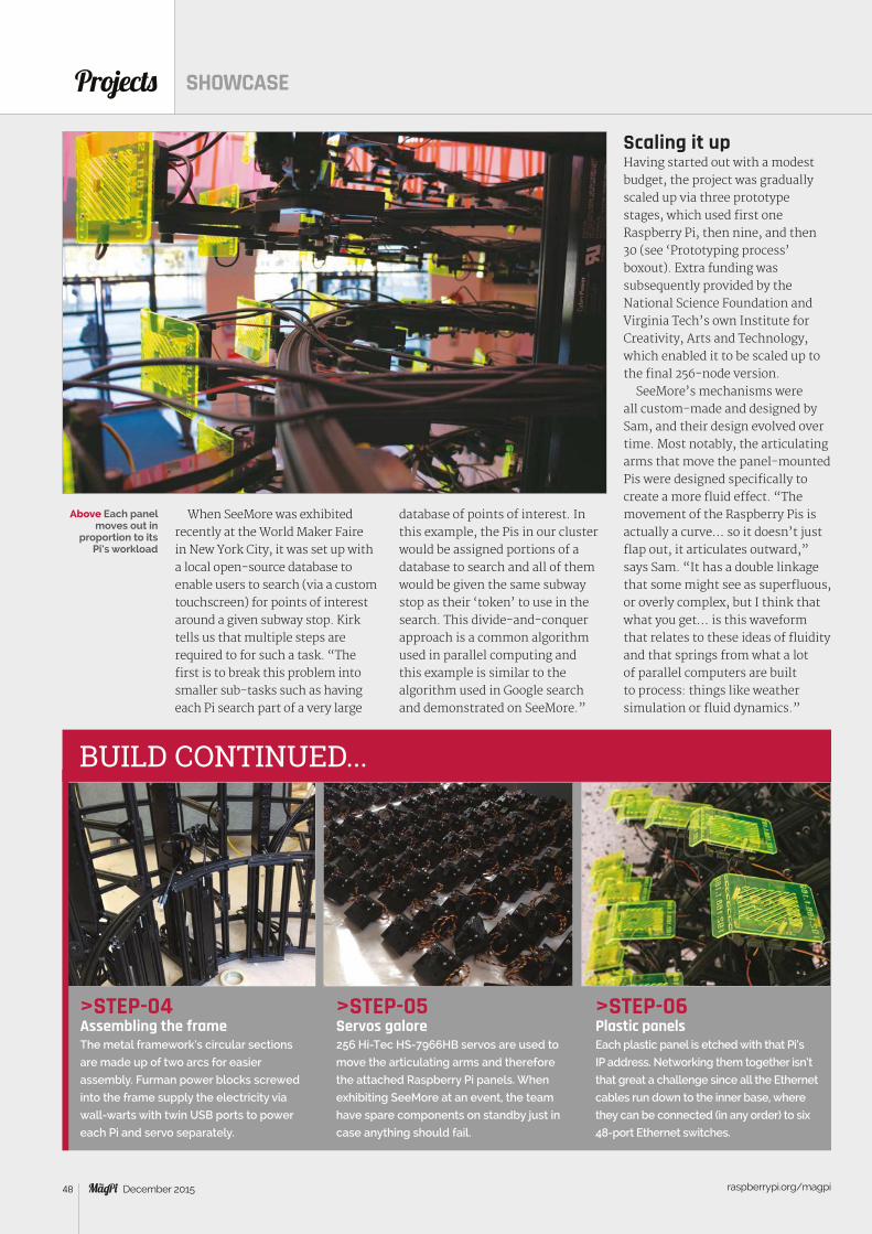
Projects SHOWCASE
raspberrypi.org/magpi 48 December 2015
When SeeMore was exhibited recently at the World Maker Faire in New York City, it was set up with a local open-source database to enable users to search (via a custom touchscreen) for points of interest around a given subway stop. Kirk tells us that multiple steps are required to for such a task. “The first is to break this problem into smaller sub-tasks such as having each Pi search part of a very large
database of points of interest. In this example, the Pis in our cluster would be assigned portions of a database to search and all of them would be given the same subway stop as their ‘token’ to use in the search. This divide-and-conquer approach is a common algorithm used in parallel computing and this example is similar to the algorithm used in Google search and demonstrated on SeeMore.”
>STEP-04Assembling the frameThe metal framework’s circular sections
are made up of two arcs for easier
assembly. Furman power blocks screwed
into the frame supply the electricity via
wall-warts with twin USB ports to power
each Pi and servo separately.
>STEP-05Servos galore256 Hi-Tec HS-7966HB servos are used to
move the articulating arms and therefore
the attached Raspberry Pi panels. When
exhibiting SeeMore at an event, the team
have spare components on standby just in
case anything should fail.
>STEP-06Plastic panelsEach plastic panel is etched with that Pi’s
IP address. Networking them together isn’t
that great a challenge since all the Ethernet
cables run down to the inner base, where
they can be connected (in any order) to six
48-port Ethernet switches.
BUILD CONTINUED...
Scaling it upHaving started out with a modest budget, the project was gradually scaled up via three prototype stages, which used first one Raspberry Pi, then nine, and then 30 (see ‘Prototyping process’ boxout). Extra funding was subsequently provided by the National Science Foundation and Virginia Tech’s own Institute for Creativity, Arts and Technology, which enabled it to be scaled up to the final 256-node version.
SeeMore’s mechanisms were all custom-made and designed by Sam, and their design evolved over time. Most notably, the articulating arms that move the panel-mounted Pis were designed specifically to create a more fluid effect. “The movement of the Raspberry Pis is actually a curve… so it doesn’t just flap out, it articulates outward,” says Sam. “It has a double linkage that some might see as superfluous, or overly complex, but I think that what you get… is this waveform that relates to these ideas of fluidity and that springs from what a lot of parallel computers are built to process: things like weather simulation or fluid dynamics.”
Above Each panel moves out in
proportion to its Pi’s workload
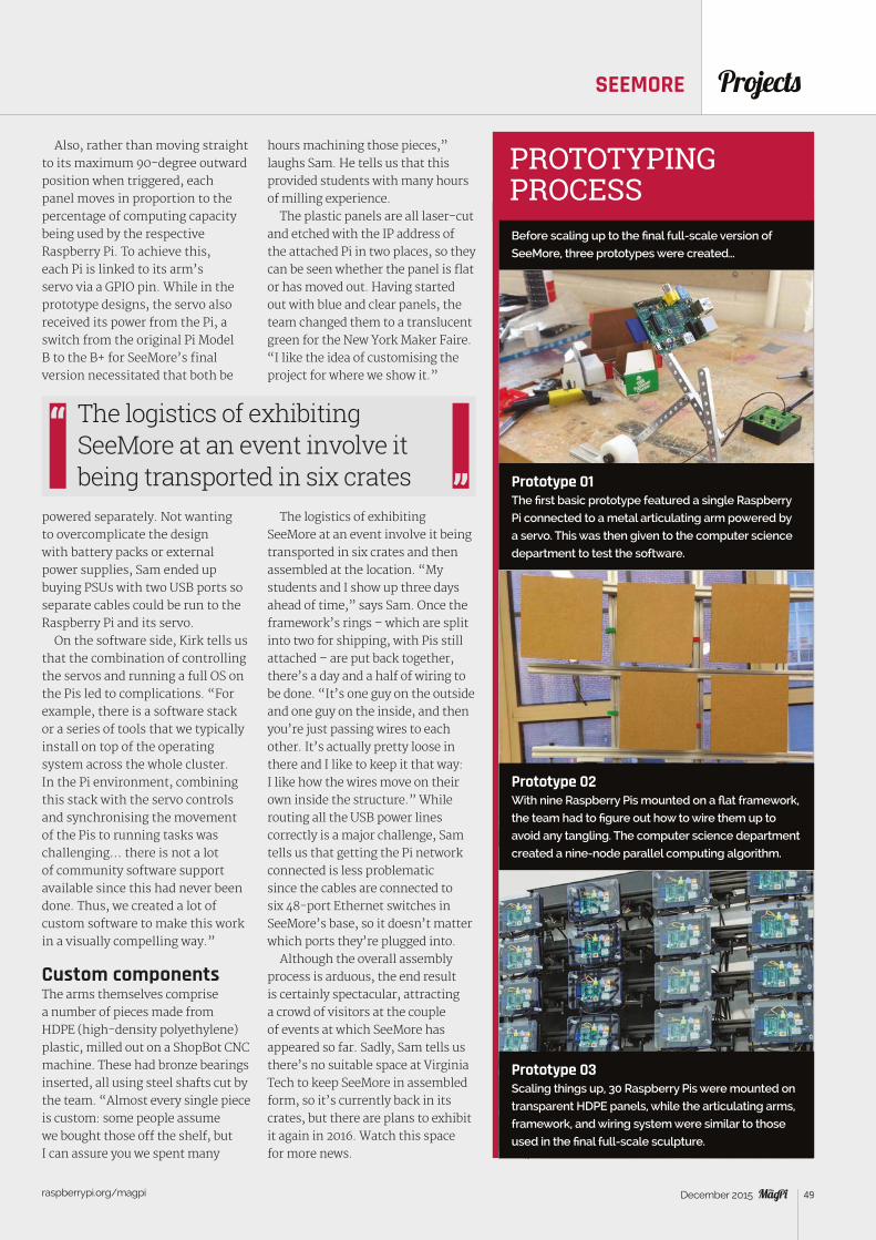
Projects
raspberrypi.org/magpi 49December 2015
Also, rather than moving straight to its maximum 90-degree outward position when triggered, each panel moves in proportion to the percentage of computing capacity being used by the respective Raspberry Pi. To achieve this, each Pi is linked to its arm’s servo via a GPIO pin. While in the prototype designs, the servo also received its power from the Pi, a switch from the original Pi Model B to the B+ for SeeMore’s final version necessitated that both be
powered separately. Not wanting to overcomplicate the design with battery packs or external power supplies, Sam ended up buying PSUs with two USB ports so separate cables could be run to the Raspberry Pi and its servo.
On the software side, Kirk tells us that the combination of controlling the servos and running a full OS on the Pis led to complications. “For example, there is a software stack or a series of tools that we typically install on top of the operating system across the whole cluster. In the Pi environment, combining this stack with the servo controls and synchronising the movement of the Pis to running tasks was challenging… there is not a lot of community software support available since this had never been done. Thus, we created a lot of custom software to make this work in a visually compelling way.”
Custom componentsThe arms themselves comprise a number of pieces made from HDPE (high-density polyethylene) plastic, milled out on a ShopBot CNC machine. These had bronze bearings inserted, all using steel shafts cut by the team. “Almost every single piece is custom: some people assume we bought those off the shelf, but I can assure you we spent many
hours machining those pieces,” laughs Sam. He tells us that this provided students with many hours of milling experience.
The plastic panels are all laser-cut and etched with the IP address of the attached Pi in two places, so they can be seen whether the panel is flat or has moved out. Having started out with blue and clear panels, the team changed them to a translucent green for the New York Maker Faire. “I like the idea of customising the project for where we show it.”
The logistics of exhibiting SeeMore at an event involve it being transported in six crates and then assembled at the location. “My students and I show up three days ahead of time,” says Sam. Once the framework’s rings – which are split into two for shipping, with Pis still attached – are put back together, there’s a day and a half of wiring to be done. “It’s one guy on the outside and one guy on the inside, and then you’re just passing wires to each other. It’s actually pretty loose in there and I like to keep it that way: I like how the wires move on their own inside the structure.” While routing all the USB power lines correctly is a major challenge, Sam tells us that getting the Pi network connected is less problematic since the cables are connected to six 48-port Ethernet switches in SeeMore’s base, so it doesn’t matter which ports they’re plugged into.
Although the overall assembly process is arduous, the end result is certainly spectacular, attracting a crowd of visitors at the couple of events at which SeeMore has appeared so far. Sadly, Sam tells us there’s no suitable space at Virginia Tech to keep SeeMore in assembled form, so it’s currently back in its crates, but there are plans to exhibit it again in 2016. Watch this space for more news.
PROTOTYPING PROCESS
Prototype 01The first basic prototype featured a single Raspberry
Pi connected to a metal articulating arm powered by
a servo. This was then given to the computer science
department to test the software.
Before scaling up to the final full-scale version of
SeeMore, three prototypes were created…
Prototype 02With nine Raspberry Pis mounted on a flat framework,
the team had to figure out how to wire them up to
avoid any tangling. The computer science department
created a nine-node parallel computing algorithm.
Prototype 03Scaling things up, 30 Raspberry Pis were mounted on
transparent HDPE panels, while the articulating arms,
framework, and wiring system were similar to those
used in the final full-scale sculpture.
The logistics of exhibiting SeeMore at an event involve it being transported in six crates
SEEMORE
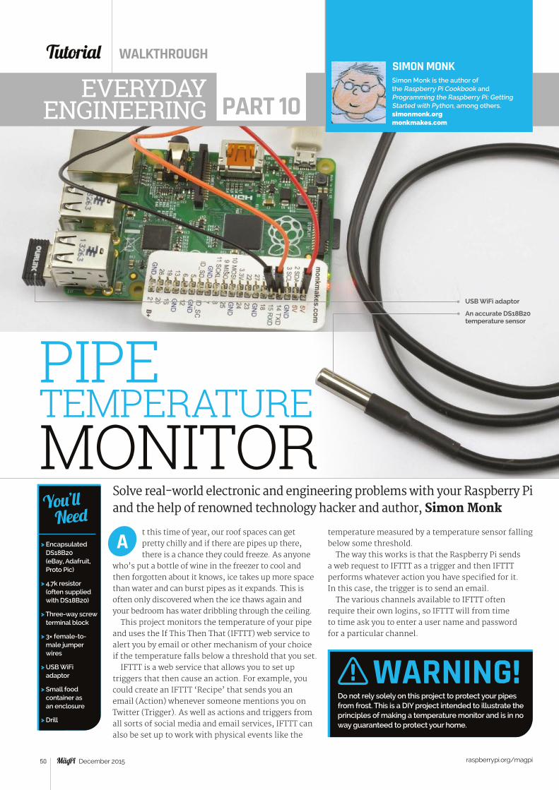
Tutorial WALKTHROUGH
raspberrypi.org/magpi 50 December 2015
Solve real-world electronic and engineering problems with your Raspberry Pi and the help of renowned technology hacker and author, Simon Monk
t this time of year, our roof spaces can get pretty chilly and if there are pipes up there, there is a chance they could freeze. As anyone
who’s put a bottle of wine in the freezer to cool and then forgotten about it knows, ice takes up more space than water and can burst pipes as it expands. This is often only discovered when the ice thaws again and your bedroom has water dribbling through the ceiling.
This project monitors the temperature of your pipe and uses the If This Then That (IFTTT) web service to alert you by email or other mechanism of your choice if the temperature falls below a threshold that you set.
IFTTT is a web service that allows you to set up triggers that then cause an action. For example, you could create an IFTTT ‘Recipe’ that sends you an email (Action) whenever someone mentions you on Twitter (Trigger). As well as actions and triggers from all sorts of social media and email services, IFTTT can also be set up to work with physical events like the
A
SIMON MONKSimon Monk is the author of the Raspberry Pi Cookbook and Programming the Raspberry Pi: Getting Started with Python, among others. simonmonk.org monkmakes.com
EVERYDAYENGINEERING PART 10
USB WiFi adaptor
> Encapsulated DS18B20 (eBay, Adafruit, Proto Pic)
> 4.7k resistor (often supplied with DS18B20)
> Three-way screw terminal block
> 3× female-to-male jumper wires
> USB WiFi adaptor
> Small food container as an enclosure
> Drill
You’ll Need
temperature measured by a temperature sensor falling below some threshold.
The way this works is that the Raspberry Pi sends a web request to IFTTT as a trigger and then IFTTT performs whatever action you have specified for it. In this case, the trigger is to send an email.
The various channels available to IFTTT often require their own logins, so IFTTT will from time to time ask you to enter a user name and password for a particular channel.
WARNING!Do not rely solely on this project to protect your pipes from frost. This is a DIY project intended to illustrate the principles of making a temperature monitor and is in no way guaranteed to protect your home.
PIPE TEMPERATURE MONITOR
An accurate DS18B20 temperature sensor
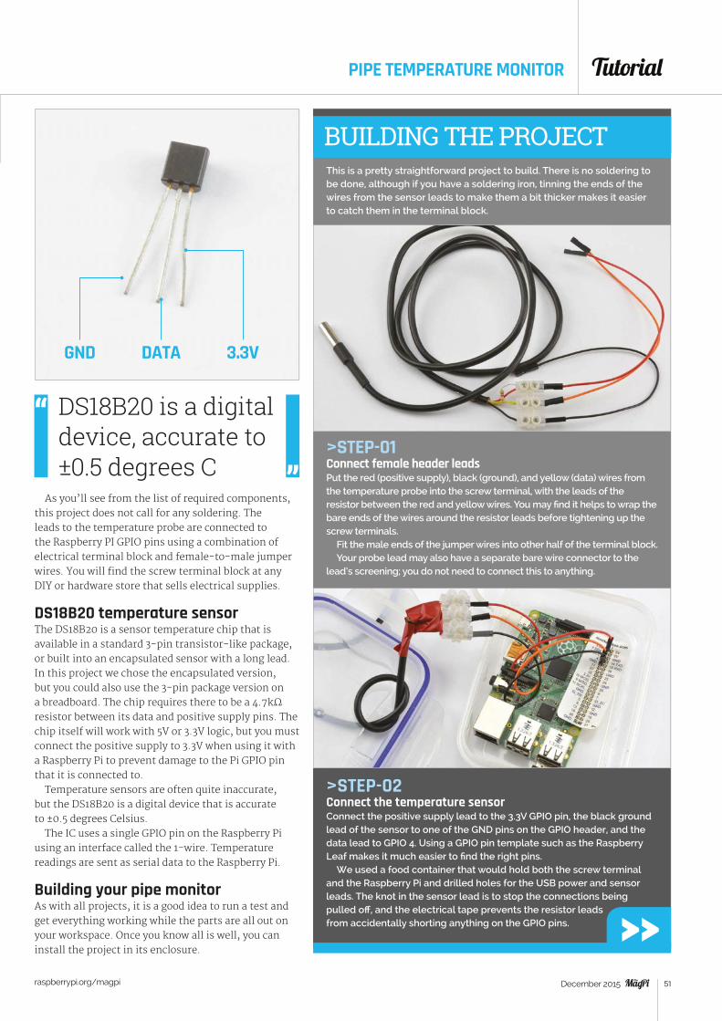
Tutorial
raspberrypi.org/magpi 51December 2015
PIPE TEMPERATURE MONITOR
This is a pretty straightforward project to build. There is no soldering to be done, although if you have a soldering iron, tinning the ends of the wires from the sensor leads to make them a bit thicker makes it easier to catch them in the terminal block.
As you’ll see from the list of required components, this project does not call for any soldering. The leads to the temperature probe are connected to the Raspberry PI GPIO pins using a combination of electrical terminal block and female-to-male jumper wires. You will find the screw terminal block at any DIY or hardware store that sells electrical supplies.
DS18B20 temperature sensorThe DS18B20 is a sensor temperature chip that is available in a standard 3-pin transistor-like package, or built into an encapsulated sensor with a long lead. In this project we chose the encapsulated version, but you could also use the 3-pin package version on a breadboard. The chip requires there to be a 4.7kΩ resistor between its data and positive supply pins. The chip itself will work with 5V or 3.3V logic, but you must connect the positive supply to 3.3V when using it with a Raspberry Pi to prevent damage to the Pi GPIO pin that it is connected to.
Temperature sensors are often quite inaccurate, but the DS18B20 is a digital device that is accurate to ±0.5 degrees Celsius.
The IC uses a single GPIO pin on the Raspberry Pi using an interface called the 1-wire. Temperature readings are sent as serial data to the Raspberry Pi.
Building your pipe monitorAs with all projects, it is a good idea to run a test and get everything working while the parts are all out on your workspace. Once you know all is well, you can install the project in its enclosure.
BUILDING THE PROJECT
>STEP-01Connect female header leadsPut the red (positive supply), black (ground), and yellow (data) wires from the temperature probe into the screw terminal, with the leads of the resistor between the red and yellow wires. You may find it helps to wrap the bare ends of the wires around the resistor leads before tightening up the screw terminals.
Fit the male ends of the jumper wires into other half of the terminal block.Your probe lead may also have a separate bare wire connector to the
lead’s screening; you do not need to connect this to anything.
>STEP-02Connect the temperature sensorConnect the positive supply lead to the 3.3V GPIO pin, the black ground lead of the sensor to one of the GND pins on the GPIO header, and the data lead to GPIO 4. Using a GPIO pin template such as the Raspberry Leaf makes it much easier to find the right pins.
We used a food container that would hold both the screw terminal and the Raspberry Pi and drilled holes for the USB power and sensor leads. The knot in the sensor lead is to stop the connections being pulled off, and the electrical tape prevents the resistor leads from accidentally shorting anything on the GPIO pins.
GND DATA 3.3V
DS18B20 is a digital device, accurate to ±0.5 degrees C
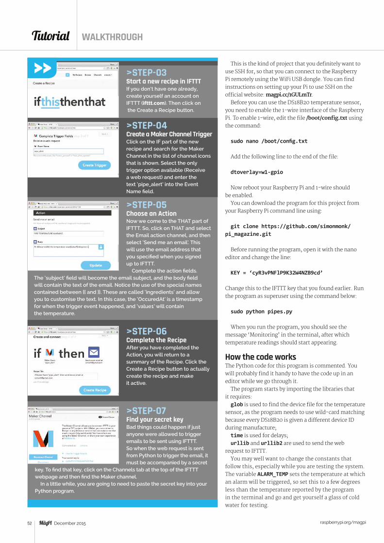
Tutorial WALKTHROUGH
raspberrypi.org/magpi 52 December 2015
>STEP-04Create a Maker Channel TriggerClick on the IF part of the new recipe and search for the Maker Channel in the list of channel icons that is shown. Select the only trigger option available (Receive a web request) and enter the text ‘pipe_alert’ into the Event Name field.
>STEP-05Choose an ActionNow we come to the THAT part of IFTTT. So, click on THAT and select the Email action channel, and then select ‘Send me an email’. This will use the email address that you specified when you signed up to IFTTT.
Complete the action fields. The ‘subject’ field will become the email subject, and the body field will contain the text of the email. Notice the use of the special names contained between {{ and }}. These are called ‘ingredients’ and allow you to customise the text. In this case, the ‘OccuredAt’ is a timestamp for when the trigger event happened, and ‘value1’ will contain the temperature.
>STEP-06Complete the RecipeAfter you have completed the Action, you will return to a summary of the Recipe. Click the Create a Recipe button to actually create the recipe and make it active.
>STEP-07Find your secret keyBad things could happen if just anyone were allowed to trigger emails to be sent using IFTTT. So when the web request is sent from Python to trigger the email, it must be accompanied by a secret
key. To find that key, click on the Channels tab at the top of the IFTTT webpage and then find the Maker channel.
In a little while, you are going to need to paste the secret key into your Python program.
This is the kind of project that you definitely want to use SSH for, so that you can connect to the Raspberry Pi remotely using the WiFi USB dongle. You can find instructions on setting up your Pi to use SSH on the official website: magpi.cc/1GULmTr.
Before you can use the DS18B20 temperature sensor, you need to enable the 1-wire interface of the Raspberry Pi. To enable 1-wire, edit the file /boot/config.txt using the command:
sudo nano /boot/config.txt
Add the following line to the end of the file:
dtoverlay=w1-gpio
Now reboot your Raspberry Pi and 1-wire should be enabled.
You can download the program for this project from your Raspberry Pi command line using:
git clone https://github.com/simonmonk/pi_magazine.git
Before running the program, open it with the nano editor and change the line:
KEY = ‘cyR3vPNFlP9K32W4NZB9cd’
Change this to the IFTTT key that you found earlier. Run the program as superuser using the command below:
sudo python pipes.py
When you run the program, you should see the message ‘Monitoring’ in the terminal, after which temperature readings should start appearing.
How the code works The Python code for this program is commented. You will probably find it handy to have the code up in an editor while we go through it.
The program starts by importing the libraries that it requires:glob is used to find the device file for the temperature
sensor, as the program needs to use wild-card matching because every DS18B20 is given a different device ID during manufacture;time is used for delays; urllib and urllib2 are used to send the web
request to IFTTT.You may well want to change the constants that
follow this, especially while you are testing the system. The variable ALARM_TEMP sets the temperature at which an alarm will be triggered, so set this to a few degrees less than the temperature reported by the program in the terminal and go and get yourself a glass of cold water for testing.
>STEP-03Start a new recipe in IFTTTIf you don’t have one already, create yourself an account on IFTTT (ifttt.com). Then click on the Create a Recipe button.
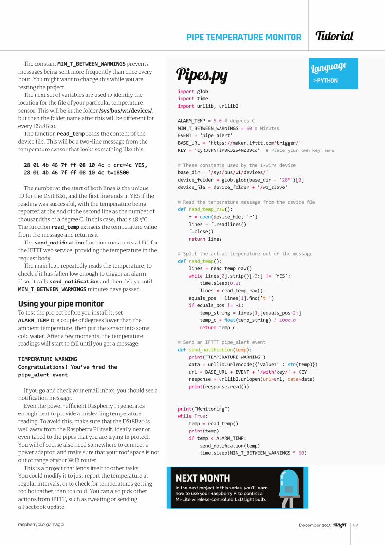
Tutorial
raspberrypi.org/magpi 53December 2015
import globimport timeimport urllib, urllib2
ALARM_TEMP = 5.0 # degrees CMIN_T_BETWEEN_WARNINGS = 60 # MinutesEVENT = 'pipe_alert'BASE_URL = 'https://maker.ifttt.com/trigger/'KEY = 'cyR3vPNFlP9K32W4NZB9cd' # Place your own key here
# These constants used by the 1-wire devicebase_dir = '/sys/bus/w1/devices/'device_folder = glob.glob(base_dir + '28*')[0]device_file = device_folder + '/w1_slave'
# Read the temperature message from the device filedef read_temp_raw(): f = open(device_file, 'r') lines = f.readlines() f.close() return lines # Split the actual temperature out of the messagedef read_temp(): lines = read_temp_raw() while lines[0].strip()[-3:] != 'YES': time.sleep(0.2) lines = read_temp_raw() equals_pos = lines[1].find('t=') if equals_pos != -1: temp_string = lines[1][equals_pos+2:] temp_c = float(temp_string) / 1000.0 return temp_c
# Send an IFTTT pipe_alert eventdef send_notification(temp): print("TEMPERATURE WARNING") data = urllib.urlencode({'value1' : str(temp)}) url = BASE_URL + EVENT + '/with/key/' + KEY response = urllib2.urlopen(url=url, data=data) print(response.read())
print("Monitoring")while True: temp = read_temp() print(temp) if temp < ALARM_TEMP: send_notification(temp) time.sleep(MIN_T_BETWEEN_WARNINGS * 60)
Pipes.py Language
>PYTHON
PIPE TEMPERATURE MONITOR
NEXT MONTH In the next project in this series, you’ll learn how to use your Raspberry Pi to control a Mi-Lite wireless-controlled LED light bulb.
The constant MIN_T_BETWEEN_WARNINGS prevents messages being sent more frequently than once every hour. You might want to change this while you are testing the project.
The next set of variables are used to identify the location for the file of your particular temperature sensor. This will be in the folder /sys/bus/w1/devices/, but then the folder name after this will be different for every DS18B20.
The function read_temp reads the content of the device file. This will be a two-line message from the temperature sensor that looks something like this:
28 01 4b 46 7f ff 08 10 4c : crc=4c YES, 28 01 4b 46 7f ff 08 10 4c t=18500
The number at the start of both lines is the unique ID for the DS18B20, and the first line ends in YES if the reading was successful, with the temperature being reported at the end of the second line as the number of thousandths of a degree C. In this case, that’s 18.5°C. The function read_temp extracts the temperature value from the message and returns it.
The send_notification function constructs a URL for the IFTTT web service, providing the temperature in the request body.
The main loop repeatedly reads the temperature, to check if it has fallen low enough to trigger an alarm. If so, it calls send_notification and then delays until MIN_T_BETWEEN_WARNINGS minutes have passed.
Using your pipe monitorTo test the project before you install it, set ALARM_TEMP to a couple of degrees lower than the ambient temperature, then put the sensor into some cold water. After a few moments, the temperature readings will start to fall until you get a message:
TEMPERATURE WARNINGCongratulations! You’ve fired the pipe_alert event
If you go and check your email inbox, you should see a notification message.
Even the power-efficient Raspberry Pi generates enough heat to provide a misleading temperature reading. To avoid this, make sure that the DS18B20 is well away from the Raspberry Pi itself, ideally near or even taped to the pipes that you are trying to protect. You will of course also need somewhere to connect a power adaptor, and make sure that your roof space is not out of range of your WiFi router.
This is a project that lends itself to other tasks. You could modify it to just report the temperature at regular intervals, or to check for temperatures getting too hot rather than too cold. You can also pick other actions from IFTTT, such as tweeting or sending a Facebook update.

Tutorial STEP BY STEP
raspberrypi.org/magpi 54 December 2015
USE THE TRAFFIC HAT WITH GPIO ZEROAs one of the boards that GPIO Zero supports, the Traffic HAT is a perfect way to show off the library...
he Traffic HAT is a great little kit: a GPIO-mounted add-on for the Raspberry Pi that makes learning how to program for physical
computing a little easier and bit more fun, along with nice big components that can also help you learn the basics of soldering.
With the release of GPIO Zero, the Traffic HAT is now easier than ever to program, whether you want to use it manually or make use of the handy Traffic HAT function built into GPIO Zero. Follow along with us as we teach you how to make the most of both the HAT and GPIO Zero.
>STEP-01Prepare the Traffic HATYou can buy the Traffic HAT pre-soldered so that you don’t have to worry about it, but it’s a great beginner kit for learning how to solder. You only need to install
T
ROB ZWETSLOOT
The board slots neatly over the Raspberry Pi – it will completely cover an A+!
Nice big lights are easy to solder on and use within the code as well
> Traffic HAT magpi.cc/ 1Mma7oD
> GPIO Zero magpi.cc/ 1MmajnP
> Soldering iron (optional)
You’ll Need
Tech writer, avid coder, and Raspberry Pi enthusiast with a history of building many things with Raspberry Pi. raspberrypi.org/magpi
the main features you’ll be using: the three LEDs, the push-button switch, and the buzzer.
Make sure to follow the outline guides on the board as to how to place them. The buzzer’s positive side is indicated on the component, and the board also has a guide showing which side it should be attached to. The LEDs should be soldered so the flat edge of the bulb meets the flat edge of the outline.
>STEP-02Install the Traffic HATMake sure your Raspberry Pi is turned off. Slot the HAT over the GPIO pins, with the board itself lying across the Raspberry Pi. This way, it shouldn’t be poking over the edge like a plank and will look like a normal addition to the Pi.
Once that’s done, you can turn on your Raspberry Pi. Once booted up into Raspbian, you’ll need to install GPIO Zero. This can be done by using the following commands in the terminal:
sudo apt-get install python-pip python-w1thermsensor python-spidev
sudo pip install gpiozero
>STEP-03 Basic GPIO ZeroThe LEDs have a GPIO number attached, as do the button and buzzer. We can use that in conjunction with GPIO Zero to activate the LEDs manually in the GPIO Zero style. Open up a new Python script in IDLE
Above We wrote the code on a computer and moved it to the Raspberry Pi, but there’s no difference from writing it on the Pi itself
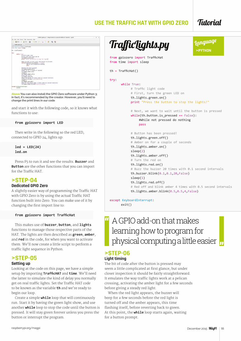
Tutorial
raspberrypi.org/magpi 55December 2015
USE THE TRAFFIC HAT WITH GPIO ZERO
and start it with the following code, so it knows what functions to use:
from gpiozero import LED
Then write in the following so the red LED, connected to GPIO 24, lights up:
led = LED(24)led.on
Press F5 to run it and see the results. Buzzer and Button are the other functions that you can import for the Traffic HAT.
>STEP-04Dedicated GPIO ZeroA slightly easier way of programming the Traffic HAT with GPIO Zero is by using the actual Traffic HAT function built into Zero. You can make use of it by changing the first import line to:
from gpiozero import TrafficHat
This makes use of buzzer, button, and lights functions to manage those respective parts of the HAT. The lights are then described as green, amber, and red in the code, for when you want to activate them. We’ll now create a little script to perform a traffic light sequence in Python.
>STEP-05Setting upLooking at the code on this page, we have a simple setup by importing TrafficHAT and time. We’ll need the latter to simulate the kind of delay you normally get on real traffic lights. Set the Traffic HAT code to be known as the variable th and we’re ready to begin our loop.
Create a simple while loop that will continuously run. Start it by having the green light show, and use another while loop to stop the code until the button is pressed. It will stay green forever unless you press the button or interrupt the program.
Above You can also install the GPIO Zero software under Python 3; in fact, it’s recommended by the creator. However, you’ll need to change the print lines in our code
>STEP-06Light timingThe bit of code after the button is pressed may seem a little complicated at first glance, but under closer inspection it should be fairly straightforward. It emulates the way traffic lights work at a pelican crossing, activating the amber light for a few seconds before giving a steady red light.
When the red light appears, the buzzer will beep for a few seconds before the red light is turned off and the amber appears, this time flashing itself, before reverting back to green. At this point, the while loop starts again, waiting for a button prompt.
from gpiozero import TrafficHatfrom time import sleep
th = TrafficHat() try: while True: # Traffic light code # First, turn the green LED on th.lights.green.on() print "Press the button to stop the lights!"
# Next, we want to wait until the button is pressed while(th.button.is_pressed == False): #While not pressed do nothing pass # Button has been pressed! th.lights.green.off() # Amber on for a couple of seconds th.lights.amber.on() sleep(2) th.lights.amber.off() # Turn the red on th.lights.red.on() # Buzz the buzzer 20 times with 0.1 second intervals th.buzzer.blink(0.1,0.1,20,False) sleep(1) th.lights.red.off() # Red off and blink amber 4 times with 0.5 second intervals th.lights.amber.blink(0.5,0.5,4,False) except KeyboardInterrupt: exit()
TrafficLights.py Language
>PYTHON
A GPIO add-on that makes learning how to program for physical computing a little easier
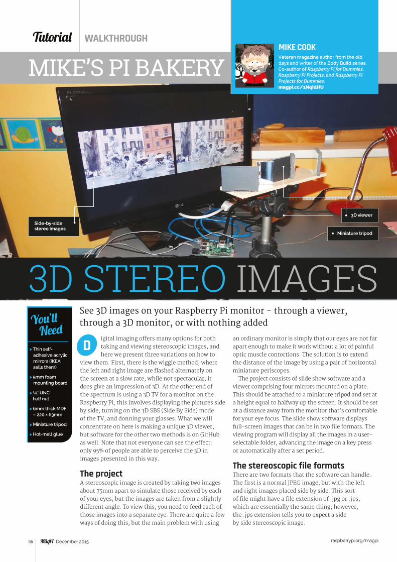
Tutorial WALKTHROUGH
raspberrypi.org/magpi 56 December 2015
See 3D images on your Raspberry Pi monitor - through a viewer, through a 3D monitor, or with nothing added
igital imaging offers many options for both taking and viewing stereoscopic images, and here we present three variations on how to
view them. First, there is the wiggle method, where the left and right image are flashed alternately on the screen at a slow rate; while not spectacular, it does give an impression of 3D. At the other end of the spectrum is using a 3D TV for a monitor on the Raspberry Pi; this involves displaying the pictures side by side, turning on the 3D SBS (Side By Side) mode of the TV, and donning your glasses. What we will concentrate on here is making a unique 3D viewer, but software for the other two methods is on GitHub as well. Note that not everyone can see the effect: only 95% of people are able to perceive the 3D in images presented in this way.
The projectA stereoscopic image is created by taking two images about 75mm apart to simulate those received by each of your eyes, but the images are taken from a slightly different angle. To view this, you need to feed each of those images into a separate eye. There are quite a few ways of doing this, but the main problem with using
D
MIKE COOKVeteran magazine author from the old days and writer of the Body Build series. Co-author of Raspberry Pi for Dummies, Raspberry Pi Projects, and Raspberry Pi Projects for Dummies. magpi.cc/1NqIdHU
MIKE’S PI BAKERY
> Thin self-adhesive acrylic mirrors (IKEA sells them)
> 5mm foam mounting board
> ¼˝ UNC half nut
> 6mm thick MDF – 220 × 63mm
> Miniature tripod
> Hot-melt glue
You’ll Need
Side-by-side stereo images
Miniature tripod
an ordinary monitor is simply that our eyes are not far apart enough to make it work without a lot of painful optic muscle contortions. The solution is to extend the distance of the image by using a pair of horizontal miniature periscopes.
The project consists of slide show software and a viewer comprising four mirrors mounted on a plate. This should be attached to a miniature tripod and set at a height equal to halfway up the screen. It should be set at a distance away from the monitor that’s comfortable for your eye focus. The slide show software displays full-screen images that can be in two file formats. The viewing program will display all the images in a user-selectable folder, advancing the image on a key press or automatically after a set period.
The stereoscopic file formats There are two formats that the software can handle. The first is a normal JPEG image, but with the left and right images placed side by side. This sort of file might have a file extension of .jpg or .jps, which are essentially the same thing; however, the .jps extension tells you to expect a side by side stereoscopic image.
3D viewer
3D STEREO IMAGES
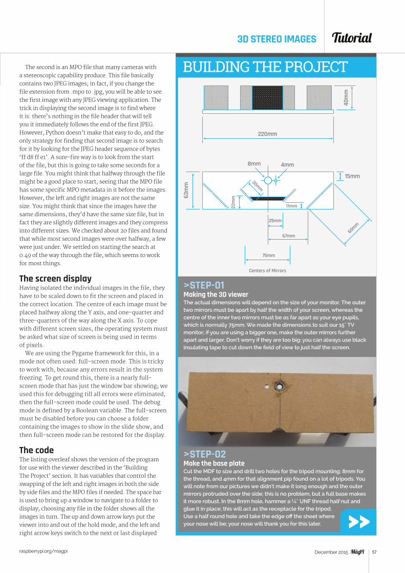
Tutorial
raspberrypi.org/magpi 57December 2015
BUILDING THE PROJECT
>STEP-01Making the 3D viewerThe actual dimensions will depend on the size of your monitor. The outer two mirrors must be apart by half the width of your screen, whereas the centre of the inner two mirrors must be as far apart as your eye pupils, which is normally 75mm. We made the dimensions to suit our 15˝ TV monitor; if you are using a bigger one, make the outer mirrors further apart and larger. Don’t worry if they are too big: you can always use black insulating tape to cut down the field of view to just half the screen.
>STEP-02Make the base plateCut the MDF to size and drill two holes for the tripod mounting: 8mm for the thread, and 4mm for that alignment pip found on a lot of tripods. You will note from our pictures we didn’t make it long enough and the outer mirrors protruded over the side; this is no problem, but a full base makes it more robust. In the 8mm hole, hammer a ¼˝ UNF thread half nut and glue it in place; this will act as the receptacle for the tripod. Use a half round hole and take the edge off the sheet where your nose will be; your nose will thank you for this later.
220mm
40m
m
63m
m15mm
22m
m
8mm 4mm
30mm
11mm
25mm
67mm
75mm
60mm
Centers of Mirrors
The second is an MPO file that many cameras with a stereoscopic capability produce. This file basically contains two JPEG images; in fact, if you change the file extension from .mpo to .jpg, you will be able to see the first image with any JPEG viewing application. The trick in displaying the second image is to find where it is: there’s nothing in the file header that will tell you it immediately follows the end of the first JPEG. However, Python doesn’t make that easy to do, and the only strategy for finding that second image is to search for it by looking for the JPEG header sequence of bytes ‘ff d8 ff e1’. A sure-fire way is to look from the start of the file, but this is going to take some seconds for a large file. You might think that halfway through the file might be a good place to start, seeing that the MPO file has some specific MPO metadata in it before the images. However, the left and right images are not the same size. You might think that since the images have the same dimensions, they’d have the same size file, but in fact they are slightly different images and they compress into different sizes. We checked about 20 files and found that while most second images were over halfway, a few were just under. We settled on starting the search at 0.49 of the way through the file, which seems to work for most things.
The screen display Having isolated the individual images in the file, they have to be scaled down to fit the screen and placed in the correct location. The centre of each image must be placed halfway along the Y axis, and one-quarter and three-quarters of the way along the X axis. To cope with different screen sizes, the operating system must be asked what size of screen is being used in terms of pixels.
We are using the Pygame framework for this, in a mode not often used: full-screen mode. This is tricky to work with, because any errors result in the system freezing. To get round this, there is a nearly full-screen mode that has just the window bar showing; we used this for debugging till all errors were eliminated, then the full-screen mode could be used. The debug mode is defined by a Boolean variable. The full-screen must be disabled before you can choose a folder containing the images to show in the slide show, and then full-screen mode can be restored for the display.
The codeThe listing overleaf shows the version of the program for use with the viewer described in the ‘Building The Project’ section. It has variables that control the swapping of the left and right images in both the side by side files and the MPO files if needed. The space bar is used to bring up a window to navigate to a folder to display; choosing any file in the folder shows all the images in turn. The up and down arrow keys put the viewer into and out of the hold mode, and the left and right arrow keys switch to the next or last displayed
3D STEREO IMAGES
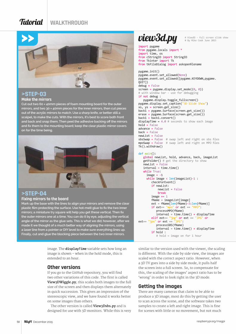
Tutorial WALKTHROUGH
raspberrypi.org/magpi 58 December 2015
view3d.py
similar to the version used with the viewer, the scaling is different. With the side by side view, the images are scaled with the correct aspect ratio. However, when a 3D TV goes into a side by side mode, it pulls half the screen into a full screen. So, to compensate for this, the scaling of the images’ aspect ratio has to be ‘wrong’ in order to look right in the 3D mode.
Getting the imagesThere are many cameras that claim to be able to produce a 3D image; most do this by getting the user to scan across the scene, and the software takes two samples to create a left and right image. This is fine for scenes with little or no movement, but not much
>STEP-03Make the mirrorsCut out two 60 × 40mm pieces of foam mounting board for the outer mirrors, and two 30 × 40mm pieces for the inner mirrors, then cut pieces out of the acrylic mirrors to match. Use a sharp knife, or better still a scalpel, to make the cuts. With the mirrors, it’s best to score both front and back and snap them. Then peel the adhesive backing off the mirrors and fix them to the mounting board; keep the clear plastic mirror covers on for the time being.
>STEP-04Fixing mirrors to the boardMark up the base with the lines to align your mirrors and remove the clear plastic film protecting the surface. Use hot-melt glue to fix the two inner mirrors; a miniature try square will help you get these vertical. Then fix the outer mirrors one at a time. You can do it by eye, adjusting the vertical angle of the mirror as the glue sets. This is what we did; however, after we made it we thought of a much better way of aligning the mirrors, using a laser line from a pointer or DIY level to make sure everything lines up. Finally, cut and glue the blocking piece between the two inner mirrors.
image. The displayTime variable sets how long an image is shown – when in the hold mode, this is extended to an hour.
Other versionsIf you go to the GitHub repository, you will find two other variations of this code. The first is called View3DWiggle.py; this scales both images to the full size of the screen and then displays them alternately in quick succession. This gives an impression of the stereoscopic view, and we have found it works better on some images than others.
The other version is called View3Dsbs.py and is designed for use with 3D monitors. While this is very
import pygamefrom pygame.locals import *import time, osfrom cStringIO import StringIOfrom Tkinter import Tkfrom tkFileDialog import askopenfilename
pygame.init()pygame.event.set_allowed(None)pygame.event.set_allowed([pygame.KEYDOWN,pygame.QUIT])debug = Falsescreen = pygame.display.set_mode((0, 0)) # with window bar - use for debuggingif not debug : pygame.display.toggle_fullscreen()pygame.display.set_caption("3D Slide Show")xs, ys = screen.get_size()back1 = pygame.Surface(screen.get_size())erase = pygame.Surface(screen.get_size())back1 = back1.convert()displayTime = 4.0 # seconds to show each imagehold = Falseadvance = Falseback = FalsenewList = FalsesbsSwap = False # swap left and right on sbs filesmpoSwap = False # swap left and right on MPO filesTk().withdraw()
def main(): global newList, hold, advance, back, imageList getFolder() # get the directory to show newList = False interval = time.time() while True: image = -1 while image < len(imageList)-1 : checkForEvent() if newList: newList = False break image += 1 fName = imageList[image] ext = fName[len(fName)-3:len(fName)] if ext== "mpo" or ext == "MPO": processMPO(fName) interval = time.time() + displayTime elif ext== "jpg" or ext == "JPG" or ext== "jps" or ext == "JPS": processSBS(fName) interval = time.time() + displayTime if hold : # hold = image on for 1 hour
# View3D - full screen slide show# By Mike Cook June 2015
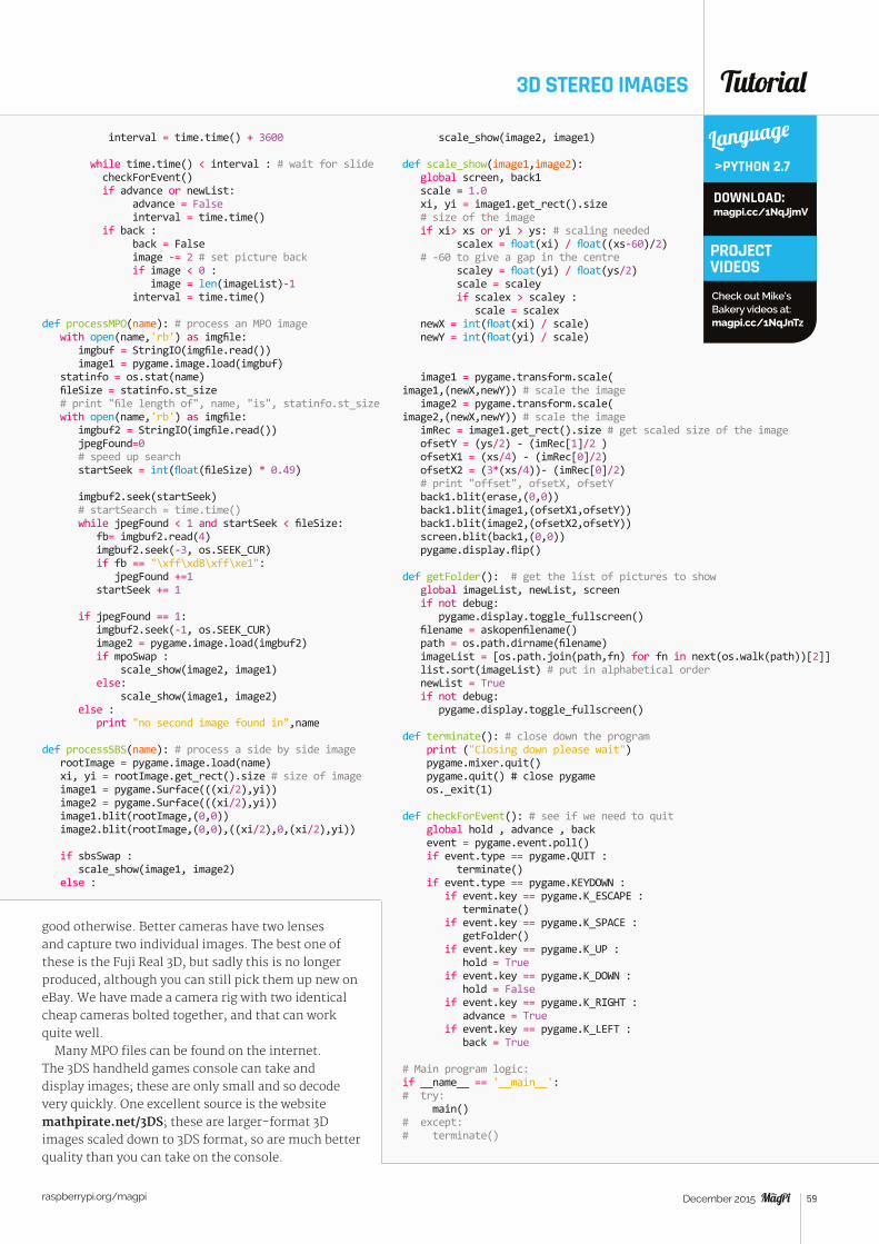
Tutorial
raspberrypi.org/magpi 59December 2015
interval = time.time() + 3600
while time.time() < interval : # wait for slide checkForEvent() if advance or newList: advance = False interval = time.time() if back : back = False image -= 2 # set picture back if image < 0 : image = len(imageList)-1 interval = time.time() def processMPO(name): # process an MPO image with open(name,'rb') as imgfile: imgbuf = StringIO(imgfile.read()) image1 = pygame.image.load(imgbuf) statinfo = os.stat(name) fileSize = statinfo.st_size # print "file length of", name, "is", statinfo.st_size with open(name,'rb') as imgfile: imgbuf2 = StringIO(imgfile.read()) jpegFound=0 # speed up search startSeek = int(float(fileSize) * 0.49) imgbuf2.seek(startSeek) # startSearch = time.time() while jpegFound < 1 and startSeek < fileSize: fb= imgbuf2.read(4) imgbuf2.seek(-3, os.SEEK_CUR) if fb == "\xff\xd8\xff\xe1": jpegFound +=1 startSeek += 1
if jpegFound == 1: imgbuf2.seek(-1, os.SEEK_CUR) image2 = pygame.image.load(imgbuf2) if mpoSwap : scale_show(image2, image1) else: scale_show(image1, image2) else : print "no second image found in",name def processSBS(name): # process a side by side image rootImage = pygame.image.load(name) xi, yi = rootImage.get_rect().size # size of image image1 = pygame.Surface(((xi/2),yi)) image2 = pygame.Surface(((xi/2),yi)) image1.blit(rootImage,(0,0)) image2.blit(rootImage,(0,0),((xi/2),0,(xi/2),yi))
if sbsSwap : scale_show(image1, image2) else :
3D STEREO IMAGES
scale_show(image2, image1)
def scale_show(image1,image2): global screen, back1 scale = 1.0 xi, yi = image1.get_rect().size # size of the image if xi> xs or yi > ys: # scaling needed scalex = float(xi) / float((xs-60)/2) # -60 to give a gap in the centre scaley = float(yi) / float(ys/2) scale = scaley if scalex > scaley : scale = scalex newX = int(float(xi) / scale) newY = int(float(yi) / scale)
image1 = pygame.transform.scale(image1,(newX,newY)) # scale the image image2 = pygame.transform.scale(image2,(newX,newY)) # scale the image imRec = image1.get_rect().size # get scaled size of the image ofsetY = (ys/2) - (imRec[1]/2 ) ofsetX1 = (xs/4) - (imRec[0]/2) ofsetX2 = (3*(xs/4))- (imRec[0]/2) # print "offset", ofsetX, ofsetY back1.blit(erase,(0,0)) back1.blit(image1,(ofsetX1,ofsetY)) back1.blit(image2,(ofsetX2,ofsetY)) screen.blit(back1,(0,0)) pygame.display.flip()
def getFolder(): # get the list of pictures to show global imageList, newList, screen if not debug: pygame.display.toggle_fullscreen() filename = askopenfilename() path = os.path.dirname(filename) imageList = [os.path.join(path,fn) for fn in next(os.walk(path))[2]] list.sort(imageList) # put in alphabetical order newList = True if not debug: pygame.display.toggle_fullscreen()
def terminate(): # close down the program print ("Closing down please wait") pygame.mixer.quit() pygame.quit() # close pygame os._exit(1) def checkForEvent(): # see if we need to quit global hold , advance , back event = pygame.event.poll() if event.type == pygame.QUIT : terminate() if event.type == pygame.KEYDOWN : if event.key == pygame.K_ESCAPE : terminate() if event.key == pygame.K_SPACE : getFolder() if event.key == pygame.K_UP : hold = True if event.key == pygame.K_DOWN : hold = False if event.key == pygame.K_RIGHT : advance = True if event.key == pygame.K_LEFT : back = True # Main program logic:if __name__ == '__main__':# try: main()# except:# terminate()
Language
>PYTHON 2.7
DOWNLOAD: magpi.cc/1NqJjmV
PROJECT VIDEOSCheck out Mike’s Bakery videos at: magpi.cc/1NqJnTz
good otherwise. Better cameras have two lenses and capture two individual images. The best one of these is the Fuji Real 3D, but sadly this is no longer produced, although you can still pick them up new on eBay. We have made a camera rig with two identical cheap cameras bolted together, and that can work quite well.
Many MPO files can be found on the internet. The 3DS handheld games console can take and display images; these are only small and so decode very quickly. One excellent source is the website mathpirate.net/3DS; these are larger-format 3D images scaled down to 3DS format, so are much better quality than you can take on the console.
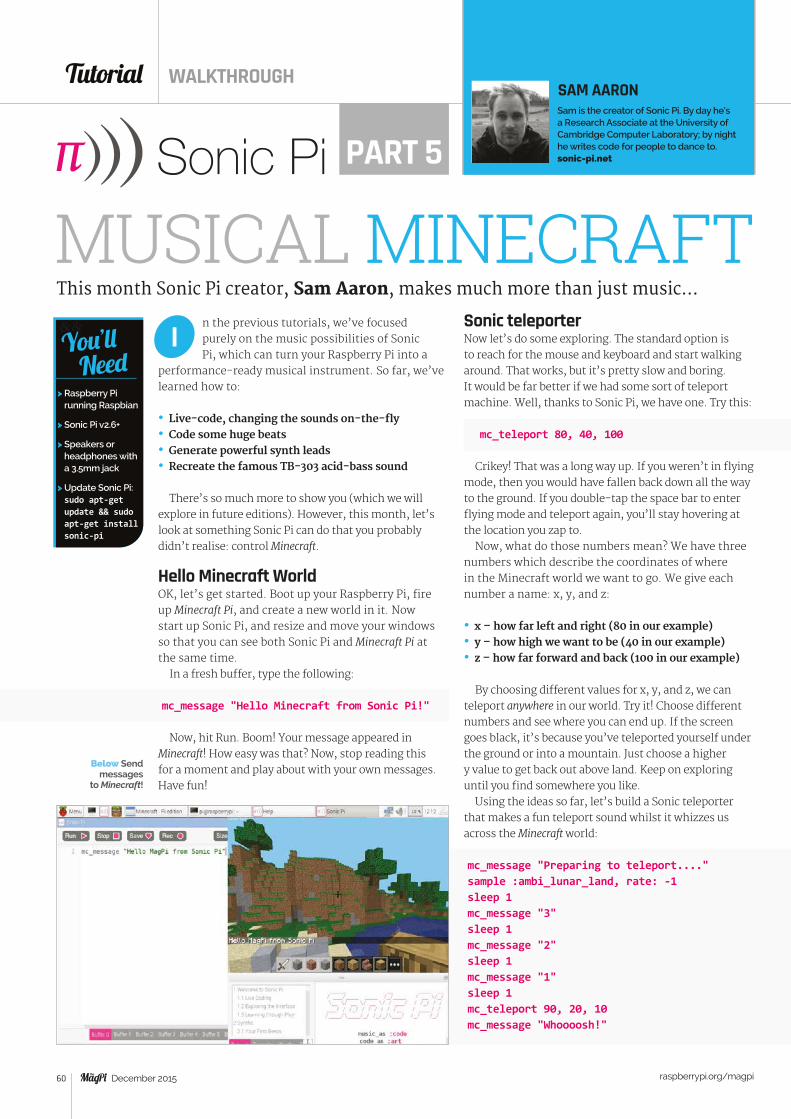
Tutorial WALKTHROUGH
raspberrypi.org/magpi 60 December 2015
n the previous tutorials, we’ve focused purely on the music possibilities of Sonic Pi, which can turn your Raspberry Pi into a
performance-ready musical instrument. So far, we’ve learned how to:
• Live-code, changing the sounds on-the-fly• Code some huge beats• Generate powerful synth leads• Recreate the famous TB-303 acid-bass sound
There’s so much more to show you (which we will explore in future editions). However, this month, let’s look at something Sonic Pi can do that you probably didn’t realise: control Minecraft.
Hello Minecraft WorldOK, let’s get started. Boot up your Raspberry Pi, fire up Minecraft Pi, and create a new world in it. Now start up Sonic Pi, and resize and move your windows so that you can see both Sonic Pi and Minecraft Pi at the same time.
In a fresh buffer, type the following:
mc_message "Hello Minecraft from Sonic Pi!"
Now, hit Run. Boom! Your message appeared in Minecraft! How easy was that? Now, stop reading this for a moment and play about with your own messages. Have fun!
Sonic teleporterNow let’s do some exploring. The standard option is to reach for the mouse and keyboard and start walking around. That works, but it’s pretty slow and boring. It would be far better if we had some sort of teleport machine. Well, thanks to Sonic Pi, we have one. Try this:
mc_teleport 80, 40, 100
Crikey! That was a long way up. If you weren’t in flying mode, then you would have fallen back down all the way to the ground. If you double-tap the space bar to enter flying mode and teleport again, you’ll stay hovering at the location you zap to.
Now, what do those numbers mean? We have three numbers which describe the coordinates of where in the Minecraft world we want to go. We give each number a name: x, y, and z:
• x – how far left and right (80 in our example)• y – how high we want to be (40 in our example)• z – how far forward and back (100 in our example)
By choosing different values for x, y, and z, we can teleport anywhere in our world. Try it! Choose different numbers and see where you can end up. If the screen goes black, it’s because you’ve teleported yourself under the ground or into a mountain. Just choose a higher y value to get back out above land. Keep on exploring until you find somewhere you like.
Using the ideas so far, let’s build a Sonic teleporter that makes a fun teleport sound whilst it whizzes us across the Minecraft world:
mc_message "Preparing to teleport...."sample :ambi_lunar_land, rate: -1sleep 1mc_message "3"sleep 1mc_message "2"sleep 1mc_message "1"sleep 1mc_teleport 90, 20, 10mc_message "Whoooosh!"
I
MUSICAL MINECRAFTThis month Sonic Pi creator, Sam Aaron, makes much more than just music…
SAM AARONSam is the creator of Sonic Pi. By day he’s a Research Associate at the University of Cambridge Computer Laboratory; by night he writes code for people to dance to. sonic-pi.netPART 5
&&
> Raspberry Pi running Raspbian
> Sonic Pi v2.6+
> Speakers or headphones with a 3.5mm jack
> Update Sonic Pi: sudo apt-get update && sudo apt-get install sonic-pi
You’ll Need
Below Send messages
to Minecraft!
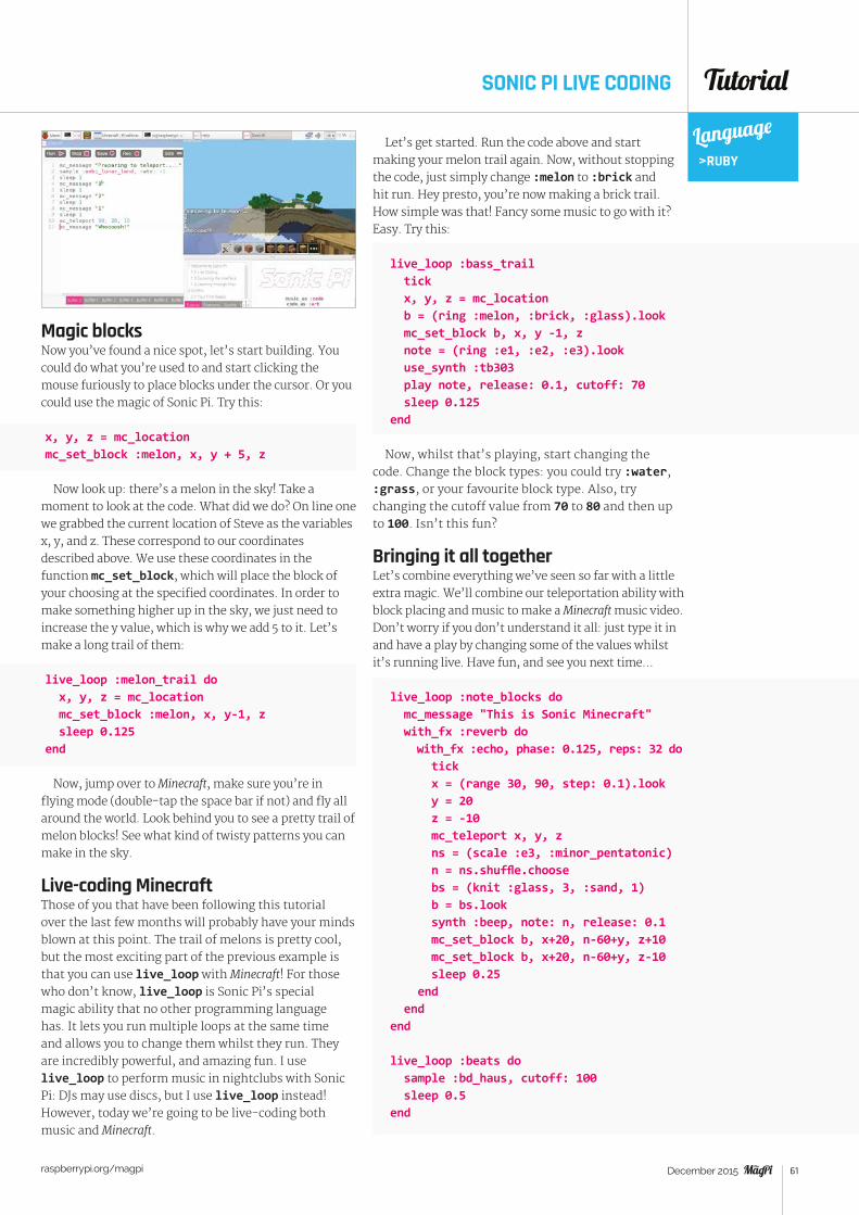
Tutorial
raspberrypi.org/magpi 61December 2015
SONIC PI LIVE CODING
Magic blocksNow you’ve found a nice spot, let’s start building. You could do what you’re used to and start clicking the mouse furiously to place blocks under the cursor. Or you could use the magic of Sonic Pi. Try this:
x, y, z = mc_locationmc_set_block :melon, x, y + 5, z
Now look up: there’s a melon in the sky! Take a moment to look at the code. What did we do? On line one we grabbed the current location of Steve as the variables x, y, and z. These correspond to our coordinates described above. We use these coordinates in the function mc_set_block, which will place the block of your choosing at the specified coordinates. In order to make something higher up in the sky, we just need to increase the y value, which is why we add 5 to it. Let’s make a long trail of them:
live_loop :melon_trail do x, y, z = mc_location mc_set_block :melon, x, y-1, z sleep 0.125end
Now, jump over to Minecraft, make sure you’re in flying mode (double-tap the space bar if not) and fly all around the world. Look behind you to see a pretty trail of melon blocks! See what kind of twisty patterns you can make in the sky.
Live-coding MinecraftThose of you that have been following this tutorial over the last few months will probably have your minds blown at this point. The trail of melons is pretty cool, but the most exciting part of the previous example is that you can use live_loop with Minecraft! For those who don’t know, live_loop is Sonic Pi’s special magic ability that no other programming language has. It lets you run multiple loops at the same time and allows you to change them whilst they run. They are incredibly powerful, and amazing fun. I use live_loop to perform music in nightclubs with Sonic Pi: DJs may use discs, but I use live_loop instead!However, today we’re going to be live-coding both music and Minecraft.
Let’s get started. Run the code above and start making your melon trail again. Now, without stopping the code, just simply change :melon to :brick and hit run. Hey presto, you’re now making a brick trail. How simple was that! Fancy some music to go with it? Easy. Try this:
live_loop :bass_trail tick x, y, z = mc_location b = (ring :melon, :brick, :glass).look mc_set_block b, x, y -1, z note = (ring :e1, :e2, :e3).look use_synth :tb303 play note, release: 0.1, cutoff: 70 sleep 0.125end
Now, whilst that’s playing, start changing the code. Change the block types: you could try :water, :grass, or your favourite block type. Also, try changing the cutoff value from 70 to 80 and then up to 100. Isn’t this fun?
Bringing it all togetherLet’s combine everything we’ve seen so far with a little extra magic. We’ll combine our teleportation ability with block placing and music to make a Minecraft music video. Don’t worry if you don’t understand it all: just type it in and have a play by changing some of the values whilst it’s running live. Have fun, and see you next time...
live_loop :note_blocks do mc_message "This is Sonic Minecraft" with_fx :reverb do with_fx :echo, phase: 0.125, reps: 32 do tick x = (range 30, 90, step: 0.1).look y = 20 z = -10 mc_teleport x, y, z ns = (scale :e3, :minor_pentatonic) n = ns.shuffle.choose bs = (knit :glass, 3, :sand, 1) b = bs.look synth :beep, note: n, release: 0.1 mc_set_block b, x+20, n-60+y, z+10 mc_set_block b, x+20, n-60+y, z-10 sleep 0.25 end endend live_loop :beats do sample :bd_haus, cutoff: 100 sleep 0.5end
Language>RUBY
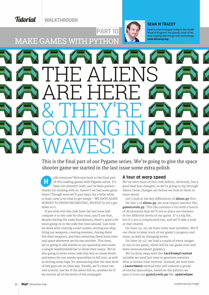
MAKE GAMES WITH PYTHON
ello everyone! Welcome back to the final part of this making games with Pygame series. It’s been ten months! Gosh, you’ve been patient -
thanks for sticking with us. Haven’t we had some great times? Though soon we’ll part ways, for a little while at least, now is no time to get weepy – WE HAVE ALIEN HORDES TO FINISH DECIMATING, PEOPLE! So let’s get down to it.
If you look over the code from the last issue and compare it to the code for this issue, you’ll see that, despite having the same foundations, there’s quite a bit more going on in the code this time around. Last time we dealt with creating a start screen, moving our ship, firing our weapons, creating enemies, having them fire their weapons, and then removing them from time and space whenever we hit one another. This time, we’re going to add shields to our spaceship and create a simple health/shield bar to show their status. We’re also going to write some code that lets us create levels and waves for our enemy spaceships to fall into, as well as writing some logic for announcing that the next level of bad guys are on their way. Finally, we’ll create two end screens: one for if the aliens kill us, another for if we survive all of the levels of the onslaught.
H
This is the final part of our Pygame series. We’re going to give the space shooter game we started in the last issue some extra polish
PART 10
A tour at warp speedWe’ve seen most of this code before, obviously, but a good deal has changed, so we’re going to zip through where those changes are before we look at them in more detail.
Let’s look at the key differences of aliens.py first...On line 7 of aliens.py, we now import another file,
gameLevels.py. This file contains a list with a bunch of dictionaries that we’ll use to place our enemies in the different levels of our game. It’s a big file, but it’s not a complicated one, and we’ll take a look at that shortly.
On lines 24-29, we have some new variables. We’ll use these to keep track of our game’s progress and state, as well as changing levels.
On lines 39-42, we load a couple of extra images to use in our game; these will be our game over and wave announcement graphics.
We’ve done away with the lastEnemyCreated variable we used last time to generate enemies after a certain time interval. Instead, we now have a launchWave method that will unleash a group of enemy spaceships, based on the pattern we pass it from our gameLevels.py file. updateGame
THE ALIENS ARE HERE & THEY’RE COMING IN WAVES!
Tutorial WALKTHROUGH
December 2015 raspberrypi.org/magpi 62
SEAN M TRACEYSean is a technologist living in the South West of England. He spends most of his time making silly things with technology. sean.mtracey.org
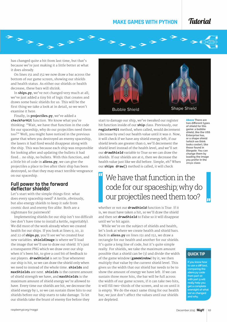
MAKE GAMES WITH PYTHON
has changed quite a bit from last time, but that’s because we’re just making it a little better at what it does already.
On lines 151 and 152 we now draw a bar across the bottom of our game screen, showing our shields and health status. As either our shields or health decrease, these bars will shrink.
In ships.py, we’ve not changed very much at all; we’ve just added a tiny bit of logic that creates and draws some basic shields for us. This will be the first thing we take a look at in detail, so we won’t examine it here.
Finally, in projectiles.py, we’ve added a checkForHit function. We know what you’re thinking: “Wait, we have that function in the code for our spaceship; why do our projectiles need them too?” Well, you might have noticed in the previous game that when you destroyed an enemy spaceship, the lasers it had fired would disappear along with the ship. This was because each ship was responsible for looking after and updating the bullets it had fired… no ship, no bullets. With this function, and a little bit of code in aliens.py, we can give the projectiles a place to live after their ship has been destroyed, so that they may enact terrible vengeance on our spaceship.
Full power to the forward deflector shields!Let’s start with the simple things first: what does every spaceship need? A kettle, obviously, but also energy shields to keep it safe from cosmic dust and enemy fire alike. Both are a nightmare for paintwork!
Implementing shields for our ship isn’t too difficult (we don’t have time to install a kettle, regrettably). We did most of the work already when we created health for our ships. If you look at lines 9, 10, 21 and 22 of ships.py, you’ll see we’ve created four new variables. shieldImage is where we’ll load the image that we’ll use to draw our shield. It’s just a transparent PNG which we draw over our ship when it’s been hit, to give a cool bit of feedback to our players. drawShield is set to True whenever our ship is hit, so we can draw the shield only when we need to instead of the whole time. shields and maxShields are next. shields is the current amount of shield strength we have, and maxShields is the maximum amount of shield energy we’re allowed to have. Every time our shields are hit, we decrease the shield energy by 1, so we can sustain three hits to our shields before our ship starts to take damage. To let our shields take the brunt of enemy fire before they
start to damage our ship, we’ve tweaked our register hit function inside of our ship class. Previously, our registerHit method, when called, would decrement (decrease by one) our health value until it was 0. Now, it will check if we have any shield energy left; if our shield levels are greater than 0, we’ll decrement the shield level instead of the health level, and we’ll set our drawShield variable to True so we can draw the shields. If our shields are at 0, then we decrease the health value just like we did before. Simple, eh? When our ships draw() method is called, it will check
whether or not our drawShield function is True. If it is, we must have taken a hit, so we’ll draw the shield and then set drawShield to False so it will disappear until we’re hit again.
While we’re on the subject of shields and health, let’s look at where we create health and shield bars. Back in aliens.py on lines 151 and 152, we draw a rectangle for our health and another for our shields. It’s quite a long line of code, but it’s quite simple really. For shields, we take the maximum amount possible that a shield can be (3) and divide the width of the game window (gameWindow) by it; we then multiply that value by the current shield level. This gives us the width that our shield bar needs to be to show the amount of energy we have left. If we can sustain three more hits, the bar will be full across the width of our game screen; if it can take two hits, it will fill two-thirds of the screen, and so on until it is empty. We do the exact same thing for our health bar; we just don’t affect the values until our shields are depleted.
Above There are two different types of shield for this game: a bubble shield, like the USS Enterprise has, or a shape shield (which we think looks cooler), like those found in Stargate. You can change them by loading the image you prefer in the ships class
We have that function in the code for our spaceship; why do our projectiles need them too?
QUICK TIP
If you know how to use a diff tool, comparing the aliens.py code from part 10 with part 9 will really help you get a complete oversight of what we’ve changed and why.
Tutorial
raspberrypi.org/magpi December 2015 63
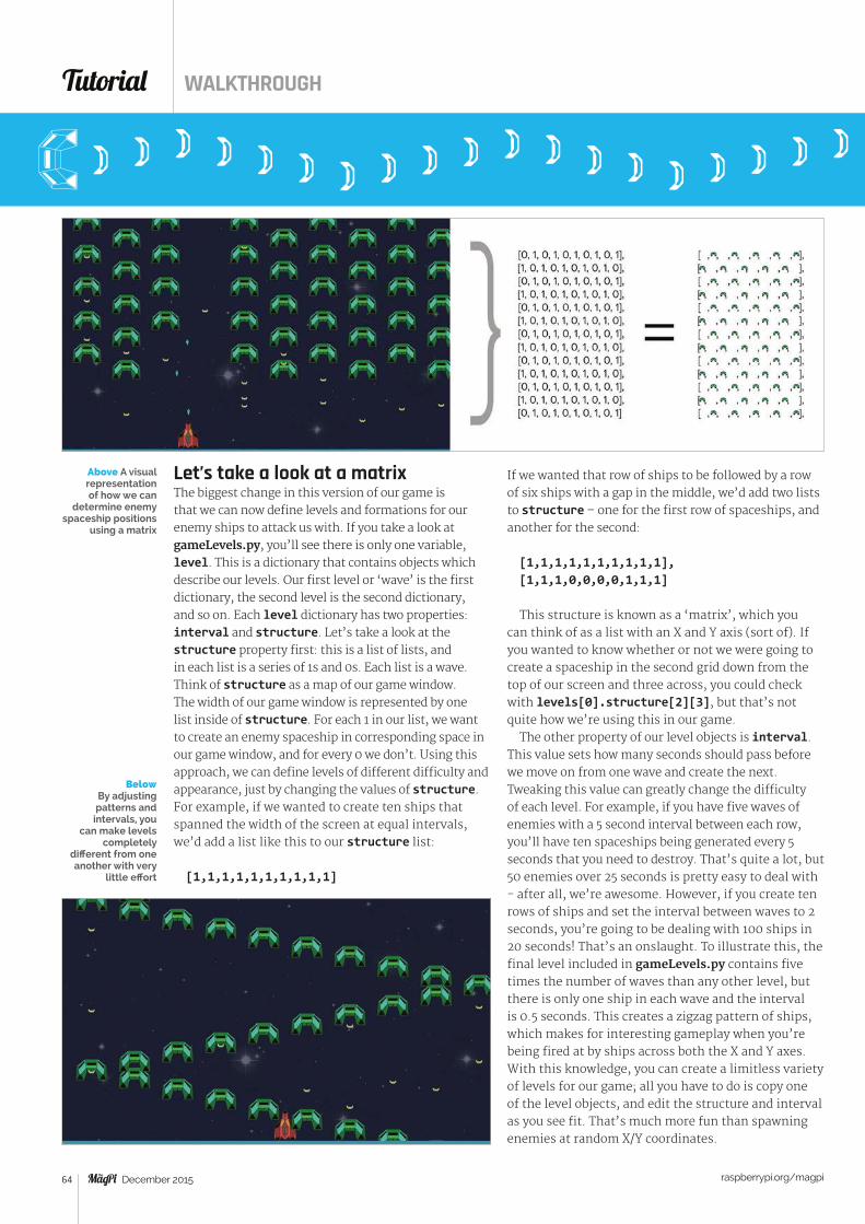
If we wanted that row of ships to be followed by a row of six ships with a gap in the middle, we’d add two lists to structure – one for the first row of spaceships, and another for the second:
[1,1,1,1,1,1,1,1,1,1],[1,1,1,0,0,0,0,1,1,1]
This structure is known as a ‘matrix’, which you can think of as a list with an X and Y axis (sort of). If you wanted to know whether or not we were going to create a spaceship in the second grid down from the top of our screen and three across, you could check with levels[0].structure[2][3], but that’s not quite how we’re using this in our game.
The other property of our level objects is interval. This value sets how many seconds should pass before we move on from one wave and create the next. Tweaking this value can greatly change the difficulty of each level. For example, if you have five waves of enemies with a 5 second interval between each row, you’ll have ten spaceships being generated every 5 seconds that you need to destroy. That’s quite a lot, but 50 enemies over 25 seconds is pretty easy to deal with - after all, we’re awesome. However, if you create ten rows of ships and set the interval between waves to 2 seconds, you’re going to be dealing with 100 ships in 20 seconds! That’s an onslaught. To illustrate this, the final level included in gameLevels.py contains five times the number of waves than any other level, but there is only one ship in each wave and the interval is 0.5 seconds. This creates a zigzag pattern of ships, which makes for interesting gameplay when you’re being fired at by ships across both the X and Y axes. With this knowledge, you can create a limitless variety of levels for our game; all you have to do is copy one of the level objects, and edit the structure and interval as you see fit. That’s much more fun than spawning enemies at random X/Y coordinates.
Let’s take a look at a matrixThe biggest change in this version of our game is that we can now define levels and formations for our enemy ships to attack us with. If you take a look at gameLevels.py, you’ll see there is only one variable, level. This is a dictionary that contains objects which describe our levels. Our first level or ‘wave’ is the first dictionary, the second level is the second dictionary, and so on. Each level dictionary has two properties: interval and structure. Let’s take a look at the structure property first: this is a list of lists, and in each list is a series of 1s and 0s. Each list is a wave. Think of structure as a map of our game window. The width of our game window is represented by one list inside of structure. For each 1 in our list, we want to create an enemy spaceship in corresponding space in our game window, and for every 0 we don’t. Using this approach, we can define levels of different difficulty and appearance, just by changing the values of structure.For example, if we wanted to create ten ships that spanned the width of the screen at equal intervals, we’d add a list like this to our structure list:
[1,1,1,1,1,1,1,1,1,1]
Below By adjusting patterns and
intervals, you can make levels
completely different from one another with very
little effort
Above A visual representation of how we can
determine enemy spaceship positions
using a matrix
Tutorial WALKTHROUGH
December 2015 raspberrypi.org/magpi 64
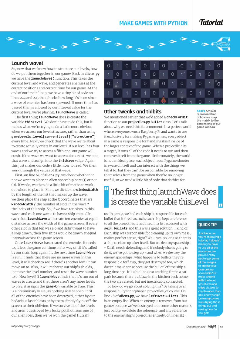
MAKE GAMES WITH PYTHON
Launch wave!So, now that we know how to structure our levels, how do we put them together in our game? Back in aliens.py we have the launchWave() function. This takes the current level and wave, and generates enemies at the correct positions and correct time for our game. At the end of our ‘main’ loop, we have a tiny bit of code on lines 222 and 223 that checks how long it’s been since a wave of enemies has been spawned. If more time has passed than is allowed by our interval value for the current level we’re playing, launchWave is called.
The first thing launchWave does is create the variable thisLevel. We don’t have to do this, but it makes what we’re trying to do a little more obvious when we access our level structure, rather than using gameLevels.level[currentLevel][“structure”] every time. Next, we check that the wave we’re about to create actually exists in our level. If our level has four waves and we try to access a fifth one, our game will crash. If the wave we want to access does exist, we take that wave and assign it to the thisWave value. Again, this just makes our code a little nicer to read. We then work through the values of that wave.
First, on line 64 of aliens.py, we check whether or not we want to place an alien spaceship here (1) or not (0). If we do, we then do a little bit of maths to work out where to place it. First, we divide the windowWidth by the length of the list that makes up the wave; we then place the ship at the X coordinates that are windowWidth / the number of slots in the wave * the index of this ship. So, if we have ten slots in this wave, and each one wants to have a ship created in each slot, launchWave will create ten enemies at equal distances across the width of the game screen. If every other slot in that ten was a 0 and didn’t want to have a ship drawn, then five ships would be drawn at equal intervals across the game screen.
Once launchWave has created the enemies it needs to, it lets the game continue on its way until it’s called by our main loop again. If, the next time launchWave is run, it finds that there are no more waves in this level, it will check to see if there’s another level it can move on to. If so, it will recharge our ship’s shields, increase the level number, and reset the wave number to 0. New level! If launchWave finds that it’s run out of waves to create and that there aren’t any more levels to play, it assigns the gameWon variable to True. This is a preliminary value, as nothing will happen until all of the enemies have been destroyed, either by our bodacious laser blasts or by them simply flying off the screen to their oblivion. If we survive all of the levels and aren’t destroyed by a lucky potshot from one of our alien foes, then we’ve won the game! Hurrah!
Other tweaks and tidbitsWe mentioned earlier that we’d added a checkForHit function to our projectiles.py Bullet class. Let’s talk about why we need this for a moment. In a perfect world where everyone owns a Raspberry Pi and wants to use it exclusively for making Pygame games, every object in a game is responsible for handling itself inside of the larger context of the game. When a projectile hits a target, it runs all of the code it needs to run and then removes itself from the game. Unfortunately, the world is not an ideal place; each object in our Pygame shooter is aware of itself and can interact with the things we tell it to, but they can’t be responsible for removing themselves from the game when they’re no longer useful, so we need a little bit of code that decides for
us. In part 9, we had each ship be responsible for each bullet that it fired; as such, each ship kept a reference to all the projectiles it had fired in a list accessed with self.bullets and this was a great solution… kind of. Each ship was responsible for cleaning up its own mess; makes perfect sense, right? Well, yes, so long as there is a ship to clean up after itself. But we destroy spaceships - Earth needs defending, and if nobody else is going to do it, we’ve got to step up - and when we destroy the enemy spaceships, what happens to bullets they’re responsible for? Yup, they get destroyed too, which doesn’t make sense because the bullet left the ship a long time ago. It’s a bit like a car catching fire in a car park because there’s a blaze in the kitchen back home: the two are related, but not inextricably connected.
So how do we go about solving this? By taking over responsibility for orphaned projectiles, of course! On line 48 of aliens.py, we have leftOverBullets. This is an empty list. When an enemy is removed from our game (because we’ve destroyed it or some other reason), just before we delete the reference, and any reference to the enemy ship’s projectiles entirely, on lines 114-
Above A visual representation of how we map the matrix to the dimensions of our game window
The first thing launchWave does is create the variable thisLevel
QUICK TIP
Just because you’re following a tutorial, it doesn’t mean you have to use all of the resources we provide. Why not tweak some of the images to create your own unique spaceship? Or mess around with the level structures and ships classes to create more than one enemy ship? Learning comes from trying these things out and seeing how far you get!
Tutorial
raspberrypi.org/magpi December 2015 65
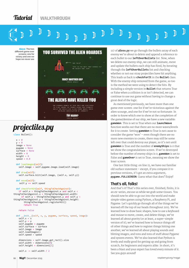
Above The two different game over
screens: one for victory and one we hope we never see
117 of aliens.py we go through the bullets array of each enemy we’re about to delete and append a reference to each bullet to our leftOverBullets list. Now, when we delete our enemy ship, we can still animate, move and update the bullets each ship has fired, by iterating through the leftOverBullets list and checking whether or not our stray projectiles have hit anything. This leads us back to checkForIt in the Bullet class. With the enemy ship removed from the game, so too is the method we were using to detect the hits. By including a simple version in Bullet that returns True or False when a collision is or isn’t detected, we can continue to use our game without having to change a great deal of the logic.
As mentioned previously, we have more than one game over screen: one for if we’re victorious against the alien scourge, and one for if we’re not so fortunate. In order to know which one to show at the completion of the game/demise of our ship, we have a new variable: gameWon. This is set to True when our launchWave function works out that there are no more waves/levels for it to create. Setting gameWon to True is not cause to consider the game ‘won’ – even though there are no more new enemies to create, there may still be some left over that could destroy our player, so it’s not until gameWon is True and the number of enemyShips is 0 that we show the congratulations screen. If we’re destroyed before the number of enemy ships is 0, gameWon is set to False and gameOver is set to True, meaning we show the loser screen.
One last little thing: on line 15, we have our familiar old surface statement – except, if you compare it to previous versions, it’s got an extra argument, pygame.FULLSCREEN. Guess what that does? Enjoy!
That’s all, folks!And that’s it! That’s this series over, finished, finito, it is an ex-series, excuse us while we grab some tissues. You should now be able to go out into the world and make simple video games using Python, a Raspberry Pi, and Pygame. Let’s quickly go through all of the things we’ve learned off the top of our heads throughout 2015. We’ve learned how to draw basic shapes; how to use a keyboard and mouse to move, create, and delete things; we’ve learned all about gravity (or at least, a super-simple version of it); we’ve learned how to bounce things off of other things and how to register things hitting one another; we’ve learned all about playing sounds and blitting images; and tons and tons of stuff about Pygame and system events. We’ve also learned that Python is lovely and really good for getting up and going from scratch, for beginners and experts alike. In short, it’s been a blast and your expert has loved every minute of it. See you guys around!
projectiles.pyclass Bullet():
x = 0 y = 0 image = None pygame = None surface = None width = 0 height = 0 speed = 0.0
def loadImages(self): self.image = self.pygame.image.load(self.image)
def draw(self): self.surface.blit(self.image, (self.x, self.y))
def move(self): self.y += self.speed
def checkForHit(self, thingToCheckAgainst): if self.x > thingToCheckAgainst.x and self.x < thingToCheckAgainst.x + thingToCheckAgainst.width: if self.y > thingToCheckAgainst.y and self.y < thingToCheckAgainst.y + thingToCheckAgainst.height: thingToCheckAgainst.registerHit() return True
return False
def __init__(self, x, y, pygame, surface, speed, image): self.x = x self.y = y self.pygame = pygame self.surface = surface self.image = image self.loadImages() self.speed = speed
dimensions = self.image.get_rect().size self.width = dimensions[0] self.height = dimensions[1]
self.x -= self.width / 2
Tutorial WALKTHROUGH
December 2015 raspberrypi.org/magpi 66
01.02.03.04.05.06.07.08.09.10.11.12.13.14.15.16.17.18.19.20.21.22.23.24.25.26.27.28.29.30.31.32.33.34.35.36.37.38.39.40.41.42.43.44.45.46.47.48.49.50.51.52.53.54.55.56.57.58.59.60.61.62.63.64.65.66.67.68.69.70.71.72.73.74.75.76.77.78.
79.80.81.82.83.84.85.86.87.88.89.90.91.92.93.94.95.96.97.98.99.100.101.102.103.104.105.106.107.108.109.110.111.112.
01.02.03.04.05.06.07.08.09.10.11.12.13.14.15.16.17.18.19.20.21.22.23.24.25.
27.28.29.30.
31.32.33.34.35.36.37.
38.39.
level = [ { "structure" :[ [0, 1, 0, 1, 0, 1, 0, 1, 0, 1], [1, 0, 1, 0, 1, 0, 1, 0, 1, 0], [0, 1, 0, 1, 0, 1, 0, 1, 0, 1], [1, 0, 1, 0, 1, 0, 1, 0, 1, 0], [0, 1, 0, 1, 0, 1, 0, 1, 0, 1], [1, 0, 1, 0, 1, 0, 1, 0, 1, 0], [0, 1, 0, 1, 0, 1, 0, 1, 0, 1], [1, 0, 1, 0, 1, 0, 1, 0, 1, 0], [0, 1, 0, 1, 0, 1, 0, 1, 0, 1], [1, 0, 1, 0, 1, 0, 1, 0, 1, 0], [0, 1, 0, 1, 0, 1, 0, 1, 0, 1], [1, 0, 1, 0, 1, 0, 1, 0, 1, 0], [0, 1, 0, 1, 0, 1, 0, 1, 0, 1] ], "interval" : 1 }, { "structure" :[ [0, 0, 0, 0, 0, 1, 1, 1, 1, 1], [1, 1, 1, 1, 1, 0, 0, 0, 0, 0], [0, 0, 0, 0, 0, 1, 1, 1, 1, 1], [1, 1, 1, 1, 1, 0, 0, 0, 0, 0], [0, 0, 0, 0, 0, 1, 1, 1, 1, 1], [1, 1, 1, 1, 1, 0, 0, 0, 0, 0], [0, 0, 0, 0, 0, 1, 1, 1, 1, 1], [1, 1, 1, 1, 1, 0, 0, 0, 0, 0], [0, 0, 0, 0, 0, 1, 1, 1, 1, 1], [1, 1, 1, 1, 1, 0, 0, 0, 0, 0], [0, 0, 0, 0, 0, 1, 1, 1, 1, 1], [1, 1, 1, 1, 1, 0, 0, 0, 0, 0] ], "interval" : .3 }, { "structure" :[ [0, 1, 0, 1, 0, 1, 0, 1, 0, 1], [1, 0, 1, 0, 1, 0, 1, 0, 1, 0], [0, 1, 0, 1, 0, 1, 0, 1, 0, 1], [1, 0, 1, 0, 1, 0, 1, 0, 1, 0], [0, 1, 0, 1, 0, 1, 0, 1, 0, 1], [1, 0, 1, 0, 1, 0, 1, 0, 1, 0], [0, 1, 0, 1, 0, 1, 0, 1, 0, 1], [1, 0, 1, 0, 1, 0, 1, 0, 1, 0], [0, 1, 0, 1, 0, 1, 0, 1, 0, 1], [1, 0, 1, 0, 1, 0, 1, 0, 1, 0], [0, 1, 0, 1, 0, 1, 0, 1, 0, 1], [1, 0, 1, 0, 1, 0, 1, 0, 1, 0], [0, 1, 0, 1, 0, 1, 0, 1, 0, 1] ], "interval" : .2 }, { "structure" :[ [1, 0, 0, 0, 0, 0, 0, 0, 0, 0], [0, 1, 0, 0, 0, 0, 0, 0, 0, 0], [0, 0, 1, 0, 0, 0, 0, 0, 0, 0], [0, 0, 0, 1, 0, 0, 0, 0, 0, 0], [0, 0, 0, 0, 1, 0, 0, 0, 0, 0], [0, 0, 0, 0, 0, 1, 0, 0, 0, 0], [0, 0, 0, 0, 0, 0, 1, 0, 0, 0], [0, 0, 0, 0, 0, 0, 0, 1, 0, 0], [0, 0, 0, 0, 0, 0, 0, 0, 1, 0], [0, 0, 0, 0, 0, 0, 0, 0, 0, 1], [0, 0, 0, 0, 0, 0, 0, 0, 1, 0], [0, 0, 0, 0, 0, 0, 0, 1, 0, 0], [0, 0, 0, 0, 0, 0, 1, 0, 0, 0], [0, 0, 0, 0, 0, 1, 0, 0, 0, 0], [0, 0, 0, 0, 1, 0, 0, 0, 0, 0], [0, 0, 0, 1, 0, 0, 0, 0, 0, 0], [0, 0, 1, 0, 0, 0, 0, 0, 0, 0], [0, 1, 0, 0, 0, 0, 0, 0, 0, 0], [1, 0, 0, 0, 0, 0, 0, 0, 0, 0], [0, 1, 0, 0, 0, 0, 0, 0, 0, 0], [0, 0, 1, 0, 0, 0, 0, 0, 0, 0], [0, 0, 0, 1, 0, 0, 0, 0, 0, 0], [0, 0, 0, 0, 1, 0, 0, 0, 0, 0], [0, 0, 0, 0, 0, 1, 0, 0, 0, 0], [0, 0, 0, 0, 0, 0, 1, 0, 0, 0], [0, 0, 0, 0, 0, 0, 0, 1, 0, 0],
[0, 0, 0, 0, 0, 0, 0, 0, 1, 0], [0, 0, 0, 0, 0, 0, 0, 0, 0, 1], [0, 0, 0, 0, 0, 0, 0, 0, 1, 0], [0, 0, 0, 0, 0, 0, 0, 1, 0, 0], [0, 0, 0, 0, 0, 0, 1, 0, 0, 0], [0, 0, 0, 0, 0, 1, 0, 0, 0, 0], [0, 0, 0, 0, 1, 0, 0, 0, 0, 0], [0, 0, 0, 1, 0, 0, 0, 0, 0, 0], [0, 0, 1, 0, 0, 0, 0, 0, 0, 0], [0, 1, 0, 0, 0, 0, 0, 0, 0, 0], [1, 0, 0, 0, 0, 0, 0, 0, 0, 0], [0, 1, 0, 0, 0, 0, 0, 0, 0, 0], [0, 0, 1, 0, 0, 0, 0, 0, 0, 0], [0, 0, 0, 1, 0, 0, 0, 0, 0, 0], [0, 0, 0, 0, 1, 0, 0, 0, 0, 0], [0, 0, 0, 0, 0, 1, 0, 0, 0, 0], [0, 0, 0, 0, 0, 0, 1, 0, 0, 0], [0, 0, 0, 0, 0, 0, 0, 1, 0, 0], [0, 0, 0, 0, 0, 0, 0, 0, 1, 0], [0, 0, 0, 0, 0, 0, 0, 0, 0, 1], [0, 0, 0, 0, 0, 0, 0, 0, 1, 0], [0, 0, 0, 0, 0, 0, 0, 1, 0, 0], [0, 0, 0, 0, 0, 0, 1, 0, 0, 0], [0, 0, 0, 0, 0, 1, 0, 0, 0, 0], [0, 0, 0, 0, 1, 0, 0, 0, 0, 0], [0, 0, 0, 1, 0, 0, 0, 0, 0, 0], [0, 0, 1, 0, 0, 0, 0, 0, 0, 0], [0, 1, 0, 0, 0, 0, 0, 0, 0, 0], [1, 0, 0, 0, 0, 0, 0, 0, 0, 0] ], "interval" : 0.5 }]
ships.pyimport projectiles, random
class Player():
x = 0 y = 0 firing = False image = None shieldImage = None drawShield = False soundEffect = 'sounds/player_laser.wav' pygame = None surface = None width = 0 height = 0 bullets = [] bulletImage = "assets/you_pellet.png" bulletSpeed = -10 health = 5 maxHealth = health shields = 3 maxShields = shields
def loadImages(self): self.image = self.pygame.image.load("assets/you_ship.png") self.shieldImage = self.pygame.image.load ("assets/shield2.png")
def draw(self): self.surface.blit(self.image, (self.x, self.y)) if self.drawShield == True: self.surface.blit(self.shieldImage, (self.x - 3, self.y - 2)) self.drawShield = False
def setPosition(self, pos): self.x = pos[0] - self.width / 2
def fire(self): self.bullets.append(projectiles.Bullet(self.x + self.width / 2, self.y, self.pygame, self.surface, self.bulletSpeed, self.bulletImage)) a = self.pygame.mixer.Sound(self.soundEffect) a.set_volume(0.2)
levels.py
MAKE GAMES WITH PYTHON Tutorial
raspberrypi.org/magpi December 2015 67
41.42.43.44.45.46.47.48.49.50.51.52.53.54.55.56.57.58.59.
60.
61.62.63.64.65.66.67.68.69.70.71.72.73.74.75.76.77.78.79.80.81.82.83.84.85.86.87.88.89.90.91.92.93.94.95.96.97.98.99.100.101.102.103.104.105.106.107.108.109.110.111.112.113.114.115.116.117.118.119.120.121.122.
01.02.03.04.05.06.07.08.09.10.11.12.13.14.15.
16.17.18.19.20.21.22.23.24.25.26.27.28.29.30.31.32.33.34.35.36.37.38.39.40.41.42.43.44.45.46.47.48.49.50.51.52.53.54.55.
56.57.58.59.60.61.62.63.64.65.
66.67.68.69.70.71.72.73.74.75.
a.play()
def drawBullets(self): for b in self.bullets: b.move() b.draw()
def registerHit(self): if self.shields == 0: self.health -= 1 else : self.shields -= 1 self.drawShield = True
def checkForHit(self, thingToCheckAgainst): bulletsToRemove = []
for idx, b in enumerate(self.bullets): if b.x > thingToCheckAgainst.x and b.x < thingToCheckAgainst.x + thingToCheckAgainst.width: if b.y > thingToCheckAgainst.y and b.y < thingToCheckAgainst.y + thingToCheckAgainst.height: thingToCheckAgainst.registerHit() bulletsToRemove.append(idx) bC = 0 for usedBullet in bulletsToRemove: del self.bullets[usedBullet - bC] bC += 1
if thingToCheckAgainst.health <= 0: return True
def __init__(self, x, y, pygame, surface): self.x = x self.y = y self.pygame = pygame self.surface = surface self.loadImages()
dimensions = self.image.get_rect().size self.width = dimensions[0] self.height = dimensions[1]
self.x -= self.width / 2 self.y -= self.height + 10
class Enemy(Player):
x = 0 y = 0 firing = False image = None soundEffect = 'sounds/enemy_laser.wav' bulletImage = "assets/them_pellet.png" bulletSpeed = 10 speed = 2 shields = 0
def move(self): self.y += self.speed
def tryToFire(self): shouldFire = random.random()
if shouldFire <= 0.01: self.fire()
def loadImages(self): self.image = self.pygame.image.load("assets/them_ship.png")
def __init__(self, x, y, pygame, surface, health): self.x = x self.y = y self.pygame = pygame self.surface = surface self.loadImages() self.bullets = [] self.health = health
dimensions = self.image.get_rect().size self.width = dimensions[0] self.height = dimensions[1]
self.x += self.width / 2
aliens.pyimport pygame, sys, random, mathimport pygame.locals as GAME_GLOBALSimport pygame.event as GAME_EVENTSimport pygame.time as GAME_TIMEimport ships
import gameLevels
windowWidth = 1024windowHeight = 614timeTick = 0
pygame.init()pygame.font.init()surface = pygame.display.set_mode((windowWidth, windowHeight), pygame.FULLSCREEN)
pygame.display.set_caption('Alien\'s Are Gonna Kill Me!')textFont = pygame.font.SysFont("monospace", 50)
gameStarted = FalsegameStartedTime = 0gameFinishedTime = 0gameOver = FalsegameWon = False
currentLevel = 0currentWave = 0lastSpawn = 0nextLevelTS = 0
# Mouse variablesmousePosition = (0,0)mouseStates = NonemouseDown = False
# Image variablesstartScreen = pygame.image.load("assets/start_screen.png")background = pygame.image.load("assets/background.png")loseScreen = pygame.image.load("assets/lose_screen.png")winScreen = pygame.image.load("assets/win_screen.png")nextWave = pygame.image.load("assets/next_level.png")finalWave = pygame.image.load("assets/final_level.png")
# Shipsship = ships.Player(windowWidth / 2, windowHeight, pygame, surface)enemyShips = []
leftOverBullets = []
# Sound setuppygame.mixer.init()
def launchWave():
global lastSpawn, currentWave, currentLevel, gameOver, gameWon, nextLevelTS
thisLevel = gameLevels.level[currentLevel]["structure"]
if currentWave < len(thisLevel):
thisWave = thisLevel[currentWave]
for idx, enemyAtThisPosition in enumerate(thisWave): if enemyAtThisPosition is 1: enemyShips.append(ships.Enemy(((windowWidth / len(thisWave)) * idx), -60, pygame, surface, 1))
elif currentLevel + 1 < len(gameLevels.level) : currentLevel += 1 currentWave = 0 ship.shields = ship.maxShields nextLevelTS = timeTick + 5000 else: gameWon = True
lastSpawn = timeTick
Tutorial WALKTHROUGH
December 2015 raspberrypi.org/magpi 68
76.77.78.79.80.81.82.83.84.85.86.87.88.89.90.91.92.93.94.95.96.97.98.99.100.101.102.103.104.105.106.107.108.109.110.111.112.113.114.115.116.117.118.119.120.121.122.123.124.125.126.127.128.129.130.131.132.133.134.135.136.137.138.139.140.141.142.143.144.145.146.147.148.149.150.151.
152.
153.154.
155.156.157.158.159.160.161.
162.163.164.165.166.167.168.169.170.171.172.173.174.175.176.177.178.179.180.181.182.183.184.185.186.187.188.189.190.191.192.193.194.195.196.
197.198.199.200.201.202.203.204.205.206.207.208.209.210.211.212.213.214.215.216.217.218.219.
220.221.222.
223.224.225.226.227.228.
if gameWon is True: surface.blit(finalWave, (250, 150)) else: surface.blit(nextWave, (250, 150))
def restartGame(): global gameOver, gameStart, currentLevel, currentWave, lastSpawn, nextLevelTS, leftOverBullets, gameWon, enemyShips, ship
gameOver = False gameWon = False currentLevel = 0 currentWave = 0 lastSpawn = 0 nextLevelTS = 0 leftOverBullets = [] enemyShips = [] ship.health = ship.maxHealth ship.shields = ship.maxShields ship.bullets = []
def quitGame(): pygame.quit() sys.exit()
# 'main' loopwhile True: timeTick = GAME_TIME.get_ticks() mousePosition = pygame.mouse.get_pos() mouseStates = pygame.mouse.get_pressed()
if gameStarted is True and gameOver is False:
updateGame() drawGame()
elif gameStarted is False and gameOver is False: surface.blit(startScreen, (0, 0))
if mouseStates[0] is 1:
if mousePosition[0] > 445 and mousePosition[0] < 580 and mousePosition[1] > 450 and mousePosition[1] < 510:
gameStarted = True
elif mouseStates[0] is 0 and mouseDown is True: mouseDown = False
elif gameStarted is True and gameOver is True and gameWon is False: surface.blit(loseScreen, (0, 0)) timeLasted = (gameFinishedTime - gameStartedTime) / 1000 if gameStarted is True and gameWon is True and len(enemyShips) is 0: surface.blit(winScreen, (0, 0))
# Handle user and system events for event in GAME_EVENTS.get():
if event.type == pygame.KEYDOWN:
if event.key == pygame.K_ESCAPE: quitGame()
if event.key == pygame.K_SPACE: if gameStarted is True and gameOver is True or gameStarted is True and gameWon is True: restartGame()
if timeTick - lastSpawn > gameLevels.level[currentLevel]["interval"] * 1000 and gameStarted is True and gameOver is False: launchWave()
if event.type == GAME_GLOBALS.QUIT: quitGame()
pygame.display.update()
currentWave += 1
def updateGame():
global mouseDown, gameOver, gameWon, leftOverBullets
if mouseStates[0] is 1 and mouseDown is False: ship.fire() mouseDown = True elif mouseStates[0] is 0 and mouseDown is True: mouseDown = False
ship.setPosition(mousePosition)
enemiesToRemove = []
for idx, enemy in enumerate(enemyShips):
if enemy.y < windowHeight: enemy.move() enemy.tryToFire() shipIsDestroyed = enemy.checkForHit(ship) enemyIsDestroyed = ship.checkForHit(enemy)
if enemyIsDestroyed is True: enemiesToRemove.append(idx)
if shipIsDestroyed is True: gameOver = True gameWon = False return
else: enemiesToRemove.append(idx)
oC = 0
for idx in enemiesToRemove: for remainingBullets in enemyShips[idx - oC].bullets: leftOverBullets.append(remainingBullets)
del enemyShips[idx - oC] oC += 1
oC = 0
for idx, aBullet in enumerate(leftOverBullets): aBullet.move() hitShip = aBullet.checkForHit(ship)
if hitShip is True or aBullet.y > windowHeight: del leftOverBullets[idx - oC] oC += 1
def drawGame():
global leftOverBullets, nextLevelTS, timeTick, gameWon
surface.blit(background, (0, 0)) ship.draw() ship.drawBullets()
for aBullet in leftOverBullets: aBullet.draw()
healthColor = [(62, 180, 76), (180, 62, 62)] whichColor = 0
if(ship.health <= 1): whichColor = 1
for enemy in enemyShips: enemy.draw() enemy.drawBullets()
pygame.draw.rect(surface, healthColor[whichColor], (0, windowHeight - 5, ( windowWidth / ship.maxHealth) * ship.health, 5)) pygame.draw.rect(surface, (62, 145, 180), (0, windowHeight - 10, (windowWidth / ship.maxShields) * ship.shields, 5))
if timeTick < nextLevelTS:
Language
>PYTHON
MAKE GAMES WITH PYTHON
DOWNLOAD: magpi.cc/ 1N1SJec
Tutorial
raspberrypi.org/magpi December 2015 69

Feature
raspberrypi.org/magpi 70 December 2015
n 15 December, British ESA astronaut Tim Peake is set to make history as the first British astronaut to visit the International Space
Station. For the next six months, he will achieve most children’s dreams as he lives and works 400 kilometres above the Earth to carry out a comprehensive science programme during a mission called Principia.
His role will be to run experiments using the unique environment of space and to try new technologies that may become crucial when humans begin to visit other planets such as Mars. But he will not be alone. Aside from living with five international colleagues, all of whom have spent years training for their difficult roles, Tim will be greeted by another Brit – one set to accompany him throughout his time away from Earth.
That extra ‘colleague’ will, of course, be the British‑made Raspberry Pi which, by the time Tim sets off on a Soyuz spacecraft from Russia’s Baikonur cosmodrome in Kazakhstan, will already be waiting on board the ISS. Two Raspberry Pis will be flown
British ESA astronaut Tim Peake won’t be the only Brit aboard the International Space Station next year. David Crookes looks at how the Pi got into the sky and what it means for future generations
skywards on a Cygnus cargo freighter on 3 December, going ahead of Tim thanks to a lack of room on the Soyuz flight. But it means the computers will be ready to be unboxed by the time Tim arrives. And then the fun and games can begin.
The Raspberry Pi’s space adventure is referred to as the Astro Pi mission and, while it hasn’t been an easy ride for those involved, it is certainly set to be rewarding. That’s because the computers have been equipped with an expansion sensor board called the Sense HAT, and have been placed inside a cutting‑edge aerospace case that has been built to withstand any conditions space will throw at it. As well as allowing the Raspberry Pi to measure the ISS’s environment, follow its journey through space, and pick up the Earth’s magnetic field, it will give schoolchildren the chance to have their code run in space for the first time ever. And that, says Tim, is proving to be most exciting of all.
“[Astro Pi] has got a great sensor suite with temperature, pressure, humidity sensors, all sorts of
O
ASTRO PI
HIGH FLIERS
Feature
LEARN MORE ONLINE: astro-pi.org
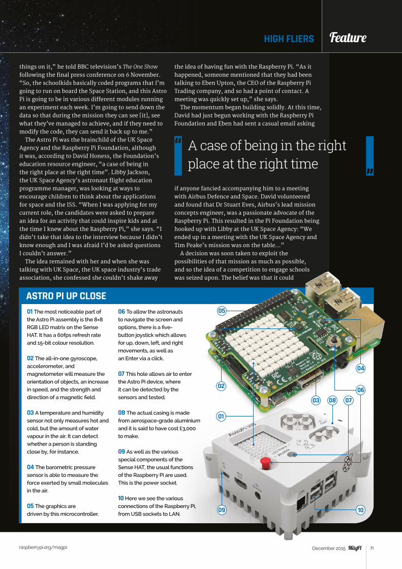
Feature
raspberrypi.org/magpi 71December 2015
things on it,” he told BBC television’s The One Show following the final press conference on 6 November. “So, the schoolkids basically coded programs that I’m going to run on board the Space Station, and this Astro Pi is going to be in various different modules running an experiment each week. I’m going to send down the data so that during the mission they can see [it], see what they’ve managed to achieve, and if they need to modify the code, they can send it back up to me.”
The Astro Pi was the brainchild of the UK Space Agency and the Raspberry Pi Foundation, although it was, according to David Honess, the Foundation’s education resource engineer, “a case of being in the right place at the right time”. Libby Jackson, the UK Space Agency’s astronaut flight education programme manager, was looking at ways to encourage children to think about the applications for space and the ISS. “When I was applying for my current role, the candidates were asked to prepare an idea for an activity that could inspire kids and at the time I knew about the Raspberry Pi,” she says. “I didn’t take that idea to the interview because I didn’t know enough and I was afraid I’d be asked questions I couldn’t answer.”
The idea remained with her and when she was talking with UK Space, the UK space industry’s trade association, she confessed she couldn’t shake away
HIGH FLIERS Feature
the idea of having fun with the Raspberry Pi. “As it happened, someone mentioned that they had been talking to Eben Upton, the CEO of the Raspberry Pi Trading company, and so had a point of contact. A meeting was quickly set up,” she says.
The momentum began building solidly. At this time, David had just begun working with the Raspberry Pi Foundation and Eben had sent a casual email asking
if anyone fancied accompanying him to a meeting with Airbus Defence and Space. David volunteered and found that Dr Stuart Eves, Airbus’s lead mission concepts engineer, was a passionate advocate of the Raspberry Pi. This resulted in the Pi Foundation being hooked up with Libby at the UK Space Agency: “We ended up in a meeting with the UK Space Agency and Tim Peake’s mission was on the table…”
A decision was soon taken to exploit the possibilities of that mission as much as possible, and so the idea of a competition to engage schools was seized upon. The belief was that it could
A case of being in the right place at the right time
01 The most noticeable part of the Astro Pi assembly is the 8×8 RGB LED matrix on the Sense HAT. It has a 60fps refresh rate and 15-bit colour resolution.
02 The all-in-one gyroscope, accelerometer, and magnetometer will measure the orientation of objects, an increase in speed, and the strength and direction of a magnetic field.
03 A temperature and humidity sensor not only measures hot and cold, but the amount of water vapour in the air. It can detect whether a person is standing close by, for instance.
04 The barometric pressure sensor is able to measure the force exerted by small molecules in the air.
05 The graphics are driven by this microcontroller.
06 To allow the astronauts to navigate the screen and options, there is a five-button joystick which allows for up, down, left, and right movements, as well as an Enter via a click.
07 This hole allows air to enter the Astro Pi device, where it can be detected by the sensors and tested.
08 The actual casing is made from aerospace-grade aluminium and it is said to have cost £3,000 to make.
09 As well as the various special components of the Sense HAT, the usual functions of the Raspberry Pi are used. This is the power socket.
10 Here we see the various connections of the Raspberry Pi, from USB sockets to LAN.
ASTRO PI UP CLOSE
03
01
04
02
05
0608 07
1009

Feature
raspberrypi.org/magpi 72 December 2015
encourage schoolchildren to become more interested in space and open their eyes to its employment possibilities. “The bottom line is that the UK space industry wants to ensure that there are enough people in the future to hire to carry on doing what they are
doing,” explains David. “And we feel this is part of the answer.”
Once the go‑ahead had been given, it was time to work out how the project would run. For Libby, the aim was to attach as much as possible to the Pi – “I knew the history of getting education payloads on the ISS,” she explains, hinting at the difficulties – but the problem was the tight schedule they had to work with. The Astro Pi mission was being put
together around a year before the expected flight, so there was never going to be enough time to invite children to come up with an experiment and make it fly. “We turned things on their head and said if we fly the hardware as it exists and ask the kids what we should do with it, that would help in terms of time,” Libby continues. “It seemed the perfect solution.”
Pi in the skyIt is not the first time a bare-bones computer has gone into space (and it’s not incidentally the Pi’s debut either, given Dave Akerman’s efforts in strapping Pis to high‑altitude balloons and taking snapshots from the edge of space). But while Arduinos were the first to boldly go where no other widely accessible device had gone before (on to satellites orbiting the Earth), Astro Pi was created to be different.
“Never before have we had a situation where the crew of the space station are using the same machine as your kids,” says David. “But this is that time: we created the Sense HAT add‑on board for the Pi and
we challenged schools to come up with computer science‑based experiments that Tim would run on the space station.”
The response from schoolchildren amazed everyone, not only in the quantity of entries but in their quality. There were stories of children coding during their lunch breaks and working after school. The chance of having their code in space was proving to be a great motivator, and narrowing the experiments down to
Feature ASTRO PI
LIFE ON THE ISSThe Astro Pi is going to live on board the
International Space Station until 2022,
when it is envisaged the battery operating
its real-time clock will finally run out of
power. During those seven years, the
Pi will be made available for use by
numerous crews, starting with Tim Peake,
whose mission is set to cross between
Expedition 46 and 47 (the current crew
are part of Expedition 44). But just what
is life like on board the ISS, and how
much time will Tim get to spend with
the computer?
WAKE-UPLike everyone else on board, Tim
will adhere to the GMT time zone.
He will wake each morning in a
small soundproofed cabin, have his
breakfast, and get down to work. “They
commute by floating in, and they
start with a meeting with the ground
controller to catch up on the day,” says
Libby Jackson, the UK Space Agency’s
astronaut flight education programme
manager. “Then they will carry on and
do their science experiments.”
WORKING DAYTim’s days will closely
follow our own working
lives. He is set to
spend his time with
five other astronauts
in an environment that
is equivalent to a five-
bedroom house, and
he will typically work a
Monday to Friday week,
starting at 8am and
finishing at 6pm.
The bottom line is that the UK space industry wants to ensure that there are enough people in the future to hire to carry on doing what they are doing
Above Tim Peake (far
right) attends the final press
conference before launch

Feature
raspberrypi.org/magpi 73December 2015
just seven winners proved tricky. “It came down to the completeness of the ideas and the quality of the coding,” reveals Libby. “The things the kids came up with are far more creative than adults.”
Indeed, the winners are certainly impressive. The Cranmere Code Club run by teacher (and The MagPi writer) Richard Hayler at the Cranmere Primary School tests the humidity surrounding Astro Pi. If fluctuation is detected, it is a possible indicator that an astronaut has come close, so the Pi will deliver a message on its 8×8 LED screen and take a photo via the camera, hoping to snap one of the ISS crew in action. “They are looking to see if humidity is a good indictor of the presence of the crew near the Astro Pi,” David explains.
SpaceCRAFT is equally ingenious, with Hannah Belshaw from the Cumnor House Girls School suggesting using the output as a CSV file from the Astro
Pi sensors within Minecraft so that the environmental measurements are represented in the game. “SpaceCRAFT logs all sensors to fill a massive CSV file and it works with code on the ground that plays it back in Minecraft,” says David. Hannah dressed in a spacesuit to appear alongside Tim during his BBC interview.
One particular favourite among those involved with Astro Pi is Flags, created by Thirsk School under the watch of teacher Dan Aldred. The program uses telemetry data and the Astro Pi’s real‑time clock to work out the ISS’s location. It searches its database to find the relevant flag and displays it on the screen with a phrase in the local language.
“It’s lovely because the children have looked and thought about where the astronauts are in the world,” says Libby. David agrees. “The crew will like it,” he
HIGH FLIERS Feature
KEEPING FITEach day is carefully
scheduled so that the
astronauts’ time on board
is fully utilised, and that
includes hours set aside for
maintenance. But they must
also have time for exercise.
Without regular fitness
sessions, they can suffer bone
and muscle loss. “They have
two hours of exercise each
day,” reveals Libby.
CHIT CHATIt is also important that the
astronauts get some time to
socialise. It can, after all, be
lonely in space. “They try to get
an hour lunch break together,
just like we would on Earth,” says
Libby, explaining that meal times
balance vitamins and minerals.
“Some days they manage it,
other days they work through
or they stagger it, but [eating
together] is the aim.”
GOODNIGHTAt the end of the day,
they seek to wrap things
up. “They have a meeting
with the crew and say
goodnight,” says Libby.
“They can enjoy free
time and during the
evening and weekends,
the mission controllers
try not to disturb the
crew unless they really
have to.”
TIME FOR PIBut what do they get up to?
“Some will watch movies,
others will look out of the
window or call friends and
family,” says Libby. “On
Saturday morning they will
clean the space station, but
Tim will hope to spend the
afternoon doing education,
working with the Astro
Pi. Sunday will be his day
off, though.”
Above Tim during training in the Soyuz TMA simulator
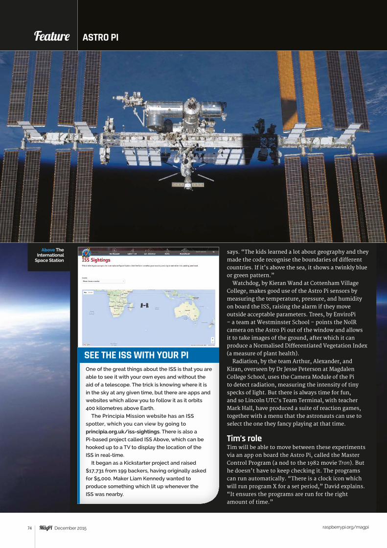
Feature
raspberrypi.org/magpi 74 December 2015
says. “The kids learned a lot about geography and they made the code recognise the boundaries of different countries. If it’s above the sea, it shows a twinkly blue or green pattern.”
Watchdog, by Kieran Wand at Cottenham Village College, makes good use of the Astro Pi sensors by measuring the temperature, pressure, and humidity on board the ISS, raising the alarm if they move outside acceptable parameters. Trees, by EnviroPi – a team at Westminster School – points the NoIR camera on the Astro Pi out of the window and allows it to take images of the ground, after which it can produce a Normalised Differentiated Vegetation Index (a measure of plant health).
Radiation, by the team Arthur, Alexander, and Kiran, overseen by Dr Jesse Peterson at Magdalen College School, uses the Camera Module of the Pi to detect radiation, measuring the intensity of tiny specks of light. But there is always time for fun, and so Lincoln UTC’s Team Terminal, with teacher Mark Hall, have produced a suite of reaction games, together with a menu that the astronauts can use to select the one they fancy playing at that time.
Tim’s roleTim will be able to move between these experiments via an app on board the Astro Pi, called the Master Control Program (a nod to the 1982 movie Tron). But he doesn’t have to keep checking it. The programs can run automatically. “There is a clock icon which will run program X for a set period,” David explains. “It ensures the programs are run for the right amount of time.”
Feature ASTRO PI
SEE THE ISS WITH YOUR PIOne of the great things about the ISS is that you are
able to see it with your own eyes and without the
aid of a telescope. The trick is knowing where it is
in the sky at any given time, but there are apps and
websites which allow you to follow it as it orbits
400 kilometres above Earth.
The Principia Mission website has an ISS
spotter, which you can view by going to
principia.org.uk/iss-sightings. There is also a
Pi-based project called ISS Above, which can be
hooked up to a TV to display the location of the
ISS in real-time.
It began as a Kickstarter project and raised
$17,731 from 199 backers, having originally asked
for $5,000. Maker Liam Kennedy wanted to
produce something which lit up whenever the
ISS was nearby.
Above The International
Space Station
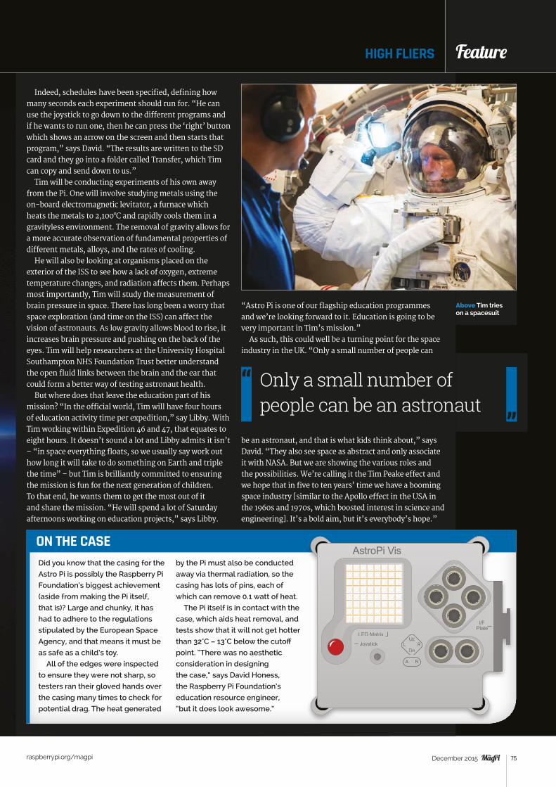
Feature
raspberrypi.org/magpi 75December 2015
HIGH FLIERS Feature
Indeed, schedules have been specified, defining how many seconds each experiment should run for. “He can use the joystick to go down to the different programs and if he wants to run one, then he can press the ‘right’ button which shows an arrow on the screen and then starts that program,” says David. “The results are written to the SD card and they go into a folder called Transfer, which Tim can copy and send down to us.”
Tim will be conducting experiments of his own away from the Pi. One will involve studying metals using the on‑board electromagnetic levitator, a furnace which heats the metals to 2,100°C and rapidly cools them in a gravityless environment. The removal of gravity allows for a more accurate observation of fundamental properties of different metals, alloys, and the rates of cooling.
He will also be looking at organisms placed on the exterior of the ISS to see how a lack of oxygen, extreme temperature changes, and radiation affects them. Perhaps most importantly, Tim will study the measurement of brain pressure in space. There has long been a worry that space exploration (and time on the ISS) can affect the vision of astronauts. As low gravity allows blood to rise, it increases brain pressure and pushing on the back of the eyes. Tim will help researchers at the University Hospital Southampton NHS Foundation Trust better understand the open fluid links between the brain and the ear that could form a better way of testing astronaut health.
But where does that leave the education part of his mission? “In the official world, Tim will have four hours of education activity time per expedition,” say Libby. With Tim working within Expedition 46 and 47, that equates to eight hours. It doesn’t sound a lot and Libby admits it isn’t – “in space everything floats, so we usually say work out how long it will take to do something on Earth and triple the time” – but Tim is brilliantly committed to ensuring the mission is fun for the next generation of children. To that end, he wants them to get the most out of it and share the mission. “He will spend a lot of Saturday afternoons working on education projects,” says Libby.
ON THE CASEDid you know that the casing for the
Astro Pi is possibly the Raspberry Pi
Foundation’s biggest achievement
(aside from making the Pi itself,
that is)? Large and chunky, it has
had to adhere to the regulations
stipulated by the European Space
Agency, and that means it must be
as safe as a child’s toy.
All of the edges were inspected
to ensure they were not sharp, so
testers ran their gloved hands over
the casing many times to check for
potential drag. The heat generated
by the Pi must also be conducted
away via thermal radiation, so the
casing has lots of pins, each of
which can remove 0.1 watt of heat.
The Pi itself is in contact with the
case, which aids heat removal, and
tests show that it will not get hotter
than 32°C – 13°C below the cutoff
point. “There was no aesthetic
consideration in designing
the case,” says David Honess,
the Raspberry Pi Foundation’s
education resource engineer,
“but it does look awesome.”
AstroPi Vis
“Astro Pi is one of our flagship education programmes and we’re looking forward to it. Education is going to be very important in Tim’s mission.”
As such, this could well be a turning point for the space industry in the UK. “Only a small number of people can
be an astronaut, and that is what kids think about,” says David. “They also see space as abstract and only associate it with NASA. But we are showing the various roles and the possibilities. We’re calling it the Tim Peake effect and we hope that in five to ten years’ time we have a booming space industry [similar to the Apollo effect in the USA in the 1960s and 1970s, which boosted interest in science and engineering]. It’s a bold aim, but it’s everybody’s hope.”
Only a small number of people can be an astronaut
Above Tim tries on a spacesuit
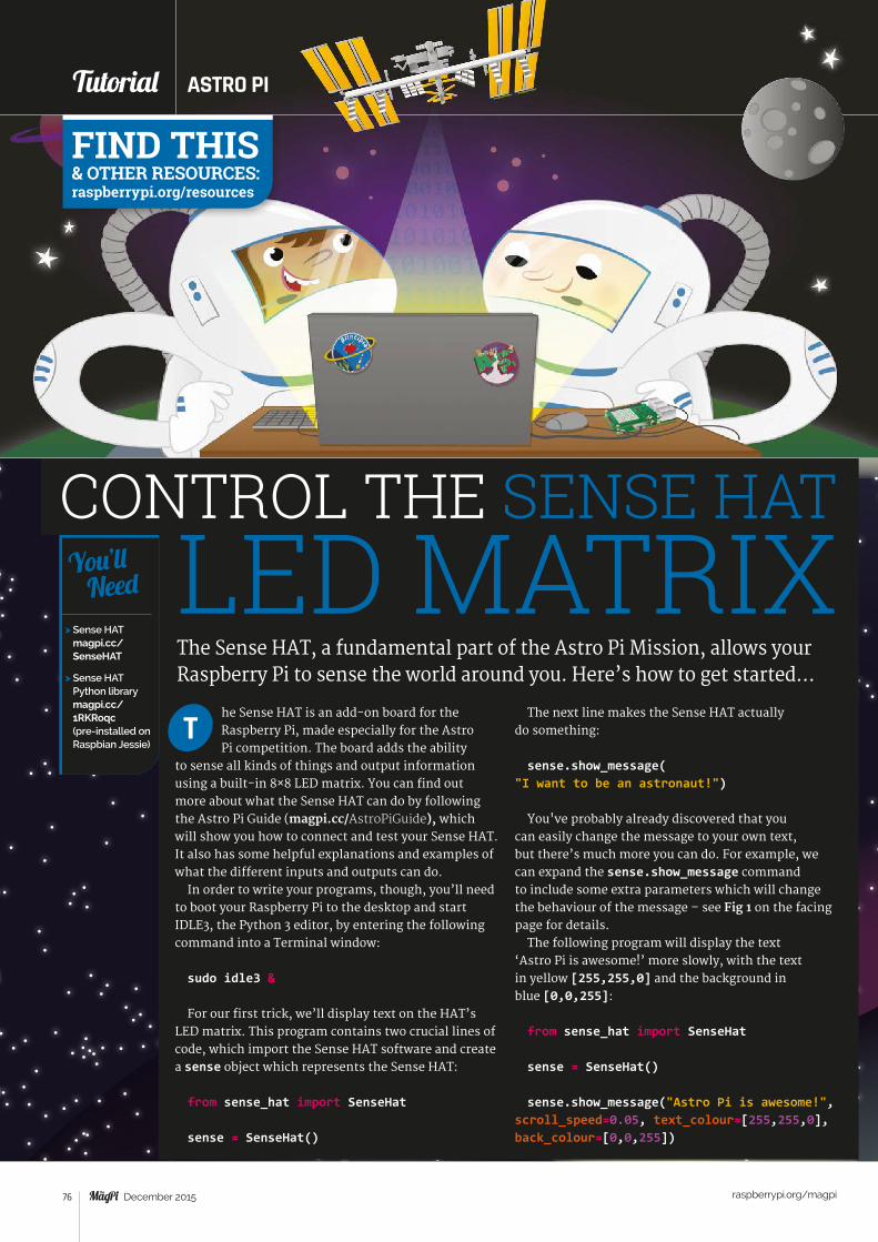
Tutorial STEP BY STEP
raspberrypi.org/magpi 76 December 2015
CONTROL THE SENSE HAT
The Sense HAT, a fundamental part of the Astro Pi Mission, allows your Raspberry Pi to sense the world around you. Here’s how to get started…
he Sense HAT is an add-on board for the Raspberry Pi, made especially for the Astro Pi competition. The board adds the ability
to sense all kinds of things and output information using a built-in 8×8 LED matrix. You can find out more about what the Sense HAT can do by following the Astro Pi Guide (magpi.cc/AstroPiGuide), which will show you how to connect and test your Sense HAT. It also has some helpful explanations and examples of what the different inputs and outputs can do.
In order to write your programs, though, you’ll need to boot your Raspberry Pi to the desktop and start IDLE3, the Python 3 editor, by entering the following command into a Terminal window:
sudo idle3 &
For our first trick, we’ll display text on the HAT’s LED matrix. This program contains two crucial lines of code, which import the Sense HAT software and create a sense object which represents the Sense HAT:
from sense_hat import SenseHat
sense = SenseHat()
T
> Sense HAT magpi.cc/SenseHAT
> Sense HAT Python library magpi.cc/ 1RKRoqc (pre-installed on Raspbian Jessie)
You’ll Need
The next line makes the Sense HAT actually do something:
sense.show_message( "I want to be an astronaut!")
You've probably already discovered that you can easily change the message to your own text, but there’s much more you can do. For example, we can expand the sense.show_message command to include some extra parameters which will change the behaviour of the message – see Fig 1 on the facing page for details.
The following program will display the text ‘Astro Pi is awesome!’ more slowly, with the text in yellow [255,255,0] and the background in blue [0,0,255]:
from sense_hat import SenseHat
sense = SenseHat()
sense.show_message("Astro Pi is awesome!", scroll_speed=0.05, text_colour=[255,255,0], back_colour=[0,0,255])
LED MATRIX
ASTRO PITutorial
FIND THIS & OTHER RESOURCES: raspberrypi.org/resources
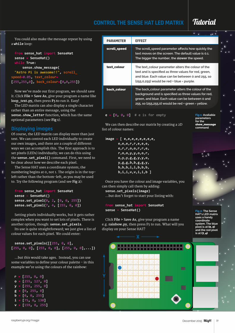
Tutorial
raspberrypi.org/magpi 77December 2015
CONTROL THE SENSE HAT LED MATRIX Tutorial
Fig 1: Available parameters for the show_message command
You could also make the message repeat by using a while loop:
from sense_hat import SenseHatsense = SenseHat()while True: sense.show_message("Astro Pi is awesome!!", scroll_
speed=0.05, text_colour= [255,255,0], back_colour=[0,0,255])
Now we’ve made our first program, we should save it. Click File > Save As, give your program a name like loop_text.py, then press F5 to run it. Easy!
The LED matrix can also display a single character rather than an entire message, using the sense.show_letter function, which has the same optional parameters (see Fig 1).
Displaying imagesOf course, the LED matrix can display more than just text. We can control each LED individually to create our own images, and there are a couple of different ways we can accomplish this. The first approach is to set pixels (LEDs) individually; we can do this using the sense.set_pixel() command. First, we need to be clear about how we describe each pixel.
The Sense HAT uses a coordinate system; the numbering begins at 0, not 1. The origin is in the top-left rather than the bottom-left, as you may be used to. Try the following program (and see Fig 2):
from sense_hat import SenseHat sense = SenseHat()sense.set_pixel(0, 2, [0, 0, 255])sense.set_pixel(7, 4, [255, 0, 0])
Setting pixels individually works, but it gets rather complex when you want to set lots of pixels. There is another option, though: sense.set_pixels.
Its use is quite straightforward; we just give a list of colour values for each pixel. We could enter:
sense.set_pixels([[255, 0, 0], [255, 0, 0], [255, 0, 0], [255, 0, 0],...])
…but this would take ages. Instead, you can use some variables to define your colour palette - in this example we’re using the colours of the rainbow:
r = [255, 0, 0] o = [255, 127, 0] y = [255, 255, 0] g = [0, 255, 0] b = [0, 0, 255] i = [75, 0, 130] v = [159, 0, 255]
e = [0, 0, 0] # e is for empty
We can then describe our matrix by creating a 2D list of colour names:
image = [ e,e,e,e,e,e,e,e, e,e,e,r,r,e,e,e, e,r,r,o,o,r,r,e, r,o,o,y,y,o,o,r, o,y,y,g,g,y,y,o, y,g,g,b,b,g,g,y, b,b,b,i,i,b,b,b, b,i,i,v,v,i,i,b ]
Once you have the colour and image variables, you can then simply call them by adding: sense.set_pixels(image) …but don’t forget to start your listing with:
from sense_hat import SenseHat sense = SenseHat()
Click File > Save As, give your program a name e.g. rainbow.py, then press F5 to run. What will you display on your Sense HAT?
PARAMETER EFFECT
scroll_speed
text_colour
back_colour
The text_colour parameter alters the colour of the
text and is specified as three values for red, green,
and blue. Each value can be between 0 and 255, so
[255,0,255] would be red + blue = purple.
The back_colour parameter alters the colour of the
background and is specified as three values for red,
green, and blue. Each value can be between 0 and
255, so [255,255,0] would be red + green = yellow.
The scroll_speed parameter affects how quickly the
text moves on the screen. The default value is 0.1.
The bigger the number, the slower the speed.
Fig 2: The Sense HAT’s LED matrix uses a handy coordinate system. The blue pixel is at (0, 2) and the red pixel is at (7, 4)
X
Y
Tutorial STEP BY STEP
raspberrypi.org/magpi 78 December 2015
FIND THIS & OTHER RESOURCES: raspberrypi.org/resources
ASTRO PITutorial
The Sense HAT, a fundamental part of the Astro Pi mission, allows your Raspberry Pi to sense the world around you. Here’s how to get started…
n space, it feels like everything is floating. This is because everything becomes weightless outside of our planet, Earth. This is probably
the biggest difference from being on Earth, where everything is pulled down towards the ground. On Earth we can all feel this downward pull, but we are so used to it that we sometimes don't even think about it. This pull or attraction we feel is called gravity.
You can recreate the effects of the force of gravity on Earth in this Scratch simulation!
Open Scratch by clicking on Menu and Programming, followed by Scratch. Alternatively, you can use Scratch 2.0 online for this activity, although some of the blocks may be slightly different. Once opened, create a new file by selecting File and New.
Next, delete the Scratch cat sprite by right-clicking on it and selecting Delete from the menu that is displayed. For this project, you need to create a new background to act as the Earth. To do this, click on Stage in the sprites palette (bottom-right) and then click on Backgrounds next to the Scripts tab. Click on Paint to draw your own background, then select the rectangle icon and a green colour. It’s important that you fill the rectangle with one solid colour. Draw a green rectangle at the bottom of the image to represent the Earth. Once you’re happy with your stage design, click OK.
I
> Raspbian magpi.cc/ 1MYYTMo
> Scratch (pre-installed on Raspbian)
You’ll Need
You’ll need to choose a sprite to use as your character. You can use the Scratch cat sprite, or you can use our Mooncake - the Astro Cat sprite. You can find Mooncake here: magpi.cc/1PEbjIm. Once you’ve got it, add it as a new sprite by clicking on the middle icon on the sprites palette, selecting Astro-cat.png from the choices and clicking OK.
In order for your gravity simulator to work with this sprite, you’ll need to set the costume center of Mooncake the Astro Cat by selecting the sprite, then clicking on Costumes followed by Edit. In the Paint Editor window, you’ll see a button with a ‘+’ symbol on it. When clicked, it will show a crosshair over the sprite, which you’ll be able to move with your mouse. Move it so that it selects the tummy of Mooncake and when you are happy, click OK.
Click on the Scripts tab of the sprite and save your Scratch project work by clicking on File and Save As. Name your program Gravity simulation and save it in your home directory or some place that you can find it later.
Storing dataTo create a variable, click on Variables in the blocks palette (top-left) and then click Make a Variable. The New Variable window opens and asks you to type
GRAVITY SIMULATOR
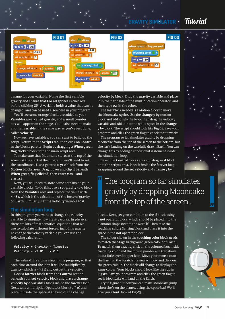
Tutorial
raspberrypi.org/magpi 79December 2015
GRAVITY SIMULATOR Tutorial
a name for your variable. Name the first variable gravity and ensure that For all sprites is checked before clicking OK. A variable holds a value that can be changed, and can be used elsewhere in your program.
You’ll see some orange blocks are added to your Variables area, called gravity, and a small counter box will appear on the stage. You’ll also need to make another variable in the same way as you’ve just done, called velocity.
Now we have variables, you can start to build up the script. Return to the Scripts tab, then click on Control in the blocks palette. Begin by dragging a When green flag clicked block into the main script area.
To make sure that Mooncake starts at the top of the screen at the start of the program, you’ll need to set the coordinates. Use a go to x: 0 y: 0 block from the Motion blocks area. Drag it over and clip it beneath When green flag clicked, then enter x as 0 and y as 148.
Next, you will need to store some data inside your variable blocks. To do this, use a set gravity to 0 block from the Variables area and replace the value with -9.81, which is the calculation of the force of gravity on Earth. Similarly, set the velocity variable to 0.
The simulation loopIn this program you want to change the velocity variable to simulate how gravity works. In physics, there are lots of mathematical equations that we use to calculate different forces, including gravity. To change the velocity variable you can use the following calculation:
Velocity = Gravity × TimestepVelocity = -9.81 × 0.1
The value 0.1 is a time step in this program, so that each time around the loop it will be multiplied by gravity (which is -9.81) and output the velocity.
Dock a forever block from the Control section beneath your set velocity block and place a change velocity by 0 Variables block inside the forever loop. Next, take a multiplier Operators block (0 * 0) and place it inside the space at the end of the change
velocity by block. Drag the gravity variable and place it in the right side of the multiplication operator, and then type 0.1 in the other.
The last block needed is a Motion block to move the Mooncake sprite. Use the change y by motion block and add it into the loop, then drag the velocity variable and add it into the white space in the change y by block. The script should look like Fig 01. Save your program and click the green flag to check that it works.
The program so far simulates gravity by dropping Mooncake from the top of the screen to the bottom, but she isn’t landing on the carefully drawn Earth. You can change this by adding a conditional statement inside the simulation loop.
Select the Control blocks area and drag an if block onto the scripts area. Place it inside the forever loop, wrapping around the set velocity and change y by
blocks. Next, set your condition to the if block using a not operator block, which should be placed into the diamond shape next to the word if. Then take the touching color? Sensing block and place it into the space in the not operator block.
The colour shown in the touching color block needs to match the Stage background green colour of Earth. To match them exactly, click on the coloured box inside touching color and the mouse pointer will transform into a little eye-dropper icon. Move your mouse onto the Earth in the Scratch preview window and click on the green colour. The block will change to display the same colour. Your blocks should look like they do in Fig 02. Save your program and click the green flag to see if Mooncake will land on the Earth.
Try to figure out how you can make Mooncake jump when she’s on the planet, using the space bar! We’ll give you a hint: look at Fig 03...
FIG 01 FIG 03FIG 02
The program so far simulates gravity by dropping Mooncake from the top of the screen...

Tutorial STEP BY STEP
raspberrypi.org/magpi 80 December 2015
ASTRO PITutorial
Test your reactions with this Scratch game that simulates how fast you’ll need to be if you want to become an astronaut
hings happen quickly when you’re travelling at 16,000 miles per hour (around 7,000 metres per second), and when debris and
micrometeoroids are heading towards you at around 22,500 miles per hour. Quick reactions and a steady hand are also needed for tasks requiring fine motor skills, such as controlling robotic arms. Astronauts are trained intensively to speed up their reactions to incidents, and to prepare them for all eventualities.
T
> Raspbian magpi.cc/ 1MYYTMo
> Scratch (pre-installed on Raspbian)
You’ll Need
NASA scientists have conducted experiments to test astronaut reaction times. Astronauts were first assessed using a computer system on the ground, then again when they were on board the ISS, and once more when they returned. It was found that their reaction times more than doubled in space. Scientists suggest that stress, as well as the brain having to adapt to microgravity, could be the cause. Normal performance was restored soon after returning to Earth.
Let’s create a game in Scratch to test your reaction skills, and those of your friends and family, to see if you could become an astronaut like Tim Peake of the ESA.
You can open Scratch by clicking on Menu and Programming, followed by Scratch. Alternatively, you can use Scratch 2.0 online for this activity, although some of the blocks may be slightly different.
Once Scratch is open, create a new file by selecting File and New. Delete the Scratch Cat sprite by right-clicking on it and selecting Delete from the menu that is displayed.
For this project, you need a space-themed background and an astronaut sprite. To add a
ASTRONAUT REACTION TIMES GAME
FIG 01
FIND THIS & OTHER RESOURCES: raspberrypi.org/resources
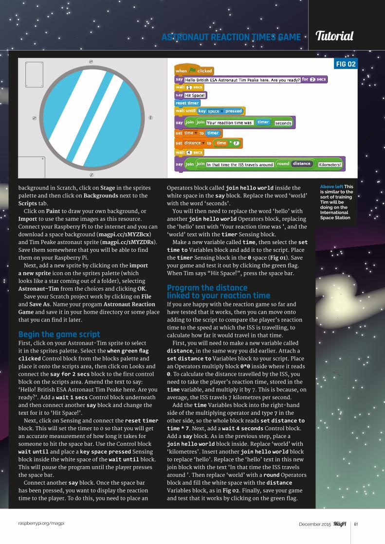
Tutorial
raspberrypi.org/magpi 81December 2015
ASTRONAUT REACTION TIMES GAME Tutorial
Above left This is similar to the sort of training Tim will be doing on the International Space Station
background in Scratch, click on Stage in the sprites palette and then click on Backgrounds next to the Scripts tab.
Click on Paint to draw your own background, or Import to use the same images as this resource. Connect your Raspberry Pi to the internet and you can download a space background (magpi.cc/1MYZBcx) and Tim Peake astronaut sprite (magpi.cc/1MYZDRs). Save them somewhere that you will be able to find them on your Raspberry Pi.
Next, add a new sprite by clicking on the import a new sprite icon on the sprites palette (which looks like a star coming out of a folder), selecting Astronaut-Tim from the choices and clicking OK.
Save your Scratch project work by clicking on File and Save As. Name your progam Astronaut Reaction Game and save it in your home directory or some place that you can find it later.
Begin the game scriptFirst, click on your Astronaut-Tim sprite to select it in the sprites palette. Select the when green flag clicked Control block from the blocks palette and place it onto the scripts area, then click on Looks and connect the say for 2 secs block to the first control block on the scripts area. Amend the text to say: ‘Hello! British ESA Astronaut Tim Peake here. Are you ready?’. Add a wait 1 secs Control block underneath and then connect another say block and change the text for it to ‘Hit Space!’.
Next, click on Sensing and connect the reset timer block. This will set the timer to 0 so that you will get an accurate measurement of how long it takes for someone to hit the space bar. Use the Control block wait until and place a key space pressed Sensing block inside the white space of the wait until block. This will pause the program until the player presses the space bar.
Connect another say block. Once the space bar has been pressed, you want to display the reaction time to the player. To do this, you need to place an
Operators block called join hello world inside the white space in the say block. Replace the word ‘world’ with the word ‘seconds’.
You will then need to replace the word ‘hello’ with another join hello world Operators block, replacing the ‘hello’ text with ‘Your reaction time was ’, and the ‘world’ text with the timer Sensing block.
Make a new variable called time, then select the set time to Variables block and add it to the script. Place the timer Sensing block in the 0 space (Fig 01). Save your game and test it out by clicking the green flag. When Tim says “Hit Space!”, press the space bar.
Program the distance linked to your reaction time If you are happy with the reaction game so far and have tested that it works, then you can move onto adding to the script to compare the player’s reaction time to the speed at which the ISS is travelling, to calculate how far it would travel in that time.
First, you will need to make a new variable called distance, in the same way you did earlier. Attach a set distance to Variables block to your script. Place an Operators multiply block 0*0 inside where it reads 0. To calculate the distance travelled by the ISS, you need to take the player’s reaction time, stored in the time variable, and multiply it by 7. This is because, on average, the ISS travels 7 kilometres per second.
Add the time Variables block into the right-hand side of the multiplying operator and type 7 in the other side, so the whole block reads set distance to time * 7. Next, add a wait 4 seconds Control block. Add a say block. As in the previous step, place a join hello world block inside. Replace ‘world’ with ‘kilometres’. Insert another join hello world block to replace ‘hello’. Replace the ‘hello’ text in this new join block with the text ‘In that time the ISS travels around ’. Then replace ‘world’ with a round Operators block and fill the white space with the distance Variables block, as in Fig 02. Finally, save your game and test that it works by clicking on the green flag.
FIG 02
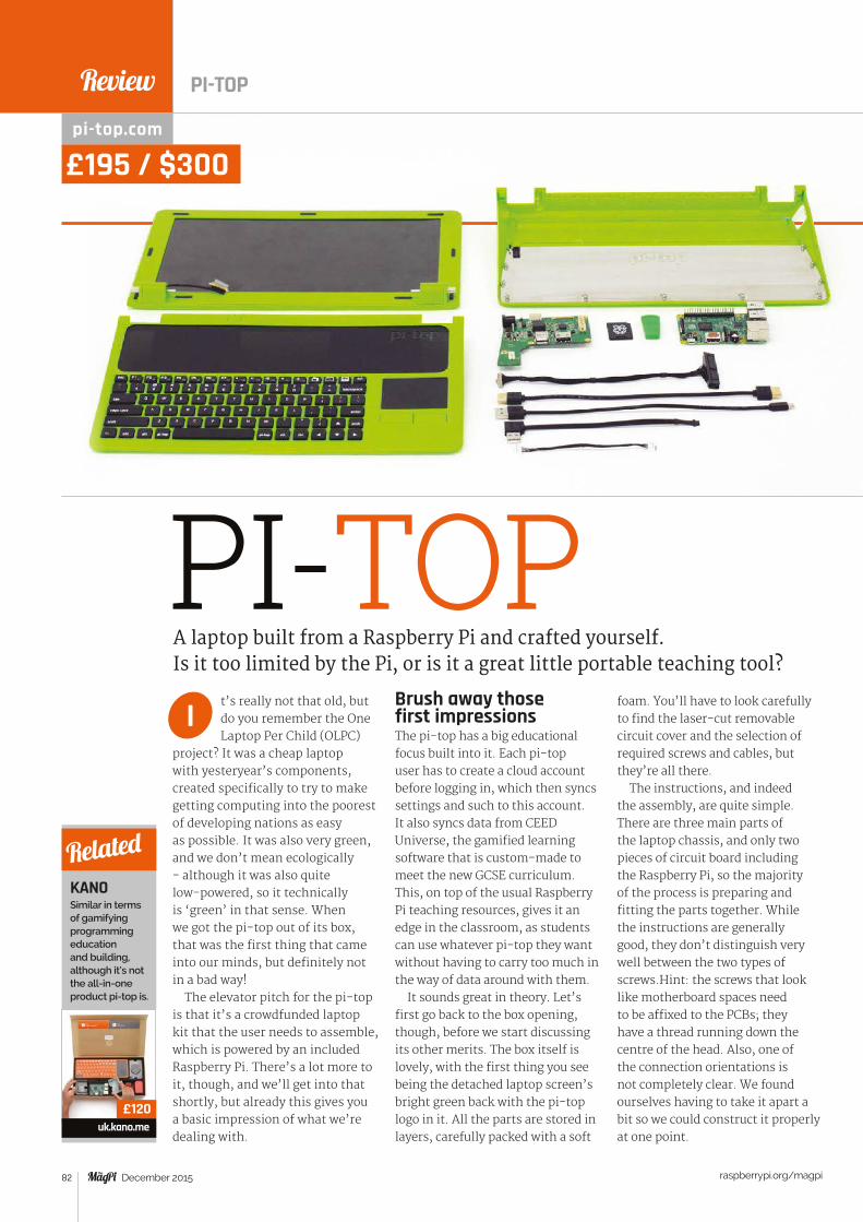
Review
raspberrypi.org/magpi 82 December 2015
PI-TOPt’s really not that old, but do you remember the One Laptop Per Child (OLPC)
project? It was a cheap laptop with yesteryear’s components, created specifically to try to make getting computing into the poorest of developing nations as easy as possible. It was also very green, and we don’t mean ecologically - although it was also quite low-powered, so it technically is ‘green’ in that sense. When we got the pi-top out of its box, that was the first thing that came into our minds, but definitely not in a bad way!
The elevator pitch for the pi-top is that it’s a crowdfunded laptop kit that the user needs to assemble, which is powered by an included Raspberry Pi. There’s a lot more to it, though, and we’ll get into that shortly, but already this gives you a basic impression of what we’re dealing with.
Brush away those first impressionsThe pi-top has a big educational focus built into it. Each pi-top user has to create a cloud account before logging in, which then syncs settings and such to this account. It also syncs data from CEED Universe, the gamified learning software that is custom-made to meet the new GCSE curriculum. This, on top of the usual Raspberry Pi teaching resources, gives it an edge in the classroom, as students can use whatever pi-top they want without having to carry too much in the way of data around with them.
It sounds great in theory. Let’s first go back to the box opening, though, before we start discussing its other merits. The box itself is lovely, with the first thing you see being the detached laptop screen’s bright green back with the pi-top logo in it. All the parts are stored in layers, carefully packed with a soft
foam. You’ll have to look carefully to find the laser-cut removable circuit cover and the selection of required screws and cables, but they’re all there.
The instructions, and indeed the assembly, are quite simple. There are three main parts of the laptop chassis, and only two pieces of circuit board including the Raspberry Pi, so the majority of the process is preparing and fitting the parts together. While the instructions are generally good, they don’t distinguish very well between the two types of screws.Hint: the screws that look like motherboard spaces need to be affixed to the PCBs; they have a thread running down the centre of the head. Also, one of the connection orientations is not completely clear. We found ourselves having to take it apart a bit so we could construct it properly at one point.
A laptop built from a Raspberry Pi and crafted yourself. Is it too limited by the Pi, or is it a great little portable teaching tool?
I
KANOSimilar in terms of gamifying programming education and building, although it’s not the all-in-one product pi-top is.
uk.kano.me
Related
£120
pi-top.com
£195 / $300
PI-TOP
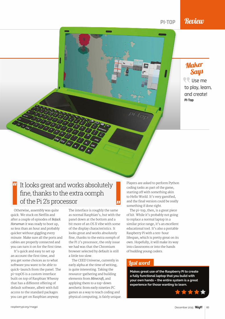
Review
raspberrypi.org/magpi 83December 2015
PI-TOP
Use me to play, learn, and create! Pi-Top
Maker Says
Last wordMakes great use of the Raspberry Pi to create a fully functional laptop that you build with your own hands – the entire system is a great experience for those wanting to learn.
Otherwise, assembly was quite quick. We stuck on Netflix and after a couple of episodes of BoJack Horseman it was ready to boot up, so less than an hour and probably quicker without giggling every minute. Make sure all the ports and cables are properly connected and you can turn it on for the first time.
It’s quick and easy to set up an account the first time, and you get some choices as to what software you want to be able to quick-launch from the panel. The pi-topOS is a custom interface built on top of Raspbian Wheezy that has a different offering of default software, albeit with full access to the standard packages you can get on Raspbian anyway.
The interface is roughly the same as normal Raspbian’s, but with the panel down at the bottom and a bit more of an OS X vibe with some of the display characteristics. It looks great and works absolutely fine, thanks to the extra oomph of the Pi 2’s processor; the only issue we had was that the Chromium browser selected by default is still a little too slow.
The CEED Universe, currently in early alpha at the time of writing, is quite interesting. Taking the resource-gathering and building elements from Minecraft, and applying them to a top-down aesthetic from early nineties PC games as a way to teach coding and physical computing, is fairly unique.
Players are asked to perform Python coding tasks as part of the game, starting off with something akin to Hello World. It’s very gamified, and the final version could be really something if done right.
The pi-top, then, is a great piece of kit. While it’s probably not going to replace a normal laptop in a similar price range, it’s an excellent educational tool. It’s also a portable Raspberry Pi with a ten-hour lifespan, which is pretty great on its own. Hopefully, it will make its way into classrooms or into the hands of budding young coders.
It looks great and works absolutely fine, thanks to the extra oomph of the Pi 2’s processor
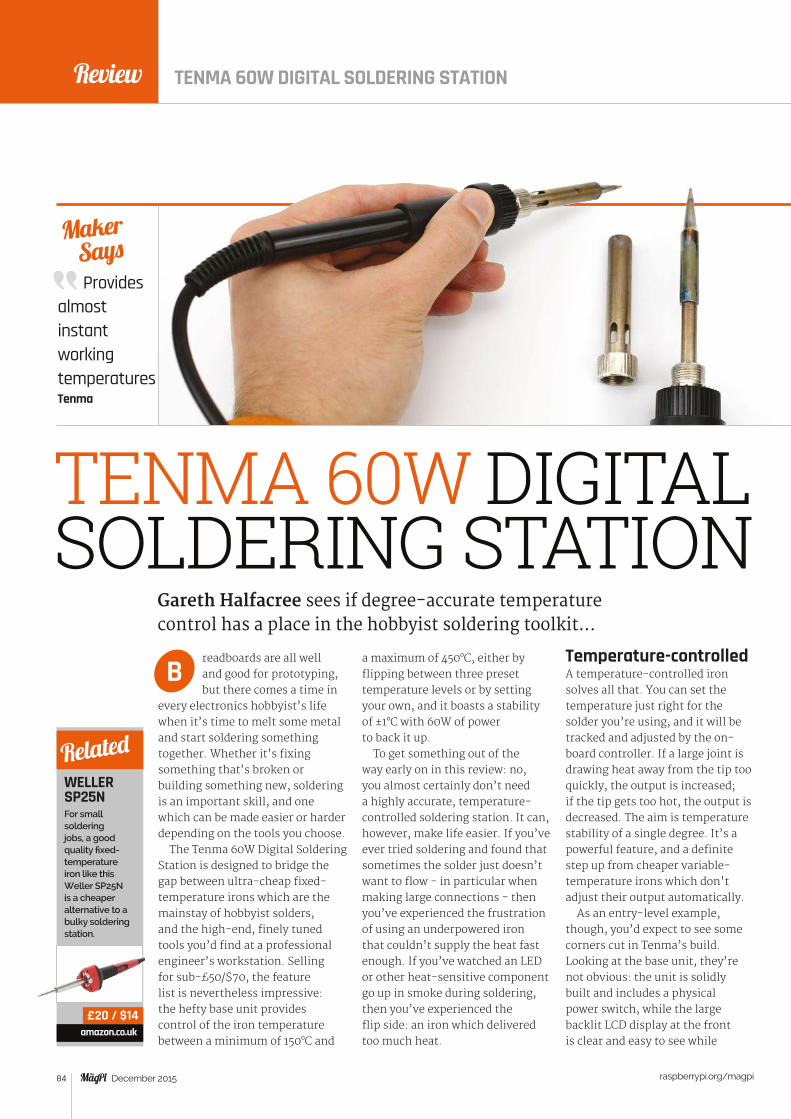
Review
raspberrypi.org/magpi 84 December 2015
Provides almost instant working temperaturesTenma
Maker Says
TENMA 60W DIGITAL SOLDERING STATION
readboards are all well and good for prototyping, but there comes a time in
every electronics hobbyist’s life when it’s time to melt some metal and start soldering something together. Whether it’s fixing something that’s broken or building something new, soldering is an important skill, and one which can be made easier or harder depending on the tools you choose.
The Tenma 60W Digital Soldering Station is designed to bridge the gap between ultra-cheap fixed-temperature irons which are the mainstay of hobbyist solders, and the high-end, finely tuned tools you’d find at a professional engineer’s workstation. Selling for sub-£50/$70, the feature list is nevertheless impressive: the hefty base unit provides control of the iron temperature between a minimum of 150°C and
a maximum of 450°C, either by flipping between three preset temperature levels or by setting your own, and it boasts a stability of ±1°C with 60W of power to back it up.
To get something out of the way early on in this review: no, you almost certainly don’t need a highly accurate, temperature-controlled soldering station. It can, however, make life easier. If you’ve ever tried soldering and found that sometimes the solder just doesn’t want to flow - in particular when making large connections - then you’ve experienced the frustration of using an underpowered iron that couldn’t supply the heat fast enough. If you’ve watched an LED or other heat-sensitive component go up in smoke during soldering, then you’ve experienced the flip side: an iron which delivered too much heat.
Temperature-controlledA temperature-controlled iron solves all that. You can set the temperature just right for the solder you’re using, and it will be tracked and adjusted by the on-board controller. If a large joint is drawing heat away from the tip too quickly, the output is increased; if the tip gets too hot, the output is decreased. The aim is temperature stability of a single degree. It’s a powerful feature, and a definite step up from cheaper variable-temperature irons which don't adjust their output automatically.
As an entry-level example, though, you’d expect to see some corners cut in Tenma’s build. Looking at the base unit, they’re not obvious: the unit is solidly built and includes a physical power switch, while the large backlit LCD display at the front is clear and easy to see while
Gareth Halfacree sees if degree-accurate temperature control has a place in the hobbyist soldering toolkit…
B
WELLER SP25NFor small soldering jobs, a good quality fixed-temperature iron like this Weller SP25N is a cheaper alternative to a bulky soldering station.
amazon.co.uk
Related
£20 / $14
TENMA 60W DIGITAL SOLDERING STATION

Review
raspberrypi.org/magpi 85December 2015
TENMA 60W DIGITAL SOLDERING STATION
Last wordWith such a small cost premium over a quality fixed-temperature iron and a fair list of advantages, if you fancy treating yourself to an iron upgrade, you could do a lot worse than the Tenma.
cpc.farnell.com
£47 / $79
soldering. A multi-pole connector provides power to and feedback from the iron, which is a small and lightweight unit thanks to the bulk of the electronics being located in the base unit. The only real negative here is that the unit is fixed to the power network of the country of purchase – either 220V or 110V – and its power lead is integrated rather than removable.
Saving penniesIt’s not until you look to the bundled stand that you begin to see where Tenma has been saving its pennies. While the stand itself is a sturdy metal housing, it fails to grip the iron adequately, largely thanks to the lack of weight in the iron and the relatively heavy lead which connects it to the base unit. It’s functional, but care is needed to make sure the iron doesn’t drop out. The bundled cleaning sponge, meanwhile, is barely adequate, and should be replaced with something thicker – or an
alternative tip-cleaning system – as soon as possible.
These points aside, though, the Tenma soldering station is a joy to use. Its 60W output and dual heating coils mean the iron’s tip – which is easily replaceable through a quick twist of a retaining nut, with various shapes and sizes available – comes up to temperature rapidly. Plus, the live temperature readout on the base unit means there’s no guesswork when it comes to seeing whether it’s ready for use or not.
Another feature is Tenma's claim to electrostatic discharge (ESD) safety. This is the promise that – unlike extremely cheap irons often found in starter kits and from bargain-basement shops – there’s no risk that a blast of static electricity will fry any sensitive components as you touch the metal tip of the iron to one of their contacts. It’s a problem unlikely to have affected most hobbyists, but the reassurance it won’t bother you in the future is undeniably nice.
Above The cleaning sponge isn’t great
Above top The large LCD is clear and easy to read
The iron itself is lightweight, since the electronics are located in the base unit
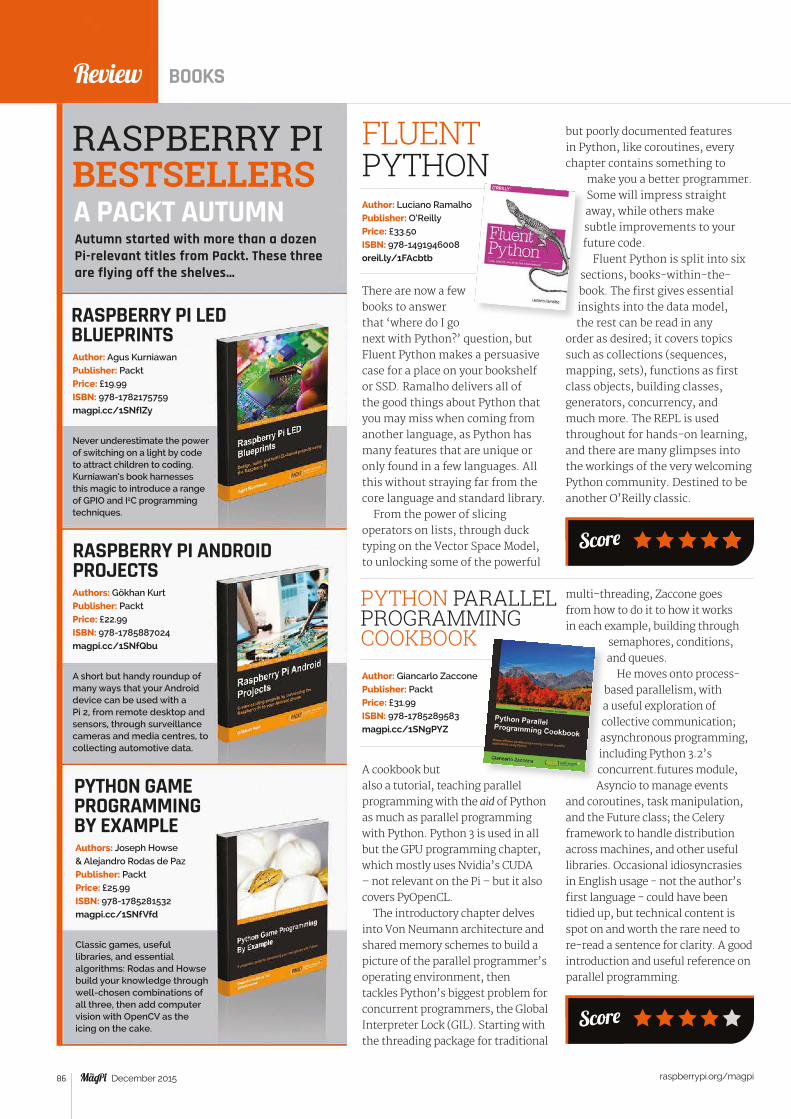
raspberrypi.org/magpi 86 December 2015
Review BOOKS
RASPBERRY PI LED BLUEPRINTS
Never underestimate the power of switching on a light by code to attract children to coding. Kurniawan’s book harnesses this magic to introduce a range of GPIO and I2C programming techniques.
Author: Agus KurniawanPublisher: PacktPrice: £19.99ISBN: 978-1782175759magpi.cc/1SNfIZy
There are now a few books to answer that ‘where do I go next with Python?’ question, but Fluent Python makes a persuasive case for a place on your bookshelf or SSD. Ramalho delivers all of the good things about Python that you may miss when coming from another language, as Python has many features that are unique or only found in a few languages. All this without straying far from the core language and standard library.
From the power of slicing operators on lists, through duck typing on the Vector Space Model, to unlocking some of the powerful
FLUENT PYTHONAuthor: Luciano RamalhoPublisher: O’ReillyPrice: £33.50ISBN: 978-1491946008oreil.ly/1FAcbtb
A short but handy roundup of many ways that your Android device can be used with a Pi 2, from remote desktop and sensors, through surveillance cameras and media centres, to collecting automotive data.
Authors: Gökhan KurtPublisher: PacktPrice: £22.99ISBN: 978-1785887024 magpi.cc/1SNfQbu
PYTHON GAME PROGRAMMING BY EXAMPLE
Classic games, useful libraries, and essential algorithms: Rodas and Howse build your knowledge through well-chosen combinations of all three, then add computer vision with OpenCV as the icing on the cake.
Authors: Joseph Howse & Alejandro Rodas de PazPublisher: PacktPrice: £25.99ISBN: 978-1785281532magpi.cc/1SNfVfd
but poorly documented features in Python, like coroutines, every chapter contains something to
make you a better programmer. Some will impress straight away, while others make subtle improvements to your future code.
Fluent Python is split into six sections, books-within-the-book. The first gives essential insights into the data model, the rest can be read in any
order as desired; it covers topics such as collections (sequences, mapping, sets), functions as first class objects, building classes, generators, concurrency, and much more. The REPL is used throughout for hands-on learning, and there are many glimpses into the workings of the very welcoming Python community. Destined to be another O’Reilly classic.
A cookbook but also a tutorial, teaching parallel programming with the aid of Python as much as parallel programming with Python. Python 3 is used in all but the GPU programming chapter, which mostly uses Nvidia’s CUDA – not relevant on the Pi – but it also covers PyOpenCL.
The introductory chapter delves into Von Neumann architecture and shared memory schemes to build a picture of the parallel programmer’s operating environment, then tackles Python’s biggest problem for concurrent programmers, the Global Interpreter Lock (GIL). Starting with the threading package for traditional
Author: Giancarlo ZacconePublisher: PacktPrice: £31.99ISBN: 978-1785289583magpi.cc/1SNgPYZ
multi-threading, Zaccone goes from how to do it to how it works in each example, building through
semaphores, conditions, and queues.
He moves onto process-based parallelism, with a useful exploration of collective communication; asynchronous programming, including Python 3.2’s concurrent.futures module, Asyncio to manage events
and coroutines, task manipulation, and the Future class; the Celery framework to handle distribution across machines, and other useful libraries. Occasional idiosyncrasies in English usage - not the author’s first language - could have been tidied up, but technical content is spot on and worth the rare need to re-read a sentence for clarity. A good introduction and useful reference on parallel programming.
PYTHON PARALLEL PROGRAMMING COOKBOOK
RASPBERRY PI ANDROID PROJECTS
RASPBERRY PI BESTSELLERSAutumn started with more than a dozen Pi-relevant titles from Packt. These three are flying off the shelves…
Score
A PACKT AUTUMN
Score

raspberrypi.org/magpi 87December 2015
Score
ReviewBOOKS
Introduction to Computing Using Python
Welcome update to the breadth-first computer science introductory textbook, with a strong focus on OOP.
Author: Ljubomir PerkovicPublisher: WileyPrice: £159.99, or £29.16 for e-bookISBN: 978-1118890943magpi.cc/1SNieiu
Discovering Computer Science
Computational thinking as “a powerful mode of inquiry and a vehicle of discovery, in a wide variety of disciplines.”
Author: Jessen HavillPublisher: Chapman and Hall/CRCPrice: £57.99ISBN: 978-1482254143magpi.cc/1SNijTe
Doing Math with Python
Pre-computer science; catch up on high-school mathematics, and have fun with Python along the way.
Author: Amit SahaPublisher: No StarchPrice: £19.99ISBN: 978-1593276409nostarch.com/doingmathwithpython
Computational Physics
Pythonic reworking of a classic that’s essential for any physics student. Useful maths and programming for all scientists.
Author: Rubin H Landau, Manuel J Páez & Cristian C BordeianuPublisher: WileyPrice: £75.00ISBN: 978-3527413157magpi.cc/1SNiw95
Making Music with Computers
Computer science introduction for a non-traditional audience, using music creation with Python in a Jython environment.
Author: Andrew R Brown & Bill ManarisPublisher: Chapman and Hall/CRCPrice: £31.99ISBN: 978-1439867914magpi.cc/1SNizl7
ESSENTIAL READING: COMPSCI ESSENTIALSRecent academic tomes to boost your brain power, with Python for CompSci learning.
Stan Gibilisco has been writing on, and tinkering with, electronics for a long time, so this short reference and introduction benefits from distilling decades of experience, showing a clarity of approach that indicates a writer and tinkerer with plenty to pass on to newcomers. The opening chapter on ‘Setting up Shop’ is a pleasingly minimalist alternative to the ‘we assume you have a giant spare room and lots of money’ approach of some other maker introductions.
Although ideal for newcomers – and it can be read linearly – there’s plenty of useful reference and tips worth dipping into for
Author: Stan GibiliscoPublisher: Tab ElectronicsPrice: £18.99ISBN: 978-0071843805magpi.cc/1SNgXrF
those who’ve been soldering since the NE555 was a hot new chip. Remaining chapters are organised
by topic in the expected manner: Resistors, Capacitors, Inductors, Transformers, Diodes, Transistors, ICs and Digital Basics, More Components and Techniques, followed by useful appendices and further reading.
What really makes the book stand out, in addition to the clear explanations, is the experiments at the end of each chapter, which combine practical use of components and tools with demonstrating various bits of electronic theory which would be quite dry and dusty if taught only as theory. For example, in testing a JFET, you gain understanding of where electrons should and should not flow.
ELECTRONICS WORKSHOP
From the contents, introduction and content of Sobkowicz’s otherwise useful introduction to 2D game programming, you’d think the GNU/Linux platform didn’t exist. Windows and Mac OS X get a chapter each, but Raspbian’s Linux relatives don’t even make a footnote in an appendix. Fortunately, you can find full instructions on installing the Gosu library used in the book on Raspbian (or Ubuntu, et al) at github.com/gosu – we used rbenv to install Gosu on Ruby 2.1.2. That done, turn to chapter three, because Ruby Game Programming still has
Author: Mark SobkowiczPublisher: Pragmatic Price: £15.99ISBN: 978-1680500738oreil.ly/1OlpR0N
plenty to offer on the Pi. This isn’t a book about Gosu, or even solely
about Ruby, but about the various techniques used in programming 2D games, which encompass a wide range of gameplay and perspective. And Python’s expressive and slightly less buttoned-up cousin Ruby makes a good
language for introducing them: it’s concise and easy to read.
Introducing sprites, interaction, platform gaming and sideways scrolling, Sobkowicz is an able guide to all the components and has written a book suitable for early-stage coders of all ages. Niggles about leaving Linux users out in the cold aside, this is a practical and enjoyable introduction to game programming.
Score
LEARN GAME PROGRAMMING WITH RUBY
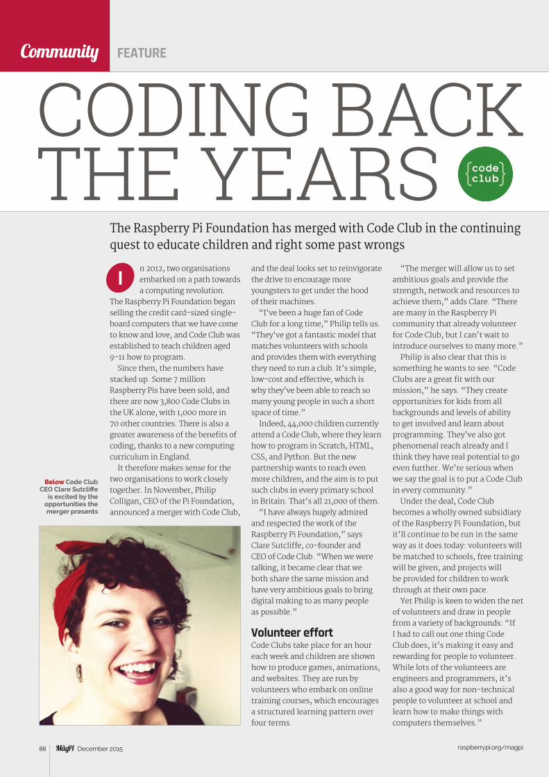
raspberrypi.org/magpi 88 December 2015
Community
n 2012, two organisations embarked on a path towards a computing revolution.
The Raspberry Pi Foundation began selling the credit card-sized single-board computers that we have come to know and love, and Code Club was established to teach children aged 9-11 how to program.
Since then, the numbers have stacked up. Some 7 million Raspberry Pis have been sold, and there are now 3,800 Code Clubs in the UK alone, with 1,000 more in 70 other countries. There is also a greater awareness of the benefits of coding, thanks to a new computing curriculum in England.
It therefore makes sense for the two organisations to work closely together. In November, Philip Colligan, CEO of the Pi Foundation, announced a merger with Code Club,
The Raspberry Pi Foundation has merged with Code Club in the continuing quest to educate children and right some past wrongs
CODING BACK THE YEARS
I
FEATURE
and the deal looks set to reinvigorate the drive to encourage more youngsters to get under the hood of their machines.
“I’ve been a huge fan of Code Club for a long time,” Philip tells us. “They’ve got a fantastic model that matches volunteers with schools and provides them with everything they need to run a club. It’s simple, low-cost and effective, which is why they’ve been able to reach so many young people in such a short space of time.”
Indeed, 44,000 children currently attend a Code Club, where they learn how to program in Scratch, HTML, CSS, and Python. But the new partnership wants to reach even more children, and the aim is to put such clubs in every primary school in Britain. That’s all 21,000 of them.
“I have always hugely admired and respected the work of the Raspberry Pi Foundation,” says Clare Sutcliffe, co-founder and CEO of Code Club. “When we were talking, it became clear that we both share the same mission and have very ambitious goals to bring digital making to as many people as possible.”
Volunteer effortCode Clubs take place for an hour each week and children are shown how to produce games, animations, and websites. They are run by volunteers who embark on online training courses, which encourages a structured learning pattern over four terms.
“The merger will allow us to set ambitious goals and provide the strength, network and resources to achieve them,” adds Clare. “There are many in the Raspberry Pi community that already volunteer for Code Club, but I can’t wait to introduce ourselves to many more.”
Philip is also clear that this is something he wants to see. “Code Clubs are a great fit with our mission,” he says. “They create opportunities for kids from all backgrounds and levels of ability to get involved and learn about programming. They’ve also got phenomenal reach already and I think they have real potential to go even further. We’re serious when we say the goal is to put a Code Club in every community.”
Under the deal, Code Club becomes a wholly owned subsidiary of the Raspberry Pi Foundation, but it’ll continue to be run in the same way as it does today: volunteers will be matched to schools, free training will be given, and projects will be provided for children to work through at their own pace.
Yet Philip is keen to widen the net of volunteers and draw in people from a variety of backgrounds: “If I had to call out one thing Code Club does, it’s making it easy and rewarding for people to volunteer. While lots of the volunteers are engineers and programmers, it’s also a good way for non-technical people to volunteer at school and learn how to make things with computers themselves.”
Below Code Club CEO Clare Sutcliffe
is excited by the opportunities the merger presents
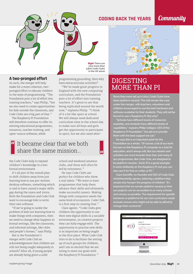
raspberrypi.org/magpi 89December 2015
Community
DIGESTING MORE THAN PI
Since they were set up in 2012, Code Clubs have
been platform-neutral. This will remain the case
under the merger, with teachers, volunteers and
children encouraged to use the best hardware and
software available for their students. They will not be
forced to use a Raspberry Pi. But why?
“Schools have different levels of resources
available, and students have different levels of
capabilities,” explains Philip Colligan, CEO of the
Raspberry Pi Foundation. “Our job is to provide
them with the best support we can.”
He says this is an important point for the
Foundation as a whole. “Of course, a lot of our work
focuses on the Raspberry Pi computer as a tool for
education, and it always will. But our mission and
activities are much broader than that, and many of
our programmes, like Code Club, are designed to
be platform-neutral… Sonic Pi is a great example.
It works brilliantly on the Raspberry Pi, but you can
also use it for free on a Mac or PC.”
Clare Sutcliffe, co-founder and CEO of Code Club,
wholeheartedly agrees, believing a platform bias
would only hamper the progress of children. “It’s
important that we remain platform-neutral so that
our projects can be accessible to as many schools
and venues as possible. The requirement for specific
hardware or platforms for our core curriculum could
exclude venues who might not be able to afford to
change their current kit.”
CODING BACK THE YEARS
A two-pronged effortAs such, the merger will help make for a more coherent, two-pronged effort to educate children in the ways of programming. “The Foundation puts a lot of effort into training teachers,” says Philip, “but we also need to create opportunities for kids outside the classroom, and Code Clubs are a big part of that.”
The Raspberry Pi Foundation will therefore continue to offer its existing educational programmes, resources, teacher training, and open-source software, while
the Code Clubs help to expand children’s knowledge in a less formal environment.
It’s all part of the overall plan to shift children away from just learning how to use pre-written desktop software, something which is said to have caused a major skills gap during the 1990s and 2000s. Both the Foundation and Code Club want to encourage kids to write their own software.
“If we’re going to tackle the problem of kids not learning how to make things with computers, then we need to change what happens in formal settings, like the classroom, and informal settings, like clubs and people’s homes,” says Philip.
But is the Foundation’s merger with Code Club an acknowledgement that children are still not being taught adequately in schools? After all, if young people are already being given a solid
programming grounding, then why have extracurricular activities?
“We’ve made great progress in England with the new computing curriculum, and the Foundation puts a lot of effort into training teachers. It’s great to see that being replicated around the world now,” explains Philip. “I think of it a bit like sport at school. We will always need dedicated curriculum time in the school day to make sure all boys and girls get the opportunity to participate in sport, but we also need after-
school and weekend amateur clubs, and those will often be led by volunteers.”
He says Code Clubs are perfect for children who show a real talent: “We want to have programmes that help them advance their skills and ultimately make successful careers. Making things with computers needs the same kind of ecosystem. Code Club is a first step in creating that.”
Clare agrees: “Code Clubs give children the opportunity to use their new digital skills in a sociable environment, on creative projects they can fully engage with. The opportunity to practise new skills is as important as being taught in the first place. What Code Club tries to do is facilitate the setting up of such groups for children, and I am so excited that we are trying to meet our goals with the Raspberry Pi Foundation.”
It became clear that we both share the same mission...
Right There are now more than
3,800 Code Clubs in the UK alone

EVENTSCommunity
raspberrypi.org/magpi 90 December 2015
RASPBERRY JAM EVENT CALENDAR
RASPBERRY PI DC Washington, DC, USA6
Find out what community-organised, Raspberry Pi-themed events are happening near you…
RASPBERRY PI DAYWhen: Saturday 12 December Where: University of Strathclyde,
Glasgow, Scotland, UK magpi.cc/1MG9kCxThe Raspberry Pi day is an event for all levels of ability and involvement to learn about the Raspberry Pi.
PRESTON RASPBERRY JAMWhen: Monday 7 December Where: Media Innovation Studio,
Media Factory Building, Preston, UK
magpi.cc/1MG6KMHA family-friendly event to get people introduced to the Raspberry Pi, and for enthusiasts to meet up.
CHRISTMAS RASPBERRY PIWhen: Wednesday 9 December Where: University of Greenwich
– Medway Campus, Chatham, UK
magpi.cc/1O6RkjHA Christmas-themed Raspberry Jam, just in time for the holiday season.
RASPBERRY PI DCWhen: Thursday 17 December Where: Difference Engine,
Washington, DC, USA
magpi.cc/1MG9xFEA presentation on Windows 10 and IoT that can be used with Grove Pi.
PUT YOUR EVENT ON THE MAP
raspberrypi.org/jam/addWant to add your get-together? List it here:
PI WARSWhen: Saturday 5 December Where: Cambridge Computer
Laboratory, Cambridge, UK piwars.orgWatch these Raspberry Pi-powered robots battle it out in feats of manoeuvrability and precision.
RASPBERRY JAM SILICON VALLEY Mountain View, CA, USA
7
A SLICE OF PI CLUBWhen: Tuesday 8 December Where: The Hexagon,
Redditch, UK magpi.cc/1O6QEuIA series of events aimed to bring like-minded people together to learn about the wonderful world of the Raspberry Pi.

EVENTS Community
raspberrypi.org/magpi 91December 2015
A SLICE OF PI CLUB Redditch, UK
RASPBERRY PI DAY Glasgow, UK5
PRESTON RASPBERRY JAM Preston, UK
LEEDS RASPBERRY JAM Leeds, UK
2
8
RASPBERRY JAM SILICON VALLEYWhen: Saturday 19 December Where: Computer History Museum,
Mountain View, CA, USA magpi.cc/1O6SHinA monthly Jam in the heart of Silicon Valley. Maybe you’ll find a startup or two.
LEEDS RASPBERRY JAMWhen: Wednesday 6 January 2016 Where: Swallow Hill Community
College, Leeds, UK magpi.cc/1O6SITuThis Jam aims to bring people together from across a wide area to discover the potential of the Pi through talks, demos, and hands-on workshops.
When: Saturday 5 December Where: Cambridge Computer Laboratory
DON’T MISS:
The second CamJam Pi Wars is a challenge-based robotics competition in which Raspberry Pi-controlled robots compete in various challenges to earn points, with prizes awarded at the end of the day. Last year there were 20 teams taking part, including schools, families, and hobbyists. This annual event offers fantastic fun for participants and spectators alike. For more details, visit piwars.org.
PI WARS
3
CHRISTMAS RASPBERRY PI Chatham, UK
4
PI WARS Cambridge, UK1

raspberrypi.org/magpi 92 December 2015
Community
ASTRO DESIGNS twitter.com/AstroDesignsLtd youtu.be/WlD0Ysn7YrA
Community
Everything else that happened this month in the world of Raspberry Pi
THE MONTH IN RASPBERRY PI
FEATURE
As we finish writing this issue of The MagPi, we’ve just experienced another frightfully excellent Halloween. You may remember in issue 38 that we had an entire feature on scare-tastic Halloween projects powered by Pi, and it seems as though many people were at it again this year with more horrifying Pi projects. Brace yourselves as we show you some of our favourites that were tweeted at us…
A SPOOKY MONTH FOR RASPBERRY PI
Stewart was the man who made the Haunted House we featured in our original Halloween article in issue 38, posing as Count Dracula and simulating a veritable monster mash in his garage. This year he’s gone a little smaller scale by hacking some pumpkins to show a variety of colours. The pumpkins are carved and have NeoPixels put in, which shift and change colour so that neither pumpkin is ever the same shade at once. It creates an eerie effect that really makes the pumpkins stand out even more.
HALLOWEEN PUMPKINSTEWART WATKISS / PENGUIN TUTOR twitter.com/stewartwatkiss youtu.be/Yy6c2NUA1Fw
PI-CONTROLLED GHOST
This one must have been genuinely quite scary (we gave it a 4/5 on our SPOOK-O-METER on our Twitter), and apparently took Astro Designs a couple of late nights to get it working before the big day. The floating, flickering and screaming ghost, as they describe it, is made of a Pi, some Lego, and a fan to keep it aloft. We definitely wouldn’t have wanted to come across that while trick-or-treating one cold October evening...
PIBORG magpi.cc/1LbAuf6
HALLOWEEN PAINTING WITH MOVING EYES
This one is a bit of a classic, although it reminds us a bit more of Scooby Doo than any of the old horror movies it was popularised by. The robotic geniuses at PiBorg cut out the eyes of an already quite creepy portrait print and then mounted them on a magnetically controlled moving frame. This was then mounted to the frame the actual picture. The result is a Pi-powered shifty-eyes ghost portrait for all your dramatic close-up needs.
raspberrypi.org/magpi 93December 2015
Community
BEST NEW PRODUCTS FOR PIThese Raspberry Pi add-ons and kits can be bought right now,
and will make using your Pi so much better
THIS MONTH IN PI
CROWDFUND THIS!The best crowdfunding hits this month that you should check out…
We know what you’re thinking – another arcade machine case for the Raspberry Pi, and another one that’s being Kickstarted. This one is a little simpler, and comes with a much bigger screen than some of its spiritual predecessors. At the time of writing, it’s already hit its goal and will be just about finished when you read this. However, we think it’s one you should be keeping an eye on for Christmas presents for the retro gamer in your life.
PIPLAY DESKCADEkck.st/1GfmWU2
Using the Raspberry Pi for the Internet of Things is not a novel concept, but the Tingbot takes this basic premise of an IoT Raspberry Pi and expands on it. Using a custom 3D-printed box and very simple programmable interface, you can create your own personal box of tricks in what’s promised to be an easier way than normal. It reminds us a bit of computer assistants in sci-fi movies, although you’ll be doing a bit more of the legwork. The Kickstarter is still going, so let us know what you think.
TINGBOTkck.st/1SipiDv
A Raspberry Pi starter kit from the folks at SB Components, the
Maker-Sphere comes with a Raspberry Pi and 16 accessories that allow
you to not only get the Pi up and running perfectly, but also start on your
first ten projects. Quite unique to this kit is the inclusion of the new Sense
HAT, the add-on board with environmental sensors that’s being sent to
the International Space Station for Astro Pi. There’s also a breadboard for
creating solderless circuits and a few components to go with it.
You can also sign up for the Maker-Sphere Project Club once you have
the kit, which will give you two extra projects every week.
maker-sphere.co.uk£129.99
MAKER-SPHERE STARTER KIT
An add-on for the superb Pi-DAC+ we reviewed in issue 37, the main draw
of the Pi-AMP+ is how it adds two 35W stereo outputs to the Raspberry
Pi to really improve the sound coming out of it. It’s perfect for creating
a mini-portable hi-fi or powering your in-home sound systems. It’s quite
smart as well, and knows if you’ve plugged your headphones into the
Pi-DAC+ underneath so it can turn itself off. While it does require its own
power source, it will power your Raspberry Pi while turned on, so at least
you’re not doubling up on power cables.
iqaudio.com£45
PI-AMP+

raspberrypi.org/magpi 94 December 2015
or
Download it today – it’s free! Get all 30 legacy issues free
Instant downloads every month
Fast rendering performance
Live links & interactivity
Magazine
for smartphones & tabletsAvailable now
Subscribe from£2.29 rolling subscription
£19.99 full year subscription
TAKE US ANYWHERE
DOWNLOAD ALL 30 ORIGINAL ISSUESFREE:
with a Newsstand subscription
SAVE45%
(limited time offer)
LEARN TO LOVE THE COMMAND LINE WITH OUR NEW ESSENTIALS E-BOOK
24 25
[ CONQUER THE COMMAND LINE ]
[ Chapter One ] [ Customise the Command Line ]24 [ Chapter Five ]
[ CHAPTER FIVE ]CUSTOMISE THE COMMAND LINE
Richard Smedley presents your cut-out-and-keep guide to using the command line on the Raspberry Pi. In part 5, we make Raspbian a little more personal as we get it to behave and look just the way you want it…
ESSENTIALS
pi@raspberrypi ~ $
New user
sudo
T
Share your Pi: make new user
accounts and others can log
in or switch users from a
command-line session
The command-line ‘environment’ is personal to each user. You can change your identity with or without a change of environment, depending upon what you need to do in another role
AVALIABLE ON THE MAGPI APP!

Review
raspberrypi.org/magpi 95December 2015
Tell us by 21 December for your chance to win!
WHAT WOULD YOU MAKE USING THE
How to enter:Simply email [email protected]
with a 100-word (max) overview of your project idea.
Terms & ConditionsCompetition closes 21 December 2015. Prize is offered worldwide to participants aged 18 or over, except employees of the Raspberry Pi Foundation, the prize supplier,
their families or friends. Winners will be notified by email after the draw date. By entering the competition, the winner consents to any publicity generated from the
competition in print and online. Participants agree to receive occasional newsletters from The MagPi magazine (unless otherwise stated upon entry). We don’t like
spam. Participants’ details will remain strictly confidential and won’t be shared with third parties. Prizes are non-negotiable and no cash alternative will be offered.
In association with:
Open a world of opportunities
CONTROL CASE BUNDLE?
THE BUNDLE INCLUDES:> 1× 3.2˝ LCD TFT
screen
> 1× Protective case with mounting points for Raspberry Pi 2
> 1× USB WiFi dongle
> 1× Power supply (with 3m cable)
> 1× microSD card preloaded with LCD software
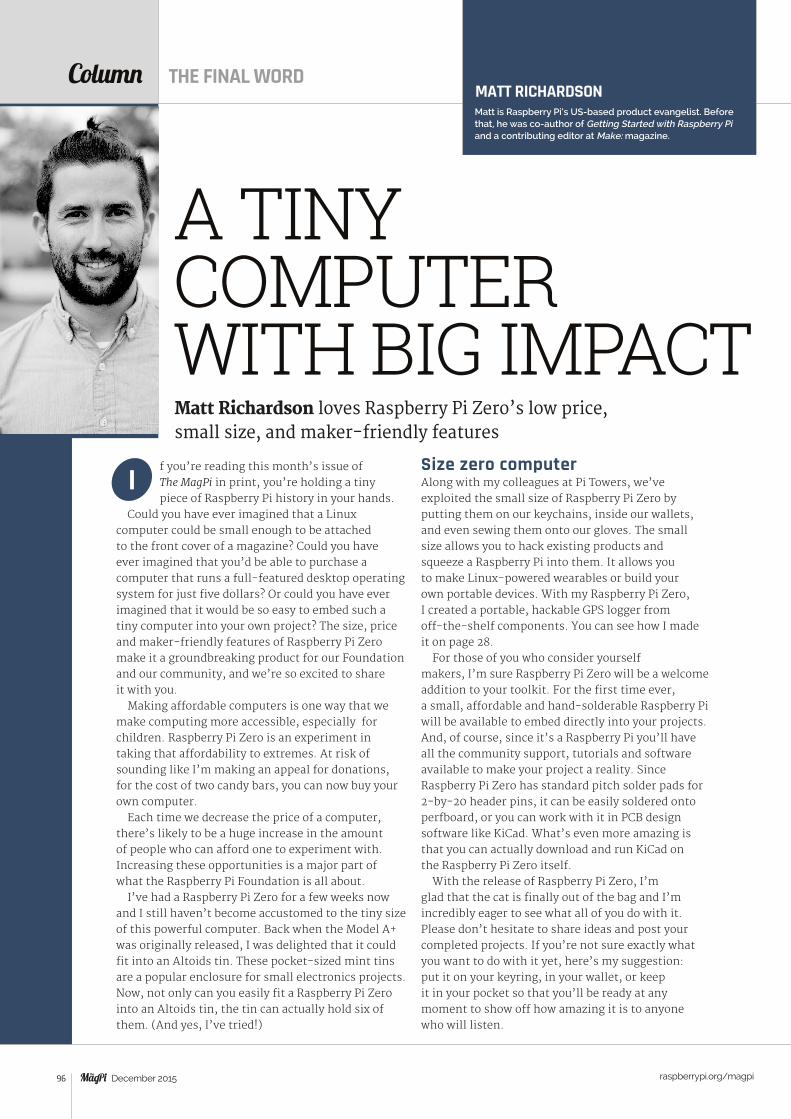
raspberrypi.org/magpi 96 December 2015
Column
f you’re reading this month’s issue of The MagPi in print, you’re holding a tiny piece of Raspberry Pi history in your hands.
Could you have ever imagined that a Linux computer could be small enough to be attached to the front cover of a magazine? Could you have ever imagined that you’d be able to purchase a computer that runs a full-featured desktop operating system for just five dollars? Or could you have ever imagined that it would be so easy to embed such a tiny computer into your own project? The size, price and maker-friendly features of Raspberry Pi Zero make it a groundbreaking product for our Foundation and our community, and we’re so excited to share it with you.
Making affordable computers is one way that we make computing more accessible, especially for children. Raspberry Pi Zero is an experiment in taking that affordability to extremes. At risk of sounding like I’m making an appeal for donations, for the cost of two candy bars, you can now buy your own computer.
Each time we decrease the price of a computer, there’s likely to be a huge increase in the amount of people who can afford one to experiment with. Increasing these opportunities is a major part of what the Raspberry Pi Foundation is all about.
I’ve had a Raspberry Pi Zero for a few weeks now and I still haven’t become accustomed to the tiny size of this powerful computer. Back when the Model A+ was originally released, I was delighted that it could fit into an Altoids tin. These pocket-sized mint tins are a popular enclosure for small electronics projects. Now, not only can you easily fit a Raspberry Pi Zero into an Altoids tin, the tin can actually hold six of them. (And yes, I’ve tried!)
ISize zero computerAlong with my colleagues at Pi Towers, we’ve exploited the small size of Raspberry Pi Zero by putting them on our keychains, inside our wallets, and even sewing them onto our gloves. The small size allows you to hack existing products and squeeze a Raspberry Pi into them. It allows you to make Linux-powered wearables or build your own portable devices. With my Raspberry Pi Zero, I created a portable, hackable GPS logger from off-the-shelf components. You can see how I made it on page 28.
For those of you who consider yourself makers, I’m sure Raspberry Pi Zero will be a welcome addition to your toolkit. For the first time ever, a small, affordable and hand-solderable Raspberry Pi will be available to embed directly into your projects. And, of course, since it’s a Raspberry Pi you’ll have all the community support, tutorials and software available to make your project a reality. Since Raspberry Pi Zero has standard pitch solder pads for 2-by-20 header pins, it can be easily soldered onto perfboard, or you can work with it in PCB design software like KiCad. What’s even more amazing is that you can actually download and run KiCad on the Raspberry Pi Zero itself.
With the release of Raspberry Pi Zero, I’m glad that the cat is finally out of the bag and I’m incredibly eager to see what all of you do with it. Please don’t hesitate to share ideas and post your completed projects. If you’re not sure exactly what you want to do with it yet, here’s my suggestion: put it on your keyring, in your wallet, or keep it in your pocket so that you’ll be ready at any moment to show off how amazing it is to anyone who will listen.
MATT RICHARDSONMatt is Raspberry Pi’s US-based product evangelist. Before that, he was co-author of Getting Started with Raspberry Pi and a contributing editor at Make: magazine.
Matt Richardson loves Raspberry Pi Zero’s low price, small size, and maker-friendly features
A TINY COMPUTER WITH BIG IMPACT
THE FINAL WORD

swag.raspberrypi.org
Raspberry Pi Birthday: 29th Feb 2016FREE BONUS DAY!
ONLY £5.99
IQaudIO
IQaudio Limited, 14 Ulysses Road
Swindon SN25 2JR Company No.: 9461908
Email: [email protected] Twitter: @IQ_audio
Audiophile accessories for the Raspberry Pi
WWW.IQAUDIO.COM
Made i
n the
UK
• Raspberry Pi HAT, no soldering required• Full-HD Audio (up to 24bit/192MHz)• Texas Instruments PCM5122• Industry standard Phono (RCA) sockets• Headphone Amplifier / 3.5mm socket• Out-of-the-box Raspbian support• Integrated hardware volume control• Access to Raspberry Pi GPIO• Connect direct to your own HiFI's line-in/aux
Pi-DAC+
• Raspberry Pi HAT, no soldering required• Up to 2x30w of crystal clear stereo amplification• Full-HD Audio (up to 24bit/192MHz)• Out-of-the-box Raspbian support• Integrated hardware volume control• Provides power to the Raspberry Pi• Software controlled AMP mute on GPIO22• I/O available (i2c, 3v, 5v, 0v, GPIO22/23/24/25)• Just add speakers for a complete HiFi streaming solution• Designed for custom install, retro radio restoration, in car, etc.
Pi-DigiAMP+
Supported applications
Pete Manchester's MediaPlayerMike Brady's Shairport-Sync
PiMusicBox
AND MANY MORE....
Buy direct