Embed Size (px)
Citation preview
A
utb©
K
1
biittettvmicaiopl
ma
0d
Journal of Power Sources 169 (2007) 375–380
Short communication
From symmetric AC/AC to asymmetric AC/graphite,a progress in electrochemical capacitors
Hongyu Wang, Masaki Yoshio ∗, Arjun Kumar Thapa, Hiroyoshi NakamuraSaga University, Saga 840-8501, Japan
Received 24 October 2006; received in revised form 13 February 2007; accepted 14 February 2007Available online 16 March 2007
bstract
Graphitic carbon instead of activated carbon has been employed as the positive electrode material in the activated carbon (AC)/carbon capacitorssing organic electrolytes. The advantageous electrochemical performance of the AC/graphite capacitors has been investigated as compared withhe AC/AC capacitors. The charge storage mechanism of anions on the graphite positive electrodes in the AC/graphite capacitors has been studiedy in situ XRD measurements.
2007 Elsevier B.V. All rights reserved.
ectrol
mrorGac
ecboeimtfomo
eywords: Electrochemical capacitors; Graphite; Activated carbon; Organic el
. Introduction
Recently, supercapacitors have drawn extensive attentionecause of their potential applications as electric storage devicesn many fields. In the conventional electric double-layer capac-tors (EDLCs), the storage of charge on electrodes is throughhe non-faradaic adsorption at the interfaces between the elec-rodes and electrolyte. Generally, both the positive and negativelectrodes in EDLCs are identical activated carbon (AC) elec-rodes. This type of symmetrical capacitors inevitably restrictsheir functional ranges such as specific capacitance, workingoltage, energy density, etc. [1,2], although they possess theerits of long cycle life and high power density. Moreover, dur-
ng the course of industrial production, the precursor of activatedarbon is mixed with a big amount of activating agents like KOHnd heated at a certain high temperature (e.g., 1000 ◦C) in thenert atmosphere. Considerable portions of carbon are “rotted”ff to construct the porous structure and wasted. These complexrocesses make the cost of activated carbon not economic forarge-scale production of EDLCs.
An alternative choice is the hybrid supercapacitor of an asym-etrical configuration in which battery electrode replaces one
ctivated carbon electrode [3–6]. The battery electrodes accu-
∗ Corresponding author. Tel.: +81 952 28 8673; fax: +81 952 28 8673.E-mail address: [email protected] (M. Yoshio).
uttatcc
378-7753/$ – see front matter © 2007 Elsevier B.V. All rights reserved.oi:10.1016/j.jpowsour.2007.02.088
ytes; Intercalation
ulate charge through faradaic electrochemical process (redoxeaction), which cannot only increases the specific capacitancef the capacitor, but also extends the working voltage. As aesult, the energy density of capacitor is enlarged considerably.enerally, there are three categories of redox-reaction materials
re used in the hybrid supercapacitors nowadays, metal oxides,onductive polymers and intercalation compounds.
We realized that the properties of the interface between thelectrodes and the electrolyte limit the performance of the wholeapacitor. Many limitations of the EDLC nowadays actually cane ascribed to this point. In fact, most solvated ions insteadf “bare” ions are adsorbed on the surface of activated carbonlectrodes. Of course, the coordinating solvent molecules ofons may occupy the space adsorbing ions. Since the solvent
olecules are electric neutral and contribute no electric charge,he “dilution” of the ions on the activated carbon electrode sur-ace by the solvent molecules may decrease the capacitancef the capacitor. On the other hand, these coordinating solventolecules of ions are very near the adsorption sites on the surface
f activated carbon and easy to be catalyzed to decompositionnder the ultrahigh strength of electric field. (We have witnessedhe burst of the AC/AC capacitors when we charged the capaci-ors to high voltages, say, 3.5 V.) An ideal case is that “bare” ions
re closely adsorbed on the accessible surface of carbon elec-rode. Then we expected that the interlayer space in graphiticarbon selectively accommodates ions and sieves out the parasiteoordinating solvent molecules. In previous studies, a concept of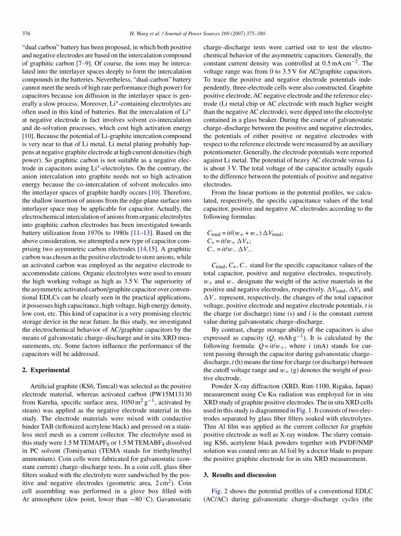
3 wer S
“aolccceoaa[ipptaettieibapcaatttilstmsc
2
efssbltiasfiicA
cccvTppttcctrpaite
lcf
tw
p�
vtv
efrdtt
mXutTpist
76 H. Wang et al. / Journal of Po
dual carbon” battery has been proposed, in which both positivend negative electrodes are based on the intercalation compoundf graphitic carbon [7–9]. Of course, the ions may be interca-ated into the interlayer spaces deeply to form the intercalationompounds in the batteries. Nevertheless, “dual-carbon” batteryannot meet the needs of high rate performance (high power) forapacitors because ion diffusion in the interlayer space is gen-rally a slow process. Moreover, Li+-containing electrolytes areften used in this kind of batteries. But the intercalation of Li+
t negative electrode in fact involves solvent co-intercalationnd de-solvation processes, which cost high activation energy10]. Because the potential of Li-graphite intercation compounds very near to that of Li metal, Li metal plating probably hap-ens at negative graphite electrode at high current densities (highower). So graphitic carbon is not suitable as a negative elec-rode in capacitors using Li+-electrolytes. On the contrary, thenion intercalation into graphite needs not so high activationnergy because the co-intercalation of solvent molecules intohe interlayer spaces of graphite hardly occurs [10]. Therefore,he shallow insertion of anions from the edge-plane surface intonterlayer space may be applicable for capacitor. Actually, thelectrochemical intercalation of anions from organic electrolytesnto graphitic carbon electrodes has been investigated towardsattery utilization from 1970s to 1980s [11–13]. Based on thebove consideration, we attempted a new type of capacitor com-rising two asymmetric carbon electrodes [14,15]. A graphiticarbon was chosen as the positive electrode to store anions, whilen activated carbon was employed as the negative electrode toccommodate cations. Organic electrolytes were used to ensurehe high working voltage as high as 3.5 V. The superiority ofhe asymmetric activated carbon/graphite capacitor over conven-ional EDLCs can be clearly seen in the practical applications,t possesses high capacitance, high voltage, high energy density,ow cost, etc. This kind of capacitor is a very promising electrictorage device in the near future. In this study, we investigatedhe electrochemical behavior of AC/graphite capacitors by theeans of galvanostatic charge–discharge and in situ XRD mea-
urements, etc. Some factors influence the performance of theapacitors will be addressed.
. Experimental
Artificial graphite (KS6, Timcal) was selected as the positivelectrode material, whereas activated carbon (PW15M13130rom Kureha, specific surface area, 1050 m2 g−1, activated byteam) was applied as the negative electrode material in thistudy. The electrode materials were mixed with conductiveinder TAB (teflonized acetylene black) and pressed on a stain-ess steel mesh as a current collector. The electrolyte used inhis study were 1.5 M TEMAPF6 or 1.5 M TEMABF4 dissolvedn PC solvent (Tomiyama) (TEMA stands for triethylmethylmmonium). Coin cells were fabricated for galvanostatic (con-tant current) charge–discharge tests. In a coin cell, glass fiber
lters soaked with the electrolyte were sandwiched by the pos-tive and negative electrodes (geometric area, 2 cm2). Coinell assembling was performed in a glove box filled withr atmosphere (dew point, lower than −80 ◦C). Gavanostatic
3
(
ources 169 (2007) 375–380
harge–discharge tests were carried out to test the electro-hemical behavior of the asymmetric capacitors. Generally, theonstant current density was controlled at 0.5 mA cm−2. Theoltage range was from 0 to 3.5 V for AC/graphite capacitors.o trace the positive and negative electrode potentials inde-endently, three-electrode cells were also constructed. Graphiteositive electrode, AC negative electrode and the reference elec-rode (Li metal chip or AC electrode with much higher weighthan the negative AC electrode), were dipped into the electrolyteontained in a glass beaker. During the course of galvanostaticharge–discharge between the positive and negative electrodes,he potentials of either positive or negative electrodes withespect to the reference electrode were measured by an auxiliaryotentiometer. Generally, the electrode potentials were reportedgainst Li metal. The potential of heavy AC electrode versus Lis about 3 V. The total voltage of the capacitor actually equalso the difference between the potentials of positive and negativelectrodes.
From the linear portions in the potential profiles, we calcu-ated, respectively, the specific capacitance values of the totalapacitor, positive and negative AC electrodes according to theollowing formulas:
Ctotal = it/(w+ + w−) �Vtotal;C+ = it/w+ �V+;C− = it/w− �V−.
Ctotal, C+, C− stand for the specific capacitance values of theotal capacitor, positive and negative electrodes, respectively.+ and w− designate the weight of the active materials in theositive and negative electrodes, respectively. �Vtotal, �V+ andV− represent, respectively, the changes of the total capacitor
oltage, positive electrode and negative electrode potentials. t ishe charge (or discharge) time (s) and i is the constant currentalue during galvanostatic charge–discharge.
By contrast, charge storage ability of the capacitors is alsoxpressed as capacity (Q, mAh g−1). It is calculated by theollowing formula: Q = it/w+, where i (mA) stands for cur-ent passing through the capacitor during galvanostatic charge–ischarge, t (h) means the time for charge (or discharge) betweenhe cutoff voltage range and w+ (g) denotes the weight of posi-ive electrode.
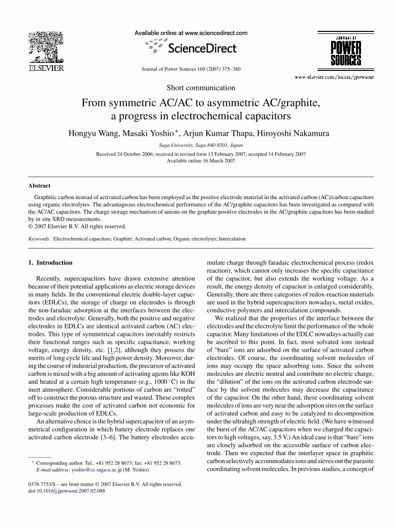
Powder X-ray diffraction (XRD, Rint-1100, Rigaku, Japan)easurement using Cu K� radiation was employed for in situRD study of graphite positive electrodes. The in situ XRD cellssed in this study is diagrammed in Fig. 1. It consists of two elec-rodes separated by glass fiber filters soaked with electrolytes.hin Al film was applied as the current collecter for graphiteositive electrode as well as X-ray window. The slurry contain-ng KS6, acetylene black powders together with PVDF/NMPolution was coated onto an Al foil by a doctor blade to preparehe positive graphite electrode for in situ XRD measurement.
. Results and discussion
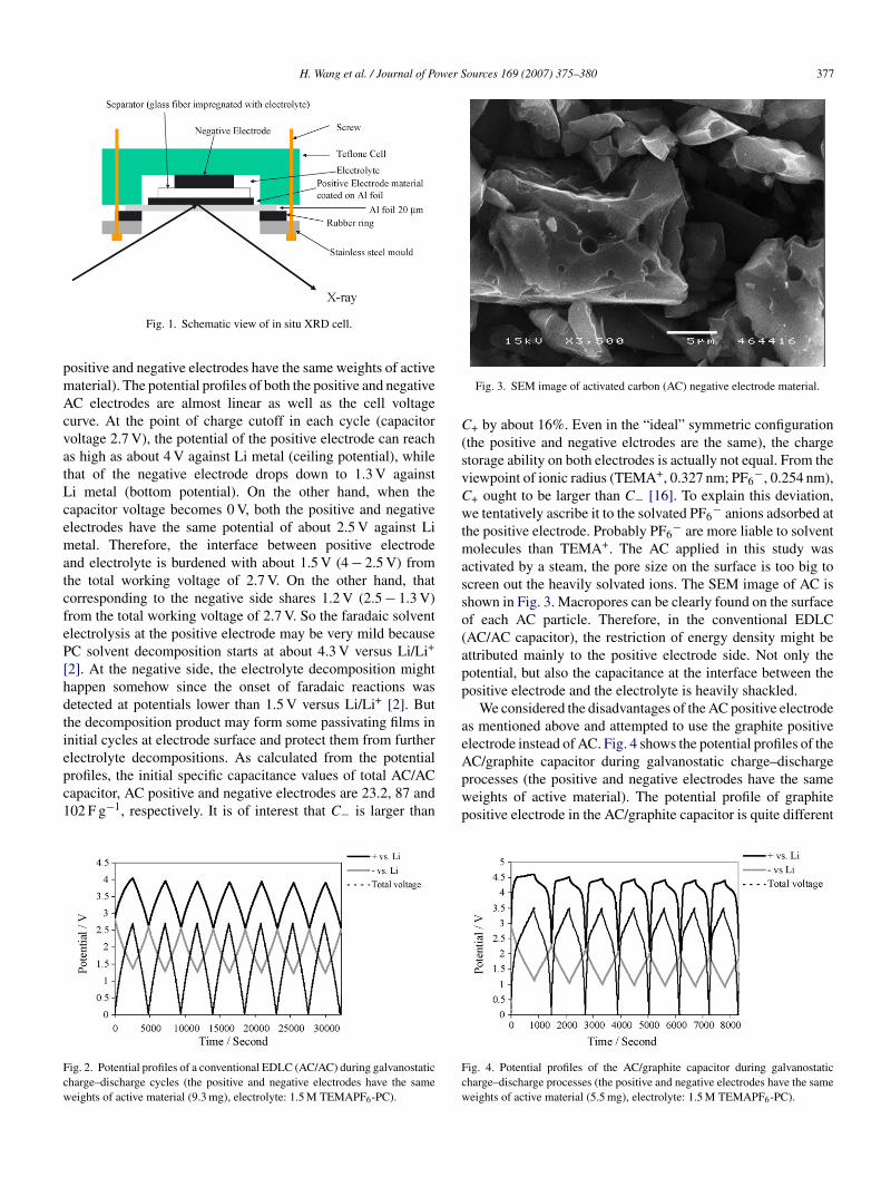
Fig. 2 shows the potential profiles of a conventional EDLCAC/AC) during galvanostatic charge–discharge cycles (the
H. Wang et al. / Journal of Power Sources 169 (2007) 375–380 377
pmAcvatLcematcfeP[hdtiepc1
Fcw
C(svCwtmasso(app
aeAC/graphite capacitor during galvanostatic charge–discharge
Fig. 1. Schematic view of in situ XRD cell.
ositive and negative electrodes have the same weights of activeaterial). The potential profiles of both the positive and negativeC electrodes are almost linear as well as the cell voltageurve. At the point of charge cutoff in each cycle (capacitoroltage 2.7 V), the potential of the positive electrode can reachs high as about 4 V against Li metal (ceiling potential), whilehat of the negative electrode drops down to 1.3 V againsti metal (bottom potential). On the other hand, when theapacitor voltage becomes 0 V, both the positive and negativelectrodes have the same potential of about 2.5 V against Lietal. Therefore, the interface between positive electrode
nd electrolyte is burdened with about 1.5 V (4 − 2.5 V) fromhe total working voltage of 2.7 V. On the other hand, thatorresponding to the negative side shares 1.2 V (2.5 − 1.3 V)rom the total working voltage of 2.7 V. So the faradaic solventlectrolysis at the positive electrode may be very mild becauseC solvent decomposition starts at about 4.3 V versus Li/Li+
2]. At the negative side, the electrolyte decomposition mightappen somehow since the onset of faradaic reactions wasetected at potentials lower than 1.5 V versus Li/Li+ [2]. Buthe decomposition product may form some passivating films innitial cycles at electrode surface and protect them from furtherlectrolyte decompositions. As calculated from the potential
rofiles, the initial specific capacitance values of total AC/ACapacitor, AC positive and negative electrodes are 23.2, 87 and02 F g−1, respectively. It is of interest that C− is larger thanig. 2. Potential profiles of a conventional EDLC (AC/AC) during galvanostaticharge–discharge cycles (the positive and negative electrodes have the sameeights of active material (9.3 mg), electrolyte: 1.5 M TEMAPF6-PC).
pwp
Fcw
Fig. 3. SEM image of activated carbon (AC) negative electrode material.
+ by about 16%. Even in the “ideal” symmetric configurationthe positive and negative elctrodes are the same), the chargetorage ability on both electrodes is actually not equal. From theiewpoint of ionic radius (TEMA+, 0.327 nm; PF6
−, 0.254 nm),+ ought to be larger than C− [16]. To explain this deviation,e tentatively ascribe it to the solvated PF6
− anions adsorbed athe positive electrode. Probably PF6
− are more liable to solventolecules than TEMA+. The AC applied in this study was
ctivated by a steam, the pore size on the surface is too big tocreen out the heavily solvated ions. The SEM image of AC ishown in Fig. 3. Macropores can be clearly found on the surfacef each AC particle. Therefore, in the conventional EDLCAC/AC capacitor), the restriction of energy density might bettributed mainly to the positive electrode side. Not only theotential, but also the capacitance at the interface between theositive electrode and the electrolyte is heavily shackled.
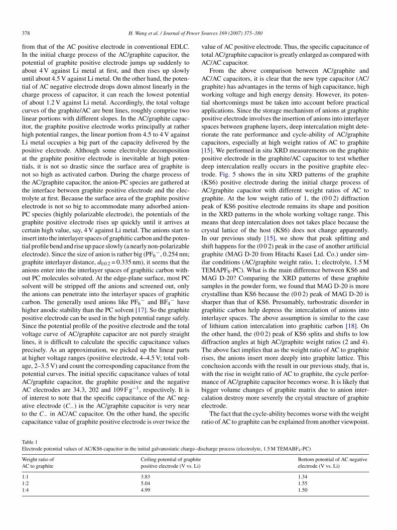
We considered the disadvantages of the AC positive electrodes mentioned above and attempted to use the graphite positivelectrode instead of AC. Fig. 4 shows the potential profiles of the
rocesses (the positive and negative electrodes have the sameeights of active material). The potential profile of graphiteositive electrode in the AC/graphite capacitor is quite different
ig. 4. Potential profiles of the AC/graphite capacitor during galvanostaticharge–discharge processes (the positive and negative electrodes have the sameeights of active material (5.5 mg), electrolyte: 1.5 M TEMAPF6-PC).
3 wer S
fIpautcoclihLpatntttePgcitegaostchpSvlpaapAAoatc
vtA
Agwtapsrc[pdt(AgpimcIsgiTMscsgiotdTrcwmb
TE
WA
111
78 H. Wang et al. / Journal of Po
rom that of the AC positive electrode in conventional EDLC.n the initial charge process of the AC/graphite capacitor, theotential of graphite positive electrode jumps up suddenly tobout 4 V against Li metal at first, and then rises up slowlyntil about 4.5 V against Li metal. On the other hand, the poten-ial of AC negative electrode drops down almost linearly in theharge process of capacitor, it can reach the lowest potentialf about 1.2 V against Li metal. Accordingly, the total voltageurves of the graphite/AC are bent lines, roughly comprise twoinear portions with different slopes. In the AC/graphite capac-tor, the graphite positive electrode works principally at ratherigh potential ranges, the linear portion from 4.5 to 4 V againsti metal occupies a big part of the capacity delivered by theositive electrode. Although some electrolyte decompositiont the graphite positive electrode is inevitable at high poten-ials, it is not so drastic since the surface area of graphite isot so high as activated carbon. During the charge process ofhe AC/graphite capacitor, the anion-PC species are gathered athe interface between graphite positive electrode and the elec-rolyte at first. Because the surface area of the graphite positivelectrode is not so big to accommodate many adsorbed anion-C species (highly polarizable electrode), the potentials of theraphite positive electrode rises up quickly until it arrives atertain high value, say, 4 V against Li metal. The anions start tonsert into the interlayer spaces of graphitic carbon and the poten-ial profile bend and rise up pace slowly (a nearly non-polarizablelectrode). Since the size of anion is rather big (PF6
−, 0.254 nm;raphite interlayer distance, d0 0 2 = 0.335 nm), it seems that thenions enter into the interlayer spaces of graphitic carbon with-ut PC molecules solvated. At the edge-plane surface, most PColvent will be stripped off the anions and screened out, onlyhe anions can penetrate into the interlayer spaces of graphiticarbon. The generally used anions like PF6
− and BF4− have
igher anodic stability than the PC solvent [17]. So the graphiteositive electrode can be used in the high potential range safely.ince the potential profile of the positive electrode and the totaloltage curve of AC/graphite capacitor are not purely straightines, it is difficult to calculate the specific capacitance valuesrecisely. As an approximation, we picked up the linear partst higher voltage ranges (positive electrode, 4–4.5 V; total volt-ge, 2–3.5 V) and count the corresponding capacitance from theotential curves. The initial specific capacitance values of totalC/graphite capacitor, the graphite positive and the negativeC electrodes are 34.3, 202 and 109 F g−1, respectively. It is
f interest to note that the specific capacitance of the AC neg-tive electrode (C−) in the AC/graphite capacitor is very nearo the C− in AC/AC capacitor. On the other hand, the specificapacitance value of graphite positive electrode is over twice thece
r
able 1lectrode potential values of AC/KS6 capacitor in the initial galvanostatic charge–di
eight ratio ofC to graphite
Ceiling potential of graphitepositive electrode (V vs. Li)
:1 3.83:2 5.04:4 4.99
ources 169 (2007) 375–380
alue of AC positive electrode. Thus, the specific capacitance ofotal AC/graphite capacitor is greatly enlarged as compared withC/AC capacitor.
From the above comparison between AC/graphite andC/AC capacitors, it is clear that the new type capacitor (AC/raphite) has advantages in the terms of high capacitance, highorking voltage and high energy density. However, its poten-
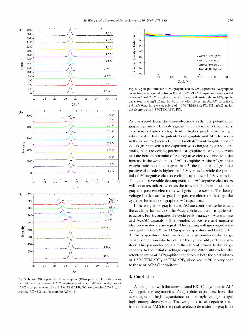
ial shortcomings must be taken into account before practicalpplications. Since the storage mechanism of anions at graphiteositive electrode involves the insertion of anions into interlayerpaces between graphene layers, deep intercalation might dete-iorate the rate performance and cycle-ability of AC/graphiteapacitors, especially at high weight ratios of AC to graphite15]. We performed in situ XRD measurements on the graphiteositive electrode in the graphite/AC capacitor to test whethereep intercalation really occurs in the positive graphite elec-rode. Fig. 5 shows the in situ XRD patterns of the graphiteKS6) positive electrode during the initial charge process ofC/graphite capacitor with different weight ratios of AC toraphite. At the low weight ratio of 1, the (0 0 2) diffractioneak of KS6 positive electrode remains its shape and positionn the XRD patterns in the whole working voltage range. This
eans that deep intercalation does not takes place because therystal lattice of the host (KS6) does not change apparently.n our previous study [15], we show that peak splitting andhift happens for the (0 0 2) peak in the case of another artificialraphite (MAG D-20 from Hitachi Kasei Ltd. Co.) under sim-lar conditions (AC/graphite weight ratio, 1; electrolyte, 1.5 MEMAPF6-PC). What is the main difference between KS6 andAG D-20? Comparing the XRD patterns of these graphite
amples in the powder form, we found that MAG D-20 is morerystalline than KS6 because the (0 0 2) peak of MAG D-20 isharper than that of KS6. Presumably, turbostratic disorder inraphitic carbon help depress the intercalation of anions intonterlayer spaces. The above assumption is similar to the casef lithium cation intercalation into graphitic carbon [18]. Onhe other hand, the (0 0 2) peak of KS6 splits and shifts to lowiffraction angles at high AC/graphite weight ratios (2 and 4).he above fact implies that as the weight ratio of AC to graphite
ises, the anions insert more deeply into graphite lattice. Thisonclusion accords with the result in our previous study, that is,ith the rise in weight ratio of AC to graphite, the cycle perfor-ance of AC/graphite capacitor becomes worse. It is likely that
igger volume changes of graphite matrix due to anion inter-
alation destroy more severely the crystal structure of graphitelectrode.The fact that the cycle-ability becomes worse with the weightatio of AC to graphite can be explained from another viewpoint.
scharge process (electrolyte, 1.5 M TEMABF4-PC)
Bottom potential of AC negativeelectrode (V vs. Li)
1.341.551.50
H. Wang et al. / Journal of Power Sources 169 (2007) 375–380 379
Fig. 5. In situ XRD patterns of the graphite (KS6) positive electrode duringthe initial charge process of AC/graphite capacitor with different weight ratiosof AC to graphite, electrolyte: 1.5 M TEMABF4-PC: (a) graphite:AC = 1:1, (b)graphite:AC = 1:2 and (c) graphite:AC = 1:4.
Fig. 6. Cycle performance of AC/graphite and AC/AC capacitors (AC/graphitecapacitors were cycled between 0 and 3.5 V; AC/AC capacitors were cycledbetween 0 and 2.5 V; weights of the active electrode materials: in AC/graphitec8t
AgeriAeaiwptTwgvc
tiaeaAcicrot
4
Aaht
apacitor, 11.6 mg/11.6 mg for both the electrolytes; in AC/AC capacitors,.0 mg/8.0 mg for the electrolyte of 1.5 M TEMABF4-PC, 8.2 mg/8.2 mg forhe electrolyte of 1.5 M TEMAPF6-PC).
s measured from the three-electrode cells, the potential ofraphite positive electrode against the reference electrode likelyxperiences higher voltage load at higher graphite/AC weightatio. Table 1 lists the potentials of graphite and AC electrodesn the capacitor (versus Li metal) with different weight ratios ofC to graphite when the capacitor was charged to 3.5 V. Gen-rally, both the ceiling potential of graphite positive electrodend the bottom potential of AC negative electrode rise with thencrease in the weight ratio of AC to graphite. As the AC/graphiteeight ratio becomes bigger than 2, the potential of graphiteositive electrode is higher than 5 V versus Li while the poten-ial of AC negative electrode climbs up to over 1.5 V versus Li.hus, the irreversible decomposition at AC negative electrodesill becomes milder, whereas the irreversible decomposition atraphite positive electrodes will gets more severe. The heavyoltage burden on the graphite positive electrode destroys theycle performance of graphite/AC capacitors.
If the weights of graphite and AC are controlled to be equal,he cycle performance of the AC/graphite capacitor is quite sat-sfactory. Fig. 6 compares the cycle performance of AC/graphitend AC/AC capacitors (the weights of positive and negativelectrode materials are equal). The cycling voltage ranges wererranged to 0–3.5 V for AC/graphite capacitors and 0–2.5 V forC/AC capacitors. Here, we adopted a parameter of dischargeapacity retention ratio to evaluate the cycle-ability of the capac-tors. This parameter equals to the ratio of nth-cycle dischargeapacity to the initial discharge capacity. After 300 cycles, theetention ratios of AC/graphite capacitors in both the electrolytesf 1.5 M TEMABF4 or TEMAPF6 dissolved in PC is very nearo those of AC/AC capacitors.
. Conclusion
As compared with the conventional EDLCs (symmetric AC/
C type), the asymmetric AC/graphite capacitors have thedvantages of high capacitance in the high voltage range,igh energy density, etc. The weight ratio of negative elec-rode material (AC) to the positive electrode material (graphite)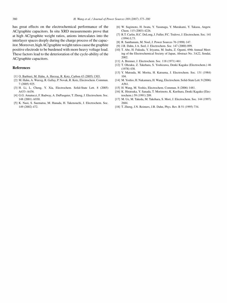
3 wer S
hAaiipTA
R
[
[[
[
[
[
80 H. Wang et al. / Journal of Po
as great effects on the electrochemical performance of theC/graphite capacitors. In situ XRD measurements prove thatt high AC/graphite weight ratios, anions intercalates into thenterlayer spaces deeply during the charge process of the capac-tor. Moreover, high AC/graphite weight ratios cause the graphiteositive electrode to be burdened with more heavy voltage load.hese factors lead to the deterioration of the cycle-ability of theC/graphite capacitors.
eferences
[1] O. Barbieri, M. Hahn, A. Herzog, R. Kotz, Carbon 43 (2005) 1303.[2] M. Hahn, A. Wursig, R. Gallay, P. Novak, R. Kotz, Electrochem. Commun.
7 (2005) 925.[3] H. Li, L. Cheng, Y. Xia, Electrochem. Solid-State Lett. 8 (2005)
A433–A436.[4] G.G. Amatucci, F. Badway, A. DuPasquier, T. Zheng, J. Electrochem. Soc.
148 (2001) A930.[5] K. Naoi, S. Suematsu, M. Hanada, H. Takenouchi, J. Electrochem. Soc.
149 (2002) 472.
[
[
[
ources 169 (2007) 375–380
[6] W. Sugimoto, H. Iwata, Y. Yasunaga, Y. Murakami, Y. Takasu, Angew.Chem. 115 (2003) 4226.
[7] R.T. Carlin, H.C. DeLong, J. Fuller, P.C. Trulove, J. Electrochem. Soc. 141(1994) L73.
[8] R. Santhanam, M. Noel, J. Power Sources 76 (1998) 147.[9] J.R. Dahn, J.A. Seel, J. Electrochem. Soc. 147 (2000) 899.10] T. Abe, H. Fukuda, Y. Iriyama, M. Inaba, Z. Ogumi, 69th Annual Meet-
ing of the Electrochemical Society of Japan, Abstract No. 3A22, Sendai,2002.
11] A. Brenner, J. Electrochem. Soc. 118 (1971) 461.12] T. Ohzuku, Z. Takehara, S. Yoshizawa, Denki Kagaku (Electrochem.) 46
(1978) 438.13] Y. Matsuda, M. Morita, H. Katsuma, J. Electrochem. Soc. 131 (1984)
104.14] M. Yoshio, H. Nakamura, H. Wang, Electrochem. Solid-State Lett. 9 (2006)
A561.15] H. Wang, M. Yoshio, Electrochem. Commun. 8 (2006) 1481.
16] K. Hiratsuka, Y. Sanada, T. Morimoto, K. Kurihara, Denki Kagaku (Elec-trochem.) 59 (1991) 209.17] M. Ue, M. Takeda, M. Takehara, S. Mori, J. Electrochem. Soc. 144 (1997)
2684.18] T. Zheng, J.N. Reimers, J.R. Dahn, Phys. Rev. B 51 (1995) 734.


