Embed Size (px)
Citation preview

FRONT RANGE FIRE APPARATUS
7600 Miller Court Frederick, CO 80504
303-449-99111-800-334-9911
www.FrontRangeFire.com
JASON BYRNE 303-929-0079

NEDERLAND FIRE PROTECTION DISTRICT PIERCE SABER 4X4 ENGINE BID #1177
1. PROPOSAL PRICING
2. MAIN PROPOSAL
3. COMPONENT LIST, ELECTRICAL ANALYSIS, TURN REPORT, WEIGHT REPORT, DRAWING
4. WARRANTIES
5. CERTIFICATIONS AND TECHNICAL INFORMATION
6. PIERCE MANUFACTURING, LICENSE & INSURANCE CERTIFICATE OF GOOD STANDING
7. FRONT RANGE FIRE APPARATUS, LICENSE & INSURANCE
8. LITERATURE

A LOT’S RIDING ON YOUR INVESTMENT.The safety of firefighters and families, the security of property and the well-being of the entire community depend on your decision. Lives and reputations ride on your investment. Make sure help is always on the way.
Go with longevity. Go with the #1 industry authority that protects the legacies great community leaders leave behind. When you invest in Pierce® fire apparatus, you’re making the right call for the long haul.
Untouchable Fire Apparatus Expertise
• Over 30,000 custom chassis built
• More than 30 patents attributed to our continued investmentin research, development and safety
• Thousands of years of cumulative experience
• First single-source manufacturer of custom fire apparatusin North America to achieve ISO 9001 certification
• Only manufacturer to have third party, UnderwritersLaboratories certification on the entire apparatus
Unshakable Stability
• Rock-solid financials as an Oshkosh Corporation Company
• Oshkosh named a World’s Most Ethical Company byEthisphere Institute
• Recognized as a 2016 Best Governance, Risk,and Compliance Program by NYSE Governance Services
• Complete transparency of a public traded company
• Greater strength from shared engineering and technologyacross all of Oshkosh Corporation
• With over 100 years of history and numerous industry-firstcontributions, we’re not going anywhere
• America’s Best Large Employers list by Forbes
No other manufacturer has a stronger foundation of expertise, stability and support.
NO REGRETS WHEN YOU CHOOSE
PIERCE.
Unmatched Support
• Over 35 years in business
• Staffed by 7 sales professionals with 150 yearsof combined experience
• State-of-the-art service center employs a teamof highly trained and certified technicians
• Mobile services and a full line of parts and equipment

Pierce Manufacturing Inc., An Oshkosh Corporation CompanyP.O. Box 2017, Appleton WI 54912-2017 USA
www.piercemfg.com
Specifications, descriptions and illustrative material in this literature are as accurate as known at the time of publication, but are subject to change without notice. Illustrations may include optional equipment and accessories and may not include all standard equipment. All measurements are nominal values. © Pierce Manufacturing Inc., Pierce and the Pierce logo are registered trademarks of Pierce Manufacturing Inc., Appleton, WI.
Printed in U.S.A. All other trademarks are the property of their respective owners. P-0108-SLLSTBLTYSS-FRNTRNG 1/17
200+FULL-TIME
ENGINEERS
ISO 9001CERTIFICATION
#1RESEARCH,
DEVELOPMENT & SAFETY
SINGLE SOURCE
GLOBALLY USED
PATENTS
$9MPARTS
INVENTORY
PIERCE PIERCE & OSHKOSHPIERCE
PIERCE
UL/ULC CERTIFIED
PIERCE & OSHKOSH
OSHKOSH
PIERCE PIERCE
3RD PARTY CERTIFIED
NFPA 1901-2009
OVER 13,000 EMPLOYEESWORLDWIDE
OSHKOSH
1,600+MANUFACTURING
EMPLOYEES
PIERCE
FRONT RANGE FIRE APPARATUS
24/7 RESPONSE
Pierce leads the industry in sponsorships that support families of fallen firefighters, recognize outstanding achievement and further the education and safety of the fire service.

PROPOSAL FOR FURNISHING FIRE APPARATUS
April 15, 2022
Nederland Fire Protection District 650 W 4th St. Nederland, CO 80466 The undersigned is prepared to manufacture for you, upon an order being placed by you, for final acceptance by Front Range Fire Apparatus., at its home office in Frederick, Colorado, the apparatus, and equipment herein named and for the following prices: (1) One Pierce Saber 4x4 Engine Per Bid #1177 $814,568.00
Note: Pricing per HGAC Discount for orders received on / prior to 4-30-22 Deduct ($54,225.00) Optional 100% Performance Bond $1,996.00 (Note: Required for Pre-Payment options) Optional Discount for 100% Pre-Payment of $742,141.00 Deduct ($20,198.00)
(Note: Requires and Includes Performance Bond) (Note: Net due within 30 days of contract signing)
Total _____________ Said apparatus and equipment are to be built and shipped in accordance with the specifications hereto attached, delays due to strikes, war, or intentional conflict, failures to obtain chassis, materials, or other causes beyond our control not preventing, within about 16 months after receipt of this order and the acceptance thereof at our office at Frederick, Colorado, and to be delivered to you in Nederland, CO. The specifications herein contained shall form a part of the final contract, and are subject to changes desired by the purchaser, provided such alterations are interlined prior to the acceptance by the company of the order to purchase, and provided such alterations do not materially affect the cost of the construction of the apparatus. The proposal for fire apparatus conforms with all Federal Department of Transportation (DOT) rules and regulations in effect at the time of bid, and with all National Fire Protection Association (NFPA) Guidelines for Automotive Fire Apparatus as published at the time of bid, except as modified by customer specifications. Any increased costs incurred by first party because of future changes in or additions to said DOT or NFPA standards will be passed along to the customers as an addition to the price set forth above. Unless accepted within 30 days from date, the right is reserved to withdraw this proposition. FRONT RANGE FIRE APPRATUS. By: ________________________ Jason Byrne SALES REPRESENTATIVE

7600 Miller Court Frederick West Business Park
Frederick, Colorado 80504 303-449-9911 800-334-9911 fax 303-532-2486
frontrangefire.com
Nederland Fire Protection District Pierce 4x4 Saber Engine Bid #1177
Bid Notes Service and Warranty Support: Dealership -Front Range Fire Apparatus is 38 road miles from Nederland, CO. -Front Range Fire Apparatus is staffed with EVT certified technicians, a Master EVT certified technician, a mobile EVT certified technician, a service manager, two dedicated parts support personnel, and additional support personnel. Please see the “Front Range Fire Apparatus” tab of our bid for additional information on service, mobile service, parts support, and certifications of our technicians. Mobile Service and Warranty Support: Dealership -Front Range Fire Apparatus is 38 road miles from Nederland, CO. -Front Range Fire Apparatus is staffed with EVT certified technicians, a Master EVT certified technician, a mobile EVT certified technician, a service manager, two dedicated parts support personnel, and additional support personnel. Please see the “Front Range Fire Apparatus” tab of our bid for additional information on service, mobile service, parts support, and certifications of our technicians. Parts Support: Dealership -Front Range Fire Apparatus is staffed with EVT certified technicians, a Master EVT certified technician, a mobile EVT certified technician, a service manager, two dedicated parts support personnel, and additional support personnel. Please see the “Front Range Fire Apparatus” tab of our bid for additional information on service, mobile service, parts support, and certifications of our technicians. Included in Proposal: Pre Build Trip #1 An inspection trip shall be provided for up to 3 people. Trip is to take place at the main manufacturing facility. The successful bidder is responsible for air fare, ground travel, lodging, and all other costs associated with this trip.

7600 Miller Court Frederick West Business Park
Frederick, Colorado 80504 303-449-9911 800-334-9911 fax 303-532-2486
frontrangefire.com
Included in Proposal: Final Inspection Trip #2 An inspection trip shall be provided for up to 3 people. Trip is to take place at the main manufacturing facility. The successful bidder is responsible for air fare, ground travel, lodging, and all other costs associated with this trip. Delivery Date -The proposed time to completed first unit for inspection is 545 days from order acceptance. Include in Proposal: Contingency Fund, For Equipment Mounting and Changes A $5,000 contingency fund shall be included in the bid price. Any and all amount of the contingency fund not used during the final design of the apparatus shall be refunded to the purchaser and listed as so on the final invoice. This fund is for changes requested by the bidder during the build process but after the bid. This fund is for equipment mounting to be provided by the successful bidder. Equipment mounting is to be charged to the fund as time and materials. Time is to be the successful bidders published shop labor rater. Materials are to be at or below manufactures MSRP for the materials and/or mounts. All changes and or labor utilizing the contingency fund is to be approved by the purchaser prior to use of those funds.

1 of 124
CONTENTS GENERAL DESIGN AND CONSTRUCTION ...................................................................................... 16
QUALITY AND WORKMANSHIP ........................................................................................................ 16
DELIVERY .......................................................................................................................................... 17
MANUAL AND SERVICE INFORMATION .......................................................................................... 17
SAFETY VIDEO .................................................................................................................................. 17
PERFORMANCE TESTS .................................................................................................................... 17
SERVICE AND WARRANTY SUPPORT ............................................................................................ 17
LIABILITY ............................................................................................................................................ 18
INSURANCE PROVIDED BY BIDDER ............................................................................................... 18
COMMERCIAL GENERAL LIABILITY INSURANCE .......................................................................... 18
COMMERCIAL AUTOMOBILE LIABILITY INSURANCE .................................................................... 19
UMBRELLA/EXCESS LIABILITY INSURANCE .................................................................................. 19
INSURANCE PROVIDED BY MANUFACTURER .............................................................................. 19
PRODUCT LIABILITY INSURANCE ................................................................................................... 19
UMBRELLA/EXCESS LIABILITY INSURANCE .................................................................................. 20
SINGLE SOURCE MANUFACTURER ................................................................................................ 20
NFPA 2016 STANDARDS ................................................................................................................... 20
NFPA COMPLIANCY .......................................................................................................................... 21
PUMP TEST ........................................................................................................................................ 21
GENERATOR TEST ........................................................................................................................... 21
WEEKLY PROGRESS REPORTS ...................................................................................................... 21
APPARATUS MANUFACTURER ....................................................................................................... 21
AFTERMARKET SUPPORT WEBSITE .............................................................................................. 21
BID BOND NOT REQUESTED ........................................................................................................... 23
PERFORMANCE BOND, 1 YEAR ...................................................................................................... 23
APPROVAL DRAWING ....................................................................................................................... 23
ELECTRICAL WIRING DIAGRAMS .................................................................................................... 24
SABER FR CHASSIS.......................................................................................................................... 24
WHEELBASE ...................................................................................................................................... 24
GVW RATING ..................................................................................................................................... 24
FRAME ................................................................................................................................................ 24

2 of 124
FRONT AXLE ...................................................................................................................................... 24
FRONT SUSPENSION ....................................................................................................................... 24
SHOCK ABSORBERS ........................................................................................................................ 24
GREASE SEALS ................................................................................................................................. 25
DRIVER CONTROL DIFFERENTIAL LOCK (DCDL) .......................................................................... 25
FRONT TIRES .................................................................................................................................... 25
REAR AXLE ........................................................................................................................................ 25
TOP SPEED OF VEHICLE ................................................................................................................. 25
REAR SUSPENSION .......................................................................................................................... 25
REAR OIL SEALS ............................................................................................................................... 25
DRIVER CONTROL DIFFERENTIAL LOCK (CTD) ............................................................................ 25
REAR TIRES ....................................................................................................................................... 26
TIRE BALANCE .................................................................................................................................. 26
TIRE PRESSURE MANAGEMENT ..................................................................................................... 26
CHROME LUG NUT COVERS ........................................................................................................... 26
MUD FLAPS ........................................................................................................................................ 26
AIR PRESSURE TIRE EQUALIZATION ............................................................................................. 26
WHEEL CHOCKS ............................................................................................................................... 26
Wheel Chock Brackets .................................................................................................................... 26
ANTI-LOCK BRAKE SYSTEM ............................................................................................................ 26
ELECTRONIC STABILITY CONTROL ................................................................................................ 27
AUTOMATIC TRACTION CONTROL ................................................................................................. 27
BRAKES .............................................................................................................................................. 27
BRAKE SYSTEM AIR COMPRESSOR .............................................................................................. 27
BRAKE SYSTEM ................................................................................................................................ 27
BRAKE SYSTEM AIR DRYER ............................................................................................................ 28
BRAKE LINES ..................................................................................................................................... 28
AIR INLET WITH AUTOMATIC EJECT .............................................................................................. 28
ADDITIONAL AIR TANK ..................................................................................................................... 28
AUTOMATIC MOISTURE EJECTORS ............................................................................................... 29
ENGINE .............................................................................................................................................. 29
HIGH IDLE .......................................................................................................................................... 29
ENGINE BRAKE ................................................................................................................................. 30

3 of 124
CLUTCH FAN...................................................................................................................................... 30
ENGINE AIR INTAKE .......................................................................................................................... 30
EXHAUST SYSTEM............................................................................................................................ 30
RADIATOR .......................................................................................................................................... 30
COOLANT LINES................................................................................................................................ 31
FUEL TANK......................................................................................................................................... 31
DIESEL EXHAUST FLUID TANK ........................................................................................................ 31
FUEL PRIMING PUMP ....................................................................................................................... 32
TRANSMISSION ................................................................................................................................. 32
TRANSMISSION SHIFTER ................................................................................................................. 32
TRANSMISSION COOLER ................................................................................................................. 32
DOWNSHIFT MODE (w/engine brake) ............................................................................................... 32
DRIVELINE ......................................................................................................................................... 33
STEERING .......................................................................................................................................... 33
STEERING WHEEL ............................................................................................................................ 33
LOGO AND CUSTOMER DESIGNATION ON DASH ......................................................................... 33
FRONT WINCH ................................................................................................................................... 33
BUMPER ............................................................................................................................................. 34
GRAVEL PAN .................................................................................................................................. 34
TOW EYES ......................................................................................................................................... 34
CAB ..................................................................................................................................................... 34
CAB ROOF DRIP RAIL ....................................................................................................................... 35
INTERIOR CAB INSULATION ............................................................................................................ 36
FENDER LINERS................................................................................................................................ 36
PANORAMIC WINDSHIELD ............................................................................................................... 36
WINDSHIELD WIPERS....................................................................................................................... 36
ENGINE TUNNEL ............................................................................................................................... 36
INTERIOR CREW CAB REAR WALL ADJUSTABLE SEATING (PATENT PENDING) ..................... 37
CAB REAR WALL EXTERIOR COVERING ........................................................................................ 38
CAB LIFT ............................................................................................................................................ 38
Cab Lift Interlock .............................................................................................................................. 38
GRILLE ............................................................................................................................................... 38
MIRRORS ........................................................................................................................................... 38

4 of 124
DOORS ............................................................................................................................................... 38
Door Panels ..................................................................................................................................... 39
MANUAL CAB DOOR WINDOWS ...................................................................................................... 40
CAB STEPS ........................................................................................................................................ 40
CAB EXTERIOR HANDRAILS ............................................................................................................ 40
STIRRUP STEPS ................................................................................................................................ 40
STEP LIGHTS ..................................................................................................................................... 40
FENDER CROWNS ............................................................................................................................ 40
CREW CAB WINDOWS ...................................................................................................................... 41
CUP HOLDER ..................................................................................................................................... 41
CAB DASH .......................................................................................................................................... 41
MOUNTING PLATE ON ENGINE TUNNEL ........................................................................................ 41
MOUNTING PLATE(S) ........................................................................................................................ 41
CAB INTERIOR ................................................................................................................................... 41
CAB INTERIOR UPHOLSTERY ......................................................................................................... 42
CAB INTERIOR PAINT ....................................................................................................................... 42
CAB FLOOR........................................................................................................................................ 42
DEFROST/AIR CONDITIONING SYSTEM ......................................................................................... 42
Cab Defroster .................................................................................................................................. 42
Cab/Crew Auxiliary Heater .............................................................................................................. 43
Air Conditioning ............................................................................................................................... 43
Climate Control ................................................................................................................................ 43
Gravity Drain Tubes ......................................................................................................................... 44
WINDOW DEFROST FANS ................................................................................................................ 44
SUN VISORS ...................................................................................................................................... 44
GRAB HANDLES ................................................................................................................................ 44
ENGINE COMPARTMENT LIGHT ...................................................................................................... 45
ACCESS TO ENGINE DIPSTICKS ..................................................................................................... 45
STORAGE BOX .................................................................................................................................. 45
MAP BOX ............................................................................................................................................ 45
CAB SAFETY SYSTEM ...................................................................................................................... 45
FRONTAL IMPACT PROTECTION .................................................................................................... 46
SIDE ROLL PROTECTION ................................................................................................................. 46

5 of 124
SEATING CAPACITY .......................................................................................................................... 47
DRIVER SEAT .................................................................................................................................... 47
OFFICER SEAT .................................................................................................................................. 47
RADIO COMPARTMENT .................................................................................................................... 47
REAR FACING DRIVER SIDE OUTBOARD SEAT ............................................................................ 48
REAR FACING PASSENGER SIDE OUTBOARD SEAT ................................................................... 48
FORWARD FACING CENTER CABINET ........................................................................................... 48
Cabinet Light ................................................................................................................................... 49
MATTING IN EMS COMPARTMENT .................................................................................................. 49
SEAT UPHOLSTERY.......................................................................................................................... 49
AIR BOTTLE HOLDERS ..................................................................................................................... 49
SEAT BELTS....................................................................................................................................... 49
HELMET STORAGE PROVIDED BY FIRE DEPARTMENT ............................................................... 50
CAB DOME LIGHTS ........................................................................................................................... 50
HAND HELD LIGHT ............................................................................................................................ 50
HAND HELD LIGHT ............................................................................................................................ 50
CAB INSTRUMENTATION ................................................................................................................. 50
Gauges ............................................................................................................................................ 51
Indicator Lamps ............................................................................................................................... 51
Alarms ............................................................................................................................................. 52
Indicator Lamp and Alarm Prove-Out .............................................................................................. 52
Control Switches .............................................................................................................................. 52
Custom Switch Panels ..................................................................................................................... 53
Diagnostic Panel .............................................................................................................................. 54
AIR RESTRICTION INDICATOR ........................................................................................................ 55
"DO NOT MOVE APPARATUS" INDICATOR ..................................................................................... 55
SWITCH PANELS ............................................................................................................................... 55
WIPER CONTROL .............................................................................................................................. 55
CUSTOMER SUPPLIED RADIO WIRING .......................................................................................... 55
SPARE CIRCUIT................................................................................................................................. 55
SPARE CIRCUIT................................................................................................................................. 56
INFORMATION CENTER ................................................................................................................... 56
COLLISION MITIGATION ................................................................................................................... 56

6 of 124
VEHICLE DATA RECORDER ............................................................................................................. 57
Seat Belt Monitoring System ........................................................................................................... 57
INTERCOM SYSTEM ......................................................................................................................... 58
RADIO / INTERCOM INTERFACE INCLUDED .................................................................................. 58
OVER THE HEAD HEADSET ............................................................................................................. 58
UNDER THE HELMET HEADSET ...................................................................................................... 58
HEADSET HANGERS......................................................................................................................... 59
RADIO ANTENNA MOUNT ................................................................................................................. 59
VEHICLE CAMERA SYSTEM ............................................................................................................. 59
VEHICLE CAMERA GUARD ............................................................................................................... 59
ELECTRICAL POWER CONTROL SYSTEM ..................................................................................... 59
VOLTAGE MONITOR SYSTEM ...................................................................................................... 60
POWER AND GROUND STUDS .................................................................................................... 60
EMI/RFI PROTECTION ................................................................................................................... 60
ELECTRICAL ...................................................................................................................................... 60
BATTERY SYSTEM ............................................................................................................................ 61
BATTERY SYSTEM ............................................................................................................................ 62
MASTER BATTERY SWITCH ............................................................................................................. 62
BATTERY COMPARTMENTS ............................................................................................................ 62
JUMPER STUDS ................................................................................................................................ 62
BATTERY CHARGER ......................................................................................................................... 62
SHORELINE INLET ............................................................................................................................ 62
ELECTRIC POWER FOR WINCH ...................................................................................................... 63
ALTERNATOR .................................................................................................................................... 63
ELECTRONIC LOAD MANAGEMENT ................................................................................................ 63
HEADLIGHTS ..................................................................................................................................... 63
FRONT DIRECTIONALS .................................................................................................................... 64
INTERMEDIATE LIGHT ...................................................................................................................... 64
CAB CLEARANCE/MARKER/ID LIGHTS ........................................................................................... 64
FRONT CAB SIDE DIRECTIONAL/MARKER LIGHTS ....................................................................... 64
REAR CLEARANCE/MARKER/ID LIGHTING .................................................................................... 64
REAR FMVSS LIGHTING ................................................................................................................... 65
LICENSE PLATE BRACKET............................................................................................................... 65

7 of 124
LIGHTING BEZEL ............................................................................................................................... 65
BACK-UP ALARM ............................................................................................................................... 65
SWITCH, BACK-UP ALARM OVERRIDE ........................................................................................... 66
CAB PERIMETER SCENE LIGHTS .................................................................................................... 66
PUMP HOUSE PERIMETER LIGHTS ................................................................................................ 66
BODY PERIMETER SCENE LIGHTS ................................................................................................. 66
ADDITIONAL PERIMETER LIGHTS ................................................................................................... 66
STEP LIGHTS ..................................................................................................................................... 66
SCENE LIGHT HOUSINGS ................................................................................................................ 67
SPECIAL SWITCHING FOR SCENE LIGHTS .................................................................................... 67
12 VOLT LIGHTING ............................................................................................................................ 67
12 VOLT LIGHTING ............................................................................................................................ 67
12 VOLT LIGHTING ............................................................................................................................ 68
12 VOLT LIGHTING ............................................................................................................................ 68
HOSE BED LIGHTS ............................................................................................................................ 68
WALKING SURFACE LIGHT .............................................................................................................. 68
FRONT WHITE WARNING LIGHT CONTROL ................................................................................... 68
SWITCH, RED..................................................................................................................................... 69
WATER TANK ..................................................................................................................................... 69
WATER TANK RESTRAINT ............................................................................................................... 70
HOSE BED .......................................................................................................................................... 70
HOSE BED DIVIDER .......................................................................................................................... 70
CUTOUT, HANDHOLD ....................................................................................................................... 70
HOSE BED COVER ............................................................................................................................ 71
RUNNING BOARDS ........................................................................................................................... 71
TAILBOARD ........................................................................................................................................ 71
REAR WALL, SMOOTH ALUMINUM/BODY MATERIAL ................................................................... 71
REAR TOW EYES .............................................................................................................................. 72
RUNNING BOARD HOSE RESTRAINT ............................................................................................. 72
RUNNING BOARD HOSE RESTRAINT ............................................................................................. 72
HOSE TRAY........................................................................................................................................ 72
EXTINGUISHER BIN IN HOSE TRAY ................................................................................................ 72
COMPARTMENTATION ..................................................................................................................... 72

8 of 124
UNDERBODY SUPPORT SYSTEM ................................................................................................... 73
AGGRESSIVE WALKING SURFACE ................................................................................................. 74
LOUVERS ........................................................................................................................................... 74
TESTING OF BODY DESIGN ............................................................................................................. 74
LEFT SIDE COMPARTMENTATION .................................................................................................. 74
RIGHT SIDE COMPARTMENTATION ................................................................................................ 75
SIDE COMPARTMENT ROLLUP DOOR(S) ....................................................................................... 76
REAR COMPARTMENTATION .......................................................................................................... 76
ROLLUP REAR COMPARTMENT DOOR .......................................................................................... 77
PULL STRAP, DOORS ....................................................................................................................... 77
SCUFFPLATE ..................................................................................................................................... 77
DOOR GUARD.................................................................................................................................... 77
ROLL-UP DOOR TRIM ....................................................................................................................... 78
COMPARTMENT LIGHTING .............................................................................................................. 78
MOUNTING TRACKS ......................................................................................................................... 78
ADJUSTABLE SHELVES.................................................................................................................... 78
SLIDE-OUT FLOOR MOUNTED TRAY .............................................................................................. 78
PARTITION, TRANSVERSE REAR COMPARTMENT ....................................................................... 79
MOUNTING PLATE ............................................................................................................................ 79
MATTING, COMPARTMENT SHELVING ........................................................................................... 79
MATTING, COMPARTMENT FLOOR ................................................................................................. 79
RUB RAIL ............................................................................................................................................ 79
BODY FENDER CROWNS ................................................................................................................. 79
BODY FENDER LINER ....................................................................................................................... 79
HARD SUCTION HOSE ...................................................................................................................... 79
HARD SUCTION HOSE COMPARTMENT ......................................................................................... 80
HANDRAILS ........................................................................................................................................ 80
HANDRAILS ........................................................................................................................................ 80
EXTINGUISHER/AIR BOTTLE/ STORAGE (Triangular) .................................................................... 80
AIR BOTTLE COMPARTMENT STRAP ............................................................................................. 80
AIR BOTTLE STORAGE (Triple) ........................................................................................................ 80
AIR BOTTLE COMPARTMENT STRAP ............................................................................................. 81
AIR BOTTLE STORAGE (Double) ...................................................................................................... 81

9 of 124
AIR BOTTLE COMPARTMENT STRAP ............................................................................................. 81
EXTENSION LADDER ........................................................................................................................ 81
ROOF LADDER .................................................................................................................................. 81
LADDER RACK ................................................................................................................................... 81
LADDER RACK INTERLOCK AND NOT STOWED INDICATOR LIGHT ........................................... 81
LIGHTS, FLASHING, HYD LADDER RACK ....................................................................................... 82
LADDER STORAGE, FOLDING LADDER .......................................................................................... 82
FOLDING LADDER ............................................................................................................................. 82
8' PIKE POLE ...................................................................................................................................... 82
4' PIKE POLE ...................................................................................................................................... 82
8' COLORADO HOOK PIKE POLE ..................................................................................................... 82
6 FT PIKE POLE ................................................................................................................................. 82
PIKE POLE STORAGE ....................................................................................................................... 82
PIKE POLE MOUNTING ..................................................................................................................... 82
PIKE POLE STORAGE ....................................................................................................................... 83
FOLDING STEPS FRONT OF BODY ................................................................................................. 83
REAR FOLDING STEPS ..................................................................................................................... 83
STEP, PULL-OUT/DROP DOWN ....................................................................................................... 83
I-ZONE BRACKETS - WILDLAND STYLE .......................................................................................... 83
PUMP COMPARTMENT ..................................................................................................................... 83
PUMP MOUNTING ............................................................................................................................. 84
LEFT SIDE PUMP CONTROL PANEL ............................................................................................... 84
IDENTIFICATION TAGS ..................................................................................................................... 84
PUMP .................................................................................................................................................. 85
PUMP TRANSMISSION ...................................................................................................................... 86
PUMPING MODE ................................................................................................................................ 86
PUMP SHIFT....................................................................................................................................... 86
AUXILIARY COOLING SYSTEM ........................................................................................................ 86
TRANSFER VALVE ............................................................................................................................ 86
INTAKE RELIEF VALVE ..................................................................................................................... 86
PRIMING PUMP .................................................................................................................................. 88
AIR BLOWOUT VALVE ....................................................................................................................... 88
RECIRCULATING LINE WITH CHECK VALVE .................................................................................. 89

10 of 124
THERMAL RELIEF VALVE ................................................................................................................. 89
PUMP MANUALS................................................................................................................................ 89
PUMP TEST ........................................................................................................................................ 89
PLUMBING, STAINLESS STEEL AND HOSE .................................................................................... 89
FOAM SYSTEM PLUMBING .............................................................................................................. 90
MAIN PUMP INLETS .......................................................................................................................... 90
INLET BUTTERFLY VALVE ................................................................................................................ 90
INLET BUTTERFLY VALVE ................................................................................................................ 90
MAIN PUMP INLET CAP PROVIDED BY FIRE DEPARTMENT ........................................................ 91
VALVES .............................................................................................................................................. 91
INLET CONTROL................................................................................................................................ 91
LEFT SIDE INLET ............................................................................................................................... 91
RIGHT SIDE INLET............................................................................................................................. 91
ANODE, INLET ................................................................................................................................... 91
ELBOW, FRONT INLET ...................................................................................................................... 91
ELBOW, REAR INLET ........................................................................................................................ 91
INLET BLEEDER VALVE .................................................................................................................... 92
TANK TO PUMP ................................................................................................................................. 92
TANK REFILL...................................................................................................................................... 92
DISCHARGE OUTLET CONTROLS ................................................................................................... 92
LEFT SIDE DISCHARGE OUTLETS .................................................................................................. 92
LEFT SIDE OUTLET ELBOWS ........................................................................................................... 92
RIGHT SIDE DISCHARGE OUTLETS ................................................................................................ 93
RIGHT SIDE OUTLET ELBOWS ........................................................................................................ 93
ADDITIONAL RIGHT SIDE OUTLET ELBOWS .................................................................................. 93
ADDITIONAL FRONT DISCHARGE OUTLET & ACCESSORIES ..................................................... 93
REAR DISCHARGE OUTLET ............................................................................................................. 93
REAR OUTLET ELBOWS ................................................................................................................... 93
DISCHARGE CAPS/ INLET PLUGS ................................................................................................... 93
OUTLET BLEEDER VALVE ................................................................................................................ 94
DELUGE RISER.................................................................................................................................. 94
MONITOR ........................................................................................................................................... 94
CROSSLAY HOSE BEDS ................................................................................................................... 94

11 of 124
CROSSLAY HOSE RESTRAINT ........................................................................................................ 95
CROSSLAY COVER ........................................................................................................................... 95
CROSSLAY 8.00" LOWER THAN STANDARD .................................................................................. 95
BOOSTER HOSE REEL ..................................................................................................................... 95
HOSE REEL BLOWOUT ..................................................................................................................... 96
Cover ................................................................................................................................................... 96
HUSKY 3 FOAM PROPORTIONER ................................................................................................... 96
System Capacity .............................................................................................................................. 96
Control System ................................................................................................................................ 96
Hydraulic Drive System ................................................................................................................... 97
Foam Concentrate Pump ................................................................................................................ 97
External Foam Concentrate Connection .......................................................................................... 97
Panel Mounted External Pick-Up Connection / Valve ...................................................................... 98
Pick-Up Hose ................................................................................................................................... 98
Discharges ....................................................................................................................................... 98
System Electrical Load .................................................................................................................... 98
SINGLE FOAM TANK REFILL ............................................................................................................ 98
FOAM TANK ....................................................................................................................................... 98
FOAM TANK DRAIN ........................................................................................................................... 98
DRAWING, PUMP OPERATOR'S PANEL ......................................................................................... 98
PUMP PANEL CONFIGURATION ...................................................................................................... 98
PUMP AND GAUGE PANEL............................................................................................................... 99
PUMP ACCESS .................................................................................................................................. 99
Right Side Panel .............................................................................................................................. 99
Panel Fastener ................................................................................................................................ 99
Front Pump House Access .............................................................................................................. 99
PUMP COMPARTMENT LIGHT ......................................................................................................... 99
THROTTLE READY GREEN INDICATOR LIGHT .............................................................................. 99
OK TO PUMP INDICATOR LIGHT ..................................................................................................... 99
AIR HORN SWITCH ............................................................................................................................ 99
DRAINS, ABOVE RUNNING BOARDS, LS & RS ............................................................................... 99
ELECTRIC GAUGE HEATER ........................................................................................................... 100
HEATER, PUMP COMPARTMENT .................................................................................................. 100

12 of 124
RUBBER SEAL AROUND PUMP PANEL OPENINGS .................................................................... 100
VACUUM AND PRESSURE GAUGES ............................................................................................. 100
PRESSURE GAUGES ...................................................................................................................... 100
WATER LEVEL GAUGE ................................................................................................................... 101
MINI SLAVE UNIT ............................................................................................................................. 101
WATER LEVEL GAUGE ................................................................................................................... 101
FOAM LEVEL GAUGE ...................................................................................................................... 101
STEP/LIGHT SHIELD ....................................................................................................................... 102
AIR HORN SYSTEM ......................................................................................................................... 102
Air Horn Location ........................................................................................................................... 102
AIR HORN CONTROL ...................................................................................................................... 102
ELECTRONIC SIREN ....................................................................................................................... 103
ELECTRONIC SIREN CONTROL ..................................................................................................... 103
SPEAKERS ....................................................................................................................................... 103
LIGHTBAR, Cab Roof ....................................................................................................................... 103
FRONT ZONE LOWER LIGHTS ....................................................................................................... 103
HEADLIGHT FLASHER .................................................................................................................... 104
SIDE ZONE LOWER LIGHTING ....................................................................................................... 104
REAR ZONE LOWER LIGHTING ..................................................................................................... 104
REAR/SIDE ZONE UPPER WARNING LIGHTS .............................................................................. 104
TRAFFIC DIRECTING LIGHT ........................................................................................................... 105
ELECTRICAL SYSTEM GENERAL DESIGN for ALTERNATING CURRENT ................................. 105
General .......................................................................................................................................... 105
Grounding ...................................................................................................................................... 105
Operation ....................................................................................................................................... 106
Overcurrent protection ................................................................................................................... 106
Wiring Methods .............................................................................................................................. 106
Wiring Identification ....................................................................................................................... 107
Wet Locations ................................................................................................................................ 107
Dry Locations ................................................................................................................................. 107
Listing ............................................................................................................................................ 107
Electrical System Testing .............................................................................................................. 108
Operational Test per Current NFPA 1901 Standard ...................................................................... 108

13 of 124
GENERATOR.................................................................................................................................... 108
GENERATOR LOCATION ................................................................................................................ 110
GENERATOR START ....................................................................................................................... 110
CIRCUIT BREAKER PANEL ............................................................................................................. 110
GENERATOR COVER ...................................................................................................................... 110
ELECTRIC CORD REEL................................................................................................................... 110
CORD ................................................................................................................................................ 111
CORD ................................................................................................................................................ 111
PORTABLE JUNCTION BOX ........................................................................................................... 111
120 VOLT RECEPTACLE ................................................................................................................. 111
120 VOLT RECEPTACLE ................................................................................................................. 111
120 VOLT RECEPTACLE ................................................................................................................. 112
NFPA REQUIRED LOOSE EQUIPMENT PROVIDED BY FIRE DEPARTMENT ............................ 112
SOFT SUCTION HOSE .................................................................................................................... 113
DRY CHEMICAL EXTINGUISHER ................................................................................................... 113
WATER EXTINGUISHER ................................................................................................................. 113
FLATHEAD AXE PROVIDED BY FIRE DEPARTMENT ................................................................... 113
PICKHEAD AXE PROVIDED BY FIRE DEPARTMENT ................................................................... 113
PAINT PROCESS ............................................................................................................................. 113
Environmental Impact .................................................................................................................... 115
PAINT ................................................................................................................................................ 115
PAINT CHASSIS FRAME ASSEMBLY ............................................................................................. 115
PAINT, FRONT WHEELS ................................................................................................................. 116
PAINT, REAR WHEELS.................................................................................................................... 116
AXLE HUB PAINT ............................................................................................................................. 117
FRONT BUMPER COATING ............................................................................................................ 117
TRANSIT COATING.......................................................................................................................... 117
COMPARTMENT INTERIOR PAINT ................................................................................................ 117
REFLECTIVE STRIPES .................................................................................................................... 117
REAR CHEVRON STRIPING ........................................................................................................... 118
CHEVRON STRIPING ON THE FRONT BUMPER .......................................................................... 118
CAB DOOR REFLECTIVE STRIPE .................................................................................................. 118
LETTERING ...................................................................................................................................... 118
14 of 124
LETTERING ...................................................................................................................................... 118
LETTERING ...................................................................................................................................... 118
EMBLEM/S ........................................................................................................................................ 118
1" BOOSTER HOSE NOZZLE .......................................................................................................... 118
Contingency Fund, For Equipment Mounting and Changes ............................................................. 118
INSPECTION TRIP #1 ...................................................................................................................... 119
INSPECTION TRIP #2 ...................................................................................................................... 119
FIRE APPARATUS PARTS MANUAL .............................................................................................. 119
Service Parts Internet Site ............................................................................................................. 119
CHASSIS SERVICE MANUALS ....................................................................................................... 119
CHASSIS OPERATION MANUAL .................................................................................................... 120
ONE (1) YEAR MATERIAL AND WORKMANSHIP .......................................................................... 120
ENGINE WARRANTY ....................................................................................................................... 120
STEERING GEAR WARRANTY ....................................................................................................... 120
FIFTY (50) YEAR STRUCTURAL INTEGRITY ................................................................................. 120
FRONT AXLE ONE (1) YEAR MATERIAL AND WORKMANSHIP WARRANTY ............................. 120
REAR AXLE WARRANTY ................................................................................................................. 120
ABS BRAKE SYSTEM THREE (3) YEAR MATERIAL AND WORKMANSHIP WARRANTY ........... 120
TEN (10) YEAR STRUCTURAL INTEGRITY .................................................................................... 120
TEN (10) YEAR PRO-RATED PAINT AND CORROSION ............................................................... 120
CAMERA SYSTEM WARRANTY ...................................................................................................... 120
COMPARTMENT LIGHT WARRANTY ............................................................................................. 121
TRANSMISSION WARRANTY ......................................................................................................... 121
TRANSMISSION COOLER WARRANTY ......................................................................................... 121
WATER TANK WARRANTY ............................................................................................................. 121
TEN (10) YEAR STRUCTURAL INTEGRITY .................................................................................... 121
ROLL UP DOOR MATERIAL AND WORKMANSHIP WARRANTY ................................................. 121
PUMP WARRANTY ......................................................................................................................... 121
TEN (10) YEAR PUMP PLUMBING WARRANTY ............................................................................ 121
FOAM SYSTEM WARRANTY ........................................................................................................... 121
TWO (2) YEAR GENERATOR MATERIAL AND WORKMANSHIP WARRANTY ............................ 121
TEN (10) YEAR PRO-RATED PAINT AND CORROSION ............................................................... 121
ONE (1) YEAR MATERIAL AND WORKMANSHIP .......................................................................... 122

15 of 124
VEHICLE STABILITY CERTIFICATION ........................................................................................... 122
ENGINE INSTALLATION CERTIFICATION ..................................................................................... 122
POWER STEERING CERTIFICATION ............................................................................................. 122
CAB INTEGRITY CERTIFICATION .................................................................................................. 122
Side Impact .................................................................................................................................... 122
Frontal Impact ................................................................................................................................ 122
Additional Frontal Impact ............................................................................................................... 122
Roof Crush .................................................................................................................................... 122
Additional Roof Crush .................................................................................................................... 123
CAB DOOR DURABILITY CERTIFICATION .................................................................................... 123
WINDSHIELD WIPER DURABILITY CERTIFICATION .................................................................... 123
SEAT BELT ANCHOR STRENGTH .................................................................................................. 123
SEAT MOUNTING STRENGTH ........................................................................................................ 123
PERFORMANCE CERTIFICATIONS ............................................................................................... 123
Cab Air Conditioning ...................................................................................................................... 123
Cab Defroster ................................................................................................................................ 123
Cab Auxiliary Heater ...................................................................................................................... 124
AMP DRAW REPORT ....................................................................................................................... 124

16 of 124
Front Range Fire Apparatus is pleased to submit a proposal to Nederland Fire Protection District for a Pierce® triple combination pumper per your request for quotation. The following paragraphs will describe in detail the apparatus, construction methods, and equipment proposed. This proposal will indicate size, type, model and make of components parts and equipment, providing proof of compliance with each and every item (except where noted) in the departments advertised specifications.
PIERCE MANUFACTURING was founded in 1913. Since then we have been building bodies with one philosophy, "BUILD THE FINEST". Our skilled craftsmen take pride in their work, which is reflected, in the final product. We have been building fire apparatus since the early "forties" giving Pierce Manufacturing over 75 years of experience in the fire apparatus market. Pierce Manufacturing has built and put into service more than 62,500 apparatus, including more than 33,900 on Pierce custom chassis designed and built specifically for fire and emergency applications. Our Appleton, Wisconsin facility has over 870,000 total square feet of floor space situated on approximately 105 acres of land. Our Bradenton, Florida facility has 300,000 square feet of floor space situated on approximately 38 acres of land.
Our beliefs in high ethical standards are carried through in all of our commitments and to everyone with whom we do business. Honesty, Integrity, Accountability and Citizenship are global tenets by which we all live and work. Consequently, we neither engage in, nor have we ever been convicted of price fixing, bid rigging, or collusion in any domestic or international fire apparatus market.
Pierce has only one brand of fire apparatus "Pierce", ensuring you are receiving top of the line product that meets your specification.
In accordance with the current edition of NFPA 1901 standards, this proposal will specify whether the fire department, manufacturer, or apparatus dealership will provide required loose equipment.
Images and illustrative material in this proposal are as accurate as known at the time of publication, but are subject to change without notice. Images and illustrative material is for reference only, and may include optional equipment and accessories and may not include all standard equipment.
GENERAL DESIGN AND CONSTRUCTION To control quality, ensure compatibility, and provide a single source for service and warranty, the custom cab, chassis, pump module and body will be entirely designed, assembled/welded and painted in Pierce owned manufacturing facilities. This includes, but not limited to the cab weldment, the pumphouse module assembly, the chassis assembly, the body and the electrical system.
QUALITY AND WORKMANSHIP Pierce has set the pace for quality and workmanship in the fire apparatus field. Our tradition of building the highest quality units with craftsmen second to none has been the rule right from the beginning and we demonstrate that ongoing commitment by: Ensuring all steel welding follows American Welding Society D1.1-2004 recommendations for structural steel welding. All aluminum welding follows American Welding society and ANSI D1.2-2003 requirements for structural welding of aluminum. All sheet metal welding follows American welding Society B2.1-2000 requirements for structural welding of sheet metal. Our flux core arc welding uses alloy rods, type 7000 and is performed to American Welding Society standards A5.20-E70T1. Furthermore, all employees classified as welders are tested

17 of 124
and certified to meet the American welding Society codes upon hire and every three (3) years thereafter. Pierce also employs and American Welding Society certified welding inspector in plant during working hours to monitor weld quality.
Pierce Manufacturing operates a Quality Management System under the requirements of ISO 9001. These standards sponsored by the International Organization for Standardization (ISO) specify the quality systems that are established by the manufacturer for design, manufacture, installation and service. A copy of the certificate of compliance is included with this proposal.
In addition to the Quality Management system, we also employ a Quality Achievement Supplier program to insure the vendors and suppliers that we utilize meet the high standards we demand. That is just part of our overall "Quality at the Source" program at Pierce.
To demonstrate the quality of our products and services, a list of at least five (5) fire departments/municipalities that have purchased vehicles for a second time is provided.
DELIVERY The apparatus will be delivered under its own power to insure proper break-in of all components while the apparatus is still under warranty. A qualified delivery representative shall deliver the apparatus and remain for a sufficient length of time to instruct personnel in proper operation, care and maintenance of the equipment delivered.
MANUAL AND SERVICE INFORMATION At time of delivery, complete operation and maintenance manuals covering the apparatus will be provided. A permanent plate will be mounted in the driver's compartment specifying the quantity and type of fluids required including engine oil, engine coolant, transmission, pump transmission lubrication, pump primer and drive axle.
SAFETY VIDEO At the time of delivery Pierce will also provide one (1) 39-minute, professionally produced apparatus safety video, in DVD format. This video will address key safety considerations for personnel to follow when they are driving, operating, and maintaining the apparatus, including the following: vehicle pre-trip inspection, chassis operation, pump operation, aerial operation, and safety during maintenance.
PERFORMANCE TESTS A road test will be conducted with the apparatus fully loaded and a continuous run of no less than ten (10) miles. During that time the apparatus will show no loss of power nor will it overheat. The transmission drive shaft or shafts and the axles will run quietly and be free of abnormal vibration or noise. The apparatus when fully loaded will not have less than 25 percent nor more than 50 percent on the front axle, and not less than 50 percent nor more than 75 percent on the rear axle. The apparatus will meet NFPA 1901 acceleration and braking requirements.
SERVICE AND WARRANTY SUPPORT Pierce dealership support will be provided by Front Range Fire Apparatus by operating a Pierce authorized service center. The service center will have factory-trained mechanics on staff versed in Pierce fire apparatus. The service facility will be located within fifty (50) miles of the fire department.

18 of 124
In addition to the dealership, Pierce has service facilities located in both, Weyauwega, Wisconsin and Bradenton, Florida. Pierce also maintains a dedicated parts facility of over 100,000 square feet in Appleton, Wisconsin. The parts facility stocks in excess of $5,000,000 in parts dedicated to service and replacement parts. The parts facility employs a staff dedicated solely for the distribution and shipment of service and replacement parts.
Service parts for the apparatus being proposed can be found via Pierceparts.com which, is an interactive online tool that delivers information regarding your specific apparatus as well as the opportunity to register for training classes.
As a Pierce customer you have the ability to view the complete bill of materials for your specific apparatus, including assembly drawings, piece part drawings, and beneficial parts notations. You will also have the ability to search the complete Pierce item master through a parts search function which offers all Pierce SKU's and descriptions offered on all Pierce apparatus. Published component catalogs, which include proprietary systems along with an extensive operators manual library is available for easy reference.
Pierce Manufacturing maintains a dedicated service and warranty staff of over 35 personnel, dedicated to customer support, which also maintains a 24 hour 7 day a week toll free hot line, four (4) on staff EVTs, and offers hands-on repair and maintenance training classes multiple times a year.
LIABILITY The successful bidder will defend any and all suits and assume all liability for the use of any patented process including any device or article forming a part of the apparatus or any appliance furnished under the contract.
INSURANCE PROVIDED BY BIDDER
COMMERCIAL GENERAL LIABILITY INSURANCE The successful bidder will, during the performance of the contract and for three (3) years following acceptance of the product, keep in force at least the following minimum limits of commercial general liability insurance:
Each Occurrence$1,000,000
Products/Completed Operations Aggregate$1,000,000
Personal and Advertising Injury$1,000,000
General Aggregate$2,000,000
Coverage will be written on a Commercial General Liability form. The policy will be written on an occurrence form and will include Contractual Liability coverage for bodily injury and property damage subject to the terms and conditions of the policy. The policy will include Owner as an additional insured when required by written contract.
19 of 124
COMMERCIAL AUTOMOBILE LIABILITY INSURANCE The successful bidder will, during the performance of the contract, keep in force at least the following minimum limits of commercial automobile liability insurance and coverage will be written on a Commercial Automobile liability form:
Each Accident Combined Single Limit:$1,000,000
UMBRELLA/EXCESS LIABILITY INSURANCE The successful bidder will, during the performance of the contract and for three (3) years following acceptance of the product, keep in force at least the following minimum limits of umbrella liability insurance:
Aggregate:$3,000,000
Each Occurrence:$3,000,000
The umbrella policy will be written on an occurrence basis and at a minimum provide excess to the bidder's General Liability and Automobile Liability policies.
The required limits can be provided by one (1) or more policies provided all other insurance requirements are met.
Coverage will be provided by a carrier(s) rated A- or better by A.M. Best.
All policies will provide a 30-day notice of cancellation to the named insured. The Certificate of Insurance will provide the following cancellation clause: Should any of the above described polices be cancelled before the expiration date thereof, notice will be delivered in accordance with the policy provisions.
Bidder agrees to furnish owner with a current Certificate of Insurance with the coverages listed above along with the bid. The certificate will show the purchaser as certificate holder.
INSURANCE PROVIDED BY MANUFACTURER
PRODUCT LIABILITY INSURANCE The manufacturer will, during the performance of the contract and for three (3) years following acceptance of the product, keep in force at least the following minimum limits of Product Liability insurance:
Each Occurrence$1,000,000
Products/Completed Operations Aggregate$1,000,000
Coverage will be written on a Commercial General Liability form. The policy will be written on an occurrence form. The manufacturer's policy will include the owner as additional insured when required by written contract between the Owner and a Pierce authorized dealer.

20 of 124
UMBRELLA/EXCESS LIABILITY INSURANCE The manufacturer will, during the performance of the contract and for three (3) years following acceptance of the product, keep in force at least the following minimum limits of umbrella liability insurance:
Each Occurrence:$25,000,000
Aggregate:$25,000,000
The umbrella policy will be written on an occurrence basis and provide excess to the manufacturer's General Liability/Products policies.
The required limits can be provided by one (1) or more policies provided all other insurance requirements are met.
Coverage will be provided by a carrier(s) rated A- or better by A.M. Best.
All policies will provide a 30-day notice of cancellation to the named insured. The Certificate of Insurance will provide the following cancellation clause: Should any of the above described polices be cancelled before the expiration date thereof, notice will be delivered in accordance with the policy provisions.
Manufacturer agrees to furnish owner with a current Certificate of Insurance with the coverages listed above along with the bid. The certificate will show the purchaser as the certificate holder.
SINGLE SOURCE MANUFACTURER Pierce Manufacturing, Inc. provides an integrated approach to the design and manufacture of our products that delivers superior apparatus and a dedicated support team. From our facilities, the chassis, cab weldment, cab, pumphouse (including the sheet metal enclosure, valve controls, piping and operators panel) and body will be entirely designed, tested, and hand assembled to the customer's exact specifications. The electrical system either hardwired or multiplexed, will be both designed and integrated by Pierce Manufacturing. The warranties relative to these major components (excluding component warranties such as engine, transmission, axles, pump, etc.) will be provided by Pierce as a single source manufacturer. Pierce's single source solution adds value by providing a fully engineered product that offers durability, reliability, maintainability, performance, and a high level of quality.
Your apparatus will be manufactured in Bradenton, Florida.
NFPA 2016 STANDARDS This unit will comply with the NFPA standards effective January 1, 2016, except for fire department directed exceptions. These exceptions will be set forth in the Statement of Exceptions.
Certification of slip resistance of all stepping, standing and walking surfaces will be supplied with delivery of the apparatus.
All horizontal surfaces designated as a standing or walking surface that are greater than 48.00" above the ground must be defined by a 1.00" wide line along its outside perimeter. Perimeter markings and designated access paths to destination points will be identified on the customer approval print and are

21 of 124
shown as approximate. Actual location(s) will be determined based on materials used and actual conditions at final build. Access paths may pass through hose storage areas and opening or removal of covers or restraints may be required. Access paths may require the operation of devices and equipment such as the aerial device or ladder rack.
A plate that is highly visible to the driver while seated will be provided. This plate will show the overall height, length, and gross vehicle weight rating.
The manufacturer will have programs in place for training, proficiency testing and performance for any staff involved with certifications.
An official of the company will designate, in writing, who is qualified to witness and certify test results.
NFPA COMPLIANCY Apparatus proposed by the bidder will meet the applicable requirements of the National Fire Protection Association (NFPA) as stated in the current edition at time of contract execution. Fire Department's specifications that differ from NFPA specifications will be indicated in the proposal as "non-NFPA."
PUMP TEST The rated water pump will be tested, approved, and certified by an ISO certified independent third party testing agency at the manufacturer's expense. The test results, along with the pump manufacturer's certification of hydrostatic test, the engine manufacturer's certified brake horsepower curve, and the manufacturer's record of pump construction details will be forwarded to the Fire Department.
GENERATOR TEST If the unit has a generator, the generator will be tested, approved, and certified by an ISO certified independent third party testing agency at the manufacturer's expense. The test results will be provided to the Fire Department at the time of delivery.
WEEKLY PROGRESS REPORTS Weekly progress reports will be provided. The weekly reports will including photographs of the apparatus or the major components as they are being constructed. The reports will commence at the beginning of the manufacturing process and will continue until just prior to the final inspection. The reports will show the progress of the apparatus through the course of each week. Special attention will be given to show the unique features and aspects of the apparatus as construction progresses.
APPARATUS MANUFACTURER Pierce Manufacturing is a subsidiary of Oshkosh Truck Corporation located in Oshkosh, Wisconsin. Oshkosh Truck Corporation is a publicly held company traded on the New York Stock Exchange (NYSE OSK). Oshkosh Truck Corporation is a fully owned and managed Corporation that is 100 percent held in the United States of America.
AFTERMARKET SUPPORT WEBSITE Pierceparts.com will provide Pierce authorized dealer access to comprehensive information pertaining to the maintenance and service of their customer's apparatus. This tool will provide the Pierce authorized dealer the ability to service and support their customers to the best of their ability with factory support at their fingertips.

22 of 124
Pierceparts.com is also accessible to the end user through the guest login. Limited access is available and vehicle specific parts information accessible by entering a specific VIN number. All end users should see their local authorized Pierce dealer for additional support and service.
The website will consist of the following screens at the dealer level:
My Fleet Screen
The My Fleet screen will provide access to truck detail information on the major components of the vehicle, warranty information, available vehicle photographs, vehicle drawings, sales options, applicable vehicle software downloads, etc.
Parts Screens
The Parts screens will provide parts look-up capability of Pierce Manufacturing sourced items, with the aid of digital photographs, part drawings and assembly drawings. The parts search application will permit the searching of parts by item description or function group (major system category). The parts application will provide the ability to submit electronically a parts order, parts quote, or parts return request directly to Pierce Manufacturing for processing.
Warranty Screen
The Warranty screens will provide dealers the ability to submit electronically warranty claims directly to Pierce Manufacturing for reimbursement.
My Reports Screens
The My Reports screens will provide access to multiple dealer reports to allow the dealership to maintain communication with the customer on the status of orders, claims, and phone contacts.
Technical Support Screens
The Technical Support screens will provide access to all currently published Operation and Maintenance and Service Publications. Access to Pierce Manufacturing Service Bulletins and Work Instructions, containing information on current service topics and recommendations will be provided.
Training
The Training screens will provide access to upcoming training classes offered by Pierce Manufacturing along with interactive electronic learning modules (Operators Guides) covering the operation of major vehicle components will be provided. Access to training manuals used in Pierce Manufacturing training classes will be provided.
About Pierce
Access to customer service articles, corporate news, quarterly newsletters, and key contacts within the Customer Service Department will be provided. The current Customer Service Policy and Procedure Manual, detailing the operation of the Customer Service group will also be accessible.

23 of 124
BID BOND NOT REQUESTED A bid bond will not be included. If requested, the following will apply:
All bidders will provide a bid bond as security for the bid in the form of a 5% bid bond to accompany their bid. This bid bond will be issued by a Surety Company who is listed on the U.S. Treasury Departments list of acceptable sureties as published in Department Circular 570. The bid bond will be issued by an authorized representative of the Surety Company and will be accompanied by a certified power of attorney dated on or before the date of bid. The bid bond will include language, which assures that the bidder/principal will give a bond or bonds as may be specified in the bidding or contract documents, with good and sufficient surety for the faithful performance of the contract, including the Basic One (1) Year Limited Warranty, and for the prompt payment of labor and material furnished in the prosecution of the contract.
Notwithstanding any document or assertion to the contrary, any surety bond related to the sale of a vehicle will apply only to the Basic One (1) Year Limited Warranty for such vehicle. Any surety bond related to the sale of a vehicle will not apply to any other warranties that are included within this bid (OEM or otherwise) or to the warranties (if any) of any third party of any part, component, attachment or accessory that is incorporated into or attached to the vehicle. In the event of any contradiction or inconsistency between this provision and any other document or assertion, this provision will prevail.
PERFORMANCE BOND, 1 YEAR The successful bidder will furnish a Performance and Payment bond (Bond) equal to 100 percent of the total contract amount within 30 days of the notice of award. Such Bond will be in a form acceptable to the Owner and issued by a surety company included within the Department of Treasury's Listing of Approved Sureties (Department Circular 570) with a minimum A.M. Best Financial Strength Rating of A and Size Category of XV. In the event of a bond issued by a surety of a lesser Size Category, a minimum Financial Strength rating of A+ is required.
Bidder and Bidder's surety agree that the Bond issued hereunder, whether expressly stated or not, also includes the surety's guarantee of the vehicle manufacturer's Basic One (1) Year Limited Warranty period included within this proposal. Owner agrees that the penal amount of this bond will be simultaneously amended to 25 percent of the total contract amount upon satisfactory acceptance and delivery of the vehicle(s) included herein. Notwithstanding anything contained within this contract to the contrary, the surety's liability for any warranties of any type will not exceed one (1) year from the date of such satisfactory acceptance and delivery, or the actual Basic One (1) Year Limited Warranty period, whichever is shorter.
APPROVAL DRAWING A drawing of the proposed apparatus will be prepared and provided to the purchaser for approval before construction begins. The Pierce sales representative will also be provided with a copy of the same drawing. The finalized and approved drawing will become part of the contract documents. This drawing will indicate the chassis make and model, location of the lights, siren, horns, compartments, major components, etc.
A "revised" approval drawing of the apparatus will be prepared and submitted by Pierce to the purchaser showing any changes made to the approval drawing.

24 of 124
ELECTRICAL WIRING DIAGRAMS Two (2) electrical wiring diagrams, prepared for the model of chassis and body, will be provided.
SABER FR CHASSIS The Pierce Saber FR® is the custom chassis developed exclusively for the fire service. Chassis provided will be a new, tilt-type custom fire apparatus. The chassis will be manufactured in the apparatus body builder's facility eliminating any split responsibility. The chassis will be designed and manufactured for heavy-duty service, with adequate strength, capacity for the intended load to be sustained, and the type of service required. The chassis will be the manufacturer's first line tilt cab.
WHEELBASE The wheelbase of the vehicle will be 177.5".
GVW RATING The gross vehicle weight rating will be 43,450 lbs.
FRAME The chassis frame will be built with two (2) steel channels bolted to five (5) cross members or more, depending on other options of the apparatus.
The frame will be stepped down behind the cab for a lower center of gravity and increased vehicle stability.
The side rails will be heat-treated steel measuring 10.25" x 3.50" x 0.375".
Each side rail will have a section modulus of 15.75 cubic inches, and a resisting bending moment (rbm) of 1,942,000 inch-pounds with a total resisting bending moment (rbm) of 3,884,000 inch-pounds.
FRONT AXLE The front axle will be a Marmon Herrington axle, Model MT-22, with a rated capacity of 19,450 lb.
It will be a planetary hub reduction type, steer able axle.
FRONT SUSPENSION The front springs will be a Standens, three (3)-leaf, taper leaf design, 54.00" long x 4.00" wide, with a ground rating of 20,000 lb.
The two (2) top leaves will wrap the forward spring hanger pin. The top leaf will also wrap the rear spring hanger pin. Both the front and rear eyes will be Berlin style wraps that will place the eyes in the horizontal plane within the main leaf. This will reduce bending stress from acceleration and braking.
A steel encased rubber bushing will be used in the spring eye. The steel encased rubber bushing will be maintenance free and require no lubrication.
SHOCK ABSORBERS To provide a smoother ride, the front axle will be furnished with heavy-duty telescoping shock absorbers.

25 of 124
GREASE SEALS Grease seals will be provided on the front axle. Stamped steel hub covers will be provided.
DRIVER CONTROL DIFFERENTIAL LOCK (DCDL) The front axle will be equipped with a driver controlled differential lock (DCDL).
The control will be located within easy reach of the driver. An indicator light will be provided next to the control switch.
FRONT TIRES The front tires will be Michelin 315/80R22.5 radials, 20 ply all position XZU® S2 tread, rated for 20,000 lb maximum axle load and 65 mph maximum speed.
The tires will be mounted on Accuride® 22.50" x 9.00" steel disc type wheels.
REAR AXLE The rear axle will be an Eaton, Model 230S4, power divider type with a capacity of 24,000 lb. The main input pinion will be geared through a drive train, to a second output pinion, on the forward face of the rear axle carrier. This in turn, will be connected to the front driving axle through a multi-piece drive shaft with a permanent section utilizing two (2) midship bearings at the approximate midpoint of the vehicle.
Actuation of the front wheel drive will be a driver controlled air operated clutch pack in the rear axle permitting engagement or disengagement of the front axle. There will be an indicator light on the cab instrument panel to show when the front axle is engaged. Shift control for front axle will have a guard so the front axle cannot be accidentally engaged.
TOP SPEED OF VEHICLE A rear axle ratio will be furnished to allow the vehicle to reach a top speed of 63 MPH.
REAR SUSPENSION The rear suspension will be Standens, semi-elliptical, 3.00" wide x 53.00" long, 12-leaf pack with a ground rating of 24,000 lb. The spring hangers will be castings.
The two (2) top leaves will wrap the forward spring hanger pin, and the rear of the spring will be a slipper style end that will ride in a rear slipper hanger. To reduce bending stress due to acceleration and braking, the front eye will be a berlin eye that will place the front spring pin in the horizontal plane within the main leaf.
A steel encased rubber bushing will be used in the spring eye. The steel encased rubber bushing will be maintenance free and require no lubrication.
REAR OIL SEALS Oil seals will be provided on the rear axle(s).
DRIVER CONTROL DIFFERENTIAL LOCK (CTD) The rear axle will be equipped with a driver controlled differential lock (CTD). The control will be located within easy reach of the driver.

26 of 124
REAR TIRES Rear tires will be four (4) Michelin 12R22.50 radials, 16 ply XDS LRH directional mud and snow tread, rated for 27,120 lb maximum axle load and 65 mph maximum speed.
The tires will be mounted on Accuride® 22.50" x 9.00" steel disc type wheels with a ten (10) stud, 11.25" bolt circle.
TIRE BALANCE All tires will be balanced with Counteract balancing beads. The beads will be inserted into the tire and eliminate the need for wheel weights.
TIRE PRESSURE MANAGEMENT There will be a RealWheels© LED AirSecure tire alert pressure management system provided, that will monitor each tire's pressure. A sensor will be provided on the valve stem of each tire for a total of two (2) tires.
The sensor will calibrate to the tire pressure when installed on the valve stem for pressures between 10 and 200 psi. The sensor will activate an integral battery operated LED when the pressure of that tire drops five (5) to eight (8) psi.
Removing the cap from the sensor will indicate the functionality of the sensor and battery. If the sensor and battery are in working condition, the LED will immediately start to flash.
CHROME LUG NUT COVERS Chrome lug nut covers will be supplied on front and rear wheels.
MUD FLAPS Mud flaps with a Pierce logo will be installed behind the front and rear wheels.
AIR PRESSURE TIRE EQUALIZATION A Crossfire air pressure equalization system will be provided on the rear dual wheels. This system will equalize the tire air pressure in the rear duals and indicate over or under inflation.
WHEEL CHOCKS There will be one (1) pair of folding Ziamatic, Model SAC-44-E, aluminum alloy, Quick-Choc wheel blocks, with easy-grip handle provided.
Wheel Chock Brackets There will be one (1) pair of Zico, Model SQCH-44-H, horizontal mounting wheel chock brackets provided for the Ziamatic, Model SAC-44-E, folding wheel chocks. The brackets will be made of aluminum and consist of a quick release spring loaded rod to hold the wheel chocks in place. The brackets will be mounted forward of the left side rear tire.
ANTI-LOCK BRAKE SYSTEM The vehicle will be equipped with a Wabco 4S4M, anti-lock braking system. The ABS will provide a four (4) channel anti-lock braking control on both the front and rear wheels. A digitally controlled system that utilizes microprocessor technology will control the anti-lock braking system. Each wheel will be monitored by the system. When any wheel begins to lockup, a signal will be sent to the control
27 of 124
unit. This control unit will then reduce the braking of that wheel for a fraction of a second and then reapply the brake. This anti-lock brake system will eliminate the lockup of any wheel thus helping to prevent the apparatus from skidding out of control.
ELECTRONIC STABILITY CONTROL A vehicle control system will be provided as an integral part of the ABS brake system from Meritor Wabco, operational only when the vehicle is in 4x2 mode.
The system will monitor and update the lateral acceleration (cornering) of the vehicle and compare it to a critical threshold where a side roll event may occur. If the critical threshold is met, the vehicle control system will automatically reduce engine RPM, engage the engine retarder (if equipped), and selectively apply brakes to the individual wheel ends of the front and rear axles to reduce the possibility of a side roll event.
The system will monitor directional stability through an electronic lateral accelerometer, steer angle sensor and yaw rate sensor. If spinout or drift out is detected, the vehicle control system will selectively apply brakes to the individual wheel ends of the front and rear axles to assist in bringing the vehicle back to its intended direction. The operator will continue to provide steering input in the desired direction as the system compensates.
Electronic Stability Control is not a guarantee that a side roll event, spin out or drift out will not occur. ESC is a supplemental safety system that will be used in conjunction with safe driving habits.
AUTOMATIC TRACTION CONTROL An anti-slip feature will be included with the ABS operational only when the vehicle is in 4x2 mode. The Automatic Traction Control will be used for traction in poor road and weather conditions. The Automatic Traction Control will act as an electronic differential lock that will not allow a driving wheel to spin, thereby supplying traction at all times. The ABS electronic control unit (ECU) will work with the engine ECU, sharing information concerning wheel slip. Engine ECU will use information to control engine speed, allowing only as much throttle application as required for the available traction, regardless of how much the driver is asking for.
BRAKES The service brake system will be full air type.
The front brakes will be 16.50" x 7.00" cam operated with automatic slack adjusters. Dust shields will be provided.
The rear brakes will be Bendix®, Model ES1657D, 16.50" x 7.00" cam operated with automatic slack adjusters.
BRAKE SYSTEM AIR COMPRESSOR The air compressor will be a Cummins/WABCO with 18.7 cubic feet per minute output.
BRAKE SYSTEM The brake system will include:
• Brake treadle valve

28 of 124
• Heated automatic moisture ejector on air dryer • Total air system minimum capacity of 5,376 cubic inches • Two (2) air pressure gauges with a red warning light and an audible alarm, that activates when
air pressure falls below 60 psi • Spring set parking brake system • Parking brake operated by a push-pull style control valve • A parking "brake on" indicator light on instrument panel • Park brake relay/inversion and anti-compounding valve, in conjunction with a double check
valve system, with an automatic spring brake application at 40 psi • A pressure protection valve to prevent all air operated accessories from drawing air from the air
system when the system pressure drops below 80 psi (550 kPa) • 1/4 turn drain valves on each air tank
The air tank will be primed and painted to meet a minimum 750 hour salt spray test.
To reduce the effects of corrosion, the air tank will be mounted with stainless steel brackets.
BRAKE SYSTEM AIR DRYER The air dryer will be a WABCO System Saver 1200 IWT, with internal wet tank, spin-on coalescing filter cartridge and 100 watt heater.
BRAKE LINES Color-coded nylon brake lines will be provided per SAE J2580.
• Supply -Black • Primary - Green • Secondary - Orange • Park - Red
The lines will be wrapped in a heat protective loom where necessary in the chassis.
AIR INLET WITH AUTOMATIC EJECT One (1) air inlet with Kussmaul Air Eject will be provided. It will allow station air to be supplied to the apparatus brake system through a shoreline hose. The inlet will automatically disconnect the air line when the truck is started. It will be equipped with a male coupling and be located driver side step well (see drawing). A check valve will be provided to prevent reverse flow of air. The inlet will discharge into the "wet" tank of the brake system. A mating female coupling will also be provided with the loose equipment.
ADDITIONAL AIR TANK An additional air tank with 1454 cubic inch displacement will be provided to increase the capacity of the main air brake system. This tank will be plumbed into the rear half of the brake system.
The air tank will be primed and painted to meet a minimum 750 hour spray test. To reduce the effects of corrosion, the air tank will be mounted with stainless steel brackets.

29 of 124
The output flow of the engine air compressor will vary with engine rpm. Full compressor output will only be achieved at governed engine speed. Engine speed will be limited by generators, pumps and other PTO driven options.
AUTOMATIC MOISTURE EJECTORS Bendix, Model DV-2,moisture ejectors for a single axle pumper reservoir capacity will be installed in the brake system.
Each moisture ejector will be equipped with a 12-volt heater, controlled by thermostat and ignition switch.
The moisture ejectors will be provided on all reservoirs.
ENGINE The chassis will be powered by an electronically controlled engine as described below:
Make: Cummins Model: L9 Power: 450 hp at 2100 rpm Torque: 1250 lb-ft at 1400 rpm Governed Speed:
2200 rpm
Emissions Level:
EPA 2021
Fuel: Diesel Cylinders: Six (6) Displacement: 543 cubic inches (8.9L) Starter: Delco 39MT™ Fuel Filters: Spin-on style primary filter with water separator and water-in-fuel sensor.
Secondary spin-on style filter.
The engine will include On-board diagnostics (OBD), which provides self diagnostic and reporting. The system will give the owner or repair technician access to state of health information for various vehicle sub systems. The system will monitor vehicle systems, engine and after treatment. The system will illuminate a malfunction indicator light on the dash console if a problem is detected.
HIGH IDLE A high idle switch will be provided, inside the cab, on the instrument panel, that will automatically maintain a preset engine rpm. A switch will be installed, at the cab instrument panel, for activation/deactivation.
The high idle will be operational only when the parking brake is on and the truck transmission is in neutral. A green indicator light will be provided, adjacent to the switch. The light will illuminate when the above conditions are met. The light will be labeled "OK to Engage High Idle."

30 of 124
ENGINE BRAKE A Jacobs® engine brake is to be installed with the controls located on the instrument panel within easy reach of the driver.
The driver will be able to turn the engine brake system on/off and have a high, medium and low setting.
The engine brake will activate when the system is on and the throttle is released.
The high setting of the brake application will activate and work simultaneously with the variable geometry turbo (VGT) provided on the engine.
The engine brake will be installed in such a manner that when the engine brake is slowing the vehicle the brake lights are activated.
The ABS system will automatically disengage the auxiliary braking device, when required.
CLUTCH FAN A fan clutch will be provided. The fan clutch will be automatic when the pump transmission is in "Road" position, and constantly engaged when in "Pump" position.
ENGINE AIR INTAKE The engine air intake will be located above the engine cooling package. It will draw fresh air from the front of the apparatus through the radiator grille.
The ember separator is designed to prevent road dirt and recirculating hot air from entering the engine.
The ember separator will be easily accessible by tilting the cab.
EXHAUST SYSTEM The exhaust system will be stainless steel from the turbo to the engine's aftertreatment device, and will be 4.00" in diameter. The exhaust system will include a single module aftertreatment device to meet current EPA standards. An insulation wrap will be provided on all exhaust pipes between the turbo and aftertreatment device to minimize the heat loss to the aftertreatment device . The exhaust will terminate horizontally ahead of the right side rear wheels. A tailpipe diffuser will be provided to reduce the temperature of the exhaust as it exits. Heat deflector shields will be provided to isolate chassis and body components from the heat of the tailpipe diffuser.
RADIATOR The radiator and the complete cooling system will meet or exceed NFPA and engine manufacturer cooling system standards.
For maximum corrosion resistance and cooling performance, the entire radiator core will be constructed using long life aluminum alloy. The radiator core will consist of aluminum fins, having a serpentine design, brazed to aluminum tubes.
The radiator core will have a minimum front area of 1060 square inches.
Supply tank will be made of heavy duty glass-reinforced nylon and the return tank will be mode of aluminum. Both tanks will be crimped onto the core assembly using header tabs and a compression

31 of 124
gasket to complete the radiator core assembly. There will be a full steel frame around the inserts to enhance cooling system durability and reliability.
The radiator will be compatible with commercial antifreeze solutions.
The radiator assembly will be isolated from the chassis frame rails with rubber isolators to prevent the development of leaks caused by twisting or straining when the apparatus operates over uneven terrain.
The radiator will include a de-aeration/expansion tank. For visual coolant level inspection, the radiator will have a built-in sight glass. The radiator will be equipped with a 15 psi pressure relief cap.
A drain port will be located at the lowest point of the cooling system and/or the bottom of the radiator to permit complete flushing of the coolant from the system.
Shields or baffles will be provided to prevent recirculation of hot air to the inlet side of the radiator.
COOLANT LINES Gates, or Goodyear, rubber hose will be used for all engine coolant lines installed by Pierce Manufacturing.
Hose clamps will be stainless steel constant torque type to prevent coolant leakage. They will expand and contract according to coolant system temperature thereby keeping a constant clamping pressure on the hose.
FUEL TANK A 75 gallon fuel tank will be provided and mounted at the rear of the chassis. The tank will be constructed of 12-gauge, hot rolled steel. It will be equipped with swash partitions and a vent. To eliminate the effects of corrosion, the fuel tank will be mounted with stainless steel straps.
A .75" drain plug will be located in a low point of the tank for drainage.
A fill inlet will be located on the left hand side of the body and is covered with a hinged, spring loaded, stainless steel door that is marked "Ultra Low Sulfur - Diesel Fuel Only." The fuel door will be brushed stainless steel
A .50" diameter vent will be installed from tank top to just below fuel fill inlet.
The fuel tank will meet all FHWA 393.67 requirements including a fill capacity of 95 percent of tank volume.
All fuel lines will be provided as recommended by the engine manufacturer.
DIESEL EXHAUST FLUID TANK A 4.5 gallon diesel exhaust fluid (DEF) tank will be provided and mounted in the driver's side body forward of the rear axle.
A 0.50" drain plug will be provided in a low point of the tank for drainage.

32 of 124
A fill inlet will be provided and marked "Diesel Exhaust Fluid Only". The fill inlet will be located below the air bottle storage behind a common door on the driver side of the vehicle.
The tank will meet the engine manufacturers requirement for 10 percent expansion space in the event of tank freezing.
The tank will include an integrated heater unit that utilizes engine coolant to thaw the DEF in the event of freezing.
FUEL PRIMING PUMP A Cummins automatic electronic fuel priming pump will be integrated as part of the engine.
TRANSMISSION An Allison 5th generation, Model EVS 3000P, electronic torque converting automatic transmission will be provided.
The transmission will be equipped with prognostics to monitor oil life, filter life, and transmission health. A wrench icon on the shift selector's digital display will indicate when service is due.
Two (2) PTO openings will be located on both sides of converter housing (positions 4 o'clock and 8 o'clock) as viewed from the rear.
A transmission temperature gauge with red light and audible alarm will be installed on the cab dash.
TRANSMISSION SHIFTER A five (5)-speed push button shift module will be mounted to right of driver on console. Shift position indicator will be indirectly lit for after dark operation.
The transmission ratio will be:
1st 3.49 to 1.00 2nd 1.86 to 1.00 3rd 1.41 to 1.00 4th 1.00 to 1.00 5th 0.75 to 1.00 R 5.03 to 1.00
TRANSMISSION COOLER A Modine plate and fin transmission oil cooler will be provided using engine coolant to control the transmission oil temperature.
DOWNSHIFT MODE (W/ENGINE BRAKE) The transmission will be provided with an aggressive downshift mode.
This will provided earlier transmission downshifts to 2nd gear, resulting in improved engine braking performance.

33 of 124
DRIVELINE Drivelines will be a heavy-duty metal tube and be equipped with Spicer® 1710 universal joints.
The shafts will be dynamically balanced before installation.
A splined slip joint will be provided in each driveshaft where the driveline design requires it. The slip joint will be coated with Glidecoat® or equivalent.
STEERING Dual steering gear, with integral heavy-duty power steering, will be provided. For reduced system temperatures, the power steering will incorporate an air to oil cooler and Vickers® V20NF hydraulic pump with integral pressure and flow control. All power steering lines will have wire braded lines with crimped fittings.
A tilt and telescopic steering column will be provided to improve fit for a broader range of driver configurations.
STEERING WHEEL The steering wheel will be 18.00" in diameter, have tilting and telescoping capabilities, and a 4-spoke design.
LOGO AND CUSTOMER DESIGNATION ON DASH The dash panel will have an emblem containing the Pierce logo and customer name. The emblem will have three (3) rows of text for the customer's department name. There will be a maximum of eight (8) characters in the first row, 11 characters in the second row and 11 characters in the third row.
The first row of text will be: Nederland
The second row of text will be: Fire
The third row of text will be: District
FRONT WINCH A Superwinch Tiger Shark series, Model 1518001, an 18,000 pound electric winch will nest below the top aluminum treadplate surface of the front bumper. A 28.00" x 10.00" door for maintenance and access to the winch direction control lever and remote control plug will be provided. The cover will be provided with a pneumatic stay arm hold-open device.
Winch will be mounted on a surface that will not flex when the winch is in use, since it could bind working parts of the winch.
Winch will be braced as recommended by the winch manufacturer.
The winch will include 90 feet of .50" synthetic rope, with hook pre-spooled on the drum.
Winch will have a 2-stage planetary gearing.
Wire cables to battery will be two (2)-gauge or larger. Speed and amperage draw of winch will be variable depending on winch load.

34 of 124
Winch will have a minimum of a 15' remote control cable.
A Hawse style fairlead will be supplied of sufficient strength to accommodate the winch capacity.
A label will be placed on or near the mount that states the maximum winch load rating and the maximum rope load rating that the mount can support.
BUMPER A one (1) piece bumper manufactured from .38" formed A36 steel with a .38" bend radius will be provided. The bumper will be a minimum of 10.88" high with a 1.50" top and bottom flange, and will extend 16.00" from the face of the cab. The bumper will be 95.28" wide with 45 degree corners and side plates. The bumper will be metal finished and painted job color.
To provide adequate support strength, the bumper will be mounted directly to the front of the C channel frame. The frame will be a bolted modular extension frame constructed of 50,000 psi tensile steel.
GRAVEL PAN A gravel pan, constructed of bright aluminum treadplate, will be furnished between the bumper and the cab face. The pan will be properly supported from the underside to prevent flexing and vibration.
TOW EYES Two (2) tow eyes will be mounted through the front face of the bumper.
The inner and outer edges of the tow eyes will have a .25" radius.
The tow eyes will be mounted directly to the bumper frame.
Cutouts will be provided in the front face of the stainless steel bumper to allow the tow eyes to extend out the front.
The tow eyes will be designed and positioned to allow up to a 9,000 lb straight horizontal pull in line with the centerline of the vehicle. The tow eyes will not be used for lifting of the apparatus.
The tow eyes will be painted black.
CAB The Saber FR cab will be designed specifically for the fire service and manufactured by the chassis builder.
The cab will be built by the apparatus manufacturer in a facility located on the manufacturer's premises.
For reasons of structural integrity and enhanced occupant protection, the cab will be a heavy duty design, constructed to the following minimal standards.
The cab will have 12 main vertical structural members located in the A-pillar (front cab corner posts), B-pillar (side center posts), C-pillar (rear corner posts), and rear wall areas. The A-pillar will be constructed of solid A356-T5 aluminum castings. The B-pillar and C-pillar will be constructed from 0.13" wall extrusions. The rear wall will be constructed of two (2) 2.00" x 2.00" outer aluminum extrusions and two (2) 2.00" x 1.00" inner aluminum extrusions. All main vertical structural members

35 of 124
will run from the floor to 4.625" x 3.864" x 0.090" thick roof extrusions to provide a cage-like structure with the A-pillar and roof extrusions being welded into a 0.25" thick corner casting at each of the front corners of the roof assembly. The front of the cab will be constructed of a 0.13" firewall plate, covered with a 0.090" front skin (for a total thickness of 0.22"), and reinforced with a full width x 0.50" thick cross-cab support located just below the windshield and fully welded to the engine tunnel. The cross-cab support will run the full width of the cab and weld to each A-pillar, the 0.13" firewall plate, and the front skin.
The cab floors will be constructed of 0.125" thick aluminum plate and reinforced at the firewall with an additional 0.25" thick cross-floor support providing a total thickness of 0.375" of structural material at the front floor area. The front floor area will also be supported with two (2) triangular 0.30" wall extrusions that also provides the mounting point for the cab lift. This tubing will run from the floor wireway of the cab to the engine tunnel side plates, creating the structure to support the forces created when lifting the cab.
The cab will be 96.00" wide (outside door skin to outside door skin) to maintain maximum maneuverability.
The cab will have an overall height (from the cab roof to the ground) of approximately 99.00". The overall height listed will be calculated based on a truck configuration with the lowest suspension weight rating, the smallest diameter tires for the suspension, no water weight, no loose equipment weight, and no personnel weight. Larger tires, wheels, and suspension will increase the overall height listed.
The floor to ceiling height inside the crew cab will be 54.50" in the center and outboard positions.
The crew cab floor will measure 36.00" from the rear wall to the front of the rear facing seat risers.
The engine tunnel, at the rearward highest point (knee level), will measure 51.50" to the rear wall.
The crew cab will be a totally enclosed design with the interior area completely open to improve visibility and verbal communication between the occupants.
The cab will be a full tilt cab style.
A 3-point cab mount system with rubber isolators will improve ride quality by isolating chassis vibrations from the cab.
CAB ROOF DRIP RAIL For enhanced protection from inclement weather, a drip rail will be furnished on the sides of the cab. The drip rail will be painted to match the cab roof, and bonded to the sides of the cab. The drip rail will extend the full length of the cab roof.

36 of 124
INTERIOR CAB INSULATION The cab will include 1.00" insulation in the ceiling, 1.50" insulation in the side walls, and 2.00" insulation in the rear wall to maximize acoustic absorption and thermal insulation.
FENDER LINERS Full circular inner fender liners in the wheel wells will be provided.
PANORAMIC WINDSHIELD A one (1)-piece safety glass windshield will be provided with over 2,775 square inches of clear viewing area. The windshield will be full width and will provide the occupants with a panoramic view. The windshield will consist of three (3) layers: outer light, middle safety laminate, and inner light. The outer light layer will provide superior chip resistance. The middle safety laminate layer will prevent the windshield glass pieces from detaching in the event of breakage. The inner light will provide yet another chip resistant layer. The cab windshield will be bonded to the aluminum windshield frame using a urethane adhesive. A custom frit pattern will be applied on the outside perimeter of the windshield for a finished automotive appearance.
WINDSHIELD WIPERS Three (3) electric windshield wipers with washer will be provided that meet FMVSS and SAE requirements.
The washer reservoir will be able to be filled without raising the cab.
[Washer Reservoir Location]
ENGINE TUNNEL Engine hood side walls will be constructed of 0.375" aluminum. The top will be constructed of 0.125" aluminum and will be tapered at the top to allow for more driver and passenger elbow room.

37 of 124
The engine hood will be insulated for protection from heat and sound. The noise insulation keeps the dBA level within the limits stated in the current NFPA 1901 standards.
The engine tunnel will be no higher than 17.00" off the crew cab floor.
INTERIOR CREW CAB REAR WALL ADJUSTABLE SEATING (PATENT PENDING) The interior rear wall of the crew cab will have mounting holes every 2.75" to allow for adjustability of the forward facing crew cab seating along the rear wall. Seats will be adjustable with use of simple hand tools allowing departments flexibility of their seating arrangement should their department needs change.

38 of 124
CAB REAR WALL EXTERIOR COVERING The exterior surface of the rear wall of the cab will be painted job color.
CAB LIFT A hydraulic cab lift system will be provided consisting of an electric powered hydraulic pump, dual lift cylinders, and necessary hoses and valves. Lift controls will be located on the right side pump panel or front area of the body in a convenient location.
The cab will be capable of tilting 43 degrees to accommodate engine maintenance and removal.
The cab will be locked down by a 2-point normally closed spring loaded hook type latch that fully engages after the cab has been lowered. The system will be hydraulically actuated to release the normally closed locks when the cab lift control is in the raised position and cab lift system is under pressure. When the cab is completely lowered and system pressure has been relieved, the spring loaded latch mechanisms will return to the normally closed and locked position. The hydraulic cylinders will be equipped with a velocity fuse that protects the cab from accidentally descending when the control is located in the tilt position.
For increased safety, a redundant mechanical stay arm will be provided that must be manually put in place on the left side between the chassis and cab frame when the cab is in the raised position. This device will be manually stowed to its original position before the cab can be lowered.
Cab Lift Interlock The cab lift system will be interlocked to the parking brake. The cab tilt mechanism will be active only when the parking brake is set and the ignition switch is in the on position. If the parking brake is released, the cab tilt mechanism will be disabled.
GRILLE A single piece polished stainless steel grille and framework will be provided on the front center of the cab.
MIRRORS A Retrac, Model 613423, dual vision, motorized, west coast style mirror, with chrome finish, will be mounted on each side of the front cab door with spring loaded retractable arms. The flat glass and convex glass will be heated and adjustable with remote control within reach of the driver.
DOORS To enhance entry and egress to the cab, the forward cab door openings will be a minimum of 37.50" wide x 63.37" high. The crew cab doors will be located on the sides of the cab and will be constructed
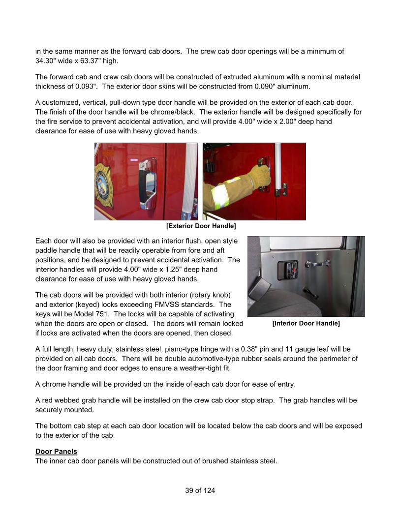
39 of 124
in the same manner as the forward cab doors. The crew cab door openings will be a minimum of 34.30" wide x 63.37" high.
The forward cab and crew cab doors will be constructed of extruded aluminum with a nominal material thickness of 0.093". The exterior door skins will be constructed from 0.090" aluminum.
A customized, vertical, pull-down type door handle will be provided on the exterior of each cab door. The finish of the door handle will be chrome/black. The exterior handle will be designed specifically for the fire service to prevent accidental activation, and will provide 4.00" wide x 2.00" deep hand clearance for ease of use with heavy gloved hands.
[Exterior Door Handle]
Each door will also be provided with an interior flush, open style paddle handle that will be readily operable from fore and aft positions, and be designed to prevent accidental activation. The interior handles will provide 4.00" wide x 1.25" deep hand clearance for ease of use with heavy gloved hands.
The cab doors will be provided with both interior (rotary knob) and exterior (keyed) locks exceeding FMVSS standards. The keys will be Model 751. The locks will be capable of activating when the doors are open or closed. The doors will remain locked if locks are activated when the doors are opened, then closed.
A full length, heavy duty, stainless steel, piano-type hinge with a 0.38" pin and 11 gauge leaf will be provided on all cab doors. There will be double automotive-type rubber seals around the perimeter of the door framing and door edges to ensure a weather-tight fit.
A chrome handle will be provided on the inside of each cab door for ease of entry.
A red webbed grab handle will be installed on the crew cab door stop strap. The grab handles will be securely mounted.
The bottom cab step at each cab door location will be located below the cab doors and will be exposed to the exterior of the cab.
Door Panels The inner cab door panels will be constructed out of brushed stainless steel.
[Interior Door Handle]

40 of 124
MANUAL CAB DOOR WINDOWS All cab entry doors will contain a conventional roll down window.
CAB STEPS The forward cab and crew cab access steps will be a full size two (2) step design to provide largest possible stepping surfaces for safe ingress and egress. The bottom steps will be designed with a grip pattern punched into bright aluminum treadplate material to provide support, slip resistance, and drainage. The bottom steps will be a bolt-in design to minimize repair costs should they need to be replaced. The forward cab steps will be a minimum 25.00" wide, and the crew cab steps will be 21.65" wide with an 8.00" minimum depth. The inside cab steps will not exceed 16.50" in height.
The vertical surfaces of the step well will be aluminum treadplate.
CAB EXTERIOR HANDRAILS A 1.25" diameter slip-resistant, knurled aluminum handrail will be provided adjacent to each cab and crew cab door opening to assist during cab ingress and egress.
The handrails at each front cab door will be 21.00" long. The handrails at each crew cab door will be 32.00" long.
STIRRUP STEPS Hinged, swing style stirrup steps will be provided below each cab and crew cab door.
The stirrup step will be lit by a white 12 volt DC LED light provided on the step.
The step light will be activated automatically when the battery switch is on and the exit doors are opened or by the same means as the body step lights.
STEP LIGHTS There will be six (6) white LED step lights with chrome housing installed for cab and crew cab access steps.
• One (1) light for the left access steps. • Two (2) lights for the left side crew cab access steps. • Two (2) lights for the right side crew cab access steps. • One (1) light for the right side access step.
In order to ensure exceptional illumination, each light will provide a minimum of 25 foot-candles (fc) covering an entire 15" x 15" square placed ten (10) inches below the light and a minimum of 1.5 fc covering an entire 30" x 30" square at the same ten (10) inch distance below the light.
The lights will be activated when the battery switch is on and the adjacent door is opened.
FENDER CROWNS Rubber fender crowns will be provided around the cab wheel openings.
Crowns will be black.

41 of 124
CREW CAB WINDOWS One (1) fixed window with tinted glass will be provided on each side of the cab, to the rear of the front cab door. The windows will be sized to enhance light penetration into the cab interior. The windows will measure 18.70" wide x 23.75" high.
CUP HOLDER There will be four (4) cup holder(s) provided. Each cup holder will be 4.00" in diameter x 4.00" high. An approximate 1.00" wide recess in the cup holder will allow it to hold beverage containers with handles.
Black rubber matting will be provided on the bottom of each cup holder.
The cup holder(s) will be painted to match the cab interior and located To be mounted at final inspection.
CAB DASH The driver side dash, switch panel located to the right of the driver, and center console will be an easily removable high impact resistant polymer cover.
The instrument gauge cluster will be surrounded with a high impact ABS plastic contoured to the same shape of the instrument gauge cluster.
The officer side dash will be a flat top design with an upper beveled edge to provide easy maintenance and will be constructed out of aluminum and painted to match the cab interior.
MOUNTING PLATE ON ENGINE TUNNEL Equipment installation provisions will be installed on the engine tunnel.
A 0.188" smooth aluminum plate will be bolted to the top surface of the engine tunnel. The plate will follow the contour of the engine tunnel and will run the entire length of the engine tunnel. The plate will be spaced off the engine tunnel .75" to allow for wire routing below the plate.
The mounting surface will be painted to match the cab interior.
MOUNTING PLATE(S) There will be one (1)driver side interior rear cab wall (full area between cabinet and outer cab wall) 0.188" aluminum mounting plate(s) provided and installed driver side interior rear cab wall (full area between cabinet and outer cab wall). The mounting surface will be painted to match the cab interior. The plates(s) will be mounted on .75" spacer stand-offs.
CAB INTERIOR The cab interior will be constructed of primarily metal (painted aluminum) to withstand the severe duty cycles of the fire service.
The engine tunnel will be painted aluminum to match the cab interior.

42 of 124
For durability and ease of maintenance, the cab interior side walls will be painted aluminum. The rear wall will be painted aluminum.
The headliner will be installed in both forward and rear cab sections. Headliner material will be vinyl. A sound barrier will be part of its composition. Material will be installed on an aluminum sheet and securely fastened to interior cab ceiling.
The forward portion of the cab headliner will permit easy access for service of electrical wiring or other maintenance needs.
All wiring will be placed in metal raceways.
CAB INTERIOR UPHOLSTERY The cab interior upholstery will be 36 oz black vinyl.
CAB INTERIOR PAINT The cab interior metal surfaces, excluding the rear heater panels, will be painted black, vinyl texture paint.
The rear heater panels will be painted black, vinyl textured paint.
CAB FLOOR The cab and crew cab floor areas will be covered with Polydamp™ acoustical floor mat consisting of a black pyramid rubber facing and closed cell foam decoupler.
The top surface of the material has a series of raised pyramid shapes evenly spaced, which offer a superior grip surface. Additionally, the material has a 0.25" thick closed cell foam (no water absorption) which offers a sound dampening material for reducing sound levels.
DEFROST/AIR CONDITIONING SYSTEM A ceiling mounted combination heater, defroster and air conditioning system will be installed in the cab above the engine tunnel area.
Cab Defroster A 54,000 BTU heater-defroster unit with 690 SCFM of air flow will be provided inside the cab. The heater-defrost will be installed in the forward portion of the cab ceiling. Air outlets will be strategically located in the cab header extrusion per the following:
• One (1) adjustable will be directed towards the left side cab window • One (1) adjustable will be directed towards the right side cab window • Six (6) fixed outlets will be directed at the windshield
The defroster will be capable of clearing 98 percent of the windshield and side glass when tested under conditions where the cab has been cold soaked at 0 degrees Fahrenheit for 10 hours, and a 2 ounce per square inch layer of frost/ice has been able to build up on the exterior windshield. The defroster system will meet or exceed SAE J382 requirements.

43 of 124
Cab/Crew Auxiliary Heater There will be one (1) 31,000 BTU auxiliary heater with 560 SCFM of air flow provided in each outboard rear facing seat risers with a dual scroll blower. An aluminum plenum incorporated into the cab structure used to transfer heat to the forward positions.
Air Conditioning A condenser will be a 59,644 BTU output that meets and exceeds the performance specification will be mounted on the radiator.
The air conditioning system will be capable of cooling the average cab temperature from 100 degrees Fahrenheit to 75 degrees Fahrenheit at 50 percent relative humidity within 30 minutes. The cooling performance test will be run only after the cab has been heat soaked at 100 degrees Fahrenheit for a minimum of 4 hours.
The evaporator unit will be installed in the rear portion of the cab ceiling over the engine tunnel. The evaporator will include one (1) high performance heating core, one (1) high performance cooling core with (1) plenum directed to the front and one (1) plenum directed to the rear of the cab.
The evaporator unit will have a 52,000 BTU at 690 SCFM rating that meets and exceeds the performance specifications.
Adjustable air outlets will be strategically located on the forward plenum cover per the following:
• Four (4) will be directed towards the seating position on the left side of the cab • Four (4) will be directed towards the seating position on the right side of the cab
Adjustable air outlets will be strategically located on the evaporator cover per the following:
• Five (5) will be directed towards crew cab area
A high efficiency particulate air (HEPA) filter will be included for the system. Access to the filter cover will be secured with four (4) screws.
The air conditioner refrigerant will be R-134A and will be installed by a certified technician.
Climate Control An automotive style controller will be provided to control the heat and air conditioning system within the cab. The controller will have three (3) functional knobs for fan speed, temperature, and air flow distribution (front to rear) control.
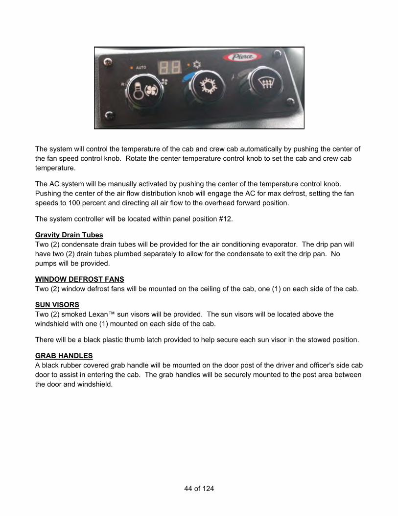
44 of 124
The system will control the temperature of the cab and crew cab automatically by pushing the center of the fan speed control knob. Rotate the center temperature control knob to set the cab and crew cab temperature.
The AC system will be manually activated by pushing the center of the temperature control knob. Pushing the center of the air flow distribution knob will engage the AC for max defrost, setting the fan speeds to 100 percent and directing all air flow to the overhead forward position.
The system controller will be located within panel position #12.
Gravity Drain Tubes Two (2) condensate drain tubes will be provided for the air conditioning evaporator. The drip pan will have two (2) drain tubes plumbed separately to allow for the condensate to exit the drip pan. No pumps will be provided.
WINDOW DEFROST FANS Two (2) window defrost fans will be mounted on the ceiling of the cab, one (1) on each side of the cab.
SUN VISORS Two (2) smoked Lexan™ sun visors will be provided. The sun visors will be located above the windshield with one (1) mounted on each side of the cab.
There will be a black plastic thumb latch provided to help secure each sun visor in the stowed position.
GRAB HANDLES A black rubber covered grab handle will be mounted on the door post of the driver and officer's side cab door to assist in entering the cab. The grab handles will be securely mounted to the post area between the door and windshield.
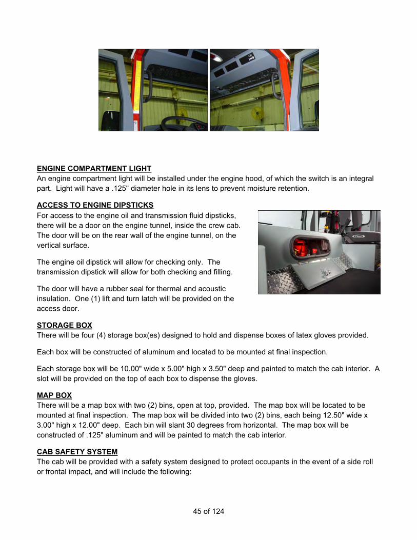
45 of 124
ENGINE COMPARTMENT LIGHT An engine compartment light will be installed under the engine hood, of which the switch is an integral part. Light will have a .125" diameter hole in its lens to prevent moisture retention.
ACCESS TO ENGINE DIPSTICKS For access to the engine oil and transmission fluid dipsticks, there will be a door on the engine tunnel, inside the crew cab. The door will be on the rear wall of the engine tunnel, on the vertical surface.
The engine oil dipstick will allow for checking only. The transmission dipstick will allow for both checking and filling.
The door will have a rubber seal for thermal and acoustic insulation. One (1) lift and turn latch will be provided on the access door.
STORAGE BOX There will be four (4) storage box(es) designed to hold and dispense boxes of latex gloves provided.
Each box will be constructed of aluminum and located to be mounted at final inspection.
Each storage box will be 10.00" wide x 5.00" high x 3.50" deep and painted to match the cab interior. A slot will be provided on the top of each box to dispense the gloves.
MAP BOX There will be a map box with two (2) bins, open at top, provided. The map box will be located to be mounted at final inspection. The map box will be divided into two (2) bins, each being 12.50" wide x 3.00" high x 12.00" deep. Each bin will slant 30 degrees from horizontal. The map box will be constructed of .125" aluminum and will be painted to match the cab interior.
CAB SAFETY SYSTEM The cab will be provided with a safety system designed to protect occupants in the event of a side roll or frontal impact, and will include the following:

46 of 124
• A supplemental restraint system (SRS) sensor will be installed on a structural cab member behind the instrument panel. The SRS sensor will perform real time diagnostics of all critical subsystems and will record sensory inputs immediately before and during a side roll or frontal impact event.
• A slave SRS sensor will be installed in the cab to provide capacity for eight (8) crew cab seating positions.
• A fault-indicating light will be provided on the vehicle's instrument panel allowing the driver to monitor the operational status of the SRS system.
• A driver side front air bag will be mounted in the steering wheel and will be designed to protect the head and upper torso of the occupant, when used in combination with the 3-point seat belt.
• A passenger side knee bolster air bag will be mounted in the modesty panel below the dash panel and will be designed to protect the legs of the occupant, when used in combination with the 3-point seat belt.
• Air curtains will be provided in the outboard bolster of outboard seat backs to provide a cushion between occupant and the cab wall.
• Suspension seats will be provided with devices to retract them to the lowest travel position during a side roll or frontal impact event.
• Seat belts will be provided with pre-tensioners to remove slack from the seat belt during a side roll or frontal impact event.
FRONTAL IMPACT PROTECTION The SRS system will provide protection during a frontal or oblique impact event. The system will activate when the vehicle decelerates at a predetermined G force known to cause injury to the occupants. The cab and chassis will have been subjected, via third party test facility, to a crash impact during frontal and oblique impact testing. Testing included all major chassis and cab components such as mounting straps for fuel and air tanks, suspension mounts, front suspension components, rear suspensions components, frame rail cross members, engine and transmission and their mounts, pump house and mounts, frame extensions and body mounts. The testing provided configuration specific information used to optimize the timing for firing the safety restraint system. The sensor will activate the pyrotechnic devices when the correct crash algorithm, wave form, is detected.
The SRS system will deploy the following components in the event of a frontal or oblique impact event:
• Driver side front air bag • Passenger side knee bolster air bag • Air curtains mounted in the outboard bolster of outboard seat backs • Suspension seats will be retracted to the lowest travel position • Seat belts will be pre-tensioned to firmly hold the occupant in place
SIDE ROLL PROTECTION The SRS system will provide protection during a fast or slow 90 degree roll to the side, in which the vehicle comes to rest on its side. The system will analyze the vehicle's angle and rate of roll to determine the optimal activation of the advanced occupant restraints.
The SRS system will deploy the following components in the event of a side roll:

47 of 124
• Air curtains mounted in the outboard bolster of outboard seat backs • Suspension seats will be retracted to the lowest travel position • Seat belts will be pre-tensioned to firmly hold the occupant in place
SEATING CAPACITY The seating capacity in the cab will be four (4).
DRIVER SEAT A seat will be provided in the cab for the driver. The seat design will be a cam action type, with air suspension. For increased convenience, the seat will include a manual control to adjust the horizontal position (6.00" travel). The manual horizontal control will be a towel-bar style located below the forward part of the seat cushion. To provide flexibility for multiple driver configurations, the seat will have an adjustable reclining back. The seat back will be a high back style with side bolster pads for maximum support. For optimal comfort, the seat will be provided with 17.00" deep foam cushions designed with EVC (elastomeric vibration control).
The seat will include the following features incorporated into the side roll protection system:
• Side air curtain will be mounted integral to the outboard bolster of the seat back. The air curtain will be covered by a decorative panel when in the stowed position.
• A suspension seat safety system will be included. When activated in the event of a side roll, this system will pretension the seat belt and retract the seat to its lowest travel position.
The seat will be furnished with a 3-point, shoulder type seat belt.
OFFICER SEAT A seat will be provided in the cab for the passenger. The seat will be a fixed type, with no suspension. For optimal comfort, the seat will be provided with 17.00" deep foam cushions designed with EVC (elastomeric vibration control).
The seat back will be an SCBA back style with 5 degree fixed recline angle. The SCBA cavity will be adjustable from front to rear in 1.00" increments, to accommodate different sized SCBA cylinders. Moving the SCBA cavity will be accomplished by unbolting, relocating, and re-bolting it in the desired location.
The seat will include the following features incorporated into the side roll protection system:
• Side air curtain will be mounted integral to the outboard bolster of the seat back. The air curtain will be covered by a decorative panel when in the stowed position.
• A seat safety system will be included. When activated, this system will pretension the seat belt.
The seat will be furnished with a 3-point, shoulder type seat belt.
RADIO COMPARTMENT A radio compartment will be provided under the officer's seat.
The inside compartment dimensions will be 16.00" wide x 7.50" high x 15.00" deep, with the back of the compartment angled up to match the cab structure.
48 of 124
A drop-down door with one (1) flush lift and turn latch will be provided for access.
The compartment will be constructed of smooth aluminum and painted to match the cab interior.
REAR FACING DRIVER SIDE OUTBOARD SEAT There will be one (1) rear facing seat provided at the driver side outboard position in the crew cab. For optimal comfort, the seat will be provided with 15.00" deep foam cushions designed with EVC (elastomeric vibration control).
The seat back will be an SCBA back style with 5 degree fixed recline angle. The SCBA cavity will be adjustable from front to rear in 1.00" increments, to accommodate different sized SCBA cylinders. Moving the SCBA cavity will be accomplished by unbolting, relocating, and re-bolting it in the desired location.
The seat will include the following features incorporated into the side roll protection system:
• Side air curtain will be mounted integral to the outboard bolster of the seat back. The air curtain will be covered by a decorative panel when in the stowed position.
• A seat safety system will be included. When activated, this system will pretension the seat belt.
The seat will be furnished with a 3-point, shoulder type seat belt.
REAR FACING PASSENGER SIDE OUTBOARD SEAT There will be one (1) rear facing seat provided at the passenger side outboard position in the crew cab. For optimal comfort, the seat will be provided with 15.00" deep foam cushions designed with EVC (elastomeric vibration control).
The seat back will be an SCBA back style with 5 degree fixed recline angle. The SCBA cavity will be adjustable from front to rear in 1.00" increments, to accommodate different sized SCBA cylinders. Moving the SCBA cavity will be accomplished by unbolting, relocating, and re-bolting it in the desired location.
The seat will include the following features incorporated into the side roll protection system:
• Side air curtain will be mounted integral to the outboard bolster of the seat back. The air curtain will be covered by a decorative panel when in the stowed position.
• A seat safety system will be included. When activated, this system will pretension the seat belt.
The seat will be furnished with a 3-point, shoulder type seat belt.
FORWARD FACING CENTER CABINET A forward facing cabinet will be provided in the crew cab at the center position.
The cabinet will be 38.50" wide x 50.00" high x 18.00" deep with one (1) Amdor rollup door with white finish, non-locking. The frame to frame opening of the cabinet will be 36.00" wide x 44.75" high. The minimum clear door opening will be 33.25" wide x 38.87" high.

49 of 124
The cabinet will include two (2) infinitely adjustable shelves with a 1.25" up-turned lippainted to match the cab interior.
The cabinet will include no louvers.
The cabinet will be constructed of smooth aluminum, and painted to match the cab interior.
Cabinet Light There will be one (1) white LED strip light installed on the left side of the interior cabinet door opening and one (1) white LED strip light installed on the right side of the interior cabinet door opening. The lighting will be controlled by an automatic door switch.
MATTING IN EMS COMPARTMENT Vinyl grating will be provided in three (3) EMS compartments, each shelf and floor of ems compartment. Tile color will be black.
The vinyl grating will be 0.50" thick and be cross bonded by 0.25" diameter ribbed sections spaced for aeration. The trim edge will not be installed at the edge of the tile.
SEAT UPHOLSTERY All seat upholstery will be black Turnout Tuff material.
AIR BOTTLE HOLDERS All SCBA type seats in the cab will have a "Hands-Free" auto clamp style bracket in its backrest. For efficiency and convenience, the bracket will include an automatic spring clamp that allows the occupant to store the SCBA bottle by simply pushing it into the seat back. For protection of all occupants in the cab, in the event of an accident, the inertial components within the clamp will constrain the SCBA bottle in the seat and will exceed the NFPA standard of 9G.
There will be a quantity of three (3) SCBA brackets.
SEAT BELTS All cab and tiller cab (if applicable) seating positions will have red seat belts. To provide quick, easy use for occupants wearing bunker gear, the female buckle and seat belt webbing length will meet or exceed the current edition of NFPA 1901 and CAN/ULC - S515 standards.
The 3-point shoulder type seat belts will include height adjustment. This adjustment will optimize the belts effectiveness and comfort for the seated firefighter. The 3-point shoulder type seat belts will be furnished with dual automatic retractors that will provide ease of operation in the normal seating position.

50 of 124
The 3-point shoulder type belts will also include the ReadyReach D-loop assembly to the shoulder belt system. The ReadyReach feature adds an extender arm to the D-loop location placing the D-loop in a closer, easier to reach location.
Any flip up seats will include a 3-point shoulder type belts only.
To ensure safe operation, the seats will be equipped with seat belt sensors in the seat cushion and belt receptacle that will activate an alarm indicating a seat is occupied but not buckled.
HELMET STORAGE PROVIDED BY FIRE DEPARTMENT NFPA 1901, 2016 edition, section 14.1.7.4.1 requires a location for helmet storage be provided.
There is no helmet storage on the apparatus as manufactured. The fire department will provide a location for storage of helmets.
CAB DOME LIGHTS There will be four (4) dual LED dome lights with grey bezels provided. Two (2) lights will be mounted above the inside shoulder of the driver and officer and two (2) lights will be installed and located, one (1) on each side of the crew cab.
The color of the LED's will be red and white.
The white LED's will be controlled by the door switches and the lens switch.
The color LED's will be controlled by the lens switch.
In order to ensure exceptional illumination, each white LED dome light will provide a minimum of 10.1 foot-candles (fc) covering an entire 20.00" x 20.00" square seating position when mounted 40.00" above the seat.
HAND HELD LIGHT There will be three (3) Streamlight, Vulcan, Model #44315, hand lights provided with a vehicle mount with 12VDC direct wire charging rack and quick release buckle strap mounted at pickup.
Each light housing will be orange in color.
HAND HELD LIGHT There will be two (2) lights Streamlight E-Flood LiteBox, Model 45805, LED hand lights with the orange thermoplastic body and dual rear LEDs provided. These will be mounted TBD.
The light will be provided with a 12 volt charger.
CAB INSTRUMENTATION The cab instrument panel will include gauges, telltale indicator lamps, control switches, alarms, and a diagnostic panel. The function of the instrument panel controls and switches will be identified by a label adjacent to each item. Actuation of the headlight switch will illuminate the labels in low light conditions. Telltale indicator lamps will not be illuminated unless necessary. The cab instruments and controls will be conveniently located within the forward cab section, forward of the driver. The gauge assembly and switch panels are designed to be removable for ease of service and low cost of ownership.

51 of 124
Gauges The gauge panel will include the following ten (10) black faced gauges with black bezels to monitor vehicle performance:
• Voltmeter gauge (volts): o Low volts (11.8 VDC)
Amber telltale light on indicator light display with steady tone alarm o High volts (15.5 VDC)
Amber telltale light on indicator light display with steady tone alarm • Engine Tachometer (RPM) • Speedometer MPH (Major Scale), KM/H (Minor Scale) • Fuel level gauge (Empty - Full in fractions):
o Low fuel (1/8 full) Amber indicator light in gauge dial with steady tone alarm
• Engine Oil pressure Gauge (PSI): o Low oil pressure to activate engine warning lights and alarms
Red indicator light in gauge dial with steady tone alarm • Front Air Pressure Gauges (PSI):
o Low air pressure to activate warning lights and alarm Red indicator light in gauge dial with steady tone alarm
• Rear Air Pressure Gauges (PSI): o Low air pressure to activate warning lights and alarm
Red indicator light in gauge dial with steady tone alarm • Transmission Oil Temperature Gauge (Fahrenheit):
o High transmission oil temperature activates warning lights and alarm Amber indicator light in gauge dial with steady tone alarm
• Engine Coolant Temperature Gauge (Fahrenheit): o High engine temperature activates an engine warning light and alarms
Red indicator light in gauge dial with steady tone alarm • Diesel Exhaust Fluid Level Gauge (Empty - Full in fractions):
o Low fluid (1/8 full) Amber indicator light in gauge dial
Indicator Lamps To promote safety, the following telltale indicator lamps will be located on the instrument panel in clear view of the driver. The indicator lamps will be "dead-front" design that is only visible when active. The colored indicator lights will have descriptive text or symbols.
The following amber telltale lamps will be present:
• Low coolant • Trac cntl (traction control) (where applicable) • Check engine • Check trans (check transmission) • Air rest (air restriction)

52 of 124
• DPF (engine diesel particulate filter regeneration) • HET (engine high exhaust temperature) (where applicable) • ABS (antilock brake system) • MIL (engine emissions system malfunction indicator lamp) (where applicable) • Regen inhibit (engine emissions regeneration inhibit) (where applicable) • Side roll fault (where applicable) • Front air bag fault (where applicable) • Aux brake overheat (auxiliary brake overheat) (where applicable) • The following red telltale lamps will be present: • Ladder rack down • Parking brake • Stop engine • The following green telltale lamps will be present: • Left turn • Right turn • Battery on • Ignition • Aux brake (auxiliary brake engaged) (where applicable) • The following blue telltale lamps will be present: • High beam
Alarms Audible steady tone warning alarm: A steady audible tone alarm will be provided whenever a warning condition is active.
Indicator Lamp and Alarm Prove-Out A system will be provided which automatically tests telltale indicator lights and alarms located on the cab instrument panel. Telltale indicators and alarms will perform prove-out for 3 to 5 seconds when the ignition switch is moved to the on position with the battery switch on.
Control Switches For ease of use, the following controls will be provided immediately adjacent to the cab instrument panel within easy reach of the driver. All switches will have backlit labels for low light applications.
Headlight/Parking light switch: A three (3)-position maintained rocker switch will be provided. The first switch position will deactivate all parking and headlights. The second switch position will activate the parking lights. The third switch will activate the headlights.
Panel back lighting intensity control switch: A three (3)-position momentary rocker switch will be provided. Pressing the top half of the switch, "Panel Up" increases the panel back lighting intensity and pressing the bottom half of the switch, "Panel Down" decreases the panel back lighting intensity. Pressing the half or bottom half of the switch several times will allow back lighting intensity to be gradually varied from minimum to maximum intensity level for ease of use.

53 of 124
Ignition switch: A three (3)-position maintained/momentary rocker switch will be provided. The first switch position will turn off and deactivate vehicle ignition. The second switch position will activate vehicle ignition and will perform prove-out on the telltale indicators and alarms for 3 to 5 seconds after the switch is turned on. A green indicator lamp is activated with vehicle ignition. The third momentary position will temporarily silence all active cab alarms. An alarm "chirp" may continue as long as alarm condition exists. Switching ignition to off position will terminate the alarm silence feature and reset function of cab alarm system.
Engine start switch: A two (2)-position momentary rocker switch will be provided. The first switch position is the default switch position. The second switch position will activate the vehicle's engine. The switch actuator is designed to prevent accidental activation.
Hazard switch will be provided on the instrument panel or on the steering column.
Heater, defrost, and air conditioning control panel.
Turn signal arm: A self-canceling turn signal with high beam headlight controls.
Windshield wiper control will have high, low, and intermittent modes.
Parking brake control: An air actuated push/pull park brake control.
Chassis horn control: Activation of the chassis horn control will be provided through the center of the steering wheel.
High idle engagement switch: A maintained rocker switch with integral indicator lamp will be provided. The switch will activate and deactivate the high idle function. The "OK To Engage High Idle" indicator lamp must be active for the high idle function to engage. A green indicator lamp integral to the high idle engagement switch will indicate when the high idle function is engaged.
"OK To Engage High Idle" indicator lamp: A green indicator light will be provided next to the high idle activation switch to indicate that the interlocks have been met to allow high idle engagement.
Emergency switching will be controlled by multiple individual warning light switches for various groups or areas of emergency warning lights. An Emergency Master switch provided on the instrument panel that enables or disables all individual warning light switches is included.
An additional "Emergency Master" button will be provided on the lower left hand corner of the gauge panel to allow convenient control of the "Emergency Master" system from inside the driver's door when standing on the ground.
Custom Switch Panels The design of cab instrumentation will allow for emergency lighting and other switches to be placed within easy reach of the operator thus improving safety. There will be positions for up to four (4) switch panels in the lower instrument console and up to six (6) switch panels in the overhead visor console. All switches have backlit labels for low light conditions.

54 of 124
Diagnostic Panel A diagnostic panel will be provided and accessible while standing on the ground. The panel will be located inside the driver's side door left of the steering column. The diagnostic panel will allow diagnostic tools such as computers to connect to various vehicle systems for improved troubleshooting providing a lower cost of ownership. Diagnostic switches will allow ABS systems to provide blink codes should a problem exist.
The diagnostic panel will include the following:
• ENGINE/TRANSMISSION/ABS J1939 Diagnostic Port • ABS Diagnostic Switch and Indicator - The switch and amber indicator will allow access to
diagnostic mode and display of standard ABS system fault blink codes that may be generated by the ABS system
• DPF REGEN (Diesel Particulate Filter Regeneration Switch) (where applicable) will be provided to request regeneration of the engine emission system. An amber indicator will be provided on top of the switch that will illuminate in a "CHECK ENGINE" condition
• REGEN INHIBIT (Diesel Particulate Filter Regeneration Inhibit Switch) (where applicable) will be provided that will request that regeneration be temporarily prevented. A green indicator will

55 of 124
be provided on top of the Regen Inhibit switch that will illuminate when the Regen Inhibit feature is active. Regen Inhibit will be disabled upon cycling of the ignition switch to the off state.
AIR RESTRICTION INDICATOR A high air restriction warning indicator light (electronic) will be provided.
"DO NOT MOVE APPARATUS" INDICATOR A flashing red indicator light, located in the driving compartment, will be illuminated automatically per the current NFPA requirements. The light will be labeled "Do Not Move Apparatus If Light Is On."
The same circuit that activates the Do Not Move Apparatus indicator will activate a pulsing alarm when the parking brake is released.
SWITCH PANELS The built-in switch panels will be located in the lower console or overhead console of the cab. Switches will be rocker type with an indicator light, of which is an integral part of the switch.
WIPER CONTROL Wiper control will consist of a two (2)-speed windshield wiper control with intermittent feature and windshield washer controls.
CUSTOMER SUPPLIED RADIO WIRING There will be two (2) 12 volt combination wiring leads of which each will include one (1) direct battery, one (1) ignition and one (1) negative for use with radio equipment.
Each lead will be 18.00" long and be provided center dash switch panel. The leads will be clearly marked in a coil and terminate with butt splices.
A breaker rated for 30 amps will be provided for circuit protection of the direct battery lead with a minimum of 10 gauge wire.
A breaker rated for 7.5 amps will be provided for circuit protection of the ignition lead.
The wires will be colored coded as follows:
• red for direct battery • yellow for ignition • black for ground
SPARE CIRCUIT There will be two (2) dual USB fast charge socket mounts installed on the apparatus.
The above wires will have the following features:
• The positive wire will be connected directly to the battery power. • The negative wire will be connected to ground. • Wires will be protected to 4.8 amps at 12 volts DC. • The USB socket mount will be TBD.

56 of 124
• Termination will be a Blue Sea Systems part number 1045 dual USB charger socket. • Wires will be sized to 125% of the protection.
This circuit(s) may be load managed when the parking brake is applied.
SPARE CIRCUIT There will be three (3) pair of wires, including a positive and a negative, installed on the apparatus.
The above wires will have the following features:
• The positive wire will be connected directly to the battery power. • The negative wire will be connected to ground. • Wires will be protected to 50 amps at 12 volts DC. • Power and ground will terminate Med cabinet centered up high, behind officer seat, in cabinet
TBD. • Termination will be to a Blue Sea System, Model 5025, 6 circuit with negative bus bar. The
terminal block will include a cover with circuit labels.
Wires will be sized to 125% of the protection.
This circuit(s) may be load managed when the parking brake is set.
INFORMATION CENTER There will be a LCD display integral to the cab gauge panel provided that will display the following information:
• Total distance • Trip distance • Total hours • Trip hours • PTO "A" hours • PTO "B" hours
COLLISION MITIGATION There will be a HAAS Alert®, Model HA5 Responder-to-Vehicle (R2V) collision avoidance system provided on the apparatus. The HA5 cellular transponder module will be installed behind the cab windshield, as high and near to the center as practical, to allow clear visibility to the sky. The module dimensions are 5.40" long x 2.70" wide x 1.30" high, and operating temperature range is -40 degree C to 85 degree C.
The transponder will be connected to the vehicle's emergency master circuit and battery direct power and ground.
While responding with emergency lights on, the HA5 transponder sends alert messages via cellular network to motorists in the vicinity of the responding truck that are equipped with the WAZE app.

57 of 124
While on scene with emergency lights on, the HA5 transponder sends road hazard alerts to motorists in the vicinity of the truck that are equipped with the WAZE app.
The HA5 Responder-to-Vehicle (R2V) collision avoidance system will include the transponder and a 5 year cellular plan subscription.
Activation of the HAAS Alert system requires a representative of the customer to accept the End User License Agreement (EULA) via an on-line portal.
VEHICLE DATA RECORDER There will be a vehicle data recorder (VDR) capable of reading and storing vehicle information provided.
The information stored on the VDR can be downloaded through a USB port mounted in a convenient location determined by cab model. A USB cable can be used to connect the VDR to a laptop to retrieve required information. The program to download the information from the VDR will be available to download on-line.
The vehicle data recorder will be capable of recording the following data via hardwired and/or CAN inputs:
• Vehicle Speed - MPH • Acceleration - MPH/sec • Deceleration - MPH/sec • Engine Speed - RPM • Engine Throttle Position - % of Full Throttle • ABS Event - On/Off • Seat Occupied Status - Yes/No by Position • Seat Belt Buckled Status - Yes/No by Position • Master Optical Warning Device Switch - On/Off • Time - 24 Hour Time • Date - Year/Month/Day
Seat Belt Monitoring System A seat belt monitoring system (SBMS) will be provided. The SBMS will be capable of monitoring up to 10 seating positions indicating the status of each seat position per the following:
• Seat Occupied & Buckled = Green LED indicator illuminated • Seat Occupied & Unbuckled = Red LED indicator with audible alarm • No Occupant & Buckled = Red LED indicator with audible alarm • No Occupant & Unbuckled = No indicator and no alarm
The SBMS will include an audible alarm that will warn that an unbuckled occupant condition exists and the parking brake is released, or the transmission is not in park.

58 of 124
INTERCOM SYSTEM A four (4) position intercom system with dual radio interface capability at the driver and officer positions and remote push to transmit buttons located TBD will be provided. Two (2) crew cab positions, located at both rear facing seats, will have radio listen / intercom only.
The following David Clark components will be supplied with this system:
• Two (2) U3805 Radio Cord Junction Modules • Two (2) U3816 Dual Radio Interface Modules (Driver, Officer) • Four (4) Remote Transmit button kits • One (1) U3800 Intercom Unit (1 Crew) • One (1) C3820 Power Cable. • One (1) U3801 Intercom Unit (1 Crew) • All necessary cables and connectors
RADIO / INTERCOM INTERFACE INCLUDED All radio interfaced stations will have universal radio interfaces installed. The interface wiring will be routed within the cab to TBD .
OVER THE HEAD HEADSET There will be two (2) over the head, headset(s) provided rear seats.
Each David Clark, Model H3432, headset will feature:
• 5' Coiled cord • Noise cancelling electric microphone • Flexible microphone boom rotates 200 degrees for left or right dress • Microphone on/off button • Comfort Gel Earseals • 23 dB noise reduction
UNDER THE HELMET HEADSET There will be two (2) under the helmet, headset(s) provided front seats.
Each David Clark, Model H3442, headset will feature:
• 5' Coiled cord • Noise cancelling electric microphone • Flexible microphone boom rotates 200 degrees for left or right dress • Microphone on/off button • Comfort Gel Earseals • 23 dB noise reduction

59 of 124
HEADSET HANGERS There will be five (5) headset hanger(s) installed driver's seat, officer's seat, driver's side outboard forward facing seat, passenger's side outboard forward facing seat and rear, center, forward facing seat. The hanger(s) will meet NFPA 1901, Section 14.1.11, requirement for equipment mounting.
RADIO ANTENNA MOUNT There will be two (2) standard 1.125", 18 thread antenna-mounting base(s) installed one (1) on the left side and one (1) on the right side on the cab roof with high efficiency, low loss, coaxial cable(s) routed to the instrument panel area. A weatherproof cap will be installed on the mount.
VEHICLE CAMERA SYSTEM There will be a color vehicle camera system provided with the following:
• One (1) camera located at the rear of the apparatus, pointing rearward, displayed automatically with the vehicle in reverse.
• One (1) camera located on the right side of the apparatus, pointing rearward, displayed automatically with the right side turn signal.
• One (1) camera located on the left side of the apparatus, pointing rearward, displayed automatically with the left side turn signal.
The camera images will be displayed on a 7.00" LCD display located in view of the driver in the custom dash, per instrument panel layout. The display will include manual camera activation capability and audio from the rear camera only.
The following components will be included:
• One (1) MO700136DC Display • One (1) SV-CW134639CAI Rear camera • Two (2) CS134404CI Side cameras • All necessary cables
VEHICLE CAMERA GUARD There will be one (1) aluminum treadplate guard(s) fastened over the vehicle camera(s) located center rear .
ELECTRICAL POWER CONTROL SYSTEM A compartment will be provided in or under the cab to house the vehicle's electrical power and signal circuit protection and control components. The power and signal protection and control compartment will contain circuit protection devices and power control devices. Power and signal protection and control components will be protected against corrosion, excessive heat, excessive vibration, physical damage and water spray.
Serviceable components will be readily accessible.
Circuit protection devices, which conform to SAE standard, will be utilized to protect each circuit. All circuit protection devices will be sized to prevent wire and component damage when subjected to

60 of 124
extreme current overload. General protection circuit breakers will be Type-I automatic reset (continuously resetting) and conform to SAE J553 or J258. When required, automotive type fuses conforming to SAE J554, J1284, J1888 or J2077 will be utilized to protect electronic equipment.
Power control relays and solenoids will have a direct current (dc) rating of 125 percent of the maximum current for which the circuit is protected.
Visual status indicators will be supplied to identify control safety interlocks and vehicle status. In addition to visual status indicators, audible alarms designed to provide early warning of problems before they become critical will be used.
VOLTAGE MONITOR SYSTEM A voltage monitor system will be provided to indicate the status of each battery system connected to the vehicle's electrical load. The monitor system will provide visual and audio warning when the system voltage is above or below optimum levels.
POWER AND GROUND STUDS Spare circuits will be provided in the primary distribution center for two-way radio equipment.
The spare circuits will consist of the following:
• One (1) 12-volt DC, 30 amp battery direct spare • One (1) 12-volt DC ground and un-fused switched battery stud located in or adjacent to the
power distribution center
EMI/RFI PROTECTION The electrical system proposed will include means to control undesired electromagnetic and radio frequency emissions. State of the art electrical system design and components will be used to ensure radiated and conducted EMI (electromagnetic interference) and RFI (radio frequency interference) emissions are suppressed at their source.
The apparatus proposed will have the ability to operate in the electromagnetic environment typically found in fire ground operations. The contractor will be able to demonstrate the EMI and RFI testing has been done on similar apparatus and certifies that the vehicle proposed meets SAE J551 requirements.
EMI/RFI susceptibility will be controlled by applying immune circuit designs, shielding, twisted pair wiring and filtering. The electrical system will be designed for full compatibility with low level control signals and high powered two-way radio communication systems. Harness and cable routing will be given careful attention to minimize the potential for conducting and radiated EMI-RFI susceptibility.
ELECTRICAL All 12-volt electrical equipment installed by Pierce Manufacturing will conform to modern automotive practices. All wiring will be high temperature crosslink type. Wiring will be run, in loom or conduit, where exposed and have grommets where wire passes through sheet metal. Automatic reset circuit breakers will be provided which conform to SAE Standards. Wiring will be color, function and number coded. Function and number codes will be continuously imprinted on all wiring harness conductors at

61 of 124
2.00" intervals. Exterior exposed wire connectors will be positive locking, and environmentally sealed to withstand elements such as temperature extremes, moisture and automotive fluids.
Electrical wiring and equipment will be installed utilizing the following guidelines:
1. All holes made in the roof will be caulked with silicon. Large fender washers, liberally caulked, will be used when fastening equipment to the underside of the cab roof.
2. Any electrical component that is installed in an exposed area will be mounted in a manner that will not allow moisture to accumulate in it. Exposed area will be defined as any location outside of the cab or body.
3. Electrical components designed to be removed for maintenance will not be fastened with nuts and bolts. Metal screws will be used in mounting these devices. Also, a coil of wire will be provided behind the appliance to allow them to be pulled away from mounting area for inspection and service work.
4. Corrosion preventative compound will be applied to all terminal plugs located outside of the cab or body. All non-waterproof connections will have this compound in the plug to prevent corrosion and for easy separation (of the plug).
5. All lights that have their sockets in a weather exposed area will have corrosion preventative compound added to the socket terminal area.
6. All electrical terminals in exposed areas will have silicon (1890) applied completely over the metal portion of the terminal.
All lights and reflectors, required to comply with Federal Motor Vehicle Safety Standard #108, will be furnished. Rear identification lights will be recessed mounted for protection.
Lights and wiring mounted in the rear bulkheads will be protected from damage by installing a false bulkhead inside the rear compartments.
An operational test will be conducted to ensure that any equipment that is permanently attached to the electrical system is properly connected and in working order.
The results of the tests will be recorded and provided to the purchaser at time of delivery.
BATTERY SYSTEM There will be four (4) 12 volt Exide®, Model 31S950X3W, batteries that include the following features will be provided:
• 950 CCA, cold cranking amps • 190 amp reserve capacity • High cycle • Group 31 • Rating of 3800 CCA at 0 degrees Fahrenheit • 760 minutes of reserve capacity • Threaded stainless steel studs

62 of 124
Each battery case will be a black polypropylene material with a vertically ribbed container for increased vibration resistance. The cover will be manifold vented with a central venting location to allow a 45 degree tilt capacity.
The inside of each battery will consist of a "maintenance free" grid construction with poly wrapped separators and a flooded epoxy bottom anchoring for maximum vibration resistance.
BATTERY SYSTEM There will be a single starting system with an ignition switch and starter button provided and located on the cab instrument panel.
MASTER BATTERY SWITCH There will be a master battery switch provided within the cab within easy reach of the driver to activate the battery system.
An indicator light will be provided on the instrument panel to notify the driver of the status of the battery system.
BATTERY COMPARTMENTS Batteries will be placed on non-corrosive mats and stored in well ventilated compartments located under the cab.
Heavy-duty, 2/0 gauge, color coded battery cables will be provided. Battery terminal connections will be coated with anti-corrosion compound.
Battery solenoid terminal connections will be encapsulated with semi-permanent rubberized compound.
JUMPER STUDS One (1) set of battery jumper studs with plastic color-coded covers will be included on the battery compartments.
BATTERY CHARGER There will be an IOTA™, Model DSL 75, battery charger with IQ4, controller provided.
The battery charger will be wired to the AC shoreline inlet through an AC receptacle adjacent to this battery charger.
There will be a Kussmaul™, Model #091-94-12, remote indicator included.
Battery charger will be located in the cab behind the driver seat
The battery charger indicator will be located in the driver's step area.
SHORELINE INLET There will be one (1) Blue Sea Sure Eject™ part number 7851, 20 amp 120 volt AC shoreline inlet provided to operate the dedicated 120 volt AC circuits on the apparatus.
The shoreline will be connected to charger / shoreline.

63 of 124
The shoreline inlet cover color to be red.
The connector body will be released from the inlet when the apparatus engine start button is activated.
There will be a mating connector body supplied with the loose equipment.
There will be a label installed near the inlet(s) that state the following:
• Line Voltage • Current Ratting (amps) • Phase • Frequency
The shoreline receptacle will be located on the driver side seat riser.
ELECTRIC POWER FOR WINCH Electric power provisions will be furnished for the portable winch from the chassis battery system.
The receiver plug will be located rear receiver hitch.
A total quantity of one (1) receptacle will be provided.
ALTERNATOR A Delco Remy®, Model 40SI, alternator will be provided. It will have a rated output current of 320 amps, as measured by SAE method J56. The alternator will feature an integral regulator and rectifier system that has been tested and qualified to an ambient temperature of 257 degrees Fahrenheit (125 degrees Celsius). The alternator will be connected to the power and ground distribution system with heavy-duty cables sized to carry the full rated alternator output.
ELECTRONIC LOAD MANAGEMENT An electronic load management (ELM) system that monitors the vehicles 12-volt electrical system, and automatically reduces the electrical load in the event of a low voltage condition and by doing so, ensures the integrity of the electrical system.
The ELM will monitor the vehicle's voltage while at the scene (parking brake applied). It will sequentially shut down individual electrical loads when the system voltage drops below a preset value. Two (2) separate electrical loads will be controlled by the load manager. The ELM will sequentially re-energize electrical loads as the system voltage recovers.
HEADLIGHTS There will be four (4) JW Speaker®, heated rectangular LED lights mounted in the front quad style, chrome housing on each side of the front bumper:
• the outside light on each side will contain a part number 055***1 low beam module • the inside light on each side will contain a part number 055***1 high beam module • the headlights to include chrome bezels
The low beam lights will be activated when the headlight switch is on.

64 of 124
The high beam and low beam lights will be activated when the headlight switch and the high beam switch is activated.
FRONT DIRECTIONALS The front directional's will be Whelen, Model M6T, amber LED arrow lights. The directional's will be housed in the same chrome common bezel as the front warning light and will be located above the headlights.
INTERMEDIATE LIGHT There will be two (2) Weldon, Model 9186-8580-29, amber LED turn signal marker lights furnished, one (1) each side, in the rear fender panel. The light will double as a turn signal and marker light.
CAB CLEARANCE/MARKER/ID LIGHTS There will be five (5) amber LED lights provided to indicate the presence and overall width of the vehicle in the following locations:
• Three (3) amber LED identification lights will be installed in the center of the cab above the windshield.
• Two (2) amber LED clearance lights will be installed, one (1) on each outboard side of the cab above the windshield.
FRONT CAB SIDE DIRECTIONAL/MARKER LIGHTS There will be two (2) Weldon, Model 9186-8580-29, amber LED lights installed front of the cab door, one (1) on each side of the cab.
The lights will activate as marker lights with the headlight switch and directional lights with the corresponding directional circuit.
REAR CLEARANCE/MARKER/ID LIGHTING There will be three (3) Truck-Lite®, Model 33050R, LED lights used as identification lights recessed and located at the rear of the apparatus per the following:
• As close as practical to the vertical centerline • Centers spaced not less than 6.00" or more than 12.00" apart • Red in color • All at the same height
There will be two (2) Truck-Lite, Model 33050R, LED lights recessed at the rear of the apparatus used as clearance lights located at the rear of the apparatus per the following:
• To indicate the overall width of the vehicle • One (1) each side of the vertical centerline • As near the top as practical • Red in color • To be visible from the rear • All at the same height
65 of 124
There will be two (2) Truck-Lite, Model 33050R, LED lights recessed on the side of the apparatus as marker lights as close to the rear as practical per the following:
• To indicate the overall length of the vehicle • One (1) each side of the vertical centerline • As near the top as practical • Red in color • To be visible from the side • All at the same height
There will be two (2) red reflectors located on the rear of the truck facing to the rear. One (1) each side, as far to the outside as practical, at a minimum of 15.00", but no more than 60.00", above the ground.
There will be two (2) red reflectors located on the side of the truck facing to the side. One (1) each side, as far to the rear as practical, at a minimum of 15.00", but no more than 60.00", above the ground.
Per FMVSS 108 and CMVSS 108 requirements.
REAR FMVSS LIGHTING The rear stop/tail and directional LED lighting will consist of the following:
• Two (2) Whelen®, Model M6BTT, red LED stop/tail lights • Two (2) Whelen, Model M6T, amber LED arrow turn lights
The lights will be provided with clear lenses.
The lights will be mounted in a polished combination housing.
There will be two (2) Whelen Model M6BUW, LED backup lights provided in the tail light housing.
LICENSE PLATE BRACKET There will be one (1) license plate bracket mounted on the rear of the body.
A white LED light will illuminate the license plate. A stainless steel light shield will be provided over the light that will direct illumination downward, preventing white light to the rear.
LIGHTING BEZEL There will be two (2) Whelen, Model M6FCV4P, four (4) place chromed ABS housings with Pierce logos provided for the rear M6 series stop/tail, directional, back up, scene lights or warning lights.
BACK-UP ALARM A PRECO, Model 1040, solid-state electronic audible back-up alarm that actuates when the truck is shifted into reverse will be provided. The device will sound at 60 pulses per minute and automatically adjust its volume to maintain a minimum ten (10) dBA above surrounding environmental noise levels.
66 of 124
SWITCH, BACK-UP ALARM OVERRIDE There will be a momentary switch provided in the cab for the back-up alarm. The switch will be within reach of the driver. The switch will cancel the back-up alarm when the switch is pushed and automatically reset when the apparatus is shifted out of reverse.
CAB PERIMETER SCENE LIGHTS There will be four (4) Amdor, Model AY-LB-12HW012, 190 lumens each, 12.00" white LED strip lights provided.
• One (1) under the driver's side cab access step. • One (1) under the passenger's side cab access step. • One (1) under the passenger's side crew cab access step. • One (1) under the driver's side crew cab access step.
The lights will be activated when the battery switch is on and the respective door is open and whenever control has been selected for the body perimeter lights.
PUMP HOUSE PERIMETER LIGHTS There will be two (2) Amdor, Model AY-LB-12HW012, 190 lumens each, 12.00" LED weatherproof strip lights with brackets provided under the pump panel running boards, centered front to rear as much as possible, one (1) each side.
The lights will be activated when the battery switch is on, and controlled by the same means as the body perimeter lights.
BODY PERIMETER SCENE LIGHTS There will be two (2) Amdor, Model AY-LB-12HW012, 190 lumens each, 12.00" 12 volt DC LED strip lights provided at the rear step area of the body, one (1) each side shining to the rear.
The perimeter scene lights will be activated when a switch within reach of the driver is activated, the parking brake is applied and either directional light is activated, activating all side facing perimeter lights.
ADDITIONAL PERIMETER LIGHTS There will be six (6) lights Amdor®, Model AY-LB-12HW012, 190 lumens each, 12.00" white LED perimeter light(s) provided one (1) light under each side of the front bumper spaced evenly, one (1) light under compartment LS1, one (1) light under compartment LS3, one (1) light under compartment RS1 and one (1) light under compartment RS3.
These lights will be activated the same as the body perimeter lights.
STEP LIGHTS There will be two (2) white LED step lights will be provided at the rear to illuminate the tailboard/step area.

67 of 124
In order to ensure exceptional illumination, each light will provide a minimum of 25 foot-candles (fc) covering an entire 15" x 15" square placed ten (10) inches below the light and a minimum of 1.5 fc covering an entire 30" x 30" square at the same ten (10) inch distance below the light.
These step lights will be actuated with the perimeter scene lights.
All other steps on the apparatus will be illuminated per the current edition of NFPA 1901.
SCENE LIGHT HOUSINGS one (1) pair of aluminum treadplate housings will be installed on the top of the body compartments each side for installation of Whelen scene lights.
SPECIAL SWITCHING FOR SCENE LIGHTS The 12 volt scene lights located at the rear of the apparatus rear scene light(s) will be controlled by the features that have been selected. These lights will also be activated when the battery switch is on, the emergency master switch is on and the transmission is shifted into reverse.
12 VOLT LIGHTING There will be two (2) Fire Research Spectra Max, Model SPA260-Q20, 12 volt LED surface mounted scene light(s) with chrome bezel(s) provided driver side body up high forward, driver side body up high rearward.
The light(s) will be controlled in the following way:
• a switch at the driver's side switch panel • a switch at the pump operator's panel • no additional switch location • no additional switch location
The light(s) may be load managed when the parking brake is applied.
12 VOLT LIGHTING There will be two (2) Fire Research Spectra Max, Model SPA260-Q20, 12 volt LED surface mounted scene light(s) with chrome bezel(s) provided officer side body up high forward, officer side body up high rearward.
The light(s) will be controlled in the following way:
• a switch at the driver's side switch panel • a switch at the pump operator's panel • no additional switch location • no additional switch location
The light(s) may be load managed when the parking brake is applied.
68 of 124
12 VOLT LIGHTING There will be one (1) HiViz Model FT-MB-33-*-*, 2.56" high x 42.44" long x 2.45" deep 12,210 effective lumens 12 volt DC LED light(s) with a combination of flood and spot optics provided on the front visor, centered.
The painted parts of the light housing and brackets to be painted job color.
The light(s) will be controlled by a switch at the driver's side switch panel, by a switch at the left side pump panel and by a switch at the passenger's side switch panel.
The light(s) may be load managed when the parking brake is applied.
12 VOLT LIGHTING There will one (1) HiViz Model FT-B-46-*-*, 13,306 lumens 2.56" high x 46.00" long x 2.45" deep 12 volt DC light(s) with white LEDs and with a combination of spot, and flood optics installed on the apparatus located, on cross bar of hard hose bed cover, centered.
The painted parts of the light housing and brackets to be black.
The light(s) will be controlled by a switch at the driver's side switch panel, by a switch at the left side pump panel and by a switch in a recessed cup located at the driver's side rear bulkhead.
The light(s) may be load managed when the parking brake is applied.
HOSE BED LIGHTS There will be white 12 volt DC LED light strips with stainless steel protective cover, provided to light the hose bed area. Hose Bed lights will meet the photometric levels listed in NFPA 1901 for Hose Bed lighting requirements.
• Light strip(s) will be installed along the upper edge of the left side of the hose bed. • Light strip(s) will be installed along the upper edge of the right side of the hose bed.
The lights will be activated by a cup switch at the rear of the apparatus no more than 72.00" from the ground.
WALKING SURFACE LIGHT There will be two (2) Model FRP, 4" round black 12 volt DC LED light(s) with bolt mount provided on one hose bed cover, one on dunnage area, see drawing to illuminate the designated walking surface on top of the body.
The light(s) will be activated when the body step lights are on.
FRONT WHITE WARNING LIGHT CONTROL There will be switch(es) installed in the cab on the switch panel that will allow the operator to activate/deactivate all the front white warning lights whenever the emergency master switch is activated and the parking brake is released. The headlight flash option is included in this white warning light control if applicable. Each time the emergency master switch is activated, and the parking brake is released, the white warning light control switch and the white warning lights will default to on.

69 of 124
SWITCH, RED There will be one (1) red switch(s) that will replace the existing switch(s) for the emergency master located emergency master.
WATER TANK Booster tank will have a capacity of 750 gallons and be constructed of polypropylene plastic by United Plastic Fabricating, Incorporated.
The tank will be stepped in design to allow for a low hosebed.
Tank joints and seams will be nitrogen welded inside and out.
Tank will be baffled in accordance with NFPA Bulletin 1901 requirements.
Baffles will have vent openings at both the top and bottom to permit movement of air and water between compartments.
Longitudinal partitions will be constructed of .38" polypropylene plastic and will extend from the bottom of the tank through the top cover to allow for positive welding.
Transverse partitions will extend from 4.00" off the bottom of the tank to the underside of the top cover.
All partitions will interlock and will be welded to the tank bottom and sides.
Tank top will be constructed of .50" polypropylene. It will be recessed .38" and will be welded to the tank sides and the longitudinal partitions.
Tank top will be sufficiently supported to keep it rigid during fast filling conditions.
Construction will include 2.00" polypropylene dowels spaced no more than 30.00" apart and welded to the transverse partitions. Two (2) of the dowels will be drilled and tapped (.50" diameter, 13.00" deep) to accommodate lifting eyes.
A sump that will be sized dependent on the tank to pump plumbing will be provided at the bottom of the water tank.
Sump will include a drain plug and the tank outlet.
Tank will be installed in a fabricated cradle assembly constructed of structural steel.
Sufficient crossmembers will be provided to properly support bottom of tank. Crossmembers will be constructed of steel bar channel or rectangular tubing.
Tank will "float" in cradle to avoid torsional stress caused by chassis frame flexing. Rubber cushions, .50" thick x 3.00" wide, will be placed on all horizontal surfaces that the tank rests on.
Stops or other provision will be provided to prevent an empty tank from bouncing excessively while moving vehicle.
Mounting system will be approved by the tank manufacturer.
70 of 124
Fill tower will be constructed of .50" polypropylene and will be a minimum of 8.00" wide x 14.00" long.
Fill tower will be furnished with a .25" thick polypropylene screen and a hinged cover.
An overflow pipe, constructed of 4.00" schedule 40 polypropylene, will be installed approximately halfway down the fill tower and extend through the water tank and exit to the rear of the rear axle.
WATER TANK RESTRAINT A heavy-duty water tank restraint will be provided.
HOSE BED The hose bed will be fabricated of 0.125"-5052 aluminum with a nominal 38,000 psi tensile strength.
The hose bed will be as low as practical.
Upper and rear edges of side panels will have a double break for rigidity.
Any area of the outboard hose bed wall that extends past the end of the hose bed floor will be covered with brushed stainless steel to prevent damage to painted surface when hose is removed.
Flooring of the hose bed will be removable aluminum grating with the top surface corrugated to aid in hose aeration. The grating slats will be a minimum of 0.50" x 4.50" with spacing between slats for hose ventilation.
A cross divider will be provided at the front of the hose bed before the tank transitions from the lower section to the upper section. The divider will run from the top of the side sheet down below the hose bed grating.
The hose bed floor will be 68"" from the ground when the truck is fully loaded.
Hose bed will accommodate Left to right, #1: 400' of 3" DJ #2: 400' of 3" DJ #3: 1000' of 5" #4: 250' of 2.5" DJ #5: 200' of 1.75" DJ Single Stack .
HOSE BED DIVIDER Four (4) adjustable hosebed dividers will be furnished for separating hose.
Each divider will be constructed of a .25" brushed aluminum sheet. Flat surfaces will be sanded for uniform appearance, or constructed of brushed aluminum.
Divider will be fully adjustable by sliding in tracks, located at the front and rear of the hose bed.
Divider will be held in place by tightening bolts, at each end.
Acorn nuts will be installed on all bolts in the hose bed which have exposed threads.
CUTOUT, HANDHOLD A cutout with radiused corners will be provided at the rear of the four (4) hose bed divider(s).

71 of 124
HOSE BED COVER A two (2) section hose bed cover, constructed of .125" bright aluminum treadplate, will be furnished. The cover will be hinged with full length stainless steel piano hinge. The sides will be slanted down.
The cover will be reinforced so that it can support the weight of a man walking on the cover.
The cover is designed with the left cover opening first.
The cover will not have separate access to the water tank fill tower or foam tank fill tower(s) if so equiped. The covers will have to be raised to access the fill tower(s).
Chrome grab handles and four (4) gas filled cylinders will be provided to assist in opening and closing the cover. A handrail is provided at the rear, in the center of the support, to assist in opening the cover.
The hose bed cover will be connected to the Do Not Move Truck indicator. The light will be activated if the cover is not in the stowed position and the parking brake is released.
A red vinyl flap will be installed on the rear of the bright aluminum treadplate hose bed cover with quarter turn fasteners. A chain weight and paddle seat belt buckles will be provided at the bottom of the cover.
RUNNING BOARDS Running boards will be fabricated of .125" bright aluminum treadplate.
Each running board will be supported by a welded 2.00" square tubing and channel assembly which will be bolted to the pump compartment substructure.
Running boards will be 14.75" deep and spaced .50" away from the pump panel.
A splash guard will be provided below the running board treadplate.
TAILBOARD The tailboard will also be constructed of .125" bright aluminum treadplate and spaced .50" from the body, as well as supported by a structural steel assembly.
The tailboard area will be 24.00" deep in the center area and 8.00" deep to the rear of the side compartments. The tailboard will be T-shaped. The outboard sides of the tailboard will be angled at 45 degrees beginning at the point where the body meets the tailboard at the outboard edge angling rearward to the rear edge of the tailboard.
The exterior side will be flanged down and in for increased rigidity of tailboard structure.
REAR WALL, SMOOTH ALUMINUM/BODY MATERIAL The rear facing surfaces of the center rear wall will be smooth aluminum.
The bulkheads, the surface to the rear of the side body compartments, will be smooth and the same material as the body.
Any inboard facing surfaces below the height of the hosebed will be aluminum diamondplate.

72 of 124
REAR TOW EYES Two (2) tow eyes, which are an integral part of the body mounting substructure, will be installed below the rear of the truck.
The tow eyes will be of adequate strength to allow the truck to be pulled from the eyes.
REAR HITCH RECEIVER
One (1) hitch receiver will be installed below the tailboard at the rear of the apparatus.
The hitch will be constructed of high strength steel and reinforced to the truck framework, via the rear body substructure. The hitch receiver will have an SAE J684 Class IV rating of 10,000 lb towing and 1000 lb tongue weight.
Slide-in portion will be held in place by one (1) safety pin with clip.
The trailer electrical connection will be a no electric connection.
RUNNING BOARD HOSE RESTRAINT A pair of 2.00" wide black nylon straps with Velcro fasteners will be provided for each hose tray to secure the hose during travel. There will be One (1) hose tray located in the right side running board. The straps will be mounted for water can TBD.
RUNNING BOARD HOSE RESTRAINT A pair of 2.00" wide black nylon straps with Velcro fasteners will be provided for each hose tray to secure the hose during travel. There will be Two (2) hose trays located one (1) in each side running board.
HOSE TRAY There will be Two (2) hose trays free floating hose tray to fit in the opening of the running board will be provided one (1) in each side running board. The tray will be flanged and drop in from the top.
Capacity of the tray will be 25' of 5" LDH driver side, 50' of 2.5" DJ on officer side.
Rubber matting will be installed on the floor of the tray to provide proper ventilation. Drain holes will be provided.
EXTINGUISHER BIN IN HOSE TRAY There will be a quantity of one (1) circular recessed extinguisher bin(s) provided officer side running board forward in the running board(s).
The bin(s) will be 8.00" in diameter and 8.00" deep. Footman loops and Velcro® straps will be provided for each bin to restrain the extinguisher.
COMPARTMENTATION Body and compartments will be fabricated of .125", 5052-H32 aluminum.
Side compartments will be an integral assembly with the rear fenders.

73 of 124
Circular fender liners will be provided for prevention of rust pockets and ease of maintenance.
Side compartment flooring will be of the sweep out design with the floor higher than the compartment door lip.
The side compartment door opening will be framed by flanging the edges in 1.75" and bending out again .75" to form an angle.
Drip protection will be provided above the doors by means of bright aluminum extrusion, formed bright aluminum treadplate or polished stainless steel.
The top of the compartment will be covered with bright aluminum treadplate rolled over the edges on the front, rear and outward side. These covers will have the corners welded.
Side compartment covers will be separate from the compartment tops.
Front facing compartment walls will be covered with bright aluminum treadplate.
All screws and bolts which protrude into a compartment will have acorn nuts on the ends to prevent injury.
UNDERBODY SUPPORT SYSTEM Due to the severe loading requirements of this pumper a method of body and compartment support suitable for the intended load will be provided.
The backbone of the support system will be the chassis frame rails which is the strongest component of the chassis and is designed for sustaining maximum loads.
The support system will include .375" thick steel vertical angle supports bolted to the chassis frame rails with .625" diameter bolts.
Attached to the bottom of the steel vertical angles will be horizontal angles, with gussets welded to the vertical members, which extend to the outside edge of the body.
A steel frame will be mounted on the top of these supports to create a floating substructure which will result in a 500 lb equipment support rating per lower compartment.
The steel frames as well as the steel vertical angles will be treated with an epoxy E-coat to provide resistance to corrosion and chemicals as standard.
The floating substructure will be separated from the horizontal members with neoprene elastomer isolators. These isolators will reduce the natural flex stress of the chassis from being transmitted to the body.
Isolators will have a broad load range, proven viability in vehicular applications, be of a fail safe design and allow for all necessary movement in three (3) transitional and rotational modes.
The neoprene isolators will be installed in a modified V three (3)-point mounting pattern to reduce the natural flex of the chassis being transmitted to the body.

74 of 124
A design with body compartments hanging on the chassis in an unsupported fashion will not be acceptable.
AGGRESSIVE WALKING SURFACE All exterior surfaces designated as stepping, standing, and walking areas will comply with the required average slip resistance of the current NFPA standards.
LOUVERS Louvers will be stamped into compartment walls to provide the proper airflow inside the body compartments and to prevent water from dripping into the compartment. Where these louvers are provided, they will be formed into the metal and not added to the compartment as a separate plate.
TESTING OF BODY DESIGN Body structural analysis will be fully tested. Proven engineering and test techniques such as finite element analysis, strain gauging, and model analysis will be performed with special attention given to fatigue, life and structural integrity of the cab, body and substructure.
Body will be tested while loaded to its greatest in-service weight.
The criteria used during the testing procedure will include:
• Raising opposite corners of the vehicle tires 9.00" to simulate the twisting a truck may experience when driving over a curb.
• Making a 90 degree turn, while driving at 20 mph to simulate aggressive driving conditions. • Driving the vehicle at 35 mph on a washboard road. • Driving the vehicle at 55 mph on a smooth road. • Accelerating the vehicle fully, until reaching the approximate speed of 45 mph on rough
pavement.
Evidence of actual testing techniques will be made available upon request.
LEFT SIDE COMPARTMENTATION The left side compartmentation will consist of three rollup door compartments.
A full height, rollup door compartment ahead of the rear wheels will be provided. The interior dimensions of this compartment will be 34.50" wide x 66.63" high x 25.88" deep in the lower 25.00" of the compartment and 12.00" deep in the remaining upper portion. The clear door opening will be a minimum of 28.75" wide x 56.88" high.
A rollup door compartment over the rear wheels will be provided. The interior dimensions of this compartment will be 66.50" wide x 32.88" high x 12.00" deep. The clear door opening will be a minimum of 58.25" wide x 23.13" high.
A full height, rollup door compartment behind the rear wheels will be provided. The interior dimensions of this compartment will be 47.75" wide x 61.63" high x 25.88" deep in the lower 20.00" of height and

75 of 124
12.00" deep in the remaining upper section of the compartment. The clear door opening will be a minimum of 44.75" wide x 51.88" high.
The interior height of the compartments will be measured from the compartment floor to the ceiling. The spool of the rollup door at the top of the compartment takes up some usable space. The depth of the compartments will be measured from the back wall to the inside of the door frame.
Closing of the door will not require releasing, unlocking, or unlatching any mechanism and will easily be accomplished with one hand.
RIGHT SIDE COMPARTMENTATION The right side compartmentation will consist of three compartments.
A rollup door compartment ahead of the rear wheels will be provided. The interior dimensions of this compartment will be 34.50" wide x 46.13" high x 25.88" deep in the lower 25.00" of the compartment and 12.00" deep in the remaining upper portion. The clear door opening will be a minimum of 28.75" wide x 36.38" high.
A horizontally hinged, drop-down door compartment over the rear wheels will be provided. The interior dimensions of this compartment will be 66.50" wide x 12.38" high x 12.00" deep. The clear door opening will be a minimum of 59.25" wide x 6.63" high.
A rollup door compartment behind the rear wheels will be provided. The interior dimensions of this compartment will be 47.75" wide x 41.13" high x 25.88" deep in the lower 20.00" of the compartment and 12.00" deep in the remaining upper portion. The clear door opening will be a minimum of 44.75" wide x 31.38" high.

76 of 124
The interior height of the compartments will be measured from the compartment floor to the ceiling. The spool of the rollup door at the top of the compartment takes up some usable space. The depth of the compartments will be measured from the back wall to the inside of the door frame.
Closing of the doors will not require releasing, unlocking, or unlatching any mechanism and will easily be accomplished with one hand.
The drop-down door will be furnished with two chain-style door holders with a plastic covering around the chain.
SIDE COMPARTMENT ROLLUP DOOR(S) There will be five (5) compartment doors installed on the side compartments. The doors will be double faced aluminum construction, painted one (1) color to match the lower portion of the body and manufactured by Gortite®.
Lath sections will be an interlocking rib design and will be individually replaceable without complete disassembly of door.
Between each slat at the pivoting joint will be a PVC inner seal to prevent metal to metal contact and prevent dirt or moisture from entering the compartments. Seals will allow door to operate in extreme temperatures ranging from 180 to -40 degrees Fahrenheit. Side, top and bottom seals will be provided to resist ingress of dirt and weather and be made of Santoprene.
All hinges, barrel clips and end pieces will be nylon 66. All nylon components will withstand temperatures from 300 to -40 degrees Fahrenheit.
A polished stainless steel lift bar to be provided for each roll-up door. Lift bar will be located at the bottom of door and have latches on the outer extrusion of the doors frame. A ledge will be supplied over lift bar for additional area to aid in closing the door.
Doors will be constructed from an aluminum box section. The exterior surface of each slat will be flat. The interior surfaces will be concave to provide strength and prevent loose equipment from jamming the door from inside.
To conserve space in the compartments, the spring roller assembly will not exceed 3.00" in diameter.
The header for the rollup door assembly will not exceed 4.00".
A heavy-duty magnetic switch will be used for control of open compartment door warning lights.
REAR COMPARTMENTATION A roll-up door compartment above the rear tailboard will be provided.
The interior dimensions of this compartment will be 40.00" wide x 33.63" high x 25.88" deep. The spool of the rollup door at the top of the compartment takes up some usable space. The depth of the compartment will be calculated with the compartment door closed.
A louvered, removable access panel will be furnished on the back wall of the compartment.

77 of 124
The rear compartment will be open into the rear side compartments.
The clear door opening of this compartment will be a minimum of 33.25" wide x 23.88" high.
Closing of the door will not require releasing, unlocking, or unlatching any mechanism and will easily be accomplished with one hand.
ROLLUP REAR COMPARTMENT DOOR There will be a rear rollup door. The door will be double faced aluminum construction, painted one (1) color to match the lower portion of the body and manufactured by Gortite®.
Lath sections will be an interlocking rib design and will be individually replaceable without complete disassembly of door.
Between each slat at the pivoting joint will be a PVC inner seal to prevent metal to metal contact and prevent dirt or moisture from entering the compartments. Seals will allow door to operate in extreme temperatures ranging from 180 to -40 degrees Fahrenheit. Side, top and bottom seals will be provided to resist ingress of dirt and weather and be made of Santoprene.
All hinges, barrel clips and end pieces will be nylon 66. All nylon components will withstand temperatures from 300 to -40 degrees Fahrenheit.
A polished stainless steel lift bar to be provided for each roll-up door. Lift bar will be located at the bottom of door and have latches on the outer extrusion of the doors frame. A ledge will be supplied over lift bar for additional area to aid in closing the door.
Door will be constructed from an aluminum box section. The exterior surface of each slat will be flat. The interior surface will be concave to provide strength and prevent loose equipment from jamming the door from inside.
To conserve space in the compartments, the spring roller assembly will not exceed 3.00" in diameter.
The header for the rollup door assembly will not exceed 4.00".
A heavy-duty magnetic switch will be used for control of open compartment door warning lights.
PULL STRAP, DOORS There will be three (3) compartment doors provided with pull straps on the following compartment doors:LS1, LS2 and LS3
SCUFFPLATE A brushed stainless steel scuffplate will be provided on the rear of the body under pike pole heads on rear bulkhead officer to protect from pike heads TBD .
DOOR GUARD six (6) compartment doors will include an L-shaped guard designed to protect the bottom and interior side of the roll-up door from damage when in the retracted position and contain any water spray while the door is being opened. The guard will be fabricated from stainless steel and installed all roll up compartment doors.

78 of 124
ROLL-UP DOOR TRIM The exterior of the aluminum trim around the door opening will be painted job color.
There will be six (6) compartments with the trim painted.
COMPARTMENT LIGHTING There will be seven (7) compartment(s) with two (2) white 12 volt DC LED compartment light strips. The dual light strips will be centered vertically along each side of the door framing. There will be two (2) light strips per compartment. The dual light strips will be in all body compartment(s).
Any remaining compartments without light strips will have a 6.00" diameter Truck-Lite, Model: 79384 light. Each light will have a number 1076 one filament, two wire bulb.
Opening the compartment door will automatically turn the compartment lighting on.
MOUNTING TRACKS There will be five (5) sets of tracks for mounting shelf(s) in LS1, LS2, LS3, RS1 and RS3. These tracks will be installed vertically to support the adjustable shelf(s), and will be full height of the compartment. The tracks will be unpainted with a natural finish.
ADJUSTABLE SHELVES There will be eight (8) shelves with a capacity of 500 lb provided.
The shelf construction will consist of .188" aluminum painted spatter gray with 2.00" sides.
Each shelf will be infinitely adjustable by means of a threaded fastener, which slides in a track.
The shelves will be held in place by .12" thick stamped plated brackets and bolts.
The location(s) will be determined at a later date.
SLIDE-OUT FLOOR MOUNTED TRAY There will be two (2) floor mounted slide-out tray(s) provided.
Each tray will have 2.00" high sides and a minimum capacity rating of 500 lb in the extended position.
Each tray will be constructed of aluminum painted spatter gray
There will be two undermount-roller bearing type slides rated at 250lb each provided. The pair of slides will have a safety factor rating of 2.
To ensure years of dependable service, the slides will be coated with a finish that is tested to withstand a minimum of 1,000 hours of salt spray per ASTM B117.
To ensure years of easy operation, the slides will require no more than a 50lb force for push-in or pull-out movement when fully loaded after having been subjected to a 40 hour vibration (shaker) test under full load. The vibration drive file will have been generated from accelerometer data collected from a heavy truck chassis driven over rough gravel roads in an unloaded condition. Proof of compliance will be provided upon request.

79 of 124
Automatic locks will be provided for both the "in" and "out" positions. The trip mechanism for the locks will be located at the front of the tray for ease of use with a gloved hand.
The location(s) will be LS1 and B1.
PARTITION, TRANSVERSE REAR COMPARTMENT Two (2) partitions will be bolted in place to separate the left and right side rear compartments from the rear tailboard compartment. The partition will be body material painted spatter gray.
MOUNTING PLATE A quantity of two (2) 3/16" thick aluminum mounting plate(s) will be provided. The aluminum plate(s) will be painted spatter gray to match compartment interior. The plate(s) will be entire back wall of each compartment in size and mounted in LS2 back wall and RS2 back wall .
MATTING, COMPARTMENT SHELVING Turtle Tile compartment matting will be provided in ten (10) shelves. The locations are, all shelves and trays.
The color of the Turtle Tile will be black.
MATTING, COMPARTMENT FLOOR Turtle Tile compartment matting will be provided in five (5) compartments on the compartment floor. The locations are, LS2, LS3, RS1, RS2, RS3.
The Turtle Tile will be black and the leading edge of the matting will include the beveled edge. The beveled edge will be black .
RUB RAIL Bottom edge of the side compartments will be trimmed with a bright aluminum extruded rub rail.
Trim will be 2.12" high with 1.38" flanges turned outward for rigidity.
The rub rails will not be an integral part of the body construction, which allows replacement in the event of damage.
BODY FENDER CROWNS Black rubber fender crowns will be provided around the rear wheel openings.
BODY FENDER LINER A unpainted brushed stainless fender liner will be provided. The liners will be removable to aid in the maintenance of rear suspension components.
HARD SUCTION HOSE Two (2) lengths of Kochek 5.00" clear corrugated PVC hard suction hose, 10' in length, will be provided by Front Range Fire Apparatus. The hose will be equipped with a long handle female coupling on one (1) end and a rocker lug male coupling on the other end. Couplings will be hard coated aluminum.

80 of 124
HARD SUCTION HOSE COMPARTMENT A quantity of one (1) enclosed hard suction hose compartment(s) will be provided on the left side above the body compartments and capable of storing two (2) hard suction hoses. The compartment will run the full length of the body.
A quantity of two (2) hard suction hoses will be carried in aluminum troughs, mounted one (1) above the other inside the compartment.
The compartment will be fabricated of the same material as the body with the exterior painted, and aluminum treadplate surface on top of the compartment..
One (1) smooth aluminum door with a D-handle latch hinged on the left side, will be provided at the rear of the compartment.
HANDRAILS The handrails will be 1.25" diameter knurled aluminum to provide a positive gripping surface.
Chrome plated end stanchions will support the handrail. Plastic gaskets will be used between end stanchions and any painted surfaces.
Drain holes will be provided in the bottom of all vertically mounted handrails.
Handrails will be provided to meet NFPA 1901 section 15.8 requirements. The handrails will be installed as noted on the sales drawing.
HANDRAILS One (1) vertical handrail will be located on each rear beavertail.
• One (1) handrail will be installed below the hose bed mounted to the underside of the rear step.
EXTINGUISHER/AIR BOTTLE/ STORAGE (TRIANGULAR) A total of one (1) extinguisher/air bottle/storage compartments will be provided Passenger side forward. The triangular shaped compartment will be sized to fit a 8.00" diameter extinguisher in the lower area and a 8.00" diameter extinguisher in the upper area. The compartment will be approximately 25.50" deep. A partition will be provided to separate the compartment. Also inside the compartment, black rubber matting will be provided. The compartment will be furnished with a drain hole. A brushed stainless steel, triangular shaped door with a Southco raised trigger C2 chrome lever latch will be provided to contain the air bottles. A dielectric barrier will be provided between the door hinge, hinge fasteners and the body sheet metal.
AIR BOTTLE COMPARTMENT STRAP A strap will be provided in the air bottle compartment(s) to help contain the bottles when the vehicle is parked on an incline. The strap will wrap around the neck and attach to the wall of the compartment.
AIR BOTTLE STORAGE (TRIPLE) A quantity of one (1) air bottle compartment designed to hold (3) air bottles up to 7.25" in diameter x 26.00" deep will be provided on the right side rearward of the rear wheels. A brushed stainless steel

81 of 124
door with a Southco raised trigger C2 chrome lever latch will be provided to contain the air bottle. A dielectric barrier will be provided between the door hinge, hinge fasteners and the body sheet metal.
Inside the compartment, black rubber matting will be provided.
AIR BOTTLE COMPARTMENT STRAP A strap will be provided in the air bottle compartment(s) to help contain the air bottles when the vehicle is parked on an incline. The strap will wrap around the neck and attach to the wall of the compartment.
AIR BOTTLE STORAGE (DOUBLE) A quantity of two (2) air bottle compartments, 15.25" wide x 7.75" tall x 26.00" deep, will be provided on the left side forward of the rear wheels. The triangular door shall cover the double air bottle opening and the DEF tank access. and on the left side rearward of the rear wheels. The triangular door shall cover the double air bottle opening and the fuel tank access.. A brushed stainless steel door with a Southco raised trigger C2 chrome lever latch will be provided to contain the air bottle. A dielectric barrier will be provided between the door hinge, hinge fasteners and the body sheet metal.
Inside the compartment, "W" shaped insert formed of composite materials will be provided.
AIR BOTTLE COMPARTMENT STRAP A strap will be provided in the air bottle compartment to help contain the air bottle when the vehicle is parked on an incline. The strap will wrap around the neck and attach to the wall of the compartment.
EXTENSION LADDER There will be a 24', two (2) section, aluminum, Duo-Safety, Series 900-A extension ladder provided.
ROOF LADDER There will be one (1) 14' aluminum, Duo-Safety, Series 775-DR roof ladder(s) provided. The ladder(s) will have roof hooks on both ends.
LADDER RACK There will be a quantity of two (2) ground ladders mounted above right side of body compartments to a vertical surface in a Zico Quic-Lift electric ladder lowering system. The ladder rack mounts will be powered by two (2), 12-volt electric actuators.
The electric controls will be located at the pump panel or in such a manner to allow the operator full view of the area in which the ladders will be lowered.
The electric actuator control will have a master switch and be interlocked to prevent operation should a compartment door, in the travel area of the ladder bracket, be in the open position.
LADDER RACK INTERLOCK AND NOT STOWED INDICATOR LIGHT An interlock will be provided to prevent operation of the ladder rack unless the apparatus parking brake has been activated.
A steady red indicator light will be located on the cab instrument panel and illuminated when the hydraulic ladder rack is not in the stowed position. The light will be labeled "Ladder Rack". In addition,

82 of 124
the "Do Not Move Apparatus" light located in the cab will be activated when the hydraulic ladder rack is not in the stowed position.
LIGHTS, FLASHING, HYD LADDER RACK Flashing amber lights facing the front and rear will be provided on the ladder rack and activated whenever the rack is in the down position.
LADDER STORAGE, FOLDING LADDER Mounting provisions will be provided to store a 10' folding ladder on the hydraulic ladder rack.
FOLDING LADDER One (1) 10' aluminum, Series 585-A Duo-Safety folding ladder will be installed [Location, Fold Ladder].
8' PIKE POLE One (1) pike pole, Fire Hooks Unlimited, Model RH 8, 8' long roof hook, with a steel handle and pry end will be provided and located in tube on top of officer side body .
4' PIKE POLE One (1) pike pole, Fire Hooks Unlimited, Model RH 4, 4' long roof hook, with a steel handle and pry end will be provided and located on back of cab.
8' COLORADO HOOK PIKE POLE One (1) pike pole will be provided TBD. The pole(s) will be Fire Hooks Unlimited Colorado hook(s), 10' with an arson-trash hook on one end and a all-purpose hook on the opposite end with a steel shaft
- one (1) Fire Hooks Unlimited, New York Roof Hook , 10' long roof hook with steel shaft and pry end will be provided.
6 FT PIKE POLE There will be two (2) Fire Hooks Unlimited NY roof hook RH-6, 6 foot pike pole(s) with steel handles and pry end provided back of cab mounting, in tube on top of officer side body.
PIKE POLE STORAGE Aluminum tubing will be used for the storage of three (3) pike poles and will be located on top of officer side body. If the head of a pike pole can come in contact with a painted surface, a stainless steel scuffplate will be provided. The pike pole tube will be notched to allow a New York style pike pole to fit into the tube.
PIKE POLE MOUNTING A total of two (2) set(s) of Fire Hooks Unlimited, model Hooks Nest 4 and PAC Handlelok, model 1004, mounting brackets will be provided for the mounting of Fire Hooks Unlimited pike poles. The Hooks Nest 4 head bracket will be used to secure the upper portion of the pike pole in conjunction with the Handlelok to secure the handle of the pike pole. The lower pinned portion of the Nest 4 bracket will be shipped with loose equipment. The brackets will be installed back of cab each side (set for 4' NY, so they can store a 4' or a 6') .

83 of 124
PIKE POLE STORAGE There will be two (2) PAC, Handlelok Model 1004, pike pole mounting bracket(s) used for pike pole storage and located top of driver side body (for CO Hook).
FOLDING STEPS FRONT OF BODY Folding steps will be provided full height on the left side body compartments to provide access to the cargo bed. Steps will be spaced evenly on the sales drawing. Actual quantity may vary due to pump panel interferences but will meet the NFPA required maximum stepping height.
The Trident steps will be bright finished, non-skid with a black tread coating on the stepping surface.
The step will incorporate an LED light to illuminate the stepping surface.
The steps can be used as a hand hold with two openings wide enough for a gloved hand.
REAR FOLDING STEPS Bright finished, non-skid folding steps with a black tread coating on the stepping surface will be provided at the rear. Each step will incorporate an LED light to illuminate the stepping surface. The steps can be used as a hand hold with two openings wide enough for a gloved hand.
STEP, PULL-OUT/DROP DOWN Two (2) pull-out steps will be provided. Each step will be 26" wide x 8.00" deep and will pull out and drop down to provide easy access.
A pullout and down (camper style) step will be installed below the body. The step surface, when pulled out from its nested position, will be 9.00" below the body. The stepping surface will be bright aluminum treadplate. Slotted side support pieces of the pullout portion of step to be made out of .25" aluminum.
The step will be located on the rear bumper.
I-ZONE BRACKETS - WILDLAND STYLE A pair of I-Zone brackets will be provided and mounted at the rear of the apparatus, (1) each side on the rear of the body as shown on the AD. The brackets will be designed with adequate reinforcement to eliminate flexing of the body (oil canning) and not interfere with rear facing lights while carrying hose.
The design of these I-Zone brackets will have a 45 degree receiver and a removable extension piece that fits into the brackets for carrying hose.
An 8.00" deep bright aluminum treadplate step will be provided at the rear of the body above the rear compartment.
PUMP COMPARTMENT The pump compartment will be separate from the hose body and compartments so that each may flex independently of the other. The pump compartment will be constructed of the same material as the body compartmentation.

84 of 124
The pump compartment substructure will be a fabricated assembly of steel tubing, angles and channels which supports both the fire pump and the side running boards.
The pump compartment will be mounted on the chassis frame rails with rubber biscuits in a four point pattern to allow for chassis frame twist.
Pump compartment, pump, plumbing and gauge panels will be removable from the chassis in a single assembly.
PUMP MOUNTING Pump will be mounted to a substructure which will be mounted to the chassis frame rail using rubber isolators. The mounting will allow chassis frame rails to flex independently without damage to the fire pump.
LEFT SIDE PUMP CONTROL PANEL All pump controls and gauges will be located at the left (driver's) side of the apparatus and properly identified.
Layout of the pump control panel will be ergonomically efficient and systematically organized.
The pump operator's control panel will be removable in two (2) main sections for ease of maintenance:
The upper section will contain sub panels for the mounting of the pump pressure control device, engine monitoring gauges, electrical switches, and foam controls (if applicable). Sub panels will be removable from the face of the pump panel for ease of maintenance. Below the sub panels will be located all valve controls and line pressure gauges.
The lower section of the panel will contain all inlets, outlets, and drains.
All push/pull valve controls will have 1/4 turn locking control rods with polished chrome plated zinc tee handles. Guides for the push/pull control rods will be chrome plated zinc castings securely mounted to the pump panel. Push/pull valve controls will be capable of locking in any position. The control rods will pull straight out of the panel and will be equipped with universal joints to eliminate binding.
IDENTIFICATION TAGS The identification tag for each valve control will be recessed in the face of the tee handle.
All discharge outlets will have color coded identification tags, with each discharge having its own unique color. Color coding will include the labeling of the outlet and the drain for each corresponding discharge.
All line pressure gauges will be mounted directly above the corresponding discharge control tee handles and recessed within the same chrome plated casting as the rod guide for quick identification. The gauge and rod guide casting will be removable from the face of the pump panel for ease of maintenance. The casting will be color coded to correspond with the discharge identification tag.
All remaining identification tags will be mounted on the pump panel in chrome plated bezels.
The pump panel on the right (passenger's) side will be removable with lift and turn type fasteners.

85 of 124
Trim rings will be installed around all inlets and outlets.
PUMP Pump will be a Waterous CMPA, 1250 gpm, two (2) stage power take off (PTO) driven, midship mounted centrifugal type.
Pump will be the class "A" type.
Pump will deliver the percentage of rated discharge at pressures indicated below:
- 100% of rated capacity at 150 psi net pump pressure.
-70% of rated capacity at 200 psi net pump pressure.
-50% of rated capacity at 250 psi net pump pressure.
Pump body will be close-grained gray iron, bronze fitted, and will be horizontally split in two (2) sections for easy removal of the entire impeller shaft assembly (including wear rings).
Pump will be designed for complete servicing from the bottom of the truck, without disturbing the pump setting or apparatus piping.
Pump case halves will be bolted together on a single horizontal face to minimize a chance of leakage and facilitate ease of reassembly. No end flanges will be used.
Discharge manifold of the pump will be cast as an integral part of the pump body assembly and will provide a minimum of three (3) 3.50" openings for flexibility in providing various discharge outlets for maximum efficiency.
The three (3) 3.50" openings will be located as follows: one (1) outlet to the right of the pump, one (1) outlet to the left of the pump, and one (1) outlet directly on top of the discharge manifold.
Impeller shaft will be stainless steel accurately ground to size. It will be supported at each end by grease lubricated, anti-friction ball bearings for rigid precise support.
Bearings will be protected from water and sediment by suitable stuffing boxes, flinger rings, and oil seals. No special or sleeve type bearings will be used.
Pump will be equipped with a self-adjusting, maintenance-free, mechanical shaft seal.
The mechanical seal will consist of a flat, highly polished, spring fed carbon ring that rotates with the impeller shaft. The carbon ring will press against a highly polished stainless steel stationary ring that is sealed within the pump body.
In addition, a throttling ring will be pressed into the steel chamber cover, providing a very small clearance around the rotating shaft in the event of a mechanical seal failure. The pump performance will not deteriorate, nor will the pump lose prime, while drafting if the seal fails during pump operation.

86 of 124
Wear rings will be bronze and easily replaceable to restore original pump efficiency and eliminate the need to replace the entire pump casing due to wear.
PUMP TRANSMISSION The pump transmission will be made of light weight aluminum casing. Power transfer to pump will be through a pressure lubricated, Morse HY-VO drive chain.
Drive shafts will be a minimum of 1.50" diameter hardened and ground alloy steel. All shafts will be ball bearing supported. The case will be designed as to eliminate the need for water cooling.
The water pump will be driven by a special heavy duty ten (10)-bolt hot shift PTO. It will be located on the left side of the chassis transmission. This PTO will be designed specifically for the torque required to drive a 1250 gpm or larger water pump.
PUMPING MODE An interlock system will be provided to ensure that the pump drive system components are properly engaged so that the apparatus can be safely operated. The interlock system will be designed to allow stationary pumping and the truck to be in motion while pumping.
A digital pump pressure gauge will be supplied in the cab.
PUMP SHIFT A pump shift will be provided within easy reach of the driver for engagement of the PTO driven pump. The shift will include the indicator lights as mandated by NFPA. The pump shift control will be illuminated to meet NFPA requirements.
AUXILIARY COOLING SYSTEM A supplementary heat exchange cooling system will be provided to allow the use of water from the discharge side of the pump for cooling the engine water. The heat exchanger will be a separate unit. It will be installed in the pump or engine compartment with the control located on the pump operator's control panel. The exchanger will be plumbed to the master drain valve.
TRANSFER VALVE Transfer valve design will be of the latest ball type, of all bronze construction incorporating a hydraulically balanced seal assembly, minimizing leakage around the ball and assuring maximum pump efficiency.
Transfer valve will operate smoothly and without sticking, even when exposed to sandy or dirty water.
Transfer valve will be operated manually by means of a handwheel control at the left side pump panel.
Transfer valve will have the ability to change from series (pressure) operation to parallel (volume) operation without reducing the operating speed of the engine regardless of the operating pressure at the pump, thus maintaining an effective fire stream at the nozzle at all times.
INTAKE RELIEF VALVE One (1) Trident Air Max intake relief valve(s) will be installed on the suction side of the pump preset at 125 psig.

87 of 124
The relief valve will have a working range of 50 PSI to 350 PSI.
The outlet will terminate below the frame rails with a 2.50" National Standard hose thread adapter and will have a "do not cap" warning tag.
One (1) adjustable air regulator and pressure indicating gauge will be located on a common bezel behind the right side pump panel with a stainless steel access door to control the intake valve(s).
PIERCE PRESSURE CONTROLLER
A Pierce electronic pressure controller will be provided.
A pressure transducer will be installed in the discharge side of the water pump. The transducer continuously monitors pump pressure sending a signal to the electronic pressure controller.
The pressure controller can be used in two (2) modes of operation, RPM mode and pressure modes. The controller will be programmed to turn on/default to Pressure Setting mode.
In the RPM mode, the controller can be activated after vehicle parking brake has been set. When in this mode, the controller will maintain the set engine speed, regardless of engine load (within engine operation capabilities).
In the pressure mode, the controller can be activated after vehicle parking brake has been set. When in this mode, the controller will automatically maintain the discharge pressure set by the operator (within the discharge capabilities of the pump and water supply) regardless of flow.
A 2.00" diameter throttle control knob with no mechanical stops, a serrated grip, and a red idle push button in the center will be a integrated/part of the pressure controller. The throttle control knob will be programmed for Clockwise rotation to increase engine speed.
Individual LED indicators for ok to pump, throttle ready, pressure mode and rpm mode will be located on the pressure controller for easy viewing.
A pump cavitation protection feature will also provided which will return the engine to idle should the pump cavitate. Cavitation is sensed by the combination of pump pressure below 30 psi and engine speed above 2000 rpm for more than five (5) seconds.
Other safety features include recognition of low water and no water conditions with an automatic programmed response and a push button to return the engine to idle.
The pressure controller LCD screen will be 4.20" in size with a minimum brightness of 750 nits. The LCD screen and LED intensity will be automatically adjust for day and nighttime operation. The LCD screen intensity can also be manually adjusted if needed.
The following information will be provided/displayed on the LCD screen -
• Engine RPM • Check engine and stop engine warning indicators • Engine oil pressure

88 of 124
• Engine coolant temperature • Water pump temperature • Fuel Level • Water tank level • Battery voltage • Operating mode (RPM or pressure) • Pressure or RPM setting
On screen messaging show diagnostic and warning messages as they occur. It will show apparatus information, stored data, and program options when selected by the operator. It will monitor inputs outputs and support audible and visual warning alarms for the following conditions -
• High battery voltage • Low battery voltage/engine off • Low battery voltage/engine running • High water pump temperature • Low fuel • Low engine oil pressure • High engine coolant temperature • Water tank out of water (visual alarm only) • No engine response (visual alarm only)
The pressure controller will store the accumulated operating hours for the pump and engine. These items are to be displayed within the pressure controller menu.
The pressure controller will include a USB port on the back of the controller for easy software upgrades if needed.
All of the read outs at the pump panel will be in metric.
PRIMING PUMP The priming pump will be a Trident Emergency Products compressed air powered, high efficiency, multi-stage venturi based AirPrime System, conforming to standards outlined in NFPA pamphlet #1901.
All wetted metallic parts of the priming system are to be of brass and stainless steel construction.
One (1) priming control will open the priming valve and start the pump primer.
Two (2) additional priming valves will be plumbed to the the left and right side main inlets. The additional push button controls will be located at the pump operator's panel.
AIR BLOWOUT VALVE A blowout will be furnished to blow out any remaining water from the pump or individual discharge lines.
Blowout will be piped from the wet tank of the brake system to the main body of the pump, and will be controlled at the pump operator's panel.

89 of 124
RECIRCULATING LINE WITH CHECK VALVE A 0.50" diameter recirculating line, from the pump to the water tank, will be furnished with a control installed at the pump operator's control panel. A check valve will be provided in this line to prevent the back flow of water from the tank to the pump if the valve is left in the open position.
THERMAL RELIEF VALVE A Waterous Overheat Protection Manager (OPM) will be included on the pump that monitors pump water temperature and opens to relieve water to cool the pump when the temperature of the pump water exceeds 140 Degrees F (60 C) and a red warning light that is triggered when the water in the pump reaches 180 F (82 C).
The warning light will act as an additional protection device if the temperature in the pump keeps rising after the valve opens. The warning light with a test switch will be mounted on the pump operator panel.
The discharge line will be plumbed to ground.
PUMP MANUALS There will be a total of two (2) pump manuals provided by the pump manufacturer and furnished with the apparatus. The manuals will be provided by the pump manufacturer in the form of two (2) electronic copies. Each manual will cover pump operation, maintenance, and parts.
PUMP TEST The pump will be tested, approved and certified by an independent third party testing agency at the manufacturer's expense. The test results along with the pump manufacturer's certification of hydrostatic test, the engine manufacturer's certified brake horse power curve and the manufacturer's record of pump construction details will be forwarded to the Fire Department.
The pump test will be performed for 1250 GPM at 8250'.
PLUMBING, STAINLESS STEEL AND HOSE All inlet and outlet lines will be plumbed with either stainless steel pipe, hydraulic type hose or synthetic rubber hose reinforced with hi-tensile polyester braid. All hose's will be equipped with brass or stainless steel couplings. All stainless steel hard plumbing will be a minimum of a schedule 10 wall thickness.
Where vibration or chassis flexing may damage or loosen piping or where a coupling is required for servicing, the piping will be equipped with victaulic or rubber couplings.
Plumbing manifold bodies will be ductile cast iron or stainless steel.
All piping lines are to be drained through a master drain valve or will be equipped with individual drain valves. All drain lines will be extended with a hose to drain below the chassis frame.
All water carrying gauge lines will be hydraulic or reinforced poly hose.
All piping, hose and fittings will have a minimum of a 700 PSI hydrodynamic pressure rating.

90 of 124
FOAM SYSTEM PLUMBING All piping that is in contact with the foam concentrate or foam/water solution will be stainless steel. The fittings will be stainless steel or brass. Cast iron pump manifolds will be allowed.
MAIN PUMP INLETS A 6.00" pump manifold inlet will be provided on each side of the vehicle. The suction inlets will include removable die cast zinc screens that are designed to provide cathodic protection for the pump, thus reducing corrosion in the pump.
INLET BUTTERFLY VALVE There will be one (1) butterfly valve provided on the left side main pump inlet.
The 6.00" Jamesbury inlet valve will be recessed behind the pump panel with a stainless steel trim ring around the opening.
A built-in, adjustable pressure relief valve and a 3/4" bleeder valve will be provided on the inlet side of the valve.
There will be an Akron 9333 electric valve controller provided on the pump operators panel. The electric control must be of a true position feedback design, requiring no clutches in the motor or current limiting. The unit must be completely sealed with momentary open, close as well and an optional one touch full open feature to operate the valve actuator. The controller will provide position indication on a full color, backlit LCD display. It will have manual adjustment of the brightness as well as an auto dimming option.
The electric actuator will be furnished with a manual override accessible at the pump panel.
A maintain switch will be provided behind the stainless steel access door near the manual override. The switch will cut off power to the valve to allow for manual override valve actuation.
INLET BUTTERFLY VALVE There will be One (1) butterfly valve provided on the right side main pump inlet(s).
The 6.00" Jamesbury inlet valve will be recessed behind the pump panel with a stainless steel trim ring around the opening.
A built-in, adjustable pressure relief valve and a 3/4" bleeder valve will be provided on the inlet side of the valve.
There will be Akron 9333 electric valve controller(s) provided on the pump operators panel. The electric control(s) must be of a true position feedback design, requiring no clutches in the motor or current limiting. The unit(s) must be completely sealed with momentary open, close as well and an optional one touch full open feature to operate the valve actuator. The controller(s) will provide position indication on a full color, backlit LCD display. They will have manual adjustment of the brightness as well as an auto dimming option.
The electric actuator will be furnished with a manual override accessible at the pump panel.

91 of 124
A maintain switch will be provided behind the stainless steel access door near the manual override. The switch will cut off power to the valve to allow for manual override valve actuation.
MAIN PUMP INLET CAP PROVIDED BY FIRE DEPARTMENT NFPA 1901, 2016 edition, section 16.6.8 requires all intakes to be provided with caps or closures capable of withstanding a hydrostatic gauge pressure of 500 psi.
The caps are not on the apparatus as manufactured. The fire department will provide both caps for the main pump inlets.
VALVES All ball valves will be Akron® Brass. The Akron valves will be the 8000 series heavy-duty style with a stainless steel ball and a simple two-seat design. No lubrication or regular maintenance is required on the valve.
Valves will have a ten (10) year warranty.
The location of the valve for the two (2) inlets will be recessed behind the pump panel.
INLET CONTROL The side auxiliary inlet(s) will incorporate a quarter-turn ball valve with the control located at the inlet valve. The valve operating mechanism will indicate the position of the valve.
LEFT SIDE INLET There will be one (1) auxiliary inlet with a 2.50" valve at the left side pump panel, terminating with a 2.50" (F) National Standard hose thread adapter.
The auxiliary inlet will be provided with a strainer, chrome swivel and plug.
RIGHT SIDE INLET There will be one (1) auxiliary inlet with a 2.50" valve at the right side pump panel, terminating with a 2.50" (F) National Standard hose thread adapter.
The auxiliary inlet will be provided with a strainer, chrome swivel and plug.
ANODE, INLET One (1) pair of sacrificial Zinc anodes will be provided in the water pump to protect the pump from corrosion. One (1) will be placed in the inlet side of the pump and the other one (1) in the discharge side of the pump.
ELBOW, FRONT INLET The inlet, located at the front of the apparatus, will be furnished with a 6.00" (F) National Standard hose thread x 5.00" Storz 30 degree elbow/adapter with a Storz cap.
ELBOW, REAR INLET The inlet, located at the rear of the apparatus, will be furnished with a 6.00" (F) National Standard hose thread x 5.00" Storz 30 degree elbow/adapter with a Storz cap.

92 of 124
INLET BLEEDER VALVE A 0.75" bleeder valve will be provided for each side gated inlet.
The valves will be located behind the panel with a "T" swing style handle control extended to the outside of the panel.
The handles will be chrome plated and provide a visual indication of valve position. The swing handle will provide an ergonomic position for operating the valve without twisting the wrist and provides excellent leverage.
The water discharged by the bleeders will be routed below the chassis frame rails.
TANK TO PUMP The booster tank will be connected to the intake side of the pump with heavy-duty piping and an air actuated quarter turn 4.00" full flow line valve.
The valve will be controlled remotely from the cab and the operator's panel. An indicator light will be provided to show the position of the valve.
The tank to pump line will run straight (no elbows) from the pump into the front face of the water tank and angle down into the tank sump. A rubber coupling will be included in this line to prevent damage from vibration or chassis flexing.
A check valve will be provided in the tank to pump supply line to prevent the possibility of "back filling" the water tank.
TANK REFILL A 1.50" combination tank refill and pump re-circulation line will be provided, using a quarter-turn full flow ball valve controlled from the pump operator's panel.
DISCHARGE OUTLET CONTROLS The discharge outlets will incorporate a quarter-turn ball valve with the control located at the pump operator's panel. The valve operating mechanism will indicate the position of the valve.
If a handwheel control valve is used, the control will be a minimum of a 3.9" diameter stainless steel handwheel with a dial position indicator built in to the center of the handwheel.
Any 3.00 inch or larger discharge valve will be a slow-operating valve in accordance with NFPA 16.7.5.3.
LEFT SIDE DISCHARGE OUTLETS There will be One (1) discharge outlet with a 2.50" valve on the left side of the apparatus, terminating with a 2.50" (M) National Standard hose thread adapter.
LEFT SIDE OUTLET ELBOWS The 2.50" discharge outlets located on the left side pump panel will be furnished with a 2.50" (F) National Standard hose thread x 2.50" (M) National Standard hose thread, chrome plated, 45 degree elbow.
93 of 124
The elbow will be Pierce VLH, which incorporates an exclusive thread design to automatically relieve stored pressure in the line when disconnected.
RIGHT SIDE DISCHARGE OUTLETS There will be One (1) discharge outlet with a 2.50" valve on the right side of the apparatus, terminating with a 2.50" (M) National Standard hose thread adapter.
RIGHT SIDE OUTLET ELBOWS The 2.50" discharge outlets located on the right side pump panel will be furnished with a 2.50" (F) National Standard hose thread x 2.50" (M) National Standard hose thread, chrome plated, 45 degree elbow.
The elbow will be Pierce VLH, which incorporates an exclusive thread design to automatically relieve stored pressure in the line when disconnected.
There will be a 4.00" discharge outlet with a 3.00" valve with a 3.00" ball, installed on the right side of the apparatus, terminating with a 4.00" (M) National Standard hose thread adapter. This discharge outlet will be actuated with a handwheel control with position indicator at the pump operator's control panel.
ADDITIONAL RIGHT SIDE OUTLET ELBOWS The 4.00" outlet will be furnished with a TFT AH3ST-NP 4.00" (F) National Standard hose thread x 5.00" Storz elbow adapter with Storz cap.
ADDITIONAL FRONT DISCHARGE OUTLET & ACCESSORIES No additional front outlets or accessories are required.
REAR DISCHARGE OUTLET There will be Three (3) discharge outlets piped to the rear of the hose bed, two (2) on the passenger's side and one (1) on the driver's side, installed so proper clearance is provided for spanner wrenches or adapters. Plumbing will consist of 2.50" piping along with a 2.50" full flow ball valve with the control from the pump operator's panel.
REAR OUTLET ELBOWS The 2.50" discharge outlets located at the rear of the apparatus will be furnished with a 2.50" (F) National Standard hose thread x 2.50" (M) National Standard hose thread, chrome plated, 45 degree elbow.
The elbow will be Pierce VLH, which incorporates an exclusive thread design to automatically relieve stored pressure in the line when disconnected.
DISCHARGE CAPS/ INLET PLUGS Chrome plated, rocker lug, caps with chain will be furnished for all discharge outlets 1.00" thru 3.00" in size, besides the pre-connected hose outlets.
Chrome plated, rocker lug, plugs with chain will be furnished for all auxiliary inlets 1.00" thru 3.00" in size.

94 of 124
The caps and plugs will incorporate a thread design to automatically relieve stored pressure in the line when disconnected.
OUTLET BLEEDER VALVE A 0.75" bleeder valve will be provided for each outlet 1.50" or larger. Automatic drain valves are acceptable with some outlets if deemed appropriate with the application.
The valves will be located behind the panel with a T swing style handle control extended to the outside of the side pump panel.
The handles will be chrome plated and provide a visual indication of valve position.
The T swing handle will provide an ergonomic position for operating the valve without twisting the wrist and provides excellent leverage.
Bleeders will be located at the bottom of the pump panel. They will be properly labeled identifying the discharge they are plumbed in to.
The water discharged by the bleeders will be routed below the chassis frame rails.
DELUGE RISER A 3.00" deluge riser will be installed above the pump in such a manner that a monitor can be mounted and used effectively. Piping will be rigidly braced and installed securely so no movement develops when the line is charged. The riser will be gated and controlled at the pump operator's panel.
Any 3.00 inch or larger discharge valve will be a slow-operating valve in accordance with NFPA 16.7.5.3.
MONITOR A Task Force Crossfire XFC-52 monitor package will be furnished and properly installed on the deluge riser. The monitor will include a M-R nozzle, 10" stream straightener and quad stacked tips. The portable base unit with folding legs and a safety valve will have (2) 2.50" female NST inlets. The monitor will be painted as provided by monitor manufacturer.
The deluge riser will have a Task Force Tips, Model XFF-APL truck mount adapter for mounting the CrossFire monitor.
CROSSLAY HOSE BEDS Two (2) crosslays with 1.50" outlets will be provided. Each bed to be capable of carrying 200' of 1.75" hose and will be plumbed with 2.00" i.d. pipe and gated with a 2.00" quarter turn ball valve.
Outlets to be equipped with a 1.50" National Standard hose thread chrome adapter located below the crosslay hosebed smooth aluminum trays, and will be staggered.
The crosslay controls will be at the pump operator's panel.
A removable tray will be provided for the crosslay hosebed. The crosslay tray will be as wide as the crosslay opening will allow and constructed of smooth aluminum to provide a lightweight sturdy tray. Two (2) hand holes will be in the floor and additional hand holes will be provided in the sides for easy

95 of 124
removal and installation from the compartment. The floor of the trays will be perforated to allow for drainage and hose drying. Tray will be held in place by a mechanical spring loaded stainless steel latch that automatically deploys upon loading the tray to hold the trays in place during transit.
Vertical scuffplates, constructed of stainless steel, will be provided at the front and rear ends of the bed on each side of vehicle.
Crosslay bed flooring will consist of removable perforated brushed aluminum.
CROSSLAY HOSE RESTRAINT There will be red vinyl end flap provided across each end of two (2) crosslay opening(s) to secure the hose during travel. Each vinyl end flap will be permanently attached at the top of the crosslay/deadlay opening(s). The flaps will be attached at the bottom of each crosslay opening using STAYPUT™ shock cord loop fasteners with pull tabs to aid in grabbing.
CROSSLAY COVER A bi-fold 0.19" aluminum treadplate cover will be installed over the crosslay hose beds. It will include a latch at each end of the cover to hold it securely in place, a chrome grab handle at each end for opening and closing the cover and a foam rubber gasket where the cover comes into contact to a painted surface. The cover will be held short on both end to avoid any clearance issue with the push up lights located on the side of the pump house.
CROSSLAY 8.00" LOWER THAN STANDARD The crosslays will be lowered 8.00" from standard.
BOOSTER HOSE REEL A Hannay electric rewind booster hose reel, with a 2/3 H.P. motor will be installed over the pump in a recessed open compartment on the left side of the apparatus.
The exterior finish of the reel will be painted #269 gray from the reel manufacturer.
A polished stainless steel roller and guide assembly will be mounted on the reel side of the apparatus.
Discharge control will be provided at the pump operator's panel. Plumbing to the reel will consist of 1.50" Aeroquip hose and a 1.50" valve.
The reel will include NPSH threaded couplings.
Reel motor will be protected from overload with a circuit breaker rated to match the motor.
Two (2) electric rewind control switches will be provided, one (1) installed on each pump panel.
Booster hose, 1.00" diameter and 150 feet, with chrome plated Barway, or equal couplings will be provided. The couplings will have 1" NPSH threads.
Working pressure of the booster hose will be a minimum of 800 psi.
Capacity of the hose reel will be 200 feet of 1.00" booster hose.
96 of 124
HOSE REEL BLOWOUT one (1) hose reel blowout(s) will be furnished to blow out any remaining water from the reel(s). The blowout will be piped from the wet tank of the brake system to the reel, and will be controlled at the pump operator's panel.
There will be one (1) additional polished stainless steel roller and guide assembly mounted officer side top of pump house (to mirror driver side).
COVER An aluminum treadplate cover will be installed over the hose reel motor solenoid and wiring. The cover will protect the solenoid and wiring from damage.
HUSKY 3 FOAM PROPORTIONER A Pierce Husky® 3 foam proportioning system will be provided. The Husky 3 is an on demand, automatic proportioning, single point, direct injection system suitable for all types of Class A and B foam concentrates, including the high viscosity (6000 cps), alcohol resistant Class B foams. Operation will be based on direct measurement of water flow, and remain consistent within the specified flows and pressures. The system will automatically proportion foam solution at rates from .1 percent to 3 percent regardless of variations in water pressure and flow, up to the maximum rated capacity of the foam concentrate pump.
The design of the system will allow operation from draft, hydrant, or relay operation.
System Capacity The system will have the ability to deliver the following minimum foam solution flow rates at accuracies that meet or exceed NFPA requirements at a pump rating of 150 psi.
100 gpm @ 3 percent
300 gpm @ 1 percent
600 gpm @ 0.5 percent
Class A foam setting in .1 percent increments from .1 percent to 1 percent. Typical settings of 1 percent, .5 percent and .3 percent (maximum capacity will be limited to the plumbing and water pump capacity).
Control System The system will be equipped with a digital electronic control display located on the pump operators panel. Push button controls will be integrated into the panel to turn the system on/off, control the foam percentage, and to set the operation modes.
The percent of injection will have a preset. This preset can be changed at the fire department as desired. The percent of injection will be able to be easily changed at the scene to adjust to changing demands.

97 of 124
Three (3) .50 tall LEDs will display the foam percentage in numeric characters. Three (3) indicator LEDs will also be included, one (1) green, one (1) red, and one (1) yellow. The LEDs will indicate various system operation or error states.
The indications will be:
• Solid Green - System On • Solid Red - Valve Position Error • Solid Yellow - Priming System • Flashing Green - Injecting Foam • Flashing Red - Low Tank Level • Flashing Yellow - Refilling Tank
The control display will house a microprocessor, which receives input from the systems water flow meter while also monitoring the position of the foam concentrate pump. The microprocessor will compare the values of the water flow versus the position/rate of the foam pump, to ensure the proportion rate is accurate. One (1) check valve will be installed in the plumbing to prevent foam from contaminating the water pump.
Hydraulic Drive System The foam concentrate pump will be powered by an electric over hydraulic drive system. The hydraulic system and motor will be integrated into one (1) unit.
Foam Concentrate Pump The foam concentrate pump will be of positive displacement, self-priming; linear actuated design, driven by the hydraulic system. The pump will be constructed of brass body; chrome plated stainless steel shaft, with a stainless steel piston. In order to increase longevity of the pump, no aluminum will be present in its construction.
A relief system will be provided which is designed to protect the drive system components and prevent over pressuring the foam concentrate pump
The foam concentrate pump will have minimum capacity for 3 gpm with all types of foam concentrates with a viscosity at or below 6000 cps including protein, fluoroprotein, AFFF, FFFP, or AR-AFFF. The system will deliver only the amount of foam concentrate flow required, without recirculating foam back to the storage tank. Recirculating foam concentrate back to the storage tank can cause agitation and premature foaming of the concentrate, which can result in system failure. The foam concentrate pump will be self-priming and have the ability to draw foam concentrate from external supplies such as drums or pails.
External Foam Concentrate Connection An external foam pick-up will be provided to enable use of a foam agent that is not stored on the vehicle. The external foam pick-up will be designed to allow continued operation after the on-board foam tank is empty, or the use of foam different than the foam in the foam tank.

98 of 124
Panel Mounted External Pick-Up Connection / Valve A bronze three (3)-way valve will be provided. The unit will be mounted to the pump panel. The valve unit will function as the foam system tank to pump valve and external suction valve. The external foam pick-up will be one (1) 0.75" male connection GHT (garden hose thread) with a cap.
Pick-Up Hose A 0.75" flexible hose with an end for insertion into foam containers will be provided. The hose will be supplied with a 0.75" female swivel GHT (garden hose thread) swivel connector. The hose will be shipped loose.
Discharges The foam system will be plumbed to the hose reel in left side of dunnage area, left rear outlet, front crosslay, rear crosslay, left rear outlet inboard and right rear outlet inboard.
System Electrical Load The maximum current draw of the electric motor and system will be no more than 55 amperes at 12 VDC.
SINGLE FOAM TANK REFILL The foam system's proportioning pump will be used to fill the foam tank. This will allow use of the auxiliary foam pick-up to pump the foam from pails or a drum on the ground into the foam tank. A foam shut-off switch will be installed in the fill dome of the tank to shut the system down when the tank is full. The fill operation will be controlled by a mode in the foam system controller. While the proportioner pump is filling the tank, the controller will display a flashing yellow LED to indicate that the tank is filling. When the tank is full, as determined by the float switch in the tank dome, the pump will stop and the controller will shut the yellow LED off. If it attempted to use tank fill and the refill valve and suction valve are in the wrong position(s), then a red LED will illuminate to indicate the improper valve position(s). When the valves are positioned properly, then filling will commence.
FOAM TANK The foam tank will be an integral portion of the polypropylene water tank. The cell will have a capacity of 20 gallons of foam with the intended use of Class A foam. The foam cell will reduce the capacity of the water tank. The foam cell will have a screen in the fill dome and a breather in the lid.
FOAM TANK DRAIN The foam tank drain will be a 1.00" quarter turn drain valve located inside the pump/plumbing compartment.
DRAWING, PUMP OPERATOR'S PANEL A detailed drawing to scale of the left side pump panel will be provided for approval prior to construction. This drawing will include all of the gauges and controls located on the pump operator's (left side) panel.
PUMP PANEL CONFIGURATION The pump panel configuration will be arranged and installed in an organized manner that will provide user-friendly operation.

99 of 124
PUMP AND GAUGE PANEL The pump and gauge panels will be constructed of aluminum with a painted FormCoat black finish. A polished aluminum trim molding will be provided around each panel.
PUMP ACCESS
Right Side Panel The right side upper pump panel will be removable.
Panel Fastener The removable panels will be secured with chrome flush lift and turn latch.
The left side pump panels will be attached with screws.
The right side lower pump panel (drain bank) will be attached with screws.
Front Pump House Access On the front of the pump house structure, provisions will be provided for access to the pump. A(n) aluminum treadplate panel will incorporate two D- handle latches to aid in removing the panel.
PUMP COMPARTMENT LIGHT A pump compartment light will be provided inside the right side pump enclosure and accessible through a door on the pump panel.
A .125" weep hole will be provided in each light lens, preventing moisture retention.
Engine monitoring graduated LED indicators will be incorporated with the pressure controller.
Also provided at the pump panel will be the following:
- Master Pump Drain Control
THROTTLE READY GREEN INDICATOR LIGHT There will be a green indicator light integrated with the pressure governor and/or engine throttle installed on the pump operators panel that is activated when the pump is in throttle ready mode.
OK TO PUMP INDICATOR LIGHT There will be a green indicator light installed on the pump operators panel that is activated when the pump is in Ok To Pump mode.
AIR HORN SWITCH An air horn control switch will be provided at the pump operator's control panel. This switch will be red and properly labeled. The switch will be located within easy reach of the operator in the electrical switch panel.
DRAINS, ABOVE RUNNING BOARDS, LS & RS Both the left side and right side drains will be installed above the running boards, on the pump panels.

100 of 124
ELECTRIC GAUGE HEATER An Innovative Controls (IC) 12v electric gauge heater controller and heat tape(s) will be provided for all of the individual pressure gauges, master pump gauges, the pump test port and the pressure governor pressure transducer(s) in the pump house area if so equipped
All gauge heater tape(s) will be wrapped as close to the gauge/test port/pressure transducer and back to the pump/valve/fittings as possible to prevent the fluid from freezing.
HEATER, PUMP COMPARTMENT A hot water heater rated for 33,000 BTU will be installed in the pump compartment.
Controls for the heater will be located at the pump operator's panel.
The pump compartment will be enclosed at the top to retain the heat generated by the heater inside the pump compartment.
RUBBER SEAL AROUND PUMP PANEL OPENINGS Rubber seals will be installed around each inlet, outlet and valve control handles (If necessary) on all of the pump panels. The rubber seals will be designed to retain as much heat as possible in the pump house.
VACUUM AND PRESSURE GAUGES The pump vacuum and pressure gauges will be liquid filled and manufactured by Class 1 Incorporated ©.
The gauges will be a minimum of 4.50" in diameter and will have white faces with black lettering, with a pressure range of 30.00"-0-600#.
The pump pressure and vacuum gauges will be installed adjacent to each other at the pump operator's control panel.
Test port connections will be provided at the pump operator's panel. One will be connected to the intake side of the pump, and the other to the discharge manifold of the pump. They will have 0.25 in. standard pipe thread connections and polished stainless steel plugs. They will be marked with a label.
PRESSURE GAUGES The individual "line" pressure gauges for the discharges will be Class 1© interlube filled.
They will be 2.50" in diameter and have white faces with black lettering.
Gauges will have a pressure range of 0-400#.
The individual pressure gauge will be installed as close to the outlet control as practical.

101 of 124
WATER LEVEL GAUGE An electric water level gauge will be incorporated in the pressure controller that registers water level by means of nine (9) LEDs. They will be at 1/8 level increments with a tank empty LED. The LEDs will be a bright type that is readable in sunlight, and have a full 180-degree of clear viewing.
To further alert the pump operator, the gauge will have a warning flash when the tank volume is less than 25 percent. The gauge will have down chasing LEDs when the tank is almost empty.
The level measurement will be ascertained by sensing the head pressure of the fluid in the tank or cell.
MINI SLAVE UNIT An electric water level gauge will be provided in the cab that registers water level by means of five (5) LEDs. They will be at 1/4 level increments with a tank empty LED. The LEDs will be a bright type that are readable in sunlight and have a full 180-degree of clear viewing.
The water level gauge in the cab will be activated when the parking brake is applied.
WATER LEVEL GAUGE There will be two (2) additional water level indicator, Whelen®, Model PSTANK2, LED module with chrome flange installed one (1) on the cab behind the left cab door and one (1) on the cab behind the right cab door.
This light module will include four (4) colored levels, and function similar to the water level indicator located at the operators panel:
• First green module indicates a full water level • Second blue module indicates a water level above 3/4 full • Third amber module indicates a water level above 1/2 full • Last red module indicates a water level above 1/4 full and empty
o Above 1/4 this light will be steady burning o At empty this light will be flashing
This module will be activated when the when either the pump is in gear, or the parking brake is applied.
FOAM LEVEL GAUGE An electronic foam level gauge will be provided on the operator's panel that registers foam level by means of five (5) colored LED lights. The lights will be durable, ultra-bright five (5) LED design viewable through 180 degrees. The foam level indicators will be as follows:
• 100 percent = Green • 75 percent = Yellow • 50 percent = Yellow • 25 percent = Yellow • Refill = Red

102 of 124
The light will flash when the level drops below the given level indicator to provide an eighth of a tank indication. To further alert the pump operator, the lights will flash sequentially when the foam tank is empty.
The level measurement will be based on the sensing of head pressure of the fluid in the tank.
The display will be constructed of a solid plastic material with a chrome plated die cast bezel to reduce vibrations that can cause broken wires and loose electronic components. The encapsulated design will provide complete protection from foam and environmental elements. An industrial pressure transducer will be mounted to the outside of the tank. The display will be able to be calibrated in the field and will measure head pressure to accurately show the tank level.
STEP/LIGHT SHIELD There will be an aluminum treadplate stepping surface no less than 8.00" deep and properly reinforced to support a man's weight, installed over the pump operators panel.
• There will be 12 volt DC white LED lights installed under the step to illuminate the controls, switches, essential instructions, gauges, and instruments necessary for the operation of the apparatus. These lights will be activated by the pump panel light switch. Additional lights will be included every 18.00" depending on the size of the pump house.
• One (1) pump panel light will come on when the pump is in ok to pump mode.
There will be a light activated above the pump panel light switch when the parking brake is applied. This is to afford the operator some illumination when first approaching the control panel.
There will be one (1) white LED, step light provided above this step. In order to ensure exceptional illumination, each step light will provide a minimum of 25 foot-candles (fc) covering an entire 15.00" x 15.00" square placed 10.00" below the light and a minimum of 1.5 fc covering an entire 30.00" x 30.00" square at the same 10.00" distance below the light. The step light will be activated by the pump panel light switch.
AIR HORN SYSTEM There will be two (2) Grover air horns recessed in the front bumper. The horn system will be piped to the air brake system wet tank utilizing 0.38" tubing. A pressure protection valve will be installed in-line to prevent loss of air in the air brake system.
Air Horn Location The air horn(s) will be located TBD.
AIR HORN CONTROL The air horn(s) will be activated by the following:
• Left side lanyard. The lanyard to be a link chain inside vinyl tubing. • Right side lanyard. The lanyard to be a link chain inside vinyl tubing.

103 of 124
ELECTRONIC SIREN A Whelen, Model: 295SLSC1, electronic siren with a plug-in, detachable noise canceling microphone will be provided.
This siren to be active when the battery switch is on and that emergency master switch is on.
Electronic siren head will be recessed in the driver side inside switch panel.
ELECTRONIC SIREN CONTROL The electronic siren will be activated by the following:
• The right side push button. • The right side foot switch.
SPEAKERS There will be two (2) Whelen®, Model SA315P, black nylon composite, 100-watt, speakers with through bumper mounting brackets and polished stainless steel grille provided. Each speaker will be connected to the siren amplifier.
There will be one (1) speaker recessed in the passenger's side corner and one (1) speaker recessed in the driver's side corner of the front bumper.
LIGHTBAR, CAB ROOF One (1) 56.00" Whelen, Justice LED lightbar will be mounted on the cab roof.
This lightbar will include the following:
Four (4) red flashing CON3 LED modules facing forward.
Two (2) white flashing CON3 LED modules facing forward.
Two (2) red flashing LIN6 LED modules one (1) in each front corner.
Two (2) red flashing LIN6 LED modules, one (1) in each rear corner.
All lenses will be clear.
One (1) switch located on a switch panel in the cab will control this lightbar.
To meet NFPA requirements, all white warning lights will be disabled when the parking brake is applied.
FRONT ZONE LOWER LIGHTS There will be two (2) Whelen®, Model M6#, LED flashing warning lights installed on the cab face above the headlights, in a common bezel with the directional lights.
• The driver's side outside light to be red to the outside and white to the inside • The passenger's side outside light to be red to the outside and white to the inside
Both lights will include a clear lens.

104 of 124
There will be a switch located in the cab on the switch panel to control the lights.
Any white warning LEDs will be deactivated and any amber warning lights will be activated when the parking brake is applied.
HEADLIGHT FLASHER The high beam headlights will flash alternately between the left and right side.
There will be a switch installed in the cab on the switch panel to control the high beam flash. This switch will be live when the battery switch and the emergency master switches are on.
The flashing will automatically cancel when the hi-beam headlight switch is activated or when the parking brake is set.
SIDE ZONE LOWER LIGHTING There will be six (6) Whelen®, Model M6*C flashing LED warning lights with chrome trim provided per the following:
• Two (2) lights, one (1) each side on the bumper extension. The side front lights to be red to the front and amber to the rear.
• Two (2) lights, lower cab corner. The side middle lights to be red. • Two (2) lights, over rear wheels. The side rear lights to be red. • The lights will include clear lenses.
There will be a switch in the cab on the switch panel to control the lights.
White LEDs will be disabled when the parking brake is applied.
REAR ZONE LOWER LIGHTING There will be two (2) Whelen®, Model M6*C, LED flashing warning lights located at the rear of the apparatus.
• The driver's side rear light to be red • The passenger's side rear light to be red
Both lights will include a lens that is clear.
There will be a switch located in the cab on the switch panel to control the lights.
REAR/SIDE ZONE UPPER WARNING LIGHTS There will be two (2) Whelen®, Model L31H*FN, LED warning beacons provided at the rear of the truck, located one (1) each side. There will be a switch located in the cab on the switch panel to control the beacons.
The color of the lights will be red LEDs with both domes clear.
The left side rear warning light will be mounted on top of the compartmentation with all wiring totally enclosed. The clearance/marker light will be mounted to the side of the compartment ridge.

105 of 124
The right side rear warning light will be mounted on a low mount stainless steel bracket with all wiring totally enclosed. This brackets will also support the clearance/marker light.
The rear deck lights will be mounted on the beavertail flange to keep the overall height as low as possible.
TRAFFIC DIRECTING LIGHT There will be one (1) Whelen®, Model TAL65, 36.00" long x 2.87" high x 2.25" deep, amber LED traffic directing light installed at the rear of the apparatus.
The Whelen, Model TACTL5, control head will be included with this installation.
The controller will be energized when the battery switch is on.
The auxiliary flash to be activated when the emergency master switch is on.
This traffic directing light will be recessed within a treadplate step at the rear of the apparatus.
The traffic directing light controller will be located within the switch panel on the center console. The controller will be within easy reach of the driver.
ELECTRICAL SYSTEM GENERAL DESIGN FOR ALTERNATING CURRENT The following guidelines will apply to the 120/240 VAC system installation:
General Any fixed line voltage power source producing alternating current (ac) line voltage will produce electric power at 60 cycles plus or minus 3 cycles.
Except where superseded by the requirements of NFPA 1901, all components, equipment and installation procedures will conform to NFPA 70, National Electrical Code (herein referred to as the NEC).
Line voltage electrical system equipment and materials included on the apparatus will be listed and installed in accordance with the manufacturer's instructions. All products will be used only in the manner for which they have been listed.
Grounding Grounding will be in accordance with Section 250-6 "Portable and Vehicle Mounted Generators" of the NEC. Ungrounded systems will not be used. Only stranded or braided copper conductors will be used for grounding and bonding.
An equipment grounding means will be provided in accordance with Section 250-91 (Grounding Conductor Material) of the NEC.
The grounded current carrying conductor (neutral) will be insulated from the equipment grounding conductors and from the equipment enclosures and other grounded parts. The neutral conductor will be colored white or gray in accordance with Section 200-6 (Means of Identifying Grounding Conductors) of the NEC.

106 of 124
In addition to the bonding required for the low voltage return current, each body and driving or crew compartment enclosure will be bonded to the vehicle frame by a copper conductor. This conductor will have a minimum amperage rating of 115 percent of the nameplate current rating of the power source specification label as defined in Section 310-15 (amp capacities) of the NEC. A single conductor properly sized to meet the low voltage and line voltage requirements will be permitted to be used.
All power source system mechanical and electrical components will be sized to support the continuous duty nameplate rating of the power source.
Operation Instructions that provide the operator with the essential power source operating instructions, including the power-up and power-down sequence, will be permanently attached to the apparatus at any point where such operations can take place.
Provisions will be made for quickly and easily placing the power source into operation. The control will be marked to indicate when it is correctly positioned for power source operation. Any control device used in the drive train will be equipped with a means to prevent the unintentional movement of the control device from its set position.
A power source specification label will be permanently attached to the apparatus near the operator's control station. The label will provide the operator with the following information:
• Rated voltage(s) and type (ac or dc) • Phase • Rated frequency • Rated amperage • Continuous rated watts • Power source engine speed
Direct drive (PTO) and portable generator installations will comply with Article 445 (Generators) of the NEC.
Overcurrent protection The conductors used in the power supply assembly between the output terminals of the power source and the main over current protection device will not exceed 144.00" (3658 mm) in length.
For fixed power supplies, all conductors in the power supply assembly will be type THHW, THW, or use stranded conductors enclosed in nonmetallic liquid tight flexible conduit rated for a minimum of 194 degree Fahrenheit (90 degrees Celsius).
For portable power supplies, conductors located between the power source and the line side of the main overcurrent protection device will be type SO or type SEO with suffix WA flexible cord rated for 600-volts at 194 degrees Fahrenheit (90 degrees Celsius).
Wiring Methods Fixed wiring systems will be limited to the following:

107 of 124
• Metallic or nonmetallic liquid tight flexible conduit rated at not less than 194 degrees Fahrenheit (90 degrees Celsius)
• or • Type SO or Type SEO cord with a WA suffix, rated at 600 volts at not less than 194 degrees
Fahrenheit (90 degrees Celsius)
Electrical cord or conduit will not be attached to chassis suspension components, water or fuel lines, air or air brake lines, fire pump piping, hydraulic lines, exhaust system components, or low voltage wiring. In addition the wiring will be run as follows.
• Separated by a minimum of 12.00" (305 mm), or properly shielded, from exhaust piping • Separated from fuel lines by a minimum of 6.00" (152 mm) distance
Electrical cord or conduit will be supported within 6.00" (152 mm) of any junction box and at a minimum of every 24.00" (610 mm) of continuous run. Supports will be made of nonmetallic materials or corrosion protected metal. All supports will be of a design that does not cut or abrade the conduit or cable and will be mechanically fastened to the vehicle.
Wiring Identification All line voltage conductors located in the main panel board will be individually and permanently identified. The identification will reference the wiring schematic or indicate the final termination point. When prewiring for future power sources or devices, the unterminated ends will be labeled showing function and wire size.
Wet Locations All wet location receptacle outlets and inlet devices, including those on hardwired remote power distribution boxes, will be of the grounding type provided with a wet location cover and installed in accordance with Section 210-7 "Receptacles and Cord Connections" of the NEC.
All receptacles located in a wet location will be not less than 24.00" (610 mm) from the ground. Receptacles on off-road vehicles will be a minimum of 30.00" (762 mm) from the ground.
The face of any wet location receptacle will be installed in a plane from vertical to not more than 45 degrees off vertical. No receptacle will be installed in a face up position.
Dry Locations All receptacles located in a dry location will be of the grounding type. Receptacles will be not less than 30.00" (762 mm) above the interior floor height.
All receptacles will be marked with the type of line voltage (120-volts or 240-volts) and the current rating in amps. If the receptacles are direct current, or other than single phase, they will be so marked.
Listing All receptacles and electrical inlet devices will be listed to UL 498, Standard for Safety Attachment Plugs and Receptacles, or other appropriate performance standards. Receptacles used for direct current voltages will be rated for the appropriate service.

108 of 124
Electrical System Testing The wiring and associated equipment will be tested by the apparatus manufacturer or the installer of the line voltage system.
The wiring and permanently connected devices and equipment will be subjected to a dielectric voltage withstand test of 900-volts for one (1) minute. The test will be conducted between live parts and the neutral conductor, and between live parts and the vehicle frame with any switches in the circuit(s) closed. This test will be conducted after all body work has been completed.
Electrical polarity verification will be made of all permanently wired equipment and receptacles to determine that connections have been properly made.
Operational Test per Current NFPA 1901 Standard The apparatus manufacturer will perform the following operation test and ensure that the power source and any devices that are attached to the line voltage electrical system are properly connected and in working order. The test will be witnessed and the results certified by an independent third-party certification organization.
The prime mover will be started from a cold start condition and the line voltage electrical system loaded to 100 percent of the nameplate rating.
The power source will be operated at 100 percent of its nameplate voltage for a minimum of two (2) hours unless the system meets category certification as defined in the current NFPA 1901 standard.
Where the line voltage power is derived from the vehicle's low voltage system, the minimum continuous electrical load as defined in the current NFPA 1901 standard will be applied to the low voltage electrical system during the operational test.
GENERATOR The apparatus will be equipped with a complete alternating current electrical power system. The generator will be a Harrison 6.0kW "C-Gen" hydraulic unit. The hydraulic generator will include the following features:
- "Flow Thru" ventilation system to cool the alternator
- Dual fan technology featuring a vertical exhaust
- Automotive type hydraulic oil cooling system
- 25% oversized "Plus Powered" alternator
- Harrison "Delta-Q" variable displacement hydraulic pump utilizing dual counterbalanced controls
- Remote mount reservoir
- Steel frame with a treadplate plate cover
- Cover able to support a 300 pound load

109 of 124
- Gear driven hydraulic motor coupled with an alternator using a Morse taper design
The wiring and generator installation will conform to the present National Electrical Codes Standards of the NFPA. The installation will be designed for continuous operation without overheating and undue stress on components.
Generator Performance
- Continuous Duty Rating: 6,000 watts
- Nominal Volts: 120/240
- Amperage: 50 amps @ 120 volts, 25 amps @ 240 volts
- Phase: Single
- Cycles: 60 hertz
- Engine Speed at Engagement: Idle
The output of the generator will be controlled by a pressure compensated hydraulic system. Electronic controls will not be used. The generator will be driven by a transmission power take off unit, through a hydraulic pump and motor. The generator will include an electrical control inside the cab. The hydraulic engagement supply will be operational at any time (no interlocks). A hot shift PTO will be used to drive the hydraulic pump.
Generator Instruments and Controls
To properly monitor the generator performance, the following instrumentation will be furnished:
- Voltage meter
- High hydraulic oil temperature warning light
- Generator run hourmeter (mounted on the generator)
- "Power On" indicator (in the cab)
The voltage meter and hydraulic oil temperature indicator will be installed near eye level in the compartment and flush-mounted in an appropriately sized, weatherproof, electrical enclosure. All instruments used will be accurate within +/- 2%.
Generator Wiring:
The system will be installed by highly qualified electrical technicians to assure the required level of safety and protection to the fire apparatus operators. The wiring, electrical fixtures, and components will be to the highest industry quality standards available on the domestic market. The equipment will be the type as designed for mobile type installations subject to vibration, moisture, and severe continuous usage. The following electrical components will be the minimum acceptable quality standards for this apparatus:

110 of 124
Wiring:
All electrical wiring will be fine stranded copper type. The wire will be sized to the load and circuit breaker rating; 10 gauge on 30 amp circuits, 12 gauge on 20 amp circuits and 14 gauge on 15 amp circuits. The cable will be run in corner areas and extruded aluminum pathways built into the body for easy access.
Load Center:
The main load center will be Cutler Hammer with circuit breakers rated to load demand.
Circuit Breakers:
Individual breakers will be provided for all on-line equipment.
GENERATOR LOCATION The generator will be mounted in the in the area over the pump on the right side. The flooring in this area will be either reinforced or constructed in such a manner that it will handle the additional weight of the generator.
GENERATOR START There will be a switch provided on the cab instrument panel to engage the generator.
CIRCUIT BREAKER PANEL The circuit breaker panel will be located high left on the back wall of compartment LS3.
GENERATOR COVER The generator shall be totally enclosed with a cover constructed of .125" bright aluminum treadplate. The cover shall be provided with adequate ventilation (Grip-Strut as required for the specific generator) and have any necessary access doors for maintenance or operation.
ELECTRIC CORD REEL Furnished with the 120 volt AC electrical system will be a Hannay, Series 1600, cord reel. The reel will be provided with a 12-volt electric rewind switch, that is guarded to prevent accidental operation and labeled for its intended use. The switch will be protected with a fuse and installed at a height not to exceed 72.00" above the operators standing position.
The exterior finish of the reel(s) will be painted #269 gray from the reel manufacturer.
A captive roller assembly to be provided to aid in the payout and loading of the reel. A ball stop will be provided to prevent the cord from being wound on the reel.
A label will be provided in a readily visible location adjacent to the reel. The label will indicate current rating, current type, phase, voltage and total cable length.
A total of two (2) cord reels will be provided one (1) in compartment D1 high and to the right and one (1) in compartment D1 high and to the left.
The cord reel will be configured with three (3) conductors.

111 of 124
CORD Provided for electric distribution will be one (1) length installed on the reel of 200 feet of black 10/3 electrical cord. No connector will be installed on the end of the cord.
CORD Provided for electric distribution will be one (1) length installed on the reel of 200 feet of yellow 10/3 electrical cord, weather resistant 105 degree Celsius to -50 degree Celsius, 600 volt jacketed SOOW cord. No connector will be installed on the end of the cord.
PORTABLE JUNCTION BOX There will be two (2) Akron EJBX electric junction box(es) provided.
There will be a cable strain relief and direct connection, no plug provided for each box.
Each box will be provided with the following:
• two (2) 15/20 amp 120 volt AC duplex straight blade receptacle with flip up covers • two (2) 20 amp 120 volt AC twist lock single receptacles with flip up covers • a 120 volt AC light inside the box
120 VOLT RECEPTACLE There will be one (1), 15/20 amp 120 volt AC three (3) wire straight blade duplex receptacle(s) with interior stainless steel wall plate(s), installed med cabinet, centered, up high, rear wall. The NEMA configuration for the receptacle(s) will be 5-20R.
The receptacle(s) will be powered from the shoreline inlet.
There will be a label installed near the receptacle(s) that state the following:
• Line Voltage • Current Ratting (amps) • Phase • Frequency
120 VOLT RECEPTACLE There will be one (1), 15/20 amp 120 volt AC three (3) wire straight blade duplex receptacle(s) with interior duplex flip up cover(s), installed TBD. The NEMA configuration for the receptacle(s) will be 5-20R.
The receptacle(s) will be powered from the shoreline inlet.
There will be a label installed near the receptacle(s) that state the following:
• Line Voltage • Current Ratting (amps) • Phase • Frequency
112 of 124
120 VOLT RECEPTACLE There will be three (3), 15/20 amp 120 volt AC three (3) wire straight blade duplex receptacle(s) with exterior flip up cover(s), installed DS over rear wheel panel, PS over rear wheel panel, rear body. The NEMA configuration for the receptacle(s) will be 5-20R.
The receptacle(s) will be powered from the on board generator.
There will be a label installed near the receptacle(s) that state the following:
• Line Voltage • Current Ratting (amps) • Phase • Frequency
NFPA REQUIRED LOOSE EQUIPMENT PROVIDED BY FIRE DEPARTMENT The following loose equipment as outlined in NFPA 1901, 2016 edition, section 5.9.3 and 5.9.4 will be provided by the fire department.
• 800 ft (60 m) of 2.50" (65 mm) or larger fire hose. • 400 ft (120 m) of 1.50" (38 mm), 1.75" (45 mm), or 2.00" (52 mm) fire hose. • One (1) handline nozzle, 200 gpm (750 L/min) minimum. • Two (2) handline nozzles, 95 gpm (360 L/min) minimum. • One (1) smoothbore of combination nozzle with 2.50" shutoff that flows a minimum of 250 gpm. • One (1) SCBA complying with NFPA 1981 for each assigned seating position, but not fewer
than four (4), mounted in brackets fastened to the apparatus or stored in containers supplied by the SCBA manufacturer.
• One (1) spare SCBA cylinder for each SCBA carried, each mounted in a bracket fastened to the apparatus or stored in a specially designed storage space(s).
• One (1) first aid kit. • Four (4) combination spanner wrenches. • Two (2) hydrant wrenches. • One (1) double female 2.50" (65 mm) adapter with National Hose threads. • One (1) double male 2.50" (65 mm) adapter with National Hose threads. • One (1) rubber mallet, for use on suction hose connections. • Two (2) salvage covers each a minimum size of 12 ft x 14 ft (3.7 m x 4.3 m). • One (1) traffic vest for each seating position, each vest to comply with ANSI/ISEA 207, Standard
for High Visibility Public Safety Vests, and have a five-point breakaway feature that includes two (2) at the shoulders, two (2) at the sides, and one (1) at the front.
• Five (5) fluorescent orange traffic cones not less than 28.00" (711 mm) in height, each equipped with a 6.00" (152 mm) retro-reflective white band no more than 4.00" (152 mm) from the top of the cone, and an additional 4.00" (102 mm) retro-reflective white band 2.00" (51 mm) below the 6.00" (152 mm) band.
• Five (5) illuminated warning devices such as highway flares, unless the five (5) fluorescent orange traffic cones have illuminating capabilities.
• One (1) automatic external defibrillator (AED).

113 of 124
• Four (4) ladder belts meeting the requirements of NFPA 1983, Standard on Fire Service Life Safety Rope and System Components (if equipped with an aerial device).
• If the supply hose carried does not use sexless couplings, an additional double female adapter and double male adapter, sized to fit the supply hose carried, will be carried mounted in brackets fastened to the apparatus.
• If none of the pump intakes are valved, a hose appliance that is equipped with one or more gated intakes with female swivel connection(s) compatible with the supply hose used on one side and a swivel connection with pump intake threads on the other side will be carried. Any intake connection larger than 3.00" (75 mm) will include a pressure relief device that meets the requirements of 16.6.6.
• If the apparatus does not have a 2.50" National Hose (NH) intake, an adapter from 2.50" NH female to a pump intake will be carried, mounted in a bracket fastened to the apparatus if not already mounted directly to the intake.
• If the supply hose carried has other than 2.50" National Hose (NH) threads, adapters will be carried to allow feeding the supply hose from a 2.50" NH thread male discharge and to allow the hose to connect to a 2.50" NH female intake, mounted in brackets fastened to the apparatus if not already mounted directly to the discharge or intake.
SOFT SUCTION HOSE There will be no soft suction hose provided.
- One (1) extinguisher, 20 pound, CO2
DRY CHEMICAL EXTINGUISHER There will be One (1) extinguisher, 20 lb dry chemical extinguisher(s) provided.
WATER EXTINGUISHER One (1) extinguisher,, 2.50 gallon pressurized water, will be provided.
FLATHEAD AXE PROVIDED BY FIRE DEPARTMENT NFPA 1901, 2016 edition, Section 5.9.4 requires one (1) flathead axe mounted in a bracket fastened to the apparatus.
The axe is not on the apparatus as manufactured. The fire department will provide and mount the axe.
PICKHEAD AXE PROVIDED BY FIRE DEPARTMENT NFPA 1901, 2016 edition, Section 5.9.4 requires one (1) pickhead axe mounted in a bracket fastened to the apparatus.
The axe is not on the apparatus as manufactured. The fire department will provide and mount the axe.
PAINT PROCESS The exterior custom cab and/or body painting procedure will consist of a seven (7) step finishing process. A commercial chassis paint process will follow similar processes as determined by the chassis manufacturer. The following procedure will be used by Pierce:

114 of 124
1. Manual Surface Preparation - All exposed metal surfaces on the custom cab and body will be thoroughly cleaned and prepared for painting. Imperfections on the exterior surfaces will be removed and sanded to a smooth finish. Exterior seams will be sealed before painting. Exterior surfaces that will not be painted include; chrome plating, polished stainless steel, anodized aluminum and bright aluminum treadplate.
2. Chemical Cleaning and Pretreatment - All surfaces will be chemically cleaned to remove dirt, oil, grease, and metal oxides to ensure the subsequent coatings bond well. The aluminum surfaces will be properly cleaned and treated using a high pressure, high temperature 4 step Acid Etch process. The steel and stainless surfaces will be properly cleaned and treated using a high temperature 3 step process specifically designed for steel or stainless. The chemical treatment converts the metal surface to a passive condition to help prevent corrosion. A final pure water rinse will be applied to all metal surfaces.
3. Surfacer Primer - The Surfacer Primer will be applied to a chemically treated metal surface to provide a strong corrosion protective base coat. A minimum thickness of 2 mils of Surfacer Primer is applied to surfaces that require a critical aesthetic finish. The surfacer primer will be a two-component high solids urethane that has excellent sanding properties and an extra smooth finish when sanded.
4. Finish Sanding - The surfacer primer will be sanded with a fine grit abrasive to achieve an ultra-smooth finish. This sanding process is critical to produce the smooth mirror like finish in the topcoat.
5. Sealer Primer - The sealer primer is applied prior to the base coat in all areas that have not been previously primed with the surfacer primer. The sealer primer is a two-component high solids urethane that goes on smooth and provides excellent gloss hold out when top coated.
6. Base coat Paint - Two coats of a high performance, two component high solids polyurethane base coat will be applied. The Base coat will be applied to a thickness that will achieve the proper color match. The Base coat will be used in conjunction with a urethane clear coat to provide protection from the environment.
7. Clear Coat - Two (2) coats of clear coat will be applied over the base coat color. The clear coat is a two-component high solids urethane that provides superior gloss and durability to the exterior surfaces. Lap style doors will be clear coated to match the body. Paint warranty for the roll-up doors will be provided by the roll-up door manufacturer.
Our specifications are written to define cyclic corrosion testing, physical strengths, durability and minimum appearance requirements must be met in order for an exterior paint finish to be considered acceptable as a quality finish.
Each batch of base coat color will be checked for a proper match before painting of the cab and the body. After the cab and body are painted, the color is verified again to make sure that it matches the color standard. Electronic color measuring equipment will be used to compare the color sample to the color standard entered into the computer. Color specifications are used to determine the color match. A Delta E reading will be used to determine a good color match within each family color.
All removable items such as brackets, compartment doors, door hinges, and trim will be removed and separately if required, to ensure paint behind all mounted items. Body assemblies that cannot be finish painted after assembly will be finish painted before assembly.

115 of 124
Environmental Impact Contractor will meet or exceed all current State regulations concerning paint operations. Pollution control will include measures to protect the atmosphere, water and soil. Controls will include the following conditions:
• Topcoats and primers will be chrome and lead free. • Metal treatment chemicals will be chrome free. The wastewater generated in the metal
treatment process will be treated on-site to remove any other heavy metals. • Particulate emission collection from sanding operations will have a 99.99 percent efficiency
factor. • Particulate emissions from painting operations will be collected by a dry filter or water wash
process. If the dry filter is used, it will have an efficiency rating of 98 percent. Water wash systems will be 99.97 percent efficient.
• Water from water wash booths will be reused. Solids will be removed on a continual basis to keep the water clean.
• Paint wastes will be disposed of in an environmentally safe manner. • Empty metal paint containers will be recycled to recover the metal. • Solvents used in clean-up operations will be recycled on-site or sent off-site for distillation and
returned for reuse.
Additionally, the finished apparatus will not be manufactured with or contain products that have ozone depleting substances. Pierce will, upon demand, present evidence that the manufacturing facility meets the above conditions and that it is in compliance with the state EPA rules and regulations.
PAINT The cab and the body will be painted #90 red
PAINT CHASSIS FRAME ASSEMBLY The chassis frame assembly will be finished with a single system black top coat before the installation of the cab and body, and before installation of the engine and transmission assembly, air brake lines, electrical wire harnesses, etc. Components treated with epoxy E-coat protection prior to paint:
• Two (2) C-channel frame rails
Components that are included with the chassis frame assembly that will be painted not e-coated are:
• Cross members • Axles • Suspensions • Steering gear • Battery boxes • Bumper extension weldment • Frame extensions

116 of 124
• Body mounting angles • Rear Body support substructure (front and rear) • Pump house substructure • Air tanks • Steel fuel tank • Castings • Individual piece parts used in chassis and body assembly
The E-coat process will meet the technical properties shown.
PAINT, FRONT WHEELS All wheel surfaces, inside and outside, will be provided with powder coat paint #90 red.
[Powder Coat Aluminum Paint Color]
PAINT, REAR WHEELS All wheel surfaces, inside and outside, will be provided with powder coat paint #90 red.
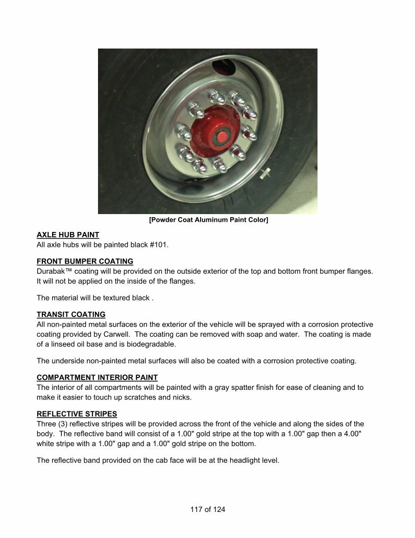
117 of 124
[Powder Coat Aluminum Paint Color]
AXLE HUB PAINT All axle hubs will be painted black #101.
FRONT BUMPER COATING Durabak™ coating will be provided on the outside exterior of the top and bottom front bumper flanges. It will not be applied on the inside of the flanges.
The material will be textured black .
TRANSIT COATING All non-painted metal surfaces on the exterior of the vehicle will be sprayed with a corrosion protective coating provided by Carwell. The coating can be removed with soap and water. The coating is made of a linseed oil base and is biodegradable.
The underside non-painted metal surfaces will also be coated with a corrosion protective coating.
COMPARTMENT INTERIOR PAINT The interior of all compartments will be painted with a gray spatter finish for ease of cleaning and to make it easier to touch up scratches and nicks.
REFLECTIVE STRIPES Three (3) reflective stripes will be provided across the front of the vehicle and along the sides of the body. The reflective band will consist of a 1.00" gold stripe at the top with a 1.00" gap then a 4.00" white stripe with a 1.00" gap and a 1.00" gold stripe on the bottom.
The reflective band provided on the cab face will be at the headlight level.

118 of 124
REAR CHEVRON STRIPING There will be alternating chevron striping located on the rear-facing vertical surface of the apparatus. The rear surface, excluding the rear compartment door, will be covered.
The colors will be red and fluorescent yellow green diamond grade.
Each stripe will be 6.00" in width.
This will meet the requirements of the current edition of NFPA 1901, which states that 50% of the rear surface will be covered with chevron striping.
CHEVRON STRIPING ON THE FRONT BUMPER There will be alternating chevron striping located on the front bumper.
The colors will be fluorescent yellow green and red diamond grade.
The size of the striping will be 6.00".
CAB DOOR REFLECTIVE STRIPE A 6.00" x 16.00" white reflective stripe will be provided across the interior of each cab door. The stripe will be located approximately 1.00" up from the bottom, on the door panel.
This stripe will meet the NFPA 1901 requirement.
LETTERING Twenty-one (21) to forty (40) reflective lettering, 3.00" high, with outline and shade will be provided.
LETTERING There will be reflective lettering, 16.00" high, with outline provided. There will be six (6) letters provided.
LETTERING Twenty-one (21) to forty (40) reflective lettering, 6.00" high, with outline and shade will be provided.
EMBLEM/S There will be two (2) reflective emblem/s, installed rear cab doors. Emblem/s will be modeled after the department patch.
1" BOOSTER HOSE NOZZLE The dealer is to provide (1) TFT DS1040P 1" Nozzle with Pistol Grip and Bail Control. Nozzle to capable of 10 GPM to 40 GPM.
CONTINGENCY FUND, FOR EQUIPMENT MOUNTING AND CHANGES A $5,000 contingency fund shall be included in the bid price. Any and all amount of the contingency fund not used during the final design of the apparatus shall be refunded to the purchaser and listed as so on the final invoice.
This fund is for changes requested by the bidder during the build process but after the bid.
119 of 124
This fund is for equipment mounting to be provided by the successful bidder.Equipment mounting is to be charged to the fund as time and materials.Time is to be the successful bidders published shop labor rater. Materials are to be at or below manufactures MSRP for the materials and/or mounts.
All changes and or labor utilizing the contingency fund is to be approved by the purchaser prior to use of those funds.
INSPECTION TRIP #1 An inspection trip will be provided for three (3) people. Trip will take place Main manufacturing facility.
INSPECTION TRIP #2 An inspection trip will be provided for three (3) people. Trip will take place main manufacturing facility.
FIRE APPARATUS PARTS MANUAL There will be one (1) custom parts manual(s) in USB flash drive format for the complete fire apparatus provided.
The manual(s) will contain the following:
• Job number • Part numbers with full descriptions • Table of contents • Parts section sorted in functional groups reflecting a major system, component, or assembly • Parts section sorted in alphabetical order • Instructions on how to locate parts
Each manual will be specifically written for the chassis and body model being purchased. It will not be a generic manual for a multitude of different chassis and bodies.
Service Parts Internet Site The service parts information included in these manuals are also available on the Pierce website. The website offers additional functions and features not contained in this manual, such as digital photographs and line drawings of select items. The website also features electronic search tools to assist in locating parts quickly.
CHASSIS SERVICE MANUALS There will be one (1) chassis service manuals on USB flash drives containing parts and service information on major components provided with the completed unit.
The manual will contain the following sections:
• Job number • Table of contents • Troubleshooting • Front Axle/Suspension • Brakes • Engine
120 of 124
• Tires • Wheels • Cab • Electrical, DC • Air Systems • Plumbing • Appendix
The manual will be specifically written for the chassis model being purchased. It will not be a generic manual for a multitude of different chassis and bodies.
CHASSIS OPERATION MANUAL The chassis operation manual will be provided on one (1) USB flash drive.
ONE (1) YEAR MATERIAL AND WORKMANSHIP A Pierce basic apparatus limited warranty certificate, WA0008, is included with this proposal.
ENGINE WARRANTY A Cummins five (5) year limited engine warranty will be provided. A limited warranty certificate, WA0181, is included with this proposal.
STEERING GEAR WARRANTY A TRW one (1) year limited steering gear warranty will be provided. A copy of the warranty certificate will be submitted with the bid package.
FIFTY (50) YEAR STRUCTURAL INTEGRITY The Pierce custom chassis frame limited warranty certificate, WA0013, is included with this proposal.
FRONT AXLE ONE (1) YEAR MATERIAL AND WORKMANSHIP WARRANTY Marmon-Herrington® offers a one (1) year or 12,000 miles warranty for axle systems used under normal service.
REAR AXLE WARRANTY A Eaton five (5)-year/100,000 mile parts and labor warranty will be provided.
ABS BRAKE SYSTEM THREE (3) YEAR MATERIAL AND WORKMANSHIP WARRANTY A Meritor Wabco™ ABS brake system limited warranty certificate, WA0232, is included with this proposal.
TEN (10) YEAR STRUCTURAL INTEGRITY The Pierce custom cab limited warranty certificate, WA0012, is included with this proposal.
TEN (10) YEAR PRO-RATED PAINT AND CORROSION A Pierce cab limited pro-rated paint warranty certificate, WA0055, is included with this proposal.
CAMERA SYSTEM WARRANTY A Pierce fifty four (54) month warranty will be provided for the camera system.

121 of 124
COMPARTMENT LIGHT WARRANTY The Pierce 12 volt DC LED strip lights limited warranty certificate, WA0203, is included with this proposal.
TRANSMISSION WARRANTY The transmission will have a five (5) year/unlimited mileage warranty covering 100 percent parts and labor. The warranty will be provided by Allison Transmission.
Note: The transmission cooler is not covered under any extended warranty you may be getting on your Allison Transmission. Please review your Allison Transmission warranty for coverage limitations.
TRANSMISSION COOLER WARRANTY The transmission cooler will carry a five (5) year parts and labor warranty (exclusive to the transmission cooler). In addition, a collateral damage warranty will also be in effect for the first three (3) years of the warranty coverage and will not exceed $10,000 per occurrence. A copy of the warranty certificate will be submitted with the bid package.
WATER TANK WARRANTY A UPF poly water tank limited warranty certificate, WA0195, is included with this proposal.
TEN (10) YEAR STRUCTURAL INTEGRITY The Pierce apparatus body limited warranty certificate, WA0009, is included with this proposal.
ROLL UP DOOR MATERIAL AND WORKMANSHIP WARRANTY A Gortite roll-up door limited warranty will be provided. The mechanical components of the roll-up door will be warranted against defects in material and workmanship for the lifetime of the vehicle. A six (6) year limited warranty will be provided on painted and satin roll up doors.
The limited warranty certificate, WA0190, is included with this proposal.
PUMP WARRANTY The Waterous pump will be provided with a Seven (7) year material and workmanship limited warranty.
A copy of the warranty certificate will be submitted with the bid package (no exception).
TEN (10) YEAR PUMP PLUMBING WARRANTY The Pierce apparatus plumbing limited warranty certificate, WA0035, is included with this proposal.
FOAM SYSTEM WARRANTY The Husky 3 foam system limited warranty certificate, WA0231, is included with this proposal.
TWO (2) YEAR GENERATOR MATERIAL AND WORKMANSHIP WARRANTY A Harrison Hydra-Gen generator two (2) year limited warranty will be provided.
TEN (10) YEAR PRO-RATED PAINT AND CORROSION A Pierce body limited pro-rated paint warranty certificate, WA0057, is included with this proposal.

122 of 124
ONE (1) YEAR MATERIAL AND WORKMANSHIP The Pierce graphics fading and deterioration limited warranty limited warranty certificate, WA0168, is included with this proposal.
VEHICLE STABILITY CERTIFICATION The fire apparatus manufacturer will provide a certification stating the apparatus complies with NFPA 1901, current edition, section 4.13, Vehicle Stability. The certification will be provided at the time of bid.
ENGINE INSTALLATION CERTIFICATION The fire apparatus manufacturer will provide a certification, along with a letter from the engine manufacturer stating they approve of the engine installation in the bidder's chassis. The certification will be provided at the time of delivery.
POWER STEERING CERTIFICATION The fire apparatus manufacturer will provide a certification stating the power steering system as installed meets the requirements of the component supplier. The certification will be provided at the time of bid.
CAB INTEGRITY CERTIFICATION The fire apparatus manufacturer will provide a cab crash test certification with this proposal. The certification will state that a specimen representing the substantial structural configuration of the cab has been tested and certified by an independent third party test facility. Testing events will be documented with photographs, real-time and high-speed video, vehicle accelerometers, cart accelerometers, and a laser speed trap. The fire apparatus manufacturer will provide a state licensed professional engineer to witness and certify all testing events. Testing will meet or exceed the requirements below:
• SAE J2422 Cab Roof Strength Evaluation - Quasi-Static Loading Heavy Trucks. • European Occupant Protection Standard ECE Regulation No.29. • SAE J2420 COE Frontal Strength Evaluation - Dynamic Loading Heavy Trucks.
Side Impact The cab will be subjected to dynamic preload where a 14,320-lb moving barrier is slammed into the side of the cab at 5.50 mph, striking with an impact of 13,000 ft-lb of force. This test is part of the SAE J2422 test procedure and more closely represents the forces a cab will see in a rollover incident.
Frontal Impact The same cab will withstand a frontal impact of 32,600 ft-lb of force using a moving barrier in accordance with SAE J2420.
Additional Frontal Impact The same cab will withstand a frontal impact of 65,098 ft-lb of force using a moving barrier. (Twice the force required by SAE J2420)
Roof Crush The cab will be subjected to a roof crush force of 22,500 lb. This value meets the ECE 29 criteria, and is equivalent to the front axle rating up to a maximum of ten (10) metric tons.

123 of 124
Additional Roof Crush The same cab will be subjected to a roof crush force of 110,000 lbs. (Four and a half times the load criteria of ECE 29)
The same cab will withstand all tests without any measurable intrusion into the survival space of the occupant area.
There will be no exception to any portion of the cab integrity certification. Nonconformance will lead to immediate rejection of bid.
CAB DOOR DURABILITY CERTIFICATION Robust cab doors help protect occupants. Cab doors will survive a 200,000 cycle door slam test where the slamming force exceeds 20 G's of deceleration. The bidder will certify that the sample doors similar to those provided on the apparatus have been tested and have met these criteria without structural damage, latch malfunction, or significant component wear.
WINDSHIELD WIPER DURABILITY CERTIFICATION Visibility during inclement weather is essential to safe apparatus performance. Windshield wipers will survive a 3 million cycle durability test in accordance with section 6.2 of SAE J198 Windshield Wiper Systems - Trucks, Buses and Multipurpose Vehicles. The bidder will certify that the wiper system design has been tested and that the wiper system has met these criteria.
SEAT BELT ANCHOR STRENGTH Seat belt attachment strength is regulated by Federal Motor Vehicle Safety Standards and should be validated through testing. Each seat belt anchor design will withstand 3000 lb of pull on both the lap and shoulder belt in accordance with FMVSS 571.210 Seat Belt Assembly Anchorages. The bidder will certify that each anchor design was pull tested to the required force and met the appropriate criteria.
SEAT MOUNTING STRENGTH Seat attachment strength is regulated by Federal Motor Vehicle Safety Standards and should be validated through testing. Each seat mounting design will be tested to withstand 20 G's of force in accordance with FMVSS 571.207 Seating Systems. The bidder will certify, at time of delivery, that each seat mount and cab structure design was pull tested to the required force and met the appropriate criteria.
PERFORMANCE CERTIFICATIONS
Cab Air Conditioning Good cab air conditioning temperature and air flow performance keeps occupants comfortable, reduces humidity, and provides a climate for recuperation while at the scene. The cab air conditioning system will cool the cab from a heat-soaked condition at 100 degrees Fahrenheit to an average of 78 degrees Fahrenheit in 30 minutes. The bidder will certify that a substantially similar cab has been tested and has met these criteria.
Cab Defroster Visibility during inclement weather is essential to safe apparatus performance. The defroster system will clear the required windshield zones in accordance with SAE J381 Windshield Defrosting Systems

124 of 124
Test Procedure And Performance Requirements - Trucks, Buses, And Multipurpose Vehicles. The bidder will certify that the defrost system design has been tested in a cold chamber and passes the SAE J381 criteria.
Cab Auxiliary Heater Good cab heat performance and regulation provides a more effective working environment for personnel, whether in-transit, or at a scene. An auxiliary cab heater will warm the cab 77 degrees Fahrenheit from a cold-soak, within 30 minutes when tested using the coolant supply methods found in SAE J381. The bidder will certify, at time of delivery, that a substantially similar cab has been tested and has met these criteria.
AMP DRAW REPORT The bidder will provide, at the time of bid and delivery, an itemized print out of the expected amp draw of the entire vehicle's electrical system.
The manufacturer of the apparatus will provide the following:
• Documentation of the electrical system performance tests. • A written load analysis, which will include the following:
o The nameplate rating of the alternator. o The alternator rating under the conditions specified per:
Applicable NFPA 1901 or 1906 (Current Edition). o The minimum continuous load of each component that is specified per:
Applicable NFPA 1901 or 1906 (Current Edition). o Additional loads that, when added to the minimum continuous load, determine the total
connected load. o Each individual intermittent load.
All of the above listed items will be provided by the bidder per the applicable NFPA 1901 or 1906 (Current Edition).

Option List
Line Option Type Option Description Qty
1 0074080 Build-to-Order, Pierce Florida Product - 2nd Gen Pumper 12 0766611 Boiler Plates, Pumper 1
Fire Department/Customer - Nederland Fire Protection District Operating/In conjunction W-Service Center - Operating Miles - 50 Miles Number of Fire Dept/Municipalities - 5 Bidder/Sales Organization - Front Range Fire Apparatus Delivery - Delivery representative Dealership/Sales Organization, Service - Front Range Fire Apparatus
3 0661794 Single Source Compliance 14 0584455 Manufacture Location, Bradenton, Florida 15 0584453 RFP Location: Bradenton, Florida 16 0588609 Vehicle Destination, US 17 0610784 Comply NFPA 1901 Changes Effective Jan 1, 2016, With Exceptions 18 0533347 Pumper/Pumper with Aerial Device Fire Apparatus 19 0588611 Vehicle Certification, Pumper 1
10 0568412 Agency, Apparatus Certification, Pumper/Tanker, Third Party, PMFD 111 0000000 STF Weekly Photo Reports - Pumper/Tanker 112 0056880 Requirements of Apparatus Manufacturer 113 0536644 Customer Service Website 114 0000113 Table of Contents 115 0620362 Consortium, HGAC 116 0537375 Unit of Measure, US Gallons 117 0030006 Bid Bond Not Requested 118 0582800 Performance Bond, 100% with 25% Warranty Bond, 1 Yr, and Payment Bond 119 0000007 Approval Drawing 120 0002928 Electrical Diagrams 121 0625274 Saber FR Chassis 4x4 122 0629024 Chassis Discount, Saber FR 123 0000110 Wheelbase 1
Wheelbase - 177.5"24 0000070 GVW Rating 1
GVW rating - 43,450 lbs25 0619391 Frame Rails, 10.25" x 3.50" x .375", Saber FR/Enf 4x4 Step Frame 126 0020018 Frame Liner Not Req'd 127 0737375 SP Axle, Front, Marmon Herrington MT-22 19,450 lb, (FWD) Saber FR/Enforcer 128 0637913 Suspension, Front, Standens, Taper Leaf, 20,000 lb, Saber FR/Enforcer 129 0000321 Shock Absorbers on Front Axle, Monroe Magnum 65, Saber/Enforcer 130 0639612 Oil Seals Not Available, Front Drive Axle 131 0670337 Differential Lock, Driver Controlled, (DCDL), Marmon Herrington MT-22 132 0664491 Tires, Front, Michelin, XZU S2, 315/80R22.50, 20 ply 133 0612060 Wheels, Front, Accuride, 22.50" x 9.00", Steel, Hub Pilot, 4x4 134 0625013 Axle, Rear, Eaton 230S4, 4WD, 24,000 lbs, Saber FR/Enforcer 135 0544248 Top Speed of Vehicle, 63 MPH 136 0565379 Suspen, Rear, Single Slipper Spring, 24,000 lb, Saber/Enforcer 137 0000485 Oil Seals, Rear Axle 138 0011855 Differential Lock, (CTD) Eaton, Sngl Axle (4x4) 139 0532538 Tires, Rear. Michelin, XDS, 12R22.50, 16 ply, Single 140 0654797 Wheels, Rear, Accuride, 22.50" x 9.00", Steel, Hub Pilot, Single 141 0568081 Tire Balancing, Counteract Beads 1
Customer: Nederland Fire Protection District Bid Number: 1177Representative Byrne, Jason Job Number: Organization: Front Range Fire Apparatus, Ltd Number of Units: 1Requirements Manager: Bid Date: 03/28/2022Description: Nederland Saber 4x4 Engine 750 Gallon LHB Stock Number:Body: Pumper, Medium, Aluminum, 2nd Gen, Saber/Commercial Price Level: 41 (Current: 41)Chassis: Saber FR Chassis 4x4 Lane:
4/15/2022
4/15/2022 2:22 PM Page 11177Bid #:

Line Option Type Option Description Qty42 0627984 Tire Pressure Monitoring, RealWheels, AirSecure, Valve Cap, Front Tires Only 1
Qty, Tire Pressure Ind - 243 0057936 Covers, Lug Nut, Chrome 144 0002045 Mud Flap, Front and Rear, Pierce Logo 145 0011930 Tire, "Crossfire" Air Pressure Equalization 146 0544802 Chocks, Wheel, SAC-44-E, Folding 1
Qty, Pair - 0147 0544806 Mounting Brackets, Chocks, SAC-44-E, Folding, Horizontal 1
Qty, Pair - 01 Location, Wheel Chocks - Left Side Rear Tire, Forward
48 0632611 SP ESC/ABS/ATC Wabco Brake System, Single Rear Axle, 4x4 ABS, 4x2 ESC/ABS/ATC
1
49 0011380 Brakes, Cam, Front, 16.50 x 7.00 (Std Marmon Herrington axle) 150 0581433 Brakes, Bendix, Cam, Rear, 16.50 x 7.00" 151 0020784 Air Compressor, Brake, Cummins/Wabco 18.7 CFM 152 0637584 Brake Reservoirs, 5,376 Cubic Inch Minimum Capacity, Saber FR/Enforcer 153 0644228 Air Dryer, Wabco System Saver 1200 IWT, Heated, 10" Frame, Standen, SFR/Enf 154 0678701 Brake Lines, Nylon, Special Color 155 0089419 Air Inlet, with Kussmaul Air Eject (Fill-In Blank Location) 1
Location - driver side step well (see drawing) Qty, Air Coupling (s) - 1
56 0000845 Air Tank, Additional for Extra Capacity 157 0630142 Moisture Ejectors, Automatic, w/Heat, All Tanks, Enforcer/Saber FR 158 0736437 Engine, Cummins L9, 450 hp, 1250 lb-ft, W/OBD, EPA 2021, Saber FR/Enforcer 159 0001244 High Idle w/Electronic Engine, Custom 160 0687994 Engine Brake, Jacobs Compression Brake, Cummins Engine 1
Switch, Engine Brake - e) ISC/ISM/ISL9/ISX Hi Med Lo61 0644227 Clutch, Fan, Air Actuated, Saber FR/Enforcer 162 0644573 Air Intake, Water & Ember Screen, Saber FR/Enforcer 163 0794761 Exhaust System, 4", 2017 L9 Engine, Horizontal, Right Side 164 0788765 Radiator, Saber FR/Enforcer 165 0001090 Cooling Hoses, Rubber 166 0051125 Fuel Tank, 75 Gallon, Left Side Fill, Qtm/AXT/Vel/Imp/DCF/SFR/Enf 1
Finish - Brushed Stainless67 0001129 Lines, Fuel 168 0618791 DEF Tank, 4.5 Gallon, DS Fill, Forward of Axle, Common Air Bottle Door 169 0723716 Fuel Priming Pump, Electronic, Automatic, Cummins, No Swt Req'd 170 0552712 Not Required, Shutoff Valve, Fuel Line 171 0699437 Cooler, Chassis Fuel, Not Req'd. 172 0642572 Trans, Allison 5th Gen, 3000 EVS P, w/Prognostics, Imp/Vel/DCF/SFR/Enf 173 0625329 Transmission, Shifter, 5-Spd, Push Button, 3000 EVS 174 0684459 Transmission Oil Cooler, Modine, External 175 0024895 Mode, Downshift, Aggressive downshift to 2nd, w/engine brake, 5 speed 176 0001370 Driveline, Spicer 1710 177 0603370 SP Driveline Reviewed & Approved 178 0637248 Steering, Dual Gear, TRW TAS-65, w/tilt, Pump w/ Cooler, Saber FR/Enforcer 179 0605356 Steering Wheel, 4 Spoke without Controls, Saber FR/Enforcer 180 0690274 Logo/Emblem, on Dash 1
Text, Row (1) One - Nederland Text, Row (2) Two - Fire Text, Row (3) Three - District
81 0779369 SP Crossmember, Special For PTO Pump Installation 182 0887571 SP Winch, Superwinch, 18,000 lb. Fixed, Front, Tiger Shark, Model#1518001,Electric 1
Stay arm, Tray Cover - b) Pneumatic Stay Arm83 0776057 SP Bumper, 16" Extended .38" Formed Steel, 10.38"H, Painted, Saber FR/Enforcer 184 0625558 No Selection Required, Cover Included with Tray/Tool Box Option 185 0614646 No Lift & Tow Package, Imp/Vel, AXT, SFR/Enf 186 0049964 Tow Eyes, Painted Black, Extended Out Front of Bumper 187 0625654 Cab, Saber FR, 6000 188 0647919 Engine Tunnel, ISL, Saber FR/Enforcer 189 0633594 Rear Wall, Interior, Adjustable Seating 1
4/15/2022 2:22 PM Page 21177Bid #:

Line Option Type Option Description Qty90 0632103 Rear Wall, Exterior, Cab, Saber FR/Enforcer 1
Material, Exterior Rear Wall - Painted91 0644201 Cab Lift, Elec/Hyd, Saber FR/Enforcer 192 0636939 Grille, Polished Stainless Steel, Front of Cab, Saber 193 0647932 Not Required, Trim, S/S Band, Across Cab Face, AXT/Dash CF/Saber/Enforcer 194 0015440 No Chrome Molding, On side of cab 195 0521669 Mirrors, Retrac, West Coast Style, Htd/Rmt, w/Htd/Rmt Convex 196 0648171 Door, Half-Height, Saber FR/Enforcer 4-Door Cab, Level Roof 1
Key Model, Cab Doors - 751 Cab, Exterior Door Handle, Finish - 4-Door, Chrome/Black
97 0655543 Door Panel, Brushed Stainless Steel, Saber/Enforcer 4-Door Cab 198 0528958 Not Required, Controls, Electric Window, AXT, Quantum, Saber, Enforcer, Dash CF 199 0633615 Steps, 4-Door Cab, Reduced Bottom Step, Saber FR/Enforcer 1
Step Well Material - Aluminum Treadplate100 0763659 Handrail, Exterior, Knurled, Alum, 4-Door Cab, AXT/SFR/Enf/Vel, 4x4 1101 0743060 SP Steps, Stirrup, Swing Style, Cab & Crew Cab Doors, AXT, Saber/Enf 4x4 1
Light, Step, Additional - P25 LED102 0892638 Lights, Cab & Crw Cab Acs Stps, P25, LED w/Bezel, 6lts 1
Color, Trim - Chrome Housing103 0040475 Crowns, Front Fender, Rubber 1104 0637984 Window, Side of C/C, Fixed, Saber FR/Enforcer 1105 0644019 Holder, Cup, 4" Diameter x 4" High x 1" Slit on Side, Matting, Alum, Each 4
Location - To be mounted at final inspection Qty, - 04
106 0722796 Dash, Poly, Saber FR/Enforcer 1107 0607217 Mounting Provisions, 3/16" Alum, Full Engine Tunnel, Saber FR/Enforcer 1
Mounting Provision Spacing - .75" Material Finish, Cab Interior - Painted
108 0657893 Mounting Plate, 3/16" Aluminum, Cab Interior 1 Location - driver side interior rear cab wall (full area between cabinet and outer cab wall) Qty, - 01 Size - driver side interior rear cab wall (full area between cabinet and outer cab wall) Mounting Provision Spacing - .75" Material Finish, Cab Interior - Painted
109 0750824 Cab Interior, Vinyl Headliner, Saber FR/Enforcer, CARE 1 Color, Cab Interior Vinyl/Fabric - Endure Vinyl - Black Engine Tunnel Cover - Painted Cab Interior Rear Wall Material - Painted Aluminum
110 0753903 Cab Interior, Paint Color, Saber FR/Enforcer 1 Color, Cab Interior Paint - b) black
111 0052100 Floor, Rubber Padded, Cab & Crew Cab, Saber/Enforcer 1112 0741237 HVAC, Saber FR, CARE 1
HVAC System, Filter Access - Removable Panel Auxiliary Cab Heater - Both HVAC System, Control Loc. - Panel Position #12
113 0012122 Fans, Window Defrost, One (1) Fan on Each Side 1114 0639675 Sun Visor, Smoked Lexan, AXT, Imp/Vel, Saber FR/Enforcer 1
Sun Visor Retention - Thumb Latch115 0634328 Grab Handles, Driver and Officer Door Posts, Saber FR/Enforcer 1116 0002526 Light, Engine Compt, All Custom Chassis 1117 0631830 Fluid Check Access, Saber FR/Enforcer, Arrow XT 1
Latch, Door, Storage - Lift and Turn Latch118 0530840 Box, Storage, Aluminum, Latex Gloves 4
Location - to be mounted at final inspection Qty, - 04
119 0660939 Map Box, 2 Bin, 30 Degree Slant 1
Location - to be mounted at final inspection120 0583042 Side Roll and Frontal Impact Protection 1121 0622619 Seating Capacity, 4 Seats 1122 0636955 Seat, Driver, Pierce PSV, Air Ride, High Back, Safety, Saber FR/Enforcer 1123 0636942 Seat, Officer, Pierce PSV, Fixed, SCBA, Safety, Saber FR/Enforcer 1
4/15/2022 2:22 PM Page 31177Bid #:

Line Option Type Option Description Qty124 0620420 Radio Compartment, Below Non-Air Ride Seat, Saber FR/Enforcer 1
Latch, Door, Storage - Lift and Turn Latch, Flush125 0635973 Seat, Rear Facing C/C, DS Outboard, Pierce PSV, SCBA, Safety, Saber
FR/Enforcer1
126 0102783 Not Required, Seat, Rr Facing C/C, Center 1127 0635969 Seat, Rear Facing C/C, PS Outboard, Pierce PSV, SCBA, Safety, Saber
FR/Enforcer1
128 0108189 Not Required, Seat, Forward Facing C/C, DS Outboard 1129 0785367 Cabinet, Forward Facing, Center, 38.50 W x 50 H x 18 D, Roll, SFR/Enf 1
Material Finish, Shelf - Painted - Cab Interior Shelf/Tray, Cabinet - (2) Shelves, Adjustable, 1.25" Up-Turned Lip Door, Cab Interior Cabinet - Rollup, Amdor, White, Non-Locking Light, Tall Cabinet - Pierce, Interior, Left Side and Pierce, Interior, Right Side Louvers, Cabinet - 0-No Louvers
130 0108190 Not Required, Seat, Forward Facing C/C, PS Outboard 1131 0617401 Matting, Turtle Tile, No Trim, EMS Compt 3
Location - each shelf and floor of ems compartment Qty, - 03 Color - 1) black
132 0566653 Upholstery, Seats In Cab, Turnout Tuff 1
Color, Cab Interior Vinyl/Fabric - c) Black133 0543991 Bracket, Air Bottle, Hands-Free II, Cab Seats 3
Qty, - 03134 0603866 Seat Belt, Dual Retractor, ReadyReach, Saber FR/Enforcer 1
Seat Belt Color - Red135 0602464 Helmet Storage, Provided by Fire Department, NFPA 2016 1136 0647647 Lights, Dome, FRP Dual LED 4 Lts 1
Color, Dome Lt - Red & White Color, Dome Lt Bzl - Grey Control, Dome Lt White - Door Switches and Lens Switch Control, Dome Lt Color - Lens Switch
137 0755334 SP Handlts, (3) Streamlight, Vulcan 180, 44315, 12v, Orange 1 Location, Portable Hand Light - At Pickup
138 0681751 Handlight, Streamlight, E- Flood LiteBox, 45805 LED, 12v Charger, Orange 2 Qty, Lights - 02 Location, Lights - TBD
139 0644187 Cab Instruments, Black Gauges, Black Bezels, Saber FR/Enforcer 1 Emergency Switching - Individual Switches
140 0002544 Air Restriction Indicator - Pierce Chassis 1141 0543751 Light, Do Not Move Apparatus 1
Alarm, Do Not Move Truck - Pulsing Alarm142 0637359 Not Required, Door Open Indicator w/Do Not Move Truck Light, Enf/Saber FR 1143 0754774 Switching, Cab Instrument Lower Console & Overhead, Rocker, Saber 1144 0644179 Wiper Control, 2-Speed with Intermittent, Saber FR/Enforcer 1145 0797189 Wiring, Spare, 4.8 A 12V DC, USB Termination Blue Sea 1045 1st 2
Qty, - 02 12vdc power from - Battery direct Location - TBD
146 0579886 Wiring, Spare, 50 A 12V DC, 6 Circuit Fuse Block, Blue Sea 5025 1st 3 Qty, - 03 12vdc power from - Battery direct Location - Med cabinet centered up high, behind officer seat, in cabinet TBD
147 0636439 Wiring, Spare, 37.5 A 12V DC, Cust Install Radio, 30A Bat Dir, 7.5A Ign & Grnd 2 Qty, - 02 Location - center dash switch panel
148 0763646 Vehicle Information Center, LCD On Gauge Cluster Only, Sab/Enf 1 System Of Measurement - US Customary
149 0734857 Collision Mitigation, HAAS Alert (R2V), HA5 1 Subscription, HAAS R2V - R2V - 5 Year Data Plan Subscription
150 0610240 Vehicle Data Recorder w/Seat Belt Monitor 1151 0735095 Intercom, David Clark, 4-Pos, 2-Dual Radio, (D, O, RPTT), 2obC, 3805 1
Location - TBD
4/15/2022 2:22 PM Page 41177Bid #:

Line Option Type Option Description Qty151 Location, Intercom, C Cab - 2) 2 rearward facing seats152 0637058 David Clark Universal Radio Interfaces Included with Single/Dual System 1
Location, Radio Interface - TBD153 0597914 Headset, David Clark, H3442 Under Helmet, Flex Mic 2
Qty, - 02 Location - front seats
154 0589947 Headset, David Clark, H3432 Over The Head, Flex Mic, Push On Push Off 2 Qty, - 02 Location - rear seats
155 0681408 Hangers For Headsets, NFPA, Each 5 Qty, - 05 Location, Headset Hangers - Driver Seat, Officer Seat, DS Outbrd, Fwrd Fcng Seat, PS Outbrd, Fwrd Fcng Seat and Rear, Center, Fwrd Fcng Seat
156 0696439 Antenna Mount, Custom Chassis, Cable Routed to Instrument Panel Area 2 Qty, - 02 Location, Antenna Mount - Left And Right Side
157 0653530 Camera, Pierce, 7" LCD, R, RS, LS Cameras 1 Location, Camera Monitor - Driver Side In Custom Dash
158 0511071 Guard, 4-Way, Rear Vision Camera 1 Qty, - 01 Location - center rear
159 0624249 Electrical Power/Signal Protection & Control, Saber FR 1160 0624260 Electrical System, Saber FR 1161 0079166 Batteries, (4) Exide Grp 31, 950 CCA ea, Threaded Stud 1162 0008621 Battery System, Single Start, All Custom Chassis 1163 0002698 Battery Compartment, Saber/Enforcer 1164 0531315 Charger, Sngl Sys, IOTA, DSL-75, 75 Amp, Kussmaul 091-94-12 Ind, Qtm/Enf/SFR 1165 0662220 Location, Charger, Cab Behind Driver Seat, Dash CF/Saber FR/Enf 1166 0536099 Location, Bat Chrg Ind, Driver's Step Area 1167 0782026 Shoreline, 20A 120V, Blue Sea Sure Eject 7851 1
Qty, - 01 Connection, Shoreline - charger / shoreline Color, Cover, Bl Sea Inlet - Red
168 0026800 Shoreline Location 1 Location, Shoreline(s) - DS Seat Riser
169 0009429 Electric Power Only, Portable Winch 1 Location - rear receiver hitch Qty, Receptacles - 01
170 0647729 Alternator, 320 amp, Delco Remy 40SI 1171 0644176 Load Manager, Integrated In Electrical System, Saber FR/Enforcer 1172 0888792 SP Headlights, Rect LED, 4X4, JW Spkr Evo 2, Heat, Saber 1
Color, Headlight Bez - Chrome Bezel173 0648418 Light, Directional, Wln M6T LED, Common Bezel, Above Headlights, Sab/Enf 1174 0620054 Light, Directional/Marker, Intermediate, Weldon 9186-8580-29 LED 2lts 1175 0647802 Lights, Clearance/Marker/ID, Front, P25 LED 5 Lts, Saber FR/Enforcer 1176 0647899 Lights, Directional/Marker, Cab Front Side, Weldon 9186-8580-29 LED, Sab/Enf 1177 0563675 Lights, Clearance/Marker/ID, Rear, Truck-Lite 33050R LED 7Lts 1178 0564683 Lights, Tail, Wln M6BTT* Red LED Stop/Tail & M6T* Amber LED Dir Arw For Hsg 1
Color, Lens - Clear179 0561471 Lights, Backup, Wln M6BUW, LED, For Tail Lt Housing 1180 0664481 Bracket, License Plate & Light, P25 LED 1181 0556842 Bezels, Wln, (2) M6 Chrome Pierce, For mtg (4) Wln M6 lights 1182 0589905 Alarm, Back-up Warning, PRECO 1040 1183 0565826 SP Switch, Back-Up Alarm Override 1184 0769569 Lights, Perimeter Cab, Amdor AY-LB-12HW012 LED 4Dr 1185 0769559 Lights, Perimeter Pump House, Amdor AY-LB-12HW012 LED 2lts 1186 0769560 Lights, Perimeter Body, Amdor AY-LB-12HW012 LED 2lts, Rear Step 1
Control, Perimeter Lts - DS Switch Panel, Parking Brake Applied and Directional Light Activation
187 0769567 Lights, Perimeter, Amdor AY-LB-12HW012 12", Brkt 6 Qty, Lights - 06
4/15/2022 2:22 PM Page 51177Bid #:

Line Option Type Option Description Qty187 Location, Additional Perimeter Lights - Each Side Under Front Bumper,
2lts, Under Compt LS1, 1lt, Under Compt LS3, 1lt, Under Compt RS1, 1lt and Under Compt RS3, 1lt
188 0556337 Lights, Step, P25 LED at Rear Tailboard, 2lts Perm Lts 1189 0029460 Housing, Light, Wln, Alum. 4-Way, Top of Body, Pair 1
Location, Lights - officer side forward, officer side rearward Qty, - 1
190 0649319 Special Switching, 12V Rear Scene Lights, Reverse Activation, Emerg Master ON 1 Location, Lights - rear scene light(s)
191 0629192 Light, FRC, 12V SPA260-Q20* LED MAX, Surface Mount 1st 2 Location, Lights - driver side body up high forward, driver side body up high rearward Qty, - 02 Switch, Lt Control 1 DC,1 - a) DS Switch Panel Switch, Lt Control 2 DC,2 - f) Pump Operator's Panel Switch, Lt Control 3 DC,3 - d) No Control Switch, Lt Control 4 DC,4 - d) No Control Color, FRC/Rom Lt Housing - FRC, Chrome Bezel
192 0629191 Light, FRC, 12V SPA260-Q20* LED MAX, Surface Mount 2nd 2 Location, Lights - officer side body up high forward, officer side body up high rearward Qty, - 02 Switch, Lt Control 1 DC,1 - a) DS Switch Panel Switch, Lt Control 2 DC,2 - f) Pump Operator's Panel Switch, Lt Control 3 DC,3 - d) No Control Switch, Lt Control 4 DC,4 - d) No Control Color, FRC/Rom Lt Housing - FRC, Chrome Bezel
193 0790483 Light, Visor, HiViz, FT-MB-33-*-*, 42.44" long 1 Qty, - 01 Location, driver's/passenger's/center - Centered Control, Scene Lts - Cab Sw Panel DS, Pump Panel Sw LS and Cab Sw Panel PS Color, Lt Housing HiViz - Job Color Scene Light Optics - Flood/Spot
194 0773362 Lights, HiViz FT-B-46-*-* LED, 1st 1 Location - on cross bar of hard hose bed cover, centered Qty, - 01 Control, Scene Lts - Cab Sw Panel DS, Pump Panel Sw LS and Body Switch, DS Rear Bulkhead Color, Lt Housing HiViz - Black
195 0532358 Not Required, Deck Lights, Other Hose Bed & Rear Lighting 1196 0645877 Lights, Hose Bed, Sides, Dual LED Light Strips 1
Control, Hose Bed Lts - Cup Switch At Rear197 0645677 Lights, Not Required, Rear Work, Alt. 12 Volt Lights At Rear Body 1198 0768376 Lights, Walk Surf, FRP Flood, LED, Qty, Loc Fet 2
Location - on one hose bed cover, one on dunnage area, see drawing Qty, Surface Lights - 2
199 0753285 Switch, White Warning Lights, Front 1 Function Reset - On
200 0590751 Switch, Red, IPOS 1 Location - emergency master Qty, - 01 Fill in Blank - emergency master
201 0693709 Pumper, Medium, Aluminum, 2nd Gen, Saber/Commercial 1202 0632361 No Additional Florida Discount - w/Saber FR Chassis 1203 0554271 Body Skirt Height, 20" 1204 0780858 SP Tank, Water, 750 Gallon, Poly, Med, New York Style, 4x4 1205 0003405 Overflow, 4.00" Water Tank, Poly 1206 0028104 Foam Cell Required 1207 0553725 Restraint, Water Tank, Heavy Duty, Special Type Tank, 4x4, or Export 1208 0003429 Not Required, Direct Tank Fill 1209 0003424 Not Required, Dump Valve 1210 0048710 Not Required, Jet Assist 1211 0030007 Not Required, Dump Valve Chute 1
4/15/2022 2:22 PM Page 61177Bid #:

Line Option Type Option Description Qty212 0514778 Not Required, Switch, Tank Dump Master 1213 0556223 Hose Bed, Aluminum, Pumper, New York Style, Fill In Blank Height 1
Fill in Blank - 68" Material Trim/Scuffplate - b) S/S, Brushed
214 0003481 Hose Bed Capacity, Special 1 Capacity, Hosebed - Left to right, #1: 400' of 3" DJ#2: 400' of 3" DJ#3: 1000' of 5" #4: 250' of 2.5" DJ #5: 200' of 1.75" DJ Single Stack
215 0083488 Divider, Hose Bed, .25" Unpainted 4
Qty, Hosebed Dividers - 4216 0089471 Cutout, Handhold, in Hose Bed Divider 4
Qty, - 04217 0689727 Cover, Hose Bed, Alum Treadplate, No Dome Access 1218 0538045 Flap, Rear of Alum Hose Bed Cover, Vinyl, Paddle Seat Belt Buckles 1
Color, Vinyl Cover - a) red219 0680205 Running Boards, 14.75" Deep 1220 0689497 Tailboard, T-Shaped, 24" & 8" Deep, Angled Corners 1221 0690037 Wall, Rear, Smooth Aluminum/Body Material 1
Material, Rear Wall Inboard Facing Surfaces - Aluminum Diamondplate222 0889721 Tow Eyes, w/Hitch Receiver, 2G Pumper 1
Connection, Trailer/12V Electrical, 2G - No Electric Connection223 0590926 Hose Restraint, Running Board, Velcro Straps 2
Location, Hose Tray, Running Board - a) both sides Qty, Tray, Hose - 2
224 0777391 Hose Restraint, Running Board, Velcro Straps, Strap Location 1 Location - for water can TBD Location, Hose Tray, Running Board - Right Side Qty, Tray, Hose - 1
225 0079470 Tray, Hose, Running Board, "Free Floating", w/Capacity Feature 2
Location, Hose Tray, Running Board - a) both sides Qty, Tray, Hose - 2 Capacity, Hose Tray - 25' of 5" LDH driver side, 50' of 2.5" DJ on officer side
226 0602109 SP Bin, Extinguisher, Running Board, 8" Diameter/8" Deep 1 Location - officer side running board forward Qty, - 01
227 0895820 Construction, Compt, Alum, 2G Pumper 1228 0531188 LS 152" Rollup, Full Height Front & Rear, FDLER, Raised Rear 6" 1229 0887574 SP RS 152" Rollup, 3/4 Height Front Rear, (1) Lap Brrom, FDLER, Raised Rear 6" 1230 0692733 Doors, Rollup, Gortite, Side Compartments 5
Qty, Door Accessory - 05 Color, Roll-up Door, Gortite - Painted to Match Lower Body Latch, Roll-up Door, Gortite - Non-Locking Liftbar
231 0013671 Compt, Rear, Rollup, 30.75" FF, 25.88" D 1232 0692746 Door, Gortite, Rollup, Rear Compartment 1
Color, Roll-up Door, Gortite - Painted to Match Lower Body Latch, Roll-up Door, Gortite - Non-Locking Liftbar
233 0555146 Pull Strap, Body Doors, Each 3 Qty, Door Accessory - 03 Location, Door Pull Strap - LS1, LS2 and LS3
234 0554995 No Body Modification Required 1235 0786048 SP Scuffplate, Rear Bulkhead, Brushed Stainless Steel, Special Size 1
Location - under pike pole heads on rear bulkhead officer to protect from pike heads Size - TBD
236 0045159 Guard, Drip Pan, S/S, L-Shape, Cover Bottom and Rear of Rollup Door Roll 6 Qty, Door Accessory - 06 Location, Door Accessory - all roll up compartment doors
237 0654498 Trim, Rollup Door, Painted Job Color, by Gortite 6 Qty, - 06
4/15/2022 2:22 PM Page 71177Bid #:
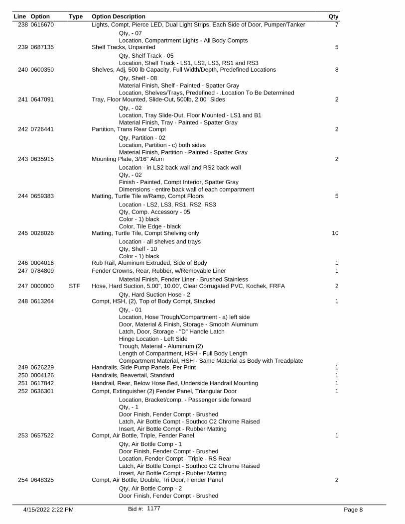
Line Option Type Option Description Qty238 0616670 Lights, Compt, Pierce LED, Dual Light Strips, Each Side of Door, Pumper/Tanker 7
Qty, - 07 Location, Compartment Lights - All Body Compts
239 0687135 Shelf Tracks, Unpainted 5 Qty, Shelf Track - 05 Location, Shelf Track - LS1, LS2, LS3, RS1 and RS3
240 0600350 Shelves, Adj, 500 lb Capacity, Full Width/Depth, Predefined Locations 8 Qty, Shelf - 08 Material Finish, Shelf - Painted - Spatter Gray Location, Shelves/Trays, Predefined - .Location To Be Determined
241 0647091 Tray, Floor Mounted, Slide-Out, 500lb, 2.00" Sides 2 Qty, - 02 Location, Tray Slide-Out, Floor Mounted - LS1 and B1 Material Finish, Tray - Painted - Spatter Gray
242 0726441 Partition, Trans Rear Compt 2 Qty, Partition - 02 Location, Partition - c) both sides Material Finish, Partition - Painted - Spatter Gray
243 0635915 Mounting Plate, 3/16" Alum 2 Location - in LS2 back wall and RS2 back wall Qty, - 02 Finish - Painted, Compt Interior, Spatter Gray Dimensions - entire back wall of each compartment
244 0659383 Matting, Turtle Tile w/Ramp, Compt Floors 5 Location - LS2, LS3, RS1, RS2, RS3 Qty, Comp. Accessory - 05 Color - 1) black Color, Tile Edge - black
245 0028026 Matting, Turtle Tile, Compt Shelving only 10 Location - all shelves and trays Qty, Shelf - 10 Color - 1) black
246 0004016 Rub Rail, Aluminum Extruded, Side of Body 1247 0784809 Fender Crowns, Rear, Rubber, w/Removable Liner 1
Material Finish, Fender Liner - Brushed Stainless247 0000000 STF Hose, Hard Suction, 5.00", 10.00', Clear Corrugated PVC, Kochek, FRFA 2
Qty, Hard Suction Hose - 2248 0613264 Compt, HSH, (2), Top of Body Compt, Stacked 1
Qty, - 01 Location, Hose Trough/Compartment - a) left side Door, Material & Finish, Storage - Smooth Aluminum Latch, Door, Storage - "D" Handle Latch Hinge Location - Left Side Trough, Material - Aluminum (2) Length of Compartment, HSH - Full Body Length Compartment Material, HSH - Same Material as Body with Treadplate
249 0626229 Handrails, Side Pump Panels, Per Print 1250 0004126 Handrails, Beavertail, Standard 1251 0617842 Handrail, Rear, Below Hose Bed, Underside Handrail Mounting 1252 0636301 Compt, Extinguisher (2) Fender Panel, Triangular Door 1
Location, Bracket/comp. - Passenger side forward Qty, - 1 Door Finish, Fender Compt - Brushed Latch, Air Bottle Compt - Southco C2 Chrome Raised Insert, Air Bottle Compt - Rubber Matting
253 0657522 Compt, Air Bottle, Triple, Fender Panel 1 Qty, Air Bottle Comp - 1 Door Finish, Fender Compt - Brushed Location, Fender Compt - Triple - RS Rear Latch, Air Bottle Compt - Southco C2 Chrome Raised Insert, Air Bottle Compt - Rubber Matting
254 0648325 Compt, Air Bottle, Double, Tri Door, Fender Panel 2 Qty, Air Bottle Comp - 2 Door Finish, Fender Compt - Brushed
4/15/2022 2:22 PM Page 81177Bid #:

Line Option Type Option Description Qty254 Location, Fender Compt - Double - LS Fwd - DEF Combo and Double -
LS Rear - Fuel Combo Latch, Air Bottle Compt - Southco C2 Chrome Raised Insert, Air Bottle Compt - W-Shaped Insert
254 0000000 STF Ladder, 24' Duo-Safety 900A 2-Sect, Provided By FRFA 1254 0000000 STF Ladder, 14' Duo-Safety 775-DR Roof, Provided By FRFA 1
Qty, - 01255 0663471 Rack, Zico Quic-Lift, Side Sheet Mount 1
Location, driver's/passenger's/center - Right256 0089550 Brkt, for 10' Folding Ladder Storage on HLR 1256 0000000 STF Ladder, Folding, 10' 585A, Duo-Safety (NO MOUNT) Provided By FRFA 1256 0000000 STF Pike Pole, 4' Fire Hooks Unlimited, New York Roof Hook, Steel, Pry End, RH-4 1
Location - on back of cab Qty, Pike Poles - 1
256 0000000 STF Pike Pole, 8' Fire Hooks Unlimited, New York Roof Hook, Steel, Pry End, RH-8 1 Location - in tube on top of officer side body Qty, Pike Poles - 1
256 0000000 STF Pike Pole, 8' Fire Hooks Unlimited, Steel, Colorado Hook 1 Location - TBD Qty, Pike Poles - 1
256 0000000 STF Pike Pole, 10' Fire Hooks Unlimited, New York Roof Hook, Steel, RH-10, Pry End 1 Qty, - 1 Location - in tube on top of officer side body
256 0000000 STF Pike Pole, 6' Fire Hooks Unlimited, New York Roof Hook, Steel, Pry End, RH-6 2 Qty, - 02 Location - back of cab mounting, in tube on top of officer side body
257 0058193 Tubes, Alum, Pike Pole Storage, Spcl Notch, NY PP Head 3 Location - on top of officer side body Qty, Pike Pole Tubes - 03
258 0673579 Mounting Bracket, Pike Pole, PAC Handlelok #1004, Ea 2 Location - top of driver side body (for CO Hook) Qty, - 02
259 0724839 SP Mounting Brackets, Pike Pole, Fire Hooks Unlimited, Hooks Nest 4/PAC Handlelok 2 Location - back of cab each side (set for 4' NY, so they can store a 4' or a 6') Qty, - 02
260 0785102 Steps, Folding, Front of Body, Cargo Bed Access, w/LED, Trident 1 Coating, Step - black Location, Steps - Full Height Left Side w/LED Light
261 0592994 Steps, Folding, Rear of Body, w/LED, Trident 1 Coating, Step - black
262 0596127 Step Package, Body, w/4x4 Chassis, Not Required, Non-NFPA 2016 Compliant 1263 0020500 Step, Camper Style, 8.00" Deep, Pull-out & Drop Down, 26" Wide 2
Location, Additional Step - rear bumper Qty, Pullout Step - 02
264 0650260 I Zone Bracket, Pair, Wildland Style 1 Fill in Blank - (1) each side on the rear of the body as shown on the AD
265 0019940 Step, Spcl Width, Rear Of Body, 8" 1266 0007575 Pump House, Side Control, 48", Control Zone 1267 0035500 Raised Pump House Structure, Side Control 1268 0646289 SP Pump, Waterous, CMPA, 1250 GPM, Two Stage, PTO 1269 0004482 Seal, Mechanical, Waterous 1270 0690873 Trans, Pump, Waterous, "PA" Series, Heavy Duty PTO 1271 0603731 Pumping Mode, Stationary and Pump in Motion (Pressure Gauge in Cab Included) 1272 0535276 Pump Shift, PTO Pump 1273 0581602 Transmission Lock-up, Not Req'd, PTO Pump 1274 0004547 Auxiliary Cooling System 1275 0004484 Transfer Valve, Manual, Waterous 1276 0746508 Valve(s), Relief Intake, Trident Air Max, Control Location 1
Qty - 1 Pressure Setting - 125 psig Intake Relief Valve Control - Behind Right Side Pump Panel
4/15/2022 2:22 PM Page 91177Bid #:
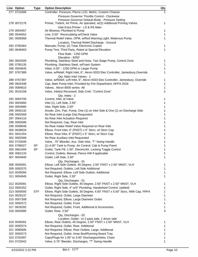
Line Option Type Option Description Qty277 0721606 Controller, Pressure, Pierce LCD, Metric, Custom Chassis 1
Pressure Governor Throttle Control - Clockwise Pressure Governor Default Mode - Pressure Setting
278 0072176 Primer, Trident, Air Prime, Air operated, w/(2) Additional Priming Valves 1 Inlet Extra Primer - LS & RS Main
279 0004457 Air Blowout, Plumbed to Pump 1280 0044552 Line, 0.50" Recirculating w/Check Valve 1281 0658368 Thermal Relief Valve, OPM, w/Red Warning Light, Waterous Pump 1
Location, Thermal Relief Discharge - Ground282 0780364 Manuals, Pump, (2) Total, Electronic Copies 1283 0648463 Pump Test, Third Party, Rated at Special Elevation 1
Flow Rate - 1250 GPM Elevation - 8250'
284 0602509 Plumbing, Stainless Steel and Hose, Two Stage Pump, Control Zone 1285 0795135 Plumbing, Stainless Steel, w/Foam System 1286 0004645 Inlets, 6.00" - 1250 GPM or Larger Pump 1287 0767389 Valve, w/Relief, Right Inlet, 6", Akron 9333 Elec Controller, Jamesbury,Override 1
Qty, Main Inlet Valves - 1288 0767397 Valve, w/Relief, Left Inlet, 6", Akron 9333 Elec Controller, Jamesbury, Override 1289 0602448 Cap, Main Pump Inlet, Provided by Fire Department, NFPA 2016 1290 0084610 Valves, Akron 8000 series- All 1291 0016158 Valve, Inlet(s) Recessed, Side Cntrl, "Control Zone" 2
Qty, Inlets - 2292 0004700 Control, Inlet, at Valve 1293 0004660 Inlet (1), Left Side, 2.50" 1294 0004680 Inlet, Right Side, 2.50" 1295 0505132 Anode, Zinc, Pair, Pump, One (1) on Inlet Side & One (1) on Discharge Side 1296 0092569 No Rear Inlet (Large Dia) Requested 1297 0064116 No Rear Inlet Actuation Required 1298 0092696 Not Required, Cap, Rear Inlet 1299 0009648 No Rear Intake Relief Valve Required on Rear Inlet 1300 0638634 Elbow, Front Inlet, 6" (FNST) x 5" Storz, w/ Storz Cap 1301 0041254 Elbow, Rear Inlet, 6" (FNST) x 5" Storz, w/ Storz Cap 1302 0092568 No Rear Auxiliary Inlet Requested 1303 0723049 Valve, .75" Bleeder, Aux. Side Inlet, "T" Swing Handle 1304 0786027 SP (1) 4.00" Tank to Pump, Air Control, Cab & Pump Panel 1305 0661594 SP Outlet, Tank Fill, 1.50", Electric/Air, Locking Toggle Control 1306 0062133 Control, Outlets, Manual, Pierce HW if applicable 1307 0004940 Outlet, Left Side, 2.50" 1
Qty, Discharges - 01308 0005091 Elbow, Left Side Outlets, 45 Degree, 2.50" FNST x 2.50" MNST, VLH 1309 0092570 Not Required, Outlets, Left Side Additional 1310 0035094 Not Required, Elbow, Left Side Outlets, Additional 1311 0004945 Outlet, Right Side, 2.50" 1
Qty, Discharges - 01312 0025091 Elbow, Right Side Outlets, 45 Degree, 2.50" FNST x 2.50" MNST, VLH 1313 0550252 Outlet, Right Side, 4" w/3" Plumbing, Handwheel Control, (added) 1313 0000000 STF Elbow, Right Side Outlets, 30 Degree, 4.00" FNST x 5.00" Storz, With Cap, FRFA 1314 0029137 Not Required, Outlet, Large Diameter 1315 0007308 Not Required, Elbow, Large Diameter Outlet 1316 0092572 Not Required, Outlet, Front 1317 0626292 Not Required, Outlet, Front, Additional & Accessories 1318 0004995 Outlet, Rear, 2.50" 3
Qty, Discharges - 03 Location, Outlet - e) 2 pass side, 1 driver side
319 0045091 Elbow, Rear Outlets, 45 Degree, 2.50" FNST x 2.50" MNST, VLH 1320 0092574 Not Required, Outlet, Rear, Additional 1321 0085695 Not Required, Elbow, Rear Outlets, Large, Additional 1322 0092573 Not Required, Outlet, Hose Bed/Running Board Tray 1323 0752097 Caps/Plugs for 1.00" to 3.00" Discharges/Inlets, Chain 1324 0723042 Valve, 0.75" Bleeder, Discharges, "T" Swing Handle 1
4/15/2022 2:22 PM Page 101177Bid #:

Line Option Type Option Description Qty325 0005065 Outlet, 3.00" Deluge Riser 1325 0000000 STF Monitor, TFT Xfire XFC-52, (2) 2.5" Inlets, Package 1
Monitor Finish - Painted by OEM326 0029304 No Nozzle Req'd 1327 0015072 Deluge Mount, For TFT Crossfire Monitor, XFF-APL, No extend-a-gun 1328 0723726 Speedlay Module Not Required 1329 0722432 Hose Restraint Not Required, No Speedlay Module 1330 0723395 Speedlays, Not Required 1331 0723394 Speedlays, Not Required 1332 0761773 SP Crosslay(s), 1.50" Single Stack, w/Side Outlets Below, with Alum Trays 2
Capacity, Special Xlay - 200' of 1.75" hose Qty, Crosslays - 2
333 0029196 Not Required, 2.50" Crosslay 1334 0793608 SP Hose Restraint, Crosslay, Vinyl, StayPut Fasteners, Each Side, Ends 2
Color, Vinyl Cover - a) red Qty, - 02 Restraint Location - Top (towards roof of truck)
335 0029260 Not Required, Speedlays 1336 0750536 Hose Restr, Spdly, Not Required, No Spdly 1337 0793101 SP Cover, Crosslay, Bi-fold 3\16" Alum Treadplate, #30369 1338 0019853 Crosslays, 8.00" Lower Than Standard - Control Zone w/9.00" Raised PH 1339 0887784 SP Reel, Booster, Steel - Over Pump, Left Side, 2/3 H.P. Motor, NPSH Fitting 1
Finish, Reel - Painted Gray340 0005280 Switches, Reel Rewind - (1) Each Pump Panel 1341 0018394 Hose, Booster - 150' of 1.00"/800 PSI, 1" NPSH Coupling 1342 0005244 Capacity, Hose Reel 200' of 1" 1343 0007428 Nozzle for Booster Reel Not Req'd 1344 0005326 Blowout, Hose Reel - Valve at Panel 1
Qty, - 1345 0622237 Roller Assembly, Additional 1
Location - officer side top of pump house (to mirror driver side) Qty, - 1
346 0047283 Cover, Reel Motor Solenoid & Wiring 1347 0624939 Foam Sys, Husky 3, Single Agent, Multi Select Feature 1
Discharge, Foam Locations - Hose Reel in Dunnage Left Side, Rear Outlet Left Side, Crosslay Front, Crosslay Rear, Rear Outlet Inboard Left Side and Rear Outlet Inboard Right Side
348 0012126 Not Required, CAF Compressor 1349 0592527 Refill, Foam Tank, Integral, Husky 3 1350 0031896 Demonstration, Foam System, Dealer Provided 1351 0022539 Foam Cell, 20 Gallon, Reduce Water 1
Type of Foam - Class "A"352 0697589 Drain, 1.00", Foam Tank #1, Husky 3 Foam System, Quarter Turn 1353 0091079 Not Required, Foam Tank #2 1354 0091112 Not Required, Foam Tank #2 Drain 1355 0737117 Drawing, Pump Operator's Panel, Side Control, Left Side, PMFD 1356 0032479 Pump Panel Configuration, Control Zone 1357 0635355 Material, Pump Panels, Side Control Painted FormCoat Black 1
Material Finish, Pump Panel, Side Control - Painted FormCoat Black Material, Pump Panel, Side Control - Aluminum
358 0723311 Panel, Pump Access, Right Side and Front, Side Control 1 Door, Material & Finish, Access - aluminum treadplate Latch, Pump Panel Access, Side Mount - Flush Lift and Turn, Chrome
359 0005945 Light, Pump Compt 1360 0586382 Gauges, Engine, Included With Pressure Controller 1361 0005601 Throttle, Engine, Incl'd w/Press Controller 1362 0739224 Indicator Light @ Pump Panel, Throttle Ready, Incl w/Pressure Gov/Throttle,Green 1363 0549333 Indicators, Engine, Included with Pressure Controller 1364 0745568 Indicator Light, Pump Panel, Ok To Pump, Green 1365 0553643 Control, Air Horn at Pmp Pnl, Red Switch 1366 0007518 Drains, Above Running Boards, LS & RS 1367 0741057 Heater, Gauge, IC, Including Master Gauges, Test Port and Press Trans 1
4/15/2022 2:22 PM Page 111177Bid #:

Line Option Type Option Description Qty368 0005748 Heater, Hot Water, 33,000 BTU 1369 0769932 Seal, Rubber, Pump Panel Openings 1370 0005689 Gauges, 4.50" Master, Class 1, 30"-0-600psi 1371 0005714 Gauge, 2.50" Pressure, Class 1, 0-400psi 1372 0739749 Gauge, Water Level, Pierce, In pressure Controller, w/Mini Slave, Lt Driver 1
Activation, Water Level G - pb) parking brake is applied373 0760619 Water Level Gauge, Wln PSTANK2, LED 1-Light, 4-Level, PMFD 2
Qty, - 02 Activation, Water Level G - Pump in gear or parking brake applied Location, Water Level Gauge, Multi-Select - Cab, Behind Left Cab Door and Cab, Behind Right Cab Door Color, Trim - Chrome Trim
374 0062992 Gauge, Foam Level, (1) Tank, Class 1, GAAAR 5lt 1375 0682503 Light Shield/Step 8", LED, P25 LED Stp Lt 1376 0606697 Air Horns, (2) Grover, In Bumper 1377 0604594 SP Location, Air Horn(s), Bumper, Special Location 1
Location - TBD378 0757092 Control, Air Horn, Multi Select 1379 0757077 Control, Air Horn, Lanyard, LS 1
Lanyard - Link Chain, Vinyl Tubing380 0757076 Control, Air Horn, Lanyard, RS 1
Lanyard - Link Chain, Vinyl Tubing381 0533071 Siren, Wln 295SLSC1, 100 or 200 Watt, w/Plug-in/Detachable Microphone Cord 1382 0510206 Location, Elect Siren, Recessed Overhead In Console 1
Location, Elec Siren - Overhead, DS Inside Sw Pnl383 0748306 Control, Elec Siren, Multi Select 1384 0748292 Control, Elec Siren, Push Button Sw, RS 1385 0748293 Control, Elec Siren, Ft Sw, RS 1386 0601304 Speaker, (2) Wln, SA315P, w/Pierce Polished Stainless Steel Grille, 100 watt 1
Connection, Speaker - siren head387 0605153 SP Location, Recessed in the Front Bumper, Driver and Passenger Side Corners 1388 0746353 Not Required, Warning Lights Intensity 1389 0637518 Lightbar, Wln, Justice, LED, 8-R, 2-W, LED, Clear Lens 1390 0552524 Lights, Front Zone, Wln M6# LED, Split, Clear Lens, In Common Bzl 1
Color, Lt DS Frnt Out Spl - a) Red and White Color, Lt PS Frnt Out Spl - a) Red and White
391 0653937 Flasher, Headlight Alternating 1 Headlt flash deactivation - a)w/high beam
392 0567481 Lights, Side Zone Lower, Wln M6 LED, Front Split Color, Clear Lens, 3pr 1 Location, Lights Mid - lower cab corner Location, Lights Rear - over rear wheels Location, Lights Front Side - b)each side bumper Color, Lt Side Middle - Red Color, Lt Side Rear - Red Color, Lt Side Frnt Split - Red and Amber
393 0564655 Lights, Rear Zn Lwr, Wln M6*C LED, Clear Lens, For Tail Lt Housing 1 Color, Lt DS Rear - r) DS Rear Lt Red Color, Lt PS Rear - r) PS Rear Lt Red
394 0088745 Light, Rear Zone Up, Wln L31HRFN LED Beacon, Red LED 1 Color, Dome, Rear Warning - j) both domes clear
395 0006551 Not Required, Lights, Rear Upper Zone Blocking 1396 0016621 Mtg, Rear Warn Lts, LS Compt Top, RS S/S low mount 1397 0791528 Light, Traffic Directing, Wln TAL65, 36.00" Long, TACTL5 1
Activation, Traffic Dir L - Aux Flash with Emergency Master398 0529858 Location, Traf Dir Lt, Recessed Within Trdplt Step 1399 0530281 Location, Traf Dir Lt Controller, Center Console in Sw Pnl 1400 0006646 Electrical System, 120/240VAC, General Design 1401 0519098 Generator, Harrison C-Gen 6.0 kW Hydraulic, Hotshift PTO, PMFD 1
Generator Interlocks - No Interlocks402 0006645 Location, Hydraulic Generator Above Pump 1
Location, Generator(s) - Over Pump, Right Side403 0016752 Starting Sw, Truck Engine Powered Gen, Cab Sw Pnl 1404 0016757 Not Required, Remote Start, Generator 1
4/15/2022 2:22 PM Page 121177Bid #:
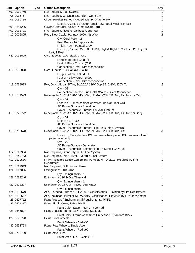
Line Option Type Option Description Qty405 0016740 Not Required, Fuel System 1406 0016767 Not Required, Oil Drain Extension, Generator 1407 0036738 Circuit Breaker Panel, Included With PTO Generator 1
Location, Circuit Breaker Panel - LS3, Back Wall High Left408 0651206 Cover, Generator, Above Pump w/Grip-Strut 1409 0016771 Not Required, Routing Exhaust, Generator 1410 0006825 Reel, Elect Cable, Hannay, 1600, (3) Wire 2
Qty, Cord Reels - 2 Reel Guide - b) Captive roller Finish, Reel - Painted Gray Location, Electric Cord Reel - D1, High & Right, 1 Reel and D1, High & Left, 1 Reel
411 0016828 Cord, Electric, 10/3 Black, 3 Wire 1 Lengths of Elect Cord - 1 Feet of Black Cord - d)200 Connection, Cord - Direct connection
412 0006828 Cord, Electric, 10/3 Yellow, 3 Wire 1 Lengths of Elect Cord - 1 Feet of Yellow Cord - e)200 Connection, Cord - Direct connection
413 0788933 Box, Junc, Akron, 3Wire, 2-15/20A 120V Dup SB, 2-20A 120V TL 2 Qty, - 02 Connection, Electric Plug / Inlet (Male) - Direct Connection
414 0781579 Receptacle, 15/20A 120V 3-Pr 3-Wr, NEMA 5-20R SB Dup, 1st, Interior Cab 1 Qty, - 01 Location 1 - med cabinet, centered, up high, rear wall AC Power Source - Shoreline Cover, Receptacle - Interior SS Wall Plate(s)
415 0779722 Receptacle, 15/20A 120V 3-Pr 3-Wr, NEMA 5-20R SB Dup, 1st, Interior Body 1
Qty, - 01 Location 1 - TBD AC Power Source - Shoreline Cover, Receptacle - Interior, Flip Up Duplex Cover(s)
416 0783678 Receptacle, 15/20A 120V 3-Pr 3-Wr, NEMA 5-20R SB Dup, 1st 3 Location, Receptacles - DS over rear wheel panel, PS over rear wheel panel, rear body Qty, - 03 AC Power Source - Generator Cover, Receptacle - Exterior Flip Up Duplex Cover(s)
417 0519934 Not Required, Brand, Hydraulic Tool System 1418 0649753 Not Required, PTO Driven Hydraulic Tool System 1419 0602516 NFPA Required Loose Equipment, Pumper, NFPA 2016, Provided by Fire
Department1
420 0519913 Not Required, Soft Suction Hose 1421 0017066 Extinguisher, 20lb CO2 1
Qty, Extinguishers - 1422 0533246 Extinguisher, 20 lb Dry Chemical 1
Qty, Extinguishers - 1423 0533277 Extinguisher, 2.5 Gal. Pressurized Water 1
Qty, Extinguishers - 1424 0602679 Axe, Flathead, Pumper NFPA 2016 Classification, Provided by Fire Department 1425 0602667 Axe, Pickhead, Pumper NFPA 2016 Classification, Provided by Fire Department 1426 0607712 Paint Process / Environmental Requirements, PMFD 1427 0601367 Paint, Single Color, Saber PMFD 1
Paint Color, Saber, PMFD - #90 Red428 0646897 Paint Chassis Frame Assy, E-Coat, Standard 1
Paint Color, Frame Assembly, Predefined - Standard Black429 0693798 Paint, Front Wheels 1
Paint, Wheels - Red #90430 0693793 Paint, Rear Wheels, Single Axle 1
Paint, Wheels - Red #90431 0733739 Paint, Axle Hubs 1
Paint, Axle Hub - Black #101
4/15/2022 2:22 PM Page 131177Bid #:

Line Option Type Option Description Qty432 0736826 SP Coating, Durabak, Top/Bottom Flange, Front Bumper ** 1
Color, Durabak Coating - Textured Black433 0581434 Transit Coating, Carwell, Corrosion Protection, Including Underside 1434 0007230 Compartment, Painted, Spatter Gray 1435 0544124 Reflective Band, 1"-4"-1" 1
Color, Reflect Band - A - i) gold Color, Reflect Band - B - l) white Color, Reflect Band - C - ze) gold
436 0007356 Reflective across Cab Face 1437 0536954 Stripe, Chevron, Rear, Diamond Grade, Pumper 1
Color, Rear Chevron DG - fluorescent yellow green438 0545179 Stripe, Diamond Grade, Chevron, Front Bumper 1
Size, Chevron Striping - 06 Color, Chevron DG - Yellow Green, Fluorescent Color, Chevron DG - B - Red
439 0065687 Stripe, Reflective, Cab Doors Interior 1 Color, Reflective - a) white
440 0033179 Lettering Specifications, Reflective 1441 0686160 Lettering, Reflective, 3.00", (21-40) 1
Outline, Lettering - Outline and Shade442 0685979 Lettering, Reflective, 16.00", Each 6
Qty, Lettering - 06 Outline, Lettering - Outline
443 0686010 Lettering, Reflective, 6.00", (21-40) 1 Outline, Lettering - Outline and Shade
444 0537144 Emblem, Reflective, Per Dept. Patch, Each, PMFD 2 Qty, - 02 Location, Emblem - rear cab doors
444 0000000 STF TFT DS1040P 1" Nozzle with Pistol Grip and Bail Control FRFA 1444 0000000 STF Contingency Fund, For Equipment Mounting and Changes 1444 0000000 STF Inspection trip #1 - when - number of people 3
Location - main manufacturing facility Qty, - 03
444 0000000 STF Inspection trip #2 - when - number of people 3 Location - Main manufacturing facility Qty, - 03
445 0772003 Manual, Fire Apparatus Parts, USB Flash Drive, Custom 1 Qty, - 01
446 0772037 Manual, Chassis Service, USB Flash Drive, Custom 1 Qty, - 01
447 0773381 Manual, Chassis Operation, (1) USB Flash Drive, Custom 1448 0030008 Warranty, Basic, 1 Year, Apparatus, WA0008 1449 0696698 Warranty, Engine, Cummins, 5 Year, WA0181 1450 0684952 Warranty, Steering Gear, TRW Ross TAS, 1 Year WA0202 1451 0596017 Warranty, Frame, 50 Year, Custom Chassis, WA0013 1452 0663011 Warranty, Axle, 1 Year, Marmon Harrington, General Service 1453 0610485 Warranty, Axle, Eaton/Dana, 5 Year/100,000 Mile, Parts and Labor 1454 0652758 Warranty, ABS Brake System, 3 Year, Meritor Wabco, WA0232 1455 0019914 Warranty, Structure, 10 Year, Custom Cab, WA0012 1456 0595813 Warranty, Paint, 10 Year, Cab, Pro-Rate, WA0055 1457 0695416 Warranty, Pierce Camera System, WA0188 1458 0647720 Warranty, Pierce LED Strip Lights, WA0203 1459 0046369 Warranty, 5-year EVS Transmission, Standard Custom, WA0187 1460 0685945 Warranty, Transmission Cooler, WA0216 1461 0688798 Warranty, Water Tank, Lifetime, UPF, Poly Tank, WA0195 1462 0596025 Warranty, Structure, 10 Year, Body, WA0009 1463 0693127 Warranty, Gortite, Roll-up Door, 6 Year, WA0190 1464 0734463 Warranty, Pump, Waterous, 7 Year Parts, WA0382 1465 0648675 Warranty, 10 Year S/S Pumbing, WA0035 1466 0657990 Warranty, Foam System, Husky 3, WA0231 1467 0725636 Warranty, Harrison Generator, 2 Year 1468 0595820 Warranty, Paint, 10 Year, Body, Pro-Rate, WA0057 1
4/15/2022 2:22 PM Page 141177Bid #:

Line Option Type Option Description Qty469 0595412 Warranty, Graphics Lamination, 1 Year, Apparatus, WA0168 1470 0683627 Certification, Vehicle Stability, CD0156 1471 0736238 Certification, Engine Installation, Saber FR/Enf, Cummins L9, 2021 1472 0686786 Certification, Power Steering, CD0098 1473 0892691 Certification, Cab Integrity, Saber FR/Enforcer, CD0189 1474 0631973 Certification, Cab Door Durability, Saber FR/Enforcer, CD0137 1475 0631978 Certification, Windshield Wiper Durability, Saber FR/Enforcer, CD0132 1476 0556828 Certification, Electric Window, Not Available 1477 0631977 Certification, Seat Belt Anchors and Mounting, Saber FR/Enforcer, CD0134 1478 0735949 Certification, Cab HVAC System Performance, SFR/Enf,
CD0165/CD0167/CD0174/CD01751
479 0545073 Amp Draw Report, NFPA Current Edition 1480 0002758 Amp Draw, NFPA/ULC Radio Allowance 1481 0799248 Appleton/Florida BTO 1482 0000017 FLORIDA DIVISION BODY 1483 0000012 PIERCE CHASSIS 1484 0004713 ENGINE, OTHER 1485 0046395 EVS 3000 Series TRANSMISSION 1486 0020011 WATEROUS PUMP 1487 0020009 POLY TANK 1488 0028048 FOAM SYSTEM 1489 0020006 SIDE CONTROL 1490 0020007 AKRON VALVES 1491 0020015 ABS SYSTEM 1492 0658751 PUMPER BASE 1
4/15/2022 2:22 PM Page 151177Bid #:

Option Description Type* Minimum Load
Intermittent Load
Total Connected
0001244 High Idle w/Electronic Engine, Custom 0.00 1.20 0.000002526 Light, Engine Compt, All Custom Chassis 0.00 1.60 0.000005748 Heater, Hot Water, 33,000 BTU 0.00 0.00 6.720005945 Light, Pump Compt 0.00 1.80 0.000006825 Reel, Elect Cable, Hannay, 1600, (3) Wire 0.00 72.00 0.000009429 Electric Power Only, Portable Winch 0.00 1.00 0.000012122 Fans, Window Defrost, One (1) Fan on Each Side 0.00 0.00 5.000062992 Gauge, Foam Level, (1) Tank, Class 1, GAAAR 5lt 0.00 0.00 1.000072176 Primer, Trident, Air Prime, Air operated, w/(2) Additional Priming Valves 0.00 0.01 0.000079166 Batteries, (4) Exide Grp 31, 950 CCA ea, Threaded Stud 0.00 3.00 0.000543751 Light, Do Not Move Apparatus 0.00 0.80 0.000549333 Indicators, Engine, Included with Pressure Controller 0.00 0.35 0.000553643 Control, Air Horn at Pmp Pnl, Red Switch 0.00 0.16 0.000561471 Lights, Backup, Wln M6BUW, LED, For Tail Lt Housing 0.00 3.20 0.000589905 Alarm, Back-up Warning, PRECO 1040 0.00 0.50 0.000624939 Foam Sys, Husky 3, Single Agent, Multi Select Feature 0.00 55.00 0.000629191 Light, FRC, 12V SPA260-Q20* LED MAX, Surface Mount 2nd 0.00 0.00 27.600629192 Light, FRC, 12V SPA260-Q20* LED MAX, Surface Mount 1st 0.00 0.00 27.600630142 Moisture Ejectors, Automatic, w/Heat, All Tanks, Enforcer/Saber FR 0.00 0.00 4.700632611 ESC/ABS/ATC Wabco Brake System, Single Rear Axle, 4x4 ABS, 4x2
ESC/ABS/ATC0.00 6.00 0.00
0636439 Wiring, Spare, 37.5 A 12V DC, Cust Install Radio, 30A Bat Dir, 7.5A Ign & Grnd
0.00 0.00 75.000644201 Cab Lift, Elec/Hyd, Saber FR/Enforcer 0.00 180.00 0.000649319 Special Switching, 12V Rear Scene Lights, Reverse Activation, Emerg
Master ON0.00 0.00 1.00
0653530 Camera, Pierce, 7" LCD, R, RS, LS Cameras 0.00 1.20 0.000653937 Flasher, Headlight Alternating 0.00 0.00 0.080663471 Rack, Zico Quic-Lift, Side Sheet Mount 0.00 28.00 0.000681751 Handlight, Streamlight, E- Flood LiteBox, 45805 LED, 12v Charger,
Orange0.00 1.00 0.00
0687994 Engine Brake, Jacobs Compression Brake, Cummins Engine 0.00 0.42 0.000735095 Intercom, David Clark, 4-Pos, 2-Dual Radio, (D, O, RPTT), 2obC, 3805 0.00 0.00 0.500741057 Heater, Gauge, IC, Including Master Gauges, Test Port and Press
Trans0.00 0.00 2.25
0755334 Handlts, (3) Streamlight, Vulcan 180, 44315, 12v, Orange 0.00 0.75 0.000760619 Water Level Gauge, Wln PSTANK2, LED 1-Light, 4-Level, PMFD 0.00 0.00 1.600768376 Lights, Walk Surf, FRP Flood, LED, Qty, Loc Fet 0.00 0.00 0.000773362 Lights, HiViz FT-B-46-*-* LED, 1st 0.00 0.00 15.000797189 Wiring, Spare, 4.8 A 12V DC, USB Termination Blue Sea 1045 1st 0.00 0.00 5.000887571 Winch, Superwinch, 18,000 lb. Fixed, Front, Tiger Shark,
Model#1518001,Electric0.00 500.00 0.00
0887784 Reel, Booster, Steel - Over Pump, Left Side, 2/3 H.P. Motor, NPSH Fitting
0.00 36.00 0.000579886 Wiring, Spare, 50 A 12V DC, 6 Circuit Fuse Block, Blue Sea 5025 1st LM 0.00 0.00 150.000741237 HVAC, Saber FR, CARE LM 0.00 0.00 100.000790483 Light, Visor, HiViz, FT-MB-33-*-*, 42.44" long LM 0.00 0.00 13.700002758 Amp Draw, NFPA/ULC Radio Allowance NFPA 5.00 0.00 0.000013671 Compt, Rear, Rollup, 30.75" FF, 25.88" D NFPA 0.90 0.00 0.900088745 Light, Rear Zone Up, Wln L31HRFN LED Beacon, Red LED NFPA 3.20 4.80 0.000519098 Generator, Harrison C-Gen 6.0 kW Hydraulic, Hotshift PTO, PMFD NFPA 19.30 0.00 0.000531188 LS 152" Rollup, Full Height Front & Rear, FDLER, Raised Rear 6" NFPA 4.50 0.00 4.500533071 Siren, Wln 295SLSC1, 100 or 200 Watt, w/Plug-in/Detachable
Microphone CordNFPA 0.80 7.20 0.00
0552524 Lights, Front Zone, Wln M6# LED, Split, Clear Lens, In Common Bzl NFPA 1.80 2.70 0.000556337 Lights, Step, P25 LED at Rear Tailboard, 2lts Perm Lts NFPA 0.50 0.00 0.000563675 Lights, Clearance/Marker/ID, Rear, Truck-Lite 33050R LED 7Lts NFPA 0.35 0.00 0.000564655 Lights, Rear Zn Lwr, Wln M6*C LED, Clear Lens, For Tail Lt Housing NFPA 1.80 2.70 0.00
* UDMC = User Defined Mission Critical, LM = User Defined Load Managed, S = Electrical Amperage Supply
1
Electrical Analysis 4/15/2022
Bid #: 1177
Nederland Saber 4x4 Engine 750 Gallon LHB Sales Rep:
Organization:
Byrne, Jason
Front Range Fire Apparatus, Ltd
Desc:
Job #:
Customer: Nederland Fire Protection District

Option Description Type* Minimum Load
Intermittent Load
Total Connected
0564683 Lights, Tail, Wln M6BTT* Red LED Stop/Tail & M6T* Amber LED Dir Arw For Hsg
NFPA 0.83 2.49 0.000567481 Lights, Side Zone Lower, Wln M6 LED, Front Split Color, Clear Lens,
3prNFPA 5.40 8.10 0.00
0586382 Gauges, Engine, Included With Pressure Controller NFPA 0.30 0.00 0.000610240 Vehicle Data Recorder w/Seat Belt Monitor NFPA 0.50 0.00 0.000618791 DEF Tank, 4.5 Gallon, DS Fill, Forward of Axle, Common Air Bottle
DoorNFPA 0.60 11.40 0.00
0620054 Light, Directional/Marker, Intermediate, Weldon 9186-8580-29 LED 2lts NFPA 0.10 0.90 0.000625654 Cab, Saber FR, 6000 NFPA 6.80 10.20 0.000637518 Lightbar, Wln, Justice, LED, 8-R, 2-W, LED, Clear Lens NFPA 6.00 1.00 1.500642572 Trans, Allison 5th Gen, 3000 EVS P, w/Prognostics,
Imp/Vel/DCF/SFR/EnfNFPA 2.00 2.00 0.00
0644176 Load Manager, Integrated In Electrical System, Saber FR/Enforcer NFPA 0.56 0.56 0.000644179 Wiper Control, 2-Speed with Intermittent, Saber FR/Enforcer NFPA 1.20 4.80 0.000644187 Cab Instruments, Black Gauges, Black Bezels, Saber FR/Enforcer NFPA 1.26 0.00 0.000644228 Air Dryer, Wabco System Saver 1200 IWT, Heated, 10" Frame,
Standen, SFR/EnfNFPA 7.81 0.00 0.00
0645877 Lights, Hose Bed, Sides, Dual LED Light Strips NFPA 2.52 0.00 0.000647647 Lights, Dome, FRP Dual LED 4 Lts NFPA 0.80 0.80 0.000647802 Lights, Clearance/Marker/ID, Front, P25 LED 5 Lts, Saber FR/Enforcer NFPA 0.35 0.00 0.000647899 Lights, Directional/Marker, Cab Front Side, Weldon 9186-8580-29
LED, Sab/EnfNFPA 0.80 0.00 0.00
0648418 Light, Directional, Wln M6T LED, Common Bezel, Above Headlights, Sab/Enf
NFPA 1.50 0.00 0.000664481 Bracket, License Plate & Light, P25 LED NFPA 0.07 0.00 0.000682503 Light Shield/Step 8", LED, P25 LED Stp Lt NFPA 4.00 0.00 0.000721606 Controller, Pressure, Pierce LCD, Metric, Custom Chassis NFPA 1.70 0.00 0.000736437 Engine, Cummins L9, 450 hp, 1250 lb-ft, W/OBD, EPA 2021, Saber
FR/EnforcerNFPA 1.00 0.00 0.00
0739224 Indicator Light @ Pump Panel, Throttle Ready, Incl w/Pressure Gov/Throttle,Green
NFPA 0.10 0.00 0.000739749 Gauge, Water Level, Pierce, In pressure Controller, w/Mini Slave, Lt
DriverNFPA 1.23 0.00 0.00
0745568 Indicator Light, Pump Panel, Ok To Pump, Green NFPA 0.10 0.00 0.000769559 Lights, Perimeter Pump House, Amdor AY-LB-12HW012 LED 2lts NFPA 0.36 0.00 0.000769560 Lights, Perimeter Body, Amdor AY-LB-12HW012 LED 2lts, Rear Step NFPA 0.36 0.00 0.000769567 Lights, Perimeter, Amdor AY-LB-12HW012 12", Brkt NFPA 1.08 0.00 0.000769569 Lights, Perimeter Cab, Amdor AY-LB-12HW012 LED 4Dr NFPA 0.72 0.00 0.000785367 Cabinet, Forward Facing, Center, 38.50 W x 50 H x 18 D, Roll,
SFR/EnfNFPA 0.50 0.50 0.00
0791528 Light, Traffic Directing, Wln TAL65, 36.00" Long, TACTL5 NFPA 0.60 1.20 0.000887574 RS 152" Rollup, 3/4 Height Front Rear, (1) Lap Brrom, FDLER,
Raised Rear 6"NFPA 1.80 0.00 1.80
0888792 Headlights, Rect LED, 4X4, JW Spkr Evo 2, Heat, Saber NFPA 5.46 7.82 0.000892638 Lights, Cab & Crw Cab Acs Stps, P25, LED w/Bezel, 6lts NFPA 1.00 0.00 0.000647729 Alternator, 320 amp, Delco Remy 40SI S 0.00 0.00 0.00
Load Totals: 97.56 963.16 445.45
Minimum Continuous Load
Supply: 187.00
Demand: 97.56
Variance: 89.44
Total Connected Load
Supply: 285.00
Demand: 279.31
Variance: 5.69
Note: Minimum Continous Load is in "Blocking Right of Way" mode.(Reference current edition of NFPA 1901)Note: Intermittent Load items are not factored in on any alternator load comparisons. These items are included on the report for reference only and should be looked at as amp draw exclusion items. (Reference current edition of NFPA 1901)Note: Total Connected Load "Demand" represents Total Connected Load minus any Load Managed items
187.00 285.00Alternator Output at Idle: Alternator Output at Governed Speed:
* UDMC = User Defined Mission Critical, LM = User Defined Load Managed, S = Electrical Amperage Supply
2
Electrical Analysis 4/15/2022
Bid #: 1177
Nederland Saber 4x4 Engine 750 Gallon LHB Sales Rep:
Organization:
Byrne, Jason
Front Range Fire Apparatus, Ltd
Desc:
Job #:
Customer: Nederland Fire Protection District

Turning Performance Analysis
Bid Number: 1177 Chassis: Saber FR Chassis 4x4
Department: Nederland Fire Protection District Body: Pumper, Medium, Aluminum, 2nd Gen, Saber/Commercial
Parameters:
*Inside Cramp Angle: 40°Axle Track: 85.86 in.Wheel Offset: 7 in.Tread Width: 12.5 in.Chassis Overhang: 65.95 in.Additional Bumper Depth: 0.00 in.Front Overhang: 65.95 in.Wheelbase: 177.5 in.
Calculated Turning Radii:Inside Turn: 16 ft. 6 in.Curb to curb: 29 ft. 0 in.Wall to wall: 32 ft. 11 in.
Notes:
*Actual Inside cramp angle may be less than shown.
Curb to Curb turning radius calculated for 9.00 inch curb.
04/15/2022
Category Option DescriptionAxle, Front, Custom 0737375 Axle, Front, Marmon Herrington MT-22 19,450 lb, (FWD) Saber FR/EnforcerWheels, Front 0612060 Wheels, Front, Accuride, 22.50" x 9.00", Steel, Hub Pilot, 4x4Tires, Front 0664491 Tires, Front, Michelin, XZU S2, 315/80R22.50, 20 plyBumpers 0776057 Bumper, 16" Extended .38" Formed Steel, 10.38"H, Painted, Saber FR/Enforcer

Definitions:
Inside CrampAngle Maximum turning angle of the front inside fire.
Axle Track King-pin to King-pin distance of front axle.
Wheel Offset Offset from the center line of the wheel to the King-pin.
Tread Width Width of the tire tread.
Chassis Overhang Distance of the center line of the front axle to the front edge of the cab. This does not include the bumper depth.
Additional Bumper Wheel Depth that the bumper assembly adds to the front overhang.
Wheelbase Distance between the center lines of the vehicles front and rear axles.
Inside Turning Radius Radius of the smallest circle around which the vehicle can turn.
Curb to Curb Turning Radius Radius of the smallest circle around which the vehicle's tires can turn. This measures assumes a curb height of 9 inches.
Wall to Wall Turning Radius Radius of the smallest circle around which the vehicle's tires can turn. This measures takes into account any front overhang due to chassis , bumper extensions and or aerial devices.
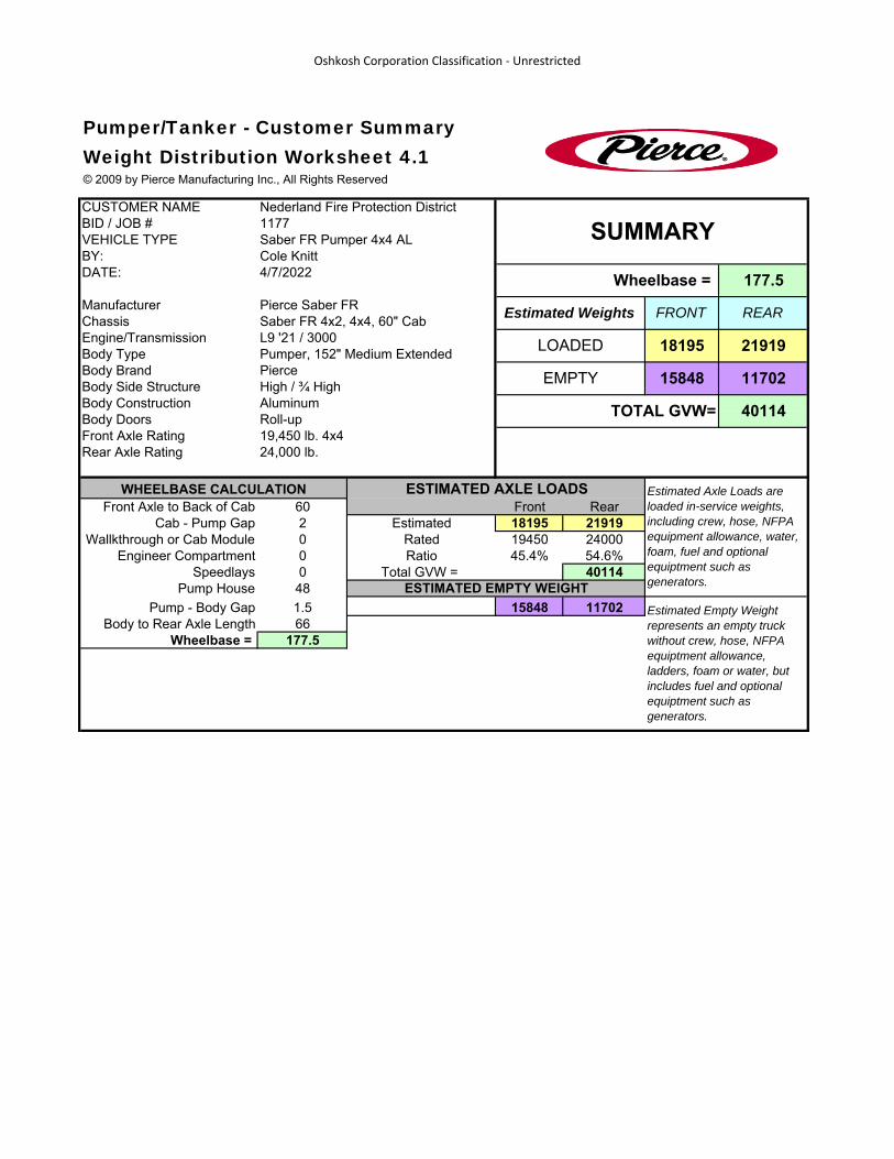
Oshkosh Corporation Classification ‐ Unrestricted#
CUSTOMER NAMEBID / JOB #VEHICLE TYPEBY:DATE:
ManufacturerChassis Saber FR 4x2, 4x4, 60" CabEngine/TransmissionBody TypeBody BrandBody Side StructureBody ConstructionBody DoorsFront Axle RatingRear Axle Rating
Front Axle to Back of Cab 60 Front RearCab - Pump Gap 2 Estimated 18195 21919
Wallkthrough or Cab Module 0 Rated 19450 24000Engineer Compartment 0 Ratio 45.4% 54.6%
Speedlays 0 Total GVW = 40114Pump House 48
Pump - Body Gap 1.5 15848 11702Body to Rear Axle Length 66
Wheelbase = 177.5
ESTIMATED AXLE LOADSWHEELBASE CALCULATION Estimated Axle Loads are loaded in-service weights, including crew, hose, NFPA equipment allowance, water, foam, fuel and optional equiptment such as generators.
Estimated Empty Weight represents an empty truck without crew, hose, NFPA equiptment allowance, ladders, foam or water, but includes fuel and optional equiptment such as generators.
24,000 lb.
ESTIMATED EMPTY WEIGHT
177.5
Roll-up19,450 lb. 4x4
11702EMPTY
TOTAL GVW=
Pumper, 152" Medium Extended
REAR
LOADED 18195 21919
Aluminum
L9 '21 / 3000
PierceHigh / ¾ High 15848
40114
4/7/2022
Estimated Weights FRONTPierce Saber FR
Wheelbase = Cole Knitt
SUMMARY
Pumper/Tanker - Customer SummaryWeight Distribution Worksheet 4.1© 2009 by Pierce Manufacturing Inc., All Rights Reserved
Nederland Fire Protection District1177Saber FR Pumper 4x4 AL
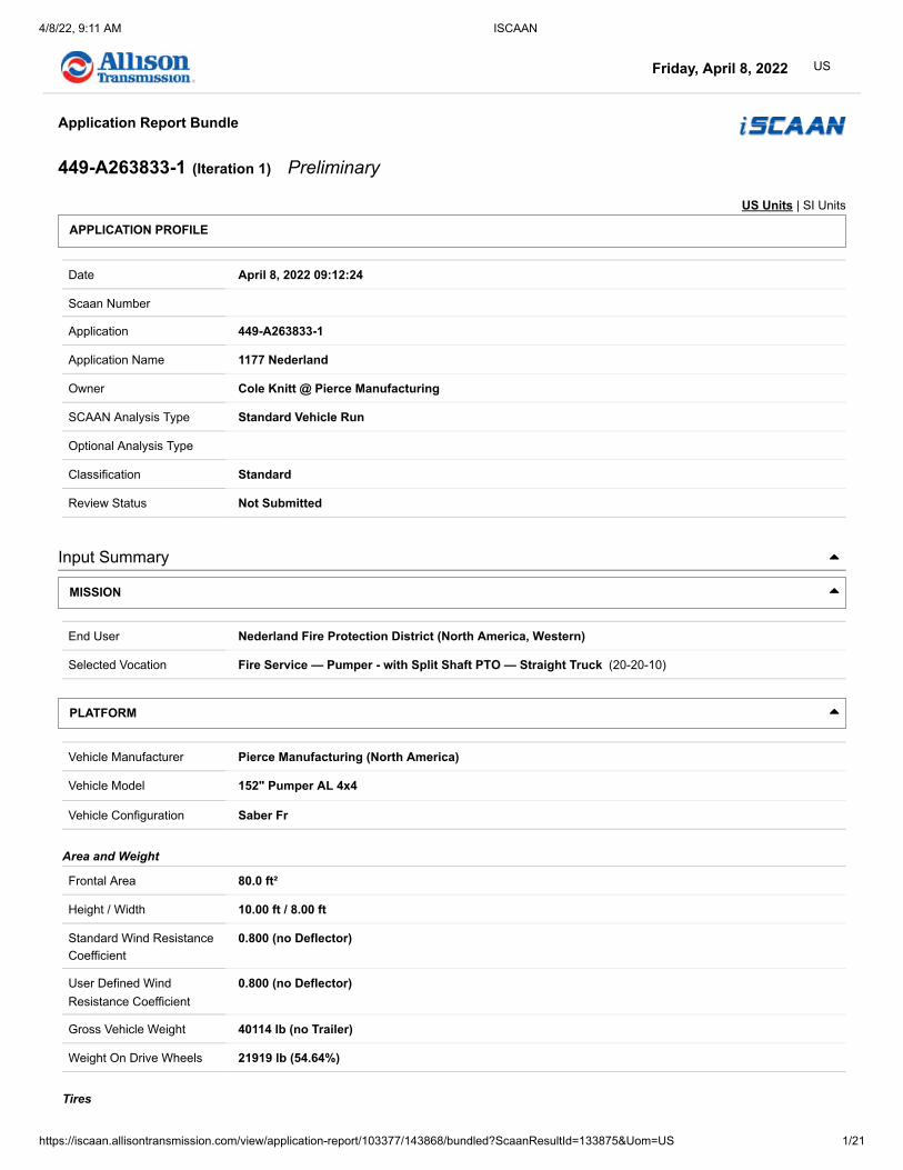
������������ � ��
������������������������������������������������������� �������!""##��"�$��%&�'��'( ����)��&���'*""�#+,-��*- ��
.//01234156�78/594�:;6<08==>?.@ABCBB?DEF48934156�DG HIJKLMLNOIP QR�Q614S�T� ��-����
���&�� &����UVWXY�YZ[�\X]_a]WXb
c��� ./910�Cd�@e@@�e>fD@f@= ������&�%������������ ==>?.@ABCBB?D��������������� DDgg�h8<89036<i���� j508�k6144�l�m18928�n36;o324;916p ������U����qU�� R436<39<�r8s1208�7;6i�����������U����qU��������t������� R436<39<)������ ���&� h54�R;uv1448< wx�'�-��� h8<89036<�y198�m954824156�z1S49124�Eh594s�.v89123d�{8S4896G ������'�|������� y198�R89}128�~�m;v/89�?��14s�R/014�Rs3o4�m���~�R4931ps4��9;2����! �! !�|����������&t���&��� m18928�n36;o324;916p�Eh594s�.v89123G|���������'�� D�@��m;v/89�.��=�=|����������t��&������ R3u89�y9����������� Ce�e�o4������������'�� De�ee�o4���C�ee�o4 ���'��'����'�)������������tt������ e�Cee�E65�z8o082459G-����c�t���'����')�������������tt������ e�Cee�E65�z8o082459G������|������������� =eDD=�0u�E65��931089G�������i��c����������� @D>D>�0u�E�=�A=�G
.mm�Fj.�F�h�m7�yF��
nFRRF�h wm�.�y�7n w
y91<3�d�./910�Cd�@e@@ -

������������ � ��
������������������������������������������������������� �������!""##��"�$��%&�'��'( ����)��&���'*""�#+,-��*- ��� ���'��.���/ 0�����1������.��/ 0�����2��3&���.�% 4�/ ����1�����5��6���.��/ ����2��3&��5��6���.�% 4�/ ����1�����5��644��.��/ ����2��3&��5��644��.�% 4�/ 1�����'����4�������#!! ���" $#!�! #�" +"��� #��� +�$���!! �!�" #�!�! !�� $$��� !"�� $#���
�&�%���64�2���� 7�89:;<=;>=�?;=@;AB ������'�2��� CDD=EF;>�C7GG�?9H�8IG?GGJKL�MNGB�8IOPQQRSR7OTUB2����)����&����� MNG�>FVWXY@2����)�����Z�)�'�&� GQJSI�@< ���'��'� &�4��� 9YDD:[�\D<]>F:F�89\�;]:D>�_�IJQQB ������'� &�4��� 9YDD:[�\D<]>F:F�89\�;]:D>�_�IJQQB ���'��'�6� )��'�2���������������44������ QJaQQ ���'��'�644 )��'�2���������������44������ QJQQQ-����b�4���'�6� )��'2����������������44������ QJaQQ-����b�4���'�644 )��'2����������������44������ QJQQQ2����c������������.��������'/ aQJ7KaK�AdOe:OWF]f�&�%����4�1�����1��g� Ih�Z��� \iYY@<W�PS�8H@FWFAB�OO�MKQ[j�X�IGKQAde:�X�GGQQ>jY�OO�8klmGIB�.� !!�$�# h��)���n/�����4�������� o9m�GQGIb����������� KMQJQ�@<p1��g�2��3&� IGKQJQ�AdOe:1��g�2��3&�� ���' IRQQ�>jY1��g�1���� MKQJQ�[j1��g�1����� ���' GIQQ�>jY0������'�1���� MISJS�[j0������'� ���' GGRQ�>jY�&�%���64��&���� Ih�Z�����&����)�4������ ?S7GRQ��&����q������r�s� ���' 7QJQ�Yj[�t�IKQQ�>jYh�Z����)����'��h�Z������������.��������'/ IJKaMM�AdOe:OWF]f
kuCUuk vkuCUuk�\o?wk�O�9TmuHm?H�Px99k9�O�\xyzUukH�Px{�|�}UC}�\o?wk9�8m\�xu�{}k?k�mllPU\mzPkB v

������������ � ��
������������������������������������������������������� �������!""##��"�$��%&�'��'( ����)��&���'*""�#+,-��*- "��
�!! ���� �#+�! ���� #++� "��$ ##"�#!!! ����# �!�! �!��+ !$"�$ �!$�� !�$�$!! �+��+ �+�! �"!�� !!�� �"$�" ���!�!! ��+�$ �+!�! �+��� "+�" �$#�! $���"!! "!��� �+!�! ��!�# "�� ��!�" #"�! .��/�0��1&��!! """�� �+!�! "!�# "�� ""�# #$��+!! "+#�! �+!�! "���" ���+ ""#� �!��$!! "�!�� �+!�! "���+ ���� "$!�� �"��#!! �!��$ �+!�! "$��" ��� "�"�� �+����� �"��� �+!�! "�!�� !�# ���+ ����!! ��!�! �$�" "���� !#"�$ ���� +$�+�!!! ��!�! ++�+ "�"�! !!+�# �#�� !�#�+�!! �+!�! �+�� "�#�! �$#�� ��#�+ !$�� .��/�.������!! �"+�! !"��+ "$+�+ �#��$ ��� ��"����"! ���� ����! "���� ��!�+ "�$�� �"��# 2������'�"!! �+��� +���! #��" �!#�� �"�+ +���#��!! !�! !�! ���� ���" �"�� +�� ���3��'2������'.��/�.���������������%����'�4���'�4��������&��������4���������5��������6�3�����789:;�<�=>?@>=�ABCD=�<�;:E>FECF�89;;=;�<�A9GH@>=F�89I�J�K@?K�ABCD=;�LEA�9>�IK=C=�E778@AEH8=M N

������������ � ��
������������������������������������������������������� �������!""##��"�$��%&�'��'( ����)��&���'*""�#+,-��*- ���
./012032�403056/637�801�91
./012032�403056/637�801�9::
���'��;���< =�����>������;��< =�����?��@&���;�% A�< ����>�����B��C���;��< ����?��@&��B��C���;�% A�< ����>�����B��CAA��;��< ����?��@&��B��CAA��;�% A�< >�����'����A�������#!! ���" $#!�! #�" +"��� #��� +�$��
$!! �!! �!!! ��!! ��!! �$!! ��!! ��!!! ���!! ���!! ���'�;���<D!!D+!!+!!!+!�!!�+!"!!"+!�!!�+!>�����;��<
D�!!!�!!�!!$!!�!!�!!!��!!��!! ?��@&��;�% A�< =�����>�����;��<����>�����;��<=�����?��@&��;�% A�����?��@&��;�% A�<
$!! �!! �!!! ��!! ��!! �$!! ��!! ��!!! ���!! ���!! ���'�;���<D+!!+!!!+!�!!�+!"!!"+!�!!�+!>�����;��<
D!!!!!�!!"!!�!!+!!$!!#!!�!!�!!�!!!�!!��!!�"!! ?��@&��;�% A�< =�����>�����;��<����>�����;��<=�����?��@&��;�% A�����?��@&��;�% A�<
EFGHFE�IJKLE�M�J.EK�NE8HFEN�O9..E.�M�I9PQHFEN�O9R�S�THGT�IJKLE.�UVI�9F�RTEKE�V44OHIVQOEW X

������������ � ��
������������������������������������������������������� �������!""##��"�$��%&�'��'( ����)��&���'*""�#+,-��*- +��
�!! �!�" #�!�! !�� $$��� !"�� $#����!! ���� �#+�! ���� #++� "��$ ##"�#!!! ����# �!�! �!��+ !$"�$ �!$�� !�$�$!! �+��+ �+�! �"!�� !!�� �"$�" ���!�!! ��+�$ �+!�! �+��� "+�" �$#�! $���"!! "!��� �+!�! ��!�# "�� ��!�" #"�! .��/�0��1&��!! """�� �+!�! "!�# "�� ""�# #$��+!! "+#�! �+!�! "���" ���+ ""#� �!��$!! "�!�� �+!�! "���+ ���� "$!�� �"��#!! �!��$ �+!�! "$��" ��� "�"�� �+����� �"��� �+!�! "�!�� !�# ���+ ����!! ��!�! �$�" "���� !#"�$ ���� +$�+�!!! ��!�! ++�+ "�"�! !!+�# �#�� !�#�+�!! �+!�! �+�� "�#�! �$#�� ��#�+ !$�� .��/�.������!! �"+�! !"��+ "$+�+ �#��$ ��� ��"����"! ���� ����! "���� ��!�+ "�$�� �"��# 2������'�"!! �+��� +���! #��" �!#�� �"�+ +���#��!! !�! !�! ���� ���" �"�� +�� ���3��'2������'.��/�.���������������%����'�4���'�4��������&��������4���������5��������6�3�����789:;�<�=>?@>=�ABCD=�<�B;=C�E=F@>=E�89;;=;�<�A9GH@>=E�89I�J�K@?K�ABCD=;�LMA�9>�IK=C=�M778@AMH8=N O

������������ � ��
������������������������������������������������������� �������!""##��"�$��%&�'��'( ����)��&���'*""�#+,-��*- $��
./01�2034506�781890:01/�;85�<5
./01�2034506�781890:01/�;85�<33$!! �!! �!!! ��!! ��!! �$!! ��!! ��!!! ���!! ���!! ���'�=���>?!!?+!!+!!!+!�!!�+!"!!"+!�!!�+!@�����=��>
?�!!!�!!�!!$!!�!!�!!!��!!��!! A��B&��=�% C�> D�����@�����=��>����@�����=��>D�����A��B&��=�% C�����A��B&��=�% C�>
$!! �!! �!!! ��!! ��!! �$!! ��!! ��!!! ���!! ���!! ���'�=���>?+!!+!!!+!�!!�+!"!!"+!�!!�+!@�����=��>
?!!!!!�!!"!!�!!+!!$!!#!!�!!�!!�!!!�!!��!!�"!! A��B&��=�% C�> D�����@�����=��>����@�����=��>D�����A��B&��=�% C�����A��B&��=�% C�>
EFFGHH<IJ�K<HHGH�L7<MGI�N�O<PGIQG2�H7GG2R S

������������ � ��
������������������������������������������������������� �������!""##��"�$��%&�'��'( ����)��&���'*""�#+,-��*- #��
�������. ���'��'�/����0��1 -����2�3���'�/����0��14���0��&����4��1 ���+ ���+������������5�������� "�+ "�+������������� ��� ��� ������6�7&�� ��� ���������'�������6 !�! !�!����������2���� !�! !�!8���������������&3���&��� 9::;<=>�?@A><B;<<;=>8������������4����. CDDD�EF@;F<�0 /!!��" 84��)���518����������� CDDD�GHE�0 /!!#""� 8��)���I18������������)����6 CDDD�GHE�J;@F�?@KLMN�GBF@OF>LP�HFQ;L:F�R�S;F<F:�9::;<=>�TUQ�VF>F@AU;=>�W=>U@=:<�X;UQ�EGYZ[\?]�0 /!�#�! )��)���18��&����������� ?W_a�0 /!!�++ 8���)����1�R�9LLFbUAc:F8������������)����'�����������)������ ]@=dKLU;=>�WA:;c@AU;=>�e]Wf�g=@�CDDD�EF@;F<�0 /!!�� �)��)���41 ��3�� ���'&�� ]@;BA@P2.������ h= ���'�7��3��� ]F@g=@BA>LF ��3�� ���'�,� �����6. `DD�@bB�Ea�]F@g=@BA>LFI&��������2.�������i��� D7�����.���'���5���� [=X�j�aN�EUA@U�j�aN�k;OQ�j�l�eaRaRlf2���������7��������� h=��������� 2���������� )���� ���'��'I33������.0m1 -���2�3���'I33������.0m1]@=b<QAgU�RR�n>F�];FLF�RR�?X=�o=;>U�0 /!!"+� 2/1 E;>O:F apDDD qrpTD qrpTD9s:F�RR�n>�kXP�E;>O:F�\Fd�RR�_s_�0 /!!"+"� 2/1 E;>O:F _pCCD qlpDD qlpDDt�������2���������)���� 2���������� )���� ���'��'I33������.0m1 -���2�3���'I33������.0m1 �������u)�����������E;>O:F _pCCD qCpTv qCpTv C_prDC
?\9hEYwEEwnh xWnh?\n[E xS\wHG[whG x

������������ � ��
������������������������������������������������������� �������!""##��"�$��%&�'��'( ����)��&���'*""�#+,-��*- ���
)����.����'�/&�'�����������0 12�'�-��� 345467895�:;64�<6=>4?>;=9�@;A>6;?>�B3=6>C�DE46;?8F�G4A>469H ������'�I������� :;64�J46K;?4�L�<MEN46�O�P;>C�JN7;>�JC8Q>�<RS�L�J>68;TC>�R6M?U�V�! �! !WI����������&X���&��� <;46?4�Y89MQ8?>M6;9T�B3=6>C�DE46;?8HI���������'�� Z[\]�<MEN46�D �__I����������X�.&������ J8a46�:62�.����b���������� cMEE;9A�d�B@;4A47H�OO�_[eCN�f�Z\[e7aQ>�f�\\ee6NE�OO�Bg<D\ZH�V� h!!�$�# 2��)���iWj����������� keee�glJ�V h!!#""� j��)���2Wj������������)����. keee�glJ�:;64�R6M?UF�gE46T49?m�l4C;?74�O�@;4A47�D77;A=9�n>C�o49468>;=9�c=9>6=7A�P;>C�JgYfpR<�V h!�#�! )��)���WI�������q��������� J>895865j��r&����������� Rc_\Z�V h!!�++ j���)����W�O�D??4N>8a74j������������)����'��h)jq� ���&� pR<�p4sM;645j���� �����X�������������&%t����������� ���b��������������X���������������
YuJJuS3 1
< DR:SpY 13SRg 1cS3lgpRgp�pDRu3o�D3@�ovu@g u3g�cwgcxJ JgcRuS3�JcSpg�O�Sx 1

������������ � ��
������������������������������������������������������� �������!""##��"�$��%&�'��'( ����)��&���'*""�#+,-��*- ���
����. ����.����� �����&������/��&� )����0���)�������'����� ��&���1��&� -���� 2������� ���&��!34 5�����������������������������%����6 7 89:;<<=>?@AB=�!�34 C�0����������������������%����6 7 89:;<<=>?@AB=�!�34 C�0���� ���'������������� ���� #�� ��� D E=F=G=H<=�!+34 �����&��C�0��� ���' ��� "!! ��� ��� 7 89:;<<=>?@AB=�!#34 5&�%����5��I&�������������� ���� ��/ #!!�! #!!�! �% J� 7 89:;<<=>?@AB=�!�34 ���������� ���')��������C�0���K������'� ���' ��� !��!! !��$ 7 89:;<<=>?@AB=�!"34 ���������� ����5��I&��)���� �##! D E=F=G=H<=LMNOP����. ���������!+ �������.����I&������'�Q�!!����R�S�������%�������������Q!!����R�TE;UVWXVVX8U�E;TXUY�;UZ�Y[XZ\]XU\�_\ 9V V\ TX8U�V 8E\��89 3

������������ � ��
������������������������������������������������������� �������!""##��"�$��%&�'��'( ����)��&���'*""�#+,-��*- !��
����. ����.����� �����&������/��&� )����0���)�������'����� ��&���1��&� -���� 2������� ���&�3!45 3�������������1��������������%����6 7 89:;<<=>?@AB=3!�45 3�������������C�0����������%����6 7 89:;<<=>?@AB=3�!45 C�0������ C��D)3E����%�� 7 89:;<<=>?@AB=3#45 3�����������E�������'����C�'-�������������F0D�������� 7 89:;<<=>?@AB=3+45 3���������������&�E�����GH����I ��/ �+!�! �+!�! �� 7 89:;<<=>?@AB=3�45 3���������������&�3��J&��GH����I ��/ �+!�! �+!�! �% F� 7 89:;<<=>?@AB=3!"45 3���������������&� ���' �!!�����!! ��"! ��� 7 89:;<<=>?@AB=3!�45 3�����������2&��&�� ���' ��#� ��� K L=M=N=O<=PQRST����. ��������3!� ����.���'�����)��0��+D������"!�C�0����H������'� ���'�UVWXYZV�L;[X\]�;\ �]_XVZX\V�YWVY9 �a�[;\ ;L VY[X8\�Y8LV�a�89 4

������������ � ��
������������������������������������������������������� �������!""##��"�$��%&�'��'( ����)��&���'*""�#+,-��*- ��
����. ����.����� �����&������/��&� )����0���)�������'����� ��&���1��&� -���� 2������� ���&�134 ���)��0����������� ����5��'��%����6 ��� "!�!! "+�$� 7 8 9:;<==>?@ABC>1"34 ���)��0��#!7���������DEE������65��'��%����6 ����+ 7 F G>H>I>J=>1�"34 ���)��0���!7���������DEE������65��'��%����6 ����! 7 F G>H>I>J=>1#34 ��/��&��5����'1������� ���'���D�0����5������' ���' �+�+ ��� F G>H>I>J=>1�"34 K����5�������'������)��0��#!7���������DEE������6 +�+�$! LM-���� F G>H>I>J=>1��34 K����5�������'������)��0���!7���������DEE������6 "$#���� LM-���� F G>H>I>J=>NOPQR����. ��������1# ����.�������+S�S��.&��1�" ���������D�0���� ���'�1�� ���!������D�0���� ���'�T<UV9T<W�XVGY�ZG9UY[UV9T�<\\9[V<UV9T�]TXZ<�_a_�bcVdYWVTY�[eY[:\�f�\U<Td<Gd \Y[UV9T�\[9GY�f�GYXYGYT[Y 3

������������ � ��
������������������������������������������������������� �������!""##��"�$��%&�'��'( ����)��&���'*""�#+,-��*- ���
����. ����.����� �����&�������/��&� )����0���)�������'����� ��&���1��&� -����1�$23 �����&��1������ ���'����!��+4�5��'�6�78��!9 ��� +!�! �"�$ ���1+$23 1������� ���'����$�!45��'��6�78��!9 ��� �!�! �"�" ���1�#23 5��'��%����:����+!����6�!�.���9�6�78��!9 ��� !��+ ��## 41+#23 5��'��%����:�����!����6"����.���9�6�78�!9 ��� $�!! ��+ 41��23 ��/��&�������������;�����! "+�����6+$�".���9��!�!4�5��'�����)��0�� �����6�78�!9 ��/ �+�! �+ ���<=>?@����. ��������1�$ ����.�������+A1+$ ����.�������"A�1�� 7&���;��������,�1�������B��.���A��.�'� �����1�������8��C�������� &����: 2D�'�-��� EFGFHIJKG�LMHF�NHOPFQPMOK�RMSPHMQP�TEOHPU�VWFHMQJX�YFSPFHKZ ������'�1������� LMHF�[FH\MQF�]�N W_FH��aMPU�[_IMP�[UJbP�Ncd�]�[PHJMeUP�cHQf�6�! �! !91����������&C���&��� NMFHQF�gJKbJQPHMKe�TEOHPU�VWFHMQJZ1���������'�� hijk�N W_FH�Vl�mnm1����������C�0&������ [JoFH�LHD�0����p���������� q WWMKS�lr�TRMFSFIZ��misU_�t�hjisIobP�t�jjssH_W��TuNVjhZ�6� A!!�$�# D��)���B9;����������� vsss�uw[�6 A!!#""� ;��)���D9;������������)����0 vsss�uw[�LMHF�cHQfX�uWFHeFKQx�wFUMQIF��RMFSFI�VIIMSOK�yPU�zFKFHJPMOK�qOKPHOIS�aMPU�[ugtl{cN�6 A!�#�! )��)���91�������8��������� [PJKGJHG;��|&����������� cqmjh�6 A!!�++ ;���)����9�VQQF_PJoIF;������������)����'��A);8� ���&� l{cN�{F}MHFG
g~[[~dE 2NlVcLd{g 2
Edcu 2

������������ � ��
������������������������������������������������������� �������!""##��"�$��%&�'��'( ����)��&���'*""�#+,-��*- "��
.��'��%����/ 0�.��'� 1������� ���'��2���3 .�����)��4� ������5���� �����.��'��%����/ "+�# � ����6�&����.��'��%����/ ""�# �6��� ���'�.��'��%����/ ���� !�� � �!�5��������7��&�� ���'����.��'� !�! ���� +6 )��'�6��'!�" �"�$ +6!�+ ���� +6�! #��$ +6��! #!�# +6"�! $� �6��! +$�� �6+�! �+�$ �6$�! �"�" "6#�! �!� "6��! ""�+ "6��! "��# �6!�! "!�� �6
8���� �����9�������������&%:����������� ���;��������������9���������������<�4����=�� >? <�4����5���� @AB?CBDC�EFGHD�IJDKH������'�������4 >LL 1�������5��������� @AB?CBDC7���)���� MNOOP &7�����/�.�����4�)���� QNPPPRSTT�UVW>UUTX�YSU>ZYU[I�SE@V[RU@�\]WY XY_[T[U a�b�@UYc YW d�RYc�>cd�YI�>RRd�YeTX�WYU[>�f�MNOOPd�YSe�WYU[>�f�QNPPgET>U@�b�RSTT�UVW>UUTX�YSU>ZYU[I�SE@V[RU@�\]WY XY_[T[U a�b�@UYc YW d�RYc�>cd�YI�>RRd�YeTX�WYU[>�f�MNOOPd�YSe�WYUg

������������ � ��
������������������������������������������������������� �������!""##��"�$��%&�'��'( ����)��&���'*""�#+,-��*- ���
���' .�����/�����'�0 1���������/2�0!� ��!���� ��$ �!!� �"!���� ��� �"#!� ��!���� ��$ +"�!� �+!���� �"�" #!� �$!���� "��$ �!""
! ! �! "! �! +! $! #! �! �!3������� ���'�/���0!+!+�!�+"!"+�!����4�5��'� �����5��'��%����67�&����5��'��%����67��� ���'5��'��%����6
8�9����:�� ;< 8�9����=���� >?@<A@BA�CDEFB�GHBIF������'�������9 ;JJ 3�������=��������� >?@<A@BAK���)���� LMNNO &K�����6�5�����9�)���� PMOOOQRSS�TUV;TTSW�XRT;YXTZG�RC>UZQT>�[XGGWSWVXTZ;\]��>TX\_XV_�QX\�;\�XG�;QQ�XaSW�VXTZ;�b�LMNNO�XRa�VXTZ;�b�PMOcCS;T>��QRSS�TUV;TTSW�XRT;YXTZG�RC>UZQT>�[XGGWSWVXTZ;\]��>TX\_XV_�QX\�;\�XG�;QQ�XaSW�VXTZ;�b�LMNNO�XRa�VXc
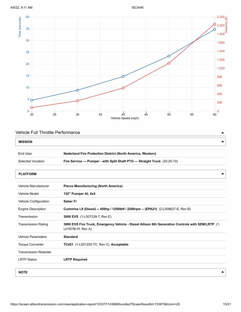
������������ � ��
������������������������������������������������������� �������!""##��"�$��%&�'��'( ����)��&���'*""�#+,-��*- +��
.�������/&���0��������1��2��������! �+ "! "+ �! �+ +! ++ $!.������� ���'�3���4!+!+�!�+"!"+�!0����3�����'�4
!�!!�!!$!!�!!�!!!��!!��!!�$!!��!!��!!!���!! 5��������32�4
67�'�-��� 89:9;<=>:�?@;9�A;BC9DC@B>�E@FC;@DC�G8B;CH�IJ9;@D=K�L9FC9;>M ������'�.������� ?@;9�N9;O@D9�P�AQJR9;�S�T@CH�NR<@C�NH=UC�AVW�P�NC;=@XHC�V;QDY�3�! �! !4.����������&2���&��� A@9;D9�Z=>QU=DCQ;@>X�G8B;CH�IJ9;@D=M.���������'�� [\]�AQJR9;�I_�a.����������2�b&������ N=c9;�?;7�b����5���������� dQJJ@>F�_e�GE@9F9<M�SS�\fHR�g�[]\f<cUC�g�]]ff;RJ�SS�GhAI][M�3� i!!�$�# 7��)���j40����������� kfff�hlN�3 i!!#""� 0��)���740������������)����b kfff�hlN�?@;9�V;QDYK�hJ9;X9>Dm�l9H@D<9�S�E@9F9<�I<<@FB>�nCH�o9>9;=C@B>�dB>C;B<F�T@CH�NhZg_pVA�3 i!�#�! )��)���4.�������1��������� NC=>:=;:0��q&����������� Vd ][�3 i!!�++ 0���)����4�IDD9RC=c<90������������)����'��i)01� ���&� _pVA�p9rQ@;9:
ZsNNsW8 6A_IV?WpZ 6
8WVh 6

������������ � ��
������������������������������������������������������� �������!""##��"�$��%&�'��'( ����)��&���'*""�#+,-��*- $��
.����)��/� 0������� ���'��1���2 3�/���� ���'��1���2 4&��&�� ���'��1���2 5��������366�����1�%2 7���%���8&���1�%2 9�����8���������%���1��2 ����.��'��1:2 5�����������;����)�<�������1=5-����2 ������8����� !�! #�� ! "$+�$ "���!# !�! "+�$� ++���!"� ��! ##� #! "$�"�! "�����" #��# "+�+� �$�$��#� ��! �$" "� "++"�+� ""#"�!# ���$ "+�"$ !!!���� $�! �" �!� �$���!� �����+� �!��� "��#� #����� ��! ��� �#� ��"��� !�#��# ��!�� ���#� +"#���� ��� �� ��+ #+�!� !�#���" ���� ����+ +�!��! #!�8������� !�! �!+� "�� !""�+� �����"$ �#!�� �+�++ �!!���� !�� �!� "�! �$�"��� ��""��+ ���! ����! "$#$��! �!�8������� ��! �" �� ��$+�"� �#����$ ��$�� ���"+ "�"��� "�! �$+ �+ �"!��#� �!�#�# ��#�� �!�+� ��!$��# �+�8������� "�$ ��� �#" #�!��"� #$���!� ��$�# ��+� �$�$��$�� "�$ �$! �#" $"+��# $!�!�+ ����� +�"$ +�#����� ��! �$# ��# $���!� $!"�# �""�! +�$ +##!�!��� $�! �!!" ++# +�����# +$�#��# �+�" ���� ��#����� ��! �!� $�$ +++��!� +"!"�$$ �$$�� "�"� ��"!���� �!�! �!�� $�$ +�+!�#$ ��#��#� ��!�! ��+ "#!���$�� ���! ��� #$$ ����� �$�"��" ���� �$! "$������ ���# �"$ #� �#$���� ��#��!# ����! ��� "!!�$��> ���# �#+ #� �#����# ������$ ��!�+ ��� ��$��+�> ���! ++# �"+ �##��+# ��#"�#� "!+�� ��� "!��"�> �$�! $�# �!+ �#+��$! ���#�+ "���+ � ""#����> ���! �# �#� �#��## �"#"�� "+��" !��# "$$�$��> "!�! ��# !�� ��"�#! �!�$�� "+"� !�� "##�"$�> "��! �!#$ � �"�$� "#��� "+��$ ��"# �!��$#�> "��� ��+ �! "����$# "+����+ "���� ���� �!#���"> "��� $!# �! "$���! "�"�$� "+�$ ��!� ��"���"> "��! $$� �" "$!���" "���!� "�$�$ #��# "!$�$""> "$�! #$$ �+" "+�"�$" "�"��$ "���! #��$ "�$�+""> "��! �$� "�" "+"!��" "!$���$ "+#�� #�$$ "�$��#"> �!�! �$� "�� ""!#��# ��"�#$ "+��� #�!" "+"�""> ���! �!$! �$� "����! �$�+�++ "+��# $�+$ "#$��""> �"�" ��+ +!� "!�!�$! ��##�"$ "���! $�� "�!��"
5���� �����6�������������&%<����������� ���7��������������6���������������)��&������'��������������������������/����'��������������'?�������1�������������*�!2�5�����?�%�����'������������9����� ������?����&��3�/����@�� AB ������'�������/ ACC3�/����8���� DEFBGFHG�IJKLH�MNHOL 0�������8��������� DEFBGFHGP���)���� QRSS &P�����?�.�����/�)���� TUVWW�XYZAXXW[�\VXA]\XM�VIDYUXD�_TMaMaWSWQWbWcWd��DX\ef\Zfg�U\e�Aeg�\M�AUUg�\hW[�Z\XA�i�QRSSjg�\Vh�Z\XA k

������������ � ��
������������������������������������������������������� �������!""##��"�$��%&�'��'( ����)��&���'*""�#+,-��*- #��
�. �"�" +!� +!� �+�!��# �!�#�!� ����" +� �#�!��. ���! +" +" �+�#��# �!"���" "!"�# +�!� ���#"�. �$�! $! $! �+��� ��$�!� "$�$ ���� ������. ���! $# $# �+#��+� �+��#� "���" ���� �!��+�. +!�! #�! #�! �+$"�!� ��"� "��# ��## ������. +��! �! �! �++���# �$$�! "+��! ��$$ �""�#��. +��! �#� �#� ���+�"� ##��!# "+��" ���� �����+�. +$�! ��� ��� �"���#� $���! "++�� ��!+ ��#��"�. +��! �!� �!� ���+��! ��+��# "+"�� "�# �#!�+!�. $!�! �!�� �!�� ���"�"! "�"�+ "++�# "��+ ��+����. $� ��+ ��+ �+#�+ ��+�$# "+�� "��" ����+. $� +�" ��+ �+�$+ !+��� "�� ��$" "�#�$�+. $��! $� �+� �"�"� !"��"� "$�" ��+# "+���$+. $��! $#! ���# �!��"# ����#� "�+�# ���$ "$���++. $$�! #�� ���# �!���� �"+�$# ""��� ��"" "�����+. $��! ##� �"$# ��#�� ������ "���! ��� "����!+. #!�! ��# ��"$ ����" �"��## "+"�! ��!� �$��#+. #��! �#� �+!$ �+!�+$ #���#! "++�" ��$ ��#��#+. #��! �" �+#+ #�#�� $"��$" "+��# �+� �"��$$+. #$�! ��" �$�+ #�+�� +�!��" "���$ �"! ����$�+. #��! �!"+ �#+ $��$# ��$��+ "���� �!$ �$���"+. �!�! �!�� �#�� $�$��# ""��$ "+�" !��+ ��"��!+. ���! ��! ��+� +#���� ���� "�"�� !�+" ���"�+. ���! ��� ���" ��+�## $��#� ""��� !�# +!+��++. �+�+ ��"! ��#� "���� #��#" "��� !�� +$�#� /������'+. �$�! ���� ���" �"$�+! �"+��+ ��"�$ !�+� �#���++. ���! ���$ "!$" #!���" ��$��� $��� ��!$ �#���"+. �!�! �"�� ""� $#�!+ ��!�+� �!� "�+� ""#��"+. �!�$ �"$+ "+� !�!! $!$�!� !�! ��! ""��!!01234�5�6711�3892331:�;732<;3=>�7048=634�?@>5A>5A15B15C15D15E1F�5�43;GH;9HI�6;G�2GI�;>�266I�;J1:�9;3=2�K�CLBBMI�;7N

������������ � ��
������������������������������������������������������� �������!""##��"�$��%&�'��'( ����)��&���'*""�#+,-��*- ���
.�������������������/��0�������! ! �! "! �! +! $! #! �! �! !!.������� ���'�1���2��!!�+!!�$!!�#!!��!!��!!��!!!��!!���!!��"!!���!!3�4���� ���'�1���2
5+!+!+�!�+"!"+�! ����6��'��172
83�'�-��� 9:;:<=>?;�@A<:�B<CD:EDAC?�FAGD<AED�H9C<DI�JK:<AE>L�M:GD:<?N ������'�.������� @A<:�O:<PAE:�Q�BRKS:<�T�UADI�OS=AD�OI>VD�BWX�Q�OD<>AYID�W<REZ�1�! �! !2@[\\�W] XWW\_�J9[J\�aOW�]X\F�T�\Xbc[B�JBB\d�HabTa\N�T�OWJ9FJ FL�@J9�X9L�Jb�X@@L�Je\_�JWfX�g�hijjkL�J[e�JWfX�g8B\XWO�T�@[\\�W] XWW\_�J9[J\�aOW�]X\F�T�\Xbc[B�JBB\d�HabTa\N�T�OWJ9FJ FL�@J9�X9L�Jb�X@@L�Je\_�JWfX�g�hijjkL�J[e8@[\\�W] XWW\_�_l_ O_�B_ @X J9b_�HabTabN�T�OWJ9FJ FL�@J9�X9L�Jb�X@@L�Je\_�JWfX�g�hijjkL�J[e�JWfX�g�aikkkL�OWJ8B\XWO�T�@[\\�W] XWW\_�_l_ O_�B_ @X J9b_�HabTabN�T�OWJ9FJ FL�@J9�X9L�Jb�X@@L�Je\_�JWfX�g�hijjkL�J[e�JWfX�g�a8fOOfX9 8B\JW@X ` 8

������������ � ��
������������������������������������������������������� �������!""##��"�$��%&�'��'( ����)��&���'*""�#+,-��*- ���
.����)��/� 0������� ���'��1���2 3�����1�����'�2 4���������15�2 �����������)�����1�������2 6�/���� ���'��1���2 3��������655�����1�%2 4���%���7&���1�%2 8�����7���������%���1��2 3�����������9����)�:�������1;3-����2� ��! !�" ! $��"" ##� "$�"�! "�����" #��# �$�$��#� ��! !�$ � $��"# �$" "++"�+� ""#"�!# ���$ !!!���� $�! !�� � $�++# �" �$���!� �����+� �!��� #����� ��! �� # +�#�� ��� ��"��� !�#��# ��!�� +"#���� !�! �$ � +�"+ �!+� !""�+� �����"$ �#!�� �!!���� ��! ��! � ��+"# �" ��$+�"� �#����$ ��$�� "�"��� "�$ ��� �$ "��#� ��� #�!��"� #$���!� ��$�# �$�$��$�� ��! ��+ �� "��� �$# $���!� $!"�# �""�! +##!�!��� $�! "� �" "�!!" �!!" +�����# +$�#��# �+�" ��#����� ��! "�� $! ���� �!� +++��!� +"!"�$$ �$$�� ��"!���� �!�! ��$ �! ��$�� �!�� +�+!�#$ ��#��#� ��!�! "#!���$�� ���! +�" !+ ���$! ��� ����� �$�"��" ���� "$������ ���# +�$ � ��"�! �"$ �#$���� ��#��!# ����! "!!�$��< ���! $�� "" ��""� ++# �##��+# ��#"�#� "!+�� "!��"�< �$�! #�! $+ ��"� $�# �#+��$! ���#�+ "���+ ""#����< ���! #�� �� ����$ �# �#��## �"#"�� "+��" "$$�$�
0����������&5���&��� =>?@A?�BCDEFCAGE@>DH�IJK@GL�MN?@>ACO0���������'�� PQRS�=ENT?@�MU�VWV0����������5�/&������ XCY?@�Z@6�/����4���������� [ENN>D\�U]�I>?\?_O��VQaLT�b�PRQa_YFG�b�RRaa@TN��Ic=MRPO�1� <!!�$�# 6��)���;23����������� daaa�ceX�1 <!!#""� 3��)���623������������)����/ daaa�ceX�Z>@?�f@EAgh�cN?@H?DAi�e?L>A_?��>?\?_�M__>\KD�jGL�k?D?@CG>KD�[KDG@K_\�l>GL�XcBbUmf=�1 <!�#�! )��)���20�������7��������� XGCDnC@n3��o&����������� f[VRP�1 <!!�++ 3���)����2�MAA?TGCY_?3������������)����'��<)37� ���&� Umf=�m?pE>@?n3���� �����5�������������&%:����������� ���4��������������5���������������3�����q�%�����'������������8����� ������q����&�������������'�������5������������������� �������;��r������r�'���'�6�/�������s&���3��������6�/����s�� tD 6�/����7���� XGCDnC@n�=Kl?@�[E@u?������'�������/ tFF 0�������7��������� XGCDnC@nv���)���� Vwdda &v�����q�.�����/�)���� Pwaaa.��'� awaaxJtfc yZzUU�f{mtffUc�MzftBMf|[�z=X{|ZfX�IP[R[RUdUVUQUjUO��XfMJ Mm h�ZMJ�tJh�M[�tZZh�M}Uc�mMf|t�~�Vwddah�Mz}�mMf|t y

������������ � ��
������������������������������������������������������� �������!""##��"�$��%&�'��'( ����)��&���'*""�#+,-��*- �!��
�. "!�! ��� �"# ��� ��# ��"�#! �!�$�� "+"� "##�"$�. "��! ��� ��� ��+� �!#$ �"�$� "#��� "+��$ �!��$#�. "��� !�� "! ���$ ��+ "��!�� "+��!+ "���+ �!#�"�". "��! !�� ""# �$�$ $$� "$!���" "���!� "�$�$ "!$�$"". "$�! �� "�� �$$" #$$ "+�"�$" "�"��$ "���! "�$�+"". "��! "�" �$� �$�� �$� "+"!��" "!$���$ "+#�� "�$��#". �!�! ��$ +"� ���� �$� ""!#��# ��"�#$ "+��� "+"�"". ���! $�! $�� �"�! �!$! "����! �$�+�++ "+��# "#$��"". �"�" #�! $�" �"" ��+ "!�!�$! ��##�"$ "���! "�!��"�. ���! #�$ #�" �!�� +" �+�#��# �!"���" "!"�# ���#"�. �$�! ��+ ��$ �!$� $! �+��� ��$�!� "$�$ ������. ���! ��� �## �!�� $# �+#��+� �+��#� "���" �!��+�. +!�! �"�" # �!� #�! �+$"�!� ��"� "��# ������. +��! �+�" �$+ !���+ �! �++���# �$$�! "+��! �""�#��. +��! �#�� ��+ !���$ �#� ���+�"� ##��!# "+��" �����+�. +$�! ���$ $!" !��$$ ��� �"���#� $���! "++�� ��#��"�. +��! "��! �!$ !�#�" �!� ���+��! ��+��# "+"�� �#!�+!�. $!�! "��$ �!"" !�#"� �!�� ���"�"! "�"�+ "++�# ��+����. $� "$� �$� !�$�� ��+ �+#�+ ��+�$# "+�� ����+. $��! "#�� �"# !�++" $� �"�"� !"��"� "$�" "+���$+. $��! ��+ �$+� !�+�# $#! �!��"# ����#� "�+�# "$���++. $$�! �+�� "!" !�+! #�� �!���� �"+�$# ""��� "�����+. $��! ���+ "�"+ !��#� ##� ��#�� ������ "���! "����!+. #!�! +"�� "�#$ !���$ ��# ����" �"��## "+"�! �$��#+. #��! +��$ �"$$ !��!! �#� �+!�+$ #���#! "++�" ��#��#+. #��! $��! ��+! !�"�! �" #�#�� $"��$" "+��# �"��$$+. #$�! #!�+ +$$$ !���! ��" #�+�� +�!��" "���$ ����$�+. #��! #��+ $+$$ !���� �!"+ $��$# ��$��+ "���� �$���"+. �!�! ���" ##!� !��" �!�� $�$��# ""��$ "+�" ��"��!+. ���! !��! �"�+ !�+ ��! +#���� ���� "�"�� ���"�+. ���! "�� ���� !�!�! ��� ��+�## $��#� ""��� +!+��+/0123�4�5600�27812209�:621;:2<=�6/37<523�>?=4@=4@04A04B04C04D0E�4�32:FG:8GH�5:F�1FH�:=�155H�:I09�8:2<1�J�BKAALH�:6M

������������ � ��
������������������������������������������������������� �������!""##��"�$��%&�'��'( ����)��&���'*""�#+,-��*- ���
! ! �! "! �! +! $! #! �! �! !! ! �! "! �!.����/�����'�0�+!!�++!�$!!�$+!�#!!�#+!��!!��+!��!!��+!��!!!��!+!��!!��+!���!!1�2���� ���'�/���0
!!�!"!�!+!$!#!�!�! 3������� ���'�/���0
4566�789:776;�<=>5=6�?@7�8:6A�B�6:CD5E�=EE6F�G?CB?6H�B�@7=>A=9AI�4=>�:>I�=C�:44I�=J6;�9=7K:�L�MNOOPI�=5J�9=7K:�LQE6:7@�B�4566�789:776;�<=>5=6�?@7�8:6A�B�6:CD5E�=EE6F�G?CB?6H�B�@7=>A=9AI�4=>�:>I�=C�:44I�=J6;�9=7K:�L�MNOOPI�=5JQ4566�789:776;�9;R;9@;�E;94:9<=>C;�G?CB?CH�B�@7=>A=9AI�4=>�:>I�=C�:44I�=J6;�9=7K:�L�MNOOPI�=5J�9=7K:�L�?NPPPI�@7=QE6:7@�B�4566�789:776;�9;R;9@;�E;94:9<=>C;�G?CB?CH�B�@7=>A=9AI�4=>�:>I�=C�:44I�=J6;�9=7K:�L�MNOOPI�=5J�9=7K:�L�?Q
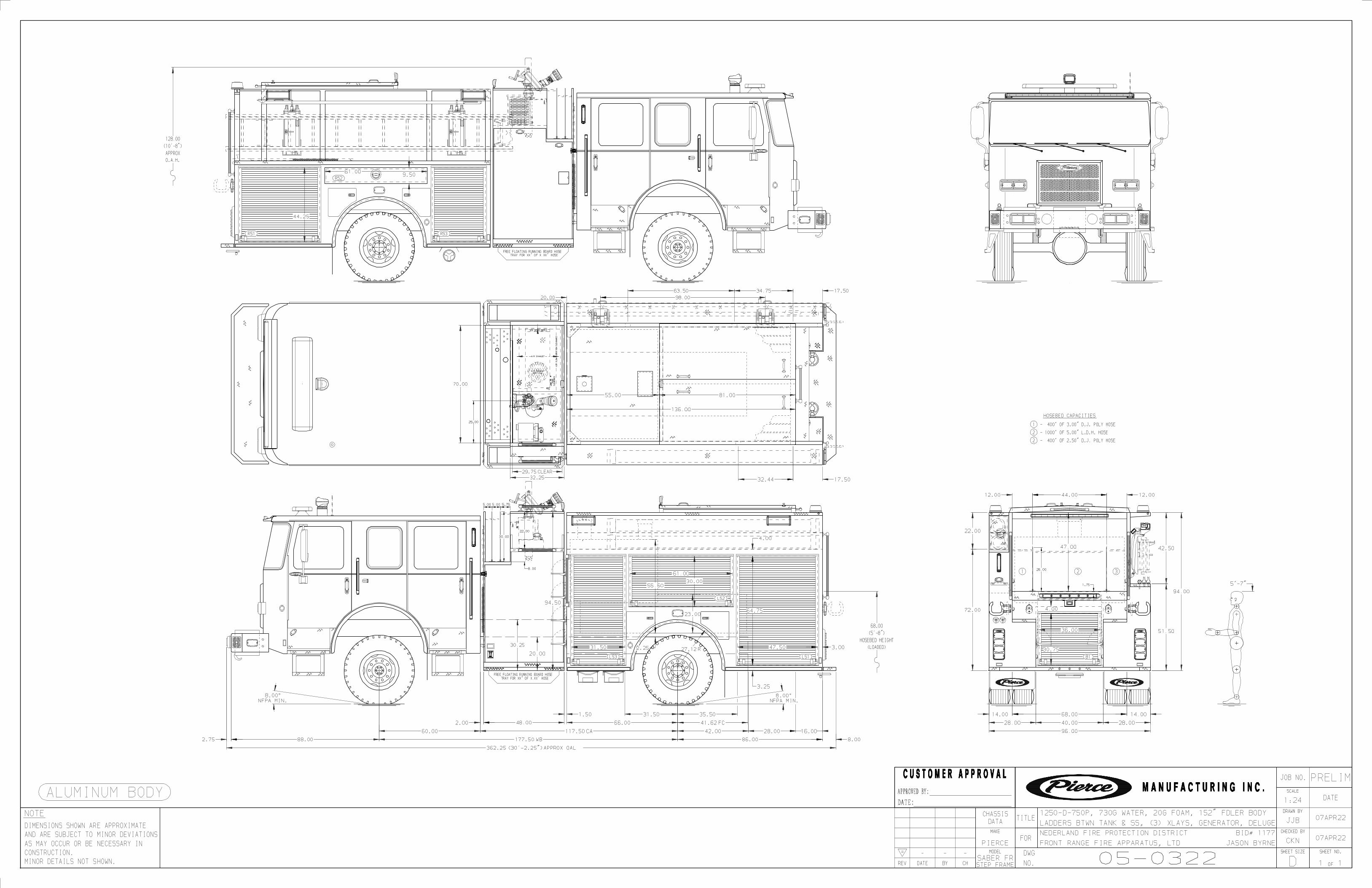

Note: Any Surety Bond, if a part of the sale of the vehicle as to which this limited warranty is provided, applies only to this Pierce Basic One Year Limited Warranty for such vehicle, and not to other warranties made by Pierce in a separate document (if any) or to the warranties (if any) made by any manufacturer (other than Pierce) of any part, component, attachment or accessory that is incorporated into or attached to the vehicle.
2/8/2010 WA0008
1. LIMITED WARRANTY
THE WARRANTY SET FORTH IN PARAGRAPH 1 IS THE SOLE AND EXCLUSIVE WARRANTY GIVEN BY PIERCE. PIERCE HEREBY DISCLAIMS AND EXCLUDES ALL OTHER WARRANTIES, WHETHER EXPRESS, IMPLIED OR STATUTORY, INCLUDING WITHOUT LIMITATION ANY WARRANTY OF MERCHANTABILITY, ANY WARRANTY OF FITNESS FOR A PARTICULAR PURPOSE, AND ANY WARRANTIES ARISING FROM COURSE OF DEALING OR USAGE OF TRADE.
2. DISCLAIMERS OF WARRANTIES
The original purchaser may void this warranty in part or in its entirety if the product is repaired or replaced (a) without prior written approval of the Pierce Customer Service Department; or (b) at a facility which has not been approved by Pierce as to technical capability. Any repairs, modifications, alterations or aftermarket parts added after manufacture without the authorization of Pierce may void this warranty.
This limited warranty shall apply only if the product is properly maintained in accordance with Pierce's maintenance instructions and manuals and is used in service which is normal to the particular model. Normal service means service which does not subject the product to stresses or impacts greater than normally result from careful use. If the Buyer discovers a defect or nonconformity, it must notify Pierce in writing within thirty (30) days after the date of discovery, but in any event prior to the expiration of the warranty period. THIS LIMITED WARRANTY MAY NOT BE ASSIGNED OR OTHERWISE TRANSFERRED BY THE BUYER TO ANY SUBSEQUENT USER OR PURCHASER OR TO ANY OTHER PERSON OR ENTITY.
No specific exclusions apply
Conditions and Exclusions:
See AlsoParagraphs2 thru 4
Limited WarrantySubject to the limitations and exclusions set forth below, Pierce Manufacturing provides the following warranty to the Buyer:
(c) any vehicle, chassis or component, part, attachment or accessory that has been repaired, altered or assembled in any way by any person or entity other than Pierce which, in the sole judgment of Pierce, adversely affects the performance, stability or purpose for which it was manufactured; or
(a) any integral parts, components, attachments or trade accessories of or to the product that are not manufactured by Pierce, including but not limited to engines, transmissions, drivelines, axles, water pumps and generators; with respect to all such parts, components, attachments and accessories, Pierce shall assign to Buyer the applicable warranties, if any, made by the respective manufacturers thereof;
Notwithstanding anything to the contrary herein, Pierce makes no warranty whatsoever as to:
Fire and Rescue Apparatus
Coverage:
One (1) Year Material and WorkmanshipBasic Apparatus
Twelve (12) months.Warranty Period Ends After:
The date the apparatus is placed in service, or 60 days from the original buyer invoice date, whichever comes first.Warranty Begins:
Portions of the apparatus manufactured by Pierce shall be free from defects in material and workmanship
(d) products or parts which may in the ordinary course wear out and have to be replaced during the warranty period, including, but not limited to, tires, fluids, gaskets and light bulbs. Pierce assumes no responsibility for the assembly of its parts or subassemblies into finishing products or vehicles unless the assembly is performed by Pierce.
(b) any vehicle, chassis, or component, part, attachment or accessory damaged by misuse, neglect, fire, exposure to severe environmental or chemical conditions, acidic environment, improper maintenance, accident, crash, or force majeure such as natural disaster, lightning, earthquake, windstorm, hail, flood, war or riot;
4. EXCLUSION OF CONSEQUENTIAL AND INCIDENTAL DAMAGES.Notwithstanding anything to the contrary herein or in any agreement between Pierce and Buyer, IN NO EVENT SHALL PIERCE BE LIABLE FOR ANY CONSEQUENTIAL, INCIDENTAL, SPECIAL, INDIRECT, OR PUNITIVE DAMAGES WHATSOEVER, WHETHER ARISING OUT OF BREACH OF CONTRACT, WARRANTY, TORT (INCLUDING NEGLIGENCE AND STRICT LIABILITY) OR OTHER THEORY OF LAW OR EQUITY, WITH RESPECT TO VEHICLES OR OTHER PRODUCTS SOLD BY PIERCE, OR THEIR OPERATION OR FAILURE TO OPERATE, OR ANY DEFECTS THEREIN, OR ANY UNDERTAKINGS, ACTS OR OMISSIONS RELATED THERETO, REGARDLESS OF WHETHER PIERCE HAS BEEN INFORMED OF THE POSSIBILITY OF ANY SUCH DAMAGES. Without limiting the generality of the foregoing, Pierce specifically disclaims any liability for property or personal injury damages, penalties, damages for lost profits or revenues, loss of vehicles or products or any associated equipment, cost of substitute vehicles or products, down-time, delay damages, any other types of economic loss, or for any claims by any third party for any such damages.
If the product fails to conform to the warranty set forth in paragraph 1 during the warranty period, and such nonconformity is not due to misuse, neglect, accident or improper maintenance, Buyer must notify Pierce within the time period specified in paragraph 1, and shall make the product available for inspection by Pierce or its designated agent. At the request of Pierce, any allegedly defective product shall be returned to Pierce by Buyer for examination and/or repair. Buyer shall be responsible for the cost of such transportation, and for risk of loss of or damage to the product during transportation. Within a reasonable time, Pierce shall repair or replace (at Pierce's option and expense) any nonconforming or defective parts. Repair or replacement shall be made only by a facility approved in advance in writing by Pierce. THIS REMEDY SHALL BE THE EXCLUSIVE AND SOLE REMEDY FOR ANY BREACH OF WARRANTY.
3. BUYER'S EXCLUSIVE REMEDY.

Cummins Warranty WorldwideFire Apparatus/Crash Trucks

CoverageProducts WarrantedThis Warranty applies to new diesel Engines sold byCummins and delivered to the first user on or afterApril 1, 2007, that are used in fire apparatus truck andcrash truck* applications Worldwide.
Base Engine WarrantyThe Base Engine Warranty covers any failures of theEngine which result, under normal use and service,from a defect in material or factory workmanship(Warrantable Failure). This Coverage begins with thesale of the Engine by Cummins and ends five years or100,000 miles (160,935 kilometers), whichever occursfirst, after the date of delivery of the Engine to the firstuser.Engine aftertreatment components included in theCummins Critical Parts List (CPL) and marked with aCummins part number are covered under Base EngineWarranty.Additional Coverage is outlined in the EmissionWarranty section.These Warranties are made to all Owners in thechain of distribution and Coverage continues to allsubsequent Owners until the end of the periods ofCoverage.
CumminsResponsibilitiesCummins will pay for all parts and labor needed torepair the damage to the Engine resulting from aWarrantable Failure.Cummins will pay for the lubricating oil, antifreeze,filter elements, belts, hoses and other maintenanceitems that are not reusable due to the WarrantableFailure.Cummins will pay for reasonable labor costs forEngine removal and reinstallation when necessary torepair a Warrantable Failure.Cummins will pay reasonable costs for towing avehicle disabled by a Warrantable Failure to thenearest authorized repair location. In lieu of the towingexpense, Cummins will pay reasonable costs formechanics to travel to and from the location of thevehicle, including meals, mileage and lodging whenthe repair is performed at the site of the failure.
OwnerResponsibilitiesOwner is responsible for the operation andmaintenance of the Engine as specified in CumminsOperation and Maintenance Manuals. Owner is alsoresponsible for providing proof that all recommendedmaintenance has been performed.Before the expiration of the applicable Warranty,Owner must notify a Cummins distributor, authorizeddealer or other repair location approved by Cumminsof any Warrantable Failure and make the Engineavailable for repair by such facility. Except for Enginesdisabled by a Warrantable Failure, Owner must alsodeliver the Engine to the repair facility.Service locations are listed on the Cummins WorldwideService Locator at cummins.com.Owner is responsible for the cost of lubricating oil,antifreeze, filter elements and other maintenance itemsprovided during Warranty repairs unless such itemsare not reusable due to the Warrantable Failure.Owner is responsible for communication expenses,meals, lodging and similar costs incurred as a result ofa Warrantable Failure.Owner is responsible for non-Engine repairs and for‘‘downtime’’ expenses, cargo damage, fines, allapplicable taxes, all business costs and other lossesresulting from a Warrantable Failure.Owner is responsible for a $100 (U.S. Dollars)deductible per each service visit under this plan in the3rd, 4th and 5th years of Base Engine Warranty. Thedeductible will not be charged during the first 2 yearsof the Base Engine Warranty.
LimitationsCummins is not responsible for failures or damageresulting from what Cummins determines to be abuseor neglect, including, but not limited to: operationwithout adequate coolants or lubricants; overfueling;overspeeding; lack of maintenance of lubricating,cooling or intake systems; improper storage, starting,warm-up, run-in or shutdown practices; unauthorizedmodifications of the Engine.Any unauthorized modifications to the aftertreatmentcould negatively effect emissions certification and voidWarranty.Cummins is also not responsible for failures caused byincorrect oil, fuel or diesel exhaust fluid or by water,dirt or other contaminants in the fuel, oil or diesel

exhaust fluid.This Warranty does not apply to accessories suppliedby Cummins which bear the name of anothercompany. Such non-warranted accessories include, butare not limited to: alternators, starters, fans, airconditioning compressors, clutches, filters,transmissions, torque converters, vacuum pumps,power steering pumps, fan drives and air compressors.Cummins branded alternators and starters are coveredfor the first two years from the date of delivery of theEngine to the first user, or the expiration of the BaseEngine Warranty, whichever occurs first.Failures resulting in excessive oil consumption are notcovered beyond the duration of the Coverage or100,000 miles (160,935 kilometers) or 7,000 hours fromthe date of delivery of the Engine to the first user,whichever of the three occurs first. Before a claim forexcessive oil consumption will be considered, Ownermust submit adequate documentation to show thatconsumption exceeds Cummins published standards.Failures of belts and hoses supplied by Cummins arenot covered beyond the first year from the date ofdelivery of the Engine to the first user or the durationof the Warranty, whichever occurs first.Parts used to repair a Warrantable Failure may be newCummins parts, Cummins approved rebuilt parts orrepaired parts. Cummins is not responsible for failuresresulting from the use of parts not approved byCummins.A new Cummins or Cummins approved rebuilt partused to repair a Warrantable Failure assumes theidentity of the part it replaced and is entitled to theremaining Coverage hereunder.Cummins Inc. reserves the right to interrogateElectronic Control Module (ECM) data for purposes offailure analysis.CUMMINS DOES NOT COVER WEAR OR WEAROUTOF COVERED PARTS.CUMMINS IS NOT RESPONSIBLE FOR INCIDENTALOR CONSEQUENTIAL DAMAGES.THIS WARRANTY AND THE EMISSION WARRANTYSET FORTH HEREINAFTER ARE THE SOLEWARRANTIES MADE BY CUMMINS IN REGARD TOTHESE ENGINES. CUMMINS MAKES NO OTHERWARRANTIES, EXPRESS OR IMPLIED, OR OFMERCHANTABILITY OR FITNESS FOR APARTICULAR PURPOSE.This Warranty gives you specific legal rights, and youmay also have other rights which vary from state tostate.
EmissionWarrantyProducts WarrantedThis Emission Warranty applies to new Enginesmarketed by Cummins that are used in the UnitedStates** in vehicles designed for transporting personsor property on a street or highway. This Warrantyapplies to Engines delivered to the first user on or afterSeptember 1, 1992.
CoverageCummins warrants to the first user and eachsubsequent purchaser that the Engine is designed,built and equipped so as to conform at the time of saleby Cummins with all U.S. federal emission regulationsapplicable at the time of manufacture and that it is freefrom defects in material or factory workmanship whichwould cause it not to meet these regulations within thelonger of the following periods: (A) Five years or100,000 miles (160,935 kilometers) of operation,whichever occurs first, as measured from the date ofdelivery of the Engine to the first user or (B) The BaseEngine Warranty.If the vehicle in which the Engine is installed isregistered in the state of California, a separateCalifornia Emission Warranty also applies.
LimitationsFailures, other than those resulting from defects inmaterial or factory workmanship, are not covered bythis Warranty.Cummins is not responsible for failures or damageresulting from what Cummins determines to be abuseor neglect, including, but not limited to: operationwithout adequate coolants or lubricants; overfueling;overspeeding; lack of maintenance of lubricating,cooling or intake systems; improper storage, starting,warm-up, run-in or shutdown practices; unauthorizedmodifications of the Engine.Any unauthorized modifications to the aftertreatmentcould negatively effect emissions certification and voidWarranty.Cummins is also not responsible for failures caused byincorrect oil, fuel or diesel exhaust fluid or by water,dirt or other contaminants in the fuel, oil or dieselexhaust fluid.Cummins is not responsible for non-Engine repairs,‘‘downtime’’ expenses, cargo damage, fines, allapplicable taxes, all business costs or other lossesresulting from a Warrantable Failure.

Cummins Inc. Box 3005 Columbus, IN 47202-3005 U.S.A.
Bulletin 3381161 Printed in U.S.A. Rev. 08/09 ©2001 Cummins Inc.
CUMMINS IS NOT RESPONSIBLE FOR INCIDENTALOR CONSEQUENTIAL DAMAGES.* Airport operated crash trucks and fire departmentoperated trucks employed to respond to fires,hazardous material releases, rescue and otheremergency-type situations.** United States includes American Samoa, theCommonwealth of Northern Mariana Islands, Guam,Puerto Rico and the U.S. Virgin Islands.
Cummins Inc.Box 3005Columbus, IN 47202-3005U.S.A.
Bulletin 3381161Printed in U.S.A. Rev. 08/09�2001 Cummins Inc.

TRW COMMERCIAL STEERING SYSTEMS800 HEATH STREETLAFAYETTE, INDIANA 47904
PRODUCT WPRODUCT WPRODUCT WPRODUCT WPRODUCT WARRANTYARRANTYARRANTYARRANTYARRANTY
I. WARRANTY: The Commercial Steering Systems group of TRW, Inc., hereinafter referred to as “CSS”, warrants that each newproduct supplied by CSS to its customer, when properly installed, used and maintained, shall be free from defect in material andworkmanship for the period specified below:
(A) CSS Product installed in New On-highway Motor Vehicle:
Within twelve (12) months after date of delivery of such vehicle to the original retail purchaser, or before such vehicle has beendriven one hundred thousand (100,000) miles, whichever event shall first occur.
(B) CSS Product installed in New Agricultural, Turf, Industrial, or Construction Vehicles and Related Equipment:
Within twelve (12) months after date of delivery of such vehicle/equipment to the original retail purchaser or before suchvehicle/equipment has been operated for two thousand (2000) hours or fifty thousand (50,000) miles, whichever occurs first.
(C) CSS Product installed in New End Product, Not Specifically Mentioned in Classifications (A) or (B) Above and AllOther Off-Highway/Severe Applications:Within six (6) months after date of delivery of the original equipment manufacturer’s end product to the original retail purchaser.
II. REMEDY: Customer’s sole remedy under the foregoing warranty is limited to correction by means of repair, replacement or issuanceof credit, at the option of CSS, of any product which is:
(A) Returned to CSS within the specified warranty time period, with prior notice to, and the written consent of, CSS, withtransportation and handling charges prepaid, together with a statement describing the alleged defect, the part number, modelnumber and application, and mileage or hours of use of such product; and
(B) Upon examination, determined by CSS not to conform to the warranty.
III. Any product which is repaired or replaced under this warranty will be returned to customer prepaid. Disposition of any productdetermined not to be covered by this warranty will be at the customer’s expense.
IV. CSS will not be liable for any repairs, replacements, or adjustments to any product or any cost of labor performed by or at the requestof customer without the express prior written consent of CSS.
V. EXCEPTIONS: The provision of this warranty shall not apply to any CSS product which is used for a purpose for which it is notdesigned, or which shall have been repaired or altered in any way, or which has been subject to misuse, negligence or accident,neglect of normal maintenance services, so as, in the judgement of CSS to adversely affect its performance and reliability. In no casewill the CSS warranty exceed the standard published warranty of its customer in terms of time and/or distance. In all events, the CSSwarranty will expire thirty (30) months after the date of manufacture as stamped on the Product. In the case of hydraulic equipment,operation with unapproved fluid or temperatures voids this warranty.
VI. EXCLUSION OF ALL OTHER REMEDIES AND LIMITATION OF LIABILITY: Customer’s sole and exclusive remedy under theforegoing warranty shall be for the repair, replacement or issuance of credit with respect to a defective product, as set forth anddescribed above. Other provisions hereof notwithstanding, CSS shall not be liable to Customer, or any successor in interest,beneficiary or assignee of Customer, based upon any claim against CSS, whether in contract, warranty, negligence, strict liability,indemnity or otherwise, for any special, consequential, incidental or other damages relating in any way to the design, manufacture,sale, installation or other use of any product purchased from CSS.
VII. EXCLUSION OF ALL OTHER WARRANTIES: THE FOREGOING WARRANTY IS THE EXCLUSIVE WARRANTY BY CSS AND ISIN LIEU OF AND EXCLUDES ALL OTHER WARRANTIES AND REPRESENTATIONS, WHETHER ORAL, WRITTEN, EX-PRESSED, IMPLIED OR STATUTORY, INCLUDING BUT NOT LIMITED TO ANY WARRANTY OF MERCHANTIBILITY ORFITNESS FOR A PARTICULAR PURPOSE.
TRW COMMERCIAL STEERING SYSTEMS Revised November 2001

Note: Any Surety Bond, if a part of the sale of the vehicle as to which this limited warranty is provided, applies only to this Pierce Basic One Year Limited Warranty for such vehicle, and not to other warranties made by Pierce in a separate document (if any) or to the warranties (if any) made by any manufacturer (other than Pierce) of any part, component, attachment or accessory that is incorporated into or attached to the vehicle.
2/8/2010 WA0013
1. LIMITED WARRANTY
THE WARRANTY SET FORTH IN PARAGRAPH 1 IS THE SOLE AND EXCLUSIVE WARRANTY GIVEN BY PIERCE. PIERCE HEREBY DISCLAIMS AND EXCLUDES ALL OTHER WARRANTIES, WHETHER EXPRESS, IMPLIED OR STATUTORY, INCLUDING WITHOUT LIMITATION ANY WARRANTY OF MERCHANTABILITY, ANY WARRANTY OF FITNESS FOR A PARTICULAR PURPOSE, AND ANY WARRANTIES ARISING FROM COURSE OF DEALING OR USAGE OF TRADE.
2. DISCLAIMERS OF WARRANTIES
The original purchaser may void this warranty in part or in its entirety if the product is repaired or replaced (a) without prior written approval of the Pierce Customer Service Department; or (b) at a facility which has not been approved by Pierce as to technical capability. Any repairs, modifications, alterations or aftermarket parts added after manufacture without the authorization of Pierce may void this warranty.
This limited warranty shall apply only if the product is properly maintained in accordance with Pierce's maintenance instructions and manuals and is used in service which is normal to the particular model. Normal service means service which does not subject the product to stresses or impacts greater than normally result from careful use. If the Buyer discovers a defect or nonconformity, it must notify Pierce in writing within thirty (30) days after the date of discovery, but in any event prior to the expiration of the warranty period. THIS LIMITED WARRANTY MAY NOT BE ASSIGNED OR OTHERWISE TRANSFERRED BY THE BUYER TO ANY SUBSEQUENT USER OR PURCHASER OR TO ANY OTHER PERSON OR ENTITY.
This warranty does not apply to damage caused by corrosion.
Conditions and Exclusions:
See AlsoParagraphs2 thru 4
Limited WarrantySubject to the limitations and exclusions set forth below, Pierce Manufacturing provides the following warranty to the Buyer:
(c) any vehicle, chassis or component, part, attachment or accessory that has been repaired, altered or assembled in any way by any person or entity other than Pierce which, in the sole judgment of Pierce, adversely affects the performance, stability or purpose for which it was manufactured; or
(a) any integral parts, components, attachments or trade accessories of or to the product that are not manufactured by Pierce, including but not limited to engines, transmissions, drivelines, axles, water pumps and generators; with respect to all such parts, components, attachments and accessories, Pierce shall assign to Buyer the applicable warranties, if any, made by the respective manufacturers thereof;
Notwithstanding anything to the contrary herein, Pierce makes no warranty whatsoever as to:
Fire and Rescue Apparatus
Coverage:
Lifetime Fifty (50) Year Structural IntegrityCustom Chassis Frame
Fifty (50) Years(Expected Life of Apparatus)
Warranty Period Ends After:
The date of the original purchase invoice (issued when the product ships from the factory).Warranty Begins:
Custom chassis frame rail manufactured by Pierce shall be free from defects in material and workmanship
(d) products or parts which may in the ordinary course wear out and have to be replaced during the warranty period, including, but not limited to, tires, fluids, gaskets and light bulbs. Pierce assumes no responsibility for the assembly of its parts or subassemblies into finishing products or vehicles unless the assembly is performed by Pierce.
(b) any vehicle, chassis, or component, part, attachment or accessory damaged by misuse, neglect, fire, exposure to severe environmental or chemical conditions, acidic environment, improper maintenance, accident, crash, or force majeure such as natural disaster, lightning, earthquake, windstorm, hail, flood, war or riot;
4. EXCLUSION OF CONSEQUENTIAL AND INCIDENTAL DAMAGES.Notwithstanding anything to the contrary herein or in any agreement between Pierce and Buyer, IN NO EVENT SHALL PIERCE BE LIABLE FOR ANY CONSEQUENTIAL, INCIDENTAL, SPECIAL, INDIRECT, OR PUNITIVE DAMAGES WHATSOEVER, WHETHER ARISING OUT OF BREACH OF CONTRACT, WARRANTY, TORT (INCLUDING NEGLIGENCE AND STRICT LIABILITY) OR OTHER THEORY OF LAW OR EQUITY, WITH RESPECT TO VEHICLES OR OTHER PRODUCTS SOLD BY PIERCE, OR THEIR OPERATION OR FAILURE TO OPERATE, OR ANY DEFECTS THEREIN, OR ANY UNDERTAKINGS, ACTS OR OMISSIONS RELATED THERETO, REGARDLESS OF WHETHER PIERCE HAS BEEN INFORMED OF THE POSSIBILITY OF ANY SUCH DAMAGES. Without limiting the generality of the foregoing, Pierce specifically disclaims any liability for property or personal injury damages, penalties, damages for lost profits or revenues, loss of vehicles or products or any associated equipment, cost of substitute vehicles or products, down-time, delay damages, any other types of economic loss, or for any claims by any third party for any such damages.
If the product fails to conform to the warranty set forth in paragraph 1 during the warranty period, and such nonconformity is not due to misuse, neglect, accident or improper maintenance, Buyer must notify Pierce within the time period specified in paragraph 1, and shall make the product available for inspection by Pierce or its designated agent. At the request of Pierce, any allegedly defective product shall be returned to Pierce by Buyer for examination and/or repair. Buyer shall be responsible for the cost of such transportation, and for risk of loss of or damage to the product during transportation. Within a reasonable time, Pierce shall repair or replace (at Pierce's option and expense) any nonconforming or defective parts. Repair or replacement shall be made only by a facility approved in advance in writing by Pierce. THIS REMEDY SHALL BE THE EXCLUSIVE AND SOLE REMEDY FOR ANY BREACH OF WARRANTY.
3. BUYER'S EXCLUSIVE REMEDY.

MARMON‐HERRINGTON PARTS AND COMPONENTS WARRANTY
Effective: January 1, 2011
Warranty Description This is to certify that we, Marmon‐Herrington Company will warrant each new chassis, assembly or component purchased by the buyer from Marmon‐Herrington or an Authorized Marmon‐Herrington dealer, and installed as original equipment against defects in material and workmanship under approved application use and service. Marmon‐Herrington’s components are warranted for a period of 12 months or 12,000 miles from the “in‐service date” specified on the completed and returned “Warranty Registration Card.” Under no circumstances will warranty consideration be available after 18 months of original invoice date. This warranty does not cover normal wear and tear, or a component that fails, malfunctions or is damaged as a result of: (1) improper installation, adjustment, repair or modification, usage, or application differing from that which was originally approved by Marmon‐Herrington; (2) accident, natural disaster, acts of god, climate, combat damage; (3) abuse or improper use, including loading beyond specified maximum vehicle or axle weight or adjusted engine power settings that exceed axle or transfer case input capacity; (4) improper or insufficient maintenance, to include use unapproved lubricant types or levels, or failure to follow published maintenance schedules; (5) costs incurred gaining access to components due to chassis or body design, or vehicle location. This warranty does not include travel time, travel expenses or towing charges. This warranty does not cover any part or component not sold by Marmon‐Herrington. This warranty provides for parts and labor at Marmon‐Herrington’s sole discretion. Marmon‐Herrington reserves the right to provide replacement parts directly to the repair facility. Labor hours are limited to the Marmon‐Herrington Standard Repair Time Table. This warranty is in lieu of all other warranties expressed or implied, and of all other obligations or liabilities incurred by Marmon‐Herrington. Marmon‐Herrington does not authorize any other entity to assume or express any liability in conjunction with the purchase or sale of Marmon‐Herrington parts or components. Repair Reporting Owner/Operator must contact Marmon‐Herrington Customer Service prior to performing any repairs to receive Repair Authorization to be eligible for warranty reimbursement. This authorization does not guarantee reimbursement, but acknowledges that the vehicle or component is within the warranty period, and that a claim has been activated. It is the responsibility of the owner/operator to ensure that the repair facility acknowledges and complies with the guidelines of this policy. At the time of Repair Authorization request, the following must be provided:
a) Marmon‐Herrington Sales Order Number b) Vehicle Identification Number c) Vehicle In‐Service Date d) Current mileage
If a Warranty Registration Card is not on file, this must be completed before Repair Authorization can be issued. Repair Procedure and Claim Filing Repair facilities will submit a written estimate of costs after it is determined that a warrantable condition exists. Estimates must contain the following information: (a) List of all necessary parts required. (b) Labor costs for disassembly, inspection and diagnosis. (c) Current labor rate.
Repair Orders and Invoices Repair orders, claims and/or invoices must contain the following: (a) Authorization number (b) Customer’s name, address, and contact information (c) Vehicle Identification Number (d) Component Model and Serial Number
Note: Miscellaneous items such as shop supplies, environmental charges, or “default administrative costs” will not be paid. All materials and supplies must be itemized and clearly defined. Any sublet repairs must have an accompanying invoice from the original vendor. Marmon‐Herrington reserves the right to withhold payment until failed parts are returned for analysis. A Return Authorization will be issued at the time replacement parts are shipped. While Marmon‐Herrington operates a full‐service parts department, replacement parts for warranty repairs must be obtained through Marmon‐Herrington Customer Service to be eligible for warranty reimbursement. Claims that include parts purchased through other sources will be subject to cost adjustment. Service Parts are warranted for a period of ninety (90) days or five thousand (5,000) miles, whichever occurs first. All other regular warranty conditions apply.
Remember to visit our website for parts and repair manuals, detailed component information and available services. Marmon‐Herrington Company 13001 Magisterial Drive Louisville, KY 40223 800.227.0727 General 502.379.6699 Customer Service marmon‐herrington.com

New for 2011!
Dana Holding Corporation is pleased to announce a change in our standard
warranty for fire/rescue vehicles. All steer and drive axles will now come
with a 5 year / 100,000 mile warranty. For further information, please go to
www.roadranger.com.
Dana Holding Corporation is working with chassis manufactures to supply a 24K
front steer beam with a 5 ¼’ drop. We have listened to your requests for a
slightly higher GAWR for single axle aerials. Not all fire stations can
accommodate a long wheel base application. This allows manufactures to meet
the limited length requirements for smaller fire houses. Please submit your
requests through our website. Please indicate on the application your need
for 24K GAWR.
Finally, our drive axles will accommodate simultaneous auxiliary braking.
Dana axles are built tough and were design with Telma retarders in mind.
Submit your application for single or tandem designation.
Dana Holding Corporation will work with you to provide the best drive train
solution with the best warranty in the fire/rescue industry. For additional
information please contact:
Alan Manzon
Account Manager – Specialty Markets
Dana Holding Corporation
One Village Center Dr.
Van Buren Twp., MI 48111-5711
Phone: (734)629-1141
Cell: (269)312-3220
Grace Lake Corporate Center 1 Village Center Drive Van Buren Township, Michigan 48111 www.dana.com

Coverage:
Limited WarrantyNotwithstanding anything to the contrary herein, Pierce makes no warranty whatsoever as to:
The Meritor Wabco ABS brake system shall be covered by Meritor Wabco as indicated in the attached Meritor Wabco warranty coverage description
(b) any vehicle, chassis, or component, part, attachment or accessory damaged by misuse, neglect, fire, exposure to severe environmental or chemical conditions, acidic environment, improper maintenance, accident, crash, or force majeure such as natural disaster, lightning, earthquake, windstorm, hail, flood, war or riot;
Subject to the limitations and exclusions set forth below, Pierce Manufacturing provides the following warranty to the Buyer:
(c) any vehicle, chassis or component, part, attachment or accessory that has been repaired, altered or assembled in any way by any person or entity other than Pierce which, in the sole judgment of Pierce, adversely affects the performance, stability or purpose for which it was manufactured; or
(a) any integral parts, components, attachments or trade accessories of or to the product that are not manufactured by Pierce, including but not limited to engines, transmissions, drivelines, axles, water pumps and generators; with respect to all such parts, components, attachments and accessories, Pierce shall assign to Buyer the applicable warranties, if any, made by the respective manufacturers thereof;
The date of the original purchase invoice (issued when the product ships from the factory).Warranty Begins:
(d) products or parts which may in the ordinary course wear out and have to be replaced during the warranty period, including, but not limited to, tires, fluids, gaskets and light bulbs. Pierce assumes no responsibility for the assembly of its parts or subassemblies into finishing products or vehicles unless the assembly is performed by Pierce.
Three (3) YearWarranty Period Ends After:
The original purchaser may void this warranty in part or in its entirety if the product is repaired or replaced (a) without prior written approval of the Pierce Customer Service Department; or (b) at a facility which has not been approved by Pierce as to technical
This limited warranty shall apply only if the product is properly maintained in accordance with Pierce's maintenance instructions and manuals and is used in service which is normal to the particular model. Normal service means service which does not subject the product to stresses or impacts greater than normally result from careful use. If the Buyer discovers a defect or nonconformity, it must notify Pierce in writing within thirty (30) days after the date of discovery, but in any event prior to the expiration of the warranty period. THIS LIMITED WARRANTY MAY NOT BE ASSIGNED OR OTHERWISE TRANSFERRED BY THE BUYER TO ANY SUBSEQUENT USER OR PURCHASER OR TO ANY OTHER PERSON OR ENTITY.
The exclusions listed in the attached Meritor Wabco warranty description shall apply.
Conditions and Exclusions:
See AlsoParagraphs2 thru 4
Notwithstanding anything to the contrary herein or in any agreement between Pierce and Buyer, IN NO EVENT SHALL PIERCE BE LIABLE FOR ANY CONSEQUENTIAL, INCIDENTAL, SPECIAL, INDIRECT, OR PUNITIVE DAMAGES WHATSOEVER, WHETHER ARISING OUT OF BREACH OF CONTRACT, WARRANTY, TORT (INCLUDING NEGLIGENCE AND STRICT LIABILITY) OR OTHER THEORY OF LAW OR EQUITY, WITH RESPECT TO VEHICLES OR OTHER PRODUCTS SOLD BY PIERCE, OR THEIR OPERATION OR FAILURE TO OPERATE, OR ANY DEFECTS THEREIN, OR ANY UNDERTAKINGS, ACTS OR OMISSIONS RELATED THERETO, REGARDLESS OF WHETHER PIERCE HAS BEEN INFORMED OF THE POSSIBILITY OF ANY SUCH DAMAGES. Without limiting the generality of the foregoing, Pierce specifically disclaims any liability for property or personal injury damages, penalties, damages for lost profits or revenues, loss of vehicles or products or any associated equipment, cost of substitute vehicles or products, down-time, delay damages, any other types of economic loss, or for any claims by any third party for any such damages.
If the product fails to conform to the warranty set forth in paragraph 1 during the warranty period, and such nonconformity is not due to misuse, neglect, accident or improper maintenance, Buyer must notify Pierce within the time period specified in paragraph 1, and shall make the product available for inspection by Pierce or its designated agent. At the request of Pierce, any allegedly defective product shall be returned to Pierce by Buyer for examination and/or repair. Buyer shall be responsible for the cost of such transportation, and for risk of loss of or damage to the product during transportation. Within a reasonable time, Pierce shall repair or replace (at Pierce's option and expense) any nonconforming or defective parts. Repair or replacement shall be made only by a facility approved in advance in writing by Pierce. THIS REMEDY SHALL BE THE EXCLUSIVE AND SOLE REMEDY FOR ANY BREACH OF WARRANTY.
Note: Any Surety Bond, if a part of the sale of the vehicle as to which this limited warranty is provided, applies only to this Pierce Basic One Year Limited Warranty for such vehicle, and not to other warranties made by Pierce in a separate document (if any) or to the warranties (if any) made by any manufacturer (other than Pierce) of any part, component, attachment or accessory that is incorporated into or attached to the vehicle.2/25/2013 WA0232
THE WARRANTY SET FORTH IN PARAGRAPH 1 IS THE SOLE AND EXCLUSIVE WARRANTY GIVEN BY PIERCE. PIERCE HEREBY DISCLAIMS AND EXCLUDES ALL OTHER WARRANTIES, WHETHER EXPRESS, IMPLIED OR STATUTORY, INCLUDING WITHOUT LIMITATION ANY WARRANTY OF MERCHANTABILITY, ANY WARRANTY OF FITNESS FOR A PARTICULAR PURPOSE, AND ANY WARRANTIES ARISING FROM COURSE OF DEALING OR USAGE OF TRADE.
capability. Any repairs, modifications, alterations or aftermarket parts added after manufacture without the authorization of Pierce may void this warranty.

WARRANTY
Warranty coverage is essential to protecting your investment. But understanding the full details of your coverage can be challenging. This straightforward approach allows you, our valued customer, to better understand how your specific vehicle applications will be covered in your region. Our component warranty coverage is provided according to vocation/usage categories listed below.
• Linehaul covers high mileage operation (over 60,000 miles/year) on well-maintained major highways of concrete orasphalt construction.
• General Service covers moderate mileage operations (less than 60,000 miles/year) on well-maintained public roads (less than 10percent off-road) typically with less than three (3) stops per mile.
• Heavy Service (Vocational) covers vehicles with more than 10 percent off-road OR moderate to frequent starts/stops typically with morethan three (3) stops per mile.
• Off-Highway Service covers lower mileage operations. Vehicles are not typically licensed for highway use.
• The standard aftermarket warranty for WABCO products - including WABCO Original parts, WABCO Reman Solutions, ProVia quality aftermarket parts and WABCO retrofit solutions - is one year, parts only from in-service date when purchased from ZF distributor networks or its affiliates and/or subsidiaries.
MODEL YEAR 2021 VEHICLES
How to Read Warranty Coverage (Example) Number of Years Mileage (in thousands) Unl=Unlimited P=Parts Only P&L=Parts & Labor
3 300 P

WARRANTY - MODEL YEAR 2021 VEHICLES
¹ ZF and WABCO branded components. 2 WABCO compressors installed on Cummins, Mercedes, and DDC engines are not warranted or serviced by ZF. Please contact
your respective dealer/distributor of those engines for warranty and servicing. 3 An extended warranty of 4/400/P will apply when a WABCO Trailer Control Line Filter is
used in combination with a WABCO Trailer ABS valve.
• Aerial Ladder Truck• Aerial Platform• Ambulance• Auto Hauler• Beverage Truck• Bulk Hauler• Chip Hauler (Truck)• Cross Country Coach• Doubles
• Flatbed• Front Engine Commercial
Chassis• Front Engine Integral
Coach• General Freight• Grain Hauler• Intercity Coach• Intermodal Chassis
• Livestock Hauler• Meat Packer• Moving Van• Municipal Truck• Pipe Hauler• Platform Auto Hauler• Pumper• Rear Engine Integral Coach• Recreational Vehicles
• Refrigerated Freight• School Bus• Stake Truck• Tanker• Tanker Truck• Triples• Tour Bus• Wrecker
LINEHAUL/GENERAL SERVICE VEHICLES
LINEHAUL/GENERAL SERVICE WARRANTY INFORMATION
LINEHAUL TYPICALLY IS
• High mileage operation (over 60,000 miles/year)• Well maintained major highways of concrete or
asphalt construction
GENERAL SERVICE TYPICALLY IS
• Moderate mileage operations (less than 60,000 miles/year)• Well maintained public roads (less than 10% off-road)• Less than three (3) stops per mile
WABCO Components1
Air Management
Air Brake Valves
1/100/P<railer Lift Axle Control Valve
Trailer Control Line Filter3
Air Compressors (ALL)2 2/200/P&L
Air Dryers (ALL) 3/300/P&L
Aerodynamics
OptiFlow® TrailerSkirt 2/UnU/P
OptiFlow® Trailer Tail and AutoTail 2/UnI/P
Braking Systems
ABS (Anti-Lock Braking System) Air
3/300/P&L
ABS (Anti-Lock Braking System) Hydraulic
Electronic Braking System (EBS)
Electronic Stability Control (ESC)
Roll Stability Control (RSS)
Trailer Roll Stability Support (RSS)
Trailer ABS (Anti-Lock Braking System)3
Driveline Suspension Control
Clutch Controls 2/200/P&L
Leveling Valves1/100/P&L
OptiRide® Automated Manual Transmission (AMT)
OptiRide® Electronically Controlled Air Suspension (ECAS) 3/300/P&L
WABCO Components1 (cont.)
Safety
OnGuardACTIVE®
3/300/P&L
OnLane®
OnLaneALERT®
OnSide®
Trailer SafeStart™
Trailer TailGUARD™
Telematics
TrailerCAST™ Telematics Device 3/300/P&L
Wheel End Solutions
EasyFit™ Slack Adjuster 6/600/P
MAXXUS™ Truck Air Disc Brake 5/500/P&L
IVTM - Wheel Module 6/P
IVTM - All Other Products 2/P
Pan 17 and 19 Air Disc Brake 2/Unl/P and 1/Unl/L
Pan 22 Air Disc Brake 5/500/P and 1/L
TRISTOP™ D Actuator w/ IBV or IRB 6/600/P
TRISTOP™ D Actuator 3/300/P
UNISTOP™ Actuator 2/200/P
Trailer MAXX22T™ Air Disc Brake 5/500/P and 1/L

1 ZF and WABCO branded components. 2 WABCO compressors installed on Cummins, Mercedes, and DDC engines are not warranted or serviced by ZF. Please contact your respective dealer/distributor of those engines for warranty and servicing. 3 An extended warranty of 4/400/P will apply when a WABCO Trailer Control Line Filter is used in combination with a WABCO Trailer ABS valve.
WABCO Components1
Air Management
Air Brake Valves
1/100/P&LAir Compressors (ALL)2
Air Dryers (ALL)
Trailer Control Line Filter3
Braking Systems
ABS (Anti-Lock Braking System) Air 3/300/P&L
ABS (Anti-Lock Braking System) Hydraulic 2/200/P&L
Electronic Braking System (EBS)
3/300/P&L
Electronic Stability Control (ESC)
Trailer ABS Valve3
Roll Stability Control (RSS)
Trailer Roll Stability Support (RSS)
Driveline Suspension Control
OptiRide® Electronically Controlled Air Suspension (ECAS) 2/200/P&L
Leveling Valves 1/100/P&L
Clutch Controls 2/200/P&L
Safety
OnGuardACTIVE®
3/300/P&L
OnLane®
OnLaneALERT®
OnSide®
Trailer SafeStart™
Trailer TailGUARD™
Telematics
TrailerCAST™ Telematics Device 3/300/P&L
Wheel End Solutions
EasyFit™ Slack Adjuster 2/200/P
MAXXUS™ Air Disc Brake 1/Unl/P&L
IVTM - Wheel Module 6/P
IVTM - All Other Products 2/P
Pan 22, 19 and 17 Air Disc Brake 1/Unl/P&L
Trailer MAXX22T™ 1/Unl/P&L
TRISTOP™ D Actuator w/ IBV 3/Unl/P
TRISTOP™ D Actuator 2/200/P
UNISTOP™ Actuator 1/100/P
• Airport Rescue Fire (ARF)• Airport Shuttle• Asphalt Truck• Block Truck• Bottom Dump Trailer
Combination• Cementing Vehicle• City Bus• Commercial Pick-Up• Concrete Pumper• Construction Material Hauler• Crash Fire Rescue (CFR)• Mixer• Demolition• Drill Rig• Dump• Emergency Service• Equipment Hauling• Flatbed Trailer Hauler• Flatbed Truck• Fracturing Truck• Front Loader• Geophysical Exploration• Hopper Trailer Combinations• Landscaping Truck• Liquid Waste Hauler• Log Hauling• Lowboy• Michigan Special
Gravel Trains• Michigan Special
Log Hauler
• Michigan SpecialSteel Hauler
• Michigan SpecialWaste Vehicle
• Municipal Dump• Newspaper Delivery• Package Delivery• Pick-up and Delivery• Rapid Intervention
Vehicle (RIV)• Rear Loader• Recycling Truck• Residential Pick-Up/Waste• Rigging Truck• Roll-Off• Scrap Truck• Semi-End Dump• Sewer/Septic Vacuum• Shuttle Bus• Side Loader• Snowplow/Snowblower• Steel Hauling• Tanker• Tank Truck• Tractors with Pole Trailers• Tractor/Trailer with Jeeps• Transfer Dump• Transfer Vehicle• Transit Bus• Trolley• Utility Truck• Winch Truck
HEAVY SERVICE VEHICLES
HEAVY SERVICE (VOCATIONAL) WARRANTY INFORMATION
HEAVY SERVICE TYPICALLY IS
• On/Off road vocations (10% or more off-road) OR• Moderate to frequent starts/stops typically more than three (3)
stops per mile

WARRANTY - MODEL YEAR 2021 VEHICLES
INDUSTRIAL AND OFF-HIGHWAY SERVICE TYPICALLY IS
• Low mileage operation3
• Vehicles are not typically licensed for highway use
¹ ZF and WABCO branded components. 2 WABCO compressors installed on Cummins, Mercedes, and DDC engines are not warranted or serviced by ZF. Please contact your respective dealer/distributor of those engines for warranty and servicing. 3 Equivalent hours of service limit: 2,000 hours for all components.
INDUSTRIAL/OFF-HIGHWAY SERVICE WARRANTY INFORMATION
WABCO Components1
Air Management
Air Brake Valves
2/Unl/PAir Compressors (ALL)2
Air Dryers (ALL)
Brake Actuation
Air/Hydraulic Actuators
2/Unl/P
Master Cylinders
Remote Actuators
Slave and Wheel Cylinders
Two Fluid Actuators
Brake Locks
Brake Locks (ALL)
2/Unl/PElectric Brake Locks
Lever Locks
Braking Systems
ABS (Anti-Lock Braking System) Air 1/100/P&L
ABS (Anti-Lock Braking System) Hydraulic
Driveline Suspension Control
Clutch Controls1/100/P&L
Leveling Valves
Electrohydraulics & Controls
Electronic Pedals
2/Unl/PElectrohydraulic Brake Valves (EBV)
Pressure Switches
Hydraulic Braking Solutions
Accumulator Charging Valves
2/Unl/PHydraulic Throttle Controls and Switches
Modulating Brake Valves
Wheel End Solutions
EasyFit™ Slack Adjuster 2/200/P
Caliper Disc Brakes 2/Unl/P
MAXXUS™ Air Disc Brake 1/Unl/P&L
Multiple Disc Brakes 2/Unl/P
IVTM - Wheel Module 6/P
IVTM - All Other Products 2/P
Pan 22, 19 and 17 Air Disc Brake 1/Unl/P&L
TRISTOP™ D Actuator w/ IBV 3/Unl/P
TRISTOP™ D Actuator 2/200/P
UNISTOP™ Actuator 1/100/P
Market Common Application Types
AgricultureFertilizer Spreader, Tractor, Heavy Duty Ag Trailers, Harvester, Sprayer, Skid Loader, Silage Bagger, Slurry Wagons, Grain Cart
Airport Support
Pushback Tractor, Towing Tugs, Aircraft Tow Tractor, Refueling Trucks, Food Service Trucks, Baggage Tractors, De-Icing Equipment, Runway Clearing Equipment
Construction
All-Terrain Crane, Rough Terrain Crane, Excavator, Compactor, Wheel Loader, Road Roller, Motor Grader, Articulated Dump Truck, Rubber Tire Road Roller, Backhoe Loaders, Haul Trucks, Scraper Rough Terrain Forklifts, Trenchers, Drills
Forestry Logging Forwarder, Kidder, Loaders, Yard Forklifts, Harvesters Fellers
Material Handling
Port Tractor, Rail Yard Spotter, Stevedoring Tractor, Trailer Spotter, Yard Jockey, Scissor Lift, Straddle Carrier, Manlift, Forklift, Boom Lift Telebandlers, Aerial Work Platforms
Mining
Specialized Mining, Excavator, Haul Truck, Underground Loader, Service Trucks, Wheel Loaders, Scrapers, Load Haul Dumps, Personnel Transports, Bolters, Scalers
MunicipalStreet Sweeper, Utility Tractor, Utility Trucks, Tree Trimmers, Dump Trucks, Tow Trucks, Flat Bed Trucks, Winch Applications
Oil & GasFracturing Trailer, Injecter Heads, Top Drives, Jack/Lift Boats, Wireline Trucks, Load-On / Load-Off
RailRailcar Mover, Track Layers, Grinders, Platform Crane, Locomotive Railcars, Ballast Equipment, Winch Applications

ABS, ELECTRONIC STABILITY CONTROL (ESC), ROLL STABILITY CONTROL (RSC), OPTIRIDE®, ONGUARD® AND ONLANE®, COLLECTIVELY “ELECTRONICS”
Failure of electronic components due to overvoltage condition, improper grounding, electrostatic discharge (ESD), improper shielding, electromagnetic interference (EMI), or other wiring or installation issues. Malfunctions and failure codes caused by other electronic subsystem failures (data bus, engine, transmission, dashboard, etc.)
HYDRAULIC COMPONENTS
For certain components, brake fluid DOT3 or DOT4 is used as the operating medium. Use of any other fluid will void all warranties associated with that component. For hydraulic braking applications the brake fluid is considered a maintenance item. Maintenance intervals are listed in TB-1367.
COVERAGE LIMITATIONSPRODUCT DESCRIPTION
ALL PRODUCTS
Any claim beyond 60 days from date of repair will not be accepted or honored under this warranty program.
Products purchased on an incomplete vehicle (glider) are limited to one year, 1/Unl/P.
For vehicles that operate full- or part-time outside of the United States and Canada, a 1-Year/Unlimited Miles parts only (1/Unl/P) will apply.
TOOLBOX PLUS™ DIAGNOSTIC SOFTWARE
Proper diagnostics of WABCO Electronics may require the latest version of TOOLBOX PLUS™. Additional labor due to use of an outdated version of TOOLBOX™ software and/or the time to purchase or install the latest version of TOOLBOX PLUS™ are not covered under product warranty.
TERMS AND CONDITIONS
COVERAGE EXCLUSIONSPRODUCT DESCRIPTION
ALL PRODUCTS
This Warranty shall not apply to the following, but not limited to: (1) damage to the product or its component parts caused by incorrect use, installation, maintenance or repair, including without limitation (a) improper fit of mating components or brackets, damaged threads, cut, broken, chafed, pinched or otherwise damaged wiring (sensors, harnesses and connectors), (b) sensors damaged during removal when seized in block, or associated with sensor adjustments/ alignments, and (c) damage resulting from the use or installation of non-genuine WABCO components or materials; (2) damage to the product, its component parts, or diminished product or component part performance due to incorrect operation, deviation from approved conditions or misapplication; (3) any unauthorized disassembly of the product or its component parts including without limitation (a) obliterated, defaced or missing WABCO or WABCO name plate, serial numbers or label identifying the device as a ZF product or WABCO component, (b) changes to sealed adjusting screws, and (c) opening or attempted repair of non-serviceable components; (4) malfunctionof the component due to internal contamination of the vehicle system including without limitation (a) water and other contamination damage that is due to the use of a non-genuine air dryer cartridge or (b) valve failures due to contamination in air system, (5) complaints associated with noise, (6) damage resulting from corrosion (including oxidation of electrical devices and connections).
AIR DRYERS
Mounting brackets (see vehicle OEM). Desiccant cartridge housing only.
AIR SYSTEM COMPONENTS
Normal wear items; Gladhand seals, dash valve knobs, valve actuation handles, treadles, pedals.
WARRANTY - MODEL YEAR 2021 VEHICLES
(1) What is Covered by this Commercial Warranty?
ZF CV Systems North America LLC and its North American
subsidiaries and affiliates (ZF) warrant to the owner (“Owner”) that the
components listed in this publication, which have been installed by an
Original Equipment Manufacturer (“OEM”) as original equipment will be
free from defects in material and workmanship. This warranty
coverage begins from the original in-service date to the limits provided
and runs concurrently with any warranties provided by OEMs and/or
any distribution agreements and/or any service contracts that cover
the components listed in this publication, if any. If the components
listed in this publication are covered by an OEM warranty and/or
service contract, then the OEM’s warranty and/ or service contract
shall supersede ZF’s warranty and Owner shall comply with all OEM’s
warranty and/or service contract requirements for claims under such
OEM’s warranty and/or service contract until those agreements expire.
Once those agreements expire and provided the ZF warranty has not expired under the terms stated above, the ZF warranty will be in effect
until its expiration date.
Warranty coverage ends at the expiration of the applicable time period
from the date of vehicle purchase by the first Owner, or, the applicable
mileage limitation, whichever occurs first. Duration of coverage varies
by component and vocation as detailed previously in this publication.
Some components are warranted for parts only and the Owner
must pay any labor costs associated with the repair or replacement
of the component. Other components are warranted for both parts
and reasonable labor to repair or replace the subject component.
Additional diagnostic time due to use of an outdated version of
TOOLBOX™, time to purchase or install latest version of TOOLBOX™
are the responsibility of the authorized ZF distributor networks and are
not covered under product warranty. Components installed as
replacements under this warranty are warranted only for the remainder
of the original period of time or mileage under the original warranty.
(2) Designation of Vocational Use Required. To obtain warranty coverage,
each Owner must notify ZF through the OEM new truck and/or trailer
dealer of the intended vocational use of the vehicle into which the
WABCO components have been incorporated prior to the vehicle in-
service date. This notification may be accomplished by registering the
vehicle through your OEM new truck and/or trailer dealer or with ZF
directly. Failure to notify ZF of (I) the intended vocational use of the
vehicle or (II) a change in vocational use from that which was
originally designated, will result in the application of a one year,
unlimited mileage, parts only warranty (1/Unl/P) from the initial in-
service date. A second Owner and each subsequent Owner must
also notify ZF as to the intended vocational use of the vehicle. This
notification can be sent directly to ZF or through
the OEM new truck and/or trailer dealer. The duration and mileage
coverage of this warranty cannot exceed the coverage extended
to the first Owner after his or her initial designation of vocational
use. Coverage under ZF’s warranty requires that the application of
products be properly approved pursuant to OEM and ZF, approvals.
(3) What is the Cost of this Warranty? There is no charge to the Owner for this warranty.
(4) What is not Covered by this Warranty? In addition to the items listed on
"Coverage Exclusions," this warranty does not cover normal wear and
tear, or service items; nor does it cover a component that fails, malfunctions or is damaged as a result of (a) improper handling,
storage, installation, adjustment, repair or modification including
the use of unauthorized attachments or changes or modification in the
vehicle’s configuration, usage, or vocation from that which was originally approved by ZF, (b) accident, fire or other casualty, natural
disaster, road debris, negligence, misuse, abuse, or improper use
(including loading beyond the specified maximum vehicle weight or
altering engine power settings to exceed the brake system capacity),
or (c) improper or insufficient maintenance (including deviation from
maintenance intervals, approved lubricants, or lube levels). This
warranty does not cover any component or part that is not sold by ZF.
(5) To obtain service. If the owner discovers within the applicable coverage
period a defect in material or workmanship, the Owner must promptly
give notice to either ZF or the dealer from which the vehicle was
purchased. To obtain service, the vehicle must be taken to any
participating OEM dealer or ZF distributor networks' servicer. The
dealer or ZF authorized servicer will inspect the vehicle and contact ZF
for an evaluation of the claim. When authorized by ZF, the dealer or ZF
authorized servicer will repair or replace during the term of this
warranty any defective WABCO component covered by this warranty.
(6) Disclaimer of Warranty and Limitation of remedies. TO THE MAXIMUM EXTENT PERMITTED BY LAW, THE LIMITED WARRANTY SET FORTH HEREIN IS EXCLUSIVE AND IS IN LIEU OF ALL OTHER WARRANTIES, EXPRESS OR IMPLIED, ARISING BY OPERATION OF
LAW OR OTHERWISE, INCLUDING, WITHOUT LIMITATION, ANY IMPLIED WARRANTY OF MERCHANTABILITY OR FITNESS FOR A PARTICULAR PURPOSE AND/OR WARRANTY FOR HIDDEN OR LATENT DEFECTS, AND IN NO EVENT WILL ZF OR ANY OF ITS
AFFILIATES BE LIABLE FOR DIRECT, INDIRECT, INCIDENTAL, PROGRESSIVE, SPECIAL, OR CONSEQUENTIAL DAMAGES OF ANY
KIND.
TERMS AND CONDITIONS

(7) Legal action. Any legal action or claim arising from or related to this Warranty, in contract or otherwise, must be commenced within one year from the accrual of that cause of action, or be barred forever. Any dispute arising in connection with this agreement shall be governed by
and construed according to the laws of the State of Michigan and be
brought, heard and determined exclusively in either the Circuit Court
for the County of Oakland, State of Michigan or the United States
District Court for the Eastern District of Michigan. The parties stipulate
that the referenced venues are convenient.
(8) Remedy. The exclusive remedy under this warranty shall be the repair or replacement of the defective component at ZF's option. ZF reserves
the right to require that all applicable covered components are available
and/or returned to ZF for review
and evaluation. THE MAXIMUM LIABILITY, IF ANY, OF ZF FOR ALL
DAMAGES, INCLUDING WITHOUT LIMITATION CONTRACT DAMAGES, BREACH OF WARRANTY, NEGLIGENCE, STRICT LIABILITY, OR OTHER TORT, IS LIMITED TO AN AMOUNT NOT TO EXCEED THE PURCHASE PRICE OF THE PRODUCT and where indicated in the product and application warranty information above, the inclusion of labor is limited to the standard repair time. THE
PARTIES ACKNOWLEDGE AND AGREE THAT THE LIMITATION
OF DAMAGES PROVISION SET FORTH IN THIS PARAGRAPH SURVIVES BETWEEN THE ORIGINAL END USER AND ZF EVEN IF
THE EXCLUSIVE REMEDY SET FORTH ABOVE IS DEEMED TO FAIL
OF ITS ESSENTIAL PURPOSE. ZF may change the design or make
improvements to its Products without incurring any warranty obligation
for previously manufactured Product .
(9) Entire Agreement. This is the entire agreement between ZF and the
Owner about warranty and no, ZF employee, or dealer is authorized to
make any additional warranty on behalf of ZF unless in writing and
signed by an authorized representative of ZF.

About ZF Friedrichshafen AG
ZF is a global technology company and supplies systems for passenger cars, commercial vehicles and industrial technology, enabling the
next generation of mobility. ZF allows vehicles to see, think and act. In the four technology domains Vehicle Motion Control, Integrated
Safety, Automated Driving, and Electric Mobility, ZF offers comprehensive solutions for established vehicle manufacturers and newly
emerging transport and mobility service providers. ZF electrifies different kinds of vehicles. With its products, the company contributes to
reducing emissions and protecting the climate.
ZF, which acquired WABCO Holdings Inc. on May 29, 2020, now has 160,000 employees worldwide with approximately 260 locations
in 41 countries. In 2019, the two then-independent companies achieved sales of €36.5 billion (ZF) and $3.4 billion (WABCO). For more
information, visit: www.wabco-na.com
© 2021 ZF CV Systems North America LLC - All rights reserved - SP1375 / 2.2021
For further product details contact your distributor or the WABCO Customer Care Center at 855-228-3203.

Note: Any Surety Bond, if a part of the sale of the vehicle as to which this limited warranty is provided, applies only to this Pierce Basic One Year Limited Warranty for such vehicle, and not to other warranties made by Pierce in a separate document (if any) or to the warranties (if any) made by any manufacturer (other than Pierce) of any part, component, attachment or accessory that is incorporated into or attached to the vehicle.
2/8/2010 WA0012
1. LIMITED WARRANTY
THE WARRANTY SET FORTH IN PARAGRAPH 1 IS THE SOLE AND EXCLUSIVE WARRANTY GIVEN BY PIERCE. PIERCE HEREBY DISCLAIMS AND EXCLUDES ALL OTHER WARRANTIES, WHETHER EXPRESS, IMPLIED OR STATUTORY, INCLUDING WITHOUT LIMITATION ANY WARRANTY OF MERCHANTABILITY, ANY WARRANTY OF FITNESS FOR A PARTICULAR PURPOSE, AND ANY WARRANTIES ARISING FROM COURSE OF DEALING OR USAGE OF TRADE.
2. DISCLAIMERS OF WARRANTIES
The original purchaser may void this warranty in part or in its entirety if the product is repaired or replaced (a) without prior written approval of the Pierce Customer Service Department; or (b) at a facility which has not been approved by Pierce as to technical capability. Any repairs, modifications, alterations or aftermarket parts added after manufacture without the authorization of Pierce may void this warranty.
This limited warranty shall apply only if the product is properly maintained in accordance with Pierce's maintenance instructions and manuals and is used in service which is normal to the particular model. Normal service means service which does not subject the product to stresses or impacts greater than normally result from careful use. If the Buyer discovers a defect or nonconformity, it must notify Pierce in writing within thirty (30) days after the date of discovery, but in any event prior to the expiration of the warranty period. THIS LIMITED WARRANTY MAY NOT BE ASSIGNED OR OTHERWISE TRANSFERRED BY THE BUYER TO ANY SUBSEQUENT USER OR PURCHASER OR TO ANY OTHER PERSON OR ENTITY.
This warranty applies only to the cab tubular support and mounting structures and other structural components of the cab of the vehicle model, as identified in the Pierce specifications for the Fire and Rescue Apparatus.
This warranty does not apply to damage caused by corrosion.
Conditions and Exclusions:
See AlsoParagraphs2 thru 4
Limited WarrantySubject to the limitations and exclusions set forth below, Pierce Manufacturing provides the following warranty to the Buyer:
(c) any vehicle, chassis or component, part, attachment or accessory that has been repaired, altered or assembled in any way by any person or entity other than Pierce which, in the sole judgment of Pierce, adversely affects the performance, stability or purpose for which it was manufactured; or
(a) any integral parts, components, attachments or trade accessories of or to the product that are not manufactured by Pierce, including but not limited to engines, transmissions, drivelines, axles, water pumps and generators; with respect to all such parts, components, attachments and accessories, Pierce shall assign to Buyer the applicable warranties, if any, made by the respective manufacturers thereof;
Notwithstanding anything to the contrary herein, Pierce makes no warranty whatsoever as to:
Fire and Rescue Apparatus
Coverage:
Ten (10) Year Structural IntegrityCustom Cab
Ten (10) Years- or -100,000 Miles
Warranty Period Ends After:
The date of the original purchase invoice (issued when the product ships from the factory).Warranty Begins:
The Pierce Custom Cab shall be free from structural failures caused by defects in material and workmanship
(d) products or parts which may in the ordinary course wear out and have to be replaced during the warranty period, including, but not limited to, tires, fluids, gaskets and light bulbs. Pierce assumes no responsibility for the assembly of its parts or subassemblies into finishing products or vehicles unless the assembly is performed by Pierce.
(b) any vehicle, chassis, or component, part, attachment or accessory damaged by misuse, neglect, fire, exposure to severe environmental or chemical conditions, acidic environment, improper maintenance, accident, crash, or force majeure such as natural disaster, lightning, earthquake, windstorm, hail, flood, war or riot;
4. EXCLUSION OF CONSEQUENTIAL AND INCIDENTAL DAMAGES.Notwithstanding anything to the contrary herein or in any agreement between Pierce and Buyer, IN NO EVENT SHALL PIERCE BE LIABLE FOR ANY CONSEQUENTIAL, INCIDENTAL, SPECIAL, INDIRECT, OR PUNITIVE DAMAGES WHATSOEVER, WHETHER ARISING OUT OF BREACH OF CONTRACT, WARRANTY, TORT (INCLUDING NEGLIGENCE AND STRICT LIABILITY) OR OTHER THEORY OF LAW OR EQUITY, WITH RESPECT TO VEHICLES OR OTHER PRODUCTS SOLD BY PIERCE, OR THEIR OPERATION OR FAILURE TO OPERATE, OR ANY DEFECTS THEREIN, OR ANY UNDERTAKINGS, ACTS OR OMISSIONS RELATED THERETO, REGARDLESS OF WHETHER PIERCE HAS BEEN INFORMED OF THE POSSIBILITY OF ANY SUCH DAMAGES. Without limiting the generality of the foregoing, Pierce specifically disclaims any liability for property or personal injury damages, penalties, damages for lost profits or revenues, loss of vehicles or products or any associated equipment, cost of substitute vehicles or products, down-time, delay damages, any other types of economic loss, or for any claims by any third party for any such damages.
If the product fails to conform to the warranty set forth in paragraph 1 during the warranty period, and such nonconformity is not due to misuse, neglect, accident or improper maintenance, Buyer must notify Pierce within the time period specified in paragraph 1, and shall make the product available for inspection by Pierce or its designated agent. At the request of Pierce, any allegedly defective product shall be returned to Pierce by Buyer for examination and/or repair. Buyer shall be responsible for the cost of such transportation, and for risk of loss of or damage to the product during transportation. Within a reasonable time, Pierce shall repair or replace (at Pierce's option and expense) any nonconforming or defective parts. Repair or replacement shall be made only by a facility approved in advance in writing by Pierce. THIS REMEDY SHALL BE THE EXCLUSIVE AND SOLE REMEDY FOR ANY BREACH OF WARRANTY.
3. BUYER'S EXCLUSIVE REMEDY.
Fire and Rescue Apparatus
Coverage:
Ten (10) Year Pro-Rated Paint and CorrosionCab
Ten (10) YearsWarranty Period Ends After:
The date of the original purchase invoice (issued when the product ships from the factory).Warranty Begins:
Exterior surfaces of the cab painted by Pierce shall be free from blistering, peeling, corrosion or any other adhesion defect caused by defective manufacturing methods or paint material selection.
(d) products or parts which may in the ordinary course wear out and have to be replaced during the warranty period, including, but not limited to, tires, fluids, gaskets and light bulbs. Pierce assumes no responsibility for the assembly of its parts or subassemblies into finishing products or vehicles unless the assembly is performed by Pierce.
(b) any vehicle, chassis, or component, part, attachment or accessory damaged by misuse, neglect, fire, exposure to severe environmental or chemical conditions, acidic environment, improper maintenance, accident, crash, or force majeure such as natural disaster, lightning, earthquake, windstorm, hail, flood, war or riot;
Limited Warranty
Subject to the limitations and exclusions set forth below, Pierce Manufacturing provides the following warranty to the Buyer:
(c) any vehicle, chassis or component, part, attachment or accessory that has been repaired, altered or assembled in any way by any person or entity other than Pierce which, in the sole judgment of Pierce, adversely affects the performance, stability or purpose for which it was manufactured; or
(a) any integral parts, components, attachments or trade accessories of or to the product that are not manufactured by Pierce, including but not limited to engines, transmissions, drivelines, axles, water pumps and generators; with respect to all such parts, components, attachments and accessories, Pierce shall assign to Buyer the applicable warranties, if any, made by the respective manufacturers thereof;
Notwithstanding anything to the contrary herein, Pierce makes no warranty whatsoever as to:
Note: Any Surety Bond, if a part of the sale of the vehicle as to which this limited warranty is provided, applies only to this Pierce Basic One Year Limited Warranty for such vehicle, and not to other warranties made by Pierce in a separate document (if any) or to the warranties (if any) made by any manufacturer (other than Pierce) of any part, component, attachment or accessory that is incorporated into or attached to the vehicle.
2/8/2010 WA0055
1. LIMITED WARRANTY
THE WARRANTY SET FORTH IN PARAGRAPH 1 IS THE SOLE AND EXCLUSIVE WARRANTY GIVEN BY PIERCE. PIERCE HEREBY DISCLAIMS AND EXCLUDES ALL OTHER WARRANTIES, WHETHER EXPRESS, IMPLIED OR STATUTORY, INCLUDING WITHOUT LIMITATION ANY WARRANTY OF MERCHANTABILITY, ANY WARRANTY OF FITNESS FOR A PARTICULAR PURPOSE, AND ANY WARRANTIES ARISING FROM COURSE OF DEALING OR USAGE OF TRADE.
2. DISCLAIMERS OF WARRANTIES
The original purchaser may void this warranty in part or in its entirety if the product is repaired or replaced (a) without prior written approval of the Pierce Customer Service Department; or (b) at a facility which has not been approved by Pierce as to technical capability. Any repairs, modifications, alterations or aftermarket parts added after manufacture without the authorization of Pierce may void this warranty.
This limited warranty shall apply only if the product is properly maintained in accordance with Pierce's maintenance instructions and manuals and is used in service which is normal to the particular model. Normal service means service which does not subject the product to stresses or impacts greater than normally result from careful use. If the Buyer discovers a defect or nonconformity, it must notify Pierce in writing within thirty (30) days after the date of discovery, but in any event prior to the expiration of the warranty period. THIS LIMITED WARRANTY MAY NOT BE ASSIGNED OR OTHERWISE TRANSFERRED BY THE BUYER TO ANY SUBSEQUENT USER OR PURCHASER OR TO ANY OTHER PERSON OR ENTITY.
This limited warranty is applicable to the vehicle in the following percentage costs of warranty repair, if any:
Topcoat Durability & Appearance: Gloss, Color Retention & Cracking0-72 months 100%73-96 months 50%97-120 months 25%
Integrity of Coating System: Adhesion, Blistering/Bubbling0-36 months 100%37-84 months 50%85-120 months 25%
Corrosion: Dissimilar Metal and Crevice0-36 months 100%37-48 months 50%49-72 months 25%73-120 months 10%
Corrosion Perforation0-120 months 100%
This limited warranty applies only to exterior paint. Paint on the vehicle's interior is warranted only under the Pierce Basic One Year Limited Warranty.
Items not covered by this warranty include:(a) Damage from lack of maintenance and cleaning (proper cleaning and maintenance procedures are detailed in the Pierce operation and maintenance manual).(b) UV paint fade.(c) Any cab not manufactured by Pierce.
Conditions and Exclusions:
See AlsoParagraphs2 thru 4

Note: Any Surety Bond, if a part of the sale of the vehicle as to which this limited warranty is provided, applies only to this Pierce Basic One Year Limited Warranty for such vehicle, and not to other warranties made by Pierce in a separate document (if any) or to the warranties (if any) made by any manufacturer (other than Pierce) of any part, component, attachment or accessory that is incorporated into or attached to the vehicle.
1/11/2011 WA0188
1. LIMITED WARRANTY
THE WARRANTY SET FORTH IN PARAGRAPH 1 IS THE SOLE AND EXCLUSIVE WARRANTY GIVEN BY PIERCE. PIERCE HEREBY DISCLAIMS AND EXCLUDES ALL OTHER WARRANTIES, WHETHER EXPRESS, IMPLIED OR STATUTORY, INCLUDING WITHOUT LIMITATION ANY WARRANTY OF MERCHANTABILITY, ANY WARRANTY OF FITNESS FOR A PARTICULAR PURPOSE, AND ANY WARRANTIES ARISING FROM COURSE OF DEALING OR USAGE OF TRADE.
2. DISCLAIMERS OF WARRANTIES
The original purchaser may void this warranty in part or in its entirety if the product is repaired or replaced (a) without prior written approval of the Pierce Customer Service Department; or (b) at a facility which has not been approved by Pierce as to technical capability. Any repairs, modifications, alterations or aftermarket parts added after manufacture without the authorization of Pierce may void this warranty.
This limited warranty shall apply only if the product is properly maintained in accordance with Pierce's maintenance instructions and manuals and is used in service which is normal to the particular model. Normal service means service which does not subject the product to stresses or impacts greater than normally result from careful use. If the Buyer discovers a defect or nonconformity, it must notify Pierce in writing within thirty (30) days after the date of discovery, but in any event prior to the expiration of the warranty period. THIS LIMITED WARRANTY MAY NOT BE ASSIGNED OR OTHERWISE TRANSFERRED BY THE BUYER TO ANY SUBSEQUENT USER OR PURCHASER OR TO ANY OTHER PERSON OR ENTITY.
This limited warranty does not apply to related wire harnesses, cables, and connectors, which are covered by the Pierce one (1) year basic apparatus limited warranty.
Conditions and Exclusions:
See AlsoParagraphs2 thru 4
Limited WarrantySubject to the limitations and exclusions set forth below, Pierce Manufacturing provides the following warranty to the Buyer:
(c) any vehicle, chassis or component, part, attachment or accessory that has been repaired, altered or assembled in any way by any person or entity other than Pierce which, in the sole judgment of Pierce, adversely affects the performance, stability or purpose for which it was manufactured; or
(a) any integral parts, components, attachments or trade accessories of or to the product that are not manufactured by Pierce, including but not limited to engines, transmissions, drivelines, axles, water pumps and generators; with respect to all such parts, components, attachments and accessories, Pierce shall assign to Buyer the applicable warranties, if any, made by the respective manufacturers thereof;
Notwithstanding anything to the contrary herein, Pierce makes no warranty whatsoever as to:
Fire and Rescue Apparatus
Coverage:
54 Months Material and WorkmanshipCamera System
Fifty - Four (54) monthsWarranty Period Ends After:
The date of delivery.Warranty Begins:
This limited warranty covers repairs to correct any defect related to materials or workmanship of the Sharpvision camera system installed on the apparatus occuring during thewarranty period.
(d) products or parts which may in the ordinary course wear out and have to be replaced during the warranty period, including, but not limited to, tires, fluids, gaskets and light bulbs. Pierce assumes no responsibility for the assembly of its parts or subassemblies into finishing products or vehicles unless the assembly is performed by Pierce.
(b) any vehicle, chassis, or component, part, attachment or accessory damaged by misuse, neglect, fire, exposure to severe environmental or chemical conditions, acidic environment, improper maintenance, accident, crash, or force majeure such as natural disaster, lightning, earthquake, windstorm, hail, flood, war or riot;
4. EXCLUSION OF CONSEQUENTIAL AND INCIDENTAL DAMAGES.Notwithstanding anything to the contrary herein or in any agreement between Pierce and Buyer, IN NO EVENT SHALL PIERCE BE LIABLE FOR ANY CONSEQUENTIAL, INCIDENTAL, SPECIAL, INDIRECT, OR PUNITIVE DAMAGES WHATSOEVER, WHETHER ARISING OUT OF BREACH OF CONTRACT, WARRANTY, TORT (INCLUDING NEGLIGENCE AND STRICT LIABILITY) OR OTHER THEORY OF LAW OR EQUITY, WITH RESPECT TO VEHICLES OR OTHER PRODUCTS SOLD BY PIERCE, OR THEIR OPERATION OR FAILURE TO OPERATE, OR ANY DEFECTS THEREIN, OR ANY UNDERTAKINGS, ACTS OR OMISSIONS RELATED THERETO, REGARDLESS OF WHETHER PIERCE HAS BEEN INFORMED OF THE POSSIBILITY OF ANY SUCH DAMAGES. Without limiting the generality of the foregoing, Pierce specifically disclaims any liability for property or personal injury damages, penalties, damages for lost profits or revenues, loss of vehicles or products or any associated equipment, cost of substitute vehicles or products, down-time, delay damages, any other types of economic loss, or for any claims by any third party for any such damages.
If the product fails to conform to the warranty set forth in paragraph 1 during the warranty period, and such nonconformity is not due to misuse, neglect, accident or improper maintenance, Buyer must notify Pierce within the time period specified in paragraph 1, and shall make the product available for inspection by Pierce or its designated agent. At the request of Pierce, any allegedly defective product shall be returned to Pierce by Buyer for examination and/or repair. Buyer shall be responsible for the cost of such transportation, and for risk of loss of or damage to the product during transportation. Within a reasonable time, Pierce shall repair or replace (at Pierce's option and expense) any nonconforming or defective parts. Repair or replacement shall be made only by a facility approved in advance in writing by Pierce. THIS REMEDY SHALL BE THE EXCLUSIVE AND SOLE REMEDY FOR ANY BREACH OF WARRANTY.
3. BUYER'S EXCLUSIVE REMEDY.

Fire and Rescue Apparatus
Coverage:
Ten (10) Year Material and Workmanship
Pierce 12V LED Strip Light
Limited Warranty
Notwithstanding anything to the contrary herein, Pierce makes no warranty whatsoever as to:
This limited warranty covers repairs to correct any defect related to materials or workmanship of the Pierce 12V LED strip lights installed on the apparatus occuring during the warranty period.
1. LIMITED WARRANTY
(b) any vehicle, chassis, or component, part, attachment or accessory damaged by misuse, neglect, fire, exposure to severe environmental or chemical conditions, acidic environment, improper maintenance, accident, crash, or force majeure such as natural disaster, lightning, earthquake, windstorm, hail, flood, war or riot;
Subject to the limitations and exclusions set forth below, Pierce Manufacturing provides the following warranty to the Buyer:
(c) any vehicle, chassis or component, part, attachment or accessory that has been repaired, altered or assembled in any way by any person or entity other than Pierce which, in the sole judgment of Pierce, adversely affects the performance, stability or purpose for which it was manufactured; or
(a) any integral parts, components, attachments or trade accessories of or to the product that are not manufactured by Pierce, including but not limited to engines, transmissions, drivelines, axles, water pumps and generators; with respect to all such parts, components, attachments and accessories, Pierce shall assign to Buyer the applicable warranties, if any, made by the respective manufacturers thereof;
The date of the original purchase invoice (issued when the product ships from the factory).Warranty Begins:
This limited warranty shall apply only if the product is properly maintained in accordance with Pierce's maintenance instructions and manuals and is used in service which is normal to the particular model. Normal service means service which does not subject the product to stresses or impacts greater than normally result from careful use. If the Buyer discovers a defect or nonconformity, it must notify Pierce in writing within thirty (30) days after the date of discovery, but in any event prior to the expiration of the warranty period. THIS LIMITED WARRANTY MAY NOT BE ASSIGNED OR OTHERWISE TRANSFERRED BY THE BUYER TO ANY SUBSEQUENT USER OR PURCHASER OR TO ANY OTHER PERSON OR ENTITY.
This limited warranty does not apply to related wire harnesses, cables, and connectors, which are covered by the Pierce one (1) year basic apparatus limited warranty.
Conditions and Exclusions:
See AlsoParagraphs2 thru 4
4. EXCLUSION OF CONSEQUENTIAL AND INCIDENTAL DAMAGES.
Notwithstanding anything to the contrary herein or in any agreement between Pierce and Buyer, IN NO EVENT SHALL PIERCE BE LIABLE FOR ANY CONSEQUENTIAL, INCIDENTAL, SPECIAL, INDIRECT, OR PUNITIVE DAMAGES WHATSOEVER, WHETHER ARISING OUT OF BREACH OF CONTRACT, WARRANTY, TORT (INCLUDING NEGLIGENCE AND STRICT LIABILITY) OR OTHER THEORY OF LAW OR EQUITY, WITH RESPECT TO VEHICLES OR OTHER PRODUCTS SOLD BY PIERCE, OR THEIR OPERATION OR FAILURE TO OPERATE, OR ANY DEFECTS THEREIN, OR ANY UNDERTAKINGS, ACTS OR OMISSIONS RELATED THERETO, REGARDLESS OF WHETHER PIERCE HAS BEEN INFORMED OF THE POSSIBILITY OF ANY SUCH DAMAGES. Without limiting the generality of the foregoing, Pierce specifically disclaims any liability for property or personal injury damages, penalties, damages for lost profits or revenues, loss of vehicles or products or any associated equipment, cost of substitute vehicles or products, down-time, delay damages, any other types of economic loss, or for any claims by any third party for any such damages.
If the product fails to conform to the warranty set forth in paragraph 1 during the warranty period, and such nonconformity is not due to misuse, neglect, accident or improper maintenance, Buyer must notify Pierce within the time period specified in paragraph 1, and shall make the product available for inspection by Pierce or its designated agent. At the request of Pierce, any allegedly defective product shall be returned to Pierce by Buyer for examination and/or repair. Buyer shall be responsible for the cost of such transportation, and for risk of loss of or damage to the product during transportation. Within a reasonable time, Pierce shall repair or replace (at Pierce's option and expense) any nonconforming or defective parts. Repair or replacement shall be made only by a facility approved in advance in writing by Pierce. THIS REMEDY SHALL BE THE EXCLUSIVE AND SOLE REMEDY FOR ANY BREACH OF WARRANTY.
3. BUYER'S EXCLUSIVE REMEDY.
(d) products or parts which may in the ordinary course wear out and have to be replaced during the warranty period, including, but not limited to, tires, fluids, gaskets and light bulbs. Pierce assumes no responsibility for the assembly of its parts or subassemblies into finishing products or vehicles unless the assembly is performed by Pierce.
Ten (10) YearWarranty Period Ends After:
Note: Any Surety Bond, if a part of the sale of the vehicle as to which this limited
warranty is provided, applies only to this Pierce Basic One Year Limited Warranty for
such vehicle, and not to other warranties made by Pierce in a separate document (if any)
or to the warranties (if any) made by any manufacturer (other than Pierce) of any part,
component, attachment or accessory that is incorporated into or attached to the vehicle.
7/5/2011 WA0203
THE WARRANTY SET FORTH IN PARAGRAPH 1 IS THE SOLE AND EXCLUSIVE WARRANTY GIVEN BY PIERCE. PIERCE HEREBY DISCLAIMS AND EXCLUDES ALL OTHER WARRANTIES, WHETHER EXPRESS, IMPLIED OR STATUTORY, INCLUDING WITHOUT LIMITATION ANY WARRANTY OF MERCHANTABILITY, ANY WARRANTY OF FITNESS FOR A PARTICULAR PURPOSE, AND ANY WARRANTIES ARISING FROM COURSE OF DEALING OR USAGE OF TRADE.
2. DISCLAIMERS OF WARRANTIES
The original purchaser may void this warranty in part or in its entirety if the product is repaired or replaced (a) without prior written approval of the Pierce Customer Service Department; or (b) at a facility which has not been approved by Pierce as to technical capability. Any repairs, modifications, alterations or aftermarket parts added after manufacture without the authorization of Pierce may void this warranty.

NEW PRODUCT WARRANTY
PARTICIPATING OEM SALES DISTRIBUTOR SALES
LIMITED WARRANTY ON NEW ALLISON AUTOMATIC TRANSMISSIONS USED IN EMERGENCY VEHICLE APPLICATIONS
Allison Transmission will provide for repairs or replacement, at its option, during the warranty period of each new Allison transmission listed below that is installed in an Emergency Vehicle in accordance with the following terms, conditions, and limitations.
WHAT IS COVERED
WARRANTY APPLIES — This warranty is for new Allison transmission models listed below installed in an Emergency Vehicle and is provided to the original and any subsequent owner(s) of the vehicle during the warranty period.
REPAIRS COVERED — The warranty covers repairs or replacement, at Allison Transmission’s option, to correct any transmission malfunction resulting from defects in material or workmanship occurring during the warranty period. Needed repairs or replacements will be performed using the method Allison Transmission determines most appropriate under the circumstances.
TOWING — Towing is covered to the nearest Allison Transmission Distributor or authorized Dealer only when necessary to prevent further damage to your transmission.
PAYMENT TERMS — Warranty repairs, including parts and labor, will be covered per the schedule shown in the chart contained in section “APPLICABLE MODELS, WARRANTY LIMITATIONS, AND ADJUSTMENT SCHEDULE.”
OBTAINING REPAIRS — To obtain warranty repairs, take the vehicle to any Allison Transmission Distributor or authorized Dealer within a reasonable amount of time and request the needed repairs. A reasonable amount of time must be allowed for the Distributor or Dealer to perform necessary repairs.
TRANSMISSION REMOVAL AND REINSTALLATION — Labor costs for the removal and re-installation of the transmission, when necessary to make a warranty repair, are covered by this warranty.
WARRANTY PERIOD — The warranty period for all coverages shall begin on the date the transmission is delivered to the first retail purchaser, with the following exception:
Demonstration Service - A transmission in a new truck or bus may be demonstrated to a total of 5000 miles (8000 kilometers). If the vehicle is within this limit when sold to a retail purchaser, the warranty start date is the date of purchase. Normal warranty services are applicable to the demonstrating Dealer. Should the truck or bus be sold to a retail purchaser after these limits are reached, the warranty period will begin on the date the vehicle was first placed in demonstration service and the purchaser will be entitled to the remaining warranty.
APPLICABLE MODELS, WARRANTY LIMITATIONS, AND ADJUSTMENT SCHEDULE
WARRANTY LIMITATIONS (Whichever occurs first)
ADJUSTMENT CHARGE TO BEPAID BY THE CUSTOMER APPLICABLE
MODELS Months
Transmission Miles Or Kilometers Parts Labor
MT, MD 3000, 3200, 3500, 3700 0–24 No Limit No Charge No Charge
HT with Hydraulic Controls 0–24 No Limit No Charge No Charge
AT, 1000 Series, 2000 Series, 2400 Series 0–36 No Limit No Charge No Charge
HT with Electronic Controls 0–60 No Limit No Charge No Charge
HD 1000 EVS, 2100 EVS, 2200 EVS 2350 EVS, 2500 EVS, 2550 EVS,
3000 EVS, 3500 EVS, 4000, 4000 EVS, 4500, 4500 EVS, 4700,
4700 EVS, 4800, 4800 EVS
0–60 No Limit No Charge No Charge
Page 1 of 2

WHAT IS NOT COVERED DAMAGE DUE TO ACCIDENT, MISUSE, or ALTERATION — Defects and damage caused as the result of any of the following
are not covered: — Flood, collision, fire, theft, freezing, vandalism, riot, explosion, or objects striking the vehicle; — Misuse of the vehicle; — Installation into unapproved applications and installations; — Alterations or modification of the transmission or the vehicle, and — Damage resulting from improper storage (refer to long-term storage procedure outlined in the applicable Allison Service Manual) — Anything other than defects in Allison Transmission material or workmanship NOTE: This warranty is void on transmissions used in vehicles currently or previously titled as salvaged, scrapped, junked, or totaled. CHASSIS, BODY, and COMPONENTS — The chassis and body company (assemblers) and other component and equipment manufacturers
are solely responsible for warranties on the chassis, body, component(s), and equipment they provide. Any transmission repair caused by an alteration(s) made to the Allison transmission or the vehicle which allows the transmission to be installed or operated outside of the limits defined in the appropriate Allison Installation Guideline is solely the responsibility of the entity making the alteration(s).
DAMAGE CAUSED by LACK of MAINTENANCE or by the USE of TRANSMISSION FLUIDS NOT RECOMMENDED in the OPERATOR’S MANUAL — Defects and damage caused by any of the following are not covered:
— Failure to follow the recommendations of the maintenance schedule intervals applicable to the transmission; — Failure to use transmission fluids or maintain transmission fluid levels recommended in the Operator’s Manual.
MAINTENANCE — Normal maintenance (such as replacement of filters, screens, and transmission fluid) is not covered and is the owner’s responsibility.
REPAIRS by UNAUTHORIZED DEALERS — Defects and damage caused by a service outlet that is not an authorized Allison Transmission Distributor or Dealer are not covered.
USE of OTHER THAN GENUINE ALLISON TRANSMISSION PARTS — Defects and damage caused by the use of parts that are not genuine Allison Transmission parts are not covered.
EXTRA EXPENSES — Economic loss and extra expenses are not covered. Examples include but are not limited to: loss of vehicle use; inconvenience; storage; payment for loss of time or pay; vehicle rental expense; lodging; meals; or other travel costs.
“DENIED PARTY” OWNERSHIP — Warranty repair parts and labor costs are not reimbursed to any participating or non-participating OEMs, dealers or distributors who perform warranty work for, or on behalf of, end users identified by the United States as being a “denied party” or who are citizens of sanctioned or embargoed countries as defined by the U.S. Department of Treasury Office of Foreign Assets Control. Furthermore, warranty reimbursements are not guaranteed if the reimbursement would be contrary to any United States export control laws or regulations as defined by the U.S. Department of Commerce, the U.S. Department of State, or the U.S. Department of Treasury.
OTHER TERMS APPLICABLE TO CONSUMERS AS DEFINED by the MAGNUSON-MOSS WARRANTY ACT This warranty gives you specific legal rights and you may also have other rights which vary from state to state. Allison Transmission does not authorize any person to create for it any other obligation or liability in connection with these transmissions. ANY IMPLIED WARRANTY OF MERCHANTABILITY OR FITNESS FOR A PARTICULAR PURPOSE APPLICABLE TO THESE TRANSMISSIONS IS LIMITED IN DURATION TO THE DURATION OF THIS WRITTEN WARRANTY. PERFORMANCE OF REPAIRS AND NEEDED ADJUSTMENTS IS THE EXCLUSIVE REMEDY UNDER THIS WRITTEN WARRANTY OR ANY IMPLIED WARRANTY. ALLISON TRANSMISSION SHALL NOT BE LIABLE FOR INCIDENTAL OR CONSEQUENTIAL DAMAGES (SUCH AS, BUT NOT LIMITED TO, LOST WAGES OR VEHICLE RENTAL EXPENSES) RESULTING FROM BREACH OF THIS WRITTEN WARRANTY OR ANY IMPLIED WARRANTY.** ** Some states do not allow limitations on how long an implied warranty will last or the exclusion or limitation of incidental or consequential damages, so the above limitations or exclusions may not apply to you.
OTHER TERMS APPLICABLE TO OTHER END-USERS THIS WARRANTY IS THE ONLY WARRANTY APPLICABLE TO THE ALLISON TRANSMISSION MODELS LISTED ABOVE AND IS EXPRESSLY IN LIEU OF ANY OTHER WARRANTIES, EXPRESS OR IMPLIED, INCLUDING ANY IMPLIED WARRANTY OF MERCHANTABILITY OR FITNESS FOR A PARTICULAR PURPOSE. ALLISON TRANSMISSION DOES NOT AUTHORIZE ANY PERSON TO CREATE FOR IT ANY OTHER OBLIGATION OR LIABILITY IN CONNECTION WITH SUCH TRANSMISSIONS. ALLISON TRANSMISSION SHALL NOT BE LIABLE FOR INCIDENTAL OR CONSEQUENTIAL DAMAGES RESULTING FROM BREACH OF THIS WARRANTY OR ANY IMPLIED WARRANTY.
QUESTIONS If you have any questions regarding this warranty or the performance of warranty obligations, you may contact any Allison Transmission Distributor or Dealer or write to: Allison Transmission, Inc. P.O. Box 894 Indianapolis, IN 46206-0894 Attention: Warranty Administration PF-9
Form SE0616EN (201009) Page 2 of 2
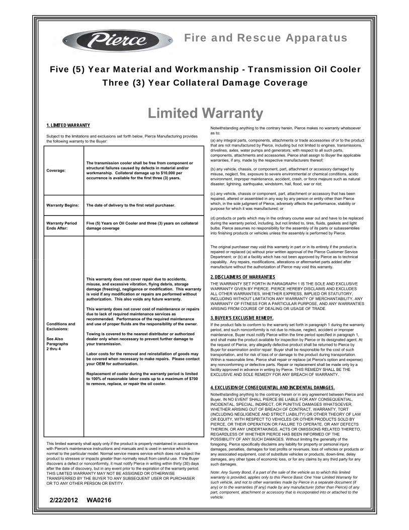
Warranty Begins:
The transmission cooler shall be free from component or structural failures caused by defects in material and/or workmanship. Collateral damage up to $10,000 per occurrence is available for the first three (3) years.
(b) any vehicle, chassis, or component, part, attachment or accessory damaged by misuse, neglect, fire, exposure to severe environmental or chemical conditions, acidic environment, improper maintenance, accident, crash, or force majeure such as natural disaster, lightning, earthquake, windstorm, hail, flood, war or riot;
(d) products or parts which may in the ordinary course wear out and have to be replaced during the warranty period, including, but not limited to, tires, fluids, gaskets and light bulbs. Pierce assumes no responsibility for the assembly of its parts or subassemblies into finishing products or vehicles unless the assembly is performed by Pierce.
Five (5) Years on Oil Cooler and three (3) years on collateral damage coverage
Warranty Period Ends After:
Fire and Rescue Apparatus
Coverage:
Five (5) Year Material and Workmanship - Transmission Oil CoolerThree (3) Year Collateral Damage Coverage
1. LIMITED WARRANTY
The original purchaser may void this warranty in part or in its entirety if the product is repaired or replaced (a) without prior written approval of the Pierce Customer Service Department; or (b) at a facility which has not been approved by Pierce as to technical
Limited WarrantySubject to the limitations and exclusions set forth below, Pierce Manufacturing provides the following warranty to the Buyer:
(c) any vehicle, chassis or component, part, attachment or accessory that has been repaired, altered or assembled in any way by any person or entity other than Pierce which, in the sole judgment of Pierce, adversely affects the performance, stability or purpose for which it was manufactured; or
(a) any integral parts, components, attachments or trade accessories of or to the product that are not manufactured by Pierce, including but not limited to engines, transmissions, drivelines, axles, water pumps and generators; with respect to all such parts, components, attachments and accessories, Pierce shall assign to Buyer the applicable warranties, if any, made by the respective manufacturers thereof;
Notwithstanding anything to the contrary herein, Pierce makes no warranty whatsoever as to:
The date of delivery to the first retail purchaser.
This limited warranty shall apply only if the product is properly maintained in accordance with Pierce's maintenance instructions and manuals and is used in service which is normal to the particular model. Normal service means service which does not subject the product to stresses or impacts greater than normally result from careful use. If the Buyer discovers a defect or nonconformity, it must notify Pierce in writing within thirty (30) days after the date of discovery, but in any event prior to the expiration of the warranty period. THIS LIMITED WARRANTY MAY NOT BE ASSIGNED OR OTHERWISE TRANSFERRED BY THE BUYER TO ANY SUBSEQUENT USER OR PURCHASER OR TO ANY OTHER PERSON OR ENTITY.
This warranty does not cover repair due to accidents, misuse, and excessive vibration, flying debris, storage damage (freezing), negligence or modification. This warranty is void if any modification or repairs are performed without authorization. This also voids any future warranty.
This warranty does not cover cost of maintenance or repairs due to lack of required maintenance services as recommended. Performance of the required maintenance and use of proper fluids are the responsibility of the owner.
Towing is covered to the nearest distributor or authorized dealer only when necessary to prevent further damage to your transmission.
Labor costs for the removal and reinstallation of goods may be covered when necessary to make repairs. Please contact your OEM for authorization.
Replacement of cooler during the warranty period is limited to 100% of reasonable labor costs up to a maximum of $700 to remove, replace, or repair the oil cooler.
Conditions and Exclusions:
See AlsoParagraphs2 thru 4
4. EXCLUSION OF CONSEQUENTIAL AND INCIDENTAL DAMAGES.Notwithstanding anything to the contrary herein or in any agreement between Pierce and Buyer, IN NO EVENT SHALL PIERCE BE LIABLE FOR ANY CONSEQUENTIAL, INCIDENTAL, SPECIAL, INDIRECT, OR PUNITIVE DAMAGES WHATSOEVER, WHETHER ARISING OUT OF BREACH OF CONTRACT, WARRANTY, TORT (INCLUDING NEGLIGENCE AND STRICT LIABILITY) OR OTHER THEORY OF LAW OR EQUITY, WITH RESPECT TO VEHICLES OR OTHER PRODUCTS SOLD BY PIERCE, OR THEIR OPERATION OR FAILURE TO OPERATE, OR ANY DEFECTS THEREIN, OR ANY UNDERTAKINGS, ACTS OR OMISSIONS RELATED THERETO, REGARDLESS OF WHETHER PIERCE HAS BEEN INFORMED OF THE POSSIBILITY OF ANY SUCH DAMAGES. Without limiting the generality of the foregoing, Pierce specifically disclaims any liability for property or personal injury damages, penalties, damages for lost profits or revenues, loss of vehicles or products or any associated equipment, cost of substitute vehicles or products, down-time, delay damages, any other types of economic loss, or for any claims by any third party for any such damages.
If the product fails to conform to the warranty set forth in paragraph 1 during the warranty period, and such nonconformity is not due to misuse, neglect, accident or improper maintenance, Buyer must notify Pierce within the time period specified in paragraph 1, and shall make the product available for inspection by Pierce or its designated agent. At the request of Pierce, any allegedly defective product shall be returned to Pierce by Buyer for examination and/or repair. Buyer shall be responsible for the cost of such transportation, and for risk of loss of or damage to the product during transportation. Within a reasonable time, Pierce shall repair or replace (at Pierce's option and expense) any nonconforming or defective parts. Repair or replacement shall be made only by a facility approved in advance in writing by Pierce. THIS REMEDY SHALL BE THE EXCLUSIVE AND SOLE REMEDY FOR ANY BREACH OF WARRANTY.
3. BUYER'S EXCLUSIVE REMEDY.
Note: Any Surety Bond, if a part of the sale of the vehicle as to which this limited warranty is provided, applies only to this Pierce Basic One Year Limited Warranty for such vehicle, and not to other warranties made by Pierce in a separate document (if any) or to the warranties (if any) made by any manufacturer (other than Pierce) of any part, component, attachment or accessory that is incorporated into or attached to the vehicle.2/22/2012 WA0216
THE WARRANTY SET FORTH IN PARAGRAPH 1 IS THE SOLE AND EXCLUSIVE WARRANTY GIVEN BY PIERCE. PIERCE HEREBY DISCLAIMS AND EXCLUDES ALL OTHER WARRANTIES, WHETHER EXPRESS, IMPLIED OR STATUTORY, INCLUDING WITHOUT LIMITATION ANY WARRANTY OF MERCHANTABILITY, ANY WARRANTY OF FITNESS FOR A PARTICULAR PURPOSE, AND ANY WARRANTIES ARISING FROM COURSE OF DEALING OR USAGE OF TRADE.
2. DISCLAIMERS OF WARRANTIES
capability. Any repairs, modifications, alterations or aftermarket parts added after manufacture without the authorization of Pierce may void this warranty.

United Plastic Fabricating, Inc. (hereinafter called “UPF”) warrants each POLY-TANK®, Booster/Foam Tank POLYSIDE® Wetside Tank, Integrator Tank/Body, ELLIPSE™ Elliptical Tank, Ellip-T-Tank Tank and DEFENDER™ Skid Tank to be free from defects in material and workmanship for the service life of the original vehicle (vehicle must be actively used in an emergency re-sponse for ���suppression). All UPF Tanks must be installed and operated in accordance with the UPF Installation and Operating Guidelines. Failure to do so can void the warranty.
Every UPF Tank is inspected and tested before leaving our facility. Should your UPF Tank require service, please notify UPF via email, fax, in writing or by calling UPF at 1-978-975-4520. Please provide the serial number, a de-scription of the service request, the location along with the phone number and name of the contact person. Our goal is to have scheduled work completed within a reasonable time period.
Under a valid warranty claim, UPF will cover the cost to repair the UPF Tank including the customary and reasonable costs to make the tank accessible such as the removal and reinstallation of the tank if authorized in advance (pre-approved) by UPF. The warranty will not cover tanks that have been im-properly installed, operated, misused, abused, or �����from its intended or designed use. Serial number must not have been altered, defaced or re-moved. Tanks that are not stored or installed properly which results in the tank suffering UV damage will not be covered by this agreement.
Should UPF determine that the service claim is valid under this warranty for a tank located outside of the United States and Canada, UPF will assume the costs for labor and material for the warranty repair as described above plus all travel costs to the U.S. port of embarkation. Costs for airline travel outside of the U.S. and Canada will not be the responsibility of UPF.
In the event the tank shall become stationed in an area of the world that is considered to be a war zone or where unsafe conditions exist for the safe passage of United States Nationals, as reported by the United States Depart-ment of State, (http://www.state.gov), and a request to perform service or warranty repairs, UPF reserves the right to refuse to honor such requests. It is the purchaser’s responsibility to relocate the tank to an area where such repairs can be performed without undue risk to UPF employees or their des-ignee. UPF will make every reasonable effort to support our products though alternative means.
For Ellipse™ elliptical tanks, a separate ���year warranty provided by the subcontractor is applied to the sub-frames, chute linings (rubber isolation strips) and metal components. The stainless steel wrap provided by UPF shall be warranted by the subcontractor performing the wrap installation in accordance with their warranty in place at the time of the installation. UPF will not be liable for any warranty costs associated with the wrap, sub-frames, chute linings (rubber isolation strips) and metal components but will assist with all claims on behalf of its customer.
For PolySide® wetsided tanks and Integrator™ Tank/Body units, all polypro-pylene components related to the tank shall carry the standard UPF lifetime FO
R: P
OLY
-TA
NK
®, P
OLY
SID
E®
, IN
TE
GR
ATO
R™
, ELL
IPS
E™
, ELL
IP-T
-TA
NK
™ &
DE
FEN
DE
R™
WA
RR
AN
TY
UN
ITED
PLA
STIC
FA
BRIC
ATIN
G, I
NC.
LIFETIME SERVICE WARRANTY
Continued on back
E f f e c t i v e 1 A u g u s t , 2 0 0 9

service warranty. Other polypropylene components, including but not limited to compartments, wheel wells, fenders and other body related components shall be warranted by UPF for a period of ten years. The warranty for the PolySide® and Integrator™ units excludes paint or hardware, which shall be covered by the manufacturer of the paint/hardware.
All UPF tanks 50 gallons or less utilized for �����applications and installed on specialty vehicles such as ATVs, trailers, boats, etc. are covered under a separate warranty policy available from UPF. Further, UPF Protector™ foam and water trailers are warranted under a separate warranty policy available from UPF.
This UPF warranty is transferable within the United States only with prior writ-ten approval by UPF (except an original apparatus manufacturer may assign ��������������������������������
UPF will NOT reimburse any unnecessary work and/or work that has not been pre-approved. Any and all third party charges must be pre-authorized and approved in writing by UPF prior to commencing the work. Any unauthorized third party repairs, alterations, actions or modi-�����will not be covered and can void the warranty. UPF will be the sole determining authority as to whether a service claim will be valid and covered under this warranty.
In no event will UPF be liable for an amount in excess of the purchase price of the booster/foam tank at the time of manufacture or for any loss or dam-age, whether direct, indirect, incidental, consequential, or otherwise arising out of failure of its product. Loss of contents (water, foam, etc.) shall not be the responsibility of UPF. Further, UPF is not responsible for costs associated with service repairs to chassis, sub-frames, bodies, valves, dumps, hoses, pressure vacuum vents, and other components (i.e. liquid level transducers, etc.). Further, UPF will not cover the cost for travel of the vehicle to and from a repair facility.
This warranty contains the entire warranty. It is the sole warranty and price agreements or representation, whether oral or written, are either merged herein or expressly cancelled. UPF neither assumes, nor authorizes any per-son supposing to act on its behalf to change, nor assume for it, any warranty or liability concerning its product.
This warranty gives you �����legal rights, and you may also have other rights which vary from state to state. Some states do not allow exclusion or limitation or incidental or consequential damage, so the above limitation or exclusion may not apply to you. Since some states do not allow limitations on the length of an implied warranty, the above limitation may not apply to you.
THERE ARE NO WARRANTIES, EXPRESSED OR IMPLIED, WHICH EX-TEND BEYOND THE DESCRIPTION OF THE FACE HEREOF. THERE IS NO EXPRESS OR IMPLIED WARRANTY OF MERCHANTABILITY OR A WARRANTY OF FITNESS FOR A PARTICULAR PURPOSE. ADDITION-ALLY, THIS WARRANTY IS IN LIEU OF ALL OTHER OBLIGATION OR LIABILITIES ON THE PART OF UPF.
FOR
: PO
LY-T
AN
K®
, PO
LYS
IDE
®, I
NT
EG
RA
TOR
™, E
LLIP
SE
™, E
LLIP
-T-T
AN
K™
& D
EFE
ND
ER
™W
AR
RA
NT
YU
NIT
ED P
LAST
IC F
ABR
ICAT
ING
, IN
C.
POLY-TANK®,& POLYSIDE® are registered trademarks of UPF, Inc. INTEGRATOR™, ELLIPSE™, ELLIP-T-TANK™ & DEFENDER™ are trademarks of UPF, Inc. © 08/01/09 UPF, Inc. Printed in the USA

2 6 0 0 A M E R I C A N D R I V E • A P P L E T O N , W I 5 4 9 1 2 - 2 0 1 7 • 9 2 0 - 8 3 2 - 3 0 0 0
P I E R C E M A N U F A C T U R I N G I N C .
B U L L E T I N TO: All Dealer Service Representatives From: Kevin Hanegraaf DATE: January 4, 2010
RE: UPF Tank Warranty Policy – Truck in Accident Service Topic #292 To keep the UPF tank warranty valid on trucks that have been involved in a vehicular accident, it is UPF’s policy that the customer must remove the tank from the truck and send it back to one of UPF’s facilities for inspection. In the event that this does not take place, the warranty will be considered null and void. The customer must remove and send the tank back to UPF for inspection in order to maintain the original warranty coverage, at which time it will be: - Filled with water - Visually inspected - Ultraviolet spark tested on articulating test stand in the dark - Recommendation for repairs if necessary provided by UPF - Fully evaluated and repaired by UPF If your customer chooses to leave the tank on the truck and wants a technician to inspect and/or repair the tank in the field, then the warranty is no longer in effect. This direction is upheld by UPF because the technician cannot inspect the entire tank when it is still installed on the truck. Note: This memo is intended to relay the information Pierce has received
on UPF’s tank warranty for trucks that are in a vehicular accident. In the event of an actual claim, we direct you to consult with UPF’s service Manager Maura Watts (800-638-8265 x253)

Note: Any Surety Bond, if a part of the sale of the vehicle as to which this limited warranty is provided, applies only to this Pierce Basic One Year Limited Warranty for such vehicle, and not to other warranties made by Pierce in a separate document (if any) or to the warranties (if any) made by any manufacturer (other than Pierce) of any part, component, attachment or accessory that is incorporated into or attached to the vehicle.
2/8/2010 WA0009
1. LIMITED WARRANTY
THE WARRANTY SET FORTH IN PARAGRAPH 1 IS THE SOLE AND EXCLUSIVE WARRANTY GIVEN BY PIERCE. PIERCE HEREBY DISCLAIMS AND EXCLUDES ALL OTHER WARRANTIES, WHETHER EXPRESS, IMPLIED OR STATUTORY, INCLUDING WITHOUT LIMITATION ANY WARRANTY OF MERCHANTABILITY, ANY WARRANTY OF FITNESS FOR A PARTICULAR PURPOSE, AND ANY WARRANTIES ARISING FROM COURSE OF DEALING OR USAGE OF TRADE.
2. DISCLAIMERS OF WARRANTIES
The original purchaser may void this warranty in part or in its entirety if the product is repaired or replaced (a) without prior written approval of the Pierce Customer Service Department; or (b) at a facility which has not been approved by Pierce as to technical capability. Any repairs, modifications, alterations or aftermarket parts added after manufacture without the authorization of Pierce may void this warranty.
This limited warranty shall apply only if the product is properly maintained in accordance with Pierce's maintenance instructions and manuals and is used in service which is normal to the particular model. Normal service means service which does not subject the product to stresses or impacts greater than normally result from careful use. If the Buyer discovers a defect or nonconformity, it must notify Pierce in writing within thirty (30) days after the date of discovery, but in any event prior to the expiration of the warranty period. THIS LIMITED WARRANTY MAY NOT BE ASSIGNED OR OTHERWISE TRANSFERRED BY THE BUYER TO ANY SUBSEQUENT USER OR PURCHASER OR TO ANY OTHER PERSON OR ENTITY.
This warranty applies only to the body tubular support and mounting structures and other structural components of the body of the vehicle model, as identified in the Pierce specifications for the Fire and Rescue Apparatus.
This warranty does not apply to damage caused by corrosion.
Conditions and Exclusions:
See AlsoParagraphs2 thru 4
Limited WarrantySubject to the limitations and exclusions set forth below, Pierce Manufacturing provides the following warranty to the Buyer:
(c) any vehicle, chassis or component, part, attachment or accessory that has been repaired, altered or assembled in any way by any person or entity other than Pierce which, in the sole judgment of Pierce, adversely affects the performance, stability or purpose for which it was manufactured; or
(a) any integral parts, components, attachments or trade accessories of or to the product that are not manufactured by Pierce, including but not limited to engines, transmissions, drivelines, axles, water pumps and generators; with respect to all such parts, components, attachments and accessories, Pierce shall assign to Buyer the applicable warranties, if any, made by the respective manufacturers thereof;
Notwithstanding anything to the contrary herein, Pierce makes no warranty whatsoever as to:
Fire and Rescue Apparatus
Coverage:
Ten (10) Year Structural IntegrityApparatus Body
Ten (10) Years- or -100,000 Miles
Warranty Period Ends After:
The date of the original purchase invoice (issued when the product ships from the factory).Warranty Begins:
The apparatus body shall be free from structural failures caused by defects in material and workmanship
(d) products or parts which may in the ordinary course wear out and have to be replaced during the warranty period, including, but not limited to, tires, fluids, gaskets and light bulbs. Pierce assumes no responsibility for the assembly of its parts or subassemblies into finishing products or vehicles unless the assembly is performed by Pierce.
(b) any vehicle, chassis, or component, part, attachment or accessory damaged by misuse, neglect, fire, exposure to severe environmental or chemical conditions, acidic environment, improper maintenance, accident, crash, or force majeure such as natural disaster, lightning, earthquake, windstorm, hail, flood, war or riot;
4. EXCLUSION OF CONSEQUENTIAL AND INCIDENTAL DAMAGES.Notwithstanding anything to the contrary herein or in any agreement between Pierce and Buyer, IN NO EVENT SHALL PIERCE BE LIABLE FOR ANY CONSEQUENTIAL, INCIDENTAL, SPECIAL, INDIRECT, OR PUNITIVE DAMAGES WHATSOEVER, WHETHER ARISING OUT OF BREACH OF CONTRACT, WARRANTY, TORT (INCLUDING NEGLIGENCE AND STRICT LIABILITY) OR OTHER THEORY OF LAW OR EQUITY, WITH RESPECT TO VEHICLES OR OTHER PRODUCTS SOLD BY PIERCE, OR THEIR OPERATION OR FAILURE TO OPERATE, OR ANY DEFECTS THEREIN, OR ANY UNDERTAKINGS, ACTS OR OMISSIONS RELATED THERETO, REGARDLESS OF WHETHER PIERCE HAS BEEN INFORMED OF THE POSSIBILITY OF ANY SUCH DAMAGES. Without limiting the generality of the foregoing, Pierce specifically disclaims any liability for property or personal injury damages, penalties, damages for lost profits or revenues, loss of vehicles or products or any associated equipment, cost of substitute vehicles or products, down-time, delay damages, any other types of economic loss, or for any claims by any third party for any such damages.
If the product fails to conform to the warranty set forth in paragraph 1 during the warranty period, and such nonconformity is not due to misuse, neglect, accident or improper maintenance, Buyer must notify Pierce within the time period specified in paragraph 1, and shall make the product available for inspection by Pierce or its designated agent. At the request of Pierce, any allegedly defective product shall be returned to Pierce by Buyer for examination and/or repair. Buyer shall be responsible for the cost of such transportation, and for risk of loss of or damage to the product during transportation. Within a reasonable time, Pierce shall repair or replace (at Pierce's option and expense) any nonconforming or defective parts. Repair or replacement shall be made only by a facility approved in advance in writing by Pierce. THIS REMEDY SHALL BE THE EXCLUSIVE AND SOLE REMEDY FOR ANY BREACH OF WARRANTY.
3. BUYER'S EXCLUSIVE REMEDY.

A & A Manufacturing Co., Inc. 2300 S. Calhoun Road · New Berlin, WI 53151 · Phone (262) 786-1500 · Fax (262) 786-3280
Pierce Warranty Statement for Gortite Roll Up Doors Rev 2/24/2011 All mechanical components of the door shall be warranted to be free from defects in materials and workmanship for the lifetime of the vehicle. All parts covered under this warranty shall be to the original owner. A&A manufacturing warrants that painted doors shall be free of blistering, peeling, bubbling, or any other adhesion defect caused by defective manufacturing methods or paint material selection. The time period for the coverage shall be 6 years from date of door shipment to Pierce. Satin anodized finish doors shall be warranted for 6 years against corrosion defects from date of door shipment to Pierce. Replacement of decals/Scotchlite is not covered. The maximum amount A&A will reimburse for labor is $60.00 per hour and the maximum amount of time allowed for repair is as follows: Door 1.0 Hr. Slat Replacement 1.0 Hr. Pennant Plate Replacement 1.0 Hr. Roller Replacement .5 Hr.
Seal Replacement .5 Hr. Switch/Magnet Replacement 1.0 Hr. Travel Time 4.0 Hr.

Waterous Company125 Hardman Avenue SouthSouth St. Paul, MN 55075 USAwww.waterousco.com
F-2891 (04/15/20)
Waterous Seven-Year Limited WarrantyWATEROUS warrants, to the original Buyer only, that products manufactured by WATEROUS will be free from defects in material and workmanship under normal use and service for a period of seven (7) years from the date the product is first placed in service, or seven and one-half (7-1/2) years from the date of shipment by WATEROUS, whichever period shall be the first to expire; provided the Buyer notifies WATEROUS, in writing, of the defect in said product within the warranty period, and said product is found by WATEROUS to be nonconforming with the aforesaid warranty. When required in writing by WATEROUS, defective products must be promptly returned by Buyer to WATEROUS at WATEROUS’ plant at South St. Paul, Minnesota, or at such other place as may be specified by WATEROUS, with transportation and other charges prepaid. A Returned Material Authorization (RMA) is required for all products and parts and may be requested by phone, fax, email, or mail. The aforesaid warranty excludes any responsibility or liability of WATEROUS for:
(a) damages or defects due to accident, abuse, misuse, abnormal operating conditions, negligence, accidental causes, use in non-�re�ghting applications, or improper maintenance, or attributable to written speci�cations or instructions furnished by Buyer;
(b) defects in products manufactured by others and furnished by WATEROUS hereunder, it being understood and agreed by the parties that the only warranty provided for such products shall be the warranty provided by the manufacturer thereof which, if assignable, WATEROUS will assign to Buyer, if requested by Buyer;
(c) any product or part, altered, modi�ed, serviced or repaired other than by WATEROUS, without its prior written consent;(d) the cost of dismantling, removing, transporting, storing, or insuring the defective product or part and the cost of reinstallation; and(e) normal wear items (packing, strainers��lters, light bulbs, anodes, intake screens, mechanical seals, etc.).
ALL OTHER WARRANTIES ARE EXCLUDED, WHETHER EXPRESS OR IMPLIED BY OPERATION OF LAW OR OTHERWISE, INCLUDING ALL IMPLIED WARRANTIES OF MERCHANTABILITY OR FITNESS FOR A PARTICULAR PURPOSE. IN NO EVENT, WHETHER AS A RESULT OF BREACH OF CONTRACT, WARRANTY, TORT (INCLUDING NEGLIGENCE), STRICT LIABILITY, OR ANY OTHER CAUSE OF ACTION, SHALL WATEROUS BE LIABLE FOR ANY PUNITIVE, SPECIAL, INCIDENTAL OR CONSEQUENTIAL DAMAGES, OR FOR PERSONAL INJURY OR PROPERTY DAMAGES.The exclusive remedy of Buyer and the sole liability of WATEROUS, whether based on contract, warranty, tort or any other basis of recovery whatsoever, is expressly limited at the election of WATEROUS to:
(a) the replacement at the agreed point of delivery of any product or part, which upon inspection by WATEROUS or its duly authorized representative, is found not to conform to the limited warranty set forth above, or
(b) the repair of such product or part, or(c) the refund or crediting to Buyer of the net sales price of the defective product or part.
BUYER’S REMEDIES CONTAINED HEREIN ARE EXCLUSIVE OF ANY OTHER REMEDY OTHERWISE AVAILABLE TO BUYER.
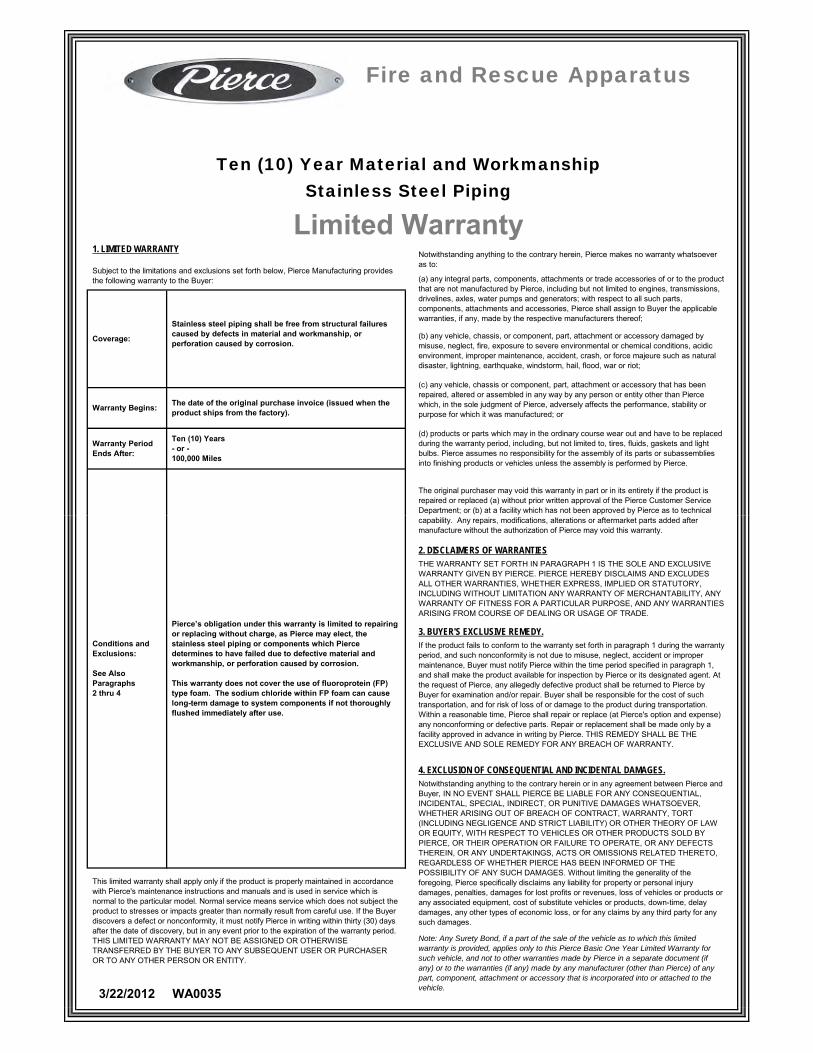
Warranty Begins:
Stainless steel piping shall be free from structural failures caused by defects in material and workmanship, or perforation caused by corrosion.
(b) any vehicle, chassis, or component, part, attachment or accessory damaged by misuse, neglect, fire, exposure to severe environmental or chemical conditions, acidic environment, improper maintenance, accident, crash, or force majeure such as natural disaster, lightning, earthquake, windstorm, hail, flood, war or riot;
(d) products or parts which may in the ordinary course wear out and have to be replaced during the warranty period, including, but not limited to, tires, fluids, gaskets and light bulbs. Pierce assumes no responsibility for the assembly of its parts or subassemblies into finishing products or vehicles unless the assembly is performed by Pierce.
Ten (10) Years- or -100,000 Miles
Warranty Period Ends After:
Fire and Rescue Apparatus
Coverage:
Ten (10) Year Material and WorkmanshipStainless Steel Piping
1. LIMITED WARRANTY
The original purchaser may void this warranty in part or in its entirety if the product is repaired or replaced (a) without prior written approval of the Pierce Customer Service Department; or (b) at a facility which has not been approved by Pierce as to technical
Limited WarrantySubject to the limitations and exclusions set forth below, Pierce Manufacturing provides the following warranty to the Buyer:
(c) any vehicle, chassis or component, part, attachment or accessory that has been repaired, altered or assembled in any way by any person or entity other than Pierce which, in the sole judgment of Pierce, adversely affects the performance, stability or purpose for which it was manufactured; or
(a) any integral parts, components, attachments or trade accessories of or to the product that are not manufactured by Pierce, including but not limited to engines, transmissions, drivelines, axles, water pumps and generators; with respect to all such parts, components, attachments and accessories, Pierce shall assign to Buyer the applicable warranties, if any, made by the respective manufacturers thereof;
Notwithstanding anything to the contrary herein, Pierce makes no warranty whatsoever as to:
The date of the original purchase invoice (issued when the product ships from the factory).
This limited warranty shall apply only if the product is properly maintained in accordance with Pierce's maintenance instructions and manuals and is used in service which is normal to the particular model. Normal service means service which does not subject the product to stresses or impacts greater than normally result from careful use. If the Buyer discovers a defect or nonconformity, it must notify Pierce in writing within thirty (30) days after the date of discovery, but in any event prior to the expiration of the warranty period. THIS LIMITED WARRANTY MAY NOT BE ASSIGNED OR OTHERWISE TRANSFERRED BY THE BUYER TO ANY SUBSEQUENT USER OR PURCHASER OR TO ANY OTHER PERSON OR ENTITY.
Pierce’s obligation under this warranty is limited to repairing or replacing without charge, as Pierce may elect, the stainless steel piping or components which Pierce determines to have failed due to defective material and workmanship, or perforation caused by corrosion.
This warranty does not cover the use of fluoroprotein (FP) type foam. The sodium chloride within FP foam can cause long-term damage to system components if not thoroughly flushed immediately after use.
Conditions and Exclusions:
See AlsoParagraphs2 thru 4
4. EXCLUSION OF CONSEQUENTIAL AND INCIDENTAL DAMAGES.Notwithstanding anything to the contrary herein or in any agreement between Pierce and Buyer, IN NO EVENT SHALL PIERCE BE LIABLE FOR ANY CONSEQUENTIAL, INCIDENTAL, SPECIAL, INDIRECT, OR PUNITIVE DAMAGES WHATSOEVER, WHETHER ARISING OUT OF BREACH OF CONTRACT, WARRANTY, TORT (INCLUDING NEGLIGENCE AND STRICT LIABILITY) OR OTHER THEORY OF LAW OR EQUITY, WITH RESPECT TO VEHICLES OR OTHER PRODUCTS SOLD BY PIERCE, OR THEIR OPERATION OR FAILURE TO OPERATE, OR ANY DEFECTS THEREIN, OR ANY UNDERTAKINGS, ACTS OR OMISSIONS RELATED THERETO, REGARDLESS OF WHETHER PIERCE HAS BEEN INFORMED OF THE POSSIBILITY OF ANY SUCH DAMAGES. Without limiting the generality of the foregoing, Pierce specifically disclaims any liability for property or personal injury damages, penalties, damages for lost profits or revenues, loss of vehicles or products or any associated equipment, cost of substitute vehicles or products, down-time, delay damages, any other types of economic loss, or for any claims by any third party for any such damages.
If the product fails to conform to the warranty set forth in paragraph 1 during the warranty period, and such nonconformity is not due to misuse, neglect, accident or improper maintenance, Buyer must notify Pierce within the time period specified in paragraph 1, and shall make the product available for inspection by Pierce or its designated agent. At the request of Pierce, any allegedly defective product shall be returned to Pierce by Buyer for examination and/or repair. Buyer shall be responsible for the cost of such transportation, and for risk of loss of or damage to the product during transportation. Within a reasonable time, Pierce shall repair or replace (at Pierce's option and expense) any nonconforming or defective parts. Repair or replacement shall be made only by a facility approved in advance in writing by Pierce. THIS REMEDY SHALL BE THE EXCLUSIVE AND SOLE REMEDY FOR ANY BREACH OF WARRANTY.
3. BUYER'S EXCLUSIVE REMEDY.
Note: Any Surety Bond, if a part of the sale of the vehicle as to which this limited warranty is provided, applies only to this Pierce Basic One Year Limited Warranty for such vehicle, and not to other warranties made by Pierce in a separate document (if any) or to the warranties (if any) made by any manufacturer (other than Pierce) of any part, component, attachment or accessory that is incorporated into or attached to the vehicle.3/22/2012 WA0035
THE WARRANTY SET FORTH IN PARAGRAPH 1 IS THE SOLE AND EXCLUSIVE WARRANTY GIVEN BY PIERCE. PIERCE HEREBY DISCLAIMS AND EXCLUDES ALL OTHER WARRANTIES, WHETHER EXPRESS, IMPLIED OR STATUTORY, INCLUDING WITHOUT LIMITATION ANY WARRANTY OF MERCHANTABILITY, ANY WARRANTY OF FITNESS FOR A PARTICULAR PURPOSE, AND ANY WARRANTIES ARISING FROM COURSE OF DEALING OR USAGE OF TRADE.
2. DISCLAIMERS OF WARRANTIES
capability. Any repairs, modifications, alterations or aftermarket parts added after manufacture without the authorization of Pierce may void this warranty.

This limited warranty shall apply only if the product is properly maintained in accordance with Pierce's maintenance instructions and manuals and is used in service which is normal to the particular model. Normal service means service which does not subject the product to stresses or impacts greater than normally result from careful use. If the Buyer discovers a defect or nonconformity, it must notify Pierce in writing within thirty (30) days after the date of discovery, but in any event prior to the expiration of the warranty period. THIS LIMITED WARRANTY MAY NOT BE ASSIGNED OR OTHERWISE TRANSFERRED BY THE BUYER TO ANY SUBSEQUENT USER OR PURCHASER OR TO ANY OTHER PERSON OR ENTITY.
This warranty does not cover repair due to accidents, misuse, and excessive vibration, flying debris, storage damage (freezing), negligence or modification. This warranty is void if any modification or repairs are performed without authorization. This also voids any future warranty.
This warranty does not cover cost of maintenance or repairs due to lack of required maintenance services as recommended. Performance of the required maintenance and use of proper fluids are the responsibility of the owner.
Conditions and Exclusions:
See AlsoParagraphs2 thru 4
4. EXCLUSION OF CONSEQUENTIAL AND INCIDENTAL DAMAGES.Notwithstanding anything to the contrary herein or in any agreement between Pierce and Buyer, IN NO EVENT SHALL PIERCE BE LIABLE FOR ANY CONSEQUENTIAL, INCIDENTAL, SPECIAL, INDIRECT, OR PUNITIVE DAMAGES WHATSOEVER, WHETHER ARISING OUT OF BREACH OF CONTRACT, WARRANTY, TORT (INCLUDING NEGLIGENCE AND STRICT LIABILITY) OR OTHER THEORY OF LAW OR EQUITY, WITH RESPECT TO VEHICLES OR OTHER PRODUCTS SOLD BY PIERCE, OR THEIR OPERATION OR FAILURE TO OPERATE, OR ANY DEFECTS THEREIN, OR ANY UNDERTAKINGS, ACTS OR OMISSIONS RELATED THERETO, REGARDLESS OF WHETHER PIERCE HAS BEEN INFORMED OF THE POSSIBILITY OF ANY SUCH DAMAGES. Without limiting the generality of the foregoing, Pierce specifically disclaims any liability for property or personal injury damages, penalties, damages for lost profits or revenues, loss of vehicles or products or any associated equipment, cost of substitute vehicles or products, down-time, delay damages, any other types of economic loss, or for any claims by any third party for any such damages.
If the product fails to conform to the warranty set forth in paragraph 1 during the warranty period, and such nonconformity is not due to misuse, neglect, accident or improper maintenance, Buyer must notify Pierce within the time period specified in paragraph 1, and shall make the product available for inspection by Pierce or its designated agent. At the request of Pierce, any allegedly defective product shall be returned to Pierce by Buyer for examination and/or repair. Buyer shall be responsible for the cost of such transportation, and for risk of loss of or damage to the product during transportation. Within a reasonable time, Pierce shall repair or replace (at Pierce's option and expense) any nonconforming or defective parts. Repair or replacement shall be made only by a facility approved in advance in writing by Pierce. THIS REMEDY SHALL BE THE EXCLUSIVE AND SOLE REMEDY FOR ANY BREACH OF WARRANTY.
3. BUYER'S EXCLUSIVE REMEDY.
(d) products or parts which may in the ordinary course wear out and have to be replaced during the warranty period, including, but not limited to, tires, fluids, gaskets and light bulbs. Pierce assumes no responsibility for the assembly of its parts or subassemblies into finishing products or vehicles unless the assembly is performed by Pierce.
One (1) Year & Five (5) YearWarranty Period Ends After:
Note: Any Surety Bond, if a part of the sale of the vehicle as to which this limited warranty is provided, applies only to this Pierce Basic One Year Limited Warranty for such vehicle, and not to other warranties made by Pierce in a separate document (if any) or to the warranties (if any) made by any manufacturer (other than Pierce) of any part, component, attachment or accessory that is incorporated into or attached to the vehicle.1/30/2013 WA0231
THE WARRANTY SET FORTH IN PARAGRAPH 1 IS THE SOLE AND EXCLUSIVE WARRANTY GIVEN BY PIERCE. PIERCE HEREBY DISCLAIMS AND EXCLUDES ALL OTHER WARRANTIES, WHETHER EXPRESS, IMPLIED OR STATUTORY, INCLUDING WITHOUT LIMITATION ANY WARRANTY OF MERCHANTABILITY, ANY WARRANTY OF FITNESS FOR A PARTICULAR PURPOSE, AND ANY WARRANTIES ARISING FROM COURSE OF DEALING OR USAGE OF TRADE.
2. DISCLAIMERS OF WARRANTIES
The original purchaser may void this warranty in part or in its entirety if the product is repaired or replaced (a) without prior written approval of the Pierce Customer Service Department; or (b) at a facility which has not been approved by Pierce as to technical capability. Any repairs, modifications, alterations or aftermarket parts added after manufacture without the authorization of Pierce may void this warranty.
Fire and Rescue Apparatus
Coverage:
One (1) Year Material and Workmanship Foam System & Five (5) Year Material and Workmanship Control Head
Limited WarrantyNotwithstanding anything to the contrary herein, Pierce makes no warranty whatsoever as to:
Limited warranty 1 year parts and labor for for the foam system and 5 years parts and labor for the control head.
1. LIMITED WARRANTY
(b) any vehicle, chassis, or component, part, attachment or accessory damaged by misuse, neglect, fire, exposure to severe environmental or chemical conditions, acidic environment, improper maintenance, accident, crash, or force majeure such as natural disaster, lightning, earthquake, windstorm, hail, flood, war or riot;
Subject to the limitations and exclusions set forth below, Pierce Manufacturing provides the following warranty to the Buyer:
(c) any vehicle, chassis or component, part, attachment or accessory that has been repaired, altered or assembled in any way by any person or entity other than Pierce which, in the sole judgment of Pierce, adversely affects the performance, stability or purpose for which it was manufactured; or
(a) any integral parts, components, attachments or trade accessories of or to the product that are not manufactured by Pierce, including but not limited to engines, transmissions, drivelines, axles, water pumps and generators; with respect to all such parts, components, attachments and accessories, Pierce shall assign to Buyer the applicable warranties, if any, made by the respective manufacturers thereof;
The date of the original purchase invoice (issued when the product ships from the factory).Warranty Begins:

| 14233 West Road | Houston TX 77041 | Tel 281.807.4420 | Fax 281.807.4815 | www.harrisonhydragen.com |
MANUFACTURER’S LIMITED WARRANTY - HYDRAULIC GENERATORS
STANDARD
Harrison Hydra-Gen® (Seller) extends to the original purchaser (Buyer) of goods for use (whether
it be an OEM, dealer, re-seller, or end-user) the following warranty covering the Harrison Hydra-
Gen® Generator System, subject to the qualifications indicated. Harrison Hydra-Gen® Generator
Systems shall consist of a Harrison generator tray assembly and its’ components, a Harrison
hydraulic pump assembly, and a Harrison supplied meter assembly; unless otherwise specified in
below guidelines.
Harrison Hydra-Gen® warrants the original purchaser that the Generator System manufactured
or supplied by Harrison Hydra-Gen® will be free from defects in materials and workmanship,
provided such goods are:
1. Installed, operated and maintained in accordance with the Harrison Hydra-Gen® owner’s
manual, and/or written installation addendums.
2. Each new application has been reviewed and approved by the Harrison Hydra-Gen®
Application Engineering Group.
PERIOD OF WARRANTY
*Two (2) years or 2000 hours of usage, whichever
comes first, from the date the product is shipped from
Harrison to the Installer.
*The END USER must complete and return to Harrison Hydra-Gen the Harrison Hydra-
Gen Warranty Registration Card, Form WR-1, provided in the generator manual and
provided online @ www.harrisonhydragen.com, within 45 days of delivery.
Warranty includes all parts and labor. In addition, maintenance items that are contaminated or
damaged by a proven warrantable failure are covered in years 1-2, and Labor time up to 4 hours,
travel time up to 2.5 hours, and mileage up to 100 miles for warranty related repairs are covered.

| 14233 West Road | Houston TX 77041 | Tel 281.807.4420 | Fax 281.807.4815 | www.harrisonhydragen.com |
Repair or replacement parts are warranted for ninety (90) days from date of purchase, excluding
labor and travel expenses. Any part repaired or replaced during the warranty period assumes the
remainder of the warranty or ninety (90) days, whichever is greater.
Only components supplied by Harrison Hydra-Gen are covered under this warranty.
There is no other express warranty. Implied warranties, including merchantability and fitness for a
particular purpose, are limited to periods set forth above and to the extent permitted by law. Any
and all implied warranties are excluded. In no event is Harrison Hydra-Gen liable for incidental
or consequential damages.
The Buyer (OEM, dealer, re-seller, or end-user) must notify Harrison Hydra-Gen, an Authorized
Distributor, or a designated Harrison Hydra-Gen Service Representative, in writing, within thirty
(30) calendar days after goods or parts failed to meet this warranty.
The sole liability of Harrison Hydra-Gen and the Buyer’s sole remedy for a failure of goods
under this warranty and for any and all other claims arising out of the purchase and use of the
goods, including negligence on the part of the manufacturer, shall be limited to the repair or
replacement of the product, at the option of Harrison Hydra-Gen, of the parts that do not
conform to this warranty, provided that the product or parts are returned to the Harrison Hydra-
Gen manufacturing facility.
A Returned Goods Authorization (RGA) is required for all products and parts being returned, and
may be requested by phone, fax, email, or mail.
Failure to make timely delivery to Harrison Hydra-Gen of the goods claimed to be defective
shall void any warranty.
Unless previous written agreements have been made between the Buyer and Harrison Hydra-
Gen, the Buyer shall be responsible for all freight and shipping charges in connection with the
delivery of the goods claimed to be defective, to Harrison Hydra-Gen at its manufacturing
facility, and the return of repaired or replacement goods to the Buyer.
If Harrison Hydra-Gen determines that no warranty coverage is available for goods claimed to
be defective, whether determination is based on the warranty being voided, the product failure

| 14233 West Road | Houston TX 77041 | Tel 281.807.4420 | Fax 281.807.4815 | www.harrisonhydragen.com |
being due to a cause not covered by the warranty, the failure to make a timely and proper
warranty claim, or otherwise, the Buyer shall have the option of either:
1. Having the goods not repaired and returned to the Buyer, freight collect.
2. Having the goods repaired, If Harrison Hydra-Gen determines that the product is
repairable, and returned to the Buyer, freight collect. The Buyer will be responsible for all
costs associated with the repair and testing of the goods and shall authorize Harrison
Hydra-Gen, in writing, to have the goods repaired and tested by Harrison Hydra-Gen.
The owner is obligated to operate and maintain the goods in accordance with the
recommendations published by Harrison Hydra-Gen in the owner’s manual. The owner is
responsible for the costs associated with such maintenance and any adjustments that may be
required.
This warranty shall not apply to:
1. Damages or defects caused by normal wear, accident, misuse, abuse, abnormal operating
conditions, negligence, corrosion, accident causes, or attributable to written specifications
or instructions furnished by the installer.
2. Damages or defects caused by improper maintenance in accordance with the Harrison
Hydra-Gen product manuals and operating guidelines.
3. Damages caused by operator error.
4. Damages or defects caused by improper installation.
5. Damages or defects caused by inadequate water drainage provided by the installer in the
area where the generator is installed or stored.
6. Damages or defects caused by inadequate air flow space or ventilation provided by the
installer in the area where the generator is installed.
7. Any product or part altered or modified by the installer or service facility without written
prior consent by Harrison Hydra-Gen.
8. Cost of normal maintenance, adjustments, installation or start-up.
9. Normal wear items and components needing periodic maintenance such a rubber hoses
and filters.
10. Excessive labor due to components being concealed in vehicle as a result of installation.
11. Water, road debris, excessive dirt, salt, abrasive particles, or large foreign objects found in
the generator.
12. Telephone or other communications expense.
13. Paint, hydraulic fluid, and interconnecting hoses (internal or external to system assemblies).
| 14233 West Road | Houston TX 77041 | Tel 281.807.4420 | Fax 281.807.4815 | www.harrisonhydragen.com |
This warranty gives you specific legal rights, and you may also have other rights that may vary
from state to state or province to province.
No person is authorized to give any other warranties or to assume any other liabilities behalf of
Harrison Hydra-Gen, unless made or assumed in writing by an officer of Harrison Hydra-Gen.
Contact Harrison Hydra-Gen for questions regarding your warranty rights and responsibilities at
(281) 807-4420; or visit our website at www.harrisonhydragen.com.

Note: Any Surety Bond, if a part of the sale of the vehicle as to which this limited warranty is provided, applies only to this Pierce Basic One Year Limited Warranty for such vehicle, and not to other warranties made by Pierce in a separate document (if any) or to the warranties (if any) made by any manufacturer (other than Pierce) of any part, component, attachment or accessory that is incorporated into or attached to the vehicle.
2/8/2010 WA0057
1. LIMITED WARRANTY
THE WARRANTY SET FORTH IN PARAGRAPH 1 IS THE SOLE AND EXCLUSIVE WARRANTY GIVEN BY PIERCE. PIERCE HEREBY DISCLAIMS AND EXCLUDES ALL OTHER WARRANTIES, WHETHER EXPRESS, IMPLIED OR STATUTORY, INCLUDING WITHOUT LIMITATION ANY WARRANTY OF MERCHANTABILITY, ANY WARRANTY OF FITNESS FOR A PARTICULAR PURPOSE, AND ANY WARRANTIES ARISING FROM COURSE OF DEALING OR USAGE OF TRADE.
2. DISCLAIMERS OF WARRANTIES
The original purchaser may void this warranty in part or in its entirety if the product is repaired or replaced (a) without prior written approval of the Pierce Customer Service Department; or (b) at a facility which has not been approved by Pierce as to technical capability. Any repairs, modifications, alterations or aftermarket parts added after manufacture without the authorization of Pierce may void this warranty.
This limited warranty shall apply only if the product is properly maintained in accordance with Pierce's maintenance instructions and manuals and is used in service which is normal to the particular model. Normal service means service which does not subject the product to stresses or impacts greater than normally result from careful use. If the Buyer discovers a defect or nonconformity, it must notify Pierce in writing within thirty (30) days after the date of discovery, but in any event prior to the expiration of the warranty period. THIS LIMITED WARRANTY MAY NOT BE ASSIGNED OR OTHERWISE TRANSFERRED BY THE BUYER TO ANY SUBSEQUENT USER OR PURCHASER OR TO ANY OTHER PERSON OR ENTITY.
This limited warranty is applicable to the vehicle in the following percentage costs of warranty repair, if any:
Topcoat Durability & Appearance: Gloss, Color Retention & Cracking0-72 months 100%73-96 months 50%97-120 months 25%
Integrity of Coating System: Adhesion, Blistering/Bubbling0-36 months 100%37-84 months 50%85-120 months 25%
Corrosion: Dissimilar Metal and Crevice0-36 months 100%37-48 months 50%49-72 months 25%73-120 months 10%
Corrosion Perforation0-120 months 100%
This limited warranty applies only to exterior paint. Paint on the vehicle's interior is warranted only under the Pierce Basic One Year Limited Warranty.
Items not covered by this warranty include:(a) Damage from lack of maintenance and cleaning (proper cleaning and maintenance procedures are detailed in the Pierce operation and maintenance manual).(b) UV paint fade.(c) Any cab not manufactured by Pierce.
Conditions and Exclusions:
See AlsoParagraphs2 thru 4
Limited WarrantySubject to the limitations and exclusions set forth below, Pierce Manufacturing provides the following warranty to the Buyer:
(c) any vehicle, chassis or component, part, attachment or accessory that has been repaired, altered or assembled in any way by any person or entity other than Pierce which, in the sole judgment of Pierce, adversely affects the performance, stability or purpose for which it was manufactured; or
(a) any integral parts, components, attachments or trade accessories of or to the product that are not manufactured by Pierce, including but not limited to engines, transmissions, drivelines, axles, water pumps and generators; with respect to all such parts, components, attachments and accessories, Pierce shall assign to Buyer the applicable warranties, if any, made by the respective manufacturers thereof;
Notwithstanding anything to the contrary herein, Pierce makes no warranty whatsoever as to:
Fire and Rescue Apparatus
Coverage:
Ten (10) Year Pro-Rated Paint and CorrosionCustom Body
Ten (10) YearsWarranty Period Ends After:
The date of the original purchase invoice (issued when the product ships from the factory).Warranty Begins:
Exterior surfaces of the body shall be free from blistering, peeling, corrosion or any other adhesion defect caused by defective manufacturing methods or paint material selection.
(d) products or parts which may in the ordinary course wear out and have to be replaced during the warranty period, including, but not limited to, tires, fluids, gaskets and light bulbs. Pierce assumes no responsibility for the assembly of its parts or subassemblies into finishing products or vehicles unless the assembly is performed by Pierce.
(b) any vehicle, chassis, or component, part, attachment or accessory damaged by misuse, neglect, fire, exposure to severe environmental or chemical conditions, acidic environment, improper maintenance, accident, crash, or force majeure such as natural disaster, lightning, earthquake, windstorm, hail, flood, war or riot;
4. EXCLUSION OF CONSEQUENTIAL AND INCIDENTAL DAMAGES.Notwithstanding anything to the contrary herein or in any agreement between Pierce and Buyer, IN NO EVENT SHALL PIERCE BE LIABLE FOR ANY CONSEQUENTIAL, INCIDENTAL, SPECIAL, INDIRECT, OR PUNITIVE DAMAGES WHATSOEVER, WHETHER ARISING OUT OF BREACH OF CONTRACT, WARRANTY, TORT (INCLUDING NEGLIGENCE AND STRICT LIABILITY) OR OTHER THEORY OF LAW OR EQUITY, WITH RESPECT TO VEHICLES OR OTHER PRODUCTS SOLD BY PIERCE, OR THEIR OPERATION OR FAILURE TO OPERATE, OR ANY DEFECTS THEREIN, OR ANY UNDERTAKINGS, ACTS OR OMISSIONS RELATED THERETO, REGARDLESS OF WHETHER PIERCE HAS BEEN INFORMED OF THE POSSIBILITY OF ANY SUCH DAMAGES. Without limiting the generality of the foregoing, Pierce specifically disclaims any liability for property or personal injury damages, penalties, damages for lost profits or revenues, loss of vehicles or products or any associated equipment, cost of substitute vehicles or products, down-time, delay damages, any other types of economic loss, or for any claims by any third party for any such damages.
If the product fails to conform to the warranty set forth in paragraph 1 during the warranty period, and such nonconformity is not due to misuse, neglect, accident or improper maintenance, Buyer must notify Pierce within the time period specified in paragraph 1, and shall make the product available for inspection by Pierce or its designated agent. At the request of Pierce, any allegedly defective product shall be returned to Pierce by Buyer for examination and/or repair. Buyer shall be responsible for the cost of such transportation, and for risk of loss of or damage to the product during transportation. Within a reasonable time, Pierce shall repair or replace (at Pierce's option and expense) any nonconforming or defective parts. Repair or replacement shall be made only by a facility approved in advance in writing by Pierce. THIS REMEDY SHALL BE THE EXCLUSIVE AND SOLE REMEDY FOR ANY BREACH OF WARRANTY.
3. BUYER'S EXCLUSIVE REMEDY.

Note: Any Surety Bond, if a part of the sale of the vehicle as to which this limited warranty is provided, applies only to this Pierce Basic One Year Limited Warranty for such vehicle, and not to other warranties made by Pierce in a separate document (if any) or to the warranties (if any) made by any manufacturer (other than Pierce) of any part, component, attachment or accessory that is incorporated into or attached to the vehicle.
2/22/2010 WA0168
1. LIMITED WARRANTY
THE WARRANTY SET FORTH IN PARAGRAPH 1 IS THE SOLE AND EXCLUSIVE WARRANTY GIVEN BY PIERCE. PIERCE HEREBY DISCLAIMS AND EXCLUDES ALL OTHER WARRANTIES, WHETHER EXPRESS, IMPLIED OR STATUTORY, INCLUDING WITHOUT LIMITATION ANY WARRANTY OF MERCHANTABILITY, ANY WARRANTY OF FITNESS FOR A PARTICULAR PURPOSE, AND ANY WARRANTIES ARISING FROM COURSE OF DEALING OR USAGE OF TRADE.
2. DISCLAIMERS OF WARRANTIES
The original purchaser may void this warranty in part or in its entirety if the product is repaired or replaced (a) without prior written approval of the Pierce Customer Service Department; or (b) at a facility which has not been approved by Pierce as to technical capability. Any repairs, modifications, alterations or aftermarket parts added after manufacture without the authorization of Pierce may void this warranty.
This limited warranty shall apply only if the product is properly maintained in accordance with Pierce's maintenance instructions and manuals and is used in service which is normal to the particular model. Normal service means service which does not subject the product to stresses or impacts greater than normally result from careful use. If the Buyer discovers a defect or nonconformity, it must notify Pierce in writing within thirty (30) days after the date of discovery, but in any event prior to the expiration of the warranty period. THIS LIMITED WARRANTY MAY NOT BE ASSIGNED OR OTHERWISE TRANSFERRED BY THE BUYER TO ANY SUBSEQUENT USER OR PURCHASER OR TO ANY OTHER PERSON OR ENTITY.
This warranty does not cover damage from lack of maintenance and cleaning (proper cleaning and maintenance procedures are detailed in the Pierce operation and maintenance manual).
Conditions and Exclusions:
See AlsoParagraphs2 thru 4
Limited Warranty
Subject to the limitations and exclusions set forth below, Pierce Manufacturing provides the following warranty to the Buyer:
(c) any vehicle, chassis or component, part, attachment or accessory that has been repaired, altered or assembled in any way by any person or entity other than Pierce which, in the sole judgment of Pierce, adversely affects the performance, stability or purpose for which it was manufactured; or
(a) any integral parts, components, attachments or trade accessories of or to the product that are not manufactured by Pierce, including but not limited to engines, transmissions, drivelines, axles, water pumps and generators; with respect to all such parts, components, attachments and accessories, Pierce shall assign to Buyer the applicable warranties, if any, made by the respective manufacturers thereof;
Notwithstanding anything to the contrary herein, Pierce makes no warranty whatsoever as to:
Fire and Rescue Apparatus
Coverage:
One (1) Year Material and WorkmanshipGraphics Fading and Deterioration
One (1) YearWarranty Period Ends After:
The date the apparatus is placed in service, or 60 days from the original buyer invoice date, whichever comes first.Warranty Begins:
Each graphic lamination shall be free from defects in material,workmanship, fading, and deterioration.
(d) products or parts which may in the ordinary course wear out and have to be replaced during the warranty period, including, but not limited to, tires, fluids, gaskets and light bulbs. Pierce assumes no responsibility for the assembly of its parts or subassemblies into finishing products or vehicles unless the assembly is performed by Pierce.
(b) any vehicle, chassis, or component, part, attachment or accessory damaged by misuse, neglect, fire, exposure to severe environmental or chemical conditions, acidic environment, improper maintenance, accident, crash, or force majeure such as natural disaster, lightning, earthquake, windstorm, hail, flood, war or riot;
4. EXCLUSION OF CONSEQUENTIAL AND INCIDENTAL DAMAGES.Notwithstanding anything to the contrary herein or in any agreement between Pierce and Buyer, IN NO EVENT SHALL PIERCE BE LIABLE FOR ANY CONSEQUENTIAL, INCIDENTAL, SPECIAL, INDIRECT, OR PUNITIVE DAMAGES WHATSOEVER, WHETHER ARISING OUT OF BREACH OF CONTRACT, WARRANTY, TORT (INCLUDING NEGLIGENCE AND STRICT LIABILITY) OR OTHER THEORY OF LAW OR EQUITY, WITH RESPECT TO VEHICLES OR OTHER PRODUCTS SOLD BY PIERCE, OR THEIR OPERATION OR FAILURE TO OPERATE, OR ANY DEFECTS THEREIN, OR ANY UNDERTAKINGS, ACTS OR OMISSIONS RELATED THERETO, REGARDLESS OF WHETHER PIERCE HAS BEEN INFORMED OF THE POSSIBILITY OF ANY SUCH DAMAGES. Without limiting the generality of the foregoing, Pierce specifically disclaims any liability for property or personal injury damages, penalties, damages for lost profits or revenues, loss of vehicles or products or any associated equipment, cost of substitute vehicles or products, down-time, delay damages, any other types of economic loss, or for any claims by any third party for any such damages.
If the product fails to conform to the warranty set forth in paragraph 1 during the warranty period, and such nonconformity is not due to misuse, neglect, accident or improper maintenance, Buyer must notify Pierce within the time period specified in paragraph 1, and shall make the product available for inspection by Pierce or its designated agent. At the request of Pierce, any allegedly defective product shall be returned to Pierce by Buyer for examination and/or repair. Buyer shall be responsible for the cost of such transportation, and for risk of loss of or damage to the product during transportation. Within a reasonable time, Pierce shall repair or replace (at Pierce's option and expense) any nonconforming or defective parts. Repair or replacement shall be made only by a facility approved in advance in writing by Pierce. THIS REMEDY SHALL BE THE EXCLUSIVE AND SOLE REMEDY FOR ANY BREACH OF WARRANTY.
3. BUYER'S EXCLUSIVE REMEDY.
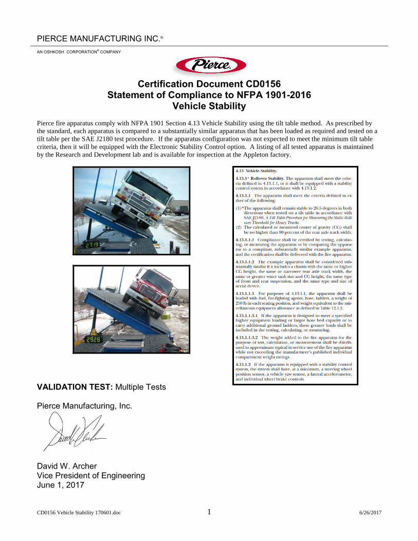
CD0156 Vehicle Stability 170601.doc 1 6/26/2017
PIERCE MANUFACTURING INC.®
AN OSHKOSH CORPORATION® COMPANY
Certification Document CD0156
Statement of Compliance to NFPA 1901-2016 Vehicle Stability
Pierce fire apparatus comply with NFPA 1901 Section 4.13 Vehicle Stability using the tilt table method. As prescribed by the standard, each apparatus is compared to a substantially similar apparatus that has been loaded as required and tested on a tilt table per the SAE J2180 test procedure. If the apparatus configuration was not expected to meet the minimum tilt table criteria, then it will be equipped with the Electronic Stability Control option. A listing of all tested apparatus is maintained by the Research and Development lab and is available for inspection at the Appleton factory.
VALIDATION TEST: Multiple Tests Pierce Manufacturing, Inc.
David W. Archer Vice President of Engineering June 1, 2017

CD0098 Power Steering System 110623.doc 1 10/14/2014
PIERCE MANUFACTURING INC.®
AN OSHKOSH CORPORATION® COMPANY
Certification Document CD0098
Power Steering System Pierce Manufacturing, Inc. certifies that the power steering system as installed in our custom chassis meets the requirements of the component supplier, the NFPA 1901 and NFPA 1906 guidelines as applicable, and Pierce internal design standards.
VALIDATION TEST: RD1987, RD2055 RD2056, RD2057, RD2058, RD2059 Pierce Manufacturing, Inc.
David W. Archer Director of Engineering June 03, 2011

CD0189 Cab Integrity Certification - Saber FR-Enforcer 210929.doc 1 12/1/2021
Oshkosh Corporation Classification - Restricted
PIERCE MANUFACTURING INC.®
AN OSHKOSH TRUCK CORPORATION® COMPANY
Certification Document CD0189
Saber® FR - EnforcerTM Cab Integrity Certification
Pierce Manufacturing certifies the integrity of the Saber® FR – EnforcerTM cab relative to occupant protection. A specimen representing the substantial structural configuration of the Saber® FR – EnforcerTM
cab models has been successfully tested in accordance with the following standards. • SAE J2422 Cab Roof Strength Evaluation – Quasi-Static Loading Heavy Trucks. • European Occupant Protection Standard ECE Regulation No. 29. • SAE J2420 COE Frontal Strength Evaluation – Dynamic Loading Heavy Trucks.
Side Impact: The test cab was subjected to dynamic preload where a 14,320 lb. moving barrier was impacted into the top corner with sufficient speed to impact the top corner of the cab with 13,000 ft-lbs. of energy. This satisfies SAE J2422 requirements. Frontal Impact: The test cab was struck by the 14,320 lb. moving barrier at a speed sufficient to impart the required 65,098 ft-lbs. of energy. Twice the energy required per SAE J2420. Roof Crush: This test cab was then subjected to a roof crush force of 110,000 lbs. This value exceeds the ECE 29 criteria, which must be equivalent to the front axle rating. This is 4.6 times higher than max. front axle rating.

CD0189 Cab Integrity Certification - Saber FR-Enforcer 210929.doc 2 12/1/2021
Oshkosh Corporation Classification - Restricted
Pass-Fail criteria of the SAE tests and the ECE 29 test is a measure of whether the “survival space” inside the cab is compromised, all doors remain shut, and the cab remained attached to the chassis frame in at least one location. The Pierce cab met all of the Performance Criteria requirements on all 3 integrity tests. Witnessed and certified by: Pierce Manufacturing, Inc.
David W Archer Vice President of Engineering

Oshkosh Corporation Classification: Unrestricted
CD0137 Door Durability - Saber FR - Enforcer 141118.doc 1 11/18/2014
PIERCE MANUFACTURING INC.®
AN OSHKOSH CORPORATION® COMPANY
Certification Document CD0137
Saber®FR – EnforcerTM Cab Doors
Pierce Manufacturing certifies the integrity of the Saber®FR – EnforcerTM cab doors. Specimens representing the substantial structural configuration of the Saber®FR – EnforcerTM cab front and crew doors have been successfully tested to meet the following objectives: OBJECTIVES:
Survive a 200,000-cycle door slam test with a slam acceleration up to 20 g’s on one representative
Validate the assembly concept of the main structure of the door by evaluating the durability of the bonding technique.
Evaluate components, structure, and mounting of the door during and the end of the test for fatigue and failure to ensure durability.
Verify that the door seals function properly at the end of the test. Evaluate the new extrusions and castings of the cab doorframe during and at the end of
the test for fatigue, failure, and deformation of seal flanges. Evaluate various mounting options for the electronic control module for durability during
portions of the slam test. CONCLUSIONS:
The door structure and doorframe successfully completed a 200,000-cycle door slam test with a door slam acceleration of 20 g’s.
VALIDATION TEST: RD2425 Pierce Manufacturing, Inc. David Archer November 18, 2014

CD0132 Windshield Wipers - Enforcer-Saber FR 141117.doc 1 11/18/2014
PIERCE MANUFACTURING INC.®
AN OSHKOSH CORPORATION® COMPANY
Certification Document CD0132
Saber®FR – EnforcerTM Windshield Wiper System
Pierce Manufacturing certifies the integrity of the Saber® FR –EnforcerTM Windshield Wiper System. Specimens representing the configuration of the Saber® FR –EnforcerTM windshield wipers have been successfully tested to meet the following objectives: OBJECTIVES:
Complete 3,000,000 cycles of windshield wiper operation per SAE J198 § 6.2 Inspect wiper motor, pivots, linkages, and mounts frequently to validate cumulative
wiper system integrity. CONCLUSIONS:
The wiper linkage, pivots, and mounts successfully completed the 3,000,000 cycles. VALIDATION TEST: RD2462 Pierce Manufacturing, Inc.
David Archer Vice President of Engineering

CD0134 Seats and Belts - Saber FR - Enforcer .doc 1 11/17/2014
PIERCE MANUFACTURING INC.®
AN OSHKOSH CORPORATION® COMPANY
Certification Document CD0134
Saber® FR – EnforcerTM
Seats and Seat Belts Pierce Manufacturing certifies the conformance of the Saber® FR – EnforcerTM cab seats and seat belts to Federal Motor Vehicle Safety Standards. Representative Saber® FR – EnforcerTM
Seat and Seat Belt designs have been tested successfully in accordance with FMVSS 207. Physical testing was performed to qualify passenger seats to meet Federal Motor Vehicle Safety Standards (FMVSS) 207 and 210. This requires that a minimum of 3,000 lbf be applied to both the lap and shoulder belts via appropriate body blocks. A third force of twenty times the mass of the seat must be applied at the center-of-gravity (CG) of the seat. All three forces are applied at the same time, reached within thirty seconds of the start of the test, and be held for a minimum of ten seconds. A force equal to twenty times the mass of the seat was applied to each seat in the direction opposite to the combination pull. A moment of 275 lb-ft was applied to the seat with reference to the H-point. This testing ensures that the seat mounting and seat belt anchors are adequate to retain the seats and occupants in a crash. The Federal requirements are based on the high deceleration rates of passenger vehicles, so the design requirements are significantly more conservative considering the slower crash speeds of heavy trucks. VALIDATION TESTS: RD2397 Pierce Manufacturing, Inc.
David Archer Vice President of Engineering

CD0165 Heat - Saber FR-Enforcer MCC 290420.doc 1 4/28/2020
Oshkosh Corporation Classification - Restricted
PIERCE MANUFACTURING INC.®
AN OSHKOSH CORPORATION® COMPANY
Certification Document CD0165
Saber® FR – EnforcerTM Cab Heater
Pierce Manufacturing certifies the performance of the Saber® FR – EnforcerTM cab heat systems. The Saber®FR - EnforcerTM Heater System was tested successfully in an environmental chamber. Heater testing was performed using the coolant supply procedures from SAE J381. The average cab temperature increased 82.3º F from -10º F to 72.3º F within the prescribed 30 minutes utilizing the right side under seat auxiliary heater. The cab was contained in a cold chamber at -10º F during the duration of the test.
VALIDATION TEST: TR#19-0047 R00

CD0165 Heat - Saber FR-Enforcer MCC 290420.doc 2 4/28/2020
Oshkosh Corporation Classification - Restricted
Pierce Manufacturing, Inc.
David Archer Vice President of Engineering

CD0167 Saber FR - Enforcer Air Conditioning_Defrost 290420.doc 1 4/28/2020
Oshkosh Corporation Classification - Restricted
PIERCE MANUFACTURING INC.®
AN OSHKOSH CORPORATION® COMPANY
Certification Document CD0167
Saber® FR - EnforcerTM
Air Conditioning & Defrost Pierce Manufacturing certifies the performance of the Saber®FR - EnforcerTM cab air conditioning and defrost system. The air conditioning and defrost system was tested successfully in an environmental chamber. Air Conditioning: Air conditioning performance testing was conducted at an ambient of 100°F and 50 percent relative humidity. The engine speed was maintained at 1000 RPM with the QP21 compressor The vehicle was heat soaked in the environmental chamber. All temperature probes were monitored to confirm temperature stabilization. The transient test began when all the vehicle doors were closed, and the air conditioning turned on. The average cab temperature dropped to a maximum of 72.1°F within 30 minutes.

CD0167 Saber FR - Enforcer Air Conditioning_Defrost 290420.doc 2 4/28/2020
Oshkosh Corporation Classification - Restricted
Defrosting Defroster testing was performed in accordance with SAE J381 Windshield Defrosting Systems Test Procedure and Performance Requirements-Trucks, Buses, and Multipurpose Vehicles. This SAE Recommended Practice establishes uniform test procedures and performance requirements for the defrosting system of enclosed cab trucks, buses, and multipurpose vehicles. Current engineering practice prescribes that for laboratory evaluation of defroster systems, an ice coating of known thickness be applied to the windshield and left- and right-hand side windows to provide more uniform and repeatable test results, even though under actual conditions such a coating would necessarily be scraped off before driving. The test condition, therefore, represents a more severe condition than the actual condition, where the defroster system must merely be capable of maintaining a cleared viewing area. During the test, the vehicle is cold soaked to 0º F in a cold chamber. A prescribed layer of ice is applied to the windshield. The defroster is then run, and the advancing melt boundary marked as the test proceeds. The SAE prescribed area of the windshield was 100% cleared and the side windows were 75% cleared within the specified 30-minute period.
Defrost Results
Start of Test 15 Minutes 30 Minutes
Right Viewed From Outside Left

CD0167 Saber FR - Enforcer Air Conditioning_Defrost 290420.doc 3 4/28/2020
Oshkosh Corporation Classification - Restricted
VALIDATION TEST: MCC Test Report TR#19-0047 R00
Pierce Manufacturing, Inc.
David W. Archer Vice President of Engineering
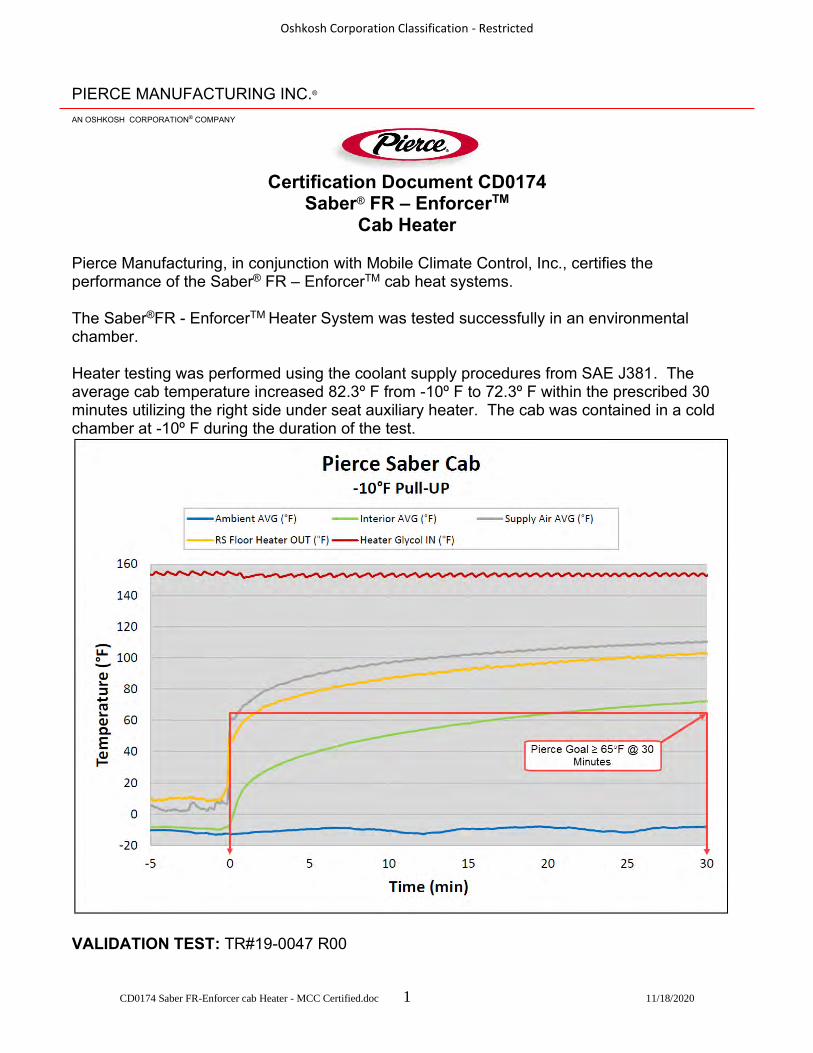
CD0174 Saber FR-Enforcer cab Heater - MCC Certified.doc 1 11/18/2020
Oshkosh Corporation Classification - Restricted
PIERCE MANUFACTURING INC.®
AN OSHKOSH CORPORATION® COMPANY
Certification Document CD0174
Saber® FR – EnforcerTM Cab Heater
Pierce Manufacturing, in conjunction with Mobile Climate Control, Inc., certifies the performance of the Saber® FR – EnforcerTM cab heat systems. The Saber®FR - EnforcerTM Heater System was tested successfully in an environmental chamber. Heater testing was performed using the coolant supply procedures from SAE J381. The average cab temperature increased 82.3º F from -10º F to 72.3º F within the prescribed 30 minutes utilizing the right side under seat auxiliary heater. The cab was contained in a cold chamber at -10º F during the duration of the test.
VALIDATION TEST: TR#19-0047 R00

CD0174 Saber FR-Enforcer cab Heater - MCC Certified.doc 2 11/18/2020
Oshkosh Corporation Classification - Restricted
Pierce Manufacturing, Inc.
David Archer Vice President of Engineering Mobile Climate Control, Inc.
Brent Griffith Lead Test Engineer & Large Application Specialist

CD0175 Saber FR - Enforcer Air Conditioning_Defrost - MCC Certified.doc 1 11/18/2020
Oshkosh Corporation Classification - Restricted
PIERCE MANUFACTURING INC.®
AN OSHKOSH CORPORATION® COMPANY
Certification Document CD0175
Saber® FR - EnforcerTM
Air Conditioning & Defrost Pierce Manufacturing, in conjunction with Mobile Climate Control, Inc., certifies the performance of the Saber®FR - EnforcerTM cab air conditioning and defrost system. The air conditioning and defrost system was tested successfully in an environmental chamber. Air Conditioning: Air conditioning performance testing was conducted at an ambient of 100°F and 50 percent relative humidity. The engine speed was maintained at 1000 RPM with the QP21 compressor The vehicle was heat soaked in the environmental chamber. All temperature probes were monitored to confirm temperature stabilization. The transient test began when all the vehicle doors were closed, and the air conditioning turned on. The average cab temperature dropped to a maximum of 72.1°F within 30 minutes.
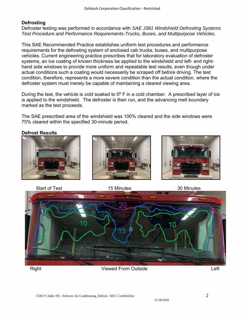
CD0175 Saber FR - Enforcer Air Conditioning_Defrost - MCC Certified.doc 2 11/18/2020
Oshkosh Corporation Classification - Restricted
Defrosting Defroster testing was performed in accordance with SAE J381 Windshield Defrosting Systems Test Procedure and Performance Requirements-Trucks, Buses, and Multipurpose Vehicles. This SAE Recommended Practice establishes uniform test procedures and performance requirements for the defrosting system of enclosed cab trucks, buses, and multipurpose vehicles. Current engineering practice prescribes that for laboratory evaluation of defroster systems, an ice coating of known thickness be applied to the windshield and left- and right-hand side windows to provide more uniform and repeatable test results, even though under actual conditions such a coating would necessarily be scraped off before driving. The test condition, therefore, represents a more severe condition than the actual condition, where the defroster system must merely be capable of maintaining a cleared viewing area. During the test, the vehicle is cold soaked to 0º F in a cold chamber. A prescribed layer of ice is applied to the windshield. The defroster is then run, and the advancing melt boundary marked as the test proceeds. The SAE prescribed area of the windshield was 100% cleared and the side windows were 75% cleared within the specified 30-minute period.
Defrost Results
Start of Test 15 Minutes 30 Minutes
Right Viewed From Outside Left

CD0175 Saber FR - Enforcer Air Conditioning_Defrost - MCC Certified.doc 3 11/18/2020
Oshkosh Corporation Classification - Restricted
VALIDATION TEST: MCC Test Report TR#19-0047 R00
Pierce Manufacturing, Inc.
David W. Archer Vice President of Engineering Mobile Climate Control, Inc.
Brent Griffith Lead Test Engineer & Large Application Specialist

Pierce Manufacturing


OFFICE OF THE SECRETARY OF STATE
OF THE STATE OF COLORADO
CERTIFICATE OF FACT OF GOOD STANDING
I, Wayne W. Williams , as the Secretary of State of the State of Colorado, hereby certify that,
according to the records of this office,
is an entity formed or registered under the law of , has complied with all
applicable requirements of this office, and is in good standing with this office. This entity has
been assigned entity identification number and has provided the assumed entity
name for use in Colorado
This certificate reflects facts established or disclosed by documents delivered to this office on
paper through that have been posted, and by documents delivered to this office
electronically through @ .
I have affixed hereto the Great Seal of the State of Colorado and duly generated, executed, and issued this
official certificate at Denver, Colorado on @ in accordance with applicable law. This
certificate is assigned Confirmation Number .
*********************************************End of Certificate******************************************** Notice: A certificate issued electronically from the Colorado Secretary of State’s Web site is fully and immediately valid and effective. However, as an option, the issuance and validity of a certificate obtained electronically may be established by visiting the Validate a Certificate page of the Secretary of State’s Web site, http://www.sos.state.co.us/biz/CertificateSearchCriteria.do entering the certificate’s confirmation number displayed on the certificate, and following the instructions displayed. Confirming the issuance of a certificate is merely optional and is not necessary to the valid and effective issuance of a certificate. For more information, visit our Web site, http://www.sos.state.co.us/ click “Businesses, trademarks, trade names” and select “Frequently Asked Questions.”
Pierce Manufacturing Company
Tennessee
Pierce Corporation
08/06/201808/08/2018 16:36:43
08/08/2018 16:36:4311052899
20171636101

Organizational Background and Overview
Pierce Celebrates Its 100th Year in Business Pierce Manufacturing, an Oshkosh Corporation (NYSE:OSK) company, and the leading U.S. manufacturer of fire and emergency vehicles, is celebrating its 100th Anniversary in 2013. Pierce is kicking off its yearlong commemoration by launching a special website section located at www.piercemfg.com/100thAnniversary. The site features an interactive historical timeline, a 100thAnniversary video, a photo contest, limited edition merchandise, and upcoming events. “Pierce is a company with humble beginnings, a rich history, and an exciting future,” said Jim Johnson, Oshkosh Corporation executive vice president and president of the Fire & Emergency segment and Pierce Manufacturing. “It is significant that only a small fraction of companies from any industry achieve the 100 year milestone. On behalf of Pierce employees, and all those who preceded us, we pledge an unwavering level of commitment to firefighters, and boldness in our thinking, as we look ahead to the next hundred years.” Founded in 1913 by Humphrey and Dudley Pierce in Appleton, Pierce Manufacturing first built after-market bodies for Ford Model T chassis. In 1939, the company manufactured its first fire truck body and grew to 20 employees. In 1958, ushering in a new era of boom and platform vehicles, Pierce designed the first ever articulating aerial apparatus that was used to reach up and over tall obstructions. Pierce introduced its first custom chassis and body – the Arrow – in 1982, and that design changed the face of the modern fire industry. Pierce Manufacturing has built 51,650 fire trucks and 27,000 custom chassis. Pierce manufactures pumpers, tankers, aerials, wildland pumpers, rescues, hazmat, and communication vehicles.
More recent examples of Pierce innovations include industry firsts like the Dash® CF fire apparatus (that features an innovative cab-forward design), frontal airbag and the side roll protection systems, and the patented Pierce Ultimate Configuration (PUC) response vehicle. Other examples include Command Zone™ advanced electronics to enhance vehicle troubleshooting and reliability, and TAK-4® independent front suspension for unmatched vehicle maneuverability. Pierce engineers and manufactures its own Husky® foam and Hercules® compressed air foam systems that more effectively attack and suppress structural, wildland, automobile, and fuel fires. Every vehicle component is designed to help firefighters perform safely at their highest level. “The more than 2,000 people who work for Pierce, including many families with multiple generations of service, are our backbone – and the reason for our longevity, success and growth,” added Johnson. “Pierce employees think of their work as more of a vocation than a job, and the average employee tenure is nearly 20 years. That speaks volumes.” Pierce markets its products through the industry’s largest and most comprehensive dealer and service network. The company enjoys a nationwide web of dealerships with over 600 certified and factory trained Service Brigade technicians and over 50 service centers. Pierce also offers custom training sessions for fire departments.
Oshkosh Capital offers lease purchases which can range from 3, 5, 7 or 10 year terms.
About Pierce Manufacturing Pierce Manufacturing Inc., an Oshkosh Corporation [NYSE: OSK] company, is celebrating its 100th year in business in 2013. Pierce is the leading North American manufacturer of custom fire apparatus. Products include custom and commercial pumpers, aerials, rescue trucks, wildland trucks, mini-pumpers, elliptical tankers, and homeland security apparatus. In addition, Pierce designs its own foam systems and was the first company to introduce frontal airbags and the Side Roll Protection system to fire apparatus. To learn more about Pierce, visit www.piercemfg.com. About Oshkosh Corporation Oshkosh Corporation is a leading designer, manufacturer and marketer of a broad range of specialty access equipment, commercial, fire & emergency and military vehicles and vehicle bodies. Oshkosh Corporation manufactures, distributes and services products under the brands of Oshkosh®, JLG®, Pierce®, McNeilus®, Jerr-Dan®, Frontline™, CON-E-CO®, London® and IMT®. Oshkosh products are valued worldwide in businesses where high quality, superior performance, rugged reliability and long-term value are paramount. For more information, visitwww.oshkoshcorporation.com. ®, TM All brand names referred to in this news release are trademarks of Oshkosh Corporation or its subsidiary companies.


Environmental Protection DepartmentEnvironmental Management Practice
Pierce Manufacturing Inc.
At Pierce Manufacturing Inc. (Pierce), a subsidiary of Oshkosh Corporation, the primary
responsibility of the Environmental Protection Department is to provide oversight to ensure that all
facilities and company activities continue to operate in compliance with applicable environmental
laws and regulations. Specifically, Pierce facilities are subject to State and Federal regulatory
programs that involve issues such as air quality, waste generation and disposal, process
wastewater, storm water management, underground/aboveground storage tanks, and emergency
planning and community right-to-know. Regulations that apply to company activities are contained
in the Environmental Protection Agency regulations of Chapter 40 Code of Federal Regulations,
Department of Transportation Regulations in Chapter 49 Code of Federal Regulations,
Environmental Protection Regulations in the Wisconsin NR Rules, and state/local wastewater and
storm drainage rules. The Pierce facilities are in compliance with these applicable regulations
including applicable ozone-depleting substances regulations.
As required by these environmental regulatory programs, Pierce Environmental Protection
Department personnel perform weekly and/or monthly assessments, inspections, and
recordkeeping activities. In addition to these internal inspections, our facilities are inspected by
Federal, State, and Local environmental agencies. Pierce has an outstanding compliance history,
and a good working relationship with these agencies. Pierce was acquired by Oshkosh Truck in
September 1996. Since that time, Pierce has not had any environmental fines or penalties, and
Pierce has a good working relationship with the Wisconsin Department of Natural Resources
(WDNR). Pierce had voluntarily committed to reducing Volatile Organic Compounds (VOCs) and
conducted extensive research on the reformulation of the hundreds of different paints Pierce uses.
As a result, Pierce was the first Wisconsin manufacturer in the industry to successfully use low
VOC coatings, and has received two environmental protection awards for doing so. In August
2000, Pierce was nominated by the WDNR and received the WDNR’s
Prevention/Environment/Prosperity (PEP) Award for their innovative paint emission reduction
program. In May 2001, Pierce was presented with the Wisconsin Business Friend of the
Environment Award in recognition of Pierce’s leadership in environmental protection.


ANY PROPRIETOR/PARTNER/EXECUTIVEOFFICER/MEMBER EXCLUDED?
INSR ADDL SUBRLTR INSD WVD
PRODUCER CONTACTNAME:
FAXPHONE(A/C, No):(A/C, No, Ext):
E-MAILADDRESS:
INSURER A :
INSURED INSURER B :
INSURER C :
INSURER D :
INSURER E :
INSURER F :
POLICY NUMBERPOLICY EFF POLICY EXP
TYPE OF INSURANCE LIMITS(MM/DD/YYYY) (MM/DD/YYYY)
AUTOMOBILE LIABILITY
UMBRELLA LIAB
EXCESS LIAB
WORKERS COMPENSATIONAND EMPLOYERS' LIABILITY
DESCRIPTION OF OPERATIONS / LOCATIONS / VEHICLES (ACORD 101, Additional Remarks Schedule, may be attached if more space is required)
AUTHORIZED REPRESENTATIVE
EACH OCCURRENCE $DAMAGE TO RENTEDCLAIMS-MADE OCCUR $PREMISES (Ea occurrence)
MED EXP (Any one person) $
PERSONAL & ADV INJURY $
GEN'L AGGREGATE LIMIT APPLIES PER: GENERAL AGGREGATE $PRO-POLICY LOC PRODUCTS - COMP/OP AGGJECT
OTHER: $COMBINED SINGLE LIMIT
$(Ea accident)
ANY AUTO BODILY INJURY (Per person) $OWNED SCHEDULED
BODILY INJURY (Per accident) $AUTOS ONLY AUTOS
HIRED NON-OWNED PROPERTY DAMAGE$AUTOS ONLY AUTOS ONLY (Per accident)
$
OCCUR EACH OCCURRENCE
CLAIMS-MADE AGGREGATE $
DED RETENTION $
PER OTH-STATUTE ER
E.L. EACH ACCIDENT
E.L. DISEASE - EA EMPLOYEE $If yes, describe under
E.L. DISEASE - POLICY LIMITDESCRIPTION OF OPERATIONS below
INSURER(S) AFFORDING COVERAGE NAIC #
COMMERCIAL GENERAL LIABILITY
Y / N
N / A(Mandatory in NH)
SHOULD ANY OF THE ABOVE DESCRIBED POLICIES BE CANCELLED BEFORETHE EXPIRATION DATE THEREOF, NOTICE WILL BE DELIVERED INACCORDANCE WITH THE POLICY PROVISIONS.
THIS IS TO CERTIFY THAT THE POLICIES OF INSURANCE LISTED BELOW HAVE BEEN ISSUED TO THE INSURED NAMED ABOVE FOR THE POLICY PERIODINDICATED. NOTWITHSTANDING ANY REQUIREMENT, TERM OR CONDITION OF ANY CONTRACT OR OTHER DOCUMENT WITH RESPECT TO WHICH THISCERTIFICATE MAY BE ISSUED OR MAY PERTAIN, THE INSURANCE AFFORDED BY THE POLICIES DESCRIBED HEREIN IS SUBJECT TO ALL THE TERMS,EXCLUSIONS AND CONDITIONS OF SUCH POLICIES. LIMITS SHOWN MAY HAVE BEEN REDUCED BY PAID CLAIMS.
THIS CERTIFICATE IS ISSUED AS A MATTER OF INFORMATION ONLY AND CONFERS NO RIGHTS UPON THE CERTIFICATE HOLDER. THISCERTIFICATE DOES NOT AFFIRMATIVELY OR NEGATIVELY AMEND, EXTEND OR ALTER THE COVERAGE AFFORDED BY THE POLICIESBELOW. THIS CERTIFICATE OF INSURANCE DOES NOT CONSTITUTE A CONTRACT BETWEEN THE ISSUING INSURER(S), AUTHORIZEDREPRESENTATIVE OR PRODUCER, AND THE CERTIFICATE HOLDER.
IMPORTANT: If the certificate holder is an ADDITIONAL INSURED, the policy(ies) must have ADDITIONAL INSURED provisions or be endorsed.If SUBROGATION IS WAIVED, subject to the terms and conditions of the policy, certain policies may require an endorsement. A statement onthis certificate does not confer rights to the certificate holder in lieu of such endorsement(s).
COVERAGES CERTIFICATE NUMBER: REVISION NUMBER:
CERTIFICATE HOLDER CANCELLATION
© 1988-2015 ACORD CORPORATION. All rights reserved.ACORD 25 (2016/03)
CERTIFICATE OF LIABILITY INSURANCEDATE (MM/DD/YYYY)
$
$
$
$
$
The ACORD name and logo are registered marks of ACORD
1/25/2022
(303) 368-5757 (303) 368-5863
11150
Front Range Fire Apparatus Ltd.7600 Miller Ct.Longmont, CO 80504
41190
A 1,000,000
MFPK08553108 12/27/2021 12/27/2022 1,000,000
5,000
1,000,000
2,000,000
2,000,000
GARAGE LIABILIT Included
1,000,000A
MFCA08347008 12/27/2021 12/27/2022
3,000,000AMFUM07987208 12/27/2021 12/27/2022
3,000,000
B4043254 5/1/2021 5/1/2022 500,000
500,000
500,000
A Garage & Dealers (Si MFCA08347008 12/27/2021
Coverage applies per policy terms and conditions If required by written contract, as provided by attached policy form, Certificate Holder is included as Additional Insured as respects General Liability.
City of Colorado Springs30 S. Nevada Ave.Colorado Springs, CO 80903
FRONRAN-05 SHIGDON
T. Charles Wilson Insurance Service384 Inverness Parkway Suite 170Englewood, CO 80112 [email protected]
Arch Insurance CompanyPinnacol Assurance
Aggregate
X
12/27/2022
XX
X
X
X X
X X

OFFICE OF THE SECRETARY OF STATE
OF THE STATE OF COLORADO
CERTIFICATE OF FACT OF GOOD STANDING
I, Jena Griswold , as the Secretary of State of the State of Colorado, hereby certify that, according to the
records of this office,
is a
formed or registered on under the law of Colorado, has complied with all applicable
requirements of this office, and is in good standing with this office. This entity has been assigned entity
identification number .
This certificate reflects facts established or disclosed by documents delivered to this office on paper through
that have been posted, and by documents delivered to this office electronically through
@ .
I have affixed hereto the Great Seal of the State of Colorado and duly generated, executed, and issued this
official certificate at Denver, Colorado on @ in accordance with applicable law.
This certificate is assigned Confirmation Number .
*********************************************End of Certificate******************************************* Notice: A certificate issued electronically from the Colorado Secretary of State’s Web site is fully and immediately valid and effective. However, as an option, the issuance and validity of a certificate obtained electronically may be established by visiting the Validate a Certificate page of the Secretary of State’s Web site, http://www.sos.state.co.us/biz/CertificateSearchCriteria.do entering the certificate’s confirmation number displayed on the certificate, and following the instructions displayed. Confirming the issuance of a certificate is merely optional and is not necessary to the valid and effective issuance of a certificate. For more information, visit our Web site, http://www.sos.state.co.us/ click “Businesses, trademarks, trade names” and select “Frequently Asked Questions.”
FRONT RANGE FIRE APPARATUS, LIMITED
Corporation
19871634538
03/08/202203/09/2022 15:37:35
03/09/2022 15:37:3513854934
08/26/1985


7600 Miller Ct. Frederick, Colorado
303-449-9911
Service Center

The industry leading service facility at Front Range Fire Apparatus offers complete maintenance, inspections, and repair on emergency rescue apparatus, including non-Pierce and non-AEV apparatus. Whether it’s basic preventative maintenance or complete restorations, our technicians take great pride in providing all the services you need to keep your fleet ready.
Our service facility is fully insured and staffed by Pierce Master Technicians that are EVT and ASE certified, as well as stocked with state-of-the-art equipment, including diagnostic software, truck lifts, and a mobile draft commander pump test trailer. The facility consists of over 15,000 square feet with room for up to 14 apparatus.
Service Facility
MEET THE TEAM
ASHER STRAW
General Manager
SEAN BLATZER
Service Manager
[email protected] BRAD SHAEFERCLYDE BOWERSEVAN BAIERIVAN GONZALEZFREDDY NUANES
www.frontrangefire.com
7600 Miller Court Frederick, CO 80504
Service Technicians
DOUG BEAM
Technical Support/Warranty
KENT MCCREARY
Service Writer

GENERAL MAINTENANCE, SERVICE REPAIRS, AND INSPECTIONS ON ALL MAKES AND MODELS OF FIRE APPARATUS.
Mobile Service
Apparatus training
Service contracts
Customized preventative maintenance programs
Annual pump tests and acceptance tests
Certified pump, plumbing and valve repairs
CAFS and foam system installation
Electrical system repairs and upgrades
Air brake maintenance repair and service
Aerial maintenance and repair
Service, Repair , and Installation
Generator
Air brake
CAFS and foam system
Fire Pump
Tank
Electrical
Steel water and UPF poly tank Onboard battery chargers
Air systems
Custom Welding and Fabrication
Steel
Aluminum
UL Inspection and Repair
Aerial Service and Repair
Structural
Hydraulic
Electrical
Apparatus Body and Accident Repair
…and more!
Proudly serving the fire service industry for over 45 years.
Whether your truck is out of service with a major repair issue or just needs an oil change, our service technicians are here for you.


Duane Doucettte
Owner
Truck Sales Rep
Denver/Metro Area
Cell: (303) 304-6118
Office:(303) 449-9911 x 121
Rose CainBookkeeper
Office: 303-449-9911 x [email protected]
Mark Balch
Ambulance Sales Rep. Colorado Cell:
303-883-7860
Office: 303-449-9911 x 122
Front Range Fire Apparatus Sales & Operations
Jennifer Doucettte
Business Operations ManagerCell: (303) 304-6118
Office:(303) 449-9911 x 130
Wayne Kerber
Truck Sales Rep.
North Western Colorado/ Mountains
Cell: 970-531-7184
Don Chapman
Truck Sales Rep
Colorado/Mountains
Cell: 719-588-1580
Jason ByrneTruck Sales Rep
Cell: [email protected]
Margaret StrawSpecial Projects Coordinator
Office: 303-449-9911 x 27 [email protected]

Sean BlatzerService Manager
Office: 303-449-9911 x 115 [email protected]
Doug BeamTechnical Support/Warrantypport
Office: 303-449-9911 x 120 Cell: 303-475-5371
Front Range Fire Apparatus Service
Asher StrawService Manager
Office: 303-449-9911 x 112Cell: 720-202-4286
Parts
Office: 303-449-9911 x 165


