Embed Size (px)
Citation preview
FRP CONFINED CONCRETE STRESS-STRAIN MODEL UTILIZING A VARIABLE STRAIN DUCTILITY RATIO
By Domingo A. Moran1 and Chris P. Pantelides2
A model for representing the compressive behavior of concrete members confined using FRP
composite jackets is presented. The distinguishing feature of the analytical model is that the plastic behavior of the FRP-confined concrete can be represented by an experimentally derived variable strain ductility ratio, which defines the increase in plastic axial compressive strain versus the increase in plastic axial compressive strength of the FRP-confined concrete. This is demonstrated to be a function of the stiffness of the confining FRP jacket and the extent of internal damage, rather than a constant as is typically assumed for steel confined concrete. The model predicts that the plastic dilation rate of FRP-confined concrete is a function of the confining stiffness of the FRP jacket and the type of FRP jacket construction, be it bonded or non-bonded. An expression was obtained for predicting the ultimate compressive strength and strain of FRP- confined concrete based on equilibrium and plasticity analysis. The ultimate compressive strength and strain of the FRP-confined concrete were found to be a function of the jacket stiffness, the type of jacket construction, and the ultimate strain in the FRP jacket. Comparisons with experimental results indicate good agreement.
INTRODUCTION The retrofit of reinforced concrete columns with FRP composite jackets has become increasingly
common in regions of high seismicity. A significant amount of research has been carried out on the use of FRP composite jackets for the seismic retrofit and repair of existing reinforced concrete columns and bridge systems (Saadatmanesh et al. 1994, Seible et al. 1997, Xiao and Ma 1997, Pantelides et al. 1999).
The compressive stress-strain behavior of FRP confined concrete cylinders is essentially
nonlinear. The initial portion of the stress-strain response typically follows that of the unconfined concrete. After achieving the unconfined concrete strength, the response of the FRP-confined concrete softens, this softening can occur with either a localized descending branch that may stabilize as the dilation of the concrete core progresses, or it may exhibit a bilinear behavior until the FRP composite jacket fails.
Several investigators have introduced stress-strain models for concrete confined by FRP jackets.
Two very promising models are those introduced by Xiao and Wu (2000) and Spoelstra and Monti (1999). The Xiao and Wu (2000) model is an elasticity based bilinear model in which the behavior of the FRP confined concrete is described in terms of the mechanical properties of the concrete core and the confining FRP jacket. The Spoelstra and Monti (1999) model, is an iterative equilibrium-based model in which the behavior of the FRP confined concrete is governed by both the Mander et al. (1988) model for steel confined concrete and the Pantazopoulou and Mills (1995) constitutive model for concrete.
1 Engineer, Reaveley Engineers and Assoc., Salt Lake City, UT 84106 2 Prof., Dept. of Civil and Envr. Eng., Univ. of Utah, Salt Lake City, UT 84112.
2
In the Mander et al. (1988) model for steel confined concrete, the increase in the peak compressive strength of the confined concrete is expressed in terms of a constant effective confining pressure, and a resultant constant strain ductility ratio that defines the increase in the compressive strain relative to the increase in the compressive strength of the steel confined concrete. By contrast, the model proposed herein is based on an internal damage failure surface that determines the increase in the plastic compressive strength of the FRP-confined concrete. A variable strain ductility ratio is introduced, in which the increase in the plastic compressive strain of the FRP-confined concrete is shown to be a function of the hoop stiffness of the FRP composite jacket and the extent of internal damage in the concrete core.
CONFINEMENT EFFECTIVENESS OF FRP-CONFINED CONCRETE
The confinement effectiveness, , of the confining element, is typically defined by the well known Richart et al. (1928) relationship in which:
cck
co
rrr
co
cccc f
fkkkffk =+== ; 1 1 (1)
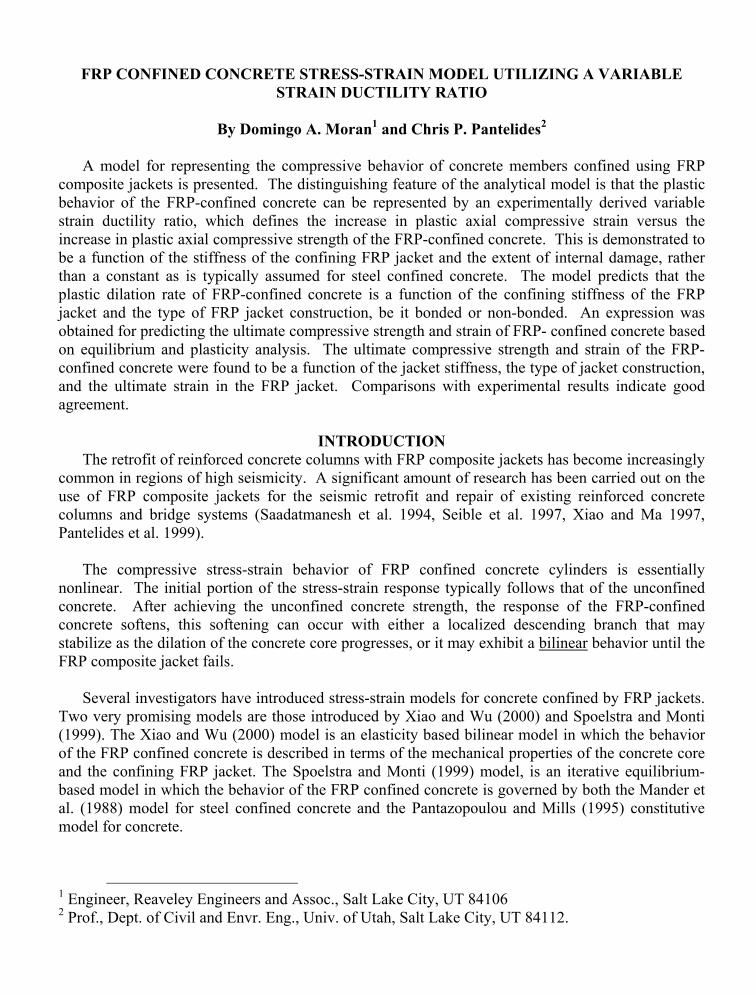
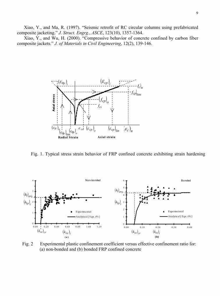
where confinement coefficient, =1k =rk confinement ratio and =rf average confining pressure. In Fig. 1, a typical stress-strain curve is shown in terms of the normalized compressive stress ( )ick versus the effective confinement ratio ( )irek of members exhibiting strain hardening plastic behavior. By examining the stress-strain behavior of concrete cylinder tests of specimens confined by non-bonded Glass FRP composite jackets (GFRP), performed by Mirmiran (1997), and cylinders confined by bonded Carbon FRP composite jackets (CFRP), performed by Xiao and Wu (2000), it was found that on average the plastic region of the compressive stress-strain behavior tends to initiate at an average plastic strain ( )
opθε , see Fig. 1, where for non-bonded FRP jacketed cylinders
( ) 0.5≈opθε mm/m, and for bonded FRP jacketed cylinders ( ) 0.3≈
opθε mm/m. Also, by selecting a
series of plastic jacket strains, ( )ipθε , that are within the range ( ) ( ) ( )uip θθopθ εεε ≤≤ where =uθε
ultimate radial jacket strain, as shown in Fig. 1. The following is proposed for circular concrete members, confined by circular strap or continuous FRP jackets, in which the plastic confinement effectiveness ( )
icpk of FRP confined concrete is defined as:
( ) ( ) ( ) ( )ireipco
icpicp kk
ff
k 11+== (2)
( ) ( ) ( ) ( )( )
−== 211 1;
ire
pipavgipip
kkk
γαα (3)
( ) ( ) ( ) ( ) ejjeijeco
ij
co
ireire kKKK
fkC
ff
k ==== ; eθ
θ εε
(4)
c
jjj
co
jj D
EtC
fC
K2
; == (5)
3
where jacket thickness, jacket tangent hoop modulus of elasticity, concrete column diameter, unconfined concrete core compressive strength, hoop jacket stiffness,
normalized jacket stiffness,
=jt =jE =cD=cof =jC
=jK ( ) =iref effective confining pressure, confinement efficiency of the FRP jacket that accounts for arching of passive confining stresses, where 0
=ek0.1≤≤ ek ; for
circular continuous FRP jackets 0.1=ek . Also ( ) =irek effective confinement ratio and ( ) =icpf
plastic compressive stress at a given plastic radial strain, ( )ipθε , in the confining FRP jacket. In (3)
the term ( ) =ipα variable confinement coefficient. Regression analysis suggests that for non-
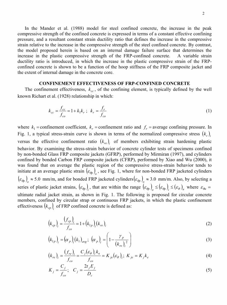
bonded FRP confined concrete and for bonded. In Figs. 2(a) and 2(b) the experimental
3−101.9= xpγ3−107x.1=pγ
( )ipk1 determined using (2) is plotted versus the effective confinement ratio, ( )irek ,
of (4), for both non-bonded and bonded FRP confined concrete, respectively. In these figures, it can be observed that at high effective confinement ratios, ( )irek , the experimental ( )
ipk1 approaches an
average asymptotic value of ( ) 3.21 ≈avgk for non-bonded and ( )1 avg 1.4≈k for bonded FRP
confined concrete. Also, in these figures the analytical ( )ipk1 of (3) is plotted as solid lines. Using
(2)-(5) the following analytical relationship ( )icpk , can be obtained as follows:
( ) ( ) ( ) ( ) ( )avgjejeipipjeco
icpicp kK
ff
k 1 ; 1 =+== ωεαω θ (6)
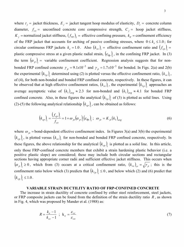
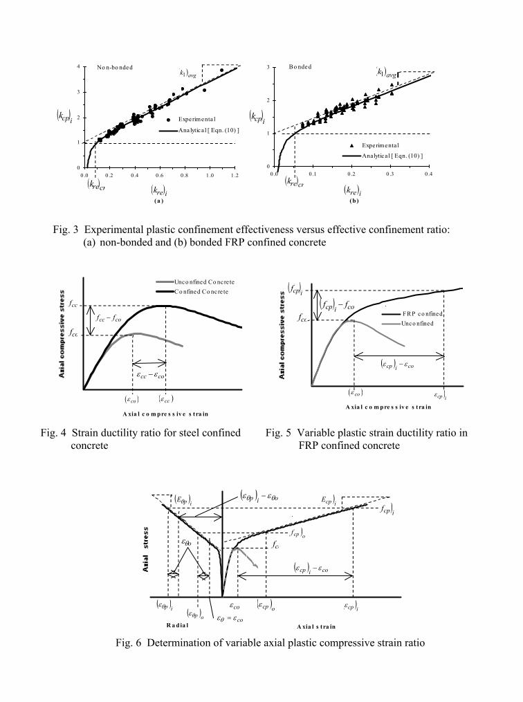
where =jeω bond-dependent effective confinement index. In Figures 3(a) and 3(b) the experimental ( )
icpk , is plotted versus ( for non-bonded and bonded FRP confined concrete, respectively. In
these figures, the above relationship for the analytical
)irek( )
icpk is plotted as a solid line. In this article, only those FRP-confined concrete members that exhibit a strain hardening plastic behavior (i.e. a positive plastic slope) are considered; these may include both circular sections and rectangular sections having appropriate corner radii and sufficient effective jacket stiffness. This occurs when ( ) 0≥
ipα , which from (3) occurs at a critical confinement ratio, ( ) pcrrek γ= ; this is the
confinement ratio below which (3) predicts that ( ) 01 ≤ipk , and below which (2) and (6) predict that
( ) 0.1≤icpk .
VARIABLE STRAIN DUCTILITY RATIO OF FRP-CONFINED CONCRETE
The increase in strain ductility of concrete confined by either steel reinforcement, steel jackets, or FRP composite jackets can be found from the definition of the strain ductility ratio R , as shown in Fig. 4, which was proposed by Mander et al. (1988) as:
co
cc
cckk
Rεε
εε =−−
= k;11
(7)
4
where is defined in (1), compressive strain effectiveness, ( cck ) =εk =coε peak compressive strain of the unconfined concrete core, where typically 0.2≈coε mm/m, and =ccε peak compressive strain of the confined concrete, as shown in Fig. 4. For concrete in a biaxial compression state of stress, Darwin and Pecknold (1977) indicate that R is a constant, where ; for steel confined concrete Mander et al. (1988) indicate that
3=RR is also a constant, where . In the case of FRP-
confined concrete, the experimental data suggest that the plastic strain ductility ratio 0.5=R
( )ipR , as shown
in Fig. 5, varies as the internal damage (i.e. ( )ipθε ) of the concrete core progresess, where:
( ) ( )( )
( ) ( ) ( ) ( )co
icpipipip
icp
ipip kk
kR
ε
ελ
λεε =−=
−= ; 1 ;
1 (8)
and ( )
icpk is defined in (2) and (6), ( ) =icpε plastic compressive strain, and ( ) =
ipλ axial plastic
compressive strain ratio at a given plastic radial strain ( )ipθε . From the analysis of the experimental
data and the use of (8) and Fig. 6, the following relationship for the analytical compressive strain
and strain ductility ratios are proposed:
i
p
−λ
ipR
_
( ) ( )[ ] ( ) ( ) pjeppcoopooipje
pip kK β
θθθθ ωψεεεεεψ
λ =−=−=
−;;1 (9)
( )
( )( )
( )( )
−
=∆
∆
=
−
ip
oipi
pip
i
ip
kR
θ
θθε
ε
ε
εε
ψ;
1
(10)
where =oθε increment in radial strain, as shown in Fig. 6; =pψ kinematic restraint coefficient in
which, for non-bonded FRP confined concrete the constants are 30.0=pβ and k , and
for bonded
3104.7 −= xp
45.0=pβ and k . Also 3104.3 −= xp ( ) =∆ iε internal damage coefficient that determines the degree of internal damage due to the dilation of the FRP-confined concrete core; when ( )
ipθε
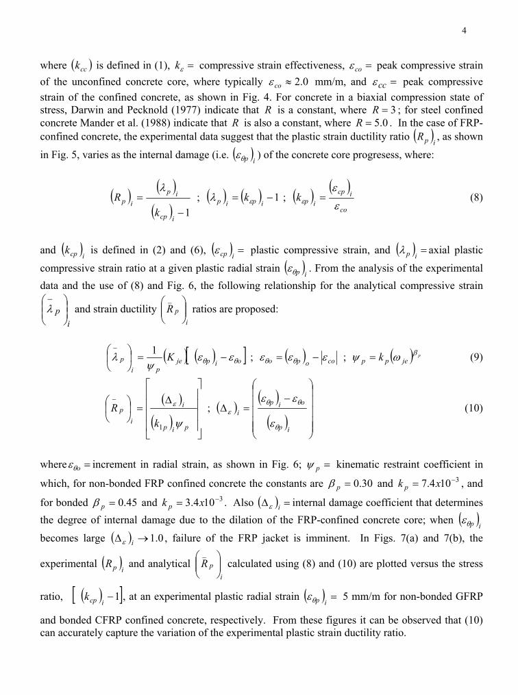
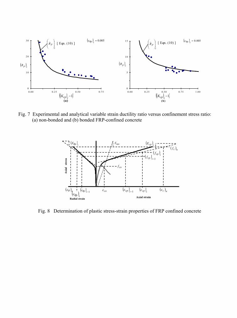
becomes large , failure of the FRP jacket is imminent. In Figs. 7(a) and 7(b), the
experimental
( )∆ iε 0.1→
( )ipR
( )[ 1−i
and analytical calculated using (8) and (10) are plotted versus the stress
ratio, , at an experimental plastic radial strain
ipR
_
]cpk ( ) =ipθε 5 mm/m for non-bonded GFRP
and bonded CFRP confined concrete, respectively. From these figures it can be observed that (10) can accurately capture the variation of the experimental plastic strain ductility ratio.
5
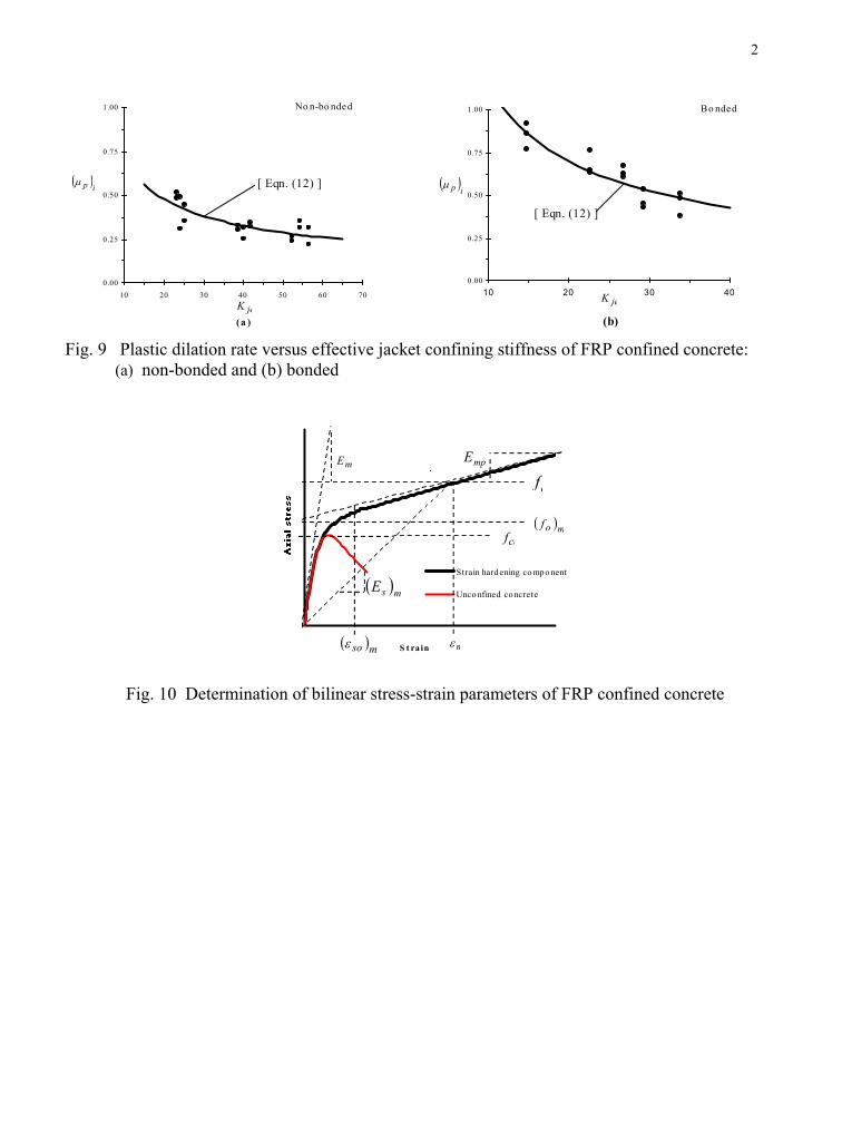
In modeling the non-linear compressive behavior of FRP confined concrete, Mirmiran (1997), Mirmiran and Shahawy (1996, 1997a, 1997b), and Samaan, et al. (1998) introduced the concept of an ultimate dilation rate ( )uµ , defined as:
p
cp
ucu E
Edd
θ
θ
εε
µ == (11)
where =θε average radial strain and =cε average axial strain in the concrete member, =cpE axial plastic modulus and radial plastic modulus. Mirmiran and Shahawy (1997a, 1997b), Samaan et al. (1998), Stanton et al. (1999), and Xiao and Wu (2000) have suggested a series of predictive relationships for the ultimate dilation rate,
=pEθ
uµ , in terms of the normalized confining stiffness, , of (5). Using the definition of the dilation rate of (11) and using (6), (8) and (9), and the use of Fig. 8, a bond-dependent asymptotic plastic dilation rate,
jK
( )pµ , is introduced herein, where:
( )( )
( ) ( )( ) ( ) jeco
p
icpicp
ipip
ip
icp
icp
pp KE
Edd
εψ
εε
εε
εε
µ θθ
θ
θ =−
−==
=
−
−
1
1 (12)
The analytical plastic dilation rate, ( )pµ , of (12) is plotted as a solid line in Fig. 9(a) and 9(b)
versus the effective jacket confining stiffness, ( )jeK , of non-bonded GFRP and bonded CFRP confined concrete cylinder tests, respectively. From these figures, it can be observed that (12) can accurately capture the variation of the platic dilation rate, ( )pµ , with respect to the effective stiffness, , of the confining FRP jacket. Solving for jeK ( )pψ in (12), substituting it into (9), and
further solving for the axial plastic compressive strain, ( )icpε , in (8) yields:
( ) ( ) ( )( )
co
oipi
p
icoicp ε
εε
µεε θθ
θθ −
=∆
∆+= ; 1 (13)
where radial strain ratio. Thus, at a given plastic radial strain ( ) =∆ iθ ( )
ipθε , in which
( ) ( ) ( )uop θθ ipθ εεε ≤≤ , a stress-strain coordinate, ( )icpcpf ε, , in the plastic region of the compressive
behavior of the FRP-confined concrete can now be predicted. At a given plastic radial strain, ( )ipθε ,
(6) and (13) can be used to predict the plastic compressive stress, ( )icpf , and the axial plastic
compressive strain, ( )icpε , respectively.
STRESS-STRAIN MODEL
The stress-strain model developed herein is based on a typical compressive stress-strain behavior of an FRP-confined concrete member that exhibits a bilinear compressive behavior, as shown in both
6
Figs. 8 and 10, is assumed herein to describe the behavior of FRP-confined concrete, where for convenience only the absolute values of strain and stress are considered:
( ) ( ) ( )
( )
+
−+
−== mp
nn
om
mmpm
mpmmsmmsc E
fEE
EEEEf
mm
1
1
;
ε
ε (14)
( ) ( )[11
1;;−
−−
==
=
ipipjecopp
pcp fE
EE αηα
ηϕϕω
µ θθθθ ] (15)
o
ccococ
EEpsifMPafE
µθ =
≈ ; 000,57 4733 (16)
( ) ( ) ( ) ( )[ ]θθθ
θ ϕαεω −+==ipipje
co
oo f
fk 1 (17)
( ) ( ) ( ) ( ) ( )[ ]{ } ipcoipco
po
co
coco f
Ek
ff
k θθθ
θ µεε ∆+−
+== (18)
where: variable secant modulus evaluated at the strain ( ) =msE mε , which is governed by the Richard and Abbott (1975) model. In addition, =mpE average plastic modulus in either the axial ( )cpE or radial ( )pθE strain direction, =mE tangent modulus of elasticity in either the axial ( )cE or radial strain direction, ( )θE =oµ initial Poisson’s ratio of the unconfined concrete core, where typically 18.0≈oµ , reference intercept stress in either the axial or radial ( ) =mof ( )cof ( )θof strain direction, and ( ) normalized reference intercept stress in either the axial ( or radial
strain direction. In the above relationships the subscript indicates the strain component under consideration, ( indicates an axial strain component, and
=mok
cm =
)cok( )θok m
) ( )θ=m indicates a radial (transverse) strain component. Also, the terms with the subscript i are evaluated at the limi radial strain where
t( ) ( )
limpθipθ εε = the terms with the subscript, i-1, are evaluated at ( ) ( )lim1ip pθθ εηε =
−
where 90.080.0 ≤≤η . By selecting a limiting radial strain, ( )limpθε , in the FRP jacket such that
( ) uθpθuθ εεε ≤≤lim
60.0 , and setting ( ) 5.12lim
=pθε mm/m for GFRP confined concrete, and
( ) 5.8=limpθε mm/m for CFRP confined concrete, sufficiently accurate plastic properties of the FRP-
confined concrete could be obtained. Assuming that both the FRP-confined and the unconfined concrete behave identically up to the
critical dilation stress, , which can be considered the axial stress at which the rate of volume dilation of the concrete core increases due to unrestrained crack propagation in the concrete
cocd ff 70.0≈
7
core (Pantazopoulou 1995). As a result, the curvature parameter, n , of (14) can then be determined from the iterative solution of the following relationship:
m
EE
−
−
( ) ( ) 10.170.0
;;070.011
m
md
comd
mpmd
mpmEm
momd
mpmnnEm
EfE
EE
kkE
EEk m
m ≈===
−−−
ε(19)
where dilation secant modulus in either the axial =mdE ( )cdE or radial strain direction, and ( dEθ )
=mdε axial ( )cdε or radial ( dθ )ε dilation strain at the axial dilation stress, . ( )cdf In an FRP-confined concrete member, the compressive failure of the member occurs
simultaneously with the failure of the FRP composite jacket, be it failure of the jacket due to rupture, delamination, lap failure or shear failure. Due to the interaction between the axial shortening and radial dilation which induces a biaxial state of stress and strain in the FRP-jacket, in addition to stress concentrations at the jacket-to-concrete interface that occur as the dilation of the concrete core progresses, failure of the FRP composite jacket can occur at an ultimate radial FRP jacket strain,
uθε , that may be below the rupture strain of FRP composite tensile coupon tests. For circular concrete members confined by an FRP jacket having a high effective jacket stiffness, , a non-
iterative solution for the ultimate axial compressive strain, jeK
cuε , at the ultimate radial strain uθε in the FRP jacket can be obtained by evaluating (13) at the ultimate jacket radial strain, where ( ) ui θpθ εε = .
The proposed stress-strain model was compared to experimental results and was found to
accurately capture the bilinear compressive behavior of FRP confined concrete. The proposed model captures most of the experimental results, with some deviation at the onset of plastic behavior and at strains near failure.
CONCLUSIONS A comprehensive model for representing the compressive behavior of concrete members confined
by FRP composite jackets is presented. The proposed model is based on accepted concrete and FRP composite behavior, and fundamental principles of mechanics of materials, and it is applicable to both bonded and unbonded FRP-confined concrete. The distinguishing feature of the proposed model is a variable strain ductility ratio which was demonstrated to be a function of the stiffness of the confining FRP composite jacket and the extent of internal damage, rather than a constant as is typically assumed for steel confined concrete. The ultimate compressive strength and strain of the FRP confined concrete were found to be a function of the effective jacket stiffness, type of jacket construction (bonded or unbonded), and the ultimate strain in the FRP jacket. An expression for the ultimate axial compressive strain was derived herein based on equilibrium and a unique graphical analysis. Comparisons with experimental results indicate good agreement. The stress strain model as proposed herein can be easily implemented into a spreadsheet or other computer language program for evaluating the confinement effectiveness of FRP-confined concrete members.
8
AKNOWLEDGEMENTS The research presented herein is part of continuing research at the Center for Composites in
Construction at the University of Utah, sponsored by the Utah Department of Transportation (UDOT), and the Idaho National Engineering and Environmental Laboratories (INEEL). The authors wish to express their gratitude to Dr. Y. Xiao of USC for providing experimental data on carbon FRP confined concrete cylinders. The opinions expressed in this paper are those of the authors, and do not necessarily reflect the opinions of the sponsoring organizations.
REFERENCES
Darwin, D., and Pecknold, D. A. (1977). “Nonlinear biaxial stress-strain law for concrete.” J. Engrg. Mech. Div., ASCE, 103(2), 229-241.
Mander, J.B., Priestley, M.J.N., and Park, R. (1988). “Theoretical stress strain model for confined concrete.” J. Struct. Engrg., ASCE, 114(8), 1804-1826.
Mirmiran, A., and Shahawy, M. (1996). “A new concrete–filled hollow FRP composite column.” Composites Part B: Engrg., 27B(3-4), 263-268, Elsevier Sci. Ltd, London, U.K.
Mirmiran, A. (1997). “Analytical and experimental investigation of reinforced concrete columns encased in fiberglass tubular jackets and use of fiber jacket for pile splicing.” Final Rep. Contract No. B-9135, Florida Dept. of Transp., Tallahassee, Fla.
Mirmiran, A., and Shahawy, M. (1997a). “Behavior of concrete columns confined by fiber composites.” J. Structural Engrg., ASCE, 123(5), 583-590.
Mirmiran, A., and Shahawy, M. (1997b). “Dilation characteristics of confined concrete.” Mech. of Cohesive-Frictional Mat. Int. J., 2(3), 237-249.
Pantelides, C.P., Gergely, J., Reaveley, L.D., and Volnyy, V.A. (1999). “Retrofit of RC bridge pier with CFRP advanced composites.” J. Struct. Engrg., ASCE 125(10), 1094-1099.
Pantazopoulou, S.J. (1995). “Role of expansion on mechanical behavior of concrete.” J. Struct. Engrg., ASCE, 121(12), 1795-1805.
Pantazopoulou, S.J., and Mills, R.H. (1995). “Microstrucutural aspects of the mechanical response of plain concrete.” ACI Materials J., 92(6), 605-616.
Richard, R.M., and Abbott, B.J. (1975). “Versatile elastic-plastic stress-strain formula.” J. Engrg. Mech., ASCE, 101(4), 511-515.
Richart, F.E., Brandtzaeg, A., Brown, R.L. (1928). “Study of the failure of concrete under combined compressive stresses.” Univ. of Illinois Engrg. Experiment Station, Bull. No. 185, Urbana, Ill.
Saadatmanesh, H., Ehsani, M.R., and Li, M.W. (1994). “Strength and ductility of concrete columns externally reinforced with fiber composite straps.” ACI Struct. J., 91(4), 434-447.
Samaan, M., Mirmiran, A., and Shahawy, M. (1998). “Model of concrete confined by fiber composites.” J. Struct. Engrg., 124(9), 1025-1031.
Seible, F., Priestley, M.J.N., Hegemier, G.A., and Innamorato, D. (1997). “Seismic retrofit of RC columns with continuous carbon fiber jackets.” J. of Compos. for Constr., ASCE, 1(2), 52-62.
Spoelstra, M.R., and Monti, G. (1999). “FRP confined concrete model.” J. of Compos. for Constr., ASCE, 3(3), 143-150.
Stanton, J.F., Owen, L.M., and MacRae, G.A. (1998). “Stress-strain properties of confined concrete.” Proc. Sixth Intern. Conf. on Earthq. Engrg., EERI, Oakland, Ca.
Wu, H., and Xiao, Y. (2000). “Compressive stress-strain behavior of concrete confined by carbon fiber jackets.” Proc. Sixth ASCCS Conf., Los Angeles, Ca., 919-926.
9
Xiao, Y., and Ma, R. (1997). “Seismic retrofit of RC circular columns using prefabricated composite jacketing.” J. Struct. Engrg., ASCE, 123(10), 1357-1364.
Xiao, Y., and Wu, H. (2000). “Compressive behavior of concrete confined by carbon fiber composite jackets.” J. of Materials in Civil Engineering, 12(2), 139-146.
Axial strain Radial Strain
( )ipEθ
cof
)ucf
( )ucε
( )ocpf
( )limcpf
( )limcpε( )ocpε( )opθε( )limpθε( )uθε coε
( )icpE
Fig. 1. Typical stress strain behavior of FRP confined concrete exhibiting strain hardening
(a )
0
1
2
3
4
0 .00 0 .2 0 0 .4 0 0 .60 0 .80 1 .0 0 1 .2 0
Experimenta l
Analytica l [ Eqn. (9) ]
( )avgk1
( )ipk1
( )irek( )crrek
Non-bonded
(b)
0
1
2
3
4
5
6
0 .0 0 0 .10 0 .20 0 .3 0 0 .4 0
Experimenta l
Analytica l [ Eqn. (9) ]
( )ipk1
( )avgk1
( )irek( )crrek
Bonded
Fig. 2 Experimental plastic confinement coefficient versus effective confinement ratio for: (a) non-bonded and (b) bonded FRP confined concrete
(a )
0
1
2
3
4
0 .0 0 .2 0 .4 0 .6 0 .8 1 .0 1 .2
Experimenta l
Ana lytica l [ Eqn. (10) ]
( )avgk1
( )crrek ( )irek
No n-bo nded
( )icpk
(b)
0
1
2
3
0 .0 0 .1 0 .2 0 .3 0 .4
Experimenta l
Analytica l [ Eqn. (10) ]
( )avgk1
( )irek( )crrek
( )icpk
Bo nded
Fig. 3 Experimental plastic confinement effectiveness versus effective confinement ratio:
(a) non-bonded and (b) bonded FRP confined concrete
A xia l c o m pre s s iv e s tra in
Unco nfined Co ncre te Co nfined Co ncre te
( )ε co ( )ccε
ccf
cocc εε −
cofcocc ff −
A xia l c o m pre s s iv e s tra in
FRP co nfined Unco nfined
( )ε co
( )icpf
)icpε
cof( ) coicp ff −
( ) coicp εε −
Fig. 4 Strain ductility ratio for steel confined Fig. 5 Variable plastic strain ductility ratio in concrete FRP confined concrete
A xia l s tra in R a dia l
)icpE
( )ocpf
( )ocpε( )opθε
coε ( )icpε
( ) coicp εε −
oθε
( )ipθε
( )icpf( )ipEθ
cof
coεεθ =
( ) oip θθ εε −
Fig. 6 Determination of variable axial plastic compressive strain ratio
(a)
0
1 0
2 0
3 0
0 .00 0 .2 5 0 .50 0 .7 5
( )ipR
( )( )1−icpK
( ) 005.0=ipθε
ipR
_[ Eqn. (10) ]
(b)
0
5
10
15
0 .0 0 0 .2 5 0 .50 0 .75 1 .00
( )( )1−icpK
( )ipR
( ) 005.0=ipθε
ipR
_ [ Eqn. (10) ]
Fig. 7 Experimental and analytical variable strain ductility ratio versus confinement stress ratio: (a) non-bonded and (b) bonded FRP-confined concrete
Axial strain
Axi
al
stre
ss
Radial strain
( )icpE( )ipEθ
cof
( )ucf
( )ucε( )uθε coε( )ipθε
( ) 1−ipθε
( )icpf( ) 1−icpf
( ) 1−icpε ( )icpε
secE
Fig. 8 Determination of plastic stress-strain properties of FRP confined concrete
2
(a )
0.00
0.25
0.50
0.75
1.00
10 20 30 40 50 60 70
( )ipµ
jeK
No n-bo nded
[ Eqn. (12) ]
(b)
0.00
0.25
0.50
0.75
1.00
10 20 30 40
( )ipµ
jeK
Bo nded
[ Eqn. (12) ]
Fig. 9 Plastic dilation rate versus effective jacket confining stiffness of FRP confined concrete:
(a) non-bonded and (b) bonded
S t ra in
Strain hard ening co mpo nent
Unco nfined concrete
mE
mε
cof
( )msoε
( )mof
cf
( )msE
mpE
Fig. 10 Determination of bilinear stress-strain parameters of FRP confined concrete


