Embed Size (px)
Citation preview
4/25/19
1
Seminar 10Chariots for Apollo Spacecraft Design
FRS 148, Princeton UniversityRobert Stengel
Copyright 2019 by Robert Stengel. All rights reserved. For educational use only.http://www.princeton.edu/~stengel/FRS.html
NASA-SP-4205, Ch 2 to 7 Understanding Space, Ch 11, Sec 13.3, 13.4
1
2
4/25/19
2
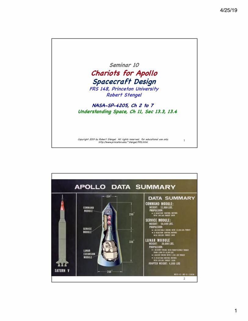
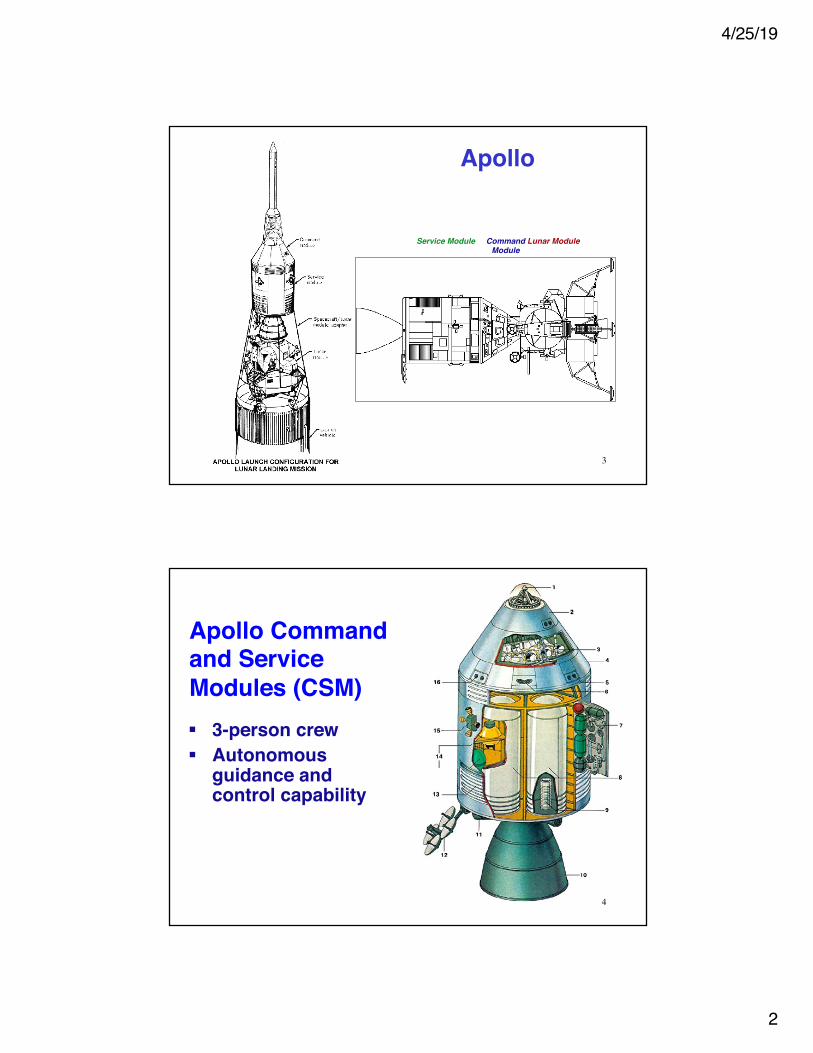
Apollo
Command Module
Service Module Lunar Module
3
Apollo Command and Service Modules (CSM)§ 3-person crew§ Autonomous
guidance and control capability
4
4/25/19
3
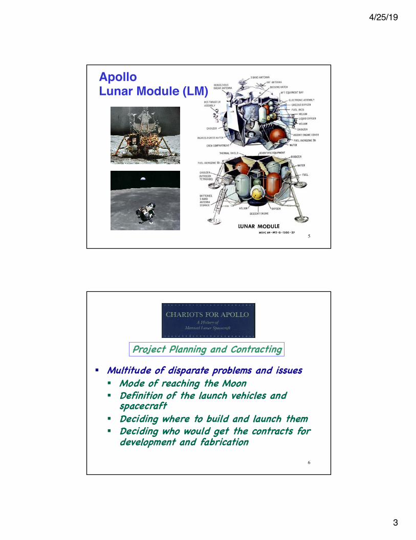
Apollo Lunar Module (LM)
5
§ Multitude of disparate problems and issues§ Mode of reaching the Moon§ Definition of the launch vehicles and
spacecraft§ Deciding where to build and launch them§ Deciding who would get the contracts for
development and fabrication
Project Planning and Contracting
6
4/25/19
4
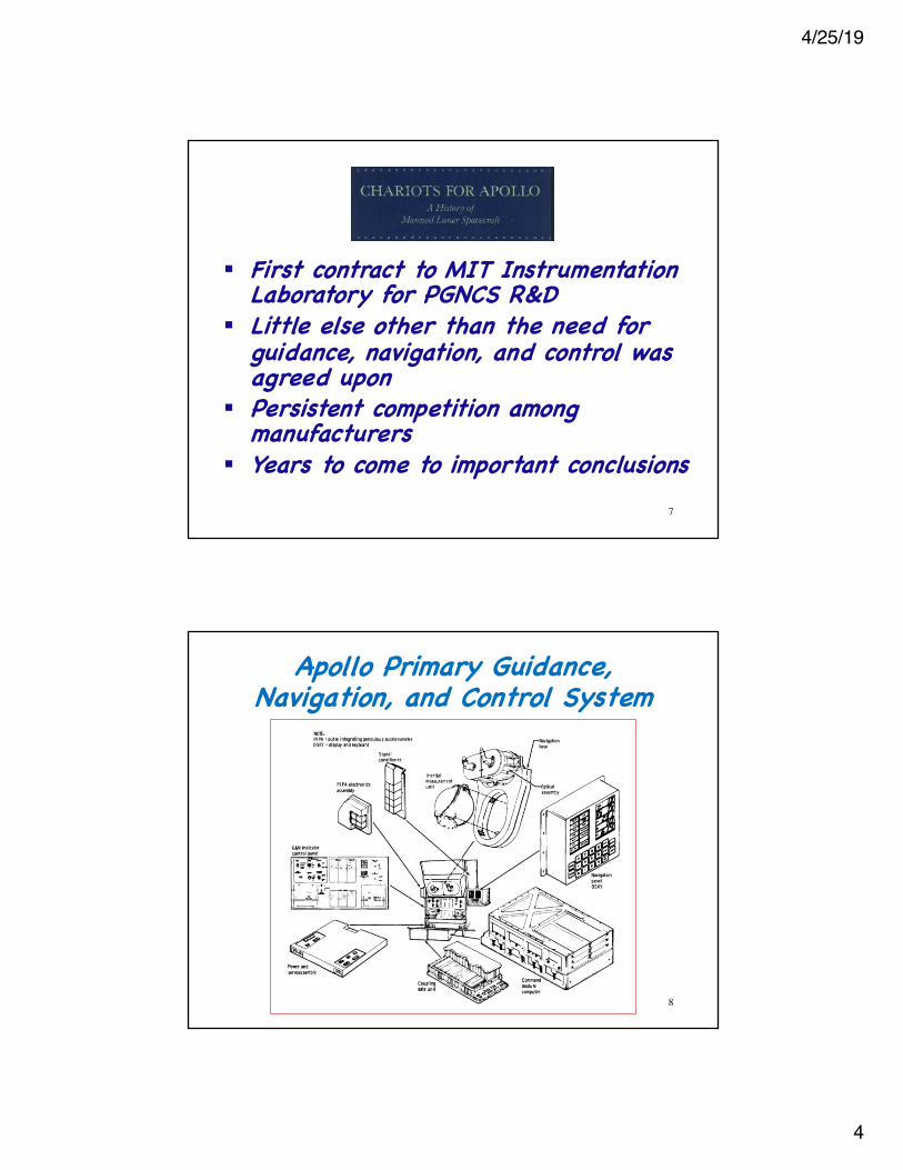
§ First contract to MIT Instrumentation Laboratory for PGNCS R&D
§ Little else other than the need for guidance, navigation, and control was agreed upon
§ Persistent competition among manufacturers
§ Years to come to important conclusions7
Apollo Primary Guidance, Navigation, and Control System
8
4/25/19
5
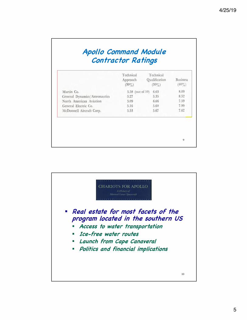
Apollo Command Module Contractor Ratings
9
§ Real estate for most facets of the program located in the southern US§ Access to water transportation§ Ice-free water routes§ Launch from Cape Canaveral§ Politics and financial implications
10
4/25/19
6
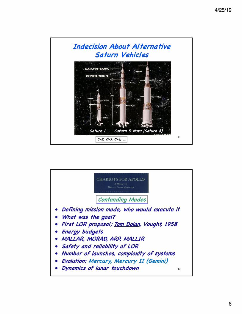
Indecision About Alternative Saturn Vehicles
11
Saturn 1 Saturn 5 Nova (Saturn 8)C-2, C-3, C-4, ...
• Defining mission mode, who would execute it• What was the goal?• First LOR proposal; Tom Dolan, Vought, 1958• Energy budgets• MALLAR, MORAD, ARP, MALLIR• Safety and reliability of LOR• Number of launches, complexity of systems• Evolution: Mercury, Mercury II (Gemini)• Dynamics of lunar touchdown
Contending Modes
12
4/25/19
7
• Reaching consensus• Centralizing decision processes at NASA HQ• Lunar crasher• Persistent criticism of LOR from PSAC• Wiesner not a fan of human space flight• Weight-lifting capability of Saturn C-5• Von Braun’s acquiescence for LOR
Joe Shea
13
• NASA-NAA relationship, LOR, LEM contractor• Harrison Storms, et al, at NAA• Design and testing facilities• Briefings, agendas, mockups, boilerplates• Test launches, landing systems, cabin• NASA centers, MIT Instrumentation Lab• Quality control and cross-checks• Interface control documents
Matching Modules and Missions
14
4/25/19
8
• Lunar landing vehicle, mysterious surface• PSAC pressures, reliability estimates• JFK’s preoccupation with Cuban missile crisis• Wiesner’s opposition, Webb’s commitment• Responsibility for CSM-LEM rested with MSC• NAA suggested LEM builder be sub-contractor• Grumman vs. McDonnell, other programs in
progress, contract negotiations• Integrated Mission Control Center at MSC• Gemini for rendezvous and docking tests
Jerome Wiesner
15
• Selection of CSM-LEM docking configuration• Block I, II CM configurations (before fire)• GE role in ground support• Bellcomm (NASA HQ support contractor)• Apollo Systems Specification manual • Critical Design Review (CDR) • Performance Development Review (PDR)• Lack of cooperation among NASA centers• Telecommunications and Tracking Stations
Command Module and Program Changes
16
4/25/19
9
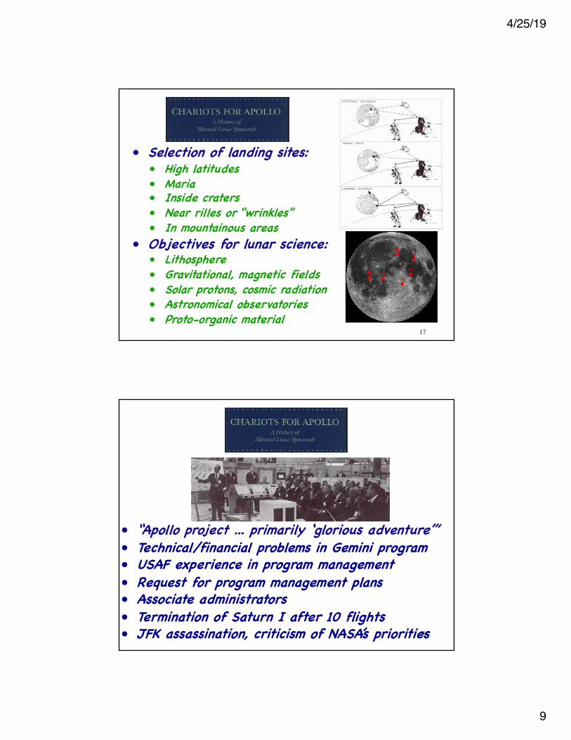
• Selection of landing sites:• High latitudes• Maria• Inside craters• Near rilles or “wrinkles”• In mountainous areas
• Objectives for lunar science:• Lithosphere• Gravitational, magnetic fields• Solar protons, cosmic radiation• Astronomical observatories• Proto-organic material
17
• “Apollo project ... primarily ‘glorious adventure’”• Technical/financial problems in Gemini program• USAF experience in program management• Request for program management plans• Associate administrators• Termination of Saturn I after 10 flights• JFK assassination, criticism of NASA’s priorities18
4/25/19
10
• Block I /Block II CM versions• Stabilizing CM during launch abort• Land or water touchdown• Design Reference Mission; responsibilities• Probe-and-drogue docking adapter• Mockup Review Board• Parachute failure, Little Joe II test• From fixed to controlled fins on LJII
19
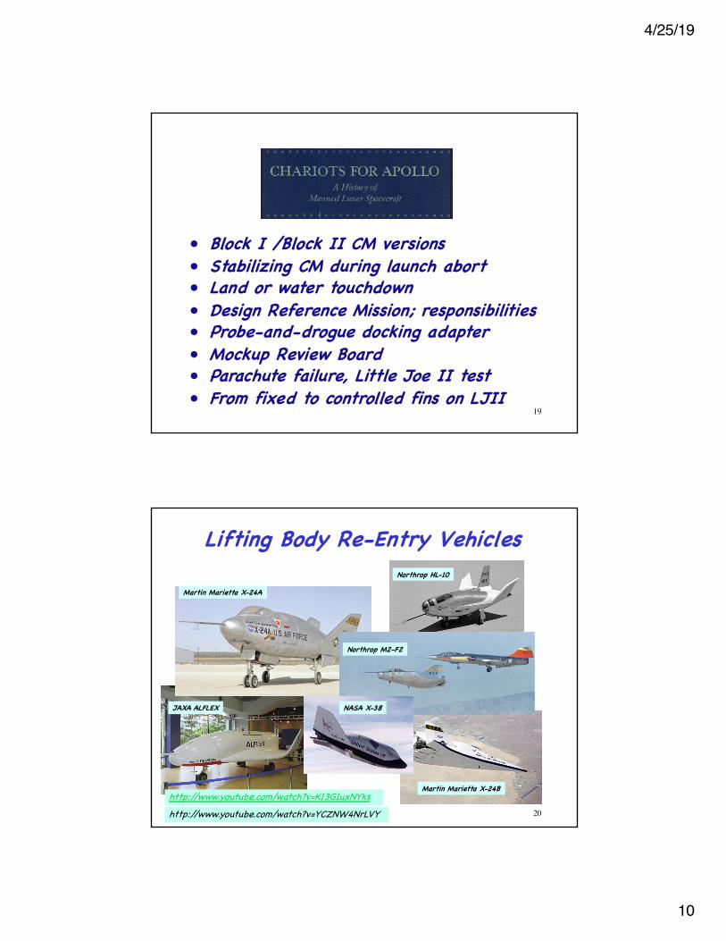
Lifting Body Re-Entry VehiclesNorthrop HL-10
Martin Marietta X-24A
Northrop M2-F2
Martin Marietta X-24B
JAXA ALFLEX NASA X-38
http://www.youtube.com/watch?v=K13G1uxNYkshttp://www.youtube.com/watch?v=YCZNW4NrLVY 20
4/25/19
11
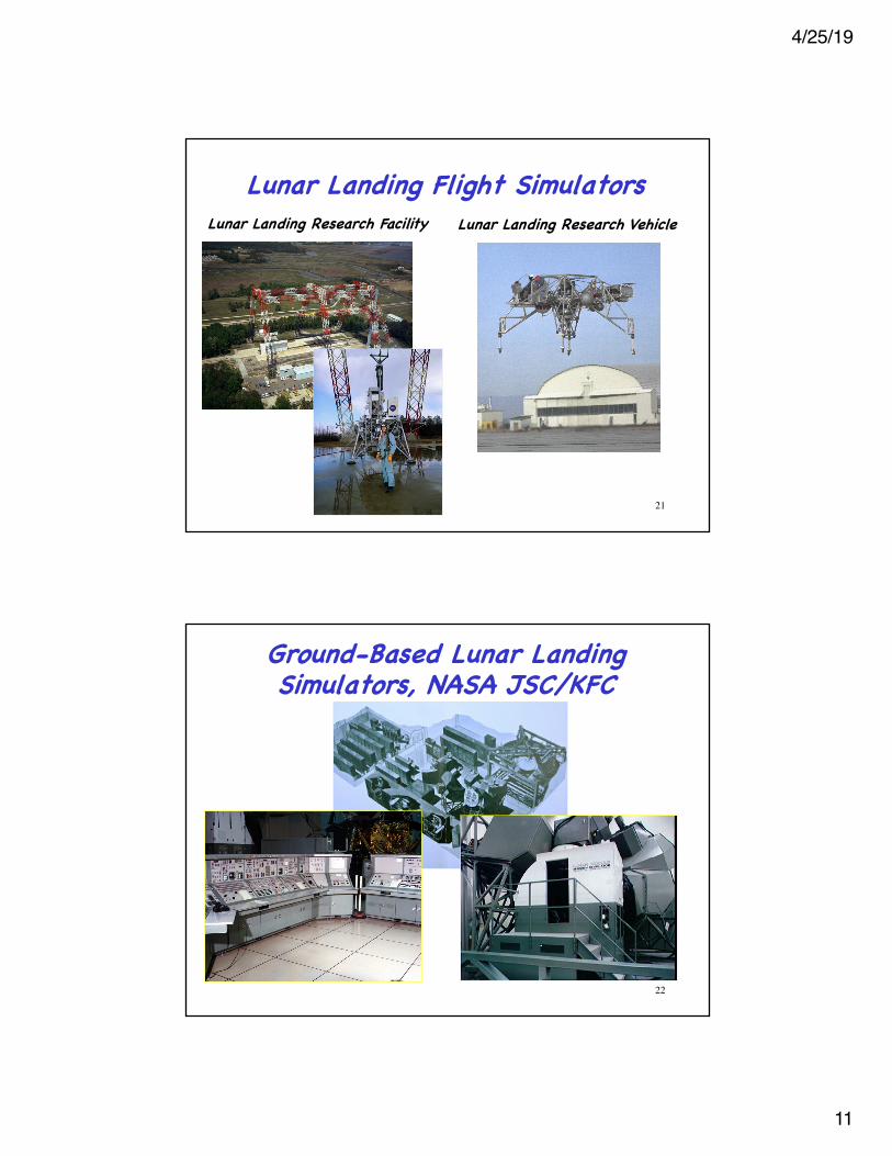
Lunar Landing Flight SimulatorsLunar Landing Research Facility Lunar Landing Research Vehicle
21
Ground-Based Lunar Landing Simulators, NASA JSC/KFC
22
4/25/19
12
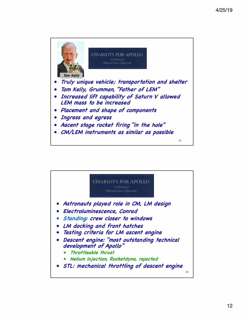
• Truly unique vehicle; transportation and shelter• Tom Kelly, Grumman, “Father of LEM”• Increased lift capability of Saturn V allowed
LEM mass to be increased• Placement and shape of components• Ingress and egress• Ascent stage rocket firing “in the hole”• CM/LEM instruments as similar as possible
Tom Kelly
23
• Astronauts played role in CM, LM design• Electroluminescence, Conrad• Standing: crew closer to windows• LM docking and front hatches• Testing criteria for LM ascent engine• Descent engine: “most outstanding technical
development of Apollo”• Throttleable thrust• Helium injection, Rocketdyne, rejected
• STL: mechanical throttling of descent engine24
4/25/19
13
• Continuing competition between corporations• Bi-propellant RCS thrusters, Marquardt.
Thrust spiking problem remediated• RCA: • engineering support• landing and rendezvous radars• sub-sub contract to Ryan• antennas, accuracy, weight• inflight test system• radar control system
• In-flight maintenance considered; redundancy chosen instead
25
• Adoption of CM GNC for LM• Everything had to be renegotiated• Reliability, 3-gimbal platform, conflict
between Grumman and MIT/IL (“scratchy”)• Mockup reviews• Grumman: Test to failure• Mueller: All-up testing concept
26
4/25/19
14
§ Flight Article Configuration Inspection (FACI)§ Certification of Flight Worthiness (COFW)§ Design Certification Review (DCR)§ Flight Readiness Review (FRR)§ Weight control, configuration control§ Unnecessary changes in Block II opposed§ LEM testing: a pacing item§ Space suit development
Searching for Order - 1965
27
Spacecraft Design
28
4/25/19
15
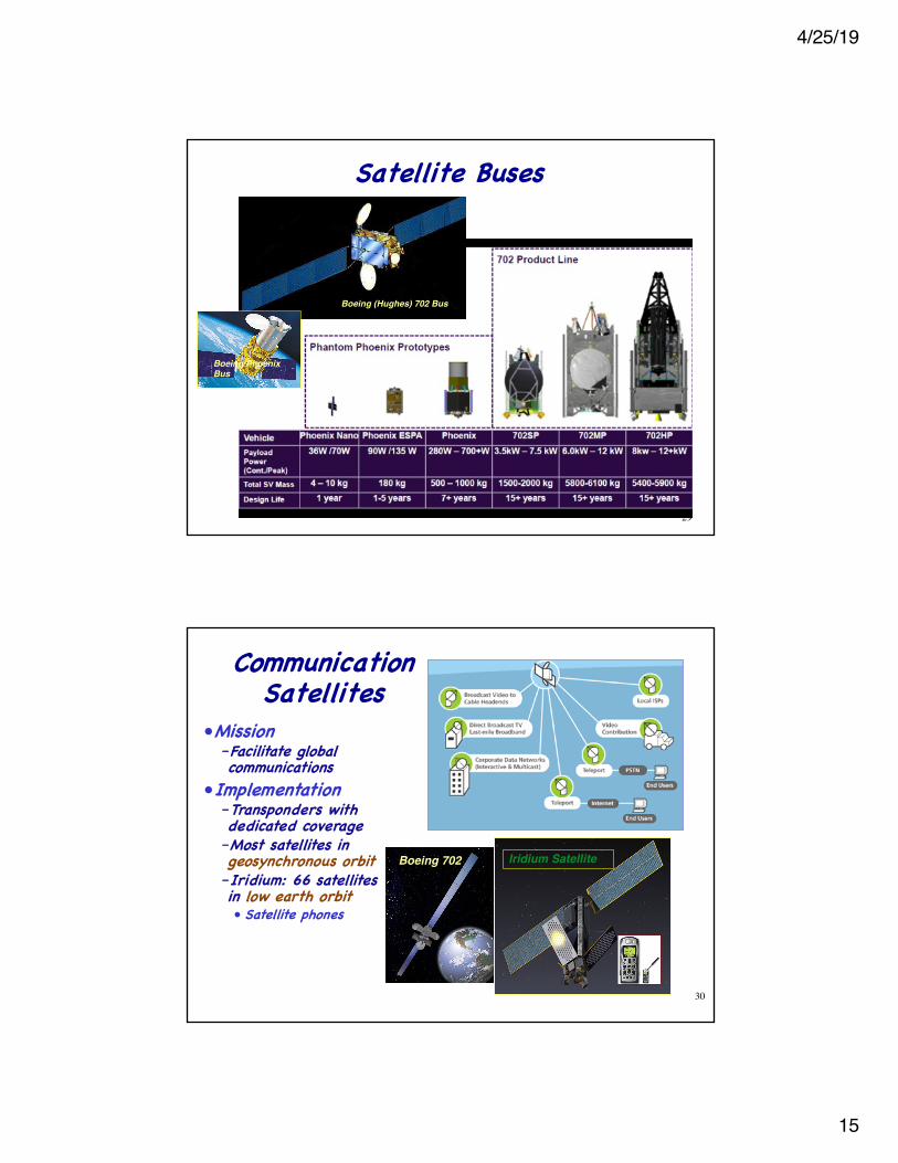
Satellite Buses
Boeing (Hughes) 702 Bus
29
Boeing Phoenix Bus
Communication Satellites
•Mission–Facilitate global communications
•Implementation–Transponders with dedicated coverage–Most satellites in geosynchronous orbit–Iridium: 66 satellites in low earth orbit• Satellite phones
Boeing 702 Iridium Satellite
30
4/25/19
16
31
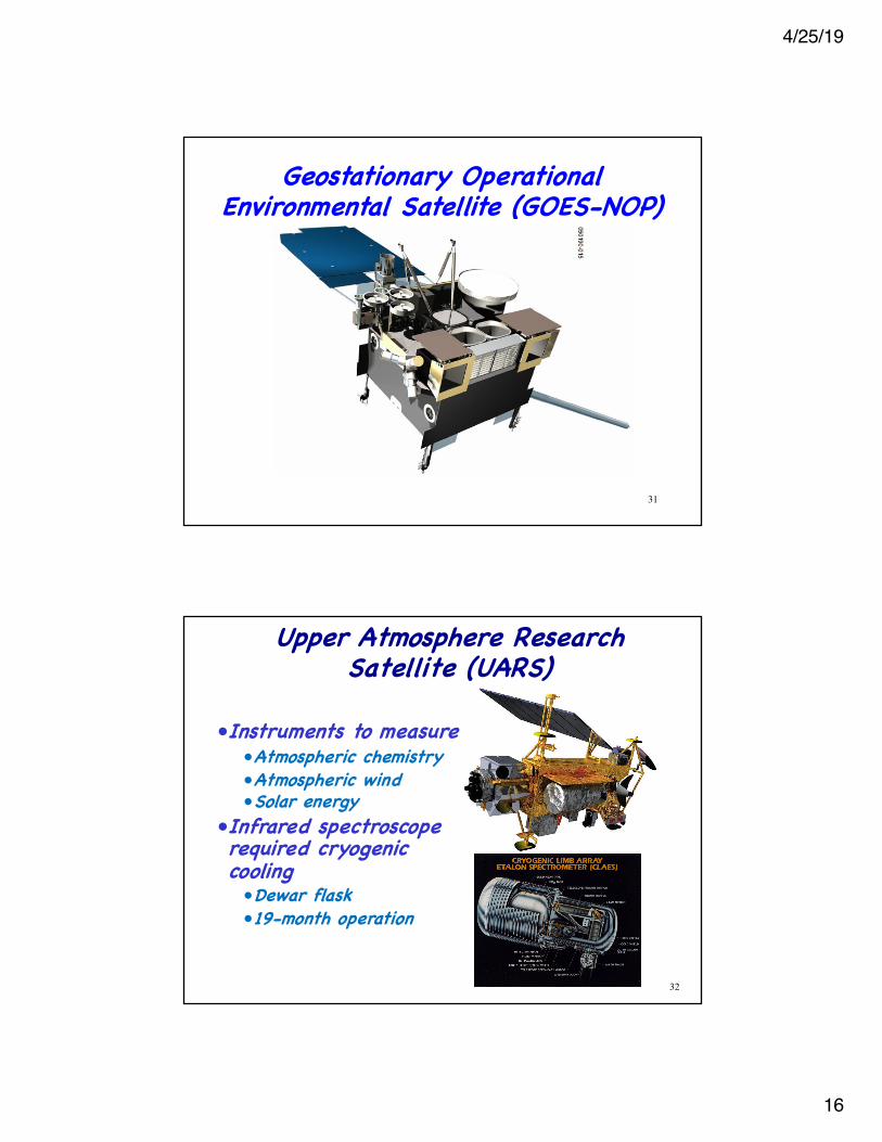
Geostationary Operational Environmental Satellite (GOES-NOP)
Upper Atmosphere Research Satellite (UARS)
32
•Instruments to measure•Atmospheric chemistry•Atmospheric wind•Solar energy
•Infrared spectroscope required cryogenic cooling•Dewar flask•19-month operation
4/25/19
17
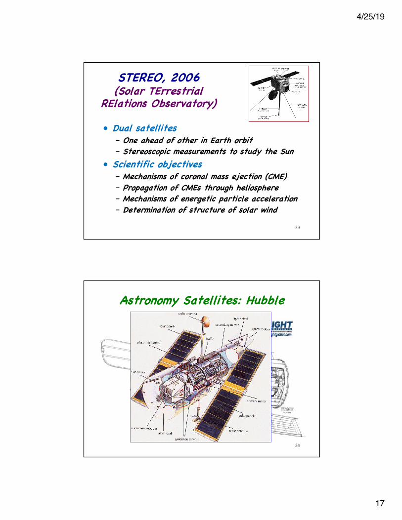
STEREO, 2006 (Solar TErrestrial
RElations Observatory)
• Dual satellites– One ahead of other in Earth orbit– Stereoscopic measurements to study the Sun
• Scientific objectives– Mechanisms of coronal mass ejection (CME)– Propagation of CMEs through heliosphere– Mechanisms of energetic particle acceleration– Determination of structure of solar wind
33
Astronomy Satellites: Hubble
34
4/25/19
18
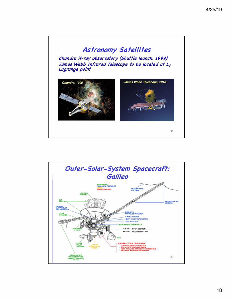
Astronomy Satellites Chandra X-ray observatory (Shuttle launch, 1999)James Webb Infrared Telescope to be located at L2Lagrange point
James Webb Telescope, 2018Chandra, 1999
35
36
Outer-Solar-System Spacecraft: Galileo
4/25/19
19
Outer-Solar-System Spacecraft: New Horizons
•Mission duration: 2006-2019+•Destination: Pluto, Kuiper Belt•Radioisotope thermal power generator•Spin-stabilized in cruise, 3-axis control (hydrazine RCS) for science
• Fastest spacecraft to date (Vearth = 16.21 km/s, Atlas 5)
• 546,700-kg initial mass• Payload = 478 kg• Jupiter fly-by added 4 km/s to speed 37
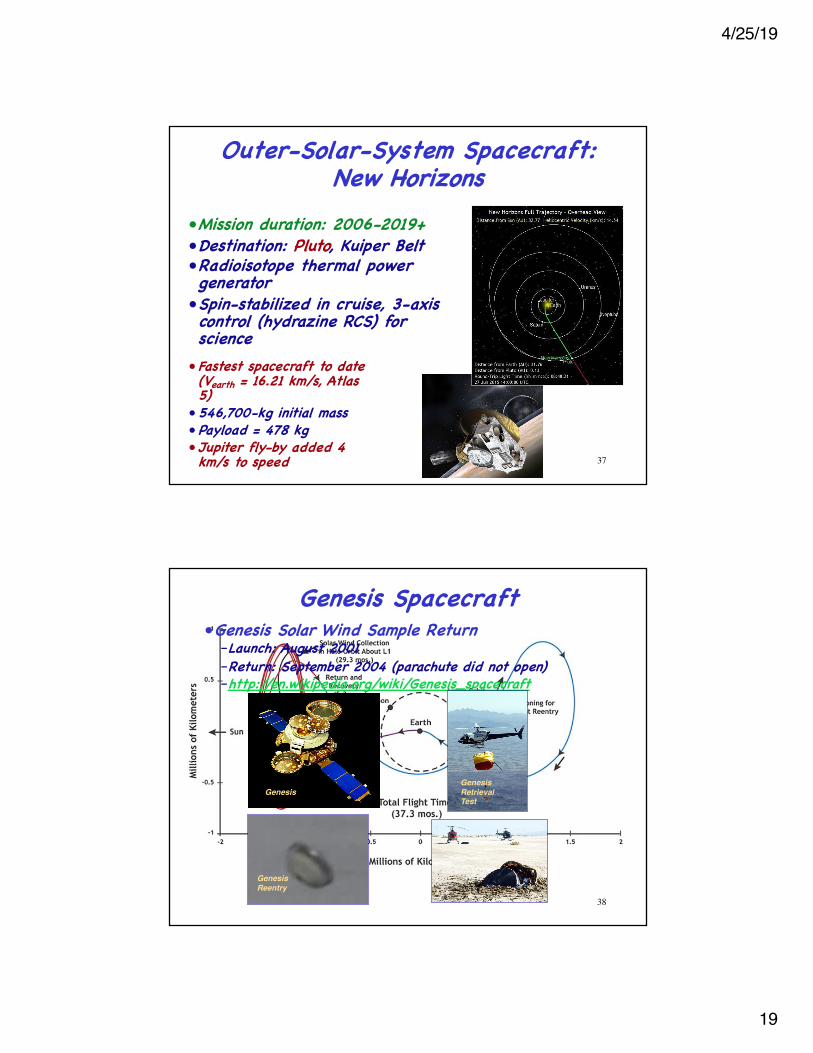
Genesis Spacecraft •Genesis Solar Wind Sample Return
–Launch: August 2001–Return: September 2004 (parachute did not open)–http://en.wikipedia.org/wiki/Genesis_spacecraft
GenesisGenesis Retrieval Test
GenesisReentry
38
4/25/19
20
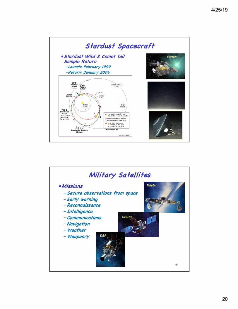
Stardust Spacecraft •Stardust Wild 2 Comet Tail Sample Return–Launch: February 1999–Return: January 2006
Stardust
39
Military Satellites •Missions–Secure observations from space–Early warning–Reconnaissance– Intelligence–Communications–Navigation–Weather–Weaponry
Milstar
SBIRS
DSP
40
4/25/19
21
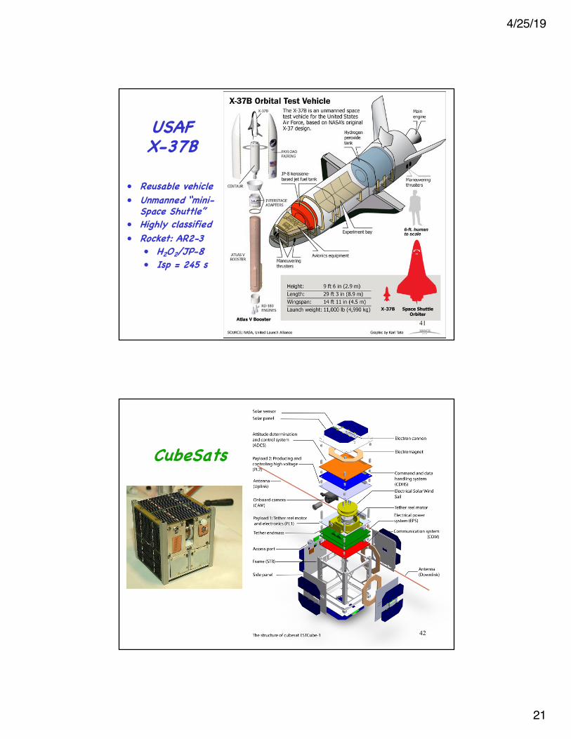
• Reusable vehicle• Unmanned “mini-
Space Shuttle” • Highly classified• Rocket: AR2-3
• H2O2/JP-8 • Isp = 245 s
USAF X-37B
41
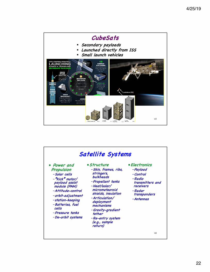
CubeSats
42
4/25/19
22
CubeSats
43
§ Secondary payloads§ Launched directly from ISS§ Small launch vehicles
Satellite Systems•Structure
–Skin, frames, ribs, stringers, bulkheads–Propellant tanks–Heat/solar/ micrometeoroid shields, insulation–Articulation/ deployment mechanisms–Gravity-gradient tether–Re-entry system (e.g., sample return)
• Power and Propulsion–Solar cells–�Kick� motor/ payload assist module (PAM)–Attitude-control–orbit-adjustment–station-keeping–Batteries, fuel cells–Pressure tanks–De-orbit systems
•Electronics–Payload–Control–Radio transmitters and receivers–Radar transponders–Antennas
44
4/25/19
23
Spacecraft Stiffness* Requirements for Primary Structure
* Natural frequency45
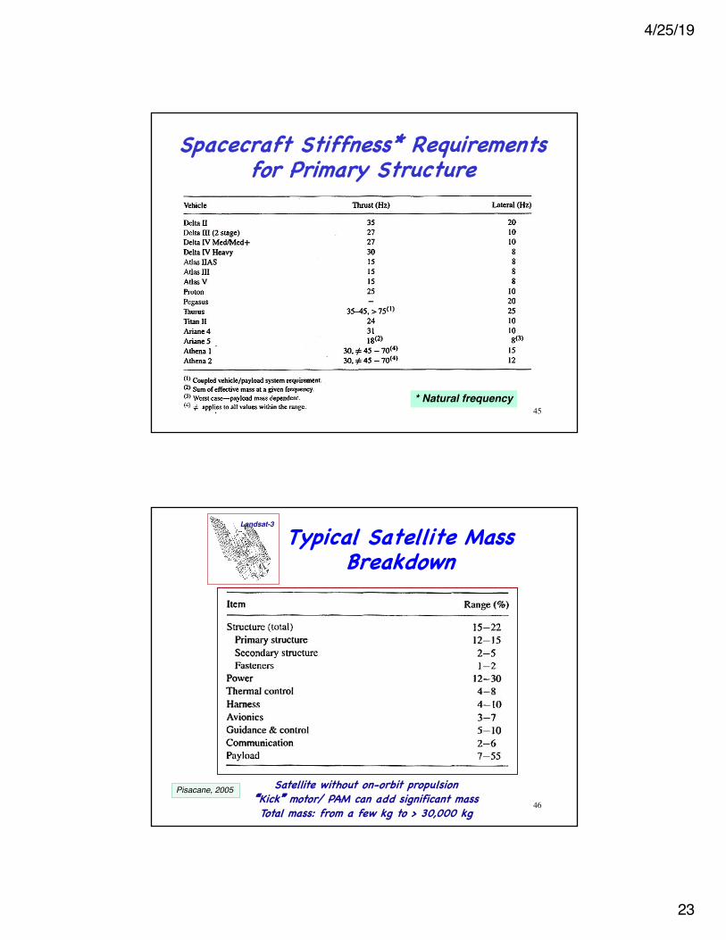
Typical Satellite Mass Breakdown
Satellite without on-orbit propulsion�Kick� motor/ PAM can add significant massTotal mass: from a few kg to > 30,000 kg
Landsat-3
46
Pisacane, 2005
4/25/19
24
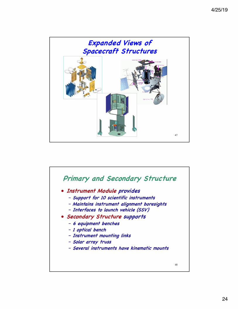
Expanded Views of Spacecraft Structures
47
Primary and Secondary Structure• Instrument Module provides
– Support for 10 scientific instruments– Maintains instrument alignment boresights– Interfaces to launch vehicle (SSV)
• Secondary Structure supports– 6 equipment benches– 1 optical bench– Instrument mounting links– Solar array truss– Several instruments have kinematic mounts
48
4/25/19
25
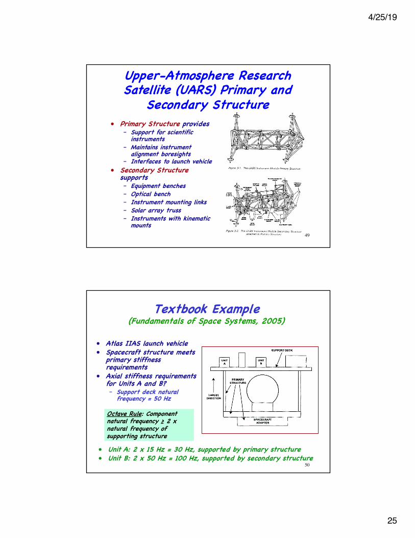
• Primary Structure provides– Support for scientific
instruments– Maintains instrument
alignment boresights– Interfaces to launch vehicle
• Secondary Structuresupports– Equipment benches– Optical bench– Instrument mounting links– Solar array truss– Instruments with kinematic
mounts
Upper-Atmosphere Research Satellite (UARS) Primary and
Secondary Structure
49
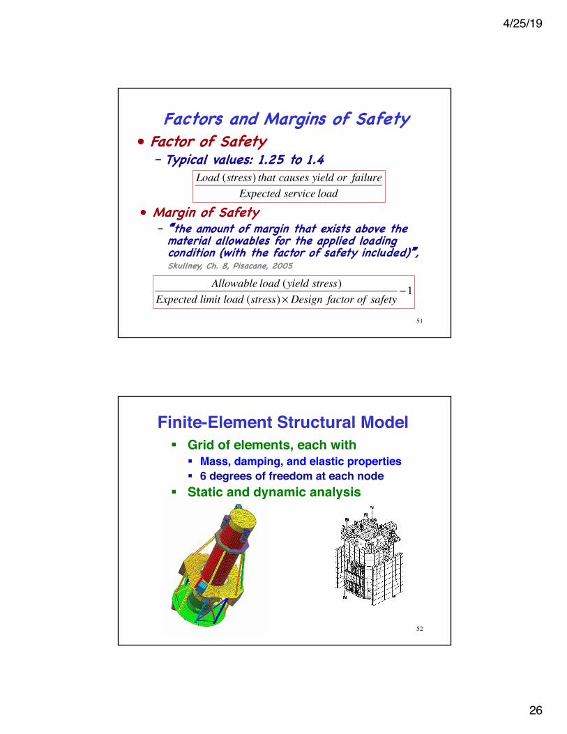
Textbook Example(Fundamentals of Space Systems, 2005)
• Atlas IIAS launch vehicle• Spacecraft structure meets
primary stiffness requirements
• Axial stiffness requirements for Units A and B?– Support deck natural
frequency = 50 Hz
Octave Rule: Component natural frequency ≥ 2 x natural frequency of supporting structure
• Unit A: 2 x 15 Hz = 30 Hz, supported by primary structure• Unit B: 2 x 50 Hz = 100 Hz, supported by secondary structure
50
4/25/19
26
Factors and Margins of Safety• Factor of Safety
– Typical values: 1.25 to 1.4
Allowable load (yield stress)Expected limit load (stress)× Design factor of safety
−1
• Margin of Safety– �the amount of margin that exists above the
material allowables for the applied loading condition (with the factor of safety included)�, Skullney, Ch. 8, Pisacane, 2005
Load (stress) that causes yield or failureExpected service load
51
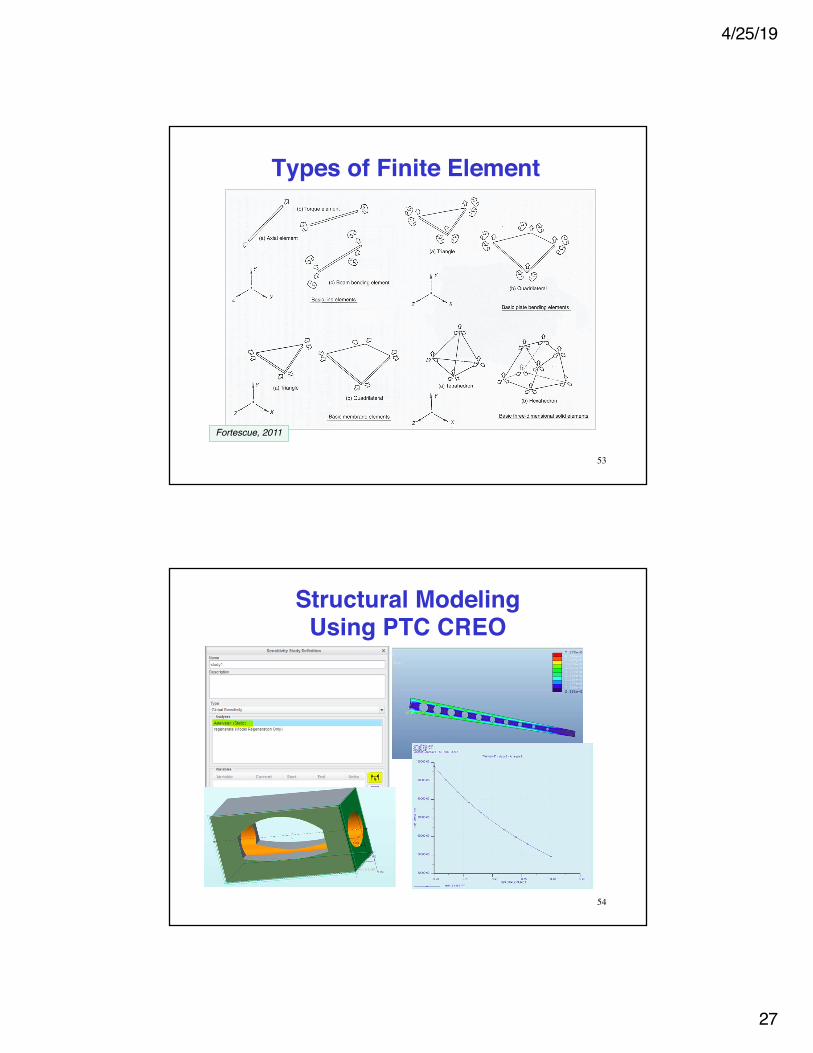
Finite-Element Structural Model
52
§ Grid of elements, each with§ Mass, damping, and elastic properties§ 6 degrees of freedom at each node
§ Static and dynamic analysis
4/25/19
27
Types of Finite Element
53
Fortescue, 2011
Structural Modeling Using PTC CREO
54
4/25/19
28
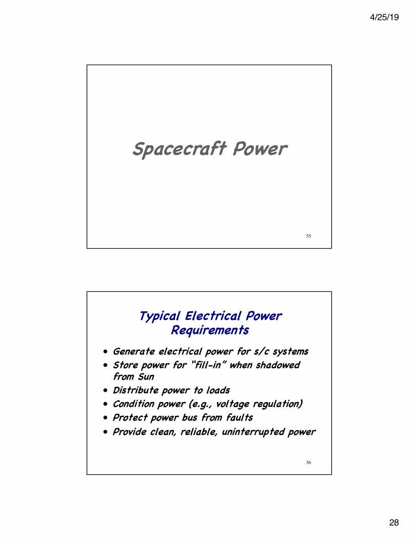
Spacecraft Power
55
Typical Electrical Power Requirements
• Generate electrical power for s/c systems• Store power for “fill-in” when shadowed
from Sun• Distribute power to loads• Condition power (e.g., voltage regulation)• Protect power bus from faults• Provide clean, reliable, uninterrupted power
56
4/25/19
29
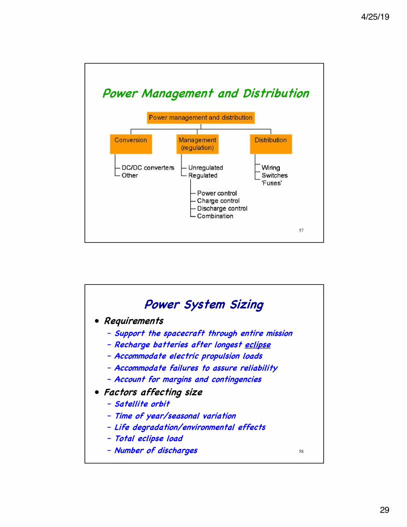
Power Management and Distribution
57
Power System Sizing• Requirements
– Support the spacecraft through entire mission– Recharge batteries after longest eclipse– Accommodate electric propulsion loads– Accommodate failures to assure reliability– Account for margins and contingencies
• Factors affecting size– Satellite orbit– Time of year/seasonal variation– Life degradation/environmental effects– Total eclipse load– Number of discharges 58
4/25/19
30
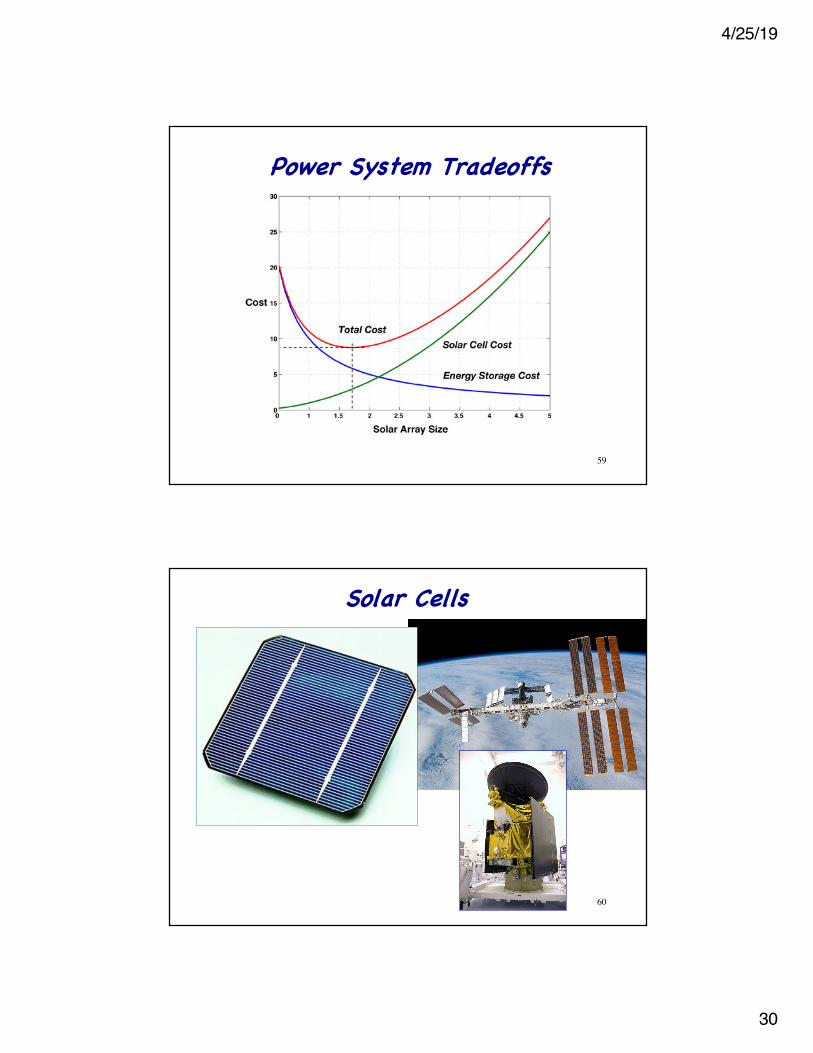
Power System Tradeoffs
59
Solar Cells
60
4/25/19
31
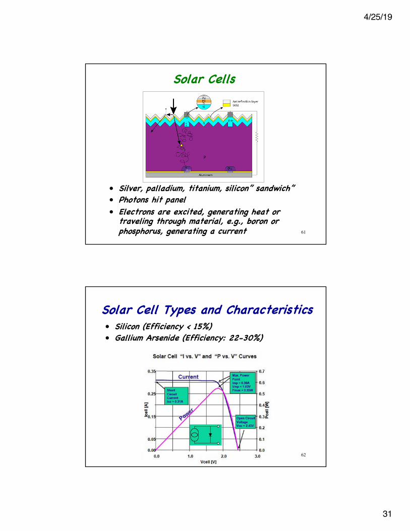
Solar Cells
61
• Silver, palladium, titanium, silicon” sandwich”• Photons hit panel• Electrons are excited, generating heat or
traveling through material, e.g., boron or phosphorus, generating a current
Solar Cell Types and Characteristics• Silicon (Efficiency < 15%)• Gallium Arsenide (Efficiency: 22-30%)
62
4/25/19
32
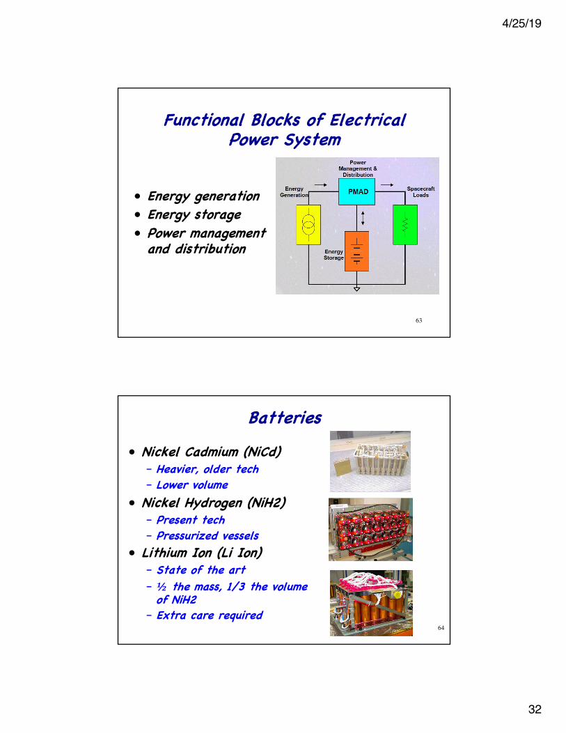
Functional Blocks of Electrical Power System
• Energy generation• Energy storage• Power management
and distribution
63
Batteries• Nickel Cadmium (NiCd)
– Heavier, older tech– Lower volume
• Nickel Hydrogen (NiH2)– Present tech– Pressurized vessels
• Lithium Ion (Li Ion)– State of the art– ½ the mass, 1/3 the volume
of NiH2– Extra care required
64
4/25/19
33
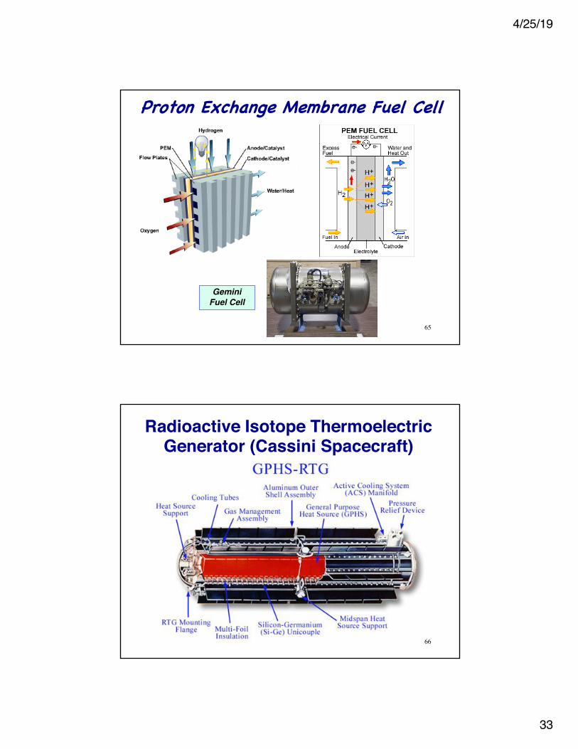
Proton Exchange Membrane Fuel Cell
65
Gemini Fuel Cell
Radioactive Isotope Thermoelectric Generator (Cassini Spacecraft)
66
4/25/19
34
Thermal Control
67
Typical Temperature Requirements• Maximum & minimum operational/non-
operational temperatures• Maximum diurnal swing• Maximum gradients• Survival/safe state temperature• Allowable rate of change• Control requirements of sub-systems
68
4/25/19
35
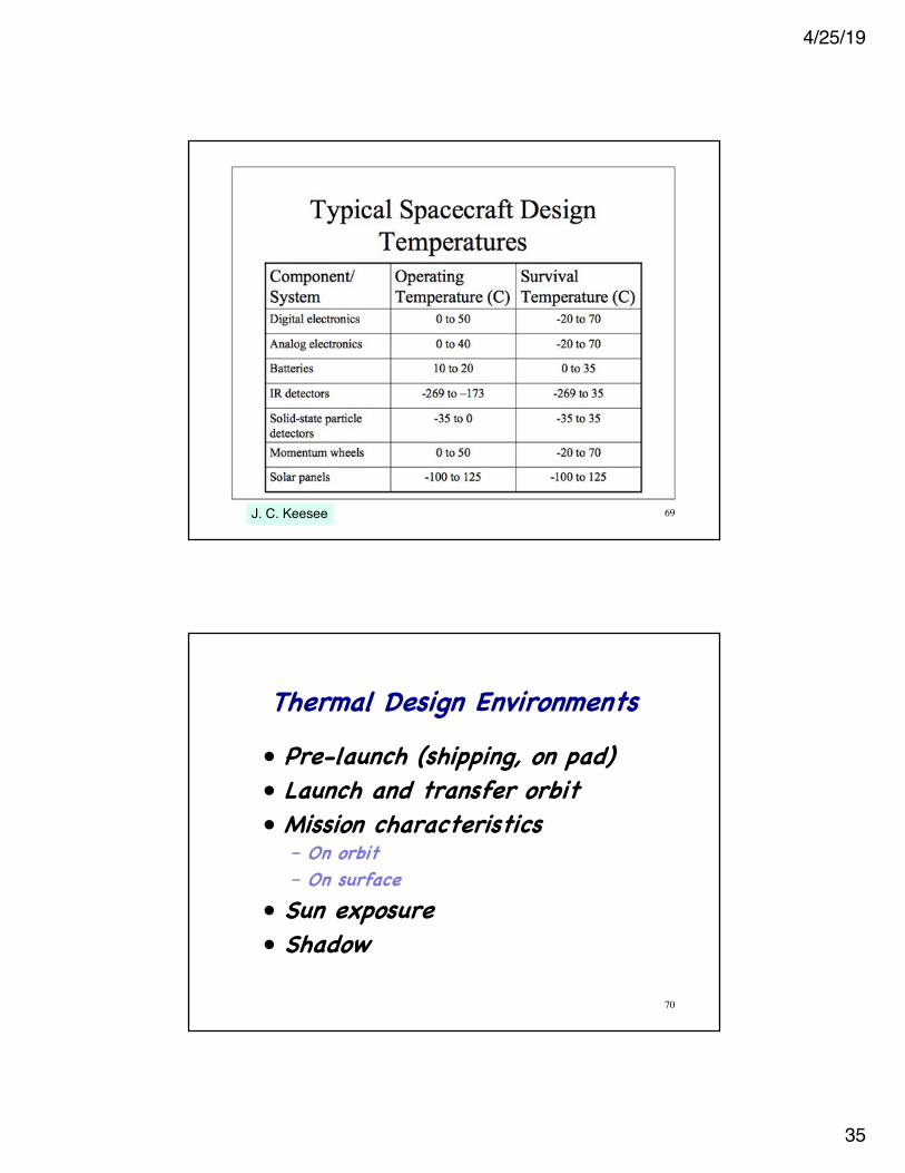
69J. C. Keesee
Thermal Design Environments• Pre-launch (shipping, on pad)• Launch and transfer orbit• Mission characteristics
– On orbit– On surface
• Sun exposure• Shadow
70
4/25/19
36
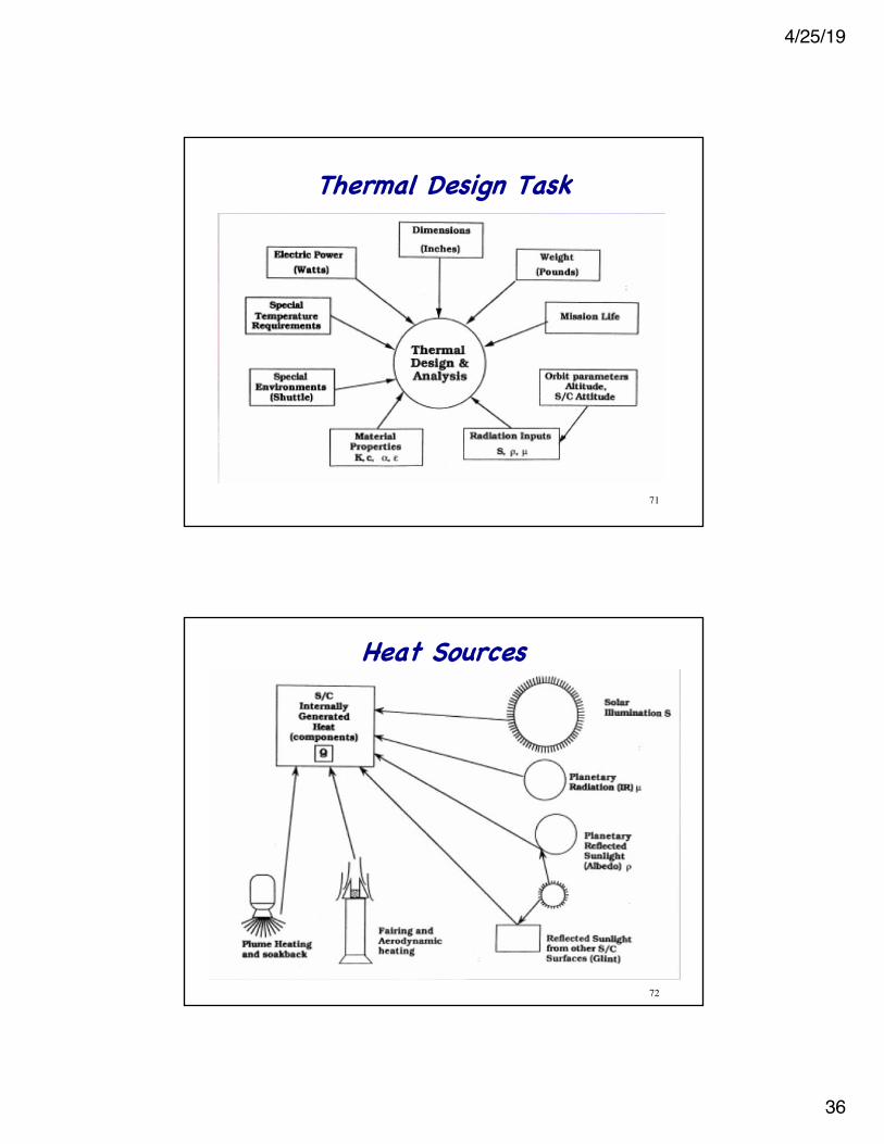
Thermal Design Task
71
Heat Sources
72
4/25/19
37
Thermal Design Constraints• Equipment utilization philosophy• Design margin philosophy• Failure mode philosophy• Power system margin• Mass budget• Temperature specifications• Sun/shadow duty cycle• Equipment redundancy
73
Thermal Analysis• Steady state (thermal equilibrium)• Transient• Thermal network models
– Nodes• Elements that can be characterized by a
single temperature• Energy storage devices
– Conductors• Energy transport
– Energy sinks• Closed-form idealizations• Finite element/difference software
74
4/25/19
38
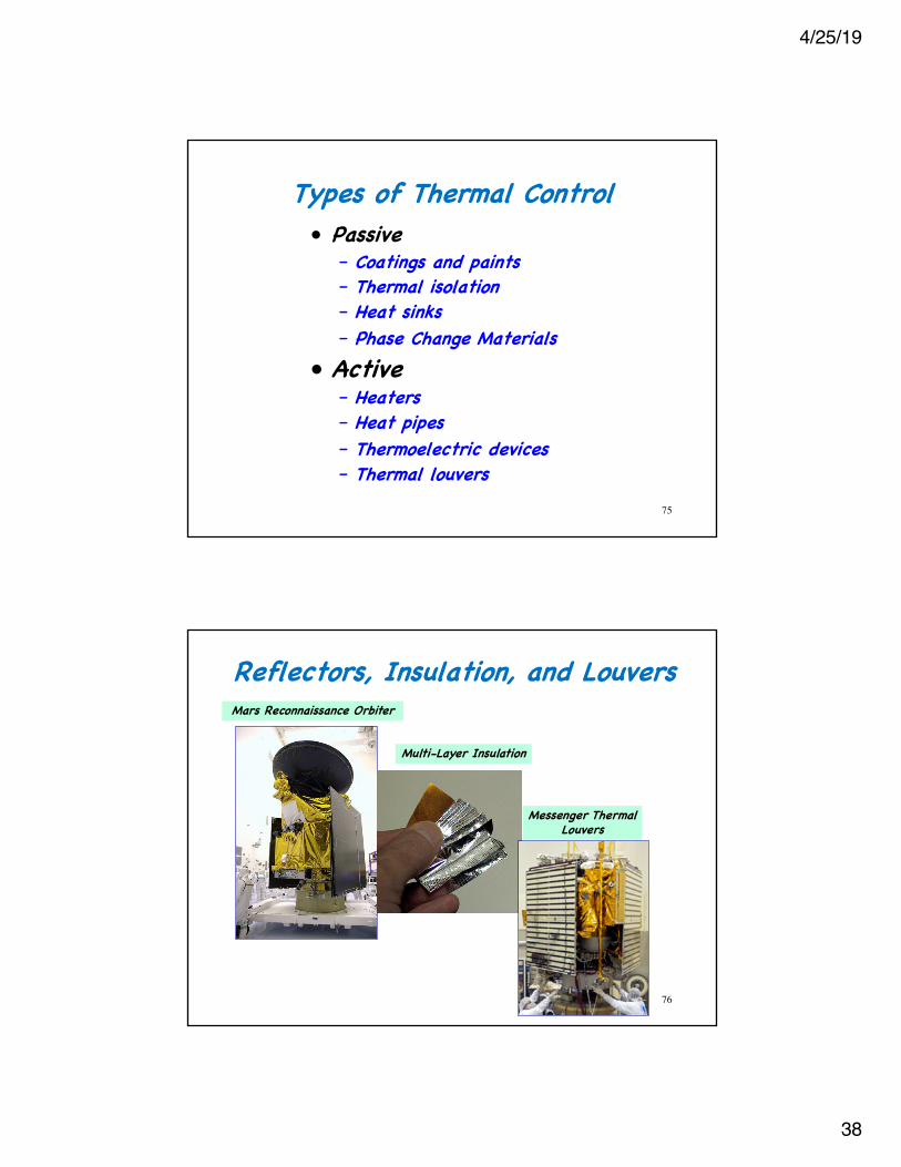
Types of Thermal Control• Passive
– Coatings and paints– Thermal isolation– Heat sinks– Phase Change Materials
• Active– Heaters– Heat pipes– Thermoelectric devices– Thermal louvers
75
Reflectors, Insulation, and Louvers
76
Mars Reconnaissance Orbiter
Multi-Layer Insulation
Messenger Thermal Louvers
4/25/19
39
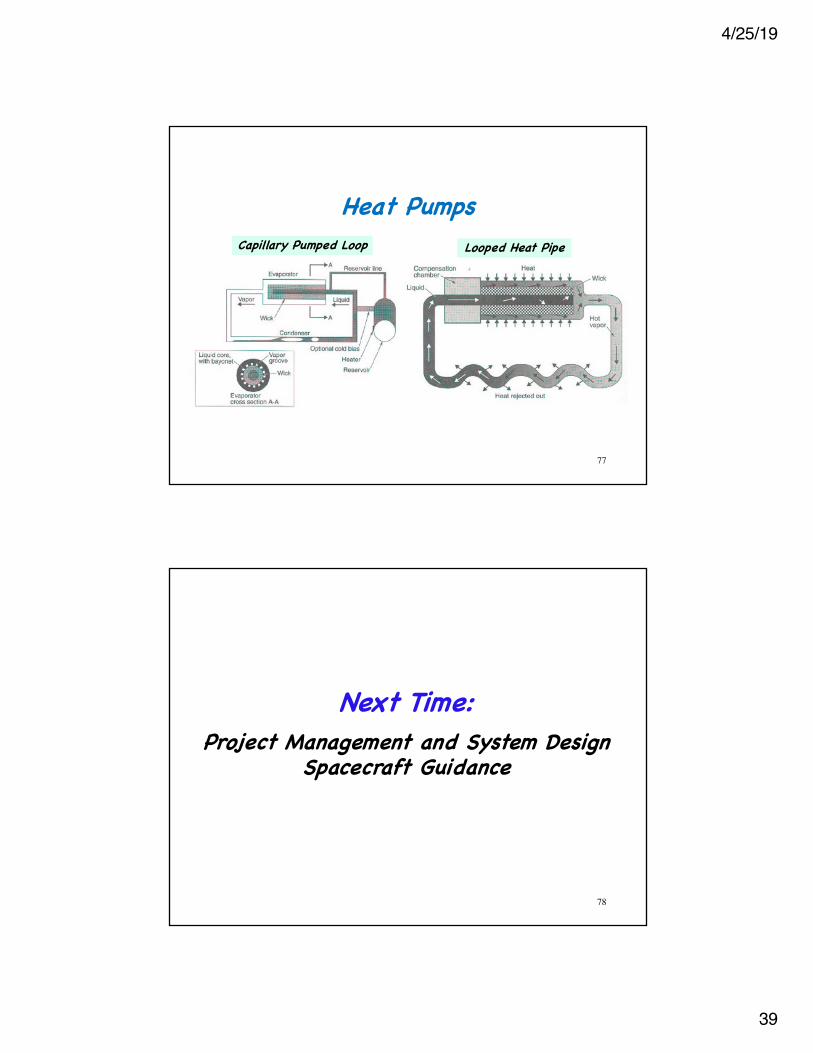
Heat Pumps
77
Capillary Pumped Loop Looped Heat Pipe
Next Time:
78
Project Management and System DesignSpacecraft Guidance
4/25/19
40
Supplemental Material
79
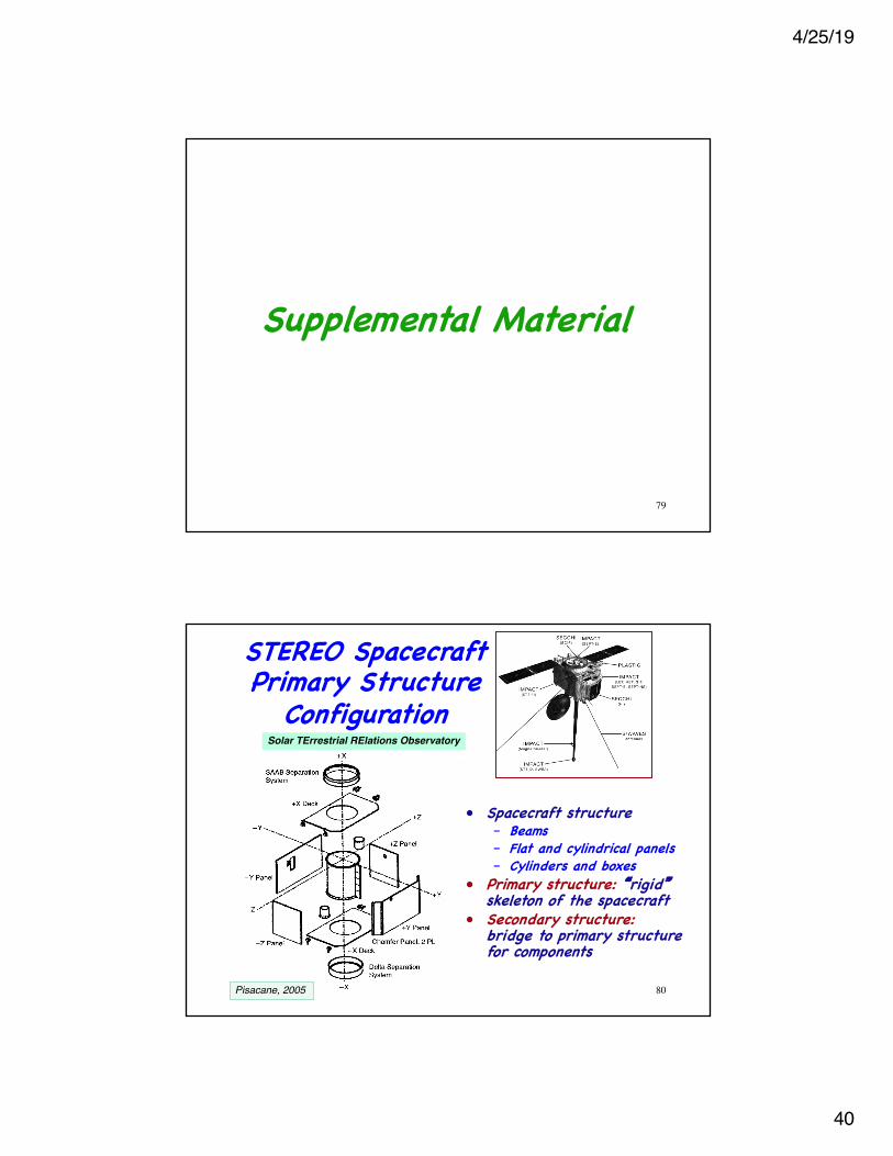
• Spacecraft structure– Beams– Flat and cylindrical panels– Cylinders and boxes
• Primary structure: �rigid�skeleton of the spacecraft
• Secondary structure:bridge to primary structure for components
Solar TErrestrial RElations Observatory
STEREO Spacecraft Primary Structure
Configuration
80Pisacane, 2005
4/25/19
41
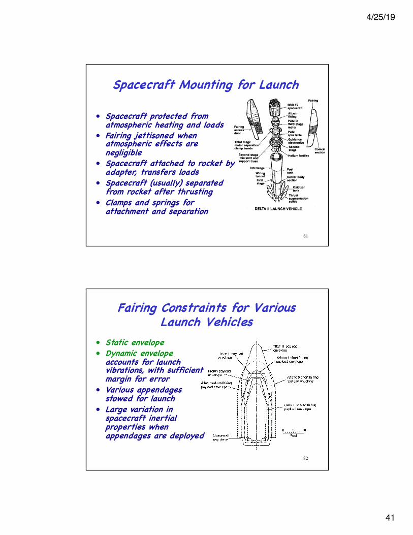
• Spacecraft protected from atmospheric heating and loads
• Fairing jettisoned when atmospheric effects are negligible
• Spacecraft attached to rocket by adapter, transfers loads
• Spacecraft (usually) separated from rocket after thrusting
• Clamps and springs for attachment and separation
Spacecraft Mounting for Launch
81
Fairing Constraints for Various Launch Vehicles
• Static envelope• Dynamic envelope
accounts for launch vibrations, with sufficient margin for error
• Various appendages stowed for launch
• Large variation in spacecraft inertial properties when appendages are deployed
82
4/25/19
42
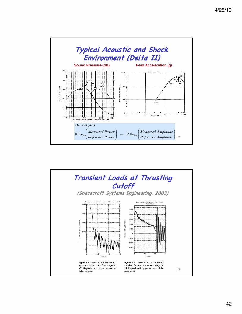
Typical Acoustic and Shock Environment (Delta II)
Sound Pressure (dB) Peak Acceleration (g)
�
Decibel (dB)
10log10Measured PowerReference Power
⎛
⎝ ⎜
⎞
⎠ ⎟ or 20log10
Measured AmplitudeReference Amplitude
⎛
⎝ ⎜
⎞
⎠ ⎟
83
Transient Loads at Thrusting Cutoff
(Spacecraft Systems Engineering, 2003)
84
4/25/19
43
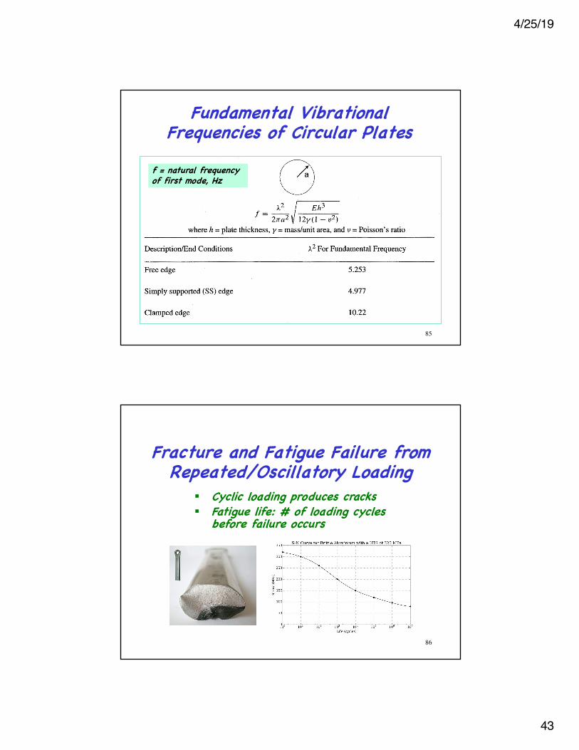
Fundamental Vibrational Frequencies of Circular Plates
f = natural frequency of first mode, Hz
85
Fracture and Fatigue Failure from Repeated/Oscillatory Loading
86
§ Cyclic loading produces cracks§ Fatigue life: # of loading cycles
before failure occurs
4/25/19
44
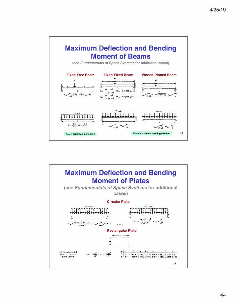
Maximum Deflection and Bending Moment of Beams
(see Fundamentals of Space Systems for additional cases)
Fixed-Free Beam Fixed-Fixed Beam Pinned-Pinned Beam
Ymax = maximum deflection Mmax = maximum bending moment 87
Maximum Deflection and Bending Moment of Plates
(see Fundamentals of Space Systems for additional cases)
Circular Plate
�
m =1/ν
88
Rectangular Plate
4/25/19
45
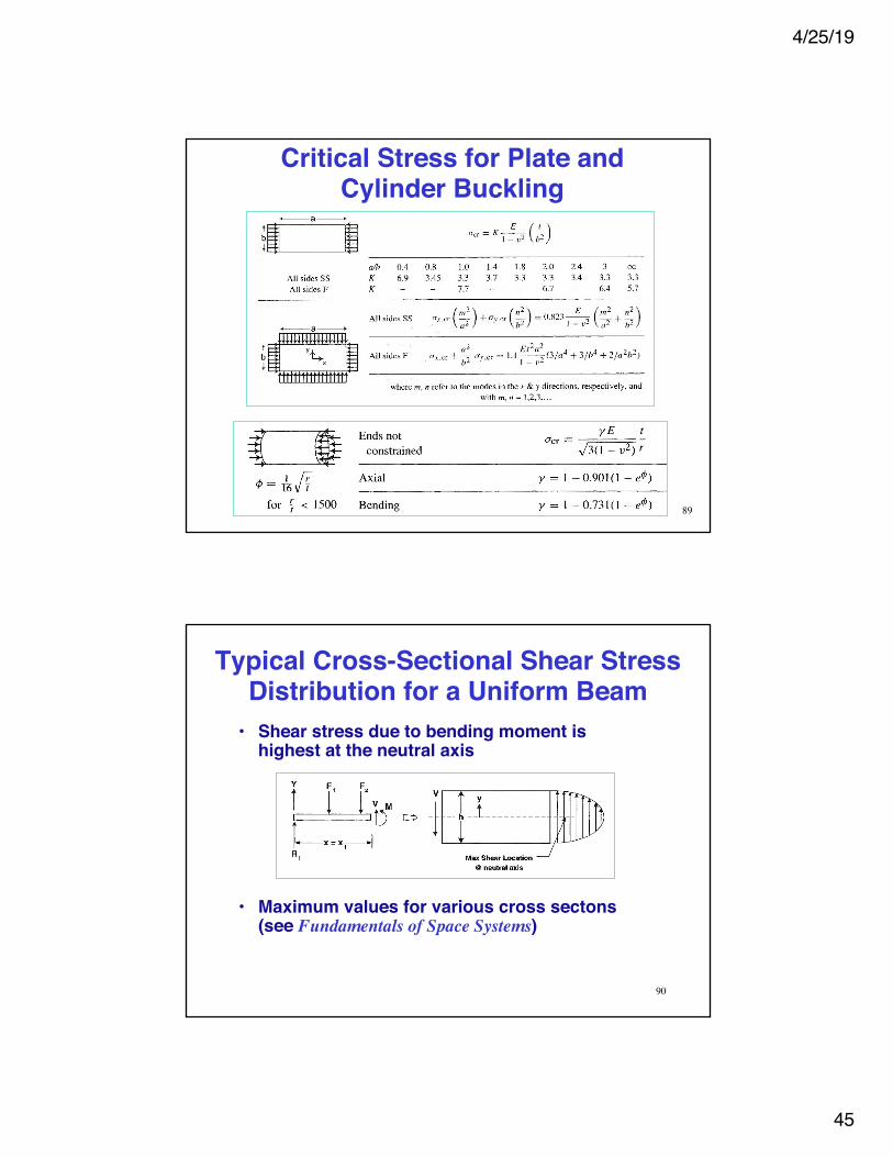
Critical Stress for Plate and Cylinder Buckling
89
Typical Cross-Sectional Shear Stress Distribution for a Uniform Beam• Shear stress due to bending moment is
highest at the neutral axis
• Maximum values for various cross sectons (see Fundamentals of Space Systems)
90
4/25/19
46
91
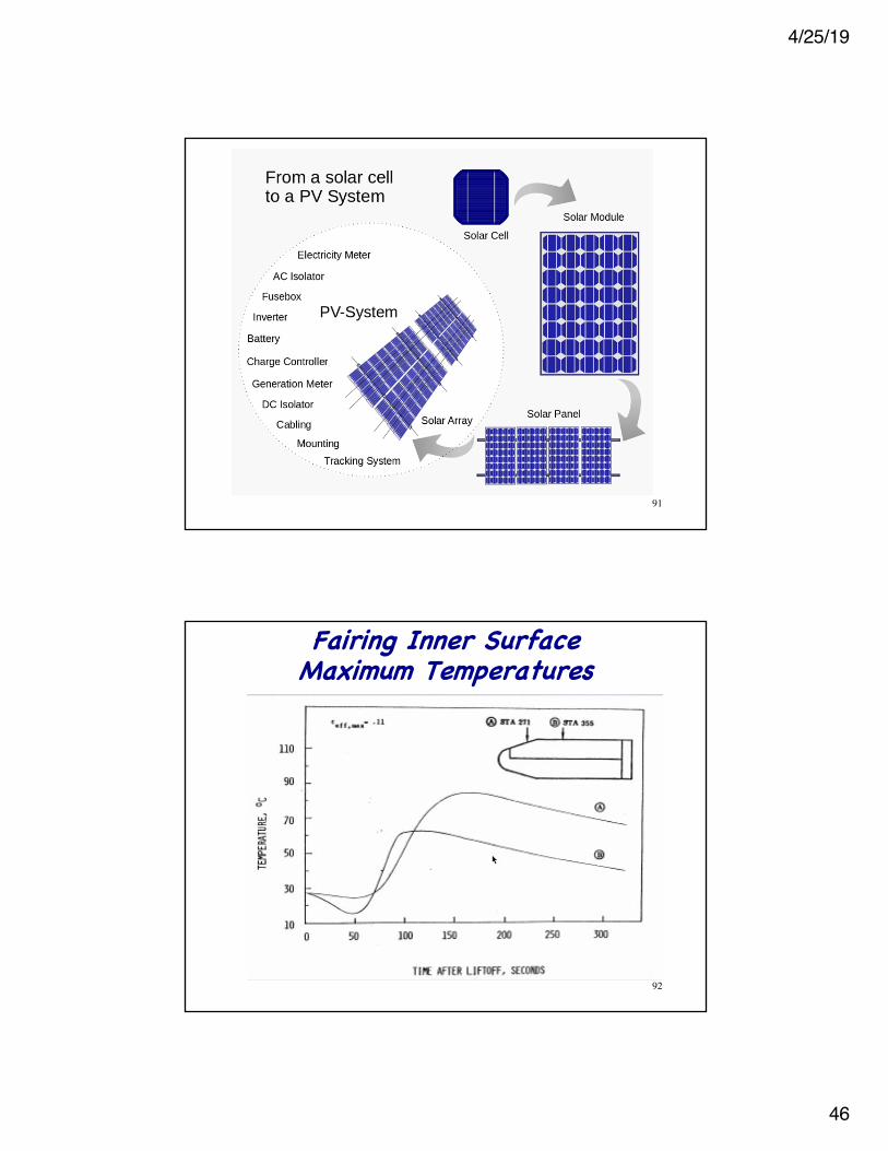
Fairing Inner Surface Maximum Temperatures
92


