Embed Size (px)
Citation preview
IBM System Storage N series
Gateway Installation Requirements andReference Guide
���
GA32-1049-03

Contents
Preface ........................................................................................................... 7About this guide .......................................................................................................... 7Supported features ....................................................................................................... 7Websites ...................................................................................................................... 7Getting information, help, and service ........................................................................ 8Before you call ............................................................................................................ 8Using the documentation ............................................................................................. 8Hardware service and support ..................................................................................... 9Firmware updates ........................................................................................................ 9How to send your comments ....................................................................................... 9
Gateway technology overview ................................................................... 10How a gateway uses third-party storage ................................................................... 10Supported methods to connect to a storage array ...................................................... 11Number of storage arrays supported behind a gateway ............................................ 11Sharing storage arrays among hosts .......................................................................... 12
Gateway planning overview ...................................................................... 13Information about Data ONTAP support for back-end storage arrays ..................... 13Gateway limits needed for planning a configuration with third-party storage ......... 14Planning tasks for a gateway implementation ........................................................... 14Planning storage requirements for disks and third-party storage .............................. 16
Location of the root volume .......................................................................... 17Stages of implementation when using third-party storage ........................................ 17N6200 series system configuration restrictions ........................................................ 18
Planning for RAID implementation ......................................................... 19RAID protection for third-party storage .................................................................... 19Implications of LUN size and number for Data ONTAP RAID groups ................... 19
Planning for Data ONTAP use of array LUNs ........................................ 21How array LUNs are made available for host use .................................................... 21How array LUNs become available for Data ONTAP storage use ........................... 22
Considerations when planning for disk ownership ....................................... 22Array LUN assignment changes ................................................................... 23
Array LUN types supported by Data ONTAP .......................................................... 23
Table of Contents | 3
Factors that impact the number and size of array LUNs you need ........................... 23Factors impacting the number of array LUNs needed .................................. 23Minimum number of array LUNs per gateway ............................................. 24Spare core array LUN requirement for core dumps ...................................... 24Minimum and maximum array LUN sizes supported by Data ONTAP ....... 25Minimum array LUN size for the root volume ............................................. 26Elements that reduce the usable space in an array LUN ............................... 26Considering checksum type when planning array LUN size and number .... 27
Planning for LUN security on the storage arrays ................................... 32Available LUN security methods .............................................................................. 32
Planning for paths to array LUNs ............................................................ 34Requirement for redundant setup of components in a path ....................................... 34
When to check for redundant paths to array LUNs ....................................... 35Required number of paths to an array LUN .............................................................. 35
Advantages of four paths to an array LUN (Cluster-Mode in 8.1 andlater) ......................................................................................................... 36
Using LUN groups to partition the load over gateway connections ......................... 36Implementation requirements for a multiple LUN group configuration ....... 37Example of a configuration with multiple LUN groups ............................... 38
How paths are reflected in array LUN names ........................................................... 39Array LUN name format ............................................................................... 40How the array LUN name changes in Data ONTAP displays ...................... 42
Valid pathing: stand-alone system with a single 2-port array LUN group ............... 42Valid pathing: a single 4-port array LUN group in a fabric-attached
configuration ........................................................................................................ 44Determining the array LUNs for specific aggregates .............................. 46
Rules for mixing storage in aggregates for gateways ............................................... 46How the checksum type is determined for aggregates with array LUNs .................. 46Checking the checksum type of spare array LUNs ................................................... 47Aggregate rules when the storage arrays are from the same family ......................... 48Aggregate rules when the storage arrays are from different vendors or families ..... 50
Zoning guidelines ........................................................................................ 53Zoning requirements ................................................................................................. 53Zoning recommendation for a configuration with third-party storage ...................... 54Example of zoning in a configuration with third-party storage ................................ 55
Determining whether to use neighborhoods (7-Mode in 8.x) ................. 57
4 | Gateway Installation Requirements and Reference Guide
What a gateway neighborhood is .............................................................................. 57Requirements for gateway neighborhoods ................................................................ 58Planning the number of array LUNs and disks in a neighborhood ........................... 58How to establish a neighborhood .............................................................................. 60
Planning a port-to-port connectivity scheme ........................................... 62Guidelines for connecting your system to third-party storage .................................. 62Requirements for gateway FC initiator port usage .................................................... 63Guidelines for connecting a gateway to native disk shelves ..................................... 64How FC initiator ports are labeled ............................................................................ 65
Connecting a gateway to back-end devices .............................................. 66Connecting a gateway stand-alone system to back-end devices ............................... 66Connecting an HA pair to back-end devices ............................................................. 68
Commands for checking back-end configuration (Cluster-Mode in8.1 and later) .......................................................................................... 71
Back-end configuration errors detected by the storage errors show command(Cluster-Mode in 8.1 and later) ........................................................................... 73
Situations not identified by the storage errors show command ................................ 74Verifying installation with third-party storage (Cluster-Mode in 8.1
and later) ................................................................................................ 76Checking for back-end configuration errors preventing system operation
(Cluster-Mode in 8.1 and later) ........................................................................... 78Storage errors show messages and their resolution (Cluster-Mode in 8.1
and later) .................................................................................................. 79Array LUN is too small or too large ............................................................. 80LUN IDs for the same LDEV do not match .................................................. 81Duplicate LUN IDs on a target port .............................................................. 84Fewer than two paths to an array LUN ......................................................... 88An access control LUN was presented .......................................................... 90All paths to an array LUN are on the same storage array controller ............. 91
Checking whether the configuration matches your intentions (Cluster-Mode in8.1 and later) ........................................................................................................ 93
Reasons for fewer array LUN groups than expected .................................... 95Reasons for more array LUN groups than expected ..................................... 96Reasons for more paths to an array LUN than expected ............................... 98Reasons for the incorrect number of LUNs in array LUN groups ................ 99Reasons storage arrays are missing from command output ........................ 100
Table of Contents | 5
Verifying an installation with third-party storage (7-Mode in 8.x) ..... 101Checking the number of paths (7-Mode in 8.x) ...................................................... 101Example output showing correct and incorrect pathing (7-Mode in 8.x) ............... 102
Troubleshooting ........................................................................................ 105Getting started with troubleshooting ....................................................................... 105Invalid path setup examples .................................................................................... 106
Invalid path setup: too many paths to an array LUN (7-Mode) .................. 106Invalid path setup: alternate paths are not configured ................................. 107
What happens when a link failure occurs ................................................................ 109Relationship between zoning and host group configuration ................................... 109
Dependency between zone and host group definitions ............................... 109Example of cascading zoning and host group configuration errors ............ 111
Installation quick start (7-Mode and third-party storage only) ........... 114Example configuration for the installation quick start (7-Mode and third-party
storage) .............................................................................................................. 114Performing preinstallation tasks on the storage array ............................................. 115Installing the gateway .............................................................................................. 116Setting up the switches ............................................................................................ 117Setting up LUN security .......................................................................................... 117Assigning an array LUN to a gateway and creating the root volume ..................... 118Installing Data ONTAP and licenses ...................................................................... 119Testing your setup ................................................................................................... 120Additional setup ...................................................................................................... 122
Obtaining WWNs manually .................................................................... 123Settings for connecting to an ASCII terminal console .......................... 124Target queue depth customization .......................................................... 126
Guidelines for specifying the appropriate target queue depth ................................. 126Setting the target queue depth ................................................................................. 127
Terminology comparison between storage array vendors ................... 128Glossary ..................................................................................................... 132Copyright information ............................................................................. 134Trademark information ........................................................................... 135Index ........................................................................................................... 138
6 | Gateway Installation Requirements and Reference Guide
Preface
About this guideThis document applies to IBM N series systems running Data ONTAP, including systems withgateway functionality. If the term 7-Mode is used in the document, it refers to Data ONTAPoperating in 7-Mode, which has the same features and functionality found in the prior Data ONTAP7.1, 7.2, and 7.3 release families. If the term Cluster-Mode is used in this document, it refers to DataONTAP operating in Cluster-Mode, which has different features and functionality from 7-Mode andprior Data ONTAP 7.1, 7.2, and 7.3 release families.
In this document, the term gateway describes IBM N series storage systems that have been orderedwith gateway functionality. Gateways support various types of storage, and they are used with third-party disk storage systems—for example, disk storage systems from IBM, HP®, Hitachi DataSystems®, and EMC®. In this case, disk storage for customer data and the RAID controllerfunctionality is provided by the back-end disk storage system. A gateway might also be used withdisk storage expansion units specifically designed for the IBM N series models.
The term filer describes IBM N series storage systems that either contain internal disk storage orattach to disk storage expansion units specifically designed for the IBM N series storage systems.Filer storage systems do not support using third-party disk storage systems.
Supported featuresIBM System Storage N series storage systems are driven by NetApp Data ONTAP software. Somefeatures described in the product software documentation are neither offered nor supported by IBM.Please contact your local IBM representative or reseller for further details.
Information about supported features can also be found on the N series support website (accessed andnavigated as described in Websites on page 7).
WebsitesIBM maintains pages on the World Wide Web where you can get the latest technical information anddownload device drivers and updates. The following web pages provide N series information:
• A listing of currently available N series products and features can be found at the following webpage:www.ibm.com/storage/nas/
• The IBM System Storage N series support website requires users to register in order to obtainaccess to N series support content on the web. To understand how the N series support web
7
content is organized and navigated, and to access the N series support website, refer to thefollowing publicly accessible web page:www.ibm.com/storage/support/nseries/This web page also provides links to AutoSupport information as well as other important N seriesproduct resources.
• IBM System Storage N series products attach to a variety of servers and operating systems. Todetermine the latest supported attachments, go to the IBM N series interoperability matrix at thefollowing web page:www.ibm.com/systems/storage/network/interophome.html
• For the latest N series hardware product documentation, including planning, installation andsetup, and hardware monitoring, service and diagnostics, see the IBM N series InformationCenter at the following web page:publib.boulder.ibm.com/infocenter/nasinfo/nseries/index.jsp
Getting information, help, and serviceIf you need help, service, or technical assistance or just want more information about IBM products,you will find a wide variety of sources available from IBM to assist you. This section containsinformation about where to go for additional information about IBM and IBM products, what to do ifyou experience a problem with your IBM N series product, and whom to call for service, if it isnecessary.
Before you callBefore you call, make sure you have taken these steps to try to solve the problem yourself:
• Check all cables to make sure they are connected.• Check the power switches to make sure the system is turned on.• Use the troubleshooting information in your system documentation and use the diagnostic tools
that come with your system.• Refer to the N series support website (accessed and navigated as described in Websites on page 7)
for information on known problems and limitations.
Using the documentationThe latest versions of N series software documentation, including Data ONTAP and other softwareproducts, are available on the N series support website (accessed and navigated as described in Websites on page 7).
Current N series hardware product documentation is shipped with your hardware product in printeddocuments or as PDF files on a documentation CD. For the latest N series hardware productdocumentation PDFs, go to the N series support website.
8 | Gateway Installation Requirements and Reference Guide
Hardware documentation, including planning, installation and setup, and hardware monitoring,service, and diagnostics, is also provided in an IBM N series Information Center at the following webpage:
publib.boulder.ibm.com/infocenter/nasinfo/nseries/index.jsp
Hardware service and supportYou can receive hardware service through IBM Integrated Technology Services. Visit the followingweb page for support telephone numbers:
www.ibm.com/planetwide/
Firmware updatesIBM N series product firmware is embedded in Data ONTAP. As with all devices, ensure that yourun the latest level of firmware. Any firmware updates are posted to the N series support website(accessed and navigated as described in Websites on page 7).
Note: If you do not see new firmware updates on the N series support website, you are running thelatest level of firmware.
Verify that the latest level of firmware is installed on your machine before contacting IBM fortechnical support.
How to send your commentsYour feedback helps us to provide the most accurate and high-quality information. If you havecomments or suggestions for improving this document, please send them by email to [email protected].
Be sure to include the following:
• Exact publication title• Publication form number (for example, GC26-1234-02)• Page, table, or illustration numbers• A detailed description of any information that should be changed
Preface | 9
Gateway technology overview
A gateway is an open storage controller that virtualizes storage from third-party storage arrayvendors, native disks, or both into a single heterogeneous storage pool.
The Data ONTAP software provides a unified storage software platform that simplifies managingboth native disk shelves and LUNs on storage arrays. You can add storage when and where you needit, without disruption.
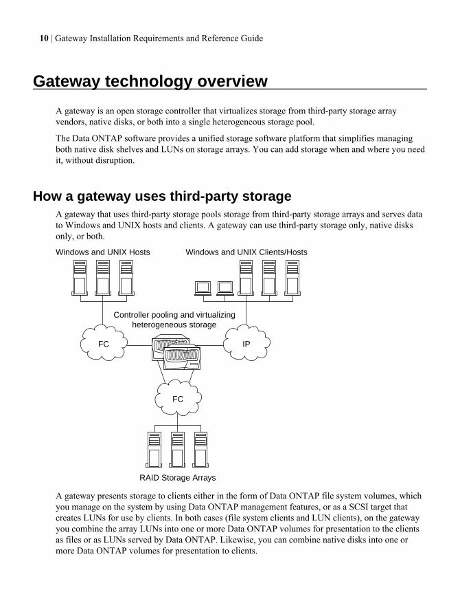
How a gateway uses third-party storageA gateway that uses third-party storage pools storage from third-party storage arrays and serves datato Windows and UNIX hosts and clients. A gateway can use third-party storage only, native disksonly, or both.
Controller pooling and virtualizing heterogeneous storage
FC
RAID Storage Arrays
FC
Windows and UNIX Hosts
IP
Windows and UNIX Clients/Hosts
A gateway presents storage to clients either in the form of Data ONTAP file system volumes, whichyou manage on the system by using Data ONTAP management features, or as a SCSI target thatcreates LUNs for use by clients. In both cases (file system clients and LUN clients), on the gatewayyou combine the array LUNs into one or more Data ONTAP volumes for presentation to the clientsas files or as LUNs served by Data ONTAP. Likewise, you can combine native disks into one ormore Data ONTAP volumes for presentation to clients.
10 | Gateway Installation Requirements and Reference Guide
Supported methods to connect to a storage arrayThe Gateway Interoperability Matrix at the N series support website (accessed and navigated asdescribed in Websites on page 7) contains information about the connection methods supported forspecific storage arrays and platforms running Data ONTAP.
You can incorporate a fabric-attached configuration into an existing FC SAN infrastructure. Fabric-attached configurations are supported for both stand-alone systems and High Availability (HA) pairs.
Support for a direct-attached configuration is limited to some storage arrays and some Data ONTAPreleases. It is not supported for new deployments.
Number of storage arrays supported behind a gatewayFor most storage arrays, you can connect a stand-alone gateway or the nodes in an HA pair tomultiple storage arrays. For a few storage arrays, you are limited to one storage array behind thegateway.
The Gateway Interoperability Matrix identifies the storage arrays for which you are limited to onestorage array behind the gateway.
If multiple storage arrays behind a gateway are supported for your storage array, the rules are asfollows:
• There is no limit to the number of storage arrays you can deploy behind your system.However, you must use different gateway FC initiator ports for each storage array.
• The storage arrays can be from the same vendor, either all from the same family or from differentfamilies.
• The storage arrays can be from different vendors.
Different rules apply for assigning array LUNs to aggregates, depending on whether Data ONTAPconsiders the storage arrays to be in the same family.
Note: Storage arrays in the same family share the same performance and failover characteristics.For example, members of the same family all perform active-active failover, or they all performactive-passive failover. Storage arrays with 4-GB HBAs are not considered to be in the samefamily as storage arrays with 8-GB HBAs.
The Gateway Implementation Guide for Third-Party Storage contains information about the storagearray families for each vendor.
Related concepts
Rules for mixing storage in aggregates for gateways on page 46Aggregate rules when the storage arrays are from different vendors or families on page 50Aggregate rules when the storage arrays are from the same family on page 48
Gateway technology overview | 11
Sharing storage arrays among hostsA typical storage array provides storage for both gateways and other hosts. However, for somestorage arrays, you must dedicate the storage array to gateways.
To determine whether your vendor’s storage array must be dedicated to the gateway, see theGateway Interoperability Matrix at the N series support website (accessed and navigated as describedin Websites on page 7).
12 | Gateway Installation Requirements and Reference Guide
Gateway planning overview
Successful implementation of a gateway deployment requires careful planning and verifying properinstallation and configuration of all devices in your deployment.
Information about Data ONTAP support for back-endstorage arrays
Not all Data ONTAP releases support the same features, configurations, storage array models, andgateways. During your deployment planning, you need to check Data ONTAP support information toensure that your deployment conforms to Data ONTAP hardware and software requirements for allsystems in the deployment.
Previously all support information used to set up deployments with third-party storage was includedin the Gateway Interoperability Matrix. As of November 2012, the information is divided into twodifferent tools, as shown in the following table:
For information about... You should look here...
Data ONTAP working with back-end devices,including the following:
• Supported storage arrays and storage arrayfirmware
• Supported switches and switch firmware• Whether your storage array supports
nondisruptive (live) upgrade of the storagearray firmware
• Whether MetroCluster is supported withyour storage array
Gateway Interoperability Matrix at the N seriessupport website (accessed and navigated asdescribed in Websites on page 7)
Data ONTAP limits for releases and platforms,including the following:
• Minimum and maximum array LUN sizes,including the minimum array LUN size forthe root volume and spare array LUNs
• Minimum aggregate size for aggregates witharray LUNs
• Supported block size• Minimum and maximum capacity• Neighborhood limits
Gateway Limits Reference for Third-PartyStorage
13
The Gateway Interoperability Matrix shows the Brocade and Cisco switches that are supported. Youcan find guides for configuring specific vendor switches on the N series support website (accessedand navigated as described in Websites on page 7).
Gateway limits needed for planning a configuration withthird-party storage
The Gateway Limits Reference for Third-Party Storage contains information about limits that youneed to consider when planning for a configuration with third-party storage.
The Gateway Limits Reference for Third-Party Storage includes the following limits that do notapply to native disks:
• Minimum and maximum array LUN size that Data ONTAP supports• Storage arrays for which multiple LUN groups are supported• RAID group limits for third-party storage• Minimum aggregate size• Maximum number of array LUNs and disks combined, per platform
The Data ONTAP Storage Management Guides contain storage limits that are the same for nativedisks and array LUNs.
Planning tasks for a gateway implementationSuccessfully implementing a gateway configuration requires carefully planning your Data ONTAPand storage configurations for gateway use. If your gateways use third-party storage, you mustcommunicate with the storage array and switch administrators to ensure that the back-end devices areconfigured to work with gateways.
If you order your system with disk shelves, the factory configures the root volume and installslicenses and Data ONTAP software. You must perform these steps yourself if your system is usingonly third-party storage.
The final authority about what is supported for gateways is the Gateway Interoperability Matrix atthe N series support website (accessed and navigated as described in Websites on page 7).
General planning task
• Determine how much storage space is needed by the hosts and clients that you plan to connect tothe gateway.
Additional planning tasks if you are using third-party storage
• Determine the requirements for setting up your storage array to work with the gateway, includingthe following:
14 | Gateway Installation Requirements and Reference Guide
• Configuration settings on the storage array that are required for the gateway to work with thethird-party storage arraySee the Gateway Implementation Guide for Third-Party Storage.
• Which configuration is supported for the storage array you want to useSee the Gateway Implementation Guide for Third-Party Storage.
• Environment requirements, for example, which storage array, storage array firmware, andswitch firmware are supportedSee the Gateway Interoperability Matrix.
• Plan for LUN security.This task includes setting access controls on the storage array and, if switches are deployed,setting zoning on switches.
• Determine the Data ONTAP requirements for gateways to be able to use array LUNs.See the Data ONTAP Storage Management Guide for your system's operating mode for detailsabout aggregates and volumes.
• Determine the number and size of LUNs on the storage array that you need for Data ONTAP.• Determine the minimum size for an array for the root volume and the minimum size of a spare
core LUN, both of which vary according to gateway.See the Gateway Implementation Guide for Third-Party Storage.
• Determine your port-to-port connectivity scheme between the gateways and the storage array,which involves planning for the following:
• Supported configurations for your vendor• Gateway FC initiator port usage• Cabling redundant paths between the gateway and storage array, either directly or through
switches• Zoning of switches (for a fabric-attached configuration)• Mapping (exporting) array LUNs to the ports to which the gateways are connected
Additional planning tasks if you are using native disk shelves
Native disk shelves can be installed on a new or existing gateway. Data ONTAP automaticallyassigns ownership to native disks attached to your system.
• Determine gateway port usage.If your system uses both disks and array LUNs, determine what data should go on disks and whatshould go on array LUNs.
• If your gateway uses both third-party storage and native disks, you need to determine how manydisks and array LUNs combined can be assigned to your system without exceeding the supportedmaximum assigned device limit for your system.See the Gateway Limits Reference for Third-Party Storage for more information.
• If you have an HA pair, determine whether to use the Multipath Storage feature.See the appropriate High-Availability Configuration Guide for more information about MultipathStorage.
Gateway planning overview | 15
See the appropriate Data ONTAP Storage Management Guide for information about disk ownershipfor storage on native disk shelves connected to a gateway.
Additional planning task if you are using Data ONTAP data protection features
• Determine the data protection features you want to use and their setup requirements.See the appropriate Data Protection Online Backup and Recovery Guide.
Additional planning task for Data ONTAP storage management features
• Determine other features to simplify storage management that you want to use, for example,quotas.See the appropriate Data ONTAP Storage Management Guide.
Related concepts
Planning storage requirements for disks and third-party storage on page 16Planning for Data ONTAP use of array LUNs on page 21Planning for LUN security on the storage arrays on page 32Planning for paths to array LUNs on page 34Determining the array LUNs for specific aggregates on page 46Planning a port-to-port connectivity scheme on page 62
Planning storage requirements for disks and third-partystorage
Before you start setting up your gateways, you need to determine how much storage you need foryour organization's requirements and where you want to locate data—what should go on disks andwhat should go on array LUNs.
Considerations include the following:
• Which LUNs on the storage arrays you want this gateway to own• Which native disks you want this gateway to own• Where you want to locate the root volume• Whether you want your native disk shelf to be used only for the root volume, only for data, or for
both
Note: For systems running Cluster-Mode, the root volume must be on a disk shelf.
• Whether you want your array LUNs to be used only for the root volume, only for data, or for both• If you are moving a disk shelf from a filer to a gateway, whether you want to preserve the data on
that disk shelf
Note: The bootarg.storageencryption.support variable must be set to true to be ableto move an FDE disk shelf from a filer to a gateway. If it is not, all disks are marked as failed.
16 | Gateway Installation Requirements and Reference Guide
• How you want to use your aggregates and volumes
Related concepts
Planning tasks for a gateway implementation on page 14Location of the root volume on page 17Guidelines for connecting a gateway to native disk shelves on page 64
Location of the root volumeFor Data ONTAP operating in 7-Mode, it is recommended that the root volume be installed on anative disk shelf if the gateway has one. For Data ONTAP operating in Cluster-Mode, the rootvolume must be installed on a native disk shelf.
If you order a gateway with native disk shelves, the factory installs the root volume on a native disk.
• Cluster-Mode systems must be ordered with native disks, and the root volume must be on a nativedisk shelf.
• On 7-Mode systems, the root volume can be on third-party storage or on a native disk shelf.Installing the root volume on a native disk shelf is recommended.
• In a 7-Mode HA pair, it is highly recommended that the root volume be located on the same typeof storage for both nodes—either on a disk shelf for both nodes or on an array LUN for bothnodes.Although an asymmetrical approach is highly discouraged, it is not a requirement to follow thesame strategy for both nodes.
Stages of implementation when using third-party storageGateway implementation with third-party storage has two stages: a back-end implementation and afront-end implementation. When planning your configuration it is helpful to understand the high-level tasks in each stage.
Stage 1: back-end implementation
Gateways typically use third-party storage, although use of third-party storage is not required. Settingup the back-end implementation includes all tasks that are required to set up the gateway with astorage array, up to the point where you can install Data ONTAP software.
Tasks to set up the back-end implementation include the following:
1. Creating and formatting array LUNs
2. Assigning ports
3. Cabling
4. Zoning switches (if applicable)
5. In Data ONTAP, assigning specific array LUNs to a gateway
Gateway planning overview | 17
6. In Data ONTAP, providing information to set up a gateway on the networkThis process is similar to filer setup.
7. Installing Data ONTAP software
If a gateway is ordered with disk shelves, the Data ONTAP software is installed by the factory. Insuch a configuration, you do not need to create the root volume and install licenses and Data ONTAPsoftware. The Data ONTAP Software Setup Guide for 7-Mode and the Data ONTAP Software SetupGuide for Cluster-Mode provide instructions for how to set up your system in Data ONTAPdepending on whether your system is shipped with disk shelves.
Stage 2: front-end implementation
Tasks to set up the front-end implementation include the following:
• Configuring the gateway for all protocols (NAS, FC, or both)• Configuring Data ONTAP features such as SnapVault, SnapMirror, SnapValidator, Snapshot
copies, and so on• Creating volumes and aggregates• Setting up data protection, including NDMP dumps to tapes• Setting up native disks (if your system uses native disks for storage)
N6200 series system configuration restrictionsThere are some restrictions for N6200 series systems that do not apply to other models.
N6200 series system on-board storage port guidelines
The two onboard FC ports, labeled 0c and 0d, are not on independent busses. Therefore, they do notprovide storage redundancy. Some port failures can cause the system to panic.
To configure redundant port pairs, you need to use an FC HBA in an available expansion slot.
N6210 configuration restrictions
The following restrictions apply to N6210 configurations without an added FC HBA:
• Only a single storage array can be connected to an N6210 configuration.• The storage array must present all LUNs in a single LUN group.
18 | Gateway Installation Requirements and Reference Guide
Planning for RAID implementation
You need to plan the size of and number of LUNs in the storage array RAID groups and decidewhether you want to share the RAID group among hosts.
RAID protection for third-party storageThird-party storage arrays provide the RAID protection for the array LUNs that they make availableto gateways, not Data ONTAP.
Data ONTAP uses RAID 0 (striping) for array LUNs. Data ONTAP supports a variety of RAIDtypes on the storage arrays, except RAID 0 because RAID 0 does not provide storage protection.
When creating RAID groups on storage arrays, you need to follow the best practices of the storagearray vendor to ensure that there is an adequate level of protection on the storage array so that diskfailure does not result in loss of data or loss of access to data.
Note: A RAID group on a storage array is the arrangement of disks that together form the definedRAID level. Each RAID group supports only one RAID type. The number of disks that you selectfor a RAID group determines the RAID type that a particular RAID group supports. Differentstorage array vendors use different terms to describe this entity—RAID groups, parity groups, diskgroups, Parity RAID groups, and other terms.
Gateways support native disk shelves as well as third-party storage. Data ONTAP supports RAID4and RAID-DP on the native disk shelves connected to a gateway but does not support RAID4 andRAID-DP with array LUNs.
See the Gateway Implementation Guide for Third-Party Storage to determine whether there arespecific requirements or limitations about RAID types for your storage array.
Implications of LUN size and number for Data ONTAP RAIDgroups
Part of planning for aggregates is to plan the size and number of Data ONTAP RAID groups youneed for those aggregates, and the size and number of array LUNs for the Data ONTAP RAIDgroups. Setting up Data ONTAP RAID groups for array LUNs requires planning and coordinationwith the storage array administrator.
Planning for Data ONTAP RAID groups involves the following:
1. Planning the size of the aggregate that best meets your data needs.2. Planning the number and size of the RAID groups that you need for the size of the aggregate.
RAID groups in the same aggregate should be the same size, with the same number of arrayLUNs in each RAID group. Use the default RAID group size if possible.
19
3. Planning the size of the array LUNs that you need in your Data ONTAP RAID groups.
• To avoid a performance penalty, all array LUNs in a particular Data ONTAP RAID groupshould be the same size.
• The array LUNs should be the same size in all RAID groups in the same aggregate.
4. Communicating with the storage array administrator to create the number of array LUNs of thesize you need for the aggregate.The array LUNs should be optimized for performance, according to the instructions in the storagearray vendor documentation.
For more recommendations about setting up Data ONTAP RAID groups for use with third-partystorage, including minimum and maximum RAID group size, see the appropriate Data ONTAPStorage Management Guide.
Related concepts
Determining the array LUNs for specific aggregates on page 46
20 | Gateway Installation Requirements and Reference Guide
Planning for Data ONTAP use of array LUNs
For Data ONTAP to use third-party storage, a storage array administrator must first create LUNs onthe storage array and make them available to Data ONTAP. Then the Data ONTAP administratormust configure Data ONTAP to use the array LUNs that the storage array made available.
When planning how to provision array LUNs for Data ONTAP use, you need to consider the types ofarray LUNs that Data ONTAP supports, Data ONTAP minimum and maximum array LUN sizes,and the number of array LUNs you need.
Note: Data ONTAP considers an array LUN to be a virtual disk.
How array LUNs are made available for host useA storage array administrator must create array LUNs and make them available to specified FCinitiator ports of gateways.
The process to make LUNs available to hosts and the terminology to describe it varies among storagearray vendors. The basic process on the storage array to make LUNs available for host use is asfollows:
1. Create logical devices (LDEVs).
Note: LDEV is a term used by some vendors and this guide to describe a piece of logicalRAID storage configured from disks.
2. Create a host group (or vendor equivalent).Include in the host group the WWPNs of the initiator ports of the hosts that are allowed to see theLDEV.
Note: To simplify management, most storage arrays enable you to define one or more hostgroups. You can define specific WWPNs (ports) and WWNs (hosts) to be members of thesame group. You then associate specific array LUNs with the host group. Hosts in the hostgroup can access the LUNs associated with the host group; hosts that are not in that host groupcannot access those LUNs. Different vendors use different terms to describe this concept. Theprocess of creating a host group differs among vendors.
3. Map the LDEVs to host groups as LUNs.
Related concepts
How array LUNs become available for Data ONTAP storage use on page 22
21
How array LUNs become available for Data ONTAP storageuse
A gateway cannot use an array LUN presented to it until after Data ONTAP has been configured touse the array LUN.
Although the storage array administrator makes an array LUN accessible to Data ONTAP, DataONTAP cannot use the array LUN for storage until both of the following tasks are completed:
1. One gateway must be assigned to be the owner of the array LUN.
2. The array LUN must be added to an aggregate.
When you assign an array LUN to a gateway, Data ONTAP writes data to the array LUN to identifythe assigned system as the owner of the array LUN. This logical relationship is referred to as diskownership.
When you assign an array LUN to a gateway, it becomes a spare LUN owned by that system and it isno longer available to any other gateway.
A spare array LUN cannot be used for storage until you add it to an aggregate. Thereafter, DataONTAP ensures that only the owner of the array LUN can write data to and read data from the LUN.
In an HA pair, both nodes must be able to see the same storage, but only one node in the pair is theowner of the array LUN. The partner node takes over read/write access to an array LUN in case of afailure of the owning node. The original owning node resumes ownership after the problem thatcaused unavailability of the node is fixed.
Related concepts
How array LUNs are made available for host use on page 21Considerations when planning for disk ownership on page 22Determining the array LUNs for specific aggregates on page 46
Considerations when planning for disk ownershipIf you are deploying multiple gateways, you must determine which gateways will own which arrayLUNs.
Consider the following when planning which gateways will own which array LUNs:
• The maximum assigned device limit supported by your platformThe Gateway Limits Reference for Third-Party Storage shows the maximum assigned devicelimit that is supported for different platforms. This is a hard-coded limit. If your system uses botharray LUNs and disks, this maximum limit is the maximum of disks and array LUNs combined.You must account for both types of storage when determining how many array LUNs and disksyou can assign to a system.
22 | Gateway Installation Requirements and Reference Guide
• The amount of load that you expect to be generated by different applications used in yourenvironmentSome types of applications are likely to generate a lot of requests, whereas other applications (forexample, archival applications) generate fewer requests. You might want to consider weighingownership assignments based on expected load from specific applications.
Related concepts
How array LUNs become available for Data ONTAP storage use on page 22
Array LUN assignment changesYou can change assignment of a spare array LUN from one gateway to another.
Information about changing the ownership of an array LUN is provided in the Data ONTAP StorageManagement Guide for your operating mode.
Array LUN types supported by Data ONTAPYou can map only storage array LUNS to Data ONTAP.
Some storage arrays have a non-storage command LUN. You cannot map a command type LUN to asystem running Data ONTAP.
Starting in Data ONTAP 8.1, you can map LUN 0 to Data ONTAP if it is a storage type LUN.
See the Gateway Implementation Guide for Third-Party Storage for a discussion about array LUNtypes used by particular vendors that are not supported by Data ONTAP.
Factors that impact the number and size of array LUNs youneed
You must consider a number of factors, including usable space in a LUN, when determining howmany array LUNs you need and their size.
Factors impacting the number of array LUNs neededFactors such as array LUN size, Data ONTAP overhead, and checksum type impact the number ofarray LUNs that you need.
You should consider the following when determining the number of array LUNs that you need:
• The smaller the array LUNs, the more LUNs you need for the storage that you want.Ideally, creating one large array LUN from a given storage array RAID group is recommended.
• Device limits define the maximum number of disks and array LUNS that can be assigned to agateway.See the Gateway Limits Reference for Third-Party Storage for information about device limits.
Planning for Data ONTAP use of array LUNs | 23
• The more usable space in an array LUN, the fewer array LUNs are needed.The amount of usable space in an array LUN is determined by the space that Data ONTAPrequires, checksum type, and additional factors such as space required for optional Snapshotreserves.
• Different applications generate different loads.When determining assignment of array LUNs to gateways, you should consider what the storagewill be used for and the number of requests likely to be generated by different applications.
Minimum number of array LUNs per gatewayIf the root volume is on third-party storage, each stand-alone gateway and each node in an HA pairmust own at least one array LUN. If the root volume is on a native disk, the only array LUNs neededare those for data storage.
If you are deploying a MetroCluster configuration, two array LUNs are required, one LUN from eachsite, so that the root volume can be mirrored.
Note: MetroCluster configurations are not supported on gateways with native disks. MetroClusterconfigurations are not supported for Data ONTAP Cluster-Mode.
Related concepts
Factors impacting the number of array LUNs needed on page 23
Spare core array LUN requirement for core dumpsIf you want automatic takeover to occur if the partner node panics, a spare core array LUN isrequired in some circumstances. Core dump files can be written to the core dump space reserved oneach array LUN. However, when automatic takeover occurs when a partner node panics, the coredump files need to be written to a single spare core LUN.
A core dump file contains the contents of memory and NVRAM. When a hardware or softwarefailure causes a gateway to crash, Data ONTAP typically creates a core file that technical support canuse to troubleshoot the problem.
Takeover if the partner node panics shortens the time between the initial failure and when service isfully restored because the takeover can be faster than recovery from the panic. However, thesubsequent giveback causes another brief outage.
If you want automatic takeover to occur if the partner node panics, the requirements are as follows:
• The Data ONTAP command for automatic takeover on panic must be enabled.Data ONTAP is configured by default to initiate a takeover if the partner node panics in somecircumstances.
• A spare core array LUN must be available for a core dump file.When a panic initiates takeover by the partner node, a core dump file is not saved unless a sparecore LUN is available.
Note: Core dump files can be written in the reserved core space on each array LUN, but thisprocess is time consuming.
24 | Gateway Installation Requirements and Reference Guide
• The spare core array LUN must meet the minimum required spare core LUN size.For information about the minimum spare core LUN size for each gateway platform, see theGateway Limits Reference for Third-Party Storage.
The following commands control whether a node in an HA pair immediately takes over for apanicked partner.
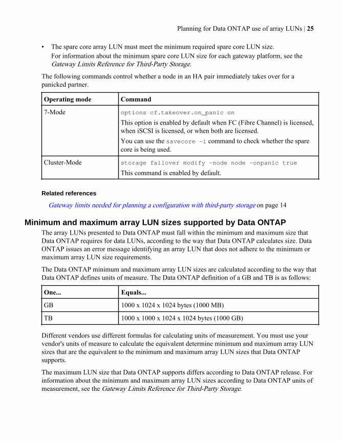
Operating mode Command
7-Mode options cf.takeover.on_panic on
This option is enabled by default when FC (Fibre Channel) is licensed,when iSCSI is licensed, or when both are licensed.You can use the savecore -i command to check whether the sparecore is being used.
Cluster-Mode storage failover modify -node node -onpanic true
This command is enabled by default.
Related references
Gateway limits needed for planning a configuration with third-party storage on page 14
Minimum and maximum array LUN sizes supported by Data ONTAPThe array LUNs presented to Data ONTAP must fall within the minimum and maximum size thatData ONTAP requires for data LUNs, according to the way that Data ONTAP calculates size. DataONTAP issues an error message identifying an array LUN that does not adhere to the minimum ormaximum array LUN size requirements.
The Data ONTAP minimum and maximum array LUN sizes are calculated according to the way thatData ONTAP defines units of measure. The Data ONTAP definition of a GB and TB is as follows:
One... Equals...
GB 1000 x 1024 x 1024 bytes (1000 MB)
TB 1000 x 1000 x 1024 x 1024 bytes (1000 GB)
Different vendors use different formulas for calculating units of measurement. You must use yourvendor's units of measure to calculate the equivalent determine minimum and maximum array LUNsizes that are the equivalent to the minimum and maximum array LUN sizes that Data ONTAPsupports.
The maximum LUN size that Data ONTAP supports differs according to Data ONTAP release. Forinformation about the minimum and maximum array LUN sizes according to Data ONTAP units ofmeasurement, see the Gateway Limits Reference for Third-Party Storage.
Planning for Data ONTAP use of array LUNs | 25
Note: The minimum array LUN size for a data (storage) LUN is different from the minimum LUNsize for the root volume. See the Gateway Limits Reference for Third-Party Storage for moreinformation.
Related concepts
Minimum array LUN size for the root volume on page 26
Related references
Gateway limits needed for planning a configuration with third-party storage on page 14Array LUN is too small or too large on page 80
Minimum array LUN size for the root volumeThe array LUN used for the root volume must be larger than the minimum size required for otherarray LUNs.
It is strongly recommended that you do not set the size of a root volume below the minimum sizearray LUN for the root volume that is shown in the Gateway Limits Reference for Third-PartyStorage. The reason is that you want to ensure that there is sufficient space in the root volume forsystem files, log files, and core files. You need to provide these files to technical support if a systemproblem occurs.
Note: The minimum array LUN size for a non-root volume is considerably smaller than for theroot volume. Therefore, be sure that you look at the information about the minimum array LUNsize for the root volume. Both the minimum array LUN size for the root volume and the minimumarray LUN size for non-root volumes are shown in the Gateway Limits Reference for Third-PartyStorage.
Related concepts
Minimum and maximum array LUN sizes supported by Data ONTAP on page 25Location of the root volume on page 17
Related references
Gateway limits needed for planning a configuration with third-party storage on page 14
Elements that reduce the usable space in an array LUNNot all capacity in an array LUN is available for storage. The usable space in an array LUN isimpacted by a number of fixed and optional elements.
When planning the number and size of the array LUNs you need, you must consider the usable spacein the array LUN according to the checksum type you are using and the optional elements you mightconfigure.
26 | Gateway Installation Requirements and Reference Guide
When calculating the usable space in an array LUN, you must consider the following factors thatdecrease the usable space of the LUN:
• 10%—Reserved for use by Data ONTAP• 0.1% for LUNS less than or equal to 2TiB, and 0.2% for LUNs greater than 2TiB—Core dump• 5%—Volume-level Snapshot reserve (default, configurable)• 0%—Aggregate-level Snapshot copy (default, configurable)• Checksum type (you assign one type):
• 12.5%—Block checksum (BCS)• 1.56 %—Advanced Zoned checksum (AZCS)
Note: The percentages shown are for Data ONTAP 8.1.1 and later and might differ from thepercentages for previous Data ONTAP releases.
Space for aggregate-level and volume-level Snapshot reserves is optional and changeable throughData ONTAP. See the Data ONTAP Data Protection Online Backup Guide for more informationabout Snapshot copies.
Related concepts
Characteristics of checksum types that Data ONTAP supports on page 28Considering checksum type when planning array LUN size and number on page 27Formulas for calculating array LUN size, considering the checksum type on page 29
Considering checksum type when planning array LUN size and numberWhen planning the number and size of array LUNs that you need for Data ONTAP, you mustconsider impact of the checksum type on the amount of usable space in the array LUN. A checksumtype must be specified for each array LUN assigned to a gateway.
When an array LUN from the storage array is mapped on the storage array to be used by a gateway,Data ONTAP treats the array LUN as a raw, unformatted disk. When you assign an array LUN to agateway you specify the checksum type, which tells Data ONTAP how to format the raw array LUN.The impact of the checksum type on usable space depends on the checksum type you specify for theLUN.
Related concepts
Characteristics of checksum types that Data ONTAP supports on page 28Elements that reduce the usable space in an array LUN on page 26Formulas for calculating array LUN size, considering the checksum type on page 29
Planning for Data ONTAP use of array LUNs | 27
Characteristics of checksum types that Data ONTAP supports
Data ONTAP supports block checksum type (BCS) and advanced zoned checksum type (AZCS). Forarray LUNs, you need to consider how the different checksum types impact performance and usablespace in an array LUN.
Starting in Data ONTAP 8.1.1, Data ONTAP supports the following checksum types for array LUNs,disks, and aggregates:
• BCS• AZCS• Zoned checksum (ZCS)—legacy support only
The type of checksum assigned to an array LUN in Data ONTAP can impact performance or theusable space of an array LUN. Therefore, the number and size of array LUNs you need can beimpacted depending on the checksum type you assign to array LUNs.
The following table describes the characteristics of the checksum types:
Checksum type Description
BCS BCS is the default and recommended checksum type for array LUNs.BCS provides better performance for array LUNs than AZCS.BCS has a greater impact on the usable space in an array LUN thanAZCS. BCS uses 12.5 % of the usable space in an array LUN.
AZCS(advanced_zoned)
Starting in Data ONTAP 8.1.1, AZCS is an alternative to BCS. Theimpact of AZCS on usable space in an array LUN is less than with BCS;AZCS uses 1.56% of the device capacity. However, you must weigh theneed for more usable space against performance. AZCS can sometimescause performance problems for array LUNs.AZCS is not recommended for array LUNs for high-performancerandom workloads. However, you can use AZCS with array LUNs forDR, archive, or similar workloads.
Note: This caution about the possible performance impact of AZCSdoes not apply to native disks.
28 | Gateway Installation Requirements and Reference Guide
Checksum type Description
ZCS (zoned) Prior to Data ONTAP 8.1.1, zoned checksum array LUNs were usedwith ZCS type aggregates. Starting in 8.1.1, any new aggregates createdwith zoned checksum array LUNs are AZCS aggregates, and the arrayLUNs become advanced_zoned LUNs after they are added to theaggregate. You can add zoned checksum array LUNs to existing ZCSaggregates.Like AZCS, ZCS has a performance penalty for high-performancerandom workloads. However, ZCS does not provide as muchfunctionality as AZCS. For example, unlike ZCS, AZCS supportsdeduplication and compression.
Note: Different guidelines apply to assigning the checksum type for disks. Those guidelines differaccording to disk size and type.
Related concepts
Elements that reduce the usable space in an array LUN on page 26Formulas for calculating array LUN size, considering the checksum type on page 29
Formulas for calculating array LUN size, considering the checksum type
A number of elements, including checksum type, impact the usable capacity of an array LUN. Youcan use a formula to calculate how much usable capacity there would be in a given size array LUN,or to calculate how large an array LUN needs to be to provide the amount of storage that you want.
A number of elements, including checksum type, impact the size of the array LUN you need for theamount of usable capacity. Usable capacity is the amount of space that is available for storage.
The following table shows the ways of calculating the array LUN size you need:
If you know... You want to find out...
How large your array LUNs are How much capacity is available for storage (usablecapacity). You need to consider the amount ofspace required for all elements.
How much storage that you want in the arrayLUN
How large an array LUN you need. You need totake into account your desired amount of storageand space required for other elements.
Note: 2 TB in these formulas represents 2 TiB, or 2199023255552 bytes, which is 2097.152 GnaBor 2.097 TnaB according to the way that Data ONTAP calculates measurements.
Planning for Data ONTAP use of array LUNs | 29
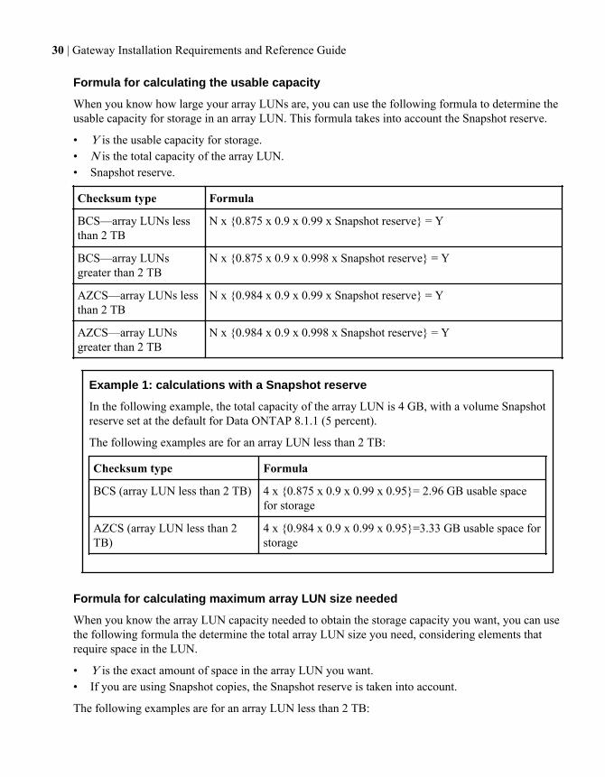
Formula for calculating the usable capacity
When you know how large your array LUNs are, you can use the following formula to determine theusable capacity for storage in an array LUN. This formula takes into account the Snapshot reserve.
• Y is the usable capacity for storage.• N is the total capacity of the array LUN.• Snapshot reserve.
Checksum type Formula
BCS—array LUNs lessthan 2 TB
N x {0.875 x 0.9 x 0.99 x Snapshot reserve} = Y
BCS—array LUNsgreater than 2 TB
N x {0.875 x 0.9 x 0.998 x Snapshot reserve} = Y
AZCS—array LUNs lessthan 2 TB
N x {0.984 x 0.9 x 0.99 x Snapshot reserve} = Y
AZCS—array LUNsgreater than 2 TB
N x {0.984 x 0.9 x 0.998 x Snapshot reserve} = Y
Example 1: calculations with a Snapshot reserve
In the following example, the total capacity of the array LUN is 4 GB, with a volume Snapshotreserve set at the default for Data ONTAP 8.1.1 (5 percent).
The following examples are for an array LUN less than 2 TB:
Checksum type Formula
BCS (array LUN less than 2 TB) 4 x {0.875 x 0.9 x 0.99 x 0.95}= 2.96 GB usable spacefor storage
AZCS (array LUN less than 2TB)
4 x {0.984 x 0.9 x 0.99 x 0.95}=3.33 GB usable space forstorage
Formula for calculating maximum array LUN size needed
When you know the array LUN capacity needed to obtain the storage capacity you want, you can usethe following formula the determine the total array LUN size you need, considering elements thatrequire space in the LUN.
• Y is the exact amount of space in the array LUN you want.• If you are using Snapshot copies, the Snapshot reserve is taken into account.
The following examples are for an array LUN less than 2 TB:
30 | Gateway Installation Requirements and Reference Guide
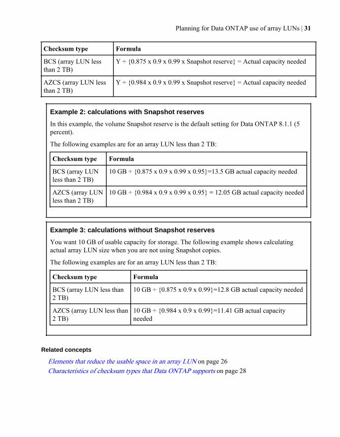
Checksum type Formula
BCS (array LUN lessthan 2 TB)
Y ÷ {0.875 x 0.9 x 0.99 x Snapshot reserve} = Actual capacity needed
AZCS (array LUN lessthan 2 TB)
Y ÷ {0.984 x 0.9 x 0.99 x Snapshot reserve} = Actual capacity needed
Example 2: calculations with Snapshot reserves
In this example, the volume Snapshot reserve is the default setting for Data ONTAP 8.1.1 (5percent).
The following examples are for an array LUN less than 2 TB:
Checksum type Formula
BCS (array LUNless than 2 TB)
10 GB ÷ {0.875 x 0.9 x 0.99 x 0.95}=13.5 GB actual capacity needed
AZCS (array LUNless than 2 TB)
10 GB ÷ {0.984 x 0.9 x 0.99 x 0.95} = 12.05 GB actual capacity needed
Example 3: calculations without Snapshot reserves
You want 10 GB of usable capacity for storage. The following example shows calculatingactual array LUN size when you are not using Snapshot copies.
The following examples are for an array LUN less than 2 TB:
Checksum type Formula
BCS (array LUN less than2 TB)
10 GB ÷ {0.875 x 0.9 x 0.99}=12.8 GB actual capacity needed
AZCS (array LUN less than2 TB)
10 GB ÷ {0.984 x 0.9 x 0.99}=11.41 GB actual capacityneeded
Related concepts
Elements that reduce the usable space in an array LUN on page 26Characteristics of checksum types that Data ONTAP supports on page 28
Planning for Data ONTAP use of array LUNs | 31
Planning for LUN security on the storage arrays
If you are using your gateway with third-party storage, you must use a LUN security method toeliminate the possibility of a non gateway overwriting array LUNs owned by a gateway, or thereverse.
LUN security is a method for isolating the hosts that can access particular array LUNs. LUN securityis similar to switch zoning in concept, but it is performed on the storage array. LUN security andLUN masking are equivalent terms to describe this functionality.
Attention: The Data ONTAP disk ownership scheme prevents one gateway from overwriting anarray LUN owned by another gateway. However, it does not prevent a gateway from overwritingan array LUN accessible by a non gateway host. Likewise, without a method of preventingoverwriting, a non gateway host could overwrite an array LUN used by a gateway.
Available LUN security methodsWith LUN security, you can mask array LUNs for viewing by only certain hosts, present LUNs onlyfor a specific host on a port, or dedicate a storage array to a particular host.
You should use both zoning and LUN security for added protection and redundancy for the gateway.If, for example, you do not have LUN security configured and you have to replace a SAN switch, thegateway could panic before you can configure the zoning on the new switch because the switch iswide open.
In addition to reading about the LUN security methods described here, you should also see theGateway Implementation Guide for Third-Party Storage for any additional details regarding LUNsecurity for your vendor’s storage arrays. Some storage arrays must be dedicated for gateway use.
Method 1: Port-level security
You can use port-level security to present only the array LUNs for a particular host. That port thenbecomes dedicated to that host.
Note: Not all storage arrays support port-level security. Some storage arrays present all LUNs onall ports by default, and they do not provide a way to restrict the visibility of LUNs to particularhosts. For these arrays you must use either a LUN security product or dedicate the storage array tothe gateway. You should check your storage array documentation to determine whether yourstorage array supports port-level security.
32 | Gateway Installation Requirements and Reference Guide
Method 2: LUN security products
You can use a LUN security product to control hosts that are zoned to the same port so that they cansee specific array LUNs over that port. This prevents other hosts from accessing those same arrayLUNs by masking them from the other hosts.
Method 3: Dedicate the storage array for the gateway use
You can dedicate the storage array to the gateway use. In this case, no hosts other than gateways areconnected to the storage array.
Planning for LUN security on the storage arrays | 33
Planning for paths to array LUNs
Paths are the physical connections between the gateway and the storage array. Redundant paths arerequired to eliminate any single point of failure (SPOF) between the gateway and the storage array.
Requirement for redundant setup of components in a pathGateways must connect to the storage array through a redundant Fibre Channel (FC) network. TwoFC networks or fabric zones are required to protect against a connection failing and so that fabricports or switches can be taken offline for upgrades and replacements without impacting the gateways.
Gateway redundancy requirements
• You must attach each connection to a different FC initiator port in the port pair on the gateway.• Each gateway FC initiator port in the same initiator port pair must be on a different bus.
FC switch redundancy requirements
• You must use redundant switches.• You must use redundant ports on the FC switches.
Storage array redundancy requirements
You need to ensure that the ports on the storage array that you select to access a given LUN are fromdifferent components that could represent a single point of failure, for example, from alternatecontrollers, clusters, or enclosures. You want to ensure that you do not lose all access to a LUN ifone component fails.
Note: A given array LUN is accessed through only one port at a time.
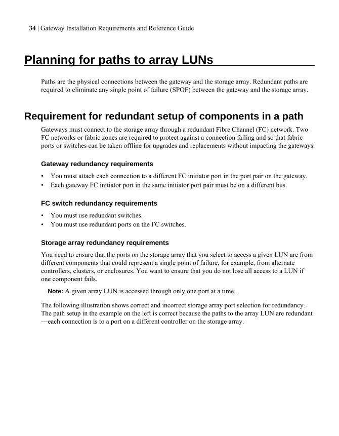
The following illustration shows correct and incorrect storage array port selection for redundancy.The path setup in the example on the left is correct because the paths to the array LUN are redundant—each connection is to a port on a different controller on the storage array.
34 | Gateway Installation Requirements and Reference Guide
Storagearray
Controller 2 Controller 2Controller 1 Controller 1
A A LUNs 1-10
B BStoragearray
A ALUNs 1-10
B B
Correct Incorrect
When to check for redundant paths to array LUNsYou need to check for redundant paths to an array LUN after installation and during fabricmaintenance activities.
You should recheck for path redundancy when performing the following activities:
• Initial installation• Fabric maintenance, for example:
• Before, during, and after an infrastructure upgrade• Before and after taking a switch out of service for maintenance
Be sure that the paths were configured as redundant paths before you remove a switchbetween the gateways and the storage array so that access to the array LUNs is notinterrupted.
• Before and after maintaining hardware on a storage arrayFor example, you should recheck for path redundancy when maintaining the hardwarecomponent on which host adapters and ports are located. (The name of this component varieson different storage array models).
Required number of paths to an array LUNThe required number of paths to an array LUN varies depending on Data ONTAP release and mode.
Data ONTAP release Number of paths supported
8.1 and later operating in Cluster-Mode 2 or, with an active-active storage array, 4
8.1 and later operating in 7-Mode 2
Releases prior to 8.1 (both modes) 2
For all releases and operating modes, Data ONTAP expects and requires that a storage array provideaccess to a specific array LUN on two redundant storage array ports; that is, through two redundantpaths. A given array LUN is accessed through only one port at a time.
Planning for paths to array LUNs | 35
You need to ensure that the ports on the storage array that you select to access a given LUN are fromdifferent components that could represent a single point of failure, for example, from alternatecontrollers, clusters, or enclosures. You want to ensure that you do not lose all access to a LUN ifone component fails.
Related concepts
Advantages of four paths to an array LUN (Cluster-Mode in 8.1 and later) on page 36
Advantages of four paths to an array LUN (Cluster-Mode in 8.1 and later)When planning the number of paths to an array LUN for Cluster-Mode in Data ONTAP 8.1 and later,you need to consider whether you want to set up two or four paths.
The advantages of setting up four paths to an array LUN include the following:
• If a switch fails, both storage array controllers are still available.• If a storage array controller fails, both switches are still available.• Performance can be improved because load balancing is over four paths instead of two.
Note: Only two paths to an array LUN are supported for Data ONTAP 8.1 operating in 7-Modeand releases prior to Data ONTAP 8.1.
Related concepts
Required number of paths to an array LUN on page 35
Using LUN groups to partition the load over gatewayconnections
Using multiple LUN groups allows for additional capacity, as well as potentially improving systemperformance by spreading the workload across more back-end ports. Use of multiple LUN groups isnot supported for all storage arrays.
A LUN group is set of logical devices on the storage array that a gateway accesses over the samepaths. The storage array administrator configures a set of logical devices as a group to define whichhost WWPNs can access them. Data ONTAP refers to this set of devices as a LUN group.
Advantages of using multiple LUN groups are as follows:
• There are limits on the number of LUNs that a given gateway FC initiator port pair can support.For large storage arrays in particular, the needed capacity is more likely to exceed what a singleLUN group can provide.
• You can partition the load of array LUNs over the FC initiator port pairs.
The number of paths to a LUN group varies according to release and operating mode.
36 | Gateway Installation Requirements and Reference Guide
See the Gateway Limits Reference for Third-Party Storage to determine whether a configurationusing multiple LUN groups is supported for your storage array. See the Gateway Best Practice Guidefor information about the maximum number of LUNs supported on an FC initiator port.
Related concepts
Implementation requirements for a multiple LUN group configuration on page 37
Related tasks
Checking whether the configuration matches your intentions (Cluster-Mode in 8.1 and later) onpage 93
Related references
Reasons for fewer array LUN groups than expected on page 95Reasons for more array LUN groups than expected on page 96
Implementation requirements for a multiple LUN group configurationImplementing a multiple LUN group configuration requires setup on the gateways and on the storagearrays.
The following setup is done on the storage array to implement a multiple LUN group configuration:
• As many ports as possible are used to provide access to the array LUNs you allocated for thegateway.
• Host groups (or your vendor's equivalent) are used to define which array LUN groups arepresented to each gateway FC initiator port.
The following setup is done on the gateway to implement a multiple LUN group configuration:
• One initiator port pair is used for each array LUN group.Each FC initiator port pair accesses a different LUN group on the storage array through redundantpaths.
• One large aggregate is created (in the Data ONTAP configuration), and array LUNs frommultiple RAID groups (parity groups) are added to the aggregate.By doing so, the I/O is spread across more disks. The combination of spreading I/O across theRAID groups and creating one large aggregate results in a significant performance boost.
The following is done on the switch to implement a multiple LUN group configuration:
• Switch zoning is configured to define which target ports the gateway initiator ports are to use toaccess each array LUN group.
• For active-passive storage arrays, both ports of the storage array controller are cabled to the sameswitch fabric.
Related concepts
Example of a configuration with multiple LUN groups on page 38
Planning for paths to array LUNs | 37
Related references
Reasons for fewer array LUN groups than expected on page 95Reasons for more array LUN groups than expected on page 96
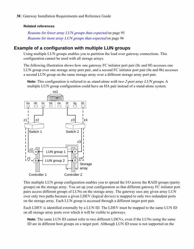
Example of a configuration with multiple LUN groupsUsing multiple LUN groups enables you to partition the load over gateway connections. Thisconfiguration cannot be used with all storage arrays.
The following illustration shows how one gateway FC initiator port pair (0c and 0f) accesses oneLUN group over one storage array port pair, and a second FC initiator port pair (0a and 0h) accessesa second LUN group on the same storage array over a different storage array port pair.
Note: This configuration is referred to as stand-alone with two 2-port array LUN groups. Amultiple LUN group configuration could have an HA pair instead of a stand-alone system.
vs1
0a 0b 0c 0d 0e 0f 0g 0h
Storagearray
Controller 2Controller 1
AA LUN group 1
BB LUN group 2
Switch 1
z1 z2 z3 z4
z4
z3
z2
z1
Switch 2
This multiple LUN group configuration enables you to spread the I/O across the RAID groups (paritygroups) on the storage array. You set up your configuration so that different gateway FC initiator portpairs access different groups of LUNs on the storage array. The gateway sees any given array LUNover only two paths because a given LDEV (logical device) is mapped to only two redundant portson the storage array. Each LUN group is accessed through a different target port pair.
Each LDEV is identified externally by a LUN ID. The LDEV must be mapped to the same LUN IDon all storage array ports over which it will be visible to gateways.
Note: The same LUN ID cannot refer to two different LDEVs, even if the LUNs using the sameID are in different host groups on a target port. Although LUN ID reuse is not supported on the
38 | Gateway Installation Requirements and Reference Guide
same target port, LUN ID reuse is supported on a storage array if the LUNs are mapped todifferent storage array ports.
The following table summarizes the zoning for this example. Single-initiator zoning is therecommended zoning strategy.
Zone Gateway FC initiator port Storage array
Switch 1
z1 Port 0a Controller 1 Port B
z2 Port 0c Controller 1 Port A
Switch 2
z3 Port 0f Controller 2 Port A
z4 Port 0h Controller 2 Port B
See the Gateway Limits Reference for Third-Party Storage for information about the storage arraysfor which Data ONTAP supports multiple LUN groups.
Related concepts
Using LUN groups to partition the load over gateway connections on page 36Implementation requirements for a multiple LUN group configuration on page 37
Related references
Reasons for fewer array LUN groups than expected on page 95Reasons for more array LUN groups than expected on page 96
How paths are reflected in array LUN namesThe array LUN name is a path-based name that includes the devices in the path between the gatewayand the storage array.
By looking at the array LUN name as it is displayed in Data ONTAP output, you can identify thefollowing:
• Devices in the path between the gateway and the storage array• Ports used• The LUN identifier that the storage array presents externally for mapping to hosts
The format of the array LUN differs depending on the type of configuration and the Data ONTAPoperating mode that the system is running.
Planning for paths to array LUNs | 39
Related concepts
Array LUN name format on page 40
Array LUN name formatThe array LUN name is a path-based name that includes the devices in the path between the gatewayand the storage array, ports used, and the SCSI LUN ID on the path that the storage array presentsexternally for mapping to hosts.
On a gateway operating in 7-Mode, there are two names for each array LUN because there are twopaths to each LUN, for example, brocade3:6.126L1 and brocade15:6.126L1.
On an 8.0.x gateway operating in Cluster-Mode, there are two names for each array LUN becausethere are two paths to each LUN.
Array LUN format for systems operating in 7-Mode and releases prior to 8.0
Configuration Array LUN name format Component descriptions
Direct-attached adapter.idlun-id adapter is the adapter numberon the gateway.id is the channel adapter porton the storage array.lun-id is the array LUNnumber that the storage arraypresents to hosts.Example:0a.0L1
Fabric-attached switch-name:port.idlun-
id
switch-name is the name ofthe switch.port is the switch port that isconnected to the target port (theend point).id is the device ID.lun-id is the array LUNnumber that the storage arraypresents to hosts.Example:brocade3:6.126L1
brocade3:6.126 is the pathcomponent and L1 is the SCSILUN ID.
40 | Gateway Installation Requirements and Reference Guide
Array LUN name format for systems operating in Cluster-Mode
Configuration Array LUN name format Component descriptions
Direct-attached node-name.adapter.idlun-
id
node-name is the name of theCluster-Mode node. WithCluster-Mode, the node nameis prepended to the LUN nameso that the path-based name isunique within the cluster.adapter is the adapternumber on the gateway.id is the channel adapter porton the storage array.lun-id is the array LUNnumber that the storage arraypresents to hosts.Example: node1.0a.0L1
Fabric-attached node-name:switch-
name:port.idlun-id
node-name is the name of theCluster-Mode node. WithCluster-Mode, the node nameis prepended to the LUN nameso that the path-based name isunique within the cluster.switch-name is the name ofthe switch.port is the switch port that isconnected to the target port(the end point).id is the device ID.lun-id is the array LUNnumber that the storage arraypresents to hosts.Example:node1:brocade3:6.126L1
Related concepts
How the array LUN name changes in Data ONTAP displays on page 42How paths are reflected in array LUN names on page 39
Planning for paths to array LUNs | 41
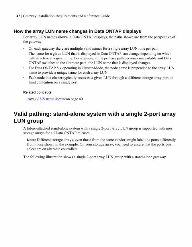
How the array LUN name changes in Data ONTAP displaysFor array LUN names shown in Data ONTAP displays, the paths shown are from the perspective ofthe gateway.
• On each gateway there are multiple valid names for a single array LUN, one per path.The name for a given LUN that is displayed in Data ONTAP can change depending on whichpath is active at a given time. For example, if the primary path becomes unavailable and DataONTAP switches to the alternate path, the LUN name that is displayed changes.
• For Data ONTAP 8.x operating in Cluster-Mode, the node name is prepended to the array LUNname to provide a unique name for each array LUN.
• Each node in a cluster typically accesses a given LUN through a different storage array port tolimit contention on a single port.
Related concepts
Array LUN name format on page 40
Valid pathing: stand-alone system with a single 2-port arrayLUN group
A fabric-attached stand-alone system with a single 2-port array LUN group is supported with moststorage arrays for all Data ONTAP releases.
Note: Different storage arrays, even those from the same vendor, might label the ports differentlyfrom those shown in the example. On your storage array, you need to ensure that the ports youselect are on alternate controllers.
The following illustration shows a single 2-port array LUN group with a stand-alone gateway.
42 | Gateway Installation Requirements and Reference Guide
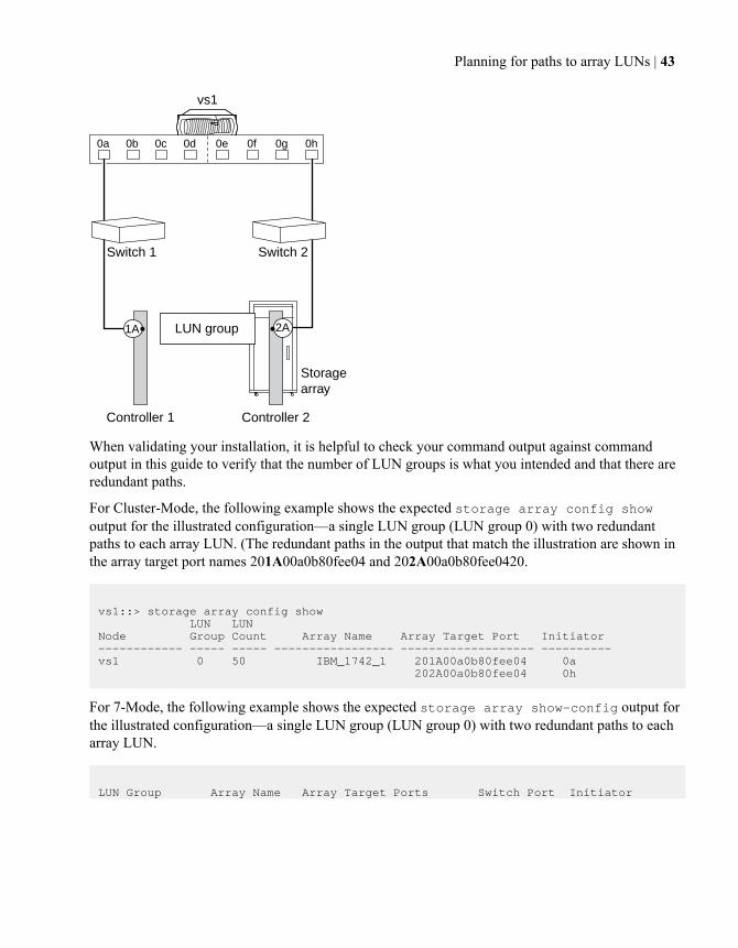
vs1
0a 0b 0c 0d 0e 0f 0g 0h
Storagearray
Controller 1 Controller 2
LUN group
Switch 1 Switch 2
1A 2A
When validating your installation, it is helpful to check your command output against commandoutput in this guide to verify that the number of LUN groups is what you intended and that there areredundant paths.
For Cluster-Mode, the following example shows the expected storage array config showoutput for the illustrated configuration—a single LUN group (LUN group 0) with two redundantpaths to each array LUN. (The redundant paths in the output that match the illustration are shown inthe array target port names 201A00a0b80fee04 and 202A00a0b80fee0420.
vs1::> storage array config show LUN LUNNode Group Count Array Name Array Target Port Initiator------------ ----- ----- ----------------- ------------------- ---------- vs1 0 50 IBM_1742_1 201A00a0b80fee04 0a 202A00a0b80fee04 0h
For 7-Mode, the following example shows the expected storage array show-config output forthe illustrated configuration—a single LUN group (LUN group 0) with two redundant paths to eacharray LUN.
LUN Group Array Name Array Target Ports Switch Port Initiator
Planning for paths to array LUNs | 43
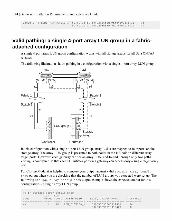
Group 0 (4 LUNS) HP_HSV210_1 50:00:1f:e1:50:0a:86:6d vnmc4300s35:11 0a 50:00:1f:e1:50:0a:86:69 vnbr4100s31:15 0h
Valid pathing: a single 4-port array LUN group in a fabric-attached configuration
A single 4-port array LUN group configuration works with all storage arrays for all Data ONTAPreleases.
The following illustration shows pathing in a configuration with a single 4-port array LUN group:
Storagearray
vs1 vs2
0a 0b 0c 0d 0a 0b 0c 0d
1A
Switch 1 Switch 2
Fabric 1 Fabric 2
1B
2A
2BLUN group 1
z1 z3 z2 z4
z4z2
z3z1
Controller 1 Controller 2
In this configuration with a single 4-port LUN group, array LUNs are mapped to four ports on thestorage array. The array LUN group is presented to both nodes in the HA pair on different arraytarget ports. However, each gateway can see an array LUN, end-to-end, through only two paths.Zoning is configured so that each FC initiator port on a gateway can access only a single target arrayport.
For Cluster-Mode, it is helpful to compare your output against valid storage array configshow output when you are checking that the number of LUN groups you expected were set up. Thefollowing storage array config show output example shows the expected output for thisconfiguration—a single array LUN group.
vs::> storage array config show LUN LUNNode Group Count Array Name Array Target Port Initiator------------ ----- ----- ------------- ----------------------- ---------vs1 1 10 IBM_2107900_1 50050763030301241A 0a 50050763031301242A 0c
44 | Gateway Installation Requirements and Reference Guide
vs2 1 10 IBM_2107900_1 50050763030881241B 0a 50050763031881242B 0c 4 entries were displayed.
For 7-Mode, you can check the storage array show-config output to see how many array LUNgroups were created.
Planning for paths to array LUNs | 45
Determining the array LUNs for specificaggregates
There are a number of rules about mixing different types of storage in aggregates that are unique togateways that use third-party storage. You must understand these rules when planning which arrayLUNs and disks to add to which aggregates.
Rules for mixing storage in aggregates for gatewaysWhen planning for aggregates, you must consider the rules for mixing storage in aggregates. Youcannot mix different storage types or array LUNs from different vendors or vendor families in thesame aggregate.
Adding the following to the same aggregate is not supported:
• Array LUNs and disks• Array LUNs with different checksum types• Array LUNs from different drive types (for example, FC and SATA) or different speeds• Array LUNs from different storage array vendors• Array LUNs from different storage array model families
Note: Storage arrays in the same family share the same performance and failover characteristics.For example, members of the same family all perform active-active failover, or they all performactive-passive failover. Storage arrays with 4-GB HBAs are not considered to be in the samefamily as storage arrays with 8-GB HBAs.
Related concepts
How the checksum type is determined for aggregates with array LUNs on page 46Aggregate rules when the storage arrays are from the same family on page 48Aggregate rules when the storage arrays are from different vendors or families on page 50
How the checksum type is determined for aggregates witharray LUNs
Each Data ONTAP aggregate has a checksum type associated with it. The aggregate checksum typeis determined by the checksum type of the array LUNs that are added to it.
The checksum type of an aggregate is determined by the checksum type of the first array LUN that isadded to the aggregate. The checksum type applies to an entire aggregate (that is, to all volumes inthe aggregate). Mixing array LUNs of different checksum types in an aggregate is not supported.
46 | Gateway Installation Requirements and Reference Guide
• An array LUN of type block must be used with block checksum type aggregates.• An array LUN of type zoned must be used with advanced zoned checksum (AZCS or
advanced_zoned) type aggregates.
Note: Prior to Data ONTAP 8.1.1, zoned checksum array LUNs were used with ZCS (zoned)type aggregates. Starting in 8.1.1, any new aggregates created with zoned checksum arrayLUNs are AZCS aggregates. You can, however, add zoned checksum array LUNs to existingZCS aggregates.
Before you add array LUNs to an aggregate, you must know the checksum type of the LUNs youwant to add, for the following reasons:
• You cannot add array LUNs of different checksum types to the same aggregate.• You cannot convert an aggregate from one checksum type to the other.
When you create an aggregate you can specify the number of array LUNs to be added, or you canspecify the names of the LUNs to be added. If you want to specify a number of array LUNs to beadded to the aggregate, the same number or more array LUNs of that checksum type must beavailable.
Related concepts
Rules for mixing storage in aggregates for gateways on page 46Aggregate rules when the storage arrays are from the same family on page 48Aggregate rules when the storage arrays are from different vendors or families on page 50
Checking the checksum type of spare array LUNsIf you plan to add a spare array LUN to an aggregate by specifying its name, you need to make surethat the checksum type of the array LUN you want to add is the same as the aggregate checksumtype.
About this task
You cannot mix array LUNs of different checksum types in an aggregate for third-party storage. Thechecksum type of the aggregate and the checksum type of the array LUNs added to it must be thesame.
If you specify a number of spare array LUNs to be added to an aggregate, by default Data ONTAPselects array LUNs of the same checksum type as the aggregate.
Note: Data ONTAP 8.1.1 and later supports a new checksum scheme called advanced zonedchecksum (AZCS). Existing zoned checksum aggregates are still supported. The checksum type ofall newly created aggregates using zoned checksum array LUNS is AZCS, which provides morefunctionality than the “version 1” zoned checksum type that was supported in previous releasesand continues to be supported for existing zoned aggregates. Zoned checksum spare array LUNsadded to an existing zoned checksum aggregate continue to be zoned checksum array LUNs.
Determining the array LUNs for specific aggregates | 47
Zoned checksum spare array LUNs added to an AZCS checksum type aggregate use the AZCSchecksum scheme for managing checksums.
Step
1. Check the checksum type of the spare array LUNs by entering the following command:
Mode Command
7-Mode aggr status -s
The output shows information about the spare disks or array LUNs on the system, includingthe checksum type of each. You can add a block checksum array LUN to a block checksumaggregate and a zoned array LUN to either a zoned aggregate or an AZCS checksumaggregate.
Cluster-Mode
storage disk show -fields checksum-compatibility -container-type spare
You can add a block checksum array LUN to a block checksum aggregate and a zoned arrayLUN to either a zoned checksum aggregate or an AZCS checksum aggregate.
Aggregate rules when the storage arrays are from the samefamily
Specific rules apply to how you can lay out array LUNs in aggregates when the storage arrays arefrom the same storage array vendor and model family.
If your storage arrays are from the same vendor, the rules for adding array LUNs to aggregates are asfollows:
• You can mix array LUNs from the storage arrays in the same aggregate if the storage arrays are inthe same family.
• You can separate the array LUNs into different aggregates.
The following examples show some options for laying out array LUNs in aggregates when thestorage arrays behind a gateway are in the same vendor family.
Note: For simplicity, the illustrations show only two storage arrays; your deployment can includemore storage arrays.
Example 1: Add LUNs from all storage arrays to a single aggregate
As shown in the following illustration, you can create one aggregate, then add all LUNs fromall the storage arrays in the same family to the same aggregate:
48 | Gateway Installation Requirements and Reference Guide
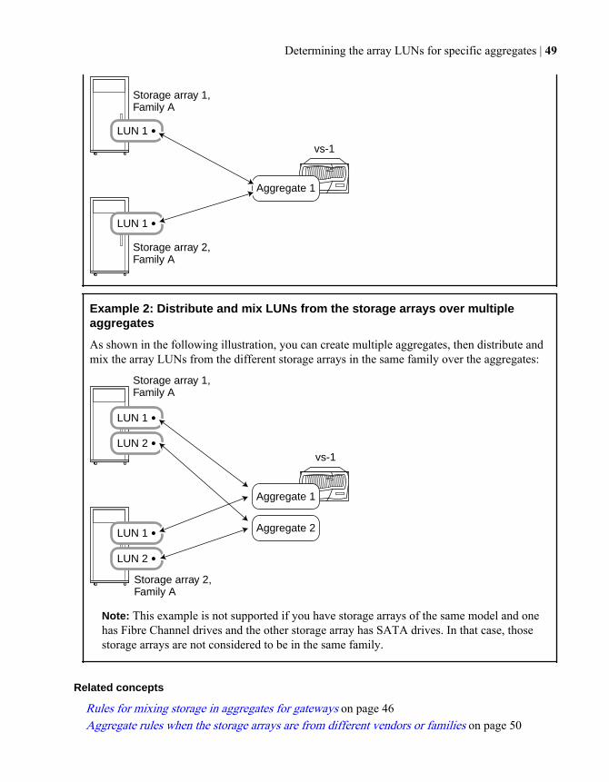
Storage array 1, Family A
vs-1
LUN 1
Storage array 2, Family A
LUN 1
Aggregate 1
Example 2: Distribute and mix LUNs from the storage arrays over multipleaggregates
As shown in the following illustration, you can create multiple aggregates, then distribute andmix the array LUNs from the different storage arrays in the same family over the aggregates:
Storage array 1, Family A
LUN 1
LUN 2
Storage array 2, Family A
LUN 1
LUN 2
vs-1
Aggregate 1
Aggregate 2
Note: This example is not supported if you have storage arrays of the same model and onehas Fibre Channel drives and the other storage array has SATA drives. In that case, thosestorage arrays are not considered to be in the same family.
Related concepts
Rules for mixing storage in aggregates for gateways on page 46Aggregate rules when the storage arrays are from different vendors or families on page 50
Determining the array LUNs for specific aggregates | 49
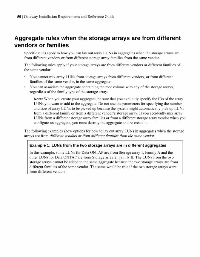
Aggregate rules when the storage arrays are from differentvendors or families
Specific rules apply to how you can lay out array LUNs in aggregates when the storage arrays arefrom different vendors or from different storage array families from the same vendor.
The following rules apply if your storage arrays are from different vendors or different families ofthe same vendor:
• You cannot mix array LUNs from storage arrays from different vendors, or from differentfamilies of the same vendor, in the same aggregate.
• You can associate the aggregate containing the root volume with any of the storage arrays,regardless of the family type of the storage array.
Note: When you create your aggregate, be sure that you explicitly specify the IDs of the arrayLUNs you want to add to the aggregate. Do not use the parameters for specifying the numberand size of array LUNs to be picked up because the system might automatically pick up LUNsfrom a different family or from a different vendor’s storage array. If you accidently mix arrayLUNs from a different storage array families or from a different storage array vendor when youconfigure an aggregate, you must destroy the aggregate and re-create it.
The following examples show options for how to lay out array LUNs in aggregates when the storagearrays are from different vendors or from different families from the same vendor.
Example 1: LUNs from the two storage arrays are in different aggregates
In this example, some LUNs for Data ONTAP are from Storage array 1, Family A and theother LUNs for Data ONTAP are from Storage array 2, Family B. The LUNs from the twostorage arrays cannot be added to the same aggregate because the two storage arrays are fromdifferent families of the same vendor. The same would be true if the two storage arrays werefrom different vendors.
50 | Gateway Installation Requirements and Reference Guide
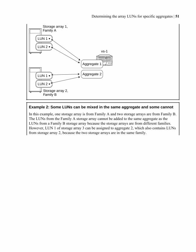
Storage array 1, Family A
vs-1
LUN 1
LUN 2
Storage array 2, Family B
LUN 1
Aggregate 1
Aggregate 2
LUN 2
Example 2: Some LUNs can be mixed in the same aggregate and some cannot
In this example, one storage array is from Family A and two storage arrays are from Family B.The LUNs from the Family A storage array cannot be added to the same aggregate as theLUNs from a Family B storage array because the storage arrays are from different families.However, LUN 1 of storage array 3 can be assigned to aggregate 2, which also contains LUNsfrom storage array 2, because the two storage arrays are in the same family.
Determining the array LUNs for specific aggregates | 51
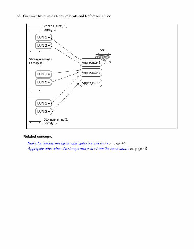
Storage array 1, Family A
LUN 1
LUN 2
Storage array 2, Family B
LUN 1
LUN 2
Storage array 3, Family B
LUN 1
LUN 2
vs-1
Aggregate 1
Aggregate 2
Aggregate 3
Related concepts
Rules for mixing storage in aggregates for gateways on page 46Aggregate rules when the storage arrays are from the same family on page 48
52 | Gateway Installation Requirements and Reference Guide
Zoning guidelines
A common error when installing a gateway configuration is to misconfigure zoning. For successfulzoning, follow the guidelines provided for setting up zoning between a gateway and a storage array.The Gateway Interoperability Matrix at the N series support website (accessed and navigated asdescribed in Websites on page 7) contains information about specific switch guidelines and potentialissues. The Gateway Best Practice Guide also contains information about zoning.
Zoning requirementsConfiguring zoning on a Fibre Channel (FC) switch enables you to define paths between connectednodes, restricting visibility and connectivity between devices connected to a common FC SAN.
Zoning enables a storage administrator to restrict the array LUNs that a particular gateway can see.Data ONTAP requires that an array LUN be visible on only one target port for each initiator port.
The requirements for configuring zoning in a gateway deployment are as follows:
• The Gateway Interoperability Matrix must identify a switch and the switch firmware assupported.
• Zoning must be configured to restrict each initiator port to a single target port on each storagearray.
• On the switch, ports on the gateway and ports on the storage array must be assigned to the samezone.This enables the gateways to see the LUNs on the storage arrays.
• When storage array ports are shared across heterogeneous systems, array LUNs from the gatewaycannot be exposed to other systems, and the reverse.LUN security or array LUN masking must be used to ensure that only the array LUNs that are forData ONTAP storage are visible to the gateways.
Zoning can be configured by specifying WWNs (worldwide names) or ports.
You can find guides for configuring specific vendor switches on the N series support website(accessed and navigated as described in Websites on page 7).
Related concepts
Zoning recommendation for a configuration with third-party storage on page 54Example of zoning in a configuration with third-party storage on page 55Dependency between zone and host group definitions on page 109
Related references
Relationship between zoning and host group configuration on page 109
53
Zoning recommendation for a configuration with third-partystorage
You should use single-initiator zoning, which limits each zone to a single gateway FC initiator port.
The benefits of creating a separate zone for each gateway FC initiator port and each non gatewayhost are as follows:
• You limit the number of ports over which a specific array LUN can be accessed.You can prevent a gateway from accessing a given array LUN for Data ONTAP over more thantwo storage array ports.
• Single-initiator zoning improves discovery and boot time because the gateway FC initiators donot attempt to discover each other.
Related concepts
Zoning requirements on page 53Example of zoning in a configuration with third-party storage on page 55
54 | Gateway Installation Requirements and Reference Guide
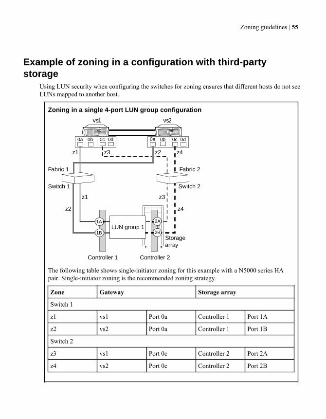
Example of zoning in a configuration with third-partystorage
Using LUN security when configuring the switches for zoning ensures that different hosts do not seeLUNs mapped to another host.
Zoning in a single 4-port LUN group configuration
Storagearray
vs1 vs2
0a 0b 0c 0d 0a 0b 0c 0d
1A
Switch 1 Switch 2
Fabric 1 Fabric 2
1B
2A
2BLUN group 1
z1 z3 z2 z4
z4z2
z3z1
Controller 1 Controller 2
The following table shows single-initiator zoning for this example with a N5000 series HApair. Single-initiator zoning is the recommended zoning strategy.
Zone Gateway Storage array
Switch 1
z1 vs1 Port 0a Controller 1 Port 1A
z2 vs2 Port 0a Controller 1 Port 1B
Switch 2
z3 vs1 Port 0c Controller 2 Port 2A
z4 vs2 Port 0c Controller 2 Port 2B
Zoning guidelines | 55
Related concepts
Zoning recommendation for a configuration with third-party storage on page 54Dependency between zone and host group definitions on page 109
Related references
Relationship between zoning and host group configuration on page 109
56 | Gateway Installation Requirements and Reference Guide
Determining whether to use neighborhoods (7-Mode in 8.x)
A neighborhood is a logical entity that enables gateways to see the same array LUNs. Ordinarilysystems that are not part of an HA pair have no relationship with each other; they cannot see thesame array LUNs and you cannot load balance between them. A neighborhood makes it possible todo these things.
Neighborhoods do not pertain to configurations with only one stand-alone system or only one HApair and no other systems.
Note: Nodes in Cluster-Mode provide like functionality to neighborhoods, which are supportedonly for 7-Mode gateways.
What a gateway neighborhood isA gateway neighborhood is a logical relationship between up to six gateways that enables you toeasily reassign ownership of array LUNs from one neighborhood member to another through DataONTAP. The members of a neighborhood can be stand-alone systems or HA pairs. Neighborhoodfunctionality is limited to third-party storage.
With a neighborhood, you can also transparently load balance data service among the gateways in aneighborhood by moving vFiler units among neighborhood members. The physical storage alwaysremains on the storage array.
Although neighborhood members see the same array LUNs, the systems outside of an HA paircannot see each other’s disks.
The neighborhood relationship does not provide any failover between neighborhood members if amember becomes unavailable. Failover of services is a function of the relationship between twonodes in an HA pair, and can occur only between the two nodes in an HA pair.
57
Requirements for gateway neighborhoodsIf you are thinking about using neighborhoods, you need to check to be sure they are supported foryour storage array and for the Data ONTAP release running on your gateways.
For... This is supported...
Data ONTAP releases • Releases 8.0 and later operating in 7-Mode• Data ONTAP releases earlier than 8.x (which
support only 7-Mode)
Mixing Data ONTAP releases from differentrelease families is not supported. For example,mixing Data ONTAP release 7.3.x with an 8.xrelease is not supported.
Storage arrays Storage arrays that the Gateway InteroperabilityMatrix does not indicate are not supported withneighborhoods.
Platforms All platform types. Mixed platform types aresupported.
Configurations Any combination of stand-alone systems andHA pairs.Neighborhoods are not supported for aMetroCluster configuration.
Number of gateways A maximum of six systems.
Number of LUNs and disks supported No more than the limits for the maximumdevices in a neighborhood and the neighborhoodmaximum LUN limit.
Related concepts
Planning the number of array LUNs and disks in a neighborhood on page 58
Planning the number of array LUNs and disks in aneighborhood
When determining the number of LUNs that storage arrays can present to the gateways in yourneighborhood, you must consider both the platform maximum assigned device limit and the
58 | Gateway Installation Requirements and Reference Guide
neighborhood maximum LUN limit. You cannot exceed the limits for the maximum devices in aneighborhood and the neighborhood maximum LUN limit.
The relationship between the following two limits determines the limits for your neighborhood. Youshould use the limits information in the Gateway Limits Reference for Third-Party Storage tocalculate the limits for your neighborhood.
Type of limit... What it is...
Platform maximum assigned device limit Maximum number of array LUNs and diskscombined that can be assigned to a stand-alonesystem or nodes in an HA pair.You cannot exceed the platform maximumassigned device limit.Furthermore, the combined total of array LUNsand disks assigned to a system cannot exceed theneighborhood maximum LUN limit.
Neighborhood maximum LUN limit (the visiblelimit)
Maximum number of array LUNs that allsystems in the neighborhood combined can see,and the maximum number of array LUNs thatcan be assigned to all systems in theneighborhood combined.
Platform maximum assigned device limit
For every platform, Data ONTAP hard codes the maximum number of devices (disks and arrayLUNs combined) that can be assigned to a stand-alone system or an HA pair (through the DataONTAP disk ownership feature).
The platform maximum assigned device limit does not limit the number of disks and array LUNs thatthe systems in a gateway neighborhood can see (that is, the visible limit); it limits only the number ofdisks and LUNs that you can assign to the platform. The visible limit is determined by theneighborhood maximum LUN limit.
Note: The platform maximum assigned device limit applies whether a gateway is in aneighborhood or not. The platform maximum assigned device limit is the same for a stand-alonesystem and an HA pair because each node in the pair must be able to handle its storage and itspartner’s storage if the partner becomes unavailable.
Neighborhood maximum LUN limit
The neighborhood maximum LUN limit has the following two components:
• It is the maximum visible limit for the neighborhood.This limit is the maximum number of the same array LUNs that gateways in a neighborhood areallowed to see. (All members of the neighborhood see all the same array LUNs but a LUN can beassigned to only one of them.)
Determining whether to use neighborhoods (7-Mode in 8.x) | 59
Individual gateways in the neighborhood that have disks attached cannot see more array LUNsand disks combined than the maximum visible limit.
• It is the maximum assigned LUN limit for all the systems in the neighborhood combined.The platform maximum assigned device limit, not the neighborhood maximum LUN limit,dictates the maximum number of disks and array LUNs that can be assigned to a stand-alonesystem or HA pair. However, in the context of the neighborhood, you might not be able to assignthe maximum number of devices that the platform can support because the combined total ofassigned devices must not exceed the neighborhood limit.
Neighborhood members can never see more array LUNs than the neighborhood maximum LUN limitfor the platform type. However, the following factors can reduce the maximum LUN limit from thatnumber:
• If the systems in the neighborhood are mixed platform types• If there are neighborhood restrictions for the storage arrays that are presenting LUNs to the
neighborhood systems• If disks are connected to the gateways in the neighborhood
Note: The lowest limit based on any factor becomes the maximum LUN limit for yourneighborhood.
Example of how the limits work together
Assume that you have two stand-alone systems in the neighborhood, and the maximum assignedlimit for the platform is 600 devices. If the neighborhood LUN limit is 1,000 array LUNs, you cannotassign 600 array LUNs to each system because the total assigned LUNs for the two systems would be1,200, which is 200 LUNs more than the 1,000 neighborhood maximum LUN limit.
Related concepts
Requirements for gateway neighborhoods on page 58
How to establish a neighborhoodA neighborhood exists only when a gateway can see array LUNs that belong to another gateway thatis not its partner in an HA pair. To establish a neighborhood, the storage arrays and switches must beconfigured to enable all gateways in the same neighborhood to see the same array LUNs.
Data ONTAP configuration to establish a neighborhood
No explicit configuration is required on a gateway to support neighborhoods. The underlyingfunctionality that enables the gateways to operate as a neighborhood is the Data ONTAP diskownership feature (assigning array LUNs to a specific gateway).
Note: After you determine the maximum number of LUNs that the storage arrays can present toyour neighborhood, be sure to communicate that information to the storage array administrators.
60 | Gateway Installation Requirements and Reference Guide
Storage array configuration to establish a neighborhood
The storage array administrator must configure one or more storage arrays to present the same LUNsto the gateways that you want to be in the neighborhood.
How a storage array administrator creates and presents LUNs to hosts varies on different storagearrays. Typically the storage array administrator specifies the FC initiator ports of a number ofgateways to be in the same host group on the storage array. This host group configuration enables allthe systems to see the same LUNs.
The storage array administrator must also set the storage array access controls so that all thegateways can see the same array LUNs.
Switch configuration to establish a neighborhood
If your configuration is fabric-attached, you must zone switch ports that connect to your gateway FCinitiator ports. This ensures that all gateways in the neighborhood can see the same array LUNs.
Note: It is recommended that you use single-initiator zoning, which limits each zone to a singlegateway FC initiator port.
Determining whether to use neighborhoods (7-Mode in 8.x) | 61
Planning a port-to-port connectivity scheme
Planning connectivity between the gateway FC initiator ports and storage array ports includesdetermining how to achieve redundancy and meeting requirements for the number of paths to anarray LUN.
Related concepts
Zoning recommendation for a configuration with third-party storage on page 54Guidelines for connecting your system to third-party storage on page 62Requirements for gateway FC initiator port usage on page 63How FC initiator ports are labeled on page 65
Guidelines for connecting your system to third-partystorage
When planning how to connect your system to third-party storage, be sure that your port-to-portconnectivity plan addresses redundancy, pathing, and other guidelines.
The requirements to set up connections are as follows:
• You need to attach each connection in a redundant port pair on the storage array to a different FCinitiator port on the gateway.
• If your storage array supports fewer LUNs per host group per port than the number of LUNs thatthe gateways will be using, you need to add additional cables between the gateway and thestorage array.
• You need to use redundant ports on the Fibre Channel switches.• You need to avoid a SPOF.
You need to ensure that the ports on the storage array that you select to access a given LUN arefrom different components that could represent a single point of failure, for example, fromalternate controllers, clusters, or enclosures. You want to ensure that you do not lose all access toa LUN if one component fails.
• Do not exceed the number of paths supported for your Data ONTAP release and operating mode.Data ONTAP 8.1 and later operating in Cluster-Mode supports two or four paths to an arrayLUN. Data ONTAP 8.1 and later operating in 7-Mode, and releases prior to Data ONTAP 8.1,support only two paths to an array LUN.
See the Gateway Implementation Guide for Third-Party Storage for information about any uniqueport-to-port connectivity requirements for your storage array type.
62 | Gateway Installation Requirements and Reference Guide
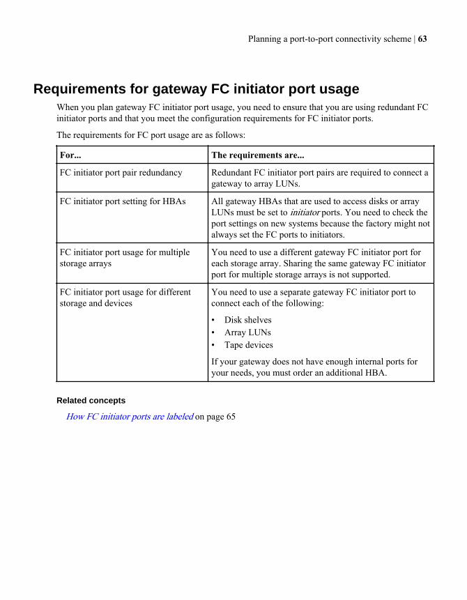
Requirements for gateway FC initiator port usageWhen you plan gateway FC initiator port usage, you need to ensure that you are using redundant FCinitiator ports and that you meet the configuration requirements for FC initiator ports.
The requirements for FC port usage are as follows:
For... The requirements are...
FC initiator port pair redundancy Redundant FC initiator port pairs are required to connect agateway to array LUNs.
FC initiator port setting for HBAs All gateway HBAs that are used to access disks or arrayLUNs must be set to initiator ports. You need to check theport settings on new systems because the factory might notalways set the FC ports to initiators.
FC initiator port usage for multiplestorage arrays
You need to use a different gateway FC initiator port foreach storage array. Sharing the same gateway FC initiatorport for multiple storage arrays is not supported.
FC initiator port usage for differentstorage and devices
You need to use a separate gateway FC initiator port toconnect each of the following:
• Disk shelves• Array LUNs• Tape devices
If your gateway does not have enough internal ports foryour needs, you must order an additional HBA.
Related concepts
How FC initiator ports are labeled on page 65
Planning a port-to-port connectivity scheme | 63
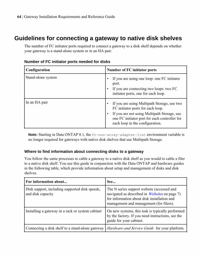
Guidelines for connecting a gateway to native disk shelvesThe number of FC initiator ports required to connect a gateway to a disk shelf depends on whetheryour gateway is a stand-alone system or in an HA pair.
Number of FC initiator ports needed for disks
Configuration Number of FC initiator ports
Stand-alone system • If you are using one loop: one FC initiatorport.
• If you are connecting two loops: two FCinitiator ports, one for each loop.
In an HA pair • If you are using Multipath Storage, use twoFC initiator ports for each loop.
• If you are not using Multipath Storage, useone FC initiator port for each controller foreach loop in the configuration.
Note: Starting in Data ONTAP 8.1, the fc-non-array-adapter-list environment variable isno longer required for gateways with native disk shelves that use Multipath Storage.
Where to find information about connecting disks to a gateway
You follow the same processes to cable a gateway to a native disk shelf as you would to cable a filerto a native disk shelf. You use this guide in conjunction with the Data ONTAP and hardware guidesin the following table, which provide information about setup and management of disks and diskshelves.
For information about... See...
Disk support, including supported disk speeds,and disk capacity
The N series support website (accessed andnavigated as described in Websites on page 7)for information about disk installation andmanagement and management (for filers).
Installing a gateway in a rack or system cabinet On new systems, this task is typically performedby the factory. If you need instructions, see theguide for your cabinet.
Connecting a disk shelf to a stand-alone gateway Hardware and Service Guide for your platform.
64 | Gateway Installation Requirements and Reference Guide
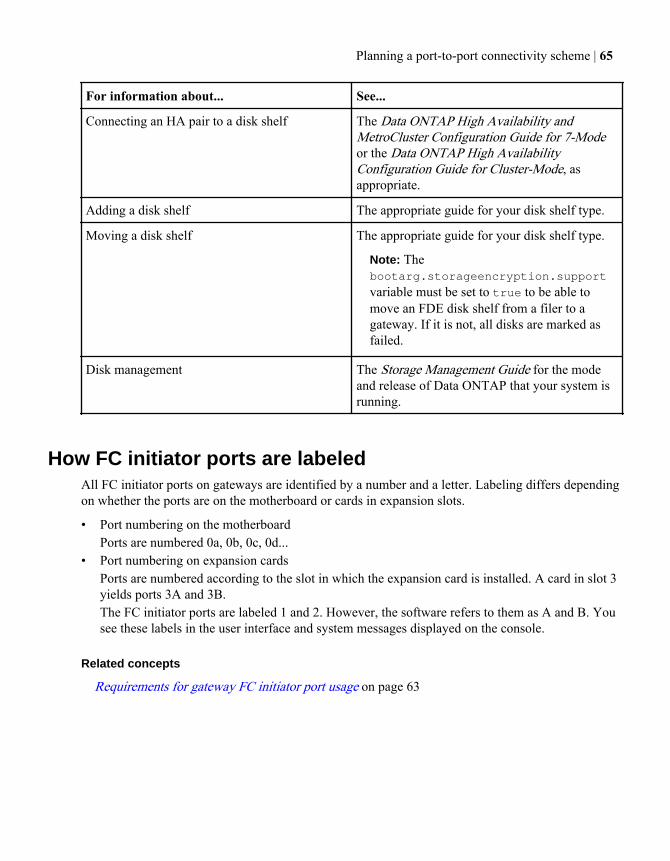
For information about... See...
Connecting an HA pair to a disk shelf The Data ONTAP High Availability andMetroCluster Configuration Guide for 7-Modeor the Data ONTAP High AvailabilityConfiguration Guide for Cluster-Mode, asappropriate.
Adding a disk shelf The appropriate guide for your disk shelf type.
Moving a disk shelf The appropriate guide for your disk shelf type.
Note: Thebootarg.storageencryption.support
variable must be set to true to be able tomove an FDE disk shelf from a filer to agateway. If it is not, all disks are marked asfailed.
Disk management The Storage Management Guide for the modeand release of Data ONTAP that your system isrunning.
How FC initiator ports are labeledAll FC initiator ports on gateways are identified by a number and a letter. Labeling differs dependingon whether the ports are on the motherboard or cards in expansion slots.
• Port numbering on the motherboardPorts are numbered 0a, 0b, 0c, 0d...
• Port numbering on expansion cardsPorts are numbered according to the slot in which the expansion card is installed. A card in slot 3yields ports 3A and 3B.The FC initiator ports are labeled 1 and 2. However, the software refers to them as A and B. Yousee these labels in the user interface and system messages displayed on the console.
Related concepts
Requirements for gateway FC initiator port usage on page 63
Planning a port-to-port connectivity scheme | 65
Connecting a gateway to back-end devices
Plan gateway FC initiator and storage array port usage before connecting gateways to back-enddevices. You must set up redundant connections to avoid a single point of failure (SPOF).
Connecting a gateway stand-alone system to back-enddevices
You can connect a stand-alone gateway to a storage array either directly or through a switch.
About this task
System and port names in the following procedure are examples.
Steps
1. Identify onboard ports and expansion adapter ports for your gateway.
2. Locate the ports on the storage array that you want to use to connect to the gateway.
3. Connect the gateway to the storage array by using redundant FC initiator ports.
4. For a direct-attached configuration, connect the gateway to the storage array as follows:
a) Connect one cable from one FC initiator port on the gateway to controller 1 port 1 on thestorage array.
b) Connect a cable from a redundant FC initiator port on the gateway to controller 2 port 1 on thestorage array.
5. For a fabric-attached configuration, connect the gateway to the switches as follows:
a) Connect one cable from the one FC initiator port on the gateway to Switch 1.b) Connect another cable from the redundant port on the gateway to Switch 2.
6. For a fabric-attached configuration, connect the switch to the storage arrays as follows:
a) Connect Switch 1 to the storage array controller 1, port 1.b) Connect Switch 2 to the storage array controller 2, port 1.
7. Connect a console cable to the console port on each gateway to the RJ-45 to DB-9 adapter that isincluded with your system.
8. Install the cable management tray as follows:
a) Pinch the arms of the tray and fit the holes in the arms through the motherboard tray pins.b) Push the cables into the cable holders, thread the adapter cables through the top rows of the
cable holders, and thread the port cables through the lower cable holders.
66 | Gateway Installation Requirements and Reference Guide
9. Connect the gateway to an Ethernet network by plugging the network cable into the networkingport.
If you are connecting more than one network cable to the network, connect to the portssequentially.
10. Optional: Connect a remote management device from the back of the gateway to the networkusing an Ethernet cable.
Note: If you are using RLM, the network switch port for the RLM connection must negotiatedown to 10/100 or autonegotiate.
11. Verify that the storage array is configured and connected properly, and that it is powered on.
Note: Your configured and connected storage array must be powered on before you power onyour gateway. The gateway expects these units to be ready for input/output when it powers onand performs its reset and self-test.
12. If your deployment includes switches, make sure that all switch IDs are set, then turn on eachswitch 10 minutes apart from one another.
13. If applicable, turn on any tape backup devices.
14. For each power supply on the gateway, do the following:
a) Ensure that the power switch is in the Off (0) position.b) Connect the socket end of the power cord to the power plug on the power supply.c) Secure the power cord with the retaining adjustable clip on the power supply.d) Plug the other end of the power cord into a grounded electrical outlet.
Note: To obtain power supply redundancy, you must connect the second power supply to aseparate AC circuit.
15. Start a communications program.
You must use some form of communications program to be able to perform initial network setupand gateway configuration. You can start a communications program through a remotemanagement device after connecting to the serial port.
16. Turn the power switch on the gateway to the On (|) position.
The system verifies the hardware and loads the operating system.
17. If the storage array does not automatically discover gateway WWNs after you connect thegateway to the storage array, you must obtain the WWNs manually.
After you finish
Continue with the appropriate setup of your gateway and Data ONTAP.
Related concepts
Settings for connecting to an ASCII terminal console on page 124
Connecting a gateway to back-end devices | 67
Related tasks
Connecting an HA pair to back-end devices on page 68Obtaining WWNs manually on page 123
Connecting an HA pair to back-end devicesYou can connect an HA pair to a storage array either directly or through a switch.
About this task
System and port names in the following procedure are examples.
Steps
1. Identify the onboard ports and expansion adapter ports for your gateway.
2. See the N series Introduction and Planning Guide to ensure that your HA interconnect adapter isin the correct slot for your system in an HA pair.
3. Plug one end of the optical cable into one of the local node’s HA adapter ports, then plug theother end into the partner node’s corresponding HA adapter port.
Note: Do not cross-cable the HA interconnect adapter. Cable the local node ports only to theidentical ports on the partner node.
4. Repeat the previous step for the two remaining ports on the HA adapter.
5. Locate the ports on the storage array that you want to use to connect the gateway to the storagearray, either directly or through a switch.
6. For a direct-attached HA pair, connect gateway 1 to the storage array, using redundant FCinitiator ports:
a) Connect one cable from one FC initiator port on gateway 1 to controller 1, port 1, on thestorage array.
b) Connect a cable from a redundant FC initiator port on gateway 1 to controller 2, port 1, on thestorage array.
7. For a direct-attached HA pair, connect gateway 2 to the storage array, using redundant FCinitiator ports:
a) Connect one cable from one FC initiator port on gateway 2 to controller 1, port 2, on thestorage array.
b) Connect a cable from a redundant FC initiator port on gateway 2 to controller 2, port 2, on thestorage array.
8. For a fabric-attached HA pair, connect gateway 1 to the switches, using redundant port pairs:
a) Connect one cable from one FC initiator port on gateway 1 to Switch 1.b) Connect another cable from a redundant FC initiator port on gateway 1 to Switch 2.
68 | Gateway Installation Requirements and Reference Guide

9. For a fabric-attached HA pair, connect gateway 2 to the switches, using redundant port pairs:
a) Connect one cable from one FC initiator port on gateway 2 to Switch 1.b) Connect another cable from a redundant FC initiator port on gateway 2 to Switch 2.
10. For a fabric-attached configuration, connect the switches to the storage array:
a) Connect Switch 1 to the storage array cluster (controller) 1, port 2.b) Connect Switch 2 to the storage array cluster (controller) 2, port 2.
11. Optional: Connect the gateway to a tape backup device through a separate FC initiator port orSCSI tape adapter.
12. Connect a console cable to the console port on each gateway to the RJ-45 to DB-9 adapter that isincluded with your system.
13. Install the cable management tray as follows:
a) Pinch the arms of the tray and fit the holes in the arms through the motherboard tray pins.b) Push the cables into the cable holders, thread the adapter cables through the top rows of the
cable holders, and thread the port cables through the lower cable holders.
14. Connect the gateway to an Ethernet network by plugging the network cable into the networkingport.
If you are connecting more than one network cable to the network, you need to connect to theports sequentially. Use the cable management tray to direct all the cabling from your system.
15. Optional: Connect a remote management device from the back of the gateway to the networkusing an Ethernet cable.
Note: The network switch port for the RLM connection must negotiate down to 10/100 orautonegotiate.
16. Verify that the storage array is configured and connected properly, and that it is powered on.
Note: Your configured and connected storage array must be powered on before you power onyour gateway. See your storage array documentation for how to power on the storage array.The gateway expects these units to be ready for input/output when it powers on and performsits reset and self-test.
17. If your deployment includes switches, make sure that all switch IDs are set, then turn on eachswitch 10 minutes apart from one another.
18. If applicable, turn on any tape backup devices.
19. For each power supply on the gateway, do the following:
a) Ensure that the power switch is in the Off (0) position.b) Connect the socket end of the power cord to the power plug on the power supply.c) Secure the power cord with the retaining adjustable clip on the power supply.d) Plug the other end of the power cord into a grounded electrical outlet.
Connecting a gateway to back-end devices | 69
Note: To obtain power supply redundancy, you must connect the second power supply to aseparate AC circuit.
20. Start a communications program.
You must use some form of communications program to be able to perform initial network setupand gateway configuration. You can start a communications program through a remotemanagement device after connecting to the serial port.
21. Turn the power switch on the gateway to the On (|) position.
The system verifies the hardware and loads the operating system.
22. If the storage array does not automatically discover gateway WWNs after you connect thegateway to the storage array, you must obtain the WWNs manually.
After you finish
Continue with the appropriate setup of your gateway and Data ONTAP.
Related concepts
Settings for connecting to an ASCII terminal console on page 124
Related tasks
Connecting a gateway stand-alone system to back-end devices on page 66Obtaining WWNs manually on page 123
70 | Gateway Installation Requirements and Reference Guide
Commands for checking back-end configuration(Cluster-Mode in 8.1 and later)
Starting in Data ONTAP 8.1, several Cluster-Mode commands provide information about the storagearray configuration, including back-end configuration errors. These commands are particularly usefulduring installation verification and troubleshooting.
The storage array config show command is the first command to use during installationverification. It is also the first command to use if you notice that your system is not working as youexpect, or if you receive an error message.
Commands that are particularly useful for installation verification and troubleshooting are shown inthe following table:
Command Description
storage array config show Provides information, at the storage array level,about the configuration of the back-end devices in agateway deployment. This command shows howstorage arrays connect to the cluster.If Data ONTAP detects an issue that would preventthe gateways and third-party storage from operatingproperly together, storage array config showinstructs you to run storage errors show toobtain details about the error.This command is also useful for verifying that theconfiguration is set up as you intended. For example,you can look at the output to confirm that the numberof array LUN groups that you intended were created.
storage array path quiesce Temporarily suspends I/O to a specific array LUN ona specific path. The path becomes active again onreboot or by running storage array path resume.Some storage arrays require ceasing I/O for a periodof time to remove or move an array LUN.
Note: The storage array path quiescecommand cannot be used with IBM DS storagearrays.
71
Command Description
storage array path resume Allows I/O to start flowing again; this is the inverseof quiesce. The storage array path resumecommand is used primarily for hardwaremaintenance (for example, cable or GBIC pulls) orafter an accidental quiescence of a path to an arrayLUN occurs.It is not always necessary to run this command afterquiescing a path. For example, Data ONTAP candiscover a newly mapped array LUN.
storage array show Displays information about the storage arrays thatare visible to the cluster, for example, name, vendor,model, and failover type.
storage disk show Entering storage disk show without parametersshows the following for all disks and array LUNs:the name, usable size, container type, position,aggregate, and owner.Entering storage disk show diskname orarrayLUNname shows details about an individualdisk or array LUN, for example, the status (assignedor unassigned), the owner, and the paths for the arrayLUN. The output is broken into three sections:information about the array LUN, information aboutthe paths to the array LUN, and any errors associatedwith the array LUN.For example, if storage errors show outputindicates that there are multiple IDs for the sameLUN, you can use storage disk showarrayLUNname to see the LUN IDs that are used onthe two paths.
storage errors show Provides details, at the array LUN level, about back-end configuration errors that prevent the gateway andthe storage array from operating together. You mustfix errors identified by storage errors showbefore you can configure Data ONTAP to work withthe third-party storage.
72 | Gateway Installation Requirements and Reference Guide
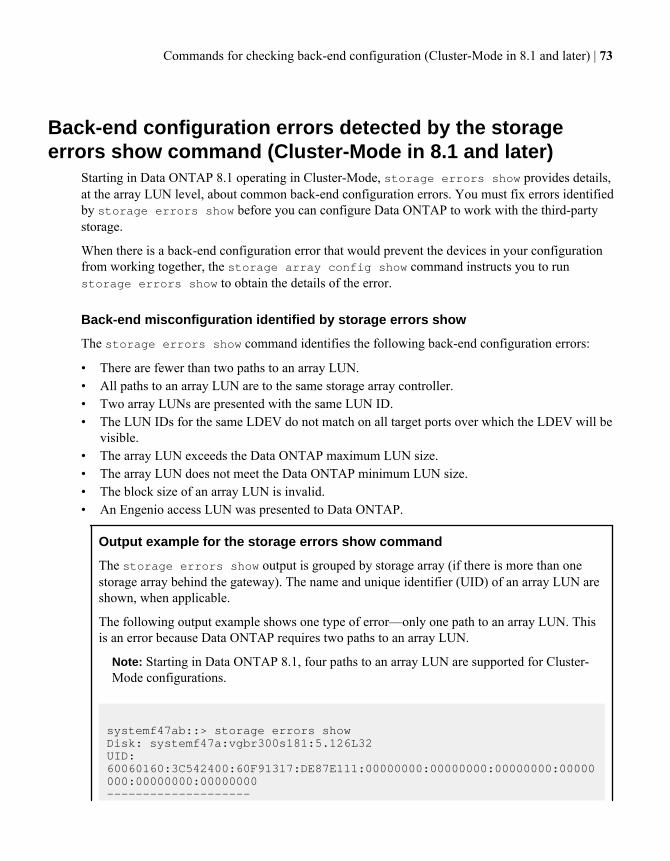
Back-end configuration errors detected by the storageerrors show command (Cluster-Mode in 8.1 and later)
Starting in Data ONTAP 8.1 operating in Cluster-Mode, storage errors show provides details,at the array LUN level, about common back-end configuration errors. You must fix errors identifiedby storage errors show before you can configure Data ONTAP to work with the third-partystorage.
When there is a back-end configuration error that would prevent the devices in your configurationfrom working together, the storage array config show command instructs you to runstorage errors show to obtain the details of the error.
Back-end misconfiguration identified by storage errors show
The storage errors show command identifies the following back-end configuration errors:
• There are fewer than two paths to an array LUN.• All paths to an array LUN are to the same storage array controller.• Two array LUNs are presented with the same LUN ID.• The LUN IDs for the same LDEV do not match on all target ports over which the LDEV will be
visible.• The array LUN exceeds the Data ONTAP maximum LUN size.• The array LUN does not meet the Data ONTAP minimum LUN size.• The block size of an array LUN is invalid.• An Engenio access LUN was presented to Data ONTAP.
Output example for the storage errors show command
The storage errors show output is grouped by storage array (if there is more than onestorage array behind the gateway). The name and unique identifier (UID) of an array LUN areshown, when applicable.
The following output example shows one type of error—only one path to an array LUN. Thisis an error because Data ONTAP requires two paths to an array LUN.
Note: Starting in Data ONTAP 8.1, four paths to an array LUN are supported for Cluster-Mode configurations.
systemf47ab::> storage errors showDisk: systemf47a:vgbr300s181:5.126L32UID: 60060160:3C542400:60F91317:DE87E111:00000000:00000000:00000000:00000000:00000000:00000000--------------------
Commands for checking back-end configuration (Cluster-Mode in 8.1 and later) | 73
vgbr300s181:5.126L32 (600601603c54240060f91317de87e111): This array LUN is only available on one path. Proper configuration requires two paths.
Disk: systemf47a:vgbr300s181:5.126L33UID: 60060160:3C542400:62F91317:DE87E111:00000000:00000000:00000000:00000000:00000000:00000000--------------------vgbr300s181:5.126L33 (600601603c54240062f91317de87e111): This array LUN is only available on one path. Proper configuration requires two paths.
Disk: systemf47a:vgbr300s181:5.126L34UID: 60060160:3C542400:64F91317:DE87E111:00000000:00000000:00000000:00000000:00000000:00000000--------------------vgbr300s181:5.126L34 (600601603c54240064f91317de87e111): This array LUN is only available on one path. Proper configuration requires two paths.
Related concepts
Situations not identified by the storage errors show command on page 74Required number of paths to an array LUN on page 35
Related tasks
Checking for back-end configuration errors preventing system operation (Cluster-Mode in 8.1 andlater) on page 78
Related references
LUN IDs for the same LDEV do not match on page 81Fewer than two paths to an array LUN on page 88
Situations not identified by the storage errors showcommand
There might be situations that you consider to be an issue but are not errors from the perspective ofData ONTAP because the situation does not prevent the system from operating. The storageerrors show command does not identify configurations that do not prevent system operation.
The storage errors show command does not alert you to situations such as the following:
• Configurations that do not conform to best practice recommendations; that is, they are notrequired
74 | Gateway Installation Requirements and Reference Guide
• Conditions that can occur during transitional statesFor example, you might see more LUN groups than you intended in storage array configshow output until migration of LUNs from one LUN group to another is complete.
• Conditions that do not match your intentionsFor example, if you wanted multiple LUN groups and only one was configured, Data ONTAPdoes not identify that as an error because it cannot determine your intentions, and a single LUNgroup is supported.
Related concepts
Back-end configuration errors detected by the storage errors show command (Cluster-Mode in 8.1and later) on page 73
Commands for checking back-end configuration (Cluster-Mode in 8.1 and later) | 75
Verifying installation with third-party storage(Cluster-Mode in 8.1 and later)
It is important to detect and resolve any back-end configuration errors before you deploy your systemin a production environment.
The two stages for verifying back-end configuration are as follows:
1. Checking for any back-end configuration errors that prevent Data ONTAP from operating withthe storage array.These are the errors that are flagged by storage errors show. You must fix these errors.
2. Checking to ensure that the configuration is as you intended.There are a number of situations that are not errors from the system perspective but might not bewhat you intended. For example, the storage array config show output shows two LUNgroups but you only intended one LUN group. This document refers to such situations assituations that do not meet your intentions.
The following illustration shows the workflow in which you first verify that there are noconfiguration errors from the system perspective and then you verify that installation is as youintended.
76 | Gateway Installation Requirements and Reference Guide
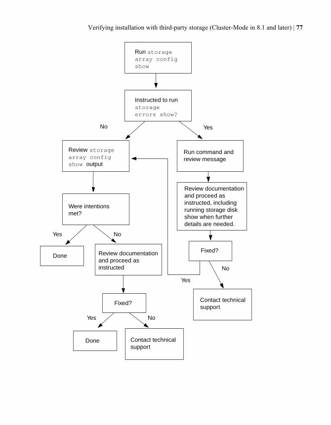
No Yes
Yes No
Yes
Yes
No
No
Run storage array config show
Run command and review message
Were intentions met?
Done
Done
Fixed?
Fixed?
Review documentation and proceed as instructed, including running storage disk show when further details are needed.
Contact technical support
Contact technical support
Review documentation and proceed as instructed
Instructed to run storage errors show?
Review storage array config show output
Verifying installation with third-party storage (Cluster-Mode in 8.1 and later) | 77
Checking for back-end configuration errors preventingsystem operation (Cluster-Mode in 8.1 and later)
Data ONTAP requires you to fix common back-end configuration errors that would prevent thestorage array and gateway from operating together normally.
Steps
1. Enter the following command:storage array config show
The first step in installation verification (and troubleshooting) is to run the storage arrayconfig show command. If Data ONTAP detects an error in the back-end configuration, thefollowing message is displayed at the bottom of the storage array config show output:
Warning: Configuration errors were detected. Use 'storage errors show' for detailed information.
2. Take the appropriate action, as follows:
If... Then...
storage array configshow instructs you to run storageerrors show
Go to Step 3.
storage array configshow does NOT instruct you to runstorage errors show
Review the storage array config show output to makesure that the output reflects the configuration you intended. See Checking whether the configuration matches your intentions(Cluster-Mode in 8.1 and later) on page 93. (You do not need tocontinue with the next steps in this procedure.)
3. Enter the following command:storage errors show
The storage errors show command enables you to see details of the problem at the arrayLUN level.
4. Review the error message and fix any errors shown.
You must fix any errors shown by storage errors show. See Storage errors show messagesand their resolution (Cluster-Mode in 8.1 and later) on page 79 to learn about the cause of eachproblem detected by storage errors show and how to fix it.
5. After fixing the problem, run storage errors show again to confirm that the error was fixed.
If storage errors show continues to show the problem, review the documentation again formore information about what to do, or contact technical support.
78 | Gateway Installation Requirements and Reference Guide
6. After you resolve the back-end configuration error, run storage array config show againso that you can review the output to ensure that the configuration meets your intentions.
Related concepts
Back-end configuration errors detected by the storage errors show command (Cluster-Mode in 8.1and later) on page 73Situations not identified by the storage errors show command on page 74
Related tasks
Checking whether the configuration matches your intentions (Cluster-Mode in 8.1 and later) onpage 93
Storage errors show messages and their resolution (Cluster-Mode in 8.1and later)
When storage errors show flags an error condition, you need to determine why the erroroccurred and how to fix it.
The following table lists the back-end configuration errors detected by storage errors show andrefers you to detailed information about the causes of each error and its resolution.
storage errors show message For more information about this messagesee...
NAME (Serial #): All paths to this
array LUN are connected to the same
fault domain. This is a single point
of failure.
All paths to an array LUN are on the samestorage array controller on page 91
NAME (Serial #): This Array LUN is
only available on one path. Proper
configuration requires two paths.
Fewer than two paths to an array LUN on page88
NAME (Serial #): This Array LUN is
using multiple LUN IDs. Only one LUN
ID per serial number is supported.
LUN IDs for the same LDEV do not match onpage 81
NAME (Serial #), port WWPN1: LUN 1
occurs more than once. LUNs cannot
be reused on the same array target
port.
Duplicated LUN IDs on a target port on page84
NAME (Serial #): This array LUN is
too large and is not usable. The
maximum array LUN size supported is
xTB.
Array LUN is too small or too large on page80
Verifying installation with third-party storage (Cluster-Mode in 8.1 and later) | 79
storage errors show message For more information about this messagesee...
NAME (Serial #): This array LUN is
too small and is not usable. The
minimum array LUN size supported is
1GB.
Array LUN is too small or too large on page80
NAME (Serial #): This array LUN is
an access control LUN. It is not
supported and should be masked off
or disabled.
Access control LUN was presented on page 90
Array LUN is too small or too largeWhen planning array LUN sizes, you must conform to Data ONTAP minimum and maximum arrayLUN size limits. These limits vary according to Data ONTAP release. The storage errors showoutput identifies array LUNs that do not meet size requirements.
Data ONTAP does not allow you to assign array LUNs with size issues to a gateway.
Storage errors show message
NAME (Serial #): This array LUN is too large and is not usable. The maximum array LUN size supported is xTB
OR
NAME (Serial #): This array LUN is too small and is not usable. The minimum array LUN size supported is 1GB.
Explanation
This message is generated when the array LUN is smaller than the minimum array LUN size allowedby Data ONTAP or exceeds the maximum size allowed. Primary reasons why an array LUN mightbe too small or too large are as follows:
• The storage array administrator did not convert the Data ONTAP array LUN size limits into theequivalent limits according to the vendor's definition of units of measure.The Data ONTAP minimum and maximum array LUN size limits are calculated according to theway that Data ONTAP defines units of measure. Many vendors calculate measurementsdifferently than Data ONTAP.The Gateway Limits Reference for Third-Party Storage contains information about the array LUNsize limits for Data ONTAP and the units of measure that Data ONTAP uses to calculateminimum and maximum array LUN size limits.
• The array LUNs are for another host whose size limits are different from Data ONTAP limits.
80 | Gateway Installation Requirements and Reference Guide
In an open SAN, Data ONTAP can see array LUNs intended for other hosts if those array LUNshave not been masked off.Data ONTAP generates an error message about size issues for any array LUN it can see.
Troubleshooting and problem resolution
1. Review the storage errors show output so that you can tell the storage array administratorwhich array LUN has a size problem.
• If the array LUN with the size problem is for Data ONTAP, the storage array administratormust resize the array LUN to meet Data ONTAP requirements, then present it again to DataONTAP.
• If the array LUN with the size problem is for another host, the storage array administratormust mask off the array LUN so that Data ONTAP cannot see it.
2. After the problem is fixed, run storage array config show again to confirm that it nolonger indicates that there is an error.
LUN IDs for the same LDEV do not matchA logical device (LDEV) must be mapped to the same LUN ID on all storage array ports over whichit will be visible to gateways. The storage errors show output identifies the LDEVs whoseLUN IDs do not match.
Data ONTAP does not allow you to assign array LUNs to a gateway if the LUN IDs do not match.
Storage errors show message
vgci9148s76:1-9.126L3 (4849544143484920443630303035323430303132): This Array LUN is using multiple LUN IDs. Only one LUN ID per serial number is supported.
Explanation
One of the following errors was made during storage array configuration:
• The LDEV was presented to the same gateway FC initiator port from multiple target ports and theLUN IDs are not consistent.
• The LUN IDs of two LDEVs were swapped.In this case, an error is reported for each array LUN.
• Different LUN IDs for the same LDEV were used when mapping the LDEV to storage arrayports that are presenting the LDEV to the gateway.
Note: This error is more likely to occur on storage arrays on which each port is configuredseparately, for example, on Hitachi storage arrays. On some storage arrays, for example IBMstorage arrays, ports are not configured separately.
Verifying installation with third-party storage (Cluster-Mode in 8.1 and later) | 81
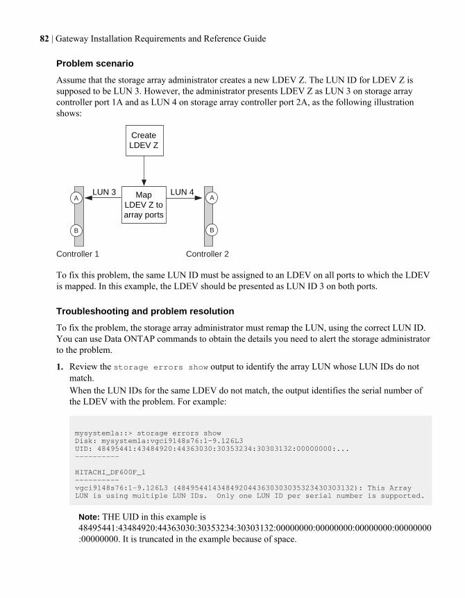
Problem scenario
Assume that the storage array administrator creates a new LDEV Z. The LUN ID for LDEV Z issupposed to be LUN 3. However, the administrator presents LDEV Z as LUN 3 on storage arraycontroller port 1A and as LUN 4 on storage array controller port 2A, as the following illustrationshows:
A A
B B
Controller 1 Controller 2
Map LDEV Z to array ports
Create LDEV Z
LUN 3 LUN 4
To fix this problem, the same LUN ID must be assigned to an LDEV on all ports to which the LDEVis mapped. In this example, the LDEV should be presented as LUN ID 3 on both ports.
Troubleshooting and problem resolution
To fix the problem, the storage array administrator must remap the LUN, using the correct LUN ID.You can use Data ONTAP commands to obtain the details you need to alert the storage administratorto the problem.
1. Review the storage errors show output to identify the array LUN whose LUN IDs do notmatch.When the LUN IDs for the same LDEV do not match, the output identifies the serial number ofthe LDEV with the problem. For example:
mysystem1a::> storage errors showDisk: mysystem1a:vgci9148s76:1-9.126L3UID: 48495441:43484920:44363030:30353234:30303132:00000000:...----------
HITACHI_DF600F_1----------vgci9148s76:1-9.126L3 (4849544143484920443630303035323430303132): This Array LUN is using multiple LUN IDs. Only one LUN ID per serial number is supported.
Note: THE UID in this example is48495441:43484920:44363030:30353234:30303132:00000000:00000000:00000000:00000000:00000000. It is truncated in the example because of space.
82 | Gateway Installation Requirements and Reference Guide
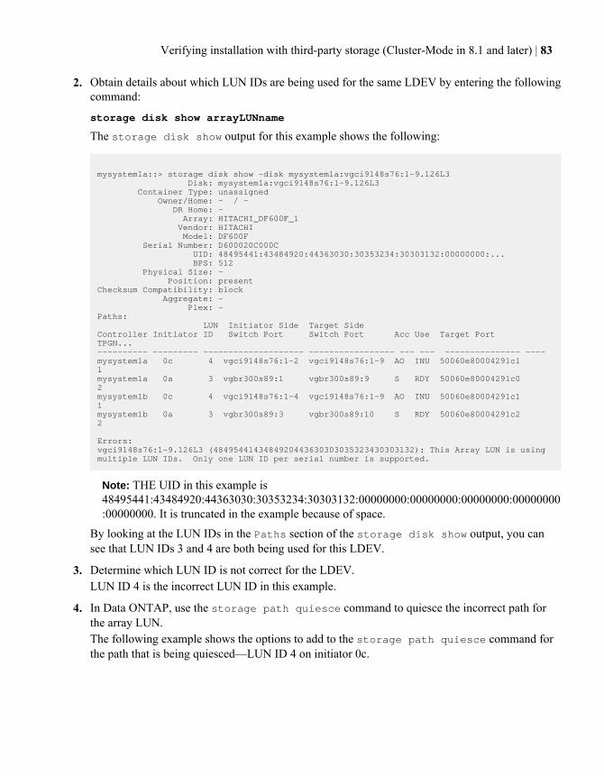
2. Obtain details about which LUN IDs are being used for the same LDEV by entering the followingcommand:
storage disk show arrayLUNname
The storage disk show output for this example shows the following:
mysystem1a::> storage disk show -disk mysystem1a:vgci9148s76:1-9.126L3 Disk: mysystem1a:vgci9148s76:1-9.126L3 Container Type: unassigned Owner/Home: - / - DR Home: - Array: HITACHI_DF600F_1 Vendor: HITACHI Model: DF600F Serial Number: D600020C000C UID: 48495441:43484920:44363030:30353234:30303132:00000000:... BPS: 512 Physical Size: - Position: presentChecksum Compatibility: block Aggregate: - Plex: -Paths: LUN Initiator Side Target SideController Initiator ID Switch Port Switch Port Acc Use Target Port TPGN...---------- --------- -------------------- ----------------- --- --- --------------- ---- mysystem1a 0c 4 vgci9148s76:1-2 vgci9148s76:1-9 AO INU 50060e80004291c1 1 mysystem1a 0a 3 vgbr300s89:1 vgbr300s89:9 S RDY 50060e80004291c0 2 mysystem1b 0c 4 vgci9148s76:1-4 vgci9148s76:1-9 AO INU 50060e80004291c1 1 mysystem1b 0a 3 vgbr300s89:3 vgbr300s89:10 S RDY 50060e80004291c2 2
Errors:vgci9148s76:1-9.126L3 (4849544143484920443630303035323430303132): This Array LUN is using multiple LUN IDs. Only one LUN ID per serial number is supported.
Note: THE UID in this example is48495441:43484920:44363030:30353234:30303132:00000000:00000000:00000000:00000000:00000000. It is truncated in the example because of space.
By looking at the LUN IDs in the Paths section of the storage disk show output, you cansee that LUN IDs 3 and 4 are both being used for this LDEV.
3. Determine which LUN ID is not correct for the LDEV.LUN ID 4 is the incorrect LUN ID in this example.
4. In Data ONTAP, use the storage path quiesce command to quiesce the incorrect path forthe array LUN.The following example shows the options to add to the storage path quiesce command forthe path that is being quiesced—LUN ID 4 on initiator 0c.
Verifying installation with third-party storage (Cluster-Mode in 8.1 and later) | 83
storage path quiesce -node mysystem1a -initiator 0c -target-wwpn 50060e80004291c1 -lun-number 4
The storage array path quiesce command temporarily suspends I/O to a specific arrayLUN on a specific path. Some storage arrays require ceasing I/O for a period of time when anarray LUN is to be removed or moved.After the path is quiesced, Data ONTAP can no longer see that LUN.
5. Wait 1 minute for the storage array's activity timer to expire.Although not all storage arrays require ceasing I/O for a period of time, it is good practice to doso.
6. On the storage array, remap the LUN to the target port by using the correct LUN ID, LUN ID 3 inthis scenario.The next time the Data ONTAP discovery process runs, it discovers the new array LUN.Discovery runs every minute.
7. After Data ONTAP discovery is complete, run storage array config show in Data ONTAPagain to confirm that there is no longer an error.
Duplicate LUN IDs on a target portEach array LUN on the same storage array target port must have a unique LUN ID. The storageerrors show output identifies the LUNs that are presented with the same LUN ID on the sametarget port.
Storage errors show message
NAME (UID), port WWPNx: LUN x occurs more than once. LUNs cannot be reused on the same array target port.
Explanation
The usual cause of duplicate LUN IDs on a target port is a zoning error. An administrator puts thegateway FC initiators into different host groups to create multiple LUN groups on a storage array, butthen makes a zoning mistake that allows the initiators in the different host groups to access the sametarget port.
When this type of zoning error is made, storage array config show output shows two LUNgroups with the same target ports.
Problem scenario
The administrator wants to map four LDEVs (a, b, c, and d) for Data ONTAP use, two LDEVs ineach of two LUN groups. For this scenario, assume that the storage array presents LDEVs to initiatorports without considering the target port by which the initiator accesses the storage arrays; that is, the
84 | Gateway Installation Requirements and Reference Guide
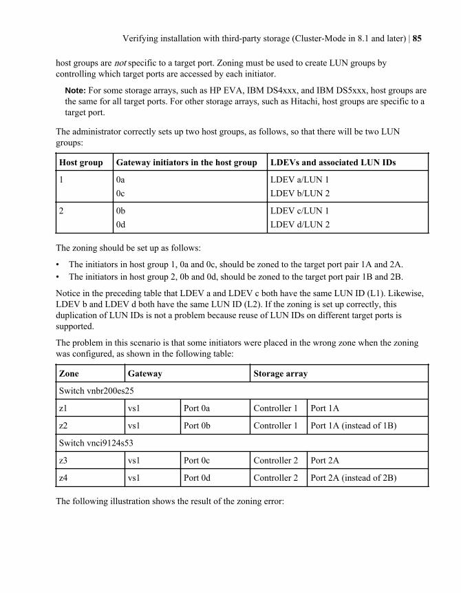
host groups are not specific to a target port. Zoning must be used to create LUN groups bycontrolling which target ports are accessed by each initiator.
Note: For some storage arrays, such as HP EVA, IBM DS4xxx, and IBM DS5xxx, host groups arethe same for all target ports. For other storage arrays, such as Hitachi, host groups are specific to atarget port.
The administrator correctly sets up two host groups, as follows, so that there will be two LUNgroups:
Host group Gateway initiators in the host group LDEVs and associated LUN IDs
1 0a0c
LDEV a/LUN 1LDEV b/LUN 2
2 0b0d
LDEV c/LUN 1LDEV d/LUN 2
The zoning should be set up as follows:
• The initiators in host group 1, 0a and 0c, should be zoned to the target port pair 1A and 2A.• The initiators in host group 2, 0b and 0d, should be zoned to the target port pair 1B and 2B.
Notice in the preceding table that LDEV a and LDEV c both have the same LUN ID (L1). Likewise,LDEV b and LDEV d both have the same LUN ID (L2). If the zoning is set up correctly, thisduplication of LUN IDs is not a problem because reuse of LUN IDs on different target ports issupported.
The problem in this scenario is that some initiators were placed in the wrong zone when the zoningwas configured, as shown in the following table:
Zone Gateway Storage array
Switch vnbr200es25
z1 vs1 Port 0a Controller 1 Port 1A
z2 vs1 Port 0b Controller 1 Port 1A (instead of 1B)
Switch vnci9124s53
z3 vs1 Port 0c Controller 2 Port 2A
z4 vs1 Port 0d Controller 2 Port 2A (instead of 2B)
The following illustration shows the result of the zoning error:
Verifying installation with third-party storage (Cluster-Mode in 8.1 and later) | 85
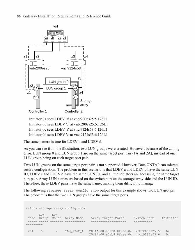
LUN group 0
Storagearray
Controller 2Controller 1
2A1A LUN group 1
2B1B
z1 z2 z3 z4
z4
z3
z2
z1
vs1
0a 0b 0c 0d
vnbr200es25 vnci9124s53
Initiator 0a sees LDEV 'a' at vnbr200es25:5.126L1Initiator 0b sees LDEV 'c' at vnbr200es25:5.126L1Initiator 0c sees LDEV 'a' at vnci9124s53:6.126L1Initiator 0d sees LDEV 'c' at vnci9124s53:6.126L1
The same pattern is true for LDEV b and LDEV d.
As you can see from the illustration, two LUN groups were created. However, because of the zoningerror, LUN group 0 and LUN group 1 are on the same target port pair (1A and 2A), instead of oneLUN group being on each target port pair.
Two LUN groups on the same target port pair is not supported. However, Data ONTAP can toleratesuch a configuration. The problem in this scenario is that LDEV a and LDEV b have the same LUNID, LDEV c and LDEV d have the same LUN ID, and all the initiators are accessing the same targetport pair. Array LUN names are based on the switch port on the storage array side and the LUN ID.Therefore, these LDEV pairs have the same name, making them difficult to manage.
The following storage array config show output for this example shows two LUN groups.The problem is that the two LUN groups have the same target ports.
vs1::> storage array config show
LUN LUN Node Group Count Array Name Array Target Ports Switch Port Initiator ----- ----- ------- ----------- ------------------- ---------- --------- vs1 0 2 IBM_1742_1 20:1A:00:a0:b8:0f:ee:04 vnbr200es25:5 0a 20:2A:00:a0:b8:0f:ee:04 vnci9124s53:6 0c
86 | Gateway Installation Requirements and Reference Guide
1 2 IBM_1742_1 20:1A:00:a0:b8:0f:ee:04 vnbr200es25:5 0b 20:2A:00:a0:b8:0f:ee:04 vnci9124s53:6 0d
Warning: Configuration were errors detected. Use 'storage errors show' for detailed information.
The following storage errors show output for this example identifies the LUNs with theproblem:
vs1::> storage errors show
Disk: vs1:vnbr200es25:5.126L1 UID: UID-a----------vnbr200es25:5.126L1 (UID-a), port WWPN1: LUN 1 occurs more than once. LUNs cannot be reused on the same array target port.
Disk: vs1:vnbr200es25:5.126L2UID: UID-b----------vnbr200es25:5.126L2 (UID-b), port WWPN1: LUN 2 occurs more than once. LUNs cannot be reused on the same array target port.
Disk: vs1:vnbr200es25:5.126L1UID: UID-c----------vnbr200es25:5.126L1 (UID-c), port WWPN2: LUN 1 occurs more than once. LUNs cannot be reused on the same array target port.
Disk: vs1:vnbr200es25:5.126L2UID: UID-d----------vnbr200es25:5.126L2 (UID-d), port WWPN2: LUN 2 occurs more than once. LUNs cannot be reused on the same array target port.
From this storage errors show example you can see that the UIDs of all four LDEVs are shown,but there are only two unique LUN names, vnbr200es25:5.126L1 and vnbr200es25:5.126L2, insteadof four.
Troubleshooting and problem resolution
The storage array administrator must fix the zoning so that the initiators in different host groups donot have access to the same target port.
1. In storage array config output, look for initiators that are talking to the same target port.
2. Enter the following command to view the details of the error: storage errors show
3. Determine the LDEV for which the LUN IDs are duplicated.
4. For each target port on controller 1 that has multiple initiators from the same gateway mapped toit, change the zoning so that the two initiators are not talking to the same target port.
Verifying installation with third-party storage (Cluster-Mode in 8.1 and later) | 87
You are performing this step because initiators in different host groups should not be in the samezone. You need to perform this step on one initiator at a time so that there is always a path to thearray LUN.
5. Repeat the procedure on controller 2.
6. Enter storage errors show in Data ONTAP and confirm that the error has been fixed.
Related concepts
Dependency between zone and host group definitions on page 109Example of cascading zoning and host group configuration errors on page 111
Related references
Relationship between zoning and host group configuration on page 109
Fewer than two paths to an array LUNCommon reasons for fewer than two paths to an array LUN are a mapping error, a zoning error, or acable dropping out. The storage errors show output identifies array LUNs with only a singlepath.
Data ONTAP requires redundant paths to an array LUN so that access to the LUN is maintained if adevice fails. Two paths must exist to each array LUN.
Storage errors show message
NAME (UID): This Array LUN is only available on one path. Proper configuration requires two paths.
Explanation
Reasons you would see fewer than two paths to an array LUN include the following:
• The LDEV was mapped on only one storage array port.• The second path to the array LUN was not zoned.• There is a problem with the host group mapping.• There is a problem with switch connections.• The cable dropped out.• SFPs failed on the adapter.
Note: If a path drops out on a running system, an EMS message is generated.
88 | Gateway Installation Requirements and Reference Guide
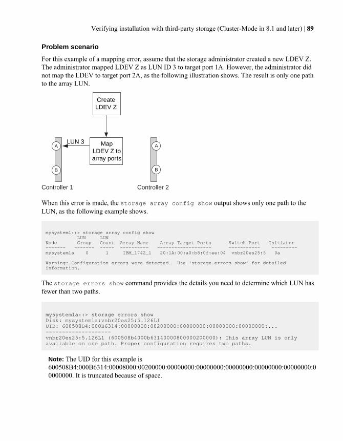
Problem scenario
For this example of a mapping error, assume that the storage administrator created a new LDEV Z.The administrator mapped LDEV Z as LUN ID 3 to target port 1A. However, the administrator didnot map the LDEV to target port 2A, as the following illustration shows. The result is only one pathto the array LUN.
A A
B B
Controller 1 Controller 2
Map LDEV Z to array ports
Create LDEV Z
LUN 3
When this error is made, the storage array config show output shows only one path to theLUN, as the following example shows.
mysystem1::> storage array config show LUN LUNNode Group Count Array Name Array Target Ports Switch Port Initiator------- ------- ----- ---------- ------------------- ----------- --------- mysystem1a 0 1 IBM_1742_1 20:1A:00:a0:b8:0f:ee:04 vnbr20es25:5 0a
Warning: Configuration errors were detected. Use 'storage errors show' for detailed information.
The storage errors show command provides the details you need to determine which LUN hasfewer than two paths.
mysystem1a::> storage errors showDisk: mysystem1a:vnbr20es25:5.126L1UID: 600508B4:000B6314:00008000:00200000:00000000:00000000:00000000:...--------------------vnbr20es25:5.126L1 (600508b4000b63140000800000200000): This array LUN is only available on one path. Proper configuration requires two paths.
Note: The UID for this example is600508B4:000B6314:00008000:00200000:00000000:00000000:00000000:00000000:00000000:00000000. It is truncated because of space.
Verifying installation with third-party storage (Cluster-Mode in 8.1 and later) | 89
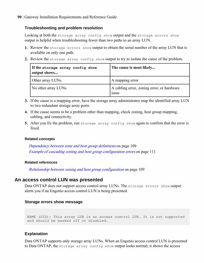
Troubleshooting and problem resolution
Looking at both the storage array config show output and the storage errors showoutput is helpful when troubleshooting fewer than two paths to an array LUN.
1. Review the storage errors show output to obtain the serial number of the array LUN that isavailable on only one path.
2. Review the storage array config show output to try to isolate the cause of the problem.
If the storage array config showoutput shows...
The cause is most likely...
Other array LUNs A mapping error
No other array LUNs A cabling error, zoning error, or hardwareissue
3. If the cause is a mapping error, have the storage array administrator map the identified array LUNto two redundant storage array ports.
4. If the cause seems to be a problem other than mapping, check zoning, host group mapping,cabling, and connectivity.
5. After you fix the problem, run storage array config show again to confirm that the error isfixed.
Related concepts
Dependency between zone and host group definitions on page 109Example of cascading zoning and host group configuration errors on page 111
Related references
Relationship between zoning and host group configuration on page 109
An access control LUN was presentedData ONTAP does not support access control array LUNs. The storage errors show outputalerts you if an Engenio access control LUN is being presented.
Storage errors show message
NAME (UID): This array LUN is an access control LUN. It is not supported and should be masked off or disabled.
Explanation
Data ONTAP supports only storage array LUNs. When an Engenio access control LUN is presentedto Data ONTAP, the storage array config show output looks normal; it shows the access
90 | Gateway Installation Requirements and Reference Guide
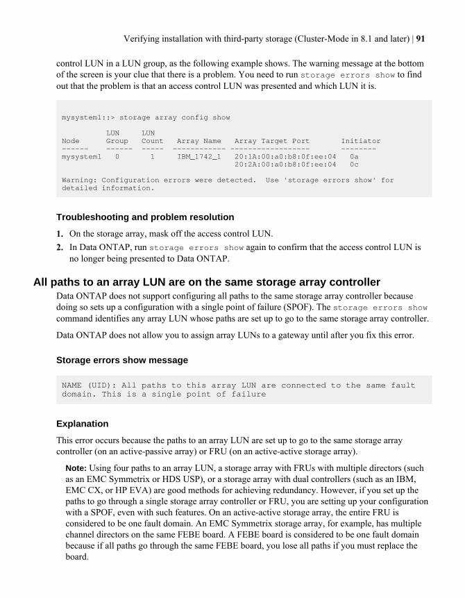
control LUN in a LUN group, as the following example shows. The warning message at the bottomof the screen is your clue that there is a problem. You need to run storage errors show to findout that the problem is that an access control LUN was presented and which LUN it is.
mysystem1::> storage array config show
LUN LUNNode Group Count Array Name Array Target Port Initiator------ ------ ----- ------------ ------------------ -------- mysystem1 0 1 IBM_1742_1 20:1A:00:a0:b8:0f:ee:04 0a 20:2A:00:a0:b8:0f:ee:04 0c
Warning: Configuration errors were detected. Use 'storage errors show' for detailed information.
Troubleshooting and problem resolution
1. On the storage array, mask off the access control LUN.2. In Data ONTAP, run storage errors show again to confirm that the access control LUN is
no longer being presented to Data ONTAP.
All paths to an array LUN are on the same storage array controllerData ONTAP does not support configuring all paths to the same storage array controller becausedoing so sets up a configuration with a single point of failure (SPOF). The storage errors showcommand identifies any array LUN whose paths are set up to go to the same storage array controller.
Data ONTAP does not allow you to assign array LUNs to a gateway until after you fix this error.
Storage errors show message
NAME (UID): All paths to this array LUN are connected to the same fault domain. This is a single point of failure
Explanation
This error occurs because the paths to an array LUN are set up to go to the same storage arraycontroller (on an active-passive array) or FRU (on an active-active storage array).
Note: Using four paths to an array LUN, a storage array with FRUs with multiple directors (suchas an EMC Symmetrix or HDS USP), or a storage array with dual controllers (such as an IBM,EMC CX, or HP EVA) are good methods for achieving redundancy. However, if you set up thepaths to go through a single storage array controller or FRU, you are setting up your configurationwith a SPOF, even with such features. On an active-active storage array, the entire FRU isconsidered to be one fault domain. An EMC Symmetrix storage array, for example, has multiplechannel directors on the same FEBE board. A FEBE board is considered to be one fault domainbecause if all paths go through the same FEBE board, you lose all paths if you must replace theboard.
Verifying installation with third-party storage (Cluster-Mode in 8.1 and later) | 91
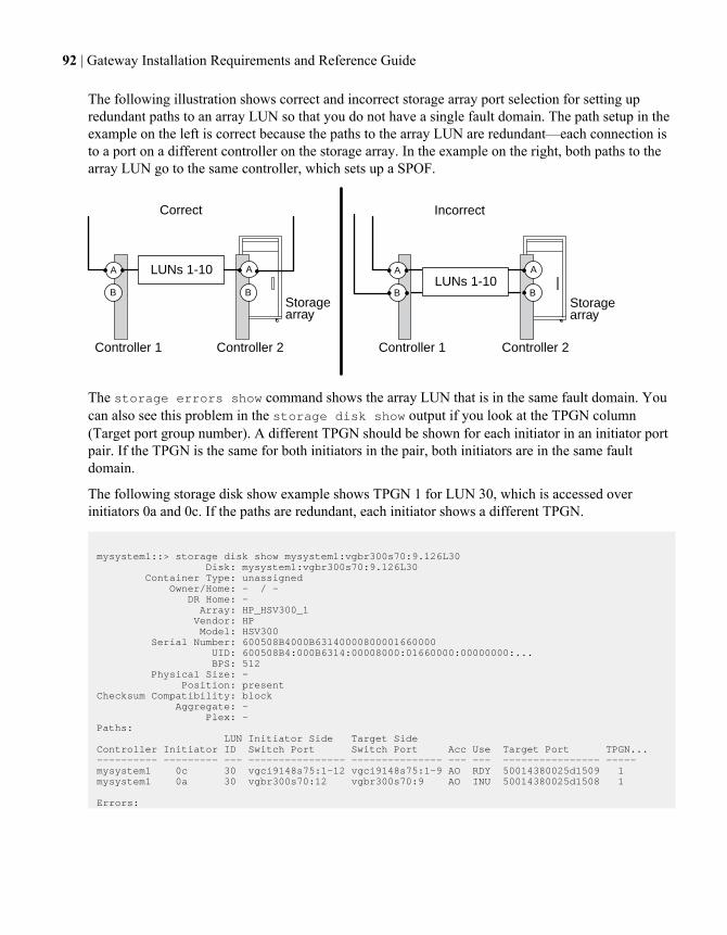
The following illustration shows correct and incorrect storage array port selection for setting upredundant paths to an array LUN so that you do not have a single fault domain. The path setup in theexample on the left is correct because the paths to the array LUN are redundant—each connection isto a port on a different controller on the storage array. In the example on the right, both paths to thearray LUN go to the same controller, which sets up a SPOF.
Storagearray
Controller 2 Controller 2Controller 1 Controller 1
A A LUNs 1-10
B BStoragearray
A ALUNs 1-10
B B
Correct Incorrect
The storage errors show command shows the array LUN that is in the same fault domain. Youcan also see this problem in the storage disk show output if you look at the TPGN column(Target port group number). A different TPGN should be shown for each initiator in an initiator portpair. If the TPGN is the same for both initiators in the pair, both initiators are in the same faultdomain.
The following storage disk show example shows TPGN 1 for LUN 30, which is accessed overinitiators 0a and 0c. If the paths are redundant, each initiator shows a different TPGN.
mysystem1::> storage disk show mysystem1:vgbr300s70:9.126L30 Disk: mysystem1:vgbr300s70:9.126L30 Container Type: unassigned Owner/Home: - / - DR Home: - Array: HP_HSV300_1 Vendor: HP Model: HSV300 Serial Number: 600508B4000B63140000800001660000 UID: 600508B4:000B6314:00008000:01660000:00000000:... BPS: 512 Physical Size: - Position: presentChecksum Compatibility: block Aggregate: - Plex: -Paths: LUN Initiator Side Target SideController Initiator ID Switch Port Switch Port Acc Use Target Port TPGN... ---------- --------- --- ---------------- --------------- --- --- ---------------- ----- mysystem1 0c 30 vgci9148s75:1-12 vgci9148s75:1-9 AO RDY 50014380025d1509 1 mysystem1 0a 30 vgbr300s70:12 vgbr300s70:9 AO INU 50014380025d1508 1
Errors:
92 | Gateway Installation Requirements and Reference Guide
vgbr300s70:9.126L30 (600508b4000b63140000800001660000): All paths to this array LUN are connected to the same fault domain. This is a single point of failure.
Note: The full UID in this example is600508B4:000B6314:00008000:01660000:00000000:00000000:00000000:00000000:00000000:00000000. It is truncated in the example because of space.
Troubleshooting and problem resolution
The paths to the array LUN must be reconfigured so that they go to redundant storage arraycontrollers or FRUs.
1. Add a cable to the redundant target port on the other controller.You should maintain redundancy while fixing this problem by adding a cable to the alternatecontroller before you remove a cable from the controller with the SPOF. Redundancy ismaintained in this case because you are increasing the number of paths to three paths temporarilyinstead of decreasing the number of paths to one while you are fixing the problem.
2. Remove one cable from the controller that was set up with the SPOF.You now have two redundant paths to the array LUN.
3. From the Data ONTAP command line, enter the following command again and confirm that theerror has been fixed:storage errors show
Checking whether the configuration matches yourintentions (Cluster-Mode in 8.1 and later)
After resolving any back-end configuration errors that were detected by storage errors show,you next need to check whether the back-end configuration matches your intentions. For example,you want to check that the number of array LUN groups you intended were configured and that eachLUN group has the correct number of LUNs.
Steps
1. Enter the following command:storage array config show
The storage array config show output groups information about LUN groups, LUNcounts, and paths by storage array, as the following example for an HA pair shows:
Example
mysystem1::> storage array config show LUN LUNNode Group Count Array Name Array Target Port Initiator
Verifying installation with third-party storage (Cluster-Mode in 8.1 and later) | 93
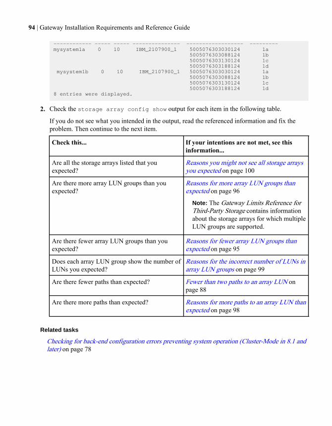
------------ ----- ----- --------------- ------------------ ---------mysystem1a 0 10 IBM_2107900_1 5005076303030124 1a 5005076303088124 1b 5005076303130124 1c 5005076303188124 1d mysystem1b 0 10 IBM_2107900_1 5005076303030124 1a 5005076303088124 1b 5005076303130124 1c 5005076303188124 1d8 entries were displayed.
2. Check the storage array config show output for each item in the following table.
If you do not see what you intended in the output, read the referenced information and fix theproblem. Then continue to the next item.
Check this... If your intentions are not met, see thisinformation...
Are all the storage arrays listed that youexpected?
Reasons you might not see all storage arraysyou expected on page 100
Are there more array LUN groups than youexpected?
Reasons for more array LUN groups thanexpected on page 96
Note: The Gateway Limits Reference forThird-Party Storage contains informationabout the storage arrays for which multipleLUN groups are supported.
Are there fewer array LUN groups than youexpected?
Reasons for fewer array LUN groups thanexpected on page 95
Does each array LUN group show the number ofLUNs you expected?
Reasons for the incorrect number of LUNs inarray LUN groups on page 99
Are there fewer paths than expected? Fewer than two paths to an array LUN onpage 88
Are there more paths than expected? Reasons for more paths to an array LUN thanexpected on page 98
Related tasks
Checking for back-end configuration errors preventing system operation (Cluster-Mode in 8.1 andlater) on page 78
94 | Gateway Installation Requirements and Reference Guide
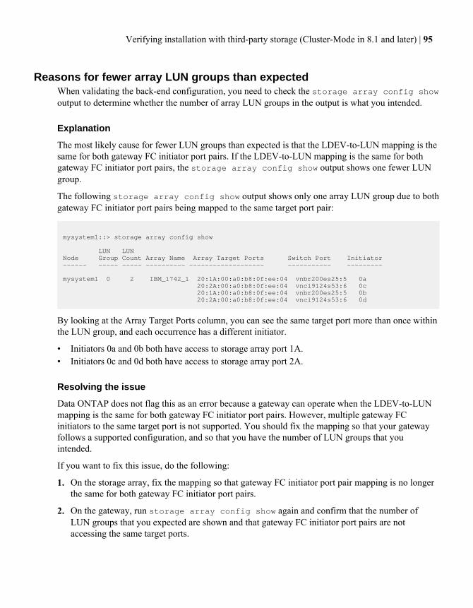
Reasons for fewer array LUN groups than expectedWhen validating the back-end configuration, you need to check the storage array config showoutput to determine whether the number of array LUN groups in the output is what you intended.
Explanation
The most likely cause for fewer LUN groups than expected is that the LDEV-to-LUN mapping is thesame for both gateway FC initiator port pairs. If the LDEV-to-LUN mapping is the same for bothgateway FC initiator port pairs, the storage array config show output shows one fewer LUNgroup.
The following storage array config show output shows only one array LUN group due to bothgateway FC initiator port pairs being mapped to the same target port pair:
mysystem1::> storage array config show
LUN LUNNode Group Count Array Name Array Target Ports Switch Port Initiator------ ----- ----- ---------- ------------------- ----------- ---------
mysystem1 0 2 IBM_1742_1 20:1A:00:a0:b8:0f:ee:04 vnbr200es25:5 0a 20:2A:00:a0:b8:0f:ee:04 vnci9124s53:6 0c 20:1A:00:a0:b8:0f:ee:04 vnbr200es25:5 0b 20:2A:00:a0:b8:0f:ee:04 vnci9124s53:6 0d
By looking at the Array Target Ports column, you can see the same target port more than once withinthe LUN group, and each occurrence has a different initiator.
• Initiators 0a and 0b both have access to storage array port 1A.• Initiators 0c and 0d both have access to storage array port 2A.
Resolving the issue
Data ONTAP does not flag this as an error because a gateway can operate when the LDEV-to-LUNmapping is the same for both gateway FC initiator port pairs. However, multiple gateway FCinitiators to the same target port is not supported. You should fix the mapping so that your gatewayfollows a supported configuration, and so that you have the number of LUN groups that youintended.
If you want to fix this issue, do the following:
1. On the storage array, fix the mapping so that gateway FC initiator port pair mapping is no longerthe same for both gateway FC initiator port pairs.
2. On the gateway, run storage array config show again and confirm that the number ofLUN groups that you expected are shown and that gateway FC initiator port pairs are notaccessing the same target ports.
Verifying installation with third-party storage (Cluster-Mode in 8.1 and later) | 95
Reasons for more array LUN groups than expectedWhen validating your configuration, you should check the storage array config show outputto ensure that the number of LUN groups is what you intended. The most common reason for toomany array LUN groups is that the LDEV is spanning target port pairs.
Explanation
Common reasons why you would see more LUN groups than expected are as follows:
• An LDEV is not mapped to a redundant target port pair.The most common cause of an extra LUN group is that the LDEV is spanning path pairs. AnLDEV is said to be spanning path pairs if matching LUN IDs for the LDEV are not presented to aredundant target port pair on the storage array.
Note: On many storage arrays, it is not possible to present an LDEV to target ports that are notredundant if you follow the conventional process for creating and mapping LDEVs.
• Data ONTAP is trying to balance the load over the target ports during migration of array LUNsfrom one LUN group to another.In this case, the LDEV spanning path pairs is a transitional state.
• Too many connections were set up.
Data ONTAP can run with a single array LUN group or multiple array LUN groups. Therefore, DataONTAP does not consider any number of LUN groups to be a misconfiguration. However, multipleLUN groups are not supported for all storage arrays in all Data ONTAP releases. Duringconfiguration planning, you should check the information in the Gateway Limits Reference forThird-Party Storage about the storage arrays for which multiple array LUN groups are supported.
Problem scenario
Assume that there are two existing LUN groups, LUN group 0 and LUN group 1. LUN group 0 hastwo array LUNs and LUN group 1 has three array LUNs. The administrator created a new LDEV Z,intending to add LUN 3 to LUN group 0. The administrator mapped LDEV Z as LUN 3 on twostorage array ports. However, the ports to which LUN 3 are mapped, storage array ports 1A and 2B,are not a redundant target port pair, as the following illustration shows.
96 | Gateway Installation Requirements and Reference Guide
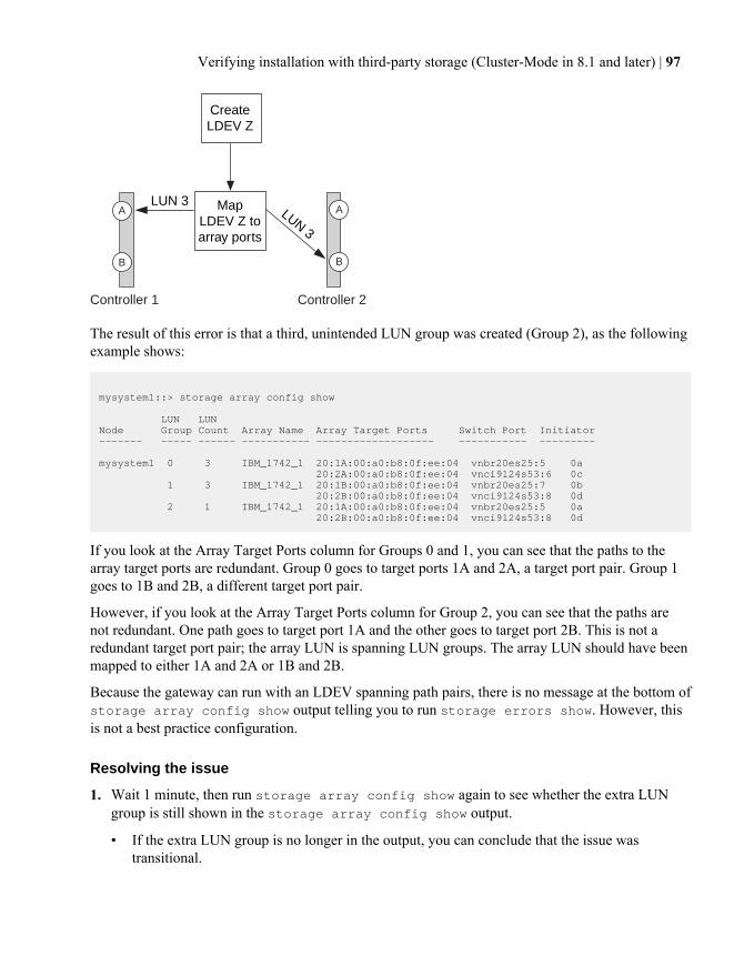
A A
B B
Controller 1 Controller 2
Map LDEV Z to array ports
Create LDEV Z
LUN 3LUN 3
The result of this error is that a third, unintended LUN group was created (Group 2), as the followingexample shows:
mysystem1::> storage array config show
LUN LUNNode Group Count Array Name Array Target Ports Switch Port Initiator------- ----- ------ ----------- ------------------- ----------- --------- mysystem1 0 3 IBM_1742_1 20:1A:00:a0:b8:0f:ee:04 vnbr20es25:5 0a 20:2A:00:a0:b8:0f:ee:04 vnci9124s53:6 0c 1 3 IBM_1742_1 20:1B:00:a0:b8:0f:ee:04 vnbr20es25:7 0b 20:2B:00:a0:b8:0f:ee:04 vnci9124s53:8 0d 2 1 IBM_1742_1 20:1A:00:a0:b8:0f:ee:04 vnbr20es25:5 0a 20:2B:00:a0:b8:0f:ee:04 vnci9124s53:8 0d
If you look at the Array Target Ports column for Groups 0 and 1, you can see that the paths to thearray target ports are redundant. Group 0 goes to target ports 1A and 2A, a target port pair. Group 1goes to 1B and 2B, a different target port pair.
However, if you look at the Array Target Ports column for Group 2, you can see that the paths arenot redundant. One path goes to target port 1A and the other goes to target port 2B. This is not aredundant target port pair; the array LUN is spanning LUN groups. The array LUN should have beenmapped to either 1A and 2A or 1B and 2B.
Because the gateway can run with an LDEV spanning path pairs, there is no message at the bottom ofstorage array config show output telling you to run storage errors show. However, thisis not a best practice configuration.
Resolving the issue
1. Wait 1 minute, then run storage array config show again to see whether the extra LUNgroup is still shown in the storage array config show output.
• If the extra LUN group is no longer in the output, you can conclude that the issue wastransitional.
Verifying installation with third-party storage (Cluster-Mode in 8.1 and later) | 97
• If the extra LUN group still appears in the output, the storage array administrator must remapthe LDEV, as documented in the next steps.You need to maintain redundancy while fixing this problem. This procedure instructs you tomap the LDEV to the correct target port before removing the mapping to the incorrect targetport. Redundancy is maintained in this case because you are increasing the number of paths tothree, temporarily, instead of decreasing the number of paths to one while you are fixing theproblem.
2. Decide which of the inconsistent target ports should be remapped.
3. On the storage array, map the LDEV to the new (correct) target port.
4. In Data ONTAP, run storage array config show to confirm that three paths are shown.
5. Remove the incorrect mapping.
6. Wait 1 minute while Data ONTAP discovers the LUN.
7. In Data ONTAP, run storage array config show again to make sure that the extra LUNgroup is gone.
Reasons for more paths to an array LUN than expectedThe primary reasons for an unexpected additional path to an array LUN are zoning issues and toomany cables. Three paths to an array LUN is not best practice, but you are not required to fix thisissue.
Example of storage array config show output
The FC initiator port pair on the gateway is 0a and 0c. The following example shows an extra path,0b, in the storage array config show output:
mysystem1::> storage array config show LUN LUNNode Group Count Array Name Array Target Port Initiator---------- ----- ----- ---------------- ------------------ ---------- mysystem1a 1 3 HITACHI_DF600F_1 50060e80004291c0 0a 50060e80004291c1 0b 0c 3 entries were displayed.
Note: If an initiator in the storage array config show output is not preceded by an arraytarget port, the initiator is connecting to the same array target port as the initiator above it.
Explanation
Three paths within a LUN group indicates that there is an extra path. For Cluster-Modeconfigurations, best practice is two or four paths.
Reasons there could be more paths than expected include the following:
98 | Gateway Installation Requirements and Reference Guide
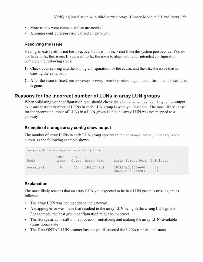
• More cables were connected than are needed.• A zoning configuration error caused an extra path.
Resolving the issue
Having an extra path is not best practice, but it is not incorrect from the system perspective. You donot have to fix this issue. If you want to fix the issue to align with your intended configuration,complete the following steps:
1. Check your cabling and the zoning configuration for the cause, and then fix the issue that iscausing the extra path.
2. After the issue is fixed, run storage array config show again to confirm that the extra pathis gone.
Reasons for the incorrect number of LUNs in array LUN groupsWhen validating your configuration, you should check the storage array config show outputto ensure that the number of LUNs in each LUN group is what you intended. The most likely causefor the incorrect number of LUNs in a LUN group is that the array LUN was not mapped to agateway.
Example of storage array config show output
The number of array LUNs in each LUN group appears in the storage array config showoutput, as the following example shows:
mysystem1::> storage array config show
LUN LUNNode Group Count Array Name Array Target Port Initiator------ ------ ----- -------------- -------------------- ---------- mysystem1 0 50 IBM_1742_1 201A00a0b80fee04 0a 202A00a0b80fee04 0c
Explanation
The most likely reasons that an array LUN you expected to be in a LUN group is missing are asfollows:
• The array LUN was not mapped to the gateway.• A mapping error was made that resulted in the array LUN being in the wrong LUN group.
For example, the host group configuration might be incorrect.• The storage array is still in the process of initializing and making the array LUNs available
(transitional state).• The Data ONTAP LUN scanner has not yet discovered the LUNs (transitional state).
Verifying installation with third-party storage (Cluster-Mode in 8.1 and later) | 99
Resolving the issue
1. If the array LUN has not been mapped to the gateway, the storage array administrator needs tomap it.The process for mapping array LUNs to hosts varies among storage arrays.
2. If the array LUN has been mapped to the gateway, check zoning and the host groupconfiguration.
3. After the issue is fixed, run storage array config show again to confirm that the issue wasreally fixed.
Related concepts
Dependency between zone and host group definitions on page 109Example of cascading zoning and host group configuration errors on page 111
Related references
Relationship between zoning and host group configuration on page 109
Reasons storage arrays are missing from command outputA storage array that is not connected to the gateway does not appear in the storage arrayconfig show output. Problems with cabling, zoning, and host group configuration can prevent aconnection between the two devices.
Resolving the issue
1. Check cabling, host group configuration, and zoning as follows:
• Check that cables are connected.• Check that the WWPNs for the gateway initiators are in the host group.• Check that both the storage array and the gateway initiator are in the same zone.
2. After the problem is fixed, run storage array config show in Data ONTAP to confirm thatthe issue was fixed.
Related concepts
Dependency between zone and host group definitions on page 109Example of cascading zoning and host group configuration errors on page 111
Related references
Relationship between zoning and host group configuration on page 109
100 | Gateway Installation Requirements and Reference Guide
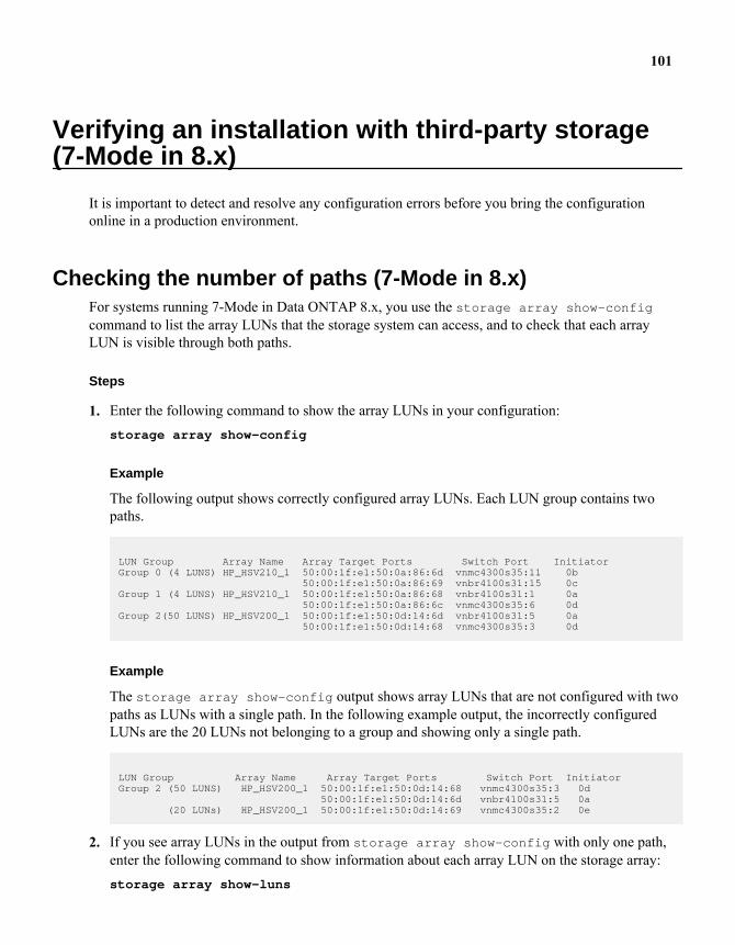
Verifying an installation with third-party storage(7-Mode in 8.x)
It is important to detect and resolve any configuration errors before you bring the configurationonline in a production environment.
Checking the number of paths (7-Mode in 8.x)For systems running 7-Mode in Data ONTAP 8.x, you use the storage array show-configcommand to list the array LUNs that the storage system can access, and to check that each arrayLUN is visible through both paths.
Steps
1. Enter the following command to show the array LUNs in your configuration:storage array show-config
Example
The following output shows correctly configured array LUNs. Each LUN group contains twopaths.
LUN Group Array Name Array Target Ports Switch Port InitiatorGroup 0 (4 LUNS) HP_HSV210_1 50:00:1f:e1:50:0a:86:6d vnmc4300s35:11 0b 50:00:1f:e1:50:0a:86:69 vnbr4100s31:15 0cGroup 1 (4 LUNS) HP_HSV210_1 50:00:1f:e1:50:0a:86:68 vnbr4100s31:1 0a 50:00:1f:e1:50:0a:86:6c vnmc4300s35:6 0dGroup 2(50 LUNS) HP_HSV200_1 50:00:1f:e1:50:0d:14:6d vnbr4100s31:5 0a 50:00:1f:e1:50:0d:14:68 vnmc4300s35:3 0d
Example
The storage array show-config output shows array LUNs that are not configured with twopaths as LUNs with a single path. In the following example output, the incorrectly configuredLUNs are the 20 LUNs not belonging to a group and showing only a single path.
LUN Group Array Name Array Target Ports Switch Port InitiatorGroup 2 (50 LUNS) HP_HSV200_1 50:00:1f:e1:50:0d:14:68 vnmc4300s35:3 0d 50:00:1f:e1:50:0d:14:6d vnbr4100s31:5 0a (20 LUNs) HP_HSV200_1 50:00:1f:e1:50:0d:14:69 vnmc4300s35:2 0e
2. If you see array LUNs in the output from storage array show-config with only one path,enter the following command to show information about each array LUN on the storage array:storage array show-luns
101
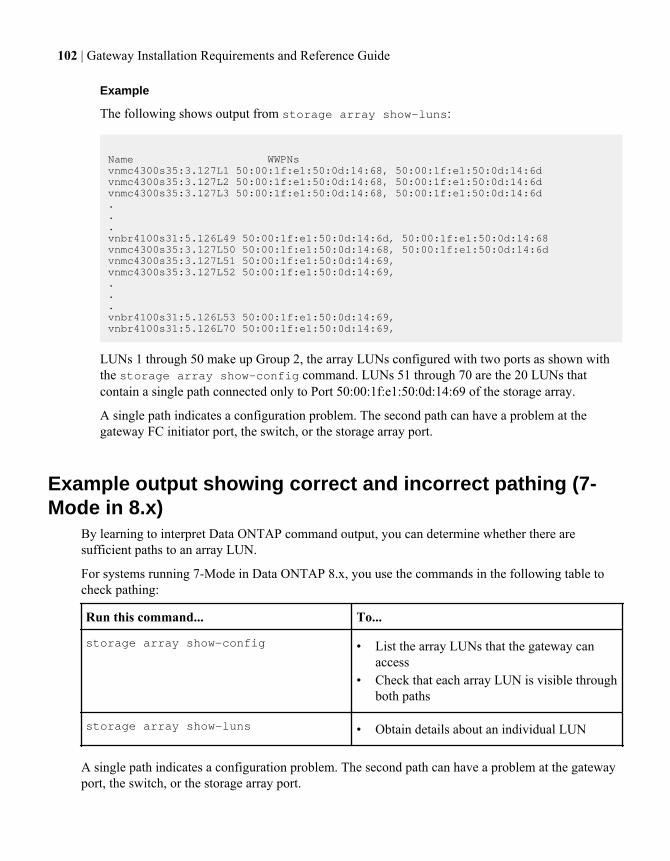
Example
The following shows output from storage array show-luns:
Name WWPNsvnmc4300s35:3.127L1 50:00:1f:e1:50:0d:14:68, 50:00:1f:e1:50:0d:14:6dvnmc4300s35:3.127L2 50:00:1f:e1:50:0d:14:68, 50:00:1f:e1:50:0d:14:6dvnmc4300s35:3.127L3 50:00:1f:e1:50:0d:14:68, 50:00:1f:e1:50:0d:14:6d...vnbr4100s31:5.126L49 50:00:1f:e1:50:0d:14:6d, 50:00:1f:e1:50:0d:14:68vnmc4300s35:3.127L50 50:00:1f:e1:50:0d:14:68, 50:00:1f:e1:50:0d:14:6dvnmc4300s35:3.127L51 50:00:1f:e1:50:0d:14:69,vnmc4300s35:3.127L52 50:00:1f:e1:50:0d:14:69,...vnbr4100s31:5.126L53 50:00:1f:e1:50:0d:14:69,vnbr4100s31:5.126L70 50:00:1f:e1:50:0d:14:69,
LUNs 1 through 50 make up Group 2, the array LUNs configured with two ports as shown withthe storage array show-config command. LUNs 51 through 70 are the 20 LUNs thatcontain a single path connected only to Port 50:00:1f:e1:50:0d:14:69 of the storage array.
A single path indicates a configuration problem. The second path can have a problem at thegateway FC initiator port, the switch, or the storage array port.
Example output showing correct and incorrect pathing (7-Mode in 8.x)
By learning to interpret Data ONTAP command output, you can determine whether there aresufficient paths to an array LUN.
For systems running 7-Mode in Data ONTAP 8.x, you use the commands in the following table tocheck pathing:
Run this command... To...
storage array show-config • List the array LUNs that the gateway canaccess
• Check that each array LUN is visible throughboth paths
storage array show-luns • Obtain details about an individual LUN
A single path indicates a configuration problem. The second path can have a problem at the gatewayport, the switch, or the storage array port.
102 | Gateway Installation Requirements and Reference Guide
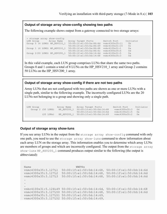
Output of storage array show-config showing two paths
The following example shows output from a gateway connected to two storage arrays:
> storage array show-config LUN Group Array Name Array Target Ports Switch Port InitiatorGroup 0 (4 LUNS) HP_HSV210_1 50:00:1f:e1:50:0a:86:6d vnmc4300s35:11 0b 50:00:1f:e1:50:0a:86:69 vnbr4100s31:15 0cGroup 1 (4 LUNS) HP_HSV210_1 50:00:1f:e1:50:0a:86:68 vnbr4100s31:1 0a 50:00:1f:e1:50:0a:86:6c vnmc4300s35:6 0dGroup 2(50 LUNS) HP_HSV200_1 50:00:1f:e1:50:0d:14:6d vnbr4100s31:5 0a 50:00:1f:e1:50:0d:14:68 vnmc4300s35:3 0d
In this valid example, each LUN group comprises LUNs that share the same two paths.Groups 0 and 1 contain a total of 8 LUNs on the HP_HSV210_1 array and Group 2 contains50 LUNs on the HP_HSV200_1 array.
Output of storage array show-config if there are not two paths
Array LUNs that are not configured with two paths are shown as one or more LUNs with asingle path, similar to the following example. The incorrectly configured LUNs are the 20LUNs not belonging to a group and showing only a single path.
LUN Group Array Name Array Target Ports Switch Port Initiator Group 2 (50 LUNS) HP_HSV200_1 50:00:1f:e1:50:0d:14:68 vnmc4300s35:3 0d 50:00:1f:e1:50:0d:14:6d vnbr4100s31:5 0a (20 LUNs) HP_HSV200_1 50:00:1f:e1:50:0d:14:69 vnmc4300s35:2 0e
Output of storage array show-luns
If you see array LUNs in the output from the storage array show-config command with onlyone path, you need to use the storage array show-luns command to show information abouteach array LUN on the storage array. This information enables you to determine which array LUNsare members of groups and which are incorrectly configured. The output from the storage arrayshow-luns HP_HSV200_1 command produces output similar to the following (the output isabbreviated):
Name WWPNs vnmc4300s35:3.127L1 50:00:1f:e1:50:0d:14:68, 50:00:1f:e1:50:0d:14:6d vnmc4300s35:3.127L2 50:00:1f:e1:50:0d:14:68, 50:00:1f:e1:50:0d:14:6d vnmc4300s35:3.127L3 50:00:1f:e1:50:0d:14:68, 50:00:1f:e1:50:0d:14:6d . . . vnbr4100s31:5.126L49 50:00:1f:e1:50:0d:14:6d, 50:00:1f:e1:50:0d:14:68 vnmc4300s35:3.127L50 50:00:1f:e1:50:0d:14:68, 50:00:1f:e1:50:0d:14:6d vnmc4300s35:3.127L51 50:00:1f:e1:50:0d:14:69, vnmc4300s35:3.127L52 50:00:1f:e1:50:0d:14:69,
Verifying an installation with third-party storage (7-Mode in 8.x) | 103
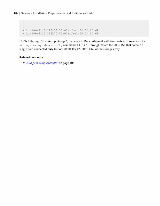
. . . vnbr4100s31:5.126L53 50:00:1f:e1:50:0d:14:69, vnbr4100s31:5.126L70 50:00:1f:e1:50:0d:14:69,
LUNs 1 through 50 make up Group 2, the array LUNs configured with two ports as shown with thestorage array show-config command. LUNs 51 through 70 are the 20 LUNs that contain asingle path connected only to Port 50:00:1f:e1:50:0d:14:69 of the storage array.
Related concepts
Invalid path setup examples on page 106
104 | Gateway Installation Requirements and Reference Guide
Troubleshooting
You should validate your configuration during initial installation so you can resolve issues beforeyour configuration is put into a production environment.
Getting started with troubleshootingBefore escalating a problem, there are a number of things you can check to figure out the problemyourself. You should check for the obvious and easiest problems first.
About this task
This procedure suggests an order for approaching troubleshooting.
Note: As you troubleshoot, you should save any information you gather. If you need to escalatethe problem, you will need to provide that data.
Steps
1. Determine whether the problem is unique to the gateway.
You need to determine whether the problem is a front-end problem (a Data ONTAP problem thataffects all platforms running Data ONTAP) or a back-end problem (a problem with the switch orstorage array configuration). For example, if you are trying to use a Data ONTAP feature and it isnot working as you expected, the problem is likely to be a front-end problem.
2. If the issue is a front-end problem, proceed with troubleshooting the Data ONTAP feature byfollowing troubleshooting instructions in the Data ONTAP guides.
3. If the issue is a back-end problem, check the Gateway Interoperability Matrix to ensure that thefollowing is supported: the configuration, storage array, storage array firmware, switch, andswitch firmware.
4. If your system is running 7-Mode, or Cluster-Mode in a Data ONTAP release prior to 8.1, checkEMS messages for clues to the problem.
5. If your system is running Cluster-Mode in Data ONTAP 8.1 and later, use the storage arrayshow config command to check whether there are any common back-end configuration errorsthat the system can detect.
If Data ONTAP detects a back-end configuration error, it tells you to run the storage errorsshow command to find out details about the error.
When you troubleshoot your system using the storage array show config and storageerrors show commands, you check for the same issues as you did during installationverification of your system. You can check both errors that the system detects and differences inwhat you expected to see in your configuration.
105
6. If you have not yet been able to determine the problem, check the following documents to ensurethat you are complying to requirements for your system working with third-party storage arrays:
• Gateway Installation Requirements and Reference Guide• Gateway Implementation Guide for Third-Party Storage• Gateway Limits Reference for Third-Party Storage
7. If you still need help resolving the problem, contact technical support.
Related concepts
Verifying installation with third-party storage (Cluster-Mode in 8.1 and later) on page 76Verifying an installation with third-party storage (7-Mode in 8.x) on page 101
Invalid path setup examplesPath setup can be invalid because paths to an array LUN are not redundant or the number of paths toan array LUN does not meet Data ONTAP requirements.
Related concepts
Requirement for redundant setup of components in a path on page 34Required number of paths to an array LUN on page 35
Invalid path setup: too many paths to an array LUN (7-Mode)Systems operating in 7-Mode require two paths to an array LUN; more than two paths to an arrayLUN is not supported.
The path setup in the following example is invalid because the same array LUN would be accessedover four paths instead of only two paths:
106 | Gateway Installation Requirements and Reference Guide
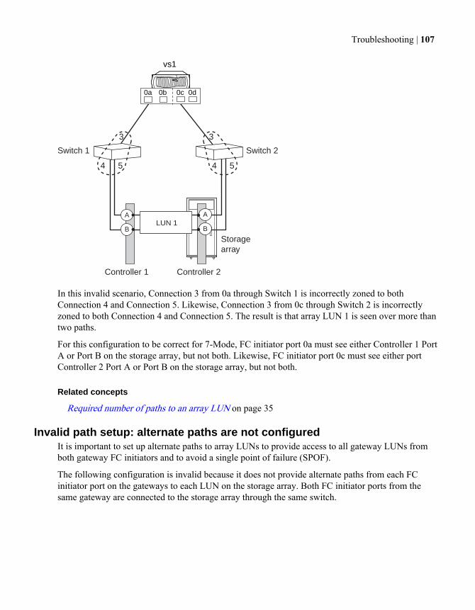
Storagearray
Switch 1 Switch 2
3 3
4 5 4 5
A A
B BLUN 1
0a 0b 0c 0d
vs1
Controller 1 Controller 2
In this invalid scenario, Connection 3 from 0a through Switch 1 is incorrectly zoned to bothConnection 4 and Connection 5. Likewise, Connection 3 from 0c through Switch 2 is incorrectlyzoned to both Connection 4 and Connection 5. The result is that array LUN 1 is seen over more thantwo paths.
For this configuration to be correct for 7-Mode, FC initiator port 0a must see either Controller 1 PortA or Port B on the storage array, but not both. Likewise, FC initiator port 0c must see either portController 2 Port A or Port B on the storage array, but not both.
Related concepts
Required number of paths to an array LUN on page 35
Invalid path setup: alternate paths are not configuredIt is important to set up alternate paths to array LUNs to provide access to all gateway LUNs fromboth gateway FC initiators and to avoid a single point of failure (SPOF).
The following configuration is invalid because it does not provide alternate paths from each FCinitiator port on the gateways to each LUN on the storage array. Both FC initiator ports from thesame gateway are connected to the storage array through the same switch.
Troubleshooting | 107
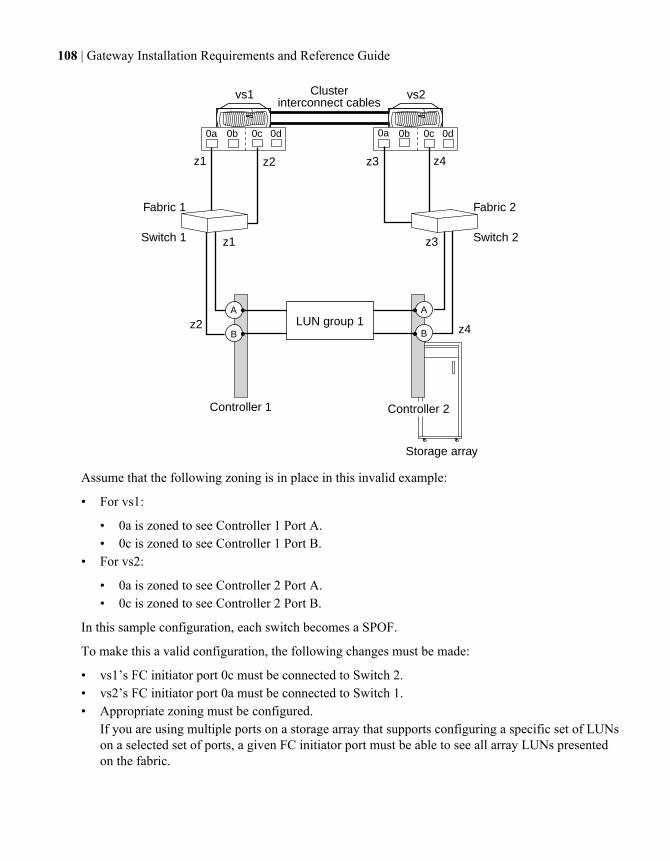
B
0a 0b 0c 0d 0a 0b 0c 0d
AA
B
Controller 2
z1
z1 z3
z3 z4
Switch 1 Switch 2
Fabric 1 Fabric 2
Storage array
Controller 1
z2
z2 z4LUN group 1
Clusterinterconnect cables
vs2vs1
Assume that the following zoning is in place in this invalid example:
• For vs1:
• 0a is zoned to see Controller 1 Port A.• 0c is zoned to see Controller 1 Port B.
• For vs2:
• 0a is zoned to see Controller 2 Port A.• 0c is zoned to see Controller 2 Port B.
In this sample configuration, each switch becomes a SPOF.
To make this a valid configuration, the following changes must be made:
• vs1’s FC initiator port 0c must be connected to Switch 2.• vs2’s FC initiator port 0a must be connected to Switch 1.• Appropriate zoning must be configured.
If you are using multiple ports on a storage array that supports configuring a specific set of LUNson a selected set of ports, a given FC initiator port must be able to see all array LUNs presentedon the fabric.
108 | Gateway Installation Requirements and Reference Guide
Related concepts
Requirement for redundant setup of components in a path on page 34
What happens when a link failure occursData ONTAP monitors a link’s usage periodically. The Data ONTAP response to a link failurediffers depending on where the failure occurs.
The following table shows what occurs if there is a failure in a fabric-attached configuration:
If a failure occurs in the link between the... Then...
Gateway and the switch Data ONTAP receives notification immediatelyand sends traffic to the other path immediately.
Switch and the storage array Data ONTAP is not immediately aware thatthere is a link failure because the link is stillestablished between the gateway and the switch.Data ONTAP becomes aware that there is afailure when the I/O times out. Data ONTAPretries three times to send the traffic on theoriginal path, then it fails over the traffic to theother path.
Relationship between zoning and host group configurationWhen you fix zoning configuration errors you sometimes have to change host group configurationalso, and the reverse.
Related concepts
Dependency between zone and host group definitions on page 109Example of cascading zoning and host group configuration errors on page 111Zoning guidelines on page 53
Dependency between zone and host group definitionsErrors made in zone definitions can require reconfiguration of host group definitions and the reverse.
When a zone definition is constructed, two ports are specified: the WWPN of the gateway initiatorport and the storage array port WWPN or WWNN for that zone. Likewise, when the host group forgateway is configured on the storage array, the WWPNs of the gateway initiator ports that you wantto be members of the host group are specified.
The typical ordering of configuration is as follows:
Troubleshooting | 109
1. Construct a zone definition.
2. Construct the host group on the storage array (by picking the WWPN of the gateway initiatorfrom the picklist).
3. Present array LUNs to the ports.
However, host groups are sometimes configured before zone definitions, which requires manuallyentering WWPNs in the host group configuration on the storage array.
Common errors
In Data ONTAP output, the gateway initiator ports are identified by adapter number—for example,0a, 0b, 0c, 0d, and so on for models with onboard ports. WWPNs are shown in the switch GUI andthe storage array GUI. Because WWPNs are long and in hexadecimal format, the following errors arecommon:
How WWPNs are specified Common error
The administrator types in WWPNs A typing mistake is made.
WWPNs are automatically discovered by theswitch
The wrong gateway initiator port WWPN isselected from the picklist.
Note: When the gateways, switches, and storage array are cabled together, the switchautomatically discovers the WWPNs of the gateways and storage array ports. The WWPNs arethen available in picklists in the switch GUI, enabling selection of the WWPN of each zonemember rather than typing it. To eliminate the possibility of typing errors, it is recommended thatthe switch discover WWPNs.
Cascading effect of errors
An obvious first step when troubleshooting problems with a fabric-attached configuration is to checkwhether zoning was configured correctly. Considering the relationship between the host group andzone definitions is also important. Fixing a problem might require reconfiguring both the zonedefinition and the host group definition, depending on where the error was made during theconfiguration process.
If the switch is automatically discovering WWPNs and zone definitions are configured first, theWWPNs of the gateway initiator ports that will be used to access LUNs on the storage array areautomatically propagated to the host group configuration picklists in the storage array GUI.Therefore, any zoning errors are also propagated to the storage array host group picklists. Thepicklists show the long, hexadecimal WWPNs instead of the short gateway initiator port labels thatare visible on the gateway (for example, 0a, 0b, and so on). Therefore, it is not easy to see that theWWPN you expected to be listed is not there.
The following table shows the effects of certain errors:
110 | Gateway Installation Requirements and Reference Guide
Zone definition on the switch Host group configuration onthe storage array
Symptom in Data ONTAPoutput
The gateway initiator port inthe zone definition is incorrect.This caused the incorrectgateway initiator port WWPNto be propagated to the hostgroup configuration.
The WWPN of the gatewayinitiator port shown in thepicklist was selected, not theWWPN you intended.
Array LUNs are not visibleover the gateway initiator porton which the expected LUNswould be visible.
The zone definition includesthe correct gateway initiatorport.
The WWPN in the host groupdefinition is incorrect becauseof either of the following:
• The wrong WWPN wasselected.
• Host groups wereconfigured manually beforethe zone definition wasconfigured and a typingerror was made when typingin the WWPN of thegateway initiator port.
Related concepts
Example of cascading zoning and host group configuration errors on page 111Zoning requirements on page 53
Example of cascading zoning and host group configuration errorsErrors made in zone definitions can impact host group definitions and the reverse. When LUNs arenot visible over a path, you need to check for both zoning and host group configuration errors.
Assume your configuration sequence is as follows:
1. The zone definition was created on the switch.The WWPN for gateway initiator port 0a was put in the zone definition. However, the intentionwas that the WWPN for gateway initiator port 0c was to be put into the zone definition.
2. The host group was created on the storage array.The WWPN for gateway initiator port 0a was selected (because that was the only WWPNavailable and it was not obvious that it was the WWPN for 0a and not 0c).
3. In Data ONTAP, you looked at array LUNs over the gateway initiator ports, expecting to seearray LUNs over 0c.However, there were no array LUNs over 0c because both the zone definition and the host groupdefinition incorrectly include the WWPN for gateway initiator port 0a.
Troubleshooting | 111
Note: You used the sysconfig -v command for 7-Mode or the storage array showconfig command for C-Mode.
4. You start troubleshooting because you cannot see LUNs over the initiator over which youexpected to see them.
You need to check both the zoning and host group configuration but it does not matter which of thefollowing procedures you start with first. You might see different messages depending on whetheryou start fixing things from the host group first or the zoning first.
Troubleshooting by checking the zoning first
1. Check the zone definitions for the gateway.You realize you have two zones with the WWPN for gateway initiator port 0a in it and no zoneswith the WWPN for 0c in it.
2. Fix the incorrect zone definitions and activate them.
Note: For 7-Mode, if you were to run sysconfig -v on the gateway now to check the arrayLUNs over the gateway initiator ports, you would still not be able see the array LUNs over 0cbecause the host group still has the wrong initiator in it (0a is still in the host group). ForCluster-Mode, you would not see the array LUNs over the initiator ports when runningstorage array config show.
3. Go to the array and reconfigure the host group to include the WWPN for gateway initiator port0c.Now that the WWPN for 0c is in a zone definition that has been activated, the WWPN for 0cshows up in the picklist in host group configuration on the storage array.
4. On the gateway, run sysconfig -v for 7-Mode or storage array config show forCluster-Mode to check the array LUNs over the gateway initiator ports to confirm that arrayLUNs are shown over 0c.
Troubleshooting by checking the host group first
Note: If the storage array does not let you modify WWPNs, you need to modify the host groupdefinition after modifying the zone definition.
1. From the gateway console, run storage show adapter adapter#, then write down theWWPN of the adapter that is missing—0c in this example.
2. Go to the storage array and compare the WWPN you wrote down to the WWPNs shown in thehost group picklist to see whether the WWPN of the gateway initiator port you were expected islisted.If the WWPN you expected does not appear, then the initiator you intended is not in the zonedefinition.
3. If the storage array allows you to modify WWPNs, you could modify the WWPN shown to be theWWPN that you wrote down.
112 | Gateway Installation Requirements and Reference Guide
You still cannot see LUNs over the initiator you were intending because the zoning has not beenfixed yet.
4. Go to the switch and replace the incorrect WWPN with the correct gateway port initiator, thenactivate the zone definition.
5. If you were not able to correct the WWPN in the host group definition earlier in the process, go tothe storage array and reconfigure the host group to include the WWPN for gateway initiator port0c.Now that the WWPN for 0c is in a zone definition that has been activated, the WWPN for 0cshows up in the picklist in host group configuration on the storage array.
6. On the gateway, run sysconfig -v for 7-Mode or storage array config show forCluster-Mode to check the array LUNs over the gateway initiator ports to confirm that arrayLUNs are shown over 0c.You should now see the LUNs you expected over the initiator you expected to see them.
Related concepts
Dependency between zone and host group definitions on page 109Zoning requirements on page 53
Troubleshooting | 113

Installation quick start (7-Mode and third-partystorage only)
If you are familiar with setting up a system running Data ONTAP, quick start instructions might besufficient to help you set up your gateway to work with a storage array.
The quick start installation instructions are for a gateway 7-Mode configuration that uses only third-party storage.
Steps
1. Example configuration for the installation quick start (7-Mode and third-party storage) on page1142. Performing preinstallation tasks on the storage array on page 1153. Installing the gateway on page 1164. Setting up the switches on page 1175. Setting up LUN security on page 1176. Assigning an array LUN to a gateway and creating the root volume on page 1187. Installing Data ONTAP and licenses on page 1198. Testing your setup on page 1209. Additional setup on page 122
Example configuration for the installation quick start (7-Mode and third-party storage)
Setting up connectivity between a gateway and a storage array is basically the same for anyconfiguration.
Refer to this single 4-port array LUN group example as you are using the quick start. This is therecommended configuration. It is supported with all gateways, all switches, and all storage arrays,regardless of vendor.
114 | Gateway Installation Requirements and Reference Guide

Storagearray
vs1 vs2
0a 0b 0c 0d 0a 0b 0c 0d
1A
Switch 1 Switch 2
Fabric 1 Fabric 2
1B
2A
2BLUN group 1
z1 z3 z2 z4
z4z2
z3z1
Controller 1 Controller 2
In this configuration with a single 4-port LUN group, array LUNs are mapped to four ports on thestorage array. The array LUN group is presented to both nodes in the HA pair on different arraytarget ports. However, each gateway can see an array LUN, end-to-end, through only two paths.Zoning is configured so that each FC initiator port on a gateway can access only a single target arrayport.
Note: Gateway FC initiator port names and storage array port names vary depending on thegateway and storage array model. In the illustration, Controller 1 and Controller 2 are the hardwarecomponents on which the ports are located. Different vendors and different storage array modelsuse different terminology to represent these hardware components (for example, cluster orcontroller for Hitachi, HP XP, and IBM; Storage Processor (SP) for EMC CLARiiON; andController Module for Fujitsu ETERNUS).
Performing preinstallation tasks on the storage arrayBefore you can begin installing a gateway configuration, the storage array administrator must preparestorage for Data ONTAP to use.
Steps
1. Ensure compliance with supported storage array models, firmware, switches, Data ONTAPversion, and so on.
See the Gateway Interoperability Matrix at the N series support website (accessed and navigatedas described in Websites on page 7) for interoperability information and the Gateway Limits
Installation quick start (7-Mode and third-party storage only) | 115
Reference for Third-Party Storage for information about limits such as the minimum array LUNsize for the root volume.
2. Ask your storage administrator to create at least four LUNs on the storage array for the gateway.
Each node in the HA pair requires an array LUN for the root volume and an array LUN for coredumps.
3. Ask your storage array administrator to configure any parameters on the storage array that arerequired to work with Data ONTAP.
See the Gateway Implementation Guide for Third-Party Storage for information about theparameters that must be set to work with Data ONTAP.
4. Obtain appropriate Data ONTAP software.
Related concepts
Zoning recommendation for a configuration with third-party storage on page 54Minimum array LUN size for the root volume on page 26Spare core array LUN requirement for core dumps on page 24
Installing the gatewayAfter the storage administrator makes storage available to Data ONTAP, you are ready to install thegateway.
Steps
1. Power on the gateway and interrupt the boot process by pressing Ctrl-C when you see thefollowing message on the console:
Starting Press CTRL-C for special boot menu
2. Select “Maintenance mode boot” on the menu.
Do not proceed any further with gateway installation and setup at this time.
3. Check the settings of the gateway HBAs to ensure that they are configured as initiators.
a) Determine which ports are configured as target ports:
fcadmin config
b) Configure the required ports as initiator ports:
fcadmin config -t initiator port#
4. Install the Fibre Channel cables connecting the gateway to switches and switches to the storagearray.
116 | Gateway Installation Requirements and Reference Guide
Setting up the switchesSwitch configuration is typically done by the storage or SAN administrator. Some customers usehard zoning and other customers use soft zoning.
About this task
The switches need to be zoned so that the gateways and the storage arrays can see each other. Youneed to use single-initiator zoning so that the gateway FC initiator ports do not see each other.
Step
1. Zone the switches:a) Log in to the storage array and obtain the WWPNs of the FC adapters of the storage array.b) Use the Fibre Channel switch commands to zone each switch so that the storage array and the
gateway see each other’s WWPNs.
In the example configuration, the zones are as follows for soft zoning:
Zone Gateway and port Storage array controller and port
Switch 1
z1 vs1 0a Controller 1 1A
z2 vs2 0a Controller 1 1B
Switch 2
z3 vs1 0c Controller 2 2A
z4 vs2 0c Controller 2 2B
Related concepts
Zoning guidelines on page 53
Setting up LUN securityThe storage array administrator must configure the storage array so that other hosts cannot access thearray LUNs intended for use by Data ONTAP.
About this task
The concept of LUN security is similar to zoning except that LUN security is set up on the storagearray. LUN security keeps different servers from using each other's storage on the SAN. LUNsecurity might also be referred to as LUN masking.
Installation quick start (7-Mode and third-party storage only) | 117
Steps
1. Set up LUN security on the storage array.
2. Create host groups, or the equivalent, for the gateway.
The term host group is used on some storage arrays to describe a configuration parameter thatenables you to specify host access to specific ports on the storage array. Different storage arraysuse different terms to describe this configuration parameter. Each storage array vendor has itsown process for creating a host group or the equivalent.
Related concepts
Planning for LUN security on the storage arrays on page 32
Assigning an array LUN to a gateway and creating the rootvolume
For each gateway, you must assign an array LUN to it and create its root volume before you caninstall Data ONTAP.
About this task
At this point it is easiest if you assign only one array LUN to each gateway. You can add additionalarray LUNs after you install Data ONTAP and verify your configuration.
For Data ONTAP 8.x, the root volume must be a FlexVol volume. You should assign only one arrayLUN to the aggregate with the root volume. The FlexVol volume can then use all of the space for theroot volume.
Steps
1. Return to the gateway console.
The system should still be in Maintenance mode.
2. Enter the following command to confirm that you can see the array LUNs created by the storageadministrator:
disk show -v
If you do not see the array LUNs, reboot the gateway into Maintenance mode, and then double-check that the array LUNs exist, that the host groups were created correctly, that zoning iscorrect, and that cabling is correct.
3. Enter the following command to assign the first array LUN to the gateway:
disk assign {disk_name}
For example, on gateway 1, enter disk assign L1, and on gateway 2, enter disk assign L2.
118 | Gateway Installation Requirements and Reference Guide
Note: For Data ONTAP 8.1, use block checksum type (BCS), the default. For Data ONTAP8.1.1 and later, advanced zoned checksum type (AZCS) is also available but BCS type isrecommended.
4. Confirm that the system ID of the gateway is shown as the owner of the array LUN:
disk show -v
If the system ID of a gateway is shown, the array LUN was assigned to the gateway.
5. Exit Maintenance mode:
halt
6. At the boot environment prompt, enter the following command:
bye
7. Press Ctrl-c to interrupt the boot process and to display the boot options menu.
8. Select the Clean configuration and initialize all disks option to create the root volume with oneof the array LUNs that you assigned to this storage system.
9. Enter y when the system prompts you whether you want to install a new file system.
10. Enter y when the system displays the This will erase all the data on the disks,are you sure? message.
The storage system creates a FlexVol root volume named vol0 in an aggregate named aggr0(the system automatically creates the aggregate). After these are created on one of the assignedarray LUNs, the system prompts for setup information.
Related concepts
Planning for Data ONTAP use of array LUNs on page 21Characteristics of checksum types that Data ONTAP supports on page 28
Installing Data ONTAP and licensesWhen you order a gateway without disk shelves, you must install Data ONTAP and the requiredgateway license.
About this task
You can perform Data ONTAP software installation using either of the following methods:
• Map the gateway C$ share to your laptop as a CIFS share.• On an HTTP server, use the software install http://ipaddr/file.zip command to
install the software.
This procedure describes using the CIFS share method.
Installation quick start (7-Mode and third-party storage only) | 119
Steps
1. Install the CIFS license.
2. Run CIFS setup in workgroup mode.
3. Map the gateway C$ share to your laptop.
4. Make an /etc/software directory (or enter the software list command to createthe /etc/software directory).
5. Copy the Data ONTAP executable to the /etc/software directory.
6. Enter the following command to run the software executable:
software install release_setup.exe
7. Download the Data ONTAP software.
8. Install the gateway license.
9. Reboot the gateway.
10. If your gateway is a node in an HA pair, repeat the setup and Data ONTAP software installationsteps on the partner node before validating your setup.
Testing your setupBefore putting a gateway into a production environment, you must test your setup to ensure thateverything works.
About this task
Testing for proper setup of a gateway with a storage array includes the following:
• Checking your system to ensure that the configuration is as expected• Verifying that there are two paths to storage• Testing normal controller failover• Testing path failover and controller failover
Steps
1. Use the following commands to confirm that the results of configuration are what you expect:
Use this command... To...
disk show -v Check whether all array LUNs are visible.
sysconfig -v Check which gateway FC initiator ports, switch ports, and arrayLUNs are used.
storage array show-config Display connectivity to back-end storage arrays.
120 | Gateway Installation Requirements and Reference Guide
Use this command... To...
sysconfig -r Check the aggregate configuration and ensure that spare arrayLUNs are available.
2. Ensure that there are two paths to each array LUN so that the gateway can continue to operatewhen running on a single path:
a) Enter the following command:storage array show-config
b) Check whether two paths to the array LUNs are shown.
If you do not see two paths to the array LUNs, check zoning, host group configuration, andcabling.
c) Look at the adapters shown to see whether all paths are on a single adapter.
If you see both paths through only one gateway FC initiator port (the gateway’s 0c port, forexample) this is an indication that the back-end zoning is redundantly crossed. This is not asupported configuration.
Note: Do not continue with testing until you see two paths.
3. Test normal controller failover.
a) On the partner node (vs2 in the example configuration), enter the following commands toperform a cf takeover; a takeover of vs1 should occur:
vs2> cf statusvs2> cf takeover (vs1 goes down; vs2 takes over)vs1/vs2> df (vs2 looks at vs1) vs1/vs2> partner (to switch to the partner) vs2> sysconfigvs2 (takeover)> cf statusvs2 (takeover)> cf giveback (to return to normal operation)
b) Repeat the same commands on the local gateway (vs1 in the example configuration).
4. Test path failover and cluster failover:
a) On the local gateway (vs1 in the example configuration), enter the following commands:
vs1> fcadmin offline 0avs1> storage show disk -p (you should see only one path) or enter storage array show-configvs1> fcadmin offlinevs1> fcadmin offline HA pair (takeover should occur)
b) On the partner node (vs2 in the example configuration), enter the following commands:cf takeover
cf giveback
Installation quick start (7-Mode and third-party storage only) | 121
c) After both the local node (vs1) and the partner node (vs2) are back online, go to the partnernode (vs2 in the example) and repeat the procedure.
Related concepts
Verifying an installation with third-party storage (7-Mode in 8.x) on page 101
Additional setupAfter initial installation and testing, you can assign additional array LUNs to your gateways and setup various Data ONTAP features on your systems.
Tasks after initial installation and testing include the following:
• Assign additional array LUNs to the gateways as required.After the basic gateway setup is complete, you can have the storage administrator createadditional array LUNs for the gateways, as needed.
• Create Data ONTAP aggregates and volumes as desired.• Set up additional Data ONTAP features on your gateway, for example, features for backup and
recovery.
Related concepts
Planning for Data ONTAP use of array LUNs on page 21Determining the array LUNs for specific aggregates on page 46
122 | Gateway Installation Requirements and Reference Guide
Obtaining WWNs manually
If the gateway is not connected to the SAN switch, you need to obtain the World Wide Port Names(WWPNs) of the gateway FC initiator ports that will be used to connect the gateway to the switch.
About this task
Having the switch automatically discover WWPNs is the preferred method of obtaining WWPNsbecause you can avoid potential errors resulting from typing the WWPNs into the switchconfiguration.
Steps
1. Connect the gateway console connection to a laptop computer.
2. Power on your gateway.
Interrupt the boot process by pressing Ctrl-c when you see the following message on the console:
Starting Press CTRL-c for floppy boot menu
3. Select the Maintenance Mode option on the boot options menu.
4. Enter the following command to list the WWPNs of the gateway FC initiator ports:
storage show adapter
To list a specific adapter WWPN, add the adapter name, for example, storage show adapter0a.
5. Record the WWPNs that will be used and leave the gateway in Maintenance mode.
Related tasks
Connecting a gateway stand-alone system to back-end devices on page 66Connecting an HA pair to back-end devices on page 68
123
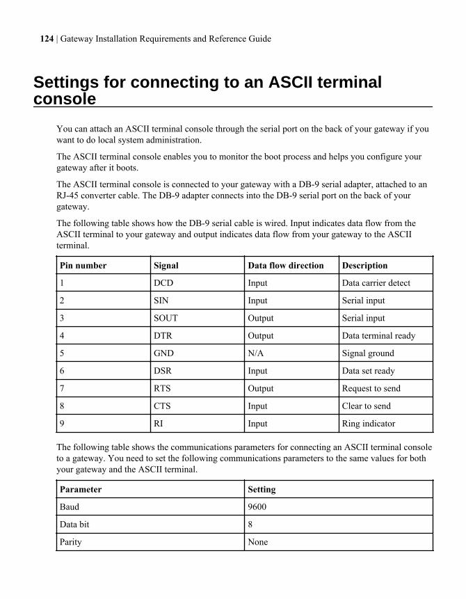
Settings for connecting to an ASCII terminalconsole
You can attach an ASCII terminal console through the serial port on the back of your gateway if youwant to do local system administration.
The ASCII terminal console enables you to monitor the boot process and helps you configure yourgateway after it boots.
The ASCII terminal console is connected to your gateway with a DB-9 serial adapter, attached to anRJ-45 converter cable. The DB-9 adapter connects into the DB-9 serial port on the back of yourgateway.
The following table shows how the DB-9 serial cable is wired. Input indicates data flow from theASCII terminal to your gateway and output indicates data flow from your gateway to the ASCIIterminal.
Pin number Signal Data flow direction Description
1 DCD Input Data carrier detect
2 SIN Input Serial input
3 SOUT Output Serial input
4 DTR Output Data terminal ready
5 GND N/A Signal ground
6 DSR Input Data set ready
7 RTS Output Request to send
8 CTS Input Clear to send
9 RI Input Ring indicator
The following table shows the communications parameters for connecting an ASCII terminal consoleto a gateway. You need to set the following communications parameters to the same values for bothyour gateway and the ASCII terminal.
Parameter Setting
Baud 9600
Data bit 8
Parity None
124 | Gateway Installation Requirements and Reference Guide
Parameter Setting
Stop bits 1
Flow control None
Note: See your terminal documentation for information about changing the ASCII consoleterminal settings.
Related tasks
Connecting a gateway stand-alone system to back-end devices on page 66Connecting an HA pair to back-end devices on page 68
Settings for connecting to an ASCII terminal console | 125
Target queue depth customization
By default, the gateway can send 256 commands to the target port on the storage array. For mostcompanies the default target queue depth is appropriate, but you can change it if it is not.
The target queue depth limits the number of commands (read and write requests) that the storagearray port must handle from gateways and non gateway hosts. When multiple initiators are accessinga target port on the storage array, you do not want the outstanding commands in the queue buffer,from all initiators together, to exceed what the storage array can handle. Otherwise, the performanceof gateways and non gateway hosts can suffer. Storage arrays differ in the number of commands thatthey can handle in the queue buffer.
Non gateway hosts also provide a means for limiting the target queue length. See the documentationfor the host for information about limiting target queue length.
Note: Target queue depth might also be referred to as target queue length, Q-Depth, or MaxThrottle.
Guidelines for specifying the appropriate target queue depthYou need to consider the impact of all the initiators on the storage array port when you are planningthe configuration for a specific gateway or a specific non gateway host.
If your deployment includes more than one initiator, you need to configure each initiator so that thetotal number of commands by all initiators does not exceed the maximum that the storage array portcan handle.
Guidelines for specifying the appropriate target queue length are as follows:
• Do not configure a value of 0. 0 (zero) means that there is no limit on the outstanding commands.• Divide 256 by the number of gateways and non gateway hosts that will be acting as initiators on
the target port on the storage array, configuring each gateway and non gateway host with theresulting value.
• Consider the volume of commands that specific initiators would be likely to send to the targetport.You could then configure higher values for initiators likely to send a greater number of requestsand a lower value for initiators likely to send a lesser number of requests.
• Configure non gateway hosts according to the guidelines provided for those hosts.
Related tasks
Setting the target queue depth on page 127
126 | Gateway Installation Requirements and Reference Guide
Setting the target queue depthThe default target queue depth is acceptable for most companies, but you can change it if you wantto.
About this task
For Data ONTAP operating in Cluster-Mode, this option is available through the nodeshell.
Step
1. Use the following option to set the target queue depth:
options disk.target_port.cmd_queue_depth value
Related concepts
Guidelines for specifying the appropriate target queue depth on page 126
Target queue depth customization | 127
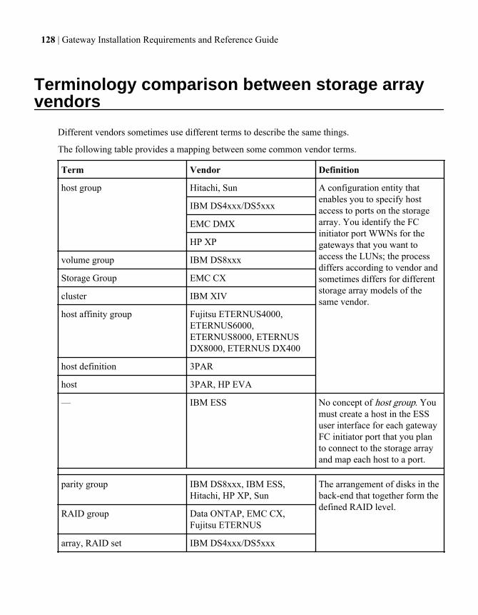
Terminology comparison between storage arrayvendors
Different vendors sometimes use different terms to describe the same things.
The following table provides a mapping between some common vendor terms.
Term Vendor Definition
host group Hitachi, Sun A configuration entity thatenables you to specify hostaccess to ports on the storagearray. You identify the FCinitiator port WWNs for thegateways that you want toaccess the LUNs; the processdiffers according to vendor andsometimes differs for differentstorage array models of thesame vendor.
IBM DS4xxx/DS5xxx
EMC DMX
HP XP
volume group IBM DS8xxx
Storage Group EMC CX
cluster IBM XIV
host affinity group Fujitsu ETERNUS4000,ETERNUS6000,ETERNUS8000, ETERNUSDX8000, ETERNUS DX400
host definition 3PAR
host 3PAR, HP EVA
— IBM ESS No concept of host group. Youmust create a host in the ESSuser interface for each gatewayFC initiator port that you planto connect to the storage arrayand map each host to a port.
parity group IBM DS8xxx, IBM ESS,Hitachi, HP XP, Sun
The arrangement of disks in theback-end that together form thedefined RAID level.
RAID group Data ONTAP, EMC CX,Fujitsu ETERNUS
array, RAID set IBM DS4xxx/DS5xxx
128 | Gateway Installation Requirements and Reference Guide
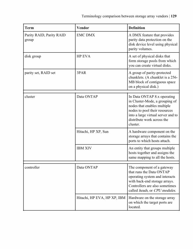
Term Vendor Definition
Parity RAID, Parity RAIDgroup
EMC DMX A DMX feature that providesparity data protection on thedisk device level using physicalparity volumes.
disk group HP EVA A set of physical disks thatform storage pools from whichyou can create virtual disks.
parity set, RAID set 3PAR A group of parity-protectedchunklets. (A chunklet is a 256-MB block of contiguous spaceon a physical disk.)
cluster Data ONTAP In Data ONTAP 8.x operatingin Cluster-Mode, a grouping ofnodes that enables multiplenodes to pool their resourcesinto a large virtual server and todistribute work across thecluster.
Hitachi, HP XP, Sun A hardware component on thestorage arrays that contains theports to which hosts attach.
IBM XIV An entity that groups multiplehosts together and assigns thesame mapping to all the hosts.
controller Data ONTAP The component of a gatewaythat runs the Data ONTAPoperating system and interactswith back-end storage arrays.Controllers are also sometimescalled heads, or CPU modules.
Hitachi, HP EVA, HP XP, IBM Hardware on the storage arrayon which the target ports arelocated.
Terminology comparison between storage array vendors | 129
Term Vendor Definition
interface module IBM XIV A hardware component on thestorage arrays that contains theports to which hosts attach.node 3-PAR
FEBE Board EMC Symmetrix
Storage processor (SP) EMC CLARiiON
Controller Module Fujitsu ETERNUS
LUN Many storage arrays A grouping of one or moredisks or disk partitions into onespan of disk storage space. Inthe Data ONTAPdocumentation, this is referredto as array LUN.
Data ONTAP The gateway can virtualize thestorage attached to it and servethe storage up as LUNs toapplications and clients outsidethe gateway (for example,through iSCSI and FCP).Clients are unaware of where afront-end LUN is stored.
LUN, virtual disk HP EVA A virtual disk (called a Vdisk inthe user interface) is asimulated disk drive created ina disk group. You can assign acombination of characteristicsto a virtual disk, such as aname, redundancy level, andsize. Presenting a virtual diskoffers its storage to a host.
array LUN Data ONTAP documentation,Data ONTAP storagemanagement tools
The Data ONTAPdocumentation uses the termarray LUN to distinguish LUNson the storage arrays fromfront-end LUNs (Data ONTAPLUNs).
130 | Gateway Installation Requirements and Reference Guide
Term Vendor Definition
vLUN 3PAR (volume-LUN) A pairingbetween a virtual volume and alogical unit number (LUN). Fora host to see a virtual volume,the volume must be exported asa LUN by creating vLUNs onthe storage array.
volume IBM, IBM XIV Equivalent to what otherstorage array vendors call aLUN.
Data ONTAP A logical entity that holds userdata that is accessible throughone or more of the accessprotocols supported by DataONTAP, including NetworkFile System (NFS), CommonInternet File System (CIFS),HyperText Transfer Protocol(HTTP), Fibre Channel (FC),and Internet SCSI (iSCSI). Thegateway treats an IBM volumeas a disk.
EMC DMX A general term referring to astorage device. A physicalvolume corresponds to a singledisk device.
virtual volume 3PAR A virtual storage unit createdby mapping data from one ormore logical disks.
Terminology comparison between storage array vendors | 131

Glossary
array LUN The storage that third-party storage arrays provide to storage systems running DataONTAP software. One array LUN is the equivalent of one disk on a native diskshelf.
checksum A form of redundancy check, a simple measure for protecting the integrity of datathrough error detection. A checksum is used mainly in data storage and networkingprotocols. It adds up the basic components of a message, typically the bytes, andstores the resulting value. Later, the checksum can verify that the message was notcorrupted by doing the same operation on the data, and checking the sum.
controller • For IBM N series storage systems, the component that runs the Data ONTAPoperating system and controls its disk subsystem.Controllers are also sometimes called storage controllers, storage appliances,appliances, storage engines, heads, CPU modules, or controller modules.
• For gateways, the component that runs the Data ONTAP operating system andinteracts with back-end storage arrays.Controllers are also sometimes called gateways, heads, or CPU modules.
• For some storage array vendors, controller refers to the hardware component onwhich host adapters and ports are located.Some vendors refer to this component as a cluster.
family The collection of storage arrays that share the same performance and failovercharacteristics. For example, members of the same family all perform active-activefailover, or they all perform active-passive failover. Storage arrays with 4-GB HBAsare not considered to be in the same family as storage arrays with 8-GB HBAs.
host group A management entity on a storage array that establishes connectivity between a hostand storage (array LUNs) through port definitions. Hosts in the host group can accessthe LUNs associated with the host group; hosts that are not in the host group cannotaccess those LUNs. Different vendors use different terms to describe this concept.The process of creating a host group differs among vendors.
LDEV A piece of logical RAID storage configured from disks. Each LDEV has an internalnumber that is unique to the storage array. When an LDEV is presented out of a porton the storage array, the hosts see it as a LUN. The LUN ID—the external numberseen by the hosts—must match on each of the two ports over which they arepresented. LUN IDs do not have to be unique on the storage array but must be uniqueon a port. Different storage array vendors use different terms to describe this concept.
LUN group A set of logical devices on the storage array that a gateway accesses over the samepaths. The storage array administrator configures a set of logical devices as a groupto define which host WWPNs can access them. Data ONTAP refers to this set of
132 | Gateway Installation Requirements and Reference Guide
devices as a LUN group. The number of paths to a LUN group varies according torelease and operating mode.
LUNsecurity
A method for designating which hosts can access particular array LUNs. LUNsecurity is similar to switch zoning in concept, but it is performed on the storagearray. LUN security and LUN masking are equivalent terms to describe thisfunctionality.
open targetport
A port that Data ONTAP can see on the fabric, but the port presents no array LUNsto Data ONTAP.
An open target port can occur for a variety of reasons, and the reasons might varyamong storage arrays. For example, an open target port would occur if the gateway iszoned into the storage array target port, but the initiator's WWPN is not in the hostgroup for that target port. It occurs if the host group is empty.
A gateway continues to function normally with an open target port. However, DataONTAP cannot access any array LUNs that are not associated with a host group.
targetgroup portnumber
The identifier (TPGN) for the group of target ports on a specific storage arraycontroller or field-replaceable unit (FRU), which is called a target port group. DataONTAP uses the TPGN to detect whether paths to an array LUN are redundant.Some Data ONTAP command output shows the TPGN.
Glossary | 133
Copyright and trademark information
Copyright ©1994 - 2013 NetApp, Inc. All rights reserved. Printed in the U.S.A.
Portions copyright © 2013 IBM Corporation. All rights reserved.
US Government Users Restricted Rights - Use, duplication or disclosurerestricted by GSA ADP Schedule Contract with IBM Corp.
No part of this document covered by copyright may be reproduced in anyform or by any means— graphic, electronic, or mechanical, includingphotocopying, recording, taping, or storage in an electronic retrievalsystem—without prior written permission of the copyright owner.
References in this documentation to IBM products, programs, or services donot imply that IBM intends to make these available in all countries in whichIBM operates. Any reference to an IBM product, program, or service is notintended to state or imply that only IBM’s product, program, or service maybe used. Any functionally equivalent product, program, or service that doesnot infringe any of IBM’s or NetApp’s intellectual property rights may beused instead of the IBM or NetApp product, program, or service. Evaluationand verification of operation in conjunction with other products, except thoseexpressly designated by IBM and NetApp, are the user’s responsibility.
No part of this document covered by copyright may be reproduced in anyform or by any means— graphic, electronic, or mechanical, includingphotocopying, recording, taping, or storage in an electronic retrievalsystem—without prior written permission of the copyright owner.
Software derived from copyrighted NetApp material is subject to thefollowing license and disclaimer:
THIS SOFTWARE IS PROVIDED BY NETAPP "AS IS" AND WITHOUT ANYEXPRESS OR IMPLIED WARRANTIES, INCLUDING, BUT NOT LIMITEDTO, THE IMPLIED WARRANTIES OF MERCHANTABILITY AND FITNESSFOR A PARTICULAR PURPOSE, WHICH ARE HEREBY DISCLAIMED. INNO EVENT SHALL NETAPP BE LIABLE FOR ANY DIRECT, INDIRECT,INCIDENTAL, SPECIAL, EXEMPLARY, OR CONSEQUENTIAL DAMAGES(INCLUDING, BUT NOT LIMITED TO, PROCUREMENT OF SUBSTITUTEGOODS OR SERVICES; LOSS OF USE, DATA, OR PROFITS; OR BUSINESSINTERRUPTION) HOWEVER CAUSED AND ON ANY THEORY OFLIABILITY, WHETHER IN CONTRACT, STRICT LIABILITY, OR TORT
© Copyright IBM Corp. 2013 134
(INCLUDING NEGLIGENCE OR OTHERWISE) ARISING IN ANY WAY OUTOF THE USE OF THIS SOFTWARE, EVEN IF ADVISED OF THEPOSSIBILITY OF SUCH DAMAGE.
NetApp reserves the right to change any products described herein at anytime, and without notice. NetApp assumes no responsibility or liability arisingfrom the use of products described herein, except as expressly agreed to inwriting by NetApp. The use or purchase of this product does not convey alicense under any patent rights, trademark rights, or any other intellectualproperty rights of NetApp.
The product described in this manual may be protected by one or more U.S.A.patents, foreign patents, or pending applications.
RESTRICTED RIGHTS LEGEND: Use, duplication, or disclosure by thegovernment is subject to restrictions as set forth in subparagraph (c)(1)(ii) ofthe Rights in Technical Data and Computer Software clause at DFARS252.277-7103 (October 1988) and FAR 52-227-19 (June 1987).
Trademark information
IBM, the IBM logo, and ibm.com are trademarks or registered trademarks ofInternational Business Machines Corporation in the United States, othercountries, or both. A complete and current list of other IBM trademarks isavailable on the Web at http://www.ibm.com/legal/copytrade.shtml
Linux is a registered trademark of Linus Torvalds in the United States, othercountries, or both.
Microsoft, Windows, Windows NT, and the Windows logo are trademarks ofMicrosoft Corporation in the United States, other countries, or both.
UNIX is a registered trademark of The Open Group in the United States andother countries.
NetApp, the NetApp logo, Network Appliance, the Network Appliance logo,Akorri, ApplianceWatch, ASUP, AutoSupport, BalancePoint, BalancePointPredictor, Bycast, Campaign Express, ComplianceClock, Cryptainer,CryptoShred, Data ONTAP, DataFabric, DataFort, Decru, Decru DataFort,DenseStak, Engenio, Engenio logo, E-Stack, FAServer, FastStak, FilerView,FlexCache, FlexClone, FlexPod, FlexScale, FlexShare, FlexSuite, FlexVol,FPolicy, GetSuccessful, gFiler, Go further, faster, Imagine Virtually Anything,Lifetime Key Management, LockVault, Manage ONTAP, MetroCluster,MultiStore, NearStore, NetCache, NOW (NetApp on the Web), Onaro,OnCommand, ONTAPI, OpenKey, PerformanceStak, RAID-DP, ReplicatorX,SANscreen, SANshare, SANtricity, SecureAdmin, SecureShare, Select, Service
135 IBM System Storage N series: Gateway Installation Requirements and Reference Guide
Builder, Shadow Tape, Simplicity, Simulate ONTAP, SnapCopy, SnapDirector,SnapDrive, SnapFilter, SnapLock, SnapManager, SnapMigrator, SnapMirror,SnapMover, SnapProtect, SnapRestore, Snapshot, SnapSuite, SnapValidator,SnapVault, StorageGRID, StoreVault, the StoreVault logo, SyncMirror, TechOnTap, The evolution of storage, Topio, vFiler, VFM, Virtual File Manager,VPolicy, WAFL, Web Filer, and XBB are trademarks or registered trademarksof NetApp, Inc. in the United States, other countries, or both.
All other brands or products are trademarks or registered trademarks of theirrespective holders and should be treated as such.
NetApp, Inc. is a licensee of the CompactFlash and CF Logo trademarks.
NetApp, Inc. NetCache is certified RealSystem compatible.
Notices
This information was developed for products and services offered in theU.S.A.
IBM may not offer the products, services, or features discussed in thisdocument in other countries. Consult your local IBM representative forinformation on the products and services currently available in your area. Anyreference to an IBM product, program, or service is not intended to state orimply that only that IBM product, program, or service may be used. Anyfunctionally equivalent product, program, or service that does not infringe onany IBM intellectual property right may be used instead. However, it is theuser’s responsibility to evaluate and verify the operation of any non-IBMproduct, program, or service.
IBM may have patents or pending patent applications covering subject matterdescribed in this document. The furnishing of this document does not giveyou any license to these patents. You can send license inquiries, in writing to:
IBM Director of LicensingIBM CorporationNorth Castle DriveArmonk, N.Y. 10504-1785U.S.A.
For additional information, visit the web at:http://www.ibm.com/ibm/licensing/contact/
The following paragraph does not apply to the United Kingdom or any othercountry where such provisions are inconsistent with local law:
Copyright and trademark information 136
INTERNATIONAL BUSINESS MACHINES CORPORATION PROVIDESTHIS PUBLICATION “AS IS” WITHOUT WARRANTY OF ANY KIND,EITHER EXPRESS OR IMPLIED, INCLUDING, BUT NOT LIMITED TO,THE IMPLIED WARRANTIES OF NON-INFRINGEMENT,MERCHANTABILITY OR FITNESS FOR A PARTICULAR PURPOSE. Somestates do not allow disclaimer of express or implied warranties in certaintransactions, therefore, this statement may not apply to you.
This information could include technical inaccuracies or typographical errors.Changes are periodically made to the information herein; these changes willbe incorporated in new editions of the publication. IBM may makeimprovements and/or changes in the product(s) and/or the program(s)described in this publication at any time without notice.
Any references in this information to non-IBM web sites are provided forconvenience only and do not in any manner serve as an endorsement of thoseweb sites. The materials at those web sites are not part of the materials forthis IBM product and use of those web sites is at your own risk.
IBM may use or distribute any of the information you supply in any way itbelieves appropriate without incurring any obligation to you.
Any performance data contained herein was determined in a controlledenvironment. Therefore, the results obtained in other operating environmentsmay vary significantly. Some measurements may have been made ondevelopment-level systems and there is no guarantee that these measurementswill be the same on generally available systems. Furthermore, somemeasurement may have been estimated through extrapolation. Actual resultsmay vary. Users of this document should verify the applicable data for theirspecific environment.
Information concerning non-IBM products was obtained from the suppliers ofthose products, their published announcements or other publicly availablesources. IBM has not tested those products and cannot confirm the accuracyof performance, compatibility or any other claims related to non-IBMproducts. Questions on the capabilities of non-IBM products should beaddressed to the suppliers of those products.
If you are viewing this information in softcopy, the photographs and colorillustrations may not appear.
137 IBM System Storage N series: Gateway Installation Requirements and Reference Guide
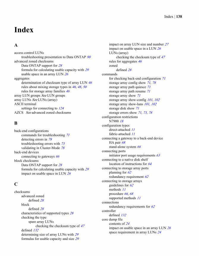
Index
Aaccess control LUNs
troubleshooting presentation to Data ONTAP 90advanced zoned checksums
Data ONTAP support for 28formula for calculating usable capacity with 29usable space in an array LUN 26
aggregatesdetermination of checksum type of array LUN 46rules about mixing storage types in 46, 48, 50rules for storage array families 46
array LUN groups See LUN groupsarray LUNs See LUNs (array)ASCII terminal
settings for connecting to 124AZCS See advanced zoned checksums
Bback-end configurations
commands for troubleshooting 71detecting errors in 78troubleshooting errors with 73validating in Cluster-Mode 78
back-end devicesconnecting to gateways 66
block checksumsData ONTAP support for 28formula for calculating usable capacity with 29impact on usable space in LUN 26
Cchecksums
advanced zoneddefined 28
blockdefined 28
characteristics of supported types 28checking the type
spare array LUNschecking the checksum type of 47
defined 132determining size of array LUNs with 29formulas for usable capacity and size 29
impact on array LUN size and number 27impact on usable space in a LUN 26LUNs (array)
checking the checksum type of 47rules for aggregates 46zoned
defined 28commands
for checking back-end configuration 71storage array config show 71, 78storage array path quiesce 71storage array path resume 71storage array show 71storage array show-config 101, 102storage array show-luns 101, 102storage disk show 71storage errors show 71, 73, 78
configuration restrictionsN7900 18
configuration typesdirect-attached 11fabric-attached 11
connecting a gateway to a back-end deviceHA pair 68stand-alone system 66
connecting portsinitiator port usage requirements 63
connecting to a native disk shelflocation of instructions for 64
connecting to storage array portsplanning for 62redundancy requirement 62
connecting to storage arraysguidelines for 62methods 11procedure 66, 68supported methods 11
connectionsredundancy requirements for 62
controllerdefined 132
core dump filecontents of 24impact on usable space in an array LUN 26space requirement in array LUNs 24
Index | 138
DData ONTAP RAID groups See RAID groups (DataONTAP)desired capacity of array LUNs
calculating 29disk ownership
changing 23considerations when planning for 22defined 22how array LUN becomes available 22
disk shelvesguidelines for connecting system to 64
EEngenio access control LUNs
troubleshooting presentation to Data ONTAP 90errors
back-end configuration troubleshooting 73storage errors show 79
Ffabric-attached configurations with third-party storage
support for 11family
defined 46, 132FC initiator ports
labeling guidelines 65usage requirements for 63
Ggateway implementation
planning tasks for 13, 14Gateway Interoperability Matrix
planning information in 13gateway neighborhoods See neighborhoodsgateways
array LUN requirements 21connecting to back-end devices 66how they use storage 10minimum number of array LUNs for 24number storage arrays behind 11
glossary 132
Hhost groups
defined 132impact of zoning errors on 109, 111what to include in 21
Iimplementation stages with third-party storage 17initiator ports
FC labeling guidelines 65usage requirements 63
installationadditional setup possibilities 122assigning array LUN 118creating root volume 118quickstart for Data ONTAP 8.x in 7-Mode 114setting up LUN security 117stages, with third-party storage 17storage array preinstallation tasks 115switches 117testing 76, 101, 120validating for 8.x 7-mode 101validating for Cluster-Mode in 8.1 76, 93
Llabeling guidelines
FC initiator ports 65LDEVs
defined 132spanning path pairs 96troubleshooting
inconsistent LUN IDs detected 73LUN ID mismatches 81
when created 21limits for third-party storage
where to find information needed for planning 14link failures
Data ONTAP response to 109load partitioning
using LUN groups for 36location
of the root volume 17LUN groups
configuration example with multiple 38configuration requirements for multiple 37defined 36load partitioning with 36
139 | Gateway Installation Requirements and Reference Guide
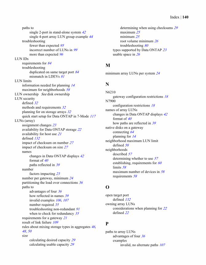
paths tosingle 2-port in stand-alone system 42single 4-port array LUN group example 44
troubleshootingfewer than expected 95incorrect number of LUNs in 99more than expected 96
LUN IDsrequirements for 84troubleshooting
duplicated on same target port 84mismatch in LDEVs 81
LUN limitsinformation needed for planning 14maximum for neighborhoods 58
LUN ownership See disk ownershipLUN security
defined 32methods and requirements 32planning for on storage arrays 32quick start setup for Data ONTAP in 7-Mode 117
LUNs (array)assignment changes 23availability for Data ONTAP storage 22availability for host use 21defined 132impact of checksum on number 27impact of checksum on size 27names
changes in Data ONTAP displays 42format of 40paths reflected in 39
numberfactors impacting 23
number per gateway, minimum 24partitioning the load over connections 36paths to
advantages of four 36how reflected in names 39invalid examples 106, 107number required 35troubleshooting non-redundant 91when to check for redundancy 35
requirements for a gateway 21result of link failure 109rules about mixing storage types in aggregates 46,48, 50size
calculating desired capacity 29calculating usable capacity 29
determining when using checksums 29maximum 25minimum 25root volume minimum 26troubleshooting 80
types supported by Data ONTAP 23usable space in 26
Mminimum array LUNs per system 24
NN6210
gateway configuration restrictions 18N7900
configuration restrictions 18names of array LUNs
changes in Data ONTAP displays 42format of 40how paths are reflected in 39
native disks on a gatewayconnecting 64planning for 14
neighborhood maximum LUN limitdefined 58
neighborhoodsdescribed 57determining whether to use 57establishing, requirements for 60limits 58maximum number of devices in 58requirements 58
Oopen target port
defined 132owning array LUNs
considerations when planning for 22defined 22
Ppaths to array LUNs
advantages of four 36examples
invalid, no alternate paths 107
Index | 140
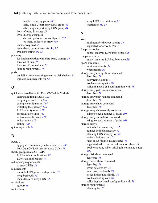
invalid, too many paths 106valid, single 2-port array LUN group 42valid, single 4-port array LUN group 44
how reflected in names 39invalid setup examples
alternate paths are not configured 107too many paths to an array 106
number required 35redundancy requirements for 34, 35troubleshooting 88, 98
planningfor implementation with third-party storage 14location of data 16location of root volume 16storage requirements 16
portsguidelines for connecting to native disk shelves 64initiator, requirements for 63
Qquick start installation for Data ONTAP in 7-Mode
adding additional LUNs 122assigning array LUNs 118example configuration 114installing the gateway 116LUN security setup 117preinstallation tasks 115software and licenses 119switch setup 117testing 120
quiescing a path 71
RRAID 0
aggregate checksum type for array LUNs 46how Data ONTAP uses for array LUNs 19
RAID groups (Data ONTAP)LUN number implications 19LUN size implications 19
redundancy requirementsto array LUNs 34
requirementsmultiple LUN group configuration 37neighborhoods 58redundancy to array LUN 34
restrictionsN7900 18
root volume
array LUN size minimum 26location of 16, 17
Ssize
minimum for the root volume 26supported for array LUNs 25
Snapshot copiesimpact on array LUN usable space 26
Snapshot reserveimpact on array LUN usable space 26
spare core array LUNminimum size for 24when needed 24
storage array config show commanddescribed 71interpreting output 93troubleshooting with 78validating back-end configuration with 78
storage array path quiesce commanddescribed 71
storage array path resume commanddescribed 71
storage array show commanddescribed 71
storage array show-config commandusing to check number of paths 101
storage array show-luns commandusing to check number of paths 101
storage arraysmethods for connecting to 11number behind a gateway 11planning LUN security for 32preinstallation tasks 115rules about mixing in aggregates 46supported, where to find information about 13troubleshooting when missing in command output100
storage disk show commanddescribed 71
storage errors show commanddescribed 71errors detected by 73index to error details 79issues it does not identify 74troubleshooting with 78validating back-end configuration with 78
storage requirementsplanning for 16
141 | Gateway Installation Requirements and Reference Guide
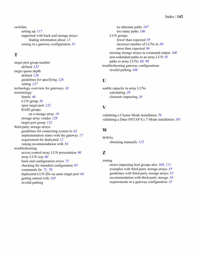
switchessetting up 117supported with back-end storage arrays
finding information about 13zoning in a gateway configuration 53
Ttarget port group number
defined 132target queue depth
defined 126guidelines for specifying 126setting 127
technology overview for gateways 10terminology
family 46LUN group 36open target port 132RAID groups
on a storage array 19storage array vendor 128target port group 132
third-party storage arraysguidelines for connecting system to 62implementation states with the gateway 17requirement for dedicated 12zoning recommendation with 54
troubleshootingaccess control array LUN presentation 90array LUN size 80back-end configuration errors 73checking for intended configuration 93commands for 71, 78duplicated LUN IDs on same target port 84getting started with 105invalid pathing
no alternate paths 107too many paths 106
LUN groupsfewer than expected 95incorrect number of LUNs in 99more than expected 96
missing storage arrays in command output 100non-redundant paths to an array LUN 91paths to array LUNs 88, 98
troubleshooting gateway configurationsinvalid pathing 106
Uusable capacity in array LUNs
calculating 29elements impacting 26
Vvalidating a Cluster-Mode installation 76validating a Data ONTAP 8.x 7-Mode installation 101
WWWNs
obtaining manually 123
Zzoning
errors impacting host groups also 109, 111examples with third-party storage arrays 55guidelines with third-party storage arrays 53recommendation with third-party storage 54requirements in a gateway configuration 53
Index | 142

����
NA 210-05862_A0, Printed in USA
GA32-1049-03


