Embed Size (px)
Citation preview

Electronic Communications of the EASSTVolume 13 (2008)
Proceedings of theSecond International Workshop on
Layout of (Software) Engineering Diagrams(LED 2008)
Generating Euler Diagrams from Existing Layouts
Gem Stapleton, John Howse Peter Rodgers and Leishi Zhang
16 pages
Guest Editors: Andrew Fish, Harald StorrleManaging Editors: Tiziana Margaria, Julia Padberg, Gabriele TaentzerECEASST Home Page: http://www.easst.org/eceasst/ ISSN 1863-2122

ECEASST
Generating Euler Diagrams from Existing Layouts
Gem Stapleton1, John Howse2 Peter Rodgers3 and Leishi Zhang4
1 [email protected],2 [email protected]/reseach/vmg
University of Brighton, UK
3 [email protected], 4 [email protected] of Kent, UK
Abstract: Euler diagrams have a wide variety of uses, from informationvisualiza-tion to logical reasoning. In the case of software engineering, they form the basis ofa number of notations, such as state charts and constraint diagrams. In all of theirapplication areas, the ability to automatically layout Euler diagrams brings consid-erable benefits. There have been several recent contributions towards the automaticgeneration and layout of Euler diagrams, all of which start from an abstract de-scription of the diagram and produce a collection of closed curves embedded in theplane. In this paper, we are concerned with producing layouts by modifying exist-ing ones. This type of layout approach is particularly useful in domains where werequire an updated, or modified, diagram such as in a logical reasoning context. Weprovide two methods to add a curve to an Euler diagram in orderto create a newdiagram. The first method is guaranteed to produce layouts that meet specified well-formedness conditions that are typically chosen by others who produced generationalgorithms; these conditions are thought to correlate wellaccurate user interpreta-tion. We also overview a second method that can be used to produce a layout of anyabstract description.
Keywords: Information visualization, diagram layout, Venn diagrams
1 Introduction
Automated diagram layout has the potential to bring huge benefits and it is unsurprising that,with the computing power now available, considerable research effort is focused on this topic.In software engineering, the prevalent use of diagrammaticnotations makes this area an idealcandidate to benefit from state-of-the-art generation and layout techniques. Many diagrams arebased on collections of closed (usually simple) curves, such as state charts and class diagramsboth of which are part of the array of languages that form the UML. Various other languages arebased on closed curves, such as constraint diagrams, that are designed for software specification;see [HS05, KC99] for examples of such specifications. To illustrate, the constraint diagram infigure1 expresses that every store stocks at least two copies of somefilm in its collection. A wellstudied fragment of the constraint diagram language, called spider diagrams, that is also based onclosed curves has been used in a variety of application areas; see, for example, [Cla05, Nie2006].
A finite collection of closed curves constitutes an Euler diagram and, therefore, the languages
1 / 16 Volume 13 (2008)

Generating Euler Diagrams
sp q r
Store
Stock
Film
storeCopies
collection
allCopies
sp
qr
Figure 1: A constraint diagram.
mentioned above can all be viewed as extending Euler diagrams in some manner. Thus, theautomated layout of Euler diagrams provides an essential basis for the automated layout of a largerange of other diagrams. In addition to those mentioned above, Euler diagrams have numerousother application areas; for example [DES03, HES+05, KMG+05, Lov02, TVV05].
Various methods for generating Euler diagrams have been developed, each concentrating ona particular class of Euler diagrams; see, for example [CR05b, CR03, FH02, KMG+05, RZF08,VV04]. Ideally, such generation algorithms will produce diagrams with desirable properties inan efficient way; such properties are sometimes called wellformedness conditions and will bemore fully explained below. The generation algorithms developed so far produce Euler diagramsthat have certain sets of properties. Each of these generation methods starts with an abstractdescription of the required diagram and proceeds to seek a layout.
In this paper, we take a different approach to generation, inthat we take an existing diagramlayout and transform it in to another layout. In particular,we describe how to add a curve to anexisting layout to create a new Euler diagram using two methods. The first method is presentedin two stages, with the first stage describing how to add a new curve to a so-called wellformedlayout in such a way that each ‘minimal region’ is split in to two minimal regions (one insideand one outside the new curve) and wellformedness is maintained. The technique is extended toallow selected minimal regions to be split, others to be completely contained by the new curveand the rest to be completely outside the new curve. In fact, our technique guarantees to be ableto find an embedding of the new curve in the required manner whenever this is possible giventhe existing layout. The second method (informally outlined in the paper) can be used to find alayout of any Euler diagram description; we can decompose the layout problem in to a sequenceof layout problems, where we add a new curve at each stage. Thus, in this paper we provide twoapproaches to Euler diagram generation that, in addition tocontributing to the general generationproblem, are particularly advantageous in any situation where we wish to modify a diagram byadding a curve and maintain the existing layout.
In section2, we provide motivation specific to our generation approach of adding a curveand section3 overviews the syntax of Euler diagrams and other necessary background material.Section4 defines the operation of adding a curve to Euler diagrams and their descriptions. Insection5 we show how to add a curve to a so-called atomic wellformed Euler diagram and provethat the resulting diagram is also atomic and wellformed. Section6 generalizes to the non-atomic(nested) case. Section7 shows how to add a curve to an arbitrary Euler diagrams; the technique
Proc. LED 2008 2 / 16

ECEASST
ensures that any abstract Euler diagram can be generated by adding curves one at a time. Theapplication of our layout technique to the general generation problem is discussed in section8. Finally, section9 discusses a prototype implementation of the approach and presents someoutput from the software.
2 Motivation
Euler diagram generation is hard and, as the number of curvesincreases, the layout problembecomes increasingly more difficult. Moreover, we may have added requirements of our layoutsin certain contexts.
For example, Euler diagrams often form the basis of visual logics and, in such settings, theautomated layout of diagrams is essential when building theorem provers. A common operationin reasoning systems based on Euler diagrams is to add a curveto a diagram in such a manner thateach so-called zone (defined later) splits in to two new regions, one inside and the other outsidethe new curve [SK00, Shi94, SA04]. To illustrate, in figure2, we can add a curve tod1 to gived2.The diagramd2 has the same abstract description asd3 but looks rather different. At the abstractlevel, adding a curve toab(d1), the abstract description ofd1, would giveab(d2) = ab(d3). Ifwe want to preserve the layout ofd1 when adding the curve, we need some method to generated2, rather than go via the abstract syntax,d1 7→ ab(d1) 7→ ab(d2), and then generate a concretediagram with abstractionab(d2), which could result ind3. Moreover, sometimes we want to
A B
d1
A B
d2
C CD
B C
d3
D
A
Figure 2: Adding a curve.
add a curve to an Euler diagram in such a manner that not every zone is split in two, such asin [SMF+07]. In this, and other areas, it can be helpful to layout one diagram so that it lookssimilar to another, preserving as much of the user’s mental map as possible [MEL+95]. Ourapproach to layout gives this preservation for free, in thatwe take an existing layout and add toit a curve.
Another area where our approach to generation will be particularly helpful is when we utilizea library of nicely drawn examples (such as with circles) as abasis for producing further layouts;see [SFR07] for preliminary work towards building such a library. For example, such a librarymight include a layout for each abstract description where at most three curves are used. If wethen wanted a layout of a diagram containing four curves, we can extract from the library a goodlayout of an appropriate three curve diagram and add the forth curve to produce the requireddiagram.
3 / 16 Volume 13 (2008)

Generating Euler Diagrams
3 Euler Diagrams
We now overview a formalization of Euler diagrams and their descriptions. Moreover, we alsodescribe various concepts that will be required throughoutthe paper, in particularwellformedandatomicdiagrams.
3.1 Concrete Diagrams
As stated above, an Euler diagram is a collection of closed curves drawn in the plane. We assumethat each curve has a label chosen from some fixed set of labels, L .
Definition 1 A concrete Euler diagram is a pair,d = (Curve, l), where
1. Curveis a finite collection of closed curves each with codomainR2,
2. l : Curve→ L is a function that returns the label of each curve.
A B
d4
CA
B
d5
C
D
A B
d6
C
D
Figure 3: Concrete Euler diagram syntax.
For example,d4 in figure3 contains three curves labelledA, B andC. To be more precise,d4
depicts the images of three simple closed curves. Given a curve, c: [0,1] → R2 say, we denote
the image ofc by im(c) (following the standard notation for the image of a function). Thecurves partitionR2−
⋃
c∈Curveim(c) into connected regions of the plane, calledminimal regions.
A contour in an Euler diagram is the set of curves in that diagram with the same label. Apoint is interior to a contour if it is inside an odd number of its curves, otherwise it is exterior.For formal definitions of the interior of curves in the non-simple case see [SRH+07]. A zonein a diagram is a maximal set of minimal regions that can be described as being inside certaincontours (possibly no contours) and exterior to the remaining contours. In figure3, d4 has sixzones, of which two are insideA. The diagramd5 has ten minimal regions but only eight zones,such as the disconnected zone insideB but outside the remaining curves.
Concrete Euler diagrams may possess certain properties, sometimes called wellformednessconditions, such as containing no triple points (where three or more curves intersect at a sin-gle point) or no concurrency between curves (where curves intersect at a non-discrete set ofpoints). Typically, generation algorithms produce concrete diagrams that possess certain prop-erties, in part for reasons of interpretability. We say thata concrete Euler diagram,(Curve, l) iswellformed if
1. the functionl is injective (no pair of distinct curves have the same label),
2. all of the curves are simple (no curve self-intersects),
Proc. LED 2008 4 / 16
ECEASST
3. there are no triple points of intersection between curves,
4. the zones are connected (each zone consists of exactly oneminimal region), and
5. every time two curves intersect they do so transversely (note that this implies that no curvesrun concurrently);
see [SRH+07] for formalizations of these properties. The generation algorithm in [FH02], forexample, draws diagrams that are wellformed.
In figure3, bothd4 andd6 are wellformed butd5 is not. Whilst all ofd5’s curves are simple(that is, they do not self-intersect), it has a triple point whereA, B andC intersect, the zones arenot all connected, and the curvesC andD do not meet transversely at the point they intersect.
The concept ofnesting in diagrams is of particular importance in automated layout. The(images of the) curves in a concrete Euler diagram form connected components ofR2. If thecurves give rise to exactly one connected component then thediagram is calledatomic, otherwisethe diagram isnested [FHT04]. In figure 3, d4 and d5 are atomic whereasd6 is nested andcomprises three atomic components. When laying out nested diagrams, we can automaticallygenerate each of the atomic components separately and then merge the results together. In thecase of wellformed diagrams, it has been shown that nestedness can be detected from diagramdescriptions and the atomic components identified prior to layout [FHT04].
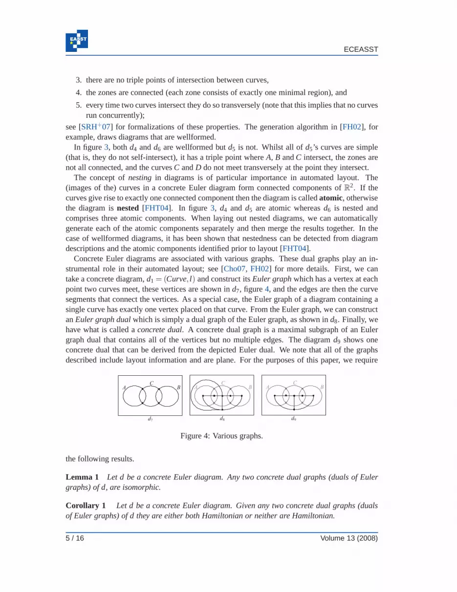
Concrete Euler diagrams are associated with various graphs. These dual graphs play an in-strumental role in their automated layout; see [Cho07, FH02] for more details. First, we cantake a concrete diagram,d1 = (Curve, l) and construct itsEuler graphwhich has a vertex at eachpoint two curves meet, these vertices are shown ind7, figure4, and the edges are then the curvesegments that connect the vertices. As a special case, the Euler graph of a diagram containing asingle curve has exactly one vertex placed on that curve. From the Euler graph, we can constructanEuler graph dualwhich is simply a dual graph of the Euler graph, as shown ind8. Finally, wehave what is called aconcrete dual. A concrete dual graph is a maximal subgraph of an Eulergraph dual that contains all of the vertices but no multiple edges. The diagramd9 shows oneconcrete dual that can be derived from the depicted Euler dual. We note that all of the graphsdescribed include layout information and are plane. For thepurposes of this paper, we require
A B
d7 d8
C
d9
A BC
A BC
Figure 4: Various graphs.
the following results.
Lemma 1 Let d be a concrete Euler diagram. Any two concrete dual graphs (duals of Eulergraphs) of d, are isomorphic.
Corollary 1 Let d be a concrete Euler diagram. Given any two concrete dualgraphs (dualsof Euler graphs) of d they are either both Hamiltonian or neither are Hamiltonian.
5 / 16 Volume 13 (2008)

Generating Euler Diagrams
In the context of layout, typical algorithms take a diagram description, convert it into an ab-stract dual graph (sometimes called the superdual) and subsequently seek subgraphs of this ab-stract dual as candidate concrete dual graphs. Once an appropriate candidate concrete dual graphis found, the curves are embedded around the vertices.
3.2 Diagram Descriptions
In order to generate an Euler diagram, we start with a description of that diagram. To illustrate,d4 in figure 3 can be described as having three curves,A, B andC, which are also contours.These contours divide the plane in such a manner that there are six zones present. Each zone canbe described as being inside certain contours and outside the remaining contours. For instance,there is one zone insideA only and another zone inside preciselyA andC. Thus, each presentzone can be described by the labels of the contours that the zone is inside. Note that there isalways a zone outside all of the contours (the infinite minimal region).
Definition 2 An abstract Euler diagram description (or, simply, abstract description),d, isa pair,(l ,Z) wherel = l(d) is a subset ofL andZ = Z(d) ⊆ Pl such that /0∈ Z(d). Elements ofZ are called (abstract)zones.
Definition 3 Given a concrete Euler diagramd = (Curve, l), we mapd to abstract descriptionab(d) = (im(l),Z), called theabstraction of d, whereZ contains exactly one abstract zone foreach concrete zone ind; in particular, given a concrete zone,z, in d, the abstract zone
ab(z) = {l(c) : c∈C(z)}
is in Z whereC(z) is the set of curves ind that containz.
The diagramd4 in figure3 has abstraction(L,Z) whereL = {A,B,C} and
Z = { /0,{A},{A,C},{C},{B,C},{B}}.
The generation problem can be summarized asgiven an abstract description, d1, find a con-crete Euler diagram, d2, such that ab(d2) = d1. Sometimes, the generation problem is restrictedby imposing certain conditions ond2, for instance requiring that the concrete diagram is well-formed.
4 Adding a Curve
There are situations when we want to add a curve to a given layout in a specified manner, such aswhen generating diagrams. In order to do this, we need to knowwhat is meant by adding a curveand how to specify its addition. In this section, we formalize the notion of adding a curve at boththe abstract and concrete levels. At the concrete level thisis easy: we simply take a diagram andadd to it a curve and a label. In figure5, we addC to d10, giving d11.
Definition 4 Let d = (Curve, l) be a concrete Euler diagram. LetL be a label inL and letc bea curve that is not inCurve. Then we definedd+(c,L) = (Curve∪{c}, l ∪ (c,L)). If L 6∈ im(l)
Proc. LED 2008 6 / 16

ECEASST
and the number of zones doubles when addingc thend+(c,L) is said to be derived fromd bysplitting each zone.
A B
d10 d11
CA B
Figure 5: A more complex example.
At the abstract level, things are not quite so straightforward. We note that each zone can beeither completely contained by the new curve, completely outside the new curve, or split by thenew curve. In figure5, the diagramd11 has a curveC that completely contains the zone insideB,is completely outside the zone insideA and splits the zone outside bothA andB. We can thinkof the split zone as being both inside and outsideC. To describe howC is added at the abstractlevel, we state which zones are to be insideC and which are to be outsideC; those which are splitare stated as being both inside and outside. Thus, the insidezones and outside zones betweenthem include all of the zones.
Definition 5 Let d = (l ,Z) be an abstract description. LetL be a label inL and letin andoutbe two subsets ofZ such thatin∪out = Z and /0∈ out. Thend+(L, in,out) is defined to be
d+(L, in,out) = (l ∪{L},Zin ∪Zout)
whereZin = {z∪{L} : z∈ in} andZout = out. If in = Z andout = Z andL 6∈ l thend+(L, in,out)is said to be derived fromd by splitting each zone.
In figure5, in = {{B}, /0} andout = {{A}, /0}; when addingC to d10 to gived11, C containsthe zone{B} (in the setin−out), splits the zone /0 (in the setin∩out) and does not contain thezone{A} (in the setout− in). The following lemma shows that the notions of splitting each zoneat the abstract and concrete level coincide.
Lemma 2 Let d= (Curve, l) be a concrete Euler diagram. Let L be a label inL and let c bea curve that is not in Curve. Then d+(c,L) is derived from d by splitting each zone if and onlyif ab(d+(c,L)) is derived from ab(d) by splitting each zone.
5 Adding Curves to Wellformed Atomic Layouts
Intuitively, when adding the curve to an atomic diagram, we are seeking a path that cuts zones tobe split in two, contains certain zones, excludes the remaining zones, and returns to its startingpoint. First, we consider the special case of splitting eachzone. To illustrate, if we wish to adda curve tod4 in figure3 that splits each zone then we can do so by finding a Hamiltoniancycle
7 / 16 Volume 13 (2008)

Generating Euler Diagrams
d12
A BC
A B
d13
C
D
Figure 6: Splitting zones and Hamiltonian cycles.
in the concrete dual (figure4, d9), as shown in figure6, d12. This Hamiltonian cycle then, rathernicely, gives us the new curve and wellformedness is maintained, as shown ind13.
Of course, there are concrete dual graphs that have different layouts, but corollary1 establishesthat this is not an issue when splitting each zone. The following theorem, importantly, providesa constructive method for embedding the new curve, namely find a Hamiltonian cycle in anarbitrary concrete dual graph and use that cycle as the imageof the new curve.
Theorem 1 Let d= (Curve, l) be an atomic wellformed concrete Euler diagram containing atleast two curves. Let L be a label inL − im(l). There exists a curve, c, that is not in Curve suchthat d+(c,L) is wellformed and derived from d by splitting each zone if andonly if a concretedual graph of d is Hamiltonian.
d14
A BC
Figure 7: An extended Euler dual.
There are topologically different ways of adding a curve that splits each zone1. In fact, givenall concrete dual graphs (reduced by equivalence up to an isotopy of a subset ofR2; we omitthe details) we can exactly classify the number of topologically different ways of adding such acurve. To do this, we define a new type of dual graph for atomic diagrams that generalizes boththe concrete dual graph and the Euler graph dual: theextended Euler dual. Its constructionis the same as the Euler graph dual, except that it has additional edges as follows. Given anedge in the Euler graph dual that connects a vertex,v1, to the vertex,v2, in the infinite face, wehad a choice about the direction that edge wraps around the curves. For each such edge, weadd a new edge incident withv1 andv2 that wraps the opposite way around the curves. Notethat the extended Euler dual is not necessarily planar; in fact, it is only planar when exactlyone zone is topologically adjacent to the infinite face. We add the new edges in such a manner
1 Givend and curvesc1 andc2 added tod, d +(c1,L) is topologically different tod+(c2,L) if c1 andc2 are notisotopic inR
2−V(G) whereV(G) is the set of (images of the) vertices in the Euler graph.
Proc. LED 2008 8 / 16

ECEASST
that a minimal number of edge crossings are introduced. The minimal number of crossings is1+2+ ...+(deg(v2)
2 −1). The construction is illustrated in figure7, whered14 shows the extendedEuler dual ofd4 in figure4.
These extra edges are required in order to make the graph reflect all possible ways (up to somenotion of equivalence) of adding a new curve and maintainingwellformedness. We note that weonly add extra edges incident withv2 since the infinite face is the only zone that is not simplyconnected in an atomic wellformed diagram. In simply connected faces, there is essentially nochoice about the ‘direction’ of the edges.
Theorem 2 The set of all plane Hamiltonian cycles in the extended Eulerdual of an atomicwellformed concrete Euler diagram, d, gives all the topologically different ways of introducinga curve that splits each zone in d and maintains wellformedness.
The method of adding a curve that splits each zone generalizes. When we want to add acurve that splits a specified set of zones, we instead seek a plane, simple cycle2 in the extendedEuler dual that passes through exactly the vertices corresponding to the zones that are to be split.Suppose that we wish to add a curve tod4 in figure3 such that the zone inside exactlyC is splitas is the zone outside all curves. Then there are several waysof doing this, resulting in diagramswith different abstract descriptions. The method is to find asimple cycle in the extended Eulerdual that contains precisely the vertices inside these two zones. One such cycle is shown ind15,figure 8, which results in the curveD being added as shown ind16. Another cycle givesd17,which has an abstraction different from that ofd16. Typically, we want to specify which zonesare to be contained by the new curve as well as those which are to be split. A method for addingan appropriate curve is captured by the following theorem.
d17
D
A BC
d16
D
A BC
d15
A BC
Figure 8: Splitting specified zones.
Theorem 3 Let d= (Curve, l) be an atomic wellformed concrete Euler diagram. Let L be alabel in L − im(l). Given ab(d) = (l ,Z), let in ⊆ Z and out⊆ Z be such that in∪ out = Zand /0 ∈ out. Then there exists a curve, c, that is not in Curve such that d + (c,L) is atomic,wellformed and has abstraction ab(d)+ (L, in,out) if and only if either
1. there exists a plane, simple cycle, C, in the extended Euler dual, G, such that
2 A simple cycle is a cycle, containing at least one vertex, that does not pass through any vertex more than once. Aplane cycle is a cycle in which no pair of edges cross.
9 / 16 Volume 13 (2008)

Generating Euler Diagrams
(a) the vertices in G that correspond to zones that are elements of the set in∩ out areexactly those in C,
(b) the vertices in G that correspond to zones that are elements of the set in− out arelocated inside C, and
(c) the vertices in G that correspond to zones that are elements of the set out− in arelocated outside C,
or
2. |in| = |in∩out| = 2 and the two concrete zones corresponding to the abstract zones thatare elements of the set in∩out are topologically adjacent.
Again, it is the plane, simple cycle that provides the image of the curve to be added exceptin case 2, where we do not seek a such a cycle. Instead, we are effectively seeking a path oflength 1 (indicating the adjacency of the two zones) and can simply add a curve that is a circle,for example, in the appropriate manner.
6 Adding a Curve to Wellformed Nested Layouts
The previous section characterizes exactly when a curve canbe added to an atomic wellformeddiagram and maintain wellformedness. Moreover, the characterization provides a constructivemethod to add a curve to give a new diagram with some specified abstract syntax. Here wedemonstrate how to extend the approach to the nested case by example only, due to space limita-tions. In figure9, we may want to add a new curve tod18 that splits the zone outside all curves,that inside justB and that inside justD, and all remaining zones are outside the curve. To dothis, we decompose the diagram into its atomic components, add the new curve,E, to each partin the required manner and then recompose the diagram, joining up the curves labelledE in eachof the atomic parts to create a single curve labelledE, shown ind19. The curveE is called adisconnecting curvefor d19, the theory of which is developed in [FF08].
A B
d18
C
D
A B
D
C
E
E
A B
C
D A B
d19
C
D
E
E E
Figure 9: Adding curves to wellformed nested diagrams.
In summary, the approach is to add the required curve to each atomic component and then jointhe pieces of the new curve together, to create one curve. Theresults of the previous section tell
Proc. LED 2008 10 / 16

ECEASST
us when the curve can be added to the atomic pieces. The only further requirement is that thesenew curves can be joined together to create an appropriate curve in the original nested diagram.We note that being able to add a curve to each atomic part does not imply that it is possible toadd that curve to the entire diagram. For example, suppose wehad wanted to add a curve tod18 so that instead of splitting the zone inside justD we split the zone inside bothC andD. Itwould not then be possible to join the curves labelledE in the atomic components together toform an appropriate curve ind18 whilst maintaining wellformedness. The following theoremcharacterizes the case when we wish to split each zone.
Theorem 4 Let d be a wellformed concrete Euler diagram containing exactly n atomic com-ponents, say d1, ... , dn. Let L be a label inL − im(l). Then there exists a curve, c, such thatd+(c,L) is wellformed and derived from d by splitting each zone if andonly if each di has a aHamiltonian concrete dual or contains exactly one curve.
In the more general wellformed case (where we do not necessarily wish to split every zone),we must be able to add a curve,c, to each atomic component in the required manner (as illustratedabove). We need to know when the curves added to the atomic components can be joined up toform c. Suppose thatc is to be added to a diagram,d, consisting of two atomic componentsd1 and d2, with d2 nested in a zonez1 of d1. Then the curvesc1 and c2 added tod1 and d2
respectively can be joined whenever they both pass through the zonez1: in other words, ind1
the curvec1 splitsz1 and ind2 the zone outside all of the curves is split byc2. This observationgeneralizes to the case when there are more atomic components.
7 Adding Curves In General
We aim to be able to generate an embedding of any abstract description, which is not possiblewhen imposing the wellformedness conditions. Thus, we no longer insist that the wellformed-ness conditions are met and allow ourselves to add a curve to arbitrary Euler diagrams. Thereare many ways of adding curves in the general case and it can beshown that methods exist thatallow the inductive construction of a concrete diagram (i.e. by successively adding contours) forany abstract description. Here we informally outline one such method, but better layouts can beachieved by using more sophisticated techniques; for spacereasons we do not provide details.Since we are allowed multiple label use, the method may add many curves (which constitute asingle contour) in order to achieve the correct zone set after addition.
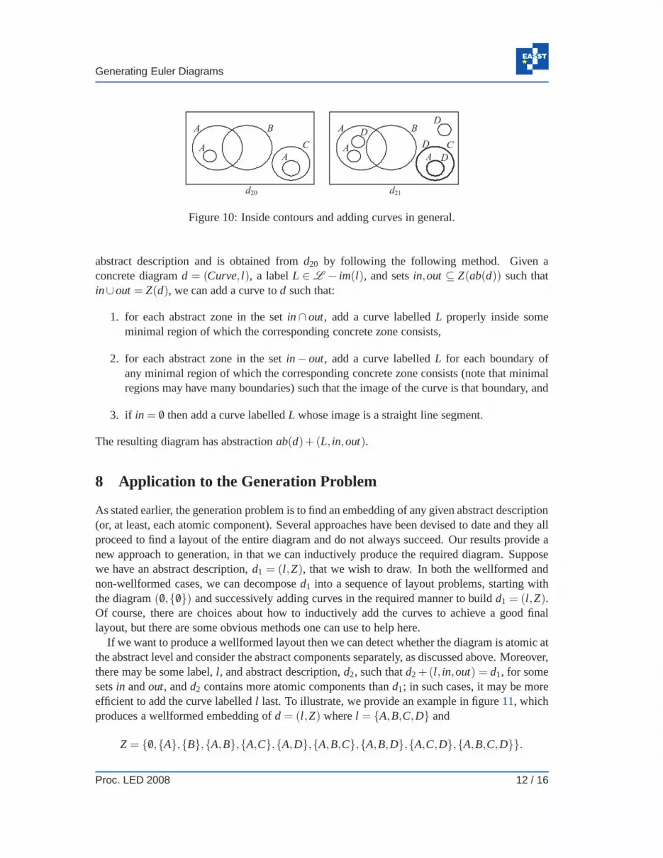
One point to note is how the interior of a contour is defined when multiple curves have thesame label; such a definition is given in [SRH+07] and extends work in [VV04]. To illustrate,in figure 10, d20 contains three curves labelledA, which we will refer to as the contourA. Apoint is interior to the contourA if the number of curves labelledA to which it is interior is odd,otherwise it is exterior to the contourA. Thus, the zones in the diagram are
Z(d20) = { /0,{A},{A,B},{B},{C},{A,C}}
and the zone /0 is disconnected.Suppose, to the abstract descriptionab(d20), we wish to add a contour labelledD, given
in = { /0,{A},{C}} and out = { /0,{A},{A,B},{B},{A,C}. The diagramd21 has the required
11 / 16 Volume 13 (2008)
Generating Euler Diagrams
d20
A B
C
AA
d21
A B
C
AA
D
D
D
D
Figure 10: Inside contours and adding curves in general.
abstract description and is obtained fromd20 by following the following method. Given aconcrete diagramd = (Curve, l), a labelL ∈ L − im(l), and setsin,out ⊆ Z(ab(d)) such thatin∪out = Z(d), we can add a curve tod such that:
1. for each abstract zone in the setin∩ out, add a curve labelledL properly inside someminimal region of which the corresponding concrete zone consists,
2. for each abstract zone in the setin− out, add a curve labelledL for each boundary ofany minimal region of which the corresponding concrete zoneconsists (note that minimalregions may have many boundaries) such that the image of the curve is that boundary, and
3. if in = /0 then add a curve labelledL whose image is a straight line segment.
The resulting diagram has abstractionab(d)+ (L, in,out).
8 Application to the Generation Problem
As stated earlier, the generation problem is to find an embedding of any given abstract description(or, at least, each atomic component). Several approaches have been devised to date and they allproceed to find a layout of the entire diagram and do not alwayssucceed. Our results provide anew approach to generation, in that we can inductively produce the required diagram. Supposewe have an abstract description,d1 = (l ,Z), that we wish to draw. In both the wellformed andnon-wellformed cases, we can decomposed1 into a sequence of layout problems, starting withthe diagram( /0,{ /0}) and successively adding curves in the required manner to build d1 = (l ,Z).Of course, there are choices about how to inductively add thecurves to achieve a good finallayout, but there are some obvious methods one can use to helphere.
If we want to produce a wellformed layout then we can detect whether the diagram is atomic atthe abstract level and consider the abstract components separately, as discussed above. Moreover,there may be some label,l , and abstract description,d2, such thatd2 +(l , in,out) = d1, for somesetsin andout, andd2 contains more atomic components thand1; in such cases, it may be moreefficient to add the curve labelledl last. To illustrate, we provide an example in figure11, whichproduces a wellformed embedding ofd = (l ,Z) wherel = {A,B,C,D} and
Z = { /0,{A},{B},{A,B},{A,C},{A,D},{A,B,C},{A,B,D},{A,C,D},{A,B,C,D}}.
Proc. LED 2008 12 / 16

ECEASST
C
d4
BA
D
C
d5
BA
d1
A
d2
B
d3
A
Figure 11: Application to the general generation problem.
There are limits to the inductive construction method. First, we know of wellformed concretediagrams that cannot be produced using the inductive approach. One such diagram can be seenin figure12; the removal of any curve results in a diagram that is not wellformed. In this case,a wellformed diagram with the same abstract description canbe generated using the inductivemethod even though this particular layout cannot be achieved. It remains the subject of futurework to establish whether any abstract description that hasa wellformed embedding can be drawnusing our inductive approach that utilizes the extended Euler dual. However, the general methodfor adding a contour, outlined in section7, can be shown to yield an embedding of any abstractdescription using such an inductive construction.
AB
CD
E
Figure 12: A wellformed Venn-5 embedding.
9 Implementation
To prototype the generation mechanism, we have started implementing the method as a Java pro-gram. This draws closed curves with polygons, detects the extended Euler dual using geometricalgorithms and routes the edges around this dual as shown in figure13, where the polygons areregular and form Venn-3. Note that the routing mechanism used for constructing the extendedEuler dual means that some edges are very close together and can be mistaken as tangential.
In figure 13, we show the result of finding a Hamiltonian cycle in the extended Euler dual,and using that cycle to add a new polygon, labelled ‘d’ to the diagram, resulting in Venn-4.In this case we chose the new curve so that it intersects with every zone, but we could have
13 / 16 Volume 13 (2008)

Generating Euler Diagrams
Figure 13: Using the extended Euler dual graph to add a curve.
used any simple cycle in the extended Euler dual to add a curveand maintained wellformedness(of course, the chosen cycle impacts the abstract description). We can enumerate every simplecycle by finding sets of faces in the extended Euler dual that are connected; the cycle formed bytraveling around such a set of faces then gives rise to a new curve. Layout improvements, suchas those applied in [FRM03], are required in order to improve the appearance of the diagram;this is currently being implemented.
Our intention is to use this generation mechanism to enumerate through possible diagrams,looking for those that can be drawn ‘nicely’, for instance where a regular polygon can be addedto a diagram already consisting of regular polygons. The process of generating the extendedEuler dual and discovering a single simple cycle within it isreasonable efficient and works inreal time. However, the time complexity of enumerating every cycle is exponential relative tothe number of edges and so will be infeasible as the size of thediagrams increases beyond thesmall diagrams shown in this paper; heuristics will need to be developed for this task.
10 Conclusion
In this paper we have presented several methods for generating Euler diagrams by modifyingexisting layouts. The technique we have presented to add a curve in the wellformed case guar-antees to preserve wellformedness. Moreover this novel technique of using inductive generationmethods can be used to produce embeddings of a class of abstract description. Indeed, our gen-eral method of adding a curve in the non-wellformed case can be used to generate an embeddingof any abstract description.
We plan to use these inductive embedding methods (concentrating initially on wellformeddiagrams) to populate a library of drawn examples from whichwe can subsequently create furtherembeddings by adding further curves. We anticipate that such a library will contain a concretediagram for each abstract description with up to three labels, and many with four labels (thereare 216 abstract descriptions with four labels). We will then be able to take abstract descriptionsand select sub-diagrams from the library and add curves to them to produce the required concretediagram.
Proc. LED 2008 14 / 16

ECEASST
Further work also includes extending the generation algorithms to allow subsets of the well-formedness conditions to be imposed. We anticipate using a hybrid of the Euler graph and theextended Euler dual to allow, for example, concurrency or triple points to be present in the cre-ated layouts. This will enable a wider variety of layouts to be produced and will allow us to takeuser preference more fully into account, for example.
Acknowledgements: This work is supported by the UK EPSRC grants EP/E011160/1 andEP/E010393/1 for the Visualization with Euler Diagrams project. Thanks also to John Taylor forhelpful discussions on aspects of this research.
Bibliography
[Cho07] S. Chow.Generating and Drawing Area-Proportional Euler and Venn Diagrams.PhD thesis, University of Victoria, 2007.
[Cla05] R. Clark. Failure Mode Modular De-Composition Using Spider Diagrams.Proc.Euler Diagrams 2004Elsevier, ENTCS vol. 134, pages 19–31, 2005.
[CR03] S. Chow, F. Ruskey. Drawing Area-Proportional Venn and Euler Diagrams.Proc.Graph Drawing 2003, Perugia, Italy, Springer, 466–477, September 2003.
[CR05b] S. Chow, F. Ruskey. Towards a General Solution to Drawing Area-Proportional Eu-ler Diagrams.Proc. Euler Diagrams, Elsevier, ENTCS vol 134, pages 3–18, 2005.
[DES03] R. DeChiara, U. Erra, V. Scarano. A System for Virtual Directories Using EulerDiagrams. Proc. Information Visualisation, IEEE ComputerSociety, pages 120-126, 2003.
[FH02] J. Flower, J. Howse. Generating Euler Diagrams.Proceedings of 2nd InternationalConference on the Theory and Application of Diagrams, Springer, pages 61–75,April 2002.
[FHT04] J. Flower, J. Howse, J. Taylor. Nesting in Euler diagrams: syntax, semantics andconstruction.Software and Systems Modelling3:55–67, March 2004.
[FRM03] J. Flower, P. Rodgers, P. Mutton. Layout metrics forEuler Diagrams.7th Inter-national Conference on Information VisualisationIEEE Computer Society Press,pages 272-280, 2003.
[FF08] A. Fish, J. Flower. Euler Diagram Decomposition.accepted for Diagrams 2008,Springer, 2008.
[HES+05] P. Hayes, T. Eskridge, R. Saavedra, T. Reichherzer, M. Mehrotra, D. Bobrovnikoff.Collaborative Knowledge Capture in Ontologies.Proc. 3rd International Confer-ence on Knowledge Capture, pp. 99–106, 2005.
15 / 16 Volume 13 (2008)

Generating Euler Diagrams
[HS05] J. Howse, S. Schuman. Precise Visual Modelling.Journal of Software and SystemsModeling4:310–325, 2005.
[KC99] S.-K. Kim, D. Carrington. Visualization of Formal Specifications.6th Asia PacificSoftware Engineering Conference, IEEE Computer Society Press, pages 102–109,1999.
[KMG+05] H. Kestler, A. Muller, T. Gress, M. Buchholz. Generalized Venn Diagrams: A NewMethod for Visualizing Complex Genetic Set Relations.Journal of Bioinformatics21(8):1592–1595, 2005.
[Lov02] J. Lovdahl.Towards a Visual Editing Environment for the Languages of the Seman-tic Web. PhD thesis, Linkoping University, 2002.
[MEL+95] K. Misue, P. Eades, W. Lai, K. Sugiyama. Layout Adjustment and the Mental Map,Journal of Visual Languages and Computing, 2(6):183-210, 1995.
[Nie2006] L. Niebroj. Defining Health/Illness: Societal and/or Clinical Medicine?Journal ofPhysiology and Pharmacology, 57(4):251-262, 2006.
[RZF08] P. Rodgers, L. Zhang, A. Fish. General Euler DiagramGeneration, accepted forDiagrams 2008, Springer, 2008.
[SK00] H. Sawamura, K. Kiyozuka. JVenn: A Visual Reasoning System with Diagramsand Sentences.Proc. 1st International Conference on the Theory and Applicationof DiagramsSpringer, pages 271–285, 2000.
[Shi94] S.-J. Shin.The Logical Status of Diagrams. Cambridge University Press, 1994.
[SFR07] G. Stapleton, A. Fish and P. Rodgers. Abstract EulerDiagram Isomorphism.ac-cepted for Visual Languages and Computing, Knowledge Systems Institute, 2008.
[SMF+07] G. Stapleton, J. Masthoff, J. Flower, A. Fish, J. Southern. Automated TheoremProving in Euler Diagrams Systems.Journal of Automated Reasoning, June 2007.
[SRH+07] G. Stapleton, P. Rodgers, J. Howse and J. Taylor. Properties of Euler Diagrams.Proc. of Layout of Software Engineering Diagrams, EASST, pages 2–16, 2007.
[SA04] N. Swoboda, G. Allwein. Using DAG Transformations toVerify Euler/Venn Ho-mogeneous and Euler/Venn FOL Heterogeneous Rules of Inference. Journal onSoftware and System Modeling3(2):136–149, 2004.
[TVV05] J. Thievre, M. Viaud, A. Verroust-Blondet. Using Euler Diagrams in TraditionalLibrary Environments.Euler Diagrams 2004Elsevier, ENTCS vol 134, pages 189–202, 2005.
[VV04] A. Verroust, M.-L. Viaud. Ensuring the Drawability of Euler Diagrams for up toEight Sets.Proc. 3rd International Conference on the Theory and Application ofDiagramsSpringer, pages 128–141, 2004.
Proc. LED 2008 16 / 16