Embed Size (px)
Citation preview
Generator Protection
Siemens LSA 2.5.5 . April 1995 1
Application
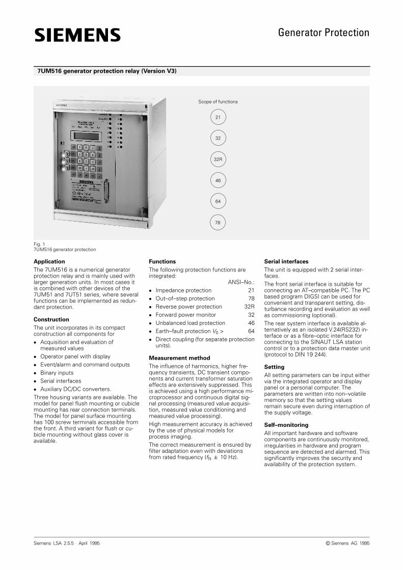
The 7UM516 is a numerical generatorprotection relay and is mainly used withlarger generation units. In most cases itis combined with other devices of the7UM51 and 7UT51 series, where severalfunctions can be implemented as redun-dant protection.
Construction
The unit incorporates in its compactconstruction all components for Acquisition and evaluation of
measured values Operator panel with display Event/alarm and command outputs Binary inputs Serial interfaces Auxiliary DC/DC converters.Three housing variants are available. Themodel for panel flush mounting or cubiclemounting has rear connection terminals.The model for panel surface mountinghas 100 screw terminals accessible fromthe front. A third variant for flush or cu-bicle mounting without glass cover isavailable.
Functions
The following protection functions areintegrated:
ANSI–No.: Impedance protection 21 Out–of–step protection 78 Reverse power protection 32R Forward power monitor 32 Unbalanced load protection 46 Earth–fault protection V0 > 64 Direct coupling (for separate protection
units).
Measurement method
The influence of harmonics, higher fre-quency transients, DC transient compo-nents and current transformer saturationeffects are extensively suppressed. Thisis achieved using a high performance mi-croprocessor and continuous digital sig-nal processing (measured value acquisi-tion, measured value conditioning andmeasured value processing).High measurement accuracy is achievedby the use of physical models forprocess imaging.The correct measurement is ensured byfilter adaptation even with deviationsfrom rated frequency (fN 10 Hz).
Serial interfaces
The unit is equipped with 2 serial inter-faces.The front serial interface is suitable forconnecting an AT–compatible PC. The PCbased program DIGSI can be used forconvenient and transparent setting, dis-turbance recording and evaluation as wellas commissioning (optional).The rear system interface is available al-ternatively as an isolated V.24(RS232) in-terface or as a fibre–optic interface forconnecting to the SINAUT LSA stationcontrol or to a protection data master unit(protocol to DIN 19 244).
Setting
All setting parameters can be input eithervia the integrated operator and displaypanel or a personal computer. Theparameters are written into non–volatilememory so that the setting valuesremain secure even during interruption ofthe supply voltage.
Self–monitoring
All important hardware and softwarecomponents are continuously monitored,irregularities in hardware and programsequence are detected and alarmed. Thissignificantly improves the security andavailability of the protection system.
7UM516 generator protection relay (Version V3)
Fig. 17UM516 generator protection
21
32
32R
46
64
Scope of functions
78
Siemens AG 1995
Generator Protection
Siemens LSA 2.5.5 . April 19952
Impedance protection
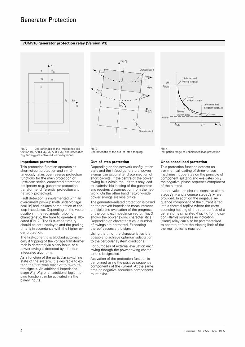
This protection function operates asshort–circuit protection and simul-taneously takes over reserve protectionfunctions for the main protection orupstream series–connected protectionequipment (e.g. generator protection,transformer differential protection andnetwork protection).Fault detection is implemented with anovercurrent pick–up (with undervoltageseal–in) and initiates computation of theloop impedance. Depending on the vectorposition in the rectangular trippingcharacteristic, the time to operate is allo-cated (Fig. 2). The first–zone time t1should be set undelayed and the gradingtime t2 in accordance with the higher or-der protection.The first–zone trip is blocked automati-cally if tripping of the voltage transformermcb is detected via binary input, or apower swing is detected by a furtherintegrated algorithm.As a function of the particular switchingstate of the system, it is desirable to ex-tend the first zone reach or to re–routetrip signals. An additional impedancestage R1B, X1B or an additional logic trip-ping function can be activated via thebinary inputs.
Out–of–step protection
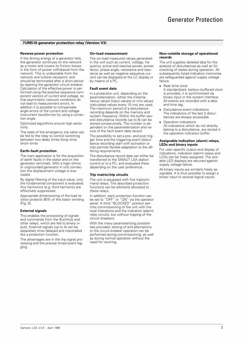
Depending on the network configurationstate and the infeed generators, powerswings can occur after disconnection ofshort circuits. If the centre of the powerswing falls within the unit this may leadto inadmissible loading of the generatorand requires disconnection from the net-work. On the other hand network–sidepower swings are less critical.The generator–related protection is basedon the proven impedance measurementprinciple and evaluation of the progressof the complex impedance vector. Fig. 3shows the power swing characteristics.Depending on characteristics, a numberof swings are permitted. Exceedingthereof causes a trip signal.Using the tilt of the characteristics it ispossible to achieve optimum adaptationto the particular system conditions.For purposes of external evaluation eachswing through the power swing charac-teristic is signalled.Activation of the protection function isperformed using the positive sequencecomponents of the current. At the sametime no negative sequence componentsmust exist.
Unbalanced load protection
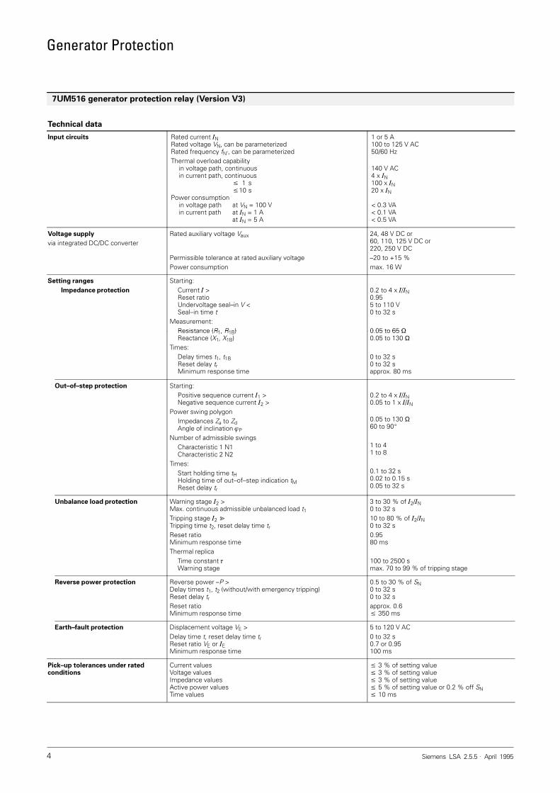
This protection function detects un-symmetrical loading of three–phasemachines. It operates on the principle ofcomponent splitting and evaluates onlythe negative–phase sequence componentof the current.In the evaluation circuit a sensitive alarmstage 2 > and a course stage 2 areprovided. In addition the negative se-quence component of the current is fedinto a thermal replica where the corre-sponding heating of the rotor surface of agenerator is simulated (Fig. 4). For indica-tion (alarm) purposes an indication(alarm) relay can also be parameterizedto operate before the tripping limit of thethermal replica is reached.
7UM516 generator protection relay (Version V3)
Fig. 2 Characteristic of the impedance pro-tection (R1 0,4 XTr, X1 0,7 XTr; characteristicsX1B and R1B are activated via binary input)
X
R
X1B
R1B
t2
t1
t1b
R1
X1
Fig. 3Characteristic of the out–of–step tripping
P
Z TRIP
Z Make
Z TRIP
Characteristic 2
Im Z
Re Z
Z pos
Characteristic 1
Z Make
Fig. 4Instigation range of unbalanced load protection
Unbalanced loadWarning stage 2>
Thermalinstigation stage
Thermalwarning stage
tTWARN
T>>TRIP
2adm. 2>> 2
Unbalanced loadInstigation stage 2>>
Generator Protection
Siemens LSA 2.5.5 . April 1995 3
Reverse power protection
If the driving energy of a generator fails,the generator continues on the networkas a motor and covers its friction lossesin the form of power withdrawal from thenetwork. This is undesirable from thenetwork and turbine viewpoint, andshould be terminated after a short periodby opening the generator circuit–breaker.Calculation of the effective power is per-formed using the positive sequence com-ponent vectors of current and voltage, sothat asymmetric network conditions donot lead to measurement errors. Inaddition it is possible to compensateangle errors of the current and voltageinstrument transformer by using a correc-tion angle.Optimized algorithms ensure high sensi-tivity.The state of the emergency trip valve canbe fed to the relay to control switchingbetween two delay times (long–timeshort–time).
Earth–fault protection
The main application is for the acquisitionof earth faults in the stator and on thegenerator terminals. With a high–ohmicor ungrounded generator in unit connec-tion the displacement voltage is eva-luated.By digital filtering of the input value, onlythe fundamental component is evaluated.Any harmonics (e.g. third harmonic) areeffectively suppressed.Appropriate dimensioning of the load re-sistor protects 90% of the stator winding(Fig. 5).
External signals
This enables the processing of signalsand commands from the Buchholz andother relays, which are fed to binary in-puts. External signals (up to 4) can beseparately time–delayed and marshalledlike a protection function.The advantages are in the trip signal pro-cessing and the precise timed event log-ging.
On–load measurement
The on–load measured values generatedin the unit such as current, voltage, fre-quency, active and reactive power, powerfactor, phase angle, resistance and reac-tance as well as negative sequence cur-rent can be displayed at the LC display orby means of a PC.
Fault event data
In a protection unit, depending on theparameterization, either the instanta-neous values (input values) or rms values(calculated values every 10 ms) are used.The maximum period of a disturbancerecording depends on the memory andsystem frequency. Within the buffer sev-eral disturbance records (up to 8) can bestored consecutively. The number is de-pendent on the parameterization and na-ture of the fault event data record.The possibility to set a pre– and post trig-ger time and the triggering event (distur-bance recording start with activation ortrip) permits flexible adaptation to the dif-fering requirements.The disturbance record data can either betransferred to the SINAUT LSA stationcontrol or to a PC, and evaluated theredepending on the user preference.
Trip matrix/trip circuits
The unit is equipped with five trip/com-mand relays. The described protectionfunctions can be arbitrarily allocated tothese relays.In addition, each protection function canbe set to ”OFF” or ”ON” via the operatorpanel. A third ”BLOCKED” position per-mits commissioning of the unit with thelocal indications and the indication (alarm)relay circuits, but without tripping of thecircuit–breakers.With the many parameterizing possibili-ties provided, testing of and alternationsto the circuit–breaker operation can beperformed during commissioning, as wellas during normal operation without theneed for rewiring.
Non–volatile storage of operationalrecords
The unit supplies detailed data for theanalysis of disturbances as well as forchecking of states during operation. Allsubsequently listed indication memoriesare safeguarded against supply voltagefailure. Real–time clock
A standardized, battery–buffered clockis provided, it is synchronized viabinary input or the system interface.All events are recorded with a dateand time tag.
Disturbance event indicationsThe indications of the last 3 distur-bances are always accessible.
Operation indicationsAll indications which do not directlybelong to a disturbance, are stored inthe operation indication buffer.
Assignable indication (alarm) relays,LEDs and binary inputs
For user–specific output and display ofindications, indication (alarm) relays andLEDs can be freely assigned. The stor-able LED displays are secured againstsupply voltage failure.All binary inputs are similarly freely as-signable. It is thus possible to assign abinary input to several logical inputs.
7UM516 generator protection relay (Version V3)
Generator Protection
Siemens LSA 2.5.5 . April 19954
Technical data
Input circuits Rated current NRated voltage VN, can be parameterizedRated frequency fN’, can be parameterizedThermal overload capability
in voltage path, continuousin current path, continuous
1 s10 s
Power consumptionin voltage path at VN = 100 Vin current path at N = 1 A
at N = 5 A
1 or 5 A100 to 125 V AC50/60 Hz
140 V AC4 x N100 x N20 x N
< 0.3 VA< 0.1 VA< 0.5 VA
Voltage supply
via integrated DC/DC converterRated auxiliary voltage Vaux
Permissible tolerance at rated auxiliary voltagePower consumption
24, 48 V DC or60, 110, 125 V DC or220, 250 V DC–20 to +15 %max. 16 W
Setting ranges
Impedance protection
Starting:Current >Reset ratioUndervoltage seal–in V <Seal–in time t
Measurement:Resistance (R1 R1B)
0.2 to 4 x /N0.955 to 110 V0 to 32 s
0.05 to 65 ΩResistance (R1, R1B)Reactance (X1, X1B)
Times:Delay times t1, t1BReset delay trMinimum response time
0.05 to 65 Ω0.05 to 130 Ω
0 to 32 s0 to 32 sapprox. 80 ms
Out–of–step protection Starting:Positive sequence current 1 >Negative sequence current 2 >
Power swing polygonImpedances Za to ZdAngle of inclination P
Number of admissible swingsCharacteristic 1 N1Characteristic 2 N2
Times:Start holding time tHHolding time of out–of–step indication tMReset delay tr
0.2 to 4 x /N0.05 to 1 x /N
0.05 to 130 Ω60 to 90
1 to 41 to 8
0.1 to 32 s0.02 to 0.15 s0.05 to 32 s
Unbalance load protection Warning stage 2 >Max. continuous admissible unbalanced load t1Tripping stage 2 Tripping time t2, reset delay time trReset ratioMinimum response timeThermal replica
Time constant Warning stage
3 to 30 % of 2/N0 to 32 s10 to 80 % of 2/N0 to 32 s0.9580 ms
100 to 2500 smax. 70 to 99 % of tripping stage
Reverse power protection Reverse power –P >Delay times t1, t2 (without/with emergency tripping)Reset delay trReset ratioMinimum response time
0.5 to 30 % of SN0 to 32 s0 to 32 sapprox. 0.6 350 ms
Earth–fault protection Displacement voltage VE >Delay time t, reset delay time trReset ratio VE or EMinimum response time
5 to 120 V AC0 to 32 s0.7 or 0.95100 ms
Pick–up tolerances under ratedconditions
Current valuesVoltage valuesImpedance valuesActive power valuesTime values
3 % of setting value 3 % of setting value 3 % of setting value 5 % of setting value or 0.2 % off SN 10 ms
7UM516 generator protection relay (Version V3)
Generator Protection
Siemens LSA 2.5.5 . April 1995 5
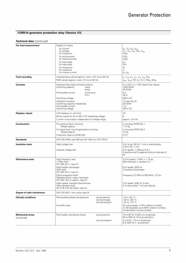
Technical data (continued)
On–load measurement Display of valuesfor currentfor voltagefor frequencyfor active powerfor reactive powerfor load anglefor load anglefor resistancefor reactancefor inverse current
L1, L2, L3, posVL1, VL2, VL3, 3V0, VposFreq.P/SNQ/SN
p.f.PHIRX2, 2th.
Fault recording Instantaneous values (approx. every 1.67 ms at 50 Hz)RMS values (approx. every 10 ms at 50 Hz)
L1, L2, L3, vL1, vL2, vL3, 3v0pos, Vpos, PHI, 2, R, X, P/SN, Q/SN
Contacts Potential–free trip/command contactsSwitching capacity make
breakPermissible current continuous
0.5 sSwitching voltageIndication contactsSwitching capacity make/breakPermissible currentSwitching voltage
3 x 2 NO, 2 x 1 NO (total 5 trip relays)1000 W/VA30 W/VA5 A30 A250 A DC13 (see Fig. 5)20 W/VA1 A250 V DC
Displays, inputs LED displays on unit frontBinary inputs for 24 to 250 V DC operating voltageCurrent consumption independent of voltage range
168approx. 2.5 mA
Construction For panel surface mountingWeight approx.
For panel flush mounting/cubicle mountingWeight approx.
Protection class to EN 60 529
in housing 7XP20 40–111.5 kgin housing 7XP20 40–210 kgIP 51
Standards DIN VDE 0435, part 303 and IEC 255–5 or IEC 255–6
Insulation tests High voltage test
Impulse voltage test
2 kV (rms), 50 Hz; 1 min or alternatively2.8 kV DC; 1 min5 kV (peak); 1.2/50 s; 0.5 J;3 positive and 3 negative shots at intervals of5s
Disturbance tests High frequency test(1 MHz test)IEC 255–22–1, class IIIElectrostatic discharges(ESD test)IEC 255–22–2, class IIIElectromagnetic fields(Radiated electr. magn. field test)IEC 255–222–3 (report), class IIIHigh–speed, transient disturbances(Fast transient test)IEC 41B (CO) 53 (draft), class III
2.5 kV (peak); 1 MHz; = 15 s;400 shots per s; duration 2 s
8 kV (peak); 5/30 ns;10 positive discharges
Frequency 27 MHz to 500 MHz; 10 V/m
2 kV (peak); 5/50 ns; 5 kHz;4 mJ per pulse; 1 min per polarity
Degree of radio interference DIN VDE 0871, limit value class B
Climatic conditions Permissible ambient temperature during serviceduring storageduring transport
Humidity class
–5 to +55 C–25 to +55 C–25 to +70 CAnnual average 75% relative humidity;on 30 days/year up to 95% relative humidity;condensation not permissible
Mechanical stress
DIN 40 046Permissible mechanical stress during service
during transport
10 to 60 Hz: 0.035 mm amplitude60 to 500 Hz: 0.5 g acceleration5 to 8 Hz: 7.5 mm amplitude8 to 500 Hz: 2 acceleration
7UM516 generator protection relay (Version V3)
Generator Protection
Siemens LSA 2.5.5 . April 19956
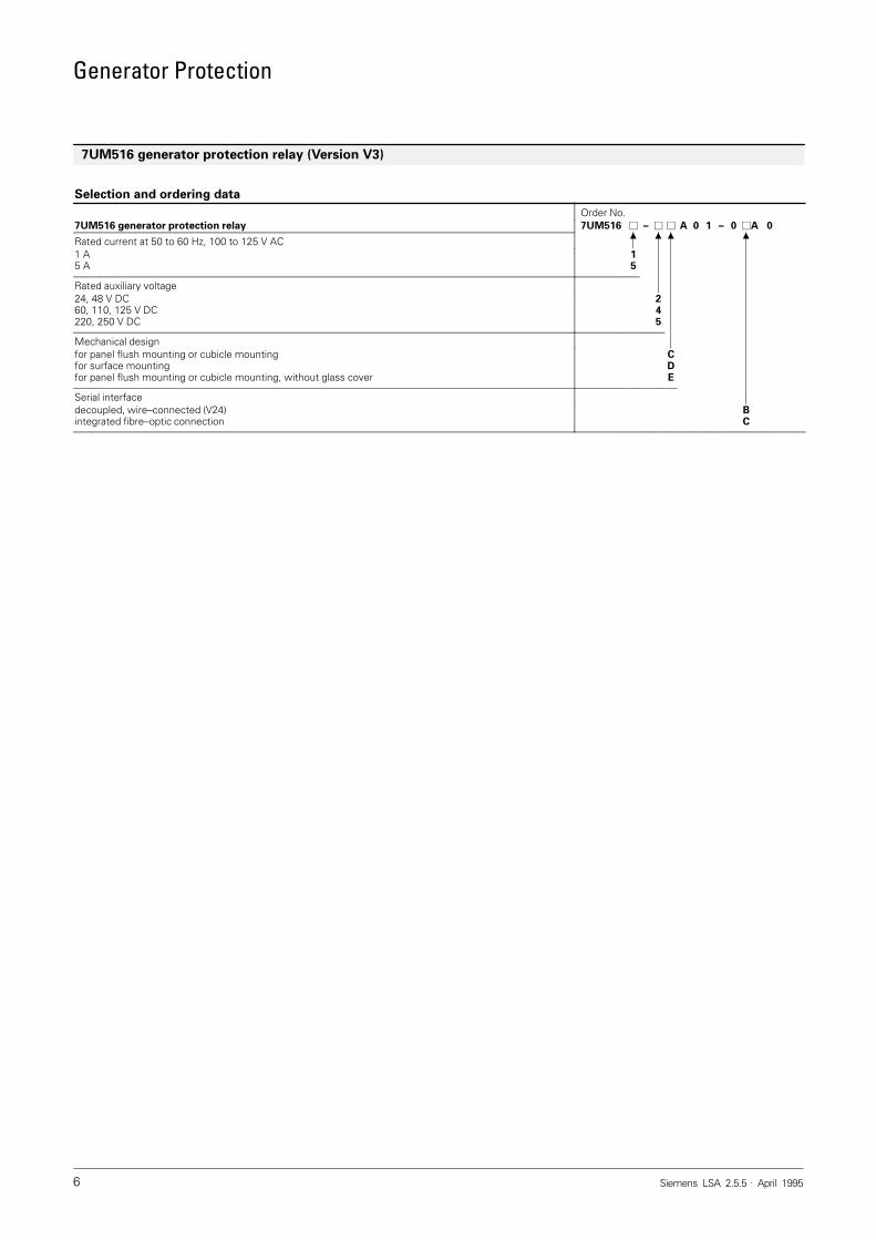
Selection and ordering data
Order No.7UM516 generator protection relay 7UM516 – A 0 1 – 0 A 0
Rated current at 50 to 60 Hz, 100 to 125 V AC1 A5 A
15
Rated auxiliary voltage24, 48 V DC60, 110, 125 V DC220, 250 V DC
245
Mechanical designfor panel flush mounting or cubicle mountingfor surface mountingfor panel flush mounting or cubicle mounting, without glass cover
CDE
Serial interfacedecoupled, wire–connected (V24)integrated fibre–optic connection
BC
7UM516 generator protection relay (Version V3)
Generator Protection
Siemens LSA 2.5.5 . April 1995 7
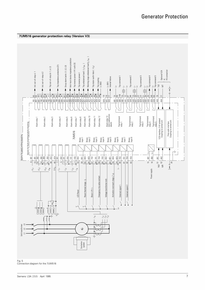
7UM516 generator protection relay (Version V3)
Fig. 5Connection diagram for the 7UM516
or
Ind.
out
–of–
step
cl.
1
Trip
out
–of–
step
(cl.
1, c
l. 2)
Trip
impe
danc
e pr
otec
tion
(Z1)
Grou
p al
arm
(act
iv. L
1, L
2, L
3)
Anti–
hunt
dev
ice
impe
danc
e pr
otec
tion
Trip
reve
rse
pow
er l–
Pr l
with
SS
Trip
unb
alan
ced
load
(
)
War
ning
sta
ge u
nbal
ance
d lo
ad (
)
Trip
sta
tor e
arth
–fal
ut (
)
Trip
cou
plin
g
Ind.
out
–of–
step
cl.2
Trip
reve
rse
pow
er l
L+ (M
2)
L+ (M
1)In
tern
al fa
ilure
TxD
Trip
com
man
d 1
Trip
com
man
d 2
Trip
com
man
d 3
Trip
com
man
d 4
Trip
com
man
d 5
Optio
nal V
.24
FO c
onne
ctio
n
RL
Exte
rnal
sig
nal 2
LED
Rese
t
Rese
t the
rmal
imag
e
Bloc
k I–
Pr I
>
Emer
genc
y tri
p va
lve
cont
act
Volta
ge tr
ansf
orm
er m
cb
Activ
atio
n ov
erre
ach
stag
e
Exte
rnal
sig
nal 1
Exci
tatio
nsy
stem
I N I L1
I L2
I L3
L+
n
e
L3L2
L1
GI 2
th.
I 2
I 2I 2
th.
V0
Unit
trans
form
er
65 64 63 68 67 66 71 70 69 86 85 84 87 88 89 7491 92 94 95 96 43 44 45 46 47 489390
7B1
8B1
6B1
7B2
8B2
6B2
7B3
8B3
6B3
7B4
8B4
6B4
3D1
4D1
3D2
3D3
4D3
4D4
3C1
4C1
3C2
4C2
3C3
4C3
3C4
4C4
3D4
4D2
19 18 17
6A3
6A1
6A2
99 100
75 72 97 98 73 20 22 23 21 24 25 49 50 76 77
5B1
5B3
5B4
5B2
5A1
5A3
5A4
5A2
6D1
6D3
6D4
6D2
5D1
5D2
5D3
5D4
4A3
4A4
L+ L– L+ MT
L– L+ L– L+ L+
Vers
ion
for f
lush
mou
ntin
g/cu
bicl
e m
ount
ing
Trip
/com
man
dre
lay
5
Alar
m re
lay
13
Trip
/com
man
dre
lay
1
Trip
/com
man
dre
lay
2
Trip
/com
man
dre
lay
3
Trip
/com
man
dre
lay
4
Alar
m re
lay
1
Alar
m re
lay
2
Alar
m re
lay
3
Alar
m re
lay
4
Alar
m re
lay
5
Alar
m re
lay
6
Alar
m re
lay
7
Alar
m re
lay
8
Alar
m re
lay
9
Alar
m re
lay
10
Alar
m re
lay
11
Alar
m re
lay
12
Bina
ryin
put 2
Bina
ryin
put 1
Bina
ryin
put 3
Bina
ryin
put 4
Bina
ryin
put 5
Bina
ryin
put 6
Bina
ryin
put 7
Bina
ryin
put 8 V.
24 in
terfa
ce, 2
kV
isol
ated
Coup
ling
to c
entra
l uni
t
Fibr
e op
tic in
terfa
ceCo
uplin
g to
cen
tral u
nit
L+ L–
4B1
4B2
L–
4A1
4A2
RxD
15 16 51 52 2683828180797862616059585756
1A1
555453
1A2
7D3
7D4
7D1
7D2
8D3
8D4
8D1
8D2
7A3
7A4
7A1
7A2
8A3
8A4
8A1
8A2
3B1
2B1
3B2
2B2
3B3
2B3
2C2
2C4
3A1
3A2
2A1
2A2
3 79 13 10 14 11 31 39 40 1 5 2 6
VL3
VL2
VL1
I NI L1
I L2
I L3
Vers
ion
for p
anel
sur
face
mou
ntin
g
I 2
Z1Ü
Pow
er s
uppl
y
MR
VN V
03
7UM
516
(Uni
t mal
func
tion
alar
m)
Generator Protection
Siemens LSA 2.5.5 . April 19958
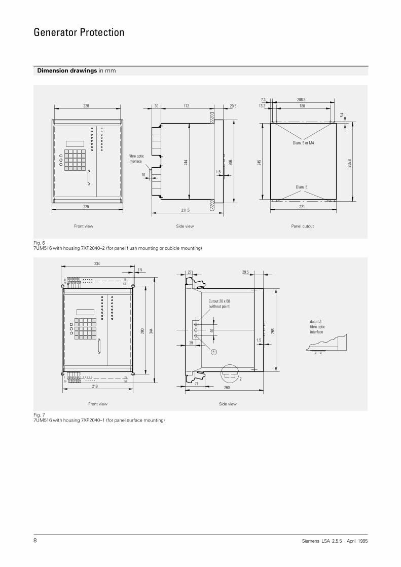
Dimension drawings in mm
Fig. 67UM516 with housing 7XP2040–2 (for panel flush mounting or cubicle mounting)
Front view Side view Panel cutout
206.5
180
221
7.3
13.2
255.
8
245
266
231.5
30 29.5
1.5
5.4
225
220
244
172
10
Fibre opticinterface
Diam. 5 or M4
Diam. 6
Fig. 77UM516 with housing 7XP2040–1 (for panel surface mounting)
Front view Side view
260
27 29.526
6
71Z
280
344
234
219
detail Z:fibre opticinterface
126
1.539
40
Cutout 20 x 60 (without paint)
10051 75
5025
76
7.5
. . . . .. . . . .
. . . . .. . . . .
Generator Protection
Siemens LSA 2.5.5 . April 1995 9
Conditions of Sale and Delivery
Subject to theGeneral Conditions of Supply and Deliveryfor Products and Services of theElectrical and Electronic Industryand to any other conditions agreed uponwith the recipients of catalogs.
The technical data, dimensions and weights are subject to change unlessotherwise stated on the individual pagesof this catalog.
The illustrations are for reference only.
We reserve the right to adjust the pricesand shall charge the price applying onthe date of delivery.
Export Regulations
In accordance with present German andUS export regulations export licences (da-ted 03.95) are not required for the prod-ucts listed in this catalog.Export and re–export are therefore
permissible without the approval of therelevant authorities except where currentGerman export regulations contain coun-try–specific restrictions.
Subject to change.Relevant are the criteria stated in the delivery note and in the invoice.An export licence may be required due to country–specific application of theproduct.
Trademarks
All product designations used are trade-marks or product names of Siemens AGor of suppliers.
Dimensions
All dimensions in this catalog are given inmm
Responsible for
Technical contents: Norbert Schuster,Siemens AG, EV S T11, Nürnberg
General editing: Claudia Kühn–Sutiono,Siemens AG, EV MK 2, Erlangen
Conditions of Sale and Delivery Export Regulations Trademarks Dimensions
A 9.91 a

Generator Protection
Siemens LSA 2.5.5 . April 199510Siemens Aktiengesellschaft
BereichEnergieübertragung und -verteilungGeschäftsgebietZähler, Sekundär- und NetzleittechnikP. O. Box 48 06D-90026 Nürnberg
Order No.: E50001-K5752–A151-A1–7600Printed in the Federal Republic of GermanyKG K 0495 3.0 SC 10 En
PowerTransmissionand Distribution


