Embed Size (px)
Citation preview
Geotechnical Exploration Report
The Freese Center State Route 598
Galion, Ohio 44833
Prepared for
Galion Port Authority P.O. Box 761
Galion, Ohio 44833
Daniel E Karch, E.I. Project Manager
Prepared by
Professional Service Industries, Inc. 4960 Vulcan Avenue
Columbus, Ohio 43228
Paul S. Hundley, P.E. July 31, 2020 Geotechnical Dept.
Manager/Principal Consultant PSI Project No. 01021746
PSI Project Number: 01021746 The Freese Center
July 21, 2020
www.intertek.com/building
TABLE OF CONTENTS
1 PROJECT INFORMATION ....................................................................................................................... 1 1.1 PROJECT AUTHORIZATION ............................................................................................................... 1 1.2 PROJECT DESCRIPTION ..................................................................................................................... 1 1.3 PURPOSE AND SCOPE OF SERVICES ................................................................................................. 2
2 SITE AND SUBSURFACE CONDITIONS .................................................................................................... 4 2.1 SITE LOCATION AND DESCRIPTION .................................................................................................. 4 2.2 SITE GEOLOGY .................................................................................................................................. 4 2.3 SUBSURFACE CONDITIONS .............................................................................................................. 5 2.4 WATER LEVEL MEASUREMENTS ...................................................................................................... 6 2.5 LABORATORY TEST RESULTS ............................................................................................................ 6
3 GEOTECHNICAL EVALUATION ............................................................................................................... 8 3.1 GEOTECHNICAL DISCUSSION ........................................................................................................... 8
4 GEOTECHNICAL RECOMMENDATIONS ................................................................................................ 10 4.1 SITE PREPARATION ......................................................................................................................... 10 4.2 FOUNDATION RECOMMENDATIONS ............................................................................................. 12
4.2.1 SHALLOW FOUNDATIONS ............................................................................................ 12 4.2.2 INTERMEDIATE FOUNDATION SYSTEM – AGGREGATE PIERS OR CONTROLLED
MODULUS COLUMNS .................................................................................................. 13 4.2.3 ACIP PILES .................................................................................................................... 14
4.3 EARTHQUAKE AND SEISMIC DESIGN CONSIDERATION ................................................................. 15 4.4 FLOOR SLAB RECOMMENDATIONS ................................................................................................ 16 4.5 UTILITIES TRENCHING .................................................................................................................... 17 4.6 PAVEMENT DESIGN RECOMMENDATIONS .................................................................................... 17 4.7 PAVEMENT DRAINAGE AND MAINTENANCE ................................................................................. 19 4.8 SILTATION CONTROL ...................................................................................................................... 19
5 CONSTRUCTION CONSIDERATIONS ..................................................................................................... 20 5.1 MOISTURE SENSITIVE SOILS/WEATHER RELATED CONCERNS ....................................................... 20 5.2 DRAINAGE AND GROUNDWATER CONSIDERATIONS .................................................................... 20 5.3 EXCAVATIONS ................................................................................................................................ 20
6 GEOTECHNICAL RISK .......................................................................................................................... 22 7 REPORT LIMITATIONS ........................................................................................................................ 23 APPENDIX - Site Location Map
Boring Location Plan Profile Boring Logs Laboratory Test Results USGS Seismic Design Maps Physiographic Regions of Ohio Karst Mapping General Notes Unified Soil Classification Chart (USCS)
PSI Project Number: 01021746 The Freese Center
July 31, 2020 Page 1
www.intertek.com/building
1 PROJECT INFORMATION
1.1 PROJECT AUTHORIZATION
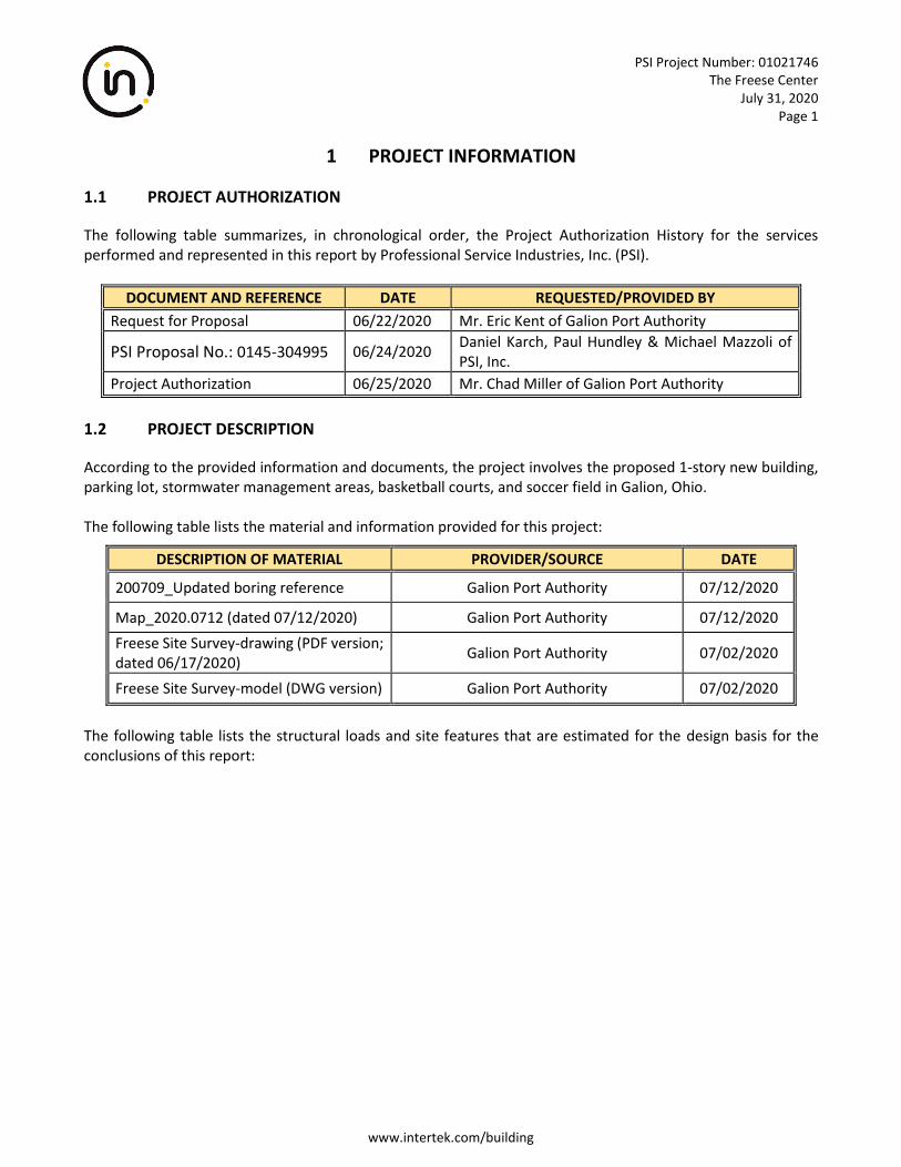
The following table summarizes, in chronological order, the Project Authorization History for the services performed and represented in this report by Professional Service Industries, Inc. (PSI).
DOCUMENT AND REFERENCE DATE REQUESTED/PROVIDED BY
Request for Proposal 06/22/2020 Mr. Eric Kent of Galion Port Authority
PSI Proposal No.: 0145-304995 06/24/2020 Daniel Karch, Paul Hundley & Michael Mazzoli of PSI, Inc.
Project Authorization 06/25/2020 Mr. Chad Miller of Galion Port Authority
1.2 PROJECT DESCRIPTION
According to the provided information and documents, the project involves the proposed 1-story new building, parking lot, stormwater management areas, basketball courts, and soccer field in Galion, Ohio. The following table lists the material and information provided for this project:
DESCRIPTION OF MATERIAL PROVIDER/SOURCE DATE
200709_Updated boring reference Galion Port Authority 07/12/2020
Map_2020.0712 (dated 07/12/2020) Galion Port Authority 07/12/2020
Freese Site Survey-drawing (PDF version; dated 06/17/2020)
Galion Port Authority 07/02/2020
Freese Site Survey-model (DWG version) Galion Port Authority 07/02/2020
The following table lists the structural loads and site features that are estimated for the design basis for the conclusions of this report:
PSI Project Number: 01021746 The Freese Center
July 31, 2020 Page 2
www.intertek.com/building
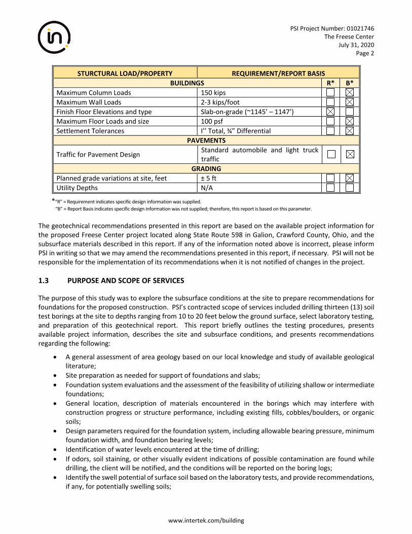
STURCTURAL LOAD/PROPERTY REQUIREMENT/REPORT BASIS
BUILDINGS R* B*
Maximum Column Loads 150 kips
Maximum Wall Loads 2-3 kips/foot
Finish Floor Elevations and type Slab-on-grade (~1145’ – 1147’)
Maximum Floor Loads and size 100 psf
Settlement Tolerances I’’ Total, ¾” Differential
PAVEMENTS
Traffic for Pavement Design Standard automobile and light truck traffic
GRADING
Planned grade variations at site, feet ± 5 ft
Utility Depths N/A
*“R” = Requirement indicates specific design information was supplied.
“B” = Report Basis indicates specific design information was not supplied; therefore, this report is based on this parameter.
The geotechnical recommendations presented in this report are based on the available project information for the proposed Freese Center project located along State Route 598 in Galion, Crawford County, Ohio, and the subsurface materials described in this report. If any of the information noted above is incorrect, please inform PSI in writing so that we may amend the recommendations presented in this report, if necessary. PSI will not be responsible for the implementation of its recommendations when it is not notified of changes in the project.
1.3 PURPOSE AND SCOPE OF SERVICES
The purpose of this study was to explore the subsurface conditions at the site to prepare recommendations for foundations for the proposed construction. PSI’s contracted scope of services included drilling thirteen (13) soil test borings at the site to depths ranging from 10 to 20 feet below the ground surface, select laboratory testing, and preparation of this geotechnical report. This report briefly outlines the testing procedures, presents available project information, describes the site and subsurface conditions, and presents recommendations regarding the following:
• A general assessment of area geology based on our local knowledge and study of available geological literature;
• Site preparation as needed for support of foundations and slabs;
• Foundation system evaluations and the assessment of the feasibility of utilizing shallow or intermediate foundations;
• General location, description of materials encountered in the borings which may interfere with construction progress or structure performance, including existing fills, cobbles/boulders, or organic soils;
• Design parameters required for the foundation system, including allowable bearing pressure, minimum foundation width, and foundation bearing levels;
• Identification of water levels encountered at the time of drilling;
• If odors, soil staining, or other visually evident indications of possible contamination are found while drilling, the client will be notified, and the conditions will be reported on the boring logs;
• Identify the swell potential of surface soil based on the laboratory tests, and provide recommendations, if any, for potentially swelling soils;
PSI Project Number: 01021746 The Freese Center
July 31, 2020 Page 3
www.intertek.com/building
• Recommendation of modulus of subgrade reaction, and analysis of the swell potential of surface soil based on index tests;
• Recommendations for fill including the selection of materials for use and procedures for placement;
• This report incorporating the design parameters and recommendations, with attachments including a boring location drawing, and boring logs.
The scope of services did not include an environmental assessment for determining the presence or absence of wetlands, or hazardous or toxic materials in the soil, bedrock, surface water, groundwater, or air on, below, or around this site. Any statements in this report or on the boring logs regarding odors, colors, and unusual or suspicious items or conditions are strictly for informational purposes. PSI’s scope also did not provide any service to investigate or detect the presence of moisture, mold or other biological contaminants in or around any structure, or any service that was designed or intended to prevent or lower the risk of the occurrence or the amplification of the same. The Client should be aware that mold is ubiquitous to the environment with mold amplification occurring when building materials are impacted by moisture. The Client should also be aware that site conditions are outside of PSI’s control, and that mold amplification will likely occur, or continue to occur, in the presence of moisture. As such, PSI cannot and shall not be held responsible for the occurrence or reoccurrence of mold amplification.
PSI Project Number: 01021746 The Freese Center
July 31, 2020 Page 4
www.intertek.com/building
2 SITE AND SUBSURFACE CONDITIONS
2.1 SITE LOCATION AND DESCRIPTION
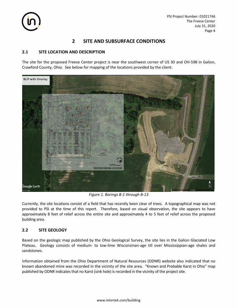
The site for the proposed Freese Center project is near the southwest corner of US 30 and OH-598 in Galion, Crawford County, Ohio. See below for mapping of the locations provided by the client.
Figure 1. Borings B-1 through B-13
Currently, the site locations consist of a field that has recently been clear of trees. A topographical map was not provided to PSI at the time of this report. Therefore, based on visual observation, the site appears to have approximately 8 feet of relief across the entire site and approximately 4 to 5 feet of relief across the proposed building area.
2.2 SITE GEOLOGY
Based on the geologic map published by the Ohio Geological Survey, the site lies in the Galion Glaciated Low Plateau. Geology consists of medium- to low-lime Wisconsinan-age till over Mississippian-age shales and sandstones. Information obtained from the Ohio Department of Natural Resources (ODNR) website also indicated that no known abandoned mine was recorded in the vicinity of the site area. “Known and Probable Karst in Ohio” map published by ODNR indicates that no Karst (sink hole) is recorded in the vicinity of the project site.
PSI Project Number: 01021746 The Freese Center
July 31, 2020 Page 5
www.intertek.com/building
2.3 SUBSURFACE CONDITIONS
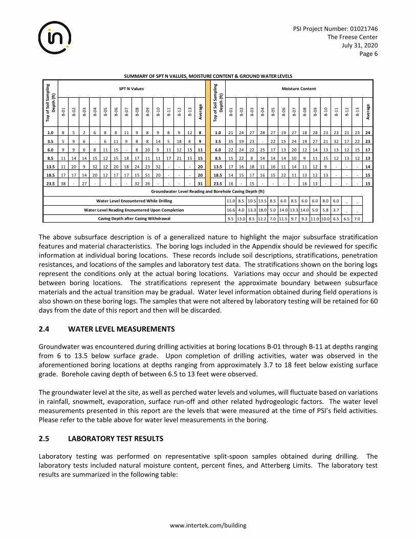
The site subsurface conditions were explored with thirteen (13) soil test boring within the proposed development area on July 16 and 17, 2020. The test borings were advanced in the vicinity of the proposed Freese Center and were terminated at depths ranging from approximately 10 to 25 feet. The surface elevations at the boring should be surveyed prior to construction activities. The borings were advanced utilizing 3 ¼ inch inside diameter, hollow stem auger drilling methods. Soil samples were routinely obtained during the drilling process. Select soil samples were later tested in the laboratory to obtain soil material properties for the foundation recommendations. Drilling, sampling, and laboratory testing was accomplished in general accordance with ASTM procedures. The laboratory test results are included in each boring log. A description of the classification system and the results of the laboratory tests are included in the Appendix. TOPSOIL/ORGANIC MIXTURE: A topsoil or organic mixture was encountered at the surface of the test boring locations ranging in thickness between approximately eight (8) to fifteen (15) inches. The topsoil/organic mixture thicknesses should be expected to vary across the site. Topsoil/organic mixture thicknesses are included in this report for informational purposes only and should not be used for bidding or estimating purposes. COHESIVE SOILS: Underlying the topsoil at all boring locations, cohesive soils consisting of Lean Clay (CL), Silt with Sand (ML), and Sandy Silt (ML) with varying degrees of sand and gravel were encountered to depths ranging from about 11.5 feet below existing surface grades to termination depths. The Standard Penetration Test values (“N”-values) for the cohesive soils ranged from two (2) to thirty-eight (38) blows per foot indicating “soft” to “hard” consistencies. Three (3) Atterberg limit tests were performed on selected samples of cohesive soils and indicated liquid limits ranging from thirty-two (32) to forty-seven (47) percent and plasticity indices ranging from fifteen (15) to twenty-seven (27). Moisture contents of the cohesive soils ranged from twelve (12) to thirty-five (35) percent. GRANULAR SOILS: Underlying the cohesive soils at the majority of boring locations, granular soils consisting of Silty Sand with Gravel (SM) were encountered to depths ranging from about 8.5 feet below existing surface grades. The Standard Penetration Test value (“N”-value) for the granular soil ranged from eight (8) to fifty-one (51) blows per foot indicating “loose” to “very dense” consistencies. Moisture contents of the granular soil ranged from eight (8) to twenty-two (22) percent. The following table briefly summarizes the range of results from the field and laboratory testing programs. Please refer to the attached boring logs and laboratory data sheets for more specific information:
PSI Project Number: 01021746 The Freese Center
July 31, 2020 Page 6
www.intertek.com/building
The above subsurface description is of a generalized nature to highlight the major subsurface stratification features and material characteristics. The boring logs included in the Appendix should be reviewed for specific information at individual boring locations. These records include soil descriptions, stratifications, penetration resistances, and locations of the samples and laboratory test data. The stratifications shown on the boring logs represent the conditions only at the actual boring locations. Variations may occur and should be expected between boring locations. The stratifications represent the approximate boundary between subsurface materials and the actual transition may be gradual. Water level information obtained during field operations is also shown on these boring logs. The samples that were not altered by laboratory testing will be retained for 60 days from the date of this report and then will be discarded.
2.4 WATER LEVEL MEASUREMENTS
Groundwater was encountered during drilling activities at boring locations B-01 through B-11 at depths ranging from 6 to 13.5 below surface grade. Upon completion of drilling activities, water was observed in the aforementioned boring locations at depths ranging from approximately 3.7 to 18 feet below existing surface grade. Borehole caving depth of between 6.5 to 13 feet were observed. The groundwater level at the site, as well as perched water levels and volumes, will fluctuate based on variations in rainfall, snowmelt, evaporation, surface run-off and other related hydrogeologic factors. The water level measurements presented in this report are the levels that were measured at the time of PSI’s field activities. Please refer to the table above for water level measurements in the boring.
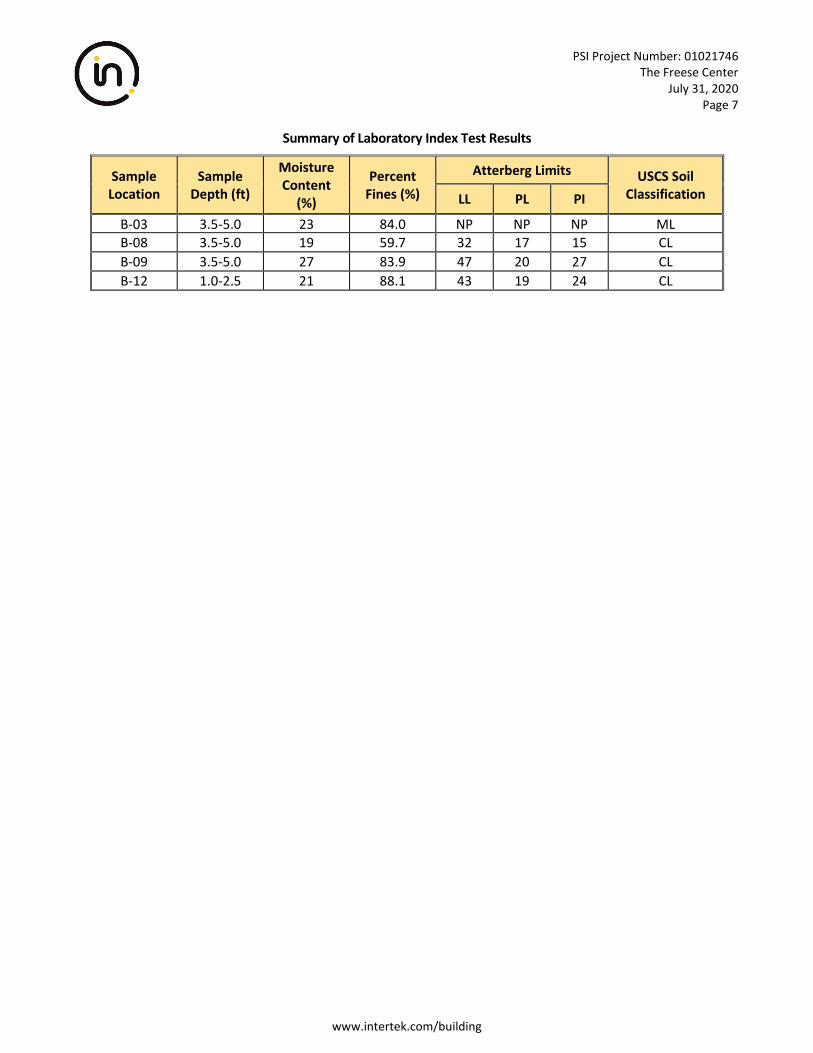
2.5 LABORATORY TEST RESULTS
Laboratory testing was performed on representative split-spoon samples obtained during drilling. The laboratory tests included natural moisture content, percent fines, and Atterberg Limits. The laboratory test results are summarized in the following table:
B-0
1
B-0
2
B-0
3
B-0
4
B-0
5
B-0
6
B-0
7
B-0
8
B-0
9
B-1
0
B-1
1
B-1
2
B-1
3
Ave
rage
B-0
1
B-0
2
B-0
3
B-0
4
B-0
5
B-0
6
B-0
7
B-0
8
B-0
9
B-1
0
B-1
1
B-1
2
B-1
3
Ave
rage
1.0 8 5 2 6 8 8 11 9 8 9 8 9 12 8 1.0 21 24 27 28 27 19 27 18 28 23 23 21 23 24
3.5 5 9 6 - 6 11 9 8 8 14 5 18 8 9 3.5 35 19 23 - 22 15 24 19 27 21 32 17 22 23
6.0 9 9 6 8 11 15 - 8 20 9 11 12 15 11 6.0 22 24 22 25 17 13 20 12 14 13 13 12 15 17
8.5 11 14 14 15 12 15 18 17 11 11 17 21 15 15 8.5 15 22 8 14 14 14 10 9 11 15 12 13 12 13
13.5 11 20 9 32 12 20 18 24 23 32 - - - 20 13.5 17 16 18 11 16 11 14 11 12 9 - - - 14
18.5 17 17 14 20 12 17 17 15 51 20 - - - 20 18.5 14 15 17 16 15 22 11 13 12 13 - - - 15
23.5 38 - 27 - - - - 32 26 - - - - 31 23.5 16 - 15 - - - - 16 13 - - - - 15
11.0 8.5 10.5 13.5 8.5 6.0 8.5 6.0 6.0 8.0 6.0 - -
16.6 4.0 13.3 18.0 5.0 14.0 13.3 14.0 5.0 5.8 3.7 - -
9.5 13.0 8.5 12.2 7.0 11.5 9.7 9.3 11.0 10.0 6.5 6.5 7.0
SUMMARY OF SPT N VALUES, MOISTURE CONTENT & GROUND WATER LEVELS
Water Level Encountered While Drilling
Top
of
Soil
Sam
plin
g
De
pth
(ft
)
Top
of
Soil
Sam
plin
g
De
pth
(ft
)
Groundwater Level Reading and Borehole Caving Depth (ft)
SPT N Values Moisture Content
Caving Depth after Casing Withdrawal
Water Level Reading Encountered Upon Completion
PSI Project Number: 01021746 The Freese Center
July 31, 2020 Page 7
www.intertek.com/building
Summary of Laboratory Index Test Results
Sample Location
Sample Depth (ft)
Moisture Content
(%)
Percent Fines (%)
Atterberg Limits USCS Soil Classification LL PL PI
B-03 3.5-5.0 23 84.0 NP NP NP ML B-08 3.5-5.0 19 59.7 32 17 15 CL
B-09 3.5-5.0 27 83.9 47 20 27 CL
B-12 1.0-2.5 21 88.1 43 19 24 CL
PSI Project Number: 01021746 The Freese Center
July 31, 2020 Page 8
www.intertek.com/building
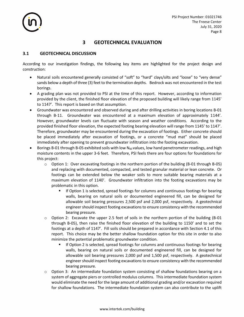
3 GEOTECHNICAL EVALUATION
3.1 GEOTECHNICAL DISCUSSION
According to our investigation findings, the following key items are highlighted for the project design and construction:
• Natural soils encountered generally consisted of “soft” to “hard” clays/silts and “loose” to “very dense” sands below a depth of three (3) feet to the termination depths. Bedrock was not encountered in the test borings.
• A grading plan was not provided to PSI at the time of this report. However, according to information provided by the client, the finished floor elevation of the proposed building will likely range from 1145’ to 1147’. This report is based on that assumption.
• Groundwater was encountered and observed during and after drilling activities in boring locations B-01 through B-11. Groundwater was encountered at a maximum elevation of approximately 1144’. However, groundwater levels can fluctuate with season and weather conditions. According to the provided finished floor elevation, the expected footing bearing elevation will range from 1145’ to 1147’. Therefore, groundwater may be encountered during the excavation of footings. Either concrete should be placed immediately after excavation of footings, or a concrete “mud mat” should be placed immediately after opening to prevent groundwater infiltration into the footing excavation.
• Borings B-01 through B-05 exhibited soils with low N60 values, low hand penetrometer readings, and high moisture contents in the upper 3-6 feet. Therefore, PSI feels there are four options for foundations for this project:
o Option 1: Over excavating footings in the northern portion of the building (B-01 through B-05) and replacing with documented, compacted, and tested granular material or lean concrete. Or footings can be extended below the weaker soils to more suitable bearing materials at a maximum elevation of 1140’. Groundwater infiltration into the footing excavations may be problematic in this option.
▪ If Option 1 is selected, spread footings for columns and continuous footings for bearing walls, bearing on natural soils or documented engineered fill, can be designed for allowable soil bearing pressures 2,500 psf and 2,000 psf, respectively. A geotechnical engineer should inspect footing excavations to ensure consistency with the recommended bearing pressure.
o Option 2: Excavate the upper 2.5 feet of soils in the northern portion of the building (B-01 through B-05), then raise the finished floor elevation of the building to 1150’ and to set the footings at a depth of 1147’. Fill soils should be prepared in accordance with Section 4.1 of this report. This choice may be the better shallow foundation option for this site in order to also minimize the potential problematic groundwater condition.
▪ If Option 2 is selected, spread footings for columns and continuous footings for bearing walls, bearing on natural soils or documented engineered fill, can be designed for allowable soil bearing pressures 2,000 psf and 1,500 psf, respectively. A geotechnical engineer should inspect footing excavations to ensure consistency with the recommended bearing pressure.
o Option 3: An intermediate foundation system consisting of shallow foundations bearing on a system of aggregate piers or controlled modulus columns. This intermediate foundation system would eliminate the need for the large amount of additional grading and/or excavation required for shallow foundations. The intermediate foundation system can also contribute to the uplift
PSI Project Number: 01021746 The Freese Center
July 31, 2020 Page 9
www.intertek.com/building
capacity of the foundation system. A specialty contractor should be consulted about lateral loading capacities of the intermediate foundation system as well as the selection of the proper system for this site.
o Option 4: A deep foundation system of Auger-Cast-in-Place (ACIP) piles. This deep foundation system would be better suited than drilled shafts for this site due to the sand layers and elevated groundwater table that are present. ACIP piles would provide the highest amount of axial and lateral load capacity compared to the shallow and intermediate foundation system. If this foundation option is selected, PSI should be allowed to return to the site to perform additional soil borings to a deeper depth than was performed originally.
PSI Project Number: 01021746 The Freese Center
July 31, 2020 Page 10
www.intertek.com/building
4 GEOTECHNICAL RECOMMENDATIONS
The following geotechnical related recommendations have been developed based on the subsurface conditions encountered and PSI’s understanding of the proposed development. Should changes in the project criteria occur, a review must be made by PSI to determine if modifications to our recommendations will be required.
4.1 SITE PREPARATION
PSI recommends that topsoil, vegetation, roots, soft, organic, frozen, or unsuitable soils in the construction area be stripped from the site and either wasted or stockpiled for later use in non-structural areas. A representative of the geotechnical engineer should determine and document the depth of removal at the time of construction. In this region, these otherwise competent clay type soils can undergo a significant loss of stability when construction activities are performed during wetter portions of the year. PSI anticipates that the soils in the project area can become easily disturbed if subjected to conventional rubber tire or narrow track-type equipment. Soils that become disturbed would need to be excavated and replaced; however, this remedial excavation may expose progressively wetter soils with depth, thus compounding the problem condition. Thus, a normal approach to subgrade preparation may not be possible. Appropriate wide-track equipment selection should aid in minimizing potential disturbance. After stripping to the proposed subgrade level, the subgrade in development areas should be scarified and compacted to at least 98% of the materials’ standard proctor maximum dry density, in general accordance with ASTM procedures, to a depth of at least twelve inches below the surface and then proof-rolled with a loaded tandem axle dump truck or similar heavy rubber tired vehicle (typically with an axial load greater than nine tons or meeting specifications outlined in ODOT Item 204 for roadway subgrade compaction and proof-rolling). The subgrade should be compacted or stabilized before proof rolling. Soils that are observed to rut or deflect excessively (typically greater than one inch) under the moving load should be undercut and replaced with properly compacted low plasticity fill material. The proof-rolling and undercutting activities should be witnessed by a representative of the geotechnical engineer and should be performed during a period of dry weather. Care should be taken during construction activities not to allow excessive drying or wetting of exposed soils. If aeration, dry and compaction cannot meet this requirement, chemical stabilization will be required. This condition will be encountered at the lower portions on the site (B-01 to B-05) where the option to undercut and replace wet soil is selected. After subgrade preparation and observation have been completed, fill placement required to establish grade may begin. Low-plasticity structural fill materials placed beneath the lightly loaded structural features or slabs should be free of organic or other deleterious materials and have a maximum particle size of less than three (3) inches. Low-plasticity soils for this site are defined as having a liquid limit less than forty-five (45) and plasticity index less than twenty (20). The in-situ soils can be reused as engineered fill as long they are free of organic material and meet the requirements outlined in this report. A representative of PSI should be on-site to observe, test, and document the placement of the fill. If the fill is too dry, water should be uniformly applied and thoroughly mixed into the soil by disking or scarifying. Close moisture content control will be required to achieve the recommended degree of compaction. Modification of the soils using admixtures such as lime, fly ash, kiln dust or cement may be necessary if wet or cool season earthwork is necessary and can be used to lower the plasticity of fat clays to an acceptable level.
PSI Project Number: 01021746 The Freese Center
July 31, 2020 Page 11
www.intertek.com/building
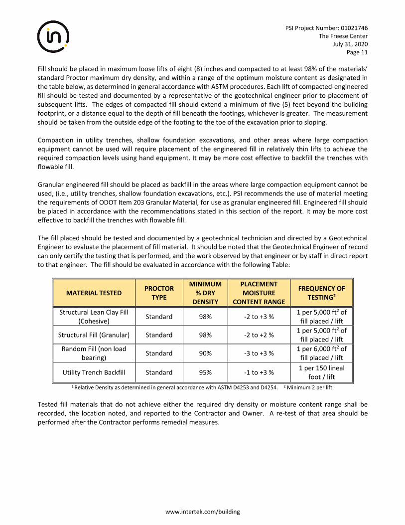
Fill should be placed in maximum loose lifts of eight (8) inches and compacted to at least 98% of the materials’ standard Proctor maximum dry density, and within a range of the optimum moisture content as designated in the table below, as determined in general accordance with ASTM procedures. Each lift of compacted-engineered fill should be tested and documented by a representative of the geotechnical engineer prior to placement of subsequent lifts. The edges of compacted fill should extend a minimum of five (5) feet beyond the building footprint, or a distance equal to the depth of fill beneath the footings, whichever is greater. The measurement should be taken from the outside edge of the footing to the toe of the excavation prior to sloping. Compaction in utility trenches, shallow foundation excavations, and other areas where large compaction equipment cannot be used will require placement of the engineered fill in relatively thin lifts to achieve the required compaction levels using hand equipment. It may be more cost effective to backfill the trenches with flowable fill. Granular engineered fill should be placed as backfill in the areas where large compaction equipment cannot be used, (i.e., utility trenches, shallow foundation excavations, etc.). PSI recommends the use of material meeting the requirements of ODOT Item 203 Granular Material, for use as granular engineered fill. Engineered fill should be placed in accordance with the recommendations stated in this section of the report. It may be more cost effective to backfill the trenches with flowable fill. The fill placed should be tested and documented by a geotechnical technician and directed by a Geotechnical Engineer to evaluate the placement of fill material. It should be noted that the Geotechnical Engineer of record can only certify the testing that is performed, and the work observed by that engineer or by staff in direct report to that engineer. The fill should be evaluated in accordance with the following Table:
MATERIAL TESTED PROCTOR
TYPE
MINIMUM % DRY
DENSITY
PLACEMENT MOISTURE
CONTENT RANGE
FREQUENCY OF TESTING2
Structural Lean Clay Fill (Cohesive)
Standard 98% -2 to +3 % 1 per 5,000 ft2 of
fill placed / lift
Structural Fill (Granular) Standard 98% -2 to +2 % 1 per 5,000 ft2 of
fill placed / lift
Random Fill (non load bearing)
Standard 90% -3 to +3 % 1 per 6,000 ft2 of
fill placed / lift
Utility Trench Backfill Standard 95% -1 to +3 % 1 per 150 lineal
foot / lift 1 Relative Density as determined in general accordance with ASTM D4253 and D4254. 2 Minimum 2 per lift.
Tested fill materials that do not achieve either the required dry density or moisture content range shall be recorded, the location noted, and reported to the Contractor and Owner. A re-test of that area should be performed after the Contractor performs remedial measures.
PSI Project Number: 01021746 The Freese Center
July 31, 2020 Page 12
www.intertek.com/building
4.2 FOUNDATION RECOMMENDATIONS
4.2.1 SHALLOW FOUNDATIONS
It is PSI’s opinion that the planned construction for the proposed building can be supported on conventional spread-type footing foundations bearing on either competent naturally deposited soils or properly compacted and documented engineered fill if either Option 1 or Option 2 are pursued. During footing excavations, a geotechnical engineer should observe the excavation bottoms to document its consistency with the recommended bearing pressures from the geotechnical report. Option 1: Spread footings for columns and continuous footings for bearing walls, bearing on natural soils or documented engineered fill, can be designed for allowable soil bearing pressures 2,500 psf and 2,000 psf, respectively. A geotechnical engineer should inspect footing excavations to ensure consistency with the recommended bearing pressure. Option 2: Spread footings for columns and continuous footings for bearing walls, bearing on natural soils or documented engineered fill, can be designed for allowable soil bearing pressures 2,000 psf and 1,500 psf, respectively. A geotechnical engineer should inspect footing excavations to ensure consistency with the recommended bearing pressure. PSI recommends a minimum dimension of thirty (30) inches for square footings and eighteen (18) inches for continuous footings to minimize the possibility of a local bearing capacity failure. Exterior footings and footings in unheated areas should be located at a depth of thirty-six (36) inches or deeper below the final exterior grade to provide adequate frost protection. If the building is to be constructed during the winter months or if footings will likely be subjected to freezing temperatures after foundation construction, then the footings should be protected from freezing. PSI recommends that interior footings be a minimum depth of eighteen (18) inches below the finished floor elevation. The foundation excavations should be observed and documented by a representative of PSI prior to steel or concrete placement to assess that the foundation materials are consistent with the materials discussed in this report, and therefore are capable of supporting the design loads. Soft or loose soil zones encountered at the bottom of the footing excavations should be removed to the level of suitable soils, and replaced with adequately compacted dense graded aggregate. Granular fill placed below the foundations where unsuitable materials are removed should extend ½ feet outside the foundation limits for every one foot in thickness between the intended bearing surface and the underlying, suitable natural soils. Cavities formed as a result of excavation of soft or loose soil zones should be backfilled with lean concrete or dense graded compacted crushed stone. After opening, footing excavations should be observed, and concrete placed as quickly as possible to avoid exposure of the footing bottoms to wetting and drying. Surface run-off water should be drained away from the excavations and not be allowed to pond. If possible, the foundation concrete should be placed during the same day the excavation is made. If it is required that footing excavations be left open for more than 1 day, they should be protected to reduce evaporation or entry of moisture. Based on the known subsurface conditions and site geology, laboratory testing and past experience, PSI anticipates that properly designed and constructed footings supported on the recommended materials should
PSI Project Number: 01021746 The Freese Center
July 31, 2020 Page 13
www.intertek.com/building
experience total and differential settlement between adjacent columns of less than one (1) inch and ¾ inch, respectively. 4.2.2 INTERMEDIATE FOUNDATION SYSTEM – AGGREGATE PIERS OR CONTROLLED MODULUS COLUMNS
Use of an Intermediate Ground Improvement foundation system can produce a denser or stiffer soil strata than original soils to increase soil strength and minimize foundation settlement. An intermediate ground improvement normally improves the sub-grade to allow the use of conventional shallow spread foundations. A suitable intermediate foundation selected for this project should be capable of reducing the potential for differential settlement of foundations and avoid a bearing capacity failure on the weaker soils. Several intermediate ground improvement methods are available in the US market. These systems may include Rammed Aggregate Piers (RAP-GeopierTM), Controlled Modulus Columns™ (CMCs) or Vibro Stone Columns (VSCs). Each of these intermediate ground improvement methods may have some restrictions due to the site, sub-grade and proposed structure conditions. For this site, the high water levels and the silty sand can present problems with VSCs due to the vibration that is used to install them. Controlled Modulus Columns use a grout inclusion which introduces a cost factor when considering the size of the project. Specialty contractors should be consulted for the improvement method selection. Specialty contractors provide detailed design for their improvement method. The project structure design engineer/owner’s representative should contact these specialty contractors directly and select a proper ground improvement method for the project. Rammed Aggregate Piers and Vibro Stone Columns fall into the category of “Aggregate Piers”. Based on the assumed structural loads, it is anticipated that total and differential foundation settlements can be within tolerance limits if a proper intermediate ground improvement method using Aggregate Piers is used to support proposed foundations. However, actual settlements will be dependent upon the depth of the foundations, column spacing, structural loads and other related factors. Use of cement-treated aggregate has been used to increase rigidity of the aggregate pier.
Controlled Modulus Columns (CMCs) are cement grout inclusions and may be more appropriate to reduce total and differential settlement. To provide initial guidance, PSI recommends that the structural engineer consult with the specialty contractor for further details. Additional information can be found in the U.S. Department of Transportation Federal Highway Administration, Publication No. FHWA-SA-98-086, Demonstration Project 116. General comments concerning this approach are provided in the subsequent paragraphs. Conventional vibro-stone aggregate columns are constructed using a vibro-replacement or vibro-displacement method. A similar approach consisting of rammed aggregate piers, or VibroPier™ elements, involves removing a volume of soil, then building a bottom bulb, using well-graded highway base course stone placed in thin lifts (12-inches compacted thickness). The lifts are compacted by a repeating ramming action that also stresses the soil laterally. Due to the presence of high water level at his site, vibration method of installation is not recommended. Temporary casing method of installation may also be required. Current design methods are relatively empirical and based on a field evaluation of a select number of projects. The foundation systems are proprietary and are designed and installed by a specialty contractor.
PSI Project Number: 01021746 The Freese Center
July 31, 2020 Page 14
www.intertek.com/building
The installer should provide detailed design calculations sealed by a professional engineer licensed in the State of Ohio. The design calculations should demonstrate that aggregate pier soil reinforcement is estimated to control long-term settlements and provide satisfactory differential settlement required by the structural engineer. The design parameters should be verified by a full-scale modulus load test (similar to a pile load test) performed on a non-production pier installed at the site. The geotechnical engineer should be retained to monitor the field instrumentation and contractor executed load test program to evaluate the performance of the aggregate pier design. The specialty foundation contractor should design the aggregate pier elements to support the proposed structure within the structural design tolerance (i.e., settlement potential, sliding resistance, uplift capacity, etc.) required. After implementation of the selected ground improvement program, the proposed nitrogen pad may be designed utilizing conventional shallow foundations based on the design bearing pressure provided by the aggregate pier designer. Upon completing a preliminary design of the intermediate foundation system to support the structure, a design/construction cost estimate should be provided, including the estimated time to install the pier elements. This estimate should include the cost to provide a full-scale modulus load test(s) required to verify the design assumptions. The load test provides a conservative measure of the stiffness of the aggregate pier element and will provide quality control guidelines for the pier installation procedure. The Modulus Load Test should be performed on a non-production pier in the general area of the site considered to be representative of the most critical soil condition. It is recommended that personnel from our office monitor the aggregate pier installer’s activities as a Quality Assurance service. PSI’s services will supplement the installer’s internal Quality Control program. Together, these programs will monitor drilling length, pier element lengths, average lift thickness, installation procedures, aggregate quality and densification of lifts. These items will be documented for each aggregate pier element installed to provide a complete installation report. 4.2.3 ACIP PILES
Auger Cast-In-Place (ACIP) or continuous flight auger (CFA) piles are considered to be a feasible deep foundation system where deep foundations are required for the building. ACIP piles are generally more cost effective to install than driven piles or drilled shafts and can support heavy loads when drilled to a dense bearing stratum. The piles are installed using a temporary drill casing (flight auger) and concrete grout mixture is pumped under a positive head during the entire installation process. The continuous positive head and unit weight of the fluid cement grout is sufficient to neutralize the hydrostatic forces that can develop below the water level on the site. PSI recommends that we be allowed to conduct additional deeper soil borings at the site in order to determine soil parameters for the design of ACIP piles.
PSI Project Number: 01021746 The Freese Center
July 31, 2020 Page 15
www.intertek.com/building
4.3 EARTHQUAKE AND SEISMIC DESIGN CONSIDERATION
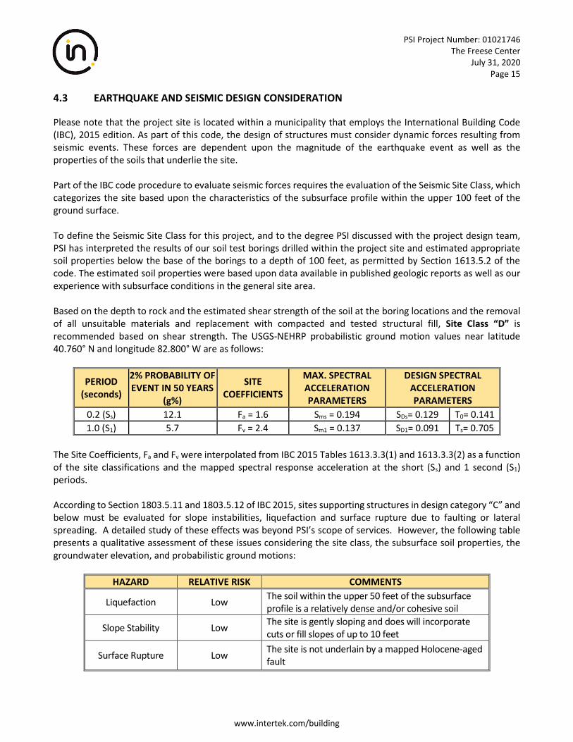
Please note that the project site is located within a municipality that employs the International Building Code (IBC), 2015 edition. As part of this code, the design of structures must consider dynamic forces resulting from seismic events. These forces are dependent upon the magnitude of the earthquake event as well as the properties of the soils that underlie the site. Part of the IBC code procedure to evaluate seismic forces requires the evaluation of the Seismic Site Class, which categorizes the site based upon the characteristics of the subsurface profile within the upper 100 feet of the ground surface. To define the Seismic Site Class for this project, and to the degree PSI discussed with the project design team, PSI has interpreted the results of our soil test borings drilled within the project site and estimated appropriate soil properties below the base of the borings to a depth of 100 feet, as permitted by Section 1613.5.2 of the code. The estimated soil properties were based upon data available in published geologic reports as well as our experience with subsurface conditions in the general site area. Based on the depth to rock and the estimated shear strength of the soil at the boring locations and the removal of all unsuitable materials and replacement with compacted and tested structural fill, Site Class “D” is recommended based on shear strength. The USGS-NEHRP probabilistic ground motion values near latitude 40.760° N and longitude 82.800° W are as follows:
PERIOD (seconds)
2% PROBABILITY OF EVENT IN 50 YEARS
(g%)
SITE COEFFICIENTS
MAX. SPECTRAL ACCELERATION PARAMETERS
DESIGN SPECTRAL ACCELERATION PARAMETERS
0.2 (Ss) 12.1 Fa = 1.6 Sms = 0.194 SDs= 0.129 T0= 0.141
1.0 (S1) 5.7 Fv = 2.4 Sm1 = 0.137 SD1= 0.091 Ts= 0.705
The Site Coefficients, Fa and Fv were interpolated from IBC 2015 Tables 1613.3.3(1) and 1613.3.3(2) as a function of the site classifications and the mapped spectral response acceleration at the short (Ss) and 1 second (S1) periods. According to Section 1803.5.11 and 1803.5.12 of IBC 2015, sites supporting structures in design category “C” and below must be evaluated for slope instabilities, liquefaction and surface rupture due to faulting or lateral spreading. A detailed study of these effects was beyond PSI’s scope of services. However, the following table presents a qualitative assessment of these issues considering the site class, the subsurface soil properties, the groundwater elevation, and probabilistic ground motions:
HAZARD RELATIVE RISK COMMENTS
Liquefaction Low The soil within the upper 50 feet of the subsurface profile is a relatively dense and/or cohesive soil
Slope Stability Low The site is gently sloping and does will incorporate cuts or fill slopes of up to 10 feet
Surface Rupture Low The site is not underlain by a mapped Holocene-aged fault
PSI Project Number: 01021746 The Freese Center
July 31, 2020 Page 16
www.intertek.com/building
4.4 FLOOR SLAB RECOMMENDATIONS
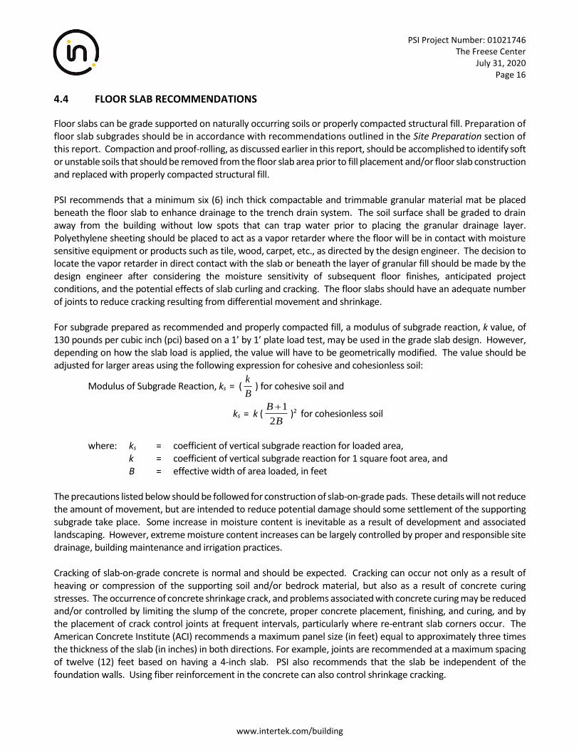
Floor slabs can be grade supported on naturally occurring soils or properly compacted structural fill. Preparation of floor slab subgrades should be in accordance with recommendations outlined in the Site Preparation section of this report. Compaction and proof-rolling, as discussed earlier in this report, should be accomplished to identify soft or unstable soils that should be removed from the floor slab area prior to fill placement and/or floor slab construction and replaced with properly compacted structural fill. PSI recommends that a minimum six (6) inch thick compactable and trimmable granular material mat be placed beneath the floor slab to enhance drainage to the trench drain system. The soil surface shall be graded to drain away from the building without low spots that can trap water prior to placing the granular drainage layer. Polyethylene sheeting should be placed to act as a vapor retarder where the floor will be in contact with moisture sensitive equipment or products such as tile, wood, carpet, etc., as directed by the design engineer. The decision to locate the vapor retarder in direct contact with the slab or beneath the layer of granular fill should be made by the design engineer after considering the moisture sensitivity of subsequent floor finishes, anticipated project conditions, and the potential effects of slab curling and cracking. The floor slabs should have an adequate number of joints to reduce cracking resulting from differential movement and shrinkage. For subgrade prepared as recommended and properly compacted fill, a modulus of subgrade reaction, k value, of 130 pounds per cubic inch (pci) based on a 1’ by 1’ plate load test, may be used in the grade slab design. However, depending on how the slab load is applied, the value will have to be geometrically modified. The value should be adjusted for larger areas using the following expression for cohesive and cohesionless soil:
Modulus of Subgrade Reaction, ks = (B
k) for cohesive soil and
ks = k (B
B
2
1+)2 for cohesionless soil
where: ks = coefficient of vertical subgrade reaction for loaded area, k = coefficient of vertical subgrade reaction for 1 square foot area, and B = effective width of area loaded, in feet The precautions listed below should be followed for construction of slab-on-grade pads. These details will not reduce the amount of movement, but are intended to reduce potential damage should some settlement of the supporting subgrade take place. Some increase in moisture content is inevitable as a result of development and associated landscaping. However, extreme moisture content increases can be largely controlled by proper and responsible site drainage, building maintenance and irrigation practices. Cracking of slab-on-grade concrete is normal and should be expected. Cracking can occur not only as a result of heaving or compression of the supporting soil and/or bedrock material, but also as a result of concrete curing stresses. The occurrence of concrete shrinkage crack, and problems associated with concrete curing may be reduced and/or controlled by limiting the slump of the concrete, proper concrete placement, finishing, and curing, and by the placement of crack control joints at frequent intervals, particularly where re-entrant slab corners occur. The American Concrete Institute (ACI) recommends a maximum panel size (in feet) equal to approximately three times the thickness of the slab (in inches) in both directions. For example, joints are recommended at a maximum spacing of twelve (12) feet based on having a 4-inch slab. PSI also recommends that the slab be independent of the foundation walls. Using fiber reinforcement in the concrete can also control shrinkage cracking.
PSI Project Number: 01021746 The Freese Center
July 31, 2020 Page 17
www.intertek.com/building
Areas supporting slabs should be properly moisture conditioned and compacted. Backfill in all interior and exterior water and sewer line trenches should be carefully compacted to reduce the shear stress in the concrete extending over these areas. Exterior slabs should be isolated from the building. These slabs should be reinforced to function as independent units. Movement of these slabs should not be transmitted to the building foundation or superstructure.
4.5 UTILITIES TRENCHING
Excavation for utility trenches shall be performed in accordance with OSHA regulations as stated in 29 CFR Part 1926. It should be noted that utility trench excavations have the potential to degrade the properties of the adjacent fill materials. Utility trench walls that can move laterally can lead to reduced bearing capacity and increased settlement of adjacent structural elements and overlying slabs. Backfill for utility trenches is as important as the original subgrade preparation or structural fill placed to support either a foundation or slab. Therefore, it is imperative that the backfill for utility trenches be placed to meet the project specifications for the structural fill of this project. PSI recommends that granular material, flowable fill or lean mix concrete be utilized for utility trench backfill. If on-site soils are placed as trench backfill, the backfill for the utility trenches should be placed in four to six inch loose lifts and compacted to a minimum of 98% of the maximum dry density achieved by the standard Proctor test. The backfill soil should be moisture conditioned to be within 2% of the optimum moisture content as determined by the standard Proctor test. Up to four inches of bedding material placed directly under the pipes or conduits placed in the utility trench can be compacted to the 98% compaction criteria with respect to the standard Proctor. Compaction testing should be performed for every 200 cubic yards of backfill place or each lift within 200 linear feet of trench, whichever is less. Backfill of utility trenches should not be performed with water standing in the trench. If granular material is used for the backfill of the utility trench, the granular material should have a gradation that will filter protect the backfill material from the adjacent soils. If this gradation is not available, a geosynthetic non-woven filter fabric should be used to reduce the potential for the migration of fines into the backfill material. Granular backfill material shall be compacted to meet the above compaction criteria. The clean granular backfill material should be compacted to achieve a relative density greater than 75% or as specified by the geotechnical engineer for the specific material used.
4.6 PAVEMENT DESIGN RECOMMENDATIONS
PSI’s scope of services did not include extensive sampling and CBR testing of existing subgrade or potential sources of imported fill for the specific purpose of detailed pavement analysis. Instead, this report is based on pavement-related design parameters that are considered to be typical for the area soils types. Pavement design will include proper preparation of subgrade sectors, careful design of the pavement area drainage systems and utilization of an aggregate base course with asphalt concrete or concrete surface course. Preparation of pavement subgrades should be in accordance with recommendations outlined in the Site Preparation section of this report. Please note that compaction of the upper twelve (12) inches of the subgrade to 98% of the Maximum Dry Density obtained in accordance with ASTM D-698 is recommended in the parking lot pavement area to increase the subgrade strength. Granular engineered fill is recommended in these areas if fill is planned. Careful attention will be required in fine-grading the subgrade surfaces in order to eliminate undulations and depressions that would tend to collect water.
PSI Project Number: 01021746 The Freese Center
July 31, 2020 Page 18
www.intertek.com/building
The edges of compacted fill should extend a minimum two (2) feet beyond the edges of the pavement, or a distance equal to the depth of fill beneath the pavement, whichever is greater. The measurement should be taken from the outside edge of the pavement to the toe of the excavation prior to sloping. If preparation is conducted during cool, wet seasons, or if compaction efforts cannot achieve sufficient strength, either chemical stabilization or geogrid and aggregate materials may be required to stabilize the subgrade. PSI recommends that the exposed surface be proof-rolled and any soft areas removed. Compaction of fill soil intended to support pavement should meet or exceed 98% of the maximum dry density as determined by ASTM D698 (Standard Proctor). The moisture content at the time of compaction should be within 3% of the optimum value. Any removed soil should be replaced by compacted structural fill to arrive at the desired grade. Flexible Pavement
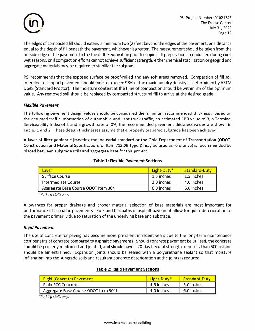
The following pavement design values should be considered the minimum recommended thickness. Based on the assumed traffic information of automobile and light truck traffic, an estimated CBR value of 3, a Terminal Serviceability Index of 2 and a growth rate of 0%, the recommended pavement thickness values are shown in Tables 1 and 2. These design thicknesses assume that a properly prepared subgrade has been achieved.
A layer of filter geofabric (meeting the industrial standard or the Ohio Department of Transportation (ODOT) Construction and Material Specifications of Item 712.09 Type D may be used as reference) is recommended be placed between subgrade soils and aggregate base for this project.
Table 1: Flexible Pavement Sections
Layer Light-Duty* Standard-Duty
Surface Course 1.5 inches 1.5 inches
Intermediate Course 2.0 inches 4.0 inches
Aggregate Base Course ODOT Item 304 6.0 inches 6.0 inches
*Parking stalls only.
Allowances for proper drainage and proper material selection of base materials are most important for performance of asphaltic pavements. Ruts and birdbaths in asphalt pavement allow for quick deterioration of the pavement primarily due to saturation of the underlying base and subgrade. Rigid Pavement
The use of concrete for paving has become more prevalent in recent years due to the long-term maintenance cost benefits of concrete compared to asphaltic pavements. Should concrete pavement be utilized, the concrete should be properly reinforced and jointed, and should have a 28-day flexural strength of no less than 600 psi and should be air entrained. Expansion joints should be sealed with a polyurethane sealant so that moisture infiltration into the subgrade soils and resultant concrete deterioration at the joints is reduced.
Table 2: Rigid Pavement Sections
Rigid (Concrete) Pavement Light-Duty* Standard-Duty
Plain PCC Concrete 4.5 inches 5.0 inches
Aggregate Base Course ODOT Item 304h 4.0 inches 6.0 inches
*Parking stalls only.
PSI Project Number: 01021746 The Freese Center
July 31, 2020 Page 19
www.intertek.com/building
Pavement for any dumpster pad areas or areas subject to consistent heavy loads should be constructed of a minimum of 8 inches of Portland cement concrete with load transfer devices installed where construction joints are required. A thickened edge equal to 20 percent of the pavement thickness and a minimum of 2 inches is recommended on the outside of slabs subjected to wheel loads. This thickened edge usually takes the form of an integral curb, tied shoulders, or thickened pavement tapered in the outer 4 feet of the pavement. Jointing for crack control should have a maximum spacing of 2 times the slab thickness (inches) in feet or for a 5 inch thickness the joints spacing should be a maximum 10 feet. Fill material should be compacted behind the curb or the edge of the outside slabs should be thickened. Design for drainage is of the utmost importance to minimize detrimental effects that may shorten the service life of the pavements. The pavement should be crowned or sloped to promote effective surface drainage and reduce the risk of water ponding. We recommend a minimum slope of 1.5 percent. In addition, the subgrade should be similarly sloped to promote effective subgrade drainage. We recommend “stub” or “finger” drains be provided around catch-basins and in other low areas of the proposed pavements to limit the accumulation of water on the frost susceptible subgrade soils. Subsurface edge drains should be provided at curbs. Where no curbs are proposed, ditches should be provided, and the pavement base course should be daylighted through the ditch sideslope to facilitate drainage of the base course. All materials used, and field operations required in connection with the contemplated pavement structures should follow recommendations and procedural details as per the Ohio Department of Transportation, Asphalt Institute, and/or American Concrete Institute.
4.7 PAVEMENT DRAINAGE AND MAINTENANCE
PSI recommends pavements to be sloped to provide rapid surface drainage. Water allowed to pond on or adjacent to the pavement could saturate the subgrade and cause premature deterioration of the pavements, and removal and replacement may be required. It must be emphasized that if water is allowed to pond beneath the pavement, then freeze-thaw cycles will cause subsequent heaving of the pavement section (and ultimately failure). Consideration should be given to the use of interceptor drains to collect and remove water collecting in the granular base. The interceptor drains could be incorporated with the storm drains of other utilities located in the pavement areas. Periodic maintenance of the pavement should be anticipated. This should include sealing of cracks and joints and by maintaining proper surface drainage to avoid ponding of water on or near the pavement areas. Underdrains, sub-drains and underslab drains presented in this report will not prevent moisture vapor that can cause mold growth.
4.8 SILTATION CONTROL
The Clean Water Act, implemented in 1990 includes a federal permit program called the National Pollutant Discharge Elimination System (NPDES). This program requires that projects sites more than one (1) acre or are part of a development which exceeds one (1) acre be covered under a permit. This typically includes the development of a storm water pollution prevention plan (SWPPP) as well as period inspections (typically once a week plus after significant rainfall). PSI is available to assist with these services.
PSI Project Number: 01021746 The Freese Center
July 31, 2020 Page 20
www.intertek.com/building
5 CONSTRUCTION CONSIDERATIONS
PSI should be retained to provide observation and testing of construction activities involved in the foundation, earthwork, and related activities of this project. PSI cannot accept responsibility for conditions that deviate from those described in this report, nor for the performance of the foundation system if not engaged to also provide construction observation and testing for this project.
5.1 MOISTURE SENSITIVE SOILS/WEATHER RELATED CONCERNS
The upper fine-grained soils encountered at this site will be sensitive to disturbances caused by construction traffic and to changes in moisture content. During wet weather periods, increases in the moisture content of the soil can cause significant reduction in the soil strength and support capabilities. In addition, soils that become wet may be slow to dry and thus significantly retard the progress of grading and compaction activities. It will, therefore, be advantageous to perform earthwork and foundation construction activities during dry weather.
5.2 DRAINAGE AND GROUNDWATER CONSIDERATIONS
PSI recommends that the Contractor determine the actual groundwater levels at the site at the time of the construction activities to assess the impact groundwater may have on construction. Water should not be allowed to collect in the foundation excavation or on prepared subgrades of the construction area either during or after construction. Undercut or excavated areas should be sloped toward one corner to facilitate removal of collected rainwater, groundwater, or surface runoff. Positive site drainage should be provided to reduce infiltration of surface water around the perimeter of the foundation. The grades should be sloped away from the foundation and surface drainage should be collected and discharged such that water is not permitted to infiltrate the backfill area of the foundation. It is possible that seasonal variations will cause fluctuations or a water table to be present in the upper soils. Additionally, perched water may be encountered in discontinuous zones within the overburden or near the contact with bedrock. Water should be removed from excavations by pumping. Should excessive and uncontrolled amounts of seepage occur, the Geotechnical engineer should be consulted.
5.3 EXCAVATIONS
In Federal Register, Volume 54, Number 209 (October 1989), the United States Department of Labor, Occupational Safety and Health Administration (OSHA) amended its "Construction Standards for Excavations, 29 CFR, part 1926, Subpart P". This document was issued to better enhance the safety of workers entering trenches or excavations. It is mandated by this federal regulation that excavations, whether they be utility trenches, basement excavation or footing excavations, be constructed in accordance with the new OSHA guidelines. It is PSI’s understanding that these regulations are being strictly enforced and if they are not closely followed, the owner and the contractor could be liable for substantial penalties.
The contractor is solely responsible for designing and constructing stable, temporary excavations and should shore, slope, or bench the sides of the excavations as required to maintain stability of both the excavation sides and bottom. The contractor's "responsible person", as defined in 29 CFR Part 1926, should evaluate the soil exposed in the excavations as part of the contractor's safety procedures. In no case should slope height, slope inclination, or excavation depth, including utility trench excavation depth, exceed those specified in local, state, and federal safety regulations.

PSI Project Number: 01021746 The Freese Center
July 31, 2020 Page 21
www.intertek.com/building
PSI is providing this information solely as a service to our client. PSI does not assume responsibility for construction site safety or the contractor's or other parties’ compliance with local, state, and federal safety or other regulations. A trench safety plan was beyond the scope of our services for this project.
PSI Project Number: 01021746 The Freese Center
July 31, 2020 Page 22
www.intertek.com/building
6 GEOTECHNICAL RISK
The concept of risk is an important aspect of the geotechnical evaluation. The primary reason is the analytical methods used to develop geotechnical recommendations do not comprise an exact science. The analytical tools which geotechnical engineers use are generally empirical and must be used in conjunction with engineering judgment and experience. Therefore, the solutions and recommendations presented in the geotechnical evaluation should not be considered risk-free and, more importantly, are not a guarantee that the interaction between the soils and the proposed structure will perform as planned. The engineering recommendations presented in the preceding section constitutes PSI’s professional estimate of those measures that are necessary for the proposed structure to perform according to the proposed design based on the information generated and referenced during this evaluation, and PSI’s experience in working with these conditions.
PSI Project Number: 01021746 The Freese Center
July 31, 2020 Page 23
www.intertek.com/building
7 REPORT LIMITATIONS
The recommendations submitted are based on the available subsurface information obtained by PSI and design details furnished by the Galion Port Authority. If there are revisions to the plans for this project or if deviations from the subsurface conditions noted in this report are encountered during construction, PSI should be notified immediately to determine if changes in the foundation recommendations are required. If PSI is not retained to perform these functions, PSI will not be responsible for the impact of those conditions on the project. The geotechnical engineer warrants that the findings, recommendations, specifications, or professional advice contained herein have been made in accordance with generally accepted professional geotechnical engineering practices in the local area. No other warranties are implied or expressed. After the plans and specifications are more complete, the geotechnical engineer should be retained and provided the opportunity to review the final design plans and specifications to check that our engineering recommendations have been properly incorporated into the design documents. At that time, it may be necessary to submit supplementary recommendations. This report has been prepared for the exclusive use of the Galion Port Authority for the specific application to the proposed Freese Center located along State Route 598 in Galion, Crawford County, Ohio.
www.intertek.com/building
APPENDIX
Site Location Map Boring Location Plan
Profile Boring Logs
Laboratory Test Results USGS Seismic Design Maps
Physiographic Regions of Ohio Karst Mapping General Notes
Unified Soil Classification Chart (USCS)
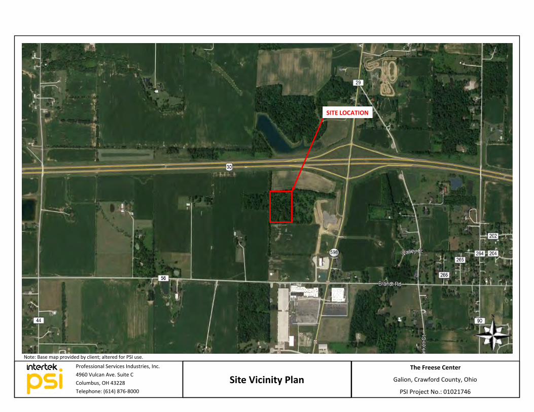
Site Vicinity Plan PSI Project No.: 01021746
Galion, Crawford County, Ohio
The Freese Center
Note: Base map provided by client; altered for PSI use.
Professional Services Industries, Inc.
4960 Vulcan Ave. Suite C
Columbus, OH 43228
Telephone: (614) 876-8000
SITE LOCATION
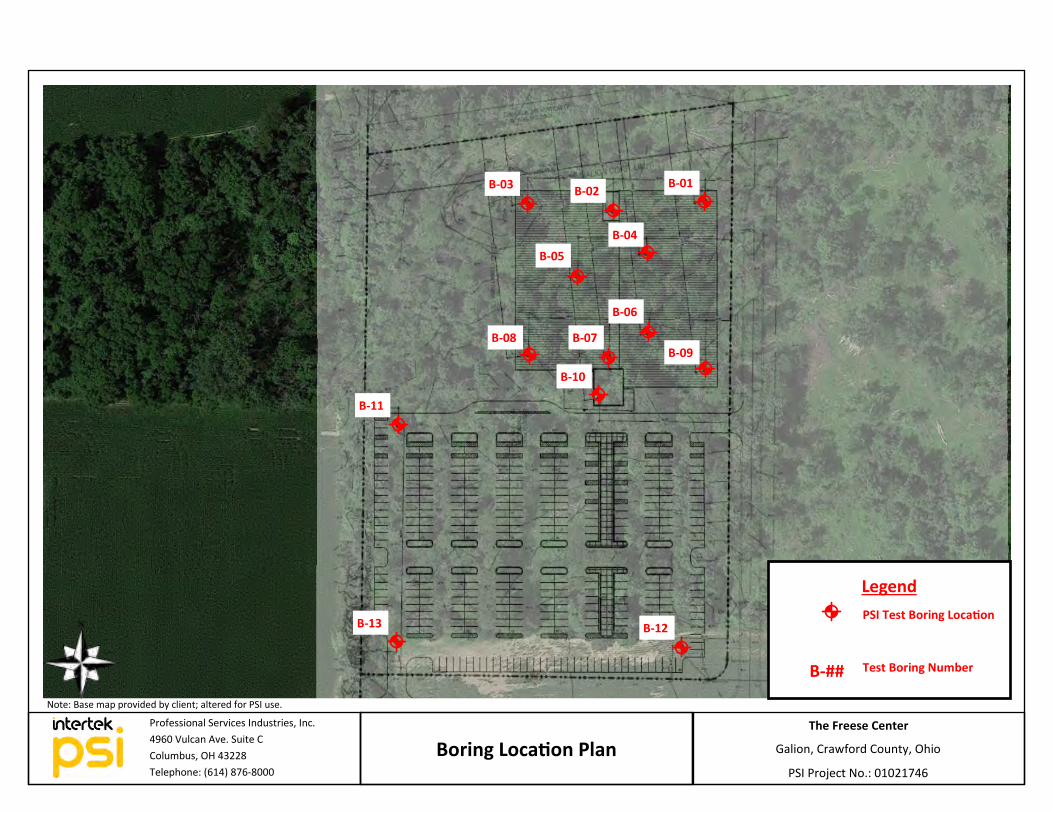
Boring Location Plan PSI Project No.: 01021746
Galion, Crawford County, Ohio
The Freese Center
Note: Base map provided by client; altered for PSI use.
Legend
PSI Test Boring Location
Test Boring Number B-##
Professional Services Industries, Inc.
4960 Vulcan Ave. Suite C
Columbus, OH 43228
Telephone: (614) 876-8000
B-01 B-02
B-04
B-05
B-08 B-07
B-06
B-09
B-10
B-11
B-13 B-12
B-03
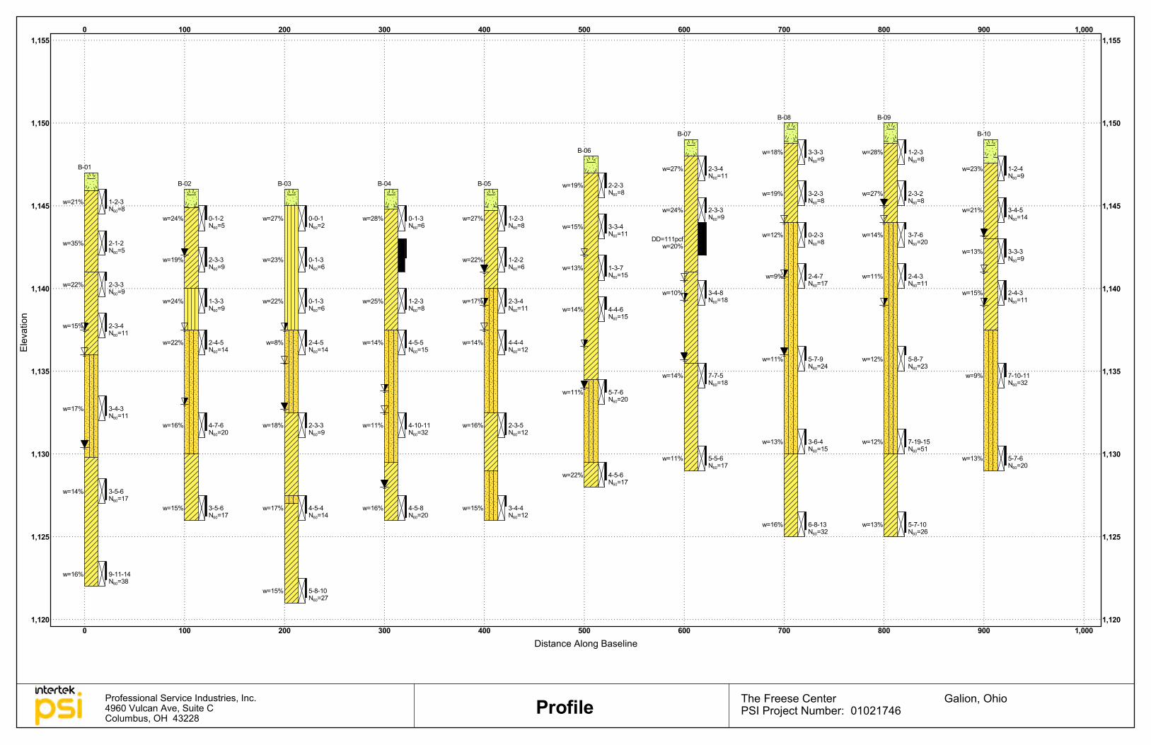
1,120
1,125
1,130
1,135
1,140
1,145
1,150
1,155
0 100 200 300 400 500 600 700 800 900 1,0001,120
1,125
1,130
1,135
1,140
1,145
1,150
1,1550 100 200 300 400 500 600 700 800 900 1,000
w=21%
w=35%
w=22%
w=15%
w=17%
w=14%
w=16%
1-2-3N60=8
2-1-2N60=5
2-3-3N60=9
2-3-4N60=11
3-4-3N60=11
3-5-6N60=17
9-11-14N60=38
B-01
w=24%
w=19%
w=24%
w=22%
w=16%
w=15%
0-1-2N60=5
2-3-3N60=9
1-3-3N60=9
2-4-5N60=14
4-7-6N60=20
3-5-6N60=17
B-02
w=27%
w=23%
w=22%
w=8%
w=18%
w=17%
w=15%
0-0-1N60=2
0-1-3N60=6
0-1-3N60=6
2-4-5N60=14
2-3-3N60=9
4-5-4N60=14
5-8-10N60=27
B-03
w=28%
w=25%
w=14%
w=11%
w=16%
0-1-3N60=6
1-2-3N60=8
4-5-5N60=15
4-10-11N60=32
4-5-8N60=20
B-04
w=27%
w=22%
w=17%
w=14%
w=16%
w=15%
1-2-3N60=8
1-2-2N60=6
2-3-4N60=11
4-4-4N60=12
2-3-5N60=12
3-4-4N60=12
B-05 w=19%
w=15%
w=13%
w=14%
w=11%
w=22%
2-2-3N60=8
3-3-4N60=11
1-3-7N60=15
4-4-6N60=15
5-7-6N60=20
4-5-6N60=17
B-06
w=27%
w=24%
DD=111pcfw=20%
w=10%
w=14%
w=11%
2-3-4N60=11
2-3-3N60=9
3-4-8N60=18
7-7-5N60=18
5-5-6N60=17
B-07
w=18%
w=19%
w=12%
w=9%
w=11%
w=13%
w=16%
3-3-3N60=9
3-2-3N60=8
0-2-3N60=8
2-4-7N60=17
5-7-9N60=24
3-6-4N60=15
6-8-13N60=32
B-08
w=28%
w=27%
w=14%
w=11%
w=12%
w=12%
w=13%
1-2-3N60=8
2-3-2N60=8
3-7-6N60=20
2-4-3N60=11
5-8-7N60=23
7-19-15N60=51
5-7-10N60=26
B-09
w=23%
w=21%
w=13%
w=15%
w=9%
w=13%
1-2-4N60=9
3-4-5N60=14
3-3-3N60=9
2-4-3N60=11
7-10-11N60=32
5-7-6N60=20
B-10
Distance Along Baseline
Galion, OhioProfile The Freese CenterPSI Project Number: 01021746
Professional Service Industries, Inc.4960 Vulcan Ave, Suite CColumbus, OH 43228
Elev
atio
n
1
2
3
4
5
6
7
14
15
6
13
14
15
13
(CL)
(CL)
(SM)
(CL)
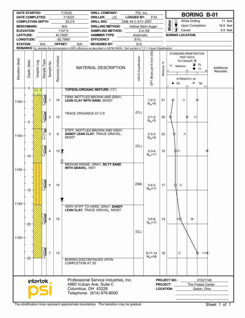
21
35
22
15
17
14
16
TOPSOIL/ORGANIC MIXTURE (13")
FIRM, MOTTLED BROWN AND GRAY,LEAN CLAY WITH SAND, MOIST
TRACE ORGANICS AT 3.5'
STIFF, MOTTLED BROWN AND GRAY,SANDY LEAN CLAY, TRACE GRAVEL,MOIST
MEDIUM DENSE, GRAY, SILTY SANDWITH GRAVEL, WET
VERY STIFF TO HARD, GRAY, SANDYLEAN CLAY, TRACE GRAVEL, MOIST
BORING DISCONTINUED UPONCOMPLETION AT 25'
1-2-3N60=8
2-1-2N60=5
2-3-3N60=9
2-3-4N60=11
3-4-3N60=11
3-5-6N60=17
9-11-14N60=38
PROJECT NO.: 01021746PROJECT: The Freese Center
Dep
th, (
feet
)
STRENGTH, tsf
AdditionalRemarks
USC
S C
lass
ifica
tion
0Qp
Sam
ple
Type
2.0
0
Moi
stur
e, %
MoistureMATERIAL DESCRIPTION
STANDARD PENETRATIONTEST DATA
N in blows/ft
Qu
Sam
ple
No.
Gra
phic
Log
50
PL
Elev
atio
n (fe
et)
LL
4.0
25
Rec
over
y (in
ches
)
While DrillingUpon CompletionCaved
1145
1140
1135
1130
1125
LATITUDE: 40.7605°LONGITUDE: -82.7989°
LOCATION: Galion, Ohio
16.6 feet11 feet
Wat
er
DRILLER: J.E.
Professional Service Industries, Inc.4960 Vulcan Ave, Suite CColumbus, OH 43228Telephone: (614) 876-8000
SPT
Blow
s pe
r 6-in
ch (S
S)
DATE STARTED: 7/16/20
BENCHMARK: N/A
The stratification lines represent approximate boundaries. The transition may be gradual. Sheet 1 of 1
DRILL COMPANY: PSI, Inc.
STATION: N/A OFFSET: N/A
LOGGED BY: P.M.DRILL RIG: CME 45 C ATV 2007
REVIEWED BY: D.K.EFFICIENCY 91%HAMMER TYPE: Automatic BORING LOCATION:
0
5
10
15
20
25
DATE COMPLETED: 7/16/20 BORING B-01
ELEVATION: 1147 ft
COMPLETION DEPTH 25.0 ft
9.5 feetDRILLING METHOD: Hollow Stem AugerSAMPLING METHOD: 2-in SS
REMARKS: N60 denotes the normalization to 60% efficiency as described in ASTM D4633. Soil symbol in "( )" = Visual Classification
>>
1
2
3
4
5
6
10
14
13
14
13
15
(CL)
(ML)
(SM)
(CL)
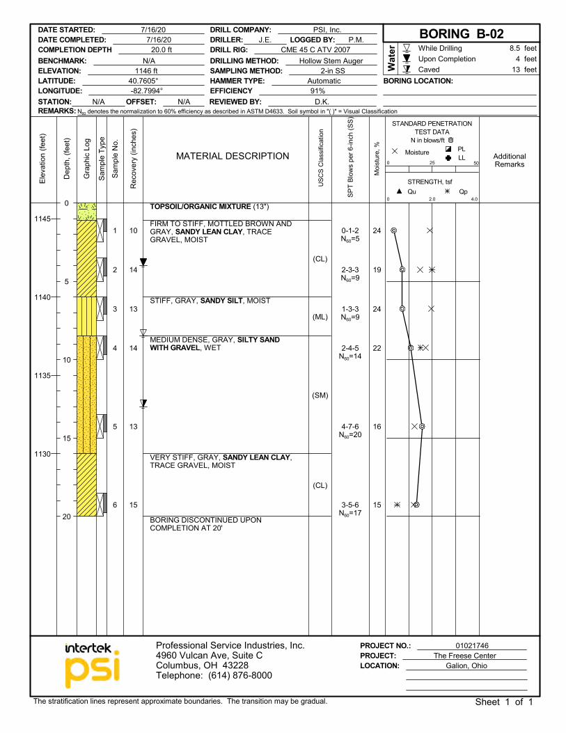
24
19
24
22
16
15
TOPSOIL/ORGANIC MIXTURE (13")
FIRM TO STIFF, MOTTLED BROWN ANDGRAY, SANDY LEAN CLAY, TRACEGRAVEL, MOIST
STIFF, GRAY, SANDY SILT, MOIST
MEDIUM DENSE, GRAY, SILTY SANDWITH GRAVEL, WET
VERY STIFF, GRAY, SANDY LEAN CLAY,TRACE GRAVEL, MOIST
BORING DISCONTINUED UPONCOMPLETION AT 20'
0-1-2N60=5
2-3-3N60=9
1-3-3N60=9
2-4-5N60=14
4-7-6N60=20
3-5-6N60=17
PROJECT NO.: 01021746PROJECT: The Freese Center
Dep
th, (
feet
)
STRENGTH, tsf
AdditionalRemarks
USC
S C
lass
ifica
tion
0Qp
Sam
ple
Type
2.0
0
Moi
stur
e, %
MoistureMATERIAL DESCRIPTION
STANDARD PENETRATIONTEST DATA
N in blows/ft
Qu
Sam
ple
No.
Gra
phic
Log
50
PL
Elev
atio
n (fe
et)
LL
4.0
25
Rec
over
y (in
ches
)
While DrillingUpon CompletionCaved
1145
1140
1135
1130
LATITUDE: 40.7605°LONGITUDE: -82.7994°
LOCATION: Galion, Ohio
4 feet8.5 feet
Wat
er
DRILLER: J.E.
Professional Service Industries, Inc.4960 Vulcan Ave, Suite CColumbus, OH 43228Telephone: (614) 876-8000
SPT
Blow
s pe
r 6-in
ch (S
S)
DATE STARTED: 7/16/20
BENCHMARK: N/A
The stratification lines represent approximate boundaries. The transition may be gradual. Sheet 1 of 1
DRILL COMPANY: PSI, Inc.
STATION: N/A OFFSET: N/A
LOGGED BY: P.M.DRILL RIG: CME 45 C ATV 2007
REVIEWED BY: D.K.EFFICIENCY 91%HAMMER TYPE: Automatic BORING LOCATION:
0
5
10
15
20
DATE COMPLETED: 7/16/20 BORING B-02
ELEVATION: 1146 ft
COMPLETION DEPTH 20.0 ft
13 feetDRILLING METHOD: Hollow Stem AugerSAMPLING METHOD: 2-in SS
REMARKS: N60 denotes the normalization to 60% efficiency as described in ASTM D4633. Soil symbol in "( )" = Visual Classification
1
2
3
4
5
6
7
15
14
13
12
11
13
14
ML
(SM)
(CL)
(SM)
(CL)
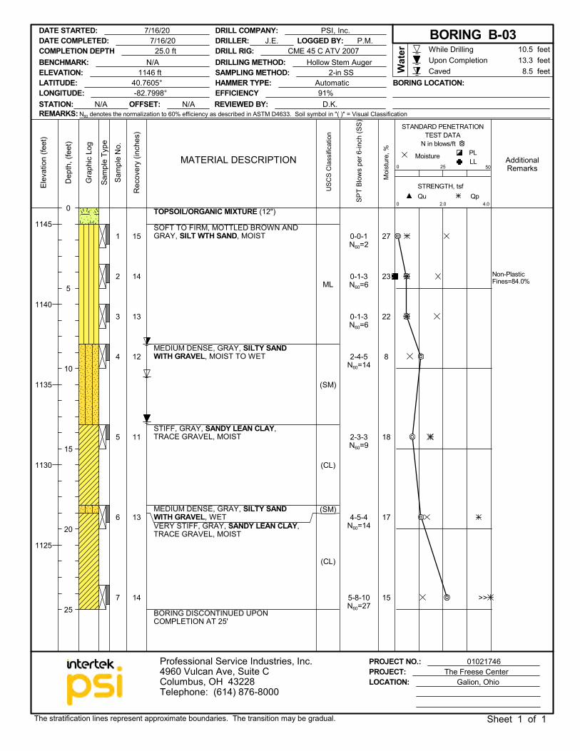
27
23
22
8
18
17
15
Non-PlasticFines=84.0%
TOPSOIL/ORGANIC MIXTURE (12")
SOFT TO FIRM, MOTTLED BROWN ANDGRAY, SILT WTH SAND, MOIST
MEDIUM DENSE, GRAY, SILTY SANDWITH GRAVEL, MOIST TO WET
STIFF, GRAY, SANDY LEAN CLAY,TRACE GRAVEL, MOIST
MEDIUM DENSE, GRAY, SILTY SANDWITH GRAVEL, WETVERY STIFF, GRAY, SANDY LEAN CLAY,TRACE GRAVEL, MOIST
BORING DISCONTINUED UPONCOMPLETION AT 25'
0-0-1N60=2
0-1-3N60=6
0-1-3N60=6
2-4-5N60=14
2-3-3N60=9
4-5-4N60=14
5-8-10N60=27
PROJECT NO.: 01021746PROJECT: The Freese Center
Dep
th, (
feet
)
STRENGTH, tsf
AdditionalRemarks
USC
S C
lass
ifica
tion
0Qp
Sam
ple
Type
2.0
0
Moi
stur
e, %
MoistureMATERIAL DESCRIPTION
STANDARD PENETRATIONTEST DATA
N in blows/ft
Qu
Sam
ple
No.
Gra
phic
Log
50
PL
Elev
atio
n (fe
et)
LL
4.0
25
Rec
over
y (in
ches
)
While DrillingUpon CompletionCaved
1145
1140
1135
1130
1125
LATITUDE: 40.7605°LONGITUDE: -82.7998°
LOCATION: Galion, Ohio
13.3 feet10.5 feet
Wat
er
DRILLER: J.E.
Professional Service Industries, Inc.4960 Vulcan Ave, Suite CColumbus, OH 43228Telephone: (614) 876-8000
SPT
Blow
s pe
r 6-in
ch (S
S)
DATE STARTED: 7/16/20
BENCHMARK: N/A
The stratification lines represent approximate boundaries. The transition may be gradual. Sheet 1 of 1
DRILL COMPANY: PSI, Inc.
STATION: N/A OFFSET: N/A
LOGGED BY: P.M.DRILL RIG: CME 45 C ATV 2007
REVIEWED BY: D.K.EFFICIENCY 91%HAMMER TYPE: Automatic BORING LOCATION:
0
5
10
15
20
25
DATE COMPLETED: 7/16/20 BORING B-03
ELEVATION: 1146 ft
COMPLETION DEPTH 25.0 ft
8.5 feetDRILLING METHOD: Hollow Stem AugerSAMPLING METHOD: 2-in SS
REMARKS: N60 denotes the normalization to 60% efficiency as described in ASTM D4633. Soil symbol in "( )" = Visual Classification
>>
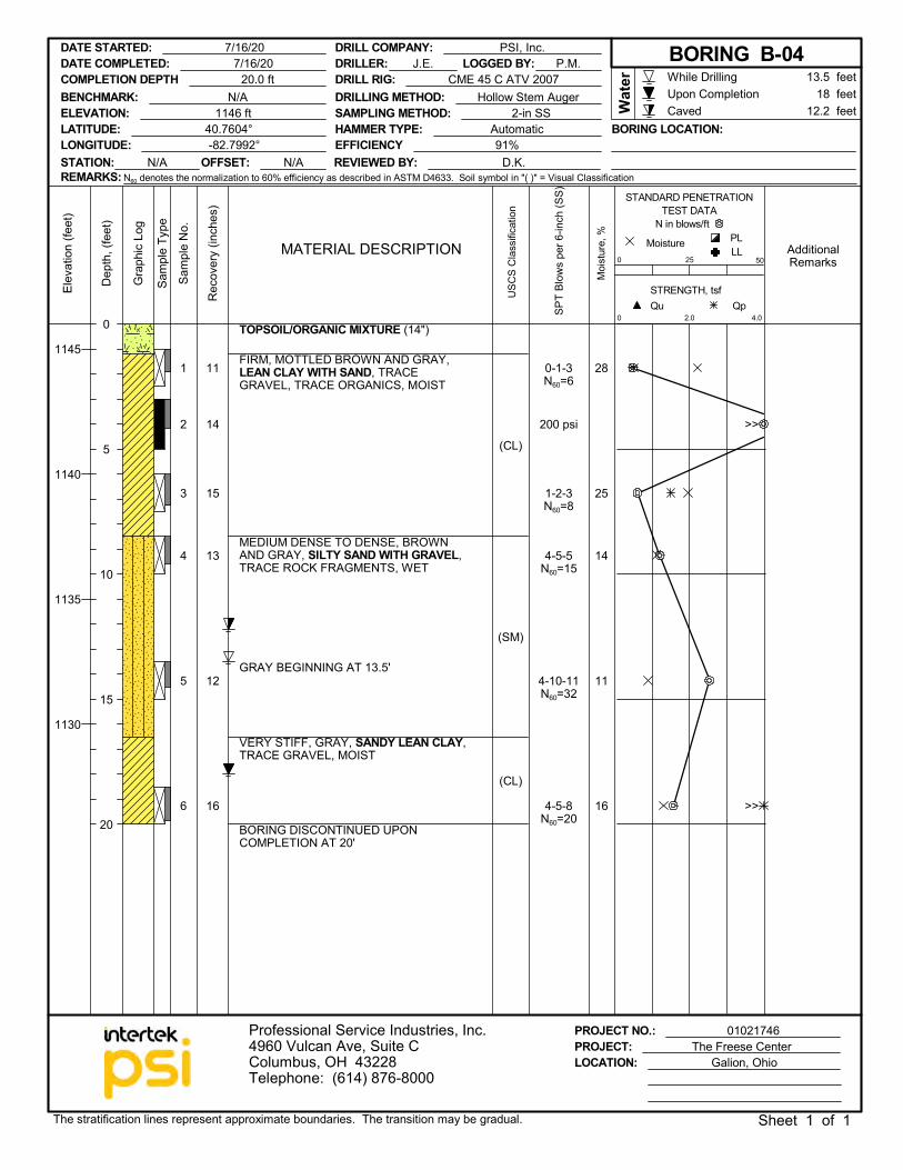
1
2
3
4
5
6
11
14
15
13
12
16
(CL)
(SM)
(CL)
28
25
14
11
16
200 psi
TOPSOIL/ORGANIC MIXTURE (14")
FIRM, MOTTLED BROWN AND GRAY,LEAN CLAY WITH SAND, TRACEGRAVEL, TRACE ORGANICS, MOIST
MEDIUM DENSE TO DENSE, BROWNAND GRAY, SILTY SAND WITH GRAVEL,TRACE ROCK FRAGMENTS, WET
GRAY BEGINNING AT 13.5'
VERY STIFF, GRAY, SANDY LEAN CLAY,TRACE GRAVEL, MOIST
BORING DISCONTINUED UPONCOMPLETION AT 20'
0-1-3N60=6
1-2-3N60=8
4-5-5N60=15
4-10-11N60=32
4-5-8N60=20
PROJECT NO.: 01021746PROJECT: The Freese Center
Dep
th, (
feet
)
STRENGTH, tsf
AdditionalRemarks
USC
S C
lass
ifica
tion
0Qp
Sam
ple
Type
2.0
0
Moi
stur
e, %
MoistureMATERIAL DESCRIPTION
STANDARD PENETRATIONTEST DATA
N in blows/ft
Qu
Sam
ple
No.
Gra
phic
Log
50
PL
Elev
atio
n (fe
et)
LL
4.0
25
Rec
over
y (in
ches
)
While DrillingUpon CompletionCaved
1145
1140
1135
1130
LATITUDE: 40.7604°LONGITUDE: -82.7992°
LOCATION: Galion, Ohio
18 feet13.5 feet
Wat
er
DRILLER: J.E.
Professional Service Industries, Inc.4960 Vulcan Ave, Suite CColumbus, OH 43228Telephone: (614) 876-8000
SPT
Blow
s pe
r 6-in
ch (S
S)
DATE STARTED: 7/16/20
BENCHMARK: N/A
The stratification lines represent approximate boundaries. The transition may be gradual. Sheet 1 of 1
DRILL COMPANY: PSI, Inc.
STATION: N/A OFFSET: N/A
LOGGED BY: P.M.DRILL RIG: CME 45 C ATV 2007
REVIEWED BY: D.K.EFFICIENCY 91%HAMMER TYPE: Automatic BORING LOCATION:
0
5
10
15
20
DATE COMPLETED: 7/16/20 BORING B-04
ELEVATION: 1146 ft
COMPLETION DEPTH 20.0 ft
12.2 feetDRILLING METHOD: Hollow Stem AugerSAMPLING METHOD: 2-in SS
REMARKS: N60 denotes the normalization to 60% efficiency as described in ASTM D4633. Soil symbol in "( )" = Visual Classification
>>
>>
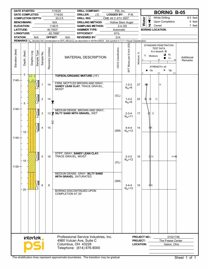
1
2
3
4
5
6
14
14
13
15
16
8
(CL)
(SM)
(CL)
(SM)
27
22
17
14
16
15
TOPSOIL/ORGANIC MIXTURE (15")
FIRM, MOTTLED BROWN AND GRAY,SANDY LEAN CLAY, TRACE GRAVEL,MOIST
MEDIUM DENSE, BROWN AND GRAY,SILTY SAND WITH GRAVEL, WET
STIFF, GRAY, SANDY LEAN CLAY,TRACE GRAVEL, MOIST
MEDIUM DENSE, GRAY, SILTY SANDWITH GRAVEL, SATURATED
BORING DISCONTINUED UPONCOMPLETION AT 20'
1-2-3N60=8
1-2-2N60=6
2-3-4N60=11
4-4-4N60=12
2-3-5N60=12
3-4-4N60=12
PROJECT NO.: 01021746PROJECT: The Freese Center
Dep
th, (
feet
)
STRENGTH, tsf
AdditionalRemarks
USC
S C
lass
ifica
tion
0Qp
Sam
ple
Type
2.0
0
Moi
stur
e, %
MoistureMATERIAL DESCRIPTION
STANDARD PENETRATIONTEST DATA
N in blows/ft
Qu
Sam
ple
No.
Gra
phic
Log
50
PL
Elev
atio
n (fe
et)
LL
4.0
25
Rec
over
y (in
ches
)
While DrillingUpon CompletionCaved
1145
1140
1135
1130
LATITUDE: 40.7603°LONGITUDE: -82.7996°
LOCATION: Galion, Ohio
5 feet8.5 feet
Wat
er
DRILLER: J.E.
Professional Service Industries, Inc.4960 Vulcan Ave, Suite CColumbus, OH 43228Telephone: (614) 876-8000
SPT
Blow
s pe
r 6-in
ch (S
S)
DATE STARTED: 7/16/20
BENCHMARK: N/A
The stratification lines represent approximate boundaries. The transition may be gradual. Sheet 1 of 1
DRILL COMPANY: PSI, Inc.
STATION: N/A OFFSET: N/A
LOGGED BY: P.M.DRILL RIG: CME 45 C ATV 2007
REVIEWED BY: D.K.EFFICIENCY 91%HAMMER TYPE: Automatic BORING LOCATION:
0
5
10
15
20
DATE COMPLETED: 7/16/20 BORING B-05
ELEVATION: 1146 ft
COMPLETION DEPTH 20.0 ft
7 feetDRILLING METHOD: Hollow Stem AugerSAMPLING METHOD: 2-in SS
REMARKS: N60 denotes the normalization to 60% efficiency as described in ASTM D4633. Soil symbol in "( )" = Visual Classification
>>
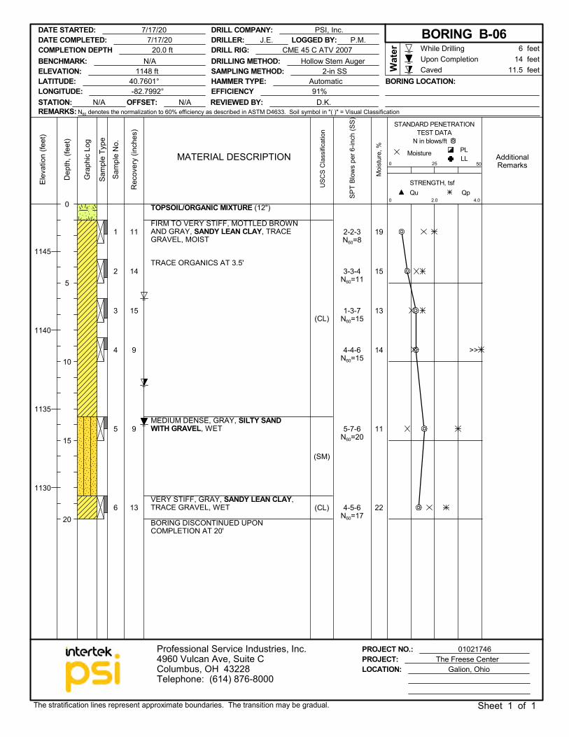
1
2
3
4
5
6
11
14
15
9
9
13
(CL)
(SM)
(CL)
19
15
13
14
11
22
TOPSOIL/ORGANIC MIXTURE (12")
FIRM TO VERY STIFF, MOTTLED BROWNAND GRAY, SANDY LEAN CLAY, TRACEGRAVEL, MOIST
TRACE ORGANICS AT 3.5'
MEDIUM DENSE, GRAY, SILTY SANDWITH GRAVEL, WET
VERY STIFF, GRAY, SANDY LEAN CLAY,TRACE GRAVEL, WET
BORING DISCONTINUED UPONCOMPLETION AT 20'
2-2-3N60=8
3-3-4N60=11
1-3-7N60=15
4-4-6N60=15
5-7-6N60=20
4-5-6N60=17
PROJECT NO.: 01021746PROJECT: The Freese Center
Dep
th, (
feet
)
STRENGTH, tsf
AdditionalRemarks
USC
S C
lass
ifica
tion
0Qp
Sam
ple
Type
2.0
0
Moi
stur
e, %
MoistureMATERIAL DESCRIPTION
STANDARD PENETRATIONTEST DATA
N in blows/ft
Qu
Sam
ple
No.
Gra
phic
Log
50
PL
Elev
atio
n (fe
et)
LL
4.0
25
Rec
over
y (in
ches
)
While DrillingUpon CompletionCaved
1145
1140
1135
1130
LATITUDE: 40.7601°LONGITUDE: -82.7992°
LOCATION: Galion, Ohio
14 feet6 feet
Wat
er
DRILLER: J.E.
Professional Service Industries, Inc.4960 Vulcan Ave, Suite CColumbus, OH 43228Telephone: (614) 876-8000
SPT
Blow
s pe
r 6-in
ch (S
S)
DATE STARTED: 7/17/20
BENCHMARK: N/A
The stratification lines represent approximate boundaries. The transition may be gradual. Sheet 1 of 1
DRILL COMPANY: PSI, Inc.
STATION: N/A OFFSET: N/A
LOGGED BY: P.M.DRILL RIG: CME 45 C ATV 2007
REVIEWED BY: D.K.EFFICIENCY 91%HAMMER TYPE: Automatic BORING LOCATION:
0
5
10
15
20
DATE COMPLETED: 7/17/20 BORING B-06
ELEVATION: 1148 ft
COMPLETION DEPTH 20.0 ft
11.5 feetDRILLING METHOD: Hollow Stem AugerSAMPLING METHOD: 2-in SS
REMARKS: N60 denotes the normalization to 60% efficiency as described in ASTM D4633. Soil symbol in "( )" = Visual Classification
>>
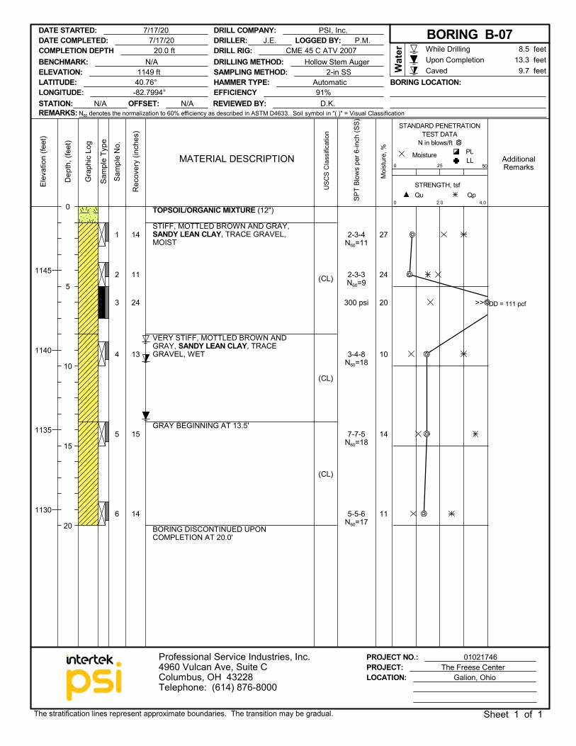
1
2
3
4
5
6
14
11
24
13
15
14
(CL)
(CL)
(CL)
27
24
20
10
14
11
300 psi DD = 111 pcf
TOPSOIL/ORGANIC MIXTURE (12")
STIFF, MOTTLED BROWN AND GRAY,SANDY LEAN CLAY, TRACE GRAVEL,MOIST
VERY STIFF, MOTTLED BROWN ANDGRAY, SANDY LEAN CLAY, TRACEGRAVEL, WET
GRAY BEGINNING AT 13.5'
BORING DISCONTINUED UPONCOMPLETION AT 20.0'
2-3-4N60=11
2-3-3N60=9
3-4-8N60=18
7-7-5N60=18
5-5-6N60=17
PROJECT NO.: 01021746PROJECT: The Freese Center
Dep
th, (
feet
)
STRENGTH, tsf
AdditionalRemarks
USC
S C
lass
ifica
tion
0Qp
Sam
ple
Type
2.0
0
Moi
stur
e, %
MoistureMATERIAL DESCRIPTION
STANDARD PENETRATIONTEST DATA
N in blows/ft
Qu
Sam
ple
No.
Gra
phic
Log
50
PL
Elev
atio
n (fe
et)
LL
4.0
25
Rec
over
y (in
ches
)
While DrillingUpon CompletionCaved
1145
1140
1135
1130
LATITUDE: 40.76°LONGITUDE: -82.7994°
LOCATION: Galion, Ohio
13.3 feet8.5 feet
Wat
er
DRILLER: J.E.
Professional Service Industries, Inc.4960 Vulcan Ave, Suite CColumbus, OH 43228Telephone: (614) 876-8000
SPT
Blow
s pe
r 6-in
ch (S
S)
DATE STARTED: 7/17/20
BENCHMARK: N/A
The stratification lines represent approximate boundaries. The transition may be gradual. Sheet 1 of 1
DRILL COMPANY: PSI, Inc.
STATION: N/A OFFSET: N/A
LOGGED BY: P.M.DRILL RIG: CME 45 C ATV 2007
REVIEWED BY: D.K.EFFICIENCY 91%HAMMER TYPE: Automatic BORING LOCATION:
0
5
10
15
20
DATE COMPLETED: 7/17/20 BORING B-07
ELEVATION: 1149 ft
COMPLETION DEPTH 20.0 ft
9.7 feetDRILLING METHOD: Hollow Stem AugerSAMPLING METHOD: 2-in SS
REMARKS: N60 denotes the normalization to 60% efficiency as described in ASTM D4633. Soil symbol in "( )" = Visual Classification
>>
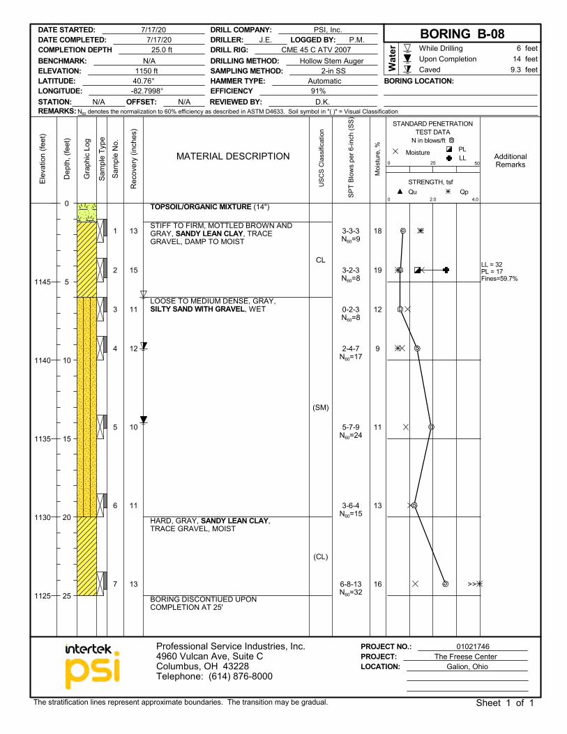
1
2
3
4
5
6
7
13
15
11
12
10
11
13
CL
(SM)
(CL)
18
19
12
9
11
13
16
LL = 32PL = 17Fines=59.7%
TOPSOIL/ORGANIC MIXTURE (14")
STIFF TO FIRM, MOTTLED BROWN ANDGRAY, SANDY LEAN CLAY, TRACEGRAVEL, DAMP TO MOIST
LOOSE TO MEDIUM DENSE, GRAY,SILTY SAND WITH GRAVEL, WET
HARD, GRAY, SANDY LEAN CLAY,TRACE GRAVEL, MOIST
BORING DISCONTIUED UPONCOMPLETION AT 25'
3-3-3N60=9
3-2-3N60=8
0-2-3N60=8
2-4-7N60=17
5-7-9N60=24
3-6-4N60=15
6-8-13N60=32
PROJECT NO.: 01021746PROJECT: The Freese Center
Dep
th, (
feet
)
STRENGTH, tsf
AdditionalRemarks
USC
S C
lass
ifica
tion
0Qp
Sam
ple
Type
2.0
0
Moi
stur
e, %
MoistureMATERIAL DESCRIPTION
STANDARD PENETRATIONTEST DATA
N in blows/ft
Qu
Sam
ple
No.
Gra
phic
Log
50
PL
Elev
atio
n (fe
et)
LL
4.0
25
Rec
over
y (in
ches
)
While DrillingUpon CompletionCaved
1145
1140
1135
1130
1125
LATITUDE: 40.76°LONGITUDE: -82.7998°
LOCATION: Galion, Ohio
14 feet6 feet
Wat
er
DRILLER: J.E.
Professional Service Industries, Inc.4960 Vulcan Ave, Suite CColumbus, OH 43228Telephone: (614) 876-8000
SPT
Blow
s pe
r 6-in
ch (S
S)
DATE STARTED: 7/17/20
BENCHMARK: N/A
The stratification lines represent approximate boundaries. The transition may be gradual. Sheet 1 of 1
DRILL COMPANY: PSI, Inc.
STATION: N/A OFFSET: N/A
LOGGED BY: P.M.DRILL RIG: CME 45 C ATV 2007
REVIEWED BY: D.K.EFFICIENCY 91%HAMMER TYPE: Automatic BORING LOCATION:
0
5
10
15
20
25
DATE COMPLETED: 7/17/20 BORING B-08
ELEVATION: 1150 ft
COMPLETION DEPTH 25.0 ft
9.3 feetDRILLING METHOD: Hollow Stem AugerSAMPLING METHOD: 2-in SS
REMARKS: N60 denotes the normalization to 60% efficiency as described in ASTM D4633. Soil symbol in "( )" = Visual Classification
>>
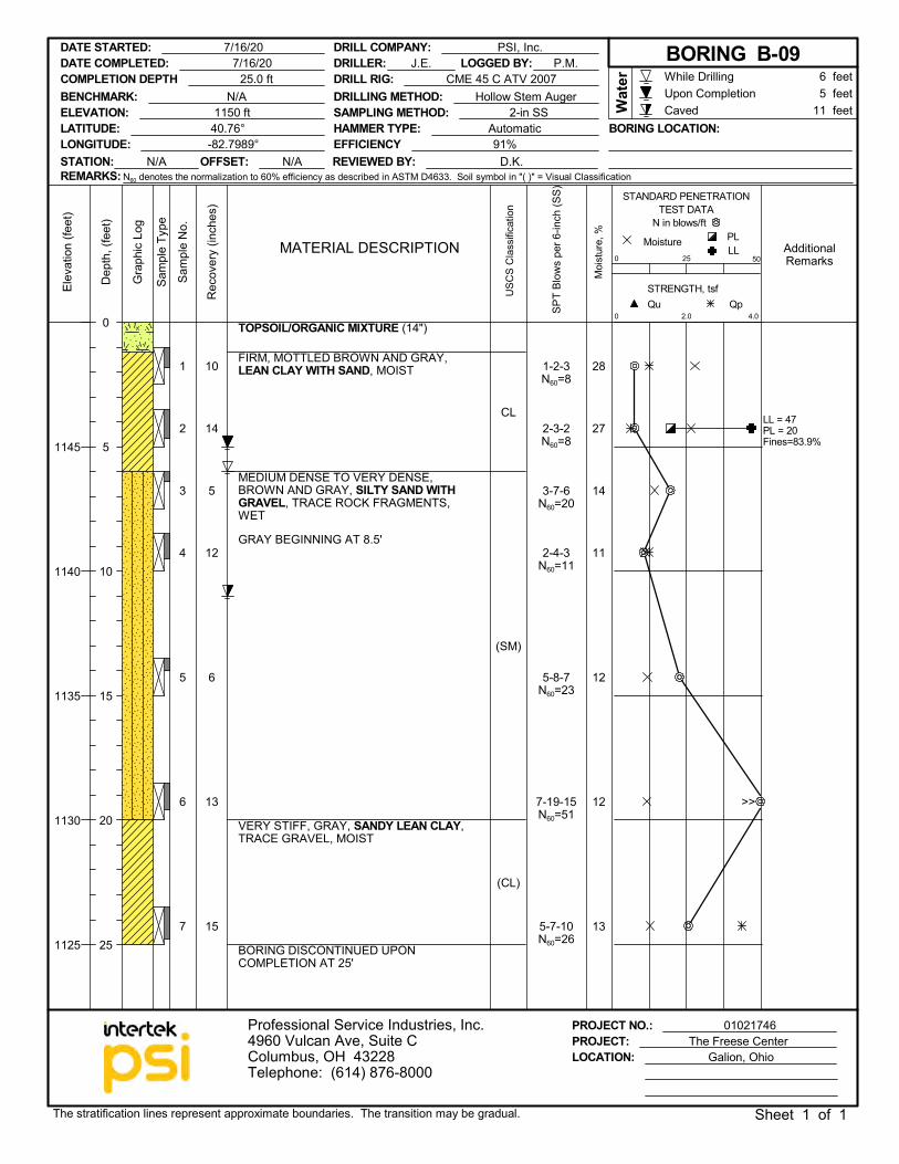
1
2
3
4
5
6
7
10
14
5
12
6
13
15
CL
(SM)
(CL)
28
27
14
11
12
12
13
LL = 47PL = 20Fines=83.9%
TOPSOIL/ORGANIC MIXTURE (14")
FIRM, MOTTLED BROWN AND GRAY,LEAN CLAY WITH SAND, MOIST
MEDIUM DENSE TO VERY DENSE,BROWN AND GRAY, SILTY SAND WITHGRAVEL, TRACE ROCK FRAGMENTS,WET
GRAY BEGINNING AT 8.5'
VERY STIFF, GRAY, SANDY LEAN CLAY,TRACE GRAVEL, MOIST
BORING DISCONTINUED UPONCOMPLETION AT 25'
1-2-3N60=8
2-3-2N60=8
3-7-6N60=20
2-4-3N60=11
5-8-7N60=23
7-19-15N60=51
5-7-10N60=26
PROJECT NO.: 01021746PROJECT: The Freese Center
Dep
th, (
feet
)
STRENGTH, tsf
AdditionalRemarks
USC
S C
lass
ifica
tion
0Qp
Sam
ple
Type
2.0
0
Moi
stur
e, %
MoistureMATERIAL DESCRIPTION
STANDARD PENETRATIONTEST DATA
N in blows/ft
Qu
Sam
ple
No.
Gra
phic
Log
50
PL
Elev
atio
n (fe
et)
LL
4.0
25
Rec
over
y (in
ches
)
While DrillingUpon CompletionCaved
1145
1140
1135
1130
1125
LATITUDE: 40.76°LONGITUDE: -82.7989°
LOCATION: Galion, Ohio
5 feet6 feet
Wat
er
DRILLER: J.E.
Professional Service Industries, Inc.4960 Vulcan Ave, Suite CColumbus, OH 43228Telephone: (614) 876-8000
SPT
Blow
s pe
r 6-in
ch (S
S)
DATE STARTED: 7/16/20
BENCHMARK: N/A
The stratification lines represent approximate boundaries. The transition may be gradual. Sheet 1 of 1
DRILL COMPANY: PSI, Inc.
STATION: N/A OFFSET: N/A
LOGGED BY: P.M.DRILL RIG: CME 45 C ATV 2007
REVIEWED BY: D.K.EFFICIENCY 91%HAMMER TYPE: Automatic BORING LOCATION:
0
5
10
15
20
25
DATE COMPLETED: 7/16/20 BORING B-09
ELEVATION: 1150 ft
COMPLETION DEPTH 25.0 ft
11 feetDRILLING METHOD: Hollow Stem AugerSAMPLING METHOD: 2-in SS
REMARKS: N60 denotes the normalization to 60% efficiency as described in ASTM D4633. Soil symbol in "( )" = Visual Classification
>>
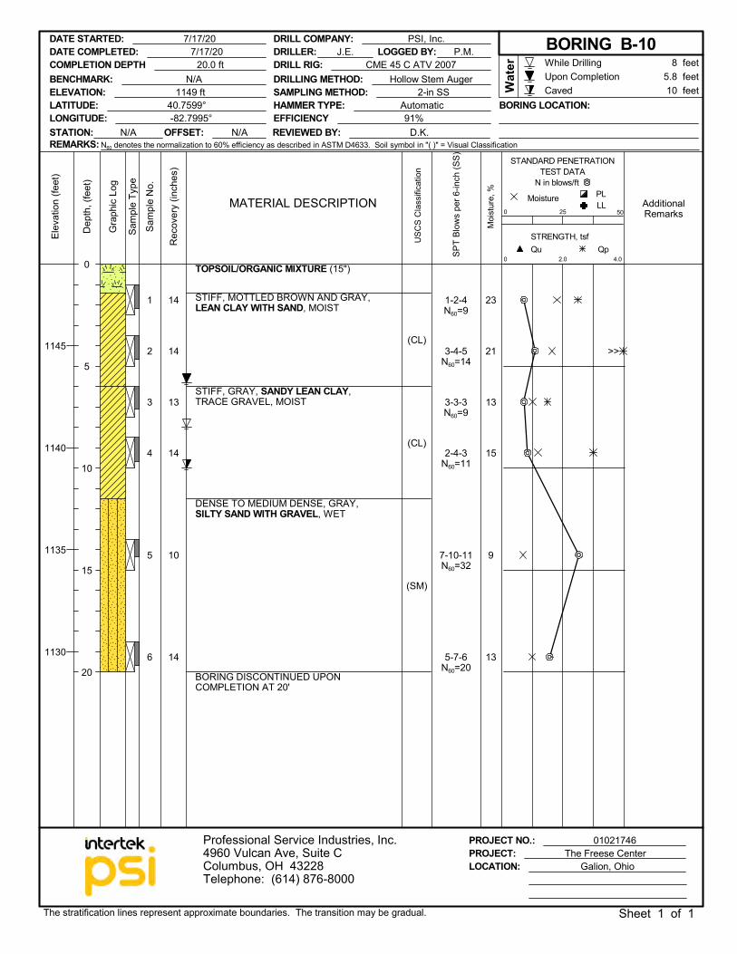
1
2
3
4
5
6
14
14
13
14
10
14
(CL)
(CL)
(SM)
23
21
13
15
9
13
TOPSOIL/ORGANIC MIXTURE (15")
STIFF, MOTTLED BROWN AND GRAY,LEAN CLAY WITH SAND, MOIST
STIFF, GRAY, SANDY LEAN CLAY,TRACE GRAVEL, MOIST
DENSE TO MEDIUM DENSE, GRAY,SILTY SAND WITH GRAVEL, WET
BORING DISCONTINUED UPONCOMPLETION AT 20'
1-2-4N60=9
3-4-5N60=14
3-3-3N60=9
2-4-3N60=11
7-10-11N60=32
5-7-6N60=20
PROJECT NO.: 01021746PROJECT: The Freese Center
Dep
th, (
feet
)
STRENGTH, tsf
AdditionalRemarks
USC
S C
lass
ifica
tion
0Qp
Sam
ple
Type
2.0
0
Moi
stur
e, %
MoistureMATERIAL DESCRIPTION
STANDARD PENETRATIONTEST DATA
N in blows/ft
Qu
Sam
ple
No.
Gra
phic
Log
50
PL
Elev
atio
n (fe
et)
LL
4.0
25
Rec
over
y (in
ches
)
While DrillingUpon CompletionCaved
1145
1140
1135
1130
LATITUDE: 40.7599°LONGITUDE: -82.7995°
LOCATION: Galion, Ohio
5.8 feet8 feet
Wat
er
DRILLER: J.E.
Professional Service Industries, Inc.4960 Vulcan Ave, Suite CColumbus, OH 43228Telephone: (614) 876-8000
SPT
Blow
s pe
r 6-in
ch (S
S)
DATE STARTED: 7/17/20
BENCHMARK: N/A
The stratification lines represent approximate boundaries. The transition may be gradual. Sheet 1 of 1
DRILL COMPANY: PSI, Inc.
STATION: N/A OFFSET: N/A
LOGGED BY: P.M.DRILL RIG: CME 45 C ATV 2007
REVIEWED BY: D.K.EFFICIENCY 91%HAMMER TYPE: Automatic BORING LOCATION:
0
5
10
15
20
DATE COMPLETED: 7/17/20 BORING B-10
ELEVATION: 1149 ft
COMPLETION DEPTH 20.0 ft
10 feetDRILLING METHOD: Hollow Stem AugerSAMPLING METHOD: 2-in SS
REMARKS: N60 denotes the normalization to 60% efficiency as described in ASTM D4633. Soil symbol in "( )" = Visual Classification
>>
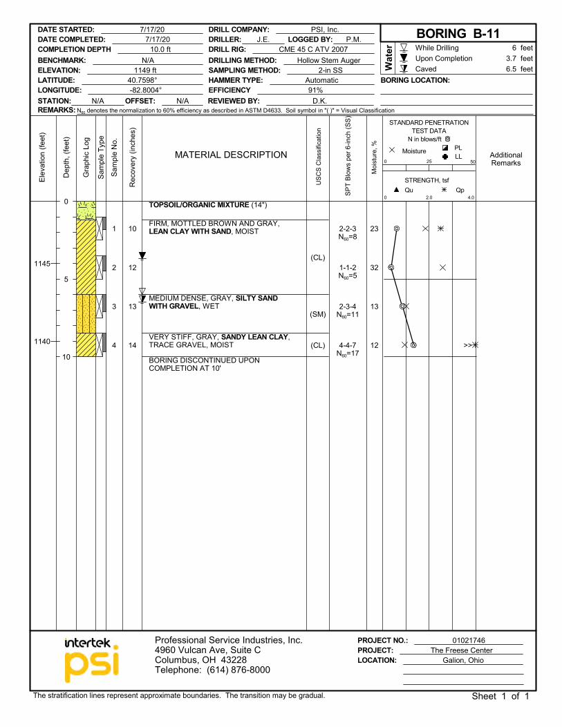
1
2
3
4
10
12
13
14
(CL)
(SM)
(CL)
23
32
13
12
TOPSOIL/ORGANIC MIXTURE (14")
FIRM, MOTTLED BROWN AND GRAY,LEAN CLAY WITH SAND, MOIST
MEDIUM DENSE, GRAY, SILTY SANDWITH GRAVEL, WET
VERY STIFF, GRAY, SANDY LEAN CLAY,TRACE GRAVEL, MOIST
BORING DISCONTINUED UPONCOMPLETION AT 10'
2-2-3N60=8
1-1-2N60=5
2-3-4N60=11
4-4-7N60=17
PROJECT NO.: 01021746PROJECT: The Freese Center
Dep
th, (
feet
)
STRENGTH, tsf
AdditionalRemarks
USC
S C
lass
ifica
tion
0Qp
Sam
ple
Type
2.0
0
Moi
stur
e, %
MoistureMATERIAL DESCRIPTION
STANDARD PENETRATIONTEST DATA
N in blows/ft
Qu
Sam
ple
No.
Gra
phic
Log
50
PL
Elev
atio
n (fe
et)
LL
4.0
25
Rec
over
y (in
ches
)
While DrillingUpon CompletionCaved
1145
1140
LATITUDE: 40.7598°LONGITUDE: -82.8004°
LOCATION: Galion, Ohio
3.7 feet6 feet
Wat
er
DRILLER: J.E.
Professional Service Industries, Inc.4960 Vulcan Ave, Suite CColumbus, OH 43228Telephone: (614) 876-8000
SPT
Blow
s pe
r 6-in
ch (S
S)
DATE STARTED: 7/17/20
BENCHMARK: N/A
The stratification lines represent approximate boundaries. The transition may be gradual. Sheet 1 of 1
DRILL COMPANY: PSI, Inc.
STATION: N/A OFFSET: N/A
LOGGED BY: P.M.DRILL RIG: CME 45 C ATV 2007
REVIEWED BY: D.K.EFFICIENCY 91%HAMMER TYPE: Automatic BORING LOCATION:
0
5
10
DATE COMPLETED: 7/17/20 BORING B-11
ELEVATION: 1149 ft
COMPLETION DEPTH 10.0 ft
6.5 feetDRILLING METHOD: Hollow Stem AugerSAMPLING METHOD: 2-in SS
REMARKS: N60 denotes the normalization to 60% efficiency as described in ASTM D4633. Soil symbol in "( )" = Visual Classification
>>
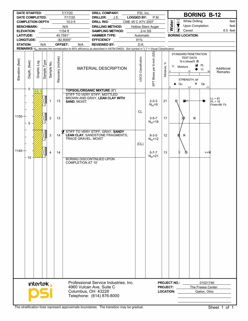
1
2
3
4
13
13
14
14
CL
(CL)
21
17
12
13
LL = 43PL = 19Fines=88.1%
TOPSOIL/ORGANIC MIXTURE (8")STIFF TO VERY STIFF, MOTTLEDBROWN AND GRAY, LEAN CLAY WITHSAND, MOIST
STIFF TO VERY STIFF, GRAY, SANDYLEAN CLAY, SANDSTONE FRAGMENTS,TRACE GRAVEL, MOIST
BORING DISCONTINUED UPONCOMPLETION AT 10'
2-3-3N60=9
3-5-7N60=18
8-3-5N60=12
5-7-7N60=21
PROJECT NO.: 01021746PROJECT: The Freese Center
Dep
th, (
feet
)
STRENGTH, tsf
AdditionalRemarks
USC
S C
lass
ifica
tion
0Qp
Sam
ple
Type
2.0
0
Moi
stur
e, %
MoistureMATERIAL DESCRIPTION
STANDARD PENETRATIONTEST DATA
N in blows/ft
Qu
Sam
ple
No.
Gra
phic
Log
50
PL
Elev
atio
n (fe
et)
LL
4.0
25
Rec
over
y (in
ches
)
While DrillingUpon CompletionCaved
1150
1145
LATITUDE: 40.7591°LONGITUDE: -82.8005°
LOCATION: Galion, Ohio
feet feet
Wat
er
DRILLER: J.E.
Professional Service Industries, Inc.4960 Vulcan Ave, Suite CColumbus, OH 43228Telephone: (614) 876-8000
SPT
Blow
s pe
r 6-in
ch (S
S)
DATE STARTED: 7/17/20
BENCHMARK: N/A
The stratification lines represent approximate boundaries. The transition may be gradual. Sheet 1 of 1
DRILL COMPANY: PSI, Inc.
STATION: N/A OFFSET: N/A
LOGGED BY: P.M.DRILL RIG: CME 45 C ATV 2007
REVIEWED BY: D.K.EFFICIENCY 91%HAMMER TYPE: Automatic BORING LOCATION:
0
5
10
DATE COMPLETED: 7/17/20 BORING B-12
ELEVATION: 1154 ft
COMPLETION DEPTH 10.0 ft
6.5 feetDRILLING METHOD: Hollow Stem AugerSAMPLING METHOD: 2-in SS
REMARKS: N60 denotes the normalization to 60% efficiency as described in ASTM D4633. Soil symbol in "( )" = Visual Classification
>>
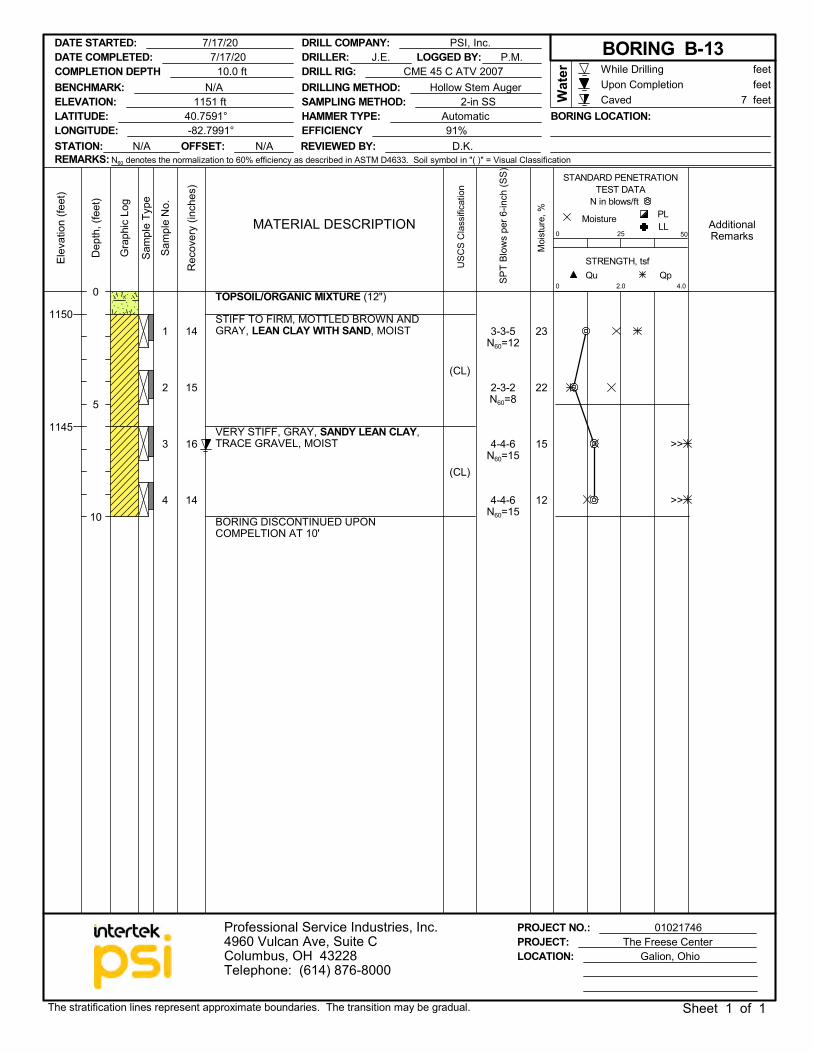
1
2
3
4
14
15
16
14
(CL)
(CL)
23
22
15
12
TOPSOIL/ORGANIC MIXTURE (12")
STIFF TO FIRM, MOTTLED BROWN ANDGRAY, LEAN CLAY WITH SAND, MOIST
VERY STIFF, GRAY, SANDY LEAN CLAY,TRACE GRAVEL, MOIST
BORING DISCONTINUED UPONCOMPELTION AT 10'
3-3-5N60=12
2-3-2N60=8
4-4-6N60=15
4-4-6N60=15
PROJECT NO.: 01021746PROJECT: The Freese Center
Dep
th, (
feet
)
STRENGTH, tsf
AdditionalRemarks
USC
S C
lass
ifica
tion
0Qp
Sam
ple
Type
2.0
0
Moi
stur
e, %
MoistureMATERIAL DESCRIPTION
STANDARD PENETRATIONTEST DATA
N in blows/ft
Qu
Sam
ple
No.
Gra
phic
Log
50
PL
Elev
atio
n (fe
et)
LL
4.0
25
Rec
over
y (in
ches
)
While DrillingUpon CompletionCaved
1150
1145
LATITUDE: 40.7591°LONGITUDE: -82.7991°
LOCATION: Galion, Ohio
feet feet
Wat
er
DRILLER: J.E.
Professional Service Industries, Inc.4960 Vulcan Ave, Suite CColumbus, OH 43228Telephone: (614) 876-8000
SPT
Blow
s pe
r 6-in
ch (S
S)
DATE STARTED: 7/17/20
BENCHMARK: N/A
The stratification lines represent approximate boundaries. The transition may be gradual. Sheet 1 of 1
DRILL COMPANY: PSI, Inc.
STATION: N/A OFFSET: N/A
LOGGED BY: P.M.DRILL RIG: CME 45 C ATV 2007
REVIEWED BY: D.K.EFFICIENCY 91%HAMMER TYPE: Automatic BORING LOCATION:
0
5
10
DATE COMPLETED: 7/17/20 BORING B-13
ELEVATION: 1151 ft
COMPLETION DEPTH 10.0 ft
7 feetDRILLING METHOD: Hollow Stem AugerSAMPLING METHOD: 2-in SS
REMARKS: N60 denotes the normalization to 60% efficiency as described in ASTM D4633. Soil symbol in "( )" = Visual Classification
>>
>>
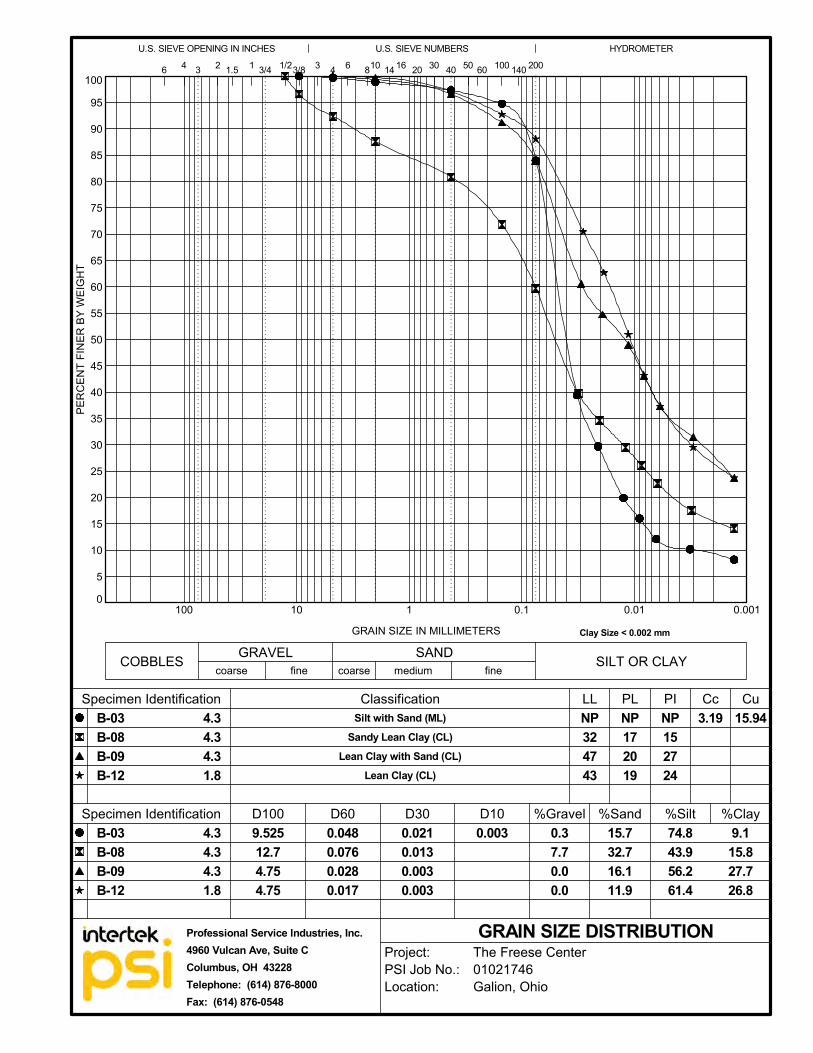
0
5
10
15
20
25
30
35
40
45
50
55
60
65
70
75
80
85
90
95
100
0.0010.010.1110100
2
Clay Size < 0.002 mm
Silt with Sand (ML)Sandy Lean Clay (CL)
Lean Clay with Sand (CL)Lean Clay (CL)
COBBLES
14
Specimen Identification
Specimen Identification
PI Cc
D10
41 3/4 100 140
U.S. SIEVE OPENING IN INCHES
3
D600.0480.0760.0280.017
9.52512.74.754.75
0.0210.0130.0030.003
0.003
200
fine
GRAIN SIZE DISTRIBUTION
20 301.5
coarse medium
4.34.34.31.8
Classification
D100
50
NP172019
NP152724
6
Cu
fineSAND SILT OR CLAYGRAVEL
1/23/8
HYDROMETER
3
GRAIN SIZE IN MILLIMETERS
PER
CEN
T FI
NER
BY
WEI
GH
T40
U.S. SIEVE NUMBERS
4
B-03B-08B-09B-12
LL PL15.94
6 810
%Gravel %Sand %Silt %Clay
B-03B-08B-09B-12
3.19
60
coarse
D30
4.34.34.31.8
16
NP324743
15.732.716.111.9
74.843.956.261.4
9.115.827.726.8
0.37.70.00.0
Project:PSI Job No.:Location:
The Freese Center01021746Galion, Ohio
Professional Service Industries, Inc.4960 Vulcan Ave, Suite CColumbus, OH 43228Telephone: (614) 876-8000Fax: (614) 876-0548
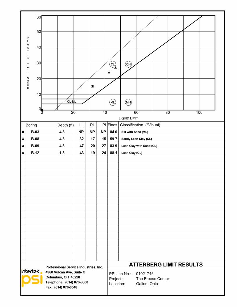
0
10
20
30
40
50
60
0 20 40 60 80 100
LL
PSI Job No.:Project:Location:
01021746The Freese CenterGalion, Ohio
Fines
PLASTICITY
INDEX
CL
NP152724
NP324743
PI
CH
CL-ML
Classification (*Visual)
ML
Boring Depth (ft) PL
LIQUID LIMIT
MH
84.059.783.988.1
Silt with Sand (ML)
Sandy Lean Clay (CL)
Lean Clay with Sand (CL)
Lean Clay (CL)
ATTERBERG LIMIT RESULTS
NP172019
Professional Service Industries, Inc.4960 Vulcan Ave, Suite CColumbus, OH 43228Telephone: (614) 876-8000Fax: (614) 876-0548
4.34.34.31.8
B-03B-08B-09B-12
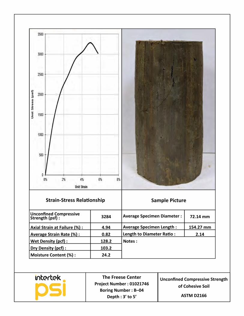
Unconfined Compressive Strength
of Cohesive Soil
ASTM D2166
The Freese Center
Project Number : 01021746
Boring Number : B–04
Depth : 3’ to 5’
Strain-Stress Relationship
Notes :
Sample Picture
Unconfined Compressive Strength (psf) : 3284 72.14 mm Average Specimen Diameter :
Average Specimen Length : 154.27 mm
Length to Diameter Ratio : 2.14
4.94 Axial Strain at Failure (%) :
0.82 Average Strain Rate (%) :
128.2
103.2
24.2
Wet Density (pcf) :
Dry Density (pcf) :
Moisture Content (%) :
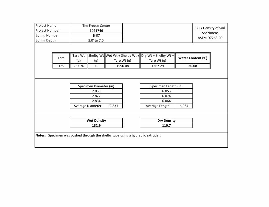
125 257.76 0
2.831 6.064
Project Number
Boring Number
Boring Depth
The Freese Center
1021746
B-07
5.0' to 7.0'
Project Name
TareTare Wt
(g)
Shelby Wt
(g)
Wet Wt + Shelby Wt +
Tare Wt (g)
Dry Wt + Shelby Wt +
Tare Wt (g)
1590.08 1367.29 20.08
Bulk Density of Soil
Specimens
ASTM D7263-09
Specimen Diameter (in) Specimen Length (in)
Water Content (%)
2.833
2.827
2.834
6.053
6.074
6.064
110.7132.9
Notes: Specimen was pushed through the shelby tube using a hydraulic extruder.
Average Diameter Average Length
Wet Density Dry Density
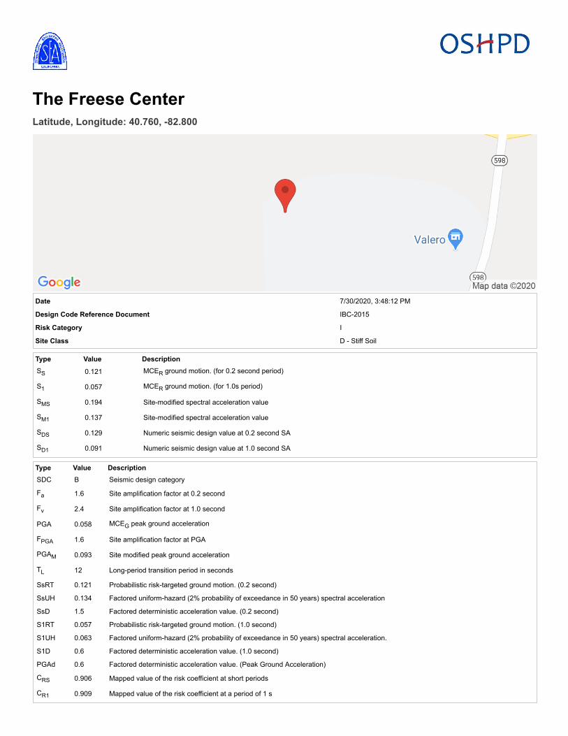
The Freese CenterLatitude, Longitude: 40.760, -82.800
Date 7/30/2020, 3:48:12 PM
Design Code Reference Document IBC-2015
Risk Category I
Site Class D - Stiff Soil
Type Value DescriptionSS 0.121 MCER ground motion. (for 0.2 second period)
S1 0.057 MCER ground motion. (for 1.0s period)
SMS 0.194 Site-modified spectral acceleration value
SM1 0.137 Site-modified spectral acceleration value
SDS 0.129 Numeric seismic design value at 0.2 second SA
SD1 0.091 Numeric seismic design value at 1.0 second SA
Type Value DescriptionSDC B Seismic design category
Fa 1.6 Site amplification factor at 0.2 second
Fv 2.4 Site amplification factor at 1.0 second
PGA 0.058 MCEG peak ground acceleration
FPGA 1.6 Site amplification factor at PGA
PGAM 0.093 Site modified peak ground acceleration
TL 12 Long-period transition period in seconds
SsRT 0.121 Probabilistic risk-targeted ground motion. (0.2 second)
SsUH 0.134 Factored uniform-hazard (2% probability of exceedance in 50 years) spectral acceleration
SsD 1.5 Factored deterministic acceleration value. (0.2 second)
S1RT 0.057 Probabilistic risk-targeted ground motion. (1.0 second)
S1UH 0.063 Factored uniform-hazard (2% probability of exceedance in 50 years) spectral acceleration.
S1D 0.6 Factored deterministic acceleration value. (1.0 second)
PGAd 0.6 Factored deterministic acceleration value. (Peak Ground Acceleration)
CRS 0.906 Mapped value of the risk coefficient at short periods
CR1 0.909 Mapped value of the risk coefficient at a period of 1 s

DISCLAIMER
While the information presented on this website is believed to be correct, SEAOC /OSHPD and its sponsors and contributors assume no responsibility orliability for its accuracy. The material presented in this web application should not be used or relied upon for any specific application without competent examinationand verification of its accuracy, suitability and applicability by engineers or other licensed professionals. SEAOC / OSHPD do not intend that the use of thisinformation replace the sound judgment of such competent professionals, having experience and knowledge in the field of practice, nor to substitute for thestandard of care required of such professionals in interpreting and applying the results of the seismic data provided by this website. Users of the information fromthis website assume all liability arising from such use. Use of the output of this website does not imply approval by the governing building code bodies responsiblefor building code approval and interpretation for the building site described by latitude/longitude location in the search results of this website.
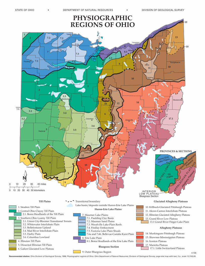
��������������� ���������
��
�
�� �� �� ������
�� �� �� �� ����������
�����������
����������� �� ��
�������� ������� ������� �� ����������������� ������������� �� ��
������������������������ �� ��������������� � ��������������� ������������!����"�����#��� ������ ��������� ���������$ ����%��&���'�(���#��� ������ ����)��*����� ����+���� �������" ��
%��# ������� �� ��
)��*����,����# ������� �� ��
+��-� ���- �,��������"�� �����
����������������������
.��&��������/��� ���.������� ��0�� �������.����&����������� ���.����!���(� ����/� � ���'����.�%��1�� ���2������.�)��1����������/� � ������� �.�+�����.�+���� �(�� ����� ���3������ ��
4��2������/��� ��4�������������� �����������2������/��� ��
��������������� ���
5��������� ��0�����'�0�� � � ��
������ �!�����"��#���� ����
�6��3� �,/ - �,�������������0��� �����
����7/�� �����#��� ������ �����
����# �����- �,������7 �0����� �����
����-����'�(�����"�� ����������-����'�(���1�0�� ��/��� ��
����"��#���� ����
�%��&��/�0�� �������0��� �����
�)�����"�� &�������$$���� �����
�+��#������ �����
�.��&��������� ������.�������� ���"��8�� ���� �����
��$� ����%������� �
��������� �������
��/�����9��$������������������ 2������/��� ���
�����
�
��
������
!"#$%
&��#�
'��#(�
)��("�
*!��!! )���!
*�(�!$#
+���$
*!$��$
,�"$%���-$
���".�$(�
/!$��(�*�"�."�
�0!��!)��1�$�!$�
)������$�$*�2
�!2��$
*$3$$!�
*43��4�+�4�$�
5!����!
���$��$
�!�$
&'
()&
(
()'
()'
()'
()*
()+
(),
()-�
()-.
/
')&
&0
&,)&
&,
&0
&&
&0
-
'
&0
,),
&'
,)&
,)'
,
,)*
,)+
,)-
*
1
1
&0
&+
&(
&*
&()&
&-
/)&
&0
+ +�+*��+�� �+&�+��
*��&6+���7'�+���"��$
8���
�!��� !$�
& !$�
�!3!��#�+�%4�$2
!��!"�
+�%4�$2� !��!"�
��&�6 �76�7'� �+&�+�)"�%�!�����3��$
&'
-
+
'
&'
-
&0
+�������,
��*+6 5��&
+�������,
��*+6 5��
&)�6�+
��*+6 5��&
)�6�+
��*
+
6 5
� � &
7
6
&+ � �
� �*+ 6
5� �
&
+�������,��*+6
5�� &
*7��
5)�
���*+6 5��&
����������������� ����������������� ������������� ����������������������� ������������������� ����� ������������� ���� ������������� ������������� ������ !�" �����#����� $���%��&����� ���%��''�''&
�()(*��+��,-� . �*�) (/*�(��+��)(0 )1� *��0 2*� . �-3-�-����+��*�1��-2)1��0 3*4
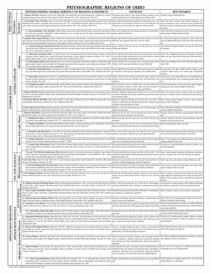
DISTINGUISHING CHARACTERISTICS OF REGIONS & DISTRICTS GEOLOGY BOUNDARIES
Til
l P
lain
sSe
ctio
ns
*
Pro
vin
ces
Maj
or
Div
isio
ns
PHYSIOGRAPHIC REGIONS OF OHIO
* Section names modified from Fenneman (1938, 1946).
Hu
ron
-Eri
e La
ke
Pla
ins
Blu
egra
ss S
ecti
on
INT.
LO
W P
LAT
EA
US
INT
ER
IOR
PLA
INS
CE
NT
RA
L LO
WLA
ND
All
egh
eny
(K
anaw
ha)
Pla
teau
sG
laci
ated
All
egh
eny
(So
uth
ern
New
Yo
rk)
Pla
teau
s
AP
PA
LAC
HIA
N P
LAT
EA
US
AP
PA
LAC
HIA
N H
IGH
LAN
DS
Wisconsinan-age (latest Ice-Age) loamy till from a northern source(Saginaw glacial lobe) over Mississippian-age Coldwater Shale
Clayey, high-lime Wisconsinan-age till from a northeastern source (Erieglacial lobe) and lacustrine materials over Lower Paleozoic-agecarbonate rocks and, in the east, shales; loess thin to absent
Thin, clayey, medium-lime Wisconsinan-age till over resistant Missis-sippian-age Berea Sandstone
Loamy, high-lime Wisconsinan-age till, outwash, and loess over LowerPaleozoic-age carbonate rocks and, in the east, shales
Loamy, high-lime Wisconsinan-age till with thin loess cap overSilurian-age dolomites
Loamy, high-lime Wisconsinan-age till and sand and gravel outwashover resistant Silurian-age carbonate rocks (north) and less resistantOrdovician-age shales and limestones (south)
Loamy, high-lime Wisconsinan-age till over generally deeply buriedSilurian- to Devonian-age carbonate rocks and Ohio Shale
Loamy, high-lime Wisconsinan-age till and sand and gravel outwashover Silurian- to Devonian-age carbonate rocks and Ohio Shale
Loamy, high-lime Wisconsinan-age till and sparse outwash overSilurian- and Devonian-age carbonate rocks and Ohio Shale in thesoutheast
Loamy, high-lime (west) to medium-lime (east) Wisconsinan-agetill and extensive outwash in Scioto Valley over deep Devonian- toMississippian-age carbonate rocks, shales, and siltstones
Silt-loam, high-lime, Illinoian-age till with loess cap; soils leachedseveral feet; underlain by Ordovician- and Silurian-age carbonate rocksand calcareous shales
Hilltops of high-lime Illinoian-age till with loess cap; slopes ofbedrock- and till-derived colluvium and Ordovician- and Silurian-agecarbonate rocks and calcareous shales
Medium- to low-lime Wisconsinan-age till over Mississippian-ageshales and sandstones
Pleistocene-age silt, clay, and wave-planed clayey till over Silurian-and Devonian-age carbonate rocks and shales
Pleistocene-age lacustrine clay over clay till and Silurian-agedolomites
Late Wisconsinan-age sand over clay till and lacustrine deposits;Silurian- and Devonian-age carbonate rocks and shales buried deeply.
Thin to absent Wisconsinan-age wave-planed clay till, lacustrinedeposits, and sand over Silurian-age reefal Lockport Dolomite
Silty to gravelly Wisconsinan-age lacustrine deposits and wave-planedclayey till over Silurian-age Lockport Dolomite
Silty to gravelly Wisconsinan-age lacustrine deposits and wave-planedclay till over deeply covered Silurian-age dolomite
Columbus and Delaware Limestones overlain by thin clay till in 7.6b,and thin silty and sandy Wisconsinan-age lacustrine deposits and wave-planed clay till in 7.6a
Pleistocene-age lacustrine sand, silt, clay, and wave-planed till overDevonian- and Mississippian-age shales and sandstones
Thin lacustrine deposits over thin, wave-planed, clayey, medium-limeWisconsinan-age till; underlain by resistant Berea Sandstone
Ordovician- and Silurian-age dolomites, limestones, and calcareousshales; thin pre-Wisconsinan drift on ridges in west; silt-loamcolluvium
Thin to thick Wisconsinan-age clay to loam till over Mississippian-and Pennsylvanian-age shales, sandstones, conglomerates and coals
Sandy Wisconsinan-age and older drift over Devonian- to Pennsylvanian-age sandstones, conglomerates and shales
Colluvium and Illinoian-age till over Devonian- to Pennsylvanian-ageshales, siltstones and sandstones
Clayey, low-lime Wisconsinan-age till over deeply buried, soft Devonian-age shales and near-surface Mississippian-age sandstones and shales
Surficial lacustrine clay and drift over deeply buried, soft Devonian-age shales
Mississippian and Pennsylvanian-age siltstones, shales, sandstones andeconomically important coals and claystones; Wisconsinan-age sand,gravel, and lacustrine silt; silt-loam colluvium
Devonian- and Mississippian-age shales, siltstones, and locally thicksandstones; Pleistocene-age sandy outwash in Scioto River; Teays-ageMinford Clay; silt-loam and channery colluvium
Pennsylvanian-age (Pottsville, Allegheny and Conemaugh Groups)cycles of sandstones, siltstones, shales and economically importantcoals; Pleistocene (Teays)-age Minford Clay; silt-loam and channerycolluvium
Pennsylvanian-age Upper Conemaugh Group through Permian-ageDunkard Group cyclic sequences of red and gray shales, and siltstones,sandstones, limestones and coals; Pleistocene (Teays)-age MinfordClay; red and brown silty-clay loam colluvium; landslide deposits
Similar to Marietta Plateau but lacking Pleistocene (Teays)-age MinfordClay
Southeast: edge of Wabash Moraine
North: Lake Plain; northeast: limit of Berea Sandstone; east:Berea Escarpment; south: Powell and Union City/BloomerMoraines; northern segment boundaries: Wabash Moraine andlake plain
South: limit of Berea Sandstone; elsewhere: Berea Escarpmentand/or margin of highest Pleistocene lake
East: Berea and Allegheny Escarpments; north: Powell andUnion City/Bloomer Moraines; south: limit of Wisconsinan-agetill
North: Bloomer Moraine and limit of loamy till; south: UnionCity Moraine
North: limit of Knightstown/Farmersville Moraines and kamefields; east: high, dissected hills draining to Whitewater River
North: areas with hilltops above 1200'; elsewhere: hilltops aboveabout 1300'
East and north: rear edge of Cable Moraine Complex; south:outwash to Clifton Gorge; west: western edge of Mad RiverOutwash
South and west: front of Reesville and rear of Cable Moraines;north: Powell Moraine; east: increasing eastward slope (see3.6)
North: Powell Moraine; east and south: Berea and/or AlleghenyEscarpments; west: flatter and higher Darby Plain
North: Wisconsinan glacial margin (Cuba and HartwellMoraines); elsewhere: limit of common till-covered hillslopes
East: maximum glacial margin; elsewhere: limit of generalabsence of till on hillslopes
North: limit of Berea Sandstone; west: Berea Escarpment; southand east: Allegheny Escarpment
Northeast: Lake Erie; elsewhere: margin of highest Pleistocenelake
Northeast: subdued (“drowned”) remnant of Defiance Moraine;elsewhere: limit of lacustrine clay
Limit of sandy deposits and/or low dunes
Limit of thinly mantled Lockport Dolomite (Bowling Green Faultto the west and the Defiance Moraine to the south)
West: 775' beach ridge; north: Defiance Moraine; south: marginof highest Pleistocene lake level
South and east: unmodified Defiance Moraine; elsewhere: verylow-relief lake plain
Limit of thinly mantled Columbus and Delaware Limestones,which is marked in the west by the Columbus Escarpment
North: Lake Erie; south: margin of highest Pleistocene lake
North: portion of Lake Plain underlain by soft shales; south:margin of highest Pleistocene lake
Eastern segment: maximum glacial margin and high easternridges capped by noncarbonate rocks; connected by Ohio Riverbluffs to western segment which is bounded by nondissectedtill plain
West and north: resistant sandstones of the Allegheny and PortageEscarpments; south and east: Wisconsinan glacial margin
Limit of common, sandy ice-contact features and deposits
North and west: Wisconsinan glacial margin; south and east:Illinoian (maximum) glacial margin
North: Portage Escarpment; south and west: Defiance Moraine;southeast: increasing relief from proximity of buried Pennsyl-vanian-age sandstones
Margins of steeply sloping troughs containing the Grand Riverand parts of Rock and Mosquito Creeks
North and west: maximum glacial margin; southeast: transitionto finer grained bedrock; southwest: transition to coarsergrained bedrock
North: Maximum glacial margin; west:: carbonate bedrock; east:limit of Mississippian-age bedrock
West: limit of common Pennsylvanian-age bedrock; north andeast: gradation to finer rock sequences
North and west: transition to medium-grained LowerConemaugh rocks; east: Flushing Divide
North: transition to medium-grained rocks; west and south:Flushing Divide; east: Ohio River
1. Steuben Till Plain. Hummocky terrain with rolling hills, interspersed flats and closed depressions; wetlands, few streams,deranged drainage; only a small part of the region is in Ohio; elevation 950’-1100’, moderately low relief (60’)
2. Central Ohio Clayey Till Plain. Surface of clayey till; well-defined moraines with intervening flat-lying ground moraine andintermorainal lake basins; no boulder belts; about a dozen silt-, clay- and till-filled lake basins range in area from a few to 200square miles; few large streams; limited sand & gravel outwash; elevation 700’-1150’, moderate relief (100’)
2.1. Berea Headlands of the Till Plain. Gently rolling to flat terrain of thin drift descending to Lake Erie; punctuated bymore than 20 streamlined “whalebacks” of Berea Sandstone, 0.5 to 2.5 miles long, 30’-60' high; somewhat poorly drained;elevation 800’-1000’, low relief (20’)
3. Southern Ohio Loamy Till Plain. Surface of loamy till; end and recessional moraines, commonly associated with boulderbelts, between relatively flat-lying ground moraine, cut by steep-valleyed large streams; stream valleys filled with outwash andalternate between broad floodplains and narrows; buried valleys common; elevation 530’-1150’, moderate relief (200’)
3.1. Union City-Bloomer Transitional Terrain. Well-defined moraines with low-relief, hummocky ground moraine like theCentral Ohio Clayey Till Plain to the north; loamy till with loess cap like Southern Ohio Loamy Till Plain to the south; elevation920’-1075’, moderately low relief (30’)
3.2. Whitewater Interlobate Plain. An upland between two converging glacial lobes with hummocky moraines, morainecomplexes, kames, boulder belts, and broad outwash trains/plains; contains highest elevations in Indiana (1257’) and inadjacent Ohio counties (1240’); elevation in Ohio 980’-1240’, moderate relief (150’)
3.3. Bellefontaine Upland. Moderately high relief (250’) dissected topography with moraine complexes, boulder belts, high-gradient major streams, caves and sinkholes; few glacial depressions/kettles compared to surrounding areas; elevation 1100’-1549’, includes highest elevation in Ohio (Campbell Hill, 1549’)
3.4. Mad River Interlobate Plain. Area between two major converging glacial lobes with extensive outwash, outwash ter-races, and bordering moraines; springs and cool, ground-water-fed surface waters; elevation 800’-1350’, moderate relief (200’)
3.5. Darby Plain. Moderately low relief (25’), broadly hummocky ground moraine with several broad, indistinct recessionalmoraines; between hummocks are broad, poorly drained swales which held wet prairies/meadows in pioneer days; few largestreams; elevation 750’-1100’
3.6. Columbus Lowland. Lowland surrounded in all directions by relative uplands, having a broad regional slope toward theScioto Valley; many larger streams; elevation 600’-850’ (950’ near Powell Moraine), moderately low relief (25’)
4. Illinoian Till Plain. Rolling ground moraine of older till generally lacking ice-constructional features such as moraines, kames,and eskers; many buried valleys; modern valleys alternating between broad floodplains and bedrock gorges; elevation 600’-1100’,moderately low relief (50’)
5. Dissected Illinoian Till Plain. Hilly former till plain in which glacial deposits have been eroded from many valley sides;relatively high stream density; elevation 600’-1340’, moderate relief (200’)
6. Galion Glaciated Low Plateau. Rolling upland transitional between the gently rolling Till Plain and the hilly Glaciated AlleghenyPlateau; mantled with thin to thick drift; elevation 800’-1400’, moderate relief (100’)
7. Maumee Lake Plains. Flat-lying Ice-Age lake basin with beach ridges, bars, dunes, deltas, and clay flats; contained the formerBlack Swamp; slightly dissected by modern streams; elevation 570’-800’, very low relief (5’)
7.1. Paulding Clay Basin. Nearly flat lacustrine plain; most clayey of all Lake Plain subregions; low-gradient, highly meander-ing streams; easily ponded soils; elevation 700’-725’, extremely low relief (less than 5’)
7.2. Maumee Sand Plains. Lacustrine plain mantled by sand; includes low dunes, inter-dunal pans, beach ridges, and sandsheets of glacial lakeshores; well to poorly drained; elevation 600’-800’, very low relief (10’)
7.3. Woodville Lake-Plain Reefs. Very low relief (10’) lacustrine plain with low dunes and lake-margin features, punctuatedby more than 75 ancient bedrock reefs rising 10’ to 40’ above the level of the plain and ranging in area from 0.1 to 3.0 squaremiles; the oblong reefs are thinly draped with drift; elevation 600’-775’
7.4. Findlay Embayment. Very low relief (10’), broadly rolling lacustrine plain; embayment of ancestral Lake Erie in whichrelatively coarse lacustrine sediments collected; elevation 775’-800’
7.5. Fostoria Lake-Plain Shoals. Portion of the Defiance Moraine lightly eroded by shallow Lake Maumee with low north-south trending hillocks and shallow, closed depressions; many sandy areas; elevation 750’-825’, low relief, decreasing west-ward (10’-15’)
7.6a and 7.6b. Bellevue-Castalia Karst Plain. Hummocky plain of rock knobs and numerous sinkholes, large solutionfeatures, and caves; large springs; thinly mantled by drift; region straddles both Lake Plain (7.6a) and Till Plain (7.6b); 7.6a hasgreatest relief of any Lake Plain region (25’); elevation 570’-825’
8. Erie Lake Plain. Edge of very low-relief (10’) Ice-Age lake basin separated from modern Lake Erie by shoreline cliffs; majorstreams in deep gorges; elevation 570’-800’
8.1 Berea Headlands of the Erie Lake Plain. Portion of the Erie Lake Plain underlain by resistant Berea Sandstone; severallarge sandstone headlands jut into the Ice-Age lake basin; contains several streamlined “whalebacks” of Berea Sandstone, 0.5to 2.0 miles long, 20’-35’ high; poorly drained; elevation 670’-800’, very low relief (10’)
9. Outer Bluegrass Region. Moderately high relief (300’) dissected plateau of carbonate rocks; in east, caves and other karstfeatures relatively common; in west, thin, early drift caps narrow ridges; elevation 455’-1120’
10. Killbuck-Glaciated Pittsburgh Plateau. Ridges and flat uplands generally above 1200’, covered with thin drift and dissectedby steep valleys; valley segments alternate between broad drift-filled and narrow rock-walled reaches; elevation 600’-1505’,moderate relief (200’)
11. Akron-Canton Interlobate Plateau. Hummocky area between two converging glacial lobes dominated by kames, kameterraces, eskers, kettles, kettle lakes, and bogs/fens; deranged drainage with many natural lakes; elevation 900’-1200’, moderaterelief (200’)
12. Illinoian Glaciated Allegheny Plateau. Dissected, rugged hills; loess and older drift on ridgetops, but absent on bedrockslopes; dissection similar to unglaciated regions of the Allegheny Plateau; elevation 600’-1400’, moderate relief (200’)
13. Grand River Low Plateau. Gently rolling ground and end moraine having thin to thick drift; poorly drained areas andwetlands relatively common; elevation 760’-1200’, low relief (20’) except near Grand River Valley (200’)
13.1. Grand River Finger-Lake Plain. Very low relief (10’) lake deposits in steep-sided troughs (200' relief) within theGrand River Low Plateau; cut by glacial and stream erosion; extensive wetlands; elevation 800’-900’
14. Muskingum-Pittsburgh Plateau. Moderately high to high relief (300’-600’) dissected plateau having broad major valleysthat contain outwash terraces, and tributaries with lacustrine terraces; medium-grained bedrock sequences coarser than those inMarietta Plateau (17) but finer than those in Ironton Plateau (16); remnants of ancient Teays-age drainage system uncommon;elevation 650’-1400’
15. Shawnee-Mississippian Plateau. High relief (400’-800‘), highly dissected plateau of coarse and fine grained rock sequences;most rugged area in Ohio; remnants of ancient lacustrine clay-filled Teays drainage system are extensive in lowlands, absent inuplands; elevation 490’-1340’
16. Ironton Plateau. Moderately high relief (300’) dissected plateau; coarser grained coal-bearing rock sequences morecommon than in other regions of the Allegheny Plateau; common lacustrine clay-filled Teays Valley remnants; elevation 515’-1060’
17. Marietta Plateau. Dissected, high-relief (generally 350’, to 600’ near Ohio River) plateau; mostly fine-grained rocks; redshales and red soils relatively common; landslides common; remnants of ancient lacustrine clay-filled Teays drainage systemcommon; elevation 515’-1400’
17.1. Little Switzerland Plateau. Highly dissected, high-relief (generally 450’, to 750’ along Ohio River) plateau; mostlyfine-grained rocks; red shales and red soils relatively common; landslides common; high-gradient shale-bottomed streamssubject to flash flooding; no remnants of ancient Teays drainage system; elevation 540’-1400’
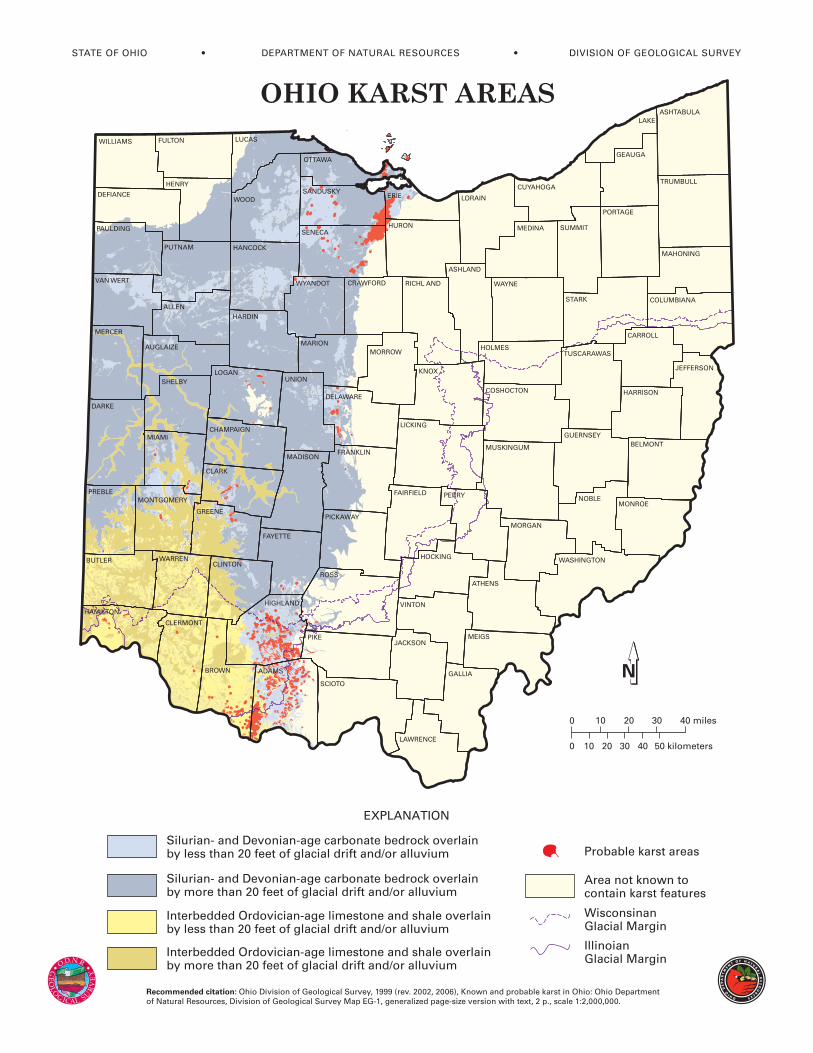
0
0
10 20 30 40 miles
10 20 30 40 50 kilometers
Silurian- and Devonian-age carbonate bedrock overlain by less than 20 feet of glacial drift and/or alluvium
Silurian- and Devonian-age carbonate bedrock overlain by more than 20 feet of glacial drift and/or alluvium
Interbedded Ordovician-age limestone and shale overlain by less than 20 feet of glacial drift and/or alluvium
Interbedded Ordovician-age limestone and shale overlain by more than 20 feet of glacial drift and/or alluvium
Probable karst areas
WisconsinanGlacial Margin
IllinoianGlacial Margin
Area not known tocontain karst features
EXPLANATION
MUSKINGUM
WILLIAMS
DEFIANCE
PAULDING
VAN WERT
MERCER
DARKE
MIAMI
PREBLE
BUTLER
HAMILTON
CLERMONT
PIKE
HIGHLAND
CLINTON
ROSS
GREENE
FAYETTE
CLARK
MADISON
CHAMPAIGN
LOGAN
HARDIN
MARION
HANCOCK
WYANDOT
WOODSANDUSKY
LUCAS
OTTAWA
ERIE
HURONSENECA
CRAWFORD RICHL AND
MORROW
KNOX
DELAWARE
PICKAWAY
SCIOTO
LAWRENCE
GALLIA
VINTON
PERRY
HOCKING
FAIRFIELD
LICKING
HOLMES
COSHOCTON
LORAIN
MEDINA
CUYAHOGA
GEAUGA
SUMMIT
PORTAGE
WAYNE
STARK
TUSCARAWAS
GUERNSEY
HARRISON
BELMONT
MORGAN
ATHENS
NOBLE
JEFFERSON
COLUMBIANA
MAHONING
TRUMBULL
LAKE
FULTON
HENRY
PUTNAM
ALLEN
AUGLAIZE
SHELBY
WARREN
BROWN ADAMS
UNION
JACKSONMEIGS
CARROLL
MONROE
WASHINGTON
ASHTABULA
MONTGOMERY
ASHLAND
FRANKLIN
OHIO KARST AREAS
Recommended citation: Ohio Division of Geological Survey, 1999 (rev. 2002, 2006), Known and probable karst in Ohio: Ohio Department of Natural Resources, Division of Geological Survey Map EG-1, generalized page-size version with text, 2 p., scale 1:2,000,000.
STA PARTMENT OF NA LOGICAL SURVEY
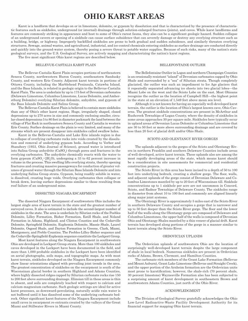
OHIO KARST AREASKarst is a landform that develops on or in limestone, dolomite, or gypsum by dissolution and that is characterized by the presence of characteris-
tic features such as sinkholes, underground (or internal) drainage through solution-enlarged fractures (joints), and caves. While karst landforms and features are commonly striking in appearance and host to some of Ohio’s rarest fauna, they also can be a signifi cant geologic hazard. Sudden collapse of an underground cavern or opening of a sinkhole can cause surface subsidence that can severely damage or destroy any overlying structure such as a building, bridge, or highway. Improperly backfi lled sinkholes are prone to both gradual and sudden subsidence, and similarly threaten overlying structures. Sewage, animal wastes, and agricultural, industrial, and ice-control chemicals entering sinkholes as surface drainage are conducted directly and quickly into the ground-water system, thereby posing a severe threat to potable water supplies. Because of such risks, many of the nation’s state geological surveys, and the U.S. Geological Survey, are actively mapping and characterizing the nation’s karst regions.
The fi ve most signifi cant Ohio karst regions are described below.
BELLEVUE-CASTALIA KARST PLAIN
The Bellevue-Castalia Karst Plain occupies portions of northeastern Seneca County, northwestern Huron County, southeastern Sandusky County, and western Erie County. Adjacent karst terrain in portions of Ottawa County, including the Marblehead Peninsula, Catawba Island, and the Bass Islands, is related in geologic origin to the Bellevue-Castalia Karst Plain. The area is underlain by up to 175 feet of Devonian carbonates (Delaware Limestone, Columbus Limestone, Lucas Dolomite, and Amher-stburg Dolomite) overlying Silurian dolomite, anhydrite, and gypsum of the Bass Islands Dolomite and Salina Group.
The Bellevue-Castalia Karst Plain is believed to contain more sinkholes than any of Ohio’s other karst regions. Huge, irregularly shaped, closed depressions up to 270 acres in size and commonly enclosing smaller, circu-lar-closed depressions 5 to 80 feet in diameter pockmark the land between the village of Flat Rock in northeastern Seneca County and Castalia in western Erie County. Surface drainage on the plain is very limited, and many of the streams which are present disappear into sinkholes called swallow holes.
Karst in the Bellevue-Castalia and Lake Erie islands region is due to collapse of overlying carbonate rocks into voids created by the dissolu-tion and removal of underlying gypsum beds. According to Verber and Stansbery (1953, Ohio Journal of Science), ground water is introduced into Salina Group anhydrite (CaSO4) through pores and fractures in the overlying carbonates. The anhydrite chemically reacts with the water to form gypsum (CaSO4•2H2O), undergoing a 33 to 62 percent increase in volume in the process. This swelling lifts overlying strata, thereby opening fractures and creating massive passageways for conduction of greater vol-umes of ground water through the Silurian Bass Islands Dolomite and into underlying Salina Group strata. Gypsum, being readily soluble in water, is dissolved, creating huge voids. Overlying carbonates then collapse or break down, leaving surface depressions similar to those resulting from roof failure of an underground mine.
DISSECTED NIAGARA ESCARPMENT
The dissected Niagara Escarpment of southwestern Ohio includes the largest single area of karst terrain in the state and the greatest number of surveyed caves. It also is estimated to include the second-largest number of sinkholes in the state. The area is underlain by Silurian rocks of the Peebles Dolomite, Lilley Formation, Bisher Formation, Estill Shale, and Noland Formation in Adams, Highland, and Clinton Counties and the Cedarville Dolomite, Springfi eld Dolomite, Euphemia Dolomite, Massie Shale, Laurel Dolomite, Osgood Shale, and Dayton Formation in Greene, Clark, Miami, Montgomery, and Preble Counties. The Peebles-Lilley-Bisher sequence and the Cedarville-Springfi eld-Euphemia sequence constitute the Lockport Group.
Most karst features along the Niagara Escarpment in southwestern Ohio are developed in Lockport Group strata. More than 100 sinkholes and caves developed in the Lockport have been documented in the fi eld, and more than 1,000 probable sinkholes in the Lockport have been identifi ed on aerial photographs, soils maps, and topographic maps. As with most karst terrain, sinkholes developed on the Niagara Escarpment commonly show linear orientations aligned with prevailing joint trends in the area. The greatest concentration of sinkholes on the escarpment is south of the Wisconsinan glacial border in southern Highland and Adams Counties, where highly dissected ridges capped by Silurian carbonate rocks rise 150 to 200 feet above surrounding drainage. Illinoian till in these areas is thin to absent, and soils are completely leached with respect to calcium and calcium-magnesium carbonate. Such geologic settings are ideal for active karst processes, as downward-percolating, naturally acidic rain water is not buffered until it has dissolved some of the underlying carbonate bed-rock. Other signifi cant karst features of the Niagara Escarpment include small caves in escarpment re-entrants created by the valleys of the Great Miami and Stillwater Rivers in Miami County.
BELLEFONTAINE OUTLIER
The Bellefontaine Outlier in Logan and northern Champaign Counties is an erosionally resistant “island” of Devonian carbonates capped by Ohio Shale and surrounded by a “sea” of Silurian strata. Though completely glaciated, the outlier was such an impediment to Ice Age glaciers that it repeatedly separated advancing ice sheets into two glacial lobes—the Miami Lobe on the west and the Scioto Lobe on the east. Most Ohioans recognize the outlier as the location of Campbell Hill—the highest point in the state at an elevation of 1,549 feet above mean sea level.
Although it is not known for having an especially well-developed karst terrain, the outlier is the location of Ohio’s largest known cave, Ohio Cav-erns. The greatest sinkhole concentrations are present in McArthur and Rushcreek Townships of Logan County, where the density of sinkholes in some areas approaches 30 per square mile. Sinkholes here typically occur in upland areas of Devonian Lucas Dolomite or Columbus Limestone that are 30 to 50 feet or more above surrounding drainage and are covered by less than 20 feet of glacial drift and/or Ohio Shale.
SCIOTO AND OLENTANGY RIVER GORGES
The uplands adjacent to the gorges of the Scioto and Olentangy Riv-ers in northern Franklin and southern Delaware Counties include areas of well-developed, active karst terrain. These uplands also are among the most rapidly developing areas of the state, which means karst should be a consideration in site assessments for commercial and residential construction projects.
The Scioto River in this area has been incised to a depth of 50 to 100 feet into underlying bedrock, creating a shallow gorge. The fl oor, walls, and adjacent uplands of the gorge consist of Devonian Delaware and Co-lumbus Limestones mantled by up to 20 feet of Wisconsinan till. Sinkhole concentrations up to 1 sinkhole per acre are not uncommon in Concord, Scioto, and Radnor Townships of Delaware County. The sinkholes range in diameter from about 10 to 100 feet and commonly are aligned linearly along major joint systems.
The Olentangy River is approximately 5 miles east of the Scioto River in southern Delaware County and occupies a gorge that is narrower and up to 50 feet deeper than the Scioto River gorge. The fl oor and the lower half of the walls along the Olentangy gorge are composed of Delaware and Columbus Limestones, the upper half of the walls is composed of Devonian Ohio and Olentangy Shales mantled by a thin veneer of glacial drift. Karst terrain has developed along portions of the gorge in a manner similar to karst terrain along the Scioto River.
ORDOVICIAN UPLANDS
The Ordovician uplands of southwestern Ohio are the location of surprisingly well-developed karst terrain despite the large component of shale in local bedrock. Numerous sinkholes are present in Ordovician rocks of Adams, Brown, Clermont, and Hamilton Counties.
The carbonate-rich members of the Grant Lake Formation (Bellevue and Mount Auburn), Grant Lake Limestone (Bellevue and Straight Creek), and the upper portion of the Arnheim formation are the Ordovician units most prone to karstifi cation; however, the shale-rich (70 percent shale, 30 percent limestone) Waynesville Formation also has been subjected to a surprising amount of karst development in southeastern Brown and southwestern Adams Counties, just north of the Ohio River.
ACKNOWLEDGMENT
The Division of Geological Survey gratefully acknowledges the Ohio Low-Level Radioactive-Waste Facility Development Authority for its fi nancial support for mapping Ohio karst terrain.
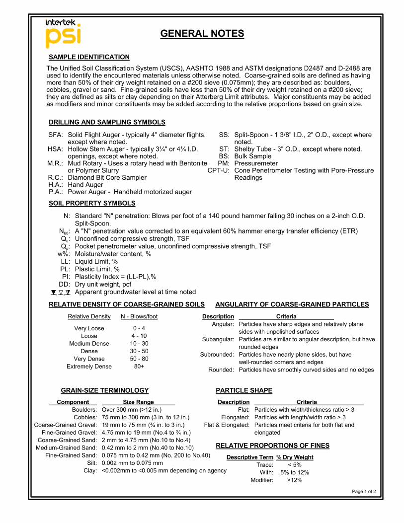
GENERAL NOTES
SAMPLE IDENTIFICATION
SOIL PROPERTY SYMBOLS
SFA:
HSA:
M.R.:
R.C.:H.A.:P.A.:
DescriptionFlat:
Elongated:Flat & Elongated:
DescriptionAngular:
Subangular:
Subrounded:
Rounded:
CriteriaParticles with width/thickness ratio > 3Particles with length/width ratio > 3Particles meet criteria for both flat andelongated
Descriptive TermTrace:
With:Modifier:
Size Range Over 300 mm (>12 in.)75 mm to 300 mm (3 in. to 12 in.)19 mm to 75 mm (¾ in. to 3 in.)4.75 mm to 19 mm (No.4 to ¾ in.)2 mm to 4.75 mm (No.10 to No.4)0.42 mm to 2 mm (No.40 to No.10)0.075 mm to 0.42 mm (No. 200 to No.40)0.002 mm to 0.075 mm<0.002mm to <0.005 mm depending on agency
Component Boulders:Cobbles:
Coarse-Grained Gravel:Fine-Grained Gravel:
Coarse-Grained Sand:Medium-Grained Sand:
Fine-Grained Sand:Silt:
Clay:
SS:
ST:BS:PM:
CPT-U:
ANGULARITY OF COARSE-GRAINED PARTICLESRELATIVE DENSITY OF COARSE-GRAINED SOILS
N - Blows/foot
0 - 44 - 1010 - 3030 - 5050 - 80
80+
Relative Density
Very LooseLoose
Medium DenseDense
Very DenseExtremely Dense
Split-Spoon - 1 3/8" I.D., 2" O.D., except wherenoted.Shelby Tube - 3" O.D., except where noted.Bulk SamplePressuremeterCone Penetrometer Testing with Pore-PressureReadings
DRILLING AND SAMPLING SYMBOLS
RELATIVE PROPORTIONS OF FINES% Dry Weight
< 5%5% to 12%
>12%
Page 1 of 2
The Unified Soil Classification System (USCS), AASHTO 1988 and ASTM designations D2487 and D-2488 areused to identify the encountered materials unless otherwise noted. Coarse-grained soils are defined as havingmore than 50% of their dry weight retained on a #200 sieve (0.075mm); they are described as: boulders,cobbles, gravel or sand. Fine-grained soils have less than 50% of their dry weight retained on a #200 sieve;they are defined as silts or clay depending on their Atterberg Limit attributes. Major constituents may be addedas modifiers and minor constituents may be added according to the relative proportions based on grain size.
Standard "N" penetration: Blows per foot of a 140 pound hammer falling 30 inches on a 2-inch O.D.Split-Spoon.A "N" penetration value corrected to an equivalent 60% hammer energy transfer efficiency (ETR)Unconfined compressive strength, TSFPocket penetrometer value, unconfined compressive strength, TSFMoisture/water content, %Liquid Limit, %Plastic Limit, %Plasticity Index = (LL-PL),%Dry unit weight, pcfApparent groundwater level at time noted
CriteriaParticles have sharp edges and relatively planesides with unpolished surfacesParticles are similar to angular description, but haverounded edgesParticles have nearly plane sides, but havewell-rounded corners and edgesParticles have smoothly curved sides and no edges
N:
N60:Qu:Qp:
w%:LL:PL:PI:
DD:, ,
Solid Flight Auger - typically 4" diameter flights,except where noted.Hollow Stem Auger - typically 3¼" or 4¼ I.D.openings, except where noted.Mud Rotary - Uses a rotary head with Bentoniteor Polymer SlurryDiamond Bit Core SamplerHand AugerPower Auger - Handheld motorized auger
GRAIN-SIZE TERMINOLOGY PARTICLE SHAPE
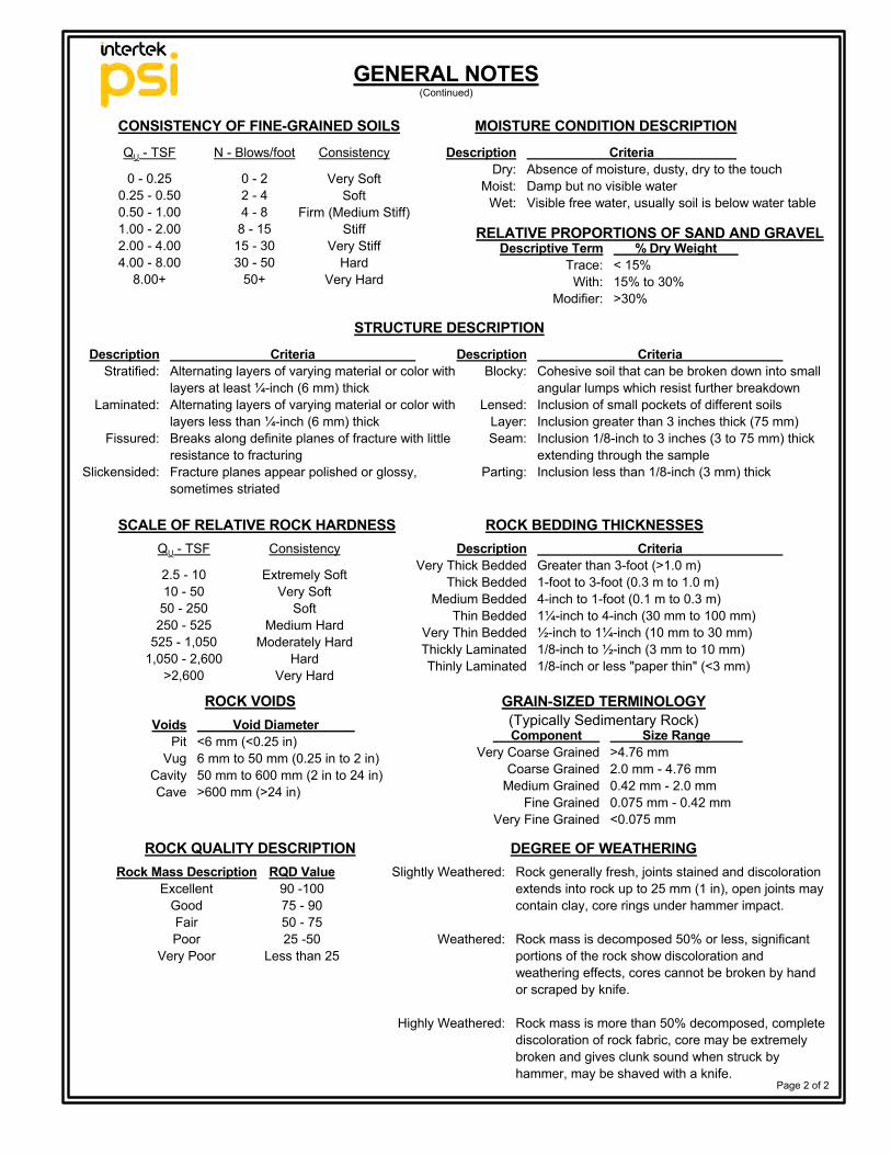
GENERAL NOTES
QU - TSF N - Blows/foot Consistency
0 - 22 - 44 - 8
8 - 1515 - 3030 - 50
50+
CriteriaAbsence of moisture, dusty, dry to the touchDamp but no visible waterVisible free water, usually soil is below water table
RELATIVE PROPORTIONS OF SAND AND GRAVEL% Dry Weight
< 15%15% to 30%>30%
Descriptive TermTrace:
With:Modifier:
0 - 0.250.25 - 0.500.50 - 1.001.00 - 2.002.00 - 4.004.00 - 8.00
8.00+
MOISTURE CONDITION DESCRIPTION
Page 2 of 2
CONSISTENCY OF FINE-GRAINED SOILS
DescriptionBlocky:
Lensed:Layer:Seam:
Parting:
DescriptionStratified:
Laminated:
Fissured:
Slickensided:
STRUCTURE DESCRIPTION
QU - TSF
Extremely SoftVery Soft
SoftMedium Hard
Moderately HardHard
Very Hard
SCALE OF RELATIVE ROCK HARDNESS ROCK BEDDING THICKNESSESConsistency
CriteriaAlternating layers of varying material or color withlayers at least ¼-inch (6 mm) thickAlternating layers of varying material or color withlayers less than ¼-inch (6 mm) thickBreaks along definite planes of fracture with littleresistance to fracturingFracture planes appear polished or glossy,sometimes striated
CriteriaGreater than 3-foot (>1.0 m)1-foot to 3-foot (0.3 m to 1.0 m)4-inch to 1-foot (0.1 m to 0.3 m)1¼-inch to 4-inch (30 mm to 100 mm)½-inch to 1¼-inch (10 mm to 30 mm)1/8-inch to ½-inch (3 mm to 10 mm)1/8-inch or less "paper thin" (<3 mm)
DescriptionDry:
Moist:Wet:
DescriptionVery Thick Bedded
Thick BeddedMedium Bedded
Thin BeddedVery Thin BeddedThickly LaminatedThinly Laminated
2.5 - 1010 - 50
50 - 250250 - 525
525 - 1,0501,050 - 2,600
>2,600
(Continued)
Component Very Coarse Grained
Coarse GrainedMedium Grained
Fine GrainedVery Fine Grained
GRAIN-SIZED TERMINOLOGY(Typically Sedimentary Rock)
ROCK VOIDSVoids
PitVug
CavityCave
Void Diameter <6 mm (<0.25 in)6 mm to 50 mm (0.25 in to 2 in)50 mm to 600 mm (2 in to 24 in)>600 mm (>24 in)
ROCK QUALITY DESCRIPTIONRQD Value
90 -10075 - 9050 - 7525 -50
Less than 25
Size Range >4.76 mm2.0 mm - 4.76 mm0.42 mm - 2.0 mm0.075 mm - 0.42 mm<0.075 mm
Rock generally fresh, joints stained and discolorationextends into rock up to 25 mm (1 in), open joints maycontain clay, core rings under hammer impact.
Rock mass is decomposed 50% or less, significantportions of the rock show discoloration andweathering effects, cores cannot be broken by handor scraped by knife.
Rock mass is more than 50% decomposed, completediscoloration of rock fabric, core may be extremelybroken and gives clunk sound when struck byhammer, may be shaved with a knife.
Rock Mass DescriptionExcellent
GoodFairPoor
Very Poor
DEGREE OF WEATHERINGSlightly Weathered:
Weathered:
Highly Weathered:
CriteriaCohesive soil that can be broken down into smallangular lumps which resist further breakdownInclusion of small pockets of different soilsInclusion greater than 3 inches thick (75 mm)Inclusion 1/8-inch to 3 inches (3 to 75 mm) thickextending through the sampleInclusion less than 1/8-inch (3 mm) thick
Very SoftSoft
Firm (Medium Stiff)Stiff
Very StiffHard
Very Hard
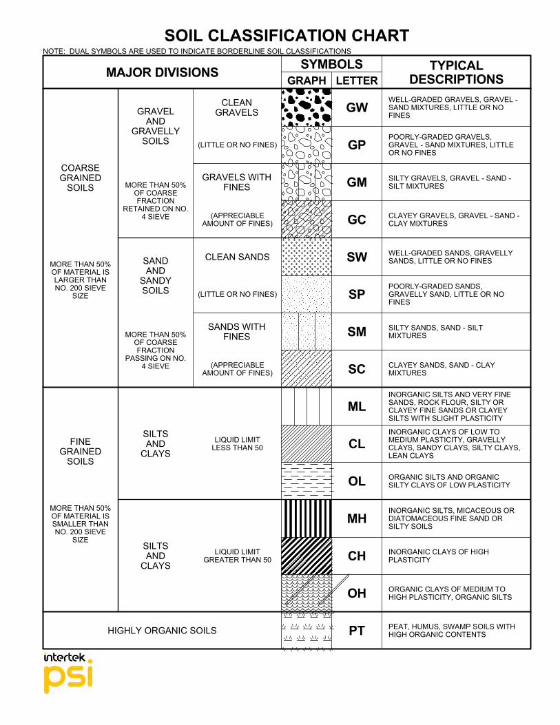
OH
CH
MH
OL
CL
ML
SC
SM
SP
COARSEGRAINED
SOILS
SW
TYPICALDESCRIPTIONS
WELL-GRADED GRAVELS, GRAVEL -SAND MIXTURES, LITTLE OR NOFINES
POORLY-GRADED GRAVELS,GRAVEL - SAND MIXTURES, LITTLEOR NO FINES
SILTY GRAVELS, GRAVEL - SAND -SILT MIXTURES
LETTERGRAPHSYMBOLSMAJOR DIVISIONS
SOIL CLASSIFICATION CHART
PT
GC
GM
GP
GW
CLAYEY GRAVELS, GRAVEL - SAND -CLAY MIXTURES
WELL-GRADED SANDS, GRAVELLYSANDS, LITTLE OR NO FINES
POORLY-GRADED SANDS,GRAVELLY SAND, LITTLE OR NOFINES
SILTY SANDS, SAND - SILTMIXTURES
CLAYEY SANDS, SAND - CLAYMIXTURES
INORGANIC SILTS AND VERY FINESANDS, ROCK FLOUR, SILTY ORCLAYEY FINE SANDS OR CLAYEYSILTS WITH SLIGHT PLASTICITY
INORGANIC CLAYS OF LOW TOMEDIUM PLASTICITY, GRAVELLYCLAYS, SANDY CLAYS, SILTY CLAYS,LEAN CLAYS
ORGANIC SILTS AND ORGANICSILTY CLAYS OF LOW PLASTICITY
INORGANIC SILTS, MICACEOUS ORDIATOMACEOUS FINE SAND ORSILTY SOILS
INORGANIC CLAYS OF HIGHPLASTICITY
ORGANIC CLAYS OF MEDIUM TOHIGH PLASTICITY, ORGANIC SILTS
PEAT, HUMUS, SWAMP SOILS WITHHIGH ORGANIC CONTENTS
CLEANGRAVELS
GRAVELS WITHFINES
CLEAN SANDS
(LITTLE OR NO FINES)
SANDS WITHFINES
LIQUID LIMITLESS THAN 50
LIQUID LIMITGREATER THAN 50
HIGHLY ORGANIC SOILS
GRAVELAND
GRAVELLYSOILS
(APPRECIABLEAMOUNT OF FINES)
(APPRECIABLEAMOUNT OF FINES)
(LITTLE OR NO FINES)
FINEGRAINED
SOILS
SANDAND
SANDYSOILS
SILTSAND
CLAYS
SILTSAND
CLAYS
MORE THAN 50%OF MATERIAL ISLARGER THANNO. 200 SIEVE
SIZE
MORE THAN 50%OF MATERIAL ISSMALLER THANNO. 200 SIEVE
SIZE
MORE THAN 50%OF COARSEFRACTION
PASSING ON NO.4 SIEVE
MORE THAN 50%OF COARSEFRACTION
RETAINED ON NO.4 SIEVE
NOTE: DUAL SYMBOLS ARE USED TO INDICATE BORDERLINE SOIL CLASSIFICATIONS


