Embed Size (px)
Citation preview
INTRODUCTION
Disposal of plastic waste in environment isconsidered to be a big problem due to its very lowbiodegradability and presence in large quantities. Inrecent time significant research is underway to study thepossibility of disposal of these wastes in mass concretewhere strength of concrete may not be major criteriaunder consideration, such as heavy mass of concreting inPCC in pavements. If plastic wastes can be mixed in theconcrete mass in some form, without significant effect onits other properties or slight compromise in strength, wecan consume large quantities of plastic waste by mixingit in the concrete mass. Plastic is one component ofmunicipal solid waste (MSW) which is becoming a majorresearch issue for its possible use in concreteespecially in self-compacting concrete and light weightconcrete. Although some of these materials can bebeneficially incorporated in concrete, both as part ofthe cementitious binder phase or as aggregates, it isimportant to realize that not all waste materials aresuitable for such use.
Concrete has proved to be an excellent disposalmeans for fly ash, silica fume, ground granulated blastfurnace slag (GGBS), marble powder, and so forth whichnot only traps the hazardous material but also enhancesthe properties of concrete. Concrete, as a material, hassignificantly been benefited from the usage of fly ash,silica fumes, and GGBS. For a constant workability, thereduction in water demand of concrete due to fly ash isusually between 5 and 15% when compared with Portlandcement only mix. The reduction is large at higher w/cratio. In recent years there has been an increased use ofmixing the Portland cement and GGBS components directlyin the concrete mixer. An advantage of this procedure is
that the proportion of Portland cement and GGBS can bevaried at will. The granulated slug can be ground to afineness of any desired value, but usually, greater than350 m3/kg. The presence of GGBS in the mix improvesworkability and makes the mix more mobile but cohesive.However, the workability of concrete containing GGBS ismore sensitive to variations in the water content of themix than is the case with Portland cement only concrete.Mixes containing GGBS are found to exhibit an early lossof slump. The presence of GGBS in the mix leads toretardation of 30 to 60 min at normal temperatures .Silica fume has a very high reactivity with calciumhydroxide, and this reactivity permits silica fume as areplacement for a small proportion of Portland cement .Marble powder has higher density and it is assumed thatthis would improve the segregation resistance of theself-compacting concrete. Corinaldesi et al.mentionedthat high fineness of marble powder is proved to be veryeffective in assuming very good cohesiveness of mortarand concrete.
1They further showed that marble powder had a very
high Blaine’s fineness value of about 1.5 m2/g with 90% ofparticles passing through 50 μm sieves and 50% under 7 μm. According to Gupta et al. the value of segregationindex increases with the increase in the amount of marblepowder as a replacement of fly ash. Binici et al.foundthat marble dust concrete had higher compressive strengththan that of the corresponding lime stone dust andcontrol concrete with equivalent w/c and mix proportion.Batayneh et al.found that glass containing concretecomposites was the most consistent composite thanfiberglass within the selected range of 5 and 20%aggregate substitutes. Rebeiz investigated the strength
properties of unreinforced and reinforced polymerconcrete using an unsaturated polyester resin based onrecycle polyethylene terephthalate (PET) plastic waste.The results showed that the resins based on recycled PETcan be used to produce a good quality of precastconcrete. Sikalidis et al. investigated the utilizationof MSW for the production of mortar. Choi et al.investigated the effects of waste PET bottles aggregateon p, properties of concrete. The waste plastic couldreduce the weight by 2–6% of normal weight concrete.However, the compressive strength was reduced up to 33%compared to that of normal concrete. Similarly, theresults of Batayeneh et al. showed the deterioration ofcompressive strength with an increase in the proportionplastic content. For the plastic proportion of 20% ofsand, the compressive strength was reduced up to 70%compared to that of normal concrete. Recently, Marzouk etal. studied the use of consumed plastic bottle waste assand-substitution aggregate within composite materialsfor building applications and showed the effects of PETwaste on the density and compressive strength ofconcrete. It was found that the density and compressivestrength decreased when the PET aggregates exceeded 50%by volume of sand. Jo et al. investigated the mechanicalproperties such as compressive strength and flexuralstrength of polymer concrete using an unsaturatedpolyester resin based on recycled PET, which contributesin reducing the cost of the material and saving energy.Pezzi et al. used plastic material particles incorporatedas aggregate in concrete and evaluated the chemical,physical, and mechanical properties. The results showedthat the addition of polymeric material in fractions <10%in volume inside of cement matrix does not imply asignificant variation of the concrete mechanicalfeatures.

The main objective of this paper is to study thebehaviour of M30 grade waste plastic mix concrete withand without super plasticizer.
2
LITERATURE REVIEWThe Indian concrete industry is today consuming
about 400 million tones of concrete every year and it is expected, that this may reach a billion tones in less than a decade.
All the materials required to produce such huge quantities of concrete, come from the earth’s crust, thusdepleting its resources every year creating ecological strains. On the other hand human activities on earth produce waste plastics.
The use of plastics in various places as packaging strips etc. are increasing day by day.
This results in production of plastic waste from allsort livings from industrial manufactures to domestic users.
So, we are in need to search for new construction materials as well as a method to dispose the plastic waste. To find a solution to the above problems one of them can be used to solve the other.
Plastics are the organic polymer materials having carbon as the common element in their makeup.
The polymers consist of combination of carbon with Oxygen, Hydrogen, Nitrogen and other organic substances. Plastics are normally stable and not biodegradable. So, their disposal poses problems.
Research works are going on in make use of plastics wastes effectively as additives in bitumen mixes for the road pavements (Lakshmipathy el.,al ,2003), (Vasudevan 2004), Repair and up gradation of reinforced concrete

silos using Fiber Reinforced plastics(FRP) (Bhedasgaonkaret.,al 2004).
A laboratory experimental study carried out to utilize waste plastics (in the form of strips) obtained from milk pouches in the pavement construction (Chandrakaran 2004), pilot level studies using industrialPVC scrap to develop PVC board (Agarwal 2004).
Reengineered plastics are used for solving the solidwaste management problems to great extent.
This study attempt is to give a contribution to the effective use of domestic wastes plastics in concrete in order to prevent the environmental strains caused by them, also to limit the consumption of high amount of natural resources.
3
EXPERIMENTAL PROGRAMTwelve cube specimens,eight cylinder specimens and
two prism specimens for M20 grade of concrete with three different volume percentages of plastic (0.5%,1.5% for cubes & cylinders and 1.0% for prism specimens)as recommended by IS: 10262- 1982
3.1. STUDIES ON MATERIALS:
3.1.1. CEMENT:
Ordinary Portland Cement of 53 Grade of brand name Ultra Tech Company, available in the local market was used for the investigation. Care has been taken to see that the procurement was made from single batching in air
tight containers to prevent it from being effected by atmospheric conditions. The cement thus procured was tested for physical requirements in accordance with IS: 169-1989 and for chemical requirement in accordance IS:4032-1988. The following tests were carried out to determine the physical properties of the specified cement.
1. Specific Gravity (Density bottle method)2. Normal consistency (using Vicat apparatus)3. Initial setting time (using Vicat apparatus)4. Final setting time (using Vicat apparatus)5. Fineness (using 90µ sieve)
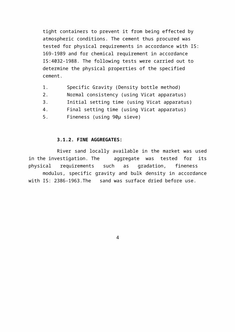
3.1.2. FINE AGGREGATES:
River sand locally available in the market was usedin the investigation. The aggregate was tested for itsphysical requirements such as gradation, fineness
modulus, specific gravity and bulk density in accordancewith IS: 2386-1963.The sand was surface dried before use.
4
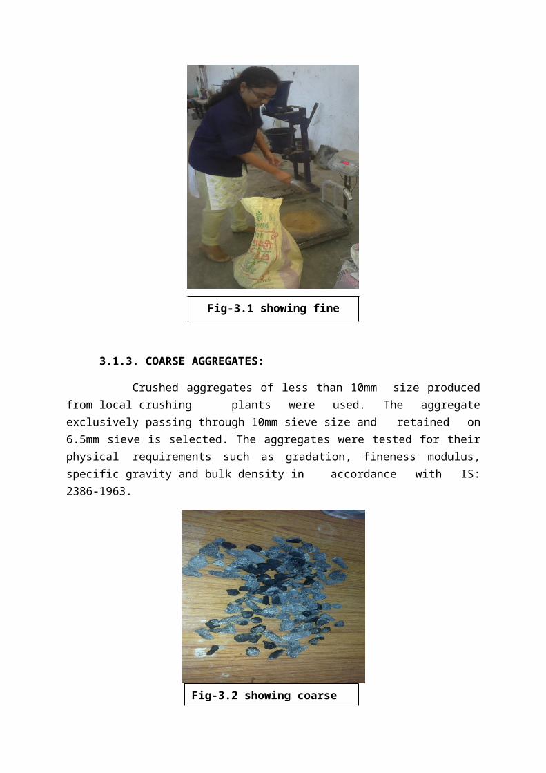
3.1.3. COARSE AGGREGATES:
Crushed aggregates of less than 10mm size producedfrom local crushing plants were used. The aggregateexclusively passing through 10mm sieve size and retained on6.5mm sieve is selected. The aggregates were tested for theirphysical requirements such as gradation, fineness modulus,specific gravity and bulk density in accordance with IS:2386-1963.
Fig-3.1 showing fineaggregate
Fig-3.2 showing coarse
5
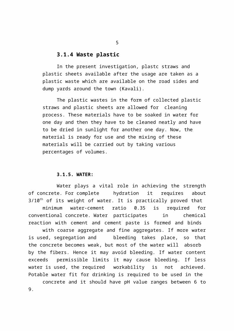
3.1.4 Waste plastic
In the present investigation, plastc straws and plastic sheets available after the usage are taken as a plastic waste which are available on the road sides and dump yards around the town (Kavali).
The plastic wastes in the form of collected plastic straws and plastic sheets are allowed for cleaning process. These materials have to be soaked in water for one day and then they have to be cleaned neatly and have to be dried in sunlight for another one day. Now, the material is ready for use and the mixing of these materials will be carried out by taking various percentages of volumes.
3.1.5. WATER:
Water plays a vital role in achieving the strengthof concrete. For complete hydration it requires about3/10th of its weight of water. It is practically proved that
minimum water-cement ratio 0.35 is required forconventional concrete. Water participates in chemicalreaction with cement and cement paste is formed and binds
with coarse aggregate and fine aggregates. If more wateris used, segregation and bleeding takes place, so thatthe concrete becomes weak, but most of the water will absorbby the fibers. Hence it may avoid bleeding. If water contentexceeds permissible limits it may cause bleeding. If lesswater is used, the required workability is not achieved.Potable water fit for drinking is required to be used in the
concrete and it should have pH value ranges between 6 to9.
6
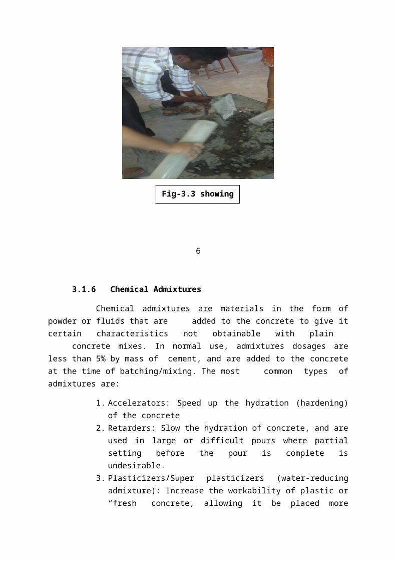
3.1.6 Chemical Admixtures
Chemical admixtures are materials in the form ofpowder or fluids that are added to the concrete to give itcertain characteristics not obtainable with plain
concrete mixes. In normal use, admixtures dosages areless than 5% by mass of cement, and are added to the concreteat the time of batching/mixing. The most common types ofadmixtures are:
1. Accelerators: Speed up the hydration (hardening)of the concrete
2. Retarders: Slow the hydration of concrete, and areused in large or difficult pours where partialsetting before the pour is complete isundesirable.
3. Plasticizers/Super plasticizers (water-reducingadmixture): Increase the workability of plastic or“fresh” concrete, allowing it be placed more
Fig-3.3 showingwater
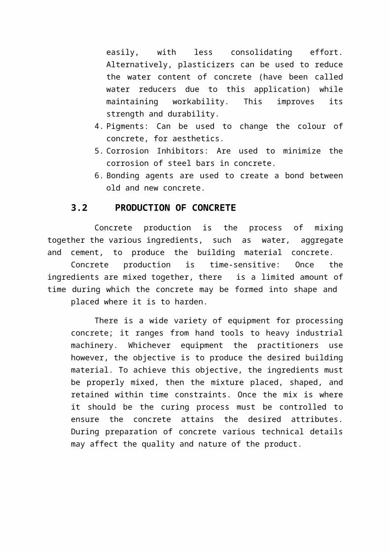
easily, with less consolidating effort.Alternatively, plasticizers can be used to reducethe water content of concrete (have been calledwater reducers due to this application) whilemaintaining workability. This improves itsstrength and durability.
4. Pigments: Can be used to change the colour ofconcrete, for aesthetics.
5. Corrosion Inhibitors: Are used to minimize thecorrosion of steel bars in concrete.
6. Bonding agents are used to create a bond betweenold and new concrete.
3.2 PRODUCTION OF CONCRETE
Concrete production is the process of mixingtogether the various ingredients, such as water, aggregateand cement, to produce the building material concrete.
Concrete production is time-sensitive: Once theingredients are mixed together, there is a limited amount oftime during which the concrete may be formed into shape and
placed where it is to harden.
There is a wide variety of equipment for processingconcrete; it ranges from hand tools to heavy industrialmachinery. Whichever equipment the practitioners usehowever, the objective is to produce the desired buildingmaterial. To achieve this objective, the ingredients mustbe properly mixed, then the mixture placed, shaped, andretained within time constraints. Once the mix is whereit should be the curing process must be controlled toensure the concrete attains the desired attributes.During preparation of concrete various technical detailsmay affect the quality and nature of the product.
7
When initially mixed, Portland cement and waterrapidly form a gel of tangled chains of interlockingcrystals, and components of the gel continue to reactover time. Initially the gel is fluid, which improvesworkability and aids in placement of the material, but asthe concrete sets, the chains of crystals join into arigid structure, counteracting the fluidity of the geland fixing the particles of aggregate in place. Duringcuring, the cement contributes to react with the residualwater in a process of hydration. In properly formulatedconcrete, once this curing process has terminated theproduct has the desired physical and chemical properties.Among the qualities typically desired, are mechanicalstrength, low moisture permeability, and chemical andvolumetric stability.
3.2.1 CONCRETE MIXING:
Thorough mixing is essential for the production ofuniform, high quality concrete. For this reason equipmentand methods should be capable of effectively mixingconcrete materials containing the largest specifiedaggregate to produce uniform mixtures of the lowest slumppractical for the work.
Separate paste mixing has shown that the mixing ofcement and water into a paste before combining thesematerials with aggregates can increase the compressivestrength of the resulting concrete. The paste isgenerally mixed in a high-speed, shear-type mixer ataw/cm (water to cement ratio) of 0.30 to 0.45 by mass.The cement paste premix may include admixtures such asaccelerators or retarders, super plasticizers, pigments,

or silica fume. The premixed paste is then blended withaggregates and any remaining batch water and final mixingis completed in conventional concrete mixing equipment.
High-energy mixed (HEM) concrete is produced bymeans of high-speed mixing of cement, water and sand withnet specific energy consumption of at least 5 kilojoulesper kilogram of the mix. A plasticizer is then added tothe activated mixture, which can later be mixed withaggregates in a conventional concrete mixer. In thisprocess, sand provides dissipation of energy and createshigh-shear conditions on the surface of cement particles.This results in the full volume of water interacting withcement. The liquid activated mixture can be used byitself or foamed (expanded) for lightweight concrete. HEMconcrete hardens in low and subzero temperatureconditions and possesses an increased volume of gel,which drastically reduces capillarity in solid and porousmaterials.
8
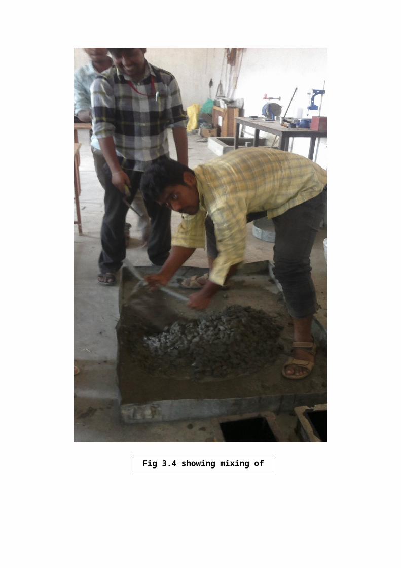
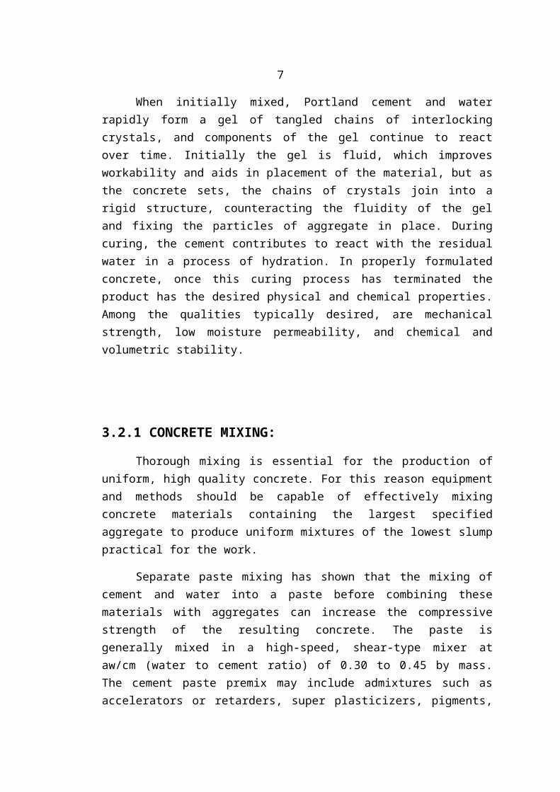
Fig 3.4 showing mixing ofconcrete
9
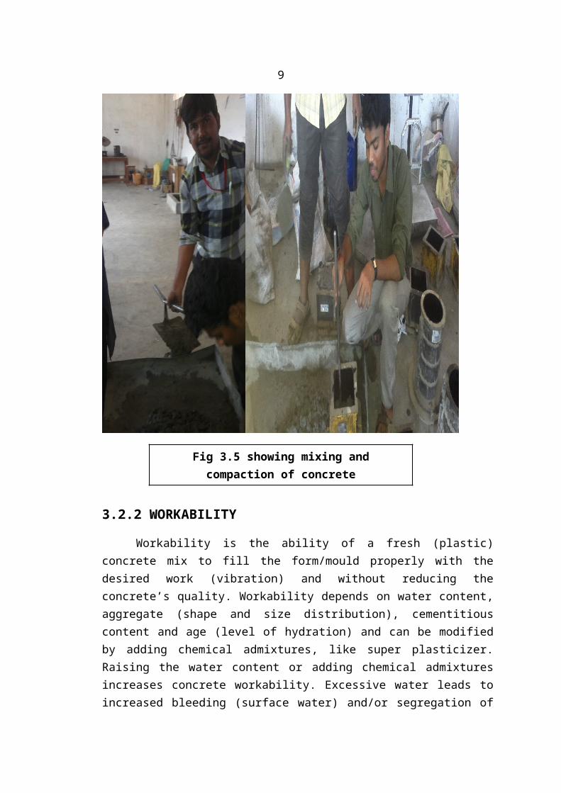
3.2.2 WORKABILITY
Workability is the ability of a fresh (plastic)concrete mix to fill the form/mould properly with thedesired work (vibration) and without reducing theconcrete’s quality. Workability depends on water content,aggregate (shape and size distribution), cementitiouscontent and age (level of hydration) and can be modifiedby adding chemical admixtures, like super plasticizer.Raising the water content or adding chemical admixturesincreases concrete workability. Excessive water leads toincreased bleeding (surface water) and/or segregation of
Fig 3.5 showing mixing andcompaction of concrete
aggregates (when the cement and aggregates start toseparate), with the resulting concrete having reducedquality. The use of an aggregate with an undesirablegradation can result in a very harsh mix design with avery low slump, which cannot be readily made moreworkable by addition of reasonable amounts of water.
10
Workability can be measured by the concrete slumptest, a simplistic measure of the plasticity of a freshbatch of concrete following the ASTM C 143 or EN 12350-2test standards. Slump is normally measured by filling an“Abrams cone” with a sample from a fresh batch ofconcrete.
The cone is placed with the wide end down onto alevel, non-absorptive surface. It is then filled in threelayers of equal volume, with each layer being tamped witha steel rod to consolidate the layer.
When the cone is carefully lifted off, the enclosedmaterial slumps a certain amount due to gravity. Arelatively dry sample slumps very little, having a slumpvalue of one or two inches (25 or 50 mm) out of one foot(305 mm). A relatively wet concrete sample may slump asmuch as eight inches. Workability can also be measured byusing the flow table test.
Slump can be increased by addition of chemicaladmixtures such as plasticizer or super plasticizerwithout changing the water-cement ratio. Some otheradmixtures, especially air-entraining admixture, canincrease the slump of a mix.
High-flow concrete, like self-consolidatingconcrete, is tested by other flow-measuring methods. Oneof these methods includes placing the cone on the narrow
end and observing how the mix flows through the conewhile it is gradually lifted.
After mixing, concrete is a fluid and can be pumped tothe location where needed.
3.2.3 CURING
In all but the least critical applications, careneeds to be taken to properly cure concrete, to achievebest strength and hardness. This happens after theconcrete has been placed. Cement requires a moist,controlled environment to gain strength and harden fully.The cement paste hardens over time, initially setting andbecoming rigid though very weak and gaining in strengthin the weeks following. In around 4 weeks, typically over90% of the final strength is reached, thoughstrengthening may continue for decades. The conversion ofcalcium hydroxide in the concrete into calcium carbonatefrom absorption of CO2 over several decades furtherstrengthen the concrete and making it more resilient todamage. However, this reaction, called carbonation,lowers the pH of the cement pore solution and can causethe reinforcement bars to corrode.
11
Hydration and hardening of concrete during the firstthree days is critical. Abnormally fast drying andshrinkage due to factors such as evaporation from windduring placement may lead to increased tensile stressesat a time when it has not yet gained sufficient strength,resulting in greater shrinkage cracking. The early
strength of the concrete can be increased if it is keptdamp during the curing process. Minimizing stress priorto curing minimizes cracking. High-early-strengthconcrete is designed to hydrate faster, often byincreased use of cement that increases shrinkage andcracking. Strength of concrete changes (increases) up tothree years. It depends on cross-section dimension ofelements and conditions of structure exploitation.
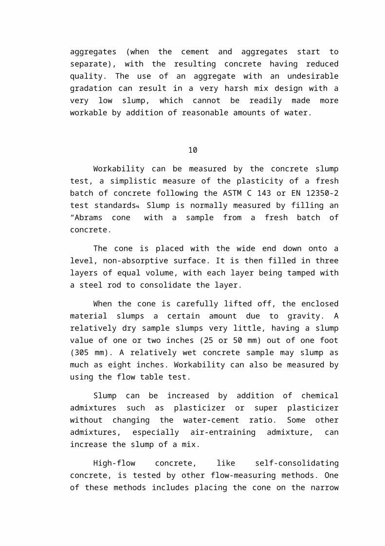
During this period concrete needs to be kept undercontrolled temperature and humid atmosphere. In practice,this is achieved by spraying or ponding the concretesurface with water, thereby protecting the concrete massfrom ill effects of ambient conditions. The pictures tothe right show two of many ways to achieve this, ponding-submerging setting concrete in water and wrapping inplastic to contain the water in the mix.
Properly curing concrete leads to increased strengthand lower permeability and avoids cracking where thesurface dries out prematurely. Care must also be taken toavoid freezing, or overheating due to the exothermicsetting of cement. Improper curing can cause scaling,reduced strength, poor abrasion resistance and cracking.
12
3.3. Precautions
Following precautions should be followedcarefully while mixing and placing the concrete.
1. The plastic straws and sheets taking should be cutupto our requirements without errors.2. The water for curing should be tested every 7 days andtemperature of the water must be at 27±2°C.3. The concrete moulds should be carefully removed frommoulds, placed in water and taking to the tests withoutcausing any failure.
Fig 3.6 showing the curing ofconcrete moulds
13
EXPERIMENTAL INVESTIGATIONS4.1. CEMENT:
4.1.1. NORMAL CONSISTENCY OF CEMENT:
Aim: To determine the normal consistency of givencement sample.
Reference: IS: 269 – 1976 and IS: 4031 – 1968
Apparatus:
1. Vicat apparatus (confirming to IS: 5513 –1968) with plunger (10 mm diameter).
2. Vicat mould
3. Gauging trowel4. Measuring jar5. Balance6. Tray
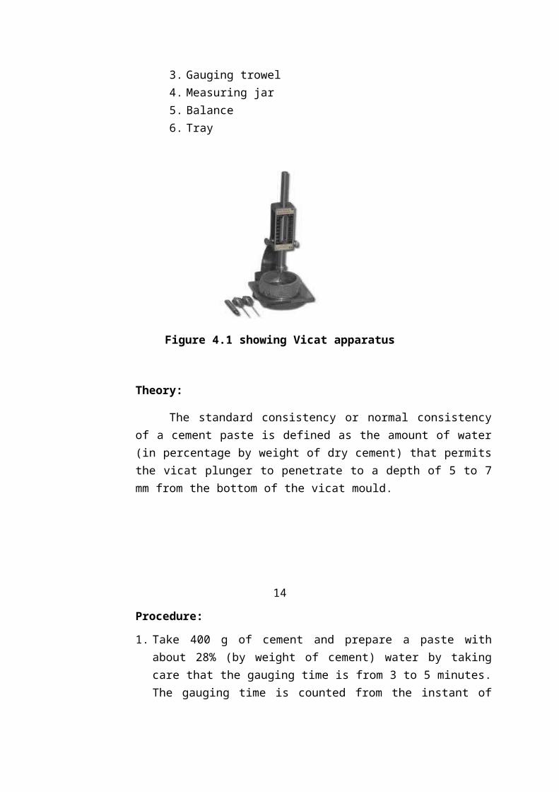
Figure 4.1 showing Vicat apparatus
Theory:
The standard consistency or normal consistencyof a cement paste is defined as the amount of water(in percentage by weight of dry cement) that permitsthe vicat plunger to penetrate to a depth of 5 to 7mm from the bottom of the vicat mould.
14
Procedure:
1. Take 400 g of cement and prepare a paste withabout 28% (by weight of cement) water by takingcare that the gauging time is from 3 to 5 minutes.The gauging time is counted from the instant of
adding of water to dry cement until the mould isfilled.
2. Fill the vicat mould by placing it on a non-porousplate with the cement paste prepared. Aftercompletely filling the mould, smooth off thesurface with a single movement of the trowel,making it level with the top of the mould.
3. Shake the mould slightly to remove any air bubblesas their presence may affect the penetration ofthe plunger.
4. Place the specimen along with the non-porous plateunder the vicat plunger and lower it gently sothat it just touches the surface of the specimen.
5. Quickly release the plunger and allow it to sink.Note the reading.
6. Prepare the paste with varying percentages ofwater and repeat the experiment until the plungerstops penetrating at a level 5 to 7 mm from bottomand tabulate the results.
Observations:
Amount of water
(%)Initialreading
Finalreadin
g
Depth ofpenetration frombottom(mm)
Table1: Normal consistency of cement
Result:

Normal consistency of the given cement sample is:_____%
This can be done by using Vicat apparatushaving 10mm dia. of plunger.
Where the depth of penetration of plunger is limitedto 5 to 7 from bottom that % of water can be treatas consistency of cement
15
4.1.2 INITIAL SETTING TIME OF CEMENT:
Aim: To determine the initial setting time ofthe given cement sample.
Reference: IS: 269 – 1976 and IS: 4031 – 1968
Apparatus:
1. Vicat apparatus (confirming to IS: 5513 –1968) with needle (1.13 mm diameter).
2. Vicat mould3. Gauging trowel4. Measuring jar5. Balance6. Tray7. Stop watch
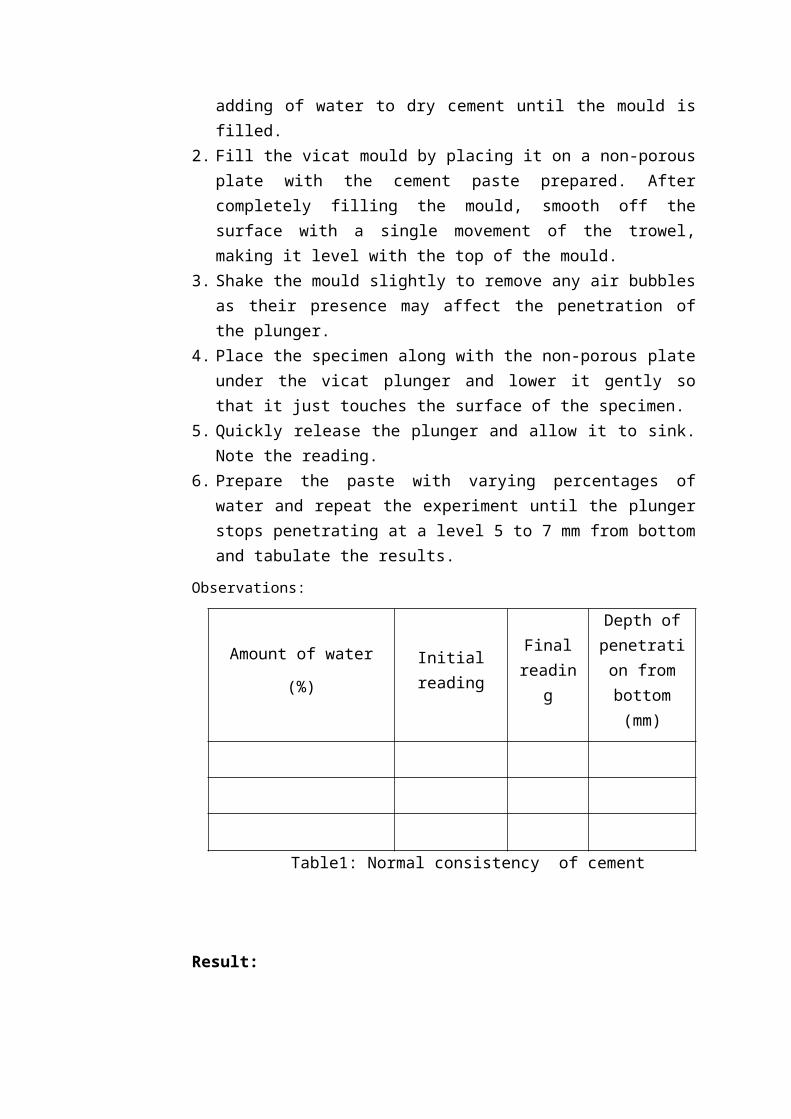
Figure 4.2 showing Vicat apparatus in initial setting time ofcement
16
Theory:
In order to place the concrete in position, itis necessary that the initial setting time of thecement is not too low. Once it has been laid, thehardening should be rapid so that the structure canbe subjected to the incidental loads as early aspossible.
The initial set is a stage after which anyvisible crack will not re-unite. Therefore certain
limit for the initial setting time has to bespecified.
Procedure:
1. Prepare a neat cement paste by gauging 400 gcement with 0.85P water, where P is the normalconsistency of the given sample of cement.
2. The gauging time is between 3 and 5 minutes. Thegauging time is counted from the instant of addingof water to dry cement.
3. Fill the vicat mould with the prepared paste andlevel it to the top of the mould. The cement blockthus prepared is known as the test block.
4. Place the test block on a non-porous plate and setit below the vicat needle. Lower the needle tomake contact with the surface of the test block.
5. Quickly release the needle and allow it to sink.Note the reading.
6. Repeat the experiment until the needle failspiercing the block at a level 5 to 7 mm frombottom.
Observations:
1. Weight of cement taken: 400 gms2. Amount of water added: 108.8 ml
Result:
Initial setting time of the given cement sampleis: _____ min
17
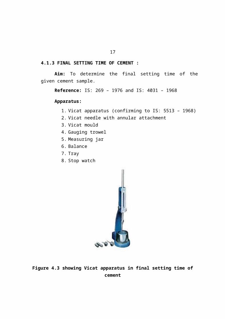
4.1.3 FINAL SETTING TIME OF CEMENT :
Aim: To determine the final setting time of thegiven cement sample.
Reference: IS: 269 – 1976 and IS: 4031 – 1968
Apparatus:
1. Vicat apparatus (confirming to IS: 5513 – 1968)2. Vicat needle with annular attachment3. Vicat mould4. Gauging trowel5. Measuring jar6. Balance7. Tray8. Stop watch
Figure 4.3 showing Vicat apparatus in final setting time ofcement
Theory:
In actual construction dealing with cementpaste, mortar or concrete, certain time is requiredfor mixing, transporting and placing. During thistime, cement paste, mortar or concrete should be inplastic condition.
18
Once the concrete is placed in the finalposition, compacted and finished, it should lose itsplasticity at the earliest possible time so that itis vulnerable to damages from external destructiveagencies. This time is referred to as the finalsetting time.
Procedure:
1. Prepare a neat cement paste by gauging 400 gcement with 0.85P water, where P is the normalconsistency of the given sample of cement.2. The gauging time is between 3 and 5 minutes. Thegauging time is counted from the instant of addingof water to dry cement.3 .Fill the vicat mould with the prepared paste andlevel it to the top of the mould. The cement blockthus prepared is known as the test block.4. Place the test block under the vicat needle withthe annular attachment and lower the needle just tomake contact with the surface of the test block.5. Quickly release the needle allowing it to
penetrate into the test block.
6. The cement is said to be finally set when theneedle makes an impression on the test block and theattachment fails to do so.7.The time elapsed between this stage and theinstant when the water was added to the cement iscalled the final setting time.Observations:
1. Weight of the cement taken: 400 gms2. Amount of water added: 108.8 ml
Result:
Final setting time of the given cement sampleis:_________ min
The period elapsing between the time when wateris added to the cement and the time at which theneedle penetrates the test block to a depth equal to5 to 7 mm from the bottom is taken as initialsetting time and the needle makes an impression onthe test block is taken as final setting time.
19
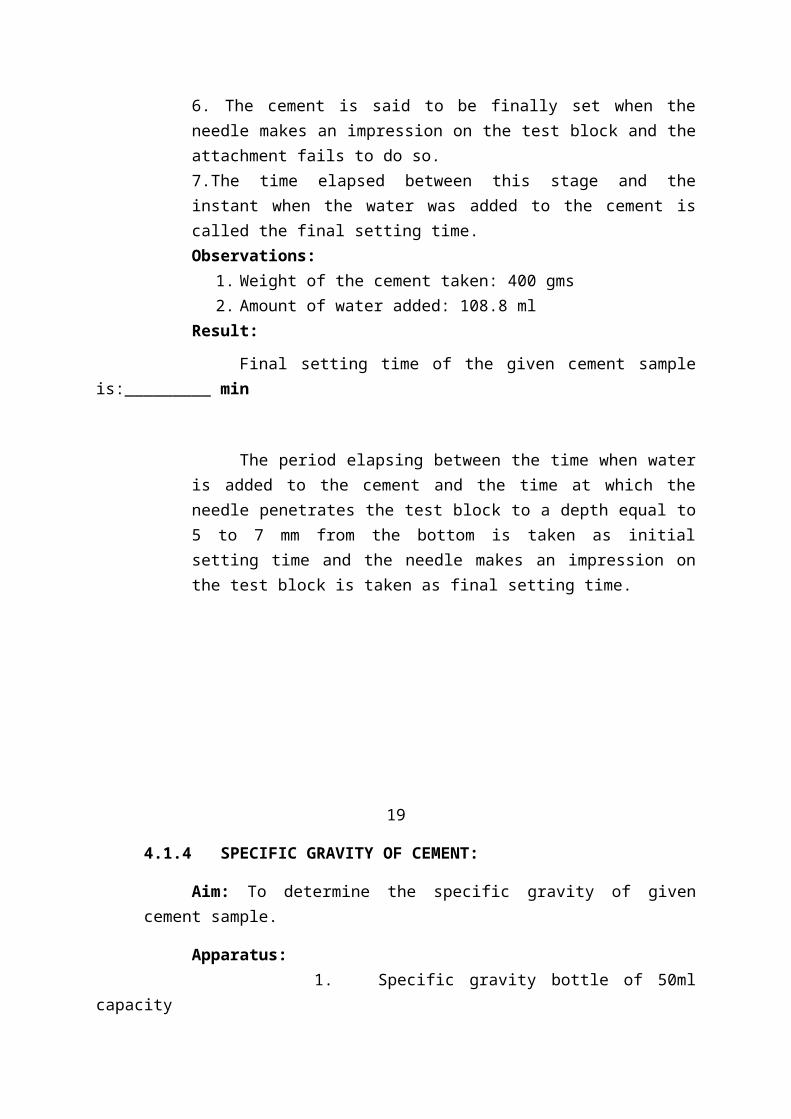
4.1.4 SPECIFIC GRAVITY OF CEMENT:
Aim: To determine the specific gravity of givencement sample.
Apparatus: 1. Specific gravity bottle of 50mlcapacity
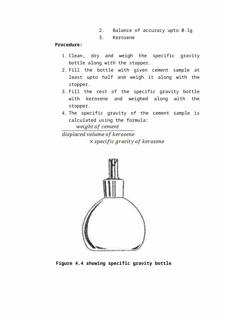
2. Balance of accuracy upto 0.1g 3. Kerosene
Procedure:
1. Clean, dry and weigh the specific gravitybottle along with the stopper.
2. Fill the bottle with given cement sample atleast upto half and weigh it along with thestopper.
3. Fill the rest of the specific gravity bottlewith kerosene and weighed along with thestopper.
4. The specific gravity of the cement sample iscalculated using the formula:
Figure 4.4 showing specific gravity bottle
20
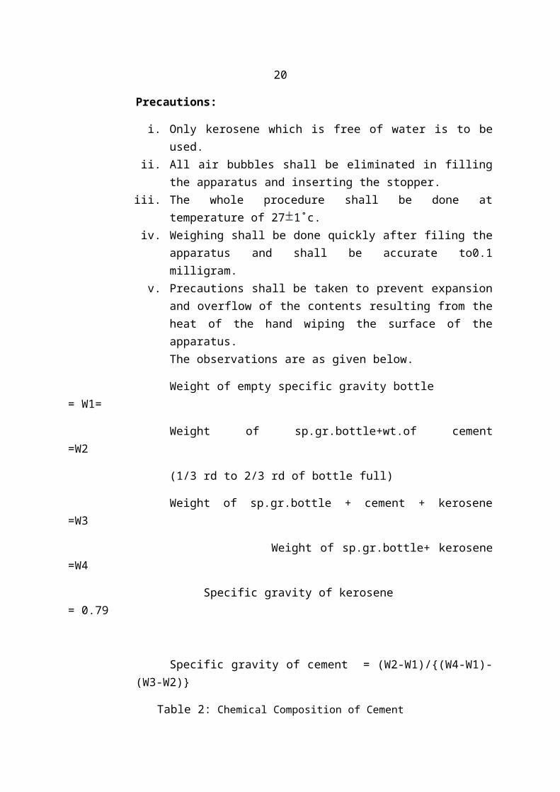
Precautions:
i. Only kerosene which is free of water is to beused.
ii. All air bubbles shall be eliminated in fillingthe apparatus and inserting the stopper.
iii. The whole procedure shall be done attemperature of 27 1˚c.
iv. Weighing shall be done quickly after filing theapparatus and shall be accurate to0.1milligram.
v. Precautions shall be taken to prevent expansionand overflow of the contents resulting from theheat of the hand wiping the surface of theapparatus.
The observations are as given below.
Weight of empty specific gravity bottle = W1=
Weight of sp.gr.bottle+wt.of cement=W2
(1/3 rd to 2/3 rd of bottle full)
Weight of sp.gr.bottle + cement + kerosene=W3
Weight of sp.gr.bottle+ kerosene=W4
Specific gravity of kerosene= 0.79
Specific gravity of cement = (W2-W1)/{(W4-W1)-(W3-W2)}
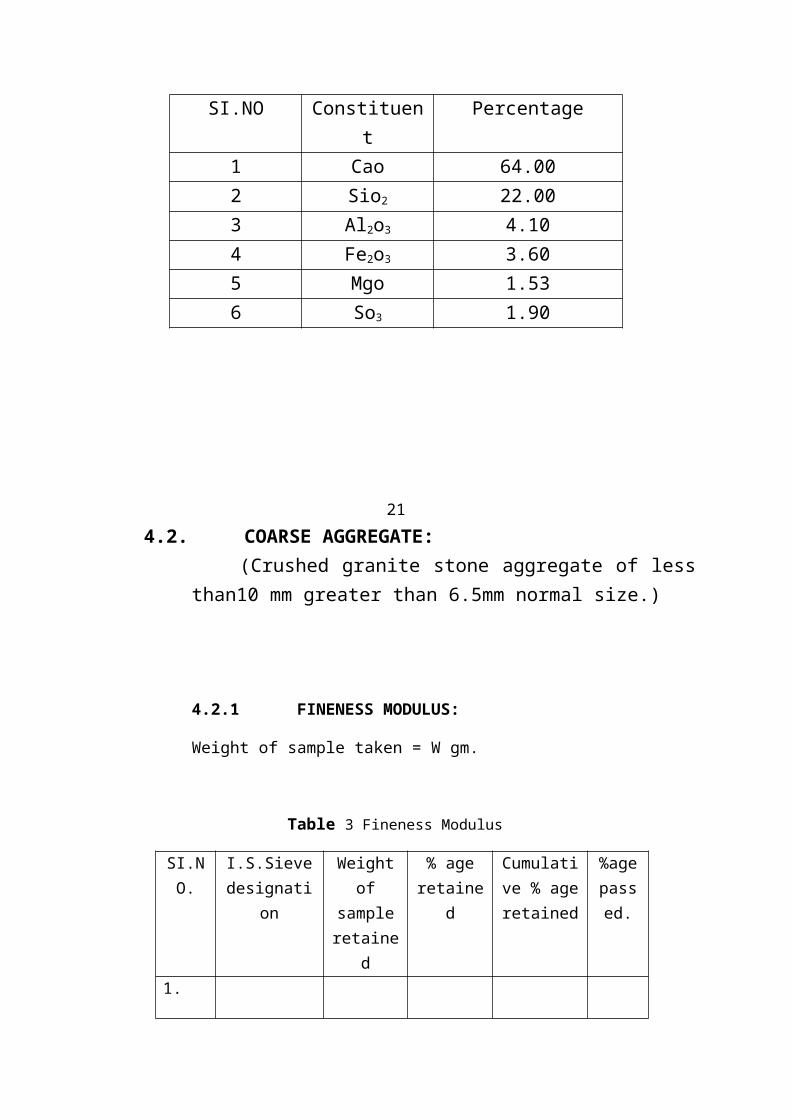
Table 2: Chemical Composition of Cement
SI.NO Constituent
Percentage
1 Cao 64.002 Sio2 22.003 Al2o3 4.104 Fe2o3 3.605 Mgo 1.536 So3 1.90
214.2. COARSE AGGREGATE:
(Crushed granite stone aggregate of lessthan10 mm greater than 6.5mm normal size.)
4.2.1 FINENESS MODULUS:
Weight of sample taken = W gm.
Table 3 Fineness Modulus
SI.NO.
I.S.Sievedesignati
on
Weightof
sampleretaine
d
% ageretaine
d
Cumulative % ageretained
%agepassed.
1.

2.
3.
4.
5.
6.
7.
8.
9.
22
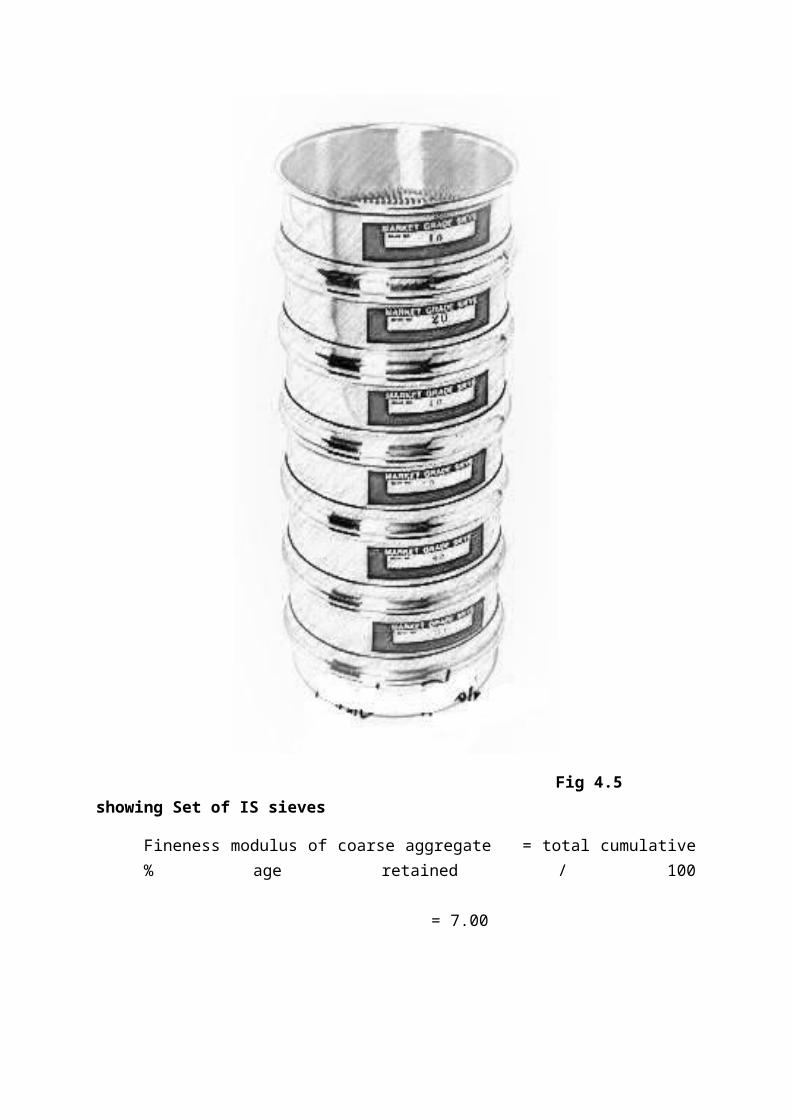
Fig 4.5 showing Set of IS sieves
Fineness modulus of coarse aggregate = total cumulative% age retained / 100
= 7.00
23
4.2.2 SPECIFIC GRAVITY AND WATER ABSORPTION
Aim:- To determine the specific gravity and waterabsorption of coarse aggregate.
Apparatus:-i. Balance: capacity not less than 3kgsii. Oveniii. Wire basketiv. Tray: A shallow tray of area not less than
325sq.cm air tight containerv. Cloths: Two pieces of soft absorbent clothes
not less than 750mm*450mmTheory:-
The specific gravity is used in the calculationof the quantities for a concrete mix. As theaggregates forms around three- fourth of the weightof concrete, there is a minimum requirement on thedensity of concrete for its use in the gravity dams.
The porosity, permeability and water absorptionof the aggregate influence its properties likereaction with cement paste, resistance to freezingand thawing as well as its chemical stability.
The strength of the aggregates generally decreaseswith increase in porosity.
Preparation of sample:A naturally heated sample of about 1kg is used,
artificially heated aggregates shall be normally notused. If such material is used, the fact shall bestated in the report.
Two tests shall be done and it is recommendedthat the two samples are not to be testedconcurrently.
Procedure:
1. The sample is washed thoroughly to remove finerparticles and dust and is drained. Then the sampleis placed in the wire basket and immersed indistilled water at a temperature of 22oC – 32oC for24 hours ± 30 minutes.
2. Entrapped air is removed from the sample byagitating (dropping) the sample along with thebasket in distilled water for about 25 times from25 mm above the base of the tank at a rate of onedrop per second.
3. The aggregate and basket shall be completelyimmersed in the distilled water during the time ofexperiment.
244. Shake the basket and the sample and weigh it in
water at a temperature of 22oC to 32oC.5. If it is necessary for them to be transferred to a
different tank for weighing, they shall be shaken25 times as explained above in the new tank beforeweighing.
6. Remove the basket and the aggregate from water andallow it to drain for a few minutes, after whichthe aggregate shall be gently emptied on to one ofthe dry clothes and the basket will be returned tothe water, shaken 25 times and weighed.
7. Surface dry the aggregate with the second cloth,transferring it from the first cloth when itremoves no further moisture. Then the aggregate isweighed.
8. Dry the sample in oven at 100oC to 110oC for 24hours and then weigh it, after transferring intothe air – tight container.
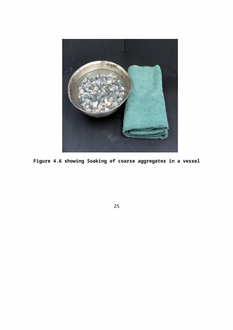
Figure 4.6 showing Soaking of coarse aggregates in a vessel
25
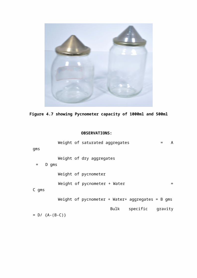
Figure 4.7 showing Pycnometer capacity of 1000ml and 500ml
OBSERVATIONS:
Weight of saturated aggregates = Agms
Weight of dry aggregates = D gms
Weight of pycnometer
Weight of pycnometer + Water =C gms
Weight of pycnometer + Water+ aggregates = B gms
Bulk specific gravity= D/ {A-(B-C)}
26
4.2.3 Specific gravity of fine aggregate:
Weight of empty pycnometer =W1 gm.
Weight of pycnometer + coarse aggregate =W2 gm.
Weight of pycnometer + coarse agg + water =W3gm.
Weight of pycnometer + water =W4 gms
1) Dry weight of aggregate=W2-W1
2) Weight of equivalent volume of water =(W2-W1)-(W3-W4)
Specific gravity= (W2-W1)/(W2-W1)-(W3-W4)
4.2.4 Compression test and Split tensile test:
a) Remove the specimens from water after specifiedcuring time and wipe out excess water from thesurface.
b) Leave the specimen in the atmosphere for24hours before testing.
c) Place the specimen in the machine in such amanner that the load shall be applies to theopposite sides of the specimen cast.
d) Align the specimen centrally on the base plate ofthe machine for a cubic or cylindrical specimen.e) Rotate the movable portion gently by hand so thatit touches the top surface of the specimen.f) Apply the load gradually without shock andcontinuously at the rate of 140kg/cm2 /minute tillthe specimen fails.
g) Increase the load until failure and notethe maximum load.
27
4.2.5 Flexural Test
a) Remove the specimens from water after specifiedcuring time and wipe out excess water from thesurface.
b) Leave the specimen in the atmospherefor 24hours before testing.
c) The specimen is then placed in the machine insuch a manner that the load is applied to theuppermost surface as cast in the mould, along the
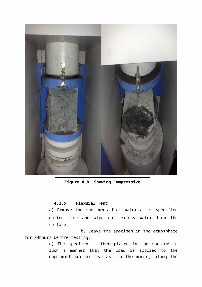
Figure 4.8 Showing Compressivetesting machine
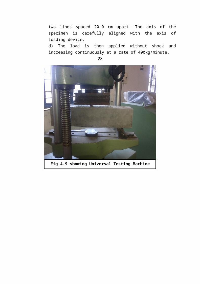
two lines spaced 20.0 cm apart. The axis of thespecimen is carefully aligned with the axis ofloading device.d) The load is then applied without shock andincreasing continuously at a rate of 400kg/minute.
28
Fig 4.9 showing Universal Testing Machinewith Prism mould
29
Calculations & Results:
Compression Test:
Size of the cube=15cm×15cm×15cm
Area of the specimen (calculated from the mean sizeof the specimen) = 225cm2
Compressive strength at 28 days =……N/mm2
Compressive strength = (Load in N/ Area in mm2)=……….. N/mm2
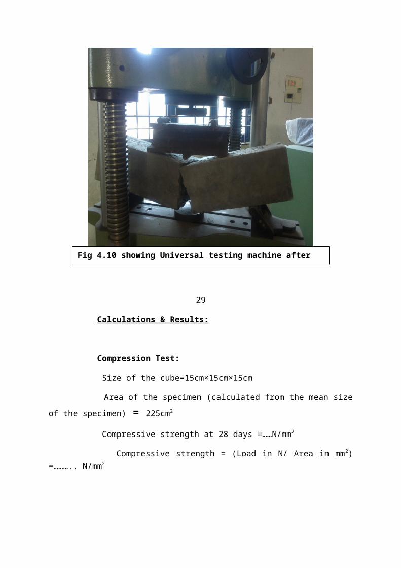
Fig 4.10 showing Universal testing machine after testing the prism mould
Split Tensile Test:
Size of the specimen = 15cm in diameter and 30cm long
Tensile Strength = 2P/πDL =……… N/mm2
Tensile Strength at 28 days = ……... N/mm2
Flexural Test:
Size of the specimen = 15cm×15cm×70cm
Flexural Strength = p×l/b×d×d=……. N/mm2
Flexural Strength at 28 days = ……… N/mm2
30
CONCRETE MIX DESIGNThis chapter deals with the design procedure adopted
for preparation of concrete with the application of robofine.5.1 MIX DESIGN OF CONCRETE:
The strength is mainly influenced by water cementratio, and is almost independent of the other parametersthe properties of concrete with a compressive strength of
20MPa,are influenced by the properties of aggregate inaddition to that of water cement ratio. To obtain goodstrength, it is necessary to use the lowest possible w/cratio which affects the workability of the mix. In thepresent state of art, concrete which has a desired 28dayscompressive strength of minimum 20 MPa, can be made bysuitable proportion of the ingredients using normalmethods for compacting the mixes.
5.2 MIX DESIGN PROCEDURE:1. The strength of the cement as available in thecountry today has greatly improved since 1982. The28-day strength of A, B, C, D, E, F. Category ofcement is to be reviewed.
2. The graph connecting, different strength ofcements and W/C is to be reestablished.
3. The graph connecting 28-day compressive strengthof concrete and W/C ratio is to be extended up to80Mpa, if this graph is to be cater for highstrength concrete.
4. As per the revision of 456-2000, the degree ofworkability is expressed in terms of slump insteadof compacting factor. This results in change ofvalues in estimating approximate sand and watercontents for normal concrete up to 35Mpa and highstrength concrete above 35Mpa. The table givingadjustment of values in water content and sand % forother than standard conditions, requires appropriatechanges and modifications.
5.In the view of the above and other changes made inthe revision of IS456-2000, the mix design procedureas recommended in IS 10262-82 is required to bemodified to the extent considered necessary andexamples of mix design is worked out.
31
5.3 MIX DESIGN FOR PLASTIC MIXED CONCRETE
a) Design stipulations
Characteristic compressive strength required in the fieldat 28 days : 20Mpa
Maximum size of aggregate :20mm
i. Degree of quality control : Goodii. Type of exposure : Mild
b) Tested data for materials
i. Specific gravity of cement :3.14
Comp Strength of cement at 7 day: Satisfies the requirement IS:269-1989
ii. Specific gravity of Coarse aggregates : 2.63Specific gravity of Fine aggregates :2.75
iii. Water absorption of Coarse aggregates : 1%iv. Free moisture in CA & FA :
Nil
c) Target mean strength of concrete
The target mean strength for specifiedcharacteristic cube strength is
20+1.65*4=26.6N/mm2
d) Selection of water - cement ratio
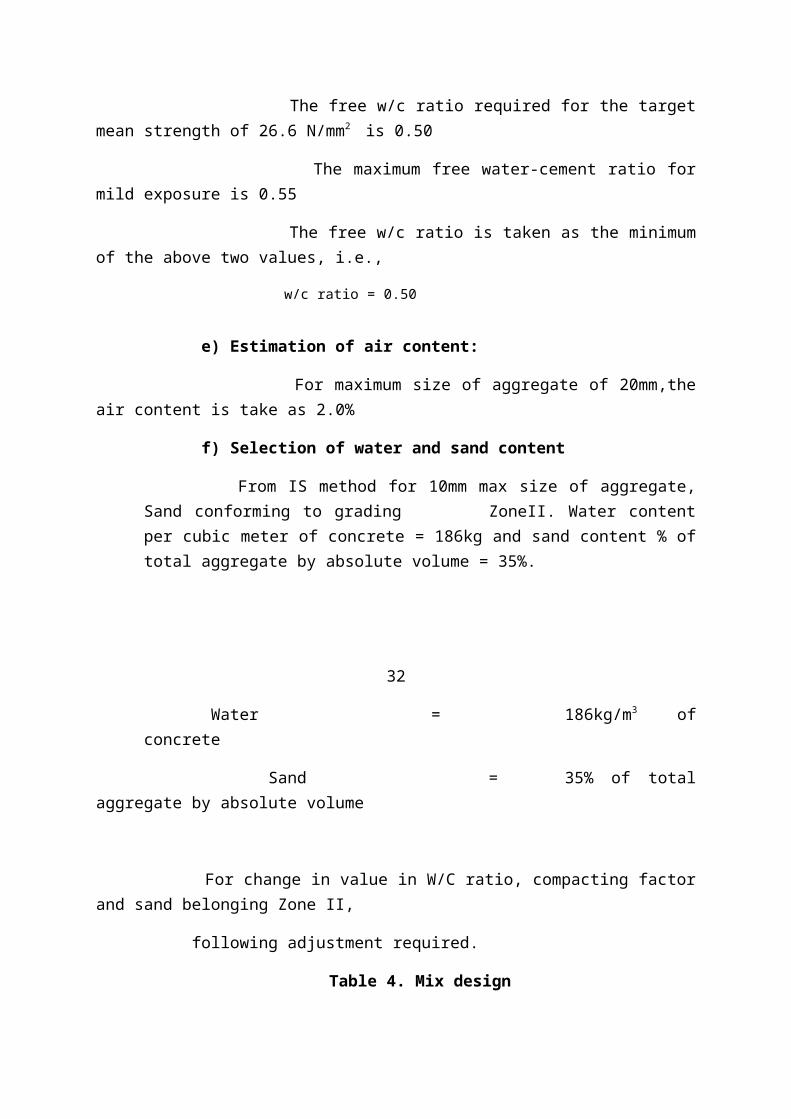
The free w/c ratio required for the targetmean strength of 26.6 N/mm2 is 0.50
The maximum free water-cement ratio formild exposure is 0.55
The free w/c ratio is taken as the minimumof the above two values, i.e.,
w/c ratio = 0.50
e) Estimation of air content:
For maximum size of aggregate of 20mm,theair content is take as 2.0%
f) Selection of water and sand content
From IS method for 10mm max size of aggregate,Sand conforming to grading ZoneII. Water contentper cubic meter of concrete = 186kg and sand content % oftotal aggregate by absolute volume = 35%.
32
Water = 186kg/m3 ofconcrete
Sand = 35% of totalaggregate by absolute volume
For change in value in W/C ratio, compacting factorand sand belonging Zone II,
following adjustment required.
Table 4. Mix design
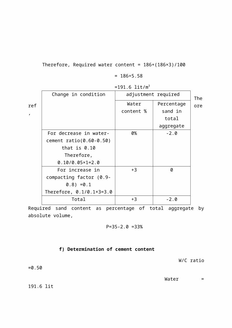
Therefore, Required water content = 186+(186×3)/100
= 186+5.58
=191.6 lit/m3
Theref ore,
Required sand content as percentage of total aggregate byabsolute volume,
P=35-2.0 =33%
f) Determination of cement content
W/C ratio=0.50
Water =191.6 lit
Change in condition adjustment required
Watercontent %
Percentagesand intotal
aggregateFor decrease in water-cement ratio(0.60-0.50)
that is 0.10Therefore,
0.10/0.05×1=2.0
0% -2.0
For increase incompacting factor (0.9-
0.8) =0.1Therefore, 0.1/0.1×3=3.0
+3 0
Total +3 -2.0
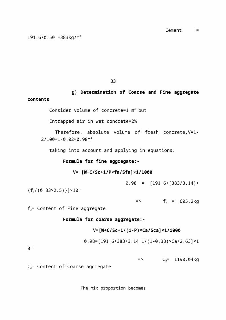
Cement =191.6/0.50 =383kg/m3
33
g) Determination of Coarse and Fine aggregatecontents
Consider volume of concrete=1 m3 but
Entrapped air in wet concrete=2%
Therefore, absolute volume of fresh concrete,V=1-2/100=1-0.02=0.98m3
taking into account and applying in equations.
Formula for fine aggregate:-
V= [W+C/Sc+1/P×fa/Sfa]×1/1000
0.98 = [191.6+(383/3.14)+{fa/(0.33×2.5)}]×10-3
=> fa = 605.2kgfa= Content of Fine aggregate
Formula for coarse aggregate:-
V=[W+C/Sc+1/(1-P)×Ca/Sca]×1/1000
0.98=[191.6+383/3.14+1/(1-0.33)×Ca/2.63]×10-3
=> Ca= 1190.04kgCa= Content of Coarse aggregate
The mix proportion becomes
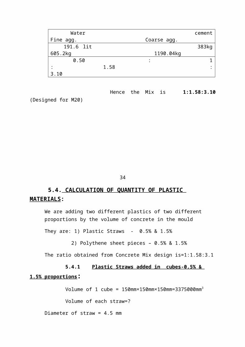
Water cementFine agg. Coarse agg. 191.6 lit 383kg605.2kg 1190.04kg 0.50 : 1: 1.58 :3.10
Hence the Mix is 1:1.58:3.10(Designed for M20)
34
5.4. CALCULATION OF QUANTITY OF PLASTIC MATERIALS:
We are adding two different plastics of two different proportions by the volume of concrete in the mould
They are: 1) Plastic Straws - 0.5% & 1.5%
2) Polythene sheet pieces – 0.5% & 1.5%
The ratio obtained from Concrete Mix design is=1:1.58:3.1
5.4.1 Plastic Straws added in cubes-0.5% & 1.5% proportions: Volume of 1 cube = 150mm×150mm×150mm=3375000mm3
Volume of each straw=?
Diameter of straw = 4.5 mm
Length of straw =?
Taking aspect ratio as L/d = 20L/4.5=20
Therefore, L = 4.5×20=90mm= 9 cm
Therefore, volume of each straw=π/4 × (4.5×4.5) ×90=1431.38 mm3
Number of straws required for 0.5% =?
3375000 × (0.5/100)=16875mm3
Number of straws for 1 cube mould=16875÷1431.38=11.78~12 straws
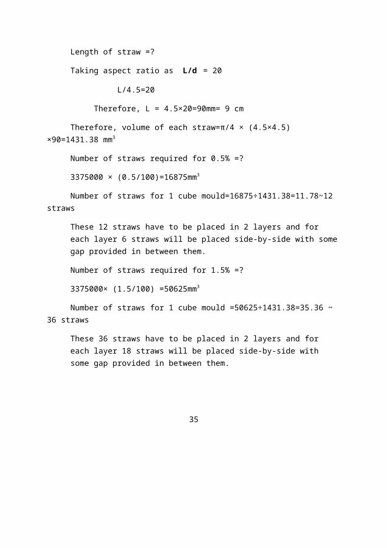
These 12 straws have to be placed in 2 layers and for each layer 6 straws will be placed side-by-side with somegap provided in between them.
Number of straws required for 1.5% =?
3375000× (1.5/100) =50625mm3
Number of straws for 1 cube mould =50625÷1431.38=35.36 ~ 36 straws
These 36 straws have to be placed in 2 layers and for each layer 18 straws will be placed side-by-side with some gap provided in between them.
35
36
Fig 5.1 showing a cube mould with

5.4.2 Plastic straws added in cylinders-0.5% & 1.5% proportions :
Volume of 1 cylinder = π/4 ×(150×150) × 300
=5301437.603mm3
Here, we are taking the same aspect ratio and the volume of each straw will remains same as above.
Therefore, Number of straws required for 0.5% =?
5301437.603× (0.5/100) = 26507.18mm3
Number of straws for 1 cylinder mould =26507.18÷1431.38=18.51~18sheets
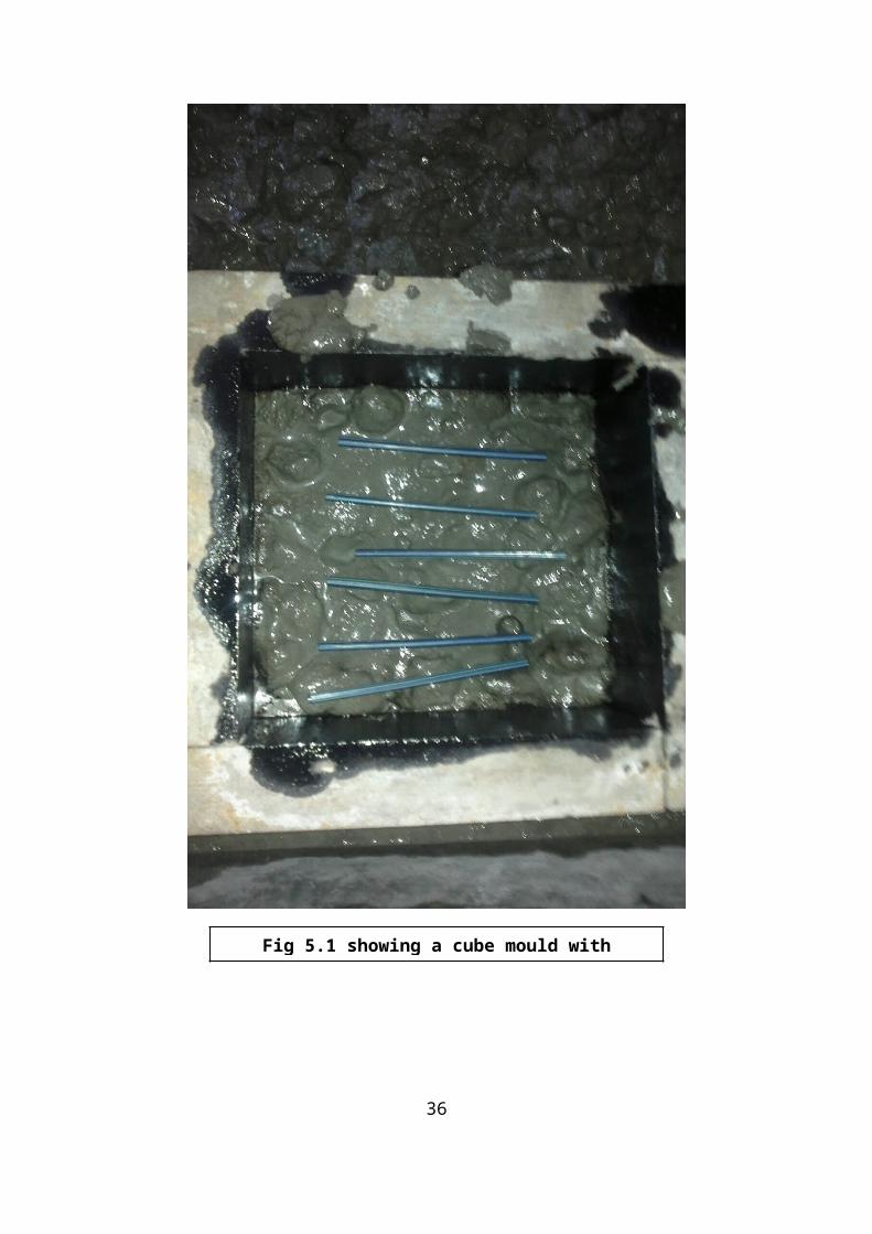
These 18 straws have to be placed in 3 layers and for each layer 6 straws will be placed side-by-side with somegap provided in between them.
Number of straws required for 1.5% =?
5301437.603× (1.5/100)=79521.56mm3
Number of straws for 1 cylinder mould =79521.56÷1431.38=55.5~54 straws
These 54 straws have to be placed in 3 layers and for each layer 18 straws will be placed side-by-side with some gap provided in between them.

37
38
Fig 5.2 showing a cylindrical mould withplastic straws in a layer
5.4.3 Plastic straws added in prism moulds-1% proportion:
Volume of Prism mould = 150mm×150mm×700mm = 15750000mm3
Volume of each straw = 1431.38mm3
Adding 1% of straws by volume of beam= 15750000× (1/100) =157500
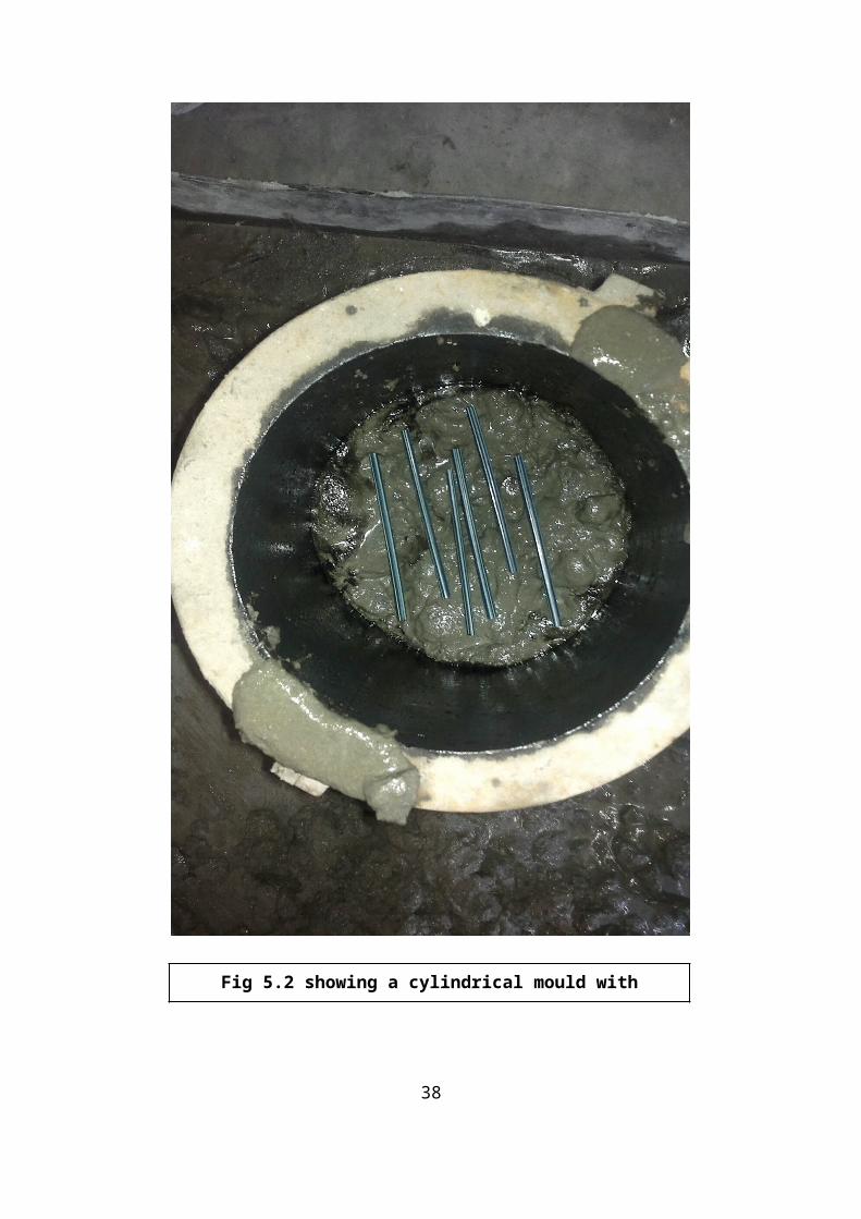
Number of straws for 1 prism mould= 157500÷1431.38=110.03~110 straws
These 110 straws have to be placed in one layer side-by-side and oriented along the longer direction of the prismmould by providing some gap in between them.
Fig 5.3 showing a prism mould with plasticstraws in a layer
39
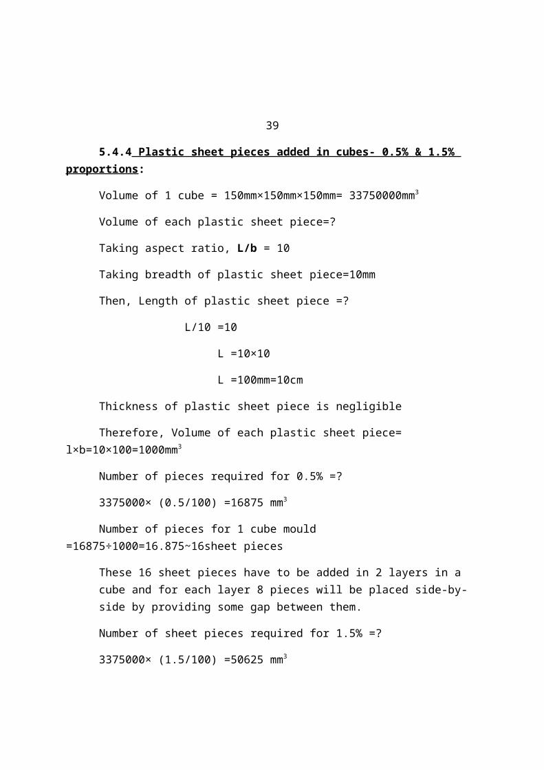
5.4.4 Plastic sheet pieces added in cubes- 0.5% & 1.5% proportions:
Volume of 1 cube = 150mm×150mm×150mm= 33750000mm3
Volume of each plastic sheet piece=?
Taking aspect ratio, L/b = 10
Taking breadth of plastic sheet piece=10mm
Then, Length of plastic sheet piece =?
L/10 =10
L =10×10
L =100mm=10cm
Thickness of plastic sheet piece is negligible
Therefore, Volume of each plastic sheet piece= l×b=10×100=1000mm3
Number of pieces required for 0.5% =?
3375000× (0.5/100) =16875 mm3
Number of pieces for 1 cube mould =16875÷1000=16.875~16sheet pieces
These 16 sheet pieces have to be added in 2 layers in a cube and for each layer 8 pieces will be placed side-by-side by providing some gap between them.
Number of sheet pieces required for 1.5% =?
3375000× (1.5/100) =50625 mm3
Number of pieces for 1 cube mould= 50625÷1000=50.625~50 sheet pieces
These 50 sheet pieces have to be added in 2 layers in a cube and for each layer 25 pieces will be added.
40
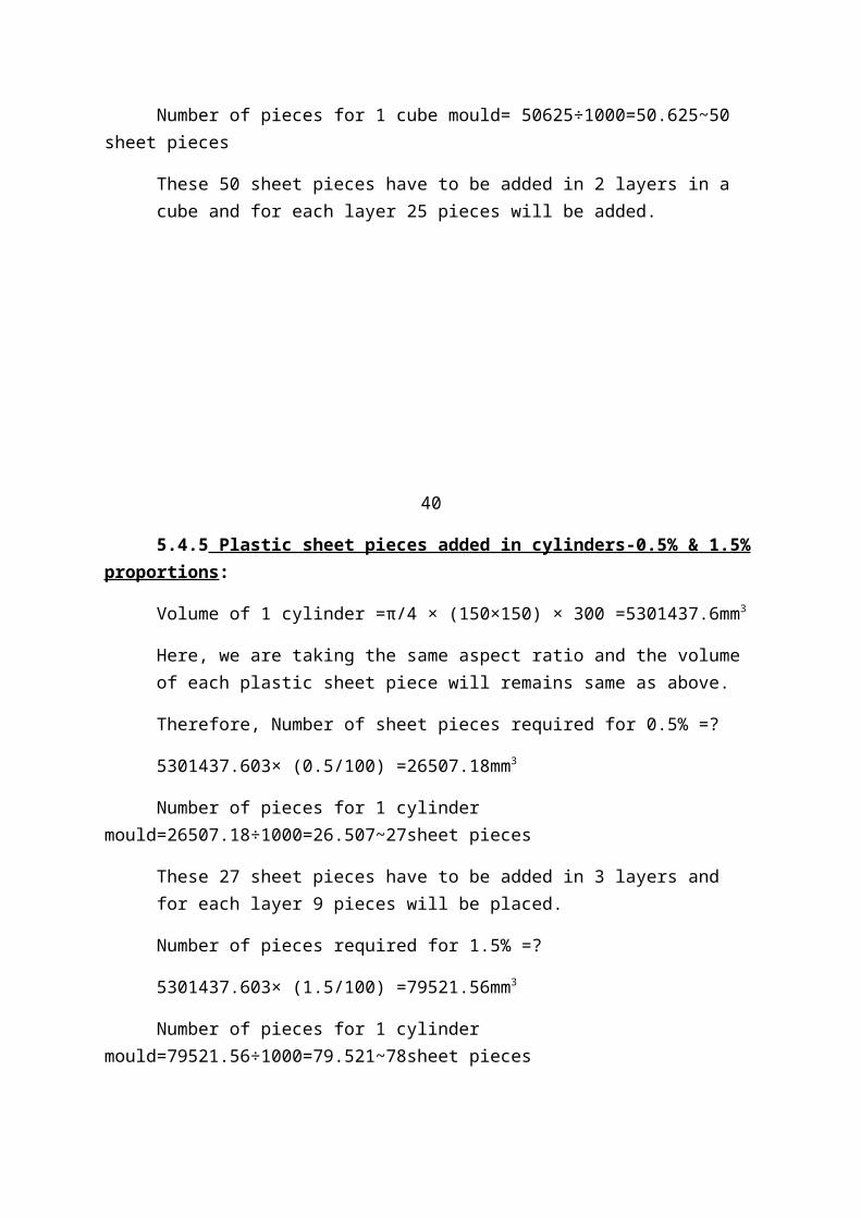
5.4.5 Plastic sheet pieces added in cylinders-0.5% & 1.5%proportions:
Volume of 1 cylinder =π/4 × (150×150) × 300 =5301437.6mm3
Here, we are taking the same aspect ratio and the volume of each plastic sheet piece will remains same as above.
Therefore, Number of sheet pieces required for 0.5% =?
5301437.603× (0.5/100) =26507.18mm3
Number of pieces for 1 cylinder mould=26507.18÷1000=26.507~27sheet pieces
These 27 sheet pieces have to be added in 3 layers and for each layer 9 pieces will be placed.
Number of pieces required for 1.5% =?
5301437.603× (1.5/100) =79521.56mm3
Number of pieces for 1 cylinder mould=79521.56÷1000=79.521~78sheet pieces
These 78 sheet pieces have to be added in 3 layers and for each layer 26 pieces will be placed.
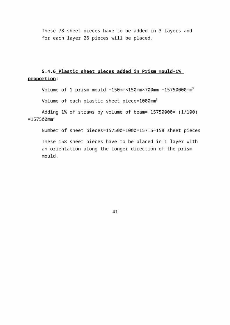
5.4.6 Plastic sheet pieces added in Prism mould-1% proportion:
Volume of 1 prism mould =150mm×150mm×700mm =15750000mm3
Volume of each plastic sheet piece=1000mm3
Adding 1% of straws by volume of beam= 15750000× (1/100) =157500mm3
Number of sheet pieces=157500÷1000=157.5~158 sheet pieces
These 158 sheet pieces have to be placed in 1 layer with an orientation along the longer direction of the prism mould.
41

Fig 5.4 showing a prism mould with plasticsheet pieces in a layer
42
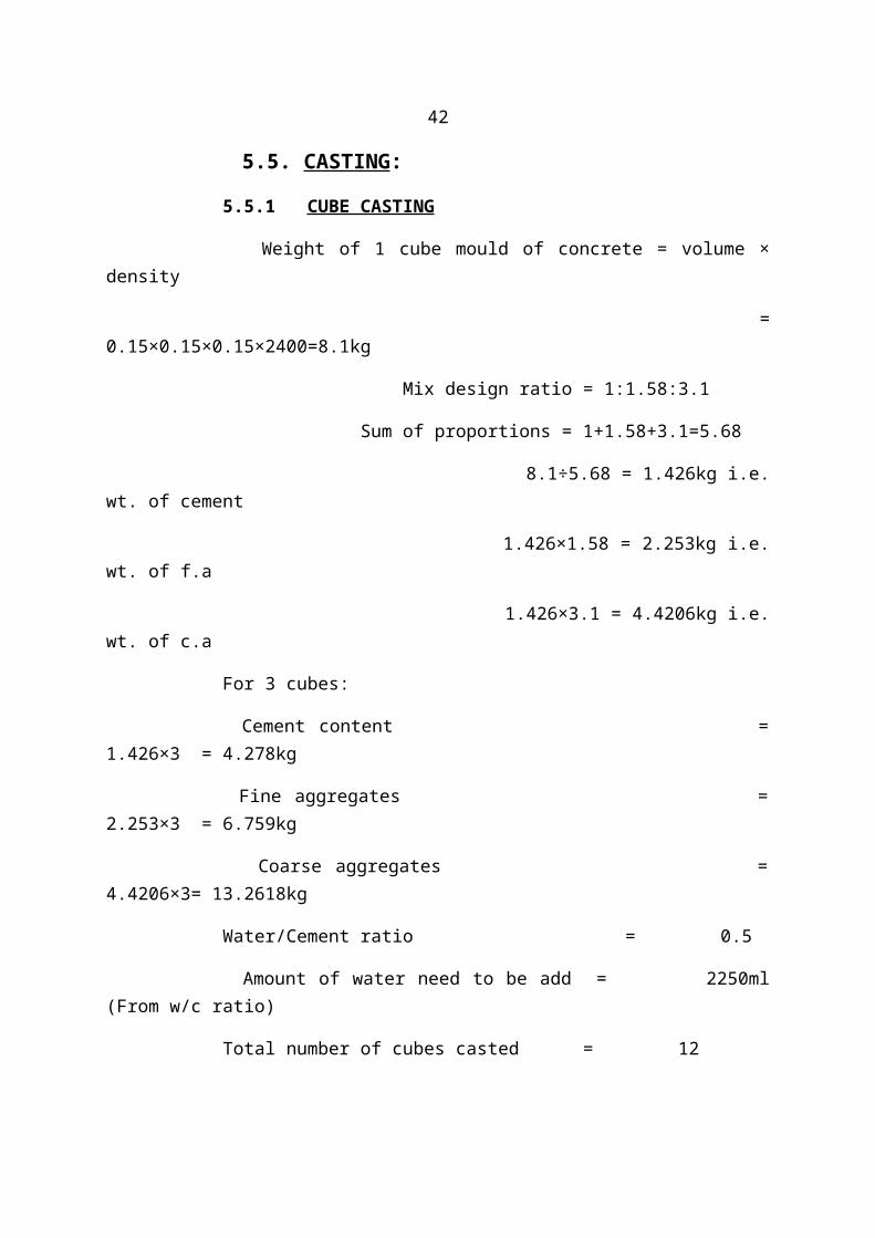
5.5. CASTING:
5.5.1 CUBE CASTING
Weight of 1 cube mould of concrete = volume ×density
=0.15×0.15×0.15×2400=8.1kg
Mix design ratio = 1:1.58:3.1
Sum of proportions = 1+1.58+3.1=5.68
8.1÷5.68 = 1.426kg i.e.wt. of cement
1.426×1.58 = 2.253kg i.e.wt. of f.a
1.426×3.1 = 4.4206kg i.e.wt. of c.a
For 3 cubes:
Cement content =1.426×3 = 4.278kg
Fine aggregates =2.253×3 = 6.759kg
Coarse aggregates =4.4206×3= 13.2618kg
Water/Cement ratio = 0.5
Amount of water need to be add = 2250ml(From w/c ratio)
Total number of cubes casted = 12
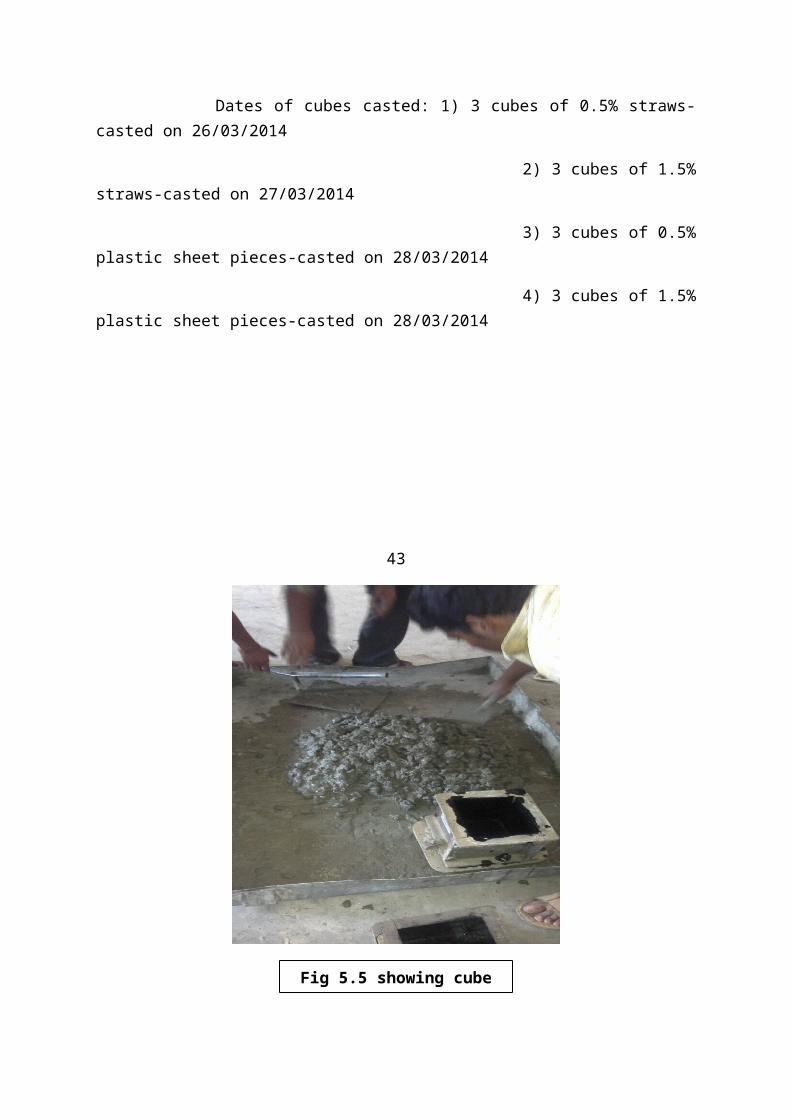
Dates of cubes casted: 1) 3 cubes of 0.5% straws-casted on 26/03/2014
2) 3 cubes of 1.5%straws-casted on 27/03/2014
3) 3 cubes of 0.5%plastic sheet pieces-casted on 28/03/2014
4) 3 cubes of 1.5%plastic sheet pieces-casted on 28/03/2014
43
Fig 5.5 showing cube
5.5.2 CYLINDER CASTING
Weight of 1 cylinder mould of concrete = Volume ×density
= π/4×(0.15×0.15)×0.3×2400 = 12.72kg
Mix design ratio =1:1.58:3.1
Sum of proportions =1+1.58+3.1=5.68
12.72÷5.68= 2.239kg i.e. wt.of cement
2.239×1.58= 3.53kg i.e. wt. of f.a
2.239×3.1= 6.9409kg i.e. wt of c.a
44
For 2 cylinders:
Cement content = 2.239×2 =4.478kg
Fine aggregates = 3.53×2 =7.07kg
Coarse aggregates =6.9409×2=13.88kg

Water/Cement ratio =0.5
Amount of water need to be add = 2250ml(From w/c ratio)
Total number of cylinders casted = 2
Dates of cylinders casted: 1) 2 cylinders of 0.5%straws-casted on 26/03/2014
2) 2 cylindersof 1.5% straws-casted on 27/03/2014
3) 2 cylindersof 0.5% plastic pieces-casted on 28/03/2014
4) 2 cylindersof 1.5% plastic pieces-casted on 28/03/2014
Fig 5.6 showing Cylindermould casting

45
5.5.3 PRISM CASTING:
Weight of concrete in 1 prism mould = Volume ×density
= 0.15×0.15×0.7× 2400
= 37.8kg
Mix design ratio =1:1.58:3.1
Sum of proportions =1+1.58+3.1=5.68
37.8÷5.68 =6.65kg i.e. wt. of cement
6.65×1.58 =10.507kg i.e. wt. of f.a
6.65×3.1 = 20.615kgi.e. wt. of c.a
Water to be added = ?
From, water/cement ratio = 0.5
W/6.65= 0.5
Weight of water, W = 0.5×6.65= 3.325liters= 3325 ml
Total number of prisms casted = 2
Dates of prisms casted: 1) A prism of 1% plasticstraws-casted on 27/03/2014

2) A prism of 1%plastic sheet pieces-casted on 27/03/2014
46
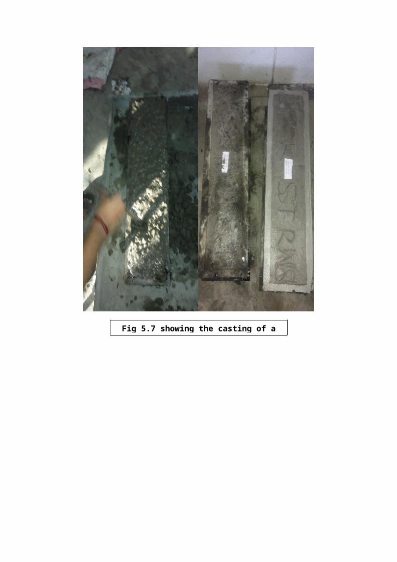
Fig 5.7 showing the casting of a
47
EXPERIMENTAL RESULTS
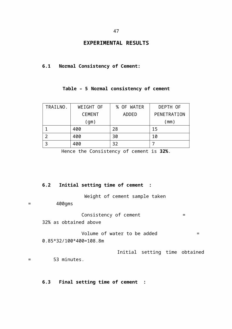
6.1 Normal Consistency of Cement:
Table – 5 Normal consistency of cement
Hence the Consistency of cement is 32%.
6.2 Initial setting time of cement :
Weight of cement sample taken = 400gms
Consistency of cement =32% as obtained above
Volume of water to be added = 0.85*32/100*400=108.8m
Initial setting time obtained= 53 minutes.
6.3 Final setting time of cement :
TRAILNO. WEIGHT OFCEMENT(gm)
% OF WATERADDED
DEPTH OFPENETRATION
(mm)1 400 28 152 400 30 103 400 32 7
Weight of cement sample taken =400gms
Consistency of cement =32% as obtained above
Volume of water to be added =0.85*32/100*400=108.8m
Final setting time= 458 minutes.
48
6.4 Specific gravity of cement :
Weight of empty specific gravity bottle W1= 44.1 gm.
Weight of sp.gr. bottle + wt. of cement W2= 70.00gm.
(1/3 rd to 2/3 rd of bottle full)
Weight of specific gravity bottle + cement +kerosene W3 = 106.20 gm
Weight of specific gravity bottle+kerosene W4 = 83.80 gm.
Specific gravity of kerosene= 0.79
Specific gravity of cement = (W2-W1)/{(W4-W1)-(W3-W2)}
= 3.14
6.5. Specific gravity of Coarse aggregates :
Weight of saturated aggregatesA = 500gms
Weight of dry aggregates D = 490gms
Weight of pycnometer = 610gms
Weight of pycnometer + Water C =1502.8gms
Weight of pycnometer + Water+ aggregates B= 1816.8gms
specific gravity= D/{A-(B-C)}
= 2.63
49
6.6 Specific gravity of Fine aggregates :
Weight of empty pycnometer W1 = 610gm.
Weight of pycnometer + fine aggregate W2 = 1110gm.
Weight of pycnometer + fine agg + water W3 =1769.2 gm.
Weight of pycnometer + water W4 = 1450 gm.
1) Dry weight of aggregate=W2-W1
2) Weight of equivalent volume of water =(W2-W1)-(W3-W4)
Specific gravity =(W2-W1)/(W2-W1)-(W3-W4)
= 2.75
6.7 Water absorption test :
Weight of oven dried aggregate= 500g
Weight of aggregate soaked in water for 24hours = 501g
Percentage of water absorbed= (501-500)/100
=0.1%

50
6.8 Final Test Results
6.8.1 Compressive strength
Concrete cubes of size 15cm×15cm×15cm are tested
Table-6. COMPRESSIVE STRENGTH OF CUBES AT 28 DAYSTypeof
Plastic
added
MixDesig-nation
% ofAddition
No.ofcubes
Ultimate load(kN)
Compressive
Strength(Mpa) @ 28
days
AverageCube
Compressive
Strength(Mpa) @ 28
daysWithou
tPlasti
c
M0 0% 3 650 28.88 28.88
Plastic
Straws
M1 0.5%1 1215 54
51.252 1190 52.883 1055 46.88
M2 1.5%1 1160 51.55
47.552 1090 48.443 960 42.67
Plastic
Sheets
M3 0.5%1 1330 59.11
58.812 1300 57.773 1340 59.55
M4 1.5%1 1230 54.66
56.292 1320 58.673 1250 55.56
51
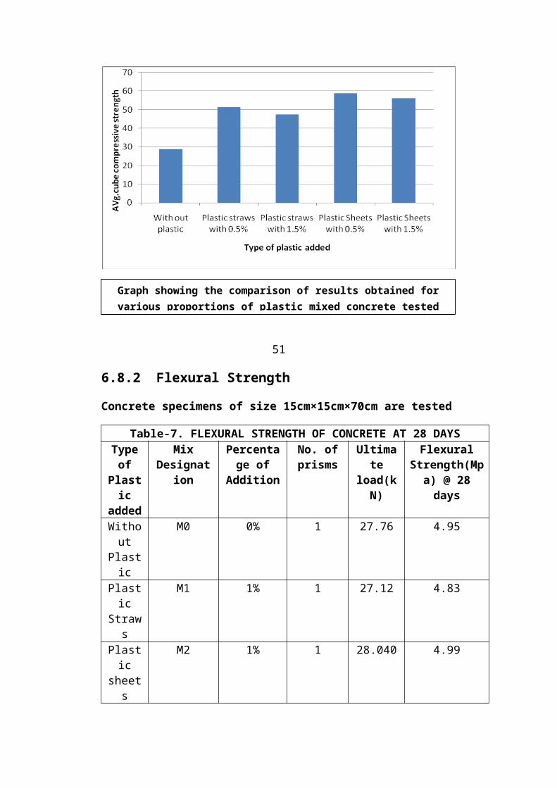
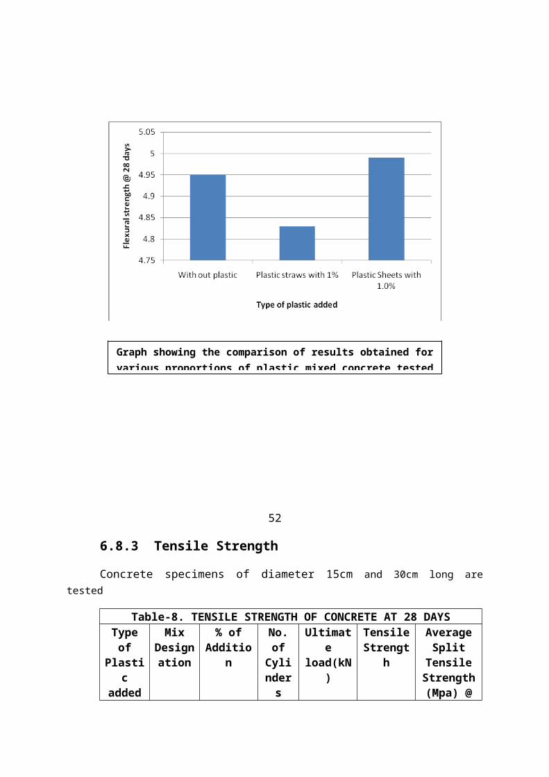
6.8.2 Flexural Strength
Concrete specimens of size 15cm×15cm×70cm are tested
Table-7. FLEXURAL STRENGTH OF CONCRETE AT 28 DAYSTypeof
Plastic
added
MixDesignat
ion
Percentage of
Addition
No. ofprisms
Ultimate
load(kN)
FlexuralStrength(Mpa) @ 28days
Without
Plastic
M0 0% 1 27.76 4.95
Plastic
Straws
M1 1% 1 27.12 4.83
Plastic
sheets
M2 1% 1 28.040 4.99
Graph showing the comparison of results obtained forvarious proportions of plastic mixed concrete tested
52
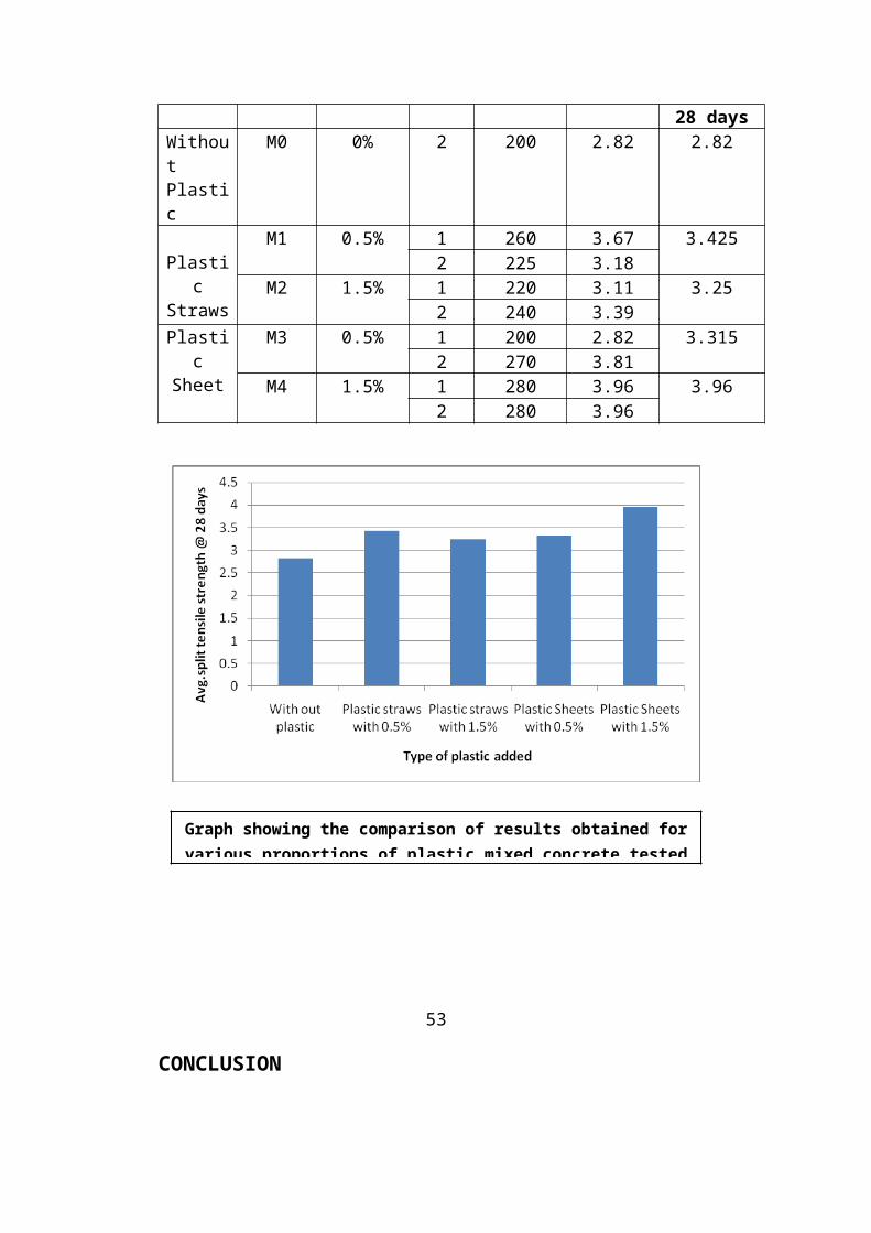
6.8.3 Tensile Strength
Concrete specimens of diameter 15cm and 30cm long aretested
Table-8. TENSILE STRENGTH OF CONCRETE AT 28 DAYSTypeof
Plastic
added
MixDesignation
% ofAdditio
n
No.ofCylinders
Ultimate
load(kN)
TensileStrengt
h
AverageSplit
TensileStrength(Mpa) @
Graph showing the comparison of results obtained forvarious proportions of plastic mixed concrete tested
28 daysWithoutPlastic
M0 0% 2 200 2.82 2.82
Plastic
Straws
M1 0.5% 1 260 3.67 3.4252 225 3.18
M2 1.5% 1 220 3.11 3.252 240 3.39
Plastic
Sheet
M3 0.5% 1 200 2.82 3.3152 270 3.81
M4 1.5% 1 280 3.96 3.962 280 3.96
53
CONCLUSION
Graph showing the comparison of results obtained forvarious proportions of plastic mixed concrete tested
Based on experimental investigation on the “strengthof concrete” and considering the “environmental aspects” the following observations are made regarding of plasticmixed concrete for compression members.
The avg. cube compressive strength of concrete with 0.5% & 1.5% plastic straws gives a better result of 1.77 times & 1.64 times more than the avg. cube compressive strength of conventional concrete(without plastic) respectively.
Similarly, the avg. cube compressive strength of concrete with 0.5% & 1.5% plastic sheet pieces gives even better result of 2.03 times & 1.94 times more thanthe avg. cube compressive strength of conventional concrete(without plastic) respectively.
The Flexural strength of concrete with 1% plasticstraws gives 0.97 times of the flexural strength of conventional concrete(without plastic) and for 1% plastic sheet pieces mixed with concrete gives a betterresult of 1.008 times more than that of the flexural strength of conventional concrete(without plastic).
The avg. split tensile strength of concrete with 0.5% & 1.5% plastic straws gives a better result of 1.21 times & 1.15 times more than the avg. split tensile strength of conventional concrete(without plastic) respectively.
Similarly, the avg. split tensile strength of concrete with 0.5% & 1.5% plastic sheet pieces gives even better result of 1.17 times & 1.4 times more than that of the avg. split tensile strength of conventionalconcrete(without plastic) respectively.
The plastic mixed concrete for compression members is having more compressive strength and tensile strength values than the conventional concrete and therefore it is
more preferable for the construction of compression members.
Also, we can recommend Road side plastic waste and Raw plastics as a material that can be used for improving thestrength characteristics of compression members.
The concrete industry, which uses vast amounts of energy and natural resources and contributes to generation of CO2, can improve its record with an increased reliance on recycled materials and in particular by replacing large percentages of Portland cement by waste plastic materials. Substitution of waste materials will conserve resources, and will avoid environmental and ecological damages. But let us now all work together to keep our planet livable.
54
REFERENCES
1. Suryavanshi, C.S., “Use of industrial and domestic waste in concrete” . Civil Engineering and ConstructionReview, 26(February 1999).
2. Cement and Concrete: Environmental Considerations from EBN (Environmental Building news) Volume 2, No. 2-March/April 1993.
3. Gambhir.M.L., “concrete technology”, 3rd edition, the Tata McGraw Hill Publishers, 2007.
4. Hemant.S, Mittal L.N, Kulkarni.P.D, “Laboratory manual on concrete technology”, CBS Publications, 2005.
5. Krishna Raju.N, “Design of concrete mixes” 4th edition, CBS Publishers, 2002.
6. Mehta,P.K., “Reducing the Environmental Impact of concrete” Conctrete International, October 2001, Vol. 19, No. 7, pp. 61-66.
7. Santhakumar, A.R., “Concrete technology” 3rd edition, OxfordUniversity publishers, 2009.
8. Shetty, M.S., “Concrete technology”, first multi color edition, S.chand publishers,
2005.
WEBLIOGRAPHY
http:// www.concrete.net.au
http:// www.cement industry.com

http:// www.Recent advances in civil Engineering.com
http:// www.plastc mixed concrete.com
55
CODE BOOKS
1) IS: 456:2000, Indian Standard plain and Reinforced Concrete Code of practice, 4th revision, Bureau of Indian Standards, New Delhi.
2) IS: 10262-1982 Recommended Guidelines for Concrete Mix Design, Bureau of Indian Standards, New Delhi.
3) IS:383-1970, Specification for Coarse and Fine Aggregate from Natural Source of Concrete, Bureau of Indian Standards, New Delhi.

56


