Embed Size (px)
Citation preview

Eurographics/ IEEE-VGTC Symposium on Visualization (2006)Thomas Ertl, Ken Joy, and Beatriz Santos (Editors)
1. Introduction
The representation of a volume dataset as a collection ofpartially overlapping 3D radial basis functions (RBFs, simplycalled kernels in those days), centered at the grid positions,gave rise to one of the first volume rendering algorithms --splatting [Wes90]. While early splatting approaches sufferedfrom blurring as well as popping artifacts during view transi-tions, the introduction of post-rasterization classification andshading [MMC99], in conjunction with the image-aligned ker-nel-slicing approach [MSH*99], enabled volume renderingwith splatting at high quality in both static and dynamic view-ing modes. A hallmark of splatting is its object-centric (or bet-ter, voxel-centric) rendering paradigm, which enables theefficient and rendering of sparse and irregularly-shapeddatasets [MHB*00][HHF*05]. Splatting is also a popular para-digm for surface rendering with point-based representations,giving rise to point-based rendering [LW85][PZvB*00][RL00]. Here, surfaces are represented as collections of sur-face-aligned 2D RBFs which are rasterized to the screen toform the image. Just as in volume splatting, surface-splattingwith points allows a more efficient representation and render-ing of intricate objects with high, but possibly sparse detail. Interms of volume rendering, if all one desires are iso-surfaces,then a favorable approach is to convert a volume into a set ofsurface points on the fly and render these with surface splatting[LT04][vRLH*04]. This eliminates the need for reconstructingthe surface in volume space by interpolating the local neigh-borhood of 3D RBFs. On the other hand, if the goal is to createa composited or summed integration of the volume data, say,along the viewing direction, then it is preferable to retain thevolumetric RBF representation during the rendering. Our paperfocuses on this latter task.
Point-based objects rendered with RBF surface splatting arecommonly created from dense point clouds, which wereacquired via range scanning. To find the RBF-based surface,some optimization method is used, such as least squares andothers [DTS01][OBH04]. More recently, researchers have also
used methods of this kind to reduce volumetric datasets origi-nated from computational science, such as CFD or finite ele-ment simulation, into a smaller set of RBFs [JWH*04][WBH*05], and a scattered volumetric point cloud resultsfrom this RBF-fitting process. On the other hand, volumetricscanning, using Lidar and others, also gives rise to scatteredvolumetric point clouds [JRS*02].
The original volume splatting algorithm was motivated bymedical data, which come on cartesian grids. The renderingalgorithms for these could rely on this regular structure andrasterize and composite the splats in very regular ways. Scat-tered data, on the other hand, requires more complicated spacetraversal, rasterization, and compositing strategies. Most meth-ods simply order the RBFs and then rasterize them as single,pre-shaded blobs, projecting their screen space footprints (usu-ally a Gaussian). However, pre-shading and -classificationleads to blurring on zooms, and it also can cause the leakage ofcolor. A better method, just as in the splat rendering of regulardata, is to reconstruct a set of parallel, image-aligned densityslices of the volume first, and then perform color lookup andshading, followed by a merging with a front-to-back or back-to-front compositing buffer. The method presented in thispaper follows this high-quality paradigm.
In that respect, our work is most similar to that of Jang et al.[JWH*04], who use an octree for spatially organizing theRBFs and then pass a set of equi-distant slice planes across thisdecomposition. The octree helps to quickly locate the RBFswhich intersect with the slice. Then, for each slice plane pixel -- forming a point Psl in volume space -- they employ a frag-ment program on the GPU to evaluate the exponential Gauss-ian functions of the RBFs overlapping at Psl, plugging in thevolume-space distance of Psl and each RBF center. They reportframe-rates of 4 fps for grids with less than 1000 kernels.Although excellent images can be obtained, the explicit object-space interpolation approach suffers from high memory andcomputational overhead, since each point may have to beloaded and its kernel function be evaluated a number of times
GPU-Accelerated Volume Splatting With Elliptical RBFs
Neophytos Neophytou1 Klaus Mueller1 Kevin T. McDonnell2 Wei Hong1 Xin Guan1 Hong Qin1 Arie Kaufman1
1Center for Visual Computing, Computer Science, Stony Brook University2Department of Mathematics and Computer Science, Dowling College
AbstractRadial Basis Functions (RBFs) have become a popular rendering primitive, both in surface and in volume rendering.
This paper focuses on volume visualization, giving rise to 3D kernels. RBFs are especially convenient for the represen-tation of scattered and irregularly distributed point samples, where the RBF kernel is used as a blending function for thespace in between samples. Common representations employ radially symmetric RBFs, and various techniques have beenintroduced to render these, also with efficient implementations on programmable graphics hardware (GPUs). In thispaper, we extend the existing work to more generalized, ellipsoidal RBF kernels, for the rendering of scattered volumedata. We devise a post-shaded kernel-centric rendering approach, specifically designed to run efficiently on GPUs, andwe demonstrate our renderer using datasets from subdivision volumes and computational science.
Categories and Subject Descriptors (according to ACM CSS): I.3.3 [Computer Graphics]: Display Algorithms
©The Eurographics Association 2006.

©The Eurographics Association 2006.
Neophytou et. al./ GPU-Accelerated Volume Splatting With Elliptical RBFs
per slice, once for each slice pixel. This in turn limits theattainable rendering frame rate. We take the opposite strategy,more in line with point-based rendering, which spreads a vol-ume point’s contributions to all affected pixels in a slice witha single load and requires only a few kernel evaluations. Morespecifically, the contributions of our paper are:• Instead of using expensive fragment programs at each slice
pixel, we rasterize kernel sections, taking advantage of themuch faster hard-wired floating-point polygonal rasteriza-tion facilities provided by the latest graphics cards, such asthe Nvidia 6800 FX. This enables us to achieve splat ren-dering rates of two orders of magnitudes higher than withan explicit kernel function evaluation approach.
• In addition to spherical RBFs we also support generalizedellipsoidal kernels, using a novel GPU-based scalable ker-nel slicing method. Elliptical RBFs potentially enable abetter, more data-aligned fitting, which can reduce thenumber of RBFs and also lower fitting errors resultingfrom the optimization. While we do not explore this poten-tial in this paper, there have been a number of results inpoint-based surface rendering which substantiate this claim[DTS01].
• Finally, our method also uses a spatial decomposition (buta flat organization, not an octree), in conjunction with anactive splat list, to quickly locate the kernels falling into aslice slab. Our paper is organized as follows: In Section 2 we review
some related previous works on the rendering of irregulargrids, splatting, and GPU-accelerated rendering. Then, in Sec-tions 3 and 4, we describe the theory and implementation ofour framework. Section 5 presents some of our results, and inSection 6 we conclude and give directions for future work.
2. Related Work
Our paper deals with the point-based rendering of irregu-larly distributed RBFs in volumes. For a survey of point-based rendering methods for surfaces refer, for example, to[KB04]. In the scope of regular-grid splatting of pre-classifiedpoints, the EWA framework has been devised to separate theobject-space scaling and filtering of 3D kernels from theimage-space filtering of footprints [ZPvB*01]. Our frame-work could be enhanced in similar ways, and we will discussideas to this end in the future work section of this paper. TheEWA algorithm has recently also been accelerated on theGPU [CRZ*04].
In the following, we shall concentrate on related work involumetric RBF splatting of scattered and irregularly-griddeddata. There have been various algorithms that use the splattingparadigm for these purposes. Meredith and Ma [MM01] usespherical kernels that fit into a cube and are mapped to tex-tured squares for projection. Jang et al. [JRS*02] fill a cellwith one or more ellipsoidal kernels, which they render withelliptical splats. A similar approach was also taken by Mao[Mao96]. Hopf et al. [HLE04] apply splatting to very largetime-varying datasets and render the data as anti-aliased GLpoints. Common to all these approaches is that shading pre-cedes splat projection because the overlap of the kernels involume space makes it difficult to interpolate the local infor-mation, such as gradient and density, needed for the shadinginformation. Doing so would be equivalent to a local recon-struction of the field function. The image-aligned splattingmethod [MSH*99], on the other hand, enables this by interpo-
lating a set of parallel, image-aligned density slices, splattingthe slices of the kernels they intersect (see also Section 3).This allows the mapping of pixel densities into color by waysof the transfer function, as well as shading by calculating thegradients within-slice (x, y) and across-slice (z). This, in turn,enables crisp edges on zooms and reduces the color leakagecreated by mixing pre-colored RBF “balls” on the imageplane. It also resolves the ordering paradox resulting from thepartial overlap of the kernels, which is even more pronouncedin the irregular, scattered data case, where possibly large andsmall RBFs mix together.
As mentioned in Section 1, a slice-interpolating approachbearing these advantages was recently taken by Jang et al.[JWH04] for scattered data, but they use a GPU fragment pro-gram to evaluate the Gaussian function of all kernels thatoverlap at a given point. Their post-shaded approach leads toimagery with much better lighting effects, but it suffers fromthe overhead associated with the explicit kernel evaluation.Since they run an optimization algorithm to encode their vol-umes into a minimal set of spherical RBFs, the number of ker-nels they must render is not very large (not more than 1000),and therefore they can obtain interactive frame-rates of up to4 fps. However, the reduction is highly dependent on theaccuracy threshold set and the complexity of the original,unoptimized volume. It is therefore worthwhile to exploremethods that can process points at a faster rate. In fact, by per-forming the local function reconstruction via analytic meansin the fragment shaders, the explicit approach does not exploitthe much faster hard-wired interpolation facilities that exist inGPUs, and which have been exploited by even early splattingapproaches run on SGI hardware [CM93]. It turns out that byusing the new floating blending capabilities of the latest gen-eration of graphics cards, all splatting operations necessarycan be executed within the hard-wired parallel rasterizationand pixel processing units on these cards. We shall see that byusing these facilities a significantly higher point renderingrate can be obtained, while still maintaining the high visualquality enabled by the slice-based post-shaded rendering.
3. Method
First, we briefly review the image-aligned splattingapproach [MSH*99] and show the modifications required forthe splatting of ellipsoids. We also summarize how it is accel-erated on the GPU (see [NM05] for more detail). Then wemove to its extension to elliptical RBF kernels.
3.1 The modified image-aligned splatting algorithm
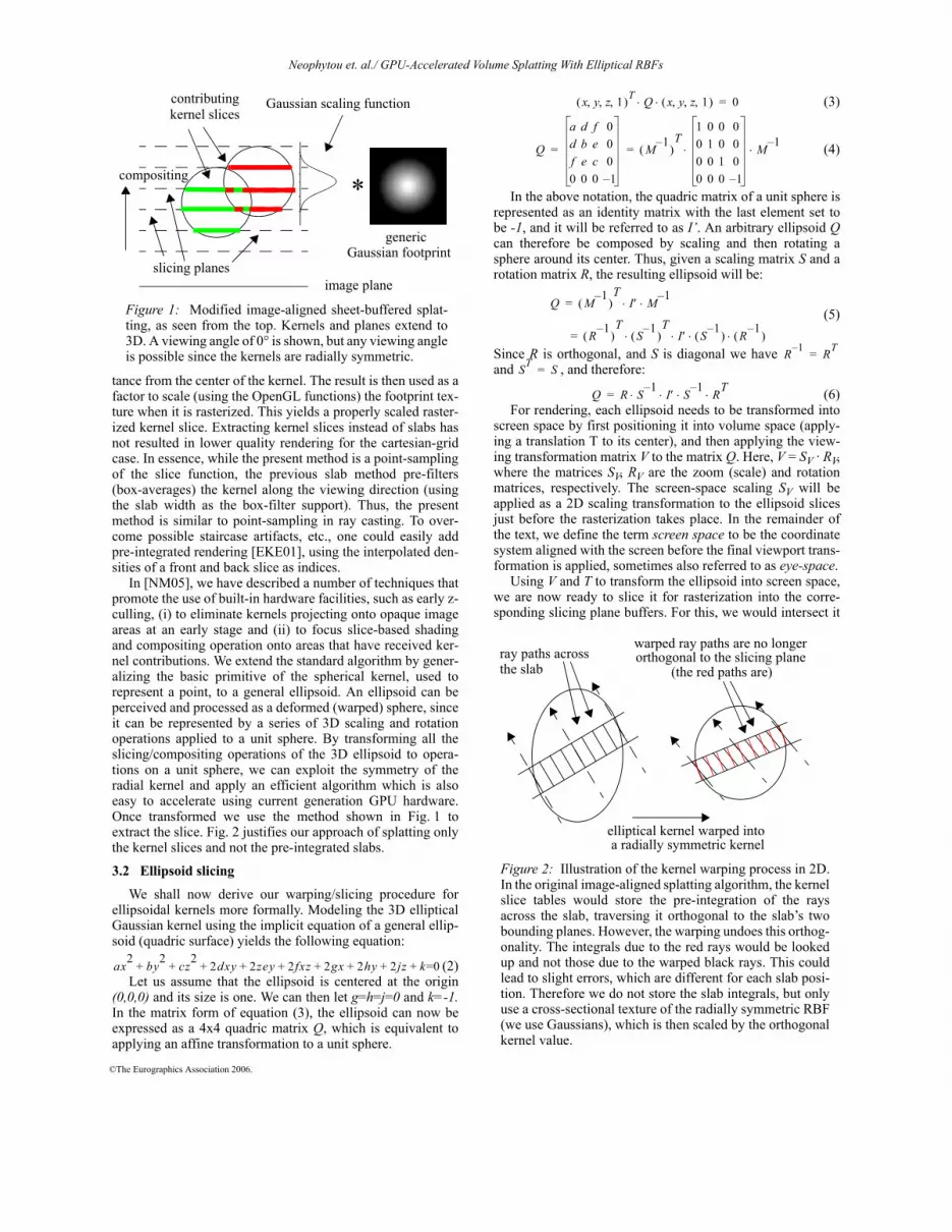
Fig. 1 illustrates the algorithm in its modified form. Forreasons which will become apparent at the end of this section,the slicing planes only extract slices of the kernel, and not pre-integrated kernel slabs, as was done in [MSH*99]. The algo-rithm only requires a single 2D generic Gaussian footprinttexture (and not an array as in [MSH*99]) and a 1D texturewith a Gaussian scaling function. This decomposition isenabled by the separability of higher-dimensional Gaussianfunctions into a set of products of lower-dimensional Gauss-ians.
(1)Here, the first part is the scaling function and the second is
the splat. When a slicing plane cuts across a kernel, the 1DGaussian scaling texture is indexed by the slice plane’s dis-
G Ae k x2 y2 z2+ +( )– Ae kz2– e k x2 y2+( )–= =
©The Eurographics Association 2006.
Neophytou et. al./ GPU-Accelerated Volume Splatting With Elliptical RBFs
tance from the center of the kernel. The result is then used as afactor to scale (using the OpenGL functions) the footprint tex-ture when it is rasterized. This yields a properly scaled raster-ized kernel slice. Extracting kernel slices instead of slabs hasnot resulted in lower quality rendering for the cartesian-gridcase. In essence, while the present method is a point-samplingof the slice function, the previous slab method pre-filters(box-averages) the kernel along the viewing direction (usingthe slab width as the box-filter support). Thus, the presentmethod is similar to point-sampling in ray casting. To over-come possible staircase artifacts, etc., one could easily addpre-integrated rendering [EKE01], using the interpolated den-sities of a front and back slice as indices.
In [NM05], we have described a number of techniques thatpromote the use of built-in hardware facilities, such as early z-culling, (i) to eliminate kernels projecting onto opaque imageareas at an early stage and (ii) to focus slice-based shadingand compositing operation onto areas that have received ker-nel contributions. We extend the standard algorithm by gener-alizing the basic primitive of the spherical kernel, used torepresent a point, to a general ellipsoid. An ellipsoid can beperceived and processed as a deformed (warped) sphere, sinceit can be represented by a series of 3D scaling and rotationoperations applied to a unit sphere. By transforming all theslicing/compositing operations of the 3D ellipsoid to opera-tions on a unit sphere, we can exploit the symmetry of theradial kernel and apply an efficient algorithm which is alsoeasy to accelerate using current generation GPU hardware.Once transformed we use the method shown in Fig. 1 toextract the slice. Fig. 2 justifies our approach of splatting onlythe kernel slices and not the pre-integrated slabs.
3.2 Ellipsoid slicing
We shall now derive our warping/slicing procedure forellipsoidal kernels more formally. Modeling the 3D ellipticalGaussian kernel using the implicit equation of a general ellip-soid (quadric surface) yields the following equation:
(2)Let us assume that the ellipsoid is centered at the origin
(0,0,0) and its size is one. We can then let g=h=j=0 and k=-1.In the matrix form of equation (3), the ellipsoid can now beexpressed as a 4x4 quadric matrix Q, which is equivalent toapplying an affine transformation to a unit sphere.
(3)
(4)
In the above notation, the quadric matrix of a unit sphere isrepresented as an identity matrix with the last element set tobe -1, and it will be referred to as I’. An arbitrary ellipsoid Qcan therefore be composed by scaling and then rotating asphere around its center. Thus, given a scaling matrix S and arotation matrix R, the resulting ellipsoid will be:
(5)
Since R is orthogonal, and S is diagonal we have and , and therefore:
(6)For rendering, each ellipsoid needs to be transformed into
screen space by first positioning it into volume space (apply-ing a translation T to its center), and then applying the view-ing transformation matrix V to the matrix Q. Here, V = SV · RV,where the matrices SV, RV are the zoom (scale) and rotationmatrices, respectively. The screen-space scaling SV will beapplied as a 2D scaling transformation to the ellipsoid slicesjust before the rasterization takes place. In the remainder ofthe text, we define the term screen space to be the coordinatesystem aligned with the screen before the final viewport trans-formation is applied, sometimes also referred to as eye-space.
Using V and T to transform the ellipsoid into screen space,we are now ready to slice it for rasterization into the corre-sponding slicing plane buffers. For this, we would intersect it
compositing
image plane
contributing kernel slices
*
Gaussian scaling function
generic Gaussian footprint
slicing planes
Figure 1: Modified image-aligned sheet-buffered splat-ting, as seen from the top. Kernels and planes extend to3D. A viewing angle of 0° is shown, but any viewing angleis possible since the kernels are radially symmetric.
ax2 by2 cz2 2dxy 2zey 2fxz 2gx 2hy 2jz k=0+ + + + + + + + +
elliptical kernel warped into a radially symmetric kernel
Figure 2: Illustration of the kernel warping process in 2D.In the original image-aligned splatting algorithm, the kernelslice tables would store the pre-integration of the raysacross the slab, traversing it orthogonal to the slab’s twobounding planes. However, the warping undoes this orthog-onality. The integrals due to the red rays would be lookedup and not those due to the warped black rays. This couldlead to slight errors, which are different for each slab posi-tion. Therefore we do not store the slab integrals, but onlyuse a cross-sectional texture of the radially symmetric RBF(we use Gaussians), which is then scaled by the orthogonalkernel value.
ray paths across warped ray paths are no longerorthogonal to the slicing plane
the slab (the red paths are)
x y z 1, , ,( )T Q x y z 1, , ,( )⋅ ⋅ 0=
Q
a d f 0d b e 0f e c 00 0 0 1–
M 1–( )
T1 0 0 00 1 0 00 0 1 00 0 0 1–
M 1–⋅ ⋅= =
Q M 1–( )
TI′ M 1–⋅ ⋅=
R 1–( )
TS 1–( )
TI′ S 1–
( ) R 1–( )⋅ ⋅ ⋅ ⋅=
R 1– RT=ST S=
Q R S 1– I′ S⋅ 1– RT⋅ ⋅ ⋅=

©The Eurographics Association 2006.
Neophytou et. al./ GPU-Accelerated Volume Splatting With Elliptical RBFs
with a group of equidistant planes perpendicular to the view-ing direction. The kernel slices would then be added to thecorresponding slicing buffers. Fig. 3a illustrates an arbitraryellipsoid with a set of slicing planes along the viewing direc-tion. However, since the kernel slices and the orthogonal scal-ing are orientation-dependent, we would require a separategeneric footprint and scaling function for each possible screenspace orientation of this individual ellipsoid, and for each ori-entation of the collection of ellipsoids in a given view.
We can overcome these obstacles by warping the slicingplanes from the space of a given ellipsoidal kernel into thespace of a standard spherical kernel of unit size. By express-ing an ellipsoidal kernel as a transformation applied to aspherical kernel, we can take also advantage of the hard-wiredGPU texture-mapping and blending functionality to achieve avery fast mapping. While an ellipsoid will be sliced in screenspace, resulting in a set of stacked 2D ellipses, the kernelevaluation will be done by applying the corresponding texturecoordinates of the slicing polygons to a 3D spherical kernel inunit texture space. Thus these ellipses will be treated asdeformed disks, or, more specifically, as slices of a sphericalkernel. Fig. 3b illustrates the corresponding texture coordinatespace, where the intersecting polygons are now slicing a unitsphere. Further optimizations are then applied to take advan-tage of the fact that the Gaussian kernel being used is spheri-cally symmetric. We will now describe our slicing techniquein further detail.
3.3 Efficient ellipsoid slicing on the GPU
The obvious approach to ellipsoid slicing would dealdirectly with equation (2) of the general ellipsoid, and itsquadric representation in equation (4). To create a 2D ellipseone only needs to drop the last two rows and columns of thematrix Q. This approach was used for EWA splatting[ZPvB*01], which, however, splats entire kernels withoutslicing. Incorporating slicing is possible, but we discoveredthat it requires many operations, including square roots, thatare not well accelerated on the GPU hardware. Although theycould be issued in a fragment program, we prefer the fasterhard-wired vector and matrix operations the hardware pro-vides. Further, such a method requires conditional statements,
which also pose challenges and are currently not recom-mended for wide use by the GPU manufacturers. In the fol-lowing paragraphs, we describe an approach which performsthe slicing task with fewer computations and uses more vectorand matrix operations which are better accelerated on theGPU. For our own research, we have used the results of theother, analytical approach to evaluate the correctness of ourmethod. Unfortunately, the space restrictions do not permit usto include both solutions in this paper.
For the following discussion, consider the transformationpipeline , where the final screenspace ellipsoid is expressed as the result of a series of trans-formations to be applied to a unit sphere, positioned at the ori-gin. Reading from right to left (multiplication order), S and Rare the scaling and orientation matrixes, which define theshape and orientation of each ellipsoid, while T positions theellipsoid in volume space, by applying a translation from theorigin. The matrix TRS defines the ellipsoid returned from anoptimization [JWH*04][WBH*05], local fitting, or modelingprocedure [GM04][MCQ04]. Matrices RV, SV and TV are thedecomposition of the viewing transformation and they encodea rotation, scaling and translation of the volume. The scalingand translation are applied during the rasterization stage, soour slicing pipeline uses , which encodes allthe transformations that lead to a unscaled view transformedellipsoid. Therefore, by multiplying the view transformedellipsoid quadric Q with we would obtain a unit sphere:
(7)
On the other hand, when the same transformation, , isapplied to the set of intersecting polygons which slice theellipsoid, we end up with a set of parallel polygons that slice aunit sphere. Note that these slicing planes in unit sphere spaceare not necessarily axis-aligned, as one can observe fromFig. 3b. But this difference in slice orientation is not relevant,since the kernel is radially symmetric. The notable and crucialdifference, however, is that in unit sphere space the numberand distance of slice planes has changed, due to the warp.Since our plan is to set up an incremental procedure for: (i)the retrieval of consecutive kernel slices, and (ii) their raster-ization to the screen, we need to know four sets of vectors: • the vector nus connecting the centers of adjacent slices in
unit sphere space (the black vector in Fig. 3b): this willallow us to compute the increment in the 1D texture storingthe Gaussian scaling function.
• the vector nss connecting the centers of adjacent slices inscreen space (the black vector in Fig. 3a): this will allow usto incrementally position the extracted kernel slice texturepolygon in the sheet buffer for rasterization.
• the slice texture polygon orientation vectors uss, vss inscreen space (the blue and red vectors in Fig. 3a): these arealso needed to position the kernel slice texture polygons --they define slicess , the polygon that maps the slice textureonto the sheet buffer, as defined in equations (13) and (15).
• the slice texture orientation vectors uus, vus in unit spherespace (blue and red vectors in Fig. 3b): they define sliceus,the polygon that maps the slice texture in the unit sphere.
Multiplying all the vertices of sliceus and nus by matrix Myields slicess and nss.
(a) (b)
Figure 3: Ellipsoidal kernel sliced (a) in screen space, (b)in unit texture space (unit sphere space). The u,v,n vectorsare shown in red, blue, and black respectively. These 3vectors, along with the size of the direction vector n pro-vide enough information to create all the intersectingslices of the ellipsoid in screen space (progressing alongthe viewing direction) and evaluate the correspondingGaussian kernel by texture-mapping the 2D slices fromthe unit sphere space.
E TV SV RV T R S⋅ ⋅ ⋅ ⋅ ⋅=
M RV T R S⋅ ⋅ ⋅=
M 1–
Q ′ M 1–( )1–
⎝ ⎠⎛ ⎞
TQ M 1–( )
1–⋅ ⋅=
MT M 1–( )T
I′ M 1–⋅ ⋅⎝ ⎠⎛ ⎞ M⋅ ⋅ I′= =
M 1–

©The Eurographics Association 2006.
Neophytou et. al./ GPU-Accelerated Volume Splatting With Elliptical RBFs
Inside the GPU, each ellipsoid is expressed using 13 floatvalues. These include the scaling and rotation matrices, S andR, and the position and scalar value of the point (density, X, Y,Z, Sx, Sy, Sz, R1, R2, R3, R4, R5, R6). We only store 6 elementsto represent the 3x3 rotation matrix R, since it is orthogonaland the last 3 elements can be derived using a cross-productoperation of the first two lines of the matrix. We use the trans-lation, rotation and scaling matrices to compute and .
(8)
The key element to our approach is that all slicing opera-tions on the ellipsoid are computed in the ellipsoid’s coordi-nate system, with the ellipsoid centered at (0,0,0). We definematrix M’, which brings the screen space ellipsoid to the ellip-soid’s coordinate system by cancelling the translation asshown in equation (9). The inverse of matrix M’ is also veryeasy to compute, since R and RV are both orthogonal.
(9)
Using M’, we first compute the slicing planes in unit texturespace by applying the inverse transform to the coordi-nate system vectors of the screen aligned slicing planes. Theresulting vectors, u,v,n in unit sphere space are the first threecolumns of :
(10)These vectors are no longer orthogonal, since S is not ortho-normal in general, and therefore we must re-orthogonalizethem, resulting in u’,v’,n’.
(11)Here, the corrected-normalized vector n’ is the direction ofthe axis passing through the center of all slicing planes andthrough the center of the sphere in unit texture space (alongthe black vector in Fig. 3b), while the corrected normalizedvectors u’ and v’ define the actual orientation of the slicingplanes. The real length of n’ (which has been normalized to aunit vector) can be recovered by computing its dot productwith the original vector n. The resulting vector will become:
(12)Thus, n” is the normal vector for all slicing planes in the
unit sphere space and its length is the distance between anytwo slicing planes. This vector may be used to advance thecurrent slicing plane for the kernel to the next slicing plane byadding n” to each of the corner vertices. Therefore, u’ and v’can be used to define the slicing polygon as the set of vertices:
(13)and the normal vector along the slicing axis is defined as:
(14)Now, to obtain the corresponding slicing polygons and
normal vector in screen space, we need to multiply the aboveset with the original transformation matrix . Thus,
(15)and the corresponding normal vector is
(16)
Note that the sampling distance in screen space is usuallydefined as (but any value can be chosen to achievetighter or sparser sampling along the viewing axis). Thus,
(17)where (dx, dy) is the screen-space vector that can be used toincrementally position consecutive kernel slice polygons onthe sheet buffer screen. Using (12), the unit sphere space slicedistance vector is:
(18)where can be used to index the Gaussian scaling func-tion. Since the Gaussian in kernel space is a radially symmet-ric function, we can choose to slice it along the z direction,which also reduces to:
(19)We can now set up an incremental kernel slicing procedurewhich only needs to perform the (screen space - unit spherespace) transformation once for the initial kernel mapping andcan use simple vector additions to obtain the remaining map-pings. The setup cost for each ellipsoid is not large, requiringtwo matrix-matrix multiplications to obtain
three cross-products, two normaliza-tions, one dot product, four matrix-vector multiplications, anda few scalar-vector multiplications. The incremental slicingjust involves four vector additions and a scalar addition. Moreon this next.
4. Implementation
Our current implementation extends the existing GPU-accelerated framework for image-aligned post-shaded splat-ting of regular volumetric datasets [NM05] to scattered datapoints, represented either as ellipsoidal or as spherical ker-nels. This existing GPU-accelerated image-aligned splatterachieves very high quality images even for sparse datasets athigh magnifications and interactive frame-rates.
Extending this GPU accelerated algorithm, however, torender unstructured data sets that consist of arbitrarily ori-ented general ellipsoids of various sizes poses several chal-lenges. Splatting is an object order approach which employsfront-to-back compositing (for occlusion culling). Either asorting/bucketing operation is required whenever the view-point changes, or one may use a spatial decomposition datastructure which will facilitate a front-to-back traversal of thedataset during rendering. Both of these solutions are not triv-ial to implement on the GPU and they impose several trade-offs. These trade-offs involve the amount of data that has tobe transferred from the CPU during every frame, versus theamount of data that will be replicated and processed multipletimes directly on the GPU. We have addressed the visibilityand occlusion issue using a flat cubic data-structure (yet theextension to an octree would be possible) in combination witha set of vertex and fragment programs that are used to emulatedynamic behaviors which would otherwise be taken forgranted on the random access memory model of the CPU. Thevariability of the data is also addressed by this collection ofvertex and fragment programs, which define a set of multiple-attribute arrays. The data points are first processed as texturestaking advantage of the parallelism employed by the GPU atthe fragment level to screen-align and slice all of the relevantellipsoids (those that have non-zero opacity and color aftertransfer function indexing, and their immediate neighbors that
M M 1–
M RV
1 0 0 X0 1 0 Y0 0 1 Z0 0 0 1
R11 R12 R13 0
R21 R22 R23 0
R31 R32 R33 0
0 0 0 1
Sx 0 0 0
0 Sy 0 0
0 0 Sz 0
0 0 0 1
⋅ ⋅ ⋅=
M ′ RV T 1– RV1– M⋅ ⋅ ⋅ RV T 1– RV
1– RV T R S
M ′
⋅ ⋅ ⋅ ⋅ ⋅ ⋅
RV R S
M ′ 1–⋅ ⋅
S 1– R 1– RV1–⋅ ⋅
= =
=
=
M ′ 1–
M ′ 1–
u v n, ,[ ] M ′ 1–=
n ′ norm u v×( ) u ′, norm n ′ v×( ) v ′, n ′ u ′×( )= = =
n″ n n′• n ′⋅=
sliceus u ′– v ′– u ′– v ′+ u ′ v ′+ u′ v ′–, , ,{ }=
nus n″=
Mslicess M sliceus⋅=
nss M nus⋅=
∆z 1.0=
nss dx dy 1.0, ,( )=
nus 0 0 n″, ,( )=n″
sliceussliceus 0 0 0, ,( ) 0 1 0, ,( ) 1 1 0, ,( ) 1 0 0, ,( ), , ,{ }=
M ′ 1– S 1– R 1– RV1–⋅ ⋅=

©The Eurographics Association 2006.
Neophytou et. al./ GPU-Accelerated Volume Splatting With Elliptical RBFs
usually have slightly lower densities and were only barelyrejected by this test). This is an operation that consumes onlylittle overhead, but we also note that it is conceivable, forlarger volumes, to divide the space into sub-volumes and per-form the entire process in front-to-back order, but only onsub-volumes that are still visible after compositing the onesahead of them. These textures are then passed on to the vertexprocessor as vertex attribute arrays, where they are iterativelyprocessed (rasterized) as the slicing operation proceedsthrough the volume.
Similar to [NM05], we employ an elaborate mechanismwhich exploits the early z-culling hardware optimization inorder to eliminate extraneous splatting onto already opaqueregions (early splat elimination). A similar mechanism, whichalso takes advantage of early z-culling, is used to restrict theexpensive shading and compositing operations only to frag-ments of the current sheet-buffer that have been updated bysplatting. This efficient hardware-accelerated fragment levelmethod provides an alternative to more complex CPU basedmethods that use tiles or quadtree based structures.
Finally, in order to achieve correct results, we haveadjusted the shading/compositing process to normalize thecontents of the sheet-buffer during reconstruction, and wealso take special considerations at the volume boundaries. Inthe following subsections we will describe our implementa-tion in further detail.
4.1 Ellipsoid slicing and rendering on the GPU
The slicing of all the input points in the system is done by afragment program which processes all the initial input data asa set of textures. We have seen in Section 3 that 13 floatingpoint values are required for an ellipsoid. These are packed ina set of 3 textures and are permanently resident in GPU mem-ory. To fit all values, we “pack” the Z and Y elements of thetranslation matrix T together. The output of the slicing calcu-lation also returns 12 values for each ellipsoidal point. Theseinclude the starting position for the first intersecting slice inscreen-space, (px, py, pz) which is the center of the slice, the2D u and v vectors (ux,uy),(vx,vy), which define the axis-aligned slicing polygon, as explained in Section 3, and the
vector which defines the difference of eachslicing polygon to the next. To slice the kernel in unit texturespace, the vector is provided, and the start-ing position is given by (0, 0, StartZus). Finally, the scalarvalue of the data point is provided as a single float. The rangefor the scalar density value is [0...1], which gives some roomto encode more data into the density input value, as we shallsee in the remainder of this section. These 12 values areencoded in a set of 3 textures. The processing of all the datapoints is performed in one pass and the results are simulta-neously assigned to the 3 destination textures using the multi-ple render targets (MRT) extension, which is available onboth the latest NVidia as well as ATI boards. The measuredtimings for this step were around 30-90 msec, for datasets ofsizes varying from 35K-500K points.
The slicing step has to take place once every time the viewpoint changes. When all points are processed they are con-verted into vertex arrays within the graphics board memory,and they are then assigned as vertex attribute arrays andpassed to the splatting vertex program. The vertex programmaintains the slicing polygon for each data point via the useof a uniform status variable that is passed to the program for
all vertices. The currentSlicingZ parameter, which is passed toall the vertices, holds the z value of the current image alignedslicing plane. Thus, for every point, the vertex program firstdecides whether it does intersect this slice, and if so, it com-putes the position of each of its corners and the correspondingtexture coordinates. Otherwise it forces the point to be culledby setting the coordinates outside of the view frustum.
The polygons slicing general ellipsoids have to be renderedusing the GL_QUAD primitive, since point sprites are notapplicable in this case. Our system follows the standardmethod used for rendering billboards with vertex programs.This method requires that the point data is replicated once forevery destination vertex, and an additional piece of informa-tion is provided in the vertex data to decide which one of thepolygon corners it represents. We employ this approach, andencode the polygon identity information using the densityvalue. During the construction of the textures, we have den-sity = (vertexCount%4) * 1000 + inputScalarDensity. Thevertex program decides the texture coordinates as well as thecorner positioning for a given vertex.
The third set of parameters define the slicing of the 3Dspherical kernel in 3D unit texture space. This operation isimplemented using the texture mapping of a 2D textureencoded Gaussian kernel, modulated by a 1D Gaussian alongthe z-direction. The 1D Gaussian value is currently computedinside the vertex shader, since vertex textures are still slower.
After all of the kernel contributions for the correspondingslice have been accumulated, the reconstructed density slice ispassed to a fragment program which performs classification,shading and composites the results to the final frame-bufferimage. In order to achieve correct reconstruction of unstruc-tured data, a normalization step needs to be performed on thereconstructed densities. This is done by maintaining the splat-ted weights contributed by all sliced points in a separate chan-nel of the slicing buffer. During normalization, the fragmentprogram divides the densities by their corresponding weight.Special care has to be taken at the boundary regions of thevolume, where coverage is sparse, and therefore the accumu-lated weights are smaller than one. Dividing by the smallweight values would give rise to unnaturally high density val-ues at the boundaries. In this implementation, a threshold isset before the division is performed. Thus, the resulting densi-ties are:
(20)An alternative solution to the boundary problem when splat-ting irregular grids would be to add a set of “ghost points”around the boundaries, which will have zero density, but nor-mal weight values. This follows the fact that regular volumesimplicitly have infinite coverage throughout the volume. Thatis, there exist empty points which have weights, but zero val-ues wherever there is empty space in the regular volume,including the boundary regions. Normalization, however, isnot required in regular volumes because everything wouldhave to be divided by the same weight which can be inte-grated in the kernel texture.
4.2 GPU-support for spatial decomposition
In this work we address the spatial decomposition require-ment imposed by the image aligned splatting algorithm byusing a flat decomposition data structure in combination withadditional functionality in the vertex programs that processeach point. The volume is decomposed into a low-resolution
nss dx dy 1.0, ,( )=
nus 0 0 n″, ,( )=normalizedDensity density( ) max 1 weight,( )( )⁄=

©The Eurographics Association 2006.
Neophytou et. al./ GPU-Accelerated Volume Splatting With Elliptical RBFs
cubic block data structure, which can then be traversed in afront-to-back order in the exact same way as a full octree.
The spatial decomposition structure is first created on theCPU in a preprocessing step just after the volume is loaded.Every point is sliced and rasterized onto a very low resolution3D grid, where each grid point maintains a list of all the pointsthat intersect it. The result is a 3D regular cubic structure,which when traversed in a front-to-back order it will return alist of data points for each of its non-empty cells. The struc-ture is then flattened onto a set of four 2D textures by copyingthe contents of every cell, in the format described inSection 4.1. The resulting texture will be processed by theellipsoid slicing fragment program, resulting in a set ofattribute vertex arrays for rendering, every time the viewpointchanges.
During rendering, each active cell’s associated vertex listwill be called using the glDrawArrays OpenGL call. The cellsare placed in the active list in a front-to-back traversal of thedecomposition data structure, and they are taken out of theactive list when they stop producing slicing polygons, whichis when the currentSliceZ has passed even the largest point,and which can be determined by a comparison with the maxi-mum point diagonal for the cell.
The main challenge with maintaining such a structure onthe GPU during rendering is the handling of splats that span tomore than one cells, and are therefore being called for render-ing in multiple lists. In the CPU scenario, a flag could haveeasily been set in the data-structure to signify that a point hasalready been called by another list and should not be consid-ered active. In our implementation we emulate the taggingbehavior by using uniform variables that pass the current stateto the vertex program. Along with the current slicing plane,we pass the current cell ID as a uniform variable. During theslicing step, for each data point, we also compute the ID of thestarting cell. This is the cell where the first slicing polygon forthe point will be encountered, and it is easily computed byprojecting (startx, starty, startz) to the 3D cubic decompositionstructure. The point is then assigned that ID in all cells that itparticipates in. Then, in the rendering stage, we also computethe cell ID for each cell that is sliced by the current sheetbuffer, and a point/vertex is only allowed to render if its start-ing cell ID is the same than that of the current cell, and if italso intersects the current slicing buffer. If it has a differentID, then it has already been activated before for rendering,and this new instantiation of the point can be is culled fromthe viewing frustum.
5. Results
We have tested our system using datasets from subdivisionvolumes [MCQ04] and computational science, both encodedas a field of irregularly distributed ellipsoidal RBFs. The RBFfields for the former set of volumes was obtained by fittingGaussian kernels to a mid-level of the subdivision hierarchy,while the RBF field for the latter was obtained by fitting basisfunctions to a local Delauney triangulation [HNM*06]. Thispaper does not seek to determine error bounds on these -- it ismerely concerned with achieving their fast rendering. Thehardware configuration consists of a Pentium 4 running at3GHz and 1 GB RAM, and the graphics board is an NVidiaQuadro FX 3400 with 256MB RAM, which is equivalent to aGeForce 6800 GT board.
In order to test throughput, all the datasets were rendered atan image resolution of 400x400 pixels. Table 1 summarizesthe results for each dataset, along with some description. Thesecond column lists the number of ellipsoidal or sphericaldata points included in the dataset (the number in parentheseslists the number of non-occluded, splatted voxels, which arebetween 70-90% of the total number of voxels). As we renderour volumes in semi-transparent mode, occlusion cullingeffects are less pronounced. The third column gives the rangeof the minimum and maximum diagonals of the enclosingcube for the ellipsoidal or spherical kernels, which is a mea-sure of the maximum point sizes. This is actually the diagonalof the enclosing cube for an ellipsoidal or spherical kernel,and it gives a measure of the maximum size of the point. Thefourth column shows our measured frame rate for thesedatasets at an image resolution of 400x400 and the fifth col-umn directs to Fig. 4 (color-plate).
The first two datasets, “Blunt Fin” and “Combustion”,were created using the Delauney RBF fitting method, andthey were composed using ellipsoidal points. The last fourdatasets were created from subdivision volumes, and they allencode deformed objects. All are rendered in semi-transparentcompositing mode. Looking at the results, we find that therendering of irregular data using the image aligned splattingalgorithm can give a points/sec. throughput rate of up to twoorders of magnitude higher than existing methods that usefragment-shader based kernel evaluations [JWH*04][WBH*05] on the slice plane instead, with the same high-quality visual results that slice-based post-shaded methodsproduce (using the same GPU platform or of one generationpast, respectively). Here, we only compare the frame rates forpure volume rendering (the system of [WBH*05] is muchmore versatile, also rendering and mixing in results from flowfield analysis).
Our next observation is that although the elliptical datasetshave a significantly smaller point count, they also are signifi-cantly slower to rasterize. This can be explained by the factthat the size (diagonal) of the ellipsoids used to compose thesedatasets affects a much larger range. After a closer look intothe rasterization process, we have found that these datasetsalso have much larger overlaps between the neighboringpoints, resulting in significant overdraw.
5.1 Comparison with fragment-centric approaches
The existing volume RBF splatting method [JWH*04][WBH*05] uses a fragment-centric approach, evaluating allRBFs on a single fragment position before moving to the next,making it a gather-algorithm. Ours, on the other hand, is an
Dataset # Points Diagonal FPS Fig.4
Blunt Fin 34k (31k) 0.9-120 1.6 a,b
Combust. 39k (35k) 8.3-27.4 1.9 c,d
Chess Pc. 84k (63k)) 1.9-2.5 3.5 e
Monster 91k (60k) 2.5-3.0 4.0 f
Toy Car 173k (117k) 2.0-4.3 2.2 g
Toy Train 199k (139k) 2.0-4.0 2.1 h
Table 1: Results.

©The Eurographics Association 2006.
Neophytou et. al./ GPU-Accelerated Volume Splatting With Elliptical RBFs
RBF-centric approach, that is, we process (rasterize) the slicesof the entire RBF before moving to the next, making it a scat-ter-algorithm. Similar to other researchers, we have alsofound that it is often advantageous to rather evaluate a (mod-est) function in the fragment shader than incurring the over-head associated with accessing a lookup texture to retrieve thepre-computed result. We do this to obtain the footprint scalingvalues from the 1D Gaussian scaling function, and so does thefragment-centric approach of [JWH*04][WBH*05] which,however, needs to evaluate the entire 3D RBF function ateach fragment, in addition to the overhead associated withcomputing the 3D index. Looking at the fragment-centric andRBF-centric approaches, we observe that for a given datasetboth will perform the same number of sheet-buffer writes andwill also need the same number of RBF function values. How-ever, they differ greatly in terms of the efficiency at whichthese operations are performed, First, the RBF-centricapproach only requires an evaluation of one 1D Gaussian perRBF-slice, using the inexpensive kernel rasterization tospread the function values across the sheet buffer fragments.The fragment-based approach, on the other hand, needs toevaluate the 3D Gaussian for each fragment, which is muchmore costly than a simple scaled texture mapping. Second, thetexture rasterization of the RBF-centric approach is likely tobe significantly more coherent, light-weight, and optimizedon the GPU hardware than the heavier (in terms of data) tex-ture fetches of the fragment-centric scheme. Third, each datafetch of the RBF-centric approach will amount to a rasteriza-tion, unless the fragment is killed early due to early fragmentelimination. On the other hand, the fragment-centricapproach, may sometimes pull in RBFs that are out of reachof the fragment’s location, although this number may be lowfor good tree encoding. All of these considerations mayexplain the large difference in performance of the twoapproaches, especially when considering that our approachuses the considerably more data-intensive ellipsoidal RBFs.
6. Conclusions and Future Work
We have described a framework which extends the high-quality image-aligned sheet-buffer splatting method to irregu-lar grids, and we have shown how to successfully accelerate iton the GPU. The performance of our implementation, interms of splats/sec., is quite high, and this suggests that it maybe preferable to use splatting for the slice-based post-shadedrendering of scattered point datasets and RBFs, instead ofreconstructing the slice plane fragment values via explicit ker-nel-evaluations in fragment programs.
A possible future extension of our work could be the inte-gration of EWA-type filtering in perspective viewing. Forthis, one may simply stretch the kernel slice textures as afunction of slice distance to achieve the desired low-passingeffect. This would use the zoom (scale) matrix SV introducedin Section 3.2. Finally, future work will also be gearedtowards improving the fitting procedure for elliptical RBFs. AcknowledgementsThis research was supported, in part, by NSF CAREER grantACI-0093157 and NIH grant 5R21EB004099-02.
References[CM93] R. Crawfis and N. Max, “Texture splats for 3D scalar and
field visualization,” IEEE Visualization 1993.
[CRZ*04] W. Chen, L. Ren, M. Zwicker, H. Pfister, “Hardware-accelerated adaptive EWA volume splatting,” IEEE Visualization2004.
[DTS01] Q. Dinh, G. Turk, G. G. Slabaugh, “Reconstructing surfacesusing anisotropic basis functions,” ICCV 2001: 606-613.
[EKE01] K. Engel, M. Krauss and T. Ertl. “High-quality preinte-grated volume rendering using hardware-accelerated pixel shad-ing,” Proc. of Graphics Hardware Workshop 2001.
[GM04] X. Guan, K. Mueller, “Point-based surface rendering withmotion blur,” Symp. on Point-Based Graphics 2004.
[HHF*05] F. Vega Higuera, P. Hastreiter, R. Fahlbusch, and G.Greiner, “High Performance Volume Splatting for Visualization ofNeurovascular Data,” Proc. IEEE Visualization 2005.
[HLE04] M. Hopf, M. Luttenberger, T. Ertl, “Hierarchical splatting ofscattered 4D data,” IEEE Computer Graphics & Applications,24(4): 64-72, 2004.
[HNM*06] W. Hong, N. Neophytou, K. Mueller, and A. Kaufman“Constructing 3D Elliptical Gaussians for Irregular Data”, Mathe-matical Foundations of Scientific Visualization, Comp. Graphics,and Massive Data Exploration, Springer-Verlag, Germany 2006.
[JWH*04] Y. Jang, M. Weiler, M. Hopf, J. Huang, D. Ebert, K.Gaither, T. Ertl, “Interactively visualizing procedurally encodedscalar fields,” IEEE/EG Visualization Symp. 2004.
[JRS*02] J. Jang, W. Ribarsky, C. D. Shaw, N. Faust, “View-depen-dent multiresolution splatting of non-uniform data,” Proc. IEEE/EG Visualization Symp. 2002.
[KB04] L. Kobbelt, M. Botsch, “A survey of point-based techniquesin computer graphics,” Computers & Graphics, 28(6):801-814,2004.
[LT04] Y. Livnat, X. Tricoche, “Interactive point-based isosurfaceextraction,” IEEE Visualization 2004.
[LW85] M. Levoy, T. Whitted "The use of points as a display primi-tive," TR 85-022, U. North Carolina, Chappel Hill, 1985.
[Mao96] X. Mao, “Splatting of curvilinear volumes,” IEEE Trans.Visualization and Computer Graphics, 2(2): 156-170, 1996.
[MCQ04] K. McDonnell, Y. Chang, H. Qin, “Interpolatory, solid sub-division of unstructured hexahedral meshes,” The Visual Computer,20(6):418–436, 2004.
[MM01] J. Meredith, K.-L. Ma, “Multiresolution view-dependendsplat based volume rendering of large irregular data,” Symp. Paral-lel and Large-Data Visualization and Graphics 2001.
[MHB*00] M. Meissner, J. Huang, D. Bartz, K. Mueller, and R.Crawfis, "A practical comparison of popular volume renderingalgorithms," 2000 Symp. on Volume Rendering.
[MMC99] K. Mueller, T. Möller, and R. Crawfis, "Splatting withoutthe blur," Proc. IEEE Visualization, 1999.
[MSH*99] K. Mueller, N. Shareef, J. Huang, R. Crawfis, "High-qual-ity splatting on rectilinear grids with efficient culling of occludedvoxels," IEEE Trans. on Visualization and Computer Graphics,5(2): 116-134, 1999.
[NM05] N. Neophytou and K. Mueller, “GPU accelerated imagealigned splatting,” IEEE-TCVG/EG Workshop on Volume Graphics2005.
[OBH04] Y. Ohtake, A. Belyaev, H. Seidel, “3D scattered dataapproximation with adaptive compactly supported radial basisfunctions,” Conf. Shape Modeling and Applications 2004.
[PZvB*00] H. Pfister, M. Zwicker, J. van Baar, M. Gross, "Surfels:surface elements as rendering primitives," Proc. Siggraph 2000.
[RL00] S. Rusinkiewicz, M. Levoy, "Qsplat: a multiresolution pointrendering system for large meshes," Proc. Siggraph 2000.
[vRLH*04] B. von Rymon-Lipinski, N. Hanssen, T. Jansen, L. Ritter,E. Keeve, “Efficient point-based isosurface exploration using thespan-triangle,” Proc. IEEE Visualization 2004.
[WBH*05] M. Weiler, R. P. Botchen, J. Huang and Y. Jang, "Hard-ware-assisted feature analysis and visualization of procedurallyencoded multifield volumetric data," IEEE Computer Graphics &Applications, 25(5): 72-81, 2005.
[Wes90] L. Westover, “Footprint evaluation for volume rendering,”Proc. SIGGRAPH 1990.
[ZPvB*01] M. Zwicker, H. Pfister, J. van Baar, M. Gross, “EWA Vol-ume Splatting,” Proc. IEEE Visualization 2001.

Neophytou et. al./ GPU-Accelerated Volume Splatting With Elliptical RBFs
Figure 4: Example renderings of irregular datasets using our image aligned splattr: (a,b) two views of Blunt Fin, (c,d) twodifferent views of the Combustion dataset, (e) deformed chess piece, (f) deformed green monster, (g) Deformed toy car, (h)deformed toy train.
(a)
(b) (c) (d)
(e) (f) (g) (h)