Embed Size (px)
Citation preview
1 2,1
H
1,01
3 1,0
Li
6,94
11 0,9
Na
23,0
19 0,8
K
39,1
37 0,8
Rb
85,5
55 0,7
Cs
132,9
87 0,7
Fr
(223)
4 1,5
Be
9,01
12 1,2
Mg
24,3
20 1,0
Ca
40,1
38 1,0
Sr
87,6
56 0,9
Ba
137,3
88 0,9
Ra
226,0
21 1,3
Sc
45,0
39 1,2
Y
88,9
57-71
La-Lu
Lanthanides
89-103
Ac-Lr
Actinides
22 1,5
Ti
47,9
40 1,4
Zr
91,2
72 1,6
Hf
178,5
104
Rf
(261)
23 1,6
V
50,9
41 1,6
Nb
92,9
73 1,5
Ta
180,9
105
Db
(262)
24 1,6
Cr
52,0
42 1,8
Mo
95,9
74 2,4
W
183,8
106
Sg
(263)
25 1,5
Mn
54,9
43 1,9
Tc
(98)
75 1,9
Re
186,2
107
Bh
(262)
26 1,8
Fe
55,8
44 2,2
Ru
101,1
76 2,2
Os
190,2
108
Hs
(265)
27 1,8
Co
58,9
45 2,2
Rh
102,9
77 2,2
Ir
192,2
109
Mt
(266)
28 1,8
Ni
58,7
46 2,2
Pd
106,4
78 2,2
Pt
195,1
110
Ds
(269)
29 1,9
Cu
63,5
47 1,9
Ag
107,9
79 2,5
Au
197,0
111
Rg
(272)
30 1,6
Zn
65,4
48 1,7
Cd
112,4
80 2,0
Hg
200,6
112
Cn
(277)
31 1,6
Ga
69,7
13 1,5
Al
27,0
5 2,0
B
10,8
49 1,7
In
114,8
81 1,6
Tl
204,4
113
Uut
(284)
6 2,5
C
12,0
14 1,8
Si
28,1
32 1,8
Ge
72,6
50 1,8
Sn
118,7
82 1,8
Pb
207,2
114
Uuq
(289)
7 3,0
N
14,0
15 2,1
P
31,0
33 2,0
As
74,9
51 1,9
Sb
121,8
83 1,9
Bi
209,0
115
Uup
(288)
8 3,5
O
16,0
16 2,5
S
32,1
34 2,4
Se
79,0
52 2,1
Te
127,6
84 2,0
Po
(209)
116
Uuh
(293)
9 4,0
F
19,0
17 3,0
Cl
35,45
35 2,8
Br
79,9
53 2,5
I
126,9
85 2,5
At
(210)
117
Uus
(282)
10
Ne
20,2
2
He
4,00
18
Ar
39,9
36
Kr
83,8
54
Xe
131,3
86
Rn
(222)
118
Uuo
(282)
1 IA
2 IIA
3 IIIB 4 IVB 5 VB 6 VIB 7 VIIB 8 VII 9 VII 10 VII 11 IB 12 IIB
13 IIIA 14 IVA 15 VA 16 VIA 17 VIIA
18 0
57 1,1
La
138,9
58 1,1
Ce
140,1
59 1,1
Pr
140,9
60 1,1
Nd
144,2
61
Pm
(145)
62 1,1
Sm
150,4
63
Eu
152,0
64 1,2
Gd
157,3
65
Tb
158,9
66 1,2
Dy
162,5
67 1,2
Ho
164,9
68 1,2
Er
167,3
69 1,3
Tm
168,9
70
Yb
173,0
71 1,3
Lu
175,0
89 1,1
Ac
227,0
90 1,3
Th
232,0
91 1,5
Pa
231,0
92 1,4
U
238,0
93 1,3
Np
237,0
94 1,3
Pu
(244)
95 1,3
Am
(243)
96 1,3
Cm
(247)
97 1,3
Bk
(247)
98 1,3
Cf
(251)
99 1,3
Es
(252)
100 1,3
Fm
(257)
101 1,3
Md
(258)
102 1,3
No
(258)
103
Lr
(260)
Transition Metal
Metal
Metalloid
Non-metal
Noble Gas
Lanthanide
Actinide
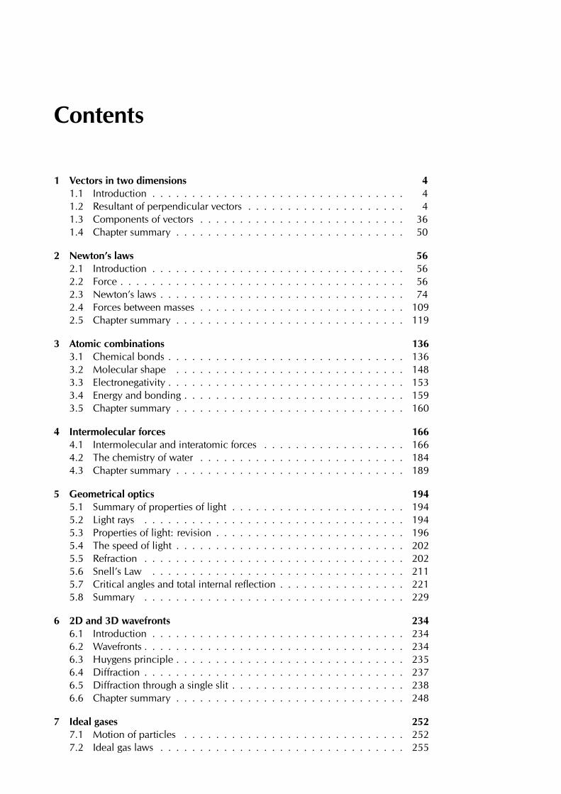
Periodic Table of the Elements
No EN
Element
AMU

EVERYTHING SCIENCE
GRADE 11 PHYSICAL SCIENCESVERSION 1 CAPS
WRITTEN BY VOLUNTEERS
COPYRIGHT NOTICE
You are allowed and encouraged to copy any of the Everything Maths and Everything Science textbooks. You can legally photocopy any page or even the entire book. You can download it from www.everythingmaths.co.za and www.everythingscience.co.za, read it on your phone, tablet, iPad, or computer. You can burn it to CD, put on your flash drive, e-mail it around or upload it to your website.
The only restriction is that you have to keep this book, its cover, title, contents and short-codes unchanged.
This book was derived from the original Free High School Science Texts written by volunteer academics, educators and industry professionals. Everything Maths and Everything Science are trademarks of Siyavula Education.
For more information about the Creative Commons Attribution-NoDerivs 3.0 Unported (CC BY-ND 3.0) license see http://creativecommons.org/licenses/by-nd/3.0/
Your freedom to legally copy this book

AUTHORS AND CONTRIBUTORS
Siyavula Education is a social enterprise launched in 2012 with capital and support from the PSG Group Limited and the Shuttleworth Foundation. The Everything Maths and Science
series is one of the titles developed and openly released by Siyavula. For more information about the writing and distribution of these or other openly licensed titles:
www.siyavula.com [email protected]
021 469 4771
Siyavula AuthorsDr. Mark Horner; Heather Williams
Siyavula and DBE teamJayanthi SK Maharaj (Veena); Marongwa Masemula; Ewald Zietsman; Bridget Nash; Prof.
Gilberto Isquierdo; Karen Kornet; Dr. Kevin Reddy; Enoch Ndwamato Makhado; Clive Mhaka
Siyavula and Free High School Science Text contributorsDr. Mark Horner; Dr. Samuel Halliday; Dr. Sarah Blyth; Dr. Rory Adams; Dr. Spencer Wheaton
Iesrafeel Abbas; Sarah Abel; Dr. Rory Adams; Andrea Africa; Wiehan Agenbag; Matthew Amundsen; Ben Anhalt; Prashant
Arora; Amos Baloyi; Bongani Baloyi; Raymond Barbour; Caro-Joy Barendse; Richard Baxter; Tara Beckerling; Tim van Beek;
Mariaan Bester; Jennifer de Beyer; Dr. Sarah Blyth; Sebastian Bodenstein; Martin Bongers; Thinus Booysen; Gareth Boxall;
Stephan Brandt; Hannes Breytenbach; Alexander Briell; Wilbur Britz; Graeme Broster; Craig Brown; Michail Brynard; Deanne
de Bude; Richard Burge; Bianca Bˆhmer; Jan Buys; George Calder-Potts; Eleanor Cameron; Mark Carolissen; Shane Carollis-
son; Richard Case; Sithembile Cele; Alice Chang; Richard Cheng; Fanny Cherblanc; Dr. Christine Chung; Brett Cocks; RochÈ
Compaan; Willem Conradie; Stefaan Conradie; Rocco Coppejans; Tim Craib; Andrew Craig; Tim Crombie; Dan Crytser; Jock
Currie; Dr. Anne Dabrowski; Laura Daniels; Gareth Davies; Sandra Dickson; Sean Dobbs; Buhle Donga; William Donkin; Esmi
Dreyer; Matthew Duddy; Christel Durie; Fernando Durrell; Dr. Dan Dwyer; Frans van Eeden; Alexander Ellis; Tom Ellis; Andrew
Fisher; Giovanni Franzoni; Olivia Gillett; Ingrid von Glehn; Tamara von Glehn; Lindsay Glesener; Kevin Godby; Dr. Vanessa
Godfrey; Terence Goldberg; Dr. Johan Gonzalez; Saaligha Gool; Hemant Gopal; Dr. Stephanie Gould; Umeshree Govender;
Heather Gray; Lynn Greeff; Jaco Greyling; Martli Greyvenstein; Carine Grobbelaar; Suzanne GrovÈ; Dr. Tom Gutierrez; Brooke
Haag; Kate Hadley; Alex Hall; Dr. Sam Halliday; Asheena Hanuman; Dr. Melanie Dymond Harper; Ebrahim Harris; Dr. Nicho-
las Harrison; Neil Hart; Nicholas Hatcher; Jason Hayden; Laura Hayward; Dr. William P. Heal; Pierre van Heerden; Dr. Fritha
Hennessy; Dr. Colleen Henning; Shaun Hewitson; Millie Hilgart; Grant Hillebrand; Nick Hobbs; Chris Holdsworth; Dr. Benne
Holwerda; Dr. Mark Horner; Robert Hovden; Mfandaidza Hove; Jennifer Hsieh; George Hugo; Laura Huss; Prof. Ed Jacobs
Siyavula Education

Hester Jacobs; Stefan Jacobs; Rowan Jelley; Grant Jelley; Clare Johnson; Francois Jooste; Luke Jordan; Tana Joseph; Corli
Joubert; Dr. Fabian Jutz; Brian Kamanzi; Herman Kamper; Dr. Lutz Kampmann; Simon Katende; Natalia Kavalenia; Rabia
Khan; Nothando Khumalo; Paul Kim; Lizl King; Melissa Kistner; Dr. Jennifer Klay; Andrea Koch; Grove Koch; Bishop Komo-
lafe; Dr. Timo Kriel; Lara Kruger; Sihle Kubheka; Andrew Kubik; Luca Lategan; Dr. Jannie Leach; Nkoana Lebaka; Dr. Marco
van Leeuwen; Dr. Tom Leinster; Ingrid Lezar; Henry Liu; Christopher Loetscher; Linda Loots; Michael Loseby; Bets Lourens;
Chris Louw; Amandla Mabona; Malothe Mabutho; Stuart Macdonald; Dr. Anton Machacek; Tshepo Madisha; Batsirai Ma-
gunje; Dr. Komal Maheshwari; Michael Malahe; Masoabi Malunga; Kosma von Maltitz; Masilo Mapaila; Bryony Martin; Nicole
Masureik; Jacques Masuret ; John Mathew; Dr. Will Matthews; Chiedza Matuso; JoEllen McBride; Nikolai Meures; Margaretha
Meyer; Riana Meyer; Filippo Miatto; Jenny Miller; Rossouw Minnaar; Abdul Mirza; Colin Mkhize; Mapholo Modise; Carla Mo-
erdyk; Tshwarelo Mohlala; Relebohile Molaoa; Marasi Monyau; Asogan Moodaly; Jothi Moodley; Robert Moon; Calvin Moore;
Bhavani Morarjee; Kholofelo Moyaba; Nina Gitau Muchunu; Christopher Muller; Helgard Muller; Johan Muller; Caroline Mu-
nyonga; Alban Murewi; Kate Murphy; Emmanuel Musonza; Tom Mutabazi; David Myburgh; Johann Myburgh; Kamie Naidu;
Nolene Naidu; Gokul Nair; Vafa Naraghi; Bridget Nash; Eduan NaudÈ; Tyrone Negus; Theresa Nel; Huw Newton-Hill; Buntu
Ngcebetsha; Towan Nothling; Dr. Markus Oldenburg; Adekunle Oyewo; Thomas OíDonnell; Dr. Jaynie Padayachee; Poveshen
Padayachee; Masimba Paradza; Quinton Paulse; Dave Pawson; Justin Pead; Carli Pengilly; Nicolette Pekeur; Joan Pienaar;
Petrus Pieter; Sirika Pillay; Jacques Plaut; Jaco du Plessis; Barry Povey; Barry Povey; Andrea Prinsloo; David Prinsloo; Joseph
Raimondo; Sanya Rajani; Alastair Ramlakan; Thinus Ras; Dr. Matina J. Rassias; Ona Rautenbach; Dr. Jocelyn Read; Jonathan
Reader; Jane Reddick; Robert Reddick; Dr. Matthew Reece; Chris Reeders; Razvan Remsing; Laura Richter; Max Richter;
Sean Riddle; Dr. David Roberts; Christopher Roberts; Helen Robertson; Evan Robinson; Christian Roelofse; Raoul Rontsch;
Dr. Andrew Rose; Katie Ross; Jeanne-MariÈ Roux; Karen Roux; Mark Roux; Bianca Ruddy; Heinrich Rudman; Nitin Rug-
hoonauth; Katie Russell; Steven Sam; Jason Avron Samuels; Dr. Carl Scheffler; Nathaniel Schwartz; Duncan Scott; Christo
van Schalkwyk; Rhoda van Schalkwyk; Helen Seals; Relebohile Sefako; Prof. Sergey Rakityansky; Sandra Serumaga-Zake;
Paul Shangase; Cameron Sharp; Ian Sherratt; Dr. James Short; Cho Hee Shrader; Roger Sieloff; Brandon Sim; Bonga Sko-
zana; Clare Slotow; Bradley Smith; Greg Solomon; Nicholas Spaull; Hester Spies; Dr. Andrew Stacey; Dr. Jim Stasheff; Mike
Stay; Nicol Steenkamp; Dr. Fred Strassberger; Mike Stringer; Stephanie Strydom; Abdulhuck Suliman; Masixole Swartbooi;
Tshenolo Tau; Tim Teatro; Ben Thompson; Shen Tian; Xolani Timbile; Liezel du Toit; Nicola du Toit; Dr. Francois Toerien; RenÈ
Toerien; Dr. Johan du Toit; Robert Torregrosa; Jimmy Tseng; Pieter Vergeer; Rizmari Versfeld; Nina Verwey; Mfundo Vezi;
Mpilonhle Vilakazi; Wetsie Visser; Alexander Volkwyn; Mia de Vos; Dr. Karen Wallace; John Walmsley; Helen Waugh; Leandra
Webb; Dr. Dawn Webber; Michelle Wen; Dr. Rufus Wesi; Francois Wessels; Wessel Wessels; Neels van der Westhuizen; Sabet
van der Westhuizen; Dr. Alexander Wetzler; Dr. Spencer Wheaton; Vivian White; Dr. Gerald Wigger; Harry Wiggins; Heather
Williams; Wendy Williams; Julie Wilson; Timothy Wilson; Andrew Wood; Emma Wormauld; Dr. Sahal Yacoob; Jean Youssef;
Ewald Zietsman; Johan Zietsman; Marina van Zyl

This text book was developed with corporate social investment funding from MMI
Holdings.
Well structured, impactful Corporate Social Investment (CSI) has the ability to
contribute positively to nation building and drive positive change in the com-
munities. MMI’s commitment to social investment means that we are constant-
ly looking for ways in which we can assist some of South Africa’s most vulnerable
citizens to expand their horizons and gain greater access to life’s opportunities.
This means that we do not view social investment as a nice to have or as an exercise
in marketing or sponsorship but rather as a critical part of our contribution to society.
The merger between Metropolitan and Momentum was lauded for the complementary fit
between two companies. This complementary fit is also evident in the focus areas of CSI
programmes where Metropolitan and Momentum together cover and support the most
important sectors and where the greatest need is in terms of social participation.
HIV/AIDS is becoming a manageable disease in many developed countries but in a country
such as ours, it remains a disease where people are still dying of this scourge unnecessar-
ily. Metropolitan continues to make a difference in making sure that HIV AIDS moves away
from being a death sentence to a manageable disease. Metropolitan’s other focus area is
education which remains the key to economic prosperity for our country.
Momentum’s focus on persons with disabilities ensures that this community is included and
allowed to make their contribution to society. Orphaned and vulnerable children are another
focus area for Momentum and projects supported ensure that children are allowed to grow
up safely, to assume their role along with other children in inheriting a prosperous future.
SPONSOR

EVERYTHING MATHS AND SCIENCE
The Everything Mathematics and Science series covers Mathematics, Physical Sciences,
Life Sciences and Mathematical Literacy.
The Siyavula Everything Science textbooks
The Siyavula Everything Maths textbooks

You can read all of the Everything Series textbooks on your mobile phone. Visit the
Everything Maths and Everything Science mobi sites at:
All Mxit users can read their Everything Series textbooks on Mxit Reach. Add Everything
Maths and Everything Science as Mxit contacts or browse to the books on Mxit Reach.
READ ON MOBILE
MOBI-WEB
m.everythingmaths.co.za and m.everythingscience.co.za
MXIT
mxit>tradepost>reach>education>everything maths or everything science

The on-line books feature videos, presentations, simulations and fully worked solutions
to the questions and exercises found in the book.
For off-line reading on your PC, tablet, iPad and Kindle you can download a digital copy
of the Everything Series textbooks. Visit the Everything Maths and Everything Science
websites and download the books.
DIGITAL TEXTBOOKS
READ ONLINE
www.everythingmaths.co.za and www.everythingscience.
DOWNLOAD FOR TABLETS
www.everythingmaths.co.za and www.everythingscience.co.za

You can check your answer to any question in this textbook on your mobile phone by
entering the shortcode found in the textbook into the search box on the mobi-site.
To do well in tests and exams you need practice. Practise the exercises from this text-
book, additional exercises and questions from past exam papers on m.everythingmaths.
co.za and m.everythingscience.co.za and Mxit Reach.
PRACTISE INTELLIGENTLY
CHECK YOUR ANSWERS ON YOUR PHONE
m.everythingmaths.co.za and m.everythingscience.co.za
PRACTISE FOR TESTS AND EXAMS ON YOUR PHONE
m.everythingmaths.co.za and m.everythingscience.co.za

If you complete you practice homework and test questions at m.everythingmaths.co.za
or m.everythingscience.co.za, you can track of your work. Your dashboard will show you
your progress and mastery for every topic in the book and help you to manage your stud-
ies. You can use your dashboard to show your teachers, parents, universities or bursary
institutions what you have done during the year.
MANAGE YOUR STUDIES
YOUR DASHBOARD
EVERYTHING SCIENCE
When we look outside at everything in nature, look around us at everything manufactured
or look up at everything in space we cannot but be struck by the incredible diversity and
complexity of life; so many things, that look so different, operating in such unique ways.
The physical universe really contains incredible complexity.
Yet, what is even more remarkable than this seeming complexity is the fact that things in
the physical universe are knowable. We can investigate them, analyse them and under-
stand them. It is this ability to understand the physical universe that allows us to trans-
form elements and make technological progress possible.
If we look back at some of the things that developed over the last century ñ space travel,
advances in medicine, wireless communication (from television to mobile phones) and
materials a thousand times stronger than steel we see they are not the consequence of
magic or some inexplicable phenomena. They were all developed through the study and
systematic application of the physical sciences. So as we look forward at the 21st century
and some of the problems of poverty, disease and pollution that face us, it is partly to the
physical sciences we need to turn.
For however great these challenges seem, we know that the physical universe is know-
able and that the dedicated study thereof can lead to the most remarkable advances.
There can hardly be a more exciting challenge than laying bare the seeming complexity
of the physical universe and working with the incredible diversity therein to develop prod-
ucts and services that add real quality to peopleís lives.
Physical sciences is far more wonderful, exciting and beautiful than magic! It is every-
where.
Contents
1 Vectors in two dimensions 41.1 Introduction . . . . . . . . . . . . . . . . . . . . . . . . . . . . . . . . 41.2 Resultant of perpendicular vectors . . . . . . . . . . . . . . . . . . . . 41.3 Components of vectors . . . . . . . . . . . . . . . . . . . . . . . . . . 361.4 Chapter summary . . . . . . . . . . . . . . . . . . . . . . . . . . . . . 50
2 Newton’s laws 562.1 Introduction . . . . . . . . . . . . . . . . . . . . . . . . . . . . . . . . 562.2 Force . . . . . . . . . . . . . . . . . . . . . . . . . . . . . . . . . . . . 562.3 Newton’s laws . . . . . . . . . . . . . . . . . . . . . . . . . . . . . . . 742.4 Forces between masses . . . . . . . . . . . . . . . . . . . . . . . . . . 1092.5 Chapter summary . . . . . . . . . . . . . . . . . . . . . . . . . . . . . 119
3 Atomic combinations 1363.1 Chemical bonds . . . . . . . . . . . . . . . . . . . . . . . . . . . . . . 1363.2 Molecular shape . . . . . . . . . . . . . . . . . . . . . . . . . . . . . 1483.3 Electronegativity . . . . . . . . . . . . . . . . . . . . . . . . . . . . . . 1533.4 Energy and bonding . . . . . . . . . . . . . . . . . . . . . . . . . . . . 1593.5 Chapter summary . . . . . . . . . . . . . . . . . . . . . . . . . . . . . 160
4 Intermolecular forces 1664.1 Intermolecular and interatomic forces . . . . . . . . . . . . . . . . . . 1664.2 The chemistry of water . . . . . . . . . . . . . . . . . . . . . . . . . . 1844.3 Chapter summary . . . . . . . . . . . . . . . . . . . . . . . . . . . . . 189
5 Geometrical optics 1945.1 Summary of properties of light . . . . . . . . . . . . . . . . . . . . . . 1945.2 Light rays . . . . . . . . . . . . . . . . . . . . . . . . . . . . . . . . . 1945.3 Properties of light: revision . . . . . . . . . . . . . . . . . . . . . . . . 1965.4 The speed of light . . . . . . . . . . . . . . . . . . . . . . . . . . . . . 2025.5 Refraction . . . . . . . . . . . . . . . . . . . . . . . . . . . . . . . . . 2025.6 Snell’s Law . . . . . . . . . . . . . . . . . . . . . . . . . . . . . . . . 2115.7 Critical angles and total internal reflection . . . . . . . . . . . . . . . . 2215.8 Summary . . . . . . . . . . . . . . . . . . . . . . . . . . . . . . . . . 229
6 2D and 3D wavefronts 2346.1 Introduction . . . . . . . . . . . . . . . . . . . . . . . . . . . . . . . . 2346.2 Wavefronts . . . . . . . . . . . . . . . . . . . . . . . . . . . . . . . . . 2346.3 Huygens principle . . . . . . . . . . . . . . . . . . . . . . . . . . . . . 2356.4 Diffraction . . . . . . . . . . . . . . . . . . . . . . . . . . . . . . . . . 2376.5 Diffraction through a single slit . . . . . . . . . . . . . . . . . . . . . . 2386.6 Chapter summary . . . . . . . . . . . . . . . . . . . . . . . . . . . . . 248
7 Ideal gases 2527.1 Motion of particles . . . . . . . . . . . . . . . . . . . . . . . . . . . . 2527.2 Ideal gas laws . . . . . . . . . . . . . . . . . . . . . . . . . . . . . . . 255
7.3 Chapter summary . . . . . . . . . . . . . . . . . . . . . . . . . . . . . 284
8 Quantitative aspects of chemical change 2908.1 Gases and solutions . . . . . . . . . . . . . . . . . . . . . . . . . . . . 2908.2 Stoichiometric calculations . . . . . . . . . . . . . . . . . . . . . . . . 2988.3 Volume relationships in gaseous reactions . . . . . . . . . . . . . . . . 3108.4 Chapter summary . . . . . . . . . . . . . . . . . . . . . . . . . . . . . 312
9 Electrostatics 3189.1 Introduction . . . . . . . . . . . . . . . . . . . . . . . . . . . . . . . . 3189.2 Coulomb’s law . . . . . . . . . . . . . . . . . . . . . . . . . . . . . . 3189.3 Electric field . . . . . . . . . . . . . . . . . . . . . . . . . . . . . . . . 3289.4 Chapter summary . . . . . . . . . . . . . . . . . . . . . . . . . . . . . 341
10 Electromagnetism 34610.1 Introduction . . . . . . . . . . . . . . . . . . . . . . . . . . . . . . . . 34610.2 Magnetic field associated with a current . . . . . . . . . . . . . . . . . 34610.3 Faraday’s law of electromagnetic induction . . . . . . . . . . . . . . . 35710.4 Chapter summary . . . . . . . . . . . . . . . . . . . . . . . . . . . . . 369
11 Electric circuits 37211.1 Introduction . . . . . . . . . . . . . . . . . . . . . . . . . . . . . . . . 37211.2 Ohm’s Law . . . . . . . . . . . . . . . . . . . . . . . . . . . . . . . . 37211.3 Power and energy . . . . . . . . . . . . . . . . . . . . . . . . . . . . . 39911.4 Chapter summary . . . . . . . . . . . . . . . . . . . . . . . . . . . . . 413
12 Energy and chemical change 41812.1 Energy changes in chemical reactions . . . . . . . . . . . . . . . . . . 41812.2 Exothermic and endothermic reactions . . . . . . . . . . . . . . . . . 42512.3 Activation energy and the activated complex . . . . . . . . . . . . . . 42912.4 Chapter summary . . . . . . . . . . . . . . . . . . . . . . . . . . . . . 432
13 Types of reactions 43813.1 Acids and bases . . . . . . . . . . . . . . . . . . . . . . . . . . . . . . 43813.2 Acid-base reactions . . . . . . . . . . . . . . . . . . . . . . . . . . . . 44313.3 Redox reactions . . . . . . . . . . . . . . . . . . . . . . . . . . . . . . 45213.4 Chapter summary . . . . . . . . . . . . . . . . . . . . . . . . . . . . . 465
14 The lithosphere 47014.1 Introduction . . . . . . . . . . . . . . . . . . . . . . . . . . . . . . . . 47014.2 The lithosphere . . . . . . . . . . . . . . . . . . . . . . . . . . . . . . 47014.3 Mining and mineral processing . . . . . . . . . . . . . . . . . . . . . . 47714.4 Energy resources . . . . . . . . . . . . . . . . . . . . . . . . . . . . . 48514.5 Summary . . . . . . . . . . . . . . . . . . . . . . . . . . . . . . . . . 486
15 Quantities used in the book 490
Solutions to exercises 491
List of Definitions 508
Image Attribution 510
2 CONTENTS

CHAPTER 1
Vectors in two dimensions
1.1 Introduction 4
1.2 Resultant of perpendicular vectors 4
1.3 Components of vectors 36
1.4 Chapter summary 50
1 Vectors in two dimensions
1.1 Introduction ESBK2
In grade 10 you learnt about vectors in one dimension. Now we will take these con-cepts further and learn about vectors in two dimensions as well as components ofvectors.
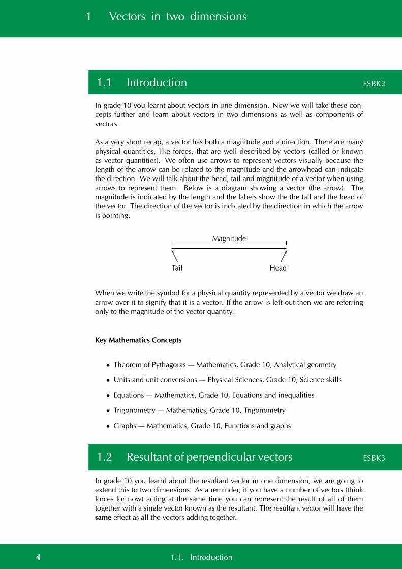
As a very short recap, a vector has both a magnitude and a direction. There are manyphysical quantities, like forces, that are well described by vectors (called or knownas vector quantities). We often use arrows to represent vectors visually because thelength of the arrow can be related to the magnitude and the arrowhead can indicatethe direction. We will talk about the head, tail and magnitude of a vector when usingarrows to represent them. Below is a diagram showing a vector (the arrow). Themagnitude is indicated by the length and the labels show the the tail and the head ofthe vector. The direction of the vector is indicated by the direction in which the arrowis pointing.
Tail Head
Magnitude
When we write the symbol for a physical quantity represented by a vector we draw anarrow over it to signify that it is a vector. If the arrow is left out then we are referringonly to the magnitude of the vector quantity.
Key Mathematics Concepts
• Theorem of Pythagoras — Mathematics, Grade 10, Analytical geometry
• Units and unit conversions — Physical Sciences, Grade 10, Science skills
• Equations — Mathematics, Grade 10, Equations and inequalities
• Trigonometry — Mathematics, Grade 10, Trigonometry
• Graphs — Mathematics, Grade 10, Functions and graphs
1.2 Resultant of perpendicular vectors ESBK3
In grade 10 you learnt about the resultant vector in one dimension, we are going toextend this to two dimensions. As a reminder, if you have a number of vectors (thinkforces for now) acting at the same time you can represent the result of all of themtogether with a single vector known as the resultant. The resultant vector will have thesame effect as all the vectors adding together.
4 1.1. Introduction
We will focus on examples involving forces but it is very important to rememberthat this applies to all physical quantities that can be described by vectors, forces,displacements, accelerations, velocities and more.
Vectors on the Cartesian plane ESBK4
The first thing to make a note of is that in Grade 10 we worked with vectors all actingin a line, on a single axis. We are now going to go further and start to deal with twodimensions. We can represent this by using the Cartesian plane which consists of twoperpendicular (at a right angle) axes. The axes are a x-axis and a y-axis. We normallydraw the x-axis from left to right (horizontally) and the y-axis up and down (vertically).
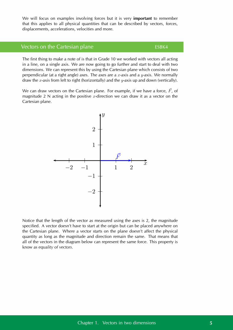
We can draw vectors on the Cartesian plane. For example, if we have a force, F , ofmagnitude 2 N acting in the positive x-direction we can draw it as a vector on theCartesian plane.
1
2
−1
−2
1 2−1−2x
y
F
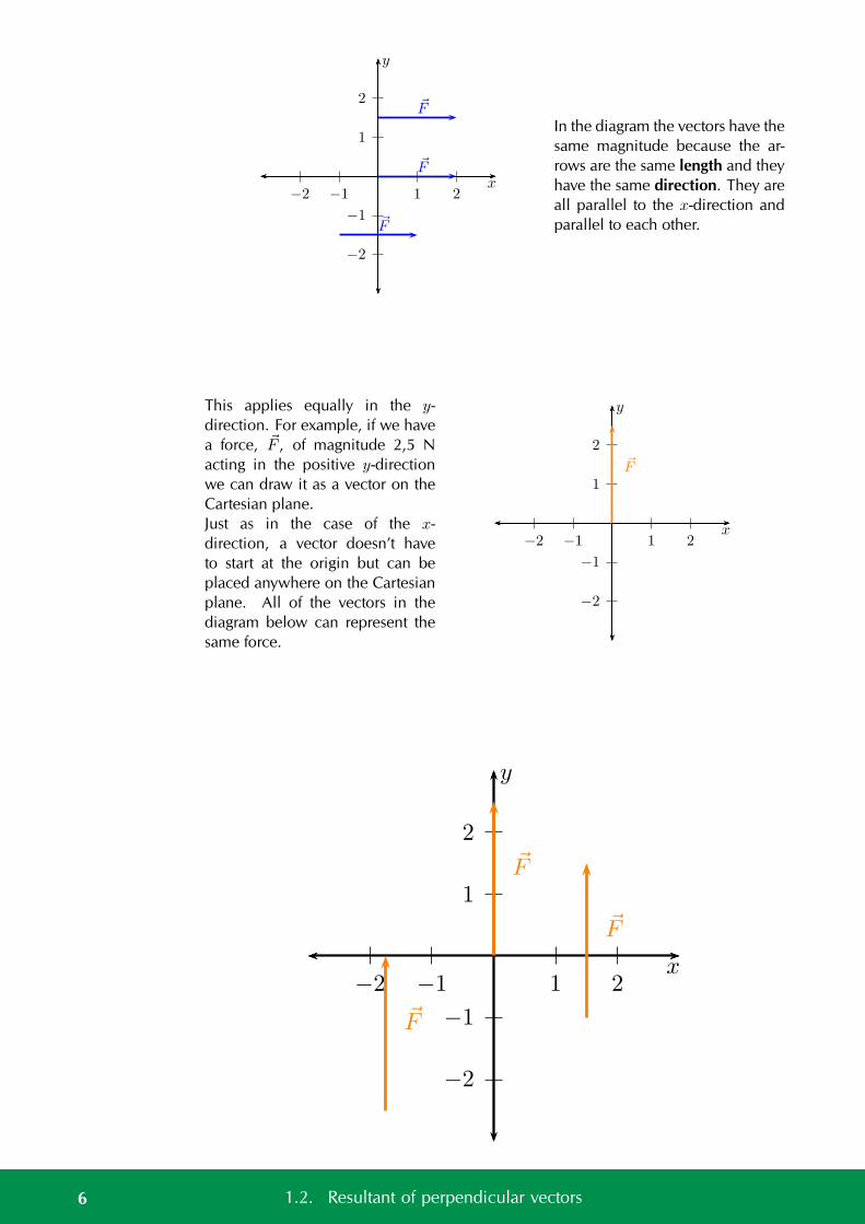
Notice that the length of the vector as measured using the axes is 2, the magnitudespecified. A vector doesn’t have to start at the origin but can be placed anywhere onthe Cartesian plane. Where a vector starts on the plane doesn’t affect the physicalquantity as long as the magnitude and direction remain the same. That means thatall of the vectors in the diagram below can represent the same force. This property isknow as equality of vectors.
5Chapter 1. Vectors in two dimensions
1
2
−1
−2
1 2−1−2x
y
F
F
F
In the diagram the vectors have thesame magnitude because the ar-rows are the same length and theyhave the same direction. They areall parallel to the x-direction andparallel to each other.
This applies equally in the y-direction. For example, if we havea force, F , of magnitude 2,5 Nacting in the positive y-directionwe can draw it as a vector on theCartesian plane.Just as in the case of the x-direction, a vector doesn’t haveto start at the origin but can beplaced anywhere on the Cartesianplane. All of the vectors in thediagram below can represent thesame force.
1
2
−1
−2
1 2−1−2x
y
F
1
2
−1
−2
1 2−1−2x
y
F
F
F
6 1.2. Resultant of perpendicular vectors
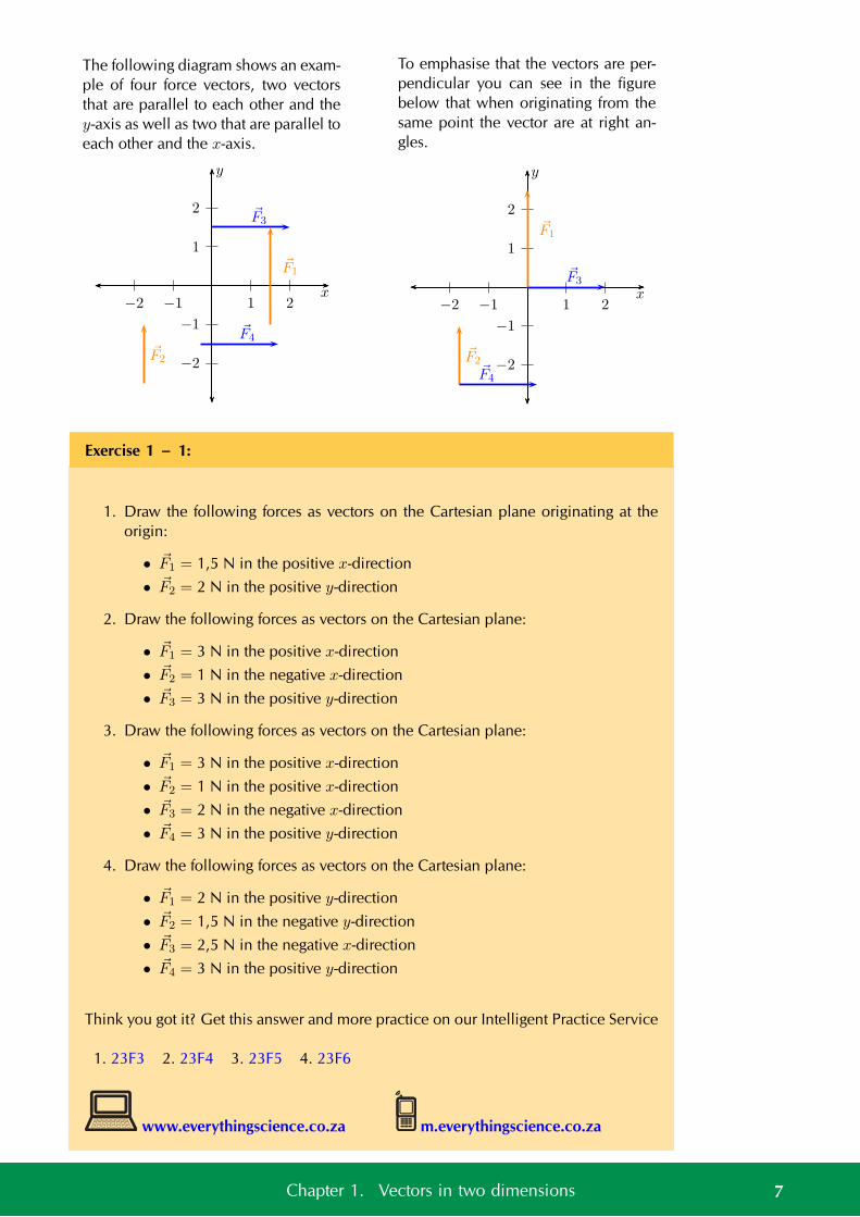
The following diagram shows an exam-ple of four force vectors, two vectorsthat are parallel to each other and they-axis as well as two that are parallel toeach other and the x-axis.
1
2
−1
−2
1 2−1−2x
y
F1
F2
F3
F4
To emphasise that the vectors are per-pendicular you can see in the figurebelow that when originating from thesame point the vector are at right an-gles.
1
2
−1
−2
1 2−1−2x
y
F1
F2
F3
F4
Exercise 1 – 1:
1. Draw the following forces as vectors on the Cartesian plane originating at theorigin:
• F1 = 1,5 N in the positive x-direction
• F2 = 2 N in the positive y-direction
2. Draw the following forces as vectors on the Cartesian plane:
• F1 = 3 N in the positive x-direction
• F2 = 1 N in the negative x-direction
• F3 = 3 N in the positive y-direction
3. Draw the following forces as vectors on the Cartesian plane:
• F1 = 3 N in the positive x-direction
• F2 = 1 N in the positive x-direction
• F3 = 2 N in the negative x-direction
• F4 = 3 N in the positive y-direction
4. Draw the following forces as vectors on the Cartesian plane:
• F1 = 2 N in the positive y-direction
• F2 = 1,5 N in the negative y-direction
• F3 = 2,5 N in the negative x-direction
• F4 = 3 N in the positive y-direction
Think you got it? Get this answer and more practice on our Intelligent Practice Service
1. 23F3 2. 23F4 3. 23F5 4. 23F6
www.everythingscience.co.za m.everythingscience.co.za
7Chapter 1. Vectors in two dimensions
Vectors in two dimensions are notalways parallel to an axis. Wemight know that a force acts at anangle to an axis so we still knowthe direction of the force and if weknow the magnitude we can drawthe force vector. For example, wecan draw F1 = 2 N acting at 45
to the positive x-direction: 0
1
2
0 1 2x
y
F1
45
−1
−2
1 2x
y
F1
45We always specify the angle as be-ing anti-clockwise from the posi-tive x-axis. So if we specified annegative angle we would measureit clockwise from the x-axis. Forexample, F1 = 2 N acting at −45
to the positive x-direction:
We can use many other ways of specifying the direction of a vector. The directionjust needs to be unambiguous. We have used the Cartesian coordinate system and anangle with the x-axis so far but there are other common ways of specifying directionthat you need to be aware of and comfortable to handle.
Compass directions ESBK5
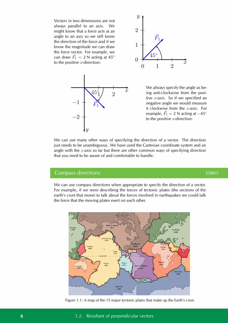
We can use compass directions when appropriate to specify the direction of a vector.For example, if we were describing the forces of tectonic plates (the sections of theearth’s crust that move) to talk about the forces involved in earthquakes we could talkthe force that the moving plates exert on each other.
Figure 1.1: A map of the 15 major tectonic plates that make up the Earth’s crust.
8 1.2. Resultant of perpendicular vectors
The four cardinal directions areNorth, South, East and West whenusing a compass. They are shownin this figure:When specifying a direction ofa vector using a compass direc-tions are given by name, Northor South. If the direction is di-rectly between two directions wecan combine the names, for exam-ple North-East is half-way betweenNorth and East. This can only hap-pen for directions at right angles toeach other, you cannot say North-South as it is ambiguous.
Figure 1.2: A sketch of the compass directions.
Bearings ESBK6
Another way of using the compass to specify direction in a numerical way is to usebearings. A bearing is an angle, usually measured clockwise from North. Note thatthis is different to the Cartesian plane where angles are anti- or counter-clockwise fromthe positive x-direction.
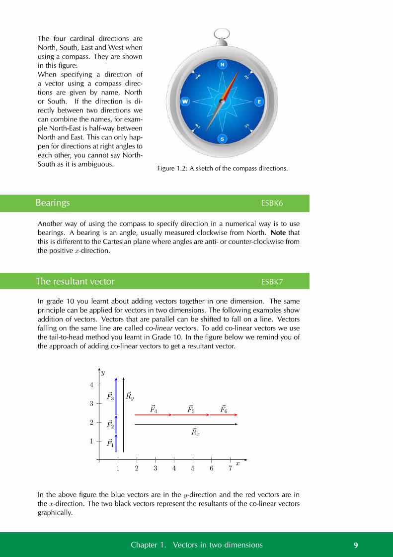
The resultant vector ESBK7
In grade 10 you learnt about adding vectors together in one dimension. The sameprinciple can be applied for vectors in two dimensions. The following examples showaddition of vectors. Vectors that are parallel can be shifted to fall on a line. Vectorsfalling on the same line are called co-linear vectors. To add co-linear vectors we usethe tail-to-head method you learnt in Grade 10. In the figure below we remind you ofthe approach of adding co-linear vectors to get a resultant vector.
1
2
3
4
1 2 3 4 5 6 7x
y
F3
F2
F1
Ry
F4F5
F6
Rx
In the above figure the blue vectors are in the y-direction and the red vectors are inthe x-direction. The two black vectors represent the resultants of the co-linear vectorsgraphically.
9Chapter 1. Vectors in two dimensions
What we have done is implement the tail-to-head method of vector addition for thevertical set of vectors and the horizontal set of vectors.
Worked example 1: Revision: head-to-tail addition in one dimension
QUESTION
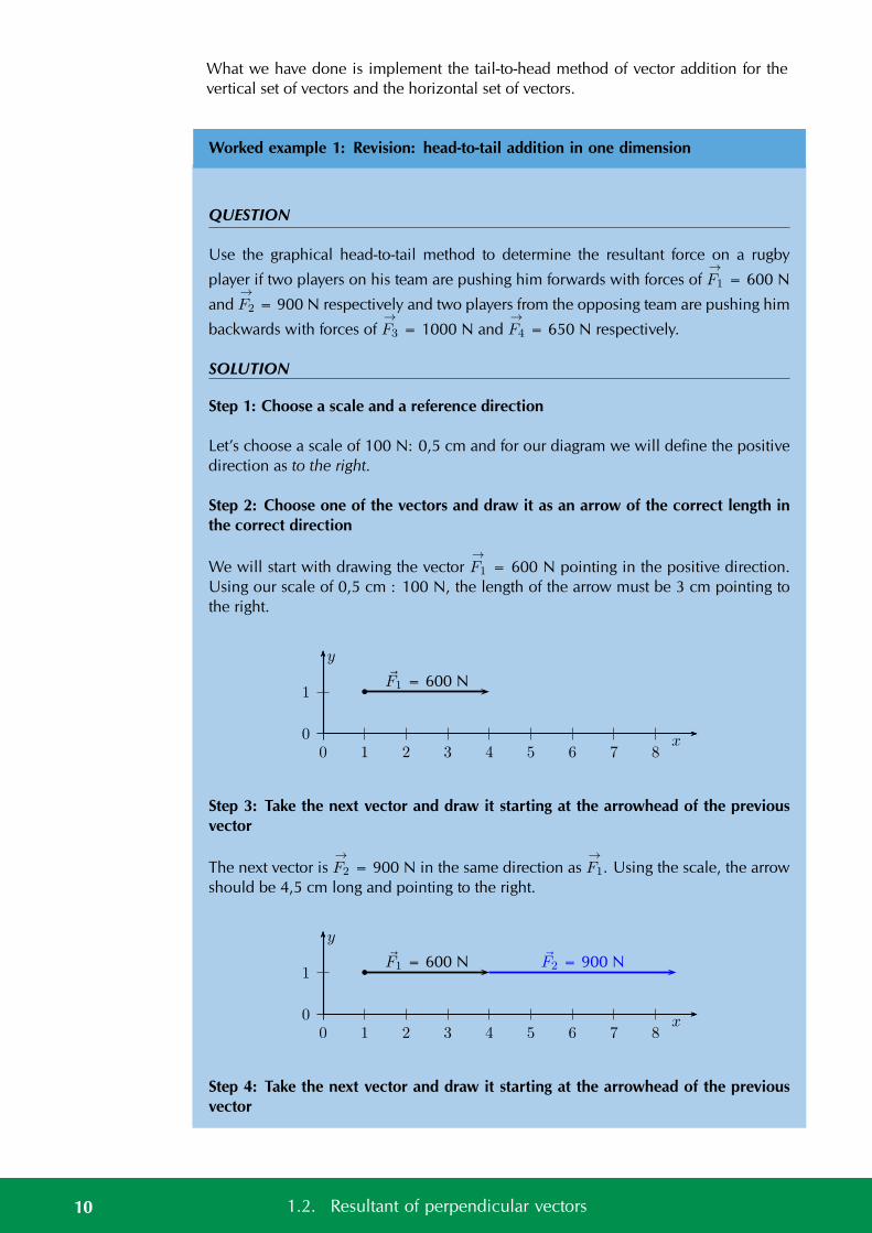
Use the graphical head-to-tail method to determine the resultant force on a rugby
player if two players on his team are pushing him forwards with forces of→F1 = 600 N
and→F2 = 900 N respectively and two players from the opposing team are pushing him
backwards with forces of→F3 = 1000 N and
→F4 = 650 N respectively.
SOLUTION
Step 1: Choose a scale and a reference direction
Let’s choose a scale of 100 N: 0,5 cm and for our diagram we will define the positivedirection as to the right.
Step 2: Choose one of the vectors and draw it as an arrow of the correct length inthe correct direction
We will start with drawing the vector→F1 = 600 N pointing in the positive direction.
Using our scale of 0,5 cm : 100 N, the length of the arrow must be 3 cm pointing tothe right.
0
1
0 1 2 3 4 5 6 7 8x
y
F1 = 600 N
Step 3: Take the next vector and draw it starting at the arrowhead of the previousvector
The next vector is→F2 = 900 N in the same direction as
→F1. Using the scale, the arrow
should be 4,5 cm long and pointing to the right.
0
1
0 1 2 3 4 5 6 7 8x
y
F1 = 600 N F2 = 900 N
Step 4: Take the next vector and draw it starting at the arrowhead of the previousvector
10 1.2. Resultant of perpendicular vectors
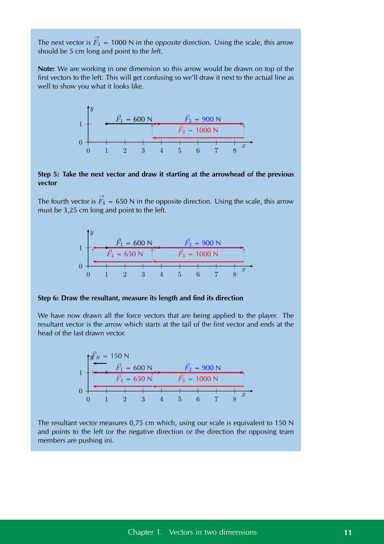
The next vector is→F3 = 1000 N in the opposite direction. Using the scale, this arrow
should be 5 cm long and point to the left.
Note: We are working in one dimension so this arrow would be drawn on top of thefirst vectors to the left. This will get confusing so we’ll draw it next to the actual line aswell to show you what it looks like.
0
1
0 1 2 3 4 5 6 7 8x
y
F1 = 600 N F2 = 900 N
F3 = 1000 N
Step 5: Take the next vector and draw it starting at the arrowhead of the previousvector
The fourth vector is→F4 = 650 N in the opposite direction. Using the scale, this arrow
must be 3,25 cm long and point to the left.
0
1
0 1 2 3 4 5 6 7 8x
y
F1 = 600 N F2 = 900 N
F3 = 1000 NF4 = 650 N
Step 6: Draw the resultant, measure its length and find its direction
We have now drawn all the force vectors that are being applied to the player. Theresultant vector is the arrow which starts at the tail of the first vector and ends at thehead of the last drawn vector.
0
1
0 1 2 3 4 5 6 7 8x
y
F2 = 900 N
F3 = 1000 NF4 = 650 N
FR = 150 N
F1 = 600 N
The resultant vector measures 0,75 cm which, using our scale is equivalent to 150 Nand points to the left (or the negative direction or the direction the opposing teammembers are pushing in).
11Chapter 1. Vectors in two dimensions
Exercise 1 – 2:
1. Find the resultant in the x-direction, Rx, and y-direction, Ry for the followingforces:
• F1 = 1,5 N in the positive x-direction
• F2 = 1,5 N in the positive x-direction
• F3 = 2 N in the negative x-direction
2. Find the resultant in the x-direction, Rx, and y-direction, Ry for the followingforces:
• F1 = 2,3 N in the positive x-direction
• F2 = 1 N in the negative x-direction
• F3 = 2 N in the positive y-direction
• F4 = 3 N in the negative y-direction
3. Find the resultant in the x-direction, Rx, and y-direction, Ry for the followingforces:
• F1 = 3 N in the positive x-direction
• F2 = 1 N in the positive x-direction
• F3 = 2 N in the negative x-direction
• F4 = 3 N in the positive y-direction
4. Find the resultant in the x-direction, Rx, and y-direction, Ry for the followingforces:
• F1 = 2 N in the positive y-direction
• F2 = 1,5 N in the negative y-direction
• F3 = 2,5 N in the negative x-direction
• F4 = 3 N in the positive y-direction
5. Find a force in the x-direction, Fx, and y-direction, Fy, that you can add to thefollowing forces to make the resultant in the x-direction, Rx, and y-direction, Ry
zero:
• F1 = 2,4 N in the positive y-direction
• F2 = 0,7 N in the negative y-direction
• F3 = 2,8 N in the negative x-direction
• F4 = 3,3 N in the positive y-direction
Think you got it? Get this answer and more practice on our Intelligent Practice Service
1. 23F7 2. 23F8 3. 23F9 4. 23FB 5. 23FC
www.everythingscience.co.za m.everythingscience.co.za
12 1.2. Resultant of perpendicular vectors
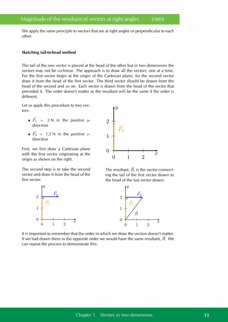
Magnitude of the resultant of vectors at right angles ESBK8
We apply the same principle to vectors that are at right angles or perpendicular to eachother.
Sketching tail-to-head method
The tail of the one vector is placed at the head of the other but in two dimensions thevectors may not be co-linear. The approach is to draw all the vectors, one at a time.For the first vector begin at the origin of the Cartesian plane, for the second vectordraw it from the head of the first vector. The third vector should be drawn from thehead of the second and so on. Each vector is drawn from the head of the vector thatpreceded it. The order doesn’t matter as the resultant will be the same if the order isdifferent.
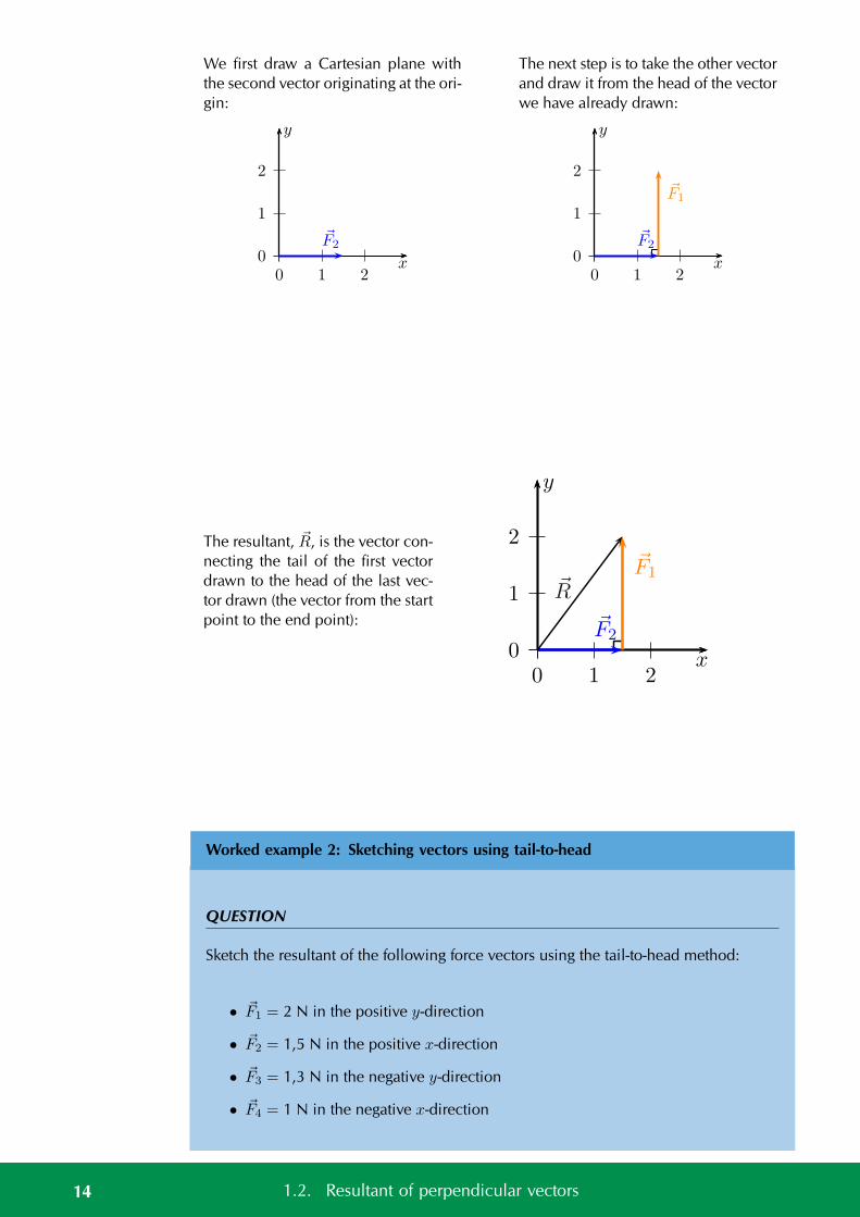
Let us apply this procedure to two vec-tors:
• F1 = 2 N in the positive y-direction
• F2 = 1,5 N in the positive x-direction
First, we first draw a Cartesian planewith the first vector originating at theorigin as shown on the right.
0
1
2
0 1 2x
y
F1
The second step is to take the secondvector and draw it from the head of thefirst vector:
0
1
2
0 1 2x
y
F1
F2
The resultant, R, is the vector connect-ing the tail of the first vector drawn tothe head of the last vector drawn:
0
1
2
0 1 2x
y
F1
F2
R
It is important to remember that the order in which we draw the vectors doesn’t matter.If we had drawn them in the opposite order we would have the same resultant, R. Wecan repeat the process to demonstrate this:
13Chapter 1. Vectors in two dimensions
We first draw a Cartesian plane withthe second vector originating at the ori-gin:
0
1
2
0 1 2x
y
F2
The next step is to take the other vectorand draw it from the head of the vectorwe have already drawn:
0
1
2
0 1 2x
y
F1
F2
The resultant, R, is the vector con-necting the tail of the first vectordrawn to the head of the last vec-tor drawn (the vector from the startpoint to the end point):
0
1
2
0 1 2x
y
F1
F2
R
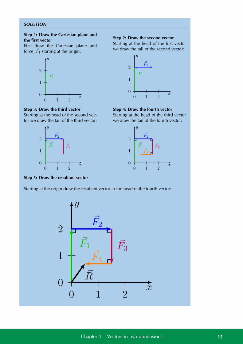
Worked example 2: Sketching vectors using tail-to-head
QUESTION
Sketch the resultant of the following force vectors using the tail-to-head method:
• F1 = 2 N in the positive y-direction
• F2 = 1,5 N in the positive x-direction
• F3 = 1,3 N in the negative y-direction
• F4 = 1 N in the negative x-direction
14 1.2. Resultant of perpendicular vectors
SOLUTION
Step 1: Draw the Cartesian plane andthe first vectorFirst draw the Cartesian plane andforce, F1 starting at the origin:
0
1
2
0 1 2x
y
F1
Step 2: Draw the second vectorStarting at the head of the first vectorwe draw the tail of the second vector:
0
1
2
0 1 2x
y
F1
F2
Step 3: Draw the third vectorStarting at the head of the second vec-tor we draw the tail of the third vector:
0
1
2
0 1 2x
y
F1
F2
F3
Step 4: Draw the fourth vectorStarting at the head of the third vectorwe draw the tail of the fourth vector:
0
1
2
0 1 2x
y
F1
F2
F3F4
Step 5: Draw the resultant vector
Starting at the origin draw the resultant vector to the head of the fourth vector:
0
1
2
0 1 2x
y
F1
F2
F3F4
R
15Chapter 1. Vectors in two dimensions
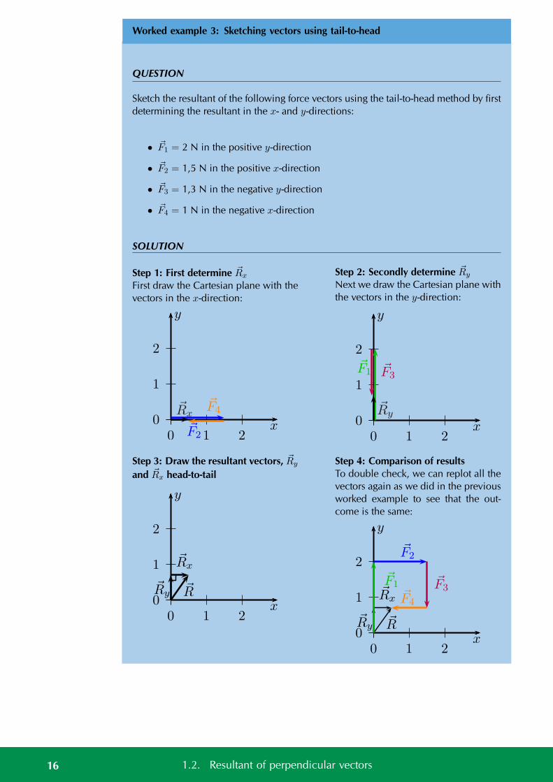
Worked example 3: Sketching vectors using tail-to-head
QUESTION
Sketch the resultant of the following force vectors using the tail-to-head method by firstdetermining the resultant in the x- and y-directions:
• F1 = 2 N in the positive y-direction
• F2 = 1,5 N in the positive x-direction
• F3 = 1,3 N in the negative y-direction
• F4 = 1 N in the negative x-direction
SOLUTION
Step 1: First determine Rx
First draw the Cartesian plane with thevectors in the x-direction:
0
1
2
0 1 2x
y
F2
F4Rx
Step 2: Secondly determine Ry
Next we draw the Cartesian plane withthe vectors in the y-direction:
0
1
2
0 1 2x
y
F1 F3
Ry
Step 3: Draw the resultant vectors, Ry
and Rx head-to-tail
0
1
2
0 1 2x
y
Ry
Rx
R
Step 4: Comparison of resultsTo double check, we can replot all thevectors again as we did in the previousworked example to see that the out-come is the same:
0
1
2
0 1 2x
y
Ry
Rx
R
F1
F2
F3F4
16 1.2. Resultant of perpendicular vectors
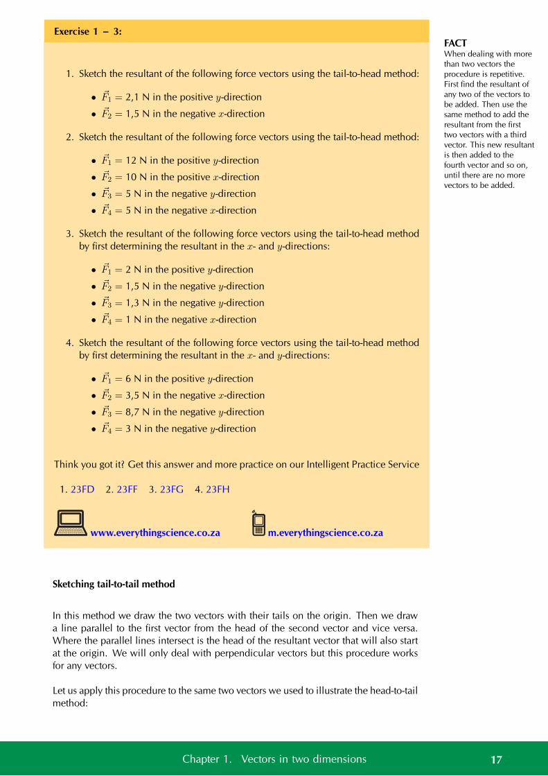
FACTWhen dealing with morethan two vectors theprocedure is repetitive.First find the resultant ofany two of the vectors tobe added. Then use thesame method to add theresultant from the firsttwo vectors with a thirdvector. This new resultantis then added to thefourth vector and so on,until there are no morevectors to be added.
Exercise 1 – 3:
1. Sketch the resultant of the following force vectors using the tail-to-head method:
• F1 = 2,1 N in the positive y-direction
• F2 = 1,5 N in the negative x-direction
2. Sketch the resultant of the following force vectors using the tail-to-head method:
• F1 = 12 N in the positive y-direction
• F2 = 10 N in the positive x-direction
• F3 = 5 N in the negative y-direction
• F4 = 5 N in the negative x-direction
3. Sketch the resultant of the following force vectors using the tail-to-head methodby first determining the resultant in the x- and y-directions:
• F1 = 2 N in the positive y-direction
• F2 = 1,5 N in the negative y-direction
• F3 = 1,3 N in the negative y-direction
• F4 = 1 N in the negative x-direction
4. Sketch the resultant of the following force vectors using the tail-to-head methodby first determining the resultant in the x- and y-directions:
• F1 = 6 N in the positive y-direction
• F2 = 3,5 N in the negative x-direction
• F3 = 8,7 N in the negative y-direction
• F4 = 3 N in the negative y-direction
Think you got it? Get this answer and more practice on our Intelligent Practice Service
1. 23FD 2. 23FF 3. 23FG 4. 23FH
www.everythingscience.co.za m.everythingscience.co.za
Sketching tail-to-tail method
In this method we draw the two vectors with their tails on the origin. Then we drawa line parallel to the first vector from the head of the second vector and vice versa.Where the parallel lines intersect is the head of the resultant vector that will also startat the origin. We will only deal with perpendicular vectors but this procedure worksfor any vectors.
Let us apply this procedure to the same two vectors we used to illustrate the head-to-tailmethod:
17Chapter 1. Vectors in two dimensions
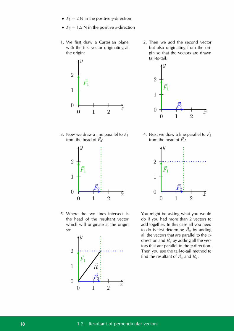
• F1 = 2 N in the positive y-direction
• F2 = 1,5 N in the positive x-direction
1. We first draw a Cartesian planewith the first vector originating atthe origin:
0
1
2
0 1 2x
y
F1
2. Then we add the second vectorbut also originating from the ori-gin so that the vectors are drawntail-to-tail:
0
1
2
0 1 2x
y
F1
F2
3. Now we draw a line parallel to F1
from the head of F2:
0
1
2
0 1 2x
y
F1
F2
4. Next we draw a line parallel to F2
from the head of F1:
0
1
2
0 1 2x
y
F1
F2
5. Where the two lines intersect isthe head of the resultant vectorwhich will originate at the originso:
0
1
2
0 1 2x
y
F1
F2
R
You might be asking what you woulddo if you had more than 2 vectors toadd together. In this case all you needto do is first determine Rx by addingall the vectors that are parallel to the x-direction and Ry by adding all the vec-tors that are parallel to the y-direction.Then you use the tail-to-tail method tofind the resultant of Rx and Ry.
18 1.2. Resultant of perpendicular vectors
Exercise 1 – 4:
1. Sketch the resultant of the following force vectors using the tail-to-tail method:
• F1 = 2,1 N in the positive y-direction
• F2 = 1,5 N in the negative x-direction
2. Sketch the resultant of the following force vectors using the tail-to-tail method byfirst determining the resultant in the x- and y-directions:
• F1 = 2 N in the positive y-direction
• F2 = 1,5 N in the negative y-direction
• F3 = 1,3 N in the negative y-direction
• F4 = 1 N in the negative x-direction
3. Sketch the resultant of the following force vectors using the tail-to-tail method byfirst determining the resultant in the x- and y-directions:
• F1 = 6 N in the positive y-direction
• F2 = 3,5 N in the negative x-direction
• F3 = 8,7 N in the negative y-direction
• F4 = 3 N in the negative y-direction
Think you got it? Get this answer and more practice on our Intelligent Practice Service
1. 23FJ 2. 23FK 3. 23FM
www.everythingscience.co.za m.everythingscience.co.za
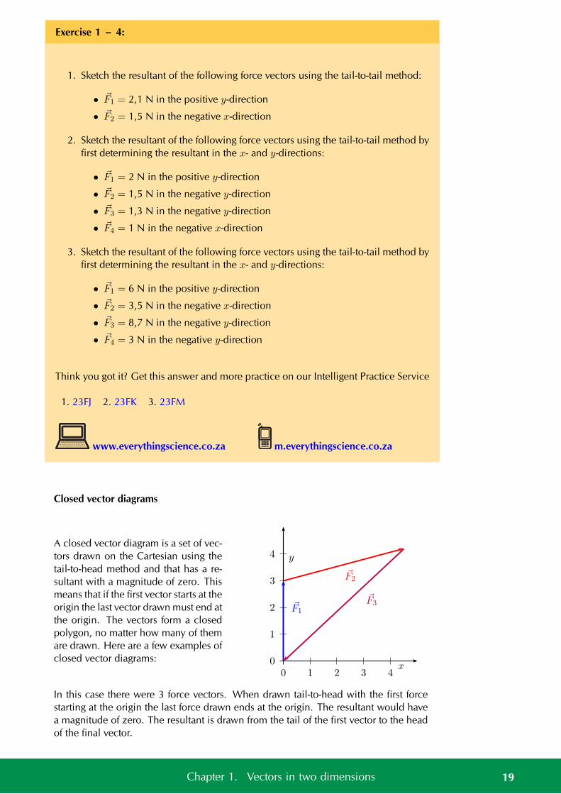
Closed vector diagrams
A closed vector diagram is a set of vec-tors drawn on the Cartesian using thetail-to-head method and that has a re-sultant with a magnitude of zero. Thismeans that if the first vector starts at theorigin the last vector drawn must end atthe origin. The vectors form a closedpolygon, no matter how many of themare drawn. Here are a few examples ofclosed vector diagrams: 0
1
2
3
4
0 1 2 3 4x
y
F1
F2
F3
In this case there were 3 force vectors. When drawn tail-to-head with the first forcestarting at the origin the last force drawn ends at the origin. The resultant would havea magnitude of zero. The resultant is drawn from the tail of the first vector to the headof the final vector.
19Chapter 1. Vectors in two dimensions
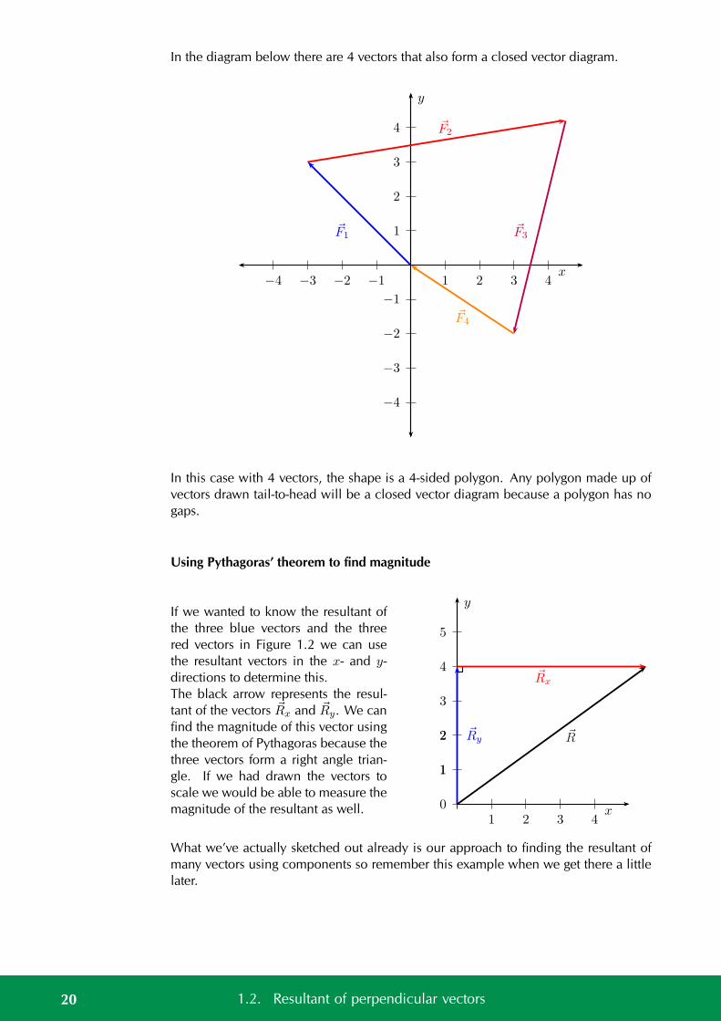
In the diagram below there are 4 vectors that also form a closed vector diagram.
1
2
3
4
−1
−2
−3
−4
1 2 3 4−1−2−3−4x
y
F1
F2
F3
F4
In this case with 4 vectors, the shape is a 4-sided polygon. Any polygon made up ofvectors drawn tail-to-head will be a closed vector diagram because a polygon has nogaps.
Using Pythagoras’ theorem to find magnitude
If we wanted to know the resultant ofthe three blue vectors and the threered vectors in Figure 1.2 we can usethe resultant vectors in the x- and y-directions to determine this.The black arrow represents the resul-tant of the vectors Rx and Ry. We canfind the magnitude of this vector usingthe theorem of Pythagoras because thethree vectors form a right angle trian-gle. If we had drawn the vectors toscale we would be able to measure themagnitude of the resultant as well. 0
1
2
3
4
5
1
2
1 2 3 4x
y
Ry
Rx
R
What we’ve actually sketched out already is our approach to finding the resultant ofmany vectors using components so remember this example when we get there a littlelater.
20 1.2. Resultant of perpendicular vectors
Worked example 4: Finding the magnitude of the resultant
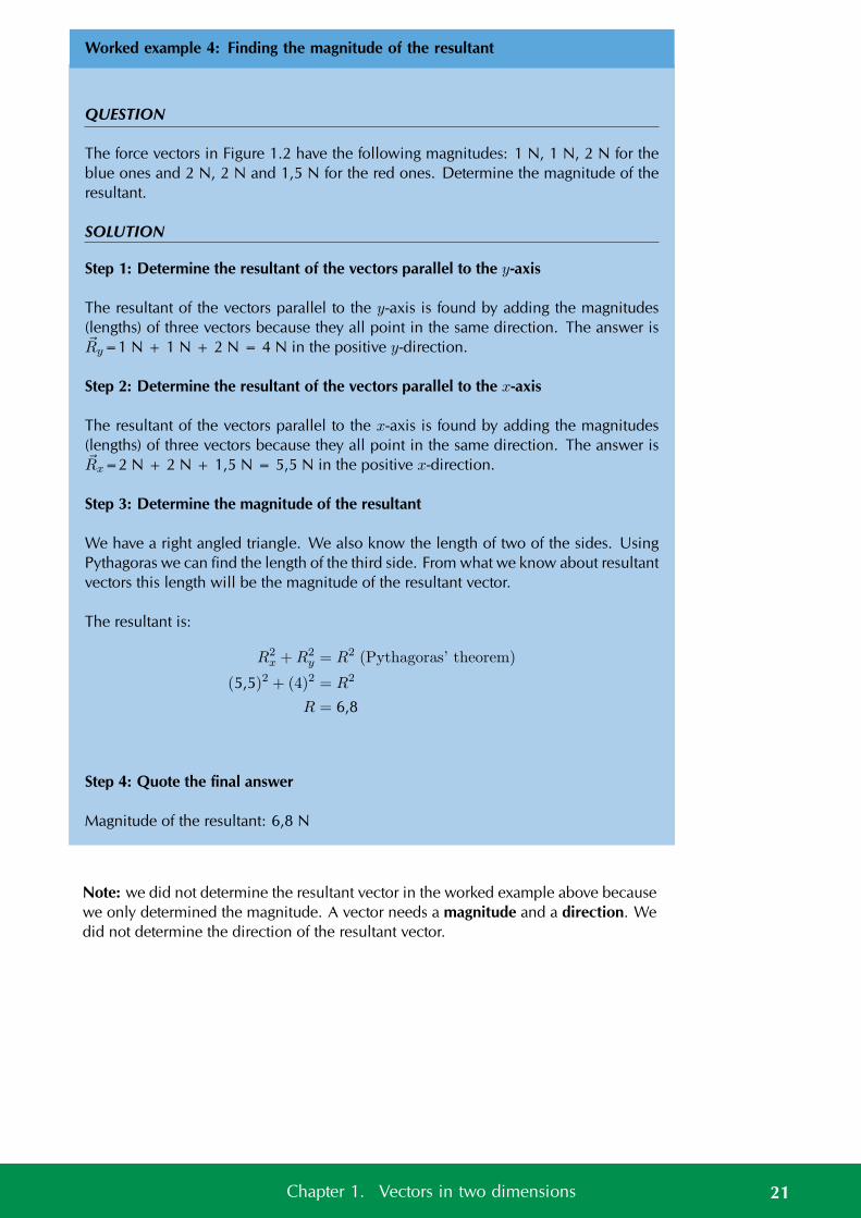
QUESTION
The force vectors in Figure 1.2 have the following magnitudes: 1 N, 1 N, 2 N for theblue ones and 2 N, 2 N and 1,5 N for the red ones. Determine the magnitude of theresultant.
SOLUTION
Step 1: Determine the resultant of the vectors parallel to the y-axis
The resultant of the vectors parallel to the y-axis is found by adding the magnitudes(lengths) of three vectors because they all point in the same direction. The answer isRy=1 N + 1 N + 2 N = 4 N in the positive y-direction.
Step 2: Determine the resultant of the vectors parallel to the x-axis
The resultant of the vectors parallel to the x-axis is found by adding the magnitudes(lengths) of three vectors because they all point in the same direction. The answer isRx=2 N + 2 N + 1,5 N = 5,5 N in the positive x-direction.
Step 3: Determine the magnitude of the resultant
We have a right angled triangle. We also know the length of two of the sides. UsingPythagoras we can find the length of the third side. From what we know about resultantvectors this length will be the magnitude of the resultant vector.
The resultant is:
R2x +R2
y = R2 (Pythagoras’ theorem)
(5,5)2 + (4)2 = R2
R = 6,8
Step 4: Quote the final answer
Magnitude of the resultant: 6,8 N
Note: we did not determine the resultant vector in the worked example above becausewe only determined the magnitude. A vector needs a magnitude and a direction. Wedid not determine the direction of the resultant vector.
21Chapter 1. Vectors in two dimensions
Graphical methods ESBK9
Graphical techniques
In grade 10 you learnt how to add vectors in one dimension graphically.
We can expand these ideas to include vectors in two-dimensions. The followingworked example shows this.
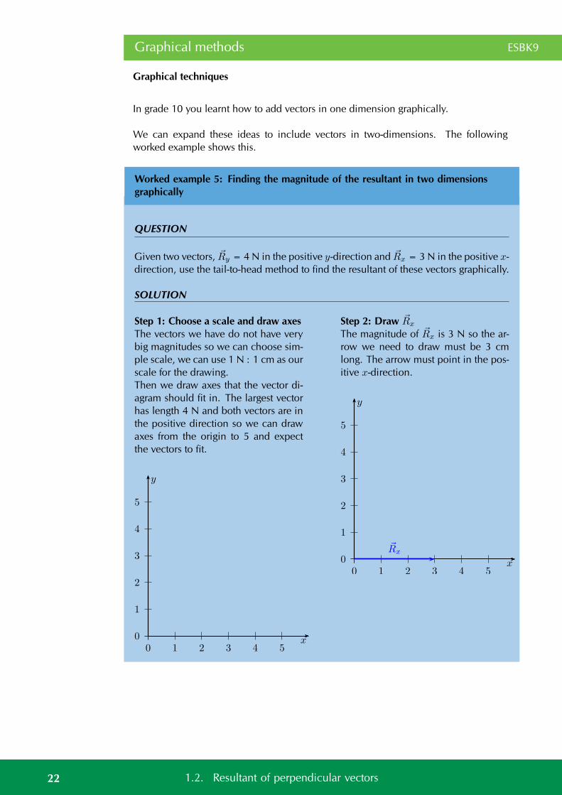
Worked example 5: Finding the magnitude of the resultant in two dimensionsgraphically
QUESTION
Given two vectors, Ry = 4 N in the positive y-direction and Rx = 3 N in the positive x-direction, use the tail-to-head method to find the resultant of these vectors graphically.
SOLUTION
Step 1: Choose a scale and draw axesThe vectors we have do not have verybig magnitudes so we can choose sim-ple scale, we can use 1 N : 1 cm as ourscale for the drawing.Then we draw axes that the vector di-agram should fit in. The largest vectorhas length 4 N and both vectors are inthe positive direction so we can drawaxes from the origin to 5 and expectthe vectors to fit.
0
1
2
3
4
5
0 1 2 3 4 5
y
x
Step 2: Draw Rx
The magnitude of Rx is 3 N so the ar-row we need to draw must be 3 cmlong. The arrow must point in the pos-itive x-direction.
0
1
2
3
4
5
0 1 2 3 4 5
y
x
Rx
22 1.2. Resultant of perpendicular vectors
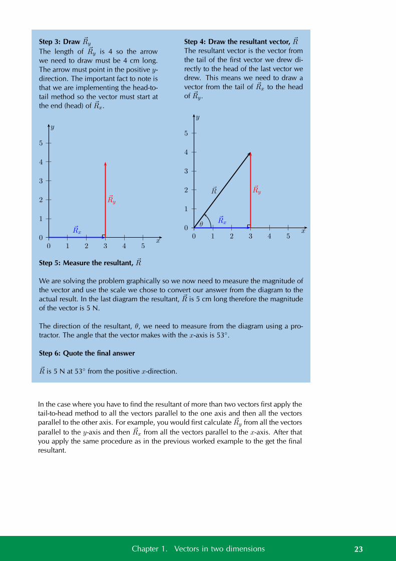
Step 3: Draw Ry
The length of Ry is 4 so the arrowwe need to draw must be 4 cm long.The arrow must point in the positive y-direction. The important fact to note isthat we are implementing the head-to-tail method so the vector must start atthe end (head) of Rx.
0
1
2
3
4
5
0 1 2 3 4 5
y
x
Rx
Ry
Step 4: Draw the resultant vector, RThe resultant vector is the vector fromthe tail of the first vector we drew di-rectly to the head of the last vector wedrew. This means we need to draw avector from the tail of Rx to the headof Ry.
0
1
2
3
4
5
0 1 2 3 4 5
y
x
Rx
RyR
θ
Step 5: Measure the resultant, R
We are solving the problem graphically so we now need to measure the magnitude ofthe vector and use the scale we chose to convert our answer from the diagram to theactual result. In the last diagram the resultant, R is 5 cm long therefore the magnitudeof the vector is 5 N.
The direction of the resultant, θ, we need to measure from the diagram using a pro-tractor. The angle that the vector makes with the x-axis is 53.
Step 6: Quote the final answer
R is 5 N at 53 from the positive x-direction.
In the case where you have to find the resultant of more than two vectors first apply thetail-to-head method to all the vectors parallel to the one axis and then all the vectorsparallel to the other axis. For example, you would first calculate Ry from all the vectorsparallel to the y-axis and then Rx from all the vectors parallel to the x-axis. After thatyou apply the same procedure as in the previous worked example to the get the finalresultant.
23Chapter 1. Vectors in two dimensions
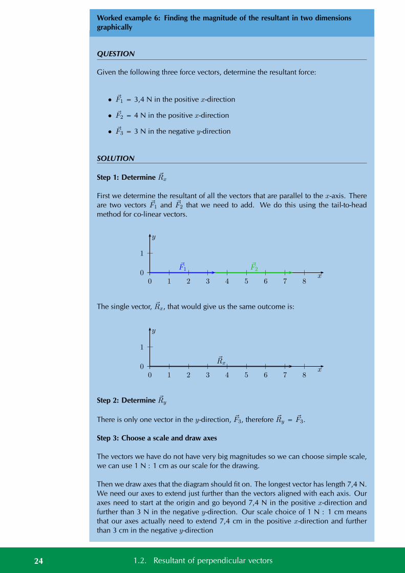
Worked example 6: Finding the magnitude of the resultant in two dimensionsgraphically
QUESTION
Given the following three force vectors, determine the resultant force:
• F1 = 3,4 N in the positive x-direction
• F2 = 4 N in the positive x-direction
• F3 = 3 N in the negative y-direction
SOLUTION
Step 1: Determine Rx
First we determine the resultant of all the vectors that are parallel to the x-axis. Thereare two vectors F1 and F2 that we need to add. We do this using the tail-to-headmethod for co-linear vectors.
0
1
0 1 2 3 4 5 6 7 8
y
x
F1F2
The single vector, Rx, that would give us the same outcome is:
0
1
0 1 2 3 4 5 6 7 8
y
x
Rx
Step 2: Determine Ry
There is only one vector in the y-direction, F3, therefore Ry = F3.
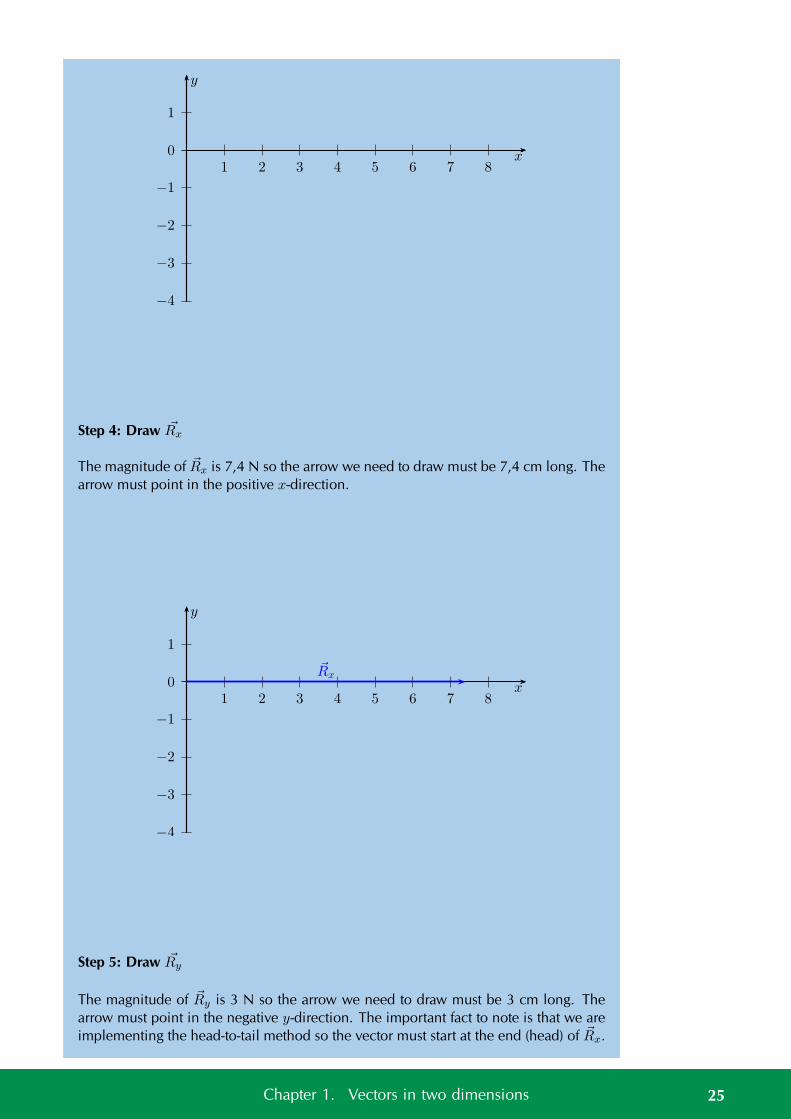
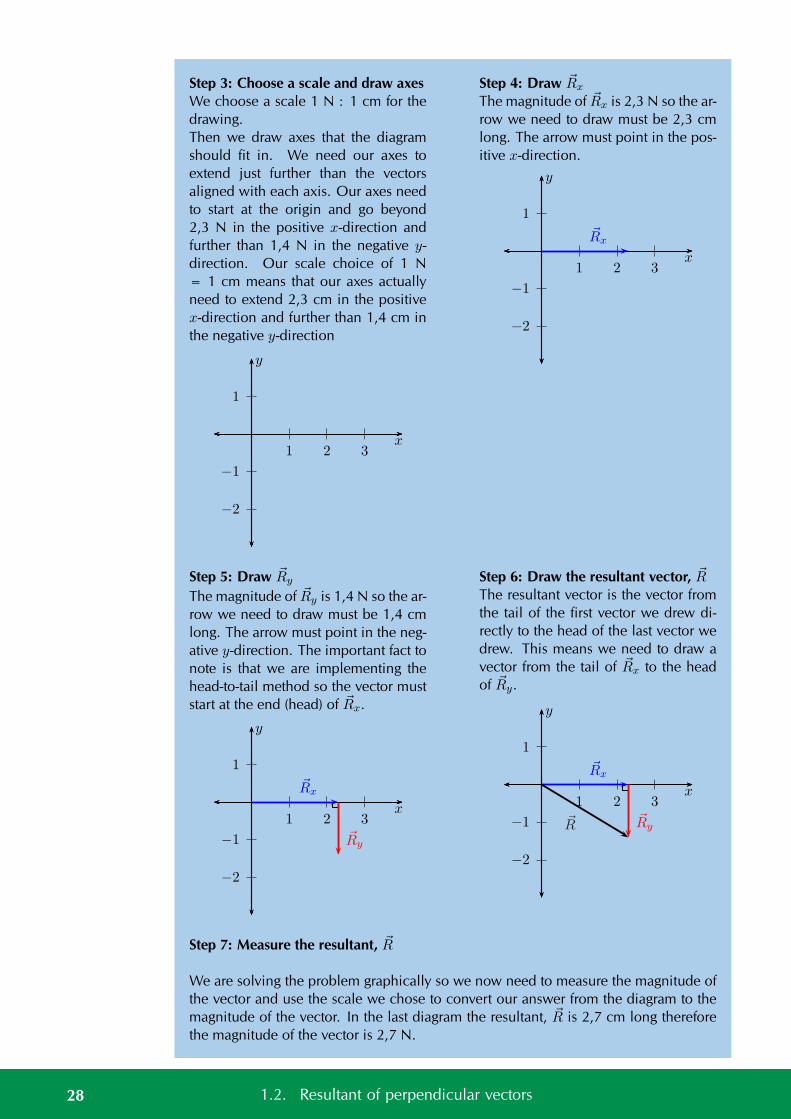
Step 3: Choose a scale and draw axes
The vectors we have do not have very big magnitudes so we can choose simple scale,we can use 1 N : 1 cm as our scale for the drawing.
Then we draw axes that the diagram should fit on. The longest vector has length 7,4 N.We need our axes to extend just further than the vectors aligned with each axis. Ouraxes need to start at the origin and go beyond 7,4 N in the positive x-direction andfurther than 3 N in the negative y-direction. Our scale choice of 1 N : 1 cm meansthat our axes actually need to extend 7,4 cm in the positive x-direction and furtherthan 3 cm in the negative y-direction
24 1.2. Resultant of perpendicular vectors
0
1
−1
−2
−3
−4
1 2 3 4 5 6 7 8
y
x
Step 4: Draw Rx
The magnitude of Rx is 7,4 N so the arrow we need to draw must be 7,4 cm long. Thearrow must point in the positive x-direction.
0
1
−1
−2
−3
−4
1 2 3 4 5 6 7 8
y
x
Rx
Step 5: Draw Ry
The magnitude of Ry is 3 N so the arrow we need to draw must be 3 cm long. Thearrow must point in the negative y-direction. The important fact to note is that we areimplementing the head-to-tail method so the vector must start at the end (head) of Rx.
25Chapter 1. Vectors in two dimensions
0
1
−1
−2
−3
−4
1 2 3 4 5 6 7 8
y
x
Rx
Ry
Step 6: Draw the resultant vector, R
The resultant vector is the vector from the tail of the first vector we drew directly to thehead of the last vector we drew. This means we need to draw a vector from the tail ofRx to the head of Ry.
0
1
−1
−2
−3
−4
1 2 3 4 5 6 7 8
y
x
Rx
Ry
θ
Step 7: Measure the resultant, R
We are solving the problem graphically so we now need to measure the magnitudeof the vector and use the scale we chose to convert our answer from the diagram tothe actual result. In the last diagram the resultant, R is 8,0 cm long therefore themagnitude of the vector is 8,0 N.
The direction of the resultant we need to measure from the diagram using a protractor.The angle that the vector makes with the x-axis is 22.
Step 8: Quote the final answer
R is 8,0 N at −22 from the positive x-direction.
26 1.2. Resultant of perpendicular vectors
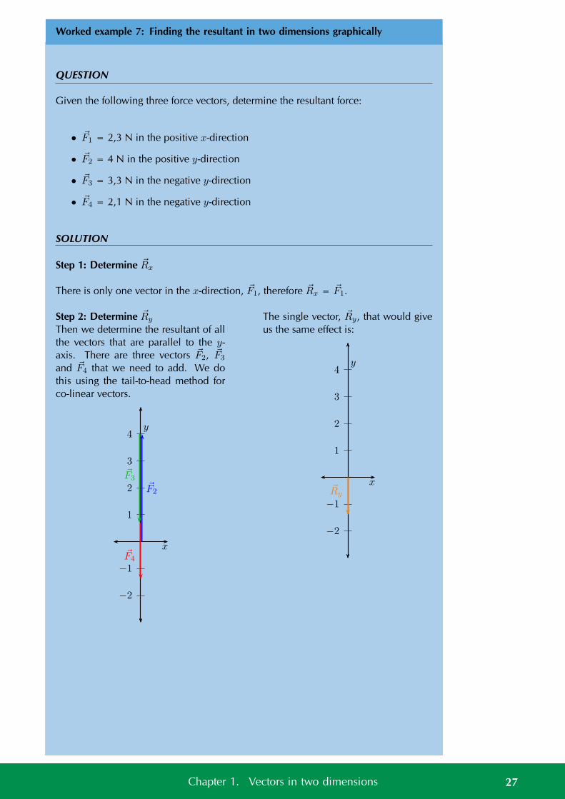
Worked example 7: Finding the resultant in two dimensions graphically
QUESTION
Given the following three force vectors, determine the resultant force:
• F1 = 2,3 N in the positive x-direction
• F2 = 4 N in the positive y-direction
• F3 = 3,3 N in the negative y-direction
• F4 = 2,1 N in the negative y-direction
SOLUTION
Step 1: Determine Rx
There is only one vector in the x-direction, F1, therefore Rx = F1.
Step 2: Determine Ry
Then we determine the resultant of allthe vectors that are parallel to the y-axis. There are three vectors F2, F3
and F4 that we need to add. We dothis using the tail-to-head method forco-linear vectors.
1
2
3
4
−1
−2
x
y
F2
F3
F4
The single vector, Ry, that would giveus the same effect is:
1
2
3
4
−1
−2
x
y
Ry
27Chapter 1. Vectors in two dimensions
Step 3: Choose a scale and draw axesWe choose a scale 1 N : 1 cm for thedrawing.Then we draw axes that the diagramshould fit in. We need our axes toextend just further than the vectorsaligned with each axis. Our axes needto start at the origin and go beyond2,3 N in the positive x-direction andfurther than 1,4 N in the negative y-direction. Our scale choice of 1 N= 1 cm means that our axes actuallyneed to extend 2,3 cm in the positivex-direction and further than 1,4 cm inthe negative y-direction
1
−1
−2
1 2 3x
y
Step 4: Draw Rx
The magnitude of Rx is 2,3 N so the ar-row we need to draw must be 2,3 cmlong. The arrow must point in the pos-itive x-direction.
1
−1
−2
1 2 3x
y
Rx
Step 5: Draw Ry
The magnitude of Ry is 1,4 N so the ar-row we need to draw must be 1,4 cmlong. The arrow must point in the neg-ative y-direction. The important fact tonote is that we are implementing thehead-to-tail method so the vector muststart at the end (head) of Rx.
1
−1
−2
1 2 3x
y
Rx
Ry
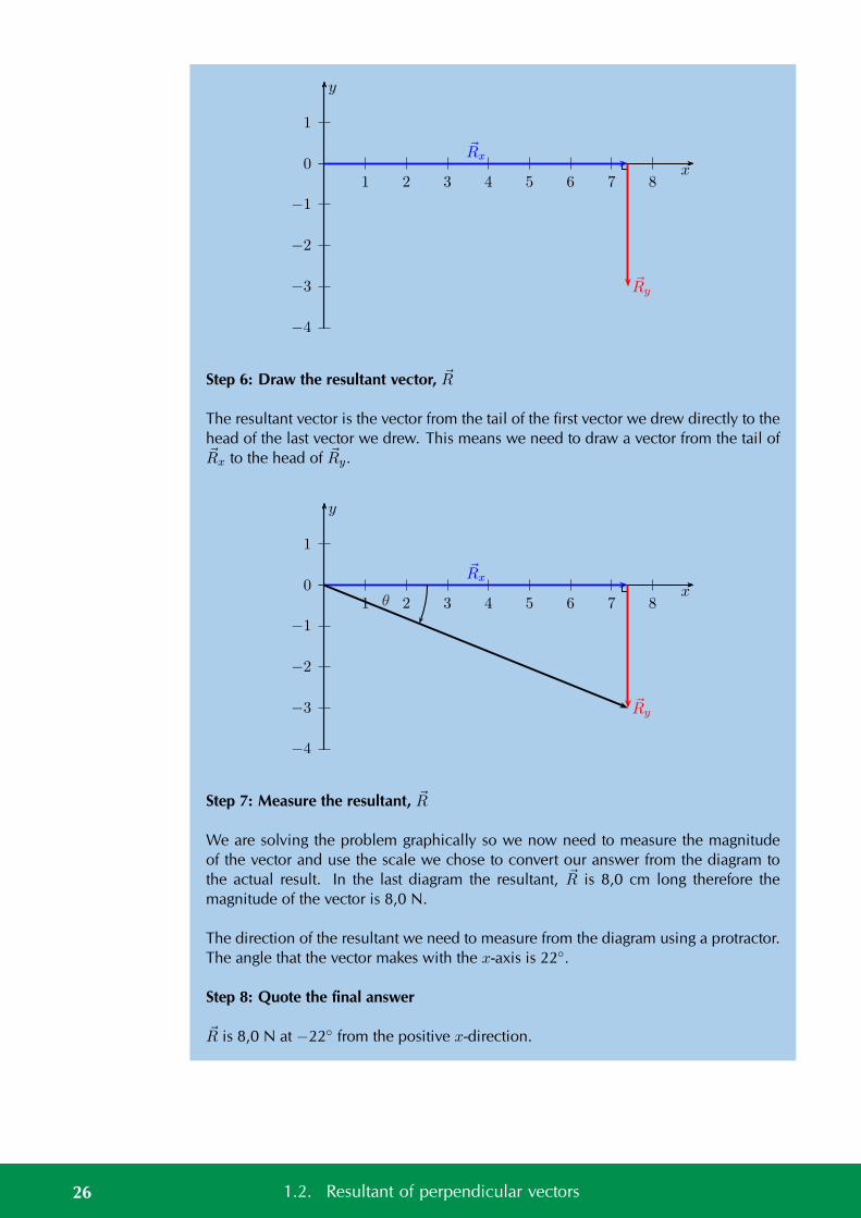
Step 6: Draw the resultant vector, RThe resultant vector is the vector fromthe tail of the first vector we drew di-rectly to the head of the last vector wedrew. This means we need to draw avector from the tail of Rx to the headof Ry.
1
−1
−2
1 2 3x
y
Rx
RyR
Step 7: Measure the resultant, R
We are solving the problem graphically so we now need to measure the magnitude ofthe vector and use the scale we chose to convert our answer from the diagram to themagnitude of the vector. In the last diagram the resultant, R is 2,7 cm long thereforethe magnitude of the vector is 2,7 N.
28 1.2. Resultant of perpendicular vectors
The direction of the resultant we need to measure from the diagram using a protractor.The angle that the vector makes with the x-axis is 31 degrees.
Step 8: Quote the final answer
R is 2,7 N at −31 from the positive x-direction.
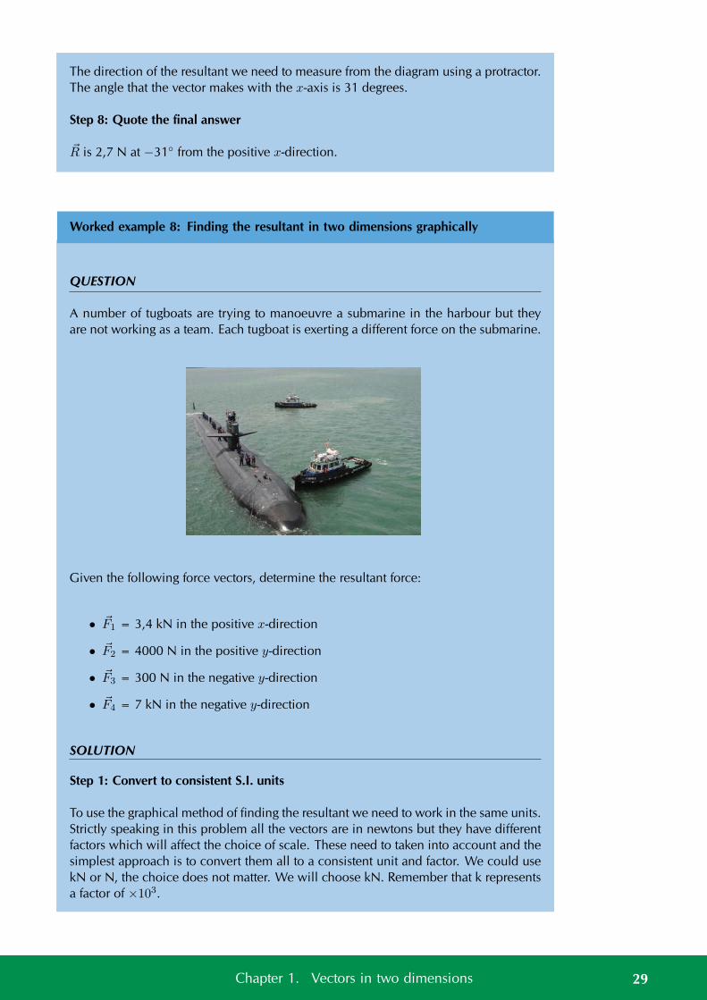
Worked example 8: Finding the resultant in two dimensions graphically
QUESTION
A number of tugboats are trying to manoeuvre a submarine in the harbour but theyare not working as a team. Each tugboat is exerting a different force on the submarine.
Given the following force vectors, determine the resultant force:
• F1 = 3,4 kN in the positive x-direction
• F2 = 4000 N in the positive y-direction
• F3 = 300 N in the negative y-direction
• F4 = 7 kN in the negative y-direction
SOLUTION
Step 1: Convert to consistent S.I. units
To use the graphical method of finding the resultant we need to work in the same units.Strictly speaking in this problem all the vectors are in newtons but they have differentfactors which will affect the choice of scale. These need to taken into account and thesimplest approach is to convert them all to a consistent unit and factor. We could usekN or N, the choice does not matter. We will choose kN. Remember that k representsa factor of ×103.
29Chapter 1. Vectors in two dimensions
F1 and F4 do not require any adjustment because they are both in kN. To convert Nto kN we use:
kN = ×103
NkN
=1
×103
N = ×10−3 kN
To convert the magnitude of F2 to kN:
F2 = 4000 N
F2 = 4000 × 10−3 kN
F2 = 4 kN
Therefore F2 = 4 kN in the positive y-direction.
To convert the magnitude of F3 to kN:
F3 = 300 N
F3 = 300 × 10−3 kN
F3 = 0,3 kN
Therefore F3 = 0,3 kN in the negative y-direction. So:
• F1 = 3,4 kN in the positive x-direction
• F2 = 4 kN in the positive y-direction
• F3 = 0,3 kN in the negative y-direction
• F4 = 7 kN in the negative y-direction
Step 2: Choose a scale and draw axes
The vectors we have do have very big magnitudes so we need to choose a scale thatwill allow us to draw them in a reasonable space, we can use 1 kN : 1 cm as our scalefor the drawings.
Step 3: Determine Rx
There is only one vector in the x-direction, F1, therefore Rx = F1.
Step 4: Determine Ry
Then we determine the resultant of all the vectors that are parallel to the y-axis. Thereare three vectors F2, F3 and F4 that we need to add. We do this using the tail-to-headmethod for co-linear vectors.
30 1.2. Resultant of perpendicular vectors

1
2
3
4
−1
−2
−3
−4
y
x
F2
F3
F4
The single vector, Ry, that would giveus the same outcome is:
1
2
3
4
−1
−2
−3
−4
y
xRy
Step 5: Draw axesThen we draw axes that the diagramshould fit on. We need our axes toextend just further than the vectorsaligned with each axis. Our axes needto start at the origin and go beyond3,4 kN in the positive x-direction andfurther than 3,3 kN in the negative y-direction. Our scale choice of 1 kN: 1 cm means that our axes actuallyneed to extend 3,4 cm in the positivex-direction and further than 3,3 cm inthe negative y-direction
1
−1
−2
−3
−4
1 2 3 4x
y
Step 6: Draw Rx
The length of Rx is 3,4 kN so the arrowwe need to draw must be 3,4 cm long.The arrow must point in the positive x-direction.
1
−1
−2
−3
−4
1 2 3 4x
y
Rx
31Chapter 1. Vectors in two dimensions
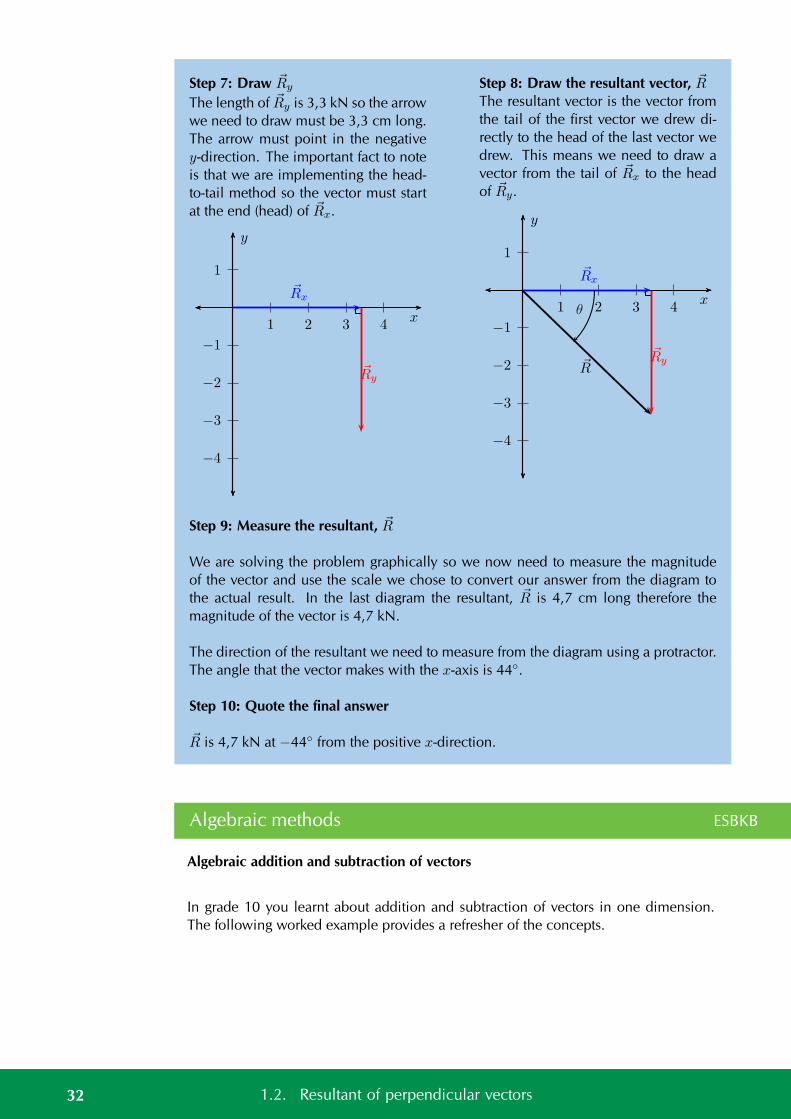
Step 7: Draw Ry
The length of Ry is 3,3 kN so the arrowwe need to draw must be 3,3 cm long.The arrow must point in the negativey-direction. The important fact to noteis that we are implementing the head-to-tail method so the vector must startat the end (head) of Rx.
1
−1
−2
−3
−4
1 2 3 4x
y
Rx
Ry
Step 8: Draw the resultant vector, RThe resultant vector is the vector fromthe tail of the first vector we drew di-rectly to the head of the last vector wedrew. This means we need to draw avector from the tail of Rx to the headof Ry.
1
−1
−2
−3
−4
1 2 3 4x
y
R
Rx
Ry
θ
Step 9: Measure the resultant, R
We are solving the problem graphically so we now need to measure the magnitudeof the vector and use the scale we chose to convert our answer from the diagram tothe actual result. In the last diagram the resultant, R is 4,7 cm long therefore themagnitude of the vector is 4,7 kN.
The direction of the resultant we need to measure from the diagram using a protractor.The angle that the vector makes with the x-axis is 44.
Step 10: Quote the final answer
R is 4,7 kN at −44 from the positive x-direction.
Algebraic methods ESBKB
Algebraic addition and subtraction of vectors
In grade 10 you learnt about addition and subtraction of vectors in one dimension.The following worked example provides a refresher of the concepts.
32 1.2. Resultant of perpendicular vectors
Worked example 9: Adding vectors algebraically
QUESTION
A force of 5 N to the right is applied to a crate. A second force of 2 N to the left is alsoapplied to the crate. Calculate algebraically the resultant of the forces applied to thecrate.
SOLUTION
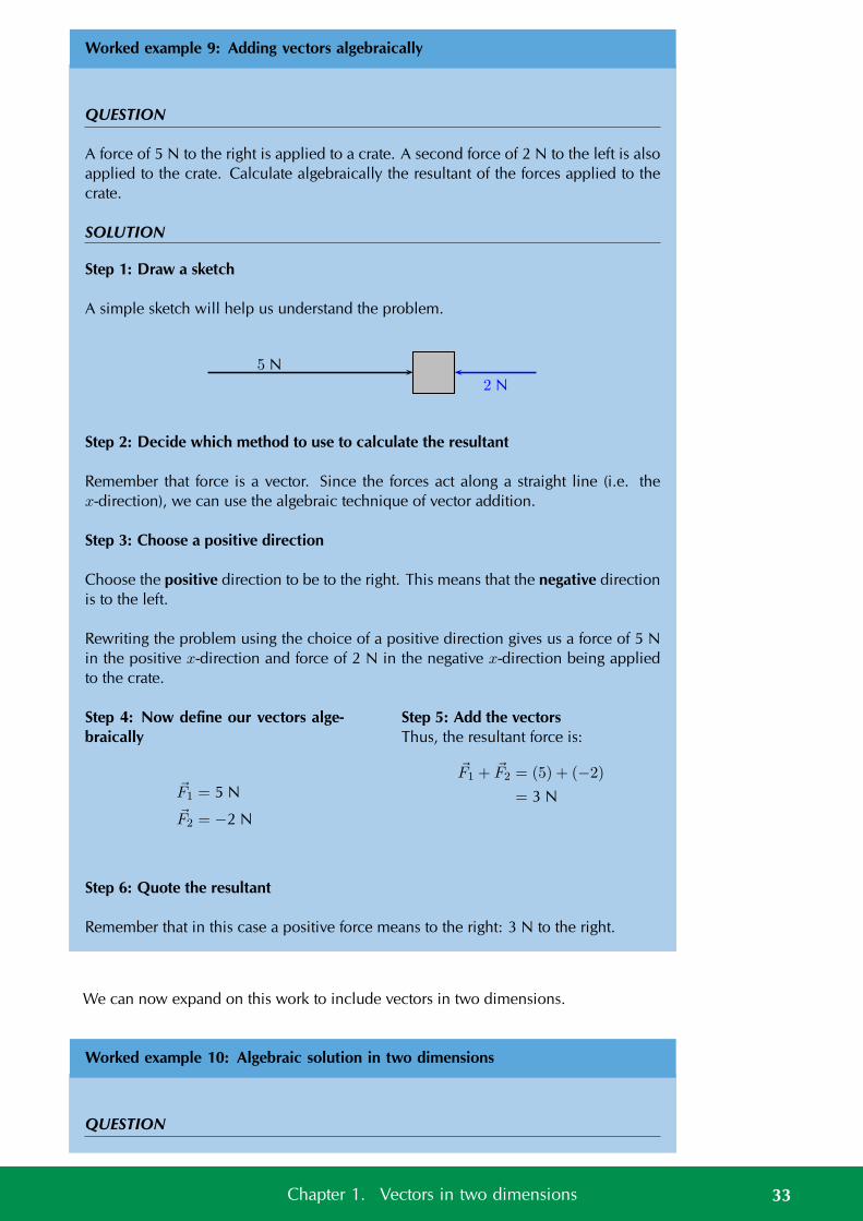
Step 1: Draw a sketch
A simple sketch will help us understand the problem.
5 N
2 N
Step 2: Decide which method to use to calculate the resultant
Remember that force is a vector. Since the forces act along a straight line (i.e. thex-direction), we can use the algebraic technique of vector addition.
Step 3: Choose a positive direction
Choose the positive direction to be to the right. This means that the negative directionis to the left.
Rewriting the problem using the choice of a positive direction gives us a force of 5 Nin the positive x-direction and force of 2 N in the negative x-direction being appliedto the crate.
Step 4: Now define our vectors alge-braically
F1 = 5 NF2 = −2 N
Step 5: Add the vectorsThus, the resultant force is:
F1 + F2 = (5) + (−2)
= 3 N
Step 6: Quote the resultant
Remember that in this case a positive force means to the right: 3 N to the right.
We can now expand on this work to include vectors in two dimensions.
Worked example 10: Algebraic solution in two dimensions
QUESTION
33Chapter 1. Vectors in two dimensions
A force of 40 N in the positive x-direction acts simultaneously (at the same time) toa force of 30 N in the positive y-direction. Calculate the magnitude of the resultantforce.
SOLUTION
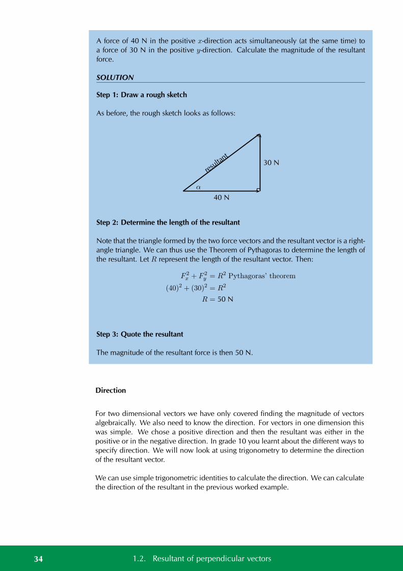
Step 1: Draw a rough sketch
As before, the rough sketch looks as follows:
resu
ltant
40 N
30 N
α
Step 2: Determine the length of the resultant
Note that the triangle formed by the two force vectors and the resultant vector is a right-angle triangle. We can thus use the Theorem of Pythagoras to determine the length ofthe resultant. Let R represent the length of the resultant vector. Then:
F 2x + F 2
y = R2 Pythagoras’ theorem
(40)2 + (30)2 = R2
R = 50 N
Step 3: Quote the resultant
The magnitude of the resultant force is then 50 N.
Direction
For two dimensional vectors we have only covered finding the magnitude of vectorsalgebraically. We also need to know the direction. For vectors in one dimension thiswas simple. We chose a positive direction and then the resultant was either in thepositive or in the negative direction. In grade 10 you learnt about the different ways tospecify direction. We will now look at using trigonometry to determine the directionof the resultant vector.
We can use simple trigonometric identities to calculate the direction. We can calculatethe direction of the resultant in the previous worked example.
34 1.2. Resultant of perpendicular vectors
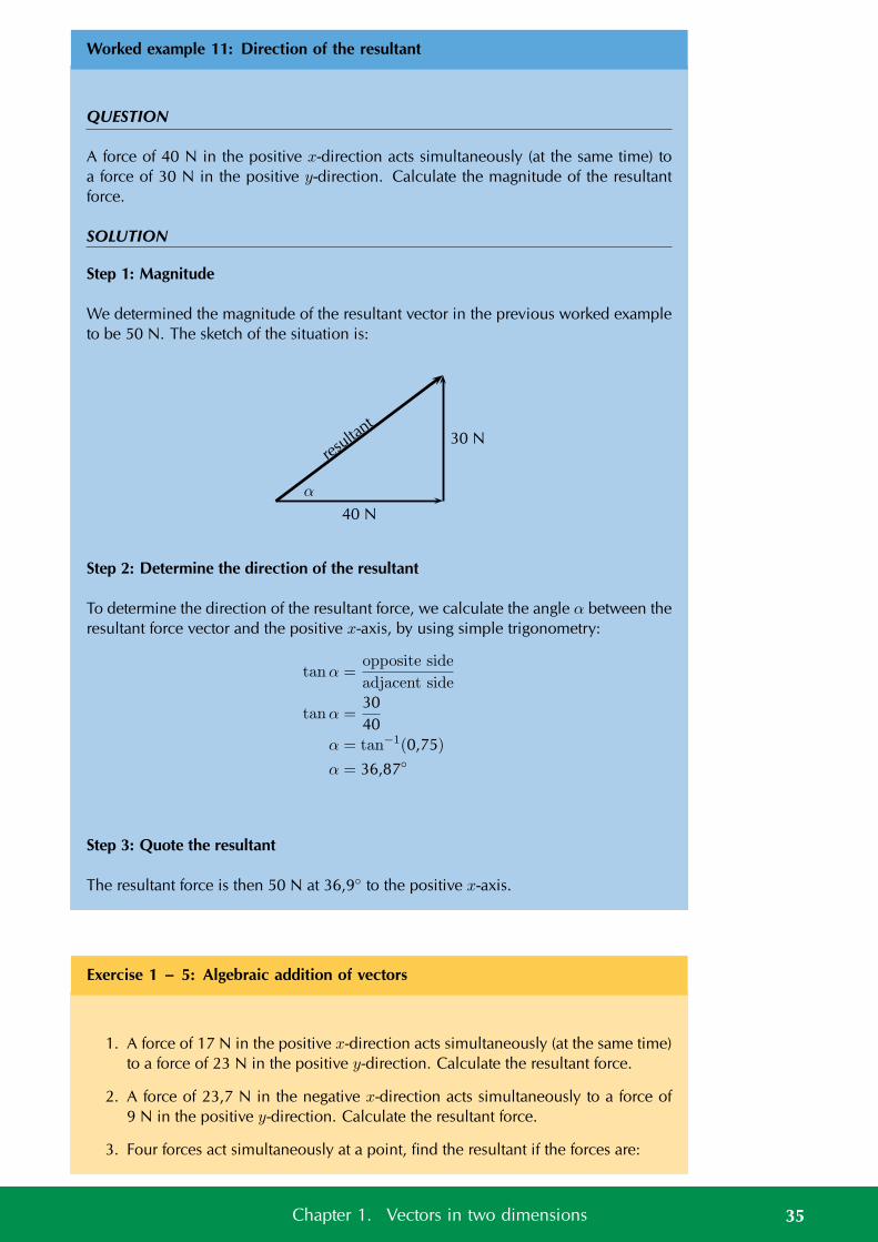
Worked example 11: Direction of the resultant
QUESTION
A force of 40 N in the positive x-direction acts simultaneously (at the same time) toa force of 30 N in the positive y-direction. Calculate the magnitude of the resultantforce.
SOLUTION
Step 1: Magnitude
We determined the magnitude of the resultant vector in the previous worked exampleto be 50 N. The sketch of the situation is:
resu
ltant
40 N
30 N
α
Step 2: Determine the direction of the resultant
To determine the direction of the resultant force, we calculate the angle α between theresultant force vector and the positive x-axis, by using simple trigonometry:
tanα =opposite side
adjacent side
tanα =3040
α = tan−1(0,75)
α = 36,87
Step 3: Quote the resultant
The resultant force is then 50 N at 36,9 to the positive x-axis.
Exercise 1 – 5: Algebraic addition of vectors
1. A force of 17 N in the positive x-direction acts simultaneously (at the same time)to a force of 23 N in the positive y-direction. Calculate the resultant force.
2. A force of 23,7 N in the negative x-direction acts simultaneously to a force of9 N in the positive y-direction. Calculate the resultant force.
3. Four forces act simultaneously at a point, find the resultant if the forces are:
35Chapter 1. Vectors in two dimensions
• F1 = 2,3 N in the positive x-direction
• F2 = 4 N in the positive y-direction
• F3 = 3,3 N in the negative y-direction
• F4 = 2,1 N in the negative y-direction
4. The following forces act simultaneously on a pole, if the pole suddenly snaps inwhich direction will it be pushed:
• F1 = 2,3 N in the negative x-direction
• F2 = 11,7 N in the negative y-direction
• F3 = 6,9 N in the negative y-direction
• F4 = 1,9 N in the negative y-direction
Think you got it? Get this answer and more practice on our Intelligent Practice Service
1. 23FN 2. 23FP 3. 23FQ 4. 23FR
www.everythingscience.co.za m.everythingscience.co.za
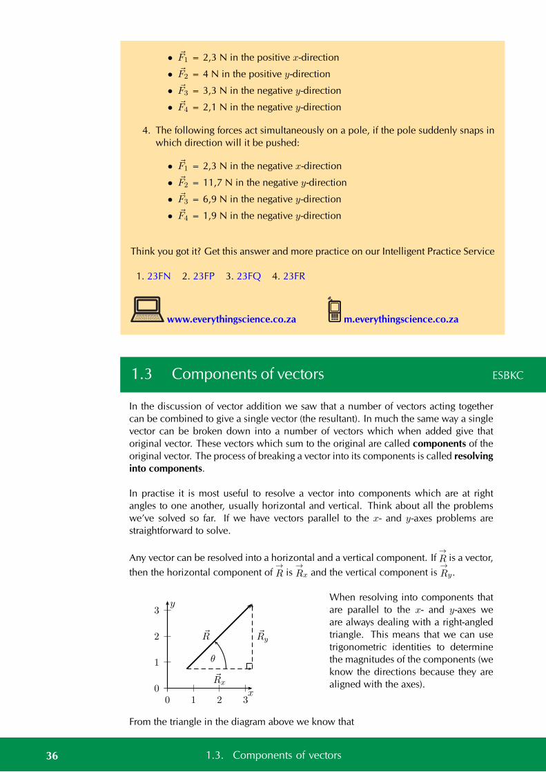
1.3 Components of vectors ESBKC
In the discussion of vector addition we saw that a number of vectors acting togethercan be combined to give a single vector (the resultant). In much the same way a singlevector can be broken down into a number of vectors which when added give thatoriginal vector. These vectors which sum to the original are called components of theoriginal vector. The process of breaking a vector into its components is called resolvinginto components.
In practise it is most useful to resolve a vector into components which are at rightangles to one another, usually horizontal and vertical. Think about all the problemswe’ve solved so far. If we have vectors parallel to the x- and y-axes problems arestraightforward to solve.
Any vector can be resolved into a horizontal and a vertical component. If→R is a vector,
then the horizontal component of→R is
→Rx and the vertical component is
→Ry.
x
y
0
1
2
3
0 1 2 3
R Ry
Rx
θ
When resolving into components thatare parallel to the x- and y-axes weare always dealing with a right-angledtriangle. This means that we can usetrigonometric identities to determinethe magnitudes of the components (weknow the directions because they arealigned with the axes).
From the triangle in the diagram above we know that
36 1.3. Components of vectors
cos(θ) =Rx
RRx
R= cos(θ)
Rx = R cos(θ)
and
sin θ =Ry
RRy
R= sin(θ)
Ry = R sin(θ)
Rx = R cos(θ)
Ry = R sin(θ)
Note that the angle is measured counter-clockwise from the positive x-axis.
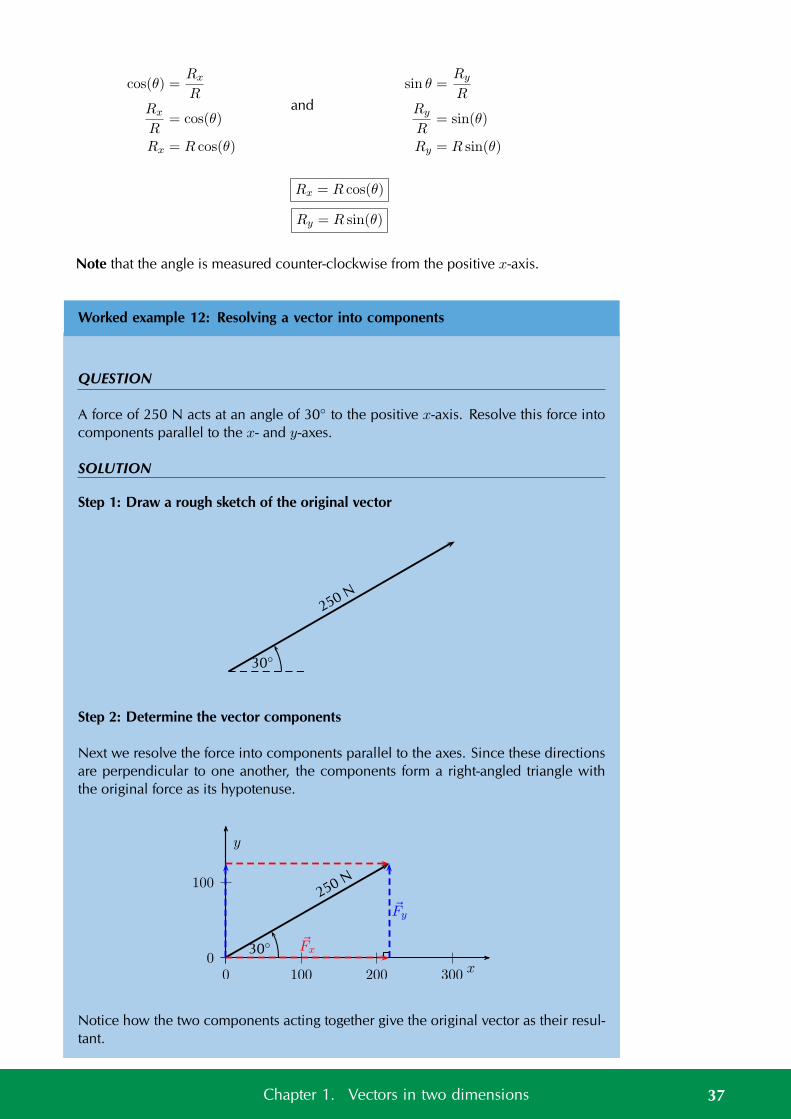
Worked example 12: Resolving a vector into components
QUESTION
A force of 250 N acts at an angle of 30 to the positive x-axis. Resolve this force intocomponents parallel to the x- and y-axes.
SOLUTION
Step 1: Draw a rough sketch of the original vector
250 N
30
Step 2: Determine the vector components
Next we resolve the force into components parallel to the axes. Since these directionsare perpendicular to one another, the components form a right-angled triangle withthe original force as its hypotenuse.
0
100
0 100 200 300
y
x
250 N
30 Fx
Fy
Notice how the two components acting together give the original vector as their resul-tant.
37Chapter 1. Vectors in two dimensions
Step 3: Determine the magnitudes of the component vectors
Now we can use trigonometry to calculate the magnitudes of the components of theoriginal displacement:
Fy = 250 sin(30)
= 125 Nand Fx = 250 cos(30)
= 216,5 N
Remember Fx and Fy are the magnitudes of the components. Fx is in the positivex-direction and Fy is in the positive y-direction.
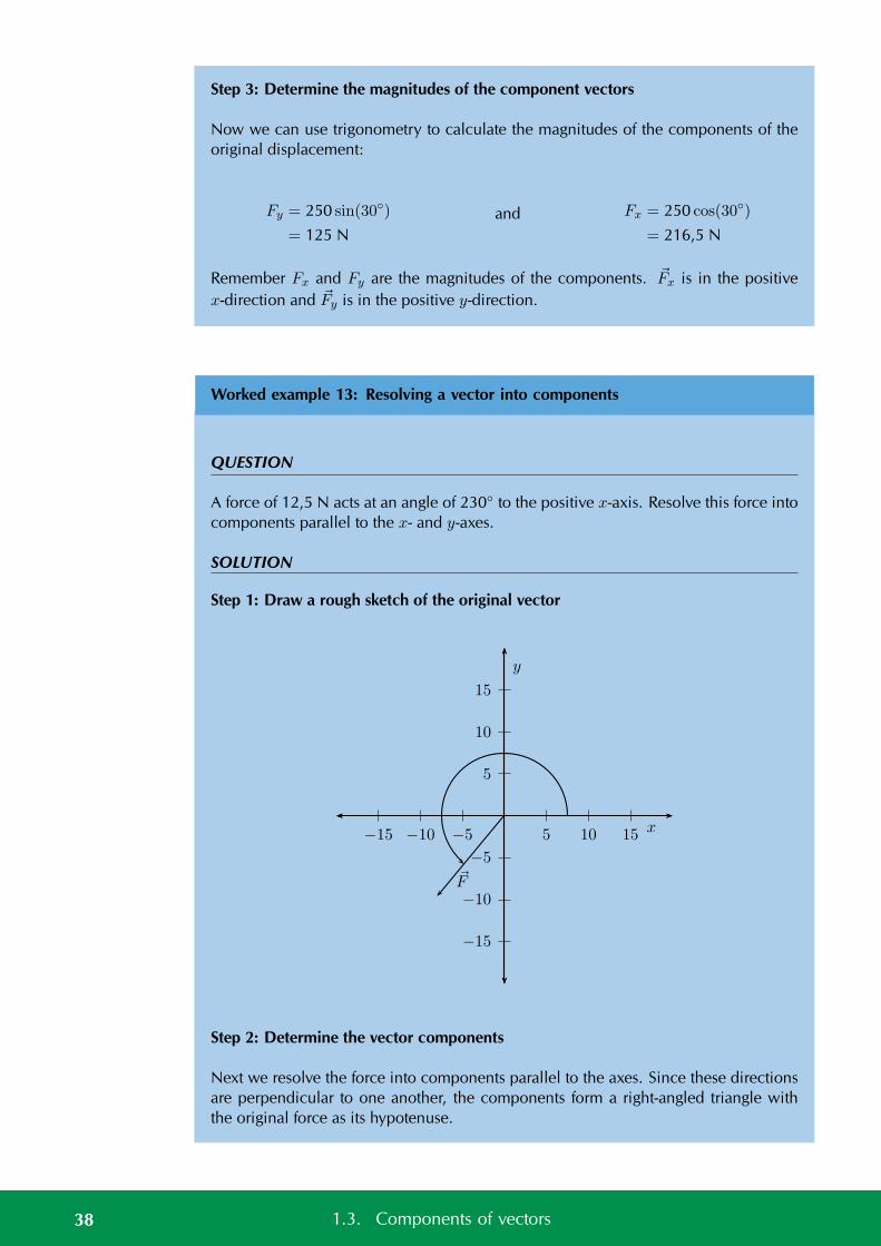
Worked example 13: Resolving a vector into components
QUESTION
A force of 12,5 N acts at an angle of 230 to the positive x-axis. Resolve this force intocomponents parallel to the x- and y-axes.
SOLUTION
Step 1: Draw a rough sketch of the original vector
5
10
15
−5
−10
−15
5 10 15−5−10−15 x
y
F
Step 2: Determine the vector components
Next we resolve the force into components parallel to the axes. Since these directionsare perpendicular to one another, the components form a right-angled triangle withthe original force as its hypotenuse.
38 1.3. Components of vectors
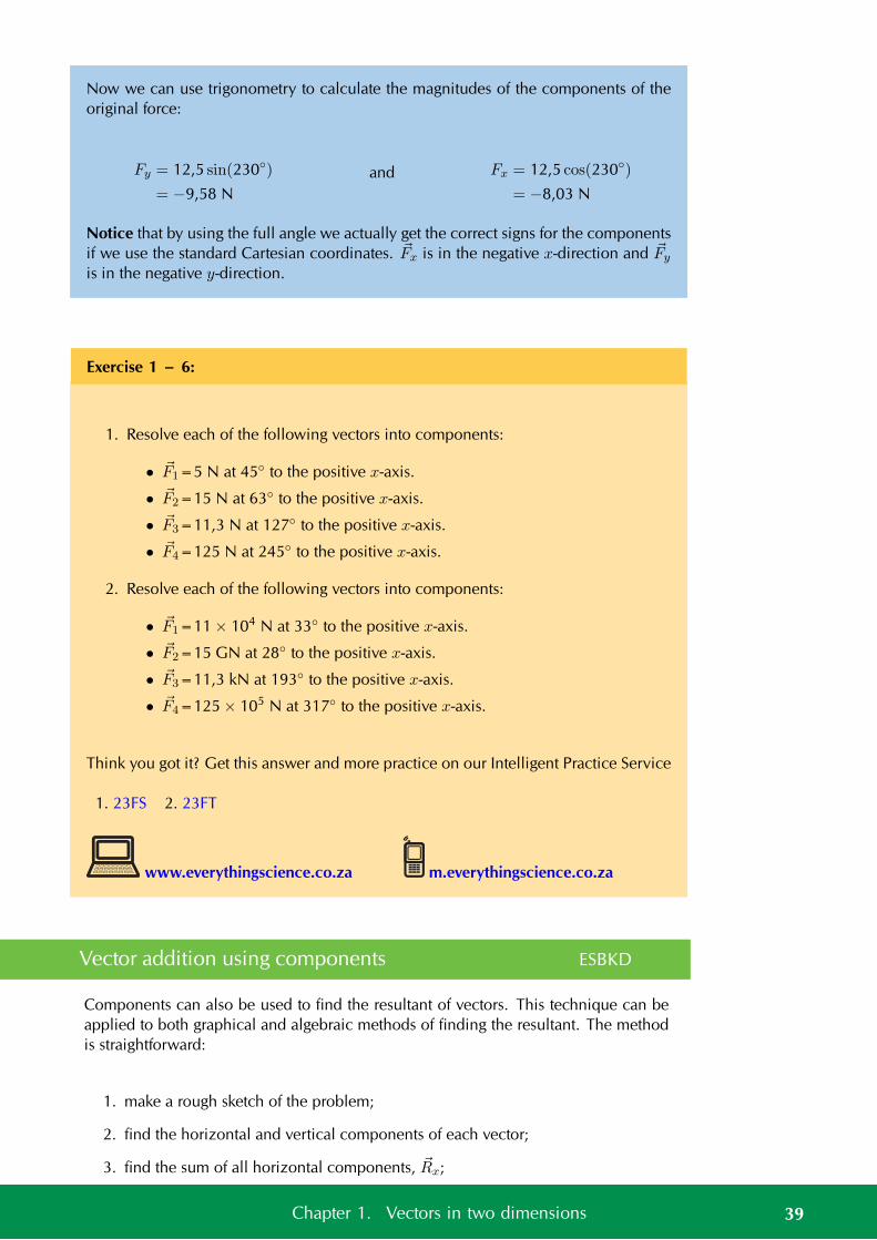
Now we can use trigonometry to calculate the magnitudes of the components of theoriginal force:
Fy = 12,5 sin(230)
= −9,58 Nand Fx = 12,5 cos(230)
= −8,03 N
Notice that by using the full angle we actually get the correct signs for the componentsif we use the standard Cartesian coordinates. Fx is in the negative x-direction and Fy
is in the negative y-direction.
Exercise 1 – 6:
1. Resolve each of the following vectors into components:
• F1=5 N at 45 to the positive x-axis.
• F2=15 N at 63 to the positive x-axis.
• F3=11,3 N at 127 to the positive x-axis.
• F4=125 N at 245 to the positive x-axis.
2. Resolve each of the following vectors into components:
• F1=11 × 104 N at 33 to the positive x-axis.
• F2=15 GN at 28 to the positive x-axis.
• F3=11,3 kN at 193 to the positive x-axis.
• F4=125 × 105 N at 317 to the positive x-axis.
Think you got it? Get this answer and more practice on our Intelligent Practice Service
1. 23FS 2. 23FT
www.everythingscience.co.za m.everythingscience.co.za
Vector addition using components ESBKD
Components can also be used to find the resultant of vectors. This technique can beapplied to both graphical and algebraic methods of finding the resultant. The methodis straightforward:
1. make a rough sketch of the problem;
2. find the horizontal and vertical components of each vector;
3. find the sum of all horizontal components, Rx;
39Chapter 1. Vectors in two dimensions
4. find the sum of all the vertical components, Ry;
5. then use them to find the resultant, R.
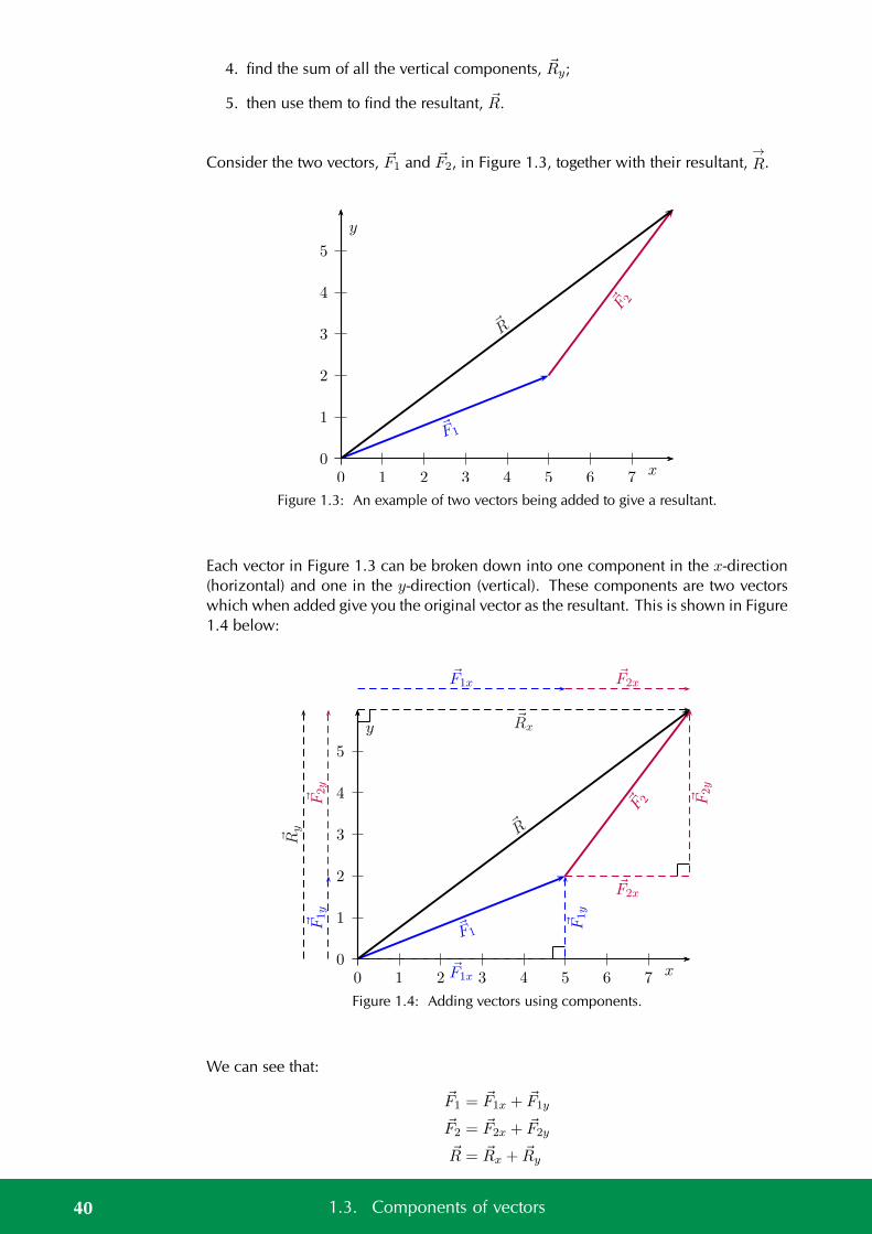
Consider the two vectors, F1 and F2, in Figure 1.3, together with their resultant,→R.
0
1
2
3
4
5
0 1 2 3 4 5 6 7 x
y
F1
F 2
R
Figure 1.3: An example of two vectors being added to give a resultant.
Each vector in Figure 1.3 can be broken down into one component in the x-direction(horizontal) and one in the y-direction (vertical). These components are two vectorswhich when added give you the original vector as the resultant. This is shown in Figure1.4 below:
0
1
2
3
4
5
0 1 2 3 4 5 6 7 x
y
F1
F1x
F1x
F1y
F1y
F 2
F2x
F2x
F2y
F2y
R
Rx
Ry
Figure 1.4: Adding vectors using components.
We can see that:
F1 = F1x + F1y
F2 = F2x + F2y
R = Rx + Ry
40 1.3. Components of vectors
But, Rx = F1x + F2x
and Ry = F1y + F2y
In summary, addition of the x-components of the two original vectors gives the x-component of the resultant. The same applies to the y-components. So if we justadded all the components together we would get the same answer! This is anotherimportant property of vectors.
Worked example 14: Adding vectors using components
QUESTION
If in Figure 1.4, F1=5,385 N at an angle of 21,8 to the horizontal and F2=5 N at anangle of 53,13 to the horizontal, find the resultant force, R.
SOLUTION
Step 1: Decide how to tackle the problem
The first thing we must realise is that the order that we add the vectors does not matter.Therefore, we can work through the vectors to be added in any order. We also drawup the following table to help us work through the problem:
Vector x-component y-component TotalF1
F2
Resultant
Step 2: Resolve F1 into components
We find the components of F1 by using known trigonometric ratios.
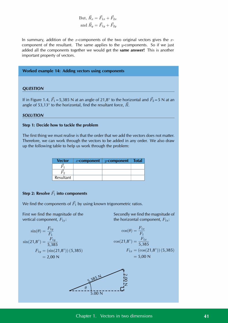
First we find the magnitude of thevertical component, F1y:
sin(θ) =F1y
F1
sin(21,8) =F1y
5,385F1y = (sin(21,8)) (5,385)
= 2,00 N
Secondly we find the magnitude ofthe horizontal component, F1x:
cos(θ) =F1x
F1
cos(21,8) =F1x
5,385F1x = (cos(21,8)) (5,385)
= 5,00 N
5,385 N
5.00 N
2.0
0N
θ
41Chapter 1. Vectors in two dimensions
The components give the sides of the right angle triangle, for which the original vector,F1, is the hypotenuse.
Vector x-component y-component ResultantF1 5,00 N 2,00 N 5,385 NF2
Resultant
Step 3: Resolve F2 into components
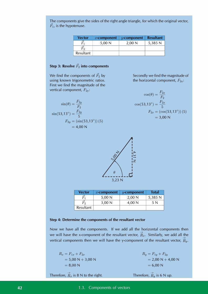
We find the components of F2 byusing known trigonometric ratios.First we find the magnitude of thevertical component, F2y:
sin(θ) =F2y
F2
sin(53,13) =F2y
5F2y = (sin(53,13)) (5)
= 4,00 N
Secondly we find the magnitude ofthe horizontal component, F2x:
cos(θ) =F2x
F2
cos(53,13) =F2x
5F2x = (cos(53,13)) (5)
= 3,00 N
5,00
N
3,23 N
4,3
1N
θ
Vector x-component y-component TotalF1 5,00 N 2,00 N 5,385 NF2 3,00 N 4,00 N 5 N
Resultant
Step 4: Determine the components of the resultant vector
Now we have all the components. If we add all the horizontal components then
we will have the x-component of the resultant vector,→Rx. Similarly, we add all the
vertical components then we will have the y-component of the resultant vector,→Ry.
Rx = F1x + F2x
= 5,00 N + 3,00 N
= 8,00 N
Therefore,→Rx is 8 N to the right.
Ry = F1y + F2y
= 2,00 N + 4,00 N
= 6,00 N
Therefore,→Ry is 6 N up.
42 1.3. Components of vectors
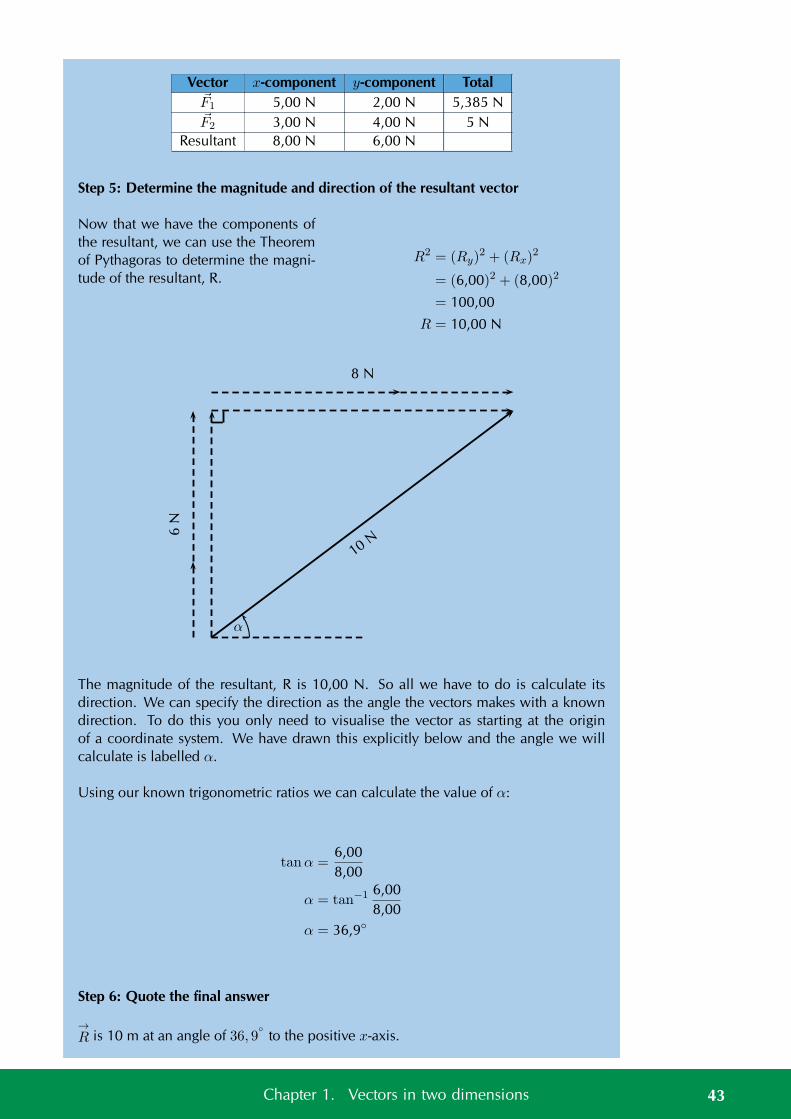
Vector x-component y-component TotalF1 5,00 N 2,00 N 5,385 NF2 3,00 N 4,00 N 5 N
Resultant 8,00 N 6,00 N
Step 5: Determine the magnitude and direction of the resultant vector
Now that we have the components ofthe resultant, we can use the Theoremof Pythagoras to determine the magni-tude of the resultant, R.
R2 = (Ry)2 + (Rx)
2
= (6,00)2 + (8,00)2
= 100,00
R = 10,00 N
10N
6N
8 N
α
The magnitude of the resultant, R is 10,00 N. So all we have to do is calculate itsdirection. We can specify the direction as the angle the vectors makes with a knowndirection. To do this you only need to visualise the vector as starting at the originof a coordinate system. We have drawn this explicitly below and the angle we willcalculate is labelled α.
Using our known trigonometric ratios we can calculate the value of α:
tanα =6,008,00
α = tan−1 6,008,00
α = 36,9
Step 6: Quote the final answer
→R is 10 m at an angle of 36, 9
to the positive x-axis.
43Chapter 1. Vectors in two dimensions
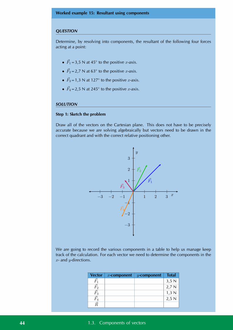
Worked example 15: Resultant using components
QUESTION
Determine, by resolving into components, the resultant of the following four forcesacting at a point:
• F1=3,5 N at 45 to the positive x-axis.
• F2=2,7 N at 63 to the positive x-axis.
• F3=1,3 N at 127 to the positive x-axis.
• F4=2,5 N at 245 to the positive x-axis.
SOLUTION
Step 1: Sketch the problem
Draw all of the vectors on the Cartesian plane. This does not have to be preciselyaccurate because we are solving algebraically but vectors need to be drawn in thecorrect quadrant and with the correct relative positioning other.
1
2
3
−1
−2
−3
1 2 3−1−2−3 x
y
F1
F2
F3
F4
We are going to record the various components in a table to help us manage keeptrack of the calculation. For each vector we need to determine the components in thex- and y-directions.
Vector x-component y-component TotalF1 3,5 NF2 2,7 NF3 1,3 NF4 2,5 NR
44 1.3. Components of vectors
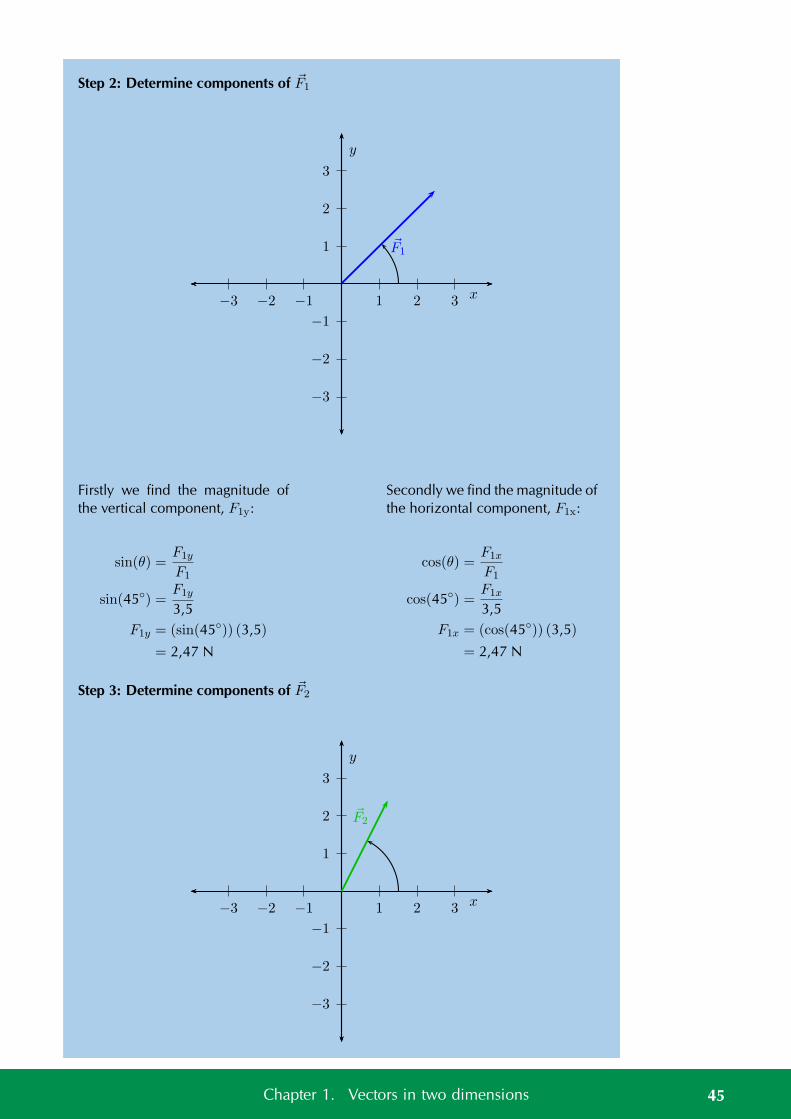
Step 2: Determine components of F1
1
2
3
−1
−2
−3
1 2 3−1−2−3 x
y
F1
Firstly we find the magnitude ofthe vertical component, F1y:
sin(θ) =F1y
F1
sin(45) =F1y
3,5F1y = (sin(45)) (3,5)
= 2,47 N
Secondly we find the magnitude ofthe horizontal component, F1x:
cos(θ) =F1x
F1
cos(45) =F1x
3,5F1x = (cos(45)) (3,5)
= 2,47 N
Step 3: Determine components of F2
1
2
3
−1
−2
−3
1 2 3−1−2−3 x
y
F2
45Chapter 1. Vectors in two dimensions
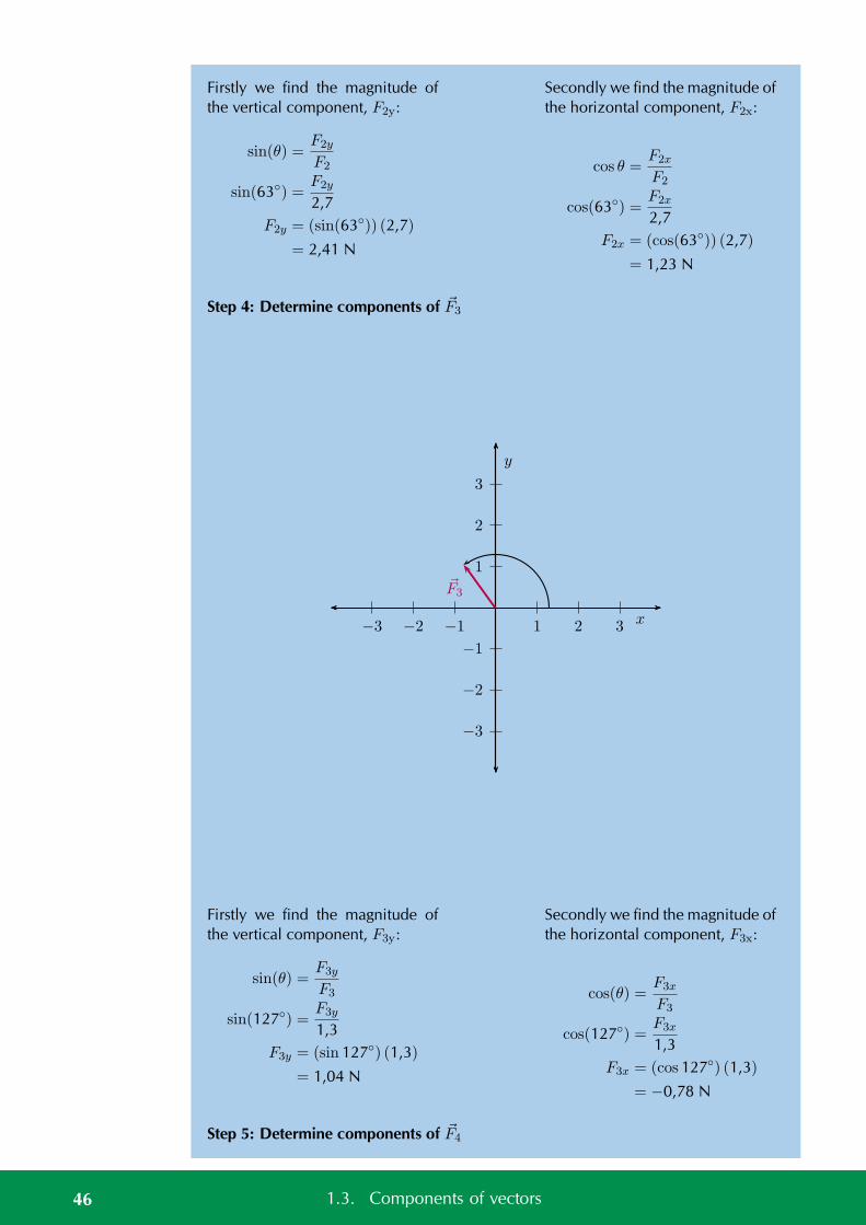
Firstly we find the magnitude ofthe vertical component, F2y:
sin(θ) =F2y
F2
sin(63) =F2y
2,7F2y = (sin(63)) (2,7)
= 2,41 N
Secondly we find the magnitude ofthe horizontal component, F2x:
cos θ =F2x
F2
cos(63) =F2x
2,7F2x = (cos(63)) (2,7)
= 1,23 N
Step 4: Determine components of F3
1
2
3
−1
−2
−3
1 2 3−1−2−3 x
y
F3
Firstly we find the magnitude ofthe vertical component, F3y:
sin(θ) =F3y
F3
sin(127) =F3y
1,3F3y = (sin 127) (1,3)
= 1,04 N
Secondly we find the magnitude ofthe horizontal component, F3x:
cos(θ) =F3x
F3
cos(127) =F3x
1,3F3x = (cos 127) (1,3)
= −0,78 N
Step 5: Determine components of F4
46 1.3. Components of vectors
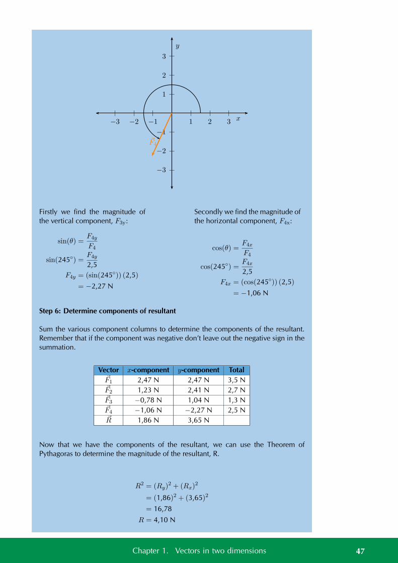
1
2
3
−1
−2
−3
1 2 3−1−2−3 x
y
F4
Firstly we find the magnitude ofthe vertical component, F3y:
sin(θ) =F4y
F4
sin(245) =F4y
2,5F4y = (sin(245)) (2,5)
= −2,27 N
Secondly we find the magnitude ofthe horizontal component, F4x:
cos(θ) =F4x
F4
cos(245) =F4x
2,5F4x = (cos(245)) (2,5)
= −1,06 N
Step 6: Determine components of resultant
Sum the various component columns to determine the components of the resultant.Remember that if the component was negative don’t leave out the negative sign in thesummation.
Vector x-component y-component TotalF1 2,47 N 2,47 N 3,5 NF2 1,23 N 2,41 N 2,7 NF3 −0,78 N 1,04 N 1,3 NF4 −1,06 N −2,27 N 2,5 NR 1,86 N 3,65 N
Now that we have the components of the resultant, we can use the Theorem ofPythagoras to determine the magnitude of the resultant, R.
R2 = (Ry)2 + (Rx)
2
= (1,86)2 + (3,65)2
= 16,78
R = 4,10 N
47Chapter 1. Vectors in two dimensions
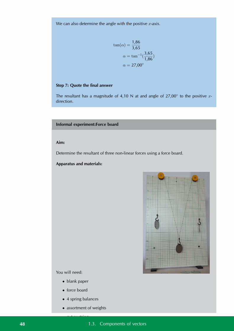
We can also determine the angle with the positive x-axis.
tan(α) =1,863,65
α = tan−1(3,651,86
)
α = 27,00
Step 7: Quote the final answer
The resultant has a magnitude of 4,10 N at and angle of 27,00 to the positive x-direction.
Informal experiment:Force board
Aim:
Determine the resultant of three non-linear forces using a force board.
Apparatus and materials:
You will need:
• blank paper
• force board
• 4 spring balances
• assortment of weights
• gut or string
• four pulleys48 1.3. Components of vectors
Method:
Before beginning the detailed method think about the strategy. By connecting a cord tothe ring, running it over a pulley and hanging weights off it you can get a force exertedon the ring. The more weights or heavier the weight you hang the greater the force.The force is in the direction of the cord. If you run a number of cords over pulleysyou are exerting more forces, all in different directions, on the ring. So we have asystem where we can change the magnitude and direction of the forces acting on thering. By putting a spring balance between the cord and the ring, we can measure theforce. Putting a piece of paper under the ring allows us to draw the directions and thereadings on the spring balances allows us to measure the magnitude.
We are going to use this information to measure the forces acting on the rings and thenwe can determine the resultants graphically.
1. Set up the forceboard and place a piece of paper under the ring.
2. Set up four different forces by connecting a spring balance to the ring on the oneside and some cord on the other side. Run the cord over a pulley and attachsome weights to it. Work in a group to do this effectively.
3. Draw a line along each cord being careful not to move any of them.
4. Make a note of the reading on each spring balance.
5. Now remove the paper.
6. Working on the paper, draw each line back towards the where the centre of thering had been. The lines should all intersect at a point. Make this point thecentre of your Cartesian coordinate system.
7. Now choose an appropriate scale to relate the length of arrows to the readingson the spring balances. Using the appropriate spring balance and correct line onthe paper, draw an arrow to represent each of the forces.
Results:
For two different choices of 3 of the force vectors we will determine the resultant. Todetermine the resultant we need to add the vectors together. The easiest way to do thisis to replicate the vectors using a ruler and protractor and draw them tail-to-head.
Conclusions and questions:
Note the direction and the magnitudes of the resultants of the various combinations.
1. How does the calculated resultant compare to the vector that wasn’t used tocalculate the resultant in each case?
2. What general relationship should exist between the resultant and the fourth vec-tor and why do you think this is the case?
3. Would this be the same if we had more or less forces in the problem? Justifyyour answer.
49Chapter 1. Vectors in two dimensions
See simulation: 23FV at www.everythingscience.co.za
See video: 23FW at www.everythingscience.co.za
1.4 Chapter summary ESBKF
See presentation: 23FX at www.everythingscience.co.za
• A vector has a magnitude and direction.
• Vectors can be used to represent many physical quantities that have a magnitudeand direction, like forces.
• Vectors may be represented as arrows where the length of the arrow indicatesthe magnitude and the arrowhead indicates the direction of the vector.
• Vectors in two dimensions can be drawn on the Cartesian plane.
• Vectors can be added graphically using the head-to-tail method or the tail-to-tailmethod.
• A closed vector diagram is a set of vectors drawn on the Cartesian using thetail-to-head method and that has a resultant with a magnitude of zero.
• Vectors can be added algebraically using Pythagoras’ theorem or using compo-nents.
• The direction of a vector can be found using simple trigonometric calculations.
• The components of a vector are a series of vectors that, when combined, givethe original vector as their resultant.
• Components are usually created that align with the Cartesian coordinate axes.For a vector F that makes an angle of θ with the positive x-axis the x-componentis Rx = R cos(θ) and the y-component is Ry = R sin(θ).
Exercise 1 – 7:
1. Draw the following forces as vectors on the Cartesian plane originating at theorigin:
• F1 = 3,7 N in the positive x-direction
• F2 = 4,9 N in the positive y-direction
2. Draw the following forces as vectors on the Cartesian plane:
• F1 = 4,3 N in the positive x-direction
• F2 = 1,7 N in the negative x-direction
• F3 = 8,3 N in the positive y-direction
3. Find the resultant in the x-direction, Rx, and y-direction, Ry for the followingforces:
50 1.4. Chapter summary
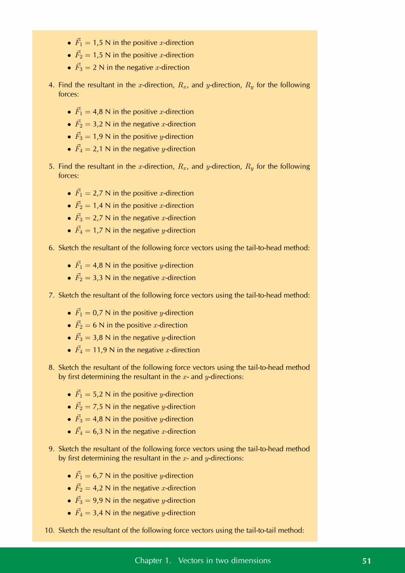
• F1 = 1,5 N in the positive x-direction
• F2 = 1,5 N in the positive x-direction
• F3 = 2 N in the negative x-direction
4. Find the resultant in the x-direction, Rx, and y-direction, Ry for the followingforces:
• F1 = 4,8 N in the positive x-direction
• F2 = 3,2 N in the negative x-direction
• F3 = 1,9 N in the positive y-direction
• F4 = 2,1 N in the negative y-direction
5. Find the resultant in the x-direction, Rx, and y-direction, Ry for the followingforces:
• F1 = 2,7 N in the positive x-direction
• F2 = 1,4 N in the positive x-direction
• F3 = 2,7 N in the negative x-direction
• F4 = 1,7 N in the negative y-direction
6. Sketch the resultant of the following force vectors using the tail-to-head method:
• F1 = 4,8 N in the positive y-direction
• F2 = 3,3 N in the negative x-direction
7. Sketch the resultant of the following force vectors using the tail-to-head method:
• F1 = 0,7 N in the positive y-direction
• F2 = 6 N in the positive x-direction
• F3 = 3,8 N in the negative y-direction
• F4 = 11,9 N in the negative x-direction
8. Sketch the resultant of the following force vectors using the tail-to-head methodby first determining the resultant in the x- and y-directions:
• F1 = 5,2 N in the positive y-direction
• F2 = 7,5 N in the negative y-direction
• F3 = 4,8 N in the positive y-direction
• F4 = 6,3 N in the negative x-direction
9. Sketch the resultant of the following force vectors using the tail-to-head methodby first determining the resultant in the x- and y-directions:
• F1 = 6,7 N in the positive y-direction
• F2 = 4,2 N in the negative x-direction
• F3 = 9,9 N in the negative y-direction
• F4 = 3,4 N in the negative y-direction
10. Sketch the resultant of the following force vectors using the tail-to-tail method:
51Chapter 1. Vectors in two dimensions
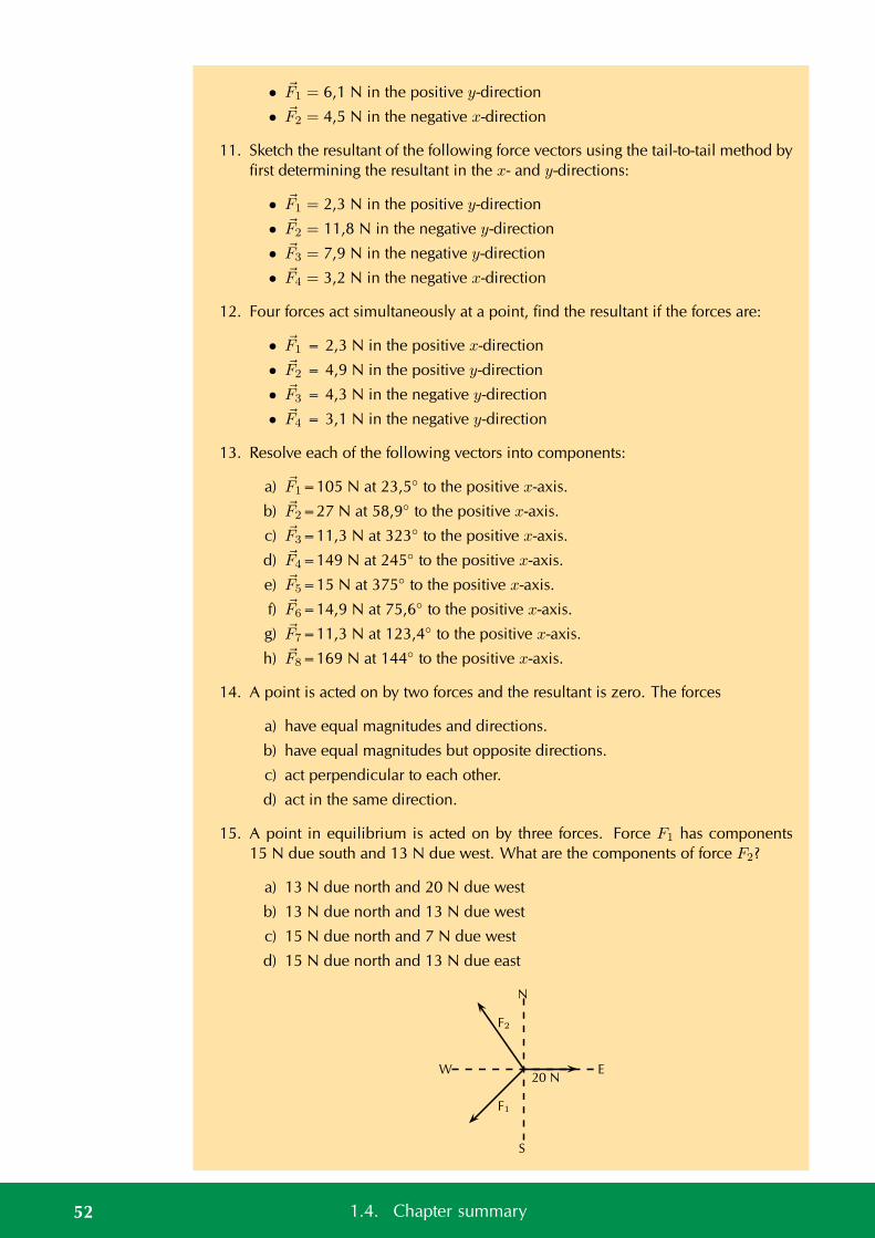
• F1 = 6,1 N in the positive y-direction
• F2 = 4,5 N in the negative x-direction
11. Sketch the resultant of the following force vectors using the tail-to-tail method byfirst determining the resultant in the x- and y-directions:
• F1 = 2,3 N in the positive y-direction
• F2 = 11,8 N in the negative y-direction
• F3 = 7,9 N in the negative y-direction
• F4 = 3,2 N in the negative x-direction
12. Four forces act simultaneously at a point, find the resultant if the forces are:
• F1 = 2,3 N in the positive x-direction
• F2 = 4,9 N in the positive y-direction
• F3 = 4,3 N in the negative y-direction
• F4 = 3,1 N in the negative y-direction
13. Resolve each of the following vectors into components:
a) F1=105 N at 23,5 to the positive x-axis.
b) F2=27 N at 58,9 to the positive x-axis.
c) F3=11,3 N at 323 to the positive x-axis.
d) F4=149 N at 245 to the positive x-axis.
e) F5=15 N at 375 to the positive x-axis.
f) F6=14,9 N at 75,6 to the positive x-axis.
g) F7=11,3 N at 123,4 to the positive x-axis.
h) F8=169 N at 144 to the positive x-axis.
14. A point is acted on by two forces and the resultant is zero. The forces
a) have equal magnitudes and directions.
b) have equal magnitudes but opposite directions.
c) act perpendicular to each other.
d) act in the same direction.
15. A point in equilibrium is acted on by three forces. Force F1 has components15 N due south and 13 N due west. What are the components of force F2?
a) 13 N due north and 20 N due west
b) 13 N due north and 13 N due west
c) 15 N due north and 7 N due west
d) 15 N due north and 13 N due east
N
W
S
E20 N
F2
F1
52 1.4. Chapter summary
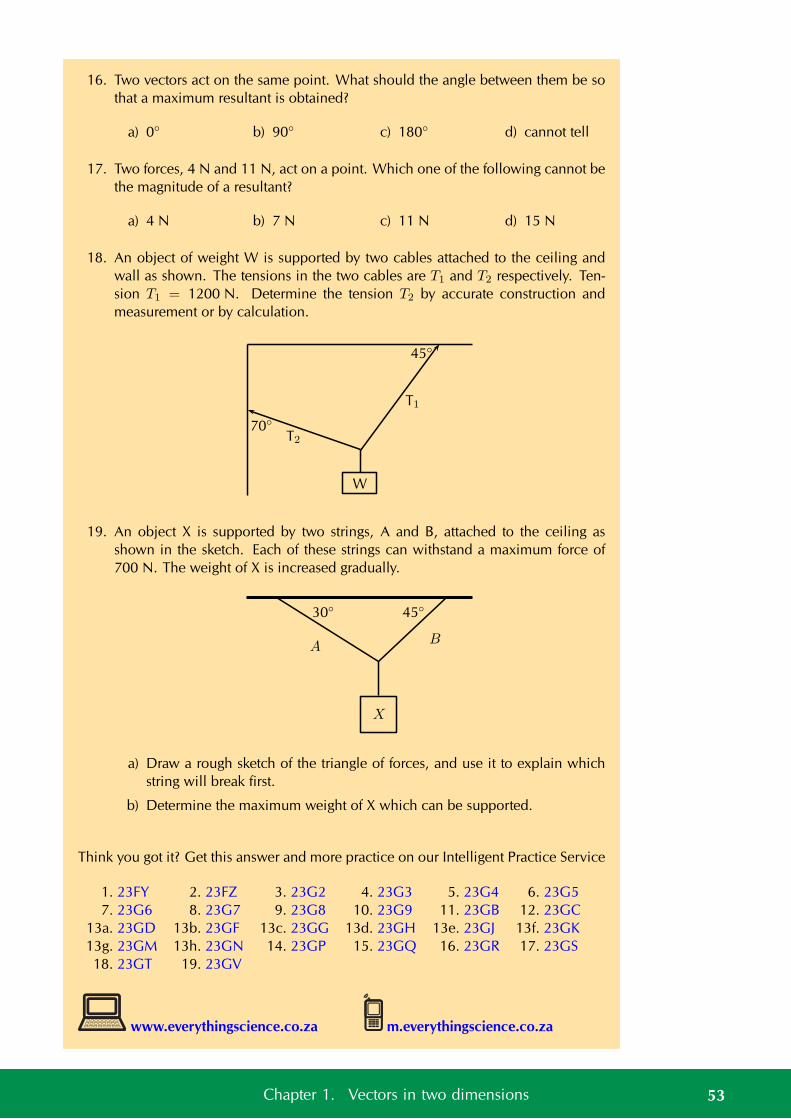
16. Two vectors act on the same point. What should the angle between them be sothat a maximum resultant is obtained?
a) 0 b) 90 c) 180 d) cannot tell
17. Two forces, 4 N and 11 N, act on a point. Which one of the following cannot bethe magnitude of a resultant?
a) 4 N b) 7 N c) 11 N d) 15 N
18. An object of weight W is supported by two cables attached to the ceiling andwall as shown. The tensions in the two cables are T1 and T2 respectively. Ten-sion T1 = 1200 N. Determine the tension T2 by accurate construction andmeasurement or by calculation.
T1
T2
W
45
70
19. An object X is supported by two strings, A and B, attached to the ceiling asshown in the sketch. Each of these strings can withstand a maximum force of700 N. The weight of X is increased gradually.
X
AB
4530
a) Draw a rough sketch of the triangle of forces, and use it to explain whichstring will break first.
b) Determine the maximum weight of X which can be supported.
Think you got it? Get this answer and more practice on our Intelligent Practice Service
1. 23FY 2. 23FZ 3. 23G2 4. 23G3 5. 23G4 6. 23G57. 23G6 8. 23G7 9. 23G8 10. 23G9 11. 23GB 12. 23GC
13a. 23GD 13b. 23GF 13c. 23GG 13d. 23GH 13e. 23GJ 13f. 23GK13g. 23GM 13h. 23GN 14. 23GP 15. 23GQ 16. 23GR 17. 23GS18. 23GT 19. 23GV
www.everythingscience.co.za m.everythingscience.co.za
53Chapter 1. Vectors in two dimensions

CHAPTER 2
Newton’s laws
2.1 Introduction 56
2.2 Force 56
2.3 Newton’s laws 74
2.4 Forces between masses 109
2.5 Chapter summary 119
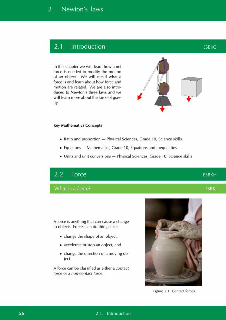
2 Newton’s laws
2.1 Introduction ESBKG
In this chapter we will learn how a netforce is needed to modify the motionof an object. We will recall what aforce is and learn about how force andmotion are related. We are also intro-duced to Newton’s three laws and wewill learn more about the force of grav-ity.
Key Mathematics Concepts
• Ratio and proportion — Physical Sciences, Grade 10, Science skills
• Equations — Mathematics, Grade 10, Equations and inequalities
• Units and unit conversions — Physical Sciences, Grade 10, Science skills
2.2 Force ESBKH
What is a force? ESBKJ
A force is anything that can cause a changeto objects. Forces can do things like:
• change the shape of an object,
• accelerate or stop an object, and
• change the direction of a moving ob-ject.
A force can be classified as either a contactforce or a non-contact force.
Figure 2.1: Contact forces
56 2.1. Introduction
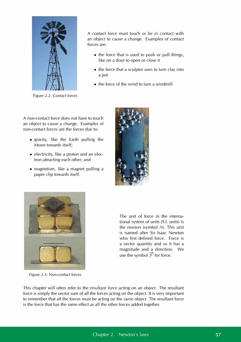
Figure 2.2: Contact forces
A contact force must touch or be in contact withan object to cause a change. Examples of contactforces are:
• the force that is used to push or pull things,like on a door to open or close it
• the force that a sculptor uses to turn clay intoa pot
• the force of the wind to turn a windmill
A non-contact force does not have to touchan object to cause a change. Examples ofnon-contact forces are the forces due to:
• gravity, like the Earth pulling theMoon towards itself;
• electricity, like a proton and an elec-tron attracting each other; and
• magnetism, like a magnet pulling apaper clip towards itself.
Figure 2.3: Non-contact forces
The unit of force in the interna-tional system of units (S.I. units) isthe newton (symbol N). This unitis named after Sir Isaac Newtonwho first defined force. Force isa vector quantity and so it has amagnitude and a direction. Weuse the symbol
−→F for force.
This chapter will often refer to the resultant force acting on an object. The resultantforce is simply the vector sum of all the forces acting on the object. It is very importantto remember that all the forces must be acting on the same object. The resultant forceis the force that has the same effect as all the other forces added together.
57Chapter 2. Newton’s laws

Different types of forces in physics ESBKK
A lot of the physics topics you will study revolvearound the impact or effect of forces. Althoughthere are many different forces, will learn some fun-damental principles for approaching the problemsand applications in this book no matter which forceapplies
Physics is the study of the natural world and youprobably know a lot more physics than you think.You see things happening everyday that are gov-erned by the laws of physics but you probably aren’tthinking about physics at the time. If you throw astone up in the air it eventually falls to the ground.A lot of physics can be learnt by analysing an every-day situation.
We are going to learn about some forces in the nextfew sections but before we start lets describe an ev-eryday situation in which they all play a role so youcan visualise what is happening. You need a ta-ble and a three books that all have different masses.Take any book and put it on the table. Nothing hap-pens, the book just rests on the table if the table isflat. If you slowly lift one side of the table so that thetop of the table is tilted the book doesn’t move im-mediately. As you lift the table more and more thebook suddenly starts to slide off the table. You canrepeat this with all three books and see how muchyou have to tilt the table before the books start toslide.
This real world situation illustrates a lot of thephysics we want to learn about in this chapter.
The normal force
58 2.2. Force
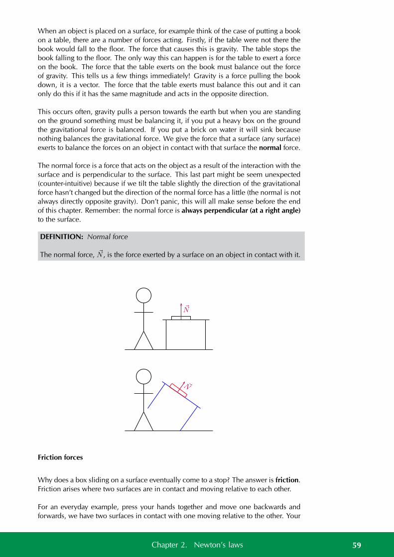
When an object is placed on a surface, for example think of the case of putting a bookon a table, there are a number of forces acting. Firstly, if the table were not there thebook would fall to the floor. The force that causes this is gravity. The table stops thebook falling to the floor. The only way this can happen is for the table to exert a forceon the book. The force that the table exerts on the book must balance out the forceof gravity. This tells us a few things immediately! Gravity is a force pulling the bookdown, it is a vector. The force that the table exerts must balance this out and it canonly do this if it has the same magnitude and acts in the opposite direction.
This occurs often, gravity pulls a person towards the earth but when you are standingon the ground something must be balancing it, if you put a heavy box on the groundthe gravitational force is balanced. If you put a brick on water it will sink becausenothing balances the gravitational force. We give the force that a surface (any surface)exerts to balance the forces on an object in contact with that surface the normal force.
The normal force is a force that acts on the object as a result of the interaction with thesurface and is perpendicular to the surface. This last part might be seem unexpected(counter-intuitive) because if we tilt the table slightly the direction of the gravitationalforce hasn’t changed but the direction of the normal force has a little (the normal is notalways directly opposite gravity). Don’t panic, this will all make sense before the endof this chapter. Remember: the normal force is always perpendicular (at a right angle)to the surface.
DEFINITION: Normal force
The normal force, N , is the force exerted by a surface on an object in contact with it.
N
N
Friction forces
Why does a box sliding on a surface eventually come to a stop? The answer is friction.Friction arises where two surfaces are in contact and moving relative to each other.
For an everyday example, press your hands together and move one backwards andforwards, we have two surfaces in contact with one moving relative to the other. Your
59Chapter 2. Newton’s laws
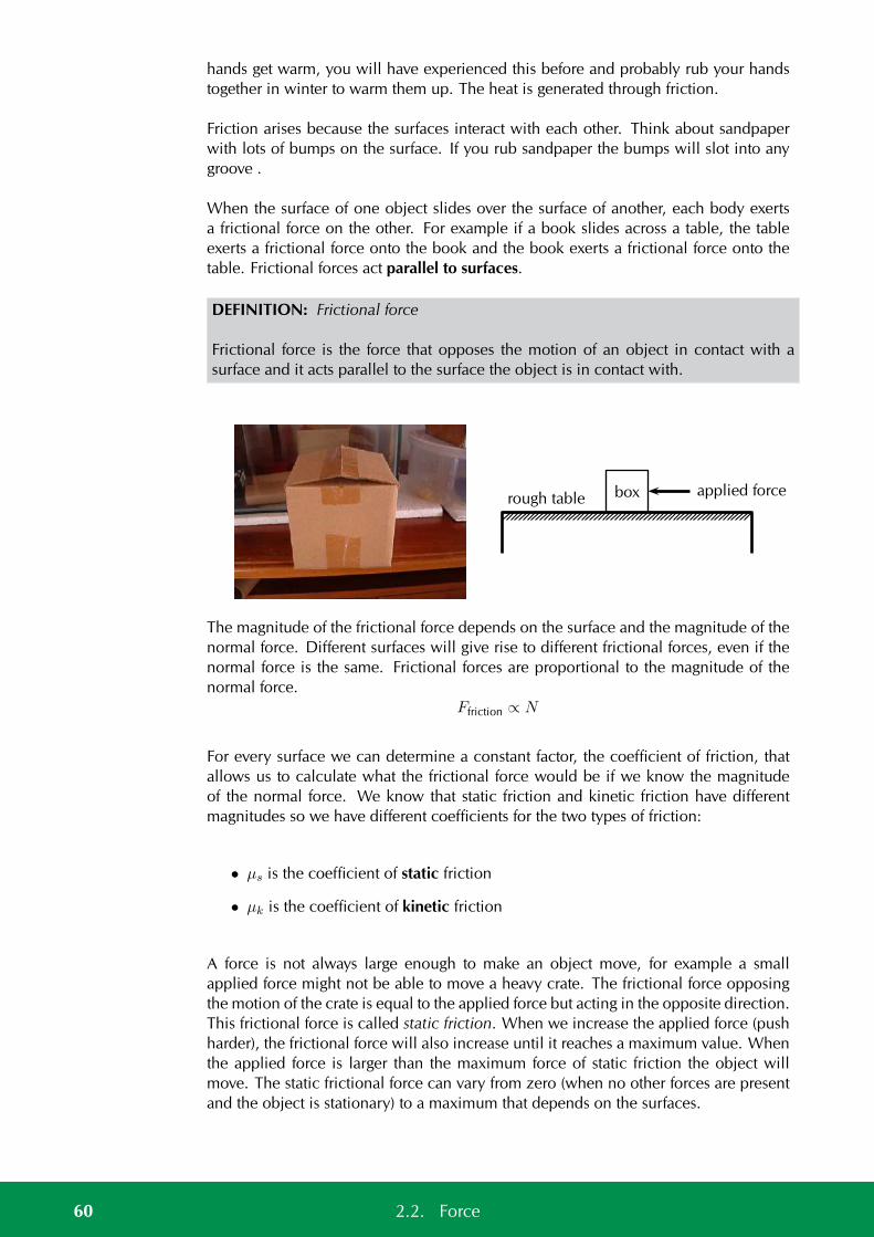
hands get warm, you will have experienced this before and probably rub your handstogether in winter to warm them up. The heat is generated through friction.
Friction arises because the surfaces interact with each other. Think about sandpaperwith lots of bumps on the surface. If you rub sandpaper the bumps will slot into anygroove .
When the surface of one object slides over the surface of another, each body exertsa frictional force on the other. For example if a book slides across a table, the tableexerts a frictional force onto the book and the book exerts a frictional force onto thetable. Frictional forces act parallel to surfaces.
DEFINITION: Frictional force
Frictional force is the force that opposes the motion of an object in contact with asurface and it acts parallel to the surface the object is in contact with.
boxrough tableapplied force
The magnitude of the frictional force depends on the surface and the magnitude of thenormal force. Different surfaces will give rise to different frictional forces, even if thenormal force is the same. Frictional forces are proportional to the magnitude of thenormal force.
Ffriction ∝ N
For every surface we can determine a constant factor, the coefficient of friction, thatallows us to calculate what the frictional force would be if we know the magnitudeof the normal force. We know that static friction and kinetic friction have differentmagnitudes so we have different coefficients for the two types of friction:
• µs is the coefficient of static friction
• µk is the coefficient of kinetic friction
A force is not always large enough to make an object move, for example a smallapplied force might not be able to move a heavy crate. The frictional force opposingthe motion of the crate is equal to the applied force but acting in the opposite direction.This frictional force is called static friction. When we increase the applied force (pushharder), the frictional force will also increase until it reaches a maximum value. Whenthe applied force is larger than the maximum force of static friction the object willmove. The static frictional force can vary from zero (when no other forces are presentand the object is stationary) to a maximum that depends on the surfaces.
60 2.2. Force
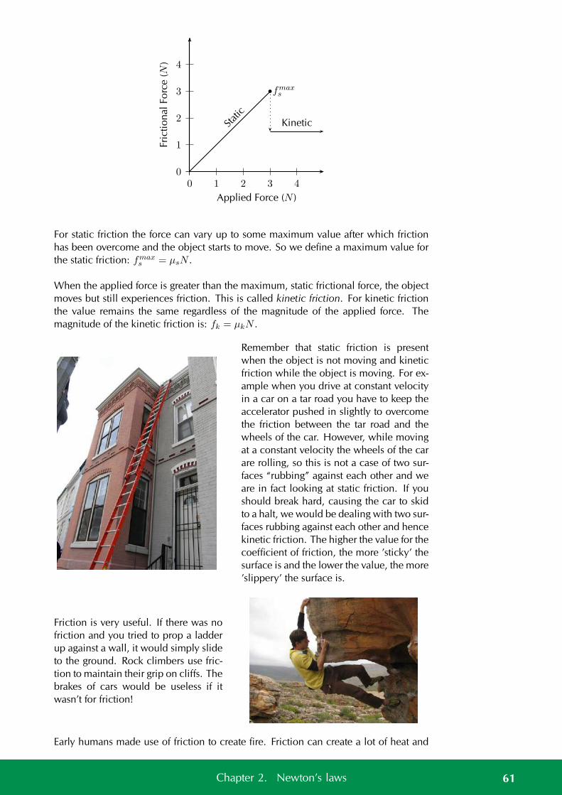
0
1
2
3
4
0 1 2 3 4
Applied Force (N )
Fric
tio
nalFo
rce
(N)
Static
Kinetic
fmaxs
For static friction the force can vary up to some maximum value after which frictionhas been overcome and the object starts to move. So we define a maximum value forthe static friction: fmax
s = µsN .
When the applied force is greater than the maximum, static frictional force, the objectmoves but still experiences friction. This is called kinetic friction. For kinetic frictionthe value remains the same regardless of the magnitude of the applied force. Themagnitude of the kinetic friction is: fk = µkN .
Remember that static friction is presentwhen the object is not moving and kineticfriction while the object is moving. For ex-ample when you drive at constant velocityin a car on a tar road you have to keep theaccelerator pushed in slightly to overcomethe friction between the tar road and thewheels of the car. However, while movingat a constant velocity the wheels of the carare rolling, so this is not a case of two sur-faces “rubbing” against each other and weare in fact looking at static friction. If youshould break hard, causing the car to skidto a halt, we would be dealing with two sur-faces rubbing against each other and hencekinetic friction. The higher the value for thecoefficient of friction, the more ’sticky’ thesurface is and the lower the value, the more’slippery’ the surface is.
Friction is very useful. If there was nofriction and you tried to prop a ladderup against a wall, it would simply slideto the ground. Rock climbers use fric-tion to maintain their grip on cliffs. Thebrakes of cars would be useless if itwasn’t for friction!
Early humans made use of friction to create fire. Friction can create a lot of heat and
61Chapter 2. Newton’s laws
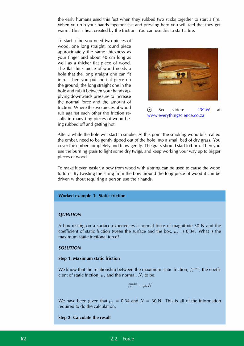
the early humans used this fact when they rubbed two sticks together to start a fire.When you rub your hands together fast and pressing hard you will feel that they getwarm. This is heat created by the friction. You can use this to start a fire.
To start a fire you need two pieces ofwood, one long straight, round pieceapproximately the same thickness asyour finger and about 40 cm long aswell as a thicker flat piece of wood.The flat thick piece of wood needs ahole that the long straight one can fitinto. Then you put the flat piece onthe ground, the long straight one in thehole and rub it between your hands ap-plying downwards pressure to increasethe normal force and the amount offriction. Where the two pieces of woodrub against each other the friction re-sults in many tiny pieces of wood be-ing rubbed off and getting hot.
See video: 23GW atwww.everythingscience.co.za
After a while the hole will start to smoke. At this point the smoking wood bits, calledthe ember, need to be gently tipped out of the hole into a small bed of dry grass. Youcover the ember completely and blow gently. The grass should start to burn. Then youuse the burning grass to light some dry twigs, and keep working your way up to biggerpieces of wood.
To make it even easier, a bow from wood with a string can be used to cause the woodto turn. By twisting the string from the bow around the long piece of wood it can bedriven without requiring a person use their hands.
Worked example 1: Static friction
QUESTION
A box resting on a surface experiences a normal force of magnitude 30 N and thecoefficient of static friction tween the surface and the box, µs, is 0,34. What is themaximum static frictional force?
SOLUTION
Step 1: Maximum static friction
We know that the relationship between the maximum static friction, fmaxs , the coeffi-
cient of static friction, µs and the normal, N , to be:
fmaxs = µsN
We have been given that µs = 0,34 and N = 30 N. This is all of the informationrequired to do the calculation.
Step 2: Calculate the result
62 2.2. Force
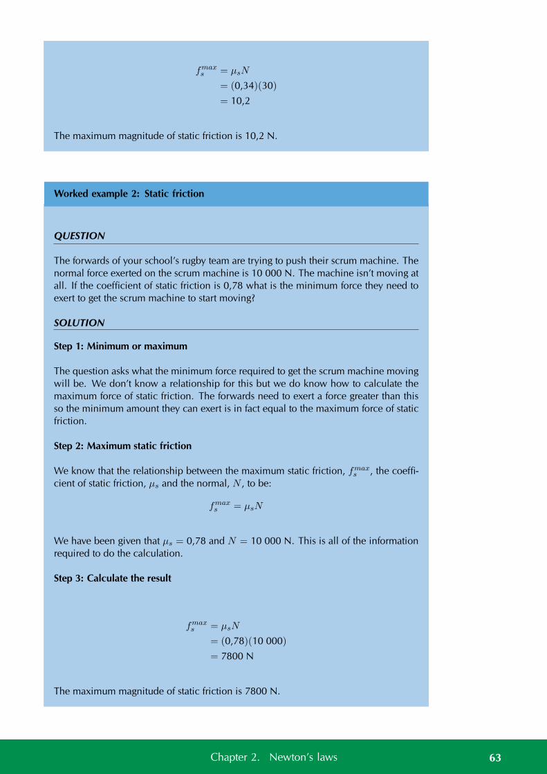
fmaxs = µsN
= (0,34)(30)
= 10,2
The maximum magnitude of static friction is 10,2 N.
Worked example 2: Static friction
QUESTION
The forwards of your school’s rugby team are trying to push their scrum machine. Thenormal force exerted on the scrum machine is 10 000 N. The machine isn’t moving atall. If the coefficient of static friction is 0,78 what is the minimum force they need toexert to get the scrum machine to start moving?
SOLUTION
Step 1: Minimum or maximum
The question asks what the minimum force required to get the scrum machine movingwill be. We don’t know a relationship for this but we do know how to calculate themaximum force of static friction. The forwards need to exert a force greater than thisso the minimum amount they can exert is in fact equal to the maximum force of staticfriction.
Step 2: Maximum static friction
We know that the relationship between the maximum static friction, fmaxs , the coeffi-
cient of static friction, µs and the normal, N , to be:
fmaxs = µsN
We have been given that µs = 0,78 and N = 10 000 N. This is all of the informationrequired to do the calculation.
Step 3: Calculate the result
fmaxs = µsN
= (0,78)(10 000)
= 7800 N
The maximum magnitude of static friction is 7800 N.
63Chapter 2. Newton’s laws
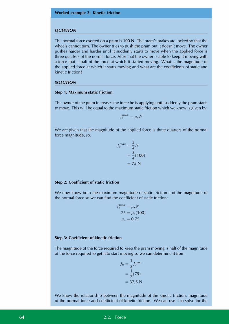
Worked example 3: Kinetic friction
QUESTION
The normal force exerted on a pram is 100 N. The pram’s brakes are locked so that thewheels cannot turn. The owner tries to push the pram but it doesn’t move. The ownerpushes harder and harder until it suddenly starts to move when the applied force isthree quarters of the normal force. After that the owner is able to keep it moving witha force that is half of the force at which it started moving. What is the magnitude ofthe applied force at which it starts moving and what are the coefficients of static andkinetic friction?
SOLUTION
Step 1: Maximum static friction
The owner of the pram increases the force he is applying until suddenly the pram startsto move. This will be equal to the maximum static friction which we know is given by:
fmaxs = µsN
We are given that the magnitude of the applied force is three quarters of the normalforce magnitude, so:
fmaxs =
34N
=34(100)
= 75 N
Step 2: Coefficient of static friction
We now know both the maximum magnitude of static friction and the magnitude ofthe normal force so we can find the coefficient of static friction:
fmaxs = µsN
75 = µs(100)
µs = 0,75
Step 3: Coefficient of kinetic friction
The magnitude of the force required to keep the pram moving is half of the magnitudeof the force required to get it to start moving so we can determine it from:
fk =12fmaxs
=12(75)
= 37,5 N
We know the relationship between the magnitude of the kinetic friction, magnitudeof the normal force and coefficient of kinetic friction. We can use it to solve for the
64 2.2. Force
coefficient of kinetic friction:
fk = µkN
37,5 = µk(100)
µk = 0,375
Worked example 4: Coefficient of static friction
QUESTION
A block of wood experiences a normal force of 32 N from a rough, flat surface. Thereis a rope tied to the block. The rope is pulled parallel to the surface and the tension(force) in the rope can be increased to 8 N before the block starts to slide. Determinethe coefficient of static friction.
SOLUTION
Step 1: Analyse the question and determine what is asked
The normal force is given (32 N) and we know that the block does not move until theapplied force is 8 N.
We are asked to find the coefficient for static friction µs.
Step 2: Find the coefficient of static friction
Ff = µsN
8 = µs(32)
µs = 0,25
Note that the coefficient of friction does not have a unit as it shows a ratio. The valuefor the coefficient of friction friction can have any value up to a maximum of 0,25.When a force less than 8 N is applied, the coefficient of friction will be less than0,25.
Worked example 5: Static friction
QUESTION
A box resting on an inclined plane experiences a normal force of magnitude 130 Nand the coefficient of static friction, µs, between the box and the surface is 0,47. What
65Chapter 2. Newton’s laws
is the maximum static frictional force?
SOLUTION
Step 1: Maximum static friction
We know that the relationship between the maximum static friction, fmaxs , the coeffi-
cient of static friction, µs and the normal, N , to be:
fmaxs = µsN.
This does not depend on whether the surface is inclined or not. Changing the incli-nation of the surface will affect the magnitude of the normal force but the method ofdetermining the frictional force remains the same.
We have been given that µs = 0,47 and N = 130 N. This is all of the informationrequired to do the calculation.
Step 2: Calculate the result
fmaxs = µsN
= (0,47)(130)
= 61,1 N
The maximum magnitude of static friction is 61,1 N.
Informal experiment:Normal forces and friction
Aim:
To investigate the relationship between normal force and friction.
Apparatus:
Spring balance, several blocks, of the same material, with hooks attached to one end,several rough and smooth surfaces, bricks or blocks to incline the surfaces
Method:
• Attach each of the blocks to the spring balance in turn and note the reading.
• Take one block and attach it to the spring balance. Now slide the block alongeach of the surfaces in turn. Note the readings. Repeat for the other blocks.
• Repeat the above step but incline the surfaces at different angles.
Results:
66 2.2. Force
Record your results in a table
Tension
Tension is the magnitude of the force that exists in objects like ropes, chains andstruts that are providing support. For example, there are tension forces in the ropessupporting a child’s swing hanging from a tree.
Exercise 2 – 1:
1. A box is placed on a rough surface. It has a normal force of magnitude 120 N. Aforce of 20 N applied to the right cannot move the box. Calculate the magnitudeand direction of the friction forces.
2. A block rests on a horizontal surface. The normal force is 20 N. The coefficientof static friction between the block and the surface is 0,40 and the coefficient ofdynamic friction is 0,20.
a) What is the magnitude of the frictional force exerted on the block while theblock is at rest?
b) What will the magnitude of the frictional force be if a horizontal force ofmagnitude 5 N is exerted on the block?
c) What is the minimum force required to start the block moving?
d) What is the minimum force required to keep the block in motion once ithas been started?
e) If the horizontal force is 10 N, determine the frictional force.
3. A lady injured her back when she slipped and fell in a supermarket. She holdsthe owner of the supermarket accountable for her medical expenses. The ownerclaims that the floor covering was not wet and meets the accepted standards.He therefore cannot accept responsibility. The matter eventually ends up incourt. Before passing judgement, the judge approaches you, a science student,to determine whether the coefficient of static friction of the floor is a minimumof 0,5 as required. He provides you with a tile from the floor, as well as one ofthe shoes the lady was wearing on the day of the incident.
a) Write down an expression for the coefficient of static friction.
b) Plan an investigation that you will perform to assist the judge in his judge-ment. Follow the steps outlined below to ensure that your plan meets therequirements.
i. Formulate an investigation question.ii. Apparatus: List all the other apparatus, except the tile and the shoe,
that you will need.iii. A stepwise method: How will you perform the investigation? Include
a relevant, labelled diagram.iv. Results: What will you record?v. Conclusion: How will you interpret the results to draw a conclusion?
67Chapter 2. Newton’s laws
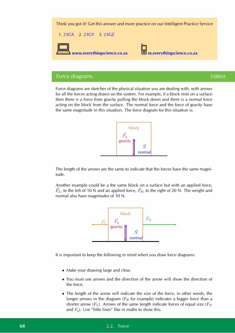
Think you got it? Get this answer and more practice on our Intelligent Practice Service
1. 23GX 2. 23GY 3. 23GZ
www.everythingscience.co.za m.everythingscience.co.za
Force diagrams ESBKM
Force diagrams are sketches of the physical situation you are dealing with, with arrowsfor all the forces acting drawn on the system. For example, if a block rests on a surfacethen there is a force from gravity pulling the block down and there is a normal forceacting on the block from the surface. The normal force and the force of gravity havethe same magnitude in this situation. The force diagram for this situation is:
Fg
gravityN
normal
block
The length of the arrows are the same to indicate that the forces have the same magni-tude.
Another example could be a the same block on a surface but with an applied force,FL, to the left of 10 N and an applied force, FR, to the right of 20 N. The weight andnormal also have magnitudes of 10 N.
Fg
gravityN
normal
block
FL
FR
It is important to keep the following in mind when you draw force diagrams:
• Make your drawing large and clear.
• You must use arrows and the direction of the arrow will show the direction ofthe force.
• The length of the arrow will indicate the size of the force, in other words, thelonger arrows in the diagram (FR for example) indicates a bigger force than ashorter arrow (FL). Arrows of the same length indicate forces of equal size (FN
and Fg). Use “little lines” like in maths to show this.
68 2.2. Force
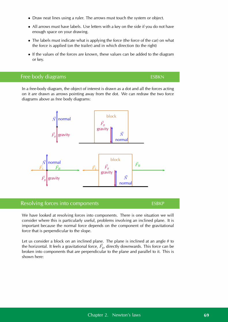
• Draw neat lines using a ruler. The arrows must touch the system or object.
• All arrows must have labels. Use letters with a key on the side if you do not haveenough space on your drawing.
• The labels must indicate what is applying the force (the force of the car) on whatthe force is applied (on the trailer) and in which direction (to the right)
• If the values of the forces are known, these values can be added to the diagramor key.
Free body diagrams ESBKN
In a free-body diagram, the object of interest is drawn as a dot and all the forces actingon it are drawn as arrows pointing away from the dot. We can redraw the two forcediagrams above as free body diagrams:
Fg
N
gravity
normalFg
gravityN
normal
block
Fg
N
gravity
normalFL
FRFg
gravityN
normal
block
FL
FR
Resolving forces into components ESBKP
We have looked at resolving forces into components. There is one situation we willconsider where this is particularly useful, problems involving an inclined plane. It isimportant because the normal force depends on the component of the gravitationalforce that is perpendicular to the slope.
Let us consider a block on an inclined plane. The plane is inclined at an angle θ tothe horizontal. It feels a gravitational force, Fg, directly downwards. This force can bebroken into components that are perpendicular to the plane and parallel to it. This isshown here:
69Chapter 2. Newton’s laws
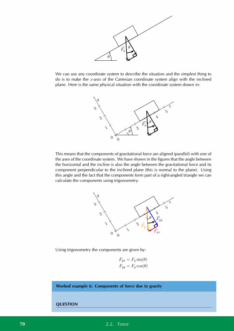
θ
θFg
We can use any coordinate system to describe the situation and the simplest thing todo is to make the x-axis of the Cartesian coordinate system align with the inclinedplane. Here is the same physical situation with the coordinate system drawn in:
0
1
2
3
0
1
2
3
4
5
x
y
θ
θFg
This means that the components of gravitational force are aligned (parallel) with one ofthe axes of the coordinate system. We have shown in the figures that the angle betweenthe horizontal and the incline is also the angle between the gravitational force and itscomponent perpendicular to the inclined plane (this is normal to the plane). Usingthis angle and the fact that the components form part of a right-angled triangle we cancalculate the components using trigonometry:
0
1
2
3
0
1
2
3
4
5
x
y
θ
Fg
Fgx
Fgy
Using trigonometry the components are given by:
Fgx = Fg sin(θ)
Fgy = Fg cos(θ)
Worked example 6: Components of force due to gravity
QUESTION
70 2.2. Force
A block on an inclined plane experiences a force due to gravity, Fg of 137 N straightdown. If the slope is inclined at 37 to the horizontal, what is the component of theforce due to gravity perpendicular and parallel to the slope?
SOLUTION
Step 1: Components
We know that for a block on a slope we can resolve the force due to gravity, Fg intocomponents parallel and perpendicular to the slope.
Fgx = Fg sin(θ)
Fgy = Fg cos(θ)
Step 2: Calculations
This problem is straightforward as we know that the slope is inclined at an angle of37. This is the same angle we need to use to calculate the components, therefore:
Fgx = Fg sin(θ)
= (137) sin(37)
= 82,45 N
Fgy = Fg cos(θ)
= (137) cos(37)
= 109,41 N
Step 3: Final answer
The component of Fg that is perpendicular to the slope is Fgy=109,41 N in the nega-tive y-direction.
The component of Fg that is perpendicular to the slope is Fgx=82,45 N in the negativex-direction.
Exercise 2 – 2:
1. A block on an inclined plane experiences a force due to gravity, Fg of 456 Nstraight down. If the slope is inclined at 67,8 to the horizontal, what is thecomponent of the force due to gravity perpendicular and parallel to the slope?
2. A block on an inclined plane is subjected to a force due to gravity, Fg of 456 Nstraight down. If the component of the gravitational force parallel to the slope isFgx=308,7 N in the negative x-direction (down the slope), what is the inclineof the slope?
Think you got it? Get this answer and more practice on our Intelligent Practice Service
1. 23H2 2. 23H3
71Chapter 2. Newton’s laws
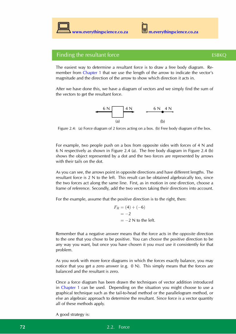
www.everythingscience.co.za m.everythingscience.co.za
Finding the resultant force ESBKQ
The easiest way to determine a resultant force is to draw a free body diagram. Re-member from Chapter 1 that we use the length of the arrow to indicate the vector’smagnitude and the direction of the arrow to show which direction it acts in.
After we have done this, we have a diagram of vectors and we simply find the sum ofthe vectors to get the resultant force.
6 N 4 N
(a)
6 N 4 N
(b)
Figure 2.4: (a) Force diagram of 2 forces acting on a box. (b) Free body diagram of the box.
For example, two people push on a box from opposite sides with forces of 4 N and6 N respectively as shown in Figure 2.4 (a). The free body diagram in Figure 2.4 (b)shows the object represented by a dot and the two forces are represented by arrowswith their tails on the dot.
As you can see, the arrows point in opposite directions and have different lengths. Theresultant force is 2 N to the left. This result can be obtained algebraically too, sincethe two forces act along the same line. First, as in motion in one direction, choose aframe of reference. Secondly, add the two vectors taking their directions into account.
For the example, assume that the positive direction is to the right, then:
FR = (4) + (−6)
= −2
= −2 N to the left.
Remember that a negative answer means that the force acts in the opposite directionto the one that you chose to be positive. You can choose the positive direction to beany way you want, but once you have chosen it you must use it consistently for thatproblem.
As you work with more force diagrams in which the forces exactly balance, you maynotice that you get a zero answer (e.g. 0 N). This simply means that the forces arebalanced and the resultant is zero.
Once a force diagram has been drawn the techniques of vector addition introducedin Chapter 1 can be used. Depending on the situation you might choose to use agraphical technique such as the tail-to-head method or the parallelogram method, orelse an algebraic approach to determine the resultant. Since force is a vector quantityall of these methods apply.
A good strategy is:
72 2.2. Force
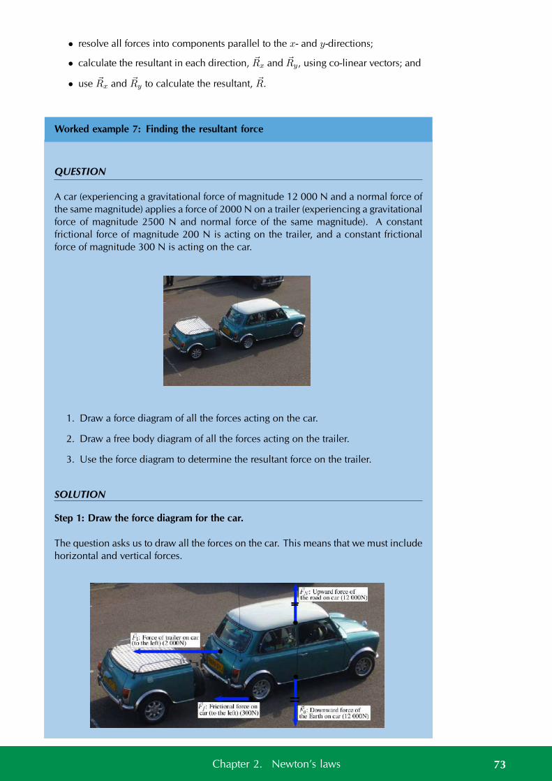
• resolve all forces into components parallel to the x- and y-directions;
• calculate the resultant in each direction, Rx and Ry, using co-linear vectors; and
• use Rx and Ry to calculate the resultant, R.
Worked example 7: Finding the resultant force
QUESTION
A car (experiencing a gravitational force of magnitude 12 000 N and a normal force ofthe same magnitude) applies a force of 2000 N on a trailer (experiencing a gravitationalforce of magnitude 2500 N and normal force of the same magnitude). A constantfrictional force of magnitude 200 N is acting on the trailer, and a constant frictionalforce of magnitude 300 N is acting on the car.
1. Draw a force diagram of all the forces acting on the car.
2. Draw a free body diagram of all the forces acting on the trailer.
3. Use the force diagram to determine the resultant force on the trailer.
SOLUTION
Step 1: Draw the force diagram for the car.
The question asks us to draw all the forces on the car. This means that we must includehorizontal and vertical forces.
73Chapter 2. Newton’s laws
Step 2: Determine the resultant force on the trailer.
To find the resultant force we need to add all the horizontal forces together. We donot add vertical forces as the movement of the car and trailer will be in a horizontaldirection, and not up or down. FR = 2000 + (−200) = 1800N to the right.
See simulation: 23H4 at www.everythingscience.co.za
Exercise 2 – 3: Forces and motion
1. A boy pushes a shopping trolley (weight due to gravity of 150 N) with a constantforce of 75 N. A constant frictional force of 20 N is present.
a) Draw a labelled force diagram to identify all the forces acting on the shop-ping trolley.
b) Draw a free body diagram of all the forces acting on the trolley.
c) Determine the resultant force on the trolley.
2. A donkey (experiencing a gravitational force of 2500 N) is trying to pull a cart(force due to gravity of 800 N) with a force of 400 N. The rope between thedonkey and the cart makes an angle of 30 with the cart. The cart does notmove.
a) Draw a free body diagram of all the forces acting on the donkey.
b) Draw a force diagram of all the forces acting on the cart.
c) Find the magnitude and direction of the frictional force preventing the cartfrom moving.
Think you got it? Get this answer and more practice on our Intelligent Practice Service
1. 23H5 2. 23H6
www.everythingscience.co.za m.everythingscience.co.za
2.3 Newton’s laws ESBKR
In this section we will look at the effect of forces on objects and how we can makethings move. This will link together what you have learnt about motion and what youhave learnt about forces.
74 2.3. Newton’s laws
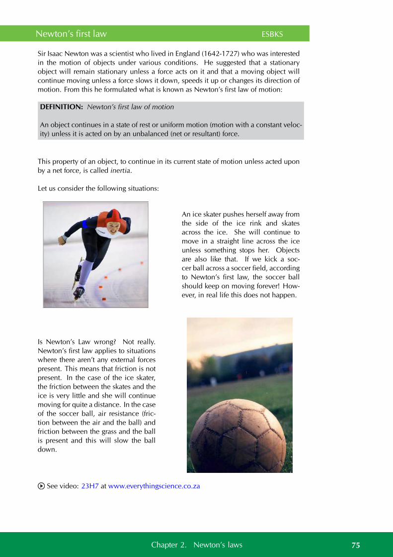
Newton’s first law ESBKS
Sir Isaac Newton was a scientist who lived in England (1642-1727) who was interestedin the motion of objects under various conditions. He suggested that a stationaryobject will remain stationary unless a force acts on it and that a moving object willcontinue moving unless a force slows it down, speeds it up or changes its direction ofmotion. From this he formulated what is known as Newton’s first law of motion:
DEFINITION: Newton’s first law of motion
An object continues in a state of rest or uniform motion (motion with a constant veloc-ity) unless it is acted on by an unbalanced (net or resultant) force.
This property of an object, to continue in its current state of motion unless acted uponby a net force, is called inertia.
Let us consider the following situations:
An ice skater pushes herself away fromthe side of the ice rink and skatesacross the ice. She will continue tomove in a straight line across the iceunless something stops her. Objectsare also like that. If we kick a soc-cer ball across a soccer field, accordingto Newton’s first law, the soccer ballshould keep on moving forever! How-ever, in real life this does not happen.
Is Newton’s Law wrong? Not really.Newton’s first law applies to situationswhere there aren’t any external forcespresent. This means that friction is notpresent. In the case of the ice skater,the friction between the skates and theice is very little and she will continuemoving for quite a distance. In the caseof the soccer ball, air resistance (fric-tion between the air and the ball) andfriction between the grass and the ballis present and this will slow the balldown.
See video: 23H7 at www.everythingscience.co.za
75Chapter 2. Newton’s laws
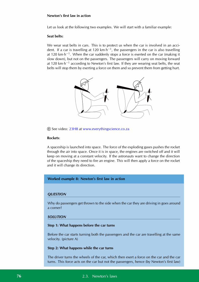
Newton’s first law in action
Let us look at the following two examples. We will start with a familiar example:
Seat belts:
We wear seat belts in cars. This is to protect us when the car is involved in an acci-dent. If a car is travelling at 120 km·h−1, the passengers in the car is also travellingat 120 km·h−1. When the car suddenly stops a force is exerted on the car (making itslow down), but not on the passengers. The passengers will carry on moving forwardat 120 km·h−1 according to Newton’s first law. If they are wearing seat belts, the seatbelts will stop them by exerting a force on them and so prevent them from getting hurt.
See video: 23H8 at www.everythingscience.co.za
Rockets:
A spaceship is launched into space. The force of the exploding gases pushes the rocketthrough the air into space. Once it is in space, the engines are switched off and it willkeep on moving at a constant velocity. If the astronauts want to change the directionof the spaceship they need to fire an engine. This will then apply a force on the rocketand it will change its direction.
Worked example 8: Newton’s first law in action
QUESTION
Why do passengers get thrown to the side when the car they are driving in goes arounda corner?
SOLUTION
Step 1: What happens before the car turns
Before the car starts turning both the passengers and the car are travelling at the samevelocity. (picture A)
Step 2: What happens while the car turns
The driver turns the wheels of the car, which then exert a force on the car and the carturns. This force acts on the car but not the passengers, hence (by Newton’s first law)
76 2.3. Newton’s laws
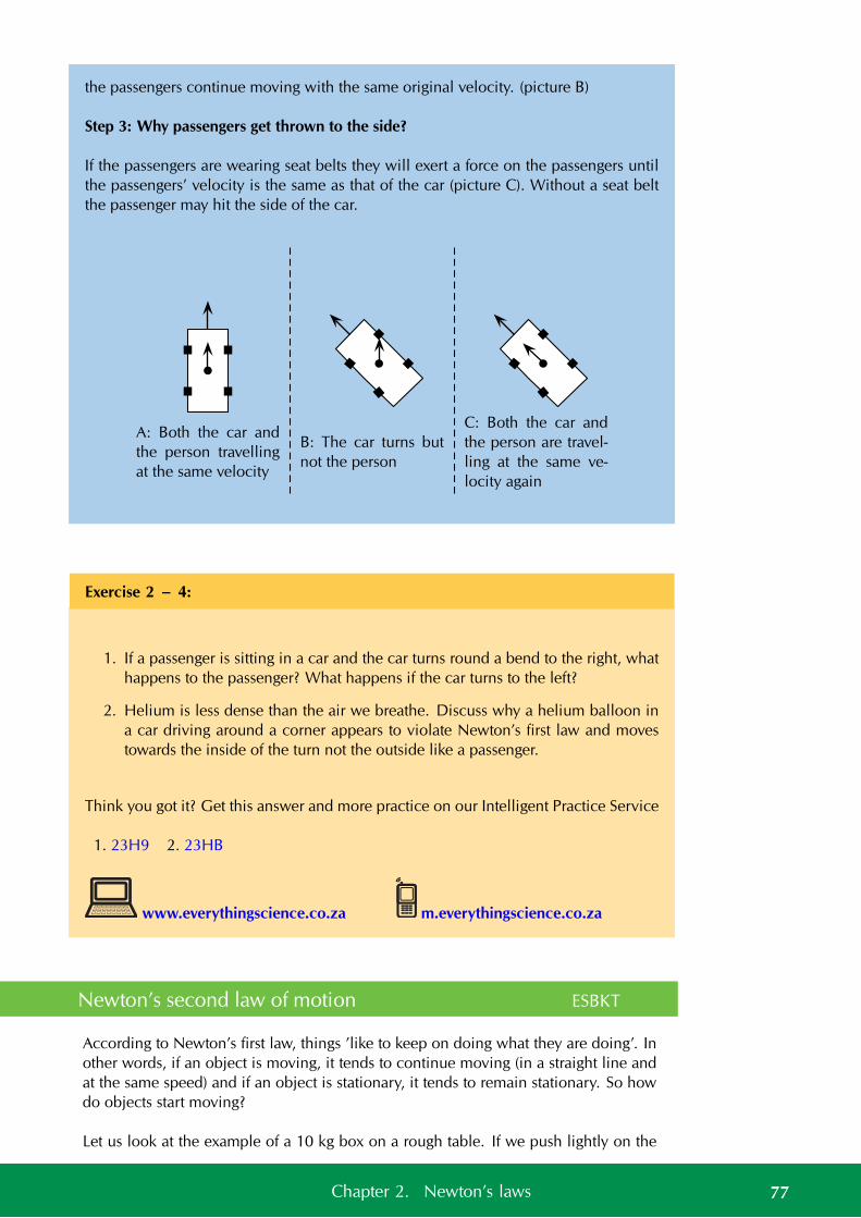
the passengers continue moving with the same original velocity. (picture B)
Step 3: Why passengers get thrown to the side?
If the passengers are wearing seat belts they will exert a force on the passengers untilthe passengers’ velocity is the same as that of the car (picture C). Without a seat beltthe passenger may hit the side of the car.
A: Both the car and
the person travelling
at the same velocity
B: The car turns but
not the person
C: Both the car and
the person are travel-
ling at the same ve-
locity again
Exercise 2 – 4:
1. If a passenger is sitting in a car and the car turns round a bend to the right, whathappens to the passenger? What happens if the car turns to the left?
2. Helium is less dense than the air we breathe. Discuss why a helium balloon ina car driving around a corner appears to violate Newton’s first law and movestowards the inside of the turn not the outside like a passenger.
Think you got it? Get this answer and more practice on our Intelligent Practice Service
1. 23H9 2. 23HB
www.everythingscience.co.za m.everythingscience.co.za
Newton’s second law of motion ESBKT
According to Newton’s first law, things ’like to keep on doing what they are doing’. Inother words, if an object is moving, it tends to continue moving (in a straight line andat the same speed) and if an object is stationary, it tends to remain stationary. So howdo objects start moving?
Let us look at the example of a 10 kg box on a rough table. If we push lightly on the
77Chapter 2. Newton’s laws
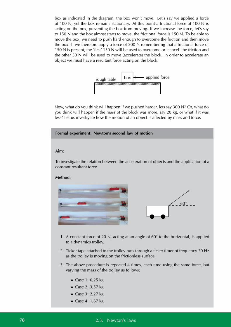
box as indicated in the diagram, the box won’t move. Let’s say we applied a forceof 100 N, yet the box remains stationary. At this point a frictional force of 100 N isacting on the box, preventing the box from moving. If we increase the force, let’s sayto 150 N and the box almost starts to move, the frictional force is 150 N. To be able tomove the box, we need to push hard enough to overcome the friction and then movethe box. If we therefore apply a force of 200 N remembering that a frictional force of150 N is present, the ’first’ 150 N will be used to overcome or ’cancel’ the friction andthe other 50 N will be used to move (accelerate) the block. In order to accelerate anobject we must have a resultant force acting on the block.
boxrough tableapplied force
Now, what do you think will happen if we pushed harder, lets say 300 N? Or, what doyou think will happen if the mass of the block was more, say 20 kg, or what if it wasless? Let us investigate how the motion of an object is affected by mass and force.
Formal experiment: Newton’s second law of motion
Aim:
To investigate the relation between the acceleration of objects and the application of aconstant resultant force.
Method:
60
1. A constant force of 20 N, acting at an angle of 60 to the horizontal, is appliedto a dynamics trolley.
2. Ticker tape attached to the trolley runs through a ticker timer of frequency 20 Hzas the trolley is moving on the frictionless surface.
3. The above procedure is repeated 4 times, each time using the same force, butvarying the mass of the trolley as follows:
• Case 1: 6,25 kg
• Case 2: 3,57 kg
• Case 3: 2,27 kg
• Case 4: 1,67 kg
78 2.3. Newton’s laws
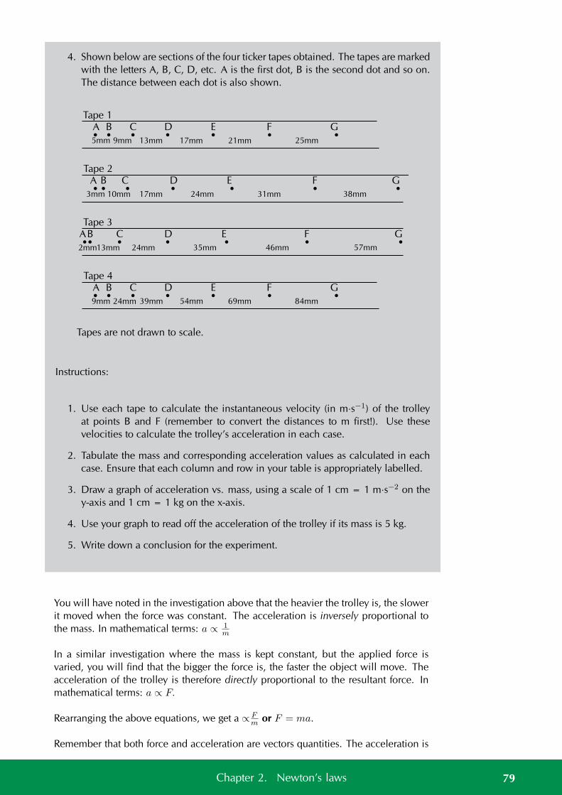
4. Shown below are sections of the four ticker tapes obtained. The tapes are markedwith the letters A, B, C, D, etc. A is the first dot, B is the second dot and so on.The distance between each dot is also shown.
Tape 1
5mm 9mm 13mm 17mm 21mm 25mm
Tape 2
3mm 10mm 17mm 24mm 31mm 38mm
Tape 3
2mm13mm 24mm 35mm 46mm 57mm
Tape 4
9mm 24mm 39mm 54mm 69mm 84mm
Tapes are not drawn to scale.
A B C D E F G
A B C D E F G
AB C D E F G
A B C D E F G
Instructions:
1. Use each tape to calculate the instantaneous velocity (in m·s−1) of the trolleyat points B and F (remember to convert the distances to m first!). Use thesevelocities to calculate the trolley’s acceleration in each case.
2. Tabulate the mass and corresponding acceleration values as calculated in eachcase. Ensure that each column and row in your table is appropriately labelled.
3. Draw a graph of acceleration vs. mass, using a scale of 1 cm = 1 m·s−2 on they-axis and 1 cm = 1 kg on the x-axis.
4. Use your graph to read off the acceleration of the trolley if its mass is 5 kg.
5. Write down a conclusion for the experiment.
You will have noted in the investigation above that the heavier the trolley is, the slowerit moved when the force was constant. The acceleration is inversely proportional tothe mass. In mathematical terms: a ∝ 1
m
In a similar investigation where the mass is kept constant, but the applied force isvaried, you will find that the bigger the force is, the faster the object will move. Theacceleration of the trolley is therefore directly proportional to the resultant force. Inmathematical terms: a ∝ F.
Rearranging the above equations, we get a ∝ Fm or F = ma.
Remember that both force and acceleration are vectors quantities. The acceleration is
79Chapter 2. Newton’s laws
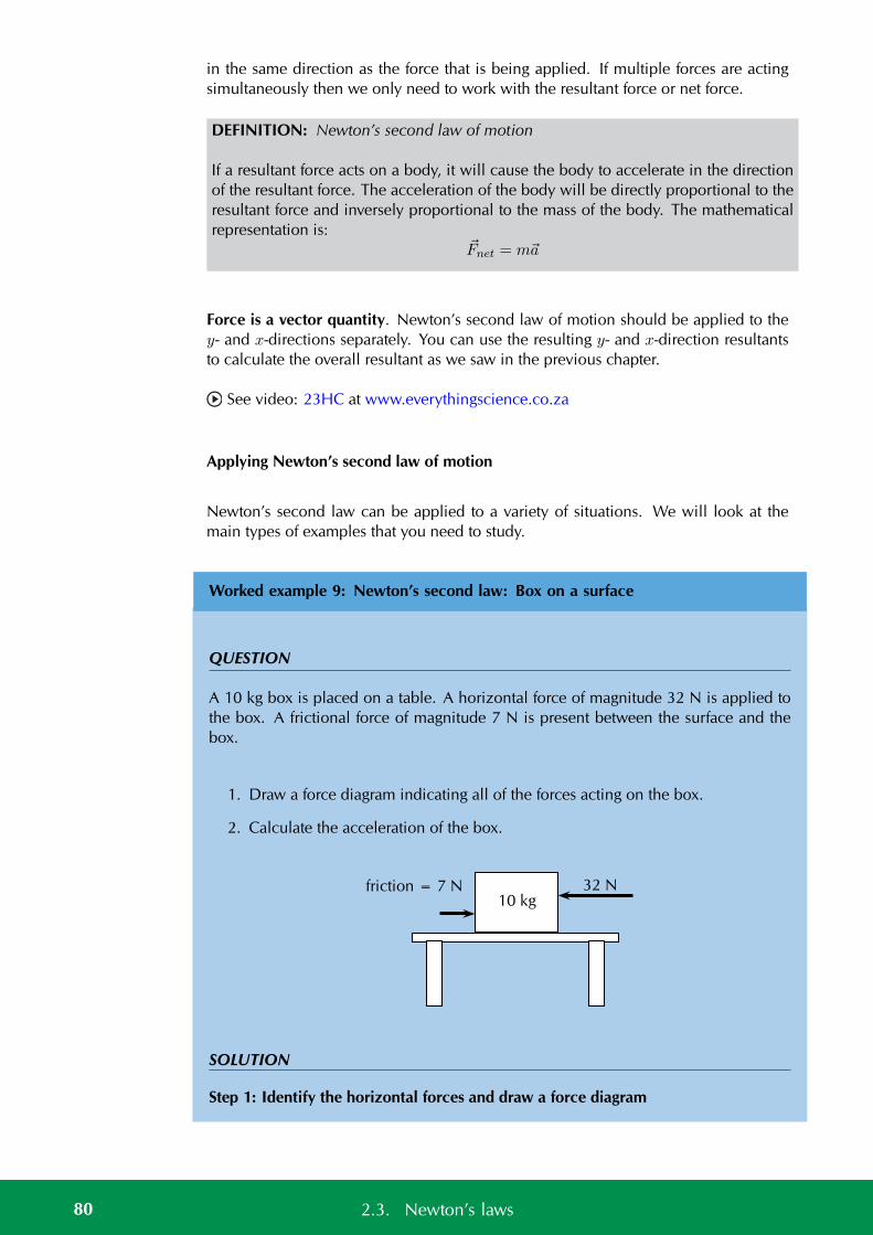
in the same direction as the force that is being applied. If multiple forces are actingsimultaneously then we only need to work with the resultant force or net force.
DEFINITION: Newton’s second law of motion
If a resultant force acts on a body, it will cause the body to accelerate in the directionof the resultant force. The acceleration of the body will be directly proportional to theresultant force and inversely proportional to the mass of the body. The mathematicalrepresentation is:
Fnet = ma
Force is a vector quantity. Newton’s second law of motion should be applied to they- and x-directions separately. You can use the resulting y- and x-direction resultantsto calculate the overall resultant as we saw in the previous chapter.
See video: 23HC at www.everythingscience.co.za
Applying Newton’s second law of motion
Newton’s second law can be applied to a variety of situations. We will look at themain types of examples that you need to study.
Worked example 9: Newton’s second law: Box on a surface
QUESTION
A 10 kg box is placed on a table. A horizontal force of magnitude 32 N is applied tothe box. A frictional force of magnitude 7 N is present between the surface and thebox.
1. Draw a force diagram indicating all of the forces acting on the box.
2. Calculate the acceleration of the box.
10 kg32 Nfriction = 7 N
SOLUTION
Step 1: Identify the horizontal forces and draw a force diagram
80 2.3. Newton’s laws
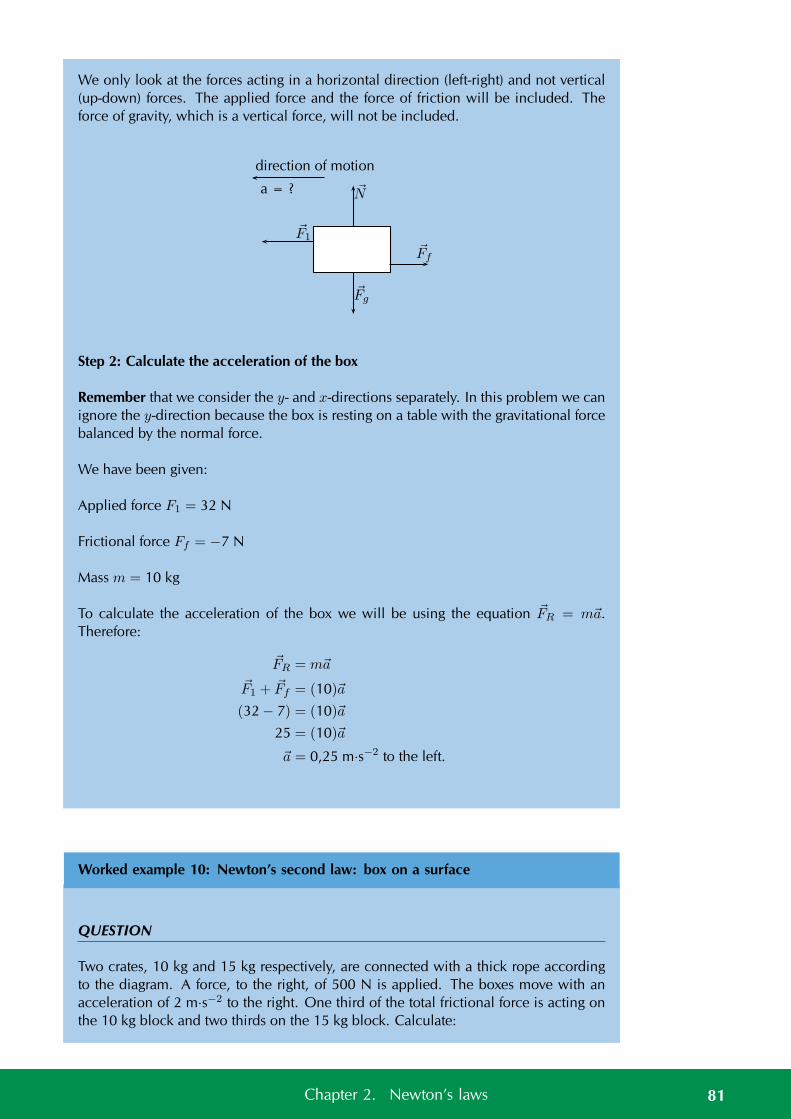
We only look at the forces acting in a horizontal direction (left-right) and not vertical(up-down) forces. The applied force and the force of friction will be included. Theforce of gravity, which is a vertical force, will not be included.
direction of motion
a = ?
F1
Ff
Fg
N
Step 2: Calculate the acceleration of the box
Remember that we consider the y- and x-directions separately. In this problem we canignore the y-direction because the box is resting on a table with the gravitational forcebalanced by the normal force.
We have been given:
Applied force F1 = 32 N
Frictional force Ff = −7 N
Mass m = 10 kg
To calculate the acceleration of the box we will be using the equation FR = ma.Therefore:
FR = ma
F1 + Ff = (10)a
(32 − 7) = (10)a
25 = (10)a
a = 0,25 m·s−2 to the left.
Worked example 10: Newton’s second law: box on a surface
QUESTION
Two crates, 10 kg and 15 kg respectively, are connected with a thick rope accordingto the diagram. A force, to the right, of 500 N is applied. The boxes move with anacceleration of 2 m·s−2 to the right. One third of the total frictional force is acting onthe 10 kg block and two thirds on the 15 kg block. Calculate:
81Chapter 2. Newton’s laws
1. the magnitude and direction of the total frictional force present.
2. the magnitude of the tension in the rope at T.
15 kg
a = 2 m · s−2
500 N
10 kg T
SOLUTION
Step 1: Evaluate what is given
To make things easier lets give the two crates labels, let us call the 10 kg crate number2 and the 15 kg crate number 1.
We have two crates that have overall has an acceleration that is given. The fact thatthe crates are tied together with a rope means that they will both have the same accel-eration. They will also both feel the same force due to the tension in the rope.
We are told that there is friction but we are only given the relationship between thetotal frictional force both crates experience and the fraction each one experiences. Thetotal friction, FfT will be the sum of the friction on crate 1, Ff1, and the friction oncrate 2, Ff2. We are told that Ff1 = 2
3FfT and Ff2 = 1
3FfT . We know the blocks are
accelerating to the right and we know that friction will be in the direction opposite tothe direction of motion and parallel to the surface.
Step 2: Draw force diagrams
The diagram for the crates is:
15 kg
a = 2 m · s−2
Applied force = 500 N
10 kgFriction = ?
The diagram for crate 1 (indicated by blue dotted lines) will be:
N1
Fg1
FappliedT
Ff1
Where:
82 2.3. Newton’s laws
• Fg1 is the force due to gravity on the first crate
• N1 is the normal force from the surface on the first crate
• T is the force of tension in the rope
• Fapplied is the external force being applied to the crate
• Ff1 is the force of friction on the first crate
The diagram for crate 2 (indicated by orange dashed lines) will be:
N2
Fg2
T
Ff2
Where:
• Fg2 is the force due to gravity on the second crate
• N2 is the normal force from the surface on the second crate
• T is the force of tension in the rope
• Ff2 is the force of friction on the second crate
Step 3: Apply Newton’s second law of motion
The problem tells us that the crates are accelerating along the x-direction which meansthat the forces in the y-direction do not result in a net force. We can treat the differentdirections separately so we only need to consider the x-direction.
We are working with one dimension and can choose a sign convention to indicate thedirection of the vectors. We choose vectors to the right (or in the positive x-direction)to be positive.
We can now apply Newton’s second law of motion to the first crate because we knowthe acceleration and we know all the forces acting on the crate. Using positive toindicate a force to the right we know that Fres1 = Fapplied − Ff1 − T
Fres1 = m1a
Fapplied − Ff1 − T = m1a
Fapplied −23FfT − T = m1a
(500)− 23FfT − T = (15)(2)
−T = (15)(2)− (500) +23FfT
83Chapter 2. Newton’s laws
Now apply Newton’s second law of motion to the second crate because we know theacceleration and we know all the forces acting on the crate. We know that Fres2 =T − Ff2. Note that tension is in the opposite direction.
Fres2 = m2a
T − Ff2 = m2a
T − 13FfT = m2a
T = (10)(2) +13FfT
Step 4: Solve simultaneously
We have used Newton’s second law of motion to create two equations with two un-knowns, this means we can solve simultaneously. We solved for T in the equationsabove but one carries a negative sign so if we add the two equations we will subtractout the value of the tension allowing us to solve for FfT :
(T ) + (−T ) = ((10)(2) +13FfT ) + ((15)(2)− (500) +
23FfT )
0 = 20 + 30 − 500 +13FfT +
23FfT
0 = −450 + FfT
FfT = 450 N
We can substitute the magnitude of FfT into the equation for crate 2 to determine themagnitude of the tension:
T = (10)(2) +13FfT
T = (10)(2) +13(450)
T = 20 + 150
T = 170 N
Step 5: Quote final answers
The total force due to friction is 450 N to the left. The magnitude of the force of tensionis 170 N.
Worked example 11: Newton’s second law: box on a surface (AlternativeMethod)
QUESTION
Two crates, 10 kg and 15 kg respectively, are connected with a thick rope accordingto the diagram. A force, to the right, of 500 N is applied. The boxes move with an
84 2.3. Newton’s laws
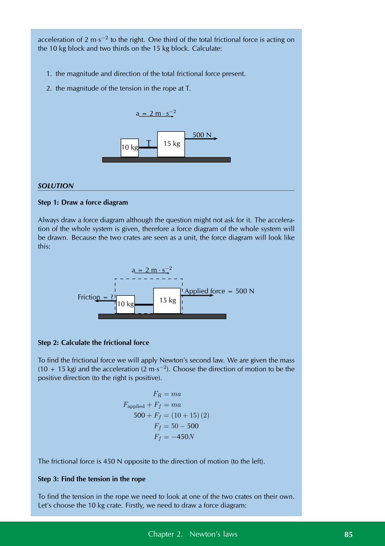
acceleration of 2 m·s−2 to the right. One third of the total frictional force is acting onthe 10 kg block and two thirds on the 15 kg block. Calculate:
1. the magnitude and direction of the total frictional force present.
2. the magnitude of the tension in the rope at T.
15 kg
a = 2 m · s−2
500 N
10 kg T
SOLUTION
Step 1: Draw a force diagram
Always draw a force diagram although the question might not ask for it. The accelera-tion of the whole system is given, therefore a force diagram of the whole system willbe drawn. Because the two crates are seen as a unit, the force diagram will look likethis:
15 kg
a = 2 m · s−2
Applied force = 500 N
10 kgFriction = ?
Step 2: Calculate the frictional force
To find the frictional force we will apply Newton’s second law. We are given the mass(10 + 15 kg) and the acceleration (2 m·s−2). Choose the direction of motion to be thepositive direction (to the right is positive).
FR = ma
Fapplied + Ff = ma
500 + Ff = (10 + 15) (2)
Ff = 50− 500
Ff = −450N
The frictional force is 450 N opposite to the direction of motion (to the left).
Step 3: Find the tension in the rope
To find the tension in the rope we need to look at one of the two crates on their own.Let’s choose the 10 kg crate. Firstly, we need to draw a force diagram:
85Chapter 2. Newton’s laws
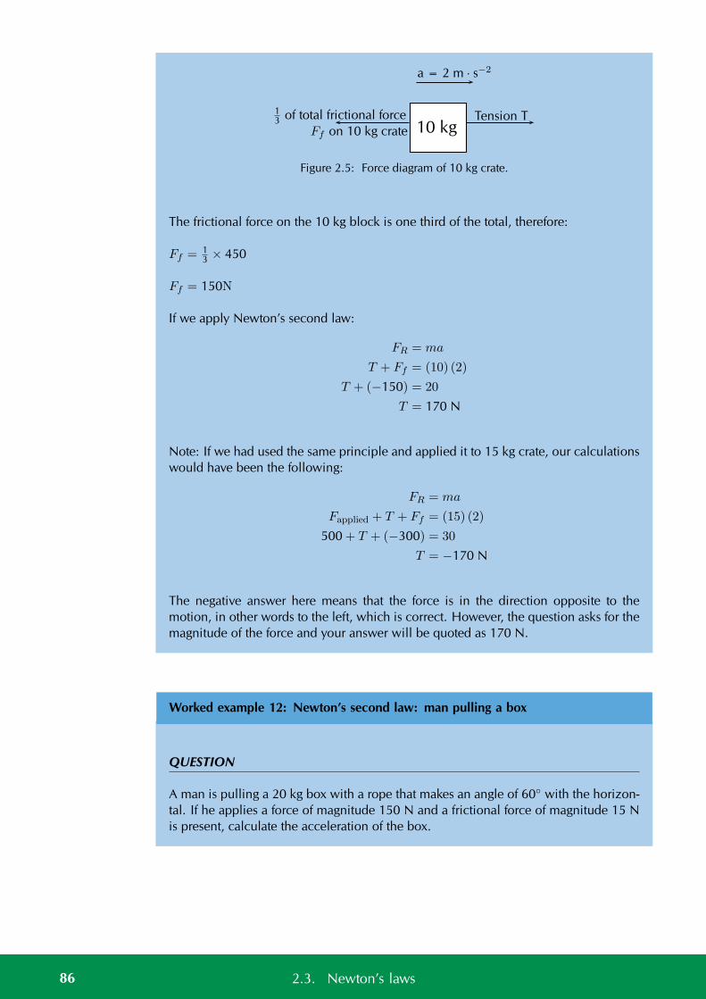
10 kgTension T1
3 of total frictional force
a = 2 m · s−2
Ff on 10 kg crate
Figure 2.5: Force diagram of 10 kg crate.
The frictional force on the 10 kg block is one third of the total, therefore:
Ff = 13 × 450
Ff = 150N
If we apply Newton’s second law:
FR = ma
T + Ff = (10) (2)
T + (−150) = 20
T = 170 N
Note: If we had used the same principle and applied it to 15 kg crate, our calculationswould have been the following:
FR = ma
Fapplied + T + Ff = (15) (2)
500 + T + (−300) = 30
T = −170 N
The negative answer here means that the force is in the direction opposite to themotion, in other words to the left, which is correct. However, the question asks for themagnitude of the force and your answer will be quoted as 170 N.
Worked example 12: Newton’s second law: man pulling a box
QUESTION
A man is pulling a 20 kg box with a rope that makes an angle of 60 with the horizon-tal. If he applies a force of magnitude 150 N and a frictional force of magnitude 15 Nis present, calculate the acceleration of the box.
86 2.3. Newton’s laws
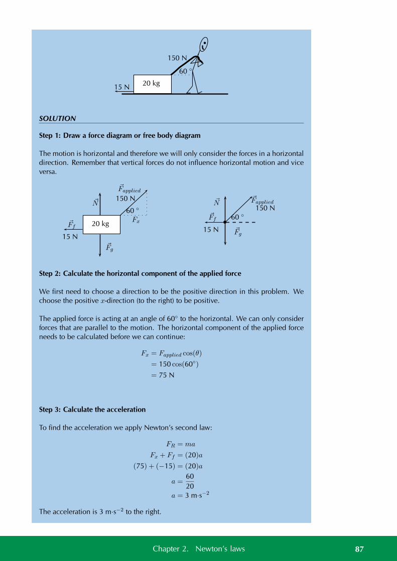
20 kg
60
150 N
15 N
SOLUTION
Step 1: Draw a force diagram or free body diagram
The motion is horizontal and therefore we will only consider the forces in a horizontaldirection. Remember that vertical forces do not influence horizontal motion and viceversa.
20 kg
60
150 N
15 N
FxFf
Fapplied
Fg
N
60
150 N
15 N
Ff
FappliedN
Fg
Step 2: Calculate the horizontal component of the applied force
We first need to choose a direction to be the positive direction in this problem. Wechoose the positive x-direction (to the right) to be positive.
The applied force is acting at an angle of 60 to the horizontal. We can only considerforces that are parallel to the motion. The horizontal component of the applied forceneeds to be calculated before we can continue:
Fx = Fapplied cos(θ)
= 150 cos(60)
= 75 N
Step 3: Calculate the acceleration
To find the acceleration we apply Newton’s second law:
FR = ma
Fx + Ff = (20)a
(75) + (−15) = (20)a
a =6020
a = 3 m·s−2
The acceleration is 3 m·s−2 to the right.
87Chapter 2. Newton’s laws
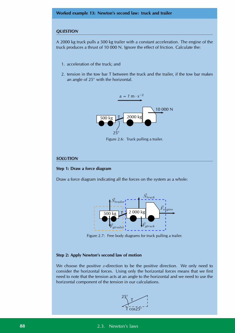
Worked example 13: Newton’s second law: truck and trailer
QUESTION
A 2000 kg truck pulls a 500 kg trailer with a constant acceleration. The engine of thetruck produces a thrust of 10 000 N. Ignore the effect of friction. Calculate the:
1. acceleration of the truck; and
2. tension in the tow bar T between the truck and the trailer, if the tow bar makesan angle of 25 with the horizontal.
25
a = ? m · s−2
500 kg 2000 kg
10 000 N
T
Figure 2.6: Truck pulling a trailer.
SOLUTION
Step 1: Draw a force diagram
Draw a force diagram indicating all the forces on the system as a whole:
2 000 kgT
Fengine
500 kg
NtruckNtrailer
FgtruckFgtrailer
Figure 2.7: Free body diagrams for truck pulling a trailer.
Step 2: Apply Newton’s second law of motion
We choose the positive x-direction to be the positive direction. We only need toconsider the horizontal forces. Using only the horizontal forces means that we firstneed to note that the tension acts at an angle to the horizontal and we need to use thehorizontal component of the tension in our calculations.
T
T cos25
25
88 2.3. Newton’s laws
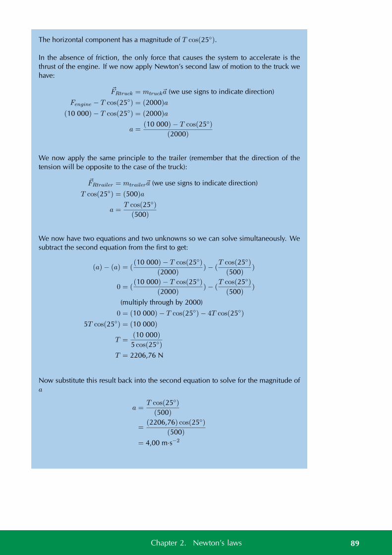
The horizontal component has a magnitude of T cos(25).
In the absence of friction, the only force that causes the system to accelerate is thethrust of the engine. If we now apply Newton’s second law of motion to the truck wehave:
FRtruck = mtrucka (we use signs to indicate direction)
Fengine − T cos(25) = (2000)a
(10 000)− T cos(25) = (2000)a
a =(10 000)− T cos(25)
(2000)
We now apply the same principle to the trailer (remember that the direction of thetension will be opposite to the case of the truck):
FRtrailer = mtrailera (we use signs to indicate direction)
T cos(25) = (500)a
a =T cos(25)
(500)
We now have two equations and two unknowns so we can solve simultaneously. Wesubtract the second equation from the first to get:
(a)− (a) = ((10 000)− T cos(25)
(2000))− (
T cos(25)
(500))
0 = ((10 000)− T cos(25)
(2000))− (
T cos(25)
(500))
(multiply through by 2000)
0 = (10 000)− T cos(25)− 4T cos(25)
5T cos(25) = (10 000)
T =(10 000)
5 cos(25)
T = 2206,76 N
Now substitute this result back into the second equation to solve for the magnitude ofa
a =T cos(25)
(500)
=(2206,76) cos(25)
(500)
= 4,00 m·s−2
89Chapter 2. Newton’s laws
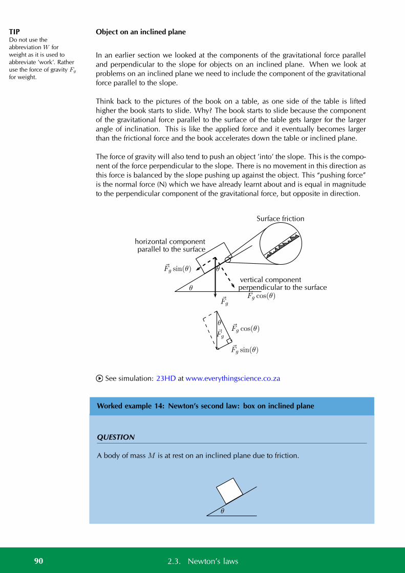
TIPDo not use theabbreviation W forweight as it is used toabbreviate ’work’. Ratheruse the force of gravity Fg
for weight.
Object on an inclined plane
In an earlier section we looked at the components of the gravitational force paralleland perpendicular to the slope for objects on an inclined plane. When we look atproblems on an inclined plane we need to include the component of the gravitationalforce parallel to the slope.
Think back to the pictures of the book on a table, as one side of the table is liftedhigher the book starts to slide. Why? The book starts to slide because the componentof the gravitational force parallel to the surface of the table gets larger for the largerangle of inclination. This is like the applied force and it eventually becomes largerthan the frictional force and the book accelerates down the table or inclined plane.
The force of gravity will also tend to push an object ’into’ the slope. This is the compo-nent of the force perpendicular to the slope. There is no movement in this direction asthis force is balanced by the slope pushing up against the object. This “pushing force”is the normal force (N) which we have already learnt about and is equal in magnitudeto the perpendicular component of the gravitational force, but opposite in direction.
Fg
Surface friction
horizontal componentparallel to the surface
vertical componentperpendicular to the surfaceθ
θFg sin(θ)
Fg cos(θ)
θ
Fg sin(θ)
Fg cos(θ)Fg
See simulation: 23HD at www.everythingscience.co.za
Worked example 14: Newton’s second law: box on inclined plane
QUESTION
A body of mass M is at rest on an inclined plane due to friction.
θ
90 2.3. Newton’s laws
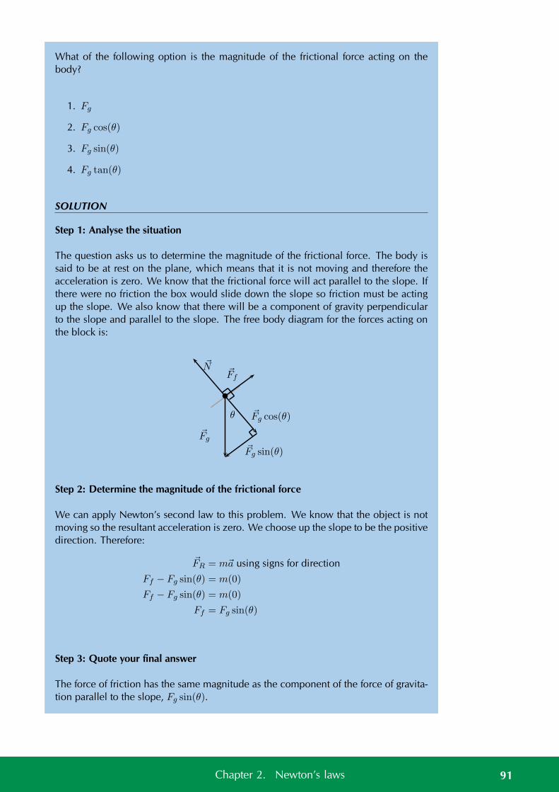
What of the following option is the magnitude of the frictional force acting on thebody?
1. Fg
2. Fg cos(θ)
3. Fg sin(θ)
4. Fg tan(θ)
SOLUTION
Step 1: Analyse the situation
The question asks us to determine the magnitude of the frictional force. The body issaid to be at rest on the plane, which means that it is not moving and therefore theacceleration is zero. We know that the frictional force will act parallel to the slope. Ifthere were no friction the box would slide down the slope so friction must be actingup the slope. We also know that there will be a component of gravity perpendicularto the slope and parallel to the slope. The free body diagram for the forces acting onthe block is:
N
θ
Fg
Fg sin(θ)
Fg cos(θ)
Ff
Step 2: Determine the magnitude of the frictional force
We can apply Newton’s second law to this problem. We know that the object is notmoving so the resultant acceleration is zero. We choose up the slope to be the positivedirection. Therefore:
FR = ma using signs for direction
Ff − Fg sin(θ) = m(0)
Ff − Fg sin(θ) = m(0)
Ff = Fg sin(θ)
Step 3: Quote your final answer
The force of friction has the same magnitude as the component of the force of gravita-tion parallel to the slope, Fg sin(θ).
91Chapter 2. Newton’s laws
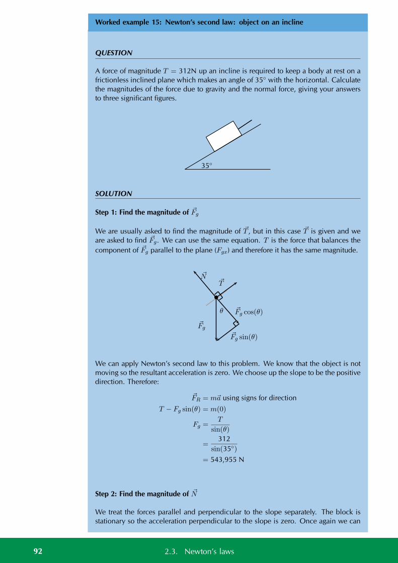
Worked example 15: Newton’s second law: object on an incline
QUESTION
A force of magnitude T = 312N up an incline is required to keep a body at rest on africtionless inclined plane which makes an angle of 35 with the horizontal. Calculatethe magnitudes of the force due to gravity and the normal force, giving your answersto three significant figures.
35
SOLUTION
Step 1: Find the magnitude of Fg
We are usually asked to find the magnitude of T , but in this case T is given and weare asked to find Fg. We can use the same equation. T is the force that balances thecomponent of Fg parallel to the plane (Fgx) and therefore it has the same magnitude.
N
θ
Fg
Fg sin(θ)
Fg cos(θ)
T
We can apply Newton’s second law to this problem. We know that the object is notmoving so the resultant acceleration is zero. We choose up the slope to be the positivedirection. Therefore:
FR = ma using signs for direction
T − Fg sin(θ) = m(0)
Fg =T
sin(θ)
=312
sin(35)
= 543,955 N
Step 2: Find the magnitude of N
We treat the forces parallel and perpendicular to the slope separately. The block isstationary so the acceleration perpendicular to the slope is zero. Once again we can
92 2.3. Newton’s laws
apply Newton’s second law of motion. We choose the direction of the normal forceas the positive direction.
FR = ma using signs for direction
N − Fg cos(θ) = m(0)
N = Fg cos(θ)
We could substitute in the value of Fg calculated earlier. We would like to illustratethat there is another approach to adopt to ensure you get the correct answer evenif you made a mistake calculating Fg. Fg cos(θ) can also be determined with theuse of trigonometric ratios. We know from the previous part of the question thatT = Fg sin(θ). We also know that
tan(θ) =Fg sin(θ)
Fg cos(θ)
=T
N
N =T
tan(θ)
=312
tan(35)
= 445,58 N
Note that the question asks that the answers be given to 3 significant figures. Wetherefore round N from 445,58 N up to 446 N perpendicular to the surface upwardsand T from 543,955 N up to 544 N parallel to the plane, up the slope.
Lifts and rockets
So far we have looked at objects being pulled or pushed across a surface, in otherwords motion parallel to the surface the object rests on. Here we only consideredforces parallel to the surface, but we can also lift objects up or let them fall. This isvertical motion where only vertical forces are being considered.
Let us consider a 500 kg lift, with no passengers, hanging on a cable. The purposeof the cable is to pull the lift upwards so that it can reach the next floor or lower thelift so that it can move downwards to the floor below. We will look at five possiblestages during the motion of the lift and apply our knowledge of Newton’s second lawof motion to the situation. The 5 stages are:
1. A stationary lift suspended above the ground.
2. A lift accelerating upwards.
3. A lift moving at a constant velocity.
4. A lift decelerating (slowing down).
5. A lift accelerating downwards (the cable snaps!).
93Chapter 2. Newton’s laws
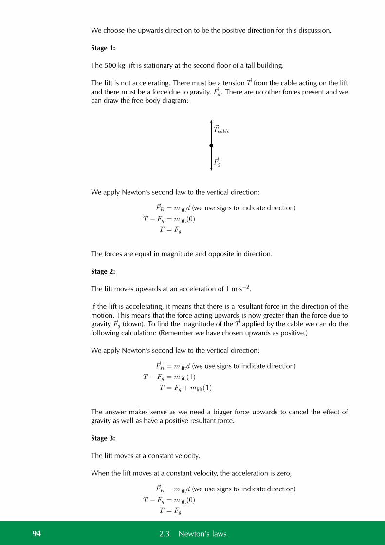
We choose the upwards direction to be the positive direction for this discussion.
Stage 1:
The 500 kg lift is stationary at the second floor of a tall building.
The lift is not accelerating. There must be a tension T from the cable acting on the liftand there must be a force due to gravity, Fg. There are no other forces present and wecan draw the free body diagram:
Tcable
Fg
We apply Newton’s second law to the vertical direction:
FR = mlifta (we use signs to indicate direction)
T − Fg = mlift(0)
T = Fg
The forces are equal in magnitude and opposite in direction.
Stage 2:
The lift moves upwards at an acceleration of 1 m·s−2.
If the lift is accelerating, it means that there is a resultant force in the direction of themotion. This means that the force acting upwards is now greater than the force due togravity Fg (down). To find the magnitude of the T applied by the cable we can do thefollowing calculation: (Remember we have chosen upwards as positive.)
We apply Newton’s second law to the vertical direction:
FR = mlifta (we use signs to indicate direction)
T − Fg = mlift(1)
T = Fg +mlift(1)
The answer makes sense as we need a bigger force upwards to cancel the effect ofgravity as well as have a positive resultant force.
Stage 3:
The lift moves at a constant velocity.
When the lift moves at a constant velocity, the acceleration is zero,
FR = mlifta (we use signs to indicate direction)
T − Fg = mlift(0)
T = Fg
94 2.3. Newton’s laws
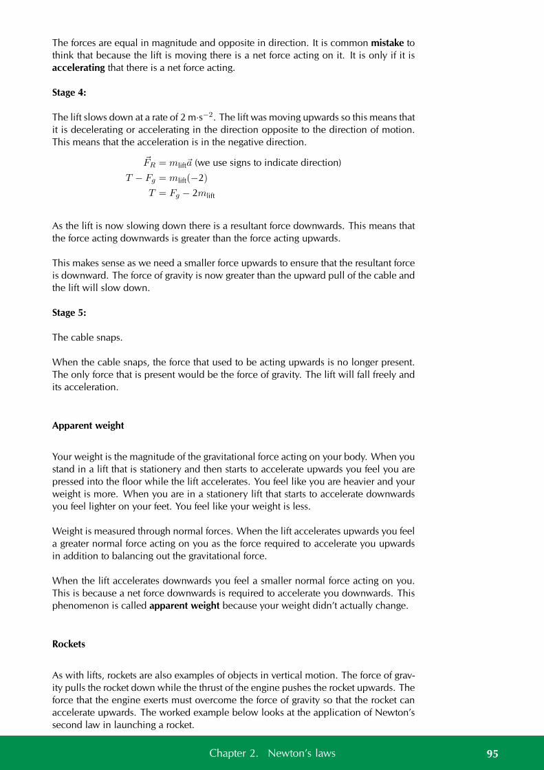
The forces are equal in magnitude and opposite in direction. It is common mistake tothink that because the lift is moving there is a net force acting on it. It is only if it isaccelerating that there is a net force acting.
Stage 4:
The lift slows down at a rate of 2 m·s−2. The lift was moving upwards so this means thatit is decelerating or accelerating in the direction opposite to the direction of motion.This means that the acceleration is in the negative direction.
FR = mlifta (we use signs to indicate direction)
T − Fg = mlift(−2)
T = Fg − 2mlift
As the lift is now slowing down there is a resultant force downwards. This means thatthe force acting downwards is greater than the force acting upwards.
This makes sense as we need a smaller force upwards to ensure that the resultant forceis downward. The force of gravity is now greater than the upward pull of the cable andthe lift will slow down.
Stage 5:
The cable snaps.
When the cable snaps, the force that used to be acting upwards is no longer present.The only force that is present would be the force of gravity. The lift will fall freely andits acceleration.
Apparent weight
Your weight is the magnitude of the gravitational force acting on your body. When youstand in a lift that is stationery and then starts to accelerate upwards you feel you arepressed into the floor while the lift accelerates. You feel like you are heavier and yourweight is more. When you are in a stationery lift that starts to accelerate downwardsyou feel lighter on your feet. You feel like your weight is less.
Weight is measured through normal forces. When the lift accelerates upwards you feela greater normal force acting on you as the force required to accelerate you upwardsin addition to balancing out the gravitational force.
When the lift accelerates downwards you feel a smaller normal force acting on you.This is because a net force downwards is required to accelerate you downwards. Thisphenomenon is called apparent weight because your weight didn’t actually change.
Rockets
As with lifts, rockets are also examples of objects in vertical motion. The force of grav-ity pulls the rocket down while the thrust of the engine pushes the rocket upwards. Theforce that the engine exerts must overcome the force of gravity so that the rocket canaccelerate upwards. The worked example below looks at the application of Newton’ssecond law in launching a rocket.
95Chapter 2. Newton’s laws
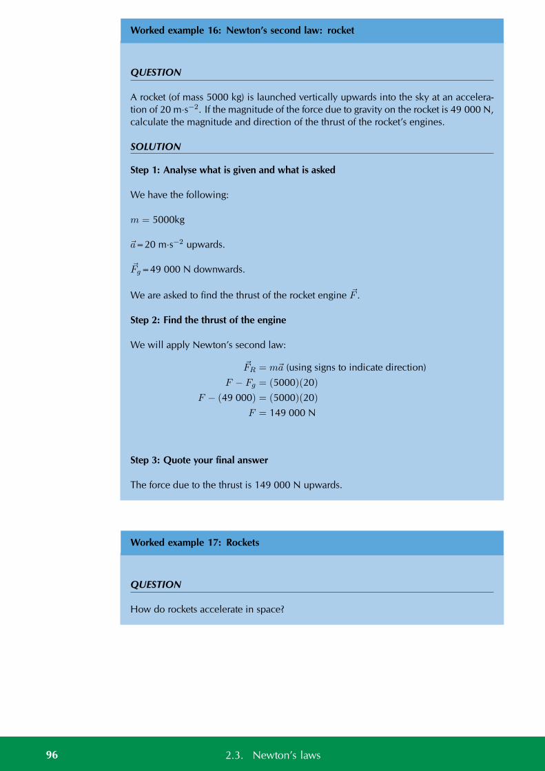
Worked example 16: Newton’s second law: rocket
QUESTION
A rocket (of mass 5000 kg) is launched vertically upwards into the sky at an accelera-tion of 20 m·s−2. If the magnitude of the force due to gravity on the rocket is 49 000 N,calculate the magnitude and direction of the thrust of the rocket’s engines.
SOLUTION
Step 1: Analyse what is given and what is asked
We have the following:
m = 5000kg
a=20 m·s−2 upwards.
Fg=49 000 N downwards.
We are asked to find the thrust of the rocket engine F .
Step 2: Find the thrust of the engine
We will apply Newton’s second law:
FR = ma (using signs to indicate direction)
F − Fg = (5000)(20)
F − (49 000) = (5000)(20)
F = 149 000 N
Step 3: Quote your final answer
The force due to the thrust is 149 000 N upwards.
Worked example 17: Rockets
QUESTION
How do rockets accelerate in space?
96 2.3. Newton’s laws
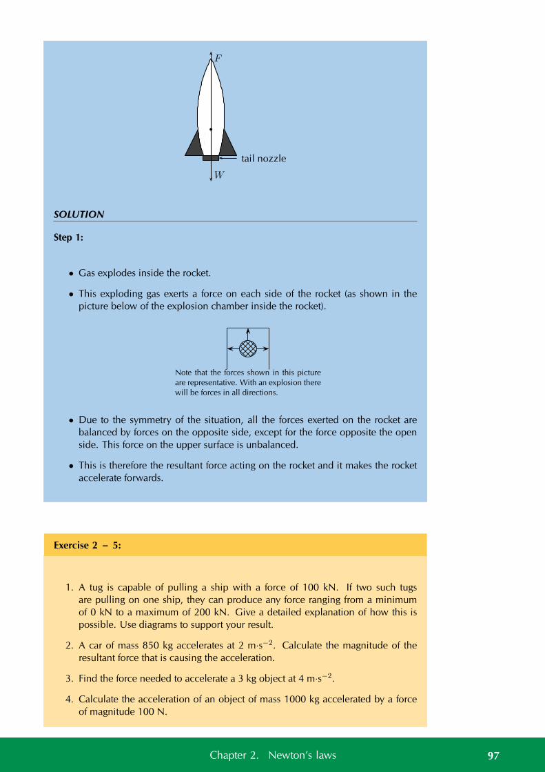
F
W
tail nozzle
SOLUTION
Step 1:
• Gas explodes inside the rocket.
• This exploding gas exerts a force on each side of the rocket (as shown in thepicture below of the explosion chamber inside the rocket).
Note that the forces shown in this picture
are representative. With an explosion there
will be forces in all directions.
• Due to the symmetry of the situation, all the forces exerted on the rocket arebalanced by forces on the opposite side, except for the force opposite the openside. This force on the upper surface is unbalanced.
• This is therefore the resultant force acting on the rocket and it makes the rocketaccelerate forwards.
Exercise 2 – 5:
1. A tug is capable of pulling a ship with a force of 100 kN. If two such tugsare pulling on one ship, they can produce any force ranging from a minimumof 0 kN to a maximum of 200 kN. Give a detailed explanation of how this ispossible. Use diagrams to support your result.
2. A car of mass 850 kg accelerates at 2 m·s−2. Calculate the magnitude of theresultant force that is causing the acceleration.
3. Find the force needed to accelerate a 3 kg object at 4 m·s−2.
4. Calculate the acceleration of an object of mass 1000 kg accelerated by a forceof magnitude 100 N.
97Chapter 2. Newton’s laws
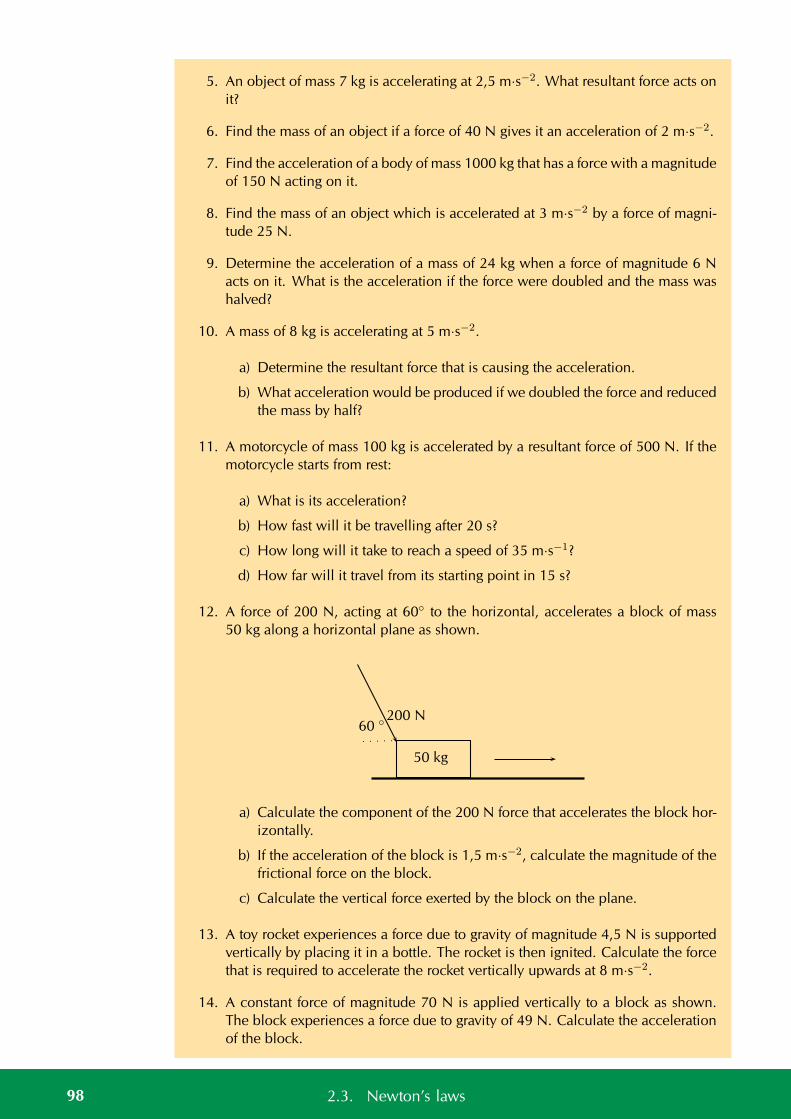
5. An object of mass 7 kg is accelerating at 2,5 m·s−2. What resultant force acts onit?
6. Find the mass of an object if a force of 40 N gives it an acceleration of 2 m·s−2.
7. Find the acceleration of a body of mass 1000 kg that has a force with a magnitudeof 150 N acting on it.
8. Find the mass of an object which is accelerated at 3 m·s−2 by a force of magni-tude 25 N.
9. Determine the acceleration of a mass of 24 kg when a force of magnitude 6 Nacts on it. What is the acceleration if the force were doubled and the mass washalved?
10. A mass of 8 kg is accelerating at 5 m·s−2.
a) Determine the resultant force that is causing the acceleration.
b) What acceleration would be produced if we doubled the force and reducedthe mass by half?
11. A motorcycle of mass 100 kg is accelerated by a resultant force of 500 N. If themotorcycle starts from rest:
a) What is its acceleration?
b) How fast will it be travelling after 20 s?
c) How long will it take to reach a speed of 35 m·s−1?
d) How far will it travel from its starting point in 15 s?
12. A force of 200 N, acting at 60 to the horizontal, accelerates a block of mass50 kg along a horizontal plane as shown.
50 kg
60 200 N
a) Calculate the component of the 200 N force that accelerates the block hor-izontally.
b) If the acceleration of the block is 1,5 m·s−2, calculate the magnitude of thefrictional force on the block.
c) Calculate the vertical force exerted by the block on the plane.
13. A toy rocket experiences a force due to gravity of magnitude 4,5 N is supportedvertically by placing it in a bottle. The rocket is then ignited. Calculate the forcethat is required to accelerate the rocket vertically upwards at 8 m·s−2.
14. A constant force of magnitude 70 N is applied vertically to a block as shown.The block experiences a force due to gravity of 49 N. Calculate the accelerationof the block.
98 2.3. Newton’s laws
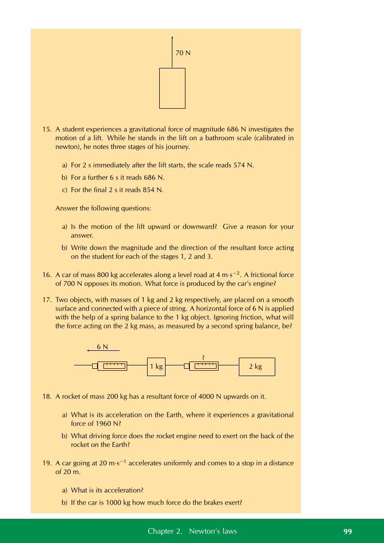
70 N
15. A student experiences a gravitational force of magnitude 686 N investigates themotion of a lift. While he stands in the lift on a bathroom scale (calibrated innewton), he notes three stages of his journey.
a) For 2 s immediately after the lift starts, the scale reads 574 N.
b) For a further 6 s it reads 686 N.
c) For the final 2 s it reads 854 N.
Answer the following questions:
a) Is the motion of the lift upward or downward? Give a reason for youranswer.
b) Write down the magnitude and the direction of the resultant force actingon the student for each of the stages 1, 2 and 3.
16. A car of mass 800 kg accelerates along a level road at 4 m·s−2. A frictional forceof 700 N opposes its motion. What force is produced by the car’s engine?
17. Two objects, with masses of 1 kg and 2 kg respectively, are placed on a smoothsurface and connected with a piece of string. A horizontal force of 6 N is appliedwith the help of a spring balance to the 1 kg object. Ignoring friction, what willthe force acting on the 2 kg mass, as measured by a second spring balance, be?
1 kg 2 kg
6 N
?
18. A rocket of mass 200 kg has a resultant force of 4000 N upwards on it.
a) What is its acceleration on the Earth, where it experiences a gravitationalforce of 1960 N?
b) What driving force does the rocket engine need to exert on the back of therocket on the Earth?
19. A car going at 20 m·s−1 accelerates uniformly and comes to a stop in a distanceof 20 m.
a) What is its acceleration?
b) If the car is 1000 kg how much force do the brakes exert?
99Chapter 2. Newton’s laws
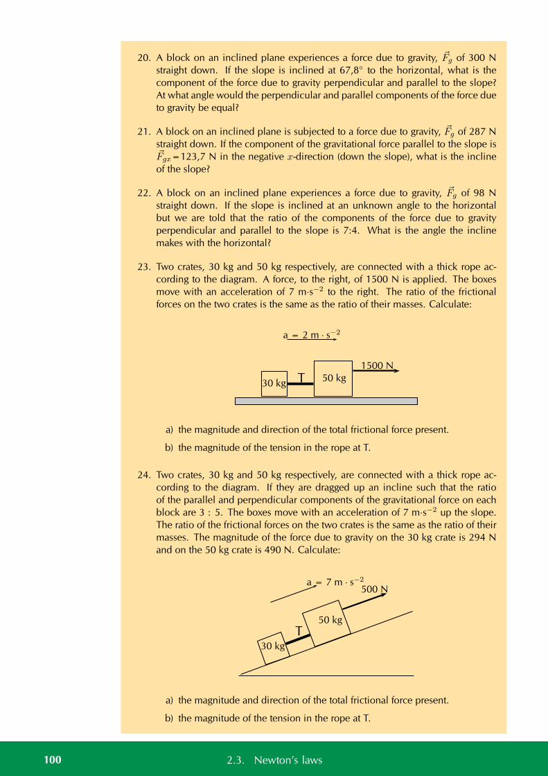
20. A block on an inclined plane experiences a force due to gravity, Fg of 300 Nstraight down. If the slope is inclined at 67,8 to the horizontal, what is thecomponent of the force due to gravity perpendicular and parallel to the slope?At what angle would the perpendicular and parallel components of the force dueto gravity be equal?
21. A block on an inclined plane is subjected to a force due to gravity, Fg of 287 Nstraight down. If the component of the gravitational force parallel to the slope isFgx=123,7 N in the negative x-direction (down the slope), what is the inclineof the slope?
22. A block on an inclined plane experiences a force due to gravity, Fg of 98 Nstraight down. If the slope is inclined at an unknown angle to the horizontalbut we are told that the ratio of the components of the force due to gravityperpendicular and parallel to the slope is 7:4. What is the angle the inclinemakes with the horizontal?
23. Two crates, 30 kg and 50 kg respectively, are connected with a thick rope ac-cording to the diagram. A force, to the right, of 1500 N is applied. The boxesmove with an acceleration of 7 m·s−2 to the right. The ratio of the frictionalforces on the two crates is the same as the ratio of their masses. Calculate:
50 kg
a = 2 m · s−2
1500 N
30 kg T
a) the magnitude and direction of the total frictional force present.
b) the magnitude of the tension in the rope at T.
24. Two crates, 30 kg and 50 kg respectively, are connected with a thick rope ac-cording to the diagram. If they are dragged up an incline such that the ratioof the parallel and perpendicular components of the gravitational force on eachblock are 3 : 5. The boxes move with an acceleration of 7 m·s−2 up the slope.The ratio of the frictional forces on the two crates is the same as the ratio of theirmasses. The magnitude of the force due to gravity on the 30 kg crate is 294 Nand on the 50 kg crate is 490 N. Calculate:
50 kg
a = 7 m · s−2
500 N
30 kg
T
a) the magnitude and direction of the total frictional force present.
b) the magnitude of the tension in the rope at T.
100 2.3. Newton’s laws
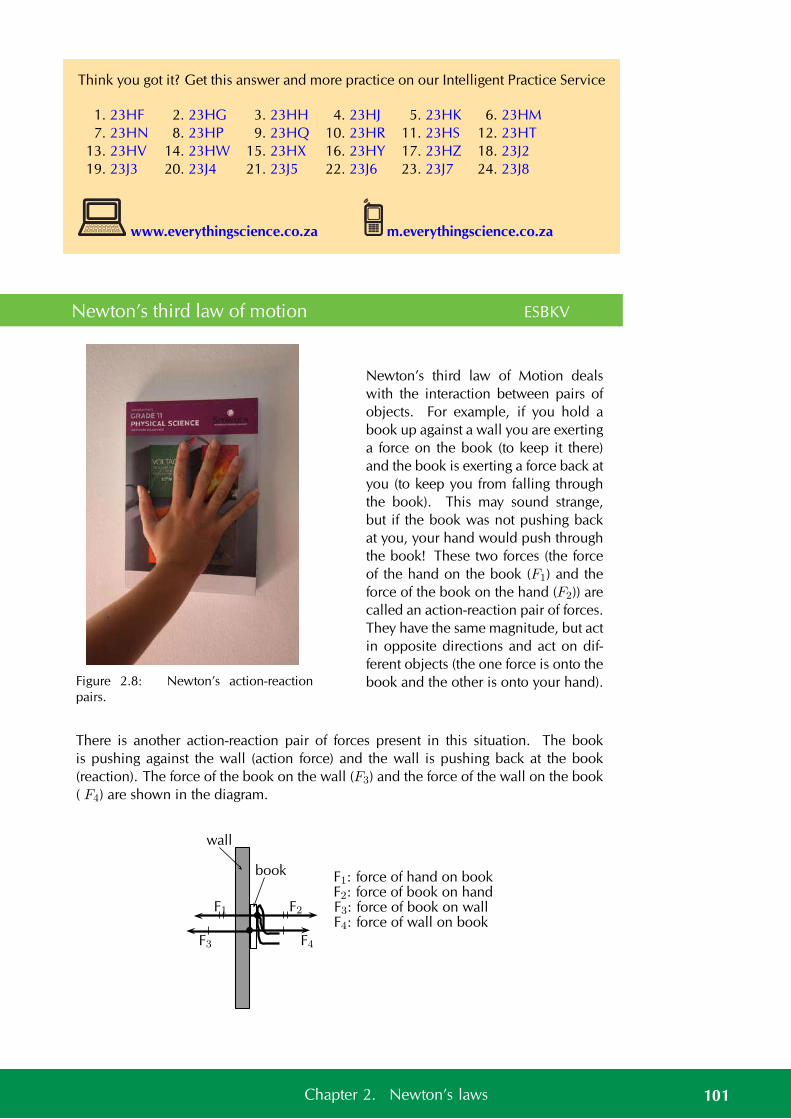
Think you got it? Get this answer and more practice on our Intelligent Practice Service
1. 23HF 2. 23HG 3. 23HH 4. 23HJ 5. 23HK 6. 23HM7. 23HN 8. 23HP 9. 23HQ 10. 23HR 11. 23HS 12. 23HT
13. 23HV 14. 23HW 15. 23HX 16. 23HY 17. 23HZ 18. 23J219. 23J3 20. 23J4 21. 23J5 22. 23J6 23. 23J7 24. 23J8
www.everythingscience.co.za m.everythingscience.co.za
Newton’s third law of motion ESBKV
Figure 2.8: Newton’s action-reactionpairs.
Newton’s third law of Motion dealswith the interaction between pairs ofobjects. For example, if you hold abook up against a wall you are exertinga force on the book (to keep it there)and the book is exerting a force back atyou (to keep you from falling throughthe book). This may sound strange,but if the book was not pushing backat you, your hand would push throughthe book! These two forces (the forceof the hand on the book (F1) and theforce of the book on the hand (F2)) arecalled an action-reaction pair of forces.They have the same magnitude, but actin opposite directions and act on dif-ferent objects (the one force is onto thebook and the other is onto your hand).
There is another action-reaction pair of forces present in this situation. The bookis pushing against the wall (action force) and the wall is pushing back at the book(reaction). The force of the book on the wall (F3) and the force of the wall on the book( F4) are shown in the diagram.
wall
book F1: force of hand on bookF2: force of book on handF3: force of book on wallF4: force of wall on book
F1 F2
F3 F4
101Chapter 2. Newton’s laws
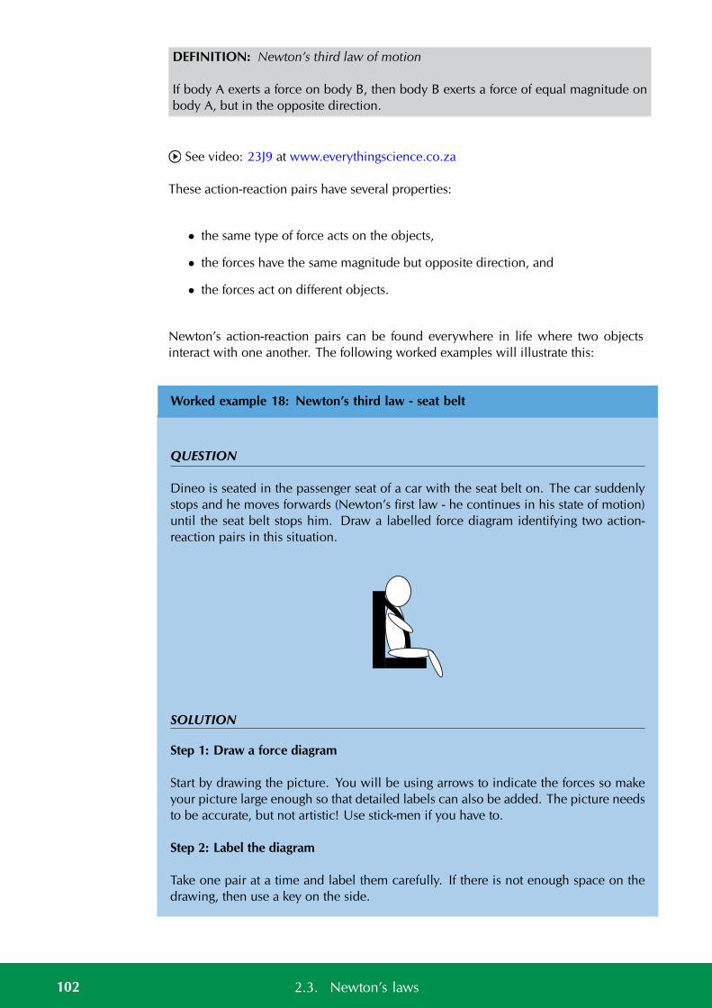
DEFINITION: Newton’s third law of motion
If body A exerts a force on body B, then body B exerts a force of equal magnitude onbody A, but in the opposite direction.
See video: 23J9 at www.everythingscience.co.za
These action-reaction pairs have several properties:
• the same type of force acts on the objects,
• the forces have the same magnitude but opposite direction, and
• the forces act on different objects.
Newton’s action-reaction pairs can be found everywhere in life where two objectsinteract with one another. The following worked examples will illustrate this:
Worked example 18: Newton’s third law - seat belt
QUESTION
Dineo is seated in the passenger seat of a car with the seat belt on. The car suddenlystops and he moves forwards (Newton’s first law - he continues in his state of motion)until the seat belt stops him. Draw a labelled force diagram identifying two action-reaction pairs in this situation.
SOLUTION
Step 1: Draw a force diagram
Start by drawing the picture. You will be using arrows to indicate the forces so makeyour picture large enough so that detailed labels can also be added. The picture needsto be accurate, but not artistic! Use stick-men if you have to.
Step 2: Label the diagram
Take one pair at a time and label them carefully. If there is not enough space on thedrawing, then use a key on the side.
102 2.3. Newton’s laws
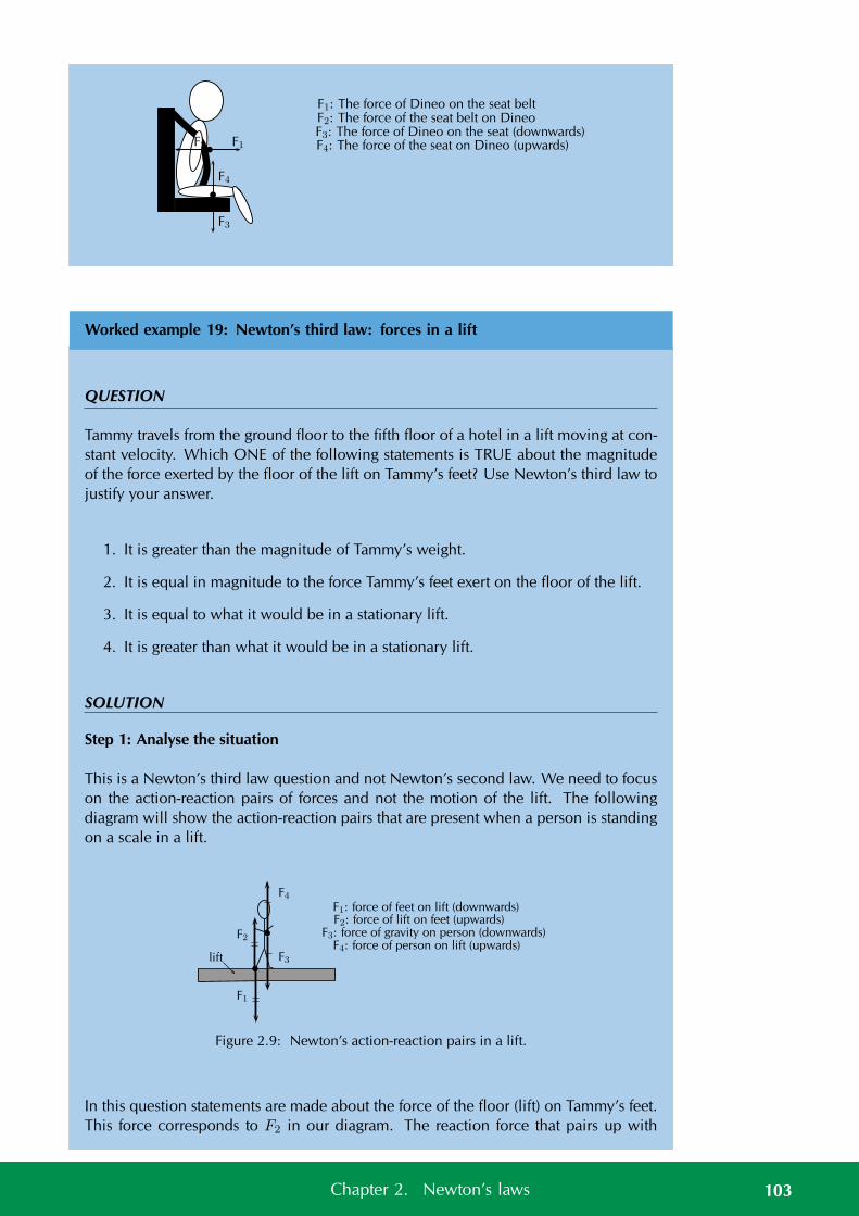
F1: The force of Dineo on the seat belt
F1F2
F2: The force of the seat belt on DineoF3: The force of Dineo on the seat (downwards)
F4
F3
F4: The force of the seat on Dineo (upwards)
Worked example 19: Newton’s third law: forces in a lift
QUESTION
Tammy travels from the ground floor to the fifth floor of a hotel in a lift moving at con-stant velocity. Which ONE of the following statements is TRUE about the magnitudeof the force exerted by the floor of the lift on Tammy’s feet? Use Newton’s third law tojustify your answer.
1. It is greater than the magnitude of Tammy’s weight.
2. It is equal in magnitude to the force Tammy’s feet exert on the floor of the lift.
3. It is equal to what it would be in a stationary lift.
4. It is greater than what it would be in a stationary lift.
SOLUTION
Step 1: Analyse the situation
This is a Newton’s third law question and not Newton’s second law. We need to focuson the action-reaction pairs of forces and not the motion of the lift. The followingdiagram will show the action-reaction pairs that are present when a person is standingon a scale in a lift.
F1: force of feet on lift (downwards)F2: force of lift on feet (upwards)
F3: force of gravity on person (downwards)F4: force of person on lift (upwards)
lift
F1
F2
F4
F3
Figure 2.9: Newton’s action-reaction pairs in a lift.
In this question statements are made about the force of the floor (lift) on Tammy’s feet.This force corresponds to F2 in our diagram. The reaction force that pairs up with
103Chapter 2. Newton’s laws
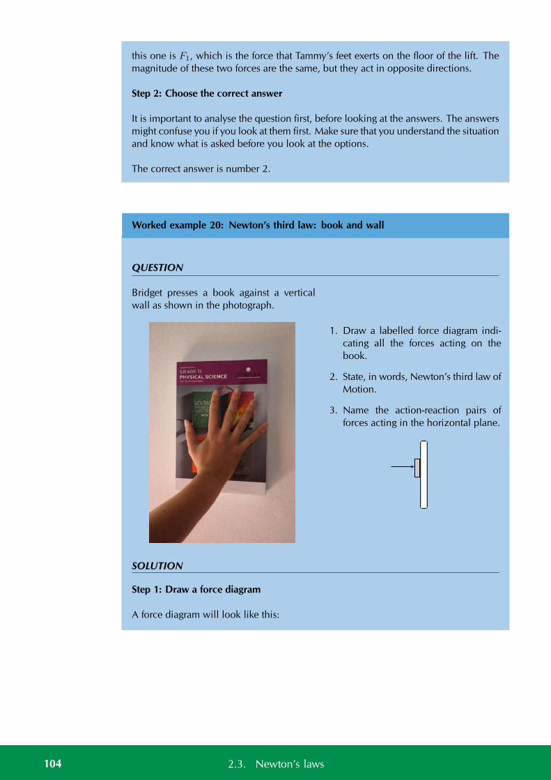
this one is F1, which is the force that Tammy’s feet exerts on the floor of the lift. Themagnitude of these two forces are the same, but they act in opposite directions.
Step 2: Choose the correct answer
It is important to analyse the question first, before looking at the answers. The answersmight confuse you if you look at them first. Make sure that you understand the situationand know what is asked before you look at the options.
The correct answer is number 2.
Worked example 20: Newton’s third law: book and wall
QUESTION
Bridget presses a book against a verticalwall as shown in the photograph.
1. Draw a labelled force diagram indi-cating all the forces acting on thebook.
2. State, in words, Newton’s third law ofMotion.
3. Name the action-reaction pairs offorces acting in the horizontal plane.
SOLUTION
Step 1: Draw a force diagram
A force diagram will look like this:
104 2.3. Newton’s laws
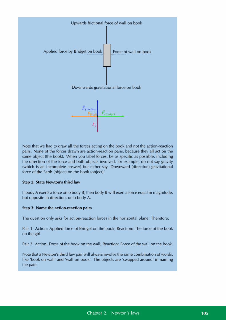
Upwards frictional force of wall on book
Downwards gravitational force on book
Force of wall on bookApplied force by Bridget on book
Fg
Ffriction
FWallFBridget
Note that we had to draw all the forces acting on the book and not the action-reactionpairs. None of the forces drawn are action-reaction pairs, because they all act on thesame object (the book). When you label forces, be as specific as possible, includingthe direction of the force and both objects involved, for example, do not say gravity(which is an incomplete answer) but rather say ’Downward (direction) gravitationalforce of the Earth (object) on the book (object)’.
Step 2: State Newton’s third law
If body A exerts a force onto body B, then body B will exert a force equal in magnitude,but opposite in direction, onto body A.
Step 3: Name the action-reaction pairs
The question only asks for action-reaction forces in the horizontal plane. Therefore:
Pair 1: Action: Applied force of Bridget on the book; Reaction: The force of the bookon the girl.
Pair 2: Action: Force of the book on the wall; Reaction: Force of the wall on the book.
Note that a Newton’s third law pair will always involve the same combination of words,like ’book on wall’ and ’wall on book’. The objects are ’swapped around’ in namingthe pairs.
105Chapter 2. Newton’s laws
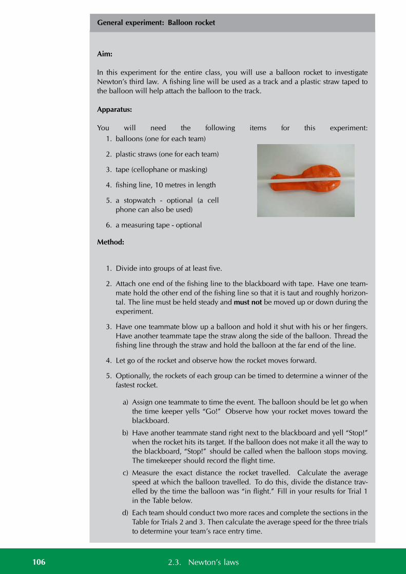
General experiment: Balloon rocket
Aim:
In this experiment for the entire class, you will use a balloon rocket to investigateNewton’s third law. A fishing line will be used as a track and a plastic straw taped tothe balloon will help attach the balloon to the track.
Apparatus:
You will need the following items for this experiment:1. balloons (one for each team)
2. plastic straws (one for each team)
3. tape (cellophane or masking)
4. fishing line, 10 metres in length
5. a stopwatch - optional (a cellphone can also be used)
6. a measuring tape - optional
Method:
1. Divide into groups of at least five.
2. Attach one end of the fishing line to the blackboard with tape. Have one team-mate hold the other end of the fishing line so that it is taut and roughly horizon-tal. The line must be held steady and must not be moved up or down during theexperiment.
3. Have one teammate blow up a balloon and hold it shut with his or her fingers.Have another teammate tape the straw along the side of the balloon. Thread thefishing line through the straw and hold the balloon at the far end of the line.
4. Let go of the rocket and observe how the rocket moves forward.
5. Optionally, the rockets of each group can be timed to determine a winner of thefastest rocket.
a) Assign one teammate to time the event. The balloon should be let go whenthe time keeper yells “Go!” Observe how your rocket moves toward theblackboard.
b) Have another teammate stand right next to the blackboard and yell “Stop!”when the rocket hits its target. If the balloon does not make it all the way tothe blackboard, “Stop!” should be called when the balloon stops moving.The timekeeper should record the flight time.
c) Measure the exact distance the rocket travelled. Calculate the averagespeed at which the balloon travelled. To do this, divide the distance trav-elled by the time the balloon was “in flight.” Fill in your results for Trial 1in the Table below.
d) Each team should conduct two more races and complete the sections in theTable for Trials 2 and 3. Then calculate the average speed for the three trialsto determine your team’s race entry time.
106 2.3. Newton’s laws
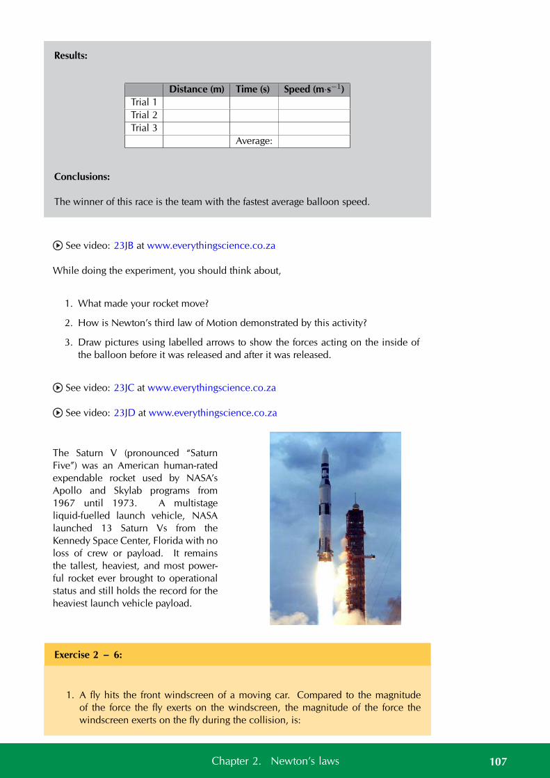
Results:
Distance (m) Time (s) Speed (m·s−1)Trial 1Trial 2Trial 3
Average:
Conclusions:
The winner of this race is the team with the fastest average balloon speed.
See video: 23JB at www.everythingscience.co.za
While doing the experiment, you should think about,
1. What made your rocket move?
2. How is Newton’s third law of Motion demonstrated by this activity?
3. Draw pictures using labelled arrows to show the forces acting on the inside ofthe balloon before it was released and after it was released.
See video: 23JC at www.everythingscience.co.za
See video: 23JD at www.everythingscience.co.za
The Saturn V (pronounced “SaturnFive”) was an American human-ratedexpendable rocket used by NASA’sApollo and Skylab programs from1967 until 1973. A multistageliquid-fuelled launch vehicle, NASAlaunched 13 Saturn Vs from theKennedy Space Center, Florida with noloss of crew or payload. It remainsthe tallest, heaviest, and most power-ful rocket ever brought to operationalstatus and still holds the record for theheaviest launch vehicle payload.
Exercise 2 – 6:
1. A fly hits the front windscreen of a moving car. Compared to the magnitudeof the force the fly exerts on the windscreen, the magnitude of the force thewindscreen exerts on the fly during the collision, is:
107Chapter 2. Newton’s laws
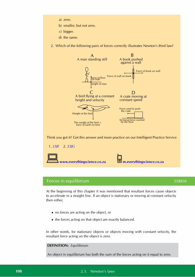
a) zero.
b) smaller, but not zero.
c) bigger.
d) the same.
2. Which of the following pairs of forces correctly illustrates Newton’s third law?
A man standing still
A crate moving atconstant speed
A bird flying at a constantheight and velocity
A book pushedagainst a wall
force of floor
weight of man
on man
Force used to pushthe crate
frictional force exertedby the floorThe weight of the bird =
force of Earth on bird
Weight of the bird
Force of wall on book
Force of book on wall
A
DC
B
Think you got it? Get this answer and more practice on our Intelligent Practice Service
1. 23JF 2. 23JG
www.everythingscience.co.za m.everythingscience.co.za
Forces in equilibrium ESBKW
At the beginning of this chapter it was mentioned that resultant forces cause objectsto accelerate in a straight line. If an object is stationary or moving at constant velocitythen either,
• no forces are acting on the object, or
• the forces acting on that object are exactly balanced.
In other words, for stationary objects or objects moving with constant velocity, theresultant force acting on the object is zero.
DEFINITION: Equilibrium
An object in equilibrium has both the sum of the forces acting on it equal to zero.
108 2.3. Newton’s laws
2.4 Forces between masses ESBKX
Gravity is arguably the first force that people really learn about. People don’t re-ally think of it as learning about gravity because it is such a big part of our everydaylives. Babies learning to crawl or walk are struggling against gravity, games involvingjumping, climbing or balls all give people a sense of the effect of gravity. The saying“everything that goes up, must come down” is all about gravity. Rain falls from the skybecause of gravity and so much more. We all know that these things happen but wedon’t often stop to ask what is gravity, what causes it and how can we describe it moreaccurately than “everything that goes up, must come down”?
All of the examples mentioned involve objects with mass falling to the ground, theyare being attracted to the Earth. Gravity is the name we give to the force that arisesbetween objects because of their mass. It is always an attractive force. It is a non-contact force, therefore it acts at a distance. The Earth is responsible for a gravitationalforce on the moon which keeps it in its orbit around the Earth and the gravitationalforce the moon exerts on the Earth is the dominant cause of ocean tides.
Sir Isaac Newton was the first scientist to precisely define the gravitational force, andto show that it could explain both falling bodies and astronomical motions. The grav-itational force is relatively simple. It is always attractive, and it depends only on themasses involved and the distance between them. Stated in modern language, New-ton’s universal law of gravitation states that every particle in the universe attracts everyother particle with a force along a line joining them. The force is directly proportionalto the product of their masses and inversely proportional to the square of the distancebetween them.
Newton’s law of universal gravitation ESBKY
DEFINITION: Newton’s law of universal gravitation
Every point mass attracts every other point mass by a force directed along the line con-necting the two. This force is proportional to the product of the masses and inverselyproportional to the square of the distance between them.
The magnitude of the attractive gravitational force between the two point masses, F isgiven by:
F = Gm1m2
d2
where: F is in newtons (N), G is the gravitational constant 6,67 × 10⁻¹¹ N·m2·kg−2,m1 is the mass of the first point mass in kilograms (kg), m2 is the mass of the secondpoint mass in kilograms (kg) and d is the distance between the two point masses inmetres (m). For any large objects (not point masses) we use the distance from thecentre of the object(s) to do the calculation. This is very important when dealing withvery large objects like planets. The distance from the centre of the planet and fromthe surface of the planet differ by a large amount. Remember that this is a force ofattraction and should be described by a vector. We use Newton’s law of universalgravitation to determine the magnitude of the force and then analyse the problem todetermine the direction.
For example, consider a man of mass 80 kg standing 10 m from a woman with a mass
109Chapter 2. Newton’s laws
of 65 kg. The attractive gravitational force between them would be:
F = Gm1m2
d2
=(
6,67 × 10⁻¹¹)(
(80)(65)(10)2
)
= 3,47 × 10⁻⁹ N
If the man and woman move to 1 m apart, then the force is:
F = Gm1m2
d2
=(
6,67 × 10⁻¹¹)(
(80)(65)(1)2
)
= 3,47 × 10⁻⁷ N
As you can see, these forces are very small.
Now consider the gravitational force between the Earth and the Moon. The mass ofthe Earth is 5,98 × 1024 kg, the mass of the Moon is 7,35 × 10²² kg and the Earth andMoon are 3,8 × 10⁸ m apart. The gravitational force between the Earth and Moon is:
F = Gm1m2
d2
=(
6,67 × 10⁻¹¹)(
(5,98 × 1024)(7,35 × 10²²)
(0,38 × 10⁹)2
)
= 2,03 × 10²⁰ N
From this example you can see that the force is very large.
These two examples demonstrate that the greater the masses, the greater the forcebetween them. The 1/d2 factor tells us that the distance between the two bodies playsa role as well. The closer two bodies are, the stronger the gravitational force betweenthem is. We feel the gravitational attraction of the Earth most at the surface since thatis the closest we can get to it, but if we were in outer-space, we would barely feel theeffect of the Earth’s gravity!
Remember that F = ma which means that every object on Earth feels the same grav-itational acceleration! That means whether you drop a pen or a book (from the sameheight), they will both take the same length of time to hit the ground... in fact they willbe head to head for the entire fall if you drop them at the same time. We can showthis easily by using Newton’s second law and the equation for the gravitational force.The force between the Earth (which has the mass MEarth) and an object of mass mo is
F =GmoMEarth
d2and the acceleration of an object of mass mo (in terms of the force
acting on it) is ao =F
mo.
So we equate them and we find that:
ao = GMEarth
d2Earth
Since it doesn’t depend on the mass of the object, mo, the acceleration on a body(due to the Earth’s gravity) does not depend on the mass of the body. Thus all objects
110 2.4. Forces between masses
experience the same gravitational acceleration. The force on different bodies will bedifferent but the acceleration will be the same. Due to the fact that this accelerationcaused by gravity is the same on all objects we label it differently, instead of using awe use gEarth which we call the gravitational acceleration and it has a magnitude ofapproximately 9,8 m·s−2.
The fact that gravitational acceleration is independent of the mass of the object holdsfor any planet, not just Earth, but each planet will have a different magnitude of gravi-tational acceleration.
Exercise 2 – 7:
1. When the planet Jupiter is closest to Earth it is 6,28×10⁸ km away. If Jupiter hasa mass of 1,9×1027 kg, what is the magnitude of the gravitational force betweenJupiter and the Earth?
2. When the planet Jupiter is furthest from the Earth it is 9,28 × 10⁸ km away. IfJupiter has a mass of 1,9 × 1027 kg, what is the magnitude of the gravitationalforce between Jupiter and the Earth?
3. What distance must a satellite with a mass of 80 kg be away from the Earth tofeel a force of 1000 N? How far from Jupiter to feel the same force?
4. The radius of Jupiter is 71,5×10³ km and the radius of the moon is 1,7×10³ km,if the moon has a mass of 7,35× 10²² kg work out the gravitational accelerationon Jupiter and on the moon.
5. Astrology, NOT astronomy, makes much of the position of the planets at themoment of one’s birth. The only known force a planet exerts on Earth is gravita-tional. Calculate:
a) the gravitational force exerted on a 4,20 kg baby by a 100 kg father 0,200 maway at birth
b) the force on the baby due to Jupiter if it is at its closest distance to Earth,some 6,29 × 10¹¹ m away.
c) How does the force of Jupiter on the baby compare to the force of the fatheron the baby?
6. The existence of the dwarf planet Pluto was proposed based on irregularities inNeptune’s orbit. Pluto was subsequently discovered near its predicted position.But it now appears that the discovery was fortuitous, because Pluto is small andthe irregularities in Neptune’s orbit were not well known. To illustrate that Plutohas a minor effect on the orbit of Neptune compared with the closest planet toNeptune:
a) Calculate the acceleration due to gravity at Neptune due to Pluto whenthey are 4,50 × 10¹² m apart, as they are at present. The mass of Pluto is1,4 × 1022 kg and the mass of Neptune is: 1,02 × 1026 kg.
b) Calculate the acceleration due to gravity at Neptune due to Uranus,presently about 2,50×10¹² m apart, and compare it with that due to Pluto.The mass of Uranus is 8,62 × 1025 kg.
111Chapter 2. Newton’s laws
Think you got it? Get this answer and more practice on our Intelligent Practice Service
1. 23JH 2. 23JJ 3. 23JK 4. 23JM 5. 23JN 6. 23JP
www.everythingscience.co.za m.everythingscience.co.za
Weight and mass ESBKZ
In everyday discussion many people use weight and mass to mean the same thingwhich is not true.
Mass is a scalar and weight is a vector. Mass is a measurement of how much matteris in an object; weight is a measurement of how hard gravity is pulling on that object.Your mass is the same wherever you are, on Earth; on the moon; floating in space,because the amount of stuff you’re made of doesn’t change. Your weight dependson how strong a gravitational force is acting on you at the moment; you’d weigh lesson the moon than on Earth, and in space you’d weigh almost nothing at all. Mass ismeasured in kilograms, kg, and weight is a force and measured in newtons, N.
When you stand on a scale you are trying measure how much of you there is. Peoplewho are trying to reduce their mass hope to see the reading on the scale get smallerbut they talk about losing weight. Their weight will decrease but it is because theirmass is decreasing. A scale uses the persons weight to determine their mass.
You can use Fg = mg to calculate weight.
Worked example 21: Newton’s second law: lifts and g
QUESTION
A lift, with a mass of 250 kg, is initially at rest on the ground floor of a tall building.Passengers with an unknown total mass, m, climb into the lift. The lift acceleratesupwards at 1,6 m·s−2. The cable supporting the lift exerts a constant upward force of7700 N.
1. Draw a labelled force diagram indicating all the forces acting on the lift while itaccelerates upwards.
2. What is the maximum mass, m, of the passengers the lift can carry in order toachieve a constant upward acceleration of 1,6 m·s−2.
SOLUTION
Step 1: Draw a force diagram.
We choose upwards as the positive direction.
112 2.4. Forces between masses
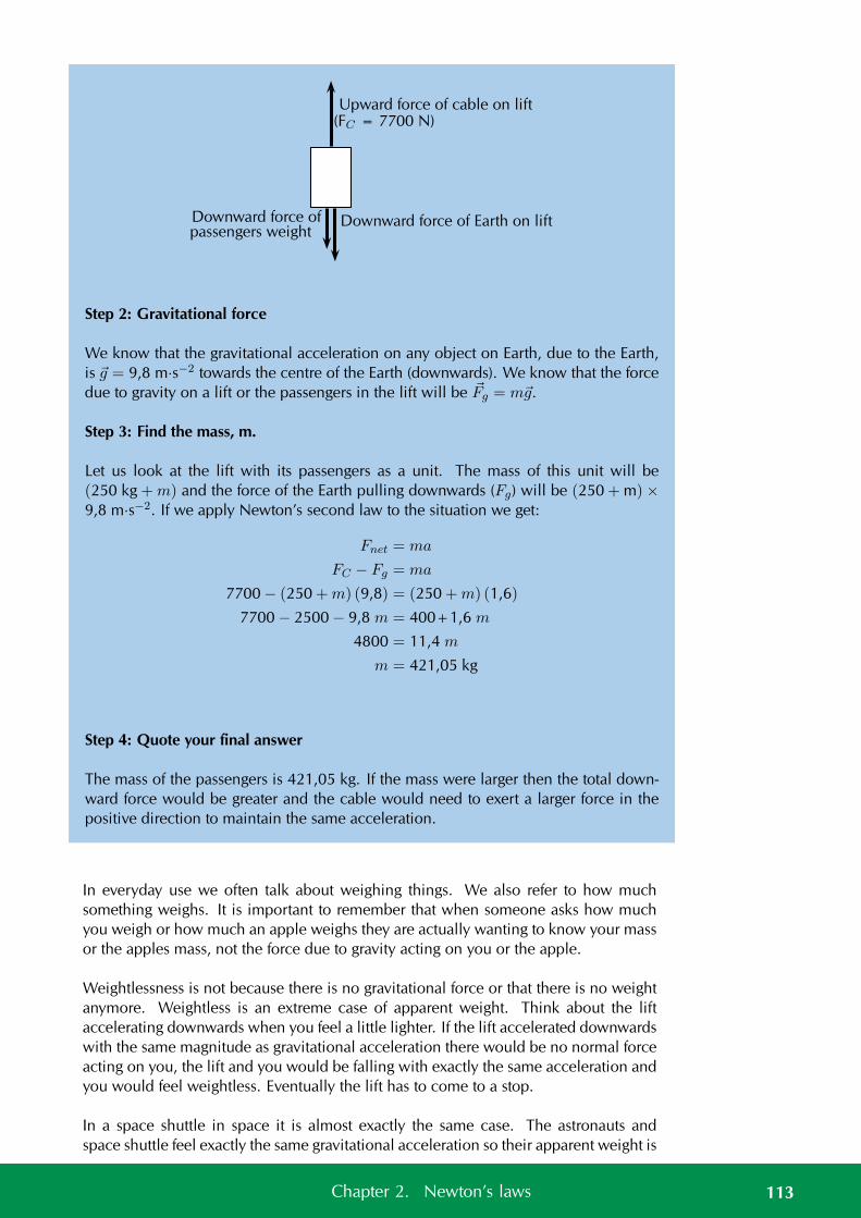
Downward force of Earth on lift
Upward force of cable on lift
Downward force ofpassengers weight
(FC = 7700 N)
Step 2: Gravitational force
We know that the gravitational acceleration on any object on Earth, due to the Earth,is g = 9,8 m·s−2 towards the centre of the Earth (downwards). We know that the forcedue to gravity on a lift or the passengers in the lift will be Fg = mg.
Step 3: Find the mass, m.
Let us look at the lift with its passengers as a unit. The mass of this unit will be(250 kg +m) and the force of the Earth pulling downwards (Fg) will be (250 + m) ×9,8 m·s−2. If we apply Newton’s second law to the situation we get:
Fnet = ma
FC − Fg = ma
7700 − (250 +m) (9,8) = (250 +m) (1,6)
7700 − 2500 − 9,8 m = 400+1,6 m
4800 = 11,4 m
m = 421,05 kg
Step 4: Quote your final answer
The mass of the passengers is 421,05 kg. If the mass were larger then the total down-ward force would be greater and the cable would need to exert a larger force in thepositive direction to maintain the same acceleration.
In everyday use we often talk about weighing things. We also refer to how muchsomething weighs. It is important to remember that when someone asks how muchyou weigh or how much an apple weighs they are actually wanting to know your massor the apples mass, not the force due to gravity acting on you or the apple.
Weightlessness is not because there is no gravitational force or that there is no weightanymore. Weightless is an extreme case of apparent weight. Think about the liftaccelerating downwards when you feel a little lighter. If the lift accelerated downwardswith the same magnitude as gravitational acceleration there would be no normal forceacting on you, the lift and you would be falling with exactly the same acceleration andyou would feel weightless. Eventually the lift has to come to a stop.
In a space shuttle in space it is almost exactly the same case. The astronauts andspace shuttle feel exactly the same gravitational acceleration so their apparent weight is
113Chapter 2. Newton’s laws
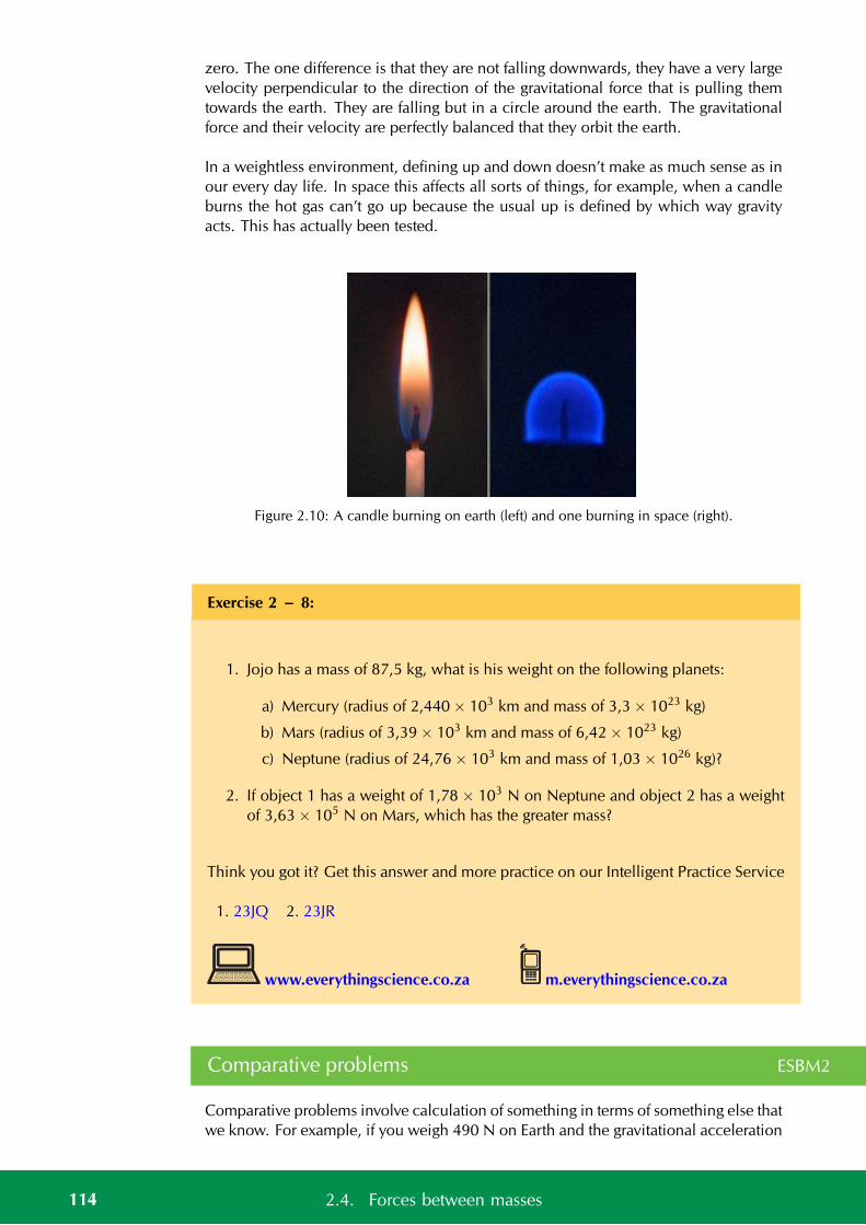
zero. The one difference is that they are not falling downwards, they have a very largevelocity perpendicular to the direction of the gravitational force that is pulling themtowards the earth. They are falling but in a circle around the earth. The gravitationalforce and their velocity are perfectly balanced that they orbit the earth.
In a weightless environment, defining up and down doesn’t make as much sense as inour every day life. In space this affects all sorts of things, for example, when a candleburns the hot gas can’t go up because the usual up is defined by which way gravityacts. This has actually been tested.
Figure 2.10: A candle burning on earth (left) and one burning in space (right).
Exercise 2 – 8:
1. Jojo has a mass of 87,5 kg, what is his weight on the following planets:
a) Mercury (radius of 2,440 × 103 km and mass of 3,3 × 10²³ kg)
b) Mars (radius of 3,39 × 10³ km and mass of 6,42 × 10²³ kg)
c) Neptune (radius of 24,76 × 10³ km and mass of 1,03 × 1026 kg)?
2. If object 1 has a weight of 1,78 × 10³ N on Neptune and object 2 has a weightof 3,63 × 10⁵ N on Mars, which has the greater mass?
Think you got it? Get this answer and more practice on our Intelligent Practice Service
1. 23JQ 2. 23JR
www.everythingscience.co.za m.everythingscience.co.za
Comparative problems ESBM2
Comparative problems involve calculation of something in terms of something else thatwe know. For example, if you weigh 490 N on Earth and the gravitational acceleration
114 2.4. Forces between masses
on Venus is 0,903 that of the gravitational acceleration on the Earth, then you wouldweigh 0, 903× 490N = 442,5N on Venus.
Method for answering comparative problems
• Write out equations and calculate all quantities for the given situation
• Write out all relationships between variable from first and second case
• Write out second case
• Substitute all first case variables into second case
• Write second case in terms of first case
Worked example 22: Comparative problem
QUESTION
A man has a mass of 70 kg. The planet Zirgon is the same size as the Earth but hastwice the mass of the Earth. What would the man weigh on Zirgon, if the gravitationalacceleration on Earth is 9,8 m·s−2?
SOLUTION
Step 1: Determine what information has been given
The following has been provided:
• the mass of the man, m
• the mass of the planet Zirgon (mZ ) in terms of the mass of the Earth (MEarth),mZ = 2MEarth
• the radius of the planet Zirgon (rZ ) in terms of the radius of the Earth (rE ),rZ = rEarth
Step 2: Determine how to approach the problem
We are required to determine the man’s weight on Zirgon (wZ ). We can do this byusing:
Fg = mg = Gm1 ·m2
d2
to calculate the weight of the man on Earth and then use this value to determine theweight of the man on Zirgon.
Step 3: Situation on Earth
115Chapter 2. Newton’s laws
FEarth = mgE = GMEarth ·m
d2E= (70 kg)
(9,8 m·s−2
)
= 686 N
Step 4: Situation on Zirgon in terms of situation on Earth
Write the equation for the gravitational force on Zirgon and then substitute the valuesfor mZ and rZ , in terms of the values for the Earth.
wZ = mgZ = GmZ ·m
r2Z
= G2MEarth ·m
r2Earth
= 2
(GMEarth ·m
r2E
)
= 2FEarth
= 2 (686 N)
= 1372 N
Step 5: Quote the final answer
The man weighs 1372 N on Zirgon.
Worked example 23: Comparative problem
QUESTION
A man has a mass of 70 kg. On the planet Beeble how much will he weigh if Bee-ble has a mass half of that of the Earth and a radius one quarter that of the Earth.Gravitational acceleration on Earth is 9,8 m·s−2.
SOLUTION
Step 1: Determine what information has been given
The following has been provided:
• the mass of the man on Earth, m
• the mass of the planet Beeble (mB) in terms of the mass of the Earth(MEarth),mB = 1
2MEarth
• the radius of the planet Beeble (rB) in terms of the radius of the Earth (rE ),rB = 1
4rE
116 2.4. Forces between masses
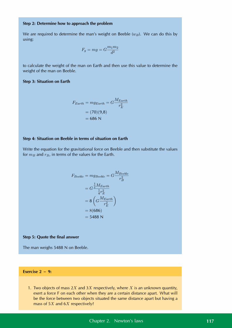
Step 2: Determine how to approach the problem
We are required to determine the man’s weight on Beeble (wB). We can do this byusing:
Fg = mg = Gm1m2
d2
to calculate the weight of the man on Earth and then use this value to determine theweight of the man on Beeble.
Step 3: Situation on Earth
FEarth = mgEarth = GMEarth
r2E= (70)(9,8)
= 686 N
Step 4: Situation on Beeble in terms of situation on Earth
Write the equation for the gravitational force on Beeble and then substitute the valuesfor mB and rB, in terms of the values for the Earth.
FBeeble = mgBeeble = GMBeeble
r2B
= G12MEarth
14r
2E
= 8(GMEarth
r2E
)
= 8(686)
= 5488 N
Step 5: Quote the final answer
The man weighs 5488 N on Beeble.
Exercise 2 – 9:
1. Two objects of mass 2X and 3X respectively, where X is an unknown quantity,exert a force F on each other when they are a certain distance apart. What willbe the force between two objects situated the same distance apart but having amass of 5X and 6X respectively?
117Chapter 2. Newton’s laws
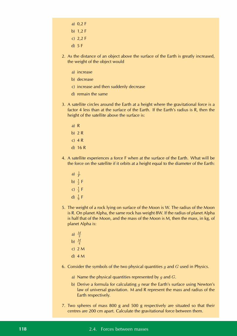
a) 0,2 F
b) 1,2 F
c) 2,2 F
d) 5 F
2. As the distance of an object above the surface of the Earth is greatly increased,the weight of the object would
a) increase
b) decrease
c) increase and then suddenly decrease
d) remain the same
3. A satellite circles around the Earth at a height where the gravitational force is afactor 4 less than at the surface of the Earth. If the Earth’s radius is R, then theheight of the satellite above the surface is:
a) R
b) 2 R
c) 4 R
d) 16 R
4. A satellite experiences a force F when at the surface of the Earth. What will bethe force on the satellite if it orbits at a height equal to the diameter of the Earth:
a) 1F
b) 12 F
c) 13 F
d) 19 F
5. The weight of a rock lying on surface of the Moon is W. The radius of the Moonis R. On planet Alpha, the same rock has weight 8W. If the radius of planet Alphais half that of the Moon, and the mass of the Moon is M, then the mass, in kg, ofplanet Alpha is:
a) M2
b) M4
c) 2 M
d) 4 M
6. Consider the symbols of the two physical quantities g and G used in Physics.
a) Name the physical quantities represented by g and G.
b) Derive a formula for calculating g near the Earth’s surface using Newton’slaw of universal gravitation. M and R represent the mass and radius of theEarth respectively.
7. Two spheres of mass 800 g and 500 g respectively are situated so that theircentres are 200 cm apart. Calculate the gravitational force between them.
118 2.4. Forces between masses
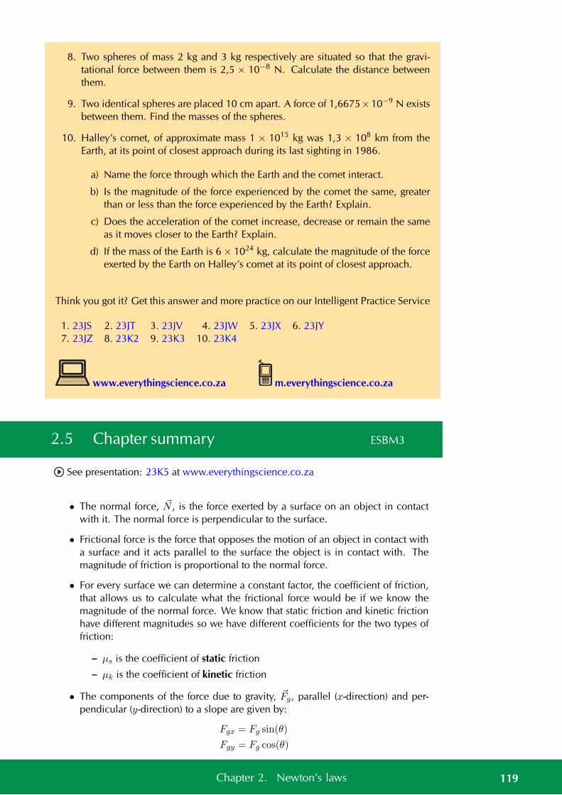
8. Two spheres of mass 2 kg and 3 kg respectively are situated so that the gravi-tational force between them is 2,5 × 10⁻⁸ N. Calculate the distance betweenthem.
9. Two identical spheres are placed 10 cm apart. A force of 1,6675×10⁻⁹ N existsbetween them. Find the masses of the spheres.
10. Halley’s comet, of approximate mass 1 × 10¹⁵ kg was 1,3 × 10⁸ km from theEarth, at its point of closest approach during its last sighting in 1986.
a) Name the force through which the Earth and the comet interact.
b) Is the magnitude of the force experienced by the comet the same, greaterthan or less than the force experienced by the Earth? Explain.
c) Does the acceleration of the comet increase, decrease or remain the sameas it moves closer to the Earth? Explain.
d) If the mass of the Earth is 6 × 1024 kg, calculate the magnitude of the forceexerted by the Earth on Halley’s comet at its point of closest approach.
Think you got it? Get this answer and more practice on our Intelligent Practice Service
1. 23JS 2. 23JT 3. 23JV 4. 23JW 5. 23JX 6. 23JY7. 23JZ 8. 23K2 9. 23K3 10. 23K4
www.everythingscience.co.za m.everythingscience.co.za
2.5 Chapter summary ESBM3
See presentation: 23K5 at www.everythingscience.co.za
• The normal force, N , is the force exerted by a surface on an object in contactwith it. The normal force is perpendicular to the surface.
• Frictional force is the force that opposes the motion of an object in contact witha surface and it acts parallel to the surface the object is in contact with. Themagnitude of friction is proportional to the normal force.
• For every surface we can determine a constant factor, the coefficient of friction,that allows us to calculate what the frictional force would be if we know themagnitude of the normal force. We know that static friction and kinetic frictionhave different magnitudes so we have different coefficients for the two types offriction:
– µs is the coefficient of static friction
– µk is the coefficient of kinetic friction
• The components of the force due to gravity, Fg, parallel (x-direction) and per-pendicular (y-direction) to a slope are given by:
Fgx = Fg sin(θ)
Fgy = Fg cos(θ)
119Chapter 2. Newton’s laws
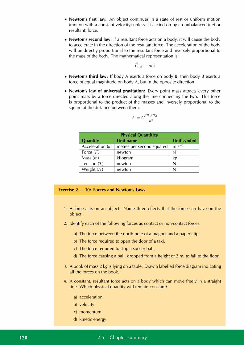
• Newton’s first law: An object continues in a state of rest or uniform motion(motion with a constant velocity) unless it is acted on by an unbalanced (net orresultant) force.
• Newton’s second law: If a resultant force acts on a body, it will cause the bodyto accelerate in the direction of the resultant force. The acceleration of the bodywill be directly proportional to the resultant force and inversely proportional tothe mass of the body. The mathematical representation is:
Fnet = ma
• Newton’s third law: If body A exerts a force on body B, then body B exerts aforce of equal magnitude on body A, but in the opposite direction.
• Newton’s law of universal gravitation: Every point mass attracts every otherpoint mass by a force directed along the line connecting the two. This forceis proportional to the product of the masses and inversely proportional to thesquare of the distance between them.
F = Gm1m2
d2
Physical QuantitiesQuantity Unit name Unit symbolAcceleration (a) metres per second squared m·s−1
Force (F ) newton NMass (m) kilogram kgTension (T ) newton NWeight (N ) newton N
Exercise 2 – 10: Forces and Newton’s Laws
1. A force acts on an object. Name three effects that the force can have on theobject.
2. Identify each of the following forces as contact or non-contact forces.
a) The force between the north pole of a magnet and a paper clip.
b) The force required to open the door of a taxi.
c) The force required to stop a soccer ball.
d) The force causing a ball, dropped from a height of 2 m, to fall to the floor.
3. A book of mass 2 kg is lying on a table. Draw a labelled force diagram indicatingall the forces on the book.
4. A constant, resultant force acts on a body which can move freely in a straightline. Which physical quantity will remain constant?
a) acceleration
b) velocity
c) momentum
d) kinetic energy
120 2.5. Chapter summary
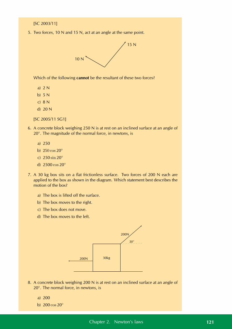
[SC 2003/11]
5. Two forces, 10 N and 15 N, act at an angle at the same point.
10 N
15 N
Which of the following cannot be the resultant of these two forces?
a) 2 N
b) 5 N
c) 8 N
d) 20 N
[SC 2005/11 SG1]
6. A concrete block weighing 250 N is at rest on an inclined surface at an angle of20. The magnitude of the normal force, in newtons, is
a) 250
b) 250 cos 20
c) 250 sin 20
d) 2500 cos 20
7. A 30 kg box sits on a flat frictionless surface. Two forces of 200 N each areapplied to the box as shown in the diagram. Which statement best describes themotion of the box?
a) The box is lifted off the surface.
b) The box moves to the right.
c) The box does not move.
d) The box moves to the left.
30kg
30
200N
200N
8. A concrete block weighing 200 N is at rest on an inclined surface at an angle of20. The normal force, in newtons, is
a) 200
b) 200 cos 20
121Chapter 2. Newton’s laws
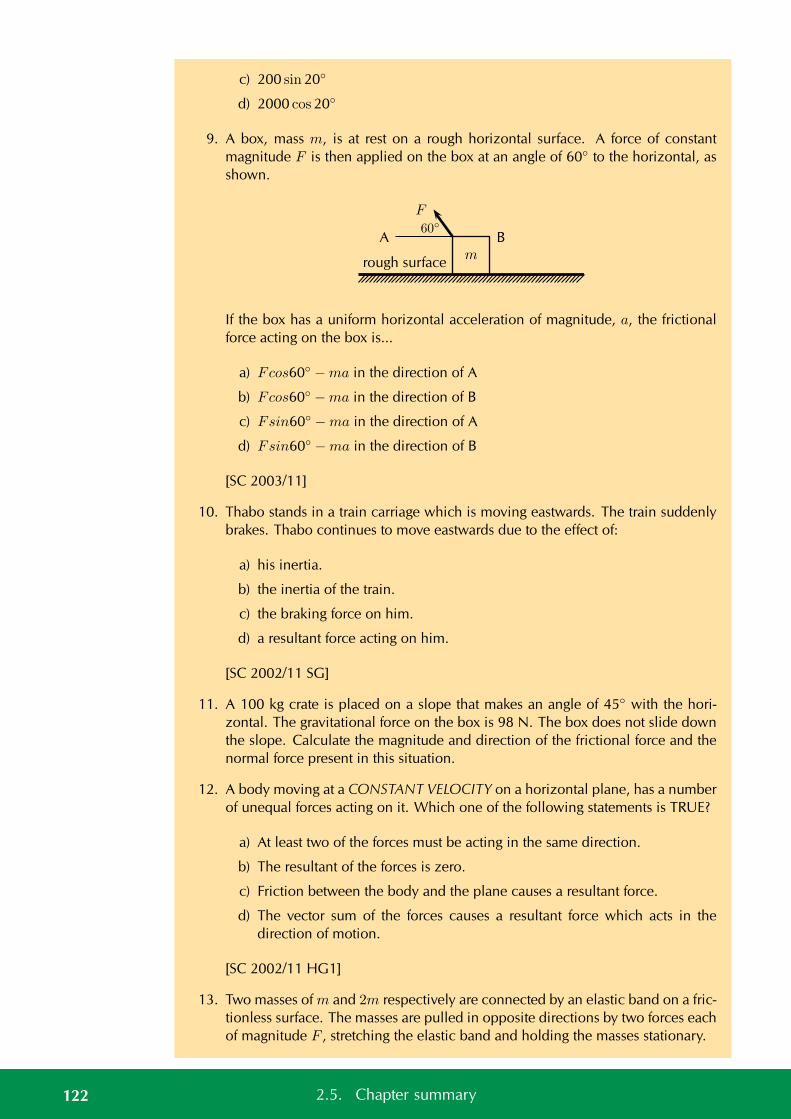
c) 200 sin 20
d) 2000 cos 20
9. A box, mass m, is at rest on a rough horizontal surface. A force of constantmagnitude F is then applied on the box at an angle of 60 to the horizontal, asshown.
F
A Bm
60
rough surface
If the box has a uniform horizontal acceleration of magnitude, a, the frictionalforce acting on the box is...
a) Fcos60 −ma in the direction of A
b) Fcos60 −ma in the direction of B
c) Fsin60 −ma in the direction of A
d) Fsin60 −ma in the direction of B
[SC 2003/11]
10. Thabo stands in a train carriage which is moving eastwards. The train suddenlybrakes. Thabo continues to move eastwards due to the effect of:
a) his inertia.
b) the inertia of the train.
c) the braking force on him.
d) a resultant force acting on him.
[SC 2002/11 SG]
11. A 100 kg crate is placed on a slope that makes an angle of 45 with the hori-zontal. The gravitational force on the box is 98 N. The box does not slide downthe slope. Calculate the magnitude and direction of the frictional force and thenormal force present in this situation.
12. A body moving at a CONSTANT VELOCITY on a horizontal plane, has a numberof unequal forces acting on it. Which one of the following statements is TRUE?
a) At least two of the forces must be acting in the same direction.
b) The resultant of the forces is zero.
c) Friction between the body and the plane causes a resultant force.
d) The vector sum of the forces causes a resultant force which acts in thedirection of motion.
[SC 2002/11 HG1]
13. Two masses of m and 2m respectively are connected by an elastic band on a fric-tionless surface. The masses are pulled in opposite directions by two forces eachof magnitude F , stretching the elastic band and holding the masses stationary.
122 2.5. Chapter summary
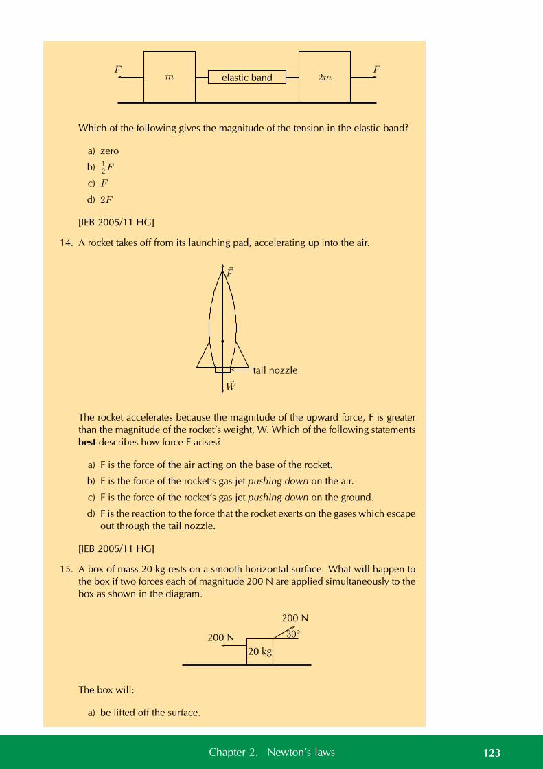
Fm elastic band 2m
F
Which of the following gives the magnitude of the tension in the elastic band?
a) zero
b) 12F
c) F
d) 2F
[IEB 2005/11 HG]
14. A rocket takes off from its launching pad, accelerating up into the air.
F
W
tail nozzle
The rocket accelerates because the magnitude of the upward force, F is greaterthan the magnitude of the rocket’s weight, W. Which of the following statementsbest describes how force F arises?
a) F is the force of the air acting on the base of the rocket.
b) F is the force of the rocket’s gas jet pushing down on the air.
c) F is the force of the rocket’s gas jet pushing down on the ground.
d) F is the reaction to the force that the rocket exerts on the gases which escapeout through the tail nozzle.
[IEB 2005/11 HG]
15. A box of mass 20 kg rests on a smooth horizontal surface. What will happen tothe box if two forces each of magnitude 200 N are applied simultaneously to thebox as shown in the diagram.
20 kg
200 N 30200 N
The box will:
a) be lifted off the surface.
123Chapter 2. Newton’s laws
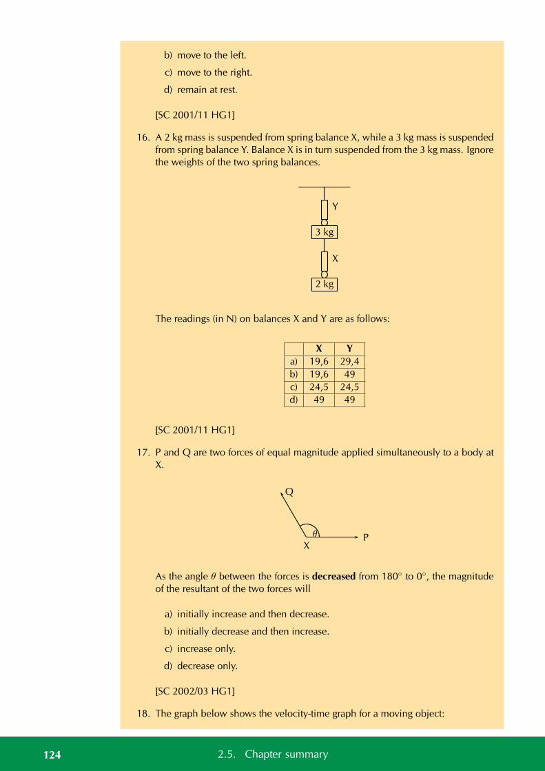
b) move to the left.
c) move to the right.
d) remain at rest.
[SC 2001/11 HG1]
16. A 2 kg mass is suspended from spring balance X, while a 3 kg mass is suspendedfrom spring balance Y. Balance X is in turn suspended from the 3 kg mass. Ignorethe weights of the two spring balances.
Y
3 kg
X
2 kg
The readings (in N) on balances X and Y are as follows:
X Ya) 19,6 29,4b) 19,6 49c) 24,5 24,5d) 49 49
[SC 2001/11 HG1]
17. P and Q are two forces of equal magnitude applied simultaneously to a body atX.
P
Q
θ
X
As the angle θ between the forces is decreased from 180 to 0, the magnitudeof the resultant of the two forces will
a) initially increase and then decrease.
b) initially decrease and then increase.
c) increase only.
d) decrease only.
[SC 2002/03 HG1]
18. The graph below shows the velocity-time graph for a moving object:
124 2.5. Chapter summary
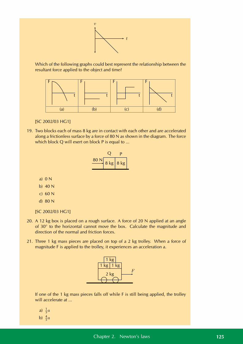
v
t
Which of the following graphs could best represent the relationship between theresultant force applied to the object and time?
F
t
F
t
F
t
F
t
(a) (b) (c) (d)
[SC 2002/03 HG1]
19. Two blocks each of mass 8 kg are in contact with each other and are acceleratedalong a frictionless surface by a force of 80 N as shown in the diagram. The forcewhich block Q will exert on block P is equal to ...
8 kg
Q
8 kg
P
80 N
a) 0 N
b) 40 N
c) 60 N
d) 80 N
[SC 2002/03 HG1]
20. A 12 kg box is placed on a rough surface. A force of 20 N applied at an angleof 30 to the horizontal cannot move the box. Calculate the magnitude anddirection of the normal and friction forces.
21. Three 1 kg mass pieces are placed on top of a 2 kg trolley. When a force ofmagnitude F is applied to the trolley, it experiences an acceleration a.
2 kg
1 kg 1 kg
1 kg
F
If one of the 1 kg mass pieces falls off while F is still being applied, the trolleywill accelerate at ...
a) 15a
b) 45a
125Chapter 2. Newton’s laws
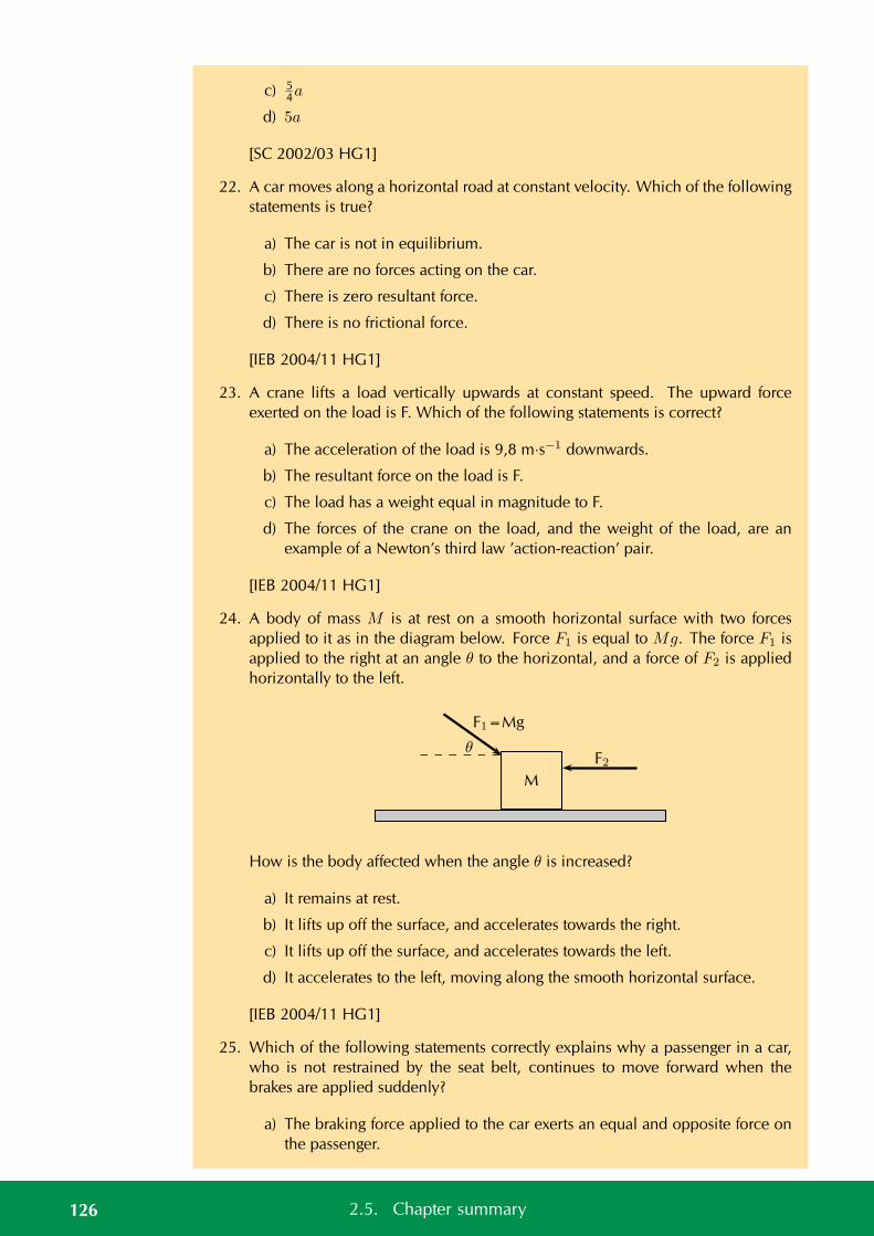
c) 54a
d) 5a
[SC 2002/03 HG1]
22. A car moves along a horizontal road at constant velocity. Which of the followingstatements is true?
a) The car is not in equilibrium.
b) There are no forces acting on the car.
c) There is zero resultant force.
d) There is no frictional force.
[IEB 2004/11 HG1]
23. A crane lifts a load vertically upwards at constant speed. The upward forceexerted on the load is F. Which of the following statements is correct?
a) The acceleration of the load is 9,8 m·s−1 downwards.
b) The resultant force on the load is F.
c) The load has a weight equal in magnitude to F.
d) The forces of the crane on the load, and the weight of the load, are anexample of a Newton’s third law ’action-reaction’ pair.
[IEB 2004/11 HG1]
24. A body of mass M is at rest on a smooth horizontal surface with two forcesapplied to it as in the diagram below. Force F1 is equal to Mg. The force F1 isapplied to the right at an angle θ to the horizontal, and a force of F2 is appliedhorizontally to the left.
M
F2θ
F1=Mg
How is the body affected when the angle θ is increased?
a) It remains at rest.
b) It lifts up off the surface, and accelerates towards the right.
c) It lifts up off the surface, and accelerates towards the left.
d) It accelerates to the left, moving along the smooth horizontal surface.
[IEB 2004/11 HG1]
25. Which of the following statements correctly explains why a passenger in a car,who is not restrained by the seat belt, continues to move forward when thebrakes are applied suddenly?
a) The braking force applied to the car exerts an equal and opposite force onthe passenger.
126 2.5. Chapter summary
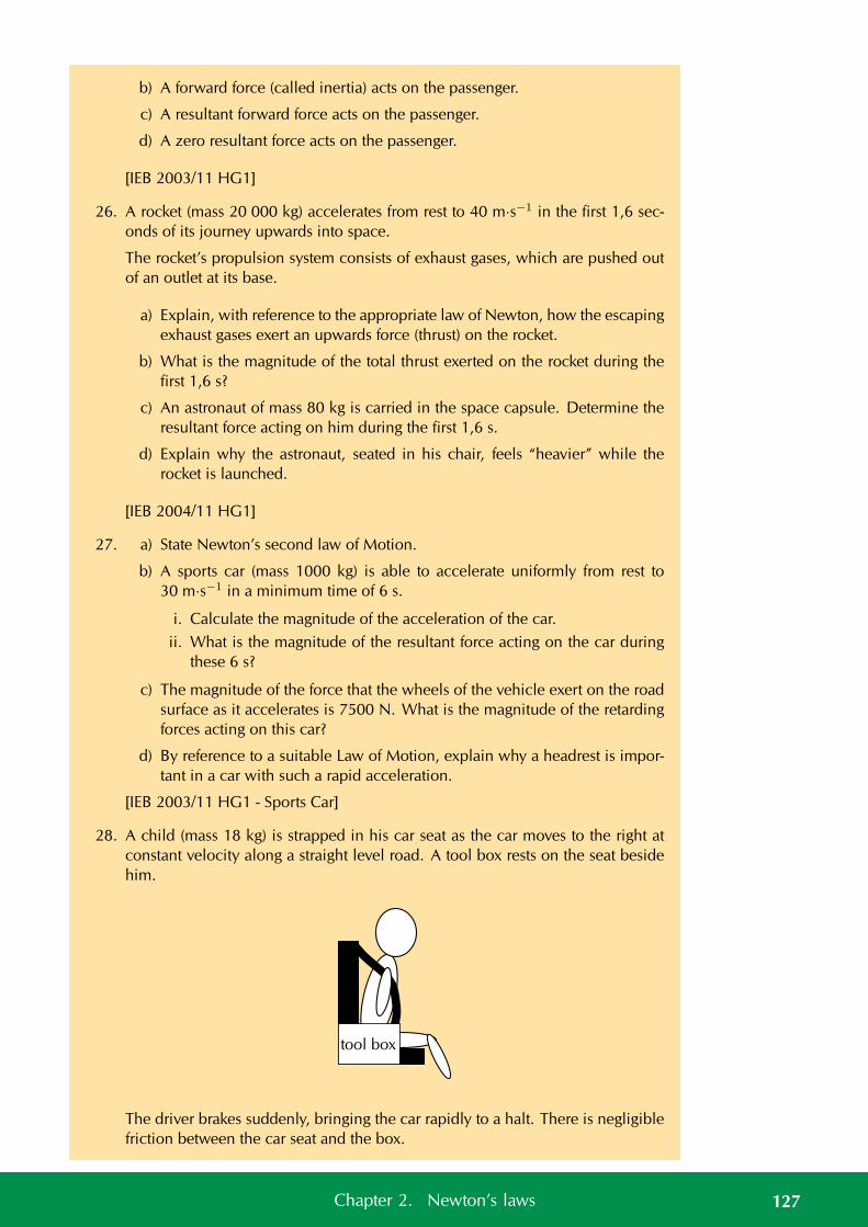
b) A forward force (called inertia) acts on the passenger.
c) A resultant forward force acts on the passenger.
d) A zero resultant force acts on the passenger.
[IEB 2003/11 HG1]
26. A rocket (mass 20 000 kg) accelerates from rest to 40 m·s−1 in the first 1,6 sec-onds of its journey upwards into space.
The rocket’s propulsion system consists of exhaust gases, which are pushed outof an outlet at its base.
a) Explain, with reference to the appropriate law of Newton, how the escapingexhaust gases exert an upwards force (thrust) on the rocket.
b) What is the magnitude of the total thrust exerted on the rocket during thefirst 1,6 s?
c) An astronaut of mass 80 kg is carried in the space capsule. Determine theresultant force acting on him during the first 1,6 s.
d) Explain why the astronaut, seated in his chair, feels “heavier” while therocket is launched.
[IEB 2004/11 HG1]
27. a) State Newton’s second law of Motion.
b) A sports car (mass 1000 kg) is able to accelerate uniformly from rest to30 m·s−1 in a minimum time of 6 s.
i. Calculate the magnitude of the acceleration of the car.ii. What is the magnitude of the resultant force acting on the car during
these 6 s?
c) The magnitude of the force that the wheels of the vehicle exert on the roadsurface as it accelerates is 7500 N. What is the magnitude of the retardingforces acting on this car?
d) By reference to a suitable Law of Motion, explain why a headrest is impor-tant in a car with such a rapid acceleration.
[IEB 2003/11 HG1 - Sports Car]
28. A child (mass 18 kg) is strapped in his car seat as the car moves to the right atconstant velocity along a straight level road. A tool box rests on the seat besidehim.
tool box
The driver brakes suddenly, bringing the car rapidly to a halt. There is negligiblefriction between the car seat and the box.
127Chapter 2. Newton’s laws
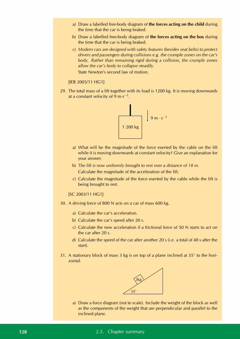
a) Draw a labelled free-body diagram of the forces acting on the child duringthe time that the car is being braked.
b) Draw a labelled free-body diagram of the forces acting on the box duringthe time that the car is being braked.
c) Modern cars are designed with safety features (besides seat belts) to protectdrivers and passengers during collisions e.g. the crumple zones on the car’sbody. Rather than remaining rigid during a collision, the crumple zonesallow the car’s body to collapse steadily.State Newton’s second law of motion.
[IEB 2005/11 HG1]
29. The total mass of a lift together with its load is 1200 kg. It is moving downwardsat a constant velocity of 9 m·s−1.
9 m · s−1
1 200 kg
a) What will be the magnitude of the force exerted by the cable on the liftwhile it is moving downwards at constant velocity? Give an explanation foryour answer.
b) The lift is now uniformly brought to rest over a distance of 18 m.Calculate the magnitude of the acceleration of the lift.
c) Calculate the magnitude of the force exerted by the cable while the lift isbeing brought to rest.
[SC 2003/11 HG1]
30. A driving force of 800 N acts on a car of mass 600 kg.
a) Calculate the car’s acceleration.
b) Calculate the car’s speed after 20 s.
c) Calculate the new acceleration if a frictional force of 50 N starts to act onthe car after 20 s.
d) Calculate the speed of the car after another 20 s (i.e. a total of 40 s after thestart).
31. A stationary block of mass 3 kg is on top of a plane inclined at 35 to the hori-zontal.
35
3kg
a) Draw a force diagram (not to scale). Include the weight of the block as wellas the components of the weight that are perpendicular and parallel to theinclined plane.
128 2.5. Chapter summary
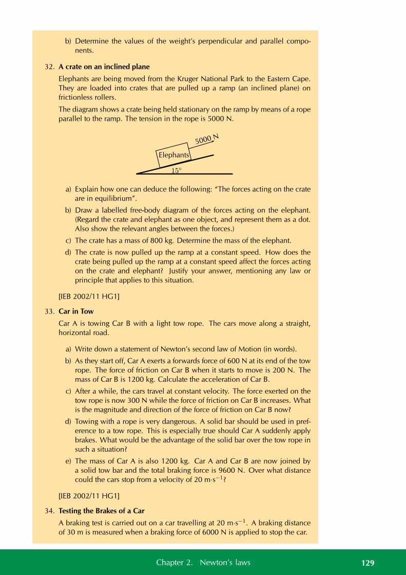
b) Determine the values of the weight’s perpendicular and parallel compo-nents.
32. A crate on an inclined plane
Elephants are being moved from the Kruger National Park to the Eastern Cape.They are loaded into crates that are pulled up a ramp (an inclined plane) onfrictionless rollers.
The diagram shows a crate being held stationary on the ramp by means of a ropeparallel to the ramp. The tension in the rope is 5000 N.
15
Elephants
5000 N
a) Explain how one can deduce the following: “The forces acting on the crateare in equilibrium”.
b) Draw a labelled free-body diagram of the forces acting on the elephant.(Regard the crate and elephant as one object, and represent them as a dot.Also show the relevant angles between the forces.)
c) The crate has a mass of 800 kg. Determine the mass of the elephant.
d) The crate is now pulled up the ramp at a constant speed. How does thecrate being pulled up the ramp at a constant speed affect the forces actingon the crate and elephant? Justify your answer, mentioning any law orprinciple that applies to this situation.
[IEB 2002/11 HG1]
33. Car in Tow
Car A is towing Car B with a light tow rope. The cars move along a straight,horizontal road.
a) Write down a statement of Newton’s second law of Motion (in words).
b) As they start off, Car A exerts a forwards force of 600 N at its end of the towrope. The force of friction on Car B when it starts to move is 200 N. Themass of Car B is 1200 kg. Calculate the acceleration of Car B.
c) After a while, the cars travel at constant velocity. The force exerted on thetow rope is now 300 N while the force of friction on Car B increases. Whatis the magnitude and direction of the force of friction on Car B now?
d) Towing with a rope is very dangerous. A solid bar should be used in pref-erence to a tow rope. This is especially true should Car A suddenly applybrakes. What would be the advantage of the solid bar over the tow rope insuch a situation?
e) The mass of Car A is also 1200 kg. Car A and Car B are now joined bya solid tow bar and the total braking force is 9600 N. Over what distancecould the cars stop from a velocity of 20 m·s−1?
[IEB 2002/11 HG1]
34. Testing the Brakes of a Car
A braking test is carried out on a car travelling at 20 m·s−1. A braking distanceof 30 m is measured when a braking force of 6000 N is applied to stop the car.
129Chapter 2. Newton’s laws
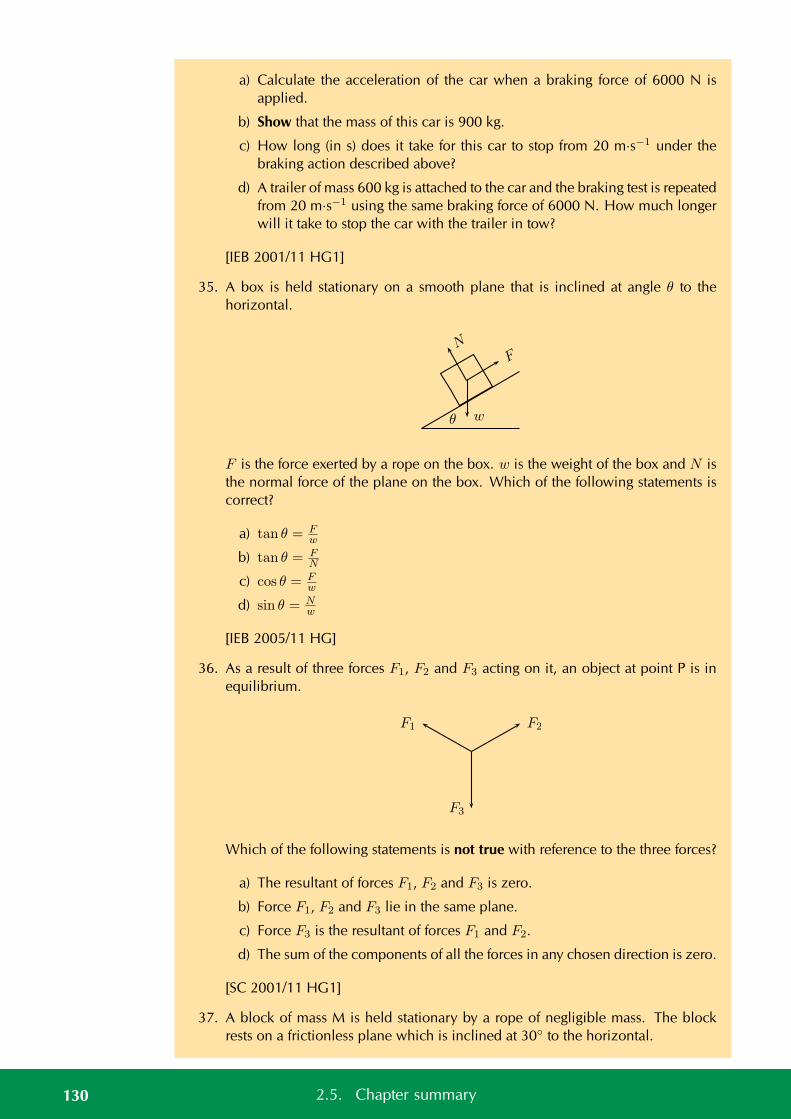
a) Calculate the acceleration of the car when a braking force of 6000 N isapplied.
b) Show that the mass of this car is 900 kg.
c) How long (in s) does it take for this car to stop from 20 m·s−1 under thebraking action described above?
d) A trailer of mass 600 kg is attached to the car and the braking test is repeatedfrom 20 m·s−1 using the same braking force of 6000 N. How much longerwill it take to stop the car with the trailer in tow?
[IEB 2001/11 HG1]
35. A box is held stationary on a smooth plane that is inclined at angle θ to thehorizontal.
NF
wθ
F is the force exerted by a rope on the box. w is the weight of the box and N isthe normal force of the plane on the box. Which of the following statements iscorrect?
a) tan θ = Fw
b) tan θ = FN
c) cos θ = Fw
d) sin θ = Nw
[IEB 2005/11 HG]
36. As a result of three forces F1, F2 and F3 acting on it, an object at point P is inequilibrium.
F2F1
F3
Which of the following statements is not true with reference to the three forces?
a) The resultant of forces F1, F2 and F3 is zero.
b) Force F1, F2 and F3 lie in the same plane.
c) Force F3 is the resultant of forces F1 and F2.
d) The sum of the components of all the forces in any chosen direction is zero.
[SC 2001/11 HG1]
37. A block of mass M is held stationary by a rope of negligible mass. The blockrests on a frictionless plane which is inclined at 30 to the horizontal.
130 2.5. Chapter summary
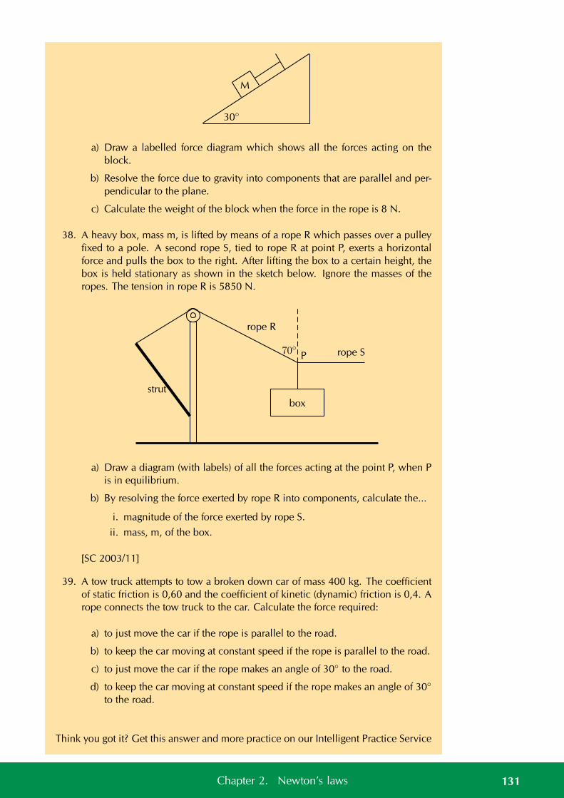
30
M
a) Draw a labelled force diagram which shows all the forces acting on theblock.
b) Resolve the force due to gravity into components that are parallel and per-pendicular to the plane.
c) Calculate the weight of the block when the force in the rope is 8 N.
38. A heavy box, mass m, is lifted by means of a rope R which passes over a pulleyfixed to a pole. A second rope S, tied to rope R at point P, exerts a horizontalforce and pulls the box to the right. After lifting the box to a certain height, thebox is held stationary as shown in the sketch below. Ignore the masses of theropes. The tension in rope R is 5850 N.
P rope S70
strut
rope R
box
a) Draw a diagram (with labels) of all the forces acting at the point P, when Pis in equilibrium.
b) By resolving the force exerted by rope R into components, calculate the...
i. magnitude of the force exerted by rope S.
ii. mass, m, of the box.
[SC 2003/11]
39. A tow truck attempts to tow a broken down car of mass 400 kg. The coefficientof static friction is 0,60 and the coefficient of kinetic (dynamic) friction is 0,4. Arope connects the tow truck to the car. Calculate the force required:
a) to just move the car if the rope is parallel to the road.
b) to keep the car moving at constant speed if the rope is parallel to the road.
c) to just move the car if the rope makes an angle of 30 to the road.
d) to keep the car moving at constant speed if the rope makes an angle of 30
to the road.
Think you got it? Get this answer and more practice on our Intelligent Practice Service
131Chapter 2. Newton’s laws
1. 23K6 2a. 23K7 2b. 23K8 2c. 23K9 2d. 23KB 3. 23KC4. 23KD 5. 23KF 6. 23KG 7. 23KH 8. 23KJ 9. 23KK
10. 23KM 11. 23KN 12. 23KP 13. 23KQ 14. 23KR 15. 23KS16. 23KT 17. 23KV 18. 23KW 19. 23KX 20. 23KY 21. 23KZ22. 23M2 23. 23M3 24. 23M4 25. 23M5 26. 23M6 27. 23M728. 23M8 29. 23M9 30. 23MB 31. 23MC 32. 23MD 33. 23MF34. 23MG 35. 23MJ 36. 23MK 37. 23MM 38. 23MN 39. 23MP
www.everythingscience.co.za m.everythingscience.co.za
Exercise 2 – 11: Gravitation
1. An object attracts another with a gravitational force F. If the distance betweenthe centres of the two objects is now decreased to a third (1
3 ) of the originaldistance, the force of attraction that the one object would exert on the otherwould become...
a) 19F
b) 13F
c) 3F
d) 9F
[SC 2003/11]
2. An object is dropped from a height of 1 km above the Earth. If air resistance isignored, the acceleration of the object is dependent on the...
a) mass of the object
b) radius of the earth
c) mass of the earth
d) weight of the object
[SC 2003/11]
3. A man has a mass of 70 kg on Earth. He is walking on a new planet that has amass four times that of the Earth and the radius is the same as that of the Earth (ME = 6 × 1024 kg, rE = 6 × 10⁶ m )
a) Calculate the force between the man and the Earth.
b) What is the man’s weight on the new planet?
c) Would his weight be bigger or smaller on the new planet? Explain how youarrived at your answer.
4. Calculate the distance between two objects, 5000 kg and 6 × 10¹² kg respec-tively, if the magnitude of the force between them is 3 × 10⁸ N
5. An astronaut in a satellite 1600 km above the Earth experiences a gravitationalforce of magnitude 700 N on Earth. The Earth’s radius is 6400 km. Calculate:
132 2.5. Chapter summary
a) The magnitude of the gravitational force which the astronaut experiencesin the satellite.
b) The magnitude of the gravitational force on an object in the satellite whichweighs 300 N on Earth.
6. An astronaut of mass 70 kg on Earth lands on a planet which has half the Earth’sradius and twice its mass. Calculate the magnitude of the force of gravity whichis exerted on him on the planet.
7. Calculate the magnitude of the gravitational force of attraction between twospheres of lead with a mass of 10 kg and 6 kg respectively if they are placed50 mm apart.
8. The gravitational force between two objects is 1200 N. What is the gravitationalforce between the objects if the mass of each is doubled and the distance be-tween them halved?
9. Calculate the gravitational force between the Sun with a mass of 2×1030 kg andthe Earth with a mass of 6×1024 kg if the distance between them is 1,4×10⁸ km.
10. How does the gravitational force of attraction between two objects change when
a) the mass of each object is doubled.
b) the distance between the centres of the objects is doubled.
c) the mass of one object is halved, and the distance between the centres ofthe objects is halved.
11. Read each of the following statements and say whether you agree or not. Givereasons for your answer and rewrite the statement if necessary:
a) The gravitational acceleration g is constant.
b) The weight of an object is independent of its mass.
c) G is dependent on the mass of the object that is being accelerated.
12. An astronaut weighs 750 N on the surface of the Earth.
a) What will his weight be on the surface of Saturn, which has a mass 100times greater than the Earth, and a radius 5 times greater than the Earth?
b) What is his mass on Saturn?
13. Your mass is 60 kg in Paris at ground level. How much less would you weighafter taking a lift to the top of the Eiffel Tower, which is 405 m high? Assume theEarth’s mass is 6,0 × 1024 kg and the Earth’s radius is 6400 km.
14. a) State Newton’s law of universal gravitation.
b) Use Newton’s law of universal gravitation to determine the magnitude ofthe acceleration due to gravity on the Moon.
The mass of the Moon is 7,4 × 10²² kg.
The radius of the Moon is 1,74 × 10⁶ m.
c) Will an astronaut, kitted out in his space suit, jump higher on the Moon oron the Earth? Give a reason for your answer.
133Chapter 2. Newton’s laws

Think you got it? Get this answer and more practice on our Intelligent Practice Service
1. 23MS 2. 23MT 3. 23MV 4. 23MW 5. 23MY 6. 23MZ7. 23N2 8. 23N3 9. 23N4 10. 23N5 11a. 23N6 11b. 23N7
11c. 23N8 12. 23N9 13. 23NC 14. 23ND
www.everythingscience.co.za m.everythingscience.co.za
134 2.5. Chapter summary
CHAPTER 3
Atomic combinations
3.1 Chemical bonds 136
3.2 Molecular shape 148
3.3 Electronegativity 153
3.4 Energy and bonding 159
3.5 Chapter summary 160
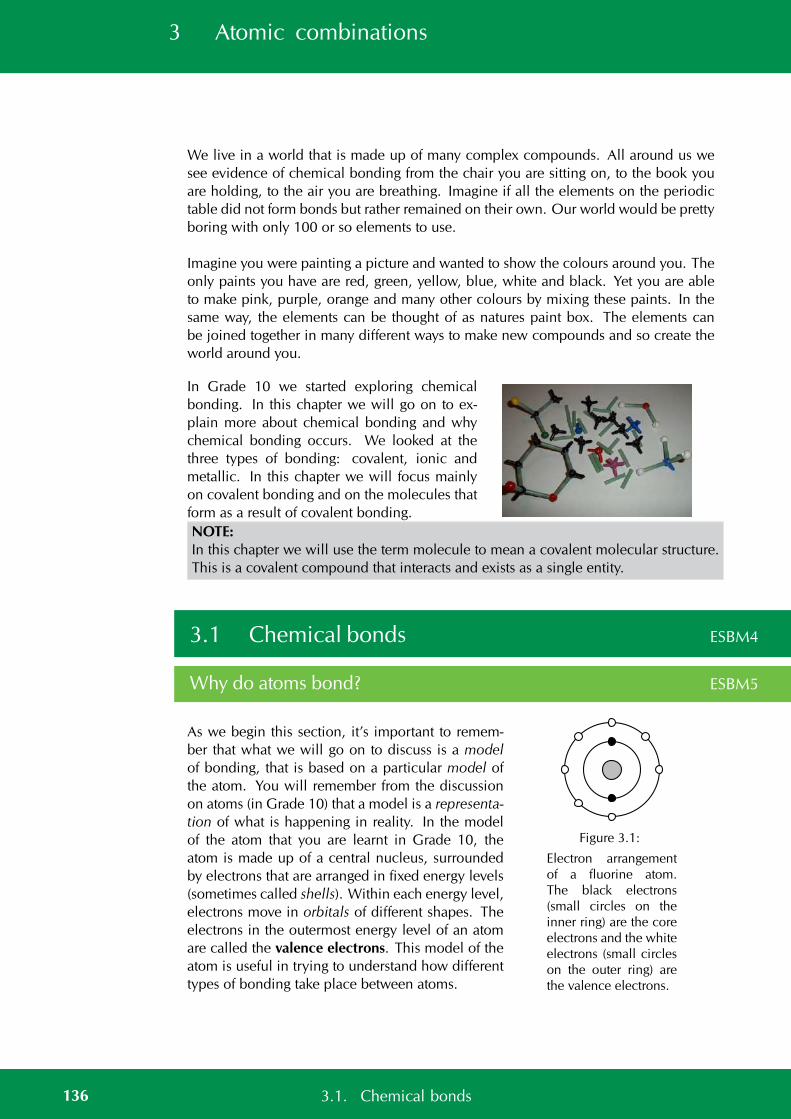
3 Atomic combinations
We live in a world that is made up of many complex compounds. All around us wesee evidence of chemical bonding from the chair you are sitting on, to the book youare holding, to the air you are breathing. Imagine if all the elements on the periodictable did not form bonds but rather remained on their own. Our world would be prettyboring with only 100 or so elements to use.
Imagine you were painting a picture and wanted to show the colours around you. Theonly paints you have are red, green, yellow, blue, white and black. Yet you are ableto make pink, purple, orange and many other colours by mixing these paints. In thesame way, the elements can be thought of as natures paint box. The elements canbe joined together in many different ways to make new compounds and so create theworld around you.
In Grade 10 we started exploring chemicalbonding. In this chapter we will go on to ex-plain more about chemical bonding and whychemical bonding occurs. We looked at thethree types of bonding: covalent, ionic andmetallic. In this chapter we will focus mainlyon covalent bonding and on the molecules thatform as a result of covalent bonding.NOTE:In this chapter we will use the term molecule to mean a covalent molecular structure.This is a covalent compound that interacts and exists as a single entity.
3.1 Chemical bonds ESBM4
Why do atoms bond? ESBM5
As we begin this section, it’s important to remem-ber that what we will go on to discuss is a modelof bonding, that is based on a particular model ofthe atom. You will remember from the discussionon atoms (in Grade 10) that a model is a representa-tion of what is happening in reality. In the modelof the atom that you are learnt in Grade 10, theatom is made up of a central nucleus, surroundedby electrons that are arranged in fixed energy levels(sometimes called shells). Within each energy level,electrons move in orbitals of different shapes. Theelectrons in the outermost energy level of an atomare called the valence electrons. This model of theatom is useful in trying to understand how differenttypes of bonding take place between atoms.
Figure 3.1:
Electron arrangementof a fluorine atom.The black electrons(small circles on theinner ring) are the coreelectrons and the whiteelectrons (small circleson the outer ring) arethe valence electrons.
136 3.1. Chemical bonds
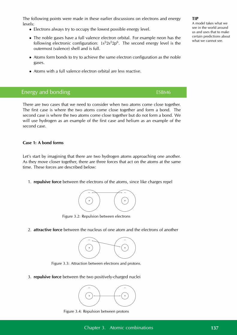
TIPA model takes what wesee in the world aroundus and uses that to makecertain predictions aboutwhat we cannot see.
The following points were made in these earlier discussions on electrons and energylevels:
• Electrons always try to occupy the lowest possible energy level.
• The noble gases have a full valence electron orbital. For example neon has thefollowing electronic configuration: 1s22s22p6. The second energy level is theoutermost (valence) shell and is full.
• Atoms form bonds to try to achieve the same electron configuration as the noblegases.
• Atoms with a full valence electron orbital are less reactive.
Energy and bonding ESBM6
There are two cases that we need to consider when two atoms come close together.The first case is where the two atoms come close together and form a bond. Thesecond case is where the two atoms come close together but do not form a bond. Wewill use hydrogen as an example of the first case and helium as an example of thesecond case.
Case 1: A bond forms
Let’s start by imagining that there are two hydrogen atoms approaching one another.As they move closer together, there are three forces that act on the atoms at the sametime. These forces are described below:
1. repulsive force between the electrons of the atoms, since like charges repel
+ +
Figure 3.2: Repulsion between electrons
2. attractive force between the nucleus of one atom and the electrons of another
+ +
Figure 3.3: Attraction between electrons and protons.
3. repulsive force between the two positively-charged nuclei
+ +
Figure 3.4: Repulsion between protons
137Chapter 3. Atomic combinations
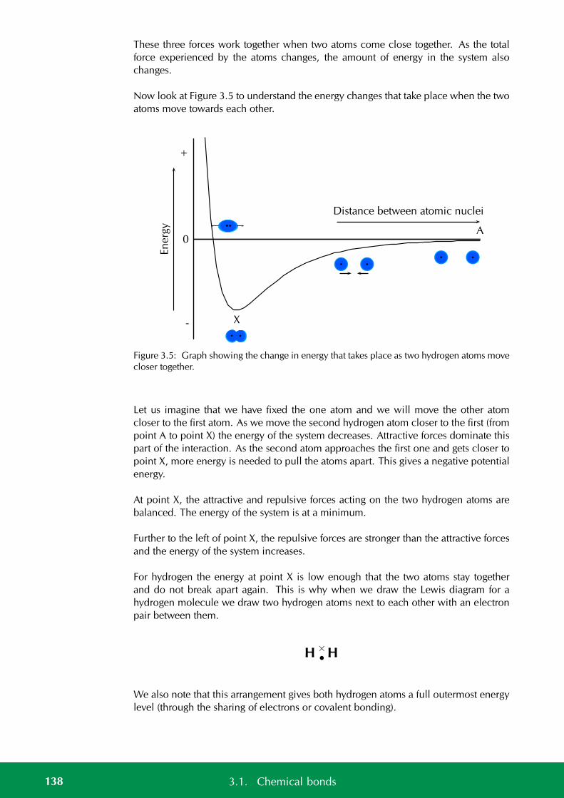
These three forces work together when two atoms come close together. As the totalforce experienced by the atoms changes, the amount of energy in the system alsochanges.
Now look at Figure 3.5 to understand the energy changes that take place when the twoatoms move towards each other.
En
erg
y+
0
-
Distance between atomic nuclei
A
X
Figure 3.5: Graph showing the change in energy that takes place as two hydrogen atoms movecloser together.
Let us imagine that we have fixed the one atom and we will move the other atomcloser to the first atom. As we move the second hydrogen atom closer to the first (frompoint A to point X) the energy of the system decreases. Attractive forces dominate thispart of the interaction. As the second atom approaches the first one and gets closer topoint X, more energy is needed to pull the atoms apart. This gives a negative potentialenergy.
At point X, the attractive and repulsive forces acting on the two hydrogen atoms arebalanced. The energy of the system is at a minimum.
Further to the left of point X, the repulsive forces are stronger than the attractive forcesand the energy of the system increases.
For hydrogen the energy at point X is low enough that the two atoms stay togetherand do not break apart again. This is why when we draw the Lewis diagram for ahydrogen molecule we draw two hydrogen atoms next to each other with an electronpair between them.
H H•×
We also note that this arrangement gives both hydrogen atoms a full outermost energylevel (through the sharing of electrons or covalent bonding).
138 3.1. Chemical bonds
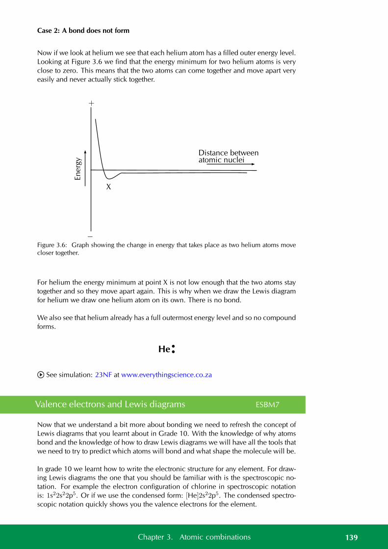
Case 2: A bond does not form
Now if we look at helium we see that each helium atom has a filled outer energy level.Looking at Figure 3.6 we find that the energy minimum for two helium atoms is veryclose to zero. This means that the two atoms can come together and move apart veryeasily and never actually stick together.
En
erg
y
Distance betweenatomic nuclei
+
−
X
Figure 3.6: Graph showing the change in energy that takes place as two helium atoms movecloser together.
For helium the energy minimum at point X is not low enough that the two atoms staytogether and so they move apart again. This is why when we draw the Lewis diagramfor helium we draw one helium atom on its own. There is no bond.
We also see that helium already has a full outermost energy level and so no compoundforms.
He ••
See simulation: 23NF at www.everythingscience.co.za
Valence electrons and Lewis diagrams ESBM7
Now that we understand a bit more about bonding we need to refresh the concept ofLewis diagrams that you learnt about in Grade 10. With the knowledge of why atomsbond and the knowledge of how to draw Lewis diagrams we will have all the tools thatwe need to try to predict which atoms will bond and what shape the molecule will be.
In grade 10 we learnt how to write the electronic structure for any element. For draw-ing Lewis diagrams the one that you should be familiar with is the spectroscopic no-tation. For example the electron configuration of chlorine in spectroscopic notationis: 1s22s22p5. Or if we use the condensed form: [He]2s22p5. The condensed spectro-scopic notation quickly shows you the valence electrons for the element.
139Chapter 3. Atomic combinations
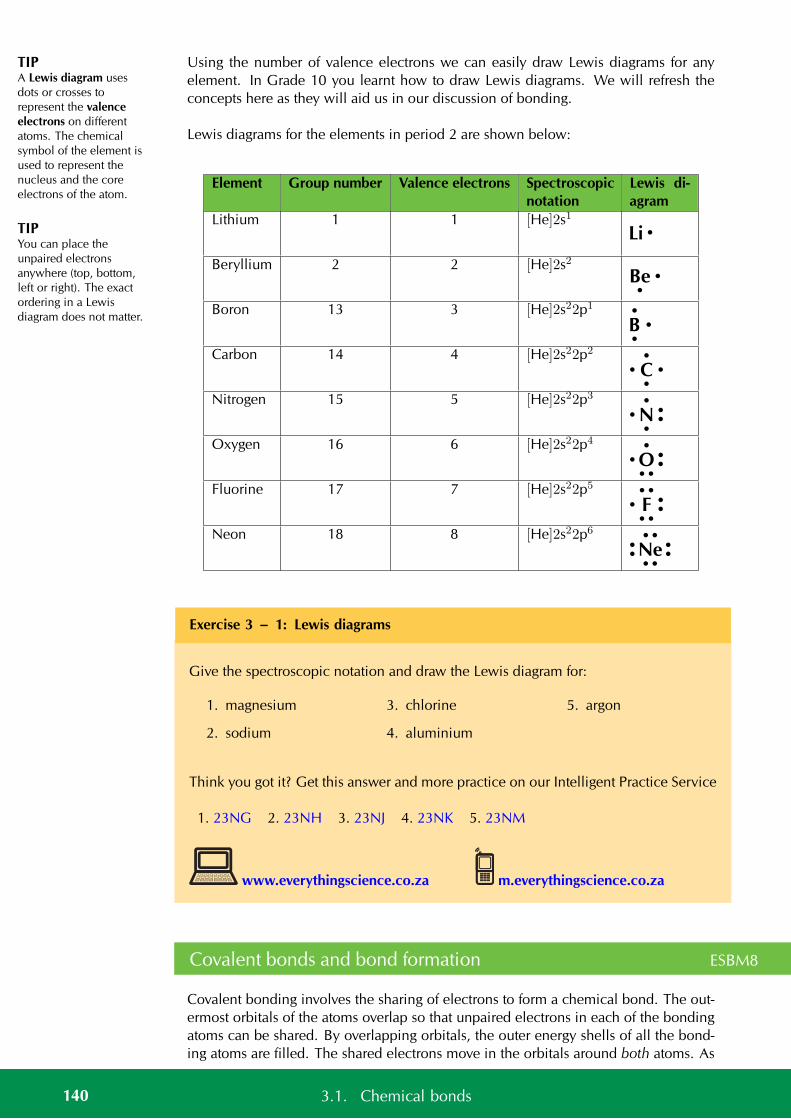
TIPA Lewis diagram usesdots or crosses torepresent the valenceelectrons on differentatoms. The chemicalsymbol of the element isused to represent thenucleus and the coreelectrons of the atom.
TIPYou can place theunpaired electronsanywhere (top, bottom,left or right). The exactordering in a Lewisdiagram does not matter.
Using the number of valence electrons we can easily draw Lewis diagrams for anyelement. In Grade 10 you learnt how to draw Lewis diagrams. We will refresh theconcepts here as they will aid us in our discussion of bonding.
Lewis diagrams for the elements in period 2 are shown below:
Element Group number Valence electrons Spectroscopicnotation
Lewis di-agram
Lithium 1 1 [He]2s1Li •
Beryllium 2 2 [He]2s2Be•
•
Boron 13 3 [He]2s22p1
B•
•
•
Carbon 14 4 [He]2s22p2
C•
•
•
•
Nitrogen 15 5 [He]2s22p3
N•
••
•
•
Oxygen 16 6 [He]2s22p4
O• •
••
•
•
Fluorine 17 7 [He]2s22p5
F• •
••
••
•
Neon 18 8 [He]2s22p6
Ne• •
••
••
••
Exercise 3 – 1: Lewis diagrams
Give the spectroscopic notation and draw the Lewis diagram for:
1. magnesium
2. sodium
3. chlorine
4. aluminium
5. argon
Think you got it? Get this answer and more practice on our Intelligent Practice Service
1. 23NG 2. 23NH 3. 23NJ 4. 23NK 5. 23NM
www.everythingscience.co.za m.everythingscience.co.za
Covalent bonds and bond formation ESBM8
Covalent bonding involves the sharing of electrons to form a chemical bond. The out-ermost orbitals of the atoms overlap so that unpaired electrons in each of the bondingatoms can be shared. By overlapping orbitals, the outer energy shells of all the bond-ing atoms are filled. The shared electrons move in the orbitals around both atoms. As
140 3.1. Chemical bonds
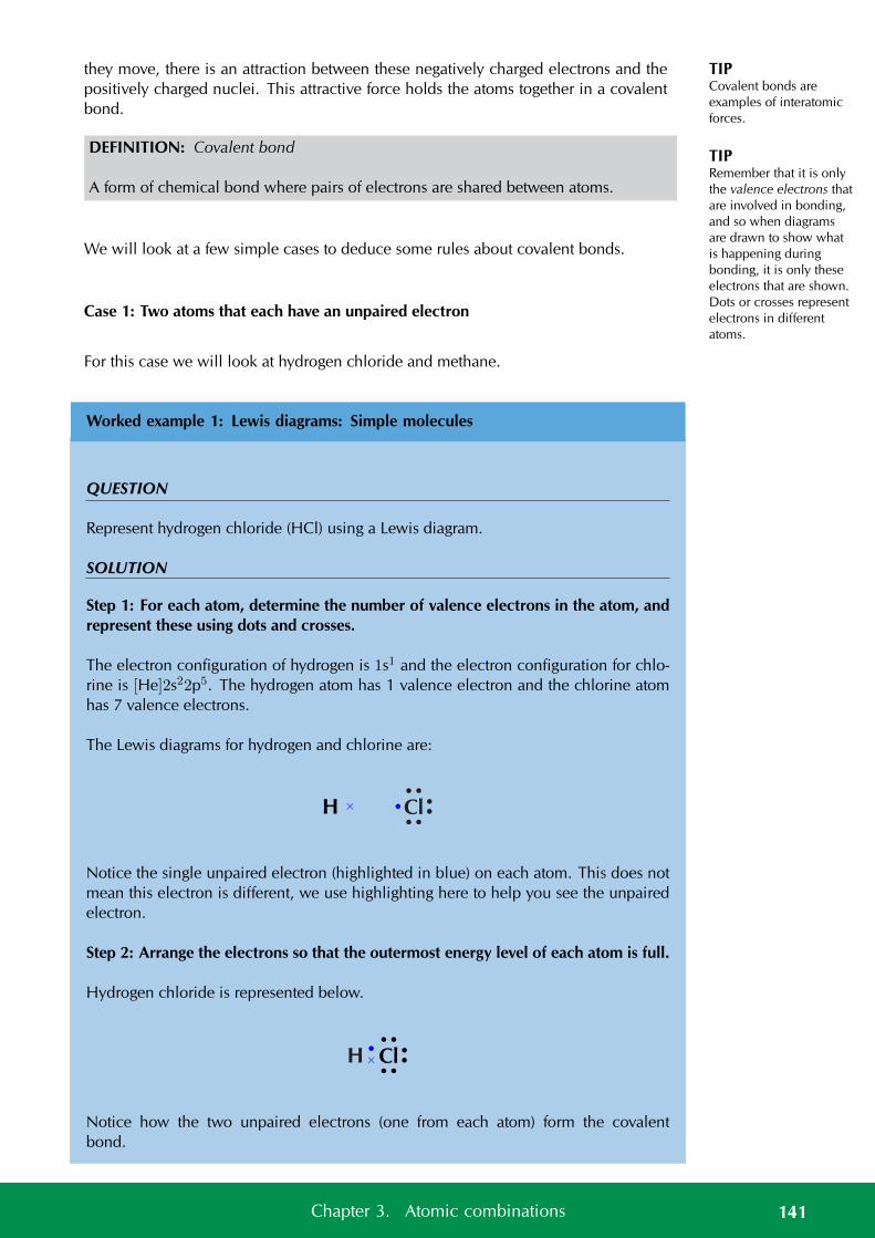
TIPCovalent bonds areexamples of interatomicforces.
TIPRemember that it is onlythe valence electrons thatare involved in bonding,and so when diagramsare drawn to show whatis happening duringbonding, it is only theseelectrons that are shown.Dots or crosses representelectrons in differentatoms.
they move, there is an attraction between these negatively charged electrons and thepositively charged nuclei. This attractive force holds the atoms together in a covalentbond.
DEFINITION: Covalent bond
A form of chemical bond where pairs of electrons are shared between atoms.
We will look at a few simple cases to deduce some rules about covalent bonds.
Case 1: Two atoms that each have an unpaired electron
For this case we will look at hydrogen chloride and methane.
Worked example 1: Lewis diagrams: Simple molecules
QUESTION
Represent hydrogen chloride (HCl) using a Lewis diagram.
SOLUTION
Step 1: For each atom, determine the number of valence electrons in the atom, andrepresent these using dots and crosses.
The electron configuration of hydrogen is 1s1 and the electron configuration for chlo-rine is [He]2s22p5. The hydrogen atom has 1 valence electron and the chlorine atomhas 7 valence electrons.
The Lewis diagrams for hydrogen and chlorine are:
H × Cl• •
••
••
•
Notice the single unpaired electron (highlighted in blue) on each atom. This does notmean this electron is different, we use highlighting here to help you see the unpairedelectron.
Step 2: Arrange the electrons so that the outermost energy level of each atom is full.
Hydrogen chloride is represented below.
Cl• •
••
••
•×H
Notice how the two unpaired electrons (one from each atom) form the covalentbond.
141Chapter 3. Atomic combinations
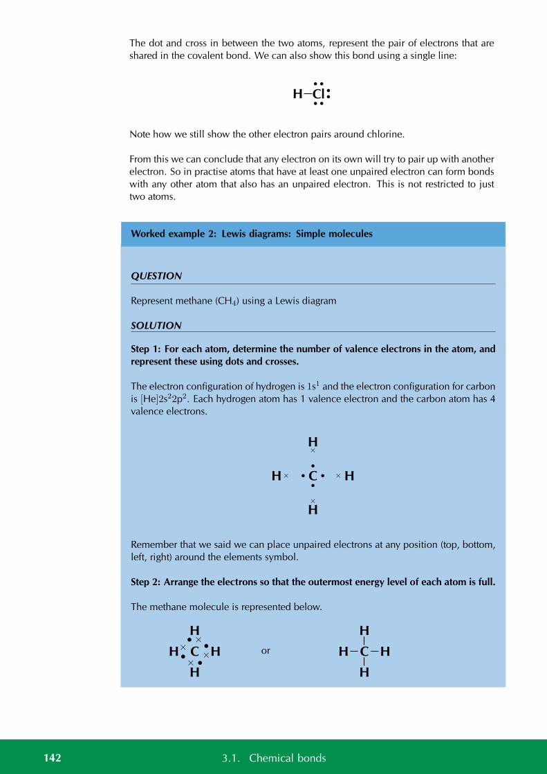
The dot and cross in between the two atoms, represent the pair of electrons that areshared in the covalent bond. We can also show this bond using a single line:
Cl• •
••
••
H
Note how we still show the other electron pairs around chlorine.
From this we can conclude that any electron on its own will try to pair up with anotherelectron. So in practise atoms that have at least one unpaired electron can form bondswith any other atom that also has an unpaired electron. This is not restricted to justtwo atoms.
Worked example 2: Lewis diagrams: Simple molecules
QUESTION
Represent methane (CH4) using a Lewis diagram
SOLUTION
Step 1: For each atom, determine the number of valence electrons in the atom, andrepresent these using dots and crosses.
The electron configuration of hydrogen is 1s1 and the electron configuration for carbonis [He]2s22p2. Each hydrogen atom has 1 valence electron and the carbon atom has 4valence electrons.
H×
H
×
H×
H
×
C•
•
•
•
Remember that we said we can place unpaired electrons at any position (top, bottom,left, right) around the elements symbol.
Step 2: Arrange the electrons so that the outermost energy level of each atom is full.
The methane molecule is represented below.
H C× •
ו
ו
ו
H
H
H or H C
H
H
H
142 3.1. Chemical bonds
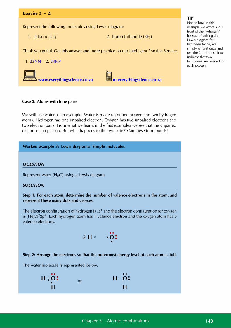
TIPNotice how in thisexample we wrote a 2 infront of the hydrogen?Instead of writing theLewis diagram forhydrogen twice, wesimply write it once anduse the 2 in front of it toindicate that twohydrogens are needed foreach oxygen.
Exercise 3 – 2:
Represent the following molecules using Lewis diagram:
1. chlorine (Cl2) 2. boron trifluoride (BF3)
Think you got it? Get this answer and more practice on our Intelligent Practice Service
1. 23NN 2. 23NP
www.everythingscience.co.za m.everythingscience.co.za
Case 2: Atoms with lone pairs
We will use water as an example. Water is made up of one oxygen and two hydrogenatoms. Hydrogen has one unpaired electron. Oxygen has two unpaired electrons andtwo electron pairs. From what we learnt in the first examples we see that the unpairedelectrons can pair up. But what happens to the two pairs? Can these form bonds?
Worked example 3: Lewis diagrams: Simple molecules
QUESTION
Represent water (H2O) using a Lewis diagram
SOLUTION
Step 1: For each atom, determine the number of valence electrons in the atom, andrepresent these using dots and crosses.
The electron configuration of hydrogen is 1s1 and the electron configuration for oxygenis [He]2s22p4. Each hydrogen atom has 1 valence electron and the oxygen atom has 6valence electrons.
H × O•
••
••
•
2
Step 2: Arrange the electrons so that the outermost energy level of each atom is full.
The water molecule is represented below.
H O• ×
••
••
ו
H
or H O ••
••
H
143Chapter 3. Atomic combinations

TIPA lone pair can be usedto form a dative covalentbond.
And now we can answer the questions that we asked before the worked example. Wesee that oxygen forms two bonds, one with each hydrogen atom. Oxygen howeverkeeps its electron pairs and does not share them. We can generalise this to any atom.If an atom has an electron pair it will normally not share that electron pair.
A lone pair is an unshared electron pair. A lone pair stays on the atom that it belongsto.
In the example above the lone pairs on oxygen are highlighted in red. When we drawthe bonding pairs using lines it is much easier to see the lone pairs on oxygen.
Exercise 3 – 3:
Represent the following molecules using Lewis diagrams:
1. ammonia (NH3) 2. oxygen difluoride (OF2)
Think you got it? Get this answer and more practice on our Intelligent Practice Service
1. 23NQ 2. 23NR
www.everythingscience.co.za m.everythingscience.co.za
Case 3: Atoms with multiple bonds
We will use oxygen and hydrogen cyanide as examples.
Worked example 4: Lewis diagrams: Molecules with multiple bonds
QUESTION
Represent oxygen (O2) using a Lewis diagram
SOLUTION
Step 1: For each atom, determine the number of valence electrons that the atom hasfrom its electron configuration.
The electron configuration of oxygen is [He]2s22p4. Oxygen has 6 valence electrons.
O×
×
××
×× O
•
••
••
•
144 3.1. Chemical bonds
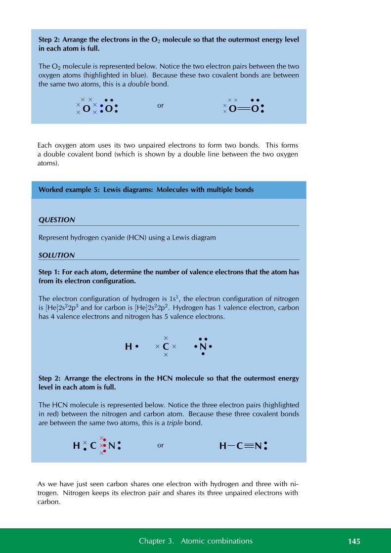
Step 2: Arrange the electrons in the O2 molecule so that the outermost energy levelin each atom is full.
The O2 molecule is represented below. Notice the two electron pairs between the twooxygen atoms (highlighted in blue). Because these two covalent bonds are betweenthe same two atoms, this is a double bond.
O O
××
××
× ×
••
••
• •or O O
××
× ×
••
• •
Each oxygen atom uses its two unpaired electrons to form two bonds. This formsa double covalent bond (which is shown by a double line between the two oxygenatoms).
Worked example 5: Lewis diagrams: Molecules with multiple bonds
QUESTION
Represent hydrogen cyanide (HCN) using a Lewis diagram
SOLUTION
Step 1: For each atom, determine the number of valence electrons that the atom hasfrom its electron configuration.
The electron configuration of hydrogen is 1s1, the electron configuration of nitrogenis [He]2s22p3 and for carbon is [He]2s22p2. Hydrogen has 1 valence electron, carbonhas 4 valence electrons and nitrogen has 5 valence electrons.
H • C×
×
×
×
N•
•••
•
Step 2: Arrange the electrons in the HCN molecule so that the outermost energylevel in each atom is full.
The HCN molecule is represented below. Notice the three electron pairs (highlightedin red) between the nitrogen and carbon atom. Because these three covalent bondsare between the same two atoms, this is a triple bond.
H C
ו
××
×
N ••
••• or H C N •
•
As we have just seen carbon shares one electron with hydrogen and three with ni-trogen. Nitrogen keeps its electron pair and shares its three unpaired electrons withcarbon.
145Chapter 3. Atomic combinations
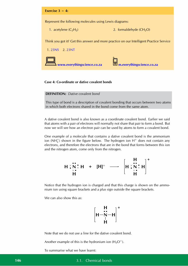
Exercise 3 – 4:
Represent the following molecules using Lewis diagrams:
1. acetylene (C2H2) 2. formaldehyde (CH2O)
Think you got it? Get this answer and more practice on our Intelligent Practice Service
1. 23NS 2. 23NT
www.everythingscience.co.za m.everythingscience.co.za
Case 4: Co-ordinate or dative covalent bonds
DEFINITION: Dative covalent bond
This type of bond is a description of covalent bonding that occurs between two atomsin which both electrons shared in the bond come from the same atom.
A dative covalent bond is also known as a coordinate covalent bond. Earlier we saidthat atoms with a pair of electrons will normally not share that pair to form a bond. Butnow we will see how an electron pair can be used by atoms to form a covalent bond.
One example of a molecule that contains a dative covalent bond is the ammoniumion (NH+
4 ) shown in the figure below. The hydrogen ion H+ does not contain anyelectrons, and therefore the electrons that are in the bond that forms between this ionand the nitrogen atom, come only from the nitrogen.
H N× •
ו
••
ו
H
H + [H]+ H N× •
ו
••
ו
H
H
H +
Notice that the hydrogen ion is charged and that this charge is shown on the ammo-nium ion using square brackets and a plus sign outside the square brackets.
We can also show this as:
H N
••
H
H
H +
Note that we do not use a line for the dative covalent bond.
Another example of this is the hydronium ion (H3O+).
To summarise what we have learnt:
146 3.1. Chemical bonds
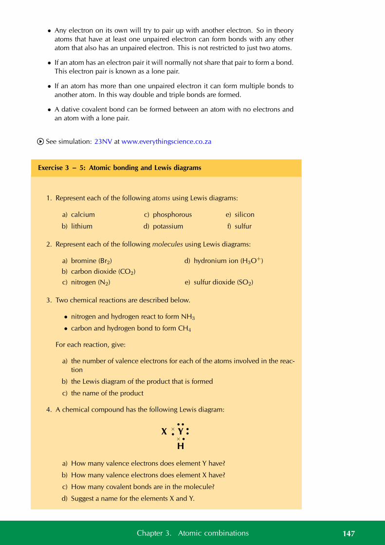
• Any electron on its own will try to pair up with another electron. So in theoryatoms that have at least one unpaired electron can form bonds with any otheratom that also has an unpaired electron. This is not restricted to just two atoms.
• If an atom has an electron pair it will normally not share that pair to form a bond.This electron pair is known as a lone pair.
• If an atom has more than one unpaired electron it can form multiple bonds toanother atom. In this way double and triple bonds are formed.
• A dative covalent bond can be formed between an atom with no electrons andan atom with a lone pair.
See simulation: 23NV at www.everythingscience.co.za
Exercise 3 – 5: Atomic bonding and Lewis diagrams
1. Represent each of the following atoms using Lewis diagrams:
a) calcium
b) lithium
c) phosphorous
d) potassium
e) silicon
f) sulfur
2. Represent each of the following molecules using Lewis diagrams:
a) bromine (Br2)
b) carbon dioxide (CO2)
c) nitrogen (N2)
d) hydronium ion (H3O+)
e) sulfur dioxide (SO2)
3. Two chemical reactions are described below.
• nitrogen and hydrogen react to form NH3
• carbon and hydrogen bond to form CH4
For each reaction, give:
a) the number of valence electrons for each of the atoms involved in the reac-tion
b) the Lewis diagram of the product that is formed
c) the name of the product
4. A chemical compound has the following Lewis diagram:
X Y× •
••
••
ו
H
a) How many valence electrons does element Y have?
b) How many valence electrons does element X have?
c) How many covalent bonds are in the molecule?
d) Suggest a name for the elements X and Y.
147Chapter 3. Atomic combinations

5. Complete the following table:
Compound CO2 CF4 HI C2H2
Lewis diagramTotal number of bonding pairsTotal number of non-bonding pairsSingle, double or triple bonds
Think you got it? Get this answer and more practice on our Intelligent Practice Service
1a. 23NW 1b. 23NX 1c. 23NY 1d. 23NZ 1e. 23P2 1f. 23P32a. 23P4 2b. 23P5 2c. 23P6 2d. 23P7 2e. 23P8 3. 23P94. 23PB 5. 23PC
www.everythingscience.co.za m.everythingscience.co.za
3.2 Molecular shape ESBM9
Molecular shape (the shape that a single molecule has) is important in determininghow the molecule interacts and reacts with other molecules. Molecular shape alsoinfluences the boiling point and melting point of molecules. If all molecules werelinear then life as we know it would not exist. Many of the properties of moleculescome from the particular shape that a molecule has. For example if the water moleculewas linear, it would be non-polar and so would not have all the special properties ithas.
Valence shell electron pair repulsion (VSEPR) theory ESBMB
The shape of a covalent molecule can be predicted using the Valence Shell ElectronPair Repulsion (VSEPR) theory. Very simply, VSEPR theory says that the valence elec-tron pairs in a molecule will arrange themselves around the central atom(s) of themolecule so that the repulsion between their negative charges is as small as possible.
In other words, the valence electron pairs arrange themselves so that they are as farapart as they can be.
DEFINITION: Valence Shell Electron Pair Repulsion Theory
Valence shell electron pair repulsion (VSEPR) theory is a model in chemistry, which isused to predict the shape of individual molecules. VSEPR is based upon minimisingthe extent of the electron-pair repulsion around the central atom being considered.
VSEPR theory is based on the idea that the geometry (shape) of a molecule is mostlydetermined by repulsion among the pairs of electrons around a central atom. The pairsof electrons may be bonding or non-bonding (also called lone pairs). Only valenceelectrons of the central atom influence the molecular shape in a meaningful way.
148 3.2. Molecular shape
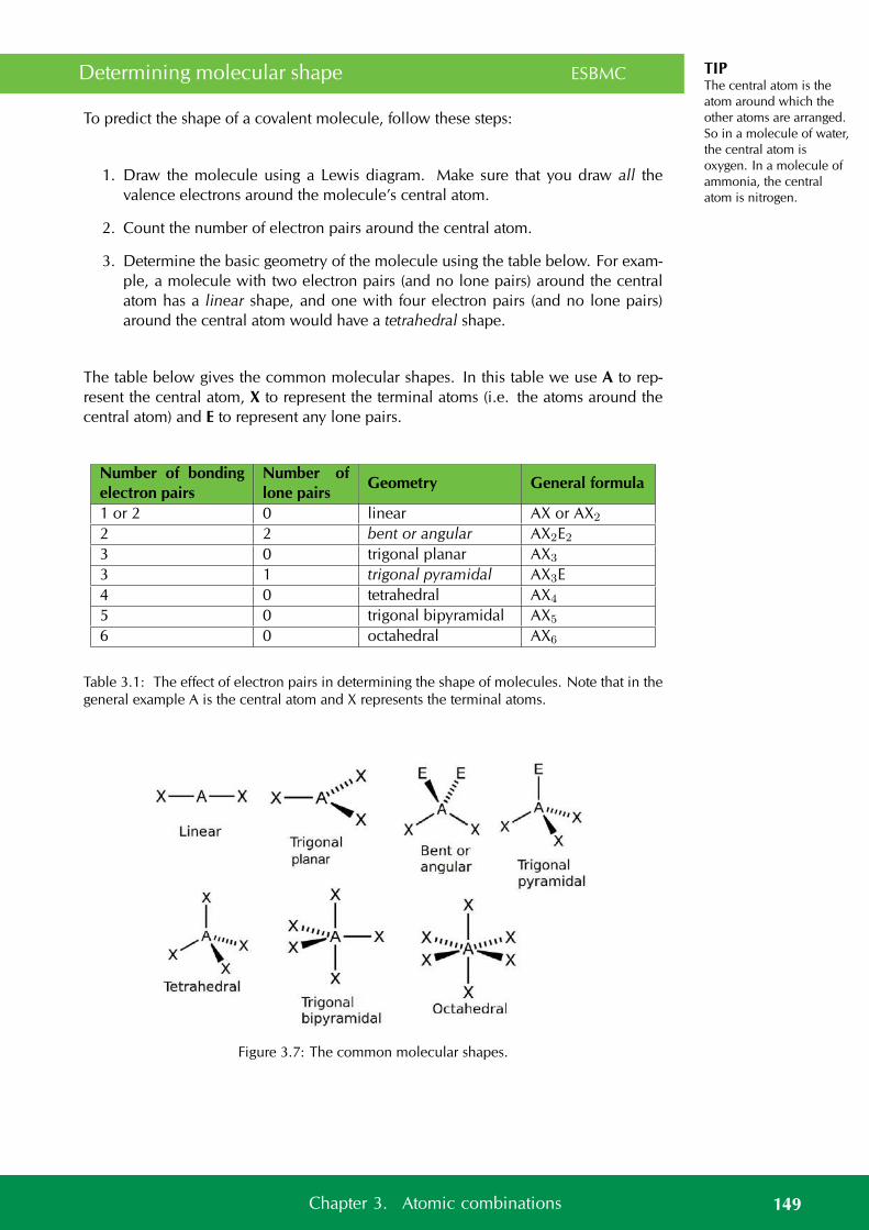
TIPThe central atom is theatom around which theother atoms are arranged.So in a molecule of water,the central atom isoxygen. In a molecule ofammonia, the centralatom is nitrogen.
Determining molecular shape ESBMC
To predict the shape of a covalent molecule, follow these steps:
1. Draw the molecule using a Lewis diagram. Make sure that you draw all thevalence electrons around the molecule’s central atom.
2. Count the number of electron pairs around the central atom.
3. Determine the basic geometry of the molecule using the table below. For exam-ple, a molecule with two electron pairs (and no lone pairs) around the centralatom has a linear shape, and one with four electron pairs (and no lone pairs)around the central atom would have a tetrahedral shape.
The table below gives the common molecular shapes. In this table we use A to rep-resent the central atom, X to represent the terminal atoms (i.e. the atoms around thecentral atom) and E to represent any lone pairs.
Number of bondingelectron pairs
Number oflone pairs
Geometry General formula
1 or 2 0 linear AX or AX2
2 2 bent or angular AX2E23 0 trigonal planar AX3
3 1 trigonal pyramidal AX3E4 0 tetrahedral AX4
5 0 trigonal bipyramidal AX5
6 0 octahedral AX6
Table 3.1: The effect of electron pairs in determining the shape of molecules. Note that in thegeneral example A is the central atom and X represents the terminal atoms.
Figure 3.7: The common molecular shapes.
149Chapter 3. Atomic combinations
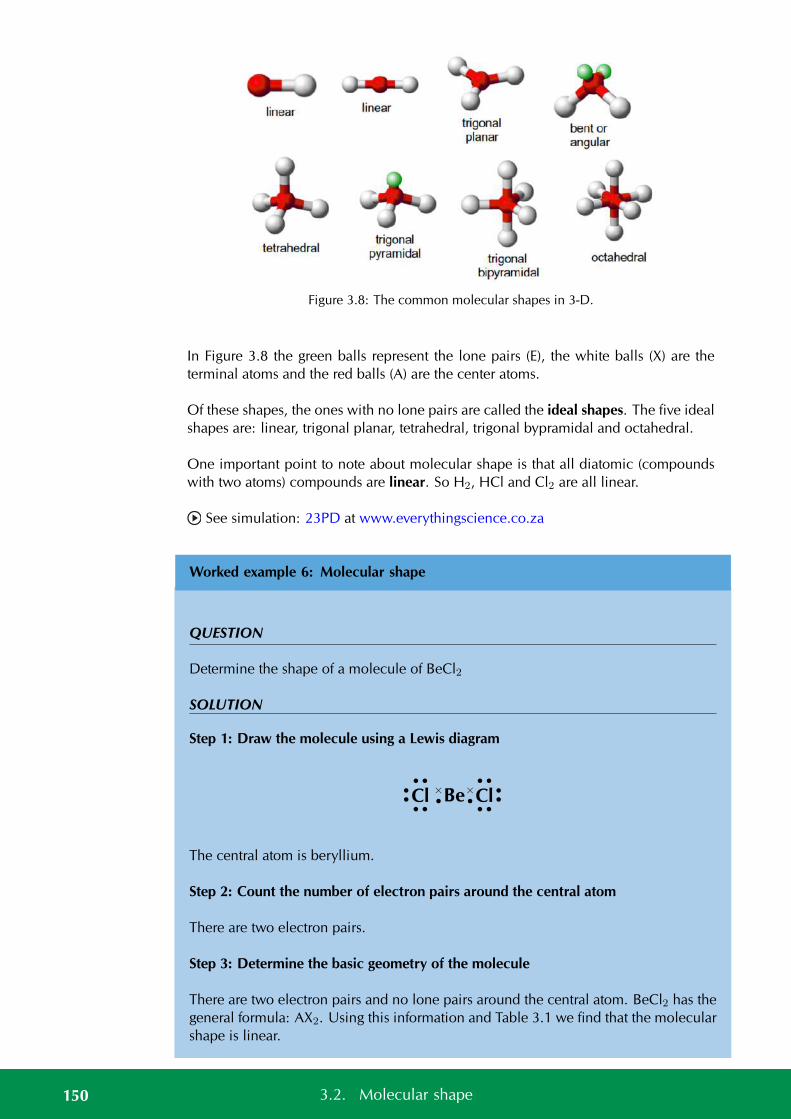
Figure 3.8: The common molecular shapes in 3-D.
In Figure 3.8 the green balls represent the lone pairs (E), the white balls (X) are theterminal atoms and the red balls (A) are the center atoms.
Of these shapes, the ones with no lone pairs are called the ideal shapes. The five idealshapes are: linear, trigonal planar, tetrahedral, trigonal bypramidal and octahedral.
One important point to note about molecular shape is that all diatomic (compoundswith two atoms) compounds are linear. So H2, HCl and Cl2 are all linear.
See simulation: 23PD at www.everythingscience.co.za
Worked example 6: Molecular shape
QUESTION
Determine the shape of a molecule of BeCl2
SOLUTION
Step 1: Draw the molecule using a Lewis diagram
Cl
••
••
• •
Be
ו
•×Cl ••
••
• •
The central atom is beryllium.
Step 2: Count the number of electron pairs around the central atom
There are two electron pairs.
Step 3: Determine the basic geometry of the molecule
There are two electron pairs and no lone pairs around the central atom. BeCl2 has thegeneral formula: AX2. Using this information and Table 3.1 we find that the molecularshape is linear.
150 3.2. Molecular shape
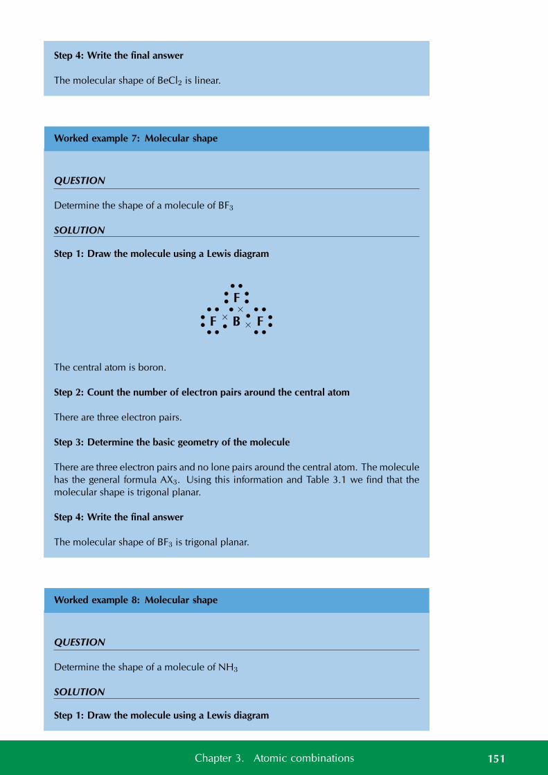
Step 4: Write the final answer
The molecular shape of BeCl2 is linear.
Worked example 7: Molecular shape
QUESTION
Determine the shape of a molecule of BF3
SOLUTION
Step 1: Draw the molecule using a Lewis diagram
F B F
F• ••
•
• •
ו
ו
• × • •
••
• •
• •
••
••
The central atom is boron.
Step 2: Count the number of electron pairs around the central atom
There are three electron pairs.
Step 3: Determine the basic geometry of the molecule
There are three electron pairs and no lone pairs around the central atom. The moleculehas the general formula AX3. Using this information and Table 3.1 we find that themolecular shape is trigonal planar.
Step 4: Write the final answer
The molecular shape of BF3 is trigonal planar.
Worked example 8: Molecular shape
QUESTION
Determine the shape of a molecule of NH3
SOLUTION
Step 1: Draw the molecule using a Lewis diagram
151Chapter 3. Atomic combinations
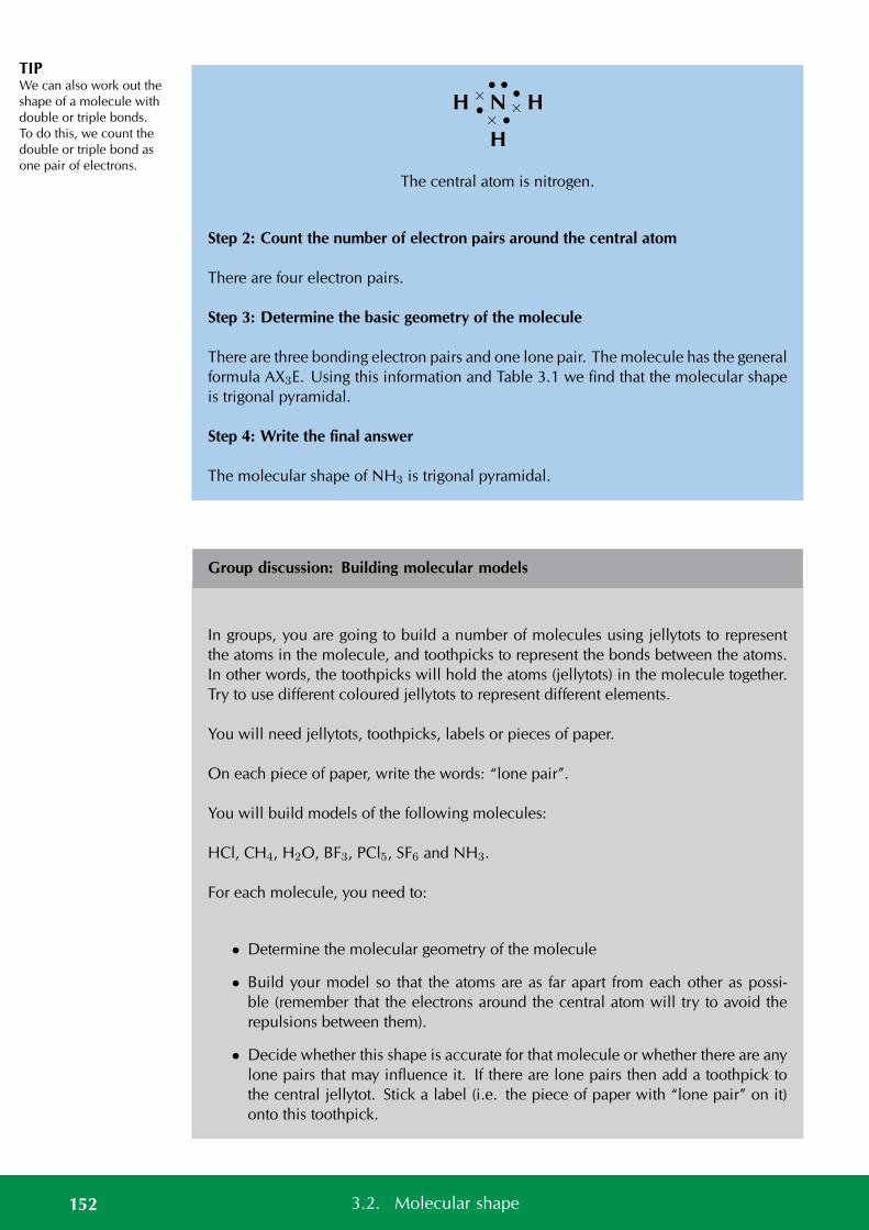
TIPWe can also work out theshape of a molecule withdouble or triple bonds.To do this, we count thedouble or triple bond asone pair of electrons.
H N H
H
ו
ו
• •
× •
The central atom is nitrogen.
Step 2: Count the number of electron pairs around the central atom
There are four electron pairs.
Step 3: Determine the basic geometry of the molecule
There are three bonding electron pairs and one lone pair. The molecule has the generalformula AX3E. Using this information and Table 3.1 we find that the molecular shapeis trigonal pyramidal.
Step 4: Write the final answer
The molecular shape of NH3 is trigonal pyramidal.
Group discussion: Building molecular models
In groups, you are going to build a number of molecules using jellytots to representthe atoms in the molecule, and toothpicks to represent the bonds between the atoms.In other words, the toothpicks will hold the atoms (jellytots) in the molecule together.Try to use different coloured jellytots to represent different elements.
You will need jellytots, toothpicks, labels or pieces of paper.
On each piece of paper, write the words: “lone pair”.
You will build models of the following molecules:
HCl, CH4, H2O, BF3, PCl5, SF6 and NH3.
For each molecule, you need to:
• Determine the molecular geometry of the molecule
• Build your model so that the atoms are as far apart from each other as possi-ble (remember that the electrons around the central atom will try to avoid therepulsions between them).
• Decide whether this shape is accurate for that molecule or whether there are anylone pairs that may influence it. If there are lone pairs then add a toothpick tothe central jellytot. Stick a label (i.e. the piece of paper with “lone pair” on it)onto this toothpick.
152 3.2. Molecular shape
TIPDepending on whichsource you use forelectronegativities youmay see slightly differentvalues.
• Adjust the position of the atoms so that the bonding pairs are further away fromthe lone pairs.
• How has the shape of the molecule changed?
• Draw a simple diagram to show the shape of the molecule. It doesn’t matterif it is not 100% accurate. This exercise is only to help you to visualise the3-dimensional shapes of molecules. (See Figure 3.8 to help you).
Do the models help you to have a clearer picture of what the molecules look like? Tryto build some more models for other molecules you can think of.
Exercise 3 – 6: Molecular shape
Determine the shape of the following molecules.
1. BeCl2
2. F2
3. PCl5
4. SF6
5. CO2
6. CH4
7. H2O
8. COH2
Think you got it? Get this answer and more practice on our Intelligent Practice Service
1. 23PF 2. 23PG 3. 23PH 4. 23PJ 5. 23PK 6. 23PM7. 23PN 8. 23PP
www.everythingscience.co.za m.everythingscience.co.za
3.3 Electronegativity ESBMD
So far we have looked at covalent molecules. But how do we know that they arecovalent? The answer comes from electronegativity. Each element (except for thenoble gases) has an electronegativity value.
Electronegativity is a measure of how strongly an atom pulls a shared electron pairtowards it. The table below shows the electronegativities of the some of the elements.
For a full list of electronegativities see the periodic table at the front of the book. Onthis periodic table the electronegativity values are given in the top right corner. Do notconfuse these values with the other numbers shown for the elements. Electronegativi-ties will always be between 0 and 4 for any element. If you use a number greater than4 then you are not using the electronegativity.
153Chapter 3. Atomic combinations
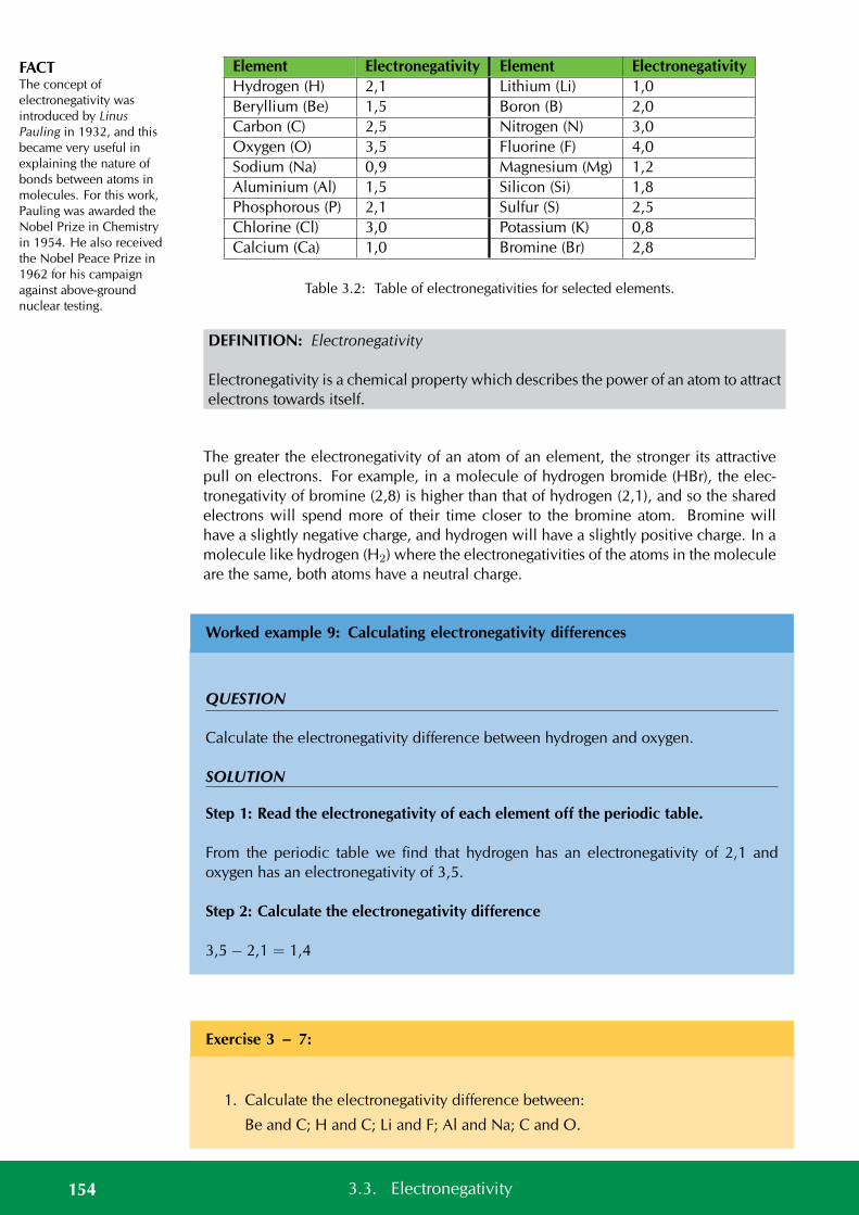
FACTThe concept ofelectronegativity wasintroduced by LinusPauling in 1932, and thisbecame very useful inexplaining the nature ofbonds between atoms inmolecules. For this work,Pauling was awarded theNobel Prize in Chemistryin 1954. He also receivedthe Nobel Peace Prize in1962 for his campaignagainst above-groundnuclear testing.
Element Electronegativity Element ElectronegativityHydrogen (H) 2,1 Lithium (Li) 1,0Beryllium (Be) 1,5 Boron (B) 2,0Carbon (C) 2,5 Nitrogen (N) 3,0Oxygen (O) 3,5 Fluorine (F) 4,0Sodium (Na) 0,9 Magnesium (Mg) 1,2Aluminium (Al) 1,5 Silicon (Si) 1,8Phosphorous (P) 2,1 Sulfur (S) 2,5Chlorine (Cl) 3,0 Potassium (K) 0,8Calcium (Ca) 1,0 Bromine (Br) 2,8
Table 3.2: Table of electronegativities for selected elements.
DEFINITION: Electronegativity
Electronegativity is a chemical property which describes the power of an atom to attractelectrons towards itself.
The greater the electronegativity of an atom of an element, the stronger its attractivepull on electrons. For example, in a molecule of hydrogen bromide (HBr), the elec-tronegativity of bromine (2,8) is higher than that of hydrogen (2,1), and so the sharedelectrons will spend more of their time closer to the bromine atom. Bromine willhave a slightly negative charge, and hydrogen will have a slightly positive charge. In amolecule like hydrogen (H2) where the electronegativities of the atoms in the moleculeare the same, both atoms have a neutral charge.
Worked example 9: Calculating electronegativity differences
QUESTION
Calculate the electronegativity difference between hydrogen and oxygen.
SOLUTION
Step 1: Read the electronegativity of each element off the periodic table.
From the periodic table we find that hydrogen has an electronegativity of 2,1 andoxygen has an electronegativity of 3,5.
Step 2: Calculate the electronegativity difference
3,5 − 2,1 = 1,4
Exercise 3 – 7:
1. Calculate the electronegativity difference between:
Be and C; H and C; Li and F; Al and Na; C and O.
154 3.3. Electronegativity
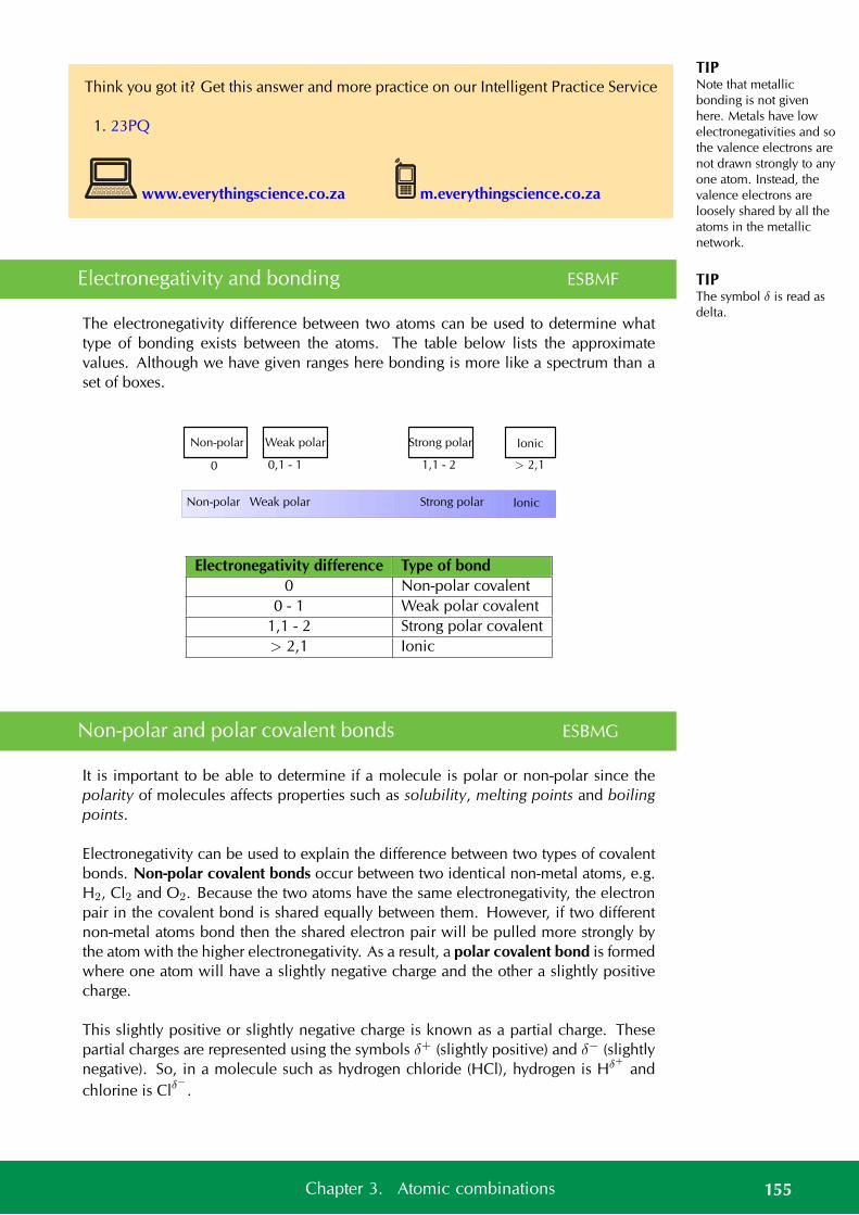
TIPNote that metallicbonding is not givenhere. Metals have lowelectronegativities and sothe valence electrons arenot drawn strongly to anyone atom. Instead, thevalence electrons areloosely shared by all theatoms in the metallicnetwork.
TIPThe symbol δ is read asdelta.
Think you got it? Get this answer and more practice on our Intelligent Practice Service
1. 23PQ
www.everythingscience.co.za m.everythingscience.co.za
Electronegativity and bonding ESBMF
The electronegativity difference between two atoms can be used to determine whattype of bonding exists between the atoms. The table below lists the approximatevalues. Although we have given ranges here bonding is more like a spectrum than aset of boxes.
Non-polar Weak polar Strong polar Ionic
IonicStrong polarWeak polarNon-polar
0 0,1 - 1 1,1 - 2 > 2,1
Electronegativity difference Type of bond0 Non-polar covalent
0 - 1 Weak polar covalent1,1 - 2 Strong polar covalent> 2,1 Ionic
Non-polar and polar covalent bonds ESBMG
It is important to be able to determine if a molecule is polar or non-polar since thepolarity of molecules affects properties such as solubility, melting points and boilingpoints.
Electronegativity can be used to explain the difference between two types of covalentbonds. Non-polar covalent bonds occur between two identical non-metal atoms, e.g.H2, Cl2 and O2. Because the two atoms have the same electronegativity, the electronpair in the covalent bond is shared equally between them. However, if two differentnon-metal atoms bond then the shared electron pair will be pulled more strongly bythe atom with the higher electronegativity. As a result, a polar covalent bond is formedwhere one atom will have a slightly negative charge and the other a slightly positivecharge.
This slightly positive or slightly negative charge is known as a partial charge. Thesepartial charges are represented using the symbols δ+ (slightly positive) and δ− (slightlynegative). So, in a molecule such as hydrogen chloride (HCl), hydrogen is Hδ+ andchlorine is Clδ
−.
155Chapter 3. Atomic combinations
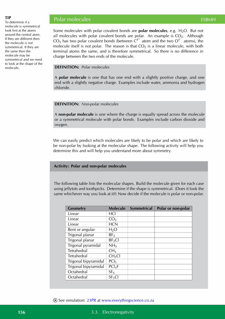
TIPTo determine if amolecule is symmetricallook first at the atomsaround the central atom.If they are different thenthe molecule is notsymmetrical. If they arethe same then themolecule may besymmetrical and we needto look at the shape of themolecule.
Polar molecules ESBMH
Some molecules with polar covalent bonds are polar molecules, e.g. H2O. But notall molecules with polar covalent bonds are polar. An example is CO2. AlthoughCO2 has two polar covalent bonds (between Cδ+ atom and the two Oδ− atoms), themolecule itself is not polar. The reason is that CO2 is a linear molecule, with bothterminal atoms the same, and is therefore symmetrical. So there is no difference incharge between the two ends of the molecule.
DEFINITION: Polar molecules
A polar molecule is one that has one end with a slightly positive charge, and oneend with a slightly negative charge. Examples include water, ammonia and hydrogenchloride.
DEFINITION: Non-polar molecules
A non-polar molecule is one where the charge is equally spread across the moleculeor a symmetrical molecule with polar bonds. Examples include carbon dioxide andoxygen.
We can easily predict which molecules are likely to be polar and which are likely tobe non-polar by looking at the molecular shape. The following activity will help youdetermine this and will help you understand more about symmetry.
Activity: Polar and non-polar molecules
The following table lists the molecular shapes. Build the molecule given for each caseusing jellytots and toothpicks. Determine if the shape is symmetrical. (Does it look thesame whichever way you look at it?) Now decide if the molecule is polar or non-polar.
Geometry Molecule Symmetrical Polar or non-polarLinear HClLinear CO2
Linear HCNBent or angular H2OTrigonal planar BF3Trigonal planar BF2ClTrigonal pyramidal NH3
Tetrahedral CH4
Tetrahedral CH3ClTrigonal bipyramidal PCl5Trigonal bipyramidal PCl4FOctahedral SF6Octahedral SF5Cl
See simulation: 23PR at www.everythingscience.co.za
156 3.3. Electronegativity
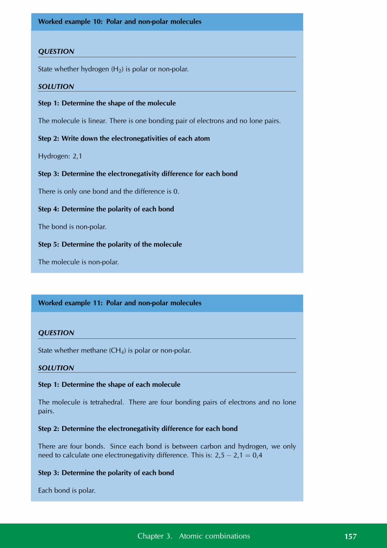
Worked example 10: Polar and non-polar molecules
QUESTION
State whether hydrogen (H2) is polar or non-polar.
SOLUTION
Step 1: Determine the shape of the molecule
The molecule is linear. There is one bonding pair of electrons and no lone pairs.
Step 2: Write down the electronegativities of each atom
Hydrogen: 2,1
Step 3: Determine the electronegativity difference for each bond
There is only one bond and the difference is 0.
Step 4: Determine the polarity of each bond
The bond is non-polar.
Step 5: Determine the polarity of the molecule
The molecule is non-polar.
Worked example 11: Polar and non-polar molecules
QUESTION
State whether methane (CH4) is polar or non-polar.
SOLUTION
Step 1: Determine the shape of each molecule
The molecule is tetrahedral. There are four bonding pairs of electrons and no lonepairs.
Step 2: Determine the electronegativity difference for each bond
There are four bonds. Since each bond is between carbon and hydrogen, we onlyneed to calculate one electronegativity difference. This is: 2,5 − 2,1 = 0,4
Step 3: Determine the polarity of each bond
Each bond is polar.
157Chapter 3. Atomic combinations
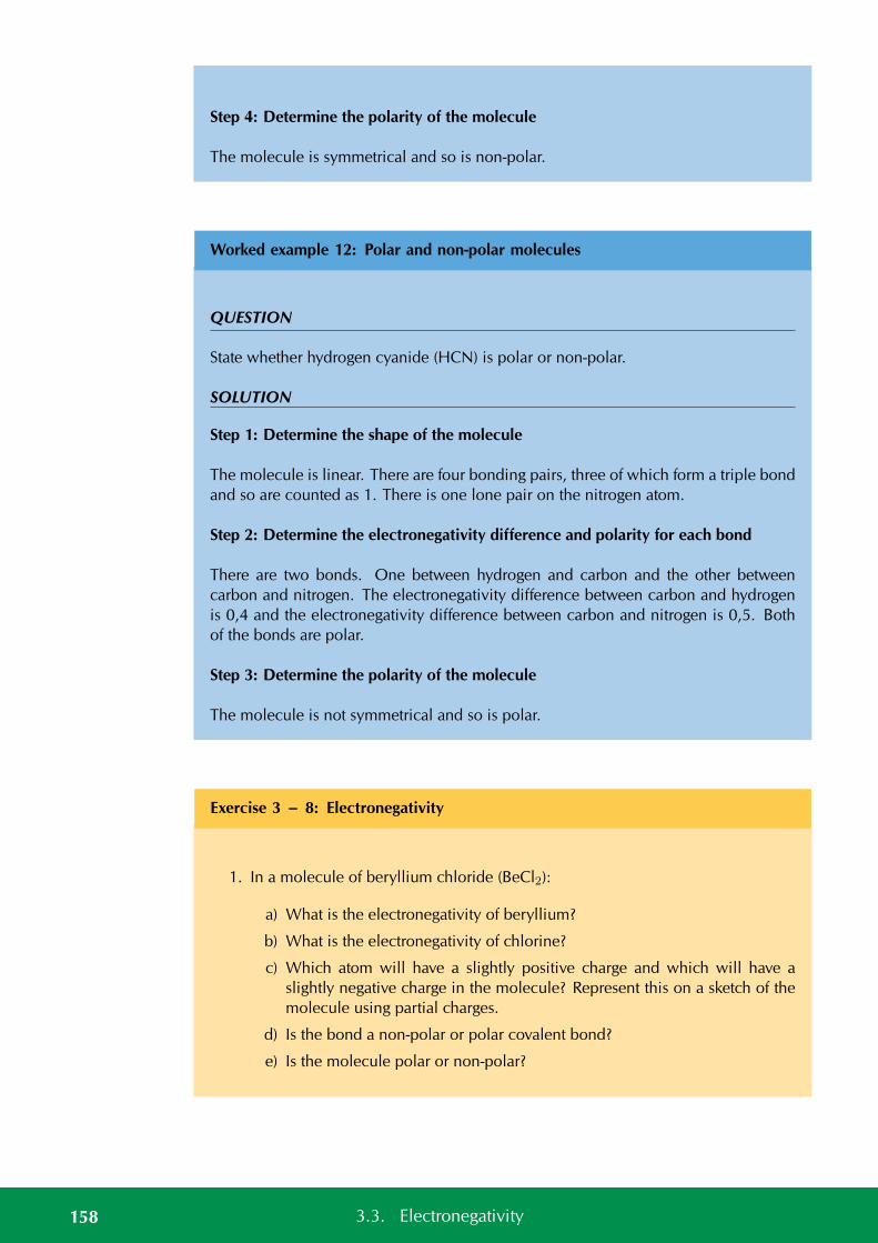
Step 4: Determine the polarity of the molecule
The molecule is symmetrical and so is non-polar.
Worked example 12: Polar and non-polar molecules
QUESTION
State whether hydrogen cyanide (HCN) is polar or non-polar.
SOLUTION
Step 1: Determine the shape of the molecule
The molecule is linear. There are four bonding pairs, three of which form a triple bondand so are counted as 1. There is one lone pair on the nitrogen atom.
Step 2: Determine the electronegativity difference and polarity for each bond
There are two bonds. One between hydrogen and carbon and the other betweencarbon and nitrogen. The electronegativity difference between carbon and hydrogenis 0,4 and the electronegativity difference between carbon and nitrogen is 0,5. Bothof the bonds are polar.
Step 3: Determine the polarity of the molecule
The molecule is not symmetrical and so is polar.
Exercise 3 – 8: Electronegativity
1. In a molecule of beryllium chloride (BeCl2):
a) What is the electronegativity of beryllium?
b) What is the electronegativity of chlorine?
c) Which atom will have a slightly positive charge and which will have aslightly negative charge in the molecule? Represent this on a sketch of themolecule using partial charges.
d) Is the bond a non-polar or polar covalent bond?
e) Is the molecule polar or non-polar?
158 3.3. Electronegativity

2. Complete the table below:
Molecule Difference in electroneg-ativity between atoms
Non-polar/polarcovalent bond
Polar/non-polarmolecule
H2OHBrF2CH4
PF5BeCl2COC2H2
SO2
BF3
Think you got it? Get this answer and more practice on our Intelligent Practice Service
1. 23PS 2. 23PT
www.everythingscience.co.za m.everythingscience.co.za
3.4 Energy and bonding ESBMJ
As we saw earlier in the chapter we can show the energy changes that occur as atomscome together (Figure 3.5). Shown below is the same image but this time with twoextra pieces of information: the bond energy and the bond length.
En
erg
y
+
0
-
Distance between atomic nuclei
A
bond energy
lengthbond
X
Figure 3.9: Graph showing the change in energy that takes place as atoms move closer to-gether.
159Chapter 3. Atomic combinations
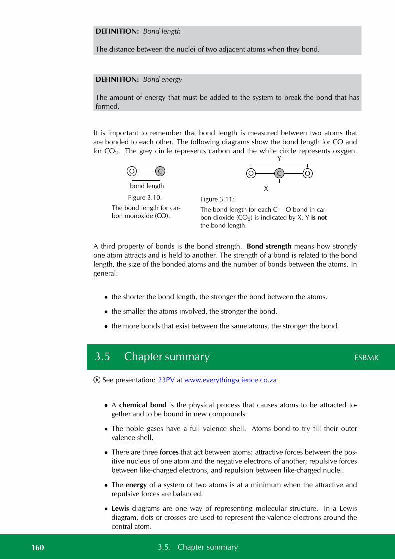
DEFINITION: Bond length
The distance between the nuclei of two adjacent atoms when they bond.
DEFINITION: Bond energy
The amount of energy that must be added to the system to break the bond that hasformed.
It is important to remember that bond length is measured between two atoms thatare bonded to each other. The following diagrams show the bond length for CO andfor CO2. The grey circle represents carbon and the white circle represents oxygen.
bond length
CO
Figure 3.10:
The bond length for car-bon monoxide (CO).
X
Y
O C O
Figure 3.11:
The bond length for each C − O bond in car-bon dioxide (CO2) is indicated by X. Y is notthe bond length.
A third property of bonds is the bond strength. Bond strength means how stronglyone atom attracts and is held to another. The strength of a bond is related to the bondlength, the size of the bonded atoms and the number of bonds between the atoms. Ingeneral:
• the shorter the bond length, the stronger the bond between the atoms.
• the smaller the atoms involved, the stronger the bond.
• the more bonds that exist between the same atoms, the stronger the bond.
3.5 Chapter summary ESBMK
See presentation: 23PV at www.everythingscience.co.za
• A chemical bond is the physical process that causes atoms to be attracted to-gether and to be bound in new compounds.
• The noble gases have a full valence shell. Atoms bond to try fill their outervalence shell.
• There are three forces that act between atoms: attractive forces between the pos-itive nucleus of one atom and the negative electrons of another; repulsive forcesbetween like-charged electrons, and repulsion between like-charged nuclei.
• The energy of a system of two atoms is at a minimum when the attractive andrepulsive forces are balanced.
• Lewis diagrams are one way of representing molecular structure. In a Lewisdiagram, dots or crosses are used to represent the valence electrons around thecentral atom.
160 3.5. Chapter summary
• A covalent bond is a form of chemical bond where pairs of electrons are sharedbetween two atoms.
• A single bond occurs if there is one electron pair that is shared between the sametwo atoms.
• A double bond occurs if there are two electron pairs that are shared between thesame two atoms.
• A triple bond occurs if there are three electron pairs that are shared between thesame two atoms.
• A dative covalent bond is a description of covalent bonding that occurs betweentwo atoms in which both electrons shared in the bond come from the same atom.
• Dative covalent bonds occur between atoms of elements with a lone pair andatoms of elements with no electrons. Examples include the hydronium ion(H3O+) and the ammonium ion (NH+
4 ).
• The shape of molecules can be predicted using the VSEPR theory.
• Valence shell electron pair repulsion (VSEPR) theory is a model in chemistry,which is used to predict the shape of individual molecules. VSEPR is basedupon minimising the extent of the electron-pair repulsion around the centralatom being considered.
• Electronegativity is a chemical property which describes the power of an atomto attract electrons towards itself in a chemical.
• Electronegativity can be used to explain the difference between two types ofcovalent bonds: polar covalent bonds (between non-identical atoms) and non-polar covalent bonds (between identical atoms or atoms with the same elec-tronegativity).
• A polar molecule is one that has one end with a slightly positive charge, andone end with a slightly negative charge. Examples include water, ammonia andhydrogen chloride.
• A non-polar molecule is one where the charge is equally spread across themolecule or a symmetrical molecule with polar bonds.
• Bond length is the distance between the nuclei of two atoms when they bond.
• Bond energy is the amount of energy that must be added to the system to breakthe bond that has formed.
• Bond strength means how strongly one atom attracts and is held to another atom.Bond strength depends on the length of the bond, the size of the atoms and thenumber of bonds between the two atoms.
Exercise 3 – 9:
1. Give one word/term for each of the following descriptions.
a) The distance between two adjacent atoms in a molecule.
b) A type of chemical bond that involves the sharing of electrons between twoatoms.
161Chapter 3. Atomic combinations
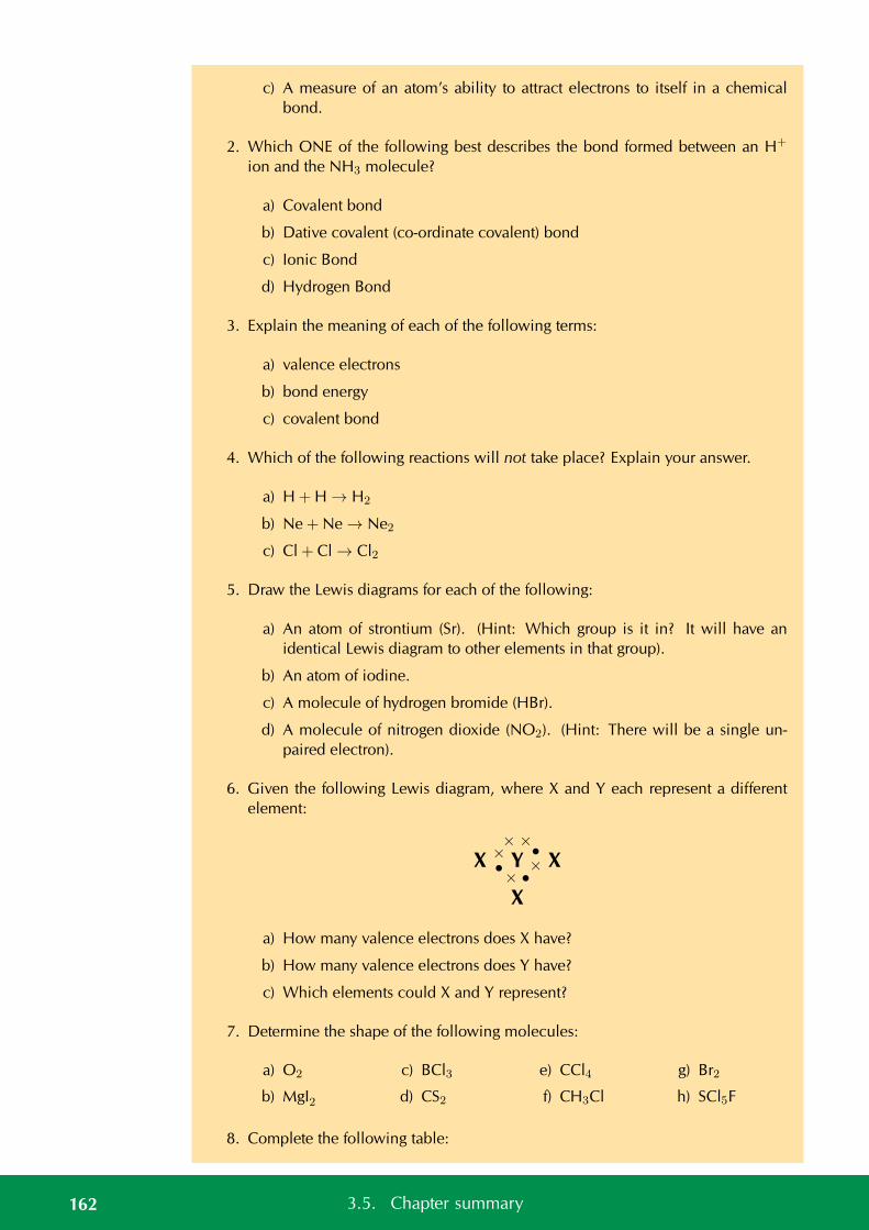
c) A measure of an atom’s ability to attract electrons to itself in a chemicalbond.
2. Which ONE of the following best describes the bond formed between an H+
ion and the NH3 molecule?
a) Covalent bond
b) Dative covalent (co-ordinate covalent) bond
c) Ionic Bond
d) Hydrogen Bond
3. Explain the meaning of each of the following terms:
a) valence electrons
b) bond energy
c) covalent bond
4. Which of the following reactions will not take place? Explain your answer.
a) H + H → H2
b) Ne + Ne → Ne2
c) Cl + Cl → Cl2
5. Draw the Lewis diagrams for each of the following:
a) An atom of strontium (Sr). (Hint: Which group is it in? It will have anidentical Lewis diagram to other elements in that group).
b) An atom of iodine.
c) A molecule of hydrogen bromide (HBr).
d) A molecule of nitrogen dioxide (NO2). (Hint: There will be a single un-paired electron).
6. Given the following Lewis diagram, where X and Y each represent a differentelement:
X Y X
X
ו
ו
× ×
× •
a) How many valence electrons does X have?
b) How many valence electrons does Y have?
c) Which elements could X and Y represent?
7. Determine the shape of the following molecules:
a) O2
b) MgI2
c) BCl3
d) CS2
e) CCl4
f) CH3Cl
g) Br2
h) SCl5F
8. Complete the following table:
162 3.5. Chapter summary
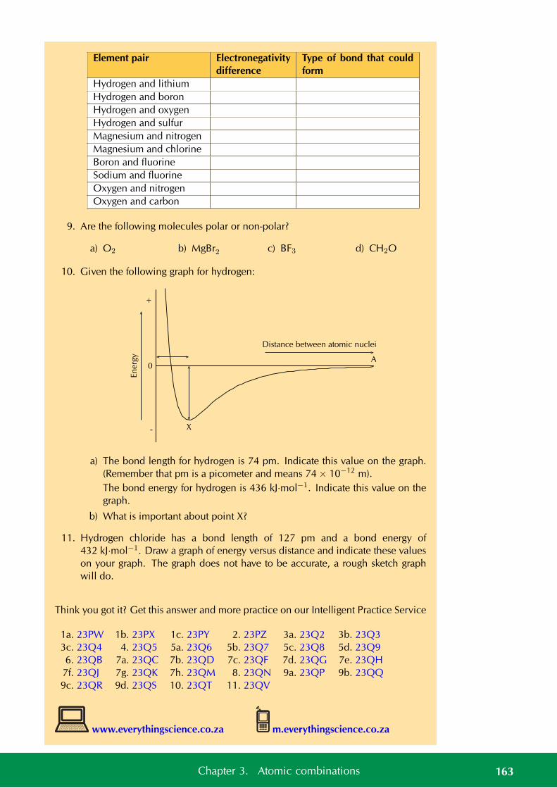
Element pair Electronegativitydifference
Type of bond that couldform
Hydrogen and lithiumHydrogen and boronHydrogen and oxygenHydrogen and sulfurMagnesium and nitrogenMagnesium and chlorineBoron and fluorineSodium and fluorineOxygen and nitrogenOxygen and carbon
9. Are the following molecules polar or non-polar?
a) O2 b) MgBr2 c) BF3 d) CH2O
10. Given the following graph for hydrogen:
En
erg
y
+
0
-
Distance between atomic nuclei
A
X
a) The bond length for hydrogen is 74 pm. Indicate this value on the graph.(Remember that pm is a picometer and means 74 × 10−12 m).The bond energy for hydrogen is 436 kJ·mol−1. Indicate this value on thegraph.
b) What is important about point X?
11. Hydrogen chloride has a bond length of 127 pm and a bond energy of432 kJ·mol−1. Draw a graph of energy versus distance and indicate these valueson your graph. The graph does not have to be accurate, a rough sketch graphwill do.
Think you got it? Get this answer and more practice on our Intelligent Practice Service
1a. 23PW 1b. 23PX 1c. 23PY 2. 23PZ 3a. 23Q2 3b. 23Q33c. 23Q4 4. 23Q5 5a. 23Q6 5b. 23Q7 5c. 23Q8 5d. 23Q96. 23QB 7a. 23QC 7b. 23QD 7c. 23QF 7d. 23QG 7e. 23QH
7f. 23QJ 7g. 23QK 7h. 23QM 8. 23QN 9a. 23QP 9b. 23QQ9c. 23QR 9d. 23QS 10. 23QT 11. 23QV
www.everythingscience.co.za m.everythingscience.co.za
163Chapter 3. Atomic combinations


CHAPTER 4
Intermolecular forces
4.1 Intermolecular and interatomic forces 166
4.2 The chemistry of water 184
4.3 Chapter summary 189
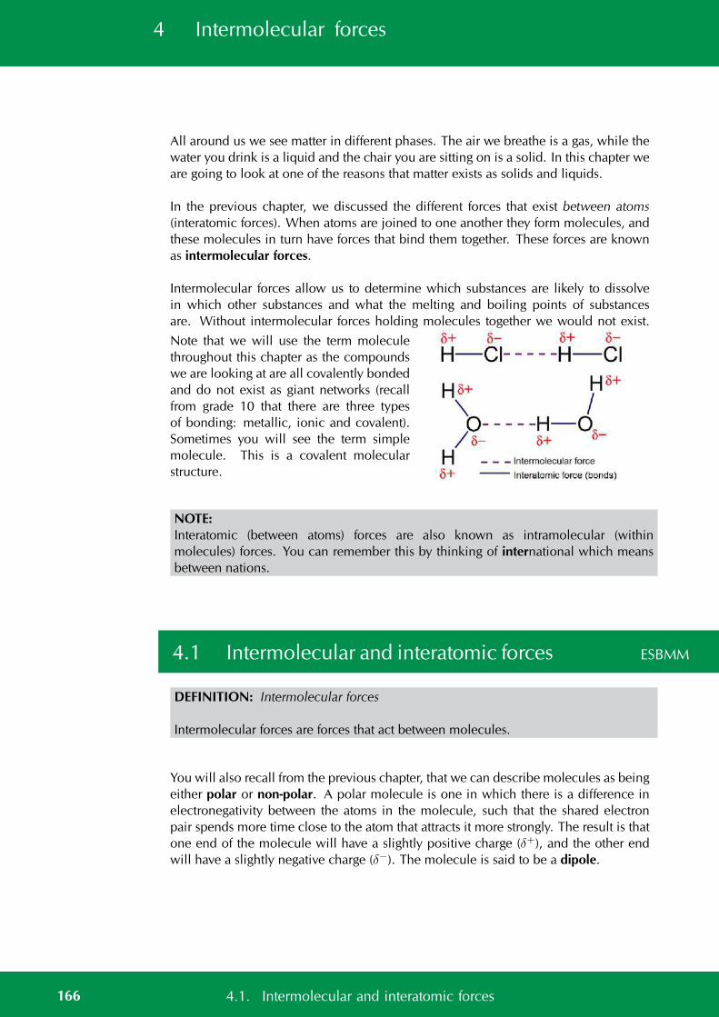
4 Intermolecular forces
All around us we see matter in different phases. The air we breathe is a gas, while thewater you drink is a liquid and the chair you are sitting on is a solid. In this chapter weare going to look at one of the reasons that matter exists as solids and liquids.
In the previous chapter, we discussed the different forces that exist between atoms(interatomic forces). When atoms are joined to one another they form molecules, andthese molecules in turn have forces that bind them together. These forces are knownas intermolecular forces.
Intermolecular forces allow us to determine which substances are likely to dissolvein which other substances and what the melting and boiling points of substancesare. Without intermolecular forces holding molecules together we would not exist.
Note that we will use the term moleculethroughout this chapter as the compoundswe are looking at are all covalently bondedand do not exist as giant networks (recallfrom grade 10 that there are three typesof bonding: metallic, ionic and covalent).Sometimes you will see the term simplemolecule. This is a covalent molecularstructure.
NOTE:Interatomic (between atoms) forces are also known as intramolecular (withinmolecules) forces. You can remember this by thinking of international which meansbetween nations.
4.1 Intermolecular and interatomic forces ESBMM
DEFINITION: Intermolecular forces
Intermolecular forces are forces that act between molecules.
You will also recall from the previous chapter, that we can describe molecules as beingeither polar or non-polar. A polar molecule is one in which there is a difference inelectronegativity between the atoms in the molecule, such that the shared electronpair spends more time close to the atom that attracts it more strongly. The result is thatone end of the molecule will have a slightly positive charge (δ+), and the other endwill have a slightly negative charge (δ−). The molecule is said to be a dipole.
166 4.1. Intermolecular and interatomic forces
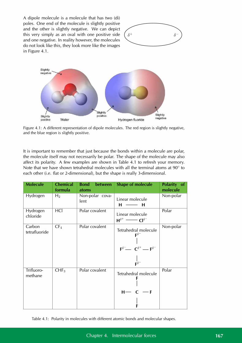
A dipole molecule is a molecule that has two (di)poles. One end of the molecule is slightly positiveand the other is slightly negative. We can depictthis very simply as an oval with one positive sideand one negative. In reality however, the moleculesdo not look like this, they look more like the imagesin Figure 4.1.
δ+ δ−
Figure 4.1: A different representation of dipole molecules. The red region is slightly negative,and the blue region is slightly positive.
It is important to remember that just because the bonds within a molecule are polar,the molecule itself may not necessarily be polar. The shape of the molecule may alsoaffect its polarity. A few examples are shown in Table 4.1 to refresh your memory.Note that we have shown tetrahedral molecules with all the terminal atoms at 90 toeach other (i.e. flat or 2-dimensional), but the shape is really 3-dimensional.
Molecule Chemicalformula
Bond betweenatoms
Shape of molecule Polarity ofmolecule
Hydrogen H2 Non-polar cova-lent Linear molecule
H H
Non-polar
Hydrogenchloride
HCl Polar covalentLinear molecule
Hδ+ Clδ−
Polar
Carbontetrafluoride
CF4 Polar covalentTetrahedral molecule
Cδ+
Fδ−
Fδ−
Fδ−
Fδ−
Non-polar
Trifluoro-methane
CHF3 Polar covalentTetrahedral molecule
C
F
F
F
H
Polar
Table 4.1: Polarity in molecules with different atomic bonds and molecular shapes.
167Chapter 4. Intermolecular forces
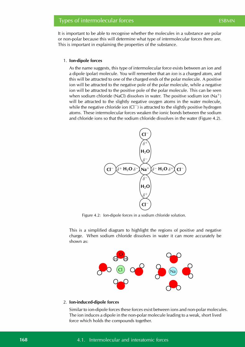
Types of intermolecular forces ESBMN
It is important to be able to recognise whether the molecules in a substance are polaror non-polar because this will determine what type of intermolecular forces there are.This is important in explaining the properties of the substance.
1. Ion-dipole forces
As the name suggests, this type of intermolecular force exists between an ion anda dipole (polar) molecule. You will remember that an ion is a charged atom, andthis will be attracted to one of the charged ends of the polar molecule. A positiveion will be attracted to the negative pole of the polar molecule, while a negativeion will be attracted to the positive pole of the polar molecule. This can be seenwhen sodium chloride (NaCl) dissolves in water. The positive sodium ion (Na+)will be attracted to the slightly negative oxygen atoms in the water molecule,while the negative chloride ion (Cl−) is attracted to the slightly positive hydrogenatoms. These intermolecular forces weaken the ionic bonds between the sodiumand chloride ions so that the sodium chloride dissolves in the water (Figure 4.2).
Na+ Cl−Cl−
Cl−
Cl−
H2OH2O
H2O
H2O
δ−δ−
δ−
δ−
δ+δ+
δ+
δ+
Figure 4.2: Ion-dipole forces in a sodium chloride solution.
This is a simplified diagram to highlight the regions of positive and negativecharge. When sodium chloride dissolves in water it can more accurately beshown as:
NaCl
OHH
2. Ion-induced-dipole forces
Similar to ion-dipole forces these forces exist between ions and non-polar molecules.The ion induces a dipole in the non-polar molecule leading to a weak, short livedforce which holds the compounds together.
168 4.1. Intermolecular and interatomic forces
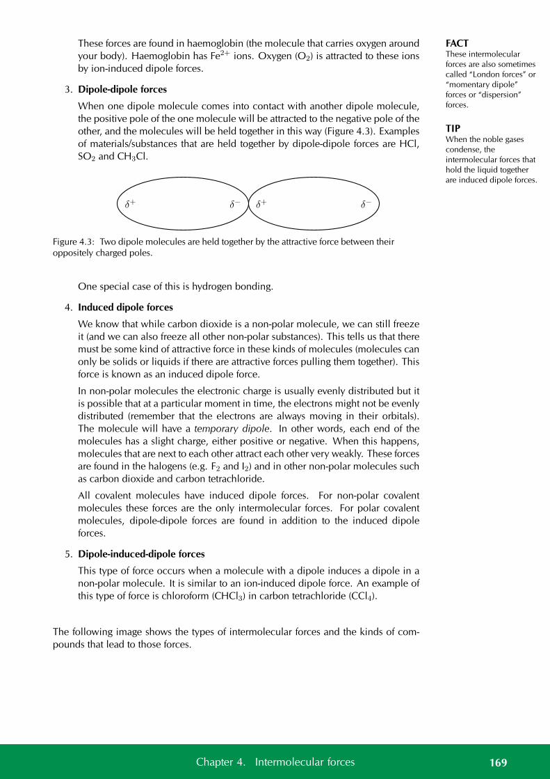
FACTThese intermolecularforces are also sometimescalled “London forces” or“momentary dipole”forces or “dispersion”forces.
TIPWhen the noble gasescondense, theintermolecular forces thathold the liquid togetherare induced dipole forces.
These forces are found in haemoglobin (the molecule that carries oxygen aroundyour body). Haemoglobin has Fe2+ ions. Oxygen (O2) is attracted to these ionsby ion-induced dipole forces.
3. Dipole-dipole forces
When one dipole molecule comes into contact with another dipole molecule,the positive pole of the one molecule will be attracted to the negative pole of theother, and the molecules will be held together in this way (Figure 4.3). Examplesof materials/substances that are held together by dipole-dipole forces are HCl,SO2 and CH3Cl.
δ+ δ− δ+ δ−
Figure 4.3: Two dipole molecules are held together by the attractive force between theiroppositely charged poles.
One special case of this is hydrogen bonding.
4. Induced dipole forces
We know that while carbon dioxide is a non-polar molecule, we can still freezeit (and we can also freeze all other non-polar substances). This tells us that theremust be some kind of attractive force in these kinds of molecules (molecules canonly be solids or liquids if there are attractive forces pulling them together). Thisforce is known as an induced dipole force.
In non-polar molecules the electronic charge is usually evenly distributed but itis possible that at a particular moment in time, the electrons might not be evenlydistributed (remember that the electrons are always moving in their orbitals).The molecule will have a temporary dipole. In other words, each end of themolecules has a slight charge, either positive or negative. When this happens,molecules that are next to each other attract each other very weakly. These forcesare found in the halogens (e.g. F2 and I2) and in other non-polar molecules suchas carbon dioxide and carbon tetrachloride.
All covalent molecules have induced dipole forces. For non-polar covalentmolecules these forces are the only intermolecular forces. For polar covalentmolecules, dipole-dipole forces are found in addition to the induced dipoleforces.
5. Dipole-induced-dipole forces
This type of force occurs when a molecule with a dipole induces a dipole in anon-polar molecule. It is similar to an ion-induced dipole force. An example ofthis type of force is chloroform (CHCl3) in carbon tetrachloride (CCl4).
The following image shows the types of intermolecular forces and the kinds of com-pounds that lead to those forces.
169Chapter 4. Intermolecular forces
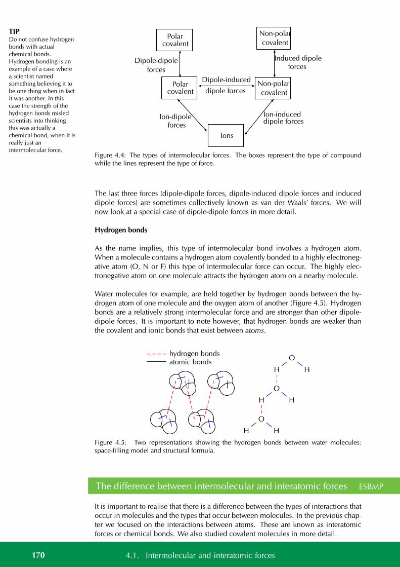
TIPDo not confuse hydrogenbonds with actualchemical bonds.Hydrogen bonding is anexample of a case wherea scientist namedsomething believing it tobe one thing when in factit was another. In thiscase the strength of thehydrogen bonds misledscientists into thinkingthis was actually achemical bond, when it isreally just anintermolecular force.
covalent
Non-polar
Ions
Polarcovalent
covalent
Non-polarPolarcovalent
Dipole-dipole
forces
Dipole-induced
dipole forces
Induced dipoleforces
Ion-dipole Ion-induceddipole forces
forces
Figure 4.4: The types of intermolecular forces. The boxes represent the type of compoundwhile the lines represent the type of force.
The last three forces (dipole-dipole forces, dipole-induced dipole forces and induceddipole forces) are sometimes collectively known as van der Waals’ forces. We willnow look at a special case of dipole-dipole forces in more detail.
Hydrogen bonds
As the name implies, this type of intermolecular bond involves a hydrogen atom.When a molecule contains a hydrogen atom covalently bonded to a highly electroneg-ative atom (O, N or F) this type of intermolecular force can occur. The highly elec-tronegative atom on one molecule attracts the hydrogen atom on a nearby molecule.
Water molecules for example, are held together by hydrogen bonds between the hy-drogen atom of one molecule and the oxygen atom of another (Figure 4.5). Hydrogenbonds are a relatively strong intermolecular force and are stronger than other dipole-dipole forces. It is important to note however, that hydrogen bonds are weaker thanthe covalent and ionic bonds that exist between atoms.
O
HH
O
HH
O
HH
hydrogen bondsatomic bonds
Figure 4.5: Two representations showing the hydrogen bonds between water molecules:space-filling model and structural formula.
The difference between intermolecular and interatomic forces ESBMP
It is important to realise that there is a difference between the types of interactions thatoccur in molecules and the types that occur between molecules. In the previous chap-ter we focused on the interactions between atoms. These are known as interatomicforces or chemical bonds. We also studied covalent molecules in more detail.
170 4.1. Intermolecular and interatomic forces
Remember that a covalent bond has an electronegativity difference of less than 2,1.Covalent molecules have covalent bonds between their atoms. Van der Waals’ forcesonly occur in covalent molecules. We can show the interatomic and intermolecularforces between covalent compounds diagrammatically or in words. Intermolecularforces occur between molecules and do not involve individual atoms. Interatomicforces are the forces that hold the the atoms in molecules together. Figure 4.5 showsthis.
Interatomic forces Intermolecular forcesAtoms or molecules Forces between atoms Forces between moleculesStrength of forces Strong forces Relatively weak forcesDistance between atomsor molecules
Very short distances Larger distances than bonds
Table 4.2: The differences between interatomic and intermolecular forces.
Worked example 1: Intermolecular forces
QUESTION
Which intermolecular forces are found in carbon tetrachloride (CCl4)?
SOLUTION
Step 1: Think about what you know about the molecule.
Carbon has an electronegativity of 2,5. Chlorine has an electronegativity of 3,0. Theelectronegativity difference between carbon and chlorine is 1,0 (recall the section onelectronegativity in the previous chapter). We also know that the bond between carbonand chlorine is polar.
Also from the previous chapter we know that carbon tetrachloride is a tetrahedralmolecule (recall molecular shape). Carbon tetrachloride is symmetrical and so is non-polar overall.
Step 2: Now decide which case it is
Carbon tetrachloride is non-polar and so the only kind of force that can exist is induceddipole.
Worked example 2: Intermolecular forces
QUESTION
Which intermolecular forces are found in the following solution: sodium chloride inwater?
171Chapter 4. Intermolecular forces

SOLUTION
Step 1: Think about what you know about the molecules
Sodium chloride is ionic. (the electronegativity difference is 2,1). Water has polarbonds (the electronegativity difference is 1,4). Water is a polar molecule (its molecularshape is bent or angular).
Step 2: Now decide which case it is
This is an ionic substance interacting with a polar substance. This interaction is anion-dipole force.
Exercise 4 – 1:
Which intermolecular forces are found in:
1. hydrogen fluoride (HF)
2. methane (CH4)
3. potassium chloride in ammonia (KCl in NH3)
4. krypton (Kr)
Think you got it? Get this answer and more practice on our Intelligent Practice Service
1. 23QW 2. 23QX 3. 23QY 4. 23QZ
www.everythingscience.co.za m.everythingscience.co.za
Understanding intermolecular forces ESBMQ
The types of intermolecular forces that occur in a substance will affect its properties,such as its phase, melting point and boiling point. You should remember from thekinetic theory of matter (see grade 10), that the phase of a substance is determined byhow strong the forces are between its particles. The weaker the forces, the more likelythe substance is to exist as a gas. This is because the particles are able to move far apartsince they are not held together very strongly. If the forces are very strong, the particlesare held closely together in a solid structure. Remember also that the temperature ofa material affects the energy of its particles. The more energy the particles have, themore likely they are to be able to overcome the forces that are holding them together.This can cause a change in phase.
Shown below are the three phases of water. Note that we are showing two dimensionalfigures when in reality these are three dimensional.
172 4.1. Intermolecular and interatomic forces
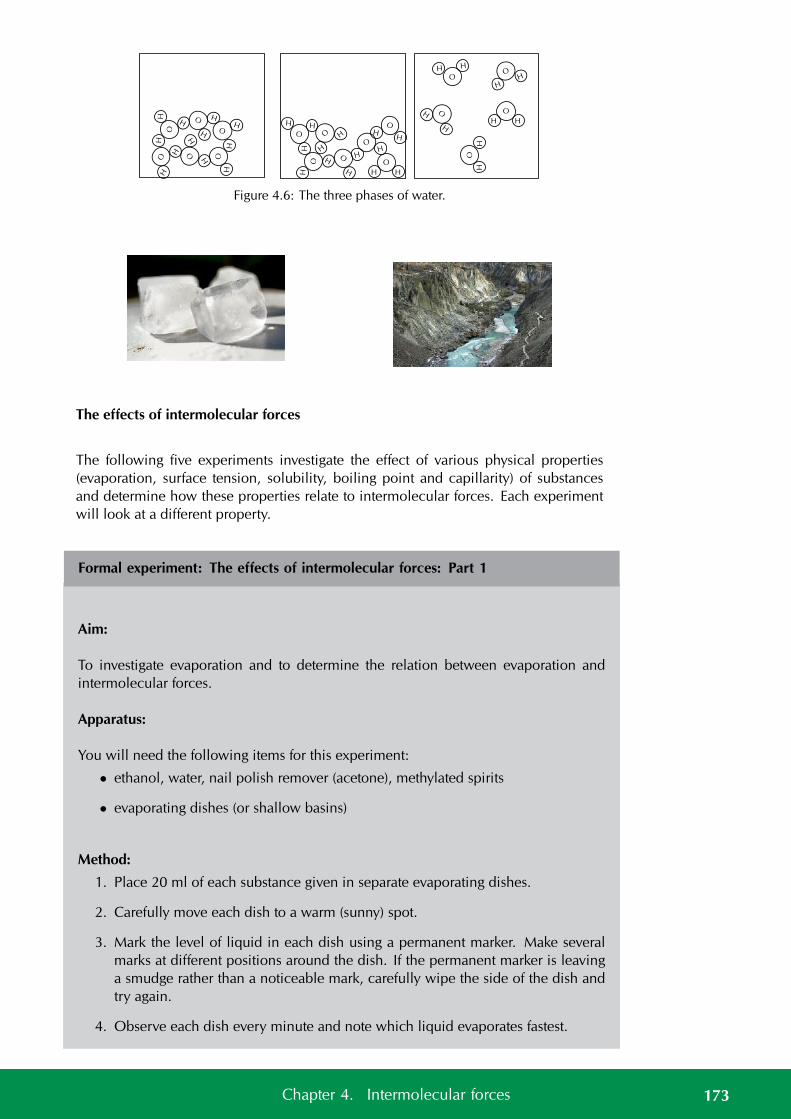
OH
H
O
HH
O
H H
O
HH
O
HH
OHH
O
HH
O
H H
O
HH
OH
H
OH
H
OH
H
O
H
H
OH
H
OH
H
O
H
H
OH
H
OH
H
Figure 4.6: The three phases of water.
The effects of intermolecular forces
The following five experiments investigate the effect of various physical properties(evaporation, surface tension, solubility, boiling point and capillarity) of substancesand determine how these properties relate to intermolecular forces. Each experimentwill look at a different property.
Formal experiment: The effects of intermolecular forces: Part 1
Aim:
To investigate evaporation and to determine the relation between evaporation andintermolecular forces.
Apparatus:
You will need the following items for this experiment:
• ethanol, water, nail polish remover (acetone), methylated spirits
• evaporating dishes (or shallow basins)
Method:
1. Place 20 ml of each substance given in separate evaporating dishes.
2. Carefully move each dish to a warm (sunny) spot.
3. Mark the level of liquid in each dish using a permanent marker. Make severalmarks at different positions around the dish. If the permanent marker is leavinga smudge rather than a noticeable mark, carefully wipe the side of the dish andtry again.
4. Observe each dish every minute and note which liquid evaporates fastest.
173Chapter 4. Intermolecular forces
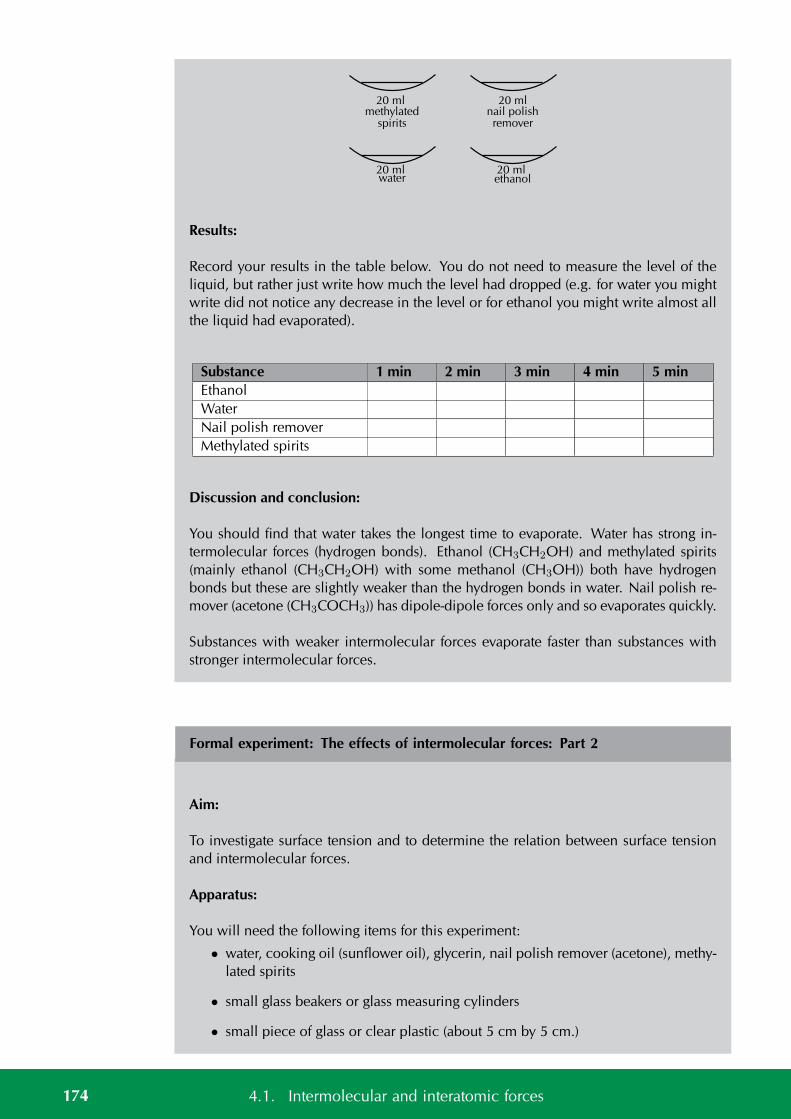
20 mlethanol
20 mlwater
20 mlmethylated
spiritsnail polishremover
20 ml
Results:
Record your results in the table below. You do not need to measure the level of theliquid, but rather just write how much the level had dropped (e.g. for water you mightwrite did not notice any decrease in the level or for ethanol you might write almost allthe liquid had evaporated).
Substance 1 min 2 min 3 min 4 min 5 minEthanolWaterNail polish removerMethylated spirits
Discussion and conclusion:
You should find that water takes the longest time to evaporate. Water has strong in-termolecular forces (hydrogen bonds). Ethanol (CH3CH2OH) and methylated spirits(mainly ethanol (CH3CH2OH) with some methanol (CH3OH)) both have hydrogenbonds but these are slightly weaker than the hydrogen bonds in water. Nail polish re-mover (acetone (CH3COCH3)) has dipole-dipole forces only and so evaporates quickly.
Substances with weaker intermolecular forces evaporate faster than substances withstronger intermolecular forces.
Formal experiment: The effects of intermolecular forces: Part 2
Aim:
To investigate surface tension and to determine the relation between surface tensionand intermolecular forces.
Apparatus:
You will need the following items for this experiment:
• water, cooking oil (sunflower oil), glycerin, nail polish remover (acetone), methy-lated spirits
• small glass beakers or glass measuring cylinders
• small piece of glass or clear plastic (about 5 cm by 5 cm.)
174 4.1. Intermolecular and interatomic forces
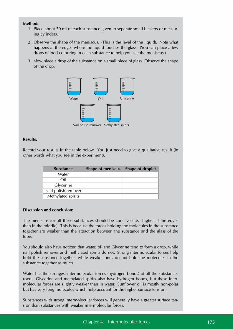
Method:1. Place about 50 ml of each substance given in separate small beakers or measur-
ing cylinders.
2. Observe the shape of the meniscus. (This is the level of the liquid). Note whathappens at the edges where the liquid touches the glass. (You can place a fewdrops of food colouring in each substance to help you see the meniscus.)
3. Now place a drop of the substance on a small piece of glass. Observe the shapeof the drop.
Water Oil Glycerine
Nail polish remover Methylated spirits
Results:
Record your results in the table below. You just need to give a qualitative result (inother words what you see in the experiment).
Substance Shape of meniscus Shape of dropletWater
OilGlycerine
Nail polish removerMethylated spirits
Discussion and conclusion:
The meniscus for all these substances should be concave (i.e. higher at the edgesthan in the middle). This is because the forces holding the molecules in the substancetogether are weaker than the attraction between the substance and the glass of thetube.
You should also have noticed that water, oil and Glycerine tend to form a drop, whilenail polish remover and methylated spirits do not. Strong intermolecular forces helphold the substance together, while weaker ones do not hold the molecules in thesubstance together as much.
Water has the strongest intermolecular forces (hydrogen bonds) of all the substancesused. Glycerine and methylated spirits also have hydrogen bonds, but these inter-molecular forces are slightly weaker than in water. Sunflower oil is mostly non-polarbut has very long molecules which help account for the higher surface tension.
Substances with strong intermolecular forces will generally have a greater surface ten-sion than substances with weaker intermolecular forces.
175Chapter 4. Intermolecular forces
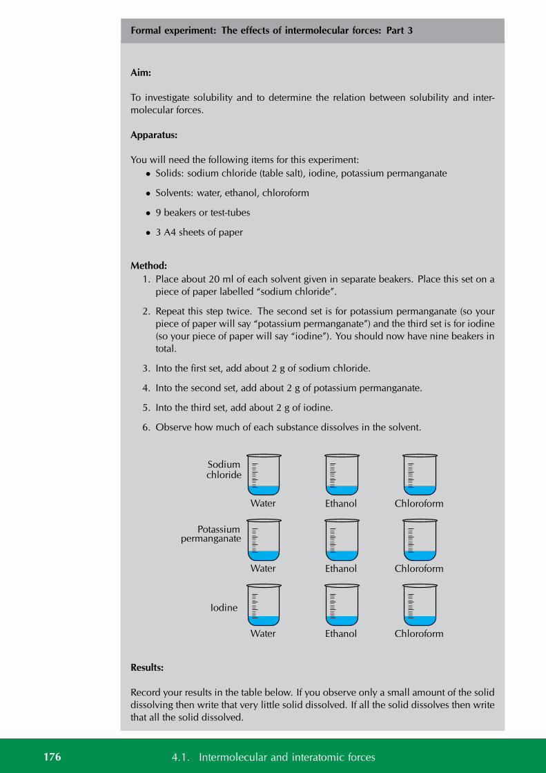
Formal experiment: The effects of intermolecular forces: Part 3
Aim:
To investigate solubility and to determine the relation between solubility and inter-molecular forces.
Apparatus:
You will need the following items for this experiment:• Solids: sodium chloride (table salt), iodine, potassium permanganate
• Solvents: water, ethanol, chloroform
• 9 beakers or test-tubes
• 3 A4 sheets of paper
Method:1. Place about 20 ml of each solvent given in separate beakers. Place this set on a
piece of paper labelled “sodium chloride”.
2. Repeat this step twice. The second set is for potassium permanganate (so yourpiece of paper will say “potassium permanganate”) and the third set is for iodine(so your piece of paper will say “iodine”). You should now have nine beakers intotal.
3. Into the first set, add about 2 g of sodium chloride.
4. Into the second set, add about 2 g of potassium permanganate.
5. Into the third set, add about 2 g of iodine.
6. Observe how much of each substance dissolves in the solvent.
Sodiumchloride
Potassiumpermanganate
Iodine
Water
Water
Water
Ethanol
Ethanol
Ethanol
Chloroform
Chloroform
Chloroform
Results:
Record your results in the table below. If you observe only a small amount of the soliddissolving then write that very little solid dissolved. If all the solid dissolves then writethat all the solid dissolved.
176 4.1. Intermolecular and interatomic forces
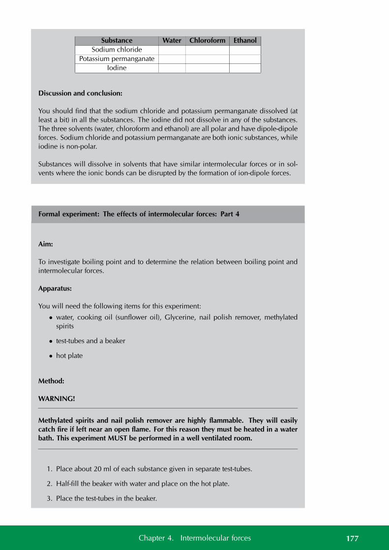
Substance Water Chloroform EthanolSodium chloride
Potassium permanganateIodine
Discussion and conclusion:
You should find that the sodium chloride and potassium permanganate dissolved (atleast a bit) in all the substances. The iodine did not dissolve in any of the substances.The three solvents (water, chloroform and ethanol) are all polar and have dipole-dipoleforces. Sodium chloride and potassium permanganate are both ionic substances, whileiodine is non-polar.
Substances will dissolve in solvents that have similar intermolecular forces or in sol-vents where the ionic bonds can be disrupted by the formation of ion-dipole forces.
Formal experiment: The effects of intermolecular forces: Part 4
Aim:
To investigate boiling point and to determine the relation between boiling point andintermolecular forces.
Apparatus:
You will need the following items for this experiment:
• water, cooking oil (sunflower oil), Glycerine, nail polish remover, methylatedspirits
• test-tubes and a beaker
• hot plate
Method:
WARNING!
Methylated spirits and nail polish remover are highly flammable. They will easilycatch fire if left near an open flame. For this reason they must be heated in a waterbath. This experiment MUST be performed in a well ventilated room.
1. Place about 20 ml of each substance given in separate test-tubes.
2. Half-fill the beaker with water and place on the hot plate.
3. Place the test-tubes in the beaker.
177Chapter 4. Intermolecular forces
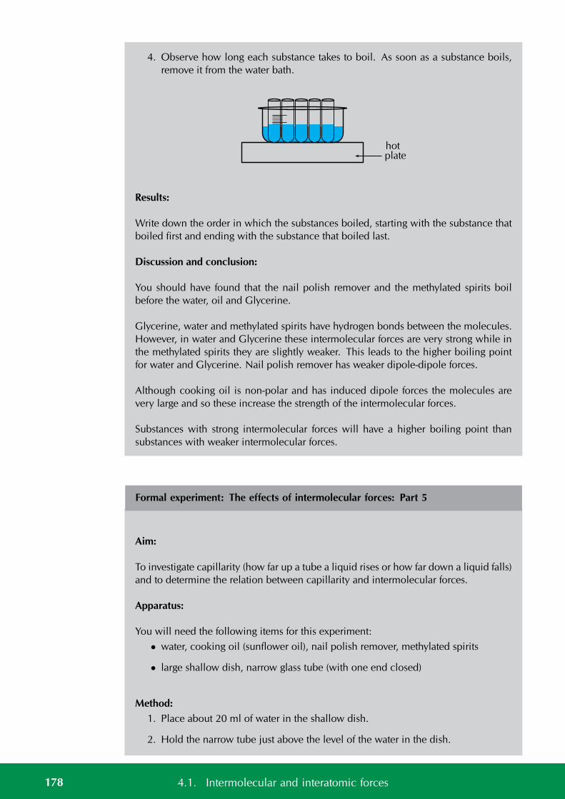
4. Observe how long each substance takes to boil. As soon as a substance boils,remove it from the water bath.
hotplate
Results:
Write down the order in which the substances boiled, starting with the substance thatboiled first and ending with the substance that boiled last.
Discussion and conclusion:
You should have found that the nail polish remover and the methylated spirits boilbefore the water, oil and Glycerine.
Glycerine, water and methylated spirits have hydrogen bonds between the molecules.However, in water and Glycerine these intermolecular forces are very strong while inthe methylated spirits they are slightly weaker. This leads to the higher boiling pointfor water and Glycerine. Nail polish remover has weaker dipole-dipole forces.
Although cooking oil is non-polar and has induced dipole forces the molecules arevery large and so these increase the strength of the intermolecular forces.
Substances with strong intermolecular forces will have a higher boiling point thansubstances with weaker intermolecular forces.
Formal experiment: The effects of intermolecular forces: Part 5
Aim:
To investigate capillarity (how far up a tube a liquid rises or how far down a liquid falls)and to determine the relation between capillarity and intermolecular forces.
Apparatus:
You will need the following items for this experiment:
• water, cooking oil (sunflower oil), nail polish remover, methylated spirits
• large shallow dish, narrow glass tube (with one end closed)
Method:1. Place about 20 ml of water in the shallow dish.
2. Hold the narrow tube just above the level of the water in the dish.
178 4.1. Intermolecular and interatomic forces
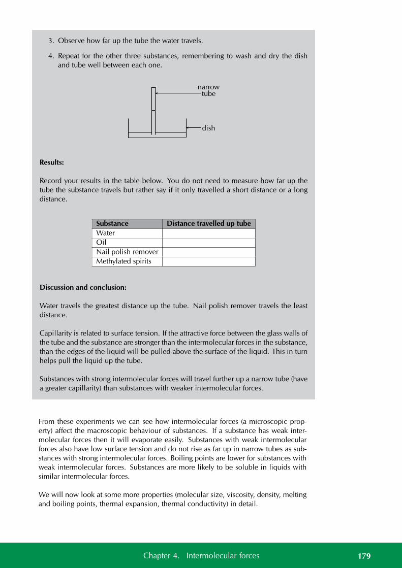
3. Observe how far up the tube the water travels.
4. Repeat for the other three substances, remembering to wash and dry the dishand tube well between each one.
narrowtube
dish
Results:
Record your results in the table below. You do not need to measure how far up thetube the substance travels but rather say if it only travelled a short distance or a longdistance.
Substance Distance travelled up tubeWaterOilNail polish removerMethylated spirits
Discussion and conclusion:
Water travels the greatest distance up the tube. Nail polish remover travels the leastdistance.
Capillarity is related to surface tension. If the attractive force between the glass walls ofthe tube and the substance are stronger than the intermolecular forces in the substance,than the edges of the liquid will be pulled above the surface of the liquid. This in turnhelps pull the liquid up the tube.
Substances with strong intermolecular forces will travel further up a narrow tube (havea greater capillarity) than substances with weaker intermolecular forces.
From these experiments we can see how intermolecular forces (a microscopic prop-erty) affect the macroscopic behaviour of substances. If a substance has weak inter-molecular forces then it will evaporate easily. Substances with weak intermolecularforces also have low surface tension and do not rise as far up in narrow tubes as sub-stances with strong intermolecular forces. Boiling points are lower for substances withweak intermolecular forces. Substances are more likely to be soluble in liquids withsimilar intermolecular forces.
We will now look at some more properties (molecular size, viscosity, density, meltingand boiling points, thermal expansion, thermal conductivity) in detail.
179Chapter 4. Intermolecular forces
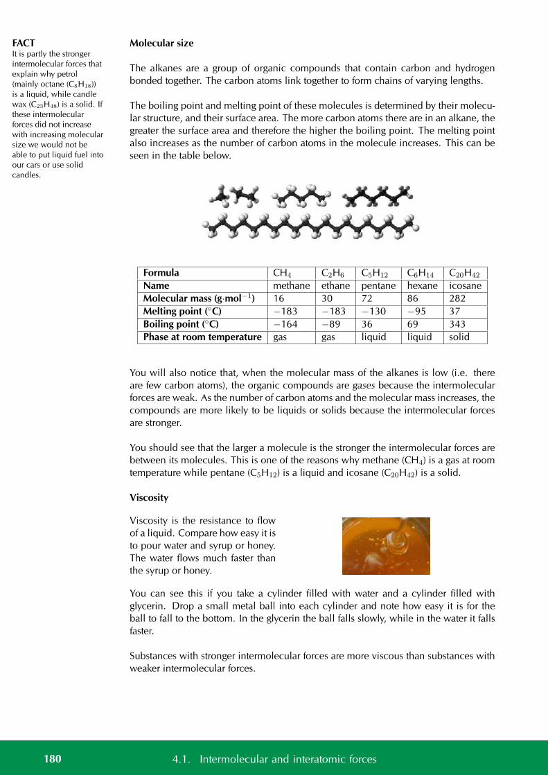
FACTIt is partly the strongerintermolecular forces thatexplain why petrol(mainly octane (C8H18))is a liquid, while candlewax (C23H48) is a solid. Ifthese intermolecularforces did not increasewith increasing molecularsize we would not beable to put liquid fuel intoour cars or use solidcandles.
Molecular size
The alkanes are a group of organic compounds that contain carbon and hydrogenbonded together. The carbon atoms link together to form chains of varying lengths.
The boiling point and melting point of these molecules is determined by their molecu-lar structure, and their surface area. The more carbon atoms there are in an alkane, thegreater the surface area and therefore the higher the boiling point. The melting pointalso increases as the number of carbon atoms in the molecule increases. This can beseen in the table below.
Formula CH4 C2H6 C5H12 C6H14 C20H42
Name methane ethane pentane hexane icosaneMolecular mass (g·mol−1) 16 30 72 86 282Melting point (C) −183 −183 −130 −95 37Boiling point (C) −164 −89 36 69 343Phase at room temperature gas gas liquid liquid solid
You will also notice that, when the molecular mass of the alkanes is low (i.e. thereare few carbon atoms), the organic compounds are gases because the intermolecularforces are weak. As the number of carbon atoms and the molecular mass increases, thecompounds are more likely to be liquids or solids because the intermolecular forcesare stronger.
You should see that the larger a molecule is the stronger the intermolecular forces arebetween its molecules. This is one of the reasons why methane (CH4) is a gas at roomtemperature while pentane (C5H12) is a liquid and icosane (C20H42) is a solid.
Viscosity
Viscosity is the resistance to flowof a liquid. Compare how easy it isto pour water and syrup or honey.The water flows much faster thanthe syrup or honey.
You can see this if you take a cylinder filled with water and a cylinder filled withglycerin. Drop a small metal ball into each cylinder and note how easy it is for theball to fall to the bottom. In the glycerin the ball falls slowly, while in the water it fallsfaster.
Substances with stronger intermolecular forces are more viscous than substances withweaker intermolecular forces.
180 4.1. Intermolecular and interatomic forces
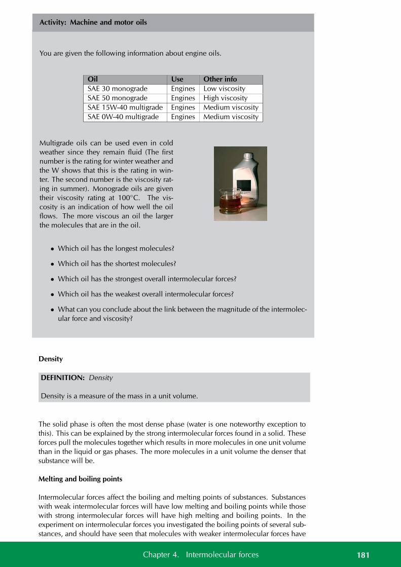
Activity: Machine and motor oils
You are given the following information about engine oils.
Oil Use Other infoSAE 30 monograde Engines Low viscositySAE 50 monograde Engines High viscositySAE 15W-40 multigrade Engines Medium viscositySAE 0W-40 multigrade Engines Medium viscosity
Multigrade oils can be used even in coldweather since they remain fluid (The firstnumber is the rating for winter weather andthe W shows that this is the rating in win-ter. The second number is the viscosity rat-ing in summer). Monograde oils are giventheir viscosity rating at 100C. The vis-cosity is an indication of how well the oilflows. The more viscous an oil the largerthe molecules that are in the oil.
• Which oil has the longest molecules?
• Which oil has the shortest molecules?
• Which oil has the strongest overall intermolecular forces?
• Which oil has the weakest overall intermolecular forces?
• What can you conclude about the link between the magnitude of the intermolec-ular force and viscosity?
Density
DEFINITION: Density
Density is a measure of the mass in a unit volume.
The solid phase is often the most dense phase (water is one noteworthy exception tothis). This can be explained by the strong intermolecular forces found in a solid. Theseforces pull the molecules together which results in more molecules in one unit volumethan in the liquid or gas phases. The more molecules in a unit volume the denser thatsubstance will be.
Melting and boiling points
Intermolecular forces affect the boiling and melting points of substances. Substanceswith weak intermolecular forces will have low melting and boiling points while thosewith strong intermolecular forces will have high melting and boiling points. In theexperiment on intermolecular forces you investigated the boiling points of several sub-stances, and should have seen that molecules with weaker intermolecular forces have
181Chapter 4. Intermolecular forces
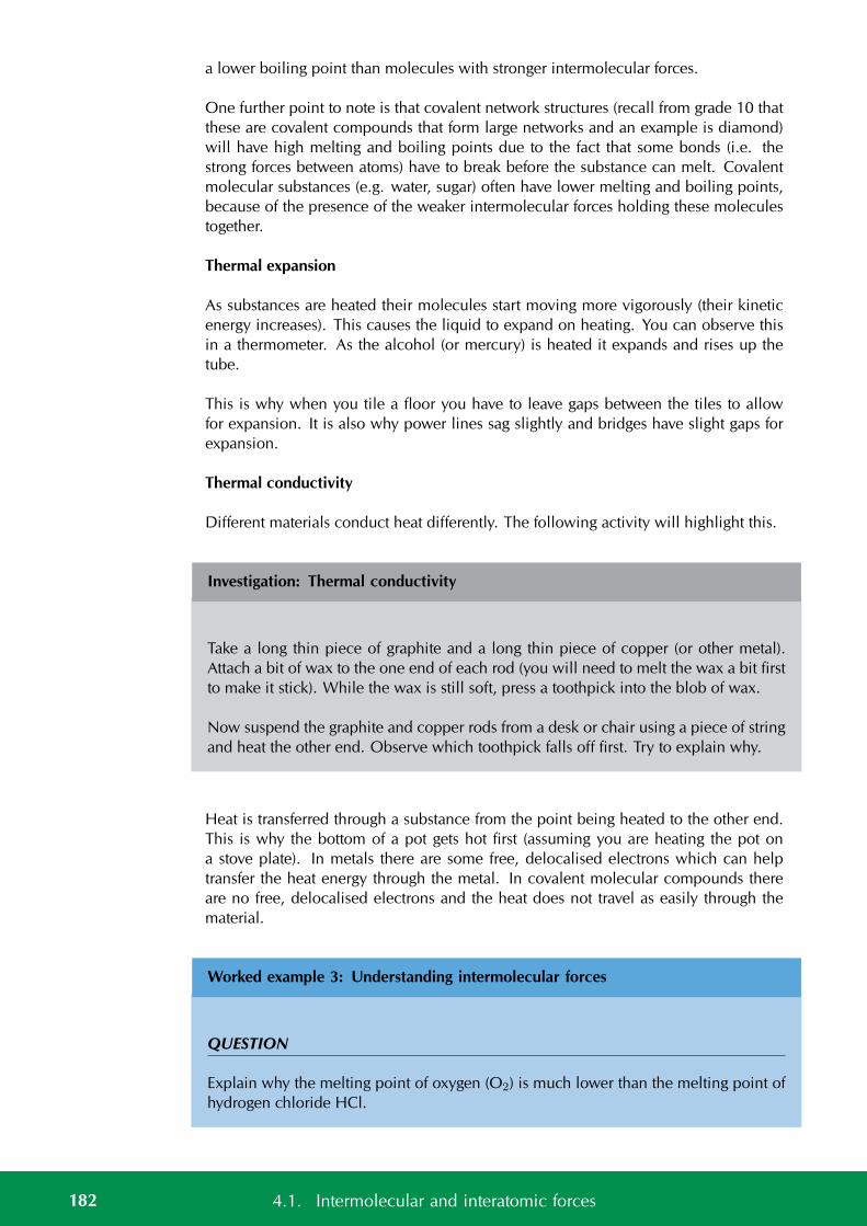
a lower boiling point than molecules with stronger intermolecular forces.
One further point to note is that covalent network structures (recall from grade 10 thatthese are covalent compounds that form large networks and an example is diamond)will have high melting and boiling points due to the fact that some bonds (i.e. thestrong forces between atoms) have to break before the substance can melt. Covalentmolecular substances (e.g. water, sugar) often have lower melting and boiling points,because of the presence of the weaker intermolecular forces holding these moleculestogether.
Thermal expansion
As substances are heated their molecules start moving more vigorously (their kineticenergy increases). This causes the liquid to expand on heating. You can observe thisin a thermometer. As the alcohol (or mercury) is heated it expands and rises up thetube.
This is why when you tile a floor you have to leave gaps between the tiles to allowfor expansion. It is also why power lines sag slightly and bridges have slight gaps forexpansion.
Thermal conductivity
Different materials conduct heat differently. The following activity will highlight this.
Investigation: Thermal conductivity
Take a long thin piece of graphite and a long thin piece of copper (or other metal).Attach a bit of wax to the one end of each rod (you will need to melt the wax a bit firstto make it stick). While the wax is still soft, press a toothpick into the blob of wax.
Now suspend the graphite and copper rods from a desk or chair using a piece of stringand heat the other end. Observe which toothpick falls off first. Try to explain why.
Heat is transferred through a substance from the point being heated to the other end.This is why the bottom of a pot gets hot first (assuming you are heating the pot ona stove plate). In metals there are some free, delocalised electrons which can helptransfer the heat energy through the metal. In covalent molecular compounds thereare no free, delocalised electrons and the heat does not travel as easily through thematerial.
Worked example 3: Understanding intermolecular forces
QUESTION
Explain why the melting point of oxygen (O2) is much lower than the melting point ofhydrogen chloride HCl.
182 4.1. Intermolecular and interatomic forces
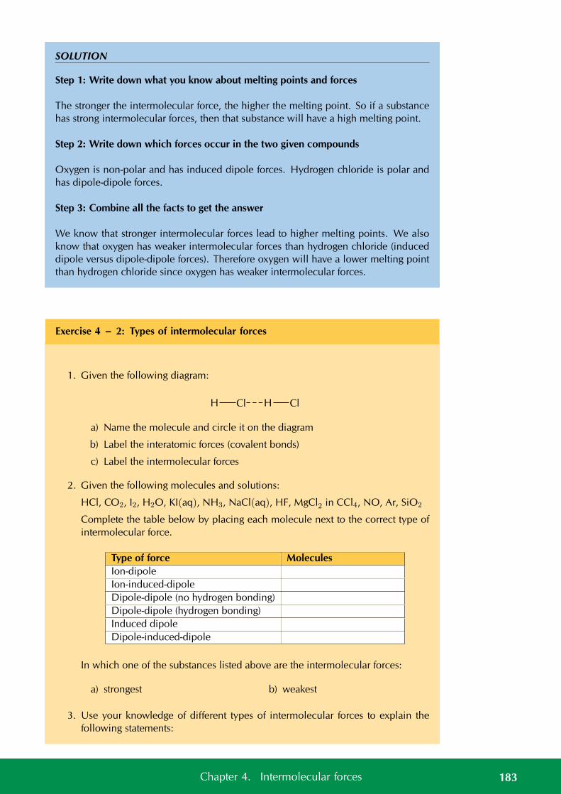
SOLUTION
Step 1: Write down what you know about melting points and forces
The stronger the intermolecular force, the higher the melting point. So if a substancehas strong intermolecular forces, then that substance will have a high melting point.
Step 2: Write down which forces occur in the two given compounds
Oxygen is non-polar and has induced dipole forces. Hydrogen chloride is polar andhas dipole-dipole forces.
Step 3: Combine all the facts to get the answer
We know that stronger intermolecular forces lead to higher melting points. We alsoknow that oxygen has weaker intermolecular forces than hydrogen chloride (induceddipole versus dipole-dipole forces). Therefore oxygen will have a lower melting pointthan hydrogen chloride since oxygen has weaker intermolecular forces.
Exercise 4 – 2: Types of intermolecular forces
1. Given the following diagram:
H Cl H Cl
a) Name the molecule and circle it on the diagram
b) Label the interatomic forces (covalent bonds)
c) Label the intermolecular forces
2. Given the following molecules and solutions:
HCl, CO2, I2, H2O, KI(aq), NH3, NaCl(aq), HF, MgCl2 in CCl4, NO, Ar, SiO2
Complete the table below by placing each molecule next to the correct type ofintermolecular force.
Type of force MoleculesIon-dipoleIon-induced-dipoleDipole-dipole (no hydrogen bonding)Dipole-dipole (hydrogen bonding)Induced dipoleDipole-induced-dipole
In which one of the substances listed above are the intermolecular forces:
a) strongest b) weakest
3. Use your knowledge of different types of intermolecular forces to explain thefollowing statements:
183Chapter 4. Intermolecular forces
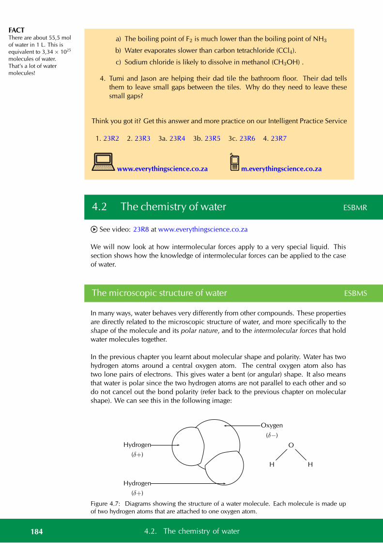
FACTThere are about 55,5 molof water in 1 L. This isequivalent to 3,34 × 1025
molecules of water.That’s a lot of watermolecules!
a) The boiling point of F2 is much lower than the boiling point of NH3
b) Water evaporates slower than carbon tetrachloride (CCl4).
c) Sodium chloride is likely to dissolve in methanol (CH3OH) .
4. Tumi and Jason are helping their dad tile the bathroom floor. Their dad tellsthem to leave small gaps between the tiles. Why do they need to leave thesesmall gaps?
Think you got it? Get this answer and more practice on our Intelligent Practice Service
1. 23R2 2. 23R3 3a. 23R4 3b. 23R5 3c. 23R6 4. 23R7
www.everythingscience.co.za m.everythingscience.co.za
4.2 The chemistry of water ESBMR
See video: 23R8 at www.everythingscience.co.za
We will now look at how intermolecular forces apply to a very special liquid. Thissection shows how the knowledge of intermolecular forces can be applied to the caseof water.
The microscopic structure of water ESBMS
In many ways, water behaves very differently from other compounds. These propertiesare directly related to the microscopic structure of water, and more specifically to theshape of the molecule and its polar nature, and to the intermolecular forces that holdwater molecules together.
In the previous chapter you learnt about molecular shape and polarity. Water has twohydrogen atoms around a central oxygen atom. The central oxygen atom also hastwo lone pairs of electrons. This gives water a bent (or angular) shape. It also meansthat water is polar since the two hydrogen atoms are not parallel to each other and sodo not cancel out the bond polarity (refer back to the previous chapter on molecularshape). We can see this in the following image:
O
HH
Oxygen
(δ−)
Hydrogen
(δ+)
Hydrogen
(δ+)
Figure 4.7: Diagrams showing the structure of a water molecule. Each molecule is made upof two hydrogen atoms that are attached to one oxygen atom.
184 4.2. The chemistry of water
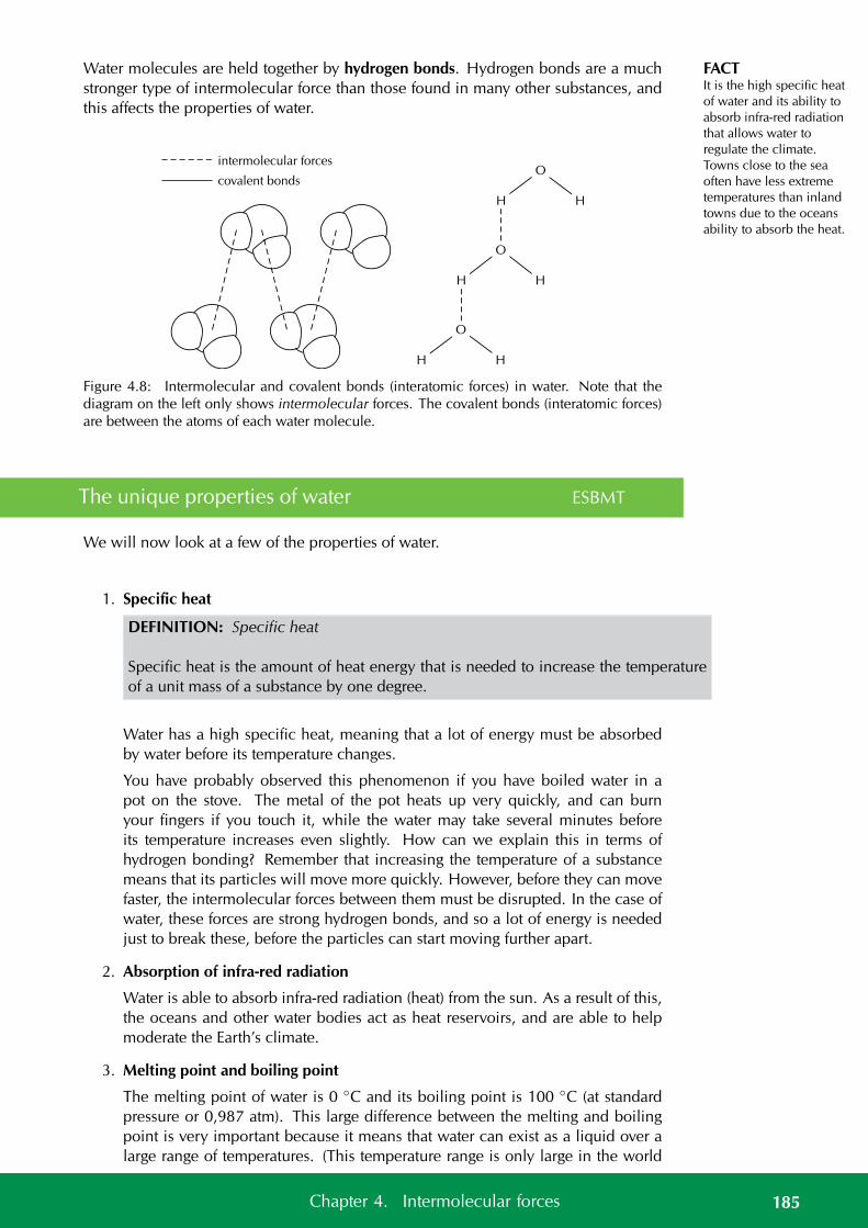
FACTIt is the high specific heatof water and its ability toabsorb infra-red radiationthat allows water toregulate the climate.Towns close to the seaoften have less extremetemperatures than inlandtowns due to the oceansability to absorb the heat.
Water molecules are held together by hydrogen bonds. Hydrogen bonds are a muchstronger type of intermolecular force than those found in many other substances, andthis affects the properties of water.
O
HH
O
HH
O
HH
intermolecular forces
covalent bonds
Figure 4.8: Intermolecular and covalent bonds (interatomic forces) in water. Note that thediagram on the left only shows intermolecular forces. The covalent bonds (interatomic forces)are between the atoms of each water molecule.
The unique properties of water ESBMT
We will now look at a few of the properties of water.
1. Specific heat
DEFINITION: Specific heat
Specific heat is the amount of heat energy that is needed to increase the temperatureof a unit mass of a substance by one degree.
Water has a high specific heat, meaning that a lot of energy must be absorbedby water before its temperature changes.
You have probably observed this phenomenon if you have boiled water in apot on the stove. The metal of the pot heats up very quickly, and can burnyour fingers if you touch it, while the water may take several minutes beforeits temperature increases even slightly. How can we explain this in terms ofhydrogen bonding? Remember that increasing the temperature of a substancemeans that its particles will move more quickly. However, before they can movefaster, the intermolecular forces between them must be disrupted. In the case ofwater, these forces are strong hydrogen bonds, and so a lot of energy is neededjust to break these, before the particles can start moving further apart.
2. Absorption of infra-red radiation
Water is able to absorb infra-red radiation (heat) from the sun. As a result of this,the oceans and other water bodies act as heat reservoirs, and are able to helpmoderate the Earth’s climate.
3. Melting point and boiling point
The melting point of water is 0 C and its boiling point is 100 C (at standardpressure or 0,987 atm). This large difference between the melting and boilingpoint is very important because it means that water can exist as a liquid over alarge range of temperatures. (This temperature range is only large in the world
185Chapter 4. Intermolecular forces
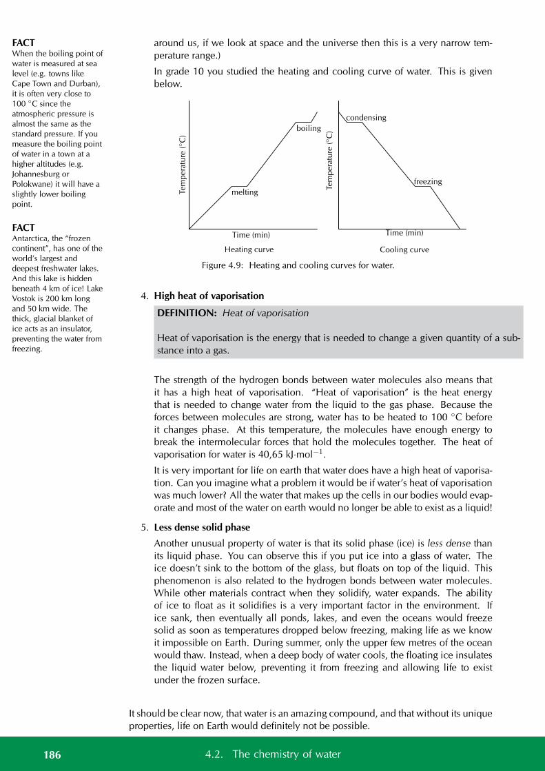
FACTWhen the boiling point ofwater is measured at sealevel (e.g. towns likeCape Town and Durban),it is often very close to100 C since theatmospheric pressure isalmost the same as thestandard pressure. If youmeasure the boiling pointof water in a town at ahigher altitudes (e.g.Johannesburg orPolokwane) it will have aslightly lower boilingpoint.
FACTAntarctica, the “frozencontinent”, has one of theworld’s largest anddeepest freshwater lakes.And this lake is hiddenbeneath 4 km of ice! LakeVostok is 200 km longand 50 km wide. Thethick, glacial blanket ofice acts as an insulator,preventing the water fromfreezing.
around us, if we look at space and the universe then this is a very narrow tem-perature range.)
In grade 10 you studied the heating and cooling curve of water. This is givenbelow.
Heating curve Cooling curve
Time (min)
Tem
pera
ture
(C
)
Time (min)
condensing
freezing
melting
boiling
Tem
pera
ture
(C
)
Figure 4.9: Heating and cooling curves for water.
4. High heat of vaporisation
DEFINITION: Heat of vaporisation
Heat of vaporisation is the energy that is needed to change a given quantity of a sub-stance into a gas.
The strength of the hydrogen bonds between water molecules also means thatit has a high heat of vaporisation. “Heat of vaporisation” is the heat energythat is needed to change water from the liquid to the gas phase. Because theforces between molecules are strong, water has to be heated to 100 C beforeit changes phase. At this temperature, the molecules have enough energy tobreak the intermolecular forces that hold the molecules together. The heat ofvaporisation for water is 40,65 kJ·mol−1.
It is very important for life on earth that water does have a high heat of vaporisa-tion. Can you imagine what a problem it would be if water’s heat of vaporisationwas much lower? All the water that makes up the cells in our bodies would evap-orate and most of the water on earth would no longer be able to exist as a liquid!
5. Less dense solid phase
Another unusual property of water is that its solid phase (ice) is less dense thanits liquid phase. You can observe this if you put ice into a glass of water. Theice doesn’t sink to the bottom of the glass, but floats on top of the liquid. Thisphenomenon is also related to the hydrogen bonds between water molecules.While other materials contract when they solidify, water expands. The abilityof ice to float as it solidifies is a very important factor in the environment. Ifice sank, then eventually all ponds, lakes, and even the oceans would freezesolid as soon as temperatures dropped below freezing, making life as we knowit impossible on Earth. During summer, only the upper few metres of the oceanwould thaw. Instead, when a deep body of water cools, the floating ice insulatesthe liquid water below, preventing it from freezing and allowing life to existunder the frozen surface.
It should be clear now, that water is an amazing compound, and that without its uniqueproperties, life on Earth would definitely not be possible.
186 4.2. The chemistry of water
Worked example 4: Properties of water
QUESTION
Explain why water takes a long time to heat up, but the pot that you are heating it ingets hot quickly.
SOLUTION
Step 1: Decide which property is applied here
We are asked why water takes a long time to heat up compared to the pot you areheating it in. The property that applies here is the high specific heat of water. Theother properties of water do not apply here since we are comparing the pot to thewater and the pot is not changing phase.
Step 2: Write the final answer
Water has a high specific heat, while the metal that the pot is made of does not. Themetal pot needs less energy to heat it up and so it gets hotter faster. Water needs a lotof energy to change its temperature and so it takes longer to get hot.
Informal experiment:The properties of water
Aim:
To investigate the properties of water.
Apparatus:
• water
• ice
• beakers
• carbon tetrachloride, oil, ethanol
• various solids (e.g. sodium chloride, potassium chloride, potassium perman-ganate, iodine)
Method:
1. Pour about 100 ml of water into a glass beaker.
2. Place the beaker on a stand and heat it over a Bunsen burner for about a minute.
3. After this time, carefully touch the side of the beaker (Make sure you touch theglass very lightly because it will be very hot and may burn you!). Then test thetemperature of the water.
187Chapter 4. Intermolecular forces
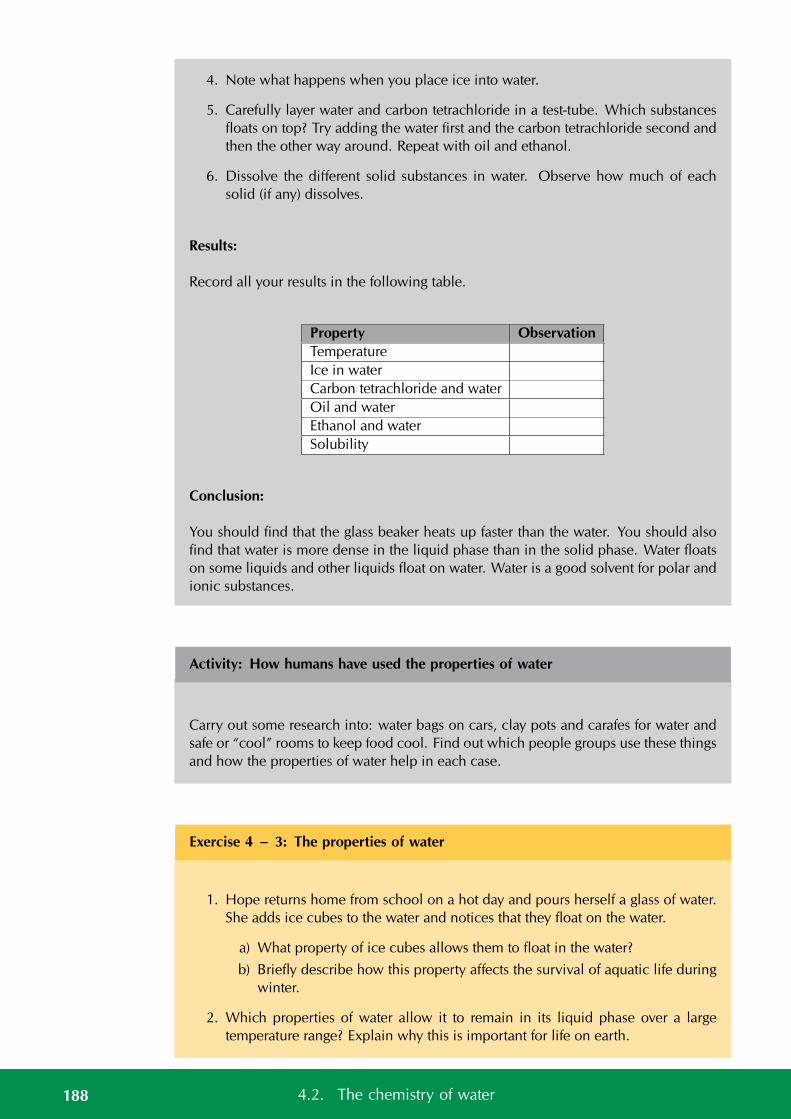
4. Note what happens when you place ice into water.
5. Carefully layer water and carbon tetrachloride in a test-tube. Which substancesfloats on top? Try adding the water first and the carbon tetrachloride second andthen the other way around. Repeat with oil and ethanol.
6. Dissolve the different solid substances in water. Observe how much of eachsolid (if any) dissolves.
Results:
Record all your results in the following table.
Property ObservationTemperatureIce in waterCarbon tetrachloride and waterOil and waterEthanol and waterSolubility
Conclusion:
You should find that the glass beaker heats up faster than the water. You should alsofind that water is more dense in the liquid phase than in the solid phase. Water floatson some liquids and other liquids float on water. Water is a good solvent for polar andionic substances.
Activity: How humans have used the properties of water
Carry out some research into: water bags on cars, clay pots and carafes for water andsafe or “cool” rooms to keep food cool. Find out which people groups use these thingsand how the properties of water help in each case.
Exercise 4 – 3: The properties of water
1. Hope returns home from school on a hot day and pours herself a glass of water.She adds ice cubes to the water and notices that they float on the water.
a) What property of ice cubes allows them to float in the water?
b) Briefly describe how this property affects the survival of aquatic life duringwinter.
2. Which properties of water allow it to remain in its liquid phase over a largetemperature range? Explain why this is important for life on earth.
188 4.2. The chemistry of water

3. Which property of water allows the oceans to act as heat reservoirs? What effectdoes this have on the Earths climate?
Think you got it? Get this answer and more practice on our Intelligent Practice Service
1. 23R9 2. 23RB 3. 23RC
www.everythingscience.co.za m.everythingscience.co.za
4.3 Chapter summary ESBMV
See presentation: 23RD at www.everythingscience.co.za
• Intermolecular forces are the forces that act between molecules.
• The type of intermolecular force in a substance, will depend on the nature ofthe molecules.
• Polar molecules have an unequal distribution of charge, meaning that one partof the molecule is slightly positive and the other part is slightly negative. Themolecule is said to be a dipole.
• Non-polar molecules have an equal distribution of charge.
• There are five types of intermolecular forces: ion-dipole forces, ion-induced-dipole forces, dipole-dipole forces, dipole-induced dipole forces and induceddipole forces.
• Ion-dipole forces exist between ions and polar (dipole) molecules. The ion isattracted to the part of the molecule that has an opposite charge to its own.
• Ion-induced dipole forces exist between ions and non-polar molecules. An ioninduces a dipole in the non-polar molecule.
• Dipole-dipole forces exist between two polar (dipole) molecules.
• Dipole-induced dipole forces exist between a polar molecule and a non-polarmolecule.
• Induced dipole forces exist between two non-polar molecules.
• Dipole-dipole forces, dipole-induced dipole forces and induced dipole forcesare collectively called van der Waals’ forces.
• Hydrogen bonds are a type of dipole-dipole force that occurs when a hydrogenatom is attached to a highly electronegative atom (oxygen, fluorine, nitrogen).A hydrogen atom on one molecule is attracted to the electronegative atom on asecond molecule.
• Intermolecular forces affect the properties of substances.
• Substances with larger molecules have stronger intermolecular forces than sub-stances with smaller molecules.
189Chapter 4. Intermolecular forces
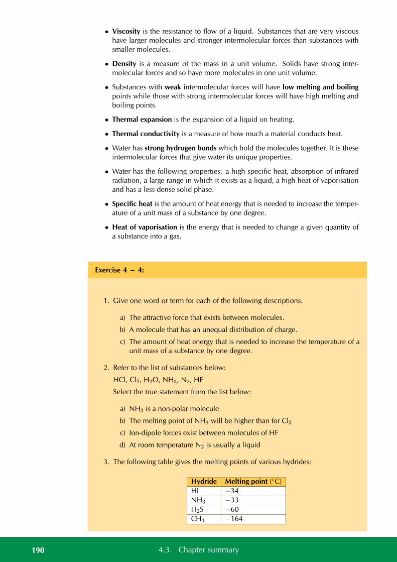
• Viscosity is the resistance to flow of a liquid. Substances that are very viscoushave larger molecules and stronger intermolecular forces than substances withsmaller molecules.
• Density is a measure of the mass in a unit volume. Solids have strong inter-molecular forces and so have more molecules in one unit volume.
• Substances with weak intermolecular forces will have low melting and boilingpoints while those with strong intermolecular forces will have high melting andboiling points.
• Thermal expansion is the expansion of a liquid on heating.
• Thermal conductivity is a measure of how much a material conducts heat.
• Water has strong hydrogen bonds which hold the molecules together. It is theseintermolecular forces that give water its unique properties.
• Water has the following properties: a high specific heat, absorption of infraredradiation, a large range in which it exists as a liquid, a high heat of vaporisationand has a less dense solid phase.
• Specific heat is the amount of heat energy that is needed to increase the temper-ature of a unit mass of a substance by one degree.
• Heat of vaporisation is the energy that is needed to change a given quantity ofa substance into a gas.
Exercise 4 – 4:
1. Give one word or term for each of the following descriptions:
a) The attractive force that exists between molecules.
b) A molecule that has an unequal distribution of charge.
c) The amount of heat energy that is needed to increase the temperature of aunit mass of a substance by one degree.
2. Refer to the list of substances below:
HCl, Cl2, H2O, NH3, N2, HF
Select the true statement from the list below:
a) NH3 is a non-polar molecule
b) The melting point of NH3 will be higher than for Cl2
c) Ion-dipole forces exist between molecules of HF
d) At room temperature N2 is usually a liquid
3. The following table gives the melting points of various hydrides:
Hydride Melting point (C)HI −34NH3 −33H2S −60CH4 −164
190 4.3. Chapter summary
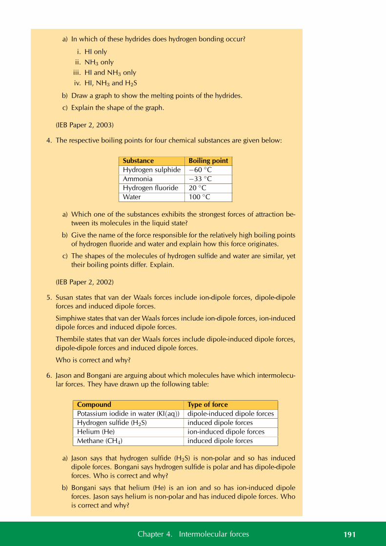
a) In which of these hydrides does hydrogen bonding occur?
i. HI only
ii. NH3 only
iii. HI and NH3 only
iv. HI, NH3 and H2S
b) Draw a graph to show the melting points of the hydrides.
c) Explain the shape of the graph.
(IEB Paper 2, 2003)
4. The respective boiling points for four chemical substances are given below:
Substance Boiling pointHydrogen sulphide −60 CAmmonia −33 CHydrogen fluoride 20 CWater 100 C
a) Which one of the substances exhibits the strongest forces of attraction be-tween its molecules in the liquid state?
b) Give the name of the force responsible for the relatively high boiling pointsof hydrogen fluoride and water and explain how this force originates.
c) The shapes of the molecules of hydrogen sulfide and water are similar, yettheir boiling points differ. Explain.
(IEB Paper 2, 2002)
5. Susan states that van der Waals forces include ion-dipole forces, dipole-dipoleforces and induced dipole forces.
Simphiwe states that van der Waals forces include ion-dipole forces, ion-induceddipole forces and induced dipole forces.
Thembile states that van der Waals forces include dipole-induced dipole forces,dipole-dipole forces and induced dipole forces.
Who is correct and why?
6. Jason and Bongani are arguing about which molecules have which intermolecu-lar forces. They have drawn up the following table:
Compound Type of forcePotassium iodide in water (KI(aq)) dipole-induced dipole forcesHydrogen sulfide (H2S) induced dipole forcesHelium (He) ion-induced dipole forcesMethane (CH4) induced dipole forces
a) Jason says that hydrogen sulfide (H2S) is non-polar and so has induceddipole forces. Bongani says hydrogen sulfide is polar and has dipole-dipoleforces. Who is correct and why?
b) Bongani says that helium (He) is an ion and so has ion-induced dipoleforces. Jason says helium is non-polar and has induced dipole forces. Whois correct and why?
191Chapter 4. Intermolecular forces

c) They both agree on the rest of the table. However, they have not got thecorrect force for potassium iodide in water (KI(aq)). What type of forceactually exists in this compound?
7. Khetang is looking at power lines around him for a school project. He noticesthat they sag slightly between the pylons. Why do power lines need to sagslightly?
8. Briefly describe how the properties of water make it a good liquid for life onEarth.
Think you got it? Get this answer and more practice on our Intelligent Practice Service
1a. 23RF 1b. 23RG 1c. 23RH 2. 23RJ 3. 23RK 4. 23RM5. 23RN 6. 23RP 7. 23RQ 8. 23RR
www.everythingscience.co.za m.everythingscience.co.za
192 4.3. Chapter summary
CHAPTER 5
Geometrical optics
5.1 Summary of properties of light 194
5.2 Light rays 194
5.3 Properties of light: revision 196
5.4 The speed of light 202
5.5 Refraction 202
5.6 Snell’s Law 211
5.7 Critical angles and total internal reflection 221
5.8 Summary 229
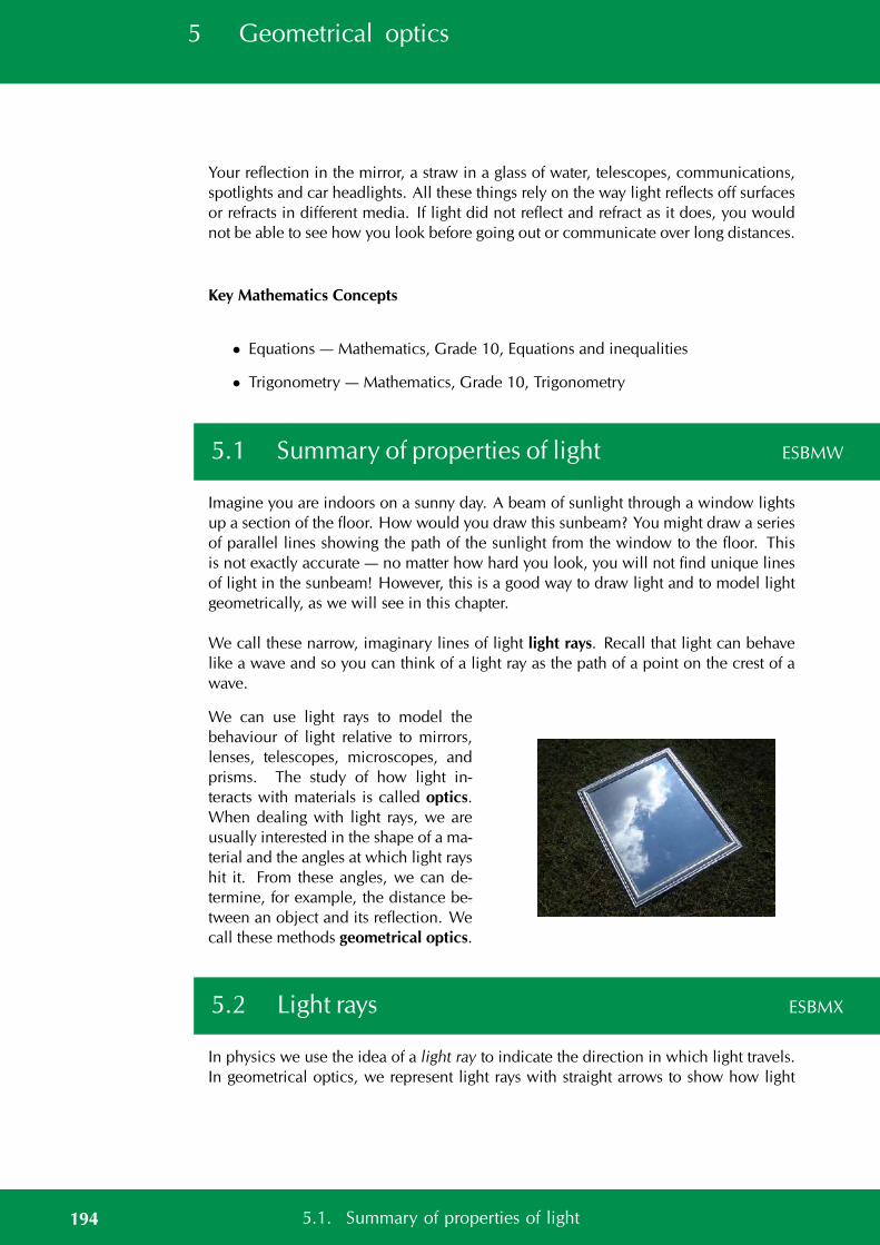
5 Geometrical optics
Your reflection in the mirror, a straw in a glass of water, telescopes, communications,spotlights and car headlights. All these things rely on the way light reflects off surfacesor refracts in different media. If light did not reflect and refract as it does, you wouldnot be able to see how you look before going out or communicate over long distances.
Key Mathematics Concepts
• Equations — Mathematics, Grade 10, Equations and inequalities
• Trigonometry — Mathematics, Grade 10, Trigonometry
5.1 Summary of properties of light ESBMW
Imagine you are indoors on a sunny day. A beam of sunlight through a window lightsup a section of the floor. How would you draw this sunbeam? You might draw a seriesof parallel lines showing the path of the sunlight from the window to the floor. Thisis not exactly accurate — no matter how hard you look, you will not find unique linesof light in the sunbeam! However, this is a good way to draw light and to model lightgeometrically, as we will see in this chapter.
We call these narrow, imaginary lines of light light rays. Recall that light can behavelike a wave and so you can think of a light ray as the path of a point on the crest of awave.
We can use light rays to model thebehaviour of light relative to mirrors,lenses, telescopes, microscopes, andprisms. The study of how light in-teracts with materials is called optics.When dealing with light rays, we areusually interested in the shape of a ma-terial and the angles at which light rayshit it. From these angles, we can de-termine, for example, the distance be-tween an object and its reflection. Wecall these methods geometrical optics.
5.2 Light rays ESBMX
In physics we use the idea of a light ray to indicate the direction in which light travels.In geometrical optics, we represent light rays with straight arrows to show how light
194 5.1. Summary of properties of light
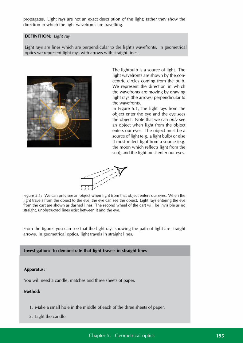
propagates. Light rays are not an exact description of the light; rather they show thedirection in which the light wavefronts are travelling.
DEFINITION: Light ray
Light rays are lines which are perpendicular to the light’s wavefronts. In geometricaloptics we represent light rays with arrows with straight lines.
The lightbulb is a source of light. Thelight wavefronts are shown by the con-centric circles coming from the bulb.We represent the direction in whichthe wavefronts are moving by drawinglight rays (the arrows) perpendicular tothe wavefronts.In Figure 5.1, the light rays from theobject enter the eye and the eye seesthe object. Note that we can only seean object when light from the objectenters our eyes. The object must be asource of light (e.g. a light bulb) or elseit must reflect light from a source (e.g.the moon which reflects light from thesun), and the light must enter our eyes.
Figure 5.1: We can only see an object when light from that object enters our eyes. When thelight travels from the object to the eye, the eye can see the object. Light rays entering the eyefrom the cart are shown as dashed lines. The second wheel of the cart will be invisible as nostraight, unobstructed lines exist between it and the eye.
From the figures you can see that the light rays showing the path of light are straightarrows. In geometrical optics, light travels in straight lines.
Investigation: To demonstrate that light travels in straight lines
Apparatus:
You will need a candle, matches and three sheets of paper.
Method:
1. Make a small hole in the middle of each of the three sheets of paper.
2. Light the candle.
195Chapter 5. Geometrical optics
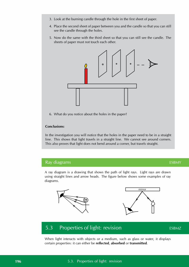
3. Look at the burning candle through the hole in the first sheet of paper.
4. Place the second sheet of paper between you and the candle so that you can stillsee the candle through the holes.
5. Now do the same with the third sheet so that you can still see the candle. Thesheets of paper must not touch each other.
6. What do you notice about the holes in the paper?
Conclusions:
In the investigation you will notice that the holes in the paper need to be in a straightline. This shows that light travels in a straight line. We cannot see around corners.This also proves that light does not bend around a corner, but travels straight.
Ray diagrams ESBMY
A ray diagram is a drawing that shows the path of light rays. Light rays are drawnusing straight lines and arrow heads. The figure below shows some examples of raydiagrams.
mirror
5.3 Properties of light: revision ESBMZ
When light interacts with objects or a medium, such as glass or water, it displayscertain properties: it can either be reflected, absorbed or transmitted.
196 5.3. Properties of light: revision
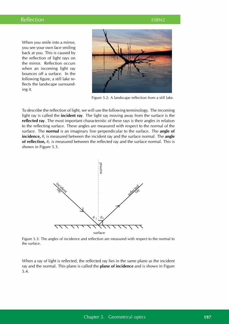
Reflection ESBN2
When you smile into a mirror,you see your own face smilingback at you. This is caused bythe reflection of light rays onthe mirror. Reflection occurswhen an incoming light raybounces off a surface. In thefollowing figure, a still lake re-flects the landscape surround-ing it.
Figure 5.2: A landscape reflection from a still lake.
To describe the reflection of light, we will use the following terminology. The incominglight ray is called the incident ray. The light ray moving away from the surface is thereflected ray. The most important characteristic of these rays is their angles in relationto the reflecting surface. These angles are measured with respect to the normal of thesurface. The normal is an imaginary line perpendicular to the surface. The angle ofincidence, θi is measured between the incident ray and the surface normal. The angleof reflection, θr is measured between the reflected ray and the surface normal. This isshown in Figure 5.3.
incidentre
flectedray ray
surface
no
rmal
θ i θ r
Figure 5.3: The angles of incidence and reflection are measured with respect to the normal tothe surface.
When a ray of light is reflected, the reflected ray lies in the same plane as the incidentray and the normal. This plane is called the plane of incidence and is shown in Figure5.4.
197Chapter 5. Geometrical optics
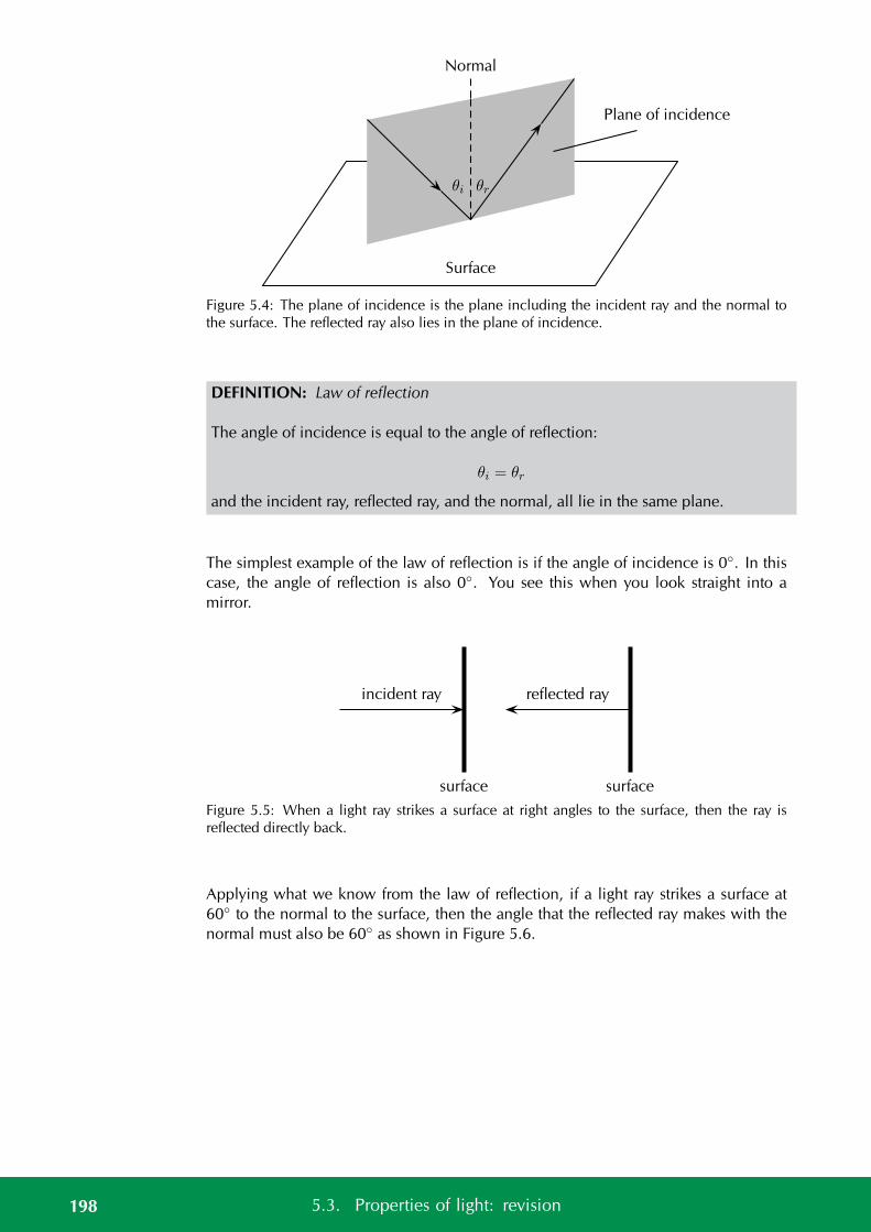
Normal
Plane of incidence
Surface
θi θr
Figure 5.4: The plane of incidence is the plane including the incident ray and the normal tothe surface. The reflected ray also lies in the plane of incidence.
DEFINITION: Law of reflection
The angle of incidence is equal to the angle of reflection:
θi = θr
and the incident ray, reflected ray, and the normal, all lie in the same plane.
The simplest example of the law of reflection is if the angle of incidence is 0. In thiscase, the angle of reflection is also 0. You see this when you look straight into amirror.
surface
incident ray
surface
reflected ray
Figure 5.5: When a light ray strikes a surface at right angles to the surface, then the ray isreflected directly back.
Applying what we know from the law of reflection, if a light ray strikes a surface at60 to the normal to the surface, then the angle that the reflected ray makes with thenormal must also be 60 as shown in Figure 5.6.
198 5.3. Properties of light: revision
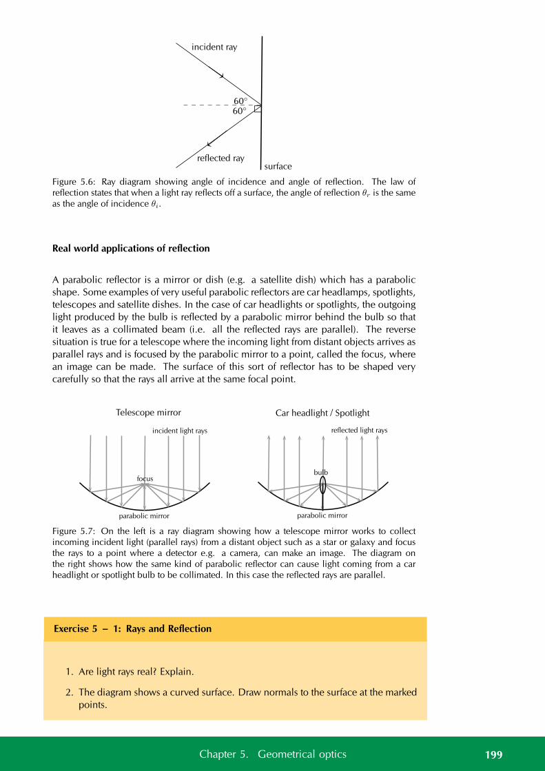
incident ray
reflected raysurface
60
60
Figure 5.6: Ray diagram showing angle of incidence and angle of reflection. The law ofreflection states that when a light ray reflects off a surface, the angle of reflection θr is the sameas the angle of incidence θi.
Real world applications of reflection
A parabolic reflector is a mirror or dish (e.g. a satellite dish) which has a parabolicshape. Some examples of very useful parabolic reflectors are car headlamps, spotlights,telescopes and satellite dishes. In the case of car headlights or spotlights, the outgoinglight produced by the bulb is reflected by a parabolic mirror behind the bulb so thatit leaves as a collimated beam (i.e. all the reflected rays are parallel). The reversesituation is true for a telescope where the incoming light from distant objects arrives asparallel rays and is focused by the parabolic mirror to a point, called the focus, wherean image can be made. The surface of this sort of reflector has to be shaped verycarefully so that the rays all arrive at the same focal point.
parabolic mirror
incident light rays
focus
Telescope mirror
parabolic mirror
reflected light rays
bulb
Car headlight / Spotlight
Figure 5.7: On the left is a ray diagram showing how a telescope mirror works to collectincoming incident light (parallel rays) from a distant object such as a star or galaxy and focusthe rays to a point where a detector e.g. a camera, can make an image. The diagram onthe right shows how the same kind of parabolic reflector can cause light coming from a carheadlight or spotlight bulb to be collimated. In this case the reflected rays are parallel.
Exercise 5 – 1: Rays and Reflection
1. Are light rays real? Explain.
2. The diagram shows a curved surface. Draw normals to the surface at the markedpoints.
199Chapter 5. Geometrical optics
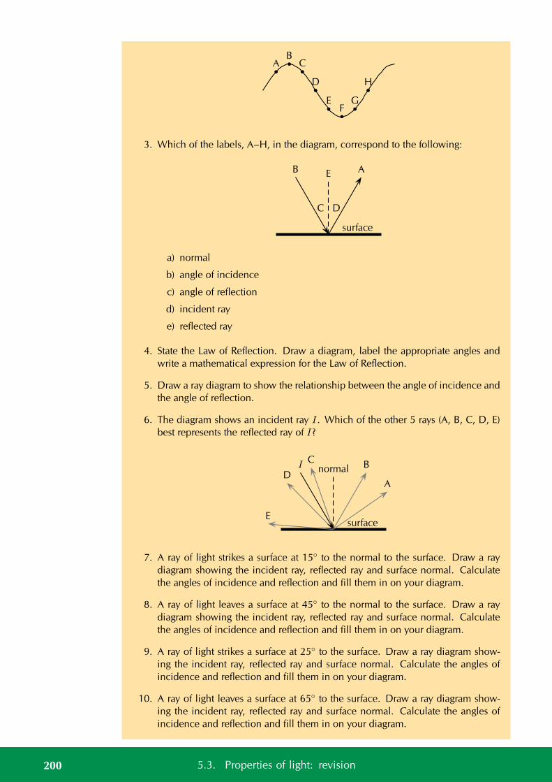
AB
C
D
EF
G
H
3. Which of the labels, A–H, in the diagram, correspond to the following:
EB A
C D
surface
a) normal
b) angle of incidence
c) angle of reflection
d) incident ray
e) reflected ray
4. State the Law of Reflection. Draw a diagram, label the appropriate angles andwrite a mathematical expression for the Law of Reflection.
5. Draw a ray diagram to show the relationship between the angle of incidence andthe angle of reflection.
6. The diagram shows an incident ray I. Which of the other 5 rays (A, B, C, D, E)best represents the reflected ray of I?
surface
normal
A
BC
D
E
I
7. A ray of light strikes a surface at 15 to the normal to the surface. Draw a raydiagram showing the incident ray, reflected ray and surface normal. Calculatethe angles of incidence and reflection and fill them in on your diagram.
8. A ray of light leaves a surface at 45 to the normal to the surface. Draw a raydiagram showing the incident ray, reflected ray and surface normal. Calculatethe angles of incidence and reflection and fill them in on your diagram.
9. A ray of light strikes a surface at 25 to the surface. Draw a ray diagram show-ing the incident ray, reflected ray and surface normal. Calculate the angles ofincidence and reflection and fill them in on your diagram.
10. A ray of light leaves a surface at 65 to the surface. Draw a ray diagram show-ing the incident ray, reflected ray and surface normal. Calculate the angles ofincidence and reflection and fill them in on your diagram.
200 5.3. Properties of light: revision
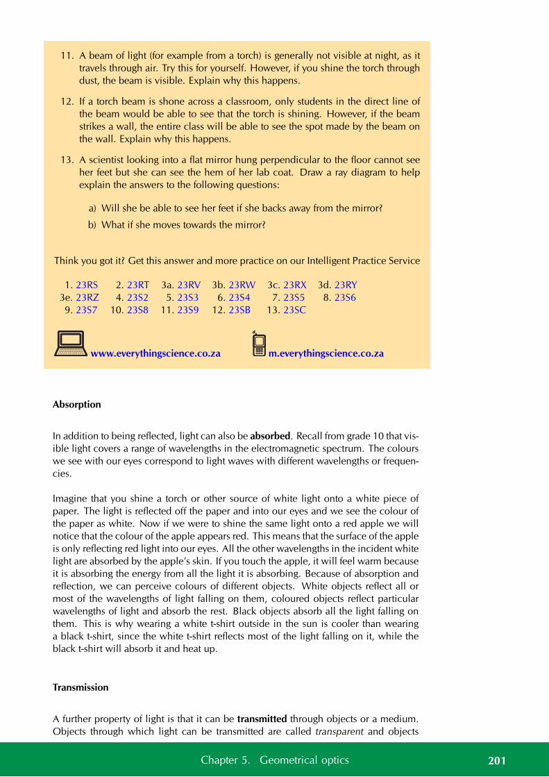
11. A beam of light (for example from a torch) is generally not visible at night, as ittravels through air. Try this for yourself. However, if you shine the torch throughdust, the beam is visible. Explain why this happens.
12. If a torch beam is shone across a classroom, only students in the direct line ofthe beam would be able to see that the torch is shining. However, if the beamstrikes a wall, the entire class will be able to see the spot made by the beam onthe wall. Explain why this happens.
13. A scientist looking into a flat mirror hung perpendicular to the floor cannot seeher feet but she can see the hem of her lab coat. Draw a ray diagram to helpexplain the answers to the following questions:
a) Will she be able to see her feet if she backs away from the mirror?
b) What if she moves towards the mirror?
Think you got it? Get this answer and more practice on our Intelligent Practice Service
1. 23RS 2. 23RT 3a. 23RV 3b. 23RW 3c. 23RX 3d. 23RY3e. 23RZ 4. 23S2 5. 23S3 6. 23S4 7. 23S5 8. 23S69. 23S7 10. 23S8 11. 23S9 12. 23SB 13. 23SC
www.everythingscience.co.za m.everythingscience.co.za
Absorption
In addition to being reflected, light can also be absorbed. Recall from grade 10 that vis-ible light covers a range of wavelengths in the electromagnetic spectrum. The colourswe see with our eyes correspond to light waves with different wavelengths or frequen-cies.
Imagine that you shine a torch or other source of white light onto a white piece ofpaper. The light is reflected off the paper and into our eyes and we see the colour ofthe paper as white. Now if we were to shine the same light onto a red apple we willnotice that the colour of the apple appears red. This means that the surface of the appleis only reflecting red light into our eyes. All the other wavelengths in the incident whitelight are absorbed by the apple’s skin. If you touch the apple, it will feel warm becauseit is absorbing the energy from all the light it is absorbing. Because of absorption andreflection, we can perceive colours of different objects. White objects reflect all ormost of the wavelengths of light falling on them, coloured objects reflect particularwavelengths of light and absorb the rest. Black objects absorb all the light falling onthem. This is why wearing a white t-shirt outside in the sun is cooler than wearinga black t-shirt, since the white t-shirt reflects most of the light falling on it, while theblack t-shirt will absorb it and heat up.
Transmission
A further property of light is that it can be transmitted through objects or a medium.Objects through which light can be transmitted are called transparent and objects
201Chapter 5. Geometrical optics
which block out light or that light cannot pass through are called opaque.
For example, glass windows allow visible light to pass through them which is why wecan see through windows. The light rays from things outside the window can passthrough or be transmitted through the glass and into our eyes. Brick walls on the otherhand are opaque to visible light. We cannot see through brick walls because the lightcannot be transmitted through the wall into our eyes. The transmission of light throughan object depends on the wavelength of the light. For example, short wavelengthvisible light cannot be transmitted through a brick wall whereas long wavelength radiowaves can easily pass through walls and be received by a radio or cell phone. In otherwords, a brick wall is transparent to radio waves!
5.4 The speed of light ESBN3
One of the most exciting discoveries in physics during the last century, and the corner-stone of Einstein’s Theory of Relativity, is that light travels at a constant speed in a givenmedium. Light also has a maximum speed at which it can propagate, and nothing canmove faster than the speed of light. The maximum speed at which light can travel iswhen it propagates through free space (a vacuum) at 299 792 485 m·s−1. A vacuumis a region with no matter in it, not even air. However, the speed of light in air is veryclose to that in a vacuum.
We use the symbol c to represent the speed of light in a vacuum and approximate it asc = 3 × 10⁸ m·s−1
DEFINITION: Speed of light
The speed of light, c, is constant in a given medium and has a maximum speed invacuum of
c = 3 × 10⁸ m·s−1
5.5 Refraction ESBN4
See video: 23SD at www.everythingscience.co.za
See video: 23SF at www.everythingscience.co.za
In the previous sections we studied light reflecting off various surfaces. What happenswhen light passes from one medium into another? The speed of light, like that ofall waves, is dependent on the medium through which it is travelling. When lightmoves from one medium into another (for example, from air to glass), the speed oflight changes. If the light ray hits the boundary of the new medium (for example theedge of a glass block) at any angle which is not perpendicular to or parallel with theboundary, the light ray will change its direction through the next medium, or appearto ‘bend’. This is called refraction of light. It is important to note that while the speedof the light changes when it passes into the new medium, the frequency of the light
202 5.4. The speed of light
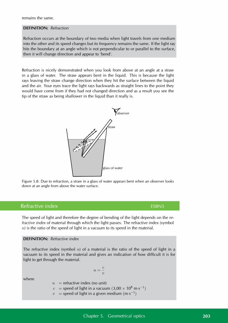
remains the same.
DEFINITION: Refraction
Refraction occurs at the boundary of two media when light travels from one mediuminto the other and its speed changes but its frequency remains the same. If the light rayhits the boundary at an angle which is not perpendicular to or parallel to the surface,then it will change direction and appear to ‘bend’.
Refraction is nicely demonstrated when you look from above at an angle at a strawin a glass of water. The straw appears bent in the liquid. This is because the lightrays leaving the straw change direction when they hit the surface between the liquidand the air. Your eyes trace the light rays backwards as straight lines to the point theywould have come from if they had not changed direction and as a result you see thetip of the straw as being shallower in the liquid than it really is.
glass of water
straw
observer
Figure 5.8: Due to refraction, a straw in a glass of water appears bent when an observer looksdown at an angle from above the water surface.
Refractive index ESBN5
The speed of light and therefore the degree of bending of the light depends on the re-fractive index of material through which the light passes. The refractive index (symboln) is the ratio of the speed of light in a vacuum to its speed in the material.
DEFINITION: Refractive index
The refractive index (symbol n) of a material is the ratio of the speed of light in avacuum to its speed in the material and gives an indication of how difficult it is forlight to get through the material.
n =c
v
wheren = refractive index (no unit)c = speed of light in a vacuum (3,00 × 10⁸ m·s−1)v = speed of light in a given medium (m·s−1)
203Chapter 5. Geometrical optics
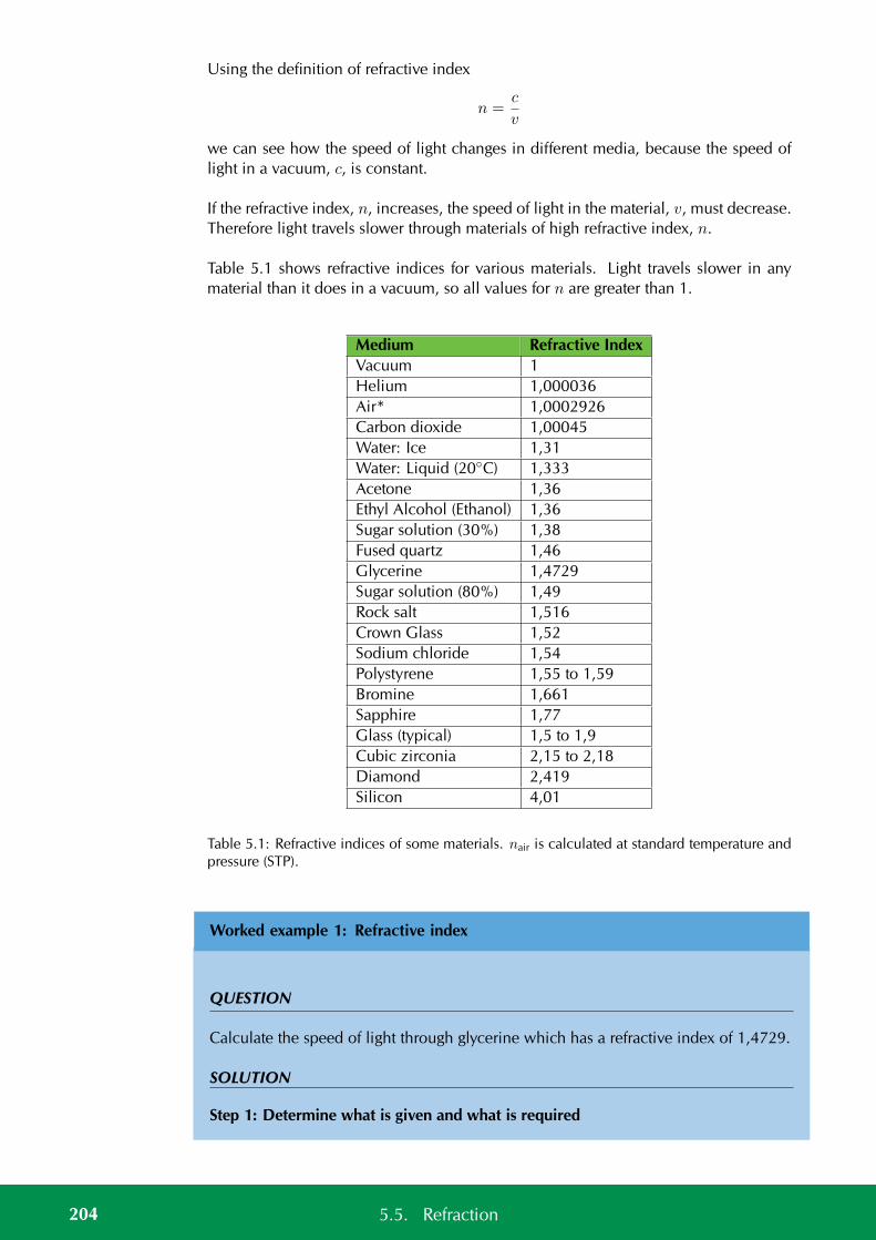
Using the definition of refractive index
n =c
v
we can see how the speed of light changes in different media, because the speed oflight in a vacuum, c, is constant.
If the refractive index, n, increases, the speed of light in the material, v, must decrease.Therefore light travels slower through materials of high refractive index, n.
Table 5.1 shows refractive indices for various materials. Light travels slower in anymaterial than it does in a vacuum, so all values for n are greater than 1.
Medium Refractive IndexVacuum 1Helium 1,000036Air* 1,0002926Carbon dioxide 1,00045Water: Ice 1,31Water: Liquid (20C) 1,333Acetone 1,36Ethyl Alcohol (Ethanol) 1,36Sugar solution (30%) 1,38Fused quartz 1,46Glycerine 1,4729Sugar solution (80%) 1,49Rock salt 1,516Crown Glass 1,52Sodium chloride 1,54Polystyrene 1,55 to 1,59Bromine 1,661Sapphire 1,77Glass (typical) 1,5 to 1,9Cubic zirconia 2,15 to 2,18Diamond 2,419Silicon 4,01
Table 5.1: Refractive indices of some materials. nair is calculated at standard temperature andpressure (STP).
Worked example 1: Refractive index
QUESTION
Calculate the speed of light through glycerine which has a refractive index of 1,4729.
SOLUTION
Step 1: Determine what is given and what is required
204 5.5. Refraction
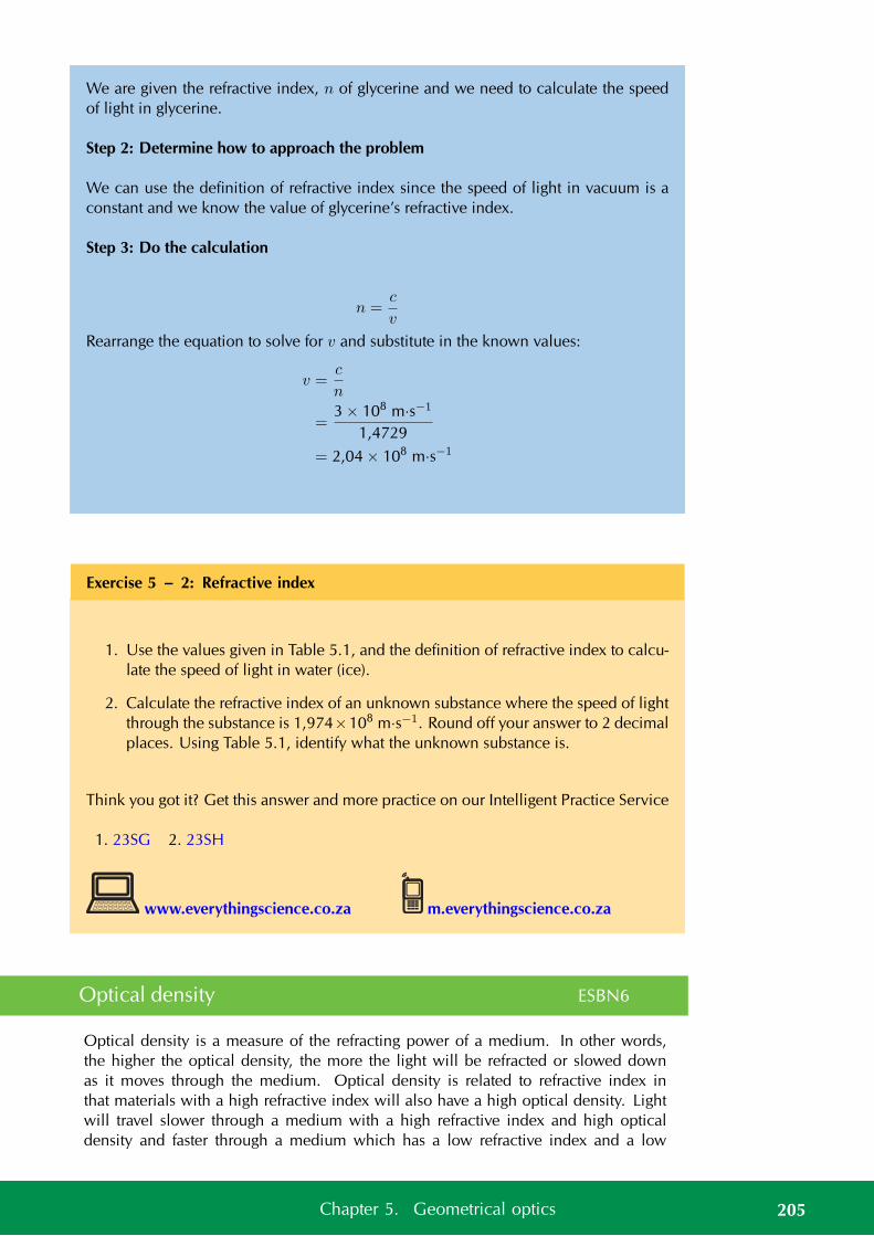
We are given the refractive index, n of glycerine and we need to calculate the speedof light in glycerine.
Step 2: Determine how to approach the problem
We can use the definition of refractive index since the speed of light in vacuum is aconstant and we know the value of glycerine’s refractive index.
Step 3: Do the calculation
n =c
v
Rearrange the equation to solve for v and substitute in the known values:
v =c
n
=3 × 10⁸ m·s−1
1,4729
= 2,04 × 10⁸ m·s−1
Exercise 5 – 2: Refractive index
1. Use the values given in Table 5.1, and the definition of refractive index to calcu-late the speed of light in water (ice).
2. Calculate the refractive index of an unknown substance where the speed of lightthrough the substance is 1,974×108 m·s−1. Round off your answer to 2 decimalplaces. Using Table 5.1, identify what the unknown substance is.
Think you got it? Get this answer and more practice on our Intelligent Practice Service
1. 23SG 2. 23SH
www.everythingscience.co.za m.everythingscience.co.za
Optical density ESBN6
Optical density is a measure of the refracting power of a medium. In other words,the higher the optical density, the more the light will be refracted or slowed downas it moves through the medium. Optical density is related to refractive index inthat materials with a high refractive index will also have a high optical density. Lightwill travel slower through a medium with a high refractive index and high opticaldensity and faster through a medium which has a low refractive index and a low
205Chapter 5. Geometrical optics
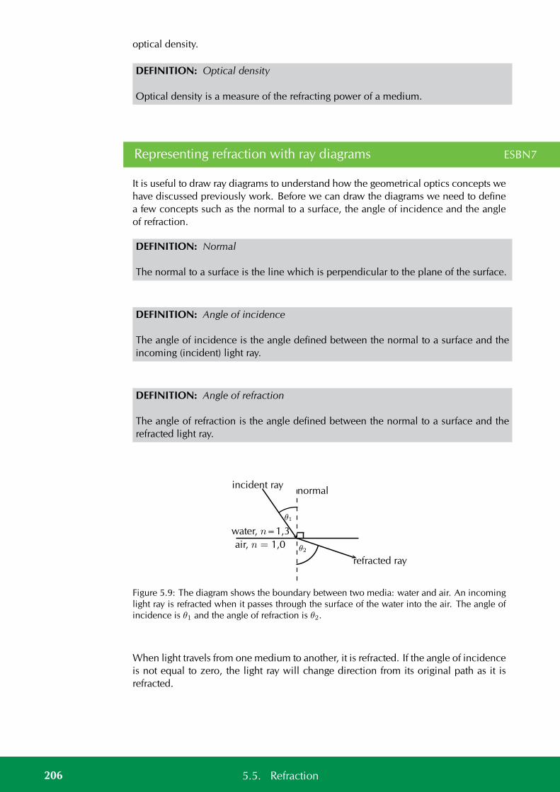
optical density.
DEFINITION: Optical density
Optical density is a measure of the refracting power of a medium.
Representing refraction with ray diagrams ESBN7
It is useful to draw ray diagrams to understand how the geometrical optics concepts wehave discussed previously work. Before we can draw the diagrams we need to definea few concepts such as the normal to a surface, the angle of incidence and the angleof refraction.
DEFINITION: Normal
The normal to a surface is the line which is perpendicular to the plane of the surface.
DEFINITION: Angle of incidence
The angle of incidence is the angle defined between the normal to a surface and theincoming (incident) light ray.
DEFINITION: Angle of refraction
The angle of refraction is the angle defined between the normal to a surface and therefracted light ray.
water, n=1,3
air, n = 1,0
normalincident ray
refracted ray
θ2
θ1
Figure 5.9: The diagram shows the boundary between two media: water and air. An incominglight ray is refracted when it passes through the surface of the water into the air. The angle ofincidence is θ1 and the angle of refraction is θ2.
When light travels from one medium to another, it is refracted. If the angle of incidenceis not equal to zero, the light ray will change direction from its original path as it isrefracted.
206 5.5. Refraction
water, n=1,3
air, n = 1,0
normalincident ray
refracted ray
θ2
θ1
Figure 5.10: Light is moving from an optically dense medium to an optically less densemedium.
air, n = 1,0
water, n=1,3
normalincident ray
refracted ray
θ2
θ1
Figure 5.11: Light is moving from an optically less dense medium to an optically densermedium.
A practical demonstration of the propagation of light from air into glass and back intoair or light from one medium to another can be done. You will need a glass block,ray box, colour filters, non-rectangular glass blocks, water, paper, ruler, pencil andprotractor.
General experiment: Propagation of light from air into glass and back into air
Aim:
To investigate propagation of light from air into glass and back into air
Apparatus:
ray box, rectangular glass block, plain paper, pencil, ruler, protractor.
207Chapter 5. Geometrical optics
Method:
Follow the steps below:
1. Place the glass block on a plain piece of paper and use your pencil to drawaround the block to make its outline on the paper.
2. Now turn on the ray box and aim the light ray through the left side of the glassblock as illustrated in the diagram:
glass block
ray box
3. Now use your pencil to draw a dot somewhere on the incident light ray andanother dot at the point where it enters the glass block.
4. Use your pencil to draw a dot at the point where the light exits the glass blockand also somewhere else along the exiting ray.
5. Turn off the ray box and remove the glass block from the paper. Use your rulerto join the dots so that you have drawn a picture that looks like the figure above.
6. Now draw the normals to the surfaces where the light ray enters and leaves theblock and mark the angle of incidence and angle of refraction on the left surfaceand the right surface.
Questions for discussion:
1. At the surface where the light enters the glass block, what do you notice aboutthe angle of incidence compared to the angle of refraction?
208 5.5. Refraction
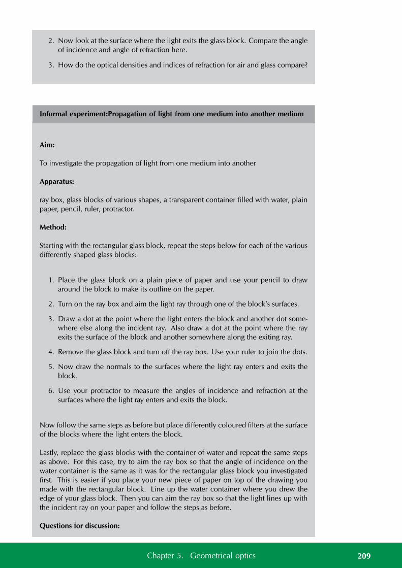
2. Now look at the surface where the light exits the glass block. Compare the angleof incidence and angle of refraction here.
3. How do the optical densities and indices of refraction for air and glass compare?
Informal experiment:Propagation of light from one medium into another medium
Aim:
To investigate the propagation of light from one medium into another
Apparatus:
ray box, glass blocks of various shapes, a transparent container filled with water, plainpaper, pencil, ruler, protractor.
Method:
Starting with the rectangular glass block, repeat the steps below for each of the variousdifferently shaped glass blocks:
1. Place the glass block on a plain piece of paper and use your pencil to drawaround the block to make its outline on the paper.
2. Turn on the ray box and aim the light ray through one of the block’s surfaces.
3. Draw a dot at the point where the light enters the block and another dot some-where else along the incident ray. Also draw a dot at the point where the rayexits the surface of the block and another somewhere along the exiting ray.
4. Remove the glass block and turn off the ray box. Use your ruler to join the dots.
5. Now draw the normals to the surfaces where the light ray enters and exits theblock.
6. Use your protractor to measure the angles of incidence and refraction at thesurfaces where the light ray enters and exits the block.
Now follow the same steps as before but place differently coloured filters at the surfaceof the blocks where the light enters the block.
Lastly, replace the glass blocks with the container of water and repeat the same stepsas above. For this case, try to aim the ray box so that the angle of incidence on thewater container is the same as it was for the rectangular glass block you investigatedfirst. This is easier if you place your new piece of paper on top of the drawing youmade with the rectangular block. Line up the water container where you drew theedge of your glass block. Then you can aim the ray box so that the light lines up withthe incident ray on your paper and follow the steps as before.
Questions for discussion:
209Chapter 5. Geometrical optics
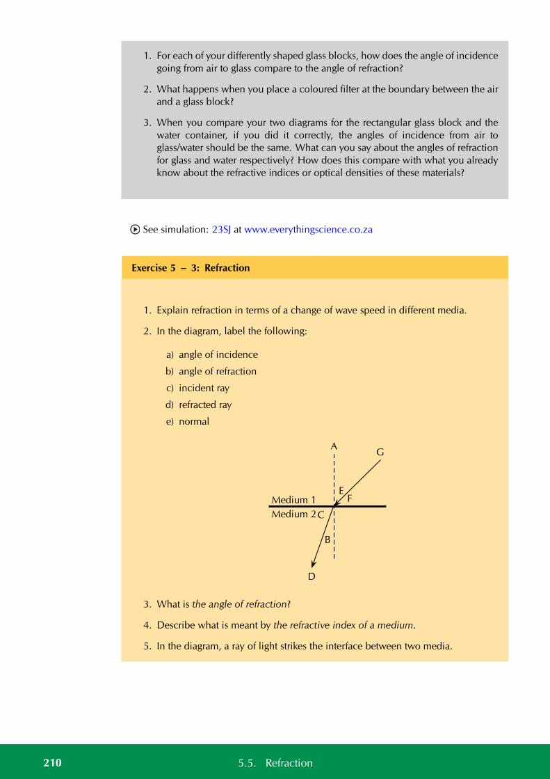
1. For each of your differently shaped glass blocks, how does the angle of incidencegoing from air to glass compare to the angle of refraction?
2. What happens when you place a coloured filter at the boundary between the airand a glass block?
3. When you compare your two diagrams for the rectangular glass block and thewater container, if you did it correctly, the angles of incidence from air toglass/water should be the same. What can you say about the angles of refractionfor glass and water respectively? How does this compare with what you alreadyknow about the refractive indices or optical densities of these materials?
See simulation: 23SJ at www.everythingscience.co.za
Exercise 5 – 3: Refraction
1. Explain refraction in terms of a change of wave speed in different media.
2. In the diagram, label the following:
a) angle of incidence
b) angle of refraction
c) incident ray
d) refracted ray
e) normal
A
Medium 1
Medium 2
EF
G
D
C
B
3. What is the angle of refraction?
4. Describe what is meant by the refractive index of a medium.
5. In the diagram, a ray of light strikes the interface between two media.
210 5.5. Refraction
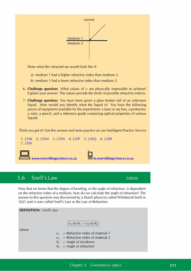
normal
Medium 1
Medium 2
Draw what the refracted ray would look like if:
a) medium 1 had a higher refractive index than medium 2.
b) medium 1 had a lower refractive index than medium 2.
6. Challenge question: What values of n are physically impossible to achieve?Explain your answer. The values provide the limits of possible refractive indices.
7. Challenge question: You have been given a glass beaker full of an unknownliquid. How would you identify what the liquid is? You have the followingpieces of equipment available for the experiment: a laser or ray box, a protractor,a ruler, a pencil, and a reference guide containing optical properties of variousliquids.
Think you got it? Get this answer and more practice on our Intelligent Practice Service
1. 23SK 2. 23SM 3. 23SN 4. 23SP 5. 23SQ 6. 23SR7. 23SS
www.everythingscience.co.za m.everythingscience.co.za
5.6 Snell’s Law ESBN8
Now that we know that the degree of bending, or the angle of refraction, is dependenton the refractive index of a medium, how do we calculate the angle of refraction? Theanswer to this question was discovered by a Dutch physicist called Willebrord Snell in1621 and is now called Snell’s Law or the Law of Refraction.
DEFINITION: Snell’s law
n1 sin θ1 = n2 sin θ2
wheren1 = Refractive index of material 1n2 = Refractive index of material 2θ1 = Angle of incidenceθ2 = Angle of refraction
211Chapter 5. Geometrical optics
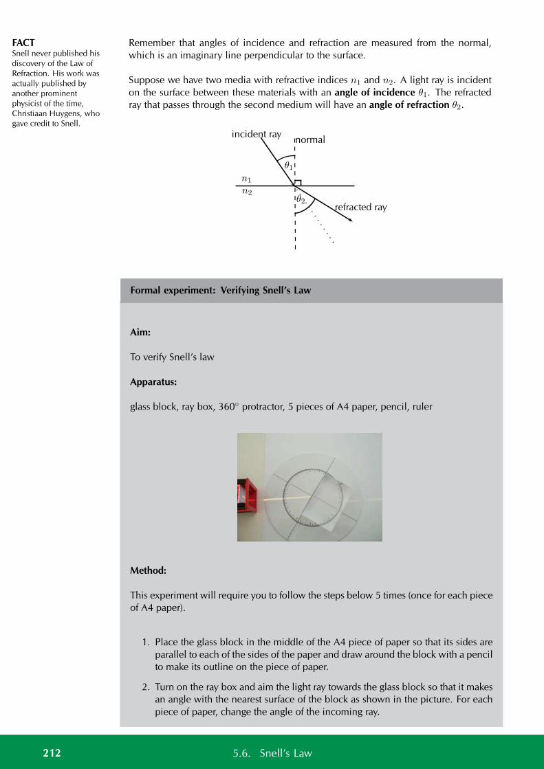
FACTSnell never published hisdiscovery of the Law ofRefraction. His work wasactually published byanother prominentphysicist of the time,Christiaan Huygens, whogave credit to Snell.
Remember that angles of incidence and refraction are measured from the normal,which is an imaginary line perpendicular to the surface.
Suppose we have two media with refractive indices n1 and n2. A light ray is incidenton the surface between these materials with an angle of incidence θ1. The refractedray that passes through the second medium will have an angle of refraction θ2.
n1
n2
normalincident ray
refracted rayθ2
θ1
Formal experiment: Verifying Snell’s Law
Aim:
To verify Snell’s law
Apparatus:
glass block, ray box, 360 protractor, 5 pieces of A4 paper, pencil, ruler
Method:
This experiment will require you to follow the steps below 5 times (once for each pieceof A4 paper).
1. Place the glass block in the middle of the A4 piece of paper so that its sides areparallel to each of the sides of the paper and draw around the block with a pencilto make its outline on the piece of paper.
2. Turn on the ray box and aim the light ray towards the glass block so that it makesan angle with the nearest surface of the block as shown in the picture. For eachpiece of paper, change the angle of the incoming ray.
212 5.6. Snell’s Law
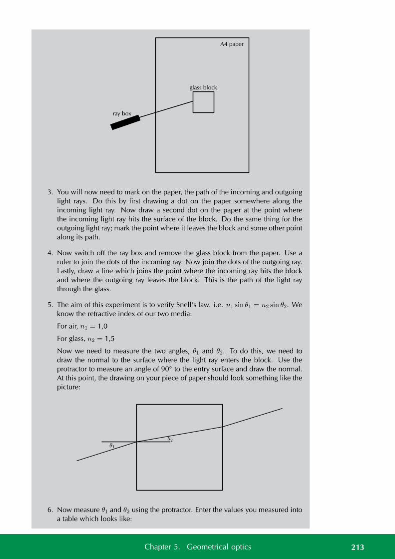
A4 paper
glass block
ray box
3. You will now need to mark on the paper, the path of the incoming and outgoinglight rays. Do this by first drawing a dot on the paper somewhere along theincoming light ray. Now draw a second dot on the paper at the point wherethe incoming light ray hits the surface of the block. Do the same thing for theoutgoing light ray; mark the point where it leaves the block and some other pointalong its path.
4. Now switch off the ray box and remove the glass block from the paper. Use aruler to join the dots of the incoming ray. Now join the dots of the outgoing ray.Lastly, draw a line which joins the point where the incoming ray hits the blockand where the outgoing ray leaves the block. This is the path of the light raythrough the glass.
5. The aim of this experiment is to verify Snell’s law. i.e. n1 sin θ1 = n2 sin θ2. Weknow the refractive index of our two media:
For air, n1 = 1,0
For glass, n2 = 1,5
Now we need to measure the two angles, θ1 and θ2. To do this, we need todraw the normal to the surface where the light ray enters the block. Use theprotractor to measure an angle of 90 to the entry surface and draw the normal.At this point, the drawing on your piece of paper should look something like thepicture:
θ1
θ2
6. Now measure θ1 and θ2 using the protractor. Enter the values you measured intoa table which looks like:
213Chapter 5. Geometrical optics
θ1 θ2 n1 sin θ1 n2 sin θ2
Discussion:
Have a look at your completed table. You should have 5 rows filled in, one for eachof your pieces of A4 paper. For each row, what do you notice about the values in thelast two columns? Do your values agree with what Snell’s law predicts?
Formal experiment: Using Snell’s law to determine the refractive index of an un-known material
Aim:
To determine the refractive index of an unknown material
Apparatus:
ray box, 360 protractor, 5 pieces of A4 paper, a block of unknown transparent mate-rial, pencil, ruler
Method:
This experiment will require you to follow the steps below at least 5 times. The stepsare the same as you followed in the previous experiment.
1. Place the block in the middle of the A4 piece of paper so that its sides are parallelto each of the sides of the paper and draw around the block with a pencil to makeits outline on the piece of paper.
2. Turn on the ray box and aim the light ray towards the block so that it makes anangle with the nearest surface of the block. For each piece of paper, change theangle of the incoming ray.
3. You will now need to mark on the paper, the path of the incoming and outgoinglight rays. Do this by first drawing a dot on the paper somewhere along theincoming light ray. Now draw a second dot on the paper at the point wherethe incoming light ray hits the surface of the block. Do the same thing for theoutgoing light ray; mark the point where it leaves the block and some other pointalong its path.
4. Now switch off the ray box and remove the block from the paper. Use a ruler tojoin the dots of the incoming ray. Now join the dots of the outgoing ray. Lastly,draw a line which joins the point where the incoming ray hits the block andwhere the outgoing ray leaves the block. This is the path of the light ray throughthe block.
214 5.6. Snell’s Law
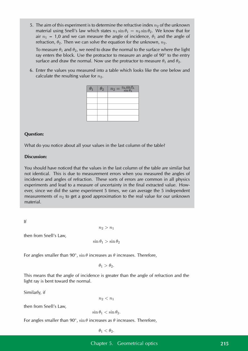
5. The aim of this experiment is to determine the refractive index n2 of the unknownmaterial using Snell’s law which states n1 sin θ1 = n2 sin θ2. We know that forair n1 = 1,0 and we can measure the angle of incidence, θ1 and the angle ofrefraction, θ2. Then we can solve the equation for the unknown, n2.
To measure θ1 and θ2, we need to draw the normal to the surface where the lightray enters the block. Use the protractor to measure an angle of 90 to the entrysurface and draw the normal. Now use the protractor to measure θ1 and θ2.
6. Enter the values you measured into a table which looks like the one below andcalculate the resulting value for n2.
θ1 θ2 n2 =n1 sin θ1sin θ2
Question:
What do you notice about all your values in the last column of the table?
Discussion:
You should have noticed that the values in the last column of the table are similar butnot identical. This is due to measurement errors when you measured the angles ofincidence and angles of refraction. These sorts of errors are common in all physicsexperiments and lead to a measure of uncertainty in the final extracted value. How-ever, since we did the same experiment 5 times, we can average the 5 independentmeasurements of n2 to get a good approximation to the real value for our unknownmaterial.
Ifn2 > n1
then from Snell’s Law,sin θ1 > sin θ2
For angles smaller than 90, sin θ increases as θ increases. Therefore,
θ1 > θ2.
This means that the angle of incidence is greater than the angle of refraction and thelight ray is bent toward the normal.
Similarly, ifn2 < n1
then from Snell’s Law,sin θ1 < sin θ2.
For angles smaller than 90, sin θ increases as θ increases. Therefore,
θ1 < θ2.
215Chapter 5. Geometrical optics
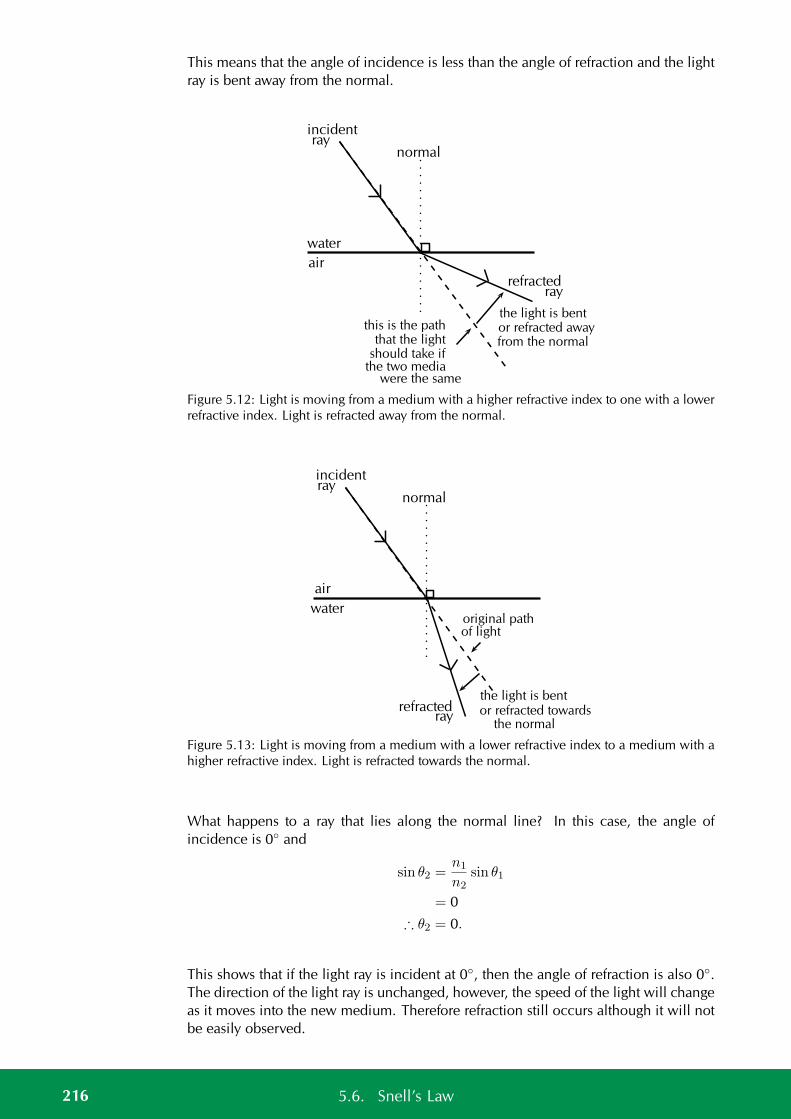
This means that the angle of incidence is less than the angle of refraction and the lightray is bent away from the normal.
water
air
normal
incidentray
refractedray
the light is bentor refracted awayfrom the normal
this is the paththat the light
should take ifthe two media
were the same
Figure 5.12: Light is moving from a medium with a higher refractive index to one with a lowerrefractive index. Light is refracted away from the normal.
water
air
normal
incidentray
refractedray
the light is bentor refracted towards
the normal
original pathof light
Figure 5.13: Light is moving from a medium with a lower refractive index to a medium with ahigher refractive index. Light is refracted towards the normal.
What happens to a ray that lies along the normal line? In this case, the angle ofincidence is 0 and
sin θ2 =n1
n2sin θ1
= 0
∴ θ2 = 0.
This shows that if the light ray is incident at 0, then the angle of refraction is also 0.The direction of the light ray is unchanged, however, the speed of the light will changeas it moves into the new medium. Therefore refraction still occurs although it will notbe easily observed.
216 5.6. Snell’s Law
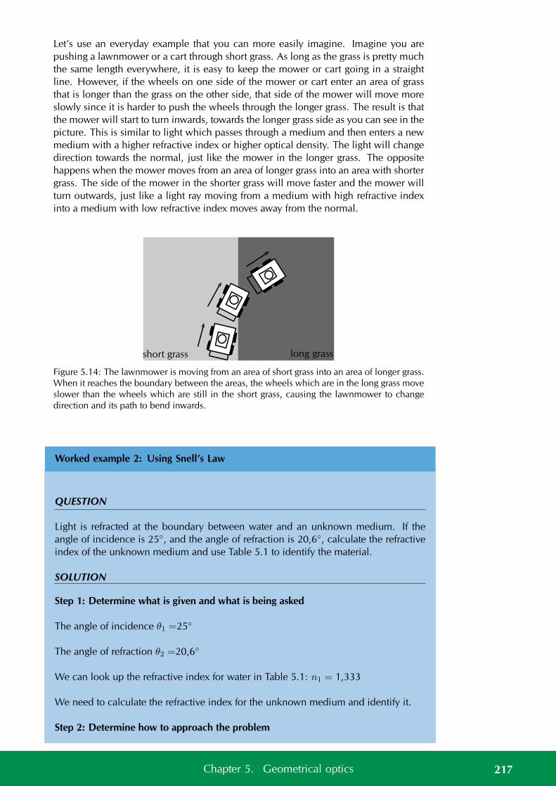
Let’s use an everyday example that you can more easily imagine. Imagine you arepushing a lawnmower or a cart through short grass. As long as the grass is pretty muchthe same length everywhere, it is easy to keep the mower or cart going in a straightline. However, if the wheels on one side of the mower or cart enter an area of grassthat is longer than the grass on the other side, that side of the mower will move moreslowly since it is harder to push the wheels through the longer grass. The result is thatthe mower will start to turn inwards, towards the longer grass side as you can see in thepicture. This is similar to light which passes through a medium and then enters a newmedium with a higher refractive index or higher optical density. The light will changedirection towards the normal, just like the mower in the longer grass. The oppositehappens when the mower moves from an area of longer grass into an area with shortergrass. The side of the mower in the shorter grass will move faster and the mower willturn outwards, just like a light ray moving from a medium with high refractive indexinto a medium with low refractive index moves away from the normal.
short grass long grass
Figure 5.14: The lawnmower is moving from an area of short grass into an area of longer grass.When it reaches the boundary between the areas, the wheels which are in the long grass moveslower than the wheels which are still in the short grass, causing the lawnmower to changedirection and its path to bend inwards.
Worked example 2: Using Snell’s Law
QUESTION
Light is refracted at the boundary between water and an unknown medium. If theangle of incidence is 25, and the angle of refraction is 20,6, calculate the refractiveindex of the unknown medium and use Table 5.1 to identify the material.
SOLUTION
Step 1: Determine what is given and what is being asked
The angle of incidence θ1 =25
The angle of refraction θ2 =20,6
We can look up the refractive index for water in Table 5.1: n1 = 1,333
We need to calculate the refractive index for the unknown medium and identify it.
Step 2: Determine how to approach the problem
217Chapter 5. Geometrical optics
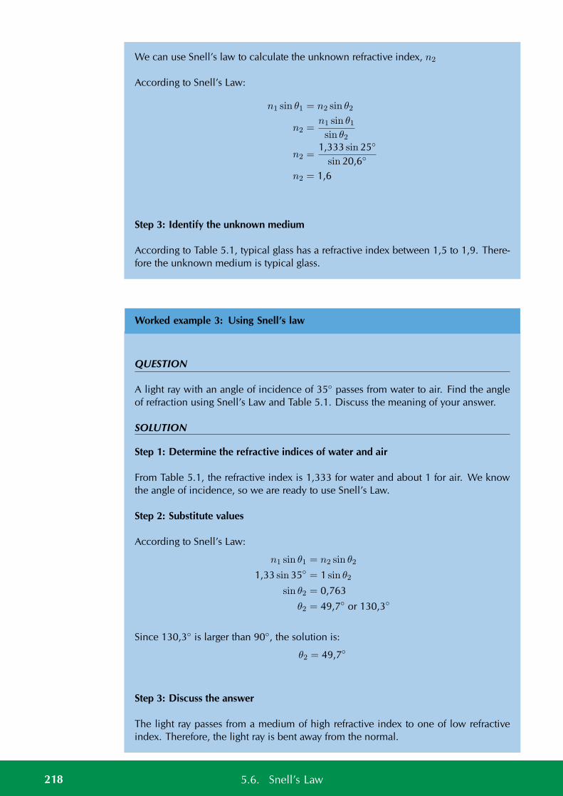
We can use Snell’s law to calculate the unknown refractive index, n2
According to Snell’s Law:
n1 sin θ1 = n2 sin θ2
n2 =n1 sin θ1sin θ2
n2 =1,333 sin 25
sin 20,6
n2 = 1,6
Step 3: Identify the unknown medium
According to Table 5.1, typical glass has a refractive index between 1,5 to 1,9. There-fore the unknown medium is typical glass.
Worked example 3: Using Snell’s law
QUESTION
A light ray with an angle of incidence of 35 passes from water to air. Find the angleof refraction using Snell’s Law and Table 5.1. Discuss the meaning of your answer.
SOLUTION
Step 1: Determine the refractive indices of water and air
From Table 5.1, the refractive index is 1,333 for water and about 1 for air. We knowthe angle of incidence, so we are ready to use Snell’s Law.
Step 2: Substitute values
According to Snell’s Law:
n1 sin θ1 = n2 sin θ2
1,33 sin 35 = 1 sin θ2
sin θ2 = 0,763
θ2 = 49,7 or 130,3
Since 130,3 is larger than 90, the solution is:
θ2 = 49,7
Step 3: Discuss the answer
The light ray passes from a medium of high refractive index to one of low refractiveindex. Therefore, the light ray is bent away from the normal.
218 5.6. Snell’s Law
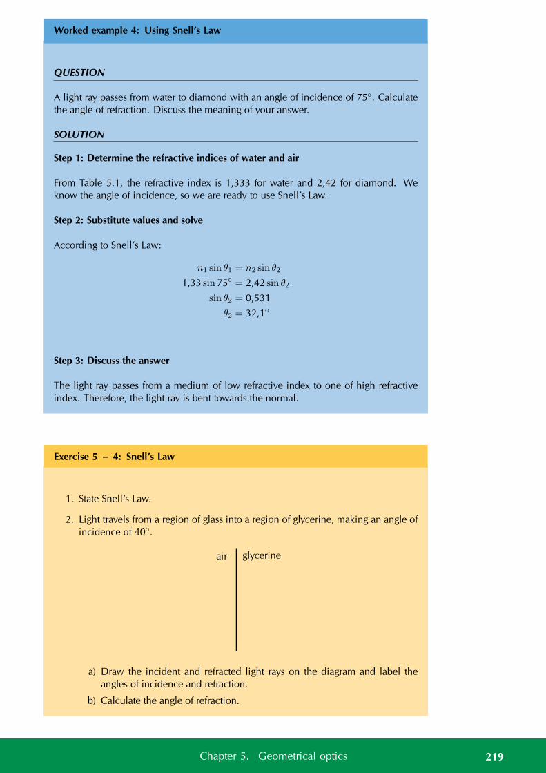
Worked example 4: Using Snell’s Law
QUESTION
A light ray passes from water to diamond with an angle of incidence of 75. Calculatethe angle of refraction. Discuss the meaning of your answer.
SOLUTION
Step 1: Determine the refractive indices of water and air
From Table 5.1, the refractive index is 1,333 for water and 2,42 for diamond. Weknow the angle of incidence, so we are ready to use Snell’s Law.
Step 2: Substitute values and solve
According to Snell’s Law:
n1 sin θ1 = n2 sin θ2
1,33 sin 75 = 2,42 sin θ2
sin θ2 = 0,531
θ2 = 32,1
Step 3: Discuss the answer
The light ray passes from a medium of low refractive index to one of high refractiveindex. Therefore, the light ray is bent towards the normal.
Exercise 5 – 4: Snell’s Law
1. State Snell’s Law.
2. Light travels from a region of glass into a region of glycerine, making an angle ofincidence of 40.
air glycerine
a) Draw the incident and refracted light rays on the diagram and label theangles of incidence and refraction.
b) Calculate the angle of refraction.
219Chapter 5. Geometrical optics
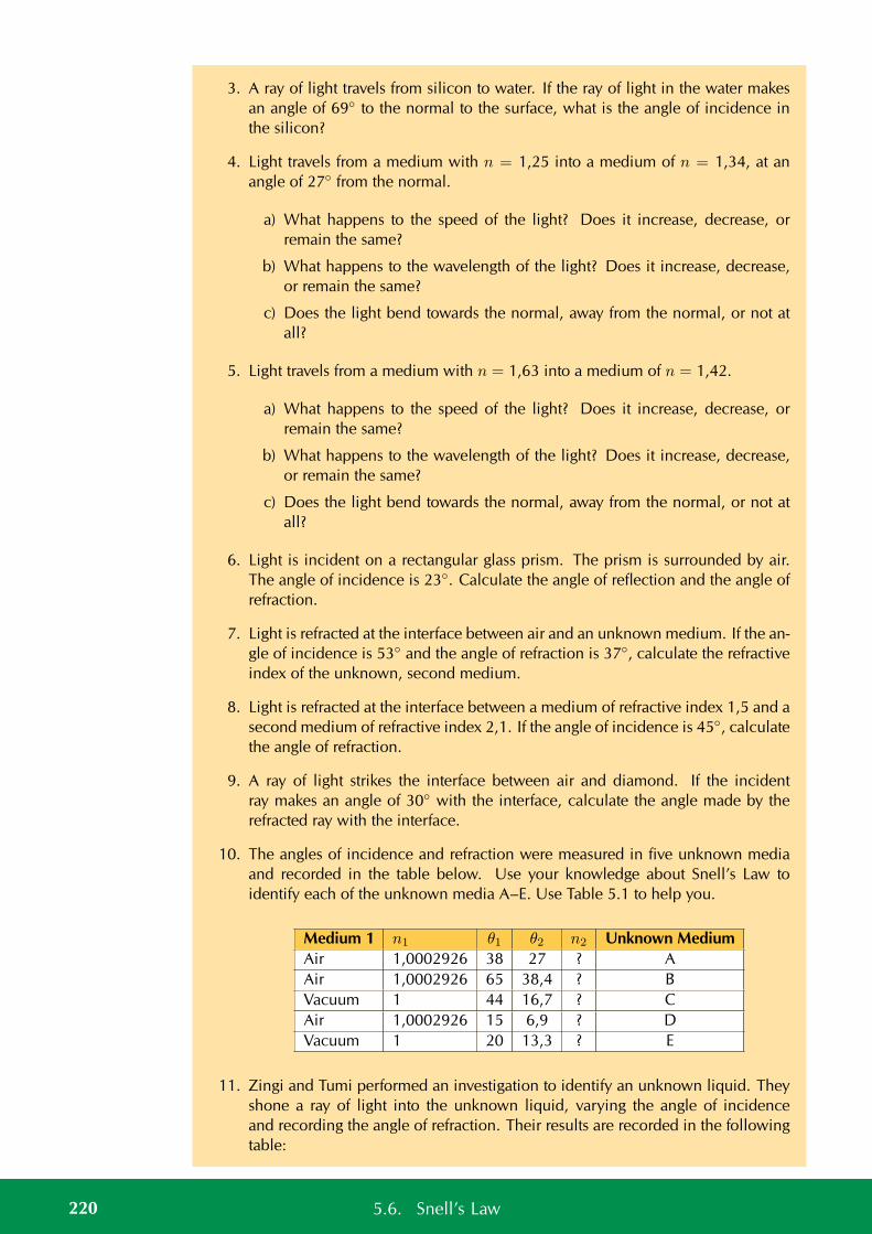
3. A ray of light travels from silicon to water. If the ray of light in the water makesan angle of 69 to the normal to the surface, what is the angle of incidence inthe silicon?
4. Light travels from a medium with n = 1,25 into a medium of n = 1,34, at anangle of 27 from the normal.
a) What happens to the speed of the light? Does it increase, decrease, orremain the same?
b) What happens to the wavelength of the light? Does it increase, decrease,or remain the same?
c) Does the light bend towards the normal, away from the normal, or not atall?
5. Light travels from a medium with n = 1,63 into a medium of n = 1,42.
a) What happens to the speed of the light? Does it increase, decrease, orremain the same?
b) What happens to the wavelength of the light? Does it increase, decrease,or remain the same?
c) Does the light bend towards the normal, away from the normal, or not atall?
6. Light is incident on a rectangular glass prism. The prism is surrounded by air.The angle of incidence is 23. Calculate the angle of reflection and the angle ofrefraction.
7. Light is refracted at the interface between air and an unknown medium. If the an-gle of incidence is 53 and the angle of refraction is 37, calculate the refractiveindex of the unknown, second medium.
8. Light is refracted at the interface between a medium of refractive index 1,5 and asecond medium of refractive index 2,1. If the angle of incidence is 45, calculatethe angle of refraction.
9. A ray of light strikes the interface between air and diamond. If the incidentray makes an angle of 30 with the interface, calculate the angle made by therefracted ray with the interface.
10. The angles of incidence and refraction were measured in five unknown mediaand recorded in the table below. Use your knowledge about Snell’s Law toidentify each of the unknown media A–E. Use Table 5.1 to help you.
Medium 1 n1 θ1 θ2 n2 Unknown MediumAir 1,0002926 38 27 ? AAir 1,0002926 65 38,4 ? BVacuum 1 44 16,7 ? CAir 1,0002926 15 6,9 ? DVacuum 1 20 13,3 ? E
11. Zingi and Tumi performed an investigation to identify an unknown liquid. Theyshone a ray of light into the unknown liquid, varying the angle of incidenceand recording the angle of refraction. Their results are recorded in the followingtable:
220 5.6. Snell’s Law

Angle of incidence Angle of refraction0,0 0,00
5,0 3,76
10,0 7,50
15,0 11,2
20,0 14,9
25,0 18,5
30,0 22,1
35,0 25,5
40,0 28,9
45,0 32,1
50,0 35,2
55,0 38,0
60,0 40,6
65,0 43,0
70,0 ?75,0 ?80,0 ?85,0 ?
a) Write down an aim for the investigation.
b) Make a list of all the apparatus they used.
c) Identify the unknown liquid.
12. Predict what the angle of refraction will be for 70, 75, 80 and 85.
Think you got it? Get this answer and more practice on our Intelligent Practice Service
1. 23ST 2. 23SV 3. 23SW 4. 23SX 5. 23SY 6. 23SZ7. 23T2 8. 23T3 9. 23T4 10. 23T5 11. 23T6 12. 23T7
www.everythingscience.co.za m.everythingscience.co.za
5.7 Critical angles and total internal reflection ESBN9
Total internal reflection ESBNB
See video: 23T8 at www.everythingscience.co.za
You may have noticed when experimenting with ray boxes and glass blocks in theprevious section that sometimes, when you changed the angle of incidence of thelight, it was not refracted out into the air, but was reflected back through the block.
221Chapter 5. Geometrical optics
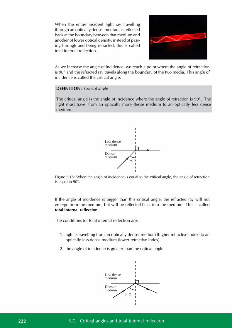
When the entire incident light ray travellingthrough an optically denser medium is reflectedback at the boundary between that medium andanother of lower optical density, instead of pass-ing through and being refracted, this is calledtotal internal reflection.
As we increase the angle of incidence, we reach a point where the angle of refractionis 90 and the refracted ray travels along the boundary of the two media. This angle ofincidence is called the critical angle.
DEFINITION: Critical angle
The critical angle is the angle of incidence where the angle of refraction is 90. Thelight must travel from an optically more dense medium to an optically less densemedium.
Less densemedium
mediumDenser
θc
Figure 5.15: When the angle of incidence is equal to the critical angle, the angle of refractionis equal to 90.
If the angle of incidence is bigger than this critical angle, the refracted ray will notemerge from the medium, but will be reflected back into the medium. This is calledtotal internal reflection.
The conditions for total internal reflection are:
1. light is travelling from an optically denser medium (higher refractive index) to anoptically less dense medium (lower refractive index).
2. the angle of incidence is greater than the critical angle.
Less densemedium
mediumDenser
> θc
222 5.7. Critical angles and total internal reflection
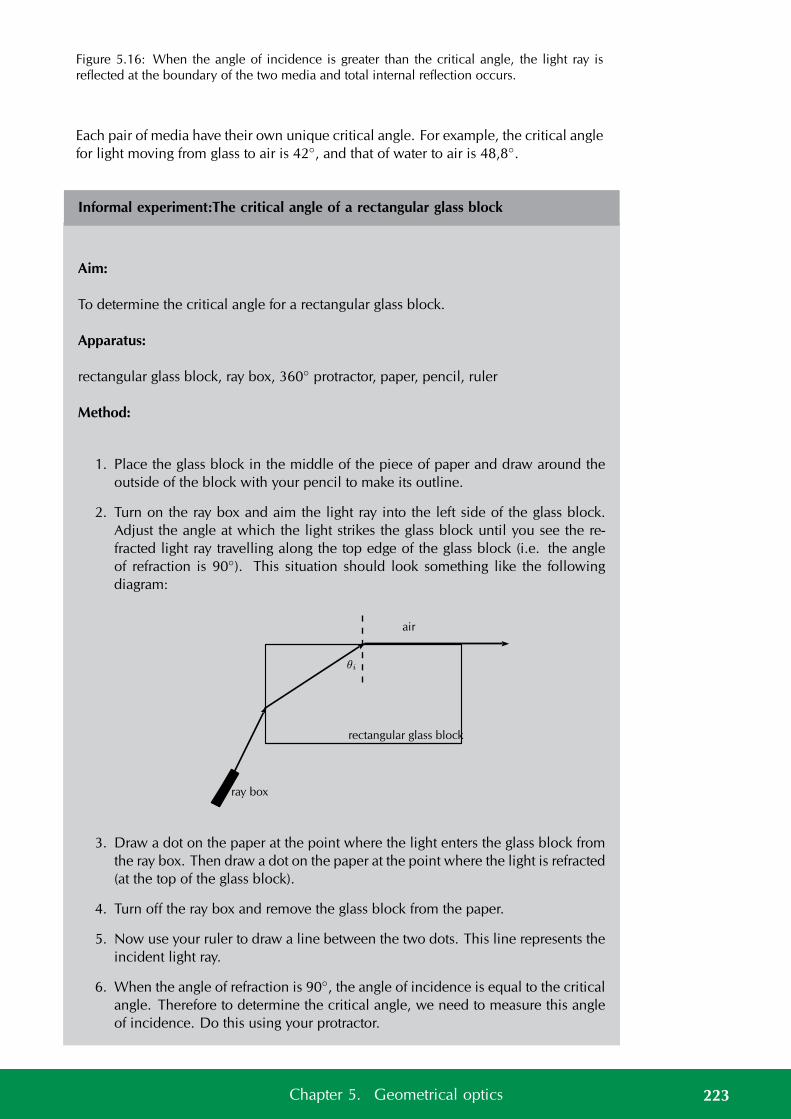
Figure 5.16: When the angle of incidence is greater than the critical angle, the light ray isreflected at the boundary of the two media and total internal reflection occurs.
Each pair of media have their own unique critical angle. For example, the critical anglefor light moving from glass to air is 42, and that of water to air is 48,8.
Informal experiment:The critical angle of a rectangular glass block
Aim:
To determine the critical angle for a rectangular glass block.
Apparatus:
rectangular glass block, ray box, 360 protractor, paper, pencil, ruler
Method:
1. Place the glass block in the middle of the piece of paper and draw around theoutside of the block with your pencil to make its outline.
2. Turn on the ray box and aim the light ray into the left side of the glass block.Adjust the angle at which the light strikes the glass block until you see the re-fracted light ray travelling along the top edge of the glass block (i.e. the angleof refraction is 90). This situation should look something like the followingdiagram:
rectangular glass block
air
θi
ray box
3. Draw a dot on the paper at the point where the light enters the glass block fromthe ray box. Then draw a dot on the paper at the point where the light is refracted(at the top of the glass block).
4. Turn off the ray box and remove the glass block from the paper.
5. Now use your ruler to draw a line between the two dots. This line represents theincident light ray.
6. When the angle of refraction is 90, the angle of incidence is equal to the criticalangle. Therefore to determine the critical angle, we need to measure this angleof incidence. Do this using your protractor.
223Chapter 5. Geometrical optics
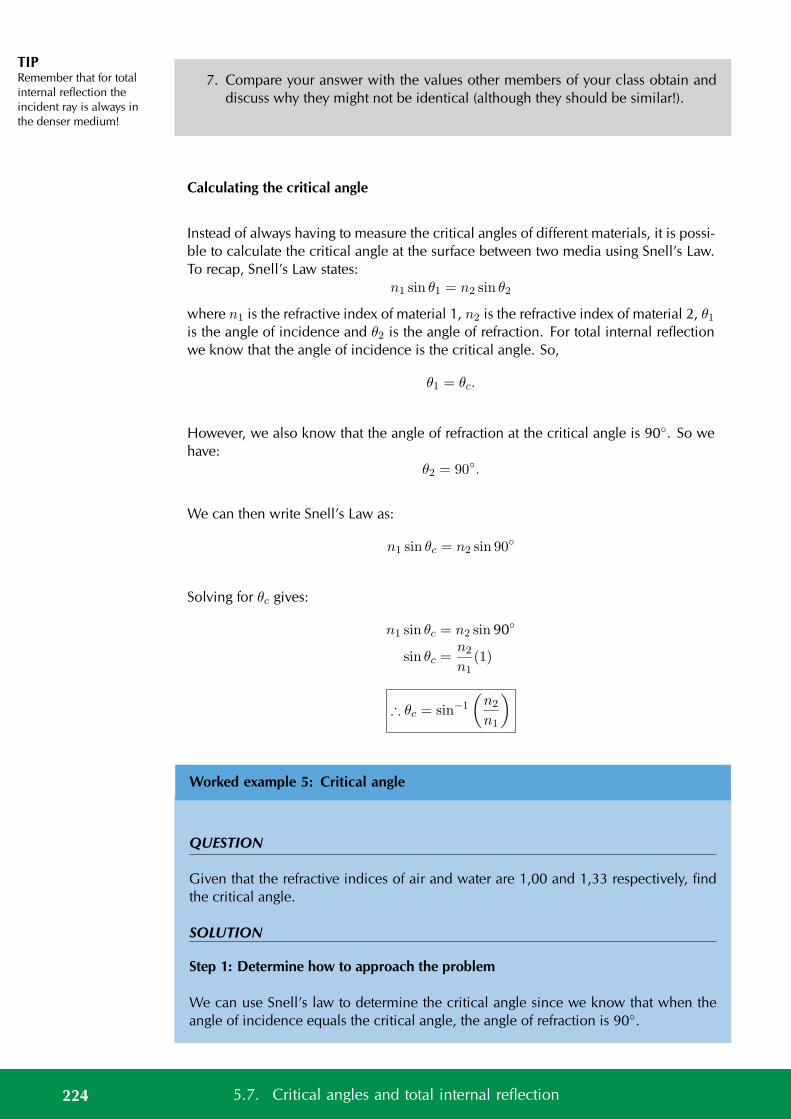
TIPRemember that for totalinternal reflection theincident ray is always inthe denser medium!
7. Compare your answer with the values other members of your class obtain anddiscuss why they might not be identical (although they should be similar!).
Calculating the critical angle
Instead of always having to measure the critical angles of different materials, it is possi-ble to calculate the critical angle at the surface between two media using Snell’s Law.To recap, Snell’s Law states:
n1 sin θ1 = n2 sin θ2
where n1 is the refractive index of material 1, n2 is the refractive index of material 2, θ1is the angle of incidence and θ2 is the angle of refraction. For total internal reflectionwe know that the angle of incidence is the critical angle. So,
θ1 = θc.
However, we also know that the angle of refraction at the critical angle is 90. So wehave:
θ2 = 90.
We can then write Snell’s Law as:
n1 sin θc = n2 sin 90
Solving for θc gives:
n1 sin θc = n2 sin 90
sin θc =n2
n1(1)
∴ θc = sin−1
(n2
n1
)
Worked example 5: Critical angle
QUESTION
Given that the refractive indices of air and water are 1,00 and 1,33 respectively, findthe critical angle.
SOLUTION
Step 1: Determine how to approach the problem
We can use Snell’s law to determine the critical angle since we know that when theangle of incidence equals the critical angle, the angle of refraction is 90.
224 5.7. Critical angles and total internal reflection
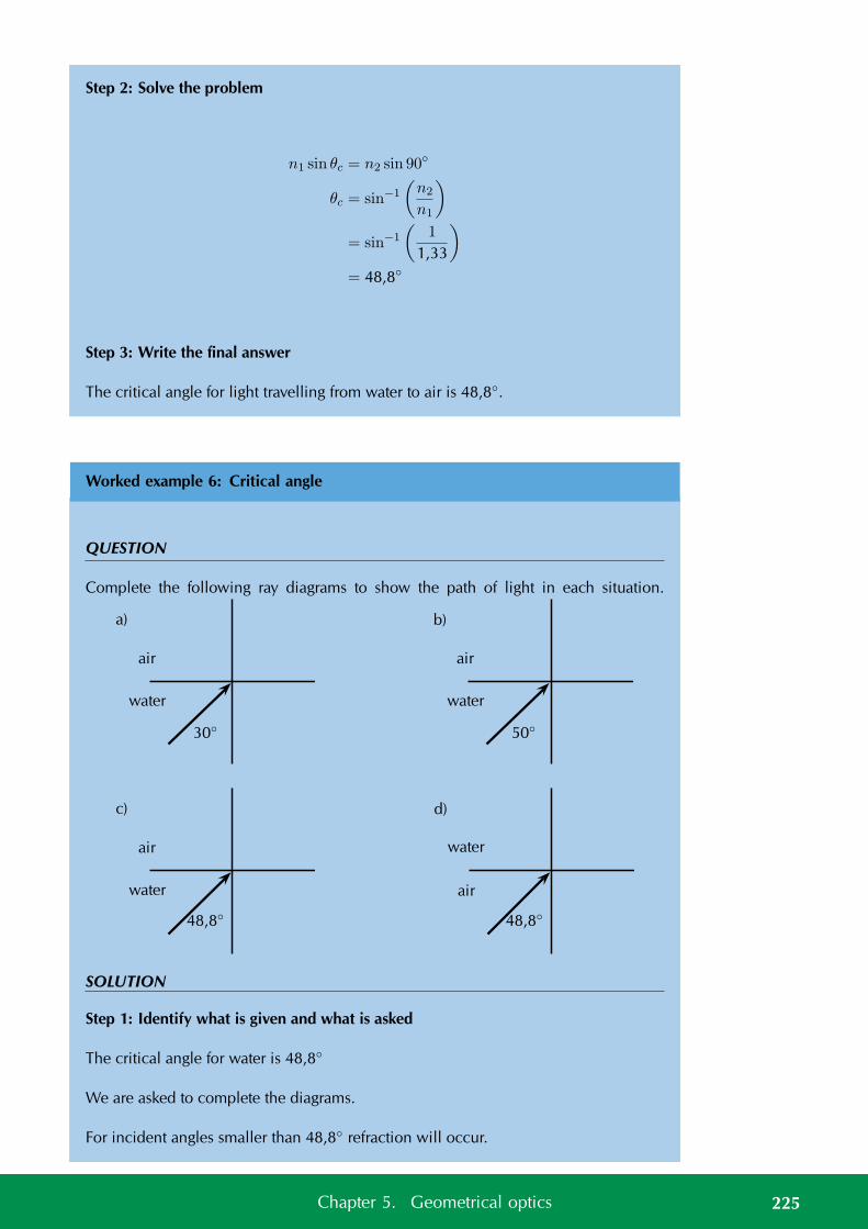
Step 2: Solve the problem
n1 sin θc = n2 sin 90
θc = sin−1
(n2
n1
)
= sin−1
(1
1,33
)
= 48,8
Step 3: Write the final answer
The critical angle for light travelling from water to air is 48,8.
Worked example 6: Critical angle
QUESTION
Complete the following ray diagrams to show the path of light in each situation.
air
water
30
a)
air
water
50
b)
air
water
48,8
c)
water
air
48,8
d)
SOLUTION
Step 1: Identify what is given and what is asked
The critical angle for water is 48,8
We are asked to complete the diagrams.
For incident angles smaller than 48,8 refraction will occur.
225Chapter 5. Geometrical optics
For incident angles greater than 48,8 total internal reflection will occur.
For incident angles equal to 48,8 refraction will occur at 90.
The light must travel from a medium with a higher refractive index (higher opticaldensity) to a medium with lower refractive index (lower optical density).
Step 2: Complete the diagrams
air
water
30
a)
Refraction occurs (ray is bent awayfrom the normal).
air
water
50
b)
50
Total internal reflection occurs.
air
water
48,8
c)
θc = 48,8.
water
air
48,8
d)
Refraction towards the normal (air isless dense than water).
Fibre optics
Total internal reflection is a very useful natural phenomenon since it can be used toconfine light. One of the most common applications of total internal reflection isin fibre optics. An optical fibre is a thin, transparent fibre, usually made of glass orplastic, for transmitting light. Optical fibres are usually thinner than a human hair! Theconstruction of a single optical fibre is shown in Figure 5.17.
The basic functional structure of an optical fibre consists of an outer protective claddingand an inner core through which light pulses travel. The overall diameter of the fibre isabout 125 µm (125× 10−6 m) and that of the core is just about 50 µm (50× 10−6 m).The difference in refractive index of the cladding and the core allows total internalreflection to occur in the same way as happens at an air-water surface. If light isincident on a cable end with an angle of incidence greater than the critical angle thenthe light will remain trapped inside the glass strand. In this way, light travels veryquickly down the length of the cable.
226 5.7. Critical angles and total internal reflection
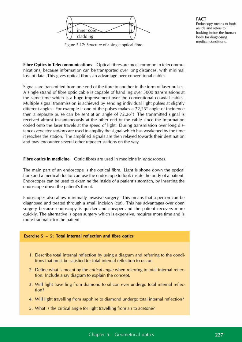
FACTEndoscopy means to lookinside and refers tolooking inside the humanbody for diagnosingmedical conditions.
inner core
cladding
Figure 5.17: Structure of a single optical fibre.
Fibre Optics in Telecommunications Optical fibres are most common in telecommu-nications, because information can be transported over long distances, with minimalloss of data. This gives optical fibres an advantage over conventional cables.
Signals are transmitted from one end of the fibre to another in the form of laser pulses.A single strand of fibre optic cable is capable of handling over 3000 transmissions atthe same time which is a huge improvement over the conventional co-axial cables.Multiple signal transmission is achieved by sending individual light pulses at slightlydifferent angles. For example if one of the pulses makes a 72,23 angle of incidencethen a separate pulse can be sent at an angle of 72,26! The transmitted signal isreceived almost instantaneously at the other end of the cable since the informationcoded onto the laser travels at the speed of light! During transmission over long dis-tances repeater stations are used to amplify the signal which has weakened by the timeit reaches the station. The amplified signals are then relayed towards their destinationand may encounter several other repeater stations on the way.
Fibre optics in medicine Optic fibres are used in medicine in endoscopes.
The main part of an endoscope is the optical fibre. Light is shone down the opticalfibre and a medical doctor can use the endoscope to look inside the body of a patient.Endoscopes can be used to examine the inside of a patient’s stomach, by inserting theendoscope down the patient’s throat.
Endoscopes also allow minimally invasive surgery. This means that a person can bediagnosed and treated through a small incision (cut). This has advantages over opensurgery because endoscopy is quicker and cheaper and the patient recovers morequickly. The alternative is open surgery which is expensive, requires more time and ismore traumatic for the patient.
Exercise 5 – 5: Total internal reflection and fibre optics
1. Describe total internal reflection by using a diagram and referring to the condi-tions that must be satisfied for total internal reflection to occur.
2. Define what is meant by the critical angle when referring to total internal reflec-tion. Include a ray diagram to explain the concept.
3. Will light travelling from diamond to silicon ever undergo total internal reflec-tion?
4. Will light travelling from sapphire to diamond undergo total internal reflection?
5. What is the critical angle for light travelling from air to acetone?
227Chapter 5. Geometrical optics
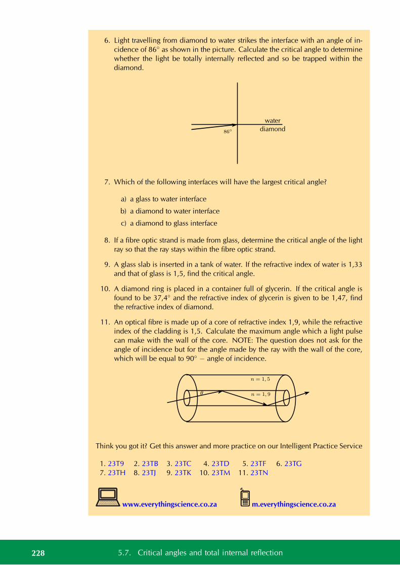
6. Light travelling from diamond to water strikes the interface with an angle of in-cidence of 86 as shown in the picture. Calculate the critical angle to determinewhether the light be totally internally reflected and so be trapped within thediamond.
water
diamond86
7. Which of the following interfaces will have the largest critical angle?
a) a glass to water interface
b) a diamond to water interface
c) a diamond to glass interface
8. If a fibre optic strand is made from glass, determine the critical angle of the lightray so that the ray stays within the fibre optic strand.
9. A glass slab is inserted in a tank of water. If the refractive index of water is 1,33and that of glass is 1,5, find the critical angle.
10. A diamond ring is placed in a container full of glycerin. If the critical angle isfound to be 37,4 and the refractive index of glycerin is given to be 1,47, findthe refractive index of diamond.
11. An optical fibre is made up of a core of refractive index 1,9, while the refractiveindex of the cladding is 1,5. Calculate the maximum angle which a light pulsecan make with the wall of the core. NOTE: The question does not ask for theangle of incidence but for the angle made by the ray with the wall of the core,which will be equal to 90 − angle of incidence.
θ n = 1, 9
n = 1, 5
Think you got it? Get this answer and more practice on our Intelligent Practice Service
1. 23T9 2. 23TB 3. 23TC 4. 23TD 5. 23TF 6. 23TG7. 23TH 8. 23TJ 9. 23TK 10. 23TM 11. 23TN
www.everythingscience.co.za m.everythingscience.co.za
228 5.7. Critical angles and total internal reflection
5.8 Summary ESBNC
See presentation: 23TP at www.everythingscience.co.za
• Light rays are lines which are perpendicular to the light’s wavefronts. In geomet-rical optics we represent light rays with arrows with straight lines.
• Light rays reflect off surfaces. The incident ray shines in on the surface and thereflected ray is the one that bounces off the surface. The normal is the lineperpendicular to the surface where the light strikes the surface.
• The angle of incidence is the angle between the incident ray and the surface,and the incident ray, reflected ray, and the normal, all lie in the same plane.
• The Law of Reflection states the angle of incidence (θi) is equal to the angle ofreflection (θr) and that the reflected ray lies in the plane of incidence.
• Light can be absorbed and transmitted.
• The speed of light, c, is constant in a given medium and has a maximum speedin vacuum of 3 × 10⁸ m·s−1
• Refraction occurs at the boundary of two media when light travels from onemedium into the other and its speed changes but its frequency remains the same.If the light ray hits the boundary at an angle which is not perpendicular to orparallel to the surface, then it will change direction and appear to ‘bend’.
• The refractive index (symbol n) of a material is the ratio of the speed of light in avacuum to its speed in the material and gives an indication of how difficult it isfor light to get through the material.
n = cv
• Optical density is a measure of the refracting power of a medium.
• The normal to a surface is the line which is perpendicular to the plane of thesurface.
• The angle of incidence is the angle defined between the normal to a surface andthe incoming (incident) light ray.
• The angle of refraction is the angle defined between the normal to a surface andthe refracted light ray.
• Snell’s Law gives the relationship between the refractive indices, angles of inci-dence and reflection of two media.
n1 sin θ1 = n2 sin θ2
• Light travelling from one medium to another of lighter optical density will berefracted towards the normal.
Light travelling from one medium to another of lower optical density will berefracted away from the normal.
• The critical angle of a medium is the angle of incidence when the angle ofrefraction is 90 and the refracted ray runs along the interface between the twomedia.
229Chapter 5. Geometrical optics
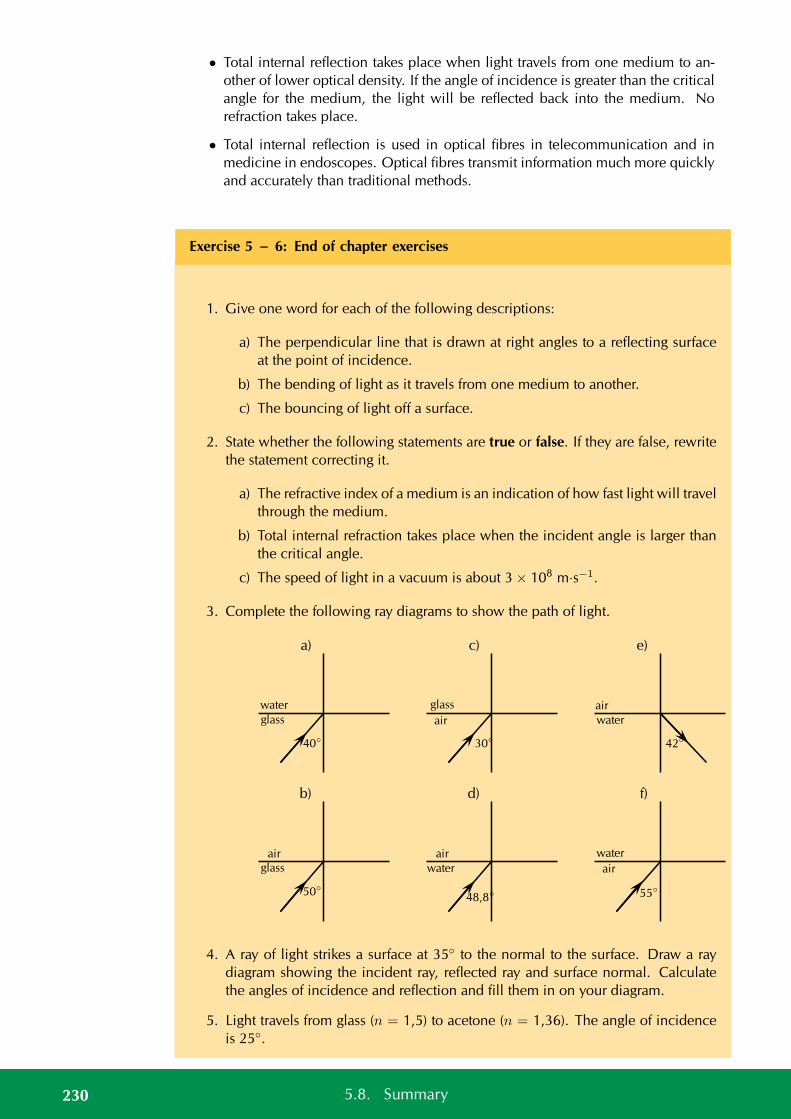
• Total internal reflection takes place when light travels from one medium to an-other of lower optical density. If the angle of incidence is greater than the criticalangle for the medium, the light will be reflected back into the medium. Norefraction takes place.
• Total internal reflection is used in optical fibres in telecommunication and inmedicine in endoscopes. Optical fibres transmit information much more quicklyand accurately than traditional methods.
Exercise 5 – 6: End of chapter exercises
1. Give one word for each of the following descriptions:
a) The perpendicular line that is drawn at right angles to a reflecting surfaceat the point of incidence.
b) The bending of light as it travels from one medium to another.
c) The bouncing of light off a surface.
2. State whether the following statements are true or false. If they are false, rewritethe statement correcting it.
a) The refractive index of a medium is an indication of how fast light will travelthrough the medium.
b) Total internal refraction takes place when the incident angle is larger thanthe critical angle.
c) The speed of light in a vacuum is about 3 × 10⁸ m·s−1.
3. Complete the following ray diagrams to show the path of light.
a)
water
glass
40
b)
airglass
50
c)
glass
air
30
d)
air
water
48,8
e)
air
water
42
f)
water
air
55
4. A ray of light strikes a surface at 35 to the normal to the surface. Draw a raydiagram showing the incident ray, reflected ray and surface normal. Calculatethe angles of incidence and reflection and fill them in on your diagram.
5. Light travels from glass (n = 1,5) to acetone (n = 1,36). The angle of incidenceis 25.
230 5.8. Summary

a) Describe the path of light as it moves into the acetone.
b) Calculate the angle of refraction.
c) What happens to the speed of the light as it moves from the glass to theacetone?
d) What happens to the wavelength of the light as it moves into the acetone?
6. Light strikes the interface between diamond and an unknown medium with anincident angle of 32. The angle of refraction is measured to be 46. Calculatethe refractive index of the medium and identify the medium.
7. Explain what total internal reflection is and how it is used in medicine andtelecommunications. Why is this technology much better to use?
Think you got it? Get this answer and more practice on our Intelligent Practice Service
1a. 23TQ 1b. 23TR 1c. 23TS 2a. 23TT 2b. 23TV 2c. 23TW3a. 23TX 3b. 23TY 3c. 23TZ 3d. 23V2 3e. 23V3 3f. 23V44. 23V5 5. 23V6 6. 23V7 7. 23V8
www.everythingscience.co.za m.everythingscience.co.za
231Chapter 5. Geometrical optics

CHAPTER 6
2D and 3D wavefronts
6.1 Introduction 234
6.2 Wavefronts 234
6.3 Huygens principle 235
6.4 Diffraction 237
6.5 Diffraction through a single slit 238
6.6 Chapter summary 248
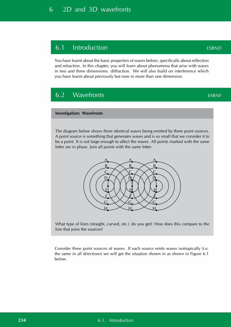
6 2D and 3D wavefronts
6.1 Introduction ESBND
You have learnt about the basic properties of waves before, specifically about reflectionand refraction. In this chapter, you will learn about phenomena that arise with wavesin two and three dimensions: diffraction. We will also build on interference whichyou have learnt about previously but now in more than one dimension.
6.2 Wavefronts ESBNF
Investigation: Wavefronts
The diagram below shows three identical waves being emitted by three point sources.A point source is something that generates waves and is so small that we consider it tobe a point. It is not large enough to affect the waves. All points marked with the sameletter are in phase. Join all points with the same letter.
AA A
BB B
CC C
DD D
EE E
FF F
GG G
HH H
What type of lines (straight, curved, etc.) do you get? How does this compare to theline that joins the sources?
Consider three point sources of waves. If each source emits waves isotropically (i.e.the same in all directions) we will get the situation shown in as shown in Figure 6.1below.
234 6.1. Introduction
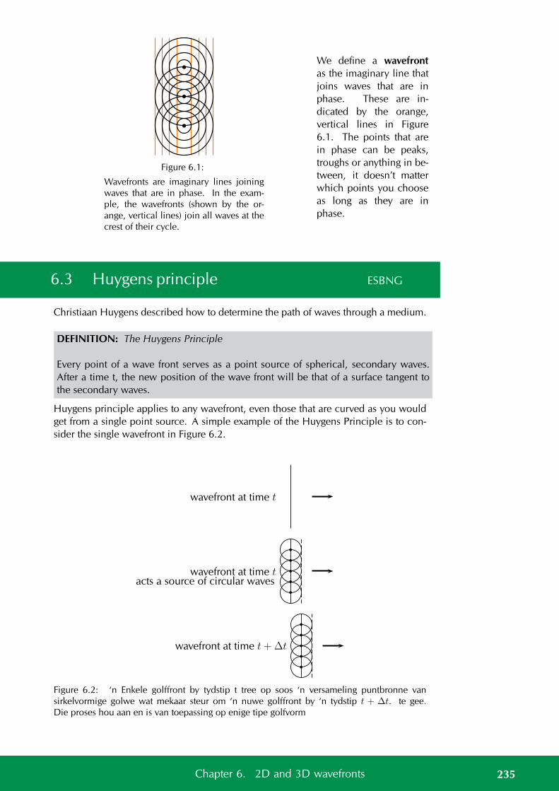
Figure 6.1:
Wavefronts are imaginary lines joiningwaves that are in phase. In the exam-ple, the wavefronts (shown by the or-ange, vertical lines) join all waves at thecrest of their cycle.
We define a wavefrontas the imaginary line thatjoins waves that are inphase. These are in-dicated by the orange,vertical lines in Figure6.1. The points that arein phase can be peaks,troughs or anything in be-tween, it doesn’t matterwhich points you chooseas long as they are inphase.
6.3 Huygens principle ESBNG
Christiaan Huygens described how to determine the path of waves through a medium.
DEFINITION: The Huygens Principle
Every point of a wave front serves as a point source of spherical, secondary waves.After a time t, the new position of the wave front will be that of a surface tangent tothe secondary waves.
Huygens principle applies to any wavefront, even those that are curved as you wouldget from a single point source. A simple example of the Huygens Principle is to con-sider the single wavefront in Figure 6.2.
wavefront at time t
wavefront at time t
acts a source of circular waves
wavefront at time t+∆t
Figure 6.2: ‘n Enkele golffront by tydstip t tree op soos ‘n versameling puntbronne vansirkelvormige golwe wat mekaar steur om ‘n nuwe golffront by ‘n tydstip t + ∆t. te gee.Die proses hou aan en is van toepassing op enige tipe golfvorm
235Chapter 6. 2D and 3D wavefronts
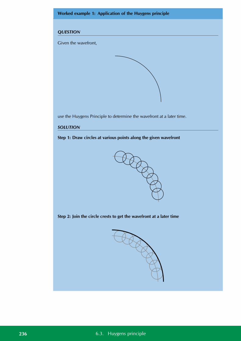
Worked example 1: Application of the Huygens principle
QUESTION
Given the wavefront,
use the Huygens Principle to determine the wavefront at a later time.
SOLUTION
Step 1: Draw circles at various points along the given wavefront
Step 2: Join the circle crests to get the wavefront at a later time
236 6.3. Huygens principle
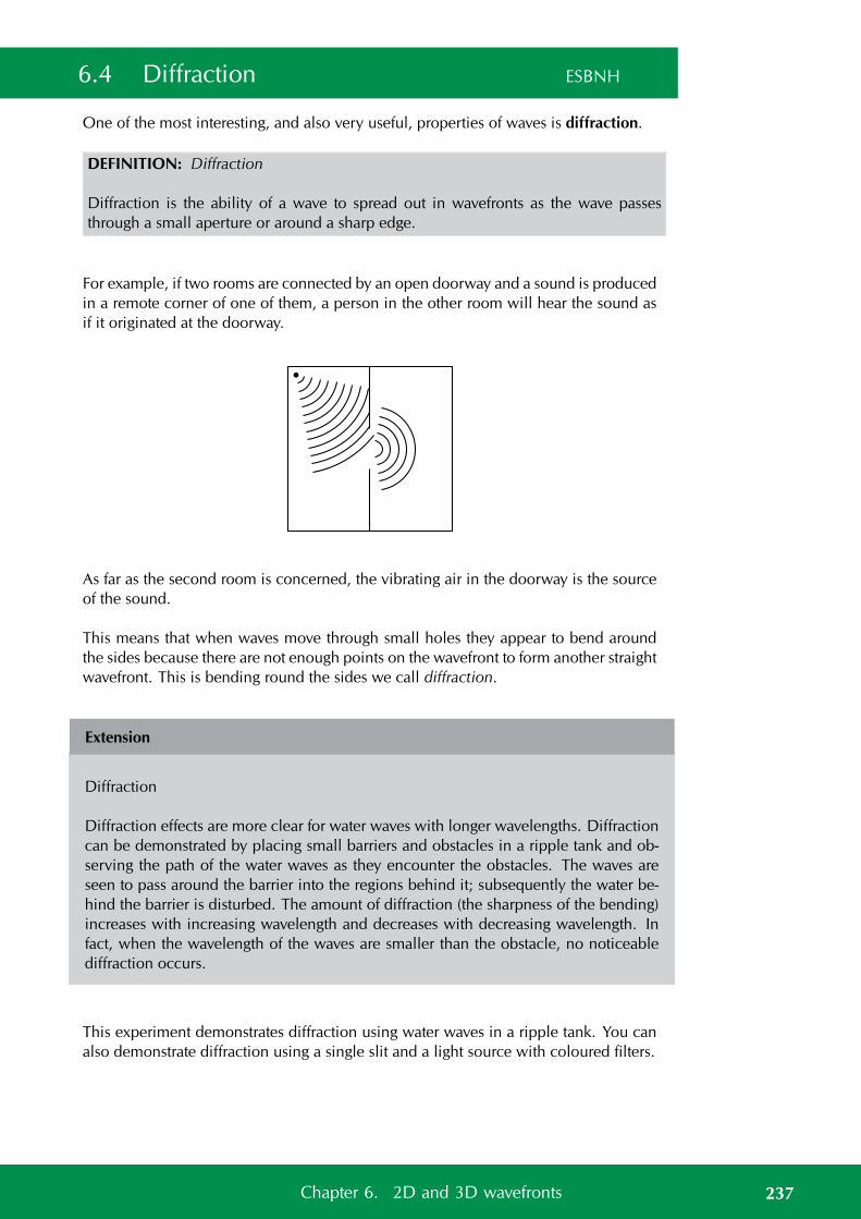
6.4 Diffraction ESBNH
One of the most interesting, and also very useful, properties of waves is diffraction.
DEFINITION: Diffraction
Diffraction is the ability of a wave to spread out in wavefronts as the wave passesthrough a small aperture or around a sharp edge.
For example, if two rooms are connected by an open doorway and a sound is producedin a remote corner of one of them, a person in the other room will hear the sound asif it originated at the doorway.
As far as the second room is concerned, the vibrating air in the doorway is the sourceof the sound.
This means that when waves move through small holes they appear to bend aroundthe sides because there are not enough points on the wavefront to form another straightwavefront. This is bending round the sides we call diffraction.
Extension
Diffraction
Diffraction effects are more clear for water waves with longer wavelengths. Diffractioncan be demonstrated by placing small barriers and obstacles in a ripple tank and ob-serving the path of the water waves as they encounter the obstacles. The waves areseen to pass around the barrier into the regions behind it; subsequently the water be-hind the barrier is disturbed. The amount of diffraction (the sharpness of the bending)increases with increasing wavelength and decreases with decreasing wavelength. Infact, when the wavelength of the waves are smaller than the obstacle, no noticeablediffraction occurs.
This experiment demonstrates diffraction using water waves in a ripple tank. You canalso demonstrate diffraction using a single slit and a light source with coloured filters.
237Chapter 6. 2D and 3D wavefronts
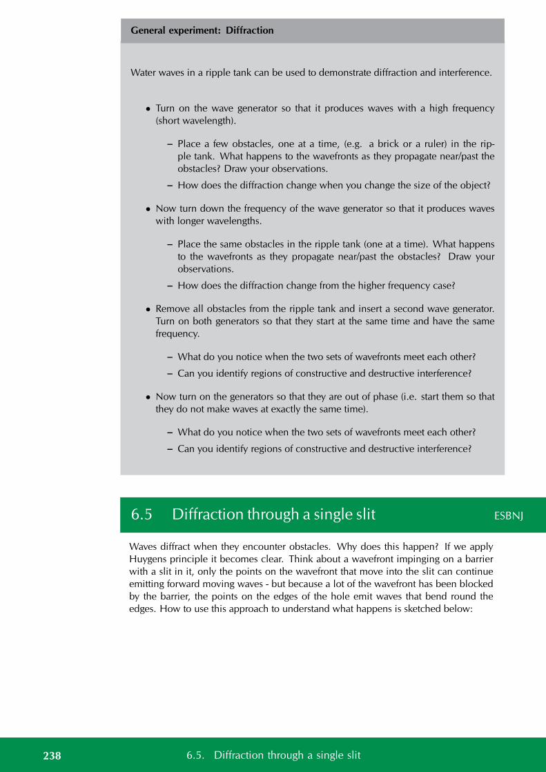
General experiment: Diffraction
Water waves in a ripple tank can be used to demonstrate diffraction and interference.
• Turn on the wave generator so that it produces waves with a high frequency(short wavelength).
– Place a few obstacles, one at a time, (e.g. a brick or a ruler) in the rip-ple tank. What happens to the wavefronts as they propagate near/past theobstacles? Draw your observations.
– How does the diffraction change when you change the size of the object?
• Now turn down the frequency of the wave generator so that it produces waveswith longer wavelengths.
– Place the same obstacles in the ripple tank (one at a time). What happensto the wavefronts as they propagate near/past the obstacles? Draw yourobservations.
– How does the diffraction change from the higher frequency case?
• Remove all obstacles from the ripple tank and insert a second wave generator.Turn on both generators so that they start at the same time and have the samefrequency.
– What do you notice when the two sets of wavefronts meet each other?
– Can you identify regions of constructive and destructive interference?
• Now turn on the generators so that they are out of phase (i.e. start them so thatthey do not make waves at exactly the same time).
– What do you notice when the two sets of wavefronts meet each other?
– Can you identify regions of constructive and destructive interference?
6.5 Diffraction through a single slit ESBNJ
Waves diffract when they encounter obstacles. Why does this happen? If we applyHuygens principle it becomes clear. Think about a wavefront impinging on a barrierwith a slit in it, only the points on the wavefront that move into the slit can continueemitting forward moving waves - but because a lot of the wavefront has been blockedby the barrier, the points on the edges of the hole emit waves that bend round theedges. How to use this approach to understand what happens is sketched below:
238 6.5. Diffraction through a single slit
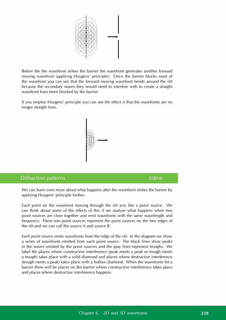
Before the the wavefront strikes the barrier the wavefront generates another forwardmoving wavefront (applying Huygens’ principle). Once the barrier blocks most ofthe wavefront you can see that the forward moving wavefront bends around the slitbecause the secondary waves they would need to interfere with to create a straightwavefront have been blocked by the barrier.
If you employ Huygens’ principle you can see the effect is that the wavefronts are nolonger straight lines.
Diffraction patterns ESBNK
We can learn even more about what happens after the wavefront strikes the barrier byapplying Huygens’ principle further.
Each point on the wavefront moving through the slit acts like a point source. Wecan think about some of the effects of this if we analyse what happens when twopoint sources are close together and emit wavefronts with the same wavelength andfrequency. These two point sources represent the point sources on the two edges ofthe slit and we can call the source A and source B.
Each point source emits wavefronts from the edge of the slit. In the diagram we showa series of wavefronts emitted from each point source. The black lines show peaksin the waves emitted by the point sources and the gray lines represent troughs. Welabel the places where constructive interference (peak meets a peak or trough meetsa trough) takes place with a solid diamond and places where destructive interference(trough meets a peak) takes place with a hollow diamond. When the wavefronts hit abarrier there will be places on the barrier where constructive interference takes placeand places where destructive interference happens.
239Chapter 6. 2D and 3D wavefronts
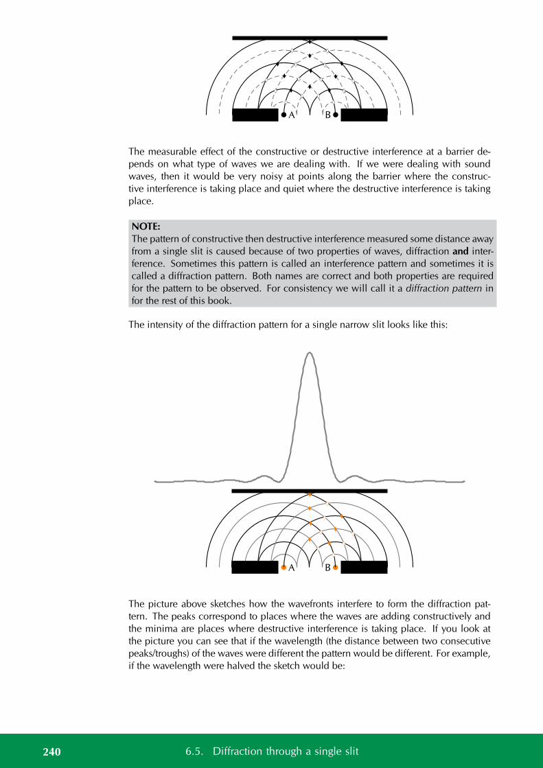
A B
The measurable effect of the constructive or destructive interference at a barrier de-pends on what type of waves we are dealing with. If we were dealing with soundwaves, then it would be very noisy at points along the barrier where the construc-tive interference is taking place and quiet where the destructive interference is takingplace.
NOTE:The pattern of constructive then destructive interference measured some distance awayfrom a single slit is caused because of two properties of waves, diffraction and inter-ference. Sometimes this pattern is called an interference pattern and sometimes it iscalled a diffraction pattern. Both names are correct and both properties are requiredfor the pattern to be observed. For consistency we will call it a diffraction pattern infor the rest of this book.
The intensity of the diffraction pattern for a single narrow slit looks like this:
A B
The picture above sketches how the wavefronts interfere to form the diffraction pat-tern. The peaks correspond to places where the waves are adding constructively andthe minima are places where destructive interference is taking place. If you look atthe picture you can see that if the wavelength (the distance between two consecutivepeaks/troughs) of the waves were different the pattern would be different. For example,if the wavelength were halved the sketch would be:
240 6.5. Diffraction through a single slit
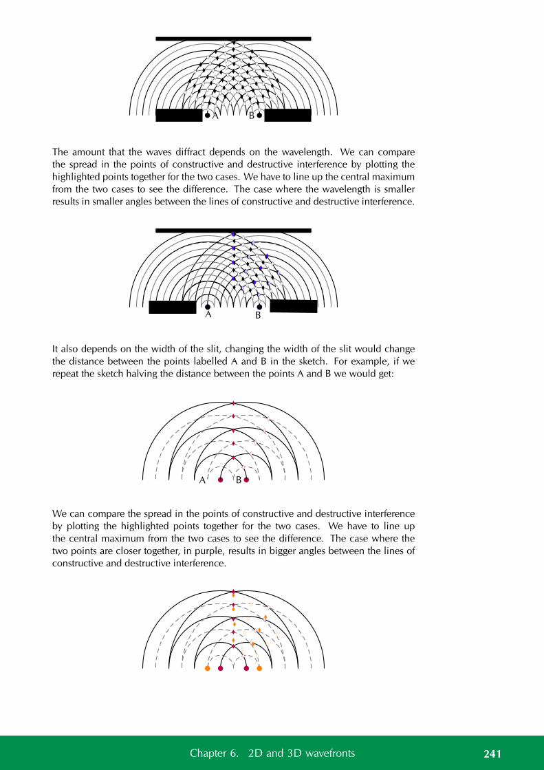
A B
The amount that the waves diffract depends on the wavelength. We can comparethe spread in the points of constructive and destructive interference by plotting thehighlighted points together for the two cases. We have to line up the central maximumfrom the two cases to see the difference. The case where the wavelength is smallerresults in smaller angles between the lines of constructive and destructive interference.
A B
It also depends on the width of the slit, changing the width of the slit would changethe distance between the points labelled A and B in the sketch. For example, if werepeat the sketch halving the distance between the points A and B we would get:
A B
We can compare the spread in the points of constructive and destructive interferenceby plotting the highlighted points together for the two cases. We have to line upthe central maximum from the two cases to see the difference. The case where thetwo points are closer together, in purple, results in bigger angles between the lines ofconstructive and destructive interference.
241Chapter 6. 2D and 3D wavefronts
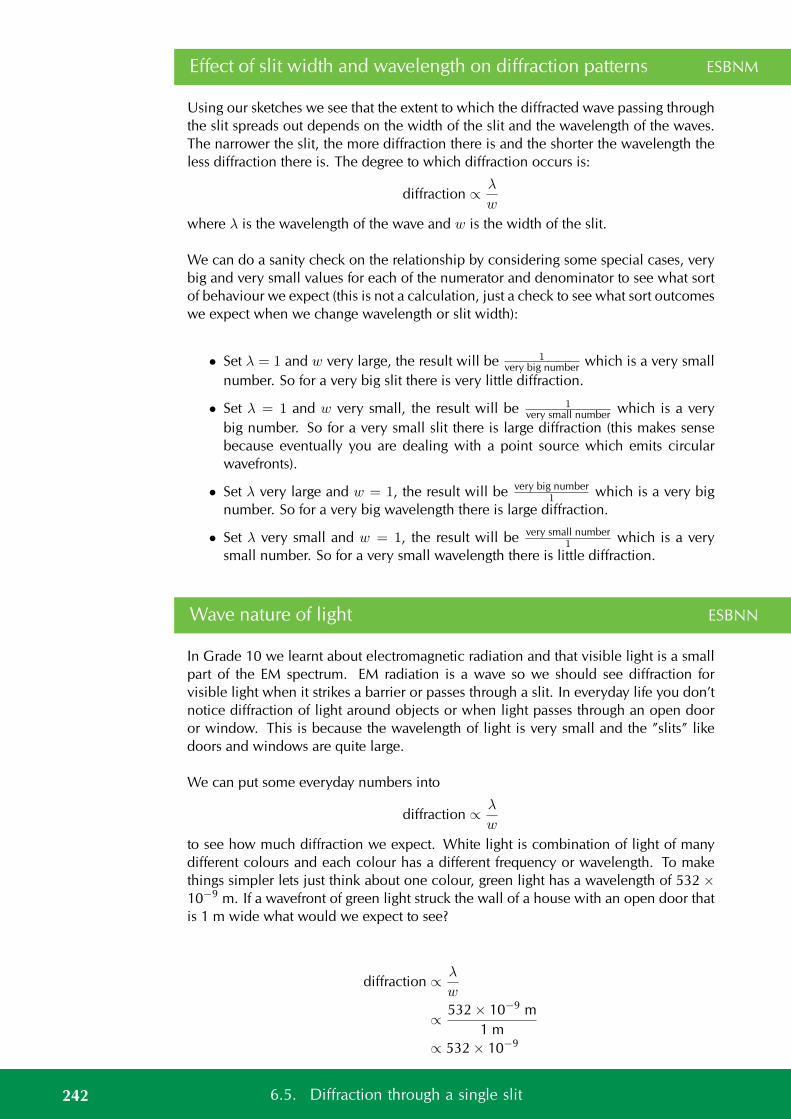
Effect of slit width and wavelength on diffraction patterns ESBNM
Using our sketches we see that the extent to which the diffracted wave passing throughthe slit spreads out depends on the width of the slit and the wavelength of the waves.The narrower the slit, the more diffraction there is and the shorter the wavelength theless diffraction there is. The degree to which diffraction occurs is:
diffraction ∝ λ
w
where λ is the wavelength of the wave and w is the width of the slit.
We can do a sanity check on the relationship by considering some special cases, verybig and very small values for each of the numerator and denominator to see what sortof behaviour we expect (this is not a calculation, just a check to see what sort outcomeswe expect when we change wavelength or slit width):
• Set λ = 1 and w very large, the result will be 1very big number which is a very small
number. So for a very big slit there is very little diffraction.
• Set λ = 1 and w very small, the result will be 1very small number which is a very
big number. So for a very small slit there is large diffraction (this makes sensebecause eventually you are dealing with a point source which emits circularwavefronts).
• Set λ very large and w = 1, the result will be very big number1 which is a very big
number. So for a very big wavelength there is large diffraction.
• Set λ very small and w = 1, the result will be very small number1 which is a very
small number. So for a very small wavelength there is little diffraction.
Wave nature of light ESBNN
In Grade 10 we learnt about electromagnetic radiation and that visible light is a smallpart of the EM spectrum. EM radiation is a wave so we should see diffraction forvisible light when it strikes a barrier or passes through a slit. In everyday life you don’tnotice diffraction of light around objects or when light passes through an open dooror window. This is because the wavelength of light is very small and the ”slits” likedoors and windows are quite large.
We can put some everyday numbers into
diffraction ∝ λ
w
to see how much diffraction we expect. White light is combination of light of manydifferent colours and each colour has a different frequency or wavelength. To makethings simpler lets just think about one colour, green light has a wavelength of 532 ×10−9 m. If a wavefront of green light struck the wall of a house with an open door thatis 1 m wide what would we expect to see?
diffraction ∝ λ
w
∝ 532 × 10−9 m1 m
∝ 532 × 10−9
242 6.5. Diffraction through a single slit
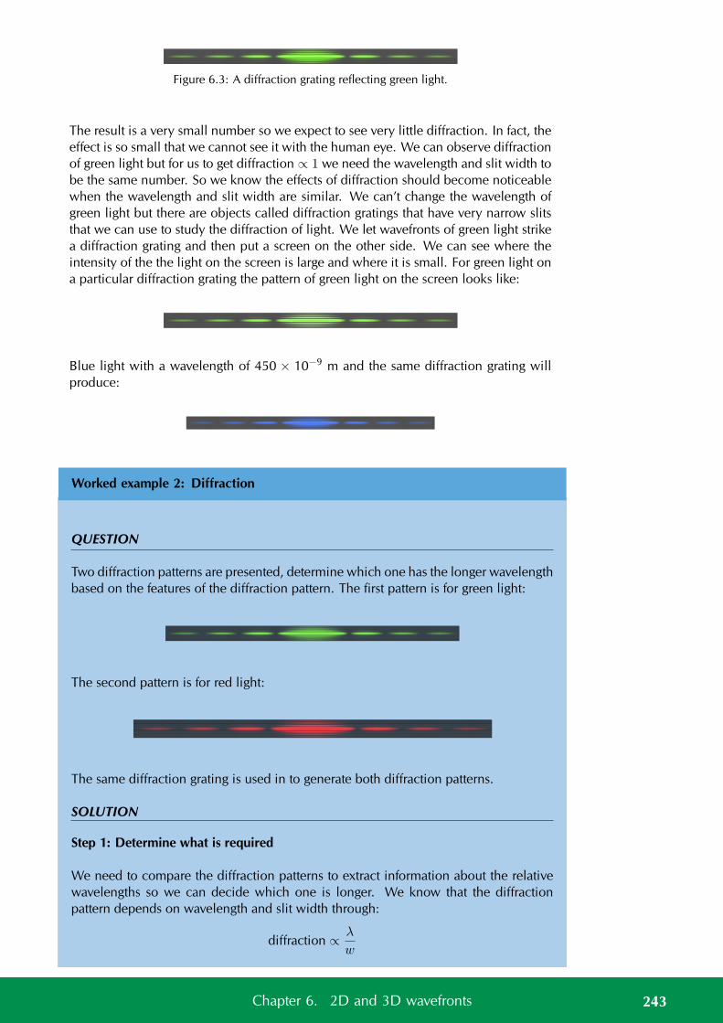
Figure 6.3: A diffraction grating reflecting green light.
The result is a very small number so we expect to see very little diffraction. In fact, theeffect is so small that we cannot see it with the human eye. We can observe diffractionof green light but for us to get diffraction ∝ 1 we need the wavelength and slit width tobe the same number. So we know the effects of diffraction should become noticeablewhen the wavelength and slit width are similar. We can’t change the wavelength ofgreen light but there are objects called diffraction gratings that have very narrow slitsthat we can use to study the diffraction of light. We let wavefronts of green light strikea diffraction grating and then put a screen on the other side. We can see where theintensity of the the light on the screen is large and where it is small. For green light ona particular diffraction grating the pattern of green light on the screen looks like:
Blue light with a wavelength of 450 × 10−9 m and the same diffraction grating willproduce:
Worked example 2: Diffraction
QUESTION
Two diffraction patterns are presented, determine which one has the longer wavelengthbased on the features of the diffraction pattern. The first pattern is for green light:
The second pattern is for red light:
The same diffraction grating is used in to generate both diffraction patterns.
SOLUTION
Step 1: Determine what is required
We need to compare the diffraction patterns to extract information about the relativewavelengths so we can decide which one is longer. We know that the diffractionpattern depends on wavelength and slit width through:
diffraction ∝ λ
w
243Chapter 6. 2D and 3D wavefronts
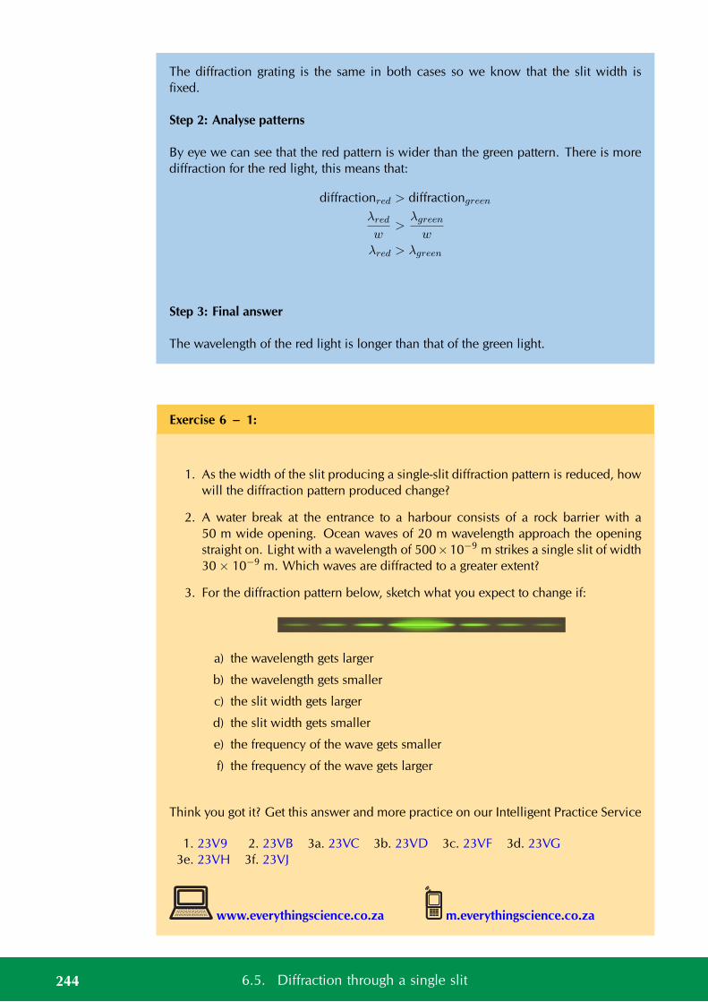
The diffraction grating is the same in both cases so we know that the slit width isfixed.
Step 2: Analyse patterns
By eye we can see that the red pattern is wider than the green pattern. There is morediffraction for the red light, this means that:
diffractionred > diffractiongreen
λred
w>
λgreen
wλred > λgreen
Step 3: Final answer
The wavelength of the red light is longer than that of the green light.
Exercise 6 – 1:
1. As the width of the slit producing a single-slit diffraction pattern is reduced, howwill the diffraction pattern produced change?
2. A water break at the entrance to a harbour consists of a rock barrier with a50 m wide opening. Ocean waves of 20 m wavelength approach the openingstraight on. Light with a wavelength of 500×10−9 m strikes a single slit of width30 × 10−9 m. Which waves are diffracted to a greater extent?
3. For the diffraction pattern below, sketch what you expect to change if:
a) the wavelength gets larger
b) the wavelength gets smaller
c) the slit width gets larger
d) the slit width gets smaller
e) the frequency of the wave gets smaller
f) the frequency of the wave gets larger
Think you got it? Get this answer and more practice on our Intelligent Practice Service
1. 23V9 2. 23VB 3a. 23VC 3b. 23VD 3c. 23VF 3d. 23VG3e. 23VH 3f. 23VJ
www.everythingscience.co.za m.everythingscience.co.za
244 6.5. Diffraction through a single slit

Calculating maxima and minima [NOT IN CAPS] ESBNP
This section is for interest and extension, skip to end of chapter summary if you arefollowing CAPS.
There is a formula we can use to determine where the peaks and minima are in theinterference spectrum. There will be more than one minimum. There are the samenumber of minima on either side of the central peak and the distances from the firstone on each side are the same to the peak. The distances to the peak from the secondminimum on each side is also the same, in fact the two sides are mirror images of eachother. We label the first minimum that corresponds to a positive angle from the centreas m = 1 and the first on the other side (a negative angle from the centre) as m = −1,the second set of minima are labelled m = 2 and m = −2 etc.
λ yn
θ
w
The equation for the angle at which the minima occur is given in the definition below:
DEFINITION: Interference Minima
The angle at which the minima in the interference spectrum occur is:sin θ = mλ
wwhereθ is the angle to the minimumw is the width of the slitλ is the wavelength of the impinging wavefrontsm is the order of the minimum, m = ±1,±2,±3, ...
Worked example 3: Diffraction minimum
QUESTION
A slit with a width of 2511 nm has red light of wavelength 650 nm impinge on it. Thediffracted light interferes on a surface. At which angle will the first minimum be?
SOLUTION
Step 1: Check what you are given
We know that we are dealing with diffraction patterns from the diffraction of lightpassing through a slit. The slit has a width of 2511 nm which is 2511 × 10−9 m and
245Chapter 6. 2D and 3D wavefronts
we know that the wavelength of the light is 650 nm which is 650 × 10−9 m. We arelooking to determine the angle to first minimum so we know that m = 1.
Step 2: Applicable principles
We know that there is a relationship between the slit width, wavelength and interfer-ence minimum angles: sin θ = mλ
w
We can use this relationship to find the angle to the minimum by substituting what weknow and solving for the angle.
Step 3: Substitution
sin θ =650 × 10−9 m
2511 × 10−9 m
sin θ =650
2511sin θ = 0,258861012
θ = sin−1 0,258861012
θ = 15
The first minimum is at 15 from the centre maximum.
Worked example 4: Diffraction minimum
QUESTION
A slit with a width of 2511 nm has green light of wavelength 532 nm impinge on it.The diffracted light interferes on a surface, at what angle will the first minimum be?
SOLUTION
Step 1: Check what you are given
We know that we are dealing with diffraction patterns from the diffraction of lightpassing through a slit. The slit has a width of 2511 nm which is 2511 × 10−9 m andwe know that the wavelength of the light is 532 nm which is 532 × 10−9 m. We arelooking to determine the angle to first minimum so we know that m = 1.
Step 2: Applicable principles
We know that there is a relationship between the slit width, wavelength and interfer-ence minimum angles: sin θ = mλ
w
We can use this relationship to find the angle to the minimum by substituting what weknow and solving for the angle.
246 6.5. Diffraction through a single slit
Step 3: Substitution
sin θ =532 × 10−9 m
2511 × 10−9 m
sin θ =532
2511sin θ = 0,211867782
θ = sin−1 0,211867782
θ = 12.2
The first minimum is at 12,2 from the centre peak.
From the formula sin θ = mλw you can see that a smaller wavelength for the same slit
results in a smaller angle to the interference minimum. This is something you just sawin the two worked examples. Do a sanity check, go back and see if the answer makessense. Ask yourself which light had the longer wavelength, which light had the largerangle and what do you expect for longer wavelengths from the formula.
Worked example 5: Diffraction minimum
QUESTION
A slit has a width which is unknown and has green light of wavelength 532 nm impingeon it. The diffracted light interferes on a surface, and the first minimum is measure atan angle of 20,77?
SOLUTION
Step 1: Check what you are given
We know that we are dealing with diffraction patterns from the diffraction of lightpassing through a slit. We know that the wavelength of the light is 532 nm which is532 × 10−9 m. We know the angle to first minimum so we know that m = 1 andθ = 20.77.
Step 2: Applicable principles
We know that there is a relationship between the slit width, wavelength and interfer-ence minimum angles: sin θ = mλ
w
We can use this relationship to find the width by substituting what we know andsolving for the width.
Step 3: Substitution
247Chapter 6. 2D and 3D wavefronts
sin θ =532 × 10−9 m
w
sin 20,77 =532 × 10−9
w
w =532 × 10−9
0,3546666667
w = 1500 × 10−9
w = 1500 nm
The slit width is 1500 nm.
See simulation: 23VK at www.everythingscience.co.za
6.6 Chapter summary ESBNQ
See presentation: 23VM at www.everythingscience.co.za
• A wavefront is an imaginary line that connects waves that are in phase.
• Huygen’s Principle states that every point of a wave front serves as a point sourceof spherical, secondary waves. After a time t, the new position of the wave frontwill be that of a surface tangent to the secondary waves.
• Diffraction is the ability of a wave to spread out in wavefronts as the wave passesthrough a small aperture or around a sharp edge.
• When a wave passes through a slit, diffraction of the wave occurs. Diffraction ofthe wave is when the wavefront spreads out or “bends” around corners.
• The degree of diffraction depends on the width of the slit and the wavelength ofthe wave with: diffraction ∝ λ
w where λ is the wavelength of the wave and w isthe width of the slit.
Exercise 6 – 2:
1. In the diagram below the peaks of wavefronts are shown by black lines andthe troughs by grey lines. Mark all the points where constructive interferencebetween two waves is taking place and where destructive interference is takingplace. Also note whether the interference results in a peak or a trough.
248 6.6. Chapter summary
A B
C
2. For a slit of width 1300 nm, order the following EM waves from least to mostdiffracted:
a) green at 510 nm
b) blue at 475 nm
c) red at 650 nm
d) yellow at 570 nm
3. For light of wavelength 540 nm, determine which of the following slits widthsresults in the maximum and which results in the minimum amount of diffraction
a) 323 × 10−9 m
b) 12,47 nm
c) 21,1 pm
4. For light of wavelength 635 nm, determine what the width of the slit needs tobe to have the diffraction be less than the angle of diffraction in each of thesecases:
a) Water waves at the entrance to a harbour which has a rock barrier witha 3 m wide opening. The waves have a wavelength of 16 m wavelengthapproach the opening straight on.
b) Light with a wavelength of 786 × 10−9 m strikes a single slit of width 30 ×10−7 m.
Think you got it? Get this answer and more practice on our Intelligent Practice Service
1. 23VN 2. 23VP 3. 23VQ 4. 23VR
www.everythingscience.co.za m.everythingscience.co.za
249Chapter 6. 2D and 3D wavefronts

CHAPTER 7
Ideal gases
7.1 Motion of particles 252
7.2 Ideal gas laws 255
7.3 Chapter summary 284
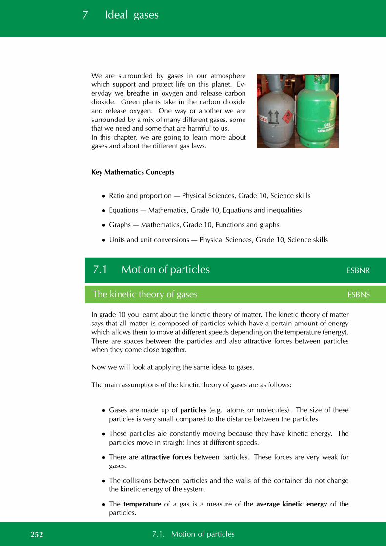
7 Ideal gases
We are surrounded by gases in our atmospherewhich support and protect life on this planet. Ev-eryday we breathe in oxygen and release carbondioxide. Green plants take in the carbon dioxideand release oxygen. One way or another we aresurrounded by a mix of many different gases, somethat we need and some that are harmful to us.In this chapter, we are going to learn more aboutgases and about the different gas laws.
Key Mathematics Concepts
• Ratio and proportion — Physical Sciences, Grade 10, Science skills
• Equations — Mathematics, Grade 10, Equations and inequalities
• Graphs — Mathematics, Grade 10, Functions and graphs
• Units and unit conversions — Physical Sciences, Grade 10, Science skills
7.1 Motion of particles ESBNR
The kinetic theory of gases ESBNS
In grade 10 you learnt about the kinetic theory of matter. The kinetic theory of mattersays that all matter is composed of particles which have a certain amount of energywhich allows them to move at different speeds depending on the temperature (energy).There are spaces between the particles and also attractive forces between particleswhen they come close together.
Now we will look at applying the same ideas to gases.
The main assumptions of the kinetic theory of gases are as follows:
• Gases are made up of particles (e.g. atoms or molecules). The size of theseparticles is very small compared to the distance between the particles.
• These particles are constantly moving because they have kinetic energy. Theparticles move in straight lines at different speeds.
• There are attractive forces between particles. These forces are very weak forgases.
• The collisions between particles and the walls of the container do not changethe kinetic energy of the system.
• The temperature of a gas is a measure of the average kinetic energy of theparticles.
252 7.1. Motion of particles
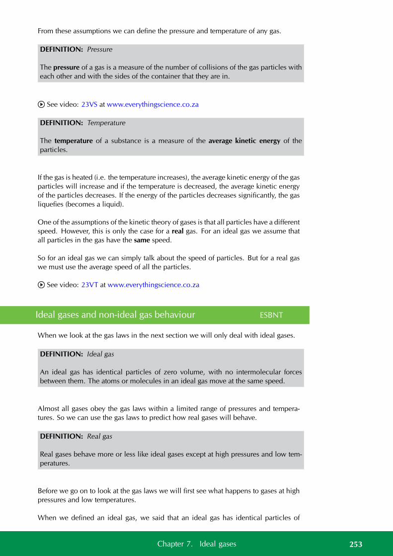
From these assumptions we can define the pressure and temperature of any gas.
DEFINITION: Pressure
The pressure of a gas is a measure of the number of collisions of the gas particles witheach other and with the sides of the container that they are in.
See video: 23VS at www.everythingscience.co.za
DEFINITION: Temperature
The temperature of a substance is a measure of the average kinetic energy of theparticles.
If the gas is heated (i.e. the temperature increases), the average kinetic energy of the gasparticles will increase and if the temperature is decreased, the average kinetic energyof the particles decreases. If the energy of the particles decreases significantly, the gasliquefies (becomes a liquid).
One of the assumptions of the kinetic theory of gases is that all particles have a differentspeed. However, this is only the case for a real gas. For an ideal gas we assume thatall particles in the gas have the same speed.
So for an ideal gas we can simply talk about the speed of particles. But for a real gaswe must use the average speed of all the particles.
See video: 23VT at www.everythingscience.co.za
Ideal gases and non-ideal gas behaviour ESBNT
When we look at the gas laws in the next section we will only deal with ideal gases.
DEFINITION: Ideal gas
An ideal gas has identical particles of zero volume, with no intermolecular forcesbetween them. The atoms or molecules in an ideal gas move at the same speed.
Almost all gases obey the gas laws within a limited range of pressures and tempera-tures. So we can use the gas laws to predict how real gases will behave.
DEFINITION: Real gas
Real gases behave more or less like ideal gases except at high pressures and low tem-peratures.
Before we go on to look at the gas laws we will first see what happens to gases at highpressures and low temperatures.
When we defined an ideal gas, we said that an ideal gas has identical particles of
253Chapter 7. Ideal gases
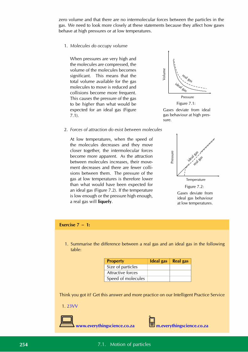
zero volume and that there are no intermolecular forces between the particles in thegas. We need to look more closely at these statements because they affect how gasesbehave at high pressures or at low temperatures.
1. Molecules do occupy volume
When pressures are very high andthe molecules are compressed, thevolume of the molecules becomessignificant. This means that thetotal volume available for the gasmolecules to move is reduced andcollisions become more frequent.This causes the pressure of the gasto be higher than what would beexpected for an ideal gas (Figure7.1).
ideal gas
real gasVo
lum
e
Pressure
Figure 7.1:
Gases deviate from idealgas behaviour at high pres-sure.
2. Forces of attraction do exist between molecules
At low temperatures, when the speed ofthe molecules decreases and they movecloser together, the intermolecular forcesbecome more apparent. As the attractionbetween molecules increases, their move-ment decreases and there are fewer colli-sions between them. The pressure of thegas at low temperatures is therefore lowerthan what would have been expected foran ideal gas (Figure 7.2). If the temperatureis low enough or the pressure high enough,a real gas will liquefy.
idea
l gas
real
gas
Pre
ssu
re
Temperature
Figure 7.2:
Gases deviate fromideal gas behaviourat low temperatures.
Exercise 7 – 1:
1. Summarise the difference between a real gas and an ideal gas in the followingtable:
Property Ideal gas Real gasSize of particlesAttractive forcesSpeed of molecules
Think you got it? Get this answer and more practice on our Intelligent Practice Service
1. 23VV
www.everythingscience.co.za m.everythingscience.co.za
254 7.1. Motion of particles
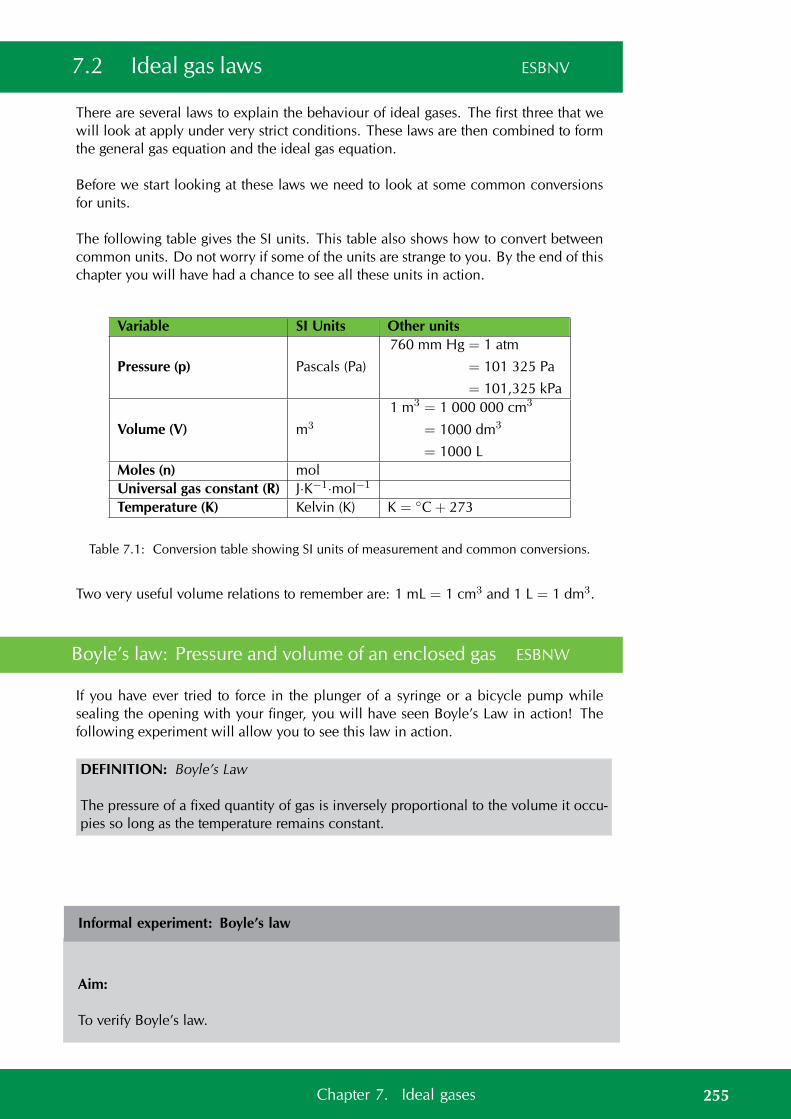
7.2 Ideal gas laws ESBNV
There are several laws to explain the behaviour of ideal gases. The first three that wewill look at apply under very strict conditions. These laws are then combined to formthe general gas equation and the ideal gas equation.
Before we start looking at these laws we need to look at some common conversionsfor units.
The following table gives the SI units. This table also shows how to convert betweencommon units. Do not worry if some of the units are strange to you. By the end of thischapter you will have had a chance to see all these units in action.
Variable SI Units Other units
Pressure (p) Pascals (Pa)
760 mm Hg = 1 atm
= 101 325 Pa
= 101,325 kPa
Volume (V) m3
1 m3 = 1 000 000 cm3
= 1000 dm3
= 1000 LMoles (n) molUniversal gas constant (R) J·K−1·mol−1
Temperature (K) Kelvin (K) K = C + 273
Table 7.1: Conversion table showing SI units of measurement and common conversions.
Two very useful volume relations to remember are: 1 mL = 1 cm3 and 1 L = 1 dm3.
Boyle’s law: Pressure and volume of an enclosed gas ESBNW
If you have ever tried to force in the plunger of a syringe or a bicycle pump whilesealing the opening with your finger, you will have seen Boyle’s Law in action! Thefollowing experiment will allow you to see this law in action.
DEFINITION: Boyle’s Law
The pressure of a fixed quantity of gas is inversely proportional to the volume it occu-pies so long as the temperature remains constant.
Informal experiment: Boyle’s law
Aim:
To verify Boyle’s law.
255Chapter 7. Ideal gases

Apparatus:
Boyle’s law apparatus (a syringe or bicycle pump attached to a pressure gauge.)
Method:
1. Use the pump to fill the syringe (or glass tube) until the pressure gauge reads themaximum value. Note the volume and the pressure reading.
2. Slowly release some of the air until the pressure has dropped by about 20 units(the units will depend on what your pressure gauge measures, e.g. kPa).
3. Let the system stabilise for about 2 min and then read the volume.
4. Repeat the above two steps until you have six pairs of pressure-volume readings.
Results:
Record your results in the following table. Remember that your pressure and volumeunits will be determined by the apparatus you are using.
Pressure Volume
What happens to the volume as the pressure decreases?
Plot your results as a graph of pressure versus volume (in other words plot pressure onthe x-axis and volume on the y-axis). Pressure is the independent variable, which weare changing to see what happens to volume.
Plot your results as a graph of pressure versus the inverse of volume (in other words1V , so for each volume reading you will work out the value of 1 divided by the volumereading).
What do you notice about each graph?
256 7.2. Ideal gas laws
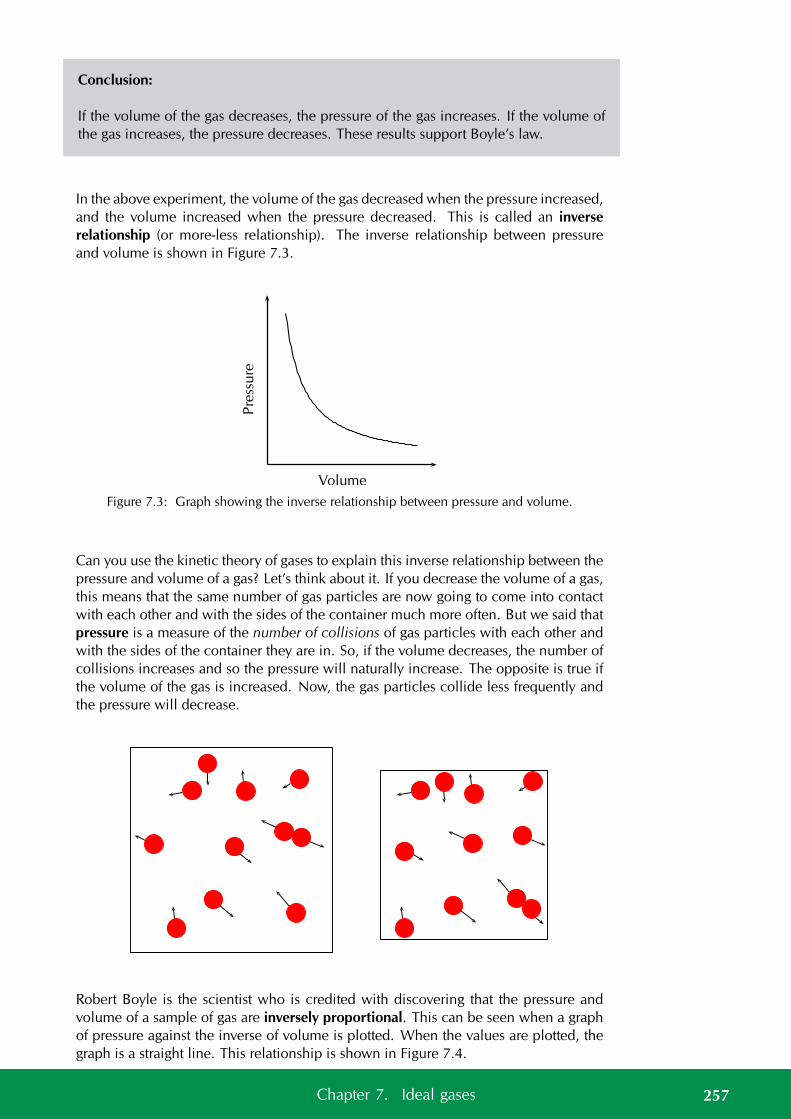
Conclusion:
If the volume of the gas decreases, the pressure of the gas increases. If the volume ofthe gas increases, the pressure decreases. These results support Boyle’s law.
In the above experiment, the volume of the gas decreased when the pressure increased,and the volume increased when the pressure decreased. This is called an inverserelationship (or more-less relationship). The inverse relationship between pressureand volume is shown in Figure 7.3.
Pre
ssu
re
Volume
Figure 7.3: Graph showing the inverse relationship between pressure and volume.
Can you use the kinetic theory of gases to explain this inverse relationship between thepressure and volume of a gas? Let’s think about it. If you decrease the volume of a gas,this means that the same number of gas particles are now going to come into contactwith each other and with the sides of the container much more often. But we said thatpressure is a measure of the number of collisions of gas particles with each other andwith the sides of the container they are in. So, if the volume decreases, the number ofcollisions increases and so the pressure will naturally increase. The opposite is true ifthe volume of the gas is increased. Now, the gas particles collide less frequently andthe pressure will decrease.
Robert Boyle is the scientist who is credited with discovering that the pressure andvolume of a sample of gas are inversely proportional. This can be seen when a graphof pressure against the inverse of volume is plotted. When the values are plotted, thegraph is a straight line. This relationship is shown in Figure 7.4.
257Chapter 7. Ideal gases
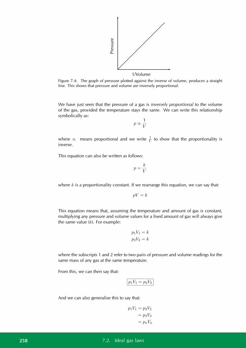
Pre
ssu
re
1/Volume
Figure 7.4: The graph of pressure plotted against the inverse of volume, produces a straightline. This shows that pressure and volume are inversely proportional.
We have just seen that the pressure of a gas is inversely proportional to the volumeof the gas, provided the temperature stays the same. We can write this relationshipsymbolically as:
p ∝ 1V
where ∝ means proportional and we write 1V to show that the proportionality is
inverse.
This equation can also be written as follows:
p =k
V
where k is a proportionality constant. If we rearrange this equation, we can say that:
pV = k
This equation means that, assuming the temperature and amount of gas is constant,multiplying any pressure and volume values for a fixed amount of gas will always givethe same value (k). For example:
p1V1 = k
p2V2 = k
where the subscripts 1 and 2 refer to two pairs of pressure and volume readings for thesame mass of any gas at the same temperature.
From this, we can then say that:
p1V1 = p2V2
And we can also generalise this to say that:
p1V1 = p2V2
= p3V3
= pnVn
258 7.2. Ideal gas laws
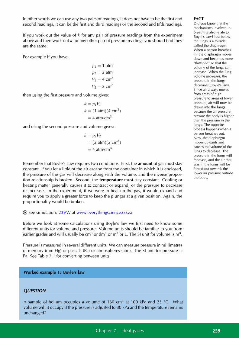
FACTDid you know that themechanisms involved inbreathing also relate toBoyle’s Law? Just belowthe lungs is a musclecalled the diaphragm.When a person breathesin, the diaphragm movesdown and becomes more“flattened” so that thevolume of the lungs canincrease. When the lungvolume increases, thepressure in the lungsdecreases (Boyle’s law).Since air always movesfrom areas of highpressure to areas of lowerpressure, air will now bedrawn into the lungsbecause the air pressureoutside the body is higherthan the pressure in thelungs. The oppositeprocess happens when aperson breathes out.Now, the diaphragmmoves upwards andcauses the volume of thelungs to decrease. Thepressure in the lungs willincrease, and the air thatwas in the lungs will beforced out towards thelower air pressure outsidethe body.
In other words we can use any two pairs of readings, it does not have to be the first andsecond readings, it can be the first and third readings or the second and fifth readings.
If you work out the value of k for any pair of pressure readings from the experimentabove and then work out k for any other pair of pressure readings you should find theyare the same.
For example if you have:
p1 = 1 atm
p2 = 2 atm
V1 = 4 cm3
V2 = 2 cm3
then using the first pressure and volume gives:
k = p1V1
k = (1 atm)(4 cm3)
= 4 atm·cm3
and using the second pressure and volume gives:
k = p2V2
= (2 atm)(2 cm3)
= 4 atm·cm3
Remember that Boyle’s Law requires two conditions. First, the amount of gas must stayconstant. If you let a little of the air escape from the container in which it is enclosed,the pressure of the gas will decrease along with the volume, and the inverse propor-tion relationship is broken. Second, the temperature must stay constant. Cooling orheating matter generally causes it to contract or expand, or the pressure to decreaseor increase. In the experiment, if we were to heat up the gas, it would expand andrequire you to apply a greater force to keep the plunger at a given position. Again, theproportionality would be broken.
See simulation: 23VW at www.everythingscience.co.za
Before we look at some calculations using Boyle’s law we first need to know somedifferent units for volume and pressure. Volume units should be familiar to you fromearlier grades and will usually be cm3 or dm3 or m3 or L. The SI unit for volume is m3.
Pressure is measured in several different units. We can measure pressure in millimetresof mercury (mm Hg) or pascals (Pa) or atmospheres (atm). The SI unit for pressure isPa. See Table 7.1 for converting between units.
Worked example 1: Boyle’s law
QUESTION
A sample of helium occupies a volume of 160 cm3 at 100 kPa and 25 C. Whatvolume will it occupy if the pressure is adjusted to 80 kPa and the temperature remainsunchanged?
259Chapter 7. Ideal gases
TIPIt is not necessary toconvert to SI units forBoyle’s law. Changingpressure and volume intodifferent units involvesmultiplication. If youwere to change the unitsin the above equation,this would involvemultiplication on bothsides of the equation, andso the conversions canceleach other out. However,although SI units don’thave to be used, you mustmake sure that for eachvariable you use the sameunits throughout theequation. This is not truefor some of thecalculations we will do ata later stage, where SIunits must be used.
SOLUTION
Step 1: Write down all the information that you know about the gas.
p1 = 100 kPa
p2 = 80 kPa
V1 = 160 cm3
V2 =?
Step 2: Use an appropriate gas law equation to calculate the unknown variable.
Because the temperature of the gas stays the same, the following equation can be used:
p2V2 = p1V1
Step 3: Substitute the known values into the equation, making sure that the units foreach variable are the same. Calculate the unknown variable.
(80)V2 = (100)(160)
(80)V2 = 16 000
V2 = 200 cm3
The volume occupied by the gas at a pressure of 80 kPa is 200 cm3
Step 4: Check your answer
Boyle’s law states that the pressure is inversely proportional to the volume. Since thepressure decreased the volume must increase. Our answer for the volume is greaterthan the initial volume and so our answer is reasonable.
Worked example 2: Boyle’s law
QUESTION
The volume of a sample of gas is increased from 2,5 L to 2,8 L while a constanttemperature is maintained. What is the final pressure of the gas under these volumeconditions, if the initial pressure is 695 Pa?
260 7.2. Ideal gas laws
SOLUTION
Step 1: Write down all the information that you know about the gas.
V1 = 2,5 L
V2 = 2,8 L
p1 = 695 Pa
p2 =?
Step 2: Choose a relevant gas law equation to calculate the unknown variable.
The sample of gas is at constant temperature and so we can use Boyle’s law:
p2V2 = p1V1
Step 3: Substitute the known values into the equation, making sure that the units foreach variable are the same. Calculate the unknown variable.
(2,8)p2 = (695)(2,5)
(2,8)p2 = 1737,5
p2 = 620,5 kPa
The pressure of the gas at a volume of 2,8 L is 620,5 kPa
Step 4: Check your answer
Boyle’s law states that the pressure is inversely proportional to the volume. Since thevolume increased the pressure must decrease. Our answer for the pressure is less thanthe initial pressure and so our answer is reasonable.
Exercise 7 – 2: Boyle’s law
1. An unknown gas has an initial pressure of 150 kPa and a volume of 1 L. If thevolume is increased to 1,5 L, what will the pressure be now?
2. A bicycle pump contains 250 cm3 of air at a pressure of 90 kPa. If the air iscompressed, the volume is reduced to 200 cm3. What is the pressure of the airinside the pump?
261Chapter 7. Ideal gases

3. The air inside a syringe occupies a volume of 10 cm3 and exerts a pressure of100 kPa. If the end of the syringe is sealed and the plunger is pushed down, thepressure increases to 120 kPa. What is the volume of the air in the syringe?
4. During an investigation to find the relationship between the pressure and volumeof an enclosed gas at constant temperature, the following results were obtained.
Volume (dm3) 12 16 20 24 28 32 36 40Pressure (kPa) 400 300 240 200 171 150 133 120
a) Plot a graph of pressure (p) against volume (V). Volume will be on the x-axisand pressure on the y-axis. Describe the relationship that you see.
b) Plot a graph of p against1
V. Describe the relationship that you see.
c) Do your results support Boyle’s Law? Explain your answer.
5. Masoabi and Justine are experimenting with Boyle’s law. They both used thesame amount of gas. Their data is given in the table below:
Masoabi JustineInitial Final Initial Final
Temperature (K) 325 350 325 325Volume (dm3) 1 3 1 3Pressure (Pa) 650 233 650 217
Masoabi and Justine argue about who is correct.
a) Calculate the final pressure that would be expected using the initial pressureand volume and the final volume.
b) Who correctly followed Boyle’s law and why?
Think you got it? Get this answer and more practice on our Intelligent Practice Service
1. 23VX 2. 23VY 3. 23VZ 4. 23W2 5. 23W3
www.everythingscience.co.za m.everythingscience.co.za
Charles’ law: Volume and temperature of an enclosed gas ESBNX
Charles’ law describes the relationship between the volume and temperature of a gas.The law was first published by Joseph Louis Gay-Lussac in 1802, but he referencedunpublished work by Jacques Charles from around 1787. This law states that at con-stant pressure, the volume of a given mass of an ideal gas increases or decreases bythe same factor as its temperature (in Kelvin) increases or decreases. Another way of
262 7.2. Ideal gas laws
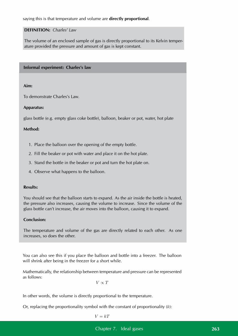
saying this is that temperature and volume are directly proportional.
DEFINITION: Charles’ Law
The volume of an enclosed sample of gas is directly proportional to its Kelvin temper-ature provided the pressure and amount of gas is kept constant.
Informal experiment: Charles’s law
Aim:
To demonstrate Charles’s Law.
Apparatus:
glass bottle (e.g. empty glass coke bottle), balloon, beaker or pot, water, hot plate
Method:
1. Place the balloon over the opening of the empty bottle.
2. Fill the beaker or pot with water and place it on the hot plate.
3. Stand the bottle in the beaker or pot and turn the hot plate on.
4. Observe what happens to the balloon.
Results:
You should see that the balloon starts to expand. As the air inside the bottle is heated,the pressure also increases, causing the volume to increase. Since the volume of theglass bottle can’t increase, the air moves into the balloon, causing it to expand.
Conclusion:
The temperature and volume of the gas are directly related to each other. As oneincreases, so does the other.
You can also see this if you place the balloon and bottle into a freezer. The balloonwill shrink after being in the freezer for a short while.
Mathematically, the relationship between temperature and pressure can be representedas follows:
V ∝ T
In other words, the volume is directly proportional to the temperature.
Or, replacing the proportionality symbol with the constant of proportionality (k):
V = kT
263Chapter 7. Ideal gases
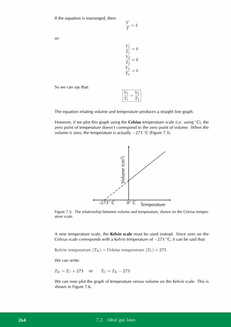
If the equation is rearranged, then:V
T= k
or:
V1
T1= k
V2
T2= k
Vn
Tn= k
So we can say that:V1
T1=
V2
T2
The equation relating volume and temperature produces a straight line graph.
However, if we plot this graph using the Celsius temperature scale (i.e. using C), thezero point of temperature doesn’t correspond to the zero point of volume. When thevolume is zero, the temperature is actually −273 C (Figure 7.5).
Vo
lum
e(c
m3)
-273 C 0 C Temperature
Figure 7.5: The relationship between volume and temperature, shown on the Celsius temper-ature scale.
A new temperature scale, the Kelvin scale must be used instead. Since zero on theCelsius scale corresponds with a Kelvin temperature of −273 C, it can be said that:
Kelvin temperature (TK) = Celsius temperature (TC) + 273
We can write:
TK = TC + 273 or TC = TK − 273
We can now plot the graph of temperature versus volume on the Kelvin scale. This isshown in Figure 7.6.
264 7.2. Ideal gas laws
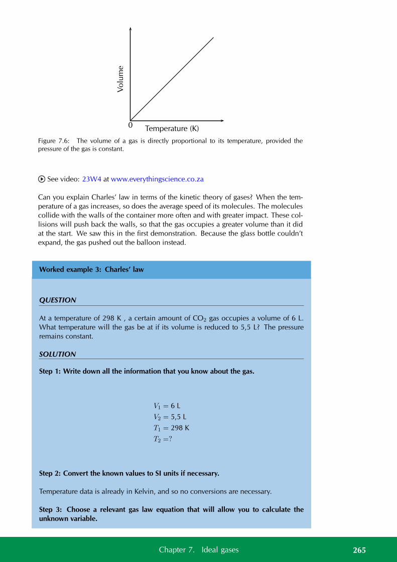
Vo
lum
e0 Temperature (K)
Figure 7.6: The volume of a gas is directly proportional to its temperature, provided thepressure of the gas is constant.
See video: 23W4 at www.everythingscience.co.za
Can you explain Charles’ law in terms of the kinetic theory of gases? When the tem-perature of a gas increases, so does the average speed of its molecules. The moleculescollide with the walls of the container more often and with greater impact. These col-lisions will push back the walls, so that the gas occupies a greater volume than it didat the start. We saw this in the first demonstration. Because the glass bottle couldn’texpand, the gas pushed out the balloon instead.
Worked example 3: Charles’ law
QUESTION
At a temperature of 298 K , a certain amount of CO2 gas occupies a volume of 6 L.What temperature will the gas be at if its volume is reduced to 5,5 L? The pressureremains constant.
SOLUTION
Step 1: Write down all the information that you know about the gas.
V1 = 6 L
V2 = 5,5 L
T1 = 298 K
T2 =?
Step 2: Convert the known values to SI units if necessary.
Temperature data is already in Kelvin, and so no conversions are necessary.
Step 3: Choose a relevant gas law equation that will allow you to calculate theunknown variable.
265Chapter 7. Ideal gases
The pressure is kept constant while the volume and temperature are being varied. Theamount of gas is also kept constant and so we can use Charles’ law:
V1
T1=
V2
T2
Step 4: Substitute the known values into the equation. Calculate the unknown vari-able.
6298
=5,5T2
0,0201 . . . =5,5T2
(0,0201 . . .)T2 = 5,5
T2 = 273,2 K
The gas will be at a temperature of 273,2 K.
Step 5: Check your answer
Charles’ law states that the temperature is directly proportional to the volume. In thisexample the volume decreases and so the temperature must decrease. Our answergives a lower final temperature than the initial temperature and so is correct.
Worked example 4: Charles’ law
QUESTION
Ammonium chloride and calcium hydroxide are allowed to react. The ammonia thatis released in the reaction is collected in a gas syringe (a syringe that has very littlefriction so that the plunger can move freely) and sealed in. This gas is allowed tocome to room temperature which is 20 C. The volume of the ammonia is found tobe 122 mL. It is now placed in a water bath set at 32 C. What will be the volumereading after the syringe has been left in the bath for 1 hour (assume the plunger movescompletely freely)? (By leaving the syringe for this length of time, we can be certainthat the sample of gas is at the higher temperature.)
SOLUTION
Step 1: Write down all the information that you know about the gas.
266 7.2. Ideal gas laws
TIPNote that here thetemperature must beconverted to Kelvin sincethe change from degreesCelsius involves addition,not multiplication by afixed conversion ratio (asis the case with pressureand volume.)
V1 = 122 mL
V2 =?
T1 = 20 C
T2 = 7 C
Step 2: Convert the known values to SI units if necessary.
Here, temperature must be converted into Kelvin, therefore:
T1 = 20 + 273 = 293 K
T2 = 32 + 273 = 305 K
Step 3: Choose a relevant gas law equation that will allow you to calculate theunknown variable.
The pressure is kept constant while the volume and temperature are being varied. Theamount of gas is also kept constant and so we can use Charles’ law:
V2
T2=
V1
T1
Step 4: Substitute the known values into the equation. Calculate the unknown vari-able.
V2
305=
122293
V2
305= 0,416 . . .
V2 = 127 mL
The volume reading on the syringe will be 127 mL after the syringe has been left inthe water bath for one hour.
Step 5: Check your answer
Charles’ law states that the temperature is directly proportional to the volume. In thisexample the temperature increases and so the volume must increase. Our answer givesa higher final volume than the initial volume and so is correct.
267Chapter 7. Ideal gases
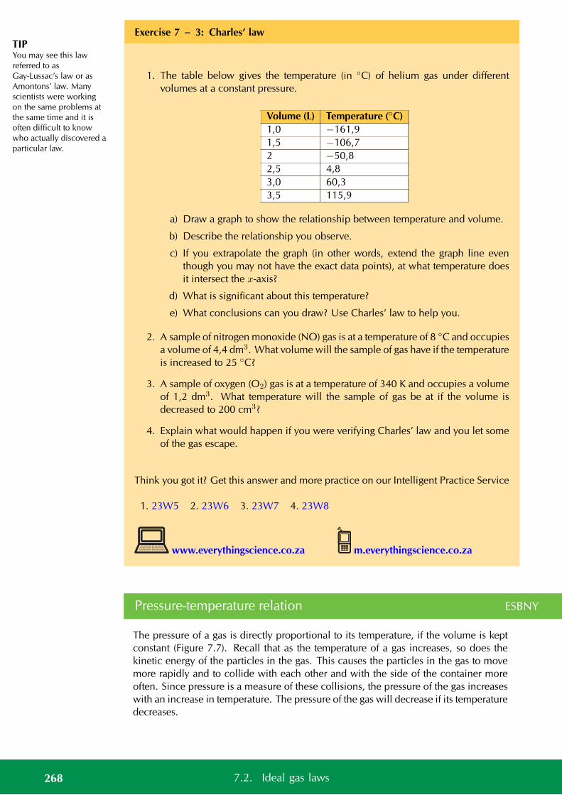
TIPYou may see this lawreferred to asGay-Lussac’s law or asAmontons’ law. Manyscientists were workingon the same problems atthe same time and it isoften difficult to knowwho actually discovered aparticular law.
Exercise 7 – 3: Charles’ law
1. The table below gives the temperature (in C) of helium gas under differentvolumes at a constant pressure.
Volume (L) Temperature (C)1,0 −161,91,5 −106,72 −50,82,5 4,83,0 60,33,5 115,9
a) Draw a graph to show the relationship between temperature and volume.
b) Describe the relationship you observe.
c) If you extrapolate the graph (in other words, extend the graph line eventhough you may not have the exact data points), at what temperature doesit intersect the x-axis?
d) What is significant about this temperature?
e) What conclusions can you draw? Use Charles’ law to help you.
2. A sample of nitrogen monoxide (NO) gas is at a temperature of 8 C and occupiesa volume of 4,4 dm3. What volume will the sample of gas have if the temperatureis increased to 25 C?
3. A sample of oxygen (O2) gas is at a temperature of 340 K and occupies a volumeof 1,2 dm3. What temperature will the sample of gas be at if the volume isdecreased to 200 cm3?
4. Explain what would happen if you were verifying Charles’ law and you let someof the gas escape.
Think you got it? Get this answer and more practice on our Intelligent Practice Service
1. 23W5 2. 23W6 3. 23W7 4. 23W8
www.everythingscience.co.za m.everythingscience.co.za
Pressure-temperature relation ESBNY
The pressure of a gas is directly proportional to its temperature, if the volume is keptconstant (Figure 7.7). Recall that as the temperature of a gas increases, so does thekinetic energy of the particles in the gas. This causes the particles in the gas to movemore rapidly and to collide with each other and with the side of the container moreoften. Since pressure is a measure of these collisions, the pressure of the gas increaseswith an increase in temperature. The pressure of the gas will decrease if its temperaturedecreases.
268 7.2. Ideal gas laws
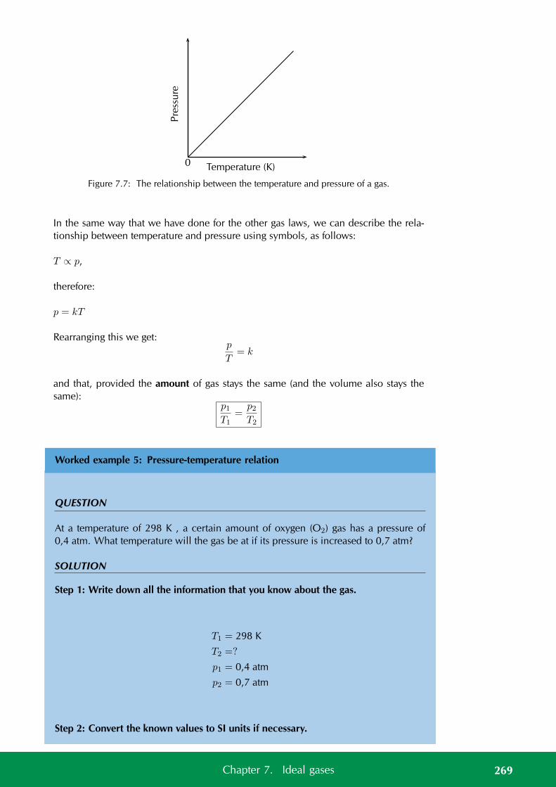
Pre
ssu
re0 Temperature (K)
Figure 7.7: The relationship between the temperature and pressure of a gas.
In the same way that we have done for the other gas laws, we can describe the rela-tionship between temperature and pressure using symbols, as follows:
T ∝ p,
therefore:
p = kT
Rearranging this we get:p
T= k
and that, provided the amount of gas stays the same (and the volume also stays thesame):
p1T1
=p2T2
Worked example 5: Pressure-temperature relation
QUESTION
At a temperature of 298 K , a certain amount of oxygen (O2) gas has a pressure of0,4 atm. What temperature will the gas be at if its pressure is increased to 0,7 atm?
SOLUTION
Step 1: Write down all the information that you know about the gas.
T1 = 298 K
T2 =?
p1 = 0,4 atm
p2 = 0,7 atm
Step 2: Convert the known values to SI units if necessary.
269Chapter 7. Ideal gases
The temperature is already in Kelvin. We do not need to convert the pressure topascals.
Step 3: Choose a relevant gas law equation that will allow you to calculate theunknown variable.
The volume is kept constant while the pressure and temperature are being varied.The amount of gas is also kept constant and so we can use the pressure-temperaturerelation:
p1T1
=p2T2
Step 4: Substitute the known values into the equation. Calculate the unknown vari-able.
0,4298
=0,7T2
0,0013 . . . =0,7T2
(0,0013 . . .)T2 = 0,7
T2 = 521,5 K
The temperature will be 521,5 K.
Step 5: Check your answer
The pressure-temperature relation states that the pressure is directly proportional tothe temperature. In this example the pressure increases and so the temperature mustincrease. Our answer gives a higher final temperature than the initial temperature andso is correct.
Worked example 6: Pressure-temperature relation
QUESTION
A fixed volume of carbon monoxide (CO) gas has a temperature of 32 C and a pressureof 680 Pa. If the temperature is decreased to 15 C what will the pressure be?
SOLUTION
Step 1: Write down all the information that you know about the gas.
270 7.2. Ideal gas laws
T1 = 32 C
T2 = 15 C
p1 = 680 Pa
p2 =?
Step 2: Convert the known values to SI units if necessary.
We need to convert the given temperatures to Kelvin temperature.
T1 = 32 + 273
= 305 K
T2 = 15 + 273
= 288 K
Step 3: Choose a relevant gas law equation that will allow you to calculate theunknown variable.
p2T2
=p1T1
Step 4: Substitute the known values into the equation. Calculate the unknown vari-able.
p2288
=680305
p2288
= 2,2295 . . .
p2 = 642,1 Pa
The pressure will be 642,1 Pa.
Step 5: Check your answer
The pressure-temperature relation states that the pressure is directly proportional tothe temperature. In this example the temperature decreases and so the pressure mustdecrease. Our answer gives a lower final pressure than the initial pressure and so iscorrect.
Exercise 7 – 4: Pressure-temperature relation
1. The table below gives the temperature (in C) of helium under different pressures
271Chapter 7. Ideal gases

at a constant volume.
Pressure (atm) Temperature (C) Temperature (K)1,0 201,2 78,61,4 137,21,6 195,81,8 254,42,0 313
a) Convert all the temperature data to Kelvin.
b) Draw a graph to show the relationship between temperature and pressure.
c) Describe the relationship you observe.
2. A cylinder that contains methane gas is kept at a temperature of 15 C and exertsa pressure of 7 atm. If the temperature of the cylinder increases to 25 C, whatpressure does the gas now exert?
3. A cylinder of propane gas at a temperature of 20 C exerts a pressure of 8 atm.When a cylinder has been placed in sunlight, its temperature increases to 25 C.What is the pressure of the gas inside the cylinder at this temperature?
4. A hairspray can is a can that contains a gas under high pressures. The can has thefollowing warning written on it: “Do not place near open flame. Do not disposeof in a fire. Keep away from heat.” Use what you know about the pressure andtemperature of gases to explain why it is dangerous to not follow this warning.
5. A cylinder of acetylene gas is kept at a temperature of 291 K. The pressure inthe cylinder is 5 atm. This cylinder can withstand a pressure of 8 atm beforeit explodes. What is the maximum temperature that the cylinder can safely bestored at?
Think you got it? Get this answer and more practice on our Intelligent Practice Service
1. 23W9 2. 23WB 3. 23WC 4. 23WD 5. 23WF
www.everythingscience.co.za m.everythingscience.co.za
The general gas equation ESBNZ
All the gas laws we have described so far rely on the fact that the amount of gas andone other variable (temperature, pressure or volume) remains constant. Since this isunlikely to be the case most times, it is useful to combine the relationships into oneequation. We will use Boyle’s law and the pressure-temperature relation to work outthe general gas equation.
Boyle’s law: p ∝ 1
V(constant T)
In other words pressure is inversely proportional to the volume at constant temperature.
272 7.2. Ideal gas laws
TIPRemember that thegeneral gas equation onlyapplies if the mass (ornumber of moles) of thegas is fixed.
Pressure-temperature relation: p ∝ T (constant V)
In other words pressure is also directly proportional to the temperature at constantvolume.
If we now vary both the volume and the temperature, the two proportionalities willstill hold, but will be equal to a different proportionality constant.
So we can combine these relationships, to get:
p ∝ T
V
Note that this says that the pressure is still directly proportional to the temperature andinversely proportional to the volume.
If we introduce the proportionality constant, k, we get:
p = kT
V
or, rearranging the equation:pV = kT
We can also rewrite this relationship as follows:
pV
T= k
Provided the mass of the gas stays the same, we can also say that:
p1V1
T1=
p2V2
T2
In the above equation, the subscripts 1 and 2 refer to two pressure and volume readingsfor the same mass of gas under different conditions. This is known as the general gasequation. Temperature is always in Kelvin and the units used for pressure and volumemust be the same on both sides of the equation.
Worked example 7: General gas equation
QUESTION
At the beginning of a journey, a truck tyre has a volume of 30 dm3 and an internalpressure of 170 kPa. The temperature of the tyre is 16 C. By the end of the trip, thevolume of the tyre has increased to 32 dm3 and the temperature of the air inside thetyre is 40 C. What is the tyre pressure at the end of the journey?
SOLUTION
Step 1: Write down all the information that you know about the gas.
273Chapter 7. Ideal gases
T1 = 16 C
T2 = 40 C
V1 = 30 dm3
V2 = 32 dm3
p1 = 170 kPa
p2 =?
Step 2: Convert the known values to SI units if necessary.
We need to convert the given temperatures to Kelvin temperature.
T1 = 16 + 273
= 289 K
T2 = 40 + 273
= 313 K
Step 3: Choose a relevant gas law equation that will allow you to calculate theunknown variable.
Temperature, pressure and volume are all varying so we must use the general gasequation:
p2V2
T2=
p1V1
T1
Step 4: Substitute the known values into the equation. Calculate the unknown vari-able.
(32)p2313
=(170)(30)
289(32)p2
313= 17,647 . . .
(32)p2 = 5523,529 . . .
p2 = 172,6 kPa
The pressure will be 172,6 kPa.
274 7.2. Ideal gas laws
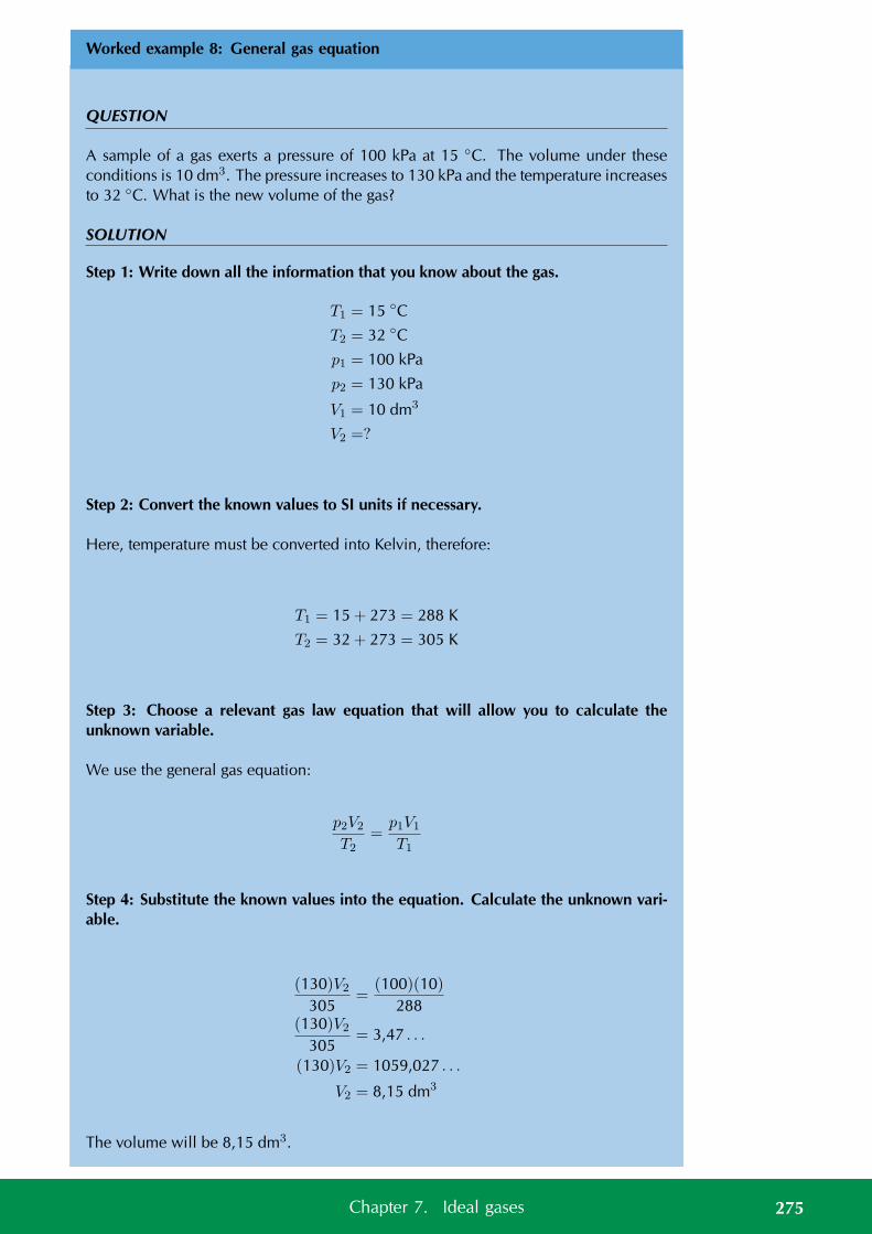
Worked example 8: General gas equation
QUESTION
A sample of a gas exerts a pressure of 100 kPa at 15 C. The volume under theseconditions is 10 dm3. The pressure increases to 130 kPa and the temperature increasesto 32 C. What is the new volume of the gas?
SOLUTION
Step 1: Write down all the information that you know about the gas.
T1 = 15 C
T2 = 32 C
p1 = 100 kPa
p2 = 130 kPa
V1 = 10 dm3
V2 =?
Step 2: Convert the known values to SI units if necessary.
Here, temperature must be converted into Kelvin, therefore:
T1 = 15 + 273 = 288 K
T2 = 32 + 273 = 305 K
Step 3: Choose a relevant gas law equation that will allow you to calculate theunknown variable.
We use the general gas equation:
p2V2
T2=
p1V1
T1
Step 4: Substitute the known values into the equation. Calculate the unknown vari-able.
(130)V2
305=
(100)(10)288
(130)V2
305= 3,47 . . .
(130)V2 = 1059,027 . . .
V2 = 8,15 dm3
The volume will be 8,15 dm3.
275Chapter 7. Ideal gases
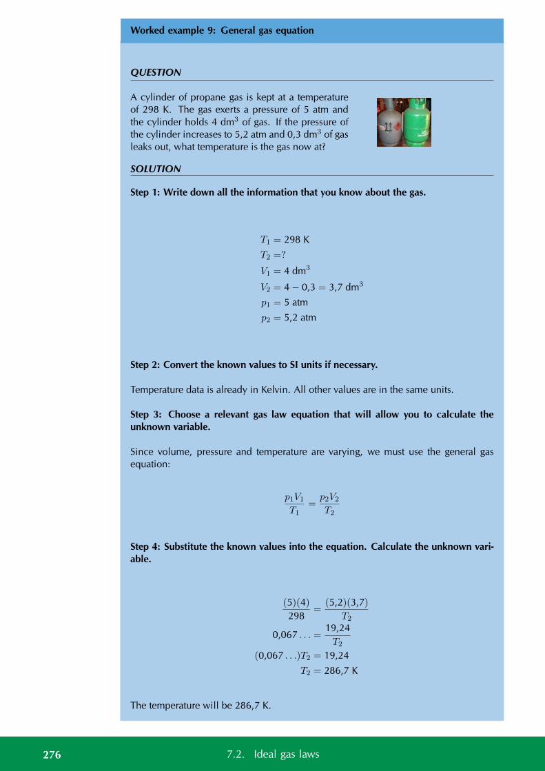
Worked example 9: General gas equation
QUESTION
A cylinder of propane gas is kept at a temperatureof 298 K. The gas exerts a pressure of 5 atm andthe cylinder holds 4 dm3 of gas. If the pressure ofthe cylinder increases to 5,2 atm and 0,3 dm3 of gasleaks out, what temperature is the gas now at?
SOLUTION
Step 1: Write down all the information that you know about the gas.
T1 = 298 K
T2 =?
V1 = 4 dm3
V2 = 4 − 0,3 = 3,7 dm3
p1 = 5 atm
p2 = 5,2 atm
Step 2: Convert the known values to SI units if necessary.
Temperature data is already in Kelvin. All other values are in the same units.
Step 3: Choose a relevant gas law equation that will allow you to calculate theunknown variable.
Since volume, pressure and temperature are varying, we must use the general gasequation:
p1V1
T1=
p2V2
T2
Step 4: Substitute the known values into the equation. Calculate the unknown vari-able.
(5)(4)298
=(5,2)(3,7)
T2
0,067 . . . =19,24T2
(0,067 . . .)T2 = 19,24
T2 = 286,7 K
The temperature will be 286,7 K.
276 7.2. Ideal gas laws
TIPA joule can be defined asPa·m3. So when you areusing the ideal gasequation you must usethe SI units to ensure thatyou get the correctanswer.
Exercise 7 – 5: The general gas equation
1. A closed gas system initially has a volume of 8 L and a temperature of 100 C.The pressure of the gas is unknown. If the temperature of the gas decreases to50 C, the gas occupies a volume of 5 L and the pressure of the gas is 1,2 atm.What was the initial pressure of the gas?
2. A balloon is filled with helium gas at 27 C and a pressure of 1,0 atm. As theballoon rises, the volume of the balloon increases by a factor of 1,6 and thetemperature decreases to 15 C. What is the final pressure of the gas (assumingnone has escaped)?
3. 25 cm3 of gas at 1 atm has a temperature of 25 C. When the gas is compressedto 20 cm3, the temperature of the gas increases to 28 C. Calculate the finalpressure of the gas.
Think you got it? Get this answer and more practice on our Intelligent Practice Service
1. 23WG 2. 23WH 3. 23WJ
www.everythingscience.co.za m.everythingscience.co.za
The ideal gas equation ESBP2
In the early 1800’s, Amedeo Avogadro noted that if you have samples of differentgases, of the same volume, at a fixed temperature and pressure, then the samples mustcontain the same number of freely moving particles (i.e. atoms or molecules).
DEFINITION: Avogadro’s Law
Equal volumes of gases, at the same temperature and pressure, contain the same num-ber of molecules.
You will remember from the previous section, that we combined different gas lawequations to get one that included temperature, volume and pressure. In this equation
pV
T= k
the value of k is different for different masses of gas.
We find that when we calculate k for 1 mol of gas that we get:
pV
T= 8,314
This result is given a special name. It is the universal gas constant, R. R is measuredin units of J·K−1·mol−1. No matter which gas we use, 1 mol of that gas will have thesame constant.
277Chapter 7. Ideal gases
TIPAll quantities in theequation pV = nRTmust be in the same unitsas the value of R. In otherwords, SI units must beused throughout theequation.
If we now extend this result to any number of moles of a gas we get the following:
pV
T= nR
where n is the number of moles of gas.
Rearranging this equation gives:
pV = nRT
This is the ideal gas equation. When you work with this equation you must have allunits in SI units.
See video: 23WK at www.everythingscience.co.za
Worked example 10: Ideal gas equation
QUESTION
Two moles of oxygen (O2) gas occupy a volume of 25 dm3 at a temperature of 40 C.Calculate the pressure of the gas under these conditions.
SOLUTION
Step 1: Write down all the information that you know about the gas.
p =?
V = 25 dm3
n = 2 mol
T = 40 C
R = 8,314 J·K·mol−1
Step 2: Convert the known values to SI units if necessary.
We need to convert the temperature to Kelvin and the volume to m3:
V =25
1000= 0,025 dm3
T = 40 + 273 = 313 K
Step 3: Choose a relevant gas law equation that will allow you to calculate theunknown variable.
We are varying everything (temperature, pressure, volume and amount of gas) and sowe must use the ideal gas equation.
pV = nRT
278 7.2. Ideal gas laws
Step 4: Substitute the known values into the equation. Calculate the unknown vari-able.
(0,025 m3)(p) = (2 mol)(8,314 J·K−1·mol−1)(313 K)
(0,025 m3)(p) = 5204,564 Pa·m3
p = 208 182,56 Pa
The pressure will be 208 182,56 Pa or 208,2 kPa.
Worked example 11: Ideal gas equation
QUESTION
Carbon dioxide (CO2) gas is produced as a result of the reaction between calciumcarbonate and hydrochloric acid. The gas that is produced is collected in a containerof unknown volume. The pressure of the gas is 105 kPa at a temperature of 20 C. Ifthe number of moles of gas collected is 0,86 mol, what is the volume?
SOLUTION
Step 1: Write down all the information that you know about the gas.
p = 105 kPa
V =?
n = 0,86 mol
T = 20 C
R = 8,314 J·K·mol−1
Step 2: Convert the known values to SI units if necessary.
We need to convert the temperature to Kelvin and the pressure to Pa:
p = 105 × 1000 = 105 000 Pa
T = 20 + 273 = 293 K
Step 3: Choose a relevant gas law equation that will allow you to calculate theunknown variable.
279Chapter 7. Ideal gases
We are varying everything (temperature, pressure, volume and amount of gas) and sowe must use the ideal gas equation.
pV = nRT
Step 4: Substitute the known values into the equation. Calculate the unknown vari-able.
(105 000 Pa)V = (8,314 J·K−1·mol−1)(293 K)(0,86 mol)
(105 000 Pa)V = 2094,96 Pa·m3
V = 0,020 m3
= 20 dm3
The volume is 20 dm3.
Worked example 12: Ideal gas equation
QUESTION
Nitrogen (N2) reacts with hydrogen (H2) according to the following equation:
N2 + 3H2 → 2NH3
2 mol ammonia (NH3) gas is collected in a separate gas cylinder which has a volumeof 25 dm3. The pressure of the gas is 195,89 kPa. Calculate the temperature of the gasinside the cylinder.
SOLUTION
Step 1: Write down all the information that you know about the gas.
p = 195,98 Pa
V = 25 dm3
n = 2 mol
R = 8,3 J·K−1mol−1
T =?
Step 2: Convert the known values to SI units if necessary.
280 7.2. Ideal gas laws
We must convert the volume to m3 and the pressure to Pa:
V =25
1000= 0,025 m3
p = 195,89 × 1000
= 195 890 Pa
Step 3: Choose a relevant gas law equation that will allow you to calculate theunknown variable.
pV = nRT
Step 4: Substitute the known values into the equation. Calculate the unknown vari-able.
(195 890)(0,025) = (2)(8,314)T
4897,25 = 16,628(T )
T = 294,52 K
The temperature is 294,52 K.
Worked example 13: Ideal gas equation
QUESTION
Calculate the number of moles of air particles in a classroom of length 10 m, a widthof 7 m and a height of 2 m on a day when the temperature is 23 C and the air pressureis 98 kPa .
SOLUTION
Step 1: Calculate the volume of air in the classroom
The classroom is a rectangular prism (recall grade 10 maths on measurement). We cancalculate the volume using:
V = length× width× height
= (10)(7)(2)
= 140 m3
281Chapter 7. Ideal gases
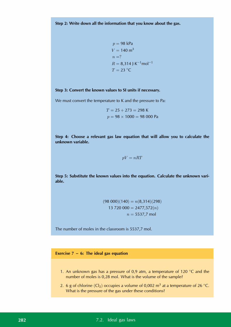
Step 2: Write down all the information that you know about the gas.
p = 98 kPa
V = 140 m3
n =?
R = 8,314 J·K−1mol−1
T = 23 C
Step 3: Convert the known values to SI units if necessary.
We must convert the temperature to K and the pressure to Pa:
T = 25 + 273 = 298 K
p = 98 × 1000 = 98 000 Pa
Step 4: Choose a relevant gas law equation that will allow you to calculate theunknown variable.
pV = nRT
Step 5: Substitute the known values into the equation. Calculate the unknown vari-able.
(98 000)(140) = n(8,314)(298)
13 720 000 = 2477,572(n)
n = 5537,7 mol
The number of moles in the classroom is 5537,7 mol.
Exercise 7 – 6: The ideal gas equation
1. An unknown gas has a pressure of 0,9 atm, a temperature of 120 C and thenumber of moles is 0,28 mol. What is the volume of the sample?
2. 6 g of chlorine (Cl2) occupies a volume of 0,002 m3 at a temperature of 26 C.What is the pressure of the gas under these conditions?
282 7.2. Ideal gas laws
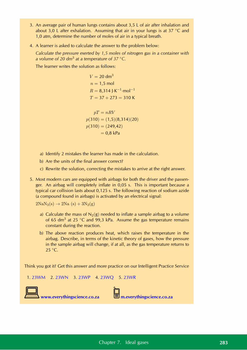
3. An average pair of human lungs contains about 3,5 L of air after inhalation andabout 3,0 L after exhalation. Assuming that air in your lungs is at 37 C and1,0 atm, determine the number of moles of air in a typical breath.
4. A learner is asked to calculate the answer to the problem below:
Calculate the pressure exerted by 1,5 moles of nitrogen gas in a container witha volume of 20 dm3 at a temperature of 37 C.
The learner writes the solution as follows:
V = 20 dm3
n = 1,5 mol
R = 8,314 J·K−1·mol−1
T = 37 + 273 = 310 K
pT = nRV
p(310) = (1,5)(8,314)(20)
p(310) = (249,42)
= 0,8 kPa
a) Identify 2 mistakes the learner has made in the calculation.
b) Are the units of the final answer correct?
c) Rewrite the solution, correcting the mistakes to arrive at the right answer.
5. Most modern cars are equipped with airbags for both the driver and the passen-ger. An airbag will completely inflate in 0,05 s. This is important because atypical car collision lasts about 0,125 s. The following reaction of sodium azide(a compound found in airbags) is activated by an electrical signal:
2NaN3(s) → 2Na (s) + 3N2(g)
a) Calculate the mass of N2(g) needed to inflate a sample airbag to a volumeof 65 dm3 at 25 C and 99,3 kPa. Assume the gas temperature remainsconstant during the reaction.
b) The above reaction produces heat, which raises the temperature in theairbag. Describe, in terms of the kinetic theory of gases, how the pressurein the sample airbag will change, if at all, as the gas temperature returns to25 C.
Think you got it? Get this answer and more practice on our Intelligent Practice Service
1. 23WM 2. 23WN 3. 23WP 4. 23WQ 5. 23WR
www.everythingscience.co.za m.everythingscience.co.za
283Chapter 7. Ideal gases
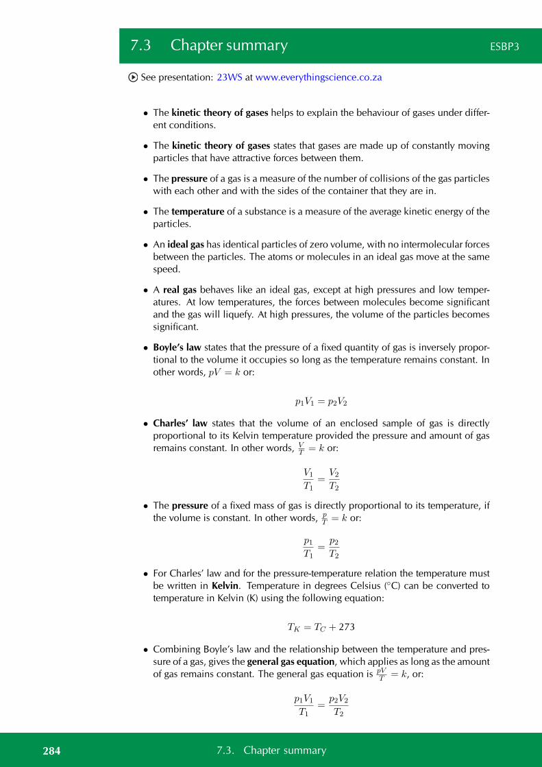
7.3 Chapter summary ESBP3
See presentation: 23WS at www.everythingscience.co.za
• The kinetic theory of gases helps to explain the behaviour of gases under differ-ent conditions.
• The kinetic theory of gases states that gases are made up of constantly movingparticles that have attractive forces between them.
• The pressure of a gas is a measure of the number of collisions of the gas particleswith each other and with the sides of the container that they are in.
• The temperature of a substance is a measure of the average kinetic energy of theparticles.
• An ideal gas has identical particles of zero volume, with no intermolecular forcesbetween the particles. The atoms or molecules in an ideal gas move at the samespeed.
• A real gas behaves like an ideal gas, except at high pressures and low temper-atures. At low temperatures, the forces between molecules become significantand the gas will liquefy. At high pressures, the volume of the particles becomessignificant.
• Boyle’s law states that the pressure of a fixed quantity of gas is inversely propor-tional to the volume it occupies so long as the temperature remains constant. Inother words, pV = k or:
p1V1 = p2V2
• Charles’ law states that the volume of an enclosed sample of gas is directlyproportional to its Kelvin temperature provided the pressure and amount of gasremains constant. In other words, V
T = k or:
V1
T1=
V2
T2
• The pressure of a fixed mass of gas is directly proportional to its temperature, ifthe volume is constant. In other words, p
T = k or:
p1T1
=p2T2
• For Charles’ law and for the pressure-temperature relation the temperature mustbe written in Kelvin. Temperature in degrees Celsius (C) can be converted totemperature in Kelvin (K) using the following equation:
TK = TC + 273
• Combining Boyle’s law and the relationship between the temperature and pres-sure of a gas, gives the general gas equation, which applies as long as the amountof gas remains constant. The general gas equation is pV
T = k, or:
p1V1
T1=
p2V2
T2
284 7.3. Chapter summary
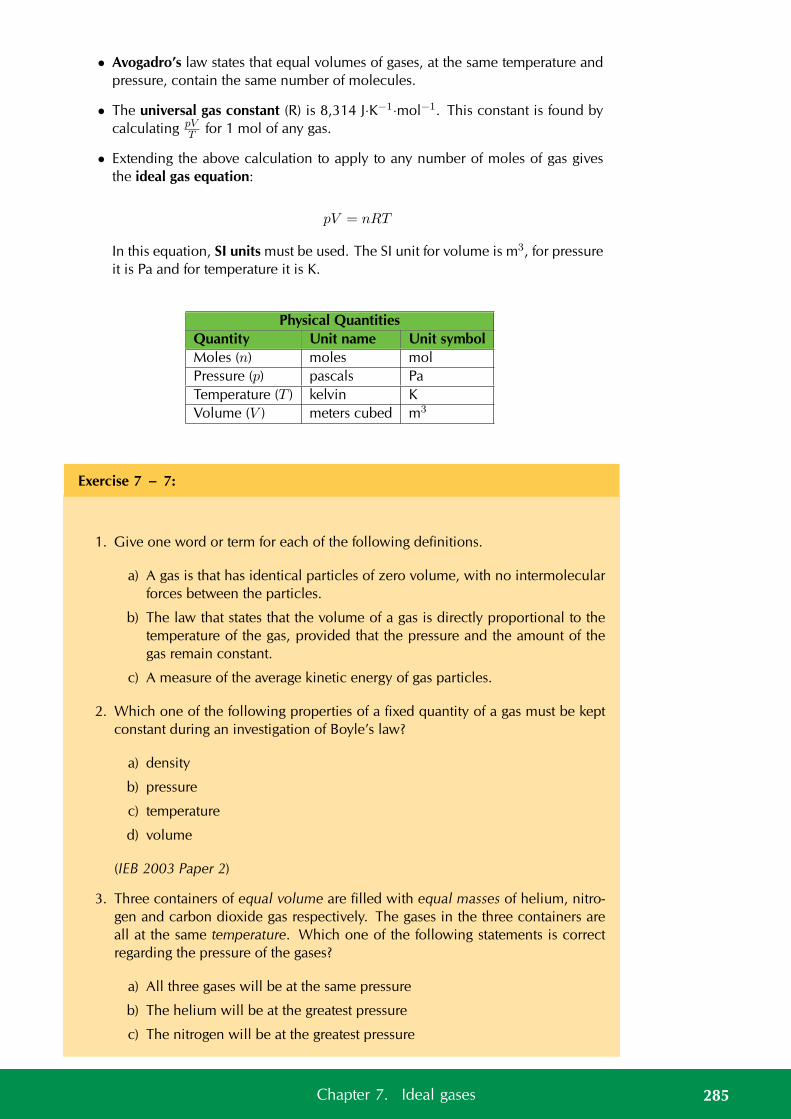
• Avogadro’s law states that equal volumes of gases, at the same temperature andpressure, contain the same number of molecules.
• The universal gas constant (R) is 8,314 J·K−1·mol−1. This constant is found bycalculating pV
T for 1 mol of any gas.
• Extending the above calculation to apply to any number of moles of gas givesthe ideal gas equation:
pV = nRT
In this equation, SI units must be used. The SI unit for volume is m3, for pressureit is Pa and for temperature it is K.
Physical QuantitiesQuantity Unit name Unit symbolMoles (n) moles molPressure (p) pascals PaTemperature (T ) kelvin KVolume (V ) meters cubed m3
Exercise 7 – 7:
1. Give one word or term for each of the following definitions.
a) A gas is that has identical particles of zero volume, with no intermolecularforces between the particles.
b) The law that states that the volume of a gas is directly proportional to thetemperature of the gas, provided that the pressure and the amount of thegas remain constant.
c) A measure of the average kinetic energy of gas particles.
2. Which one of the following properties of a fixed quantity of a gas must be keptconstant during an investigation of Boyle’s law?
a) density
b) pressure
c) temperature
d) volume
(IEB 2003 Paper 2)
3. Three containers of equal volume are filled with equal masses of helium, nitro-gen and carbon dioxide gas respectively. The gases in the three containers areall at the same temperature. Which one of the following statements is correctregarding the pressure of the gases?
a) All three gases will be at the same pressure
b) The helium will be at the greatest pressure
c) The nitrogen will be at the greatest pressure
285Chapter 7. Ideal gases
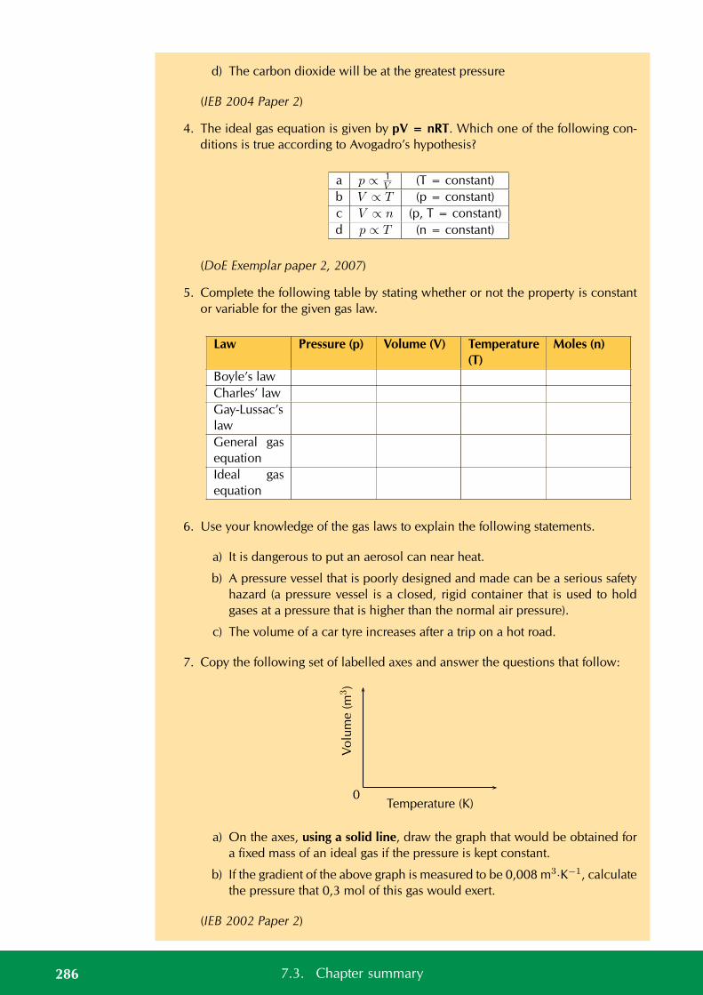
d) The carbon dioxide will be at the greatest pressure
(IEB 2004 Paper 2)
4. The ideal gas equation is given by pV = nRT. Which one of the following con-ditions is true according to Avogadro’s hypothesis?
a p ∝ 1V (T = constant)
b V ∝ T (p = constant)c V ∝ n (p, T = constant)d p ∝ T (n = constant)
(DoE Exemplar paper 2, 2007)
5. Complete the following table by stating whether or not the property is constantor variable for the given gas law.
Law Pressure (p) Volume (V) Temperature(T)
Moles (n)
Boyle’s lawCharles’ lawGay-Lussac’slawGeneral gasequationIdeal gasequation
6. Use your knowledge of the gas laws to explain the following statements.
a) It is dangerous to put an aerosol can near heat.
b) A pressure vessel that is poorly designed and made can be a serious safetyhazard (a pressure vessel is a closed, rigid container that is used to holdgases at a pressure that is higher than the normal air pressure).
c) The volume of a car tyre increases after a trip on a hot road.
7. Copy the following set of labelled axes and answer the questions that follow:
Temperature (K)
Vo
lum
e(m
3)
0
a) On the axes, using a solid line, draw the graph that would be obtained fora fixed mass of an ideal gas if the pressure is kept constant.
b) If the gradient of the above graph is measured to be 0,008 m3·K−1, calculatethe pressure that 0,3 mol of this gas would exert.
(IEB 2002 Paper 2)
286 7.3. Chapter summary
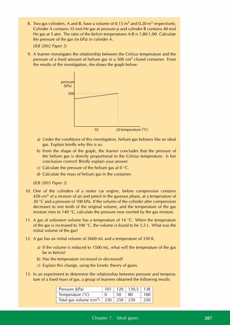
8. Two gas cylinders, A and B, have a volume of 0,15 m3 and 0,20 m3 respectively.Cylinder A contains 35 mol He gas at pressure p and cylinder B contains 40 molHe gas at 5 atm. The ratio of the Kelvin temperatures A:B is 1,80:1,00. Calculatethe pressure of the gas (in kPa) in cylinder A.
(IEB 2002 Paper 2)
9. A learner investigates the relationship between the Celsius temperature and thepressure of a fixed amount of helium gas in a 500 cm3 closed container. Fromthe results of the investigation, she draws the graph below:
pressure(kPa)
300
10 20 temperature (0C)
a) Under the conditions of this investigation, helium gas behaves like an idealgas. Explain briefly why this is so.
b) From the shape of the graph, the learner concludes that the pressure ofthe helium gas is directly proportional to the Celsius temperature. Is herconclusion correct? Briefly explain your answer.
c) Calculate the pressure of the helium gas at 0 C.
d) Calculate the mass of helium gas in the container.
(IEB 2003 Paper 2)
10. One of the cylinders of a motor car engine, before compression contains450 cm3 of a mixture of air and petrol in the gaseous phase, at a temperature of30 C and a pressure of 100 kPa. If the volume of the cylinder after compressiondecreases to one tenth of the original volume, and the temperature of the gasmixture rises to 140 C, calculate the pressure now exerted by the gas mixture.
11. A gas of unknown volume has a temperature of 14 C. When the temperatureof the gas is increased to 100 C, the volume is found to be 5,5 L. What was theinitial volume of the gas?
12. A gas has an initial volume of 2600 mL and a temperature of 350 K.
a) If the volume is reduced to 1500 mL, what will the temperature of the gasbe in Kelvin?
b) Has the temperature increased or decreased?
c) Explain this change, using the kinetic theory of gases.
13. In an experiment to determine the relationship between pressure and tempera-ture of a fixed mass of gas, a group of learners obtained the following results:
Pressure (kPa) 101 120 130,5 138Temperature (C) 0 50 80 100Total gas volume (cm3) 250 250 250 250
287Chapter 7. Ideal gases

a) Draw a straight-line graph of pressure (on the dependent, y-axis) versustemperature (on the independent, x-axis) on a piece of graph paper. Plotthe points. Give your graph a suitable heading.
b) A straight-line graph passing through the origin is essential to obtain amathematical relationship between pressure and temperature..Extrapolate (extend) your graph and determine the temperature (in C) atwhich the graph will pass through the temperature axis.
c) Write down, in words, the relationship between pressure and Kelvin tem-perature.
d) From your graph, determine the pressure (in kPa) at 173 K. Indicate on yourgraph how you obtained this value.
e) How would the gradient of the graph be affected (if at all) if a larger mass ofthe gas is used? Write down ONLY increases, decreases or stays the same.
(DoE Exemplar Paper 2, 2007)
Think you got it? Get this answer and more practice on our Intelligent Practice Service
1a. 23WT 1b. 23WV 1c. 23WW 2. 23WX 3. 23WY 4. 23WZ5. 23X2 6a. 23X3 6b. 23X4 6c. 23X5 7. 23X6 8. 23X79. 23X8 10. 23X9 11. 23XB 12. 23XC 13. 23XD
www.everythingscience.co.za m.everythingscience.co.za
288 7.3. Chapter summary

CHAPTER 8
Quantitative aspects of chemicalchange
8.1 Gases and solutions 290
8.2 Stoichiometric calculations 298
8.3 Volume relationships in gaseous reactions 310
8.4 Chapter summary 312
8 Quantitative aspects of chemical change
Wherever we look in real life we see the importance of mixing things in precise quan-tities. Cooking and baking, the medicines you take when sick, the products that youbuy, all of these rely on the ingredients being mixed in specific amounts. And eventhe amount of product formed relies on how much of each ingredient is used. In thischapter we will look at some of these quantities and how they can be calculated.
In grade 10 we learnt about writing chemical equations and about the information thatcan be obtained from a balanced chemical equation. In this chapter we are going to ex-plore these concepts further and learn more about gases, solutions and reactions. Wewill explore the concept of theoretical yield in greater detail and learn about limitingreagents.
Key Mathematics Concepts
• Ratio and proportion — Physical Sciences, Grade 10, Science skills
• Equations — Mathematics, Grade 10, Equations and inequalities
• Units and unit conversions — Physical Sciences, Grade 10, Science skills
8.1 Gases and solutions ESBP4
We will begin by taking a closer look at gases and solutions and work out how to solveproblems relating to them.
Molar volumes of gases ESBP5
It is possible to calculate the volume of one mole of gas at standard temperature andpressure (STP) using what we now know about gases.
NOTE:STP is a temperature of 273 K and a pressure of 101,3 kPa. The amount of gas isusually 1 mol.
We write down all the values that we know about one mole of gas at STP:
p = 101,3 kPa = 101 300 Pa
n = 1 mol
R = 8,31 J·K−1·mol−1
T = 273 K
Now we can substitute these values into the ideal gas equation:
290 8.1. Gases and solutions
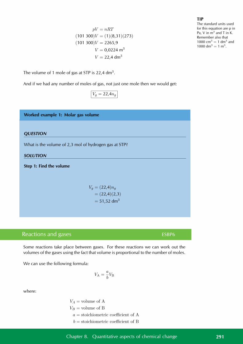
TIPThe standard units usedfor this equation are p inPa, V in m3 and T in K.Remember also that1000 cm3 = 1 dm3 and1000 dm3 = 1 m3.
pV = nRT
(101 300)V = (1)(8,31)(273)
(101 300)V = 2265,9
V = 0,0224 m3
V = 22,4 dm3
The volume of 1 mole of gas at STP is 22,4 dm3.
And if we had any number of moles of gas, not just one mole then we would get:
Vg = 22,4ng
Worked example 1: Molar gas volume
QUESTION
What is the volume of 2,3 mol of hydrogen gas at STP?
SOLUTION
Step 1: Find the volume
Vg = (22,4)ng
= (22,4)(2,3)
= 51,52 dm3
Reactions and gases ESBP6
Some reactions take place between gases. For these reactions we can work out thevolumes of the gases using the fact that volume is proportional to the number of moles.
We can use the following formula:
VA =a
bVB
where:
VA = volume of A
VB = volume of B
a = stoichiometric coefficient of A
b = stoichiometric coefficient of B
291Chapter 8. Quantitative aspects of chemical change
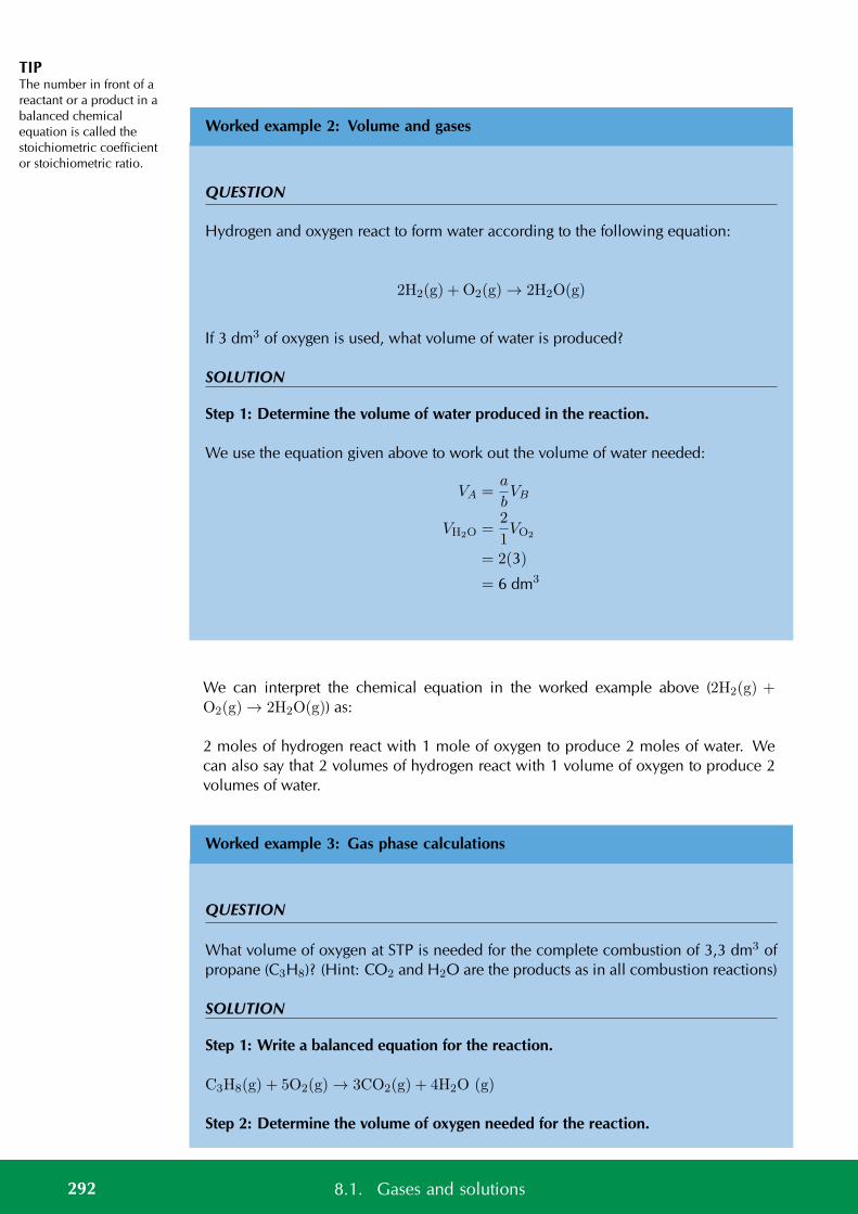
TIPThe number in front of areactant or a product in abalanced chemicalequation is called thestoichiometric coefficientor stoichiometric ratio.
Worked example 2: Volume and gases
QUESTION
Hydrogen and oxygen react to form water according to the following equation:
2H2(g) + O2(g) → 2H2O(g)
If 3 dm3 of oxygen is used, what volume of water is produced?
SOLUTION
Step 1: Determine the volume of water produced in the reaction.
We use the equation given above to work out the volume of water needed:
VA =a
bVB
VH2O =2
1VO2
= 2(3)
= 6 dm3
We can interpret the chemical equation in the worked example above (2H2(g) +O2(g) → 2H2O(g)) as:
2 moles of hydrogen react with 1 mole of oxygen to produce 2 moles of water. Wecan also say that 2 volumes of hydrogen react with 1 volume of oxygen to produce 2volumes of water.
Worked example 3: Gas phase calculations
QUESTION
What volume of oxygen at STP is needed for the complete combustion of 3,3 dm3 ofpropane (C3H8)? (Hint: CO2 and H2O are the products as in all combustion reactions)
SOLUTION
Step 1: Write a balanced equation for the reaction.
C3H8(g) + 5O2(g) → 3CO2(g) + 4H2O (g)
Step 2: Determine the volume of oxygen needed for the reaction.
292 8.1. Gases and solutions
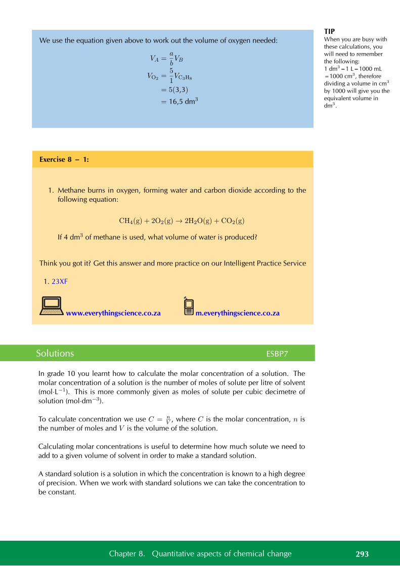
TIPWhen you are busy withthese calculations, youwill need to rememberthe following:1 dm3=1 L=1000 mL=1000 cm3, thereforedividing a volume in cm3
by 1000 will give you theequivalent volume indm3.
We use the equation given above to work out the volume of oxygen needed:
VA =a
bVB
VO2 =5
1VC3H8
= 5(3,3)
= 16,5 dm3
Exercise 8 – 1:
1. Methane burns in oxygen, forming water and carbon dioxide according to thefollowing equation:
CH4(g) + 2O2(g) → 2H2O(g) + CO2(g)
If 4 dm3 of methane is used, what volume of water is produced?
Think you got it? Get this answer and more practice on our Intelligent Practice Service
1. 23XF
www.everythingscience.co.za m.everythingscience.co.za
Solutions ESBP7
In grade 10 you learnt how to calculate the molar concentration of a solution. Themolar concentration of a solution is the number of moles of solute per litre of solvent(mol·L−1). This is more commonly given as moles of solute per cubic decimetre ofsolution (mol·dm−3).
To calculate concentration we use C = nV , where C is the molar concentration, n is
the number of moles and V is the volume of the solution.
Calculating molar concentrations is useful to determine how much solute we need toadd to a given volume of solvent in order to make a standard solution.
A standard solution is a solution in which the concentration is known to a high degreeof precision. When we work with standard solutions we can take the concentration tobe constant.
293Chapter 8. Quantitative aspects of chemical change
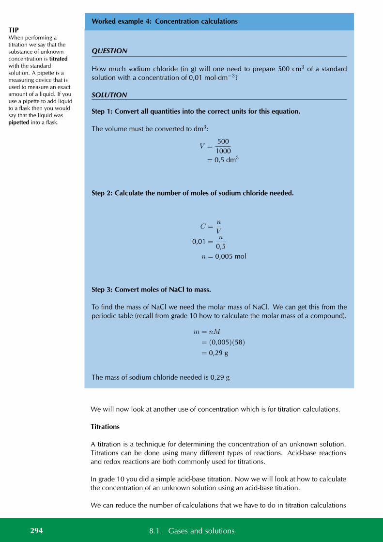
TIPWhen performing atitration we say that thesubstance of unknownconcentration is titratedwith the standardsolution. A pipette is ameasuring device that isused to measure an exactamount of a liquid. If youuse a pipette to add liquidto a flask then you wouldsay that the liquid waspipetted into a flask.
Worked example 4: Concentration calculations
QUESTION
How much sodium chloride (in g) will one need to prepare 500 cm3 of a standardsolution with a concentration of 0,01 mol·dm−3?
SOLUTION
Step 1: Convert all quantities into the correct units for this equation.
The volume must be converted to dm3:
V =500
1000= 0,5 dm3
Step 2: Calculate the number of moles of sodium chloride needed.
C =n
V
0,01 =n
0,5n = 0,005 mol
Step 3: Convert moles of NaCl to mass.
To find the mass of NaCl we need the molar mass of NaCl. We can get this from theperiodic table (recall from grade 10 how to calculate the molar mass of a compound).
m = nM
= (0,005)(58)
= 0,29 g
The mass of sodium chloride needed is 0,29 g
We will now look at another use of concentration which is for titration calculations.
Titrations
A titration is a technique for determining the concentration of an unknown solution.Titrations can be done using many different types of reactions. Acid-base reactionsand redox reactions are both commonly used for titrations.
In grade 10 you did a simple acid-base titration. Now we will look at how to calculatethe concentration of an unknown solution using an acid-base titration.
We can reduce the number of calculations that we have to do in titration calculations
294 8.1. Gases and solutions
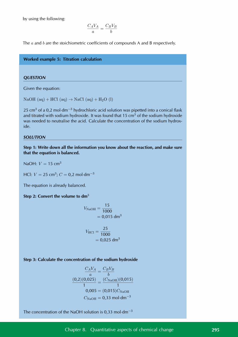
by using the following:
CAVA
a=
CBVB
b
The a and b are the stoichiometric coefficients of compounds A and B respectively.
Worked example 5: Titration calculation
QUESTION
Given the equation:
NaOH (aq) + HCl (aq) → NaCl (aq) + H2O (l)
25 cm3 of a 0,2 mol·dm−3 hydrochloric acid solution was pipetted into a conical flaskand titrated with sodium hydroxide. It was found that 15 cm3 of the sodium hydroxidewas needed to neutralise the acid. Calculate the concentration of the sodium hydrox-ide.
SOLUTION
Step 1: Write down all the information you know about the reaction, and make surethat the equation is balanced.
NaOH: V = 15 cm3
HCl: V = 25 cm3; C = 0,2 mol·dm−3
The equation is already balanced.
Step 2: Convert the volume to dm3
VNaOH =15
1000= 0,015 dm3
VHCl =25
1000= 0,025 dm3
Step 3: Calculate the concentration of the sodium hydroxide
CAVA
a=
CBVB
b(0,2)(0,025)
1=
(CNaOH)(0,015)1
0,005 = (0,015)CNaOH
CNaOH = 0,33 mol·dm−3
The concentration of the NaOH solution is 0,33 mol·dm−3
295Chapter 8. Quantitative aspects of chemical change
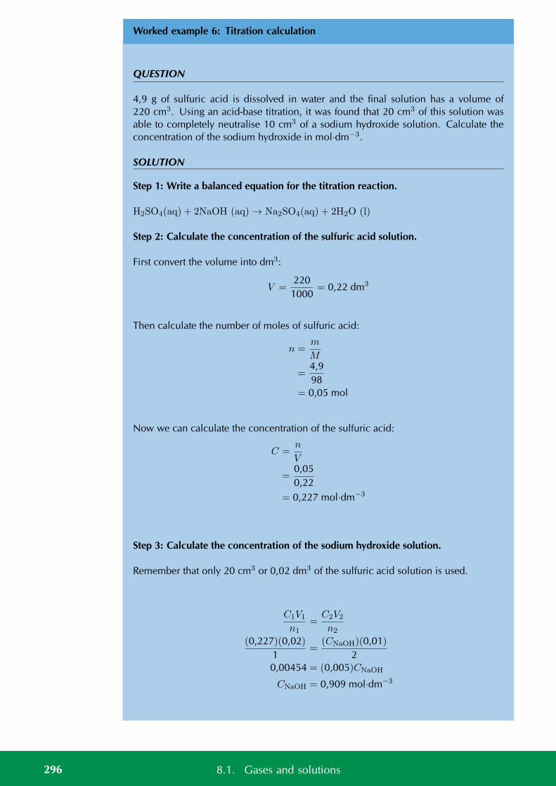
Worked example 6: Titration calculation
QUESTION
4,9 g of sulfuric acid is dissolved in water and the final solution has a volume of220 cm3. Using an acid-base titration, it was found that 20 cm3 of this solution wasable to completely neutralise 10 cm3 of a sodium hydroxide solution. Calculate theconcentration of the sodium hydroxide in mol·dm−3.
SOLUTION
Step 1: Write a balanced equation for the titration reaction.
H2SO4(aq) + 2NaOH (aq) → Na2SO4(aq) + 2H2O (l)
Step 2: Calculate the concentration of the sulfuric acid solution.
First convert the volume into dm3:
V =220
1000= 0,22 dm3
Then calculate the number of moles of sulfuric acid:
n =m
M
=4,998
= 0,05 mol
Now we can calculate the concentration of the sulfuric acid:
C =n
V
=0,050,22
= 0,227 mol·dm−3
Step 3: Calculate the concentration of the sodium hydroxide solution.
Remember that only 20 cm3 or 0,02 dm3 of the sulfuric acid solution is used.
C1V1
n1=
C2V2
n2
(0,227)(0,02)1
=(CNaOH)(0,01)
20,00454 = (0,005)CNaOH
CNaOH = 0,909 mol·dm−3
296 8.1. Gases and solutions
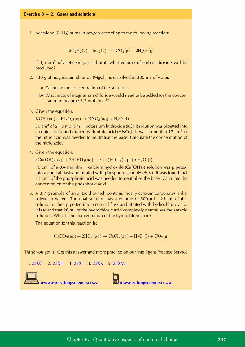
Exercise 8 – 2: Gases and solutions
1. Acetylene (C2H2) burns in oxygen according to the following reaction:
2C2H2(g) + 5O2(g) → 4CO2(g) + 2H2O (g)
If 3,5 dm3 of acetylene gas is burnt, what volume of carbon dioxide will beproduced?
2. 130 g of magnesium chloride (MgCl2) is dissolved in 300 mL of water.
a) Calculate the concentration of the solution.
b) What mass of magnesium chloride would need to be added for the concen-tration to become 6,7 mol·dm−3?
3. Given the equation:
KOH (aq) + HNO3(aq) → KNO3(aq) + H2O (l)
20 cm3 of a 1,3 mol·dm−3 potassium hydroxide (KOH) solution was pipetted intoa conical flask and titrated with nitric acid (HNO3). It was found that 17 cm3 ofthe nitric acid was needed to neutralise the base. Calculate the concentration ofthe nitric acid.
4. Given the equation:
3Ca(OH)2(aq) + 2H3PO4(aq) → Ca3(PO4)2(aq) + 6H2O (l)
10 cm3 of a 0,4 mol·dm−3 calcium hydroxide (Ca(OH)2) solution was pipettedinto a conical flask and titrated with phosphoric acid (H3PO4). It was found that11 cm3 of the phosphoric acid was needed to neutralise the base. Calculate theconcentration of the phosphoric acid.
5. A 3,7 g sample of an antacid (which contains mostly calcium carbonate) is dis-solved in water. The final solution has a volume of 500 mL. 25 mL of thissolution is then pipetted into a conical flask and titrated with hydrochloric acid.It is found that 20 mL of the hydrochloric acid completely neutralises the antacidsolution. What is the concentration of the hydrochloric acid?
The equation for this reaction is:
CaCO3(aq) + 2HCl (aq) → CaCl2(aq) + H2O (l) + CO2(g)
Think you got it? Get this answer and more practice on our Intelligent Practice Service
1. 23XG 2. 23XH 3. 23XJ 4. 23XK 5. 23XM
www.everythingscience.co.za m.everythingscience.co.za
297Chapter 8. Quantitative aspects of chemical change
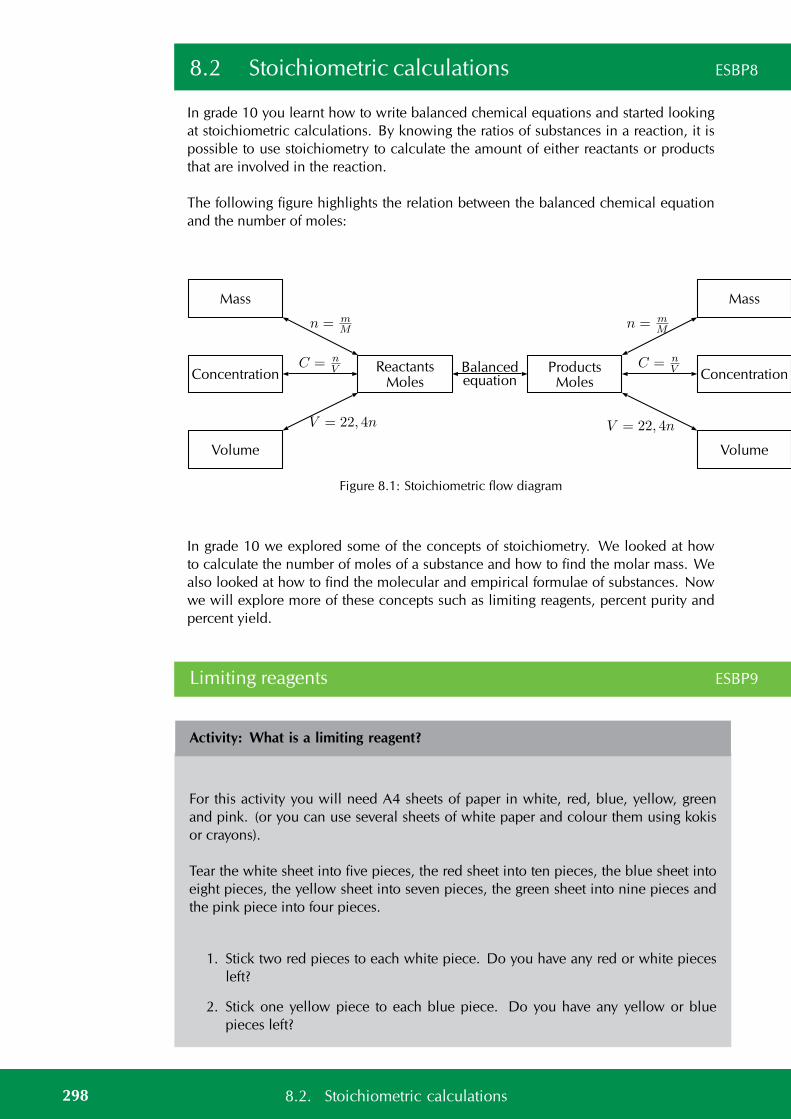
8.2 Stoichiometric calculations ESBP8
In grade 10 you learnt how to write balanced chemical equations and started lookingat stoichiometric calculations. By knowing the ratios of substances in a reaction, it ispossible to use stoichiometry to calculate the amount of either reactants or productsthat are involved in the reaction.
The following figure highlights the relation between the balanced chemical equationand the number of moles:
Mass
Concentration
Volume
ReactantsMoles
ProductsMoles
Balancedequation
Mass
Concentration
Volume
n = mM
C = nV
V = 22, 4n
n = mM
C = nV
V = 22, 4n
Figure 8.1: Stoichiometric flow diagram
In grade 10 we explored some of the concepts of stoichiometry. We looked at howto calculate the number of moles of a substance and how to find the molar mass. Wealso looked at how to find the molecular and empirical formulae of substances. Nowwe will explore more of these concepts such as limiting reagents, percent purity andpercent yield.
Limiting reagents ESBP9
Activity: What is a limiting reagent?
For this activity you will need A4 sheets of paper in white, red, blue, yellow, greenand pink. (or you can use several sheets of white paper and colour them using kokisor crayons).
Tear the white sheet into five pieces, the red sheet into ten pieces, the blue sheet intoeight pieces, the yellow sheet into seven pieces, the green sheet into nine pieces andthe pink piece into four pieces.
1. Stick two red pieces to each white piece. Do you have any red or white piecesleft?
2. Stick one yellow piece to each blue piece. Do you have any yellow or bluepieces left?
298 8.2. Stoichiometric calculations
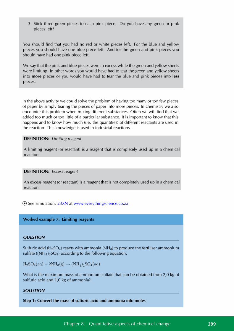
3. Stick three green pieces to each pink piece. Do you have any green or pinkpieces left?
You should find that you had no red or white pieces left. For the blue and yellowpieces you should have one blue piece left. And for the green and pink pieces youshould have had one pink piece left.
We say that the pink and blue pieces were in excess while the green and yellow sheetswere limiting. In other words you would have had to tear the green and yellow sheetsinto more pieces or you would have had to tear the blue and pink pieces into lesspieces.
In the above activity we could solve the problem of having too many or too few piecesof paper by simply tearing the pieces of paper into more pieces. In chemistry we alsoencounter this problem when mixing different substances. Often we will find that weadded too much or too little of a particular substance. It is important to know that thishappens and to know how much (i.e. the quantities) of different reactants are used inthe reaction. This knowledge is used in industrial reactions.
DEFINITION: Limiting reagent
A limiting reagent (or reactant) is a reagent that is completely used up in a chemicalreaction.
DEFINITION: Excess reagent
An excess reagent (or reactant) is a reagent that is not completely used up in a chemicalreaction.
See simulation: 23XN at www.everythingscience.co.za
Worked example 7: Limiting reagents
QUESTION
Sulfuric acid (H2SO4) reacts with ammonia (NH3) to produce the fertiliser ammoniumsulfate ((NH4)2SO4) according to the following equation:
H2SO4(aq) + 2NH3(g) → (NH4)2SO4(aq)
What is the maximum mass of ammonium sulfate that can be obtained from 2,0 kg ofsulfuric acid and 1,0 kg of ammonia?
SOLUTION
Step 1: Convert the mass of sulfuric acid and ammonia into moles
299Chapter 8. Quantitative aspects of chemical change
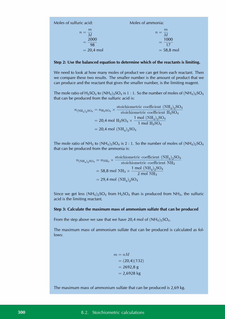
Moles of sulfuric acid:
n =m
M
=2000
98= 20,4 mol
Moles of ammonia:
n =m
M
=1000
17= 58,8 mol
Step 2: Use the balanced equation to determine which of the reactants is limiting.
We need to look at how many moles of product we can get from each reactant. Thenwe compare these two results. The smaller number is the amount of product that wecan produce and the reactant that gives the smaller number, is the limiting reagent.
The mole ratio of H2SO4 to (NH4)2SO4 is 1 : 1. So the number of moles of (NH4)2SO4
that can be produced from the sulfuric acid is:
n(NH4)2SO4= nH2SO4 ×
stoichiometric coefficient (NH4)2SO4
stoichiometric coefficient H2SO4
= 20,4 mol H2SO4 ×1 mol (NH4)2SO4
1 mol H2SO4
= 20,4 mol (NH4)2SO4
The mole ratio of NH3 to (NH4)2SO4 is 2 : 1. So the number of moles of (NH4)2SO4
that can be produced from the ammonia is:
n(NH4)2SO4= nNH3 ×
stoichiometric coefficient (NH4)2SO4
stoichiometric coefficient NH3
= 58,8 mol NH3 ×1 mol (NH4)2SO4
2 mol NH3
= 29,4 mol (NH4)2SO4
Since we get less (NH4)2SO4 from H2SO4 than is produced from NH3, the sulfuricacid is the limiting reactant.
Step 3: Calculate the maximum mass of ammonium sulfate that can be produced
From the step above we saw that we have 20,4 mol of (NH4)2SO4.
The maximum mass of ammonium sulfate that can be produced is calculated as fol-lows:
m = nM
= (20,4)(132)
= 2692,8 g
= 2,6928 kg
The maximum mass of ammonium sulfate that can be produced is 2,69 kg.
300 8.2. Stoichiometric calculations

Exercise 8 – 3:
1. When an electrical current is passed through a sodium chloride solution, sodiumhydroxide can be produced according to the following equation:
2NaCl (aq) + H2O (l) → Cl2(g) + H2(g) + 2NaOH (aq)
What is the maximum mass of sodium hydroxide that can be obtained from4,0 kg of sodium chloride and 3,0 kg of water?
Think you got it? Get this answer and more practice on our Intelligent Practice Service
1. 23XP
www.everythingscience.co.za m.everythingscience.co.za
Percent yield ESBPB
The percent yield of a reaction is very important as it tells us how efficient a reactionis. A reaction that has a low percent yield is not very useful in industry. If you aremaking a new medicine or pesticide and your reaction has a low percent yield thenyou would search for a different way of doing the reaction. This reduces the amountof (often very expensive) chemicals that you use and reduces waste.
The percent yield can be calculated using:
%yield =actual yield
theoretical yield× 100
where the actual yield is the amount of product that is produced when you carry outthe reaction and the theoretical yield is the amount of product that you calculate forthe reaction using stoichiometric methods.
Worked example 8: Percent yield
QUESTION
Sulfuric acid (H2SO4) reacts with ammonia (NH3) to produce the fertiliser ammoniumsulfate ((NH4)2SO4) according to the following equation:
H2SO4(aq) + 2NH3(g) → (NH4)2SO4(aq)
A factory worker carries out the above reaction (using 2,0 kg of sulfuric acid and 1,0 kgof ammonia) and gets 2,5 kg of ammonium sulfate. What is the percentage yield ofthe reaction?
SOLUTION
Step 1: Determine which is the limiting reagent
301Chapter 8. Quantitative aspects of chemical change
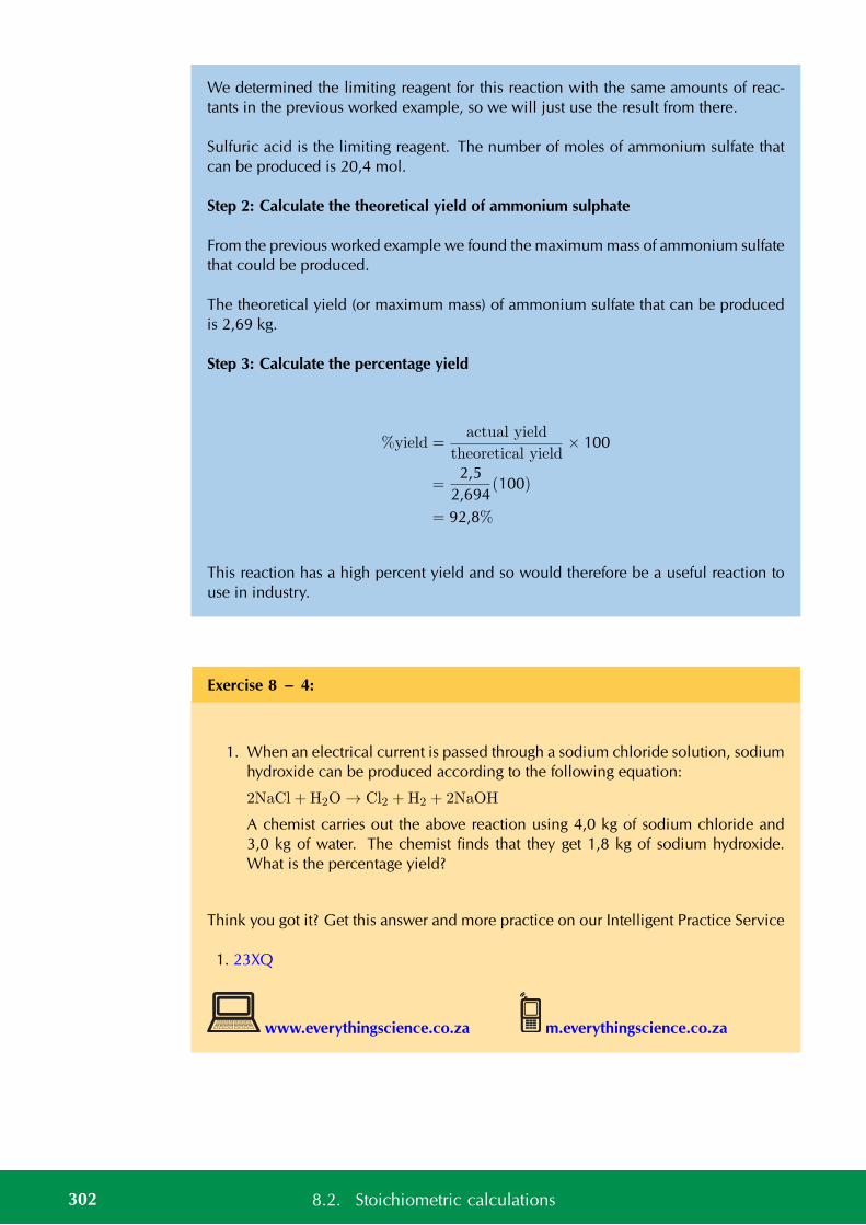
We determined the limiting reagent for this reaction with the same amounts of reac-tants in the previous worked example, so we will just use the result from there.
Sulfuric acid is the limiting reagent. The number of moles of ammonium sulfate thatcan be produced is 20,4 mol.
Step 2: Calculate the theoretical yield of ammonium sulphate
From the previous worked example we found the maximum mass of ammonium sulfatethat could be produced.
The theoretical yield (or maximum mass) of ammonium sulfate that can be producedis 2,69 kg.
Step 3: Calculate the percentage yield
%yield =actual yield
theoretical yield× 100
=2,5
2,694(100)
= 92,8%
This reaction has a high percent yield and so would therefore be a useful reaction touse in industry.
Exercise 8 – 4:
1. When an electrical current is passed through a sodium chloride solution, sodiumhydroxide can be produced according to the following equation:
2NaCl + H2O → Cl2 +H2 + 2NaOH
A chemist carries out the above reaction using 4,0 kg of sodium chloride and3,0 kg of water. The chemist finds that they get 1,8 kg of sodium hydroxide.What is the percentage yield?
Think you got it? Get this answer and more practice on our Intelligent Practice Service
1. 23XQ
www.everythingscience.co.za m.everythingscience.co.za
302 8.2. Stoichiometric calculations
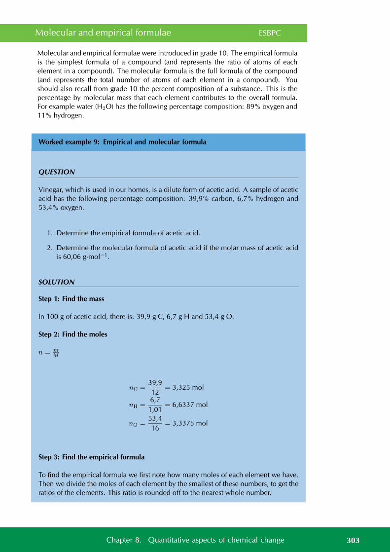
Molecular and empirical formulae ESBPC
Molecular and empirical formulae were introduced in grade 10. The empirical formulais the simplest formula of a compound (and represents the ratio of atoms of eachelement in a compound). The molecular formula is the full formula of the compound(and represents the total number of atoms of each element in a compound). Youshould also recall from grade 10 the percent composition of a substance. This is thepercentage by molecular mass that each element contributes to the overall formula.For example water (H2O) has the following percentage composition: 89% oxygen and11% hydrogen.
Worked example 9: Empirical and molecular formula
QUESTION
Vinegar, which is used in our homes, is a dilute form of acetic acid. A sample of aceticacid has the following percentage composition: 39,9% carbon, 6,7% hydrogen and53,4% oxygen.
1. Determine the empirical formula of acetic acid.
2. Determine the molecular formula of acetic acid if the molar mass of acetic acidis 60,06 g·mol−1.
SOLUTION
Step 1: Find the mass
In 100 g of acetic acid, there is: 39,9 g C, 6,7 g H and 53,4 g O.
Step 2: Find the moles
n = mM
nC =39,912
= 3,325 mol
nH =6,7
1,01= 6,6337 mol
nO =53,416
= 3,3375 mol
Step 3: Find the empirical formula
To find the empirical formula we first note how many moles of each element we have.Then we divide the moles of each element by the smallest of these numbers, to get theratios of the elements. This ratio is rounded off to the nearest whole number.
303Chapter 8. Quantitative aspects of chemical change

C H O3,325 6,6337 3,3375
3,3253,325
6,63373,325
3,33753,325
1 2 1
The empirical formula is CH2O.
Step 4: Find the molecular formula
The molar mass of acetic acid using the empirical formula (CH2O) is 30,02 g·mol−1.However the question gives the molar mass as 60,06 g·mol−1. Therefore the actualnumber of moles of each element must be double what it is in the empirical formula(
60,0630,02
= 2)
. The molecular formula is therefore C2H4O2 or CH3COOH
Exercise 8 – 5:
1. A sample of oxalic acid has the following percentage composition: 26,7% car-bon, 2,2% hydrogen and 71,1% oxygen.
Determine the molecular formula of oxalic acid if the molar mass of oxalic acidis 90 g·mol−1.
Think you got it? Get this answer and more practice on our Intelligent Practice Service
1. 23XR
www.everythingscience.co.za m.everythingscience.co.za
Percent purity ESBPD
The final use of stoichiometric calculations that we will look at is to determine the per-cent purity of a sample. Percent purity is important since when you make a compoundyou may have a small amount of impurity in the sample and you would need to keepthis below a certain level. Or you may need to know how much of a particular ion isdissolved in water to determine if it is below the legally allowed level.
Percent purity can be calculated using:
%purity =mass of compound
mass of sample× 100
304 8.2. Stoichiometric calculations
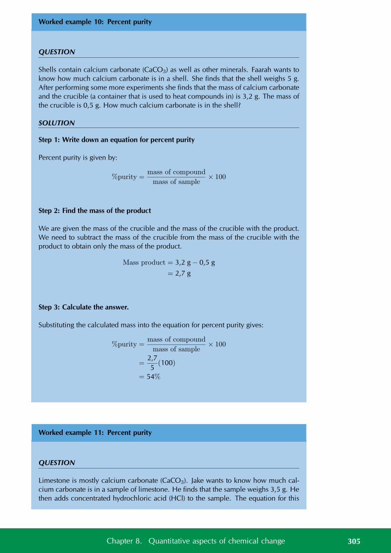
Worked example 10: Percent purity
QUESTION
Shells contain calcium carbonate (CaCO3) as well as other minerals. Faarah wants toknow how much calcium carbonate is in a shell. She finds that the shell weighs 5 g.After performing some more experiments she finds that the mass of calcium carbonateand the crucible (a container that is used to heat compounds in) is 3,2 g. The mass ofthe crucible is 0,5 g. How much calcium carbonate is in the shell?
SOLUTION
Step 1: Write down an equation for percent purity
Percent purity is given by:
%purity =mass of compound
mass of sample× 100
Step 2: Find the mass of the product
We are given the mass of the crucible and the mass of the crucible with the product.We need to subtract the mass of the crucible from the mass of the crucible with theproduct to obtain only the mass of the product.
Mass product = 3,2 g − 0,5 g
= 2,7 g
Step 3: Calculate the answer.
Substituting the calculated mass into the equation for percent purity gives:
%purity =mass of compound
mass of sample× 100
=2,75
(100)
= 54%
Worked example 11: Percent purity
QUESTION
Limestone is mostly calcium carbonate (CaCO3). Jake wants to know how much cal-cium carbonate is in a sample of limestone. He finds that the sample weighs 3,5 g. Hethen adds concentrated hydrochloric acid (HCl) to the sample. The equation for this
305Chapter 8. Quantitative aspects of chemical change
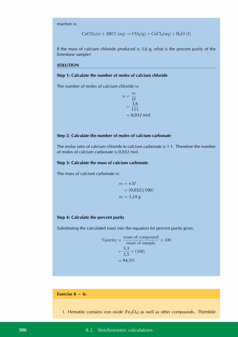
reaction is:
CaCO3(s) + 2HCl (aq) → CO2(g) + CaCl2(aq) + H2O (l)
If the mass of calcium chloride produced is 3,6 g, what is the percent purity of thelimestone sample?
SOLUTION
Step 1: Calculate the number of moles of calcium chloride
The number of moles of calcium chloride is:
n =m
M
=3,6111
= 0,032 mol
Step 2: Calculate the number of moles of calcium carbonate
The molar ratio of calcium chloride to calcium carbonate is 1:1. Therefore the numberof moles of calcium carbonate is 0,032 mol.
Step 3: Calculate the mass of calcium carbonate
The mass of calcium carbonate is:
m = nM
= (0,032)(100)
m = 3,24 g
Step 4: Calculate the percent purity
Substituting the calculated mass into the equation for percent purity gives:
%purity =mass of compound
mass of sample× 100
=3,33,5
× (100)
= 94,3%
Exercise 8 – 6:
1. Hematite contains iron oxide (Fe2O3) as well as other compounds. Thembile
306 8.2. Stoichiometric calculations

wants to know how much iron oxide is in a sample of hematite. He finds thatthe sample of hematite weighs 6,2 g. After performing some experiments hefinds that the mass of iron oxide and the crucible (a container that is used to heatcompounds in) is 4,8 g. The mass of the crucible is 0,5 g. How much iron oxideis in the sample of hematite?
Think you got it? Get this answer and more practice on our Intelligent Practice Service
1. 23XS
www.everythingscience.co.za m.everythingscience.co.za
See video: 23XT at www.everythingscience.co.za
General experiment: The thermal decomposition of lead(II) nitrate
Aim:
To observe what happens when lead(II) nitrate is heated.
Apparatus:
• Bunsen burner
• Test tube (glass)
• Test tube holder
• 0,5 g lead(II) nitrate
Method:
WARNING!
Lead(II) nitrate produces toxic nitrogen dioxide on heating.
1. Place the lead(II) nitrate sample in the test tube.
2. Light the Bunsen burner and carefully hold the test tube in the flame. Rememberto point the mouth of the test tube away from you.
3. Observe what happens.
Results:
A crackling noise is heard on heating the sample and a small amount of a brownishcoloured gas is noted. The white powder became yellow.
307Chapter 8. Quantitative aspects of chemical change
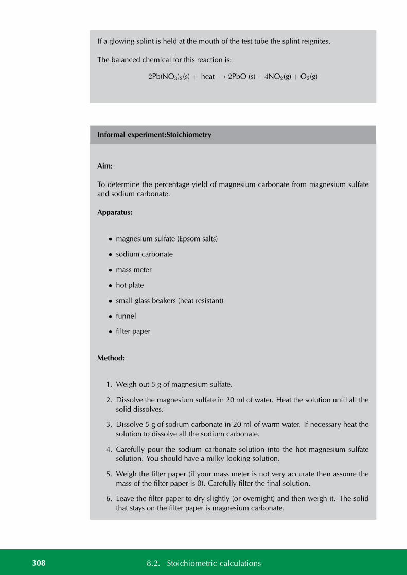
If a glowing splint is held at the mouth of the test tube the splint reignites.
The balanced chemical for this reaction is:
2Pb(NO3)2(s) + heat → 2PbO (s) + 4NO2(g) + O2(g)
Informal experiment:Stoichiometry
Aim:
To determine the percentage yield of magnesium carbonate from magnesium sulfateand sodium carbonate.
Apparatus:
• magnesium sulfate (Epsom salts)
• sodium carbonate
• mass meter
• hot plate
• small glass beakers (heat resistant)
• funnel
• filter paper
Method:
1. Weigh out 5 g of magnesium sulfate.
2. Dissolve the magnesium sulfate in 20 ml of water. Heat the solution until all thesolid dissolves.
3. Dissolve 5 g of sodium carbonate in 20 ml of warm water. If necessary heat thesolution to dissolve all the sodium carbonate.
4. Carefully pour the sodium carbonate solution into the hot magnesium sulfatesolution. You should have a milky looking solution.
5. Weigh the filter paper (if your mass meter is not very accurate then assume themass of the filter paper is 0). Carefully filter the final solution.
6. Leave the filter paper to dry slightly (or overnight) and then weigh it. The solidthat stays on the filter paper is magnesium carbonate.
308 8.2. Stoichiometric calculations
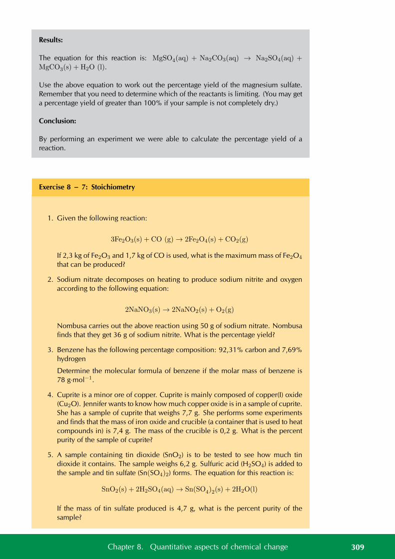
Results:
The equation for this reaction is: MgSO4(aq) + Na2CO3(aq) → Na2SO4(aq) +MgCO3(s) + H2O (l).
Use the above equation to work out the percentage yield of the magnesium sulfate.Remember that you need to determine which of the reactants is limiting. (You may geta percentage yield of greater than 100% if your sample is not completely dry.)
Conclusion:
By performing an experiment we were able to calculate the percentage yield of areaction.
Exercise 8 – 7: Stoichiometry
1. Given the following reaction:
3Fe2O3(s) + CO (g) → 2Fe2O4(s) + CO2(g)
If 2,3 kg of Fe2O3 and 1,7 kg of CO is used, what is the maximum mass of Fe2O4
that can be produced?
2. Sodium nitrate decomposes on heating to produce sodium nitrite and oxygenaccording to the following equation:
2NaNO3(s) → 2NaNO2(s) + O2(g)
Nombusa carries out the above reaction using 50 g of sodium nitrate. Nombusafinds that they get 36 g of sodium nitrite. What is the percentage yield?
3. Benzene has the following percentage composition: 92,31% carbon and 7,69%hydrogen
Determine the molecular formula of benzene if the molar mass of benzene is78 g·mol−1.
4. Cuprite is a minor ore of copper. Cuprite is mainly composed of copper(I) oxide(Cu2O). Jennifer wants to know how much copper oxide is in a sample of cuprite.She has a sample of cuprite that weighs 7,7 g. She performs some experimentsand finds that the mass of iron oxide and crucible (a container that is used to heatcompounds in) is 7,4 g. The mass of the crucible is 0,2 g. What is the percentpurity of the sample of cuprite?
5. A sample containing tin dioxide (SnO2) is to be tested to see how much tindioxide it contains. The sample weighs 6,2 g. Sulfuric acid (H2SO4) is added tothe sample and tin sulfate (Sn(SO4)2) forms. The equation for this reaction is:
SnO2(s) + 2H2SO4(aq) → Sn(SO4)2(s) + 2H2O(l)
If the mass of tin sulfate produced is 4,7 g, what is the percent purity of thesample?
309Chapter 8. Quantitative aspects of chemical change
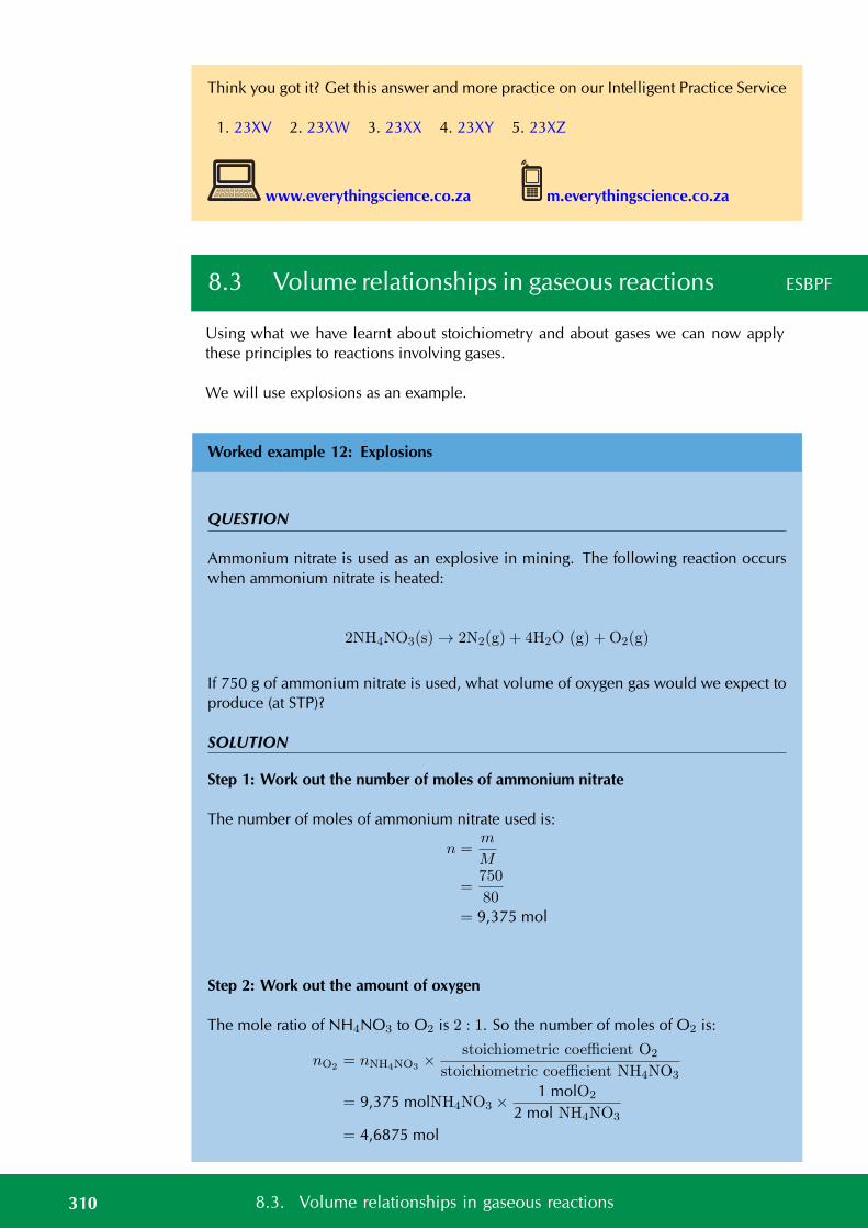
Think you got it? Get this answer and more practice on our Intelligent Practice Service
1. 23XV 2. 23XW 3. 23XX 4. 23XY 5. 23XZ
www.everythingscience.co.za m.everythingscience.co.za
8.3 Volume relationships in gaseous reactions ESBPF
Using what we have learnt about stoichiometry and about gases we can now applythese principles to reactions involving gases.
We will use explosions as an example.
Worked example 12: Explosions
QUESTION
Ammonium nitrate is used as an explosive in mining. The following reaction occurswhen ammonium nitrate is heated:
2NH4NO3(s) → 2N2(g) + 4H2O (g) + O2(g)
If 750 g of ammonium nitrate is used, what volume of oxygen gas would we expect toproduce (at STP)?
SOLUTION
Step 1: Work out the number of moles of ammonium nitrate
The number of moles of ammonium nitrate used is:
n =m
M
=750
80= 9,375 mol
Step 2: Work out the amount of oxygen
The mole ratio of NH4NO3 to O2 is 2 : 1. So the number of moles of O2 is:
nO2 = nNH4NO3 ×stoichiometric coefficient O2
stoichiometric coefficient NH4NO3
= 9,375 molNH4NO3 ×1 molO2
2 mol NH4NO3
= 4,6875 mol
310 8.3. Volume relationships in gaseous reactions
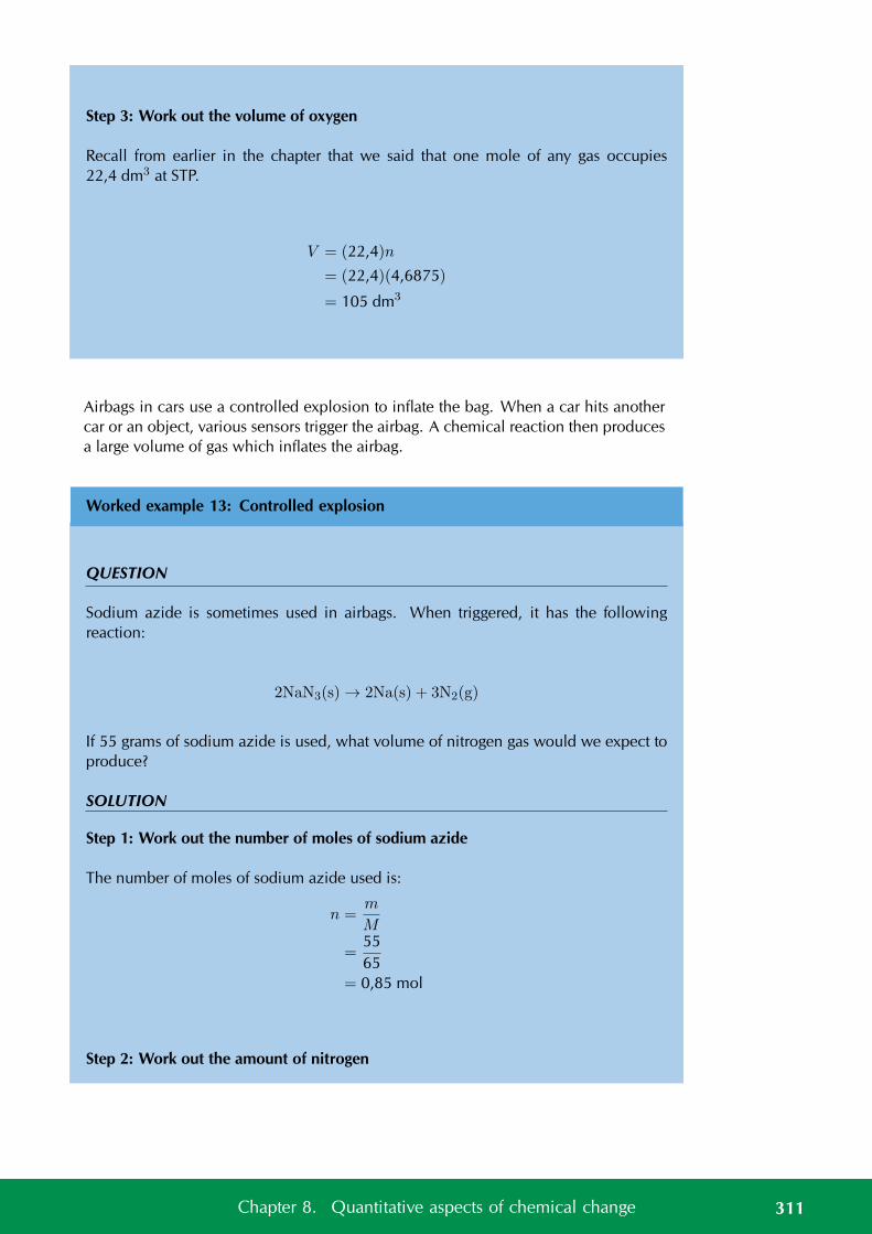
Step 3: Work out the volume of oxygen
Recall from earlier in the chapter that we said that one mole of any gas occupies22,4 dm3 at STP.
V = (22,4)n
= (22,4)(4,6875)
= 105 dm3
Airbags in cars use a controlled explosion to inflate the bag. When a car hits anothercar or an object, various sensors trigger the airbag. A chemical reaction then producesa large volume of gas which inflates the airbag.
Worked example 13: Controlled explosion
QUESTION
Sodium azide is sometimes used in airbags. When triggered, it has the followingreaction:
2NaN3(s) → 2Na(s) + 3N2(g)
If 55 grams of sodium azide is used, what volume of nitrogen gas would we expect toproduce?
SOLUTION
Step 1: Work out the number of moles of sodium azide
The number of moles of sodium azide used is:
n =m
M
=5565
= 0,85 mol
Step 2: Work out the amount of nitrogen
311Chapter 8. Quantitative aspects of chemical change
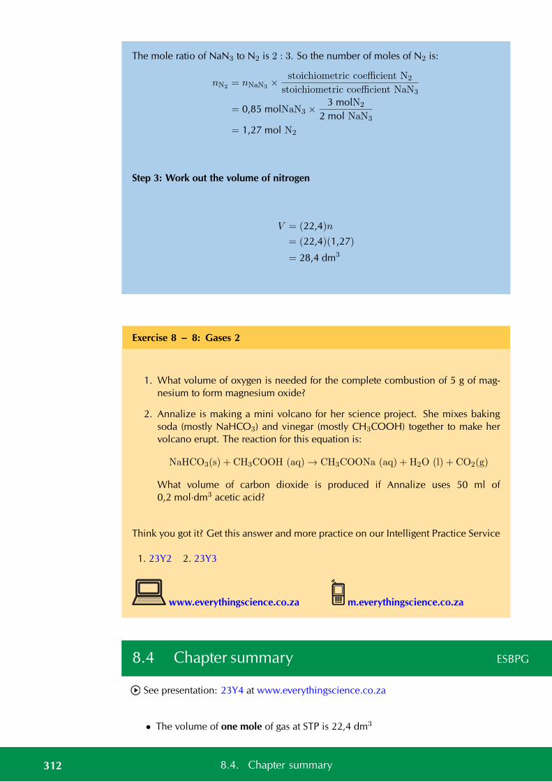
The mole ratio of NaN3 to N2 is 2 : 3. So the number of moles of N2 is:
nN2 = nNaN3 ×stoichiometric coefficient N2
stoichiometric coefficient NaN3
= 0,85 molNaN3 ×3 molN2
2 mol NaN3
= 1,27 mol N2
Step 3: Work out the volume of nitrogen
V = (22,4)n
= (22,4)(1,27)
= 28,4 dm3
Exercise 8 – 8: Gases 2
1. What volume of oxygen is needed for the complete combustion of 5 g of mag-nesium to form magnesium oxide?
2. Annalize is making a mini volcano for her science project. She mixes bakingsoda (mostly NaHCO3) and vinegar (mostly CH3COOH) together to make hervolcano erupt. The reaction for this equation is:
NaHCO3(s) + CH3COOH (aq) → CH3COONa (aq) + H2O (l) + CO2(g)
What volume of carbon dioxide is produced if Annalize uses 50 ml of0,2 mol·dm3 acetic acid?
Think you got it? Get this answer and more practice on our Intelligent Practice Service
1. 23Y2 2. 23Y3
www.everythingscience.co.za m.everythingscience.co.za
8.4 Chapter summary ESBPG
See presentation: 23Y4 at www.everythingscience.co.za
• The volume of one mole of gas at STP is 22,4 dm3
312 8.4. Chapter summary
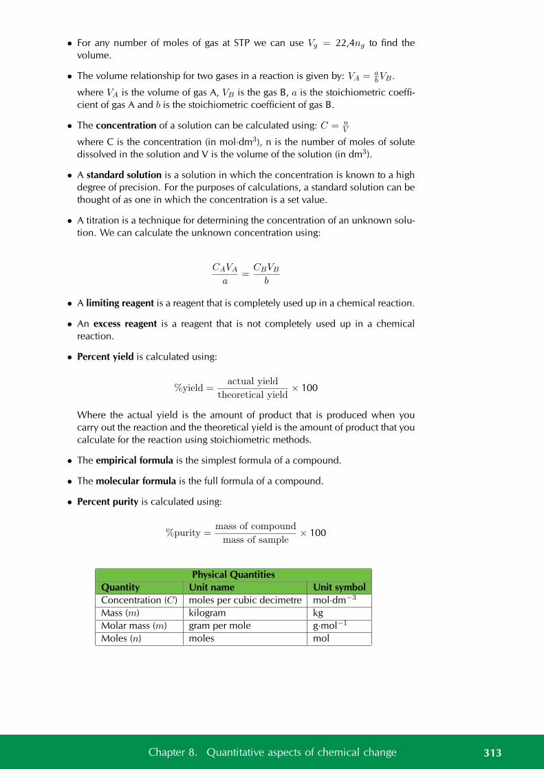
• For any number of moles of gas at STP we can use Vg = 22,4ng to find thevolume.
• The volume relationship for two gases in a reaction is given by: VA = abVB.
where VA is the volume of gas A, VB is the gas B, a is the stoichiometric coeffi-cient of gas A and b is the stoichiometric coefficient of gas B.
• The concentration of a solution can be calculated using: C = nV
where C is the concentration (in mol·dm3), n is the number of moles of solutedissolved in the solution and V is the volume of the solution (in dm3).
• A standard solution is a solution in which the concentration is known to a highdegree of precision. For the purposes of calculations, a standard solution can bethought of as one in which the concentration is a set value.
• A titration is a technique for determining the concentration of an unknown solu-tion. We can calculate the unknown concentration using:
CAVA
a=
CBVB
b
• A limiting reagent is a reagent that is completely used up in a chemical reaction.
• An excess reagent is a reagent that is not completely used up in a chemicalreaction.
• Percent yield is calculated using:
%yield =actual yield
theoretical yield× 100
Where the actual yield is the amount of product that is produced when youcarry out the reaction and the theoretical yield is the amount of product that youcalculate for the reaction using stoichiometric methods.
• The empirical formula is the simplest formula of a compound.
• The molecular formula is the full formula of a compound.
• Percent purity is calculated using:
%purity =mass of compound
mass of sample× 100
Physical QuantitiesQuantity Unit name Unit symbolConcentration (C) moles per cubic decimetre mol·dm−3
Mass (m) kilogram kgMolar mass (m) gram per mole g·mol−1
Moles (n) moles mol
313Chapter 8. Quantitative aspects of chemical change
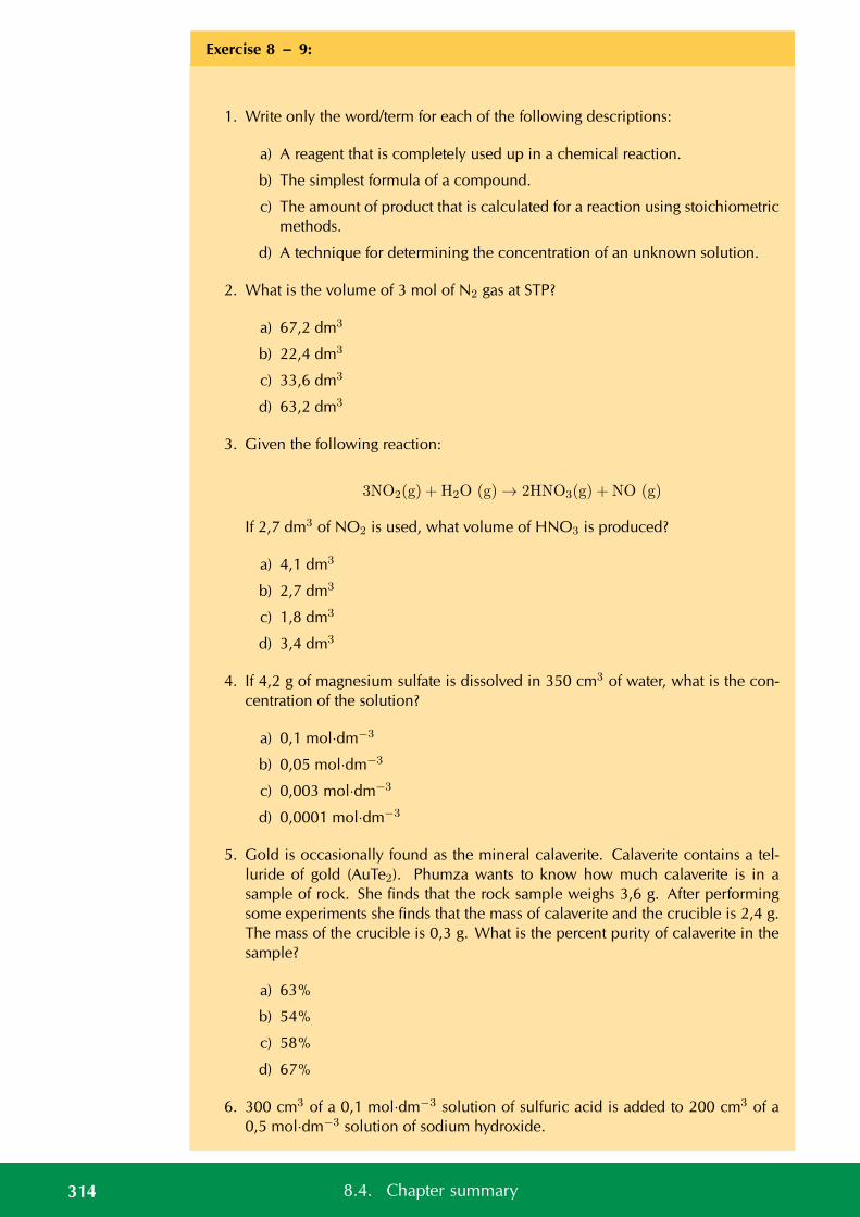
Exercise 8 – 9:
1. Write only the word/term for each of the following descriptions:
a) A reagent that is completely used up in a chemical reaction.
b) The simplest formula of a compound.
c) The amount of product that is calculated for a reaction using stoichiometricmethods.
d) A technique for determining the concentration of an unknown solution.
2. What is the volume of 3 mol of N2 gas at STP?
a) 67,2 dm3
b) 22,4 dm3
c) 33,6 dm3
d) 63,2 dm3
3. Given the following reaction:
3NO2(g) + H2O (g) → 2HNO3(g) + NO (g)
If 2,7 dm3 of NO2 is used, what volume of HNO3 is produced?
a) 4,1 dm3
b) 2,7 dm3
c) 1,8 dm3
d) 3,4 dm3
4. If 4,2 g of magnesium sulfate is dissolved in 350 cm3 of water, what is the con-centration of the solution?
a) 0,1 mol·dm−3
b) 0,05 mol·dm−3
c) 0,003 mol·dm−3
d) 0,0001 mol·dm−3
5. Gold is occasionally found as the mineral calaverite. Calaverite contains a tel-luride of gold (AuTe2). Phumza wants to know how much calaverite is in asample of rock. She finds that the rock sample weighs 3,6 g. After performingsome experiments she finds that the mass of calaverite and the crucible is 2,4 g.The mass of the crucible is 0,3 g. What is the percent purity of calaverite in thesample?
a) 63%
b) 54%
c) 58%
d) 67%
6. 300 cm3 of a 0,1 mol·dm−3 solution of sulfuric acid is added to 200 cm3 of a0,5 mol·dm−3 solution of sodium hydroxide.
314 8.4. Chapter summary
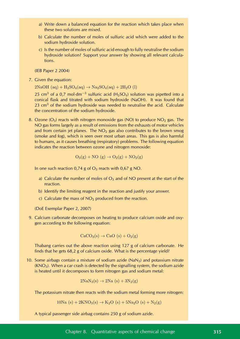
a) Write down a balanced equation for the reaction which takes place whenthese two solutions are mixed.
b) Calculate the number of moles of sulfuric acid which were added to thesodium hydroxide solution.
c) Is the number of moles of sulfuric acid enough to fully neutralise the sodiumhydroxide solution? Support your answer by showing all relevant calcula-tions.
(IEB Paper 2 2004)
7. Given the equation:
2NaOH (aq) + H2SO4(aq) → Na2SO4(aq) + 2H2O (l)
25 cm3 of a 0,7 mol·dm−3 sulfuric acid (H2SO4) solution was pipetted into aconical flask and titrated with sodium hydroxide (NaOH). It was found that23 cm3 of the sodium hydroxide was needed to neutralise the acid. Calculatethe concentration of the sodium hydroxide.
8. Ozone (O3) reacts with nitrogen monoxide gas (NO) to produce NO2 gas. TheNO gas forms largely as a result of emissions from the exhausts of motor vehiclesand from certain jet planes. The NO2 gas also contributes to the brown smog(smoke and fog), which is seen over most urban areas. This gas is also harmfulto humans, as it causes breathing (respiratory) problems. The following equationindicates the reaction between ozone and nitrogen monoxide:
O3(g) + NO (g) → O2(g) + NO2(g)
In one such reaction 0,74 g of O3 reacts with 0,67 g NO.
a) Calculate the number of moles of O3 and of NO present at the start of thereaction.
b) Identify the limiting reagent in the reaction and justify your answer.
c) Calculate the mass of NO2 produced from the reaction.
(DoE Exemplar Paper 2, 2007)
9. Calcium carbonate decomposes on heating to produce calcium oxide and oxy-gen according to the following equation:
CaCO3(s) → CaO (s) + O2(g)
Thabang carries out the above reaction using 127 g of calcium carbonate. Hefinds that he gets 68,2 g of calcium oxide. What is the percentage yield?
10. Some airbags contain a mixture of sodium azide (NaN3) and potassium nitrate(KNO3). When a car crash is detected by the signalling system, the sodium azideis heated until it decomposes to form nitrogen gas and sodium metal:
2NaN3(s) → 2Na (s) + 3N2(g)
The potassium nitrate then reacts with the sodium metal forming more nitrogen:
10Na (s) + 2KNO3(s) → K2O (s) + 5Na2O (s) + N2(g)
A typical passenger side airbag contains 250 g of sodium azide.
315Chapter 8. Quantitative aspects of chemical change
a) What mass of sodium metal is formed in the first reaction?
b) What is the total volume of nitrogen gas formed from both reactions?
c) How much potassium nitrate (in g) is needed for all the sodium to be usedup in the second reaction?
11. Chlorofluorocarbons (CFC’s) are a class of compounds that have a long historyof use in refrigerators. CFC’s are slowly being phased out as they deplete theamount of ozone in the ozone layer. Jabu has a sample of a CFC that has the fol-lowing percentage composition: 14,05% carbon, 41,48% chlorine and 44,46%fluorine.
Determine the molecular formula of this CFC if the molar mass is 171 g·mol−1.
12. A sample containing tin dioxide (SnO2) is to be tested to see how much tindioxide it contains. The sample weighs 6,2 g. Sulfuric acid (H2SO4) is added tothe sample and tin sulfate (Sn(SO4)2) forms. The equation for this reaction is:
SnO2(s) + 2H2SO4(aq) → Sn(SO4)2(s) + 2H2O (l)
If the mass of tin sulfate produced is 4,7 g, what is the percent purity of thesample?
13. Syngas (synthesis gas) is a mixture of carbon monoxide and hydrogen. Syngascan be produced from methane using:
CH4(g) + H2O (g) → CO (g) + 3H2(g)
Neels wants to make a mixture of syngas that has three times the volume ofhydrogen gas.
a) If the volume of methane used is 4 dm3, what volume of carbon monoxideand hydrogen will be produced?
b) Will this amount of methane produce the correct mixture?
Think you got it? Get this answer and more practice on our Intelligent Practice Service
1a. 23Y5 1b. 23Y6 1c. 23Y7 1d. 23Y8 2. 23Y9 3. 23YB4. 23YC 5. 23YD 6. 23YF 7. 23YG 8. 23YH 9. 23YJ
10. 23YK 11. 23YM 12. 23YN 13. 23YP
www.everythingscience.co.za m.everythingscience.co.za
316 8.4. Chapter summary

CHAPTER 9
Electrostatics
9.1 Introduction 318
9.2 Coulomb’s law 318
9.3 Electric field 328
9.4 Chapter summary 341
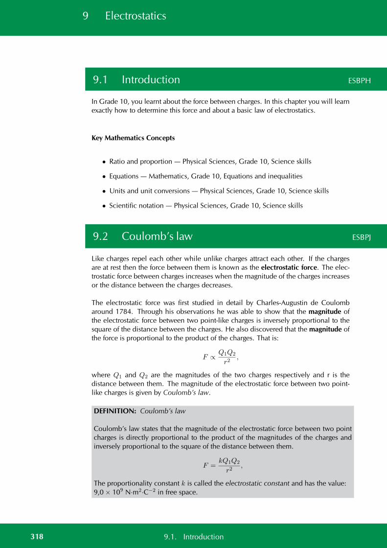
9 Electrostatics
9.1 Introduction ESBPH
In Grade 10, you learnt about the force between charges. In this chapter you will learnexactly how to determine this force and about a basic law of electrostatics.
Key Mathematics Concepts
• Ratio and proportion — Physical Sciences, Grade 10, Science skills
• Equations — Mathematics, Grade 10, Equations and inequalities
• Units and unit conversions — Physical Sciences, Grade 10, Science skills
• Scientific notation — Physical Sciences, Grade 10, Science skills
9.2 Coulomb’s law ESBPJ
Like charges repel each other while unlike charges attract each other. If the chargesare at rest then the force between them is known as the electrostatic force. The elec-trostatic force between charges increases when the magnitude of the charges increasesor the distance between the charges decreases.
The electrostatic force was first studied in detail by Charles-Augustin de Coulombaround 1784. Through his observations he was able to show that the magnitude ofthe electrostatic force between two point-like charges is inversely proportional to thesquare of the distance between the charges. He also discovered that the magnitude ofthe force is proportional to the product of the charges. That is:
F ∝ Q1Q2
r2,
where Q1 and Q2 are the magnitudes of the two charges respectively and r is thedistance between them. The magnitude of the electrostatic force between two point-like charges is given by Coulomb’s law.
DEFINITION: Coulomb’s law
Coulomb’s law states that the magnitude of the electrostatic force between two pointcharges is directly proportional to the product of the magnitudes of the charges andinversely proportional to the square of the distance between them.
F =kQ1Q2
r2,
The proportionality constant k is called the electrostatic constant and has the value:9,0 × 10⁹ N·m2·C−2 in free space.
318 9.1. Introduction
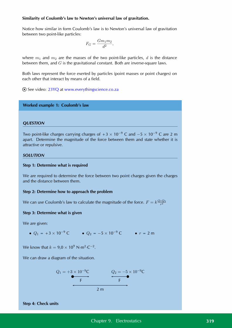
Similarity of Coulomb’s law to Newton’s universal law of gravitation.
Notice how similar in form Coulomb’s law is to Newton’s universal law of gravitationbetween two point-like particles:
FG =Gm1m2
d2,
where m1 and m2 are the masses of the two point-like particles, d is the distancebetween them, and G is the gravitational constant. Both are inverse-square laws.
Both laws represent the force exerted by particles (point masses or point charges) oneach other that interact by means of a field.
See video: 23YQ at www.everythingscience.co.za
Worked example 1: Coulomb’s law
QUESTION
Two point-like charges carrying charges of +3 × 10⁻⁹ C and −5 × 10⁻⁹ C are 2 mapart. Determine the magnitude of the force between them and state whether it isattractive or repulsive.
SOLUTION
Step 1: Determine what is required
We are required to determine the force between two point charges given the chargesand the distance between them.
Step 2: Determine how to approach the problem
We can use Coulomb’s law to calculate the magnitude of the force. F = kQ1Q2
r2
Step 3: Determine what is given
We are given:
• Q1 = +3 × 10⁻⁹ C • Q2 = −5 × 10⁻⁹ C • r = 2 m
We know that k = 9,0 × 10⁹ N·m2·C−2.
We can draw a diagram of the situation.
Q1 = +3× 10⁻⁹C Q2 = −5× 10⁻⁹C
2 m
F F
Step 4: Check units
319Chapter 9. Electrostatics
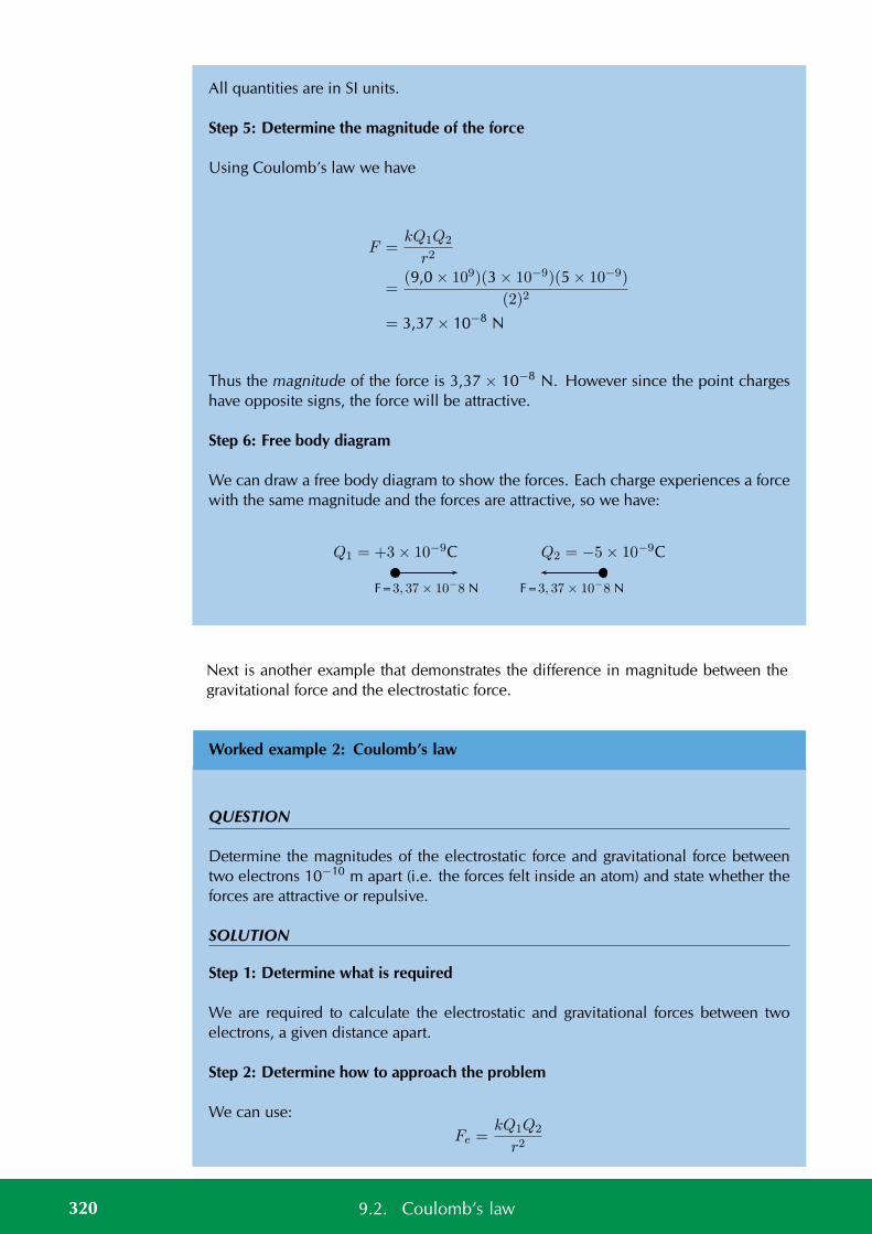
All quantities are in SI units.
Step 5: Determine the magnitude of the force
Using Coulomb’s law we have
F =kQ1Q2
r2
=(9,0 × 10⁹)(3 × 10⁻⁹)(5 × 10⁻⁹)
(2)2
= 3,37 × 10⁻⁸ N
Thus the magnitude of the force is 3,37 × 10⁻⁸ N. However since the point chargeshave opposite signs, the force will be attractive.
Step 6: Free body diagram
We can draw a free body diagram to show the forces. Each charge experiences a forcewith the same magnitude and the forces are attractive, so we have:
Q1 = +3× 10⁻⁹C Q2 = −5× 10⁻⁹C
F=3, 37× 10−
8 N F=3, 37× 10−
8 N
Next is another example that demonstrates the difference in magnitude between thegravitational force and the electrostatic force.
Worked example 2: Coulomb’s law
QUESTION
Determine the magnitudes of the electrostatic force and gravitational force betweentwo electrons 10−10 m apart (i.e. the forces felt inside an atom) and state whether theforces are attractive or repulsive.
SOLUTION
Step 1: Determine what is required
We are required to calculate the electrostatic and gravitational forces between twoelectrons, a given distance apart.
Step 2: Determine how to approach the problem
We can use:
Fe =kQ1Q2
r2
320 9.2. Coulomb’s law
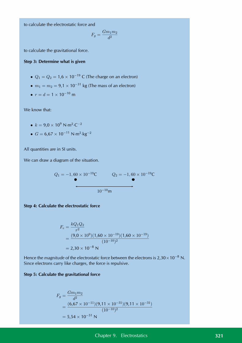
to calculate the electrostatic force and
Fg =Gm1m2
d2
to calculate the gravitational force.
Step 3: Determine what is given
• Q1 = Q2 = 1,6 × 10⁻¹⁹ C (The charge on an electron)
• m1 = m2 = 9,1 × 10⁻³¹ kg (The mass of an electron)
• r = d = 1 × 10⁻¹⁰ m
We know that:
• k = 9,0 × 10⁹ N·m2·C−2
• G = 6,67 × 10⁻¹¹ N·m2·kg−2
All quantities are in SI units.
We can draw a diagram of the situation.
Q1 = −1, 60× 10−19C Q2 = −1, 60× 10−19C
10−10m
Step 4: Calculate the electrostatic force
Fe =kQ1Q2
r2
=(9,0 × 10⁹)(1,60 × 10⁻¹⁹)(1,60 × 10⁻¹⁹)
(10−10)2
= 2,30 × 10⁻⁸ N
Hence the magnitude of the electrostatic force between the electrons is 2,30×10⁻⁸ N.Since electrons carry like charges, the force is repulsive.
Step 5: Calculate the gravitational force
Fg =Gm1m2
d2
=(6,67 × 10⁻¹¹)(9,11 × 10⁻³¹)(9,11 × 10⁻³¹)
(10−10)2
= 5,54 × 10−51 N
321Chapter 9. Electrostatics
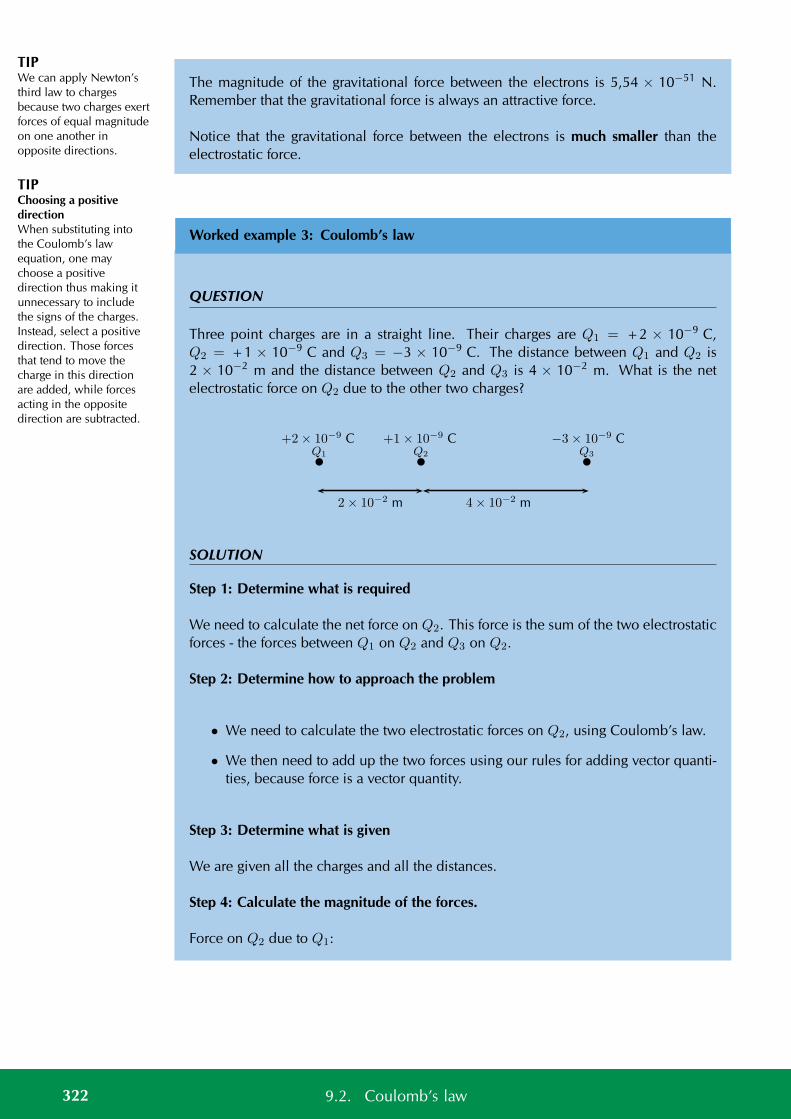
TIPWe can apply Newton’sthird law to chargesbecause two charges exertforces of equal magnitudeon one another inopposite directions.
TIPChoosing a positivedirectionWhen substituting intothe Coulomb’s lawequation, one maychoose a positivedirection thus making itunnecessary to includethe signs of the charges.Instead, select a positivedirection. Those forcesthat tend to move thecharge in this directionare added, while forcesacting in the oppositedirection are subtracted.
The magnitude of the gravitational force between the electrons is 5,54 × 10−51 N.Remember that the gravitational force is always an attractive force.
Notice that the gravitational force between the electrons is much smaller than theelectrostatic force.
Worked example 3: Coulomb’s law
QUESTION
Three point charges are in a straight line. Their charges are Q1 = +2 × 10⁻⁹ C,Q2 = +1 × 10⁻⁹ C and Q3 = −3 × 10⁻⁹ C. The distance between Q1 and Q2 is2 × 10−2 m and the distance between Q2 and Q3 is 4 × 10⁻² m. What is the netelectrostatic force on Q2 due to the other two charges?
Q2 Q3Q1
+1× 10⁻⁹ C −3× 10⁻⁹ C+2× 10⁻⁹ C
2× 10⁻² m 4× 10⁻² m
SOLUTION
Step 1: Determine what is required
We need to calculate the net force on Q2. This force is the sum of the two electrostaticforces - the forces between Q1 on Q2 and Q3 on Q2.
Step 2: Determine how to approach the problem
• We need to calculate the two electrostatic forces on Q2, using Coulomb’s law.
• We then need to add up the two forces using our rules for adding vector quanti-ties, because force is a vector quantity.
Step 3: Determine what is given
We are given all the charges and all the distances.
Step 4: Calculate the magnitude of the forces.
Force on Q2 due to Q1:
322 9.2. Coulomb’s law
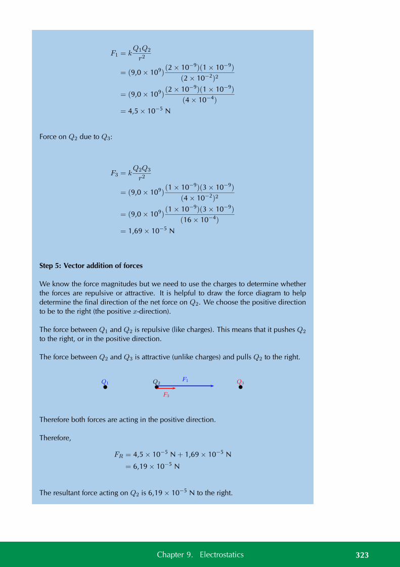
F1 = kQ1Q2
r2
= (9,0 × 10⁹)(2 × 10⁻⁹)(1 × 10⁻⁹)
(2 × 10⁻²)2
= (9,0 × 10⁹)(2 × 10⁻⁹)(1 × 10⁻⁹)
(4 × 10⁻⁴)
= 4,5 × 10⁻⁵ N
Force on Q2 due to Q3:
F3 = kQ2Q3
r2
= (9,0 × 10⁹)(1 × 10⁻⁹)(3 × 10⁻⁹)
(4 × 10⁻²)2
= (9,0 × 10⁹)(1 × 10⁻⁹)(3 × 10⁻⁹)
(16 × 10−4)
= 1,69 × 10⁻⁵ N
Step 5: Vector addition of forces
We know the force magnitudes but we need to use the charges to determine whetherthe forces are repulsive or attractive. It is helpful to draw the force diagram to helpdetermine the final direction of the net force on Q2. We choose the positive directionto be to the right (the positive x-direction).
The force between Q1 and Q2 is repulsive (like charges). This means that it pushes Q2
to the right, or in the positive direction.
The force between Q2 and Q3 is attractive (unlike charges) and pulls Q2 to the right.
Q2 Q3Q1F1
F3
Therefore both forces are acting in the positive direction.
Therefore,
FR = 4,5 × 10⁻⁵ N + 1,69 × 10⁻⁵ N
= 6,19 × 10⁻⁵ N
The resultant force acting on Q2 is 6,19 × 10⁻⁵ N to the right.
323Chapter 9. Electrostatics
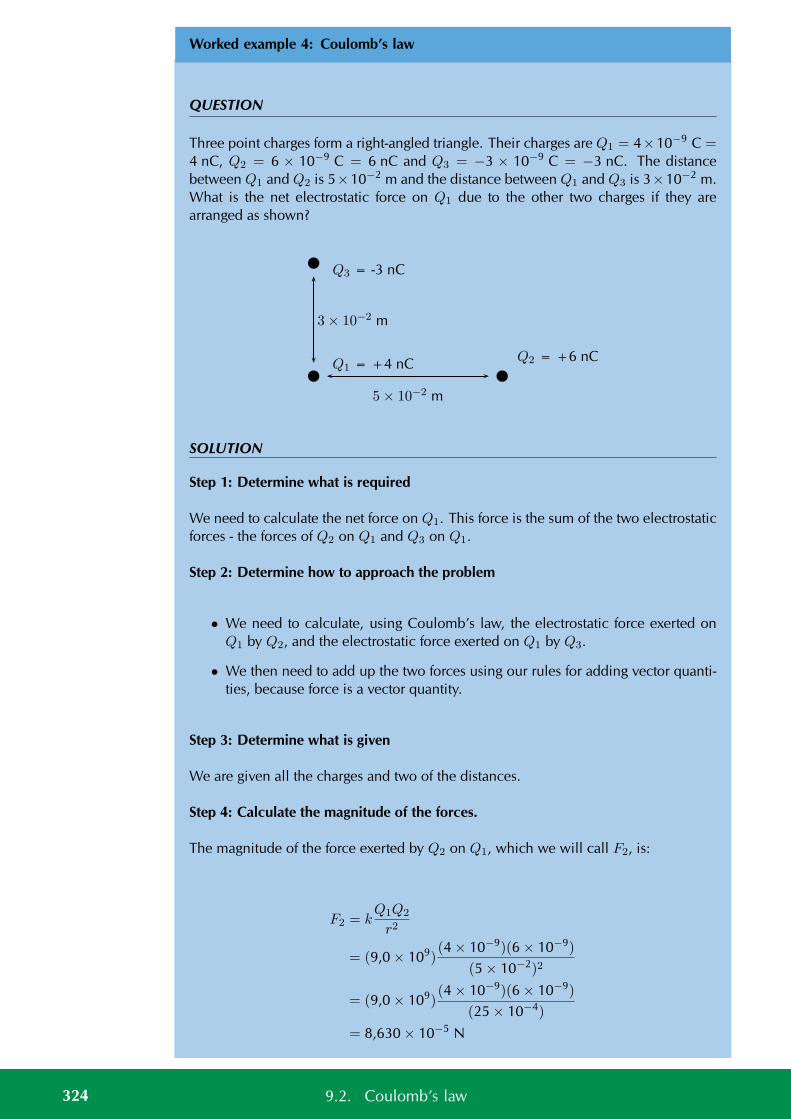
Worked example 4: Coulomb’s law
QUESTION
Three point charges form a right-angled triangle. Their charges are Q1 = 4×10⁻⁹ C =4 nC, Q2 = 6 × 10⁻⁹ C = 6 nC and Q3 = −3 × 10⁻⁹ C = −3 nC. The distancebetween Q1 and Q2 is 5×10⁻² m and the distance between Q1 and Q3 is 3×10⁻² m.What is the net electrostatic force on Q1 due to the other two charges if they arearranged as shown?
Q2 = +6 nC
Q3 = -3 nC
Q1 = +4 nC
5× 10⁻² m
3× 10⁻² m
SOLUTION
Step 1: Determine what is required
We need to calculate the net force on Q1. This force is the sum of the two electrostaticforces - the forces of Q2 on Q1 and Q3 on Q1.
Step 2: Determine how to approach the problem
• We need to calculate, using Coulomb’s law, the electrostatic force exerted onQ1 by Q2, and the electrostatic force exerted on Q1 by Q3.
• We then need to add up the two forces using our rules for adding vector quanti-ties, because force is a vector quantity.
Step 3: Determine what is given
We are given all the charges and two of the distances.
Step 4: Calculate the magnitude of the forces.
The magnitude of the force exerted by Q2 on Q1, which we will call F2, is:
F2 = kQ1Q2
r2
= (9,0 × 10⁹)(4 × 10⁻⁹)(6 × 10⁻⁹)
(5 × 10⁻²)2
= (9,0 × 10⁹)(4 × 10⁻⁹)(6 × 10⁻⁹)
(25 × 10−4)
= 8,630 × 10−5 N
324 9.2. Coulomb’s law
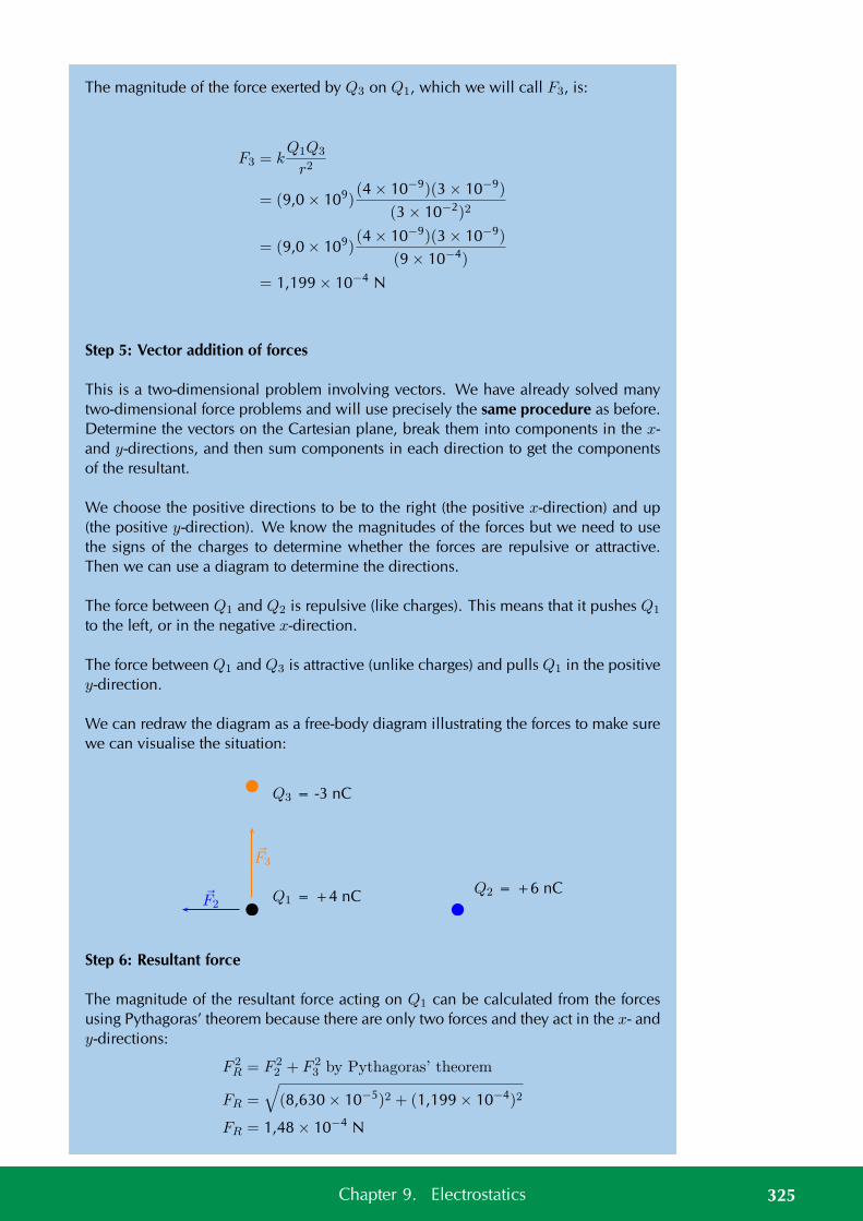
The magnitude of the force exerted by Q3 on Q1, which we will call F3, is:
F3 = kQ1Q3
r2
= (9,0 × 10⁹)(4 × 10⁻⁹)(3 × 10⁻⁹)
(3 × 10⁻²)2
= (9,0 × 10⁹)(4 × 10⁻⁹)(3 × 10⁻⁹)
(9 × 10⁻⁴)
= 1,199 × 10−4 N
Step 5: Vector addition of forces
This is a two-dimensional problem involving vectors. We have already solved manytwo-dimensional force problems and will use precisely the same procedure as before.Determine the vectors on the Cartesian plane, break them into components in the x-and y-directions, and then sum components in each direction to get the componentsof the resultant.
We choose the positive directions to be to the right (the positive x-direction) and up(the positive y-direction). We know the magnitudes of the forces but we need to usethe signs of the charges to determine whether the forces are repulsive or attractive.Then we can use a diagram to determine the directions.
The force between Q1 and Q2 is repulsive (like charges). This means that it pushes Q1
to the left, or in the negative x-direction.
The force between Q1 and Q3 is attractive (unlike charges) and pulls Q1 in the positivey-direction.
We can redraw the diagram as a free-body diagram illustrating the forces to make surewe can visualise the situation:
Q2 = +6 nC
Q3 = -3 nC
Q1 = +4 nC
F3
F2
Step 6: Resultant force
The magnitude of the resultant force acting on Q1 can be calculated from the forcesusing Pythagoras’ theorem because there are only two forces and they act in the x- andy-directions:
F 2R = F 2
2 + F 23 by Pythagoras’ theorem
FR =
√(8,630 × 10−5)2 + (1,199 × 10−4)2
FR = 1,48 × 10⁻⁴ N
325Chapter 9. Electrostatics
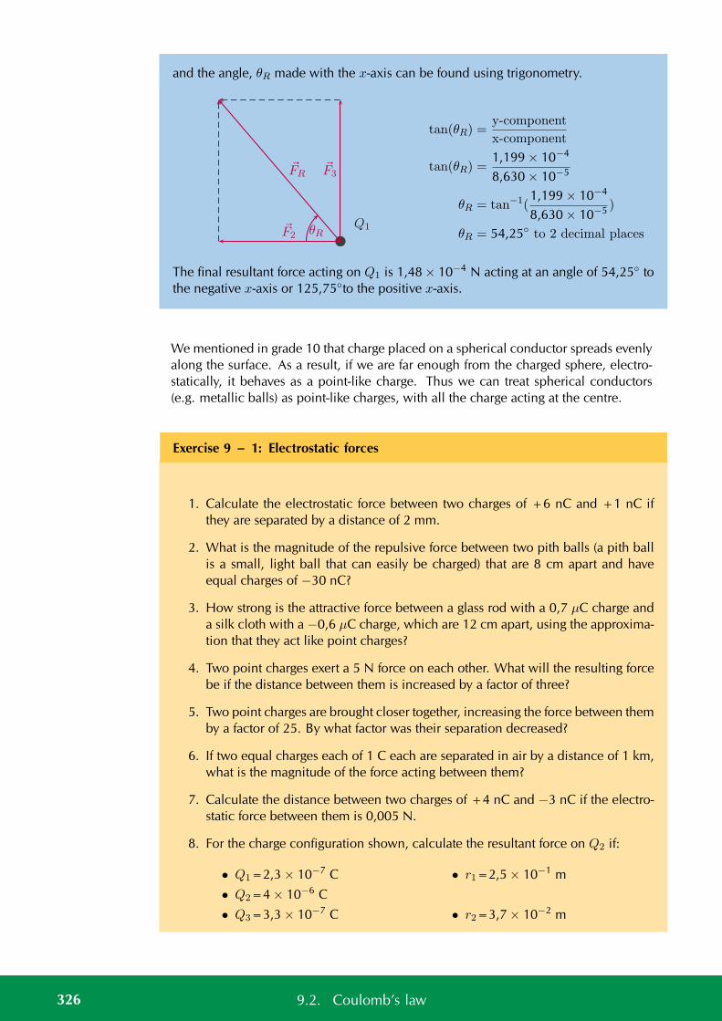
and the angle, θR made with the x-axis can be found using trigonometry.
θRQ1F2
FRF3
tan(θR) =y-component
x-component
tan(θR) =1,199 × 10−4
8,630 × 10−5
θR = tan−1(1,199 × 10−4
8,630 × 10−5 )
θR = 54,25 to 2 decimal places
The final resultant force acting on Q1 is 1,48 × 10⁻⁴ N acting at an angle of 54,25 tothe negative x-axis or 125,75to the positive x-axis.
We mentioned in grade 10 that charge placed on a spherical conductor spreads evenlyalong the surface. As a result, if we are far enough from the charged sphere, electro-statically, it behaves as a point-like charge. Thus we can treat spherical conductors(e.g. metallic balls) as point-like charges, with all the charge acting at the centre.
Exercise 9 – 1: Electrostatic forces
1. Calculate the electrostatic force between two charges of +6 nC and +1 nC ifthey are separated by a distance of 2 mm.
2. What is the magnitude of the repulsive force between two pith balls (a pith ballis a small, light ball that can easily be charged) that are 8 cm apart and haveequal charges of −30 nC?
3. How strong is the attractive force between a glass rod with a 0,7 µC charge anda silk cloth with a −0,6 µC charge, which are 12 cm apart, using the approxima-tion that they act like point charges?
4. Two point charges exert a 5 N force on each other. What will the resulting forcebe if the distance between them is increased by a factor of three?
5. Two point charges are brought closer together, increasing the force between themby a factor of 25. By what factor was their separation decreased?
6. If two equal charges each of 1 C each are separated in air by a distance of 1 km,what is the magnitude of the force acting between them?
7. Calculate the distance between two charges of +4 nC and −3 nC if the electro-static force between them is 0,005 N.
8. For the charge configuration shown, calculate the resultant force on Q2 if:
• Q1=2,3 × 10⁻⁷ C
• Q2=4 × 10⁻⁶ C
• Q3=3,3 × 10⁻⁷ C
• r1=2,5 × 10⁻¹ m
• r2=3,7 × 10⁻² m
326 9.2. Coulomb’s law
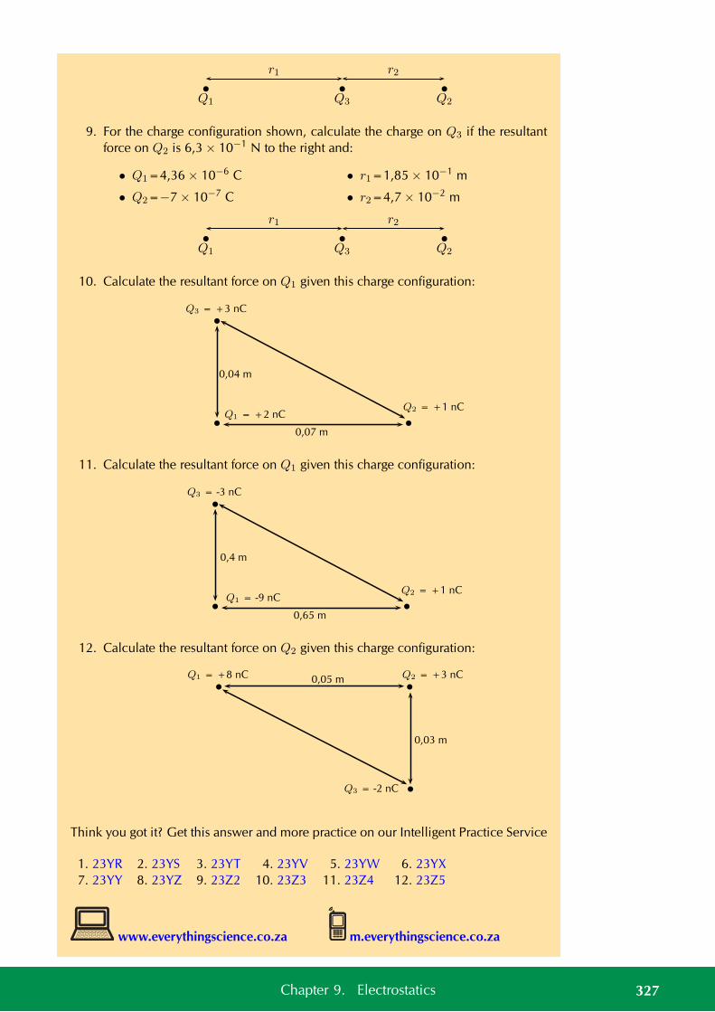
Q2Q3Q1
r1 r2
9. For the charge configuration shown, calculate the charge on Q3 if the resultantforce on Q2 is 6,3 × 10⁻¹ N to the right and:
• Q1=4,36 × 10⁻⁶ C
• Q2=−7 × 10⁻⁷ C
• r1=1,85 × 10⁻¹ m
• r2=4,7 × 10⁻² m
Q2Q3Q1
r1 r2
10. Calculate the resultant force on Q1 given this charge configuration:
Q3 = +3 nC
Q2 = +1 nCQ1 = +2 nC
0,04 m
0,07 m
11. Calculate the resultant force on Q1 given this charge configuration:
Q3 = -3 nC
Q2 = +1 nCQ1 = -9 nC
0,4 m
0,65 m
12. Calculate the resultant force on Q2 given this charge configuration:
Q1 = +8 nC
Q3 = -2 nC
Q2 = +3 nC
0,03 m
0,05 m
Think you got it? Get this answer and more practice on our Intelligent Practice Service
1. 23YR 2. 23YS 3. 23YT 4. 23YV 5. 23YW 6. 23YX7. 23YY 8. 23YZ 9. 23Z2 10. 23Z3 11. 23Z4 12. 23Z5
www.everythingscience.co.za m.everythingscience.co.za
327Chapter 9. Electrostatics
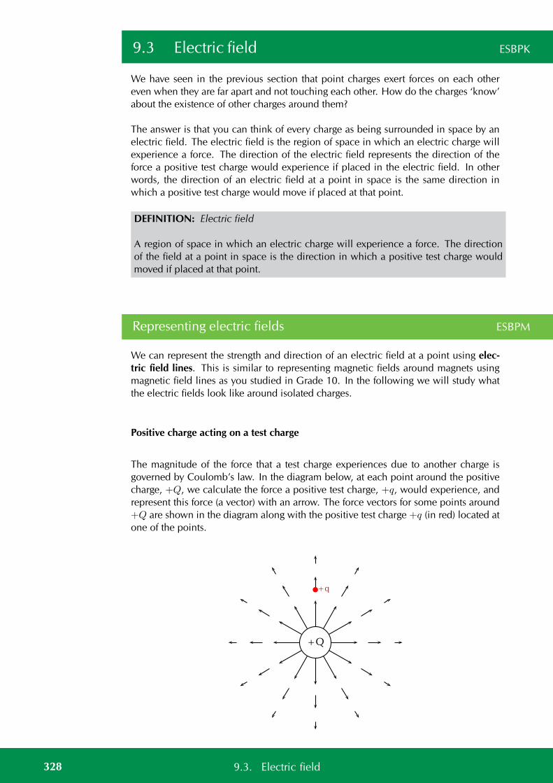
9.3 Electric field ESBPK
We have seen in the previous section that point charges exert forces on each othereven when they are far apart and not touching each other. How do the charges ‘know’about the existence of other charges around them?
The answer is that you can think of every charge as being surrounded in space by anelectric field. The electric field is the region of space in which an electric charge willexperience a force. The direction of the electric field represents the direction of theforce a positive test charge would experience if placed in the electric field. In otherwords, the direction of an electric field at a point in space is the same direction inwhich a positive test charge would move if placed at that point.
DEFINITION: Electric field
A region of space in which an electric charge will experience a force. The directionof the field at a point in space is the direction in which a positive test charge wouldmoved if placed at that point.
Representing electric fields ESBPM
We can represent the strength and direction of an electric field at a point using elec-tric field lines. This is similar to representing magnetic fields around magnets usingmagnetic field lines as you studied in Grade 10. In the following we will study whatthe electric fields look like around isolated charges.
Positive charge acting on a test charge
The magnitude of the force that a test charge experiences due to another charge isgoverned by Coulomb’s law. In the diagram below, at each point around the positivecharge, +Q, we calculate the force a positive test charge, +q, would experience, andrepresent this force (a vector) with an arrow. The force vectors for some points around+Q are shown in the diagram along with the positive test charge +q (in red) located atone of the points.
+Q
+q
328 9.3. Electric field
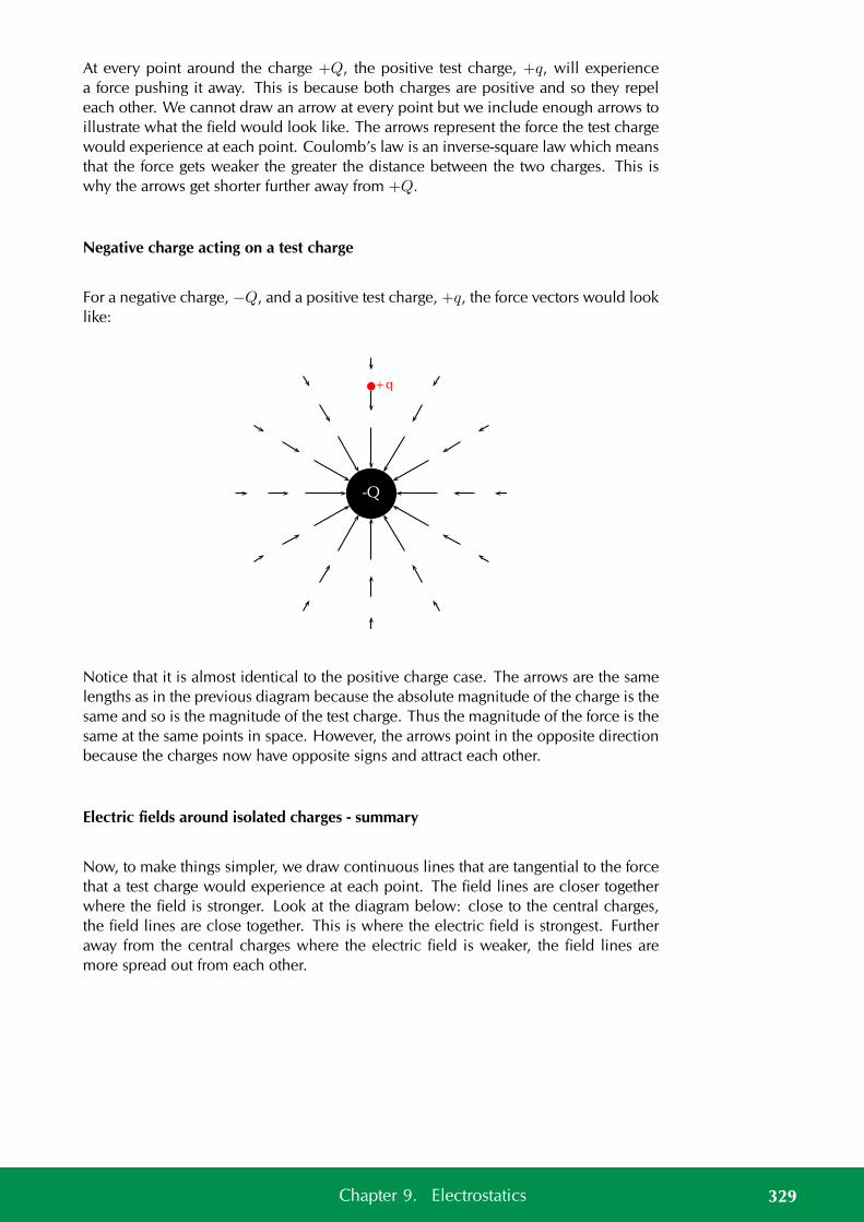
At every point around the charge +Q, the positive test charge, +q, will experiencea force pushing it away. This is because both charges are positive and so they repeleach other. We cannot draw an arrow at every point but we include enough arrows toillustrate what the field would look like. The arrows represent the force the test chargewould experience at each point. Coulomb’s law is an inverse-square law which meansthat the force gets weaker the greater the distance between the two charges. This iswhy the arrows get shorter further away from +Q.
Negative charge acting on a test charge
For a negative charge, −Q, and a positive test charge, +q, the force vectors would looklike:
-Q
+q
Notice that it is almost identical to the positive charge case. The arrows are the samelengths as in the previous diagram because the absolute magnitude of the charge is thesame and so is the magnitude of the test charge. Thus the magnitude of the force is thesame at the same points in space. However, the arrows point in the opposite directionbecause the charges now have opposite signs and attract each other.
Electric fields around isolated charges - summary
Now, to make things simpler, we draw continuous lines that are tangential to the forcethat a test charge would experience at each point. The field lines are closer togetherwhere the field is stronger. Look at the diagram below: close to the central charges,the field lines are close together. This is where the electric field is strongest. Furtheraway from the central charges where the electric field is weaker, the field lines aremore spread out from each other.
329Chapter 9. Electrostatics
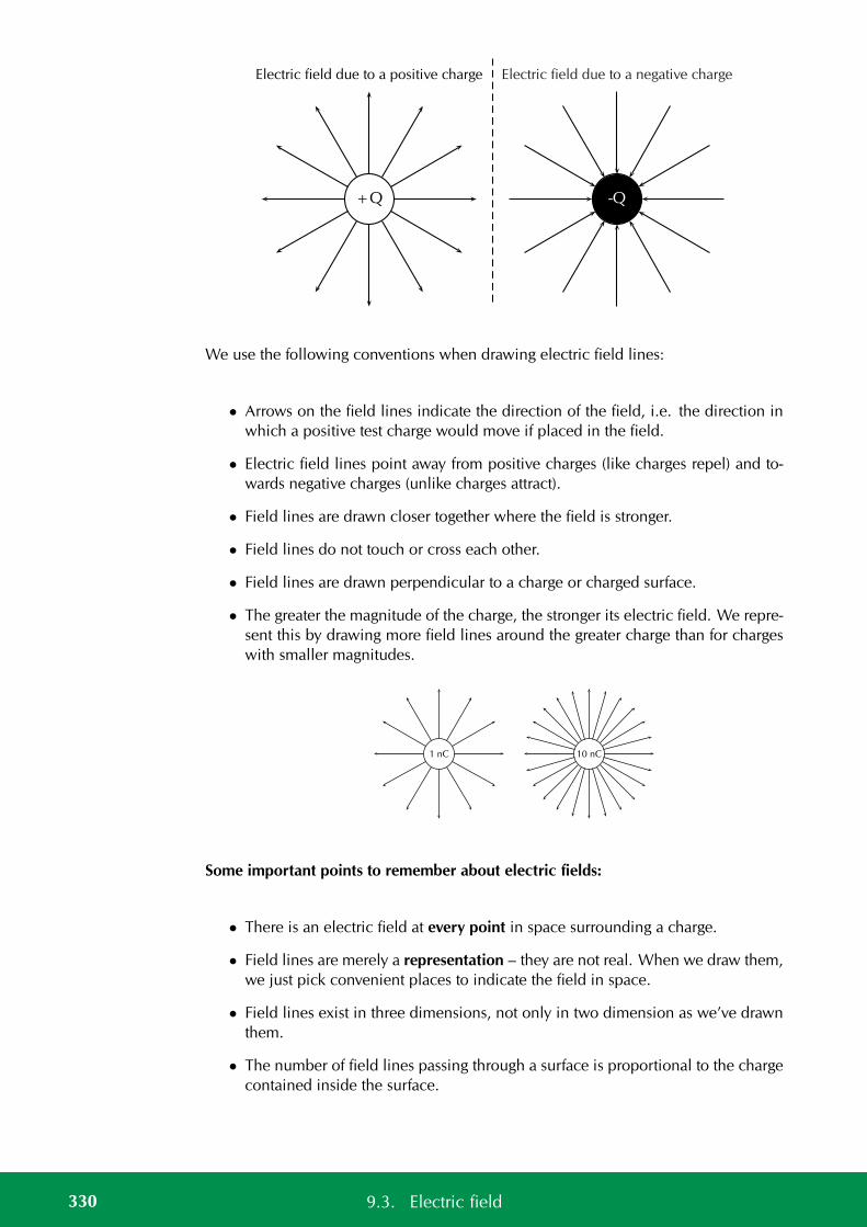
+Q
Electric field due to a positive charge
-Q
Electric field due to a negative charge
We use the following conventions when drawing electric field lines:
• Arrows on the field lines indicate the direction of the field, i.e. the direction inwhich a positive test charge would move if placed in the field.
• Electric field lines point away from positive charges (like charges repel) and to-wards negative charges (unlike charges attract).
• Field lines are drawn closer together where the field is stronger.
• Field lines do not touch or cross each other.
• Field lines are drawn perpendicular to a charge or charged surface.
• The greater the magnitude of the charge, the stronger its electric field. We repre-sent this by drawing more field lines around the greater charge than for chargeswith smaller magnitudes.
1 nC 10 nC
Some important points to remember about electric fields:
• There is an electric field at every point in space surrounding a charge.
• Field lines are merely a representation – they are not real. When we draw them,we just pick convenient places to indicate the field in space.
• Field lines exist in three dimensions, not only in two dimension as we’ve drawnthem.
• The number of field lines passing through a surface is proportional to the chargecontained inside the surface.
330 9.3. Electric field
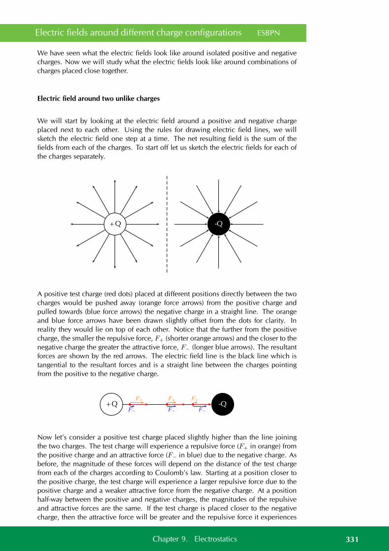
Electric fields around different charge configurations ESBPN
We have seen what the electric fields look like around isolated positive and negativecharges. Now we will study what the electric fields look like around combinations ofcharges placed close together.
Electric field around two unlike charges
We will start by looking at the electric field around a positive and negative chargeplaced next to each other. Using the rules for drawing electric field lines, we willsketch the electric field one step at a time. The net resulting field is the sum of thefields from each of the charges. To start off let us sketch the electric fields for each ofthe charges separately.
+Q -Q
A positive test charge (red dots) placed at different positions directly between the twocharges would be pushed away (orange force arrows) from the positive charge andpulled towards (blue force arrows) the negative charge in a straight line. The orangeand blue force arrows have been drawn slightly offset from the dots for clarity. Inreality they would lie on top of each other. Notice that the further from the positivecharge, the smaller the repulsive force, F+ (shorter orange arrows) and the closer to thenegative charge the greater the attractive force, F− (longer blue arrows). The resultantforces are shown by the red arrows. The electric field line is the black line which istangential to the resultant forces and is a straight line between the charges pointingfrom the positive to the negative charge.
+Q -QF+
F−
F+
F−
F+
F−
Now let’s consider a positive test charge placed slightly higher than the line joiningthe two charges. The test charge will experience a repulsive force (F+ in orange) fromthe positive charge and an attractive force (F− in blue) due to the negative charge. Asbefore, the magnitude of these forces will depend on the distance of the test chargefrom each of the charges according to Coulomb’s law. Starting at a position closer tothe positive charge, the test charge will experience a larger repulsive force due to thepositive charge and a weaker attractive force from the negative charge. At a positionhalf-way between the positive and negative charges, the magnitudes of the repulsiveand attractive forces are the same. If the test charge is placed closer to the negativecharge, then the attractive force will be greater and the repulsive force it experiences
331Chapter 9. Electrostatics
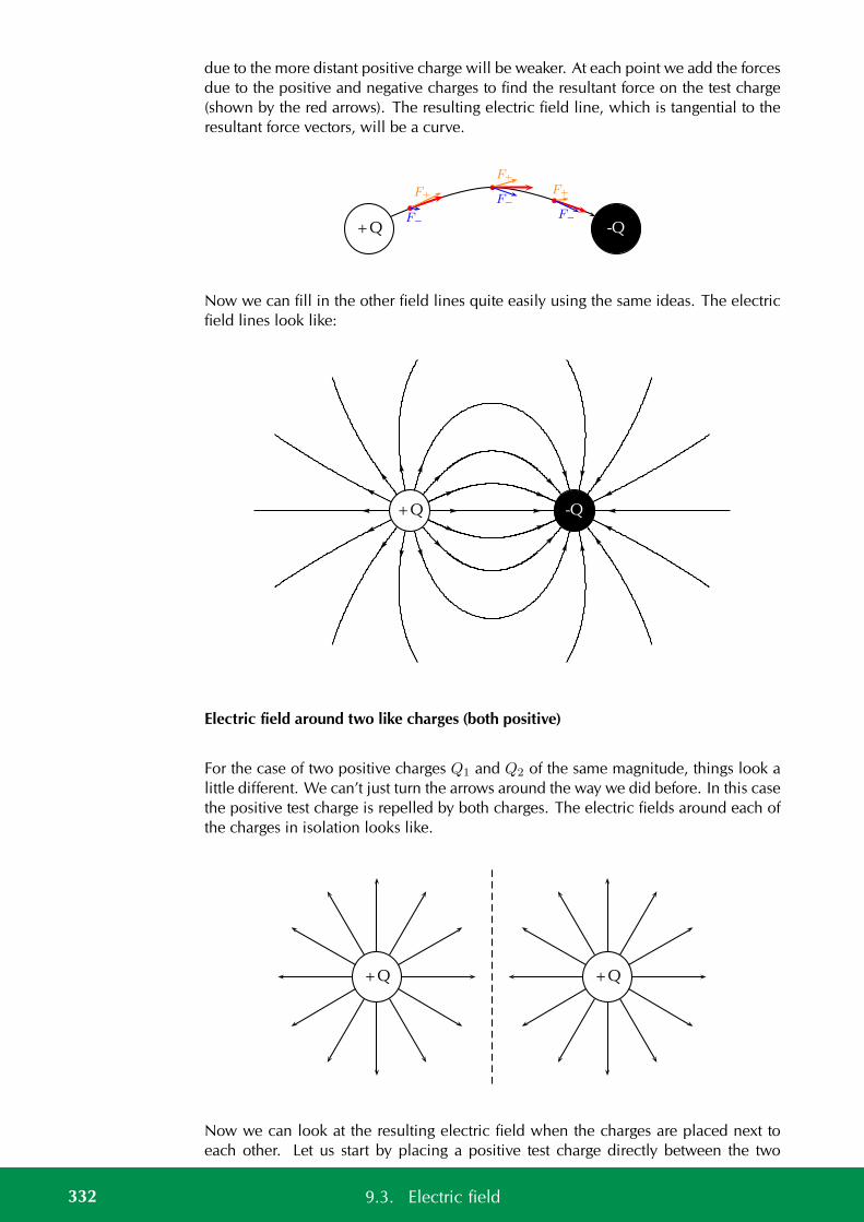
due to the more distant positive charge will be weaker. At each point we add the forcesdue to the positive and negative charges to find the resultant force on the test charge(shown by the red arrows). The resulting electric field line, which is tangential to theresultant force vectors, will be a curve.
+Q -Q
F+
F−
F+
F−
F+
F−
Now we can fill in the other field lines quite easily using the same ideas. The electricfield lines look like:
+Q -Q
Electric field around two like charges (both positive)
For the case of two positive charges Q1 and Q2 of the same magnitude, things look alittle different. We can’t just turn the arrows around the way we did before. In this casethe positive test charge is repelled by both charges. The electric fields around each ofthe charges in isolation looks like.
+Q +Q
Now we can look at the resulting electric field when the charges are placed next toeach other. Let us start by placing a positive test charge directly between the two
332 9.3. Electric field
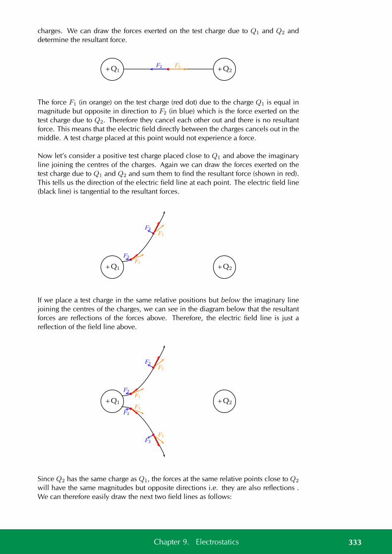
charges. We can draw the forces exerted on the test charge due to Q1 and Q2 anddetermine the resultant force.
+Q1 +Q2F1F2
The force F1 (in orange) on the test charge (red dot) due to the charge Q1 is equal inmagnitude but opposite in direction to F2 (in blue) which is the force exerted on thetest charge due to Q2. Therefore they cancel each other out and there is no resultantforce. This means that the electric field directly between the charges cancels out in themiddle. A test charge placed at this point would not experience a force.
Now let’s consider a positive test charge placed close to Q1 and above the imaginaryline joining the centres of the charges. Again we can draw the forces exerted on thetest charge due to Q1 and Q2 and sum them to find the resultant force (shown in red).This tells us the direction of the electric field line at each point. The electric field line(black line) is tangential to the resultant forces.
+Q1 +Q2
F1
F2
F1
F2
If we place a test charge in the same relative positions but below the imaginary linejoining the centres of the charges, we can see in the diagram below that the resultantforces are reflections of the forces above. Therefore, the electric field line is just areflection of the field line above.
+Q1 +Q2
F1
F2
F1
F2
F1
F2
F1
F2
Since Q2 has the same charge as Q1, the forces at the same relative points close to Q2
will have the same magnitudes but opposite directions i.e. they are also reflections .We can therefore easily draw the next two field lines as follows:
333Chapter 9. Electrostatics
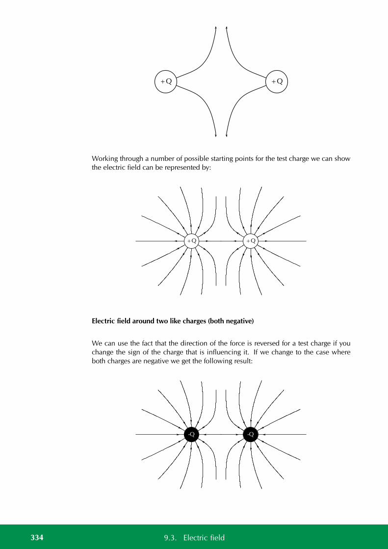
+Q +Q
Working through a number of possible starting points for the test charge we can showthe electric field can be represented by:
+Q +Q
Electric field around two like charges (both negative)
We can use the fact that the direction of the force is reversed for a test charge if youchange the sign of the charge that is influencing it. If we change to the case whereboth charges are negative we get the following result:
-Q -Q
334 9.3. Electric field

Charges of different magnitudes
When the magnitudes are not equal the larger charge will influence the direction ofthe field lines more than if they were equal. For example, here is a configurationwhere the positive charge is much larger than the negative charge. You can see thatthe field lines look more similar to that of an isolated charge at greater distances thanin the earlier example. This is because the larger charge gives rise to a stronger fieldand therefore makes a larger relative contribution to the force on a test charge than thesmaller charge.
+10Q-Q
Electric field strength ESBPP
In the previous sections we have studied how we can represent the electric fieldsaround a charge or combination of charges by means of electric field lines. In this rep-resentation we see that the electric field strength is represented by how close togetherthe field lines are. In addition to the drawings of the electric field, we would also liketo be able to quantify (put a number to) how strong an electric field is and what itsdirection is at any point in space.
A small test charge q placed near a charge Q will experience a force due to the electricfield surrounding Q. The magnitude of the force is described by Coulomb’s law anddepends on the magnitude of the charge Q and the distance of the test charge from Q.The closer the test charge q is to the charge Q, the greater the force it will experience.Also, at points closer to the charge Q, the stronger is its electric field. We define theelectric field at a point as the force per unit charge.
DEFINITION: Electric field
The magnitude of the electric field, E, at a point can be quantified as the force per unitcharge We can write this as:
E =F
q
where F is the Coulomb force exerted by a charge on a test charge q.The units of the electric field are newtons per coulomb: N·C−1.
335Chapter 9. Electrostatics
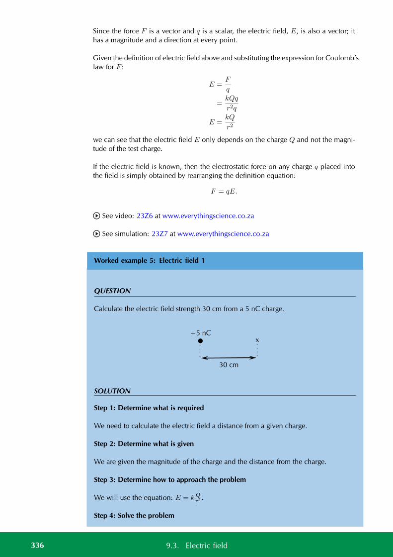
Since the force F is a vector and q is a scalar, the electric field, E, is also a vector; ithas a magnitude and a direction at every point.
Given the definition of electric field above and substituting the expression for Coulomb’slaw for F :
E =F
q
=kQq
r2q
E =kQ
r2
we can see that the electric field E only depends on the charge Q and not the magni-tude of the test charge.
If the electric field is known, then the electrostatic force on any charge q placed intothe field is simply obtained by rearranging the definition equation:
F = qE.
See video: 23Z6 at www.everythingscience.co.za
See simulation: 23Z7 at www.everythingscience.co.za
Worked example 5: Electric field 1
QUESTION
Calculate the electric field strength 30 cm from a 5 nC charge.
+5 nCx
30 cm
SOLUTION
Step 1: Determine what is required
We need to calculate the electric field a distance from a given charge.
Step 2: Determine what is given
We are given the magnitude of the charge and the distance from the charge.
Step 3: Determine how to approach the problem
We will use the equation: E = k Qr2.
Step 4: Solve the problem
336 9.3. Electric field
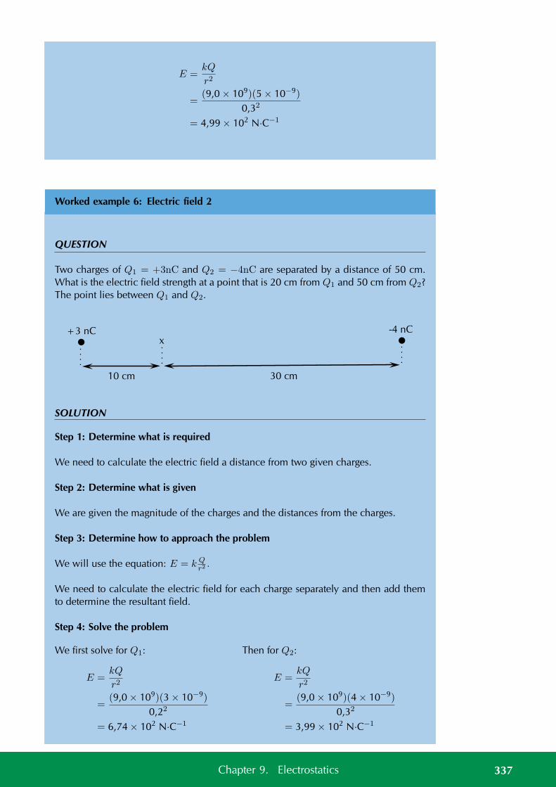
E =kQ
r2
=(9,0 × 10⁹)(5 × 10⁻⁹)
0,32
= 4,99 × 10² N·C−1
Worked example 6: Electric field 2
QUESTION
Two charges of Q1 = +3nC and Q2 = −4nC are separated by a distance of 50 cm.What is the electric field strength at a point that is 20 cm from Q1 and 50 cm from Q2?The point lies between Q1 and Q2.
+3 nCx
10 cm 30 cm
-4 nC
SOLUTION
Step 1: Determine what is required
We need to calculate the electric field a distance from two given charges.
Step 2: Determine what is given
We are given the magnitude of the charges and the distances from the charges.
Step 3: Determine how to approach the problem
We will use the equation: E = k Qr2.
We need to calculate the electric field for each charge separately and then add themto determine the resultant field.
Step 4: Solve the problem
We first solve for Q1:
E =kQ
r2
=(9,0 × 10⁹)(3 × 10⁻⁹)
0,22
= 6,74 × 10² N·C−1
Then for Q2:
E =kQ
r2
=(9,0 × 10⁹)(4 × 10⁻⁹)
0,32
= 3,99 × 10² N·C−1
337Chapter 9. Electrostatics
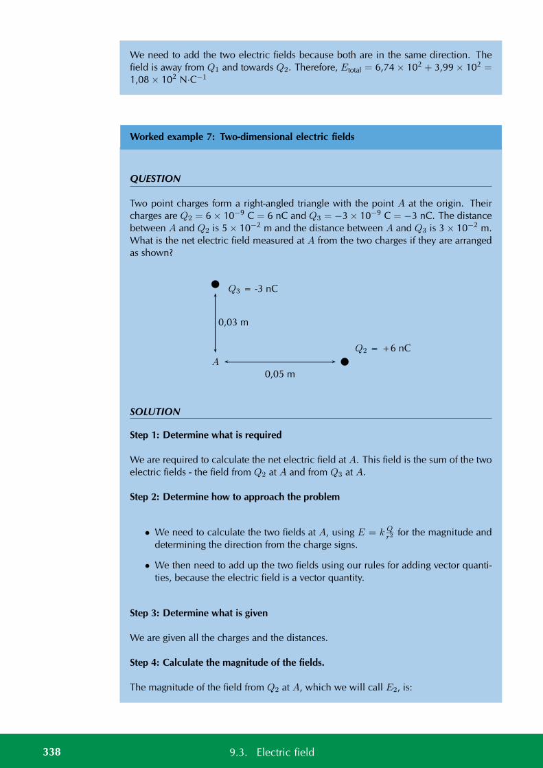
We need to add the two electric fields because both are in the same direction. Thefield is away from Q1 and towards Q2. Therefore, Etotal = 6,74 × 10² + 3,99 × 102 =1,08 × 10² N·C−1
Worked example 7: Two-dimensional electric fields
QUESTION
Two point charges form a right-angled triangle with the point A at the origin. Theircharges are Q2 = 6 × 10⁻⁹ C = 6 nC and Q3 = −3 × 10⁻⁹ C = −3 nC. The distancebetween A and Q2 is 5 × 10⁻² m and the distance between A and Q3 is 3 × 10⁻² m.What is the net electric field measured at A from the two charges if they are arrangedas shown?
Q2 = +6 nC
Q3 = -3 nC
A
0,05 m
0,03 m
SOLUTION
Step 1: Determine what is required
We are required to calculate the net electric field at A. This field is the sum of the twoelectric fields - the field from Q2 at A and from Q3 at A.
Step 2: Determine how to approach the problem
• We need to calculate the two fields at A, using E = k Qr2
for the magnitude anddetermining the direction from the charge signs.
• We then need to add up the two fields using our rules for adding vector quanti-ties, because the electric field is a vector quantity.
Step 3: Determine what is given
We are given all the charges and the distances.
Step 4: Calculate the magnitude of the fields.
The magnitude of the field from Q2 at A, which we will call E2, is:
338 9.3. Electric field
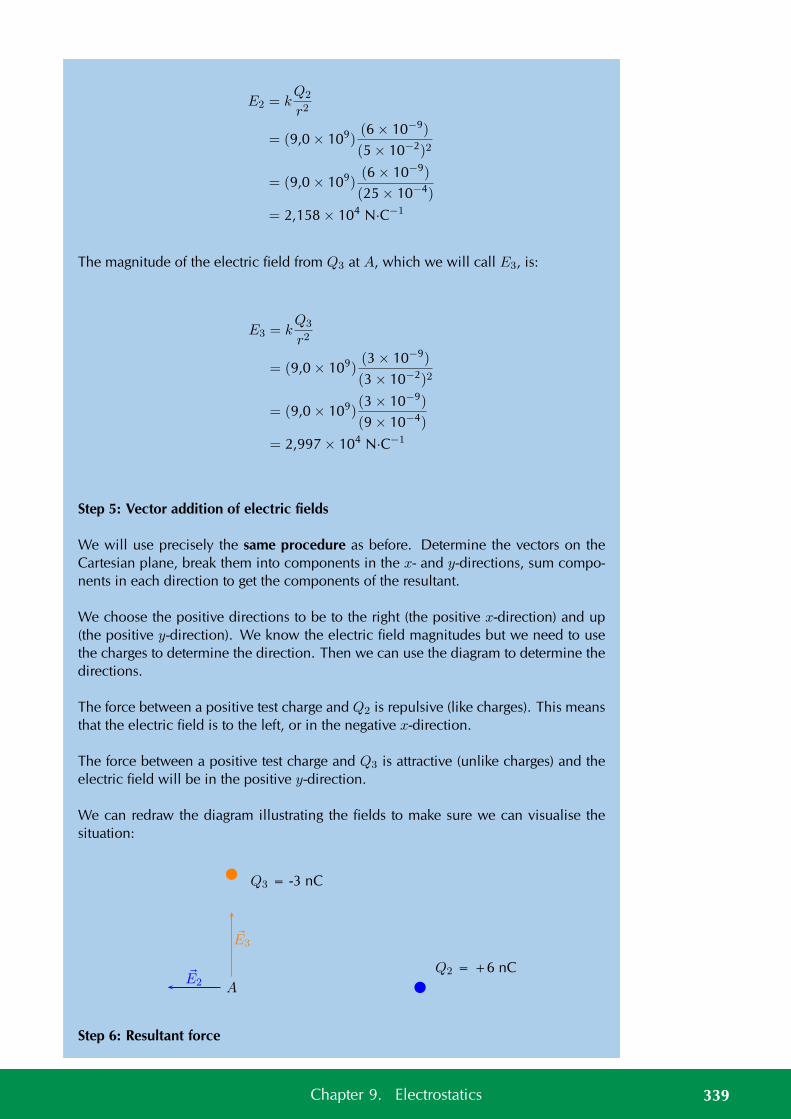
E2 = kQ2
r2
= (9,0 × 10⁹)(6 × 10⁻⁹)
(5 × 10⁻²)2
= (9,0 × 10⁹)(6 × 10⁻⁹)
(25 × 10−4)
= 2,158 × 104 N·C−1
The magnitude of the electric field from Q3 at A, which we will call E3, is:
E3 = kQ3
r2
= (9,0 × 10⁹)(3 × 10⁻⁹)
(3 × 10⁻²)2
= (9,0 × 10⁹)(3 × 10⁻⁹)
(9 × 10⁻⁴)
= 2,997 × 104 N·C−1
Step 5: Vector addition of electric fields
We will use precisely the same procedure as before. Determine the vectors on theCartesian plane, break them into components in the x- and y-directions, sum compo-nents in each direction to get the components of the resultant.
We choose the positive directions to be to the right (the positive x-direction) and up(the positive y-direction). We know the electric field magnitudes but we need to usethe charges to determine the direction. Then we can use the diagram to determine thedirections.
The force between a positive test charge and Q2 is repulsive (like charges). This meansthat the electric field is to the left, or in the negative x-direction.
The force between a positive test charge and Q3 is attractive (unlike charges) and theelectric field will be in the positive y-direction.
We can redraw the diagram illustrating the fields to make sure we can visualise thesituation:
Q2 = +6 nC
Q3 = -3 nC
A
E3
E2
Step 6: Resultant force
339Chapter 9. Electrostatics
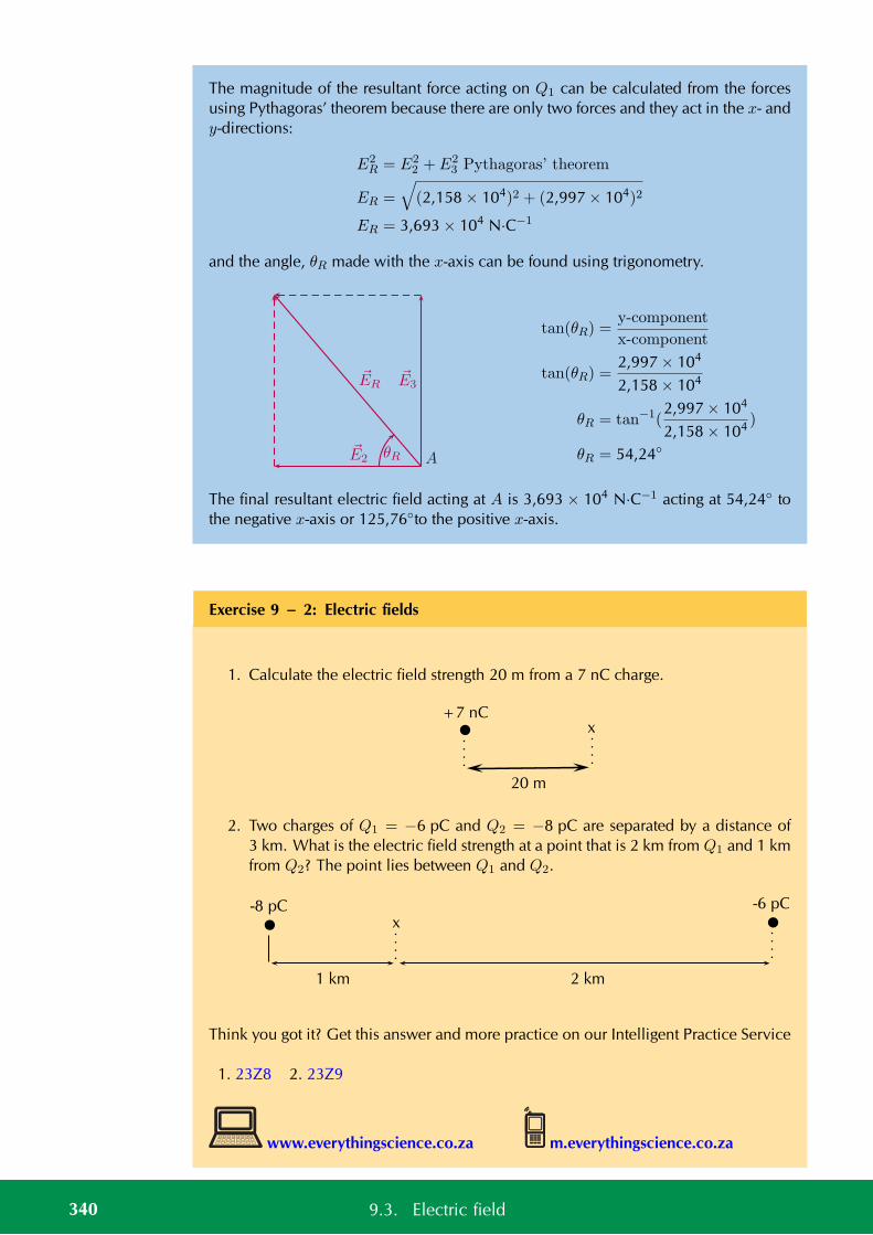
The magnitude of the resultant force acting on Q1 can be calculated from the forcesusing Pythagoras’ theorem because there are only two forces and they act in the x- andy-directions:
E2R = E2
2 + E23 Pythagoras’ theorem
ER =
√(2,158 × 104)2 + (2,997 × 104)2
ER = 3,693 × 104 N·C−1
and the angle, θR made with the x-axis can be found using trigonometry.
θR AE2
ERE3
tan(θR) =y-component
x-component
tan(θR) =2,997 × 104
2,158 × 104
θR = tan−1(2,997 × 104
2,158 × 104 )
θR = 54,24
The final resultant electric field acting at A is 3,693 × 104 N·C−1 acting at 54,24 tothe negative x-axis or 125,76to the positive x-axis.
Exercise 9 – 2: Electric fields
1. Calculate the electric field strength 20 m from a 7 nC charge.
+7 nCx
20 m
2. Two charges of Q1 = −6 pC and Q2 = −8 pC are separated by a distance of3 km. What is the electric field strength at a point that is 2 km from Q1 and 1 kmfrom Q2? The point lies between Q1 and Q2.
-8 pCx
1 km 2 km
-6 pC
Think you got it? Get this answer and more practice on our Intelligent Practice Service
1. 23Z8 2. 23Z9
www.everythingscience.co.za m.everythingscience.co.za
340 9.3. Electric field
9.4 Chapter summary ESBPQ
See presentation: 23ZB at www.everythingscience.co.za
• Objects can be positively, negatively charged or neutral.
• Coulomb’s law describes the electrostatic force between two point charges andcan be stated as: the magnitude of the electrostatic force between two pointcharges is directly proportional to the product of the magnitudes of the chargesand inversely proportional to the square of the distance between them.
F = kQ1Q2
r2
• An electric field is a region of space in which an electric charge will experiencea force. The direction of the field at a point in space is the direction in which apositive test charge would moved if placed at that point.
• We can represent the electric field using field lines. By convention electric fieldlines point away from positive charges (like charges repel) and towards negativecharges (unlike charges attract).
• The magnitude of the electric field, E, at a point can be quantified as the forceper unit charge We can write this as: E = F
q where F is the Coulomb forceexerted by a charge on a test charge q. The units of the electric field are newtonsper coulomb: N·C−1 .
• The electric field due to a point charge Q is defined as the force per unit charge:
E = Fq = kQ
r2
• The electrostatic force is attractive for unlike charges and repulsive for like charges.
Physical QuantitiesQuantity Unit name Unit symbolCharge (q) coulomb CDistance (d) metre mElectric field (E) newtons per coulomb N·C−1
Force (F ) newton N
Exercise 9 – 3:
1. Two charges of +3 nC and −5 nC are separated by a distance of 40 cm. Whatis the electrostatic force between the two charges?
2. Two conducting metal spheres carrying charges of +6 nC and −10 nC are sep-arated by a distance of 20 mm.
a) What is the electrostatic force between the spheres?
b) The two spheres are touched and then separated by a distance of 60 mm.What are the new charges on the spheres?
c) What is new electrostatic force between the spheres at this distance?
341Chapter 9. Electrostatics
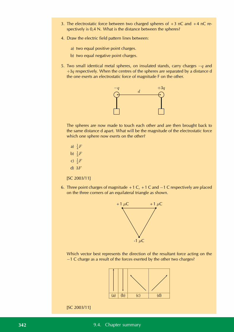
3. The electrostatic force between two charged spheres of +3 nC and +4 nC re-spectively is 0,4 N. What is the distance between the spheres?
4. Draw the electric field pattern lines between:
a) two equal positive point charges.
b) two equal negative point charges.
5. Two small identical metal spheres, on insulated stands, carry charges −q and+3q respectively. When the centres of the spheres are separated by a distance dthe one exerts an electrostatic force of magnitude F on the other.
d−q +3q
The spheres are now made to touch each other and are then brought back tothe same distance d apart. What will be the magnitude of the electrostatic forcewhich one sphere now exerts on the other?
a) 14F
b) 13F
c) 12F
d) 3F
[SC 2003/11]
6. Three point charges of magnitude +1 C, +1 C and −1 C respectively are placedon the three corners of an equilateral triangle as shown.
+1 µC +1 µC
-1 µC
Which vector best represents the direction of the resultant force acting on the−1 C charge as a result of the forces exerted by the other two charges?
(a) (b) (c) (d)
[SC 2003/11]
342 9.4. Chapter summary
7. a) Write a statement of Coulomb’s law.
b) Calculate the magnitude of the force exerted by a point charge of +2 nCon another point charge of −3 nC separated by a distance of 60 mm.
c) Sketch the electric field between two point charges of +2 nC and −3 nC,respectively, placed 60 mm apart from each other.
[IEB 2003/11 HG1 - Force Fields]
8. The electric field strength at a distance x from a point charge is E. What is themagnitude of the electric field strength at a distance 2x away from the pointcharge?
a) 14E
b) 12E
c) 2E
d) 4E
[SC 2002/03 HG1]
Think you got it? Get this answer and more practice on our Intelligent Practice Service
1. 23ZC 2. 23ZD 3. 23ZF 4a. 23ZG 4b. 23ZH 5. 23ZJ6. 23ZK 7. 23ZM 8. 23ZN
www.everythingscience.co.za m.everythingscience.co.za
343Chapter 9. Electrostatics

CHAPTER 10
Electromagnetism
10.1 Introduction 346
10.2 Magnetic field associated with a current 346
10.3 Faraday’s law of electromagnetic induction 357
10.4 Chapter summary 369
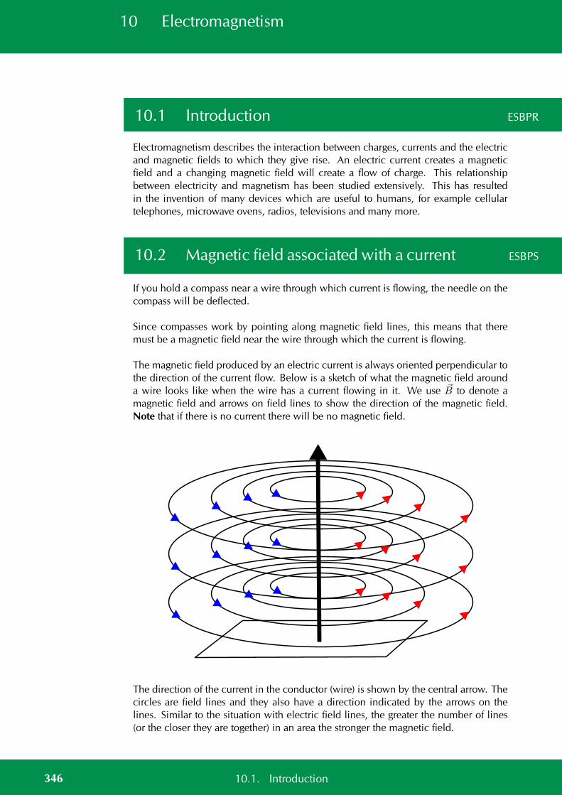
10 Electromagnetism
10.1 Introduction ESBPR
Electromagnetism describes the interaction between charges, currents and the electricand magnetic fields to which they give rise. An electric current creates a magneticfield and a changing magnetic field will create a flow of charge. This relationshipbetween electricity and magnetism has been studied extensively. This has resultedin the invention of many devices which are useful to humans, for example cellulartelephones, microwave ovens, radios, televisions and many more.
10.2 Magnetic field associated with a current ESBPS
If you hold a compass near a wire through which current is flowing, the needle on thecompass will be deflected.
Since compasses work by pointing along magnetic field lines, this means that theremust be a magnetic field near the wire through which the current is flowing.
The magnetic field produced by an electric current is always oriented perpendicular tothe direction of the current flow. Below is a sketch of what the magnetic field arounda wire looks like when the wire has a current flowing in it. We use B to denote amagnetic field and arrows on field lines to show the direction of the magnetic field.Note that if there is no current there will be no magnetic field.
The direction of the current in the conductor (wire) is shown by the central arrow. Thecircles are field lines and they also have a direction indicated by the arrows on thelines. Similar to the situation with electric field lines, the greater the number of lines(or the closer they are together) in an area the stronger the magnetic field.
346 10.1. Introduction
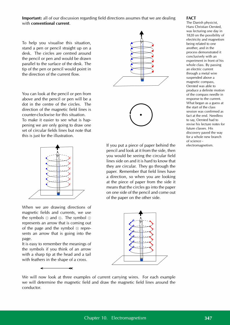
FACTThe Danish physicist,Hans Christian Oersted,was lecturing one day in1820 on the possibility ofelectricity and magnetismbeing related to oneanother, and in theprocess demonstrated itconclusively with anexperiment in front of hiswhole class. By passingan electric currentthrough a metal wiresuspended above amagnetic compass,Oersted was able toproduce a definite motionof the compass needle inresponse to the current.What began as a guess atthe start of the classsession was confirmed asfact at the end. Needlessto say, Oersted had torevise his lecture notes forfuture classes. Hisdiscovery paved the wayfor a whole new branchof science -electromagnetism.
Important: all of our discussion regarding field directions assumes that we are dealingwith conventional current.
To help you visualise this situation,stand a pen or pencil straight up on adesk. The circles are centred aroundthe pencil or pen and would be drawnparallel to the surface of the desk. Thetip of the pen or pencil would point inthe direction of the current flow.
You can look at the pencil or pen fromabove and the pencil or pen will be adot in the centre of the circles. Thedirection of the magnetic field lines iscounter-clockwise for this situation.To make it easier to see what is hap-pening we are only going to draw oneset of circular fields lines but note thatthis is just for the illustration.
××××××
If you put a piece of paper behind thepencil and look at it from the side, thenyou would be seeing the circular fieldlines side on and it is hard to know thatthey are circular. They go through thepaper. Remember that field lines havea direction, so when you are lookingat the piece of paper from the side itmeans that the circles go into the paperon one side of the pencil and come outof the paper on the other side.
When we are drawing directions ofmagnetic fields and currents, we usethe symbols and ⊗. The symbol represents an arrow that is coming outof the page and the symbol ⊗ repre-sents an arrow that is going into thepage.It is easy to remember the meanings ofthe symbols if you think of an arrowwith a sharp tip at the head and a tailwith feathers in the shape of a cross.
++++++
+
++
+++
We will now look at three examples of current carrying wires. For each examplewe will determine the magnetic field and draw the magnetic field lines around theconductor.
347Chapter 10. Electromagnetism
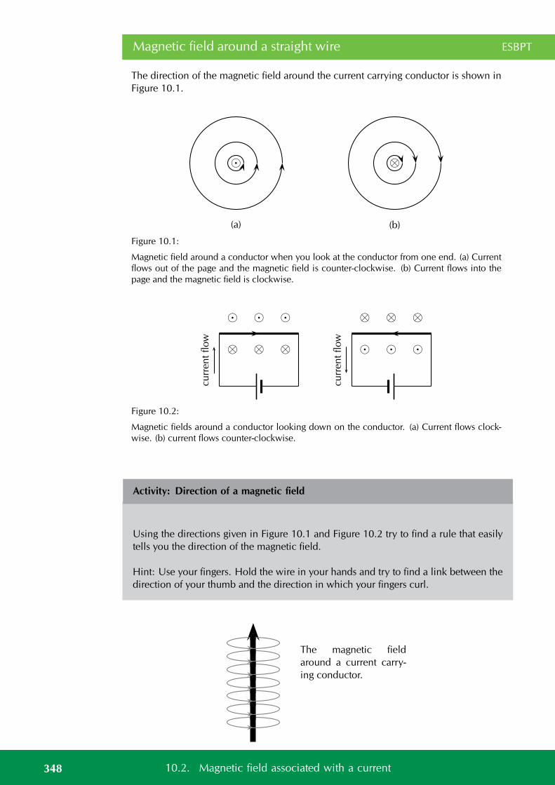
Magnetic field around a straight wire ESBPT
The direction of the magnetic field around the current carrying conductor is shown inFigure 10.1.
⊗
(a) (b)
Figure 10.1:
Magnetic field around a conductor when you look at the conductor from one end. (a) Currentflows out of the page and the magnetic field is counter-clockwise. (b) Current flows into thepage and the magnetic field is clockwise.
⊗ ⊗ ⊗
cu
rren
tflow
⊗ ⊗ ⊗
cu
rren
tflow
Figure 10.2:
Magnetic fields around a conductor looking down on the conductor. (a) Current flows clock-wise. (b) current flows counter-clockwise.
Activity: Direction of a magnetic field
Using the directions given in Figure 10.1 and Figure 10.2 try to find a rule that easilytells you the direction of the magnetic field.
Hint: Use your fingers. Hold the wire in your hands and try to find a link between thedirection of your thumb and the direction in which your fingers curl.
The magnetic field
around a current carry-
ing conductor.
348 10.2. Magnetic field associated with a current
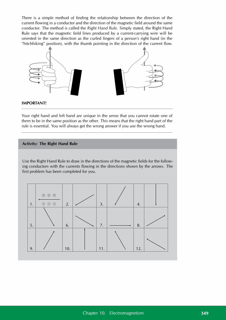
There is a simple method of finding the relationship between the direction of thecurrent flowing in a conductor and the direction of the magnetic field around the sameconductor. The method is called the Right Hand Rule. Simply stated, the Right HandRule says that the magnetic field lines produced by a current-carrying wire will beoriented in the same direction as the curled fingers of a person’s right hand (in the“hitchhiking” position), with the thumb pointing in the direction of the current flow.
IMPORTANT!
Your right hand and left hand are unique in the sense that you cannot rotate one ofthem to be in the same position as the other. This means that the right hand part of therule is essential. You will always get the wrong answer if you use the wrong hand.
Activity: The Right Hand Rule
Use the Right Hand Rule to draw in the directions of the magnetic fields for the follow-ing conductors with the currents flowing in the directions shown by the arrows. Thefirst problem has been completed for you.
1.
⊗ ⊗ ⊗
2. 3. 4.
5. 6. 7. 8.
9. 10. 11. 12.
349Chapter 10. Electromagnetism
Activity: Magnetic field around a current carrying conductor
Apparatus:
1. one 9 V battery with holder
2. two hookup wires with alligator clips
3. compass
4. stop watch
Method:
1. Connect your wires to the battery leaving one end of each wire unconnected sothat the circuit is not closed.
2. Be sure to limit the current flow to 10 seconds at a time (Why you might ask, thewire has very little resistance on its own so the battery will go flat very quickly).This is to preserve battery life as well as to prevent overheating of the wires andbattery contacts.
3. Place the compass close to the wire.
4. Close the circuit and observe what happens to the compass.
5. Reverse the polarity of the battery and close the circuit. Observe what happensto the compass.
Conclusions:
Use your observations to answer the following questions:
1. Does a current flowing in a wire generate a magnetic field?
2. Is the magnetic field present when the current is not flowing?
3. Does the direction of the magnetic field produced by a current in a wire dependon the direction of the current flow?
4. How does the direction of the current affect the magnetic field?
Magnetic field around a current carrying loop ESBPV
So far we have only looked at straight wires carrying a current and the magnetic fieldsaround them. We are going to study the magnetic field set up by circular loops of wirecarrying a current because the field has very useful properties, for example you willsee that we can set up a uniform magnetic field.
350 10.2. Magnetic field associated with a current
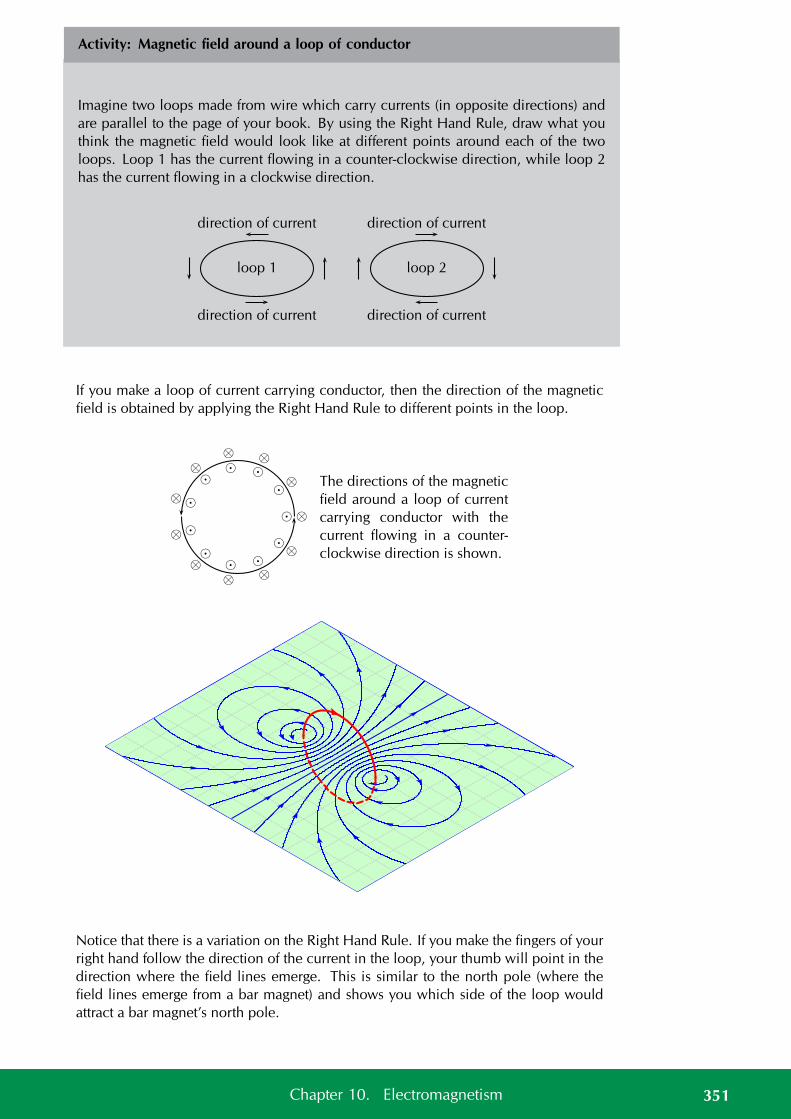
Activity: Magnetic field around a loop of conductor
Imagine two loops made from wire which carry currents (in opposite directions) andare parallel to the page of your book. By using the Right Hand Rule, draw what youthink the magnetic field would look like at different points around each of the twoloops. Loop 1 has the current flowing in a counter-clockwise direction, while loop 2has the current flowing in a clockwise direction.
direction of current
direction of current
loop 1
direction of current
direction of current
loop 2
If you make a loop of current carrying conductor, then the direction of the magneticfield is obtained by applying the Right Hand Rule to different points in the loop.
⊗
⊗
⊗
⊗
⊗
⊗
⊗
⊗
⊗
⊗
⊗
The directions of the magnetic
field around a loop of current
carrying conductor with the
current flowing in a counter-
clockwise direction is shown.
-7 -6 -5 -4 -3 -2 -1 0 1 2 3 4 5 6
-6-5-4-3-2-1 0 1 2 3 4 5 6
Notice that there is a variation on the Right Hand Rule. If you make the fingers of yourright hand follow the direction of the current in the loop, your thumb will point in thedirection where the field lines emerge. This is similar to the north pole (where thefield lines emerge from a bar magnet) and shows you which side of the loop wouldattract a bar magnet’s north pole.
351Chapter 10. Electromagnetism
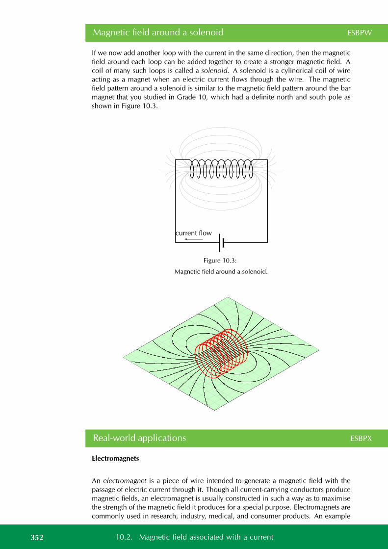
Magnetic field around a solenoid ESBPW
If we now add another loop with the current in the same direction, then the magneticfield around each loop can be added together to create a stronger magnetic field. Acoil of many such loops is called a solenoid. A solenoid is a cylindrical coil of wireacting as a magnet when an electric current flows through the wire. The magneticfield pattern around a solenoid is similar to the magnetic field pattern around the barmagnet that you studied in Grade 10, which had a definite north and south pole asshown in Figure 10.3.
current flow
Figure 10.3:
Magnetic field around a solenoid.
-7 -6 -5 -4 -3 -2 -1 0 1 2 3 4 5 6
-8-7-6-5-4-3-2-1 0 1 2 3 4 5 6 7 8
Real-world applications ESBPX
Electromagnets
An electromagnet is a piece of wire intended to generate a magnetic field with thepassage of electric current through it. Though all current-carrying conductors producemagnetic fields, an electromagnet is usually constructed in such a way as to maximisethe strength of the magnetic field it produces for a special purpose. Electromagnets arecommonly used in research, industry, medical, and consumer products. An example
352 10.2. Magnetic field associated with a current
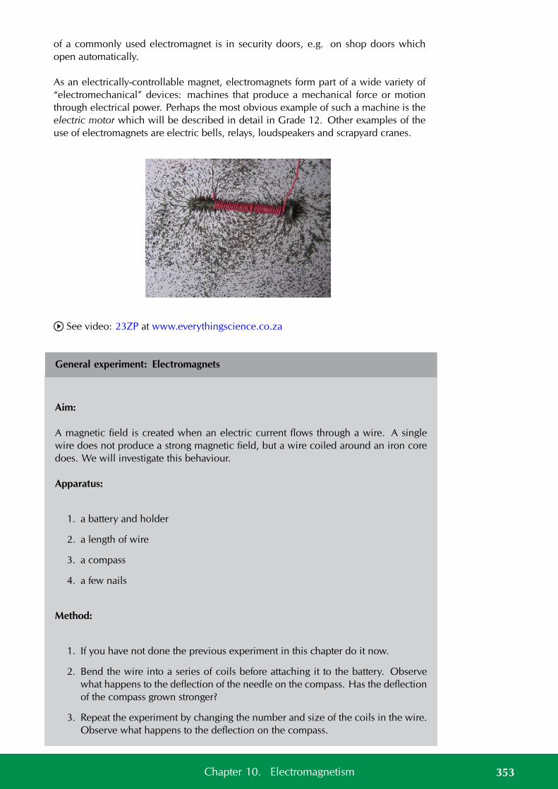
of a commonly used electromagnet is in security doors, e.g. on shop doors whichopen automatically.
As an electrically-controllable magnet, electromagnets form part of a wide variety of“electromechanical” devices: machines that produce a mechanical force or motionthrough electrical power. Perhaps the most obvious example of such a machine is theelectric motor which will be described in detail in Grade 12. Other examples of theuse of electromagnets are electric bells, relays, loudspeakers and scrapyard cranes.
See video: 23ZP at www.everythingscience.co.za
General experiment: Electromagnets
Aim:
A magnetic field is created when an electric current flows through a wire. A singlewire does not produce a strong magnetic field, but a wire coiled around an iron coredoes. We will investigate this behaviour.
Apparatus:
1. a battery and holder
2. a length of wire
3. a compass
4. a few nails
Method:
1. If you have not done the previous experiment in this chapter do it now.
2. Bend the wire into a series of coils before attaching it to the battery. Observewhat happens to the deflection of the needle on the compass. Has the deflectionof the compass grown stronger?
3. Repeat the experiment by changing the number and size of the coils in the wire.Observe what happens to the deflection on the compass.
353Chapter 10. Electromagnetism
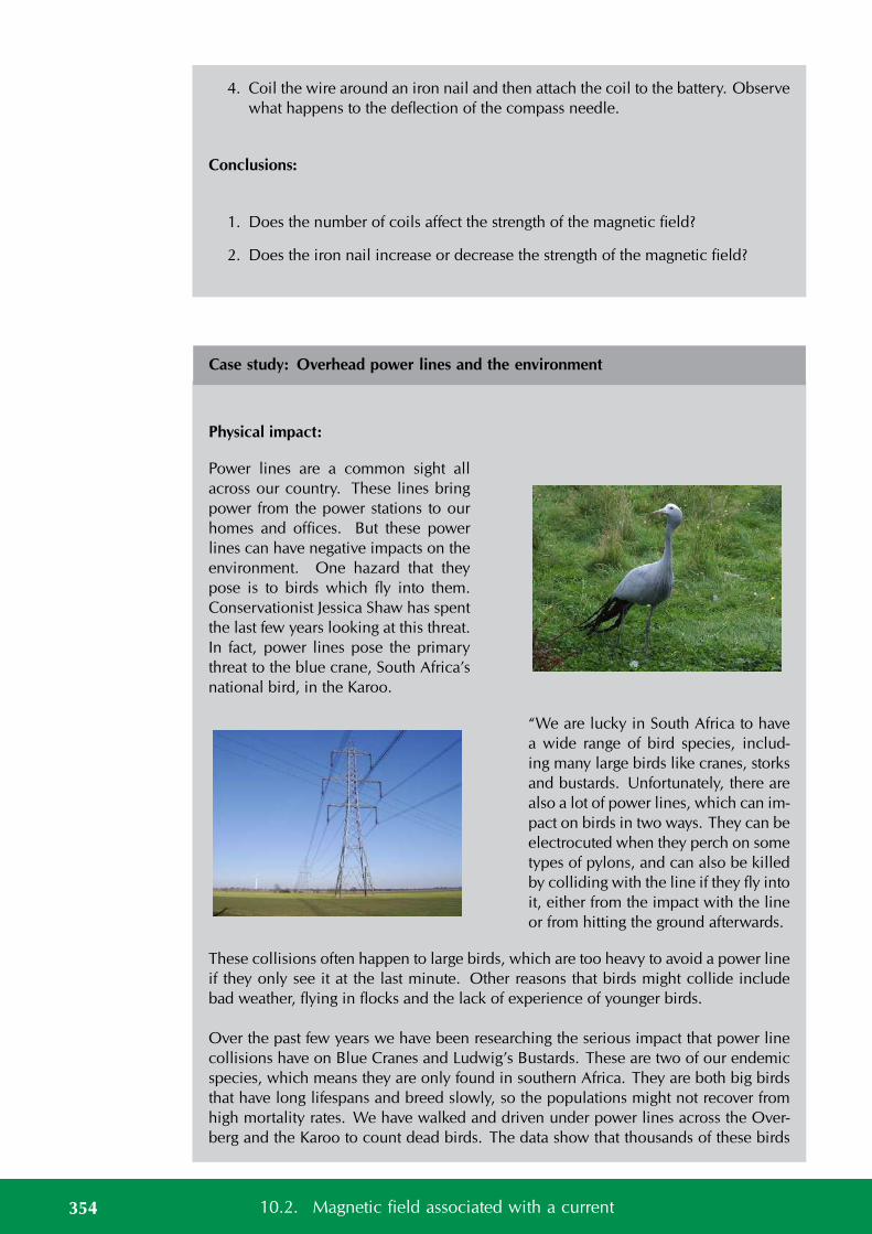
4. Coil the wire around an iron nail and then attach the coil to the battery. Observewhat happens to the deflection of the compass needle.
Conclusions:
1. Does the number of coils affect the strength of the magnetic field?
2. Does the iron nail increase or decrease the strength of the magnetic field?
Case study: Overhead power lines and the environment
Physical impact:
Power lines are a common sight allacross our country. These lines bringpower from the power stations to ourhomes and offices. But these powerlines can have negative impacts on theenvironment. One hazard that theypose is to birds which fly into them.Conservationist Jessica Shaw has spentthe last few years looking at this threat.In fact, power lines pose the primarythreat to the blue crane, South Africa’snational bird, in the Karoo.
“We are lucky in South Africa to havea wide range of bird species, includ-ing many large birds like cranes, storksand bustards. Unfortunately, there arealso a lot of power lines, which can im-pact on birds in two ways. They can beelectrocuted when they perch on sometypes of pylons, and can also be killedby colliding with the line if they fly intoit, either from the impact with the lineor from hitting the ground afterwards.
These collisions often happen to large birds, which are too heavy to avoid a power lineif they only see it at the last minute. Other reasons that birds might collide includebad weather, flying in flocks and the lack of experience of younger birds.
Over the past few years we have been researching the serious impact that power linecollisions have on Blue Cranes and Ludwig’s Bustards. These are two of our endemicspecies, which means they are only found in southern Africa. They are both big birdsthat have long lifespans and breed slowly, so the populations might not recover fromhigh mortality rates. We have walked and driven under power lines across the Over-berg and the Karoo to count dead birds. The data show that thousands of these birds
354 10.2. Magnetic field associated with a current
FACTWhen lightning strikes aship or an aeroplane, itcan damage or otherwisechange its magneticcompass. There havebeen recorded instancesof a lightning strikechanging the polarity ofthe compass so theneedle points southinstead of north.
are killed by collisions every year, and Ludwig’s Bustard is now listed as an Endan-gered species because of this high level of unnatural mortality. We are also lookingfor ways to reduce this problem, and have been working with Eskom to test differentline marking devices. When markers are hung on power lines, birds might be able tosee the power line from further away, which will give them enough time to avoid acollision.”
Impact of fields:
The fact that a field is created around the power lines means that they can potentiallyhave an impact at a distance. This has been studied and continues to be a topic ofsignificant debate. At the time of writing, the World Health Organisation guidelinesfor human exposure to electric and magnetic fields indicate that there is no clear linkbetween exposure to the magnetic and electric fields that the general public encountersfrom power lines, because these are extremely low frequency fields.
Power line noise can interfere with radio communications and broadcasting. Essen-tially, the power lines or associated hardware improperly generate unwanted radiosignals that override or compete with desired radio signals. Power line noise canimpact the quality of radio and television reception. Disruption of radio communica-tions, such as amateur radio, can also occur. Loss of critical communications, such aspolice, fire, military and other similar users of the radio spectrum, can result in evenmore serious consequences.
Group discussion:
• Discuss the above information.
• Discuss other ways that power lines affect the environment.
Exercise 10 – 1: Magnetic Fields
1. Give evidence for the existence of a magnetic field near a current carrying wire.
2. Describe how you would use your right hand to determine the direction of amagnetic field around a current carrying conductor.
3. Use the Right Hand Rule to determine the direction of the magnetic field for thefollowing situations:
355Chapter 10. Electromagnetism
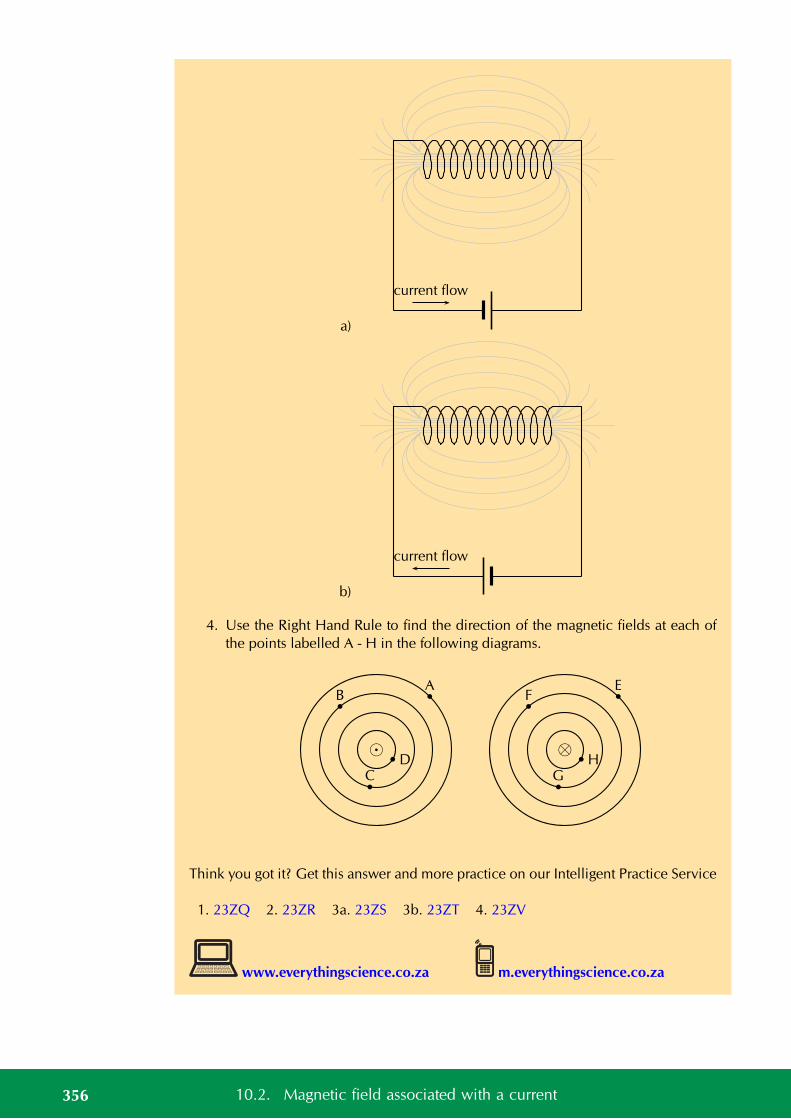
a)
current flow
b)
current flow
4. Use the Right Hand Rule to find the direction of the magnetic fields at each ofthe points labelled A - H in the following diagrams.
AB
CD
⊗
EF
GH
Think you got it? Get this answer and more practice on our Intelligent Practice Service
1. 23ZQ 2. 23ZR 3a. 23ZS 3b. 23ZT 4. 23ZV
www.everythingscience.co.za m.everythingscience.co.za
356 10.2. Magnetic field associated with a current
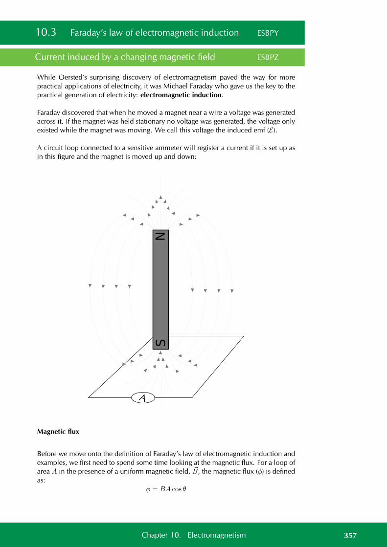
10.3 Faraday’s law of electromagnetic induction ESBPY
Current induced by a changing magnetic field ESBPZ
While Oersted’s surprising discovery of electromagnetism paved the way for morepractical applications of electricity, it was Michael Faraday who gave us the key to thepractical generation of electricity: electromagnetic induction.
Faraday discovered that when he moved a magnet near a wire a voltage was generatedacross it. If the magnet was held stationary no voltage was generated, the voltage onlyexisted while the magnet was moving. We call this voltage the induced emf (E ).
A circuit loop connected to a sensitive ammeter will register a current if it is set up asin this figure and the magnet is moved up and down:
A
Magnetic flux
Before we move onto the definition of Faraday’s law of electromagnetic induction andexamples, we first need to spend some time looking at the magnetic flux. For a loop ofarea A in the presence of a uniform magnetic field, B, the magnetic flux (φ) is definedas:
φ = BA cos θ
357Chapter 10. Electromagnetism
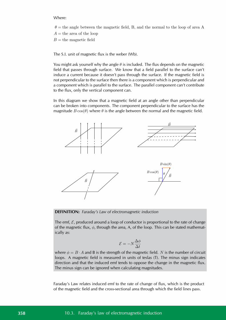
Where:
θ = the angle between the magnetic field, B, and the normal to the loop of area A
A = the area of the loop
B = the magnetic field
The S.I. unit of magnetic flux is the weber (Wb).
You might ask yourself why the angle θ is included. The flux depends on the magneticfield that passes through surface. We know that a field parallel to the surface can’tinduce a current because it doesn’t pass through the surface. If the magnetic field isnot perpendicular to the surface then there is a component which is perpendicular anda component which is parallel to the surface. The parallel component can’t contributeto the flux, only the vertical component can.
In this diagram we show that a magnetic field at an angle other than perpendicularcan be broken into components. The component perpendicular to the surface has themagnitude B cos(θ) where θ is the angle between the normal and the magnetic field.
θ B
B cos(θ)
B sin(θ)
B
B
B
DEFINITION: Faraday’s Law of electromagnetic induction
The emf, E , produced around a loop of conductor is proportional to the rate of changeof the magnetic flux, φ, through the area, A, of the loop. This can be stated mathemat-ically as:
E = −N∆φ
∆t
where φ = B ·A and B is the strength of the magnetic field. N is the number of circuitloops. A magnetic field is measured in units of teslas (T). The minus sign indicatesdirection and that the induced emf tends to oppose the change in the magnetic flux.The minus sign can be ignored when calculating magnitudes.
Faraday’s Law relates induced emf to the rate of change of flux, which is the productof the magnetic field and the cross-sectional area through which the field lines pass.
358 10.3. Faraday’s law of electromagnetic induction
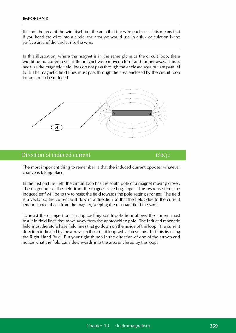
IMPORTANT!
It is not the area of the wire itself but the area that the wire encloses. This means thatif you bend the wire into a circle, the area we would use in a flux calculation is thesurface area of the circle, not the wire.
In this illustration, where the magnet is in the same plane as the circuit loop, therewould be no current even if the magnet were moved closer and further away. This isbecause the magnetic field lines do not pass through the enclosed area but are parallelto it. The magnetic field lines must pass through the area enclosed by the circuit loopfor an emf to be induced.
A
Direction of induced current ESBQ2
The most important thing to remember is that the induced current opposes whateverchange is taking place.
In the first picture (left) the circuit loop has the south pole of a magnet moving closer.The magnitude of the field from the magnet is getting larger. The response from theinduced emf will be to try to resist the field towards the pole getting stronger. The fieldis a vector so the current will flow in a direction so that the fields due to the currenttend to cancel those from the magnet, keeping the resultant field the same.
To resist the change from an approaching south pole from above, the current mustresult in field lines that move away from the approaching pole. The induced magneticfield must therefore have field lines that go down on the inside of the loop. The currentdirection indicated by the arrows on the circuit loop will achieve this. Test this by usingthe Right Hand Rule. Put your right thumb in the direction of one of the arrows andnotice what the field curls downwards into the area enclosed by the loop.
359Chapter 10. Electromagnetism
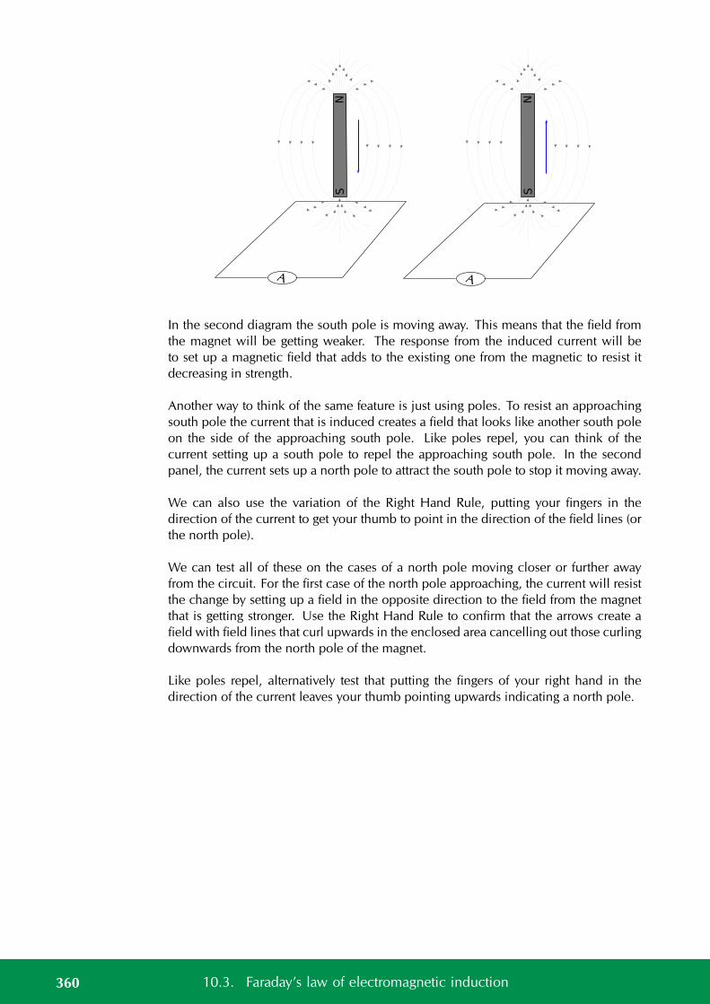
A
A
In the second diagram the south pole is moving away. This means that the field fromthe magnet will be getting weaker. The response from the induced current will beto set up a magnetic field that adds to the existing one from the magnetic to resist itdecreasing in strength.
Another way to think of the same feature is just using poles. To resist an approachingsouth pole the current that is induced creates a field that looks like another south poleon the side of the approaching south pole. Like poles repel, you can think of thecurrent setting up a south pole to repel the approaching south pole. In the secondpanel, the current sets up a north pole to attract the south pole to stop it moving away.
We can also use the variation of the Right Hand Rule, putting your fingers in thedirection of the current to get your thumb to point in the direction of the field lines (orthe north pole).
We can test all of these on the cases of a north pole moving closer or further awayfrom the circuit. For the first case of the north pole approaching, the current will resistthe change by setting up a field in the opposite direction to the field from the magnetthat is getting stronger. Use the Right Hand Rule to confirm that the arrows create afield with field lines that curl upwards in the enclosed area cancelling out those curlingdownwards from the north pole of the magnet.
Like poles repel, alternatively test that putting the fingers of your right hand in thedirection of the current leaves your thumb pointing upwards indicating a north pole.
360 10.3. Faraday’s law of electromagnetic induction
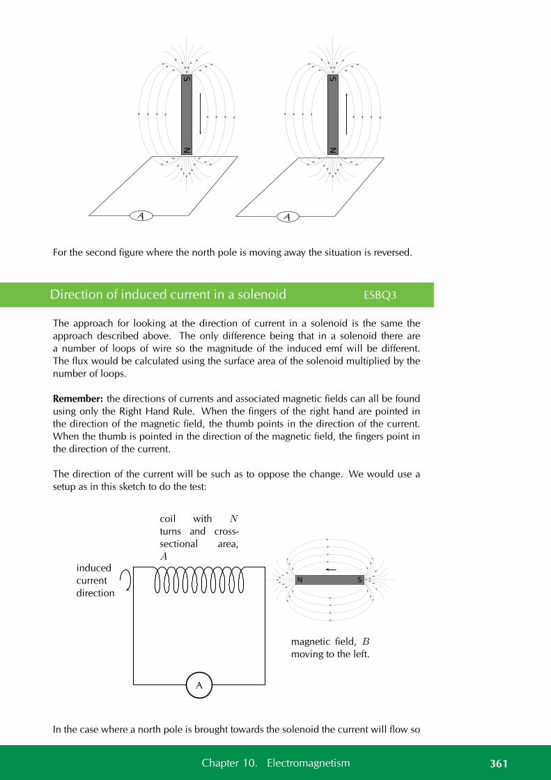
A
A
For the second figure where the north pole is moving away the situation is reversed.
Direction of induced current in a solenoid ESBQ3
The approach for looking at the direction of current in a solenoid is the same theapproach described above. The only difference being that in a solenoid there area number of loops of wire so the magnitude of the induced emf will be different.The flux would be calculated using the surface area of the solenoid multiplied by thenumber of loops.
Remember: the directions of currents and associated magnetic fields can all be foundusing only the Right Hand Rule. When the fingers of the right hand are pointed inthe direction of the magnetic field, the thumb points in the direction of the current.When the thumb is pointed in the direction of the magnetic field, the fingers point inthe direction of the current.
The direction of the current will be such as to oppose the change. We would use asetup as in this sketch to do the test:
A
coil with N
turns and cross-
sectional area,
A
magnetic field, B
moving to the left.
induced
current
direction
In the case where a north pole is brought towards the solenoid the current will flow so
361Chapter 10. Electromagnetism
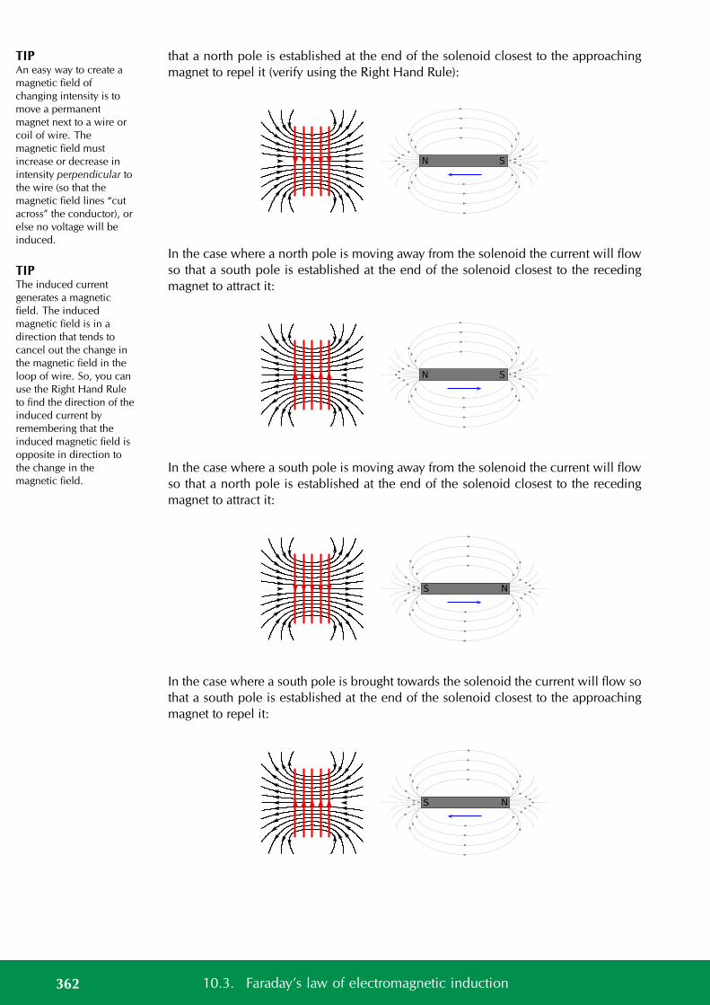
TIPAn easy way to create amagnetic field ofchanging intensity is tomove a permanentmagnet next to a wire orcoil of wire. Themagnetic field mustincrease or decrease inintensity perpendicular tothe wire (so that themagnetic field lines “cutacross” the conductor), orelse no voltage will beinduced.
TIPThe induced currentgenerates a magneticfield. The inducedmagnetic field is in adirection that tends tocancel out the change inthe magnetic field in theloop of wire. So, you canuse the Right Hand Ruleto find the direction of theinduced current byremembering that theinduced magnetic field isopposite in direction tothe change in themagnetic field.
that a north pole is established at the end of the solenoid closest to the approachingmagnet to repel it (verify using the Right Hand Rule):
In the case where a north pole is moving away from the solenoid the current will flowso that a south pole is established at the end of the solenoid closest to the recedingmagnet to attract it:
In the case where a south pole is moving away from the solenoid the current will flowso that a north pole is established at the end of the solenoid closest to the recedingmagnet to attract it:
In the case where a south pole is brought towards the solenoid the current will flow sothat a south pole is established at the end of the solenoid closest to the approachingmagnet to repel it:
362 10.3. Faraday’s law of electromagnetic induction
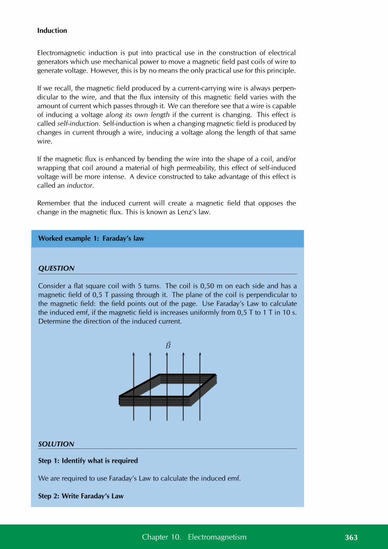
Induction
Electromagnetic induction is put into practical use in the construction of electricalgenerators which use mechanical power to move a magnetic field past coils of wire togenerate voltage. However, this is by no means the only practical use for this principle.
If we recall, the magnetic field produced by a current-carrying wire is always perpen-dicular to the wire, and that the flux intensity of this magnetic field varies with theamount of current which passes through it. We can therefore see that a wire is capableof inducing a voltage along its own length if the current is changing. This effect iscalled self-induction. Self-induction is when a changing magnetic field is produced bychanges in current through a wire, inducing a voltage along the length of that samewire.
If the magnetic flux is enhanced by bending the wire into the shape of a coil, and/orwrapping that coil around a material of high permeability, this effect of self-inducedvoltage will be more intense. A device constructed to take advantage of this effect iscalled an inductor.
Remember that the induced current will create a magnetic field that opposes thechange in the magnetic flux. This is known as Lenz’s law.
Worked example 1: Faraday’s law
QUESTION
Consider a flat square coil with 5 turns. The coil is 0,50 m on each side and has amagnetic field of 0,5 T passing through it. The plane of the coil is perpendicular tothe magnetic field: the field points out of the page. Use Faraday’s Law to calculatethe induced emf, if the magnetic field is increases uniformly from 0,5 T to 1 T in 10 s.Determine the direction of the induced current.
B
SOLUTION
Step 1: Identify what is required
We are required to use Faraday’s Law to calculate the induced emf.
Step 2: Write Faraday’s Law
363Chapter 10. Electromagnetism
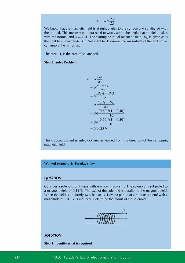
E = −N∆φ
∆t
We know that the magnetic field is at right angles to the surface and so aligned withthe normal. This means we do not need to worry about the angle that the field makeswith the normal and φ = BA. The starting or initial magnetic field, Bi, is given as isthe final field magnitude, Bf . We want to determine the magnitude of the emf so wecan ignore the minus sign.
The area, A, is the area of square coil.
Step 3: Solve Problem
E = N∆φ
∆t
= Nφf − φi
∆t
= NBfA−BiA
∆t
= NA(Bf −Bi)
∆t
= (5)(0,50)2(1 − 0,50)
10
= (5)(0,50)2(1 − 0,50)
10= 0,0625 V
The induced current is anti-clockwise as viewed from the direction of the increasingmagnetic field.
Worked example 2: Faraday’s law
QUESTION
Consider a solenoid of 9 turns with unknown radius, r. The solenoid is subjected toa magnetic field of 0,12 T. The axis of the solenoid is parallel to the magnetic field.When the field is uniformly switched to 12 T over a period of 2 minutes an emf with amagnitude of −0,3 V is induced. Determine the radius of the solenoid.
B
SOLUTION
Step 1: Identify what is required
364 10.3. Faraday’s law of electromagnetic induction
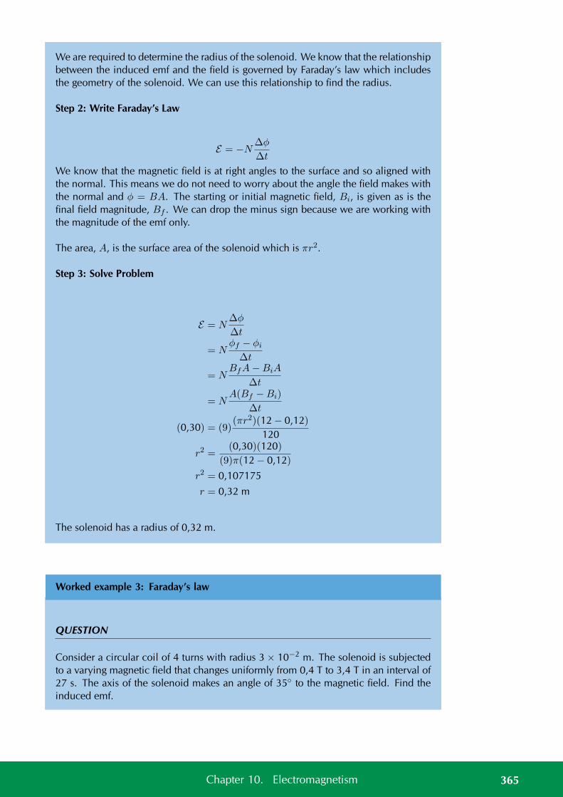
We are required to determine the radius of the solenoid. We know that the relationshipbetween the induced emf and the field is governed by Faraday’s law which includesthe geometry of the solenoid. We can use this relationship to find the radius.
Step 2: Write Faraday’s Law
E = −N∆φ
∆t
We know that the magnetic field is at right angles to the surface and so aligned withthe normal. This means we do not need to worry about the angle the field makes withthe normal and φ = BA. The starting or initial magnetic field, Bi, is given as is thefinal field magnitude, Bf . We can drop the minus sign because we are working withthe magnitude of the emf only.
The area, A, is the surface area of the solenoid which is πr2.
Step 3: Solve Problem
E = N∆φ
∆t
= Nφf − φi
∆t
= NBfA−BiA
∆t
= NA(Bf −Bi)
∆t
(0,30) = (9)(πr2)(12 − 0,12)
120
r2 =(0,30)(120)
(9)π(12 − 0,12)
r2 = 0,107175
r = 0,32 m
The solenoid has a radius of 0,32 m.
Worked example 3: Faraday’s law
QUESTION
Consider a circular coil of 4 turns with radius 3 × 10⁻² m. The solenoid is subjectedto a varying magnetic field that changes uniformly from 0,4 T to 3,4 T in an interval of27 s. The axis of the solenoid makes an angle of 35 to the magnetic field. Find theinduced emf.
365Chapter 10. Electromagnetism
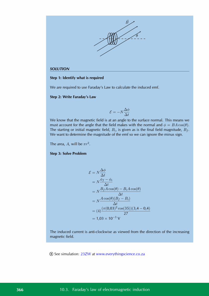
B
θ
SOLUTION
Step 1: Identify what is required
We are required to use Faraday’s Law to calculate the induced emf.
Step 2: Write Faraday’s Law
E = −N∆φ
∆t
We know that the magnetic field is at an angle to the surface normal. This means wemust account for the angle that the field makes with the normal and φ = BA cos(θ).The starting or initial magnetic field, Bi, is given as is the final field magnitude, Bf .We want to determine the magnitude of the emf so we can ignore the minus sign.
The area, A, will be πr2.
Step 3: Solve Problem
E = N∆φ
∆t
= Nφf − φi
∆t
= NBfA cos(θ)−BiA cos(θ)
∆t
= NA cos(θ)(Bf −Bi)
∆t
= (4)(π(0,03)2 cos(35))(3,4 − 0,4)
27= 1,03 × 10⁻³ V
The induced current is anti-clockwise as viewed from the direction of the increasingmagnetic field.
See simulation: 23ZW at www.everythingscience.co.za
366 10.3. Faraday’s law of electromagnetic induction
Real-life applications
The following devices use Faraday’s Law in their operation.
• induction stoves
• tape players
• metal detectors
• transformers
Project: Real-life applications of Faraday’s Law
Choose one of the following devices and do some research on the internet, or ina library, how your device works. You will need to refer to Faraday’s Law in yourexplanation.
• induction stoves
• tape players
• metal detectors
• transformers
Exercise 10 – 2: Faraday’s Law
1. State Faraday’s Law of electromagnetic induction in words and write down amathematical relationship.
2. Describe what happens when a bar magnet is pushed into or pulled out of asolenoid connected to an ammeter. Draw pictures to support your description.
3. Explain how it is possible for the magnetic flux to be zero when the magneticfield is not zero.
4. Use the Right Hand Rule to determine the direction of the induced current in thesolenoid below.
367Chapter 10. Electromagnetism
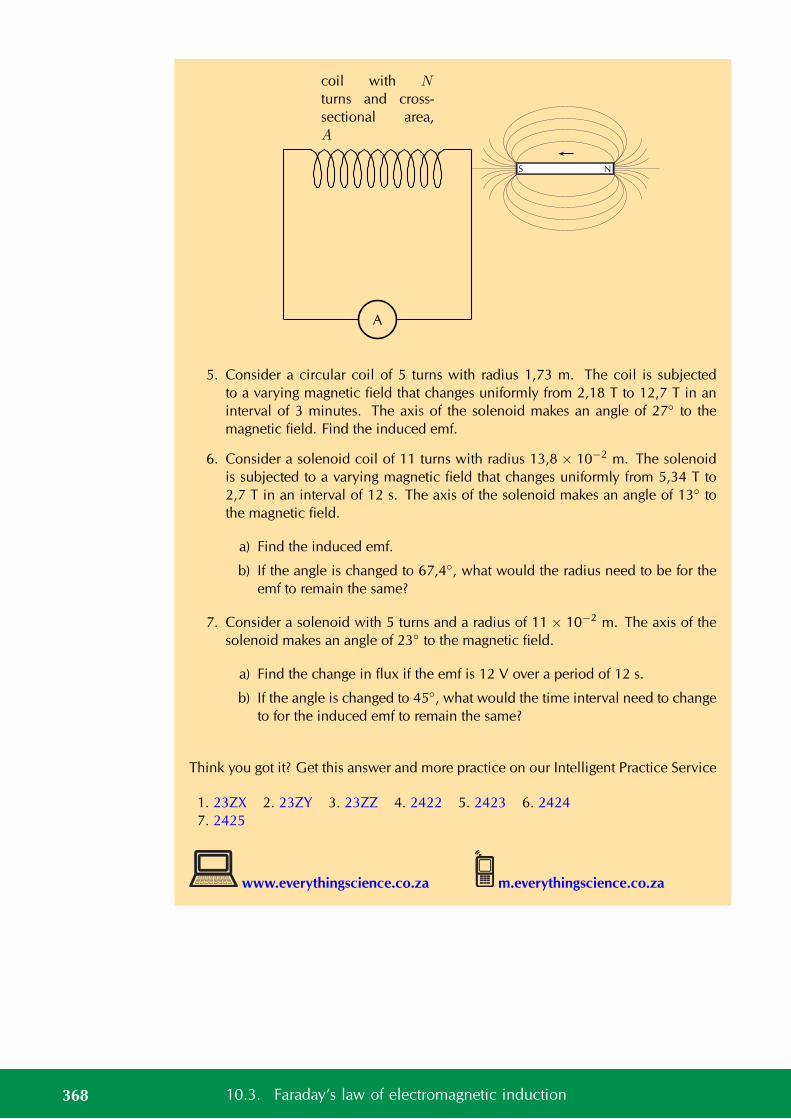
A
coil with N
turns and cross-
sectional area,
A
S N
5. Consider a circular coil of 5 turns with radius 1,73 m. The coil is subjectedto a varying magnetic field that changes uniformly from 2,18 T to 12,7 T in aninterval of 3 minutes. The axis of the solenoid makes an angle of 27 to themagnetic field. Find the induced emf.
6. Consider a solenoid coil of 11 turns with radius 13,8 × 10⁻² m. The solenoidis subjected to a varying magnetic field that changes uniformly from 5,34 T to2,7 T in an interval of 12 s. The axis of the solenoid makes an angle of 13 tothe magnetic field.
a) Find the induced emf.
b) If the angle is changed to 67,4, what would the radius need to be for theemf to remain the same?
7. Consider a solenoid with 5 turns and a radius of 11 × 10−2 m. The axis of thesolenoid makes an angle of 23 to the magnetic field.
a) Find the change in flux if the emf is 12 V over a period of 12 s.
b) If the angle is changed to 45, what would the time interval need to changeto for the induced emf to remain the same?
Think you got it? Get this answer and more practice on our Intelligent Practice Service
1. 23ZX 2. 23ZY 3. 23ZZ 4. 2422 5. 2423 6. 24247. 2425
www.everythingscience.co.za m.everythingscience.co.za
368 10.3. Faraday’s law of electromagnetic induction
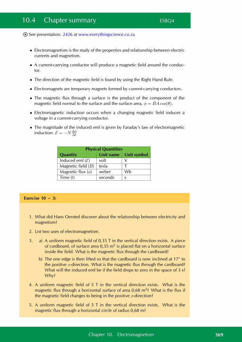
10.4 Chapter summary ESBQ4
See presentation: 2426 at www.everythingscience.co.za
• Electromagnetism is the study of the properties and relationship between electriccurrents and magnetism.
• A current-carrying conductor will produce a magnetic field around the conduc-tor.
• The direction of the magnetic field is found by using the Right Hand Rule.
• Electromagnets are temporary magnets formed by current-carrying conductors.
• The magnetic flux through a surface is the product of the component of themagnetic field normal to the surface and the surface area, φ = BA cos(θ).
• Electromagnetic induction occurs when a changing magnetic field induces avoltage in a current-carrying conductor.
• The magnitude of the induced emf is given by Faraday’s law of electromagneticinduction: E = −N ∆φ
∆t
Physical QuantitiesQuantity Unit name Unit symbolInduced emf (E ) volt VMagnetic field (B) tesla TMagnetic flux (φ) weber WbTime (t) seconds s
Exercise 10 – 3:
1. What did Hans Oersted discover about the relationship between electricity andmagnetism?
2. List two uses of electromagnetism.
3. a) A uniform magnetic field of 0,35 T in the vertical direction exists. A pieceof cardboard, of surface area 0,35 m2 is placed flat on a horizontal surfaceinside the field. What is the magnetic flux through the cardboard?
b) The one edge is then lifted so that the cardboard is now inclined at 17 tothe positive x-direction. What is the magnetic flux through the cardboard?What will the induced emf be if the field drops to zero in the space of 3 s?Why?
4. A uniform magnetic field of 5 T in the vertical direction exists. What is themagnetic flux through a horizontal surface of area 0,68 m2? What is the flux ifthe magnetic field changes to being in the positive x-direction?
5. A uniform magnetic field of 5 T in the vertical direction exists. What is themagnetic flux through a horizontal circle of radius 0,68 m?
369Chapter 10. Electromagnetism
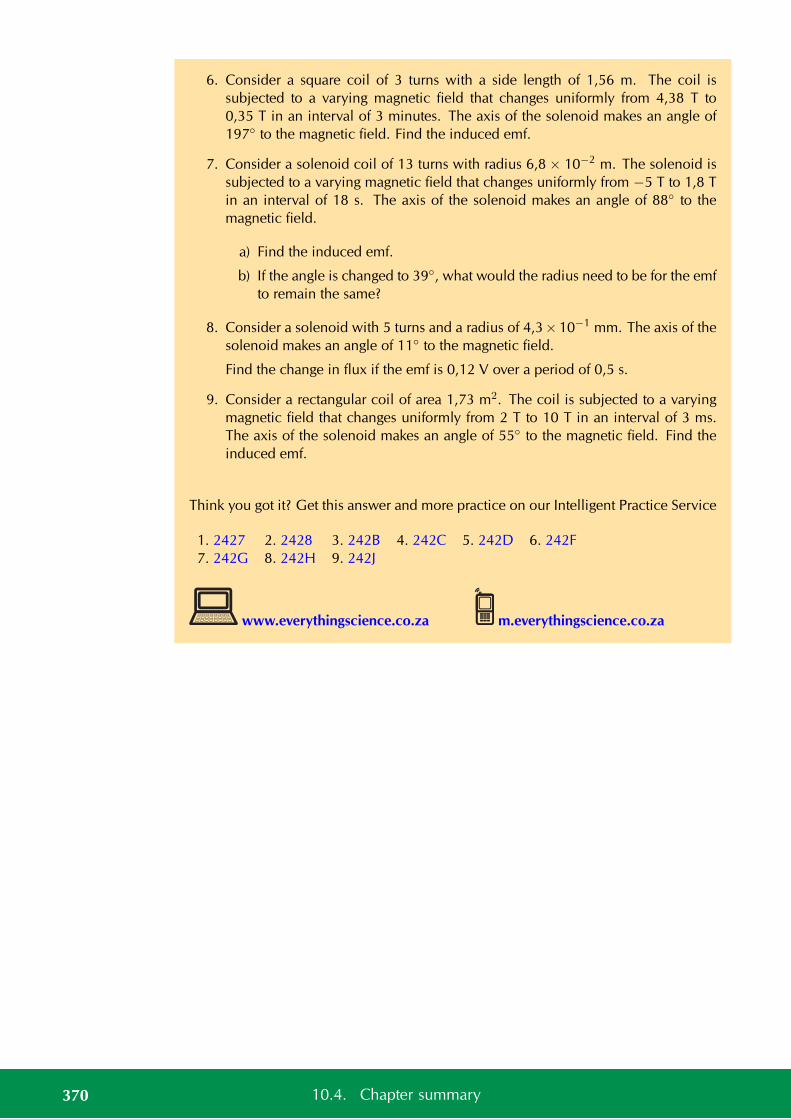
6. Consider a square coil of 3 turns with a side length of 1,56 m. The coil issubjected to a varying magnetic field that changes uniformly from 4,38 T to0,35 T in an interval of 3 minutes. The axis of the solenoid makes an angle of197 to the magnetic field. Find the induced emf.
7. Consider a solenoid coil of 13 turns with radius 6,8 × 10⁻² m. The solenoid issubjected to a varying magnetic field that changes uniformly from −5 T to 1,8 Tin an interval of 18 s. The axis of the solenoid makes an angle of 88 to themagnetic field.
a) Find the induced emf.
b) If the angle is changed to 39, what would the radius need to be for the emfto remain the same?
8. Consider a solenoid with 5 turns and a radius of 4,3×10⁻¹ mm. The axis of thesolenoid makes an angle of 11 to the magnetic field.
Find the change in flux if the emf is 0,12 V over a period of 0,5 s.
9. Consider a rectangular coil of area 1,73 m2. The coil is subjected to a varyingmagnetic field that changes uniformly from 2 T to 10 T in an interval of 3 ms.The axis of the solenoid makes an angle of 55 to the magnetic field. Find theinduced emf.
Think you got it? Get this answer and more practice on our Intelligent Practice Service
1. 2427 2. 2428 3. 242B 4. 242C 5. 242D 6. 242F7. 242G 8. 242H 9. 242J
www.everythingscience.co.za m.everythingscience.co.za
370 10.4. Chapter summary

CHAPTER 11
Electric circuits
11.1 Introduction 372
11.2 Ohm’s Law 372
11.3 Power and energy 399
11.4 Chapter summary 413
11 Electric circuits
11.1 Introduction ESBQ5
The study of electrical circuits is essential to understand the technology that uses elec-tricity in the real-world. We depend on electricity and electrical appliances to makemany things possible in our daily lives. This becomes very clear when there is a powerfailure and we can’t use the kettle to boil water for tea or coffee, can’t use the stoveor oven to cook dinner, can’t charge our cellphone batteries, watch TV, or use electriclights.
Key Mathematics Concepts
• Units and unit conversions — Physical Sciences, Grade 10, Science skills
• Equations — Mathematics, Grade 10, Equations and inequalities
• Graphs — Mathematics, Grade 10, Functions and graphs
11.2 Ohm’s Law ESBQ6
Three quantities which are fundamental to electric circuits are current, voltage (poten-tial difference) and resistance. To recap:
1. Electrical current, I, is defined as the rate of flow of charge through a circuit.
2. Potential difference or voltage, V , is the amount of energy per unit chargeneeded to move that charge between two points in a circuit.
3. Resistance, R, is a measure of how ‘hard’ it is to push current through a circuitelement.
We will now look at how these three quantities are related to each other in electriccircuits.
An important relationship between the current, voltage and resistance in a circuit wasdiscovered by Georg Simon Ohm and it is called Ohm’s Law.
DEFINITION: Ohm’s Law
The amount of electric current through a metal conductor, at a constant temperature,in a circuit is proportional to the voltage across the conductor and can be describedbyI = V
Rwhere I is the current through the conductor, V is the voltage across the conductorand R is the resistance of the conductor. In other words, at constant temperature, theresistance of the conductor is constant, independent of the voltage applied across it orcurrent passed through it.
372 11.1. Introduction
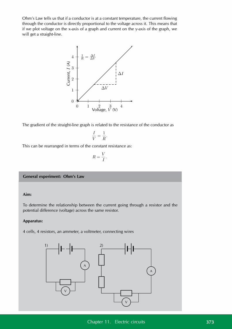
Ohm’s Law tells us that if a conductor is at a constant temperature, the current flowingthrough the conductor is directly proportional to the voltage across it. This means thatif we plot voltage on the x-axis of a graph and current on the y-axis of the graph, wewill get a straight-line.
0
1
2
3
4
0 1 2 3 4
∆I
∆V
Cu
rren
t,I
(A)
Voltage, V (V)
1R= ∆I
∆V
The gradient of the straight-line graph is related to the resistance of the conductor as
I
V=
1
R.
This can be rearranged in terms of the constant resistance as:
R =V
I.
General experiment: Ohm’s Law
Aim:
To determine the relationship between the current going through a resistor and thepotential difference (voltage) across the same resistor.
Apparatus:
4 cells, 4 resistors, an ammeter, a voltmeter, connecting wires
V
A
1)
V
A
2)
373Chapter 11. Electric circuits

Method:
This experiment has two parts. In the first part we will vary the applied voltage acrossthe resistor and measure the resulting current through the circuit. In the second partwe will vary the current in the circuit and measure the resulting voltage across theresistor. After obtaining both sets of measurements, we will examine the relationshipbetween the current and the voltage across the resistor.
1. Varying the voltage:
a) Set up the circuit according to circuit diagram 1), starting with just one cell.
b) Draw the following table in your lab book.
Number of cells Voltage, V (V) Current, I (A)1234
c) Get your teacher to check the circuit before turning the power on.
d) Measure the voltage across the resistor using the voltmeter, and the currentin the circuit using the ammeter.
e) Add one more 1,5 V cell to the circuit and repeat your measurements.
f) Repeat until you have four cells and you have completed your table.
2. Varying the current:
a) Set up the circuit according to circuit diagram 2), starting with only 1 resis-tor in the circuit.
b) Draw the following table in your lab book.
Voltage, V (V) Current, I (A)
c) Get your teacher to check your circuit before turning the power on.
d) Measure the current and measure the voltage across the single resistor.
e) Now add another resistor in series in the circuit and measure the currentand the voltage across only the original resistor again. Continue addingresistors until you have four in series, but remember to only measure thevoltage across the original resistor each time. Enter the values you measureinto the table.
Analysis and results:
1. Using the data you recorded in the first table, draw a graph of current versusvoltage. Since the voltage is the variable which we are directly varying, it isthe independent variable and will be plotted on the x-axis. The current is thedependent variable and must be plotted on the y-axis.
374 11.2. Ohm’s Law
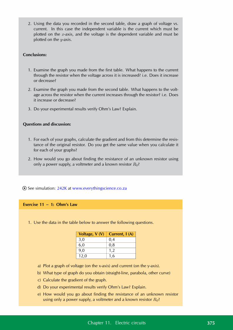
2. Using the data you recorded in the second table, draw a graph of voltage vs.current. In this case the independent variable is the current which must beplotted on the x-axis, and the voltage is the dependent variable and must beplotted on the y-axis.
Conclusions:
1. Examine the graph you made from the first table. What happens to the currentthrough the resistor when the voltage across it is increased? i.e. Does it increaseor decrease?
2. Examine the graph you made from the second table. What happens to the volt-age across the resistor when the current increases through the resistor? i.e. Doesit increase or decrease?
3. Do your experimental results verify Ohm’s Law? Explain.
Questions and discussion:
1. For each of your graphs, calculate the gradient and from this determine the resis-tance of the original resistor. Do you get the same value when you calculate itfor each of your graphs?
2. How would you go about finding the resistance of an unknown resistor usingonly a power supply, a voltmeter and a known resistor R0?
See simulation: 242K at www.everythingscience.co.za
Exercise 11 – 1: Ohm’s Law
1. Use the data in the table below to answer the following questions.
Voltage, V (V) Current, I (A)3,0 0,46,0 0,89,0 1,212,0 1,6
a) Plot a graph of voltage (on the x-axis) and current (on the y-axis).
b) What type of graph do you obtain (straight-line, parabola, other curve)
c) Calculate the gradient of the graph.
d) Do your experimental results verify Ohm’s Law? Explain.
e) How would you go about finding the resistance of an unknown resistorusing only a power supply, a voltmeter and a known resistor R0?
375Chapter 11. Electric circuits
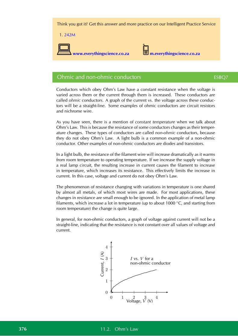
Think you got it? Get this answer and more practice on our Intelligent Practice Service
1. 242M
www.everythingscience.co.za m.everythingscience.co.za
Ohmic and non-ohmic conductors ESBQ7
Conductors which obey Ohm’s Law have a constant resistance when the voltage isvaried across them or the current through them is increased. These conductors arecalled ohmic conductors. A graph of the current vs. the voltage across these conduc-tors will be a straight-line. Some examples of ohmic conductors are circuit resistorsand nichrome wire.
As you have seen, there is a mention of constant temperature when we talk aboutOhm’s Law. This is because the resistance of some conductors changes as their temper-ature changes. These types of conductors are called non-ohmic conductors, becausethey do not obey Ohm’s Law. A light bulb is a common example of a non-ohmicconductor. Other examples of non-ohmic conductors are diodes and transistors.
In a light bulb, the resistance of the filament wire will increase dramatically as it warmsfrom room temperature to operating temperature. If we increase the supply voltage ina real lamp circuit, the resulting increase in current causes the filament to increasein temperature, which increases its resistance. This effectively limits the increase incurrent. In this case, voltage and current do not obey Ohm’s Law.
The phenomenon of resistance changing with variations in temperature is one sharedby almost all metals, of which most wires are made. For most applications, thesechanges in resistance are small enough to be ignored. In the application of metal lampfilaments, which increase a lot in temperature (up to about 1000 C, and starting fromroom temperature) the change is quite large.
In general, for non-ohmic conductors, a graph of voltage against current will not be astraight-line, indicating that the resistance is not constant over all values of voltage andcurrent.
0
1
2
3
4
0 1 2 3 4Voltage, V (V)
Cu
rren
t,I
(A)
I vs. V for anon-ohmic conductor
376 11.2. Ohm’s Law
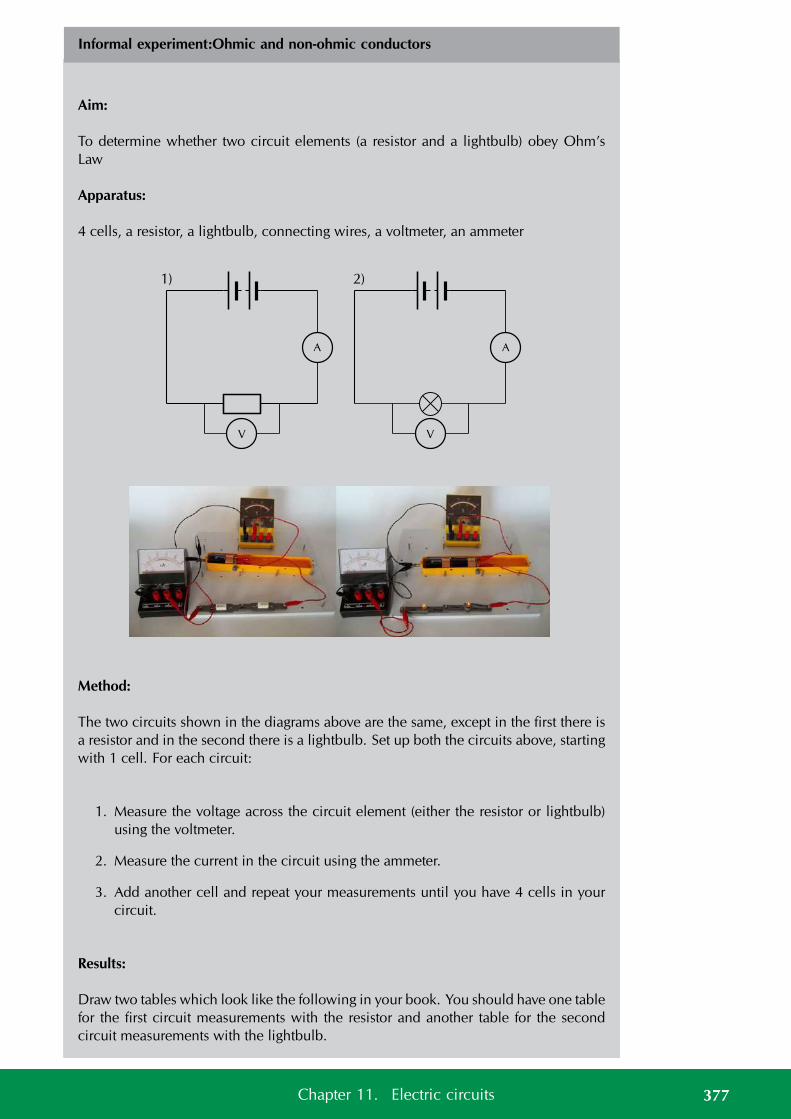
Informal experiment:Ohmic and non-ohmic conductors
Aim:
To determine whether two circuit elements (a resistor and a lightbulb) obey Ohm’sLaw
Apparatus:
4 cells, a resistor, a lightbulb, connecting wires, a voltmeter, an ammeter
V
A
1)
V
A
2)
Method:
The two circuits shown in the diagrams above are the same, except in the first there isa resistor and in the second there is a lightbulb. Set up both the circuits above, startingwith 1 cell. For each circuit:
1. Measure the voltage across the circuit element (either the resistor or lightbulb)using the voltmeter.
2. Measure the current in the circuit using the ammeter.
3. Add another cell and repeat your measurements until you have 4 cells in yourcircuit.
Results:
Draw two tables which look like the following in your book. You should have one tablefor the first circuit measurements with the resistor and another table for the secondcircuit measurements with the lightbulb.
377Chapter 11. Electric circuits
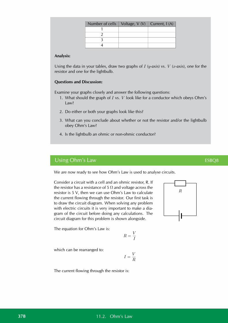
Number of cells Voltage, V (V) Current, I (A)1234
Analysis:
Using the data in your tables, draw two graphs of I (y-axis) vs. V (x-axis), one for theresistor and one for the lightbulb.
Questions and Discussion:
Examine your graphs closely and answer the following questions:1. What should the graph of I vs. V look like for a conductor which obeys Ohm’s
Law?
2. Do either or both your graphs look like this?
3. What can you conclude about whether or not the resistor and/or the lightbulbobey Ohm’s Law?
4. Is the lightbulb an ohmic or non-ohmic conductor?
Using Ohm’s Law ESBQ8
We are now ready to see how Ohm’s Law is used to analyse circuits.
Consider a circuit with a cell and an ohmic resistor, R. Ifthe resistor has a resistance of 5 Ω and voltage across theresistor is 5 V, then we can use Ohm’s Law to calculatethe current flowing through the resistor. Our first task isto draw the circuit diagram. When solving any problemwith electric circuits it is very important to make a dia-gram of the circuit before doing any calculations. Thecircuit diagram for this problem is shown alongside.
R
The equation for Ohm’s Law is:
R =V
I
which can be rearranged to:
I =V
R
The current flowing through the resistor is:
378 11.2. Ohm’s Law
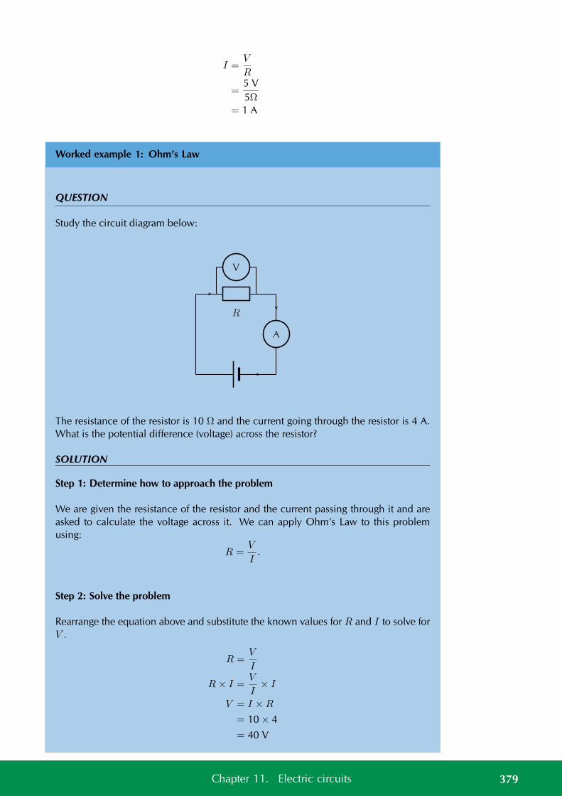
I =V
R
=5 V5Ω
= 1 A
Worked example 1: Ohm’s Law
QUESTION
Study the circuit diagram below:
R
V
A
The resistance of the resistor is 10 Ω and the current going through the resistor is 4 A.What is the potential difference (voltage) across the resistor?
SOLUTION
Step 1: Determine how to approach the problem
We are given the resistance of the resistor and the current passing through it and areasked to calculate the voltage across it. We can apply Ohm’s Law to this problemusing:
R =V
I.
Step 2: Solve the problem
Rearrange the equation above and substitute the known values for R and I to solve forV .
R =V
I
R× I =V
I× I
V = I ×R
= 10 × 4
= 40 V
379Chapter 11. Electric circuits

Step 3: Write the final answer
The voltage across the resistor is 40 V.
Exercise 11 – 2: Ohm’s Law
1. Calculate the resistance of a resistor that has a potential difference of 8 V acrossit when a current of 2 A flows through it. Draw the circuit diagram before doingthe calculation.
2. What current will flow through a resistor of 6 Ω when there is a potential dif-ference of 18 V across its ends? Draw the circuit diagram before doing thecalculation.
3. What is the voltage across a 10 Ω resistor when a current of 1,5 A flows thoughit? Draw the circuit diagram before doing the calculation.
Think you got it? Get this answer and more practice on our Intelligent Practice Service
1. 242N 2. 242P 3. 242Q
www.everythingscience.co.za m.everythingscience.co.za
Recap of resistors in series and parallel ESBQ9
In Grade 10, you learnt about resistors and were introduced to circuits where resistorswere connected in series and in parallel. In a series circuit there is one path alongwhich current flows. In a parallel circuit there are multiple paths along which currentflows.
series circuitone current path
parallel circuitmultiple current paths
When there is more than one resistor in a circuit, we are usually able to calculatethe total combined resistance of all the resistors. This is known as the equivalentresistance.
380 11.2. Ohm’s Law
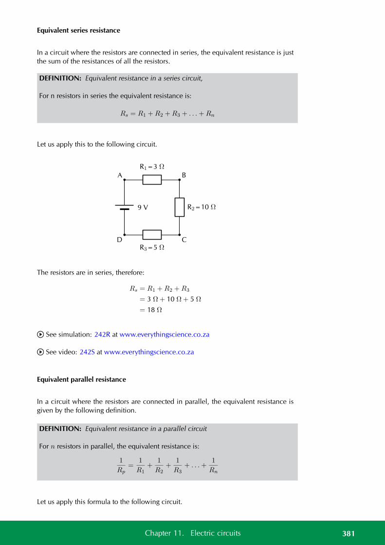
Equivalent series resistance
In a circuit where the resistors are connected in series, the equivalent resistance is justthe sum of the resistances of all the resistors.
DEFINITION: Equivalent resistance in a series circuit,
For n resistors in series the equivalent resistance is:
Rs = R1 +R2 +R3 + . . .+Rn
Let us apply this to the following circuit.
R1=3 Ω
R2=10 Ω
R3=5 Ω
9 V
A B
CD
The resistors are in series, therefore:
Rs = R1 +R2 +R3
= 3 Ω+ 10 Ω+ 5 Ω
= 18 Ω
See simulation: 242R at www.everythingscience.co.za
See video: 242S at www.everythingscience.co.za
Equivalent parallel resistance
In a circuit where the resistors are connected in parallel, the equivalent resistance isgiven by the following definition.
DEFINITION: Equivalent resistance in a parallel circuit
For n resistors in parallel, the equivalent resistance is:
1
Rp=
1
R1+
1
R2+
1
R3+ . . .+
1
Rn
Let us apply this formula to the following circuit.
381Chapter 11. Electric circuits
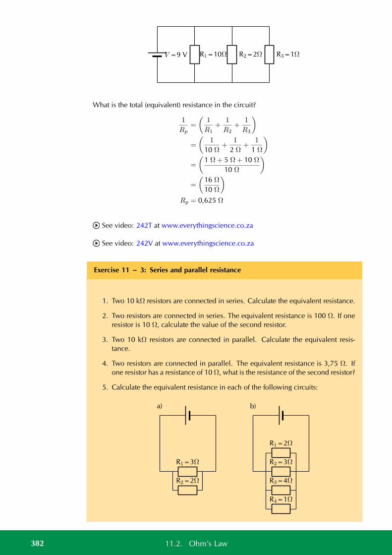
R1=10Ω R2=2Ω R3=1ΩV =9 V
What is the total (equivalent) resistance in the circuit?
1
Rp=
(1
R1+
1
R2+
1
R3
)
=
(1
10 Ω+
1
2 Ω+
1
1 Ω
)
=
(1 Ω+ 5 Ω+ 10 Ω
10 Ω
)
=
(16 Ω
10 Ω
)
Rp = 0,625 Ω
See video: 242T at www.everythingscience.co.za
See video: 242V at www.everythingscience.co.za
Exercise 11 – 3: Series and parallel resistance
1. Two 10 kΩ resistors are connected in series. Calculate the equivalent resistance.
2. Two resistors are connected in series. The equivalent resistance is 100 Ω. If oneresistor is 10 Ω, calculate the value of the second resistor.
3. Two 10 kΩ resistors are connected in parallel. Calculate the equivalent resis-tance.
4. Two resistors are connected in parallel. The equivalent resistance is 3,75 Ω. Ifone resistor has a resistance of 10 Ω, what is the resistance of the second resistor?
5. Calculate the equivalent resistance in each of the following circuits:
R1=3Ω
R2=2Ω
a)
R1=2Ω
R2=3Ω
R3=4Ω
R4=1Ω
b)
382 11.2. Ohm’s Law
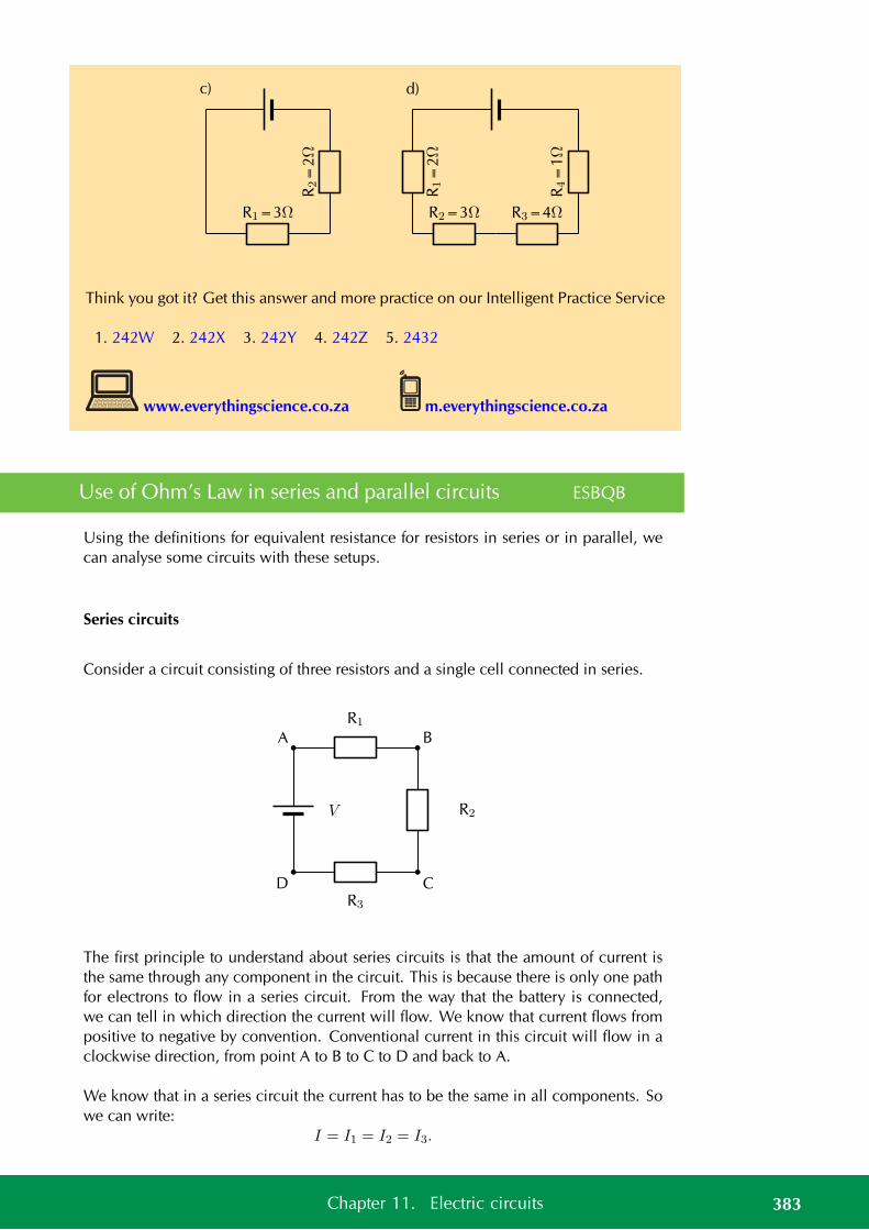
R1=3Ω
R2=
2Ω
c)
R1=
2Ω
R4=
1Ω
R3=4ΩR2=3Ω
d)
Think you got it? Get this answer and more practice on our Intelligent Practice Service
1. 242W 2. 242X 3. 242Y 4. 242Z 5. 2432
www.everythingscience.co.za m.everythingscience.co.za
Use of Ohm’s Law in series and parallel circuits ESBQB
Using the definitions for equivalent resistance for resistors in series or in parallel, wecan analyse some circuits with these setups.
Series circuits
Consider a circuit consisting of three resistors and a single cell connected in series.
R1
R2
R3
V
A B
CD
The first principle to understand about series circuits is that the amount of current isthe same through any component in the circuit. This is because there is only one pathfor electrons to flow in a series circuit. From the way that the battery is connected,we can tell in which direction the current will flow. We know that current flows frompositive to negative by convention. Conventional current in this circuit will flow in aclockwise direction, from point A to B to C to D and back to A.
We know that in a series circuit the current has to be the same in all components. Sowe can write:
I = I1 = I2 = I3.
383Chapter 11. Electric circuits
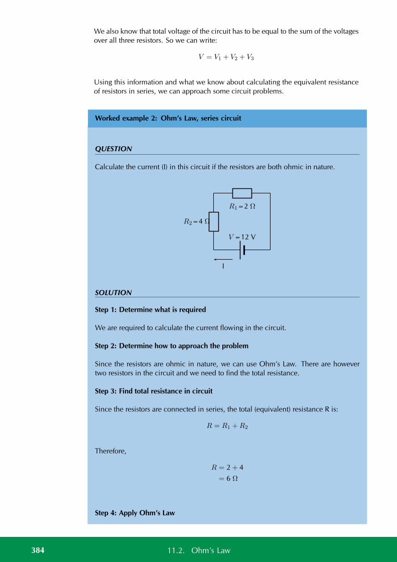
We also know that total voltage of the circuit has to be equal to the sum of the voltagesover all three resistors. So we can write:
V = V1 + V2 + V3
Using this information and what we know about calculating the equivalent resistanceof resistors in series, we can approach some circuit problems.
Worked example 2: Ohm’s Law, series circuit
QUESTION
Calculate the current (I) in this circuit if the resistors are both ohmic in nature.
V =12 V
R1=2 Ω
R2=4 Ω
I
SOLUTION
Step 1: Determine what is required
We are required to calculate the current flowing in the circuit.
Step 2: Determine how to approach the problem
Since the resistors are ohmic in nature, we can use Ohm’s Law. There are howevertwo resistors in the circuit and we need to find the total resistance.
Step 3: Find total resistance in circuit
Since the resistors are connected in series, the total (equivalent) resistance R is:
R = R1 +R2
Therefore,
R = 2 + 4
= 6 Ω
Step 4: Apply Ohm’s Law
384 11.2. Ohm’s Law
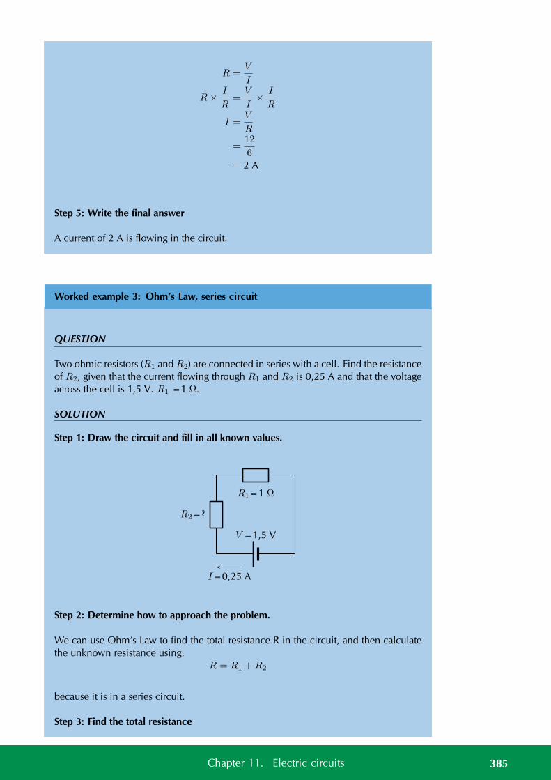
R =V
I
R× I
R=
V
I× I
R
I =V
R
=12
6= 2 A
Step 5: Write the final answer
A current of 2 A is flowing in the circuit.
Worked example 3: Ohm’s Law, series circuit
QUESTION
Two ohmic resistors (R1 and R2) are connected in series with a cell. Find the resistanceof R2, given that the current flowing through R1 and R2 is 0,25 A and that the voltageacross the cell is 1,5 V. R1 =1 Ω.
SOLUTION
Step 1: Draw the circuit and fill in all known values.
V =1,5 V
R1=1 Ω
R2=?
I=0,25 A
Step 2: Determine how to approach the problem.
We can use Ohm’s Law to find the total resistance R in the circuit, and then calculatethe unknown resistance using:
R = R1 +R2
because it is in a series circuit.
Step 3: Find the total resistance
385Chapter 11. Electric circuits
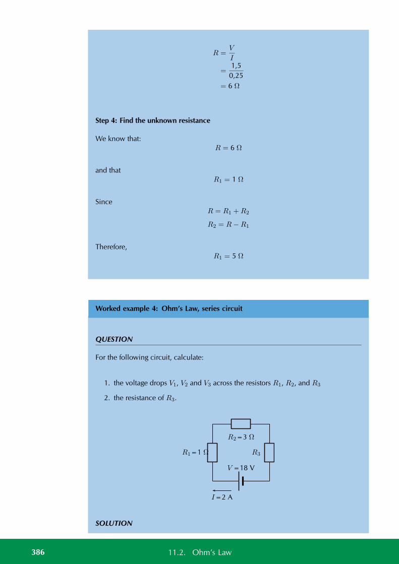
R =V
I
=1,5
0,25= 6 Ω
Step 4: Find the unknown resistance
We know that:R = 6 Ω
and thatR1 = 1 Ω
SinceR = R1 +R2
R2 = R−R1
Therefore,R1 = 5 Ω
Worked example 4: Ohm’s Law, series circuit
QUESTION
For the following circuit, calculate:
1. the voltage drops V1, V2 and V3 across the resistors R1, R2, and R3
2. the resistance of R3.
V =18 V
R2=3 Ω
R1=1 Ω R3
I=2 A
SOLUTION
386 11.2. Ohm’s Law
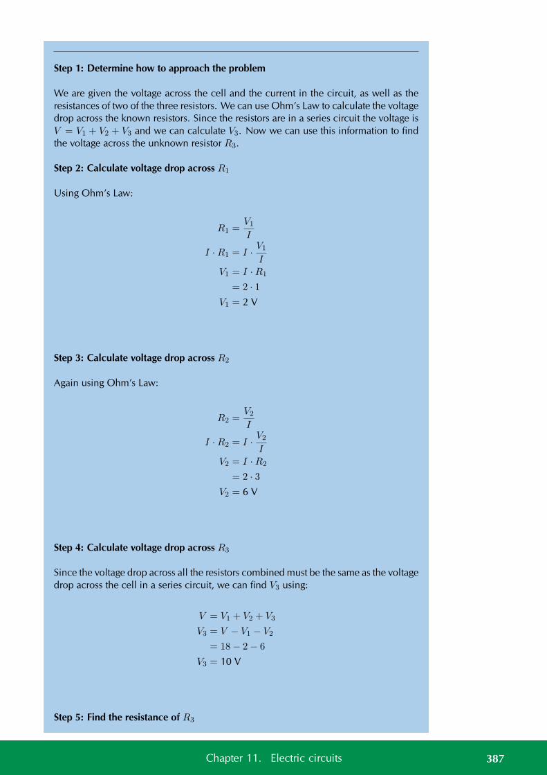
Step 1: Determine how to approach the problem
We are given the voltage across the cell and the current in the circuit, as well as theresistances of two of the three resistors. We can use Ohm’s Law to calculate the voltagedrop across the known resistors. Since the resistors are in a series circuit the voltage isV = V1 + V2 + V3 and we can calculate V3. Now we can use this information to findthe voltage across the unknown resistor R3.
Step 2: Calculate voltage drop across R1
Using Ohm’s Law:
R1 =V1
I
I ·R1 = I · V1
IV1 = I ·R1
= 2 · 1V1 = 2 V
Step 3: Calculate voltage drop across R2
Again using Ohm’s Law:
R2 =V2
I
I ·R2 = I · V2
IV2 = I ·R2
= 2 · 3V2 = 6 V
Step 4: Calculate voltage drop across R3
Since the voltage drop across all the resistors combined must be the same as the voltagedrop across the cell in a series circuit, we can find V3 using:
V = V1 + V2 + V3
V3 = V − V1 − V2
= 18− 2− 6
V3 = 10 V
Step 5: Find the resistance of R3
387Chapter 11. Electric circuits
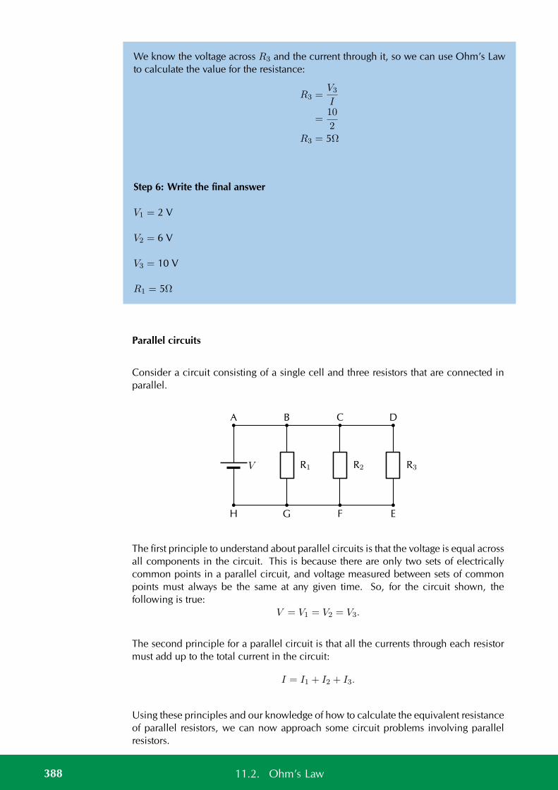
We know the voltage across R3 and the current through it, so we can use Ohm’s Lawto calculate the value for the resistance:
R3 =V3
I
=10
2R3 = 5Ω
Step 6: Write the final answer
V1 = 2 V
V2 = 6 V
V3 = 10 V
R1 = 5Ω
Parallel circuits
Consider a circuit consisting of a single cell and three resistors that are connected inparallel.
R1 R2 R3V
A B C D
EFGH
The first principle to understand about parallel circuits is that the voltage is equal acrossall components in the circuit. This is because there are only two sets of electricallycommon points in a parallel circuit, and voltage measured between sets of commonpoints must always be the same at any given time. So, for the circuit shown, thefollowing is true:
V = V1 = V2 = V3.
The second principle for a parallel circuit is that all the currents through each resistormust add up to the total current in the circuit:
I = I1 + I2 + I3.
Using these principles and our knowledge of how to calculate the equivalent resistanceof parallel resistors, we can now approach some circuit problems involving parallelresistors.
388 11.2. Ohm’s Law
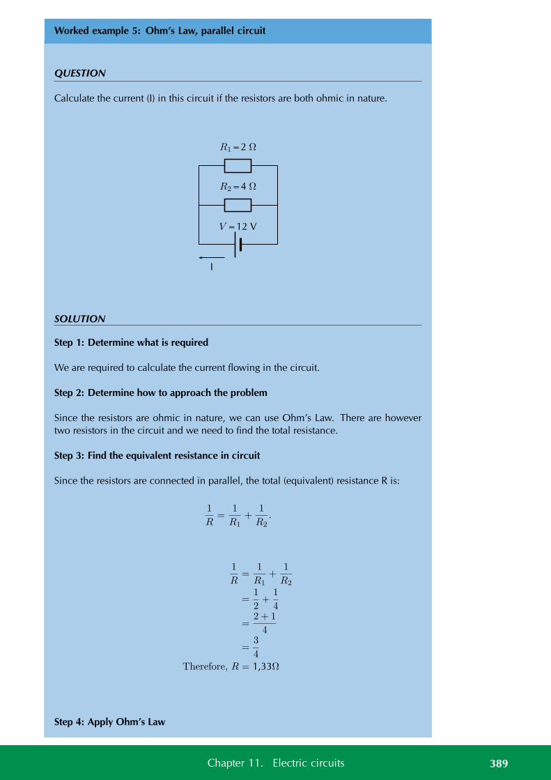
Worked example 5: Ohm’s Law, parallel circuit
QUESTION
Calculate the current (I) in this circuit if the resistors are both ohmic in nature.
V =12 V
R1=2 Ω
R2=4 Ω
I
SOLUTION
Step 1: Determine what is required
We are required to calculate the current flowing in the circuit.
Step 2: Determine how to approach the problem
Since the resistors are ohmic in nature, we can use Ohm’s Law. There are howevertwo resistors in the circuit and we need to find the total resistance.
Step 3: Find the equivalent resistance in circuit
Since the resistors are connected in parallel, the total (equivalent) resistance R is:
1
R=
1
R1+
1
R2.
1
R=
1
R1+
1
R2
=1
2+
1
4
=2 + 1
4
=3
4Therefore, R = 1,33Ω
Step 4: Apply Ohm’s Law
389Chapter 11. Electric circuits
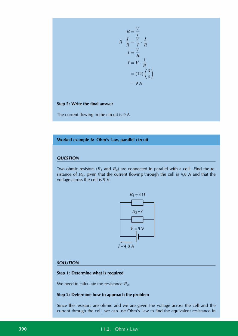
R =V
I
R · IR
=V
I· IR
I =V
R
I = V · 1R
= (12)
(3
4
)
= 9 A
Step 5: Write the final answer
The current flowing in the circuit is 9 A.
Worked example 6: Ohm’s Law, parallel circuit
QUESTION
Two ohmic resistors (R1 and R2) are connected in parallel with a cell. Find the re-sistance of R2, given that the current flowing through the cell is 4,8 A and that thevoltage across the cell is 9 V.
V =9 V
R1=3 Ω
R2=?
I=4,8 A
SOLUTION
Step 1: Determine what is required
We need to calculate the resistance R2.
Step 2: Determine how to approach the problem
Since the resistors are ohmic and we are given the voltage across the cell and thecurrent through the cell, we can use Ohm’s Law to find the equivalent resistance in
390 11.2. Ohm’s Law
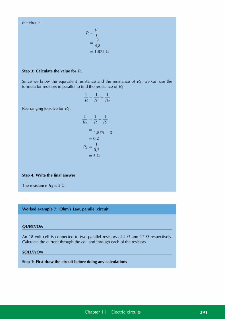
the circuit.
R =V
I
=9
4,8= 1,875 Ω
Step 3: Calculate the value for R2
Since we know the equivalent resistance and the resistance of R1, we can use theformula for resistors in parallel to find the resistance of R2.
1
R=
1
R1+
1
R2
Rearranging to solve for R2:
1
R2=
1
R− 1
R1
=1
1,875− 1
3
= 0,2
R2 =1
0,2= 5 Ω
Step 4: Write the final answer
The resistance R2 is 5 Ω
Worked example 7: Ohm’s Law, parallel circuit
QUESTION
An 18 volt cell is connected to two parallel resistors of 4 Ω and 12 Ω respectively.Calculate the current through the cell and through each of the resistors.
SOLUTION
Step 1: First draw the circuit before doing any calculations
391Chapter 11. Electric circuits
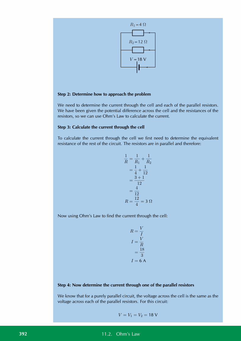
V =18 V
R1=4 Ω
R2=12 Ω
Step 2: Determine how to approach the problem
We need to determine the current through the cell and each of the parallel resistors.We have been given the potential difference across the cell and the resistances of theresistors, so we can use Ohm’s Law to calculate the current.
Step 3: Calculate the current through the cell
To calculate the current through the cell we first need to determine the equivalentresistance of the rest of the circuit. The resistors are in parallel and therefore:
1
R=
1
R1+
1
R2
=1
4+
1
12
=3 + 1
12
=4
12
R =12
4= 3 Ω
Now using Ohm’s Law to find the current through the cell:
R =V
I
I =V
R
=18
3I = 6 A
Step 4: Now determine the current through one of the parallel resistors
We know that for a purely parallel circuit, the voltage across the cell is the same as thevoltage across each of the parallel resistors. For this circuit:
V = V1 = V2 = 18 V
392 11.2. Ohm’s Law
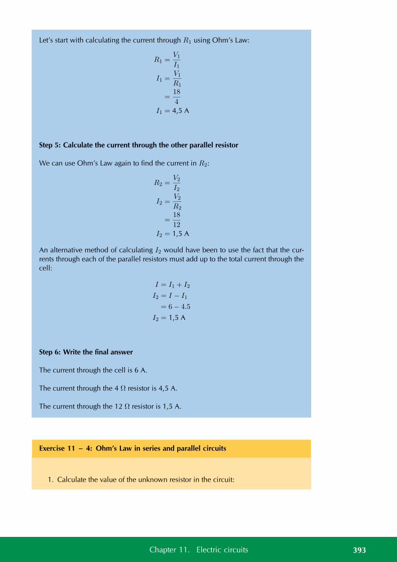
Let’s start with calculating the current through R1 using Ohm’s Law:
R1 =V1
I1
I1 =V1
R1
=18
4I1 = 4,5 A
Step 5: Calculate the current through the other parallel resistor
We can use Ohm’s Law again to find the current in R2:
R2 =V2
I2
I2 =V2
R2
=18
12I2 = 1,5 A
An alternative method of calculating I2 would have been to use the fact that the cur-rents through each of the parallel resistors must add up to the total current through thecell:
I = I1 + I2
I2 = I − I1
= 6− 4.5
I2 = 1,5 A
Step 6: Write the final answer
The current through the cell is 6 A.
The current through the 4 Ω resistor is 4,5 A.
The current through the 12 Ω resistor is 1,5 A.
Exercise 11 – 4: Ohm’s Law in series and parallel circuits
1. Calculate the value of the unknown resistor in the circuit:
393Chapter 11. Electric circuits
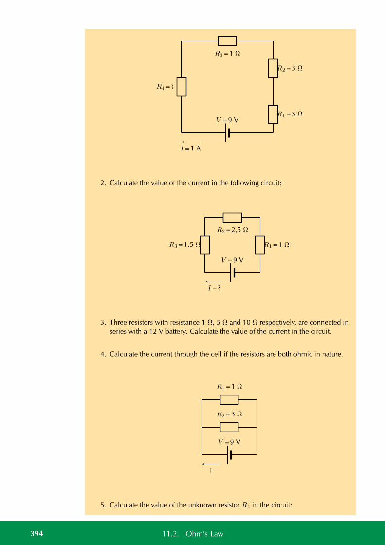
V =9 V
R3=1 Ω
R1=3 Ω
R2=3 Ω
R4=?
I=1 A
2. Calculate the value of the current in the following circuit:
V =9 V
R2=2,5 Ω
R1=1 ΩR3=1,5 Ω
I=?
3. Three resistors with resistance 1 Ω, 5 Ω and 10 Ω respectively, are connected inseries with a 12 V battery. Calculate the value of the current in the circuit.
4. Calculate the current through the cell if the resistors are both ohmic in nature.
V =9 V
R1=1 Ω
R2=3 Ω
I
5. Calculate the value of the unknown resistor R4 in the circuit:
394 11.2. Ohm’s Law
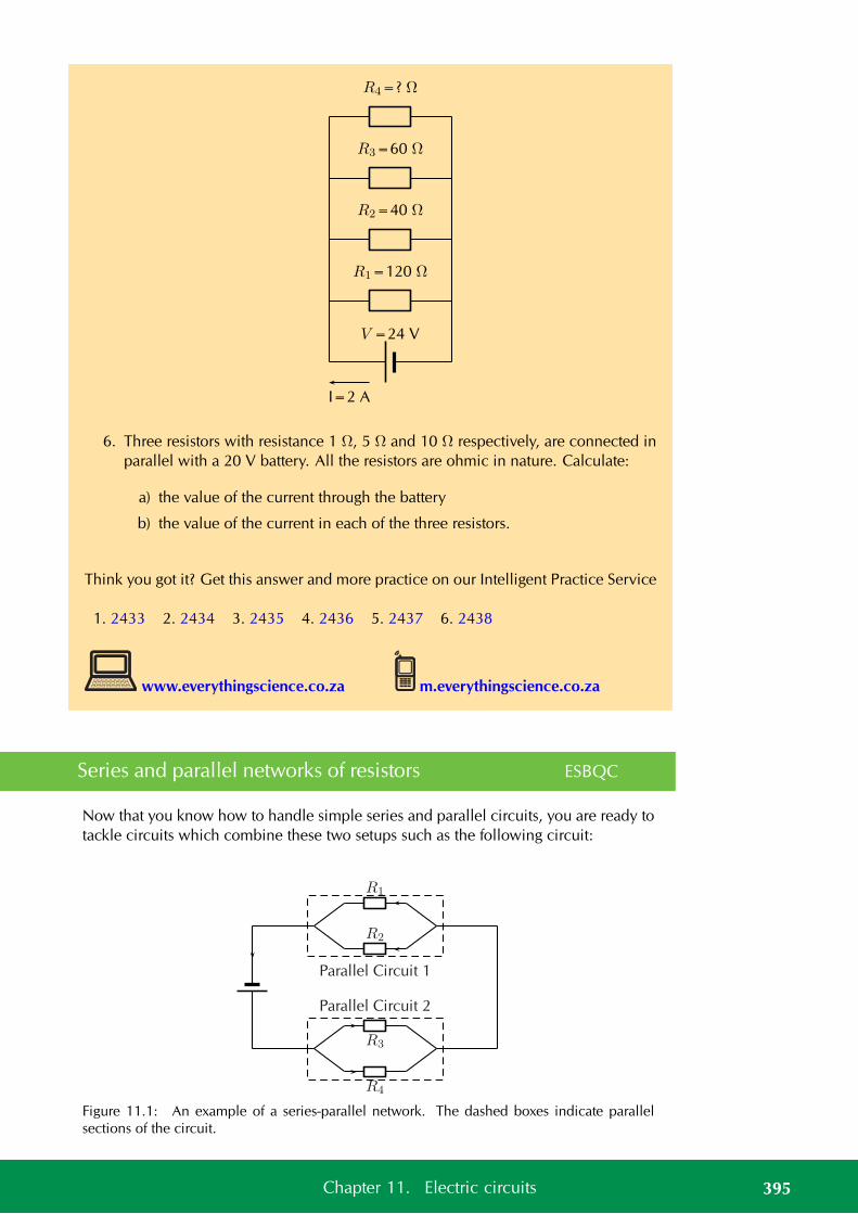
V =24 V
R2=40 Ω
R1=120 Ω
R3=60 Ω
R4=? Ω
I=2 A
6. Three resistors with resistance 1 Ω, 5 Ω and 10 Ω respectively, are connected inparallel with a 20 V battery. All the resistors are ohmic in nature. Calculate:
a) the value of the current through the battery
b) the value of the current in each of the three resistors.
Think you got it? Get this answer and more practice on our Intelligent Practice Service
1. 2433 2. 2434 3. 2435 4. 2436 5. 2437 6. 2438
www.everythingscience.co.za m.everythingscience.co.za
Series and parallel networks of resistors ESBQC
Now that you know how to handle simple series and parallel circuits, you are ready totackle circuits which combine these two setups such as the following circuit:
R1
R2
R3
R4
Parallel Circuit 2
Parallel Circuit 1
Figure 11.1: An example of a series-parallel network. The dashed boxes indicate parallelsections of the circuit.
395Chapter 11. Electric circuits
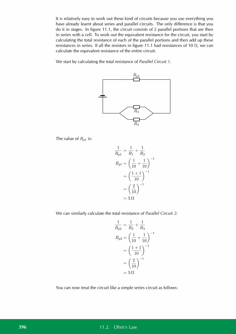
It is relatively easy to work out these kind of circuits because you use everything youhave already learnt about series and parallel circuits. The only difference is that youdo it in stages. In figure 11.1, the circuit consists of 2 parallel portions that are thenin series with a cell. To work out the equivalent resistance for the circuit, you start bycalculating the total resistance of each of the parallel portions and then add up theseresistances in series. If all the resistors in figure 11.1 had resistances of 10 Ω, we cancalculate the equivalent resistance of the entire circuit.
We start by calculating the total resistance of Parallel Circuit 1.
Rp1
R3
R4
The value of Rp1 is:
1
Rp1=
1
R1+
1
R2
Rp1 =
(1
10+
1
10
)−1
=
(1 + 1
10
)−1
=
(2
10
)−1
= 5Ω
We can similarly calculate the total resistance of Parallel Circuit 2:
1
Rp2=
1
R3+
1
R4
Rp2 =
(1
10+
1
10
)−1
=
(1 + 1
10
)−1
=
(2
10
)−1
= 5Ω
You can now treat the circuit like a simple series circuit as follows:
396 11.2. Ohm’s Law
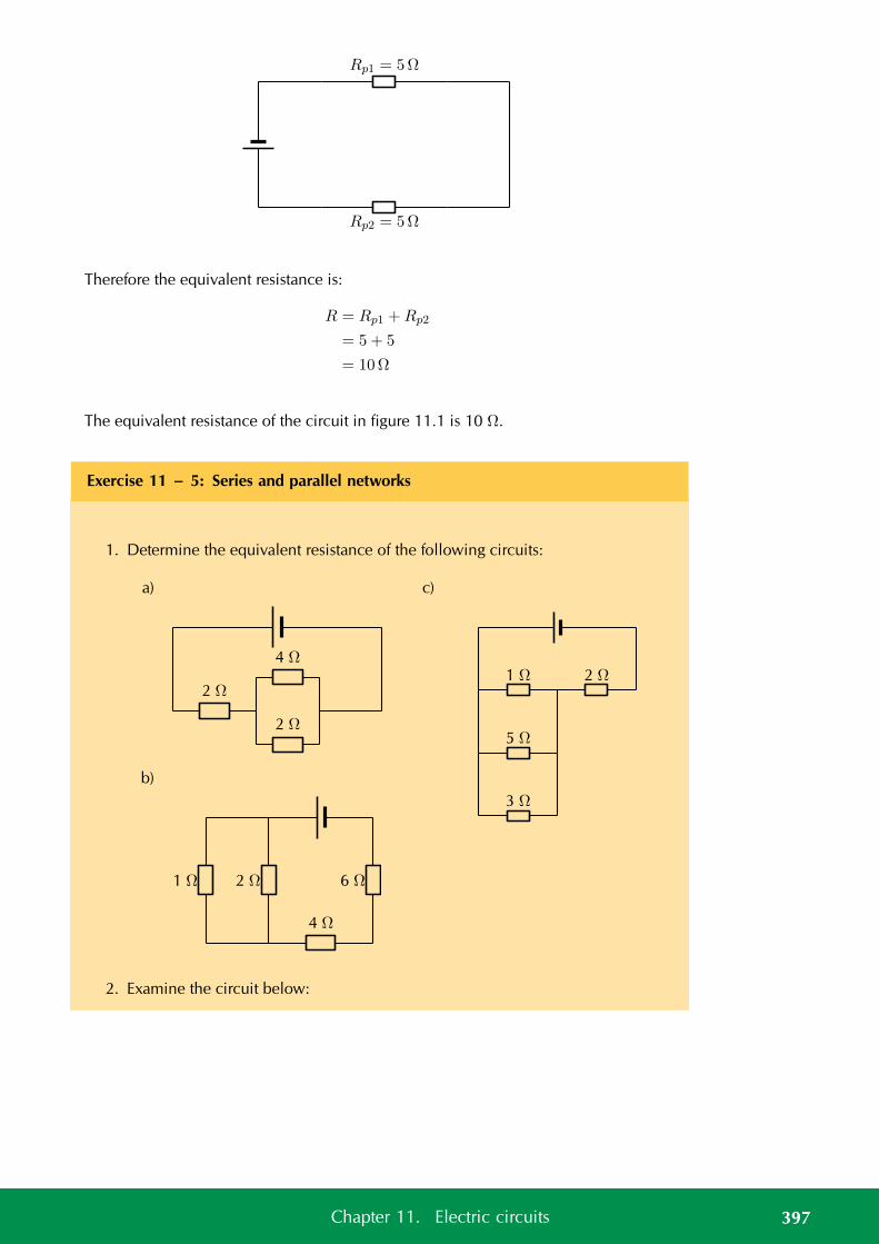
Rp1 = 5Ω
Rp2 = 5Ω
Therefore the equivalent resistance is:
R = Rp1 +Rp2
= 5 + 5
= 10Ω
The equivalent resistance of the circuit in figure 11.1 is 10 Ω.
Exercise 11 – 5: Series and parallel networks
1. Determine the equivalent resistance of the following circuits:
a)
4 Ω
2 Ω
2 Ω
b)
1 Ω 2 Ω
4 Ω
6 Ω
c)
1 Ω 2 Ω
5 Ω
3 Ω
2. Examine the circuit below:
397Chapter 11. Electric circuits
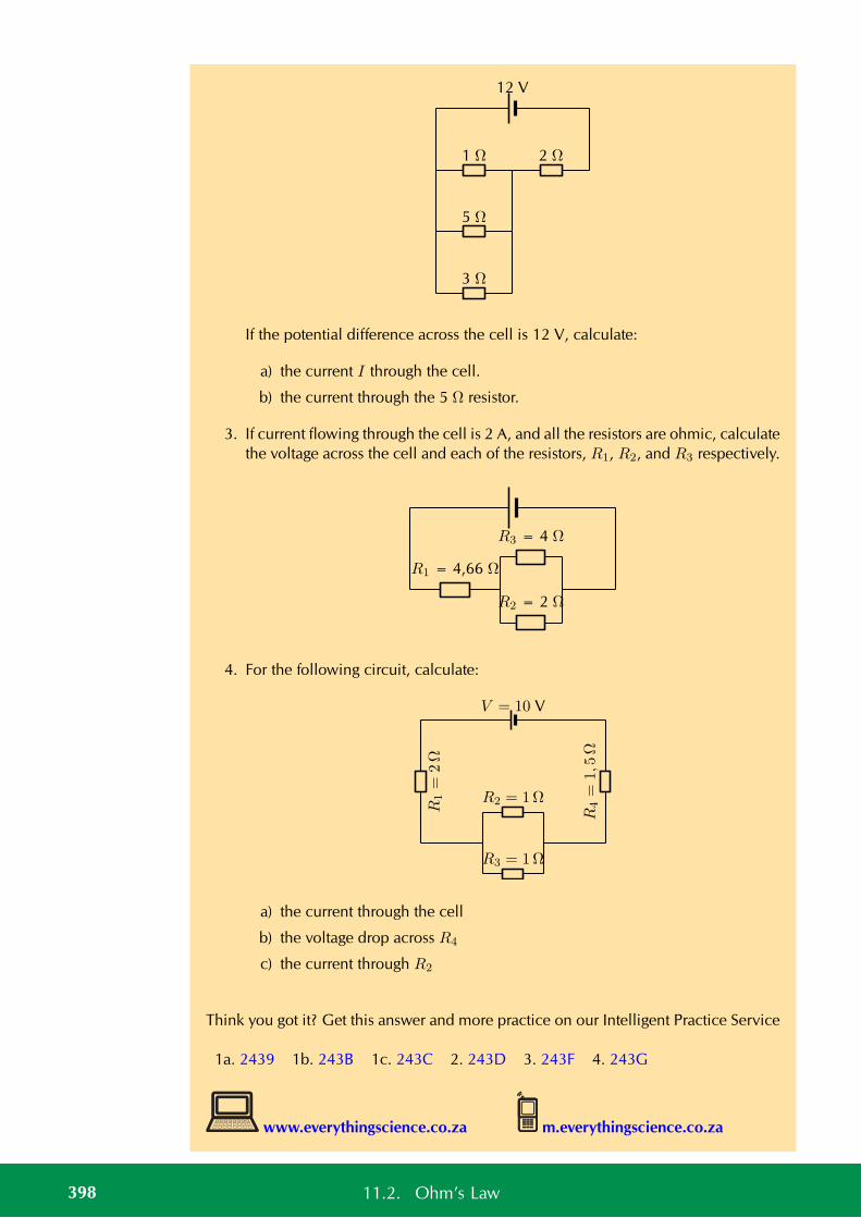
12 V
1 Ω 2 Ω
5 Ω
3 Ω
If the potential difference across the cell is 12 V, calculate:
a) the current I through the cell.
b) the current through the 5 Ω resistor.
3. If current flowing through the cell is 2 A, and all the resistors are ohmic, calculatethe voltage across the cell and each of the resistors, R1, R2, and R3 respectively.
R3 = 4 Ω
R2 = 2 Ω
R1 = 4,66 Ω
4. For the following circuit, calculate:
R1=
2Ω
R2 = 1Ω
R3 = 1Ω
R4=
1,5
Ω
V = 10 V
a) the current through the cell
b) the voltage drop across R4
c) the current through R2
Think you got it? Get this answer and more practice on our Intelligent Practice Service
1a. 2439 1b. 243B 1c. 243C 2. 243D 3. 243F 4. 243G
www.everythingscience.co.za m.everythingscience.co.za
398 11.2. Ohm’s Law
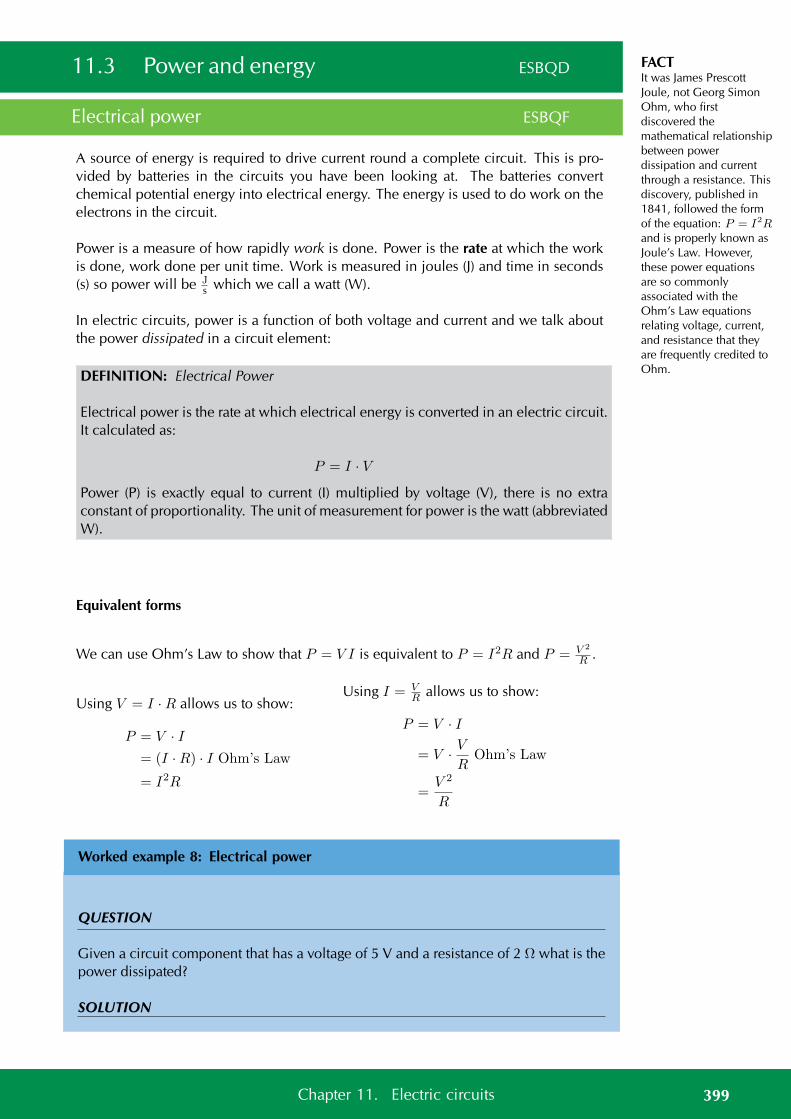
FACTIt was James PrescottJoule, not Georg SimonOhm, who firstdiscovered themathematical relationshipbetween powerdissipation and currentthrough a resistance. Thisdiscovery, published in1841, followed the formof the equation: P = I2Rand is properly known asJoule’s Law. However,these power equationsare so commonlyassociated with theOhm’s Law equationsrelating voltage, current,and resistance that theyare frequently credited toOhm.
11.3 Power and energy ESBQD
Electrical power ESBQF
A source of energy is required to drive current round a complete circuit. This is pro-vided by batteries in the circuits you have been looking at. The batteries convertchemical potential energy into electrical energy. The energy is used to do work on theelectrons in the circuit.
Power is a measure of how rapidly work is done. Power is the rate at which the workis done, work done per unit time. Work is measured in joules (J) and time in seconds(s) so power will be J
s which we call a watt (W).
In electric circuits, power is a function of both voltage and current and we talk aboutthe power dissipated in a circuit element:
DEFINITION: Electrical Power
Electrical power is the rate at which electrical energy is converted in an electric circuit.It calculated as:
P = I · V
Power (P) is exactly equal to current (I) multiplied by voltage (V), there is no extraconstant of proportionality. The unit of measurement for power is the watt (abbreviatedW).
Equivalent forms
We can use Ohm’s Law to show that P = V I is equivalent to P = I2R and P = V 2
R .
Using V = I ·R allows us to show:
P = V · I= (I ·R) · I Ohm’s Law
= I2R
Using I = VR allows us to show:
P = V · I
= V · VR
Ohm’s Law
=V 2
R
Worked example 8: Electrical power
QUESTION
Given a circuit component that has a voltage of 5 V and a resistance of 2 Ω what is thepower dissipated?
SOLUTION
399Chapter 11. Electric circuits
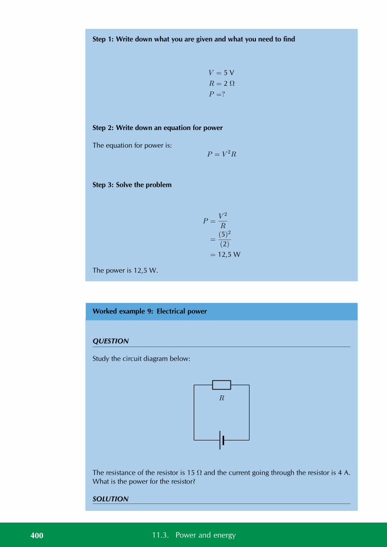
Step 1: Write down what you are given and what you need to find
V = 5 V
R = 2 Ω
P =?
Step 2: Write down an equation for power
The equation for power is:P = V 2R
Step 3: Solve the problem
P =V 2
R
=(5)2
(2)
= 12,5 W
The power is 12,5 W.
Worked example 9: Electrical power
QUESTION
Study the circuit diagram below:
R
The resistance of the resistor is 15 Ω and the current going through the resistor is 4 A.What is the power for the resistor?
SOLUTION
400 11.3. Power and energy
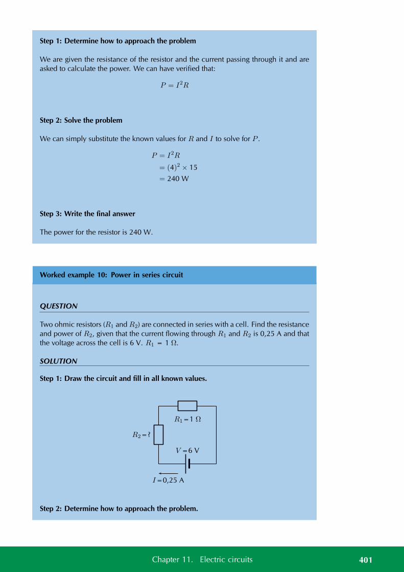
Step 1: Determine how to approach the problem
We are given the resistance of the resistor and the current passing through it and areasked to calculate the power. We can have verified that:
P = I2R
Step 2: Solve the problem
We can simply substitute the known values for R and I to solve for P .
P = I2R
= (4)2 × 15
= 240 W
Step 3: Write the final answer
The power for the resistor is 240 W.
Worked example 10: Power in series circuit
QUESTION
Two ohmic resistors (R1 and R2) are connected in series with a cell. Find the resistanceand power of R2, given that the current flowing through R1 and R2 is 0,25 A and thatthe voltage across the cell is 6 V. R1 = 1 Ω.
SOLUTION
Step 1: Draw the circuit and fill in all known values.
V =6 V
R1=1 Ω
R2=?
I=0,25 A
Step 2: Determine how to approach the problem.
401Chapter 11. Electric circuits
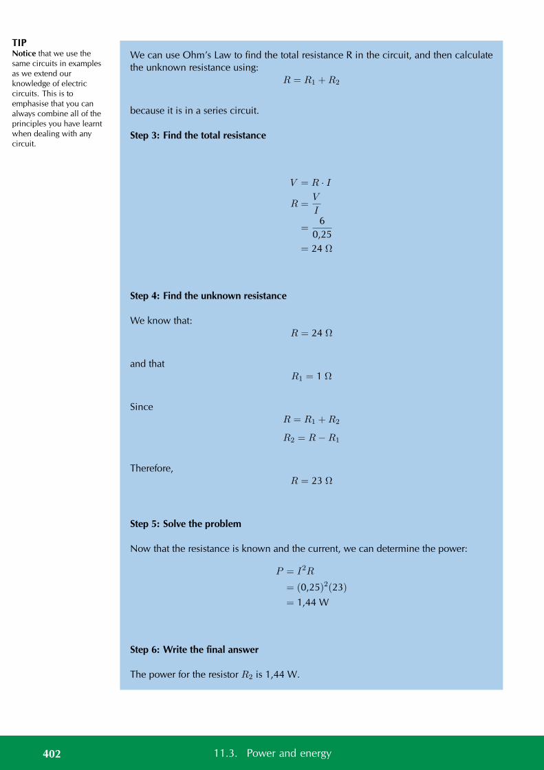
TIPNotice that we use thesame circuits in examplesas we extend ourknowledge of electriccircuits. This is toemphasise that you canalways combine all of theprinciples you have learntwhen dealing with anycircuit.
We can use Ohm’s Law to find the total resistance R in the circuit, and then calculatethe unknown resistance using:
R = R1 +R2
because it is in a series circuit.
Step 3: Find the total resistance
V = R · I
R =V
I
=6
0,25= 24 Ω
Step 4: Find the unknown resistance
We know that:R = 24 Ω
and thatR1 = 1 Ω
SinceR = R1 +R2
R2 = R−R1
Therefore,R = 23 Ω
Step 5: Solve the problem
Now that the resistance is known and the current, we can determine the power:
P = I2R
= (0,25)2(23)
= 1,44 W
Step 6: Write the final answer
The power for the resistor R2 is 1,44 W.
402 11.3. Power and energy
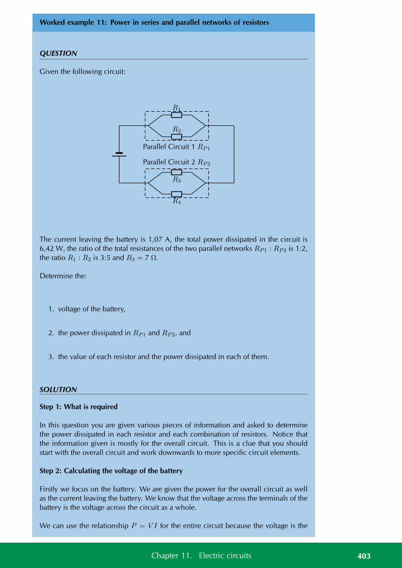
Worked example 11: Power in series and parallel networks of resistors
QUESTION
Given the following circuit:
R1
R2
R3
R4
Parallel Circuit 2 RP2
Parallel Circuit 1 RP1
The current leaving the battery is 1,07 A, the total power dissipated in the circuit is6,42 W, the ratio of the total resistances of the two parallel networks RP1 : RP2 is 1:2,the ratio R1 : R2 is 3:5 and R3 = 7 Ω.
Determine the:
1. voltage of the battery,
2. the power dissipated in RP1 and RP2, and
3. the value of each resistor and the power dissipated in each of them.
SOLUTION
Step 1: What is required
In this question you are given various pieces of information and asked to determinethe power dissipated in each resistor and each combination of resistors. Notice thatthe information given is mostly for the overall circuit. This is a clue that you shouldstart with the overall circuit and work downwards to more specific circuit elements.
Step 2: Calculating the voltage of the battery
Firstly we focus on the battery. We are given the power for the overall circuit as wellas the current leaving the battery. We know that the voltage across the terminals of thebattery is the voltage across the circuit as a whole.
We can use the relationship P = V I for the entire circuit because the voltage is the
403Chapter 11. Electric circuits
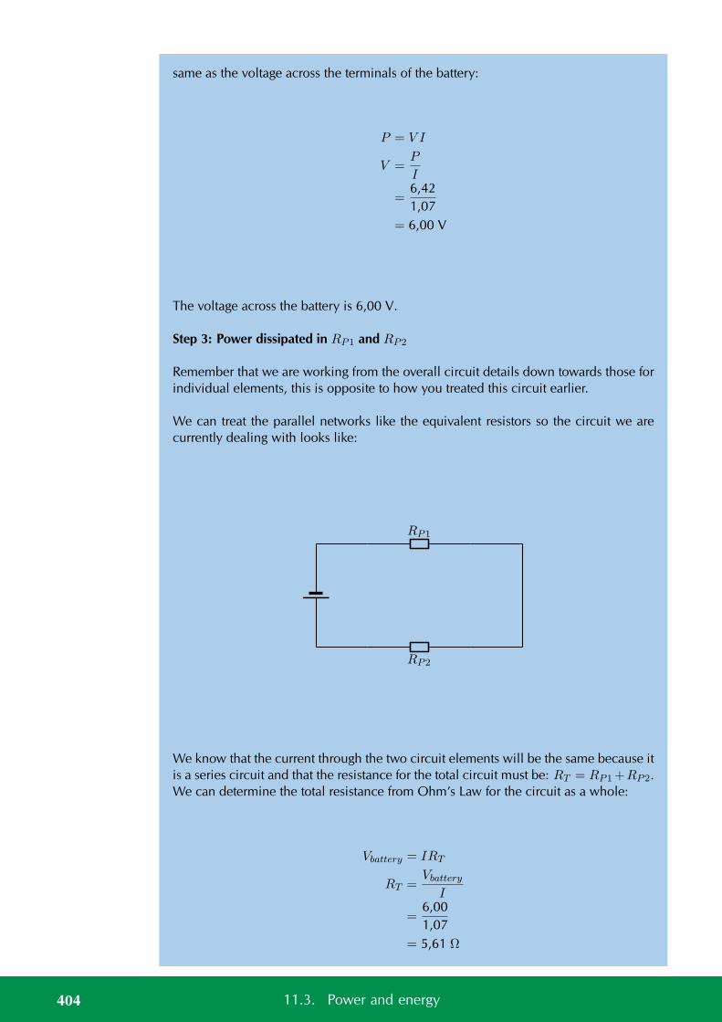
same as the voltage across the terminals of the battery:
P = V I
V =P
I
=6,421,07
= 6,00 V
The voltage across the battery is 6,00 V.
Step 3: Power dissipated in RP1 and RP2
Remember that we are working from the overall circuit details down towards those forindividual elements, this is opposite to how you treated this circuit earlier.
We can treat the parallel networks like the equivalent resistors so the circuit we arecurrently dealing with looks like:
RP1
RP2
We know that the current through the two circuit elements will be the same because itis a series circuit and that the resistance for the total circuit must be: RT = RP1+RP2.We can determine the total resistance from Ohm’s Law for the circuit as a whole:
Vbattery = IRT
RT =Vbattery
I
=6,001,07
= 5,61 Ω
404 11.3. Power and energy
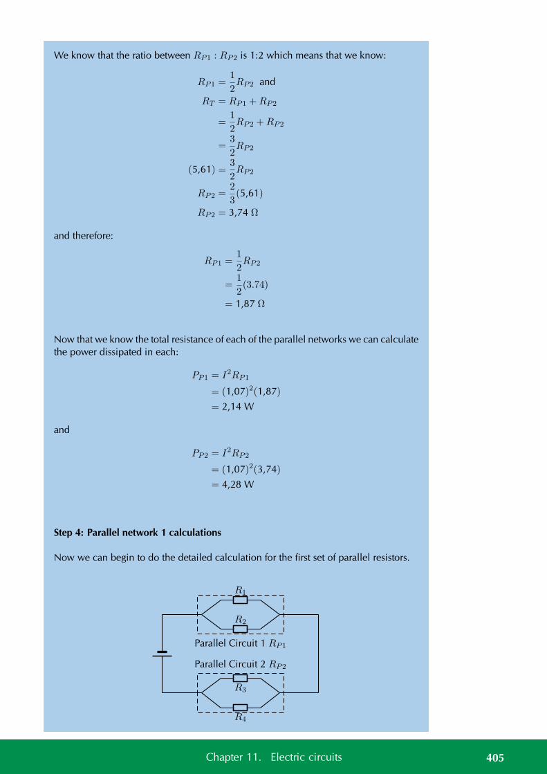
We know that the ratio between RP1 : RP2 is 1:2 which means that we know:
RP1 =1
2RP2 and
RT = RP1 +RP2
=1
2RP2 +RP2
=3
2RP2
(5,61) =3
2RP2
RP2 =2
3(5,61)
RP2 = 3,74 Ω
and therefore:
RP1 =1
2RP2
=1
2(3.74)
= 1,87 Ω
Now that we know the total resistance of each of the parallel networks we can calculatethe power dissipated in each:
PP1 = I2RP1
= (1,07)2(1,87)
= 2,14 W
and
PP2 = I2RP2
= (1,07)2(3,74)
= 4,28 W
Step 4: Parallel network 1 calculations
Now we can begin to do the detailed calculation for the first set of parallel resistors.
R1
R2
R3
R4
Parallel Circuit 2 RP2
Parallel Circuit 1 RP1
405Chapter 11. Electric circuits
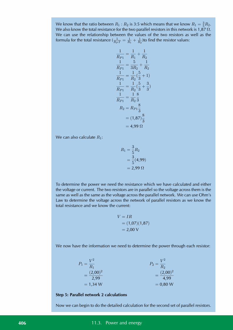
We know that the ratio between R1 : R2 is 3:5 which means that we know R1 =35R2.
We also know the total resistance for the two parallel resistors in this network is 1,87 Ω.We can use the relationship between the values of the two resistors as well as theformula for the total resistance ( 1
RPT = 1R1
+ 1R2
)to find the resistor values:
1
RP1=
1
R1+
1
R2
1
RP1=
5
3R2+
1
R2
1
RP1=
1
R2(5
3+ 1)
1
RP1=
1
R2(5
3+
3
3)
1
RP1=
1
R2
8
3
R2 = RP18
3
= (1,87)8
3= 4,99 Ω
We can also calculate R1:
R1 =3
5R2
=3
5(4,99)
= 2,99 Ω
To determine the power we need the resistance which we have calculated and eitherthe voltage or current. The two resistors are in parallel so the voltage across them is thesame as well as the same as the voltage across the parallel network. We can use Ohm’sLaw to determine the voltage across the network of parallel resistors as we know thetotal resistance and we know the current:
V = IR
= (1,07)(1,87)
= 2,00 V
We now have the information we need to determine the power through each resistor:
P1 =V 2
R1
=(2,00)2
2,99= 1,34 W
P2 =V 2
R2
=(2,00)2
4,99= 0,80 W
Step 5: Parallel network 2 calculations
Now we can begin to do the detailed calculation for the second set of parallel resistors.
406 11.3. Power and energy
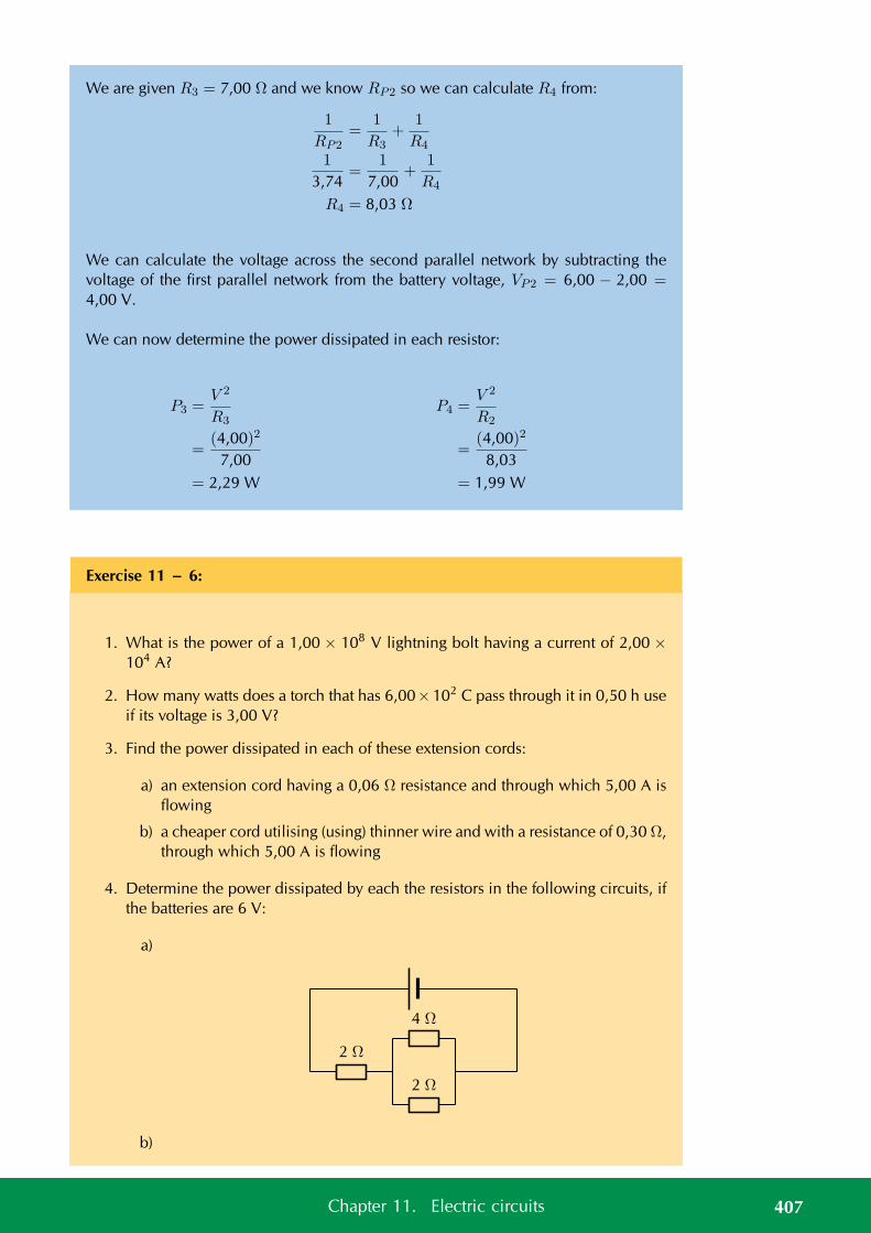
We are given R3 = 7,00 Ω and we know RP2 so we can calculate R4 from:
1
RP2=
1
R3+
1
R4
1
3,74=
1
7,00+
1
R4
R4 = 8,03 Ω
We can calculate the voltage across the second parallel network by subtracting thevoltage of the first parallel network from the battery voltage, VP2 = 6,00 − 2,00 =4,00 V.
We can now determine the power dissipated in each resistor:
P3 =V 2
R3
=(4,00)2
7,00= 2,29 W
P4 =V 2
R2
=(4,00)2
8,03= 1,99 W
Exercise 11 – 6:
1. What is the power of a 1,00 × 10⁸ V lightning bolt having a current of 2,00 ×10⁴ A?
2. How many watts does a torch that has 6,00×10² C pass through it in 0,50 h useif its voltage is 3,00 V?
3. Find the power dissipated in each of these extension cords:
a) an extension cord having a 0,06 Ω resistance and through which 5,00 A isflowing
b) a cheaper cord utilising (using) thinner wire and with a resistance of 0,30 Ω,through which 5,00 A is flowing
4. Determine the power dissipated by each the resistors in the following circuits, ifthe batteries are 6 V:
a)
4 Ω
2 Ω
2 Ω
b)
407Chapter 11. Electric circuits
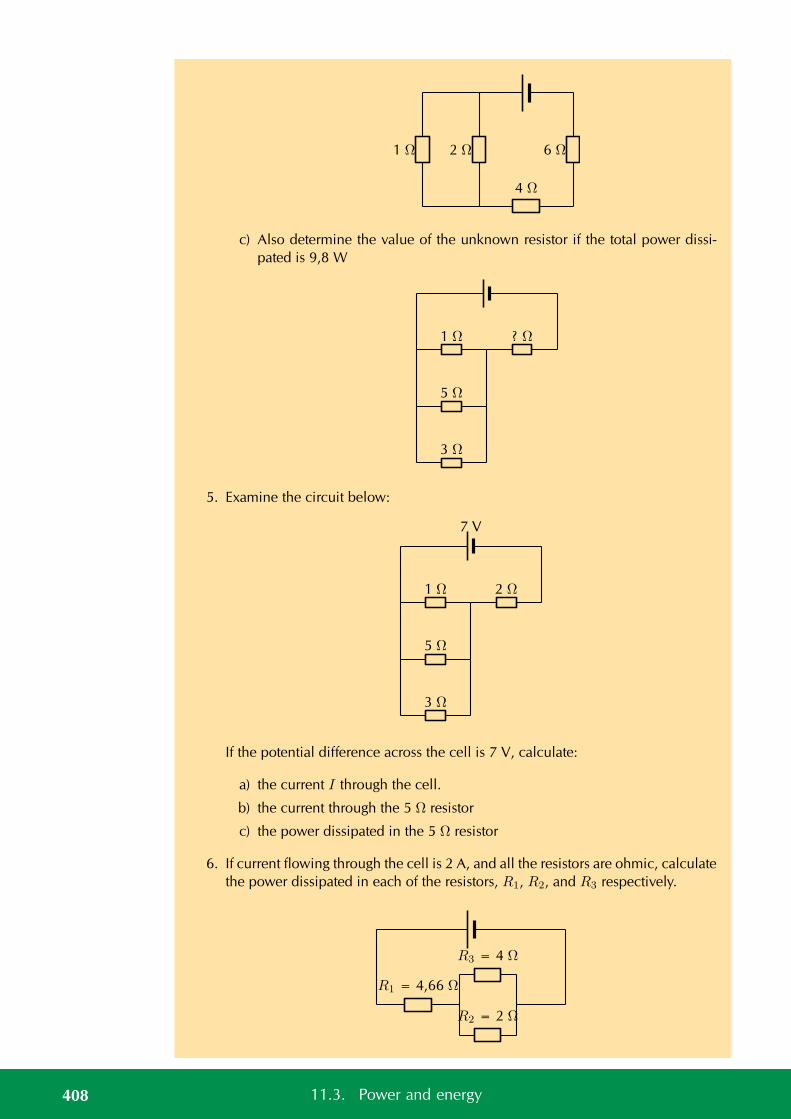
1 Ω 2 Ω
4 Ω
6 Ω
c) Also determine the value of the unknown resistor if the total power dissi-pated is 9,8 W
1 Ω ? Ω
5 Ω
3 Ω
5. Examine the circuit below:
7 V
1 Ω 2 Ω
5 Ω
3 Ω
If the potential difference across the cell is 7 V, calculate:
a) the current I through the cell.
b) the current through the 5 Ω resistor
c) the power dissipated in the 5 Ω resistor
6. If current flowing through the cell is 2 A, and all the resistors are ohmic, calculatethe power dissipated in each of the resistors, R1, R2, and R3 respectively.
R3 = 4 Ω
R2 = 2 Ω
R1 = 4,66 Ω
408 11.3. Power and energy
Think you got it? Get this answer and more practice on our Intelligent Practice Service
1. 243H 2. 243J 3. 243K 4a. 243M 4b. 243N 4c. 243P5. 243Q 6. 243R
www.everythingscience.co.za m.everythingscience.co.za
Electrical energy ESBQG
When power is dissipated in a device there is a transfer of energy from one kind toanother. For example, a resistor may get very hot which indicates that the energy isbeing dissipated as heat. Power was the rate at which work was done, the rate at whichenergy is transferred. If we want to calculate the total amount of energy we need tomultiply the rate of energy transfer by the time over which that energy transfer tookplace.
Electrical energy is simply power times time. Mathematically we write:
E = P × t
Energy is measured in joules (J) and time in seconds (s).
Worked example 12: Electrical energy
QUESTION
A 30 W light bulb is left on for 8 hours overnight, how much energy was wasted?
SOLUTION
Step 1: What is required
We need to determine the total amount of electrical energy dissipated by the lightbulb. We know the relationship between the power and energy and we are given thetime. Time is not given in the correct units so we first need to convert to S.I. units:
8 hr = 8× 3600 s
= 28 800 s
Step 2: Calculate the energy
We know that:
E = Pt
= (30)(28 800)
= 864 000 J
409Chapter 11. Electric circuits
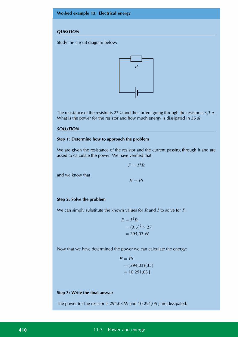
Worked example 13: Electrical energy
QUESTION
Study the circuit diagram below:
R
The resistance of the resistor is 27 Ω and the current going through the resistor is 3,3 A.What is the power for the resistor and how much energy is dissipated in 35 s?
SOLUTION
Step 1: Determine how to approach the problem
We are given the resistance of the resistor and the current passing through it and areasked to calculate the power. We have verified that:
P = I2R
and we know thatE = Pt
Step 2: Solve the problem
We can simply substitute the known values for R and I to solve for P .
P = I2R
= (3,3)2 × 27
= 294,03 W
Now that we have determined the power we can calculate the energy:
E = Pt
= (294,03)(35)
= 10 291,05 J
Step 3: Write the final answer
The power for the resistor is 294,03 W and 10 291,05 J are dissipated.
410 11.3. Power and energy
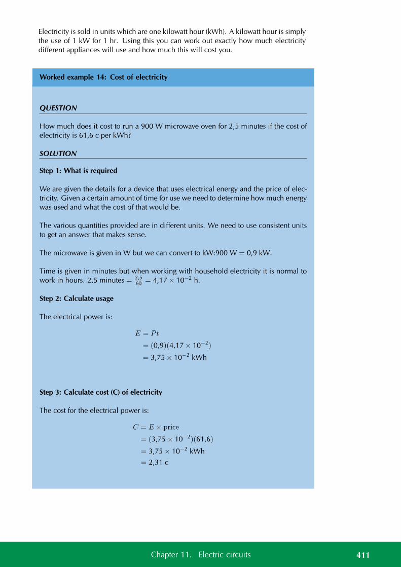
Electricity is sold in units which are one kilowatt hour (kWh). A kilowatt hour is simplythe use of 1 kW for 1 hr. Using this you can work out exactly how much electricitydifferent appliances will use and how much this will cost you.
Worked example 14: Cost of electricity
QUESTION
How much does it cost to run a 900 W microwave oven for 2,5 minutes if the cost ofelectricity is 61,6 c per kWh?
SOLUTION
Step 1: What is required
We are given the details for a device that uses electrical energy and the price of elec-tricity. Given a certain amount of time for use we need to determine how much energywas used and what the cost of that would be.
The various quantities provided are in different units. We need to use consistent unitsto get an answer that makes sense.
The microwave is given in W but we can convert to kW:900 W = 0,9 kW.
Time is given in minutes but when working with household electricity it is normal towork in hours. 2,5 minutes = 2,5
60 = 4,17 × 10⁻² h.
Step 2: Calculate usage
The electrical power is:
E = Pt
= (0,9)(4,17 × 10⁻²)
= 3,75 × 10⁻² kWh
Step 3: Calculate cost (C) of electricity
The cost for the electrical power is:
C = E × price
= (3,75 × 10⁻²)(61,6)
= 3,75 × 10⁻² kWh
= 2,31 c
411Chapter 11. Electric circuits
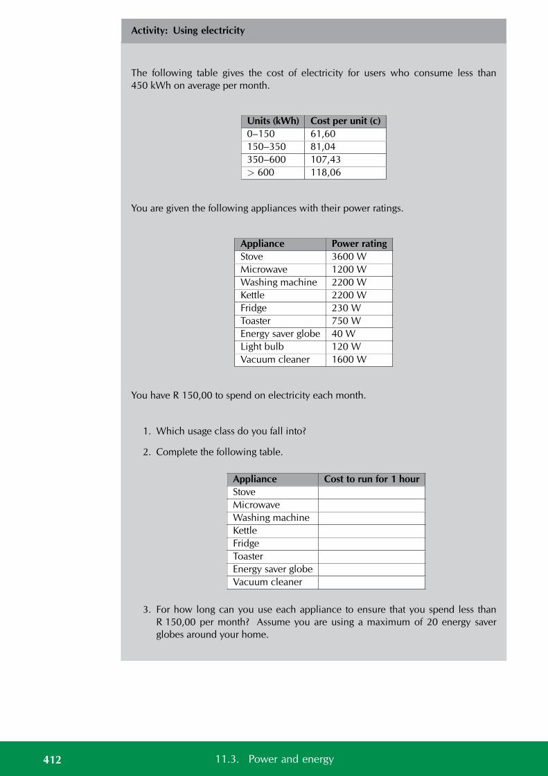
Activity: Using electricity
The following table gives the cost of electricity for users who consume less than450 kWh on average per month.
Units (kWh) Cost per unit (c)0–150 61,60150–350 81,04350–600 107,43> 600 118,06
You are given the following appliances with their power ratings.
Appliance Power ratingStove 3600 WMicrowave 1200 WWashing machine 2200 WKettle 2200 WFridge 230 WToaster 750 WEnergy saver globe 40 WLight bulb 120 WVacuum cleaner 1600 W
You have R 150,00 to spend on electricity each month.
1. Which usage class do you fall into?
2. Complete the following table.
Appliance Cost to run for 1 hourStoveMicrowaveWashing machineKettleFridgeToasterEnergy saver globeVacuum cleaner
3. For how long can you use each appliance to ensure that you spend less thanR 150,00 per month? Assume you are using a maximum of 20 energy saverglobes around your home.
412 11.3. Power and energy
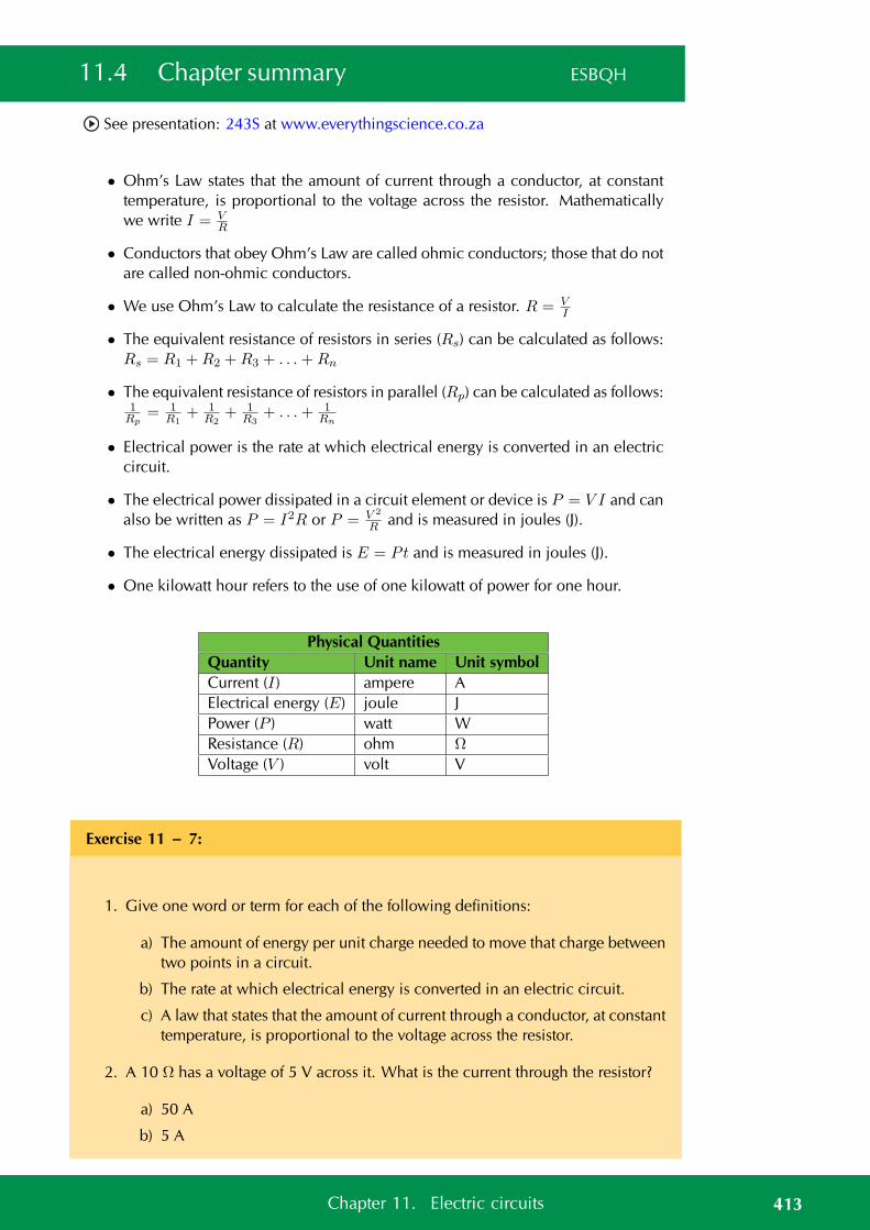
11.4 Chapter summary ESBQH
See presentation: 243S at www.everythingscience.co.za
• Ohm’s Law states that the amount of current through a conductor, at constanttemperature, is proportional to the voltage across the resistor. Mathematicallywe write I = V
R
• Conductors that obey Ohm’s Law are called ohmic conductors; those that do notare called non-ohmic conductors.
• We use Ohm’s Law to calculate the resistance of a resistor. R = VI
• The equivalent resistance of resistors in series (Rs) can be calculated as follows:Rs = R1 +R2 +R3 + . . .+Rn
• The equivalent resistance of resistors in parallel (Rp) can be calculated as follows:1Rp
= 1R1
+ 1R2
+ 1R3
+ . . .+ 1Rn
• Electrical power is the rate at which electrical energy is converted in an electriccircuit.
• The electrical power dissipated in a circuit element or device is P = V I and canalso be written as P = I2R or P = V 2
R and is measured in joules (J).
• The electrical energy dissipated is E = Pt and is measured in joules (J).
• One kilowatt hour refers to the use of one kilowatt of power for one hour.
Physical QuantitiesQuantity Unit name Unit symbolCurrent (I) ampere AElectrical energy (E) joule JPower (P ) watt WResistance (R) ohm Ω
Voltage (V ) volt V
Exercise 11 – 7:
1. Give one word or term for each of the following definitions:
a) The amount of energy per unit charge needed to move that charge betweentwo points in a circuit.
b) The rate at which electrical energy is converted in an electric circuit.
c) A law that states that the amount of current through a conductor, at constanttemperature, is proportional to the voltage across the resistor.
2. A 10 Ω has a voltage of 5 V across it. What is the current through the resistor?
a) 50 A
b) 5 A
413Chapter 11. Electric circuits
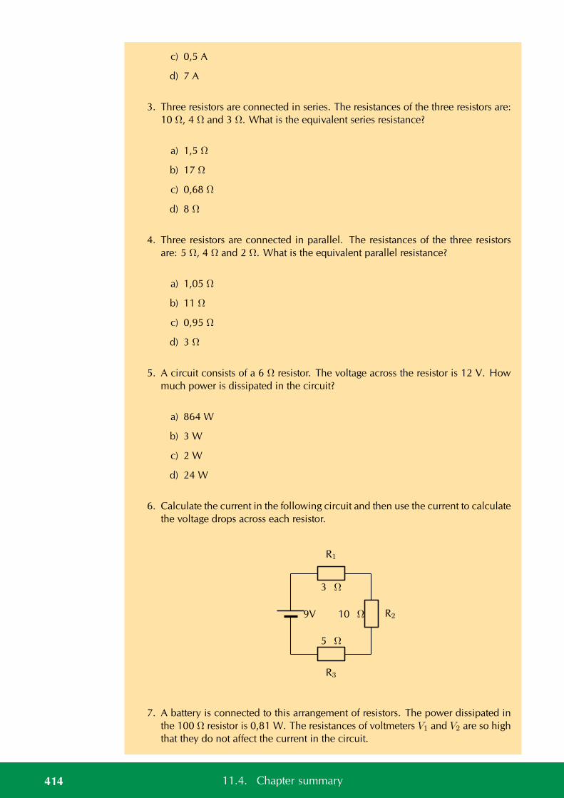
c) 0,5 A
d) 7 A
3. Three resistors are connected in series. The resistances of the three resistors are:10 Ω, 4 Ω and 3 Ω. What is the equivalent series resistance?
a) 1,5 Ω
b) 17 Ω
c) 0,68 Ω
d) 8 Ω
4. Three resistors are connected in parallel. The resistances of the three resistorsare: 5 Ω, 4 Ω and 2 Ω. What is the equivalent parallel resistance?
a) 1,05 Ω
b) 11 Ω
c) 0,95 Ω
d) 3 Ω
5. A circuit consists of a 6 Ω resistor. The voltage across the resistor is 12 V. Howmuch power is dissipated in the circuit?
a) 864 W
b) 3 W
c) 2 W
d) 24 W
6. Calculate the current in the following circuit and then use the current to calculatethe voltage drops across each resistor.
R1
R2
R3
9V
3 Ω
10 Ω
5 Ω
7. A battery is connected to this arrangement of resistors. The power dissipated inthe 100 Ω resistor is 0,81 W. The resistances of voltmeters V1 and V2 are so highthat they do not affect the current in the circuit.
414 11.4. Chapter summary
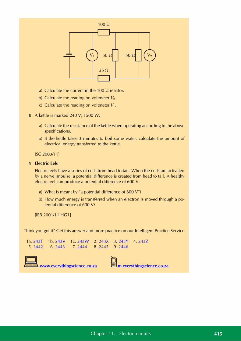
V1
100 Ω
25 Ω
50 Ω 50 Ω V2
a) Calculate the current in the 100 Ω resistor.
b) Calculate the reading on voltmeter V2.
c) Calculate the reading on voltmeter V1.
8. A kettle is marked 240 V; 1500 W.
a) Calculate the resistance of the kettle when operating according to the abovespecifications.
b) If the kettle takes 3 minutes to boil some water, calculate the amount ofelectrical energy transferred to the kettle.
[SC 2003/11]
9. Electric Eels
Electric eels have a series of cells from head to tail. When the cells are activatedby a nerve impulse, a potential difference is created from head to tail. A healthyelectric eel can produce a potential difference of 600 V.
a) What is meant by “a potential difference of 600 V”?
b) How much energy is transferred when an electron is moved through a po-tential difference of 600 V?
[IEB 2001/11 HG1]
Think you got it? Get this answer and more practice on our Intelligent Practice Service
1a. 243T 1b. 243V 1c. 243W 2. 243X 3. 243Y 4. 243Z5. 2442 6. 2443 7. 2444 8. 2445 9. 2446
www.everythingscience.co.za m.everythingscience.co.za
415Chapter 11. Electric circuits

CHAPTER 12
Energy and chemical change
12.1 Energy changes in chemical reactions 418
12.2 Exothermic and endothermic reactions 425
12.3 Activation energy and the activated complex 429
12.4 Chapter summary 432
12 Energy and chemical change
You have probably seen a fire burning or burnt fuel for warmth or cooking or light.A fire burning is one of the most noticeable examples of a chemical reaction thatproduces a lot of energy.
All chemical reactions involve energy changes. In somereactions, we are able to observe these energy changesas either an increase or a decrease in the overall energyof the system. In some reactions we see this as a changein the temperature. In other reactions we can observethis change when a reaction starts to give off light orwhen a reaction will only work after light is shone on it.
The study of energy changes (particularly heat) in chemical reactions is known aschemical thermodynamics. This is also sometimes called thermochemistry.
See video: 2447 at www.everythingscience.co.za
Key Mathematics Concepts
• Graphs — Mathematics, Grade 10, Functions and graphs
• Equations — Mathematics, Grade 10, Equations and inequalities
• Units and unit conversions — Physical Sciences, Grade 10, Science skills
12.1 Energy changes in chemical reactions ESBQJ
What causes the energy changes in chemical reactions? ESBQK
When a chemical reaction occurs, bonds in the reactants break, while new bonds formin the product. The following example explains this. Hydrogen reacts with oxygen toform water, according to the following equation:
2H2(g) + O2(g) → 2H2O(g)
In this reaction, the bond between the two hydrogen atoms in the H2 molecule willbreak, as will the bond between the oxygen atoms in the O2 molecule. New bondswill form between the two hydrogen atoms and the single oxygen atom in the watermolecule that is formed as the product.
For bonds to break, energy must be absorbed. When new bonds form, energy isreleased. The energy that is needed to break a bond is called the bond energy or bonddissociation energy. Bond energies are measured in units of kJ·mol−1.
DEFINITION: Bond energy
Bond energy is a measure of bond strength in a chemical bond. It is the amount ofenergy (in kJ·mol−1) that is needed to break the chemical bond between two atoms.
418 12.1. Energy changes in chemical reactions
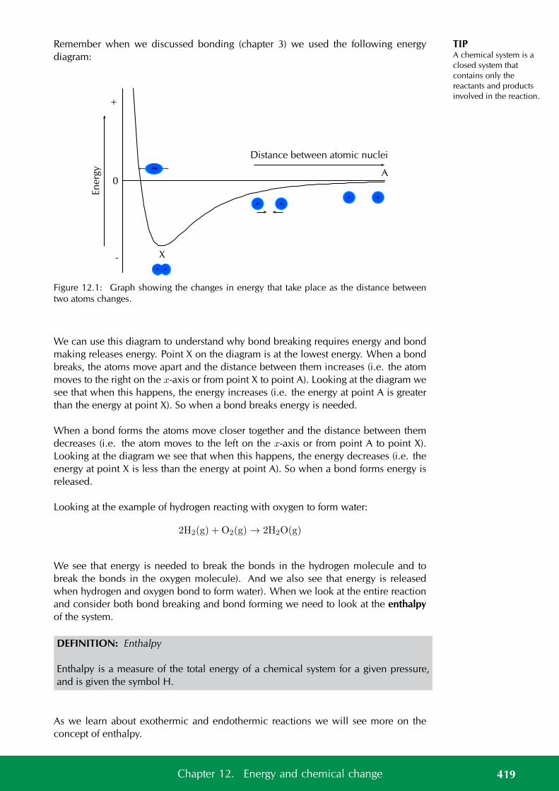
TIPA chemical system is aclosed system thatcontains only thereactants and productsinvolved in the reaction.
Remember when we discussed bonding (chapter 3) we used the following energydiagram:
En
erg
y+
0
-
Distance between atomic nuclei
A
X
Figure 12.1: Graph showing the changes in energy that take place as the distance betweentwo atoms changes.
We can use this diagram to understand why bond breaking requires energy and bondmaking releases energy. Point X on the diagram is at the lowest energy. When a bondbreaks, the atoms move apart and the distance between them increases (i.e. the atommoves to the right on the x-axis or from point X to point A). Looking at the diagram wesee that when this happens, the energy increases (i.e. the energy at point A is greaterthan the energy at point X). So when a bond breaks energy is needed.
When a bond forms the atoms move closer together and the distance between themdecreases (i.e. the atom moves to the left on the x-axis or from point A to point X).Looking at the diagram we see that when this happens, the energy decreases (i.e. theenergy at point X is less than the energy at point A). So when a bond forms energy isreleased.
Looking at the example of hydrogen reacting with oxygen to form water:
2H2(g) + O2(g) → 2H2O(g)
We see that energy is needed to break the bonds in the hydrogen molecule and tobreak the bonds in the oxygen molecule). And we also see that energy is releasedwhen hydrogen and oxygen bond to form water). When we look at the entire reactionand consider both bond breaking and bond forming we need to look at the enthalpyof the system.
DEFINITION: Enthalpy
Enthalpy is a measure of the total energy of a chemical system for a given pressure,and is given the symbol H.
As we learn about exothermic and endothermic reactions we will see more on theconcept of enthalpy.
419Chapter 12. Energy and chemical change
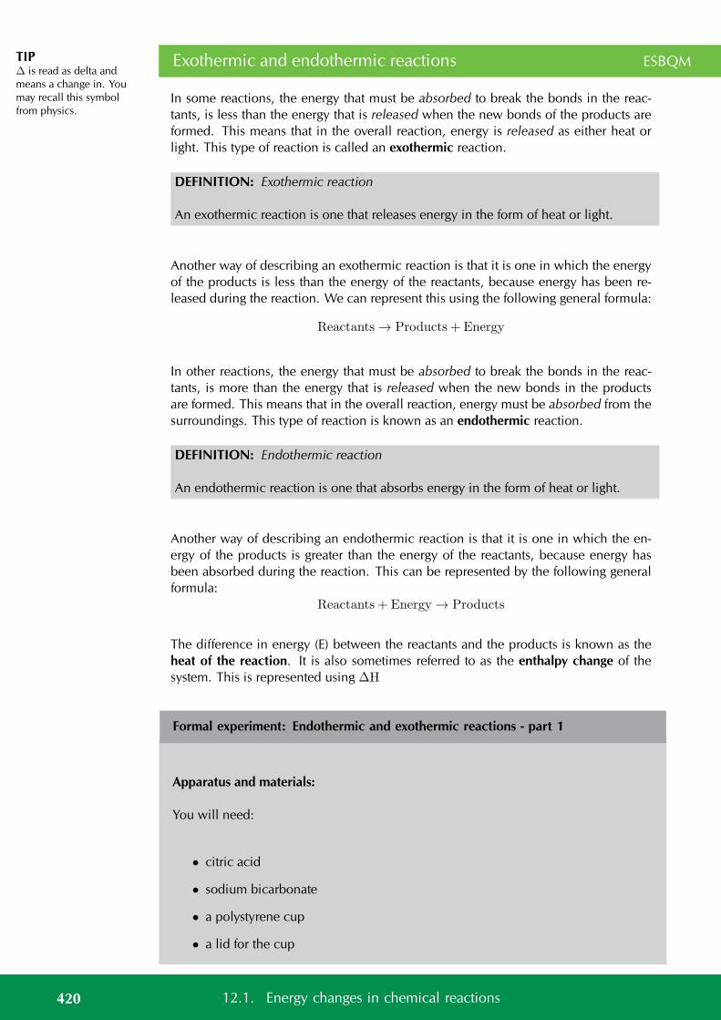
TIP∆ is read as delta andmeans a change in. Youmay recall this symbolfrom physics.
Exothermic and endothermic reactions ESBQM
In some reactions, the energy that must be absorbed to break the bonds in the reac-tants, is less than the energy that is released when the new bonds of the products areformed. This means that in the overall reaction, energy is released as either heat orlight. This type of reaction is called an exothermic reaction.
DEFINITION: Exothermic reaction
An exothermic reaction is one that releases energy in the form of heat or light.
Another way of describing an exothermic reaction is that it is one in which the energyof the products is less than the energy of the reactants, because energy has been re-leased during the reaction. We can represent this using the following general formula:
Reactants → Products + Energy
In other reactions, the energy that must be absorbed to break the bonds in the reac-tants, is more than the energy that is released when the new bonds in the productsare formed. This means that in the overall reaction, energy must be absorbed from thesurroundings. This type of reaction is known as an endothermic reaction.
DEFINITION: Endothermic reaction
An endothermic reaction is one that absorbs energy in the form of heat or light.
Another way of describing an endothermic reaction is that it is one in which the en-ergy of the products is greater than the energy of the reactants, because energy hasbeen absorbed during the reaction. This can be represented by the following generalformula:
Reactants + Energy → Products
The difference in energy (E) between the reactants and the products is known as theheat of the reaction. It is also sometimes referred to as the enthalpy change of thesystem. This is represented using ∆H
Formal experiment: Endothermic and exothermic reactions - part 1
Apparatus and materials:
You will need:
• citric acid
• sodium bicarbonate
• a polystyrene cup
• a lid for the cup
420 12.1. Energy changes in chemical reactions
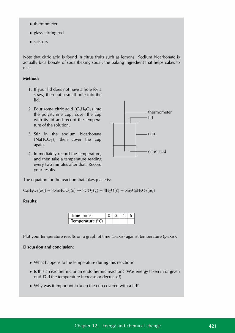
• thermometer
• glass stirring rod
• scissors
Note that citric acid is found in citrus fruits such as lemons. Sodium bicarbonate isactually bicarbonate of soda (baking soda), the baking ingredient that helps cakes torise.
Method:
1. If your lid does not have a hole for astraw, then cut a small hole into thelid.
2. Pour some citric acid (C6H8O7) intothe polystyrene cup, cover the cupwith its lid and record the tempera-ture of the solution.
3. Stir in the sodium bicarbonate(NaHCO3), then cover the cupagain.
4. Immediately record the temperature,and then take a temperature readingevery two minutes after that. Recordyour results.
lid
thermometer
cup
citric acid
The equation for the reaction that takes place is:
C6H8O7(aq) + 3NaHCO3(s) → 3CO2(g) + 3H2O() + Na3C6H5O7(aq)
Results:
Time (mins) 0 2 4 6Temperature (C)
Plot your temperature results on a graph of time (x-axis) against temperature (y-axis).
Discussion and conclusion:
• What happens to the temperature during this reaction?
• Is this an exothermic or an endothermic reaction? (Was energy taken in or givenout? Did the temperature increase or decrease?)
• Why was it important to keep the cup covered with a lid?
421Chapter 12. Energy and chemical change
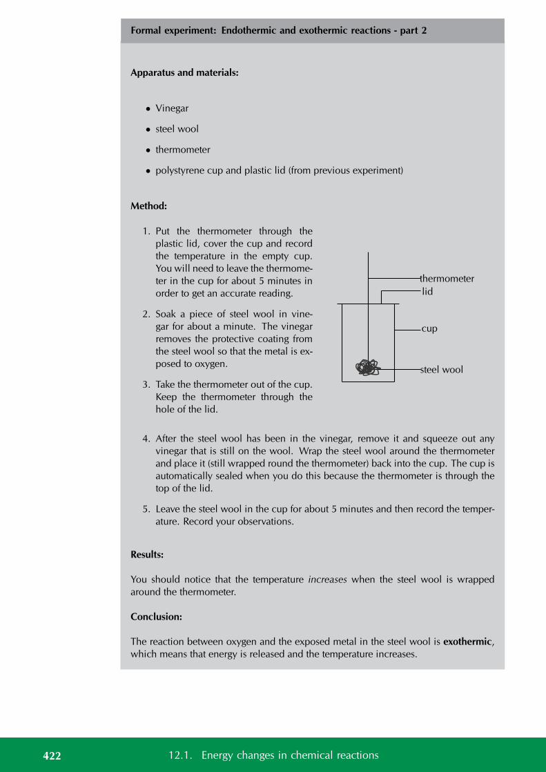
Formal experiment: Endothermic and exothermic reactions - part 2
Apparatus and materials:
• Vinegar
• steel wool
• thermometer
• polystyrene cup and plastic lid (from previous experiment)
Method:
1. Put the thermometer through theplastic lid, cover the cup and recordthe temperature in the empty cup.You will need to leave the thermome-ter in the cup for about 5 minutes inorder to get an accurate reading.
2. Soak a piece of steel wool in vine-gar for about a minute. The vinegarremoves the protective coating fromthe steel wool so that the metal is ex-posed to oxygen.
3. Take the thermometer out of the cup.Keep the thermometer through thehole of the lid.
lid
thermometer
cup
steel wool
4. After the steel wool has been in the vinegar, remove it and squeeze out anyvinegar that is still on the wool. Wrap the steel wool around the thermometerand place it (still wrapped round the thermometer) back into the cup. The cup isautomatically sealed when you do this because the thermometer is through thetop of the lid.
5. Leave the steel wool in the cup for about 5 minutes and then record the temper-ature. Record your observations.
Results:
You should notice that the temperature increases when the steel wool is wrappedaround the thermometer.
Conclusion:
The reaction between oxygen and the exposed metal in the steel wool is exothermic,which means that energy is released and the temperature increases.
422 12.1. Energy changes in chemical reactions
TIPNote that we are onlydiscussing chemicalchanges (recall fromgrade 10 about physicaland chemical changes).Physical changes can alsobe classified asexothermic orendothermic. When weare referring to physicalchange then we talkabout exothermic orendothermic processes.Evaporation is anendothermic processwhile condensation is anexothermic process.
Examples of endothermic and exothermic reactions ESBQN
There are many examples of endothermic and exothermic reactions that occur aroundus all the time. The following are just a few examples.
1. Endothermic reactions
• PhotosynthesisPhotosynthesis is the chemical reaction that takes place in green plants,which uses energy from the sun to change carbon dioxide and water intofood that the plant needs to survive, and which other organisms (such as hu-mans and other animals) can eat so that they too can survive. The equationfor this reaction is:
6CO2(g) + 6H2O (l) + energy → C6H12O6(s) + 6O2(g)
Photosynthesis is an endothermic reaction. Energy in the form of sunlightis absorbed during the reaction.
• The thermal decomposition of limestoneIn industry, the breakdown of limestone into quicklime and carbon dioxideis very important. Quicklime can be used to make steel from iron and alsoto neutralise soils that are too acid. However, the limestone must be heatedin a kiln (oven) at a temperature of over 900 C before the decompositionreaction will take place. The equation for the reaction is shown below:
CaCO3(s) → CaO (s) + CO2(g)
2. Exothermic reactions
• Combustion reactionsThe burning of fuel is an example of a combustion reaction, and we ashumans rely heavily on this process for our energy requirements. The fol-lowing equations describe the combustion of a hydrocarbon such as petrol(C8H18):fuel + oxygen → heat + water + carbon dioxide
2C8H18(l) + 25O2(g) → 16CO2(g) + 18H2O (g) + heat
This is why we burn fuels (such as paraffin, coal, propane and butane) forenergy, because the chemical changes that take place during the reactionrelease huge amounts of energy, which we then use for things like powerand electricity. You should also note that carbon dioxide is produced duringthis reaction. The chemical reaction that takes place when fuels burn hasboth positive and negative consequences. Although we benefit from heat,power and electricity the carbon dioxide that is produced has a negativeimpact on the environment.
• RespirationRespiration is the chemical reaction that happens in our bodies to produceenergy for our cells. The equation below describes what happens duringthis reaction:
C6H12O6(s) + 6O2(g) → 6CO2(g) + 6H2O(l) + energy
In the reaction above, glucose (a type of carbohydrate in the food we eat)reacts with oxygen from the air that we breathe in, to form carbon dioxide
423Chapter 12. Energy and chemical change
FACTLightsticks or glowsticksare used by divers,campers, and fordecoration and fun. Alightstick is a plastic tubewith a glass vial inside it.To activate a lightstick,you bend the plastic stick,which breaks the glassvial. This allows thechemicals that are insidethe glass to mix with thechemicals in the plastictube. These twochemicals react andrelease energy. Anotherpart of a lightstick is afluorescent dye whichchanges this energy intolight, causing thelightstick to glow! This isknown asphosphorescence orchemiluminescence.
(which we breathe out), water and energy. The energy that is producedallows the cell to carry out its functions efficiently. Can you see now whyyou must eat food to get energy? It is not the food itself that provides youwith energy, but the exothermic reaction that takes place when compoundswithin the food react with the oxygen you have breathed in!
See video: 2448 at www.everythingscience.co.za
See video: 2449 at www.everythingscience.co.za
Exercise 12 – 1: Exothermic and endothermic reactions 1
1. State whether energy is taken in or released in each of the following situations:
a) The bond between hydrogen and chlorine in a molecule of hydrogen chlo-ride breaks.
b) A bond is formed between hydrogen and fluorine to form a molecule ofhydrogen fluoride.
c) A molecule of nitrogen (N2) is formed.
d) A molecule of carbon monoxide breaks apart.
2. State whether the following descriptions are used to describe an endothermic oran exothermic reaction:
a) Reactants react to give products and energy.
b) The energy that must be absorbed to break the bonds in the reactants isgreater than the energy that is released when the products form.
c) The energy of the products is found to be greater than the energy of thereactants for this type of reaction.
d) Heat or light must be absorbed from the surroundings before this type ofreaction takes place.
Think you got it? Get this answer and more practice on our Intelligent Practice Service
1a. 244B 1b. 244C 1c. 244D 1d. 244F 2a. 244G 2b. 244H2c. 244J 2d. 244K
www.everythingscience.co.za m.everythingscience.co.za
424 12.1. Energy changes in chemical reactions
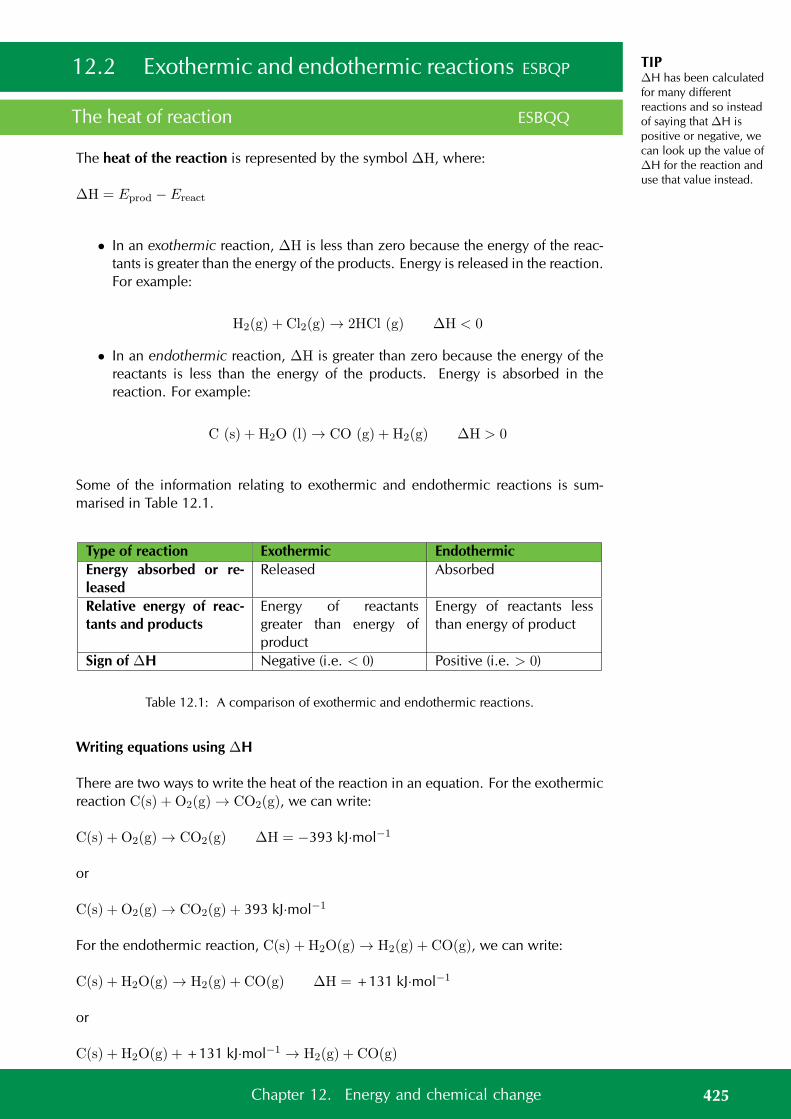
TIP∆H has been calculatedfor many differentreactions and so insteadof saying that ∆H ispositive or negative, wecan look up the value of∆H for the reaction anduse that value instead.
12.2 Exothermic and endothermic reactions ESBQP
The heat of reaction ESBQQ
The heat of the reaction is represented by the symbol ∆H, where:
∆H = Eprod − Ereact
• In an exothermic reaction, ∆H is less than zero because the energy of the reac-tants is greater than the energy of the products. Energy is released in the reaction.For example:
H2(g) + Cl2(g) → 2HCl (g) ∆H < 0
• In an endothermic reaction, ∆H is greater than zero because the energy of thereactants is less than the energy of the products. Energy is absorbed in thereaction. For example:
C (s) + H2O (l) → CO (g) + H2(g) ∆H > 0
Some of the information relating to exothermic and endothermic reactions is sum-marised in Table 12.1.
Type of reaction Exothermic EndothermicEnergy absorbed or re-leased
Released Absorbed
Relative energy of reac-tants and products
Energy of reactantsgreater than energy ofproduct
Energy of reactants lessthan energy of product
Sign of ∆H Negative (i.e. < 0) Positive (i.e. > 0)
Table 12.1: A comparison of exothermic and endothermic reactions.
Writing equations using ∆H
There are two ways to write the heat of the reaction in an equation. For the exothermicreaction C(s) + O2(g) → CO2(g), we can write:
C(s) + O2(g) → CO2(g) ∆H = −393 kJ·mol−1
or
C(s) + O2(g) → CO2(g) + 393 kJ·mol−1
For the endothermic reaction, C(s) + H2O(g) → H2(g) + CO(g), we can write:
C(s) + H2O(g) → H2(g) + CO(g) ∆H = +131 kJ·mol−1
or
C(s) + H2O(g) + +131 kJ·mol−1 → H2(g) + CO(g)
425Chapter 12. Energy and chemical change
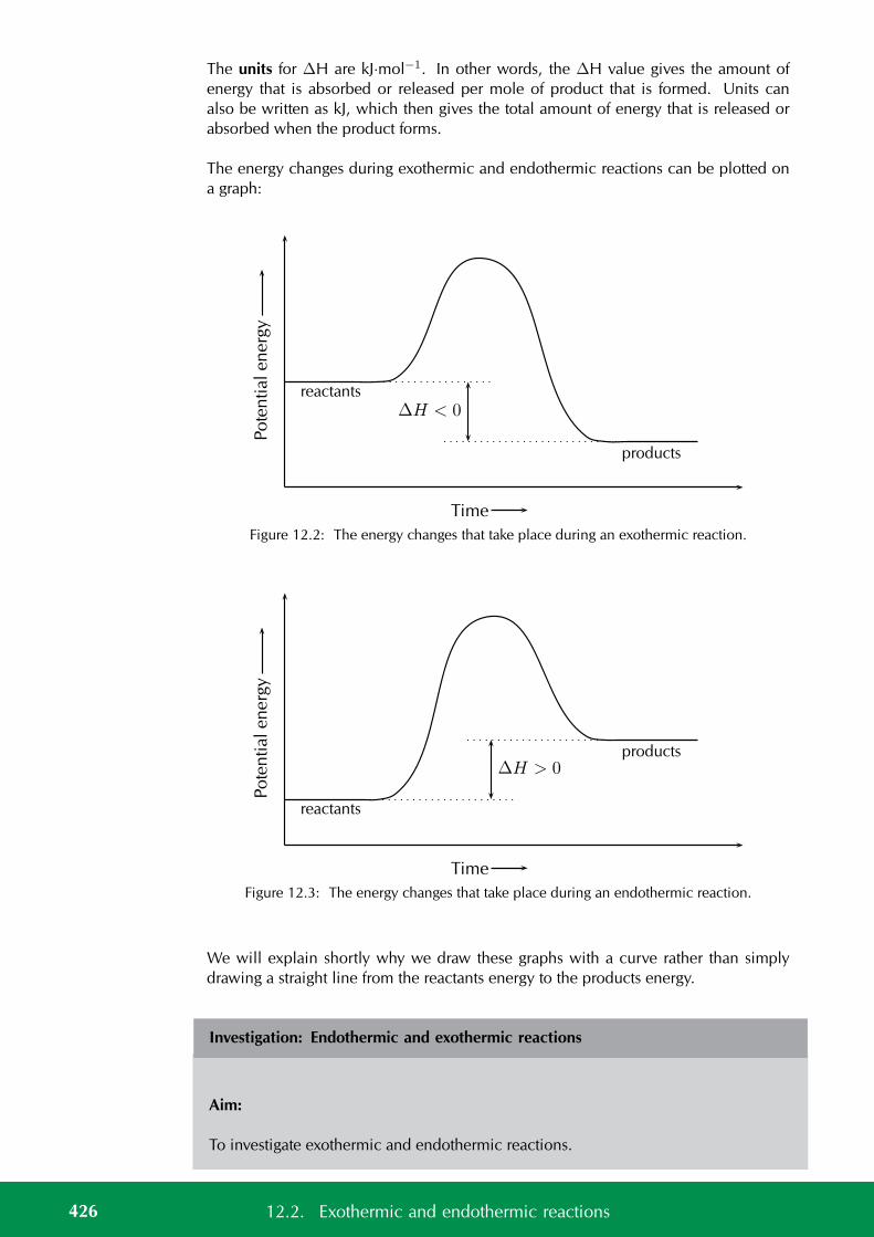
The units for ∆H are kJ·mol−1. In other words, the ∆H value gives the amount ofenergy that is absorbed or released per mole of product that is formed. Units canalso be written as kJ, which then gives the total amount of energy that is released orabsorbed when the product forms.
The energy changes during exothermic and endothermic reactions can be plotted ona graph:
products
reactants∆H < 0
Time
Pote
nti
alen
erg
y
Figure 12.2: The energy changes that take place during an exothermic reaction.
products
reactants
∆H > 0
Time
Pote
nti
alen
erg
y
Figure 12.3: The energy changes that take place during an endothermic reaction.
We will explain shortly why we draw these graphs with a curve rather than simplydrawing a straight line from the reactants energy to the products energy.
Investigation: Endothermic and exothermic reactions
Aim:
To investigate exothermic and endothermic reactions.
426 12.2. Exothermic and endothermic reactions
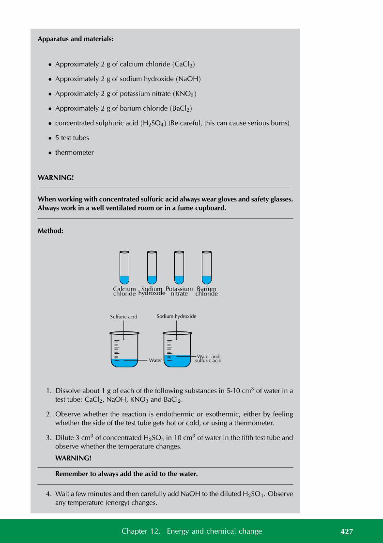
Apparatus and materials:
• Approximately 2 g of calcium chloride (CaCl2)
• Approximately 2 g of sodium hydroxide (NaOH)
• Approximately 2 g of potassium nitrate (KNO3)
• Approximately 2 g of barium chloride (BaCl2)
• concentrated sulphuric acid (H2SO4) (Be careful, this can cause serious burns)
• 5 test tubes
• thermometer
WARNING!
When working with concentrated sulfuric acid always wear gloves and safety glasses.Always work in a well ventilated room or in a fume cupboard.
Method:
chloride hydroxide nitrate chlorideCalcium Sodium Potassium Barium
WaterWater and
sulfuric acid
Sodium hydroxideSulfuric acid
1. Dissolve about 1 g of each of the following substances in 5-10 cm3 of water in atest tube: CaCl2, NaOH, KNO3 and BaCl2.
2. Observe whether the reaction is endothermic or exothermic, either by feelingwhether the side of the test tube gets hot or cold, or using a thermometer.
3. Dilute 3 cm3 of concentrated H2SO4 in 10 cm3 of water in the fifth test tube andobserve whether the temperature changes.
WARNING!
Remember to always add the acid to the water.
4. Wait a few minutes and then carefully add NaOH to the diluted H2SO4. Observeany temperature (energy) changes.
427Chapter 12. Energy and chemical change
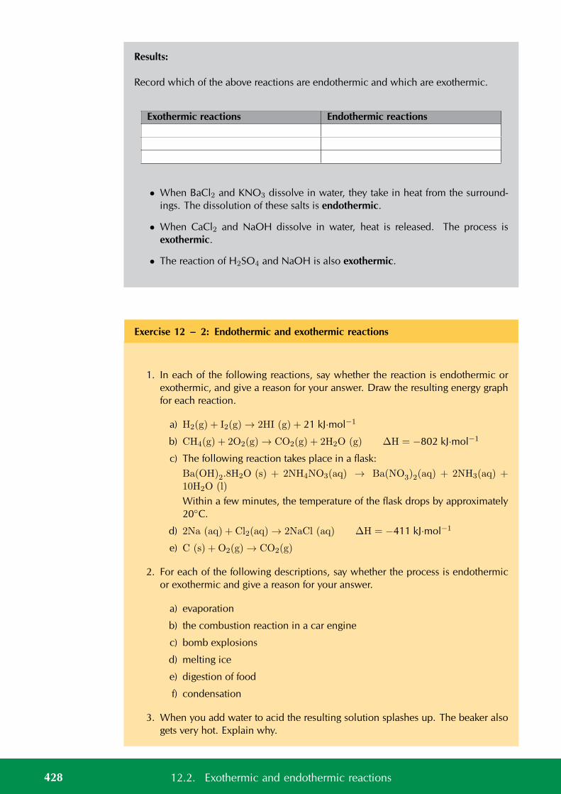
Results:
Record which of the above reactions are endothermic and which are exothermic.
Exothermic reactions Endothermic reactions
• When BaCl2 and KNO3 dissolve in water, they take in heat from the surround-ings. The dissolution of these salts is endothermic.
• When CaCl2 and NaOH dissolve in water, heat is released. The process isexothermic.
• The reaction of H2SO4 and NaOH is also exothermic.
Exercise 12 – 2: Endothermic and exothermic reactions
1. In each of the following reactions, say whether the reaction is endothermic orexothermic, and give a reason for your answer. Draw the resulting energy graphfor each reaction.
a) H2(g) + I2(g) → 2HI (g) + 21 kJ·mol−1
b) CH4(g) + 2O2(g) → CO2(g) + 2H2O (g) ∆H = −802 kJ·mol−1
c) The following reaction takes place in a flask:Ba(OH)2.8H2O (s) + 2NH4NO3(aq) → Ba(NO3)2(aq) + 2NH3(aq) +10H2O (l)
Within a few minutes, the temperature of the flask drops by approximately20C.
d) 2Na (aq) + Cl2(aq) → 2NaCl (aq) ∆H = −411 kJ·mol−1
e) C (s) + O2(g) → CO2(g)
2. For each of the following descriptions, say whether the process is endothermicor exothermic and give a reason for your answer.
a) evaporation
b) the combustion reaction in a car engine
c) bomb explosions
d) melting ice
e) digestion of food
f) condensation
3. When you add water to acid the resulting solution splashes up. The beaker alsogets very hot. Explain why.
428 12.2. Exothermic and endothermic reactions
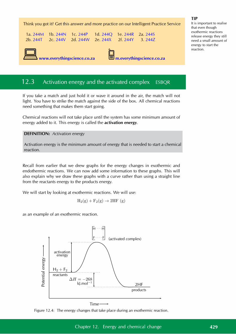
TIPIt is important to realisethat even thoughexothermic reactionsrelease energy they stillneed a small amount ofenergy to start thereaction.
Think you got it? Get this answer and more practice on our Intelligent Practice Service
1a. 244M 1b. 244N 1c. 244P 1d. 244Q 1e. 244R 2a. 244S2b. 244T 2c. 244V 2d. 244W 2e. 244X 2f. 244Y 3. 244Z
www.everythingscience.co.za m.everythingscience.co.za
12.3 Activation energy and the activated complex ESBQR
If you take a match and just hold it or wave it around in the air, the match will notlight. You have to strike the match against the side of the box. All chemical reactionsneed something that makes them start going.
Chemical reactions will not take place until the system has some minimum amount ofenergy added to it. This energy is called the activation energy.
DEFINITION: Activation energy
Activation energy is the minimum amount of energy that is needed to start a chemicalreaction.
Recall from earlier that we drew graphs for the energy changes in exothermic andendothermic reactions. We can now add some information to these graphs. This willalso explain why we draw these graphs with a curve rather than using a straight linefrom the reactants energy to the products energy.
We will start by looking at exothermic reactions. We will use:
H2(g) + F2(g) → 2HF (g)
as an example of an exothermic reaction.
(activated complex)
H
F
H
F
2HF
products
H2 + F2reactants
activationenergy
∆H = −268kJ.mol−1
Time
Pote
ntialen
erg
y
Figure 12.4: The energy changes that take place during an exothermic reaction.
429Chapter 12. Energy and chemical change
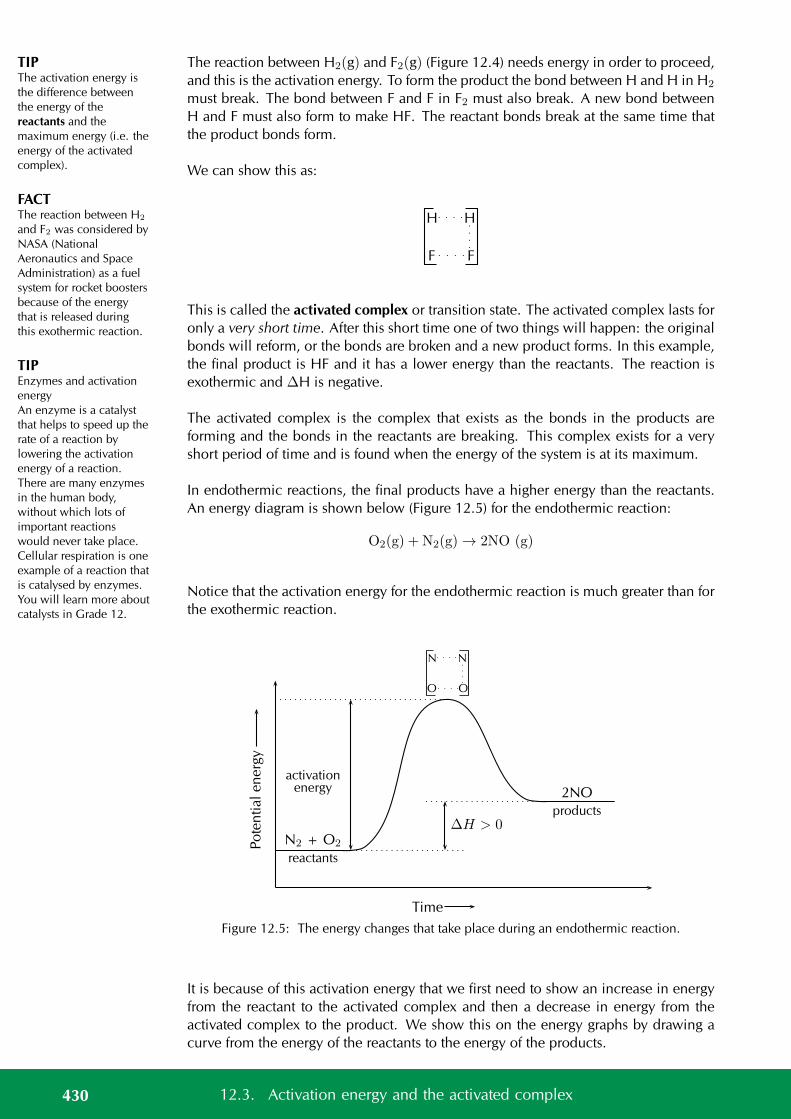
TIPThe activation energy isthe difference betweenthe energy of thereactants and themaximum energy (i.e. theenergy of the activatedcomplex).
FACTThe reaction between H2
and F2 was considered byNASA (NationalAeronautics and SpaceAdministration) as a fuelsystem for rocket boostersbecause of the energythat is released duringthis exothermic reaction.
TIPEnzymes and activationenergyAn enzyme is a catalystthat helps to speed up therate of a reaction bylowering the activationenergy of a reaction.There are many enzymesin the human body,without which lots ofimportant reactionswould never take place.Cellular respiration is oneexample of a reaction thatis catalysed by enzymes.You will learn more aboutcatalysts in Grade 12.
The reaction between H2(g) and F2(g) (Figure 12.4) needs energy in order to proceed,and this is the activation energy. To form the product the bond between H and H in H2
must break. The bond between F and F in F2 must also break. A new bond betweenH and F must also form to make HF. The reactant bonds break at the same time thatthe product bonds form.
We can show this as:
H
F
H
F
This is called the activated complex or transition state. The activated complex lasts foronly a very short time. After this short time one of two things will happen: the originalbonds will reform, or the bonds are broken and a new product forms. In this example,the final product is HF and it has a lower energy than the reactants. The reaction isexothermic and ∆H is negative.
The activated complex is the complex that exists as the bonds in the products areforming and the bonds in the reactants are breaking. This complex exists for a veryshort period of time and is found when the energy of the system is at its maximum.
In endothermic reactions, the final products have a higher energy than the reactants.An energy diagram is shown below (Figure 12.5) for the endothermic reaction:
O2(g) + N2(g) → 2NO (g)
Notice that the activation energy for the endothermic reaction is much greater than forthe exothermic reaction.
2NO
products
N2 + O2
reactants
∆H > 0
Time
Pote
ntialen
erg
y
activationenergy
N
O
N
O
Figure 12.5: The energy changes that take place during an endothermic reaction.
It is because of this activation energy that we first need to show an increase in energyfrom the reactant to the activated complex and then a decrease in energy from theactivated complex to the product. We show this on the energy graphs by drawing acurve from the energy of the reactants to the energy of the products.
430 12.3. Activation energy and the activated complex
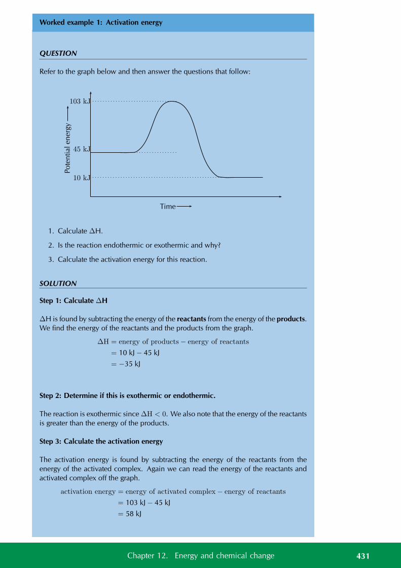
Worked example 1: Activation energy
QUESTION
Refer to the graph below and then answer the questions that follow:
103 kJ
45 kJ
10 kJ
Time
Pote
ntialen
erg
y
1. Calculate ∆H.
2. Is the reaction endothermic or exothermic and why?
3. Calculate the activation energy for this reaction.
SOLUTION
Step 1: Calculate ∆H
∆H is found by subtracting the energy of the reactants from the energy of the products.We find the energy of the reactants and the products from the graph.
∆H = energy of products− energy of reactants
= 10 kJ − 45 kJ
= −35 kJ
Step 2: Determine if this is exothermic or endothermic.
The reaction is exothermic since ∆H < 0. We also note that the energy of the reactantsis greater than the energy of the products.
Step 3: Calculate the activation energy
The activation energy is found by subtracting the energy of the reactants from theenergy of the activated complex. Again we can read the energy of the reactants andactivated complex off the graph.
activation energy = energy of activated complex− energy of reactants
= 103 kJ − 45 kJ
= 58 kJ
431Chapter 12. Energy and chemical change
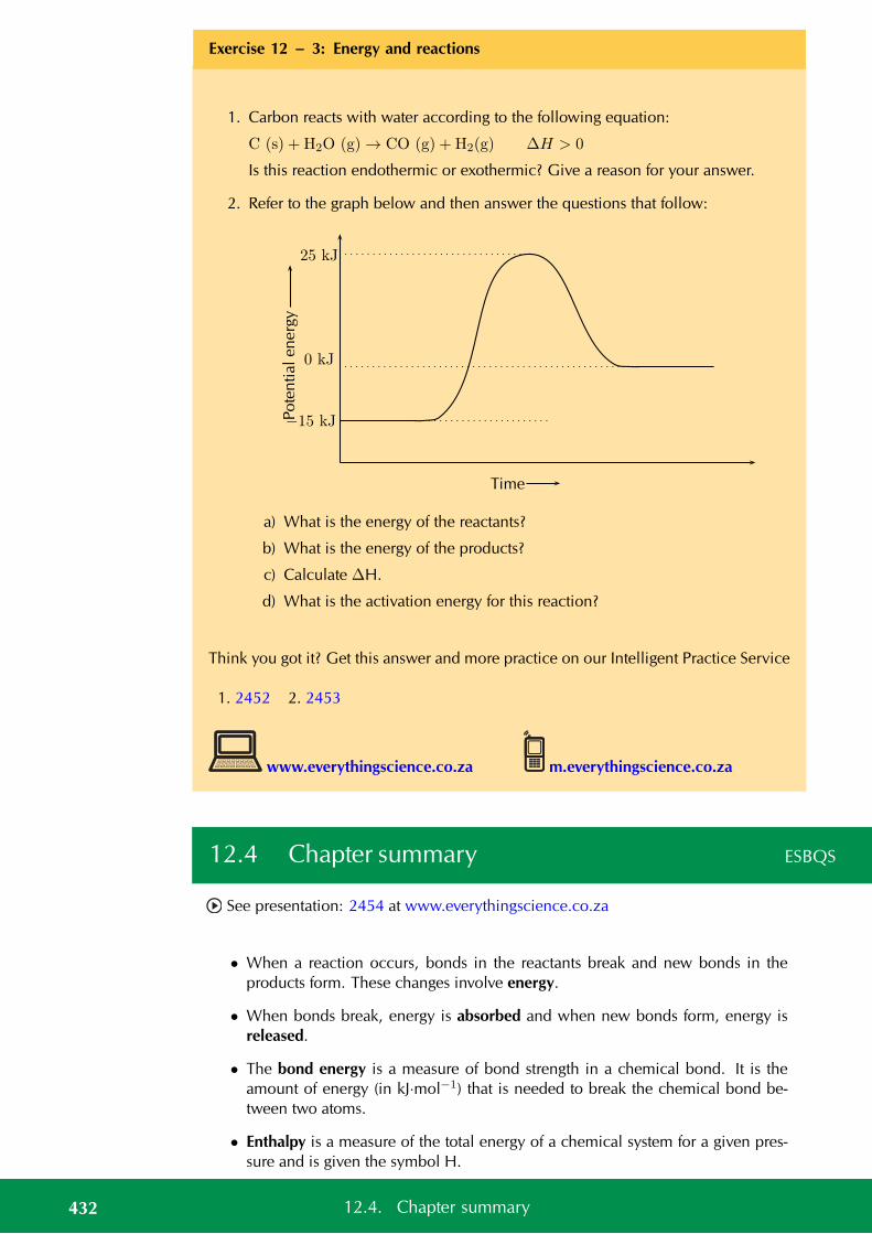
Exercise 12 – 3: Energy and reactions
1. Carbon reacts with water according to the following equation:
C (s) + H2O (g) → CO (g) + H2(g) ∆H > 0
Is this reaction endothermic or exothermic? Give a reason for your answer.
2. Refer to the graph below and then answer the questions that follow:
Time
Pote
ntialen
erg
y
−15 kJ
0 kJ
25 kJ
a) What is the energy of the reactants?
b) What is the energy of the products?
c) Calculate ∆H.
d) What is the activation energy for this reaction?
Think you got it? Get this answer and more practice on our Intelligent Practice Service
1. 2452 2. 2453
www.everythingscience.co.za m.everythingscience.co.za
12.4 Chapter summary ESBQS
See presentation: 2454 at www.everythingscience.co.za
• When a reaction occurs, bonds in the reactants break and new bonds in theproducts form. These changes involve energy.
• When bonds break, energy is absorbed and when new bonds form, energy isreleased.
• The bond energy is a measure of bond strength in a chemical bond. It is theamount of energy (in kJ·mol−1) that is needed to break the chemical bond be-tween two atoms.
• Enthalpy is a measure of the total energy of a chemical system for a given pres-sure and is given the symbol H.
432 12.4. Chapter summary
• If the energy that is needed to break the bonds is less than the energy that isreleased when new bonds form, then the reaction is exothermic. The energy ofthe products is less than the energy of the reactants.
• An exothermic reaction is one that releases energy in the form of heat or light.
• If the energy that is needed to break the bonds is more than the energy that isreleased when new bonds form, then the reaction is endothermic. The energyof the products is greater than the energy of the reactants.
• An endothermic reaction is one that absorbs energy in the form of heat or light.
• Photosynthesis and the thermal decomposition of limestone are both examplesof endothermic reactions.
• Combustion reactions and respiration are both examples of exothermic reac-tions.
• The difference in energy between the reactants and the product is called the heatof reaction and has the symbol ∆H.
• ∆H is calculated using: ∆H = Eprod − Ereact
• In an endothermic reaction, ∆H is a positive number (greater than 0). In anexothermic reaction, ∆H will be negative (less than 0).
• Chemical reactions will not take place until the system has some minimumamount of energy added to it.
• The activation energy is the minimum amount of energy that is needed to starta chemical reaction.
• The activated complex (or transition state) is the complex that exists as the bondsin the products are forming and the bonds in the reactants are breaking. Thiscomplex exists for a very short period of time and is found when the energy ofthe system is at its maximum.
Exercise 12 – 4:
1. For each of the following, give one word or term for the description.
a) The minimum amount of energy that is needed for a reaction to proceed.
b) A measure of the bond strength in a chemical bond.
c) A type of reaction where ∆H is less than zero.
d) A type of reaction that requires heat or light to proceed.
2. For the following reaction:
HCl (aq) + NaOH (aq) → NaCl (aq) + H2O (l)
choose the correct statement from the list below.
a) Energy is taken in when the new bonds in NaCl are formed.
b) Energy is released when the bonds in HCl break.
433Chapter 12. Energy and chemical change
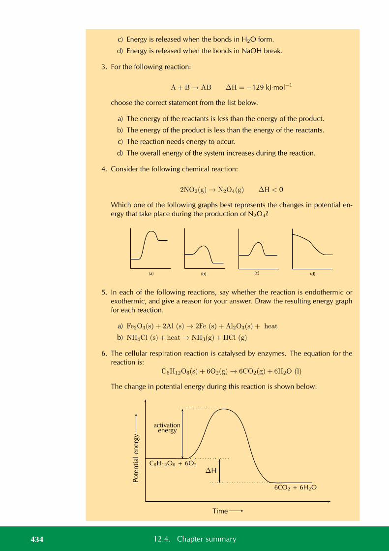
c) Energy is released when the bonds in H2O form.
d) Energy is released when the bonds in NaOH break.
3. For the following reaction:
A+ B → AB ∆H = −129 kJ·mol−1
choose the correct statement from the list below.
a) The energy of the reactants is less than the energy of the product.
b) The energy of the product is less than the energy of the reactants.
c) The reaction needs energy to occur.
d) The overall energy of the system increases during the reaction.
4. Consider the following chemical reaction:
2NO2(g) → N2O4(g) ∆H < 0
Which one of the following graphs best represents the changes in potential en-ergy that take place during the production of N2O4?
(d)(c)(b)(a)
5. In each of the following reactions, say whether the reaction is endothermic orexothermic, and give a reason for your answer. Draw the resulting energy graphfor each reaction.
a) Fe2O3(s) + 2Al (s) → 2Fe (s) + Al2O3(s) + heat
b) NH4Cl (s) + heat → NH3(g) + HCl (g)
6. The cellular respiration reaction is catalysed by enzymes. The equation for thereaction is:
C6H12O6(s) + 6O2(g) → 6CO2(g) + 6H2O (l)
The change in potential energy during this reaction is shown below:
6CO2 + 6H2O
C6H12O6 + 6O2
activationenergy
∆H
Time
Pote
ntialen
erg
y
434 12.4. Chapter summary

a) Will the value of ∆H be positive or negative? Give a reason for your answer.
b) Explain what is meant by activation energy.
c) Glucose is one of the reactants in cellular respiration. What importantchemical reaction produces glucose?
d) Is the reaction in your answer above an endothermic or an exothermic one?Explain your answer.
e) Draw the energy graph for the reaction that produces glucose.
Think you got it? Get this answer and more practice on our Intelligent Practice Service
1a. 2455 1b. 2456 1c. 2457 1d. 2458 2. 2459 3. 245B4. 245C 5a. 245D 5b. 245F 6. 245G
www.everythingscience.co.za m.everythingscience.co.za
435Chapter 12. Energy and chemical change


CHAPTER 13
Types of reactions
13.1 Acids and bases 438
13.2 Acid-base reactions 443
13.3 Redox reactions 452
13.4 Chapter summary 465
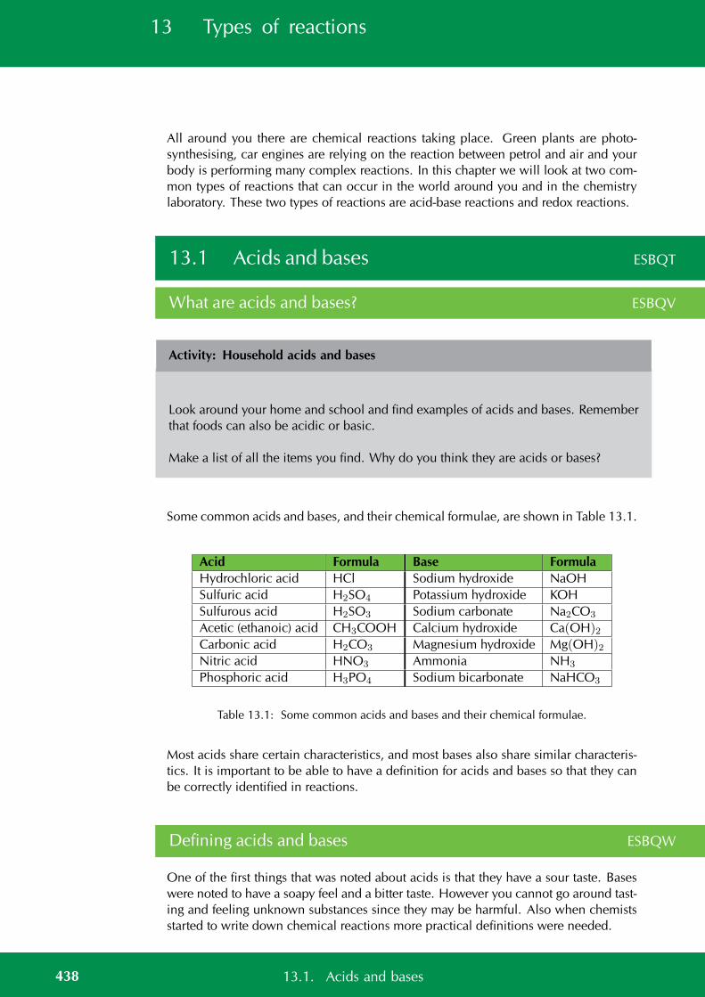
13 Types of reactions
All around you there are chemical reactions taking place. Green plants are photo-synthesising, car engines are relying on the reaction between petrol and air and yourbody is performing many complex reactions. In this chapter we will look at two com-mon types of reactions that can occur in the world around you and in the chemistrylaboratory. These two types of reactions are acid-base reactions and redox reactions.
13.1 Acids and bases ESBQT
What are acids and bases? ESBQV
Activity: Household acids and bases
Look around your home and school and find examples of acids and bases. Rememberthat foods can also be acidic or basic.
Make a list of all the items you find. Why do you think they are acids or bases?
Some common acids and bases, and their chemical formulae, are shown in Table 13.1.
Acid Formula Base FormulaHydrochloric acid HCl Sodium hydroxide NaOHSulfuric acid H2SO4 Potassium hydroxide KOHSulfurous acid H2SO3 Sodium carbonate Na2CO3
Acetic (ethanoic) acid CH3COOH Calcium hydroxide Ca(OH)2Carbonic acid H2CO3 Magnesium hydroxide Mg(OH)2Nitric acid HNO3 Ammonia NH3
Phosphoric acid H3PO4 Sodium bicarbonate NaHCO3
Table 13.1: Some common acids and bases and their chemical formulae.
Most acids share certain characteristics, and most bases also share similar characteris-tics. It is important to be able to have a definition for acids and bases so that they canbe correctly identified in reactions.
Defining acids and bases ESBQW
One of the first things that was noted about acids is that they have a sour taste. Baseswere noted to have a soapy feel and a bitter taste. However you cannot go around tast-ing and feeling unknown substances since they may be harmful. Also when chemistsstarted to write down chemical reactions more practical definitions were needed.
438 13.1. Acids and bases
TIPFor more information ondissociation, refer toGrade 10 (chapter 18:reactions in aqueoussolution).
A number of definitions for acids and bases have developed over the years. One ofthe earliest was the Arrhenius definition. Arrhenius (1887) noticed that water dissoci-ates (splits up) into hydronium (H3O+) and hydroxide (OH−) ions according to thefollowing equation:
2H2O (l) → H3O+(aq) + OH−(aq)
Arrhenius described an acid as a compound that increases the concentration of H3O+
ions in solution and a base as a compound that increases the concentration of OH−
ions in solution.
Look at the following examples showing the dissociation of hydrochloric acid andsodium hydroxide (a base) respectively:
1. HCl (aq) + H2O(l) → H3O+(aq) + Cl−(aq)
Hydrochloric acid in water increases the concentration of H3O+ ions and istherefore an acid.
2. NaOH (s)H2O−→ Na+(aq) + OH−(aq)
Sodium hydroxide in water increases the concentration of OH− ions and is there-fore a base.
Note that we write H2O−→ to indicate that water is needed for the dissociation.
However, this definition could only be used for acids and bases in water. Since thereare many reactions which do not occur in water it was important to come up with amuch broader definition for acids and bases.
In 1923, Lowry and Bronsted took the work of Arrhenius further to develop a broaderdefinition for acids and bases. The Bronsted-Lowry model defines acids and bases interms of their ability to donate or accept protons.
DEFINITION: Acids
A Bronsted-Lowry acid is a substance that gives away protons (hydrogen cations H+),and is therefore called a proton donor.
DEFINITION: Bases
A Bronsted-Lowry base is a substance that takes up protons (hydrogen cations H+),and is therefore called a proton acceptor.
Below are some examples:
1. HCl (aq) + NH3(aq) → NH+4 (aq) + Cl−(aq)
We highlight the chlorine and the nitrogen so that we can follow what happensto these two elements as they react. We do not highlight the hydrogen atoms aswe are interested in how these change. This colour coding is simply to help youidentify the parts of the reaction and does not represent any specific property ofthese elements.
HCl (aq) + NH3(aq) → NH+4 (aq) + Cl−(aq)
439Chapter 13. Types of reactions
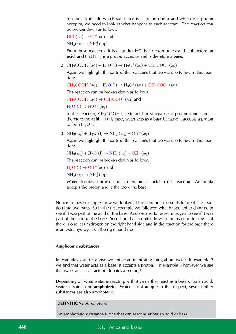
In order to decide which substance is a proton donor and which is a protonacceptor, we need to look at what happens to each reactant. The reaction canbe broken down as follows:
HCl (aq) → Cl−(aq) and
NH3(aq) → NH+4 (aq)
From these reactions, it is clear that HCl is a proton donor and is therefore anacid, and that NH3 is a proton acceptor and is therefore a base.
2. CH3COOH (aq) + H2O (l) → H3O+(aq) + CH3COO−(aq)
Again we highlight the parts of the reactants that we want to follow in this reac-tion:
CH3COOH (aq) + H2O (l) → H3O+(aq) + CH3COO−(aq)
The reaction can be broken down as follows:
CH3COOH (aq) → CH3COO−(aq) and
H2O (l) → H3O+(aq)
In this reaction, CH3COOH (acetic acid or vinegar) is a proton donor and istherefore the acid. In this case, water acts as a base because it accepts a protonto form H3O+.
3. NH3(aq) + H2O (l) → NH+4 (aq) + OH−(aq)
Again we highlight the parts of the reactants that we want to follow in this reac-tion:
NH3(aq) + H2O (l) → NH+4 (aq) + OH−(aq)
The reaction can be broken down as follows:
H2O (l) → OH−(aq) and
NH3(aq) → NH+4 (aq)
Water donates a proton and is therefore an acid in this reaction. Ammoniaaccepts the proton and is therefore the base.
Notice in these examples how we looked at the common elements to break the reac-tion into two parts. So in the first example we followed what happened to chlorine tosee if it was part of the acid or the base. And we also followed nitrogen to see if it waspart of the acid or the base. You should also notice how in the reaction for the acidthere is one less hydrogen on the right hand side and in the reaction for the base thereis an extra hydrogen on the right hand side.
Amphoteric substances
In examples 2 and 3 above we notice an interesting thing about water. In example 2we find that water acts as a base (it accepts a proton). In example 3 however we seethat water acts as an acid (it donates a proton)!
Depending on what water is reacting with it can either react as a base or as an acid.Water is said to be amphoteric. Water is not unique in this respect, several othersubstances are also amphoteric.
DEFINITION: Amphoteric
An amphoteric substance is one that can react as either an acid or base.
440 13.1. Acids and bases
When we look just at Bronsted-Lowry acids and bases we can also talk about am-phiprotic substances which are a special type of amphoteric substances.
DEFINITION: Amphiprotic
An amphiprotic substance is one that can react as either a proton donor (Bronsted-Lowry acid) or as a proton acceptor (Bronsted-Lowry base). Examples of amphiproticsubstances include water, hydrogen carbonate ion (HCO−
3 ) and hydrogen sulfate ion(HSO−
4 ).
Note: You may also see the term ampholyte used to mean a substance that can act asboth an acid and a base. This term is no longer in general use in chemistry.
Polyprotic acids [NOT IN CAPS]
A polyprotic (many protons) acid is an acid that has more than one proton that it candonate. For example sulfuric acid can donate one proton to form the hydrogen sulfateion:
H2SO4(aq) + OH−(aq) → HSO−4 (aq) + H2O (l)
Or it can donate two protons to form the sulfate ion:
H2SO4(aq) + 2OH−(aq) → SO2−4 (aq) + 2H2O (l)
In this chapter we will mostly consider monoprotic acids (acids with only one protonto donate). If you do see a polyprotic acid in a reaction then write the resulting reactionequation with the acid donating all its protons.
Some examples of polyprotic acids are:
H2SO4, H2SO3, H2CO3 and H3PO4.
See simulation: 245H at www.everythingscience.co.za
Exercise 13 – 1: Acids and bases
1. Identify the Bronsted-Lowry acid and the Bronsted-Lowry base in the followingreactions:
a) HNO3(aq) + NH3(aq) → NO−3 (aq) + NH+
4 (aq)
b) HBr (aq) + KOH (aq) → KBr (aq) + H2O (l)
2. a) Write a reaction equation to show HCO−3 acting as an acid.
b) Write a reaction equation to show HCO−3 acting as an base.
c) Compounds such as HCO−3 are . . .
441Chapter 13. Types of reactions
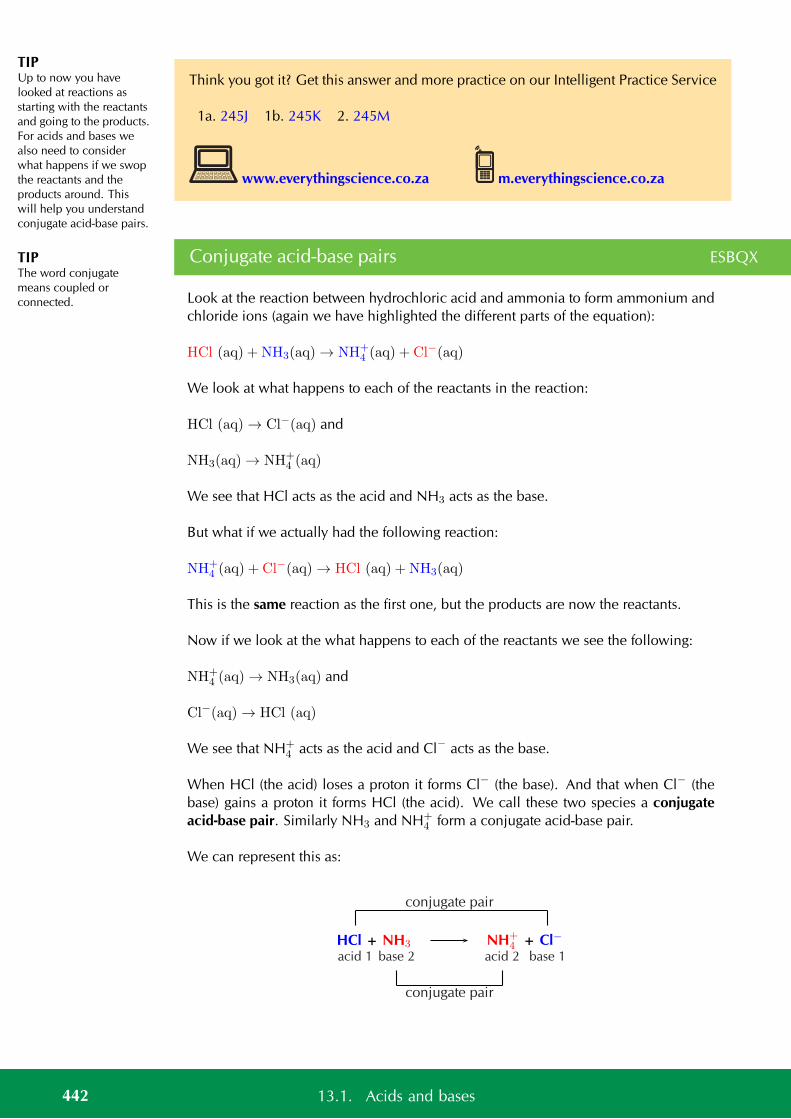
TIPUp to now you havelooked at reactions asstarting with the reactantsand going to the products.For acids and bases wealso need to considerwhat happens if we swopthe reactants and theproducts around. Thiswill help you understandconjugate acid-base pairs.
TIPThe word conjugatemeans coupled orconnected.
Think you got it? Get this answer and more practice on our Intelligent Practice Service
1a. 245J 1b. 245K 2. 245M
www.everythingscience.co.za m.everythingscience.co.za
Conjugate acid-base pairs ESBQX
Look at the reaction between hydrochloric acid and ammonia to form ammonium andchloride ions (again we have highlighted the different parts of the equation):
HCl (aq) + NH3(aq) → NH+4 (aq) + Cl−(aq)
We look at what happens to each of the reactants in the reaction:
HCl (aq) → Cl−(aq) and
NH3(aq) → NH+4 (aq)
We see that HCl acts as the acid and NH3 acts as the base.
But what if we actually had the following reaction:
NH+4 (aq) + Cl−(aq) → HCl (aq) + NH3(aq)
This is the same reaction as the first one, but the products are now the reactants.
Now if we look at the what happens to each of the reactants we see the following:
NH+4 (aq) → NH3(aq) and
Cl−(aq) → HCl (aq)
We see that NH+4 acts as the acid and Cl− acts as the base.
When HCl (the acid) loses a proton it forms Cl− (the base). And that when Cl− (thebase) gains a proton it forms HCl (the acid). We call these two species a conjugateacid-base pair. Similarly NH3 and NH+
4 form a conjugate acid-base pair.
We can represent this as:
HCl + NH3 NH+4 + Cl−
acid 1 base 2 base 1acid 2
conjugate pair
conjugate pair
442 13.1. Acids and bases
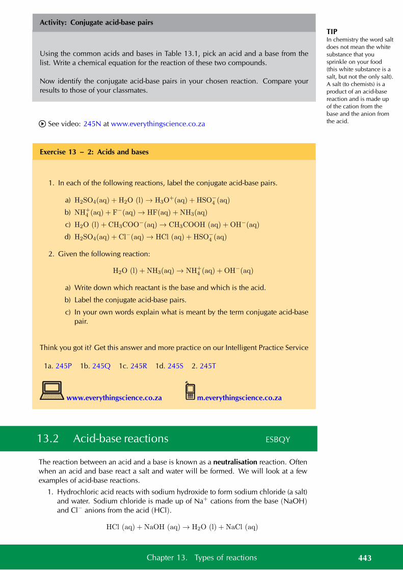
TIPIn chemistry the word saltdoes not mean the whitesubstance that yousprinkle on your food(this white substance is asalt, but not the only salt).A salt (to chemists) is aproduct of an acid-basereaction and is made upof the cation from thebase and the anion fromthe acid.
Activity: Conjugate acid-base pairs
Using the common acids and bases in Table 13.1, pick an acid and a base from thelist. Write a chemical equation for the reaction of these two compounds.
Now identify the conjugate acid-base pairs in your chosen reaction. Compare yourresults to those of your classmates.
See video: 245N at www.everythingscience.co.za
Exercise 13 – 2: Acids and bases
1. In each of the following reactions, label the conjugate acid-base pairs.
a) H2SO4(aq) + H2O (l) → H3O+(aq) + HSO−
4 (aq)
b) NH+4 (aq) + F−(aq) → HF(aq) + NH3(aq)
c) H2O (l) + CH3COO−(aq) → CH3COOH (aq) + OH−(aq)
d) H2SO4(aq) + Cl−(aq) → HCl (aq) + HSO−4 (aq)
2. Given the following reaction:
H2O (l) + NH3(aq) → NH+4 (aq) + OH−(aq)
a) Write down which reactant is the base and which is the acid.
b) Label the conjugate acid-base pairs.
c) In your own words explain what is meant by the term conjugate acid-basepair.
Think you got it? Get this answer and more practice on our Intelligent Practice Service
1a. 245P 1b. 245Q 1c. 245R 1d. 245S 2. 245T
www.everythingscience.co.za m.everythingscience.co.za
13.2 Acid-base reactions ESBQY
The reaction between an acid and a base is known as a neutralisation reaction. Oftenwhen an acid and base react a salt and water will be formed. We will look at a fewexamples of acid-base reactions.
1. Hydrochloric acid reacts with sodium hydroxide to form sodium chloride (a salt)and water. Sodium chloride is made up of Na+ cations from the base (NaOH)and Cl− anions from the acid (HCl).
HCl (aq) + NaOH (aq) → H2O (l) + NaCl (aq)
443Chapter 13. Types of reactions
FACTBee stings are acidic andhave a pH between 5 and5,5. They can be soothedby using substances suchas bicarbonate of sodaand milk of magnesia.Both bases help toneutralise the acidic beesting and relieve some ofthe itchiness!
2. Hydrogen bromide reacts with potassium hydroxide to form potassium bromide(a salt) and water. Potassium bromide is made up of K+ cations from the base(KOH) and Br− anions from the acid (HBr).
HBr (aq) + KOH (aq) → H2O (l) + KBr (aq)
3. Hydrochloric acid reacts with ammonia to form ammonium chloride (a salt).Ammonium chloride is made up of NH+
4 cations from the base (NH3) and Cl−
anions from the acid (HCl).
HCl (aq) + NH3(aq) → NH4Cl (aq)
You should notice that in the first two examples, the base contained OH− ions, andtherefore the products were a salt and water. NaCl (table salt) and KBr are both salts.In the third example, NH3 also acts as a base, despite not having OH− ions. A salt isstill formed as the only product, but no water is produced.
It is important to realise how useful these neutralisation reactions are. Below are someexamples:
• Domestic uses
Calcium oxide (CaO) is a base (all metal oxides are bases) that is put on soil thatis too acidic. Powdered limestone (CaCO3) can also be used but its action ismuch slower and less effective. These substances can also be used on a largerscale in farming and in rivers.
Limestone (white stone or calcium carbonate) is used in pit latrines (or longdrops). The limestone is a base that helps to neutralise the acidic waste.
• Biological uses
Acids in the stomach (e.g. hydrochloric acid) play an important role in helping todigest food. However, when a person has a stomach ulcer, or when there is toomuch acid in the stomach, these acids can cause a lot of pain. Antacids are takento neutralise the acids so that they don’t burn as much. Antacids are bases whichneutralise the acid. Examples of antacids are aluminium hydroxide, magnesiumhydroxide (“milk of magnesia”) and sodium bicarbonate (“bicarbonate of soda”).Antacids can also be used to relieve heartburn.
• Industrial uses
Basic calcium hydroxide (limewater) can be used to absorb harmful acidic SO2
gas that is released from power stations and from the burning of fossil fuels.
General experiment: Acid-base reactions
Aim:
To investigate acid-base reactions.
Apparatus and materials:
• Volumetric flask
• conical flasks
444 13.2. Acid-base reactions
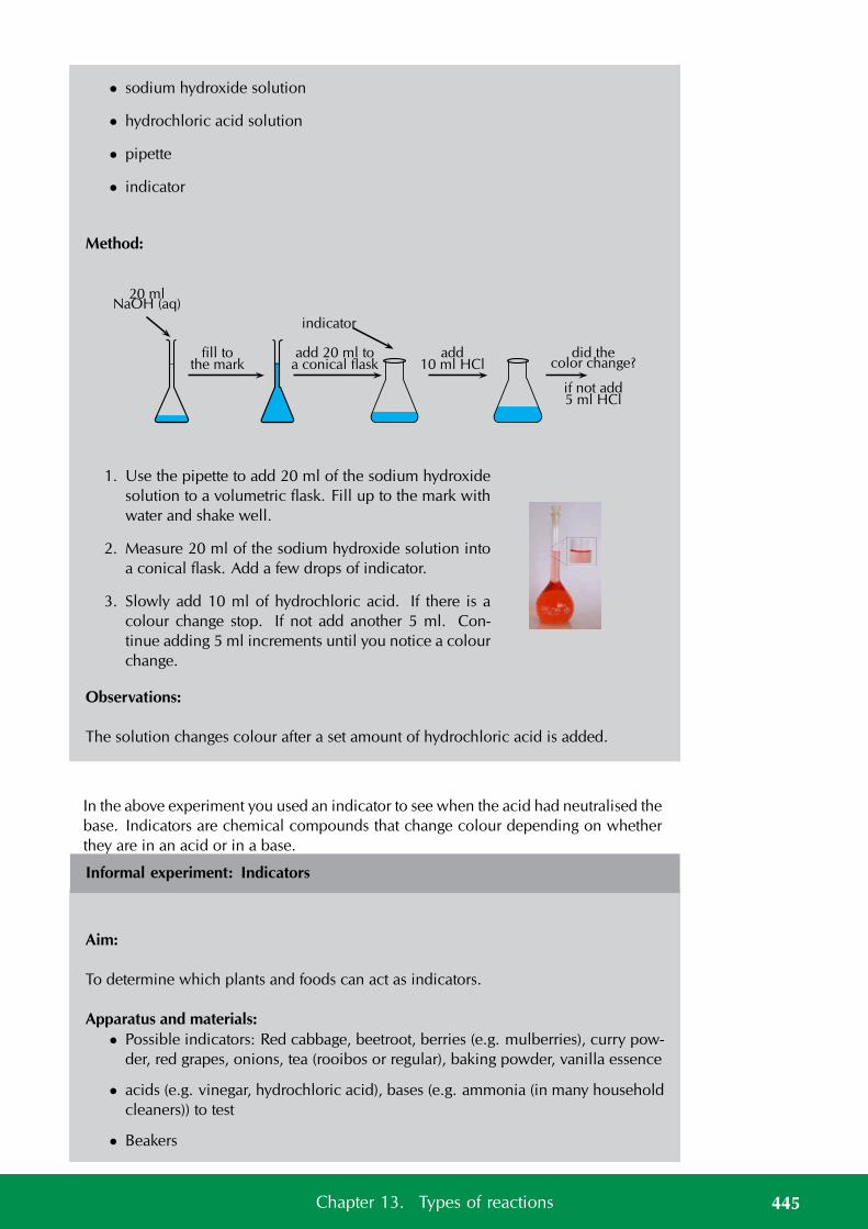
• sodium hydroxide solution
• hydrochloric acid solution
• pipette
• indicator
Method:
20 mlNaOH (aq)
fill tothe mark
add 20 ml toa conical flask
indicator
add10 ml HCl
did thecolor change?
if not add5 ml HCl
1. Use the pipette to add 20 ml of the sodium hydroxidesolution to a volumetric flask. Fill up to the mark withwater and shake well.
2. Measure 20 ml of the sodium hydroxide solution intoa conical flask. Add a few drops of indicator.
3. Slowly add 10 ml of hydrochloric acid. If there is acolour change stop. If not add another 5 ml. Con-tinue adding 5 ml increments until you notice a colourchange.
Observations:
The solution changes colour after a set amount of hydrochloric acid is added.
In the above experiment you used an indicator to see when the acid had neutralised thebase. Indicators are chemical compounds that change colour depending on whetherthey are in an acid or in a base.
Informal experiment: Indicators
Aim:
To determine which plants and foods can act as indicators.
Apparatus and materials:• Possible indicators: Red cabbage, beetroot, berries (e.g. mulberries), curry pow-
der, red grapes, onions, tea (rooibos or regular), baking powder, vanilla essence
• acids (e.g. vinegar, hydrochloric acid), bases (e.g. ammonia (in many householdcleaners)) to test
• Beakers
445Chapter 13. Types of reactions

Method:1. Take a small amount of your first possible indicator (do not use the onions, vanilla
essence and baking powder). Boil the substance up until the water has changedcolour.
2. Filter the resulting solution into a beaker being careful not to get any plant matterinto the beaker. (You can also pour the water through a colander or sieve.)
3. Pour half the resulting coloured solution into a second beaker.
4. Place one beaker onto an A4 sheet of paper labelled “acids”. Place the otherbeaker onto a sheet of paper labelled “bases”.
5. Repeat with all your other possible indicators (except the onions, vanilla essenceand baking powder).
6. Into all the beakers on the acid sheet carefully pour 5 ml of acid. Record yourobservations.
7. Into all the beakers on the base sheet carefully pour 5 ml of base. Record yourobservations.
If you have more than one acid or base then you will need to repeat the abovesteps to get fresh indicator samples for your second acid or base. Or you can useless of the resulting coloured solution for each acid and base you want to test.
8. Observe the smell of the onions and vanilla essence. Place a small piece ofonion into a beaker. This is for testing with the acid. Pour 5 ml of acid. Waveyour hand over the top of the beaker to blow the air towards your nose. Whatdo you notice about the smell of the onions? Repeat with the vanilla essence.
9. Place a small piece of onion into a beaker. This is for testing with the base. Pour5 ml of base. Wave your hand over the top of the beaker to blow the air towardsyour nose. What do you notice about the smell of the onions? Repeat with thevanilla essence.
10. Finally place a teaspoon of baking powder into a beaker. Carefully pour 5 ml ofacid into the beaker. Record your observations. Repeat using the base.
Observations:
Substance Colour Results with acid Results with baseRed cabbageBeetrootBerriesCurry powderTeaRed grapesOnionsVanilla essenceBaking powder
You should note that some of the substances change colour in the presence of eitheran acid or a base. The baking powder fizzes when it is in the acid solution, but noreaction is noted when it is in the base solution. Vanilla essence and onions shouldlose their characteristic smell when in the base.
446 13.2. Acid-base reactions

FACTVanilla and onions areknown as olfactory(smell) indicators.Olfactory indicators losetheir characteristic smellwhen mixed with acids orbases.
We will now look at three specific types of acid-base reactions. In each of these typesof acid-base reaction the acid remains the same but the kind of base changes. We willlook at what kind of products are produced when acids react with each of these basesand what the general reaction looks like.
Acid and metal hydroxide ESBQZ
When an acid reacts with a metal hydroxide a salt and water are formed. We havealready briefly explained this. Some examples are:
• HCl (aq) + NaOH (aq) → H2O (l) + NaCl (aq)
• 2HBr (aq) +Mg(OH)2(aq) → 2H2O (l) +MgBr2(aq)
• 3HCl (aq) + Al(OH)3(aq) → 3H2O (l) + AlCl3(aq)
We can write a general equation for this type of reaction:
nH+(aq) +M(OH)n(aq) → nH2O (l) +Mn+(aq)
Where n is the group number of the metal and M is the metal.
Exercise 13 – 3:
1. Write a balanced equation for the reaction between HNO3 and KOH.
Think you got it? Get this answer and more practice on our Intelligent Practice Service
1. 245V
www.everythingscience.co.za m.everythingscience.co.za
Acid and metal oxide ESBR2
When an acid reacts with a metal oxide a salt and water are also formed. Someexamples are:
• 2HCl (aq) + Na2O (aq) → H2O (l) + 2NaCl
• 2HBr (aq) +MgO → H2O (l) +MgBr2(aq)
• 6HCl (aq) + Al2O3(aq) → 3H2O (l) + 2AlCl3(aq)
447Chapter 13. Types of reactions

We can write a general equation for the reaction of a metal oxide with an acid:
2yH+(aq) +MxOy(aq) → yH2O (l) + xMn+(aq)
Where n is the group number of the metal. The x and y represent the ratio in whichthe metal combines with the oxide and depends on the valency of the metal.
Exercise 13 – 4:
1. Write a balanced equation for the reaction between HBr and K2O.
Think you got it? Get this answer and more practice on our Intelligent Practice Service
1. 245W
www.everythingscience.co.za m.everythingscience.co.za
Acid and a metal carbonate ESBR3
General experiment: The reaction of acids with carbonates
Apparatus and materials:
• Small amounts of baking powder (sodium bicarbonate)
• hydrochloric acid (dilute) and vinegar
• retort stand
• two test tubes
• one rubber stopper for the test tube
• a delivery tube
• lime water (calcium hydroxide in water)
The experiment should be set up as shown below.
448 13.2. Acid-base reactions
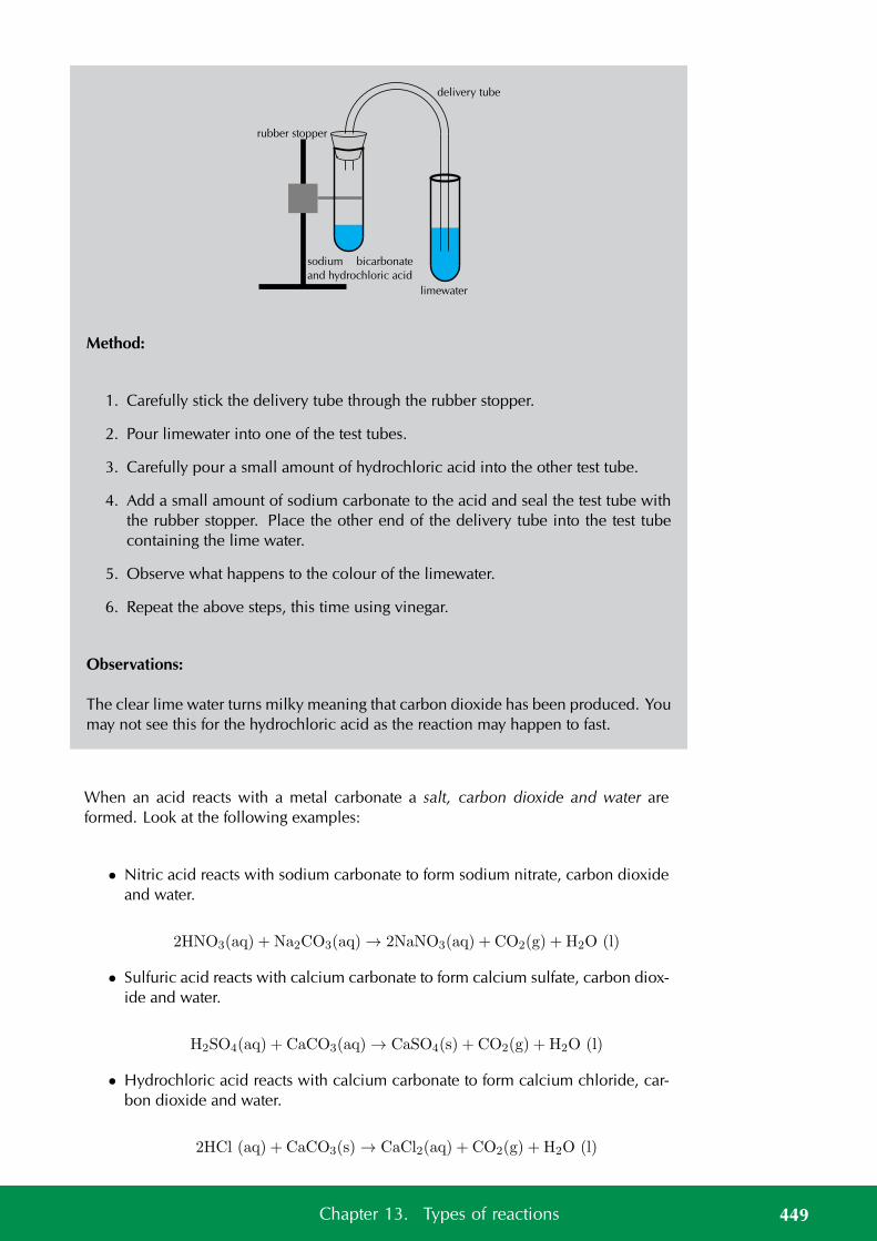
sodium bicarbonate
and hydrochloric acid
limewater
delivery tube
rubber stopper
Method:
1. Carefully stick the delivery tube through the rubber stopper.
2. Pour limewater into one of the test tubes.
3. Carefully pour a small amount of hydrochloric acid into the other test tube.
4. Add a small amount of sodium carbonate to the acid and seal the test tube withthe rubber stopper. Place the other end of the delivery tube into the test tubecontaining the lime water.
5. Observe what happens to the colour of the limewater.
6. Repeat the above steps, this time using vinegar.
Observations:
The clear lime water turns milky meaning that carbon dioxide has been produced. Youmay not see this for the hydrochloric acid as the reaction may happen to fast.
When an acid reacts with a metal carbonate a salt, carbon dioxide and water areformed. Look at the following examples:
• Nitric acid reacts with sodium carbonate to form sodium nitrate, carbon dioxideand water.
2HNO3(aq) + Na2CO3(aq) → 2NaNO3(aq) + CO2(g) + H2O (l)
• Sulfuric acid reacts with calcium carbonate to form calcium sulfate, carbon diox-ide and water.
H2SO4(aq) + CaCO3(aq) → CaSO4(s) + CO2(g) + H2O (l)
• Hydrochloric acid reacts with calcium carbonate to form calcium chloride, car-bon dioxide and water.
2HCl (aq) + CaCO3(s) → CaCl2(aq) + CO2(g) + H2O (l)
449Chapter 13. Types of reactions
Exercise 13 – 5:
1. Write a balanced equation for the reaction between HCl and K2CO3.
Think you got it? Get this answer and more practice on our Intelligent Practice Service
1. 245X
www.everythingscience.co.za m.everythingscience.co.za
Using what we have learnt about acids and bases we can now look at preparing somesalts.
General experiment: Making salts
Aim:
To make some salts using acid-base reactions.
Materials:
• hydrochloric acid (1 mol·dm−3), sulfuric acid (dilute), sodium hydroxide, cop-per(II) oxide, calcium carbonate
• beakers, mass meter, funnels, filter paper, bunsen burner, measuring cylinders
Method:
WARNING!
Wear gloves and safety glasses when working with sulfuric acid. Work in a wellventilated room.
Part 1
1. Measure out 20 ml of hydrochloric acid into a beaker.
2. Measure out 20 ml of sodium hydroxide and carefully add this to the beakercontaining hydrochloric acid.
3. Gently heat the resulting solution until all the water has evaporated. You shouldhave a white powder left.
450 13.2. Acid-base reactions
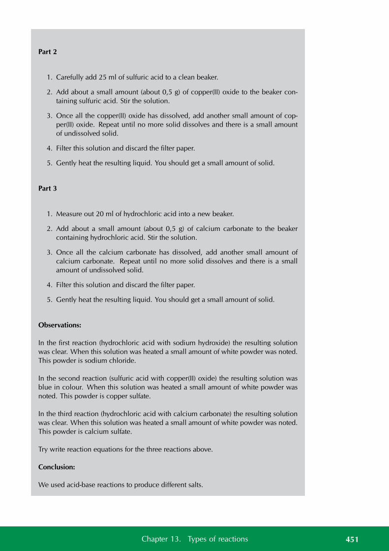
Part 2
1. Carefully add 25 ml of sulfuric acid to a clean beaker.
2. Add about a small amount (about 0,5 g) of copper(II) oxide to the beaker con-taining sulfuric acid. Stir the solution.
3. Once all the copper(II) oxide has dissolved, add another small amount of cop-per(II) oxide. Repeat until no more solid dissolves and there is a small amountof undissolved solid.
4. Filter this solution and discard the filter paper.
5. Gently heat the resulting liquid. You should get a small amount of solid.
Part 3
1. Measure out 20 ml of hydrochloric acid into a new beaker.
2. Add about a small amount (about 0,5 g) of calcium carbonate to the beakercontaining hydrochloric acid. Stir the solution.
3. Once all the calcium carbonate has dissolved, add another small amount ofcalcium carbonate. Repeat until no more solid dissolves and there is a smallamount of undissolved solid.
4. Filter this solution and discard the filter paper.
5. Gently heat the resulting liquid. You should get a small amount of solid.
Observations:
In the first reaction (hydrochloric acid with sodium hydroxide) the resulting solutionwas clear. When this solution was heated a small amount of white powder was noted.This powder is sodium chloride.
In the second reaction (sulfuric acid with copper(II) oxide) the resulting solution wasblue in colour. When this solution was heated a small amount of white powder wasnoted. This powder is copper sulfate.
In the third reaction (hydrochloric acid with calcium carbonate) the resulting solutionwas clear. When this solution was heated a small amount of white powder was noted.This powder is calcium sulfate.
Try write reaction equations for the three reactions above.
Conclusion:
We used acid-base reactions to produce different salts.
451Chapter 13. Types of reactions
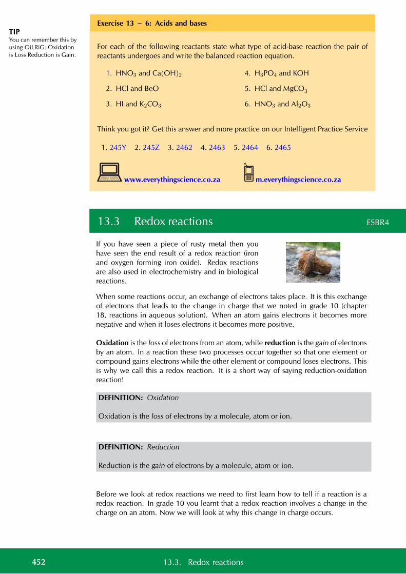
TIPYou can remember this byusing OiLRiG: Oxidationis Loss Reduction is Gain.
Exercise 13 – 6: Acids and bases
For each of the following reactants state what type of acid-base reaction the pair ofreactants undergoes and write the balanced reaction equation.
1. HNO3 and Ca(OH)2
2. HCl and BeO
3. HI and K2CO3
4. H3PO4 and KOH
5. HCl and MgCO3
6. HNO3 and Al2O3
Think you got it? Get this answer and more practice on our Intelligent Practice Service
1. 245Y 2. 245Z 3. 2462 4. 2463 5. 2464 6. 2465
www.everythingscience.co.za m.everythingscience.co.za
13.3 Redox reactions ESBR4
If you have seen a piece of rusty metal then youhave seen the end result of a redox reaction (ironand oxygen forming iron oxide). Redox reactionsare also used in electrochemistry and in biologicalreactions.
When some reactions occur, an exchange of electrons takes place. It is this exchangeof electrons that leads to the change in charge that we noted in grade 10 (chapter18, reactions in aqueous solution). When an atom gains electrons it becomes morenegative and when it loses electrons it becomes more positive.
Oxidation is the loss of electrons from an atom, while reduction is the gain of electronsby an atom. In a reaction these two processes occur together so that one element orcompound gains electrons while the other element or compound loses electrons. Thisis why we call this a redox reaction. It is a short way of saying reduction-oxidationreaction!
DEFINITION: Oxidation
Oxidation is the loss of electrons by a molecule, atom or ion.
DEFINITION: Reduction
Reduction is the gain of electrons by a molecule, atom or ion.
Before we look at redox reactions we need to first learn how to tell if a reaction is aredox reaction. In grade 10 you learnt that a redox reaction involves a change in thecharge on an atom. Now we will look at why this change in charge occurs.
452 13.3. Redox reactions
TIPYou will notice that someelements always have thesame oxidation numberwhile other elements canchange oxidationnumbers depending onthe compound they arein.
Oxidation numbers ESBR5
By giving elements an oxidation number, it is possible to keep track of whether thatelement is losing or gaining electrons during a chemical reaction. The loss of electronsin one part of the reaction must be balanced by a gain of electrons in another part ofthe reaction.
DEFINITION: Oxidation number
Oxidation number is the charge an atom would have if it was in a compound com-posed of ions.
There are a number of rules that you need to know about oxidation numbers, andthese are listed below.
1. A molecule consisting of only one element always has an oxidation number ofzero, since it is neutral.
For example the oxidation number of hydrogen in H2 is 0. The oxidation numberof bromine in Br2 is also 0.
2. Monatomic ions (ions with only one element or type of atom) have an oxidationnumber that is equal to the charge on the ion.
For example, the chloride ion Cl− has an oxidation number of −1, and themagnesium ion Mg2+ has an oxidation number of +2.
3. In a molecule or compound, the sum of the oxidation numbers for each elementin the molecule or compound will be zero.
For example the sum of the oxidation numbers for the elements in water will be0.
4. In a polyatomic ion the sum of the oxidation numbers is equal to the charge.
For example the sum of the oxidation numbers for the elements in the sulfate ion(SO2−
4 ) will be −2.
5. An oxygen atom usually has an oxidation number of −2. One exception is inperoxides (e.g. hydrogen peroxide) when oxygen has an oxidation number of−1.
For example oxygen in water will have an oxidation number of −2 while inhydrogen peroxide (H2O2) it will have an oxidation number of −1.
6. The oxidation number of hydrogen is often +1. One exception is in the metalhydrides where the oxidation number is −1.
For example the oxidation number of the hydrogen atom in water is +1, whilethe oxidation number of hydrogen in lithium hydride (LiH) is −1.
7. The oxidation number of fluorine is −1.
453Chapter 13. Types of reactions
Worked example 1: Oxidation numbers
QUESTION
Give the oxidation number of sulfur in a sulfate (SO2−4 ) ion
SOLUTION
Step 1: Determine the oxidation number for each atom
Oxygen will have an oxidation number of −2. (Rule 5, this is not a peroxide.) Theoxidation number of sulfur at this stage is uncertain since sulfur does not have a setoxidation number.
Step 2: Determine the oxidation number of sulfur by using the fact that the oxidationnumbers of the atoms must add up to the charge on the compound
In the polyatomic SO2−4 ion, the sum of the oxidation numbers must be −2 (rule 4).
Let the oxidation number of sulfur be x. We know that oxygen has an oxidationnumber of −2 and since there are four oxygen atoms in the sulfate ion, then the sumof the oxidation numbers of these four oxygen atoms is −8.
Putting this together gives:
x+ (−8) = −2
x = −2 + 8
= +6
So the oxidation number of sulfur is +6.
Step 3: Write down the final answer
In the sulfate ion, the oxidation number of sulfur is +6.
Worked example 2: Oxidation numbers
QUESTION
Give the oxidation number of both elements in ammonia (NH3).
SOLUTION
Step 1: Determine the oxidation number for each atom
Hydrogen will have an oxidation number of +1 (rule 6, ammonia is not a metal hy-dride). At this stage we do not know the oxidation number for nitrogen.
Step 2: Determine the oxidation number of nitrogen by using the fact that the oxida-tion numbers of the atoms must add up to the charge on the compound
454 13.3. Redox reactions
In the compound NH3, the sum of the oxidation numbers must be 0 (rule 3).
Let the oxidation number of nitrogen be x. We know that hydrogen has an oxidationnumber of +1 and since there are three hydrogen atoms in the ammonia molecule,then the sum of the oxidation numbers of these three hydrogen atoms is +3.
Putting this together gives:
x+ (+3) = 0
= −3
So the oxidation number of nitrogen is −3.
Step 3: Write the final answer
Hydrogen has an oxidation number of +1 and nitrogen has an oxidation number of−3.
Worked example 3: Oxidation numbers
QUESTION
Give the oxidation numbers for all the atoms in sodium chloride (NaCl).
SOLUTION
Step 1: Determine the oxidation number for each atom in the compound
This is an ionic compound composed of Na+ and Cl− ions. Using rule 2 the oxidationnumber for the sodium ion is +1 and for the chlorine ion it is −1.
This then gives us a sum of 0 for the compound.
Step 2: Write the final answer
The oxidation numbers for sodium is +1 and for chlorine it is −1.
Exercise 13 – 7: Oxidation numbers
1. Give the oxidation numbers for each element in the following chemical com-pounds:
a) MgF2 b) CaCl2 c) CH4 d) MgSO4
2. Compare the oxidation numbers of:
455Chapter 13. Types of reactions
TIPThe word species is usedin chemistry to indicateeither a compound, amolecule, an ion, anatom or an element.
a) nitrogen in:NO2 and NO
b) carbon in:CO2 and CO
c) chromium in:Cr2O2−
7 and CrO−4
d) oxygen in:H2O and H2O2
e) hydrogen in:NaH and H2O
3. Give the oxidation numbers for each of the elements in all the compounds.State if there is any difference between the oxidation number of the element inthe reactant and the element in the product.
a) C (s) + O2(g) → CO2(g)
b) N2(g) + 3H2(g) → 2NH3(g)
Think you got it? Get this answer and more practice on our Intelligent Practice Service
1a. 2466 1b. 2467 1c. 2468 1d. 2469 2a. 246B 2b. 246C2c. 246D 2d. 246F 2e. 246G 3a. 246H 3b. 246J
www.everythingscience.co.za m.everythingscience.co.za
Redox reactions ESBR6
Now that we know how to determine the oxidation number of a compound, we willgo on to look at how to use this knowledge in reactions.
Oxidation and reduction
By looking at how the oxidation number of an element changes during a reaction,we can easily see whether that element is being oxidised (lost electrons) or reduced(gained electrons).
If the oxidation number of a species becomes more positive, the species has beenoxidised and if the oxidation number of a species becomes more negative, the specieshas been reduced.
We will use the reaction between magnesium and chlorine as an example.
The chemical equation for this reaction is:
Mg (aq) + Cl2(aq) → MgCl2(aq)
As a reactant, magnesium has an oxidation number of zero, but as part of the productmagnesium chloride, the element has an oxidation number of +2. Magnesium haslost two electrons and has therefore been oxidised (note how the oxidation numberbecomes more positive). This can be written as a half-reaction. The half-reaction forthis change is:
Mg → Mg2+ + 2e−
456 13.3. Redox reactions
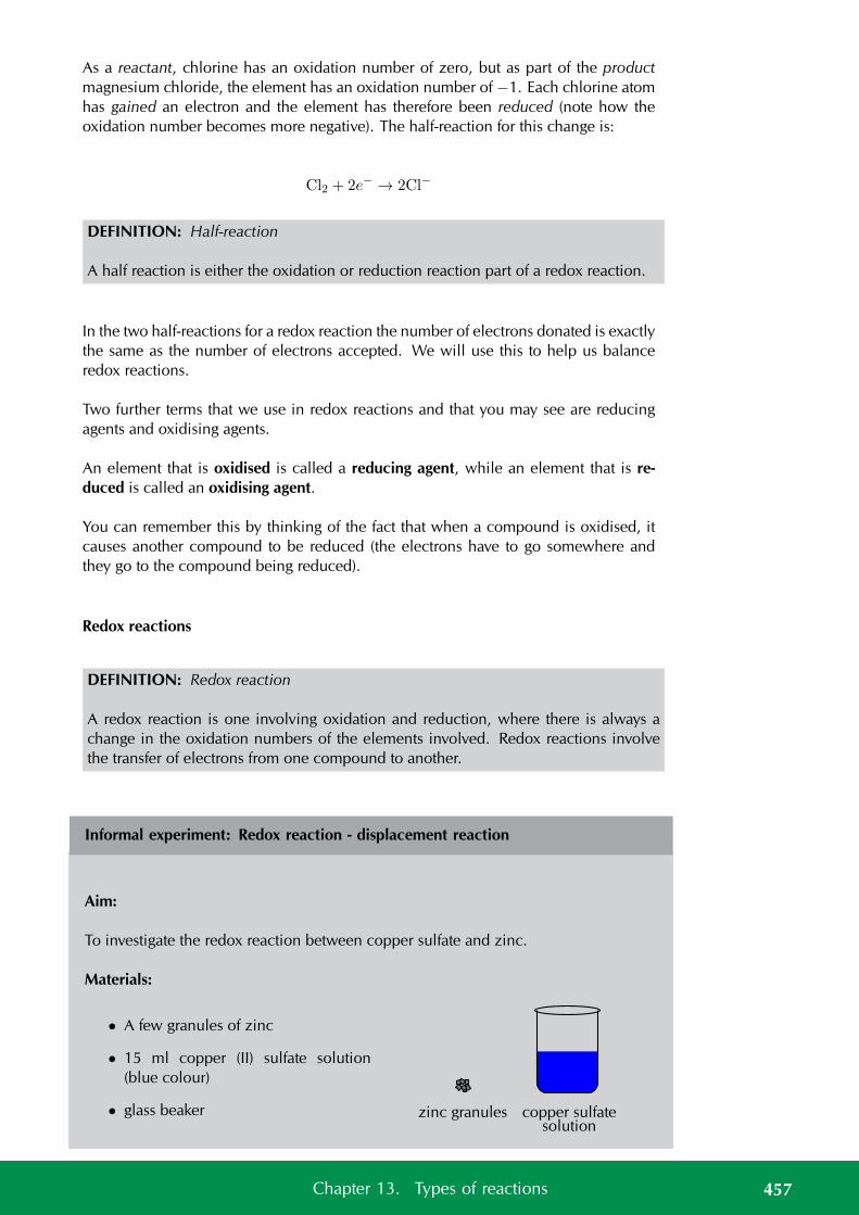
As a reactant, chlorine has an oxidation number of zero, but as part of the productmagnesium chloride, the element has an oxidation number of −1. Each chlorine atomhas gained an electron and the element has therefore been reduced (note how theoxidation number becomes more negative). The half-reaction for this change is:
Cl2 + 2e− → 2Cl−
DEFINITION: Half-reaction
A half reaction is either the oxidation or reduction reaction part of a redox reaction.
In the two half-reactions for a redox reaction the number of electrons donated is exactlythe same as the number of electrons accepted. We will use this to help us balanceredox reactions.
Two further terms that we use in redox reactions and that you may see are reducingagents and oxidising agents.
An element that is oxidised is called a reducing agent, while an element that is re-duced is called an oxidising agent.
You can remember this by thinking of the fact that when a compound is oxidised, itcauses another compound to be reduced (the electrons have to go somewhere andthey go to the compound being reduced).
Redox reactions
DEFINITION: Redox reaction
A redox reaction is one involving oxidation and reduction, where there is always achange in the oxidation numbers of the elements involved. Redox reactions involvethe transfer of electrons from one compound to another.
Informal experiment: Redox reaction - displacement reaction
Aim:
To investigate the redox reaction between copper sulfate and zinc.
Materials:
• A few granules of zinc
• 15 ml copper (II) sulfate solution(blue colour)
• glass beaker copper sulfatesolution
zinc granules
457Chapter 13. Types of reactions
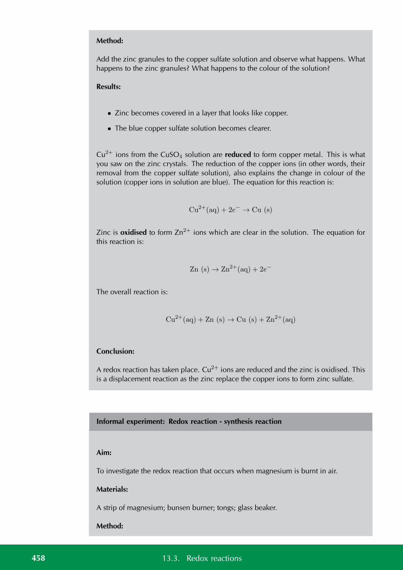
Method:
Add the zinc granules to the copper sulfate solution and observe what happens. Whathappens to the zinc granules? What happens to the colour of the solution?
Results:
• Zinc becomes covered in a layer that looks like copper.
• The blue copper sulfate solution becomes clearer.
Cu2+ ions from the CuSO4 solution are reduced to form copper metal. This is whatyou saw on the zinc crystals. The reduction of the copper ions (in other words, theirremoval from the copper sulfate solution), also explains the change in colour of thesolution (copper ions in solution are blue). The equation for this reaction is:
Cu2+(aq) + 2e− → Cu (s)
Zinc is oxidised to form Zn2+ ions which are clear in the solution. The equation forthis reaction is:
Zn (s) → Zn2+(aq) + 2e−
The overall reaction is:
Cu2+(aq) + Zn (s) → Cu (s) + Zn2+(aq)
Conclusion:
A redox reaction has taken place. Cu2+ ions are reduced and the zinc is oxidised. Thisis a displacement reaction as the zinc replace the copper ions to form zinc sulfate.
Informal experiment: Redox reaction - synthesis reaction
Aim:
To investigate the redox reaction that occurs when magnesium is burnt in air.
Materials:
A strip of magnesium; bunsen burner; tongs; glass beaker.
Method:
458 13.3. Redox reactions
WARNING!
Do not look directly at the flame.
1. Light the bunsen burner and use a pair of tongs to hold the magnesium ribbonin the flame.
2. Hold the lit piece of magnesium over a beaker. What do you observe?
Results:
The magnesium burns with a bright white flame. When the magnesium is held over abeaker, a fine powder is observed in the beaker. This is magnesium oxide.
The overall reaction is:
2Mg (s) + O2(g) → 2MgO (s)
Conclusion:
A redox reaction has taken place. Magnesium is oxidised and the oxygen is reduced.This is a synthesis reaction as we have made magnesium oxide from magnesium andoxygen.
Informal experiment: Redox reaction - decomposition reaction
Aim:
To investigate the decomposition of hydrogen peroxide.
Materials:
Dilute hydrogen peroxide (about 3%); manganese dioxide; test tubes; a water bowl;stopper and delivery tube, Bunsen burner
459Chapter 13. Types of reactions
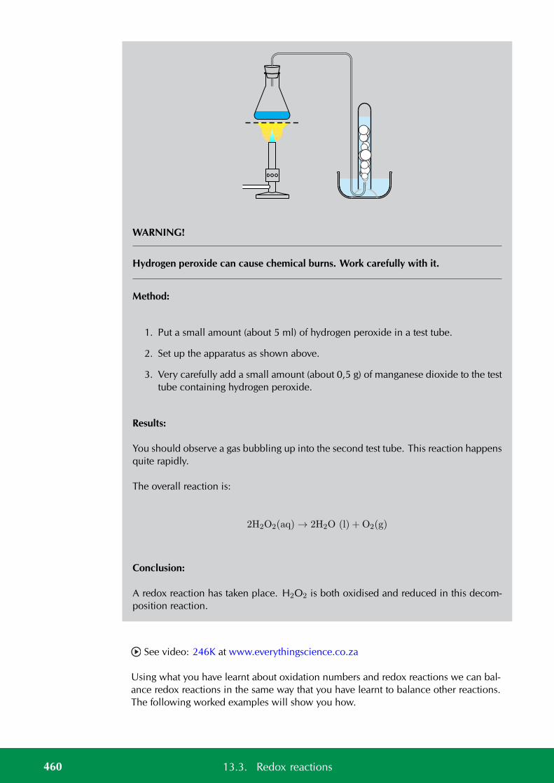
WARNING!
Hydrogen peroxide can cause chemical burns. Work carefully with it.
Method:
1. Put a small amount (about 5 ml) of hydrogen peroxide in a test tube.
2. Set up the apparatus as shown above.
3. Very carefully add a small amount (about 0,5 g) of manganese dioxide to the testtube containing hydrogen peroxide.
Results:
You should observe a gas bubbling up into the second test tube. This reaction happensquite rapidly.
The overall reaction is:
2H2O2(aq) → 2H2O (l) + O2(g)
Conclusion:
A redox reaction has taken place. H2O2 is both oxidised and reduced in this decom-position reaction.
See video: 246K at www.everythingscience.co.za
Using what you have learnt about oxidation numbers and redox reactions we can bal-ance redox reactions in the same way that you have learnt to balance other reactions.The following worked examples will show you how.
460 13.3. Redox reactions
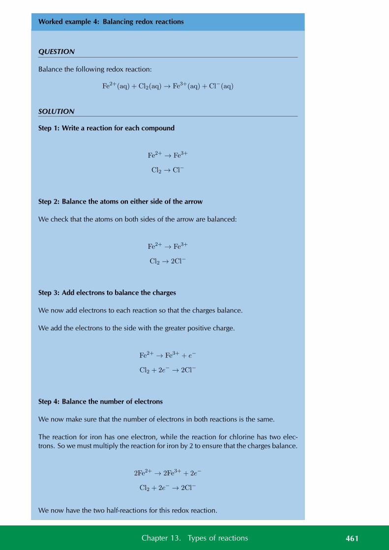
Worked example 4: Balancing redox reactions
QUESTION
Balance the following redox reaction:
Fe2+(aq) + Cl2(aq) → Fe3+(aq) + Cl−(aq)
SOLUTION
Step 1: Write a reaction for each compound
Fe2+ → Fe3+
Cl2 → Cl−
Step 2: Balance the atoms on either side of the arrow
We check that the atoms on both sides of the arrow are balanced:
Fe2+ → Fe3+
Cl2 → 2Cl−
Step 3: Add electrons to balance the charges
We now add electrons to each reaction so that the charges balance.
We add the electrons to the side with the greater positive charge.
Fe2+ → Fe3+ + e−
Cl2 + 2e− → 2Cl−
Step 4: Balance the number of electrons
We now make sure that the number of electrons in both reactions is the same.
The reaction for iron has one electron, while the reaction for chlorine has two elec-trons. So we must multiply the reaction for iron by 2 to ensure that the charges balance.
2Fe2+ → 2Fe3+ + 2e−
Cl2 + 2e− → 2Cl−
We now have the two half-reactions for this redox reaction.
461Chapter 13. Types of reactions
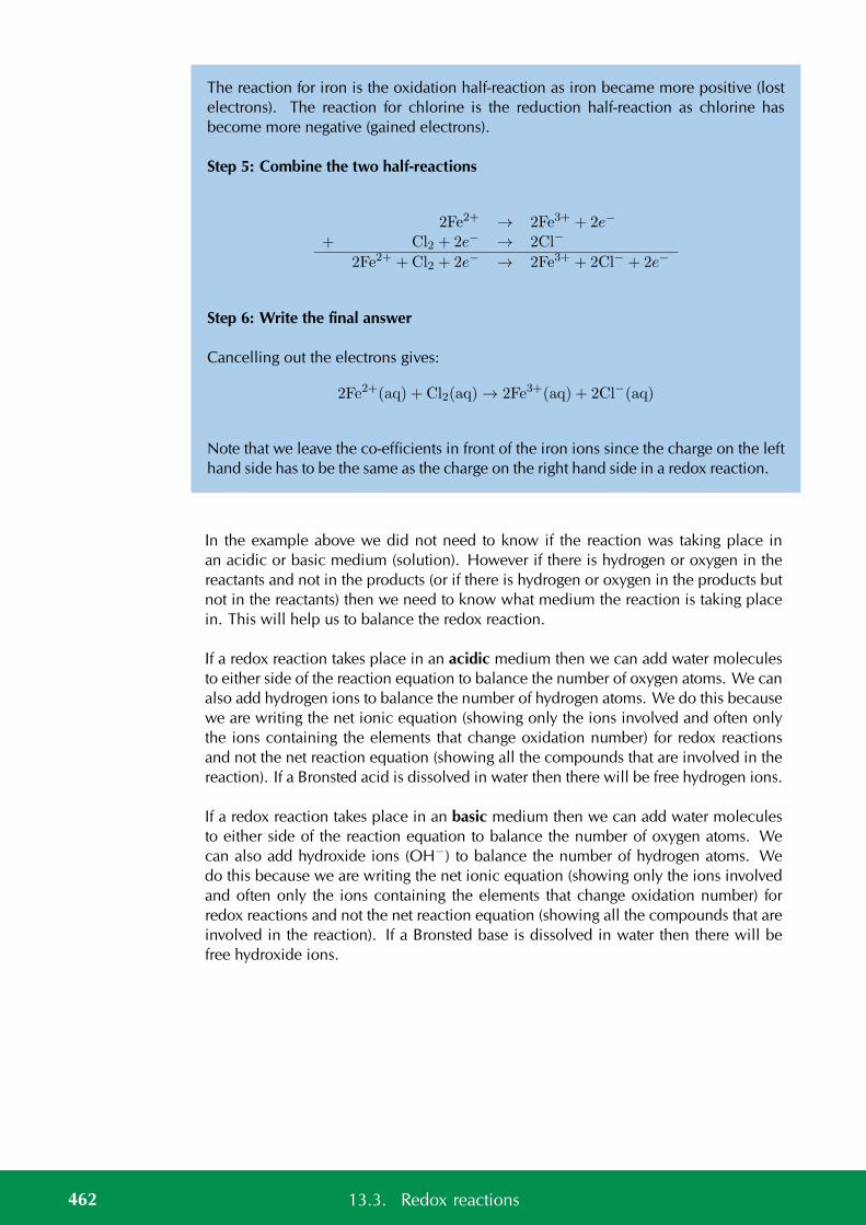
The reaction for iron is the oxidation half-reaction as iron became more positive (lostelectrons). The reaction for chlorine is the reduction half-reaction as chlorine hasbecome more negative (gained electrons).
Step 5: Combine the two half-reactions
2Fe2+ → 2Fe3+ + 2e−
+ Cl2 + 2e− → 2Cl−
2Fe2+ +Cl2 + 2e− → 2Fe3+ + 2Cl− + 2e−
Step 6: Write the final answer
Cancelling out the electrons gives:
2Fe2+(aq) + Cl2(aq) → 2Fe3+(aq) + 2Cl−(aq)
Note that we leave the co-efficients in front of the iron ions since the charge on the lefthand side has to be the same as the charge on the right hand side in a redox reaction.
In the example above we did not need to know if the reaction was taking place inan acidic or basic medium (solution). However if there is hydrogen or oxygen in thereactants and not in the products (or if there is hydrogen or oxygen in the products butnot in the reactants) then we need to know what medium the reaction is taking placein. This will help us to balance the redox reaction.
If a redox reaction takes place in an acidic medium then we can add water moleculesto either side of the reaction equation to balance the number of oxygen atoms. We canalso add hydrogen ions to balance the number of hydrogen atoms. We do this becausewe are writing the net ionic equation (showing only the ions involved and often onlythe ions containing the elements that change oxidation number) for redox reactionsand not the net reaction equation (showing all the compounds that are involved in thereaction). If a Bronsted acid is dissolved in water then there will be free hydrogen ions.
If a redox reaction takes place in an basic medium then we can add water moleculesto either side of the reaction equation to balance the number of oxygen atoms. Wecan also add hydroxide ions (OH−) to balance the number of hydrogen atoms. Wedo this because we are writing the net ionic equation (showing only the ions involvedand often only the ions containing the elements that change oxidation number) forredox reactions and not the net reaction equation (showing all the compounds that areinvolved in the reaction). If a Bronsted base is dissolved in water then there will befree hydroxide ions.
462 13.3. Redox reactions
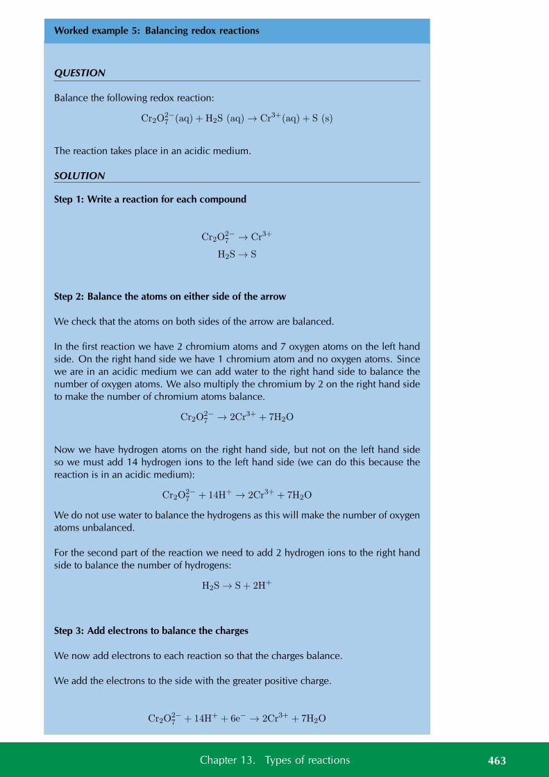
Worked example 5: Balancing redox reactions
QUESTION
Balance the following redox reaction:
Cr2O2−7 (aq) + H2S (aq) → Cr3+(aq) + S (s)
The reaction takes place in an acidic medium.
SOLUTION
Step 1: Write a reaction for each compound
Cr2O2−7 → Cr3+
H2S → S
Step 2: Balance the atoms on either side of the arrow
We check that the atoms on both sides of the arrow are balanced.
In the first reaction we have 2 chromium atoms and 7 oxygen atoms on the left handside. On the right hand side we have 1 chromium atom and no oxygen atoms. Sincewe are in an acidic medium we can add water to the right hand side to balance thenumber of oxygen atoms. We also multiply the chromium by 2 on the right hand sideto make the number of chromium atoms balance.
Cr2O2−7 → 2Cr3+ + 7H2O
Now we have hydrogen atoms on the right hand side, but not on the left hand sideso we must add 14 hydrogen ions to the left hand side (we can do this because thereaction is in an acidic medium):
Cr2O2−7 + 14H+ → 2Cr3+ + 7H2O
We do not use water to balance the hydrogens as this will make the number of oxygenatoms unbalanced.
For the second part of the reaction we need to add 2 hydrogen ions to the right handside to balance the number of hydrogens:
H2S → S + 2H+
Step 3: Add electrons to balance the charges
We now add electrons to each reaction so that the charges balance.
We add the electrons to the side with the greater positive charge.
Cr2O2−7 + 14H+ + 6e− → 2Cr3+ + 7H2O
463Chapter 13. Types of reactions
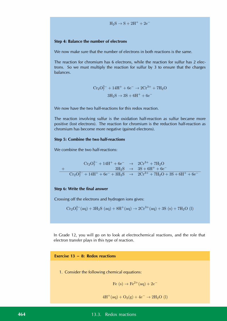
H2S → S + 2H+ + 2e−
Step 4: Balance the number of electrons
We now make sure that the number of electrons in both reactions is the same.
The reaction for chromium has 6 electrons, while the reaction for sulfur has 2 elec-trons. So we must multiply the reaction for sulfur by 3 to ensure that the chargesbalances.
Cr2O2−7 + 14H+ + 6e− → 2Cr3+ + 7H2O
3H2S → 3S + 6H+ + 6e−
We now have the two half-reactions for this redox reaction.
The reaction involving sulfur is the oxidation half-reaction as sulfur became morepositive (lost electrons). The reaction for chromium is the reduction half-reaction aschromium has become more negative (gained electrons).
Step 5: Combine the two half-reactions
We combine the two half-reactions:
Cr2O2−7 + 14H+ + 6e− → 2Cr3+ + 7H2O
+ 3H2S → 3S + 6H+ + 6e−
Cr2O2−7 + 14H+ + 6e− + 3H2S → 2Cr3+ + 7H2O+ 3S + 6H+ + 6e−
Step 6: Write the final answer
Crossing off the electrons and hydrogen ions gives:
Cr2O2−7 (aq) + 3H2S (aq) + 8H+(aq) → 2Cr3+(aq) + 3S (s) + 7H2O (l)
In Grade 12, you will go on to look at electrochemical reactions, and the role thatelectron transfer plays in this type of reaction.
Exercise 13 – 8: Redox reactions
1. Consider the following chemical equations:
Fe (s) → Fe2+(aq) + 2e−
4H+(aq) + O2(g) + 4e− → 2H2O (l)
464 13.3. Redox reactions
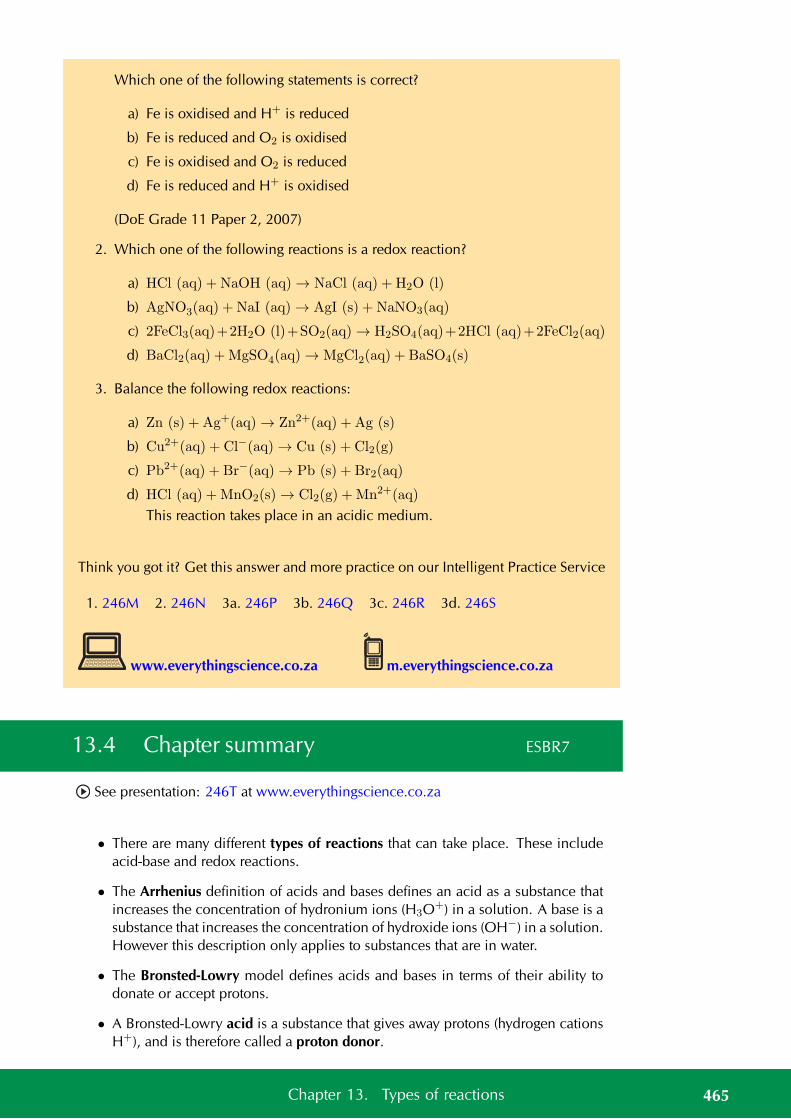
Which one of the following statements is correct?
a) Fe is oxidised and H+ is reduced
b) Fe is reduced and O2 is oxidised
c) Fe is oxidised and O2 is reduced
d) Fe is reduced and H+ is oxidised
(DoE Grade 11 Paper 2, 2007)
2. Which one of the following reactions is a redox reaction?
a) HCl (aq) + NaOH (aq) → NaCl (aq) + H2O (l)
b) AgNO3(aq) + NaI (aq) → AgI (s) + NaNO3(aq)
c) 2FeCl3(aq)+2H2O (l)+SO2(aq) → H2SO4(aq)+2HCl (aq)+2FeCl2(aq)
d) BaCl2(aq) +MgSO4(aq) → MgCl2(aq) + BaSO4(s)
3. Balance the following redox reactions:
a) Zn (s) + Ag+(aq) → Zn2+(aq) + Ag (s)
b) Cu2+(aq) + Cl−(aq) → Cu (s) + Cl2(g)
c) Pb2+(aq) + Br−(aq) → Pb (s) + Br2(aq)
d) HCl (aq) +MnO2(s) → Cl2(g) +Mn2+(aq)
This reaction takes place in an acidic medium.
Think you got it? Get this answer and more practice on our Intelligent Practice Service
1. 246M 2. 246N 3a. 246P 3b. 246Q 3c. 246R 3d. 246S
www.everythingscience.co.za m.everythingscience.co.za
13.4 Chapter summary ESBR7
See presentation: 246T at www.everythingscience.co.za
• There are many different types of reactions that can take place. These includeacid-base and redox reactions.
• The Arrhenius definition of acids and bases defines an acid as a substance thatincreases the concentration of hydronium ions (H3O+) in a solution. A base is asubstance that increases the concentration of hydroxide ions (OH−) in a solution.However this description only applies to substances that are in water.
• The Bronsted-Lowry model defines acids and bases in terms of their ability todonate or accept protons.
• A Bronsted-Lowry acid is a substance that gives away protons (hydrogen cationsH+), and is therefore called a proton donor.
465Chapter 13. Types of reactions
• A Bronsted-Lowry base is a substance that takes up protons (hydrogen cationsH+), and is therefore called a proton acceptor.
• An amphoteric substance is one that can react as either an acid or base. Water(H2O) is an example of an amphoteric substance.
• An amphiprotic is one that can react as either a proton donor (Bronsted-Lowryacid) or as a proton acceptor (Bronsted-Lowry base). HCO−
3 and HSO−4 are
examples of amphiprotic substances.
• A conjugate acid-base pair refers to two compounds in a reaction (one reactantand one product) that transform or change into the other through the loss or gainof a proton.
• The reaction between an acid and a base is a neutralisation reaction.
• Acids and bases are used in domestic uses (for example calcium carbonate onacidic soil) in biology (for example in antacids for stomach ulcers) and in industry(for example in absorbing harmful SO2 gas),.
• Indicators are chemical compounds that change colour depending on whetherthey are in an acid or in a base.
• When an acid reacts with a metal hydroxide a salt and water are formed. The saltis made up of a cation from the base and an anion from the acid. An example ofa salt is potassium chloride (KCl), which is the product of the reaction betweenpotassium hydroxide (KOH) and hydrochloric acid (HCl).
• When an acid reacts with a metal oxide a salt and water are formed. An exampleis the reaction between magnesium oxide (MgO) and hydrochloric acid (HCl).
• When an acid reacts with a metal carbonate a salt, water and carbon dioxide areformed. An example is the reaction between calcium carbonate (CaCO3) andhydrochloric acid (HCl).
• Oxidation is the loss of electrons by a molecule, atom or ion.
• Reduction is the gain of electrons by a molecule, atom or ion.
• A redox reaction is one involving oxidation and reduction, where there is alwaysa change in the oxidation numbers of the elements involved. Redox reactionsinvolve the transfer of electrons from one compound to another.
• An oxidation number is the charge an atom would have if it was in a compoundcomposed of ions.
• If the oxidation number of a species becomes more positive, the species hasbeen oxidised and if the oxidation number of a species becomes more negative,the species has been reduced.
• A half reaction is either the oxidation or reduction reaction part of a redox re-action. In the two half-reactions for a redox reaction the number of electronsdonated is exactly the same as the number of electrons accepted.
• An element that is oxidised is called a reducing agent, while an element that isreduced is called an oxidising agent.
466 13.4. Chapter summary
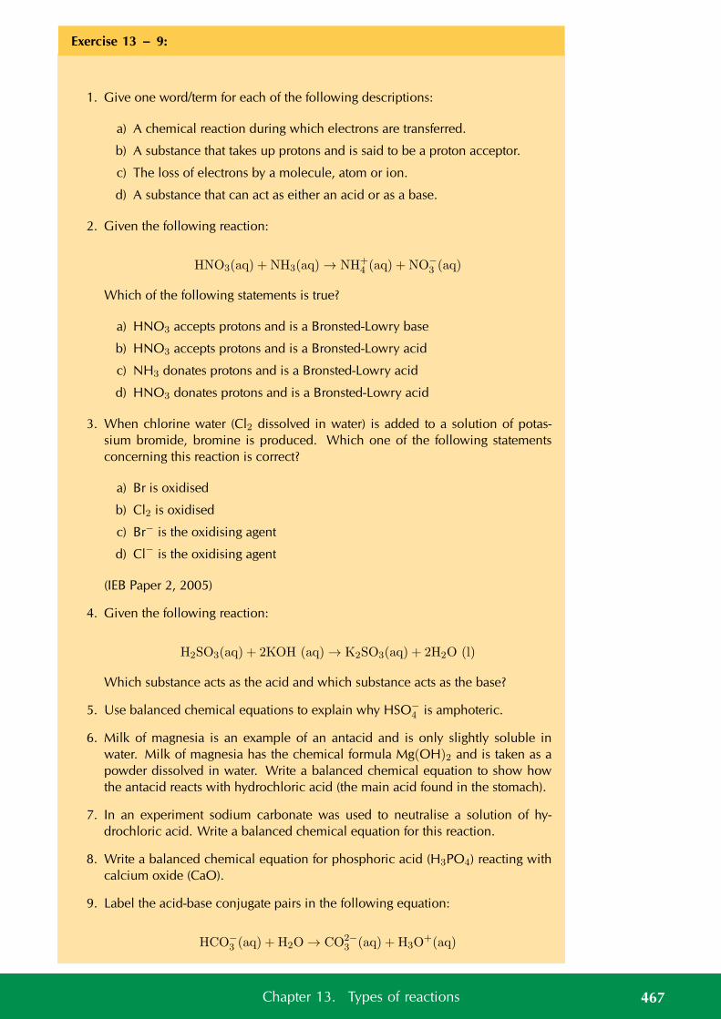
Exercise 13 – 9:
1. Give one word/term for each of the following descriptions:
a) A chemical reaction during which electrons are transferred.
b) A substance that takes up protons and is said to be a proton acceptor.
c) The loss of electrons by a molecule, atom or ion.
d) A substance that can act as either an acid or as a base.
2. Given the following reaction:
HNO3(aq) + NH3(aq) → NH+4 (aq) + NO−
3 (aq)
Which of the following statements is true?
a) HNO3 accepts protons and is a Bronsted-Lowry base
b) HNO3 accepts protons and is a Bronsted-Lowry acid
c) NH3 donates protons and is a Bronsted-Lowry acid
d) HNO3 donates protons and is a Bronsted-Lowry acid
3. When chlorine water (Cl2 dissolved in water) is added to a solution of potas-sium bromide, bromine is produced. Which one of the following statementsconcerning this reaction is correct?
a) Br is oxidised
b) Cl2 is oxidised
c) Br− is the oxidising agent
d) Cl− is the oxidising agent
(IEB Paper 2, 2005)
4. Given the following reaction:
H2SO3(aq) + 2KOH (aq) → K2SO3(aq) + 2H2O (l)
Which substance acts as the acid and which substance acts as the base?
5. Use balanced chemical equations to explain why HSO−4 is amphoteric.
6. Milk of magnesia is an example of an antacid and is only slightly soluble inwater. Milk of magnesia has the chemical formula Mg(OH)2 and is taken as apowder dissolved in water. Write a balanced chemical equation to show howthe antacid reacts with hydrochloric acid (the main acid found in the stomach).
7. In an experiment sodium carbonate was used to neutralise a solution of hy-drochloric acid. Write a balanced chemical equation for this reaction.
8. Write a balanced chemical equation for phosphoric acid (H3PO4) reacting withcalcium oxide (CaO).
9. Label the acid-base conjugate pairs in the following equation:
HCO−3 (aq) + H2O → CO2−
3 (aq) + H3O+(aq)
467Chapter 13. Types of reactions
10. Look at the following reaction:
2H2O2(l) → 2H2O (l) + O2(g)
a) What is the oxidation number of the oxygen atom in each of the followingcompounds?
i. H2O2
ii. H2Oiii. O2
b) Does the hydrogen peroxide (H2O2) act as an oxidising agent or a reducingagent or both, in the above reaction? Give a reason for your answer.
11. Challenge question: Zinc reacts with aqueous copper sulfate (CuSO4(aq)) toform zinc sulfate (ZnSO4(aq)) and copper ions. What is the oxidation numberfor each element in the reaction?
12. Balance the following redox reactions:
a) Pb (s) + Ag+(aq) → Pb2+(aq) + Ag (s)
b) Zn2+(aq) + I−(aq) → Zn (s) + I2(g)
c) Fe3+ (aq) + NO2(aq) → Fe (s) + NO−3 (aq)
This reaction takes place in an acidic medium.
13. A nickel-cadmium battery is used in various portable devices such as calculators.This battery uses a redox reaction to work. The equation for the reaction is:
Cd (s) + NiO(OH) (s) → Cd(OH)2(s) + Ni(OH)2(s)
This reaction takes place in a basic medium. Balance the equation.
Think you got it? Get this answer and more practice on our Intelligent Practice Service
1a. 246V 1b. 246W 1c. 246X 1d. 246Y 2. 246Z 3. 24724. 2473 5. 2474 6. 2475 7. 2476 8. 2477 9. 2478
10. 2479 11. 247F 12a. 247G 12b. 247H 12c. 247J 13. 247K
www.everythingscience.co.za m.everythingscience.co.za
468 13.4. Chapter summary
CHAPTER 14
The lithosphere
14.1 Introduction 470
14.2 The lithosphere 470
14.3 Mining and mineral processing 477
14.4 Energy resources 485
14.5 Summary 486
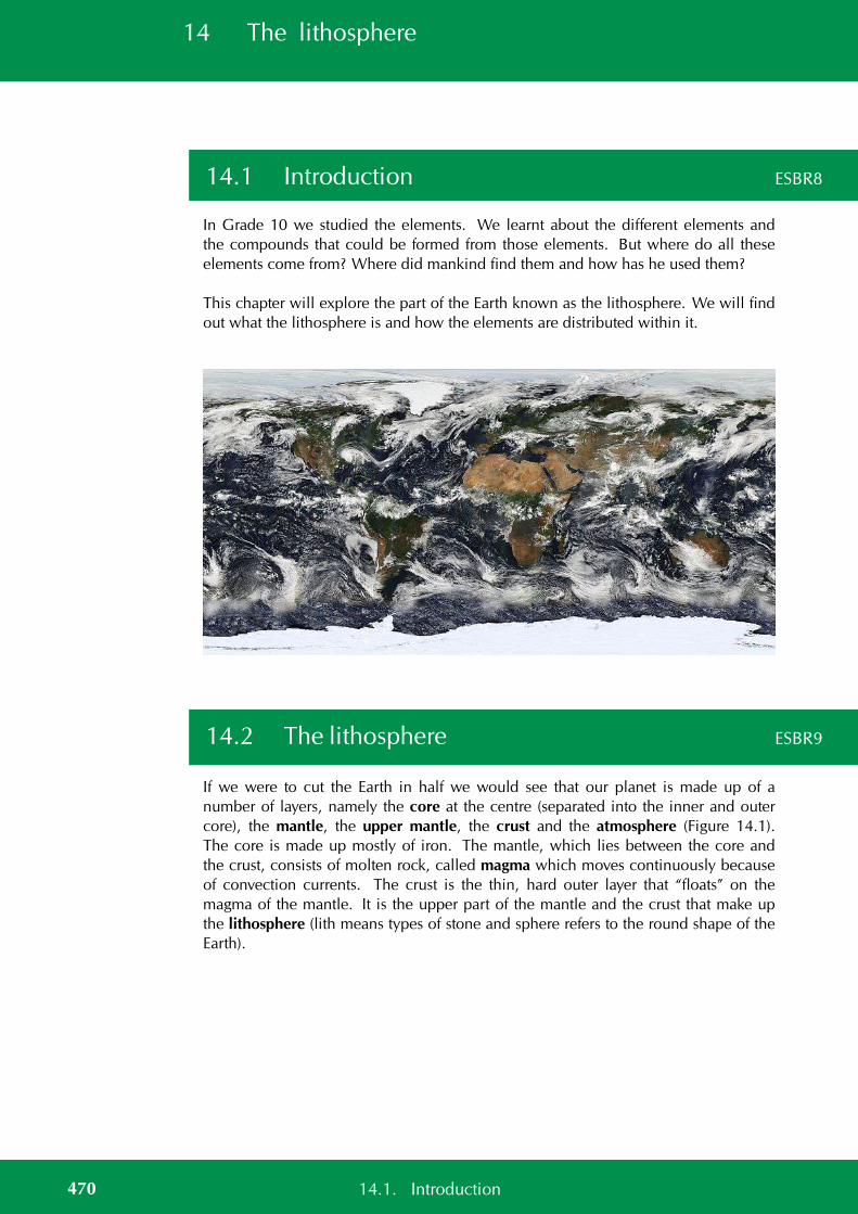
14 The lithosphere
14.1 Introduction ESBR8
In Grade 10 we studied the elements. We learnt about the different elements andthe compounds that could be formed from those elements. But where do all theseelements come from? Where did mankind find them and how has he used them?
This chapter will explore the part of the Earth known as the lithosphere. We will findout what the lithosphere is and how the elements are distributed within it.
14.2 The lithosphere ESBR9
If we were to cut the Earth in half we would see that our planet is made up of anumber of layers, namely the core at the centre (separated into the inner and outercore), the mantle, the upper mantle, the crust and the atmosphere (Figure 14.1).The core is made up mostly of iron. The mantle, which lies between the core andthe crust, consists of molten rock, called magma which moves continuously becauseof convection currents. The crust is the thin, hard outer layer that “floats” on themagma of the mantle. It is the upper part of the mantle and the crust that make upthe lithosphere (lith means types of stone and sphere refers to the round shape of theEarth).
470 14.1. Introduction
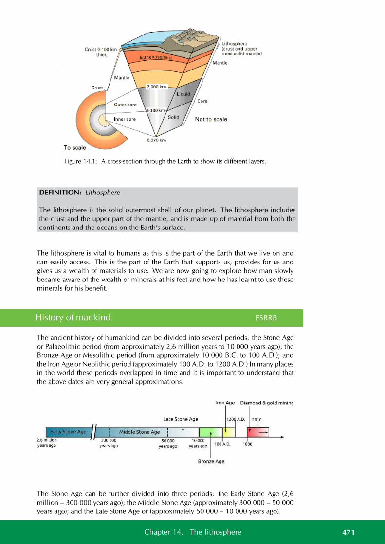
Figure 14.1: A cross-section through the Earth to show its different layers.
DEFINITION: Lithosphere
The lithosphere is the solid outermost shell of our planet. The lithosphere includesthe crust and the upper part of the mantle, and is made up of material from both thecontinents and the oceans on the Earth’s surface.
The lithosphere is vital to humans as this is the part of the Earth that we live on andcan easily access. This is the part of the Earth that supports us, provides for us andgives us a wealth of materials to use. We are now going to explore how man slowlybecame aware of the wealth of minerals at his feet and how he has learnt to use theseminerals for his benefit.
History of mankind ESBRB
The ancient history of humankind can be divided into several periods: the Stone Ageor Palaeolithic period (from approximately 2,6 million years to 10 000 years ago); theBronze Age or Mesolithic period (from approximately 10 000 B.C. to 100 A.D.); andthe Iron Age or Neolithic period (approximately 100 A.D. to 1200 A.D.) In many placesin the world these periods overlapped in time and it is important to understand thatthe above dates are very general approximations.
The Stone Age can be further divided into three periods: the Early Stone Age (2,6million – 300 000 years ago); the Middle Stone Age (approximately 300 000 – 50 000years ago); and the Late Stone Age or (approximately 50 000 – 10 000 years ago).
471Chapter 14. The lithosphere

FACTThe largest Iron Age sitein South Africa is found atMapungubwe, in theLimpopo Province.Mapungubwe (inhabitedfrom about 1000 – 1300A.D.) is thought to be theancient capital of anAfrican king. The site wasrediscovered in 1932 andhas proved to be atreasure trove ofarchaeological evidencefor an advanced society.The remains of royalburial sites, houses, tools,art and farmingimplements have beenfound. Gold-platedjewellery, sculptures andartifacts (thought to havebelonged to members ofthe royal family) have alsobeen discovered at thesite.
Age Time InformationMajormaterial
Images
Earlystoneage
2,6 million- 300 000years ago
Basic stone tools were used.Mankind mainly used the rocksand stones he found lying aroundhim. Evidence for this has beenfound in the Sterkfontein caves inthe Cradle of Humankind.
Stone
Middlestoneage
300 000 -50 000 yearsago
Mankind learnt to use fire totreat stones before they weremade into tools. Stone tools be-came more refined during this pe-riod. Evidence for this has beenfound at Swartkrans (Cradle of Hu-mankind), Montagu Cave (KleinKaroo), Klasies River Mouth (Tsit-sikamma), Stilbaai and BlombosCave (Southern Cape).
Stonetreatedwith fire
Latestoneage
50 000 -10 000years ago
Mankind started turning to othermaterials that were easily avail-able. He started working with dif-ferent materials and seeing howthese new materials could becombined with stone. Evidencefor this has been found in theMelkhoutboom Cave, in the Su-urberg Mountains (Eastern Cape).
Stonewithothernaturalmateri-als
Bronzeage
10 000 B.C.- 100 A.D.
The Bronze Age saw the first useof smelted copper and bronzein the manufacture of tools andweapons. Evidence for this hasbeen found in North Africa.
Copperand tin
Iron age100 A.D. -1200 A.D.
Primitive mining for materials oc-curred during this period. Fur-naces were used to heat metal, inorder to smelt it into weapons andtools. Evidence for this has beenfound at Melville Koppies and atMapungubwe (Limpopo).
Iron andothermetals
Table 14.1: The different ages of civilisation.
After the Iron Age ended, mankind started to explore many more ways to get at theprecious metals that they were using. Mining for the minerals started to becomemore common and man began to look for new sources of the metals and mineralshe needed.
Many different cultures in Africa used gold, diamonds and other precious metals fordifferent things. A large number of these artefact’s were looted from these people andtaken to Europe by the colonists and explorers that came from Europe. Efforts havenow begun to return these stolen artifacts to the people they came from, but manymuseums still hold onto their collections.
472 14.2. The lithosphere

FACTThe deepest mine in theworld is currently theTauTona Mine (orWestern Deep No. 3Shaft) outsideCarletonville, Gauteng.Owned by AngloGoldAshanti, it is 3,9 km deepand has about 800 km oftunnels. The rock face atthat depth reachestemperatures of 60C andair-conditioners have tobe used to cool the air inthe mine from 55C to28C.
When colonists and explorers first began exploring and settling in Africa they startedlooking at ways to use the natural resources they found.
Although diamonds had long been known to the indigenous people of South Africa,colonists found them on a farm outside Kimberley (Northern Cape) in the 1860’s. Theoriginal hill on which the diamonds were found was mined extensively by the handsof thousands of hopeful diamond prospectors who rushed to the area. Today the siteof that hill is now the Big Hole in Kimberley – one of the largest holes in the worldthat was dug by hand. In 1888, several small diamond mining companies merged toform De Beers, the company that still dominates the global diamond mining and retailindustry today.
Around the same time (1880), the colonists discovered gold reefs just south of present-day Johannesburg. The rush of gold-prospectors to the area resulted in the birth of thecity of Johannesburg. A massive labour force was required to dig deep into the bedrockto extract the rock containing the gold. Indeed, huge numbers of mine workers are stillemployed by gold mines in South Africa today, but (as with diamond mining too), dueto technological advancements over the last 150 years, much of their work is nowaided by industrial mining equipment.
Many farmers and indigenous people were forced to work in the new diamond andgold mines. These people were taken by force from their homes and put to work onthe mines. Many of them died from a result of the poor working conditions and frommining disasters that occurred.
Group discussion: Minerals and the rights to own them
Many indigenous people share the same central belief that the land and all it producesare for all the people to use equally. The land and what it produces is often vital to thesurvival of these people.
When the colonists came to Southern Africa, they largely ignored the indigenous peo-ple and exploited them for the knowledge they held and the work they could provide.A great number of atrocities were committed against the indigenous people.
Now the indigenous people are rising up and asking that what is rightfully theirs shouldbe returned to them. Organisations (such as the UN working group on indigenouspeople) have formed to address these issues.
Shortly after De Beers formed they claimed the right to all the diamonds in the areaand anyone found with diamonds could be killed for taking the diamonds illegally.Other large mining companies have tried to claim the rights to the minerals that theyproduce.
In groups or as a class discuss whether or not a few select people should hold the rightsto the land and the minerals in it. Who owns the minerals? Should big corporates holdthe rights? Or should it belong to all the people?
473Chapter 14. The lithosphere
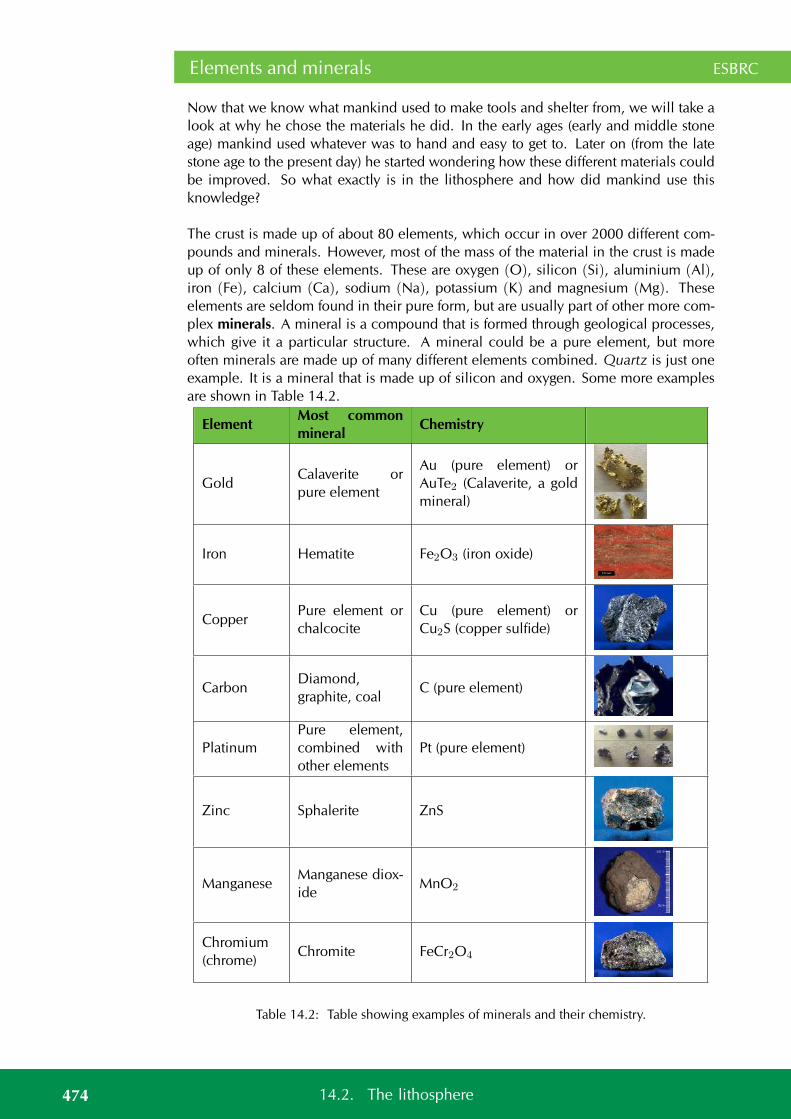
Elements and minerals ESBRC
Now that we know what mankind used to make tools and shelter from, we will take alook at why he chose the materials he did. In the early ages (early and middle stoneage) mankind used whatever was to hand and easy to get to. Later on (from the latestone age to the present day) he started wondering how these different materials couldbe improved. So what exactly is in the lithosphere and how did mankind use thisknowledge?
The crust is made up of about 80 elements, which occur in over 2000 different com-pounds and minerals. However, most of the mass of the material in the crust is madeup of only 8 of these elements. These are oxygen (O), silicon (Si), aluminium (Al),iron (Fe), calcium (Ca), sodium (Na), potassium (K) and magnesium (Mg). Theseelements are seldom found in their pure form, but are usually part of other more com-plex minerals. A mineral is a compound that is formed through geological processes,which give it a particular structure. A mineral could be a pure element, but moreoften minerals are made up of many different elements combined. Quartz is just oneexample. It is a mineral that is made up of silicon and oxygen. Some more examplesare shown in Table 14.2.
ElementMost commonmineral
Chemistry
GoldCalaverite orpure element
Au (pure element) orAuTe2 (Calaverite, a goldmineral)
Iron Hematite Fe2O3 (iron oxide)
CopperPure element orchalcocite
Cu (pure element) orCu2S (copper sulfide)
CarbonDiamond,graphite, coal
C (pure element)
PlatinumPure element,combined withother elements
Pt (pure element)
Zinc Sphalerite ZnS
ManganeseManganese diox-ide
MnO2
Chromium(chrome)
Chromite FeCr2O4
Table 14.2: Table showing examples of minerals and their chemistry.
474 14.2. The lithosphere
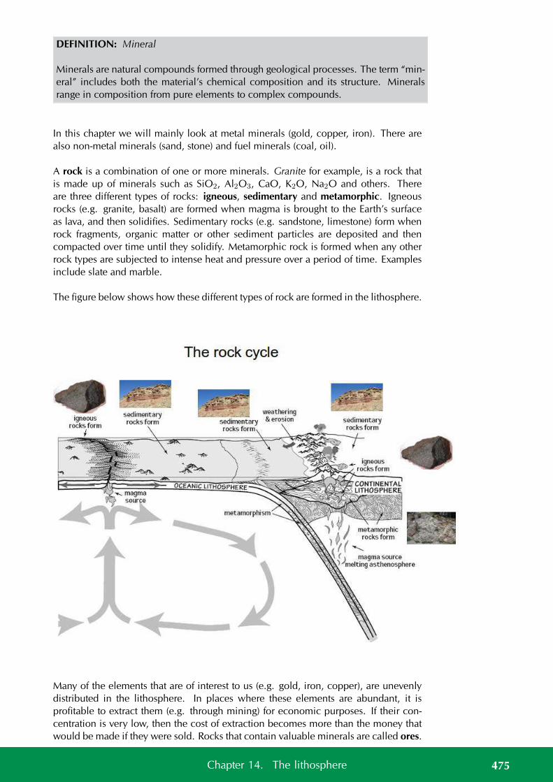
DEFINITION: Mineral
Minerals are natural compounds formed through geological processes. The term “min-eral” includes both the material’s chemical composition and its structure. Mineralsrange in composition from pure elements to complex compounds.
In this chapter we will mainly look at metal minerals (gold, copper, iron). There arealso non-metal minerals (sand, stone) and fuel minerals (coal, oil).
A rock is a combination of one or more minerals. Granite for example, is a rock thatis made up of minerals such as SiO2, Al2O3, CaO, K2O, Na2O and others. Thereare three different types of rocks: igneous, sedimentary and metamorphic. Igneousrocks (e.g. granite, basalt) are formed when magma is brought to the Earth’s surfaceas lava, and then solidifies. Sedimentary rocks (e.g. sandstone, limestone) form whenrock fragments, organic matter or other sediment particles are deposited and thencompacted over time until they solidify. Metamorphic rock is formed when any otherrock types are subjected to intense heat and pressure over a period of time. Examplesinclude slate and marble.
The figure below shows how these different types of rock are formed in the lithosphere.
Many of the elements that are of interest to us (e.g. gold, iron, copper), are unevenlydistributed in the lithosphere. In places where these elements are abundant, it isprofitable to extract them (e.g. through mining) for economic purposes. If their con-centration is very low, then the cost of extraction becomes more than the money thatwould be made if they were sold. Rocks that contain valuable minerals are called ores.
475Chapter 14. The lithosphere

FACTA gemstone (alsosometimes called a gem,semi-precious stone orprecious stone), is ahighly attractive andvaluable piece of mineralwhich, when cut andpolished, is used injewellery and otheradornments. Examples ofgemstones are amethyst,diamond, cat’s eye andsapphire.
As humans, we are particularly interested in the ores that contain metal elements, andalso in those minerals that can be used to produce energy.
Figure 14.2: Location of minerals in South Africa.
DEFINITION: Ore
An ore is a volume of rock that contains minerals which make it valuable for mining.
See video: 247M at www.everythingscience.co.za
Activity:
The following diagram shows the abundance of all the elements.
476 14.2. The lithosphere
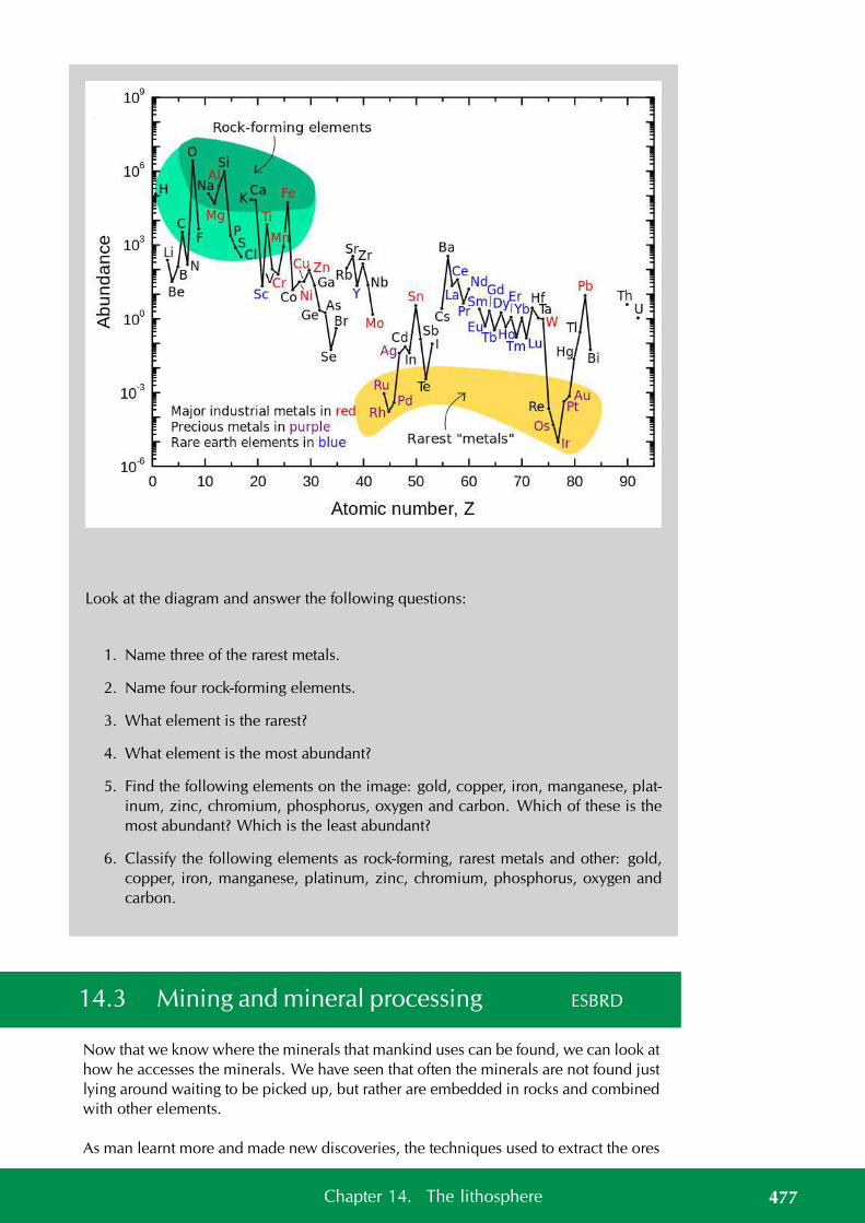
Look at the diagram and answer the following questions:
1. Name three of the rarest metals.
2. Name four rock-forming elements.
3. What element is the rarest?
4. What element is the most abundant?
5. Find the following elements on the image: gold, copper, iron, manganese, plat-inum, zinc, chromium, phosphorus, oxygen and carbon. Which of these is themost abundant? Which is the least abundant?
6. Classify the following elements as rock-forming, rarest metals and other: gold,copper, iron, manganese, platinum, zinc, chromium, phosphorus, oxygen andcarbon.
14.3 Mining and mineral processing ESBRD
Now that we know where the minerals that mankind uses can be found, we can look athow he accesses the minerals. We have seen that often the minerals are not found justlying around waiting to be picked up, but rather are embedded in rocks and combinedwith other elements.
As man learnt more and made new discoveries, the techniques used to extract the ores
477Chapter 14. The lithosphere
FACTIndigenous people oftenhave unique ways offinding mineral deposits,such as observing thebehaviour of animals ornoting the abundance ofparticular plants.
FACTCoal miners used to takea canary with them downthe mines. If the canarydied, they knew that therewas a high level of gasbuilding up and that itwas not safe to stay downin the mine.
improved and the amount of mineral that could be extracted increased greatly. Largetunnels started to be cut into the Earth to access minerals buried deep underground.New processing methods meant new kinds of metals could be mined.
The main stages in mining are: exploration, extraction, refining, manufacturing andmarketing. We will take a brief look at exploration, extraction and refining.
Exploration ESBRF
Ancient humans did not worry about whether they could make money from the oresthey mined. All they cared about was accessing metals and minerals that would helpthem eat, keep warm and beat the neighbouring tribes.
In modern times money matters and so the first step in mining is to find a suitablysized deposit of ore. For example, diamonds were found in Kimberley and gold orewas found in Johannesburg. These deposits were large enough to make mining for thegold and diamonds profitable.
As the number and size of known deposits is shrinking, geologists (who study thelithosphere) are developing new ways of finding suitable deposits. Geologists willoften spend years learning how to find ores and then spend years exploring for theores.
Obtaining the ore ESBRG
Once a suitably sized deposit of a mineral has been found, mining can begin. Inancient times mining and mineral processing were very primitive and the main methodused to extract ores was digging by hand.
Mining is largely divided into surface and underground mining. Minerals are oftenfound in river beds, beach sands and other sandy areas. These are known as alluvialdeposits. These minerals can be fairly easily removed by surface mining techniques.Other minerals occur in long streaks known as veins or in pipes, and undergroundmining techniques are used to access these minerals.
Surface mining includes open pit mines, quarrying, strip mining and landfill mining.Coal and copper are often mined in this way.
Underground mining mainly consists of digging tunnels and shafts into the Earth’scrust. Gold is often mined in this way. Underground mining is more risky than surfacemining as tunnels can collapse and dangerous gases build up underground.
We will look more at underground and surface mining shortly.
Extracting the minerals ESBRH
Once the ore has been mined it is usually crushed into smaller pieces that can beprocessed more easily. The mineral then needs to be removed from the ore.
Ancient peoples soon learnt that fire could be used to refine and purify the metals.This technique is known as smelting. This was the earliest method used to extract the
478 14.3. Mining and mineral processing
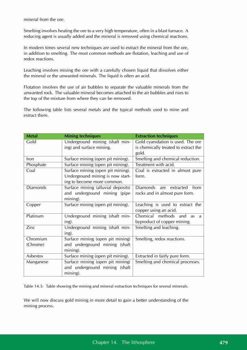
mineral from the ore.
Smelting involves heating the ore to a very high temperature, often in a blast furnace. Areducing agent is usually added and the mineral is removed using chemical reactions.
In modern times several new techniques are used to extract the mineral from the ore,in addition to smelting. The most common methods are flotation, leaching and use ofredox reactions.
Leaching involves mixing the ore with a carefully chosen liquid that dissolves eitherthe mineral or the unwanted minerals. The liquid is often an acid.
Flotation involves the use of air bubbles to separate the valuable minerals from theunwanted rock. The valuable mineral becomes attached to the air bubbles and rises tothe top of the mixture from where they can be removed.
The following table lists several metals and the typical methods used to mine andextract them.
Metal Mining techniques Extraction techniquesGold Underground mining (shaft min-
ing) and surface mining.Gold cyanidation is used. The oreis chemically treated to extract thegold.
Iron Surface mining (open pit mining). Smelting and chemical reduction.Phosphate Surface mining (open pit mining). Treatment with acid.Coal Surface mining (open pit mining).
Underground mining is now start-ing to become more common.
Coal is extracted in almost pureform.
Diamonds Surface mining (alluvial deposits)and underground mining (pipemining).
Diamonds are extracted fromrocks and in almost pure form.
Copper Surface mining (open pit mining). Leaching is used to extract thecopper using an acid.
Platinum Underground mining (shaft min-ing).
Chemical methods and as abyproduct of copper mining.
Zinc Underground mining (shaft min-ing).
Smelting and leaching.
Chromium(Chrome)
Surface mining (open pit mining)and underground mining (shaftmining).
Smelting, redox reactions.
Asbestos Surface mining (open pit mining). Extracted in fairly pure form.Manganese Surface mining (open pit mining)
and underground mining (shaftmining).
Smelting and chemical processes.
Table 14.3: Table showing the mining and mineral extraction techniques for several minerals.
We will now discuss gold mining in more detail to gain a better understanding of themining process.
479Chapter 14. The lithosphere

Gold mining ESBRJ
Gold had long been known in Africa by the indigenous people, but in the late 1800’scolonists found gold reefs and started exploiting the resource. Since then it has playeda very important role (and often a controversial one too) in South Africa’s historyand economy. Its discovery brought many foreigners into South Africa, lured by thepromises of wealth. They set up small mining villages which later grew into largersettlements, towns and cities. One of the first of these settlements was the beginningof present-day Johannesburg, also known as Egoli or Place of Gold.
Most of South Africa’s gold is concentrated in the Golden Arc which stretches fromJohannesburg to Welkom. Geologists believe that, millions of years ago, this area wasa massive inland lake. Rivers feeding into this lake brought sand, silt, pebbles and fineparticles of gold, depositing them over a long period of time. Eventually these depositsaccumulated and became compacted to form gold-bearing sedimentary rock or goldreefs. It is because of this complex but unique set of circumstances that South Africa’sgold deposits are so concentrated in that area. In other countries like Zimbabwe, goldoccurs in smaller pockets which are scattered over a much greater area.
Mining the gold ESBRK
A number of different techniques can be used to mine gold and other minerals. Thethree most common methods in South Africa are panning, open pit (not typically usedfor gold) and shaft mining.
1. Panning
Panning for gold is a manual technique that is used to sort gold from othersediments. Wide, shallow pans are filled with sand and gravel (often from riverbeds) that may contain gold. Water is added and the pans are shaken so that thegold is sorted from the rock and other materials. Because gold is much moredense, it settles on the bottom of the pan. Pilgrim’s Rest in Mpumalanga was thefirst site for gold panning in South Africa.
2. Surface mining (open pit mining)
This type of mining takes place from the surface of the Earth. In open pit mining,the topsoil is removed first and placed on the side of a trench. Then the surfacelayers of rock are removed to expose the deeper, valuable mineral layers. Thevaluable rocks are then blasted into smaller rocks using explosives. The rocksare loaded onto huge trucks and taken away for further crushing and processing.Any mineral that is found close to the surface (even up to 1000 m) can be minedusing surface mining techniques. If minerals are found deeper, as is the casewith most of the gold in South Africa, underground mining is used.
3. Underground mining (shaft mining)
South Africa’s thin but extensive gold reefs slope at an angle underneath theground, and this means that some deposits are very deep and often difficult toreach. Shaft mining is needed to reach the gold ore. After the initial drilling,blasting and equipping of a mine shaft, tunnels are built leading outwards fromthe main shaft so that the gold reef can be reached. Shaft mining is a dangerousoperation, and roof supports are needed so that the rock does not collapse. Inaddition the intense heat and high pressure below the surface make shaft miningvery complex, dangerous and expensive. A diagram illustrating open cast andshaft mining is shown in Figure 14.3.
480 14.3. Mining and mineral processing
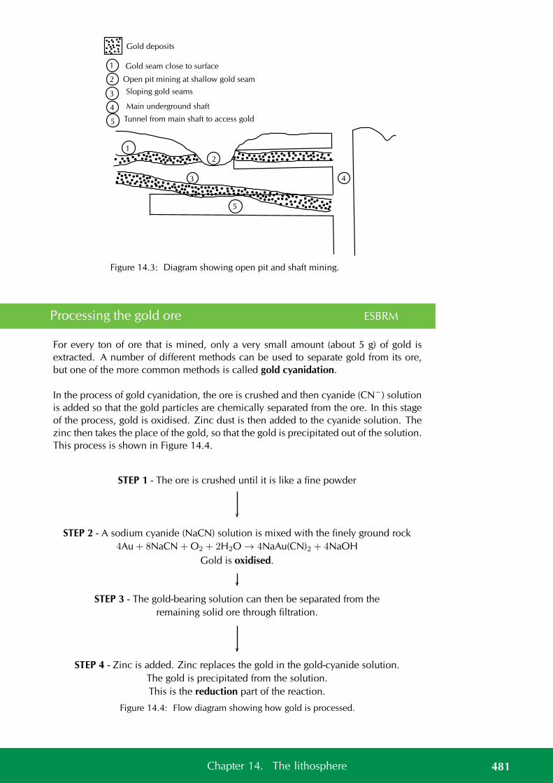
1
2
3 4
5
1
2
3
4
5
Gold seam close to surface
Open pit mining at shallow gold seam
Sloping gold seams
Tunnel from main shaft to access gold
Main underground shaft
Gold deposits
Figure 14.3: Diagram showing open pit and shaft mining.
Processing the gold ore ESBRM
For every ton of ore that is mined, only a very small amount (about 5 g) of gold isextracted. A number of different methods can be used to separate gold from its ore,but one of the more common methods is called gold cyanidation.
In the process of gold cyanidation, the ore is crushed and then cyanide (CN−) solutionis added so that the gold particles are chemically separated from the ore. In this stageof the process, gold is oxidised. Zinc dust is then added to the cyanide solution. Thezinc then takes the place of the gold, so that the gold is precipitated out of the solution.This process is shown in Figure 14.4.
STEP 1 - The ore is crushed until it is like a fine powder
STEP 2 - A sodium cyanide (NaCN) solution is mixed with the finely ground rock
4Au + 8NaCN + O2 + 2H2O → 4NaAu(CN)2 + 4NaOH
Gold is oxidised.
STEP 3 - The gold-bearing solution can then be separated from the
remaining solid ore through filtration.
STEP 4 - Zinc is added. Zinc replaces the gold in the gold-cyanide solution.
The gold is precipitated from the solution.
This is the reduction part of the reaction.
Figure 14.4: Flow diagram showing how gold is processed.
481Chapter 14. The lithosphere
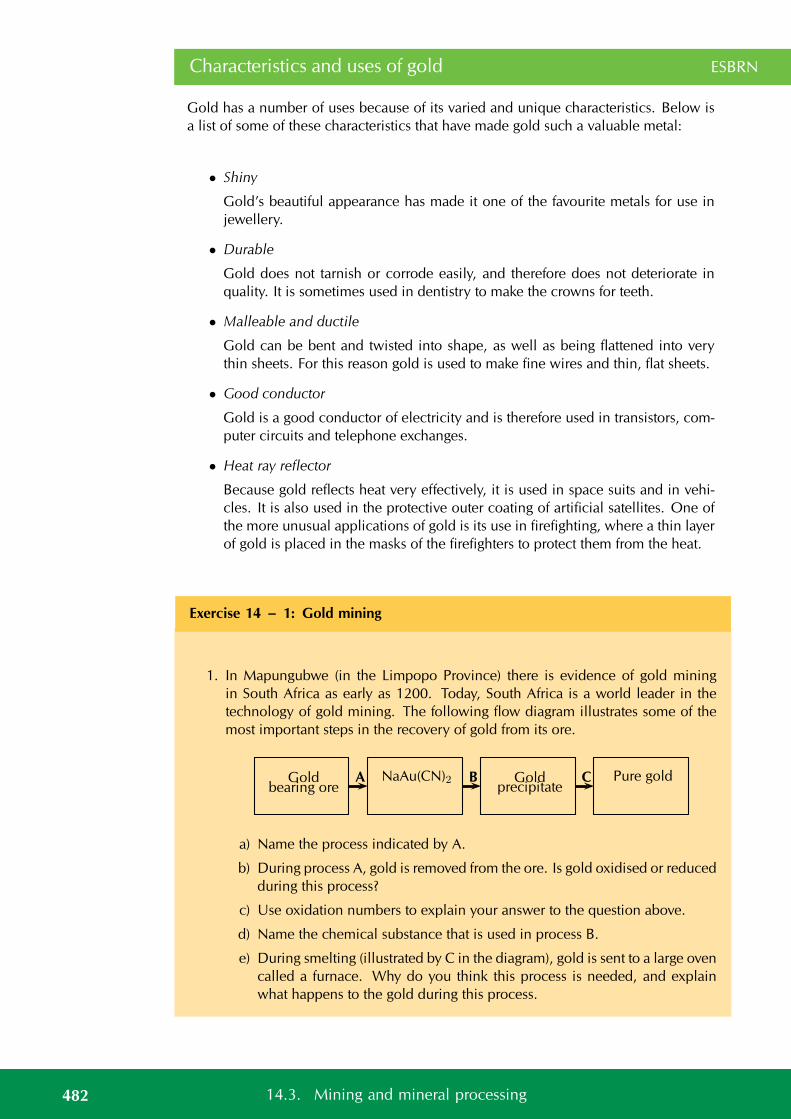
Characteristics and uses of gold ESBRN
Gold has a number of uses because of its varied and unique characteristics. Below isa list of some of these characteristics that have made gold such a valuable metal:
• Shiny
Gold’s beautiful appearance has made it one of the favourite metals for use injewellery.
• Durable
Gold does not tarnish or corrode easily, and therefore does not deteriorate inquality. It is sometimes used in dentistry to make the crowns for teeth.
• Malleable and ductile
Gold can be bent and twisted into shape, as well as being flattened into verythin sheets. For this reason gold is used to make fine wires and thin, flat sheets.
• Good conductor
Gold is a good conductor of electricity and is therefore used in transistors, com-puter circuits and telephone exchanges.
• Heat ray reflector
Because gold reflects heat very effectively, it is used in space suits and in vehi-cles. It is also used in the protective outer coating of artificial satellites. One ofthe more unusual applications of gold is its use in firefighting, where a thin layerof gold is placed in the masks of the firefighters to protect them from the heat.
Exercise 14 – 1: Gold mining
1. In Mapungubwe (in the Limpopo Province) there is evidence of gold miningin South Africa as early as 1200. Today, South Africa is a world leader in thetechnology of gold mining. The following flow diagram illustrates some of themost important steps in the recovery of gold from its ore.
Goldbearing ore
NaAu(CN)2 Goldprecipitate
Pure goldA B C
a) Name the process indicated by A.
b) During process A, gold is removed from the ore. Is gold oxidised or reducedduring this process?
c) Use oxidation numbers to explain your answer to the question above.
d) Name the chemical substance that is used in process B.
e) During smelting (illustrated by C in the diagram), gold is sent to a large ovencalled a furnace. Why do you think this process is needed, and explainwhat happens to the gold during this process.
482 14.3. Mining and mineral processing

Think you got it? Get this answer and more practice on our Intelligent Practice Service
1. 247N
www.everythingscience.co.za m.everythingscience.co.za
Mining and the environment ESBRP
Environmental impacts of gold mining
However, despite the incredible value of gold and its usefulness in a variety of appli-cations, all mining is undertaken at a cost to the environment. The following are just afew of the environmental impacts of gold mining:
• Resource consumption
Gold mining consumes large amounts of electricity and water. Electricity is oftengenerated using non-renewable resources.
• Poisoned water
If the mining process is not monitored properly, acid and other chemicals fromgold processing can leach into nearby water systems such as rivers. This causesdamage to animals and plants, as well as to humans who may rely on that waterfor drinking.
• Changing the landscape
This applies particularly to surface mines (open pit mines), where large amountsof soil and rock must be displaced in order to access the mineral reserves. Theshape of the landscape can be changed when large amounts of rocks are dug upfrom the Earth and stacked on the surface. These are called mine dumps. Openpit mines also create very large holes (pits) in the ground that change the shapeof the land.
• Air pollution
Dust from open pit mines, as well as harmful gases such as sulphur dioxide andnitrogen dioxide, could be released from mining processes and contribute to airpollution.
• Threaten natural areas
Mining activities often encroach on protected areas and threaten biodiversity intheir operation areas.
Group discussion: Mine rehabilitation
There is a growing emphasis on the need to rehabilitate old mine sites that are nolonger in use. If it is too difficult to restore the site to what it was before, then a new
483Chapter 14. The lithosphere
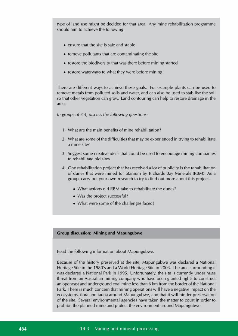
type of land use might be decided for that area. Any mine rehabilitation programmeshould aim to achieve the following:
• ensure that the site is safe and stable
• remove pollutants that are contaminating the site
• restore the biodiversity that was there before mining started
• restore waterways to what they were before mining
There are different ways to achieve these goals. For example plants can be used toremove metals from polluted soils and water, and can also be used to stabilise the soilso that other vegetation can grow. Land contouring can help to restore drainage in thearea.
In groups of 3-4, discuss the following questions:
1. What are the main benefits of mine rehabilitation?
2. What are some of the difficulties that may be experienced in trying to rehabilitatea mine site?
3. Suggest some creative ideas that could be used to encourage mining companiesto rehabilitate old sites.
4. One rehabilitation project that has received a lot of publicity is the rehabilitationof dunes that were mined for titanium by Richards Bay Minerals (RBM). As agroup, carry out your own research to try to find out more about this project.
• What actions did RBM take to rehabilitate the dunes?
• Was the project successful?
• What were some of the challenges faced?
Group discussion: Mining and Mapungubwe
Read the following information about Mapungubwe.
Because of the history preserved at the site, Mapungubwe was declared a NationalHeritage Site in the 1980’s and a World Heritage Site in 2003. The area surrounding itwas declared a National Park in 1995. Unfortunately, the site is currently under hugethreat from an Australian mining company who have been granted rights to constructan opencast and underground coal mine less than 6 km from the border of the NationalPark. There is much concern that mining operations will have a negative impact on theecosystems, flora and fauna around Mapungubwe, and that it will hinder preservationof the site. Several environmental agencies have taken the matter to court in order toprohibit the planned mine and protect the environment around Mapungubwe.
484 14.3. Mining and mineral processing
As a class discuss, whether or not the proposed mining should go ahead. Divide intotwo teams. Assign one team to be in favour of the mining and one team against it.Each team should find facts relevant to their argument and then present it to the otherteam. At the end of the discussion, draw conclusions about whether or not the miningshould take place.
Other minerals ESBRQ
We have largely focused on the process involved in mining gold. However gold is notthe only mineral of interest to humankind. Many other minerals are useful such ascopper, iron and platinum.
Activity: Other mining activities
Choose one of the minerals given in the list below and find information on how thatmineral is mined. Use the information given in this chapter about gold mining and tryto find similar information for the mineral you have chosen. Write up your findings ina report. If possible, split the class into groups and assign a different mineral to eachgroup.
• Iron
• Phosphate
• Coal
• Diamond
• Copper
• Platinum
• Zinc
• Chrome
• Asbestos
• Manganese
14.4 Energy resources ESBRR
At present we rely mainly on oil and coal resources to provide our energy needs. How-ever these resources are non-renewable energy sources and have many negative effectson the environment. Alternative sources of energy are constantly being investigated toassess if they will be able to provide for our growing energy needs. If we ignore thesealternatives, one day we will run out of oil and coal reserves.
One of the most debated topics around energy resources is climate change. Scientistsand environmentalists disagree as to the causes and effects of climate change andwhether or not it actually exists.
Activity: Climate change
Climate change is a significant and lasting change in the distribution of weather pat-terns over periods of time ranging from decades to millennia. It is seen as changes inextreme weather events (freak storms, tornadoes, tsunamis, etc.) and changes in theaverage weather conditions for cities and regions.
485Chapter 14. The lithosphere

Scientists collect data about climate change from ice core drilling, floral and faunalrecords, glacial and periglacial processes, isotopic analysis and from many other meth-ods. Each of these methods provides different indicators of how the Earth’s climate haschanged over time.
Many factors influence the Earth’s climate such as the amount of solar radiation re-ceived, changes in the Earth’s orbit, changes on the Earth’s surface, such as continen-tal drift and size of polar ice caps, etc. All these factors combined make it difficult topinpoint exactly what causes a particular change in climate. Also the effects of theseevents can take centuries to fully develop.
Human activities such as mining, burning of fossil fuels and agriculture also have aneffect on the climate. Scientists are largely in agreement that the climate is changingirreversibly and that humans are a big cause of this change.
What is not agreed upon is how big an effect humans have and how much of a problemit is. At present global temperatures are found to be increasing and polar ice caps arefound to be decreasing in size. Whether humans are simply making this worse or areactually causing the change is not yet understood.
Despite the debate, humans do need to be aware of their impact on the environmentand will need to come up with ways to reduce it.
1. Discuss the above information.
2. Discuss ways in which human activities impact on the enviroment.
3. Discuss ways in which this impact can be reduced.
4. Conduct research on climate change and the debates about it. Critically anal-yse the information and draw your own conclusions. Discuss these ideas andconclusions with your classmates.
14.5 Summary ESBRS
See presentation: 247P at www.everythingscience.co.za
• The Earth’s lithosphere is a rich source of many minerals.
• The lithosphere consists of the upper crust and mantle of the Earth.
• The minerals can be extracted using mining techniques.
• People have long been exploiting the Earth’s mineral resources.
• Mining and mineral use has a significant environmental impact.
• Other resources in the lithosphere are fuels.
486 14.5. Summary
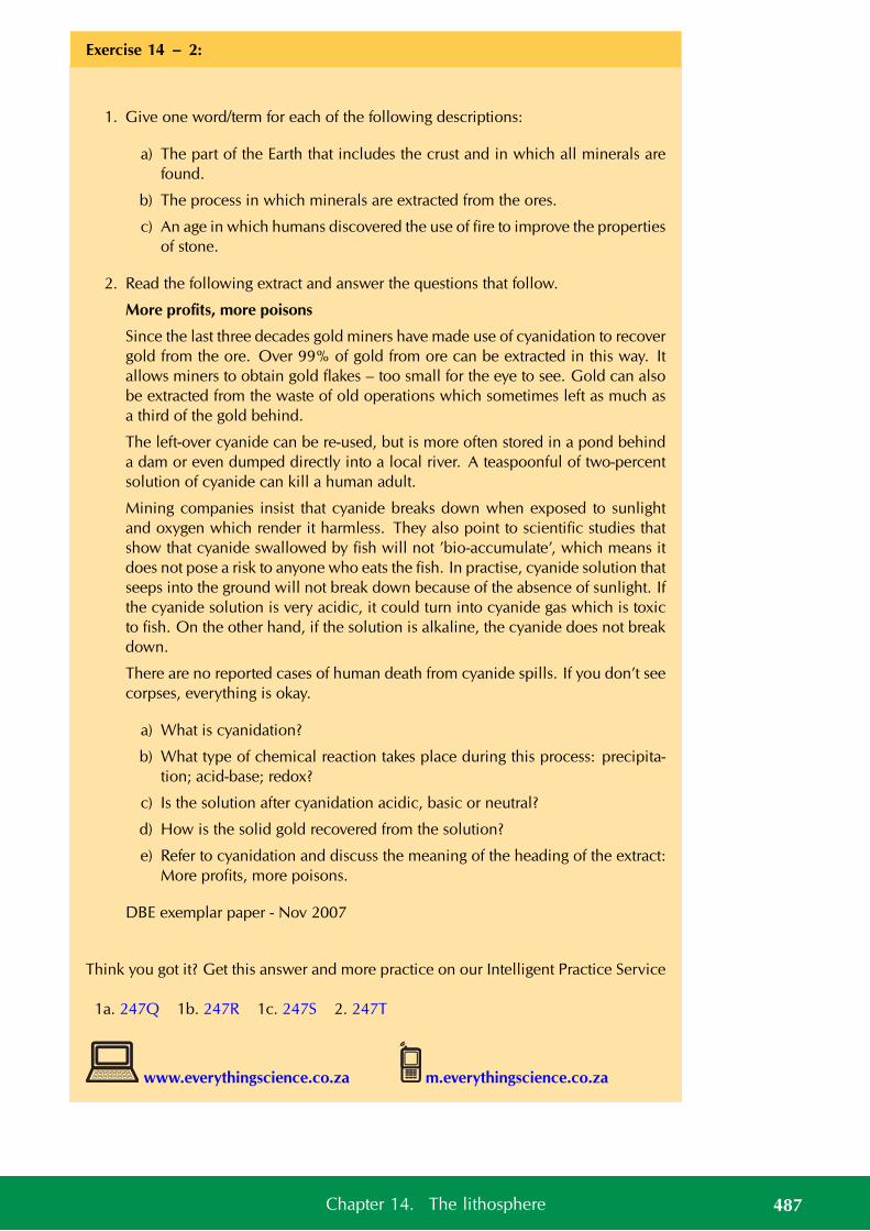
Exercise 14 – 2:
1. Give one word/term for each of the following descriptions:
a) The part of the Earth that includes the crust and in which all minerals arefound.
b) The process in which minerals are extracted from the ores.
c) An age in which humans discovered the use of fire to improve the propertiesof stone.
2. Read the following extract and answer the questions that follow.
More profits, more poisons
Since the last three decades gold miners have made use of cyanidation to recovergold from the ore. Over 99% of gold from ore can be extracted in this way. Itallows miners to obtain gold flakes – too small for the eye to see. Gold can alsobe extracted from the waste of old operations which sometimes left as much asa third of the gold behind.
The left-over cyanide can be re-used, but is more often stored in a pond behinda dam or even dumped directly into a local river. A teaspoonful of two-percentsolution of cyanide can kill a human adult.
Mining companies insist that cyanide breaks down when exposed to sunlightand oxygen which render it harmless. They also point to scientific studies thatshow that cyanide swallowed by fish will not ’bio-accumulate’, which means itdoes not pose a risk to anyone who eats the fish. In practise, cyanide solution thatseeps into the ground will not break down because of the absence of sunlight. Ifthe cyanide solution is very acidic, it could turn into cyanide gas which is toxicto fish. On the other hand, if the solution is alkaline, the cyanide does not breakdown.
There are no reported cases of human death from cyanide spills. If you don’t seecorpses, everything is okay.
a) What is cyanidation?
b) What type of chemical reaction takes place during this process: precipita-tion; acid-base; redox?
c) Is the solution after cyanidation acidic, basic or neutral?
d) How is the solid gold recovered from the solution?
e) Refer to cyanidation and discuss the meaning of the heading of the extract:More profits, more poisons.
DBE exemplar paper - Nov 2007
Think you got it? Get this answer and more practice on our Intelligent Practice Service
1a. 247Q 1b. 247R 1c. 247S 2. 247T
www.everythingscience.co.za m.everythingscience.co.za
487Chapter 14. The lithosphere

Units used in the book
488 Units used in the book

CHAPTER 15
Quantities used in the book
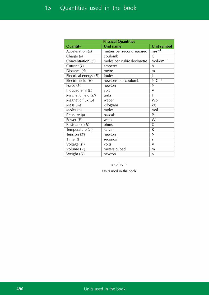
15 Quantities used in the book
Physical QuantitiesQuantity Unit name Unit symbolAcceleration (a) metres per second squared m·s−1
Charge (q) coulomb CConcentration (C) moles per cubic decimetre mol·dm−3
Current (I) amperes ADistance (d) metre mElectrical energy (E) joules JElectric field (E) newtons per coulomb N·C−1
Force (F ) newton NInduced emf (E ) volt VMagnetic field (B) tesla TMagnetic flux (φ) weber WbMass (m) kilogram kgMoles (n) moles molPressure (p) pascals PaPower (P ) watts WResistance (R) ohms Ω
Temperature (T ) kelvin KTension (T ) newton NTime (t) seconds sVoltage (V ) volts VVolume (V ) meters cubed m3
Weight (N ) newton N
Table 15.1:
Units used in the book
490 Units used in the book
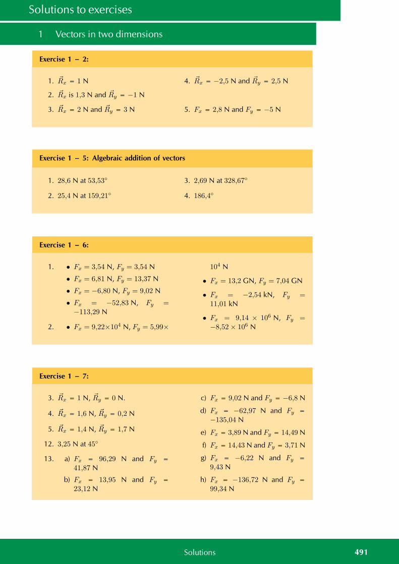
Solutions to exercises
1 Vectors in two dimensions
Exercise 1 – 2:
1. Rx = 1 N
2. Rx is 1,3 N and Ry = −1 N
3. Rx = 2 N and Ry = 3 N
4. Rx = −2,5 N and Ry = 2,5 N
5. Fx = 2,8 N and Fy = −5 N
Exercise 1 – 5: Algebraic addition of vectors
1. 28,6 N at 53,53
2. 25,4 N at 159,21
3. 2,69 N at 328,67
4. 186,4
Exercise 1 – 6:
1. • Fx = 3,54 N, Fy = 3,54 N
• Fx = 6,81 N, Fy = 13,37 N
• Fx = −6,80 N, Fy = 9,02 N
• Fx = −52,83 N, Fy =−113,29 N
2. • Fx = 9,22×10⁴ N, Fy = 5,99×
104 N
• Fx = 13,2 GN, Fy = 7,04 GN
• Fx = −2,54 kN, Fy =11,01 kN
• Fx = 9,14 × 10⁶ N, Fy =−8,52× 10⁶ N
Exercise 1 – 7:
3. Rx = 1 N, Ry = 0 N.
4. Rx = 1,6 N, Ry = 0,2 N
5. Rx = 1,4 N, Ry = 1,7 N
12. 3,25 N at 45
13. a) Fx = 96,29 N and Fy =41,87 N
b) Fx = 13,95 N and Fy =23,12 N
c) Fx = 9,02 N and Fy = −6,8 N
d) Fx = −62,97 N and Fy =−135,04 N
e) Fx = 3,89 N and Fy = 14,49 N
f) Fx = 14,43 N and Fy = 3,71 N
g) Fx = −6,22 N and Fy =9,43 N
h) Fx = −136,72 N and Fy =99,34 N
491Solutions
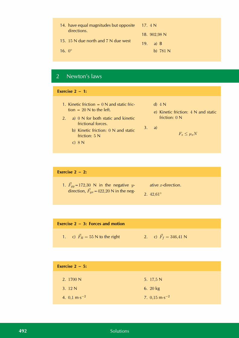
14. have equal magnitudes but oppositedirections.
15. 15 N due north and 7 N due west
16. 0
17. 4 N
18. 902,98 N
19. a) B
b) 781 N
2 Newton’s laws
Exercise 2 – 1:
1. Kinetic friction = 0 N and static fric-tion = 20 N to the left.
2. a) 0 N for both static and kineticfrictional forces.
b) Kinetic friction: 0 N and staticfriction: 5 N
c) 8 N
d) 4 N
e) Kinetic friction: 4 N and staticfriction: 0 N
3. a)Fs ≤ µsN
Exercise 2 – 2:
1. Fgy=172,30 N in the negative y-direction, Fgx=422,20 N in the neg-
ative x-direction.
2. 42,61
Exercise 2 – 3: Forces and motion
1. c) FR = 55 N to the right 2. c) Ff = 346,41 N
Exercise 2 – 5:
2. 1700 N
3. 12 N
4. 0,1 m·s−2
5. 17,5 N
6. 20 kg
7. 0,15 m·s−2
492 Solutions
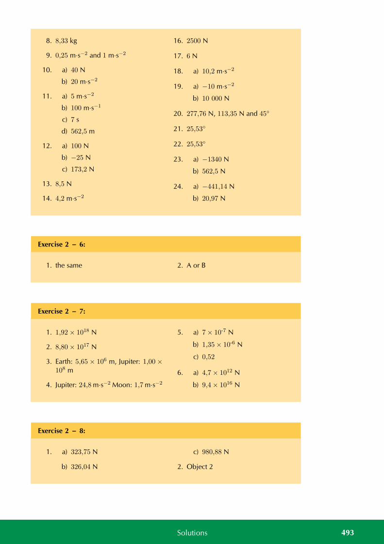
8. 8,33 kg
9. 0,25 m·s−2 and 1 m·s−2
10. a) 40 N
b) 20 m·s−2
11. a) 5 m·s−2
b) 100 m·s−1
c) 7 s
d) 562,5 m
12. a) 100 N
b) −25 N
c) 173,2 N
13. 8,5 N
14. 4,2 m·s−2
16. 2500 N
17. 6 N
18. a) 10,2 m·s−2
19. a) −10 m·s−2
b) 10 000 N
20. 277,76 N, 113,35 N and 45
21. 25,53
22. 25,53
23. a) −1340 N
b) 562,5 N
24. a) −441,14 N
b) 20,97 N
Exercise 2 – 6:
1. the same 2. A or B
Exercise 2 – 7:
1. 1,92× 10¹⁸ N
2. 8,80× 10¹⁷ N
3. Earth: 5,65 × 10⁶ m, Jupiter: 1,00 ×10⁸ m
4. Jupiter: 24,8 m·s−2 Moon: 1,7 m·s−2
5. a) 7× 10⁻⁷ N
b) 1,35× 10⁻⁶ N
c) 0,52
6. a) 4,7× 10¹² N
b) 9,4× 10¹⁶ N
Exercise 2 – 8:
1. a) 323,75 N
b) 326,04 N
c) 980,88 N
2. Object 2
493Solutions
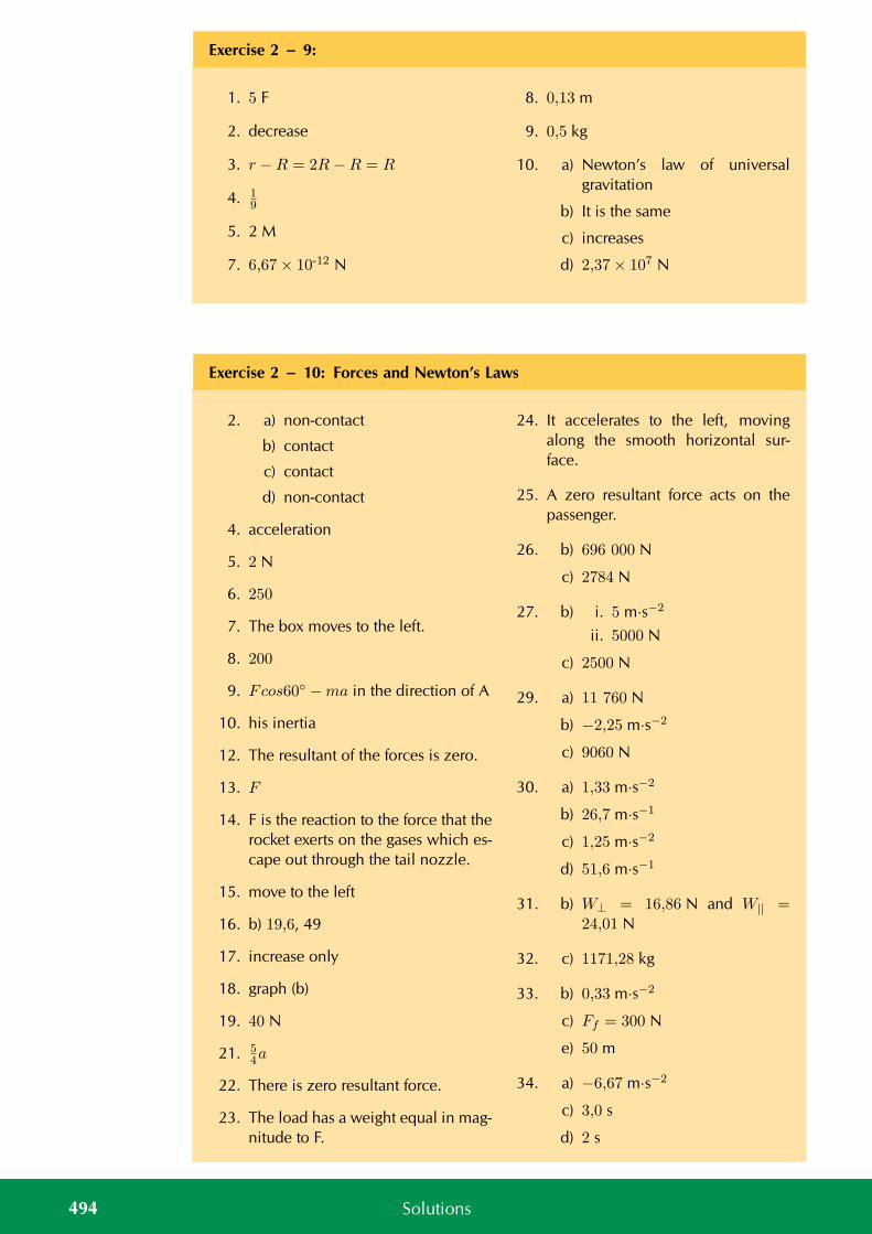
Exercise 2 – 9:
1. 5 F
2. decrease
3. r −R = 2R−R = R
4. 19
5. 2 M
7. 6,67× 10⁻¹² N
8. 0,13 m
9. 0,5 kg
10. a) Newton’s law of universalgravitation
b) It is the same
c) increases
d) 2,37× 10⁷ N
Exercise 2 – 10: Forces and Newton’s Laws
2. a) non-contact
b) contact
c) contact
d) non-contact
4. acceleration
5. 2 N
6. 250
7. The box moves to the left.
8. 200
9. Fcos60 −ma in the direction of A
10. his inertia
12. The resultant of the forces is zero.
13. F
14. F is the reaction to the force that therocket exerts on the gases which es-cape out through the tail nozzle.
15. move to the left
16. b) 19,6, 49
17. increase only
18. graph (b)
19. 40 N
21. 54a
22. There is zero resultant force.
23. The load has a weight equal in mag-nitude to F.
24. It accelerates to the left, movingalong the smooth horizontal sur-face.
25. A zero resultant force acts on thepassenger.
26. b) 696 000 N
c) 2784 N
27. b) i. 5 m·s−2
ii. 5000 N
c) 2500 N
29. a) 11 760 N
b) −2,25 m·s−2
c) 9060 N
30. a) 1,33 m·s−2
b) 26,7 m·s−1
c) 1,25 m·s−2
d) 51,6 m·s−1
31. b) W⊥ = 16,86 N and W|| =24,01 N
32. c) 1171,28 kg
33. b) 0,33 m·s−2
c) Ff = 300 N
e) 50 m
34. a) −6,67 m·s−2
c) 3,0 s
d) 2 s
494 Solutions
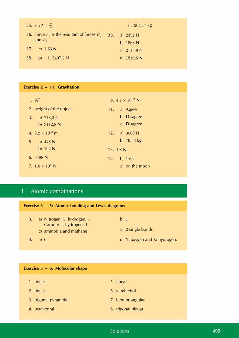
35. sin θ = Nw
36. Force F3 is the resultant of forces F1
and F2.
37. c) 1,63 N
38. b) i. 5497,2 N
ii. 204,17 kg
39. a) 2352 N
b) 1568 N
c) 2715,9 N
d) 1810,6 N
Exercise 2 – 11: Gravitation
1. 9F
2. weight of the object
3. a) 778,2 N
b) 3112,8 N
4. 8,2× 10⁻² m
5. a) 448 N
b) 192 N
6. 5488 N
7. 1,6× 10⁶ N
9. 4,1× 10²² N
11. a) Agree
b) Disagree
c) Disagree
12. a) 3000 N
b) 76,53 kg
13. 1,8 N
14. b) 1,63
c) on the moon
3 Atomic combinations
Exercise 3 – 5: Atomic bonding and Lewis diagrams
3. a) Nitrogen: 5, hydrogen: 1Carbon: 4, hydrogen: 1
c) ammonia and methane
4. a) 6
b) 1
c) 2 single bonds
d) Y: oxygen and X: hydrogen.
Exercise 3 – 6: Molecular shape
1. linear
2. linear
3. trigonal pyramidal
4. octahedral
5. linear
6. tetrahedral
7. bent or angular
8. trigonal planar
495Solutions
Exercise 3 – 7:
1. 1,0, 0,4, 3,0, 0,6 and 1,0
Exercise 3 – 8: Electronegativity
1. a) 2,1
b) 3,0
c) Hydrogen will have a slightlypositive charge and chlorine
will have a slightly negativecharge.
d) Polar covalent bond
e) polar
Exercise 3 – 9:
1. a) Bond length
b) Covalent bond
c) Electronegativity
2. Dative covalent (co-ordinate cova-lent) bond
4. Ne + Ne → Ne2
6. a) 1
b) 5
c) X could be hydrogen and Ycould be nitrogen.
7. a) linear
b) linear
c) trigonal planar
d) linear
e) tetrahedral
f) tetrahedral
g) linear
h) octahedral
9. a) non-polar
b) non-polar
c) non-polar
d) polar
4 Intermolecular forces
Exercise 4 – 1:
1. dipole-dipole
2. induced dipole
3. ion-dipole
4. induced dipole
496 Solutions
Exercise 4 – 4:
1. a) Intermolecular force
b) Polar molecule
c) Specific heat
2. The melting point of NH3 will be
higher than for Cl2
3. a) HI and NH3 only
4. a) Water
5 Geometrical optics
Exercise 5 – 1: Rays and Reflection
3. a) E
b) C
c) D
d) B
e) A
6. B
7. 15
8. 45
9. 65
10. 25
Exercise 5 – 2: Refractive index
1. 2,29× 10⁸ m·s−1 2. crown glass
Exercise 5 – 4: Snell’s Law
2. b) 25,88
3. 18,08
4. a) decreases
b) remains the same
c) Towards the normal.
5. a) increases
b) remains the same
c) Away from the normal
7. 1,327
8. 30,34
9. 78,07
10. A: acetone, B: fuzed quartz, C: di-amond, D: cubic zirconia, E: 80%sugar solution
11. c) water
497Solutions
Exercise 5 – 5: Total internal reflection and fibre optics
3. No
4. no
5. 47,33
6. The light will be trapped in the dia-mond.
7. a glass to water interface
8. 41,8
9. 62,46
10. 2,42
11. 37,86
Exercise 5 – 6: End of chapter exercises
1. a) normal
b) refraction
c) reflection
2. a) False
b) True
c) True
4. 35
5. b) 27,78
c) increases
d) stays the same
6. sapphire
6 2D and 3D wavefronts
Exercise 6 – 1:
2. light waves
Exercise 6 – 2:
2. blue, green, yellow, red 4. a) 3,4× 10⁻⁶ m
b) 2,4× 10⁻⁶ m
7 Ideal gases
Exercise 7 – 2: Boyle’s law
1. 100 kPa
2. 112,5 kPa
3. 8,33 cm3
4. c) Yes
5. a) 217 Pa
498 Solutions
Exercise 7 – 3: Charles’ law
2. 4,67 dm3 3. 56,67 K
Exercise 7 – 4: Pressure-temperature relation
1. c) linear relationship
2. 7,24 atm
3. 8,14 atm
5. 465,6 K
Exercise 7 – 5: The general gas equation
1. 0,87 atm
2. 0,6 atm
3. 1,26 atm
Exercise 7 – 6: The ideal gas equation
1. 0,008 m3
2. 106,54 kPa
3. 0,02 mol
4. b) No
c) 193,3 kPa
5. a) 73,1 g
Exercise 7 – 7:
1. a) Ideal gas
b) Charles’ law
c) Temperature
2. Temperature must be kept constant.
3. The sample of helium gas will be atthe greatest pressure.
4. V ∝ n, with p, T constant.
7. b) 311,775 Pa
8. 106,39 kPa
499Solutions
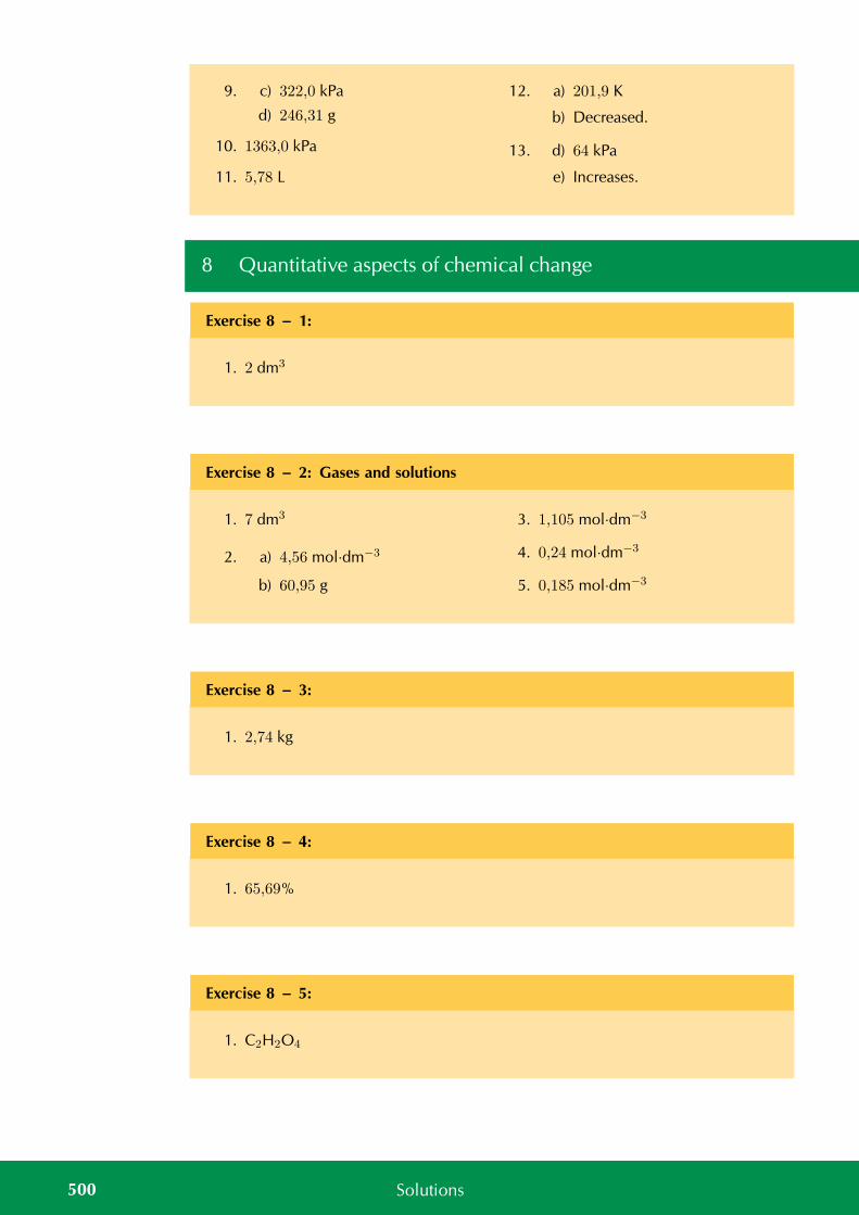
9. c) 322,0 kPa
d) 246,31 g
10. 1363,0 kPa
11. 5,78 L
12. a) 201,9 K
b) Decreased.
13. d) 64 kPa
e) Increases.
8 Quantitative aspects of chemical change
Exercise 8 – 1:
1. 2 dm3
Exercise 8 – 2: Gases and solutions
1. 7 dm3
2. a) 4,56 mol·dm−3
b) 60,95 g
3. 1,105 mol·dm−3
4. 0,24 mol·dm−3
5. 0,185 mol·dm−3
Exercise 8 – 3:
1. 2,74 kg
Exercise 8 – 4:
1. 65,69%
Exercise 8 – 5:
1. C2H2O4
500 Solutions
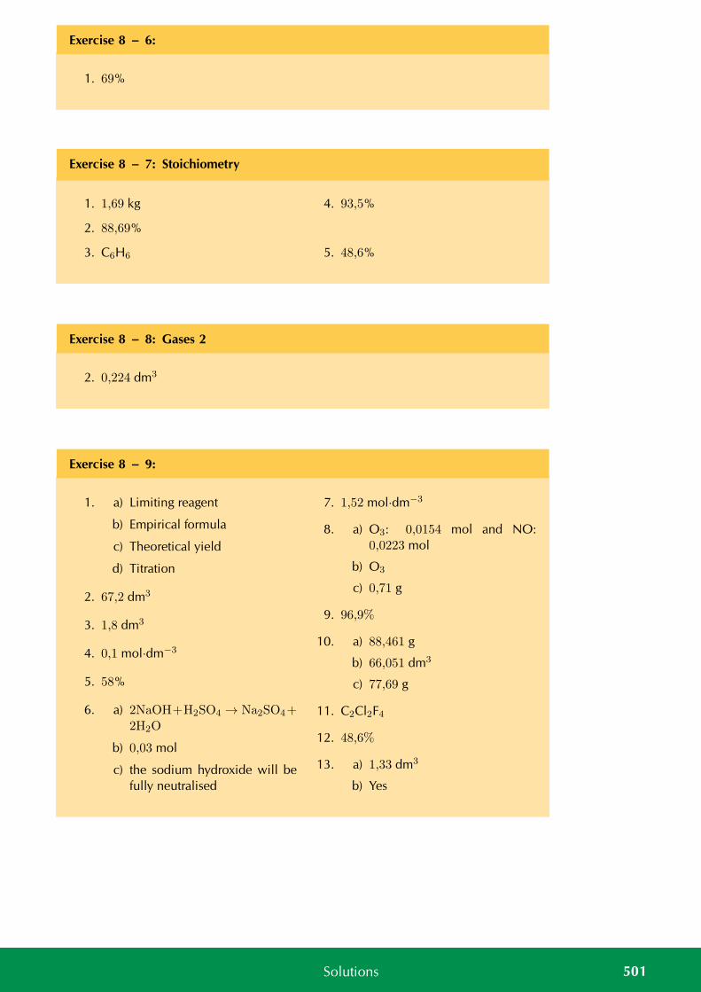
Exercise 8 – 6:
1. 69%
Exercise 8 – 7: Stoichiometry
1. 1,69 kg
2. 88,69%
3. C6H6
4. 93,5%
5. 48,6%
Exercise 8 – 8: Gases 2
2. 0,224 dm3
Exercise 8 – 9:
1. a) Limiting reagent
b) Empirical formula
c) Theoretical yield
d) Titration
2. 67,2 dm3
3. 1,8 dm3
4. 0,1 mol·dm−3
5. 58%
6. a) 2NaOH+H2SO4 → Na2SO4+2H2O
b) 0,03 mol
c) the sodium hydroxide will befully neutralised
7. 1,52 mol·dm−3
8. a) O3: 0,0154 mol and NO:0,0223 mol
b) O3
c) 0,71 g
9. 96,9%
10. a) 88,461 g
b) 66,051 dm3
c) 77,69 g
11. C2Cl2F4
12. 48,6%
13. a) 1,33 dm3
b) Yes
501Solutions
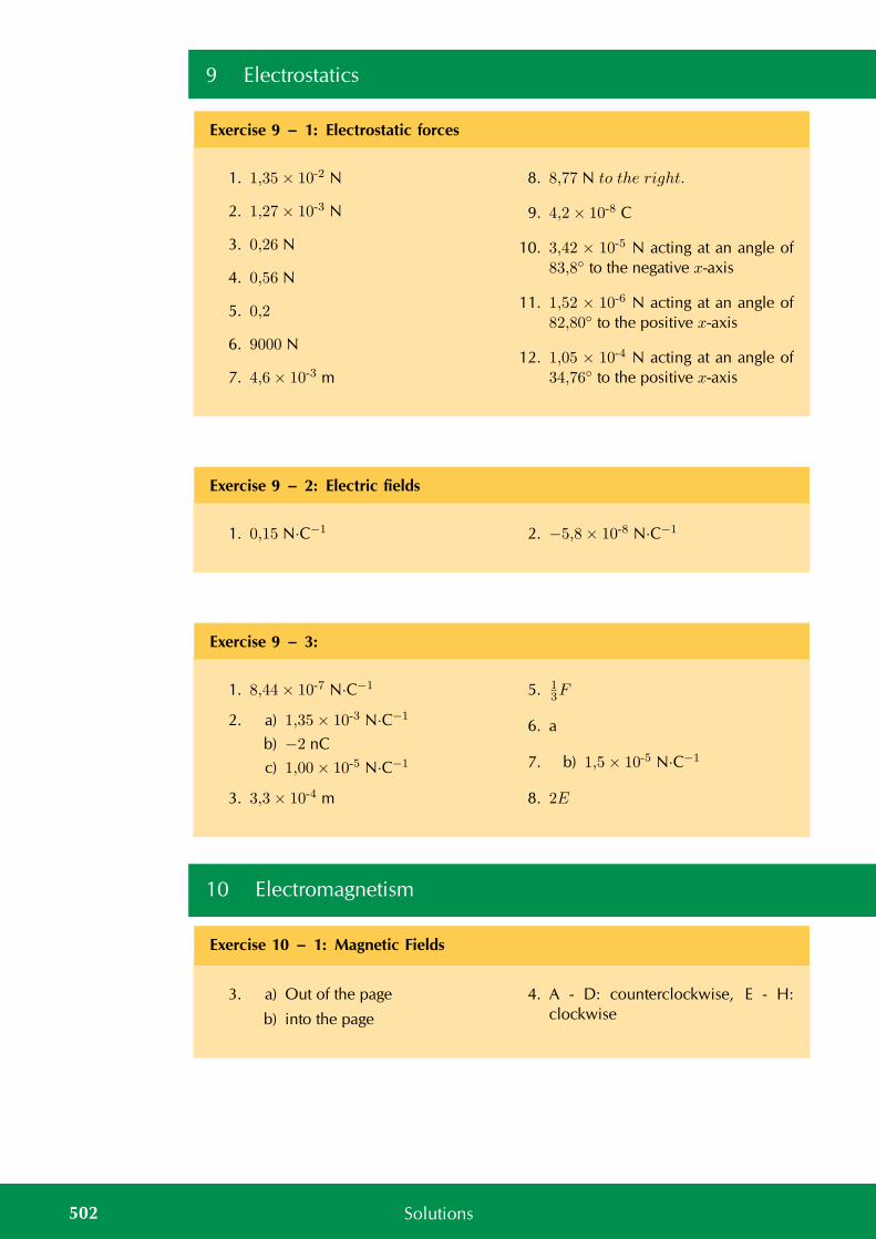
9 Electrostatics
Exercise 9 – 1: Electrostatic forces
1. 1,35× 10⁻² N
2. 1,27× 10⁻³ N
3. 0,26 N
4. 0,56 N
5. 0,2
6. 9000 N
7. 4,6× 10⁻³ m
8. 8,77 N to the right.
9. 4,2× 10⁻⁸ C
10. 3,42 × 10⁻⁵ N acting at an angle of83,8 to the negative x-axis
11. 1,52 × 10⁻⁶ N acting at an angle of82,80 to the positive x-axis
12. 1,05 × 10⁻⁴ N acting at an angle of34,76 to the positive x-axis
Exercise 9 – 2: Electric fields
1. 0,15 N·C−1 2. −5,8× 10⁻⁸ N·C−1
Exercise 9 – 3:
1. 8,44× 10⁻⁷ N·C−1
2. a) 1,35× 10⁻³ N·C−1
b) −2 nC
c) 1,00× 10⁻⁵ N·C−1
3. 3,3× 10⁻⁴ m
5. 13F
6. a
7. b) 1,5× 10⁻⁵ N·C−1
8. 2E
10 Electromagnetism
Exercise 10 – 1: Magnetic Fields
3. a) Out of the page
b) into the page
4. A - D: counterclockwise, E - H:clockwise
502 Solutions
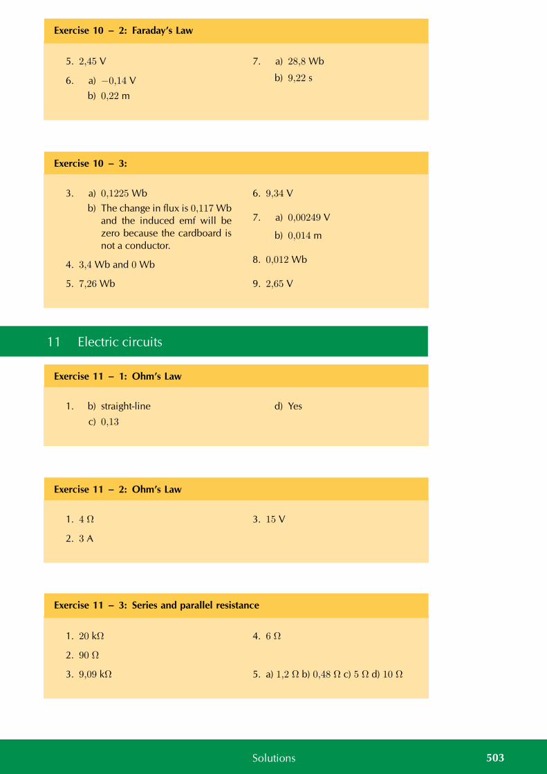
Exercise 10 – 2: Faraday’s Law
5. 2,45 V
6. a) −0,14 V
b) 0,22 m
7. a) 28,8 Wb
b) 9,22 s
Exercise 10 – 3:
3. a) 0,1225 Wb
b) The change in flux is 0,117 Wband the induced emf will bezero because the cardboard isnot a conductor.
4. 3,4 Wb and 0 Wb
5. 7,26 Wb
6. 9,34 V
7. a) 0,00249 V
b) 0,014 m
8. 0,012 Wb
9. 2,65 V
11 Electric circuits
Exercise 11 – 1: Ohm’s Law
1. b) straight-line
c) 0,13
d) Yes
Exercise 11 – 2: Ohm’s Law
1. 4 Ω
2. 3 A
3. 15 V
Exercise 11 – 3: Series and parallel resistance
1. 20 kΩ
2. 90 Ω
3. 9,09 kΩ
4. 6 Ω
5. a) 1,2 Ω b) 0,48 Ω c) 5 Ω d) 10 Ω
503Solutions
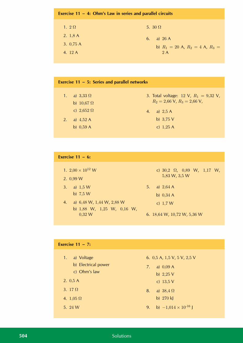
Exercise 11 – 4: Ohm’s Law in series and parallel circuits
1. 2 Ω
2. 1,8 A
3. 0,75 A
4. 12 A
5. 30 Ω
6. a) 26 A
b) R1 = 20 A, R2 = 4 A, R3 =2 A
Exercise 11 – 5: Series and parallel networks
1. a) 3,33 Ω
b) 10,67 Ω
c) 2,652 Ω
2. a) 4,52 A
b) 0,59 A
3. Total voltage: 12 V, R1 = 9,32 V,R2 = 2,66 V, R3 = 2,66 V,
4. a) 2,5 A
b) 3,75 V
c) 1,25 A
Exercise 11 – 6:
1. 2,00× 10¹² W
2. 0,99 W
3. a) 1,5 W
b) 7,5 W
4. a) 6,48 W, 1,44 W, 2,88 W
b) 1,88 W, 1,25 W, 0,16 W,0,32 W
c) 30,2 Ω, 0,89 W, 1,17 W,5,83 W, 3,5 W
5. a) 2,64 A
b) 0,34 A
c) 1,7 W
6. 18,64 W, 10,72 W, 5,36 W
Exercise 11 – 7:
1. a) Voltage
b) Electrical power
c) Ohm’s law
2. 0,5 A
3. 17 Ω
4. 1,05 Ω
5. 24 W
6. 0,5 A, 1,5 V, 5 V, 2,5 V
7. a) 0,09 A
b) 2,25 V
c) 13,5 V
8. a) 38,4 Ω
b) 270 kJ
9. b) −1,014× 10-16 J
504 Solutions
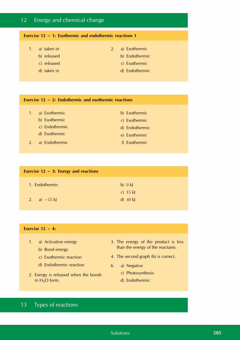
12 Energy and chemical change
Exercise 12 – 1: Exothermic and endothermic reactions 1
1. a) taken in
b) released
c) released
d) taken in
2. a) Exothermic
b) Endothermic
c) Exothermic
d) Endothermic
Exercise 12 – 2: Endothermic and exothermic reactions
1. a) Exothermic
b) Exothermic
c) Endothermic
d) Exothermic
2. a) Endothermic
b) Exothermic
c) Exothermic
d) Endothermic
e) Exothermic
f) Exothermic
Exercise 12 – 3: Energy and reactions
1. Endothermic
2. a) −15 kJ
b) 0 kJ
c) 15 kJ
d) 40 kJ
Exercise 12 – 4:
1. a) Activation energy
b) Bond energy
c) Exothermic reaction
d) Endothermic reaction
2. Energy is released when the bondsin H2O form.
3. The energy of the product is lessthan the energy of the reactants.
4. The second graph (b) is correct.
6. a) Negative
c) Photosynthesis
d) Endothermic
13 Types of reactions
505Solutions
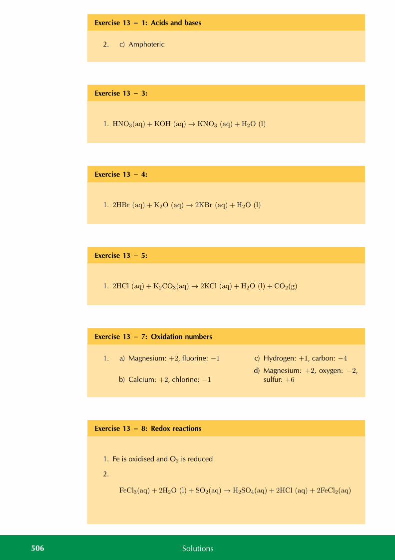
Exercise 13 – 1: Acids and bases
2. c) Amphoteric
Exercise 13 – 3:
1. HNO3(aq) + KOH (aq) → KNO3 (aq) + H2O (l)
Exercise 13 – 4:
1. 2HBr (aq) + K2O (aq) → 2KBr (aq) + H2O (l)
Exercise 13 – 5:
1. 2HCl (aq) + K2CO3(aq) → 2KCl (aq) + H2O (l) + CO2(g)
Exercise 13 – 7: Oxidation numbers
1. a) Magnesium: +2, fluorine: −1
b) Calcium: +2, chlorine: −1
c) Hydrogen: +1, carbon: −4
d) Magnesium: +2, oxygen: −2,sulfur: +6
Exercise 13 – 8: Redox reactions
1. Fe is oxidised and O2 is reduced
2.
FeCl3(aq) + 2H2O (l) + SO2(aq) → H2SO4(aq) + 2HCl (aq) + 2FeCl2(aq)
506 Solutions
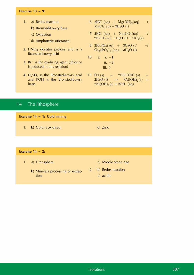
Exercise 13 – 9:
1. a) Redox reaction
b) Bronsted-Lowry base
c) Oxidation
d) Amphoteric substance
2. HNO3 donates protons and is aBronsted-Lowry acid
3. Br− is the oxidising agent (chlorineis reduced in this reaction)
4. H2SO3 is the Bronsted-Lowry acidand KOH is the Bronsted-Lowrybase.
6. 2HCl (aq) + Mg(OH)2(aq) →MgCl2(aq) + 2H2O (l)
7. 2HCl (aq) + Na2CO3(aq) →2NaCl (aq) + H2O (l) + CO2(g)
8. 2H3PO4(aq) + 3CaO (s) →Ca3(PO4)2 (aq) + 3H2O (l)
10. a) i. −1
ii. −2
iii. 0
13. Cd (s) + 2NiO(OH) (s) +2H2O (l) → Cd(OH)2(s) +2Ni(OH)2(s) + 2OH−(aq)
14 The lithosphere
Exercise 14 – 1: Gold mining
1. b) Gold is oxidised. d) Zinc
Exercise 14 – 2:
1. a) Lithosphere
b) Minerals processing or extrac-tion
c) Middle Stone Age
2. b) Redox reaction
c) acidic
507Solutions
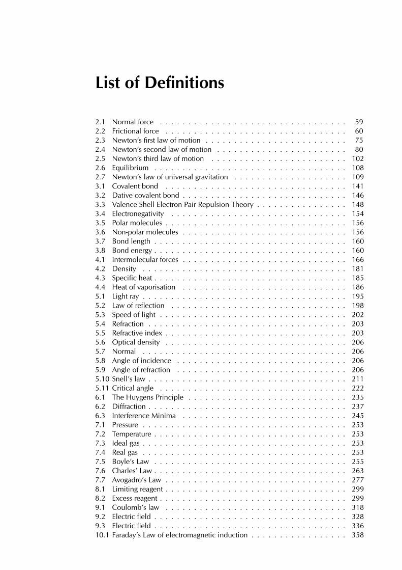
List of Definitions
2.1 Normal force . . . . . . . . . . . . . . . . . . . . . . . . . . . . . . . . . 592.2 Frictional force . . . . . . . . . . . . . . . . . . . . . . . . . . . . . . . . 602.3 Newton’s first law of motion . . . . . . . . . . . . . . . . . . . . . . . . . 752.4 Newton’s second law of motion . . . . . . . . . . . . . . . . . . . . . . . 802.5 Newton’s third law of motion . . . . . . . . . . . . . . . . . . . . . . . . 1022.6 Equilibrium . . . . . . . . . . . . . . . . . . . . . . . . . . . . . . . . . . 1082.7 Newton’s law of universal gravitation . . . . . . . . . . . . . . . . . . . . 1093.1 Covalent bond . . . . . . . . . . . . . . . . . . . . . . . . . . . . . . . . 1413.2 Dative covalent bond . . . . . . . . . . . . . . . . . . . . . . . . . . . . . 1463.3 Valence Shell Electron Pair Repulsion Theory . . . . . . . . . . . . . . . . 1483.4 Electronegativity . . . . . . . . . . . . . . . . . . . . . . . . . . . . . . . 1543.5 Polar molecules . . . . . . . . . . . . . . . . . . . . . . . . . . . . . . . . 1563.6 Non-polar molecules . . . . . . . . . . . . . . . . . . . . . . . . . . . . . 1563.7 Bond length . . . . . . . . . . . . . . . . . . . . . . . . . . . . . . . . . . 1603.8 Bond energy . . . . . . . . . . . . . . . . . . . . . . . . . . . . . . . . . . 1604.1 Intermolecular forces . . . . . . . . . . . . . . . . . . . . . . . . . . . . . 1664.2 Density . . . . . . . . . . . . . . . . . . . . . . . . . . . . . . . . . . . . 1814.3 Specific heat . . . . . . . . . . . . . . . . . . . . . . . . . . . . . . . . . . 1854.4 Heat of vaporisation . . . . . . . . . . . . . . . . . . . . . . . . . . . . . 1865.1 Light ray . . . . . . . . . . . . . . . . . . . . . . . . . . . . . . . . . . . . 1955.2 Law of reflection . . . . . . . . . . . . . . . . . . . . . . . . . . . . . . . 1985.3 Speed of light . . . . . . . . . . . . . . . . . . . . . . . . . . . . . . . . . 2025.4 Refraction . . . . . . . . . . . . . . . . . . . . . . . . . . . . . . . . . . . 2035.5 Refractive index . . . . . . . . . . . . . . . . . . . . . . . . . . . . . . . . 2035.6 Optical density . . . . . . . . . . . . . . . . . . . . . . . . . . . . . . . . 2065.7 Normal . . . . . . . . . . . . . . . . . . . . . . . . . . . . . . . . . . . . 2065.8 Angle of incidence . . . . . . . . . . . . . . . . . . . . . . . . . . . . . . 2065.9 Angle of refraction . . . . . . . . . . . . . . . . . . . . . . . . . . . . . . 2065.10 Snell’s law . . . . . . . . . . . . . . . . . . . . . . . . . . . . . . . . . . . 2115.11 Critical angle . . . . . . . . . . . . . . . . . . . . . . . . . . . . . . . . . 2226.1 The Huygens Principle . . . . . . . . . . . . . . . . . . . . . . . . . . . . 2356.2 Diffraction . . . . . . . . . . . . . . . . . . . . . . . . . . . . . . . . . . . 2376.3 Interference Minima . . . . . . . . . . . . . . . . . . . . . . . . . . . . . 2457.1 Pressure . . . . . . . . . . . . . . . . . . . . . . . . . . . . . . . . . . . . 2537.2 Temperature . . . . . . . . . . . . . . . . . . . . . . . . . . . . . . . . . . 2537.3 Ideal gas . . . . . . . . . . . . . . . . . . . . . . . . . . . . . . . . . . . . 2537.4 Real gas . . . . . . . . . . . . . . . . . . . . . . . . . . . . . . . . . . . . 2537.5 Boyle’s Law . . . . . . . . . . . . . . . . . . . . . . . . . . . . . . . . . . 2557.6 Charles’ Law . . . . . . . . . . . . . . . . . . . . . . . . . . . . . . . . . . 2637.7 Avogadro’s Law . . . . . . . . . . . . . . . . . . . . . . . . . . . . . . . . 2778.1 Limiting reagent . . . . . . . . . . . . . . . . . . . . . . . . . . . . . . . . 2998.2 Excess reagent . . . . . . . . . . . . . . . . . . . . . . . . . . . . . . . . . 2999.1 Coulomb’s law . . . . . . . . . . . . . . . . . . . . . . . . . . . . . . . . 3189.2 Electric field . . . . . . . . . . . . . . . . . . . . . . . . . . . . . . . . . . 3289.3 Electric field . . . . . . . . . . . . . . . . . . . . . . . . . . . . . . . . . . 33610.1 Faraday’s Law of electromagnetic induction . . . . . . . . . . . . . . . . . 358

11.1 Ohm’s Law . . . . . . . . . . . . . . . . . . . . . . . . . . . . . . . . . . 37311.2 Equivalent resistance in a series circuit, . . . . . . . . . . . . . . . . . . . 38111.3 Equivalent resistance in a parallel circuit . . . . . . . . . . . . . . . . . . . 38111.4 Electrical Power . . . . . . . . . . . . . . . . . . . . . . . . . . . . . . . . 39912.1 Bond energy . . . . . . . . . . . . . . . . . . . . . . . . . . . . . . . . . . 41912.2 Enthalpy . . . . . . . . . . . . . . . . . . . . . . . . . . . . . . . . . . . . 41912.3 Exothermic reaction . . . . . . . . . . . . . . . . . . . . . . . . . . . . . . 42012.4 Endothermic reaction . . . . . . . . . . . . . . . . . . . . . . . . . . . . . 42012.5 Activation energy . . . . . . . . . . . . . . . . . . . . . . . . . . . . . . . 42913.1 Acids . . . . . . . . . . . . . . . . . . . . . . . . . . . . . . . . . . . . . . 43913.2 Bases . . . . . . . . . . . . . . . . . . . . . . . . . . . . . . . . . . . . . 43913.3 Amphoteric . . . . . . . . . . . . . . . . . . . . . . . . . . . . . . . . . . 44113.4 Amphiprotic . . . . . . . . . . . . . . . . . . . . . . . . . . . . . . . . . . 44113.5 Oxidation . . . . . . . . . . . . . . . . . . . . . . . . . . . . . . . . . . . 45213.6 Reduction . . . . . . . . . . . . . . . . . . . . . . . . . . . . . . . . . . . 45213.7 Oxidation number . . . . . . . . . . . . . . . . . . . . . . . . . . . . . . 45313.8 Half-reaction . . . . . . . . . . . . . . . . . . . . . . . . . . . . . . . . . 45713.9 Redox reaction . . . . . . . . . . . . . . . . . . . . . . . . . . . . . . . . 45714.1 Lithosphere . . . . . . . . . . . . . . . . . . . . . . . . . . . . . . . . . . 47114.2 Mineral . . . . . . . . . . . . . . . . . . . . . . . . . . . . . . . . . . . . 47514.3 Ore . . . . . . . . . . . . . . . . . . . . . . . . . . . . . . . . . . . . . . 476
Image Attribution
1 Photo by USGS on Wikipedia . . . . . . . . . . . . . . . . . . . . . . . . 82 Photo by OpenClipArt library on wikipedia . . . . . . . . . . . . . . . . . 93 Photo by USnavy on Flickr . . . . . . . . . . . . . . . . . . . . . . . . . . 294 Photo by Heather Williams . . . . . . . . . . . . . . . . . . . . . . . . . . 485 Photo by Arnaud.ramey on Wikipedia . . . . . . . . . . . . . . . . . . . . 566 Photo by Walt Stoneburner on Flickr . . . . . . . . . . . . . . . . . . . . 567 Photo by MountainAsh on Flickr . . . . . . . . . . . . . . . . . . . . . . . 578 Photo by Colleen Henning . . . . . . . . . . . . . . . . . . . . . . . . . . 579 Photo by Splarka on Wikipedia . . . . . . . . . . . . . . . . . . . . . . . 5710 Photo by Nicola du Toit . . . . . . . . . . . . . . . . . . . . . . . . . . . 5811 Photo by Nicola du Toit . . . . . . . . . . . . . . . . . . . . . . . . . . . 5812 Photo by Nicola du Toit . . . . . . . . . . . . . . . . . . . . . . . . . . . 5813 Photo by Nicola du Toit . . . . . . . . . . . . . . . . . . . . . . . . . . . 5814 Photo by http :// www.morguefile.com/archive/display/84031 . . . . . . . 6015 Photo by http :// www.morguefile.com/archive/display/200857 . . . . . . 6116 Photo by Sagriffin305 on Flickr . . . . . . . . . . . . . . . . . . . . . . . 6117 Photo by unknown on Wikipedia . . . . . . . . . . . . . . . . . . . . . . 6218 Photo by Foshie on Flickr . . . . . . . . . . . . . . . . . . . . . . . . . . 7319 Derivative work by Heather Williams based on photo by Floshie on Flickr . 7320 Photo by JosDielis on Flickr . . . . . . . . . . . . . . . . . . . . . . . . 7521 Photo by Elvert Barnes on Flickr . . . . . . . . . . . . . . . . . . . . . . 7522 Photo by Heather Williams . . . . . . . . . . . . . . . . . . . . . . . . . . 7823 Photo by Nicola du Toit . . . . . . . . . . . . . . . . . . . . . . . . . . . 10124 Photo by Nicola du Toit . . . . . . . . . . . . . . . . . . . . . . . . . . . 10425 Photo by Heather Williams . . . . . . . . . . . . . . . . . . . . . . . . . . 10626 Photo by NASA on Wikipedia . . . . . . . . . . . . . . . . . . . . . . . . 10727 Photo by NASA on Wikipedia . . . . . . . . . . . . . . . . . . . . . . . . 11428 Photo by Heather Williams . . . . . . . . . . . . . . . . . . . . . . . . . . 13629 Photo created from images by Ben Mills on Wikipedia . . . . . . . . . . 14930 Photo created from images by Ben Mills on Wikipedia . . . . . . . . . . 15031 Photo by Ben Mills on Wikipedia . . . . . . . . . . . . . . . . . . . . . . 16632 Photo by Ben Mills on Wikipedia . . . . . . . . . . . . . . . . . . . . . . 16733 Photo by stevendepolo on Flickr . . . . . . . . . . . . . . . . . . . . . . . 17334 Photo by Umair Mohsin on Flickr . . . . . . . . . . . . . . . . . . . . . . 17335 Photo by Ben Mills on wikipedia . . . . . . . . . . . . . . . . . . . . . . 18036 Photo by Siona Karen on Flickr . . . . . . . . . . . . . . . . . . . . . . . 18037 Photo by H Padleckas on Wikipedia . . . . . . . . . . . . . . . . . . . . . 18138 Photo by tanjila on Flickr . . . . . . . . . . . . . . . . . . . . . . . . . 19439 Lightbulb photo by jaliyaj on Flickr . . . . . . . . . . . . . . . . . . . . 19540 Photo by freewine on Flickr . . . . . . . . . . . . . . . . . . . . . . . . . 19741 Photo by Heather Williams . . . . . . . . . . . . . . . . . . . . . . . . . . 20842 Photo by Heather Williams . . . . . . . . . . . . . . . . . . . . . . . . . . 21243 Photo by Sai2020 on Wikipedia . . . . . . . . . . . . . . . . . . . . . . . 22244 Photo by Heather Williams . . . . . . . . . . . . . . . . . . . . . . . . . . 25245 Photo by Grant Hillebrand . . . . . . . . . . . . . . . . . . . . . . . . . . 25646 Photo by Heather Williams . . . . . . . . . . . . . . . . . . . . . . . . . . 276

47 Photo by Marc Spooner on Flickr . . . . . . . . . . . . . . . . . . . . . . 35348 Photo by Gch 15 on Flickr . . . . . . . . . . . . . . . . . . . . . . . . . . 35449 Photo from morguefile.com . . . . . . . . . . . . . . . . . . . . . . . . . 35450 Photo by Heather Williams . . . . . . . . . . . . . . . . . . . . . . . . . . 37751 Photo by AndersLindgren on Flickr . . . . . . . . . . . . . . . . . . . . . 41852 Photo by Konstantin Leonov on Flickr . . . . . . . . . . . . . . . . . . . . 42453 Photo by Grant Hillebrand . . . . . . . . . . . . . . . . . . . . . . . . . . 44554 Photo by paulnasca on Wikipedia . . . . . . . . . . . . . . . . . . . . . . 45255 Photo by NASA on Wikipedia . . . . . . . . . . . . . . . . . . . . . . . . 47056 Photo by USGS on Wikipedia . . . . . . . . . . . . . . . . . . . . . . . . 47157 Photo by Nicola du Toit . . . . . . . . . . . . . . . . . . . . . . . . . . . 47158 Photo by Locutus Borg on Wikipedia . . . . . . . . . . . . . . . . . . . . 47259 Photo by Locutus Borg on Wikipedia . . . . . . . . . . . . . . . . . . . . 47260 Photo by Locutus Borg on Wikipedia . . . . . . . . . . . . . . . . . . . . 47261 Photo from Wikipedia . . . . . . . . . . . . . . . . . . . . . . . . . . . . 47262 Photo by goodfriend100 on Wikipedia . . . . . . . . . . . . . . . . . . . 47263 Photo by Aram Dulyan on Wikipedia . . . . . . . . . . . . . . . . . . . . 47464 Photo by Wilson44691 on Wikipedia . . . . . . . . . . . . . . . . . . . . 47465 Photo by USDS(geology) on Wikipedia . . . . . . . . . . . . . . . . . . . 47466 Photo by USDS(geology) on Wikipedia . . . . . . . . . . . . . . . . . . . 47467 Photo by Aram Dulyan on Wikipedia . . . . . . . . . . . . . . . . . . . . 47468 Photo by USDS(geology) on Wikipedia . . . . . . . . . . . . . . . . . . . 47469 Photo by USDS(geology) on Wikipedia . . . . . . . . . . . . . . . . . . . 47470 Photo by US geological survey on Wikipedia . . . . . . . . . . . . . . . . 47471 Photo by USGS on Wikipedia with images of rocks from Wilson44691 on Wikipedia47572 Photo created from map on Wikipedia and data from http ://www.geoscience.org.za/images/stories/ rsadeposits . gif 47673 Photo by US geological survey on Wikipedia . . . . . . . . . . . . . . . . 477