Embed Size (px)
Citation preview
GREENPLUM: DATA PROTECTION AND HIGH AVAILABILITY - A NEED FOR EVERY DATA WAREHOUSE
Sumit GuptaProject EngineerAditya Infotech
Puneet GoyalSenior SpecialistHCL Technologies
2012 EMC Proven Professional Knowledge Sharing 2
TABLE OF CONTENTS INTRODUCTION ....................................................................................................................... 4
ARCHITECTURAL STUDY OF EMC GREENPLUM DCA ......................................................... 5
Key Technology Pillars ........................................................................................................... 6
Scatter/Gather Streaming technology ..................................................................................... 7
Master Servers ....................................................................................................................... 8
Segment Servers ...................................................................................................................10
gNet Software Interconnect ...................................................................................................11
BACKUP SOLUTION FOR GREENPLUM DCA ........................................................................12
Using Data Domain Boost .....................................................................................................12
Backup a database with gp_dump .........................................................................................13
Automating Parallel Backups with gpcrondump .....................................................................13
EXAMPLES OF BACKUP AND RESTORE ...............................................................................14
TEST RESULTS .......................................................................................................................22
Objective ...............................................................................................................................22
Test 1 ....................................................................................................................................23
Test 2 ....................................................................................................................................23
Test 3 ....................................................................................................................................25
Test 4 ....................................................................................................................................26
Test 5 ....................................................................................................................................26
Test 6 ....................................................................................................................................27
Results ..................................................................................................................................29
DISASTER RECOVERY SOLUTION FOR GREENPLUM DCA ................................................30
Segment failure on local site A ..............................................................................................30
Allocation and mounting of SAN devices on the DCA ............................................................32
Moving Mirrors .......................................................................................................................32
SAN Mirror SRDF/S consistency group .................................................................................33
SAN Mirror rotating snapshots ...............................................................................................33
Failover and Failback ............................................................................................................34
Time Analysis ........................................................................................................................36
HIGH AVAILABILITY SOLUTION FOR GREENPLUM ..............................................................36
WORKING .............................................................................................................................37
PREPARE DCAs FOR SAN MIRROR ...................................................................................38
2012 EMC Proven Professional Knowledge Sharing 3
CONFIGURE THE VMAX FOR SAN MIRROR ATTACHMENT .............................................39
CONFIGURE THE DCAs TO USE VMAX DISK ....................................................................40
STARTING AUTOSNAP ........................................................................................................42
MONITORING AUTOSNAP’s OPERATION ..........................................................................42
FAILOVER AND FAILBACK ......................................................................................................42
FAILOVER ............................................................................................................................42
FAILBACK .............................................................................................................................44
CASE STUDY ...........................................................................................................................46
CONCLUSION ..........................................................................................................................47
REFERENCE ............................................................................................................................49
Disclaimer: The views, processes, or methodologies published in this article are those of the
authors. They do not necessarily reflect EMC Corporation’s views, processes, or
methodologies.
2012 EMC Proven Professional Knowledge Sharing 4
INTRODUCTION
Data warehouses are a critical tool for making business decisions. As data warehouse and
business intelligence systems (DW/BI) continue to grow, they bring some difficult challenges
with them. Some of those are; high-performance; high-availability; protected storage; backup
and disaster recovery; and constrained backup windows. With today’s rapid data growth, a
periodic full backup to tape or to a non-deduplicating disk-based storage system is no longer a
viable option. Tape or non-deduplicated disk-based backups do not provide the recoverability
and reliability customer’s demand in large capacity data warehouse environments.
Big Data is, well, big, and size is not the only challenge it places on backup. It also is a backup
application's worst nightmare because many Big Data environments consist of millions or even
billions of small files. How do you design a backup infrastructure that will support the Big Data
realities?
The business impact of DW/BI outages has caused CIOs to demand comprehensive strategies
for data protection, security, and high availability. Data recovery options must align with
application and business requirements to yield the highest availability and predictable, scalable
performance.
With the enormous amount of storage increasingly required for backing up data, businesses are
finding it ever more difficult to achieve storage efficiencies. EMC®, together with Greenplum®,
has created Data Computing Appliance (DCA). The DCA addresses essential business
requirements as well as ensures predictable functional, performance, and scalability results.
The DCA combined with Data Domain® systems, provides a total solution for data warehousing
deployment that addresses all these key challenges. This Knowledge Sharing article will
illustrate how to successfully back up, recover, and restore data from the DCA.
To integrate EMC Greenplum DCA into larger data centers, some customers require
compatibility with advanced storage and software infrastructures—such as EMC Symmetrix®
VMAX™—in order to achieve the highest levels of fault tolerance and to provide industry-leading
disaster recovery. To facilitate this, EMC engineered a solution that integrates DCA with the
VMAX, where the VMAX provides local and remote replicas of the data for disaster recovery
and point-in-time snapshots. This allows customers to recover data warehouse/business
intelligence (DW/BI) functionality quickly in the face of hardware or software failure, or even total
site loss.
2012 EMC Proven Professional Knowledge Sharing 5
ARCHITECTURAL STUDY OF EMC GREENPLUM DCA
This section discusses the logical and physical architecture of DCA. Some of the key
architectural questions raised by every solution architect include:
Is the hardware proprietary/non-proprietary/standardized?
Is this a shared nothing/ share disk/ share everything architecture?
Capability-in database analytics?
Scale-linear scalability?
What are your ingestion rates? (higher rate, better real time reporting)
Can I balance my workloads? How about mixed workloads?
What are my DW management overheads?
This section provides the answer to all of these questions. But first, let’s understand the basic
architecture and its component of Greenplum DCA.
The DCA is a self-contained data warehouse solution that integrates all the database software,
servers, and switches required to perform enterprise-scale data analytics workloads. The DCA
is delivered racked and ready for immediate data loading and query execution.
The DCA provides everything needed to run a complete Greenplum database environment
within a single rack. This includes:
Greenplum database software
Master servers to run the master database
Segment servers that run the segment instances
A high-speed interconnect bus (consisting of two switches) to communicate requests
from the master to the segments, between segments, and to provide high-speed access
to the segment servers for quick parallel loading of data across all segment servers
An admin switch to provide administrative access to all of the DCA components
2012 EMC Proven Professional Knowledge Sharing 6
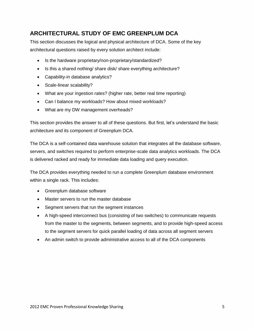
Figure 1: Architecture of Greenplum Data Computing Appliance
The DCA runs the Greenplum Database RDBMS software. The physical architecture of the
DCA supports and enables the logical architecture of Greenplum Database, by utilizing the DCA
components to perform its database operations and processing. The DCA consists of four
operational layers: Compute, Storage, Database, and Network.
Layer Description
Compute The latest Intel processor architecture for excellent compute node performance.
Storage High-density, RAID-protected Serial Attached SCSI (SAS) disks.
Database Greenplum Database incorporating MPP architecture.
Network Dual 10 GigE Ethernet switches provide a high-speed, expandable IP interconnect
solution across the Greenplum Database.
Table 1: DCA Conceptual View and DCA Layers
Key Technology Pillars
1. World’s fastest data loading: Scatter/Gather streaming technology.
2. Fast query execution with linear scalability: Shared-nothing MPP architecture.
3. Unified data access across the enterprise: Dynamic query optimization and workload
management.
2012 EMC Proven Professional Knowledge Sharing 7
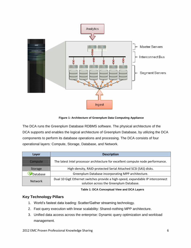
Scatter/Gather Streaming technology
Greenplum’s MPP Scatter/Gather streaming (SG Streaming) technology eliminates the
bottlenecks associated with other approaches of data loading, enabling a lightning-fast flow of
data into Greenplum DCA.
Figure 2: Scatter Streaming
The system uses a ―parallel everywhere‖ approach to loading, in which data flows from one or
more source systems to every node of the database without any sequential choke points. This
approach differs from traditional ―bulk loading‖ technologies—used by most mainstream
database and MPP appliance vendors—which push data from a single source, often over a
single channel or a small number of parallel channels and result in fundamental bottlenecks and
ever-increasing load times. Greenplum’s approach also avoids the need for a ―loader‖ tier of
servers, as is required by some other MPP database vendors, which can add significant
complexity and cost while effectively bottlenecking the bandwidth and parallelism of
communication into the database.
Data can be transformed and processed on-the-fly, utilizing all nodes of the database in parallel
for extremely high-performance extract-load-transform (ELT) and extract-transform-load
transform (ETLT) loading pipelines.
2012 EMC Proven Professional Knowledge Sharing 8
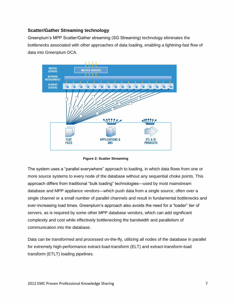
Figure 3: Gather Streaming
Final ―gathering‖ and storage of data to disk takes place on all nodes simultaneously, with data
automatically partitioned across nodes and optionally compressed. This technology is exposed
to the database administrator via a flexible and programmable ―external table‖ interface and a
traditional command-line loading interface.
Master Servers
There are two master servers, one primary and one standby. The primary Master server mirrors
logs to the standby so that it is available to take over in the event of a failure.
The standby Master server is a warm standby. If the primary Master server fails, the standby is
available to take over as the primary. The standby Master server is kept up to date by a process
that synchronizes the write-ahead-log (WAL) from the primary to the standby. If the primary
Master server fails, the log replication process is shut down, and the standby can be activated in
its place. Upon activation of the standby, the replicated logs are used to reconstruct the state of
the primary Master server at the time of the last successfully committed transaction.
2012 EMC Proven Professional Knowledge Sharing 9
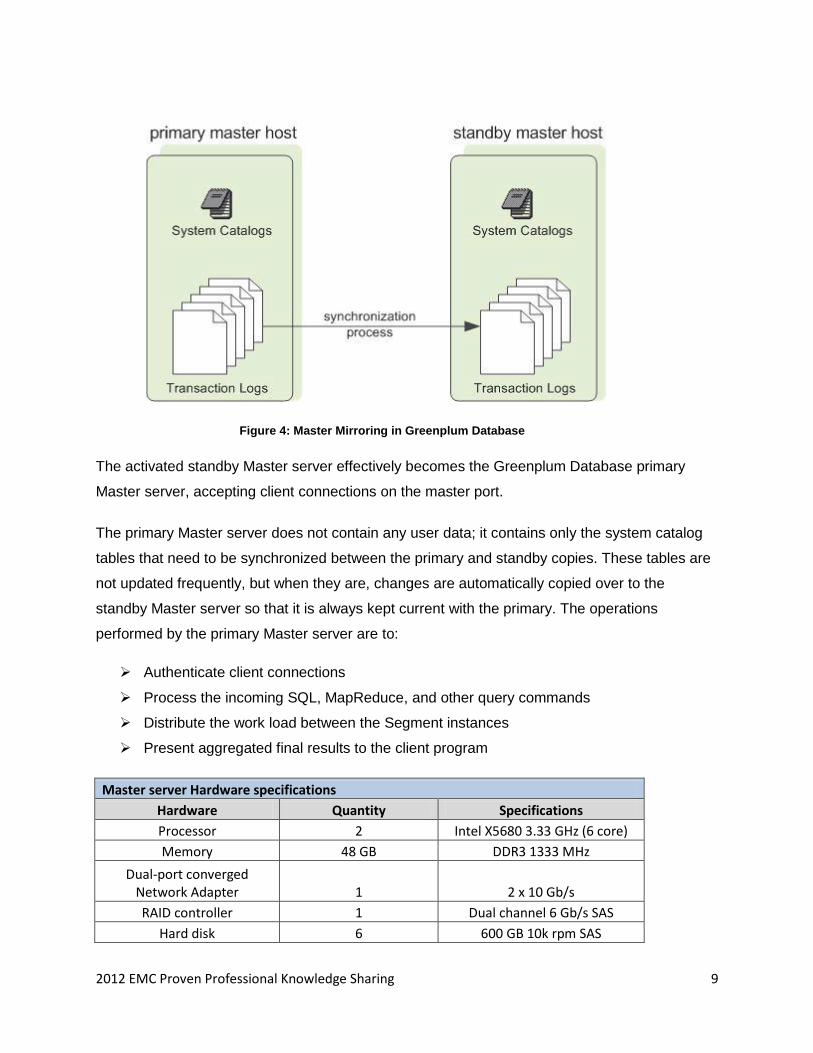
Figure 4: Master Mirroring in Greenplum Database
The activated standby Master server effectively becomes the Greenplum Database primary
Master server, accepting client connections on the master port.
The primary Master server does not contain any user data; it contains only the system catalog
tables that need to be synchronized between the primary and standby copies. These tables are
not updated frequently, but when they are, changes are automatically copied over to the
standby Master server so that it is always kept current with the primary. The operations
performed by the primary Master server are to:
Authenticate client connections
Process the incoming SQL, MapReduce, and other query commands
Distribute the work load between the Segment instances
Present aggregated final results to the client program
Master server Hardware specifications
Hardware Quantity Specifications
Processor 2 Intel X5680 3.33 GHz (6 core)
Memory 48 GB DDR3 1333 MHz
Dual-port converged Network Adapter 1 2 x 10 Gb/s
RAID controller 1 Dual channel 6 Gb/s SAS
Hard disk 6 600 GB 10k rpm SAS
2012 EMC Proven Professional Knowledge Sharing 10
Master server software specifications
Software Version
Red Hat Linux Version 5 5.5
Greenplum Database 4
Table 2: Hardware and software specifications of the Master server
Segment Servers
Each Segment server runs several individual segment instances; these are small databases
that each hold a slice of the overall data in the Greenplum Database. There are two types of
Segment Instances:
1. Primary Segment Instances
2. Mirror Segment Instances
The DCA is shipped preconfigured, with six primary segments and six mirror segments per
Segment Server. This is done to maintain a proper balance of primary and mirror data on the
Segment Servers.
What is Segment Instance?
A Segment Instance is a combination of database process, memory, and storage on a segment server. A Segment Instance contains a unique section of the entire
database. One or more Segment Instances reside on each Segment Server.
A mirror segment always resides on a different host and subnet to its corresponding primary
segment. This is to ensure that in case of a failover scenario, where a Segment Server is
unreachable or down, the mirror counterpart of the primary instance is still available on another
Segment Server.
Function Description
Data Storage User-defined tables and their indexes are distributed across the
Segment Servers of the DCA
Hardware hosts for Segment Instances
In the Greenplum Database, the database comprises multiple database segments (Segment Instances). Multiple Segment Instances
are located on each Segment Server.
Query processing Carry out the majority of query processing and data analysis
Table 3: Functions of Segment Server
Segment Servers run segment database instances (Segment Instances). The majority of query
processing occurs either within or between Segment Instances. Each Segment Server runs
2012 EMC Proven Professional Knowledge Sharing 11
many Segment Instances. Every Segment Instance has a segment of data from each user-
defined table and index. In this way, queries are serviced in parallel by every Segment Instance
on every Segment Server.
Users do not interact directly with the Segment Servers in a DCA. When a user connects to the
database and issues a query, it is to the primary Master Server. Subsequently, the primary
Master issues a distributed query tasks and then processes are created on each of the Segment
Instances to handle the work of that query.
Segment Server Hardware specifications
Hardware Quantity Specifications
Processor 2 Intel X5680 2.93 GHz (6 core)
Memory 48 GB DDR3 1333 MHz
Dual-port converged Network Adapter 1 2 x 10 Gb/s
RAID controller 1 Dual channel 6 Gb/s SAS
Hard disk 12 600 GB 10k rpm SAS
Segment Server software specifications
Software Version
Red Hat Linux Version 5 5.5
Greenplum Database 4
Figure 4: Hardware and software details of the Segment Server
gNet Software Interconnect
In shared-nothing MPP database systems, data often needs to be moved whenever there is a
join or an aggregation process for which the data requires repartitioning across the segments.
As a result, the interconnect serves as one of the most critical components within Greenplum
Database. Greenplum’s gNet Software interconnect optimizes the flow of data to allow
continuous pipelining of processing without blocking processes on any of the servers in the
system. The gNet Software Interconnect is tuned and optimized to scale to tens of thousands of
processors and uses industry-standard Gigabit Ethernet and 10 GigE switch technology.
Pipelining is the ability to begin a task before its predecessor task has completed. Within the
execution of each node in the query plan, multiple relational operations are processed by
pipelining. For example, while a table scan is taking place, selected rows can be pipelined into a
2012 EMC Proven Professional Knowledge Sharing 12
join process. This ability is important to increasing basic query parallelism. Greenplum database
utilizes pipelining whenever possible to ensure the highest possible performance.
BACKUP SOLUTION FOR GREENPLUM DCA
The backup of Greenplum can be taken in any of three ways:
Use Data Domain Boost
Back up a database with gp_dump
Automating parallel backups with gpcrondump
Using Data Domain Boost
Data Domain provides faster backup and restore at the source of decrease network traffic.
Following are the steps to configure DD Boost:
Create a configuration file .ddconfig in the user’s home directory.
Copy the configuration file to all segments.
Configure distributed segment processing in DD and apply to all the media servers and
the OST plug-ins installed on them.
Add interface into the group.
Select one interface to add with the backup application. This will be used by the backup
application and OST plug-in to communicate with the DD system. This is important for
backup with DD.
Enable the feature and verify the configuration.
Enable low-bandwidth optimization in Data Domain. No reboot is required. This feature
takes additional CPU and memory on DD so it is used for optimized deduplication with
less than 6 Mbps aggregate bandwidth. This is supported in standalone DD only.
2012 EMC Proven Professional Knowledge Sharing 13
Enable encrypted optimized duplication.
Backup a database with gp_dump
To run the backup, use the below command:
This performs the following actions on master and segment host:
On Master host:
Dump the Greenplum configuration system catalog tables into a SQL file in the master
data directory. File name is gp_catalog_1_<dbid>_<timestamp>.
Dump a CREATE DATABASE SQL statement into a file in the master data directory. File
name is gp_cdatabase_1_<dbid>_<timestamp>.
Dump the user database schema into a SQL file in the master data directory. This file is
used by gp_restore to create database schema. File name is
gp_dump_1_<dbid>_<timestamp>.
Create a dump file in a master data directory to rebuild objects associated with the
tables. File name is gp_dump_1_<dbid>_<timestamp>_post_data.
The gp_dump launches a gp_dump_agent for each segment instance to be backed up.
On Segment host:
By default, only the active instances are backed up. It dumps the user data for each
Segment Instance into a SQL file in the Segment Instance’s data directory. File name is
gp_dump_0_<dbid>_<timestamp>.
Create a log file in each Segment Instance’s data directory. File name is
gp_dump_status_0_<dbid>_<timestamp>.
Automating Parallel Backups with gpcrondump
This is a wrapper utility for gp_dump which can be called directly from crontab entry. It allows
backup of certain extra objects besides data and database.
Procedure to schedule a dump operation using CRON:
Log in with the super user.
Define a crontab entry that calls gpcrondump.
2012 EMC Proven Professional Knowledge Sharing 14
Create a file in either the Greenplum superuser’s home directory or in $GPHOME/bin.
Give the email address for notification purposes.
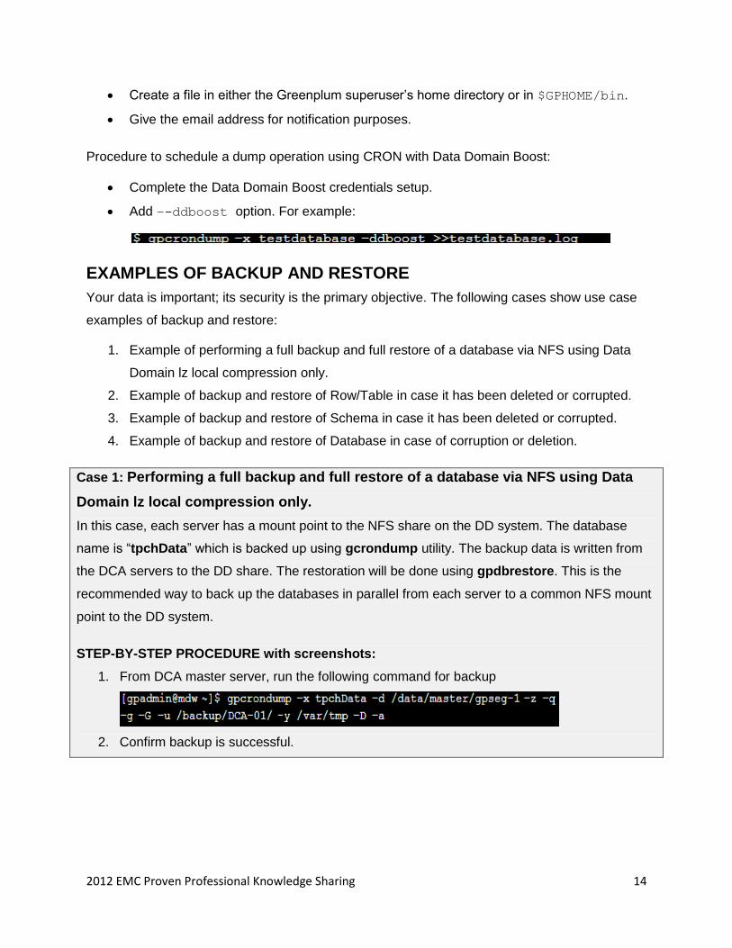
Procedure to schedule a dump operation using CRON with Data Domain Boost:
Complete the Data Domain Boost credentials setup.
Add –-ddboost option. For example:
EXAMPLES OF BACKUP AND RESTORE
Your data is important; its security is the primary objective. The following cases show use case
examples of backup and restore:
1. Example of performing a full backup and full restore of a database via NFS using Data
Domain lz local compression only.
2. Example of backup and restore of Row/Table in case it has been deleted or corrupted.
3. Example of backup and restore of Schema in case it has been deleted or corrupted.
4. Example of backup and restore of Database in case of corruption or deletion.
Case 1: Performing a full backup and full restore of a database via NFS using Data
Domain lz local compression only.
In this case, each server has a mount point to the NFS share on the DD system. The database
name is ―tpchData‖ which is backed up using gcrondump utility. The backup data is written from
the DCA servers to the DD share. The restoration will be done using gpdbrestore. This is the
recommended way to back up the databases in parallel from each server to a common NFS mount
point to the DD system.
STEP-BY-STEP PROCEDURE with screenshots:
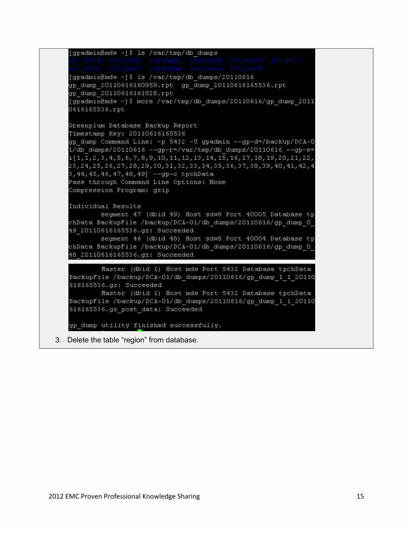
1. From DCA master server, run the following command for backup
2. Confirm backup is successful.
2012 EMC Proven Professional Knowledge Sharing 15
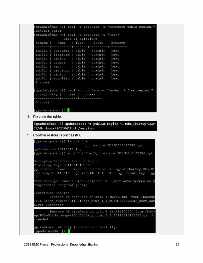
3. Delete the table ―region‖ from database.
2012 EMC Proven Professional Knowledge Sharing 16
4. Restore the table.
5. Confirm restore is successful.
2012 EMC Proven Professional Knowledge Sharing 17
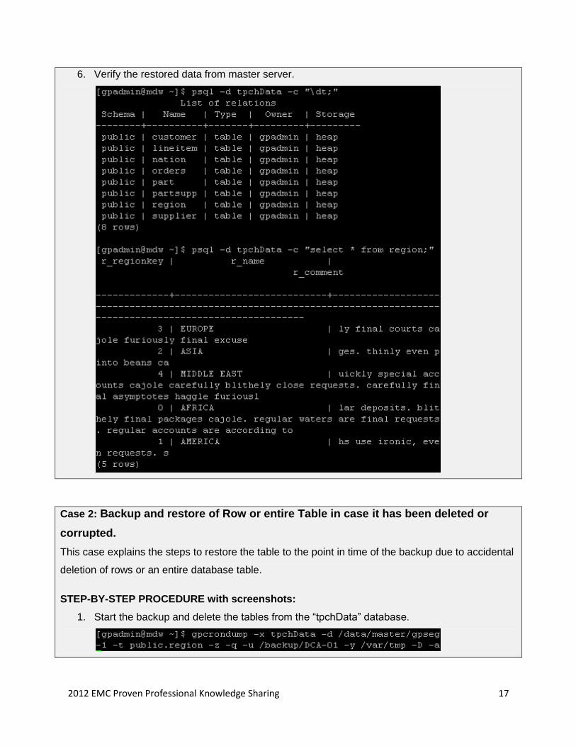
6. Verify the restored data from master server.
Case 2: Backup and restore of Row or entire Table in case it has been deleted or
corrupted.
This case explains the steps to restore the table to the point in time of the backup due to accidental
deletion of rows or an entire database table.
STEP-BY-STEP PROCEDURE with screenshots:
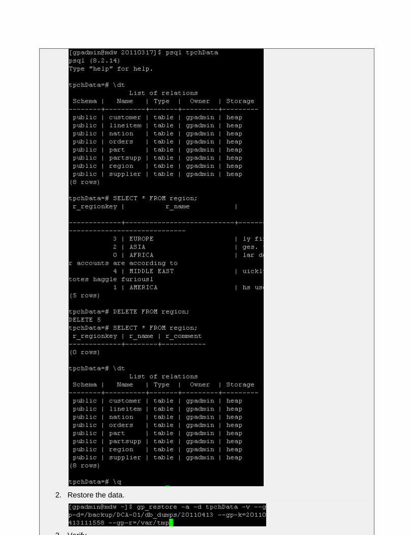
1. Start the backup and delete the tables from the ―tpchData‖ database.
2012 EMC Proven Professional Knowledge Sharing 18
2. Restore the data.
3. Verify
2012 EMC Proven Professional Knowledge Sharing 19
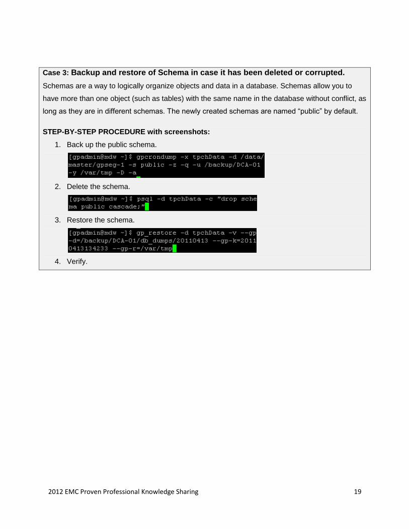
Case 3: Backup and restore of Schema in case it has been deleted or corrupted.
Schemas are a way to logically organize objects and data in a database. Schemas allow you to
have more than one object (such as tables) with the same name in the database without conflict, as
long as they are in different schemas. The newly created schemas are named ―public‖ by default.
STEP-BY-STEP PROCEDURE with screenshots:
1. Back up the public schema.
2. Delete the schema.
3. Restore the schema.
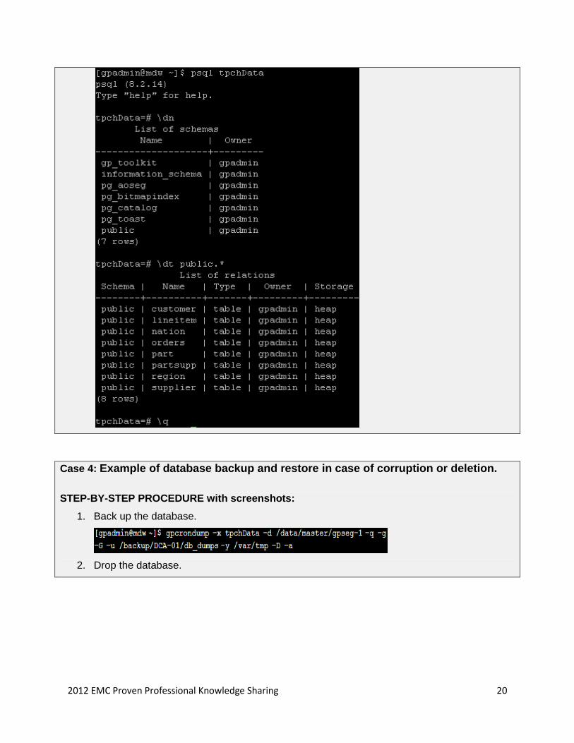
4. Verify.
2012 EMC Proven Professional Knowledge Sharing 20
Case 4: Example of database backup and restore in case of corruption or deletion.
STEP-BY-STEP PROCEDURE with screenshots:
1. Back up the database.
2. Drop the database.
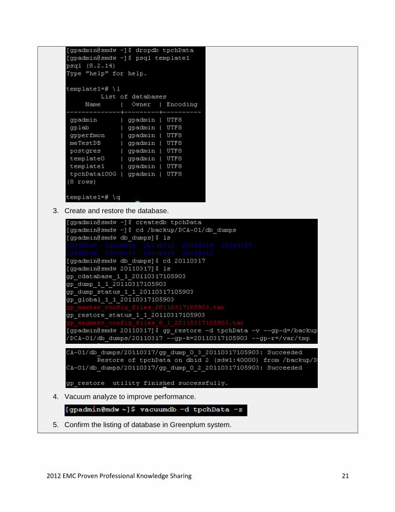
2012 EMC Proven Professional Knowledge Sharing 21
3. Create and restore the database.
4. Vacuum analyze to improve performance.
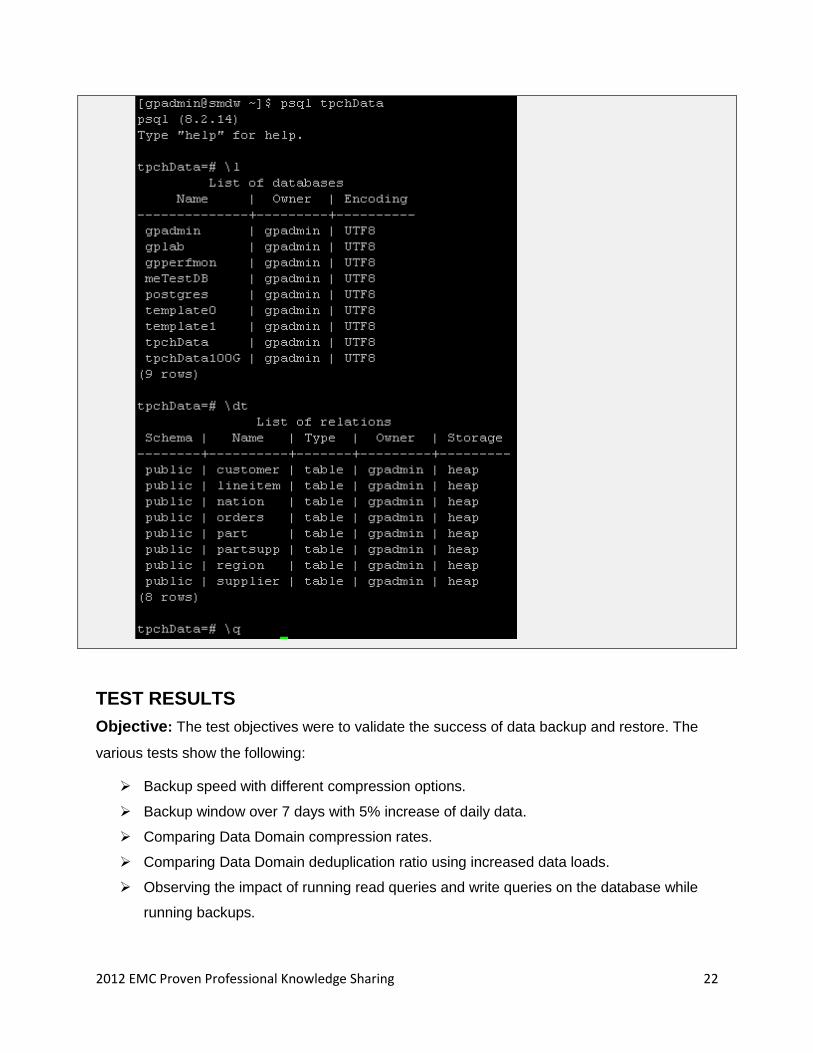
5. Confirm the listing of database in Greenplum system.
2012 EMC Proven Professional Knowledge Sharing 22
TEST RESULTS
Objective: The test objectives were to validate the success of data backup and restore. The
various tests show the following:
Backup speed with different compression options.
Backup window over 7 days with 5% increase of daily data.
Comparing Data Domain compression rates.
Comparing Data Domain deduplication ratio using increased data loads.
Observing the impact of running read queries and write queries on the database while
running backups.
2012 EMC Proven Professional Knowledge Sharing 23
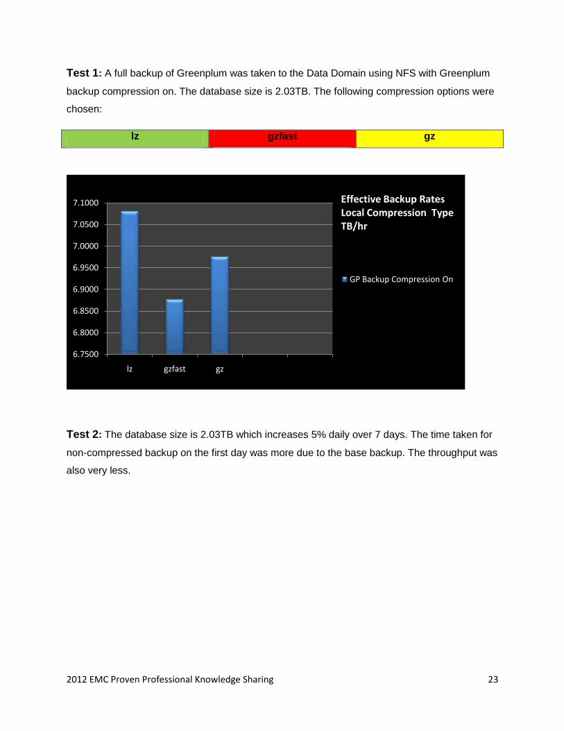
Test 1: A full backup of Greenplum was taken to the Data Domain using NFS with Greenplum
backup compression on. The database size is 2.03TB. The following compression options were
chosen:
lz gzfast gz
6.7500
6.8000
6.8500
6.9000
6.9500
7.0000
7.0500
7.1000
lz gzfast gz
GP Backup Compression On
Effective Backup RatesLocal Compression TypeTB/hr
Test 2: The database size is 2.03TB which increases 5% daily over 7 days. The time taken for
non-compressed backup on the first day was more due to the base backup. The throughput was
also very less.
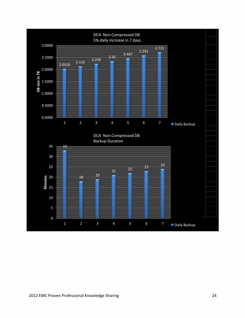
2012 EMC Proven Professional Knowledge Sharing 24
2.0310 2.132
2.239 2.35
2.467 2.591
2.721
0.0000
0.5000
1.0000
1.5000
2.0000
2.5000
3.0000
1 2 3 4 5 6 7
DB
siz
e in
TB
Daily Backup
DCA Non Compressed DB 5% daily increase in 7 days
33
18 19
21 22
23 24
0
5
10
15
20
25
30
35
1 2 3 4 5 6 7
Min
ute
s
Daily Backup
DCA Non Compressed DB Backup Duration
2012 EMC Proven Professional Knowledge Sharing 25
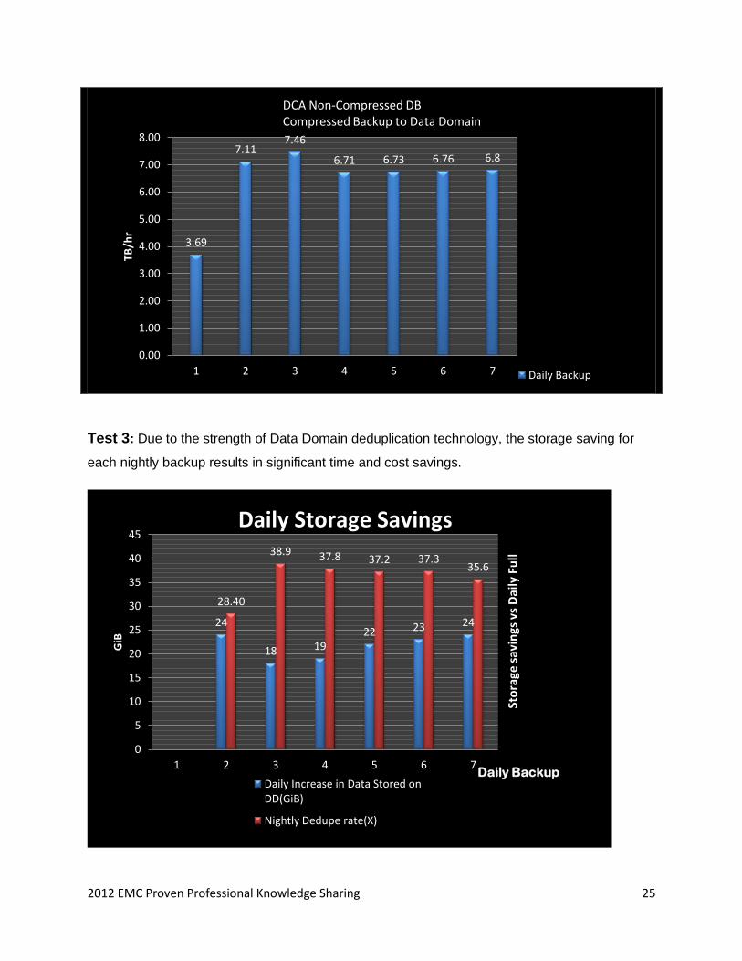
Test 3: Due to the strength of Data Domain deduplication technology, the storage saving for
each nightly backup results in significant time and cost savings.
3.69
7.11 7.46
6.71 6.73 6.76 6.8
0.00
1.00
2.00
3.00
4.00
5.00
6.00
7.00
8.00
1 2 3 4 5 6 7
TB/h
r
Daily Backup
DCA Non-Compressed DB Compressed Backup to Data Domain
24
18 19 22 23 24
28.40
38.9 37.8 37.2 37.3 35.6
0
5
10
15
20
25
30
35
40
45
1 2 3 4 5 6 7
GiB
Daily Increase in Data Stored on DD(GiB)
Nightly Dedupe rate(X)
Daily Storage Savings
Daily Backup
Sto
rage
sav
ings
vs
Dai
ly F
ull
2012 EMC Proven Professional Knowledge Sharing 26
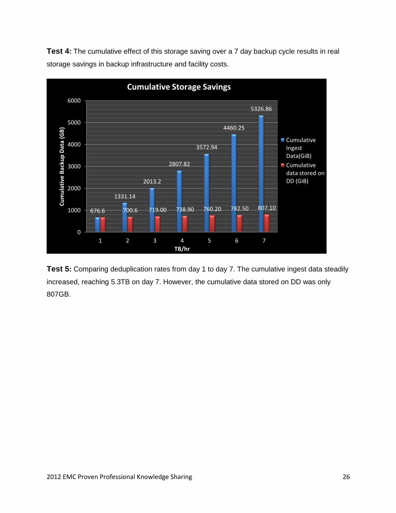
Test 4: The cumulative effect of this storage saving over a 7 day backup cycle results in real
storage savings in backup infrastructure and facility costs.
Test 5: Comparing deduplication rates from day 1 to day 7. The cumulative ingest data steadily
increased, reaching 5.3TB on day 7. However, the cumulative data stored on DD was only
807GB.
676.6
1331.14
2013.2
2807.82
3572.94
4460.25
5326.86
700.6 719.00 738.90 760.20 782.50 807.10
0
1000
2000
3000
4000
5000
6000
1 2 3 4 5 6 7
Cu
mu
lati
ve B
acku
p D
ata
(GB
)
TB/hr
Cumulative Ingest Data(GiB)
Cumulative data stored on DD (GiB)
Cumulative Storage Savings
2012 EMC Proven Professional Knowledge Sharing 27
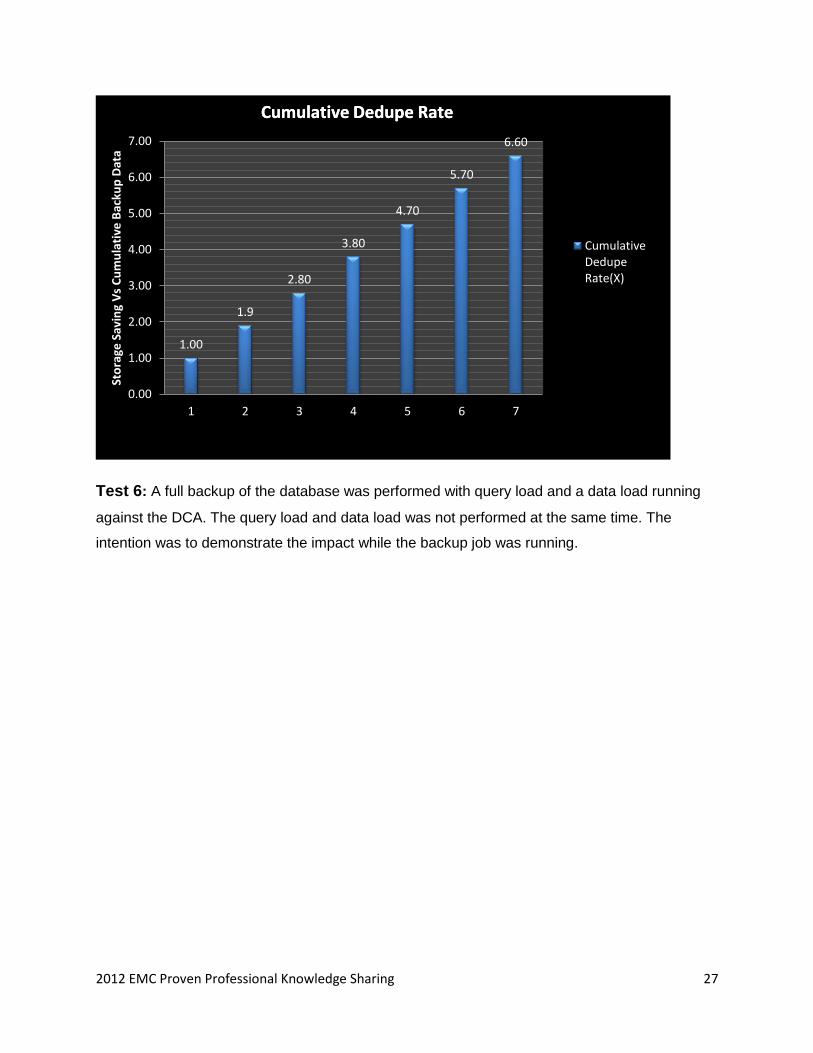
Test 6: A full backup of the database was performed with query load and a data load running
against the DCA. The query load and data load was not performed at the same time. The
intention was to demonstrate the impact while the backup job was running.
1.00
1.9
2.80
3.80
4.70
5.70
6.60
0.00
1.00
2.00
3.00
4.00
5.00
6.00
7.00
1 2 3 4 5 6 7
Sto
rage
Sav
ing
Vs
Cu
mu
lati
ve B
acku
p D
ata
Cumulative Dedupe Rate(X)
Cumulative Dedupe Rate
Cumulative Dedupe Rate
2012 EMC Proven Professional Knowledge Sharing 28
2.03
3.05
0.00
0.50
1.00
1.50
2.00
2.50
3.00
3.50
Daily Backup
Dat
abas
e S
ize
in T
B
Before Data Ingest
After Data Ingest
DCA Database Size Backup with Data Load
17.20
17.93
17.56
16.80
17.00
17.20
17.40
17.60
17.80
18.00
Min
ute
s
No Load
Query Load
Ingest Load
DCA Backup Duration
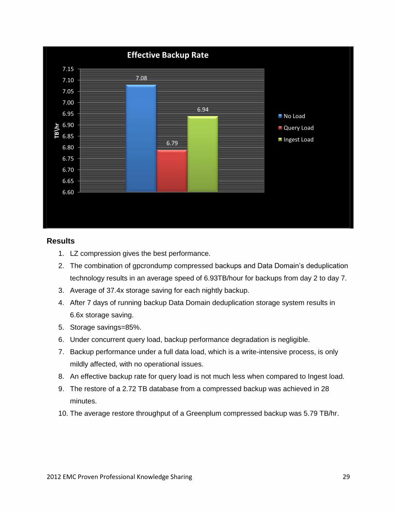
2012 EMC Proven Professional Knowledge Sharing 29
Results
1. LZ compression gives the best performance.
2. The combination of gpcrondump compressed backups and Data Domain’s deduplication
technology results in an average speed of 6.93TB/hour for backups from day 2 to day 7.
3. Average of 37.4x storage saving for each nightly backup.
4. After 7 days of running backup Data Domain deduplication storage system results in
6.6x storage saving.
5. Storage savings=85%.
6. Under concurrent query load, backup performance degradation is negligible.
7. Backup performance under a full data load, which is a write-intensive process, is only
mildly affected, with no operational issues.
8. An effective backup rate for query load is not much less when compared to Ingest load.
9. The restore of a 2.72 TB database from a compressed backup was achieved in 28
minutes.
10. The average restore throughput of a Greenplum compressed backup was 5.79 TB/hr.
7.08
6.79
6.94
6.60
6.65
6.70
6.75
6.80
6.85
6.90
6.95
7.00
7.05
7.10
7.15
TB\h
r
No Load
Query Load
Ingest Load
Effective Backup Rate
2012 EMC Proven Professional Knowledge Sharing 30
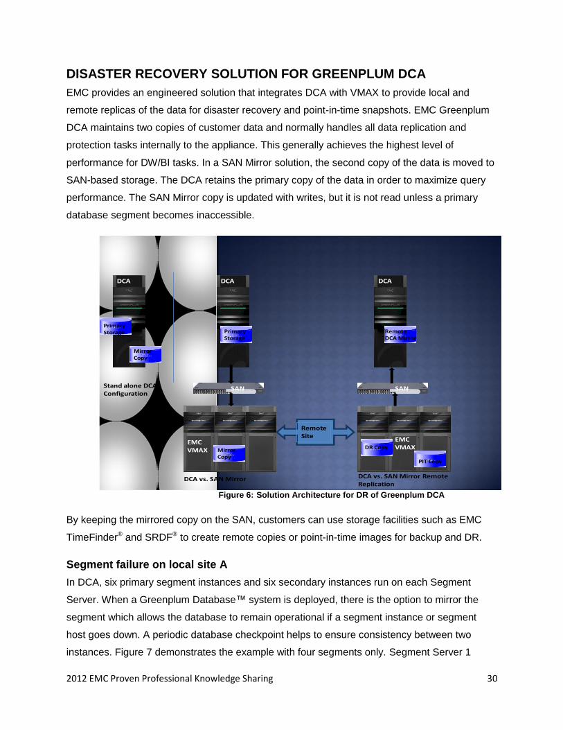
DISASTER RECOVERY SOLUTION FOR GREENPLUM DCA
EMC provides an engineered solution that integrates DCA with VMAX to provide local and
remote replicas of the data for disaster recovery and point-in-time snapshots. EMC Greenplum
DCA maintains two copies of customer data and normally handles all data replication and
protection tasks internally to the appliance. This generally achieves the highest level of
performance for DW/BI tasks. In a SAN Mirror solution, the second copy of the data is moved to
SAN-based storage. The DCA retains the primary copy of the data in order to maximize query
performance. The SAN Mirror copy is updated with writes, but it is not read unless a primary
database segment becomes inaccessible.
Primary Storage Primary
StorageRemote DCA Mirror
Mirror Copy
Mirror Copy
DR Copy
PIT Copy
Remote Site
SANSAN
DCA
EMC VMAX
DCADCA
EMC VMAX
Stand alone DCA Configuration
DCA vs. SAN Mirror DCA vs. SAN Mirror Remote Replication
Figure 6: Solution Architecture for DR of Greenplum DCA
By keeping the mirrored copy on the SAN, customers can use storage facilities such as EMC
TimeFinder® and SRDF® to create remote copies or point-in-time images for backup and DR.
Segment failure on local site A
In DCA, six primary segment instances and six secondary instances run on each Segment
Server. When a Greenplum Database™ system is deployed, there is the option to mirror the
segment which allows the database to remain operational if a segment instance or segment
host goes down. A periodic database checkpoint helps to ensure consistency between two
instances. Figure 7 demonstrates the example with four segments only. Segment Server 1
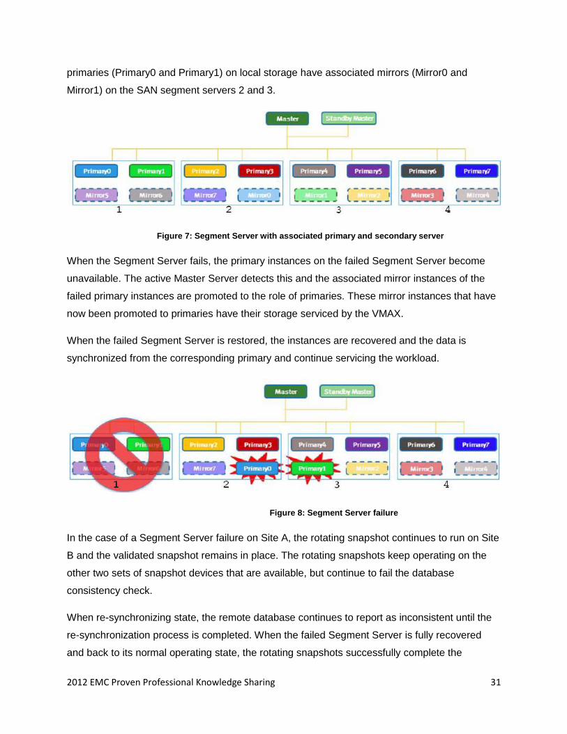
2012 EMC Proven Professional Knowledge Sharing 31
primaries (Primary0 and Primary1) on local storage have associated mirrors (Mirror0 and
Mirror1) on the SAN segment servers 2 and 3.
Figure 7: Segment Server with associated primary and secondary server
When the Segment Server fails, the primary instances on the failed Segment Server become
unavailable. The active Master Server detects this and the associated mirror instances of the
failed primary instances are promoted to the role of primaries. These mirror instances that have
now been promoted to primaries have their storage serviced by the VMAX.
When the failed Segment Server is restored, the instances are recovered and the data is
synchronized from the corresponding primary and continue servicing the workload.
Figure 8: Segment Server failure
In the case of a Segment Server failure on Site A, the rotating snapshot continues to run on Site
B and the validated snapshot remains in place. The rotating snapshots keep operating on the
other two sets of snapshot devices that are available, but continue to fail the database
consistency check.
When re-synchronizing state, the remote database continues to report as inconsistent until the
re-synchronization process is completed. When the failed Segment Server is fully recovered
and back to its normal operating state, the rotating snapshots successfully complete the
2012 EMC Proven Professional Knowledge Sharing 32
consistency check and begin rotating around the three sets of snapshot devices, while again
always keeping a validated snapshot in place.
Allocation and mounting of SAN devices on the DCA
Following are the steps:
1. Create a storage group with one or more devices.
symaccess -sid 1836 create -name sdw1 -type storage devs 034D,035D
2. Create a port group with one or more director or port combinations.
symaccess -sid 1836 create -name vmaxsw1 -type port –dirport
5F:0,6F:0,7F:0,8F:0,9F:0,10F:0,11F:0,12F:0
3. Create an initiator group.
symaccess -sid 1836 create -name sdw1 -type initiator -wwn
100000051e74804b
4. Update to include further WWNs of the FCoE cards contained in the server.
symaccess -sid 1836 -type initiator add -name sdw1 -wwn
100000051e74804c
5. Create a masking view containing the storage group, port group, and initiator group
created previously.
symaccess -sid 1836 create view -name sdw1 -pg vmaxsw1 -ig sdw1 -sg
sdw1
Moving Mirrors
Following are the steps:
1. Remove the standby Master Server (smdw).
gpinitstandby –r
2. Mount the SAN device on the standby Master Server.
mount -o noatime,inode64,allocsize=16m /dev/emcpowera1 /data/master
3. Initialize and Activate standby Master Server.
gpinitstandby -s smdw
gpactivatestandby –f -d /data/master/gpseg-1/
4. Delete the master data directory on the Master Server.
rm –r /data/master/*
5. Mount the SAN device on the Master Server.
mount -o noatime,inode64,allocsize=16m /dev/emcpowera1 /data/master
6. Initialize and Activate mdw as a standby.
gpinitstandby -s mdw
2012 EMC Proven Professional Knowledge Sharing 33
gpactivatestandby –f -d /data/master/gpseg-1/
7. Initialize the standby Master Server (smdw).
gpinitstandby -s smdw
SAN mirror SRDF/S consistency group
Following are the steps:
1. Create the consistency group on the source site.
symcg create sanmirrdf -rdf_consistency -type rdf1
2. Add devices to the group.
symcfg list -rdfg all
symcg -cg sanmirrdf -sid 55 addall dev -rdfg 1
3. Perform initial full synchronization.
symrdf -cg sanmirrdf establish
4. Enable consistency on the devices.
symcg -cg sanmirrdf enable
SAN mirror rotating snapshots
Following are the steps:
1. Check that the snapshot devices to be used contain the required VDEVs.
2. Mask snapshot devices to each Segment Server and Master Server.
3. Scan the SCSI bus.
4. Discover PowerPath.
5. Create the TimeFinder/Snap snapshot.
Symsnap –sid 36 –f snapx create –svp snap
6. Activate the snapshot.
Symsnap –sid 36 –f snapx activate
7. Mount the snapshot.
8. Check the consistency.
9. Unmount the VDEVs from DCA.
2012 EMC Proven Professional Knowledge Sharing 34
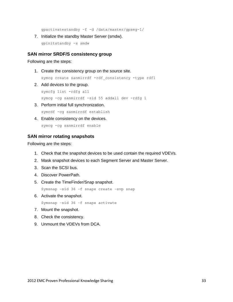
Figure 9: A High-level diagram of SAN Mirror mounts points on VMAX
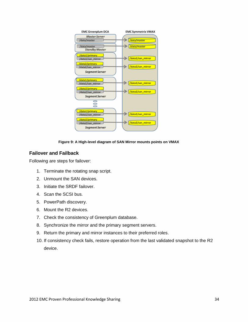
Failover and Failback
Following are steps for failover:
1. Terminate the rotating snap script.
2. Unmount the SAN devices.
3. Initiate the SRDF failover.
4. Scan the SCSI bus.
5. PowerPath discovery.
6. Mount the R2 devices.
7. Check the consistency of Greenplum database.
8. Synchronize the mirror and the primary segment servers.
9. Return the primary and mirror instances to their preferred roles.
10. If consistency check fails, restore operation from the last validated snapshot to the R2
device.
2012 EMC Proven Professional Knowledge Sharing 35
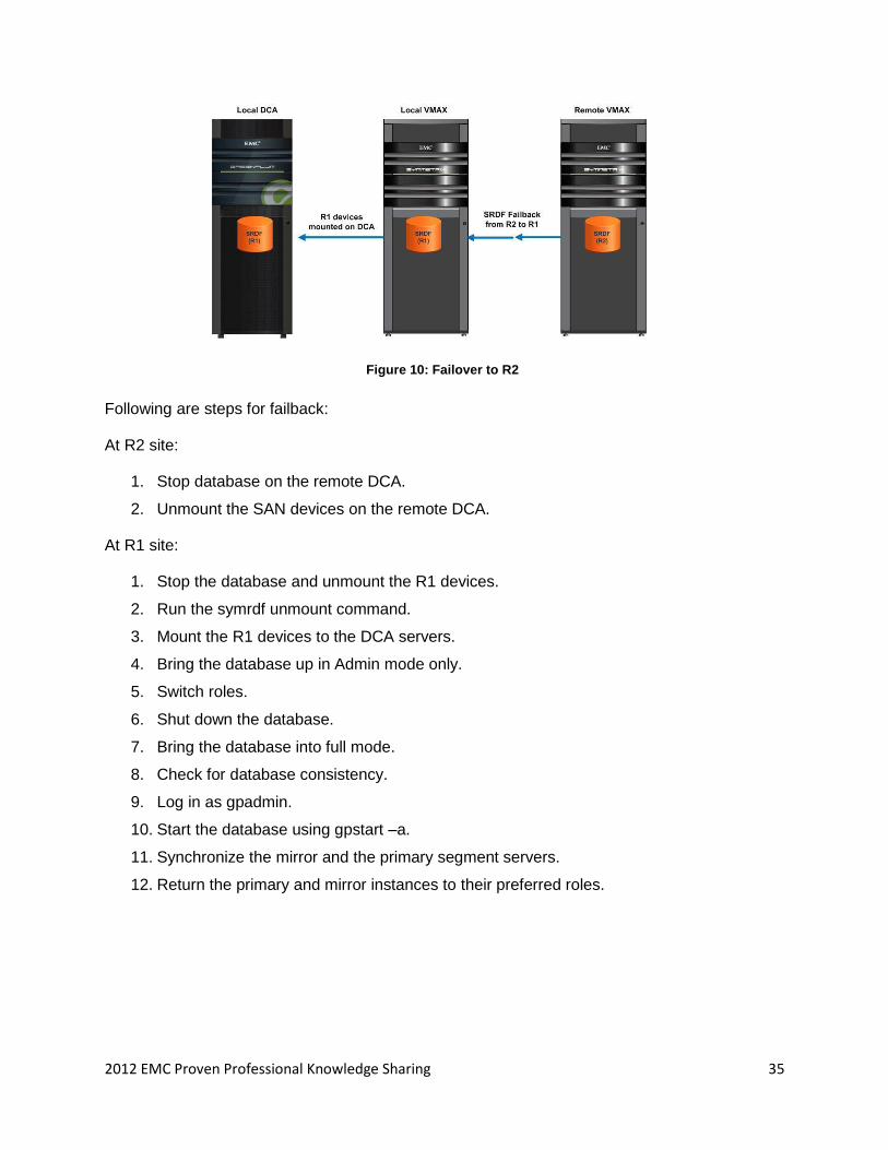
Figure 10: Failover to R2
Following are steps for failback:
At R2 site:
1. Stop database on the remote DCA.
2. Unmount the SAN devices on the remote DCA.
At R1 site:
1. Stop the database and unmount the R1 devices.
2. Run the symrdf unmount command.
3. Mount the R1 devices to the DCA servers.
4. Bring the database up in Admin mode only.
5. Switch roles.
6. Shut down the database.
7. Bring the database into full mode.
8. Check for database consistency.
9. Log in as gpadmin.
10. Start the database using gpstart –a.
11. Synchronize the mirror and the primary segment servers.
12. Return the primary and mirror instances to their preferred roles.
2012 EMC Proven Professional Knowledge Sharing 36
Time Analysis
This analysis is based on 6 TB of database which 4.5 TB on disk.
Activity Required Time
(minutes)
One Snap operation 15
SRDF failover operation 48
SNAP restore operation 180
Failback prep 6
Failback R1 site 30
Total failback time 36
HIGH AVAILABILITY SOLUTION FOR GREENPLUM
In a ―High Availability‖ (HA) configuration, a primary and standby DCA are both connected to
SAN storage. SAN Mirror is used to mirror data between the primary DCA and the SAN storage,
and TimeFinder/Snap is used to take periodic, consistent copies of the production data. Each
snap is verified on the standby DCA.
If the primary DCA becomes unavailable, the most recent copy of the production data can be
mounted by the standby DCA and processing can be quickly resumed. This also provides a
mechanism to recover from data corruption on the primary DCA.
The master and standby master databases in each DCA normally are not mirrored. In the HA
configuration, those databases must be moved from DCA internal disk to SAN disk to ensure
recoverability.
2012 EMC Proven Professional Knowledge Sharing 37
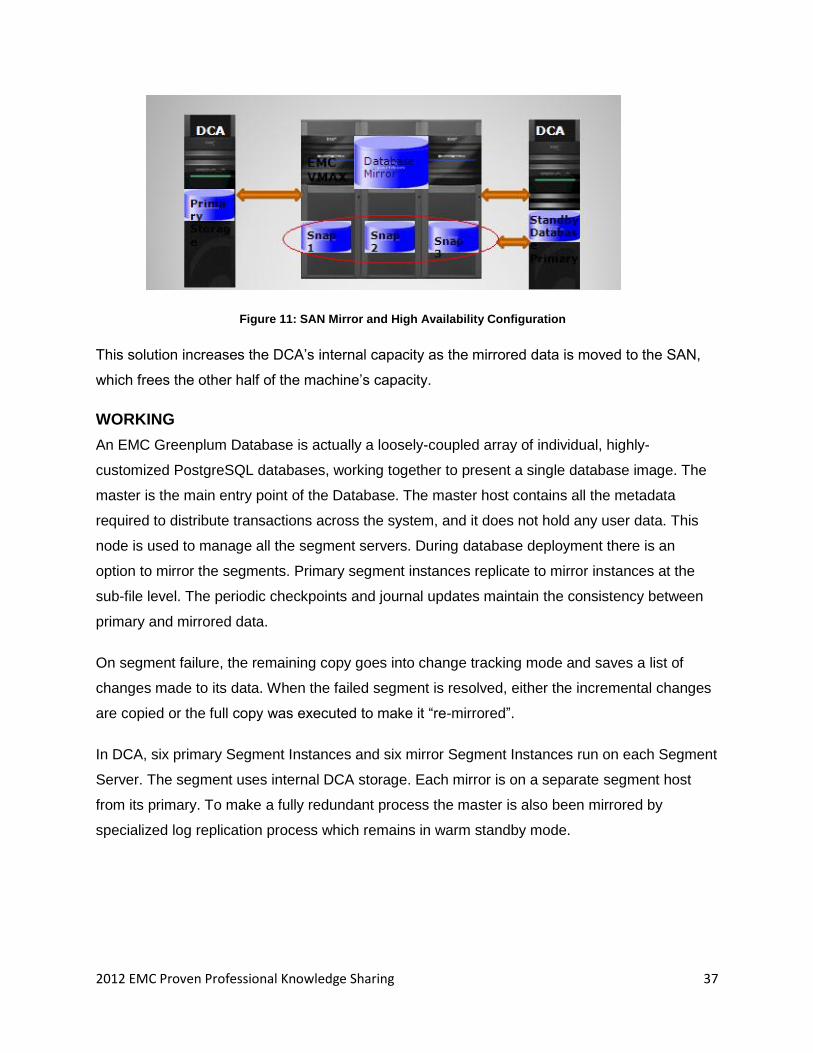
Figure 11: SAN Mirror and High Availability Configuration
This solution increases the DCA’s internal capacity as the mirrored data is moved to the SAN,
which frees the other half of the machine’s capacity.
WORKING
An EMC Greenplum Database is actually a loosely-coupled array of individual, highly-
customized PostgreSQL databases, working together to present a single database image. The
master is the main entry point of the Database. The master host contains all the metadata
required to distribute transactions across the system, and it does not hold any user data. This
node is used to manage all the segment servers. During database deployment there is an
option to mirror the segments. Primary segment instances replicate to mirror instances at the
sub-file level. The periodic checkpoints and journal updates maintain the consistency between
primary and mirrored data.
On segment failure, the remaining copy goes into change tracking mode and saves a list of
changes made to its data. When the failed segment is resolved, either the incremental changes
are copied or the full copy was executed to make it ―re-mirrored‖.
In DCA, six primary Segment Instances and six mirror Segment Instances run on each Segment
Server. The segment uses internal DCA storage. Each mirror is on a separate segment host
from its primary. To make a fully redundant process the master is also been mirrored by
specialized log replication process which remains in warm standby mode.
2012 EMC Proven Professional Knowledge Sharing 38
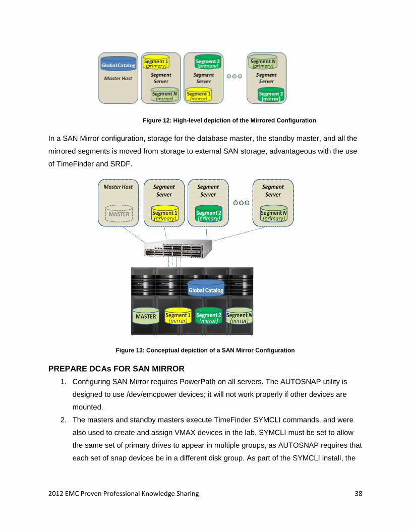
Figure 12: High-level depiction of the Mirrored Configuration
In a SAN Mirror configuration, storage for the database master, the standby master, and all the
mirrored segments is moved from storage to external SAN storage, advantageous with the use
of TimeFinder and SRDF.
Figure 13: Conceptual depiction of a SAN Mirror Configuration
PREPARE DCAs FOR SAN MIRROR
1. Configuring SAN Mirror requires PowerPath on all servers. The AUTOSNAP utility is
designed to use /dev/emcpower devices; it will not work properly if other devices are
mounted.
2. The masters and standby masters execute TimeFinder SYMCLI commands, and were
also used to create and assign VMAX devices in the lab. SYMCLI must be set to allow
the same set of primary drives to appear in multiple groups, as AUTOSNAP requires that
each set of snap devices be in a different disk group. As part of the SYMCLI install, the
2012 EMC Proven Professional Knowledge Sharing 39
following environment variable must be set in the root users .bash_profile or .bashrc to
allow multiple virtual snaps of the same STD device.
SYMCLI_MULTI_VIRTUAL_SNAP=ENABLED
export SYMCLI_MULTI_VIRTUAL_SNAP
3. Take the copy/backup of each master server and segment server that contains a
Brocade 1020 Converged Network Adapter (CNA) for Fibre Channel over Ethernet
(FCoE) connectivity to the SAN.
4. The DCA is configured with two EMC Connectrix® MP-8000B switches. Each switch
contains eight Fibre ports for SAN connection. By default, FCoE is not configured on the
switches, so it must be enabled individually on each of the MP-8000B’s internal Ethernet
ports for SAN connectivity. Each Converged Network Adapter (CNA) will then show up
as a separate initiator to be zoned on the SAN. To initially configure the MP-8000B
switches with the scripts, simply execute it from the master:
CONFIGURE THE VMAX FOR SAN MIRROR ATTACHMENT
1. Create masters, standby volumes for DCA masters, and segment mirror
databases: Each Segment Server supports two 2.7 TB database LUNs. In normal
operation, one of these LUNs is used for a mirror database instance, and the other is
used for a primary instance. In a SAN Mirror environment, the mirror LUN can be used
for additional production data. The Master Server and Standby Server each support a
single, 2.1 TB LUN. To implement SAN Mirror, LUNs of the same size should be created
on the VMAX and made visible to the servers. Volumes can be created using the
symconfigure CLI command.
2. Create snap volumes for standby DCA: Snap provide a flexible mechanism to make
instant, consistent copies of the database volumes. As hosts write data, the original data
is preserved in a ―SAVE‖ pool and pointers for the snap volumes are changed to point to
this preserved data. Only changed data is tracked by TimeFinder/Snap. The command
below creates the virtual devices once the SAVE pool has been created.
2012 EMC Proven Professional Knowledge Sharing 40
3. Create disk groups for SAN Mirror: Once the volumes are created, they should be
added to Symmetrix disk groups. Each set of Snap devices must reside in a different
disk group. The group should contain the same primary devices, but a different set of
Snap devices.
4. Assign volumes to DCA and standby DCA: Once the volumes are created, they are
assigned using the symaccess command. The new volumes should be put into storage
groups, one per server. The CNA WWN that were captured earlier can be used to create
the initiator groups. Volume 0755 is a production volume; volume 082D is a virtual
device (TimeFinder/Snap). VDEVs should be assigned both to the production host and
to the standby DCA.
CONFIGURE THE DCAs TO USE VMAX DISK
Once the devices are created and assigned to the DCA, they can be recognized by the servers
and you can build file systems and mount them on the primary DCA. The dca_setup script
assumes that the primary internal RAID volumes are mounted on /data1 and /data2. Beneath
those directories, the SAN Mirror volumes will be mounted on the ./san_mirror sub-directory.
Follow the steps below to configure DCA to use VMAX disk:
1. Download the ―inq.linux‖ command from EMC. This command is used to probe the SCSI
bus and report which devices it sees.
2. Download PYYAML module from http://pyyaml.org. The AUTOSNAP utility uses a
configuration file written in the YAML markup language. It needs a Python module to
parse the data.
3. Reboot the servers.
4. Verify all the disks are recognized by the servers.
2012 EMC Proven Professional Knowledge Sharing 41
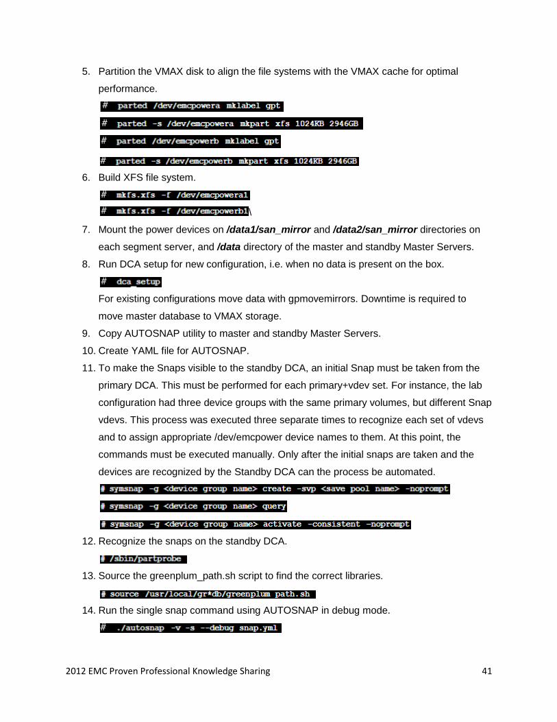
5. Partition the VMAX disk to align the file systems with the VMAX cache for optimal
performance.
6. Build XFS file system.
\
7. Mount the power devices on /data1/san_mirror and /data2/san_mirror directories on
each segment server, and /data directory of the master and standby Master Servers.
8. Run DCA setup for new configuration, i.e. when no data is present on the box.
For existing configurations move data with gpmovemirrors. Downtime is required to
move master database to VMAX storage.
9. Copy AUTOSNAP utility to master and standby Master Servers.
10. Create YAML file for AUTOSNAP.
11. To make the Snaps visible to the standby DCA, an initial Snap must be taken from the
primary DCA. This must be performed for each primary+vdev set. For instance, the lab
configuration had three device groups with the same primary volumes, but different Snap
vdevs. This process was executed three separate times to recognize each set of vdevs
and to assign appropriate /dev/emcpower device names to them. At this point, the
commands must be executed manually. Only after the initial snaps are taken and the
devices are recognized by the Standby DCA can the process be automated.
12. Recognize the snaps on the standby DCA.
13. Source the greenplum_path.sh script to find the correct libraries.
14. Run the single snap command using AUTOSNAP in debug mode.
2012 EMC Proven Professional Knowledge Sharing 42
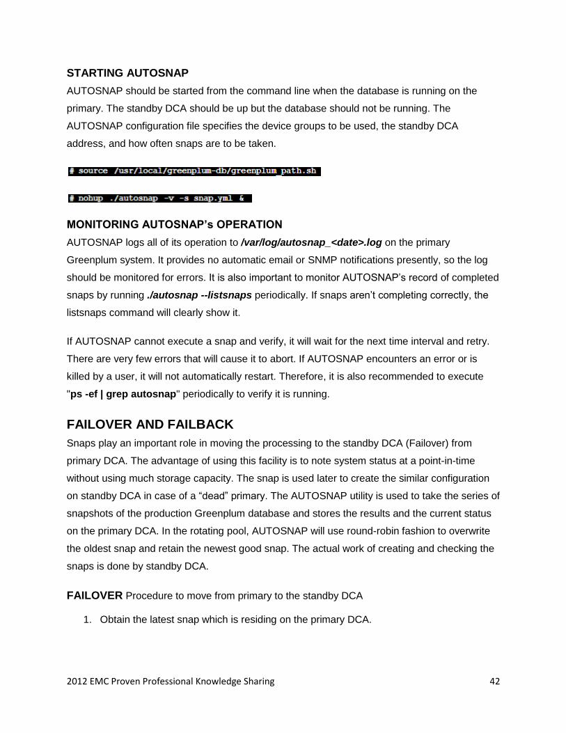
STARTING AUTOSNAP
AUTOSNAP should be started from the command line when the database is running on the
primary. The standby DCA should be up but the database should not be running. The
AUTOSNAP configuration file specifies the device groups to be used, the standby DCA
address, and how often snaps are to be taken.
MONITORING AUTOSNAP’s OPERATION
AUTOSNAP logs all of its operation to /var/log/autosnap_<date>.log on the primary
Greenplum system. It provides no automatic email or SNMP notifications presently, so the log
should be monitored for errors. It is also important to monitor AUTOSNAP’s record of completed
snaps by running ./autosnap --listsnaps periodically. If snaps aren’t completing correctly, the
listsnaps command will clearly show it.
If AUTOSNAP cannot execute a snap and verify, it will wait for the next time interval and retry.
There are very few errors that will cause it to abort. If AUTOSNAP encounters an error or is
killed by a user, it will not automatically restart. Therefore, it is also recommended to execute
"ps -ef | grep autosnap" periodically to verify it is running.
FAILOVER AND FAILBACK
Snaps play an important role in moving the processing to the standby DCA (Failover) from
primary DCA. The advantage of using this facility is to note system status at a point-in-time
without using much storage capacity. The snap is used later to create the similar configuration
on standby DCA in case of a ―dead‖ primary. The AUTOSNAP utility is used to take the series of
snapshots of the production Greenplum database and stores the results and the current status
on the primary DCA. In the rotating pool, AUTOSNAP will use round-robin fashion to overwrite
the oldest snap and retain the newest good snap. The actual work of creating and checking the
snaps is done by standby DCA.
FAILOVER Procedure to move from primary to the standby DCA
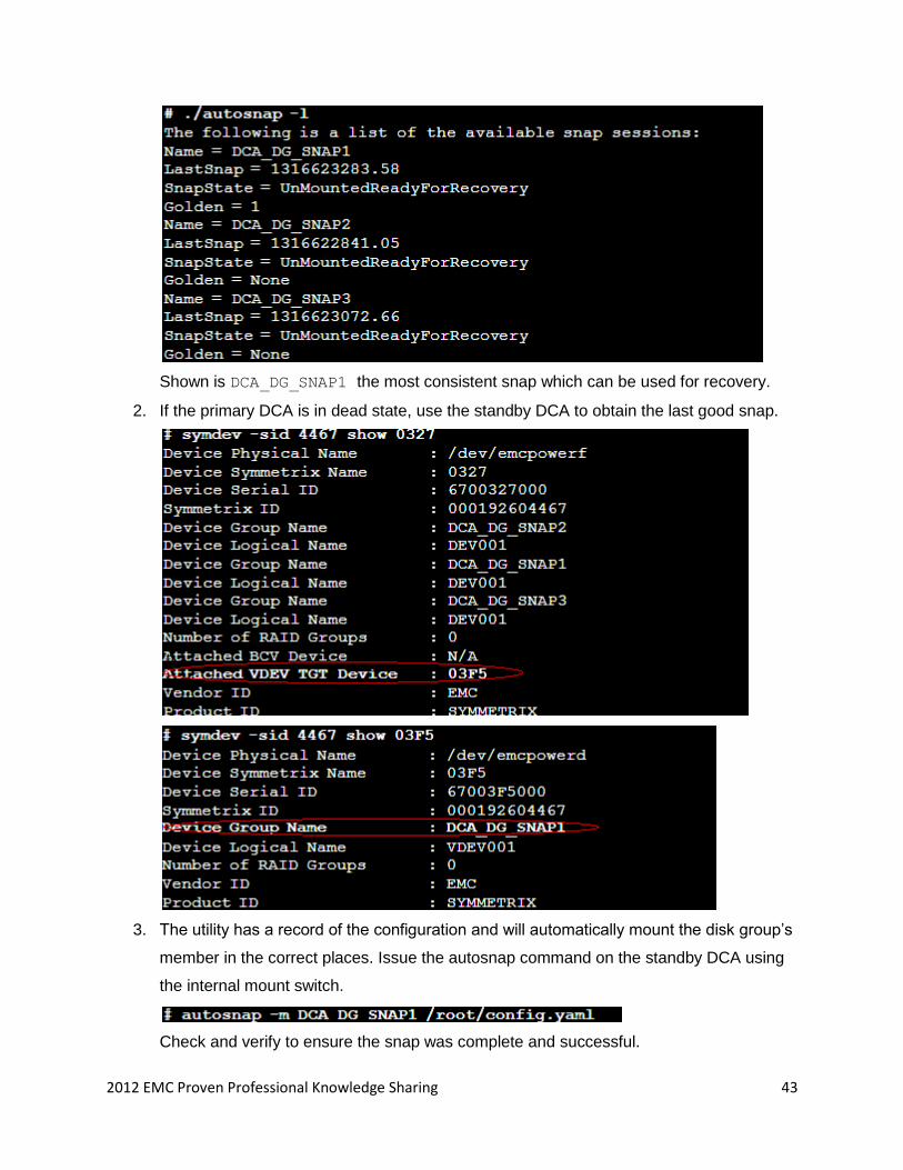
1. Obtain the latest snap which is residing on the primary DCA.
2012 EMC Proven Professional Knowledge Sharing 43
Shown is DCA_DG_SNAP1 the most consistent snap which can be used for recovery.
2. If the primary DCA is in dead state, use the standby DCA to obtain the last good snap.
3. The utility has a record of the configuration and will automatically mount the disk group’s
member in the correct places. Issue the autosnap command on the standby DCA using
the internal mount switch.
Check and verify to ensure the snap was complete and successful.
2012 EMC Proven Professional Knowledge Sharing 44
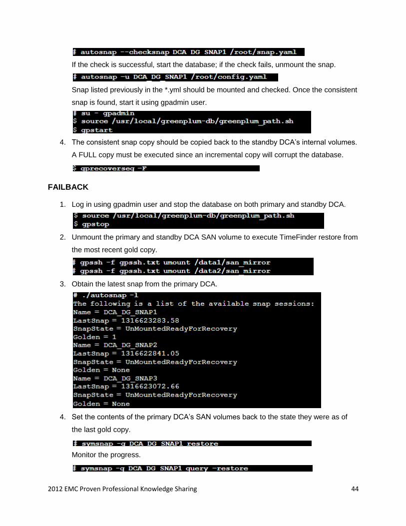
If the check is successful, start the database; if the check fails, unmount the snap.
Snap listed previously in the *.yml should be mounted and checked. Once the consistent
snap is found, start it using gpadmin user.
4. The consistent snap copy should be copied back to the standby DCA’s internal volumes.
A FULL copy must be executed since an incremental copy will corrupt the database.
FAILBACK
1. Log in using gpadmin user and stop the database on both primary and standby DCA.
2. Unmount the primary and standby DCA SAN volume to execute TimeFinder restore from
the most recent gold copy.
3. Obtain the latest snap from the primary DCA.
4. Set the contents of the primary DCA’s SAN volumes back to the state they were as of
the last gold copy.
Monitor the progress.
2012 EMC Proven Professional Knowledge Sharing 45
Terminate the snap session when all devices are in a restored state.
5. Remount the volume on the primary DCA.
6. The database has two conflicting database images on disk. The corrupted image is on
the primary DCA’s internal disk and the restored image is on the SAN Mirror disk. By
default, the DCA will use the internal disk, which is the corrupted image. We will make
the DCA read from the SAN Mirror copies. Start the database in maintenance mode to
allow configuration changes without changing user data using gpadmin login.
7. Connect to the database in utility mode.
8. Verify that the primary segments—the segments whose preferred_role is "p"—are set to
a role of ’m’ (mirror) and a status of ’d’ (down) and that the mirror segments are set to a
role of ’p’ (primary), a mode of ’c’ (change tracking), and a status of ’u’ (up).
9. Swap the roles.
10. Then, set the primary volumes to a role of ’mirror’ and a status of ’down’.
11. Verify the configuration is correct.
12. Exit psql session.
13. Stop the database and remove it from maintenance mode.
14. Restart the database normally.
2012 EMC Proven Professional Knowledge Sharing 46
15. Copy the SAN Mirror volumes back to the DCA’s primary volume to ensure full
redundancy and performance. Execute the full copy.
CASE STUDY
Case studies are one of the most important parts of technical analysis. A case study is an
intensive analysis of an individual unit stressing development factors in relation to context. Here
we will study and analyze a case where Greenplum DCA made the difference.
Tagged is a social network for meeting new people. While other social networks are for staying
in touch with people you already know, Tagged enables social discovery, group interests, and
connecting via shared interests. Based in San Francisco, California, Tagged consistently ranked
among the largest social networks.
Challenges: Growth of new connections and a rapid increase in data volumes were making the
business complex. Meeting the expectation of generating a response in minutes under complex
and targeted queries, making quicker decisions to drive out traffic, and ensuring high quality use
of features are just a few of the key challenge.
“Our data warehouse took a
few hours or even a day to
process straightforward
questions from our business
analysts. In a business that
changes as quickly as ours,
that’s way too long,” says
Johann Schleier-Smith,
tagged co-founder and CTO.
Existing Product: Oracle-based data mart.
Challenges
To analyze complete datasets (database in PB), not
samples or summaries.
Perform simple and complex enquires for intraday
analysis and response.
Predictive and advanced analytics.
Keep pace with rapid growth of database and
complexity.
Solution
EMC Greenplum DCA
EMC Professional
report.
Benefits
Ultra-fast analysis; scalable, advanced, and predictive.
Users look much deeper.
50% increase in time by members.
2012 EMC Proven Professional Knowledge Sharing 47
Business Impact
The company can continuously load data, execute analytics in real time, and generate
more detailed reports.
Collaborate with gaming partners to make the social games more fun, so that users want
to keep playing.
More effectively crunch data from 70 million user accounts.
Competitive Advantage
Members are giving more time to the site, increasing ad revenue.
Members are exposed to more ads and opportunities to spend Tagged Gold, virtual
currency, which drives business forward.
Tagged is forming 10,000 users daily.
How Business was Impacted?
The number of users grew from 20 million to 100 million.
3 PB of data was downloaded per month by users.
25 million visitors visit the site every month.
Converting Big Data into Big Business: Greenplum’s technology serves as a foundation for
Tagged to unlock the business value inherent in ―big data‖. They now ship new code every day
compared to their previous weekly release cycle.
“Faster time to market is essential because it helps us strengthen our competitive position. Greenplum
delivers the insights we need to make better decisions that drive the business forward.”
JOHANN SCHLEIER-SMITH, CO-FOUNDER AND CTO
CONCLUSION
―If data is an asset, then big data is a big asset‖
EMC Greenplum DCA is the sweet spot for the Big Data industry. This powerful appliance
delivers the fastest data loading and best price/performance in the industry. It is a complete
solution which enables data protection, business continuity, and faster performance.
2012 EMC Proven Professional Knowledge Sharing 48
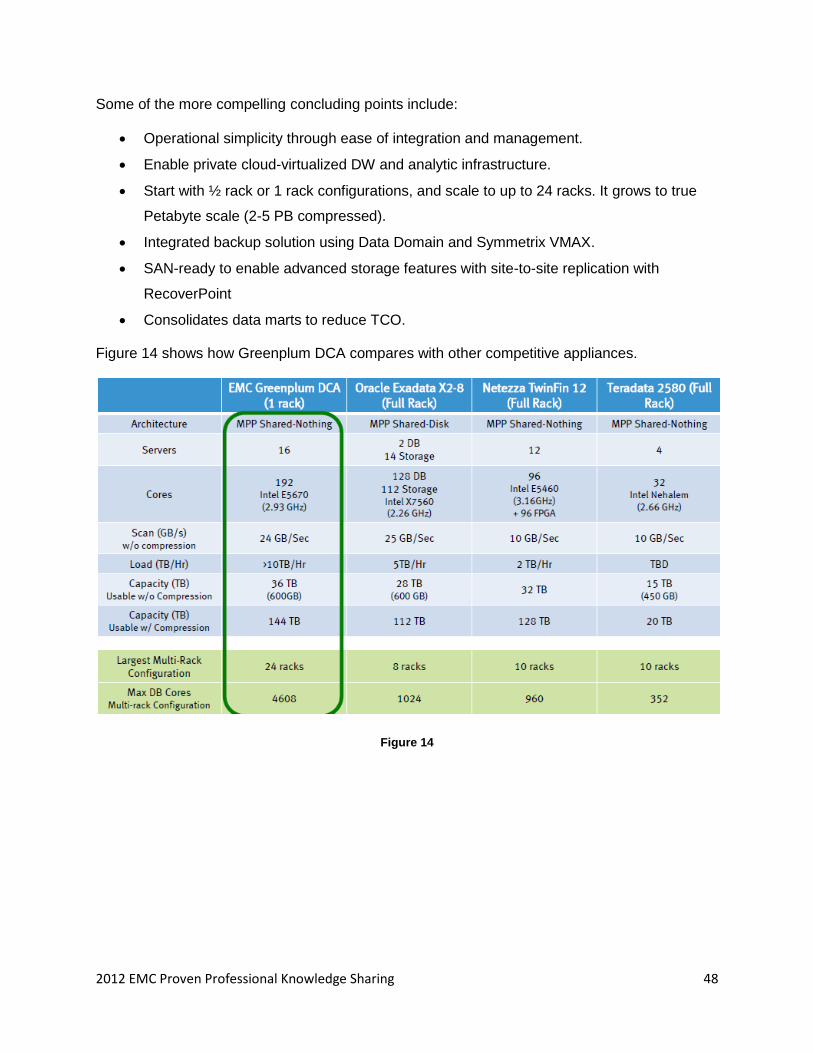
Some of the more compelling concluding points include:
Operational simplicity through ease of integration and management.
Enable private cloud-virtualized DW and analytic infrastructure.
Start with ½ rack or 1 rack configurations, and scale to up to 24 racks. It grows to true
Petabyte scale (2-5 PB compressed).
Integrated backup solution using Data Domain and Symmetrix VMAX.
SAN-ready to enable advanced storage features with site-to-site replication with
RecoverPoint
Consolidates data marts to reduce TCO.
Figure 14 shows how Greenplum DCA compares with other competitive appliances.
Figure 14
2012 EMC Proven Professional Knowledge Sharing 49
REFERENCE
1. Configuring EMC Greenplum Data Computing Appliance using SAN Mirror and EMC
Symmetrix VMAX for Disaster Recovery – Configuration guide by EMC Corporation.
2. Enhancing EMC Greenplum High Avaliability with SAN Mirror and EMC Symmetrix
VMAX – Configuration guide by EMC Corporation.
3. Tagged Case study – http://www.greenplum.com/customers/tagged
4. Whitepaper: Backup and Recovery of the EMC Greenplum Data Computing Appliance
using EMC Data Domain – An architecture Overview.
5. Greenplum Database 4.2 – Administration Guide, EMC Corporation.
6. Big Data Appliance July 23, TDWI by R Sathyanarayana.
EMC believes the information in this publication is accurate as of its publication date. The
information is subject to change without notice.
THE INFORMATION IN THIS PUBLICATION IS PROVIDED ―AS IS.‖ EMC CORPORATION
MAKES NO RESPRESENTATIONS OR WARRANTIES OF ANY KIND WITH RESPECT TO
THE INFORMATION IN THIS PUBLICATION, AND SPECIFICALLY DISCLAIMS IMPLIED
WARRANTIES OF MERCHANTABILITY OR FITNESS FOR A PARTICULAR PURPOSE.
Use, copying, and distribution of any EMC software described in this publication requires an
applicable software license.


