Embed Size (px)
Citation preview

arX
iv:2
110.
1519
8v3
[ph
ysic
s.po
p-ph
] 2
1 D
ec 2
021
Guided Self Replicating Factory for Colonization ofSolar System
Mikhail V. ShubovUniversity of MA Lowell
One University Ave,
Lowell, MA 01854
E-mail: [email protected]
Abstract
In this work, we present the concept of guided self-replicating factory (GSFR).
This factory would be established as a colony on the Moon, Mercury, Mars,
or Asteroid Belt. GSFR would grow by using in situ materials in order to
manufacture machines. The time it takes for GSFR to double it’s mass and
electric power output is called a doubling period. After about 50 doubling
periods, GSFR would become a Dyson Sphere civilization, which can house
1016 people, 1019 tons of structure and machinery and have a gross electric
power of 3 · 1024 W . GSRF would contain four parts. The electric power
station would generate electricity for all other parts. Material production
system would gather ores or native metals and produce metals, plastic, and
propellant. Material shaping and assembly system would shape metal and
plastic into details. These details would be assembled into machines. These
machines would be added to all four parts of GSFR. The space transporta-
tion system would use fuel manufactured in situ manufactured in situ in
order to facilitate transportation of machinery and astronauts from Lower
Earth Orbit (LEO) to the colony. During later stages, the space transporta-
tion system would also use spaceships fully or partially manufactured from
space colony material.
1 Introduction
Space Colonization holds the promise of opening almost unlimited resources and ushering the
New Era for Human Civilization. The resources contained within the Solar System can support a
civilization much more populous and advanced than the modern one. A civilization encompassing
the whole Solar System would be able to support a population of 10 quadrillion(
1016)
people
at material living standards vastly superior to those in USA 2020 [1]. Colonization of the Solar
System will be an extraordinary important step for Humankind.
1
The first resource widely available in the Solar System is energy. It is the most essential re-
source for modern industry and civilization [2, 3]. The solar energy in space is almost limitless –
the Sun’s thermal power is 3.86 · 1026 W [4, p.14-2]. A future civilization, which would harvest
20% of that power with 25% efficiency, will have energy production of 1.7 · 1026 kWh/year. The
current global energy production in all forms is 7 · 1013 kWh/year [5] – 2.4 trillion times less.
The scheme for harvesting this energy is called the Dyson Sphere [6]. The Dyson Sphere would
consist of a multitude of space habitats orbiting the Sun. Each habitat would be equipped with
photovoltaic or solar thermal electric power station.
The second resource widely available in the Solar System is material. The Asteroid Belt con-
tains about 3 Exatons of material composed of metal silicates, carbon compounds, water, and pure
metals [7]. An Exaton, is a unit of mass equivalent to 1018 tons. Most asteroids are of a car-
bonaceous type [8]. Carbon is very useful for production of food for space travelers, production of
fuel for propulsion within space, and for production of plastics for space habitat structures. High
quality steel is also an abundant resource in space, e.g., asteroid 16 Psyche contains 1016 tons
of nickel-rich steel [9]. Additional material for comfortable habitats can be obtained from Mer-
cury, satellites of gas giant planets, and Kuiper Belt objects [10]. Kuiper Belt contains about 120
Exatons of material – mainly water, ammonia, and carbon compounds [11]. Planet Mercury con-
tains 330 Exatons of material composed of metal silicates, carbon compounds, and pure metals [4,
p.14-2]. Satellites of Jupiter and Saturn contain at least 10 Exatons of water and hydrocarbons [4,
p.14-4]. Given the data above, it is possible to construct a total habitat space of 100 Exatons.
This is enough to provide 10,000 tons of structure for each of 10 quadrillion inhabitants of
the Solar System. The mass of modern luxury cruise liners can be approximated by multiplying
85 tons by the number of cabins [12]. Space habitats will have about 120 times more structural
material per inhabitant, and habitat material will be more advanced. This will provide a material
standard of living suitable for Solar System Civilization.
The colonization of the Solar System was originally proposed by Konstantin Tsiolkovsky in
1903 [13]. Technology necessary for space colonization appeared only in the early 1970s. During
the 1970s, many detailed studies and projects for space colonization have been published [14, 15].
Due to very high initial costs, the projects of space colonization developed in the 1970s and 1980s
did not become a reality. Humankind may have to wait many decades before space colonization
becomes a reality. But even if the projects, which have been planned for 1980s, will only be
realized during the 2080s, it is still a great step forward for Humankind.
In the author’s opinion, the colonization of the Solar System will begin with partial colonization
of the Moon and colonization of Mercury. The Lunar outpost will produce hydrogen propellant for
spaceships going to Mercury. The colony on Mercury will launch material into Mercury’s orbit and
construct Space Trams. A Space Tram is a space transportation equipped with an electric power
station and an electric thruster. Space Trams would open the gates toward colonization of the Solar
2
System.
The colonization of the Solar System is assumed to contain at least four stages. During the First
Stage, the Moon, Mercury, Mars, the Asteroid Belt, and possibly outer planet satellites will be thor-
oughly explored by astronauts as well as robotic probes. On Earth, further stages of colonization
will be engineered in great detail.
During the Second Stage, a one or more colony would be set up and technology for utilization
of in situ resources will be delivered there. We expect that the first such colony is set up on the
Moon. Later colonies may be set up on Mercury, the Asteroid Belt, and/or on Mars. Electric power
generation, ore refining and smelting, chemical, and metallurgical plants will be set up. Material
produced in these plants will enable the colony to expand existing plants and to built new ones.
The new plants will still need sophisticated equipment delivered from Earth. The first two stages
of Solar System colonization will be costly [16], but they should soon turn into the next one.
During the Third Stage, almost all machines will be manufactured from materials available in
situ, while some high technology will still be delivered from the Earth [17]. During that stage, one
or more colonies around the Solar System will start manufacturing ships for transportation around
the Solar System. Third stage will be marked by exponential growth of colonies.
During the Fourth Stage, almost all machinery will be manufactured on colonies around the
Solar System. Exponential growth will continue. Colonies throughout the Solar System will be
ready to accept numerous inhabitants. Vehicles for transportation around the Solar System will be
manufactured in large numbers. They will open the gates to colonization of the Outer Solar System.
At this point, we are unable to foresee all the further stages in the growth of space colonies.
2 Guided Self Replicating Factory (GSRF) concept
2.1 Self replicating factories (SRF)
The concept of self-replicating factory (SRF) to be used for Space Colonization has been studied
since 1940s [18, 19, 20]. Some works on self replicating machines are purely or mostly theoretical
[21, 22]. Self-replicating lunar factories have been designed by university professors [23, 24].
Advanced projects consider self-replicators on nanoscale [25].
No SRF has been built so far. Such a system may not be feasible for a long time. At this point,
we have no way of knowing how long it will take to construct SRF. It is unknown how long it will
take to surmount known difficulties. Unforeseen difficulties may arise.
Many works of Science Fiction written between XVIIth and XIXth centuries contain concepts
which are technically feasible, but have been implemented yet [26, 27]. Travel to the Moon by a
multi-stage rocket has first been described by Cyrano de Bergerac in 1655 [26]. Civilization based
on Solar Power and fully mechanized production was envisioned and described by John Etzler in
3
the 1830s and 1840s [28, 29]. Now we can appreciate the technical difficulties which had or still
have to be surmounted in order for ideas formulated in the previous centuries to become reality.
It is possible that technology needed to build an SRF are far more advanced than anything we
can imagine in 2021. Possibly, an SRF will be built only after the colonization of Solar System.
Such factory may need the work of trillions experts and resources of Solar System Civilization,
far exceeding current capabilities. It may also need technologies which will be developed only in
the coming centuries. Even in this case, SRF would be very useful in colonization of Milky Way
Galaxy [30, 31].
2.2 Guided self replicating factories (GSRF)
We are proposing a much simpler system, called guided self-replicating factory (GSRF). This
system produces electric energy. It also produces almost all parts necessary for its growth out of
in situ resources. These resources may be regolith on the surface of the Moon or Mercury, surface
resources of Mars, or resources of the Asteroid Belt. GSRF grows exponentially. Bootstrapping
systems for space colonization have been suggested in the past [32, 33].
Unlike SRF, GSRF is not completely autonomous. A GSRF on Mercury, Mars, or Asteroid belt
is operated by a team of astronauts. A GSRF on the Moon is likely to be operated remotely from
many computers located on Earth. As GSRF grows, the needed team of astronauts grows along
with it. GSRF manufactures simple machines and details. It obtains most complicated machinery
from Earth. At the later stages of growth, GSRF also produces space transports, which facilitate
delivery of materials and astronauts.
The time it takes GSRF to double is called doubling time. The doubling of GSRF does not
mean that it produces an exact replica of itself. Doubling means that GSRF doubles its mass,
energy production, and machine production.
Two factors determine the usefulness of GSRF for space colonization. First is the seed mass –
the minimum mass of the factory which can produce all details and machines for growth. Design-
ing GSRF with minimum seed mass is a complicated engineering task. The second factor is the
doubling time. A GSRF with doubling time of many years will grow very slowly. A GSRF with
doubling time of under one year can develop into a large colony within two decades. This colony
would be a key though which the Humankind can start colonizing the Solar System.
Bootstrapping systems in which production of a resource was used to produce tools which
produced more of the same resource are not new. Discovery of Bronze and ushering of the Bronze
Age enabled metalworkers to produce bronze hatchets and pickaxes. Bronze pickaxes were used
to obtain ore more efficiently than horn pickaxes. Bronze hatchets were used to cut wood more
efficiently than stone axes. Wood was needed to smelt copper and tin ore [34]. During the Industrial
Revolution, coal was extracted by pneumatic hammers. These hammers were powered by steam
engines burning a small fraction of the coal produced [35].
4
2.3 Major components of GSRF – overview
GSRF contains four major components: an electric power station, a material production system, a
material shaping and assembly system, and a space transportation system. Electric power station
produces electric energy. A power station consisting of an array of photoelectric cells would be
optimal for a lunar colony or a near-Earth spacecraft. Another type of power station consists of a
heat engine and an electric generator. A heat engine using nuclear energy is optimal for stations
on Mars and Asteroid Belt. A heat engine using concentrated solar energy is optimal for Mercury.
Thermonuclear fusion can be an important source of energy one day, but we should not count on
technology which has not been developed so far.
Material production system turns the regolith of Mercury, Moon, Mars, or an asteroid into
useful metals, polymers, propellant, and other chemicals. First, regolith, ores, and ice deposits
are extracted by mining robots. Second, the ores are concentrated. Third, useful elements are
extracted from the ores. Steel, chromium, manganese, and titanium are obtained by smelting ores.
Aluminum, magnesium, calcium, sodium, and potassium are obtained by electrolysis. Oxygen
and hydrogen are obtained by water electrolysis. Other chemicals such as methane propellant and
rubber for insulation may also be produced.
Material shaping and assembly system fabricates details and machines out of metals and
polymers. This system is most complicated, and it has most subcomponents. The design of such
system may be a task requiring hundreds of thousands of expert-years of theoretical and experi-
mental work.
Space transportation system would assist with delivery of astronauts and equipment from
Earth’s orbit to the Moon and different destinations within the Solar System. Most likely, trans-
portation from the Low Earth Orbit (LEO) to deep space would be provided by propellant man-
ufactured on the Moon and delivered to Low Earth Orbit. Transportation from near-Earth deep
space to other destinations within the Solar System would be provided by spaceships powered by
ion thrust engines.
3 Electric Energy Generation
In this Subsection, we describe a possible power station in the Solar System. We also calculate
its specific mass – the mass of structural material and machinery necessary to produce a unit of
power.
5
3.1 Possible electric power plants
3.1.1 Thermionic Conversion
“Thermionic energy conversion (TEC) is the direct conversion of heat into electricity by the mech-
anism of thermionic emission, the spontaneous ejection of hot electrons from a surface" [36, p.1].
Electrons are emitted by a hotter plate and absorbed by a colder plate, creating an electromotive
force. Efficiencies are generally 5% to 10% [36]. One advantage of thermionic energy conver-
sion is that it can use solar radiation concentrated up to 1,000 times or nuclear energy from a very
high temperature heat source. Even with low efficiency, the power output of thermionic cells can
be up to 100,000 W/m2 [37, p.73]. Several experimental studies have been performed for using
solar-heated thermionic electricity for space propulsion [38, p.2237].
Photon-enhanced thermionic emission (PETE) is a new technology which may greatly enhance
efficiency of very concentrated solar power if it turns out to work as expected [39]. PETE may
convert 1,000 times concentrated solar energy to electricity at an efficiency of 23% [40]. PETE
may work very well for temperatures of 500oC to 1,000oC – perfect for concentrated sunlight
on Mercury [41]. Silicon PETE at irradiation of 1,000 suns and 600oC temperature should have
efficiency of 30% [42]. The future of PETE technology is uncertain. No working PETE converters
have been produced so far. Some researchers claim that PETE are likely to have efficiency below
8% [43].
3.1.2 Heat engine power plants
A motive power plant consists of a heat engine and an electric generator. An electric generator
converts mechanical energy into electrical energy. Electrical generators have high efficiency –
by 1911, alternating-current generators had efficiencies of 94% to 96% [44, p.43]. Generators
assembled from in situ material on Moon, Mercury, Mars, and Asteroid Belt should be about
as efficient. Electric generators also have high specific power. Modern electric generators have
specific power of up to 13 kW/kg [45, p.383]. Most power plant generators have much lower
specific power of 0.5 kW/kg [46, p.21]. This specific power converts to specific mass of 2 kg/kW .
A heat engine converts thermal energy into mechanical energy. A heat engine has three com-
ponents: a heat source, a motor, and a heat sink. In most of the Solar System, nuclear power is
the optimal heat source. On Mercury, and possibly on the Moon, the optimal heat source is con-
centrated solar energy. Concentrated solar power thermal electric stations have been designed and
built on Earth [47, 48, 49]. Optimal heat source temperature for a space power plant is 800oC to
900oC [50, p.5].
The first type of motor is a potassium vapor turbine. These turbines have been constructed and
rigorously tested. General Electric tested one potassium turbine for 5,000 hours. The turbine had
blade tip speed of 250 m/s, potassium vapor inlet temperature of 816 oC, and exhaust temperature
6
of 671 oC. Turbine blades experienced negligible erosion during the test [50, p.5]. In order to settle
on the best design, much more detailed studies are necessary.
The second type of motor consists of Stirling engine. A 10 MW space nuclear power station
using a potassium turbine should have a specific mass of 11 kg/kWe, while a similar power plant
using a Stirling engine would have a specific mass of 21 kg/kWe [51, p.5]. Nevertheless, Stirling
engines are much simpler to manufacture than turbine engines.
The third type of motor uses supercritical carbon dioxide as the working fluid [52, 53, 54]. All
the motors discussed use Brayton cycle turbine engines. During Brayton cycle, the working fluid
remains in gaseous state. First, compressed working fluid is heated by a heat source. Second, the
working fluid expands and performs work on the turbine. Third, expanded working fluid is cooled
by the heat sink. Forth, the cooled working fluid is compressed by the compressor. The compressor
is powered by the turbine. The turbine generates more energy than the compressor consumes [55].
The heat sink is a specially constructed radiator. A radiator consists of a thin metal sheet lined
with thin capillary tubes which carry the cooling fluid. Within the radiator, the fluid’s thermal
energy turns into black body radiation. Radiator mass is inversely proportional to the fourth power
of the temperature of the cooling fluid. Hot cooling fluid reduces radiator mass, but it makes
engine functioning more difficult. Most designers of space power systems choose potassium as the
working fluid, offering the best compromise between the engine and the radiator [56, 57].
3.2 Specific mass
Specific masses for Deep-Space based nuclear power plants are available from previous designs.
A nuclear space power station with a potassium turbine can have specific mass of 16 kg/kWe for 5
MWe, 13 kg/kWe for 20 MWe, and 11 kg/kWe for 100 MWe. The notations kWe and MWe denote
kilowatts and megawatts of electric power [56, p.4]. All projected space nuclear power plants
producing over 1 MW electric power have specific masses below 30 kg/kW [57, p.12]. A database
in [57, p.76-78] lists 83 designs for space nuclear power systems. All multimegawatt designs have
specific mass below 20 kg/kWe.
Estimating specific masses for solar concentrators on the Moon, Mercury, and the Asteroid
Belt remains an open problem. Nevertheless, we can estimate the specific mass of heat engines
themselves. Any motor working in a power station on the Moon, Mercury, or Asteroid Belt is
likely to use potassium vapor as the working fluid. The first choice of motor is a turbine. Much
experimental and theoretical work has been done on the use of potassium vapor turbines for space
applications [58, 59, 60]. In a Rankine cycle, the working fluid partially condenses as it expands
within the turbine. A 1 MW Rankine potassium turbine with inlet temperature of 850oC has ther-
mal efficiency of 14% to 17%, and a specific mass of 4 kg/kW to 5 kg/kW [57, p.12]. Turbines
themselves would have to be delivered from Earth. A 1 MW Stirling engine with inlet temperature
of 850oC has thermal efficiency of 26% to 30%, and a specific mass of 18 kg/kW to 30 kg/kW
7
[57, p.12]. Stirling engines with specific power of as low as 3 kg/kW can be built [61].
As we mentioned above, any engine would have a radiator heat sink. Most potassium turbines
tested so far expel potassium at a temperature of 520oC to 670oC [50, p.5]. At these temperatures,
saturated potassium vapor has a pressure of 0.06 atm to 0.4 atm [4, p.6-70]. For turbine exhaust
temperatures of 520oC to 670oC, the radiator has specific mass of 2.5 kg/kW to 4 kg/kW [50,
p.82]. A radiator using pure gas heat carrier can have heat rejection temperature of 350oC and a
specific mass of 1 kg/kW [62]. For a 14.3% efficient Rankine turbine engine, the power radiated
away is 6 times as high as electric power produced. Thus, the radiator specific mass defined in
terms of the motive power of the engine would be 6 kW/kg to 24 kW/kg.
4 Manufacturing technology
In this section, we briefly describe the passage of material from ore deposits or native metal to the
finished product. Fully designing such system would require tens of thousands of expert-years.
4.1 Material production system
The first step through which the ore passes is being harvested by mining robots and delivered to
a mill. As the colony expands, so does the number, size, and specialization of mining robots and
delivery vehicles.
The second step is ore benefaction at the mill. This step is applicable to colonies located on
Moon, Mercury, and Mars. On Asteroid Belt, nickel steel is available in native state. Collected
ore has to be concentrated. If particles contain more than one type of mineral, they have to be
ground. Dense ore particles can be separated from less dense particles by subjecting the mixture
to centrifugal force along with shaking motion [63, p.64]. At the end of this step, we have concen-
trated ores containing iron, chromium, titanium, and manganese. We also have concentrated ores
of basic metals – sodium, potassium, magnesium, and calcium. We have “tails" – impure quartz
and alumina.
The third step is ore smelting. Energetically optimal processes for extracting metal from Lunar
and Martian ores have yet to be developed. We have some insights into extracting metal from
Mercurial ores.
Mercurial regolith contains 8% to 17% magnesium, 5% to 10% aluminum, 3% to 5% sodium,
0.6% to 1.7% iron, 0.13% to 0.15% chromium, and 0.10% to 0.12% manganese [64, p.34]. Most
iron, chromium, and manganese are present in the form of sulfide ores [65]. About 1% to 3%
of mercurial regolith consists of graphite [66]. About 15% of Mercury’s surface has extensive
graphite deposits [67]. Mercury also contains at least 9 billion tons of water ice in polar crater
deposits [68].
8
Iron, manganese and chromium can be produced from sulfide ores by graphite reduction at
high temperature:
FeS+MgSiO3+C → Fe+MgS+SiO2 +CO,
MnS+MgSiO3+C → Mn+MgS+SiO2+CO,
Cr2S3 +3 MgSiO3+3 C → 2 Cr+3 MgS+3 SiO2+3 CO.
(4.1)
Aluminum can be extracted from the ore via electrolysis using graphite anode. Electric energy cost
of rudimentary electrolysis aluminum production is 80 MJ/kg [69, p.16].
4.2 Material shaping and assembly system
The first step of material shaping and assembly is metal machining. During this step, raw metal
such as steel and aluminum is turned into details. We introduce the concept of own mass pro-
duction time (OMPT) – the time an industrial machine takes to produce its own mass in product.
Most industrial machines have OMPT of a few days. A 25 ton machine producing steel pipe 8 mm
in diameter and 0.5 mm in thickness and working 20 hours per day has OMPT of 2 days [70]. Pipe
produced by this machine is very useful for heat rejection systems of energy generating plants.
A steel plate rolling machine working 20 hours per day has OMPT of 2 days [71]. Nut making
machines working 20 hours per day have OMPTs 10 to 26 days [72, 73]. OMPTs are longer for
lighter nuts. Fortunately, nuts make up a small mass fraction of finished product.
A piece of raw steel, chromium, or aluminum ingot does not become final product upon passing
through just one machine. Likely, it would have to pass through about five machines and robotic
assemblers. The total OMPT for the whole process should be about 12 to 20 days.
A few uncommon details would be manufactured by 3d printing. Metal-based additive man-
ufacturing or 3d printing is “defined as a process of joining materials to make objects from 3D
model data, usually layer upon layer" [74]. Several types of additive manufacturing processes are
used.
Directed Energy Deposition utilizes thermal energy, typically from a laser, to fuse
materials by melting them as they are deposited.
Powder Bed Fusion uses thermal energy from a laser or electron beam to selectively
fuse powder in a powder bed.
Sheet Lamination uses sheets of material bonded to form a three-dimensional object.
[75]
In Table 1 below, we present data for several additive manufacturing machines.
9
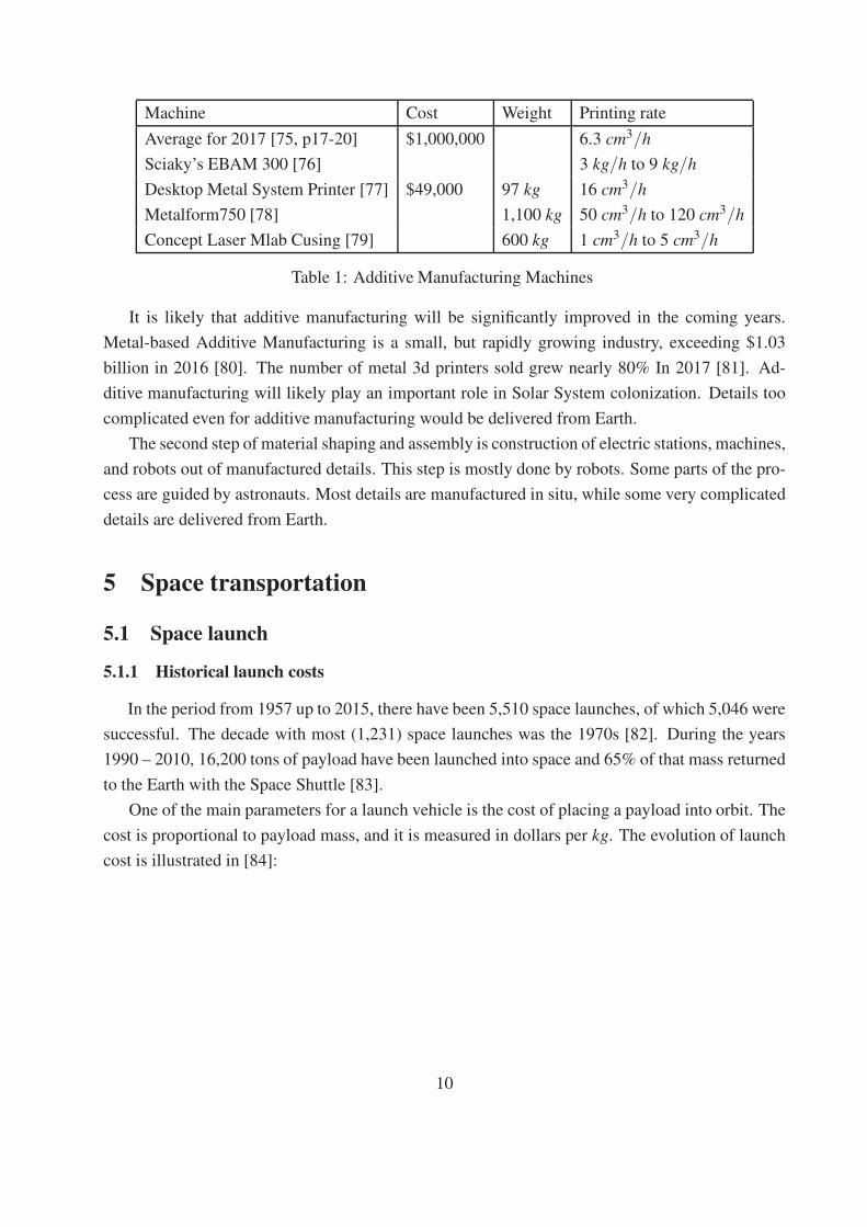
Machine Cost Weight Printing rate
Average for 2017 [75, p17-20] $1,000,000 6.3 cm3/h
Sciaky’s EBAM 300 [76] 3 kg/h to 9 kg/h
Desktop Metal System Printer [77] $49,000 97 kg 16 cm3/h
Metalform750 [78] 1,100 kg 50 cm3/h to 120 cm3/h
Concept Laser Mlab Cusing [79] 600 kg 1 cm3/h to 5 cm3/h
Table 1: Additive Manufacturing Machines
It is likely that additive manufacturing will be significantly improved in the coming years.
Metal-based Additive Manufacturing is a small, but rapidly growing industry, exceeding $1.03
billion in 2016 [80]. The number of metal 3d printers sold grew nearly 80% In 2017 [81]. Ad-
ditive manufacturing will likely play an important role in Solar System colonization. Details too
complicated even for additive manufacturing would be delivered from Earth.
The second step of material shaping and assembly is construction of electric stations, machines,
and robots out of manufactured details. This step is mostly done by robots. Some parts of the pro-
cess are guided by astronauts. Most details are manufactured in situ, while some very complicated
details are delivered from Earth.
5 Space transportation
5.1 Space launch
5.1.1 Historical launch costs
In the period from 1957 up to 2015, there have been 5,510 space launches, of which 5,046 were
successful. The decade with most (1,231) space launches was the 1970s [82]. During the years
1990 – 2010, 16,200 tons of payload have been launched into space and 65% of that mass returned
to the Earth with the Space Shuttle [83].
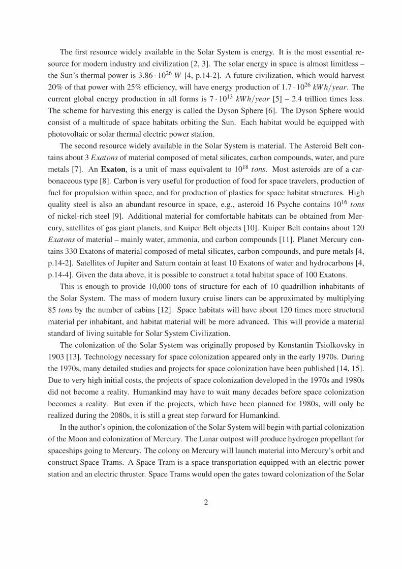
One of the main parameters for a launch vehicle is the cost of placing a payload into orbit. The
cost is proportional to payload mass, and it is measured in dollars per kg. The evolution of launch
cost is illustrated in [84]:
10
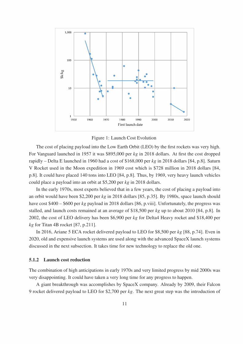
Figure 1: Launch Cost Evolution
The cost of placing payload into the Low Earth Orbit (LEO) by the first rockets was very high.
For Vanguard launched in 1957 it was $895,000 per kg in 2018 dollars. At first the cost dropped
rapidly – Delta E launched in 1960 had a cost of $168,000 per kg in 2018 dollars [84, p.8]. Saturn
V Rocket used in the Moon expedition in 1969 cost which is $728 million in 2018 dollars [84,
p.8]. It could have placed 140 tons into LEO [84, p.8]. Thus, by 1969, very heavy launch vehicles
could place a payload into an orbit at $5,200 per kg in 2018 dollars.
In the early 1970s, most experts believed that in a few years, the cost of placing a payload into
an orbit would have been $2,200 per kg in 2018 dollars [85, p.35]. By 1980s, space launch should
have cost $400 – $600 per kg payload in 2018 dollars [86, p.viii]. Unfortunately, the progress was
stalled, and launch costs remained at an average of $18,500 per kg up to about 2010 [84, p.8]. In
2002, the cost of LEO delivery has been $6,900 per kg for Delta4 Heavy rocket and $18,400 per
kg for Titan 4B rocket [87, p.211].
In 2016, Ariane 5 ECA rocket delivered payload to LEO for $8,500 per kg [88, p.74]. Even in
2020, old and expensive launch systems are used along with the advanced SpaceX launch systems
discussed in the next subsection. It takes time for new technology to replace the old one.
5.1.2 Launch cost reduction
The combination of high anticipations in early 1970s and very limited progress by mid 2000s was
very disappointing. It could have taken a very long time for any progress to happen.
A giant breakthrough was accomplishes by SpaceX company. Already by 2009, their Falcon
9 rocket delivered payload to LEO for $2,700 per kg. The next great step was the introduction of
11
the reusable first stage. On December 21, 2015, SpaceX made a huge step in History when the
first stage of Falcon 9 spacecraft returned to the launching pad [89, p.1]. During 2016, SpaceX
has successfully landed six first stage boosters [90]. By July 2019, there have been 34 successful
first stage returns out of 40 attempts [91]. By 2018, SpaceX was offering LEO delivery at $1,400
per kg via Falcon Heavy [84, p.8]. A two stage spacecraft with fully reusable stages will deliver
payload to LEO for $1,000 per kg [92, p.33].
Even though much has been achieved, more remains to be done. According to the interview
with SpaceX CEO Elon Musk [91],
by late 2014, SpaceX determined that the mass needed for a re-entry heat shield, land-
ing engines, and other equipment to support recovery of the second stage was at that
time prohibitive, and indefinitely suspended their second-stage reusability plans for
the Falcon line.
As of 2020, Falcon Heavy is the least expensive launch vehicle with LEO delivery cost of $1,400
per kg [93, 94].
5.1.3 Non-rocket space launch concepts
A space gun accelerates the payload in an inclined tunnel and launches it into space [95]. One form
of a space gun is the ram accelerator. It consists of a tube 4 m in diameter and several km long.
The tube is filled with an explosive gas combination – like oxygen and methane. The transport
enters the tube at a velocity of 1.5 km/s. The transport has scramjet engines. These engines
accelerate the transport by burning the gas mixture. The space gun can deliver 50,000 tons payload
per year at a cost of $2.50 per kg. Neither astronauts not fragile electronics can be delivered to
space by a gun due to high launch acceleration [96, p.104-121]. At present, ram accelerator remains
a purely theoretical concept. Miniature versions of ram accelerators accelerating projectiles to high
yet suborbital velocities have been tested [97, 98].
A star tram is an electromagnetic space gun. This star tram consists of a vacuum tube about
130 km long. The firing end of the tube is located either at a mountain top about 6 km tall or is
suspended in atmosphere at 10 km by lifting gas balloons. The end of the tube is inclined at 10o to
horizontal.
The transport is a streamline body 2 m in diameter and 13 m in length. Loaded transport has
a mass of 40 tons. The transport is accelerated within a vacuum tunnel by a linear induction
motor. It levitates due to magnetic field and never touches the surface. The transport leaves the
electromagnetic cannon at 8.9 km/s. It cruises out of the atmosphere and uses a small rocket engine
to get into Earth’s orbit.
A star tram system would cost about $100 Billion. It would launch about 150,000 tons of
payload per year into orbit. The transports experience 30 g acceleration, thus they can not be used
12
to transport passengers or fragile cargo. Nevertheless, they can transport both sturdy cargo and
fuel [99, 100].
5.2 Electric propulsion in space
An enormous cost reduction for deep – space missions is possible if one could lower the mass of
fuel necessary for a propulsion within Deep Space. Even though the fuel cost on Earth is small
enough, in the LEO the cost of fuel and fuel tanks mainly consists of the cost for bringing these
materials into the orbit, which is at least $1,400 per kg.
The energy and fuel requirements for space missions are generally given in terms of the change
in velocity, △v, of the spacecraft needed to accomplish a given mission [101, p.9–11]. The amount
of fuel needed for a maneuver with △v is given by the Tsiolkovsky rocket equation [101, p.9]
m0
m1= exp
(
△v
v0
)
, (5.1)
where m0 is the mass of the rocket with the fuel, m1 is the mass of the vehicle after the fuel has
been consumed, and v0 is the exhaust velocity of the rocket engine. The highest v0 for a storable
liquid rocket propellant (hydrazine and liquid fluorine) is 4.22 km/s [102]. Thus, in order for 1 kg
of a payload and a fuel tank to perform a mission with △v = 10 km/s one needs
m0 = 1 kgexp
(
10.0 km/s
4.22 km/s
)
−1 = 10.7kg (5.2)
of fuel. Even if fuel tanks are very light and some of them are discarded along the way, we require
at least 11 kg placed in LEO to accomplish the mission for 1 kg payload. Since placing 1 kg into
LEO costs at least $1,400, it would cost at least 11×$1,400 ≈ $15,400 per kilogram of payload
at the mission end.
An obvious way to deliver greater mass over space routes, demanding large △v, is to use en-
gines with exhaust velocities of tens of kilometers per second. Several types of electrical thrusters
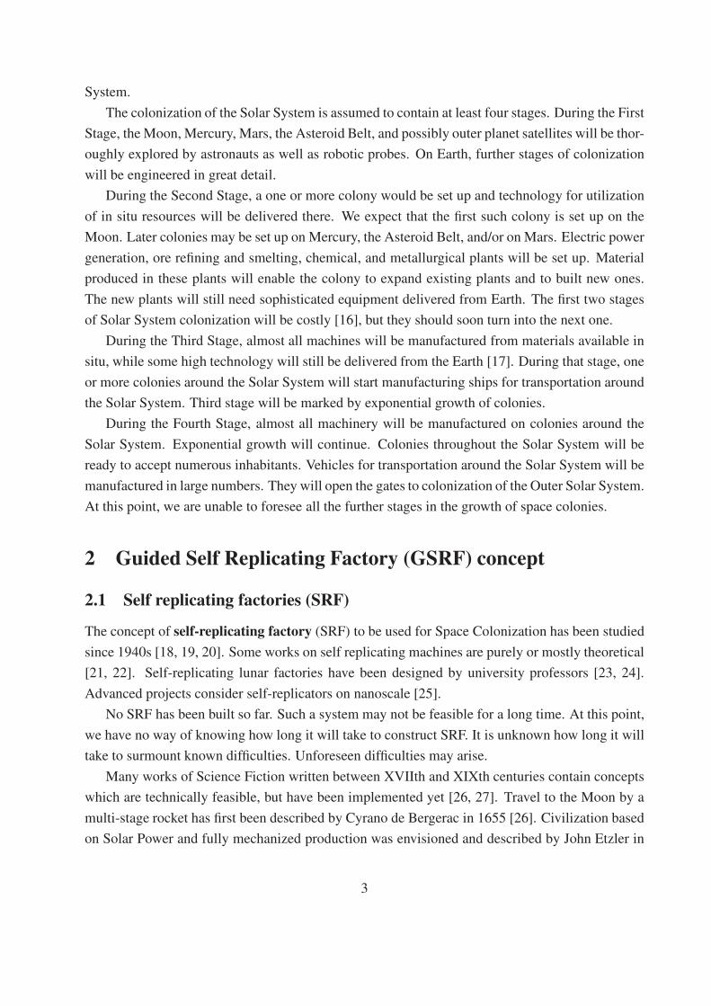
with large exhaust velocities exist. We briefly outline several types of these thrusters. The ion
thruster accelerates ions by an electric field. It was proposed by Konstantin Tsiolkovsky in 1911
[103]. The engine diagram from [104, p.5] is presented on Fig.2 below:
13
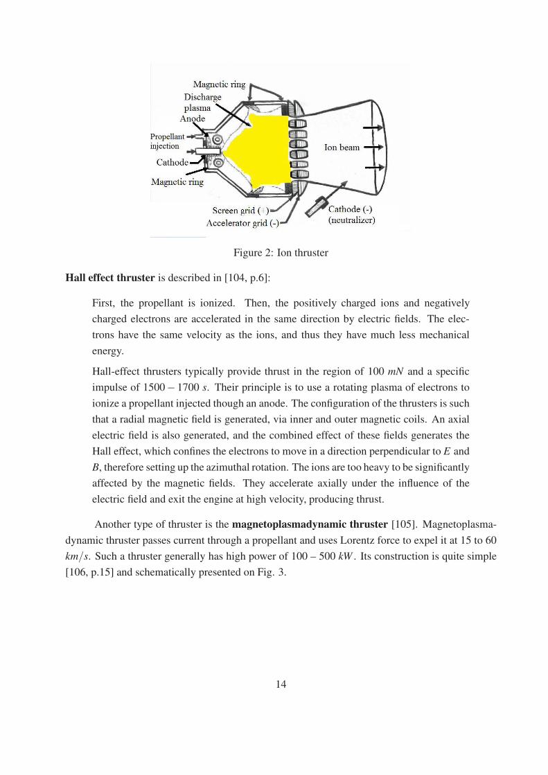
Figure 2: Ion thruster
Hall effect thruster is described in [104, p.6]:
First, the propellant is ionized. Then, the positively charged ions and negatively
charged electrons are accelerated in the same direction by electric fields. The elec-
trons have the same velocity as the ions, and thus they have much less mechanical
energy.
Hall-effect thrusters typically provide thrust in the region of 100 mN and a specific
impulse of 1500− 1700 s. Their principle is to use a rotating plasma of electrons to
ionize a propellant injected though an anode. The configuration of the thrusters is such
that a radial magnetic field is generated, via inner and outer magnetic coils. An axial
electric field is also generated, and the combined effect of these fields generates the
Hall effect, which confines the electrons to move in a direction perpendicular to E and
B, therefore setting up the azimuthal rotation. The ions are too heavy to be significantly
affected by the magnetic fields. They accelerate axially under the influence of the
electric field and exit the engine at high velocity, producing thrust.
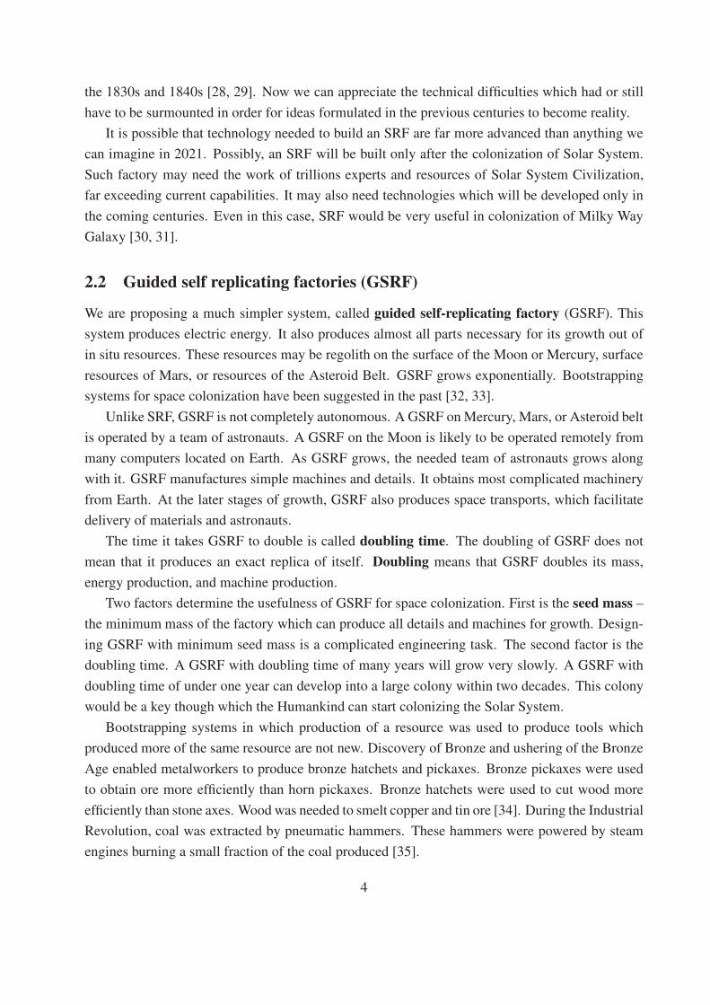
Another type of thruster is the magnetoplasmadynamic thruster [105]. Magnetoplasma-
dynamic thruster passes current through a propellant and uses Lorentz force to expel it at 15 to 60
km/s. Such a thruster generally has high power of 100 – 500 kW . Its construction is quite simple
[106, p.15] and schematically presented on Fig. 3.
14
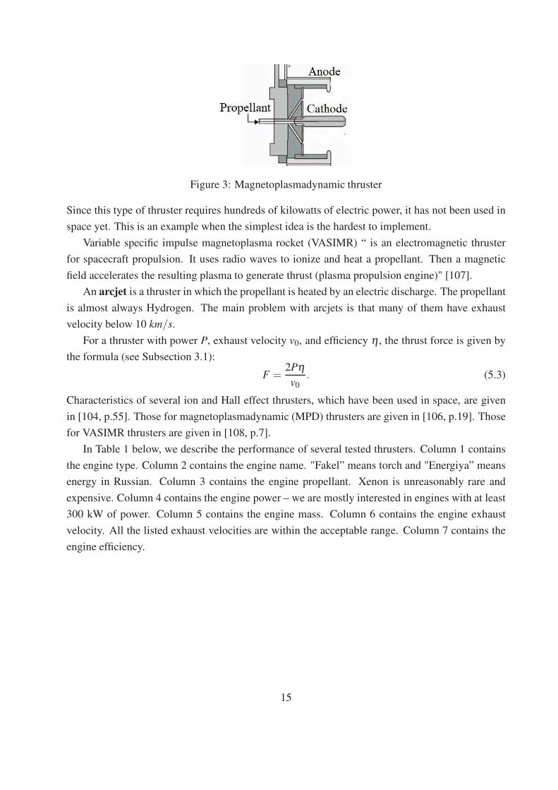
Figure 3: Magnetoplasmadynamic thruster
Since this type of thruster requires hundreds of kilowatts of electric power, it has not been used in
space yet. This is an example when the simplest idea is the hardest to implement.
Variable specific impulse magnetoplasma rocket (VASIMR) “ is an electromagnetic thruster
for spacecraft propulsion. It uses radio waves to ionize and heat a propellant. Then a magnetic
field accelerates the resulting plasma to generate thrust (plasma propulsion engine)" [107].
An arcjet is a thruster in which the propellant is heated by an electric discharge. The propellant
is almost always Hydrogen. The main problem with arcjets is that many of them have exhaust
velocity below 10 km/s.
For a thruster with power P, exhaust velocity v0, and efficiency η , the thrust force is given by
the formula (see Subsection 3.1):
F =2Pη
v0. (5.3)
Characteristics of several ion and Hall effect thrusters, which have been used in space, are given
in [104, p.55]. Those for magnetoplasmadynamic (MPD) thrusters are given in [106, p.19]. Those
for VASIMR thrusters are given in [108, p.7].
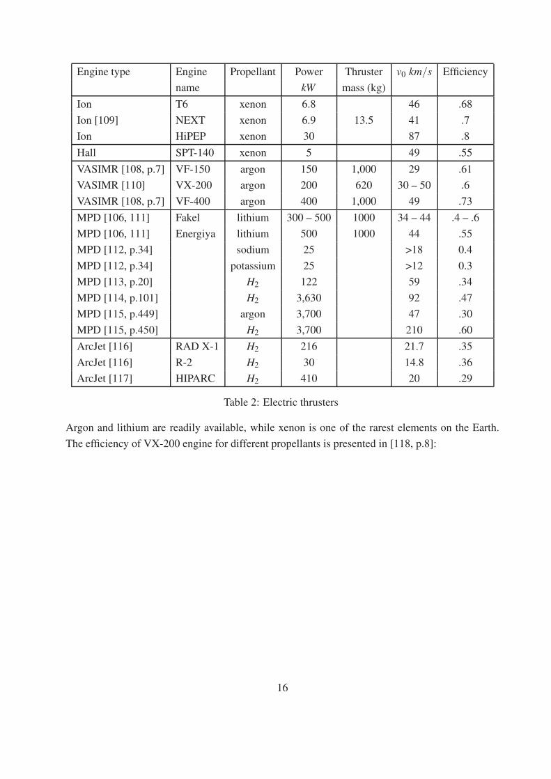
In Table 1 below, we describe the performance of several tested thrusters. Column 1 contains
the engine type. Column 2 contains the engine name. "Fakel” means torch and "Energiya” means
energy in Russian. Column 3 contains the engine propellant. Xenon is unreasonably rare and
expensive. Column 4 contains the engine power – we are mostly interested in engines with at least
300 kW of power. Column 5 contains the engine mass. Column 6 contains the engine exhaust
velocity. All the listed exhaust velocities are within the acceptable range. Column 7 contains the
engine efficiency.
15
Engine type Engine Propellant Power Thruster v0 km/s Efficiency
name kW mass (kg)
Ion T6 xenon 6.8 46 .68
Ion [109] NEXT xenon 6.9 13.5 41 .7
Ion HiPEP xenon 30 87 .8
Hall SPT-140 xenon 5 49 .55
VASIMR [108, p.7] VF-150 argon 150 1,000 29 .61
VASIMR [110] VX-200 argon 200 620 30 – 50 .6
VASIMR [108, p.7] VF-400 argon 400 1,000 49 .73
MPD [106, 111] Fakel lithium 300 – 500 1000 34 – 44 .4 – .6
MPD [106, 111] Energiya lithium 500 1000 44 .55
MPD [112, p.34] sodium 25 >18 0.4
MPD [112, p.34] potassium 25 >12 0.3
MPD [113, p.20] H2 122 59 .34
MPD [114, p.101] H2 3,630 92 .47
MPD [115, p.449] argon 3,700 47 .30
MPD [115, p.450] H2 3,700 210 .60
ArcJet [116] RAD X-1 H2 216 21.7 .35
ArcJet [116] R-2 H2 30 14.8 .36
ArcJet [117] HIPARC H2 410 20 .29
Table 2: Electric thrusters
Argon and lithium are readily available, while xenon is one of the rarest elements on the Earth.
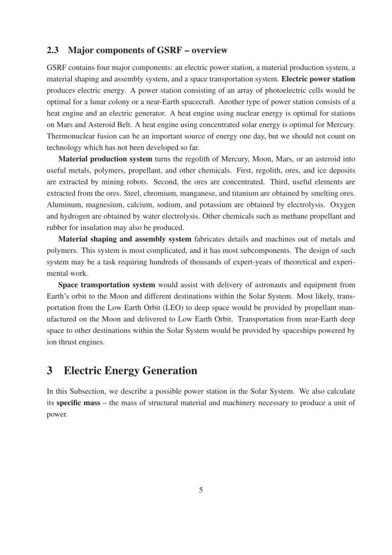
The efficiency of VX-200 engine for different propellants is presented in [118, p.8]:
16
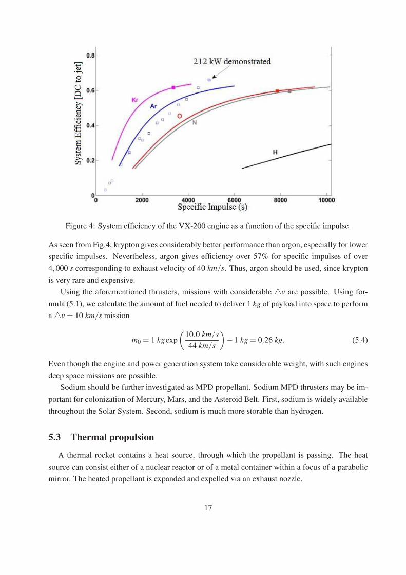
Figure 4: System efficiency of the VX-200 engine as a function of the specific impulse.
As seen from Fig.4, krypton gives considerably better performance than argon, especially for lower
specific impulses. Nevertheless, argon gives efficiency over 57% for specific impulses of over
4,000 s corresponding to exhaust velocity of 40 km/s. Thus, argon should be used, since krypton
is very rare and expensive.
Using the aforementioned thrusters, missions with considerable △v are possible. Using for-
mula (5.1), we calculate the amount of fuel needed to deliver 1 kg of payload into space to perform
a △v = 10 km/s mission
m0 = 1 kgexp
(
10.0 km/s
44 km/s
)
−1 kg = 0.26 kg. (5.4)
Even though the engine and power generation system take considerable weight, with such engines
deep space missions are possible.
Sodium should be further investigated as MPD propellant. Sodium MPD thrusters may be im-
portant for colonization of Mercury, Mars, and the Asteroid Belt. First, sodium is widely available
throughout the Solar System. Second, sodium is much more storable than hydrogen.
5.3 Thermal propulsion
A thermal rocket contains a heat source, through which the propellant is passing. The heat
source can consist either of a nuclear reactor or of a metal container within a focus of a parabolic
mirror. The heated propellant is expanded and expelled via an exhaust nozzle.
17
Within the Asteroid Belt and Outer Solar System, water and ammonia are plentiful. These sub-
stances can be used as thermal rocket propellant there. In the vicinity of Mercury, only hydrogen
can be used as a high specific impulse propellant. Solar thermal rockets can heat hydrogen to 1,900oC [119, p.205]. Nuclear reactor can heat hydrogen to 2,470 oC to 2,670 oC [120, p.9].
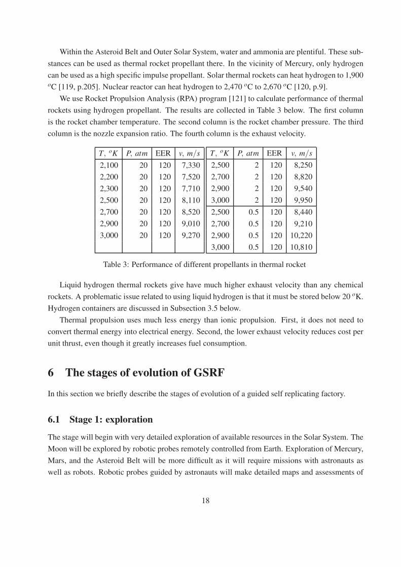
We use Rocket Propulsion Analysis (RPA) program [121] to calculate performance of thermal
rockets using hydrogen propellant. The results are collected in Table 3 below. The first column
is the rocket chamber temperature. The second column is the rocket chamber pressure. The third
column is the nozzle expansion ratio. The fourth column is the exhaust velocity.
T, oK P, atm EER v, m/s
2,100 20 120 7,330
2,200 20 120 7,520
2,300 20 120 7,710
2,500 20 120 8,110
2,700 20 120 8,520
2,900 20 120 9,010
3,000 20 120 9,270
T, oK P, atm EER v, m/s
2,500 2 120 8,250
2,700 2 120 8,820
2,900 2 120 9,540
3,000 2 120 9,950
2,500 0.5 120 8,440
2,700 0.5 120 9,210
2,900 0.5 120 10,220
3,000 0.5 120 10,810
Table 3: Performance of different propellants in thermal rocket
Liquid hydrogen thermal rockets give have much higher exhaust velocity than any chemical
rockets. A problematic issue related to using liquid hydrogen is that it must be stored below 20 oK.
Hydrogen containers are discussed in Subsection 3.5 below.
Thermal propulsion uses much less energy than ionic propulsion. First, it does not need to
convert thermal energy into electrical energy. Second, the lower exhaust velocity reduces cost per
unit thrust, even though it greatly increases fuel consumption.
6 The stages of evolution of GSRF
In this section we briefly describe the stages of evolution of a guided self replicating factory.
6.1 Stage 1: exploration
The stage will begin with very detailed exploration of available resources in the Solar System. The
Moon will be explored by robotic probes remotely controlled from Earth. Exploration of Mercury,
Mars, and the Asteroid Belt will be more difficult as it will require missions with astronauts as
well as robots. Robotic probes guided by astronauts will make detailed maps and assessments of
18
mineral resources available on Mercury, Mars, and the Asteroid Belt. These probes will also access
possibilities for construction.
As the data is gathered in situ, back on Earth, experimental and theoretical scientists as well as
graduate students will be designing the further stages of development of colonies in minute detail.
It is likely that different companies will have competing designs. Design of any space system takes
thousands to tens of thousands of expert-years [89, p.116].
6.2 Stage 2: setup of Lunar colony
In the author’s opinion, the colonization of the Solar System will start with the Moon. The Moon
is close to Earth, and it has resources which are extremely important for space transportation.
Detailed feasibility studies for Lunar colonization have been published since 1970s [122, 123,
124, 125].
Below, we briefly describe some Lunar resources and discuss their role in colonization of the
rest of the inner Solar System. The first Lunar resource is hydrogen in the form of water ice. Lunar
poles contain at least 430 million tons of ice [126, p.326]. Other sources estimate the ice deposits
at lunar poles as 660 million tons [127, p.368]. In most polar craters which contain ice, water
makes up 2.5% of the top 1.5 meters of regolith. Based on the data above, the Moon contains 48
million tons to 73 million tons of easily accessible hydrogen at the Lunar poles. The second Lunar
resource is abundance of metal ores. Chemical composition of different parts of lunar surface has
been summarized in [128]. Lunar surface contains 24% to 31% aluminum oxide, 14% to 18%
calcium oxide, 6% to 10% iron oxide, 3% to 8.6% magnesium oxide, 0.3% to 0.6% sodium oxide,
0.2% to 0.6% titanium oxide, and 0.09% to 0.18% chromium oxide [128, p. 400]. The third Lunar
resource is the abundance of minerals useful for glassmaking.
Having listed lunar resources, we describe the setup of a lunar GSRF below. First, an electric
power station would be brought to the Moon from Earth. Solar panels brought from Earth and cov-
ered with glass manufactured on the Moon would make a good power station. In 2020, Renogy,
Inc. sells flexible solar panels. These panels cost under $2 per watt or $300 per m2. These panels
have produce 175 W/m2 under 1,000 W/m2 irradiance. They have specific mass of 2.8 kg/m2
[130]. Some lightweight cells have specific power of 948 W/kg to 1,181 W/kg [131]. These cells
are much more expensive than regular photovoltaic cells. The highest specific power for any solar
cell commercially available in 2017 is 700 W/kg for III-V triple junction module. This module has
25% efficiency and 350 g/m2 areal density. These modules cost $25,000 per m2, which $100 per
Watt and $71,000 per kg – more expensive than gold [132]. Hopefully, by the time colonization
of the Solar System begins, these prices will decrease. Solar panels can be manufactured on the
Moon from solar cells delivered from Earth and cover manufactured from lunar material. Even in
1989, solar cells not assembled into panels and without cover had specific mass of 1,700 W/kg
[133]. Some researchers claim that solar cells can be manufactured on the Moon. Nevertheless,
19
production of solar cells involves deposition of submicron thick semiconductor layers. This tech-
nology may be too complicated for a lunar base [134, 135]. A transparent glass covering for solar
cells can be produced from lunar regolith after iron, nickel and chromium ores have been removed
from it [129, p.13].
Second, a material production system would be brought to the Moon from Earth. Magnesium,
aluminum, steel, titanium, and sodium would be manufactured from the resources listed above
with the use of electric energy. Vast amounts of hydrogen would also be produced. Most of this
hydrogen will be liquefied and stored in depots in space and on the Moon.
Third, a metal shaping and assembly system will be delivered to the Moon. This system will
be carefully monitored and controlled by tens of thousands of computers on Earth.
Fourth, a transport link would be set up between Moon and Earth. Rockets using liquid hy-
drogen and oxygen will transport payloads between the lunar base and orbit around the Moon.
Chemical hydrogen-oxygen rockets as well as thermal rockets using only liquid hydrogen will
transport payloads between orbit around the Moon and Low Earth Orbit(LEO). Even though hy-
drogen is plentiful on Earth, in space it is an important and rare resource due to delivery cost.
Depots containing hydrogen manufactured on the Moon would be set up in depots in orbit around
the Moon, LEO, and deep space. Propellant depots in LEO would serve as refueling stations for
spacecraft going to the Moon. Propellant depots at Lunar Orbit would serve as refueling stations
for spacecraft landing on the Moon as well as those returning to Earth.
LEO and deep space propellant depots can also serve as refueling stations for spacecraft trav-
elling from Earth to other destinations in the inner Solar System. That would greatly reduce the
payload which must be delivered to LEO in order to deliver 1 kg of payload to these destinations.
Colonization of the Solar System would be impossible without availability of propellant manufac-
tured on the Moon.
6.3 Stage 2.5: setup of one or more colony in inner Solar System
During this stage, GSRF is built on Earth, transported to Mercury, Mars, or Asteroid Belt and
assembled there. Astronauts would have to accompany GSFR. Transportation of equipment and
astronauts would be assisted by the use of hydrogen propellant manufactured at the lunar base. In
the author’s opinion, this stage will be the most expensive and risky part of inner Solar System
colonization.
First, an electric power station would be set up. On Mercury, it would be a solar thermal
electric power station. On Mars, it would be a nuclear power station. On the Asteroid Belt, the
power station can be either solar thermal or nuclear. All parts of electric power station will be
brought from Earth.
Second, a material production system would be set up. Metal production system will manu-
facture metals for machines and structures, liquid hydrogen and oxygen for propulsion, and rubber
20
for insulation. On Mercury and Mars, metals would be obtained from the ores. These ores will be
gathered by mining robots. On the Asteroid Belt, native metals are widely available. Once again,
all parts of this plant will be delivered from Earth.
An important part of material production system on Asteroid Belt would separate platinum
group metals from metal asteroid material. These metals would be delivered to Earth. Production
of platinum group metals would finance expansion of space colonization.
Third, material shaping and assembly system will be set up. This system will manufacture
simple metal, plastic, and rubber details. Below, we briefly describe some manufactured items.
Steel building blocks would be used by the astronauts to build more extensive and comfortable
habitats for themselves. Bolts, nuts, screws, metal bars, frames, wires, and details of other shapes
would be used to expand the factory. Polished aluminum mirrors would be used in concentrated
solar power. Tubes would be used in to expand the electric power station’s heat sources and heat
sinks.
Fourth, space transportation system will be set up. Initially, spaceships will be built on Earth.
Fuel for refueling spaceships will be produced in space colonies from the beginning. Initially, most
hydrogen will be produced on lunar colonies. Hydrogen can be used as propellant for thermal
nuclear rockets and magnetoplasmadynamic thrusters. Later, hydrogen will be produced in large
quantities on Mercury, Mars, and Asteroid Belt. Sodium will also be produced in large quantities.
It will be used for magnetoplasmodynamic thrusters.
Replication and expansion of the colony from in situ resources will take place during setup
stage. Nevertheless, the rate of replication will be much slower than at the next stage. In the
author’s opinion, the Setup Stage should take about 10 years.
6.4 Stage 3: exponential growth
GSRF will enter Exponential Growth Stage with full set of components needed for complete self-
sustained growth. Electric power plants will generate vast amount of electric energy. On Mercury,
the main energy source will be concentrated solar power. On Mars and Asteroid Belt, it will be
nuclear power. This energy will power all other plants.
On Mercury and Mars, mining machines will deliver metal ores, graphite (on Mercury), water
ice, and dry ice (on Mars) to the factory. Ore benefaction machines will concentrate metals and
other useful compounds. Metal extraction plants will use electric energy and minerals to produce
metals. Chemical plants will use electricity to convert ice and graphite or dry ice into propellant,
rubber, plastic, and other chemicals. On Asteroid Belt, both steel and hydrocarbons are available
in native state. Chemical plants will modify and purify metals and hydrocarbons. Chemical plants
on Asteroid Belt will also extract platinum group metals. These metals will be sold on Earth in
order to finance space colonization.
21
Metal working plants will shape metals and plastics into building blocks and machine parts. As-
tronauts assisted by machine building robots will produce machines for all aforementioned plants.
The process described above will neither be fully automated nor completely independent of com-
plex machines, robots, and computers manufactured on Earth in great quantities. Thousands of
astronauts will be arriving at Mercury, and some will be returning to Earth. Total payload from
Earth may be greater than during the previous stage.
Transportation from Earth will also be bootstrapped by resources manufactured on one or more
inner Solar System colonies. Deep spaceships will be refueled by propellant manufactured at
the colony. As the colony expands, parts of deep spaceships or whole deep spaceships will be
manufactured there. This will reduce the cost of delivering astronauts and machinery from Earth
to Mercury, Mars, and Asteroid Belt.
After several doubling periods, both qualitative and quantitative changes will occur in the
colony. The colony will become less materially dependent on Earth. Specialized factories will be
set up producing robotic machinery of increasing complexity. The number of astronauts brought
to colonies will greatly increase. There will be a great need for astronauts to operate machinery.
Even though the mass and power of machinery controlled by each astronaut will grow, this growth
will be less rapid than the growth of the colony itself. Energy and material resources will be used
to build comfortable accommodations for astronauts. Hydroponic food production will enable
astronauts to eat a healthy diet [136].
6.5 Stage 4: full civilization
In this subsection, we use the present tense in order to demonstrate the great potential of Solar
System colonization. After the colony undergoes about 10-12 doubling periods, it changes both
quantitatively and qualitatively. It contains tens of thousands of astronauts and several million
tons of structure and machinery. Electric power stations have cumulative power of 20 GW to 50
GW . The original colony has been built primarily in one place – Mercury, Mars, Ceres, or other
asteroids. Now, offshoots of the original colony are throughout the inner Solar System. Originally,
the colony consumed more resources, than it produced. Now the colony produces much more
resources than it consumes. It produces platinum-group metals, silver, and gold which are sold on
Earth. Originally, the colony brought most machinery from Earth. Now, almost all machinery is
manufactured in situ.
Originally, no astronaut viewed Mercury, Mars, or the Asteroid Belt as their home. Now,
many do. Originally, astronauts had only makeshift habitats. Now they have comfortable living
quarters in moderate-sized settlements with hydroponic farms growing healthy food. First people
are born in space. Politically, different parts of the colony are owned by different companies and
Nations. Most people on Earth have stocks from asteroid mining companies. Space Law and Space
Commerce are emerging disciplines.
22
Expansion of Space Colonies does not stop at this stage. On the contrary, almost unlimited
resources of solar energy, metals, minerals, carbon, hydrogen, and oxygen allow unlimited expan-
sion. An exponentially growing number of people are calling different parts of the Solar System
their home.
6.6 Stage 5: toward Dyson Sphere
After the colony undergoes 15-18 more doubling periods from the beginning of Stage 4, it contains
about a trillion tons of structure and machinery. The gross output of all electric power stations is 5
PW to 10 PW , where PW denotes a Petawatt or 1015 W . The population of Space Civilization is
now a billion people. New generation is born in Solar System colonies, and the younger generation
is rapidly emigrating from Earth. Space Civilization is now fully self-sufficient.
Social and political development of the True Space Age civilization is beyond our imagination.
Civilization described in this stage frequently appears in Science Fiction [137, 138]. In reality, it
is impossible to foresee problems and opportunities which will exist in this civilization.
Solar System civilization may continue growing until all resources are exhausted. After the
colony undergoes 30-33 more doubling periods from the beginning of Stage 5, it becomes a Dyson
Sphere – a multitude of space habitats orbiting Sun [6]. Mass, power, and population of Dyson
Sphere have been estimated by various researchers since the 1960s. These estimates are based on
resources available in the Solar System. Population of about 1016, which is over a million times
modern World population would be supported at very high living standards [1]. Dyson Sphere
would contain at least 1019 tons of structure and machinery. This material would come from
Asteroid Belt, Kuiper Belt, Mercury, and satellites of gas giants [4, 7, 11]. Total power output of
electric stations would be at least 3 · 1024 W – which is just 0.75% of Sun’s total radiative power.
Even though these numbers seem extraordinary, most scientists who have studied the issue since
the 1960s agree on them.
7 Conclusion
Colonization of the Solar System can be accomplished by the use of a guided self-replicating
factory. This factory would consist of four elements. Electric power station would power the
whole factory. Material production system would gather ores or native metals and produce steel,
aluminum, plastic, and propellant such as liquid hydrogen. Material shaping and assembly sys-
tem would shape metal and plastic into details and assemble them into machines. These machines
would constitute an expansion of the colony. Space transportation system would use fuel manu-
factured in situ in order to facilitate transportation of machinery and astronauts from Lower Earth
Orbit (LEO) to the colony.
23
Any colony located on Mercury, Mars, or Asteroid Belt would be guided and intensely moni-
tored by astronauts. A lunar colony would be remotely controlled from the Earth. Building a fully
robotic and independent, self replicating factory is beyond current technological capabilities. It
is possible that such a factory would be built only in the very distant future by a Dyson Sphere
civilization, which would use the vast resources of the whole Solar System.
The GSFR will not exactly replicate itself. Nevertheless, it will double during a time period
called a doubling time. During doubling time, the mass of machinery and structure doubles due
to material collected, processed, and assembled in situ. At the same time, electric power doubles.
The number of astronauts needed to work on GSFR increases by a factor a little less than 2.
After 10-12 doubling times, the space colony becomes a settlement with tens of thousands of
astronauts, millions of tons of structure, and machinery, and electric power output of 20 GW to 50
GW . By that time, there should be more than one colony within the Solar System. After another
15-18 doubling times, True Space Age will begin. A significant fraction of world population will
be living in space habitats. The civilization within the Solar System will continue to grow until it
becomes a Dyson Sphere civilization. Dyson Sphere would support a population of 1016 at very
high standards of living. This population would be supported by at least 1019 tons of structure and
machinery. Global production of electric power would be at least 3 ·1024 W .
Setting up original colonies on the Moon and in the inner Solar System would be a difficult
and expensive task. During the first stage of growth, this colony may need more expensive equip-
ment from Earth. It is likely that the overall expense for Solar System colonization would be 500
Billion dollars or more. Nevertheless, this would be an enormously important step in transforming
Humankind into a Dyson Sphere civilization.
References
[1] Lewis, J.S. Mining the Sky: Untold Riches from the Asteroids, Comets, and Planets, Read-
ing, Mass: Addison-Wesley Pub. Co, 1996.
[2] Kardashev, N. S., Transmission of information by extraterrestrial civilizations, Soviet As-
tronomy, 8(2), Sept.-Oct. 1964.
[3] Smil, V., Energy and Civilization: A History, The MIT Press, Cambridge, MA, 2017.
[4] Lide, D. R., Editor, CRC Handbook of Chemistry and Physics, 84th Edition, CRC Press.
Boca Raton, Florida, 2003.
[5] OCDE, OECD, World Energy Statistics 2016, OECD Publishing, 2016. Internet resource.
[6] Beech, M., Terraforming: The Creating of Habitable Worlds, New York: Springer, 2009.
24
[7] Pitjeva, E.V., High-precision ephemerides of planets—EPM and determination of some
astronomical constants, Solar Syst. Res. 39(3), p. 176–186, (2005).
[8] Binzel, R.P., Gehrels, T., Matthews, M.S., Asteroids II. Tucson: University of Arizona
Press, 1989.
[9] Al Conrad, P. I., Adamkovics, M., Kleer K., Males, J.R., Morzinski, K.M., Close, L.,
Kaasalainen, M., Viikinkoski, M., Timerson, B., Reddy, V., Magri, C., Nolan, M.C., How-
ell, E.S., Benner, L., Giorgini, J.D., Warner, B.D and Harris, A.W., Radar Observations
and Shape Model of Asteroid 16 Psyche, Icarus, 281, p. 388 – 403, (2017).
[10] Blondel, P., Mason, J., Solar System Update, Springer-Verlag, Berlin, 2006.
[11] Pitjeva, E.V., Pitjev, N.P., Mass of the Kuiper belt, Celestial Mechanics and Dynamical
Astronomy, 130(9), 2018.
[12] Smith, P.C., Cruise Ships the Small Scale Fleet: A Visiual Showcase, Pen and Sword,
Havertown, 2014.
[13] Tsiolkovski, K., Tikhonravov, M.K., Works on Rocket Technology, Washington, D.C.: Na-
tional Aeronautics and Space Administration, 1965.
[14] O’Neill, G.K. and Reynolds, G., Habitats in Space, The Science Teacher, 44(6), p. 22-26,
1977.
[15] O’Neill, G.K., The Colonization of Space, Physics Today, 27(9) p. 32-40, 1974.
[16] Hickman, J., The Political Economy of Very Large Space Projects, Journal of Evolution
and Technology. Jetpress.org. 4, November, 1999.
[17] Klotz, I, Tech billionaires bankroll gold rush to mine asteroids, Reuters, April 24 , 2012.
<http://www.reuters.com/article/2012/04/24/us-space-asteroid-mining-idUSBRE83N06U20120424>
[18] Chirikjian, G.S., An Architecture for Self-Replicating Lunar Factories, Department of Me-
chanical EngineeringJohns Hopkins University, 2004.
[19] Sipper, M., Fifty Years of Research on Self-Replication: An Overview, Artificial Life, 4,
pp. 237–257, 1998.
[20] Ellery, A., Building Physical Self-Replicating Machines, The European Conference on
Artificial Life, Lyon, France, 2017.
[21] Sayama, H., Von Neumann’s Machine, in the Shell: Enhancing the Robustness of Self-
Replication Processes, in Artificial Life VIII, MIT Press, pp. 49-52, 2002.
25
[22] Chirikjian, G.S., Moses, M.S., Yamaguchi, H., Towards cyclic fabrication systems for
modular robotics and rapid manufacturing, Proceedings of the 2009 IEEE/RSJ interna-
tional conference on Intelligent robots and systems, October 2009, pp. 1478–1483, 2009.
[23] Boston, P. J., Todd, P., McMillen, K. R., Robotic Lunar Ecopoiesis Test Bed: Bringing the
Experimental Method to Terraforming, Aip Conference Proceedings, pp.975-983, 2004.
[24] Chirikjian, G.S., An Architecture for Self-Replicating Lunar Factories, NIAC Phase I
Award: October 1, 2003 - March 31, 2004, 2004.
[25] Toth-Fejel, T., Modeling Kinematic Cellular Automata Final Report, NASA Institute for
Advanced Concepts Phase I: CP-02-02, General Dynamics Advanced Information Systems
Contract # P03-0984, 2004.
[26] Cyrano, B.S., Strachan, G., Other Worlds: The Comical History of the States and Empires
of the Moon and the Sun, London: New English Library, 1976.
[27] Wells, H.G., War of the Worlds, London: Legend Press, 2020.
[28] Etzler, J.A., The Paradise Within the Reach of All Men, Without Labour, by Powers of
Nature and Machinery: An Address to All Intelligent Men, London: J. Brooks, 1836.
[29] Etzler, J.A., The New World: Or, Mechanical System, to Perform the Labours of Man
and Beast by Inanimate Powers, That Cost Nothing, for Producing and Preparing the
Substances of Life, Philadelphia: C.F. Strollmeyer, 1973.
[30] Savage, M.T., The Millennial Project: Colonizing the Galaxy in Eight Easy Steps, Boston:
Little, Brown, 1994.
[31] Finney, B.R., Jones, E.M., Interstellar Migration and the Human Experience, Berkeley:
University of California Press, 1986.
[32] Metzger, Philip T., Muscatello, A., Mueller, R. P. and Mantovani, J., Affordable, rapid
bootstrapping of space industry and solar system civilization, Journal of Aerospace Engi-
neering, 26, pp.18-29, 2013.
[33] Mackenzie, B.A. Bootstrapping Space Resource Utilization with Tethers, Regolith Rockets
and Micro Rovers, Proceedings of the 5th International Conference on Space’ 96, Albu-
querque, NM, pp. 321–327, 1996.
[34] Weeks, L.R., Early Metallurgy of the Persian Gulf: Technology, Trade, and the Bronze Age
World, Boston: Brill, 2004.
26
[35] Alkire, J., Coal Energy: Putting Rocks to Work, Minneapolis, Minnesota : Super Sandcas-
tle, an imprint of Abdo Publishing, 2019.
[36] Go, D.B., Haase, J.R., George, J., Mannhart, J., Nemanich, R., Nojeh, A., Wanke, R.,
Thermionic energy Conversion in the Twenty-first Century: Advances and Opportunities
for Space and Terrestrial Applications, Frontiers in Mechanical Engineering, 3(13), 2017.
[37] Alkasim, A., Usman, A., Maximum Conersion Efficiency of Thermionic Heat to Electricity
Converters Using Pure Tungsten as the Emitter: a Theoretical Review, Global Journal of
Pure and Applied Sciences, 17(1), pp.71-79, 2011.
[38] Khalid, K.A.A., Leong, T.J., Mohamed, K., Review on Thermionic Energy Converters,
IEEE Transactions on Electron Devices, 63(6), 2016.
[39] Kribus, A., Rosenwaks, Y., Segev, G., Limit of efficiency for photon-enhanced thermionic
emission vs. photovoltaic and thermal conversion, Solar Energy Materials & Solar Cells,
140, pp.464–476, 2015.
[40] Kribus, A., Segev, G., Solar energy conversion with photon-enhanced thermionic emission,
Journal of Optics, 18(7), 2016.
[41] Bargatin, I., Hardin, B.E., Howe, R.T., Melosh, N.A., Pianetta, P., Riley, D.C., Rosenthal,
S.J., Schmitt,F., Schwede, J.W., Shen, Z.X., Sun, Y., Photon-enhanced thermionic emission
for solar concentrator systems, Nature Materials, 9, pp. 762-767, 2010.
[42] Kribus, A., Segev, G., Solar energy conversion with photonenhanced thermionic emission,
Journal of Optics, 18, 2016.
[43] Alabastri, A., Cunha, J., Raja, W., Summerer, L., Versloot, T.W., Zaccaria, R.P., Zilio, P.,
Photon-Enhanced Thermionic Emission, 2015.
[44] Steam Turbines, The Industrial Press, New York City, 1911.
[45] Farokhi, S., Future Propulsion Systems and Energy Sources in Sustainable Aviation,
Newark: John Wiley & Sons, Incorporated, 2020.
[46] Stuart, S., Electrical (Generator and Electrical Plant): Modern Power Station Practice,
Elsevier Science, Amsterdam, Netherlands, 2013.
[47] Tyagi, H., Chakraborty, P.R., Powar, S., Agarwal, A.K., Solar Energy: Systems, Chal-
lenges, and Opportunities, Singapore: Springer Singapore, 2020.
[48] Taylor, N., Solar Thermal Electricity: Technology Development Report, Luxembourg :
Publications Office of the European Union, 2019.
27
[49] Narducci, D., Bermel, P., Lorenzi, B., Wang, N., Yazawa, K., Hybrid and Fully Thermo-
electric Solar Harvesting, Cham, Switzerland: Springer, 2018.
[50] Yoder, G.L., Technology Development Program for an Advanced Potassium Rankine Power
Conversion System Compatible with Several Space Reactor Designs, Washington, D.C:
United States. Department of Energy, 2005.
[51] Mason, L.S., A Comparison of Brayton and Stirling Space Nuclear Power for Power Lev-
els from 1 Kilowatt to 10 Megawatts, National Aeronautics and Space Administration,
NASA/TM—2001-210593, 2001.
[52] Dennis, R., Overview of Supercritical Carbon Dioxide Based Power Cycles for Stationary
Power Generation, Presented to: ARPA-E Workshop on High Efficiency High Temperature
Modular Power Utilizing Innovative Designs, Materials, and Manufacturing Techniques,
2017.
[53] Almitani, K.H., Siddiqui, M.E., Energy Analysis of the S-CO2 Brayton Cycle with Im-
proved Heat Regeneration, Processes, 7(3), 2019.
[54] Zhu, Q., Power generation from coal using supercritical CO2 cycle, IEA Clean Coal Cen-
tre, 2017.
[55] Dyreby, J.J., Modeling the Supercritical Carbon Dioxide Brayton Cycle with Recompres-
sion, University of Wisconsin–Madison, Madison, WS, 2014.
[56] George, J.A., Multi-Reactor Power System Configurations for Multimegawatt Nuclear
Electric Propulsion, NASA Technical Memorandum 105212, 1991.
[57] McGinnis, S.J., Space Nuclear Power Systems for Manned Mission to Mars, Master’s The-
sis, Naval Postgraduate School, 2004.
[58] Moor, B. L., Schnetzer, E., Three-stage Potassium Vapor Turbine Test, Defense Technical
Information Center, Ft. Belvoir, 1971.
[59] Fraas, A.P., Burton D.W., LaVerne M.E., Wilson, L.V., Design Comparison of Cesium and
Potassium Vapor Turbine-Generator Units for Space Power Plants, Oak Ridge National
Laboratory, 1969.
[60] Supak, K.R., Reduced Gravity Rankine Cycle System Design and Optimization Study with
Passive Vortex Phase Separation, College Station, Texas: Texas A & M University, 2008.
<https://pdfs.semanticscholar.org/1124/0c59b699caed7ef7b8df143c255fbaa5d310.pdf>
Accessed Jan 20, 2020.
28
[61] Berchowitz, D.M., Kim, S.Y., Specific Power Estimations for Free-Piston Stirling Engines,
4th International Energy Conversion Engineering Conference and Exhibit (IECEC), 26 -
29 June 2006, San Diego, California, 2006.
[62] George, J.A., Scott, J.H., Tarditi, A.G., Direct Energy Conversion for Low Specific Mass
In-Space Power and Propulsion, Proceedings of Nuclear and Emerging Technologies for
Space 2013.
[63] Ghose, A.K., Bose, L.K., Mining in the 21st Century: Quo Vadis?, New Delhi: Balkema,
2004.
[64] Lawrence, D. J., Peplowski, P. N., Beck, A. W., Feldman, W. C., Frank, E. A., McCoy, T.
J., Nittler, L. R., Solomon, S. C., Compositional Terranes on Mercury: Information from
Fast Neutrons, Icarus, 281 pp. 32-45, 2017.
[65] Weider, S.Z., Petrology and Geochemistry of Mercury, Oxford University Press, Oxford,
UK, 2018.
[66] Peplowski, P. N., Klima, R. L., Lawrence, D. J., Ernst, C. M., Denevi, B. W., Frank, E. A.,
Goldsten, J. O., Murchie, S.L., Nittler, L.R., Solomon, S. C., Remote sensing evidence for
an ancient carbon-bearing crust on Mercury, Nature Geoscience, 9(4), pp. 273-276, 2016.
[67] Vander, K.K.E., McCubbin, F.M., Exotic Crust Formation on Mercury: Consequences of a
Shallow, Feo-Poor Mantle, Journal of Geophysical Research: Planets, 120(2) pp.195-209,
2015.
[68] Eke, V.R., Lawrence, D.J., Teodoro, L.F.A., How thick are Mercury’s polar water ice de-
posits?, Icarus, 284, pp. 407–415, 2017.
[69] Ayres, L.W., Ayres, R.U., Pokrovsky, V., On the Efficiency of Us Electricity Usage Since
1900, IR-04-027, 2004.
[70] Alibaba Group, Small diameter welded pipe production line, 2020,
<https://www.alibaba.com/product-detail/
Small-diameter-welded-pipe-production-line_62030527762.html?>
Accessed March 19, 2020.
[71] India Mart, SS Plate Rolling Machine, Production Capacity: 15-20 Ton/Day, 2020.
<https://www.indiamart.com/proddetail/ss-plate-rolling-machine-14649122673.html>,
Accessed March 19, 2020.
29
[72] ABM Fasteners, India, Nut Forming Machines (Automatic, High Speed, Cold Forging),
2020,
<http://www.abmfasteners.com/Fasteners_machinery/Nut_Plant.htm>
Accessed March 23, 2020.
[73] DinStock, Ltd, Weight Chartfor Hexagon Bolts & Nuts, 2020,
<http://www.dinstock.com/useruploads/files/weight_chart_for_hexagon_bolts_&_nuts.pdf>
Accessed March 23, 2020.
[74] Srivatsan, T.S., Sudarshan, T.S., Additive Manufacturing: Innovations, Advances, and Ap-
plications, Boca Raton, Florida: CRC Press, 2016.
[75] Gilbert, S.W., Thomas, D.S., Costs and Cost Effectiveness of Additive Manufacturing: A
Literature Review and Discussion, Gaithersburg, MD: U.S. Dept. of Commerce, National
Institute of Standards and Technology, 2014.
[76] Sciaky, Inc., Metal Additive Manufacturing Systems Brochure,
<https://www.sciaky.com/images/pdfs/product-sheets/Sciaky-EBAM-Systems.pdf>,
Accessed March 21, 2020.
[77] 3Dprinting.com, Desktop Metal System Printer,
<https://3dprinting.com/products/industrial-3d-printer/desktop-metal-system-printer/>
Accessed March 21, 2020.
[78] x3D Systems, Metalform750,
<https://x3d-systems.com/metalform750/>,
Accessed March 21, 2020.
[79] 3Dprinting.com, Concept Laser Mlab Cusing,
<https://3dprinting.com/products/industrial-3d-printer/concept-laser-mlab-cusing/>
Accessed March 21, 2020.
[80] Andrade-Campos, A., Barroqueiro, B., Neto, V., Valente, R.A.F., Metal Additive Manufac-
turing Cycle in Aerospace Industry: A Comprehensive Review, Journal of Manufacturing
and Materials Processing, 3(52), 2019.
[81] Langnau, L., Additive Manufacturing Handbook 2018, Design World, 2018.
[82] Space Launch Report Log by Decade, Space Launch Report, 2015.
http://www.spacelaunchreport.com/logdec.html
[83] Tkatchova, S., Space-based Technologies and Commercialized Development: Economic
Implications and Benefits, Hershey, PA: Engineering Science Reference, 2011.
30
[84] Jones, H.W., The Recent Large Reduction in Space Launch Cost, 48th International Con-
ference on Environmental Systems, 8-12 July 2018.
[85] Gao Report on Analysis of Cost of Space Shuttle Program: Hearings (with Commit-
tee’s Summary and Conclusions), Ninety-Third Congress, First Session, Washington: U.S.
Govt. Print. Off, 1973.
[86] Fishlock, D., A Guide to Earth Satellites, London: Macdonald and Co, 1971.
[87] Sadeh, E., Space Politics and Policy: An Evolutionary Perspective, Dordrecht: Kluwer
Academic Publishers, 2002.
[88] The Annual Compendium of Commercial Space Transportation 2016, Federal Aviation
Administration, 2016.
<https://www.faa.gov/about/office_org/headquarters_offices/ast/media/2016_Compendium.pdf>
[89] Woodward, D., Space Launch Vehicle Design, Dissertation at Department of Mechanical
and Aerospace Engineering University of Texas at Arlington, 2017.
[90] Wall, M., A Sixth Success! SpaceX Again Lands Rocket on a Ship at Sea, space.com,
August 14, 2016.
[91] Gorn, M.H., Chiara, G.De., Spacecraft: 100 Iconic Rockets, Shuttles, and Satellites That
Put Us in Space, Minneapolis: Quayside Publishing Group, 2018.
[92] Bignami, G. F. and Sommariva, A., The Future of Human Space Exploration, IASF-INAF,
Milan, Italy, 2016.
[93] Wanjek, C., Spacefarers: How Humans Will Settle the Moon, Mars, and Beyond, Cam-
bridge, Massachusetts : Harvard University Press, 2020.
[94] Pratt, T., Allnutt, J.E., Satellite Communications, Hoboken, NJ : John Wiley & Sons, Ltd,
2020.
[95] Powell, J., Maise G., Pellegrino, C., Star Tram: The New Race to Space, 2013.
[96] Bolonkin, A., Non-Rocket Space Launch and Flight, Elsevier Science, 2010.
[97] Liu, S., Knowlen, C., Axis-symmetric Ram Accelerator Projectile Performance Character-
istics, Seattle: University of Washington Libraries, 2019.
[98] Higgins, A.J., Ram Accelerators: Outstanding Issues and New Directions, Journal of
Propulsion and Power, 22(6), pp. 1170-1187, 2006.
31
[99] Maise, G., Powell, J., Rather, J., Maglev Launch: Ultra Low Cost Ultra/High Volume Ac-
cess to Space for Cargo and Humans, Space, Propulsion, and Energy Sciences International
Forum, 2010.
[100] del Monte, L., Gamma F., Andriani, R., Maglev for Space Launchers, America Institute of
Aeronautics & Astronautics, 2001.
[101] Tajmar, M., Advanced Space Propulsion Systems. Wien: Springer, 2003.
[102] Liquid rocket propellant, Wikipedia: The Free Encyclopedia. Wikimedia Foundation, 1
Nov. 2016
<https://en.wikipedia.org/wiki/Liquid_rocket_propellant>
[103] Choueiri, E.Y., A Critical History of Electric Propulsion: The First 50 Years (1906-1956),
Journal of Propulsion and Power, Vol. 20, No. 2, p. 193-203, 2004.
[104] Lopez, H., Study of earth-to-mars transfers with low-thrust propulsion, 2012.
http://upcommons.upc.edu/bitstream/handle/2099.1/14029/Project_Report.pdf
[105] Choueiri, E.Y., New Dawn For Electric Rockets, Scientific American 300.2: p. 58-65, 2009.
[106] Andrenucci, M., Magnetoplasmadynamic thrusters, Encyclopedia of Aerospace Engineer-
ing.
http://www.spaceatdia.org/uploads/mariano/ep2/Magnetoplasmadynamic Thrusters.pdf
[107] Variable Specific Impulse Magnetoplasma Rocket, Wikipedia: The Free Encyclopedia.
Wikimedia Foundation, 1 Nov. 2016
<https://en.wikipedia.org/wiki/Variable_Specific_Impulse_Magnetoplasma_Rocket>
[108] Ilin, A.V., Gilman, D.A., Carter, M.D., Chang, F.R., Squire, J.P. and Farrias, J.E., VASIMR
Solar Powered Missions for NEA Retrieval and NEA Deflection, Presented at the 3rd In-
ternational Electric Propulsion Conference, The George Washington University, Washing-
ton, D.C., October 6–10, 2013.
<http://www.adastrarocket.com/AndrewIEPC13-336-Paper.pdf>
[109] Patterson, M. and Benson, S., NEXT Ion Propulsion System Development Status and Per-
formance, AIAA-2007-5199, 43rd AIAA/ASME/SAE/ASEE Joint Propulsion Conference
and Exhibit, 2007.
<https://www.grc.nasa.gov/WWW/ion/pdfdocs/AIAA-2007-5199.pdf>
[110] Squire, J.P., Carter, M.D., Chang, F.R., Giambusso, M., Glover, T.W., Ilin, A., Oguilve-
Araya, J., Olsen, C.S., Bering, E.A. and Longmier, B.W. VASIMR Spaceflight Engine
32
System Mass Study and Scaling with Power, Presented at the 3rd International Electric
Propulsion Conference, The George Washington University, Washington, D.C., October
6–10, 2013.
<http://www.adastrarocket.com/IEPC13-149_JPSquire_submit.pdf>
[111] Gorshkov, O.A., Kozubsky, K.N., Obukhov, V.A., Ostrovsky, V.G., Shutov, V.N., Devel-
opment of High Power Magnetoplasmadynamic Thrusters in the USSR, Presented at the
30th International Electric Propulsion Conference, Florence, Italy, 2007.
[112] Nerheim, N.M., Kelly, A.J., A Critical Review of the Magnetoplasmadynamic (MPD)
Thrustor for Space Applications, Technical Report 32-1196, National Aeronautics And
Space Administration, Jet Propulsion Laboratory, California Inititute Of Technology
Pasadena, California, 1968.
[113] Mantenieks, M.A., Sovey, J.S., Performance and Lifetime Assessment of MPD Arc
Thruster Technology, NASA NASA Technical Memorandum 101293 AIAA-88-3211,
1988.
[114] White, D.J., Technology Survey and Performance Scaling for the Design of High Power
Nuclear Electric Power and Propulsion Systems, Massachusetts Institute of Technology,
2011.
[115] Nada, T.R., Performance characterisation of MPD thrusters, The Aeronautical Journal,
111(1121), pp.443-452, 2007.
[116] Curran, F.M., Haag, T.W., Hamley, J.A., Sankovic, J.M., Sarmiento, C.J., Hydrogen Arcjet
Technology, NASA Technical Memorandum 105340, IEPC-91-018, 1991.
[117] Auweter-Kurtz, M., Kurtz, H., High Thrust Density Electric Propulsion for Heavy Payload
In-Space Transportation, 4th International Spacecraft Propulsion Conference, Cagliari,
Sardinia, Italy, 2004.
[118] Longmier, B.W., Squire, J.P., Cassady, L.D., Ballenger, M.G., Carter, M.D., Olsen, C., Ilin,
A., Glover, T.W., McCaskill, G.E., Chang, F.R., Bering, E.A. and Del Valle, J., VASIMR
VX-200 Performance Measurements and Helicon Throttle Tables Using Argon and Kryp-
ton, Presented at the 3rd International Electric Propulsion Conference, The George Wash-
ington University, Washington, D.C., October 6–10, 2013.
<http://www.adastrarocket.com/Ben_IEPC11-156.pdf>
[119] Bruno, C., Antonio G., A., Advanced Propulsion Systems and Technologies, Today to 2020,
Reston, Va: American Institute of Aeronautics and Astronautics, 2008.
33
[120] Borowski, S.K., McCurdy, D.R., Packard, T.D., Nuclear Thermal Propulsion (NTP): A
Proven Growth Technology for Human NEO / Mars Exploration Missions, 2012 IEEE
Aerospace Conference, Big Sky, MT, 2012.
[121] Ponomarenko, A., Rocket Propulsion Analysis, V 1.2.6, Lite Edition 2011,
<http://www.propulsion-analysis.com/>, Cologne, Germany, 2011.
[122] General Dynamics Corporation, Lyndon B. Johnson Space Center, Lunar Resources Uti-
lization for Space Construction: Final Presentation, 21 February 1979, San Diego, Calif:
The Division, 1979.
[123] Dalton, C., Hohmann, E., Conceptual Design of a Lunar Colony, NASA/ASEE Systems
Design Institute, 1972.
[124] Eckart, P., Eckart, P., Aldrin, B., The Lunar Base Handbook: An Introduction to Lunar
Base Design, Development, and Operations, New York: McGraw-Hill, 1999.
[125] Klepeis, A., Moon Base and Beyond: The Lunar Gateway to Deep Space, North Mankato,
MN : Capstone Press, 2020.
[126] Crider, D.H., Vondrak, R.R., Ice at the Lunar Poles, American Scientist, 91, p.322-329,
2003.
[127] Fishman, C., The Big Thirst: The Secret Life and Turbulent Future of Water, Free Press,
2014.
[128] Brandstatter, F., Demidova, S.I., Kurat, G., Lorenz, C.A., Nazarov, M.A., Ntaflos, Th.,
Chemical Composition of Lunar Meteorites and the Lunar Crust, Petrologiya, 15(4),
p.416–437, 2007.
[129] Landis, G.A., Materials Refining for Solar Array Production on the Moon, National Aero-
nautics and Space Administration: NASA/TM—2005-214014, 2005.
[130] Renogy, Inc., 2775 E. Philadelphia St, Ontario, CA 91761.
<http://www.renogy.com>, Accessed March 3, 2020.
[131] Edmondson, K.M., Glenn, G., Haddad, M.H., Isshiki, T.D., Karam, N.H., King, R.R., Law,
D.C., Siddiqi, N., Lightweight, Flexible, High-Efficiency III-V multijunction cells, Proceed-
ings of 4th World Conference on Photovoltaic Energy Conversion, Waikoloa, Hawaii, May
7-12, pp.1879-1882, 2006.
34
[132] Barnes, T.M., Booth, S., Dabney, M.S., Feldman, D., Glynn, S., Haegel, N.M., Kempe,
M.D., McGott, D.L., Reese, M.O., Increasing Markets and Decreasing Package Weight for
High Specific Power Photovoltaics, Nature Energy, 3(11), pp.1002-1012, 2018.
[133] Landis, G.A., Perino, M.A., Lunar Production of Solar Cells, National Aeronautics and
Space Administration, Report NASA TM-102102, 1989.
[134] Duke, M., Freundlich, A., Ignatiev, A., Rosenberg, S., New Architecture for Space Solar
Power Systems: Fabrication of Silicon Solar Cells Using In-Situ Resources, NIAC 2nd
Annual Meeting, June 6-7 2000.
[135] Duke, M., Ignatiev, A., Rosenberg, S., In-Situ Electric Power Generation To Support Solar
System Exploration and Colonization: Manufacture of Thin Film Silicon Solar Cells On
The Moon, ICEUM4, ESTEC, Noordwijk, The Netherlands, 10-15 July 2000.
[136] Ming, D. W., Henninger, D. L., Lunar Base Agriculture: Soils for Plant Growth, Madison,
Wis., USA: American Society of Agronomy, 1989.
[137] Wolfe, G.K., How Great Science Fiction Works, The Great Courses, Chantilly, VA, 2016.
[138] Brake, M., The Science of Science Fiction: The Influence of Film and Fiction on the Science
and Culture of Our Times, Skyhorse Publishing, New York, NY, 2018.
35


