Embed Size (px)
Citation preview

GYI" ( iRI-97/0236
Gas Research Institute
Underbalanced


Underbalanced Drilling Manual
Published by Gas Research Institute
Chicago, Illinois
GRI Reference No. GRI-97/0236

Copyright 0 1997 by Gas Research Institute AI1 Rights Reserved
This work is the property of Gas Research Institute. No part of this worl; may be used or reproduced without prior written permission from Gas Research Institute, a id no part of this work may be transmitted to any other party in any form or by any mems, electronic or mechanical, including without limitation, photocopy, recording or input inti ) any information storage or retrieval system without prior written permission of Gas Research In ; t' itute.
Requests for permission to reproduce any part of the work should be mailed to:
Contract and License Management Group Gas Research Institute 8600 West Bryn Mawr Avenue Chicago, Illinois 6063 I
LEGAL NOTICE
This publication was prepared as an account of work sponsored by Gas Resea ch Institute (GRI) and other organizations. Neither GRI, members of GRI, nor any person or orga nization acting on behalf of either:
A. MAKES ANY WARRANTY OR REPRESENTATION, EXPRESS OR IMPLIED WITH RESPECT TO THE ACCURACY, COMPLETENESS, OR USEFULNESS OF
ANY INFORMATION, APPARATUS, METHOD, OR PROCESS DISCLOSED IN THIS PUBLICATION MAY NOT INFRINGE PRIVATELY OWNED RIGHTS, OR
THE INFORMATION CONTAINED IN THIS PUBLICATION, THkLT THE USE OF
B. ASSUMES ANY LIABILITY WITH RESPECT TO THE USE, OR ;OR DAMAGES RESULTING FROM THE USE OF, ANY INFORMATION, APPARF TUS, METHOD, OR PROCESS DISCLOSED IN THIS PUBLICATION.

About this Manual One of GRI's primary exploration and production goals has been to lower the cost of i inding and developing natural gas reserves. Appropriate application of underbalanced drilling techniques has the potential to significantly impact drilling costs. In the consummate, original manual on air drilling, Lyons, 1984, estimated that up to 30% of the wells drilled in the United 5 tates were candidates for air drilling. Today, with improved technology, the number of wells th it could be safely and cost-effectively drilled with air or other underbalanced technologies i ; probably significantly higher than this. However, some estimates are that only about ten per1:ent of the current wells in the United States are being drilled underbalanced. Initial evaluations by GRI attributed this low percentage to lack of public-domain knowledge and experience. T lis manual is an attempt to consolidate some of the publicly available knowledge, protocol and ex Jerience in one reference.
Industry experience has been drawn on to assemble a thorough presentation of und x-balanced drilling. The goal has been to characterize various techniques and methodologies - air, N2,
natural gas, mist, foam, mudcap, flowdrilling, coiled tubing drilling, snub drilling . . . I. Various methods are described and the concepts and operational considerations are indicated .o assist in designing, planning and running underbalanced drilling operations. Underlying cc ncepts are emphasized so that engineers can evaluate new developments and techniques that art occurring rapidly.
... 111

About the Authors John McLennan is Vice President of TerraTek, Inc., in Salt Lake City, Utah. . ohn has a Ph.D. in Civil Engineering (Rock Mechanics); University of Toronto, 1980. Prior to jc ining TerraTek, he worked for Dowel1 Schlumberger, Inc. He has varied engineering experience n rock mechanics, analyticalhumerical modeling, hydraulic fracturing, horizontal wellbore stabilit, I , coalbed methane exploitation and core analysis. He has more than fifty technical publications.
Richard S. Carden is Manager of Special Projects for Grace, Shursen, Moore a nd Associates, Inc. (GSM), in Amarillo, Texas. He earned a B.S. degree in Petroleum Engineeiing from Montana College of Mineral Science and Technology in 1977. Rich has more than eighte en years of drilling engineering and operational experience, including geothermal wells; deep, high pressure gas wells; air drilled wells; as well as directional and horizontal wells. He has worked on the Grand Canyon Waterline Project (an air and mist drilled, directional well), on DOE horizontal iir drilling projects and on numerous frontier technology drilling and well control operations. R ch teaches classes worldwide on many aspects of drilling, including air and gas drilling, horizoi tal operations and advanced well control. He has authored numerous technical papers on direction: 1 and air drilling.
David Curry has fourteen years of experience in drilling research and ceveloping drilling technology. He is currently Technical Support Manager for Hughes Christensen 's OASIS (Drilling Performance Optimization) group. Previously, he has been the Drilling Man iger for TerraTek, Inc.'s Drilling and Completions Laboratory, Managing Director of the Interna ional Drilling and Downhole Technology Center, and Drilling Mechanics Program Leader at Schlumberger Cambridge Research. David has an M.A. in Natural Sciences and a Ph.D. in 17 'acture Mechanics, both from the University of Cambridge.
C. Rick Stone is founder, President and owner of Signa Engineering Corporation, a contract petroleum engineering and project management company, based in Houston, TI :xas. He currently designs and supervises the drilling and completion of wells, many of them hor zontal, throughout the world. This includes many underbalanced Austin chalk wells. Rick has oler sixteen years of experience in drilling and production engineering, mostly with Sun Explorati )n Production and then Oryx Energy Company. During his tenure with Oryx, Rick devised the technique for flowdrilling horizontal wells in the Austin chalk and helped to design the Rotating Blowout Preventer (RBOP). He was an SPE Distinguished Lecturer, on underbalancec drilling, in 1993- 1994. Rick received his B.S. degree in Mechanical Engineering from Texas k &M University in 1979.
Richard E. Wyman recently retired as Vice President of Canadian Hunter Exl~loration, Ltd. He received his B.S. degree in Mechanical Engineering from the University of Cilifornia. Prior to joining Canadian Hunter, Dick was with Shell Oil Company for twenty-three rears. During this time, he was responsible for the Pacific Coast area logging and wellbore evaluation, and for petrophysical research in Houston; he also held positions of Chief Engineer for Shell and Manager of Engineering Research for Shell Development. Twenty years ago, Dick joine 1 Canadian Hunter as Director of Research. He has authored a number of technical papers and holds several patents.
iv

Acknowledgments Contributors and Reviewers
Gas Research Institute and the authors wish to thank the people and organizations li ;ted below for contributing to and reviewing this manual. Their comments and recommendations were a great asset.
Santos Ltd provided unpublished case studies of successful air drilling operations in A ustralia.
Brian Tarr, Mobil Technology Company, provided detailed reviews, suggestions an 1 guidance for all chapters of this manual.
Mike Akins, Chevron Petroleum Technology Corporation, reviewed all chapters of the manual.
Reuben Graham, Reuben L. Grah,am, Inc., provided important practical observations In the first two chapters and provided an unsolicited protocol for unloading holes.
Les Shale, Baker Hughes Inteq, reviewed and critiqued the first two chapters of the ms nual.
Mike Tweedy, Chevron Petroleum Technology Company, reviewed all chapters of the nanual.
Jim Williams, Parker Drilling Company, provided valuable review and critique of tk e first two chapters of the manual.
Mike Weiss, Gas Research Institute, was the driving force for pioduction of this rranual, and provided in-depth review and editorial revisions for the entire manual.
Manuscript Preparation
Sherri Heroux, TerraTek, Inc., prepared and laid out the entire manuscript, text and ill ustrations.
Research Institute and the authors wish to express their appreciation to all L ther individuals in the natural gas industry, especially members of the GRI Natural Gas Project Advisory Group, who oflered support and useful suggestions for the development of a complete and balanced Underbalanced Drilling Manual. I
The cover artwork was conceived by Rick Stone and prepared by Ben Siegel, bot i of Signa Engineering Corporation, in Houston Texas.
V

Table of Contents ... About this Manual ................................................................................................................. iii
About the Authors ................................................................................................................. iv Acknowledgments ................................................................................................................. v
CHAPTER I INTRODUCTION 1 . 1
1.2 Why Drill Underbalanced? ........................................................................................ 1-2 1.3 Underbalanced Drilling Techniques .......................................................................... 1-4 1.4 Limitations To Underbalanced Drilling .................................................................... 1-10
1.5 Summary ................................................................................................................ 1-14
What Is Underbalanced Drilling? .............................................................................. 1 . 1
CHAPTER 2 UNDERBALANCED DRILLING TECHNIQl IES 2.1 Dry Air Drilling .......................................................................................................... 2-1
2.2 Nitrogen Drilling,.’. .................................................................................................. 2-48
2.3 Natural Gas Drilling ................................................................................................ 2-53 2.4 Mist Drilling ............................................................................................................. 2-60
2.5 Stable Foam Drilling ............................................................................................... 2-75 2.6 Stiff Foam Drilling ................................................................................................. 2- 1 19
2.7 Gasified Liquids ..................................................................................................... 2- 131
2.8 Flo wdrilling ........................................................................................................... 2- 180 2.9 Mudcap Drilling .................................................................................................... 2- 196 2 . IO Snub Drilling ......................................................................................................... 2-201 2 . 11 Closed Systems ................................................................................................... 2-207
CHAPTER 3 BENEFITS OF DRILLING UNDERBALANt :ED 3.1 Penetration Rate ....................................................................................................... 3-1 3.2 Bit Life .................................................................................................................... 3-16 3.3 Differential Sticking ................................................................................................. 3-20 3.4 Lost Circulation ...................................................................................................... 3-21 3.5 Formation Evaluation .............................................................................................. 3-22 3.6 Formation Damage ................................................................................................ 3-25
. .
vi

CHAPTER 4 SELECTING AN APPROPRIATE TECHNIQUE 4.1 Introduction .............................................................................................................. 4-1 4.2 Potential Applications ................................................................................................ 4-1 4.3 Technical Feasibility ................................................................................................. 4-6 4.4 Economic Analysis ................................................................................................. 4-32
CHAPTER 5 WELL ENGINEERING 5.1 Circulation Programs ................................................................................................. 5-1
5.2 Circulation Calculations (Air, Gas, Mist) .................................................................... 5-4 5.3 Circulation Calculations (Gasified Liquids) ................................................................ 5-7
5.4 Wellhead Design ..................................................................................................... 5-15
5.5 Casing Design ......................................................................................................... 5-22
5.6 Completion Design .................................................................................................. 5-24
5.7 Bit Selection ............................................................................................................ 5-27
5.8 Underbalanced Perforating ...................................................................................... 5-33 5.9 Drillstring Design ..................................................................................................... 5-35
CHAPTER 6 SPECIAL CONSIDERATIONS 6.1 6.2
6.3 6.4 6.5
6.6
6.7 6.8
Safety in Underbalanced Drilling ............................................................................... 6-1 Regulatory Requirements .......................................................................................... 6-4
Environmental Issues ............................................................................................... 6-7
Directional Drilling .................................................................................................... 6-9 Percussion Drilling .................................................................................................. 6-31
High Pressure Drilling ............................................................................................. 6-42
Cementing .............................................................................................................. 6-48 Formation Evaluation ............................................................................................. 6-54
CHAPTER 7 CASE STUDIES 7.1 Introduction .............................................................................................................. 7-1
7.2 7.3 7.4 7.5 7.6
Case Study 1 . Controlling Bottomhole Pressure ..................................................... 7-2
Case Study 2 . Barrolka 3 ........................................................................................ 7-9
Case Study 3 . Swan Lake-1 ST ............................................................................ 7-13 Case Study 4 . Karwin- 1 ST ................................................................................... 7-16 Case Study 5 . Unloading the Hole From the Bottom ............................................. 7-18
vii

7.7 7.8 7.9
Case Study 6 . Gasified Liquid (Concentric String Injection) .................................. 7-24 Case Study 7 (Underbalanced Re-Entryl ............................................................... 7-27 Case Study 8 . Controlled Tripping ......................................................................... 7-29
7.10 Case Study 9 . Flowdrilling ..................................................................................... 7-31 Case Study 10 . Coiled Tubing Drilling ................................................................... 7-34
7.13 Case Study 12 . The Friction Dominated Regime .................................................. 7-39
7.11 7.12 Case Study 1 1 . Cementing ................................................................................... 7-38
APPENDIXA .................................................................................................................... A-1 APPENDIX B .................................................................................................................... B- 1 APPENDIX C .................................................................................................................... C- 1
APPENDIX D .................................................................................................................... D-1
... V l l l

INTRODUCTION
T i s chapter introduces underbalanced drilling, summarizes the different techniques available for drilling underbalanced, and indicates the various benefits and restrictions to their use.
1.1 What is Underbalanced Drilling ?
Most oil and natural gas wells are drilled using rotary techniques, in which a drill bit disaggregates rock at the base of the well. A drilling fluid is pumped to the bottom of the hole and then back up to the surface. The fluid is pumped down the well inside the drillstring and it returns to the surface, in the annulus between the drillstring and the borehole wall. As it flows over the hole bottom, the drilling fluid entrains the rock cuttings and removes them to the :surface.
In conventional drilling operations, the drilling fluid serves several other functions. These include stabilizing the borehole, cooling the bit, and most importantly, controlling the formation fluids. The well is said to be at balance if the borehole and formation fluid pressures are equal. In this situation, there is no net fluid flow into or out of the borehole.
The composition and properties of the drilling fluid are often chosen to ensure that
the fluid pressure in the borehole exceeds the pore fluid pressure in the formations penetrated by the wellbore, at all depths where the formation is open to tl e borehole. In this overbalanced situation, the drilling fluid pressure prevents formation fluids from flowing into the well during dri ling. There is some fluid flow from the boret ole into the rock around the borehole. Miterials are added to the drilling fluid to cstrict this flow, by depositing low perme: bility filter cake on the borehole wall and i i the pores and fractures adjacent to the bore iole.
In underbalanced drilling ope: ations, the pressure of the drilling fluid in t le borehole is intentionally maintained ,elow the formation pore fluid pressur:, in the openhole section of the well. a result, formation fluids flow into the v ell when a permeable formation is penetr: ted during underbalanced drilling. For t lis reason, underbalanced drilling is sometir ies referred to as “flowdrilling.”
Special equipment and procl :dures are required to control formation f uid inflow during underbalanced drilling. N wertheless, drilling underbalanced offei s several significant benefits over c mventional drilling techniques. These includ ::
9 Increased penetration rate and bit life,

Chapter 1 Introduction
Reduced probability of sticking the drillstring downhole,
Minimized lost circulation while drilling,
Improved formation evaluation,
Increased well productivity, and,
The requirement for primary stimulation treatments can be reduced or eliminated.
The extent to which it is possible to achieve any of these benefits is generally controlled by the properties of the target reservoir and overlying formations; and, in some instances, even by the specific characteristics of the well being drilled.
1.2 Why Drill Underbalanced?
The simple answer to the question “Why drill underbalanced?” is that it can improve the financial returns on drilling the well. This improvement can come from a variety of different factors that reduce the cost of drilling the well or increase its productivity once drilled.
Increased Penetration Rate Drilling underbalanced can lead to increased penetration rate. Most references, describing drilling operations with air or lightened drilling fluids, report penetration rates which are greater than these for wells drilled overbalanced with conventional liquid drilling fluids. A systematic review of air drilling operations, conducted by Carden, 1993,’ cited that air drilling penetration rates could be as much as ten times greater than those for mud drilling in equivalent formations.
Increased Bit Life It is often claimed that bit life is increased
when lightened fluids ar: used instead of conventional drilling I nuds. Drilling underbalanced removes the confinement imposed on the rock b! the overbalance pressure. This should de( rease the apparent strength of the rock and re h c e the work that must be done to drill awiy a given volume of rock. It is reasonable .hat this increased drilling efficiency shoi Id increase the amount of hole that can bt drilled before the bit reaches a critical wear ,$ate.
Minimized Lost Circulutic in Lost circulation occurs v hen drilling fluid enters an open formation downhole, rather than returning to the sufice. It is possible for drilling fluid to be 1cst by flow into a very permeable zone. Mc re frequently, lost circulation involves f l c lw into natural fractures that intersect tht wellbore or into fractures induced by exce: sive drilling fluid pressure. Lost circulation can be very costly during conventional drillii ig. The lost fluid has to be replaced, and thc losses have to be mitigated, usually by addi ig lost circulation material to the mud (to pl i g off the path by which the fluid is enterirg the formation), before drilling can safely t e resumed. Since there is no physical forc: driving drilling fluid into the formation if the well is drilled underbalanced, underbs lanced drilling effectively prevents a ost circulation problems.
This is not to say that lost circulation cannot occur when drilling with 1 ghtened fluids. It is possible to lose circula ion whenever the wellbore pressure exceel Is the formation pore pressure. Using a lil ;htened fluid does not, by itself, guarantc e underbalanced conditions. This is clear1 illustrated by a well, drilled with mist, in he Grand Canyon National Park.2 The pore pressure gradient was almost zero and air circulation could
1-2

only be achieved for less than one-half of the drilling time.
It is possible for chemical driving forces, caused by activity differences bletween the aqueous phase of a drilling fluid and the formation, to cause fluid to enter the formation, even though there is a pressure gradient driving flow in the opposite direction. These low rates are usually so low that they are undetectable while drilling although they can affect a well's subsequent productivity .
Minimized Differential Sticking In a well drilled conventionally, a filter cake forms on the borehole wall from solids deposited when liquid flows from the drilling mud into permeable zones, due to an overbalance pressure. If the drillstring becomes embedded in the filter cake, the pressure differential between the wellbore and the fluid in the filter cake can act over such a large area that the axial force required to move the string can exceed its tensile capacity. The drillstring is then differentially stuck. There will be no filter cake and no pressure acting to "clamp" the drillstring if the well is underbalanced. Other mechanisms can cause sticking; underbalanced drilling does not eliminate the possibility of a stuck drillstring (refer to Section 1.4).
Reduced Formation Damage Anticipated well productivity is often reduced by regions of impaired permeability, formation damage, adjacent to the wellbore. Formation damage can occur whem liquid(s), solid(s) or both enter the formation, during drilling.3*4 If the drilling fluid pressure in the wellbore is less than the pore pressure, the physical driving force: causing penetration of material from the drilling
fluid is removed. That is not to say that the possibility of formation damale from the drilling fluid is completely renoved. In some circumstances, chemic; I potential differences between drilling and pore fluids could cause filtrate to enter th: formation against the pressure gradient.3 Also, there are instances in which a well, tkat is drilled nominally underbalanced, experiences transient overbalanced conditic ns, due to less than perfect control of circulating pressures or possibly due to fluid inflow while the well is not being circul ~ t e d . ~
In any case, there are many examples of wells drilled underbalanced 1 rith higher productivity than adjacent w :lls drilled conventionally.
Earlier Production When a well is drilled unc erbalanced, hydrocarbon production can begi i as soon as a productive zone is penetraed. With suitable surface equipment, it is possible to collect oil while drilling. Some underbalanced wells have paid for themselves entirely from produc tion before drilling operations were completr d.
Reduced Stimulation Requiremc nts Following conventional drilling operations, wells are often stimulated to insrease their productivity. Stimulation c in include acidizing or surfactant treatment!, to remove formation damage; or hydraulil : fracturing can be used to guarantee adequate production in low permeability I zservoirs or to bypass damage in higher 1 iermeability formations. Reduced formati In damage means lower stimulation costs.
Improved Formation Evaluatioi Drilling underbalanced can i l nprove the detection of productive hydroca rbon zones,
1-3

Chapter I Introduction
even identifying zones that might otherwise have been bypassed if the well had been drilled conventional 1 y .
When a well is drilled underbalanced, formation fluids flow into the wellbore from any permeable formation in the openhole section. Penetrating any hydrocarbon- bearing formation with adequate drive and permeability will result in an increased hydrocarbon cut in the drilling fluid returning to the surface. With adequate mud logging and drilling records, underbalanced drilling can indicate potentially productive zones, as the well is drilled. Conversely, during conventional drilling, the overbalance pressure prevents formation inflows; hydrocarbon-bearing zones have to be identified from cuttings, core analysis, logging or DSTs.
It should be possible to use the volumes of produced hydrocarbons, from a well drilled underbalanced, to give an indication of the productivity of any pay zones that have been penetrated. Shutting down circulation will allow flow from the well to be measured; for example with a pitot tube or flow prover.’ This is a straightforward practice when a gas well is drilled with a dry gas or mist. The length of the flare at the flare pit can give a qualitative indication of productivity. Since this is also influenced by the rate of circulation, the size of the blooie line and the wind direction, it is difficult to quantify gas production rates solely from the flare length. If a drilling fluid with non-negligible liquid content is being used, the well will have to be allowed to unload before stable flow is established. The flow measured is the sum of the production from all open zones; different zones are not being selectively tested.
The reduction or elimin: tion of formation damage that results from drilling underbalanced will al: o improve the interpretation of openk ole logs. For example, there should be io modification of formation fluid compositi 3n adjacent to the wellbore, that might otllerwise mask the presence of hydrocarbons.
Environmental Benefits There can be enviro imental benefits associated with pro 3erly managed, underbalanced drilling o Jerations. These depend on the exact ~lrilling technique adopted. With dry, gaselus drilling fluids there is no potentially damaging liquid drilling mud to dispose of after drilling is completed. The chemical ; used in mist and foam drilling are ofien benign and biodegradable surfactants that do not pose significant environmental :oncerns.
On the other hand, forination fluids are produced while drillin; ; underbalanced. Particularly with open surl ace systems, these have to be handled carefully, to avoid environmental contamin ation. However, with closed surface syst:ms, there is no reserve pit and both cuttiigs and produced fluids are contained in a v ay that minimizes the potential for environmental contamination.
1.3 Underbala wed Drilling Technique s
Many different technique: are available for intentionally achieving underbalanced conditions. These mostly i nvolve circulating a drilling fluid with a density that gives a hydrostatic pressure gradjc nt in the wellbore that is less than the pore pressure gradient. The drilling fluid may b: a single gas or
1-4

liquid phase, or a two-phase gas-liquid mixture. When there is any significant volume fraction of gas (injected or produced) present, the drilling fluid will be compressible.
Underbalanced drilling does not require the use of a compressible drilling fluid - a conventional, liquid drilling fluid can give underbalanced conditions in normally or over-pressured formations, if the circulating pressure (sum of the hydrostatic head and the frictional pressure drop to the open end of the fluid return line) is less than the pore pressure. Using a drilling fluid with a density less than the reservoir pressure gradient does not guarantee underbalanced conditions. Particularly with foamed fluids, the frictional pressure drop can be substantial. This can result in a circulating wellbore pressure that exceeds the pore pressure even when the hydrostatic head of the drilling fluid does not.
Gaseous Drilling Fluids Probably the simplest and old.est of all underbalanced drilling techniques is to use dry air as the drilling fluid.6 Compressors pump air to the swivel attached to the top of the drillstring, down the drillstring, through the drill bit and back up the annulus. Figure 1-1 is a schematic of a simplified air drilling flow system.+ A rotating head provides a low pressure seal around the drillstring between the wellhead and the drill rig's rotary table, which diverts the return flow away from the rig floor. For this reason, it is sometimes referred to as a diverter. A blooie line takes the returning, cuttings- laden air flow from immediately beneath the rotating head's seal to a safe distance away
'Detailed rig-site layouts are shown in Chapter 2.
from the rig. The cuttings are allowed to collect in a pit. It is common l o use some form of water spray close to the c xit point on the blooie line, to prevent dust clouds. A lighted flame is maintained at t i e exit from the blooie line to ignite any hydr ,carbon gas in the return flow.
It is possible to use an inert gas, instead of air, as the circulating fluid; nitrogen is almost invariably chosen. Othei inert gases are usually too expensive. Nitrogen may be brought to location as a liquid in cryogen tanks. In this case, heaters are iised to boil the liquid nitrogen before it is :ompressed and pumped downhole. It is alsc possible to generate nitrogen, using mer ibrane-type filters that remove oxygen from he air flow delivered by the compressors 1)efore it is pumped d ~ w n h o l e . ~
Another option is to use natural gas as the drilling fluid. This can be less costly than using nitrogen, when drilling in L producing gas field or close to a natural g~ pipeline. The pipeline pressure may be lsrge enough that compressors are not needec . Pressure boosters will normally be require i API and NFPA (National Fire Protectic n Agency) guidelines must be followed.
Whatever gas is used, the compression system has to be have sufficier t flow rate and delivery pressure capacities t I be able to lift drilled cuttings and fluid in luxes from the wellbore. Circulating prc s u r e and cuttings transport are not indeper dent of one another. The weight of cutt ngs being transported up the annulus inxeases the wellbore pressure. As the penetration rate (the rate of cuttings generation) i icreases, so does the wellbore pressure. If thc circulation rate is too low, cuttings will ac1:umulate in

Chapter 1 Introduction
le Line /
Wellbore,
Figure 1-1. Simplified air drilling flow system.
the wellbore, the wellbore pressure will increase and flow will be choked.'
Charts prescribing minimum air flow rates for adequate hole cleaning were developed by Angel, 1957.9 These charts are still widely used in the design of air drilling operations. The circulation rates they suggest correspond to an annular velocity that would be equivalent to 3,000 ft/min at atmospheric pressure. Angel argued that this was the minimum velocity for effective cuttings transport. Predicting circulating pressures and appropriate flow rates for gaseous drilling fluids i s not, however, trivial. It will be discussed in much greater detail in Section 2.1. For the time being, it is sufficient to note thad several of the assumptions made in the: development of Angel's charts are not conservative" and
that higher gas flow rates are often required than would be predicted by the Today, most drilling servil :e companies have predictive simulators.
Two-Phase Drilling N i rids Mixing of gaseous and liquid phases is a way to achieve any des red drilling fluid density, from pure gas to ] m e liquid. These mixtures of gas and liqtid are sometimes collectively referred to as "lightened drilling fluids." Lightened drillii ig fluids can be classified as mist, foam or aerated liquid, according to the struclure and relative volumes of the gaseous ,ind liquid phases. Their structure and F roperties depend critically on the relative v Aume fractions of gas and liquid at the pre Tailing conditions of pressure and tempei ature. Different lightened drilling fluid dc nsities are shown
1-6

in Table 1-1.
Gasified Liquid
Liquid
Table 1-1. Densities (ppg) of Lightened Drilling Fluids
4.0 - 6.95
6.95 - 19.0
Description Density
0.01 -0.1
I Mist I 0.1 - 0.3 I
I 0.3 - 3.54 I Foam I 3.5 - 6.95 with backpressure
If the volume fraction of an unviscosified liquid is less than about 2.5 percent, the liquid will be suspended as discrete droplets in a continuous gaseous phase. Drilling with these low liquid volume fractions, is usually referred to as “misting” or “mist drilling.” A small triplex pump is used for low-rate, liquid injection, into the circulating gas at the surface before the fluid enters the drillstring. The injected liquid is usually water, a surfactant and a corrosion inhibitor. Sometimes, polymers or salts are added to inhibit interaction with wate:r-sensitive shales. Since the liquid is present as discrete droplets, it has little direct impact on the rheology of the circulating gas. The liquid droplets do, however, affect wellbore pressure; in a manner that is analogous to the influence of drilled cuttings in dry air.
If the relative liquid volume is higher, a stable foam results. A stable foam is usually generated when liquids, similar to those used in mist drilling, are injected into the gas flow, at rates giving downhole liquid volume fractions in the range k2.5 to +2:5 percent. The liquid forms a continuous cellular
structure, entrapping the gaseous phase. The gas and liquid move together wit 1 nominally the same velocity. Foams are often described in terms of their quali y and their texture. Foam quality is the 2 as volume fraction, usually expressed as a percentage, at the prevailing pressure and t :mperature. For example, a 90 quality foam i! 90 percent gas and 10 percent liquid, by vclume. The texture describes the bubble stru :ture of the foam - a fine foam has small ),as bubbles and a coarse foam has large bubb es.
Foams have high viscosities, en tbling very good cuttings transport. Foam .heology is largely controlled by the liquid volume fraction, at the prevailing pressu .e.13 Foam viscosities have been measured ri nging from 115 CP at a liquid volume frac :ion of 2.5 percent, to 35 cP, at a liquid volu ne fraction of 25 per~ent . ’~ In some instances, viscosifiers are added to the inje:ted liquid. These are termed “stiff’ foams.
If cuttings are to be efficiently rer loved from a well, the foam needs to be afficiently stable to retain its structure inti1 it is discharged from the blooie line. Untreated drilling foam can have a lifetime of several hours after it returns to the surf ice. Since the circulating rate is usually hindreds of cfm, very large volumes of foam night have to be contained at the surface. This foam containment problem can be o\ ercome by using an appropriate defoaming si ‘stem.
Once the liquid volume fracticn exceeds about 25 percent, the foam struc ure breaks down. The gas forms isolated bibbles that are independent of the liquid p1,ase to the extent that the two phases can move with different velocities. When gas-liquid mixtures with this structure ar: used as
- 1-7

Chapter 1 Introduction
drilling fluids, they are usually described as aerated muds. They can, be formed with combinations of gas and liquid other than air and drilling mud. It is not unusual for the liquid to be fresh water or brine, with or without viscosifiers, diesel oil or even crude oil.
The drilling rig’s mud piimps are used to pump the liquid phase to the standpipe and from there into the drillstring. Compressors, suitable for the gas in use, are normally arranged to inject the gas into the flowing mud at or close to the standpipe, aerating the drilling fluid before it is pumped down the drillstring. The aerated liquid returning from the well is passed through a gas-liquid separation system. The gas is then directed to a flare pit, whiIe the liquid flows through a conventional solids removal system. Additional gas separation measures may be necessary before the liquid can be pumped downhole again (if at all). Some form of oil-mud separation system may be required if liquid hydrocarbons are produced. Figure 1-2 schematically illustrates the main elements of an aerated mud drilling system.
It is possible to create an aerated drilling fluid downhole rather than at the surface. This is most often done by using a “parasite string.” This is a small-bore tubular that penetrates the wellhead and leads into the wellbore just above the last casing shoe. By circulating a gas, which may be air, nitrogen or natural gas, down the parasite string and into the wellbore, the density of the fluid returning up the annulus is reduced (above the injection point) and the wellbore pressure decreases correspondingly. The same effect can be achieved during re-entry drilling of previously gas-.lifted wells if the drilling assembly can he run downhole without pulling the gas lift tubing and
production casing string. This requires a small diameter, drilled hole. This is probably only practical \/hen drilling with coiled tubing. It is also possible to aerate the returning drilling flui il by injecting gas outside an uncemented cising string, or by using a dual wall drill pipe, where the drilling liquid is pumped down the central conduit of the pipe and the gas down the outer conduit. These techniques will be explained in more detail i1 Section 2.7.
Mist drilling is often usec after a significant water influx is encountered while dry air drilling. Normally air is used in mist drilling. Other than ccst, there is, no fundamental reason why c ther gases, such as nitrogen, carbon dioxidc or natural gas, should not be used in lightened drilIing fluids. If the liquid phase is flammable, i.e., crude oil or diesel, iiitrogen may be preferred over air, for easons of safety. Also, using air in lighteied drilling fluids can create conditions d3wnhole that are ideal for corrosion of the drillstring and any exposed casing. Finally, ,;as can dissolve in liquid; some more than u.hers; for example carbon dioxide in aqueou: liquids, or natural gas in crude oil.
Because gases are much nore compressible than liquids, the liquid vclume fraction in a lightened drilling fluid will vary as the drilling fluid is circulatetl around the well. As pressure increases, the liquid volume fraction and drilling fluic density will also increase. This situat on is further complicated by formation fluids flowing into the well. For example, w ien a water inflow occurs, the drilling fluid n Lay be a mist on its way down the drillstrink but change to a foam when it enters the annulus and picks up the additional water from the inflow. Calculating circulating pi essures is critical.

Flare P l f 0
Figure 1-2. Simplified aerated liquid drilling flow system.
Concepts for the design of lightened drilling fluid operations are described in Chapter 2; commercial simulators are available.
Liquid Drilling Fluids The formation pore fluid pressure often exceeds the hydrostatic pressure of fresh or saline water at the same depthi. In this environment, it is possible to drill under- balanced using a liquid. It is not uncommon for conventional drilling oper-ations to become underbalanced (un-intentionally) if the wellbore penetrates a region of higher than anticipated pore pressure.
In certain circumstances it is possible to achieve underbalanced conditions even though the drilling fluid has a density exceeding the pore pressure gradient. For example, loss of drilling fluid into a low
pressure zone can reduce th: wellbore pressure, allowing formation flu ids to flow into the well from higher up the hole. The inflowing fluids then reduce he drilling fluid density until circulation is rl :gained and a mixture of drilling and form ttion fluids flows to the surface. This is the case in the Pearsall Field in Texas, which h is seen one of the most extensive and succe;sful recent applications of underbalanced dr lling in the United States.14
Surface Systems Probably the key distinctioi I between underbalanced and conventior a1 drilling operations is that addition 11 surface equipment is required if a we11 is to be drilled underbalanced. This equipment essentially diverts all return flow away from the rig floor and separates produced
I - 9

Chapter 7 htroduction
hydrocarbons from the drilling fluid in a way that allows them to be contained. In this way, underbalanced drilling can continue safely once a permeable formation is penetrated.
The complexity of the surface system is influenced by the choice of drilling fluid and the nature and quantity of formation fluids produced while drilling. In the case of dry air drilling, with natural gas as the only potential inflow and no potential for hydrogen sulfide, it is often sufficient to have the blooie line discharge flared over an open, earthen pit in which the cuttings collect. At the other extreme, a closed, multi-phase separator, used with a nitrified water drilling fluid, has to handle cuttings, produced oil, produced gas, circulating water, and nitrogen. Such systems allow oil to be collected for storage, gas to be flared, and water to be re-cycled to the rig pumps.
Broadly, it is possible to characterize the separation systems as open or closed, depending on whether or not the separation vessels themselves are open to the atmosphere or sealed. Closed separators are not normally used with drilling fluids containing air, in order to minimize any explosion hazard when hydrocarbons are encountered. Conversely, a closed system should be used if hydrogen sulfide may be present in the produced fluids. Specific requirements for various drilling fluids will be discussed in more detail in the relevant sections of Chapter 2.
In many instances, surface equipment incorporates an adjustable choke in the drilling fluid return line, between the diverter and the separation system. Back pressure on the well provides some degree of control over the wellbore pressure,
independently from the dr illing fluid density and rheology. If this is to be done, a rotating seal element in the s ack is normally required, to provide s ifficient pressure bearing capacity to seal the back pressure generated by the choke. This technique provides the flexibilit! in controlling wellbore pressure that c tn be particularly important when drilling through poorly consolidated or very prod uctive formations, where it may be necessiry to restrict the underbalance pressure (dij ferential) to a few hundred psi. In air or mist drilling, if back pressure is increased, annular velocities are reduced and hole cl1:aning may be jeopardized. Applying a Jack pressure can also help to control charges in the liquid volume fraction with deIth. This may be required if a foam is o be maintained throughout the annulus. l 5
1.4 Limitation! : to Underbalar iced Drilling
Along with their benefits, .here are technical and economic limitations of underbalanced drilling. Carden, 1993,' rt ported that, in the United States, wellbore in itability and water inflow were the two riain reasons for terminating air drilling c perations. Other technical factors restricti ig underbalanced drilling include downhole fires, directional drilling difficulties, and excessive hydrocarbon productio 1. Various limitations on underbala iced drilling are outlined below.
Wellbore Instability As in conventional c rilling, wellbore instability may arise f ron mechanical or chemical mechanisms. These may be accentuated by drillini underbalanced. Whatever the underly mg mechanism,
1-10

wellbore instability can result in the drillstring becoming stuck downhole. Rock fragments, too large for the drilling fluid to lift from the hole, may fall, accumulate and stick the drillstring or the formation may swell or creep, reducing clearance to the point where the string sticks.
In conventional, overbalanced drilling operations, the excess of wellbore pressure over the formation pore pressure provides some degree of support at the borehole wall. In underbalanced drilling this support is missing; as the degree of underbalance is increased, so too does the tendency for wellbore instability. This can put a lower limit on the wellbore pressure; below which it is effectively impossible to drill. This limiting underbalance pressure is principally influenced by the prevailing in-si tu-stresses, the formations’ strengths, the actual reservoir pressures and the wellbore geometry. In general, it is normally only older, harder and more competent formations that have sufficient strengths to allow drilling with dry air without wellbore instability problems. In some instances, mechanically-induced wellbore instability may be controlled by adopting a drilling technique that restricts the degree of underbalance to less than the critical level. In other cases, particularly in tectonically active areas, the wellbore may be: inherently unstable under any conditions.
Chemically-induced wellbore instability can occur when drilling formations with significant amounts of water-sensitive clays. These may be dehydrated when drilling with a gaseous fluid. Conversely, these water- sensitive clays may absorb water from an aqueous phase present in the well when mist, foam or aerated liquid drilling fluids
are used. In either case, the chaige in shale water content induces additiona stresses in the near-wellbore region. These can destabilize the wellbore. In principle, it is possible to adjust the activity of :he aqueous phase; for example, by the iddition of suitable electrolytes, to match i he exposed shale and prevent chemically inc luced stress changes.I6 This can be a challmging task and complicating factors, such 2 s variations in the water inflow rate salinity, may render it impossible.
Water Inflows Water inflow can impede un lerbalanced drilling for several reasons. W ien drilling with gas, formation water can noisten the cuttings downhole, causing thcm to stick together and accumulate on thi : drillstring and on the borehole wall. Tliis is most likely to occur at the top of the ilrill collars, where the decrease in drillstrir g diameter leads to a sudden decrease in annular velocity. This cuttings accui nulation is sometimes called a “mud .ing.” If unchecked, a mud ring can grow to the point where the string is trapped. Pa -adoxically, adding water to the circulatinl: fluid can control the formation of muc rings, by saturating the cuttings and previ :nting them from adhering to each other.’ For this reason, it is normal to change fiom dry gas to mist drilling when water nflow first occurs.
Metering in foaming agent can allow relatively large water inflows I O be lifted from the well. However, foam I tability can be compromised by saline water inflows, or water inflows can be encounteied that are too rapid to be removed from thi: well, even when circulating foam. In thcse circum- stances, the buildup of water in I he well can
1-11

-- Chapter 1 Introduction
increase the circulating pressure to the point that the surface equipment’s pressure capacity is exceeded, requiring a change in drilling fluid. However, the major concern when large water inflows occur is economic; i.e., disposal costs.
Water inflows may be further controlled by using an aerated drilling fluid. Since these fluids tend to have lower underbalance pressures (differential) than occur when drilling with gas, mist or foam, the rate of water inflow will be reduced. Produced water mixes with the liquid phase of the drilling fluid and is circulated from the well. Inflow may, however, lead to difficulties in determining the air injection rate required to maintain target wellbore pressures.
There are some circumstances in which it is possible to seal off water-bearing zones, by pumping chemicals that penetrate the formation and react with one another or with the formation water to form flow barriers.
Downhole Fires Downhole fires should perhaps more properly be termed downhole explosions. l7
They are infrequent but their consequences are spectacular” - the drill collars and bit can be melted or burnt away. For a fire to occur, the downhole composition of the hydrocarbon and air mixture has to be in a flammable range. There also has to be an ignition mechanism, such as a mud ring, downhole sparking, or a small hole or washout in the drillstring.” A mud ring can lead to ignition when it seals the annulus and continued circulation causes the pressure of the hydrocarbon-air mixture to increase to the point at which combustion ignition occurs, much as it does in a diesel engine. Sparks can result downhole from contact between the drillstring and hard minerals in
the borehole wall. Circu lating air, leaking through a small washout in the drillstring, can cause a local hot spot with the potential to ignite a combustibh hydrocarbodair mixture.
Downhole fires can be a ioided by using a non-flammable circulatiq fluid. It may not be practical to change from air to a non- flammable gas, such as iitrogen, part way through drilling a well In that case, changing from dry air to mist drilling can help by reducing the protability of forming mud rings. Since the structure of a stable foam made with air is ilates the air in separate “bubbles,” the air in foam is not normally available for COI nbustion. This is one reason why air foams are widely used to extinguish hydrocarbon f i .es; using them in drilling fluid may well piovide a means to avoid downhole fires.
Directional Drilling €q iipment Difficulties with dirt ctional drilling equipment have caused :ome operators to abandon underbalanced drilling prior to undertaking directional 1 iork. The issue here is the requirement f 3r the hole to be surveyed frequently, partic mularly in the case of horizontal wells. C mventional, mud pulse telemetry Measurern :nt While Drilling (MWD) tools cannot c~perate with the compressible fluids ~)ften used in underbalanced drilling - t le pressure pulses they generate to convey 11 eir signals do not propagate back to the surf ice with sufficient amplitude to be detectable Electromagnetic MWD systems do exist, but there are concerns about their reliab dity, although tool development is imprc ving Wireline steering tools ca i be used. These have a hard-wired coniiection from the surveying instruments doc rnhole back to the surface. They cannot be It ft downhole if the
- 1-12
drillstring is to be rotated, as is normally the case. The additional time taken to trip the steering tool in and out of the hole can make underbalanced drilling unattractive. There are “wet connect” and cartridge wireline systems that allow the wireline tool to remain in the hole while rotating the drillstring, but they also result in some slowing of the drilling
Conventional downhole motors were designed to operate on incompressible fluids. Their performance deteriorates when they are run with compressible fluids. They tend to give high circulating pressures that can require additional compression equipment in the circulating system. High levels of energy stored in the drillstring can lead to disastrous overspeeding of the motor, if the bit is pulled off bottom without first venting the drillstring pressure. Downhole motors have recently been (and are being) developed specifically for operation with compressible fluids,22 capable of generating penetration rates that match those in rotary drilling2’
Excessive Hydrocarbon Production Well control concerns are fundamentally not a limitation on underbalanced drilling. Because the formation fluids are not prevented from flowing into the wellbore by the drilling fluid, as they are in conventional drilling, different well control practices and procedures are required. Under most circumstances, suitable surface equipment can contain and control produced fluids while drilling underbalanced. High hydrocarbon production rates and high pressures are desirable from the point-of- view of the long term profitability of the well. They can, however, prevent, or at least complicate, some underbalanced drilling
operations. The surface equip] nent should be able to safely handle the maxi num rate of production. It should also be ab e to contain the maximum probable surfac e pressure, which could be substantial. : f excessive production rates are encounterec, there may be little alternative but to kill t le well and switch to overbalanced drilling.
Economic Factors While it may be technically pos; ible to drill a well underbalanced, it may nct always be economical. Factors that can prc vent under- balanced drilling from being c( st effective include large water inflcws, good penetration rates or produc ivity with conventional drilling technique! , and local logistics.
In many locations, en {ironmental restrictions make produced wa er disposal expensive. With large watt r inflows, disposal costs can negate any rt ductions in well cost associated with un lerbalanced drilling.
The increased penetration rate dL e to drilling underbalanced may not always reduce the drilling cost. If the penetration ra:e with mud drilling is already quite high, (fir example, 50 f a r or more) or if only a sho -t interval is to be drilled underbalanced, the 1 otal drilling time for that interval may not b z decreased sufficiently to pay for the additional mobilization and daily costs ass ciated with the underbalanced drilling equip] nent.
Similarly, if the well producti7,ity is high when drilled conventionally, th :re may be little to be gained by drilling unc .erbalanced. At the other extreme, there are many reservoirs which have such low undamaged permeability that they would lave to be
1-13

Chapter 1 Introduction
stimulated by hydraulic fracturing even if drilled underbalanced (presuming high ROP when drilling conventionally).
Finally, in some areas, it can be uneconomic to drill underbalanced if the required equipment and materials., such as com- pressors, boosters, foaming agents, etc., are not available locally and the cost of their mobilization or transport exceeds the benefits of drilling underbalanced.
1.5 Summary
This chapter has introduced the different techniques that can be used to generate underbalanced conditions while drilling. The benefits of drilling underbalanced can be considerable, in terms of reduced drilling cost and increased productivity. However,
underbalanced drilling is lot suitable for all wells. It requires specid equipment and procedures, not used in cc nventional drilling operations. A number of technical and economic factors limit i he application of underbalanced drilling. Sometimes, the limitations seem to bc very daunting. However, it will often :urn out that the benefits outweigh the disa Ivantages.
Chapter 2 provides, mcre detail on the different techniques c f underbalanced drilling, describing how the underbalance pressure is generated, summarizes the concepts for predicting cir :ulating pressures, cuttings and liquid lifi capacities, and highlights the regimes O F application and specific limitations for th 2 various specific techniques.
1-14

References
1.
2.
3.
4.
5 .
6 .
7.
8.
9.
10.
11.
12.
Carden, R.S: “Technology Assessment of Vertical and Horizontal Air Drilling Potential in the United States,” U.S. Department of Energy Report No. DOEMCI !8252-3514 (DE94000044), (August 1993).
Lattimore, G.M., Carden, R.S. and Fisher, T.: “Grand Canyon Directional I killing and Water Line Project,” paper SPE 16169 presented at the 1987 S P E W 1 C Drilling Conference, New Orleans, LA.
Bennion, D.B. and Thomas, F.B.: “Underbalanced Drilling of Horizontal We 11s: Does it Really Eliminate Formation Damage?” paper SPE 27352 presented at the 1994 SPE International Symposium on Formation Damage Control, Lafayette, LA.
Bennion, D.B., Thomas, F.B., Bennion, D.W. and Bietz, R.F.: “Formation Dam ige Control and Research in Horizontal Wells,” presented at 1993 International Conference or Horizontal Well Technology, Houston, TX.
Graham, R.L., Foster, J.M., Amick, P.C. and Shaw, J.S.: “Reverse Circulation 4ir Drilling Can Reduce Wellbore Damage,” Oil and Gas J. (March 22, 1993) 85-94,
Brantley, J.E.: History of Oil Well Drilling, Gulf Publishing Company, Houston, ‘IX (1971).
Allan, P.D.: “Nitrogen Drilling System for Gas Drilling Applications,” paper SPE 28320 presented at the 1994 SPE Annual Technical Conference and Exhibition, New ( Irleans, LA September 25-28.
Tian, S. and Adewumi, M.A.: “Multiphase Hydrodynamic Model Predict5 Important Phenomena in Air-Drilling Hydraulics,” SPE Drill. Eng. (June 1991) 145-1 52.
Angel, R.R.: “Volume Requirements for Air and Gas Drilling,” Pet Truns., AI ME (1957) 210, 325-220; also Volume Requirements for Air and Gas Drilling, Gulf Pub ishing Co., Houston, TX (1 958).
Johnson, P.W.: “Design Techniques in Air and Gas Drilling: Minimum Flowing Pressure Gradients,” J. Cdn. Pet. Tech. (May 1995) 34, No. 5, 18-26.
Gray, K.E.: “The Cutting Carrying Capacity of Air at Pressures above Atmospl ieric,” SPE paper 8746, Pet. Truns. AIME (1958) 23.
Hook, R.A., Cooper, L.W. and Payne, B.R.: “Air, Gas and Foam Drilling: A Lot )k at Latest Techniques,” World Oil (April 1977) 95- 103.
Cleaning (‘riteria and
I - I 5

Chapter 1 Introduction
13.
14.
15.
16.
17.
18.
19.
20.
21.
22.
Beyer, A.H., Millhone, R.S. and Foote, R.W.: “Flow Behaviour of Foam as a Well Circulating Fluid,” paper SPE 3986 presented at the 1972 SPE Annual Fall Meeting, San Antonio, TX.
Stone, C.R.: “Horizontal Underbalanced Drilling,” SPE Distinguished Le sture Series, 1993- 94.
Okpobiri, G.A. and Ikoku, C.U.: “Volumetric Requirements for Foam and Mist Drilling Operations,” SPE Drill. Eng. (February 1986) 7 1-88.
Hale, A.H., Mody, F.K. and Salisbury, D.P.: “The Influence of Cheinical Potential on Wellbore Stability,” SPEDC (September 1993) 207.
Grace, R.D. and Pippin, M.: “Downhole Fires During Air Drilling,” Woild Oil (May 1989) 42-44.
Shale, L.: “Underbalanced Drilling Equipment and Techniques,” preseni Ed at 1995 ASME Energy Technology Conference, Houston, TX (January 30 - February 1).
Carden, R.S.: “Air Drilling has some Pluses for Horizontal Wells,” Oil LE zd Gas J. (April 8, 1991) 76-78.
Shale, L. and Moberley, G.T.: “Development of a Cartridge Data Trans] nission System for Use with Air Drilling Motor,” IADC/SPE paper 23907 presented at th: 1992 IADC/SPE Drilling Conference, New Orleans, LA.
Shale, L. and Curry, D.A.: “Drilling a Horizontal Well Using Air/Foam ‘ rechniques,” paper OTC 7355 presented at 1993 Annual Offshore Technology Conference, Hc iuston, TX.
Shale, L.: “Development of Air Drilling Motor Holds Promise for Spec ialized Directional Drilling Applications,” paper SPE 22564 presented at the 199 1 SPE, Annual Technical Conference and Exhibition, Dallas, TX.
1-16

UNDERBALANCED DRILLING TECHNIQUES
T h i s chapter provides detailed descriptions of the different techniques of underbalanced drilling. The major function of the circulating drilling fluid in underbalanced drilling is to lift cuttings from the hole. This aspect of each technique is considered in some detail. Methods for analyzing hole cleaning and circulating pressures are reviewed. In each case, the required equipment is described. Any special operating procedures that may have to be adopted are described, as are any limitations.
2. I Dry Air Drilling
Hole Cleaning It will rapidly become impossible for the drill bit to deepen a hole, if the cuttings it generates are not removed from the wellbore. In air drilling, the main function of the circulating air is to lift cuttings from where they are generated at the hole bottom to the surface and out of the wellbore. If the air flow is not adequate to do this, there is a real danger that the drillstring will become stuck by cuttings that settle back downhole and pack around the bottomhole assembly (BHA) when circulation is stopped (for example, to make a connection). A key concern, in any air drilling job, is to determine the air flow rate required for adequate hole cleaning. As a result, the
processes of cuttings transpon and hole cleaning have been stud ed quite extensively. These processes ai e reviewed below.
How does the air lift cutting! from the hole? The flowing air exerts a di ag force on each individual cutting, opposing gravity. If the drag force is larger than the gravitational force, the cutting will move up hole. Conversely, if the drag force is to I small, the cutting will fall back down hole. Intuitively, it is clear that the drag force will increase as the air flow rate past the cuttinl, increases. The gravitational force on the cutting will not be influenced by the air flow -ate. There should, therefore, be some thresh1 )Id air flow rate at which cuttings begin to mc ve up hole. As the flow rate increases, the rate at which the cuttings move upwards siould also increase.
It is also intuitively clear that the air velocity required to lift a cutting will inciease as the cutting size increases. Day-to-day experience tells us that dust is frequently picked up and carried along by e fen modest winds, whereas it is an unusuilly strong wind that can move sand, gri; or loose gravel. Cuttings, recovered at thl: surface in air drilling operations, are of en almost exclusively very fine. In fact, dry air drilling is sometimes termed “dusting.” These are
2-1

Chapter 2 Underbalanced Drilling Techniques
probably not representative of the cuttings generated by the bit. Laboratory air drilling experiments have shown that cuttings with dimensions of one-half inch or more are formed, although even under these conditions the majority of cuttings are fine enough to be classified as dust. Johnson, 1995,’ reported collecting cuttings that were close to one-half inch in maximum diameter, from two different shallow air drilled wells. Other author^^.^ have collected air drilled cuttings as large as one inch in dimension, in junk baskets located at the bit and at the top of the collars. It seems reasonable to conclude that these large cuttings normally stay downhole, possibly accumulating at the top of the collars, until they are broken down to a sufficiently small size that the air flow can lift them from the well.
The process of cuttings transport is complicated by the compressibility of air. As air flows up the annulus, the frictional pressure drop increases the air pressure downhole. So too does the mass of cuttings and air in the annulus, and the air density increases in direct proportion to its pressure. In consequence, the air velocity decreases with increasing depth, provided that the annular geometry remains unchanged. The drag force on the cuttings increases with increasing air pressure and decreases with decreasing air velocity. The net effect is that a higher air flow rate, when expressed in standard cubic feet per minute, is required to lift cuttings as a well becomes deeper. Air temperature also influences density, and the temperature will also change as the air flows around the well.
Strictly, there is a buoyant force on the cutting due to the displacement of its volume of air. This will be influenced by the air flow rate since the flow rate
influences the local air prcssure and hence the density. However, this buoyant force is, small for cuttings in air e‘en when the air pressure is quite high, since the air density remains much less than that of the cuttings.
At high air flow rates, the cuttings move at more or less the same spec:d as the air and are lifted efficiently out of the well. Under these circumstances, the bottomhole air pressure is largely controlled by the frictional pressure loss up tl e annulus. If the flow rate is decreased, the fictional pressure loss will fall and initialIy t1 e bottomhole air pressure will also decrease. As the air flow rate is further decreased, he efficiency of cuttings removal decreases. This causes the mass of cuttings in the anrulus to increase. At some point, the increas: in air pressure due to cuttings accumulatio 1, with falling air flow rate, exceeds the decr:ase in frictional pressure drop, and the air p; essure downhole will actually increase wit 1 decreasing air flow rate. The pressure then increases rapidly as the flow rate is .educed until the air flow is no longer capallle of supporting the cuttings. This )henomenon is sometimes referred to as ‘choking” and is well recognized in the pnt umatic transport ~iterature.~
In the context of air drilliiig, choking flow has been studied experimcntally by Supon and Adewumi, 1991,5 u;ing a 3%-inch internal diameter, 26-fol I t long model wellbore. Figure 2- 1 s immarizes their findings. The choking velc city is defined as the velocity below which th 2 cuttings are not supported by the air flow. Supon and Adewumi suggested that the air velocity leading to the minimum bottomhole air pressure represents the op:imum flow rate for cuttings transport. They found that this optimum velocity increasec , with increasing
2-2

cuttings diameter and penetration rate.
frictional resistance predominates
I I I I
I I I I
I Minimum 1
Pressure Drop
I Choking Optimal 1 Vebcify Air Velocity
nnnulus Air Velocity b
Figure2-1. The influence of air flow rate on annular pressure drop (affer Supon and Adewumi, 199f).
An alternative way of expressing this is that the minimum annular pressure drop increases with increasing cuttings' size and penetration rate. Interestingly, it was the diameter of the largest few percent of cuttings that seemed to control the so-called optimum air velocity, as opposed to an average cuttings diameter.
Deviated Holes In a deviated hole, the situation is complicated by friction between the cuttings and the borehole wall. The drag force must exceed the combined effect of gravity and friction, for a cutting to move up hole. Conversely, the gravitational force must exceed the combined effect of the drag force and friction if the cutting is to move downhole. There will be a regime in which a more or less stationary bed of cuttings will build on the lower side of an inclined hole. Hagar et a]., 1995,6 extended earlier cuttings
transport experiments, to exami le modestly inclined wellbores. The OF timum air velocity increased with increasi ig wellbore inclination, at least up to an irclination of 12", the highest angle studied. 1 his increase in air flow requirement was ascribed to friction between the cutting; and the borehole wall. They observed hat the bed of cuttings would be removed \/hen the air flow rate was increased t ) a level corresponding to the minimu m pressure drop. Shale, 1995,7 noted tha. higher air flow rates are required to efficitntly clean a deviated hole drilled using i downhole motor, if the drillstring is ]rot rotated. Drillpipe rotation aids hole ( leaning by grinding up the cuttings. This reduces the air velocity required to tram port them. Rotation also agitates thc cuttings, restricting the formation of a cut1 ings bed.
The Annular Geometry The annular geometry of a well 1 leing drilled influences cuttings transport. The lowest portion of the drillstring, i.e. the bottomhole assembly (BHA), almost inv uiably has larger diameter components (drill collars) than the drillpipe above it. Tius, the air velocity drops significantly as i flows past the top of the drill collars. This is the most demanding region for cuttings t -ansport. It is here that cuttings will accumi late first, if the flow rate is not sufficient tc remove all cuttings from the well. Beczuse the air velocity is proportional to the stluare of the wellbore diameter, even modest increases in wellbore diameter (washouts ... can reduce the air velocity sufficiently to degrade cuttings transport efficiency.
Gas Inflows Significant gas inflows can a so degrade cuttings transport efficiency, if they occur

Chapter 2 Underbalanced Drilling Techniques
above the BHA. Such inflow increases the flow rate from the point of influx to the surface, causing the annular pressure drop and the air pressure below the influx to increase. The increased air pressure reduces the air velocity lower down the well and cuttings are not lifted as efficiently in the region below the influx.
The foregoing discussion should illustrate the main factors involved in the transport of cuttings out of an air drilled wellbore, and the ways in which they interact. It should be clear that cuttings transport and circulating air pressure are closely linked. Both must be considered in any air circulation model.
Drag Force and Terminal Velocity In principle, it is possible to model the cuttings removal process by computing the drag force on the cuttings. This is probably best done by considering the terminal or free settling velocity, Vt, of the cuttings. This is the maximum velocity that is attained by a particle falling freely in an infinite quantity of the fluid in question. In a vertical hole, if the upward air velocity is Vf, the cuttings velocity, V,, will be:
v, = Vf - v,
The higher the cuttings terminal velocity, the higher the air velocity that will be required to transport the cuttings. Several authors have predicted minimum volumetric air flow rates on the basis that the air velocity downhole should be at least equal to the cuttings terminal v e ~ o c i t y . ~ ~ ~
A knowledge of cuttings terminal velocity is therefore important for fundamentally-based models of cuttings transport during air drilling. The fluid dynamics literature contains a number of different correlations
for determining terminal velocities. The following discussion is based on an experimental study cond x ted by Gray, 1958.8 For a spherical particle of diameter, d,, and density, p,, falling through a fluid of density, pf, the terminal vel, )city is given by:
P c -Pf
where:
g .... ..... gravitational accelei ation
d,........ characteristic particle diameter
Cd ....... drag coefficient, pc ....... density of cuttings ( bm/ft3), and, pf ........ density of fluid (lbn /ft3).
(32.17 ft/s2),
(feet) 7
The drag coefficient is, in g meral, a function of the Reynolds number, which is in turn determined by the velocity of the cutting relative to the fluid throlgh which it is moving. However, Gray fo md that the drag coefficient of a cutting can safely be regarded as a constant, independent of velocity, if the air flow arolind the cutting is turbulent. This will norma ly be the case in air drilling. On the othe hand, the drag coefficient was found to I)e influenced by the particle shape. Flat pirticles had drag coefficients of about 1.4. while particles classified as angular to ~b- rounded had drag coefficients of about 0.8. Combining these findings with the gas law, Gray derived the followini ; approximate expressions for terminal vel ocity:
JF V, -- 3.369 -
for flat cuttings, and
(2.3)
2-4

(2.4)
for sub-rounded cuttings.
where T and P are the bottomhole temperature (OR) and pressure (psia), respectively. The terminal velocity of cuttings in air drilling is determined mainly by the cuttings diameter, shape and density, and by the bottomhole temperature and pressure. The above expressions do not account for interactions between adjacent cuttings or between cuttings and the borehole wall. Since these interactions should tend to reduce the terminal velocity, it is probably conservative to discount their effects when modeling cuttings removal.
It can be seen from Equations (2.3) and (2.4) that the terminal velocity of cuttings will increase as their diameter increases. Higher air velocities (i.e., higher volumetric flow rates) are required to lift larger cuttings from a well. Rounded cuttings will require more air flow to remove them than flat cuttings.
The air pressure and temperature downhole vary around the well, and differ from those at the surface. As the air pressure goes up, the cuttings terminal velocity goes down, indicating that the local air velocity required to lift cuttings will also decrease. However, air density increases more or less in direct proportion to the pressure. The local air velocity will be inversely proportional to the air pressure, if the mass flow rate of gas remains constant (as it will be if the flow rate at standard temperature and pressure is constant). The terminal velocity only decreases as the square root of the pressure. As a result, the air flow rate required to lift a given size of cutting will increase as the
bottomhole air pressure increases
Friction Pressure The pressure at the hole bottom is increased by the frictional pressure drop as he cuttings laden air flows up the annulus an1 1 out of the surface equipment, and by the inass of air and cuttings in the annulus. A further pressure drop occurs if the cuttini s are being accelerated. It is usually stfficient to assume that the cuttings have reached a steady velocity and that the 2 cceleration term can be neglected. Th: pressure gradient, dP/dL (psflft), in the annulus can then expressed by:
where:
fm ....... friction factor of the mixti re of air
pm ....... mixture's density (Ibm/ft3, , Vm ....... mixture's velocity (ft/s), Dh ....... hole diameter (feet), and, D, ....... drillstring outer diameter (feet).
and cuttings,
The friction factor of the airkuttii Igs mixture is commonly regarded as the :um of the friction factors due to the air alclne, fa, and due to the presence of the cutting: , fc:
f, = fa + f, There are a number of expresions that predict the frictional pressure diop for gas flow in pipes. The best known of these expressions is probably the Weymouth equation." Whichever frictional analysis is used, it has to be modified for he annular geometry of a well being drillei This is
2-5

Chapter 2 Underbalanced Drilling Techniques
usually done through the concept of the hydraulic radius, which is defined as the cross-sectional area of the conduit divided by its perimeter. The hydraulic radius of an annulus is 0.25(Dh - Dp), where Dh is the diameter of the hole and D, is the outer diameter of the body (in this case the drillpipe) inside that hole. The hydraulic radius of a pipe of internal diameter D is simply 0.25D. When modified in this way, Angel, 1957," showed that the friction factor determined from the Weymouth equation is:
0.14
(D, -Dp)0.333 fa = (2.7)
This does not strictly apply to the case of flow in rough-walled pipes, and as argued by Guo et al., 1994,'* a borehole wall will appear rough to the circulating air flow. As air flow during drilling is nearly always turbulent, Guo et al., 1994, argued that the friction factor correlation developed by Nikuradse, 1933,13 for turbulent flow in rough pipes, is more applicable to air drilling. For annular flow, this correlation is:
1 -- A - 1.14- 0.861n
where:
E ......... the absolute roughness of the pipe (feet).
The component of friction due to th,e presence of cuttings in the air flow was studied by Machado and Ikoku, 1981,9 who experimentally determined friction factors for the cuttings, f,.
The density of the mi:.ture of air and cuttings in the annulus is determined by the mass of the cuttings and :he density of the air. The mass of cuttings is itself controlled by the penetration rate ( he rate at which cuttings are generated) an([ by the efficiency with which the cuttings ; re removed from the well. As the penetrat on rate increases, the mass of cuttings inject1:d into the aifflow downhole increases. If these cuttings are not removed efficiently from the wellbore, the mass of cuttings in the annulus will increase, as will the density of tht air and cuttings mixture. The density of tl e air is controlled by the local pressure; ir creasing pressure increases the air density.
The additional circulatin ; pressure drops down the drillstring and icross the bit are relevant to cuttings trans, iort because they can influence the : iir temperature. Temperature changes rt :sult from heat exchange with the cuttin ;s, the formation and (through the drillstrink ) with air flowing in the opposite directior , from frictional heating, and from adiaba:ic effects as the pressure changes around tk e well.
Required Air Injection Ra tes It should be clear from tkis discussion that relating the air velocity downhole to the surface injection rate is not trivial. Prediction of surface aj r injection rates required for efficient cut1 ings removal, by comparing air velocity anc cuttings terminal velocity, is not readily accomplished. Nevertheless, several met1 iods for so doing have been presented iii the petroleum literature. 9,14,15,16,17
All of these analyses hav: the same major problem when they come to be applied to field operations. They req lire knowledge of the cuttings shape and si;e. This is rarely
2-6

available. They also require knowledge of hole geometry. The annular velocity will fall markedly, and with it the cuttings transport efficiency, opposite any washouts (sections of enlarged hole diameter).
An alternative analysis of cuttings transport forms the basis of what is probably the most widely used method to predict air injection rate requirements. This was presented by Angel, 1957." Angel assumed that, for efficient cuttings transport downhole, the kinetic energy of the air (or gas) striking each cutting should be the same as that of air giving efficient cuttings transport at standard pressure and temperature, i.e.:
where:
(2.9)
p min.. .. density of air (or gas) at the minimum required downhole injection rate (lbdft3),
vm, "..... air (or gas) velocity downhole (ftlmin),
pstp...... density of air at standard pressure and temperature (lbm/ft3), and,
v, tp . . . . . . minimum air velocity for efficient cuttings transport, at standard pressure and temperature (ftlmin).
Alternatively, this can be expressed as:
I
(2.10)
It was seen earlier that a cutting's terminal velocity is more or less inversely proportional to the square root of the density of the gas through which it is falling.
Angel's analysis indicates .he same dependence of minimum air \. elocity on downhole pressure as do the ana yses based on terminal velocity.
Experience from shallow blast hc les, drilled in limestone quarrying operation! , indicated that cuttings were transported el ficiently if the air velocity equaled or exce1:ded 3,000 feet per minute. In choosing tl-is cuttings transport criterion, Angel implicit ly assumed that all cuttings lifted from a ell would have the same size and shapc as these limestone cuttings that were ransported efficiently at 3,000 ft/min a i ' velocity. Johnson, 1995,' has shown that this corresponds to Gray's (1958)* value for terminal velocity; for flat cuttir gs with a major diameter of 0.46 inches, a id for sub- rounded particles with a diameler of 0.26 inches.
Angel computed the air pressure downhole using Equation (2.5), assumin;; that the cuttings traveled uphole at the sar le speed as the air (no slippage of the cutting: relative to the airflow). The density of the mixture of air and cuttings is given by:
where:
(2.1 1)
w, ....... mass of cuttings generated in a given time; the mass flow rate of cuttings (lbdmin), and,
in the well in a given time the mass flow rate of air (lbm min).
wa ....... mass of air flowing past ai y point
If the cuttings do slip, the mixt ire density will be higher than predicted b r Equation (2.1 l), by an amount that will inc 'ease as the
2- 7

Chapter 2 Underbalanced Drilling Techniques
rate of slippage increases. This means that Angel's analysis will predict lower downhole pressures than would be observed in practice, and that the discrepancy will become greater as the air flow rate is decreased and choking starts to occur. As shown by Supon and Adewumi, 1991,5 Angel's analysis fails to predict a minimum bottomhole pressure (refer to Figure 2- 1 ) ; instead it gives a pressure that decreases monotonically with decreasing air flow rate. If air velocity downhole is sufficient to give reasonable cuttings transport (that is limited cuttings slippage), this does not lead to major practical concern.
Angel used Weymouth's friction factor to compute bottomhole pressure. As noted above, this strictly applies for flow in smooth pipes. Borehole walls are normally far from smooth. Annular pressure drop tends to be higher than Angel computed. The tacit assumption that the cuttings do not contribute to the frictional pressure drop will also tend to make the predicted pressure drop lower than actually seen. Other assumptions made were that the annular geometry is appropriately represented by a pipe with the same hydraulic diameter as the annulus (as in Equation (2.8)), that interactions between cuttings can be neglected, that the surface air temperature is 80"F, that the downhole air temperature increases by 1°F per 100 feet of depth, and that the cuttings have a specific gravity of 2.70.
The expression Angel obtained for the annulus air pressure at the hole bottom, Pb (lbf/ft2), is:
I 2a
(2.12)
where:
P,. ....... surface air pressure
T, ....... surface temperature ( O F ) , and, G ........ annular temperaturf gradient,
(Ibf/ft2, absolute),
(assumed to be 1°F per 100 feet).
T, the downhole temperatu 'e, is given by:
T=T,+Gh (2.13)
where:
h ......... hole depth (feet).
a is given by:
SQ + 28.8 ROP D: a =
53.3 Q
where:
S ......... gas specific gravity (air = l ) , Q ........ gas flow rate (scfm:, and, ROP ... rate of penetration ( Whr).
b is given by:
where:
(2.14)
(2.15)
Dh ....... hole diameter (feet), and, D, ....... drillpipe diameter ( eet).
This was combined w th the cuttings transport criterion defined n Equation (2.10) to deduce the minimum a r (gas) flow rate, as a function of hole depth, annular geometry and penetratio I rate. Angel
2-8

simplified the analysis by using the average downhole temperature, T,,, when calculating the downhole pressure. The resultant expression is:
6.61s (T. + Gh) Q2
(2.16)
,/(Ps2 + bT2 av ) e2ah/T,v - bT,2,
This was solved numerically for the gas injection rate required to give an annular velocity equivalent in cuttings lifting power to air with a velocity of 3,000 ftlmin. A series of charts was generated for different combinations of hole size, drillpipe diameter and penetration rate. These charts are commonly used in estimating air flow rate requirements.
It is possible to approximately represent the recommended minimum injection rate, Qmin, by the following expression:
(2.17)
where:
Qo....... injection rate (scfm) at zero depth that corresponds to an annular velocity of 3,000 ft/min,
N ........ factor dependent on the penetration rate, (refer to Appendix C), and,
H ........ hole depth (thousands of feet).
Differences between the minimum injection rate estimated with Equation (2.16) and the exact solution of Angel's analysis are considerably less than 10 percent for all except the smallest hole sizes at high penetration rates.
Angel also calculated bottomho e pressures for air and gas, as functions ol depth and penetration rate, at a gas injxtion rate corresponding to a surface annular velocity of 3,000 ftlmin. The pressure lepends on the annular geometry, through tlie hole and drillpipe diameters. The predictc d pressures for some typical cases are shown in Figure 2-2. At 12,000 feet hole depth, they range from 40 psi, for an I 1-inch hole lrilled with 5X-inch pipe at a zero penetration rate, to over 200 psi, for a 4%-inch hole jrilled with 2 7/8-inch pipe and a penetratioii rate of 90 feet per hour.
Grace'* measured bottomhol 2 annular pressure in an air drilled hole an i compared his measurements with values 1: redicted by Angel's analysis. A 7 7/8-inc 1 hole was being drilled below 3800 feet, with 3%-inch drillpipe and 6-inch drjll collars A caliper log had been run to determine actual hole size prior to starting the :xperiment. Initially, pressure losses were r ieasured at various flow rates, while circulat ng with the bit off bottom, without cutting! in the air stream. The results of these mc asurements are presented in Table 2- 1, togetl ier with the predicted pressures. At all flow rates studied, the predictions were abmt one psi less than the actual measured vali ies.
Bottomhole pressures were the 1 measured while drilling, to determine hc I W cuttings affected the circulating air pressure in the annulus. The penetration rat( was held constant at approximately 30 fel :t per hour, while air ff ow rates were changc d from 600 to 1,200 scfm. The pressures m :asured at a depths of 3,812 feet and 4,4118 feet are plotted, as functions of the air injection rate, in Figure 2-3. Figure 2-3 ilso shows predictions made using Angel's method-
2-9

Chapter 2 Underbalanced Drilling Techniques
250
h 200
n E 3 150
t?.
g 100
0 (I) - v
u) Q)
Q) - E
m 50
0 0 2000 4000 6000 8000 10000 12000
Depth (feet)
0 2000 4000 6000 8000 10000 12000
Depth (feet)
Figure 2-2. Bottomhole pressures predicted for injection rates equivak nt to 3,000 feet per minute standard air velocity (after Angel, 1957 ").
2-10

Table 2-1. Annular Bottomhole Pressures in an Air Drilled Hole - Compa rison of Predictions and Measurements Made While Circulating Off-€ rottom.
1007.34
1238.52
23.26 22.10
25.43 24.76
I 589.79 I 19.33 I 18.40
I 699.52 I 20.34 I 19.27
I 77 1.92 I 21.05 I 19.90
I 856.96 I 21.85 I 20.69
ology. Not surprisingly, the measured pressures were all somewhat higher than those predicted, the differences ranging from five to fourteen psi. All other factors being equal, it would be expected that the pressure should increase with increasing depth. It is interesting to note that the pressures measured at higher air flow rates were lower at 4,488 feet than they were at 3,812 feet. The cause of these anomalous observations is not certain. It is plausible, however, that there was a change in cuttings size or shape, perhaps resulting from a change in formation type. This would lead to a change in the concentration of cuttings in the annulus. If the cuttings were smaller, they would be lifted more efficiently from the hole and this would reduce the bottomhole pressure. It is also possible that there was a washout close to the hole bottom. This would reduce the local annular velocity, reducing the frictional pressure losses in the washed out zone. At the same time the cuttings concentration in the air flow would increase at the washout, causing an increase in bottomhole pressure. Without details of the hole geometry and the cuttings size and shape, it is not possible to determine the relative impact of these different factors on the air pressure.
These measurements show that ;ome of the assumptions made in Angel’s inalysis are non-conservative. They lead to under- prediction of downhole air pressures, whether or not cuttings are prcsent in the annulus. Guo et al., 1994,’’ ovc rcame what is probably the most significait of these simplifications by incorporating Nikuradse’s friction factor into Angel’s anal! sis. This is more appropriate for flow through a rough- walled borehole than Weymoi th’s factor. They also introduced varying hole inclination into the analysis.
Summary It should be apparent from thi., discussion that there are a number of differ :nt methods of analyzing cuttings trar sport and circulating pressures in air dril ing. These analyses tend to give somewfat different recommendations for air flow rf quirements. Figure 2-4 compares the recon imendations from several available ana lyses with injection rates found from exper ence to give adequate hole cleaning.” There is no uniquely “correct” flow rate for any one well. Neither is there a univer;ally correct way to specify air flow rate. Th :re will be a minimum flow rate below which the well

Chapter 2 Underbalanced Drilling Techniques
45 I I I I I I I
n
u) P
(P 40 - W
__.__
Penetration Rate: 29 ft/hr
~ fl I e Angers Predicted Pressur 7 1 1 -1 T I I I A Measured Pressure I - I I I I I 20 I
500 600 700 800 900 1000 1100 12 10 1300
Flow Rate (scfm)
34
32 n (P u) 4 30 ?! a $ 28 ?! n $ 26 E
m
-
s
8 24 22
20
I Penetration Rate: 28 ft/hr I I
I I
i m d i c t e d Pressur 1
A Measured Pressure L 500 600 700 800 900 1000 1100 12c 3 1300
How Rate (scfm)
Figure 2-3. Measured versus calculated bottomhole pressures (afil ?r Grace 18).
~
2-12

3.5
3 n E % 2.5 r
W L a 6 2 Q) Q
TI
c
1.5
?! a e 1 Q) K
.-
0.5
0 a
t Macado and lkoku -& Guo Miska and Lee
1 2000 4000 6000 8000 10000 12000 14000 16000 18000 21000
Depth (feet)
Figure 2-4. Comparison of air flow rates recommended by several differer it cuttings transport analyses (affer Guo et al, 1994 ").
will choke, and increasing the flow rate will lift progressively larger cuttings from the well. Those cuttings that are not lifted from the well are ground up until they become fine enough for the air flow to lift them to the surface. As a result, the drilling process may be slowed, but the increased cost of a lower penetration rate will be offset by the lower compressor rental and fuel requirements; i.e., operational and economic factors will influence the choice of air flow rate, in addition to cuttings transport considerations.
Circulating Pressures In mud drilling, the standpipe pressure is a major source of information on downhole conditions. The relationship between the standpipe and downhole pressures is easily established if the drilling fluid is incompressible. If the drilling fluid has
significant compressibility, as it does when drilling with air, the relationsh p between these pressures is more conplex. The standpipe pressure is a result of t i e pressure beneath the bit, the pressure droI across the bit, and the pressure change down the drillstring between the standpipe and the bit. The various analyses of hole c1:aning that were described in the preceding section all required computation of the annu ar pressure downhole. This was done by ev,iluating the pressure loss as the air and cuttings flowed uphole and discharged to : tmospheric pressure at the blooie line exit.
Bit Pressure Drop Air flow is restricted at the tit. In air drilling, it is common practice not to fit nozzles into the bit. Even so, the empty jets, which are typically less than cne inch in diameter, constrain the air to f l o~ i through a
2-13

Chapter 2 Underbalanced Drilling Techniques
passage with a much smaller cross-sectional area than the drillstring. As air flows through the jet, it expands in response to the decreased pressure and its velocity increases. Once the pressure drop exceeds a certain level, the air velocity reaches the prevailing speed of sound. At this point, the air cannot expand any faster and the upstream pressure becomes independent of the pressure into which the jet is discharging. This implies that, under sonic discharge conditions, standpipe pressure is “independent” of the annular pressure. Flow through the jet is then said to be critical or sonic. The condition for the onset of sonic flow in ideal gases is:’9
-k $=(A)= where:
(2.18)
Pb ....... downstream pressure (psia), Pa ....... upstream pressure at the onset of
sonic flow (psia), and, k ......... ratio of the specific heat at
constant pressure to that at constant volume (dimensionless).
For air, k = 1.40, and:
Pa = 1.89Pb (2.19)
If the upstream pressure is more than 1.89 times the annulus pressure beneath the bit, flow through the bit will be sonic. In this case, the pressure upstream of the bit, P a (psia), will be given by:20
(2.20)
where:
G ........ mass flow rate of 2 ir in I b d s , A,, ....... total area of the bit nozzles (in2), Ta ....... air temperature ab( Ive the bit (OR), R ........ the universal gas c’ mstant
53.3 ft.lbf/lbm.’R or air), S ......... gas gravity (1 for a ir), and, g ......... gravitational const mt (32.17 ft/s2).
Noting that the density of air under standard conditions is 0.0764 lbm/f ~ 3 , for air Equation (2.20) reduces to:
Pa = 1.88 [ r) GT,0.5 = 0.002: 19 [ r) QTa0.5
where:
Q ........ air flow rate (scfm:
If the air flow velocity
(2.21)
through the jets remains sub-sonic, the pre ;sure above the bit is related to the mass flow rate and the annulus pressure beneath the bit, Pb (psia), by2’
k
R(k - 1)G2Tb 1 Ci 2gkSAiP;
For air, this becomes:
G=- QP, 60
where:
(2.22)
(2.23)
2-14

Tb ....... temperature beneath the bit (OR). pg .......gas density at STP (lbm/ft3), and pair ...... 0.0764 at STP (lbm/ft3).
The pressure beneath the bit, Pb, can be computed following Angel's analysis, using Equation (2.12).
The circulating air cools as it expands through the flow restriction at the bit. Assuming ideal gas behavior, the temperature decrease can be estimated from the relationship:
k-1 I .-
T - T b - a[:] - (2.24)
This indicates that the absolute air temperature beneath the bit will be approximately 17 percent lower than that above the bit, if flow through the jets is sonic.
Standpipe Pressure Any one of several friction factors can be used to establish the relationship between pressure above the bit and pressure at the standpipe. If the flowing air pressure above the bit has been determined, this can be used to calculate the standpipe pressure. The change in pressure over a small element of depth down the drillstring will be the difference between the pressure loss due to friction and the pressure increase due to the change in hydrostatic head.
In this instance, the air is flowing down a more or less smooth pipe and there are no cuttings in the air flow. It is reasonably accurate to take Weymouth's equation to represent the friction between the flowing air and the inner bore of the drillstring. If this is
done, the standpipe pressure, P: (psfa), is related to the pressure above the b it by:22
where a and p are given by:
S 53.3
a=-
(2.25)
(2.26)
1 . 6 2 5 ~ 10"Q2
D5.333 P =
(2.27) where:
D, ....... internal diameter of the dri llstring (feet).
The standpipe pressure can be deb :mined by first assessing whether or not f lc w through the bit is sonic. If it is sonic, tl e pressure above the bit can be determ ned from Equation (2.21). This value can be used in Equation (2.25) to predict the standpipe pressure. If the flow through the bit is sub- sonic, the annulus pressure bene3th the bit must first be predicted. This ca i be done, following Angel's analysis, by using Equation (2.12). The pressure ab w e the bit can then be predicted using Eque tion (2.23) and this value can be used in Equ: tion (2.25) to arrive at the standpipe pressure
A very important point to note when air drilling is that large changes i t annulus pressure may result in smaller i hanges in standpipe pressure, or in the cas e of sonic flow through the bit, no thange in standpipe pressure at all. Coi sequently, hole problems that lead to an iicrease in annulus pressure may be indicar ed by little

Chapter 2 Underbalanced Drilling Techniques
or no change in standpipe pressure. For this reason, it is important to monitor standpipe pressures closely and to react promptly to any unanticipated changes. It is also important to know whether or not flow downhole is sonic. If it is sonic, the standpipe pressure will not change in response to hole problems.
This is illustrated with an example. An 8%- inch hole is being drilled at 6,000 feet with 4%-inch drillpipe. The air rate is 1,400 scfm. For simplicity, it is assumed that there are no collars in the string. Standpipe pressures have been predicted following the method described above; for a range of penetration rates up to 300 feet per hour, and for a bit equipped with no nozzles and with three 14/32-inch diameter nozzles. Table 2- 2 and Figure 2-5 show the resulting predictions.
As shown in Figure 2-5, for sub-sonic flow through a bit without nozzles, as the penetration rate increases from zero (i.e. off- bottom) to 300 feet per hour, the bottomhole annular pressure increases from 33 psia to 88 psia. At the same time, the standpipe pressure increases from 94 psia to 114 psia. A 55 psi (164 percent) increase in annular pressure has caused an increase of only 21 psi (22 percent) in the standpipe pressure. For a bit with nozzles, flow through the bit is sonic and the standpipe pressure does not change at all in response to the increasing annular pressure.
Inadequate hole cleaning can increase annular pressures, by increasing the quantity of cuttings in the annulus, exactly as would happen when the penetration rate increases. There may be little or no increase in the standpipe pressure to indicate the onset of hole cleaning problems. The fact that sonic
flow effectively isolate i the standpipe pressure from the annulus should be considered very carefully 1 )efore deciding to fit nozzles to the bit for d q air drilling.
Equipment Air Compression System Figure 2-6 shows a typicsl layout of an air compression system for dr I air drilling. The major components are desc ribed below.
Compressors As their name indicate!, these are the primary means of compr:ssing air to the pressure required to circtlate it round the well. Several different ty] les of compressor units are available - rota y vane, straight- lobe, reciprocating, and 13tary screw. Of these, the reciprocating ind rotary screw type are the most widely used for drilling applications. Local availability of compressors, with the n xessary delivery rate and pressure, teids to control compressor selection. F' )r example, both reciprocating and rotary screw types are commonly used in the Arkoma Basin and in West Texas, whereas rotary screw compressors predomin ate in the Appalachian Basin.
An internal diesel engine irovides power to drive the air compres, ing unit itself. Specially silenced compre! sors exist. These units are capable of mezting EPA noise restrictions for industrial compressors (76 dBA at 22 feet) and have sufficiently high delivery rate and op =rating pressure capacities for oil ard gas drilling applications. Considen ition should be given to the use of these u wits wherever rig- site noise levels may be a c toncern.
Compressor output is USI ally expressed in
2-1 6

Table 2-2. Predicted Eottomhole Annular and Standpipe Pressures at V orious Penetration Rates in a 6,000 Foot Dry, Air Drilled Hole.
300 88 114 167
180
160
140
2 100 3 v) VI 2 80 n
60
40
20
-a - Standpipe Pressure (Without Nozzles) ___-
- _ _ _ _ ~
0 50 100 150 200 250 300
Penetration Rate (ftlhr)
Figure 2-5. Predicted standpipe pressures as functions of penetration rat' ?, for a bit with and without nozzles, in a 6000 foot deep, air drilled hole.
- 2-I7

Chapter 2 Underbalanced Drilling Techniques
Figure 2-6. A typical layout of an air compression system, (modified ffi P r n Cooper, et al., 197724).
terms of the free volume that the output air would occupy under the prevailing input conditions. Delivery capacities of 750 to 1,000 cubic feet per minute (cfm) are common in oilfield applications. Compressor output is sometimes expressed in standard cubic feet per minute (scfm). This is the volume that the air delivered by the compressor in one minute would occupy under standard conditions of temperature and pressure (STP, 60°F and 14.7 psia). When expressed in scfm, the output decreases with increasing altitude and temperature because of the accompanying reduction in density of the free air drawn into the compressor. Assuming that air behaves as an ideal gas, the volume, VI, occupied by a given quantity of air at pressure, P1 (psia), and temperature, TI ( O F ) ,
is related to the volume, VO, at standard pressure (14.7 psia) and temperature (60°F or 520"R) by:
14.7 (TI + 460) v, = v, 520 P,
(2.28)
The air delivery rate, Qo, el pressed in scfm, can be found from the free iir delivery rate, Q, (cfm), the ambient press Ire, P (psia), and the temperature T("F), usin ;:
520 P,
Qo = 14.7(T, +460) (2.29)
The influence of reduced ambient pressure on air delivery rate, due to operating at high elevations, can be significimt in some parts of the United States. Appe idix A includes a table showing normal atm >spheric pressure as a function of elevatior. As a rule-of- thumb, atmospheric press ire decreases by 0.5 psi for each 1,000 leet of elevation increase. In the Rocky Mountains, it is not unusual to have wells loc: ted at 6,000 feet
2-18

above sea level, where the ambient pressure is around 11.8 psia. At this elevation, a compressor rated at 1,000 scfm free air delivery will deliver only 803 scfm, if the ambient temperature is 60°F. The influence of temperature on delivery rate is smaller, but not necessarily negligible. Considering the same well location, if the ambient air temperature is 100"F, the delivery rate will drop further to 745 scfm. The wellsite elevation and ambient temperature should therefore be considered when determining compressor requirements.
Wellsite elevation can have a further impact on compressor output because of its effect on the power generated by the compressor's diesel engine. Lyons, 1 984,20 indicate that the power output of internal combustion engines decreases linearly with increasing altitude. A normally aspirated diesel engine will lose 22 percent of its sea-level power rating when operated at an altitude of 6,000 feet; a turbo-charged engine will lose approximately 15 percent of its power rating. This will be significant if the compressors are to be operated close to both their volumetric delivery and pressure ratings.
Measurements of compressor delivery rates, made with an orifice meter during field operations, have indicated that the delivery rate actually achieved by different compressors can vary between 50 and 95 percent of rated capacity. A common average is 70 to 75 percent of the rated inlet capacity. The efficiency of the compressor is primarily a function of how well it has been maintained. As a result, it is not possible to determine the discharge volume simply by measuring the compressor rpm. An orifice meter is the only practical way to
determine actual volumes delivzred to the standpipe.
Very often, two or more comlressors are used to provide the required flow rate. Depending on the daily rent 11 rate for compressors, in comparison to th e total daily drilling cost, there can be adiantages in having an extra compressor In site, in addition to those necessary t , give the desired flow rate. In this way, one compressor can be pulled out ol service for maintenance without impedii ig drilling Operations.
Single stage compressors typic illy have a maximum discharge pressure o . about 135 psi. Most compressors that are used for air drilling are multi-stage (usually wo-stage in the case of rotary screw compres sors). These have maximum discharge prc ssures that range from 250 to 350 psi. In many instances, this pressure capacity is sufficient for dry air drilling. However, particularly when drilling deeper wells, wlien using a downhole motor or a percussion hammer, or when significant water inflows a re expected, the required air delivery pressun can exceed the pressure rating of ( onventional compressors. The booster is the1 I used.
Boosters Boosters are essentially positive displacement pumps (compressc rs) that take the output of the compressor(:) and boost the pressure to as high as 1,500 1 )si. Boosters for oilfield use are either sinl,le- or two- stage. Single-stage boosters are usually adequate only for lower pressur1 ; operations. Almost all of the boosters in the Appalachian area are single stage. In combination with the 107 r' pressure compressors used in this region, the total
2-19

Chapter 2 Underbalanced Drilling Techniques
system can typically operate at a maximum pressure of about 500 psi for extended periods. They are capable of higher pressures but not for long periods of time. The high compression ratio causes excessive heat that can damage the booster. The majority of the boosters available from air drilling service companies are two-stage and are capable of sustaining much higher delivery pressures. A typical two-stage booster system can operate for extended periods, at 1500 psi, without overheating.
Normally one booster unit will have sufficient volume capacity for most air drilling operations. If necessary, two or more boosters can be run in parallel to handle higher flow rates. The booster is always required to unload water from casing after cementing.
Air Header and Valves A large diameter, ideally 4 inches, hose or pipe, with a pressure rating matching or exceeding the booster’s should be used to take the air from the compression system to the rig’s standpipe manifold. This is sometimes termed the air header. The compressors are often connected to this line with ball valves, to avoid problems if it is necessary to take one out of service. Similarly, ball valves are usually used to isolate the lower pressure portion of the compression system from possible flowback through the booster when that is shut down. Check valves in these latter locations can provide an additional degree of security should there be concerns about possible operator error.
There should be a valve for venting the compressor end of the delivery line. It is also advisable to install a pressure relief valve, set to open just above the delivery
pressure rating, in ordei to protect the compressors. If a booster is installed in the circulating system, provisim has to be made for venting high air pressires between the booster and the standpiFe. Since these pressures can potentially be 1,500 psi or more, attention must be pai d to how the high pressure vent line is sited a id restrained.
Mist and Soap Pumps Figure 2-6 shows mist an i foamers (soap) pumps. These are not str ctly required for dry air drilling. However mist pumps are always required when unlo iding casing after cementing, even if the well is later dried out and dusted to TD. All air packages have a mist pump. Also, the pxsibility always exists that it will be neczssary to switch from dry air to mist cr foam as the circulating fluid, in which :ase these pumps will be needed. Further dctails are given in Sections 2.4 and 2.5 on mist and foam drilling, respectively.
It should be possible, wten necessary, to divert air from the air headx, directly to the blooie line, through a bypa: s line, so that the compressors can be kept running during connections. The bypass i ; sometimes also referred to as a blow-down line. There should be a second, bleed off line between the standpipe and thl: blooie line, downstream of the bypass line, to allow air pressure in the standpipe ar d drillstring to be bled down before makin g a connection. Two-inch diameter pipe ; are normally adequate for both bypass a id bleedoff lines. It may be possible to arral ge the standpipe manifold to provide the net ‘essary control of air flow. If not, suitable valves that can be operated from the rig floor, must be installed.
If there is any potential of having to circulate
2-20

air down the annulus, a connection with appropriate valving should be made from the air delivery line to the wellhead.
It is advisable to have mud pumps rigged up so that liquids can be circulated into the well without delay if downhole conditions so dictate. The mud pump delivery line can be connected to the standpipe manifold to allow selection of the circulating fluid. Even so, it is advisable to install check valves in the air and mud lines to prevent flow from one line entering the other.
Once the circulating air reaches the standpipe, conventional rig equipment is used to connect to the top of the kelly (or drillstring if the rig is fitted with a top drive).
Drillstring There will normally be one or two non- return or float valves placed in the drillstring; one near the surface and one just above the bit. These may be flapper or dart (piston) type valves. Both are illustrated in Figure 2-7.
d
Flapper Style Dart (or Piston) Style
Figure 2-7. Drillstring float valves for air drilling.
The drillstring should never be i un without at least the lower float valve. Th s is often a dart-type valve. It prevents cu tings from flowing back through the bit when they could plug the bit, or any downhc le motor or hammer that might be in use. In he absence of a string float, the lower float prevents any flow from the annulus back up t fe string. It also prevents flow of gas up thr drillstring while tripping.
The upper float is commonly :ermed the string float. This is usually a flapper-type valve. It prevents most of the #:ompressed air in the drillstring from being IC st at the rig floor when a connection is made. It reduces the time required to bleedoff the iir pressure in the string, and thereby reduc1:s the time taken to make a connection. It is not normally necessary when standpipe pressures are low. Typically, a string float will not be added to the string ur til the well depth reaches 3,000 to 4,000 'eet. If a downhole motor or percussion h: mmer is in use, the standpipe pressure will be higher than for conventional rotary drilling operations. In these instances, a string float will often be added to the diillstring at shallower depths.
It is common practice to remove the spring that closes the flapper valve in the string float before it is put in the string When the standpipe manifold is opened to )leedoff air pressure before making a connec ion, the air flow up the string will close the \. alve. Then, after the air pressure below the valve has bled down through the annulus the valve will fall open. Thus, if the flipper valve spring has been removed, it is possible to run wireline tools through the strmg float. It is possible to run inclination s irvey tools through the string float in this wzy, although
-- 2-21

Chapter 2 Underbalanced Drilling Techniques
great care has to be exercised when pulling the survey tool back up through the float valve. Alternatively, the string can be tripped, the float valve removed and the string run back to bottom before taking a survey. The string float will then be installed at the surface before resuming drilling operations.
Custom-modified float valves can be included in the drillstring to prevent the flow of air down the drillstring in the event of a downhole fire (refer to Figure 2-8). A fire stop will normally be run near the top of the collars. This is basically an inverted flapper valve, in which the flap is held open by a zinc ring. If a downhole fire occurs, the zinc ring melts and allows the flap valve to close. As with the conventional flapper valve run
near the top of this string, the fire stop does not obstruct the inner bore of the drillstring; wireline tools can safely >e run through it when it is open. A fire f oat is a modified dart-type float valve, ru11 instead of the conventional lower float. Under normal circumstances, it fun :tions like a conventional dart-type va ve. It opens in response to air pressure ir the string above the valve and closes when irculation is shut down. If there is a fire downhole, the zinc ring melts, allowing a s1c:eve to close the flow ports in the valve body, preventing flow in either direction thrc lugh the valve.
Return System A conventional open bel nipple will not direct the returning air f l aw away from the rig substructure. Additio Tal equipment, a
FIRE STOP
I FIRE FLOAT-Normal Condltion FIRE FLOAT-Downhole Fire
Figure 2-8. Drillstring floats for air drilling; fire stop and fire flo 3t valves.

diverter, is required above the Blowout Preventer (BOP) stack to do this. Although it is possible to use various types of equipment as a diverter, it is now normal to use either a rotating head or a rotating BOP. These are shown in Figure 2-9. Both of these use elastomeric elements to seal around the kelly and direct the return flow laterally through the outlet and into the blooie line. The principal difference between these two types of diverters is that the sealing element in a rotating head is actuated by the air pressure that it seals, whereas the element in a rotating BOP is actuated hydraulically. Typically, rotating heads have a pressure limitation of 500 psi, and rotating BOPS can seal higher pressures, up to 1,500 psi while drilling (2000 psi static).23 It is important that both are operated according to their manufacturers' recommendations.+ Unacceptably rapid wear of the seal element and mechanism will occur if the axis of the diverter is not aligned directly with the center of the rotary table or if lubrication is inadequate.
The diverter system does not remove the need for a conventional BOP stack. This should comply with local regulatory requirements. At a minimum, it should contain pipe and blind rams so that the well can be shut in with the string in or out of the well. For gas wells at least, the pipe and blind rams should be able to support the highest anticipated formation fluid pressure. Where it can be accommodated beneath the rig floor, it is desirable to have a full stack consisting, from the wellhead up, of pipe rams, blind rams, pipe rams and annular.
This provides operational flexibility. For example, it allows stripping pipe back into
Higher rated devices are now availabIe.
the well under pressure if high pressure is encountered that cannot be conta ned within the lower pressure capacity of the diverter.
The returning air flow is taker from the diverter to a flare pit through the blooie line (Figure 2-10). Ideally, the blooie line should be oriented at 45" away from the Lirection of the prevailing wind, and must be firmly restrained along its full length. I should be sufficiently long that any flared or unignited gases and cuttings are kept well away from the rig. Regulations often set E minimum length of 100 or 150 feet for the dooie line, but lengths of up to 300 feet have been recommended.
If the diameter of the blooie line i i too large, cuttings may not be efficient y carried. Conversely, if it is too narrow, tlle pressure drop down the line can become excessive. As a rule-of-thumb, the blooie lir e diameter should have a cross-sectional a-ea that is equal to that in the annulus over he longest section of hole to be drilled with air. Most blooie lines are 7-inch or 8 5/8-iiich casing. Seven-inch casing would have the same cross-sectional area as a 7 7/8-ir ch by 4%- inch annulus. An 8 5/8-inch Jlooie line would have a cross-sectional area equivalent to a 9 1/8-inch by 4Yz-inch ann ilus. It is unusual for a blooie line to have an internal diameter greater than nine inchc s. Larger diameter blooie lines are very heavy and difficult to rig up. Cranes may 1)e required to set very large diameter lines in place. It is normal for the blooie line to ha re a cross- sectional area that is less than t le annulus when drilling surface hole. F gure 2-1 1 shows frictional pressures losses, calculated for typical, 150 foot long blooie 'ines, made from 7-inch and 8 5/8-inch casin ;. Even at
2-23

Chapter 2 Underbalanced Drilling Techniques
w
Rotating Head
Kelly dtiver Quickchange packer - = A , ,r assembly assembly
Hydraulic fluld Inlet
Inner packer
Outer packer
Beatings
Mechanical seal -
Outlet flange 11 id retu n
Rotating Blowout Preventer
Figure 2-9. Diverters; rotating head and rotating blowout preventer (af er Cooper et ai., 1 977t4 and courtesy of Signa Engineering Corporation).
2-24

Rotating Head
-Dual Ram BOP
Figure 2-1 0. BIooie Line.
4
3.5
3
1
0.5
0
2000 2200 2400 2600 2800 3000 3200 3400 3600 3800 4000
Flow Rate (scfm)
Figure 2- 1 1. Frictional pressure losses down two different 150 foot long blc oie lines.
4000 scfm, the friction losses for the 8 5/8- inch line are only 1 psi and would not be detrimental to drilling operations. The 7- inch blooie line has a friction loss of 3 psi at 4000 scfm. This will have a slightly greater
effect on drilling operations.
The bypass line should be connxted to the primary jet, which is located inside the blooie line. When air is pumped through the
2-25

Chapter 2 Underbalanced Drilling Techniques
bypass line during a trip, the primary jet reduces pressure in the blooie line. Provided that the pressure decrease is sufficient, this will pull any produced gas flowing from the well into the blooie line and away from the rig floor. The rotating head is always kept in place when making a connection so that any gas flow is automatically diverted into the blooie line without having to rely on the primary jet.
Figure 2-12 shows the most effective way to install a primary jet. It should be located at a distance of about four times the blooie line's internal diameter from the exhaust end.24 This location maximizes the pressure drop in the blooie line for any given air flow rate through the jet. If it is much closer to the exhaust end, the air stream from the jet will not have expanded to the full internal diameter of the blooie line. On the other hand, if the primary jet is placed farther up the blooie line, the pressure decrease is reduced by the friction losses downstream of the jet.
Cuttings will eventually erode the tube extending into the blooie line and the jet will have to be replaced. This jet should be constructed of 3/4- to 1-inch diameter tubing. To extend the useful life of the jet, it can be covered with rubber hose. Another method for protecting the jet is to tack weld used tong dies on the upstream side of the tube. In either case, the jet should be designed so that the tube can be easily replaced.
The bleedoff line should be connected to a secondary jet, which is normally located at the other end of the blooie line, close to the diverter. A simpler design, as shown in Figure 2-12 (b), is normally adequate for the secondary jet.
Cooper et al., 1977,24 measured the pressure reduction that occurred while flowing air at 1200 scfm, sequentially i hrough identical primary and secondary j e s , into a 7-inch diameter blooie line. Wit11 the primary jet located approximately 28 inches from the blooie line exhaust end, . i 6 psi pressure drop was generated at the diverter end of the blooie line. The same flow, through the secondary jet, located mu:h closer to the diverter, resulted in a press re drop of only 2 psi.
If too small a diameter blc oie line is used, the amount of gas that can be jetted out of the wellbore can be restri :ted. When the combined pressure drop h e to the full production rate of gas flow ng from the well down the blooie line excezds the pressure drop (including momentun changes due to the jet configuration) creaied by the jet in use, some of the produced as will be vented to the rig floor when the rotating head is pulled on a trip. The pressu -e drop down the blooie line will be higier for smaller diameter blooie lines. Less gas can be jetted away from the rig floor witt a smaller blooie line than with a larger line.
In normal drilling operalions, the noise generated by the air flow exhausting from the end of the blooie line is low. Noise levels can become signijicant when the compressor delivery is byp: ssed through the primary jet or when bleedin ; pressure off the drillstring. In these situ itions, air flow through the smaller diame er lines and the primary and secondary jets xeates the noise, rather than the exhaust f-om blooie line itself.
A gas detector, capable c f discriminating hydrogen sulfide and hyc rocarbon gases, should be installed in the lllooie line, close
2-26

D
~~
Blooie Line
Air flow b Blook Line
1
3 (a) Primary Jet (b) Secondary Jet
Figure 2-12. Recommended jet construction; primary jet and secondau jet (after Cooper, et a/., 197724).
to the diverter if at all possible. Gas detectors located at the exhaust end of the blooie line can be damaged by the flare if the wind is blowing towards the rig. It is good practice to have a similar gas detector on the rig floor or in the substructure.
Some arrangement should be made to collect cuttings samples. This can be done with a valved stub line. This would normally be approximately two inches in diameter, leading from the bottom of the blooie line at some convenient point along its length. A design that has proven to be effective is shown in Figure 2-13. A used tong die, welded into a 3-inch to 1-inch pipe swedge, deflects cuttings from the return flow into the swedge, where they accumulate until the ball valve is opened. Alternatively, if there is no flare burning, it is possible to use a plate downstream of the blooie line exhaust to deflect cuttings into a suitable container.
Cuttings coming from the blooie line are often very fine, dry dust. These pose both an environmental and a health hazard, if they can blow freely about the rig site. Some
form of dust control is requ red. This normally involves dampening he cuttings with a water spray either at the end of the blooie line or preferably short11 before the cuttings leave the blooie line. C ~ o p e r et al., 1977,24 described one system .hat used a one-inch diameter water line discharging into the blooie line through two jets, separated by about eighte :n inches. Alternatively, it is possible to use a ring arrangement of jets, as is sometit nes used for defoaming when drilling wii h mist or foam.25 This provides mo-e uniform coverage of the returning cutting i flow.
One I ich Ball Valve
Figure 2-13. Cuttings samplc catcher.
2-2 7

Chapter 2 Underbalanced Drilling Techniques
The exit end of the blooie line should be above a flare pit. A pilot light should be kept ignited in the exit air flow adjacent to the end of the blooie line at all times when there is any prospect of producing hydrocarbon gas.
The requirements for flare and reserve pits will differ from well to well. For example, Cooper et al., 1977,24 recommended a flare pit at least 30 feet square in plan, with a separate reserve pit. When the well is to be drilled from surface to total depth with dry air or mist, the reserve pit and flare pit can be combined into one relatively small pit, as illustrated in Figure 2-14. A separate reserve pit is not required if this combined pit can accommodate all produced water and cement displacement water. If drilling mud is to be used in addition to air or mist, a more extensive reserve pit will be required. Sometimes, as shown in Figure 2-15, this is constructed separate from the flare pit. Then, if the flare pit is not big enough to hold all of the liquids produced when air drilling, a spillway can be constructed to allow the surplus, produced liquids to flow into the reserve pits. Care is required when the well produces a large amount of oil. All of the oil will not burn at the end of the blooie line. Some of the oil will burn on top of the reserve pit. A large burn pit is best when oil is expected.
The reserve pit wall, at the back of the reserve or flare pit, should be far enough from the end of the blooie line that water unloaded from the hole will not wash it out. When unloading cement displacement water or produced water, the water will come out of the end of the blooie line at a high velocity. If the blooie line is too close to the reserve pit wall, the water can erode a hole
and breach the reserve pit. The wall at the back of the reserve pit should be higher than the other walls. This hil;h wall prevents cuttings, dust and produ :ed fluids from drifting over the wall with t le air.
Instrumentation Some supplementary ins rumentation, in addition to that found or a conventional drilling rig, is advisable for air drilling. A low pressure gauge, with a range somewhat greater than the compress0 . pressure rating, should be installed in the lir delivery line, close to the compressors. A I equivalent high pressure gauge, with a ran ;e exceeding the delivery pressure rating of the booster, should be installed betweer the booster and the standpipe.
An orifice meter should bc installed in the air line between the boos er and the mist pump to measure the air injection rate. An air pressure gauge and a thermometer should be located upstream of, t u t close to, the orifice meter. The flow rite, Q (scfm), is calculated from the pres sure differential measured across the orific:, h, (inches of water), the flowing air pressure, Pf (psia), and the temperature, Tf (OF) by:
(2.30)
where:
F b ....... orifice flow factor, ( 4ppendix B), Fg ....... R US)'.^, and, S ......... gas gravity (1 for air 1.
The flowing air pressure can be converted from gage to absolute press- ire by adding the normal atmospheric pressui e for the rig-site altitude (Appendix A).
2-28

Bloole Line I'
FROM STANDPIPE MAN1 FOLD
Figure 2-14. Combined flare and reserve pit.
RESERVE P I T S a s looc
SAMPLE CATCHER r P R I M A R V JET I
RESERVE P I T WALL
BURN PIT FROM WATER PUMP
- I RESERVE P I T S
FLANGE GOING -TO FLUIDS
GAS SNIFER SECONDARY JET
ROTATI NG HEAD
OPTIONAL HOOK U P FOR MUD
Figure 2-15. Separate flare and reserve pits (Cooper et al., 197724).
2-29

Chapter 2 Underbalanced Drilling Techniques
A good indication of the standpipe pressure is required. This pressure will typically be much lower than during mud drilling operations. A standpipe pressure gauge with a lower range than normal, for example, 0 to 1,000 psi, should be installed. It should be possible to isolate this value from the standpipe if higher pressures are required. Small changes in standpipe pressure when air drilling can be an indication of larger changes in bottomhole pressure. Therefore, it is strongly recommended that the standpipe pressure gauge should be capable of reliably indicating any pressure change of 10 psi or more.
Operating Procedures This section gives general guidelines on operating procedures, when drilling with dry air. These are guidelines only and will need to be changed to fit specific well conditions.
Standpipe Pressure It is important to monitor standpipe pressure carefully when circulating or drilling ahead. Large pressure changes downhole due to major hole problems may only cause small changes in standpipe pressure. For example, Figure 2-16 is an orifice meter chart from an air drilled hole. The well was drilled in the Arkoma Basin, using air as the circulating medium. The chart shows the pressure in the air header, which is effectively the same as the standpipe pressure. The scale is from 0 to 500 psi. The differential record is the differential pressure across the orifice, on a scale of 1 to 100 inches of water. As can be seen on the chart, the drillstring became stuck at 3:45 a.m., while drilling at 10,854 feet. During the day, the circulating pressure was between 140 and 150 psi. When the drillstring became stuck, the pressure had increased to only 160 to 170 psi. A 20 psi pressure
increase was the differenc e between drilling and being stuck.
Any detectable changy in standpipe pressure should be treared as a warning sign of a potential problem downhole, its cause determined a m , if necessary, appropriate corrective act ton taken.
Making Connections Connections, when drillin; with dry air, are a little more complicated han when drilling with mud. Air is a comlressible fluid and the pressure must be bled -rom the drillstring before breaking off the kc:Ily. If this is not done, the energy stored in the compressed air inside the drillstring kelly hose, and standpipe will be released violently when the kelly is broken off. This poses a considerable hazard to tke rig crew. The standpipe manifold is wed to bypass the flow from the compressors and bleed the pressure off the drillstring. Figure 2-17 is a schematic of a standpipe manifold. In this figure, Valves I and 2 woiild be open during air drilling. This would allow air to pass into the standpipe. Valve:, 3, 4 and 5 would be closed.
After drilling the kelly dlwn, it is time to make a connection. Urlike mud pumps, compressors are not no mally turned off while making a connecticn. Instead the air is bypassed to the blooit line through the primary jet. Valve 3 (Fig re 2-17) is opened to allow the air to bypzss the drillstring. Valve 2 is closed to isola-e the compressors from the drillstring. Valve 4 is opened to bleed the pressure off If the drillstring. Valve 4 allows the compressed air to be vented to the blooie ine through the secondary jet. Once the pressure has bled off the drillstring, thc kelly can be disconnected and a joint a1 lded.
2-30

Figure 2-16. Meter chart from a well in the Arkoma Basin. The drillstring beci rme stuck at 3:45 a.m. while drilling at 10,854 feet.
After the connection is made, Valve 2 is opened first. Valves 4 and 3 are then closed. Valve 3 is not closed before opening Valve 2 because the compressors will be shut in and the pressure will increase rapidly. Unlike mud drilling, it takes time for the drillstring to re-pressurize and for returns to be observed at the blooie line.
After adding another joint, it is very
common in air drilling operatiors to leave the pipe on the slips until circulation is established; Le. returns are noied at the blooie line. Since differentia pressure sticking is not a problem in air dr lled holes, pipe movement is not a requirement. With air in the annulus, the cuttings will drop to the bottom while a connection is made. If the volume of cuttings in the innulus is greater than the hole volume belo\ I the bit or
2-31

Chapter 2 Underbalanced Drilling Techniques
if the cuttings bridge off at the bit, the cuttings will fill the annulus above the bit. As air is circulated into the annulus, the cuttings will again be suspended in the air column and drilling can resume. Increased standpipe pressure when breaking circulation is an indication that cuttings are above the bit. When the pressure is high enough, the cuttings wiIl start to move and the standpipe pressure will decrease.
Standpipe T o Kelly
t
From Mud Bleed-Off L ine Bypass Line From
Jet Jet Pumps To Secondary T o Primary Compressors
Figure 2-1 7. Schematic of a standpipe manifold.
Shortly after this, returns should be observed at the blooie line. If the drillstring is picked up before the cuttings are moved, the cuttings can be tightly packed in the annulus, making it more difficult or impossible to break circulation. The drillstring will be stuck. It is good practice to observe circulation at the blooie line before moving the drillstring.
Tripping Tripping from an air drilled hole is not
substantially different frcm tripping with mud in the hole, except hat it is a much cleaner operation. Genertlly, it is a good idea to circulate bottoms u 3 prior to tripping out. In an air hole, this will only take a few minutes, since annular velxities are on the order of 1000 to 6000 feet per minute, depending on the depth of he well. The trip can begin when the vo’ume of cuttings observed at the blooie line iecreases.
Do not drop the survey nstrument before tripping out of the hole. S irvey instruments fall much too rapidly in zir. They will be destroyed when they hit bo tom.
Any surveys should be rufi on wireline.
Unlike mud drilling, the ro ating head rubber is left in the bowl while pu ling the drillpipe. Any gas flowing from 1he well will be diverted down the blooie 1 ne, keeping it off the rig floor. Stripping thiough the rotating head rubber is usually che iper than the cost of fuel to keep the con pressors running through the primary jet. [f the well is not making gas, the rotating h :ad rubber can be pulled to extend its life.
Prior to pulling the bottc lmhole assembly, the rotating head rubber is pulled. However, collars with a diameter eqi a1 to the drillpipe couplings can be stripped t irough the rubber if desired. The primary je t is used to keep gas off the rig floor after p illing the rotating head rubber. The amount B f gas that can be pulled down the blooie ine is extremely variable. It depends on th: gas volume, the gas velocity in the annuhs, the blooie line diameter and how the primary jet was installed (refer to the previ 3us section). It is not uncommon to jet tw i to five million cubic feet of gas per day down the blooie line.
2-32

With the gas being jetted down the blooie line, the bottomhole assembly can be pulled and changed. Once the bottomhole assembly is run back into the wellbore, the rotating head rubber can be installed and the trip continued to bottom. After reaching bottom, it is good practice to start the air and observe returns before starting to wash to bottom. This should indicate whether or not water is present in the well. If it is, the water must be unloaded from the hole and the hole dried before drilling can resume. Unloading the hole is described below. With small quantities of water in the well, it may be possible to unload with the bit at bottom. Otherwise, it may be necessary to stage the string into the hole. This is also described in the following section. Water in the hole must be unloaded after running casing and when formation water is encountered.
Unloading the Hole When the casing is cemented, the cement is displaced with water. The displacement stage is left in the casing until the cement sets up. In order to drill the section of the hole below the casing with air, this water must be unloaded from the hole. There are two ways to unload the casing.
One method is to trip in the hole to the float collar:
9 Start circulating water with the mud pump(s), at a low enough rate that the standpipe pressure remains low. Cooper et al.,1977,24 suggested a flow rate as low as 1.5 to 2 BPH (1 to 1.5 gpm).
9 Start up one compressor and booster. Deliver air to the standpipe so that it begins to aerate the water being delivered to the standpipe by the mud pumps. If necessary, reduce the air deIivery rate so that the standpipe
pressure remains below the ; ,ir delivery pressure capacity.
Pump approximately 10 BPH of mist fluid into the air flow witli the mist pump. The mist fluid should ;ontain 0.1 to 0.25 percent, by volumc :, foaming agent, or "soap".
After air returns to surface, reduce the mud pump volume and increase the air volume. As the standpipc pressure decreases, the mud pumps ca 1 be turned off.
Another method, staging into the hole, unloads the hole without using mi id pumps:
9
9
P
9
The string should be trippei part-way into the hole. With a float valve near the bit, water will not enter the st ing as it is tripped downhole. Instead, it will be displaced into the annulus, inc reasing the hydrostatic head and the )ottomhole pres sure.
Attach the kelly and start air :irculation. The air in the drillstring will be compressed progressively UT til the air pressure at the float valve exceeds the water pressure below the valve. Water will then be lifted up the ainulus and discharged from the blooie lin 2.
Once water flow has stopptd, remove the kelly and start tripping.
The cycle of tripping and u iloading is repeated; unloading the hole in stages, until the float collar is reached and the casing is empty.
The depth to which the string should be tripped before circulating air is partly determined by the pressure capzcity of the air compression system. Lo\ v' pressure systems will not be able to unload water
2-33

Chapter 2 Underbalanced Drilling Techniques
from as deep a stage as high pressure systems. If the delivery pressure capacity of the air system is PmaX (psi) and the formation water pressure gradient is 0.433 psi/ft, the maximum stage depth, DmaX (feet), from which water can be unloaded is:
P I M X
Dm,x =- 0.433 (2.3 1)
For an air pressure capacity of 350 psi, the maximum stage depth is little more than 800 feet. With a pressure capacity of 1,500 psi, it would be possible to unload over 3,500 feet of water per stage. This is not advisable. Once air passes the bit and enters the annulus, the hydrostatic pressure resisting air circulation will reduce. The compressed air will expand and cause the rate at which the water is displaced from the well to accelerate. Water discharge from the blooie line can become very violent if the standpipe pressure necessary to initiate water displacement is high and significant energy is stored in the air compressed inside the drillstring. The high annular velocities near the surface can damage the well and surface equipment. For this reason, it is unusual to unload more than 2,000 feet in any one stage.
Even with restricted stage lengths, this method of unloading the hole causes greater water surges at the blooie line than when the mud pumps are used in conjunction with the air delivery system. The blooie line must be securely anchored. Water surges are also more likely to wash out the bank of the reserve pit opposite the blooie line. To some extent, surging can be limited by using only one compressor and booster, until air returns to the surface.
After unloading, the float equipment and
shoe are drilled out, using mist at about 6 to 10 BPH (refer to Se1:tion 2.4 “Mist Drilling”). Once neyv formation is encountered, the hole mist be dried out before the well can be dr lled with dry air. This should be done careft lly. Before drying out the well, it should be circulated until the mist comes back clean; with very few cuttings in it. The mist pump should be turned off.
The well is sometimes thcn “slugged” with extra foaming agent, in an ittempt to remove as much water as possible. To do this, the air compressors are turned off and the kelly is removed. Ten to tlienty gallons of foaming agent and two t i four barrels of water are poured down tt e drillpipe. The kelly is re-attached, the bi is run to bottom and air is circulated at thc rate that will be used when drilling. The SI ig will be seen as a stiff foam at the blooie line; like shaving cream in consistency.
Whether or not the well is slugged with foam, the hole should be blown with dry air (usually for one-half hour one hour at the most). The longer circi lating times are required for deeper wells. If the well continues to make water throughout this period, it is likely that fcrmation water is being produced and that tlle well cannot be dried out.
When the well quits maE ing water at the blooie line, it is ready to t e dried out. The moisture remaining on the iipe and borehole wall must be removed. 5imply circulating air will not normally dry out a well in an economically acceptable t meframe. If the surface humidity is higk , air circulation alone may never entirely cry the hole. The most economical drying ag :nt is cuttings. As cuttings travel up the well3ore, they absorb
2-34

moisture and carry it out of the hole. Drill ahead in five to ten foot intervals, circulating off bottom for a few minutes between each interval. While circulating off bottom after each interval, pass a tool joint to make sure that the drillstring can be moved freely. This will indicate that no mud ring is forming (the formation of mud rings, their detection and treatment are described below).
The well should start dusting (returning dry cuttings to the surface), before more than 30 feet have been drilled. If the well is only making a little water, two to three joints may need to be drilled down before it starts dusting. If the well does not start dusting after drilling 90 feet, the well is making too much water. In this case, the prospect of further dry air drilling should be abandoned and mist drilling should be adopted. The total time required to dry out the hole depends on depth. It should not exceed two to six hours.
Economics of drilling can be improved if unloading and tripping is done more rapidly. Williams, 1997, (personal communication), provided an example of how a top drive rig can reduce required times, since connections can be broken every ninety feet rather than every thirty feet. A comparison is shown in Figure 2-18.
An example of a slightly different unloading protocol is included in Chapter 7, Section 7-6 (Graham, 1997, personal communication).
Water Inflows While Drilling Water will flow into the wellbore when a permeable, water-bearing formation, or a water-bearing fracture system, is penetrated. As water enters the wellbore, it will be broken up into droplets that are lifted out of
the hole; much like cuttings arc:. The dry cuttings will tend to absorb wlter as they travel up hole. They can effecti. rely dry the well if the water inflow is slight.2 ’ There is a dangerous regime wht n a modest water inflow occurs. This moistens the cuttings and they tend to build UF into a mud ring. A mud ring can stick thl: drillstring and may lead to a downhole fi-e. Higher inflow rates saturate the cuttings and reduce their tendency to agglomerate is a sticky mass that forms a mud ring. A this stage, water droplets are likely to be jeen in the return air flow at the end of the blooie line. If the inflow rate increases, the a r flow may ultimately be incapable of se1 arating the water into droplets downhole. At this point, flow tends to “slug”; the water s lifted out of the well as discrete volumes or slugs. These slugs of water can aggrav: te wellbore instability problems as they pass uphole. If the flare/cuttings pit has earth lvalls, these may be damaged or cut out by water slugs when they reach the ~ur face .~
Water inflows cause the standpj pe pressure to increase because of the increa5 e in density of the air/cuttings/water mixture flowing up the annulus. A pressure increas; of five to ten psi can accompany an inflov, with the potential to form mud rings.” This can occur before any water is detected at the blooie line. If slug flow ~)ccurs, the standpipe pressure will show 1 irge surges (50 psi or more24) due to thc additional hydrostatic head of the water in t‘ le hole.
The consequences of water infliw and the required remedial action depend on the amount of water flowing into the well. Small water inflows are not readily detc cted. Water may not be seen at the surface be cause it can
2-35
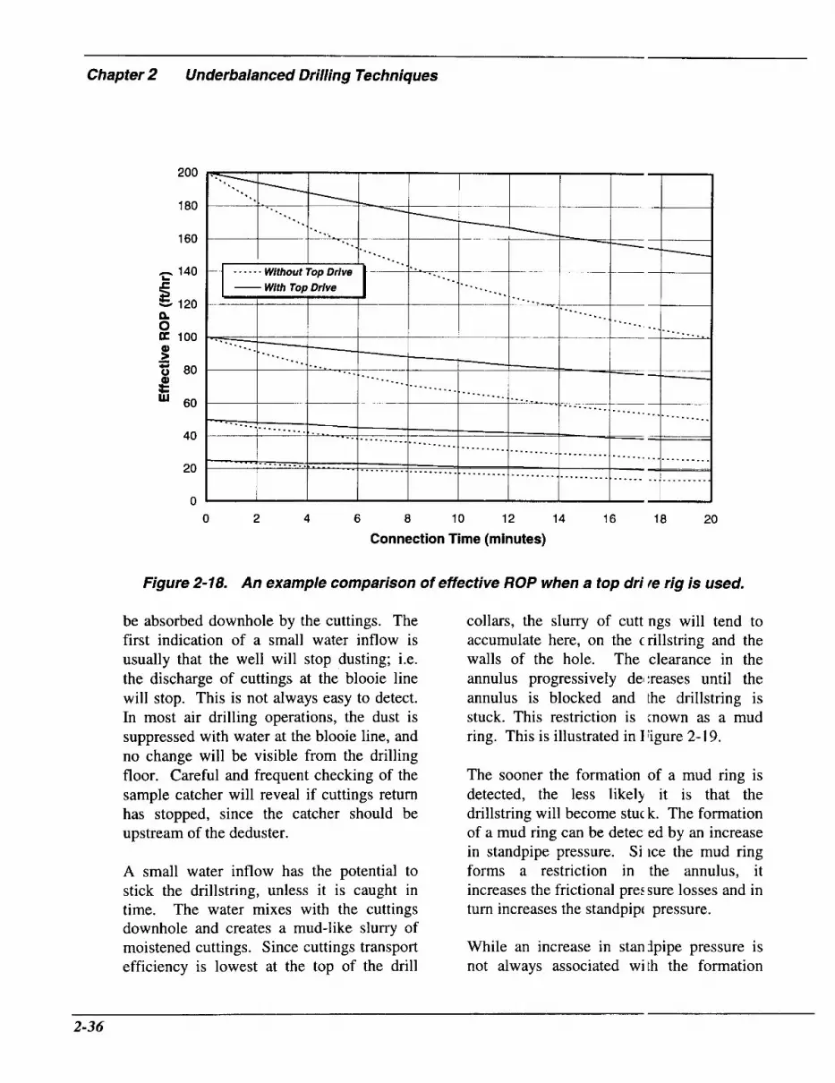
Chapter 2 Underbalanced Drilling Techniques
200
180
160
- 140 L
E 120 n
100
40
20
0 0 2 4 6 8 10 12 14 16 18 20
Connection Time (minutes)
Figure 2-18. An example comparison of effective ROP when a top dri le rig is used.
be absorbed downhole by the cuttings. The first indication of a small water inflow is usually that the well will stop dusting; i.e. the discharge of cuttings at the blooie line will stop. This is not always easy to detect. In most air drilling operations, the dust is suppressed with water at the blooie line, and no change will be visible from the drilling floor. Careful and frequent checking of the sample catcher will reveal if cuttings return has stopped, since the catcher should be upstream of the deduster.
A small water inflow has the potential to stick the drillstring, unless it is caught in time. The water mixes with the cuttings downhole and creates a mud-like slurry of moistened cuttings. Since cuttings transport efficiency is lowest at the top of the drill
collars, the slurry of cutt ngs will tend to accumulate here, on the crillstring and the walls of the hole. The clearance in the annulus progressively del :reases until the annulus is blocked and the drillstring is stuck. This restriction is mown as a mud ring. This is illustrated in I Yigure 2- 19.
The sooner the formation of a mud ring is detected, the less likely it is that the drillstring will become stuck. The formation of a mud ring can be detec ed by an increase in standpipe pressure. Si ice the mud ring forms a restriction in the annulus, it increases the frictional pre: sure losses and in turn increases the standpipt pressure.
While an increase in stanjpipe pressure is not always associated with the formation
2-36

Figure2-19. Cuttings mixed with a small amount of water will form a mud ring at the top of the drill collars where hole cleaning is critical.
of a mud ring, it should be considered as a warning of potential problems. If the standpipe pressure increases, stop drilling and check to see if the well is still dusting properly. If the well has quit dusting, there is a good chance that a mud ring has formed. Cuttings are one of the primary ingredients necessary to form a mud ring. By stopping drilling, additional cuttings will not be generated. Any mud ring will be inhibited from growing further and becoming more serious.
String Washouts Although string washouts are not especially common when air drilling, they can cause problems. They occur when a hole develops in the drillstring, allowing air to escape into the annulus without passing through the bit. The washout may be due to a fully- penetrating fatigue crack, in the pipe itself or
in the tool joint, or due to a poo . seal at the threaded connection.
In dry air drilling, the cuttini s-laden air flowing at high velocity up the ar nulus tends to erode the drillstring. This erosion is concentrated at the lower portion i of the tool joints. The tool joints also tend .o wear due to rotating contact with the hole wall. Since there is no lubricating liquid, abrasive wear occurs more rapidly than if mud 'vas present. Dry air drilling is also assoc:iated with greater downhole vibration than if mud was in the hole. These vibration: are often attributed to dramatically low er viscous damping of string motions in ai-.7,26 As a consequence, fatigue cracks can initiate and propagate more rapidly in air dri' ling than in conventional mud drilling operat ons.
Washouts associated with poor seals may deteriorate more slowly and n a y be less troublesome when drilling with air than with mud. The air flow down thl: pipe and through the washout should not Zontain any solids. As a result, metal around the leakage path is not eroded away : s rapidly as it would be by mud. Air drillinl, operations can continue for extended pt riods with minor string washouts at poor connection seals. In a mud drilled hole, wishouts can be found in a drillstring that is u: ed after the string has been used for air drillir g.
When a washout occurs in a i w d drilled well, standpipe pressure reduces. When this is detected, the string is tripped wet. When the washout comes through th: rig floor, mud will flow out of it. TI-e rig crew removes the section(s) of pip: with the washout and returns to bottom.
In air drilling operations, a wasiout is also
2-37

Chapter 2 Underbalanced Drilling Techniques
indicated by a reduction in the standpipe pressure, although the pressure change is smaller than it would be with mud. Finding the washout is difficult because the drillstring cannot be pulled wet. Attempts should be made to locate suspected washouts. Trip out of the hole and install small jets in the bit. Attach the bottomhole collar to the kelly and record the standpipe pressure, while circulating with the compressors and booster. Trip the drillstring in the hoIe and periodically (every five to six stands) pick up the kelly and observe the standpipe pressure while circulating. A substantial reduction in the standpipe pressure indicates that the washout was in the last section of pipe run. Pipe is pulled from the hole, testing each stand. When the standpipe pressure increases, the washout is in the last stand pulled. Now it is a matter of finding which joint or connection contains the washout so that it can be laid down. Overall, this is a time consuming process.
There is a temptation to drill ahead until the string parts and then fish for the parted string. This can be a dangerous strategy if the string parts when being tripped. The fish will fall more rapidly through air than through mud. It is more likely to corkscrew inside the hole when it hits bottom. Cooper et al., 1977,24 noted that these corkscrewed fish can be very difficult to retrieve. If it is believed that the washout is so severe that the string could part when tripped, they recommended that no attempt be made to trip the string. Instead, they suggested the following procedure.
> Set the bit on bottom.
> Locate the washout by reverse circulating air and running a wireline spinner tool inside the string.
> Adjust the neutral point and back off the
string below the wash )ut. This should leave a readily-retrieve4 I fish.
Limitations of Dry Air I killing The three main limitations of dry air drilling are water inflows, dow ihole fires, and wellbore instability.
Water Inflows The flow of water into a 'vel1 being drilled with dry air can cause problems that are significant enough to preclude dry air drilling.
Methods are available tc shut off water inflow. All involve attempting to inject material into the formation that is producing water, where it sets to form a barrier to water flow. The oldest, establish :d technique is to squeeze cement into the water producing zone. This is only likely t ) be successful if the water is flowing from natural fractures; cement is unlikely to entei matrix porosity. Hower et al., 1958,27 descr, bed field trials of two different water shutoff systems. One of these was based on a rcsin and catalyst system, which could be use 1 either neat or in a slurry containing inert silids for bulking and for fluid loss control. Water further catalyzed the resin setting, which tended to restrict preferential channc ling of the resin into the most permeable zones. The set resin had a compressive :trength of 2,000 psi, giving it the ability to shut off substantial water flows on:e set. The neat slurry could be squeezed iito the matrix of reasonably permeable fon iations, although it seemed to be more suitilble for fractured zones. The other water shitoff system they described was a watei -based polymer solution that set as a stiff ;el. This system had a lower initial viscosi y, allowing it to enter low permeability zcnes. Core tests showed that the gel was c2pable of sealing
2-38

differential water pressures of up to 2,000 psi.
Particularly in the case of cement or resin- based treatments, high pressures have to be applied to squeeze the treatment into the formation. These pressures can jeopardize wellbore integrity. Treatment is less likely to be successful if the formation is fractured during the squeeze. The open fracture(s) will accept the shut-off material at the expense of the water-producing permeability. Water shut-off methods that rely on liquid material setting all involve a waiting period of several hours after placement to set, before it will resist water flow and the wellbore pressure can be reduced.
There are several water shut-off methods that use gas. One requires pumping an aluminum sulfate solution into the formation, followed by gaseous ammonia.28 These react to form a solid aluminum hydroxide precipitate, in the formation. This obstructs porosity and shuts off the water flow. The gas and liquid tend to effectively mix inside the formation's porosity. Ammonia has a low vapor pressure and liquefies at quite low pressures. If the interval to be treated is deeper than one or two hundred feet, it may be necessary to use a mixture of ammonia and an inert gas, such as nitrogen or natural gas, to avoid liquefaction due to the injection pressure. In this case, it has been suggested that a second liquid treatment should follow the gas injection. Otherwise, the quantity of precipitate may be insufficient to shut-off the water flow.
This shutoff method has several advantages. It does not require any waiting time for
setting and there is no significaiit risk of it setting prematurely. The materi: 1s involved are also inexpensive (but, gaseoi s ammonia is toxic). However, it does not seem to be particularly successful in fractured formations and care needs to t e taken to avoid fracturing while treating. It has been suggested2* that injection pressi ires should not exceed 0.6 psi/ft.
Another water shutoff method2' uses only gaseous silicon tetrafluoride. ' rhis reacts with formation water to generate a blocking precipitate of hydrated silicon d ioxide. In formations containing calcium, nagnesium or sodium salts, additional I olids will precipitate and further con ribute to blocking. Laboratory tests have shown that Berea sandstone cores pluggej by this method retained only one percent of their untreated permeability, even whe 1 subjected to a pressure differential of 4,00( psi. Field treatments involve pumping a si earhead of liquid hydrocarbon or a non-re active gas, such as air or nitrogen, folloved by the silicon tetrafluoride, and finall! tailing-in with additional inert gas or a ribber plug and water.
With all of these water shutoff systems, a single packer has to be set above the zone to be treated if it is close to the hole bottom, or a straddle packer has to be set across the zone. In either case, the water producing zone must be located accurately. This may require wireline logging. Treat nents take time, particularly if they involve cement or resin placement. A shutoff tIsatment is probably only worth considering f there is a substantial interval still to be drill :d with dry air and the operator can be cor fident that further water producing zones ryrill not be encountered between the treatec zone and
- 2-39

Chapter 2 Underbalanced Drilling Techniques
the projected end of the air drilled interval.
The usual response to a water influx is to switch from dry air to mist or foam. This can lift the inflowing water, without slugging or mud ring formation. The produced water still has to be handled at the surface and disposed of in an acceptable manner. The cost of this can outweigh the reduction in drilling costs for underbalanced drilling. Conventional mud drilling may become more cost effective.26
Downhole Fires The possibility for downhole fires is a potential limitation on the use of dry air drilling. Fires occur when a mixture of oil or natural gas and air, with the hydrocarbon concentration in a combustible regime, is exposed to an ignition source. A concentration of five to fiiften percent natural gas is combustible at atmospheric pressure. The upper limit is extended with increasing pressure, reaching thirty percent when the pressure is 300 psi.
Figure 2-20 shows the influence of pressure on the combustible regime, for a typical natural gas. These limits vary somewhat with gas composition. Consider a typical air drilling flow rate of 2,000 scfm. Combustion limits suggest that gas inflows of 100 to 600 scfm (144 to 864 MscfD) would be required for a combustible mixture to occur during normal air drilling. However, as reported by Cooper et al., 1977,24 and by Grace and Pippin, 1989,30 most downhole fires are preceded by formation of a mud ring that obstructs air flow. Carden, 1993,26 has noted that downhole fires have not occurred when dry gas is encountered while drilling with dry air. Some liquid, either water or oil, had to be present. The role of the liquid in causing
a fire is presumably to moisten the cuttings, permitting the formation of a mud ring.
Once flow is obstructed, tht: air pressure will rapidly rise to the delivery pressure limit of the compressor system. This increases the temperature of the gas below the mud ring. Since air flow has been obs:ructed, even low hydrocarbon inflow rates c;in rapidly lead to combustible mixtures. Onc 2 the gas mixture is in the combustiblf' regime, the compression itself can often ignite the mixture. Sparking, fron I the drillstring rubbing against the borehole wall, particularly where the ro:k penetrated is strong and has a high qu,u-tz content, can ignite the gas mixture. Fric:tional heating of the string by air flow thro igh pinholes has also been cited as a potcntial sources of i g n i t i ~ n . ~
Downhole fires can be Tery difficult to detect since the combustic n rarely reaches the surface. It may be nccessary to run a temperature survey through the drillstring to confirm that a fire has occi rred. Downhole fires usually melt the d rillstring at the combustion site. It has bet n reported24 that slag from a downhole fire could be blown several hundred feet uphol:. The damaged string can be very difficult to fish and downhole fires usually requ ire sidetracking.
Obvious ways to avoid a cownhole fire are to prevent formation of a combustible mixture and to remove the source of ignition. Changing the circ :dation medium, from air to natural gas or in inert gas, will prevent the formation ol a combustible mixture. This may not be economically or logistically feasible. . 'reventing the formation of mud rings will effectively avoid downhole fires. Probably the most common method used to avoid a fire when
2-40

400
350
300
250 h Q v) P 0
v) v)
.- v
5 200
E n 150
100
50
0 0 10 20 30 40
Natural Gas in Mixture ("!by Volume)
Figure 2-20. Effect of pressure on combustible concentrations of natural gi 4s in air.
natural gas is encountered is to use mist rather than dry air.24
Cooper et al., 1977,24 recommended steps to minimize the probability of a downhole fire. First, attentive monitoring of the standpipe pressure is necessary. An increase of five to ten psi, without any accompanying increase in compressor output, can indicate the onset of mud ring formation or a gas inflow. Once a mud ring has developed fully, the flow of air and cuttings from the blooie line will stop. By then, the string may be stuck or a
fire may already have startec. If the standpipe pressure increasl :s when approaching a possible gas beari ig zone, or when there is a gas show at the f are pit, the following steps should be taken:
P Stop drilling.
> Shut off the air and monitor t le gas flare at the pit. If the flare contini es to burn, any of the following indicaizs that the gas is wet: wet cuttings, b1,ick smoke, yellow flame, sparking at the blooie line exit (the last three conditio IS indicate

Chapter 2 Underbalanced Drilling Techniques
condensate).
P If the flare does not continue to bum with the air shut off, resume air circulation and determine if the gas is wet, using the indicators in (2) above. DO NOT DRILL. New cuttings will promote the formation of a mud ring. Reciprocate the string to avoid formation of a mud ring.
P If the gas is wet, switch to mist or natural gas drilling.
P If the gas is dry, drill ahead in five to ten foot intervals, reciprocating the string between intervals. Continue to do this until it is certain that there is no further possibility for wet gas to be encountered.
Wellbore Instability Dry air drilling usually leads to the lowest wellbore pressures of any drilling method. These low wellbore pressures can cause mechanically-induced instability, especially in weak formations. Alternatively, if there is a significant water inflow with water- sensitive shales exposed uphole, it is possible for the produced water to cause wellbore instability as it is lifted out of the well.
Wellbore instability, during air drilling, is especially problematic when large fragments of rock break away or slough from the borehole wall. In most cases, the sloughed rock fragments are much larger than the drilled cuttings. Fragments, as large as 1.5 inches in diameter, may come over the shale shakers in a mud drilled hole. Figure 2-21 shows how particle terminal velocity (under standard conditions, computed using Equation (2.2)) increases with increasing particle size. Terminal velocities of these large rock fragments can be much higher than the 3,000 feet per minute annular
velocity used in Angel s predictions of recommended air flow .ates. The rock sloughing fragments will lot be lifted from the well by circulation rate j normally used in air drilling.
Those fragments that are too large to be lifted from the well will remain downhole until grinding action of the string breaks them down into particles sufficiently small to be lifted by the circulating air. If the rate of sloughing exceeds the rate at which the debris is broken up dou nhole, fragments will accumulate and eventually stick the string. This process is axelerated by the increased concentration of rock fragments in the air flowing up the annu us. The resulting increase in air pressure rehces the annular velocity and progressivel! leads to poorer hole cleaning so that eren smaller rock particles cannot be remov:d from the hole. Sloughing from the boi ehole wall also increases the hole diametl :r. This reduces annular velocity and furtf er degrades hole cleaning.
The time, over which the tnnulus packs off with enough rock particlef for the string to become stuck, depends on the rate at which the formation sloughs, he size of the sloughed rock fragments, and the rate at which they can be ground L p downhole.
If the formation sloughs loo fast or in big pieces, air drilling must be terminated. It is unlikely that the air circul2tion rate can be increased sufficiently to lj ft enough of the sloughed rock fragments f -om the borehole to prevent the annulus from eventually packing off. Furthermoi e, the increased annular velocity will tend tc ) increase the rate at which rock fragments ale dislodged from the borehole wall. A diilling fluid with greater lifting capacity an( higher wellbore
2-42

8000
7000
- 6000 C .- E
5000 .- E
>”
E
0 9 4000
- .- 3000
8 t- 2000
1000
0 -*---I-
I
---I I
0 0.2 0.4 0.6 0.8 1 1.2 1.4 1.6
Particle Diameter (inches)
Figure2-21. Terminal velocity as a function of parficle size at standard conditions (assuming a drag coefficient of 0.85).
pressures must be used.
Other Limitations Other factors that can restrict the use of air drilling are higher friction between the drillstring and the wellbore, and the difficulties in operating conventional downhole motors and MWD systems with compressible drilling fluids. These are normally only relevant to directional wells.
Reverse Circulation Air Drilling Some of the problems described in this section on conventional air drilling may be overcome or mitigated by reversing the circulation of the air. In this procedure, air is injected down the annulus and returned with cuttings up the drillstem. This
procedure, still considered exper mental, has several important advantages inc icated from tests by Graham, 1986.31
P Reduced Damage to Permea Zle Formations Tests strongly suggested les: damage to the formation than with coni entional air drilling. Conventional air drilling, in ‘turn, normally resulted in 1 :ss damage than conventional mud drillir g.
> Quality and Size of Drill Cui tings Improved Drill cuttings are larger and less “contaminated.” With the lar :er cuttings, it is possible to run quantitative petrophysical analyses. This is virtually impossible with conventiona “dusting.”
2-43

Chapter 2 Underbalanced Drilling Techniques
9
9
Wellbore Integrity Improved There is a potential for reduced wellbore damage because there is less hole erosion by cuttings or water influx that Q
7
There is a greater likeliiood of cuttings plugging the bit. Surface =quipment design
could promote uphole sloughing of sensitive shale.
since the velocity of air in the larger annular space would nc longer be critical to cuttings removal.
Limitations
Less Air Volume Required needs improvement. Lar, ;e inflows above Tests have indicated that reverse drilling the bit may cause problem in circulating used less air. This would be expected down the annulus.
2-44

References
1.
2.
3.
4.
5.
6.
7.
8.
9.
10.
11.
12.
13.
14.
Johnson, P.W.: “Design Techniques in Air and Gas Drilling: Cleaning (kiteria and Minimum Flowing Pressure Gradients,” J. Cdn. Pet. Tech. (May 1995) 34, No. 5, 18-26.
Bruce, G.H., Simons, L.H. and Whitaker, W.W.: “You Can Recover Large Cu tings When Air Drilling,” Oil and Gas J. (May 1962) 112-1 16.
Pratt, C.A. : “Modifications to and Experience with Air-Percussion Drilling,” SPE Drill. Eng. (December 1989) 3 15-320.
Zenz, F.A. and Othmer, D.F.: Fluidization and Fluid-Partick Systemr , Reinhold Publishing C o p , New York (1960).
Supon, S.B. and Adewumi, M.A.: “An Experimental Study of the Annulus Pr s u r e Drop in a Simulated Air-Drilling Operation,” SPE Drill. Eng. (March 1991) 74-80.
Hagar, J.M., Tian, S., Adewumi, M.A. and Watson, R.W.: “An Experimenlal Study of Particle Transport in a Deviated Wellbore,” J. Cdn. Pet. Tech. (February 199:;) 34, No.2, 5 1-54.
Shale, L.: “Underbalanced Drilling Equipment and Techniques,” presented it the 1995 ASME Energy Technology Conference, Houston, TX, January 30- February 1.
Gray, K.E.: “The Cutting Carrying Capacity of Air at Pressures Above At nospheric,” paper SPE 874-G, Pet. Trans., AIME (1958) 213, 180-185.
Machado, C.J. and Ikoku, C.U.: “Experimental Determination of Solids Frictioi I Factor and Minimum Volumetric Requirements in Air and Gas Drilling,” paper SPE 9938 xesented at the 198 1 California Regional Meeting, Bakersfield, CA.
Weymouth, T.R.: “Problems in Natural Gas Engineering,” Trans., ASME (1 9 12 ) 34, 185.
Angel, R.R.: “Volume Requirements for Air and Gas Drilling,” Pet. Trans., Al ME, (1957) 210, 325-330; also Volume Requirements .for Air and Gas Drilling, Gulf Pub lishing Co., Houston, TX (1958).
Guo, B., Miska, S.Z. and Lee, R. L.: “Volume Requirements for Directional A ir Drilling,’’ IADC/SPE paper 275 10 presented at the 1994 IADC/SPE Drilling Conference, Dallas, TX.
Nikuradse, J., “Forschungshelf,” (1933) 301.
Schoeppel, R.J. and Sapre, A.R.: “Volume Requirements in Air Drilling,” papc r SPE 1700 (1967).
2-45

Chapter 2 Underbalanced Drilling Techniques
15.
16.
17.
18.
19.
20.
21.
22.
23.
24.
25.
26.
27.
28.
Mitchell, R.F.: “Simulation of Air and Mist Drilling for Geothermal Wt lls,” J. Pet. Tech. (November 1983).
Puon, P.S. and Ameri, S.: “Simplified Approach to Air Drilling Opera ions,” paper SPE 13380 presented at the 1984 SPE Eastern Regional Meeting, Charleston, WV, October 31- November 2.
Wolcott, P.S. and Sharma, M.P.: “Analysis of Air Drilling Circulating Systems with Application to Air Volume Requirement Estimation,” paper SPE 1593 1 presented at the 1986 SPE Eastern Regional Meeting, Columbus, OH.
Grace, R.D.: “A Field Study of Annular Pressure Losses In Rotary Drillir g with Air-Solids Mixtures,” MSc. Thesis, University of Oklahoma.
Streeter, V.L.: Fluid Mechanics, McGraw-Hill Inc., New York (1971) 33“.
Lyons, W.C.: Air and Gas Drilling Manual, Gulf Publishing Co., Houstc n, TX (1984) 46.
Lyons, W.C.: Air and Gas Drilling Manual, Gulf Publishing Co., Houstc n, TX (1984) 84.
Lyons, W.C.: Air and Gas Drilling Manual, Gulf Publishing Co., Hoiston, TX (1984) Appendix A.
Cress, L.A., Stone, R. and Tangedahl, M.: “History and Development of a Rotating Blowout Preventor,” paper IADC/SPE 2393 1 presented at the 1992 Ip DC/SPE Drilling Conference, New Orleans, LA.
Cooper, L.W., Hook, R.A. and Payne, B.R.: “Air Drilling Techniques,’ paper SPE 6435 presented at the 1977 Deep Drilling and Production Symposium, Amarillc I, TX.
Shale, L. and Curry, D.A.: “Drilling a Horizontal Well Using AirEoam T xhniques,” paper OTC 7355 presented at the 1993 Annual Offshore Technology Conferenc :, Houston, TX.
Carden, R.S.: “Technology Assessment of Vertical and Horizontal Air DI illing Potential in the United States,” Final Report, Contract No. DOE/MC/28252-35 14 (D Z94000044), U.S. DOE (August 1993).
Hower, W.F., McLaughlin, C., Ramos, J. and Land, J.: “Water Can be Controlled in Air and Gas Drilling,” paper SPE 1099-G presented at the 1958 SPE Annial Fall Meeting, Houston, TX.
Goodwin, R.J. and Teplitz, A.J.: “A Water Shut-off Method for Sand-Ty ,e Porosity in Air Drilling,” paper SPE 1098-G, Pet. Trans., AIME (1959) 216, 163-167.
2-46

29. Becker, F.L. and Goodwin, R.J.: “The Use of Silicon Tetrafluoride Gas as a Formation Plugging Agent,” paper SPE 1098-G, addendum, Pet. Trans., AIME (1959) 216 168.
30. Grace, R.D. and Pippin, M.: “Downhole Fires During Air Drilling,” WorZd Oil (May 1989) 42-44.
3 1. Graham, R.L: “Exploration-Production Studies in Newly Drilled Devonian Shale Gas Wells,” Annual Report, Gas Research Institute, Chicago, IL (November 1986).
2-47

Chapter 2 Underbalanced Drilling Techniques
2.2 Nitrogen Drilling
In underbalanced drilling operations, nitrogen can be used as the drilling fluid, or as a component of the drilling fluid. The major advantage over air is that mixtures of nitrogen and hydrocarbon gases are not flammable. This removes the possibility of downhole fires.
The circulating gas does not have to be pure nitrogen to prevent downhole fires. Mixtures of air, nitrogen and hydrocarbon are not capable of combustion, provided that the oxygen concentration is kept below a critical level. Allan, 1994,' demonstrated that the flammability of natural gas is quite well represented by the flammability of methane, which has been studied extensively by the U.S. Bureau of mine^.^.^ At atmospheric pressure, at least 12.8 percent oxygen is required before it is possible to create a flammable mixture of oxygen, nitrogen and methane. The minimum oxygen concentration required for a flammable mixture is influenced by the prevailing pressure and can be represented by the following correlation:
O,, = 13.98 - 1.68 log (P) (2.32)
where:
Omin .... percent oxygen, and, P ......... absolute pressure, psia.
This correlation is shown in Figure 2-22. For a pressure of 3,000 psi, a mixture of oxygen, nitrogen and methane has to contain slightly more than eight percent oxygen to be flammable. As Allan indicated,* this represents the level of oxygen in the drilling
fluid, which effectively elifninates any possibility for downhole fii es.
Hole Cleaning Circulating nitrogen will lift cuttings and liquid inflows, in the same way that air does. As with air, flow in the ~nnulus is usually turbulent. Consequently, c ensity is the fluid property with the most iripact on cuttings transport. Since the dens ty of nitrogen is only slightly (about three >ercent) less than that of air at standard temperature and pressure, cuttings transport efficiency will be effectively the same as it is for air at the same surface injection rate.
When using air or nitro;;en, selecting an injection rate is usuallj a compromise between increased clea ning efficiency, leading to increased overal I penetration rate, and increased nitrogen c osts, compressor rental and fuel charges. The cost of increasing the nitrogen in-ection rate is far greater than for air. The riost cost efficient injection rate (not total C I )sts) for nitrogen drilling will likely be lowtr than for dry air drilling.
Equipment The principal differences between nitrogen and air drilling equipmert are due to the substitution of nitrogen for air, as the circulating fluid. There ire currently two main methods of suppljing nitrogen for drilling operations-cryoger ic and membrane filter.
Cryogenic Nitrogen Suppi y Nitrogen is widely used ir well completion, stimulation and productioi I operations. For these applications, nitrc bgen is usually transported to the wellsite 3s a liquid. Since the boiling point of licuid nitrogen, at
2-48

12
11.5
11
10.5
10
9.5
9
8.5
8 0 500 1000 1500 2000 2500 : '000
Pressure (psia)
Figure 2-22. Influence of pressure on the minimum concentration of oxyge n required for a flammable mixture of oxygen, nitrogen and methane (ilffer Allan, 1994,' and Zabetakis, 1964 ').
atmospheric pressure, is -32 1 O F , cryogenic tanks are necessary for transportation to location. A nitrogen pumping unit consists of a diesel-driven, positive displacement pump and a heat exchanger. The pump takes liquid nitrogen from the cryogenic tank and delivers it through the heat exchanger, where heat from the pump engine's exhaust is used to evaporate the liquid nitrogen. There is a Jarge rental fleet of nitrogen units available in most parts of the United States. Various sized units are available. They have maximum delivery rate and pressure specifications, but generally power restrictions will prevent them from reaching both limits simultaneously. For example, a
small unit will typically be ablc to deliver 1,100 scfm at pressures of up tcl 3,000 psi, but this rate will then fall if t i e delivery pressure is increased towards ts delivery pressure rating of 4,500 psi. Lar, ;e units can often deliver 6,000 scfm at up to 8,000 psi. The delivery pressure of a cryogenic nitrogen unit will not be a prob em for dry nitrogen drilling.
For drilling applications, the nit1 ogen pump unit replaces the bank of comFressors and the booster. Since the nitrogen i: pumped as a liquid and the conversion lrom liquid volume to gas volume, a standard conditions, is well characterized, it is
- 2-49

Chapter 2 Underbalanced Drilling Techniques
straightforward to accurately measure the nitrogen delivery rate. Control of delivery rate is also good.
If the pump is at ambient temperature when it is started up, some liquid nitrogen is effectively lost in cooling the unit down to where the nitrogen remains as a liquid until it is delivered to the heat exchanger. Before then, formation of gaseous nitrogen in the pump reduces its efficiency. Controlling the delivery rate is uncertain during cooldown. However, this does not take more than a few minutes, and should not affect operations substantially.
Each gallon of liquid nitrogen generates approximately 100 scf of nitrogen gas. For a typical drilling operation, with a volumetric flow rate of up to 2,000 scfm, this means that up to 30 bbl, or roughly 5 tons per hour, of liquid nitrogen will be required.
Membrane Filter On-site generation of nitrogen by membrane filtration can provide a feasible alternative nitrogen source. It does not involve transporting and storing large quantities of cryogenic liquid.' It requires that air coolers and a filter array are added to an otherwise conventional air drilling compression system (refer to Figure 2-23).
As shown in Figure 2-23, conventional air compressors deliver the air, at a pressure of 150 psi. The compressed air is cooled to approximately 80°F and passed through a series of primary filters. These remove contaminants, such as dust, compressor lubricant oil, and atmospheric water. The air flow then passes through the membrane filter. This consists of an array of many, very fine, hollow polymeric fibers. The lighter nitrogen molecules pass down the
fibers, while heavier ox ygen molecules penetrate the fiber walls. 7 he two gases are separated. Nitrogen is tlelivered to the booster unit and then tc the standpipe. Oxygen is vented to the atm xphere.
Nitrogen concentration ir the gas flow delivered by these membrane filters can be readily controlled, and can -ange from 92 to 99.5 percent. Nitrogen pu ity is controlled by varying the air input rlte and the back pressure on the filter unit.
Other Equipment Firestops or firefloats in tl e drillstring are not needed when drilling with nitrogen. Otherwise, the equipment u ;ed is effectively the same as that used for diy air drilling, as described earlier, in Section 2.1.
Operational Procedures No special operating procl :dures, different from those described for dr:' air drilling, are required for nitrogen drillii~g. The risk of downhole fires is removed. Since formation of a mud ring can cause st Ick pipe, timely detection of the symptoms of mud ring formation is still necessary. The release of large quantities of nitrogen and enriched oxygen into the atmosphere do not normally pose any risks. Care shoulc nevertheless be taken so that dispersion ol the discharged oxygen is not hindered. Even a modest increase in oxygen concent .ation can result in dramatic changes in the ( ombustibility of familiar materials.
Limitations An appropriate concentratio I of nitrogen, in the circulating medium, ren oves the risk of downhole fires. This overcjmes one of the major limitations of dr I air drilling. However, the other limitations of dry air drilling apply equally when iitrogen is used.
2-50

Nitrogen Into
Standpipe
Figure 2-23. Schematic of a nitrogen dri//ing system using membrane filter ' generation (after A/lan, 1994 ').
The formation of mud rings remains a concern. It is possible to use nitrogen as the gaseous phase in mist or foam drilling, overcoming problems with excessive water production.
The principal limitation on the use of nitrogen for drilling is economic. The nitrogen supply is costly, whether liquid nitrogen or membrane filters are used. The quantities of liquid nitrogen required can easily cost from $10,000 to $35,000 per day of drilling. AIlan, 1994,' cited a daily incremental cost of over $7,000, to use a membrane filter unit, capable of delivering up to 3,600 scfm of nitrogen. This cost includes rental of the compressors and boosters, and all mobilization. As a result of
its high cost, nitrogen is norma ly only used when drilling through a Ion; producing interval, as would be the case ir a horizontal well. It is less likely that the ad jitional cost/ can be justified (particularly cry )genic liquid nitrogen), for drilling long venical (or near vertical) intervals, unless multil )le zones are likely to be penetrated.
There is a possibility that nitro;en could be re-cycled if a closed surface sy item is used. This could make the use of n trogen more attractive, although the saving ; in nitrogen cost would be partly offset by t ne additional daily cost of the surface eq iipment that might be involved. This will be discussed again in Section 2.7, "Gasifi =d Liquids."
2-51

Chapter 2 Underbalanced Drilling Techniques
References
1. Allan, P.D.: “Nitrogen Drilling System for Gas Drilling Applications,” iaper SPE 28320 presented at the 1994 SPE Annual Technical Conference and Exhibitic In, New Orleans, LA.
2. Coward, H.F. and Jones, G.W.: “Limits of Flammability of Gases ard Vapors,” U.S. Bureau of Mines Bulletin No. 503, Washington, DC (1952).
3. Zabetakis, M. G.: “Flammability Characteristics of Combustible Gases a id Vapors,” U.S. Bureau of Mines Bulletin No. 627, Washington, DC (1964).
2-52

2.3 Natural Gas Drilling
As was the case with nitrogen, natural gas can be used (instead of air) as the circulating fluid for drilling underbalanced. Using natural gas will prevent the formation of a flammable gas mixture downhole when a hydrocarbon producing zone is penetrated. Unlike nitrogen, however, natural gas will almost invariably form a combustible mixture when it is released into the atmosphere. This inherently higher potential for surface fires requires few changes in operating procedures from those used in dry air drilling.
Hole Cleaning The density of natural gas is generally different from the density of air, at the same temperature and pressure. It is convenient to represent a gas's density by its specific gravity, S. The specific gravity is defined as the ratio of the weight of a unit volume of the gas at standard conditions to the weight of the same volume of air. Gaseous hydrocarbons have specific gravity's that increase with increasing molecular weight. For example, methane has a gravity of 0.55, ethane 1.05 and propane 1.55 at STP. The gravity of natural gas (gas density divided by the density of air, both densities at STP) depends on its composition, but is often in the range of 0.6 to 0.7. Thus, the density of natural gas circulating round a well differs sufficiently from air injected at the same volumetric rate that cuttings transport efficiency is influenced.
Equation (2.33) shows that a cutting's terminal velocity is effectively inversely proportional to the square root of the density of the fluid through which it is falling:
vt $2;; (2.33)
where:
Vt ....... terminal velocity (fth), d, ........ diameter of the particle (ft ), p, ....... density of the particle (lbr dft3), pf ........ density of the fluid ( l b d f '),
c d ....... drag coefficient.
g ......... gravitational acceleration (32.17 ft/s2), and,
This equation requires that the deisity of the carrier fluid is much less than hat of the cutting. This is the case when dri ling with a gaseous fluid. At atmospheric p -essure, the terminal velocity in natural g s, V,,, is related to the terminal velocity in 2 ir, V ~ , by:
(2.34)
The minimum gas injection rate iequired for efficient cuttings transport at ; tmospheric pressure increases in inverse propc srtion to the square root of the gas's specific gr, ivity.
Equation (2.5) shows that the vari ition of the pressure gradient with depth is pro ?ortional to the density of the gaskuttings mi rture in the annulus. The pressure gradient w 11 be lower for natural gas than for air, and th : downhole pressure will also be lower. However, the mixture density is not, directly pro Portional to the specific gravity of the gas. It a so depends on the mass of the cuttings and noisture in the annulus (and hence on the penetration rate). As a result, there is no simple relationship between the ga: pressure downhole and its specific gravitj. The full
2-53

Chapter 2 Underbalanced Drilling Techniques
frictional pressure drop and cuttings transport analysis has to be repeated using the specific gravity of the appropriate gas. When this is done, the net effect is that the gas injection rate required for efficient cuttings transport is higher for natural gas than it is for air, but the fractional difference decreases with increasing depth. The bottomhole pressure is lower for natural gas than it is for air, at an injection rate providing equivalent cuttings transport. As can be seen from Figure 2-2, Angel’s analysis indicates that bottomhole pressures with natural gas are ten to fifteen percent lower than those for air.
An additional complication is departure from ideal gas law behavior. Natural gas is characterized by a phenomenon referred to as “supercompressibility.” This means that it compresses more readily at some pressures than an ideal gas. The deviation from ideal compressibility can be significant at pressures around 2,200 psi, where it is possible for natural gas to compress to twice the density that would be estimated for an ideal gas. In most gas drilling situations, downhole pressures will be well below this level. Given the overall uncertainty of the computations, it is still probably reasonable to neglect departures from ideal gas compressibility when estimating required injection rates. If it is necessary to have good control of bottomhole pressure - for example, to maintain the underbalanced pressure within a specific range - then the real compressibility of natural gas may have to be considered.
Natural gas is more expensive than compressed air. The incremental cost of increasing the injection rate is higher when drilling with natural gas than it is when drilling with air. The most cost effective injection rate is likely to be closer to the recommended minimum rate than would be
the case with air.
Cummings, 1987,’ prese:ited a case history of natural gas drilling in the San Juan Basin, New Mexico. Gas injection rates of between 900 and 1,200 s:fm were found to be adequate for drilling 6%-inch hole to depths of between 6,900 and 7,500 feet, at penetration rates ranging from 40 to 75 feet per hour. The gas us:d had a specific gravity of 0.65. Angel’s analysis indicated minimum air injection ra es of between 8 15 and 950 scfm, for this rznge of depths and penetration rates. For nzturul gas, a first order estimate of the riinimum injection rates required could be derived by taking Angel’s figures for ai . drilling at the appropriate depth and pt netration rate and dividing these by the squ: re root of the gas’s specific gravity. Whc n this is done, minimum injection rates, .anging from 1,000 to 1,180 scfm, are inferred. These are very close to the rates that prwed acceptable in practice.
When drilling with natural gas, the size of the hole to be drilled should be carefully considered. Even minor reductions in hole diameter could lead to si€ nificant reductions in gas injection rates and s avings. Cummings, 1987,’ noted that increa ing the hole size from 61/-inches to 6%-i iches would have required a fifteen to twenty percent increase in the gas injection rate, while going to a 7 7/8-inch hole would h; .ve increased gas consumption (and the gas :ost) by as much as 40 percent.
Equipment Currently, natural gas drilling is only undertaken if the natural as can be obtained directly from a supply pip dine. Usually, the pipeline operator will proT ide a drill gas unit, which consists of a scrubbing vessel and an
2-54

orifice meter,' connected to the pipeline. A three-inch diameter line is used to take the gas supply to the rig location. Cummings, 1987,' noted that this line could be as much as one-half mile long. The pressure drop along the supply line needs to be considered, to ensure that adequate delivery is available at the rig site. With a three-inch diameter supply line, the pressure drop is unlikely to be much more than one psi per 100 feet of pipeline, at a gas flow rate of 1,200 scfm and an average line pressure of 150 psi. This will probably not have significant impact on gas delivery rate.
Compressors may or may not be required, depending on the pipeline pressure and the anticipated gas injection (standpipe) pressure. It may be advisable to have a booster available, in the event that downhole problems require a standpipe pressure higher than pipeline delivery pressure.
It is important to remove, as much as possible, any water or condensate from the supply gas before injecting it downhole. Otherwise, problems with mud ring formation and wellbore stability" may occur. Cummings, 1987,' suggested installing a three-phase production vessel between the drill gas supply unit and the booster. It should have working pressure and temperature ratings that at least match the pipeline delivery pressure and temperature and it should be able to handle flow in excess of the highest required gas injection rate. These requirements are not difficult to meet. For example, the vessel used by Cummings was sixteen inches in outside diameter by six feet long, with a 1,000 psi and a 100°F working pressure and temperature. It had a
If water sensitive shales are penetrated.
rated capacity of 3,125 scfm (4.5 IAMscfD). Collected water was discharged into a water tank and hydrocarbon vented in13 a stock tank.
Downstream of the booster, the 1;as should flow through an adjustable choke, to control the flow rate during drilling an( tripping. Otherwise, the gas delivery rat: can be controlled by a pressure regulatir g valve. The gas flow is then directed to a three-inch valve manifold, ideally located ( n the rig floor, adjacent to the driller's con!ole. This should allow gas to be sent to the dooie line primary jet or to the standpipe. It should also be possible to independently vert the gas delivery line and the standpipe. Bo .h of these vent lines, which should be two-inches in diameter, should run to a flare pit. hmmings recommended that this flare pit should be separate from the main flare pit into which the blooie line discharges (refer to Figures 2- 24 and 2-25).
Additional lines, from the choke manifold direct to the flare pit, and throu,;h a flow tester to the flare pit, should be in: talled if it is intended to measure the gas x-oduction rate. These lines must be ratej for the maximum anticipated well flow rate and wellhead pressure.
As natural gas is always present in the rig site, it is sensible to have hydrocarbon gas and hydrogen sulfide detectors loc: ted on the rig floor and in the well cellar. A hydrogen sulfide detector should be also be ited at the blooie line exit. As with air an11 nitrogen drilling operations, care should be t ken when locating this detector, to prevent it 1 rom being damaged by the flare while still guaranteeing
2-55

Chapter 2 Underbalanced Drilling Techniques
Booster
Driller's hfan bm
Figure 2-24. Surface equipment required for drilling with natural gas ( Mer Cummings, 1987 ').
7" Blooie Line 150 Feet Long
2" Line lo Blooie Line Je t
Orifice Choke Manifold .Wel l Tester T I 9
C r I Rotary 1
A / 2" Vent Line
Fla e Pit
Flare Pit
3 Dog House u Driller's
Manifold
Figure 2-25. Flaring arrangements for drilling with natural gas (after Cu mmings, 1987 ' I .
2-56

its exposure to the returning gas flow. There is little point in having a hydrocarbon detector at the blooie line exit.
Other required surface equipment is similar to that needed for air drilling. Cummings indicated that a conventional rotating head could be used to divert gas flow into the blooie line in certain situations (i.e. low permeability wells that need to be hydraulically fractured). Particularly if it is anticipated that high formation gas pressures or production rates may be encountered, the additional pressure capacity of a rotating blow out preventer is worth considering.
Large volumes of gas have to be flared when drilling with natural gas. The flare pit has to be designed accordingly. It may be necessary to construct banks, or even possibly use a vertical flare stack. Since the flare is larger and is burning whenever natural gas is circulated, there is a greater risk of fire damage to the hydrogen sulfide detector located at the end of the blooie line, than when dry air, nitrogen or mist are used.
Instead of using pipeline gas, in rare instances, it may be possible to transport natural gas to the rig site in large pressure vessels. Typically, these can hold up to 160,000 scf of gas at pressures up to 2,400 psi. The gas would be discharged from the vessel into a compressor and re-compressed to the required delivery pressure, rather than discharging directly to the standpipe. This allows much more of the gas in the vessel to be used. Assuming ideal gas behavior, only approximately 10,800 sft3 could be delivered at 200 psi, while 116,000 sft3 of charge could be delivered at an absolute pressure of 20 psi.
If natural gas were supplied in this way,
surface equipment used 1 vould be substantially the same as that usetl for dry air drilling, except that the compi essors and booster would have to be rated foi natural gas service. Requirements for rem07 al of water and hydrocarbon upstream of th 5 standpipe would depend on the purity )f the gas supplied. As with nitrogen, wl ken drilling with natural gas, fire floats and fire stops are not required in the drillstring.
Using a top drive may provide significant savings in connection times (J Williams, personal communication). Wher using any gaseous fluids, modifications are required to provide adequate sealing, beyonl 1 that used for mud systems. These m 3difications depend on the specific manuf; tcturer, i.e. some top drives have integrated SL rivels while others do not.
Operating Procedures Operating procedures are general1 y similar to those used when drilling with dry air or nitrogen. The gas delivery rate i ; controlled by adjusting the choke in the :upply line. Alternatively, rather than me: suring the volumetric rate, it is possible to control the gas delivery by computing tht standpipe pressure for a desired rate and aijusting the pressure regulating valve to this target standpipe pressure.
When tripping, the drillstring should be stripped through the rotating heid as far as possible, before pulling the ro ating head rubber seal element. The gas Ilow should then be directed to the primary jet to keep produced gas away from the rig floor. The cost of replacing rotating head n bbers worn by the stripping operations is almost invariably lower than the cost of 1 he gas used to jet the blooie line.
2-57

Chapter 2 Underbalanced Drilling Techniques
While there is no risk of downhole fires when drilling with natural gas, formation of a mud ring can still stick the pipe. It is possible to mist when using natural gas as the injected gas. If the well starts to make limited quantities of water, mist drilling should be adopted.
Because the returning gas is flared at all times, water droplets in the return flow are not as readily observed at the blooie line as when drilling with air. Similarly, low cuttings return may not be easily detected. However, the standpipe pressure will increase with water inflow or the formation of a mud ring. It is important that the standpipe pressure gauge have a resolution of 5 psi and that it is monitored at all times. There should also be a change in the character of the flame at the flare pit when significant water inflow occurs.
Limitations In almost all instances, natural gas drilling currently requires that there is a supply of pipeline gas, within about one-half mile of the rig site. This is probably the greatest limitation on the use of natural gas as a drilling fluid.
Even when the rig site is close to a supply pipeline, the cost of using natural gas is high, in comparison to dry air drilling. Allan, 1994,2 cited an example where the daily incremental cost of drilling with natural gas (at an injection rate of 3,000 scfm) was over $8,500 in the San Juan Basin, a region where
natural gas is readily ava lable. Although directly comparable figures were not given, it is almost certain that the equivalent cost for dry air drilling would haje been less than one-half of this. The cos: of drilling with nitrogen generated on-site was not much lower than for natural gas.
Using natural gas prevents he formation of a combustible mixture downhole and eliminates the possibility o f downhole fires. The potential for a surface f re is present at all times and the volume of ga; to be handled is greater than it would be for Iry air drilling. A typical gas injection rate of 2,000 scfm corresponds to 2.88 MMscf, D, the output of a respectably productive ga! well. Careful attention to the design of surface equipment and to operating procedures is necessary to handle this volume of gas, although it is not a technical limitation on thc applicability of natural gas drilling.
In some locations, such as c ose to habitation, there may be problems 4 )f environmental acceptability, associated u ith flaring large volumes of gas. Similar problems would exist if natural gas were encountered when drilling with dry air, in tl-e same location. Natural gas is unlikely to .lose significantly greater environmental problc ms than dry air.
Finally, mud rings can still form when water inflows occur, the disposal ( If produced water remains costly, and there is 5 till a potential for wellbore instability.
2-58

e American Petroleum Institute (API) RP 500B: Recommended Practice for Classification of Areas for Electrical Installations at Drilling Rigs and Prod iction Facilities on Land and on Marine Fixed and Mobil Platforms - 1973
National Fire Protection Association (NFPA) 70: National Electric Code - 1 )90
0 NFPA 496: Purged and Pressurized Enclosures for Electrical Equipmlmt in Hazardous (Classified) Locations - 1988
The cost savings while drilling with natural gas should offset any additional ex] )enses associated with regulatory compliance.
References
1. Cummings, S.G.: “Natural Gas Drilling Methods and Practice: San Juan Basin, New Mexico,” SPE/IADC paper 16167 presented at the 1987 SPE/IADC Drilling Conference, New Orleans, LA.
2. Allan, P.D.: “Nitrogen Drilling System for Gas Drilling Applications,” papel SPE 28320 presented at the 1994 SPE Annual Technical Conference and Exhibition, Kew Orleans, LA.
2-59

Chapter 2 Underbalanced Drilling Techniques
2.4 Mist Drilling
Mist versus Foam It is normal practice to switch from dry air to mist drilling, if a modest water influx is encountered. To do this, a small quantity of water, with a foaming agent, is injected into the compressed air flow before it enters the drillstring. This liquid and any produced formation water are dispersed into a mist of independent droplets of liquid, which move at approximately the same velocity as the gas.
Mist drilling is only one of several different drilling techniques in which the drilling fluid is a two-phase mixture of gas and liquid. Other drilling fluids which contain gaseous and liquid phases include foams and aerated (or gasified) muds. These are sometimes collectively termed “lightened drilling fluids.”’ Since the droplets in a mist are not connected to one another, the liquid phase is discontinuous. In a foam, a continuous liquid phase forms the walls of closed cellular structures that entrap the discontinuous gaseous phase. Finally, in gasified muds, the gas exists as discrete and independent bubbles.
As indicated in Chapter 1, the liquid volume fraction largely determines the structure of lightened drilling fluids. Gases have significant compressibility (their density increases with increasing pressure), whereas liquids are largely incompressible. As a result, the volume fractions of gas and liquid in a lightened drilling fluid change in response to the pressure changes that occur as the fluid circulates round the well. It is quite possible to have more than one fluid structure, such as mist and foam, present at different points in the same well.
Since mist drilling entails circulating a fluid
with essentially the same ( omponents as are used in foam drilling, (watc r, a foaming agent and a gas), there is a possit ility for confusion between these two drillin; techniques. A mist is formed if the liquid volume fraction is below approximately one o two percent, at the prevailing pressure an( I temperature. In mist drilling, the volumes of liquid and gas injected into the well giarantee that the drilling fluid is a mist as t flows down the drillstring. If there is a significant water inflow, the liquid volume ‘raction downhole can increase to where a fo; m is formed. As the drilling fluid moves ull the annulus, the pressure will decrease and any foam may or may not revert to a mist, kefore it returns to surface. Consider mist dilling to refer to those operations where the drilling fluid is a mist for at least part of its circulation history.
During foam drilling, (!;ection 2.5) the volumes of liquid and gas injected into the well are carefully controllc :d. This ensures that foam forms when the liquid enters the gas stream, at the surface. The drilling fluid remains foamed through0 at its circulation path down the drillstring, u 3 the annulus and out of the well. Foam his a dramatically higher viscosity than diy air or mist. Effective hole cleaning c wing true foam drilling will occur at much lower circulation rates than are required for rr ist drilling.
Effect of Pressure on b olume Fractions in Lightened Drilling Fluids Before discussing mist drill: ng in more detail, the impact of changing pressure on the volume fractions and dens ty of a lightened drilling fluid is considered.
Generally, a lightened fluicI consists of gas, liquid and solid phases. The solid phase consists of cuttings that en er the circulating fluid at the bit. The volunie fraction, Fp, of
2-60

each component at any particular pressure, P, is defined as the volume, Vp, which the individual component occupies at that pressure, divided by the volume of the mixture, Vfl, at the same pressure:
(2.35)
The subscripts g, f, and s denote gas, liquid (fluid) and solids, respectively. The sum of the volume fractions is, by definition, unity:
Fgp + F, + Fsp = 1 (2.36)
Over the range of pressures encountered in most underbalanced drilling operations, it is usually adequate to assume that the gaseous phase of a lightened drilling fluid acts as an ideal gas and that the liquid and solid phases are incompressible.+ That is, if Vo is the volume each component occupies at pressure, Po, then, under isothermal conditions:
VgP = v g o (F) v, = v, = v, (2.37)
vsp = vso = v, Considering the volume fraction of the gaseous phase first, and substituting from Equation (2.37) into (2.35),
FgP = (2.38)
From this, the gas fraction at press ure is:
(2.39)
Similarly, for the liquid and sclid volume fractions:
FfO Ffp = (1 - Fgo) + Fgo (+) (2.40)
(2.41)
The finite compressibility of t le gaseous phase in lightened drilling fluids means that their density increases with increasing pressure. The presence of inc' Impressible liquid and solid phases means thai the density does not change in direct propo tion to the pressure, as would be the case lor an ideal gas. Denoting the mixture density at pressure, P, by pmp and the volunie occupied by a fixed mass of the mixture at t iat pressure as V,, then:
Assumptions of an ideal gas can be easily changed if necessary, by considering Z, the real gas deviation factor.
(2.42)
2-61

Chapter 2 Underbalanced Drilling Techniques
Assuming that the gaseous phase obeys the ideal gas law and that the liquid and solid phases are incompressible, it follows that:
Finally:
(2.44)
These equations can be used to demonstrate the significance of pressure changes during mist drilling. Consider a mist drilling operation where liquid is metered at 10.7 BPH (1 cfm) into 2,000 scfm of dry air, being delivered to the standpipe at 210 psig. The liquid volume fraction at atmospheric pressure is:
1 cfm (liquid)
2000 scfm (dry air) + 1 cfm (liquid)
- 5x 10⁻⁴(x 100 3 0.05%) 1
2000 --- -
To simplify the ratios involved, atmospheric pressure will be assumed to be 15 psi. The ratio of the absolute standpipe pressure to the atmospheric pressure is (210+15)/15, that is (P/Po) = 15. The air at the standpipe will be compressed to one-fifteenth of its volume under standard conditions, and the volumetric air flow rate at this point will be 133 cfm (one-fifteenth of the value under standard conditions). Substituting these pressure and
flow rate values into Equation (2.40), the liquid volume fraction at tlie standpipe is 5 x 10⁻⁴/(5 x + 0.9995/15) = 7.5 x (x 100 3 0.75%). This value is ;till below the one to two percent threshold at which a foam may start to form. This drilling fluid will probably remain a mist during 111 stages of its circulation.
Suppose that there is a wlter inflow of 96.3 BWPH (i.e. 9 cfm), and tliat the bottomhole pressure is 135 psig. Als I suppose that the volume of cuttings added to the circulating fluid at the bit is negligible The total volume of liquid in the mixture flowing up the annulus is now 10 cfm :the injected plus produced fluid). At the b ooie line exit, the liquid volume fraction will be 10/2000 x 100, or 0.5 percent. Presuming water inflow only at the hole bottom, the 3ottomhole liquid volume fraction will be 4.7 3 percent. A foam will probably form when t le flowing air and foamer solution mix with the water flowing into the wellbore. The liqu id volume fraction will drop as the foam moles up the annulus and the foam will have br >ken down by the time it reaches the surface.
In practice, non-unif0rmi.y in the drilling fluid can lead to the forniation of slugs of foam and slug flow. I'articularly if the penetration rate is high, the solid volume fraction added to the circtlating fluid at the bit may not be negligible. This will reduce the volume fraction of ccmpressible gas in the circulating fluid and iiifluence the effect of pressure on the mixture density. This will probably not greatly influe ice the circulating fluid's structure because it - vi11 not change the continuity of the liquid and gaseous phases.
In addition to pressure, temperature also regulates the density and v~ lume fractions of lightened drilling fluids. A gas expands
2-62

significantly on heating. The fractional volume increase, at constant pressure, depends on the fractional increase in the absolute temperature. Assuming ideal gas behavior, with temperature in OR, Equation (2.37) can be re-written as:
(2.45)
The various equations for density and volume fractions can be modified to incorporate the effects of temperature changes. In practice, the impact is often small. The surface gas temperature is likely to be around 60°F or 520"R. The geothermal gradient is typically around 1.6"F per 100 feet. The bottomhole temperature at 5,000 feet will then be approximately 140°F or 600"R. At 10,000 feet, the temperature is about 220°F or 680"R. Comparing these temperatures, it is seen that the effect on volume fractions is unlikely to exceed 30 percent and for many underbalanced drilling applications it will be less than 15 percent. Taking the example given above, if the bottomhole pressure is 135 psig and air is injected at 2,000 scfm, the volumetric air flow rate at bottomhole pressure would be 200 cfm (2,000 x 15/(135 + 15)) at a bottomhole temperature of 60°F. If the bottomhole temperature were 140°F or 220°F, the volumetric air flow rate would be 231 or 262 cfm, respectively. The corresponding liquid fractions would be 4.15 percent and 3.68 percent.
In contrast, pressure changes in a circulating, lightened drilling fluid can lead to more than ten-fold changes in the volume fractions. In many instances, at least for liquid volume fractions, it may be a sufficient to neglect temperature changes.
Hole Cleaning The liquid droplets in mist can be considered to be somewhat analogous to cutt ngs. They have a lower density than cutting; (less than one-half of the density of typical ci ittings) and they tend to be smaller than most ( uttings. As a result, the droplets, in many ca;es, can be assumed to move with the same velocity as the gas;2 this means that their slip velocity is zero. They do not markedly chan ;e the flow properties of the gas in whicl they are dispersed. Consequently, mi ;t is not fundamentally more efficient than dry air for transporting cuttings from the wellbore. Theoretically, high annular vel ?cities are therefore required in mist drilling
The circulating fluid density is however, increased by the presence of the liquid droplets in mist. Droplets may alsc add to the frictional pressure losses. Bot1 I of these factors increase the bottomhole pr s u r e over that seen with dry air circulating ; ~ t the same volumetric rate. The higher f l i lid density reduces the terminal velocity of tlie cuttings, in comparison to dry air. At the same time, the increased bottomhole pressure leads to a lower annular velocity for mist (in comparison to dry air at the same volumetric injection rate). As a result, higher air injection rates are necessary ivhen mist drilling, to achieve the same annu ar velocity as for dry air. The net result of th ?se various factors is that the air injection rat, ? may need to be increased when changing8 om dry air to mist drilling, if the level of ho e cleaning efjiency is to be maintained. It is possible to adapt Angel's method of est mating air injection rates required for ade pa te hole cleaning with dry a i 3 to mist drill ng. In this method, cuttings are assumed to travel with the same velocity as the air. Thi; would be the case for the liquid drople s in mist drilling. Angel's analysis incor )orates the
2-63
Chapter 2 Underbalanced Drilling Techniques
influence of cuttings in the annulus (generated at a specified penetration rate) on the bottomhole pressure and determines the air injection rate needed to give the circulating fluid kinetic energy (downhole) equivalent to that for air flowing at 3,000 ft/min under standard conditions.
The first step in modifying the analysis for mist drilling is to determine the penetration rate that would generate the same mass of cuttings as the mass of liquid entering the well over a unit time period (i.e., represent the liquid as cuttings). The liquid includes base liquid and foamer injected at the surface, as well as any formation water inflow into the wellbore. If this total liquid rate is L (BPH), the mass flow rate of liquid entering the well will be 350.5L lbm/hr, assuming that the liquid is water (62.4 lbdft’). Angel assumed the bulk density of the rock being drilled to be 169 lbm/ft3 (2.70 g/cm’). For consistency, this density is used below. If the bit diameter is Db (inches), the apparent penetration rate, ROP, (ft/hr), giving the same mass rate (lbm/hr) as the combined liquid rate L (BPH), is:
380L (2.46) -- 350.5L
ROP, = 169(:)(2r - ’’
This apparent penetration rate, ROP,, computed for the expected liquid rate, is added to the actual anticipated penetration rate ROP. Finally, the minimum air injection rate, required for good hole cleaning during mist drilling, is determined; either from Angel’s charts or from the approximation in Equation (2.17). This would be the air injection rate for dry air drilling the same hole at a penetration rate of ROP + ROP,.
As an example, consider di il1ing.a 7 7/8-inch diameter hole, at a depth 0’ 5,000 feet, using 4%-inch diameter drillpipc :. A penetration rate of 30 f a r is anticipa.ed. In this case, using the nomenclature ol Equation (2.17), Qo = 670, N = 65, H = 501)0/1000 = 5 (refer to Appendix C), and the mi nimum air rate for dry air drilling, Qa (scfm), i: ,:
Q,=Q,+W (2.47)
= 670+ 65x5 = 995 scf m
Suppose that, for this exmple well, liquid is injected into the air stream 3t the surface, at a rate of 6 BPH. Assume thr t water is flowing into the well at 3.8 BPH. T ie total volume of liquid entering the well i! 9.8 BPH (3435 lbm/hr). The penetration rs te that would give this mass of cuttings per ho ir (Equation 2.46) is 60 ft/hr. The minimum air rate for mist drilling at 30 ft/hr actual penetration rate should be the air rate recuired for dry air drilling at a penetration rate of 90 f a r . Using the value of N at 90 ft/hr, N = 98.3 (Appendix C), the minimum air rate p-edicted would be 1 , I 62 scfm.
Mitchell, 1981,4 developec a model for dry air and mist circulatior , with cuttings transport. It accounted foi the effect of the masses of cuttings ancI mist on the momentum of the flowing fluid, and for the settling velocity of the cuitings in the mist. The model assumed that CI ttings were 0.375 inches in diameter, and usel 1 drag coefficients from Gray, 195K5 The licuid droplets were treated as cuttings with the density of water, moving with the same vclocity as the air. Mitchell modeled mist drol llet flow, using an expression for the settlin; ; velocity of the droplets. These simulatio is confirmed that the droplets travel with thc same velocity as the air.
2-64

This model also represented temperature changes that occur around a well. Mitchell presented a sample temperature analysis for a dry, air drilled well. This anaIysis indicated that flowing air temperatures, at all points in the annulus, are within 10°F of the undisturbed geothermal gradient, over most of the depth of the well. This supports Angel’s simplifying assumption that the gas temperature is equal to the geothermal temperature.
Mitchell’s model predicts higher dry air volume rates (for efficient hole cleaning) than does Angel’s analysis. For an 8%-inch diameter hole, drilled using 5-inch drillpipe, at a penetration rate of 90 f a r , Mitchell computed that an air injection rate of 1,575 scfm would give a downhole air velocity equivalent to 3,000 ft/min under standard conditions. Angel’s analysis indicated that an injection rate of 1,387 scfm would give this air velocity. Mitchell did, however, find that the lower air rate would be sufficient to lift the 0.375-inch diameter cuttings uphole. Slippage between cuttings and air would increase the cuttings load in the annulus, leading to a higher bottomhole pressure and lower air velocity than would be predicted by Angel’s method.
Mitchell compared dry air and mist drilling for an W-inch diameter hole, drilled with 5- inch drillpipe, at 90 ft/hr, to a depth of 10,000 feet. Mist was generated by injecting liquid at 2 BPH. This is rather low, in comparison with the 6 to 12 BPH liquid rates frequently used in practice.6 He used the air injection rates for dry air drilling indicated by Angel’s analysis as the minimum required for effective hole cleaning. Mitchell computed the downhole air velocity, at these air rates, using his model. The air injection rates were
then determined that would give he same air velocity downhole for mist drilli ig. The air injection rates are compared in Iiigure 2-26. The rates for mist drilIing were ty )icaIly 30 to 40 percent higher than the dry air rates. Mist drilling standpipe pressures a id cuttings velocities were also 30 to 40 pe cent higher than for dry air drilling. The ; i r injection rates shown for mist drilling are higher than would be necessary to achieve equivalent cuttings velocities and efficient h de cleaning for dry air.
As indicated earlier, it is possiblt for a foam to form when a significant watx influx is encountered. Foam has a mich greater viscosity than mist or dry air a id is much more efficient at transporting cu lings. The various analyses described a 3ove have assumed that the circulating flui 1 remains a mist everywhere in the annulus. From the point-of-view of hole cleaning eff iciency, this is a conservative assumption. Standpipe pressures will, however, increasl : if a foam forms and this could influence equipment specification.
Field experience provides guid; nce on air injection rates and pressures for r list drilling. Cooper et al., 1977: reportec that mist drilling requires 30 to 40 percert higher air injection rates for acceptable hole cleaning; in comparison to dry air drilling. l’hese higher injection rates lead to standpi1 e pressures during mist drilling that are typic ally 100 psi (30 to 50 percent) higher than thc se in dry air drilling.
Equipment The liquid phase in a drilling mis is normally water, a surfactant, and a corrosi m inhibitor. The surfactant, often referred tc as “soap,” reduces the surface tension of tl-e water and
2-65

Chapter 2 Underbalanced Drilling Techniques
2500 n
* 0 cn E - 2000 3
3 2 1500
2
0
a .- L c
5 1000 - 0 > U Q)
U Q) K
.- 500
0
Mist
0 1000 2000 3000 4000 5000 6000 7000 8000 ! 000 10000
Depth (feet)
Figure 2-26. Comparison of air injection rates for dry air and for mist dr Wing giving the same air velocity downhole (from Mitchell, 19814).
promotes the formation of fine, stable liquid droplets in the flowing gas. These same surfactants are commonly used, at higher concentrations, to create stable foams (Section 2.5).
The corrosion inhibitor (refer to Section 2.5) protects the drillstring and any exposed casing strings if, as is generally the case, air is used as the gaseous phase in mist drilling. The corrosion inhibitor must be compatible with the foaming agent.
Mist is created by injecting the liquid into the gas flow, between the gas delivery system and the rig’s standpipe. There can be benefits in using separate water and foaming agent injection sy~ tems .~ This allows the water and
foaming agent to be controllt :d independently. This can be useful, for exankple, if slug flow occurs when a significant water influx is encountered downhole. Or the other hand, there are many successfi 1 mist drilling operations that do not use a separate foaming agent injection pump; the fcaming agent and other additives are mixed ~ 4 t h the water in the mist pump tanks.
Mist injection rates are often in the range of 6 to 20 BPH, depending on ho le size.7 A 40 to 50 horsepower triplex pu np, capable of delivering 25 to 35 gpm (36 to 50 BPH), will normally be adequate. The pump’s delivery pressure must be at least eqi.al to the highest anticipated gas delivery pres: \ure. The size of the water reservoir should bc large enough to
2-66

avoid frequent refilling, but small enough for accurate monitoring of the water injection rate. A 12 bbl reservoir has been recommended for routine mist drilling operations .7
Skid-mounted mist pump units are generally available in those areas where air and mist drilling are common. A typical mist pump will come with two compartmentalized tanks on the same skid. The tanks each have a volume of 10 to 20 barrels and resemble the displacement tanks on a cementer. The tanks are usually equipped with a simple gauge, consisting of a steel rod in the tank, with marks for each barrel of tank volume. Mist injection rates, which are usually reported in barrels per hour (BPH), can be measured adequately using these gauges.
Enough water must be available on location, to refill the water reservoir without interrupting drilling. It is possible to recycle water from the reserve pit. Although, this will greatly reduce water requirements, several factors must be considered before reusing this water. First, any injection water must be relatively solids free; a high solids content could damage the water injection pump. This means that water returning from the well has to stay in the pits long enough for all cuttings to settle out. There has to be sufficient water above the cuttings and the pit bottom so that it can be drawn off without entraining solids. Second, fomiation water lifted from the well must not interfere with the foaming agent. Finally, it can be difficult to determine the concentration of various additives, such as foaming agents and corrosion inhibitors, remaining in the recycled water. If water is to be recycled from the reserve pit, a suitable air-driven or centrifugal pump should be rigged up to
transfer the water from the pit to the injection pump reservoir. The suction hose should be fitted with a good strainer. : t should be supported to prevent the suctim end from falling too close to any solids in t ie pit.
If a separate foaming agent injection pump is used, it will need to deliver frcm 0.25 to 5 GPH, or occasionally more.7 Ar air-operated pump may be adequate. It should have a delivery pressure that matches o exceeds the highest anticipated gas delivery pressure. It requires a much smaller reserrroir than is necessary for the water injection system. It is often possible to feed the foam ump directly from the drums containing the fo rming agent.
When separate water and foar ier injection pumps are used, they ar: normally manifolded together before enti :ring the air header, downstream of the corrpressors and booster. Isolating and check Val1 es should be installed in the delivery lines from both pumps. This will allow tiem to be disconnected, if required, and will prevent air from entering the pumps whm they are operating. Figure 2-6 shows a tj pica1 surface system arrangement, with separa .e mist water and foamer injection pumps.
Since air injection rates for mist drilling tend to be 30 to 40 percent higher tl~an those for dry air drilling, an additional c1)mpressor or compressors may be required. Standpipe pressures during mist drilling csn be 100 psi higher than during dry air drillin) ;. For deeper wells or when a downhole motx is used, a booster may be needed when compressors alone might have been adequat: for dry air drilling.
Normally, the return flow of mis and cuttings is directed to a system of flare and reserve
2-67
Chapter 2 Underbalanced Drilling Techniques
pits, similar to that sometimes used in dry air drilling. When mist drilling, significant volumes of formation water may have to be contained at the surface, possibly more than 2,000 BWPD. Surface equipment must be capable of holding this liquid until it can be properly disposed of. In some locations, it may be possible to arrange for continuous disposal of the returning liquid, if all additives and any produced water are environmentally benign. If the well is close to others in a producing field, it may be possible to dispose the waste water down a water injection well. In some instances, it may be possible to re-inject the water into a permeable zone, cased-off above the interval being drilled.
Otherwise, the waste water will have to be hauled off in tankers. The logistics for liquid collection and disposal have to be confirmed before starting drilling operations. It is probably appropriate to design surface equipment with the capacity to contain one or two days worth of liquids; any disruption of liquid removal could force drilling to be stopped. The pit’s liquid holding capacity is in addition to the volume required for cuttings.
It is useful to be able to measure the rate at which liquid is returning from the well. Comparing this with the liquid injection rate indicates the rate of any influx. One way to do this is to route the returns initially through a steel tank, comparable in size to a typical mud pit. Since cuttings will tend to accumulate in this tank, there should be ready access, so that these drilled solids can be periodically removed with a grab-crane or bucket digger. The liquid will have to be defoamed first.
During mist drilling, the liquid volume
fraction in the circulating fluid is normally too low for foam to exit the blooie line. Foam returns may occur if there i: substantial water influx or if the water njection rate is excessive. Foamer remaini ig in the returned liquid can lead to foaming jn the cuttings pit, if it is agitated for any reasc n. It is advisable to be prepared for defoamiig, particularly if substantial water inflov is expected. Adequate foam control shoi Jd be possible by chemical means alone. I befoaming agents will be described in Seciion 2.5, “Stable Foam Drilling.’’ A suitable defoamer should be sprayed onto the pit if the liquid foams there, or injected into the b ooie line if foam returns are experienced. A I ing-type spray, in which the defoamer enter: the blooie line through a number of small nozzles, can help in defoaming by mixin); the defoamer uniformly with the foam. T lis unit should be located three to six feet fro n the exit end of the blooie line.
Other surface equipment is the same as for dry air drilling. There is no fundamental reason why a mist should nc It be formed with other circulating gases, such as nitrogen or natural gas. If this is done, he mist and soap pumps should be incorporr ted into the gas delivery manifold, upstream of the standpipe manifold. The increased g a s flow rate and standpipe pressure required for mist drilling would have to be considererl when designing the gas delivery system. Particularly for misting with natural gas, the increased surface pressure might require adc itional compres- sors or boosters.
Operating Procedures Most mist drilling operatin ; procedures are similar to those used when dry air drilling. Procedures that are specific to mist drilling are described below.
2-68

With a twin-tank mist pump unit, the mist liquid is pumped out of one tank, while the other is isolated and re-filled with water. After filling, corrosion inhibitor and any other additives are mixed in the tank. The tank can be physically stirred or rolled using a small amount of air from the compressors. The foaming agent is added last to prevent excess foaming.
Liquid additives are much easier to mix in than solids. Solids often require long periods of stirring before they go into solution. Potassium chloride (KCl) is a common additive used to help stabilize shales. It is supplied in bags. Large quantities of undissolved KCl often remain on the bottom of the mist tank when the job is complete. Powdered polymers, used for shale stabilization, are even worse and can form small globules because of incomplete dispersion in the water. These globules are commonly called "fish eyes." If anything other than liquids is mixed with the mist liquid, this should be done in the rig's premix or suction tank, using the mud hopper. The shearing action through the mud hopper does a much better job of dispersing and dissolving powdered additives. The premix can be transferred to the mist tanks with a small centrifugal pump. The foaming agent, however, should always be added to the mist tank. Otherwise, it will foam excessively during circulation through the hopper and pumping to the mist tank,
When separate water and foaming agent injection systems are used, corrosion inhibitor can be added either to the water or to the foaming agent reservoir. If the foamer injection rate changes during drilling, it may be preferable to add the corrosion inhibitor to the injection water reservoir. The water
injection rate is less likely to be vxied. This will help to ensure that adequate volumes of inhibitor are pumped.
Water and foaming agent injecticln rates are dictated by hole conditions. Co3per et al., 1977,' suggested that a good rul 2-of-thumb was to pump one and one-half barrels of water per hour per inch of holl: diameter. They also suggested that the foaning agent should be injected at between 0.5 and 6 GPH. Suitable concentrations will vary, depending on the foaming agent. Typically, mist drilling requires only arour: d one-fifth of the concentration of foamer thi .t would be needed for foam drilling. For t xample, if 0.75 to 2 percent foamer is requir :d to create a stable foam, then the concentr; tion of the same agent for mist drilling wou d probably be in the range 0.1 to 0.5 percc nt. If the injection water is re-cycled from the reserve pits, there will be some foamer ir this water and it may be possible to reduce the rate at which foamer is added to thl: injection water. It may be possible to e ;timate the foamer concentration in the re-c; cled water if the water inflow rate can be tletermined. If this cannot be done, it i! probably appropriate to maintain the foam :r injection rate, unless foam slugging occurs
The type and volume of fluid fl(1wing from the blooie line should be monitor1:d carefully when mist drilling. It is importar t that there are'continuous returns. If the Waf zr injection rate is too low, a mud ring ma:' form and restrict circulation, with the atten0 lant risk of stuck pipe or a downhole fire. If returns stop, the water injection rate should be increased immediately.
Slugs of liquid will be seen at the blooie line if the liquid in the well is not cispersed as
~ - 2-69

Chapter 2 Underbalanced Drilling Techniques
droplets. This happens if the gas injection rate is too low or if the concentration of foaming agent is too low. Slugging causes the standpipe pressure to fluctuate markedly.
Normally, a foaming agent concentration of between 0.1 and 0.25 percent should be sufficient for misting.6 If the foaming agent concentration in the returning liquid is in this range or higher and slugs of liquid are seen at the blooie line, the air injection rate should be increased.
The rate of water inflow will determine what corrective action should be taken if the foaming agent concentration is too low. Usually, the foamer concentration should be increased until the return flow becomes steady.
If there is significant water influx, it is tempting to reduce the water injection rate if the well begins slugging. If this were done, it would not be necessary to increase the foamer injection rate. However, this should be considered only when it is certain that the bit is still drilling the water producing formation. Once the bit is below the inflow, it is possible for cuttings traveling up the annulus to form a mud ring when they mix with the inflowing water at the bottom of the water producing zone. If the liquid rate has been reduced, it should be re-established when drilling below the water zone.
It is critical to avoid too high a foamer injection rate. This leads to unnecessarily high chemical costs and can cause slugs of high viscosity foam. The standpipe pressure will fluctuate widely as each foam slug leaves the well. The high viscosity of foam increases the pressure drop up the annulus and causes the standpipe pressure to increase. The foaming agent concentration should be
reduced until steady flo\ I is re-established. The liquid volume fractior downhole must be exceeding the threshold f )r foam formation, at least intermittently. E .educing the water injection rate may also he1 I to stabilize flow.
Water is probably flowint into a mist drilled wellbore when the drillstri ig is tripped. When the string is run back in t le hole, water may have accumulated in the j~ellbore. The well will have to be unloaded before drilling can resume. Procedures for dc ing this were given in Section 2.1, “Dry Air Drilling.” If the amount of water is signifi:ant, it may not be advisable or possible to brc :ak circulation with the bit on bottom. If this is the case, the hole will have to be unloadej in stages while tripping in, as would be dc ne to remove water from the casing after cemtmting. The length of each unloading stage will have to be smaller than when empty ng casing because formation water will cortinue to enter the wellbore while tripping d ter each unloading stage. The hydrostatic pre sure that will have to be overcome is due to the length of each stage plus the influx volun e. After staging to bottom and before resumir g drilling, the well should be circulated for s( #me time to reduce the amount of water in the mnulus.
Limitations The main reason for mist drilling is to avoid forming mud rings, if P water producing zone is penetrated when cry air drilling. As discussed in Section 2.1 , ‘ Dry Air Drilling,” a mud ring is often the irecursor to stuck pipe or a downhole fire Water injected during mist drilling satu *ates the cuttings. This, in combination w th the surfactant properties of the foaming igent, prevents the cuttings from sticking tc lgether downhole. Also, liquid in the circulating fluid significantly increases its thermal capacity. This reduces the temper; ture increase that
2- 70
occurs if the circulating fluid is compressed by a flow obstruction, further decreasing the potential for ignition. Misting greatly reduces the probability of a downhole fire, overcoming one of the major limitations of dry air drilling.
If the annular velocity is insufficient to lift rock fragments, it is possible for the annulus to close, even if there is no mud ring. This may happen in highly deviated or horizontal holes, where the circulation rates required for efficient hole cleaning are much higher than in vertical and near-vertical holes. It may also happen when large fragments spall from an "unstable" formation into the wellbore. Once the annulus has packed off, the gas below will be compressed if circulation is continued. If the gas in the annulus is combustible, there is a potential for downhole ignition, just as if the annulus were closed by a mud ring.
Hole drag and an increase in standpipe pressure indicate that an accumulation of cuttings and/or rock fragments may be beginning to pack off the annulus. If this is suspected, pull off bottom to stop generating cuttings that would otherwise add to the obstruction. Continue circulating and work the pipe in an attempt to break up the obstruction. Do not attempt to pull the string without air circulation. The standpipe pressure will continue to rise until the obstruction is cleared or circulation is shut off. A downhole fire or stuck pipe both require fishing or sidetracking. The decision on how high the standpipe pressure can be allowed to rise before shutting off circulation, if the string has not been freed, will be influenced by hole conditions. It also depends on the bottomhole assembly. If the risk of downhole fire is great, (Le., if the
well is producing wet gas), and the bottomhole assembly includes expensive components (such as an MWD unit or a downhole motor), circulation shoi Id be shut down earlier than if the only components at risk are the bit and a few drill coll; .rs.
Cooper et al., 1977,7 reported si iccessfully blowing free a stuck pipe, using high pressure nitrogen from an oilfi :Id liquid nitrogen unit. They not.ed that this procedure was only likely to be successful with a pipe that had not bem pulled excessively; where the cuttings ha 1 not been packed too tightly.
Mist drilling helps to reduce the impact of water inflow on drilling operati >ns. The foamer disperses water into droplets downhole. It should, therefore, .educe the air flow rate at which the trans tion from slug to mist flow occurs downholc:. That is, mist drilling permits larger volumc s of water to be lifted from the well than would be possible in dry air drilling, whilc : avoiding unsteady slug flow. However, thc ability to handle larger water inflows do:s require greater compressor capacities.
The other limitations of dry a r drilling remain, particularly those relating to wellbore instability and hi drocarbon inflows. Mist drilling has its own characteristic limitations, inch ding in- creased air compression and wa iste water disposal demands, additional PO :entia1 for wellbore instability as a result of tie misting liquid injected into the well, and corrosion of downhole equipment. These imitations are discussed below.
Air Compression Mist drilling usually requires ai ' injection
- 2- 71

Chapter 2 Underbalanced Drilling Techniques
rates that are 30 to 40 percent higher than are required for dry air drilling at the same depth and penetration rate. Similarly, standpipe pressures are higher than they would be for dry air drilling, typically by around 100 psi. Not only will more compressor capacity be required, but it is also more probable that the booster will need to be used. These increased air requirements lead to higher daily fuel costs. They may not, however, lead to higher equipment rental charges. The compressor capacity on site depends on the capacity of the individual units available in that area. For example, consider a 7 7/8-inch hole, being drilled to 6,000 feet, using 4%-inch drillpipe. Angel's charts indicate that a minimum dry air injection rate of 1,200 scfm is required. If 1,000 cfm rated compressors are the only units available, two would be rented. Even when dry air drilling, these two units would probably be used at more than the minimum circulation rate, perhaps at 1,500 scfm. Mist drilling would require an air rate about 30 percent greater than the 1,200 psi minimum, which would be little different from the 1,500 scfm in use. This suggests that there would be no automatic requirement to have an additional compressor on site in order to switch from dry air to mist drilling in this case. The procedure normally followed is to start misting and then to determine whether or not more air volume is required, by observing hole conditions. If hole cleaning problems are encountered, an additional compressor can be added. If suitable compressors are not readily available on location and there is the prospect of having to drill with mist, appropriate compressors should be selected at the outset.
Waste Water Disposal The cost of waste water disposal can be an economic limitation. Typically, 200 to 500
bbls of injected water 'vi11 be circulated through a well each day. This water is not normally re-circulated, ar d incurs disposal costs; often more than $1 I ber barrel.
When a large water inflow occurs, the produced water can ra] )idly exceed the surface storage capacity. In some areas, large reserve pits are conctructed to handle anticipated water producf ion. Once these are filled, the options arc to abandon mist drilling and mud up, or to iaul away some of the produced water for off-site disposal. Cost per foot calculation: indicate when it will be more cost effective to mud up.
The various additives inje :ted into the well, including the foaming agent, corrosion inhibitor and any salts or polymers, add to the well cost. Finally, the supply cost of the injected water may be sig iificant in remote locations. These cost-rc dated factors all serve to limit the applicatic sn of mist drilling.
Wellbore Instability When drilling with dr r gas, wellbore instability can occur beciluse of the large difference between the stiesses in the rock adjacent to the wellbore a Id the pressure of the drilling fluid in the wellbore. The wellbore pressure is norm ally higher when drilling with mist than wit i dry gas, but the difference is not very 1ar;e in comparison with the in-situ stresses. There is little prospect for mist drill ng to improve wellbore stability if mec hanically-induced instability problems have been encountered when dry air drilling.
During mist drilling, the gns flow rate tends to be higher and the density of the circulating fluid is greater than it is for dry air drilling. These faciors increase the potential for wellbore erc sion, if weak or
2- 72
poorly consolidated formations are penetrated. The much lower annular velocities experienced during stable foam drilling may be more appropriate if wellbore erosion is suspected.
The aqueous phase in the mist drilling fluid can cause chemically-induced wellbore instability if water-sensitive shales are encountered. These shales tend to dehydrate and slough into the wellbore during dry air drilling. On the other hand, they will tend to hydrate and swell, leading to undergauge hole, on exposure to certain circulating liquids during mist drilling. Swelling may be reduced by the addition of salts, such as potassium chloride (KCl), to the injected water.* These reduce the activity of the water phase and this decreases the rate of shale hydra t i~n .~ It is also possible to add polymers to inhibit shale hydration. These include polyanionic cellulose (PAC) and partially hydrolyzed polyacrylamide (PHPA). Since these can add considerably to the cost of the well, it may be more cost effective to switch to conventional mud drilling if shale hydration is leading to wellbore instability.
Attempts to chemically stabilize shale may not, in any case, prove very successful. One example of mist-induced wellbore instability is the Wolfcamp shale, in West Texas. There are very few sloughing problems if these shales are drilled with dry air. Formations above the Wolfcamp produce water. If these are left open, drilling cannot continue into the Wolfcamp without misting. However, if mist is used, sloughing occurs. Often the well cannot reach total depth without having to mud up. Some operators have elected to run intermediate casing to isolate the water producing zones. The
Wolfcamp interval can then be dry air drilled and sloughing is normally not experienced. Even though anaysis of the shale suggested that it was not particularly sensitive to brine exposure, sloui ,hing occur- red even when salts were added to the mist water.
Corrosion During mist drilling, there is potential for rapid corrosion equipment. When mist is compressed air, there is a concentration in the aqueous
E significant 0' downhole fc mned with h gh oxygen piase. This
promotes corrosion of exposed steel. The rotating drillstring impacts agai 1st the hole wall and the casing. The resultant local deformation creates anodic regi' )ns that are more prone to corrosion than indeformed steel. Any oxide film that forms on exposed steel downhole tends to be remo7ed by these "impacts" and by the erosive a:tion of the cuttings being carried uphole. rhis allows corrosion to proceed unhinde red. Any ferrous steel equipment doa nhole will corrode rapidly if protective rr easures are not taken.
The best protection against downhole corrosion is adding a suitable ink ibitor to the injected water or the foaming igent. The corrosion inhibitor must be corn patible with the foamer and with any othe- chemicals added to the injected water. Since many foaming agents used in mist and foam drilling are anionic, anionic corrosion inhibitors will normally be requ red. Of the readily available anionic inhibitc rs, complex organo-phosphate esters are p ?obably the most successfully and widely sed in mist and foam drilling applicatioi is. Film- forming inhibitors are not usual1 y successful (they are the most commonly us1 :d inhibitors
2- 73

Chapter 2 Underbalanced Drilling Techniques
in liquid environments). They are not particularly successful in preventing normally compatible with foaming agents, corrosion in the presence cf high dissolved any film they form will be continuously oxygen concentrations. disrupted downhole, and they are not
References
1.
2.
3.
4.
5.
6.
7.
8.
9.
Rankin, M.D., Friesenhahn, T.J. and Price, W.R.: ‘&Lightened Fluid Hydraulics and Inclined Boreholes,” paper SPEUDC 18670 presented at the 1989 SPI BADC Drilling Conference, New Orleans, LA, February 28-March 3.
Govier, G.W. and Aziz, K.: The Flow of Complex Mixtures in Pipes, R ibert E. Kreiger Publishing Company, Malabar, Florida (1982) 41 9.
Angel, R.R.: “Volume Requirements for Air or Gas Drilling,’’ Pet. Tram ., AIME (1957) 210,325-330.
Mitchell, R.F.: “The Simulation of Air and Mist Drilling for Geotherm; 1 Wells,” paper SPE 10234 presented at the 1981 SPE Annual Fall Technical Conference and Exhibition, San Antonio, TX.
Gray, K.E.: “The Cutting Carrying Capacity of Air at Pressures Above At] nospheric,” Pet. Trans., AIME (1958) 213, 180-185.
Shale, L.: “Underbalanced Drilling Equipment and Techniques,” ASME pa ?er PD-Vol. 65, Drilling Technology, presented at the 1995 ASME Energy and Environment Expo ‘95, Houston, TX, January 29-February 1.
Cooper, L.W., Hook, R.A. and Payne, B.R.: “Air Drilling Techniques,” ]laper SPE 6435 presented at the 1977 SPE Deep Drilling and Production Symposium, Ama illo, TX.
Carden, R.S.: “Technology Assessment for Vertical and Horizontal Air D rilling Potential in the United States,” Final Report, Contract No. DOE/MC/28252-35 14 (DE94000044), U.S. DOE (August 1993).
Hale, A.H., Mody, F.K. and Salisbury, D.P.: “The Influence of Chemical Potential on Wellbore Stability,” SPEDC (September 1993) 207.
2- 74

2.5 Stable Foam Drilling
Foam can be used as the circulating fluid during drilling and for many well completion and production operations. Foams consist of a continuous liquid phase, forming a cellular structure that surrounds and entraps a gas. Foams can have extremely high viscosities; in all instances their viscosities are greater than that of both the liquid and the gas that they contain. At the same time, their densities are usually less than one-half that of water.
With this combination of high viscosity and low density, foamed drilling fluids can provide several benefits to drilling operations.
P The high viscosity allows efficient cuttings transport, at annular velocities that are much lower than those required for dry air or mist drilling. The gas injection rates for foam drilling can be much lower than those for dry gas or mist drilling.
P The low density of foam allows underbalanced conditions to be established in almost all circumstances. Bottomhole pressures with foam- tend to be higher than those in dry gas or mist drilling. This may reduce penetration rates below those for dry gas. However, penetration rates with foam are often still considerably higher than can be achieved in mud drilling.
P The higher annular pressures with foam can potentially reduce mechanical wellbore instability experienced when drilling with a dry gas or mist. At the same time, the low annular velocities,
typical of foam drilling, gi eatly reduce the possibility of erosion of the borehole wall or the drillstring.
Air is most commonly used as the gaseous phase in foam drilling. It is poss ible to make foam with other gases. The licuid phase is aqueous. Because the liqujd phase is continuous, a foam formed wit1 air will not normally permit combustion If produced hydrocarbons. Air foams ar ; frequently used in fire-fighting to extingi iish burning hydrocarbons.
Probably the greatest benefit oj foam as an underbalanced drilling fluid, a id the main reason for its use, is its ability to lift large quantities of produced liquids. When water inflows are too large to be effi :iently lifted with mist, it is often possible to continue drilling underbalanced by switck ing to foam.
During foam drilling, a surfactai it solution is mixed with a gas flow and th: mixture is injected into the drillstrin; :. Foam generation may not be complete until the gas and liquid phases are mixed tl oroughly as they pass through the bit. In pre-formed stable foam drilling, the foam is intentionally formed at the surface by mixing the surfactant and ga! in a foam generator. The term foam drilling will be used in this report for those cperations in which the circulating fluid rema ns a foam at all points in the well. Circulatir g conditions have to be chosen or control1c:d to ensure this. Principally, the circulati ig pressures have to guarantee that the liciuid volume fraction remains within a rea: onably well defined range. In this way, tlie beneficial properties of foam, notably its I iscosity, can be adequately exploited.
2- 75

Chapter 2 Underbalanced Drilling Techniques
Foams A foam consists of an aggregate of gas bubbles in a continuous liquid matrix.' Water alone will not form a foam - any bubbles that are created coalesce as soon as they touch one another. A surfactant, or foaming agent, in the liquid phase, stabilizes the films that form the bubble walls which allow the foam structure to persist.
Bubble Shape Foams are often classified according to the shape of the bubbles which they In a freshly generated foam, or one containing very small bubbles, the bubbles will be spherical. These are called sphere foams. Conversely, polyhedron foams contain polyhedral bubbles. Generally, sphere foams have higher liquid volume fractions than polyhedron foams - undistorted spheres do not pack as closely together as do polyhedra, and the liquid phase between spherical bubbles must be thicker than that between polyhedral bubbles. In an ideal polyhedron foam, consisting of equally-sized bubbles, the bubbles would be pentagonal dodecahedra, that is twelve-sided, with each side consisting of a pentagon. It is possible to achieve perfect close packing with this shape, minimizing the liquid volume required to form the films between bubbles. In practice, a number of factors prevent foams from containing equally sized and shaped bubbles.
Quality and Texture Two other terms used to characterize foams are quality and t e ~ t u r e . ~ A foam's quality is its gas volume fraction, expressed in percent. A 65 quality foam contains 65 percent gas by volume, while a 90 quality foam contains 90 percent gas by volume. A low quality foam (wet foam) contains more
liquid than a high quality foam (dry foam). Texture describes the size , md distribution of the bubbles. A fine foam ias small bubbles and a coarse foam ha.; large bubbles. Combining these various terms, a sphere foam tends to be a low tuality, fine foam and conversely a polyhedron foam tends to be a high quality, coarse fo m.
Once a foam's quality exceeds some threshold level, the liquic I phase becomes discontinuous and the foim breaks down into a mist of dispersed droplets. The upper limit for a stable foam is n1)t clearly defined. It depends on the shear ra:e. Okpobiri and Ikoku, 1986,3 found that f3am collapsed to mist at a quality of 94 rercent, for shear rates below 5,000 s-', but M ould persist up to 96 percent quality, for she2 r rates above this level. Beyer et al., 1972,4 reported foam becoming unstable at qualities of 97 to 98 percent, and that foam flowed as slugs of foam and gas, once the qu ility exceeded 98 percent.
The upper limit of foan stability also depends on the composition of the liquid phase. Russell, 1993,5 reported foam drilling operations in which a quality of at least 99.1 percent was required to generate a stable foam using surfacta it solution alone, but that the addition of polymeric viscosifiers to the liquid I hase gave stable foam at qualities as high as 99.65 percent. It is not clear in this case, h )w much, if any, liquid was being added to the foam by formation water inflows as the foam traveled uphole, but the effect of thl : viscosifiers was clear.
The lower limit of foam s ability is more a question of definition. Bul lbles dispersed in liquid can remain stable do vn to vanishingly small gas volume fractions The bubbles do
2- 76

not interact at all, in flowing foam, until the quality reaches about 55 If the quality exceeds about 75 percent, flow is dominated by deformation of adjacent bubbles, and the foam viscosity increases rapidly with increasing quality. It is probably this observation that led Rankin et al., 1989,7 to describe stable foams used for drilling as having qualities ranging from 75 to 97.5 percent. A lightened fluid will be regarded as a stable foam if its liquid phase is continuous and its quality exceeds 55 percent.
Breaking All foams are ultimately unstable. However, fine, low quality sphere foams decay much more slowly than do coarse polyhedron foams. Two processes disrupt the foam structure - thinning of the bubble walls, and growth of large bubbles at the expense of smaller ones.
Bubble walls thin due to gravity. The bubbles tend to rise towards the top of the foam, while the liquid drains through the bubble walls towards the base of the foam. At some point, the walls become so thin that they rupture. This is energetically favored since it reduces the surface area of the liquid and therefore reduces the surface free energy. Stirring a sphere foam to re- distribute the bubbles can prevent excessive thinning. Any agitation of a high quality polyhedron foam will, however, promote rupture of the thinned bubble walls.
Surface tension of the liquid in a bubble wall tends to collapse the bubble. This is balanced by the gas pressure inside the bubble. The gas pressure within a bubble is inversely proportional to the bubble size. When a large bubble contacts a smaller
bubble, the higher gas pressure smaller cell causes the gas ii diffuse through the liquid separat bubbles, until the smaller bubt absorbed by the larger.
inside the side it to ng the two le is fully
Foams can be stabilized by inc-easing the strength of the bubble walls and by slowing drainage of liquid through those walls. Surfactants strengthen the bul )ble walls against excessive thinning. So too can certain proteins which, if presmt in the liquid phase of an air foam, react with oxygen at the air-liquid interface, to form a skin. Increasing the bulk visccsity of the liquid phase slows drainage. Surfactant mixtures can increase the surfac e viscosity of the base fluid and this can also slow drainage through bubble walls.
Foaming Agents The primary agents used to gentrate foams are surfactants. All surfactants consist of molecules having a hydroph lic group attached to a long hydrophobic ta 11, which is usually a fatty hydrocarbon chain They are classified according to the nat ire of the hydrophilic group; which may )e anionic, cationic, amphoteric, or non-ionic. Whenever possible, surfactant molecules orient themselves so that the iydrophilic group is in an aqueous environmxt and the hydrophobic tail is in a nm-aqueous environment. They will therefore concentrate at the liquid-gas ir terfaces in foams. Here, they may increase 3r decrease the surface tension of the liqui1 and may strengthen or weaken the bubble walls. Not all surfactants will act as foami ig agents - some will destabilize the foam structure and can be used instead as defoamers
At one time or another, all classes of
2- 77

Chapter 2 Underbalanced Drilling Techniques
surfactant have been considered for drilling applications. Ammonium salts of alcohol ether sulfates are probably the most widely used. These anionic surfactants are highly soluble in most liquids. They provide a foam with good thermal stability and are suitable for use at very low surface temperatures. Their main drawback is comparatively high cost. Other anionic surfactants that can be used as foaming agents are alpha olefin sulphonates. These are inexpensive, perform well in fresh water and are very resistant to hydrocarbon contamination. They do not, however, work well in brines and will not tolerate low surface temperatures.'
Very often, commercial foaming agents contain both anionic primary foaming agents and foam boosters. The latter may be ethylene or propylene glycol butyl ethers, or amphoteric betaines. Their function is primarily to enhance foam stability.
Cationic surfactants are not commonly used as foaming agents in drilling operations. Quaternary ammonium chlorides do not perform well in fresh water, give poor to mediocre foam stability and must be used at high concentrations.2 Nevertheless, cationic surfactants may be worth considering for drilling water-sensitive shales, because of their ability to stabilize clays.7
In general, increasing the foaming agent concentration in the liquid phase will increase the stability of the foam. A convenient way to assess foam stability is to measure its half-life. Half-life is the time required for the foam volume to decrease to one-half of its original value. Initially, foam half-life will increase more or less in direct proportion to the concentration of foaming agent. With common foaming agents, once
the concentration exceeds 0.5 percent, the half-life does not increase as rapidly. Rankin et al., 1989,7 presented data showing an increase in half-life from about 200 to 300 seconds, as foaming ageni concentration was increased from 0.5 percen to 1.5 percent.
There is a critical foaming agent concentration above whicl I the foam half-life will tend to decrease wit 1 further increases in concentration.' This cc ncentration should not be encountered in normal drilling operations.
Contamination of foari by brine or hydrocarbon can signifi :antly reduce its stability. For example, 6 percent oil and 12 percent sodium chloride each reduced the half-life of one drilling loam by about 50 percent, and the simultai leous presence of both contaminants reduce([ it to less than 25 percent of its original valu :.7 Some foaming agents are more sensitive to brine contamination than others. In extreme cases, fluids will not fcam at all in the presence of even inodest chloride concentrations.2
Temperature also influenc es foam stability. As temperature increases, the rate of foam decay increases. It is necessary to increase the foaming agent concentration, as the downhole temperature ir: creases. In one example, foaming agent :oncentration had to be increased to ten tim:s that required at 70"F, in order to genera e foam with the same half-life at 400°F.'
Defoaming When correctly formulat, :d, drilling foam can have a half-life of maiy minutes, if not hours. Unmanageably largc : volumes of foam can rapidly accumulate at the surface when it is circulated at typical rates. In many
2-78

instances, it is necessary to accelerate the decay of the foam once it returns to the surface.
Several different chemical means are available to destroy a foam. Very often, defoamers are themselves surfactants. The effectiveness of a defoamer usually depends on the specific foaming agent in use. For example, iso-octanal, an oil-soluble alcohol, is effective at destroying foam made with the commonly used anionic foaming agents. So too are various silicone emulsions. The addition of very fine solids, that are not wetted by the foam's liquid phase, can enhance a defoamer's effectiveness. ' It may be necessary to stir the foam in order to achieve effective defoaming. The initial foam collapse that follows application of a defoamer can create a film of liquid that effectively shields the foam beneath from the defoamer. This is more likely to occur with oil-soluble defoamers, such as iso- oc tanol.
If the foam is generated with an ionic surfactant, contact with a small quantity of foam generated with an oppositely-charged surfactant can cause rapid collapse of both foams.'
It is also possible to destroy foams mechanically. In some instances, particularly with high quality foams, it is sufficient to agitate the foam and rupture the bubble walls. This will not be effective on lower quality sphere foams, and may actually increase their half-life by reversing any gravity-induced phase segregation. Drainage of the liquid phase can be accelerated and the foam destabilized by rotating or swirling the foam so that it is subjected to radial,
inertial forces. Various n iechanical defoaming systems exist. These c ither flow the foam through a hydrocyclone c r a tightly spiraling tube to induce rotation, or pass it through a rotating chamber. Furtl ier details on chemical and mechanical defomers are provided later.
Hole Cleaning A good drilling foam resemble,, shaving cream. It would be expected th(it drilling foam should be able to lift cut tin;^ from a borehole, at even very modes annular velocities. A number of factors interact to make hole cleaning with foan a very difficult process to model. Fi-st, foam rheology is complex and stronglj depends on foam quality. Foam vis:osity is sufficiently high that the flowing pressure drop around the well is much grea er than it would be with dry gas or mist as tl e drilling fluid. As shown previously, thc gaseous volume fraction in a lightened dril ing fluid, and by definition, foam quality, strongly depend on pressure. There is COI isiderable interaction between rheology and c irculating pressure. The situation is further complicated by inflow of formatior fluid. A gas inflow will increase foam quality, possibly to the extent that the foam breaks down into a mist and loses its visi osity. A liquid inflow will reduce foam qu: lity. This will lead to a loss of viscosity and will increase the foam density.
Rheology There have been numerous studie: of foam rheology, covering wide ranges ir gas and liquid flow rates, compositions ind flow geometries. Although there are d fferences in the results of the various stud es, some general conclusions can be drawn.
9 The two factors having the greatest
2- 79

Chapter 2 Underbalanced Drilling Techniques
impact on the flow behavior of foams are quality and flow
9 Foam viscosity is largely independent of the foaming agent's concentration in the liquid phase, at least when using oilfield foaming agents at concentrations typical of drilling foams.
9 When viscosifying agents are added to the liquid phase, the foam viscosity increases with increasing liquid phase viscosity. l 2
4,6,10,11
Foam rheology is not very sensitive to other flow variables. Beyer et al., 1972,4 studied foam flow in several different internal diameter pipes, under a wide range of pressures, temperatures, qualities, flow velocities, and foaming agent concentrations. They found that pressure and temperature influenced foam rheology mainly by regulating foam quality. Increasing pressure reduces the volume occupied by the gaseous phase, reducing the foam quality. When allowance was made for this, pressure had only a minor impact on the pressure drop characterizing foams flowing at the same rate and quality. Increasing temperature causes the gas to expand and increases foam quality. There is a secondary effect of temperature on viscosity. As the temperature increased from 70°F to 180"F, the pressure drop at constant rate and quality decreased by about 25 p e r ~ e n t . ~ By comparison, the viscosity of water decreases by 65 percent over the same temperature interval.
Mitchell, 197 1 ,6 measured foam rheology, by flowing through small diameter tubes. He found that foam was effectively Newtonian, at qualities up to about 55 percent. This means that the viscosity is independent of the shear rate, up to this quality level at
least. In this regime, the f 3am viscosity was related to its quality and o the viscosity of the liquid phase by:
where:
p~ ...... foam viscosity (CP;, p~ ...... base liquid viscosit y (cP), and, r ....... foam quality (fracti onal).
(2.48)
This expression has tht same form as theoretical models of tw o-phase viscosity proposed by Einstein, 1901 i,I3 and Hatschek, 1910,14 although the numerical values of the coefficients are somewhat lifferent.
Mitchell also found that foams with qualities greater than approximatel: 55 percent were non-Newtonian, at shear 'ates below about 20,000 s-'. He represented their rheology, in this regime, using a Bingh am plastic model, frequently used to desciibe the flow of drilling muds:
, y I 2 x 1 o4 s - I PVY z=z,+- 479
where:
z ........ shear stress (lbf/ft2:, z,, ....... yield point (Ibf/ft2). PV ..... p lastic viscosity (cI'), and, y ........ shear rate (s- ). 1
(2.49)
Mitchell determined va lues for plastic viscosity and yield point as functions of foam quality. These are s iown in Figure 2- 27. Both plastic viscosity and yield point increased with increasing quality, up to 96 percent; the highest qualit studied. Plastic
2-80

20
18
16
0 0.2 0.4 0.6 0.8 1
Foam Quality (fractional)
L.3
2
0.5
0
Figure 2-27. Plastic viscosity and yield point of foam as functions of foam qi iality (afier Mitchell, 1971 ").
viscosity ranged from less than 4 CP at 60 percent quality to more than 15 CP at - 96 percent quality. Yield point increased from less than 0.1 lbf/ft2 to more than 2 lbf/ft2 over the same range. Bearing in mind that drilling mud yield points are usually reported in units of lbj7100 ft, it is clear that a high quality foam can have a resistance to flow that is much greater than many liquid drilling muds.
Beyer et al., 1972,4 also concluded that foam could be described as a Bingham plastic. They noted that there was some slippage between the flowing foam and the walls of the pipes used in their experiments. This complicated the determination of plastic viscosity and yield point from the measured flowing pressures. Making allowance for this slippage, they found the yield point to
be independent of foam quality, n the range from 75 percent to 98 percent, ~ r i th a value of 0.1 Ib/ft2. They reported hij;her plastic viscosities than Mitchell's, ref lecting the lower yield point value and slipiiage. Their plastic viscosity ranged from clcse to 40 CP at 75 percent quality to over 1( 0 CP at 97 percent quality.
Several authors 15~16s17 have conc' uded that a power law model is a better rel~resentation of the flow behavior of f o a m than a Bingham model. For a power la1 I model:
z = Ky" (2.50)
where:
K ........ consistency index (lbf.s"/i t2), and, n ......... flow behavior index.
2-81

Chapter 2 Underbalanced Drilling Techniques
Sanghani and Ikoku, 1983,17 reported values for K and n, determined from experiments performed using an annular geometry. These data covered shear rates from 100 to 1,000 s-'. They reported effective viscosities that ranged from 60 to 500 cP. Again, viscosity increased with increasing quality, up to about 94 percent. Thereafter, viscosity decreased with increasing quality , reflecting the breakdown of foam to mist. However, even at 97.5 percent quality, viscosity was still comparable to an 80 quality foam. Above this, viscosity dropped very rapidly, implying that cuttings transport efficiency would be poor if foam quality were allowed to rise to more than 97.5 percent. These data were interpreted by Okpobiri and Ikoku, 1986,3 to indicate that foam flow would be laminar for Reynolds numbers of up to at least 3,000. This would imply that most foam drilling operations could be performed in laminar flow.
Effective viscosity (shear stress divided by shear rate) is one means of comparing the results of these different foam rheology studies. Figure 2-28 shows the effective viscosities of foam, as reported by Mitchell, 197 1: Beyer et al., 1972; and Sanghani and Ikoku, 1983,17 at several different shear rates and foam qualities. Despite differences in reported values, it is clear that drilling foam has a high effective viscosity under all conditions, and that this viscosity will increase as the foam quality increases, at least up to 90 percent quality.
Estimating Circulating Pressure Flowing pressure drop will be strongly influenced by viscosity and quality. Both viscosity and quality change, as the prevailing pressure changes. Changing the relative volumes of gas and liquid injected
into the well is not the cnly way to vary foam quality downhole. Increasing the annular pressure at the surface, by choking back the return flow, will .educe the extent to which foam quality incrc ases between the hole bottom and the wellhe; .d.
This is illustrated by a simple, and very approximate, example. 'onsider a foam circulating round a mode1 ately deep well. Foam quality at the surface is 95 percent (a gas volume fraction of 0.9:) with the return line open to atmosphere (1 1.7 psia). If the bottomhole pressure is 1,4; 0 psia, Equation (2.39) indicates that the gas volume fraction, Fgp, at the hole bottom is:
(2.5 1)
0.95 \ = 0.16 - -
0.95 + 0.05 (1 470/14.7,
That is, the foam quality M ould be only 16 percent. The large increase in pressure between the surface and tke bottom of the hole compresses the gas to I me-hundredth of its surface volume, and he gas volume fraction in the foim decreases correspondingly.
Now, suppose that the suiface pressure is increased to be 161.7 psia, ~y choking back the flow. At the same time, he air and liquid injection rates are changed $0 that the foam quality at this elevated surface pressure is still 95 percent. Ignoring .he considerable changes in annular pressure drop associated with this backpressure, a isume that the bottomhole pressure would increase by the
2-82

1000
1
80 Q U 8 / / f y Foam
10000
1
1
10000
- m
> f 100
- f 3 E 10
1
10 100 1 0 0 10000
Shear Rate (s-' )
90 Qualffy Fo8m
10 100 lo00
Shear Rate (8-' )
95 Qualify Foam
loo00
1 10 100 lo00 1 0000
Shear Rate (8" )
Figure 2-28. Effective viscosity of foam as a function of shear rate and fc )am quality (after Mitchell, 1971,' Beyer, et a/., 1972,4 and Sanghani and Ikok u, 19833).
- 2-83

Chapter 2 Underbalanced Drilling Techniques
amount of the imposed backpressure, so that it becomes (1,470 + 147) = 1,617 psia. In this instance, the gas volume fraction at the hole bottom would be:
0.95 =0.66 (2.52)
Fgp 0.95+0.05(1617/161.7)
The foam quality at the hole bottom would be 66 percent. In reality, the new bottomhole pressure will not simply be the sum of the original bottomhole pressure and the additional backpressure. Changes in foam density and viscosity combine to make the computation of the new bottomhole pressure complex, but the trend is the same. Applying a surface backpressure to circulating foam will reduce the change in foam quality between the hole bottom and the surface.
As noted above, any change in quality will change the effective viscosity, which influences the flowing pressure drop, which will further influence the quality. The situation is even more complicated because the foam density changes in response to changing pressure, and the hydrostatic head will depend on the coupling of viscosity and quality. Consequently, it is not possible to relate circulating pressures explicitly to flow parameters. Instead, numerical methods are required to predict foam circulating pressures.
Numerical Pressure Predictions Numerical models are available to predict circulating pressures and rates, when foam is used. Recent improvements in computing power allow representative calculations to be done on a PC (for example, Liu and Medley, 199618). Some of the earlier numerical approaches are described below.
These are useful for understanding the concepts of the interrelat onships between pressure, rate and quality.
Krug and Mitchell, 1972 ,19 approximated foams with a Buckingham- Reiner model, for laminar flow (without slippage) of a Bingham plastic fluid thro igh a pipe. They divided the flow path into small increments of equal pressure drop, anc assumed that the foam properties, includj ng quality and rheology, were constant over each increment. Foam temperltures in the pipe and the annulus were assur led to be equal to the undisturbed formation I emperature at the depth in question. The pressure drop, down each increment of c rillpipe length, incorporated the flowing f Yictional pressure drop and the hydrostatic p -essure increases. For example, in the annulus, the pressure drop due to friction and due to loss of hydrostatic head, are add tive. The flow increment length was exp-essed as (in the annulus):
(2.53) Pi+l- Pi Li =
Pi gc +
where:
L, ........ the length of the ith increment in the circulation patk (ft),
pi ........ p ressure at i (lbf/ft2>, pi+] .... pressure at i + 1 (lbi lft2), Pi ........ flowing density at i Jbm/ft3), g, ....... 32.2 lbm-ftAbf.s2, Vi ........ average flow veloci y (fds), PVi ..... plastic viscosity (lbi -s/ft2),+ Dh ....... hole diameter (ft), a id, D, ....... pipe/collars diamete c (ft).
To convert from CP to lb-s/ft2, multiply by 4.788 x io4.
2-84

Similar formulations were used for flow through the drillpipe. A finite difference scheme was used, taking each interval as having a pressure drop of 5 psi and iterating until the sum of the interval lengths was equal to the length of the circulating system. The foam density, quality and flowing velocity, in each interval, were adjusted to allow for cuttings and it was assumed that there was no slippage of the cuttings relative to the foam. Again, it was necessary to iterate until the sum of the flow increment lengths equaled the circulation length.
Charts were developed that showed the air and liquid volumetric injection rates and injection pressure predicted to give a bottomhole annular velocity of 90 ft/min, with an annular surface pressure of 14.7 psia, and an annular surface foam quality of 96 percent. These conditions were taken to represent practical limits for adequate hole cleaning, with a minimized circulating power requirement.
Beyer et al., 1972,4 developed a similar finite difference model of foam circulation. This model made explicit allowance for foam slippage and for possible eccentricity of the drillstring in the annulus. It did not allow for cuttings in the annulus or their impact on foam quality. The rheological data assumed in the model only covered foams with qualities from 75 to 98 percent. For lower foam qualities, the frictional pressure loss was found by interpolating between the pressure losses computed for 75 quality foam and for water at the same total velocity. For qualities above 98 percent, when foam would be expected to break down to mist, the frictional pressure loss was found by interpolation between the pressure losses computed for 98 quality
foam and dry air, at the same toial velocity. This model was tested against da:a collected while circulating pre-formed fc am around two test wells. In one of these veils, foam was circulated down a one-inch diameter tubing string and back up t le annular spacing between this and two-in1 :h diameter production tubing. In the se:ond well, circulation was down 2 7/8-inc h diameter tubing and back up the annulus (2 7/8-inch tubing x 9 5/8-inch casing). In both cases, the total depth was approxim; itely 3,000 feet. Foam pressure was measired at the surface and at several different d:pths. The model was used to predict circulating pressures, for the different geoi netries and flow conditions examined. T le average difference between predicted anl 1 measured pressures was less than 10 percent.
An approximate method for pred icting foam pressure losses and injection pre ssures, that does not require iterative sol Jtion, was developed by Blauer et al., 19 74.20 This model assumed that the density of the gaseous phase is negligible, thrc lughout the well, irrespective of the prevaili ig pressure and temperature. Lord, 1979,21 : howed that this is unreasonable. Despite thif , the model did predict injection pressures that were reasonably close to those measurt d.
Lord, 1979,21 developed an equal ion of state for foam. This related foam density to pressure, temperature, liquid den! ity, and the gas mass fraction, presuminf real gas behavior. A mechanical energy balance for the circulating system related the pressure at the entrance and exit of the circulating system in terms of the equaticn of state. Frictional pressure losses were e stimated by assuming a constant friction factor throughout the system, taken as the average
2-85

Chapter 2 Underbalanced Drilling Techniques
of the friction factors computed at the inlet and the outlet. This model still requires numerical solution, if flowing pressures are to be predicted, and the friction factor has to be carefully selected. The model accurately predicted downhole pressures when proppant-laden foam was pumped down a well.
These foam circulation models did not account for flow restrictions at the bit (i.e. nozzles), or for the influence of cuttings on annular friction pressure. Okpobiri and Ikoku, 1986,3 developed a foam circulation model that incorporated these two factors. It used rheological properties measured by Sanghani and Ikoku, 1983,17 together with friction factors for clean and solids-laden foam (from Okpobiri and Ikoku, 1986).22 This model included settling of the cuttings through the foam. This model again required iterative solution. Some sample predictions of circulating pressures and gas and liquid injection rates required for efficient hole cleaning at various depths were presented. The predicted bottomhole pressures were fairly close to those predicted, for the same conditions, using the Beyer et al., 1972, model.4
In practice, the additional complexity of allowing for the bit pressure drop may not be necessary. Okpobiri and Ikoku22 showed that the bit pressure drop is small, in comparison with other circulating pressure losses, if the bit is not fitted with nozzles. Also, additional frictional pressure due to cuttings may be negligible, unless the foam velocity is so low that cuttings accumulate in the well. At the highest solids concentration studied, the friction factor was approximately 30 percent higher than for clean, solids-free foam of the same quality.22
Recently, Guo et al., 1995,23 developed a simpler method of pred icting bottomhole pressures, during foam drj [ling. The required bottomhole foam ve ocity and the bottomhole and surface oam qualities are specified as input. The bl )ttomhole pressure and the average foam den, ity and quality are approximated (neglecting friction). Effective viscosity is estimated frjm Sanghani and Ikoku, 1983.17 This, ir turn, is used to determine a friction facto - and the resulting frictional pressure loss. 'I his is added to the first estimate of bottom1 iole pressure; the computation is repeated 1 inti1 the predicted bottomhole pressure conv xges. Predictions made by this method coapared well with those from Beyer et al., 1 )72,4 for a case of circulation without drillir g. In addition to its basic simplicity, this model uses a simple enough representation of wellbore geometry that it can be used for deviated or horizontal wells. No allowance is ma de for the increase in foam density from cutti igs in the annulus. As a result, this model piedicts bottomhole pressures that are lower than those predicted by Okpobiri and Ik0ku,19113.~~
Most of these methods f t r predicting foam circulating pressures dc not allow for formation fluid inflows One of the principal reasons for dr lling with foam, rather than dry gas, is to handle large inflows. For example, a Tvater inflow of 60 BPH (42 gpm) can oc:ur during foam drilling. Liquid injection -ates are often less than this. This indicates hat liquid inflows can significantly change t le foam quality at all points above the inflov. They will also influence foam quality 1,efore the inflow point, because the additio la1 liquid changes the borehole pressures. The situation is further complicated by the interaction between borehole pressurc and inflow rate -
2-86

as the borehole pressure increases, the difference between borehole and formation pressure (that drives the inflow) will decrease.
Millhone et al., 1972,24 demonstrated the impact of water inflow on bottomhole pressure. Using Beyer et al.'s model, they computed bottomhole pressures for four gas and liquid injection rate combinations (ranging from 0 to 20 BPH) with different water inflows in a 3,000 foot vertical well (2 7/8-inch diameter tubing inside 7-inch casing). The predictions are shown in Figure 2-29. They showed an increase in bottomhole pressure, with increasing liquid injection rates. For this well at least, the bottomhole pressure would decrease as the gas injection rate increased. In other words, the extra friction pressure drop, due to the increased quality, is more than offset by the simultaneous reduction in foam density.
In Figure 2-29, the predicted bottomhole pressures also increased as the water inflow rate increased. At a liquid injection rate of 10 gpm (14.3 BPH), bottomhole pressures could be doubled by an influx of about 30 BPH. Increasing the specified water inflow rate is analogous to increasing the area of productive formation exposed to the wellbore or increasing the formation pressure. If these parameters remain fixed, the inflow rate will be controlled by the bottomhole pressure. The well productivity line shows how, with one particular producing interval exposed, the inflow rate would decrease in response to increasing bottomhole pressure (the formation was assumed to be normally pressured). The intersections between the productivity line and the predicted bottomhole pressure lines show the relevant rates of inflow and
bottomhole pressure. Particul irly when drilling for natural gas, the prob: bility of a large gas inflow needs to be recognized. The volume of gas flowing into the W I :llbore can easily exceed that injected at tf e surface. The additional gas will tend to -educe the liquid volume fraction, increase he quality and reduce the foam density. Increased foam quality, providing that the quality is below the threshold at which foim breaks down, would increase the friction i1 pressure loss. So too would the increased vrolumetric flow rate. Both of these effects 1)ppose the reduced foam density. If the liqt id volume fraction falls so low that the foim breaks down into a mist, the viscosit! will fall dramatically. There is a stroni coupling between borehole pressure and ii iflow rate; the overall impact of the gas inflow on borehole pressure is not easy to prl :dict.
Newer generation models (Liu ar d Medley, 1996") solve the mechanical ener zy balance and also incorporate inflows of ;as, liquid and oil. The pressure profile, fozm quality, density and cuttings transport are predicted. Inclined and horizontal wells are represented.
Cuttings Transport Since foam's effective viscosity is large, it is reasonable to expect that it should be an efficient medium for transportin,; cuttings. Beyer et a]., 19724 measured the lifting force exerted by foam, flowing past a 0 1875-inch diameter sphere. Figure 2-30 stows these lifting forces as functions of foam quality; expressed as a fraction of the hi1;hest force that they observed. Lifting fora increased with increasing foam quality (decreasing liquid volume fraction) to a p( ak at the transition from foam to slug and mist flow. At this point, the force exerted b j foam was

Chapter 2 Underbalanced Drilling Techniques
0 5 10 15 20 25 30 35 10 45
Formation Fluid Influx (BWPH)
Figure 2-29. Predicted influence of water inflow on bottomhole pressui e (after Millhone et a/., 197224).
0.:
0.8 i-\ 0.5
0.4
0.3
0.2
0.1
0
T- I
0 0.2 0.4 0.6 0.8 1
Liquid Volume Fraction
Figure 2-30. Lifting forces acting on a 0.1875-inch diameter sphere for different quality foams (after Beyer et al., 1972').
2-88

over ten times greater than by water alone (liquid volume fraction of one). Much of the increase occurred as the quality increased above 80 percent; for a 60 quality foam, the lifting force was little more than twice that for water.
Rankin et al., 1989,7 used a model horizontal well to compare the transport capacities of several different lightened drilling fluids and water. Two different, unspecified foam qualities were both more efficient at transporting sand (when flowing at an annular velocity of 30 ftlmin) than water flowing at 120 ftlmin. An annular foam velocity of 100 ftlmin was adequate to lift sand along the horizontal section, around the build and out of the wellbore. In contrast, dry air needed an annular velocity of 2,500 to 3,000 ftlmin and aerated water needed 300 to 400 ftlmin.
Cuttings transport can be analyzed by comparing the drilling fluid's uphole velocity, with the settling velocity of the cuttings. The lifting force does not directly correlate with the settling veIocity (the maximum velocity that a single cutting would reach if falling freely through the fluid). It is the velocity at which the buoyant weight of the cutting is exactly opposed by the drag force generated by the fluid flowing past the cutting.
Abbott, 1974, measured terminal velocities of different sized spherical particles falling through foams.'' He found that the terminal velocities through foam were significantly less than through water, and were equivalent to those in many drilling muds. For particles, approximately 0.1 inches in diameter, terminal velocities were 10 to 20 ftlmin. Surprisingly, terminal velocities
increased as the foam quality increased. Abbott calculated that the increase in a foam's annular velocity, due to tl: e reduction in borehole pressure as the fcam moved uphole, would be more than sifficient to offset the increase in termind velocity measured for increasing foa n quality. Cuttings transport efficienl :y wouM increase as the cuttings move up hole.
In dry air drilling, flow past th; cutting is almost always turbulent. Tiis is not necessarily the case for foarr. Moore, 1974,26 forecasted the terminal v :locities for laminar, transitional, and turbule it flow past a cutting. His predictions wer: based on Equation (2.2) and drag ( oefficients, determined experimentally for lir iestone and shale cuttings flowing through nixtures of water and glycerin:
in laminar flow:
V, =4980d, - 2[pci:f1 in transitional flow:
in fully turbulent flow:
v, = 92.6,/dc [ y) (2.54)
where:
vt ........ terminal velocity of a cutting
d, ........ the cutting's diameter (in( hes), p, ....... the cutting's density (ppg , pf ........ the drilling fluid's densitj (ppg),
(ftlmin),
and,
2-89

Chapter 2 Underbalanced Drillhg Techniques
....... the fluid’s effective viscosity at the rate flowing up the annulus (cP).
A cutting’s Reynolds number, N R ~ ~ , can be expressed as:
15.47 pf v, dc
P e NRec = (2.55)
Theoretically, flow past the cutting will be laminar if N R ~ ~ e 1 , transitional if 1 < NR= < 2000, and turbulent if N R ~ ~ > 2000.
In summary, the following generalizations are possible:
9 If the flow is laminar, an increase in foam viscosity with increasing quality will dominate the reduction in foam density, and the terminal velocity will decrease with increasing foam quality, until the foam breaks down into mist.
9 If the flow is turbulent, the terminal velocity is independent of the foam’s viscosity. vt will increase with increasing foam quality, due to the reduction in density.
P For typical foam drilling conditions, Guo et al., 1995,23 presented an example showing that flow past a one-half inch diameter cutting, in a 60 quality foam, at nearly 10,000 feet, was transitional. The terminal velocity computed was about 60 feet per minute.
P In transitional flow, the terminal velocity is sensitive to the density difference between the cutting and the foam, as well as the effective viscosity of the foam. This dependence on fluid density and foam’s greatly reduced density (compared to drilling muds), is probably why foam does not show as much
increase in cuttings ti ansport capacity (over water) as might Ile expected from its viscosity.
Recent foam circulation m Idels incorporate cuttings transport and can t e used to predict gas and liquid injection r41tes required for efficient hole cleaning. Giio et al., 1995,23 calculated the bottomhole 1 ressure first and from this determined the irculating foam velocity. Moore’s terminal velocity was then used, together with Sanghani and Ikoku’s rheological data,’ to compute a terminal velocity for sor le user-selected cuttings diameters. This irras added to an arbitrary minimum, re( uired cuttings transport velocity, to determine the necessary foam annular velocity. For the conditions considered, Guc 1 et al., 1995,23 found that an annular veloc ity of 90 ft/min would be sufficient for good transport of 0.5-inch diameter cuttings.
Okpobiri and Ikoku, 1 986,3 coupled cuttings transport with their circulati ng model. They developed charts, showing ti le injection rates and pressures necessary for good hole cleaning; as functions ( f depth, hole geometry, penetration rate, ( uttings diameter and annulus backpressure (choking back the return flow at the surface).
These models have the same practical problem as many of d! y air drilling cuttings transport models - the cuttings size needs to be known bdfore the model can be used precisely.
Design Charts For dry air (and for mist) Angel’s charts, while not necessarily p -ecise, provide convenient guidelines. ‘’he best foam drilling analog to Angel’s dry gas drilling model is probably charts From Krug and
2-90

c-
Mitchell, 1972.19 These charts are reproduced in Figure 2-3 1. They indicate air and water volumes requirements (straight hole) for an annular bottomhole velocity of 90 ft/min, at a surface annular pressure of 14.7 psia (i.e. no backpressure) and a surface foam quality of 96 percent. Different charts interrelate depth, penetration rate, hole size, drillpipe diameter and predicted injection pressure.
Krug and Mitchell also computed bottomhole pressures that would be seen if their recommended gas and liquid schedules were followed. These are shown in Figure 2-32. The nonlinearity is due to the increase in average foam density with depth. As an example, when drilling 1295-inch hole with 595-inch drillpipe, at a penetration rate of 90 f a r , the bottomhole pressure is predicted to be -850 psi at a depth of 3,000 feet and -3,000 psi at a depth of 9,000 feet. These correspond to average densities of 5.5 to 6.4 ppg.' Too much reliance should not be put on design charts. With currently available PC-based software, they are unnecessary except for approximate comparisons of different drilling systems.
The different models of foam circulation used to assess cuttings transport show that:
> Both air and liquid injection rates should increase with increasing drilling depth.
P There should be little need to increase air or liquid injection rates if the penetration rate increases. However, the injection pressure will increase with an increased penetration rate. If annular velocity has to be increased to improve hole cleaning, both air and liquid injection rates must
' These recommendations assumed that there is no formation fluid inflow.
be increased; the injection 1 ressure will increase as a result.
Higher quality foams ger erally give lower bottomhole pressures.
In order to maintain foam qiiality within an acceptable range, as well depth increases, it may be necessay to apply a backpressure by choking back the return flow.
Field Evidence Typical air injection rates, repor ed for foam drilling, are much lower than thc se normally used in dry air drilling. Hut1:hinson and Anderson, 1972, 27 described a 20-inch diameter surface hole that could not be cleaned with 4,000 scfm of t l r y air, but which was effectively cleaned with stable foam, pre-formed from 700 scfr 1 air and 12 gpm surfactant solution. Russell, 1993,5 reported cases where 17%-inch and 26-inch surface holes were drilled to .ibout 1,000 feet, using only 375 to 460 scfrr air to form foam of about 99 percent quaity. These particular holes were drille at low penetration rates, and hole c1:aning was apparently less than perfect; biit the holes were nevertheless drilled s itisfactorily. Polymer-stiffened foam and higl ier injection rates improved hole cleaninf (refer to Section 2.6).
Foam has also been used to drill at significantly greater depths (Dupont, 1984'*). A seven-inch hole was drilled through a depleted Gulf Coast g i s reservoir, at 15,000 feet, using 350 scfm air and 15 gpm foaming agent solution. No annular backpressure was applied. I: espite high (99.4 percent) surface foam qua ity, no hole cleaning problems were rep orted. The reservoir pressure was so low thr t the pay (at
2-91
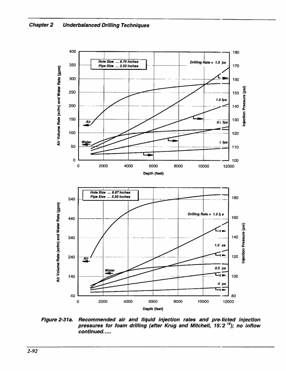
Chapter 2 Underbalanced Drilling Techniques
400
350
300
250
200
150
100
50
0
540
440
340
240
140
40
1 180 I
Drilling Rate = 1.5 'ps Pipe Size ... 3.50 inches
~~ -
I - I - 1 I 7 I I I
1 70
160
A % 150 - !!! ¶ m m
140
.- s 130 3 .-
C - 120
110
0 2000 4000 6000 8000 10000 12000
Depth (feet)
I I - - Hole Size ... 9.87inches Pipe Size ... 5.50 inches _ _
Drilling Rate = 1.5 f i 8
I----
-/,?E 1.0 ps
180
160 A m P v
2 140 $
m t 0
.- s 120 p .-
C -
100
80 0 2000 4000 6000 8000 10000 12000
Depth (feet)
Figure 2-31a. Recommended air and liquid injection rates and prel licted injection pressures for foam drilling (after Krug and Mitchell, 19;2 "); no inflow continued .....
2-92

450
400
350
300
250
200
150
100
50
0
I I I I Drilling date = 1.5 fps I 1; 10
1"O
11 io
1:io 2 v
2
e n 1a.o
1:10 g H
1:lo 1 -
1 0
11 0
91 1 0 2000 4000 6000 8000 10000 12000
1200
1050
900
750
600
450
300
1 50
0
Depth (feet)
I Hole Size ... 12.5 inches 1
0 2000 4000 6000 8000 10000 12000
Depth (feet)
Figure 2-31b. Recommended air and liquid injection rates and predictec 1 injection pressures for foam drilling (affer Krug and Mitchell, 1972 "); no inflow continued.. ...
2-93

Chapter 2 Underbalanced Drilling Techniques
450
400
350
300
250
200
1 50
100
50
0
180
170
160
150
140 2 e n
130 6
v Q
a
.- 5
120 z 110
100
90
1800
1600
1400
1200
1000
800
600
400
200
0 2000 4000 6000 8000 10000 12000 Depth (feet)
- Hole Sue ... 15.0 inches Pipe Size . . . 5.50 inches -
-_ __
f-----t- ~~ t---- i---- I Drilling Rate = 1.5 fps
I-- t- - I 1.1 fps
1 fps /
140
130
120
A a 110 9 e
3 W a
100 ; 90 5 s -
C - 80
70
60 0 2000 4000 6000 8000 10000 12000
Depth (feet)
Figure 2-3ic. Recommended air and liquid injection rates and pr6 dicted injection pressures for foam drilling (affer Krug and Mitchell, 1972 '); no inflow.
2-94

4500
4000
3500 e cn P - 3000 3 u)
f!
h u 2000
2500
0 r E 1500 E
1000 m
500
0
5000
4500
4000
v E 3500 f!
3000 cn 0 h 2500 Q - 2 2000 E
m 0 g 1500
1 000
500
0
7.87 - 4.50 In. 9.00 - 5.50 In.
t----
I Drill Rate = 1.5 fps Hole and Plpe Sizes
6.75 - 3.50 In. -
- ~~
- ~ Drill Rate = 0 fps -
~
0 2000 4000 6000 8000 10000 1: 000
Depth (feet)
0 2000 4000 6000 8000 10000 12 )oo
Depth (feet)
Figure 2-32. Predicted bottomhole pressures during foam drilling, no inflow (i rfter Krug and Mitchell, 1972 ").
_I
2-95

Chapter 2 Underbalanced Driiiing Techniques
15,000 feet) was drilled overbalanced, even though foam was used and the bottomhole pressure was predicted to be less than 2,000 psi. This does not mean that there would have been no inflows that might have modified the foam quality. Dupont also indicated that good hole cleaning had been achieved in other foam drilling jobs, at annular velocities as low as 50 ft/min.
Foam has been used to successfully drill through permafrost. Anderson, 197 1 ,29
reported a 17%-inch diameter hole, drilled to 700 feet, using 300 scfm of -99 percent quality foam. Fraser and Moore, 1987,30 presented guidelines for permafrost drilling with foam, based on experience from drilling ten wells in the Canadian arctic. Twelve and one-quarter-inch surface hole was drilled with 4%-inch drillpipe. Recommended air injection rates ranged from as low as 215 scfm near surface to 465 scfm at 2,000 feet. Suggested surface foam qualities were 98 to 99 percent. Since there were water inflows, the annular qualities could have been lower than these. For comparison, Krug and Mitchell’s charts recommended about 650 scfm air for 12%- inch hole at 2,000 feet, and Angel’s analysis indicates rates of approximately 2,500 scfm if dry air were to be used.
Without giving specific injection rates, Shale, 1995,31 noted that annular velocities during foam drilling are often as low as 100 feet per minute, and that surface foam qualities typically range from 95 to 99.7 percent. Finally, in a thorough review of lightened drilling fluid use in the U.S. mid- continent, Sheffield and Sitzman, 1985,32 recommended that surface foam quality should be kept between 95 and 98 percent, to avoid hole cleaning problems.
Summary
>
9
9
>
Foam is often selectctd as the drilling fluid when water inflo NS are anticipated. With inflows, the fo#im quality in the annulus will often bc lower than that anticipated from the injected air and liquid volumes. Thir almost certainly contributes to the fr1:quent reports of good hole cleaning and stable foam returns with pre-forme i foam injected at rates that the theorer ical work would suggest should have broken down to mist. Nevertheless, t does seem that surface foam qualitie5 may be over 95 percent, without catastrophic degradation of hole cle ming efficiency.
Overall, during foari drilling, it is concluded that e, ficient cuttings transport will nonially occur at relatively low annula] velocities (-100 ft/min), provided that the foam quality is maintained between 6C and 98 percent.
Convincing evidencc of the hole cleaning that can be ac hieved with foam are reports of granite f-agments, as large as 2X-inches in dian eter, being lifted from a well during a foam cleanout operation .33
Unless a large backpre ;sure is applied to the annulus, foam injec tion pressures are not very different frori those occurring in dry air or mist drilling, although air injection rates are us~al ly much lower. Foam drilling ge ierally requires significantly lower con ipressor power, in comparison to dry or mist drilling techniques.
Fluid Removal Circulating foam ( an effectively accommodate large inflc ws of formation
2-96

water. Any water entering the annulus is likely to be rapidly incorporated into the structure of the flowing foam. This is accelerated by the “stirring” effect of the rotating drillstring. Bentsen and Veny, 1976,34 observed that small water inflows, 10 to 20 BPH into 4%-inch diameter holes, were so effectively absorbed by 150 to 350 scfm of 99 percent or higher quality foam that the inflow could go undetected.
With large water inflows, the air injection rate may have to be increased in order to keep the foam quality within acceptable limits. If the quality is allowed to fall too low, hole cleaning efficiency will be impaired. It may also be necessary to increase the concentration of foaming agent in the injected liquid, to prevent the foam from deteriorating into slugs of air and water. Provided that the air rate is adjusted accordingly, inflows as large as 500 BPH may be lifted from a well with foam.31
Water inflow will normally increase both the bottomhole and the injection p r e s ~ u r e s . ~ ~ , ~ ~ Increasing the air injection rate will, however, tend to offset the increase in bottomhole pressure. In some circumstances, the amount of water that can be lifted from the well will ultimately be limited by the available air rate and pressure capacity. The cost of foam consumables and waste water disposal will normally intervene to make it uneconomic to continue foam drilling, long before an inflow becomes too large to be lifted from the well.
Problems may arise if the foaming agent in use is not compatible with one or more of the components of the formation fluids. Chlorides, for example, can cause some foamers to loose their efficiency. Similarly,
CYI”
hydrocarbon inflows can dest: bilize some foams by interacting with the f >amer. Any liquid hydrocarbon flowing irto the well will not mix with the aqueous liquid phase of the foam and will not, therr fore change the foam quality.
Any gas flowing into the borehole will increase the foam quality betwecm the site of the inflow and the surface. For the foam to remain stable to surface, the piimps should be able to deliver a sufficieni volume of liquid to keep the quality belcw 98 or 99 percent. If the foam quality rises above this, the foam will break down into s ugs of foam and gas, or even into mist. This can jeopardize cuttings transport a id wellbore stability.
For example, consider a well 1 being drilled with 300 scfm of air and 99 qu.ility foam at the surface. The liquid injec ion rate to achieve this quality would be 3 cfm (22 gpm). If a gas inflow of 432 IAscflD (300 scfm), is encountered, the to a1 gas rate flowing up the annulus (natuial gas plus injected air) will increase to 600 scfm. If the liquid injection rate is not inzreased, the liquid volume fraction will fall too low and the foam will collapse. At the same time, the annular velocity may be toc low for the flowing mist and slugs of foari to provide hole cleaning. The drillstring can rapidly become stuck under these circ ~ m s t a n c e s . ~ ~ Increasing the liquid rate will estore foam circulation and efficient hole cleaning, if there is a modest gas inflow as in this example. If this is done md drilling continues below the inflow, the ‘oam quality between the bit and the site 0- the inflow may become so low that hole (leaning will suffer in this region. Ideally, a foam circulation model should b: used to
2-97
Chapter 2 Underbalanced Drilling Techniques
determine the impact of the increased liquid rate on foam quality and hole cleaning below the inflow.
Now, suppose that a large gas inflow is encountered; for example, 5 MMscfD. This corresponds to approximately 3,500 scfm; the total gas rate flowing from the well would be 3,800 scfm. This would require 38 cfm, which is 285 gpm, of liquid for the foam to remain below 99 quality at surface. Few foam drilling units can come close to that liquid rate. In any case, there would be very high consumable costs and too low a foam quality below the inflow. It would be effectively impossible to continue drilling with foam throughout the borehole if such a large inflow were encountered. However, in most circumstances, the annular velocity of the mist would be sufficient for good hole cleaning. Drilling could possibly continue safely even though the returns would be mist rather than foam.
Circulating Program Design To summarize, a good starting point for designing a foam circulation program is to target at least 65 quality foam downhole, with a minimum annular velocity of 100 feet per minute, and a foam quality of not more than 95 to 98 as the foam reaches the surface. It may be necessary to have an annular backpressure to achieve this range of foam qualities. Particularly if there is no local experience, it is advisable to carefully design the circulation program. Formation fluid inflows can influence circulating foam quality to the extent that they should be considered as part of this design exercise.
Equipment In most respects, the same equipment is used to drill with pre-formed foam as is used in dry air and mist drilling. The following
sections summarize the additional equipment required for foa n drilling.
Compressors The gas is usually rrovided by air compressors. Normally, th z air rates used in foam drilling are lower tha 1 those for dry air or mist. It may be possible to use fewer or smaller compressors. For example, Fraser and Moore, 1987;' usec two 300 scfm reciprocating compressors, with a 1,000 psi delivery pressure capacity. Surface injection pressures, during routinc foam drilling, rarely exceed 200 psi. Exceptions may occur if an annular backprmure is applied, if jets are run in the bit (wk ich is not normal practice), or if a downholc motor is used. Higher surface pressures w 11 be necessary if there is a large liquid infloiv, or if liquid has to be unloaded from the borehole following a trip. For this reason, if low delivery pressure compressors ale used, it is advisable to have a booster that can increase the air pressure to 1,000 psi or more, if necessary. Boosters are ccmmonly rated to 1,500 psi.
The Gas Air is most frequently used in foam drilling. Other gases, such as nitro;en, natural gas, carbon dioxide, or exhaust gas, can be used instead. It is unlikely thet these specialty gases will be less :xpensive than compressed air, although t' le comparatively low gas rates used in fcam drilling can reduce the additional cost associated with these alternatives. Whatcver gas is used, adequate volume and pres! ure capacity are essential (Sections 2.2 and 2.3).
The Base Fluid Liquid mixing tanks and njection pumps, similar to those used in riist drilling, are required. Two 10 bbl mixing tanks are
2-98

normally used. The liquid injection pump (often referred to as the mist pump) is fed from one tank, while mixing fresh liquid in the other. A higher capacity pump may be required for foam drilling. Liquid rates typically reported for foam drilling are in the range of 10 to 20 gpm. Rates close to 100 gpm have been recommended for good hole cleaning in deep, large diameter well^.'^^'^
Because of the great impact of foam quality on hole cleaning, good metering of the gas and liquid is essential. Although monitoring the fall in liquid level in the mix tanks is usually adequate in mist drilling, a flow meter, in the mist pump suction line, may be necessary for foam drilling.
Foam Generator The one addition to a conventional aidmist drilling compressor system, for pre-formed foam drilling, is the foam generator. It ensures thorough mixing of the two phases. One type of foam generator is located where the gas and liquid flows meet. It introduces the liquid into the gas flow through a small bore tube centered in the gas flow path, and then directs the mixture through a venturi- type flow constriction. Other foam generators are located downstream from where the air and liquid flows meet. . These foam generators may contain baffle plates, or even sand beds, to promote mixing.
In practice, it is not clear that a foam generator is specifically req~ired.~’ The air and liquid mixture will invariably flow through a number of valves and experience many changes in direction, before it enters the kelly; these alone may produce a good foam. Even if foam does not form at the surface, it will when the mixture passes through the bit. There is evidence that foam generated at the surface is more tolerant of
contaminants, such as formatic n water or hydrocarbons, than foam form:d in their presence.33 Unless there are spec ific reasons not to do so, it makes sense to use a foam generator.
Portable Units As an alternative to conventiona air drilling equipment, there are a number of custom- built, portable, air foam unlts in the continental U.S.36 Although these units have mostly been assembled for completion and workover operations, s 3me have sufficient output for many fo im drilling operations. They combine air c Impressors, sometimes with a booster as well, a divided mixing tank, liquid pumps, foan generators and metering systems. Voluml :tric output from a single unit can range fiom 650 to 1,500 scfm, with pressure capaci ies ranging from 800 to 1,500 psi, for "lei/' pressure units, and up to 3,000 psi for a “high” pressure unit. The mixing tank n x-mally has a 60 bbl capacity, divided into t YO sections to allow liquid mixing to take lace in one section while pumping from the other. The liquid pump is generally capable Df pumping at least 50 gpm.
Mud Pumps As was the case for dry air drilling, it is advisable to have mud pumps hcoked up, to allow liquids to be pumped in o the well rapidly, if necessary. If there is any risk of hydrocarbon production, at rates y-eater than the surface equipment can handlc , or if there is uncertainty about the maxin um inflow rate that might be encountered, ;in adequate volume of kill weight mud should be on location.
Drillstring Float valves are necessary in thc drillstring, just above the bit and near surfaze. If long
2-99

~ ~~
Chapter 2 Underbalanced Drilling Techniques
intervals are to be drilled, it may be advisable to reposition the upper string float (or install another) to minimize the time taken to bleed down the string pressure before making a connection. Fire stops are probably not necessary, except possibly for wells with long horizontal sections that are to be drilled with an air foam.
Return System A choke should be installed in the blooie line, close to the rotating head or rotary blowout preventer, to pressurize the annulus, if necessary. Dupont, 1984,28 recommended a bladder-type choke. If the circulating program indicates that annular backpressure may be necessary, then this additional pressure should be considered when specifying the pressure capacity of the rotating head or rotating blowout preventer. The section of the blooie line between the choke and the rotating head should also have a pressure rating sufficient to support the highest backpressure likely to be imposed.
In very cold conditions, there is the possibility for foam returns to freeze and plug the blooie line. In these areas, Fraser and Moore3’ recommended using an additional foam discharge line, with both the blooie and foam discharge lines leading to the flare pit. This redundancy is not necessary for normal operations, where there will be a line from the choke manifold to the flare pit that could be used to continue circulation, but not drilling, if the blooie line were to plug. Small rigs may not have enough clearance below the floor for two diverters on top of a conventional BOP stack.
There is no fundamental reason why the blooie line should be any longer for foam than for dry air or mist drilling. The flare pit
should be far enough from the well that heat from the flare cannot ignite any gas inadvertently released onto the rig floor. At the same time, as discussej in Section 2.1, “Dry Air Drilling,” the bac cpressure created by the flowing pressure drop down the blooie line should not be excessive, if the primary jet is to be able t ’ ) draw produced gas away from the rig floor juring trips.
For most operations, a 150.foot long blooie line has proven to be saiisfactory. Four hundred feet of separation between the well’s centerline and the flire pit was used for a recent foam drilling pi oject in Oman.37 In this case, the blooie 1 ne was only 6 inches in diameter, and the jets were placed close to the rig and about h;Jf way along the blooie line. The wells were, however, killed prior to pulling off bottom; there were no concerns about jetting gas a way from the rig during trips. Both natural as and crude oil were flowing into the well: during drilling. To eliminate problems wit I the flared gas igniting crude oil in the r:turn pit, a gas separator was installed in the blooie line, 330 feet from the rig. Salt w iter was injected into the separator, presumi bly to act as a defoaming agent. Two linzs ran from the separator. One line, betwe zn 100 and 130 feet long, took gas to the flare pit. The flare pit was banked on three sidc s to reduce heat radiation at ground level. The other line, which was 130 feet long, ook the liquids (foaming solution, produced water and crude oil) to a lined liquid pit, apxoximately 130 feet by 130 feet in plan and ( 1.5 feet deep.
In foam drilling operatiois, it is more normal to discharge the retLrns into a large, combined flare and reserve ,it, as described in Section 2.1. The volimes of liquid discharged into the pits a-e likely to be greater than those in air ar d mist drilling,
2-100

considering that foam is often used to handle large water inflows. Adequate arrangements must be made to handle the anticipated volumes of liquid.
A large, open return pit is not essential for foam drilling. Effective defoaming and waste water disposal are the keys to decreasing the size of the return pit. It is even possible to use a closed, surface system when drilling with stable foam. The equipment used to do this is described in the Section 2.9, “Closed Flow Systems.”
lnjected Liquid
The Foaming Agent The injected liquid includes (at a minimum) water, a foaming agent, and a corrosion inhibitor. The foaming agent should be selected to suit the anticipated downhole conditions.
API RP4638 describes a method for testing foaming agents to be used in mist drilling. It should be equally applicable for foam drilling:
P The standard test liquids are fresh water, fresh water with 15 percent kerosene, 10 percent brine, and 10 percent brine with 15 percent kerosene.
P Ten grams of silica flour are added to one liter of test liquid, to simulate the presence of cuttings.
P Foam, generated with the specific agent, is used to lift each of the four test liquids up a 10-foot long, 2.5-inch diameter model wellbore.
P The quantity of test liquid collected in 10 minutes, at the top of the wellbore is taken as an indication of the foaming agent’s suitability for use in saline or
hydrocarbon environments.
> If possible, samples of actual formation fluids and cuttings should be ubstituted for the regular test liquids and solids.
Downhole conditions, and the interaction between the foaming agent and formation fluids, will dictate the concentrai ion of the foaming agent in the injected liqiid. Most commercial foaming agents arc: used in concentrations that range from 0.5 to 2 percent. A concentration of 1 percent is often a good starting poin.. The concentration of foaming agents should be adjusted to achieve a level of foa rt stability that balances good hole cleaning with easy defoaming.
Other Additives Particularly if air foam is used at depths greater than about 4,000 feet, careful evaluation and selection of the corrosion inhibitor are vital to preveit severe corrosion of downhole equipmen. As was the case with mist drilling, KC’, or other shale hydration inhibitors, may be added. Viscosifiers may be added to the liquid phase to create a so-called “st ff foam,” (refer to Section 2.6).
Disposal The surfactants in foaming agents are almost invariably bio-degradable. Sor le of the components may pose minor health or environmental hazards. Any haz 3rd should be identified on the Material S ifety Data Sheets (MSDS’s) for the material in question. These should be consic ered when selecting a foaming agent, pariicularly if there are constraints on disposa of waste liquid for the well in questioi. Some commonly used foaming agen.s are so environmentally benign that tht:y can be
Chapter 2 Underbalanced Drilling Techniques
disposed into urban waste water drainage systems. Contamination of the waste liquid by formation fluids or by a chemical defoamer may create disposal problems, even if the foaming agent itself is environmentally acceptable.
The liquid injected into a well is not normally recycled. If the foam decays so rapidly at the surface that chemical defoaming is not required, it may be possible to recycle the spent liquid collected in the return pits. To do this, Anderson, 1984,33 recommended using a large, U-shaped pit, to hold the returned foam until it collapses, returning the spent liquid from the pit to the mixing tank, and re-conditioning it to the original specifications (foaming agent concentration, corrosion inhibitor concentration, etc.) before reuse. When this can be done, savings of 25 to 50 percent in consumable costs are possible. It may also be possible to re-cycle injected liquid recovered from closed surface systems.” Some form of solids control is advisable to minimize the concentration of formation solids in recycled liquid. This is particularly important if downhole tools are used. These include motors which might be susceptible to erosion damage or plugging.
Finally, ensure that an adequate water supply is available at the rig site to maintain the planned injection rate.
Chemical Defoamers Very large volumes of foam can rapidly accumulate at the surface, particularly if the foam quality is not very high (for example 95 percent or less), and if there are nq formation fluid inflows to destabilize the foam. It is normal practice to take measures to accelerate foam decay. This can be done chemically and/or mechanically.
It is possible to destroy foam simply by spraying a suitable defoan er on top of the foam in the return pit. Mcre effective foam destruction results if the d1:foamer is mixed thoroughly with the retuning foam. This can be done by injecting tie defoamer into the blooie line using a ring spray, as described in Section 2.4 “ vlist Drilling” or using a turbolizer tube.40 When possible, the defoamer should be di uted, before use, with an appropriate liquid (water whenever possible), to assist in mixin, ; with the foam.
The effectiveness of a part icular defoaming agent often varies markedly from one foaming agent to another. t is important, to match the defoamer to th: foaming agent being used. Simple pi1 )t tests can be performed:
> Make a small batch (for example, one- half liter) of foam, by stirring a solution of the foaming agent in a high shear mixer.
> Spray a small quantity, (perhaps 5 ml), of the candidate defoamer onto the newly formed foam, usi ng a hypodermic syringe.
> An effective defoame- will cause a significant portion of the foam to collapse in seconds.
If there are environmental r :strictions on the disposal of the waste licpid, a silicone antifoam should be considx-ed. These are effective on many comr iercial foaming agents and are environment; lly benign.
Rates for adding defoilmers will be controlled by the concentri tion and rate of foaming agent injection, tfe quality of the foam at the surface, the extent of any contamination by formatio n fluid inflows,
2-102
the efficiency of the defoamer and the rate at which foam has to be destroyed. Effective foam destruction usually requires smaller volumes of defoamer than foamer. For silicone antifoams, which are available in different concentrations of active silicone, significantly smaller volumes of defoamer will probably be required. Even with only 10 percent active silicone, the volume of silicone antifoamer, required for very rapid defoaming, will likely be less than one-tenth of the volume of foaming agent used.
Mechanical Defoamers There are several different types of mechanical defoamers. All of these work by accelerating gravity-induced separation of the foam's liquid and gaseous phases. Hall and Roberts, 1984,40 described using an hydrocylone, in conjunction with a chemical defoamer. This combination was sufficiently successful in destroying foam that stable foam could be used in offshore drilling operations (because of disposal and storage restrictions). Defoamer was injected into the blooie line and returning foam was passed through a hydrocyclone. The solid and liquid discharge stream was passed over a shale shaker and into a surge tank, from where it was disposed of down an adjacent water injection well. This is shown in Figure 2-33. In this instance, fines in the waste liquid plugged the injection well and, ultimately, the waste liquid had to be disposed of at an onshore treatment facility. If this system is used when natural gas might be encountered, the gas emerging from the hydrocyclone should be piped to a flare.
There are two other generic types of mechanical defoaming. One, is conceptually similar to a hydrocyclone. It uses a
corkscrew-like internal flow pat1 I to subject the foam to radial inertial brces and accelerate drainage. The ot ier has a spinning, perforated drum inside an outer vessel. Foam flows into the spinning drum. There, it breaks down under the centrifugal force. Liquid passes through the holes, into the drum, and is discharged through the base of vessel, while gas is dischargzd through the top. It is not clear how well :his system will handle large quantities of sol ds, such as cuttings entrained in the foam.
Combined Chemical and il lechanical Defoaming It may be necessary to combin: chemical and mechanical defoaming, if thc : discharge is into a small tank or a clos:d system. MacDonald and Crombie, 1994;' conducted yard trials with a p( llyurethane hydrocyclone. This system dec reased the volume of foam passing throigh it by approximately 97 percent. As they noted, the remaining 3 percent would bl: sufficient to fill a conventional well tes' separator within an unacceptably short time. Injecting defoamer into the blooie line, befi )re passing the foam through the hyc rocyclone, increased the efficiency of the foam destruction process to the extc:nt that a closed surface system could be us( :d.
When drilling with an open retun system, it is worthwhile to check the qualit:' and level of foam in the pits. Particularly i ' defoamer efficiency is low or if defoamer i: not being used, it is possible for foam to be blown around the rig location or even (Iff the site altogether. Although this shoulc . not have permanent impact on the environr lent, it can cause much annoyance in urbar or semi- urban areas.
2-103

Chapter 2 Underbalanced Drilling Techniques
Foamer (0.08 gpm)
Generator
(3 gpm)
Water Well
A BC (80 gpm)
Anti-
Cyclone
Shah? Shaker 0 Foam Killer (0.03 gpm)
1 Di:posal
Yell
Onshore Water
Treatment Facility
Figure 2-33. A foam disposal system used offshore (affer Hall and R< Iberts, 1984 "),
Recycling Using most chemical defoamers effectively precludes any possibility of recycling the killed foam liquid. A technique has recently been in which foam is destroyed by changing its pH. Foam is generated and circulated through the well in the normal manner, except that a pH sensitive foaming agent is used. Acid, injected into the blooie line, reduces the pH and destabilizes the foam. The treated foam passes through a gashquid separator. The gas is directed to the flare pit. The cuttings- laden liquid discharge is passed over the shale shaker and into a conventional arrangement of mud pits. Some of the liquid is drawn off the shaker tank to re-inject into the blooie line; extra acid is added to decrease the pH, as necessary. If necessary,
the liquid can be treated with flocculant to remove clays or centrifuge d to remove fines. Lime is added to the liqiid in the pits to raise its pH and conditicn it for foaming. The liquid can then be rt -injected into the foam generator. A 90 percent reduction in the consumables required for a given foam rate was claimed for tt is system. The necessary surface equipn lent is shown in Figure 2-34. There is little information currently available to gaug : the effectiveness of this system. The co npatibility of the foaming agent with the make-up water, formation water and hyc lrocarbons would have to be establishec, just as with conventional foaming c perations. The anticipated savings in cc nsumables would then have to be weighed against the additional cost of the syste n.
2-1 04

Blooie Line Return To Air Pit or
Nitrogen Recycle
Cuttings
Supplemental Defoamer Additlon (lf Necessary)
I Excess Foam
I I
El Storage
Q .>\=I Storage
Alkali Feed
Mud Pits Polymer Recol 'ery Solution Flocculent Reac for Reuse Addition
Free Water Slop Pit Return
of Necessary) To Centrifuge for Solids Control
Figure 2-34. A recyclable foam system (after Clearwater Inc., 1996 4' 1.
Operating Procedures quality carefully. A steady dis:harge of a In many instances, drilling with stable foam stiff, high quality foam that colla xes rapidly is similar to dry air or mist drilling. The in the flare pit is preferred. Wit1 a properly procedural differences are highlighted designed circulation program, this will below. occur, unless formation fluids ire flowing
into the well. Without careful p -e-planning, Standpipe Pressure it may be necessary to adjust in-ection rates As with dry air or mist drilling, the and foaming agent concentration, to achieve standpipe pressure should be monitored the desired foam. carefully. Mud rings should not form when
If the foam is wet (quality subst intially less than 95 percent) at the surface its quality downhole may be too low for effective hole cleaning. There is no point in inj xting more
foam drilling. An increase in standpipe pressure usually indicates a formation fluid inflow. Changes in the foam quality at the blooie line can often confirm the influx.
Foam Quality liquid than necessary, incurring innecessary It is important to monitor the returning foam expenditures. Furthermore, a wet foam
2- I05
Chapter 2 Underbalanced Drilling Techniques
takes longer to decay and requires more defoamer than a dry (high quality) foam. If the foam seems wet at the surface and there is no evidence of a water inflow, reduce the rate at which liquid is injected into the well.
A water inflow can be detected from increased standpipe pressure and, if the surface system permits, by comparing the liquid injection and production rates. If a water inflow is suspected, it may be necessary to increase the concentration of the foaming agent.
If the gas volume fraction (the quality) has been allowed to become too high, the foam may destabilize as the pressure falls on approaching the surface, and slugs of foam and gas will be seen at the blooie line. In the extreme, the foam may collapse to a mist before reaching surface. These conditions will normally arise as a result of a gas influx, or too low a liquid injection rate.
Gas Znflo w A gas inflow will increase the standpipe pressure and burn at the flare. If the rate of inflow is much larger than the air injection rate, it can displace the foam above it. Initially, this correlates with an increase in the rate at which foam is discharged from the blooie line. Once the foam has been blown from the well, the returns are likely to be either slugs of foam and gas or mist, and there will be a large flare. When a gas inflow is suspected because of slugs of foam and gas in the return flow, stop drilling and increase the liquid injection rate until stable foam returns are re- established. If this is not done, cuttings may not be lifted efficiently from the well and the string can become stuck.
Liquid hydrocarbons can 2 Is0 be produced. These can reduce the effectiveness of some foaming agents. If a foariing agent is not resistant to hydrocarbon :ontamination, it may be necessary to inciease the foamer concentration and injectior rate, in order to re-establish stable foam rea irns.
As noted earlier, a very high rate gas inflow may give an annular ve1o:ity sufficient to effectively lift cuttings frcm the well. To determine if this is the case
9
P
9
9
9
Estimate the inflow rate
Compare the total gas rate (inflow plus injected air) with th: injection rate required for efficient mi st drilling for the relevant depth and hole Gize.
If the total gas rate is ufficient for the mist to clean the hole, tl iere is little point in increasing the liquid rate. If the total gas rate is not sufficieiit, and it is also not possible to incrt:ase the liquid injection rate to re .establish foam returns, it may still be possible to increase the air rate to where mist drilling become feasible
Otherwise, it may be ne ;essary to switch to mud.
If drilling does continuc with mist, with a gas inflow, the ,)otential for a downhole fire should bt? considered and the appropriate precautic Ins taken.
Liquid Inflow Slugs of liquid and gas mzy be seen at the blooie line. This will hap3en when liquid inflow is not compatible ijith the foamer. The foamer concentrati )n should be increased. It may also )e necessary to increase the foamer conc' mtration simply because the well is getting deeper and the
__ 2-1 06
foam temperature is increasing corres- pondingly.
If it is necessary to reduce the liquid injection rate, increase the concentration of corrosion inhibitor in the injected liquid to compensate for the reduction in injection rate.
Lost Circulation It is possible to lose circulation when drilling with foam. A temporary loss of returns, followed by a violent surge of foam, may be observed following a break in circulation if a water inflow has occurred and the hydrostatic head of water has to be overcome before circulation can be established. Under some circumstances, however, the circulating pressures can be sufficient for foam to be lost into downhole cavities or fractures. Particularly if this happens near surface, careful consideration must be given to where the foam may be going. This becomes even more important if hydrocarbons are flowing into the well when returns are lost. There are anecdotes of foam finding its way through aquifers, into nearby streams and rivers, or emerging from a hillside below the rig site. Any apparently uncontrolled release of foam could have damaging consequences in terms .of local opinion, even though its environmental impact should be small if no hydrocarbons are released.
Hole Cleaning The well should be monitored for characteristic signs of poor hole cleaning, such as excessive drag or fill. Poor cuttings transport may simply indicate too low an annular velocity, if steady returns of dry foam are occurring. If the well is deep, or if a wet, low quality foam is being discharged at the blooie line, the foam quality
downhole may be too low for good cuttings transport. This may be improved by reducing the liquid injection ral e or, if the surface foam is dry, by increasing the air rate and applying backpressare to the annulus.
Backpressure In some foam drilling jobs, pa~ticularly in deep wells, it may be necessary to apply a backpressure, to maintain fo; un quality everywhere in the annulus. The circulating program should specify a b rckpressure schedule, likely increasing with increasing depth. If backpressure is require( ., the choke should be adjusted, as necessaq, to follow the predetermined pressure schedule. Whenever possible, the impa:t of any change in backpressure on form quality, annular velocity and hole cleanin should be computed and evaluated before a ljusting the choke.
There is a large volume of compressible fluid in the well. The circulating pressures only respond slowly to changes i 1 the choke setting. Care should be taker , to avoid "over-controlling" the choke. I 't is better practice to make small adjustments to the choke setting and allow the E'ressure to stabilize before making an y further adjustment.
If possible, do not use backl~essure to reduce foam quality. It increases circulating pressures and compressor pow :r require- ments. If annular velocities are high enough, increasing the liquid in ection rate or even reducing the air inject on rate, is more efficient than imposing a ba ckpressure.
Making Connections Connections are made in the same way as they would be in mist drilling. Stop
2-107
Chapter 2 Underbalanced Drilling Techniques
injecting liquid, before bypassing the air flow to the primaryjet. Continue jetting the blooie line with air, while making the connection. This will draw any natural gas that might be flowing from the well away from the rig floor.
Provided that the foam quality is not too high, most of the foam in the annulus will not collapse while making a connection. With foam’s high viscosity and low settling velocities, cuttings will tend to be held in suspension by the foam in the annulus. Although it is still good practice to circulate the annulus clear of cuttings before making the connection, this is not as important with foam as it is with dry air or mist drilling. However, with a poor, unstable foam, (for example, if the quality is too high or if there is a de-stabilizing liquid inflow), the foam half-life can be less than one minute. In this case, a significant proportion of the foam in the annulus will collapse during the connection, and any cuttings will settle rapidly. If this is likely, the hole should be circulated clean before making the connection.
As with dry air drilling, it is advisable to wait until returns are established, before resuming drilling after a connection. Cuttings fill around the bottomhole assembly is less likely when drilling with foam. Very often, foam is used because there is a significant liquid influx, and there will normally be liquid in the hole after making a connection. This will not trap the string as a cuttings accumulation could. Liquid accumulation could, however, prevent re-establishing circulation, until the foam pressure below the bit overcomes the hydrostatic pressure. The hydrostatic head of the accumulated liquid can be noticeable,
even with a rapid connection. Consider an 8%-inch diameter hole, bei- ig drilled with 6- inch collars, and making 60 BWPH. If circulation is shut off for 5 minutes, 5 bbl of water would flow into ‘ h e well. This volume, flowing into a d q hole, would fill 143 feet in the annulus, ccrresponding to a bottomhole pressure increi nent of over 60 psi. The standpipe pressi re will progres- sively increase after foi m injection is resumed, until the pressure of the liquid that accumulated in the well is ( vercome and the liquid is lifted from the w:11. It can take several minutes, after mesuming foam injection, before foam ac’ually begins to flow up the annulus. Uniil that happens, any cuttings that are genei-ated will not be lifted from the hole. 110 not resume drilling, at least until the standpipe pressure has begun to fall Depending on hole conditions, it may be 4 idvisable to wait until foam returns are established before resuming drilling.
Tripping Over the time taken for a .ound trip, foam will separate into its liquid and gas constituents in all except t le shallowest of holes. This will allow all CL ttings to settle to the hole bottom. It is impoi tant to circulate the hole clear of cuttings bt fore tripping.
Liquid from a collapsed, ve t (low quality) foam can provide a signif cant hydrostatic pressure at the hole bottom. For example, if the average foam quality armnd the well is 95 percent, the liquid phase is filling about 5 percent of the hole volume. In a 5,000 foot deep hole, the foam’s bzse liquid alone could fill at least 250 feet,+ giving a bottomhole pressure increzse of over 100 psi. If the well is not maki ig any liquid (at
Neglecting any inflow.
~
2-108
the current depth), displacing the hole with air before tripping will avoid problems in re- establishing circulation.
If liquids are flowing into the well at a significant rate, a much larger volume of formation liquids can accumulate during a trip. As an example, consider a 5,000 foot deep, 8S-inch diameter hole, making 60 BWPH. A round trip will take approximately 5 hours. During this time, approximately 300 bbl, or 1,685 ft3, will flow into the hole. '' This would fill over 4,000 feet of the hole. The volume of the foam's liquid phase is negligible in comparison. In this case, there is no point in displacing the well to air before tripping.
The most efficient tripping procedure will depend on the volume of natural gas being produced. If the well is producing gas, or even suspected of producing gas, steps have to be taken to prevent gas from reaching the rig floor.
9
9
>
9
After circulating the hole clean and, if appropriate, displacing the well to air, shut off the air injection and strip the string back through the rotating head or rotating BOP, as far as possible before pulling the rubber.
If the well is not making more than about 2 MMscfD, turn on the compressors and jet the blooie line, as described in the section on tripping when drilling with dry air. This volume of gas should be jetted away from the rig floor.
Continue tripping with the rotating head rubber removed.
If the well is making much more than 2
'' Neglecting reduction in the inflow rate due to increasing hydrostatic pressure.
9
9
9
9
>
9
9
>
9
MMscfD, close the annular IIOP before pulling the rotating head rubb :r and strip the BHA through the annular as far as possible.
It may be necessary to jet the dooie line, to draw gas leaking past the BHA away from the rig floor.
Close the blind rams and flow the produced gas through an open choke to the flare pit while the string i ; out of the hole.
Once the blind rams are 4 losed, the compressors can be shut dowr . Conventional air drilling surface equipment should be able to 1 andle over 5 MMscfD of gas produaion, when tripping. In extreme cases o ' very high production rates, it may be nxessary to kill the well before tripping. Since this has the potential to damage a productive formation, it should only be considered when it is felt to be unsafe to allow the well to flow while tripping.
Resume jetting, open the blin rams and close the choke before re-rinning the string.
With significant gas production, it may be advisable to strip as much If the BHA as possible back into the wrA1 through the annular.
When possible, re-install tl e rotating head rubber and stop jetting.
If the well is not produciiig liquids, continue the trip back to bott ,m and re- establish foam circulatio i , before resuming drilling, as describe( I above.
If the well is making water, it will be
2-109

Chapter 2 Underbalanced Drilling Techniques
necessary to unload this from the hole before resuming drilling. The method adopted to do this will influence how the string is tripped back into the hole. When drilling with foam, the procedures for unloading water from the hole are similar to those used when drilling with dry air.36 There are options for staging into the hole or for unloading in one stage.
Staging into the Hole As was the case for dry air drilling, the length of stage that can be unloaded is determined by the maximum available injection pressure. A general rule-of-thumb, reported by Scott et al., 1995,36 is to limit the stage length (feet) to no more than twice the injection pressure capacity (psi). For example, up to 1,600 feet could be unloaded with 800 psi air injection capacity. This differs little from the stage length estimation given in Section 2.1, for unloading with dry air.
9
9
9
9
9
P
Run the string to the. selected stage depth.
Install the string float.
Connect the kelly.
Begin injecting a low (50 to 60 percent) quality foam.
Once circulation is established, the standpipe pressure will fall and the well will begin to unload.
At this point, increase the foam quality to the level specified for drilling, by increasing the air rate, and reducing the liquid injection rate, as appropriate. Circulating pressures will stabilize once the formation liquid is removed from the stage.
Shut down foam inject! on, trip the string down to the next s:age depth, and continue unloading n stages, until bottom is reached.
Once the bit is on bottlym, with the hole unloaded and steady fcam circulation is re-established, there is I IO need to dry the hole further before resu ning drilling.
9
9
9
9
9
Unloading in One Stage Alternatively, it is possib e to unload the hole in one stage. This method uses the hydrostatic head of a low q iality foam in the drillstring, to reduce the surface pressure needed to displace liquid frc )m the annulus.
Run to bottom, and begin injecting liquid at up to 30 gpm.
Turn on the compres;ors and slowly inject air, to create a lo\ J quality foam. If the air rate is too hi;;h, the injection pressure will rise quite rapidly. In this case, shut down the air and slug the well with liquid, before resui ning air injection at a lower rate.
The standpipe pressure should begin to fall when liquid reaches the surface, or when foam enters the annulus, if the borehole was liquid-fillc d.
When foam returns are seen, the air and liquid injection rates SI- ould be adjusted to give the foam qiality and rate required for drilling to r :sume.
Once the bit is on bottcm, with the hole unloaded and steady foim circulation is re-established, there is r o need to dry the hole further before resui ning drilling.
This procedure should on/ v be used i;f it is clear that the wellbore tan support the bottomhole pressure and t llow circulation to be re-established, withoi :t losing injected
2-110

fluids into the formation.
Mudding Up It can be difficult to mud up a well that is producing gas at a high rate. The gas can blow the mud out of the well as fast as it is pumped downhole. If this happens, the well can be shut-in and flow diverted through the choke line to restrict the gas production rate. Since this will increase the annular pressures, care must be taken not to subject the openhole section and casing shoe to a pressure higher than they can support. If there is any concern about the openhole’s ability to withstand shutting-in the well, it should be mudded up as soon as the gas production rate approaches the, level at which filling the hole with mud becomes difficult. For example, Sheffield and Sitzman, 1985,32 advised mudding up, in the Arkoma Basin, if a gas flow rate of 3 MMscf/D is encountered.
Limitations Of Foam Drilling
Why is Foam Drilling Done?
9
9
>
The principal reason for using stable foam as an underbalanced drilling fluid is its ability to lift large quantities of formation water from the borehole, without requiring excessive air (gas) volumes or injection pressures.
Foam gives good hole cleaning, at lower annular velocities than other compressible drilling fluids, reducing the potential for erosion of the, borehole wall.
It is possible to conduct foam drilling operations, using only biodegradable consumables. This means that cuttings disposal can be much easier than it would be for a mud drilled hole, if no
liquid hydrocarbons are e icountered. This is also the case for dry air (or gas) and mist drilling.
The control of foam returns is sometimes thought to restrict the us( of foam drilling. With proper attenticm to foam control, as described previou: ,ly, there is no reason why this should pose any technical limitation to foam d ,illing.
What are the Limitations? There are a number of factors tl at do limit the applicability of foam drillii Lg. These include corrosion of downhole Equipment, wellbore instability, downhole fires in horizontal wells, waste water di ;posal, and consumable costs. Some of these limitations are also common to dry air and rr ist drilling.
Corrosion If air is used as the gas phase iii a drilling foam, the corrosion rates of ferrous downhole equipment can be hi;;h. As in mist drilling, oxygen and wa er in the drilling fluid allow corrosion do. vnhole. A combination of flowing cond tions and mechanical contact between the drillstring and borehole can remove potentially “protective” corrosion products i nd prevent significant local depletion of oxjgen by the corrosion reactions. Both effec :s promote further corrosion. Foam has a higher liquid content than mist and the liqui1 phase is continuous, encouraging corrosioi I.
Any saline formation fluid flowiig into the borehole will increase the electrical conductivity of the foam’s liquid phase; this will accelerate corrosion. So toc will salts, such as potassium chloride, adled to the injected liquid to control shale hy iration.
Sour gas will further increase corrosion
2-111

Chapter 2 Underbalanced Drilling Techniques
problems during foam drilling, (and other types of underbalanced drilling). Corrosion will reduce the wall thickness of downhole equipment, as steel is converted into oxides that have little strength. If hydrogen sulfide is present, there is real potential for stress corrosion cracking, in addition to loss of bulk material. Sulfide scavengers in the injected liquid will prevent small quantities of hydrogen sulfide from attacking downhole equipment. It will not be economic to treat large quantities of hydrogen sulfide in this way. Instead, downhole equipment should be specified for sour service. Furthermore, for safety reasons, a closed system should be specified to handle the wellbore returns if hydrogen sulfide is anticipated.
Corrosion is not an insurmountable limitation to foam drilling. Adding an effective corrosion inhibitor to the injected liquid will, in many instances, slow corrosion of downhole equipment to an acceptably low level. The inhibitor must be compatible with the foaming and defoaming agents in use. Its function should not be impaired by any formation fluid inflows that might occur. As with mist drilling, it is advisable to conduct corrosion rate studies, to confirm the effectiveness of the selected corrosion inhibitor.
Corrosion problems with foam increase with increasing depth, principally because of the associated increases in temperature. For example, Scott et al., 1995,36 described a series of air foam workover jobs, in which the workstring showed a distinct line where corrosion began, at a depth of 4,000 feet. The corrosion inhibitor was ineffective at greater depths. Corrosion inhibitor evaluations should be performed under conditions that replicate downhole
temperatures and pressure i, if air foam is to be used in protracted dril ing operations, at great depths.
Using an inert gas to mzke the foam will prevent corrosion. E> cept in special circumstances, this will )e uneconomical, even when allowance is m ide for the cost of corrosion and its inhibition.
Wellbore Instability In naturally fractured fc rmations, drilled ~verba lanced ,~~ wellbore :rosion has been lessened by reducing w :llbore boundary shear stress. This happei IS because foams are efficient at cuttings ransport, at low annular velocities. Annul ir velocities with foam tend to be much lo~rer than with dry air or mist. As has beeii discussed, high quality foams typically use in drilling, have high viscosities at low sheu rates. It is not unreasonable that foam shc wld have a lower tendency to erode the boreliole wall than dry air or mist.
P Mechanical Instabilii y When drilling with foam, borehole pressures tend to be Iiigher than those encountered when drilling with dry gas or mist. The differenc : may or may not be sufficient enough tc have a beneficial effect on wellbore sta d i ty . Consider, for example, a 5,1100 foot deep, normally pressured well (refer to the example in Section 2.4). Assume that the maximum effectit e circumferential stress concentrated at he borehole wall is approximately 4,175 psi. The bottomhole pressure vould be around 25 psig with dry air ar d around 50 psig with mist. Krug and F iitchell’s charts” indicate that the circu ating bottomhole pressure could be as hi ;h as 1,500 psi, if this well were drilled with stable foam.
2-112

Using foam could increase the borehole pressure by as much as 60 times. This would decrease the difference between circumferential stress and borehole pressure by 30 percent, from 4,875 psi to 3,400 psi, but still may not provide adequate support. This will help reduce mechanically-induced wellbore in- stability in weak rock. In many instances, mudding up is the only option when major wellbore instability problems are encountered while drilling with foam. Stability calculations are discussed in Chapter 4.
P Chemical Instability As with mist drilling, it is possible to include shale inhibiting salts and polymers in the liquid phase of a foam drilling fluid. If the additives are carefully selected, they can certainly reduce chemically-induced instability problems, when water-sensitive shales are penetrated. Foam is often used when significant formation water inflows are encountered. These inflows will alter the composition of the foam's liquid phase and may promote interaction with water-sensitive shales, exposed further uphole. Foam drilling uses larger quantities of liquid than mist drilling; the costs of treating the foam will be correspondingly higher. The cost of shale stabilizing additives can become prohibitive when large water inflows occur.
Workovers Many shallow wells have been successfully worked over by drilling a liner into place in an unconsolidated and underpressured reservoir, using stable foam as the drilling
Essary and Rogers, 1976,44 reported that conventional drilling operations with
foam were djfficult because, alth mgh stable when circulating, the formati Ins would slough into the wellbore as soon as foam circulation was stopped. U ider some circumstances, the circulating iressure of foam can provide sufficient support to prevent wellbore instability. Loss of borehole pressure when circulath In was shut down in these wells caused rap d wellbore collapse. Wellbore instal lility that accompanied stopping circul ition was overcome by attaching the bit o the liner and drilling-in the liner. E~.en though circulation would be shut down lor up to 30 minutes per connection, few diffi al t ies with liner sticking were reported.
Downhole Fires Downhole fires, when drilling v rith dry air, were discussed in Section !.1. The continuous liquid phase in a foan I provides a barrier to combustion, even if he gaseous phase is air. There are mai~y reported instances of wells drilled and v,orked over using air foam, without any fire safety p r o b l e r n ~ . ~ ~ * ~ ~ Regardless, proceed intelligently.
The reported instances of dowihole fires, when drilling with foam, are i i horizontal wells.37 With the low annula. velocities typically used in foam drillir g, gravity- induced separation may occur in a long, horizontal section. It is suspec:ed that the reported fires occurred when the foam separated, forming an air-contin JOUS phase, which could support combustioi on the top side of the hole. The pstential for downhole fires when drilling 'vith an air foam should be considered whc n planning a well, particularly a horizontal well.
Foam made with inert gases idill provide more complete protection again it downhole
- -- 2-113

Chapter 2 Underbalanced Drilling Techniques
fires, irrespective of the borehole trajectory. In foam drilling, the cost of using any gas other than air is often prohibitive.
Waste Water Disposal Stable foam can lift enormous quantities of water from a well, and foam drilling can safely continue, even in the presence of very large inflows. The economic benefit of continuing to drill underbalanced with foam must be balanced against the cost of handling and disposing of the waste water. Because larger quantities of water will probably be produced during foam drilling than during dry air or mist drilling, the cost of waste water disposal becomes more of a limitation. The options for water disposal should be carefully considered, taking into account formation water composition and liquid additives.
In some locations, it may not be possible to build a reserve pit large enough to hold all of
the waste water that may lie produced when drilling a particular inter r a l . If it is not possible to dispose of the water while drilling, it may be necessar 7 to mud up, once the pit level reaches a critic a1 limit.
Consumable Cost A final limiting factor in foam drilling is the cost of the consumables. T saline or liquid hydrocarbon inflows are er perienced, it may be necessary to use larze quantities of expensive foaming agents, to maintain foam stability in the annulus. In :ombination with the additional costs of t’ie foam drilling equipment (compressors, liquid pumps, rotating head, etc.), the COI t of consumables may become too high for foam drilling to be economically more effec tive than mud drilling. In general, this is not the case and stable foam drilling can often provide a flexible and economically I leneficial method of drilling underbalanced.
2-114

References
1.
2.
3.
4.
5.
6.
7.
8.
9.
10.
1 1 .
12.
13.
Sebba, F.: “Foams and Biliquid Foams - Aphrons,” J. Wiley and Sons, Chichc ster (1987) Chapter 4.
“Reduced Pressure Drilling Systems,” Bachman Drilling and Production Spec] alties, Inc., Oklahoma City, OK.
Okpobiri, G.A. and Ikoku, C.U.: “Volumetric Requirements for Foam and Mist Drilling Operations,” SPEDE (February 1986) 71-88.
Beyer, A.H., Millhone, R.S. and Foote, R.W.: “Flow Behavior of Foam as a Well Circulating Fluid,” paper SPE 3986 presented at the 1972 SPE Annual Fall Mzeting, San Antonio, TX (October 1972).
Russell, B.A.: “How Surface Hole Drilling Performance was Improved 65 Percent,” paper SPE/IADC 25766 presented at the 1993 SPE/IADC Drilling Conference, Amst :rdam, The Netherlands, February 23-25.
Mitchell, B.J.: “Test Data Fill Theory Gap on Using Foam as a Drilling Fluic , ”Oil and Gas J. (September 1971) 96-100.
Rankin, M.D., Friesenhahn, T.J. and Price, W.R.: “Lightened Fluid Hydi aulics and Inclined Boreholes,” paper SPE/IADC 18670 presented at the 1989 S P E W IC Drilling Conference, New Orleans, LA, February 28-March 3.
Kouloheris, A.P.: “Surfactants: Important Tools in Chemical Processing,” Chemical Engineering (October 1989) 130-136.
Burcik, E.J.: J. Coll. Sci., (1950) 5,421.
Clark, N.O.: Special Report No. 6, Department of Scientific and Industrial Re ;each, Her Majesty’s Stationary Office, London (1947).
Fried, A.N.: “The Foam Drive Process for Increasing the Recovery of Oil,” U.S . Bureau of Mines, Report of Investigation No. 5866 (1961).
Reidenbach, V.G, Harris, P.C., Lee Y.N. and Lord, D.L.: “Rheological Study of Foam Fracturing Fluids using Nitrogen and Carbon Dioxide,” SPE Production L ‘ngineering (1986) 39-41.
Einstein, A.: “Eine Neue Bestimmung der Molekuldimensionen,” Annalen der E hysik, Vol. 19, Ser 5 (1906) 289.
I_
2-115

Chapter 2 Underbalanced Drilling Techniques
14.
15.
16.
17.
18.
19.
20.
21.
22.
23.
24.
25.
Hatschek, E. : “Die Viskositat der Dispersoide II. Die Emulsionen und Emulsoide,” Kolloide, Vol. 8 (1910) 34.
Raza, S.H. and Marsden, S.S.: “The Streaming Potential and the Rheology of Foam,” SPEJ (1967) 7 ,4 .
Wendorff, C.L. and Ainley, B.R.: “Massive Hydraulic Fracturing of 1 ligh-Temperature Wells with Stable Frac Foam,” paper SPE 10257 presented at the 1981 SPE Annual Fall Meeting, San Antonio, TX.
Sanghani, V. and Ikoku, C.U.: “Rheology of Foam and its Implicatior s in Drilling and Cleanout Operations,” ASME paper AO-203 presented at the 1983 ASM E Energy Sources Technology Conference and Exhibition, Houston, TX, January 30-Februa y 3.
Lui, G. and Medley G.H. Jr.: “Foam Computer Model Helps in Analysis 3f Underbalanced Drilling,” Oil and Gas J. (July 1996) 114-1 19.
Krug, J.A. and Mitchell, B.J.: “Charts Help Find Volume, Pressure IJeeded for Foam Drilling,” Oil and Gas J. (February 7, 1972) 61-64.
Blauer, R.E., Mitchell, B.J., and Kohlhaas, C.A.: “Determination of Li .minary Turbulent and Transitional Foam Flow Friction Losses in Pipes,” paper SPE 488:; presented at the 1974 Annual SPE California Regional Meeting, San Francisco, CA.
Lord, D.L.: “Mathematical Analysis of Dynamic and Static Foam Behzvior,” paper SPE 7927 presented at the 1979 SPE Symposium on Low-Permeability Gas RI servoirs, Denver, c o .
Okpobiri, G.A. and Ikoku, C.U.: “Experimental Determination of Frictioi I Factors for Mist and Foam Drilling and Well Cleanout Operations,” J. Energy Resources Tech. (December 1983) 542-553; Trans., ASME, 105.
Guo, B., Miska, S. and Hareland, G: “A Simple Approach to Determinatj 3n of Bottomhole Pressure in Directional Foam Drilling,” presented at the 1995 ASME Energy and Environmental Expo 95, Houston, TX, January 29 -February 1.
Millhone, R.S., Haskin, C.A. and Beyer, A.H.: “Factors Affecting Foam Zirculation in Oil Wells,” paper SPE 4001 presented at the 1972 SPE Annual Fall Meeting, San Antonio, Tx.
Abbott, W.K.: “An Analysis of Slip Velocities of Spherical Particles in Foam Drilling Fluid,” MSc. thesis, Colorado School of Mines, Golden, CO (1 974).
2-1 16

26.
27.
28.
29.
30.
31.
32.
33.
34.
35.
36.
37.
38.
Moore, P.L.: Drilling Practices Manual, The Petroleum Publishing Co., Tulsa, OK (1974), Chapter 8.
Hutchinson, S.O. and Anderson, G.W.: “Preformed Stable Foam Aids Workover, Drilling,” Oil and Gas J. (May 15, 1972) 74-79.
Dupont, J.: “Foam Used to Drill, Gravel-Pack Deep Gas Well,” Oil and Ga5 J. (May 7, 1984) 192- 194.
Anderson, G.W.: “Near-Gauge Holes Through Permafrost,” Oil and Gas J. (Se itember 20, 1971) 132-142.
Fraser, I.M. and Moore, R.H.: “Guidelines for Stable Foam Drilling through I ‘ermafrost,” paper SPE/IADC 16055 presented at the 1987 SPE/IADC Drilling Confe-ence, New Orleans, LA.
Shale, L.: “Underbalanced Drilling Equipment and Techniques,” presented it the 1995 ASME Energy Technology Conference, Houston, TX, January 30 - February 1.
Sheffield, J.S. and Sitzman, J.J.: “Air Drilling Practices in the Mid-Continent and Rocky Mountain Areas,” paper SPE/IADC 13490 presented at the 1985 SPE/IAIlC Drilling Conference, New Orleans, LA.
Anderson, G.W.: “Use of Preformed Stable Foam in Low Pressure Reservoir Vi ells,” paper SPE 12425 presented at the 1984 Offshore South East Asia Conference, Singap ire.
Bentsen, N.W. and Veny, J.N.: “Preformed Stable Foam Performance in Ilrilling and Evaluating Shallow Gas Wells in Alberta,” paper SPE 5712, J. Pet. Tech. (October 1976) 1237-1 240.
Cobbett, J.S.: “Application of an Air-Drilling Package in Oman,” paper SPE 9600 presented at the 198 1 SPE Middle East Oil Technical Conference, Manama, Ba irain.
Scott, S.L., Wu, Y. and Bridges, T.J.: “Air Foam Improves Efficiency of Con.pletion and Workover Operations in Low-Pressure Gas Wells,!’ SPEDC (December 1995) 2 19-225.
Kitsios, E., Kamphuis, H., Quaresma, V., Rovig, J.W. and. Reynolds, E.: “Un derbalanced Drilling Through Oil Production Zones with Stable Foam in Oman,” paper IADC/SPE 27525 presented at the 1994 IADC/SPE Drilling Conference, Dallas, TX.
“API Recommended Practice for Testing Foam Agents for Mist Drilling,” 4PI RP-46, American Petroleum Institute, Washington, D.C. (1966).
2-11 7

Chapter 2 Underbalanced Drilling Techniques
39. Rovig, J.: “The Evolution of Stable Foam as an Underbalanced Drilling Medium,” paper presented at the 1995 1st International Underbalanced Drilling Conference, The Hague, The Netherlands, October 2-4.
40. Hall, D.L. and Roberts, R.D.: “Offshore Drilling with Preformed Stable F oam,” paper SPE 12794 presented at the 1984 SPE California Regional Meeting, Long Beac h, CA.
41. MacDonald, R.R. and Crombie, D.L.: “Balanced Drilling with Coilec Tubing,” paper IADC/SPE 27435 presented at the 1994 IADC/SPE Drilling Conference, I )allas, TX.
42. Clearwater, Inc., “Underbalanced Drilling Fluids, (Air, Mist, Foam and Mud),” Product Information, Pittsburgh, PA (1996).
43. Santarelli, F.J., Dardeau, C . and Zurdo, C.: “Drilling Through E [ighly Fractured Formations: A Problem, A Model and A Cure,” paper SPE 24592 prescnted at the 1992 SPE Annual Technical Conference and Exhibition, Washington, D.C.
44. Essary, R.L. and Rogers, E.E.: “Techniques and Results of Foam Redril ing Operations - San Joaquin Valley, California,” paper SPE 5715 presented at the 1976 SPE Symposium on Formation Damage Control, Houston, TX.
45. Hutchinson, S.O.: “Stable Foam Lowers Production, Drilling and Remel Iial Costs,” 17th Annual Southwestern Petroleum Short Course (April 1970).
2-118
2.6 Stiff Foam Drilling
The previous section described drilling with pre-formed or stable foam. The liquid phase in a stable foam contains surfactants, and possibly salts and corrosion inhibitors, none of which has a significant impact on the viscosity of the liquid. It is also possible to make what is conventionally termed a "stiff' foam, by using viscosified water. This results in a more viscous and stable foam than can be produced from surfactants alone.
The use of stiff foam as a drilling fluid was pioneered by the US Atomic Energy Commission, who used it to drill a series of 64-inch diameter test holes.' In this application, the principal benefit claimed over conventional stable foam was improved wellbore stability in unconsolidated formations. Subsequent oilfield applications have established that stiff foam can be used at lower annular velocities and higher qualities (lower liquid volume fractions) than stable foam. In some circumstances, the associated reductions in compressor power requirements and water consumption can make stiff foam economically attractive, in comparison to other lightened drilling
Bottomhole pressures may also be lower than for a stable foam. This may be beneficial; for example, during percussion drilling.3
In practice, stiff foam drilling involves similar equipment and procedures to those used when drilling with stable foam. The properties of stiff foams do, however, differ from those of unviscosified stable foam.
Stiff Foams What is a stiff foam?
Consider a stiff foam to be one with an intentionally viscosified liquid pl lase. In the field, stiff foams are usually mad e by adding a foaming agent to a fairly thin, unweighted drilling mud and using this mixt ire in place of the foamer solution used in ;table foam drilling.
Essentially the same structures ue seen in stiff and non-viscosified (stable) foams. In stiff foams, the increased visccsity of the liquid phase seems to provide a nore stable structure, perhaps by slowii ig gravity drainage and rupture of the cell yvalls. This allows a foam to be created wi h a higher quality (lower liquid volume frz ction) than would be possible without the 7 riscosifiers. As might be expected, the composition of the liquid phase influences tht extent to which the liquid volume fraction can be reduced before the foam structurl : collapses. For example, Russell, 1993: described drilling operations that used botk stable and stiffened foams. A liquid volume fraction of around 1 percent (i.e., 99 percent quality), in the injected fluid, was requircd to give steady foam returns and avoid a r slugging, if the liquid phase was not visccsified. By adding 0.125 ppb of each of PAC (polyanionic cellulose) and X(. (xanthan gum) polymers to the injected liquid, steady returns were achieved, at liqu id volume fractions as low as 0.35 percsnt. The minimum liquid volume fr: ction for adequate foam stability was furtt er reduced to 0.15 percent when 0.5 1)pb CMC (carboxymethyl cellulose) was substituted for the other polymers. These wells were drilled in the Yemeni desert, where water is scarce and expensive. Lowering the liquid volume fraction necessary for ade pa te foam stability resulted in worth% hile cost reductions at this location.
2-119

Chapter 2 Underbalanced Drilling Techniques
Rheology The rheological properties of stiff foams depend on the composition of the liquid phase and the foam quality. This is different from stable foam, where viscosity is more or less independent of the foaming agent concentration and is controlled by quality. This is not surprising since the concentration of clays or viscosifying polymers has a considerable impact on the viscosity of the base of liquids, whereas low concentrations of surfactants have rather little impact on base viscosity.
Hatschek, 19 developed a theoretical model of foam viscosity, for qualities between 74 and 96 percent. The foam's viscosity, pF, was related to the base liquid viscosity, pL , and the foam quality r (expressed as a fraction), using:
(2.56)
Mitchell, 1971,5 found a better fit to his experimental data (for stable foams), if the exponent acting on the quality was increased to 0.49:
(2.57)
An analogous expression for the viscosity of lower quality foams was presented as Equation (2.48) in Section 2.5. In the context of stiff foams, these expressions indicate that foam viscosity increases as the viscosity of the liquid phase increases.
Few systematic studies of the rheology of stiff foam drilling fluids have been reported. There have, however, been studies of foam fracturing fluids that indicate, qualitatively
at least, the sort of rheolcgical behavior to be expected in stiff foam d rilling operations. Reidenbach et al., 1986,' investigated the flow properties of nitro( ;en- and carbon dioxide-based fracturing fi lams, at different qualities, with aqueous su factant solutions, containing various cc ncentrations of hydroxypropyl guar (3PG) as the viscosifying agent. 'I hey used their experimental data to dlwelop a model describing the rheology in terms of its quality and the rheology 0.' the liquid phase. Effective viscosities corn puted using this model are shown in Figure ; 2-35a and b.
These figures show that increasing foam quality and increz sing polymer concentration both inci ease a foam's viscosity. The viscosity of a foam made with 1.68 ppb HPG (40 11~m/1000 gal) was typically three to four t mes that of the unstiffened foam made with the same foaming agent concentrat ion. Addition of the HPG had the greatest ielative impact on the viscosity at low quilities. This is reasonable, since bubble dc formation plays a large part in controlling oam rheology of high quality foams. It doe: indicate that the assumption of direct proportionality between foam and liquid! phase viscosity implicit in Equations (2.5 i) and (2.57) may not be correct.
Hole Cleaning
Benefits of Stiff Foam Because the effective visc )sity of stiff foam is higher than that of st ible (unstiffened) foam, it is possible to use even lower annular velocities, wl ile maintaining acceptable hole cleaning e 'ficiency. In foam drilling, the annular kzlocity and the efficiency of cuttings tran! port are generally at their lowest close to tht: top of the BHA.
2-120

Y % .- E 8 u)
u)
> Q) P
.-
.- n
!! n
c C
Q
2
1000
t 10 Ibm HPG/lOOO gal + 20 Ibm HPG/l OOO gal + 40 Ibm HPG/lOOO aal
100
10
10 100 1000
Shear Rate (s-') 11000
000
100
10
1 10 100 1000
Shear Rate (s-') 10000
Figure 2-35a. Effective viscosity of stiffened nitrogen-based fracturing foams 60 and 70 quality (af?er Reidenbach et al., 1986 ').
2-121

Chapter 2 Underbalanced Drilling Techniques
1
n
0 n v
.L E 8 u)
0 5
.clr c 5 2 P
000
100
10
1
t 70 Ibm HPW70 PO gal
10
10000
1000
100
10 10
100 1000
Shear Rate (s-’) 10000
100 1000
Shear Rate (s-’) 10000
Figure 2-356. Effective viscosity of stiffened nitrogen-based fracturing fo im, 80 and 90 qualjty (afier Reidenbach et ai., 7986 ‘)-
2-122

Foam quality here is lower than at the surface, because of the elevated borehole pressure. Since viscosifying the base liquid has the most dramatic effects at low foam quality, the improved viscosity is most pronounced at the point in the well where it is needed the most.
Another benefit of the increased liquid phase viscosity is that foam structure will persist at higher qualities (lower liquid volume fractions). Since foam viscosity drops rapidly as the foam structure breaks down, stiff foams maintain hole cleaning efficiency at low liquid volume fractions.
Predictive Models There are models for calculating cuttings transport in stiff foam. The restrictions of these models lie in adequately characterizing friction, slippage and viscosity. Rheological models, such as the one developed by Reidenbach et al., 1986; have been incorporated into foam circulation models. Despite accurate numerical protocol, field calibration of these models (as with any oilfield models) is generaIly necessary.
There are some back-of-the-envelope methods. For example, Garavini et al., 1971,7 presented a chart that indicated suitable air and liquid (which they termed mud) injection rates for stiff foam drilling, in various hole sizes. This is shown in Figure 2-36. For a 17%-inch hole it suggests an air rate of 300 to 450 scfm and a liquid rate of 8 to 35 gpm. These limits correspond to surface foam qualities af 99 to 99.6 percent.
One rule-of-thumb for designing stiff foam circulating programs is to aim for a surface foam quality from 99 to 99.7 percent and an annular velocity from 100 to 200 feet per
minute, making no correcticn for the compressibility of the foam.8 Using this approach, foam quality recon Lmendations are similar to those from Garavi ii et al., but the suggested injection rates ar ; somewhat lower. For the same example used above (17%-inch diameter hole, drilled with 5-inch drillpipe), the annular area is 1.53 ft2. According to the rule-of-thumb, a foam rate of 150 to 300 scfm should be s ifficient for adequate hole cleaning (comparc:d to 300 to 450 scfm, predicted using Figure 2-36).
Field Cases Cobbett, 198 1 ,2 described 17%-inch diameter holes, drilled succ :ssfully to approximately 2,500 feet, using stiff foam. Typical air rates were 150 to 1' 5 scfm and liquid rates were 14 to 18 ~ p m . These correspond to surface qualities of slightly less than 99 percent. In this iistance, the liquid phase of the foam contained 2 ppb of hydroxyethyl cellulose (HEC) ;md 1.25 to 1.5 percent foaming agent. Cobbett also reported that an annular velocity of 15 to 20 ft/min was sufficient to keep the hole clean, during coring operations with sti ff foam. In these operations, annular backp ressure was used to keep the bottomhole piessure high enough to prevent the well frc m flowing; foam qualities downhole wer ; relatively low.
Russell, 1993,3 found that ir stantaneous penetration rates and holc cleaning efficiency were improved by in :reasing the foam injection rate to levels : ,ubstantially higher than those suggested abwe. When drilling a series of 17%-inc h diameter surface holes to depths of arouncl 1,000 feet, using a very low liquid fractim polymer stiffened foam, increasing the air rate from 750 to 1,600 scfm increased the penetration rate from 65 to 85 ft/hr. Some :uttings fill,
2-123

Chapter 2 Underbalanced Drilling Techniques
Mud Injection Rate (gpm)
35 30 25 20 15 10 5 0
50 75 100 125 150 175 200 225 250 275 300 325 350 375 400 425 450
Air Injection Rate (cfm)
Figure 2-36. Suggested air and liquid (mud) injection rates for stiff foi Im drilling (afier Garavini et a/., 1971 ’).
as well as tight hole, were still noted at the higher injection rate. Increasing the air rate still further, to 2,100 scfm, eliminated any indications of hole cleaning problems and minimized water requirements in an arid location.
Higher injection rates may be necessary to drill to great depth with stiff foam. Sheffield and Sitzman, 1985,9 reported using 1,000 scfm air to drill a 12x-inch diameter hole, to a depth of 11,725 feet, using a foam containing a polymeric viscosifier. In contrast, at 7,300 feet, 3,400 scfm of air had been required for mist drilling. Foam chemistry was not specified precisely and the degree of viscosification is uncertain. In any case, it is clear that using a foam drilling
fluid permitted underball nced drilling to continue to considerable jepth, with only modest air compressor pou er.
Field and laboratory data i idicate that there can be considerable variatic In in the injection rates required for adequa te hole cleaning when drilling with stiff fcam. This partly reflects the variations in fcam viscosity that can be achieved by varyin) the liquid phase composition. In add tion, different operations can tolerate di fferent levels of cuttings buildup in the anrulus. There is an economic balance betweer reduced air and liquid injection rates and increased consumables costs, as v scosifying agent concentration is increased to increase foam viscosity. The optimum i s likely to vary
2-124

from well to well.
Circulating Pressures Typically, injection pressures of around 200 psi have been reported when drilling to depths of 2,500 feet2. These are not very different from those typical of unstiffened (stable) foam. The higher viscosity of the stiff foam is offset by the lower injection rates. Without anything to rely on, it is probably reasonable to anticipate that circulating pressures will be similar to those computed for stable foam drilling.
There is no fundamental reason why annular backpressure should not be used to control the downhole quality of stiff foams. In practice, it is less likely to be necessary than with unstiffened foams. Any increase in frictional pressure drop for stiff foams is often largely offset by the lower annular velocities that are required. It is possible to maintain a foam structure at lower liquid volume fractions, and, the density of stiff foams can be lower, than for unstiffened foams. This reduces the rate of hydrostatic pressure increase with depth; this means that these foams do not compress as rapidly as do unstiffened foams. As a result, stiff foam quality may not decrease as rapidly with increasing depth (compared to sta.ble foams). This reduces the need to choke back the return flow in order to maintain foam throughout the well.
Equipment Much of the same equipment is used for stiff foam as for stable foam drilling. This section will highlight those features that are distinctive to stiffened foam.
Surface Equipment Because of lower air injection rates, it may
be possible to reduce the air compression capacity on location. Unless a very large hole will be drilled, it may not t e necessary to have more than 450 scfri injection capacity. Although many operati 3ns will not require more than 250 to 300 .)si delivery pressure, it is advisable to have ; booster on site, for unloading water.
With stiff foam, liquid injection 1 ates tend to be lower than in stable foam dri ling. Even when drilling large holes (for ex: mple, 17%- inch and larger), it is unlikely th; t more than 35 gpm will be required. The so ip pump on an aidmist drilling rig will ha? *e adequate capacity for many stiff foam drill ng jobs.
One difference from stable foani drilling is that a separate tank, in addiiion to the injection pump tanks, is used to prepare the liquid phase. A hopper sysiem, which allows solids to be added to a f l c wing liquid stream, is usually required fc br effective mixing of polymeric viscosifiers in water.
On a conventional drilling rig, t1 e mud tank and mud hopper will normally 3e used for mixing the injection liquid. A suitable pump is necessary to transfer t le hydrated polymer to the injection pump's suction tanks. If a custom-built air dr lling rig is being considered for stiff, as opposed to stable, foam drilling, then allowance must be made for the additional cost of these liquid mixing facilities.
Stiff foam tends to have a lon ;er half-life than stable foam. Even though the foam flow rate may be lower, more zttention has to be paid to foam control at thc surface. If the foam is to be allowed to collapse naturally, it may be necessary to increase the size of the reserve pits from those shown in
2-125
Chapter 2 Underbalanced Drilling Techniques
Figure 2-15. Pilot tests with the intended foam composition can indicate the haIf-life of the foam and the effectiveness of any proposed defoaming measures. If these tests are conducted before the location is prepared, they can be used as a guide to sizing of the pits.
Foam Consumables - Viscosifiers Originally, stiff foams were commonly made by adding bentonite to water, at a rate of 10 to 12 ppb, to create the viscosified base liquid. Often, up to 0.5 ppb of polymer, such as guar gum or CMC, were added to augment the bentonite. Recently, the trend has been to use polymers exclusively. Formulations that have been reported include:
9 2.0 Ibmhbl HEC', or,
9 0.5 lbm/bbl PAC and 1 lbmhbl Cypan
P 0.125 lbm/bbl PAC and 0.125 ppb XC3,
9 0.5 ppb CMC3.
(sodium polyacrylonitrile)8, or,
or,
The CMC has shown better resistance to calcium and chloride contamination than PAC and XC. Similarly, the PACKypan mix has been reported to be more resistant to minor saline and oil contamination than ben toni te-based mixes.
Where there is significant calcium in the make-up water, or if calcium contamination of the foam by formation water is possible, it may be necessary to add soda ash to the liquid phase to prevent the base fluid from breaking.
Increasing the concentration of viscosifiers, whether bentonite or polymers, will increase
the foam viscosity and tend to improve cuttings transport efficiei icy. In general, higher foam injection rates are required for adequate hole cleaning wit 3 the low polymer content fommlations (li: ted above) than when higher concentrat ons were used. Increasing the polymer c oncentration will increase the consumable c ost, although this will be partly offset if thl: higher viscosity allows a lower foam inj xtion rate to be used. Further, an excessiv :ly stiff foam will be very stable and difficult to break at the surface, potentially leadin( ; to foam control problems. The base liquid should not be thicker than necessary to a :hieve the desired hole cleaning capability. Cobbett, 198 1 ,' recommended a Marsh flnnel viscosity in the range 50 to 80 seconds; this is probably a good starting point.
Foam Consumables - Foa ners There is some possibilily for confusion between the influence of t ie foaming agent and the viscosifiers on foam stability. Constien, 1989," noted hat the polymer concentration in fra :turing foams contributed less to foam itability than did the type and concentratioii of the foaming agent. The same foaminl agents are used for stiff foam as for statle foam drilling. Typical foaming agent cc ncentrations will be around 1 percent. Beciuse the foaming agent plays the principii role in foam generation, there has to be an adequate concentration of foaming I igent for a stable foam to form. Contamination by saline formation water or liquid hydrocarbons, as well as elevated temperatu -es, will reduce a foaming agent's effectii eness and de- stabilize a stiff foam, in :xactly the same way as they do an unstiffer ed foam. Higher foaming agent concenti ations will be required under these circun stances.
~
2-126

Foam Consumables - Corrosion Inhibitors Corrosion of downhole equipment is a concern when drilling with stiff foam. Suitable corrosion inhibitors, which must be compatible with the other components of the foam and with any potential contaminants, should be added to the liquid phase. In some instances, caustic soda is added to increase the pH to between 9 and 10; this will tend to retard corrosion.'
The optimum foam composition will probably vary from well to well, and may have to be determined by on-site experimentation. If at all possible, pilot tests should be conducted to confirm foam's stability in the presence anticipated contaminants, regardless of foam composition.
Foam Control Because of its stability, stiff foam can
the of
the
be resistant to defoaming measures. The high viscosity of the liquid phase makes mechanical defoaming less effective than it is with unstiffened foams. Chemical defoamers are effective, but the high viscosity of stiff foam can slow their dispersion through the foam. For this reason, thorough mixing of the defoamer with the foam is required. Where location constraints demand that defoaming measures be taken, the consumption of defoamer is likely to be higher than for an unstiffened foam.
Operating Procedures Operating procedures are virtually identical to those for stable foam drilling. The only significant differences relate to mixing the injected liquid and controlling foam composition and quality.
Mixing the Injected Liquid Base liquid is prepared in the mixing tank, rather than in the injection puml's suction tanks. Many polymeric viscosifie rs can only be added slowly, if they are to di! perse, mix and hydrate satisfactorily in the 1 quid. The polymer should be trickled into water flowing through the rig's mid mixing hopper. The liquid should be circulated through the hopper, to allow viscosity to build. If the liquid phase contain5 bentonite, this should be allowed to hydrate, preferably overnight, before being used.
Large quantities of liquid may Iiave to be mixed. A liquid rate of 25 gpm c mesponds to over 850 BPD of continLous foam injection. Because the mixing op :ration can take some hours, it is necessaiy to start mixing a fresh batch of base 1 quid well before the previous batch is exhwted. It may be advisable to transfer eaci batch of base liquid, once mixed, to anotler tank so that the next batch can be prepare( .
Base liquid is pumped to the injection pump's suction tank that is not ir use. The foaming agent is added to the suction tank to avoid any possibility of foam formation in the main mud tanks.
Inflows In addition to a stiff foam's qiality, the concentration of viscosifying : gent also influences its viscosity and stabi lity. This provides another parameter th: t can be manipulated if there are problem: with hole cleaning or foam stability.
9 Stiff foam returns should have a consistency similar to shavi ig cream. Provided that the foamer concc mtration is sufficient and that the surfice liquid
2-Z27

Chapter 2 Underbalanced Drilling Techniques
volume fraction is not more than 99 percent, steady foam returns should be observed. If slugs of liquid and air are seen, either the foamer concentration is insufficient or it is incompatible with a formation fluid inflow. In either case the response should be to increase the foamer concentration in the injected liquid.
P If hole cleaning problems are experienced with steady foam returns, the options are to increase foam injection rate, to increase the concentration of viscosifiers in the injected liquid, or some combination of both. The economics of each specific operation will dictate which of these options is likely to be most cost effective.
P Water inflow can reduce the hole cleaning efficiency of stiff foams. It will reduce both the foam quality and the concentration of viscosifier in the liquid phase, possibly causing the viscosity downhole to fall considerably. If a water inflow occurs and hole cleaning problems are suspected, the air rate should be increased. It may also be necessary to increase the concentration of foaming agent and viscosifiers in the injected liquid. The liquid injection rate should not be reduced. Reducing the liquid injection rate would lower the concentrations of foamer and viscosifiers in the foam above the inflow, which would further reduce cuttings transport efficiency.
P Because stiff foams tend to be used at lower annular velocities and higher qualities than stable foams, they are more vulnerable to gas inflows. A modest gas inflow can increase the quality to the point that the foam breaks
down and cuttings tran: port efficiency is lost. If this happens su fficiently rapidly, the string could becom': stuck. Slugs of foam and gas will be soen at the surface and the gas will burn it the flare. If a gas inflow is suspect?d, stop drilling and increase the liqxid rate to re- establish foam returns if at all possible. Increasing the foamc r concentration may help if liquid hvdrocarbons are entering the well alonk with gas. If the inflow is too rapid, it may not be possible to achieve ste;.dy foam returns. Then, if possible, incre tse the air rate to a level sufficient to permit mist drilling. If there is insufficient c 3mpressor power to do this, the well musi be mudded up.
Limitations Stiff foam can effectively lift cuttings, at very low annular velocitie: . This makes it particularly suitable for drilling large diameter holes, where the as injection rates required for other lightenc d drilling fluids may not be econorrically feasible. Otherwise, most of the f ictors that limit stable foam drilling also lj mit drilling with stiffened foams.
Wellbore Instability As was noted earlier in Illis section, stiff foams can give better v rellbore stability through poorly consolidate( I formations than other lightened drilling luids, including stable foams.* It has bcen claimed that bentonite in a foam can cr:ate a stabilizing cake on the borehole wall ' It is not clear how any cake could deposi if the well were truly underbalanced. The Atomic Energy Commission's large diameter holes were located in desert areas, ard it is plausible that they were above the wciter table. In this case, they would have bcen overbalanced and there would have be:n a differential
2-128

pressure tending to push foam into the formation. The very low annular velocities that can be used when drilling with stiff foam reduce the potential for erosion of the borehole wall below that of unstiffened foam and other lightened fluids. This probably contributes to wellbore stability in unconsolidated formations. Reduced fluid loss and less change in capillary pressure may also afford stability.
Gas Inflows Gas inflows can pose a problem for stiffened foams. Since stiff foams tend to be used at higher qualities, there is more chance for the foam structure to collapse downhole. At the same time, air rates tend to be lower than for unstiffened foam, and there is a greater probability that the annular velocity of the collapsed foam will be too low for efficient cuttings transport.
This does not mean that stiff foam should not be used to drill gas wells. In many circumstances, it should be possible to increase the liquid injection rate and maintain a foam until the annular velocity is sufficient to lift cuttings, even after collapse. Difficulties may arise if drilling is to continue beneath a gas inflow. Then, the foam quality may be too low between the bit and the inflow site, if the liquid injection rate is to be sufficient to keep a foam stable to the surface, with the additional gas flowing up the annulus.
Downhole Fires Stiff foams tend to be more stable than unstiffened foams. For this reason, they should be more resistant to the gravity separation that can lead to downhole combustion in long, horizontal sections. The lower gas phase rates required with a stiff foam may also make it less costly to make
the foam with an inert gas, such is nitrogen, than would be the case if the foam were unstiffened. This would comple' ely remove the risk of downhole fires and would also greatly retard downhole corrosior .
Corrosion Stiffened foams are characteri;.ed by the same combination of an ami de oxygen supply and a continuous aqueoi s phase as are unstiffened foams. This offers the same potential for rapid corrosion 01' downhole equipment. While this I hould be controllable in most applications by correct selection and use of corrosion nhibitor, it does add to the cost of all foim drilling operations.
Consumable Costs Viscosifying agents in the inje Zted liquid add considerably to the cost of th : operation. In those locations where water is expensive, the low water volumes requircd for stiff foam drilling can sometimes off: *et the high product costs. So too can any Izduction in compressor power re pirements. Nevertheless, there are applicat ions where high consumable costs make stiff foam economically unattractive, co npared to other lightened drilling fluids.
Waste Water Disposal Disposal of waste water may a1 LO limit the use of stiff foam. Some viscosiiying agents have restrictions placed on their disposal. The increased viscosity of the tilled foam could also limit the possibility of re- injecting it in disposal wells.
Formation Damage Finally, the potential for format on damage should be considered. Provided that the well is kept underbalanced through th : producing zone, liquid from the foarr will not

Chapter 2 Underbalanced Drilling Techniques
mechanically enter the formation. Should productive zones. The cl, iy or polymers in overbalanced conditions be inadvertently the base liquid would red1 ce fluid loss, but created, the liquid phase of the foam can could impair permeability nuch more than a enter the pore structure of exposed simple surfactant solution.
References
1.
2.
3.
4.
5 .
6.
7.
8.
9.
10.
Shale, L.T.: “Underbalanced Drilling: Formation Damage Control Durii ig High- Angle or Horizontal Drilling,” paper SPE 27351 presented at the 1994 S PE International Symposium on Formation Damage Control, Lafayette, LA.
Cobbett, J.S.: “Application of an Air-Drilling Package in Oman,” )aper SPE 9600 presented at the 198 1 SPE Middle East Oil Technical Conference, Manarr a, Bahrain.
Russell, B.A.: “How Surface Hole Drilling Performance was Improved 6 5 Percent,” paper SPE/IADC 25766 presented at the 1993 SPEAADC Drilling Conference, Amsterdam, The Netherlands, February 23-25.
Hatschek, E.: “Die Viskositat der Dispersoide II. Die Emulsionen md Emulsoide,” Kolloide, Vol. 8 (1910) 34.
Mitchell, B.J.: “Test Data Fill Theory Gap on Using Foam as a Drillinl Fluid,” Oil and Gas J. (September 6, 1971) 96-100.
Reidenbach, V.G, Harris, P.C., Lee, Y.N. and Lord, D.L.: “Rheologica Study of Foam Fracturing Fluids Using Nitrogen and Carbon Dioxide,” SPEPE (1986) 1, 39-41.
Garavini, O., Radenti, G. and Sala, A.: “How Foam Aids Drilling Operitions on Zagros Mountain in Iran,” presented at the 1971 Weatherford International Round Up, London.
Anon: “Stiff Foam,” Magcobar Technical Memorandum.
Sheffield, J.S. and Sitzman, J.J.: “Air Drilling Practices in the Mid-Con1 inent and Rocky Mountain Areas,” paper SPEAADC 13490 presented at the 1985 SPIYIADC Drilling Conference, New Orleans, LA.
Constien, V.G.: “Fracturing Fluid and Proppant Characterization,” Reser )air Stimulation, M.J. Economides and K.G. Nolte (eds.), Prentice Hall, Englewood Cliffs, IJJ (1989).
2-130

2.7 Gasified Liquids
Foams are not the only lightened drilling fluids in which the liquid is the continuous phase. A flowing liquid's density will be reduced when a gas is mixed into it, whatever the structure of the: resultant mixture. Gasified liquids are sometimes used as underbalanced drilling fluids. Generally, these do not contain surfactants and often have high liquid volume fractions under downhole conditions. A bubbly flow regime, rather than a stable foam, is created in the wellbore. Bottomhole pressures are generally higher for gasified liquids than for other lightened drilling fluids. Effective densities of gasified liquids are usually in the range 4 to 7 ppg. Unlike other lightened drilling fluids, the liquid phase of gasified liquids is normally cleaned and pumped back downhole, after it returns to surface.
Although they had been previously used by the oil and gas industry, the first engineered approach to drilling with gasified liquids was made in Emery County, Utah in the early 1950s.' Compressed air was injected into drilling mud at the standpipe, to reduce the borehole pressure and avoid the lost circulation that occurred with mud alone.
Originally, aerated muds constituted the majority of gasified liquid drilling fluids. Their primary application was to avoid lost circulation, rather than specifically for drilling underbalanced. Severe lost circulation can be an expensive and time consuming drilling problem. There are areas where lost circulation material, cement and proprietary additives are, at best, partially successful in regaining circulation. In these
areas, gasifying the drilling fluic , to reduce its density until the circulating pressure is equal to or less than the formatica pressure, can be a cost-effective way to I irevent lost circulation.
Recently, gasified liquids have lecome the predominant underbalanced dri ling fluids used in Canada and some other regions of the world. The base liquids a e normally unviscosified water, or crude 0: lYt gasified with nitrogen or, less frequt ntly, with natural gas. Many of these ;.pplications involve horizontal wells. rhese are particularly prone to formation lamage, as the producing interval tends to be exposed to the drilling fluid for longer periods of time than it would be when drilling vertically. Stimulation of long horizontal i itervals, to overcome formation damage, is c ifficult and expensive. Drilling underbala iced often avoids formation damage and tle need for any stimulation. This can reduc:e the total well cost, even if the drilling costs are increased by the additional equipment required.
Circulating pressures can be co ntrolled by adjusting the gas and liquid injection rates. Often, the intended underbalanc :d pressure differential between the wellbore and the formation fluid is fairly small, i 1 the range of 250 to 500 psi. These low uiiderbalance pressures, which are typical of d rilling with a gasified liquid, give fewe- wellbore instability problems and lower formation fluid inflow rates than would bc seen with other lightened drilling fluids. , i s a result, gasified liquids allow less consc lidated and more prolific formations to be drilled underbalanced.
Occasionally gel mud or condensate.
2-131

Chapter 2 Underbalanced Drilling Techniques
Gasified liquids have other benefits over dry gas or mist drilling. They provide a degree of hydraulic damping of drillstring vibrations. Directional drilling, with dry gases or mist, often involves frequent failures of steering tools and MWD systems due to high vibration levels. Vibrational failure of directional tools is not a major problem when drilling with a gasified liquid. Drillstring components tend to show less erosive wear with gasified liquids than they do when drilling with dry gases or mist, reflecting the lower annular velocities used when drilling with gasified liquids. Finally, in vertical holes at least, the potential for downhole fires is eliminated.
Gasification Techniqut 1s There are two basic technil pes for gasifying the drilling fluid; injectini the gas into the liquid at the surface bef >re it enters the drillpipe, and injecting it ( ownhole into the liquid in the annulus. It i ; also possible to use both techniques n combination. Downhole gas injection requires a con- nection from the surface to the annulus. This may be provided by a par:site tubing string run outside the last string of casing, by the annulus between a tempoiary casing string hung off inside the last cemented casing string, or if deepening a pre viously gas-lifted producing well, by the €as lift system. Options for gasification are illustrated schematically in Figure 2-3 7.
Drillstring Injection Annulus Inwtion: Parasite String
Annulus Injection: Parasite Casing Annulus Injection: Through Completior
Figure 2-37. Gas injection methods for drilling with a gasified liquid I after Bieseman and Emeh, 1995*).
2-132

Drillpipe Injection
Drillpipe injection has certain advantages.
9 It does not require any additional downhole equipment, and therefore has a lower capital cost than gasifying with either a parasite tubing string or with a temporary casing.
9 Because gasified fluid fills the entire annulus, lower bottomhole pressures can be achieved than if the gas is injected part-way up the annulus.
> For the same reason, the ga.s injection rate needed for any particular bottomhole pressure is lower than with annular injection.
9 There are better hydraulics at the bit.
There are also drawbacks to drillpipe gas injection.
9 It is impossible to continue gasification when circulation is shut down to make connections or for tripping. As a result, it becomes difficult to maintain a specific underbalance pressure. Procedures exist that allow underbalanced conditions to be preserved when circulation is shut down, but these do not give good bottomhole pressure control.
9 Since gas is trapped under pressure in the drillpipe by the various string floats, the drillpipe pressure takes a finite time to bleed down when making connections and tripping. These operations are slower than they would be with only liquid in the drillpipe.
9 Flow down the drillpipe will be two- phase. This tends to give higher frictional pressure losses than would be
seen with single-phase, li quid flow. Standpipe pressures will, tt erefore, be higher than they would be vsith annular injection. The compressible phase (the gas bubbles), in both the anniilus and the drillpipe, causes rapid attenu; ltion of any Measurement While DrilliI g (MWD) pressure pulse signals. C mventional mud pulse telemetry MWD cannot be used. With drillpipe injecticn, both gas and liquid flow through an!' downhole motor. This can reduce tie motor's efficiency. It can also causl: downhole vibrations that may shorten tk e operating life of mud motors and othe- downhole equipment.
> Another potential problem w th drillpipe gas injection can arise when gasification is resumed with the bit opposite or below a permeable formaticm. If the wellbore pressure exceeds th ; formation fluid pressure and fluid 10s: control is not good, it is possible for he injected gas to flow into the exposec permeable formation rather than up the a n n ~ l u s . ~
9 Drillpipe gas injection exposc s the entire drillstring to higher corrosion rates.
Annular Gas Injection
With annular gas injection:
9 It is possible to continue ga:ification of the fluid in the annulus wl en making Connections or tripping. HOM ever, liquid circulation will be suspended and control of the bottomhole pressure is not perfect.
9 Flow down the drillstring is 5 ingle-phase (liquid); mud pulse MWD 5ystems can be used, downhole motcrs operate efficiently, and downhole vibration levels may be lower.
9 The gas injection point will iormally be
2-133

-- Chapter 2 Underbalanced Drilling Techniques
inside casing, and the potential for injected gas flowing into exposed permeable formations is more or less eliminated.
P Although the gas pressure required to initiate injection may be higher than for drillstring injection, it will normally fall to less than the standpipe pressure, once the target bottomhole pressure is established. As a result, the gas compression power required for annular injection may be less than for drillstring injection.
P Finally, if the injected gas is compressed air, not all of the drillstring will be exposed to the potentially very corrosive aerated liquid.
General The different annular gas injection techniques all require higher gas rates, and higher gas costs, to achieve a given underbalance pressure. There are further limitations specific to each technique. There is additional capital cost associated with injection down either parasite tubing or a temporary casing string. The possibility for using either method in a re-entry drilling operation is severely limited, unless existing casing or large-bore production tubing can be pulled.
There has to be sufficient clearance between the casing to which a parasite tubing string is attached and both the casing and the openhole section inside which it is run, to accommodate the tubing and its injection sub. Parasite tubing strings slow down running the casing to which they are attached. Mechanical damage is a risk while they are run. This may be a particular concern in deviated wells. The injection sub through which they port into the casing can
be a weak point in the casir g string.2
If a parasite, or micro-ann ilus casing string is used, the hole size that can be drilled is restricted to the drift iliameter of the temporary casing. The annular volume outside of the temporary ca sing will be large in comparison to the volume of a parasite tubing string. This slows down the rate at which gas injection : .nd bottomhole pressures respond to changc s in gas injection rate, to the extent that bot omhole pressure control can be difficult. The casing will normally be retrieved once the target section has been drilled; the time needed for this will add to the well cost. One benefit of the temporary casing string if that it can be safely run into deviated 01 even horizontal wells, facilitating a deep :r gas injection point than could be achievc d with a parasite tubing string.
It may be possible to deepen a well by drilling inside the existing completion. If there is a gas-lift system in ilace, this can be used to lighten the drilling fluid in the annulus without installing any additional equipment downhole. The iole size that can be drilled will in gene*al be severely restricted. Since the COI ipletion is also vulnerable to damage by a rotating drillstring, this gasificatior technique may only be feasible when dri. ling with coiled t ~ b i n g . ~
Finally, it is possible to us: more than one gasification technique at thc same time. This can be an attractive option in some circumstances, notably fo . maintaining a very low borehole pressure when hole cleaning demands high ar nular velocities. Using both micro-annulu ; and drillpipe injection can allow highc :r gas injection rates, at an acceptable surfa :e pressure, than
2-134

could be achieved with either annular or drillpipe injection a10ne.~
The Liquid Phase Originally, unweighted drilling muds were used as the liquid phase in gasified liquid drilling fluids. The recent trend is to use unviscosified fluids, such as water, brine, diesel, crude oil or condensate.
If possible, drilling mud should not be used as the liquid phase for gasified liquid drilling. Formation fluid inflows are likely during underbalanced drilling. These will contaminate and dilute the mud. Re- conditioning this mud can be expensive (removing comtamination, countering dilution).
The base liquid should be non-damaging to any producing formation to be drilled and compatible with formation fluids that may be encountered. Interactions between the drilling fluid liquid phase and formation fluids are possible in the formation, in the annulus and in the surface separation system. As long as the well is underbalanced, formation fluids will flow into the borehole and mix with the drilling fluid. Because pressure control is not easy when drilling with gasified liquids, it is probable that transient overbalanced conditions will occur and that drilling fluid will periodically flow into the formation. It is also possible, particularly when drilling a dry, gas-saturated formation with an aqueous fluid, for fluid to flow from the borehole into the formation, even when drilling underbalanced.6
Emulsions The formation of emulsions can be trouble~ome.~ Emulsions can occur when formation water flows into a hydrocarbon-
based, gasified liquid or when oil flows from the formation into a water-bast d, gasified liquid. Emulsions can cause high and irregular annular pressure losses. These not only increase the gas injection ri te required to maintain the desired UI iderbalance pressure, but also make maintainj ng a steady downhole pressure very difficult. Commonly used viscosifying and fluid hiss control polymers can promote the form;ition of oil and water emulsions. If emulsior s are likely to form downhole, adding a de-e nulsifier to the injected liquid should be cons dered.7
Foaming Foaming at the surface can also be a problem when liquid formatio i fluid is produced and mixes with the injected liquid.2 Minimizing the use of 1 iscosifying agents will restrict foaming. Ac ding small quantities of a silicone anti-foa n or other .defoaming agent to the mud pits of an open system may be required to control foaming. If a closed surface system is used, the defoamer may have to be adced to the injected liquid.
Additives Water is often the most cost-effe1:tive liquid for gasification. It is relatively -esistant to contamination by produced fluid ;. Drilling with water can lead to excessive shale sloughing in some formations. A iding salts, such as potassium chloride, ar d suitable polymers, can inhibit shale hyc ration and restrict sloughing problems, but t lese add to the cost of the drilling fluid.
Separators Water, and other non-viscosifit :d liquids, may not provide sufficient hol: cleaning capacity, in large diameter holes or when sloughing leads to hole enlargemc :nt. It may be necessary to use a drilling n u d for the
2-135
Chapter 2 Underbalanced Drilling Techniques
liquid phase. If this has to be done, the liquid phase viscosity and gel strength should be as low as possible to meet the requirements of good hole cleaning. High viscosities cause high annular pressure losses and can require increased gas injection rates to achieve the target pressure downhole. High viscosity and gel strength make separation of gas and liquid more difficult. If natural gas is flowing into the borehole, gas breakout from the drilling liquid in any open tanks has to be prevented. This requires efficient de-gassing, upstream of any open portion of the surface system. To avoid malfunctioning of the mud pumps, good gas removal is also necessary before the liquid is returned to them.
Gases readily break out of water when it passes through a simple mudgas separator. An atmospheric de-gasser will probably be sufficient for gas removal from low viscosity muds. A vacuum de-gasser may be required for higher viscosity muds.
Field Examples It has been reported that some increase in liquid phase viscosity, above the viscosity of water, was beneficial in preventing air slugging in the annulus and flow surging, when drilling geothermal wells.* Slugging of the return flow during normal circulation has not been a major problem in the many wells recently drilled with gasified water and diesel. The higher liquid rates typically used in these wells may effectively suppress slug flow. However, slugs of liquid and gas can form with these unviscosified liquids when circulation is resumed, after it has been suspended for some time; for example after a connection or a trip.
Claytor et al., 1991,9 described drilling a horizontal well in Michigan, using an
aerated mud. This provid :d an illustration of the problems that ( an result from inadequate de-gassing. They used a mud with a yield point in the *ange of 6 to 12 lbd100 ft2. Initially, th: surface system routed the returning mud through parallel gas separators and througf two of the rig's mud pits, before it went bick to the pumps. Sufficient air remained in the mud when it was pumped downhole aga In that the pumps cavitated. The volume frac:tion of air in the mud became so high, due to the air entrapped in the liquid being pumped downhole, that a large air ~ubble developed in the annulus and un1oad:d the well. No additional problems, relate( i to inefficient air removal from the mud, liere experienced after two additional pits and a de-gasser were added to the surface s, 'stem.
The liquid phase is normal y re-used after it returns to surface. Removd of fine drilled solids can be important for controlling viscosity and limiting erosi In. A high liquid yield point can restrict solids removal, and should be avoided, if possil lle. 10
The Gas Phase Air, nitrogen and natural !;as have all been used to gasify drilling fluijs. The primary advantage of air is that it is less expensive than nitrogen. Compresscrs and a booster are required to supply the a r at the necessary injection pressures and ra.es. In order to maintain the downhole p ressure within a tolerable range, more prec se control of the air rate is needed than fo- dry air or mist drilling.
Aerated liquids can be very corrosive. Careful attention should be paid to corrosion inhibition. Some drilling ( ontractors refuse to allow their drillstring: to be used in aerated liquids because c f high corrosion
2-136

rates. With careful selection of water, good pH control and appropriate selection and use of corrosion inhibitors, corrosion rates can be reduced to acceptable levels. The inhibitors involved are, however, expensive.
Combustion The risk of combustion rules out using air to lighten hydrocarbon liquids. There is no significant risk of a downhole fire with an aerated aqueous drilling fluid, provided that the liquid phase remains continuous. However, downhole fires are possible in horizontal wells drilled with aerated liquids. As was the case with air foams, the horizontal hole acts as a separator, with air migrating towards the top or high side of the hole and liquid to the bottom or low side. If the annulus bridges and the circulating system pressure increases, ignition can occur. To avoid this, nitrogen or natural gas can be used.
Aerated liquids should not be used with closed surface systems where combustible mixtures of air and hydrocarbon vapor could form inside the separators (if hydrocarbons are produced).
Nitrogen may be supplied either cryo- genically or by membrane filters operating on location, as described in Section 2.2 “Nitrogen Drilling.” Regardless of the nitrogen source, it eliminates the possibility of downhole fires. Pure, cryogenic nitrogen also prevents downhole corrosion. Membrane-generated nitrogen contains some oxygen, and downhole corrosion remains a major concern.
It is possible to inject both nitrogen and compressed air sim~ltaneously.~ Particularly for wells requiring high gas injection rates,
this could be a cost effective pvocedure, if the reduced nitrogen cost outweighs the additional cost of the air compression equipment. As was the case with membrane-generated nitrogen, c mosion of downhole equipment will be 2 problem. Correct specification of the prc portions of air and nitrogen will, however, prevent the composition of the drilling quid from entering the combustible region Different hydrocarbons will have different combustible limits. If samples ( If produced hydrocarbons are available, expe iments can be performed to determine thc minimum proportion of nitrogen required to prevent combustion. As noted in 5ection 2.2 “Nitrogen Drilling,” a mixtu -e of air, nitrogen and natural gas will not iormally be combustible if the oxygen conc mtration is less than 8 percent. Notin*; that the concentration of oxygen in air i: around 21 percent, using 38 percent air and 62 percent nitrogen in the injected gas wi 1 keep the oxygen concentration at or beloTf 8 percent at all times. Teichrob, 1994,5 found that injecting a 60 percent air - 10 percent nitrogen blend, in water, was s Jfficient to prevent combustion in a heavy oi well.
It has been reported’’ that hydrc gen sulfide can reduce the concentration of oxygen at which a mixture of natural gas, r itrogen and oxygen can ignite. Until more nformation is available, it is advisable not tc use mixed nitrogen and air or membran =-generated nitrogen (which can contain up 1 0 5 percent oxygen) in any application whe-e sour gas production is possible.
Natural gas may be taken from i gas supply line close to the well site, using the equipment described in Section :..3 “Natural Gas Drilling.” Using natural g 1s demands

Chapter 2 Underbalanced Drilling Techniques
very efficient gas removal from the returning liquid, under conditions that allow all of the gas to be collected and either flared or treated and transferred to the local gas production system.
Provided that the risk of combustion can be controlled, the selection of gas for a gasified drilling operation ultimately depends on the comparative economics. Gas injection rates tend to be lower when drilling with an aerated liquid than during conventional air or mist drilling. The gas is being injected to reduce the drilling fluid density, not to clean the hole. The lower injection rates can make the high unit costs of liquid nitrogen and natural gas less restrictive than they are in dry gas drilling.
Recycling Finally, there is no method to recycle the gas returns. Superficially, recycling looks attractive. If gas could be collected from the separator, compressed and re-injected, there could be real savings in the cost of injected nitrogen or natural gas. However, several factors combine to make this process impractical." First, the quality and rate of return gas are not steady. A secondary gas supply would be necessary to guarantee that a consistent injection rate is maintained. The return gas would have to be dried, to prevent liquid condensation in the compressors. Since most compressors are not rated for sour operation, the recycled gas would have to be scrubbed to remove any hydrogen sulfide that might enter the returns from the formation.
Rheology
Elevated viscosity and yield point should be avoided where possible.
In practice, the flow of I gasified liquid drilling fluid will almost dways be highly turbulent. The Reynolds number, k, for flow of a liquid up an annu' us is given by:
15.47Dh pw v,,
P Re =
where:
(2.58)
Dh ....... hydraulic diameter ( f the annulus (the difference betw :en the hole and pipe diameters) [inches),
pw ...... liquid density (ppg), van ...... average annular vel< city (fdmin),
p ......... liquid viscosity (cP) and,
Turbulent flow (at least trai sitional) is often designated as being established once the Reynolds number exceeds t,OOO. Consider water flowing up the annul is of an 8Yi-inch diameter hole being drilled with 5-inch drillpipe. An annular velccity of 7 ft/min would be sufficient for turbulent flow. Typically, liquid rates giving annular velocities in excess of 100 f imin are used in gasified liquid drilling. Alsc , the gas bubbles are more likely to promote turbulence than to suppress it. Turbulent flow should be expected.
The practical consequence of this is that the gasified liquid's rheology will have little impact on circulating pressr re losses or hole cleaning, at least when the liquid phase is unviscosified and annulai velocities are reasonably high.
There may be circumstan :es, particularly when drilling large hole sizc s, when it is not possible to achieve an innular velocity sufficient for good hole c eaning with an unviscosified liquid. In these instances,
2-138

drilling mud is used as the base liquid. The combination of low annular velocity and high viscosity may then prevent the development of turbulent flow. U required, the viscosity of the gasified fluid can be estimated from the gas volume fraction and the viscosity of the base fluid using relationships for low quality foams (Equation (2.48), Section 2.5, “Stable Foams”).
Circulating Pressures Multi-Phase Flow Prediction of circulating pressures, when drilling with a gasified fluid, accounts for multi-phase flow. There are at least three phases in the annulus - liquid, gas, and solid (cuttings). Depending on the injected liquid and any formation fluid inflow, there may be both aqueous and hydrocarbon liquid phases. With drillpipe gas injection, gas and liquid phases flow down the drillstring. With annular gas injection, the flow down the drillstring is purely liquid.
Generally, four different flow regimes have been identified in gas-liquid flow; bubbly, slug, churn and Guo et al., 1993,” noted that the flow regime in gasified liquid drilling is normally bubbly and it is reasonable to treat the drilling fluid as a homogenous mixture of gas, liquid(s) and solids.
Because of the compressibility of its gaseous phase, the density of a gasified liquid changes with pressure. This means that the density of the gasified liquid decreases as it flows up the annulus. The rate at which the density changes can be influenced by the frictional pressure loss. As flow rates are increased, the frictional pressure loss up the annulus increases, as does the bottomhole
pressure. This compresses t le gaseous phase and increases the downholz density of the circulating fluid. Consec uently, the bottomhole pressure of a circulat ing gasified liquid is determined principa ly by the interaction between the hydrostai ic head and the frictional pressure chanie up the annulus. Strictly, there is also a component of downhole pressure due to accsleration of the fluid up the annulus. This is ;mall and is generally neglected in any imalysis of circulating pressures.
Formation fluid inflows can t e expected when drilling underbalanced w th gasified liquids. These add to the liquid and gas flowing up the annulus. Their effects on the circulating pressure can be consic .erable.
Pressure Prediction Drilling with a gasified liqu[d can be considered analogous to conditions in a gas- lifted well.7 Although a full analysis of circulating pressures requires computer simulation, in some instances it is possible to use a static analysis i o roughly approximate the bottomhole pressure, without recourse to more complex simulation. The various f tctors that influence gasified liquid circulating pressures are considered below.
Hydrostatic Pressure in the Ann ulus The bottomhole pressure, due to I static mud column, can be analyzed in terms of the gas and liquid volume fractions. Pot .ttmann and Bergman, 199S,14 developed charts showing the volume of gas required (pir barrel of mud) to achieve any particular ieduction in effective density of the drilling Iluid. For a static column of fluid:
1441’’ VdP+h=O P2
(2.59)
~~
2-139

Chapter 2 Underbalanced Drilling Techniques
where:
V ........ specific volume of the fluid
PI ....... pressure at the top of the column (psis),
P2 ....... pressure at the bottom of the
h ......... height (feet).
(ft3/lbm), P ......... pressure (psia),
column (psia), and,
In oilfield units, assuming ideal gas behavior:
14.7S(Tavg +460) { 520P -} (2.60) Vm = 5.61+
M = 42 M W + 0.0764 GS (2.61)
where:
Vm ...... total volume (ft3) of gashbl liquid
P ......... pressure (psia), at pressure,
Tavg ..... average temperature ( O F ) , M ....... mass of mixture (Ibdbbl) of
G ........ gas gravity, and,
liquid, S ......... volume of gas (scfhbl) of mud,
MW ... mud weight (ppg).
For a static column of mixed gas and liquid in a well of depth, h, Equation (2.59) can be re-written as:
1 1 p, 2117S(Ta,, +46O)dP
h=-["808dP+-j M Pz M Pz 520P
(2.62)
This can be integrated and re-arranged to find S, the volume of gas (scfhbl of liquid):
808(Pb -Ps)-42hMW S =
0.0764 h - 4.07 1 (Tavg t 460) In (P,, /Ps )
(2.63) where:
P, ........ surface pressure (ps a), and, P b ....... desired bottomhole iressure (psia).
When the fluid column i! flowing up the annulus, work is done against friction between the fluid and the cnnular walls (the hole wall, the casing's imide surface, and the drillstring). Neglecting acceleration, the pressures at the top and bo tom of a vertical flowing column of fluid zre related to the fluid's specific volume, tlre height of the column and the energy lost to friction, Wf, by:
l G J p ' V d P + h + W f = O (2.64) P2
Poettmann and Bergman related Wf to a Fanning friction factor, f:
2 . 8 5 ~ fQ2V2mavg
(Dh +Ds>' (Dh - D s y
w, =
where:
(2.65)
Q ........ flow rate of liquid (E pm), Vmavg .. integrated average o ' V m between
the surface and the I: ottomhole pressures (ft3hbl),
Dh ....... hole diameter (inche s), and, D, ....... drillstring diameter ( inches).
This relationship implies that an average friction factor is taken to re xesent frictional effects up the full length of the annulus. Substituting Equation (2.6. ;) into Equation
2-140

(2.64) and integrating, the following relationship between well depth, surface and bottomhole pressures is obtained:
808 (Pb - P,) + 4.071(Tavg + 460) In( P,/Ps) h =
I 2.85xlO-'f Q'V& (42MW + 0.0764GS)
(Dh + D s ) 2 ( D h - D s ) 3
_ _
(2.66)
Poettmann and Carpenter, 1952,15 determined the friction factor, f, using a correlation with a reduced Reynolds number for flow of gas and liquid mixtures up gas wells. The reduced Reynolds number, &PC,
was defined (in oilfield units) as:
5.16 x 10" MQ
Dh +Ds RePC =
where:
(2.67)
Q ........ liquid flow rate, stock tank (gpm).
The correlation between the friction factor and this reduced Reynolds number is shown in Figure 2-38. This correlation was used by Poettmann and Bergman in conjunction with Equation (2.66), to compute the quantity of gas required to give a bottomhole pressure of 2,497 psig, when drilling a 6,000-foot deep 8%-inch hole with 4%-inch drillpipe and circulating an 8.6 ppg mud at 350 gpm. This example situation would require 14.9 scfm of air per barrel of mud, or 124 scfm (added to the 350 gpm mud rate) to give the desired bottomhole pressure. Equation (2.63) was used to compute the volume of air required to give this bottomhole pressure if the mud column were static. This was 13.4 scfhbl of mud (1 12 scfm).
Poettmann and Bergman, 1955, concluded that the difference between static and flowing states was sufficient]:' small to allow the much simpler static analysis to be used to estimate the air rate thzt would be required to achieve a target redu:tion in the effective fluid weight. They generated charts using their static analysis, for different average fluid temperatL res. These relate the air volume required, iii scfhbl of liquid, to the desired reducticn in mud density, the initial mud density, and the bottomhole depth. Figure 2-3 9 provides charts for average fluid temperati ires of 100, 150, and 200°F. The fluid tenlperature is often not well known and it doe: not have a large impact on the air volume required. These charts are probably SI fficient to estimate air requirements, in ; ipplications where the target bottomhole x-essure is poorly defined and when largc formation fluid inflows are not anticipated.
When drilling, the cuttings in { h e annulus will add some component to the bottomhole pressure. In most instances, this is small and can safely be ignored when predicted circulating pressures.
In order to predict standpipe prei sures, flow down the drillstring and throcgh the bit nozzles has to be considered. I ' the gas is injected into the annulus, flow down the string and through the nozzles w 11 be single (liquid) phase.
For liquid only, the prediction of hydrostatic pressure and frictional pressur: losses is relatively straightforward. The fl owing fluid compressibility is negligible and its density does not change measurably unt 1 it reaches the gas injection point. Any c mventional drilling hydraulics model can >e used to
2-141

Chapter 2 Underbalanced Drilling Techniques
1 00
10
1
0.1
0.01
0.001 1 10 100
Reduced Reynolds Number, RePC
Figure 2-38. Correlation between friction factor, f, and the reduced Re vnolds number, RePC, (after Poettmann and Carpenter, 1952 15).
CUBIC FEET OF AIR AT 14.7 PSlA AND 60.F PER BARREL OF MUD
DRILLING DEPTH IN FEET
Figure 2-39 (a). Air volumes required to achieve desired mud weigl it reductions; average fluid temperature 100°F (Poettmann and Bel gman, 1955 14).
2-142

Cubic Feet Of Air At 14.7 PSlA And 60° F Per Barrel Of Mud CFM-180 170 160 150 140 130 120 110 100 90 80 70 80 50 40 30 20 0 0
Depth-
Figure 2-39 (b). Air volumes required to achieve desired mud weight fi ?ductions; _ _ average temperature 150°F (Poettmann and Bergman, 195: i 14).
- CUBIC FEET OF AIR AT 14.7 PSlA AND 60°F PER BARREL OF MUD
180 170 160 150 140 130 120 110 100 90
AVERAGE FLUID COLUMN TEMPERATURE
LUlD WEIGHT
- !OOO 2000 3000 4 0 0 0 5000 6000 7000
) 50 4 0 30 20 40 0
--.-1 8000 9000 K,OOO
DRILLING DEPTH IN FEET - Figure 2-39 (c). Air volumes required to achieve desired mud weight fi ?ductions;
average temperature 200°F (Poettmann and Bergman, 195: i 14).
2-143

Chapter 2 Underbalanced Drilling Techniques
predict the pressure change through the bit nozzles and up the annulus. The standpipe pressure will be the sum of the bottomhole pressure, the bit pressure drop, and the drillstring frictional pressure drop, minus the hydrostatic head in the drillstring. Because the fluid flowing through the nozzles is incompressible, there is no prospect for sonic flow to isolate the standpipe pressure from the annulus, unlike dry gas drilling.
If gas is injected down the drillstring, flow will be two-phase down the string and through the nozzles. The finite compressibility of the gasified liquid means that the pressure drop through the bit nozzles, if there are any, cannot be computed from the conventional, liquid pressure drop formula. Guo et a1.,1993,” gave an expression for computing the pressure drop of a gasified liquid flowing through a nozzle:
Pa = Pb + { - GZ2}{ i- L] gcAn P b P a
where:
(2.68)
G ........ mass flow rate of drilling fluid
A,, ....... total flow area of the nozzles
gc... .. .. . gravitational conversion factor (32.17 ft .lbm/lbf *s2),
Pa ....... fluid’s density above the bit (Ibm/ft3),
P b ....... fluid’s density below the bit (Ibmfft3),
Pa .......p ressure above the bit (psfa), and, Pb ....... bottomhole pressure (below the
(Ibds),
(feet),
bit) (psfa).
This relationship neglects any energy loss
through the nozzles due tc frictional effects and any change in potential energy of the fluid due to the vanishirgly small height difference across the nozz les. Substituting from Equation (2.44), for the density of a lightened drilling fluid, this becomes:
where:
Fgo ...... volume fraction of 1 as in the liquid under standard conc itions, and,
po ....... density of the fluid 1 inder standard conditions (pressure, Po) (Ibdft3).
This expression can be used to compute the pressure above the bit frori the bottomhole pressure. The effect of ten perature changes on fluid density is neglected in this expression. As the liquid I olume fraction is quite high, the thermal capacity of the drilling fluid will be large in comparison to that of a gas. The temperat ire change across the nozzles will be much smaller than for a pure gas.
Hydrostatic and frictional p ’essures mutually interact during flow down the string. The increase in flowing pressur, >, due to friction, causes changes in the hyd -astatic pressure. The annular geometry term (Dh + D,)2 (Dh - D,)3 in Equations (2.f5) and (2.66) simplifies to D5 for flow down the string. With this substitution and with the appropriate sign changes, Equation (2.66) can now be used to pred ct the standpipe pressure from the pressure : bove the bit.
Circulation Simulations Several computer simulat m, representing flow of circulating gasifil :d liquids, have
2-144

been developed; for example, by Guo et al., 1993,12 Sap0nja,1995,~ and, by Wang et al., 1995.16
Guo et al.'s model was validated by comparing its standpipe pressure predictions with measurements made when drilling at depths from 3,000 to 7,000 feet, in three different wells, with liquid rates ranging from 180 to 300 gpm and gas rates ranging from 0 to 680 scfm. Predicted and measured standpipe pressures ranged from less than 300 psi to 700 psi. In most instances, the differences between predictions and measurements were 10 percent or less.
The frictional pressure drop, up the annulus, increases rapidly with increasing gas injection rate, to the extent that it can control the bottomhole pressure at high gas rates. Figure 2-40 illustrates the effect of gas and liquid injection rates on bottomhole pressures predicted, using Goii et al.'s methodology. This example is for a vertical 8X-inch diameter hole, 6,000 feet deep, being drilled with 4%-inch drillpipe and 6%- inch collars. Bottomhole pressure is plotted as a function of the gas injection rate, for liquid rates of 200 and 350 gpm. It is assumed that the annulus is open to atmospheric pressure at the surface.
Initially, the bottomhole pressure decreases as the gas injection rate is increased. The reduction in fluid density in the annulus is much more than the increase in frictional pressure drop due to the increased gas rate. As the gas rate increases, the frictional pressure drop becomes more significant. There is a critical gas rate for which the bottomhole pressure is a minimum. As the gas rate is increased beyond this critical value, the frictional pressure drop dominates
any reduction in fluid densit[ and the bottomhole pressure actually increases slightly. Guo et al., 1993,12 poin ed out that the critical rate depends on t i e annular geometry, the well depth and the liquid density.
Saponja, 1995; termed the rej:ion where increasing gas injection rat: reduces bottomhole pressure as I ydrostatic- dominated, while the regi In where increasing the gas rate increases pottomhole pressure was labeled friction-don inated.
In the hydrostatic-dominated r :gime, the bottomhole pressure is sensitiv : to small changes in the gas injection rate Figure 2- 40 shows that an increase in tlie gas rate from 100 to 200 scfm, injected into a 350 gpm liquid flow, would r:duce the bottomhole pressure from 1,150 psi to 825 psi. The bottomhole pressu .e is also sensitive to gas inflow. If gas flows from the formation into the an iulus, the bottomhole pressure will be redlced if the flow is in the hydrostatic-domina ted regime. This will allow more gas to f l c w into the annulus, further reducing the pre ssure. The bottomhole pressure will only sta i l ize when the gas rate becomes sufficien ly high to move flow into the friction -dominated regime.
On the other hand, bottomhole pressures do not substantially change in respoi ise to small changes in gas injection rate, if the flow is friction-dominated. Again, using the example in Figure 2-40, an incrzase in gas rate from 500 to 1,000 scfm WOL Id cause an increase of only 75 psi in the bottomhole pressure. This contrasts with the 325 psi bottomhole pressure reduction when gas flow was increased from 100 to 2 00 scfm. In
2-145

-- Chapter 2 Underbalanced Drilling Techniques
2000
1800
1600
1400
1 200
1000
800
600
400
200
0 0 100 200 300 400 500 600 700 800 )OO 1000
Air Rate (scWbbl)
Figure 2-40. Influence of gas and liquid injection rates on predic red bottomhole pressures.
the friction-dominated regime, gas inflows tend to be self-stabilizing. Bottomhole pressure increases in response to the inflow and this reduces the gas inflow rate. Saponja recommended designing the circulating program so that flow would be friction- dominated, whenever possible. However, there is no point in using flow rates that are higher than necessary for adequate hole cleaning. As can be seen from Figure 2-40, the critical gas rate is roughly proportional to the liquid rate. It is possible to achieve friction-dominated flow at a lower gas rate, by reducing the liquid rate. Particularly when using nitrogen, the cost of an unnecessarily high gas rate can be considerable and should be avoided, if at all possible. Optimization of flow rates will be discussed in more detail later.
The impact of formation liquid inflows on
bottomhole pressure can be estimated by adding the formation flirid rate to the injected rate of the ap ?ropriate phase. Consider the example shou n in Figure 2-40, with a liquid injection rate of 200 gpm. A liquid inflow of 214 BPH 150 gpm) would increase the liquid rate in tl le annulus to 350 gpm. This would increasi: the bottomhole pressure at all except very ow gas injection rates. At low gas rates the change in pressure due to the liquid inflow becomes larger with increasing gas rt te. Approaching the onset of friction-dominated flow, the bottomhole pressure becon ies less sensitive to the inflow and changes in bottomhole pressure are smaller with in xeasing gas rate.
Gas inflows can cai se bottomhole pressures to decrease or t 3 increase. The rate of gas inflow can be added to the gas injection rate to estimate the change in
2-146

bottomhole pressure. If flow is hydrostatic dominated, the bottomhole pressure is reduced by the inflow, whereas it is increased if the flow is friction-dominated.
Whether the inflow is gas or liquid, the inflow rate will be influenced by the bottomhole pressure. For gas inflow into a hydrostatic-dominated flow regime, reduction in bottomhole pressure will increase the inflow rate, tending to amplify the pressure change. In all other instances, formation fluid inflows increase the bottomhole pressure and therefore tend to be self-regulating.
In general, it will be necessary to adjust the gas and/or liquid injection rates to re- establish the desired bottomhole pressure if an inflow occurs. For a liquid inflow, a corresponding reduction in liquid injection rate will restore the bottomhole pressure. If the inflow occurs well above the bit, this could lead to hole cleaning problems. The correct response to a gas inflow will depend on the j low regime prevailing downhole. It can be possible to exploit formation fluid inflows to reduce gas injection rates along with the cost of the injected gas. This will be discussed further in the section on operating procedures.
To adequately balance an injection gas rate with a gas or formation fluid inflow requires a great deal of knowledge about the flowing formation. This becomes more difficult if the inflowing formation is damaged during tripping. Response needs to be monitored and changes made on the fly.
Drillstring injection reduces gas requirements and bottomhole pressures. Figure 2-4 1 compares bottomhole pressures, predicted for the example 6,000 foot well
(Figure 2-40) with drillstring ir jection and with injection through a parisite string ported into the borehole at 2,OCO feet. The minimum bottomhole pressure fc lr drillstring injection with a liquid rate of 350 gpm is around 650 psi, whereas injecticn down the parasite string cannot reduce the bottomhole pressure below 1,200 psi at this liquid rate. A bottomhole pressure of 1,231 psi would require less than 100 scfm of as injected into the drillstring, but would -equire 200 scfm if it were injected down :he parasite string. The same effects would I le seen with other methods of annular gas injc ction.
Due to the compressibility of a gasified liquid, its equivalent circulati ig density, ECD, changes with depth. Iiigure 2-42 shows the equivalent circulatin g densities, predicted for the 6,000 foot hole used above, with air being injected into the liquid at a rate of 100 scf per barrel. With both drillstring and parasitic string g is injection, the ECD is 2 ppg at about 301 feet from surface. The ECD increases i o 5 ppg at 6,000 feet, if the gas is injecfed into the drillstring, while it exceeds 6 ppg at this depth with the same injection rate down the parasite string. This demonstra es that it is possible to be at balance or even overbalanced at the hole bottom while at the same time being substantially ur derbalanced near surface. Zt is possible to lose circulation into a formation ntar the hole bottom while at the same timl? formation fluids flow into the borehole from a permeable zone up the hole.
It is possible to choke back the return flow, to pressurize the annulus, at lea ;t within the pressure limitations of the rota1 ing blowout preventer. When drilling wit1 foam, this may be necessary to maiitain foam throughout the annulus. t ;ood hole
2-147
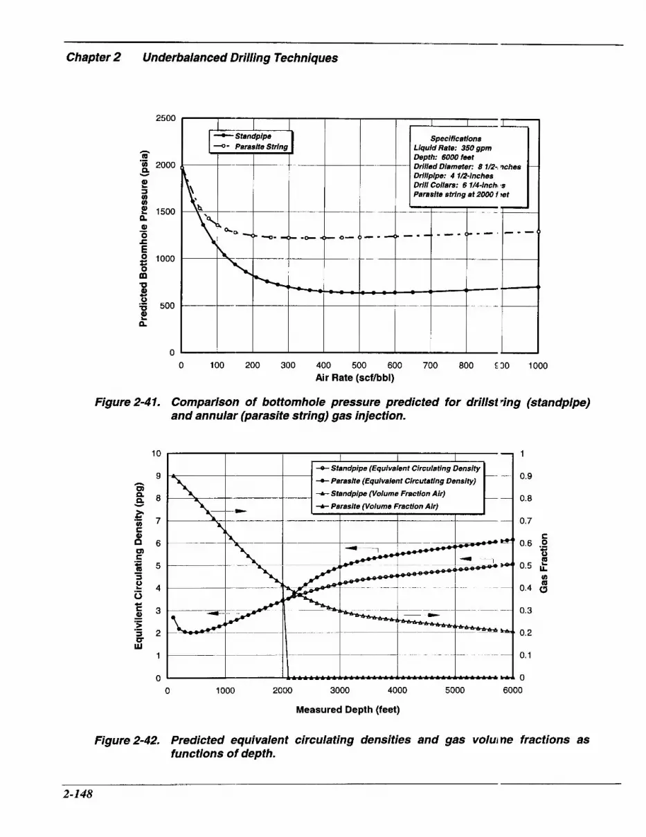
Chapter 2 Underbalanced Drilling Techniques
2500
n Q .- g, 2000 Y
t S cn u)
2 1500
0) 0 c
n - E
m B
t
8 loo0
0
0 a 500
a
0
Figure 2-41.
10
9 n a E 8
c - 5 3 .- > s 2 U Lu
1
0
.-
-C Standpipe - Parasite String
______ --
-~
q- 4+ -- 4- 0- 0- - -
0 100 200 300 400 500 600 700 800 E30 1000 Air Rate (scfhbl)
Comparison of bottomhole pressure predicted for drills2 ring (standpipe) and annular (parasite string) gas injection.
4- Standpipe (Equivalent Circulating Density + Parasite (Equivalent Circutating Density)
-A- Parasite (Volume Fraction Air)
_ _ _I _I__ -A- Standpipe (Volume Fraction Air) -_
--__-
1
0.9
0.8
0.7
C 0.6 0
0.5 E cn Q 0.4 a
0.3
0.2
0.1
0
‘E
0 1000 2000 3000 4000 5000 6000
Measured Depth (feet)
Figure 2-42. Predicted equivalent circulating densities and gas volui ne fractions as functions of depth.
2-148

cleaning, with a gasified liquid, does not require that the liquid volume fraction has to be maintained within any specific range. Choking back the return flow will increase the bottomhole pressure. It will also increase the standpipe pressure and the gas compression requirements. Any choke system should be monitored for erosion by cuttings in the return flow. Bottomhole pressure can normally be increased by reducing the gas injection rate or by increasing the liquid rate, without significant change in gas consumption.
In general, a backpressure should not be imposed on the annulus when drilling with a gasified liquid.
Finally, as is the case when drilling with other compressible fluids, the standpipe pressure does not necessarily respond to changes in annular pressure. Saponja, 1 995,7 compared pressures recorded downhole and at the surface, during a gasified liquid drilling operation (refer to Figure 2-43). The annular pressure was in the range of 325 to 450 psi when drilling normally, but increased to over 870 psi when the annulus apparently packed off due to inadequate hole cleaning. The standpipe pressure did not give any indication of a downhole problem.
Hole Cleaning The methods for ensuring good hole cleaning with a gasified liquid are influenced by the properties of the base liquid, by the hole geometry, and to some extent by the formation fluid inflow. Annular velocities of approximately 100 to 200 feet per minute are required to keep holes clean with unviscosified liquids. It may not be possible to generate that high an annular velocity in large diameter holes. If this is the case, the
base liquid viscosity will hive to be increased to provide adequa :e cuttings transport capacity. A significar t formation fluid inflow may be exploited to improve cuttings transport, by allowing t to add to the annular flow rate.
Settling Velocity Cuttings transport in a simple ga ;ified liquid can be forecasted using a n analysis presented by Guo et al., 1993 l 2 Simple spreadsheet versions can be codt d. The key assumption made is that a gasified liquid can be treated as an homogenous nLixture; this allows a cutting's settling vel xity to be determined by the average flow I lroperties of the mixture. The settling velocity of a particle of diameter, d, (inches), was taken to be:
v, = 9 2 . 6 i d c ( y ) (2.70)
where:
pc ....... cutting's density (ppg), artd, pf ........ drilling fluid's average dc nsity, at
the prevailing temperatur : and pressure (ppg).
Equation (2.70), derived by Mo xe, 1974,17 incorporates a drag coefficient ( f 1.5. This is typical of cuttings falling through a viscous liquid. Gray, 1958,'* . bund lower values for the drag coeffcient, r inging from 0.8 for rounded particles to 1.4 for flat particles; for cuttings falling thtough air, at elevated pressures. Since gas] fied liquids tend to have flow properties clcser to those of the base liquid than those of gases, c d = 1.5 is assumed here. The settlir g velocities are not very sensitive to the valu ; of the drag coefficient. A cutting, with a diameter of
2-149

Chapter 2
h m B Y
Underbalanced Drilling Techniques
8000 b
7000
0 100 200 300 400 500 600 700 800 900 1000 1100 1200 1300 1400 1500 1600 1'00 1800 1900 Time (min)
Figure 2-43. Comparison of downhole and surface pressures (after Sap mja, 1995 '). To convert from kPa to psi, multiply by 0.145.
0.25 inches and a density of 21 ppg (specific gravity 2.5), in a fluid with a downhole density of 5 ppg (specific gravity 0.6), will have a terminal velocity of 83 ftlmin. The annular velocity must exceed this value if the cutting is to move uphole.
Guo et al., 1993,12 assumed that the cuttings concentration in the annulus should not exceed some criticaI value, C,, if hole cleaning problems were to be avoided. The velocity, V,, with which cuttings must travel uphole to keep their concentration in the annulus below the critical level was related to the penetration rate ROP by:
ROP v, = -
60 C, (2.7 1)
where:
v, ........ critical velocity (ftli nin), ROP ... rate of penetration ( Ft/hr), and, C,....... cuttings concentrati in (fraction).
Taking the critical con:entration as 4 percent, cuttings would net d to travel uphole with a velocity twenty-fi ve times greater than the penetration rate. For a penetration rate of 30 ft/hr, this cor-esponds to 12.5 ft/min. In a vertical well, the minimum annular velocity required for this cuttings velocity is the sum of the terminal velocity and the required cuttings velocity; 95.5 ftlmin in this case, for vt = 83 ft/min. Larger cuttings, lower circulatin ; fluid densities and higher penetration r Ltes will require
2-150

higher annular velocities, as will highly deviated and horizontal wellbores. For example, Saponja, 1995,19 reported hole cleaning problems in a horizontal well drilled with nitrified water, when the annular velocity was 400 ft/min. A second horizontal well, drilled with nitrified crude, showed adequate hole cleaning, with an annular velocity of nearly 600 fvmin.
Examples were given by Guo et al., 1993,12 relating the gas and liquid injection rates required for good transport of different sized cuttings, for several different well geometries. Figure 2-44 is one example; for a 6%-inch diameter hole being drilled with 3%-inch drillpipe, at a depth of 10,000 feet. Increasing the gas injection rate increases the size of cutting that can be lifted uphole, whatever the liquid flow rate. In this example, a dry air injection rate of 2,400 scfm would be sufficient for efficient hole cleaning with 0.25-inch diameter cuttings. A liquid injection rate of less than 11W gpm (14.7 cfm) would actually reduce the efficiency of cuttings transport. That is, it would decrease the size of cutting that could be lifted uphole efficiently. The liquid rate would have to be above 1101 gpm to maintain or increase cuttings transport capacity.
The downhole density of the drilling fluid depends on the relative gas and liquid injection rates. If the liquid injection rate is increased while the gas rate is held constant, the circulating fluid density will increase. However, the average annular velocity of the drilling fluid downhole will initially decrease, as the liquid injection rate is increased. At first, the higher downhole pressure reduces the volume of the gas phase by more than the increase in the liquid
injection rate. With further ii creases in liquid injection rate, the rate of rzduction in gas volume becomes smaller than the increase in liquid volume, and he annular velocity begins to increase. As i' lustrated in the example in Figure 2-44, thi! can cause the efficiency of cuttings trmsport to decrease if the liquid injectilm rate is increased. This is analogous to crilling with mist rather than dry air; that is, when injecting liquid, the air rate reqiiired to lift any given size of cutting increises. This should be considered when c esigning a gasified liquid circulating prograi n.
When designing the circulation program, it is possible to use formation fluil inflow to improve cuttings transport efficic ncy. If the inflow occurs at the hole bottori, its effect on cuttings transport can be det:rmined by adding the inflow rate to the in, ected fluid rate(s). Gas inflow at the bit vi11 always improve cuttings transport. Liqu d inflow at the bit may or may not improve cuttings transport, depending on how thc. additional liquid flow affects bottomhole p ressure and annular velocity.
While this supplementary transp >rt capacity can be a bonus, care should be :xercised if drilling is to continue below .he inflow. Cuttings transport between the bit and the depth of the inflow may be imp:ded by the additional fluid flow. As noted 1 bove, a gas inflow can either increase or decrease the bottomhole pressure. A liquid inflow will always increase the bottomhole, wessure. If the bottomhole pressure increa, 'es because of an inflow, the annular velocity between the bit and the inflow site will dt !crease and the circulating fluid density wi I1 increase. An increase in bottomhole pi essure can reduce the efficiency of cutting i transport,
2-151
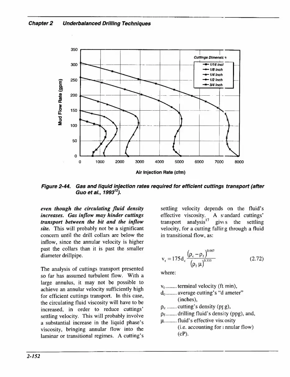
Chapter 2 Underbalanced Drilling Techniques
350
300
250
200
150
100
50
0
-C 1B inch + 114 inch
0 1000 2000 3000 4000 5000 6000 7000 8000
Air Injection Rate (cfm)
Figure 2-44. Gas and liquid injection rates required for efficient cuttings transport (afler Guo et a/., 199312).
even though the circulating fluid density increases. Gas inflow may hinder cuttings transport between the bit and the inflow site. This will probably not be a significant concern until the drill collars are below the inflow, since the annular velocity is higher past the collars than it is past the smaller diameter drillpipe.
The analysis of cuttings transport presented so far has assumed turbulent flow. With a large annulus, it may not be possible to achieve an annular velocity sufficiently high for efficient cuttings transport. In this case, the circulating fluid viscosity will have to be increased, in order to reduce cuttings’ settling velocity. This will probably involve a substantial increase in the liquid phase’s viscosity, bringing annular flow into the laminar or transitional regimes. A cutting’s
settling velocity depends on the fluid’s effective viscosity. A SI andard cuttings’ transport ana ly~is ’~ givc s the settling velocity, for a cutting falliI; g through a fluid in transitional flow, as:
0 661
(2.72) (Pc - P J
(Pf P)0.333 v, = 175dc
where:
vt ........ terminal velocity (ft min), d, ........ average cutting’s “d ameter”
p, ....... cutting’s density (PI g), pf ........ drilling fluid’s density (ppg), and, p ......... fluid’s effective visc osity
(i.e. accounting for i nnular flow) (CP).
(inches),
2-152

For example, consider a 0.25-inch diameter cutting, with a density of 21 ppg, falling through a fluid with a circulating density of 5 ppg. If the maximum attainable annular velocity is 15 ftlmin, Equation (2.72) indicates that the settling velocity would have to be restricted to 17.4 ftlmin for effective hole cleaning, at a penetration rate of 30 ft/hr. This would require an effective viscosity of 160 cP. Equation (2.48) can be used to estimate the effective viscosity of the gasified liquid, from the viscosity of the base liquid and the gas volume fraction. Remember that a high liquid viscosity will make de-gassing the returning fluid more difficult. This can lead to significant operational problems.
Equipment Gas Injection System Gas supply and compression equipment, appropriate to the selected gas, will be required; these are described in Section 2.1 for air, Section 2.2 for nitrogen and Section 2.3 for natural gas. Whatever gas is used, the injection system should be capable of delivering the required gas volume, at the highest anticipated injection pressure. For drillstring gas injection, the gas supply must be able to overcome the standpipe. pressure. This can be of the order of 1,000 psi. For parasite tubing or casing injection, the gas delivery pressure at the injection point must exceed the hydrostatic pressure of a column of any anticipated wellbore liquid. This can also easily exceed 1,000 psi, depending on the depth of injection. With air, on-site generated (membrane filter) nitrogen, or natural gas, boosters will probably be needed. A cryogenic nitrogen pump unit will probably have adequate delivery pressure for most normal drilling situations.
Whatever the type of gas an( injection technique, the rate of gas injecticln must be monitored and controlled more precisely, when drilling with gasified liquids, than when drilling with dry gases or foams. Otherwise, the desired bottomho e pressure will not be maintained. Many cc bmpressors provide little possibility for de ivery rate control by varying operating slieed. An adjustable choke should be set up on the gas delivery line, to allow controlled venting of part of the compressor output through a bypass line, direct to the flare pit. An orifice meter should be installed downstr =am of the choke to measure the volune of air delivered to the well. The metere 1 flow rate can then be used to adjust the chc ke setting, as required.
Claytor et al., 1991,9 describe11 using a backpressure valve, controlled b; feedback from a downstream flow meter, o regulate the volume of gas bypassed. This responds rapidly to variations in standpipi pressure, such as those due to bit torque changes when drilling with a downhole motor.
Cryogenic nitrogen pump units j v e much better control of delivery volume. The pump speed can be adjusted to d1:liver the appropriate nitrogen volume and :xcess gas does not have to be bypassed.
If natural gas will be injected down the drillstring, the gas supply should be connected to the standpipe in the same way as for dry gas or mist drilling (refer to Sections 2.1 and 2.4).
Parasite Tubing String The parasite gas injection strirg can be continuous (i.e. coiled), or joint :d tubing.
.______-I_
2-153

Chapter 2 Underbalanced Drilling Techniques
Continuous tubing itself will be less costly than jointed tubing. It is more costly to rig up to run continuous tubing, but once rigged up, it is usually quicker to run than jointed tubing. Only the casing connections have to be made.
Whatever tubing is selected, it must have sufficient pressure integrity to survive any feasible combination of internal and external pressures that it may experience during installation and operation. The most stringent collapse condition will probably arise when cementing the casing string it is attached to. Filling the parasite string with water or mud will offset the load trying to collapse the string. The parasite tubing could be exposed to gas at full bottomhole pressure minus the gas density gradient, or to gas at the formation pressure gradient. The parasite tubing should be designed to the same burst rating as its host casing.
In many instances, 1-inch diameter coiled tubing will be adequate. If the parasite string is jointed, 1.66-inch non-upset 10 threads per inch tubing is often used. When a high gas injection rate is required, (for example, when drilling large diameter hole), or when the injection point is very deep, the frictional pressure drop down the injection line may become significant. Under these circumstances, larger diameter tubing (greater than one-inch) coiled tubing may be required, in order to limit the gas injection pressure at surface. Clearance between the host casing string and the annular openhole space through which the parasite string is run must be considered when selecting the parasite tubing size. There has to be sufficient room for the parasite tubing and whatever clamps are used to attach it to the host casing.
If the parasite tubing is joiI ted, the clearance must be sufficient for both the tubing outside of the casing coinection and the tubing connection outsid : of the casing body. Appropriate length pup joints of the parasite tubing should be used to ensure that tubing connections are nc It made opposite casing connections. This v rould increase the casing (drift) and opc mhole diameter required to accommodatl > the combined casing-parasite tubing douk le string.
The lower end of the I arasite string is normally ported into the :asing through a custom casing subz0 (refer to Figure 2-45). This is located in the casin ;, above the float collar. After cement has b :en placed, water is circulated down the pa-asite tubing and into the casing to ensure that cement cannot plug the parasite tubing. L.lternatively, it is possible to use a gas-injec :ion float shoe,’l as shown in Figure 2-46. In that case, the lower end of the parasite tubing remains closed until the float equ pment is drilled out. This prevents cement rom entering and allows the parasite string to be pressure tested before the shoe is diilled out and the string is opened to the annu us.
A jointed parasite string can simply be screwed into an appropriatt : box connection on the injection sub or sho:. Consideration should be given to how a cc ntinuous parasite string will be attached to tie injection sub, since it is not possible to rotate the string during installation. It can 1)e welded onto a stub of tubing, previously screwed into the sub and projecting above he upper end of the sub, or, with good access, it may be possible to weld the tubin; directly to the sub. A compression type iitting on the sub can also be used, but this \,ill require more annular clearance than a wt lded connection.
2-154

Pln
2 1B -inch Parasno Into
Figure 2-45. Parasite tubing injection sub (affer Westermark, 1986 ").
The connection of the parasite string to the casing must be strong enough to support tensile loads which may be imposed when running and by the different pressure regimes that can be experienced during cementing and subsequent operations.
The parasite string should be clamped to the outside of the casing, to avoid buckling of the tubing under its own weight, if it is unsupported at any time during running. This can be done with hinged, bolt-on clamps similar to modified casing centralizers.20 Ensure that there is sufficient clearance between these clamps and the rotary table so that they will not snag when run or pulled back through the table. Westermark, 1986,20 reported welding segments of clamp to the casing connections, in order to minimze the outside diameter of the clamp. If this is done, consider the impact of the welding operation on casing integrity.
Figure 2-46. Parasite tubin g injection float shoe (am !r Comeau, 1995 ").
A coiled tubing unit should be used when a continuous parasite string is n n . Coiled tubing can be pulled directly off an unpowered spool, by using the meight of the casing string being run. But, here is no possibility for re-spooling the tu i n g if it is necessary to retrieve the ci sing-tubing string. An injector head is not nc:cessary. A coiled tubing gooseneck should ,e hung off above the rig floor, out of the path of the block and elevators. The coiled tubing is run over the gooseneck and rhrough the rotary table with the casing. Ens Ire that it is possible for the slips to suppor the casing without pinching the parasite tub ng.
Continuous tubing can normall I be pulled far enough to one side to clear collar-type elevators. It may not be possible to bend the tubing sufficiently to clear slip- type casing elevators. With jointed pipe, it i: possible to keep the upper end of the parrsite tubing below the casing elevators and slips at all
2-155

-- Chapter 2 Underbalanced Drilling Techniques
timesY2' permitting any type of elevators and slips to be used. To do this, the first joint of the parasite tubing has to be shorter than the first joint of casing above the injection sub.
P Make up the parasite tubing to the injection sub, and then make up two joints of casing.
9 Pull back the casing until the parasite tubing is above the rotary table.
9 Make up one joint of parasite tubing and clamp it to the casing.
9 Lower the casing and hang off at the top connection.
9 Pick up and make up the next joint of casing.
9 Pull back the casing to expose the parasite tubing, add the next joint of parasite tubing and repeat the process.
Often the parasite tubing will be run outside of the surface casing string, there will be no wellhead and the parasite tubing will simply extend from the conductor pipe at the surface. In this case, it is important that the casing is cemented back to surface. The parasite tubing and its clamps will make it very difficult to run a top-up string into the annulus if cement returns are not obtained and a top-up cement job is necessary.20 If there is a potential for lost cement returns, consider running a top-up string with the casing, in addition to the parasite tubing string.
The parasite string will push the casing off- center in the conductor. When the wellhead, BOP and rotating head or rotary BOP are installed on the casing that carries the parasite string, these will not be aligned with the center of the rotary table. The degree of eccentricity can be sufficient to cause rapid
wear of the rotating head or RBOP sealing elernenk2' Functionalit! of this control equipment is essential. The rig can be skidded across to re-cente the rotary table, after setting the surfacc casing-parasite tubing string. If the condi ctor pipe will be set with the rig, it is much easier for it to be pulled to one side before ils cement sets. If this is done, the surfac; casing-parasite tubing string will be certered below the rotary table when it is iistalled. If the conductor pipe was driven 1 )efore rigging up, the rig should be located !o that the rotary table will be centered 01 the (eccentric) surface casing-parasite tubi ig string and not on the conductor pipe.
If a parasite string is un outside the intermediate casing, it will lave to penetrate the wellhead at the surface and seal against it. Clearance for the para: ite tubing inside the wellhead will be very li nited. It may be possible to obtain an eccentric casing hanger. If not, a reduced di imeter section of tubing may have to be us:d inside of the wellhead.
A check valve and a ball valve should be installed on the parasite tubing at the surface. These prevent an:' fluid flow into the gas supply system ard provide well control in the event that th: well has to be shut-in. The gas supply is :onnected to the parasite string through the b 111 valve.
Annular Gas Injection Recognizing the wellhea J complexities described above, it may be easier to temporarily install a secon casing string; inside the intermediate casi ig, to allow gas injection down the annulu: between these two strings; rather than sing a parasite string on intermediate casini . If this is done, the size of the intermediate :asing may have
I_
2-156

to be increased to accommodate a temporary string with sufficient drift diameter for the hole section to be drilled. This in turn may require that the previous hole section is drilled to a larger diameter than would have otherwise been done. The diameter of the lower hole section may also have to be reduced. Deis et al., 1995,22 gave an example of horizontal wells drilled with and without annular gas injection. 7 5/8-inch intermediate casing was set and 5%-inch casing was temporarily hung off to allow annular gas injection while drilling a 4%- inch hole. Without annular injection, the intermediate casing was 7-inch diameter and the hole below was drilled to 6 1/8-inch diameter.
In some instances, a special casing head has been used to hang off the temporary casing string, inside the intermediate
(refer to Figure 2-47). These he; ds typically have two pairs of two-inch out:ets, to give separate access to the intermec iate-surface annulus and to the temporary-j ntermediate annulus down which the gas was injected. It is advantageous for the temporary string's hanger to have a sufficiently ;mall outer diameter so that it can pass through the BOP stack.5 This allows the tempora y casing to be retrieved without having to remove the BOP stack.
In certain cases, it may be posiible to use conventional wellhead equipm ent. The temporary string can be hung (Iff inside a spool which is left empty when the temporary string is removed. This will normally result in a larger gzs injection annulus than the special bowl. [t may also lead to a wellhead and BOP stacc-up so tall that it can be difficult to ac:ommodate
Figure 2-47. Casing head for micro-annular gas injection (after Teichrob, '994 ').
2-157

Chapter 2 Underbalanced Drilling Techniques
underneath the rig floor.
As was the case with parasite tubing injection, it is necessary that the gas supply system can be isolated from the casing annulus at the surface, if the well has to be shut-in. Connecting the gas supply to the wellhead through a ball valve and a check valve allows this and also prevents any liquid from flowing from the well into the gas supply system. Local well control regulations may require a second ball valve for redundancy.
Some operators run two joints of casing, with the same diameter as the temporary string, at the shoe of the intermediate string. This permits the well to be packed off before retrieving the temporary casing, ensuring well control during this operation.
The temporary string is sometimes run with an anchor and pack-off tool, to locate it firmly in the permanent casing inside which
it is run. Injection ports zre then milled in the temporary casing abcve the pack-off. There has been concern thz t cuttings can get through these injection poi ts, (for example, if the gas injection rate is rt duced) and settle on the pack-off, preventing its release when the temporary string is pullc hd. To avoid this, Teichrob, 1994,5 recomme nded running an aluminum turbolator, betw =en shear-pinned stop collars, at the base of the temporary string (refer to Figure 2-43). This should minimize the extent to whi :h cuttings could build up around the temEorary string. It would also allow the collirs to be sheared off and the casing retrie led, leaving the drillable turbolator dol mhole, if an excessive buildup of cutting s did occur.
It is possible to run the teml korary casing as a tie-back into a drilling line]. A slotted joint at the bottom of the tempoiary string can be used to route the injecttd gas into the returning drilling fluid.
End 12.5mm
Turbolator Shear-mounted Stop Collar Set at 44,000 daN
Figure 2-48. Concentric casing string shoe joint (after Teichrob, 1994 ”).
2-158

Liquid Injection The mud pumps on a conventional rig will normally be capable of injecting the liquid phase. In some instances, the required liquid injection rate may be too low for the rig pumps. Then, it will be necessary to install a smaller triplex pump, with the capacity to operate continuously at or below the required rate. The delivery pressure capacity of this pump should exceed the highest anticipated standpipe pressure.
Generally, the injection pumps will be fed from the rig’s active mud tank. Returns will not normally be taken directly to the rig tanks. The return system will be discussed below.
It is advisable to have an adequate supply of kill fluid, stored on site. Typically, this is 1.5 times the well volume. In some instances, local regulations will dictate the volume required. When drilling depleted reservoirs, the injected liquid itself may be sufficient to kill a well. If this is not the case, storing the kill fluid may require additional tanks on site, over and above the rig’s mud tanks.
Drillstring The BHA for a well drilled with gasified liquid should be kept as simple as possible. Components such as stabilizers, spiral or square collars, and jars can prevent a pressure seal and may damage the sealing element when run through a RBOP or rotating head.
As with other underbalanced drilling techniques, drillstring floats are required. Unlike the techniques described so far, however, the string is often tripped with the well under pressure. Normally, the float is
retained in the string by the pin tbove it. If there is pressure beneath the float, it may be forced out of the string when the connection above it is broken. This can be avoided by machining the connection into which it is placed to accept a snap-ring abov 2 the insert, to hold the insert in place. Altcmatively, a short joint (pipe or collar, as iippropriate) may be run above the float.7
A float in the bottom stand ol the string allows the entire string to be lulled with pressure beneath it. Canadian p ,actice is to use two flapper-type float valves in this last stand for redundancy7 and to ru11 a flapper- type upper string float every 33) feet (100 m). These floats reduce the time taken for the drillstring pressure to bleetl down on connections. They can also limi separation of gas and liquid inside the siring, when flow is shut down.
When tripping with pressure beneath the string, a special tool is used to release pressure trapped beneath each float. This is installed on top of the float sub ;md a pin is screwed down to depress the flapper valve. A side outlet directs the released, pressurized fluid flow laterally away from rig floor personnel.
A custom designed “hydrosta :ic control valve” has been used in place of conventional or modified drill tring float valves.21 This uses a second, SF ring-loaded seal beneath a float valve, to pievent fluid from flowing downhole until tlie pressure above the valve reaches some prc determined value. In this way, it is possible to keep the string above the hydrostatic control valve filled with liquid during a connc ction, even though the annular pressure may ,e less than the hydrostatic head of the liquicl inside the
~
2-159

Chapter 2 Underbalanced Drilling Techniques
drillstring. This in turn prevents air from being drawn into the string at a connection, even if the string has been filled with liquid to allow a conventional pressure pulse MWD system to transmit a survey uphole.
Finally, the influence of the string's geometry on circulating pressures should be considered. A large diameter string decreases the frictional pressure down the string, reduces the standpipe pressure, and increases the pressure drop up the annulus. In a prolific well, the increased annular pressure drop may be desirable since it will tend to limit the surface flowing pressure. On the other hand, it may make it difficult to achieve sufficient downhole pressure reduction for low pressure reservoir applications. In these instances, it may be appropriate to use smaller diameter drillstring components or even a tapered casing ~ t r i n g . ~
BOP Stack The BOP stack design depends on anticipated well conditions and local regulations. A number of different, successful configurations have been reported.
In the United States, many of the gasified liquid drilling applications to date have used aerated water or mud to overcome lost circulation in hole intervals above known reservoirs, where surface pressures are expected to be low. In these cases, rotating heads are used on top of conventional BOP stacks, to seal around the drillstring and divert flow into the flow line.
In contrast, nitrified liquids are often used in Canada, to allow very productive wells to be drilled underbalanced. Normally, a rotating blowout preventer (RBOP) is used rather
than a lower pressure rotaiing head. If the rig is equipped with a top drive it is possible to use dual annular BOP: to give a high pressure seal around the itring above the return line. Since an RB3P gives better control of the closing pressi .re and has lower stripping friction, it is usual y preferred."
It has been recommended that blind rams should be installed at the bc ttom of the BOP stack.7 This maximize 3 the distance between the blind ram ;ind the RBOP, allowing short, irregularl: r shaped BHA components to be run intc the well under pressure, without relying c n the RBOP or annular to seal around them.
A second set of pipe rams, below the blind rams, provides redundanc y. They are normally only used to shut-i i the well, in the event that work is requirecl on one of the elements higher up the stack ,23
Carefully consider how ' he BOP stack configuration will affe :t ram-to-ram stripping operations, if there is any possibility of having to str p into the well under high pressure.
Clearance beneath the rig foor needs to be considered when designing the well cellar, wellhead and BOP stack. 30P stacks, for underbalanced drilling, tend to be taller than those used in conventio ial operations. Clearance is a greater pioblem if con- ventional wellhead equiprr ent is used to inject gas down a temporary 2asing string.
Return System (Low Surfac e Pressure and Limited Hydrocarbon Prod1 ction) The surface systems used to drill with gasified liquids vary con siderably from application to application. In areas where low surface pressures and limited hydro-
2-160

carbon production are anticipated, simple surface systems can be used.
If aerated water is used, the return line can be routed from the rotating head, out to a combined return and flare pit; as would be done when drilling with dry air, mist or foam. No additional gas separator is needed. A centrifugal pump is used to transfer water from the pit to the rig's mud pumps, for re- cycling downhole. The suction line is fitted with a foot valve and filter cover, to avoid having to re-prime the transfer pump and to prevent excessive solids' pick-up. There should also be a choke line, running from below the blind rams on the BOP stack, through the rig's choke manifold, and out to the pit. This is shown in Figure 2-49.
When mud or brine is used as the liquid phase, cost limits the circulating volume. In this case, returns will not normally be routed to the pit. Instead, the return flow line leads either directly to the rig's shale shakers or to a mudgas separator, mounted alongside the shakers (refer to Figure 2-50). The separator stand should be set so that the liquid discharge is high enough to run freely onto the shakers. Mud/gas separators are available, in a range of sizes, as rental items in most parts of the United States. Both the flow line and the separator should be sized to handle the maximum anticipated gas and liquid return rates; the sum of the produced and injected fluid rates. The flow line is often six-inch diameter, although up to ten- inch diameter may be required. Jt should be fitted with valves to allow flow to be sent either to the shaker or to the separator. Typically, the inlet from the flow line to the separator will be six-inch diameter, as will the outlet feeding from the separator to the shakers. A four- to six-inch diameter line
should take gas from the separatca out to the flareheserve pit. There sholld be an ignition source here, to permit fl uing, along with gas and hydrogen sulfide cetectors; as are used in dry air, mist and foarr drilling.
Return System (High Hydrocarl on Production and/or Elevated Sur, 'ace Pressure) If there is any potential for significant hydrocarbon production or elev; ted surface pressures, some means of closiiig the flow line is needed, adjacent to its ccnnection to the BOP stack. An emergencr shutdown device (ESD) may be required in the flow line. Although not normally Jsed, it is possible to mount a manual chc ke between the flow line and the mud/gas if it is essential to apply a backpressure to the well.
There will normally be one set cf choke and kill lines in these operations with two valves between the BOP stack ar d the choke line. Local regulations may dicrate that one of these is hydraulically control11 :d, and may also require that a check valve is used to prevent flowback into the well. The choke line to the rig's manifold shculd have a pressure rating equal to the maiifold, BOP stack and wellhead arrangem mt. Two discharge lines, from the chok 2 manifold, should lead to the mudgas separator and to the pit. These lines, and the choke line, should be able to handle thr maximum anticipated flow rate, witho It creating excessive backpressure anywherc : upstream.
When significant liquid iydrocarbon production or elevated surfac 2 pressures occur - for example, when planing to drill underbalanced through a known reservoir - a more sophisticated surface separ ition system

Chapter 2 Underbalanced Drilling Techniques
compressor Booster i n
Transfer Pump
Figure 2-49. A typical surface system, for drilling with aerated water, c then significant oil production and elevated surface pressure are not expeci ed.
Gas (4-6-inch Outlet)
Mud and Gas (6" Outlet)
\
Valve Mud and Gas r \ (6'' Inlet) I Gate
Valve
Rig
Figure2-50. A typical surface layout, for drilling with aerated mud >r brine, when significant oil production and elevated surface pre: 'sure are not anticipated.
2-162

is probably required. This may be open or closed. Closed systems are normally necessary, if there is any possibility for HzS in the produced fluids. It is not advisable to use a closed system when drilling with an aerated liquid which could lead to the formation of a combustible mixture in the separator. Section 2.8, “Flowdrilling,” describes open system design and operation, and provides guidelines on choosing an open or closed system. Details of the design and operation of closed systems are given in Section 2.9, “Closed Surface Systems.’’
Instrumentation The amount of instrumentation, required to drill underbalanced with gasified liquid, depends on the bottomhole pressure. In applications, where the gasified liquid is being used to overcome lost circulation, there is no potential penalty in terms of formation damage if the well is unintentionally drilled overbalanced for short periods. In that case, no extra instrumentation is required beyond that used on an air drilling job. This includes, in addition to the normal rig instruments, an orifice meter to gauge the air delivery rate, good air and liquid delivery pressure gauges, an air delivery temperature gauge, and natural gas and hydrogen sulfide detectors on the rig floor, at the shakers and at the flareheserve pit.
More sophisticated instrumentation is necessary if the bottomhole pressure needs to be kept within tightly specified limits; to avoid formation damage without compromising wellbore stability or well control. Perhaps the best indication of the bottomhole pressure is direct measurement downhole, using an MWD unit; several of which are able to measure annular pressures. Conventional pressure pulse telemetry
MWD systems cannot transmit nformation from downhole to the surfa:e, if the drillstring contains compressible fluid. Once the gas concentration in the fluid, through which the signal is being ransmitted, exceeds about 90,000 pp n, signal attenuation becomes too rapid ’or reliable transmission.” In some dril [string gas injection applications, it may be acceptable to fill the drillstring with a suppc sedly, non- damaging liquid, before send ng MWD information uphole. This necessarily disturbs the bottomhole pre ssure and normally results in a temporary I werbalance downhole (a situation that tl-e pressure information being sent uphole is ~ !upposed to help avoid). The practical imjdication is that mud pulse MWD system3 can only effectively be used for real-timt downhole pressure monitoring when gc ‘s is only injected into the annulus using a parasite tubing or temporary casing strin ;. MWD systems, with downholc : (annular) pressure recording capability, do exist.25 These can be interrogated at t le surface, after a trip, to recover a record of downhole pressures seen during the previous run. While this information can 1 elp adjust operating parameters for the nzxt run, it cannot be used for real-time conti 01 and may not be sufficient to avoid operating overbalanced for some period of 1 ime.
Electromagnetic MWD can transmit downhole information to the surface, even when the drillstring is f lled with compressible fluid. There are some limitations to the reliability and t ,ansmission capabilities of EMWD systems. They will, however, often operate satisf actorily in many gasified liquid drilling a ?plications. One commercially available EM WD system does provide real-time indicat on of the
2-1 63

Chapter 2 Underbalanced Drilling Techniques
annular pressure,26 and others are under d e ~ e l o p m e n t . ~ ~
Several surface instrumentation packages have been developed, specifically for gasified liquid underbalanced drilling with a
These typically closed surface system. measure gas and liquid injection pressures and rates, return fluid composition, pressure and rate, surface liquid volume, measured depth, wellbore geometry and bit position. Other drilling data, such as hook load, weight on bit, and rotary speed, may be included. From these measurements, it is possible to compute the drilling fluid pressure, at any point in the well, using an hydraulics simulator. Other outputs are often available, including the flow regime
25,26,21
(laminar, turbulent), veloc ities of gas and liquid, gas density, shear rates, viscosities, frictional and hydrostatic F ressure gradients, bottoms-up time (for Sam1 le depth location and for indicating systerr response time), and liquid volumes.
These computed outpui s can provide valuable information on thc : well's condition and guidance for drilling operations. For example, the bottomhol ; pressure and pressure gradients can be 1 sed to adjust the injection rates, to maintain a desired degree of underbalance. Figuie 2-51 is one example where botton lhole pressures indicated a progressive in1 :rease in annular pressure at the bit and we-e used to adjust the injection rates to stay UI derbalanced.
1000
900
800
8 L
600
P 500
UJ f! 8
e 400 E 0 g 300 m
-
200
100
0 0 500 1000 1500 2000 2500
Openhole Length (feet)
Figure 2-51. Bottomhole pressure information, used to adjust injection I ates, in order to stay underbalanced (after Wilson, 1995").
2-164

Formation fluid inflows can also be detected and q~an t i f i ed .~ ' ?~~ A qualitative, indication of permeability is possible, using the production data and an estimated borehole pressure. Water producing zones can be identified. Changing gas production rates have been interpreted to indicate the proximity to gadoil contacts. There have been a number of horizontal wells in Canada in which non-productive zones have been identified while drilling, leading to changes in the planned trajectory away from regions of poor prod~ctivity.~' Wilson, 1995,26 cited an instance where real-time analysis of production data, while still drilling, indicated that a horizontal well had reached its economic productivity limit. This justified terminating the well approximately 2,000 feet short of the originally planned horizontal length.
Determining annular pressure is comparatively straightforward, when gas is injected down a parasite tubing or a temporary casing string.27 The flow geometry and the injected gas's properties will be well characterized. Measurements of the gas injection rate and pressure can be used to accurately compute the pressure at the bottom of the injection string. The hydrostatic head and the frictional pressure loss of the injected liquid (between this point and the hole bottom) can also be predicted with reasonable confidence. Combining these with the annular pressure at the gas injection depth indicates the bottomhole pressure with an accuracy that is often acceptable.
Operating Procedures Controlling Bottomhole Pressures When drilling ahead, bottomhole pressure is principally controlled by varying the gas
injection rate. This is done by aljusting the bypass choke (for air or natural gas), or by adjusting the nitrogen pump rat€ (for liquid nitrogen).
In applications where aerated liq lid is being used to limit lost circulation, the air rate will often be adjusted with referencc: to the pit volume. If the pit volume decreases, indicating losses are occurring, the air rate will be increased to reduce the bottomhole pressure. Conversely, if the pit volume increases, a liquid inflow is occurring, and the air injection rate will be dxreased in order to increase the bottomhc le pressure and stop the inflow.
In most Canadian underbalanc ed drilling operations, gasified liquid is usefl to prevent formation damage when drillinl; through a producing zone. The economic penalty for failing to maintain underbalancec I conditions is much greater when drilling through a reservoir which is prone to formation damage, than when drill ng other formations. Greater care is nxessary to avoid overbalanced condition!, and the benefit of real-time indication c f downhole pressure is clear. Since the dosmhole flow regime in these wells will usually be friction-controlled, the bottomhc de pressure will not normally decrease f the gas injection rate is increased. 1 nstead, the liquid and possibly the gas inject on rate will have to be reduced in order to clecrease the bottomhole pressure. Determini ng new gas and liquid injection rates, to gike a specific pressure, is not trivial, and mi st be done using a flow simulator.
Since the circulating s j stem has considerable compressibility, an! adjustment to the injection rates will cause the
2-165

- Chapter 2 Underbalanced Drilling Techniques
circulating pressures to respond and stabilize over a finite period of time. There is a danger of over-controlling under these circumstances. It will be much easier to achieve the desired pressure levels if new injection rates are first computed and used for guidance in making the rate adjustments.
Connections Connections can be slow when drilling with drillstring gas injection.
9
P
P
P
9
Gas injection should be stopped.
The liquid injection pumps should be then shut down.
The pressure in the drillstring has to be bled down through the standpipe bypass line before the joint can be broken open. This takes longer with gasified liquid than with dry air. Even with an upper string float, it can take 5 to 15 minute^.^ Breaking open the joint before the pressure has fully bled down should be avoided.
If there is no check valve in the gas supply line, the gas supply should be shut off at the standpipe manifold. The pressure in the supply line should be kept close to its operating level, to avoid any possibility of liquid running into the gas supply equipment when injection is resumed."
Making a connection can be speeded up by displacing the string as far as the upper float valve, either to gas or to liquid. If the string is displaced to gas, the pressure can be bled down rapidly and liquid should stay below the float valve. If liquid is completely displaced from the string, liquid will be discharged at the floor when the joint is broken open. Displacing to liquid is the quickest method of making a connection.
The higher fluid dens ty in the string causes it to flow ("L-tube") into the annulus, and the rig crc w does not need to wait for pressure to I,leed down. This puts a slug of liquid in o the circulating system that will cause a pressure spike downhole when inject ion is resumed; possibly causing balanced or overbalanced conditions.
Benion et al., 1995,28 d2monstrated the variation of downhole pres ure for different connection methods (refer to Figure 2-52). There are larger pressure peaks when the string is displaced to liquid, than when it is displaced to gas prior to the connection.
The drillstring does not hav 2 to be displaced to gas or liquid before a onnection when annular gas injection is 1 sed. Gas will migrate up the annulus and liquid will flow from the string into the anndus. The liquid flowing into the annulus can be prevented from increasing bottomhc le pressure by continuing gas injection aft,:r the pumps are shut off. However, the anr ulus will unload during the connection, idhether or not injection is continued.
If connection times are shoi t and the gas-to- liquid ratio is small, it is sol netimes possible to keep the annulus frori unloading by stopping gas injection and shutting-in the
Extreme caution should be used when doing this. The annu us pressure may build rapidly due to thl: difference in drillstring and annular fluid densities and the migration of gas up the annulus. The compressibility of the gas nc lw trapped in the annulus, between the lower string float and the BOP, will limit the pre sure increase to less than the difference in the hydrostatic pressures of the liquid in tke drillstring and the gasified fluid in the ann1 lus. Shutting-in
2-166

l l l l l _ l - - - _ _ - _ - _ - _ - _ _ - - l l l _ l l _ l _ l l l l l _ . _ _ l _ . I .
Hydrostatic Pressure / Reservoir Pressure
Pressure Spikes During Connections
N2 Circulation Prior to Connections
- Time
Figure 2-52. The impact of the connection procedure on bottomhole pressurt I (modified after Bennion et al., 1995").
the BOPs can cause liquid to flow into the formation because pressures are greater than during circulation. The pressure difference is larger at the casing seat than at the hole bottom. Applying surface pressure to a gasified liquid gives a higher equivalent mud density at shallower depths than at greater depths. Finally, the surface equipment will be subjected to very high instantaneous flow rates when the BOPs are opened, unless the well is first flowed through the rig's chokeline (bleed off line) to release built-up annular pressure.
Saponja, 1995,19 presented an example in which increasing the annular pressure actually sped up making connections. The well was initially drilled with water, with nitrogen injection down the drillstring.
When injection was stopped '0 make a connection, a large oil influx kill :d the well. It was not possible to regain circt lation until the oil had been pushed bacc into the formation with nitrogen pressi re on the annulus. The connection took ~ . 5 minutes. An alternative procedure, involvi ig "annular pre-charging," was devised. T i e annulus was charged with nitrogen, at ap] roximately 1950 scfm, for one or two ininutes, to increase the annular pressui E. This restricted inflow. Circulation wa 3 easily re- established after making the conr ection, and the total connection time cam: down to seven minutes. While connectioi time may be reduced, formation daniage may overwhelm any benefits, particularly if a water-based liquid is used. In this example, the injected liquid was switched t 3 oil before
2-167

Chapter 2 Underbalanced Drilling Techniques
trying this annular pre-charging; there was no detectable formation damage.
Trips Tripping procedures depend on the extent and nature of any formation fluid inflow. Tripping is easy if the well will not flow to surface, particularly if the well is not making any hydrocarbons. First gas and then liquid injection should be shut-down. If there is uncertainty about lost circulation and no potentially productive intervals are open to the wellbore, liquid injection can be continued after the gas is shut-down, to determine if there are full liquid returns. The string is stripped back through the rotating head or RBOP, as far as the BHA. At this point, the annulus should have stopped unloading and the well should be dead. The rotating head or RBOP rubber can now be removed and the trip completed. In general, it will not be possible to jet any produced gas away from the rig floor, once the rotating head or RBOP rubber is pulled. This tripping procedure cannot be used if the well is making any gas. If the well will not support a full column of liquid, hole fill- up volumes cannot be used to confirm if the well is flowing.
With drillstring gas injection, establishing circulation, after a trip, may be difficult if there is lost circulation. Many lost circulation zones can also produce substantial water volumes. Gas will break out of the drilling fluid when the well is not circulated, leaving gas between the surface and the top of the liquid column. After a short time, this liquid column will contain little entrained gas and the hydrostatic pressure at the lost circulation zone will approach the formation pressure. When gas and liquid injection are resumed, the drilling fluid will flow up the annulus to the lost
circulation zone, displac ng the standing liquid uphole and increai ing the pressure adjacent to the loss zone. If the loss zone has significant permeabilip I, which it usually will, much or all of the g isified liquid can flow into the loss zone, rither than up the annulus.
It may be necessary to st; ge the drillstring into the hole, breaking c rculation several times before reaching bc ttom. Breaking circulation above the loss zone will gasify the liquid column in the a nulus and reduce the hydrostatic pressure sufficiently that circulation can be establi ,bed from below the loss zone.
With annular gas injection, it is possible to inject gas and gasify the liquid standing in the annulus above the injection point, before any liquid is pumped into the well. If this does not reduce the annula. pressure enough for circulation to be est; blished, the gas supply system can, in prirciple at least, be re-configured so that gas ci n also be injected down the drillstring to fi rther reduce the annular pressure.
Tripping becomes more cc mplex if the well is producing hydrocarbon: or will flow to the surface. It is possible to trip, as described above, if the well is making only oil with a very low GOR, f -om a sufficiently underpressured zone that t i e well will load up and kill itself before oil reaches the surface, In most cases, some oil will reach surface and other opticns need to be considered. There are also concerns that repeated flow-cycles can lead to formation damage.2
If a well does flow to surfal :e, the options are to strip out of the hole wnile allowing the well to flow, or to kill the well before
2-168
tripping. When feasible, stripping out of the hole is preferable, since this should preserve the underbalance and avoid formation damage while tripping. Drillpipe can be stripped through the rotating head or RBOP, while the well is allowed to flow through the flow line. A rotating head or a normally configured RBOP will not seal on larger diameter drillstring components. Cylindrical collars and other slick BHA components can be stripped through the annular. If essential, it is possible to remove the kelly packer rubber from an RBOP and to allow the inner packer element to seal around larger diameter string component^;^^ but, this practice is not recommended. It may be possible to “stage” irregularly shaped BHA components, such as stabilizers, out of the well through an RBOP. To do this they have to be small enough in diameter to pass through the RBOP sealing element29 and short enough for the irregularly shaped portion to fit between the annular and the B O P . In this case, the component in question is stripped through the RBOP until the “irregularity” is above the annular. The annular is shut around the string and the RBOP is opened to allow the “irregularity” to pass.
When stripping through the annular, the choke line below the blind rams should be opened and the well flowed through an open choke to the separator system or the flareheserve pit, as appropriate. The blind rams should be closed below the bit before finally opening the annular and removing the last stand.
Flowing the well through an open choke keeps the wellhead pressure to a minimum. Nevertheless, it is almost inevitable that a “pipe light” situation will occur before the
string is out of the hole. This ot:curs when the pressure beneath the drillstring exerts an upward force on the string that :xceeds its effective weight (the sum of tlie buoyant weight of string below the presstre seal and the weight in air above it). Mlthout any restraint, the string is then forcec out of the well by the pressure beneath it. Snubbing calculations should be perforn led before stripping the string from thc well to determine when pipe light conc itions will occur. These should consider ti e probable surface pressure, the weight of thl; drillstring above the pressure seal, its buoj ant weight below the seal, the area of the stri ig where it passes through the pressure sei], and the frictional force of the sealing eler ient on the string. When a pipe light sittation does occur, the string can sometimes be kept in the hole by the frictional force of the RBOP sealing element. The frictional f xce on the string can be augmented by (losing the annular.29 Increasing the closing xessure on the seal elements will increase the frictional force they exert on the string. It is also possible to use reverse-acting s ips. With high wellhead pressures, it may b 3 necessary to use a snubbing unit to control t i e string as it is withdrawn from the well.
With a BHA consisting of collars, the weight of the first stand may be sufficient to overcome both the pressure thrus: due to the flowing well’s backpressure and the seal frictional force so that it can enter the flowing well without additional assistance. The bit should be run just above the closed blind rams, the RBOP (or anntlar) closed and the blind rams opened, before running the string into the hole. It is pos;ible to use a large diameter collar above lrillpipe to push the drillpipe into the well i the pipe’s weight alone is insufficient. A simple
2-169

Chapter 2 Underbalanced Drilling Techniques
crossover between the collar and the pipe can be difficult to handle, and a special connection tool has been used instead.29 This resembled a pipe elevator, with a collar thread box on top. It was made up onto the bottom of the collar and a single joint of drillpipe was picked up using the “elevator” portion. This would be made up to the pipe held in the RBOP and the RBOP closing pressure reduced to allow the string to run into the hole. Again, a snubbing unit may be required if the wellhead pressure is still too high.
This procedure requires that the surface system can handle the unrestricted flow rate of the well. The surface system should normally have been sized to do this. Well flow can be choked back, if necessary, to restrict the flow rate. This will increase the pressure at the wellhead. If the well flow has to be choked back, the pressure limitations of the BOP stack, and particularly of the rotating head or RBOP, if these are being used to contain the annular pressure, must be recognized. It may be necessary to kill the well if the flow cannot be handled safely.
Higher wellhead pressures will increase the snubbing loads. It may be necessary to use a snubbing unit to control the string. Hydraulic Rig Assist (HRA) snubbing units have been specifically developed to supplement drilling operations with a conventional drilling or workover rig3’ A truck-transportable unit is shown in Figure 2-53. It incorporates a BOP system, a pair of hydraulic rams to move the string, stationary and traveling slips to hold the string, a working platform and a control panel. Both the stationary and the lower set of traveling slips hold the string down against wellbore pressure when pipe light.
The upper set of slips, tlie “heavy” slips, hold the string’s weight wh :n necessary. The equalizehleedoff spool, be ween the annular and ram-type BOP units, i: connected to the annulus below the blind rams and to the choke manifold. It k as hydraulically activated valves that are cc ntrolled from the work platform. It allows 1 ressures beneath different BOP component! to be equalized (for example during staginj operations) or to be bled down as required.
The lower BOP is attached either directly to the drilling rig’s BOP stac : or to a suitably long riser spool so that the snubbing unit is just above the drilling rig’s floor. Figure 2- 53 shows one rig-up that kas been used for drilling underbalanced wit 1 a conventional drilling rig and an RBOF, with the HRA snubbing unit’s BOPs abcve the rig floor and the rig’s BOP stack bc low. The BOPs are usually rated to 5,000 I si, and can often pass equipment up to abcut six inches in diameter. This effectively imits these units to drilling operations ir side seven-inch diameter or smaller casing A typical BOP stack for drilling undert alanced with a conventional drilling rig and an HRA snubbing unit is shown in F gure 2-54.
The hydraulic cylinders, shiwn in Figure 2- 53, provide maximum snu Ibing forces that typically range from 45,OCO to 80,000 Ibf. These control the string is it is removed from the well and force it tack into the well against the wellbore pressui e. Most hoisting operations are performed with the rig’s drawworks. Drillstring and tubing are racked back in its derrick w ien necessary.
Killing a well is not an at ractive option if the well is being drilled iinderbalanced to avoid formation damage. It may become necessary if the BHA con- ‘iguration cannot
2-1 70

Figure 2-53.
4.25m Qpically
Control Panel
Heavy Slips Trawling Plate Trawling Slips
Work Platlorn
Stationary Slips
Hydraulic Cylinders
- Equalizing Spool
Hydraulically Activated Equalid Bleedoff P l w Valves
L " W An Hydraulic Rig Assist (HRA) snubbing unit (after Goertzen, 1995"'). '
Eauaiizs'i9ieedoff I plug valve Bleedoff Line
Riser Spool
Rig Floor I II I
MacPt erson and
Figure 2-54. A typical BOP stack, for drilling underbalanced with a conventit mal drilling rig and an HRA snubbing unit (after MacPherson and Goertzer ?, 19953').
- 2-1 71

Chapter 2 Underbalanced Drilling Techniques
be tripped from the well without losing the pressure seal, if the string cannot easily be run into or out of the hole in any pipe light state that can arise, or if the well’s flow cannot safely be handled by the surface system. The kill fluid should be chosen to minimize formation damage. Selecting nominally non-damaging fluids is beyond the scope of this document. It will not be discussed in any detail. An introductory discussion of the various factors involved can be found in many references; for example, Ali et al., 1994.31 A clear brine is one possibility if sufficient density can be achieved without undue cost or health and environmental concerns. Alternatively, ‘ liquids, to which suitably sized calcium carbonate particles have been added, can be considered. The particles should be sized to minimize fluid loss, ideally by conducting pilot tests on core samples from the producing formation. Spotting an appropriate acid, after drilling, should remove the majority of calcium carbonate particles and restore the permeability.
If possible, the kill fluid should be placed on top of produced crude oil, to reduce the probability of contact between the formation and the kill fluid. To do this, the well should be allowed to flow until all open productive formations are covered. The string should be stripped back above the produced liquid, ideally inside the casing shoe. Kill fluid can then be spotted above the produced liquid to kill the before continuing the trip. Alternatively, the kill fluid can be pumped down the annulus while continuing to strip the pipe. In this case, the kill fluid should be pumped at a rate equal to that at which the open displaced volume and internal volume of the drillpipe are removed from the hole.32 The kill fluid density should be chosen so that the well is dead
before the top of the €HA reaches the surface. Whatever procc dure is used to place the kill fluid, coni entional tripping practices, trip sheets, hole -fill, etc., should be followed once the we1 is killed. As a warning, the higher densit) kill fluid and the lower density produced 1 iydrocarbon may “flip over,” due to their dcnsity differences, allowing the kill fluid to contact and potentially damage the forn iation.2
Gas Inflows When a gas inflow is dejected, it may be possible to reduce the gas njection rate and cost. However, if drilling c mtinues until the BHA is below the inflow, the reduced annular velocity close to the hole bottom may not be sufficient f < r good cuttings transport (if the gas injection rate has been reduced substantially).
Limitations Recent experience in Canac a has shown that gasified liquids can be used to successfully drill underbalanced, in a wide range of normally and sub-hydrost: tically pressured reservoirs. There are factois which limit the application of gasified li quids, including high formation pressure or productivity, wellbore instability, inac equate pressure control, excessive pr iduced water, corrosion, and limited penei ration rates.
Formation Pressure and PA *oductivity Gasified liquids give 1 iigher borehole pressures, in comparison to dry gases or other lightened drilling flu ids. Because of this, they can be used to dri 1 higher pressure and productivity formatic Ins, before the pressure and rate of hydroc ubon production while drilling approach the imitations of the surface equipment. The lir iiting factors are the pressure capacity of the surface equipment, particularly the BOP stack and
2-1 72

diverter system and the flow rate capacity of the surface separator system. The flow capacity of a suitably designed surface system can be very high - natural gas production rates of as much as 40 MMcf/D have been handled safely in Canadian underbalanced drilling operations.
Assessing formation productivity and pore pressure, along with the capacity of the surface system, can indicate the largest drawdown that would be tolerable during drilling of a particular intend. This effectively sets a restriction on the borehole pressure, below which it is unsafe to drill. There are many overpressured reservoirs where the difference between borehole and formation pressures would be too great for gasified liquids to be used safely, and, a single-phase liquid drilling fluid with an appropriate density, could be used to generate underbalanced conditions. Section 2.8, "Flowdrilling," describes these oper- ations.
Wellbore Instability Gasified liquids can be used in weaker, less competent rocks than dry gases and other lightened drilling fluids. Their higher wellbore pressures reduce the effective stresses adjacent to the borehole wall. Many horizontal wells have been drilled with gasified liquids in weak rocks. Even so, borehole pressures will be lower with a gasified liquid than they would be with a drilling mud and mechanically-induced wellbore instability remains more likely. Large fluctuations in borehole pressure, that often occur when gasified liquids are used, may aggravate wellbore instability, by disturbing rock fragments that might otherwise have remained more or less stable under static loading.
Wellbore instability can be nore of a problem when drilling through shales than through sandstones or carbor ates. For example, when drilling towards a depleted reservoir, overlying shales may be overpressured, relative to the target formation. This increases the u iderbalance pressure through the shale and nakes them more prone to mechanical instability. Wellbore instability provides a iother limit on how low the borehole pressire may be taken.
Water-sensitive shales can alsc swell and slough when exposed to aqueous liquids. As the liquid phase of the drilliig fluid is usually re-cycled, it may be economical to limit shale instability by adding appropriate salt and/or polymer to a water-l: ased liquid. Using hydrocarbon-based li iuid may eliminate concerns about chemically- induced wellbore instability in sl- ales.
Pressure Control In general, downhole pres sur:^ do not remain constant when drilling P ith gasified liquids. They tend to fluctuate, particularly when tripping or making conned ions. Peak- to-peak pressure fluctuations of 500 psi are commonly recorded downholc .7725 The example in Figure 2-55 shows significant downhole pressure fluctuations above and below an average value.
These pressure fluctuations will usually not cause major problems whc n drilling underbalanced to avoid lost circulation, except possibly when re-establishing circulation. When drilling unde ,balanced to avoid formation damage, the up] ber tolerable limit to borehole pressure is g ven by the formation pressure. If the boreh de pressure increases above the formation pi essure, then
2-1 73

Chapter 2 Underbalanced Drilling Techniques
1000
900
= a 800 U
!!!
!!! n Q) 5 600 c E 0
m
3 8 700
500
400
300
L-
0 20 40 60 80 100 1: 0 140
Time (minutes)
Figure 2-55. Bottomhole pressures, recorded while drilling with gash ied liquid (affer Saponja, 1995 'I.
damage is probable. A lower tolerable borehole pressure limit will be set by productivity, wellbore stability and the surface facilities. There can be great difficulty in drilling underbalanced with a gasified liquid if this lower pressure limit is not at least 500 psi lower than the formation pressure.
Produced Water Produced water can be a problem when gasified liquid is used to avoid lost circulation. The equivalent circulating density changes with depth when drilling with a gasified liquid. The gas volume fraction decreases with increasing depth due to the higher pressure, and this increases the mixture's density. Depending on the variation of formation pressure with depth,
this could mean that a well can potentially be overbalanced near the hole bottom but underbalanced higher up h Ae. Under these circumstances, it is p'ssible to lose circulation at the same lime that a zone uphole is flowing into the well. It may be very difficult to achieve :irculation if the zone uphole is producing large quantities of water. There have been illstances in which uphole water inflows have kept the pressure in the wellbore above the f mnation pressure in a lower loss zone, so that it was not possible to circulate any fluid to surface even when injecting only dry air down the drilling string. In this cas:, the options are to drill ahead without retu-ns, to run casing or to abandon the well.
It will often be possi )le to maintain
2-1 74

circulation with water flowing into the well, provided that the inflow is not too rapid. If drilling continues for very long after the inflow starts, water disposal can easily become a problem. If the well is making fresh water, surface discharge might be approved. Otherwise, the produced water will usually have to be hauled away for disposal, off site. This can be expensive. If it is an in-fill well, it may be possible to tie into an existing disposal system.
Some wells will produce water at low circulating pressures, and then stop producing water and instead lose circulation, if the borehole pressure is increased. In this situation, it may be possible to re-inject the water downhole. This has been done in coalbed methane wells, in the Black Warrior Basin.33 These were drilled with dry air until water production occurred and filled the reserve pit. The drilling fluid would then be switched from dry air to produced water. Drilling continued with total losses, until the reserve pit was emptied, at which time air drilling was resumed. By repeating this process it was possible to reach TD with minimal amounts of produced water for off- site disposal. Drilling without returns may not be possible in all wells. Sloughing above the lost circulation zone can cause the pipe to become stuck. The potential for wellbore instability and stuck pipe should be carefully considered before adopting this option.
Produced water entering the well cannot be separated from a water-based gasified liquid. Gasified mud should not be used when large volumes of produced water are expected. The produced water will dilute the mud, requiring continuous and expensive replenishment of mud additives to maintain the liquid's properties. If a mud has to be
used to clean the hole, it should l ~ e designed to minimize the cost of the consu nables that will have to be added to counter dilution by produced water. If water prclduction is encountered when drilling with a gasified mud, the borehole pressure should be increased, if possible (witha ut risking formation damage or losing circ dation), in order to reduce the water inflow r kte.
Corrosion Corrosion of the drillstring and other downhole equipment, including a ny exposed casing in the well, can be a 7 ery severe problem when drilling with aerat :d water or water-based liquids. The rate o ' corrosion increases as the conductivity of the liquid phase increases. Using a saline liquid phase, such as produced water, or add ng salts to inhibit shale hydration, wil increase corrosion problems, as will higl downhole temperatures and the presence o ' even very small quantities of hydrogen sulfi de.
Corrosion inhibitors have to be used with aerated, water-based drilling flu ds. These are expensive and can add confiderably to well costs, particularly if water production dilutes the circulated liquid. F irthermore, some corrosion inhibitors become ineffective once the temperatu -e exceeds about 100°F and may even accelerate corrosion at temperatures of 300°F or more.34 The injected liquid's p€[ should be controlled to be above about nine, if possible, since this will ten([ to slow corrosion. Corrosion coupons should be used to monitor corrosion raes and to indicate if protective measures ai e adequate. The cost of corrosion control w ien drilling with an aerated, water-based f uid (if the downhole temperature is high anc I if the well is making high salinity wate.) may be
2-1 75
Chapter 2 Underbalanced Drilling Techniques
prohibitive.
Corrosion remains a problem if membrane- generated nitrogen or mixed air and nitrogen are used to gasify the drilling fluid. It is not a concern when using natural gas, cryogenic nitrogen, or a hydrocarbon-based liquid phase.
If there is any prospect of hydrogen sulfide production, all exposed equipment should be rated for sour service.
Penetration Rates The penetration rates, with a gasified liquid, will generally be lower than those for dry gas, mist or foam. This is because of the higher borehole pressures. Because the borehole pressure is lower than for a mud, the penetration rates will normally still be higher than for a mud. The maximum gas delivery pressure is usually less than the maximum mud pump pressure. Therefore, the standpipe pressures cannot be as high
when injecting gas down the drillstring as when drilling with mud. 1 his limits the bit pressure drop that can bo used with the gasified liquid, and this can in turn restrict any penetration rate incr:ase that might accompany the use of the g; lsified liquid.
Gasified liquids are often used in weaker formations instead of other lightened drilling fluids. In these formations, penetration rates can be high even when drilling overbalanced. The econc mic benefits of penetration rate increases ire less at these high penetration rates, whm only a small fraction of the total rig time is actually spent with the bit on bottom mzking hole. It is possible that the time ssvings due to a penetration rate increase c annot cover the cost of the extra equii ment involved; drilling underbalanced with a gasified liquid may actually cost more tl an conventional drilling. In this case, o:her benefits of drilling underbalanced havc to be sufficient to justify its use. This will )ften be the case.

1 .
2.
3.
4.
5.
6.
7.
8.
9.
10.
11.
References
2-177
Bobo, R.A. and Barrett, H.M.: “Aeration of Drilling Fluids,” World Oil (1953) 137, No. 4, 145.
Bieseman, T. and Emeh, V.: “An Introduction to Underbalanced Drilling,” pap( r presented at the 1995 1st International Underbalanced Drilling Conference, The € ague, The Netherlands, October 2-4.
Eide, E., Brinkhorst, J., Volker, H., Burge, P. and Ewen, R.: “Further Advances in Coiled Tubing Drilling,” paper SPE 28866, JPT (May 1995).
Wodka, P., Tirsgaard, H. and Damgaard A.P.: “Underbalanced Coiled Tub ng Drilled Horizontal Well in the North Sea,” paper SPE/IADC 29359 presented ai the 1995 SPE/IADC Drilling Conference, Amsterdam.
Teichrob, R.R.: “Low Pressure Reservoir Drilled with Air/N2 in a Closed Systei n,” Oil and Gas J. (March 21, 1994) 80-90.
Bennion, D.B. and Thomas, F.B.: “Underbalanced Drilling of Horizontal We 1s: Does It Really Eliminate Formation Damage?,” paper SPE 27352 presented at the 1994 SPE International Symposium on Formation Damage Control, Lafayette, LA.
Saponja, J: . “Engineering Considerations for Jointed Pipe Underbalanced Drill ing,” paper presented at the 1995 1 st International Underbalanced Drilling Conference, The 3ague, The Netherlands, October 2-4.
Wolke, R.M., Jardiolin, R.A., Suter, R.L., Moriyama, S., Sueyoshi, Y. and (ihara, Y.: “Aerated Drilling Fluids can Lower Drilling Costs and Minimize Formation Damage,” Geothermal Resources Council Bulletin (May 1990) 13 1 - 137.
Claytor, S.B., Manning, K.J. and Schmalzried, D.L.: “Drilling a Med um-Radius Horizontal Well with Aerated Drilling Fluid: A Case Study,” paper SPE/IPDC 21988 presented at the 1991 SPEIIADC Drilling Conference, Amsterdam, The Netherla mds.
Curtis, F. and Lunan, B. : “Underbalanced Drilling Operations: Correct Operating Procedures Using a Closed Surface Control System to Drill for Oil and (;as,” paper presented at the 1995 1st International Underbalanced Drilling Conference, The -Iague, The Netherlands, October 2-4.
Fried, S. and McDonald, C. : “Nitrogen Supply Alternatives for Underbalancei 1 Drilling,” paper presented at the 1995 1 st International Underbalanced Drilling Conference, The Hague, The Netherlands, October 2-4.

Chapter 2 Underbalanced Drilling Techniques
12.
13.
14.
15.
16.
17.
18.
19.
20.
21.
22.
23.
Guo, B., Hareland, G. and Rajtar, J.: “Computer Simulation Predicts 1 ‘nfavorable Mud Rate and Optimum Air Injection Rate for Aerated Mud Drilling,” psiper SPE 26892 presented at the 1993 SPE Eastern Regional Conference and Exhibition, P ttsburgh, PA.
Hasan, A.R. and Kabir, C.S.: “A Study of Multiphase Flow Behavior in Vertical Wells,” SPEPE (May 1988) 263-272.
Poettmann, F.H. and Bergman, W.E.: “Density of Drilling Muds ]!educed by Air Injection,” World Oil (August 1955) 97-100.
Poettmann, F.H. and Carpenter, P.G.: “Drilling and Production Practice,” API (1952) 257.
Wang, Z., Rommerveit, R., Vefring, E.H., Bieseman, T. and Faure, A.IA.: “A Dynamic Underbalanced Drilling Simulator,” paper presented at the 1995 L st International Underbalanced Drilling Conference, The Hague, The Netherlands, October ,-4.
Moore, P.L.: “Drilling Practices Manual,” PennWell Books, Tulsa, OK (1 374) 234.
Gray, K.E.: “The Cutting Carrying Capacity of Air at Pressures Above AI mospheric,” Pet. Trans. AIME (1958) 213, 180-185.
Saponja, J.: “Comparing Conventional Mud to Underbalanced Drillin ; in a Depleted Reservoir,” paper presented at the 1995 1 st International Underbalanced Dri lling Conference, The Hague, The Netherlands, October 2-4.
Westermark, R.V.: “Drilling with a Parasite Aerating String in the Disturt ed Belt, Gallatin County, Montana,” paper IADC/SPE 14734 presented at the 1986 IAI )C/SPE Drilling Conference, Dallas, TX.
Comeau, L. : “Underbalanced Drilling: Directional and MWD Experience, ’ paper presented at the 1995 1 st International Underbalanced Drilling Conference, 1 he Hague, The Netherlands, October 2-4.
Deis, P.V., Yurkiw, F.J. and Barrenechea, P.J.: “The Development of a 1 Underbalanced Drilling Process: An Operator’s Experience in Western Canada,” paper presented at the 1995 1st International Underbalanced Drilling Conference, The Hague, The Netherlands, October 2-4.
Hannigan, D.M. and Bourgoyne, A.T., Jr.: “Underbalanced Drilling Rotat. ng Control Head Technology Increasing in Importance,” paper presented at the 1995 1 st International Underbalanced Drilling Conference, The Hague, The Netherlands, October 1-4.
2-7 78

24.
25.
26.
27.
28.
29.
30.
31.
32.
33.
34.
Shale, L. : “Underbalanced Drilling Equipment and Techniques,” presented at the 1995 ASME Energy Technology Conference, Houston, TX.
Roy, R. and Hay, R.: “Measuring Downhole Annular Pressure While Drilling for Optimization of Underbalanced Drilling,” paper presented at the 1995 1 st tnternational Underbalanced Drilling Conference, The Hague, The Netherlands, October 2-4.
Wilson, J.: “Optimizing Drilling of Underbalanced Wellbores with Data Acquisition Systems,” paper presented at the 1995 1 st International Underbalanced Drilling Conference, The Hague, The Netherlands, October 2-4.
Taylor, J., McDonald, C. and Fried, S.: “Underbalanced Drilling Total System: Approach,” paper presented at the I995 1 st International Underbalanced Drilling Conference, The Hague, The Netherlands, October 2-4.
Bennion, D.B., Thomas, F.B., Bietz, R.F. and Bennion, D.W.: “Underbalanl :ed Drilling, Praises and Perils,” paper presented at the 1995 1 st International Underbalar ced Drilling Conference, The Hague, The Netherlands, October 2-4.
Cagnolatti, E. and Curtis, F.: “Using Underbalanced Technology to Solve Traditional Drilling Problems in Argentina,” paper presented at the 1995 1st International Underbdanced Drilling Conference, The Hague, The Netherlands, October 2-4.
MacPherson, L. and Goertzen, J.B.: “Hydraulic Rig Assist Snubbing-Well Control for Underbalanced Drilling,” paper presented at the 1995 1 st International U iderbalanced Drilling Conference, The Hague, The Netherlands, October 2-4.
Ali, S., Burnett, D., McLeod, H., Peden, J. and Penberthy, W.L., Jr.: “Experts Share Views on Formation Damage Solutions,” JPT (November 1 994) 936-940.
Joseph, R.A.: “Underbalanced ‘Horizontal Drilling - Conclusion Special Tec hniques and Equipment Reduce Problems,” Oil and Gas J. ( March 27, 1995) 41 -47.
Graves, S.L., Niederhofer, J.D. and Beavers, W.M.: “A Combination Air and I luid Drilling Technique for Zones of Lost Circulation in the Black Warrior Basin,” SPELIE (February 1986) 57-6 1 .
Scott, S.L., Wu, Y. and Bridges, T.J.: “Air Foam Improves Efficiency of Co npletion and Workover Operations in Low-Pressure Gas Wells,” SPEDC, (December 1995) 2 19-225.
2-1 79

Chapter 2 Underbalanced Drilling Techniques
2.8 Flo wdrilling
The term “flowdrilling” refers to drilling operations in which the well is allowed to flow to surface while drilling. It was first coined by a group of Oryx Energy Company engineers (Stone, unpublished), to describe the drilling technique that they had developed for the Austin chalk reservoir in the Pearsall Field, in South Texas. Flowdrilling of this and other Austin chalk reservoirs represents one of the most successful applications of underbalanced drilling to date in the United States.’
The underbalanced drilling techniques, described previously in this manual, have all used drilling fluids that are either completely gaseous or contain a gaseous phase. In the Austin chalk application, however, underbalanced conditions were created with a liquid drilling fluid. Although all underbalanced drilling is strictly flowdrilling, the term will be reserved here for those underbalanced drilling operations that involve a liquid drilling fluid.
Flowdrilling occurs when a permeable formation is intentionally drilled with a drilling fluid that encourages the formation to flow during drilling operations. Most commonly, the fluid influx will be from a hydrocarbon-bearing formation, and the flow returning to surface will consist of oil, natural gas and the drilling fluid. When flowdrilling, well control problems are handled at the surface rather than downhole. Specific downhole and surface equipment are required for safe and efficient flowdrilling operations.
Borehole pressures are necessarily higher for a liquid drilling fluid than for a gaseous or gas-containing drilling fluid. This allows
flowdrilling to be suc~:essful in many applications where it would not be technically or economical y feasible to drill with other underbalanced techniques. More productive formations, v rhich may mean higher pore pressures, hi ;her permeability formations, or both, can be drilled underbalanced, before the limits of surface equipment are reached. Higher borehole pressures may allow less competent formations to be drille d underbalanced without serious wellbore i; )stability. No gas supply system is requirec for flowdrilling. This can lead to lower daily operating costs than other underba anced drilling techniques. Since gas is not flowed down the drillstring, convention2 1 mud motors and MWD units can be used for flowdrilling, making it particularly si iited for drilling directional and horizontal 1 rrells.
However, excessive F roductivity and wellbore instability prerent flowdrilling from being appropriate fcr all oil and gas wells. These limitations Nil1 be discussed later in this section.
Creation of Underbalar iced Conditions In order for formation flui 1 to flow into the wellbore while drilling, the borehole pressure, resulting from the hydrostatic pressure of the drilling fluid plus the frictional circulating press Ire, must be less than the pore pressurt of the open formations. In other word;, there must be a pressure differential into t ie wellbore from the reservoir. The formatilm must also have sufficient permeability, I :ither matrix or fracture permeability, to adequately flow reservoir fluids.
There are two distinct situations where underbalanced conditions can be achieved
2-180

with a liquid drilling fluid. The most obvious of these occurs when the equivalent circulating density of the drilling fluid is less than the pore pressure gradient of the formations being drilled. This is directly analogous to the previously described underbalanced drilling techniques, that used lightened drilling fluids to give a borehole pressure less than the pore pressure. There are many localities where pore pressures are high enough that underbalanced conditions can be achieved in this way, with a liquid drilling fluid.
In certain instances, it is possible to allow the formation to induce underbalanced conditions even though the drilling fluid initially gives a higher hydrostatic pressure than the pore pressure. The Pearsall Field is an excellent example of this.' The native pore pressure gradient of this Austin Chalk Formation is approximately 7.3 ppg. In this field, flowdrilling was achieved using a fresh water system weighing 8.3 ppg! At first, this seems strange, yet it was here that horizontal flowdrilling was developed. There had been significant oil production in the past, from those vertical wells that had intersected one or more hydrocarbon-filled, natural fractures. The matrix permeability is low. This history resulted in quite large variations in pore pressure, with some of the previously-produced natural fractures having lower pressure than the rest of the reservoir.
The actual underbalanced condition occurred when the overbalanced fresh water system drilled out from an impermeable formation into one of the low pressure, naturally fractured zones, causing loss of circulation. This initiated a reduction in hydrostatic head in the wellbore and a corresponding reduction in the hydrostatic drilling fluid
pressure at all points downhol:. This, in turn, resulted in formation f l ~ i d s flowing into the wellbore from permeable drilled intervals, usually resulting in the introduction of oil and gas into 1 he wellbore. These fluids have lower dens ty than the fresh water drilling fluid, S(I that they naturally lowered the hydrostatic : pressure of the wellbore and alloF fed more hydrocarbons to flow into the well. Thus, flowdrilling was initiated. Thi 5 process is represented in Figure 2-56.
Regardless of which method iritiates flow, the flowdrilling process will per Jetuate itself until the hydrostatic pressur: plus the equivalent circulating pressure equals the downhole pore pressure(s). Once this occurs, influx of fluids into the wellbore from the formation will cease as the two pressures equalize or as the hyd 'ostatic head from the drilling fluid ecceeds the bottomhole producing pressure. Flowdrilling can also result in crossflov ' downhole between higher pressured, permeable intervals and lower pressured frz ctures.
Drilling Fluids The primary requirement for f l ~ )wdrilling is that the wellbore pressures should be maintained between a maximi im pressure equal to the formation presxre and a minimum pressure dictated 1 'y wellbore stability. The density of the tlrilling fluid should be chosen so that thc circulating pressure will normally be in this range.
The pressure limitation of .he diverter should also be considered when selecting the drilling fluid density. It is r ormally not advisable for the sum of the tlrilling fluid hydrostatic head and the maxim um tolerable annular pressure while drillin]; to be less

Chapter 2 Underbalanced Drilling Techniques
Figure 2-56. Flowdrilling a naturally fractured, horizontal well (cod rrtesy of Signa Engineering Corporation).
than the formation pressure.2
It should be remembered that, particularly when drilling for natural gas, the gas cut associated with flowdrilling will reduce the density of the fluid in the annulus below that in the pits. Tangedahl, 1995,3 noted that a 10 ppg mud can easily be reduced to an equivalent of 6 ppg in a high gadoil ratio well.
A major reason for drilling underbalanced is
to avoid formation dama,;e. It has to be recognized that there may be periods when underbalanced conditic ns are not maintained. The drilli ig fluid should damage the formation as little as possible. As a general rule, whenevc r possible, a clear liquid should be used a: the flowdrilling fluid.
The cost and healti, safety and environmental concerns, associated with using heavy brines, I: articularly those
2-182

containing zinc bromide, will often make conventionally weighted muds more attractive, if high densities are required.
Solids may be necessary in the drilling fluid to limit losses in those formations where lost circulation can occur during flowdrilling. Experience in the Pearsall Field indicates that drilled solids may be effective in limiting fluid losses.
Viscosifying the drilling fluid should be avoided if possible. It can lead to surface separation problems once hydrocarbon production begins, by slowing the rate at which hydrocarbons can separate: from the drilling fluid. Many viscosifying polymers promote the formation of emulsions, and these can increase separation problem^.^ So too can lubricant additives that may be required to control drillstring torque and drag with clear drilling fluids. Bentonite concentrations should be restricted, if there is any possibility of the mud being lost into fractures from which it is hoped to produce. Otherwise, and particularly if downhole temperatures are high, the mud may gel up in the fractures and not flow back when the well is brought into production.2
It will often be possible to achieve adequate hole cleaning with an unviscosified drilling fluid, simply by keeping the annular flow turbulent and the annular velocity high enough. When flowdrilling is established, that is once formation fluids are flowing into the wellbore, the annular velocity will increase and this will help transport cuttings uphole. Calculations of terminal velocity and mechanical energy balance equations are used to determine the annular velocity needed for adequate hole cleaning. Generally, higher velocities are needed in
deviated and horizontal wells thar in vertical wells.
With large hole sizes or extenr ive lateral sections, good hole cleaning rray not be possible, without viscosifying t le drilling fluid. This may also be necessary in order to keep the surface pressure withi I tolerable limits (by restricting migration o ' formation gas up the annulus).
A final point to consider when s( :lecting the drilling fluid is the solubility of formation gas downhole. If produced gas is in solution downhole, there may be high pres sure surges when it comes out of solution at he surface. This may exclude the use of a11 oil-based mud in a well where gas prcduction is anticipated.*
Surface Equipment Producing oil and gas while drilli ng requires integrating drilling and producti in systems safely and efficiently. When f lowdrilling techniques were being developel 1, this was accomplished by installing a ro ating head on top of a conventional BOP s ack with a high pressure choke manifold, ncluding a hydraulically-operated control v; Ive (HCR) with a surface equipment system for separating drilling fluids, cuttin ;s, oil and gas. The rotating head diverts return fluids, under pressure, through the surf, ice system, while drilling continues.
The approximate maximum pressure capability of the conventional rc tating head was 400 psi. Introduction of higher operating pressure rotating blowout preventers (RBOP) has inci eased the pressure rating to about 1,500' psi while
Higher pressure-rated units are now av iilable.
2-183

Chapter 2 Underbalanced Drilling Techniques
drilling and 1,000 psi while stripping, providing a safer operating margin. It is this level of underbalance which determines the amount of formation influx that can be allowed. On drilling into a permeable or fractured zone, the driller diverts the return fluids from the rig pit to a mudgas separator with a hydrostatically-maintained fluid level. The gas is separated from the total return stream, transferred to a remote flare system and burned, while the fluids and cuttings are routed to special separation pits. There, the cuttings are separated from this remaining stream, and, finally, drilling fluids are separated from any liquid hydrocarbons. These drilling fluids are sent back to the rig pits, while all produced oil or condensate is sent to remote storage. Figure 2-57 is a schematic of the surface equipment used when flowdrilling.
Although surface equipment is important in any type of drilling, it is crucial to the success and safety offlowdrilling.
An open, or atmospheric, system is commonly used in most flowdrilling applications. The Texas Atmospheric System (TAS) is the most economical method of surface fluid separation, while flowdrilling. The components of this system are illustrated in Figure 2-58. In very high gas content formations or if hydrogen sulfide gas might be encountered, a Closed Loop, or pressured, Separator system (CLS) should be used upstream of a vacuum degasser, for improved gas management and safety. The CLS can cost about four times more than the TAS because of its additional manpower requirements and the expense of having a nitrogen source available to supply operating pressure for the separator system before the onset of natural gas production.
BOP Stack A typical flowdrilling bl iwout preventer stack consists of a rotating I lead or a rotating blowout preventer (RBOP) , installed above the conventional rig blo Nout preventers (refer to Figure 2-59). A :ingle or double- ported drilling spool separa es the two. One of these outlets leads to t ie possum belly and shale shaker, for non-flow operations. The other outlet leads to the choke manifold, for flowdrilling operation i. Below this spool, the normal prekenter stack is installed. It consists of an ai mular, or Hydril, preventer flanged to a double ram-type BOP. This unit includes a set of p pe rams above a set of blind rams. A secor d, double-ported drilling spool is flanged nect in the system. One outlet on this spool is used for the choke line and the other s:rves as the kill line. Ideally, an additional, lower set of pipe rams is installed below this ;pool.
All components of the BO€ stack should be tested to their rated workin ; pressures prior to any drilling operations. The drill crew and rig depend on the protection and isolation from formation p .essures that the rotating head or the RBOP can provide during drilling and strippir g. The pressure rating of the BOP stack shoi Id be selected to accommodate the worst case, or highest possible surface pressure e: pected, in order to provide the maximum d:gree of drilling safety.
In addition to the stack itsel ’, ensure that the total choke system (choke ai id kill lines, gate or ball valves and check val ves, HCR valves and all manifold piping) ii properly rated, tested and in good working condition. A typical choke line should c:onsist of a ball valve, an HCR valve and a check valve allowing flow toward the ;hoke manifold.
2-184

GYI"
UNDERBALANCE
- -
Figure 2-57. Schematic of surface equipment required for flowdrilling (ct iurtesy of Signa Engineering Corporation).
Gas boot (Open on bottom)
G
RBOP
Annular Preventer
Pipe Rams Blind Rams
Pipe Rams
Figure 2-58. Atmospheric surface system for flowdrilling (courtesy of Signa Engineering Corporation).

Chapter 2 Underbalanced Drilling Techniques
Figure 2-59. Typical flo wdrilling BOP stack (courtesy of Signa Engineering Corporation).
The kill line should consist of dual ball or gate valves and a check valve allowing flow toward the wellbore annulus. With proper valving, the return fluids (oil, gas, cuttings and drilling fluid) can safely be routed to the choke manifold and beyond.
Rotating Head vs. RBOP The rotating control head has been in use for many years. It provides a low pressure means of diverting return fluids away from the rig, in the event of flow from the well. It has found widespread acceptance in air, mist and foam drilling operations. It can also be
used safely in low pres lure or partially depleted formation drilling or in low gadoil ratio (GOR) applications. Caution always should be exercised in usir g a rotating head in drilling applications because gas can migrate out of the returnirg annular fluids, bringing higher than expe :ted pressures to the surface.
The rotating control head uses one or two stripper rubbers, designed for interference between the inside diamet1:r of the rubbers and the outside of the drillp ipe or kelly. This seal design operates adeq uately at design pressures until these I ubber elements become worn from use, and a low pressure leak occurs, as shown in Figure 2-60. The seal design also does not allow for monitoring wear or predicting life expectancy of the rubber el :ments. Because of these problems, the Am xican Petroleum Institute (API) refuses to recognize the rotating head as a blowoiit preventer and equipment manufacturers should not rate their equipment with regard to pressure containment .
As more operators began using underbalanced drilling ope1 ations in the late 1980s, well control became a major concern. More than a few incidents nvolving the use of a rotating head led t i rig accidents, fatalities and well cost ovt rruns. The low operating pressure tole rance of the conventional rotating head i nd its propensity to leak made it the weak li ik in the system, as higher pressured formati 3ns were drilled. An example of correct use ( if a rotating head would be horizontal f l c wdrilling of a partially depleted reservoir, which has a low bottomhole pressure and pr 2dictable surface annular pressure.
For higher pressure 2 pplications, an
2-186

Drillstring 1
Figure 2-60. Leaking worn rotating head rubber.
improved diverter system was needed. The rotating blowout preventer (RBOP) was conceived, as shown in Figure 2-61. It solved the low pressure limitation, by increasing the drilling pressure rating of the rotating head from 400 to 1,500 psi. The RBOP uses hydraulically-actuated packing elements, supported on large roller bearings and isolated by mechanical seals, inside a large pressure vessel. Hydraulic oil pressure activates the rubber packing elements, which contact the drillpipe or kelly (refer to Figure 2-62). This activating pressure ccan be varied automatically as the wellbore pressure varies. The packing elements are designed to secure the wellbore with a minimum application of 300 psi hydraulic closing pressure.
The roller bearings are cooled and lubricated with the same hydraulic oil, which is contained by two mechanical seals. The
seals isolate the rotating packer I nd bearings from the wellbore. The internil, bag-type packer element is made in two sections, so that any split or leak in the ii ner section does not result in a loss c f actuating pressure. The inner section of the packer can be replaced, without replaci ig the outer section. Also, the internal packer is engineered for full-opening operation, eliminating the need to disa5semble the preventer stack in order to change bits. This kelly packer element provides a positive pressure seal on any surface As this element wears during normal operations, automatic increases in hydraulic oil volume compensate for rubber loss. 'This feature keeps leaks from developing thi oughout the entire wear life of the packx element. Whenever the element eventu: lly requires replacement, the kelly packer c m be easily pulled through the rotary table and exchanged for a new element by simply
~
2-187

Chapter 2 Underbalanced Drilling Techniques
Figure 2-61. Rotating blowout preventer (RBOP).
releasing the securing mechanism.
One of the best applications for the RBOP is drilling in highly fractured or vugular, high pressure environments. In such areas, the potential for rapid loss of circulation and resulting influx of hydrocarbons can cause significantly higher surface annular pressure. The higher working pressure of the RBOP adds a margin of safety over that provided by a rotating head. The RBOP is designed to meet the American Society of Mechanical Engineers ’ (ASME) pressure vessel codes and the API’s specifications for annular blowout preventers.
Choke Manifold The choke manifold is necessary to maintain a safe operating back pressure on the return fluids, to control the rate of hydrocarbon influx into the wellbore, and also to maintain proper hole stability. A typical flowdrilling
Figure 2-62. RBOP sl !sling elements.
choke manifold is shown i n Figure 2-63. It should be designed to hanile the maximum expected volumes (4-inch minimum piping) and should be redundant, with dual chokes that enable one to be qui:kly isolated and cleaned if plugged with c ittings, while the backup choke is operating Flanged fittings are recommended on the choke, in order to expedite the replacement process, in the event of internal erosion ( uring operations. After each flowdrilling jo 1, all ell and tee fittings should be visually or radiographically (x-ray) in ;petted, for fluid or cuttings washout, 2nd replaced if necessary. Systems for continuous monitoring of critical flowline points are currently being developed. It is recommended that the ;e fittings be “leaded”t to decrease the i mount of erosion which can occur diring extended flowdrilling.
Sometimes referred to as babbi t.
2-188

Choke
Figure 2-63. A typical flowdrilling choke manifold (courtesy of Signa 1 rngineering Corporation).
If any hydrogen sulfide (HzS) gas is possible in the formation fluids to be produced, it is critical that special trim and metallurgy be used in the choke manifold construction and that all safety requirements and training for sour service are met. It is safer to use a “closed,” two- or three-phase, low pressure separator system, ahead of an “open” atmospheric pressure separator, to -remove poisonous vapors from the return fluid stream. To counter HzS, the pH can also be adjusted and scavengers added.
During flowdrilling, the chokes will be essentially fully-opened and will gradually be closed, as necessary, to control fluid rates and pressures at the surface. It is imperative that the annular pressure not exceed the maximum rated working pressure (MWP) of the rotating device, during choking. From the choke manifold, the oil, gas, drilling
fluid and cuttings move downstream to a mudgas separator.
A sample catcher is often conrected at the choke manifold, so that formxion cuttings may be caught and analyzed from the return flow stream, during “live” flowdrilling operations when the rig pits and shale shaker are bypassed to the chokc manifold. However, cuttings from flowdrilling operations can become contan iinated with hydrocarbons, making mud11 )g analysis difficult.
Mud/Gas Separator A large, vertical mud/gas sepa’ator, with a height-adjustable support frame, is necessary for proper gas removal in the se Jarator. This “open system,” or atmosphe ic-pressured vessel, should be at least 6 feel in diameter by 12 feet high, with sufficien ly large gas

Chapter 2 Underbalanced Drilling Techniques
flare lines (6- to 12-inch) and adequate liquid dump lines to handle the expected instantaneous flow rates. The flare stack, with variable height adjusters for different flow or location condit.ions, must be equipped with an automatic flare igniter system. In areas of high gas production, it is common to see a 50- to 100-foot high flare, concurrent with an annular pressure of 1,000 psi or more. This instantaneous production rate cannot be precisely calculated; rather it is empirically derived to be between the expected future production rate and the absolute open flow (AOF) rate of the formation. The operating fluid level inside this vessel, as well as the diameters of the gas and fluid lines, however, can be calculated from this instantaneous rate.
Conventional production criteria cannot be followed in the design of flowdrilling surface production equipment because of slug flow from the wellbore, caused by the relatively unregulated vertical expansion of gas in the liquid system. A maximum instantaneous gas flow rate must be selected and then that rate is used in calculations to properly size the flare line and to optimize the liquid level in the vertical separator. The pressure drop down the flare line, when flowing the maximum instantaneous gas rate, should be less than the hydrostatic head of liquid in the U-tube between the separator and the skimmer tank gas boot. This prevents gas from entering the skimmer tank.
Weymouth's equation can be used to predict the pressure drop for a gas, in steady-state, adiabatic, flow along a pipe:
dI6l3 (P: - Pi) (2.73)
Q = 433.($] J STLZ,
where:
Q ........ gas flow rate (scf/D 1, d ......... inside diameter of tl le pipe (the gas
flare line in this cas :) (inches), To ....... standard temperatur : (520' R), Po ....... standard pressure ( I 4.7 psia), S ......... gas gravity (air =1), T ........ flowing gas temper; ture (OR), L ........ p ipe line length (mi es), and, Z , ....... average compressib lity factor
PI, P2.. the inlet and outlet I ressures (Weymouth used Z, = l ) ,
(psia).
Weymouth's Equation (2.7 3) incorporates a friction factor, f = 0.032/d1' '.
Assuming a gas gravity' of 0.6, and substituting for standard temperature and pressure, Equation (2.73) bg :comes:
Q = 19,754 (2.74)
Converting length, L, from miles to feet, and flow rate, Q, from scf/D o MMscf/D, the inlet pressure, PI, is:
PI =i Q2TL +P2" 2.06 dI6l3
(2.75)
The pressure differential erterted by the U- tube head can be expressed as:
PI - P2 = 0.433ph
where:
(2.76)
p ......... specific gravity of tl Le fluid in the U-tube or separator, and,
h ......... height from the top if the gas boot to the bottom of the U-tube (feet).
2-190

Equations (2.75) and (2.76) can be combined to solve for the U-tube height, in terms of the gas flow rate, temperature, outlet (atmospheric) pressure, and flare line diameter:
(2.77)
The mud/gas separator and the various separation pits and oil transfer tank should all be surrounded by earth dikes, to contain any possible spillage.
Primary Oil Separation Pit The liquids (oil, water and drilling fluid) and the cuttings, with free gas already removed, are carried out of the mudgas separator in the liquids line, to an open-topped skimmer pit. This 400 bbl primary oil separation pit consists of an entry gas-scrubbing device, called a mud buster or gas boot. It is designed to remove most of any retained gas, that was not previously separated in the primary mudgas separator. A gas boot is simply an open-ended vertical section of 20- inch casing, extending from the inlet to the pit down to within two feet of the bottom of the pit. A three- to four-inch atmospheric- pressured flare line will vent the gas boot and avoid accumulation of free gas in this pit.
Skimming in this pit involves a bucket and weir type mechanism that depends on regulated (manual) leveling of the fluids in the pit. The open-top design is necessary so that cuttings accumulating in the first pit section can be removed by jetting, in much the same way that rig pits are managed. After these cuttings gravity-settle out of the oil and drilling fluid, they are periodically
jetted out of the primary oil sepal ation pit to a nearby, lined cuttings pit, wheie they may be disposed of in an environmc:ntally safe manner.
Secondary Oil Separation Pit Drilling fluid from the primary oi separation pit is usually gravity flowed to :nother 400 bbl settling pit, for additional re ention and further removal of any cu tings and formation oil, carried over from I he first pit. The cleaned drilling fluid is then transferred to a drilling fluid return pit. Bcth of these skimmer pits have baffles, par titions and valves to increase retention timz. Longer retention time improves oil rec:overy and allows any final cuttings to settlc out of the drilling fluid. Chemical injectior treatments can be carried out in each of tke skimmer pits, as necessary, to help breac oil-water emulsions and aid in oil recovery and drilling fluid cleaning.
Skimmer System Safety An open-topped pit is a possible fire hazard and must be at least 400 feet dcwnwind of the wellhead. Vehicular traffic should be prevented from entering the skimmer area after flowdrilling begins. It is nc t advisable to flow drill with an open-toFped pit, if hydrogen sulfide is anticipated ( br detected. Fire extinguishers should be placed near the skimming system pits, in accorjance with the requirements of the local regulatory authority.
All transfer pumps, lights, electrical connections and switchgear should be explosion proof. The pits stould have handrails, to prevent an operator : rom falling into them, and the exit stairway, should be located to permit quick evacuaticn of the pit area.
2-191

Chapter 2 Underbalanced Drilling Techniques
Drilling Fluid Pit The drilling fluid pit serves as a reservoir for cleaned drilling fluid, which is automatically returned to the rig pit for mud pump suction. The drilling fluid pit contains two or more centrifugal pumps, with level controllers. These maintain levels adequate to ensure proper gravity flow from the primary and secondary oil separation pits. Each centrifugal pump has its own level controller and acts independently, to maintain pit level regardless of the return flow from the well. Complete redundancy in these pumps is necessary, to ensure that the return flow of drilling fluid will not be interrupted during critical flowdrilling periods.
Oil Transfer Tank The oil transfer tank receives the oil recovered by the primary and secondary oil separation pits. It is located at a safe distance from the drilling rig, and is constructed to allow the operator's representative to accurately estimate oil production rates during flowdrilling operations. This information, along with flare data, provides the operator with fairly accurate production rate estimates, for qualitative, real-time evaluation of downhole hydrocarbon-bearing intervals. The oil transfer tank should be equipped with a high liquid level alarm and be positioned at least 100 feet upwind of the primary and secondary skimmer systems, for safe loading of oil transport trucks. A manifold system and sufficient oil storage tanks are required to keep up with oil production into the oil transfer tank.
Operating Procedures The mechanical objectives during flowdrilling are to control the well at the surface (rather than below the surface), to maintain underbalanced conditions downhole at all times, to minimize
differential sticking pro Aems and to minimize drilling fluid loss :s caused by lost circulation. Drilling opera :ions should be designed to hold the maximum safe underbalance and to avoid all unnecessary interruptions to circulation.
Initially, when drilling out the casing shoe, returns should be sent dire:tly to the shale shakers. As soon as formaion fluid inflow starts and flowdrilling is esi ablished, returns should be directed instead tl irough the choke manifold into the surface se! )aration system.
Maximum tolerable surface pressures should be established before drill] ng. These will depend on the pressure be:ring capacity of the rotating head or RBO€'. The pressure limits of an RBOP, are h ghest when the string is static, and are lower when stripping the string through the div:rter than when drilling ahead. If the ~urface pressure reaches these limits, steps Iiave to be taken to reduce it. This can be tlone by shutting the well in below thc diverter and bullheading a higher densit / liquid into the annulus. Alternatively, t h ; influx can be circulated out through the :hoke. Once the surface pressure has stabili zed, the density of the drilling fluid should be increased to reduce the underbalance pressure to a manageable level.
If the annular pressure iicreases during connections or trips, whe I circulation is suspended, this probably indicates gas migration up the annulus. In this case, increasing the viscosity of he drilling fluid can restrict the rate at which pressure increases. This can, 1 iowever, cause problems with separating gas from the drilling fluid at surface.
Tripping and logging oper; tions should be
2-192

planned to reduce the underbalance pressure, while still maintaining underbalanced conditions.
Special procedures are used during flowdrilling, to make connections and for tripping. These necessitate longer rig time than is required in overbalanced drilling. In making a connection, pressure on the drillpipe must first be bled off above the top drillstring float, before breaking the connection. One or more of these floats is installed in the drillstring to serve as check valves and prevent reverse flow up the drillpipe due to the underbalanced pressure differential. One float, installed every twelve joints, provides an ideal system for making connections and trips.
To make a trip, additional steps must also be taken to ensure safety. If a gas source is available, injecting gas down the drillstring can displace the drilling fluid down to the deepest drill float, to avoid pulling a wet string. On the annulus side, it is desirable to lower the pressure differential before making a trip. This is generally done by bullheading down the annulus with a more dense drilling fluid, to reduce the underbalanced pressure differen ti al, but maintain, if possible, underbalanced conditions downhole. The volume of fluid bullheaded is usually calculated to displace annular fluids in the vertical, cased portion of the hole only, avoiding the curve and horizontal lateral sections in directional holes.
An example is a well being horizontally flowdrilled with fresh water to achieve an underbalanced condition downhole. With adequate pressure in the target formation, gas injection may not be required for
underbalanced drilling. The .eservoir is immune to the negative affects of clay swelling or other reactions caused by contacting it with fresh wat1:r. Surface annular pressures during lowdrilling operations are sufficiently low t 3 allow the use of the lower operating press ire rotating head. Drilling costs are reduced 'lecause this equipment is significantly less e %pensive to rent than a rotating blowout prevc mter.
Connections are easily made, following pressure bleed off above the sha:lowest drill float. To minimize annular pres! ures before a trip, a 10.0 ppg saturated sodiiim chloride (NaCl) saltwater is bullheaded down the annulus to the shoe at the bottom of the deepest casing set. Annular piessures are then monitored during the trip, as the drillstring is removed under pn :ssure from the well. If the annular pressure mcreases to a safe level below the maximum working pressure of the rotating head dur ng the trip, for example 300 psi, additional brine must be bullheaded down the annulus o lower the pressure differential before con tinuing the trip.
Once an underbalanced drillin1 operation is finished, the well should be completed using underbalanced techno16 gy. Well impairment reductions achiev ed in the flowdrilling phase can be lost 01- reduced if an overbalanced completion is wade. If a slotted liner completion is selectc :d, the liner must be run below the "slippinj:" elements in the BOP stack while flooding the annulus with clear, non-damaging fluid. Once the slotted line clears the BOP stack, flooding the well can be discontinued a id the liner running string can be stripped in to the liner setting depth. If casing must >e run and cemented, it is important that the pipe be run
2-I93

Chapter 2 Underbalanced Drilling Techniques
in the hole with the well underbalanced. Again, annular pressures may be subdued with clear, non-damaging fluid, to allow the safe running of pipe. In most cases, casing may be run through the rotating device by removing the rubber packing element. In certain cases, a snubbing unit must be used, if annular pressures cannot be sufficiently lowered. Foamed cement may be used to cement the casing, while maintaining downhole underbalanced conditions.
Limitations High Annular Pressures As noted earlier, flowdrilling can allow more productive formations to be drilled underbalanced. Correctly sized surface equipment should be able to handle any feasible instantaneous production rate. It is possible that the limiting production rate used to design the surface system could have been underestimated. In that case, once the production rate approaches the surface system limit, the return flow can be choked back. The extent to which the flow can be choked back is limited by the pressure capacity of the diverter. The annular pressure that is required to restrict production to a manageable rate may reach the safe working limit of the diverter. Then, there are two options; increase the drilling fluid density or change drilling technique. When lost circulation occurs while flowdrilling, the cost and drawbacks of high density drilling fluids may make an alternative drilling technique more attractive. Two possible techniques are mudcap drilling and snub drilling (flowdrilling with a snubbing unit). These are described in Sections 2.9 and 2.10, respectively .
Uncertain Formation Pressures Flowdrilling is not particularly suited to
areas where pore pressurzs are not well known, or where the pore pressure gradient increases with increasing measured depth. Under these circumstances, the well is likely to experience increasing I urface pressures and/or crossflow bet? veen different permeable zones downhole.
One situation that should be avoided, if at all possible, is flowdrilling a gas producing formation when there is a lost circulation zone open uphole, that is r~nown to have a significantly lower pore pl*essure than the producing formation. It s quite possible that such a well will have to be killed, to avoid charging the lost :irculation zone uphole. If the producing formation is to be drilled underbalanced, thzn it may be necessary to case the lowcr pressure zone, before penetrating the prod ucing formation. These concerns limit, bul do not totally preclude, the application o F flowdrilling in vertical wells.
Generally, horizontal well i are drilled in regions of known formaticn pressures and the pay is likely to have a more or less constant pressure gradient As a result, flowdrilling is well suite1 to horizontal wells.
Wellbore Instability Flowdrilling involves h igher borehole pressures than would be secn with lightened drilling fluids. Weaker fomations can be drilled with reduced risk of borehole collapse. Even so, the b )rehole pressure may still be insufficient to 1 irevent the onset of wellbore instability in \. reak formations. Furthermore, the high annul ar velocities and high levels of turbulence luring flow can erode the borehole wall. Fl Iwdrilling is not suitable for unconsolidated formations.
2-194

References 1. Stone, C.R.: “The History and Development of Underbalanced Drilling in the 1 JSA,” paper
presented at the 1995 1st International Underbalanced Drilling Conference, The Hague, The Netherlands, October 2-4.
2. Joseph, R.A.: “Underbalanced Horizontal Drilling- 1 Planning Lessens Pro1 dems, Gets Benefits of Underbalance,” OiE and Gas J. (March 20, 1995) 86-89.
3. Tangedahl, M.J.: “Well Control Issues of Underbalanced Drilling,” paper pre: ented at the 1995 1 st International Underbalanced Drilling Conference, The Hague, The : getherlands, October 2-4.
2-195

Chapter 2 Underbalanced Drilling Techniques
2.9 Mudcap Drilling
Sometimes, uncontrollable loss of circulation occurs during flowdrilling operations. The driller is faced with higher annular pressures than can safely be handled with the rotating head or RBOP equipment. One technique, called “mudcap drilling,” can be used to overcome this situation. The technique has been successfully used in drilling fractured carbonate formations in the United States, in Western Siberia and in offshore drilling areas of Southeast Asia.’ It is not strictly an underbalanced drilling technique, since the well does not flow to the surface. Rather, it is a technique for managing severe lost circulation in an over- pressured environment, without losing well control. Mudcap drilling does, however, use much of the equipment used for flowdrilling, and, in some circumstances, it is a logical alternative, when the formation pressure is too high for flowdrilling.
In mudcap drilling, the driller loads the annulus with a heavy, viscosified fluid, often saturated brine, and shuts-in the annulus of the well. This is illustrated in Figure 2-64. The shut-in surface pressure on the annulus, plus the increased hydrostatic pressure resulting from this viscous pad, will equal the formation pressure. Viscosification of the pad should be designed to minimize gas migration up the annulus. The annular column is held in place by its density and the bullheading pressure of the rig pumps. It may be periodically necessary to add fluid to this mudcap, to offset annular losses to the formation during connections or trips.
Drilling may then be resumed by pumping a clean fluid that is compatible with the formation fluids down the drillpipe, while the choke is closed and the well remains
shut-in. This “blind” drilli; ig approach with a sealed annulus results ir bullheading all drilling fluid pumped with no return flow. Obviously, the formation nust be able to freely accept these fluids aiid the fluid used must readily be availablc and relatively inexpensive. This p ocess requires specialized well control and circulating equipment; however, unlik, flowdrilling, it does not require an :xtensive fluid separation system, since the formation fluids are kept downhole.
Mudcap drilling is best zpplied in wells with:
Sustained surface presstres in excess of 2,000 psi,
Sour oil and gas product on, and,
Small diameter wellbor :s (3 7/8-inches up to 4%-inches).
One additional differc nce between flowdrilling and mudcap dtilling is that an RBOP, with its high opt rating pressure limits, is essential for safe snudcap drilling. Flowdrilling is possible I sing either an RBOP or a rotating head. A schematic layout is shown in Figure 24 5. In designing a well plan using a mudcap drilling format, drilling engineers should ca refully consider the high standpipe pressurt s involved and the associated safety consic erations, before finalizing their recommendai ion.
Mudcap Drilling Example A fractured carbonate forn iation, with an initial pore pressure gradie it of 14.5 ppg, containing sour oil and gas (H2S), was the drilling target below the %inch casing shoe, in a 4%-inch hole, at a true vertical depth (TVD) of 8,000 fe1:t. Horizontal penetration, of the vertical Fractures in the
2-196

Figure 2-64. An example of mudcap drilling (courtesy of Signa €1 igineering Corporation).
formation, was expected to result in the loss of drilling fluid. Permanent formation damage from the water-based mud was possible. The operator also wanted to keep the sour production downhole while drilling underbalanced.
These challenges - high pressure, sour production, loss of circulation, formation damage, slim hole - made this an ideal
candidate for mudcap drilling.
Mudcap drilling can be used t 3 control annular pressures and decrease he cost of lost drilling fluid. In this exarrple, a pre- calculated volume of fresh . vater was weighted to 14.5 ppg by addi1.g calcium carbonate chips and viscosified 1 [sing XCD polymer. This fluid pad was bull1 leaded into the annulus, with the return line shut-in. The
2-197

Chapter 2 Underbalanced Drilling Techniques
Figure 2-65. Schematic of equipment required for mudcap drilling (co urtesy of Signa Engineering Corporation).
driller would then start drilling with the annulus closed in, by pumping down the standpipe, using either brine or fresh water, treated with potassium chloride or lime for inhibition and a hydrogen sulfide scavenger. The 3%-inch motor used to drill a 4%-inch hole requires approximately 110 gpm supply for efficient operation. At this rate, a sixteen hour drilling day would require over 2,500 bbls of drilling fluid.
standpipe pressure would 1 le 2,580 psi plus the drillstring friction pi s u r e plus the formation injection pressur ;. The relatively low pump rate used in a sliI ihole application (low drillpipe friction press Ire) and the high permeability of a nat irally fractured formation (low injection pressure) would minimize the increase in st andpipe pressure above the differential pressi re exerted by the annular mudcap.
If a 10 ppg NaCl brine was used as the Slimhole drilling using the mudcap drilling fluid in the above example, the technique is logistically e Fficient. In the standpipe pressure would be 1,872 psi plus above example, the volum: of the viscous the drillstring friction pressure plus the mudcap fluid is only 16 bb s in the annulus. formation injection pressure. If fresh water This small volume allows the driller to was used, rather than the NaCl, the economically build and pla :e the expensive
2-198

mudcap fluid in place. The small annular volume of a slimhole also decreases the bullheading volume required to place the mudcap in position.
Bloys et al., 1994,’ discussed drilling protocols in certain carbonates, using mudcap drilling. “Currently [offshore South-East Asia] it is only possible to drill with a rotating head on rigs equipped with a surface stack; this includes jackup and platform type rigs offshore. The advantages of this method are that there is no guess work about the fluid level in the well and the pump rate required on the annulus is dictated only by the need to prevent gas migration. In gas filled carbonates the increasing over- balance would also be reduced by using a lower density mud. Hence, the logistics of pumping mud down the annulus could be planned more precisely based on the velocity required to prevent gas influx and migration (i.e. up to [120 ft/min] depending on fluid viscosity). Hence, the use of a rotating head and lower density mud could potentially reduce the volume of fluid required and the cost to drill a given massive lost circulation interval.” If substantial lost circulation is anticipated and if there is a potential for mudcap drilling, Bloys et al., 1994,’ called out extra equipment and protocols for their offshore operations, including:
9 The subsea BOP stack must include two annular BOP’S. An extra kill line connection between them is useful.
9 Kill and choke lines must be a minimum of three inches in diameter, to minimize friction.
9 There must be a facility for displacing the choke line and the riser booster line to diesel and periodically pumping diesel to keep the lines full.
9
P
9
9
9
9
9
9
P
9
Supplementary monitoring equipment includes chart recorders tc both the choke and kill lines, as well as pressure gauges (0-500 and 0- 1000 psi ranges).
Pressure transducers (and br ckups) are required in both the booster Ime and the kill line at the BOP and 1inl:ed via the BOP control system to t le surface pressure gauges and charts. This gives direct measurement of pres ure above and below the annular.
The BOP and accumulator s:rstem must be tested, to permit ram cortrols to be left in the activated open posii ion. In the block position, the rams can :lose when the fluid level in the riser falls.
Two non-ported floats in the string are needed for mudcap drilling.
For deep water, the riser should be equipped with a facility to choke out gas (up to 1000 psi) that gets abore the BOP and a line for injecting glyctl from the surface directly into the BOP.
Mixing and storage fac lities are required. On the rig, mixing ;!nd storage for 10,000 BPD is needed foi up to two days.
Storage and batch mix tanks are needed for 100 bbl pills.
It must be possible to have ciesel in all lines from the rig floor standpipe manifold to the cementing un t and from the cemenvgunk pill tan: to the cementing unit.
There needs to be an adeq late diesel supply (200 gpm) to the cemcmting unit, for mixing and pumping ccment/gunk pills.
There needs to be an adequa e seawater supply (1000 gpm) to the niud pumps
2-199

Chapter 2 Underbalanced Drilling Techniques
and manifolding for seawater to be > pumped down drillpipe and mud to be pumped down the kill line or into the riser, simultaneously.
>
There must be supply boat resupply of mud materials for 10,0( 10 BPD.
Contingency procedure j. and supplemen- tary crew training are e sential.
References
1. Bloys, B., Brown, J.D. and Tarr, B.A.: “Drilling Safely and Economically in Carbonates: Collective Experience of Arco, BP and Mobil,” paper presented at the I994 IADC Well Control Conference of the Asiflacific Region, Singapore, December 1-2
2-200

2.10 Snub Drilling
Snub drilling is simply an underbalanced drilling operation that involves the use of a snubbing unit or a coiled tubing (CT) unit. The additional expense of this equipment can be justified if very high formation pressure and uncontrollable loss of circulation are expected. Often, personnel safety considerations provide the necessary reasons for snub drilling. Finally, if sour gas is expected, there is additional motivation.
Both snubbing and CT units have BOP stacks that allow a drillstring (coiled tubing in the latter case) to be run into or out of the hole, at much higher pressures (routinely up to 10,000 psi) than can be tolerated by either a rotating head or an RBOP. Both units also allow the drillstring to be pushed into a well under pressure, even when the weight of the string alone is insufficient to overcome the pressure tending to push it out of the well. Snubbing and CT units can be used for underbalanced drilling, at pressures that cannot be managed by conventional drilling rigs.
Stone, 1996 (unpublished), recently used a rig-assisted snubbing unit, to drill a horizontal hole through an abnormally pressured (17.0 ppg), fractured carbonate formation at a TVD of 8,000 feet. This well is used to illustrate the process of snub drilling. Figure 2-66 shows the well profile. The expected problems, which had been determined in preparing the well design plan and cost estimate, were:
P Very high annular surface pressure,
> Vertical fractures,
P Severe loss of circulation,
9 High pressure stripping operations,
k Expensive drilling fluid,
9 Surface equipment limitation ;, and,
9 Personnel and rig safety cons derations.
Vertical offset wells, drilled with 17.0 ppg oil-based mud systems, were extremely expensive, because of severe lost circulation. An evaluation was made to de ermine the feasibility of drilling a well u ;ing a less expensive, lighter drilling flu d, with a viscous mudcap to reduce t ie surface pressures during trips. Thc resulting recommendation called for setti ig 5%-inch casing at the top of the target foimation and drilling a 4%-inch hole using 2 7/8-inch tubing as the drillstring.
A snub drilling method was sekcted as the best approach. A standard 150,000 lbf snubbing unit was mounted inside the derrick of the drilling rig, above a 15,000 x 10,000 psi snubbing BOP stzck. This combined snub drilling BOP stac k is shown in Figure 2-67. The rig rotaq table was removed, to allow the top BOP element to extend through the rig floor. A11 circulating lines (standpipe and kelly f- ose) were replaced with 10,000 psi equipment. Saturated 10.0 ppg sodium chlo ide (NaCI) was selected as the drilling f uid. The expected 7.0 ppg underbalancc d pressure differential required extrem :ly close coordination between all personn :1 involved in the operation.
The vertical section of the well was drilled to 8,000 feet using 17.0 ppg oil-based drilling fluid and was cased wi:h 5Y2-inch pipe. This oil mud then displac :d with the NaCl brine after the snubk ing stack, snubbing jack and surface equilment were rigged up and pressure tested.
- 2-2OI

Chapter 2 Underbalanced Drilling Techniques
Figure 2-66. Snub drilled well profile (courtesy of Signa Engineering 4 :orporation).
The intent was to flowdrill 1:he well through the prospective formation, controlling the influx of gas from this high pressure reservoir with the surface choke system. Mudcap drilling techniques were only to be used for trips. The snubbing unit would be used for these trips. With no gas cutting of the NaCl drilling fluid, the anticipated surface annular pressure would be 2,900 psi, due to the high pore pressure of the
formation. With the expeci ed gas cutting of this fluid, annular pressu res approaching 5,000 psi were probable. One thousand barrels of 1 1.6 ppg calcium chloride (CaC12) brine and XCD polymer were kept on location for bullheading vi cous pills down the annulus during trips, to lower these surface pressures. Fine-to medium-ground calcium carbonate was kept on location, as a weighting additive, to incre tse the density of
-~ 2-202
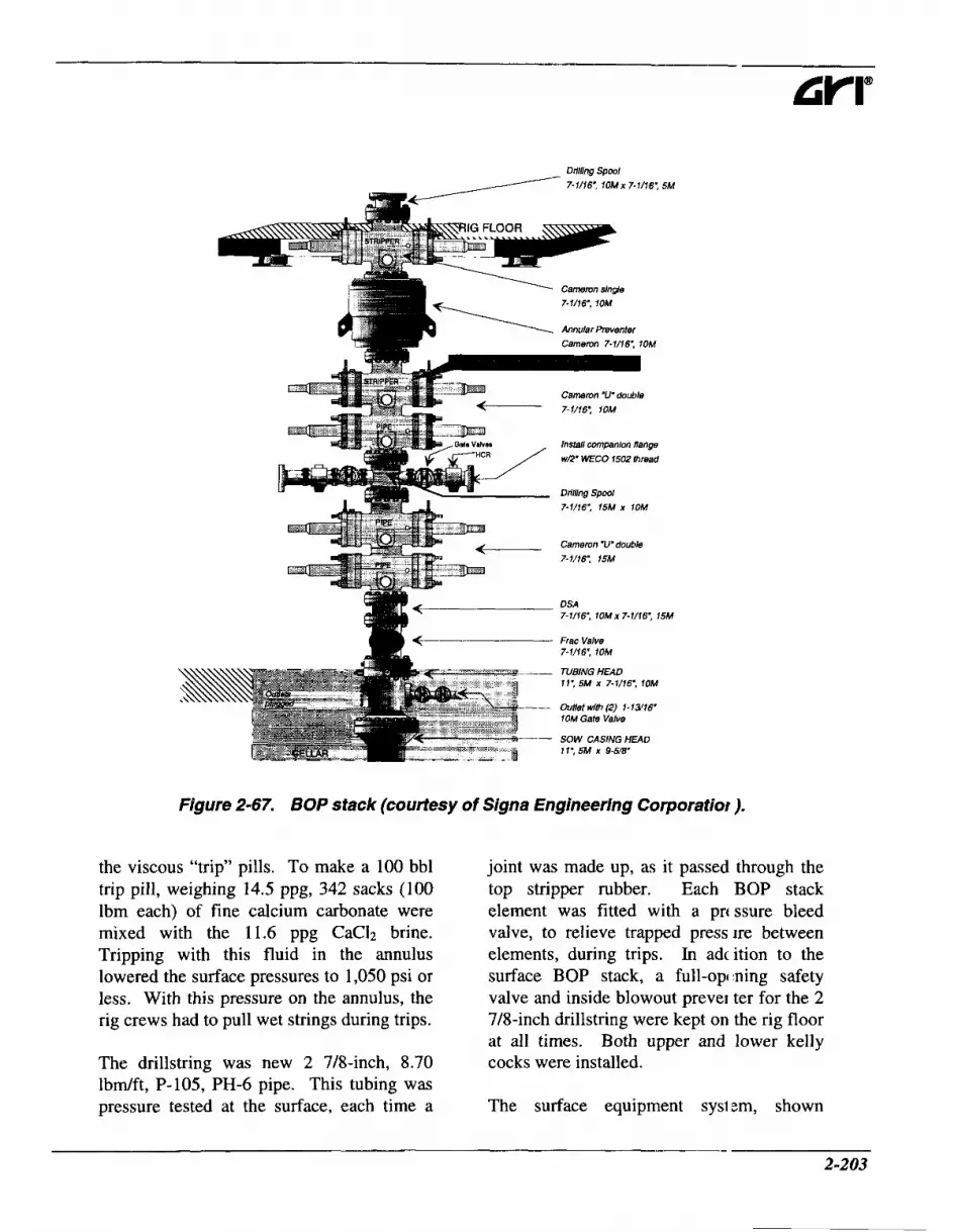
7-1/16., 10Mx 7-1/16., 5M
' Cameron s l n p 7-1/16', 10M
Annular Preventer Camemn 7-1/16: 10M
5 - - Cameron 'U'double 7- 1/16'. 1OM
Install companion flange WE' WECO 1502 thread
Drilling S p l 7-1/16,. 15M X 1OM
Camemn 'U'doubla 7-1/76', 15M
DSA 7-1/16: lOMx 7-1/16: 15M
Frac Valve 7-1/16', 1OM
-- TUBINGHEAD 11: 5M x 7-1/76., 10M
oumr wrn (2) 1 - 1 ~ ~ 10M Gate Valve
Figure 2-67. BOP stack (courtesy of Signa Engineering Corporatiof ).
the viscous "trip" pills. To make a 100 bbl trip pill, weighing 14.5 ppg, 342 sacks (100 lbm each) of fine calcium carbonate were mixed with the 11.6 ppg CaC12 brine. Tripping with this fluid in the annulus lowered the surface pressures to 1,050 psi or less. With this pressure on the annulus, the rig crews had to pull wet strings during trips.
joint was made up, as it passed through the top stripper rubber. Each BOP stack element was fitted with a prt ssure bleed valve, to relieve trapped press ire between elements, during trips. In adc ition to the surface BOP stack, a full-opining safety valve and inside blowout prever ter for the 2 7/8-inch drillstring were kept on the rig floor at all times. Both upper cocks were installed. The drillstring was new 2 7/8-inch, 8.70
lbd f t , P-105, PH-6 pipe. This tubing was pressure tested at the surface, each time a The surface equipment
and lower kelly
sysl zm, shown
2503

- Chapter 2 Underbalanced Drilling Techniques
schematically in Figure 2-68, included four choke manifolds. Two of these handled annular flow when the fluid was primarily gas. They safely eliminated erosion problems, caused by high pressure and velocity of a gas stream, laden with drill solids. The remaining two chokes were designed to process the return stream when it included liquids. The operator of these chokes would monitor the flare for liquids, to switch from the gas chokes to the liquid chokes and vice versa. Both liquid choke manifolds were four-inch, 10,000 psi working pressure systems. Both the primary and the back-up chokes consisted of one hydraulic and one manual choke. The command station for all four chokes consisted of the controls for each manifold, as well as pressure gauges showing both the
standpipe and annular pressures. The chokes were adjusted to maintain constant standpipe pressure. Twc choke operators were on duty at all times to man the choke command station.
The skimmer pit received the drilling fluid and condensate from ea:h of the liquid choke manifolds and atta ihed gas busters. The drilling fluid, skiinmed of liquid hydrocarbons and cleared of all drill cuttings, was returned to 11 e rig mud pits for circulation downhole. Th ; cuttings volume was quite small in this Winch slimhole application. The liquid h ydrocarbons were directed to the oil transf :r tank. During drilling operations, twc snubbing unit operators worked on the rig floor. Their duties included maintainii ig control of the
FLARE PIT
MANUAL CHOKE
AILLING FLUID f Prevai ing Wind
Dir !ction
Figure 2-68. Snub drilling choke system (coufiesy of Signa Engineerin Corporation).
2-204

snubbing stack, manipulating the pipe and assisting the driller. During drilling of the curve and lateral sections, the drawworks was used to support and lower the drillstring to provide weight at the bit. Rotation of this string was accomplished with a power swivel. As previously mentioned, the snubbing unit was used only for tripping the pipe. The secondary BOP stack controls were remotely positioned a safe distance away from the rig floor.
Communication between rig-site personnel becomes especially important when drilling with these extreme surface pressures. A loudspeaker intercom was installed to interconnect the rig floor, shaker pit, skimmer pit and all living quarters. Very high noise levels will normally accompany fluids flowing through chokes that are dropping over 5,000 psi at times. Hearing protection was necessary for all hands working on the rig floor and close to the choke manifolds.
The motorman, as usual, monitored and maintained the operation of the rig pumps and engines. A pump truck was added to provide drilling fluid to the operation, when the standpipe pressures exceeded 4,000 psi. The operation also required two fluid transfer operators, at all times during drilling operations. Their primary responsibility was to mix brine and trip pills and maintain working pit levels. The logistics of transferring and mixing brine were critical. A brine mixing plant was recommended for use on location for rapid fluid building capability.
The project coordinator was responsible for training each man to do his job and to coordinate verbal and hand signals among
the team members. He had ulti nate control of the project and could shut dol m the entire operation, if necessary, for safet: r reasons. In the event of a shutdown, the cho te operators would monitor the surface pr:ssures and report each 100 psi increase. 'rwo project coordinators were always on lo :ation, with only one having control of operations, at any given time; the other served as a relief for the active coordinator. All c ritical team members were housed on 1oca:ion so that any off-duty team member cou d be called on to assist, if needed.
Sunb drilling and coiled tube drilling are discussed further in Chapter 6. Adam and Berry, 1995,' summarized scme of the considerations in an underbal inced well, drilled with coiled tubing, in the Dalen field. These included custom modi 'ications of standard well test equip nent, and separatiodsurge systems. Bec muse of the potential for HzS, which was s( luble in the drilling fluid, a "closed tank" c rilling fluid treatment and storage system w :re adopted. Drilled solids were removed with sand filters and sand catchers, upstieam of the choke manifold and separator. This was sufficient because the volumc of drilled solids was very low. They also developed a sub-surface safety valve, which 1 (as installed in the completion string at 107 m and was used to isolate reservoir pressu es from the surface, effectively creating a "downhole lubricator" system. While ex; )enses were incurred, it was anticipated th: t there was economic merit since previou: wells had encountered severe mud losses, where the costs in terms of materials and t ,me spent to combat the problem were on he order of $2,500,000. Finally, there was the opportunity for interactive v 'ell design. Underbalanced drilling was selected to
2-205
Chapter 2 Underbalanced Rrilling Techniques
overcome the lost circulation and to allow gauging the production contribution from each fracture system intersected, as specific fractures were penetrated. “Thus it should be possible to tailor the length of the
horizontal section based )n observed well potential rather than drilling to some nominal departure, which may not provide any incremental benefit.”
References
1. Adam, J. and Berry, M.: “Through Completion, Underbalanced, Coiled 1 ‘ubing Side-Track of Well Dalen 2,” paper presented at the 1995 IADC Drilling Conference: Milan, Italy.
2-206

2.11 Closed Systems
Some of the underbalanced drilling techniques, described so far, have been categorized according to the drilling fluid involved. This section describes an underbalanced drilling technique that involves using a specific type of surface system, rather than a specific drilling fluid. The distinguishing feature of this technique is the use of a pressurized, four-phase separator and a fully closed surface system, to handle the fluids returning from the well.
The use of a closed surface system when drilling underbalanced was pioneered in
These systems are finding applications elsewhere in the world; for example in the UK,4 Argentina, the Netherlands,' and in Oman.6 At the time of writing, they are not extensively used in the United States. They offer benefits over open surface systems, but they also have limitations that have to be considered. The benefits arise because all fluids are contained within flow lines, pressure vessels and closed holding tanks. These systems can safely manage natural gas production containing hydrogen sulfide, prevent hydrocarbon vaporization from open pits, (i.e. environmental benefits) and, with appropriate instrumentation, allow continuous measurement of a well's productivity.
With planning, closed systems can be designed for high pressures, when drilling deep and over-pressured reservoirs.
Surface Equipment A closed surface system consists of a BOP stack connection, choke manifold, sample catcher, a pressurized separator system
which may consist of one or more component vessels), a flare stack. production tank(s), and a clean drilling li juid return line. Figure 2-69 schematically shows a closed system, typical of thofe used in Canadian operations. Many of these components are more or less tlie same as those used in open surface sys ems. The distinguishing feature is that the entire system is closed until cleaned dr lling liquid returns to the mud pump suction ank.
Several Canadian service compar ies provide underbalanced drilling closed Gystems as rental items. Often two or n ore of the components of the system will b: combined on single skids.
Return Line The return line will normally be taken from beneath the RBOP or rotating head outlet flange. If dual annulars are usell, it will be taken from a diverter spool immediately below the upper annular. The li le diameter should be sufficient to keep t le pressure drop down the line to a safe 1 :veI, at the maximum anticipated return fl IW rate of injected and produced fluids. A 6-inch return line may be necessary. Some means of closing the return line should )e installed, adjacent to its connection to the BOP stack. So too should an emergencj shutdown (ESD) valve. Local regulations r lay demand installation of this ESD. The ES > itself, and any piping between the BOP st ick and the ESD, should have a pressure r:ting that at least matches the rating of the BOP immediately above the return linc take-off.
The return line should be eqi ipped with valving, downstream of the shi t-in valves, to permit the option of directing return flow to the shale shakers. This may ,e desirable if no hydrocarbons or toxic gases are
2-207

Chapter 2 Underbalanced Drilling Techniques
c
Production Tank
r- Flare Stack
I Pressure Vessel Choke Manifoll
I Mix
Drilling Fluid Tank Rig Pump
N2 Pumpers
2 Vapor izor
Figure 2-69. A typical closed surface system (modified after Lunar 1, 1994 ').
entering the well or anticipated to enter it. There will normally be a flow control manifold and sample catcher arrangement between the return line and the separator system.
There may be one or two sets of choke and kill lines.3 As a minimum, a single choke line, from below the blind rams, will be routed through the rig manifold to the separator system or directly to the flare pit.7 The well can then be flowed while tripping or when the string is out of the hole and the blind rams are closed. This will prevent excessive surface pressures from building up. A second choke line may be installed, either between the annular and the upper pipe rams, or from between the upper pipe rams and the blind rams. If installed, this will be valved to permit flow to be routed through the return line and its flow control manifold to the separator or directly to the flare pit.7 This system provides a degree of redundancy against blockage of the main
return line or problems w th either of the choke manifolds.
Typical Canadian operatio1 s use 2,000 psi rated, hammer union couple 1 flow lines. The return and choke lines should have pressure ratings matching those of the choke manifold to which they are attached. These should be sufficient to contain any surface wellhead pressure that cai I reasonably be anticipated. Since one of tlle major reasons for using a closed system i s to handle sour gas, the closed system p:omponents are normally rated for sour ser lice. If there is any potential for hydrogel sulfide being encountered, it should be CI mfirmed that all components of the surface system, that might be exposed to the lie11 returns, are suitable for sour service. All flow lines should be electrically bonde d to prevent any sparking.
The lines, between the BOP stack and the separator, can erode because they are
2-208

exposed to solids-laden return flows. All elbows and tees should preferably be leaded, to restrict this erosion. This becomes particularly important if consolidated sandstones or cherts are drilled.
Flow Control Manifold Returns from the well should be routed through a flow control manifold at all times when drilling with a closed system. A second choke manifold, in addition to the rig choke manifold, is normally installed. Figure 2-70 is one example of a flow control arrangement. A flow control manifold, designed specifically for underbalanced drilling, would normally be used for this purpose. These tend to have larger diameter
I Rotating Blow out Preven ter/Diverter
RBOP Height 1700 mm
valves, (six-inch gate valves an( i four-inch ball valves, in some instances7,, than the conventional choke manifolds found on many rigs. This allows them to handle higher flow rates, without generating excessive back pressure. The unc erbalanced drilling flow control manifold wi 1 normally be used to control flow into the separator. The rig manifold is only used to c mtrol flow to the separator when the primarq manifold requires maintenance or when excessive pressures are encountered.
Sample Catcher With a closed system, cuttings a r e normally collected inside the separator ves sel. Some form of sample catcher has to be nstalled in
Northland Manifold
Surface Casing
-Intermediate Casing 1300-145Dm. 339.7mm
Production Casing I890 m, 244.5 mm
3W400m, 508.0 mm
re C a t c h
oke
E FlareStack
Separator 200 PSI Vessel
Water Returned C '1 Storage/ to Rlg Tanks 7 ansport
Figure 2-70. Flow control arrangement (after Saponja, 1995 ').
2-209

Chapter 2 Underbalanced Drilling Techniques
the flow line, between the BOP stack and the separator, if cuttings samples are to be taken for geologic control. Usually, two sample catch vessels are used; one collects a sample while the other is being emptied. The catch vessels may be mounted downstream of the flow control manifold, or alternatively integrated with it. Figure 2-71 shows an arrangement that puts the catch vessels on the flow control manifold. The two catch vessels normally contain screens through which some of the well rleturns will flow, depositing cuttings on the screen. The catch vessel is isolated from the return flow, and flow is routed through the other catch vessel while the screen is removed from the first vessel and cuttings are collected. Screened vessels are not necessarily used when drilling gas wells; instead the sample may just be allowed to collect in the catcher pan.2
Separator Many of the separitors used in underbalanced drilling ha le been modified from production separator s, because of the different design requireme nts.* A separator used to process under1 )alanced drilling returns will need to pr mide four-phase separation of liquid hydrc carbon, water or aqueous drilling fluid, gas! :s (both produced and injected), and cutti igs. Typically, underbalanced drilling ser arators operate at 20 to 50 psigy but they ca 1 be rated for 200 to 500 psi maximum pre:sure. Separating gases from the returns is o ~ l y efficient if the separator pressure is low Additional de- gassing equipment ma! ' be necessary downstream of the primary separator - this will be discussed later in th is section.
Frequently, underbalancec drilling returns
Sample Catcher
#I
Dlrection #4
Sam1 le Catcl er
#2
Figure 2-71. Integrated flow control and sample catcher manifold (z ffer Lunan and Boote, 1994 '*).
2-210

are produced in slug flow, with intermittent slugs of liquid at much higher instantaneous flow rates than the overall average liquid rate. These slugs can overwhelm a conventional separator. At the very least, the internal separator design will have to minimize "splashing" when a slug enters. Some underbalanced drilling separators have a spiraled entry baffle for this purpose.' Using a higher vessel pressure will reduce the tendency for slug flow, but this will also decrease the efficiency of removing gas from the liquids.8
The separator vessel should be able to rapidly dump significant liquid volumes, coming from a large liquid slug. The pressure vessel may need to be fitted with several large, mechanically activated dump outlets.
The vessel must be large enough to allow adequate retention time for the separation of the solids. The larger the vessel the better. Originally, the separators used in Canadian underbalanced drilling operations were sized so that all cuttings generated in the drilling operation could be contained within the separator itself, without any need to discharge cuttings until total depth (for the interval in question) was reached. If this is to be done, the solids capacity of the vessel should be at least three times the volume of the hole to be drilled, to account for bulking of the fragmented rock and for possible shale swelling." Newer separators, designed for underbalanced drilling, incorporate sealed, auger, screw-type pumps, to remove cuttings from the separator under pressure. 2
Horizontal or vertical separators may be used. Vertical separators are more effective
when the returns are predominzntly liquid, while horizontal separators tend t 3 be able to handle higher gas volumes more efficiently. It is possible to run vertical stparators in parallel, to provide good operating efficiency. Horizontal separatic In is better managed with one, large vessel.8
The Energy Resources Conserv; ition Board of Canada (ERCB) has set out design and operation guidelines for close d systems. These provide a sound basis for designing a closed, underbalanced drilling s stem." A typical horizontal separator, used in Canadian operations, is shown sc hematically in Figure 2-72. This cylindric 11 vessel is nine feet in diameter and 40 feet ong, with a working pressure rating of 2M psi. The maximum gas rate for this sepirator is 35 MMscfD, with a total liquid cap tcity of 425 bbl. This pressure vessel is sk id-mounted and is enclosed and heated for told climate operations.
In this horizontal separator, \le11 returns enter and are slowed by th: velocity- reducing baffle. Solids settle pi incipally in the first compartment, from wht re they can be removed by the solids trar sfer pump. Liquids pass over the partition pl ate, into the second compartment, where fu rther solids separation occurs, and where the liquids begin to separate. The liquids spill into the third compartment, where se paration is cofnpleted. Liquid hydroc: rbons and drilling liquid are discharged frc lm different levels in this compartment.
The separator vessel should be fitted with adequately sized pressure relief valves and an emergency shutdown valve, riggered on high liquid level, and high or low vessel pressure. It should also be fitted, at a
2-21 1

Chapter 2 Underbalanced Drilling Techniques
Well Effluents *\ In Adustable Partition Plates -z
t Gas:
\ Velocity Reducer ..: . . . . . . . . . . Gas . . ...a J . . . . . . : :
Continuout Pressurized Solids Tra mfer Pump
Figure 2-72. A typical, horizontal, four-phase separator, for underbalanc Ded drilling (after Lunan and Boote, 1994 ‘*I.
minimum, with sight glasses to indicate liquid levels, and with some means of observing solids levels without having to shut down or enter the vessel. Additional instrumentation can be beneficial; this will be discussed below.
If a closed system is to be used with a drilling fluid that contains any oxygen, it must be possible to purge the separator vessel with an inert gas, such as nitrogen, in order to prevent the buildup of a potentially explosive gas mixture in the separator.
Cuttings filter It is possible to use a three-phase separator, when drilling small diameter holes where limited volumes of cuttings are generated. This might be the case in coiled tubing drilling operations. To allow this, a sand trap or filter is installed upstream of the separator ~ e s s e l . ~ This reduces erosion of the flowline between the sand trap and the separator and
of the entry region of the sc parator itself.
Heater Mixtures of low rnl Ilecular weight hydrocarbons and water ca 1 potentially form hydrates at low temperatu es. These could interfere with flow into the separator or with the separator’s operation. Normally, well returns will not warm er ough to prevent hydrate formation. If the-e is a large gas volume fraction in the retiirns and they are choked back, the decrease ( If the temperature downstream of the chole may lead to hydrate formation. In this case, the returns should be routed through a heater, upstream of the flow control maniftdd. The returns should also be passed through a heater if large volumes of heavy oil (with viscosities at low temperatures that prf vent efficient gas separation) are being produ :ed.
Degasser Gas carryover from the serarator to an open mudpump suction tank is potentially
2-212

dangerous, particularly if there is any possibility of H2S production. Gas in the re- injected liquid can cause lower than anticipated pressures downhole, with consequent higher production and safety concerns. It will also interfere with the efficiency of the mud pumps. All gas has to be eliminated from any liquid to be re- injected into the well. In most circumstances, it will be necessary to use an additional degasser, downstream of the primary separator.* Secondary degassing is particularly important if high pressures or significant gas dissolution are likely, as they probably will be when drilling deep or overpressured reservoirs. An atmospheric separator or vacuum degasser can be used for this second stage of degassing.
Adam and Berry, 1995,' used closed settling tanks, vented to the flare line, to handle remnant gas. A secondary degasser is not always used in Canadian closed systems. These wells typically have low formation pressures. Here, the combination of low pressures, unviscosified liquids, and long residence times allows an adequate portion of the entrained gas to escape so that the liquid returned to the mud pumps from the separator vessel can be re-injected without problems.
Flare StackPit The flare stack must be large enough to handle the maximum anticipated gas rate (both produced and injected gas). The height and location of the stack are likely dictated by local regulations governing natural gas flaring. The flare stack should be equipped with an igniter and pilot flame system to ensure combustion of any discharged flammable gases.
Saponja, 1995,7 described a separate flare
stack and flare pit, with ga! from the separator going to the stack and gas vented from the wellhead casing annulls going to the flare pit.
Louison et al., 1984,13 used tlvo separate flare lines; one twelve-inch diameter and one ten-inch diameter, with sepal ate six-inch diameter, twenty-foot tall flarc stacks, to handle gas produced while llrilling the Midway and Navarro formatiorts in South Central Texas. They reported flares that were 25- to 30-feet high when clrilling, and up to 120 feet high after a long : hutdown in drilling. They also recommende a flare pit at the base of the stack, ior burning condensate, which would not be required or appropriate with a closed system
A backpressure regulating valve in the flare line between the separator a n j the flare stack, allows the separator pressure to be maintained when the gas produ1:tion rate is low.
Produced gas does not have t > be flared when drilling underbalanced. 11 is possible to route gas from the separator o an export line, if there are local producti in facilities that can handle the returning ga;. This has been done successfully on an un derbalanced coiled tubing drilling operation onshore in the Netherlands.'
Production Tank The production tank should b: closed to prevent vapor release. Any me: surable gas, evolving from liquid hydrocarjons in the production tank, can be vented to the flare stack.
Water Tank When the drilling fluid has an aqueous phase, water from the separalor will be
2-213

Chapter 2 Underbalanced Drilling Techniques
discharged into one or two settling tanks, before being transferred to the mud pump suction tank. Since additional solids separation occurs in these tiinks, they should have sloped bottoms and be fitted with internal risers for water drawoff, to provide the cleanest possible water to the mud pumps.3
Solids Tank There should normally be a cuttings storage tank to receive solids discharged from the separator, unless the anticipated volume of cuttings is sufficiently low that the separator will only be emptied at the end of the job.
Instrumentation Closed surface systems collect all material returning from the well. With appropriate instrumentation on the closed system and on the drilling fluid injection systems, it is possible to determine the rates and pressures at which the well is producing hydrocarbons while drilling. It is also possible to conduct a production test, using the (closed system, at any time while drilling, or before or after completion.
Much of the formation evaluation information, that can potentially be collected when drilling underbalanced, requires that an integrated instrumentation package is used to record injection rates, flow rates and pressures. Instrumentation packages for underbalanced drilling were described in Section 2.7, “Gasified Liqunds.” Separators, used for underbalanced drilling, can be instrumented to measure gas pressure and temperature, liquid hydrocarbon and water levels (flow rates), as well as methane, oxygen and hydrogen sulfide contents. The differential pressure, across an orifice meter in the flare line, will give the gas flow rate.
If the drilling fluid coni: ins any oxygen, measurement of oxyger and methane concentrations inside tk e separator is essential. Teichrob, 1994,’ ’ reported using a methane chromatograph, along with a portable oxygen and lowe. explosive limit (LEL) meter, to continuo isly monitor the flammability of the gas in a closed system separator, when drilling wi :h an airhitrogen mixture.
Drilling Fluids Closed systems can, in pinciple, be used with any underbalanced drilling fluid. The majority of applications tc date have used nitrified liquids.
It is not normally appropriate to use a closed system when drilling with air, air mist, air foam or an aerated liqi id, due to the potential for forming an e Icplosive mixture inside the separator pressi re vessel. It is possible to use a closed system, with a drilling fluid containing ( xygen, provided that the oxygen content of 1 he injected gas is maintained at a level telow which an explosive mixture occurs. Steps necessary to establish a safe oxyg1:n content were described in Section 2.7, “< iasified Liquids.” It is necessary to m mitor the gas composition inside the szparator and to purge it with inert gas, wlien necessary, to prevent combustion or expl xion.
Using a viscosified drilliiig fluid, with a closed surface system, s h ~ u l d be avoided whenever possible. Visc Isification slows the separation of gas from 1 he liquid returns. This becomes particularly i mportant if there is any hydrogen sulfide in tl ie produced gas.
Usually, the separator system has to be operated above atmospheri c pressure. The
2-214

elevated pressure drives liquids from the separator, to the various secondary separation and/or storage vessels downstream. Particularly for long, horizontal separators, this pressure promotes efficient separation of the various phases within the vessel. If the well returns contain injected andlor produced gas, the backpressure from gas flow through the flare line will normally provide the required separator pressure. It there is little gas in the returns, it is possible to pressurize the separator vessel directly with n i t r~gen .~ Alternatively, it is possible inject a small volume of nitrogen in the drilling fluid at the standpipe, even though this may not be strictly necessary to achieve underbalanced conditions d ~ w n h o l e . ~
It is possible to use a closed system for drilling underbalanced with foam. Defoaming will have to take place inside the separator vessel(s). MacDonald and Crombie, 1995,15 described a closed surface system that incorporated both mechanical (a polyurethane hydrocyclone) and chemical defoaming inside a low pressure separator vessel. This operated satisfactorily, without any foam carryover from the separator, while drilling nominally balanced with coiled tubing in a shallow (1,500 ft), low bottomhole pressure (275 psi) gas well and a somewhat deeper (5,875 ft TVD), higher pressure (740 psi), oil well. However, flow rates and surface pressures were low, in both of these cases. The liquid discharged from the separator could not be re-injected, because it contained defoamer. This prevented re-foaming, even with additional foamer.
Operating Procedures This section describes only those operating
procedures that are distinctive to closed systems. Other procedures, that ue specific to each type of underbalanced drilling fluid, are detailed in the sections describing the techniques used for drilling with those fluids.
> Liquid and solid levels in tke separator vessel should be monitored it all times that returns are flowing into the separator. Liquids and solid ; should be discharged, to the appropi iate tanks, when necessary, to maintai 1 separator efficiency.
> The liquid and solid levels should be recorded periodically, togetk er with all liquid volumes discharged, the gas pressure and temperaturt in the separator, and the gas flow ra e down the flare line. These measurem :nts can be combined with drilling flu; 3 injection rates to estimate the ~~lr ia t ion in productivity with depth.
P The separator pressure ;hould be monitored whenever returns $re flowing into the separator. If th s pressure approaches the safe working Limit of the separator vessel, the well should be choked back using the fl )w control manifold, or the drilling fl lid density should be increased to reducc the rate of production. If this fails t ) keep the pressure sufficiently low, the well should be shut-in and killed. A ? adequate volume of kill fluid, typical1 y 1.5 times the hole volume, should be 1 ept on site, if the ungasified liquid pkase of the drilling fluid is insufficient to kill the well.
> The gas flow through the fl r e line can be choked back to increas? the back pressure on the separator. '?his can be
- 2-215

Chapter 2 Underbalanced Drilling Techniques
9
9
9
9
9
done if the separator pressure becomes too low for efficient liquid discharge or to avoid slug flow into the separator. This should only be done if the gas flow rate is steady and there is no possibility of a sudden increase in the gas flow rate. If that occurred, the separator pressure would rise rapidly, potentially exceeding its safe working limits.
As was noted in Section 2.7, “Gasified Liquids,” choking back the well returns should be avoided if at all possible. This increases the gas compression and liquid injection power requirements, and, more significantly, has an impact on the bottomhole pressure that is difficult to determine. By manipulating the choke, it is very easy to inadvertently take the well overbalanced and damage the producing formation.
Watch for any signs of plugging inside the separator or flare line. If plugging occurs in a redundant coimponent, switch flow to the backup and clear the blockage. Otherwise, the well should be shut-in and the plugging remedied immediately.
If injecting a gas containing oxygen as a component of the drilling fluid, monitor the gas composition in the separator vessel at all times. Purge the separator with inert gas if the composition approaches the lower explosive limit.14
Ensure that the flare is ignited at all times when natural gas is returning from the well. This is especially important if hydrogen sulfide is present.
Monitor all flowlines for erosion, paying particular attention at any changes in direction. Ultrasonic pipe wall thickness meters make this an easy task.
9 It may be necessary to e iter the separator vessel after a job i , ) complete, for example to clean out cuttings. This should only be done i f essential. All appropriate precautions should be taken before and during any rr anned entry.
Limiiations Planning is required befcre using closed systems when high surfac e pressures are possible. Precautions are a1 ,o required if the drilling fluid is oxyge iated. Other limitations include availat ility of suitable equipment and personnel and increased operating costs. Using a clc sed system does not remove any of the spc:cific limitations associated with the drilling fluid (other than air) or the technique adoptec .
High Surface Pressures Properly designed and I )perated closed systems can handle high gas production rates, in excess of 35 MMscfD. To date, closed systems have on11 been used in shallow or modestly dee I, sub-normally pressured reservoirs, that (lo not have the potential for very high sirface pressures. Deep, overpressured reservc iirs can generate surface pressures that are 11 uch higher than available separators can tolerate. The separators are normally exFxed only to the back pressure from the gas low through the flare line. Plugging of the :eparator or flare line, for example, could exp ise the separator vessel to pressures higher than its design rating.
Extreme caution should be exercised before using a closed systei ’t to drill a deep or over-pressured gas rl !servoir, under underbalanced conditions. It is essential that a thorough safety revi1:w is conducted before committing to the ise of a closed
2-216

system. In addition to the hazards common to other drilling techniques, this review should evaluate all possible surface pressure regimes, identify all hazardous conditions, and devise means to eliminate, or to handle, any potential condition that might expose any surface system components to pressures in excess of their safe working limits.
Oxygen Containing Drilling Fluids The potential for creating an explosive gas mixture inside the separator, when there is oxygen in the drilling fluid, has already been noted. Closed systems should not be used with dry air, air mist, air foam, or aerated liquid drilling fluids.
Equipment and Personnel Availability Currently, there are a number of customized, closed systems available for rental in Canada; together with crews trained and experienced in their operation and maintenance. Few systems and trained crews are available in the United States at this time.
Operating Costs The additional surface equipment associated with a closed system, and, the additional personnel required to operate an d maintain that equipment, lead to higher rlaily costs than would be incurred vith other underbalanced or convention: 1 drilling techniques. Additional costs will also result with mobilization and demobilizi .tion of the equipment and experienced cre vs. Since neither the equipment nor the crews for closed system underbalanced c rilling are readily available in the United S:ates, these costs will probably be significant.
Any realistic economic evalu: tion of a closed system will be well specilic. Closed system drilling may offer real rierit if the formation being drilled is sr nsitive to formation damage and is likely to be very productive if it is drilled underbal mced.
- 2-21 7

Chapter 2 Underbalanced Drilling Techniques
References 1.
2.
3.
4.
5.
6.
7.
8.
9.
10.
11.
Deis, P.V., Churcher, P.L., Turner, T. and Curtis, F.: “Horizontal Under balanced Drilling Techniques used in the Mississippian Midale Beds of the Weyburn Fielc ,” paper 93-1 105 presented at the 1993 CADEKAODC Drilling Conference, Calgary, Aha.
Lunan, B.: “Underbalanced Drilling - Surface Control Systems,” p iper HWC94-20 presented at the 1994 SPE/CIM/CANMET International Conference on iecent Advances in Horizontal Well Applications, Calgary, Aka.
Deis, P.V., Yurkiw, F.J. and Barrenechea, P.J.: “The Development of B n Underbalanced Drilling Process: An Operator’s Experience in Western Canada,” prese nted at the 1995 International Underbalanced Drilling Conference, Amsterdam, The Nethe] lands.
Crerar, P.: “Underbalanced Re-entry Horizontal Drilling in the We ton Field Basal Succession Reservoir Onshore UK,” paper presented at the 1995 1st International Underbalanced Drilling Conference, The Hague, The Netherlands, October !-4.
Adam, J. and Berry, M.: “Underbalanced Coiled Tubing Sidetrack Suct :essful,” Oil and Gas J. (December 18, 1995) 9 1-98.
Surewaard, J., de Koning, K., Kool, M., Woodland, D., Roed, H. ar d Hopmans, P.: “Underbalanced Operations in Petroleum Development Oman,” paper pre: ented at the 1995 1 st International Underbalanced Drilling Conference, The Hague, The Net’ ierlands, October 2-4.
Saponja, J.: “Engineering Considerations for Jointed Pipe Underbalancec Drilling,” paper presented at the 1995 1st International Underbalanced Drilling Conference The Hague, The Netherlands, October 2-4.
Stone, C.R.: “History and Development of Underbalanced Drilling in he USA,” paper presented at the 1995 1st International Underbalanced Drilling Conference. The Hague, The Netherlands, October 2-4.
Comeau, L.: “Underbalanced Drilling: Directional and MWD Experience, ’ paper presented at the 1995 1st International Underbalanced Drilling Conference, 1 he Hague, The Netherlands, October 2-4.
Northland Production Testing Limited, Underbalanced Drilling Divisi m, Promotional Literature (1994).
Energy Resources Conservation Board: “Interim Directive ID 94-3,” Ca gary, Alta (July 18, 1994).
2-218

12. Lunan, B. and Boote, K.S.: “Underbalanced Drilling Techniques Using a Close1 I System to Control Live Wells - Western Canadian Basin Case Histories,” presented i t the 1994 SPE/CIM Annual One Day Conference, Calgary, Alta.
13. Louison, R.F., Reese, R.T. and Andrews, J.P.: “Case History; Underbalance hilling the Midway and Navarro Formations Successfully in Hallettsville, TX,” paper SPE 13 1 12 presented at the 1984 SPE Annual Technical Conference and Exhibition, Houstc In, TX.
14. Teichrob, R.R.: “Low Pressure Reservoir Drilled with Air/N2 in a Closed Systei n,” Oil and Gus J. (March 2 1, 1994) 80-90.
15. MacDonald, R.R. and Crombie, D.L: “Balanced Drilling with Coiled Tub ng,” paper IADC/SPE 27435 presented at the 1995 IADC/SPE Drilling Conference, Dallas TX.
~
2-219


BENEFITS OF DRILLING UNDERBALANCED
underbalanced drilling can offer certain
advantages over conventional drilling techniques:
9
9
9
9
P
9
9
9
9
9
9
Increased penetration rate,
Increased bit life,
Reduced probability of differential sticking,
Minimized lost circulation while drilling ,
Improved formation evaluation and reduced costs of testing,
Reduced formation damage,
Earlier production , Environmental benefits,
Improved safety,
Increased well productivity , and,
Less need for stimulation treatments.
The extent to which it is possible to achieve any of these various benefits generally depends on the specific application. Reasons why these benefits can occur arc, described. Field examples are given; indicating, where possible, the significance of the various benefits that can be expected fior different applications.
3. I Penetration Rata !
One of the most significant and I Iften quoted benefits of underbalanced drilling is increased penetration rate. 1 is almost invariably true that switc ling from conventional, overbalanced dri lling to an underbalanced drilling tech] iique will increase the instantaneous penie tration rate. The change in penetration rate i d 1 vary for different underbalanced drillin! techniques and in different rock types. E Lamples are given of the order of magnitude )f change in Penetration rate that can be a(: iieved with different underbalanced drilling techniques. If conventional drilling g ives high penetration rates or if the int:rval to be drilled is relatively shor , drilling underhalanced may not save eno igh rig time to pay for the additional equipment involved.
Why Should Penetration Rig re Be Higher? It is often stated that reducing he pressure differential across the hole bottlc m increases the penetration rate. Swi1.c hing from overbalanced to underbalanc :d drilling changes the differential pre ;sure from positive to negative, so that a penetration rate increase should be expected This is an over-simplification. It does lot address

I
Chapter 3 Benefits of Drilling Underbalanced
some fundamental aspects of how downhole pressures influence drilling response in permeable rocks and shales.
Permeable Rocks In permeable rocks, a positive pressure differential, between the drilling fluid in the wellbore and the pore fluid adjacent to the workfront, reduces penetration rates in two ways.
P This differential pressure represents an effective confining stress acting on the rock being fractured by the bit’s teeth.’*2 In most sandstones and carbonates, increasing the effective confining pressure increases the shear strength of the rock. The assertion that higher differential pressure increases the effective mean stress in permeable rocks needs to be viewed with caution, depending on the specific poroelastic- plastic properties of the rock. Regardless, shear stress, promoting failure, increases with underbalance.
P Cracks that form when the rock fractures will very rapidly fill with pore fluid at or near the original pore pressure. The difference between this pressure and that of the fluid in the borehole “clamps” the rock fragments against intact rock until communication with the wellbore can equalize the pressures around these fragments and relieve the so-called “chip hold-down forces.”2 If the bit teeth contact the workfront before the chip hold-down forces have been overcome, work will be expended unnecessarily in re-grinding the rock fragments that remain clamped to the workfront. Increasing the mud weight will increase the chip hold-down forces, making the bit’s action less efficient and decreasing the penetration rate.
There is supporting physicr 1 evidence. Both rn i~ ro -b i t~ .~ and full scale4 drilling experiments have shc wn that (in overbalanced situations) th : penetration rate in permeable rocks decreases as the difference between the b orehole pressure and the pore pressure ircreases. These measurements have shown that the absolute value of the wellbore pressure in permeable rocks does not influence pmetration rate to any detectable extent; it is t le difference that is important. Figure 3-1 sh )ws one example of the effect of differen ial pressure on penetration rate, for a micr 3 roller cone bit, drilling Indiana limest me with an unweighted, water-based mud. With a positive differential pressu re of 1,000 psi, the penetration rate was 01 ly 30 percent of that seen at balance.
Figure 3-2 (Moore, 1974’) s a composite of wells drilled with mud cimpared with a composite of wells drilled with gas. The figure shows that, below a certain depth, drilling with gas was over six times faster than drilling with mud.
When drilling at balance, there is no longer any (compres, rive) effective confining stress acting on the rock being drilled nor any static chip 1 rold-down force, favoring more rapid drillin, :. Underbalance is hypothetically even more favorable.
It is the difference betwem the borehole pressure and the pore pres ure, adjacent to the workfront, that control: the penetration
This local pore pressure is not necessarily the same as the undisturbed far- field pore pressure. Drill ng fluid filtrate (and in some cases, whole mud) will flow into the penetrated formaticns, if there is an overbalance. The hydrauli : driving forces for fluid flow will act fro n the formation
3-2

12
10
n & a
2 6
6 4
E Q c
w c .- - .-
2
0 0 lo00 2000 3000 4000 51 100
Overbalanced Differential Pressure (psi)
Figure 3-7. Micro-bit test data showing the influence of differential pfi ?ssure on penetration rate (after Cunningham and Eenink, 7959 ').
into the borehole, if it is underbalanced. In either case, fluid flow can change the pore pressure close to the workfront from its original value. Figure 3-3 shows penetration rates (under overbalanced conditions), measured at two different weights on bit, in laboratory drilling tests. A 7 7/8-inch diameter insert bit was used to drill 200 md Berea sandstone. The pressure differential across the workfront was determined in these tests, and the penetration rates are plotted versus the local differential pressure in Figure 3-3. An overbalanced pressure dgferential of 500 psi reduced the penetration rate to between 30 and 45 percent of its value at balance.
Pressure differentials, in normal drilling operations, vary from application to
application. They are usually on he order of a few hundred psi. At a depth of 6,600 feet, a mud overbalance of 0.5 ppg (ar equivalent circulating density of 0.5 ppg higl ier than the formation pressure gradient), cor esponds to a differential pressure of approxi nately 165 psi. The laboratory drilling dal:;L shown in Figures 3-1 and 3-3 indicate that the penetration rate might increase Icy 30 to 40 percent in going from 165 psi 07 erbalanced to balanced.
As the borehole pressure is red1 ced below the pore pressure, Le., as th t level of underbalance increases; the rock at the workfront moves into a state c f effective axial tension. Chip hold-down forces, in permeable rock at least, are elimir ated. As a result, the penetration rate is csrtpected to
3-3

Chapter 3 Benefits of Drilling Underbalanced
Drilling Days 0 20 40 60 80 100 120
0
1000
2000
3000
4000 0 CI @
5000 CI P :
6000
7000
8000
9000
10000
Figure 3-2. Gas drilling versus mud drilling (after Moore, 19 74 ’).
increase, with increasing underbalance, but its sensitivity to pressure changes should be lower then if it was overbalanced.
There is little experimental data, from laboratory drilling tests, to quantify the impact of underbalance pressure on penetration rate. One set of experiment^,^ with a micro (1.25-inch diameter) roller cone bit, showed that the penetration rate in Berea sandstone increased by only 20 to 25 percent, in going from balanced to between 1,000 and 4,000 psi underbalanced. Another
set of micro-bit experimc n t ~ , ~ in Indiana limestone drilled at a 430 1 isi underbalance, penetrated at a rate that w 3s apparently 10 percent lower than when tkere was a 70 psi overbalance.
Impermeable Rocks The pore pressure in any fractures created during drilling in impermt able zones does not rapidly equilibrate to r :servoir pressure levels. There is an incrc ase in effective porosity because of these cracks. This is known as dilatancy. If tl e fluid pressure
3-4
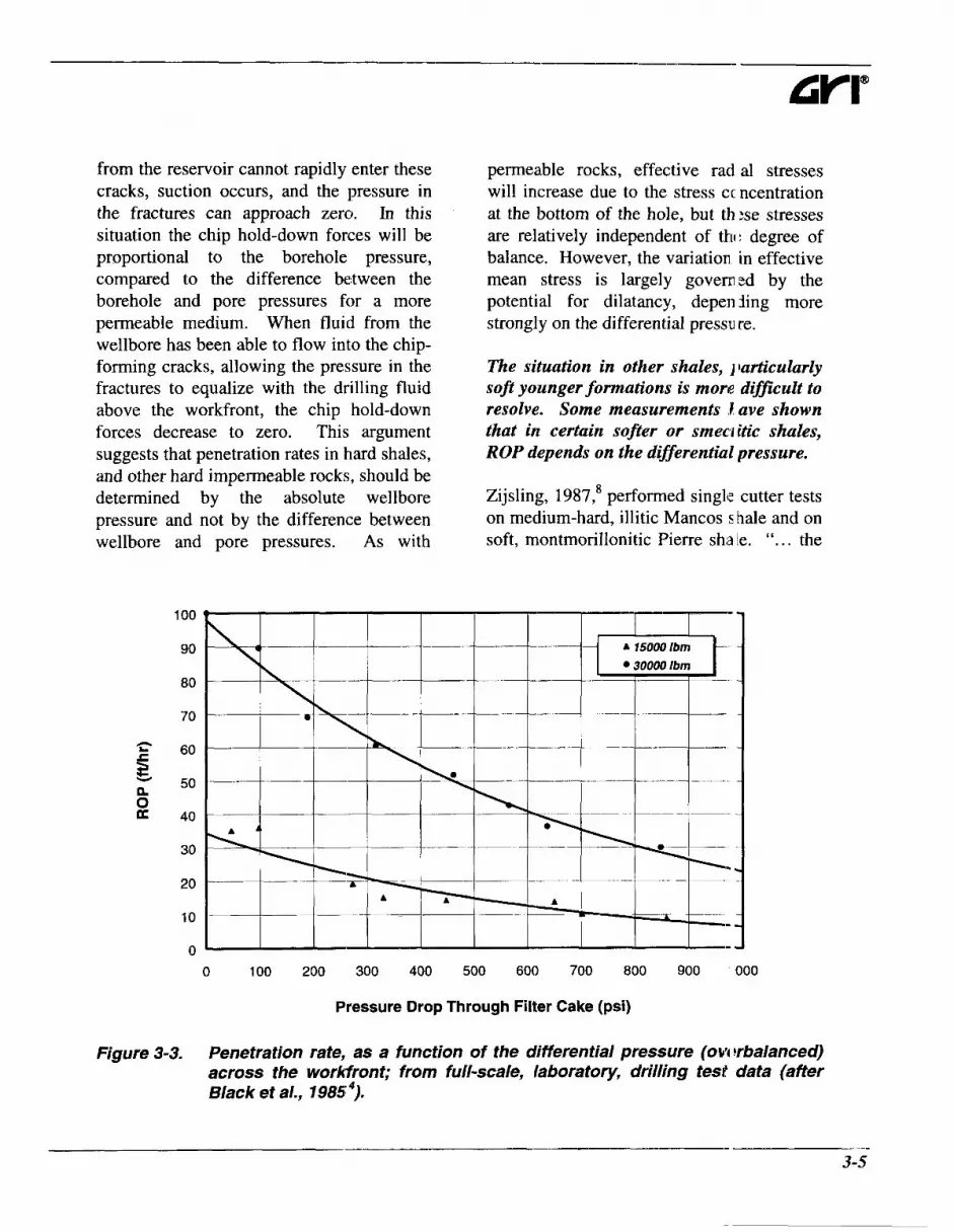
from the reservoir cannot rapidly enter these cracks, suction occurs, and the pressure in the fractures can approach zero. In this situation the chip hold-down forces will be proportional to the borehole pressure, compared to the difference between the borehole and pore pressures for a more permeable medium. When fluid from the wellbore has been able to flow into the chip- forming cracks, allowing the pressure in the fractures to equalize with the drilling fluid above the workfront, the chip hold-down forces decrease to zero. This argument suggests that penetration rates in hard shales, and other hard impermeable rocks, should be determined by the absolute wellbore pressure and not by the difference between wellbore
n c L
n z
permeable rocks, effective rad al stresses will increase due to the stress ccncentration at the bottom of the hole, but th:se stresses are relatively independent of thl: degree of balance. However, the variation in effective mean stress is largely govemzd by the potential for dilatancy, depen iing more strongly on the differential pressure.
The situation in other shales, 1 barticularly soft younger formations is more difficult to resolve. Some measurements I ave shown that in certain sojter or srneciitic shales, ROP depends on the differential pressure.
Zijsling, 1987,* performed single cutter tests on medium-hard, illitic Mancos shale and on
and pore pressures. As with soft, montmorillonitic Pierre sha !e. ". . . the
Pressure Drop Through Filter Cake (psi)
Figure 3-3. Penetration rate, as a function of the differential pressure (ow !rbalanced) across the workfront; from full-scale, laboratory, drilling test data (after Black et al., 1985 ').
3-5

Chapter 3 Benefits of Drilling Underbalanced
total bottomhole pressure rather than the overbalance (and thus the pore pressure in the sample) governs the cutting process of a PDC in Mancos shale.'' In the Pierre shale tests, the magnitude of the pore pressure and the mud pressure were both important. Similar observations were alluded to by Gray-Stephens et al., 1994.9 Regardless of the specific mechanism, evidence indicates increased penetration rate with an increased underbalanced pressure differential.
Maurer, 1966,'' showed the increase in drilling rate with reduced borehole pressure, during microbit tests on two shales, a dolomite and a quartzite. Recent laboratory experiments' have confirmed this, at least for hard shales. Figure 3-4 shows penetration rates for a milled tooth bit, drilling a hard Jurassic shale, at several different combinations of borehole and pore pressures. The penetration rate decreased with increasing borehole pressure, but it did not change if the pore pressure was changed at constant borehole pressure. Compare Figures 3-4 (a) through (c). From a mechanics point-of-view, this is completely consistent with a poroelastic constant approaching zero, characteristic of a low permeability medium.
Figure 3-5 shows the results of several shale drilling experimental program^.'^' In this figure, the penetration rates are incorporated into a normalized drilling strength index, DS,:
where:
(3.1)
WOB .............. weight on b t (lbf), RPM .............. rotary speed (rpm), ROP ............... rate of pene. ration ( f a r ) , P ..................... pressure (ps a), subscript b .... indicates bo -ehole
conditions, ; md subscript o ..... indicates atr iospheric
conditions.
This drilling strength is equal to one at atmospheric pressure. 1 i value of five indicates that the penetrition rate, at a specific borehole pressure, is one-fifth of the penetration rate at atmosph :ric pressure (i.e., the higher the index, DS,, the lower the penetration rate). The diffe rent shales in this figure all showed simi!ar increases in normalized drilling strengtl I, with increasing borehole pressure. At 2,l )OO psi borehole pressure, the normalized irilling strengths were all approximately si: .; indicating that the penetration rate, a1 this borehole pressure, would be one-si: th of the rate at atmospheric borehole prc ssure, with the same weight on bit and rota ry speed.
These results show that a small reduction in borehole pressure only causes a small increase in penetration ratc , if the borehole pressure is significantl! greater than atmospheric. Consider an E xample:
> A well is being c rilled with an unweighted mud (8.5 p ig), at a depth of 6,600 feet.
> The borehole pressure will be approximately 2,900 p: i, neglecting the annular pressure drop.
P A reduction in effective mud weight to 7 ppg would reduce the 1)orehole pressure by 500 psi, to 2,400 ])si. This would decrease the drillini strength, Le. increase the penetration rate, by less than 15 %.
3-6

- I_-
CYI"
150
125
n L z 100 E 0 .- c e n
E 75 B
0
m
L
50 c
a
25
0 0 5000 10000 15000 Zoo00 25000 30000 35000 40000 45000 50000
Downhole Weight on Bit (Ibf)
(a)
150
125
n
5 100 c 0 .- CI e B n 0 3 50 0 a
75
L
25
0 0 5000 10000 15000 20000 25000 30000 35000 40000 45000 50000
Downhole Weight on Bit (Ibf)
(b)
Figure 3-4. Penetration rate in a Jurassic shale, drilled with an @%-inch I iilled tooth bit; as a function of weight on bit, for different pore pressures PPI; (a) 440 psi borehole pressure; (6) 1450 psi borehole pressure; (ifter Gray- Stephens et ai., '1 994 ') (continued). . .
3- 7

Chapter 3 Benefits of Drilling Underbalanced
150
125
h
i 100 c 0 .- CI e 0 n 0 2 50 (R K
E 75
.c
25
0 0 5000 10000 15000 20000 25000 30000 35000 40000 45000 50000
Downhole Weight on Bit (Ibf)
(c)
Figure 3-4. Penetration rate in a Jurassic shale, drilled with an 8 x 4 7ch milled tooth bit; as a function of weight on bit, for different pore pressb res (Pp); (c) 4800 psi borehole pressure (after Gray-Stephens et al., 1994 ’).
0 500 1000 1500 2000 2500 3000 3500 4000 4500 5000
Bottomhole Pressure (psi)
Figure 3-5. The influence of bottomhole pressure on the normalized dr illing strength in hard shales (afier Gray-Stephens et al., 1994 ’).
3-8

> It would be necessary to reduce the borehole pressure to approximately 1,500 psi before the penetration rate would be doubled. This degree of pressure reduction would be close to the lowest achievable with a gas,ified liquid, and would be typical of stable foam drilling.
A borehole pressure of around 100 psi might be expected if dry air drilling. With such a low borehole pressure, a penetration rate, as much as five times that seen when drilling with mud, could be anticipated (on the basis of the laboratory data in Figure 3-5).
Additional Factors As indicated, permeability influences how underbalance pressure can affect penetration rate. Bit type, bit hydraulics and drilling fluid rheology are also important.
Roller cone bits rely on the bit hydraulics to remove cuttings from the workfront, before the bit teeth again strike the same location on the workfront. Conversely, for bits that cut with a shearing action, such as natural diamond, Thermally Stable Polycrystalline (TSP) diamond, and Polycrystalline Diamond Compact (PDC) bits, the bit's cutters push the cuttings ahead, across the workfront. With different drilling action, individual bits may respond differently to varying the magnitude of the differential pressure.
The specific influence of a bit also depends on the clearance between the bit body and the workfront. When the bit is on bottom, many natural diamond and TSP bits have restricted clearance between the bit body and the workfront. The drilling fluid pressure drops as it flows across the work.front and up
GYI"
into the annulus. The pressire over the central portion of the workfro1 t can easily be more than 500 psi greater than in the
This means that he pressure differential experienced by the *ock, as it is being drilled by a natural diarr ond or TSP bit, may be greater (tending to be more overbalanced) than it would be 1 qhen drilling with a roller cone or PDC bit. I r the extreme case, these bits might even gererate locally overbalanced conditions, ever when the annulus pressure is underbala iced. How this affects penetration rate is not specifically known.
Roller cone and most PDC 3its provide minimal flow restriction to crilling fluid once it has passed through the bit nozzles. For these bits, the drilling fliid pressure above the workfront is more ox less equal to that in the annulus.
All drill bits will not be charact xized by the same relationship between 1 rnderbalance pressure and penetration rate. rhere are no laboratory data to confirm this. However, it has been shown that natural tiamond bits undergo a greater fractional -eduction in penetration rate, with increasing overbalance, than do roller conc bits.6 Drag bits showed slightly smaller I :ductions in penetration rate than roller COI le bits, with increasing overbalance. 6
If ,the hydraulics of the entirc system are considered, removing cuttings f rom the hole bottom is not necessarily eisier during underbalanced drilling. For ex,a mple:
P Underbalanced drilling witk gases, mist, and foam tends to require less bit hydraulic horsepower thai I would be used in conventional drillini ,
P If bit nozzles are used, soiic flow can

Chapter 3 Benefits of Drilling Underbalanced
modulate annulus conditions, and,
P Drilling fluid densities are lower.
Cuttings removal from the workfront may be less efcficient with the lower density drillingfluids. This might lead to smaller increases in penetration rates than would be expected from the borehole pressure reduction alone.
Numerous drilling fluid properties can influence the penetration rate. It can be very difficult to change one property of a drilling mud without changing other properties. Nevertheless, viscosity likely has an important affect on penetration rate - higher viscosity results in lower penetration rates, all other factors being Drilling fluid viscosity will influence the rate at which fluid can flow into any chip-forming cracks and the rate at which chip hold-down forces relax6 It may even be possible that drilling fluid viscosity can favorably influence penetration rates in low permeability rock that is drilled underbalanced. For example, gas or mist drilling might give higher penetration rates in shales than techniques using foams or liquids, even if the borehole pressures were similar. High viscosities for stable and stiff foams may cause lower penetration rates than would occur for a lower viscosity, gasified liquid, at a similar borehole pressure. There is no laboratory data to confirm or disprove this hypothesis.
Drilling fluid viscosity should have less influence on penetration rates in permeable formations. Pore fluid from the undamaged rock will rapidly infiltrate chip-forming cracks and there will be reduced driving force for drilling fluid to flow into these cracks.
Field Examples Figure 3-6 shows depth v:rsus time curves for three wells, all drilled in the same area. One well was drilled exc usively with dry air, while the other wells 1 ad to be mudded up before reaching total lepth because of hole problems. This figtre clearly shows that switching to mud gave much lower penetration rates.
Figure 3-7 is a plot of bit weight and penetration rate versus delith for Well 1 in Figure 3-6. A hammer bit vas used to about 6,800 feet, with bit weigh s slightly greater than 5,000 lbf. Hamme. bits generally operate at weights much ower than those used in rotary drilling - iammer bits are discussed in more detai in Chapter 6, Section 6.4, “Percussion Drilling.” The penetration rate with the h immer was 55 to 65 f a r . Rotary drilling vrith air was used from 6,800 feet to total d1:pth. Bit weight was increased to 20,000 1E.f with the rotary bits, and the penetration r;Ite was about 30 ft/hr.
Figure 3-8 shows the equi7 alent weight and penetration rate data for t7eZl 2 . Hammer bits were used to 6,000 f :et. Rotary bits (still with dry air) were ussd to 8,100 feet. The well was mudded up it 8,100 feet and the penetration rate fell frclm over 20 fthr, with 10,000 Ibf bit weight, to approximately 5 ft/hr, with 40,000 Ibf bit \ reight.
Figure 3-9 is a plot of bit weight and penetration rate versus depth for Well 3. This well was mudded up l~elow 6,700 feet, due to hole problems. W ien drilling with mud, the penetration rate di opped to about 5 f th r (as in Well 2), even with maximum bit weight. Despite a four-fold increase in bit weight, the penetration rat: with mud was less than one-third of the rate during air
3-1 0

3000
4000
5000 - c al al r; 6 6000 [L
p" 7000
8000
9000 5 10 15 20 25 :9
Days
Figure 3-6. Depth versus days, for three wells drilled in the same area. Wt? 'I I was air drilled to TD. Wells 2 and 3 had to be mudded up becarr.;e of hole problems.
40,000
35,000
30,000
25,000 v
E
3 $ 20,000
15,000
10,000
5,000
0
LL- .- - Rotary Bits (WOB)
5000 5500 6000 6500 7000 7500 8000 8500
Depth (feet)
Figure 3-7. Bit weight and penetration rate for Well 1.
- 3-11

Chapter 3 Benefits of Drilling Underbalanced
40,000
35,000
30,000
c - m 15,000
10,000
5,000
0
40,000
35,000
30,000
25,000 v
E
3 .$ 20,000 c E 15,000
10,000
5,000
0
80
70
60 .=. s
50
d 40 5 .- c
E
n
c 30
aJ
20
10
0 0 1000 2000 3000 4000 5000 6000 7000 8000 9000
Depth (feet)
Figure 3-8. Bit weight and penetration rate for Well 2.
1 -+- fenetratlon Rate
4 - 7 - I - ~ t 1 . -
80
70
60
50
40
30
20
10
0 5000 5500 6000 6500 7000 7500 8000 3500
Depth (feet)
Figure 3-9. Bit weight and penetration rate for Well 3.
h
Y E a c d c 0 Q
aJ C aJ
.- c L 4-
n
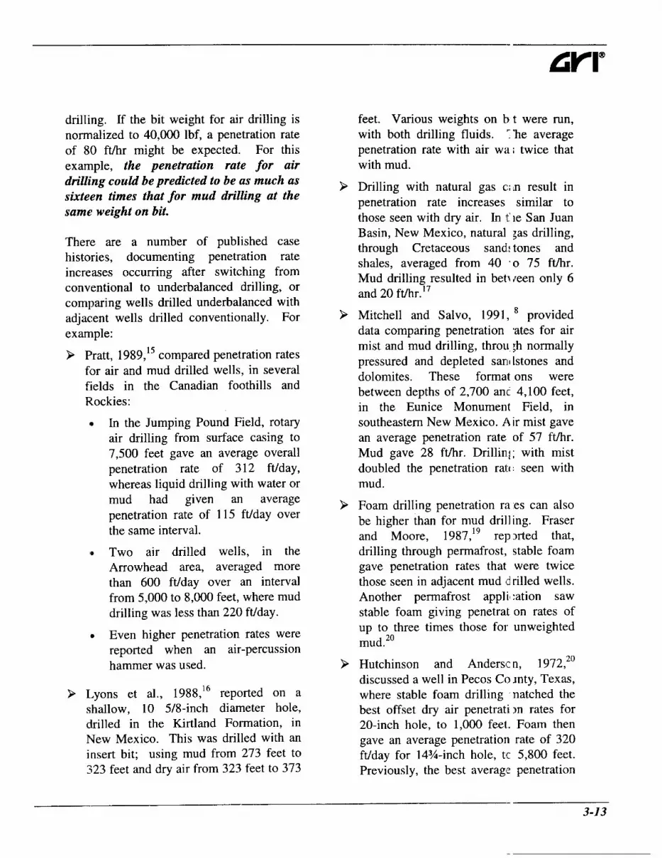
drilling. If the bit weight for air drilling is normalized to 40,000 lbf, a penetration rate of 80 ft/hr might be expected. For this example, the penetration rate for air drilling couM be predicted to be (zs much as sixteen times that for mud drilling at the same weight on bit.
There are a number of published case histories, documenting penetration rate increases occurring after switching from conventional to underbalanced drilling, or comparing wells drilled underbalanced with adjacent wells drilled conventionally. For example:
> Pratt, 1989,15 compared penetration rates for air and mud drilled wells, in several fields in the Canadian foothills and Rockies:
e In the Jumping Pound Field, rotary air drilling from surface casing to 7,500 feet gave an average overall penetration rate of 3 12 ft/day, whereas liquid drilling with water or mud had given an average penetration rate of 115 ft/day over the same interval.
e Two air drilled wells, in the Arrowhead area, averaged more than 600 ft/day over an interval from 5,000 to 8,000 feet, where mud drilling was less than 220 ft/day.
Even higher penetration rates were reported when an air-percussion hammer was used.
P Lyons et al., 1988,16 reported on a shallow, 10 5/8-inch diameter hole, drilled in the Kirtland Formation, in New Mexico. This was drilled with an insert bit; using mud from 273 feet to 323 feet and dry air from 323 feet to 373
feet. Various weights on I.) t were run, wilh both drilling fluids. T'he average penetration rate with air wa; twice that wilh mud.
Drilling with natural gas c:; tn result in penetration rate increases similar to those seen with dry air. In t le San Juan Basin, New Mexico, natural ;as drilling, through Cretaceous sand: tones and shales, averaged from 40 '0 75 ft/hr. Mud drilling resulted in betTYreen only 6 anti 20 ft/hr.17
Mitchell and Salvo, 1991, provided data comparing penetration .ates for air mist and mud drilling, throu ;h normally pressured and depleted sari1 Lstones and dolomites. These format ons were between depths of 2,700 anc 4,100 feet, in the Eunice Monument Field, in southeastern New Mexico. A ir mist gave an average penetration rate of 57 fthr. Mud gave 28 f a r . Drillinj: with mist doubled the penetration ra1.c seen with mud.
Foam drilling penetration ra es can also be higher than for mud drilling. Fraser and Moore, 1987,19 rep xted that, drilling through permafrost, stable foam gave penetration rates that were twice those seen in adjacent mud d rilled wells. Another permafrost applil :ation saw stable foam giving penetrat on rates of up to three times those for unweighted mud.20
Hutchinson and Andersc n, 1 972,20 discussed a well in Pecos Co mty, Texas, where stable foam drilling natched the best offset dry air penetratim rates for 20-inch hole, to 1,000 feet. Foam then gave an average penetration rate of 320 ft/tjay for 14%-inch hole, tc 5,800 feet. Previously, the best averag: penetration
3-13

- ~ _ Chapter 3 Benefits of Drilling Underbalanced
rate over this interval, with an unweighted brine mud, was 110 ft/day.
> Hutchinson, 1970;’ cited a number of fractured reservoir applications where stable foam drilling gave penetration rates greater than those in adjacent wells, drilled conventionally with mud.
0 Penetration rates of 30 to 75 ft/hr were seen in the Delaware limestone in Texas, where brine penetration rates averaged 15 ftkr.
A fractured schist, in Kern County, California, was drilled at rates from four to eight times greater than that normally achieved with clay-based muds.
Miocene cherts, near Santa Maria, California, were drilled with stable foam at two to four times normal mud penetration rates.
> Wolke at a], 1990,22 presented data that showed the instantaneous penetration rate increased from around 18 ft/hr to more than 40 f a r when they switched from straight mud to aerated mud, at a depth of 5,000 feet in a geothermal well.
> Comeau, 1995,23 reported that the instantaneous penetration rate, in the first horizontal well drilled underbalanced in Canada, increased from 32 ft/hr to 137 fthr, when nitrogen injection was started.
9 Drilling with nitrified water gave penetration rates of up to six times those with mud, in a horizontal well, in the Hussar field, South Central Alberta.24 The cost per foot with underbalanced drilling was almost one-half of that for conventional mud drilling. This glauconitic sandstone reservoir was
0
depleted; the convent onal mud gave a differential pressure 04 1,750 psi.
9 Data from the W=yburn field in Canada25 showed that drilling horizontal wells underbalanced v ith nitrified water (through a soft, ,balky dolostone reservoir) gave smallc r penetration rate increases over mud crilling than those reported above. Hc rizontal sections drilled underbalanced averaged 80 ftlhr, whereas a starch-basel 1, freshwater mud averaged 60 fthr. Typ cally, connections take longer with nitr fied liquids than with mud if underba anced conditions are to be maintained. The instantaneous penetration rate probi bly increased by more than the average Jenetration rate.
These field examples shou that it is possible to reduce, dramatically ir some instances, the total time to drill a fu 1 hole interval by drilling underbalanced. Th :se improvements were mainly achieved by e xperienced crews. An inexperienced crew w 11 inevitably take longer to make connecticns and trips and may not be able to achievt the same overall drilling time reduction tha: can be achieved by an experienced crew.
Practical Significance Instantaneous penetratio 1 rates will be higher underbalanced th in overbalanced. Drilling with a gas, mist or foam will give borehole pressures that are much lower than those with mud in thr hole. These underbalanced drilling tec hniques result in penetration rates that, in ml )st circumstances, are at least twice those for drilling overbalanced with mud. I [igher penetration rate increases, three-fold or more, can often be achieved when it is possible to drill with a dry gas. Gasified liquid:, and flowdrilling have borehole pressures that are often
3-14

controlled within a few hundred psi underbalanced. The penetration rate increase, for these underbalanced drilling techniques, may be less than two times, particularly when drilling shales or other low permeability rocks. On the basis of the magnitude of the differential pressure alone, penetration increases using underbalanced drilling should be relatively largest in depleted zones or reservoirs.
The instantaneous penetration rate is the rate at which the bit advances when it is on bottom. Connection times may be longer than when drilling conventionally. The difference in connection times will be slight for an experienced crew, drilling with dry air, mist or foam. It may be significant when using drilktring gasification with a gasified liquid drilling fluid. Round trip times may also be increased when drilling underbalanced. When drilling with dry air, time is lost after each trip if the wellbore has to be dried out before drilling cam resume. Time will also be lost if special steps have to be taken to limit the change in blottomhole pressure while tripping, as is usually the case when drilling with a gasified liquid using drillstring injection. Any additional time for connections or tripping reduces the benefit of increased instantaneous penetration rates. Fewer trips, due to increased footage per bit, may more than offset increased tripping time.
The impact of extending time for connections or drilling on the overall drilling time depends on the instantaneous penetration rate. Some simplistic: examples illustrate this. In these examples, the fractional changes in penetration rate, as well as the connection and tripping times, have been chosen for illustrative purposes
only. While they are not unrepre:! entative of what might actually be seen in typical operations, they should not be arbitrarily used for economic analysis of I potential underbalanced drilling applicatior .
Suppose that a 3,000 foot long interval is to be drilled, from 6,000 to 9,000 fet t.
P Drilling conventionally, connc ctions take 5 minutes and the in!tantaneous penetration rate averages 5 it/hr. One hundred connections have tc be made, which take 8.3 hours altogethc r. The trip into the hole, at the start of tlie interval, will take 3 hours and the trip out, at the end of the interval, will take 4.5 hours. Time on bottom will dondnate this interval, even assuming that no time is lost to unscheduled events. The 3,000 feet will require 600 hours on bottom. The total time taken to drill 1he interval will be (600 + 8.3 + 3 + 4.5) = 615.8 hours.
P Suppose that the same intervi 1 is drilled with dry air and that the in! tantaneous penetration rate increases tc 10 f a r . But, suppose that both conrnxtion and trip times are increased by :;O percent. The net result is a substantia reduction in time to drill the interval, to 331.6 hours. Under virtually all cirl: umstances, this time reduction will more than repay for any additional daily costs associated with underbalanced drilling.
Consider the same length of in erval in a softer, more permeable formation
P Presume that this formaticn can be drilled conventionally, at : n instant- aneous rate of 100 feet per hmr. In this case, the total time for the intt rval would be (30 + 8.3 + 3 + 4.5) = 45.6: hours.
3-15

Chapter 3 Benefits of Drilling Underbalanced
> Drilling with a gasified liquid, the instantaneous penetration rate increases to 150 feet per hour, but the connection and trip times are doubled. The total time for the interval is now (20 + 16.6 + 6 + 9) = 51.6 hours. Since the penetration rate was so high when drilling conventionally, the interval actually takes longer to drill underbalanced. A reduction in formation damage may still repay the higher daily cost of underbalanced drilling, but in this case the increased instantaneous penetration rate will not.
3.2 Bit Life
that bit life is It is often claimed increased by drilling underbalanced. If actual rotating hours on a bit are increased, this has not been weJ documented. However, and perhaps more importantly, it does appear well established that with underbalanced drilling, fewer bits are required to drill comparable intervals underbalanced.
23, 24, 26, 21
Roller Cone Bits Bearing Wear Before the introduction of sealed bearing bits, the number of hours that a bit could survive downhole may well have been increased by drilling with dry air. The air would be more or less free from the abrasive particles found in most drilling muds, and, open bearings could operate for longer with air flowing through them, than with mud. Roller cone bits now almost invariably have sealed bearings. Any benefit from the “cleaner” drilling fluid is lost. Using sealed bearings has increased the number of rotating hours that can be accumulated before bearing wear becomes excessive,
irrespective of the drilling h i d in use.28
Vibration levels downhole are usually higher when drilling with lighten zd drilling fluids. Frequent failures of surv :ying equipment, such as MWD units and stc :ering tools, attest to the severe vibrations that are often experienced when drilling vith dry air.29 As noted by Kelly, 1 990,30 rou ;h running causes momentary overloads that xomote localized seizures of the bearing sud aces, accelerating the wear process. As a lesult, bit bearing life, in hours or rotation! to failure, may actually be decreased sli ;htly by drilling underbalanced, particular y for dry air drilling in hard rock.
Cutting Structure Bit life may be defined, eitl ler in terms of the hours downhole, or, in ierms of footage drilled per bit. Penetraticn rates are often higher when drilling unc lerbalanced than when drilling conventiona ly. A bit could last fewer hours underbalai iced but still drill more footage than it wotld if it was run under overbalanced conditi Ins. The number of bits required to drill ar interval will be inversely proportional to tl le footage drilled by each bit. Consider the extent to which drilling underbalanced L an increase bit footage rather than just the number of hours each bit can survive downhole.
The mechanical specific mergy, MSE, is defined as the mechanical work that has to be done to excavate a unit iolume of In rotary drilling, work is lone both by the torque required to rotate tlie bit and by the weight on bit. The work dc ne by the bit is:
WOB . ROP
60 RPM W=2nT+ (3.2)
3-1 6

where:
W ....... work done by the bit (ft-lbf/ revolution),
7 ......... torque (ft-lbf), WOB.. weight on bit (lbf), ROP ... rate of penetration (ft/hr), and, RPM .. revolutions per minute.
The volume of rock excavated per revolution is:
ndt ROP
240. RPM V = (3.3)
where:
V ........ volume of rock excavated per
db ....... bit diameter (feet). revolution (ft3), and,
The mechanical specific energy is given by:
4807.RPM 4WOB +- d i * ROP ndt
MSE =
where:
(3.4)
MSE .. mechanical specific energy (psi).
Bit torque does not normally change substantially with changing borehole pressures. As discussed, penetration rates generally increase with decreasing borehole pressures. Mechanical specific energies are, therefore, usually lower at lower borehole pressures. Laboratory drilling data illustrate this trend. Gray-Stephens et al., 1994? showed an example, in a Jurassic shale, where a roller cone bit's torque increased by 40 percent, when the borehole pressure was decreased from 4,800 to 450 psi. At the same time, the penetration rate increased by
approximately 525 percent. TI e net effect was that the mechanical spec:ific energy decreased by more than 75 perct: nt.
In most cases, cutting structuri wear rates (expressed in terms of the disIi nce drilled) should be inversely related to the mechanical specific energy. If 1 he bit has to do less work to remove a give11 volume of rock, its cutting elements shou d wear less and a bit should be able to drill more footage (remove more rock), w ken drilling underbalanced than when dr iling over- balanced.
There are few published exam11 des of field data that provide unambiguous onfirmation of this. Mitchell and Salvo's penetration rate comparison, for wells dril ed with air mist and with mud, in the Eunicl: Monument field,'* has already been mentioied. In that instance, the interval from 1, ZOO feet to 4,100 feet could be drilled with < me bit using air mist, whereas mud drilling I equired two bits. Comeau, 1995, 23 reportell tricone bit runs in excess of 80 to 100 hours with underbalanced drilling (two to three times the life in comparable overbalan :ed hole).
Gauge Wear Roller cone bit gauge wear occi rs when the outer surfaces of the bit (heel and gauge row teeth, shirt-tails) slide agair st abrasive minerals in the borehole wall. '1 his can be a problem when drilling will I lightened drilling fluids; particularly when dry gas or mist is used to drill hard, quart itic rocks.26 When measurable gauge wear o :curs, it will normally be necessary to ream t l e next bit to bottom. Both the cutting struc:ure and the gauge of the next bit are likely t wear when reaming, reducing the footage if new hole that the bit can drill, before it 00 becomes excessively worn. In additii )n, reaming

-__._
Chapter 3 Benefits of Drilling Underbalanced
imposes side loads on the bit's bearings that can increase the rate of bearing wear.30
Roller cone bits suitable for air drilling are available in a variety of diameters, including sizes that are not normally used in oilfield applications. Reaming can be reduced, or eliminated, if it is possible to run a slightly larger bit, at the top of an interval, than is required to complete the interval. Cooper et al., 1977,26 cited an example of an 8-inch diameter mining bit being run above a 7 7/8- inch diameter bit, allowing up to 0.125 inches of gauge wear on the 8-inch bit, before reaming became necessary.
Underbalanced liquid drilling involves circulating a lower density fluid (than would be used in conventional drilling). The reduced fluid density implies a lower solids content. This in turn makes the under- balanced drilling fluid less abrasive than conventional drilling muds. As a result, lower abrasive wear rates c<an be expected. This should make gauge wear less of a concern than it would have been in a conventional drilling operation.
Dry gases have lower lubricity than liquid drilling fluids. Measurements of torque and drag in deviated and horizontal wells indicate that dry gases have drillstring friction factors of approximately 0.4 to 0.45.29 For water-based drilling muds,29 friction factors of 0.2 to 0.35 are typical. Mist and foam will improve this somewhat. It is not really feasible to use lubricant additives when drilling with dry gas, mist or foam. As long as the liquid volume fraction remains low, the friction factor will probably be large. Higher friction usually equates to higher wear rates. Gauge wear occurs more rapidly when drilling with gas, mist or foam as opposed to liquid.
Gauge wear tends to be agirravated by poor hole bottom cleaning. Higher than minimum gas injection rat€ s can help keep gauge wear to a manageade level, when drilling abrasive formation i with dry gas, mist or foam.32
Diamond Bits Bits with natural and syilthetic diamond cutting structures have different wear characteristics than roller c one bits. Both natural and synthetic din imonds exhibit considerable temperature se isitivity in their wear resistance. Diariond is only metastable, at the ambient t :mperatures and pressures that prevail 0 1 surface and downhole. Diamond reverts to graphite, once its temperature exceed, a critical value (1472"F), at pressures that are not dramatically higher than at rnospheric. As graphite is a very soft solid, the wear rate of a natural diamond bit becoi nes catastrophic if the diamonds are allowed o overheat.
Conventional Polycrystal ine Diamond Compact (PDC) cutters, U S I : ~ in PDC bits, show detectable increased Near rates once their temperature exceeds 6 i0°F.33 Thermal stresses in the polycrystallir: e diamonds can become so high that corventional PDC cutters have no effective wear resistance once their temperature reach1 :s 1 ,380°F.34
Cooling diamond cutting str rctures, whether natural or synthetic, is esse rtial in order to prevent wear at unacceptabl! high rates. The thermal capacities of gases and mists are much lower than those (If conventional drilling fluids. This mezns that higher diamond temperatures are probable (with gases or mist). In hard rccks, this could easily result in very rapid wear of natural and synthetic diamonds. Tk ermal modeling led Glowka and Stonc, 1986,34 to
3-18

recommend that PDC bits not be used for dry air drilling. Higher vibration levels, common in some lightened fluids, could also lead to increased impact damage of both natural diamonds and PDC cutters. Despite this, natural diamond bits have been used quite successfully in coring with dry air and mist; for example, in shallow Arkoma Basin wells.
Natural diamond bits have also been used successfully in mist coring of the Devonian shale with mist.35 There are no reports in the literature of successful use of PDC bits in full-hole drilling with dry gas or mist.
Natural diamond and PDC bits may be better suited to drilling with foam than with other gasified, aqueous, drilling fluids. Since diamond is not naturally water wet, thermal transfer between the water phase and the diamond is poor. Foaming agents are surfactants and provide better contact with diamond; potentially, foams offer better cooling than do other gasified aqueous liquids. With reasonable foam qualities and circulation rates, it is possible that foam could provide adequate cooling of natural and polycrystalline diamonds. The wear rate of the diamonds, in terms of the volume of rock removed, is likely to be lower, and the footage higher, than it would be if the drilling was overbalanced. There are a number of instances 21,36y37 in which natural diamond bits have been used in foam coring without excessive wear. To date, however, there are no public domain field data to confirm that full-hole PDC bits can be successfully run with foam, although one major operator is currently experimenting with this.
Drilling underbalanced with a liquid drilling fluid will give higher penetration rates than
drilling overbalanced. The soli is content of the drilling fluid will be low :r, while its thermal capacity will be little c€ anged. As a result, abrasive wear rates of bo h roller cone and PDC bits are expected to t e lower, and bit footages higher, in wells drilled underbalanced with a liquid IC rilling fluid, relative to wells drilled c( Inventionally through the same formations.
Summary
9
>
9
9
9
P
Slightly lower rotating hou-s should be expected for a roller cone bit drilling with dry gas, mist or foam 11 Ian would be seen in mud drilling. Ex~erience with liquids (e.g. nitrified cmc le) suggests rotating hours can be increa ed by two to three times.
A higher footage per bit is probable in the majority of cases where the instantaneous penetration rate is increased significantly iy drilling underbalanced.
Gauge wear may be a prcblem in dry gas, mist and foam drilling c f hard rocks. The overall footage per bit is still likely to be higher than it is tl-illing over- balanced.
Dry gas drilling hard rock v ith synthetic diamond bits could dramatic ally increase wear rates, due to excess ve diamond temperatures.
Although both natural 81 id synthetic diamond bits may have accle ptable life in foam drilling, there is no 1'rm evidence confirming this.
With a liquid drilling fluid, both roller cone and PDC bit footages should be higher when drilling underb alanced than when drilling overbalanced.
I
3-19

_.-___
Chapter 3 Benefits of Drilling Underbalanced
3.3 Differential Sticking
Differential sticking is a leading cause for a stuck pipe. When it occurs, it usually adds considerably to drilling costs; through the rig time taken to recover as much of the string as possible and the cost of equipment that may be left downhole. Additional rig time is incurred if the hole has to be redrilled around lost equipment. Drilling underbalanced can prevent differential sticking. Avoiding differential sticking in an area where it is prevalent can be sufficient justification for drilling under- balanced.
In conventional drilling operations, a positive differential is maintained between the drilling fluid pressure in the borehole and the pore fluid pressure in the formations that are open to the borehole. Liquid from the drilling mud flows into exposed permeable formations, depositing a cake of solids from the mud on the borehole wall. The thickness of this mudca.ke depends on a number of factors, including the volume of liquid lost to the formation and the solids content of the mud. The mechanisms of mudcake deposition will not be discussed. Although it is possible to restrict the mudcake thickness by controlling the fluid composition and its properties, it will form as long as the well is overbalanced and a permeable formation is exposed.
There will be a pressure gradient through the mudcake. The mudcake permeability is generally lower than that of the host formation. As a result, the pressure at the interface between the mudcake and the intact formation will usually be quite close to the undisturbed formation pressure and the change in pressure through the mudcake thickness will be close to the total
overbalance pressure.
Mudcake is relatively soft. If the drillstring is forced against the riudcake, it can ultimately contact intact r( ck. The contact area will increase with inc reasing length of permeable zone and inc ,easing mudcake thickness. With even i modestly long permeable interval, this coitact area can be considerable.
The pressure differenti; I through the mudcake will impose i force on the drillstring, pushing it agai nst the borehole wall. The force, F, reqi ired to pull the string uphole through the m udcake is:
(3.5)
where:
A, ....... area of contact (ft2), AP ...... pressure differential across the
p, ........ coefficient of frictio I between the mudcake (psid), and,
string and the mudc; Ike (dimensionless).
Quite often, the force requ red to move the string exceeds the permissil Ile overpull. The string is then differentially stuck. This is a particular problem when dc pleted zones are drilled conventionally, sinc 2 the differential pressures through these zmes tend to be high.
Various procedures can be implemented to reduce the severity of diff xential sticking. The contact area can be r:duced by using spiral or square drill collars, bladed stabilizers, and hevi-wate drillpipe in the BHA, or by reducing the mudcake thickness
3-20

through improved fluid loss and solids control. The coefficient of friction can be reduced by adding lubricants to the mud or by spotting a pill of lubricating fluid opposite the site of sticking. An added benefit of hydrocarbon-based lubricants is the destruction of WBM mudcakes, allowing pressure equalization and freeing the string.
If there is no positive pressure gradient through the mudcake, then there will be no force tending to stick the string and differential sticking will be impossible. Since the borehole pressure is necessarily lower than the formation pressure when drilling underbalanced, it is not possible for differential sticking to occur if the openhole portion of the well is underbalanced.
Saponja, 1995,24 gave an example of how underbalanced drilling can prevent differential sticking. The first 3130 feet of a horizontal well through a depleted reservoir were drilled overbalanced. Differential sticking was a problem through this interval. The well was then switched to underbalanced drilling, first with nitrified water and then with nitrified cnide. There were no more problems with differential sticking. The string was stuck once more when an unstable shale was entered and hole cleaning became inadequate. Increasing the annular velocity by 50 percent improved hole cleaning and no further problems were encountered.
A number of instances have belen reported where a string has been freed by creating underbalanced conditions after the string had become differentially stuck while drilling conventionally. Cagnolatti and Curtis, 1995,38 described one such case, that occurred during a well control operation.
Reducing the mud weight by centrifuging would free the string, while killing the well to prevent any further inflow w( uld then re- stick it.
Differential sticking is possible as long as the string is exposed to a perrieable zone with a positive (overbalance 1) pressure differential. If a well is bl:ing drilled underbalanced in order to avoic differential sticking, it is important that the entire openhole be underbalanced. LA uison et al, 1984,39 reported drilling ur derbalanced through the Midway and Navarrc ) formations in the Hallettsville area of Texa: , in order to reach a deeper but lower pressur ! productive zone, the Edwards limestone. To do this, depleted Wilcox sands had to bc penetrated. The pore pressures in these sands were sufficiently low that a positive differential pressure existed across them cven though the Midway and Navzrro were underbalanced. Differential s .icking and lost circulation were experierced in the Wilcox sands.
3.4 Lost Circulation
Moore, 1 974,5 characterized 10s. circulation as the most common drilling pro ilem. It can involve mud flowing into highl r permeable zones, open fractures or vugs t iat intersect the wellbore. In these thief zon:s, borehole pressure merely has to exceed tk e pore fluid pressure for mud losses to occur. Losses can also occur if the borehole pressure is sufficiently high that the fc nnation is hydraulically fractured. Lost cir xlation can be very costly, particularly if ex] lensive mud systems are being used or if the well is in a location where water is costly. I can also be dangerous, if it allows the well t kick when proper surface equipment is not available to
3-21

- -~ Chapter 3 Benefits of Drilling Underbalanced
handle inflow.
Lost circulation can be used to create underbalanced conditions in flowdrilling. During flowdrilling, however, the resultant production is anticipated and the surface facilities required to handle it safely will be in place. Under these circumstances, underbalanced drilling can legitimately be regarded as a safer procedure than drilling conventionally without the additional surface equipment.
Whatever the underlying mechanism, reducing the circulating borehole pressure to less than the pore pressure in exposed formations will prevent losses. Lost circulation should not, therefore, occur when drilling underbalanced, in most cases. However, it still can, given the right circumstances. Lost circulation can occur if the bottomhole pressure is extremely low. In a Texas Panhandle well, the reservoir pressure was 30 psia at approximately 4,000 feet. Even while drilling with air, the circulating pressure was greater than the reservoir pressure and the well experienced partial lost circulation.
In two other wells, lost circulation occurred because of excess water production and low bottomhole pressures. While drilling with mist, a high volume water zone was encountered along with a depleted zone. The hydrostatic pressure of the wellbore could not be lowered enough with air to circulate out the water from the water zone. The pressure required to circulilte the water to the surface was greater than the lost circulation zone could tolerate. Consequently, circulation could not be established. There are very many instances where underbalanced drilling has been
17.1 8,37,39,40,41, successful in controlling this: The technique of dr lling with aerated
mud was developed primal ily to combat lost c i r~u la t ion .~~ As was the case with differential sticking, it is e $tirely possible to lose circulation during wl at is supposed to be an underbalanced drilling operation if part of the openhole ,.ection is over- balanced.
42.43,44
3.5 Formation E valuation
Drilling underbalanced can improve formation evaluation, b: r providing an indication of productivity \. rhile drilling, and by restricting or preventinl; filtrate invasion of exposed formations. SI lecific techniques available for formation c valuation during underbalanced drilling a -e discussed in Chapter 6, Section 6.7. Prc bduction potential and real-time formation ch aracterization are possible.
Production Measureme nt Formation fluids flow into m underbalanced well whenever a perneable zone is penetrated. As noted in Chapter 2, Section 2.7, “Gasified Liquids,” several different instrumentation package i have been developed for use with closed surface
These can combine systems. measurement of formation fluid production rates and pressures, while drilling underbalanced.
46,47,48
A closed system is no: necessary for measuring gas or liquid prc duction rates. If the surface system allows produced liquids to be separated from any liquid component of the drilling fluid, IiqLid rates can be measured by recording tank levels. Gas flowing from the well can 1 le routed through the choke manifold to a cr tical flow prover

or an orifice plate, before flaring.
If desired, the bit can be pulled off bottom and drilling fluid injection can be stopped so that only formation fluids flow from the well, in effect performing an openhole production test. In a gas producer, this can allow stable production rates to be determined within one Limited (or no) invasion of drilling fluid filtrate into the producing formation accelerates the development of steady or pseudo-steady flow, as can the limited volume of liquid in the borehole, if the well is drilled with a dry gas, mist or foam.
Holdup in horizontal sections and slug flow in vertical sections of wells can complicate the interpretation of measured production rates.49 So too can production from multiple intervals. It is generally not possible to determine the extent to which each producing zone is depleting with time, if production from additional zones is added to the measured total production as the well is deepened. Nevertheless, it is possible to obtain a qualitative indication of the permeability of different exposed formations from the production rate measured while drilling underbalanced, by comparing cumulative production and estimating thickness and formation pressure^.^' This gives an indication of potentially productive zones while drilling.
Canadian experience2' is that production rates observed when drilling usually give accurate indications of the subsequent production capacity of the well. Drilling necessarily measures the early production history only. In some instances, factors unrelated to the drilling technique can prevent the observed production rate from
GYI"
being maintained when the we 1 is put on production. For example, sale: production rates from some air mist drillell (San Juan Basin Mesaverde) horizontal ga! wells were reported" to be lower the rates seen while drilling. This was thought to re:llect loading of the wellbore by produced licluids which restricted the flow of g , ~ s uphole. Alternatively, fines migrati >n during production can reduce the pen neability of the near-wellbore region and cause the production rate to decrease 7 jith time.51 Different mechanisms of , Iermeability impairment and the extent to which underbalanced drilling can preve n t them will be discussed in the following section.
Measurements of production rates have allowed non-productive 2011 :s to be identified and the planned well .rajectory to be modified while drilling a number of horizontal wells. Changes in t€ e GOR can be inferred from the production measurements, and these lave been interpreted as indicating approac h towards a gas-oil contact. Measui-1 :merits of production made while drilling, can also be used to aid geo~ tee r ing .~~ ,~ '~ l9 Water producing zones can be identifie 1. This may assist in making completion deci $ions.
Very often, measurements ojF production rate made while drilling mil ierbalanced will give enough information tl at drillstem testing is not required. This reduces the cost of evaluating the well. If it is necessary to perform an openhole te;t for gas production, this can be done Iery rapidly when drilling with dry gas, m st or foam. Rig time is reduced by not haviI g to make a round trip, rig up and rig down t le test tools, and, as noted above, the test tin e itself may be reduced. Additional equipnent is not
3-23

-- - - ~ - Chapter 3 Benefits of Drilling Underbalanced
required to conduct the test, except possibly the flow prover. Reduced testing costs offer the possibility of more extensive evaluation than might otherwise have been undertaken.
Invasion While Drilling During conventional overbalanced drilling operations, whole mud, filtrate and solids may all invade permeable zones while they are open to the wellbore. Liquid hydrocarbons and formation water may be displaced. Filtrate may also increase water saturation close to the wellbore. Invasion can complicate interpretation of wireline logging data. Understanding and managing the effects of invasion are fundamental to quantitative log interpretat i~n.~~
Invasion can complicate testing by requiring lengthy flow periods or clean-up operations before stable production rates are established. Difficulties in determining whether or not a well has cleaned up prior to testing introduce uncertainty into the assessment of test results. In the Calling Lake/Algar area of Northern Alberta, this uncertainty motivated one operator to switch to drilling exploration wells underbalanced to improve evaluation pe r f~ rmance ,~~ and avoid the cost of pre-test clean-up operations and running DSTs.
Maintaining underbalanced conditions while drilling greatly restricts or prevents most forms of invasion, by removing the physical force that drives material from the wellbore into exposed formations. The quality of drillstem or production tests is generally improved if the well is drilled underbalanced. Reduced invasion will normally help with the interpretation of logs, but selected logging tools need to be run in air-filled holes. Formation evaluation is discussed in Chapter 6. If at all possible,
one should avoid filling tke hole with mud to run logging tools since this may damage the formation.
There are circumstances under which an aqueous phase of the djilling fluid can enter the formation even though the pore pressure is higher than the drilling fluid pressure. This invasion mechanism (spontaneous imbibition) I Jill be discussed in Section 3.6, “Formation Damage. Also, underbalanced conditions may not be maintained throughout thc : drilling of an entire interval, particularly when a gasified liquid is being used as tlie drilling fluid. Generally the liquids used in these drilling operations do not have any fluid loss control, and can rapidl:‘ penetrate the formation during even E-rief periods of overbalance, leading to significant in- vasion. 49
Formation damage can occur when drilling underbalanced in lower 1 bermeability gas formations. Even with air, the pressure at the sandface will fall until i t is equivalent to the wellbore pressure. W1 d e tripping, the well is allowed to flow :nd the pressure declines. After tripping back in the hole, re- setablishing circulation c; m increase the wellbore pressure faster tf an the sandface pressure can recover. ;ome formation damage can occur befor: the sandface pressure equals the circulati ig pressure.
Invasion While Coring Cores can be invaded as lhey are cut and while they are inside the core barrel downhole. Filtrate invasil )n of cores can lead to inaccurate det xminations of wettability, relative permeal ility, and oil and water saturation^.^^
Successful techniques for c verbalanced low
3-24

invasion coring (Rathmel et al., 1990f4 have been developed. An essential element of these procedures is that the coring penetration rate has to exceed the filtrate invasion rate ahead of the bit. This may not always be possible, particularly in certain hard, depleted reservoirs. To avoid significant invasion, underbalanced coring is an option.
Cutting and collecting cores underbalanced has been done with air, air mist,35 foam and other techniques. 21336,37 This can provide cores that are generally more representative of the reservoir. The presence of oxygen in the coring fluid could influence: formation wettability.I8 It might be appropriate to avoid using air in underbalanced coring fluids if wettability modification by oxidation is a concern. Untreated lease crude may be a desirable base fluid.
Economic Impact While the value of improved formation evaluation resulting from underbalanced drilling will vary considerably from application to application, it can be substantial:
9
9
9
Improved geosteering of horizontal wells can increase productivity or delay the onset of coning.
The cost of testing can be reduced or even eliminated totally.
IJnderbalanced drilling will allow delineating additional, productive formations that might have otherwise been bypassed or not tested, if they were drilled overbalanced. This would include zones that might be difficult to interpret if they were significantly damaged or zones difficult to recognize with normal logging (e.g.. fractured
zones or permeable, radioactive dolomite).
3.6 Formation Dama ge
Formation damage is the t a m used to describe reduction in the perr ieability of reservoir rocks, induced whi le drilling, completing, stimulating, or producing/ managing a well.
Bennion et al., 1993,55 argued th it formation damage seems to be a greater woblem for horizontal wells than for vc: tical wells through the same formations:
9
9
9
k
The producing formation is exposed to the drilling fluid for longer periods of time, because a greater distar ce is drilled through the pay zone allid because drilling horizontally can zive lower penetration rates than drilling vertically.
Many horizontal wells are kf t openhole or completed with slotted or pre- perforated liners. Ur der these circumstances, it may not bl: possible to perforate through near-well13 3re damage or to do selected interval stin ulation.
Concerns about wellbore ins1 ability limit the drawdown that can be applied to some horizontal wells. This in turn can restrict clean-up during early production.
Finally, the greater length of exposed reservoir formation can rend er chemical clean-up treatments c nacceptably expensive. 56
In many applications, drilling un jerbalanced can greatly reduce or elimin: te drilling- induced formation damage. Thi: is the main driving force behind the recei t, dramatic upsurge in underbalanced drillirn; ; in Canada. Different mechanisms for forma ion damage

-I
Chapter 3 Benefits of Drilling Underbalanced
are briefly described below, distinguishing between those that can be prevented by maintaining underbalanced conditions and those that cannot.
Laboratory studies of specific formations can indicate whether or not reduction of their permeability can be avoided by drilling underbalanced. There is little public domain information directly comparing wells drilled underbalanced and overbalanced. From the literature, it is difficult, in most cases, to unambiguously establish the impact of underbalanced drilling on productivity. Nevertheless, a number of field examples have been given showing how productivity can be increased by drilling underbalanced and how, in some instances, it can remove the need for primary stimulation. One case, in Canada, compared two wells drilled 328 feet apart; the well drilled underbalanced had a seven-fold increase over the first well which had been drilled overbalanced.
There are applications in which drilling underbalanced may not yield economically valuable productivity increases. These involve formations that can be damaged during underbalanced drilling, during completion and subsequent production, and those that are not sufficiently productive even when undamaged to be economically viable without stimulation.
Formation Damage Mechanisms During drilling, formation damage can occur in a variety of These include:
Formation of scales, sludges or emulsions due to interaction between invading mud filtrate and pore fluids,
Interaction between aqueous mud filtrate and clay particles in the formation,
Invasion of solids from the drilling fluid,
9
9
9
>
restricting fluid flow through the pore structure,
Invasion and entrapment of high oil or water phase saturaticns in the near wellbore region (I )base trapping/ blocking),
Adsorption of drilling fluid additives, leading to permeabili y reductions or wettability alteration,
Migration of fines ii the formation, particularly under hig ily overbalanced conditions, and,
Generation of pore-t locking organic byproducts from bactc ria entering the formation from the drill ing fluid.
These mechanisms all invo ve penetration of the drilling mud, filtrate cr solids into the formation. If the drilling fluid pressure is reduced below the pore pn s u r e by drilling underbalanced, the physical driving force for this penetration is rem0 led. However, underbalanced drilling causes higher effective stresses arounc the wellbore, potentially reducing perme: bility.
Formation Damage Wh ‘le Underbalanced Underbalanced drilling tel :hniques do not completely eliminate thc possibility of formation damage. It can o :cur due to:
0 Temporary overbal tnce,
0 Spontaneous imbib tion,
0 Gravity-induced in. rasion,
0 Wellbore glazing,
0 Post-drilling damag e, and,
0 Mechanical degrad; Ition.
Temporary Overbalance Overbalanced conditions nay temporarily
3-26
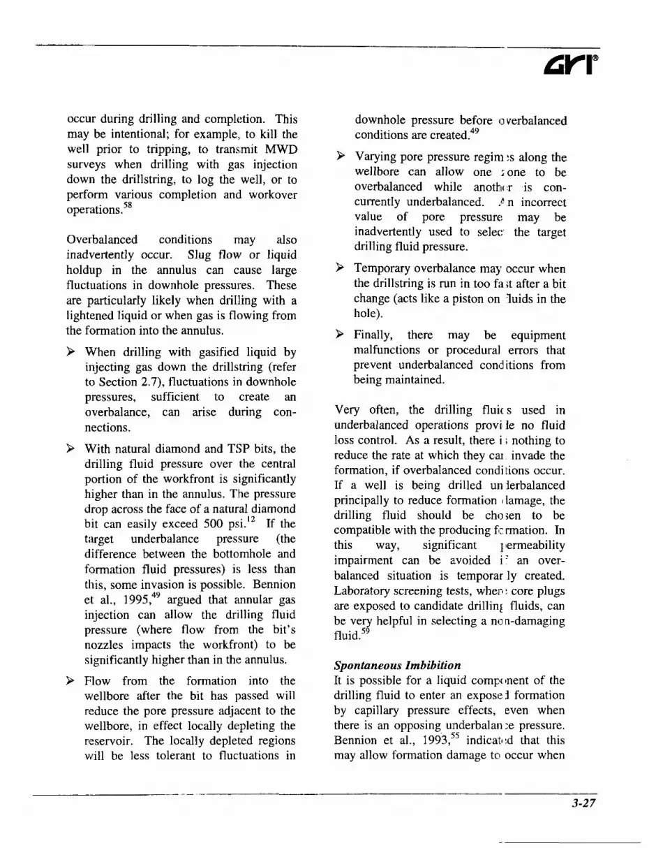
occur during drilling and completion. This may be intentional; for example, to kill the well prior to tripping, to transmit MWD surveys when drilling with gas injection down the drillstring, to log the well, or to perform various completion and workover operation^.^^
Overbalanced conditions may also inadvertently occur. Slug flow or liquid holdup in the annulus can cause large fluctuations in downhole pressures. These are particularly likely when d r i lhg with a lightened liquid or when gas is flowing from the formation into the annulus.
9
9
>
When drilling with gasified liquid by injecting gas down the drillstring (refer to Section 2.7), fluctuations in downhole pressures, sufficient to create an overbalance, can arise during con- nections.
With natural diamond and TSP bits, the drilling fluid pressure over the central portion of the workfront is significantly higher than in the annulus. The pressure drop across the face of a natural diamond bit can easily exceed 500 psi." If the target underbalance pressure (the difference between the bottolmhole and formation fluid pressures) is less than this, some invasion is possible. Bennion et al., 1995,49 argued that annular gas injection can allow the drilling fluid pressure (where flow from the bit's nozzles impacts the workfront) to be significantly higher than in the annulus.
Flow from the formation into the wellbore after the bit has passed will reduce the pore pressure adjacent to the wellbore, in effect locally depleting the reservoir. The locally depleted regions will be less tolerant to fluctuations in
>
9
9
downhole pressure before 0 verbalanced conditions are created.49
Varying pore pressure regim :s along the wellbore can allow one ione to be overbalanced while anothlc 'r is con- currently underbalanced. ! n incorrect value of pore pressure may be inadvertently used to selec the target drilling fluid pressure.
Temporary overbalance may occur when the drillstring is run in too fii ;t after a bit change (acts like a piston on luids in the hole).
Finally, there may be equipment malfunctions or procedural errors that prevent underbalanced cond itions from being maintained.
Very often, the drilling fluic s used in underbalanced operations provi le no fluid loss control. As a result, there i ; nothing to reduce the rate at which they cai invade the formation, if overbalanced condi tions occur. If a well is being drilled UII jerbalanced principally to reduce formation I lamage, the drilling fluid should be chosen to be compatible with the producing fi: rmation. In this way, significant I lermeability impairment can be avoided i ' an over- balanced situation is temporar ly created. Laboratory screening tests, when > core plugs are exposed to candidate drillini fluids, can be very helpful in selecting a non-damaging f l~ id .~ ' '
Spontaneous Imbibition It is possible for a liquid component of the drilling fluid to enter an exposei formation by capillary pressure effects, even when there is an opposing underbalan :e pressure. Bennion et al., 1993,55 indicat1:d that this may allow formation damage to occur when

_-__I ~ -- Chapter 3 Benefits of Drilling Underbalanced
drilling underbalanced.
Simplistically, capillary pressures arise because of the forces that act at liquid, gas, and solid interfaces. These depend on the nature and composition of the fluids and the matrix. These compositional variations regulate the magnitude of the capillary pressure and control which in-situ fluids will preferentially wet (be in intimate contact with) the solids constituting the formation. Some reservoir rocks are naturally water- wet, (Morrow, 1990),60 indicating that the surface energy of the rock is lower when covered by water (or an aqueous fluid) than when it is covered by a hydrocarbon. As a result, water will tend to be drawn into the rock’s pore structure if an initially hydrocarbon-filled pore is exposed to water. The capillary pressure, Pc, can be thought of as the pressure that has to be applied inside a particular pore, to prevent the wetting fluid (often water) from being drawn into it. The significance of this for underbalanced drilling is that the underbalance pressure must equal or exceed the capillary pressure, if an exposed water-wet formation is not to imbibe (draw in) water from a drilling fluid that contains an aqueous phase.
In a porous medium, capillary pressure can be approximated as:
where:
P, ....... capillary pressure (psi), y ......... interfacial tension between the
relevant fluids and/or gases (lbf/in) ,
(3.6)
8 ......... contact angle of thr wetting fluid on the rock matrix, measured through the denser ?base and varying from 0 to 1 80°, and,
rp ........ effective capillary I adius (in).
This shows that the sm:ller the pore (rp “indicates” pore size), the higher the pressure that must be allplied to prevent water from being drawn into it. Taking typical values for quartz, a specific methane and brine saturations6’ the capillary pressure will be approximately 10 psi for a pore diameter of 2 p.m, 100 psi for a pore diameter of 0.2 pm, and 1, I00 psi for a pore diameter of 0.02 pm.
There is not a unique cap llary pressure for various combinations of rock, water and hydrocarbon. The capill q pressure is related to the degree of wetting phase saturation; that is to the fral :tion of pores that are filled with the wetting 1 ihase. Presuming a very strongly water-wct formation, the capillary pressure is initial1 y very low at 100 percent water saturation, increases with decreasing water saturatic n, and becomes very large (values exceeding 1,000 psi are not infrequently measured) as the irreducible water saturation (Swim) is i pproached. This is illustrated schematicallj in Figure 3-10. The underbalance pressure necessary to prevent water from bein) drawn into an exposed water-wet forrr ation from an aqueous drilling fluid will depend on the initial formation water SE turation and the pore sizes.
A number of water-wet gas reservoirs, notably in tight formatioiis and in zones which have experienced significant gas migration, have water COi itents below the irreducible water saturatioi I . ~ ~ ~ ~ ~ It will be effectively impossible :o impose an
3-28

underbalance pressure that is high enough to prevent spontaneous imbibition of water into these formations. If the water saturation is above but close to the irreducible level, water may still be imbibed into the formation if the underbalance pressure is low. As shown in Figure 3-10, this counter- current imbibition would be possible into water-wet formations against an underbalance pressure of AP, for initial water saturations of up to Swc.
Equivalent imbibition of hydroc,wbon-based drilling fluids into oil-wet (or mixed or neutral wettability) formations is possible under analogous circumstances. Gas-bearing formations may be oil-wet when they
800
700
600
500
400
300
200
100
0
contain naturally oil-wet miner ds, such as pyrobitumen, sulfur, asphalt or residual heavy bitumen, or when a sub-ir .educible oil saturation has been establish ed by gas displacing an original oil columr .49
Strongly water-wet formation ; will not, however, imbibe hydrocarbons, neither will strongly oil-wet formations imt ibe aqueous fluids. Once liquid is imbib:d into the formation from the drilling fl lid, it may cause formation damage by any of the mechanisms that might have o~erated if it had been forced into the fornoation by an overbalance pressure. For exar iple, it may interact with the formation tself or the formation fluids, or it may leid to phase
for Initial Wetting Phase Saurations Between 20 and 47% for the Underbalance Pressure Shown in this
I I
;4------c; I I I Zone of Potential I I Spontaneous k I lmbibiton I I I I I I I I I I I I I 1 I I I I I I I
I I I
Example Underbalance Pressure - - - - - - C - * - - L ------------------I +- S (I = 47% (Equilibrium)
S,,=20% I S,r,=40% I I I \ I I
0 20 40 60 80 100
Wetting Phase, a, Saturation (YO)
Figure 3- IO. Schematic relationship between capillary pressure and water si turation for water-wet reservoir rock (afier Bennion et al., 199355).
3-29

- Chapter 3 Benefits of Drilling Underbalanced
trapping and blocking.
Knowledge of wettability, initial saturation, and capillary pressure characteristics will facilitate the identification of those regimes where spontaneous and counter-current imbibition may occur during underbalanced drilling. Together with laboratory core- flood studies, this should assist the selection of underbalanced drilling fluids and annular pressures that would minimize the potential
Gravity-Induced Invasion The density of any liquid drilling fluid will almost
in future
phase in the invariably be
greater than the density of natural gas in a gas-bearing formation. Under normal circumstances, flow from the formation into the borehole when drilling underbalanced will prevent movement of drilling fluid into the formation, even if it has a higher density than the formation fluid. If, however, the formation produces from natural fractures or large vugs, it is possible for liquid to flow into these openings under the influence of gravity even though the well is ~nderba lanced~~ and natural gas is flowing into the wellbore through the same apertures.
Wellbore Glazing Particularly when drilling with a dry gas, high temperatures can be generated where the bit and the BHA rub against the borehole wall. Since frictional coefficients between steel and dry rock are high, more energy is dissipated in friction than if there was a significant liquid volume fraction in the drilling fluid. Also, since the thermal capacity of dry gases is lower than for liquid drilling fluids, they cannot cool the borehole
as effectively. These high :emperatures have long been suspected of cr:ating a thin, low permeability, “glazed” zone57 on the borehole wall. Glazing hzs been noticed on the surface of whole core and rotary sidewall cores in air drilled holes. [n highly deviated and horizontal wells, tl ere will almost certainly be beds of cuttings on the hole bottom that will be regrcund between the BHA and the intact rock of the borehole wall. Glazing has beer noticed on the surface of whole core a n j rotary sidewall cores in air drilled holes. This regrinding may create a paste of fine cuttings that can contribute to glazing.
Glazing tends to be localized in the immediate vicinity of th : borehole wall, extending at most a few enths of an inch into the formation.57 It bill not, therefore, inhibit the productivity of a cased and perforated well. Simil arly, glazing is unlikely to be a problem i n formations that produce from natural fracti ires or vugs, even if these wells are completcd openhole. The size of the productive fea:ures is generally too great to be obstructed by the glaze.49
Any glaze created in carbonates is likely to be acid soluble, and can piobably be readily removed by an acid wash. A silicate-based glaze might be expected i.1 sandstones, and this could be more difficult to remove.49 Mud acid or hydrofluor c acid may be effective.
Damage After Drilling There is little point in drilling a well underbalanced to avoid for nation damage, if the well is then “intenti mally” damaged during completion, workov :r or production.
9 The possibility of damaging the formation by killing th: well to conduct

completion or workover operations has already been mentioned. If a separate completion fluid is used, care should be exercised to ensure that this does not damage the formation. This is probably even more important than would be the case for a conventionally drilled well since there will be little or no “protective” mudcake on the wall of a well that was drilIed underbalanced.
9 Cementing can create damage by invasion of filtrate or cement solids. A cemented casing will, holwever, be perforated and the perforations may penetrate beyond the damaged zone.
> There are several mechanisms that may cause the permeability of the near- wellbore region to decrease during the productive life of the well. Fines may be mobilized from within the producing formation by the flowing pore fluid and carried into the near-wellbore region. Francis et al., 1995,51 conducted laboratory core-flooding measurements, in which plugs from a reservoir that was a candidate for drilling underbalanced were exposed to the proposed drilling fluid under both under- and over- balanced conditions. These experiments all showed a significant permeability reduction, to 20 percent of the original level or less, irrespective of the differential pressure. Thin section petrography and scanning electron microscopy showed that the permeability impairment was caused by migration of intrinsic fines. The fines were displaced both by flow from the formation, when underbalanced, and by flow into the formation under conditions of high overbalance pressure. Drilling underbalanced would not avoid formation damage by fines migration in
9
this reservoir.
It is also possible for lkuids to be carried into the near-well1 )ore region during production, to the exb :nt that they reduce the permeability to ga 5.. Drop-out of produced liquids has beer reported as the probable cause of formxion damage in air mist drilled horizontal gas wells in the San Juan Basin:’ and in a Canadian well drilled underbalanc ed59 with nitrified liquid.
Mechanical Degradation The rock around a wellbore el periences a concentration of in-situ stresses;. simply due to drilling the well. As tl e weIIbore pressure is lowered, particularkr if there is no filter cake, the effective stres ;es increase. With elevated stresses, pc rosity and available flow channels ca.1 L decrease, reducing permeability. This is : nalogous to reductions in permeability that may occur during, the productive life of a reservoir as the reservoir is depleted. Reductions in permeability may or may not be: recoverable, possibly less so in poorly :onsolidated formations.
Around the wellbore, stresses 1 nay become so large that failure occurs, in which case near-wellbore permeability may or may not increase.
Formation Damage Reducifr on Beyond the drilling technique, 1 nany factors influence the productivity of we 11s drilled in the same field. For exampl;, there are inevitably variations in reser (oir quality (porosity, permeability, thickne ;s ...) and in formation pressure support for production. Well trajectories vary, as do the r orientation and placement in the reservir. These inherent variations must be coni idered when
3-31

Chapter 3 Benefits of Drilling Underbalanced
comparing production data from wells drilled over- and underbalanced. Also, the relative refinement of the different drilling techniques needs to be considered - it may be inappropriate to compare the last overbalanced well with the first well drilled underbalanced. Ideally, comparisons should be made from equivalent points on the learning curve.
Surewaard et al., 1995,58 recognized these uncertainties and developed a statistical model to determine how many wells would have to be drilled underbalanced in order to establish, with reasonable confidence, that a particular level of productivity improvement had been achieved. The.y applied this analysis to the Nimr field in Oman, where conventionally drilled horizontal wells showed a significant spread in productivity indices. The conclusion was that, for this field at least, ten wells would have to be drilled underbalanced to establish (at an 80 percent level of confidence) that a 50 percent increase in productivity had been achieved. Fewer underbalanced wells would be required to establish higher productivity increases - one well would be enough to prove benefit from drilling underbalanced if it gave more than 2.5 times the average productivity of equivalent conventionally drilled wells.
Noting these various qualifications, a number of examples are presented to illustrate the sort of productivity increases that drilling underbalanced can cause.
9 In the United States, the Austin Chalk has probably seen the most underbalanced drilling activity. Stone, unpublished, 1993,64 reported that many operators in South Texas had consistently achieved higher productivity
from Austin Chalk wells that were drilled underbalanced flowdrilled) than from wells that were drilled overbalanced.
9 Joseph, 1995,65 desxibed a deep, horizontal well thz t was drilled underbalanced into the Austin Chalk, in central Louisiana. This achieved a gas production rate that 'vas seven times higher than the best rate from any horizontal well drilled :onventionally in that area.
9 Hutchinson, 1970,21 cescribed a well drilled with stable fcam in fractured Miocene cherts, nea' Santa Maria, California. This well pi oduced heavy oil at 500 BOPD, whereas the best mud- drilled offset well p.oduced at 150 BOPD.
P Recently, there has bl:en considerable underbalanced drilling i 1 Canada. Much of this has been undertaken specifically to avoid formation damage. The Weyburn field, ir southeastern Saskatchewan, producs oil from a chalky dolostone at app -0ximately 4,600 feet TVD. The average porosity is 26 percent and permeabilik r varies from 1 to 100 md. To date, over :ighty horizontal wells have been drilled inderbalanced in this field. Despite this level of activity, there remains uncertain1 y over the extent to which underbalancc :d drilling may impact productivity. Springer et al., 1 994,66 reported that drilling underbalanced in thi! field led to productivity that was tv'o to three times greater than for horizor tal wells drilled overbalanced. Howeve, Mullane et al., 1995,67 suggested a more complex situation. Some of the early underbalanced wells we -e disappointing.
3-32

It was suspected that they had been damaged by allowing overbalanced conditions to occur when making connections. Acid stimulation greatly improved production, possibly confirming damage. More recent underbalanced wells have adopted better connection procedures that maintain the underbalance pressure. The preliminary results from these wells indicated increased productivity, but it was felt that further production would be required before this could be confirmed.
> The Westerose gas field, in Alberta, provides a more encouraging; picture of the extent to which underbalanced drilling can enhance productivity, while at the same time confirming the difficulty in objectively comparing different drilling techniques. The productive formations are glauconitic sandstones. They are prone to permeability impairment by swelling of interstitial clays and by phase trapping. Four vertical wells were drilled underbalanced, two using nitrified KCl and two using nitrogenKC1 foam. During drilling, two of these wells flowed gas at rates that were typically three times those from DSTs in equivalent wells drilled ~verba lanced .~~ These increases were not sufficient for the wells to be economic without further stimulation. In one well, the productive formation was damaged by the water and condensate that were used to load the well for pre-frac testing and was subsequently lost into the formation during testing. The remaining two wells that were drilled underbalanced penetrated oil-bearing, shaley sands which did not flow either oil or gas at economic rates.
> Lunan, 1995,68 presented production data from two vertical wells. drilled 330 feet apart, in the Sinclai. Field, in Northern Alberta. The productive formation in this field, the Paddy, is a medium- to coarse-grainec sandstone that is susceptible to formation damage when drilled conventionally The first well was drilled and completed conventionally and then fra Ztured. The fracturing treatment was not particularly successful, possibly because of high in- situ stresses. The seconc well was drilled underbalanced usir g nitrified condensate. This well produ :ed at a rate that was seven times greater than for the first well. Production test d; ta indicated an effective permeability thit was five times higher than for the first well. The well drilled underbalanced tad no skin, whereas the well drilled o Jerbalanced and then fractured had a skin of +43. The hig,her permeability in the !econd well negates this as an effective ompa par is on, although zero skin is encoura $ng.
> A horizontal well was dril1:d into oil- bearing glauconitic sandsf( )ne in the Hussar field, in Albe-ta, using overbalanced and then UII lerbalanced conditions along the same lat xal section, in an attempt to assess any benefits of drilling ~nderbalanced.~~ Thc first 330 ft of the horizontal interval ~ i e r e drilled overbalanced with a starc1 dguar gum polymer water-based mud. Damage sustained during overbalaric *ed drilling prevented production from t le first 330 feet of the hole when tht well was switched to nitrified crude a id a further 2,060 feet were drilled unc erbalanced. This damage was subsequeri ly removed by underbalanced abrasive jetting. A rotating jetting tool was ru 1 downhole
3-33

--__-__ Chapter 3 Benefits of Drilling Underbalanced
on coiled tubing. Oil was pumped down the coiled tubing and nitrogen was pumped down the annulus between the coiled tubing and the production tubing annulus. This effectively removed the mud-induced damage and allowed that section to produce oil.
9 Kitsios et a]., 1994,70 described a vertical well drilled with air foam, in the Amal field in Oman. This had a productivity index that was over twice the average for adjacent conventionally drilled wells.
9 It is not just production rate that can be improved by drilling underbalanced. The protocol may accelerate hydrocarbon production from wells drilled in reservoirs prone to lost circulation. Mitchell and Salvo, 1991 ," reported that wells air mist drilled in the Eunice Monument Field, in New Mexico, would produce immediately. Conventional overbalance wells typically took between one month and one year to begin producing oil, due to large volumes of mud and water that had been lost into the producing formation.
Required Stimulation In some wells, supplementary stimulation treatments are required; for example matrix acidizing or hydraulic fracturing, to remove or bypass drilling-induced formation damage. Underbalanced drilling can, in some instances, remove the need for primary stimulation, by restricting the occurrence of formation damage.
Mullane et al., 1995,67 reported that horizontal wells drilled underbalanced in the Weyburn field were cheaper overall than equivalent wells drilled overbalanced, principally because they did not require the bleach clean-up or acidization treatments
that were necessary to tievelop adequate production in the overbalar ced wells.
Hutchinson and Anderson, 1 972,20 described an oil well drilled with air foam, into a carbonate reservoir, in lolorado. This produced over 600 BOPD Adjacent mud- drilled wells experienced 1 ost circulation in the pay and required rnassii'e acid treatments before they would produce.
Summary
9
9
9
P
Drilling underbalanced will often reduce or avoid drilling-inc uced formation damage. The resullant increase in productivity, earlier production and possible reduction in stimulation costs often make underb, danced drilling economically attractivl ;, even without considering an imprc ved penetration rate.
There is no clear evidence that any one underbalanced drilling technique gives greater or lesser prodi ctivity increases than other techniques.
It is important that tlie well be kept underbalanced at all til nes, if formation damage is to be minim3zed. A well that was drilled unde "balanced can experience severe forn iation damage if overbalanced conditio is exist during completion, production or workover.
There are mechanisms 1)y which damage can occur during under Jalanced drilling, even if an underbalan :e is maintained continuously. The txtent to which underbalanced drillin ; can reduce formation damage rn ill be strongly dependent on the specific target formations. Laboratory evaluations can reveal the potential for reducing formation damage by drilling under-
3-34

balanced. negative skin unless 11 :ar-welIbore
P There is little point in drilling underbalanced (to avoid formation damage) if damage occurs during subsequent production; for example, by fines migration. Increased ROP and other factors in the total economics may dictate using underbalanced methods, regardless of formation damage.
P Drilling underbalanced will not cause a
References 1.
2.
3.
4.
5.
6.
7.
8.
9.
10.
failure causes permeabilit y increases (possibly undesirable fro m stability considerations). If an UI derbalanced well is not economic with cero skin, it will still need stimulation. Avoiding formation damage alone docs not justify using underbalanced drillin; ; techniques for a well that will still have to be stimulated after drilling.
Cheatham, J.B. Jr.: “An Analytical Study of Rock Penetration By a SingIe Tooth,” Proc., Eighth Drilling And Blasting Symposium, University of Minnesota ( I 958) 1 A- 22A.
Gamier, A.J. and Van Lingen, N.H.: “Phenomena Affecting Drilling Rate: I at Depth,” Trans., AIME (1959) 216,232-239.
Cunningham, R.A. and Eenink, J.G.: “Laboratory Study of Effect of Overburden, Formation and Mud Column Pressures on Drilling Rate of Permeable Formatit m,” Trans., AIME (1959) 216,9-17.
Black, A.D., Dearing, H.L. and DiBona, B.G.: “Effe,ct of Pore Pressure and hl ud Filtration on Drilling Rates in a Permeable Sandstone,” JPT (September 1985) 167 1 - 168 1.
Moore, P.L.: Drilling Practices Manual, PennWell Books, Tulsa, OK (1974).
Van Lingen, N.H.: “Bottom Scavenging - A Major Factor Governing Penetra ion Rates at Depth,” paper SPE 165, JPT (February 1962) 187- 196.
Eckel, J.R.: “Effect of Pressure on Rock Drillability,” paper SPE 877G, Pet. TI ans., AIME, (1958) 213, 1-6.
Zijsling, D.H.: “Single Cutter Testing - A Key for PDC Bit Development,” paper SPE 16529/1 presented at the 1987 Offshore Europe 87, Aberdeen, Scotland.
Gray-Stephens, D., Cook, J.M. and Sheppard, M.C.: “Influence of Pore Pressure on Drilling Response in Hard Shales,” SPEDC (December 1994) 263-270.
Maurer, W.C. “How Bottomhole Pressure Affects Penetration Rate,” (January 10, 1966) 61-65.
Oil and Gas J.
3-35
Chapter 3 Benefits of Drilling Underbalanced
11.
12.
13.
14.
15.
16.
17.
18.
19.
20.
21.
22.
23.
Cheatham, C.A., Nahm, J.J. and Heitkamp, N.D.: “Effects of Selected P4ud Properties on Rate of Penetration in Full-Scale Drilling Simulations,” SPE/IADC pape 13465 presented at the 1985 SPEAADC Drilling Conference, New Orleans, LA.
Winters, W.J. and Warren, T.M.: “Laboratory Study of Diamond-Bii Hydraulic Lift,” SPEDE (August 1986) 267-276.
Moore, P.L.: “How Drilling Rate is Affected by Drilling Fluid Properti x,” Oil & Gas J. (October 1958) 141.
Beck, F.E, Power, J.W. and Zamora, M.: “The Effect of Rheology on Rai e of Penetration,” SPE/IADC paper 29368 presented at the 1995 1st International Undei balanced Drilling Conference, The Hague, The Netherlands, October 2-4.
Pratt, C.A.: “Modifications to and Experience with Air-Percussion I Irilling,” SPEDE (December 1989) 3 15-320.
Lyons, W.C., Miska, S.Z. and Johnson, P.W.: “Downhole Pneumatic Turbine Motor: Testing and Simulation Results,” paper SPE 18040 presented at the 1388 SPE Annual Technical Conference and Exhibition, Houston, TX.
Cummings, S.G.: “Natural Gas Drilling Methods and Practice: San .uan Basin, New Mexico,” paper SPE/IADC 16167 presented at the 1987 SPE/IADC Dri lling Conference, New Orleans, LA.
Mitchell, R.K. and Salvo, G.S.: “The EMSU Waterflood Project: A Cas: History of Infill Drilling, Completions and Workovers,” SPEDE (June 1991) 1 18-124.
Fraser, I.M. and Moore, R.H.: “Guidelines for Stable Foam Drilling Thrc ugh Permafrost,” paper SPE/IADC 16055 presented at the 1987 SPE/IADC Drilling (jonference, New Orleans, LA.
Hutchinson, S.O. and Anderson, G.W.: “Preformed Stable Foam Aids Workover, Drilling,” Oil & Gas J. (May 15, 1972) 74-79.
Hutchinson, S.O.: “Stable Foam Lowers Production, Drilling and I. .emedial Costs,” presented at 17th Annual Southwestern Petroleum Short Course, (April 15 70).
Wolke, R.M., Jardiolin, R.A., Suter, R.L., Moriyama, S., Sueyoshi, Y. and Kihara, Y.: “Aerated Drilling Fluids Can Lower Drilling Costs and Minimize Fori nation Damage,” Geothermal Resources Council Bulletin, (May 1990) 13 1 - 1 37.
Comeau, L.: “Underbalanced Drilling: Directional and MWD Ex perience,” paper
3-36

24.
25.
26.
27.
28.
29.
30.
31.
32.
33.
34.
35.
36.
presented at the 1995 1 st International Underbalanced Drilling Conference, The Hague, The Netherlands, October 2-4.
Saponja, J.: “Comparing Conventional Mud to Underbalanced Drilling in a Depleted Reservoir,” paper presented at the 1995 1 st International Underbalanced Drilling. Conference, The Hague, The Netherlands;, October 2-4.
Deis, P.V., Yurkiw, F.J. and Barrenechea, P.J.: “The Development of an Un lerbalanced Drilling Process: An Operator’s Experience in Western Canada,” paper pres :nted at the 1995 1 st International Underbalanced Drilling Conference, The Hague, The 1 qetherlands, October 2-4.
Cooper, L.W., Hook, R.A. and Payne, R.R.: “Air Drilling Techniques,” pape- SPE 6435 presented at the 1977 SPE Deep Drilling and Production Symposium, Amarillo TX.
Wilson, G.E.: “Air Drilling and Crooked Hole Problems,” paper SPE 9529 pre5 ented at the 1980 SPE Eastern Regional Meeting, Morgantown, WV.
Brannon, K.C., Grimes, RE. and Vietmeier, W.R.: “New Oilfield Air El t Improves Drilling Economics in Appalachian Basin,” PD-Vol. 56, Drilling Technol ’gy (1994), ASME ( 1994).
Carden, R.S.: “Air Drilling has Some Pluses for Horizontal Wells,” Oil & Ga,s J. (April 8, 1991) 76-78.
Kelly, J.L., Jr.: “Forecasting the Life of Rock-Bit Journal Bearings,” SPEDE :June 1990) 165-170.
Simon, R.: “Energy Balance in Rock Drilling,” SPEJ (December 1963) 298-30( I.
Shale, L. and Curry, D.A.: “Drilling a Horizontal Well Using Airmoarn Technic lues,” paper OTC 7355 presented at the 1993 Annual OTC, Houston, TX.
Glowka, D.A. and Stone, C.M.: “Thermal Response of Polycrystalline Diamo Id Compact Cutters under Simulated Downhole Conditions,” SPEJ (April 1985) 143- 156.
Glowka, D.A. and Stone, C.M.: “Effects of Thermal and Mechanical Loading; on PDC Bit Life,” SPEDE (June 1986) 20 1-2 1 3.
Eaton, N.: Coring the Horizontal Hole, PD-Vol 27, ASME Drilling Technology Symposium, Weiner, P.D. and Kastor, R.L (eds).
Bentsen, N.W. and Veny, J.N.: “Preformed Stable Foam Performance in Ihilling and Evaluating Shallow Gas Wells in Alberta,” JPT (October 1976) 1237- 1240.
- 3-37

--_- - Chapter 3 Benefits of Drilling Underbalanced
37.
38.
39.
40.
41.
42.
43.
44.
45.
46.
47.
48.
Cobbett, J.S.: “Application of an Air-Drilling Package in Oman,” Yaper SPE 9600 presented at the 1981 SPE Middle East Oil Technical Conference, Manan a, Bahrain.
Cagnolatti, E. and Curtis, F.: “Using Underbalance Technology to : ;olve Traditional Drilling Problems in Argentina,” paper presented at the 1995 1 st International Underbalanced Drilling Conference, The Hague, The Netherlands, October 2-4.
Louison, R.F., Reese, R.T. and Andrews, J.P.: “Case History; Underbal ance Drilling the Midway and Navarro Formations Successfully in Hallettsville, TX,” I aper SPE 13 112 presented at the 1984 SPE Annual Technical Conference and Exhibition, 1 louston, TX.
Sheffield, J.S. and Sitzman, J.J.: “Air Drilling Practices in the Midcon inent and Rocky Mountain Areas,” paper SPEWDC 13490 presented at the 1985 SPE/IADC Drilling Conference, New Orleans, LA.
Westermark, R.V.: “Drilling with a Parasite Aerating String in the Disturl led Belt, Gallatin County, Montana,” paper IADCISPE 14734 presented at the 1986 IA >C/SPE Drilling Conference, Dallas, TX.
Claytor, S.B., Manning, K.J. and Schmalzried, D.L.: “Drilling a Medium-Radius Horizontal Well With Aerated Drilling Fluid: A Case Study,” paper SPE/IADC 21988 presented at the 199 1 SPEAADC Drilling Conference, Amsterdam.
Teichrob, R.R.: “Low Pressure Reservoir Drilled with Air/Nz in a Closetl System,” Oil & Gas J. (March 21, 1994) 80-90.
Adam, J. and Berry, M.: “Underbalanced Coiled Tubing Sidetrack Succe: sful,” Oil & Gas J. (December 18, 1995) 91-98.
Bobo, R.A. and Barrett, H.M.: “Aeration of Drilling Fluids,” World Oil ( 1 953) 137, No. 4, 145.
Roy, R. and Hay, R.: “Measuring Downhole Annular Pressure While Drilling for Optimization of Underbalanced Drilling,” paper presented at the 1995 1 st International Underbalanced Drilling Conference, The Hague, The Netherlands, October 1 1-4.
Wilson, J.: “Optimizing Drilling of Underbalanced Wellbores with 1 lata Acquisition Systems,” paper presented at the 1995 1 st International Underbalanced Dri lling Conference, The Hague, The Netherlands, October 2-4.
Taylor, J., McDonald, C . and Fried, S.: “Underbalanced Drilling Total Sys tems Approach,” paper presented at the 1995 1st International Underbalanced Drilling Confer mce, The Hague, The Netherlands, October 2-4.
3-38

49.
50.
51.
52.
53.
54.
55.
56.
57.
58.
59.
Bennion, D.B., Thomas, F.B., Bietz, R.F. and Bennion, D.W.: “Underbalarn :ed Drilling, Praises and Perils,’’ paper presented at the 1995 1 st International Underbalar ced Drilling Conference, The Hague, The Netherlands, October 2-4.
Dreiling, T., McClelland, M.L. and Bilyeu, B.: “Horizontal and High Angle A r Drilling in the San Juan Basin, New Mexico,” The Brief(June 1996) 12-19.
Francis, P.A., Patey, I.T.M. and Spark, 1.S.C.: “A Comparison of Underbalanced and Overbalanced Drilling-Induced Formation Damage Using Reservoir Con( .itions Core Flood Testing,” paper presented at the 1995 1 st International Underbalan zed Drilling Conference, The Hague, The Netherlands, October 2-4.
Schlumberger: Log Interpretation Principles/Applications, Schlumberger Educational Services, Houston, TX (19137).
Pallatt, N., Stockden, I.L.M., Mitchell, P.S.H. and Woodhouse, R.: “Low Inw ision Coring Gives “Native” Reservoir Water Saturations,” European Society of Professior a1 Well Log Analysts, London (1991).
Rathmel, J.J., Tibbitts, G.A., Gremley, R.B., Warner, H.R., Jr. and lihite, E.K.: “Development of a Method for Partially Uninvaded Coring in High Permeability Sandstone,” paper SPE 20413 presented at the 1990 SPE Annual Technicail Conference and Exhibition, New Orleans, LA.
Bennion, D.B., Thomas, F.B., Bennion, D.W. and Bietz, R.F.: “Formation Dar iage Control and Research in Horizontal Wells,” presented at the 1993 International Cclnference on Horizontal Well Technology, Houston, TX.
McLennan, J.D., Roegiers, J-C. and Economides, M.J.: “Extended Reach an i Horizontal Wells,” Reservoir Stimulation, Economides, M.J. and Nolte, K.G., (eds.) 1’ rentice Hall, Englewood Cliffs, NJ (1989).
Bennion, D.B. and Thomas, F.B.: “Underbalanced Drilling of Horizontal Pv ells: Does it Really Eliminate Formation Damage,” paper SPE 27352 presented at the 1S94 SPE Intl. Symposium on Formation Damage Control, Lafayette, LA.
Surewaard, J., de Koning, K., Kool, M., Woodland, D., Roed, H. and P opmans, P.: “Underbalanced Operations in Petroleum Development Oman,” paper presente d at the 1995 1 st International Underbalanced Drilling Conference, The Hague, The Nether]; nds, October 2-4.
Churcher, P.L., Yurkiw, F.J., Bieti, R.F. and Bennion, D.B.: “Designing ard Testing of Underbalanced Drilling Fluids to Limit Formation Damage: Examples from It’ le Westerose
3-39

- --.
Chapter 3 Benefits of Drilling Underbalanced
60.
61.
62.
63.
64.
65.
66.
67.
68.
69.
70.
Field, Canada,” paper presented at the 1995 1st International Undei balanced Drilling Conference, The Hague, The Netherlands, October 2-4.
Morrow, N.R.: “Wettability and Its Effect on Oil Recovery,” JPT (Dece nber 1990) 1476- 1484.
Vavra, C.L., Kaldi, J.G. and Sneider, R.M.: “Geological Applicati ms of Capillary Pressure: A Review,” AAPG Bulletin (June 1992) 76, No. 6, 840-850.
Katz, D.L. and Lundy, C.L.: “Absence of Connate Water in Michigan Reef Gas Reservoirs,” AAPG Bulletin (January 1982) 66, No. 1,91-98.
Gray, R. and Bird, K.: “Laboratory Evaluation of Underbalance Fc rmation Damage Compared to Neutral and Overbalance Conditions,” paper presented at the 1995 1st International Underbalanced Drilling Conference, The Hague, The Netherla ids, October 2-4.
Stone, C.R.: “Horizontal Underbalanced Drilling,’’ SPE Distinguished Le( ture, 1993/1994.
Joseph, R.A.: “Underbalanced Horizontal Drilling - Conclusion. Specia 1 Techniques and Equipment Reduce Problems,” Oil & Gas J. (March 27, 1995) 41-47.
Springer, S.J., Christie, D.S., Flach, P.D., Gust, D.A. and Porter, K.: “4 Review of the First 1500 Horizontal Wells in Western Canada,” presented at the 1914 SPE/CIM 4th Annual One-Day Conference on Horizontal Wells, Calgary, Canada.
Mullane, T.J., Churcher, P.L., Edmunds, A.C., Eddy, D.B., Martin, B.G. and Flach, P.D.: “Benefits of Underbalanced Drilling: Examples from the Weyburn and ’ Yesterose Fields, Western Canada,” paper presented at the 1995 1st International Under ~alanced Drilling Conference, The Hague, The Netherlands, October 2-4.
Lunan, B.: “Underbalanced Drilling - Surface Control Systems,” paper presented at the 1995 1 st International Underbalanced Drilling Conference, The Hague, rhe Netherlands, October 2-4.
Cheung, V., Aheam, B., Scheidt, K.A., Saponja, J., Penrose, R. and Christensen, D.: “Underbalanced Horizontal Drilling in the Hussar Glauconitic “A” Pool,’ presented at the SPE/CIM 4th Annual One-Day Conference on Horizontal Wells, Calgary, Canada.
Kitsios, E., Kamphuis, H., Quaresa, V., Reynolds, E. and Rovig, J.: “Underbalanced Drilling Through Oil Production Zones with Stable Foam in Oman,” 1 japer IADC/SPE 27525 presented at the 1994 IADC/SPE Drilling Conference, Dallas, TX.
3-40

SELECTING AN APPROPRIATE T€CHNIQlJ€
4. I Introduction
Chapter 2 summarized various techniques for drilling a well underbalanced. This chapter summarizes some of the con- siderations for:
9 Determining if underbalanceti drilling is potentially applicable.
controlling factor in selecting a drilling technique is the allowable range of borehole pressures.
P Selecting the potential underbalanced drilling methods, and,
9 Evaluating the economics to identify the most cost effective procedure..
9 Evaluating wellbore stability. A
Underbalanced drilling is technically feasible in almost all situations. There will be many instances when it is also the most cost effective procedure. The sa.me drilling technique does not have to be used for an entire drilling program in a well. There are instances where it can be cost effective to drill through the overburden conventionally and then switch to underbalanced drilling to penetrate the productive zones. Conversely, in solme instances, it may be advantageous to drill the upper section of a hole underbalanced and then mud up to drill through a highly productive or over-
pressured pay zone.
There will often be uncertainty in carrying out technical and economic evaluations. Underbalanced drilling is no di 'ferent from conventional drilling in this re! ard. Local experience with different drillinl ; techniques often minimizes some of these 11 ?certainties. Sensitivity analyses and risk assessments can be helpful in selecting t te optimum procedures. As experience is giiined with a specific drilling technique, operational efficiency increases as does thz ability to evaluate and forecast the asso :iated costs and benefits.
4.2 Potential Applici Itions
The key to successful exploitation lies in application of appropriate techniques. Underbalanced drilling is a go( jd example. This drilling protocol is not appropriate in all instances. The daily spe id rate for underbalanced drilling can be yeater than for conventional drilling method ; because of the use of supplementary well control and surface production equipment. lowever, in many instances, total drilling costs and long- term return on investment are greatly improved. Underbalanced drillii ig programs generally require more engir eering and planning to ensure safety and eff ciency. The benefits may be downstream of the drilling

.---
Chapter 4 Selecting An Appropriate Technique
operations.
Candidate Selection It is necessary to economically screen underbalanced methodologies. Beyond reduction of impairment, increased and earlier production, reduced fluid loss, better evaluation .. . severe drilling problems alone may dictate adopting underbalanced drilling methods. Regardless, each situation must be evaluated individually.
Some of the situations where underbalanced drilling may offer advantages include:
> Any formation subject to impairment, and particularly naturally fractured reservoirs drilled with straight hole or horizontal laterals. Mud damage of the productive fractures can be devastating when conventional drilling methods are adopted. Certain productive sands and carbonates may also be severely impaired with conventional drilling.
> Deeper reservoirs below depleted or underpressured zones can cause severe drilling problems when conventional methods are used. These problems may include lost circulation and stuck drillpipe.
9 Gas storage wells rely on high production rates during peak demand periods. Minimized formation impairment is essential to guarantee adequate on-demand deliverability.
9 Produced water or other disposal wells, particularly where hydraulic fracturing is environmentally unacceptable, depend on high injectivity polential associated with minimized drilling impairment.
9 Better evaluation: Recognition of productive zones while drilling, should
lessen the chances of b {passed pay.
9 Any situation wher,! ROP can be economically increast d and fewer bits are required.
These are only a few of the generic situations where underbal w e d drilling can offer significant advantage i. There are some situations where the ( lpportunities are moderate to marginal. Ir each case, there may be compensating fact1 )rs such as higher ROP, reduced list circulation .... . Certainly, these situatioi is require more careful evaluation. For ex: mple:
9 Low permeability, massive and relatively unfractured reservoirs which will likely need to be hydraulically fractured.
> Very high permeability formations which would pro( uce significant volumes of formation k i d s and exceed surface equipment h, indling capacity. This is a solvable problem, but it may not be economic. In tliis situation, non- invasive, clear fluid; are preferred. Clear fluids with acid- soluble solids are acceptable.
9 Macrofractured or vu rular formations which are susceptible to gravity-driven invasion of fractures or vugs or would produce volumes of formation fluid which cannot be accommodated by surface equipment. rhese difficulties can be overcome by ising clean fluids with soluble divertei s (Le., calcium carbonate chips, rock : alt . . . ). In fact, there are cases whei e underbalanced drilling is the only method that is appropriate.
9 Extremely high pres wre formations which would require t xcessively costly
4-2

fluids or wellhead and surface equipment to ensure adequate safety. Even in mud drilling, the surface equipment (BOPS, wellhead equipment, casing) must be designed for maximum shut-in surface pressure. This design pressure is the same for conventional and under- balanced drilling. Overpressured formations can be drilled with air mist and foam. Carden, 1997 (unpublished) reported deep drilling at a bottomhole pressure equivalent of 14.4 ppg (-0.75 psi/ft). As long as the production is being vented down the blooie line and there is no backpressure, a rotating head may be acceptable. The problem with overpressured formations arises with high production rates. It is more difficult (but not impossible) to kill a high pressure well, flowing at high production rates. Even normally pressured wells, flowing at high rates, are more difficult to kill. Either one of these situations may be drilled and completed with proper design.
There are some situations where under- balanced drilling may not be appropriate:
9 Highly unconsolidated formations which require elevated wellbore pressure to maintain hole stability.
9 Formations where swelhg and significant hole size reduction or wellbore instability are anticipated. Swelling and instability can also be serious problems with conventional muds.
These are generalities. In fact, under- balanced drilling may be attractive even in some, of the scenarios where stability is a
real concern. The key to ev:ry under- balanced drilling project is propel evaluation of the prospect and comparison c) . the cost to drill and complete, both convenl ionally and underbalanced. In every case, 2 well must provide the maximum returi on its investment, including appropri: .te consid- eration of safety and the el vironment. Economics is the final measure 0" success.
Drilling and production data irom offset wells, either individually or together, facilitate identification of mo5 t potential applications for underbalanced ( rilling. In some instances, underbalanced drilling is adopted principally to impro re drilling perforniance through one or mo-e intervaIs in a hole; overburden or productive zones. Alternatively, using underbalanc ed drilling can be driven exclusively by the I otential for reducing formation damage in1 known or anticipated pay zones.
Successful implementation of unc lerbalanced drilling methods in offsets is in obvious indicator of the viability of the ti: :hnique. If offset wells were successfully dri ,led using a particular underbalanced tech1 ique, that technique is a strong candidate for future drilling operations. Howeve:] , previous success does not guarantee: that the technique will be the optimun, for other wells, even wells in the immedi tte locality. It does not necessarily imply tha. it was the best technique for the wells alre3dy drilled. It merely demonstrates feasibility
Penetration Rates If offset well data indicates low penetration rates for mud (for example, less than fifteen f a r ) and the formations are 0111 and hard, dry gas, mist or foam an potential alternatives to mud. The lower the
4-3

--.
Chapter 4 Selecting An Appropriate Technique
penetration rate, the more likely it is that these techniques will reduce the drilling times sufficiently to make them economically attractive. Caution must be exercised since low penetration rates do not always indicate hard rocks. For example, very soft Gulf of Mexico shales are often characterized by penetration rates which are less than ten feet per hour, when drilled with PDC bits and water-based muds. Air, mist or foam drilling would not be suitable for these formations, principally because of the potential for wellbore instability. In addition, Gulf of Mexico sandstones are often so permeable that formation fluid inflows, either water or hydrocarbon, would probably occur at rates which could be difficult to manage on the surface if they were drilled with dry gas, mist or foam.
Air, Mist and Dry Gas Drilling Carden, 1993,' reviewed drilling practices in the continental United States, indicating that air drilling predominated in the Arkoma and Appalachian Basins, where target zones are Pennsylvanian or older. Air drilling is also frequently used in the Paradox, Uinta- Piceance-Eagle and San Juan Basins, where some of the formations are Cretaceous or even Tertiary. This indicates that age alone is not a deciding factor in selecting air drilling. Inflow rate and formation integrity are two other deciding factors.
Characteristic Formation Properties While rate of penetration and formation age are not stand alone diagnostics of environments where air, mist or foam drilling are appropriate, there are some general guidelines on identifying appropriate formations.
9 The formations penetrated must be sufficiently strong (or at least competent)
that the wellbore will remain stable at the very low pressure ; associated with these techniques.
Water-sensitive shales ue unlikely to be stable if drilled with dry gas, mist or foam. Dehydration and associated desiccation (drying 01 it and cracking) may occur with dry gas. Clay swelling can occur with aqueou! mists. Elevated pressure may be requir :d to compensate for borehole creep. Ni:rified crude may help.
Wireline sonic log! can provide qualitative indications of integrity and strength. Sonic trlvel times (the reciprocals of the vel01 :ities) are related to a formation's bLlk density and dynamic elastic modu i (characterizing the ability of the formition to deform). However, high el istic constants commonly correlate with higher compressive strength. Due to the many factors which influenc e underbalanced drilling and sonic loggiig response, it is not possible to specify a universal threshold for sonic travel time. As a rule-of-thumb, if thr compressional wave travel time is con: istently less than 70 ps/ft through form itions which are known not to be natuially fractured or water-sensitive, under1 lalanced drilling with dry gas, mist or fo; m is probably an option.
Dry Gas Versus Mist DI illing Chapter 2 indicated the different environments where these two techniques might be used. It only takzs a small liquid inflow to require that drilling is switched from dry gas to mist. Under most circumstances, it is desirzble to have the additional equipment re( uired for mist drilling on location, whenc ver drilling with
4-4

dry gas. Even before drilling starts, the decision to use mist or air drilling should be carefully considered.
When Is Foam Drilling Preferred? Foamed drilling fluids can generally provide better hole cleaning than dry gas or mist. A foamed drilling fluid should be considered when excessive water inflow has forced dry gas or mist drilling to be terminated in offset wells, or if substantial water production is anticipated. At significant depths, for example, below 10,000 feet, or when drilling large diameter hole, unrealistically high gas injection rates may be required for good hole cleaning with dry gas or mist. Foam would be a preferable fluid under these circumstances.
Stable foams have proven to be particularly successful for drilling in permafrost (Anderson, 197 1 ,2 Fraser and Moore, 1 9873) and are a candidate drilling technique when permafrost will need to be penetrated. Stiffened foams should be considered when a foamed drilling fluid is indicated and where hole cleaning is particularly demanding or where water supply is severely restricted. This is often the situation for large diameter holes.
As with other lightened drilling fluids, wellbore instability can be a problem when drilling through weaker or less competent formations with foam. If penetration rates, when drilling conventionally, were already acceptable, gasified mud should probably be used (instead of foam).
Lost Circulation Major problems with lost circulation suggest using underbalanced drilling procedures. If the interval to be drilled is sub-normally pressured, it will be necessary to use a
lightened fluid to minimize or avoid significant fluid loss. Since many lost circulation zones can also potentially produce large volumes of water! stable foam is likely preferred over dry gases and mist.
Differential Sticking Problems with differential stick ing in offset wells are an indication that UI derbalanced drilling may be desirable.
Depleted Zones Any well that will penetrate a depleted reservoir or formation, should 11 : considered as a candidate for underbalan :ed drilling. Underbalanced drilling will ofte n reduce the occurrence of differential !; icking and restrict formation damage in these environments. The fractional increase in penetration rate alone may not be adequate to justify drilling underbalanc ed. If the formation pressure gradients a ' e very low, foam may be necessary. Otherwise, a gasified liquid is probably tl le preferred fluid.
Permeability Impairment For target formations which are highly susceptible to drilling damage and which will not be stimulated h:r hydraulic fracturing, underbalanced drillii ig may offer substantial advantages. This i: particularly true for horizontal wells, whi :h are more likely to benefit from underbala nced drilling than vertical wells. This is evm more true for naturally fractured reservoi *s which are highly susceptible to drilling damage and which are often most effectivr :ly produced by horizontal wellbores, drillec to intersect the fractures.
Depleted and naturally fractur :d wells are primary candidates for 11 iderbalanced techniques. However, norma ly pressured

_p-______p
Chapter 4 Selecting An Appropriate Technique
and over-pressured reservoirs can also be drilled underbalanced using lightened drilling fluids (to minimize damage). If underbalanced conditions can be achieved with a liquid drilling fluid, the additional cost of a lightened drilling fluid is likely only justified when drilling a long interval of hard rock, where penetration rates would otherwise be unacceptably low. Similarly, the additional cost for snubbing equipment will normally only be justified if surface pressures are too high for other more conventional underbalanced drilling techniques.
The chemistry and physics of formation damage are beyond the scope of this manual. For additional information, the reader is referred to Allen and Roberts, 19824 (or many other references).
Multiple Drilling Protocols Just as it may be necessary to change from air drilling to mist drilling as the water cut increases, it is not necessary for an entire well to be drilled underbalanced. It is possible for one or more interval(s) in a well to be drilled underbalanced (with the associated benefits and costs) and the remaining (or other) zones are drilled conventionally (underbalanced drilling in these other zones is either uneconomic or technically impractical). There are many instances of depleted or damage-prone reservoirs, below weak, water-sensitive or unconsolidated zones, where the overburden has been drilled conventionally and cased off before drilling underbalanced through the pay. This is common practice for horizontal wells in many fields in central and western Canada. Also, there are many examples in the Rocky Mountains where intervals are drilled with aerated mud, and then cased off to drill the pay zone
conventionally.
4.3 Technical Fe asibility
In evaluating the feasibil ty of candidate drilling techniques, a contrc lling factor is the range of anticipated bo1 ehole pressures which will be required for each zone to be drilled. The upper limit fc lr underbalanced conditions is, by defin tion, the pore pressure. The lower limit Nil1 generally be regulated by the lowest piessure at which wellbore stability is ensiired and/or the pressure at which produced fluids can be safely and economically handled at the surface. Often, determininj the anticipated pressure ranges will impli Atly dictate the particular underbalanc ed drilling technique(s) which could t e adopted (refer to Table 4- 1).
The first step in ewluating which underbalanced drilling tec ‘znique to adopt is to determine the anticipal ed pressures.
After the pressure ranges are delineated, determine which methods are functional within the anticipated pr :ssure window. Other wellbore and fluid s1)ecifics are then considered. These include:
Will there be sloughing shales? aqueous fluids inappropi iate?
Will water producini horizons be penetrated?
Will multiple, permeal de zones, with dramatically different p( Ire pressures, be encountered?
What is the potentia for chemical formation damage, due to fluid/fluid or fluidformation interaction and is this an overwhelming problem regardless of what wellbore pressure i ; used?
Are
4-6

Table 4- I. Underbalanced Drilling Applications and Candidate Techn iques
I Reason for Drilling Underbalanced
Lost circulation through the overburden.
Formation damage through a softlmedium- depleted reservoir.
Formation damage through a normally pressured reservoir.
Lost circulatiodformation damage through a normally pressured, fractured reservoir.
Formation damage through an overpressured reservoir.
Preferred Underbalanced Drillin! I Technique
(1) Dry air.
(2) Mist, if there is a slight water inflcr v.
(3) Foam, if there is heavy water inflo N, if the borehole wall is prone to erosion, or if there i j a large hole diameter.
(4) Nitrogen or natural gas, if the we1 is producing wet gas and it is a high angle or hoir zontal hole.
(1) Aerated mud, if the ROP is high ( r xk strength low or moderate) or if water-sensitive SI ales are present.
(2) Foam is possible if wellbore instat ility is not a Droblern.
(1) Nitrified mud, if gas production is8 likely, especially if a closed system is to be used.
(2) Aerated mud, if gas production is 1 nlikely and an open surface system is to be used.
(3) Foam is possible if the pore pressu re is very low and if the formations are very hard.
(1) Nitrified brine or crude:
a
String injection, if the pore pressur t is very low;
Parasite injection, if the pore press ire is high enough and a deviatedhorizontal hLt de needs conventional MWD andor a mud II otor.
Temporary casing injection, if the lore pressure is intermediate and a high gas rate is reeded.
String and temporary casing injeci ion, if the pore pressure is very low and/or if very 1 igh gas rates are required with a closed surface syste m.
(2) Foam, if the pore pressure is very ow and an open surface. system is acceptable.
Flowdrill (use a closed surface system f sour gas is possible).
e
FlowdriZZ (use an atmospheric system i. no sour gas is possible).
Snub drill (use a closed surface system if sour gas is possible).

- ---- -.-- Chapter 4 Selecting An Appropriate Technique
> Is there a potential for sour gas production?
9 Are there features of the well geometry which dictate specific underbalanced protocols?
> What is the local availability of suitable equipment and consumables (including liquids and gases for the drilling fluids)?
These issues are considered below.
Borehole Pressure Limits
Pore Pressure The pore pressure in formations that will be open to the borehole is the upper limit for the range of borehole pressures which will give underbalanced conditions. The drilling technique adopted must result in a borehole pressure which is less than the pore pressure in all open zones. This restriction can only be relaxed for open zones that will not be influenced by overbalance.
In practice, the borehole pressure at any depth will fluctuate during drilling, principally when circulation is shut down to make a connection or to trip the string. Chapters 2 and 5 describe procedures for calculating the changes in borehole pressure that will accompany changes in circulation. If there is no formation fluid inflow, borehole pressures with dry gas, mist, foam or pure liquid drilling fluids will normally decrease when circulation is stopped. Therefore, if it is established that underbalanced conditions will result during circulation, they will likely be maintained if circulation is stopped, unless there is an overwhelming fluid influx.
As was discussed in Chapter 2, the borehole pressure can change significantly when
gasified liquid is used. It may either increase or decrease, depending on the connection and tripping p-ocedures. As a generalization, the borehc le pressure will probably increase during a connection when drilling with a liquid gasified by drillstring gas injection. In practice, if it is generally not possible to maintail t a circulating pressure that is 300 to 500 psi less than the pore pressure, underbala need conditions may not be maintained dui ing connections, when drilling with a gasifid d liquid.
As with all drilling techniqi es, pore pressure is a controlling element. 7 he difficulties in estimating pore pressurc will not be discussed. It is inevitable 'hat there will be some uncertainty in the pore pressure estimates. In some case;, this is not a serious problem. For exam )le, during in-fill drilling in depleted, non-cc mpartmentalized reservoirs, where underbal inced drilling is commonly used, reservoi * pressures are often well known. In Ither situations, formation pore pressures Mill need to be inferred from offset drilli ig and wireline logging information. In thc se instances, the pore pressure that is enccuntered may be very different from the estin iated value.
Best practice is to use a ieasonable lower bound estimate of the porl: pressure when comparing candidate drillin ; techniques (for stability and pore pressure) Wells may be mistakenly drilled overbala iced if the pore pressure is lower than expec ted (Bennion, et al., 1995a5). Surface equipment capacity and drilling specifics shoulcl be based on an upper bound estimate of the pore pressure.
Wellbore Stabirity Just as formation pore pressure is an upper limit to allowable underbal mced pressures, a lower limit may be established by the
4-8

minimum pressure required to maintain hole stability. In underbalanced drilling:
> When there is an aqueous component in the drilling fluid, water-wet formations may still imbibe water when drilled underbalanced. This is summarized in Bennion, 1996,6 and describe:d in detail in Bennion, et al., 1995.’. Precautions for inhibiting the base fluid should still be taken (when drilling undtxbalanced) and exposure to diluted formiation fluid from greater depths should also still be considered. “Because of adverse capillary pressure relations, it is possible for the formation to imbibe water-based (and in some cases hydrocarbon-based) fluids in the near wellbore region ... In an underbalanced drilling operation, imbibition effects can cause phase trapping and damage problems in a number of different reservoir scenarios.” Formation damage is not the only risk. Instability can be a far more serious concern.
9 The effects of desiccation (drying out), when a formation is contiicted with circulating dry gas, are not well defined in the literature. Imbibition into the formation would seem to be inhibited. If the water content reduces, the strength may increase (Hale et a l , 1993”). However, desiccation cracking may occur during shrinkage and some sloughing may occur. This may heighten imbibition if water does ultimately contact the shale. In sands, the strength may also be increased because of increasing capillary forces. Horsrud et al., 1994,8 indirectly referred to the potential of desiccation cracking and its impact on exposure time and extent.
9 Less dampening of vibrations may cause
greater formation disaggrega tion uphole from the bit.
> “When drilling in underba ance, pore pressure invariably leads to i . less-stable situation at the borehole wall (Bo1 et al., 1994).”9. This is supported i idirectly by Tan and Rahman, 1994,” who stated “When drilling under an iverbalance condition without an effec ive barrier present at the wellbore wall, mud pressure would penetrate p ,ogressively into the formation. Due o the low permeability of shales, the nn ud pressure penetration would result in ar increase in pore pressure near the we:] lbore wall. The increase in pore pressure reduces the effective mud support whict leads to a less stable wellbore condi1 ion. This time-dependent stability is!; ie depends strongly on the mud filtrat: and pore fluid properties and the ro:k material composition.’’ If the c xollary is assumed to apply, underbalar ced drilling should reduce drilling proble ns in shale, provided of course, the effective stress conditions do not lead to fail1 re.
Failure Modes Wellbore stability is an equal, if not greater, concern in underbalanced I killing as compared to conventional operations. Wellbore failure can be caused by one of three generic mechanisms. Thesc include:
Tensile failure: This 0cc:iirs if the maximum tensile stress acting around a wellbore exceeds the tensile strcngth of the formation. Two types of tensille failure can occur. The first is assolciated with increasing the wellbore pic s u r e and generating an hydraulic frit :ture (lost circulation situation). The secx ind type of tensile failure is extensior al, where
4-9

Chapter 4 Selecting An Appropriate Technique
concentric failure surfaces can develop around the wellbore if the pressure in the wellbore is reduced and/or if there are significant seepage forces due to inflow. This means that material can spa11 into the wellbore or can be “pushed or dragged” into the wellbore by flowing formation fluids, in an environment where frictional resistance is reduced because there are no compressive stresses acting (the radial effective stresses, at least, are tensile).
Shear failure: In a frictional material, shear failure is governed by the mean stress (arithmetic average of the principal stresses), the deviatoric stress tensor (representation of the differences in magnitudes of the in-situ principal stresses) and the shear characteristics of the medium (often a Mohr- Coulomb failure envelope, where the governing material parameters are the cohesion - the inherent shear strength - and the angle of internal friction). Shear failure can occur in an active or a passive mode. The first mode is associated with the lowest tolerable downhole pressure and movement of the yielded material is inwards (towards the wellbore). The second mode requires larger pressures and movement of the yielded material is outward (into the formation). Failure planes and directions of sliding along these planes can occur in any direction, depending on the orientations of the wellbore and the principal stresses and the material properties.
Mutrix/Pore Collapse: This is structural collapse. It is governed by the spherical stress tensor (stress average) and the matrix isostatic compressive strength (strength under hydrostatic stress application). This failure is associated with a volume reduction and densification of the medium. It can occur in chalks, weakly cemented sands and
certain other high porositr materials, as the effective hydrostatic stress es increase with a reduction in pore pressure.
The symptoms and r:sults of these instabilities include:
The wellbore may slough because of high stresses (drillinj ; the hole itself concentrates stresse ; around the wellbore), causing shl :ar failure and/or spalling. This can bc accompanied by inadequate hole cleanj ng, pipe sticking, mud rings ... Ther nal stresses can mitigate the effects O F elevated in-situ stresses (cooldown red uces stresses) but in extreme cases coolir g itself can cause extensional fracturing.
Initiation and/or exten ;ion of hydraulic fractures if the bc rehole pressure becomes high enough.
Local mobilization of ; )re-existing faults if the fluid pressure alc ng the fault plane increases.
Sudden spalling mat occur during swabbing or tripping due to transient reductions in the wellbc re pressure.
Rapid production of fo mation fluiddgas can occur if higher prc:ssured zones are encountered. Drag fl )rces may cause rapid sand production.
Ductile formations su :h as salt, other evaporites and soft shales can squeeze and restrict the hole.
Certain shales can swell, causing restricted hole gauge and accelerated sloughing.
The driller may not be ablc: to identify what type of failure is occurring For example, it may not be possible to cetermine if it is shear failure or matrix collapse. The
4-10

significance lies in understanding how a material will fail due to pore pressure reduction. Shear and tensile failure can jeopardize drilling. Matrix collapse may or may not jeopardize drilling but may lead to significant skin and dramatically restrict future productivity. Understanding your reservoir is extremely important.
Shale Stability Certain shales present additional problems - chemical instability.
The concerns for chemical stability in shale drilling are similar to those when conventional muds are used (exposure time, filtrate chemistry, ionic transpo rt...) with the added complication that dehydration- induced desiccation may be a supplementary problem. In addition, some level of wellbore integrity is provided b,y pressure drop through cake or by capillary forces in the farmation during mud drilling; less cake develops in underbalanced operations.
“Borehole instability is related fundamentally to inadequate mud weight and to the influx of water into the formation, which aggravates instability by increasing near-wellbore pore pressure and by decreasing shale strength. Several mechanisms govern water (fluid) movement in or out of the shale. The two most relevant mechanisms are the hydraulic pressure difference, Ap, between the wellbore pressure (mud weight) and the shale pore fluid pressure, and the chemical potential differences, Ap, between the drilling and shale pore fluids.”
(Hale et al., 1993l’)
Smectitic Shales These are often ductile and can creep. Reduced wellbore pressure will accelerate creep. They are chemically sensitive to the filtrate’s ionic strength. True unc lerbalanced drilling probably reduces ionic 1 iegradation and associated swelling. In two-phase systems, it is reasonable to follo Y the same procedures that would be used to minimize ionic diffusion when drilling It: alanced or overbalanced. The rationale for this is that ionic movement is governed dor iinantly by concentration gradients and bsu e aqueous fluids will contact the wellbc re surface regardless of the pressure regirre. Inflow will be usually restricted becaise of the pressure boundary conditions, bi t this does not prevent chemical interactioi , although transient conditions should be 1 ieriodically anticipated.
If the activity of water in the siale’s pore fluid is lower than the activity of 1 vater in the drilling fluid, water will be imbibed by the shale. The shale will expanc, with an associated degradation in strength Fragments of shale will slough off the borehc le wall and fall into the wellbore. These cavings can be much larger than typical cuttings; hey are not readily lifted from the hole by many underbalanced drilling fluids. H gh quality foam can be an exception. Unfort mately, the rate at which cavings slough into t le borehole often does not decrease with time. If they are too large to be lifted from the boiehole, they accumulate around the BHA and I: an stick the string, often leading to a catastrolihic loss of hole.
Increasing the borehole’s hydrostatic pressure may return the hole to stable conditions, but only temporarik; 1. At this point, shale integrity has been co mpromised and ROP will be reduced by thc increased
___I
4-1 I
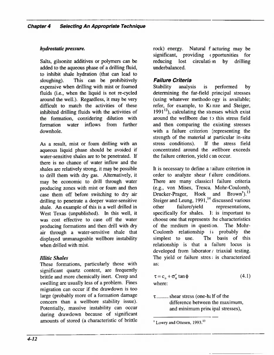
Chapter 4 Selecting An Appropriate Technique
hydrostatic pressure.
Salts, gilsonite additives or polymers can be added to the aqueous phase of a drilling fluid, to inhibit shale hydration (that can lead to sloughing). This can be prohibitively expensive when drilling with mist or foamed fluids (Le., when the liquid is not re-cycled around the well.). Regardless, it may be very difficult to match the activities of these inhibited drilling fluids with the activities of the formation, considering dilution with formation water inflows from further downhole.
As a result, mist or foam drilling with an aqueous liquid phase should be avoided if water-sensitive shales are to be penetrated. If there is no chance of water inflow and the shales are relatively strong, it may be possible to drill them with dry gas. Alternatively, it may be economic to drill through water producing zones with mist or foam and then case them off before switching to dry air drilling to penetrate a deeper water-sensitive shale. An example of this is a well drilled in West Texas (unpublished). In this well, it was cost effective to case off the water producing formations and then drill with dry air through a water-sensitive shale that displayed unmanageable wellbore instability when drilled with mist.
Illitic Shales These formations, particularly those with significant quartz content, are frequently brittle and more chemically inert. Creep and swelling are usually less of a problem. Fines migration can occur if the drawdown is too large (probably more of a formation damage concern than a wellbore stability issue). Potentially, massive instability can occur during drawdown because of significant amounts of stored (a characteristic of brittle
rock) energy. Natural facturing may be significant, providing ( Npportunities for reducing lost circulatil )n by drilling underbalanced.
Failure Criteria Stability analysis is performed by determining the far-field principal stresses (using whatever methodo ogy is available; refer, for example, to Kinze and Steiger, 1991’2), calculating the sti esses which exist around the wellbore due t 3 this stress field and then comparing the existing stresses with a failure criterion (representing the strength of the material at particular in-situ stress conditions). If the stress field concentrated around the Nellbore exceeds the failure criterion, yield c an occur.
It is necessary to define a 1 ailure criterion in order to analyze shear f ulure conditions. There are many classics1 failure criteria (e.g., von Mises, Tresca, Mohr-Coulomb, Drucker-Prager, Hoek and Brown ). Steiger and Leung, 1991 ,I4 discussed various other failure/yield represen tat ions , specifically for shales. I t is important to choose one that represents the characteristics of the medium in question. The Mohr- Coulomb relationship i 5 probably the simplest to use. Thc basis of this relationship is that a failure locus is developed from laborator 1 triaxial testing. The yield or failure stres 1 is characterized as:
t 13
z=c,+o’ , tan$ where:
(4.1)
z ......... shear stress (one-hz If of the difference between the maximum, and minimum princ ipal stresses),
- Lowry and Ottesen, 1993.13
- 4-12

o,'...... effective normal stress (average of the maximum and minimum effective principal stresses),
c,, ........ cohesion (intercept on a z - 0,' plot), and,
$ ......... angle of internal friction (angle of Mohr-Coulomb locus from the 0111 axis on a z - 0,' plot).
If the in-situ stress conditions are on or above this line (on a plot of shear stress versus normal stress) failure is predicted.
Risnes et al., 1982,15 and Bratli and Risnes, 198 1 ,I6 provided simple analyses for evaluating stress distributions and yielding of wellbores in saturated, elastic materials. Wang and Dusseault, 199 1 ,17718 presented a simple elastoplastic model. The analytical relationships in these publications form a good basis for approximating the wellbore pressures required to maintain mechanical stability. These computational approaches are described below.
Computational Approaches
Classical Elasticity Linear elastic theory (Bradley, 1979;19 Zoback et al., 198520) overpredicts the stresses near the borehole wall. It frequently indicates that almost any moderately competent sand or shale will have yielded, although field and laboratory evidence suggests that stability is in fact still maintained. Although these analyses are simple, they do not adequately represent non-linear behavior and frequently yield and failure are not discriminated. They often provide pessimistic estimates of stability - they are probably conservative.
Ramos, et al., 1994,21 demonstrated a simple
application of elastic theory. 'I his paper is important because it showed 1 )asic elastic formulations, indicated how the basic equations can be used on a w:11 which is oriented in the direction of a pri icipal stress which is not vertical (a horizontal completion was modeled), inc icated how fluid flow might be simply iicluded and described the role of core test ng and log analysis. Ramos et al., 1994 21 used the following elastic formulation:
/
9 The liquid, steady-statr pressure distribution was characterize i by:
(4.2)
where:
B ........ formation factor (bbl/sbb I), p(r) fluid pressure at a distanc e, r
(feet), from the center of the wellbore (psi),
Q ......-. flow rate per unit length sBPD/ft), p ......... viscosity (cP), k ....... I . permeability (md), a ....... -. wellbore radius (feet), pw .....". wellbore pressure (psi), 2 nd, 5 ......... units conversion factor (: 21.8).
> A critical flow rate was ca!culated, for steady state conditions, as:
C'nkc, cos$ Q5-- p l-sin$
where:
r........ units conversion factor (6.806 x
(4.3)
-- __ I__-
4-13
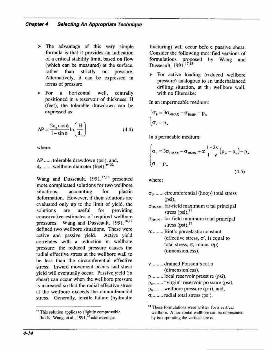
Chapter 4 Selecting An Appropriate Technique
9 The advantage of this very simple formula is that it provides an indication of a critical stability limit, based on flow (which can be measured) at the surface, rather than strictly on pressure. Alternatively, it can be expressed in terms of pressure.
9 For a horizontal well, centrally positioned in a reservoir of thickness, H (feet), the tolerable drawdown can be expressed as:
fracturing) will occur befo -e passive shear. Consider the following mot .ified versions of formulations proposed I)y Wang and Dusseault, 1991.'7*'8
> For active loading (rciduced wellbore pressure) analogous to : n underbalanced drilling situation, at th ; wellbore wall, with no filtercake:
In an impermeable medium:
=3<3HMAX -OHMIN -Pw
AP =
where:
AP ...... tolerable drawdown (psi), and, dh ....... wellbore diameter (feet).++ 22
(or = Pw (4.4)
In a permeable medium:
Wang and Dusseault, 1991,'7*'8 presented more complicated solutions for two wellbore situations, accounting for plastic deformation. However, if their solutions are evaluated only up to the limit of yield, the solutions are useful for providing conservative estimates of required wellbore pressures. Wang and Dusseault, 1991,'63'7 defined two wellbore situations. These were active and passive yield. Active yield correlates with a reduction in wellbore pressure; the reduced pressure causes the radial effective stress at the wellbore wall to be less than the circumferential effective stress. Inward movement occurs and shear yield will eventually occur. Passive yield (in shear) can occur when the wellbore pressure is increased so that the radial effective stress at the wellbore exceeds the circumferential stress. Generally, tensile failure (hydraulic
'' This solution applies to slightly compressible fluids. Wang, et al., 1991,22 addressed gas.
where:
0 0 ....... circumferential (hoo; 1) total stress
OHMAX . far-field maximum tc )tal principal
OHM^ .. far-field minimum tc tal principal
a ........ Biot's poroelastic co istant
(Psi),
stress (psi),$*
stress (psi),"
(effective stress, d, i s equal to total stress, CY, minus ap) (dimensionless),
v ......... drained Poisson's rat io (dimensionless),
p ......... local reservoir press1 re (psi), po. ....... "virgin" reservoir prt s u r e (psi), pw ....... wellbore pressure (p: i), and, or ........ radial total stress (ps ).
'' These formulations were writter for a vertical
-
wellbore. A horizontal wellbore can be represented by incorporating the vertical stre js.

> For an active state of stress, two other parameters were defined:
2c, cos 0 sa =-
l-sin+ (4.6)
> Assuming a Mohr-Coulomb failure criterion (Equation 4. 1), active failure can be predicted when:
> For an impermeable medium:
(4.7)
(4.8)
where:
psa is the minimum wellbore pressure that is allowable before shear failure is predicted (psi).
> For a permeable medium (with e l ) :
P s a = 1-2v 2-a-
1-v (4.9)
where:
po.. ...... far-field reservoir pressure (psi).
If these calculations are used tznd Psa > pw the wellbore is predicted to be at risk of shear failure.
Figure 4-1 is an example 3f tolerable pressures to avoid shear fa lure, based strictly on linear elastic anzlysis (using Wang and Dusseault's formuli tions). The reservoir simulated was assum1:d to have a depth of 5000 feet, O H M ~ = 4 0 10 psi, O ~ N
varied, po = 2165 psi (0.433 psirft), + = 35", and v = 0.25. The cohesion yraried. The figure indicates that cohesion i i a dominant parameter and every effort shodd be made to determine it. It also show; differences between permeable and mpermeable reservoirs. Wellbore pressure 3 below the predicted value (psa) indicate nstability in shear. These predictions will generally be conservative. Similar formu ations were developed for passive failure. ' The reader is referred to the cited papers.
Detournay and Cheng, 1988,23 have shown poroelastic formulations for creation of hydraulic fractures. This woul 1 be passive loading, with tensile failure.
> In a porous, permeable inedium, the breakdown pressure, Pi, can be approximated. Hydraulic f1 acturing and associated lost circulation re predicted to occur if the wellbore prer sure exceeds this value.
1-2v
where:
pb ....... the breakdown pressure (psi), and, To ....... tensile strength (psi).
4-15

- -- -- Chapter 4 Selecting An Appropriate Technique
7000
6000
5000
4000
3000
2000
1000
0
I-.. I I I I I Minimum Prlncipai Stress .. . 4000 Minimum Principal Stress .. . 3500 pa f Minimum Principal Stress ... 3000 pa I
Minimum Principal Stress ... 2500 ps I
--- .. -. \. \ -i---L--- - - .___ -.... \. Permeable
-_-.
0 200 400 600 800 1000 1200 1400 1600 l t00 2000
Cohesion (psi)
Figure 4-1. Minimum tolerable pressures to avoid shear fail' Ire.
P If no fluid penetrates the formation, the breakdown pressure can alternately be expressed as:
(4.1 1)
where:
pi .. . . ... . pore pressure at the borehole wall (behind a filtercake, if any).
Detournay and Cheng, 1988,23 also demonstrated the potential for time- dependent collapse occurring in conjunction with equilibration of pore pressure, after drilling.
Simple elastic stability apI mroximations are shown in Table 4-2.
Relationships such as th:se have been developed for deviated 1 vells. (Bradley, 1979,19 Brudy and Zoback, 1993;24 Mcknnan et al., 198925).
Even if a material has yielded and is deforming plastically, stres i is still carried by the post-yielded media. Catastrophic collapse or spalling may not necessarily yet occur. The calculatior s are further complicated by pore pressur ; changes due to transient flow. Wang and Dusseault, 199 1 b,'* presented quas -analytical re- lationships which can be u ;ed to represent the additional seepage force ; that act during flow into the wellbore.
-- 4-1 6

Table 4-2. Possible Formulae for Estimating Mechanical Stability
Failure Mode
Extensional (Due to FIow)
Active Shear
Active Shear
Passive Tension
(Hydraulic Fracturing)
Passive Tension
(Hydraulic Fracturing)
Permeable Impermeable 1 Formation Formation
d
d
d
d
Equation Equation Number
Q = - t'nkc, cos$
p l-sin$ (4.3)
Non-Linear Elastic Approaches (Pressure- Dependent Modulus and Damage Mechanics) Classical predictions. have usually assumed that the reservoir behaves as a linear elastic material, with failure being predicted by comparing the stresses at the borehole wall, calculated using elastic theory, with the peak strength of the rock. Recognizing the conservative character of these analyses, Santarelli et al., 1986,26 developed a closed-form solution for the stresses and strains around an axisymmetric wellbore in elastic rock, where the modulus was a function of the confining pressure. This model indicated:
9 The tangential stresses near t le wellbore may be much lower than predicted by elastic analysis, and,
9 The maximum tangential strt ss may not occur at the wellbore wall.
These impb that elastic analysec alone may be conservative. Non-linear el,a stic models and damage mechanics models (assessing microstructural degradation due. to stresses; refer for example to Pellegrino et al,, 199427) delimit a zone of reduced stre ses around wellbores and can even indicate :xtensional, circumferential failure. The bri ;is of these models (Santarelli, et al., 1986;' Nawrocki
4-1 7

- ---I-_
Chapter 4 Selecting An Appropriate Technique
and Dusseault, 199528) is to calculate the effective stress regime, with the added stipulation that Young’s Modulus is a function of the effective secondary minimum principal stress. The resulting stress field is compared to the failure criterion adopted to assess if yield has occurred. Preferably, non-constant pore pressure distributions away from the wellbore (at least transient and preferably steady-state as well) should be incorporated into the model to represent seepage forces and more realistic radial variation of effective stresses.
Elastoplustic Approaches These models predict a yielded zone around the wellbore, but they do impart some load- bearing capability to these zones and the wellbore may remain intact. Elastic-plastic models are an approximation of material behavior, but they do at least allow yield to occur. Numerical modeling is generally required, unless restrictive assumptions are adopted. Finite element models are usually used (Vaziri and Byrne, 199029; Wang, 199530). They have the advantage that, pending adequate knowledge of material properties and an expert to perform the analysis, various three-dimensional geometries, and assorted behavioral laws (creep, elastic-plastic, flow, non-isothermal, ionic transpo rt...) can be simulated. The relationships between the existing stresses and the associated deformations are governed by constitutive relationships. This is beyond the scope of this document. The reader is referred to Charlez, 1994;31 Ewy, 1991;32 Detournay, 1986;33 and, Veeken et a]., 1989.34
Chemo-Mechanical Models Some models have been developed, trying to integrate inflow, ionic diffusion and time-
dependent mechanical behavior. The calculations are usually c omplex, requiring numerical modeling and i i significant effort in determining material parameters. As Wong and Heidug, 19 !14 ,~~ stated, “the chemical effect results fro m modification of the strength of the structiiral and hydration forces operating between 1 :losely spaced (4 nm) and hydrated clay particles that accompanies invasion of water-based drilling fluids.” The mc idel described by these authors used an ertension of Biot’s poroelastic theory to ncorporate fluid chemistry and a modified rersion of Darcy’s law to accommodate o:motic flow. A similar, but simpler, tac :ic (incorporating hydration forces into the mechanical stress equations) has been propcsed by Bo1 et al., 1994 .9
Field Testing Surewaard et al., 1996,36 d scussed instability during underbalanced drill ng in a heavy oil reservoir in Oman. An ittempt to drill a horizontal hole with foan had met with wellbore instability proble ms in a different formation. Caliper data in the unstable shale above the target reservoir showed how the hole diameter changed wit1 I different degrees of overbalance. These indi :ated that the hole could enlarge considerably through this shale (they predicted a twenty-in ch diameter if the drilling was underbalancc d). A field trial was performed, in whic:h the proposed underbalanced drilling flu id was circulated through a 100 foot interv<d of hole, drilled through the formation (shzle) with the most potential for wellbore instal lility. Caliper logs showed the hole evolving -rom 8.2 inches to 20 inches in diameter, ovt r that period. In order to drill the reservoir underbalanced, an additional casing string would need to have been, set across the unstable shale. Eventually, it was decided that the in( remental costs of
4-18

this and other changes made underbalanced drilling uneconomic.
The dimulties in forecasting stability can be signijkant. Field calibration of predictions is oflen required.
An Example Even though elastic analyses are approximate (usually overestimate the minimum wellbore pressure for shear and underestimate the maximum wellbore pressure for hydraulic fracturing; except if natural fractures are present), they are useful for preliminary scoping of stability situations. Consider a vertical well with the following characteristics:
depth ............................................... 5000 feet O ~ A X .............................. .4000 psi (.8 psi/ft)
c, ....................................................... 1000 psi
po ................................... 2165 psi (.433 psi/ft) To ........................................................ 500 psi v ................................................................ 0.3
O ~ I N .............................................. unknown
9 ................................................................ 35"
Figure 4-2 shows elastic stability limits for shear and tensile failure, as a function of different values of the minimum horizontal stress, The intersection of the area beneath the hydraulic fracturing line and above the shear failure line is predicted to be stable. Bottomhole pressures should fall in this range for stable drilling.
Hydrocarbon Production Rate and Surface Pressures In some circumstances, the maximum hydrocarbon production rate that can safely be handled at the surface will enforce a lower limit on the borehole pressure that can be
tolerated.
For gas production, the pressure inside the surface system will be controllzd by the frictional pressure loss upstream ( d the flare. If the surface system incoqlorates an atmospheric mudgas separ itor, the backpressure must not exceed the imit set by the height of the liquid seal. Oth:rwise, gas may escape into the open liquids collection tanks, with potentially dangerous consequences. With a closed surf ice system, the backpressure must not iertceed the pressure limitation of the 1 nulti-phase separator vessel.
There will be maximum toleri.ble liquid production rates for both 2 tmospheric mudgas separators and for in mlti-phase, closed separators. The liquid retun I rate is the sum of the returning (drilling fluid liquid rate and the produced liquid rate. For :ither open or closed surface systems, an exce sive liquid return rate will cause ineff cient gas separation, with gas carrying ov:r into the liquids' collection tanks or liqu d carrying over to the flare.
In principle, surface equipmer t can be designed to handle almost any ( onceivable production rate. If the surface iystem can handle the production under abs olute open flow rate conditions, combined with the injected drilling fluids, the produi: :ion rate or surface pressures will not place: any lower limit on the allowable borehol z pressure while drilling. In practice, equipment availability will be a factor. It is IJ nlikely that it would be economic to ccsnstruct an oversizt:d surface system from scri tch.
Formation Damage Another limit to the tolerable drav idown may
--__I__-
4-19

Chapter 4 Selecting An Appropriate Technique
2000 2200 2400 2600 2800 3000 3200 3400 3600 380) 4000
Minimum In-Situ Stress (psi)
Figure 4-2. Variation of allowable wellbore pressure, estimated using I, near elastic theory, for an example 5000 foot deep well.
be the onset of formation damage caused by fines mobilization in the producing formation. Determining this limit is complex (and often highly inaccurate); involving the reservoir rock mineralogy, petrology, permeability, strength and formation fluid rheology, as well as the prevailing pressures. Laboratory experiments, using core under simulated downhole conditions, are probably the only practical way to estimate what drawdown can be tolerated before significant damage occurs.
Backpressure If the combined return rate of absolute open flow production and injected drilling fluid cannot be handled by available surface equipment, it is possible to restrict the production rate by taking returns through a
choke before entering a s eparation system. This imposed backpressure will increase the borehole pressure, which vi11 in turn reduce the rate of influx. The allowable backpressure is limited by tl le pressure ratings of the surface equipment upstream of the choke, the choke itself, the wellhead and the surface casing ,.. The lowest working pressure limit is almost in variably provided by the diverter system (Le., a rotating head or MOP) in use. RBOPs were developed specifically to increase tke ability to use surface pressure to control downhole influx while drilling.
When using compressible c rilling fluids, it is usually more cost effectiv: to switch to a higher density drilling flu d than to choke back the well. Applying a jackpressure will
4-20

increase the gas injection pressure. It will also increase the gas injection rate required for acceptable hole cleaning, when drilling with dry gas or mist. Both of these effects will increase the cost of the gas supply; air compressors, natural gas or nitrogen ...
It is usually possible to increase the borehole pressure by reducing the gas injection rate when a gasified liquid is used. Manipulating the surface backpressure is usually not necessary in this situation.
When drilling with foam, backpressure may be necessary to maintain the foam quality within acceptable limits throughout the wellbore.
The most benefit from choking back can be derived for liquid drilling fluids, in order to increase the borehole pressure. This is often done to control the rate of production during the latter stages of drilling a horizontal interval. It can permit continued use of simple drilling fluids, such as water, without incurring the incremental costs for a weighted drilling fluid.
Once the maximum tolerable surface pressure is reached, production rate can only be further reduced by increasing downhole pressure by increasing the effective density of the drilling .fluid.
Implications of Drilling Technique Select ion
9
9
9
P
Pore pressure gradients vary with depth.
Formation strength will vary with depth.
In-situ stresses will vary wit1 1 depth.
The tolerable stresses, partic ularly from a stability point-of-view arc? affected by the inclination and oritntation of deviated, extended reach ani4 I horizontal wells. The underbalance pressure at the onset of instability co~imonly de- creases as the hole angle inc reases.
Due to these various factors, it is often not possible to represent the boreh de pressure required to prevent instability with a single, simple pressure gradient. Also, a ; was shown in Chapter 2, the effective pressure gradient for a compressible drilling flu d increases with increasing well depth. 4 thorough assessment of the potential f )r wellbore instability for different underbala iced drilling techniques involves comparinl predicted/ calculated circulating pressures md limiting borehole pressures, at diffei ent depths throughout the interval(s) in ques ion.
Production rates depend on tl.13 length of reservoir that is open to the we'l'bore and on the underbalance pressure. The 1 nderbalance pressure (the drawdown) Ziving the maximum tolerable production rate will be smallest at TD in the reservoir. In vertical wells, the amount of undert dance will generally increase with incre: sing depth. This is not the case in horizon a1 wells. In these wells, frictional pressure 1 xses up the annulus will increase with mea ;ured depth, while hydrostatic pressures del lend on the true vertical depth. The circulat mg borehole pressure will be higher at the bit than at the start of the horizontal section. Since the

- Chapter 4 Selecting An Appropriate lechnique
virgin pore pressure will be nominally the same along the horizontal section, the underbalance pressure will generally be smaller at the bit than further uphole. As a result, the rate of production while drilling a horizontal well may not increase in direct proportion to the length of the horizontal section. Nevertheless, the total production should be greatest when the hole is at TD. From the point-of-view of technique selection, it is normally sufficient to confirm that the candidate drilling technique will not allow excessive production at TD.
Once the borehole pressure limits, corresponding to wellbore instability and excessive production rate, have been determined, a first pass evaluation of different drilling techniques can be performed by using the ranges of equivalent circulating densities (ECD). If the range of ECDs shown for a particular technique does not give a borehole pressure between the pore pressure and the higher of the wellbore instability and excessive production limits, that technique is unlikely to allow safe underbalanced drilling, without choking back the return flow.
This simple screening method is illustrated in Figures 4-3 through 4-5 (Examples 1 through 5), to follow. These schematics show the approximate ranges of borehole pressure achievable with various underbalanced drilling techniques, plotted against true vertical depth. These schematic plots (Figures 4-3 through 4-5) are for depths up to 10000 feet. There is no reason why underbalanced drilling should not be successful at depths well in excess of this. Note that the ranges of achievable pressures shown are only approximate. With lightened fluids and gases, the borehole pressure, for a given combination of injection rates, will not
increase linearly with depth It will increase more rapidly than this due to the compressibility of the gaseous phase, The lower limit for the boreho'e pressure when drilling with foam will alriost certainly be higher than that shown for d :pths in excess of 5,000 feet if the fluid is to .emain a foam to the surface. A single limiting ECD is used in these illustrations to avoid u idue complexity. In practice, computer sir iulation of the circulating pressures is e sential for any potential foam application at depths much greater than 5,000 feet.
Example 1 Figure 4-3 shows a shdlow, normally pressured (8.35 ppg or 0.43: psi/ft) reservoir. There are no wellbore ins1 ability concerns, from the surface casing point, at 700 feet, to TD, at 4,000 feet. The 1)roposed surface system can handle the ant cipated absolute open flow rate of the well. Minimal water inflow is expected. Since ;tability is not a problem, any gaseous or 1 ightened drilling fluid could be used, and tec hnique selection should be based principal y on economic analysis (and certain othe r considerations given in a Section 4.4). In practice, dry air drilling would probably be the most economic drilling technique Misting might be necessary to avoid mud--ing formation if slight water inflows are enco mtered. If water inflow becomes excessive, a stable foam might be needed.
Example 2 Figure 4-4 illustrates a hole interval from 2,000 to 6,000 ft which includes a depleted sandstone from 3,000 to 4,0( 0 feet. The pore pressure gradient in the depl :ted sandstone is 5 ppg (-0.26 psi/ft). Tt e pore pressure gradient above and below the sandstone is 8 ppg (0.416 psi/ft). Drillin ; conventionally with mud encounters sign ficant problems

4500
4000
3500
s 3000 a - a L
2500 9! a al 2000
1500
ln
- 0 r
m
1000
500
0
n / . . .;; .') Llquld
. I ' , I Pore Pressure /
Mist Gas .- Foam
0 2000 4000 6000 8000 10000
True Vertical Depth (feet)
Figure 4-3. Stability regimes for the well described in Example 1.
4500
4000
3500
% 3000 a 2
9!
v
2500 ln
a 0, 2000 0 S E
-
1500
lo00
500
0 0 2000 4000 6000 8000 10000
True Vertical Depth (feet)
Figure 4-4. Stability regimes for the well described in Example ; !.
4-23

- Chapter 4 Selecting An Appropriate Technique
4500
4000
3500
E 3000 z 2500
z - (u 2000
s? 2 1500
1000
v
a 0 r
500
0
Pore Pressure LImlt
Llquld
...- I Foam
I Mist Gas
4000 5000 6000 7000 8000 9000 l O o c 3
True Vertical Depth (feet)
Figure 4-5. Stability regimes for the wells described in Examples 3 through 5.
with lost circulation and differential sticking across this formation. The entire hole interval is comparatively stable, and mechanical wellbore instability is not anticipated, if the ECD is maintained above 2 ppg (-0.10 psi/ft). The depleted sand produces gas at low rates and the surface system can comfortably handle the absolute open flow. This hole could be drilled with foam, either stable or stiffened, or with a gasified liquid. In the latter case, high gas injection rates would probably be required; air would probably be the only economic option for the gasifying medium.
Example 3 The next example is for an interval that encompasses overburden and a reservoir. The pore pressure, gradient is equivalent to 8 ppg (0.416 psi/ft). This situation is shown in
Figure 4-5. There is a section of shale (from 6000 to 8000 feet) above th; reservoir (from 8000 to 9000 feet) in which it is estimated that a borehole pressure grad lent equivalent to 7 ppg (0.364 psi/ft) is required to avoid wellbore instability. The I eservoir itself is competent, and wellbore i nstability is not expected to be a problem un less the borehole pressure gradient falls belcw 5 ppg (0.260 psi/ft) equivalent. The reser voir is, however, prolific. By the time the taget TD (9,000 ft TVD) is reached, it is es imated that the maximum tolerable drawdoi m would be 500 psi. Assuming that the pon: pressure at this depth would be 3,744 psi (i e. 0.416 psi/ft x 9,000 feet), the minimum al owable borehole pressure would be 3,244 psi. This corresponds to 6.93 ppg (0.2 60 psilft). If the overburden is uncased wher the reservoir is drilled, the complete section requires that the
4-24

equivalent circulating density of the drilling fluid should be in the range 7 to 8 ppg, using a low density liquid, such as diesel or crude oil. Gasified water could also be used, but the t'zrget pressures are at the upper end of those normally developed when drilling with gasified liquids. For a gasified liquid, the volume fraction of gas required to maintain the borehole pressure gradient above 6.93 ppg (0.36 psi/ft) would not be large. It might not be possible to operate in the friction- dominated flow regime. Operating in the friction-dominated regime is preferable for controlling the borehole pressure. The possibility for drilling with a gasified liquid would require more sophisticated evaluation of the circulating pressures.
Example 4 Suppose that the maximum tolerable drawdown in Example 3 was estimated to be only 100 psi. This would set the lower borehole pressure limit at 3,644 psi (7.79 ppg) at TD. A drilling fluid formulated with diesel or crude oil would give pressures lower than this. Plain water would be too dense to give underbalanced conditions. This is little different from the situation in many Austin chalk wells, that have been successfully flowdrilled with plain water. In these Austin chalk wells, lost circulation has caused the onset of production and the hydrostatic pressure exerted by the mixture of water and formation fluid is sufficiently low that production has continued thereafter. If flow cannot be induced in this way, it may be possible to drill underbalanced with a light hydrocarbon drilling fluid and to choke back flow, to keep the production rate below the limits of the surface equipment. Any decision to drill like this would require detailed analyses of the circulating pressures, incorporating produced fluids and the surface system capacity, to confirm that this
techniq,ue could be safely ir Iplemented. Experience with flowdrilling in iffset wells might provide sufficient conf dence that production rates would not beconi 5 excessive.
Example 5 A final example is a further malification of Example 3. Suppose that the rtservoir had been depleted to a 6.5 ppg (C.338 psi/ft) equivalent gradient. If the maximum tolerabfe drawdown remained at 500 psi, the tolerable range for equivalenl circulating density through the reservoir W O L I ~ be 5.4 to 6.5 ppg. A gasified liquid would be required. This would not provide sufficien: support to avoid wellbore instability in the shale above the reservoir. It would be necessary to set casing at the top of the reservo r to drill it underbalanced. This would cert : inly impact the drilling economics.
When evaluating highly productive formations, more detailed numeri ;al analyses of circulating pressures are requi .ed than the simplistic ECD considerations described above.
> Computation of borehole pr:ssures and praduction rates, for differ :nt drilling fluid injection schemes, i ; complex. Formation fluid inflows inter x t with the drilling fluid to change t te borehole pressure. This in turn leads to changes in the inflow rate. When c rculation is stopped to make connection^ or to trip the string, produced fluids 'vi11 tend to lift the remnant drilling flu d from the annulus. This changes tk e borehole pressure and the production r zte.
> Choking back the well retiims further complicates calculation (1 F borehole pressures and production rates. If the drilling fluid is incompn ssible, the choked back circulating pres sure will be

Chapter 4 Selecting An Appropriate Technique
the sum of the circulating pressure at that depth, without the backpressure, and the imposed backpressure.. If the annular fluid contains any gas, compressibility normally causes the borehole pressure to increase by more than the imposed backpressure. Determining borehole pressure and production rates for different fluids, rates and backpressures normally requires computer simulation.
9 It is inevitable that there will be uncertainty in simulator input parameters. Sensitivity of the predictions to variations in these input parameters is required. In many circumstances, the overall uncertainty in the input parameters can be so great that the effort required for repeated computer-based simulations may not be justified, at least for technique selection.
Water Production
The flow of formation water into the borehole can influence the selection
Production of even small volumes of water can make dry gas drilling difficult. A mud ring can form as damp cuttings collect, usually at the top of the BHA where the annular velocity is lowest. It is common to switch to mist, or even foam, if a water inflow is encountered. When onset wells indicate that formation water inflows are probable, the operator should not expect to drill below the water producing zone with dry gas.
When misting, higher air injection rates are required to lift the water from the hole. The air rate must be sufficiently high to prevent
slug flow. Slug flow can damage the borehole and surface equip ment. The high air rate, in combination with t ie weight of water in the annulus, significaitly increases the standpipe pressure. Bc bosters are often needed to increase the ga; delivery pressure when substantial watc :r inflows are encountered. More con pressor power is required. If nitrogen or nilturd gas are used as the gas phase, the gas I upply cost will be greatly increased.
Certain wells can tolerate 1, lrge water influxes and slugging, during mist drilling. Surface holes have been drilled n Terrel County, Texas, with water flows Teater than lo00 BPH. Since the water \{as fresh, surface disposal was approved. Ir central Australia, fresh water flows into riist drilled wells occurred at 2000 BPH. Su rface disposal was also possible here. In both of these cases the wellbores were stable enc ugh that slugging was acceptable.
It may not be feasible to lift large volumes of water from the well by niisting. At some stage, the additional gas njection rate and pressure required become i npractical. When this occurs, foam is prefer tble. There is no unique water inflow rate E bove which foam drilling is preferable t i misting. The appropriate time for chang: ng fluids depends on the availability of additional air compression power when drilling with air mist, and on the cost of thc gas supply when drilling with other gases. Since other gases, such as nitrogen or naturil gas, are much more costly than compresse air, misting with these gases at lower rates is less economic than drilling with air mist.
Hole size also influences tfe impact of water inflow on required gas i ijection rate and
4-26

pressure. Increased cross-sectional area reduces annular velocity and hole cleaning efficiency, although large holes can usually produce more water before the gas injection pressure becomes impractically high.
Carefully managed foam can lift considerable volumes of water from a well - as much as 500 BWPH has been reported by Shale, 1995.37 When large water inflows are anticipated, dry gas or mist drilling may not be appropriate, even if wellbore stability and hydrocarbon production rates indicate that these drilling fluids would be nominally acceptable.
In many locations, the cost of waste water disposal precludes mist drilling. Foam may or may not be an alternative. Since borehole pressures will tend to be somewhat higher when foam is used instead of mist or dry gas, the water inflow rate will probably be somewhat lower. The reduction in inflow rate from normally pressured aquifers will not, however, be dramatic and disposal volumes may not be substantially different. For example, the formation fluid pressure at 4,000 feet in a normally pressured reservoir will be approximately 1,750 psi. Mist drilling might generate a borehole pressure of 50 to 100 psi before any water inflow (assume 75 psi for illustrative purposes), whereas a pressure in the range 500 to 1,000 psi might be developed when drilling with foam (assume 750 psi for illustrative purposes). Using these wellbore pressures, the underpressure (drawdown) with mist would be 1750 - 75 = 1,675 psi (not considering any borehole pressure increase due to produced water) and 1750 - 750 = 1,000 psi for foam. This example suggests that the water inflow rate with foam would be expected to be roughly 60% of that when drilling with mist (presuming Darcy flow with the inflow rate
proportional to the drawdown). However, higher liquid injection rates are used in foam drilling. Considering these co npensating factors (higher pressure but greate . base fluid load), the volume of waste watx is often fairly similar for the two diffennt drilling techniques. When water disp mal costs prevent mist drilling, it is unliketi that foam drilling will be more cost effective
In situations where water productit )n rates are too high for mist or foam drillinj;, the main alternatives are to drill underbal lnced with aerated liquids or low density licuids, or to mud up and drill overbalanced. In some instances, it is possible for a well to make water when drilled underbalz nced (for example, with dry air) and to lose circulation when drilled with liquid. In such 3 case, it is worth considering drilling with d y air until the reserve pit is filled, switching to drilling with the produced water until the ’eserve pits are depleted and then switching liack to dry air. There are only a limited number of applications where this may be ~ossible. It has been cost effective in the Blzck Warrior Basin (Graves et al., 199638). Tliis practice should only be attempted when the operator is confident that the uncertainties of drilling “blind” can be tolerated w’ ien water circulation is lost.
Multiple Permeable Zones
If all zones are to be drilled unierbalanced, the circulating pressure must satisfy the borehole pressure requirements f t )r all open, permeable zones, simultaneous11 . Several
4-2 7

--. Chapter 4 Selecting An Appropriate Technique
factors can prevent this from occurring. For example:
9 The equivalent circulating density of compressible drilling fluids increases with increasing depth along the hole.
k In vertical wells, it is possible for a permeable zone close to the bit to be overbalanced when a permeable zone higher uphole, with the same pore pressure gradient, is underbalanced.
9 In highly deviated and horizontal wells, the effect may be more pronounced. The annular pressure drop increases with distance along the hole whereas the pore pressure increases with vertical depth. Particularly in horizontal hole sections, the borehole pressure at the bit can be markedly higher than at the start of the horizontal section, even though the formation pore pressure is the same throughout the section.
9 There may be changes in the borehole pressure gradient along the wellbore, either due to overpressure or due to production from another zone(s). Deis et al., 1995,39 cited an example where a horizontal well in a compartmentalized reservoir, penetrated one portion of the reservoir overbalanced and a second portion underbalanced.
The major concern when drilling underbalanced with more thim one permeable zone open to the wellbore is the potential for an underground blowout. In an underground blowout, formation fluid flows uncontrollably from one permeable formation into another formation uphole, rather than up to the surface and out of the well. If the borehole pressure is lower than the fomiation pressure in all open, permeable zones, formation fluids will flow from all zones into the borehole and
there will be no crossflow from ,one zone to another. Care should be t: ken to ensure that changes in borehole pressu -e, occurring when circulation is suspended f 3r connections or tripping, or when the well is shut-in, do not allow crossflow to occur. If this cannot be guaranteed, the consequenc es of charging the formations uphole with for nation fluids from downhole must be assesscd carefully. The impact is likely to be m x e serious when drilling through gas-produc ing formations. If crossflow cannot be toleiated, the options include:
9 Using a different drilling technique that allows all permeable zones to remain underbalanced (if suck a technique can be identified),
9 Killing the well btfore suspending circulation (this may d efeat the purpose of underbalanced dril' ing for reducing formation damage), or,
k Changing the casing s( heme so that the upper formation(s) are cased off before penetrating the lower z( ,ne(s).
Whether drilling under- o overbalanced, it must always be possible to mud up to kill the well, without losing circuli tion or fracturing the formation. This may no be possible if the formation fluid pressun in an open permeable zone is greater tl an the pressure at which circulation is lost iito another open zone or at which some portion of the openhole can be fractured. Correct selection of casing points will preven this situation. (It should only occur if the pore pressure or fracture gradients are sign ificantly different from those assumed when c esigning the well. If this does occur, a well control program must be implemented). Tiis problem does not occur exclusively wher a well is drilled underbalanced. The same : ituation can arise if a well is drilled convent onally, with mud
4-28

in the hole.
Sour Gas
The potential for producing h3ydrogen sulfide to the sugace always needs to be
considered when selecting a drilling
There must be no possibility for hydrogen sulfide to be released into the atmosphere while the well is being drilled or completed. Beyond being extremely toxic, hydrogen sulfide (HzS) is also combustible and very corrosive. If any is produced during drilling, it should be discharged into a suitable flare. This can, in principle, be done safely if the drilling system is a dry gas or mist and if all returns from the well are flared at the discharge end of the blooie line.
Gaseous hydrogen sulfide can become entrained in any liquid phase in the drilling fluid. At the surface, it must be separated from produced and returned liquids Conventional mud/gas separators and open liquid tanks should normally not be used if hydrogen sulfide bearing formations are to be drilled underbalanced. The separation process must be completed in a closed vessel, with all separated gas being routed to a suitable flare. Otherwise, hydrogen sulfide may be released into the atmosphere. The requirement for controlling hydrogen sulfide release effectively mandates thle use of a closed surface system, if there is any possibility of producing sour gas while drilling.
Sour gas can also become entrained in a foamed drilling fluid. Complete separation of a foam into its constituent gas and liquid phases can take a considerable time - hours - if no measures are taken to kill the foam.
Unless eflective defoaming guaranteed, foams cannot be
can be used with
closed systems and, as a rerult, foams should not normally be used W A en sour gas may be encountered.
Operators and all rig site penonnel must adhere to all appropriate pegulutions. Appropriate safety precau tions are essentiul.
Drilling 1 Reservoir Fluid lncompa tibility From time to time, it can be diffixlt to avoid temporarily creating overbalance 1 conditions in a well drilled with a gas fied liquid, particularly when making coni ections and trips. Temporary overbalance is tlso possible when drilling with a low-density liquid if, for example, a gas-producing well i s shut in and gas is allowed to migrate up the v .ell.
This is a problem because steps re normally not taken to improve the fluid 10;s properties of underbalanced drilling fluids Mud cake will nominally not be deposited on the borehole wall when the well is underbalanced. In fact, formatio I fluid flow, into an underbalanced wellbore, will tend to remove any solids (for example d rilled solids) remaining from previous transient overbalanced interludes. Consec uently, flow of liquid from the drilling fli id into the formation is unlikely to be res ricted when overbalanced conditions (uni ntentionally) occur. There is also the pcssibility for counter-current imbibition of the liquid phase of the drilling fluid into the rltservoir, if a water-wet reservoir is below it ; irreducible water saturation or an oil-wet reservoir is below its irreducible oil saturation. Presuming periodic overbalance or counter- current imbibition, it is important to ensure that the drilling fluid's liquid phase is
~
4-29

Chapter 4 Selecting An Appropriate Technique
compatible with the formation when a liquid or a gasified liquid is used to drill through the reservoir (Bennion et al., 1995a;5 Surewaard et al., 1996;36 and Deis et al., 199539).
Laboratory testing can help to formulate an “inert” fluid system. Simple index tests (for example, capillary suction testing) can be performed, or, alternatively, cores from target formations can be exposed to candidate drilling fluids, under pressure regimes that are representative of conditions that might be experienced while drilling and completing the well (Bennion et al.,1995a,’ Deis et al., 199539).
It is very unlikely that overbalanced conditions will occur in a well that is being drilled with foam. Counter-current imbibition could cause the aqueous phase of a foamed drilling fluid to enter the formation, although there are no reports of this having happened. Therefore, there is probably less need for comprehensive core evaluations, unless some form of foam block is possible.
Evaluating drilling fluid compatibility is probably unnecessary if dry gas is to be used as the drilling fluid or if only the overburden is to be drilled underbalanced (unless chemo- mechanical degradation is an issue).
Hole Geometry Hole geometry can influence selection of an optimized drilling fluid in several different ways.
9 As has been discussed, the equivalent circulating density of compressible drilling fluids increases with increasing depth. A gasified liquid, with an ECD of 2 ppg at 2,000 feet, can develop an ECD of 5 ppg at 6,000 feet (refer to Figure 2- 41). In other words, a fluid that would
9
P
P
give underbalanced c( lnditions at one depth may not be ;~ble to provide comparable underbalanl :ed conditions at a greater depth, when 1 he pore pressure gradient is the same.
Annular gas injection mly reduces the density of the fluid c( lumn above the injection point. Since tl le injection point is at or just above the shoe of the last string of casing, it is not possible to develop a low ECD at the bottom of a long vertical section, P ith annular gas injection. Drillpipe gas injection may be necessary if long vertic 11 sections are to be drilled with gasified iquid.
The increase in ECD with increasing depth means that it cai be difficult to maintain acceptable fot rrn quality from the hole bottom to thc surface, during deep drilling with foan . Backpressure may be required to m,iintain the foam quality up the annulus 1 vithin limits that permit adequate hole cleaning. This increases the gas SUPF ly requirements, and can make foam unattractive for drilling at great depth. However, foam has been used satisfac orily to drill to 15,000 feet (Dupont, 198440) - the limitation is more economic than technical.
The effect of increasing hole diameter on hole cleaning efficiency is a major consideration. The dr lling fluid flow rate, required to achievt a given annular velocity, increases in ~roportion to the annulus area. Good clt aning in a 17%- inch diameter hole ti pically requires circulation rates that ai e approximately four times greater thosc required for an %&inch diameter hol: to the same depth. This geometric :ffect can restrict the use of those drillin,; fluids that rely on high annular ve ocity for hole

cleaning. This means that high viscosity drilling fluids can become more attractive as the hole diameter increases. Foams, particularly stiffened foams, and gasified muds are often the preferred fluids for drilling holes with diameters of 17%-inches and larger.
9 When drilling large diameter holes, the pressure capacity of diverter equipment, capable of passing large diameter bits, may restrict the choice of drilling technique to those that do not require any significant backpressure. RBOP's with through bore dimensions of eleven inches (up to 6.75 inches with the kelly packer in place) are off-the-shelf items. Additional sizes may be available.
When drilling with dry gas, reverse circulation can provide good cleaning in large diameter holes, without unacceptably high gas injection rates. This technique is described in Chapter 2, Section 2.1.7. It does require special surface equipment and cannot, at this time, be regarded as an established, routine, drilling technique. It may, nevertheless, be an option for drilling large diameter holes with very low borehole pressures.
There are appreciable technical limitations on directional drilling equipment suitable for underbalanced drilling. In particular, mud pulse telemetry MWD systems ccmnot operate with a compressible drilling fluid in the drillstring. Liquids, or liquids gasified by annular injection, are the only underbalanced drilling fluids that can be used with a mud pulse MWD system. Other MWD systems or procedures can be used for liquids gasified through the drillstring. Underbalanced drilling in directional and horizontal wells is discussed in more detail in Chapter 6.
Naturally Fractured Format ions Stable foam (stiff foam is even tetter) can be used at much lower annular vclocities than other underbalanced drilling flu ds. Beyond cleaning performance, reduct d wellbore erosion is sometimes cited as a benefit of foam drilling. However, in cor ipetent rock, there are few applications whei e significant erosion is likely if other 11 iderbalanced drilling fluids are used. This m iy not be the case when drilling through natur dly fractured formations. In fractured fonr ations, high viscosity drilling fluids, circul, iting at low annuliu velocities, can be t eneficial in controlling borehole enlargemei it (Santarelli et al., 199241). For this reaso 1, stiff foam may be a preferred candidate for drilling underbalanced through natura ly fractured formations. The high viscosity a nd good hole cleaning capacity of a stiffened fi )am will also help lift fragments of naturally f *actured rock that may have spalled off during, jrilling.
Logistics Logistical issues, associated with certain locations, can often influence what fluid system is selected. For exaniile, in some desert locations, water supples may be restricted and/or very expenshe. In these environments, a drilling technique that minimizes water requirement: would be preferTed. A stiff foam m iy be more economic than its stable counte part because (refer to Chapter 2, Section 2.6) t can be used at lower liquid injection rat( s. Drilling techniques that permit re-circul: tion of water would also be desirable.
Availability and access also nfluence the choice of the gaseous phase foir compressible drilling fluids,. as well as wellsi .e equipment. Cryogenic nitrogen is generall! uneconomic in a remote location. Natura gas can be attractive when drilling in a , ;as-producing
4-31 -

_I__-
Chapter 4 Selecting An Appropriate Technique
field, particularly if local gas gathering and processing facilities can recover some of the gas used.
The specific location type is a consideration. Offshore operations can generally accommodate much less supplementary surface equipment than land-based operations. The equipment that is used in underbalanced drilling operations onshore may not be suitable for use offshore. New, underbalanced drilling equipment is becoming available for offshore deployment (particularly closed systems). Nesa et al., 1995,42 reported on some of these developments, designed to comply with the relevant authority's requirements for offshore application. These modular drilling systems would be closed. Generically, the main components are an RBOP, a customized choke manifold, a well fluid processing unit (separators, drilling fluid tank with degasser equipment ...), a nitrogen injection unit and monitoring equipment.
The high cost of new offshore drilling operations and production facilities means that these fields must be extremely productive if they are to be economic. This makes them unlikely candidates for drilling with dry gas or mist. However, in mature, offshore fields, there are situations where the infrastructure platform and pipeline systems are in-place, have been amortized and production is declining. These will provide future opportunities for assorted, underbalanced drilling technologies.
4.4 Economic Analysis
Introduction The use of an underbalanced drilling technique is driven by different considerations in different applications. For
example, drilling cost redu:tion is the only justification for drilling underbalanced through an interval t f unproductive overburden. However, if thc re is a possibility of productive zones withir the overburden (that are not easily recolnized on logs), underbalanced drilling car identify these. Drilling a pay zone underialanced will be justified if the total cost to 1 Iring that interval onto production is lower thin it would have been for conventional drillin 5 methods. Even if the well cost is increfied by drilling underbalanced, in many in, 'lances, avoiding formation damage can inc -ease production rates sufficiently that the ne1 present value of the well is increased despit its higher cost. On the other hand, if the productive formation is not susceptible to drilling- induced damage and ther: are no other potential zones to be evaluated, underbalanced drilling must reduce the well cost.
When evaluating drilling tecl iniques that have not been used previously in a particular region, there is uncertainty n predicting the factors that influence costs; such as penetration rates. It is ofter useful to assess how sensitive any predict:d benefit, i.e., reduced well costs or an increase in net present value, is to the variaus assumptions made in its prediction. It can also be useful to determine how much pen :tration rate or productivity has to ircrease if an underbalanced drilling tecl-nique is to be economically beneficial, compared to conventional drilling; and then to decide whether or not that represer ts an achievable target.
Variations in cost and 1 mductivity are inevitable, even when adj icent wells are drilled with nominally ider tical techniques and procedures. Statistical i nalysis can help
4-32

to compare the cost performance of wells drilled using different techniques. If performance increases are not large, it may be necessary to drill a number of wells with each technique before any firm conclusions can be drawn about their relative merits.
Testimonials 9 Anderson, 1971,’ was an early proponent
of foam drilling, in Arctic locations where foam’s insulating properties minimized thermally-induced hole enlargement.
0 “Cost of drilling in this remote area with mud was calculated to be $227/hr. Cost of drilling with stable foam was $275/hr, but resulted in two and one-half to three times more hole [per hour].”
“It is estimated that the use of stable foam on the second well resulted in a savings of $12,000, even after allowing for the cost of transportation and standby time due to weather.”
“Another operator drilled in this area using straight air. He had good penetration rates without excessive hole enlargement, but air requirements were five times those used with stable foam. On a 16- hr/day operating basis, the costs [daily] for air drilling would be $915 as compared to $468 for stable-foam drilling. The transportation cost in and out of this remote area would, proportionately, favor stable foam since it requires only two units [compressors] as compared to six units for air drilling.”
9 Anderson, 1984,43 advocated that
0
0
9
9
recycling of foam on longterm foam drilling operations can improve economics significantly. Sat. rings of 25 to 50 percent in foaming agent and additive usage were claimed. (Defoaming agents cannot be used if the foam system is to be reclaimed). Anderson also cited that f c ams could improve the economics of re( ompletions in situations where fluid loss is a severe problem in underpressured reservoirs. “Surveys indicate th i .t foam recompletions showed a 3 1 to 50% savings over new well costs and reduction in formation dama ge resulted in a 33% gain in oil produ:tion when compared to new wells dilled with mud.”
Bentsen and Veny, 1976,44 also found drilling pay with pre-formed, ;table foam was advantageous:
Mud costs were reduced.
“Time-consuming conver tional DST procedures and costs werc eliminated by providing a system that gave a continuous formation evaluation during drilling.”
Immediate and accurate formation evaluations were PO ;sible by eliminating damage and tie need for lengthy, expensive formal ion cleanup operations.
Formation damage was less and completion costs were 5 ignificantly reduced.
Comeau, 1995,45 presented nformation from carbonate reservoirs:
0 “In carbonate reservoirs, treatments can be effective to dissolve solids that are plugging the forrr ation [from
- 4-33

Chapter 4 Selecting An Appropriate Technique
overbalanced drilling]. In sands, fewer effective treatment options are available. The cost for such a service ranges from $100,000 to $300,000 Canadian dollars depending upon the length of the well and the type of treatment required.”
> Crearar, 1995,46 stated:
“The Welton and its satellite fields are exploited by 36 producing wells. Of its typical daily production of around 3000 BOPD 40% of this is currently produced by the five side- tracked wells drilled in the last two years. The two wells which were drilled underbalanced produce 40% of the side-tracked wells’ production and 15% of the total field production .”
9 Cummings, 1 987,47 discussed advantages of natural gas drilling in the San Juan Basin:
“Natural gas drilling in the Basin Dakota field near Blanco, New Mexico has eliminated lost circulation potential and has increased penetration rates over conventional mud drilling techniques. Refinements in drilling programs have helped reduce drilling costs which are 20-30% less than mud drilling in lost circulation areas. ’ ’
> Deis et al., 1995,39 described drilling operations in western Canada. Underbalanced drilling was definitely advantageous in the Weyburn area (refer to Table 4-3).
0 “It has been observed, especially in the Weyburn project, that
underbalanced dril ling methods can be employed lot only cost effectively, but cin even improve drilling con litions and performance.”
“Penetration rates in the horizontal section averaged I lightly below 20 m/hr in the overb(i1anced wells and 25 m/hr in the untlerbalanced wells. Also, hole conditio i appears superior in the underba1anc:d wells. This is apparent in that iole conditioning trips are required on occasion to reduce drag only 01 I the overbalanced wells.”
“The overbalanced wells require that each lateral be soiked in a bleach solution to removc filter cake after drilling has been zompleted. This process requires re -entering the first lateral. Re-enterir g laterals after a trip has not been a common problem on the underbalancc :d wells.”
> Mullane et al., 1995,48 provided supplementary infon nation on the Weyburn field. They indicated that if acid stimulation is relluired to remove skin damage in recently drilled overbalanced wells, hese wells cost more on average than ‘he underbalanced wells. They also citec situations where the advantages of unde rbalanced drilling were not clear. In thl: Westerose area, the incremental :ost to drill underbalanced is approximately $100,000 (Canadian). ‘ The gas produced while drilling was found to be approximately three tir ies that produced during drill stem test:’ on offset wells that were drilled overkalanced using gel chem or extended gel mud systems.” However, these well; needed to be
4-34
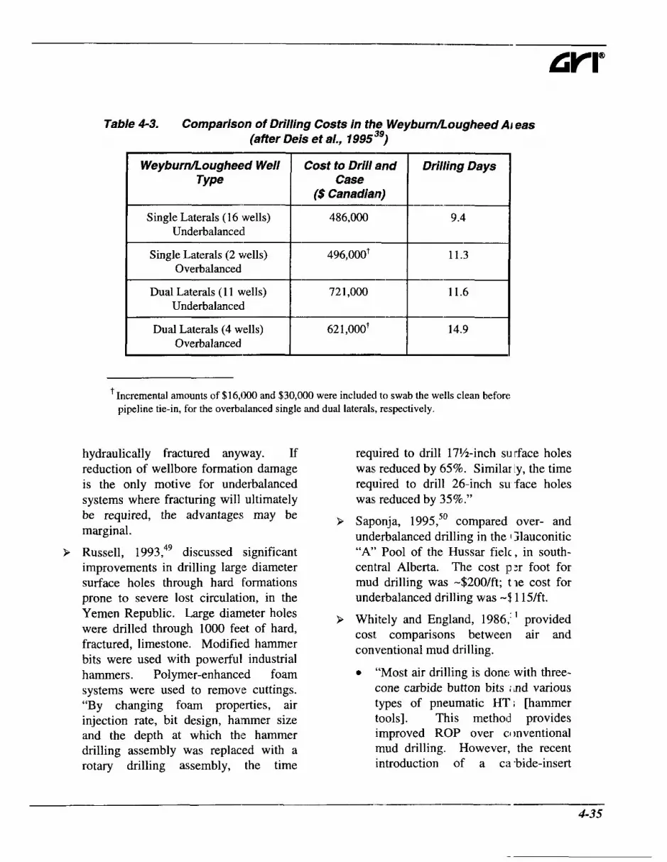
Table 4-3. Comparison of Drilling Costs in the WeyburnLougheed Ai eas (after Deis et al., 199599)
WeyburnLougheed Well Type
Cost to Drill and Case
($ Canadian)
Drilling Days
Single Laterals (16 wells) I Underbalanced 486,000 9.4
Single Laterals (2 wells) I Overbalanced ~ zz I 1 1 *
l l . I-
Dual Laterals (1 1 wells) Underbalanced
Dual Laterals (4 wells) I Overbalanced 62 1,000’ I 14.9
‘Incremental amounts of $16,000 and $30,000 were included to swab the wells clean before pipeline tie-in, for the overbalanced single and dual laterals, respectively.
hydraulically fractured anyway. If reduction of wellbore formation damage is the only motive for underbalanced systems where fracturing will ultimately be required, the advantages may be marginal.
> Russell, 1993,49 discussed significant improvements in drilling large diameter surface holes through hard formations prone to severe lost circulation, in the Yemen Republic. Large diameter holes were drilled through 1000 feet of hard, fractured, limestone. Modified hammer bits were used with powerful industrial hammers. Polymer-enhanced foam systems were used to remove cuttings. “By changing foam properties, air injection rate, bit design, hammer size and the depth at which the hammer drilling assembly was replaced with a rotary drilling assembly, the time
required to drill 17%-inch si^ rface holes was reduced by 65%. Similarly, the time required to drill 26-inch SLI face holes was, reduced by 35%.”
Saponja, 1995,50 compared over- and underbalanced drilling in the 1 Yauconitic “A” Pool of the Hussar fielc, in south- central Alberta. The cost p:r foot for mud drilling was -$200/ft; tie cost for underbalanced drilling was - 9 115/ft.
Whitely and England, 1986,‘ ’ provided cost comparisons between air and conventional mud drilling.
0 “Most air drilling is done with three- cone carbide button bits : nd various types of pneumatic HT; [hammer tools]. This method provides improved ROP over C:I mventional mud drilling. However, the recent introduction of a ca -bide-insert
4-35

Chapter 4 Selecting An Appropriate Technique
FPB/HT [flat-bottomed bithammer tool] has dramatically improved ROP over the three-cone bits and HTs previously used.”
“The average cost per foot for a 12%- inch hole was reduced from $35.48 to $18/ft - a 49% reduction.”
> Westermark, 1986,52 published figures for a situation where parasite string aeration was used as the lightening technique. The average cost per foot without aerating was $145/foot. While drilling with a parasite aerating string, the average cost was $67/ft.
0
Factors Affecting The Economics of Underbalanced Drilling As the previous testimonials have shown, underbalanced drilling may be justifiable on the basis of lower drilling costs, on higher drilling rate and lower completion cost, with increased productivity and reserves. Each case needs to be evaluated individually to determine whether underbalanced drilling is technically and economically feasible. The factors controlling the overall drilling economics are summarized below. Many of these factors have been addressed in previous chapters. Some ;are restated here for completeness.
Penetration Rate The variables affecting penetration rate include the drill bit, the bit weight, the rotary speed, as well as the bottomhole cleaning and mud properties.
Bit Selection This will be discussed further in Chapter 5. Some general remarks are pertinent. Fear, 1 996,53 discussed methodologies for optimizing bit selection and the drilling program in general. For example, the
influence of bit design or ROP; with PDC bits, probably only be( omes significant when the type of drilling f uid and rock lead to bit cleaning problems o * when the cutters become worn. For roll1:r cone bits, the evidence suggests that v y i n g the jet nozzle arrangement may or may n 2t influence ROP, depending on efficiencj of bottomhole cleaning.
Generally, using air instea 1 of conventional mud allows drilling highcr footage per bit and decreases the number of trips per well. In a fairly deep well, the rig time savings from this could be substantial.
Bourgoyne, 1995,54 indicat :d that “air or gas drilling can be used fo- intervals of a borehole that have a high rt )ck strength and a very low permeability, such that the borehole will not col1ap;e and the well cannot flow. The drilling -ate possible with air or natural gas is usuall:‘ at least twice as fast as that with clear wat :r and four times as fast as that with mud.“ The economic counterbalance is that mu1 .iple compressors may be needed to provide the necessary air pressure and flow rates. Also, small amounts of formation hyc rocarbons mixed with compressed air can >e explosive and spontaneous combustion ‘an occur down- hole. Further, if water i ; produced, mist drilling may be required. “Drilling rates with foam are generally 1 :ss than with air but more than with watx or mud. De- pending on the capability >f the formations to produce water, a mist-’ype flow pattern could be more economical han foam.”54
During air drilling, d amond-enhanced hammer bits, with diamon l-coated tungsten carbide inserts, offer ii nproved cutting structure wear resistance. These bits have improved bit life and peretration rate and
4-36

have reduced the cost per foot in the Arkoma and Appalachian Basins (Reinsvold et al., 198855).
Bit Weight and Rotary Speed For many formations, an increase in bit weight and rotary speed will increase the drilling rate. The relationships depend on specific bit types and the forma.tions being drilled. In general, the footage that a bit can drill tends to decrease with increasing rotary speed. Simple formulations are available for assessing optimum conditions. Moore, 1974,56 provided a concise and under- standable discussion. Beyond wear, increase in drilling rates must be tolerable, in order to provide adequate hole cleaning. Main- taining adequate hole cleaning capabilities strongly affects the logistics of under- balanced drilling. For adequate cleaning, sufficient bottomhole velocity and/or viscosity is required and may require optimization of the bit type.
Mud Weight Beyond formation damage issues, mud weight reduction probably is the greatest advantage of underbalanced drilling systems. An increase in mud weight will decrease the drilling rate. There may be limiting situations in some shales where increasing the mud weight beyond a certain level does not cause significant change in the rate of penetration. Figures 4-6 and 4-7, from Moore, 1 974,56 illustrate this premise. “In both of the series of the field tests in Figures 4-6 and 4-7, the degree of improved performance occurred primarily because the hydrostatic pressure was less than the formation pore pressure.”
Cost reduction, by minimizing lost circu- lation, is a very important consideration in evaluating an underbalanced drilling program.
Completions and Stimulatic In Underbalanced drilling is of1 en merited (technically and economically) f it reduces formation damage, hole pro ilems, and reduces costs of stimulation or cleanup programs in moderate or high iermeability or fractured formations. If ur derbalanced drilling is used to avoid format on damage, the total drilling and completim program should be designed so that the well will never have to be killed, prior to Ieing put on production. Mitigation of forma :ion damage in formations which will meed to be hydraulically fractured (except if naturally fractured) may be a poor and unnecessary economic decision.
Also, in certain circumstances, iigher grade surface casing may be required, ilthough the potential for underground 1 )lowout in shallow situations is probably rr ore strongly controlled by the formation breakdown pressure. Pipe grade should also be a consideration in flowdrilling : nd mudcap drilling or if corrosive fluids i3.e expected. The opposite situation is also rue, as was discussed by Grace, 1975.’7 “In the Anadarko Basin of the Texas Pl nhandle and western Oklahoma, the Morraw sands of Pennsylvanian age can be abnormally pressured while shallow foil nations are almost always subnormally pre sured. The routine practice in the early 1560’s was to set an intermediate string of casi ng on top of the Morrow interval in or& r that any abnormal pressure might t e properly controlled. This practice, comli ned with the stratigraphic nature of the Mc rrow sands, resulted in unacceptable economics. Consequently, operators ai d drilling contractors adopted the practic : of drilling into the Morrow interval wit 5out setting protective pipe. Statistically, in approxi-

- Chapter 4 Selecting An Appropriate Technique
Drllllng Days 0 20 40 60 80 100 120
0
1000
200
3000
4000 - 2 5 5 0 0
2
= P
6000
7000
8000
9Ooo
10000
Figure 4-6. Gas and mud effect on drilling time (after Moore, I J7456).
Rotating Time (hours) 0 10 20 30 40 50 60 70 80 90 100
0
500
1000 h
3 = 5 1500
2000
2500
3000 i’ - - ! \
Figure 4-7. Air and water effect on drilling time (after Moore, I ! 174 ”‘).
4-38

mately one in four Morrow testa, sands will be present, and in approximately one in 10 Morrow sands, the productivity will be sufficient to cause a drilling problem.”57 This practice requires training and equipment for handling a controlled blowout (flowdrilling) situation.
Formation Evaluation Real-time formation evaluation (refer to Chapter 6, Section 6.7) can offer significant advantages in interactive well design. TD can be altered if a diminishing return on the investment is diagnosed during drilling. Underbalanced coring is also possible. There is a potential for catching more pristine core (at least without substantial saturation alteration). Core integrity in weak, high GOR formations may be jeopardized by underbalanced recovery. Pressure transient analysis in nominally pristine formations is also possible (i.e., reduced skin should improve measurement quality and reduce time). Coring, logging and testing can be more cumbersome in underbalanced situations, although they are generally possible. Bloys et at., 1994,58 provided a good discussion of formation evaluation during mudcap drilling of offshore carbonates:
> “Wireline logging and conventional coring have been attempted in carbonates with massive lost circulation when pressure control was maintained with a floating mudcap. However, both these operations are considered extremely hazardous under these conditions.”
9 “A completely “virgin” formation production test of a mudcap drilled carbonate (to measure productivity without acidizing to remove plugging materials) is only feasible if the whole
section of interest is mudca drilled and then cased without incur ring losses. Planning to mudcap drill wt ole intervals to permit “virgin” formatio 1 production testing is only feasible if I ware ship [supply ship] is planned to provide the volumes of mud required to mudcap drill continuously.”
9 “A future alternative to :onventional coring with a floating mud( ap is coring with a 9.5 m long wireliri: retrievable coring system with an inne- core barrel that can be run through tl e drillstring . . -” The core is relatively sr la11 (1.7 1 - to 2-inches) and there car be some diameter restrictions for passing the bmel. Nevertheless, “wii dine coring with a floating mudcap wc uld be safer than conventional coring because no tripping of the drillstring is involved to recover individual cores ... Until a combination LWD/wireli ne coring drilling assembly is availabl 5 for floating mudcap coring of m issive lost circulation intervals, such ii tervals must be drilled twice to get bc th logs and cores. The first time dril ing with an LWD logging tool in the !; ring and the second time, after side trac king, coring with the wirelisc retrie\ able coring system.”
Environmental Savings Pit construction and reclamati >n costs can make up a significant part (If a drilling budget because of increasinl; :ly stringent government regulations and SI irface owner concerns. Pitless drilling is po! sible when a closed system is used (ei her over-or underbalanced) (refer to Chapt :r 2, Section 2-1 1). In assessing cost- benefit, the estimates of cost should inch de costs for ancillary equipment, flocculatic In unit rental
4-39

Chapter 4 Selecting An Appropriate Technique
(for reconditioning, if necessary), labor and chemicals. The cost (operational and rig-up) of additional rig equipment, such as the centrifuge, feed pump, special tanks, and supplementary mechanical separators should be included. Estimates must also include all labor, equipment and chemical costs (typically polymer, acids, bases and coagulants).
Astrella and Wiemers, 1 996,59 indicated that “the use of highly automated flocculation units results in maximum cost savings to the operator in continuous drilling programs because the equipment has a high utilization rate. The high utilization rate permits the capital cost to be amortized at a reasonable daily rental rate. It is uneconomical for the expensive equipment to stand idle.” The intangible side of this is guaranteeing performance and equipment reliability. Further, in selecting a closed system, there must be adequate capacity to keep up with maximum anticipated penetration rates. “Insufficient capacity can force a reduction in penetration rate or require the digging of an emergency pit.”
After a closed loop system has been designed, it is essential to compare its cost with the cost of constructing and reclaiming reserve pits. “The longer it takes to drill a well, the less economically beneficial a closed system will be,” unless disposal is an issue. There are other considerations. State regulations may impact the use of centrifuged solids. It may be possible to recycle these solids in the drilling operations (fluid). Also, recycling water reduces transportation costs and may eliminate the need for a fresh water pit.
Water disposal is another consideration. As Carden, 1993,’ stated,
“Ordinarily, water influx is not a drilling problem; rather it is a disposal problem. The reserve pit will hold I limited quantity of water. When the pit i ; full air drilling must be discontinued or t le water must be hauled off location to a prc per disposal site. Hauling water to disposil can be very expensive. Disposal cost for reserve pit water can range anywherc: from $1.00 to $10.00 per barrel dependin ; upon the solids content, salinity and the distance to the disposal.” The operator c in determine the amount of water that can bl: hauled off each day. If it costs less per foclt than mud, it is economical.
Fluid Type The bottom line controllin g factor may be the specific fluid system ad( lpted. Each fluid type has technical and ecor omic advantages and limitations (refer to Tat le 4-4).
Cost Comparisons Some line item cost comparisons are available in the literature. For example, Allan, 1994,60 comparec nitrogen and natural gas drilling, anti Tag, 1995,61 compared the expenditure 3 for cryogenic nitrogen and membrane gen :ration.
Case 1 (after Allan, 1994 6o I Nitrogen versus Natural Gas “The nitrogen drilling sy: tern [membrane generated] eliminates the dc wnhole fire risks associated with air drilling in hydrocarbon producing formations wh de significantly reducing costs as comparec to pipeline gas (methane) drilling or trucke 1 liquid nitrogen drilling. Typically, wells that must be gas drilled through productive ntervals rely on pipeline gas, expensive trucked liquid nitrogen, or air-water njection (mist) systems. Water misl injection is unacceptable in horizontal wells as the
4-40

Table 4-4. Costs and Savings For Various Underbalanced System s
Drilling Method
Air
Savings Problems ancVbr Pot€ ntial Expenditures
High penetration rates and reduction in rig time.
Possible problems if water f l o ~ I is I encountered. Low bit cost. Low water requirement.
Hole erosion, if poorly consoli jated. Possibility of downhole fire, if hydrocarbons are encountered..
No mud removal. I Suuulementarv eauiDment rent 11. Low additives cost. I Is not suitable for H&.
High penetration rates and Problems if water flow is enco mtered. of gas and/or rentals. erosion if poorly consolic ated.
Low water reauirement. I Cost is high if a market for the gas exists.
Low biccosts. I Careful metering reauired. Low water Ireauirements. I Suecialized metering equiume it. High solids carrying capacity. Defoaming. Good hole cleaning capability. Compatible with oil, salt water, calcium carbonate and most formation contaminants. Can safely entrain a considerable volume of gas into aqueous foam, rendering it non-flammable until sumped. Can handle large flows of water.
Considerable cost.
Separation and disposal.
Water disposal.
- 4-41

Chapter 4 Selecting An Appropriate Technique
Table 4-4.
Drilling Method Savings Problems ancVc w- Potential or Fluid System Expendil ures
Costs and Savings For Various Underbalanced System. i (continued..)
Considerable mud and :hemical costs- I reduction in rig time. I Gas costs if air not use( , High penetration rates and Stzy Foam
Fluid degradation possible if oil, salt water or calcium chlori je are
Improved directional drilling in comparison to dry gases or mist (refer to Chapter 6).
temporary casing string Higher gas rates are req uired. Slow pressure response if a parasite string is used. Low underbalance pres: ure may cause transient departures fro1 n underbalanced conditions and advantal es to impairment reduction may be lost.
Tool problems with dril lstring injection.
I Reduced drillstring wear. I supplementary surface :quipment.
Reduced potential for downhole fires in vertical holes with aqueous fluids.
Flowdrilling Higher borehole pressures reduce I the oossibility of instability.
No gas supply system.
Conventional mud motors and MWD units can be used.
Mudcap Drilling Can be used in situations where surface pressure is too high for flowdrilling.
Corrosion potential (ami requirement for inhibitod2) if air is use 1.
~
Supplementary surface :quipment and safety measures.
Excessive uroduction is possible.
Safety issues associated with oil and gas on drill site.
Supplementary equipmc nt and safety considerations.
Snubbing or CT unit.
Equipment rental and 01 ierating costs.
Cannot be used with ex] ilosive mixtures.
4-42

extended drilling time in producing intervals greatly increases the probability of downhole fires.”
Natural gas drilling and membrane nitrogen drilling were compared for certain wells drilled in the San Juan Basin, in New Mexico, where severe lost circulation was an issue.
General Assumptions Flowrate ................................................ 3000 cfm Gas Price .............................................. $2.00/mcf Trucking Distance ................ 50 miles (one way) Drilling Hours/day .......................................... .20 Average Gas Drilling Days/well ...................... 12 Diesel Usagehoudunit ..................... 1.0.7 gallons Diesel Fuel Price ............................. $0.80/gallon Standby Days (Equipment)/well ........................ 4
Nitrogen Drilling System Cost Compressors (8) @ $135/unit/day., ......... $12960 Boosters (2) 0 $200/unit/day (air use) ...................................................... $4800 Membrane Skids (2) @$1500/unit/day (1800 cfm/skid) ....................................... $36000 TruckingRransportation.. .......................... $9200 Fuel (delivered) 25,680 gallons x $O.SO/gallon ................. $20540 Mist Pump ................................................. $1500
Total Nitrogen Drilling CosUweU .......... $88600 Equipment Standby (4 days) ...................... $1800
Pipeline Gas Drilling Cost
$2.00/mcf ................................................. $86400 Booster (2) $300/unit/day (gas use) .......... $7200 Drill Gas Unit (installed on location) ........ $1000 Gas Line (2000 feet) .................................. $1800 Trucking/Transportation ............................ $1 800
5 138 gallons @ $O.SO/gallon ..................... $41 10
Equipment Standby (4 days) ........................ $700
Pipeline gas 43.2 mmcf 0
Fuel (delivered)
Mist Pump ................................................. $1500
Total Pipeline Gas Drilling CosUwell ................................................ $104510
Case 2 (afer Tag, I9956’) Liquh Nitrogen versus Membrane Nitrogen Fried and MacDonald, 1 995,6’ compared options for nitrogen supply in unc erbalanced drilling.
“Although operationally simlj le, the cost of the supply of the liquid nit1 3gen to the wellsite can represent a significant expense to the total UBD pro€ ram.”
“Under optimum circumstanc es, the use of natural gas can be the most cost effective method for UBI) programs with the only cost being the (: >mpression equipment. This can be m nimal if a high pressure feed supply is ;wailable at the wellsite.”
“The suitability of nitrogen membrane systems to high pressure, shcrt duration applications is not good. Only when the equipment is used over prolonged periods, at high utilization can it be made cost effective on land. Offshore applications are more affected by support logistics and obvi msly lend themselves to membrane tech iologies.”
“The system’s largest operati ig expense is the cost of fuel for the air c Impression units ... The advantage of 1:Iie nitrogen membranes versus a liqui 1 nitrogen system is the ample supp y of free nitrogen available in the air versus the cost of liquid nitrogen and t le required transportation to site.”
“The process of gas recycling can be cost effective with the previous systems in very specific applications tut is both technically and operationally :hallenging for most UBD programs.”
4-43

--
Chapter 4 Selecting An Appropriate Technique
Tag, 1995,61 provided estirnates of the costs below. for liquid nitrogen and nitrogen generated on location. These are indicated in Table 4-5. 9 On the basis of avalable technology,
select the potential drilling systems to be Economic Analysis evaluated.
Precise guidelines for economic analysis are 9 Tabulate the tangiblc: and intangible too specific to individual operators. Some costs for each system. general guidelines/examples are provided
Table 4-5. Comparison of Liquid Nitrogen and Membrane Nitrogen (Tag, 1995"').
gen Generating ;tern
Jays
' scfm
[lo days)
% (by volume)
D psi
Nitrogen Requirement
Method of Nitrogen Supply
Logistics
Cost of Utilities (liquid N2, electricity,
diesel)
Maintenance
Capital Cost
Total
1500 scfm x 60 min/hr x 24 hr/day x 10 days = 584,000 sm3 = 834,000 liters liquid N2
= 139 tanks
Trucked in Liquid NZ (equipment rental)
139 liquid N2 tanks, 1 evaporator and 1 diesel skid (141 containers)
$1,284,000
None
None
Approximately $1,300,000
These units are also available on a rental basis.
1500 scfm x 60 IT inhr x 24 hr/day x 10 days = i84,OOO sm3
On-Site I nembrane (equipmen purchaset )
4 skids maximum, 14 tonnes each, 1 power unit, 14 to] ines (5 containers)
Electrical Powe -: 1400 kW x 10 days x 24 hours @ $O.O5/kWh =
$If 800 (Power unit re ita1 included in
capita costs)
10% of Interest a nd Depreciation = $32,000
Interest and De[ reciation over 10 years = $324,000
Approximat :ly $375,000
4-44

9 When possible, rely on previous history and recognize the inevitability of statistical variation (Fear, 1996;'3 Surewaard, et a]., 199564). For the particular situation evaluated by Surewaard et al., 1996,T6 it was determined that (if a log normal distribution was applied), at least ten wells needed to be drilled underbalanced to prove with reasonable confidence (80%) that the cutoff level of improvement (a 50 percent improvement in this case) would be achieved.
> Perform basic costjft drilling evaluations. A convenient way to do this is to use the formulation from Moore, 1974?
B+C,( t+T) +
F c, = (4.12)
where: CT ............................................ total costjfoot, B ........................................................ bit cost, C, ........................................... hourly rig cost,
T ................................... round trip time, and, F ....................................... footage per bit run.
t ................................................. rotating time,
Assess Drilling Costs Carden, 1993,' provided an example of using formulas such as this for direct evaluation of the reduction in development costs. In any drilling operation, the development costs include the drilling costs (footage and day work), the intangible costs (location and roads, coring;, logging, formation testing, fuel, water, drilling fluid, cementing, transportation, perforating, stimulating, bits, rental equipment . . , ) and
the tangible costs (including iurface and production casing, tubing, the C'1 iristmas tree and surface connections, su 3plementary
affect all of these areas. The example shown is for determining the amount cf water that can be hauled off each day. St kt ly on the basis of development costs,+' data from Carden, 1993,' can be used to develop the comparison shown in Table 4-6.
equipment ... ). Underbalanced drilling can
Break-even water volumes arr : shown in Figure 4-8.
Accelerated Production Drilling is an integrated part If the field development and exploitation irocess. In addition to development costs, I he potential for increased or accelerated production needs to be evaluated. A criterion for success can be defined; such as a well inflow quality indicator (Bit seman and Emeh, 199565) or a production i nprovement factor, PIF, (Surewaard et at., I >9564). The latter authors evaluated the Vimr field; underh a1 anced operations were not considered to have an effect on the ultimate recovery. The economic benefit in the Nimr field was considered to be earlier (accelerated) oil production. Well pro- duction profiles were prepared 1'1 )r a range of PIF values, but subject to a gros ; production ceiling, limited by the lift capacity of the currently used beam pumps. Break-even well costs were then deterriined as a function of PIF, by evaluati ig the Net Present Value (NPV) as an incremental oil acceleration project. Biesman and Emeh, 1996,"' also discussed the impzct of earlier production on the net present calue (NPV).
~ ~~
* If systems other than dry air are used, modify this relationship to include the cost of fluids.
(unlike direct lifting expenses, thes : expenses are often capitalized in the first year of IJ .eduction),
4-45

- Chapter 4 Selecting An Appropriate Technique
Table 4-6. Comparison Between Air and Mud Drilling
Trip in to 4000 ft Trip out from 7000 ft
33 ..-- Trip Time (T) (hr) 16.5
Hourly Operating Cost $375/hr $250/hr ' (CJ
B +C,(T+ t) F
cost / ft = 1 9600 + 250(33 + 200' '
3000 1 = $22.62 / ft
Competitive Cost for Air 4800 + C, (1 65+ 100) $22.62 =
Drilling 3000
I *Cr =$541.29/hr I Barrels of Water That Can be Disposed of at
$l.OO/bbl
Barrels of Water That Can be Disposed of at
$5.00/bbl
= ($541.29-$375)/$1 .OO = 166 x 24 = 3984 BWPD
= ($541.29-$375)/$5.00 = 33 x 24 = 798 BWPD
Barrels of Water That = ($541.29-$375)/$10.00 Can be Disposed of at
$10.00/bbl = 16.6 x 24 = 400 BWPD
' Including fluid, for illustrative purposes.
4-46

25
24
23
22
s 21 6 19 z 20 cn
18
17
16
15 0 500 1000 1500 2000 2500 3 boo
Barrels of Produced Water Per Day
Figure 4-8. Economic wafer volume production (modified after Carden, 199 3 ' 0.00708kh
(4.13) PI = 1 (4.14)'
where: 9 The productivity index for ;in horizontal
oil well is: NPV ... Net Present Value (discounted value of asset),
DR ..... Discount rate (%), and, t .......... Discount time (years).
PI=-
Improved ProductiodReserves 1% In addition to accelerated production, production at any time can be improved by reduction in skin. To make this assumption, simple forecasts of production are required. 'where:
__ 0.00708kL
4- I n ( k ) + s
k ......-.. reservoir permeability (rid), h ......".. reservoir thickness (feet' , p. ...... *.. oil viscosity (cP), Bo ....... formation volume factor (bblhbbl),
9 The absolute and relative increase in production should be calculated, or at least estimated. For estimation, the
well is: productivity index (PI) for a vertical oil -
65 ' From Biesman and Emeh, 1996.
- 4-47

Chapter 4 Selecting An Appropriate Technique
re ........ external radius (of reservoir) (feet),
L ........ length of horizontal reservoir
s ......... skin (dimensionless).
r, ........ wellbore radius (feet),
section (feet), and,
P For a vertical well, if the reservoir is considered to be radial, prior to pseudo- steady-state conditions:
I 0.87s
.-I (4.1 5)t
(oil)
3.23 + 0.87s (gas) I' kt
where:
q ......... rate (BOPD, MscfD), pi ....... average reservoir pressure (psi), pwf ...... wellbore pressure (psi),
(dimensionless),
-
Z ........ real gas deviation factor
T ........ temperature, (OR), t .......... time (hr), and, ct ........ total compressibility (psi-').
P At pseudo-steady state, for a radially flowing, vertical well:
0.00708kh (pi - pwf ) 9 =
(4.16)
9 The Well Inflow Quality Indicator (WIQI) is the ratio cf the PI for an impaired to that for an undamaged well. PTA (pressure transil :nt analysis) is preferable for determining skin. It can be difficult and costlj. Biesman and Emeh, 1995,6s argued t iat core flooding offered another possibil ty.
9 Consider the followir~g example for evaluating PI:
k ......................................................... 50 md, h ........................................................ 25 feet,
Bo ................................................. 1 bblhbbl, re ................................................... 1980 feet, r, ........................................................ 0.41 1 , s ...................................................... variable, orientation. ....................................... vertical,
reservoir pressure .................. .4330 psi, and,
........................................... .................. 2 CP,
dep ..................................... ....... 10,000 feet,
BHPP ............ 3000 psi (psei Ido-steady state).
The relevant calculations ar~ ! shown in Table 4-7 and Figure 4-9.
Simple analyses such as these can qualitatively show how prc duction rate can be increased if underbi lanced drilling reduces skin. They may ,how that fewer wells are required and that t le producible oil or gas in place can be increa :ed.
Abandonment pressure 1 night be also reduced if the skin is red iced by drilling underbalanced. This is because of the pressure drop through the sk in. Consider the additional pressure drop due to skin in an oil
4-48

800
700
600
500
400
300
200
100
0
Skin
Table 4-7. Variation of PI and WlQI with Skin
Production PI WIQl Rate
(BOPD)
100
I 0 I 761 I 0.572 I 1 I
55 0.04 1 0.07
674 I 0.507 I 0.89 I
0.249 0.44
1
1
1-
n
'I 12
0 98
0 1 2 5 10
-----I 84
1 1 0 1 4
MJ 0 100
Skin
Figure 4-9. Variation of PI, production rate and WIQI with drilling induce jr skin.

Chapter 4 Selecting An Appropriate Technique
well, for radial steady-state flow.
14 12QB,p
kh S ms =
where:
(4.17)
APs Q ........ flow rate, (BOPD), Bo ....... formation volume fixtor (bblhbbl), p ......... viscosity, (cP), k ......... permeability (md), h ......... thickness (ft), and, s ......... skin factor (dimensionless).
pressure drop due to skin,+ (psi),
This effect can be significant and should not be ignored in economic assessments.
An Example One final example illustrates the impact of underbalanced drilling in one hypothetical five well field. The analysis is very simplified and illustrative only. Consider the following scenario. It was developed for an oil well. Similar analyses could be done for gas.
Revenue Interest ............................ R = 0.375 Working Interest .......................... WI = 0.500 Gross Income @er net bbl) Crude Price ................................... $20.00/bbl Gas Revenue ...................................... $O.OOtt Total ............................................. $20.00/bbl Less Transportation ................................ $1.00/bbl Production Taxes ............................ $6.00/bbl Leaves Gross Income (per net bbl) ................. $13.00 Estimated Operating Expenses
' Consider damage only; not due to mechanical skin or partial penetration. Similar calculations can be done for a gas producer.
(per well month) ................................. $5000 Number of Wells ........................................ 5
Three cases were examned. The only differences were in the c evelopment costs and in accelerated productj on.
Case I : This is the base c; .se. All five wells were drilled in the f i s t year with a conventional mud system. The operator has a 0.375 revenue interest an 1 a 0.500 working interest. A cash flow projection is shown in Table 4-8 and Figure 4-1 3. The appraisal value is equal to a fractim of the present worth of the net cash flow, before federal taxes, computed at a saf: rate of interest (5%).
Case 2: This is the same z s Case 1, with the exception that there is higf er production due to reduced formation damage from underbalanced drilling. Table 4-9 and Figure 4-10 show the proje stions.
Case 3: This is the same a s Case 2, with the exception that developmen : costs for the five wells are $150,000 less, due to improved drilling while underbalanc :d. The forecasts are shown in Table 4-10 and Figure 4-10. The operator can assess toth drilling costs and estimate the overall economics on net present value. Doing this, a final decision on the drilling fluid systtm can be made.
4-50

Table 4-8. Case I (Base Case)
6 -'+-- Total Year Operation I units Estimated Future
1) Gross Lease Production
2) Net Production to Operator
3) Gross Income tc Operator
4) Development costs
- - - 55,388 I bbl
18,( 24 742,528 I -- 20,77 1
R x ( l ) I bbl
270,O 17
o l o l o 0
5 ) Numberof Producing Well Months - l - 6o I 6o 48 I 48 I 36
36 2. I 312
-- I 6) Operating
ExDense 180,000 120,
20,s --
20,000 7) Capital Expenditure
8) Shareof Operating and Capital Expenses
9) Cash How to Operator
100,000 535,000 160,000 130,000 130,000 100,000 70,(100 1,225,000
170,017
I 10) 5 % Annual Deferment Factor
0.7632 0.7: 68 0.9010
-- 12, ! '86 t 2,157,736 -- 129,757 11) Present Worth
of Cash Flow I I
where:
- D,, ................... annual deferment factors, applicable to equal payments at the end of :ach month
during a specific interval of one year between (t - 1) and t year:, ; from now, i ......................................... effective annual compound safe interest rate as a decimal fraction, and, t ..................................................................................................................................... t i ne in years.

Chapter 4 Selecting An Appropriate Technique
Table 4-9. Case 2
I Year I I 1 2 3 I
Estimated Future I Operation I units I
(1) Gross Lease I Production I bbl 221,324 187,308 135,247 I I 82,997 70,241 50,718 -l-l-- R x ( l ) I ddl
(2) Net Production to Operator
(3) Gross Income 1 ODerator
1,078,9561 913,127 1659,33C
I
0 I 750,000 (4) Development costs
$ -I- 750,000 0 O
60 60 48
300,000 300,000 240,OOC
(5) Numberof Producing Well
Months 3f I 24 I 312
(6)Operating 1 ( 5 ) x $5000 I $ I Expense
20,000 20,000 20,000 I 1 20,000 20,00( Expenditure
535,000 160,000 130,000 I / (8) Shareof WI x $ Operating and [(4)+(6)+(7)1
Capital Expenses
543,956 753,127 529,330 --I-+- 0.9740 0.9276 0.8835
(9) Cash Flow to
Deferment Factor
+- $27,019 254,862 --I-- L I I
529,814 698,600 461,663 L 150,: 64 19,312 2,483,883 I I (11) Present Worth (9) x (8) $ of Cash Flow
where:
- D,, ................... annual deferment factors, applicable to equal payments at the c nd of each month
during a specific interval of one year between (t - 1) and t years from now, i ......................................... effective annual compound safe interest rate as a decj mal fraction, and, t .................................................................................................................................... time in years.
4-52

Table 4-10. Case 3
Year I 7 3 1 4 1 5 Estimated Future I Operation Units - -
50,927
- 22,848
bbl 221,324 187,308 816,781 (1) Gross Lease Production
12) Net Production R x (1) to Operator I ddl 70,24 1 82,997 306,293
(2) x $13.00 1,078,95' 31 3.127 ___
3,98 1,806 3) Gross Income ti Operator
(4) Development costs
(5) Numberof Producing Well
Months
97,011
0
- 36
0 600,000 600,000 0
60 60 312
$ 300,000 100.000 80,00( ~~
1,560,000 (6)Operating ( 5 ) x $5000 Expense
(7) Capital Expenditure
20,000 20,000 140,000 !O,OOO
OO,OO(
97,011
1,150,000 460,000 160,000 (8) Shareof Operating and
Capital Expenses
(9) Cash Flow to Operator
618,956 153,127 2,83 1,806 ;29,330 388,661 318,061 I I I +++ (10) 5% Annual
Deferment Factor 0.9740 0.9276 0.9010 1.7632
50,36.
- 602,864 598,600 2,551,458
of Cash Flow I I
ttt - (1 + i)'-' - (1 + i)+
1 4 (1 + i)"'* - 11 D C R =
where:
- D,, ................... annual deferment factors, applicable to equal payments at the end ol each month
during a specific interval of one year between (t - 1 ) and t yea 's from now, i ......................................... effective annual compound safe interest rate as a decimal f raction, and, t. .................................................................................................................................... t me in years.
4-53

Chapter 4 Selecting An Appropriate Technique
r 700,000
600,000 n 3
ii
0 400,000 0 c f 300,000
500,000
c 1 rc
c C : 200,000 p! n
100,000
0 1 2
Figure 4-10.
~~
Con Yen tional (To tal $2,157,736)
Underbalanced (10% Increase in Production) (Tor rl$2,483,883)
W Underbalanced (Add. 10% Reduction In Drilling C mts) (Total $2,557,458)
3 5 6 7
Projections Over Seven Years
Table 4-1 I . Summary of all Cases (Present Worth of Cash ) I I I
I I Year I Total
2,483,883
19 372 2,551,458
4-54

References 1.
2.
3.
4.
5.
6.
7.
8.
9.
10.
1 1 .
Carden, R.S.: “Technology Assessment of Vertical and Horizontal Air Drill ng Potential in the United States,” U.S. DOE Report No. DOE/MC/28252-3514 (I: E94000044) (August 1993).
Anderson, G.W.: “Near-Gauge Holes Through Permafrost,” Oil and Gas J. (Sc :ptember 20, 1971) 132-142.
Fraser, I.M. and Moore, R. H.: “Guidelines for Stable Foam Drilling Through ?ermafrost,” paper SPE/IADC 16055 presented at the 1987 SPE/IADC Drilling Conft rence, New Orleans, LA.
Allen, T.O. and Roberts, A.P.: “Production Operations - Well Completions, T I orkover and Stimulation, Volume 2 , OGCI, Tulsa, OK (1982).
Bennion, D.B., Thomas, F.B., Bietz, R.F. and Bennion, D.W.: “Underbalan, :ed Drilling, Praises and Perils,” presenled at the First International Underbalanced Drilling Conference, The Hague, The Netherlands, October 2-4, 1995a.
Bennion, D.B.: “Underbalanced Operations Offer Pluses and Minuses,” C il & Gas J . (January 1 , 1996) 33-40.
Bennion, D.B., Thomas, F.B., Bietz, R.F. and Bennion, D.W.: “Water and . lydrocarbon Phase Trapping in Porous Media-Diagnoses, Prevention and Treatment,” pa[ er presented at the 1995 Annual Technical Meeting of The Petroleum Society of CIM, Bar1 f, Alta, May 14-17, 1995b.
Horsrud, P., Holt, R.M., Sonstebo, E.F., Svano, G. and Bostrom, B.: “Tim :-Dependent Borehole Stability: Laboratory Studies and Numerical Simulation of Different Mechanisms in Shale,” paper presented at the 1994 SPE/ISRM Rock Mechanics h i Petroleum Engineering, Delft, The Netherlands (August 29-3 1) Euruck ’94, Balkema Rotterdam, (1994) 259-266.
Bol, G.M., Wong, S-W., Davidson, C.J. and Woodland, D.C.: Shales,” SPEDC (June 1994) 87-94.
‘‘Borehole Stability in
Tan, C.P. and Rahman, S.S.: “The Mechanism of Mud Support Reduction Due to Mud Pressure Penetration,” paper presented at the 1994 SPE/ISRM Rock lv [echanics in Petroleum Engineering, Delft, The Netherlands (,4ugust 29-3 1) Euruck ’5 4, Balkema, Rotterdam (1994) 285-292.
Hale, A.H., Mody, F.K. and Salisbury, D.P.: “The Influence of Chemical Potential on Wellbore Stability,” paper IADC/SPE 23885 presented at the 1992 IDACI’, ;PE Drilling Conference, New Orleans, LA, February 18-2 1 .
4-55
Chapter 4 Selecting An Appropriate Technique
12.
13.
14.
15.
16.
17.
18.
19.
20.
21.
22.
Kunze, K.R. and Steiger, R.P.: “Extended Leakoff Tests to Measure In I itu Stress During Drilling,” paper presented at the 1991 U.S. Symposium on Rock Mechanics, Norman, OK (July 10-12) Rock Mechanics as a Multidisciplinary Science; Proceeding: of the 32nd US. Symposium, J-C. Roegiers (ed.), Norman, OK (1991) 35-44.
Lowrey, J.P. and Ottesen, S.: “An Assessment of the Mechanical S ability of Wells Offshore Nigeria,” paper SPE 2635 1 presented at the 1993 Annual Tech nical Conference and Exhibition, Houston, TX, October 3-6.
Steiger, R.P. and P.K. hung : Critical State Shale Mechanics,” paper pres mted at the 1991 US. Symposium on Rock Mechanics, Norman, OK (July 10-12) Rock Mechanics as a Multidisciplinary Science; Proceedings of the 32nd US. Symposium, J-( j. Roegiers (ed.), Norman, OK (1991) 293-302.
Risnes, R., Bratli, R.K. and Horsrud, P.: “Sand Stresses Around A ‘Vellbore,” SPEJ (1982) 22,883-898.
Bratli, R.K. and Risnes, R.: “Stability and Failure of Sand Arches,” SI’EJ (April 1981) 236-248.
Wang, Y. and Dusseault, M.B.: “Borehole Yield and Hydraulic Fracure Initiation in Poorly Consolidated Strata - Part 1. Impermeable Media,” Znt. J. Rock M xh . Min. Sci. & Geomech. Abstr. (1 99 1 a) 28, No. 4,235-246.
Wang, Y. and Dusseault, M.B.: “Borehole Yield and Hydraulic Fraciure Initiation in Poorly Consolidated Strata - Part II. Permeable Media,” Znt. J. Rock M(1ch. Min. Sci. & Geomech. Abstr. (199 I b) 28, No. 4,247-260.
Bradley, W.B.: “Failure of Inclined Boreholes,” J. Energy Resources Teck ., Trans., ASME (1979) 101,232-239.
a b a c k , M.D., Moos, D., Hastin, L. and Anderson, R.N.: “Wellbore Brea Louts and In Situ Stress,” J. Geophys. Res. (1985) 90,5523-5530.
Ramos, G.G., Katahara, K.W., Gray, J.D. and Knox, D.J.W.: “Sand Prodl ction in Vertical and Horizontal Wells in a Friable Sandstone Formation, North Sea,” papei presented at the 1994 SPE/ISRM Rock Mechanics in Petroleum Engineering, Delft, “he Netherlands (August 29-3 1) Eurock ’94, Balkema, Rotterdam, (1994) 309-3 15.
Wang, Z. , Peden, J. and Damasena, E.: “The Prediction of Operating Conditions to Constrain Sand Production From A Gas Well,” paper SPE 21681 prese:ited at the 1991 SPE Production Operations Symposium, Oklahoma City, OK.
4-56

23.
24.
25.
26.
27.
28.
29.
30.
31.
32.
Detoumay, E. and Cheng, A. H-D.: “Poroelastic Response of a Borehole in a Non- Hydrostatic Stress Field,” Int. J. Rock Mech. Min. Sci. & Geomech. Abstr. (19f 8 ) 25, 171- 182.
Brudy, M. and Zoback, M.D.: “Compressive and Tensile Failure of Borehole: Arbitrarily Inclined to Principal Stress Axes: Application to the KTB Boreholes, G e m any,” paper presented at the 1993 U.S. Symposium on Rock Mechanics, University of Wisc onsin (June 27-30) Preprint Proc. (1993) 69-72.
Mcknnan, J.D., Roegiers, J-C. and Economides, M.J.: “Extended Reach and Horizontal Wells,” Reservoir Stimulation, M.J. Economides ‘and K.G. Nolte (eds.), P *entice-Hall Publisher, N.J. (1989) Vol. 12, 19.1-19.28.
Santarelli, F.J., Brown, E.T. and Maury, V.: “Analysis of Borehole Stnsses Using Pressure-Dependent, Linear Elasticity,” Znt. J. Rock Mech. Min. Sci. and Gar; iech. Abstr. (1986) 25, 159-170.
Pellegrino, A., Sulem, J. and Barla, G.: “Nonlinear Effects in the Study of Borehole Stability,?’ paper presented at the 1994 SPEASRM Rock Mechanics in Petroleum Engineering, Delft, The Netherlands (August 29-3 1) Eurock ’94, Balkema,, Rotterdam, (1994) 231-237.
Nawrocki, P. and Dusseault, M.: “Addressing the Effects of Material Non-Ld nearities on Wellbore Stresses Using Slress- and Strain-Dependent Elastic Moduli,” Rock: Mechanics, J.J.K. Daemen and R.A. Schultz (eds.), Balkema, Rotterdam (1995) 819-824.
Vaziri, H. and Byme, P.M.: “Analysis of Stress, Flow and Stability Around Wellbores,” Geotechnique (1990) 40, No. 1,63-77.
Wang, X.: “Numerical Modeling of Wellbore Cavitation and its Influence on Fluid Production in Coalbed Methane Reservoirs,” Ph.D. Thesis, Technical Univers ity of Nova Scotia, Canada (1995).
Charlez, P.A.: A General Review,” paper presented at the 1994 SPEhSRM Rock Mechanics in Petroleum Engineering, Delft, The Netherlands (August 29-3 1) Eurock ’94, Balkema, Rotterdam,
“The Impact of Constitutive Laws on Wellbore Stability:
(1994) 239-249.
Ewy, R.T.: “3D Stress Effects in Elastoplastic Wellbore Failure Models,” pap :r presented at the 1991 U.S. Symposium on Rock Mechanics, Norman, OK (July 10-12) Rock Mechanics as a Multidisciplinary Science; Proceedings of the 32nd US. Symr iosium, J-C. Roegiers (ed.), Norman, OK (1991) 951-960.
4-57

Chapter 4 Selecting An Appropriate Technique
33.
34.
35.
36.
37.
38.
39.
40.
41.
42.
43.
Detournay, E.: Dilatancy,” Rock Mech, Rock Eng. (1986) 19,99-108.
‘‘Elastoplastic Model of a Deep Tunnel for a Rock With Variable
Veeken, C., Walters, J.V., Kenter, C.J. and Davies, D.: “Use of Planticity Models for Predicting Borehole Stability,” paper presented at the 1989 ISRM. SPEhternational Symposium, Pau, France, Rock ut Great Depth, Balkema, Rotterdam (191 )9) 2, 835-844.
Wong, S.W. and Heidug, W.K.: “Borehole Stability in Shales: A Constitutive Model for Mechanical and Chemical Effects of Drilling Fluid Invasion,” paper prei ented at the 1994 SPEDSRM Rock Mechanics in Petroleum Engineering, Delft, The Nether lands (August 29- 3 1) Eurock ’94, Balkema, Rotterdam (1994) 25 1-257.
Surewaard, J., de Koning, K., Kool, M., Woodland, D., Roed, H. ind Hopmans, P: “Approach to Underbalanced Well Operations in Petroleum Developmi :nt Oman,” paper IADC/SPE 35069 presented at the 1996 IADC/SPE Drilling Conference, N :w Orleans, LA.
Shale, L.: “Underbalanced Drilling Equipment and Techniques,” paper pre jented at the 1995 ASME Energy Technology Conference, Houston, TX, January 30 - Februar y 1 .
Graves, S.L., Niederhofer, J.D. and Beavers, W.M.: “A Combination Air md Fluid Drilling Technique for Zones of Lost Circulation in the Black Warrior Basin,’’ $PEDE (February 1986) 57-61.
Deis, P.V., Yurkiw, F.J. and Barrenechea, P.J.: “The Development of (rn Underbalanced Drilling Process: An Operator’s Experience in Western Canada,” paper pre ;ented at the 1995 1 st International Underbalanced Drilling Conference, The Hague, The Nei herlands, October 2-4.
Dupont, J.: “Foam Used to Drill, Gravel-Pack Deep Gas Well,” Oil and Gu r J. (May 7, 1984) 192- 194.
Santarelli, F.J., Dardeau, C. and Zurdo, C.: “Drilling through Highly Fractu .ed Formations: A Problem, a Model and a Cure,” paper SPE 24592, presented at the 1992 SPE Annual Technical Conference and Exhibition, Washington DC.
Nesa, D.O., Larsen V., and Birkeland, R.: “Underbalanced Drilling Offshore,” paper presented at the 1995 1 st International Underbalanced Drilling Conference and Exhibition,” The Hague, The Netherlands, October 2-4.
Anderson, G.W.: “Use of Preformed Stable Foam in Low Pressure Rest rvoir Wells,” 5th Offshore South East Asia Meeting, Singapore, February 2 1-24, 1984.
4-58

44.
45.
46.
47.
48.
49.
50.
51.
52.
53.
54.
Bentsen, N.W. and Veny, J.N.: “Preformed Stable: Foam Performance in Prilling and Evaluating Shallow Gas Wells in Alberta,” paper SPE 5712, JPT (October, 1376) 1237- 1240.
Comeau, L. : “Underbalanced Drilling: Directional and MWD Experier ce,” paper presented at the 1995 1 st International Underbalanced Drilling Conference and Exhibition, The Hague, The Netherlands, October 2-4.
Crearar, P.: “Underbalanced Re-Entry Horizontal Drilling in the Welton 1;ield Basal Succession Reservoir Onshore UK,” paper presented at the 1995 1st IJ lternational Underbalanced Drilling conference and Exhibition, The Hague, The Netherlan Is, October 2-4.
Cummings, S.G.: “Natural. Gas Drilling Methods and Practice: San Juan ILasin, New Mexico,” paper SPE/IADC 16167 presented at the 1987 SPEmDC Drilling ( lonference, New Orleans, LA, March 15-18.
Mullane, T.J., Churcher, P.L., Edmunds, A.C., Eddy, D.B., Martin, B.G. and I;lach, P.D.: “Benefits of Underbalanced Drilling: Examples from the Weyburn and Weste ‘ose Fields, Western Canada,” paper presented at the 1995 1st International Underbalanc ed Drilling Conference, The Hague, The Netherlands, October 2-4..
Russell, B.A.: “How Surface Hole Drilling Performance Was Improved 6 i%,” paper IADC/SPE 25766 presented at the 1993 SPE/IADC Drilling Conference, f kmsterdam, February 23-25.
Saponja, J.: “Comparing Conventional Mud to Underbalanced Drilling in a Depleted Reservoir,” paper presented at the 1995 1 st International Underbalanced Drilling I :onference, The Hague, The Netherlands, October 2-4.
Whiteley, M.C. and England, W.P.: “Air Drilling Operations Improved by ’ercussion- Bit/Hammer-Tool Tandem,” SPEDE (October 1986) 377-382.
Westermark, R.V.: “Drilling With a Parasite Aerating String in the Dist irbed Belt, Gallatin County, Montana,” paper IADC/SPE 14734 presented at the 1986 IADC/SPE Drilling Conference, Dallas, TX, February 10-1 2.
Fear, M.J.; “How to Improve Rate of Penetration in Field Operations,” paper IADC/SPE 35107 presented at the 1996 IADCISPE Drilling Conference, New Orleans, LA..
Bourgoyne, A.T. Jr.: “Rotating Control Head Applications Increasing,” Oil and Gus J. (October 9, 1995).

Chapter 4 Selecting An Appropriate Technique
55.
56.
57.
58.
59.
60.
61.
62.
63.
64.
65.
66.
Reinsvold, C.H., Clement, J., Oliver, M., Witt, C. and Crockett, J.: “D amond-Enhanced Hammer Bits Reduce Cost per Foot in the Arkoma and Appalachian Basins,” paper IADC/SPE 17185 presented at the 1988 IACDISPE Drilling Confercnce, Dallas, TX, February 28 - March 2.
Moore, P.L.: (1974).
Grace, R.D. : “Pressure Control in Balanced and Underbalanced Drillini in the Anadarko Basin,” paper SPE 5396 presented at the 1975 SPE Regional Meeting, 01 lahoma City, OK
DriZZing Practices Manual, PennWell Publishing Corn pany, Tulsa, OK
March 24-25.
Bloys, B., Brown, J.D. and Tarr, B.A.: “Drilling Safely and Economica ly in Carbonates: Collective Experience of ARCO, BP and Mobil,” paper presented at the 1994 IADC Well Control Conference for the AsiaPacific Region, Singapore, December 1-2 .
Astrella, L. and Wienies, R.: “Closed Loop Drilling Systems Can Elirr inate Reserve Pit Costs,” Oil & Gas J. (May 27, 1996) 62-68.
Allan, P.D.: “Nitrogen Drilling System for Gas Drilling Applications,” Japer SPE 28320 presented at the 1994 Annual Technical Conference and Exhibition, New 3rleans, LA.
Tag, A.: “Portable Prism@ Nitrogen (PPN): A New Concept to Replace ,iquid Nitrogen,” paper presented at the 1995 1 st International Underbalanced Drilling Conference and Exhibition, The Hague, The Netherlands, October 2-4.
Scott, S.L., Wu, Y. and Bridges, T.J: “Air Foam Improves Efficiency o ‘ Completion and Workover Operations in Low-Pressure Gas Wells,” SPEDC (December l! 195) 2 19-225.
Fried, S. and MacDonald, C.: “Nitrogen Supply Alternatives for Underb, danced Drilling,” paper presented at the 1995 1 st International Underbalanced Drilling Conference and Exhibition, The Hague, The Netherlands, October 2-4.
Surewaard, J. , de Koning, K., Kool, M., Woodland, D., Roed, H. aitd Hopmans, P.: “Underbalanced Operations in Petroleum Development Oman,” paper presented at the 1995 1 st International Underbalanced Drilling Conference and Exhibition, The Hague, The Netherlands, October 2-4.
Bieseman, T. and Emeh, V.: “An Introduction to Underbalanced Drilling, ’ paper presented at the 1995 1 st International Underbalanced Drilling Conference and Exhibition, The Hague, The Netherlands, October 2-4.
Allen, T.O. and Roberts, A.P.: “Production Operations - Well Completio is, Workover and Stimulation,” Volume 2, OGCI, Tulsa, OK, 1982.
WELL ENGINEERING
5. I Circulation Programs
Design of circulation programs for underbalanced drilling is fundamentally no different than for balanced or underbalanced situations. The basis for hydraulics design is to guarantee adequate hole cleaning, to ensure vertical transport of cuttings in annular zones where velocities are reduced because of changes in annular area, to maintain wellbore stability and mitigate formation damage and to operate within the pressure and rate constraints of the tubulars and the surface equipment. Mathematically, most wellbore drilling hydraulics programs are based on continuity of mass and solution of mechanical energy balance relationships (refer to Appendix D).
The total pressure drop over an interval is equal to the change in pressure due to hydrostatic head plus the (acceleration pressure drops (kinetic energy) fior fluid and solid phases, almost always negligibly small, plus the pressure drop due to frictional interaction with the drillpipe, casing and openhole. The hydrostatic component includes the fluid(s) as well as the solids in the annulus. As indicated, the kinetic energy effects of the solids are usually ignored, although they may play some role in the region immediately above the drill collars where velocity is reduced, if extreme
overbalance is encountered. Ki ietic effects for the fluids are usually onl} considered when accounting for pressure d cop through the bit nozzles.
Guo et al., 1993,' showed relalionships for pressure loss through a bit foi an aerated mud. Neglecting elevation :hange and energy loss due to friction, the energy balance equation through a bit can be expressed as:
where:
PI ....... upstream pressure (psf), P2 ....... downstream pressure (ps 3, gc ........ conversion factor
(32.17 lbm.ft/lbf-s2), M ....... mass flow rate ( lbds) , A ........ nozzle area (ft2>, OF2 ...... downstream density (lbrr /ft3), and, PFI ...... upstream density (Ibdft:).
-k
For air drilling, sonic Pa = Pb - - ( k :I)=
(5.2)
Pb - Pa = 0.471Pa J
5-1
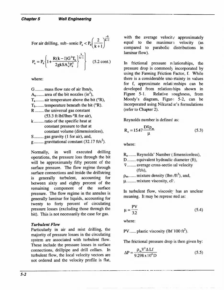
Chapter 5 Well Engineering
-k
For air drilling, sub - sonic Pa e Pb - (k:l)=
k 1
R(k 2gkSA;P; - l)G2Tb}G} (5.2 cont.)
where:
G ........ mass flow rate of air I b d s , A,, ....... area of the bit nozzles (in2), T, ....... air temperature above the bit (OR), T b ....... temperature beneath the bit (OR). R ........ the universal gas constant
(53.3 ft.lbf/lbm."R for air), k ......... ratio of the specific heat at
constant pressure to that at constant volume (dimensionless),
S ......... gas gravity (1 for air), and, g ......... gravitational constant (32.17 ft/s2).
Normally, in well executed drilling operations, the pressure loss through the bit will be approximately fifty percent of the surface pressure. The flow regime through surface connections and inside the drillstring is generally turbulent, accounting for between sixty and eighty percent of the remaining component of the surface pressure. The flow regime in the annulus is generally laminar for liquids, accounting for twenty to forty percent of circulating pressure losses (excluding those through the bit). This is not necessarily the case for gas.
Turbulent Flow Particularly in air and mist drilling, the majority of pressure losses in the circulating system are associated with turbulent flow. These include the pressure losses in surface connections, drillpipe and drill collars. In turbulent flow, the local velocity vectors are not ordered and the velocity profile is flat,
with the average velocit approximately equal to the maximuri velocity (as compared to parabolic distributions in laminar flow).
In frictional pressure rt lationships, the pressure drop is commonlj incorporated by using the Fanning Friction Factor, f. While there is a considerable uncl :rtainty in values for f, approximate relatiinships can be developed from relations hips shown in Figure 5- 1. Relative 1 oughness, from Moody's diagram, Figurt: 5-2, can be incorporated using Nikurad ;e's formulations (refer to Chapter 2).
Reynolds number is defined as:
"'Pm
P Re = 15.47-
where:
(5.3)
Re ....... Reynolds' Number ( 3imensionless), D ........ equivalent hydraulic diameter (ft), v .. ...... average cross-sectio la1 velocity
pm ....... mixture density (Ibn /ft3), and, p ......... mixture viscosity, CI '.
-
(ft/s),
In turbulent flow, viscosit:. has an unclear meaning. It may be represe ited as:
PV p=- 3.2
where:
(5.4)
PV ...... plastic viscosity (Ibf '100 ft2).
The frictional pressure drop is then given by:
pmV2A Lf
9.298x10⁴D AP = (5 .5 )

100
64/Re
I 1000
5
01
XIS
W1
= 0.00005
10000 100000 1000000 1 OOOO( 00
Reynolds Number, Re
Figure 5-1. Friction Factor, < as a function of Reynold's numbej . l.OOE+OO
n u) u) 1.00E-01 Q) E 0 2 1.00E-02
U
- .-
- E v
.00E-03
cn" u)
r m =1 0 a 1.00E-05
.00E-04
- 3! c m Q) 1.00E-06 U -
1.00E-07 1
I I I l l l l l I I I I I I I I I
10 Pipe Diameter, D (inches)
100
Figure 5-2. Moody correlation for relative roughness.
5-3

Chapter 5 Well Engineering
where:
AP ...... pressure drop (psi/ft), and, AL ...... length interval (feet).
Other pressure and velocity conditions are covered in Chapter 2. The following section shows example calculations using some of the available analytical routines for predicting fluid (gas and/or liquid requirements), specifically for air drilling. Depending on the particular project, commercial wellbore hydraulics simulators should be used interactively with available or real-time drilling data.
5.2 Circulation Calculations (Air, Gas, Mist)
Dry Air Drilling Order of magnitude calculations of required air rates can be determined using Angel’s analysis techniques, as described in Chapter 2. Section 2.1. The problem can be approached in two ways. The fundamental relationships can be specifically solved or approximations published by Angel (Appendix C) can be used. Regardless of which analysis is used, the rates are commonly underestimated. Some operators take Angel’s predictions and order out equipment to handle twice these rates; further adjusting on the fly. Some improvements may be possible by manipulating Angel’s parameter, by to incorporate alternate friction factors.
Angel’s Approximate Method
9 Collect the required information for the calculations. This includes:
0 Drilled hole size (inches),
0 OD of the drillpipe (inches),
Drilling rate (ft/hr), tnd,
Depth (thousands of feet).
9 In the table in Appendix Cy determine Qo and N. Interpolate valuc :s as required.
9 Calculate the required circulation rate using:
where:
Qo, N.. parameters from Apj Iendix Cy H ........ depth in thousands o F feet, and, Q ........ circulation rate (scfn 0.
Example 1 Using Angel’s table, detern line the required circulation rate to air drill an 11-inch hole with 5Yi-inch drillpipe, at 91 1 f a r , at 11,000 ft.
P From the table in Appen jix C:
Qo....... 1456, N........ 135, and, H........ 11.
Q = Q, + NH = 1456+ 135% 11 = 2941 scfm
(5.7)
Solving Angel’s Equation A somewhat more precise solution can be derived by programr ling Angel’s relationships into a spreads ieet. The basic equations are:
- - 6.6 1s (T, + Gh)Q*
(D; - D:)Vto
5-4

where:
S ......... gas gravity, air = 1.0 (dimensionless),
T, ....... surface temperature (OF), G.. ...... geothermal temperature gradient
(“F/ft), h ......... depth below surface to any point
under consideration (feet), Q ........ circulation rate (scfm), Dh ....... hole diameter (feet), D, ....... pipe outside diameter (feet), v, tp...... velocity of air at standard
temperature and pressure (Angel recommended 3000 ft/min),
surface (including backpressure) P, ........ pressure in the annulus at the
(psi@, T,, ...... average absolute temperature of the
flow stream (T,+(T,+Gh))/2, (OR), (to convert from O F to OR, add 459.67 to the temperature in O F ) ,
SQ + 28.8KD: 53.34
a ......... 7
K ........ drilling rate ( f a r ) , and,
1.625 x 10”Q’ b ......... (D, - D,)’.333(D2, - D;)’ *
The only real difficulty in solving for this is the fact that Q appears on both sides of the equation. Solve this by iteration.
Revising Angel’s Equation One of the difficulties with Angel’s analysis is that it uses Weymouth’s equation for a vertical, smooth-walled pipe and does not completely represent the contribution of cuttings to friction. One resolution to this is modifying Angel’s parameter, I). It was defined as:
1.625 X 10” Q2
(Dh - D,)1.333(D: - D:)’ b=- (5.9)
Recognizing that this ncorporates Weymouth’s friction factor, f = 0.014 (Dh- D -.333
p) , b can be rewritten as:
1.167 x 10⁴Q2f (5.10)
Alternate values of b can be nferred for different friction factors (refer fc sr, example, to Govier and Aziz, 1982*). Foi example, f can be varied to account for roi ghness and adjustments could be made to include supplemental friction due to cut ings. Note that the simple formulation prese nted here is for straight hole.
Simulation Angel’s analysis can be modif ed for any gaseous drilling system. The ahantage of Angel’s approach is its simplicity. Additional discussion of 1 s ing this technique is found in Johnson znd Cooper, 1993 .3
Nitrogen Drilling Angel’s method can also be used for nitrogen. The procedures are similar to those for dry air. As a first order approximation, it can be assurr ed that the cuttings transport efficiency is sii nilar to that for air. The gas gravity, S, for I itrogen can be taken as S = 0.97, compared o S = 1 for air.
Natural Gas Drilling Procedures for natural ga s drilling circulation assessment, usin, ; Angel’s
5-5

~ ~~
Chapter 5 Well Engineering
approach, are similar to those for air and nitrogen drilling. Typically, the gravity will vary from 0.60 to 0.70 for dry hydrocarbon gases. If PVT information is not available, a reasonable default value would be 0.65.
Mist Drilling As indicated in Section 2.4, a simple approximation of the pressure and the required delivery capacities during mist drilling can be found by using Angel’s analysis and artificially representing added or produced liquid as cuttings. For order of magnitude predictions:
P Estimate the total liquid rate flowing up the annulus (BPH). This includes foamer and produced water.
Determine the liquid added at the surface (BPH).
Determine the liquid inflow (BPH).
Determine the total liquid (BPH) by addition.
P Calculate an apparent, supplementary rate of penetration, to account for the liquids.
380QL D2
ROP, =- (5.11)
where:
ROP, .. apparent additional ROP due to water
QL ...... total liquid flow rate (BPH), and, D ........ bit diameter (inches).
( f a r ) .
P Decide on the desired (actual) penetration rate, ROPd, ft/hr.
P Calculate an artificial penetration rate, ROP’, to “gas lift” the cuttings and
liquid.
ROP’ = ROP, + ROP, (5.12)
> Use Angel’s methodo ogy to determine the required air rate, C, in scfm, and the bottomhole pressure, P ,, using ROP’ .
Example 2 Estimate the required air 1:irculation rate to mist drill at 11,000 feet it 90 ft/hr. Pipe diameter is 5%-inches and the hole diameter is 1 1-inches. Foamer is ad ded at the surface at 4 gpm and water is rroduced into the annulus at 11,000 feet at 9 BWPH.
The injected liqui3 rate is 4 gpm, which is 5.71 BPH . The produced forn lation fluid rate is 9 BPH.
0
0
0 The total liquid ’ate is 5.71 + 9
0 The apparent pe ietration rate to
=14.71 BPH.
account for water i 3:
380x 14.71
1 l2 = 46.2 ft / hr (5.13) ROP, =
0 The desired penztration rate is,
0 The total artificia rate is ROP’=
ROPd = 90 ft/hr.
46.2 + 90 = 136.2 ’t/hr.
0 From Appendix D
Q, = 1456
N = 160 (Extrapolated)
Q=Qo+NH
= 1456+ 160X 11
= 3216 scfm
(5.14)
5-6

5.3 Circulation Calculations (Gasified Liquids)
Approximate volumes and pressures, for gasified liquids, can be determined using the techniques described previously. More precise predictions require added levels of sophistication. Some examples of more refined circulating procedures are provided. These can be adopted for any of the fluid systems discussed. The examples shown are for flow in the annulus. Drillpipe flow calculations are similar, although cuttings are not included and the pipe's internal dimensions are used. Additional sophistication can be incorporated to account for pressure drop at the bit, and changing head due to solids or water influx (refer to example Guo et al., 1993'). The circulation simulations described below indicate methodologies for estimating air requirements to lighten or aerate muds. Although commercial simulators are readily available for drilling hydraulics, this discussion is included so that the drilling engineer can understand the concepts of those models and can do quick parametric comparisons.
Gasifying a liquid is intended to reduce the pressure within the wellbore and to minimize lost circulation or formation damage. In either case, the pressure in the zone of interest must be known in order to design the drilling system. The average density of the liquid above the zone of interest must exert a pressure that is less than (or equal to) the anticipated pressure. The amount of gas that needs to be injected into the drilling fluid can be estimated in two different ways; using relationships presented by Poettmann and Bergman, 1955,4 or by doing first principle
calculations to determine volumes, hydrostatic pressures and frictio n losses in the annulus.
Poettman-Bergman Equatio, 7s A set of charts was developed by Poettmann and Bergman, 1955,4 for avenge annular temperatures of 100, 150 and 20( )OF. Figure 5.3 is a reproduction of the 150'F chart (all three charts are included in Zhapter 2, Section 2.7). These nomograI hs can be used to quickly estimate requi red aidgas volumes.
To Find The Air Requirements
1. Find the drilling depth in feet, on the bottom scale.
2. Go up to the appropriate curvl! of Desired Fluid Weight After A =ration
3. Go across to the appropriate c Jrve of the difference between the Actual Fluid Weight before Aeration and tl le Desired Fluid Weight After Aeration ( W, -Wd).
4. Go up to the Cubic Feet of Ai. needed per Barrel of mud on the top s cale.
(Wd).
Example (Follow the Dotted Lin ?s)
1. Consider a 4200 feet deep hol 2 (bottom axis).
2. Move up to 6 ppg. Desired F uid Weight After Aeration.
3. Move over to 4.5 ppg (10.5 pi ig Actual Fluid Weight minus 6 ppg De sired Fluid Weight) .
4. Move up to 73 scf airhbl of I: iud.
Alternatively, the relationship de veloped by Poettman and Bergman can be ;olved in a spreadsheet, to calculate the voh mes, rather
5-7

Chapter 5 Well Engineering
Cubic Feet Of Air At 14.7 PSlA And 80" F Per Barrel Of Mud CFM-180 170 160 160 140 130 120 110 100 90 80 70 60 60 40 3(1 P 10 0
\ - -
ESTIMATE OF AIR
X X X I '
Figure 5-3. Nomograph for determining air rates to reduce the hydrosi atic pressure of a drilling fluid, at an average temperature of 150°F (Poeffman and Bergman, 195!j4),.
than using a nomograph. Qa ....... gas rate (i.e. air, nib ogen) (scfhbl of
Tavg..... average annular ten perature (OR), Pd ....... desired average den ;ity of the
drilling fluid (ppg), and, pf ........ density of the drillir g fluid (ppg).
drilling fluid),
(5.15) 42hp, - 808(P2 - PI)
Q, =
P2 = PI +0.052hpd (5.16)
where:
h ......... depth of interest, (feet (TVD)), PI ....... surface pressure (psia), (14.7 psia
or local barometric pressure if there is no backpressure),
P2 ....... pressure at the depth of interest, formation pressure plus barometric pressure (psia),
Example 3 shows how tho basic Poettman and Bergman, 1955: equa ion can be used. Equation (5.15) does not ac count for friction losses in the annulus. Poettmann and Bergman, 1955,4 showed tl iat friction losses make very little difference n most instances. However, there are instancf s where it can be important, especially when using high rates of air or nitrogen.
Example 3 (Standpipe Inject on) Consider a well that is to be drilled in a
5-8

formation at 6000 feet that has a pressure equivalent to 7.5 ppg (-2350 psi at 6000 feet). The average annular temperature will be 90°F (550"R). It is planned to use a 9.0 ppg base drilling mud. Air must be added to reduce the hydrostatic head and to develop underbalanced conditions. Determine how much air must be injected into the mud in order to make the bottomhole pressure at 6000 feet equivalent to a 7.5 ppg mud.
9 First, determine the pressure at the zone of interest (6000 feet in this case) using Equation (5.16).
P2 = P, -k 0.052hpd
P2 = 14.7 +(0.052)(6000 feet)(7.5 ppg) =
= 2354.7 psia
(assuming 14.7 psi is the local barometric pressure)
9 Next, use Equation (5.15) to determine the number of standard cubic feet of air per barrel of drilling fluid that must be injected into the standpipe.
42hp, - 808(P2 - PI) Qa =
(42)(6000)(9) -(808)(2354.7 - 14.7) -
(4.071)(550)ln(---)-(0.0764)(6000) 2354.7 14.7
= 34.59 scf per barrel
Therefore, 34.59 standard cubic feet of air must be added to every barrel of 9 ppg mud in order for the pressure at 6000 feet to be equivalent to a 7.5 ppg mud.
Parasite String The previous example imp1 es uniform aeration of the column. If a par: site string is used, only part of the column s lightened. Equations (5.15) and (5.16) can be modified to allow the same calculation -or injection down a parasite string. The (rilling fluid will be aerated from the depth o ' the parasite string to the surface. The drilling fluid below the depth of the parasitl: string will not be aerated. The modified eq iations are:
- 42h,p, -808(P2 - PI) Qa =
(5.17)
P2 = P, + 0.052hpd - 0.052(h - h )pr (5.18)
where:
h ......... depth of interest (feet) (T VD), h, ....... depth of the parasite strir g (feet)
Pz ....... pressure at the depth of ti ie parasite (TVD), and,
string (psia).
The average annular temperalure is only considered over the depth inter r a l from the bottom of the parasite string to tl ie surface.
Example 4 (Parasite String) Given all the data in Example 1, determine the air volume that is required if a parasite string is set at 2000 feet. "he average annular temperature is only con iidered from 2000 feet to the surface and nct from 6000 feet to the surface. The aveiage annular temperature was estimated t I be 70°F (530"R).
- 5-9

- Chapter 5 Well Engineering
> First, calculate P2. This is the required pressure at the bottom of the parasite string.
42h,p, - 808(P, - >,) 4.07 lTa,, In - -- 0.0 764h, (;) --
Q, =
P2 =PI +0.052hpd -O.O52(h- h,)p,
P2 = 14.7 psia + (0.052)(6000feet)(75ppg)- (42)(2000)(9) - (80t)(482.7 - 14.7)
(4.07 1)(530) In -- - (0.0764)(2000) (483 14.7 ,
Qa = - (0.052)(6000feet - 2000feet)(9 ppg)
=482.7 psia = 51.20 scf per barrel
This indicates that the pressure where the air enters the annulus from the parasite string must be 482.7 psia, in order for the equivalent mud weight at 6000 feet to be 7.5
PPg-
P Now, calculate the required air volume per barrel of mud:
Since all of the fluid i n th: annulus is not being aerated, more air is ret luired to achieve the same equivalent mud wc ight at 6000 feet when a parasite string is usc d. Figure 5-4 is a plot of the annular pressui e profile for this example well, using both ieration through the standpipe and through a ?arasite string.
0
1000
2000 n c Q, Q, s c 3000 P a
. . .._ _ _
c
n 4000
5000
6000 0 500 1000 1500 2000 2500
Pressure (psia)
Figure 5-4. Plot of pressure versus depth for the wells in Examples 3 md 4, injecting through the standpipe or a parasite string at 2000 feet.
5-10

Annular Calculations There is another, relatively simple way to determine pressures in a well drilled with gasified fluid. It involves calculating volumes, hydrostatic pressures and friction losses in the annulus. Pressures are incrementally calculated (from first principles).
9
9
9
>
The pressure at the surface is assumed and the volumetric flow rates are calculated for a short interval (usually around 100 feet), starting from the top.
Based on the flow rates and fluid properties, the pressure at the bottom of the first interval is calculated, using both friction losses and hydrostatic pressure.
The pressure at the bottom of this first interval is used to recalculate the fluid properties and flow rates. These are used to calculate the pressure at the bottom of the second interval. The process is repeated until the pressure at the zone of interest is determined.
If desired, you can keep going (incorporate pressure drop through the bit and work back up through the drillstring) to get standpipe pressure.
Performing these calculations by hand can be tedious. Spreadsheets can be used to perform the calculations efficiently. The calculations must be done over short intervals because the actual volume, density and flow rate change with pressure. Since gas is compressible, the volume is a strong function of pressure. The volume of the gas determines the flow rate and density of the single phase (air) or composite (gas-liquid) mixture.
Calculating Gas Density and Volume 9 The gas density and voliime can be
calculated, at any pressun:, using the following equations:
2.703SPi
T, P g = (5.19)
(5.20)
where:
Pi ........ pressure at the top of the first interval (psia),
Qa....... injection gas volumetric flow rate (sft3/bbl of drilling fluid:,
QL ...... base liquid volumetric fl IW rate
S ......... gas gravity (air = l), Ti ........ temperature at the top of the first
interval (OR), V, ....... gas volumetric rate at prl :sure
(ft3/min), and, pg ....... gas density at temperatui e and
pressure ( lbm/ft3).
(gpm),
9 The density and volume of 1 he liquid are determined. Equations (5.2 I) and (5.22) are then used to convert ljquid density (ppg) and rate (gpm) to un ts of lbm/ft3 and ft3/min.
pL = 7 . 4 8 ~ ~
QL V, =- 7.48
where:
(5.21)
QL ...... base liquid volumetric fl OW rate (gpm) 7
(5.22)
- 5-11

~ - Chapter 5 Well Engineering
VL ...... base liquid volumetric flow rate
pf ........ drilling fluid weight (ppg), and, p~ ....... drilling fluid density (lbm/ft3).
(ft3/min>,
> The next step is to determine the combined density and volume of the mixture:
v, = vg +v, (5.23)
where:
(5.24)
VT ...... volumetric flow rate of the mixture
pm ....... density of the mixture of gas and of gas and liquid (ft3/min), and,
liquid (lbm/ft3).
> The hydrostatic pressure and friction losses for the discrete interval (annulus) are calculated with the following equations, along with the pressure at the bottom of the interval (ignoring cuttings)+ :
(5.25)
(5.26)
Pi+, = Pi + Phy + Pfr (5.27)
A solid phase can be added for cuttings. In most cases this is second order. Liquid inflow can also be incorporated.
where:
Dh ....... diameter of the hole (inches), D, ....... outside diameter of the pipe
(inches), L d . . . . . measured length of .he calculation
interval (feet), L d ..... true vertical length I )f the
calculation interval :feet), Pk....... friction losses in the calculation
interval (psi), Phy ...... incremental hydrost itic pressure
over the calculation interval (psi), Pi+, ..... pressure at the bottc rn of the
calculation interval 'psi), and, PV ...... plastic viscosity (cP 1.
Using Equations (5.19) th ough (5.27), the annular pressures in the wellbore can be calculated at any deptl . Hydrostatic pressure and friction 11 )sses are both included. These equations can also be used in a directional well sincc : the hydrostatic pressure and friction pressu -es are calculated separately. Hydrostiatic pressure is a function of the true veitical depth and friction losses are a funct on of measured depth.
The following example illu ;trates how these equations can be used 1 0 calculate the pressures in the wellboie described in Example 3.
Example 5 Given the conditions frc m Example 3, determine the pressure at 6000 feet. The air injection rate is 34.59 ft3/bb I of drilling mud. The drilling fluid rate is 251 1 gpm. The hole size is 8.5 inches and the OL tside diameter of the drillpipe is 4.5 inches. There are 600 feet of 6.25-inch OD dri 1 collars at the bottom of the drillstring. Assume that the surface temperature is 60°F and the
5-12

geothermal gradient is l"F/lOO feet. The returns are being vented through a mud/gas separator and the surface pressure is assumed to be 14.7 psia. The calculation interval length will be 100 feet. The plastic viscosity of the drilling fluid is 10 cP.
P Calculate the density and volume of each phase for the first interval. This interval is near the surface. The temperature is -60°F which is (60459.67) = 520"R. The densities and flow rates are:
- 2.703SPi - - (2.703)(1)(14.7 psia) - T 520" R P, =
= 0.0764 Ibm / ft3
- - - (0.35)(3459 ft3 / bb1)(250gpm)
= 205.89 ft / min
- 14.7
pL = 7 . 4 8 ~ ~ = (7.48)(9.Oppg) =
= 67.32 lbm/ ft3
= 33.42 ft / min v -L- Q 250gpm - 7.48 - 7.48
> Calculate the total flow rate and the density of the mixture of air and drilling fluid.
V, = V, + V, = 205.89 + 33.42 =
= 239.3 1 ft3 / min
(0.0764)(205.89) + (67.32)( 33.42)
239.3 1
= 9.47 lbm / ft3
P Calculate the hydrostatic pressure, friction losses and pressiire, at the bottom of the first interval.
-- - PlIlLtV, - (9.471bm/ft3)(l( Ofeet)
144 'hy = 144 - = 658 psia
-- - ( 5 . 8 8 ~ 104)py' V?' PV0," L, Pf, =
(Dh-Dp)3(Dh +Dp)l"
(5.88 x 10⁻⁴)(9.471bm/ ft3)0'8
(85 in-45 inY(8.5 in+4.5 in, \ X X
- -
(239.31ft' /min)l'81(10 cP)0.I9( 100 ft)
(85 in - 4 5 i n r (85 in + 45 i 1)1"' X
= 1.71 psia
Pi+, = Pi + Phy + Pf, = 14,7 + 6.58 i 1.7 1 =
= 22.99 psia
P The pressure at 100 feet is 22.99 psia. For the next interval, from 100 to 200 feet down the annulus:
- (2.703)( 1)( 22.99)
pg = 520" R + 0.01" F/ ft x 100 fec t - = 0.1 191 lbm/ft3
5-13

Chapter 5 Well Engineering
- - (0.35)( 34.59)( 250)
22.99 vg =
= 13 1.65 ft3 / min
P The volume and density of the liquid remain approximately the same as for the first interval since the base liquid is a slightly compressible fluid:
V, = 131.65+33.42 = 165.07 ft3 /min
- - (0.1 191)( 13 1.65) + (67.32)(33.42)
165.07 P m =
V, = 89.8 1 + 33.42 = 123.; 3 ft3 / min
- - (0.1743)(89.81) -t- (6; .32)(33.42)
123.23 P m =
= 18.38 Ibm/ ft3
= 12.76 psia (1 8.38)( 100)
144 'hy =
X (5.88 x lo4)( 18.38)0'8 ( 123.23)'.81
(85 - 4.5)3(8;5 + 15)''81 Pf, =
( ~ o ) O . ' ~ (1 00)
(8.5 - 45)3(8.5 + 45) 1.81 = X
= 13.72 Ibm/ ft3 =0.88 psia
= 9.53 psia (1 3.72)( 100)
144 'hy =
X (5.88 x 10⁻⁴)(13.72)0~81(165.07)1'81
(85 - 4$ (85+ 4.5)'.81 Pf, =
(1 o)O.l9 (1 00) X
(85-4.5)3(8.5+45)''81
= 1.18 psia
c+2 = 'i+l + 'hy + 'ti
P,+2 = 22.99 + 953 + 1.1 8 = 33.70 psia
9 The pressure at 200 feet is 33.70 psia. The procedure is repeated for the interval from 200 to 300 feet:
= 0.1743 lbm/ ft3 (2.703)( 1)(33.70)
522 P, =
= 89.8 1 ft / min (0.35)(34.59)(250)
33.70 vg =
'i+3 = c + 2 + 'hy -k 'f,
Pi+2 = 33.70 + 12.76 + 0.88 = 47.34 psia
> The pressure at 300 fee. is equal to 47.34 psia.
9 The procedure is repeal ed until the depth of interest is reached. In this case, the pressure at 6000 feet i calculated to be 2362 psia. This pressu .e is equivalent to a 7.57 ppg mud. This implies that the friction losses in the an iulus are equal to an equivalent mud weight of only 0.07 ppg (-0.36 psi per 100 feet). Given the fact that air rates do not remain absolutely constant anc that connections have to be made, the lriction losses are insignificant. This indicates that variations in actual bo tomhole pressure are more a function t f changes in air volumes during connec ions than friction losses. Equation (5.17) is a good starting point for any field toper ation. The actual volumes must be varic d on location in
5-14

order to accomplish the project objectives.
5.4 Wellhead Design
Wellheads used in underbalanced drilling vary from crude, very simple equipment for very low pressure operations to expensive, redundant systems designed for very high pressure operations. For extremely low pore pressure drilling applications, a simple annular preventer alone might suffice to contain wellbore pressures; however, a principal manufacturer of such equipment strongly cautions that such use exceeds the design criteria of this equipment. Therefore, the minimum setup for an underbalanced drilling system should consist of a rotating head mounted above a two ram set of manually-operated blowout preventers, consisting of a pipe ram and a blind ram. An improvement to this basic system would be installing the rotating head above a set of hydraulically-operated blowout preventers. For slightly higher pressure operating conditions, a system consisting of a rotating head, an annular preventer and a two ram set of manually- operated preventers will probably work adequately. For added safety, hydraulically- operated preventers with a manual backup should be provided.
These basic systems all use a rotating head with a 400 psi (sometimes 500 psi) MWP (Maximum Working Pressure) capability. Early day air drilling used this type of equipment, along with a surface pit and a return flowline venting to this pit. Mist and foam drilling extended the depth limits and maintained low surface pressures in this underbalanced system.
A rotating head is sufficient fo- almost all air and mist operations, in ireas where formation pressures are well ct aracterized. The rotating head is used as a civerter only and is not used to maintain a b< tckpressure; therefore, there is no t. ackpressure limitation. In fact, back] ressure is detrimental to air and mist (killing and should not be applied.
It is extremely unlikely that th: flow rate through the blooie line would cr :ate enough backpressure to exceed thi : pressure limitation of the rotating head. The flow rate would have to be in exc:ss of 100 MMscfD to cause a 200 psi pres a r e drop in an 8-inch blooie line.
When accurate pressure data a .e available for an area, drilling with a rotaiing head is possible in deeper wells, especially if the target contains oil rather than gis. Because of lower rental rates, rotating h:ad drilling applications are stretched to thl :ir pressure limits, before resorting to more c xtly RBOP equipment. Many Pearsall an i Giddings (Austin Chalk) field wells are still drilled with this style of equipment, Zespite' the safer MWP offered with the RBOP. Regrettably, cost factors vel sus safety margin considerations often win >ut in favor of the rotating head. Today, a t y lical well in these fields is drilled with a rctating head system, in combination with an a inular BOP and a hydraulically-operated thrc e ram BOP stack, consisting of two sets oj pipe rams and one set of blind rams.
Return flow is diverted througf the choke manifold and surface separation equipment to isolate gas, oil, drilling fluids and cuttings. An automatic flare sq stem safely burns off hydrocarbon or hydrcgen sulfide
5-15

Chapter 5 Weii Engineering
gases from the rig site. Even moderately deep wells are drilled in this manner using nothing but fresh water as the drilling fluid. Heavier 10.0 ppg NaCl brine water is then used to reduce surface pressures during trips.
To drill these deeper wells, many operators have added the additional set of hydraulic pipe rams, to make a two pipe ram stack with blind rams. Above these BOPS, the annular preventer, with the rotating head on top, completes the medium pressure wellhead equipment. The additional set of pipe rams provides a higher level of operating safety, as well as making it possible to snub or strip from the well. As higher pore pressures are encountered, sodium chloride brine fluids can replace the previous fresh water system and provide lower surface operating pressures, in order to stay in the pressure range of the rotating head.
The next higher level of underbalanced wellhead equipment usually involves drilling deeper formations or gas-bearing reservoirs. Either one or both of these conditions can cause surface pressures to exceed the working pressure limit of the rotating head. For these wells, the RBOP, with a 1,500 psi MWP (some equipment now is functional at 2500 psi operatingkotating and 5000 psi static pressures), offers substantial depth capacity and safety advantages compared to the rotating head.
If hydrogen sulfide (H2S) gas is expected or if formations with even higher pore pressure are drilled, wellhead equipment design might call for either coiled tubing drilling (CTD) or snub drilling operations.
Rotating Head A typical rotating head ar d its components are shown in Figure 5-5. 1 schematic cross- section of a rotating heacI is illustrated in Figure 5-6. In air :nd gas drilling operations, rotating heads ire also called air heads. Rotating heads are used to pack off the annulus, diverting the air and gas flow down the blooie line. Without the rotating head, the air and gas woulc come up through the rotary table and onto th : rig floor.
Many adequate rotating he ads are available. Newer-generation rotatin; ; heads usually have sealed bearings, ratlier than external oilers. Most are driven lly a kelly driver. This attaches to the kelly md is mated to a machined piece on top of the bearing assembly. The kelly driver transfers rotation of the drillstring to the seal ng element in the rotating head. The E Earing assembly provides a seal and alloas rotation of the stripper rubber while: th: bowl remains stationary. The stripper n tbber is designed to rotate with the kelly since rotating the kelly within the stripper ru 3ber would cause the stripper rubber to wear jut much faster.
Hexagonal kellys allow for a better seal than do square kellys. These should be used whenever possible fo - air drilling applications. The life of tk e sealing element will be increased by proptr lubrication and minimal tripping through it. The drillpipe can be tripped through t h z stripper rubber when necessary but it wil not last as long before it has to be replaced. If the well is making smaller amounts o ’ gas, the stripper rubber and bearing assemlily can be pulled prior to tripping. Gas can t e jetted off of the rig by passing air through he primary jet in the blooie line, as explainec I in Chapter 2.
5-16

Figure 5-5. pressure rotating head (after Eourgoyne, 1995, source: Williams Tool Company, Inc.).
Components of a low
In an air drilling operation, the rotating head is only a diverter and must not be thought of as a replacement for a properly designed blowout preventer stack. Pressures on the sealing element should be kept to a minimum. Most low pressure rotating heads are not designed to handle much more than a few hundred psi. High pressure rotating
Figure 5-6. Cross-section o a rotating head, showing how tl re stripper rubber seals around the drillp pe or kelly, diverting flow down the blooie line (after Cooper et al., 1977 '1.
heads or rotating blowout pnventers are available for underbalanced drill ng.
The stripper rubber in a rotating head can be changed without tripping out of the hole. The driller first pulls the pipe until a tool joint is at the bottom of the strilper rubber. The annular preventer (or l ov rams) is
5-1 7

Chapter 5 Well Engineering
closed and the pressure trapped below the rotating head is bled off. The bonnet on top of the bowl is opened and the drillpipe is stripped from the hole. The first tool joint below the rubber should pick up the stripper rubber and bearing assembly as the pipe is hoisted from the hole. The tool joint is a larger OD than the pipe and will not slide through the rubber as easily. When the stripper rubber and bearing assembly are above the rig floor, the slips are set and the drillpipe connection just below the stripper rubber is broken. The stripper rubber and bearing assembly can then be pulled off of the drillpipe. The old stripper rubber is released from the bearing assembly and replaced with a new stripper rubber. The new stripper rubber and bearing assembly are placed on top of the mouse hole and the drillpipe is stabbed through the rubber with the aid of a spear. Once the new stripper rubber is above the tool joint, the tool joint is made up to the drillstring and lowered into
the hole. The stripper ru1,ber and bearing assembly are again placed in the bowl and the bonnet on top of the bowl is closed. Drilling can then continu: with the new stripper rubber.
Specific Consideration: i
Dry Air Drilling A conventional open bell nipple will not direct the returning air florq away from the rig substructure. To do this, additional equipment, a diverter, is reiuired above the BOP stack. Although it i: possible to use various types of equipment as diverters, it is now normal to use either a rotating head (Figure 5-6) or a rotating B( )P (Figure 5-7).
Both of these use elastomxic elements to seal around the kelly ‘and iirect the return flow laterally through the o itlet and into the blooie line. The prin ipal difference between these two types 0’ diverter is that
Kelly driver Qulckthsnge packer --\ , , 7 assembly assembly
Hydraulic lluid Inlet
Inner packer
Outer packer
Bearings
Mechanical seal -
Outlet flange : I 1 z id return
Figure 5-7. Blowout prewenter
5-18

the sealing element in a rotating head is actuated by the air pressure that it seals, whereas the element in a rotating BOP is actuated hydraulically. Typically, rotating heads have a pressure limitation of 400 psi, and new-generation rotating BOPs can seal higher pressures, up to 2,5001 psi while drilling (5000 psi static).6 It is important that both are operated according to their manufacturers 'recommendations. Un- acceptably rapid wear of the seal element and mechanism will occur if the axis of the diverter is not aligned directly with the center of the rotary table or if the lubrication is inadequate.
With dry air drilling, the well should be stripped through the rotating head rubber and not the primary BOPs. If the flow rate or pressures are too high to use the rotating head for stripping, the well should be killed before leaving the bottom. After all, the pipe must be stripped out of the well before it is stripped back into the well.
If the flow rates and pressures are high enough to require stripping ram to ram through the BOP stack, then a snubbing unit will be required, with a snubbing stack.
The diverter system does not remove the need for a conventional BOP stack. This should comply with local regulatory requirements. At a minimum, it should contain pipe and blind rams, so that the well can be shut-in with the string in or out of the well. For gas wells at least, the pipe and blind rams should be able to support the highest anticipated formation fluid pressure. Where it can be accommodated beneath the rig floor, it is desirable to have a full stack consisting, from the wellhead up, of pipe rams, blind rams, pipe rams and annular. This provides operational flexibility. For
example, it allows stripping pi:)e back into the well under pressure if h gh pressure hydrocarbons are encountered tk at cannot be contained within the lower pres: ure capacity of the diverter. The returning air flow is taken from the diverter to a flar : pit through the blooie line.
Nitrogen Drilling The requirements are similar to .hose for dry air drilling.
Drilling with Natural Gas Beyond the additional surface equipment, including gas monitoring ins .rumentation described in Section 2.3, t le required equipment is similar to that nteded for air drilling. Cummings, 1987,7 inc icated that a conventional rotating head couli be used to divert gas flow into the blooie 1 ne in certain situations (i.e. low permeabilil y wells that need to be hydraulically fractured). Particularly if it is anticipated that high formation gas pressures or production rates may be encountered, ths additional pressure capacity of a rotah ng blowout preventer is worth considering.
Regardless, implement, fc dlow and strictly enforce all st fety
requirements.
Mist Drilling The requirements are similar to those for dry air 'drilling.
Foam Drilling A choke should be installed j n the blooie line, close to the rotating head or RBOP, to pressurize the annulus, if neces: ary. Dupont, 1984,* recommended a bladde '-type choke. If' the circulating program ii idicates that annular backpressure may be nc cessary, then this additional pressure should 1 le considered
5-19

- Chapter 5 Well Engineering
when specifying the pressure capacity of the rotating head or RBOP. The section of the blooie line between the choke and the rotating head should have a pressure rating sufficient to support the highest back- pressure likely to be imposed.
In very cold conditions, foam returns may freeze and plug the blooie line. In these areas, Fraser and Moore, 1987; recommended using an additional foam discharge line, with both the blooie and foam discharge lines leading to the flare pit. This redundancy is not necessary for normal operations, where there will be a line from the choke manifold to the flare pit that could be used to continue circulation, but not drilling, if the blooie line were to plug. Small rigs may not have the clearance below the floor for two diverters on top of a conventional BOP stack.
Gasified Liquids In the United States, many of the gasified liquid drilling applications to-date (when surface pressures are anticipated to be low), have used aerated water or mud to overcome lost circulation in hole intervals above known reservoirs. In these instances, rotating heads are used on top of conventional BOP stacks, to seal around the drillstring and divert flow into the flowline.
Nitrified liquids are often used in Canada, to drill very productive wells underbalanced. An M O P is normally used, rather than a lower pressure rotating head. If the rig is equipped with a top drive, it is possible to use dual annular BOPS to give a high pressure seal around the string above the return line. Since an RBOP gives better control of the closing pressure and has lower stripping friction, it is usually preferred."
It has been recommended that blind rams should be installed at the bc ittom of the BOP stack.'' This maximize the distance between the blind ram md the RBOP, allowing short, irregular1 y shaped BHA components to be run into the well under pressure, without relying on the RBOP or annular to seal around them
A second set of pipe rams. below the blind rams, will provide redunlancy, and will normally only be used to sl. ut in the well, in the event that work is requi -ed on one of the elements higher up the stacl . I 2
The influence of tht BOP stack configuration on ram-tc )-ram stripping operations should be carefu Ily considered, if there is any possibility of h: ving to strip into the well under high pressurc .
The clearance beneath the rig floor should be considered when desi gning the well cellar, wellhead and BO" stack. BOP stacks, for underbalanced di illing, tend to be taller than those used In conventional operations. The situation is more difficult if conventional wellhead equi sment is used to inject gas down a tempcraq casing string.
Additional discussion of g< isified liquids is found in Chapter 2, Section 2.7.
Flo wdrilling Although surface equipmer t is important in any type of drilling, it i! crucial to the success of flowdrilling . Wellhead equipment and operating procedures are discussed in detail in Chaptc r 2, Section 2.8.
Mudcap Drilling One significant differ mce between flowdrilling and mudcap d-illing is that an
5-20

RBOP, with its high operating pressure limits, is essential for mudcap drilling. Flowdrilling is possible using either an RBOP or a rotating head. A schematic layout for mudcap drilling is shown in Figure 5-8. In designing a well plan using a mudcap drilling format, drilling engineers should carefully consider the high standpipe pressure involved and the associated safety considerations, before finalizing their recommendation.
Bloys et al., 1994,13 discussed offshore floating mudcap drilling, in carbonate zones in South East Asia. “Typically mud with a density only slightly higher than the pore pressure in the top of the exposed section of carbonate is continuously pumped into the annulus at a rate that maintains a constant fluid level sufficient to prevent any influx.
(Mud pump rates depend on the loss rate to the formation but rates of t h ? order of 10,OOO bbls/day are typical). Sea water is pumped down the drillpipe at normal circulation rate for the hole size io clean and cool the bit and move cuttings lip the hole. To make connections, mud is pu nped down the drillpipe to minimize the differential across the non-ported drillstring float but it is the float that actually prevent: any influx entering the drillpipe.”
I
“With a ware ship [supply ship] 1 nudcapping may be continued during bit trip; and while running casing but this involves aking extra risk as there will be times when the BOP cannot effectively close off tht well, e.g. when the BHA is across the BO]’. The safe method for tripping is to stop tlie losses in the open hole before tripping. Others have
I -
wn ImW , V h .
u m n ” + Figure 5-8. Schematic of equipment required for mudcap drilling (courtes
Engineering Corporation). V of Signa
5-21

Chapter 5 Well Engineering
successfully stopped losses for tripping by spotting a fast setting, viscous, cement slurry just inside the casing shoe as an alternative to plugging the formation to cure losses but this is not recommended.”
“Future refinements in mudcap drilling that have been considered . . . , but not yet applied offshore, would involve the use of a rotating head (or rotating BOP) and lower density mud being pumped into the annulus ... . Currently it is only possible to drill with a rotating head on rigs equipped with a surface stack; this includes jackup and platform type rigs offshore. The advantages of this procedure are that there is no guess work about the fluid level in the well and the pump rate required on the annulus side is dictated only by the need to prevent gas migration. In gas filled carbonates the increasing over-balance would also be reduced by using a lower density mud. Hence, the logistics of pumping mud down the annulus could be planned more precisely based on the velocity required to prevent gas influx and migration (Le. up to 2,200 m/hr [120 fpm] depending on fluid vis~osity).~ Hence, the use of a rotating head and lower density mud could potentially reduce the volume of fluid required and the cost to drill a given massive lost circulation interval.”
One significant concern is to guarantee that riser collapse pressure is not exceeded. The decision to use mudcap drilling in the operations described by Bloys, et al., I994,I3 is only made afler the first occurrence of total losses has been experienced and cured.
Snub Drilling and Coiled Tubing Drilling Both snubbing and CT units have BOP stacks that allow a drillstring (coiled tubing in the latter case) to be run into or out of the
hole, at much higher presures (routinely up to 10,000 psi) than can be .olerated by either a rotating head or an RBO ’. Both units also allow the drillstring to be 1 bushed into a well under pressure, even when the weight of the string alone is insufficieni to overcome the pressure tending to push i t out of the well. Snubbing and CT units can by used for underbalanced drilling, 4 it pressures that cannot be managed iy conventional surface equipment. Ck apter 2, Section 2.10, provides a descriF tion of required wellhead equipment anc operating con- siderations.
Closed Systems Surface equipment connmo d y used in closed system drilling operation! is discussed in Chapter 2, Section 2.1 I.
5.5 Casing Design
Casing design for an undc rbalanced hole is not substantially diffe rent than for conventional drilling. No mally, the casing is designed for tension, iiternal yield and collapse (biaxial casing design), and a design factor is assigned fcpr all three design parameters (using APT Standard 5A, operator’s company pol icies, regulatory agency requirements, wl- ichever is more stringent).
For tension, some operatl )rs will calculate the string weights biised on the buoyant weight of the casing P hile others will calculate string weight ba ;ed on air weight and use buoyancy as an additional design factor. In an air hole, it i. very common to run casing without fillirg the well with fluid first. In this case, there is no buoyancy and the string veight should be based on air weight ratker than buoyant weight. Most operators us! the same tension
5-22
design factor for air as they do for fluid.
The maximum internal yield pressure is usually based on the maximum anticipated shut-in pressure. The maximum pressure at the depth of interest will be either the shut-in bottomhole pressure minus a gas gradient or the fracture gradient at the shoe minus a gas gradient; whichever value is lower. Since the design is the same for air or fluid, the same design factor is typically used.
In designing for collapse resistance in fluid, it is common to assume that the pressure inside the casing is zero and that the pressure in the annulus is equivalent to a full column of mud. In a fluid-filled hole, the pressure inside the casing is rarely zero. Some operators do not assume that the pressure inside the casing will be zero and there will always be some fluid inside the casing. For this reason, the collapse design factor for fluid drilling is usually very close to one; however, the pressure inside the casing will always be very close to zero in an air-drilled well. Most operators will increase the collapse design factor when designing casing for an air-drilled hole. A common design factor for a fluid-filled hole is 1.125 and a common design factor for an air-drilled hole is 1.20. Similar logic is followed if the drilling fluid is not dry air, although dry air will likely be one of extreme situations for all of the design parameters.
There are other considerations for casing design. Even when designing casing for a fluid-filled hole, the potential reduction in wall thickness due to corrosion and casing wear must be considered. Casing wear must be considered in an air drilled hole.
Corrosion For fluid-filled wells, corrosion .s seldom a consideration while drilling. 1 Iowever, it must usually be considered during the productive life of the well. Conxion is not a factor when drilling with dry zir. If' there is no water present, corrosion CE nnot occur. Corrosion can be a problem with mist, foam and aerated fluids. Aerated fluids provide the most risk. In most i.ir drilling operations, corrosion is conti olled with corrosion inhibitors. It is relath ely easy to control corrosion in a mist 01)eration by adding corrosion inhibitors to the mist. As a result, corrosion is seldom a prc blem when drilling with mist; if the mist c~ntains salt for shale stabilization, uninhibite d corrosion rates will increase substantially.
Foams and aerated fluids will ty] iically have higher corrosion rates, even wh:n they are treated with inhibitors. If a well is going to be drilled for an extended periDd of time with foam or aerated fluids, it may be necessary to design the casing wi h a slightly greater wall thickness. Spend ng a little extra money on corrosion con rol is also advantageous .
Casing Wear Casing wear is caused by rotaion of the drillstring inside the casing. If tool joints rub against the casing while diilling, both the tool joints and the casing will wear. Casing wear is accelerated in ail air-drilled hole because there is no lubricatj on between the drillstring and the casing. Tortunately, most air drilled holes are dril ed rapidly. Spending less time drillii ig (fewer revolutions of the drillstring) w 111 result in less casing wear.
5-23
- Chapter 5 Well Engineering
For substantial wear to occur, there must be doglegs in the wellbore trajectory. A tool joint laying against the casing, in or near vertical well sections, will not apply sufficient force to cause much wear. The force with which a tool joint presses against the casing is commonly called the tool joint normal force. Placing the tool joint in a dogleg and adding tension will substantially increase the tool joint normal force. Therefore, casing wear will preferentially occur in sections of the hole that have doglegs and where the drillstring has sufficient tension. For this reason, casing wear usually occurs closer to the surface and is normally not a problem near the bottom of the well.
If a well is being drilled in an area where deviation and doglegging are problems, casing wear should be considered in the casing design. If only a few days are spent drilling below each casing string, wear will probably not be a significant problem and can generally be ignored, unless severe doglegs are present. Casing wear will only be a problem when a well is drilled below the casing string for an extended period of time. Bradley and Fontenot, 1975,14 presented a method to predict casing wear, depending on the conditions in the wellbore, including dogleg severity, tension in the drillstring and rotating hours below the dogleg.
5.6 Completion Design
One of the primary advantages of drilling wells underbalanced is the elimination or minimization of formation impairment. In overbalanced situations, drilling fluid and solids can penetrate and damage matrix porosity or fractures, reducing the permeability. Zf a well is properly drilled
under underbalanceti! CG nditions, but is completed using overba ‘anced methods, much if not all of the impl rirment-reducing benefits might be perntanc ntly lost. Even if this completion-related lamage can be removed or bypassed, the associated expenses can be avoided if the operator uses proper underbalanced completion procedures. These procel lures, sometimes called “live well,’’ underbalanced completion techniques, are described in this section. They include:
> Running production casing, liners, slotted liners and otlier tools under- balanced,
> Controlled cementing of production casing or liners,
> Running production tLbing and down- hole completion assemt lies, and,
> Perforating underballam ed.
Running Casing and Li qers Underbalan ced Before drilling operations are completed, and the bottomhole assembly (BHA) is removed from the wellborl under pressure, completion protocol must be determined. For example, will the completion be barefoot (openhole) or will some type of casing or liner be run.
If the completion is not bar :foot, it becomes necessary to run the casing or liner without killing the well. In this scenario, surface pressures are usually incr :ased to subdue exposed downhole Corn ations, without exceeding their pore prlessu -es. This is done by replacing the lighter innular fluid by bullheading a heavier fluicI down the back side before tripping out o f t le hole.
To run production casing or an unslotted
- 5-24

production liner in a live well, a float shoe and float collar are usually used. The shoe and float collar are often separated by two joints of pipe, in order to isolate contaminated cement and to prevent it from surrounding the lower portion of casing in the open hole. Depending on the surface pressures, it may be necessary to flow the well through the choke manifold while running pipe, to reduce the shut-in surface pressure. Even flowing the well might not sufficiently reduce this pressure to permit passage of the pipe into the well against underbalanced forces. If this is the case, a snubbing unit or a coiled tubing injector head might be required to push the casing until it becomes “pipe heavy.”
On the other hand, a slotted liner does not restrict the flow of fluids into the liner (through the slots). The slotted liner and liner hanger are run on the bottom of drillpipe or some other work string. A drill float is generally run above an ordoff tool, located immediately above the liner hanger. Once the hanger is set, the on/off tool is released and the drillpipe or work string is tripped out of the hole. The drill float provides back flow protection.
It may be necessary to “flood” the backside with drilling fluid to reduce the surface pressure and enable tools or pipe to be run into the hole. Fluid is continuously pumped down the annulus to overcome pressure resistance. If necessary, the rubber element or packer, inside a rotating head or RBOP, can be removed to allow larger diameter pipe to be run through the wellhead stack.
Cementing Pipe Underpressured Presuming that casing has been run underbalanced, underbalanced cementing
should also be considered. Formation impairment from the cement and associated filtrate fluids can be equally or more damaging than drilling. UI derbalanced cementing is not substantially d: fferent from underbalanced drilling. The hydrostatic head of the slurry can be reduced by entraining gas, usually nitrogen, or reduced- density additives. These technc dogies were originally developed to avoid b .eakdown in weak formations.
The requirements of the cemen remain the same as for conventional treatrr ents. There must be annular sealing to prevcnt flow and strength must be adequate to resist degradation of the cement bonj under the action of in-situ stresses. Otker common considerations are permeability elimination in the microannulus, compress ;ve strength and drilling fluid displacement.
Nitrogen is often added to cement to reduce its density. This reduces the hydrostatic head adjacent to target reservo rs and may further impede flow (into thc formation, before setting) because of its multi-phase characteristics. Nitrified ce ment was originally developed for place nent across lost circulation or underpressur :d intervals. It is commonly used for ur derbalanced cementing.
Historically, operators have had some difficulty in guaranteeing adeqt ate bond of lightened cement to the casiig and the formation, using conventional cementing methods, particularly across gas-bearing zones. Formation gas would often “channel” into this cement and cause contamination. This “honeycon bing” could cause inadequate bond, r( sulting in crossflow (flow of formatioii fluids in
5-25

- Chapter 5 We// Engineering
channels or a microannulus) between different formations. When one of these reservoirs contained water, a channel could allow water flow into a hydrocarbon interval, resulting in premature abandonment of the completion and loss of reserves. Today’s high quality foamed cements tend to reduce this problem. Compressible slurries can maintain cement pore pressure throughout setting and hardening, particularly through the transitional phase where the cement matrix is vulnerable to gas channeling.”
Alternatively, normal extenders are suitable for slurries with densities as low as 11.5 to 12 ppg. Below this, the resulting water separation will affect slurry properties and continuity of the annular cement column. Hollow microspheres have been used as a cement extender. Light-weight slurries using hollow spheres, enable slurries in the 9 to 12 ppg range, with no water separation and a reasonable cost. Also, as indicated, foamed cement, using nitrogen as the extender, has been accepted by many operators. The system requires alternatively formulated base cement slurries and gaseous nitrogen to create an homogeneous, ultra light-weight slurry.
Running Tubing in Underbalanced Wells Whether or not a well is designed as an openhole completion, a slotted liner completion or a perforated casing com- pletion, production tubing is generally required to protect production casing against excessive or concentrated pressures and to minimize corrosion and/or erosion. Most regulatory agencies enforce the use of tubing in well completions, to protect shallow freshwater aquifers against hydrocarbon or salt invasion and pollution.
If the underbalanced well above is an openhole or slotted liner ( ompletion, there will generally be pressurc at the surface. Cemented casing completic ns will have zero pressure until they are perf ]rated. Methods have been developed to run completion assemblies and tubi ng downhole underpressured, in openholt and slotted liner wells. Unperforated, cased wells present no problem and tubing is r t n into the well without special equipment.
If a well has surface prcssure, it should preferably not be kil led (formation impairment from cornple .ion fluids and solids might occur). Since it is not possible to use permanent tubing str ng floats similar to drill floats, temporary fl >at systems have been developed. By placi ig a tubing sub, containing a custom glass c isk in the string, pipe and tools can be run i n the well under pressure without backflo w of wellbore fluids. The glass or other similar material isolates the inside of tlie tubing from pressure while it is run ir the well along with a retrievable packe- or seal bore assembly for a per] nanent packer installation. Once the pacEer is set and the system pressure tested, this glass disk is broken by dropping a sinkx bar down the tubing and breaking the d sk. A “catcher” assembly is usually positioiied inside a mud anchor, located below a 1 erforated nipple underneath the packer, to ke ep the sinker bar from falling out of the tiubin g into the casing. This is a simple and effectik e technique.
There are other methods t ) isolate surface pressure and trip into a well. For example, a wireline-set permanent pa( ker can be run with a pump-out or push-oi t plug assembly. Once the packer is run a id set in place, pressure above the pack:er c an be bled off to zero to run the tubing. Alter the tubing is
5-26

stung into the packer and pressure tested, either pump pressure or a sinker bar is used to "open" the well to the surface; communicating the formation below the packer with the surface through the production tubing.
Another method to protect against surface pressure while running tubing into the well involves the use of a pressure rupture disk located inside the tubing string. Again, after setting and hydrostatic testing of the packer, this pressure disk is ruptured by pressuring up the tubing to a preset limit. Of all of these methods, the most commonly used is the shear glass disk sub because of its reliability and simplicity.
5.7 Bit Selection
Basic principals of bit selection for underbalanced drilling are essentially the same as those that should be followed for conventional, overbalanced drilling oper- ations. There are some detailed differences, relating to the properties of the drilling fluid in use and how these affect the drilling process. The first section below outlines the bit selection process. Subsequent sections describe those aspects of bit selection which are specific to drilling with air, mist and foam and to drilling with gasified liquid and liquid drilling fluids.
The Bit Selection Process The steps in developing the most cost- effective bit program are:
9 Assemble offset well data,
9 Develop a description of the well to be drilled,
9 Review offset well bit runs,
9 Develop candidate bit programs,
9 Confirm that the selectcd bits are
P Perform an economic ekaluation, to
consistent with the proposed BHAs and,
identify the preferred bit pro yam.
The end result of this selec ion process should'be a bit program, cons sting of the sequence of bits that will allov. the well to be drilled for the lowest cost, M hile meeting trajectory and wellbore quality t ugets.
Assemble Offset Well Data Identify a number of offset wells, ideally in the same field and drilled throigh the same target formations. Assembl: as much information as possible about ( killing these wells. When possible, this sh mld include bit records, mud logs, wirelini : logs, daily drilling reports, as well E mud and directional drilling reports.
Develop A Description of the P anned Well Characterize the proposed holt geometry - hole sizes, casing points, an i trajectory. Using available information anc I experience, outline the anticipated valu :s of rock hardness and abrasivity at all de Iths.
9
9
Sonic travel time logs giv: qualitative indications of the formatio I hardness - low travel times correspoid to rocks with high compressive strei igths. There are several proprietary con elations that interrelate unconfined compressive strength with sonic trawl time and lithological information. 16,li 18 There are methods that use such corre ations for bit selection. 17
Abrasivity is more difficull to quantify. This is not an intrinsic rock property. It is possible to form a qualitative assessment of the rock's potential for abrasive bit wear. In genxal terms, a

__ - Chapter5 ’ Weii Engineering
rock’s abrasivity is related to the hardness of its constituent minerals, its bulk compressive strength, the grain size distribution and the grain shape. Quartz is the most abrasive mineral commonly encountered in sedimentary rocks. The higher the quartz content, the more abrasive the rock. Similarly, the higher the bulk compressive strength, the more abrasive the rock is likely to be. An experimental correlation has been found between the angle of internal friction of sandstones and the abrasive wear rate of drill bit materials sliding over them. *
P Make note of any formations that may have a special impact on bit performance; for example, a conglom- erate with a high proportion of chert nodules would normally not be PDC drillable.
P To organize the bit selection process, divide the well into distinct zones. Each zone would correspond to any significant change in formation proper- ties or drilling conditions. For example, a new formation usually means a new zone, as does a change in hole size or a planned BHA change.
19
Review Offset Well Bit Runs
P From offset well bit records, determine what bits have been used to drill through each formation likely to be penetrated by the planned well. Identify which bits gave the best and worst performance, in terms of overall penetration rate and footage. Remember that many factors can cause the penetration rate or bit run length to be less than what could have been achieved with better operating practices or parameters. Consider the specific circumstances when evaluating
each bit run; past or pla ined.
Consider the dull gradii ig carefully. Why was each bit run term nated, what was the bit’s wear state at tl e end of the run, and how did that wear affect the overall penetration rate?
Use the observed bit performance to infer the apparent hardness and abrasivity of the forma1 ions penetrated - low penetration rates of en correspond to hard rocks; abrasive roc cs will give short bit runs, ending witl- severe cutting structure wear and unde *gauge bits, etc.
Identih Candidate Bits The next step in the bit selxtion process is to identify candidate bits fo . each zone to be drilled. Initially, consider both roller cone and fixed cutter bits.
Roller Cone Bits The key design features to 1 ie considered for roller cone bits are the cutt ng structure, the bearing and seal types, and , ;auge protection. The cutting structure involves tooth material, count, tooth length, tooth shape, and cone offset. Roller cole bit teeth may be either steel (milled tooth bits) or tungsten carbide hard metal (insert b ts). The cutting structure should be matched to a formation’s anticipated hardness anti abi asivity. Bearing and seal selections are in’luenced by the intended operating paran ieters and the required run duration. The degree of gauge protection should be match :d principally to the formation abrasivity ar d the nature of the drilling fluid.
Fixed Cutter Bits Design features to be considered for fixed cutter bits include the cutti ig structure, the body material and profi e, gauge, and stabilizing (anti-whirl) feat ires. For these
5-28

bits, the cutting structure involves the cutter material (PDC or Polycrystalline Diamond Compact, TSP or Thermally Stable Polycrystalline diamond, impregnated diamond, and natural diamond), the size, backrake, and density. As with roller cone bits, the cutting structure should be consistent with the formation hardness and abrasivity .
PDC cutters usually experience excessively rapid wear in very hard and abrasive formations or formations that contain numerous hard inclusions, such as chert and pyrite.
Impregnated and natural diamond bits can tolerate very hard and abrasive formations.
The required gauge protection depends on a formation's abrasivity.
Requirements for directional drilling may influence the nature and length of gauge that is suitable with a fixed cutter bit.
To penetrate hard formations with a PDC bit, it may be necessary to specify anti-whirl features for the bit's cutter layout (to avoid vibrational damage).
Develop Bit Programs At this stage of evaluation, the intent should be to develop several alternative bit programs. These should consist of the bit type (or sequence of bit types) to be run, the start and end depths, and anticipated penetration rates for each run.
For these remaining candidate bits, estimate their probable penetration rate and footage in the different zones.
P Are there bits that could drill the entire hole section in one run?
If so, the softest formation bit that can drill the interval without excessively rapid wear may often bc the most effective selection.
If not, evaluate possible bits 'or different combinations of adjacent zc nes in each hole interval. Make allowince for bit wear experienced in one zme on the penetration rate in subsequen : zones.
When considering candidate bit: , remember the bit run objectives. In som: instances, these may be fixed by directicnal drilling considerations or by the casing l~rogram. It may not be appropriate to select a bit that is capable of effectively drilling tl iousands of feet, if a trip is planned to chani:e the BHA after 500 feet or if the interval is only that long.
Confirm that the Bits are ConsiA tent with the BHAs Before proceeding any further with each candidate bit program, confirm 1 hat the bits are consistent with the proposed BHAs. In other words, do the operating pzrameters of the proposed BHAs inhibit bit pc rformance? The BHA can limit bit performal ice if WOB is limited because of restricted E HA weight or stabilization, or if the selecte i downhole motors operate at rotary speeds .hat are too high for the chosen bit. It may t e necessary to iterate the bit selection proces! in order to develop a bit program that is con sistent with all other aspects of the drilling 01 eration.
Evaluate the Economics By this time in the evaluation, se [era1 bits or sequences of bits should lave been identified as candidates for each hole interval. Use the estimated pent :tration rate and bit life to predict the probade cost for each bit run:
5-29

- Chapter 5 Well Engineering
(5.28)
where:
C, ..... the hourly cost of operating the rig
during that bit run, including the rig rate, fuel, all special services and rental items,
Ti ........ the duration of the run in hours. Cbi ..... is the cost of the bit.
The duration of the bit run should include all non-productive activities, such as making connections, surveying, circulating, etc. Different amounts of non-productive time may be required by different drilling techniques.
The predicted cost to drill the interval Ci is the sum of the costs predicted for each bit run in the program.
ci = c c I . hi (5.29)
Rank the alternative bit program according to the predicted cost to drill the hole interval.
Finally, determine the sensitivity of the predicted drilling cost, for each candidate bit program, to uncertainties in the predicted drilling performance and to potential problems associated with each candidate bit.
Bit Selection for Dry Gas, Mist and Foam Drilling This section describes the main ways in which bit selection for drilling with dry gas, mist and foam differ from bit selection for other drilling techniques. The effective hardness of the rock will probably be somewhat lower than it would be for
overbalanced driIling with mud. The rock is subjected to lower confiring stress due to lower borehole pressures. This may allow using bits that are intonded for softer formations than wou d have been appropriate when drilljng 1 Iith mud.
Roller Cone Bits When drilling with mud, it is desirable to have as much of the hole 1 ottom as possible contacted by the bit’s te1:th. This avoids leaving uncut rings of r x k . The much lower borehole pressures a ;sociated with dry gas, mist and foam cause more brittle rock failure. This creates :. smoother hole bottom, reduces the requirt ment for full hole bottom coverage, and dlo! u’s bits with fewer rows of teeth and longer teeth to be used. These features can improvl > penetration rates somewhat.20 However, experience has shown that roller cone bit penetration rates are sometimes not as stror gly dependent on cutting structure design a hen drilling with dry gas, mist or foam a s they are when drilling with mud. When drilling underbalanced, selection o f the bit’s cutting structure may be less critic a1 than it is for a conventionally drilled well
Abrasive wear rates tend t I be higher when drilling with dry gas, mist x foam than they are when drilling with hig: ier density fluids. This may be partly due to the reduced cooling and lubrication c apacities of low density drilling fluids.
Oilfield roller cone bits art usually designed with cones offset, in order to impart a scraping motion to the tit’s teeth. This promotes good penetrat ion rates when drilling with mud at e levated borehole pressures, but seems to h a re little impact on penetration rates when dri ling with air.20*21
- 5-30

The increased scraping motion created by cone offset increases a bit's susceptibility to rapid tooth wear. When drilling with dry gas, mist or foam, excessive tooth wear can be avoided by using bits with no cone offset. Specialized oilfield, air bits have been developed that combine insert shapes suitable for relatively soft formations with zero cone offset.20 If there is no cone offset, harder grades of tungsten carbide can be used for the inserts, further reducing wear rates.
Brannon et al., 1994, reported that there were fewer problems with insert loss or rotation when air drilling (in comparison to mud drilling). This makes it possible to use shallower insert holes for air bits. These, in turn, can permit thicker cone shells, larger and more durable bearings, and closer insert spacing on each row.2o
When drilling with dry gas, mist or foam, it is almost always important to select a bit with good gauge protection. Gauge wear is often a problem when drilling with dry gas, mist or foam.22 It is frequently more severe than it would be during drilling the same formations with liquid. Gauge wear can be particularly rapid if a low fluid injection rate causes inefficient removal of cuttings from the workfront. Excessive gauge wear, accompanied by rounding of the heel region of the cones, is often indicative of inadequate bottomhole cleaning.
If a bit is pulled undergauge, the next bit often needs to be reamed to bottom. Reaming can cause wear of the new bit's cutting structure and gauge even before it reaches the hole bottom. It also imposes inward loads on the bearings that can reduce bearing life. If a new bit is run into an
undergauge hole without sufficie It care, it is possible to pinch the bit and fora the legs in towards the bit's center. Cone nterference can be seen on a severely pinche 1 bit, when teeth on one cone strike those o n the other cones or even the shells of the c ther cones. This can cause catastrophic bit fa lure.
Older roller cone bits, design:d for air drilling, had open roller bearing; that were cooled by diverting some of tke air flow through the bearing. These bcarings had much shorter operating lives than more modern sealed bearings. Open 'learing life can be very short if water inflows or injected liquids enter the bearings and (.orrode the bearing surfaces. These bits should not be considered for mist or foam dril ling unless the drilled interval(s) are very shc rt.
Both sealed ball and roller ind sealed journal bearing bits are available. If sealed bearings are used, journal bear in;:^ are often preferable to ball and rollel bearings. Vibration levels can be higher w ien drilling with dry gas, mist or foam :han when drilling with mud. Journal b':arings are more tolerant of vibrations. Dri gas, mist and foam drilling is often done in smaller hole sizes (less than 12Vi-inches diameter), and at relatively low rotary speeds (less than 120 rpm); both of these situaticins tend to favor journal bearings.
If wear of the shirt-tails becomes sufficient to expose the seal, gauge wear can contribute to premature bearing failure. If the flow rate for efficient cutting: removal is inadequate, seal and bearing failure is greatly accelerated, since this causes the shirt-tails and seals to rotate i i i a bed of cuttings.
5-31

- Chapter 5 Well Engineering
Seals that have been designed for mud drilling may not be optimal for dry gas, mist or foam drilling, where the seal temperature can be higher. It has been suggested that larger cross-sectional diameter seals, made of high temperature elastomers and installed with lower radial squeeze, may help to extend the seal life (and therefore the bearings) in bits intended for dry gas, mist and foam drilling.
Sealed bearing bits are usually more expensive than bits with open bearings. In most oilfield applications, the reduced number of trips, associated with the longer life of sealed bearings, will more than offset their additional cost. Regardless, the costs and benefits of using sealed bearing bits should be evaluated for each application.
Mining bits have been successfully adapted for oilfield drilling with dry gas, mist or foam. These have open roller bearings and their diameters are sometimes different from conventional oilfield bits. This makes it possible to drill a tapered hole in situations where high gauge wear occurs; for example, a 7 7/8-inch oilfield bit could be followed with an 8-inch mining bit, reducing the amount of reaming required. This would also reduce the risk of pinching the new bit on the trip to bottom.22 Mining bits also have different diameter tolerances than their oilfield equivalents. In the past, they would be up to 0.25 inches over the nominal gauge. This may have led to problems running downhole, if several mining bits were used in the same hole.
Fixed Cutter Bits Under most circumstances, roller cone bits will be the most effective bit type with dry gas, mist or foam. It is not advisable to use a PDC bit with these drilling fluids. Since
their low thermal ca pacities prevent adequate cooling of the PDC cutters, the polycrystalline diamond layer is likely to overheat and to wear verj rapidly.23 There are few, if any, public domain reports of successfully using P I X ti ts with dry gas, mist or foam drilling. PDZ bit applications are normally successful wk en the increase in penetration rate and foot ige drilled (over roller cone bits) and any r xulting reduction in rig time cost offset the iigher cost of the bit. When drilling with dry gas, mist or foam, the penetration rate! with roller cone bits are often so high that 1 here may be little economic advantage to PDC bits, even if they were capable of opera ling effectively in these fluids.
It may be possible to use natural diamond bits with these drilling f uids; cores have been successfully cut in shallow Arkoma Basin wells with dry air and mist, and in Devonian shales, with mist 24
Diamond is not natu .ally water-wet. Surfactants in injection wa er can reduce the diamond wear rate for nati ral diamond bits. This does increase their pe ietration rate and overall ~ i f e . ~ ' , ~ ~ The suifactants used in drilling foam may permi cooling of the diamonds to rival that foi water. Natural diamond bits are inon likely to be successful with foam than with dry gas. Natural diamond bits have been successfully used to core with foam. 27,2 ;,29
Bit size may influence thl: performance of natural diamond bits. SIT all diamond bits are more likely to give a1:ceptable footage when drilling with dry gas. mist or foam (in comparison to larger bj:s in the same formations). With the sm; Her bit diameter, the cutting speed is slower for a given rotary speed, the diamond tempe rature is reduced

and abrasive wear is slowed.
Gasified Liquid and Liquid Selecting a bit for underbalanced drilling with a gasified liquid or a liquid is not much different than when drilling overbalanced. The only possible difference may be that the lower bottomhole pressure may reduce the effective hardness of the target formation; a softer formation bit might be effective where it would not be if drilling conventionally.
Gasified liquids and liquids have much better cooling capacities than dry gas, mist and foam. PDC bits can be used to drill underbalanced with gasified liquids and liquid drilling fluids, if the formation properties would allow these bits to be used in conventional drilling fluids.
5.8 Underbalanced Perforating
Wells which have been properly cased and cemented under pressure require no extra equipment for running tubing and packers. Since there is no surface pressure until they are perforated, these wells are handled in a conventional manner. However, perforating these wells does require an underbalanced methodology.
Underbalanced perforating methods depend on the pressure conditions in a particular well. In some cases, a low density completion fluid might be used to provide an underbalanced hydrostatic pressure at the proposed perforation interval (if sufficient bottomhole pressure is present in the reservoir). In other cases, a “cushion” of lower density fluid is placed in the tubing before perforating. Typically, this involves removing some of the fluid column inside
the tubing, either by swabbing o - displacing the completion fluid with a g,is, such as nitrogen. The resulting fluid co umn inside the tubing exerts lower pressure against the pore pressure in the reservoir, naintaining underbalanced conditions.
Perforating itself can be done thr )ugh tubing with a retrievable tubing gun (RTG), a “strip-type” perforating charge or a disintegrating link-type charge, ;uch as the Tornado Jet (T-J). A more pow :rful tubing conveyed perforating gun (TCP) can be run with the tubing and positioned below the packer. This type of perforator (:an be fired by several alternate methods. The most popular approach is to drop a sinker bar to contact an explosive firing head 3n the tool. Another method of activation s to use a timing device with a preset ti ne interval before firing. The firing mec:ianism can also be activated using pump pre ;sure. TCP is an excellent approach for perforating underbalanced. If desired, a t )ol dropoff assembly can be run, to remore the gun assembly from the tubing after fii ing.
The merits of underbalanced perforating, and its requirements in wells tha: have been drilled and cased underbalanctd are less definitive than for drilling and c: sing. High overbalanced or extremely o rerbalanced (ROPE) techniques, partic ularly if overpressure is generated by a nitrogen cushion, may be acceptable or even preferred methods. The primary criteria are adequate access to the formation, minimization or removal of 2hemically- related perforation dam; Lge and minimization of mechanical skir or pseudo- skin.
Although tubing-conveyed perf )rating has
5-33

-I -
Chapter 5 Well Engineering
Permeability I
been extensively implemented since the early 1970’s, definitive guidelines for the optimum underbalance and surge flow requirements, to achieve maximum clean-up efficiency, have not been adequately defined. “Rules-of-thumb” may recommend anywhere from between one-quarter of a gallon of surge flow per perforation to one gallon per perforation. The actual amount, however, is very dependent on the number of perforations actually open to flow. In reality, this may be as low as ten percent of the total number of shots fired.
Liquid
A number of recommendations have been made for the optimum underbalance for perforating both oil and gas wells.
P Gas wells typically require a higher underbalance (differential), due to the more concentrated amount of shock damage which occurs when perforating formations containing a highly compressible fluid (Yew and Zhang, 1993).30
P Bell, 1994,3’ recommended the following underbalances:
> King et al., 1986,33 used the productivity increases achieved from post-perforating acidizing to quantify the effectiveness of underbalanced perforating procedures. In wells where acidizing had no beneficial impact, it was felt that perforating underbalance was sufficient
to have removed the p :rforation-induced permeability damage. rhis underbalance pressure may not ac ually have been optimum; but merely lhat acidizing was ineffective.
P Similarly, Crawford, 1’ %9,32 interpreting the data of King et al., 1986,33 recommended using p mneability as an indicator for predictii kg the minimum underbalance, Pu(min) necessary to achieve “clean” (zero ;kin) perforations in oil wells:
2500 p . =-
u(mn) k0.3
where:
(5.30)
P ......... pressure (psi), and, k ......... permeability (md).
P Regalbuto and Riggs, 1988,34 showed that the final flow rate ratio through the perforations was+:
0 58% increased if tf e perforating was done with a 1000 ?si underbalance, and,
50% greater if thc perforating was done at balanced ;onditions and a 1000 psi “surge u! iderbalance” was applied after perfor ating.
0
P Regalbuto and Rigg;, 1988,34 also reported that, in c imparison with balanced perforating. the average perforation volume was about:
56% larger alter perforating balanced and latei surging with a
In laboratory experiments wid 100 md to 300 md Berea sandstone cores, flolv.ing at a 40 psi differential pressure.
--
5-34

1000 psi underbalance,
61% larger after perforating with a 1000 psi underbalance, and,
140% larger after perforating with a 1000 psi underbalance and later surging with a 1000 psi under- balance.
P In other studies, Halleck and Deo, 1989,35 found that underbalance pressures of between 500 and 1000 psi were needed to obtain optimum flow efficiency in Berea sandstone. By separating the perforation clean-up occurring from transient surge flow effects from that occurring due to post- shot steady-state flow, they concluded that although continued clean-up of damaged perforations (perforated at sub- optimal underbalance pressures) did occur, the perforation flow efficiency did not recover to optimum levels.
0
0
5.9 Drillstring Design
Drillstring design for an air-drilled hole is very similar to that for a mud drilled hole. The drillstring still consists primarily of drillpipe and drill collars. Stabilizers, reamers, jars and shock subs can still be used in an air hole. There are a few subtle differences. These are discussed below. Logical decisions on the string configuration can be made for various underbalanced drilling fluids and configurations. Air drilling is used as an example.
Float Valve Using a float valve is the primary difference between drilling with air and with fluid. It is not common to run a float valve when drilling with fluid. A froat valve is a requirement when drilling with air. In an
air hole, the drillstring should not be run without a float valve near the bit Air in the annulus contains cuttings, making it much more dense than the air inside th ; drillstring. When air is vented from the crillstring to make a connection, air and cuttings will U- tube intb the drillstring from the annulus. As the differential pressures equali ze, air will stop moving and the cuttings wi 1 fall to the bottom. Inside the drillstring, he cuttings will settle on top of the bit aiid plug the drillstring. The pipe will most li cely have to be tripped out of the hole in ordl:r to unplug the drillstring. Installing a float lralve above the bit eliminates the possibility of plugging the drillstring with cuttings wh le bleeding pressure off the drillstring. Wh de the best place for the float valve is mmediately above the bit, sometimes it ma) have to be run immediately above a doLmhole tool (such as a motor, hammer tool 01 stabilizer).
Safety is another reason for haring a float valve above the bit. The float vi11 prevent formation gas from venting lhrough the drillstring. While tripping 01 making a connection, gas will continue to . eed into the wellbore from the formation. Although most of the gas will flow up the annulus and out the blooie line, some gas ma: flow to the surface through the drillstring. If a float valve is present, gas cannot f ow up the drillstring and all the gas wil be vented through the blooie line. Gas b3ng vented from the drillstring onto the rig Floor can be a safety hazard if it is present n sufficient quantities.
As shown in Figure 5-9, two conmon types of float valves (check valves) ar: used. The flapper style valve has a s )ring-loaded flapper that opens when air pressure is applied above it. When flov' stops, the
. -- 5-35

--___i__-
Chapter 5 Well Engineering
spring closes the flapper. Any pressure below the flapper pushes against the bottom of the flapper, keeping it closed. A piston (or dart) style float valve works in much the same way. The flapper is replaced by a spring-loaded piston. When air pressure is applied above the piston, the valve opens. When flow stops and the pressure differential on the piston reaches zero, the spring moves the piston up and shuts off flow from below. Any pressure differential from below the piston will help keep the valve closed. Either float valve works well above the bit.
Flapper Style Dart (or Piston) Style
Figure 5-9. Flapper and piston style float valve.
In addition to the float above the bit, float valves are sometimes installed in the drillstring. When a float valve is installed in the drillstring, it is commonly called a string float. String floats are run to reduce the time required to bleed pressure off of the drillstring before making a connection. As the drillstring gets longer and the capacity increases, it takes longer and longer for the pressure to bleed off the drillstring during a connection; especially as the standpipe pressure increases. A string float can be
installed near the top of t le drillstring in a float sub. When the pressure is bled off during a connection, the oily portion of the drillstring that has to be depressurized is from the surface to the strir g float and it will depressurize much more ra ?idly. Pressurized air-fluid below the string float will vent through the bit while makir g the connection.
String floats can hinder w ireline operations such as inclination surveys The string float can cause the survey tool tc 1 become stuck in the hole. The survey tool i heavy enough to open the flapper style float and pass through it. When the survey tool i s pulled from the hole, the float is held part ally open by the wireline but it is not open enough to pass the tool. The survey tool w 11 encounter the flapper and push it closed causing the tool to become stuck. To plrevt nt problems with surveying, the string float s usually tripped out of the hole, laid down <ind the drillstring is run back to bottom tefore surveying. After surveying, the string 1 loat is reinstalled in the drillstring near the SL rface and drilling continues until the next survey. Each time the well is surveyed, thc string float is tripped out of the hole.
Some operators do survey through a string float. To keep the string float open while taking a survey, the spring is removed from the flapper. When pressur es are equalized, the flapper will fall open and stay in the open position while taking he survey. Since the flapper is always in the fully open position, the survey tool :an generally be pulled back up through thc float. There are times when the survey tool will hang up on the float, but it can us1 ally be worked through by alternately pull ing and slacking off the wireline. Regardkss, care must be exercised when pulling a su rvey tool through the float. If the survey too1 hits the float
5-36

valve too hard, the wireline could part. In an air hole, the survey tool would then fall with a very high velocity and usually would penetrate the bit. The survey tool, bottom float and bit would be ruined and the drillstring would have to be tripped out of the hole. Survey tools should never be dropped in an air hole.
Tripping the drillstring to remove the string float does not prevent problems that might occur if the drillstring becomes stuck. There are times when freepoint tools and backoff shots have to be run in the hoIe through the float. The string float can prevent running these tools; and, since the drillstring is stuck, the string float cannot be tripped out of the hole. For this reason, operators will use a jlupper style string float with the spring removed to prevent problems running wirelines even if they do not run surveys through the string float. Once pressure bleeds off the drillstring, the flapper will fall open, allowing wireline tools to be run through the float valve. The flapper valve still operates properly without the spring. Air rushing past the flapper will cause it to close when bleeding pressure off of the drills tring.
Some operators drill a small hole. in the center of the flapper. If the, drillstring becomes stuck by cuttings packing off in the annulus, the pressure in the drillstring below the flapper cannot bleed off through the annulus. Wireline tools have to be run to open the flapper valve and equalize the pressure. At times, the trapped air volume has been sufficient to blow wireline tools up the hole, causing them to become stuck. In at least one instance, wireline tools have been blown completely out of the hole when the string float was close to the surface. A
small hole in the flapper allows the pressure to equalize over an extended pe iod of time. This hole must be sufficiently sr iall to avoid problems with making a coinection or tripping pipe.
The piston style float precludes running any wireline tools. It should not t e used as a string float. As can be seen in Fi, y re 5-9, the piston provides an obstruction in the drillstring that wireline tools :annot pass through, even if the pressure is e palized.
Normally, the float is retained n the string by the pin above it. If there is pressure beneath the float, it may be forcc .d out of the string when the connection ab01 e is broken. This can be avoided by ma:hining the connection into which it is place 1 to accept a snap-ring above the insert, to hcld the insert in place. Alternatively, a short j lint (pipe or collar, as appropriate) may be n n above the float."
Downhole Tools Downhole tools, such as jars and shock subs, can be used in an air drillej hole. It is best to use mechanical jars rather than hydraulic jars. If the drillstri ig becomes stuck and the well cannot be cirl ulated, heat can build up in hydraulic jars, c ~ & ~ g them to fail more rapidly. Unlike d-illing fluid, air does not readily conduct hea: away from the jars. Excess heat builliup in the hydraulic fluid can cause seal fiilures. This does not affect mechanical j a s in an air hole. Hydraulic jars can be run in air holes, but they may not perform as \]ell over an extended period of time,
Hook et al., 1977,36 illustrated ;,ome typical bottomhole assemblies used in air drilling operations (Figure 5-10). Thc assemblies

- Chapter 5 Well Engineering
shown may seem different than those typically used in fluid-drilled wells. This is because the assemblies in Figure 5-10 are used for deviation control. Air drilling operations are commonly associated with deviation problems. Harder rocks, where air drilling is particularly applicable, are often characterized by deviation problems, when dipping bedding is encountered. The assemblies shown in Figure 5-10 are specifically designed to limit dogleg severity or inclination. Air drilling is also conducted in areas where deviation is not a problem and slick bottomhole assemblies (no stabilizers or reamers) are used to drill those wells, just as are used in fluid drilled wells.
In Figure 5-10, the assembly on the extreme left uses a square drill collar to provide stiffness. This drill collar is essentially a thirty-foot stabilizer. A square drill collar has a much higher relative stiffness than a round drill collar and will reduce dogleg severity. The outside diameter of this collar, along the diagonal, is only slightly smaller than the hole diameter; however, the edges do contact the hole wall and will wear down. When the collar wears, it has to be built back up to its gauge diameter. This is more expensive than rebuilding a stabilizer and has to be considered in the economics, to determine if square drill collars should be used. Square drill collars are not commonly used in air drilling but, they are much more common in air than in fluid drilling.
The second assembly shown in Figure 5-10 uses reamers and stabilizers to stiffen the bottomhole assembly. In an airhole, reamers are often used in place of stabilizers. Gauge problems can occur in harder formations; the reamers are used to keep the hole in gauge. Often, formations penetrated are hard
enough that reamers ,done (i.e., no stabilizers) are needed.
The third configuration in Figure 5-10 (on the right) is a pendulum assembly. The assembly consists of a bit, shock sub, float sub, short drill collar, drill collar, stabilizer and additional drill collars. This assembly is not stiff and will not ininimize dogleg severity. A shock sub is no : required for this assembly. The shock suli and short drill collar can be replaced wiih a regular drill collar. The stabilizer can b: replaced with a reamer, without changing the bottomhole assembly's effectiveness. ' rhe best position for the float sub would be I )elow rather than above the shock sub.
Drillstring Design In any well, drillstring desi ;n starts with the bottomhole assembly. rhe bottomhole assembly should be designc d so that the top of the assembly remains n tension while drilling with the maximur I anticipated bit weight. A typical design riay leave the top ten to fifteen percent of t t e drill collars in tension.
There are times when dr llpipe is run in compression; in some directional and all horizontal wells. The drill1 ipe can be run in compression, provided that the compressive load does not exceed the critical buckling load of the pipe. However, the critical buckling load in a vertical vel1 is near zero. Consequently, drillpipe shculd not be run in compression in a vertical w :11. The drillpipe must remain in tension, otherwise it will buckle and may fatigue. 7 wo examples are provided, summarizing 1 he basic com- ponents of BHA design.
5-38

Figure 5-10. Typical bottomhole assemblies used in air drilling operations 'after Hook et a/., 197736). The two assemblies at the left are referred to as lacked hole assemblies; they are designed to minimize angle building tent rency. The assembly at the right (pendulum) can be designed for building 1 Pr dropping angle, depending on the applied WOB.
Example 6 Consider a planned well, where the maximum weight on an 8%-inch bit will be 50,000 lbf, the drill collar size will be 6%-
W, = 2.67 (6S2 -2.81252) = 92 1 > / f t
where:
Di ....... inside pipe diameter (incl ies), D, ....... outside pipe diameter (in :hes), and, Wf ...... weight per foot in air (lb/ Ft).
inches outside diameter by 2 13/16-inches inside diameter, the drilling medium will be air and the excess collars should be ten percent to ensure that the drillpipe remains in tension. Determine the number of thirty- foot drill collars that will be required.
> The weight per foot of a drill collar can be determined from Equation (5.3 1).
P The length of the drill co'lars can be calculated using Equation (: .32). Since this well is to be drilled in air, the buoyancy factor is one. It will not be one in other circumstances.
W, = 2.67 (DP2 - Di') (5.3 I )
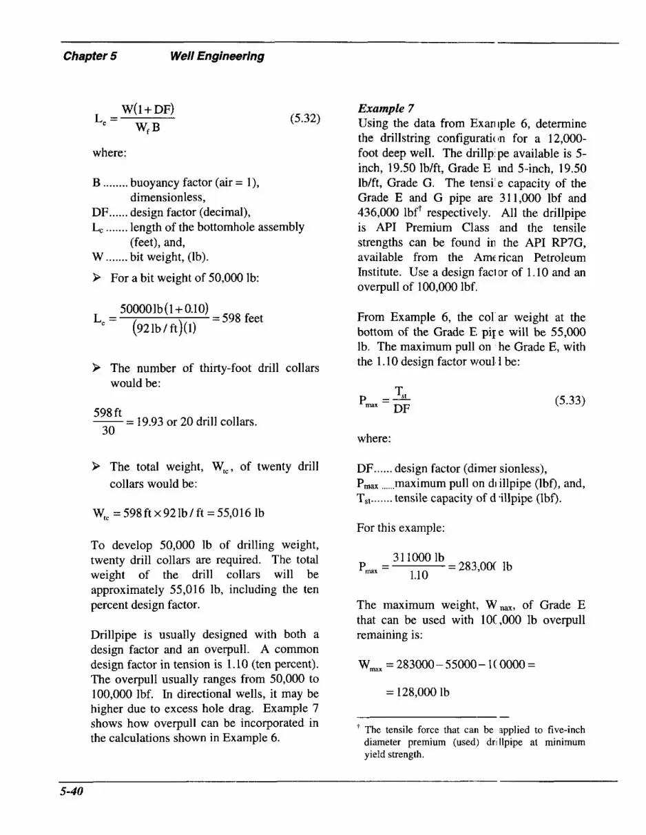
Chapter 5 Well Engineering
W( 1 + DF)
w* €3 L, =
where:
(5.32)
B ........ buoyancy factor (air = l), dimensionless,
DF ...... design factor (decimal), Lc ....... length of the bottomhole assembly
W ....... bit weight, (lb).
P For a bit weight of 50,000 lb:
(feet), and,
500001b (1 + 0.10)
(921b / ft)(l) L, = =598 feet
P The number of thirty-foot drill collars would be:
-- - 19.93 or 20 drill collars. 598 ft
30
9 The total weight, W,,, of twenty drill collars would be:
Example 7 Using the data from Exaniple 6, determine the drillstring configuratic In for a 12,000- foot deep well. The dril1p:pe available is 5- inch, 19.50 lbift, Grade E ind 5-inch, 19.50 Ib/ft, Grade G. The tensile capacity of the Grade E and G pipe are 3 11,000 lbf and 436,000 lbft respectively. All the drillpipe is API Premium Class and the tensile strengths can be found in the API RP7G, available from the Amc rican Petroleum Institute. Use a design faci or of 1.10 and an overpull of 100,000 lbf.
From Example 6, the col ar weight at the bottom of the Grade E pile will be 55,000 lb. The maximum pull on he Grade E, with the 1.10 design factor woull 1 be:
(5.33) 1 s t p =- DF I M X
where:
DF ...... design factor (dimer sionless), P,, ...... maximum pull on di illpipe (lbf), and, T,, ....... tensile capacity of d .illpipe (lbf).
W,, = 5 9 8 f t ~ 9 2 l b / f t =55,016 lb For this example:
To develop 50,000 lb of drilling weight, twenty drill collars are required. The total weight of the drill collars will be approximately 55,016 lb, including the ten percent design factor.
Drillpipe is usually designed with both a design factor and an overpull. A common design factor in tension is 1.10 (ten percent). The overpull usually ranges from 50,000 to 100,000 lbf. In directional wells, it may be higher due to excess hole drag. Example 7 shows how overpull can be incorporated in the calculations shown in Example 6.
31 1000 lb
1.1 0 =283,OoC lb pmax =
The maximum weight, Wnm, of Grade E that can be used with lOC,OOO lb overpull remaining is:
Wmx = 283000 - 55000 - 1( 0000 =
= 128,000 lb
-- The tensile force that can be applied to five-inch diameter premium (used) dri llpipe at minimum yield strength.
5-40

The maximum length, Lax, that can be used is:
w,, L,, =- Wf
(5.34)
128000 lb
19.50 lb/ft = 6564 feet (Grade E) L a x =
The maximum pull, Pmm, on the Grade G, with the 1.10 design factor, would be:
436000 lb
1.10 = 396,000 lb pmx =
The maximum weight, Wmm, of Grade G that can be used with 100,000 lbf overpull remaining is:
W,, = 396000-55000- 100000- 128000=
= 113,000 lb
The maximum length, L,-, of Grade G
drillpipe that can be used is:
113000
19.50 = 5795 feet L,, =
Since the length of Grade G is greater than that necessary to reach the sufice, Grade G is acceptable to the surface. Tlte drillstring would consist of the following:
0 598 feet of drill colkrs (refer to
0 6564 feet of 5-inch, 19.50 lb/ft,
0 4838 feet of 5-inch, 19.50 lb/ft,
Example 6),
Grade E drillpipe, and,
Grade G drillpipe.
In this example, the maximum fi wce that can be pulled on the drillstring in the event it becomes stuck is 100,000 lbf o\er the string weight, once all of the Grade E drillpipe is in the hole. The weak point will be at the top of the Grade E drillpiFe. If the drillstring is changed while fish ng, the new maximum pull must be calculate 3.

- Chapter 5 Well Engheering
References
1.
2.
3.
4.
5 .
6.
7.
8.
9.
10.
11.
Guo, B., Hareland, G. and Rajtar, J.: “Computer Simulation Predicts 1 Jnfavorable Mud Rate and Optimum Air Injection Rate for Aerated Mud Drilling,” piper SPE 26892 presented at the 1993 SPE Eastern Regional Conference and Exhibition Pittsburgh, PA, November 2-4.
Govier, G.W. and Aziz, K.: The Flow of Complex Mixtures in Pipes, r:print, Robert E. Krieger Publishing Company, Malabar, Florida ( 1982).
Johnson, A.B. and Cooper, S.: “Gas Migration Velocities During Gas K icks in Deviated Wells,” paper SPE 26331 presented at the 1993 SPE Annual Technical Conference and Exhibition, Houston, TX, October 3-6.
Poettmann, F.H. and Bergman, W.E.: “Density of Drilling Muds ‘<educed by Air Injection,” World Oil (August 1, 1955) 97-100.
Bourgoyne, A.T., Jr.: “Rotating Control Head Applications Increasing. ” Oil & Gas J. (October 9, 1995).
Cress, L.A., Stone C.R. and Tangedahl, M.: “History and Developmeit of a Rotating Blowout Preventor,” paper IADC/SPE 2393 1 presented at the 1992 IAI W S P E Drilling Conference, New Orleans.
Cummings, S.G.: “Natural Gas Drilling Methods and Practice: San Jian Basin, New Mexico,” paper SPE/IADC 16167 presented at the 1987 SPE/IADC Dril ing Converence, New Orleans, LA.
Dupont, J.: “Foam Used to Drill, Gravel-Pack Deep Gas Well,” Oil uric Gas J . (May 7, 1984) 192-194.
Fraser, I.M. and Moore, R.H.: “Guidelines for Stable Foam Drilling Thro igh Permafrost,” paper SPE/IADC 16055 presented at the 1987 SPE/IADC Drilling Conference, New Orleans, LA.
Curtis, F. and Lunan, B .: “Underbalanced Drilling Operations: Cc rrect Operating Procedures Using a Closed Surface Control System to Drill for Oil arid G as,” presented at the 1995 International Underbalanced Drilling Conference, Amsterdam, ’he Netherlands, February 28-March 2.
Saponja, J.: “Engineering Considerations for Jointed Pipe Underbal mced Drilling,” presented at the 1995 International Underbalanced Drilling Conference, lmsterdam, The Netherlands, February 28-March 2.
5-42

12.
13.
14.
15.
16.
17.
18.
19.
20.
21.
22.
23.
Hannigan, D.M. and Bourgoyne, A.T., Jr.: “Underbalanced Drilling Rot; ting Control Head Technology Increasing in Importance,” presented at the 1995 International Underbalanced Drilling Conference, Amsterdam, The Netherlands, February 2 %March 2.
Bloys, B., Brown, J.D. and Tarr, B.A.: “Drilling Safgy and Economically ir Carbonates: Collective Experience of ARCO, BP and MOBIL,” paper presented at the 1991 i IADC Well Control Conference for the AsiaPacific Region, Singapore, December 1-2.
Bradley, W.B. and Fontenot, J.E.: “The Prediction and Control of Casing Wear,” JPT (February 1975) 233-243.
Dowel1 Schlumberger, Cementing Technology, Nova Communications L d., London, (1984).
Coates, G.R. and Denoo, S.A.: “Mechanical Properties Program Using Bo *ehole Stress Analysis and Mohr’s Circle,” Trans. 198 1 SPWLA Annual Logging Symposiu m.
Mason, K.L.: “Tricone Bit Selection Using Sonic Logs,” paper SPE 13256 presented at the1984 59th SPE Annual Technical Conference and Exhibition, Houston, Ter as.
Sparr, J., Ledgerwood, L., Goodman, H., Graff, R.L. and Moo, T.J.: “Formation Compressive Strength Estimates for Predicting Drillability and PDC Bi Selection,” SPE/IADC paper presented at the 1995 SPE/IADC Drilling Conference, Am iterdam, The Netherlands, February 28-March 2.
Fear, M.J., Meany, N.C. and Evans, J.M.: “An Expert System for Drill Bjt Selection,” SPE/IADC paper 27470 presented at the 1994 SPE/IADC Drilling Confermce, Dallas, Texas, February 15- 18.
Brannon, K.C., Grimes, R.E. .and Vietmeier, W.R.: “New Oilfield Air ]lit Improves Drilling Economics in Appalachian Basin,” ASME J. Energy Tech. PD-Vol. 56, Drilling Technology (1994) 79-87.
Newman, E.F.: “Design and Application of So€ter Formation Tungsten C arbide Rock Bits,” IADC/SPE paper 1 1386 presented at the 1983 IADC/SPE Drilling Con ‘erence, New Orleans, LA.
Cooper, L.W., Hook, R.A. and Payne, R.R.: “Air Drilling Techniques,” pap !r SPE 6435, presented at the 1977 SPE Deep Drilling and Production Symposium, Amarill >, Texas.
Glowka, D.A. and Stone, C.M.: “Effects of Thermal and Mechanical Loadin] on PDC Bit Life,” SPEDE (June 1986) 201-213.

- Chapter 5 Well Engineering
24.
25.
26.
27.
28.
29.
30.
31.
32.
33.
34.
35.
36.
Eaton, N.: “Coring the Horizontal Hole,” PD-Vol. 27, ASME Dri ling Technology Symposium, Weiner, P.D. and Kastor, R.L. (eds).
Selim, A.A., Schultz, C.W. and Strebig, K.C.: “The Effect of Additive! on Impregnated Diamond Bit Performance,” paper SPE 2387, SPEJ (December 1969) 425.433.
Unger, H.F., Snowden, B.S. and Engelmann, W.H.: “Diamond Drilling with Surfactants in Upper Michigan Conglomerates Using Surface-Set Bits,” paper SPE 423 i presented at the 1973 Conference On Drilling and Rock Mechanics, SPE AIME, Aiistir, Texas (January 1973).
Hutchinson, S.O.: “Stable Foam Lowers Production, Drilling and F emedial Costs,” presented at the 17th Annual Southwestern Petroleum Short Course (April 1970).
Bentsen, N.W. and Veny, J.N.: “Preformed Stable Foam Performance in Drilling and Evaluating Shallow Gas Wells in Alberta,” JPT (October 1976) 1237- 1241 1.
Cobbett, J.S.: “Application of an Air-Drilling Package in Oman,” paper SPE 9600 presented at the 198 1 SPE Middle East Oil Technical Conference, Manam I, Bahrain.
Yew, C.H. and Zhang, X.: “A Study of the Damaged Zone Created l y Shape Charge Perforating,” paper SPE 25902 presented at the 1993 Low Pelme; bility Reservoir Symposium, April 26-28.
Bell, W.T.: “Perforating Underbalanced-Evolving Techniques,” JPT (( kt. 1984) 1653- 1662.
Crawford, H.R.: “Underbalanced Perforating Design,” paper SPE 15,749 presented at the 1989 SPE Annual Technical Conference and Exhibition, San Antonio, T :xas, October 8- 1 1 .
King, G.E., Anderson, A. and Bingham, M.: “A Field Study of Under lalance Pressure Necessary to Obtain A Clean Perforation Using Tubing-Conveyed Perfora ting,” paper SPE 14321, JPT (June 1986) 38, No. 8,662-664.
Regalbuto, J.A. and Riggs, R.S.: “Underbalanced Perforation Characteri ;tics as Affected by Differential Pressure,” SPEPE (February, 1988) 83-88.
Halleck, P.M. and Deo, M.: (November 1989) 1 1 3- 1 16.
Hook, R.A., Cooper, L.W. and Payne, B.R.: “Air, Mist and Foam Drilling: A Look at the Latest Techniques: Parts I and II,” World OiE (April and May, 1977).
“The Effect of Underbalance on Perfora ion Flow,” JPT
5-44

SPECIAL CONSlD€RATlllNS
6.7 Safety in Underbalanced Drilling
Introduction Underbalanced drilling differs from conventional overbalanced drilling in that flow of reservoir fluids (brine, oil and gas) into the wellbore is intentionally promoted because of the differential pressure. Appropriate surface equipment is available to process this returned fluid and to safely separate hydrocarbons from brine, drilling fluid and cuttings. Since significantly greater volumes of oil and gas are produced in underbalanced drilling (compared to Overbalanced drilling), and because these products are highly com- bustible, considerable attention must be paid to safety procedures.
Mudcap drilling is one case where fluids are not produced to surface (Chapter 2, Section 2.9). In this method, all reservoir fluids are contained below the surface and are not allowed to circulate back to the surface. In mudcap drilling, drilling fluid, designed to have a smaller density than the necessary kill weight fluid required by the formation pore pressure, is “bullheaded” clown the drillstring, while the annulus, which has been pre-loaded with a higher weight, viscosified fluid, remains shut-in. Safety measures are essential.
For underbalanced drillin ;, safety procedures are required to isolatf potentially explosive and flammable hydroc arbons and to properly dispose of these liquid or gaseous hydrocarbons. Onsht )re, oil or condensate is dispatched to stora ge facilities for removal while produced gas is generally flared. Offshore, both oil aiid gas are usually burned due to space lin itations for safe storage at the drilling site. T a liquids’ pipeline outlet or oil tanker is avfilable, it is possible to pump produced oil or condensate and avoid burning these products
Hydrogen Sulfide Gas Oper; ations Hydrogen sulfide gas (H2S) i: extremely poisonous. It can be presen in liquid hydrocarbon vapors or as a free gas phase. H2S is particularly dangerous bec ause it first attacks a person’s sense of smc11 and then renders the olfactory system ii (capable of noticing the distinctive rotten e ;gs odor of the gas. H2S gas can kill a : very low concentrations. The higher the cc mcentration of HZS, the more rapidly de5th occurs. Finally, H2S gas will attack 1 igh carbon content (high strength) metals, c iusing them to become extremely brittle and i ail.
Many states have regulations spc cifically for drilling in known H2S areas. If an operator conducts underbalanced drilling operations in a known H2S area, or is drilling in a

- Chapter 6 Special Considerations
remote, untested area, special precautions must be implemented to protect personnel and equipment. These situations require:
9
9
9
9
9
>
Providing necessary notice of the proposed operations and hazards.
Adequate training.
Special safety equipment, such as H2S sensors, warning alarms, wind direction socks, H2S concentration measuring devices, portable and fixed air breathing respirators.
An H2S emergency contingency plan with site specific information and detailed procedures.
Hydrogen sulfide-resistant materials and training.
Pressured surface separation vessels and auxiliary vacuum degassing equipment to isolate all personnel from possible exposure to this poisonous gas.
Flaring Gas Particularly where very high gas volumes will be produced to the surface, adequately sized flare lines, leading to properly positioned flare stacks, equipped with automatic flame igniters, are essential on underbalanced drilling sites. The prevailing wind direction must be taken into consideration in placing these flare systems on location. Depending on the specific location requirements, the height of the flare stack may be adjusted for optimum performance. Be certain that flare lines are adequately anchored.
Separation and Storage To avoid fire or explosion hazards, liquid hydrocarbon separation and storage facilities, again with wind direction taken into account, must be positioned remotely.
Adequate storage vc Jume, properly manifolded for transfer or loading, is necessary for safe, uni iterrupted under- balanced drilling.
Training Personnel training and detailed, written, underbalanced drilling pi xedures are also required for safe operatior s . Redundancy in critical manpower posititm and in choke manifold equipment he ps to avoid or accommodate unforesec n emergencies, which can rapidly develop Location ingress and egress are critical dur ng underbalanced operations. Emergency, back-up escape access is very helpful in he event of wind direction changes or blocked primary entrance access. Gas detection, fire extinguishing and other safety equipment should be placed at strateg IC locations on the rig and on the location site
Downhole Fire Air, when used to lightei a drilling fluid column for underbalanced drilling, may lead to equipment corrosion ivhen it is mixed with water, or explosicn or fire when contacted with hydroca bons. Extreme caution must be exercised when using air in drilling applications. Exte nsive experiment- ation has been conducted to determine the maximum safe limits of combining conventional air or reducc d-oxygen content air with drilling fluids anc hydrocarbons, to avoid combustible mi> tures (refer to Chapter 2).
Drilling with Natural G, 3s Never underestimate the ( angers of surface fires, in any underl: alanced drilling operation. This is paricularly true for drilling with natural gas In the United States, safety conformlancc: on a drilling rig using natural gas must 1:t least meet the
- 6-2

following guidelines.
9
9
>
American Petroleum Institute (API) RP 500B: Recommended Practice for Classification of Areas for Electrical Installations at Drilling Rigs and Production Facilities on Land and on Marine Fixed Mobile Platforms - 1973.
National Fire Protection Association (NFPA) 70: National Electric Code - 1990.
NFPA 496: Purged and Pressurized Enclosures for Electrical Equipment in Hazardous (Classified) Locations - 1988.
The cost savings while drilling with natural gas should offset any additional expenses associated with regulatory complimce.
Backflow To prevent flow back up the drillpipe, drillstring floats should be installed. Tools have been developed to relieve pressure trapped below drillstring floats. This tool is installed above a drill float and allows a pin to be screwed down to mechanically open the valve and release possible trapped pressure. A side-port outlet on the tool safely releases any pressure.
Placement of drillstring floats is important for operational and safety reasons. Complete redundancy of these valves ensures a reliable back-up in the event of a tool failure. The number of float valves chosen for an underbalanced drilling job depends somewhat on the type of drilling being used. If the drilling fluids are primarily liquids, most operators minimize the number of drill floats, sometimes using only a single valve to save rig time and rental expense. Underbalanced systems, where gas is used to reduce the drilling fluid density, generally
use many more float valves in thc drillstring. Two floats should be placed c ose to the surface to minimize the time mequired to bleed off pressure before making a connection. In the middle sec ion of the drillstring, valves are also important, to minimize downhole fluid separarion and to prevent slug flow. For maximun safety and control, two floats should also be installed in the last stand of the drillstring assembly. For optimum conditions, a gold rule-of- thumb in gas-assisted drilling is to install a float every twelve joints. Be certain that floats are restrained when connyctions are made (refer to Chapter 5, Section 5.9).
Well Control Procedures Carefully develop contingency F lans before the drilling operations start (re fer to, for example, Willis, 1995l). 'I he casing program and circulation design, as well as on-location quality control and nonitoring, are particularly important in situa .ions where an underground blowout is possik le.
Equipment Collins, 1994,2 provided a conci: e summary of certain important considei ations for ensuring safe operation of rig site equipment. The discussion was c esigned for flowdrilling but the componen:~ and the philosophy can be adopted elsewl iere. Some of the important aspects are:
9
9
9
Operational and equipme nt testing procedures must be :stablished, comprehended by all penonnel and enforced.
Operations should not cmtinue if pressures exceed the maxi1 aunt limits established.
"In flowdrilling, emphasis i! placed on monitoring pressure whil ; drilling,
6-3

Chapter 6 Special Considerations
9
9
9
9
9
9
9
tripping and stripping, in addition to early kick detection if wells are killed. Like BOP drills, safety, fire and environmental awareness should be included in routine practice.”
“There are many BOP equipment failure causes. The only way to develop testing procedures [to ensure safe equipment operation] is to prepare detailed BOP and manifolding flow diagrams that show step-by-step testing for system parts. BOP stacks should be tested when installed, each time they are reinstalled, once each week and following repair.”
Regularly inspect and monitor surface equipment (i.e. gas monitors, mudgas separators, diverter rubber elements and safety equipment).
Stop flowdrilling when H2S is detected.
Inspect mudgas separators daily (check for cuttings plugging), or more frequently in areas where ROP is high.
Inspect diverter rubber elements several times a day.
Check diverter alignment with the rotary table.
Have developed contingency plans.
6.2 Regulatory Requirements
Introduction As Eresman, 1993,3 stated, “API Committee RP 53+ proposed in draft Section 13 that underbalanced drilling is any drilling operation where an influx of formation
‘“Blowout Prevention Equipment Systems for Drilling Wells,” American Petroleum Institute Recommended Practice (1984) API RP 53.
fluids is allowed intcl the wellbore, circulated out and control ed at the surface. The influx can occur as i result of severe and uncontrollable lost returns and/or by a conscious decision of the operator to drill with an influx as a me(ins of enhancing drilling performance.”
In the United States, ( I survey of the primary oil and gtzs ,~roducing states indicated that there ere no special regulations written I pecifcally for underbalanced drilling. A n most cases, the existing regulations codd be broadly interpreted to cover under balanced drilling. For instance, in L0uisian;b in reference to drilling fluids, the operatlpr or company is required to “use due cliligimce in correcting any objectionable conlditic ns.” Most states will require adequate blc wout preventers; for underbalanced drilling as well as conventional drilling. In some cases, such as in California, it may be sufficient to simply convince the State 1 Iivision Inspector that operations would be carried out in a prudent and safe manner.
In Texas, the Railroad Con imission of Texas specifically recognized tl le possibility of underbalanced drilling in clause (E) of Rule 13 (Casing, Cementing Drilling, and Completion Requirements- Amended August 13, 1991) of regulation :.13. Clause (E) states that wells drilling to formations where the expected reservoir pre ;sure exceeds the weight of the drilling fluic column shall be equipped to divert any we’ lbore fluids away from the rig floor. All divc rter systems shall be maintained in an e ffective working condition. No well shall continue drilling operations if a test or ( dher information indicates that the diverter s {stem is unable to function or operate as desii ned.
6-4

In planning an underbalanced well, it is always advisable to check with the local, state or federal agency governing the well’s location, to determine the latest changes in applicable laws or rules which might apply. For example, in planning to drill a horizontal underbalanced well under the jurisdiction of federal authorities, the limit on total emissions from the location probably will be reached more rapidly than for a vertical well, due to the higher expected production and the length of formation exposed in the lateral. An exception request to this limit, made in advance, will more likely be approved than one made during or after drilling has started.
Regulations for Underbalanced Drilling (Canada) In North America, the most detailed regulatory suggestions are outlined in Interim Directive ID 94-3,4 from the Energy Resources Conservation Board (ERCB) in Alberta, Canada. This Directive covers recommended practices and contains sensible, well considered suggestions by individuals experienced with underbalanced drilling. This document is available from the ERCB. Of the recommended practices, the ERCB has mandated strict enforcement for three areas, pertaining to:
9 Blowout prevention system config-
9 Tripping procedures, and,
9 Well control certification of key per-
For the remainder of the practices, the ERCB accepted industry suggestions that these practices place “considerable legal and moral responsibility on operators and contractors involved in underbalanced drilling to follow the recommended practices
urations,
sonnel.
or to otherwise provide technically equivalent or better practices.’ y4
Regulations for Underbalar iced Drilling (United Kingdom) Outside of North America, otler countries have developed regulations governing underbalanced wells. In the United Kingdom, these rules have undergone significant changes over time. Regulations are well summarized by Moore, 1995.5 The Department of Trade and Ind istry (DTI), with authority under the Petroleum Production Regulations, se s specific requirements and regulations pe tinent to the drilling and completion of UI derbalanced wells. The DTI, in turn, has ddegated this authority to the Health and Safe :y Executive (HSE) to review operators’ app ications and detailed well plans, and to grmt or deny permits for the proposed work.
Safety of drilling personnel anc the general public is the overriding conside-ation of the HSE. The work must be ca-ried out in accordance with good oilfield practice, as defined by the HSE. Safety at work is the primary subject of The Health 2nd Safety at Work etc. Act of 1974 and the : rlanagement of Health and Safety at Work RI :gulations of 1992, much the same as the Occupational Safety and Health Act (OSHA) i n the United States.
New regulations for the petrolc um industry are based on a combination of ti lese existing laws and a review of safety incidents, notification of well operations, and follow- up inspections and audits. , Additionally, offshore requirements are establ shed by The Offshore Installations (Sal ety Case) Regulations of 1992, Thc : Offshore Installations (Prevention of Fire and Explosion, and Emergency Response)
6-5

- Chapter 6 Special Considerations
Regulations of 1995 and The Offshore Installations and Wells (Design and Construction) Regulations of 1996.
These regulations are designed to protect the safety and health of offshore oilfield workers by:
> Identifying potential offshore drilling
> Properly assessing these risks,
> Ensuring that these risks are as low as reasonably practicable (ALARP),
> Correctly providing notice of proposed well operations,
> Defining the performance standards for all aspects of offshore operations, and,
> Establishing a clearly defined Safety Management System.
hazards,
Three months prior to the beginning of operations, an operator must submit a safety case to the HSE for their review. This must contain information identifying all hazards associated with the proposed operations and ensure that appropriate countermeasures will be in place to handle these problems and to keep the risks ALARP.
On November 30, 1995, Regulation 11 of the Safety Case Regulations became effective. It requires offshore operators to notify the HSE twenty-one days before commencing well operations, to avoid penalty. The Borehole Sites and Operations Regulations, which became effective October 1, 1995, require onshore operators to follow similar notification procedures. It is necessary to not only notify the HSE of proposed underbalanced operations, but also to update them on all operational plans, drilling equipment to be used, procedures to
be followed, other SF ecific materials required, and environment il considerations. Both the operator and the (killing contractor must demonstrate that all identifiable risks are ALARP. The Britisk legal system is very familiar with interpret itions of this law. They have established rea: onable measures of weighing an operator’s cost in money, time and effort to achieve tl lese reductions in risks. If a proposecl operation is economically marginal 01 so excessively burdened with regulation:) as to become intolerable, latitude is genei ally allowed.
Regulations for Underk alanced Drilling (United States) In the United States, a survey of the primary oil and gas producing states indicated that there w ?re no special regulations written s 7eciJically for underbalanced drilling. I ] 1 most cases, the existing regulations COL M be broadly interpreted to cover under€ alanced drilling.
If regulations are not clear or the burden is placed on the operator to adopt safe and prudent practices, what shc uld the operator do?
9 Research specific regulations of the governing agencies.
> Interact with the relei ant agencies to ensure that there will be no future repercussions.
> Adopt reasonable practices. For ex- ample, in Canada, surfaze BOP systems, as a minimum, must COI isist of an ERCB Class III well serviciig stack design (Energy Resources Cor servation Board, Alberta Oil and G ; s Conservation Regulations Section L129 to 8.148 (including schedules 8, 10 and 11) with some type of diverter system, flaring

capability, and the capability to equalize pressure between the diverter line and a point below the lowest ram type preventer (with some exceptions).
9 For example, as Eresman, 1995,3 stated: “When a well is being drilled with air, the licensee shall install and maintain:
0 in addition to the blowout prevention equipment required in Schedule 8, a rotating head that diverts the flow during the period the well will be drilled with air,
0 a diverter line not less than 50 m [164 feet] in length,
a reserve volume of drilling fluid equal to or at least 1.S times the capacity of the hole,
when drilling formations that may contain hydrogen sulfide, a continuous hydrogen sulfide monitor on the diverter line, and,
a continuous ignition device at the end of the diverter line.”
0
0
0
Consider the following issues:
9 Be certain that the BOP stack, with a diverter system:
permits drilling to proceed while controlling annular pressure,
allows connections to be made either with the well flowing or shut-in,
allows tripping of the drillstring under pressure to change bits or bottomhole assemblies,
provides for backup annular control in case of failure of the diverter,
provides for a choke manifold arrangement which allows annular
9
9
9
9
>
P
9
9
>
>
9
pressure to be varied sc that it will not exceed related work ing pressure of the equipment,
provides a means to bleed-off pressure or to kill the well, independent of the diw rter system, grid,
provides a means to pickly and safely shut-in the well.
Use string float(s) and fire f oat(s), if air is used,
If sour gas is present, drillpi] be protection and blind shear rams are nee led,
Kill fluid is needed,
Casing integrity needs to bo guaranteed and full length cementing should be implemented as regulated,
Surface equipment spacing needs to adhere to appropriate regula1 ions,
Flaring must follow appropriate regulations,
Appropriate separator equiF ment should be used, as required,
Provide adequate provision for storage of produced fluids,
Crews need to be appropria :ely certified and trained,
Monitoring and alarms are essential for H2S environments, and,
Adhere to all safety regulati ons.
6.3 Environmental 1 sues

~ ~-
Chapter 6 Special Considerations
Land and Water Pollution Underbalanced drilling provides some environmental benefits but also causes some unique environmental complications which must be properly handled. For example, produced oil and natural gas have to be safely and environmentally processed. Oil presents the greatest challenge. If drill cuttings are oil-coated, surface handling is different than for regular, non-oiled material. These oil-coated cuttings are commonly jetted to lined containers which are environmentally disposed of following drilling operations. Designated, approved disposal sites are available for this purpose. The cuttings are either trucked or barged to these sites.
Closed loop surface facilities provide extra environmental protection over drilling operations which use earthen reserve and cuttings pits. With some exceptions (i.e. possibly supplementary chemical additives for flocculation), cleanup and disposal requirements are simplified for closed loop systems. Even more significantly, under- balanced drilling inherently involves lower drilling fluid densities than are used in comparable overpressured drilling. Clear fluid systems are often used. These fluids may be less expensive and may cause less formation damage if lost circulation or seepage occurs. Heavier mud systems, in conventional operations, can contain higher concentrations of heavy metals and other potentially harmful additives, commonly barite. In Louisiana, the Department of Natural Resources Office of Conservation and the Department of Environmental Quality both have jurisdiction over the petroleum industry. Statewide Order 29-B sets limits on the allowable concentrations of nine heavy metals, sometimes found in drilling fluids. These are arsenic, barium,
cadmium, chromium, lead, mercury, selenium, silver and zinc. ’ The concentration limit for barium is set at 20,000 ppm for wetland areas and 40,00C ppm in upland areas of the state. When si, pificant amounts of barite are in a liquid mud system, the fluid becomes “contamina ted”. This mat- erial requires environmel ita1 disposal or dilution treatment on locati in (land farming) in order to restore the surlace locations (as part of cleanup durii ig post-drilling operations). Soil sample: must be taken before and after drilling opt :rations to ensure proper compliance with tlese rules. This expense can be minimizc d or eliminated entirely by using under1 alanced drilling methods and clear drilling f uids.
Heavier drilling fluids also tend to effectively entrain pro hced oil or condensate, without breakir g out of the mud at the surface. On the cther hand, clear fluids separate oil fairly easily. Some liquid muds can contain as much as thirty percent oil by volume. These oil- iaturated drilling fluids, as well as oil-based nud systems, are an environmental consider ition for storage or disposal, if they cannclt be reused on another well.
Since underbalanced drill ng incorporates new generation wellhe ad equipment, environmental (as well as safety) considerations are improve 3. The rotating head provides low to n edium pressure containment, in addition to the rig’s conventional set of blowout preventers. The M O P provides safer, uedium to high pressure containment, as re dundancy to the regular blowout preveriters Both systems offer improved benefits over the rig preventers alone.
Surface production hand1 ing equipment,

including dual choke manifolds, gasniquid separators, liquid skimmer and retention tanks and liquid hydrocarbon storage tanks, all serve to provide a more environmentally- safe operation for underbalanced drilling.
Air Pollution Considerations Burning of hydrocarbons, produced during underbalanced drilling, can become an environmental concern. Air pollution, especially when liquid hydrocarbons are burned, can exceed allowed emissions limits for a particular drill site. This problem can be more severe when the location is in a populated or smog-prone area. Federal and state limits on total emissions originating from a particular location must be known in advance, in order to properly plan the well and to comply with these limits (or request a special waiver for an exception). Exceptions may be granted. Dust clouds may be a problem during air drilling. Water sprays can quench the dust. With air drilling, noise pollution may be a special concern near populated areas.
Produced Water Disposal In addition to hydrocarbons, produced formation water can be a disposal issue. Produced water can be supplemented by drilling water. This becomes more‘ of an issue with foams. Defoaming is an important surface procedure. Options are available for disposal. They are all impacted by specific regulations and associated costs. Disposal operations can include:
P Disposal into surface water drainage systems. This is dependent on volumes, water quality and supplementary surface processing (such as aeration), regulations and monitoring facilities.
> Reinjection. Subject to regulations,
reinjection into permeable zones in designated disposal wells may be permitted. It may or may not be required to remove cuttings. Cutting! reinjection down the annulus may be possible, if pressures are acceptable, and zone permeability is adequate. Avoiding aquifer contamination anc I ensuring containment integrity ar 5 primary considerations in permittir g disposal wells.
Approved lund disposal sites.
Overboard offshore disposl: 1. This is highly regulated and it should be anticipated that regulations r Jill become even more stringent in the ful ure.
Reserve pits. As indicated by Collins, 1994,’ “Reserve pits should t e built with integrity to retain wastes i nd prevent ovefflow during rains. In acidition, pits and drilling pads should be designed to collect rig wash, spills and leaks from equipment, stormwater n moff, and should keep non-drilling pa d rainwater from entering pits. Lined i ts , barrier walls or closed mud systems ue required in environmentally sensitj ve areas.” Collins, 1994,’ provide d further summary discussions regardi ng pits, i.e. liners for pits for oil-based muds and brines must be compatible with these fluids. Operator responsib Jities were summarized.
Any pollution resulting from d illing must be a concern to the petro1eu.n industry. Before drilling the operator mu;t be aware of pertinent regulations.
6.4 Directional Drilli, 7g
lntroduction There is no reason why dirxtional or
- -
6-9

- Chapter 6 Special Considerations
horizontal wells should not be drilled underbalanced. The design and operational issues are the same as for conventional direction drilling - directional control, surveying, hole cleaning and drillstring friction. The same downhole equipment can generally be used as for overbalanced drilling. Many high angle, extended reach and horizontal wells have been drilled with gasified liquids, with the attendant advantages.
Drilling high angle, extended reach or horizontal wells with air as the circulating medium is not yet common practice; however, air has some distinct advantages over drilling mud. These include:
9
9
9
>
Penetration rates are significantly increased, leading to shorter drilling times and lower costs,
Lost circulation problems are eliminated (or moderated) especially in areas with very low bottomhole pressures,
Drillstem testing of potential producing formations is continuously possible, and,
Formation damage is minimized.
Along with the advantages of underbalanced operations, using compressible drilling fluids can complicate direction drilling. Because compressible fluids may pose more operational problems than liquids, this section concentrates on their use in directional drilling. Some of the problems that could be expected are:
9 Conventional downhole motor life is shorter and conventional motors do not operate as efficiently,
9 Conventional Measurement While Drilling (MWD) systems do not work in an environment with compressible fluid,
9 Hole cleaning can lie a problem at inclinations above, 5( O , with dry gas, mist and foam,
9 The horizontal section length is reduced because of the inc -eased drillstring friction (drag), and,
9 Not all formations aiId lithologies are suitable for drilling wi h dry gas, mist or foam.
However, horizontal drill, ng with air, mist and foam systems can b?, and has been, successful. With careful planning, all of these problems can bo minimized or eliminated.
Horizontal wells have 1 een successfully drilled with air or foam since 1986. At a minimum, operators a .e drilling the horizontal section with air or foam to eliminate lost circulation problems in low pressure (partially deplete 1) reservoirs, and to reduce formation dama;e due to drilling fluid invasion. Problem; have been en- countered in drilling these horizontal wells. Not all of these problems are unique to air drilling. They are sometim ES exaggerated by the conditions in an air hde. By changing the conventional method O F operations in an air hole and anticipating p )tential problems, air drilling can be cost competitive and possibly even less zxpensive than conventional drilling.
Bottomhole Assemblie s The United States DOE lias led efforts in horizontal air drilling." Tt e main issues for directional drilling unl lerbalanced are similar to those for convei tional directional drilling:
> Directional control.,
9 Surveying,
6-10

P Hole cleaning, and,
P Drillstring friction.
Forces Acting at the Bit A bottomhole assembly is the arrangement of the bit, stabilizer, reamers, drill collars, subs and special tools, used at the bottom of the drillstring. Anything that is run in the hole to drill, ream or circulate is a bottomhole assembly. Hole incljnation can be controlled by adjusting the bottomhole assembly stabilization, exactly as it is in rotary drilling with conventional fluids. The simplest assembly is a bit, collars and drillpipe. This is often called a slick assembly. Use of this assembly in directional drilling is very limited and is usually confined to the vertical section of the hole, where deviation is not a problem.
Bottomhole assemblies will deviate a hole. To understand why this happens, consider the slick assembly. It is the simplest and easiest to understand. The deviation tendency in this assembly is a result of the flexiblility of the drill collars and the forces which act on the assembly, causing the collars to bend. Even though drill collars seem to be very rigid, they will bend enough to cause deviation.
The point at which the collars contact the low side of the hole is called the tangency point (Figure 6-1). The distance, L, from the bit to the tangency point, depends on the collar size, the hole size, the applied bit weight, the hole inclination, and the hole curvature. Generally, L is less than 150 feet. Above the tangency point of the slick assembly, the remainder of the drillstring has no effect on deviation. As weight is applied to the bit, the tangency point will move closer to the bit.
Because of the bending of the crill collars, the resultant force applied to the jormation is not in the direction of the hole a ;is. It is in the direction of the drill collar a: is. This is shown in Figure 6-2. The angle 1 )etween the hole and the collar axis is denoted as @. As bit weight is applied, the tangency point moves toward the bit, increasing he angle 9. An increase in bit weight leads to an increase in 41 and a resulting ncrease in deviation tendency.
Unfortunately, the resulta it force incorporates additional compone nts (Figure 6-3). The primary component is the drilling force in line with the axis of the 1 borehole. In addition, FB is the bit side forcc caused by bending of the collars, acting pe rpendicular to the axis of the borehole. Fp s the force due to gravity (acting on the tnsupported section of drill collars) resob ed in the opposite direction to and countr racting FB. The net deviation force is then rqual to the summation of FB and Fp. Ideally, if Fp is greater than FB, the hole angle will drop. If Fp is equal to FB, the hole angle will remain the same; and, if Fp is less than I ~ B , the hole angle will increase.
The deviation tendency can be c( Introlled by changing the bit weight. Increaiing the bit weight will lower the tangency point, increasing the angle 9. Si ice FB is proportional to sin@, an increase in bit weight increases the bit side force and ultimately the deviation tendency. Conversely, a decrease in bit .veight will decrease the deviation tendency.
This may all sound significai t, but the deviation force for a slick bottomhole assembly is very small. Figures 5-4 through 6-8 show the calculated resultani force for a
6-1 1

- - - Chapter 6 Special Considerations
Figure 6-1. Schematic representation of a bottomhole assembly in ai I inclined hole.
0
Figure 6-2. The resultant force applied to the formation is not in the direction of the hole axis. The force is in the direction of the drill collar axis because of bending of the drill collars.
6-12
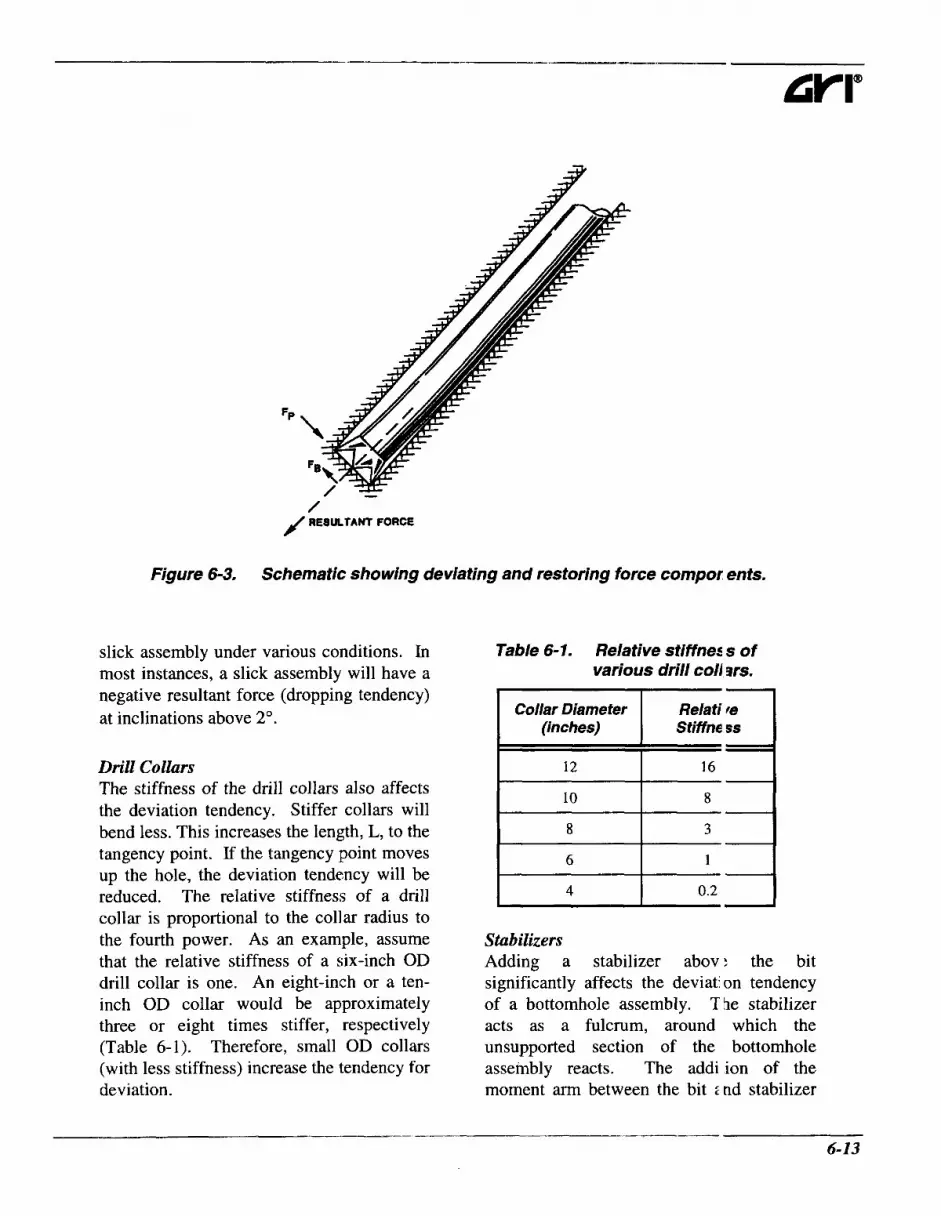
Figure 6-3. Schematic showing deviating and restoring force compor ents.
Collar Diameter (inches)
12
10
slick assembly under various conditions. In most instances, a slick assembly will have a negative resultant force (dropping tendency) at inclinations above 2". Relati te
Stiffne ss
16
8
- - - Drill ColEars
The stiffness of the drill collars also affects the deviation tendency. Stiffer collars will bend less. This increases the length, L, to the tangency point. If the tangency point moves up the hole, the deviation tendency will be reduced. The relative stiffness of a drill collar is proportional to the collar radius to the fourth power. As an example, assume that the relative stiffness of a six-inch OD drill collar is one. An eight-inch or a ten- inch OD collar would be approximately three or eight times stiffer, respectively (Table 6-1). Therefore, small OD collars (with less stiffness) increase the tendency for deviation.
Table 6-1. Relative stiffnez s of various drill coll om.
I 4 I 0.2 I I - !
Sta bilizers Adding a stabilizer abov: the bit significantly affects the deviatj on tendency of a bottomhole assembly. The stabilizer acts as a fulcrum, around which the unsupported section of the bottomhole assembly reacts. The addi ion of the moment arm between the bit 2nd stabilizer

Chapter 6 Special Considerations
100
80
60
40 F = 0) 20
5 -20
LL g o c
c - 3 -40
-60
-80
-100
-1 20
al
0 loo00 20000 30000 40000 50000 60000 71lOOO
Bit Weight (Ibf)
Figure 6-4. Resultant force for a slick assembly in a 7 7/8-inch dial neter hole.
0
0 LL - 0
3 -10
e 10
- s v) al = -20 -30
-40
-50 0 5000 10000 15000 20000 25000 30000 35000
Bit Weight (Ibf)
Figure 6-5. Resultant force for an assembly with 4%-inch drill collar P in a 6%-inch hole. Note the reduction in the resultant force, in cornpark on to Figure 6- 4.
6-14

250
200
150
E v
- s 8 100 2 c 50 0 L
3 0 w t
-50
-100
-1 50 0 loo00 20000 3oooo 40000 50000 60 XI0
Bit Weight (Ibf)
Figure 6-6. Resultant force in a hole, inclined at 2", drilled with 6Wnch c ollars. The resultant force is shown as a function of bit weight and hole siz ?.
100
50
F G O
2 8
0 5 -50 E
3
K
- a 8 -100
-1 50
-200
Figure 6-7. Resultant force in a holey inclined at 24 drilled with 8-inch collars. The resultant force is shown as a function of bit weight and hole si, !e. Note the influence of the larger diameter drill collars.
6-15

- Chapter 6 Special Considerations
-
0
- -50
aa -100 2 9
-200
-250
Figure 6-8. Resultant force in a hole, inclined at 24 drilled with Sine :h collars. The resultant force is shown as a function of bit weight and holt 1 size.
increases the bit side force. In fact, a single stabilizer assembly is a very strong building assembly.
Addition of multiple stabilizers to an assembly makes determination of side forces at the bit much more complicated. Analyzing these types of bottomhole assemblies is beyond the scope of this manual.
Formation Anisotropy and Dynamic Conditions Assuming that a formation is uniform and that the bit can drill in any direction, the bottomhole assembly would drill in the direction of the vectorial sum of the forces at the bit. Unfortunately, a bit’s side cutting and forward cutting ability are not equal. Also, anisotropic failure of the rock can cause deviation in a direction other than the
simple vectorial sum of the Forces at the bit.
The side cutting atditj of a bit is proportional to the side: for:e exerted at the bit (the vectorial sum of FE and Fp). Under static conditions, the side force on the bit can be calculated using cor iputer modeling. When the entire bottomh3le assembly is considered, it can ble :hown that the stabilizers in the assembly also exert a side force. Therefore, stabilizer: also have a side cutting ability. It would seem that the deviation tendency could th :n be calculated. However, the side forces will change under dynamic conditions. Both the bit and the stabilizers cut sideways, rt ducing the side force on each, until equjlibr: urn is reached.
Under dynamic conditions, the relative side cutting of the bit and stalilizers becomes complicated. This makes il very difficult to
- 6-1 6

calculate the deviation tendency. The relationship between the bit and stabilizer side cutting depends on the type of bit, the type of stabilizer, the penetration rate, the rotary speed, the lithology, the hole size, and the bottomhole assembly type.
Amoco test data, published by Millheim and Warren, 1978: proved that both the bit and stabilizers will cut laterally under dynamic conditions. Figure 6-9 shows the results of some of those tests. The insert at the top shows the influence of the magnitude of the side force on a bit. The rate of side cutting decreased after this force was first applied, until an equilibrium was reached; after this, the rate of displacement remained constant. The slope of the line would be the side cutting ability of the bit under ideal conditions. A significant difference in side cutting was caused by a small change in the magnitude of the side force.
The middle insert (in Figure 6-9), demonstrates how the side cutting ability of a bit changes with the penetration rate. The cutting rate was lower at higher penetration rates. The bottom insert, shows the influence of side cutting, when drilling with a stabilizer and a constant side force. Note that with 1,500 lbf side force, the blade stabilizer cut laterally at approximately the same rate as the bit with 800 lbf side force.
These tests indicated that even though the side cutting ability of a bit is small compared to the forward cutting ability, it is enough to drill in the direction of the vectorial sum of the forces at the bit under dynamic conditions. Since the angle, $, is usually less than 1" in normal drilling operations, an operator could expect horizontal displacements similar to those in
the Amoco tests. Also, the 5ide cutting ability of soft formation bits is generally considered to be better thar for hard formation bits. Diamond bits hafe a greater side cutting ability because they i re designed with more of a cutting structur: along the lateral face of the bit.
An additional factor affectini deviation tendency is formation anisotropy. In isotropic formations, equal chip . rolumes are formed on each side of the bit tc 0th and the bit will drill straight ahead (Fi y r e 6-10). However, bedding planes an d oriented structural weaknesses make 1 nost rocks anisotropic. In such an anisotrop ic situation, relatively large chip volumes arc formed on one side of the bit tooth, causing the bit to deviate (Figure 6-10).
The magnitude and direction o ' deviation, attributable to formation anisotro ?y, depends on the bedding dip. Generally, a bit will walk updip when beds are dipp ng from 0" to 45" and downdip when beds are dipping from 65" to 90". Bedding plane lip between 45" and 65" can cause either :n updip or downdip walk. Bedding strike c; UI cause the bit to walk left or right.
Basic Assemblies There are three basic types of assemblies used in directional drilling. Thes 2 are:
0 building assemblies,
0 dropping assemblies, and
holding assemblies.
A building assembly is intended to increase hole inclination; a dropping i ssembly is intended to decrease hole inclin; tion; and, a holding assembly is intended :o maintain hole inclination. It should be iioted that a

- Chapter 6 Special Considerations
Bit Side F o m Test Data - Variable Side Force 0
0.5
1
Y f 5 1.5
2
2.5
3
0
0.5
1
5 1.5
2
2.5
3
0
0.5
1
5 1.5
2
2.5
3
0 0.1 0.2 0.3 0.4 0.5 0.6 0.7 Horlzonbi Displacement (inches)
Bit Side F o m Test Data - Variabk, &netratlon R8te
I*+Y 0 0.1 0.2 0.3 0.4 0.5 0.6 0.7
Horizontal Displacement (inches)
Stabilixer Skb Force Test Data
0 0.1 0.2 0.3 0.4 0.5 0.6 Horizontal Displacement ( i n c h )
Figure 6-9. Results of Amoco tests assessing the side cutting ab'lity of bits and stabilizers (refer to Millheim and Warren, 1978 ').
6-1 8

EqmI Chlp I
Unequal Chlp
Figure 6- 10. Chip volume formation in isotropic and anisotropic rock (refer fo example, to Millheim, 1979 *).
building assembly may not always build angle. Formation characteristics may cause the assembly to drop or to hold angle. The building assembly is intended to build angle. The same is true for the dropping and holding assemblies.
Building Assemblies As indicated, the building assembly uses a stabilizer, acting as a fulcrum, to apply a side force to the bit. The magnitude of this force is a function of the distance from the bit to the tangency point. An increase in bit
weight and/or a decrease in ~lrill collar stiffness will increase the side f irce at the bit, increasing the rate of build.
The strongest building assembly consists of one stabilizer, placed 3 to 6 feel above the bit face, with collars and drillpipi: above the stabilizer. This assembly will tuild in the majority of situations. The rate of the build will be controlled by formation character- istics, the bit and stabilizer types, the lithology, the bit weight, the hill collar stiffnesses, the drillstring rpms, the pene-

- Chapter 6 Special Considerations
tration rate, and the hole geometry.
Another strong to moderate building assembly consists of a bottomhole stabilizer, placed 3 to 6 feet from the bit face, 60 feet of collars, a second stabilizer, collars, and drillpipe. This is the most common assembly used to build angle. The second stabilizer tends to dampen the building tendency. This assembly can be used when the previous assembly builds at an excessive rate. Other building assemblies are shown in Figure 6- 1 1.
Dropping Assemblies A dropping assembly is sometimes referred to as a pendulum assembly. Wilson, 198OY9 provided a good discussion, relevant to air drilling. In this assembly, a stabilizer is placed at 30, 45 or 60 feet from the bit. The stabilizer produces a plumb-bob or pendulum effect; hence the name pendulum assembly. The purpose of the stabilizer is to prevent the collar from touching the wall of the hole, causing a tangency point.
An increase in the effective length of the bottomhole assembly (the length below the tangency point) results in an increase in the weight. Since the force, Fp, is determined by that weight, it is also increased, exceeding the force, FB, due to bending. The net result is a side force on the bit, causing the hole to drop angle.
Addition of bit weight will decrease the dropping tendency of this assembly because it increases the force due to bending, FB. If enough bit weight is applied to the assembly to cause the collars to contact the borehole wall (between the stabilizer and the bit), the assembly will act as a slick assembly. Only the section of the assembly below the tangency point affects the bit side force.
If an increase in drop1)ing tendency is required, larger diameter Dr heavier collars should be used below thl: stabilizer. This increases the weight of he assembly and causes an increase in the c ropping tendency. As an example, suppose that a dropping assembly, with seven-inch OD collars, is being used in a 121/-inch hole. By substituting nine-inch 01 1 collars for the seven-inch OD collars, an increase in dropping tendency can be : chieved.
Dropping assemblies will lave a higher rate of drop as hole inclination I , increases. The force, FP, (which caus1:s the dropping tendency) is calculated us ing the following equation:
Fp = 05W sin I (6.1)
where:
W ....... buoyant weight of the collars
I .......... inclination angle (d :grees). below the stabilizer (lbf), and,
An increase in hole anl,le results in an increase in Fp, resulting n an increase in dropping tendency. Ad litional dropping assemblies are shown in Fi ;ure 6- 12.
Holding Assemblies Holding the inclination ir a hole is much more difficult than liuilc ing or dropping angle. Under ideal :onditions, most assemblies either have a building or dropping tendency. Mc s t straight hole sections of a directional well will have alternating build and drop sections. When holding inclination, these build and drop sections should be minimi; ed and spread out over a large interval.
Amoco has statistically compared the

Strength
High
6ottomhole Assembly
'<- 9ofeet -*'
High
High To
Medium
Medium To
LOW
60 feet
A
Bit 1 Stabilizer Collar
Figure 6-1 1. Schematics of various building assemblies (refer for example, to Millheim and Apostal, 1980 lo).
Strength
High
High
Medium
Low
Boffomhole Assembly
This Assembly Can Build Angle Under Certaln Circumstances.
Bit 1 Stabilizer Collar
Figure 6- 12. Schematics of various dropping assemblies (refer for example, to Millheim and Apostal, 1980 lo).
~ - ___ ~- 6-21

9-
Chapter 6 Special Considerations
performance of various holding assemblies. Figure 6-13 shows three of the most commonly used holding assemblies. The assembly at the top proved to be the most successful, even though it maintained inclination only 60 percent of the time. The assembly in the middle maintained inclination less than 50 percent of the time, and the bottom assembly was even less effective.
When selecting a holding assembly, research the well records in the area, to assess which assembly works best for the formations being drilled. If no formation-specific data are available, use the assembly at the top of Figure 6- 13 and adjust it as necessary.
Downhole Motors Downhole motors play a major role in drilling directional and horizontal wells.
Kicking off from vert cal requires a downhole motor with a lent sub or bent housing. All direction: 1 wells require steering during initial kil :koff, correction runs, sidetracks and redri 1s. High build rates (greater than say 2 c r 3"/100 ft) also require a motor and benit ho Ising.
The increasing availability of steerable systems has dramaticall I changed the number of wells that are dri lled directionally and horizontally. These s, (stems include a downhole motor (or tiirbir e) fitted with a bent sub, as well as come means of surveying while drilling. Orienting the motor and drilling with n > string rotation allows the bit to drill (mole or less) in the direction in which it is p( inted, providing the ability to change inclination and azimuth, as required. Adjusting the bent housing angle controls he build rate.
Strength Bottomhole Assembly
75 - 20 feet 30,60 or 90 feet -+'
A A f- Medium
5 - 75 feet k +'+ 30feet & 30feet +'
-- A
I+ 30 - 40 feet+'+ 30 or 60 feet & 30 or 60 feet 4 b: v
A E- Low
Bit 1 Stabilizer Colla r
Figure 6-13. Schematics of various holding assemblies (refer for exam/ ,le, to Millheim and Apostal, 1980 lo).
6-22

E
Rotating the drillstring, when drilling with a the energy stored in the drillpipe is motor and bent sub, allows the bit to drill dissipated. The high mc tor pressure ahead at more or less constant angle. drop often requires that a bioster is run
in the compression system.
9 “Typically, the air volume required to clean the hole is three times greater than the ’recommended flow rate for the conventional mud motor.”” There is a way to reduce the flow thro igh a motor. Some of the air can be direrted before passing through the motor sxtion. This can be accomplished by plac ing a jet sub above the motor. This will allow some of the air to escape from t’ie drillstring without passing through th: motor. In motors with a hollow roto], the bypass valve can be replaced by ail orifice. In each case, the orifice is a p .edetermined size and diverts the necesszry air to the annulus without it passing through the motor section. Jets shoild also be
Since drillstring friction can restrict weight transfer if the string is not rotating, the penetration rate tends to be lower when drilling in oriented mode as opposed to rotating the string, Using a bent housing means that the hole is drilled slightly over- gauge, whenever the pipe is rotated. Rotating the pipe while drilling with a motor and a high angle bent sub can lead to tracking, poor penetration rate and rapid off- center wear with a roller cone bit. These same problems are experienced whether the well is drilled under- or overbalanced; with a compressible or incompressible fluid. However, drillstring friction can be a more significant issue if drilling underbalanced with a compressible fluid.
placed in the bit to prov:de adequate bottomhole cleaning and e xtra cooling for the motor. The jets can be designed for bottomhole cleaning, using the method presented by Lyl ms, 1 984,12
Conventional positive displacement mud motors can be run on compressible fluids. As indicated by Shale, 1991,” there are major disadvantages to doing this.
9 Conventional motors are designed to run with low volumetric flow rates and high pressure drops. This leads to high inlet pressures and low efficiency wben the motor is run on compressible fluids such as air, mist or foam.
9 With compressible fluids, these motors are prone to stalling and can be difficult to restart after connections.
9 The high inlet pressure means that there is a large amount of energy stored in the compressed fluid in the drillpipe above the motor. If the bit is pulled off bottom so that the resistance to rotation is removed, the motor can speed up rapidly and be damaged by the overspeed, before
although, a pressure drop 0’ 200 to 300 psi is usually sufficient. I;xpansion of the air through the bit noz;,les provides the cooling. Friction betw1:en the rotor and the stator within the inotor causes heat to build up. Cooling i t the bottom of the hole helps the motor t 3 run longer.
9 !‘Mud motors are hydrosta ic, they can use only the displacement vrork, and not the expansion work of the compressed air. ,,’
Downhole motors have been leveloped to run on compressible fluids. These are designed to run at higher vol imetric rates and lower pressure drops than conventional mud motors. The advantages )f these new

- Chapter 6 Special Considerations
generation air motors are: fluids.
> Boosters are not needed,
> Efficiency is improved,
P These motors do not stall as easily as conventional motors,
> Overspeed is less likely, and
> They can be used with compressible (dry and mist) and slightly compressible fluids (gasified liquids, liquids).
Shale, 1991,” provided a summary of the flow rate and pressure drop calculations required to assess motor performance. He showed power outputs for one air motor type. The power outputs of these air motors are typically 1.5 to 2 times those of similar size mud motors. As a result of the higher efficiency, these motors give higher penetration rates than conventional mud motors run under the same conditions. They are capable of penetration rates that are essentially the same as those for rotary drilling with the same fluid.
These motors are recommended for directional drilling with compressible
This type of improved perf Drmance depends on proper lubrication. h, ist or foam can provide lubrication. WheI water (included in the mist or foam) is in roduced into the wellbore, enough rnust be used to completely wet the bo.ehole and the generated cuttings. Othepvise, a mud ring will form and the drillstr ng will become stuck. As a rule, a ininixum rate of 10 BWPH is used even thoug 1 the motor does not require this volume for ubrication.
Injection of water into a wellbore sometimes causes shale stability prollems and a dry hole may be desirable. Jijecting a small quantity of oil into the: air stream can also provide effective motor lub rication. 0.15 to 0.25 gallons of motor oil pt r hour should be added to dry air (Shale, 109lt1). Foamer, graphite powder, and ben onite have also been used successfully. Iqection rates of 5 gallonshour will provide a nple lubrication. Too much oil will cause tht drill cuttings to become slightly “wet;” th s can stick the drillstring. Therefore, oil injection rates should be limited.
Dreiling, et al., 1996,14 provided some field data.
with poor success. Jetting the bit did help but reduced the motor’s power mtput.” 1 6-24

Lyons et al., 1988,15 outlined the principles and performance of a prototype air turbine drill. Numerical simulations indicated the feasibility of using a turbine motor to convert the internal energy in a gas stream to mechanical energy at the bit. “Two field tests have been performed. The drilling rates obtained compared favorably with those from conventional air drilling.”
Surveying
MWD When drilling directionally, it is essential to know the hole inclination and azimuth. In conventional directional drilling, this is normally accomplished with an MWD (Measurement-While-Drilling) system in the BHA. This periodically transmits magnet- ometer and accelerometer measurements uphole, from which inclination and azimuth (or toolface orientation) can be calculated. Data transmission normally involves pulsing the mud flow, to create encoded pressure pulses in the drilling fluid in the drillpipe. These pulses are detected at the standpipe. Mud pulse telemetry does not work with compressible fluids - the signal is attenuated too rapidly for it to reach the surface. Conventional mud pulse MWD systems can only be used in underbalanced drilling if the drilling fluid inside the drillstring is incompressible. This will be the case in flowdrilling, when drilling with a parasite string or when using temporary casing gasification.
Roy and Hay, 1995,16 discussed some pressure measurement systems. “The Pressure-While-Drilling system measures the annulus pressure by means of a pressure sensor that is located in a special sub with a port to the annulus located below the MWD. The pressure data are either recorded down-
hole or transmitted in real-tine to the surface using MWD transmissior .7916
E W D One option with compressiblc fluids is electromagnetic MWD (EMW D). This electromagnetically transmits a signal through the formation (the w i n g and/or drillstring will serve as a wave guide). It requires adequate formation con( uctivity for the signal to reach the surface. T msmission can be interrupted by high resistivity formations. The transmission rznge can be limited even when the forn ations are suitable. More details on these ;ystems are given by Soulier and Lemaitre, 1993.17 In the past, reliability has been an issue with EMWD systems. Recent ieports are encouraging, although vibrat on levels downhole can be particularly s’ were when drilling with dry air, mist or foim. Shale, 1994,13 indicated that vibratioi .a1 damage and inadequate signal transm ssion may become problematic at depths be ow 4000 to 5000 feet.
Inherent limitations relate to signal attenuation.
P Younger, uncompacted rock; with high apparent porosity are chara 2terized by extremely high attenuation.
P “There is no difference of at enuation in cased hole sections for boreholes filled with air or water-based nuds but a noticeable reduction of atte iuation has been observed in the openhol ;
EMWD systems have been used in air holes with mixed results. Signals do get back to the surface and the informatior is correct. Reliability has been the main pioblem with EMWD. Frequent failures lave been
6-25

-~ Chapter 6 Special Considerations
experienced in air holes. Drilling conditions in an air hole are more extreme than those experienced in a mud-filled hole. There is no fluid in the hole to dampen vibration. EMWDs are not yet durable enough to work consistently in an air hole; but with experience and improvements, EMWD continues to improve.
Steering Tools In most air wells, a steering tool is used to get survey and tool face data while drilling with a downhole motor. The steering tool is different from EMWD in that information is sent back to the surface using a single conductor wireline rather than electromagnetic waves. The system is cumbersome and more time consuming because the wireline extends back up through the drillstring to the surface. Depending on the system used, the wireline must be removed in order to add more drillpipe as drilling progresses. This adds time and expense to the drilling operation.
Until recently, the drillstring could not be rotated with the steering tool in the hole. Therefore, a steerable system could not be used with a steering tool. A steerable system requires that the drillstring is rotated for at least a portion of the drilling process. In the past few years, some service companies have developed what is called a quick- or wet-connect. The tool allows the drillstring to be rotated with the steering tool still in the bottomhole assembly. A sub is run in the vertical portion of the well and the wireline is connected from the steering tool to the sub. The wireline is connected into the top of the sub when a survey is taken or when drilling without rotation. The wireline is disconnected from the sub and pulled into a custom swivel when the pipe is rotated.
Now operators can run a teerable system in air.
Currently, the motors ar: oriented with a steering tool that sends information to the surface using a single C I Inductor wireline. Some steering tools have the same problem as EMWD. Vibrations n the well cause frequent failures. In fact all steering tools will experience more faihres in an air hole. Selection of the right steering tool is essential. Placing jets in t le bit also reduces the vibration experience(. by the steering tool.
There are two methods thit have been used to survey the horizonta section. Both involve tripping the drill string. The first method uses an electric lin z with a side entry sub. The drillstring is pu led from the hole until the bit is at an incliiation of 70". A side entry sub is required i long with a latch- in assembly for the steerir g tool. Above an inclination of 70°, the ste:ring tool will no longer fall in the hole and :annot be pumped down with air. Unlike mild, the air passing by the steering tool does not generate enough drag to carry a he,ivy tool down the hole. The steering tool must be installed through a side entry SUI ' above 70" and tripped to bottom with the Irillstring. A side entry sub is installed ancI the survey tool (single-shot or steering tocl) is run to the bit on an electric line. Then the drillstring is tripped back to bottom wit 1 the remainder of the wire on the outside if the drillstring. After reaching TD, a survc y is taken and the drillstring is tripped back 3ut of the hole to the side entry sub. The survey tool is removed and the drillstriilg is run back to bottom to continue drillin:. As is evident, surveying the horizontal section is time consuming and expensive.

An alternative method has been used to reduce the time and associated costs for surveying. Tripping the drillpipe to 70" is still required; but an electric line and side entry sub are not used. A single-shot (a steering tool cannot be used) is run on slickline with a releasing overshot. When the single-shot enters the monel collars, a monel sensor activates the releasing overshot, disconnecting the single-shot from the slick line. The slickline is removed from the hole and the drillstring tripped to bottom. The survey is taken and the pipe is tripped back to 70". The single-shot is retrieved by using a standard overshot on the: slickline. Costs are reduced because tripping is much quicker without an electric line on the outside of the pipe, and the cost of the electric line is eliminated. The cost of the releasing overshot is only a fraction of the electric line costs.
Without an MWD system for air holes, it is much more difficult to use a steerable system in the horizontal section. The steerable system has to be oriented by a steering tool, and the drillstring must be tripped to 70" in order to install the steering tool. The cost savings associated with steerable systems are derived from reducing the amount of tripping necessary to drill the well. In an air hole, tripping is required anyway, so steerable systems are frequently not cost effective, especially since motor life is shorter and less predictable. Ordinarily, rotary assemblies are used to drill the horizontal sections using motor corrections as necessary.
Other alternatives to EMWD include using either a continuous wire cartridge link to a steering tool that stays downhole with the drilling BHA, or a wet-connect to the
steering tool. The former is dt scribed by Shale and Moberley, 1992,'* whi e the latter is described by Shale and Cury, 1993.19 The cartridge system is similar o the wet- connect but, instead of having a single wet- connect, the wireline is connect:d back to the surface with a series of disposable cartridges. It is connected into a slip ring sub at the top of the kelly to allov electrical connection while rotating. The system is relatively new and its reliability is not yet proven.
9 A cartridge data transmiss on (CDT) system uses a steering tool hat allows orientation of the drilling I iotor in a particular direction, while sti I1 allowing drilling straight ahead with drillstring rotation. "... the CDT system comprises three main subsections; the downhole probe, which is connected to i transition assembly; the wireline ca rtridge as- sembly and cartridge landing assembly; and, a rotating slip ring asseribly which connects to the surface proc:ssing unit and driller's remote display Data is transmitted to the compute - interface unit via a simple conductor w reline."
9 The time taken for a survey w th the wet- connect system partially depe Ids on hole geometry, but it is on the crder of 10 minutes.
Dreiling, et al., 199614 discussed ising a wet connect system. "In this system, he steering probe is inserted in its rece ving non- magnetic collar while the drillstri *lg is in the vertical hole. The wireline is cut and a connection made to a "wet-coinect" sub inserted into the drillstring at t le surface. The trip is then completed a id drilling operations begun. When a survel is desired, the drillstring is "blown down" o evacuate
-~ 6-2 7
Chapter 6 Special Considerations
the air and the female end of the connection is then lowered on wireline to the wet- connect sub.” These operations were so time-consuming and there was so much trouble time that subsequent wells were drilled with EMWD.
Regardless of which method is used with the steering tool, failures in air are still a problem. Like EMWD, steering tools fail much more frequently in air than they do in mud. Both tools need to be hardened to work consistently in an air environment.
Hole Cleaning It is more difficult to lift cuttings effectively from a highly deviated or horizontal hole than it is from a near-vertical hole. The cuttings settling direction is still vertical while the drilling fluid flow is not. As a result, the cuttings tend to settle on the hole bottom. There is a strong tendency for cuttings beds to form at hole angles of from 45 to 60”. If accumulation is left unchecked, this deposition can lead to difficulties in tripping or even to stuck pipe. Also:
“Experience has shown that the volume of air that will clean the hole while drilling with a rotary assembly will not necessarily clean the hole during downhole motor drilling with no drillstring rotation.”
“In high inclination or horizontal wells, cuttings fall to a maximum inclination. Thus, poor hole cleaning will be evidenced by excessive drag while the BHA is pulled through that section, and by bridges encountered during a trip in the hole.”
Shale, 199520
It is possible to cleln deviated and horizontal holes drillec I underbalanced, whether using dry air (l,attimore, Carden and Fisher, 1987”), foam (Shale and Curry, 199319), gasified liquids (many horizontal holes are drilled with gisified liquids in Canada) and flowdrillir g (Pearsall and Giddings fields of South ai id Central Texas).
Even when dry air s used, the rate needed to clean the ho e is more than for a vertical well. As a de-of-thumb, the rate should be twice tiat recommended by Angel, 1957.22 Even more rate is required when drillil g with mist or foam. The exact volt me is difficult to predict. For this reison, it is often desirable to run downliole motors using oil as the lubricant.
Drillpipe rotation aids cleaning in an air hole. Experience ha! shown that the volume of air that will clean the hole while drilling with a rotary assembly, will not clean the htle while drilling with a downhole motx (no drillstring rotation). The cutting:, are agitated and ground finer by the rotation of the drillpipe, allowing the air to carry them out of the hole.
Many studies of cutting; transport from inclined holes have beer done for mud. Relatively little has b :en done with compressible fluids. The -e are theoretical analyses of cuttings transliort for dry air,23 for foam,24 and for gasifiec These models have the same limitations as they do in vertical hole applicatio is - for example, the cuttings size is rarely known with any accuracy.
A rule-of-thumb that seens to work is that adequate cleaning of a ho rizontal hole will probably be achieved by ut Ving 2.5 times the
6-28

volumetric rate that would have been required for a vertical hole of the same measured depth. In the absence of field experience, this is probably a reasonable starting point.
Torque and Drag Torque and drag are significant issues in drilling with compressible fluids. They are caused by frictional interaction between the drillstring and the wellbore wall. Drag is a function of the frictional coefficient. In mud-filled holes, the coefficient of friction is regulated by the lubricity of the mud and the relevant additives. In holes drilled with compressible fluids, the drag can only be impacted by modifying the frictional coefficient (may be possible with foam or mist), changing the profile of the well (“building angle at higher rates and to low inclinations will yield a greater drag than buildup at low rates and to high inclinations”26) or changing the string weight (“reducing the tension in a dogleg reduces the torque and drag in the ~ e l l b o r e ” ~ ~ ) .
The friction coefficient in an air-drilled hole can be three to four times that expected in mud-filled holes (Shale, 1995JZ6 Carden, 199 1 ,27 gives typical numbers for friction coefficients with dry air and with oil- and water-based muds. String torque and drag must be carefully considered before drilling a deviated or horizontal well with a compressible fluid, to ensure that the proposed BHA can be tripped in and out of the hole and rotated safely, and can supply the required weight on bit. Higher string friction with air (or mist particularly) can limit the ultimate horizontal departure that can be attained to much less than that achievable with a liquid drilling fluid. It will also reduce the penetration rate that can
be achieved when drilling in orit nted mode.
Horizontal Section Length The length of horizontal hole that can be drilled with air will be less thai with mud. At some point, drag will x-event the drillstring or casing from fallini in the hole. The drag is a function of the friction coefficient between the pipe ancI the wall of the hole. In a mud-filled hole. the friction coefficient is affected by the lulricity of the mud, which can be controlled w th additives.
There are no friction reducing additives that can easily be added to air. Foan I or mist can increase lubricity, but the att mdant hole cleaning problems can often nullify the effect. Cuttings will create addi, ional drag.
A typical friction coefficient fo . an air hole is 0.45. Frictional coefficients i n mud-filled holes range from 0.2 to 0.35. F gure 6-14 is a plot of hook load versus hoiizontal hole length for 5%-inch, 20 l b d f t ca ;ing at 2,600 feet TVD, with various friction coefficients. When the hook load falls bel( w zero, the pipe will no longer fall into the hole by itself, limiting the amount of ho izontal hole section that can be drilled.
Lithology and Target Consi raints The types of lithologies that c; n be drilled with air are limited. Gene-ally, older, consolidated rocks are applic ible for air drilling. Softer rocks will havl: a tendency to slough since there are rcduced fluid pressure forces to support the bc rehole wall.
The amount of water th It can be accommodated in an air hole i t * limited. If the formations above the tari:et reservoir produce significant amounts 0. water, that portion of the well would have to be drilled with fluid. The horizontal sec ion can still

- Chapter 6 Special Considerations
60000
50000
40000 v F U (II 0 30000 4 Y 0 0 = 20000
10000
0 0 500 1000 1500 2000 2500 3000 3500 4000 4510 5000
Horizontal Section Length {feet)
Figure 6-14. Horizontal section length versus hook load.
be drilled with air, if casing is set through the water producing strata. A cost analysis would have to be performed in order to determine if an extra casing string would be economical.
Air drilling cannot be continued when excessive oil and/or gas rates are realized from the producing formation. The gas presents a fire hazard while tripping. Normally, up to 5 MMcf/D can be kept off the rig floor by using a blooie line with proper jetting configurations. Large volumes of oil must be picked up from the pit, stored in tanks, cleaned and sold.
Without a true steerable system for an air hole, thin reservoirs cannot be drilled efficiently. A target thickness of 50 feet or more is required when using rotary
assemblies. The build and drop tendencies of rotary hold assemblies are difficult to maintain below 0.25"/100 feet. In thin targets, too many motor correction runs would usually be requirei to make air drilling cost effective.
Summary Underbalanced drilling of directional and horizontal wells is essentii lly no different than if these well were drill :d overbalanced with mud. Drilling I Lirectional and horizontal wells underbala wed is now a practical proposition and can be a cost effective alternative to dri ling with mud. The operator needs to bc aware of the limitations and advantages 1 )f air drilling in order to optimize drilling 01 lerations. Some of the standard practices ised in drilling vertical air holes have to b: modified. As
6-30

with any horizontal drilling operation, careful planning is one of the keys to a successful well. Underbalanced directional surveying is evolving so rapidly? that service companies should be consulted for the status of current technology.
Specialized air motors are available. These have largely overcome many of the restrictions on using downhole motors with compressible fluids. Even so, motor life can still be shorter in an air-drilled hole than when drilling with mud, and motor operating procedures need careful attention. Surveying the horizontal section is difficult and time consuming. A reliable electromagnetic MWD system would greatly simplify survey programs and would make a steerable system cost effective. Horizontal drilling with air is more effective in thicker target intervals because of the limitations of steerable systems. Hole cleaning is more difficult above inclinations of 50" and is complicated even further when mist or foam is used. The formations that are applicable to air drilling are older, consolidated formations that do not produce excessive amounts of gas, oil, or water.
6.5 Percussion Drilling
Background In percussion drilling, rock is broken by causing the bit to repeatedly strike the workfront, without imparting any significant shearing component to its action. In oil and gas drilling, this action is achieved by incorporating a hammer tool in the BHA, immediately above the bit. The hammer is actuated by the drilling fluid flowing through it. It takes energy from the fluid flow and uses this to drive the bit down to impact the rock, lift the bit, drive it down
again, and so on. Typical hamrier operation rates are 10 to 20 Hz. Noise mz y or may not be a problem; the operating frequencies are in the low audible range (partb:ularly when the bit is near the surface).
Percussion drilling is normally only used when drilling with dry gas, mist or foam. The main reason for this is that reliable hammers are not available for drilling with liquid (such as mud). One can ii nagine that a liquid would effectively c ampen the hammer's impact. With wate inflow, the increased annular pressure can also dampen percussion effectiveness. Mot lest pressure increases (or differential iressure in permeable rock) over format on pressure may reduce penetration rates more than would happen in rotary dri ling. This pressure rapidly suppresses ten: ile failure at the workfront that occurs in a d y hole being percussion drilled. Similar da npening can occur with foam.28
Impacts between teeth (imerts) of a percussion bit and the rock cau: e crushing at the points of impact. In add tion, impact loading sends compressional ;tress waves into the rock being drilled. Tht se reflect off internal boundaries in the rock (grain boundaries, bedding planes, et :.) as tensile waves. These tensile waves sp 3111 fragments from the rock surface. Since th rock breaks in tension, the fracturing prccess is very efficient. Percussion drilling can be one of the most energy-efficient drillin g techniques. It removes the largest volume D f rock for a given quantity of energy input. Percussion drilling is not appropriate i r soft rock, particularly soft? ductile shale s. It should not be used if even a shor interval of ductile rock will be penetrated.
One of the main benefits c f percussion

_l_l___
Chapter 6 Special Considerations
drilling is a high penetration rate in hard rock, with a low weight on bit. It can be very difficult to get sufficient weight in the string above the bit to drill hard rock near surface with a roller cone bit. In this situation, a hammer can be very beneficial. Penetration rates with percussion drilling can be significantly higher than those for rotary drilling with the same drilling fluid, even when it is possible to get full weight on the roller cone bit. Details of penetration rate increases associated with percussion drilling are given by Finger, 1984,28 and Pratt, 1989.29
Percussion drilling requires low weight on bit. Only a few thousand pounds is required, even for large diameter bits. The weight only needs to be enough to ensure that the bit is in contact with the workfront and to actuate the hammer. The hammer action provides the energy to break the rock, not the string rotation or the weight on bit. Whitelely and England, 1986;' suggested drilloff tests to find the optimum weight for each application.
Another potential benefit of percussion drilling (over rotary drilling) is that the reduced rotary speed and weight on bit can increase the life of drillstring components. Abrasive wear is much reduced, and the fatigue life can be improved because of the reduced number of string revolutions to drill a given distance.
It has been claimed that hammer drilling will reduce hole deviation, because the hammers are operated at lower weights on bit (Reinsvold et al., 198831). Pratt, 1989,29 noted that a stabilized hammer is required if percussion drilling is to give dogleg severities less than those for rotary drilling and to avoid spiraled or ledged hole.
Equipment Oilfield air percussion hammers, using reinforced three cone bits, were introduced in the early 1960s. Roller cone bits are not used with current generatic n hammers since higher impact energy levzls will lead to fatigue failure of the bit 3ody. Industrial hammers, with a solid heal! and a relatively flat-bottomed bit, with ungsten carbide inserts, supplanted the original oilfield hammers. As Finger, 1 %4,28 indicated, testing established that inc ustrial hammers, with less WOB and abolt the same air supply, drill much fastc.r than oilfield hammers. Oilfield ha,mm :rs are designed with lower piston velocitit s, to protect the bearings. Also, energy tra isfer through the one-piece industrial bit is F ore efficient than through the bearings and t ireaded joints in the roller bit.
Industrial hammers with flat-bottom bits were used as early as tlie 1960s. The operating pressure of thes e hammers was typically 100 psi and their t ffectiveness was limited. Hammers, wit 1 an operating pressure range of 250 psi, u ere introduced in the 1970s and penetration rates improved. By the 1980s, the trend toward higher pressure hammers continue 1, with operating pressures as high as 350 €si; however, the higher pressures can causc problems with the flat-bottom bits. H#amn er pressure drop typically adds 150 to 200 psi to the standpipe pressure. An ope 'ator will usually need to run a booster, in addition to air compressors. Othenvis z , no special requirements are needed, t eyond those for rotary drilling with the sane fluid. Finger, 1984,28 indicated that it has been theoretically shown that thc power input to the rock should increase as the 3/2 power of the fluid supply pressure. F gure 6- 15 shows laboratory data correlating ROP to supply
6-32

pressure.
Figure 6-16 shows one type of industrial hammer. This figure indicates that an industrial hammer transfers kinetic energy through the bit to the rock by using a reciprocating piston within the hammer. The rock fails in compression and the hammer drills ahead. In most cases, weight on bit is maintained at less than 5000 lbf and the hammer is rotated at 15 to 30 rpm. The percussion hammer provides high penetration rates at low bit weights. Figure 6-17 shows common flat-bottomed bits used with an air percussion hammer.
The device in Figure 6-16 is commonly called an internally ported hammer. High pressure air is contained within the control rod by the choke at the end of the rod. The air pressure forces the piston to travel up and down. The hammer in Figure 6-16 is in the open position, as it would be while being run into the hole. Once the bit is placed on bottom, the bit pushes the piston up, until these upper ports align with the upper control rod window. High pressure air will pass through the upper piston ports and into the bottom air chamber, causing the piston to move up. Once the piston moves above the foot valve, the high pressure air is allowed to bleed off through the bit. As the piston continues to travel up, the lower piston ports pass by the three lower windows in the control rod, allowing high pressure air to pass into the upper air chamber. The high pressure air above the piston will cause the piston to reverse direction and the piston is forced down. As the piston hits the strike face of the bit, the high pressure air above the piston is vented below the choke, through the lower piston ports. Simultaneously, the upper piston ports will
again be aligned with the upper control rod window, repeating the cycle.
Figure 6- 18 shows anothei hammer available to the industry. l'his is an externally ported hammer. The tool works in the Same way as the internally ported hammer except that the high pressure air travels on the outside of the p ston rather than through a central tube. Cor iponents of this type of tool are shown in Fig ire 6- 19.
The rate of penetration of a hammer tool in hard rock is proportional to th: operating pressure. The higher the pressure differential between the upstream and downstream side of the choke, the more impact erergy that is imparted to the bit. A common h ammer will cycle at 10 to 20 Hz (higher pressure is associated with a higher frequenc I).
If a rock's unconfined compressi re strength, C,, is known, it is possible to use the high efficiency of percussion drilling to estimate the maximum penetration rate tiat will be achieved. The mechanical spec fic energy, MSE, for drilling, is the enzrgy input required to excavate a unit voluine of rock. In hard rock percussion drilling, this can be close to the unconfined compress ve strength of the rock (Teale, 1963,32 and Simon, 196333). An approximation of tke ROP can be made:
> Assume that the MSE = C,.
> Determine the hammer ma. iufacturer's power output value. The pen( $ration rate is related to the rock's unconfined compressive strength, the har imer power output and the hole area by:

- -- Chapter 6 Special Considerations
70
60
= 50 c Q fii 40 K - 30 .- 5 2 t t 20
c
10
0
Figure 6- 15.
50 100 150 200 250 300
Air Supply Pressure (psi)
ROP for three different percussion tools with 8- to 8Wnc in Sierra White Granite, for a WOB of 5000 Ibf. The flaw r 600 and 1100 scfm for each hammer (affer Finger, 1984
Pln up Connection
Beckflow Valve
Control Rod
Control Rod Wlndows (4)
&-- Piston Foot Valve e T P i s t o n Strike Face
-Upper Bearlng Surface (lock rlngs attach here)
Lower Bearlng Surface 1 - ---
d-Enhanced Inserts
350
+ solid-head bits ste was between
Cutaway vlew o t a Downhole Hammer Blt Profile lndustrlal Hammar with Speclffc Featuras
Figure 6-1 6. Internally ported hammer and a flat-bottom &it (z Inon.).
6-34

Figure 6-1 7. Flat-bottom bits, used in conjunction with an air percussion ham, ner (anon.).
Figure 6-1 8. Externally ported hammer (anon.).

- Chapter 6 Special Considerations
V Dart
B Spring
Check Valve Guide -@ Make-up -0 Ring I
Choke 8
Rigid Vaiv-
0-Ring - a L
5" - 8"
Piston
- 0-Ring
- Bit Retaine(r Ring a- 0-Ring
8- Foot Vaive
Drill Bit
Piston Casn
Piston Retainer Ring
Figure 6-19. Components of an externally ported hammer (a, ion.).
where:
ROP ... rate of penetration ( f a r ) , P ....... hammer power output (hp), C, ....... unconfined compressive strength
Dh ....... hole diameter (inches).
-
(psi), and
The pressure differential or operating
pressure is a function of tlie choke size, the air rate and the bottomhcle pressure. The operating pressure is the d ifference between the pressure upstream of 1 he choke and the bottomhole pressure. Thi : deeper the well gets, the higher the bottom hole pressure will be. This reduces the pre ssure differential. As a well gets deeper, snialler choke sizes are required to maintain a 1 :onstant operating pressure if the flow rate is not increased. When water is encou itered, wellbore pressure can rise dramatic illy and hammers often quit working.
6-36

The injection flow rates should meet the manufacturer's specifications and should be consistent with rates required for good hole cleaning. If hole cleaning requires a higher flow rate than the hammer can tolerate, there may need to be a bypass port in the hammer or in the string just above the hammer. This port is adjusted (using a changeable chokehozzle) to ensure that the hammer's specifications are not exceeded.
Hammers require lubrication for trouble-free operations. Inadequate lubrication is a major cause of hammer wear and failure. Most hammer manufacturers recommend using rock drill oil, because it has a high film strength and will adhere to the piston. The oil is usually injected into the standpipe with a positive displacement pump. The minimum recommended injection rate is approximately 0.2 quarts per 100 scfm per hour. Alternatively, oil can be dumped down the drillstring during connections. When first running a hammer, several gallons of oil should be poured down the drillstring, to coat its inside; otherwise, very little oil will reach the hammer during initial injection.
A dirty drillstring can lead to premature hammer failure. Rust, mud and dirt in the drillstring can flake off while drilling with the hammer and this debris will be carried down to the hammer with the air. To work effectively, hammer tools have small clearances between the piston and other parts. Dirt or rust between moving parts will cause excessive wear. To avoid problems, the inside of the drillstring should be cleaned, especially if it has been previously used in mud drilling. Many operators will hit the drillpipe with a hammer as it is being picked up, to knock rust and mud loose. The
best method for cleaning is to use a high pressure wash inside the drillst ing, similar to that used to clean paraffin rom tubing. Avoid excessive doping of :onnections; dope can accelerate hammer we; r.
One of the primary uses of hammers has been to drill larger diameter sur-ace holes in hard rock. When drilling wit11 the rotary close to the surface, very little weight can initially be applied to the bit, due to the small number of drill collars. Not enough weight can be applied to cause the rock to fail in compression (the prin ary drilling mechanism). A hammer will diill with very low bit weights because thc energy is supplied by the piston. Surface hole can be drilled in a matter of hours rathe than days.
Hammers have also been usell to control hole deviation. The literature i idicates that a well drilled with a hammer uill have less deviation than a well drilled wii h the rotary, although no specific reason can be given. In any event, penetration rates with the hammer are much higher than with a rot t r y assembly fanning bottom. The operator I hould prove to himself that the added exlense of the hammer is offset by lower f ~ a l drilling costs. Deviation problems stil exist, even with hammers.
Directional drilling is possi ,le with a hammer in the string, usirg stabilizer placement to control bit inclii iation. The hammer's stiffness and proxim ty to the bit can limit possible stabilizer placement, restricting directional control.
Percussion hammers have been ised in place of drilling with a typical rotary i ssembly, but they are not economical when I iaximum bit weights can be run with the rot: ry assembly.

- Chapter 6 Special Considerations
Even hammer bits should be rotated at the slowest rotary speed possible, without stalling the rotary drive (1 5 rpm, if possible). The string is rotated only to ensure that the bit inserts do not fall into cavities created by the previous impact and to “pulverize” the formation over the full cross-sectional area. Rotation does not impart additional energy to the rock. Pratt, 1989,29 stated that “We generally kept the rotary table speed below 45 rev/min because bit life above this value is short.” Excessive rotary speed increases gauge wear. Although penetration rates will be comparable in both instances (hammer versus rotary), the extra cost of the hammer and potential failures makes the cost per foot for percussion drilling higher. If maximum bit weight cannot be run, then the hammer will outperform the rotary assembly. Whiteley and England, 1986,30 provided some indication of the influence of WOB for the bit-hammer combinations that they used (refer to Figure 6-20).
Finger, 1984,28 also addressed the issue of WOB, emphasizing that solid heads are vulnerable to excessive weight because they are relatively weak in shear and that maintaining relatively small weight control can become difficult at greater depth.
Hole Cleaning “Before we used the industrial air hammer, we used Angel’s model to calculate minimum air volumes as a function of depth. Fill on bottom and long circulation times necessary to clean the hole indicated that the air volumes used were inadequate ... The problems with the Angel model are that cuttings slip velocity is neglected, cuttings are assumed to be dust size, and 3,000 ft/min air velocity is assumed to be adequate for hole cleaning.”29 Pratt, 1989,29 indicated that an alternative, more fundamental
cleaning model was adopt :d and modified by:
> Using a revised air piediction module inside the drillstring where the friction factor was calibrate 1 from actual measurements.
> Exit boundary conditioi~s were modified as an input paramete and exit chip velocity was fixed at zei 0.
> The influence of the BIIA and changing hole size were incorpor; ted, and,
> Chip size change wa: built into the model.
“Misting is usually reqi ired in larger- diameter holes because of freshwater sands encountered near the surfaze. Soaps, clay stabilizers, and corrosion nhibitors mixed with water are injected into the supply air to facilitate hole cleaning, to avoid clay swelling, and to protecl the drillstring. The volume of chemicals and w iter injected into the supply air is usually ne;;ligible and does not affect the operation o f t le FPB/HT [flat- bottomed percussion l i t h mmer tool] at typical injection rates :nd supply air
“Inhibited mist is a mixtu e of KC1 water and soap to clean the hole of cuttings and prevent mud rings from forming. This formula also works in I irotecting water sensitive shales from sloug ling. Usually a concentration of 3 to 4% I:CI will provide some inhibiting qualitie! to eliminate hydration of clays; hc bwever, higher concentrations may be req uired depending on the degree of sensitivi y. An anionic polymer can be used in con-unction with the KC1 water and soap to prwide additional inhibiting qualities. The liquid volume fraction [for foam] must be maintained between 2 to 5% to possess a high solids
6-38

7000
6000 s v
5000 C 0
3000 TI 5
8 2000
lo00
0 2 4 6 8 10 12 14 16
Bit Diameter (inches)
Figure 6-20. FPBLHT [flat-boftomed percussion bimammer tool] tandem rei :ommended WOB versus hole size (after Whiteley and England, 198S3*).
carrying capacity [polymer base fluid]. Too formula, per barrel of water, cor sisted of much liquid causes the foam to collapse under its own weight, whereas too much air causes large air pockets to form."34
1/8 lb polyanionic cellu ose polymer (PAC) - 1/23 Ib xanthan gum poly ner (XC)
Russell, 1993,35 also advocated misting andor foaming to prevent air slugging and cleanup. "To prevent air slugging, water and foaming surfactant were sometimes used in concentrations that were higher than necessary. This increased the hydrostatic pressure of foam in the annulus, which reduced the frequency of the air hammer and, as a result, also reduced its power . . . . It became apparent that, to optimize air hammer performance, a foam with high bubble stability and low density was required .... The desired foam properties were achieved by adding polymers to the water and foaming agent. The optimum
1% foaming agent by weight water.3935
Later CMC (carboxymethyl ct llulose) was used instead of XC and PAC. It was less expensive, easier to mix, resista i t to calcium and chloride ion contaminatim, and the liquid volume was reduced.35
Gauge Wear Hammers are not without prcblems. The most significant problem has been gauge wear. In some formations, . lat-bottomed bits can loose gauge quickly. Higher bit weights have a tendency to mcrease this
6-39
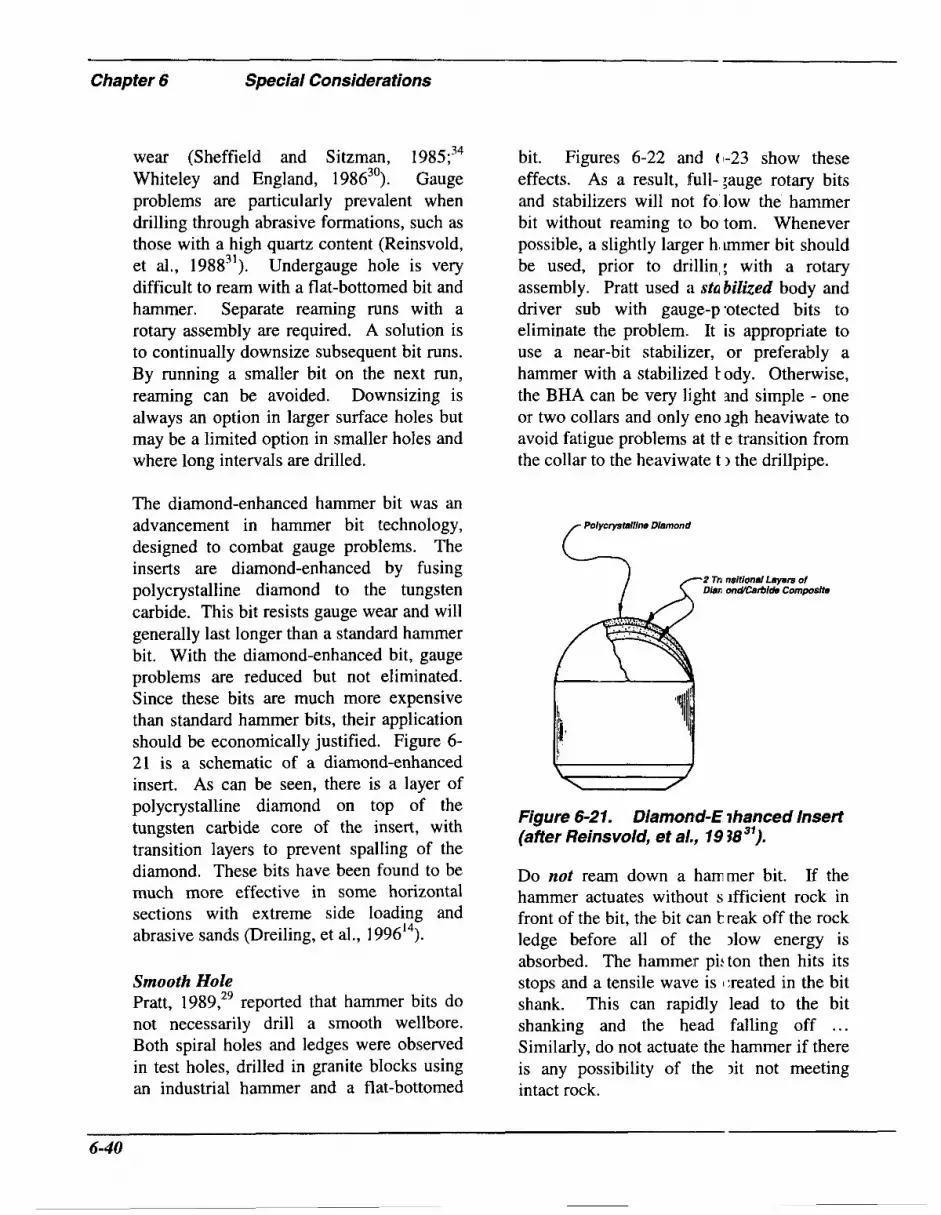
Chapter 6 Special Considerations
wear (Sheffield and Sitzman, 1985;34 Whiteley and England, 198630). Gauge problems are particularly prevalent when drilling through abrasive formations, such as those with a high quartz content (Reinsvold, et al., 198831). Undergauge hole is very difficult to ream with a flat-bottomed bit and hammer. Separate reaming runs with a rotary assembly are required. A solution is to continually downsize subsequent bit runs. By running a smaller bit on the next run, reaming can be avoided. Downsizing is always an option in larger surface holes but may be a limited option in smaller holes and where long intervals are drilled.
The diamond-enhanced hammer bit was an advancement in hammer bit technology, designed to combat gauge problems. The inserts are diamond-enhanced by fusing polycrystalline diamond to the tungsten carbide. This bit resists gauge wear and will generally last longer than a standard hammer bit. With the diamond-enhanced bit, gauge problems are reduced but not eliminated. Since these bits are much more expensive than standard hammer bits, their application should be economically justified. Figure 6- 21 is a schematic of a diamond-enhanced insert. As can be seen, there is a layer of polycrystalline diamond on top of the tungsten carbide core of the insert, with transition layers to prevent spalling of the diamond. These bits have been found to be much more effective in some horizontal sections with extreme side loading and abrasive sands (Dreiling, et al., 199614).
Smooth Hole Pratt, 1989,29 reported that hammer bits do not necessarily drill a smooth wellbore. Both spiral holes and ledges were observed in test holes, drilled in granite blocks using an industrial hammer and a flat-bottomed
bit. Figures 6-22 and (1-23 show these effects. As a result, full- ;auge rotary bits and stabilizers will not fo low the hammer bit without reaming to bo tom. Whenever possible, a slightly larger h, immer bit should be used, prior to drillin,: with a rotary assembly. Pratt used a stabilized body and driver sub with gauge-p-otected bits to eliminate the problem. It is appropriate to use a near-bit stabilizer, or preferably a hammer with a stabilized t ody. Otherwise, the BHA can be very light md simple - one or two collars and only eno Igh heaviwate to avoid fatigue problems at ti e transition from the collar to the heaviwate t 1 the drillpipe.
Po1ycrystalfin.s Diamond
-2 Tn nsltional Layers of Dian ondCarbfd8 Composite
Figure 6-21. Diamond-€ ihanced Insert (affer Reinsvold, et al., 19 383').
Do not ream down a hammer bit. If the hammer actuates without s ifficient rock in front of the bit, the bit can k reak off the rock ledge before all of the )low energy is absorbed. The hammer pi:ton then hits its stops and a tensile wave is 1:reated in the bit shank. This can rapidly lead to the bit shanking and the he:ad falling off ... Similarly, do not actuate the hammer if there is any possibility of the )it not meeting intact rock.
6-40

Figure 6-22. Spiral hole drilled with an industrial hammer and a flat-boffome d bit (after Pratt, 1989 *').
Figure 6-23. Ledges drilled with an industrial hammer and a flat-bottomerl bit (after Praff, I989 *').
Fatigue Over a period of time, a hammer will fail and extra trips will be required to replace it. To prevent excess wear, the inside of the drillpipe should be clean. Dirt, rust and scale will lead to premature failure.
Flat-head bits are prone to fatigue cracking where the head attaches to the shank (shanking the bit). This is one of the main problems with percussion drilling. Some of the energy in the compressional stress wave, that is sent down through the bit by the
hammer, is reflected at the bit-ro :k interface and travels back up through tl e bit as a tensile wave. Concentration of these repeated tensilc stresses at thc transition from the bit head to the shank :an lead to fatigue cracking. It is importait to avoid large differences between the b t head and shank diameters. This can be ~lifficult for some hole sizes (notably 171/2-irch hole) as the shank size is dictated by the hammer to be used, and there are some large gaps between available hammer diame ters. Avoid using smaller diameter hammes than the
Chapter 6 Special Considerations
hole can accommodate. This minimizes the risk of bit shanking and provides more hammer power, leading to higher penetration rates.
Some flat-head bits are provided with a fishing thread on top of the head. Fishing for the head can be difficult if there is any hole instability - debris often covers the thread. An alternative is to use a “catching ring” that prevents the bit head from being left downhole when the hammer is tripped, even if the head has separated from the shank.
Performance Pratt, 1989,29 cautioned that acoustic analysis indicated that hammers may strike more slowly than indicated by the manufacturer’s specifications, confirming that the manufacturer’s air volume consumption curves are highly inaccurate in deep oilfield applications. These curves are commonly developed for atmospheric pressure discharge porn the tool. Air volume through the hammer is reduced considerably by backpressure. Choke sizes should be adjusted to keep the on- versus off-bottom pressure difference at about 100 psi. Choke sizes can be calculated by using the equations for calculating bottomhole pressures.
Summary
9 Maintain proper WOB.
> Rotate as slowly as possible.
9 Provide an air bypass if necessary.
9 Keep the threads clean and use recommended lubricant. Dope the pins only.
> When changing out bits in unfinished hole, be sure that the next bit is no more
than 0.25-inches largei than the bit being removed.
9 Stabilize as required, particularly if the bit size is more than two inches larger than the outer d i m e t x of the hammer tool.
> Monitor the cc~mpiessors and the standpipe gauge.
9 Blow the hole clean pe riodically.
9 Never run on downholl :junk.
6.6 High Pressi ire Drilling In previous chapters, vari, )us high pressure, underbalanced drilling techniques were described. These teciiniques included flowdrilling, mudcapl di illing and snub drilling. Each of these methods will be discussed with emphasis o n their application in high pressured environr ients. Because of the high pressures, flowd illing with coiled tubing (CTD) will also be discussed and compared to jointed I ipe flowdrilling. Special attention must be 1 jven to the higher surface pressures because of the additional forces required to o p ~ o s e them when running tools and pipe into the hole. Stringent safety considera tions are required because of the higher s u f i ce pressures.
Flo wdrilling in High Pi essured Formations Flowdrilling may be perfo med using jointed pipe or coiled tubing (C’T). With the trend towards drilling hjghe: pressured en- vironments, more and more work is being done with coiled tubing. Improvements in CT manufacturing and CTD (coiled tubing drilling) technology hav 2 facilitated this trend. CTD provides a safer method of drilling than jointed pipe drilling, primarily due to the elimination of c innections.
6-42

"Coiled tubing provides a safe, rigless way to perform underbalanced drilling and significantly reduce formation damage in horizontal wells, lateral drainholes and deepenings. Coiled tubing units are typically used for live well interventions. Coiled tubing equipment isolates wellbores from the atmosphere during the entire well work or drilling operation and avoids killing wells before tripping. Coiled tubing, however, is also limited by higher cost compared to fully depreciated conventional rigs, and cannot perform jointed pipe running for casing and tubing completion operations.3736
Regardless of the increasing use of CTD, a great amount of high pressure, underbalanced drilling is performed using jointed pipe. Most of this drilling also involves drilling in horizontal laterals or curves. This includes using drillpipe in the string as well as using tubing drillstrings. Without exception, all surface well control equipment pressure ratings must be increased to a safe level. The maximum working pressure (MWP) of standard BOPs must be upgraded to exceed the highest possible surface pressures. Rotating blowout preventer equipment should replace the rotating head to achieve safer, higher pressured operations. All other surface equipment should also be reviewed, to ensure maximum operational safety.
In many high pressure drilling applications with jointed pipe, using clear drilling fluids could result in surface pressure that would exceed even the higher rated maximum working pressure of the RBOP. For additional discussion on RBOPs, refer to Chapter 2 or to Hannegan and Bourgoyne,
1995.37 Unfortunately, the F ermeability impairment-reducing properties of clear drilling fluids must be sacrificed n changing to a more conventional heavier n md system. The increased hydrostatic pressu .e resulting from these heavier muds would still be below the pore pressure in the arget, high formations. Heavier muds wc uld reduce surface annular pressures to a saj e operating range and formation F ermeability impairment would still be mil imized by drilling underbalanced.
An example of flowdrilling very high pressured formations using jointt d pipe is a fractured limestone target at 13,000 feet, with a pore pressure in excess of 2,100 psi; a pressure gradient of 0.70 psi/f. At this pressure level, the rig BOPs, mi st be rated for 10,000 psi service. Mud weights of approximately 13.0 ppg could ,e used to achieve underbalanced drilling conditions, and still reduce surface annular ~lressures to a safe operating limit. In this :xample, a static surface pressure of greate * than 300 psi would be seen if a full column of drilling fluid opposed formi tion pore pressures. Reduction in flu d density, caused by hydrocarbon influx and gas cut mud, would result in high:r surface pressures. Extreme care should be used to ensure that these pressures remai I below the MWP of the RBOP. Before mak ing trips in such pressured environments, a higher density mud could be bullheadell down the annulus to subdue the well anc allow for lower surface pressures durir g tripping operations.
As even higher pressure areas are drilled, coiled tubing drilling, mudcap drilling or snub drilling may -be required (refer for example, to Bloys, et al., 199438).
6-43

Chapter 6 Special Considerations
Coiled Tubing Drilling Coiled tubing (CT) is ideal for deployment in “live well” conditions. Its very design, using a reel of continuous drillpipe, eliminates the need for making connections, required in jointed pipe operations. Coiled tubing has a uniform outside diameter. This eliminates tool joint and tubing upsets. Leising and Newman, 1993,39 summarized some typical CTD applications (refer to Table 6-2). Vertical deepening, with a pendular assembly to keep the hole straight, is probably the most straightforward application, A long BHA is used to provide WOB without buckling the CT. The neutral point is always in the BHA so that the CT is always in tension.
Coiled tubing operations in Canada have encompassed underbalanced deepening of vertical wells and horizontal sidetracks, after rotary drilling to the top of the target formation. In Alaska, coiled tubing operations have been coupled with larger workover rigs. Snubbing jacks have also been used for completion and running tubing after drilling. Since CTD operations rely on downhole tool movement with a mud motor, rather than drillstring rotation, stripper rubbers may be used to contain surface annular pressures. “Typical CTU blowout preventer stacks include a four ram unit with tubing rams, blind rams, cutter rams (shear rams), and slip rams. Above the rams is a riser. The riser must be of sufficient length to lubricate tools in or out of a live well. At the top of the riser a hydraulic pack-off is installed to facilitate an annular seal while sliding pipe in or out of the well.”3 All rams are replaced with an annular for shallow gas. Snubbing CT into the well with hydraulic jacking force is accomplished with an injector head, rather than a snub unit. The
injector head is an i n t e F l part of a coiled tubing unit. Its function i! to inject CT pipe into, or remove it from, the well during live well conditions.
Madigan, 1993,40 in dis cussing slimhole CTD, indicated that:
“Openhole drilling with motors on coiled tubing h IS several key advantages over c( mventional rotary drilling techniques First, a smaller, much more mobile rig can be used. Second, considerab le trip time can be saved since connections do not have to be made up and broken every thirty feet. Thir3, coiled tubing offers a cons iderable safety advantage in that drilling can proceed underbalar ced with relative safety . y40
“Another benefit i: that the addition of a circulating, sut above the motor allows the drilliiig fluid to be circulated out of the well immediately upon :ompletion of the well. The well ca i be immediately tested, and the tubi ig stripped out of the well under pressures as high as 5000 psi.”4o
Drilling engineer; often worry whether relatively flexible coiled tubing and the lack of drill collars will allow drillin ; straight holes. High speed PDMs and small fixed cutter bits, such a: thermally stable diamond (TSD) t its, allow much higher rate of penet ration at lower bit weights than poss ible with rolling cutter bits, affordi ng straight hole. TSDs apparently also produce smaller cuttings. 40

Table 6-2. Summary of Typical CTD Applications (aRer Leising and Newm 3n, 1993 "')
Environmental ot servation ~ ~~
Observation and delineation wells
S limhole productiodinjection wells
I 1 Vertical ~ Deviate1 f I
Re-entry Drilling Deepening of existing wells Lateral drain ioles
New Well Drilling Disposal exploration wells Steam injec :ion I I
Coiled tubing design and manufacturing technology continues to advance. Similarly, slimhole tools run in the hole with CT have improved in recent years, with the increased use and demand for these operations. With that has come improved field experience and training. Higher strength alloy steels, combined with sophisticated and rigorous quality assurance measures, provide safer, more dependable CT products. Field testing and computer modeling have also helped to determine fatigue limits for every string of CT pipe currently in use.
Design Considerations for Coil Tubing Drilling Leising and Newman, 1993,39 is a good reference on CTD design. The protocol should (iteratively) entail:
> Select the CT size, the hole size, the drilling fluid, and the BHA.
> Calculate the reel weight and size. Be sure it can be transported and will fit on location.
P Calculate the tubing forces and stresses, to ensure that they never exceed 80% of the yield strength and that the minimum acceptable WOB can be provided at TD. Include friction associated with bending the BHA around any curves.
> In Vertical Wells: "If a cmstant wall thickness with depth is a;sumed, the maximum depth of the CT i 1 the drilling fluid, without exceeding :io% of the yield strength of the mater.al, is given by:
(6.3) OY
Dmax = 4.245 - 0.06493Wd,
where:
D,, ... maximum depth (feet), Wdf ..... drilling fluid weight (ppl ),
0, ....... yield stress (psi). and,
Tapered strings can be used for greater depths.
9 In Deviated Wells: A tiibing forces model should be used because of the potential for helical locking in the hole. The force that can be app1ic:d to the CT to push the BHA around tt e curve and into the deviated section inay also be limited by the maximum fc rce that can be applied in the vertical section.
0 Ensure that the inject01 can supply the necessary pull/push :if kickoff is shallow).
6-45

- _~ .l__l__-
Chapter 6 Special Considerations
Calculate the drilling fluid pressure drop in the CT, BHA and annulus at 100% motor flow capacity and determine the absolute pressure in the CT during drilling. Be certain that pressure limitations are not exceeded.
Assess torsional limitations. “The downhole motor-stall torque should be no larger than the maximum working torque for the CT. When the string is picked up, torque will be near zero. During drilling, the torque again will be at the maximum operating torque. Torsional cycling compounds bending cycling and
In reduces fatigue life .... general, torque is not a signijkant limitation unless large hole drilling is performed with small diameter CT. This is most relevant to shallow, vertical-hole drilling.
Calculate the fatigue life using the parameters from above. Large diameter and continuous application of drilling pressure can increase fatigue wear. Some life prediction models are available.
Assess any hydraulic limits (assume drilling at 80% of the maximum motor flow rate). Consider hole cleaning in vertical, inclined and horizontal sections.
0 Be certain that methods for directional control are possible. “If the tubing is too limber, small WOB and torque changes will change the toolface angle. An orienting tool is used to make toolface changes during CTD. This tool can be controlled from the surface by means of pressure, weight, or an electric
,939
wireline and causes drilling to proceed in a diffeient direction ... BHA analysis is the same as for conventional drilling. Because the CT cannot be rotatel 1, to drill straight ahead, either the na urd tendency of the formation must be countered by the BHA, or the orienting tool must be actuated periodj :ally to prevent undesired uniform b iild.”39
High Pressure Mudcap Drilling Mudcap drilling, described n Chapter 2.9, is another technique conimo ily adopted for high pressure operations. 1 ‘his method uses a high density, viscosific d mud in the annulus, while drilling without returns; a less expensive drilling fluid is pumped down the drillpipe. In lower pressure environments, this drilling fluid is often a non-damaging clear fluid such as brine water. As higher pore presure formations are encountered, the ma: .imum working pressure of the M O P is rc:ached with this relatively low density fluid. Mudcap drilling in these areas requires highe r density drilling fluids.
Consider, for example, ( 1 formation at 15,000 feet, with a pore prc mure of 1 1,900 psi. The mud weight nece;sary to balance this pressure is approxim itely 15.2 ppg. Mudcap drilling in this for nation could be performed with a 14.0 3pg viscosified annular fluid closed in at t le surface, with approximately 1,000 psi pressure. The drilling fluid pumped throL gh the drillpipe must weigh more than satuiated NaCl brine water, due to the 4.,10(1 psi resulting underbalanced pressure. Th at pressure, plus the frictional pressure losse: #, would put too great a strain on su face pumping equipment. An 11.7 ppg ( alcium chloride
6-46
water (40.0% calcium chloride by weight of solution) would lower surface pumping pressures by 1,326 psi, still resulting in excessive conditions. More costly brines such as calcium bromide or zinc bromide would be cost prohibitive. A 12.8 ppg lignosulfonate mud could be used to mudcap drill the zone, with surface pump pressures of 1,916 psi plus friction loss.
In selecting fluids to be used for mudcap drilling projects, a close evaluation of cost and possible formation impairment must be factored into the equation. The maximum operating limits of the rig’s pumps, as well as its BOPs and the M O P must also be considered. The optimum design for the job requires a balance between these pressure limits and the cost of the necessary fluids. Bloys et al., 1994,38 provided additional discussion of required equipment for offshore operations.
Snub Drilling in High Pressure Formations Conventional snubbing units, as well as hydraulic rig assist (HRA) snubbing, allow entering a well under pressure. In underbalanced drilling, snubbing enables a we11 to be safely drilled, by allowing the removal and insertion of all downhole equipment, including tools and pipe, under live well conditions. HRA snubbing was introduced in Canada roughly fifteen years ago. About eight years ago, it began to be used in the United States. It offers a lower cost alternative to the conventional snub unit.
Equipment for HRA snubbing is designed to be portable and easy to rig up and rig down. It consists of a set of hydraulic ram-type BOPs, connected directly above the rig BOPs or MOP. A pair of hydraulic
cylinders provides the jacking f irce for pipe movement. This equipment, ;long with a working platform and contrcll panel, is transported on a tandem axle truck which also carries the hydraulic pcwer source. Risers are used to position t i e unit just above bhe rotary table. As pari of this riser spool, ports with hydraulicdly-operated valves are added to bleed off md equalize pressures between the ram prevl :nters and an annular preventer mounted or top of the snub stack. Above this annu ar, a set of inverted slips, or stationary siubbers, are installed, to hold the pipe while the snubbing operator extends or retracts 1 he traveling head of the unit. In this manner, the operator is able to move the pile into or out of the well one step at a time. The inverted positioning of these slips prevc:nts the pipe from being pushed out of the well by the pressure. A second set of irverted slips, called traveling snubbers, is mcunted on the bottom of the traveling head, dong with a conventional set of slips, moun ed on top of the traveling head. This trawling head is fixed on top of the hydraulic cylinders, to mechanically push or pull the ~ i p e from the wellbore under pressure.
HRA snubbing is so named because it assists the drilling rig, while iising the rig drawworks and derrick for pulling and racking pipe during trips. Th: HRA snub operator works on the unit platform, operating the hydraulic cylindc rs, slips and BOPs at the control panel. :‘his operator must work very closely with he driller in coordinating all rig activities. In snubbing pipe into the hole, the hydratlic cylinders provide the physical force to ~ u s h the pipe downhole under “pipe light’ conditions. When sufficient pipe has been run to allow enough weight in the strin;, the pipe becomes “pipe heavy,” and the cylinders are

Chapter 6 Special Consideratlons
no longer required to push the pipe into the hole. The rig drawworks are then used to run the pipe into the hole or pull it from the well, until a “pipe light” condition again exists.
A typical HRA snubbing unit crew consists of two men per twelve hour tower and one twenty-four hour supervisor, for a total compliment of five men. Close coordination between the toolpusher and the snubbing supervisor is very important. The rig crew and the snub crew must work together to safely achieve the desired drilling goal. Due to the technical nature of snubbing equipment and because of the advanced training and experience of the snubbing supervisor, the snubbing supervisor has final authority whenever disputes arise. Aside from the very high daily expense of the snubbing unit, there are a number of advantages to snubbing, including the following:
9
P
9
Pressure control is handled with the snubbing unit’s BOPs, with its annular preventer as a primary system and its rams as secondary preventers. The snubbing unit also has its own accumulator system. The rig BOPs and accumulator provide backup to these sy s tems.
Snubbing crew personnel are highly trained and experienced in working with high pressure at the surface; rig personnel are more accustomed to controlling and preventing such pressures.
In the event of “pipe light” conditions, the snubbing unit can provide the necessary control to inject or pull pipe and tools under pressure.
Snubbing offers a versatile and safe, yet expensive, solution in underbalanced drilling operations. To offs :t this expense, it is possible to minimize the time on location for these services. Snubking provides the most positive method for pipe movement and pressure control through its independent use of hydraulic cylinders, pipe slips and BOPs.
6.7 Cementing
Introduction Slotted or pre-drilled liner s are commonly run in high permeabilit I environments. There are situations when : cementing and perforating are carried out; for example, in lower permeability environ nents, in certain naturally fractured fonnati ins, or where a gas cap needs to be cement€ d off, etc.
Remedial procedures to overcome incomplete cement col imns due to formation fracturing or e: xessive loss of returns, are expensive anc historically are relatively ineffective. Lig itweight cement slurries were designed to o\ ercome gradient- driven loss of cement to i i ~ i t u formations (either from hydraulic fracturing in formations with low in-situ stresses and low tensile strength or flow into naturally fractured or cavernous fori nations). These slurries complement othe . underbalanced operations performed on a 1 vell; there is less chance of fracturing weak formations and the number of stages r:quired can be reduced. This section b riefly highlights some of the design coisiderations for underbalanced cementing.
Normal extenders can be used to provide slurries with densities as 1c w as 11.5 to 12 ppg. For densities less .han this, water
6-48

separation becomes a significant problem, P Heat Insulation: As is tlie case for unless alternate methodologies are adopted. foamed drilling in permdrost, the These alternatives include using hollow entrained voids in foamed cements microspheres as extenders or using cement foamed with nitrogen.
Extremely lightweight cement can be used
provide good insulating char: cteristics.
Properties of Foamed Ceme nt Nitrogen is incorporated direci ly into the slurry. Some modifications cf the base
Provide primary cementing in formations that will fiacture easily. Foamed cement density can be reduced to as low as 6 ppg in order to minimize, or completely eliminate, losses during single-stage cementing of long intervals. Cements with light-weight solid extenders are commonly used for primary cementing of conductor and surface pipes, where washouts and low fracturing pressures are common.
Cure Lost Circulation in Cavernous Vugs: Remedial plugging of large vugs is not always effective with conventional systems, since gravity causes the slurry to slump to the bottom of the cavity. Thixotropic characteristics of foamed cement can reduce this gravitational segregation.
Squeezing Depleted Zones: Squeezing is carried out to place cement in a specific location to achieve an hydraulic seat. This includes shutting off perforations, fractures, channels and other undesirable voids. Accurate placement and controlled dehydration is difficult in formations that cannot tolerate con- ventional cement densities (13 to 16 PPg)* Light-weight systems are appropriate.
Zonal Isolation: Gas influx during hydration and setting may be reduced if foamed cements are used.
cement system are usually idopted to guarantee relatively homogem ous distri- bution of the gas phase in the slurry. Conventional extenders, such as perlite, will crush as hydrostatic pressure of the column increases. Nitrogen concentrati ms, on the other hand, can be increased to overcome volumetric reductions with incre sing depth. On location, foamed cement is generated by providing gas from a compresso. or a liquid nitrogen vaporizing unit; surfa ctant(s) are added to stabilize the foam. l 'he specific surfactant system used is a kej to cement stability, particularly in th ; alkaline environment of the water phase c F the slurry.
As with foamed drilling fluids, rheology is relatively complex, depending on the gas content, bubble size, water-to-c :merit ratio ... Pumping is usually not a p-oblem and these foams can be generally c iaracterized as pseudoplastic fluids. The f l c w behavior index, n', generally decreases as the quality of the foam increases. Relarders and accelerators can be used, as in conventional systems, in accordance wi :h service company recommendations, an( preferably in conjunction with supporting laboratory information.
The questions many operators as : are:
P Will the strength of the system be adequate and will the sheath be completely destroyed by I erforating?

_ _ _ _ ~ -- - Chapter 6 Special Considerations
The compressive strength of the foam slurry will generally be higher than a comparable non-foamed slurry of the same density. Compressive strength will vary with the base slurry density and the foam quality. Consider the specifics of the well and consult with the service company. The degree and impact of perforation damage has probably not been adequately quantified.
Will there be gas migration through the cement itself a fer the system has set? Possibly. Consult with the service company to design an appropriate system.
Will bond be any different than for conventional systems? The same precautions apply as for any cement system, the most important being effective mud removal.
Systems With Low Density Particulate Additives The service companies also have various competitive products where hydrostatic head of the cement column is reduced by the addition of lightweight particulates, for example hollow microspheres. Using these as extenders facilitates developing lower density (9 to 12 ppg) with only modest sacrifices in strength, permeability and free water segregation. There are upper limits of applicability associated with hydrostatic particle crushing; but these limits are often quite high. “Extra caution is required when mixing slurries with densities below 9 lb/gal.” It is important that free water is carefully controlled. Hollow glass spheres have been used to lighten drilling fluids, with the advantage that the system is relatively incompressible. These drilling systems have been described by Medley et
al, 1995.42
Design Consideration, 5
Foam Quality As with foamed drilling fl uids, foam quality indicates the volumetric c( Incentration of gas in the total cement sysiem. In general, depending on the specifi : application, the quality should not exce:d 40 to 44%.41 Recent publications SUE gest that higher qualities may be used, clepending on the required strength and permeability of the sheath. Good foam stabi ity is essential in order to maintain a pore gtructure which is not highly interconnected when the cement sets. “This [interconnecti rrity] is caused by unstable nitrogen bubble walls that rupture upon contact with other nitrogen bubbles, then bubbles coalesce forming large gas pockets. This results n a sponge-like structure with PO ;sible density inhomogeneity due to grav ity drainage of the base slurry. A good rule-of-thumb for an initial design is to mix thr base slurry at its optimum water ratio ... The same mechanisms that product free water will contribute to segregati on in foamed slurries.77 43
Foamers and stabilizers a e selected on the basis of stability, efficiei cy, compatibility (elevated temperature, pressure, highly alkaline calcium containi ng water phase), adequate strength and per meability control, cost, safety, ease of handling ... Pure surfactants are never us1 :d without foam stabilizers, preventinghr hibiting bubble coalescence. de Rozib es and Ferrikre, 1990,43 found it difficult to produce stable foams with qualities gi eater than 70% (except in certain high sk ear environments where they reached 80%).
6-50

PVT Behavior Nitrogen requirements are affected by the system response to temperature and pressure; the pressure after displacement and the temperature prior to setting. Cement wellbore hydraulics simulators are available for designing the nitrogen requirements. Cement systems with nitrogen are commonly designed to yield densities in the range of 7 to 11 ppg. System design is similar to conventional systems, taking into account the density variations and the in-situ fracture and formation pressure gradients.
Cement System Nitrogen requirements are also affected by the formulation of the basic system. The base slurry can be extended itself and this will reduce nitrogen requirements (higher water content). This will however lead to sacrifices in strength and permeability. In foamed cementing, it is essential to have a reliable caliper log since the hydrostatic head strongly influences the system’s densities. Finally, non-nitrifed caps (on the order of 500 feet) of mud, spacer or cement are commonly used when circulating to the surface.
Free Water Excess free water is an extremely critical issue in deviated, particularly horizontal sections. “This is of particular importance in nonconventional wells, since any free water present may migrate to the high side of the annulus and create a channel.” 44 This may severely restrict the use of some foamed or solid extended systems; regardless, great care is required. Requirements for horizontal well cementing are well summarized by Wilson, 1991.45 Ryan et al., 1 995,46 provided general guidelines for mud clean-up in horizontal wells.
Backpressure With modern simulation comp iter codes, the hydrostatic and density pro ’ile can be characterized during all of the circulation period. Accurate backpressu re control during circulation to the surface i ; extremely important (de Rozikres and Ferris -e, 199043).
Permeability “Permeability increases with qua ity. When the bubbles are small and the listribution uniform, this increase is very pro1 Lressive. If the bubbles are non-unif jrm, the permeability remains fairly lorn and then increases sharply. This transit ion occurs between [lo and 10.85 ppg] on he class G system and between [9.2 and 10 l~pg] on the class C system. Therefore it secms that in case of non-uniform bubbles, a 1 iercolation threshold occurs around 35% qu zlity.” 43
Compressive Strength Below 5 ppg, foams are not sol d. Above this density, strength and p xmeability depend on the bubble size distrimtion, the cement type, the additives and inany other parameters. Table 6-3 shc ws some controlled laboratory data from c e Rozikres and Ferri&e, 1990.43 Measur :ments by these authors also supported using the thickening time of the base slurry to estimate the thickening time of the comple e system.
Fluid Loss In general, increasing the g;ts content reduces the fluid loss. This is shown in Figures 6-24 and 6-25, from C’hmilowski and Kondratoff, 1992.47 System permeability can also be ajfected by temperature. Increased tempe :ature can reduce permeability due to )referential growth of certain crystals.

- Chapter 6 Special Considerations
Table 6-3. Example unconfined compressive strengths and permeab lities for various foamed cements (after de Rozieres and Ferriere, 1990&,
Class G foamed cement (curing time 72 hours at 81 '9
Broad Bubble Size Distribution Narrow Bubble 2 'ize Distribution
Permeability (md)
Compressive Strength
(Psi)
4915 1.89
1.45 3
14.5
173
676
3730
1.27
1.12
0.85
0.6 1
Class C foamed cement (curing time 72 hours at 81 OF)
Broad Bubble Size Distribution Narrow Bubble 6 ire Distribution
Compressive Strength
(Psi)
Permeability (md)
Permeability (md)
Compressive Strength
(Psi)
0.050 3015
2030 0.0075 1335 1.25
5.7
25.7
199
6300
6-52

160
140
120
0- E 100 0 u)
$ 80 -I TI a 60 ii
v
40
20
0 0 5 10 15 20 25
Time (minutes)
Figure 6-24. Fluid loss values for varying foamed cement qualities (after Chmilowski and Kondratoff, 199Z4').
120
100
80 0- E 0 cn v
60 3 E a
40
20
0
I I I I
0 5 10 15 20 25 30
Time (minutes)
Figure 6-25. Fluid loss values for 37% quality foamed cement with vaying amounts of fluid loss additive (after Chmilowski and Kondratoff, 1992 ).
- 6-53

Chapter 6 Special Considerations
Basic Design The design of a foamed cement job should consider the pressure and density profiles at various stages during circulation and not just at the end of the job. Simulators consider, for each stage, the depth to the middlet of the stage, and calculate the pressure at the middlet of the stage. The overall job design optimizes:
9 The number of stages,
9 The nitrogen ratio for each stage,
P The value of the backpressure (critical because the magnitude of the back- pressure strongly affects the amount of base fluid in the well) and,
9 The number of feet of cap fluid and its method of placement. The cap can be circulated ahead of the foam or can be pumped when foam first reaches the surface (bullheading down the annulus). While more difficult operationally, the second option may be preferable to avoid U-tubing of the first foam behind the cap. Also, if the cap precedes the foam, the hydrostatic pressure of the column may exceed the fracturing pressure when the cap turns around the shoe. For bullheading, after foam has reached the surface and the correct backpressure is applied, the tail is pumped and followed with mud (avoid free fall). When the tail has turned the shoe, pumping stops and the well is shut in, keeping backpressure on the return line. The cap is then pumped down the casing.
The governing constraints are:
P The hydrostatic profile of the column should always remain below the fracturing pressure,
One service company uses the bottom of the stage.
P In certain environmeits, it may be possible to cement c( kmpletely under- balanced by cement ng below the formation pressure. Thj s is only possible if it can be guarantee11 that the slurry quality will not be atlversely affected (gas pockets, supplemei itary liquids) and that channeling and/or microannuli will not develop. Work 1:losely with the service company.
> The density profile at tlie end of the job must provide the cenent qualities to support casing and F rovide adequate isolation,
P The procedures need to be as operationally simple as : iossible,
9 Cement loss must be mi iimized and,
9 Nitrogen usage should t: e minimized.
Purvis and Smith, 1994,48 discussed some operational issues and presented case studies. Chmilowski i nd Kondratoff, 1992,47 provided observatic Ins on designing foamed cement squeeze 01)erations in low pressure, highly permeable formations (e.g., the Ellenberger and San 4ndres in West Texas, the Sadlerochit in jlaska, the Keg River, Wabamum and Led1 c D3 in Canada and the Baturaja in Indsnesia). They advocated more effective u: e of information from pre-squeeze injectivity data.
6.8 Formation €1 raluation
Evaluation of Underbali rnced Holes
Evaluation of Formation Fluids While Drilling The information that can b : acquired while drilling underbalanced holl :s is commonly more diagnostic than that obtained while
6-54

drilling conventional holes. Since under- balanced drilling implies that the pressures in the borehole are less than formation pressures, formation fluids may be produced into the borehole. The circulating drilling fluids will carry these fluids to the surface where these produced fluids may be evaluated.
Evaluation at the surface can be qualitative or quantitative. For instance, an experienced driller can infer something about the produced fluids by simply watching the flare or effluent at the end of the blooie line in an open drilling system. Increased amounts of natural gas will, of course, lead to a larger flare. Oil would cause a darkening of smoke from the flare while an influx of water will result in a noticeable change in the color of the flare, if not extinguishing it altogether. Mud logging should be used to help identify the formations, assess the quality of the reservoir rock, and pinpoint the types and depths of formation fluid influx into the wellbore.
In a closed system, flares may still be monitored but liquids can be quantitatively
measured, using sight tubes at! ached to the separator at various levels. Other instru- mentation can be used to keep ' rack of fluid types and rates. In addition, the various liquids produced can be collect€ d in separate tanks after separation, for recycling, sales or disposal at a later time.
Evaluation with Logging Tc BOIS 49s0951*52
The choice of logging tools run into a borehole, whether drilled unde rbalanced or not, will largely depend on wh, it liquids are in the borehole at the time of 13gging. If a liquid was used to drill the hol: and covers the zones of interest during logging, the logging program would be no ( ifferent than for a conventionally drilled hole. Depending on the pressure balance at .he time of logging, the wireline tools miglit have to be run through a lubricator. Hoivever, if the hole was drilled with gas (zir, methane, nitrogen ...) and gas remains o"er the zones of interest at the time of loggilg, a careful selection of logging tools is recluired. Any, or all, of the following tools c o ~ l d be useful for evaluation of such holes:
I > Epitherml Neutron - To identify porosity of liquid-filled zones. - - - - - - - . - . __ - - - - - . . __ . -__ - . . - - -
- -I
Chapter 6 Special Considerations
Gamma Ray Log The Gamma Ray Log measures the natural radioactivity of the formation and usually correlates with the Spontaneous Potential, SPY (which cannot be run in gas-filled boreholes). Like the SPY the gamma log can distinguish sands from normally more radioactive shales. Also, it provides a good correlation curve, defines bed thicknesses, and aids in interpretation of environmental deposition. It is usually a more diagnostic indicator of beds in a carbonate sequence than the SP. The gamma log can be run in any liquid- or gas-filled hole, either cased or uncased. A gamma log run in a gas-filled borehole may have a slightly higher radioactive count than the same log run in a hole filled with mud, particularly if the mud has a high concentration of barite.
Spectral Gamma Ray Log Like the conventional Gamma Ray Log, the Spectral Gamma Ray Log records gamma ray intensity; however, additional curves identify potentially productive zones. These curves (uranium, potasium and thorium concentrations) also provide for more detailed correlation with nearby wells that have similar information. Sometimes, naturally fractured zones or carbonates will have small quantities of uranium, precipitated by subsurface water flow. This can be identified by the uranium curve as a potentially productive zone whereas it might be misinterpreted as a shale interval from the gamma ray log. In an underbalanced hole, this would provide important auxiliary information to help pinpoint flow intervals.
Epithermal Neutron Log Neutron logging instruments contain a radioactive source that bombards the formation with fast neutrons. These neutrons are slowed primarily by hydrogen
atoms in formation flui Is and can be counted by detectors i n th: tool which are scaled in porosity units. 11 clean or shale- free formations, the neutrm log does not recognize gas-filled poro:ity. It can be compared with another porc sity device, such as a density log, to detect gas-filled zones (crossover). It can all o be used in combination with other ~orosity logs for interpretation of lithology, including shaly sands.
In an air-filled or mixed fluid (such as nitrified crude oil) hole, the normal Compensated Neutron Log will not respond properly; detrimental effect: of the borehole fluid can be minimized vith a Sidewall Epithermal Neutron instrurient. In such a tool, both the neutron iource and the detector are mounted in a pad shoe that is pressed against the )orehole wall. Intermediate speed (e:pith :rmal) neutrons can then accurately reflect the liquid-filled porosity. Log interpret8 tion charts are available to distinguish sandstone and dolomite porosity from lime stone porosity.
Induction Resistivity Log The induction log is designc. d for medium to deep investigation If formation conductivity. It is pro1)ably the most commonly run logging tciol. This tool consists of one or more ccils that generate an alternating electromagn ;tic field. The induced currents, which depend on the conductivity of the formati on, are detected by receiver coils. Multiple coils are used to focus the measurement deep into the formation. This minimizes effects of the borehole, the invaded zoie, and nearby zones. The induction log lvorks best when the borehole fluid is rc:lati-rely resistive, as would be the case with fresl iwater, oil-based muds or empty boreholes. Focused
6-56

resistivity tools, such as the Laterolog,? are recommended for conductive borehole fluids, but are not suitable for air-filled holes where air (or other gases) remains in the borehole at the time of logging.
With a measurement of formation resistivity, Rt, (the reciprocal of conductivity) and knowledge of porosity, @, from other logs or core measurements, formation water resistivity, Rw, the cementation exponent, m, and the saturation exponent, n; an estimation of water saturation, Sw, may be made from the classic Archie's equation.'
I l n
s, = [3--] (6.4)
Where significant amounts of conductive minerals, such as clay, are also present in the formation, allowance must be made for their influence on the total resistivity. As with logging in conventional holes, consideration must also be given to borehole geometry and bed thickness.
If a Dual Induction Focused Log is run in an air hole, the SP and focused curves are not presented (because a conductive borehole liquid would be required) but the medium and deep induction curves do an excellent job, due to the lack of invasion and reduced borehole fluid effects.
High Resolution Density Log Under ideal conditions, the density log can provide excellent measurements of porosity in a gas-drilled hole. This tool, which is firmly pressed against the borehole wall, emits a beam of gamma rays into the rock,
Mark of Schlumberger. assuming a = 1
from a source, such as C S ' ~ ~ . TI~ese gamma rays interact with electrons in thz formation through Compton scattering. TI e resulting, lower-energy gamma rays are sei ised by two detectors above the source. Although the tool responds to electron density, for most formatibn rocks the apparent bulk density is practically identical to the zctual bulk density. For a few rocks or mi ierals, such as sylvite and halite (and to a 1:sser extent gypsum, anhydrite, and cc al), small corrections are needed to arrive st true bulk density values. In addition to bilk density, the tool will record an index of photoelectric absorption, Pe. This value ii useful in determining formation lithology. Porosity is calculated from:
@ = -Pb X l O O Pm -Pf
where:
@ ......... porosity (percent), Pma ..... density of the rock matrix (g/cm3), P b ...... bulk density of the formal ion
pf ....... density of the formation f uid (g/cm3), and,
(g/cm3>.
One of the difficulties in this fo mulation is selecting pf. To illustrate the inportance of selecting the correct densit r for the formation fluid, consider the following example. If a gas zone is dril ed with an aqueous mud, pf could be taken i s l g/cm3. If the same hole is air-drilled, a possible assumption for pf would be 0.5 g/cm3. Assuming P b = 2.1 g/Cm3 and Pma = 2.64 g/cm3, porosity would be calcula ed as:
2.64 - 2.1 = 3 3 % for an aque )us mud ' = 2.64 - 1.0
or
__ 6-57

- Chapter 6 Speciaal Considerations
2.64 - 2.1 ' = 2.64 - 05 = 25% for an air drilled hole
Conditions that can cause difficulties with density log interpretation include rugose or caved boreholes and lack of information on matrix or fluid density. Environmental corrections must be made for the borehole size and the fluid in the well.
Temperature Log Because cooling occurs as gas expands into the wellbore from the formation, a temperature log can assist in pinpointing zones of gas entry. Estimates may be made of the percent contribution from each interval. Temperature logging can also locate zones of lost circulation or fluid entry into the formation.
Either absolute or differential temperature can be measured. A logging tool that measures differential temperatures will quantify the temperature difference between one sensor and another, located a short distance away. The differential temperature curve allows observation of very small temperature changes without the need to frequently adjust the borehole temperature curve scale. Temperature tools are usually combined with gamma ray tools for correlation and readings are taken as the tool is run into the borehole.
Nuclear Magnetic Resonance Log Although Nuclear Magnetic Resonance (NMR) logs are less commonly used in underbalanced holes, they can provide useful information for liquid-filled formations. Borehole fluid will not affect these measurements. Parameters such as effective porosity, initial water saturation, and permeability (especially for sandstones) can
be estimated without pr or knowledge of lithology or calibrations T Jith cores. Other information, such as oil viscosity, pore size distribution, and residual ( iil saturation, may also be estimated.
NMR tools evaluate the riagnetic moments of hydrogen nuclei, abur dantly present in both water and oil. Magnets in the tool orient the magnetic rioments of the hydrogen nuclei parallel 1 0 the field. The magnitude of the magnet zation is directly related to the number of h) drogen nuclei and consequently the liquid-fi led porosity. By disturbing the magnetic 'ield with an RF pulse from the tool, the ra:e of return of the nuclei to their original coiifiguration can be measured. Short relaxatior times correspond to small pores, long relaxa ion times indicate large pores. The variaiice in relaxation times can be related to por size distribution, which can be correlated to capillary pressure and permeability. Fluid f ow should be not be permitted while these neasurements are made.
MWD If an MWD (Measuremer t While Drilling) system is used, further elraluation may be made, while drilling with ntegrated logging devices that sense n atural radiation, resistivity and porosity. If gas or gasified liquid is used as thc drilling fluid, conventional mud pulse te lemetry cannot be used to transmit the sign; Is. Alternatively, as described previous !y, other data transmission sys terns: such as electromagnetic or hard-w red tools, may be considered.
Coring Underbalancecj Underbalanced coring has been carried out, to obtain relatively pristinc samples and still
6-58

avoid formation damage. Reducing coring fluid invasion allows for careful determinations of formation properties where wettability alteration has been minimized.
Permeability And Deliverability Assessments Butler et al., 1996,53 emphasized the value of pressure monitoring for real-time evaluation of reservoirs; to identify geologic anomalies (fractures, tight zones, pinchouts, discontinuities, water zones . . . ). Computer modeling may be used during drilling to evaluate sandface drawdown, develop inflow performance relationships, and, in combination with mass balance monitoring, indicate wellbore productivity. “Effective monitoring of production rates permits real-time decisions regarding changes in drilling depth, wellbore orientation, and overall section length. In some cases, hori- zontal lengths have been reduced 75% from that planned when economic production rates have been achieved, saving the operator significant drilling costs.” These authors emphasized the importance of an adequate sampling interval (take measurements as frequently as needed), to detect any and all significant fluid slugs.
53
“Each drillpipe connection introduces an annular fluid slug into the system. Annular fluid slugging occurs primarily during pump off periods. The severity of annular slugging depends on fluid concentration in the injection mixture as well as the type of hydrocarbon produced and the capacity of the well to flow under its own energy. If a well produces relatively small amounts of gas, for example, and there is a relatively large fluid concentration, a definite fluid slug will form in the b~ t tomhole . ”~~
If the underbalanced ROP is sufficiently high and bottoms up (along with the connection slugs) are not beini circulated out, controlled drilling should be ;onsidered.
Consider a low-energy gas we 1. Precise production data monitoring after a connection shows decreased gas production followed by a significant gas p e k As the fluid slug, formed by separation of injected fluids moves to surface, gas pr3duction is reduced. Eventually, the slug is I urged from the well, and the resultant com )ressed gas behind the slug expands at the ;urface and manifests itself as an increase in 1 roduction.
A well that is producing liquid h! drocarbons would continually exhibit fluid s ugging due to formation loading. Prc lific fluid producers can actually kill themselves during times of pump off. Restarting gadfluid injection down drillp pe can be problematic under these circumst mces.
If there is insufficient time for each fluid slug, containing increased conce itrations of drilled solids, to circulate througf the system and back to surface befoie another connection is made, the dugs can accumulate and create enough b ickpressure to overbalance the well. Penetration rate must therefore be adequately cor trolled.+ If only one fluid slug is observed at the surface between connections, the system is in equilibrium with injection, pro( uction and penetration rate. If more tha I one slug occurs, the system is not in equil brium. The effective rate of penetration is de k e d by the overall pumping time necessary to purge a slug of fluid from a well.
Periodically circulate bottoms up be- ore making a connection.

- Chapter 6 Special Considerations
References
1.
2.
3.
4.
5.
6.
7.
8.
9.
10.
11.
12.
13.
Willis, R.B.: “Well Control Practices for Air-Drilled Holes,” paper SPE 4497 presented at the 1995 Eastern Regional Meeting, Morgantown, WV, November 6-8.
Collins, G. J.: “Proper Planning Improves Flowdrilling,” World Oil (Octo1 ber 1994) 43-50.
Eresman, D.: “Underbalanced Drilling - A Regulatory Perspectivl :,” paper 93-306 presented at the 1993 CADEKAODC Spring Drilling Conference, Calgary, Alberta, Canada, April 24-16.
“Recommended Practices for Underbalanced Drilling,” Energy Resoui ces Conservation Board Interim Directive ID 94-3 (July 1994) Calgary, Alberta, Canada.
Moore, B.: “The Regulation of Underbalanced Drilling in the UK Sector ” paper presented at the 1995 International Underbalanced Drilling Conference, Imsterdam, The Netherlands.
Yost, A.B.: “Horizontal Gas Well Promises More Devonian Productio, 1,” The American Oil and Gas Reporter (July 1988).
Millheim, K.K. and Warren, T.M.: “Side Cutting Characteristics 0’ Rock Bits and Stabilizers While Drilling,” paper SPE 7518 presented at the 1978 SPE Annual Fall Technical Conference and Exhibition, Houston, TX, October 1-3.
Millheim, K.K.: “Hard-Formation Directional Drilling Calls for Speci; 11 Care,” Oil and Gas J. (February 12, 1979).
Wilson, G.E.: “Air Drilling and Crooked Hole Problems,” paper SPE 952 9 presented at the 1980 SPE Eastern Regional Meeting, Morgantown, WV, November 5-7.
Millheim, K.K. and Apostal, M.C.: “The Effect of Bottom-Hole Assen bly Dynamics on the Trajectory of a Bit,” paper SPE 9222 presented at the 1980 SPE Innual Technical Conference and Exhibition, Dallas, TX.
Shale, L.: “Development of Air Drilling Motor Holds Promise for Speci dized Directional Drilling Applications,” paper SPE 22564 presented at the 199 1 SPE innual Technical Conference and Exhibition, Dallas, TX.
Lyons, W.C.: Air and Gas Drilling Manual, Gulf Publishing Companj, Houston, Texas (1 984) 46-25.
Shale, L.: “Underbalanced Drilling: Formation Damage Control Durii ig High-Angle or Horizontal Drilling,” paper SPE 2735 1 presented at the 1994 5 PE International Symposium on Formation Damage Control, Lafayette, LA, February 7-10.

14.
15.
16.
17.
18.
19.
20.
21.
22.
23.
24.
25.
Dreiling, T., McClelland, M.L. and Bilyeu, B.: “Horizontal and High Angle A r Drilling in the San Juan Basin, New Mexico,” The Brief, Murphy Publishing Inc. (June 19 96).
Lyons, W.C., Miska, S.Z. and P.W. Johnson: “Downhole Pneumatic Tur h e Motor: Testing and Simulation Results,” paper SPE 18040 presented at the 1988 , ;PE Annual Technical Conference and Exhibition, Houston, TX, October 2-5.
Roy, R. and Hay, R.: “Measuring Downhole Annular Pressure While Drilling for Optimization of Underbalanced Drilling,” paper presented at the 1995 1st hternational Underbalanced Drilling Conference, The Hague, The Netherlands, October 2-4.
Soulier, L. and Lemaitre, M.: “E.M. MWD Data Transmission Status and P~:rspectives,” paper SPEDADC 25686 presented at the 1993 SPE/IADC Drilling Conference, Amsterdam, The Netherlands, February 23-25.
Shale, L. and Moberley, G.T.: “Development of a Cartridge Data Transmissioi i System for Use with Air Drilling Motor,” paper SPE/IADC 23907 presented at the 199: SPE/IADC Drilling Conference, New Orleans, February 18-2 1.
Shale, L. and Curry, D.A.: “Drilling a Horizontal Well Using Air/Foam Techni lues,” paper OTC 7355 presented at the 1993 Annual Offshore Technology Conference, Ho iston, TX.
Shale, L.: “Underbalanced Drilling Equipment and Techniques,” PD ( 1995) 65, Drilling Technology, ASME (1 995).
Lattimore, G.M., Carden, R.S. and Fisher, T.: “Grand Canyon Directional 3rilling and Waterline Project,” paper SPE/IADC 16169 presented at the 1987 SPE/IA DC Drilling Conference, New Orleans, LA, March 15-1 8.
Angel, R.R.: “Volume Requirements for Air or Gas Drilling,” Pet Trans., P I M E (1957) 210,325-330.
Guo, B., Miska, S.Z. and Lee, R.: “Volume Requirements for Directional P ir Drilling,” paper IADC/SPE 27510 presented at the 1994 IADC/SPE Drilling Conference Dallas, TX, February 1 5- 18.
Guo, B., Miska, S.Z. and Hareland, G.: “A Simple Approach to Deteimination of Bottomhole Pressure in Directional Foam Drilling,’’ paper presented at the 1995 ASME Energy and Environmental Expo 95, Houston, TX, January 29-February 1.
Guo, B., Hareland, G. and Rajtar, J.M.: “Computer Simulation Predicts Unfa rorable Mud Rate and Optimum Air Injection Rate for Aerated Mud Drilling,” paper SPE 26892 presented at the I993 SPE Eastern Regional Conference and Exhibition, Pittsb xrgh, PA.

Chapter 6 Special Considerations
26.
27.
28.
29.
30.
31.
32.
33.
34.
35.
36.
37.
38.
Shale, L.: “Underbalanced Drilling With Air Offers Many Pluses,” Oil unc ’ Gus J. (June 26, 1995) 33-39.
Carden, R.S.: “Air Drilling Has Some Pluses for Horizontal Wells,” Oil md Gus J. (April 8, 199 1) 76-78.
Finger, J.T.: “Investigation of Percussion Drills for Geothermal Ap Aications,” JPT (December 1984) 2128-2136.
Pratt, C.A.: “Modifications To and Experience With Air-Percussion C rilling,” SPEDE (December 1989) 3 15-320.
Whiteley, M.C. and England, W.P.: “Air Drilling Operations Improver I by Percussion- Bit/Hammer-Tool Tandem,” SPEDE (October 1986) 377-382.
Reinsvold, C.H., Clement, J., Oliver, M., Witt, C. and Crockett, J.: “Di; mond-Enhanced Hammer Bits Reduce Cost per Foot in the Arkoma and Appalachiar Basins,” paper IADC/SPE 17185 presented at the 1988 IADC/SPE Drilling Confereice, Dallas, TX, February 28 - March 2.
Teale, R. : “The Concept of Specific Energy in Rock Drilling”, Int. J. Rock Mech. and Mining Sci. (1965) 2, 57-73.
Simon, R.: “Energy Balance in Rock Drilling,’y SPEJ (December 1963) 29, i-306.
Sheffield, J.S. and Sitzman, J.J.: “Air Drilling Practices in the Mid-cont nent and Rocky Mountain Areas,” paper SPE/IADC 13490 presented at 1985 SPE /IADC Drilling Conference, New Orleans, LA.
Russell, B.A.: “How Surface Hole Drilling Performance Was Irn1x-o~ :d 65%,” paper SPE/IADC 25766 presented at the 1993 SPE/IADC Drilling Conference, 4msterdam, The Netherlands, February 23-25.
Tee], M.E.: “What’s Happening in Drilling- ‘Pseudo-underbalanced’ Drilli ig and Beyond,” World Oil (April 1995) 29.
Hannegan, D.M. and Bourgoyne, A.T. : “Underbalanced Drilling - Rotati ig Control Head Technology Increasing in Importance,” paper presented at the 1995 1 st International Underbalanced Drilling Conference, The Hague, The Netherlands, October 2 -4.
Bloys, B., Brown, J.D. and Tan-, B.A.: “Drilling Safely and Economical1 y in Carbonates: Collective Experience of ARCO, BP and Mobil,” paper presented at the 994 IADC Well Control Conference for the AsiaPacific Region, Singapore, December 1-2
6-62
39.
40.
41.
42.
43.
44.
45.
46.
47.
48.
49.
50.
Leising, L.J. and Newman, K.R.: “Coiled-Tubing Drilling,” SPEDC (Decembc r 1993) 227- 232.
Madigan, J.: “Applications of Slimhole Technology - A Service Company ’erspective,” presented at the 1993 DEA 44/67 Forum on Horjzontal and Slimhole/Ccliled Tubing Technology.
Dowel1 Schlumberger: 1984.
Cementing Technology, Nova Communications L :d., London,
Medley, G.H., Maurer, W.C. and Garkasi, A.Y.: “Use of Hollow Glass Spheres for Underbalanced Drilling Fluids,” paper SPE 30500 presented at the 1995 3PE Annual Technical Conference and Exhibition, Dallas, TX, October 22-25.
de Rozi&es, J. and Ferribe, R. F.: “Foamed Cement Characterization Undl:r Downhole Conditions and Its Impact on Job Design,” paper IADCISPE 19935 presentee at the 1990 IADCISPE Drilling Conference, February 27-March 2.
Reiley, R.H., Black, J.W., Stagg, T.O., Walters, D.A. and Atol, G.R.: “Improving Liner Cementing in High-Angle/Horizontal Wells,” World Oil’s Handbook 0,. Horizontal Drilling and Completion Technology, Gulf Publishing Company, Houston, T: C (1991) 54- 58.
Wilson, M.A.: “Cementing Horizontal Wells in Preparation for Stimulation,” World Oil’s Handbook of Horizontal Drilling and Completion Technology, Gulf Publishii Ig Company, Houston, TX (1991).
Ryan, D.F., Browne, S.V. and Burnham, M.P.: “Mud Clean-up in Horizonlal Wells: A Major Joint Industry Study,” paper SPE 30528 presented at the 1995 3PE Annual Technical Conference and Exhibition, Dallas, TX, October 22-25.
Chmilowski, W. and Kondratoff, L.B.: “Foamed Cement for Squeeze Cerr enting Low- Pressure, Highly Permeable Reservoirs: Design and Evaluation,” SPED1 ’ (December 1992) 284-290.
Purvis, D.L. and Smith, D.D.: Dynamics During Foam Cementing,” SPEDC (June 1994) 124-132.
“Real-Time Monitoring Provides Insight Into Flow
Halliburton Log Interpretution Charts, Halliburton Energy Services, Houston, TX (1 994).
Log Interpretation Principles/Applications, Schlumberger Educational Servic es, Houston, TX (1991).
I _-__ 6-63
Chapter 6 Special Considerations
5 1. Wireling Services Catalog, Schlumberger Educational Services, Houston, TX (199 1).
52. Western Atlas Services Catalog, Western Atlas, Atlas Wireline Servic zs, Houston, TX (1984).
53. Butler, S.D., Rashid, A.U. and Teichrob, R.R.: “Monitoring Downhole PI zssures and Flow Rates Critical for Underbalanced Drilling,’’ Oil and Gus J. (September 16, 1996) 31-39.
6-64

CASE STUDIES
7. I Introduction
There are numerous published and unpublished case studies demonstrating the feasibility and practice of underbalanced drilling. This chapter selects some illustrative examples. The case studies provided include.
9 CaseStudyl Controlling Bottomhole Pressure This case study emphasizes one of the most important elements in underbalanced drilling. This is dealing with reservoir influx. An example vertical well is shown, from Saponja, 1996.' The discussion is supplemented by methods for forecasting and the value of monitoring bottomhole pressure.
9 CaseStudy2 Barrolka 3 This case study was provided courtesy of Santos Ltd. It demonstrates successful implementation of air drilling.
P CaseStudy3 Swan Lake-1 ST This is another air drilling example, also supplied courtesy of Santos Ltd. This well showed production ten times that of conventionally drilled wells. Sloughing difficulties were encountered. However, drilling was finally stopped because it
was not advisable to continie with the high gas flow rate.
P CaseStudy4 Karwin-1 ST This air drilling example wis provided courtesy of Santos Ltd. Whi e sloughing was a problem, air drilling €roved to be more successful than c onventional techniques.
9 CaseStudy5 Unloading A Hole From Thl r Bottom This is an hypothetical exam )le showing how a well can be unloaded from the bottom after setting and cementing casing. It is included to demonstrate the diversity of the applicatic ns for air drilling and to emphasizl: how an understanding of wellbore hy baulics can lead to cost effective solulions. The authors are grateful to It. Graham (Reuben L. Graham, Inc.) for this demonstration case study.
> Case Study 6 Husky Wainwright 15B-31-4 4-4W4M Creative engineering, witk extensive preplanning and safety eval iations, led to successful drilling of thi: well, with water, air ,and nitrogen, and ; i concentric string gasifying configuratior , into a low pressure reservoir. This is a clearly and comprehensively documei ited case
7- I

Chapter 7 Case Studies
(Teichrob, 1 994).2
Case Study 7 Deep, High Pressured Re-entry Overbalanced re-entry had failed to access a target gas sand at 16,500 feet, in three previous sidetrack attempts. Casing had collapsed at 15,450 feet. Flow- drilling was ultimately successful (Stone and Cress, 1997).3
Case Study 8 Cotton Valley Lime Using an M O P and determining an acceptable trip rate (to prevent surging and swabbing pressures from exceeding critical downhole limits) substantially reduced lost time in this well (Stone and Cress, 1997).3
Case Study 9 Depleted Fractured Carbonate A target carbonate was overlain by overpressured shales and underlain by normally pressured permeable water sands. Significant lost circulation problems had been encountered in the past. Flowdrilling reduced the time to drill the section from about 60 days to 2 days (Stone and Cress, 1997).3 Although not included here, two additional papers, by Joseph, 1995a,b>5 are important reading for anyone considering high pressure drilling.
Case Study 10 Dalen-2 A considerable amount has been published about the coiled tubing drilling of this well in the Netherlands. It demonstrates the value of effective planning and coiled tubing technology. The case study is accompanied by a further description of some of the methods available for underbalanced
completions. Two O F the papers des- cribing the procedures in this well are by Adam and Berry, 1995 ,6 and Wang et al., 1995.7
> Case Study 11 Cementing The Dakoi z Formation Purvis and Smith, 1 >94,8 provided a description of s ~ m e of the methodologies for underbalanced cementing (whether 1 [sed with under- balanced drilling or no ).
> CaseStudyl2
Saponja, 1995? clearly demonstrated the importance of effectively nanipulating flow rate of each phase, di ring multiphase, underbalanced drilling.
The Friction Control14 d Regime
7.2 Case Study I Controlling 1 3ottomhole Pressure
Reference Saponja, J.: “Challenges Kith Jointed Pipe Underbalanced Operatioi s,” paper SPE 37066 presented at he 1996 SPE International Conference o I Horizontal Well Technology, Calgary, 1 dberta, Canada, November 18-20.
Background Saponja, 1996,’ describe( a vertical well, drilled underbalanced w th nitrogen and water, at 706 cfm md 3.8 BPM, respectively. Gas inflow s arted at 6970 feet and rapidly increased t , 2.3 MMcf/D. Concurrently, the bottc d o l e pressure dropped from 2030 to 13 15 psi, since this system was in the hydrost: tically-dominated regime. Drilling contirued but it was inefficient since the fomation gas inflow would have allowed low1 :r nitrogen rates.
7-2

Figure 7-1 shows how reducing the nitrogen injection rate by 75 percent, and increasing the water injection rate, impacted the pressure behavior.
This example clearly indicates the importance of forecasting a reservoir’s inflow performance. In this instance, bottomhole gas inflow would be reduced by almost 60 percent if the bottomhole pressure were maintained at 2030 psi. How should formation inflow be anticipated? Offset well information can be used as can real-time monitoring. Pre-drilling simul- ation can be of great value.
Before Drilling Develop a typical inflow performance curve (Vogel IPR curve, Figure 7-2). This will allow for sizing of drillpipe and surface facilities. For example, separator sizing, to avoid blow-through, depends on the peak gas rate (refer, for example, to MacDougall, 199 l).”
Most operators specify hole and tubing size prior to deciding on specific fluids and operational protocols. Hole and tubular size may prevent or at least severely limit successful drilling and unloading of solids and produced fluids. This is more of a problem in re-entry situations where the hole and casing sizes often require compromises.
During Drilling Reservoir fluid inflow is particularly important for horizontal wells that penetrate long sections of productive pay or intersect natural fractures. As Saponja, 1995,9 stated:
“Maximizing use of the natural energy available from the reservoir can reduce circulation system requirements, such as
nitrogen injection rates, but rese rvoir liquid inflow during connections can re ;ult in large liquid slugs, large pressure ;pikes and problems with regaining circu ation (lost circulation). In highly perrneablt reservoirs, inflow of liquid during connectil Ins can kill the well, making circulation in possible to regain without imposing o rerbalanced pressures. Connection time must be minimized to reduce the amour t of liquid inflow from the reservoir.”
For horizontal wells, as more horizontal length is drilled, it can become pi ogressively more difficult to regain circulai ion after a connection. Saponja, 1995,” ha; discussed a procedure, referred to as A~lnular Pre- Charging, where the annular pi essure and GLR are increased prior to a :onnection, reducing the formation drawdowr , as well as the liquid inflow. This protocol a Is0 reduces the liquid volume in the wellbore and inhibits liquid slugging an 3 inertial acceleration effects. Operatic aally, the procedure requires precise tim ng of the annulus closure followed by a period of continued gas injection and cauti In to avoid causing overbalanced condi :ions. In horizontal wells particularly, different inflow conditions along the length of the well must be considered; for cxample to prevent excessive inflow at the lee1 and/or fluid loss at the toe, because 0’ frictional effects (Comeau, 1995)”
Comeau, 1995,” discussed using a Hydrostatic Control Valve duri ig drilling with gasified liquids with a parzsite string. The valve maintains an hydro! tatic head while making a connection and peevents the drillpipe from going on vacuuci. It also prevents backflow up the drillFipe during tripping and making connections.
7-3

Chapter 7 Case Studies
3500
3000 s B
3 ?!
v
2500
2000 a, 0 r: -
1500 g m z 1000 a ' 500 - e
1
.. ___ Start Nitrogen Injection Clrculatlon Rates:
Nitrogen: 706cftn W8W: 3.88PM
______. -
Formation Gas Inflow 2.3 MMcUD Clrculatlon Rates:
Water: 3.8BPM Nitrogen: 706cfm Formation Gas: 2.3 MMcm ,t
" 6300 6400 6500 6600 6700 6800 6900 7000 7100 7200
Depth (feet)
Figure 7-1. Controlling bottomhole pressure in a vettical well drilled v rith nitrogen and water (afier Saponja, 1995 ').
1
2 0.7
$ 0.6
f 0.5 a u, 0.4 ?! n
f
u)
-r
0 0.1 0.2 0.3 0.4 0.5 0.6 0.7 0.8 0.: 1
Flow RatelMaximum Flow Rate
Figure 7-2. A typical representation of Inflow Performance Relationst ips showing the interrelationship between bottomhole pressure and flob I rate (modified from Saponja, 1995 '). For additional information, refer to Brown and Lea, 1985, l3 or Vogel, 1968. l4
7-4

Numerical Predictions Butler et al., 1996,15 stated:
> “Multiphase flow modeling software should incorporate a choice of several distinct fluid flow models to commingle injected and produced fluids, ultimately defining flow regimes and velocities.”
> <‘It is extremely dif f iult to predetermine the inflow from a hori- zontal wellbore during underbalanced drilling operations. Therefore, a range of inflow rates is designed into the program to ensure successful comple- tion. Typically, inflow at 50%? loo%, and 150% of the anticipated production rate is modeled and evaluated. It is critical to ensure that the pressure drop calculations across the horizontal section conform to equilibrium of production, drawdown, and reasonable backpressure held at the surface.”
> ‘(A test matrix, comprised of differing flow rates at specified drawdown is performed. The objective is to construct an operational envelope under which the probability of success is maximized. The envelope should contain enough end points in pressure drawdown and corresponding flow rates to encompass actual well site conditions. This analysis ensures effective contingency planning is in place should reservoir inflow markedly differ from that anticipated.”
> “As drilling proceeds, reservoir inflow will likely change. On site engineering personnel may have to respond immediately with an injection blend ratio change to maintain optimum underbalanced drilling conditions. Injection blend changes are based on updated multiphase flow model results.
Computer modeling may be used during drilling to evaluate sandfacl : drawdown, develop inflow performar ce relation- ships and, in combinatior with mass balance monitoring, provi le wellbore productivity information. ”
“Due to the nature of uiiderbalanced drilling, the well con rol during underbalanced drilling is c1 ianged from primary pressure contrc 1 by the hydrostatic pressure of drill ng fluids to flow control where the bottomhole pressure and thereby the production during drilling is moritored and controlled. The critical pa aameters are the gas injection rate (if appj icable), well head pressure, bottomhole I ressure, and reservoir drawdown. It is rssential that the operation is in a stab e operating range where the bottomholt pressure is not sensitive to the changes in normal control parameters, espc cially gas injection rate and reservoir d -awdown.”
Because of the added level of complexity, underbalanced drilling numeric: 1 simulators have been developed, affordin g organized pre-planning. For example, Mj sselbrook et al., 1991,16 discussed a siinulator for evaluating circulation conc itions for multiple phases and for foreczsting coiled tubing stress states. These aut1 ors gave an example:
“Computer modeling allows he user to calculate whether or not a job is possible. It is also an economical means 0’ optimizing particular job programs. Fa r example, consider a sand cleanout in a d:viated well with a water sensitive formatim and low bottomhole pressure. An effect ive cleanout will require that the return velocity in the annulus be above certain minim ims in order
7-5
Chapter 7 Case Studies
for sand transport to take place. As the pump rate is increased to accomplish this, it is possible that the combination of hydrostatic and friction pressure may become greater than the bottomhole pressure can support and the returns will then be lost to the formation. Knowing this, the model can be used to simulate different approaches. Foam or various ratios of liquid and nitrogen slugs may be tried to reduce the hydrostatic pressure and smaller diameter coiled tubing can be modeled to ascertain the effects of reduced annular flow restriction.’’
Wang et al., 1995,7 described a dynamic (as opposed to static or steady-state simulators which represent constant flow rates for drilling fluids, gas injection and reservoir production, with no significant drillstring movement) underbalanced drilling simul- ator. It incorporated transient multiphase hydraulics in a realistic well geometry and well-reservoir interaction. Reservoir influx (matrix and fractured) was considered.
Do wnhole Monitoring Operators can use downhole monitoring to comprehend the interactive processes which occur during underbalanced drilling. Adjustments made to surface. parameters can be monitored so that the operator can make procedural modifications. Simulations can also be run during planning stages so that correctly sized tubulars and surface equipment, such as separators, can be used. High frequency data acquisition can allow identification of downhole pressure fluctuations. Figure 7-3, from Wilson, 1995,17 is an example of pressure fluctuations discernible with rapid data acquisition, showing:
(1) ................................................ pipe purge,
(2) ...................................... connection made,
(3), (4) ...................... an ann ilar slug forming and traveling to the surface, and,
(5 ) ................ re-establishme nt of equilibrium with injection fluids, gases md produced gas.
Figures 7-4 and 7-5, from Wilson, 1995,17 show the increase in gas production rates and the variations in pressure with increasing openhole length Intersection of fractures was evidenced. E ‘igure 7-5 shows that while the casing shoe p -essure remained relatively constant, the bit p messure increased constantly until liquid and I itrogen injection rate adjustments were requ ired to maintain an underbalanced condition.
Various pressure monitorii g systems have been described in this msnual. Roy and Hay, 1995,18 described a system for measuring pressure while drilling (PWD) and provided example dsta showing the potential for deviating fro1 i underbalanced conditions. This syster 1 for pressure measurement monitors the tnnulus pressure with a sensor that is locatetl in a sub below the MWD. The data is eiiher recorded or, when appropriate, it can b z transmitted in real-time to the surface using MWD protocols. The well descr bed was drilled with drillpipe N2 injection, with misting to lubricate the air motor. Da a were recorded only. Real-time manipulaiions of flow to maintain underbalanced cor ditions were not possible since the pressure data were recorded only. Figure 7-6 shows the measured pressures. It ind cates that much of the well was drilled underbalanced although overbalance wi s much more common during the latter p; rt of the drilling program. This figure d :monstrates the occurrence of overbalance a i inflowing fluid fills the annulus, part cularly during connections when nitrogen vas not injected.

3.5
3
n $ 2.5 I I v CI I D 2 2 E 0 1.5 5 a e 1 n U
0.5
0 0.0 0.5 1 .o 1.5 2.0 2.5 3.0 3.5 4.0
Time (hours)
Figure 7-3. Variation of production rate, as measured at five minute saripling inter- vals, showing characteristic pressure signatures (after Wilson, 1995 ").
7000
6000
5000 n E
4 c s 4000
(A K 8 3000 (3
2000
1000
0
*.. - Gas Rete -
- - - True Vertical Depth
I I
3500 4000 4500 5000 5500 6000 6500
Drilled Depth (feet)
3650
3700
3750
3800
3850
3900
3950
4000
Figure 7-4. The variation of gas production with drilling and the intiications of intersecting fractures (after, Wilson, 1995 ").
7- 7

Chapter 7 Case Studies
1200
1 000
fi u) P - 800 a u) u)
2
tf 600 B 0 c -
400 5 m
200
0
J I
a' Nitrogen: 950 rcfm NHmgen: 9 . 0 scfm /
I c -
I * I 4 - Bottomhole Pressure at the Cash I Shoe
- - - Formation Pressure - Bottomhole Pressure at the Bit
0 500 1000 1500 2000 2500 Openhole Length (feet)
Figure 7-5. The variation of bottomhole pressure with drilling and dt 'monstration of the maintenance of underbalance pressure by manipulating injection rates. (after Wilson, 1995 ").
2200 -
2100 .-
2000 n
.$ 1900 n e! 1800 a 3 1700 n 5 1600 a C $ 1500
1400
1300
v
u)
-
I - tT t - I - I- ---
0 2 4 6 8 10 12 14 16 18 20 22
Time (hours)
Figure 7-6. Downhole annular pressure during drilling (after Roy and Hay, 1995 ").
7-8

Summary Saponja, 1996,’ stated:
9 “Underbalanced drilling has been unsuccessful in some reservoirs - wells believed to be drilled underbalanced were found to have formation damage or positive skin. However, review of operating procedures and Circulating systems revealed that overbalance pressures occurred during drillstring connections and incompatible drilling fluids were used.”
9 “A properly designed circulating system does not allow extreme reservoir inflow rates or high annular flowing pressures at the surface.”
9 “Multi-phase flow can allow drilling at any pressure gradient. Computer models simulate the multi-phase flowing system, including reservoir inflow and pressure- volume-temperature relationships. Most available models are static and interpret steady state flow. The dynamic simulators that have been developed consider the impact of starting, stopping and changing circulation, fluid effects during connections and drillstring movement .”
9 “At the pre-planning phase, multi-phase flow modeling is required to determine circulation system parameters. Injection fluids must be analyzed in conjunction with produced reservoir fluids, at a variety of conditions, to determine bottomhole pressure operating limits. Operating limits are determined prior to execution so that contingency plans for the circulating system are in place. Actual well conditions, reservoir pressure variations, and reservoir inflow performance will determine the optimal
circulating system.”
7.3 Case Study 2 Barrolka 3
Refereqce This unpublished case study w i s provided courtesy of Santos Ltd.
Objective The primary objective was to iir drill the Toolachee 85.3 sand to minimize formation damage and to evaluate the undamaged potential of this reservoir. Thi,; was a gas exploration well. Figure 7-7 is a well schematic.
Operational Summary 9
9
9
9
9
Sixteen-inch conductor pipe was set at forty feet below ground level
12G-inch hole was drilled t , 1754 feet RT, without problems. A rrill-tooth bit was run on a slick BHL, and pre- hydrated bentonite spud mu1 1 was used. The bit drilled to 1754 feet RT in 16.0 hours, at an average ROP of 09.6 f a r .
9 5/8-inch casing was run ar d cemented to the surface, with the shoe i t 1748 feet.
8%-inch hole was drilled with few problems. A new, milled-tcoth bit was run in the hole on a pendilum BHA, with stabilizers at 45 feet anc 75 feet and j k s located two drill collar; below the heavy-weight drillpipe. A leakoff test was performed after drilling jut the shoe track with water. Breakdo\ in occurred at 14.9 ppg (0.77 psdft).
The hole was displaced o 8.9 ppg KClPHPA mud. Drillinl continued through the Cadna-Owie, Murta and Namur formations to a del th of 5188
____c;__-
7-9

Chapter 7 Case Studies
Depth (feet) 0
1000
2000
3000
4000
5000
6000
7000
8000
9000
Formation
Weatbourns
Nappamsnl
- - Patchawarra Toolaches I Figure 7-7. Formations drilled and the casing program for Ba, rolka 3.
feet, at which point the bit was pulled due to increased torque. The bit drilled a total of 3434 feet in 45.5 hours, at an average ROP of 75.5 ft/hr.
9 A new 8%-inch bit was run in the hole on a pendulum BHA assembly, similar to that used before. The bit was reameawashed to bottom from 5063 feet and drilling then continued through the Namur, Westbourne, Adori, Birkhead and into the Hutton formation, to 6645 feet. The mud weight had been gradually increased with KCl to 9.4 ppg
by 6600 feet. The bit vas pulled due to an increase in torque. Tight spots were encountered on the uay out and these were worked (from 6100 to 5900 feet and from 5500 to 54:O feet). This bit drilled a total of 1457 i eet in 52 hours, at an average ROP of 28.1 ) ft/hr.
9 A new bit, on a simi ar assembly, was run into the hole. Real ning was required from 5754 to 5980 feel and from 6252 to 6645 feet. At 7129 feet, a 700 psi pressure drop was 4 bbserved. After pressure testing surfs( e equipment, the
7-1 0

9
9
9
9
9
9
9
rig pulled out of the hole, looking for a washout in the drillstring. This bit drilled 484 feet in 32.5 hours, at an average ROP of 14.9 f a r . The pressure drop was due to a lost nozzle.
The bit used to drill to 6645 feet was run back into the hole with a junk sub. The hole was worked and drilled to 7 132 feet and the lost nozzle was recovered.
A new 8%-inch bit was run into the hole on a BHA with a junk sub, near-bit reamer and a stabilizer at 60 feet. It was necessary to ream hole from 4971 to 5501 feet and from 5739 to 7132 feet. Drilling continued to 7 150 feet, at which time the bit was pulled because of concern over having reamed an excessive amount of hole. The average ROP over the 18 feet drilled was 18 f a r .
A new bit was run in on a pendulum assembly and drilling continued through the Nappamerri formation to 7993 feet. The bit was pulled due to a decrease in the penetration rate. 843 feet had been drilled, at an average rate of 15.5 f a r .
A new bit was run into the hole on a similar pendulum BHA. The hole was reamed from 7891 to 7993 feet. Drilling continued to 8420 feet, with the top of the Toolachee formation at 8298 feet (casing depth).
Logging showed enlarged hole at 8406 feet.
Seven-inch casing was set and cemented. After waiting on cement, the tubing spool and 7 1/16-inch BOPS were installed and successfully pressure and function tested to a high of 3000 psi and a low of 200 psi.
The cement and shoe track were drilled
9
9
9
>
out with mud. A new, six-iich bit was used on a slick assembly (one drill collar, two float subs, 12 drill collars and one set of drilling jars). Thl: bit drilled the cement, float shoe and collar and three feet of new hole usi ig 9.4 ppg KCIPOLYPHPA drilling fl lid to 8423 feet. A pressure integrit:' test was performed. The formation held at an equivalent mud weight of 14.0 ppg (0.73 psi/ft). The bit was tripped and a bond log was run. The actual cernmt top was logged at 4100 feet, with the xising shoe at 8418 feet.
As air drilling was a new pi-ocedure in this region, before any t i r drilling started, all wellsite perso nnel were trained on air drilling proc ?dures and safety aspects. There were eight, one- half hour sessions.
The well was rigged up to ccnvert to air drilling operations. The sal ne six-inch bit was rerun. The drillinl fluid was displaced with water and thc water was displaced by aidmist. Air hilling the six-inch hole began at 8423 fr et RT.
The six-inch hole was drillec from 8423 to 8481 feet in 3 hours, whim the flow from the blooie line ignited. Open flow tests were inconclusive. Dril ing contin- ued to 8488 feet and a secoI d flow test was performed. The results were inconclusive. At TD (853 feet), the well was flowed through a test choke manifold and successfully flo w tested.
Because of wet conditions on location, the crane needed for the snibbing unit could not be used. The dri lstring was stripped out of the well using the primary jet and the rotating f ead rubber, without incident. 108 feet ivere drilled in 5 hours, at an average R 3 P of 21.6
7-11

Chapter 7 Case Studies
ft/hr.
> During all flow testing and drilling operations, exposed coals appeared to be sloughing. Several attempts were made to stabilize the formation. The entire Toolachee 85.3 sand reservoir and approximately ten feet of the lower coal seam were drilled. There were hole cleaning problems due to sloughing, during the aidmist operations. Future air drilled wells might use lower air rates to prevent formation erosion and switch to higher air rates if hole cleaning becomes more difficult. Water rates will be minimized in the future.
> The well was logged under lubricator and wireline BOPS.
P A hydraulic set retric vable production packer with blanked 3ff tailpipe on 2 3/8-inch tubing was sr ubbed in the well and set at 8340 fec t RT. Drilling operations lasted for 34.44 days from spud.
Highlights of the Air D illing Program
> The air drilling ope ,ations went ex- tremely well, particu larly considering that this was the in tial well in the project.
Time (days) 0.0 10.0 20.0 30.0 40.0
0
1000
2000
3000
4000 - - Q Q
5000 5 Q 0
6000
7000
8000
9000
10000
I I 4ndr Casingand rminingfor crews
Fish for No- and
and Rig Up to Ak Drlll
I Ak Drillland Snub
Figure 7-8. Drilling schedule (Barrolka 3).
7-12

During air drilling, there were several gas shows and open flow tests were performed. The air drilling eliminated Objective the cost of conventional openhole The primary objective was to :idetrack this testing. well to test the Toolachce, Epsilon,
courtesy of Santos Ltd.
It is difficult to compare rates of penetration between mud and air drilling. Some comparison is possible from Table 7- 1.
Pre-drilling safety and training were effective.
The final pressure test showed subs- tantial production potential.
Although sloughing was a continual problem, air drilling in the coal seams may have identified supplementary gas reservoirs. This has been the case in certain coalbed methane reservoirs in the United States.
Patchawarra and Tirrawarra for nations. The proposed total depth was 1O,OS2 feet. The formations had been tested in the original well, where DSTs indicated a CI bmbined rate of 0.83 MMscfD.
A permanent packer was set it 9622 feet with 3Yi-inch tubing. The tubing was pulled, the packer was pluggei off, and a retrievable whipstock was set : it 8 195 feet. The sidetrack was to be drilled L sing aidmist in order to minimize formation damage and to identify productive zones whi le drilling.
Operational Summary P Pressure was bled to 100 ])si and 9.94
ppg brine was pumped down the tubing 7.4 Case Study 3 to kill the gas flow. k BPV was
installed in the tubing harger and the tree was removed. The BCP stack was
Reference nippled up and pressure rested. The This unpublished case study was provided tubing was pulled.
Swan Lake - I ST
Table 7-1. Drilling Summary
7-13

Chapter 7 Case Studies
P A DR latch plug was run on tubing and set at 9614 feet. The casing and packer, with the DR plug, were pressure tested to 3000 psi.
P Air drilling continued to 8578 feet when the standpipe pressure i icreased to 1000 psi for 15 minutes. Tile pipe was free but it was difficult to get back to bottom.
P Wellhead equipment was installed and pressure tested.
P A six-inch bit and casing scraper were run on a BHA (twelve 4%-inch drill collars and 3%-inch drillpipe) to the sidetrack depth. The bottom collar was plugged with scale. The BHA had to be pulled and a casing scraper was run. The hole was displaced with 9 ppg KCl and the tubing was pulled.
The pressure fell to "10 psi and the drillstring was workel 1 several times through the tight hole. After making a connection at 8578 feet, the pipe became stuck without reciproc: tion or rotation. A single had to be la i j down and the kelly reconnected. Air . iressure was 750 psi and appeared to be Circulating. The drillstring was worked, without the jars hitting, and air was ciculated for two hours to clean the hole The drillstring started to move down ar d the jars started hitting. The drillstring started rotating. White smoke, indicatini water, appeared at the blooie line. rhe string was worked to bottom i/hile the well unloaded fluid,
> A retrievable whipstock assembly was set at 8195 feet. A casing window was milled from 8178 to 8186 feet and new formation was drilled to 8193 feet. The casing seat was tested to 13.7 ppg EMW.
P The drillstring was pul ed inside of the casing window. Singles were run back into the hole, while cii culating air and mist. The blooie line tischarge cleared up quickly. The hole was reamed and washed 40 feet to bottor 1.
P The hole was drilled to 8329 feet P After circulating for 30 minutes to clean without difficulty. An openhole flow the hole, the connectioii was made and test was carried out. 183 McfD was air drilling continued t 8671 feet. A measured for three hours, through a %- flow test was conductecl to evaluate the inch choke, at 18 psi. Epsilon formation (8531 to 8556 feet).
P A six-inch hole was drilled with mud from 8193 to 8206 feet. The drilling mud was displaced with water and the water was displaced with aidmist. Six- inch diameter air drilling began at 8206 feet.
P Air drilling continued without difficulty to 8452 feet, at which point the standpipe pressure increased by 600 psi and the mud loggers had an increase in gas. The average ROP was 20 fthr. Flow testing indicated 4.74 MMcfD through a %-inch choke, at 857 psi.
P Air drilling continued to 8505 feet. A third flow test indicated 8.20 MMcfD, through a %-inch choke at 1535 psi.
A flow rate of 8.0C MMcf/D was measured through a '/!-inch choke at 1485 psi, after a flou period of 289 minutes.
P A final flow test 'vas performed, indicating a rate of 7.685 MMcfD, through a %-inch chol e, at 1418 psi, after a flow period of 19 5 minutes.
P The drillpipe was pi lled using the primary jet and the rotai ing head rubber.

While pulling the string, it became stuck at 5600 feet. The string was jarred out to 5038 feet, where it pulled free. This was caused by casing collapse from 5027 to 5050 feet.
P The drillstring was run in the hole and the well was dynamically killed with 9.3
PPg mid.
> The drilling parameters for this sidetrack are shown in Figure 7-9.
drilling was the 7-inch cas ng collapse. Drilling was not terminate( 1 because of these problems. Drilling was stopped because it was not advisabk 1 to continue with the high gas flow rate.
> The DSTs performed in the original strarght hole had indicated a combined rate of 0.83 MMcfD. The f nal flow test in the sidetracked, air dr lled section indicated rates almost ten :imes higher than this. It would seem that the air drilling program dramatic, illy reduced formation damage.
> During drilling, a leak had jeveloped in the rotating head. It was f xed with no difficulties. The entire i ir discharge system would be inspected Jefore future use, to ensure that the conponents had not experienced excessive w ear.
Highlights of the Air Drilling Program
P Air drilling was initiated through the target interval. Stress related sloughing of the carbonaceous shales and coals caused some hole cleaning problems while drilling.
P The major difficulty encountered while
Parameter
0 10 20 30 40 50 60 70 80 90 130 8150
8200
8250
8300
8350 n
r; 5 8400 f 8450 P
8500
8550
8600
8650
8700
Figure 7-9. Drilling parameters, during sidetracking of Swan Lake-I ST, wii b air mist.
7-15

Chapter 7 Case Studies
> To avoid future casing collapse problems, surface pressure could be monitored in the production- intermediate casing annulus and pressure buildup prevented. On re-entries of existing wells, it was recommended that a casing inspection log be run to determine if corrosion has reduced the wall thickness and weakened the pipe.
7.5 Case Study 4 Karwin-1 ST
Reference This unpublished case study was provided courtesy of Santos Ltd.
Objectives The Karwin-1 ST well was sidetracked below 7753 feet in order to test the Patchawarra Formation. It had been tested in the original well, resulting in gas flows that were too small to measure. The sidetrack hole was to be drilled with air and mist, in order to minimize formation damage and increase productivity.
Operational Summary > Cement was drilled out to the sidetrack
point and a bond log was run. An "anchorstock" whipstock assembly was run in the hole and the well was sidetracked at 7753 feet. The casing seat was tested to an EMW of 13.6 ppg.
9 The mud was unloaded from the hole and the Patchawarra Formation was drilled with aidmist. The hole was drilled from 7767 to 7878 feet without difficulty. An openhole flow test was conducted (79 Mcf/D).
9 A second flow test was conducted at 7938 feet (177 Mcf/D).
Hole cleaning problem! became evident at 7985 feet. The formation was sloughing and the hol: was becoming more difficult to clean. A third flow test was conducted (3 1 1 Mc 7D). Drilling continued ant I hole cleaning problems increased. 1 he pipe became stuck while drilling at t 182 feet. It was jarred free. The remai ider of the kelly was drilled down to 8:!05 feet. While circulating to clean th > hole, the pipe became stuck again, d i e to sloughing. Sloughing problems c( d n u e d . Since most of the drilling tirgets had been reached, drilling was ter ninated.
A four-arm caliper rur could not pass 81 10 feet. An ellilltical hole was demonstrated. There was a large wash- out in a carbonaceous sl: ale from 7956 to 7962 feet, and there were massive washouts below SO00 fe :t.
A final flow test indicatzd a flow rate of 182 Mcf/D.
A completion packer \{as run into the hole and set at 7640 fe:t. The annulus was filled with 2% K(11 brine and the tree was installed.
Air Drilling Highlights Problems were encounter :d because the formations were sloughing. The sloughing problems were responsible for considerable time being spent to circulate and clean the hole, stuck pipe and fishing. Of all the options available, dusting h i s been the most successful in reducing sloughing in this well. It has been recommended hat future wells be dusted until there is an ii,dication that the wellbore needs to be misted
In future operations, if watt r is encountered and the hole has to be inisted, the hole
7-16

would be drilled with as little water as increased up to the maximum ra:e available. possible and at lower annular velocities. If If the hole cannot be cleaned b j running all the well sloughs and drilling can continue, of the compressors, air drilling vi11 need to the viscosity of the mist should be increased be terminated. Otherwise, the BHA will by adding more surfactant. If the well still eventually become stuck. Figur :s 7-10 and does not clean up, the air volume should be 7-1 1 indicate the drilling history 3f this well.
Parameter 0 5 10 15 20 25 30
7700
7800
h p 7900 = 5 f eo00
81 00
8200
8300 ' I I I I I
Figure 7-10. Weight on bit and rotating time while air mist drilling the sidetrac :k in Karwin-I ST.
Parameter 0 20 40 60 80 100 120 140
7600
7700
7800
y 7900 = 5
eo00
81 00
8200
8300
Figure 7-1 1. ROP and RPM while air mist drilling the sidetrack in Karwir - I ST.
~ _ _ 7-1 7

Chapter 7 Case Studies
7.6 Case Study 5 Unloading the Hole From the Bottom
Reference This hypothetical situation was provided courtesy of R.L. Grahim, Rebuen L. Graham, Inc.
lntroduction Unloading a hole from the bottom is a technique that can be used to remove water or mud from the hole ‘after setting and cementing casing, so that air drilling can be resumed. This operation is a simple process that is not widely used or understood, but can be implemented at any depth (it has been used at depths greater than 17,000 feet) with a relatively modest booster capacity (1000 psig). This is accomplished by reducing the equivalent mud density of the liquid by adding air.
The maximum available booster operating pressure is used to counteract the hydrostatic head and friction. This relationship determines the amount of air that can be injected into the circulating system. Typically, liquid circulation is established at 2 to 3 BPM and air is then injected at an appropriate rate. To determine the proper air injection rate, check the circulating pressure with just liquid (as above) and subtract this pressure from the maximum booster operating pressure. The result is the maximum difference in hydrostatic head which can be utilized for unloading the liquid from the hole. A calculation must be made to determine the proper volume of air to be injected. One simple method is to determine the average pressure in the well by adding the surface circulating pressure (mud gauge) and the liqcid hydrostatic
pressure at the bottom 0’’ the hole [0.052 (psi/ft/ppg) x depth (fee) x mud weight (ppg)] and divide by two. This gives an average pressure which can be used to estimate the volume of ai * in the drillstring for a first unloading cyc e. Consider the following hypothetical cas1 !.
Suppose that 8 5/8-inch, 6 lb/ft casing has been set and cemented a’ 7000 feet. The cement plug, cement anc shoe have been drilled out using water and it is desired to go back to air drilling. The compressor system consists of two 1050 scfri primaries and a two-stage booster which :an handle about 1400 scfm at 1000 psig. The drillpipe is 4%-inch, 16.6 Iblft and ttere are fifteen 6- inch x 2%-inch collars. The temperature gradient is loF/10O feet and the surface temperature is 60°F (520”P ).
First Injection Cycle
The first step is to calculi ite the volume in the drillstring and in the a nnulus.
9 The drillstring capacity is the drillpipe volume plus the drill c( lllar volume.
9 The capacity of the dril lpipe is:
2 (T) 7c
6550 =523 ft3
> The capacity of the dril I collars is:
7-18

= 15.3 ft3 (7.2) 4 3 0 x 1 5 ~
9 The total drillstring capacity is 538 ft'.
9 For the specified casing, the internal diameter is 7.825 inches. The annular volume is:
7000[ .n( 7.825 / 12)' 1-6550[ .n(4.5/ 12), ]-
L
(7.3)
Calculate the average volume of air.
9 For the equipment on location, it is known that the circulating pressure at 3 BPM (126 gpm) is 250 psig as fluid is pumped down the drillpipe. This pressure can be up to 900 psi (this provides a cushion of 100 psi below the booster capacity).
9 The hydrostatic pressure with water in the hole is:
X
9
7000 feet x 0.052 psi / ft / ppg X (7.4) 8.33 ppg = 3021.2 psig
The average downhole pressure is the arithmetic average of the surface pressure plus the bottomhole hydrostatic pressure (ignoring friction at this low rate):
(302 1.2 + 900) / 2 = 1960.6 psig (7.5)
9 The average temperature is determined
by dividing the total depih by two, multiplying this by the emperature gradient and adding the surfac :e pressure.
(7000/ 2) X 0.01 + 60 = 95" F = 555'R (7.6)
9 The average volume occupiec by 1 scf of air is:
v, = v,{=} = 1 { 555- 14X 1
520. (14.6 + 1' 160.6) TIP,
= 7.89 x 10⁻³ft3
(7.7)
where:
TI ....... temperature at standard c( lnditions
T2 ....... average downhole temper iture (%), PI ....... p ressure at standard conditions
P2 ....... average downhole (psia).
(OR),
(psia), and,
The density of this unit surface v( dume of air at average downhole conditions i; 1:
= 9.68 lbm/ ft3 = 1.29 ppg
where: (7.8)
pl ....... density of air at standard 1 emper- ature and pressure (0.0761. lbm/ft3), and,
hole temperature and pres sure (1 bm/ft3).
p2 ....... density of air at the averaj :e down-
9 Since the density of the air is less than

Chapter 7 Case Studies
the density of water, the hydrostatic pressure in the column can be reduced by aeration. Recall that the available booster pressure is 1000 psi minus a 100 psi safety factor minus 250 psi which is expended in circulating water at 3 BPM. This gives an additional 650 psi to work with.
First Cycle
> Knowing that the excess booster capacity is approximately 650 psi, calculate the volume of air that will reduce the hydrostatic pressure by 650 psi when the lightened fluid reaches the bit:
AF' = 7000 (feet) x .052 (psi / ft / ppg) x
(frictional changes have. not been incorporated), a sma ler air rate, for example, 500 scfm, wc uld be chosen and pumping started. To begin, one com- pressor unit is brough: on line, making every effort to control the air rate (with the bleed choke) to 50( 1 scfm (4.05 cfm). Since the total drillstri ig capacity is 538 ft3 and the approximatl: downhole rate is 20.89 cfm (126 gpm = 126/7.48 = 16.84 cfm plus 4.05 cfm) it should take approximately 538/(20 89) = 26 minutes of pumping for the li,;ht fluid to reach the bit. The circulating pressure should rise from 250 psi to abc but 900 psi.
9 This is an approxirnatc: method that can be used on location f x estimating the initial required air volu nes.
x 8.33 (ppg)l,, - 7000 (feet) x .052 (psi / ft / ppg) Second cycle
x PAF (PPg) I aerated fluid 9
... 650 = 3032 - 3 . 6 4 ~ ~ ~ + PAP = 654 ppg
(7.9)
9 The required density of the aerated fluid is 6.54 ppg. With water (8.33 ppg) circulated at 3 BPM (126 gpm) and air, at the average downhole pressure, (1.29 ppg), the required air rate is:
520-(14.6 + 1960.6) 555.14.6
-} = 713 scfm -+ Q, = 5.77
(7.10)
> Since this is a gross approximation
The next step is to more accurately determine the time and circulating pressure when the ligit fluid (aerated) turns the bottom of t le hole. Simple approximations, showi I above, indicate that this will occur a te r -26 minutes. The circulating pressi re could change this time. Observe the circulating pressure and deternine the largest circulating pressure a n J when this peak occurs. Using these o xerved pressures and time data, recalclilate the average pressure and the werage volume occupied by one sft3 of air. As the circulating pressure drlps, more air can be added. It is importint not to increase the air rate too aggress ively. Therefore, the next step is to evaluate an interim scenario after pumpir g for about ten minutes (this is an arbi rary time) longer than required to get thz aerated fluid to the bottom.
7-20

Evaluate The Pressures and Volumes After 36 Minutes 9 Because of mass balance considerations,
pumping for ten minutes longer than needed to get aerated fluid to bottom leads to a volume of aerated fluid in the annulus that is approximately equal to the sum of the volume of water pumped in the ten minutes plus the downhole volume of air injected in the same ten minutes.
> The volume of water moving into the annulus in the ten minutes is:
126 gpm x 10 minutes
7.48 gallons/ ft3 v, = = 1685 ft3
(7.1 1)
9 The volume of air moving into the annulus in the ten minutes is:
V, = 500 scfmx 10 minutes X
= 39.44 ft3 555.14.6 { 520.(1960.6+ 14.6)
(7.12)
9 The total volume moving into the annulus in the ten minutes is:
V, = 1685+ 39.44 = 207.95 ft3 (7.13)
> The annular capacity around the drill collars (ft3/ft) and (ft3) is:
?{ 4 (FJ - (;r} = 0.1376 ft3 / ft
450 feet ~ 0 . 1 3 7 6 ft'/ft = 61.93 f t3 (7.14)
> Since 207.95 ft3 has moved into the
annulus, 207.95 - 61.93 = 146.02 ft3 is behind the drillpipe. The annular ca acity around the drillpip: (ft3/ft) and (ft ) is: Y
?{(TI 4 -(ET] = 0.2235 t3 I ft
6550 feet x 0.2235 ft3 / ft = 1464 02 ft3 (7.15)
9 The height of aerated licuid in the annulus between the drillp pe and the borehole wall is 146.02 ft3/ 1.2235 ft3/ft = 653.3 feet. The total heigl~t of aerated fluid in the annulus is 450 + 653.3 feet = 1103.3 feet.
> The hydrostatic head at tliis point is (7000-1103.3) feet x 0.052 psi/ft/ppg x 8.33 ppg = 2554 psig. Using the pressures of 2554 psig and 3021.2 psig (refer to Equation (7.4)), to calculate an average pressure for the aer ited fluid in the annulus, results in an average pressure of 2788 psig. Using this average pressure and an average teriperature of 584"R (temperature at the nidpoint of 6446 feet) the corrected ail volume in the annulus is:
Vcorrected = 500 scfm x 10 minutes: :
(7.16) 9 The total volume movin; into the
annulus in the ten minutes is then:
V, = 1685 + 29.25 = 197.75 ft (7.17)
> The volume behind the crillstring is 197.75 - 61.93 = 135.82 ft3. This

Chapter 7 Case Studies
corresponds to 135.82 ft3/0.2235 ft3/ft = 607.7 feet. The total height of aerated fluid in the annulus is 450 + 607.7 = 1057.7 feet.
9 Calculating the bottomhole pressure:
PBH = (7000- 1057.7)X0.052 X 8.33+
0.052 7.48. (29.25 + 1 6 8 3
+ 1057.7 X
[ 520.(2788+ 14.6)] + 5 84 * 14.6
x (29.25x.0764
+ 1685X 7.48 X 8.33) =
= 2573 + 404.3 = 2978 psi (7.18)
9 This indicates that the bottomhole pressure has decreased from 3021 to 2978 psi. Very little pressure drop has occurred. This pressure drop may not be apparent on a typical mud gauge. Continue the pumping program in the same manner until a pressure decrease is apparent. Perform additional interim pressure calculations, for example, after another ten minutes (i.e., 46 minutes after the start of pumping).
Evaluate The Pressure and Volumes After 46 Minutes
As a starting point, take a first estimate of the average downhole pressure in the aerated column on the backside as the pressure at the top of the column in the annulus after 36 minutes of pumping. This would be for a depth of water of 7000 - 1057.7 = 5942.3 feet. The corresponding hydrostatic pressure would be:
PBH = 5942.3 x 0.052 x 8.33 = 2574 psi (7.19)
9 Approximate the tempe 'atwe as:
T = 5942.3 X 0.0 1 + 520 = 57' 1" R (7.20)
9 The volume of water moving into the annulus in this addition; 1 ten minutes is:
126 gpm x 10 minutes 7.48 gallons / ft
v, = = 1685 ft3
(7.21)
9 The volume of air rioving into the annulus in this addition: 1 ten minutes is:
V, = 500 scfm x 10 minutes K
x { 520 . i l ; ; : 4 ; 6 1 4 . 6 ) } = 3 1. CO ft3 (7.22)
9 The total volume moving into the annulus in this additional ten minute period is:
V, =1685+31.40=199.9 f t ' (7.23)
9
9
The additional footage If annulus filled is behind drillpipe onlj. This is 199.9 ft3/0.2235 ft3/ft = 894.L feet. The total height of aerated fluid n the annulus is approximately 1057.2 b 894.4 = 1952 feet.
The bottomhole pressure is now approximately:
PBH = (7000 - 1952)~.052 X I 1.33 + 0.052
7.48. (3 1.40 + 1685: ' + 1952 x
x { 3 1.40x.0764 [ 520-(2574i 14.6)] + 579.14.6
+ 1685x 7.48 x 8.33)
= 2925 psi (7.24)
__;_ -- ~
7-22

9 The measured pressure drop (from initial conditions) is now 3021 - 2925 = 96 psi. This is probably detectable on the mud gauge. This suggests that there is now a possibility to increase the air rate and decrease the water rate to further lighten the fluid.
9 Since it is not known exactly how much to increase the air, increase the air rate nominally and cut the water rate to offset the increase in the volume of air. The rate changes can be estimated. Suppose that the air injection rate is increased from 500 to 800 scfm. The previous calculations have indicated that there is approximately 96 psi in excess booster capacity because of the reduced head in the annulus. The average downhole pressure is determined from the circul- ating pressure of 900 psig and the previously estimated bottomhole pressure of 2925 psig [(900+2925)/2 = 1913 psig. The temperature can be averaged over the full well depth (555"R). Increasing the surface air rate from 500 to 800 scfm (by 300 scfm) increases the average downhole air rate by:
AQ, = 300 scfm X { 520 l??l4.6)}.=
= 2.425 cfm = 18.1 gpm (7.25)
Therefore, if the air rate is increased by 300 scfm, reduce the water rate by 18 gpm, from 126 to 108 gpm. Presuming that the surface circulating pressure is 900 psig, the bottomhole conditions, after an additional 15 minutes of pumping (61 minutes total air injection time) can be approximated.
Evaluate The Pressure and Volumes After 61 Minutes
As a starting point, take a first estimate of the average downhole pressure n the aerated column on the backside, as th: pressure at the top of the column in the anr ulus after 46 minutes of pumping. This wculd be for a depth of water of 7000 - 1952 = 5048 feet. The corresponding hydrosta ic pressure would be:
PBH = 5048 x 0.052 x 8.33 = 218i psi (7.26)
9 Approximate the temperatui e as:
T = 5048 X 0.01 + 520 = 570"R (7.27)
9 The volume of water moiing into the annulus in this additional fi teen minutes is:
108 gpm x 15 minutes
7.48 gallons / ft3 v, = = 2 6.6 ft3
(7.28)
> The volume of air moving i ito the annu- lus in this additional fifteen minutes is:
V, = 800 scfm x 15 minutes x (7.29)
X { 520.~~~~~:4 .6) } = 87.23 f i 3
9 The total volume moviiig into the annulus in this additional f fteen minute period is:
V, = 216.6+87.23 = 297.83 ft3 (7.30)
9 The additional footage of innulus filled is behind drillpipe only. 'I his is 297.83 ft3/0.2235 ft3/ft = 1332.6 feet. The total height of aerated fluid in t le annulus is approximately 1952 + 1332.6 = 3285
7-23

Chapter 7 Case Studies
feet.
approximately: P The bottomhole pressure is now
PBH = (7000 - 3285) X 0.052 x 8.33 + 0.052
7.48 - (2 16.6 + 87.23) + 3285 x
X (87.23x.0764 [ 520.(ZL87+14.6)] 570. 14,6 +
+ 2 16.6 x 7.48 x 8.333 = 2772.4 psi (7.3 1 )
9 It is apparent from this calculation that the adjustments are very reasonable and it is justified to proceed with pumping the new volumes.
Additional Cycles At this point, nearly half of the non-aerated water is out of the hole and the emphasis should be on cutting back on the water rate.
Use the pressure gauge to govern additional pumping. Cut the water volume by 0.5 bpm and pump for ten minutes, continuously monitoring the pressure. If there is no change (increase or further decrease) in pres- sure, reduce the water rate by another 0.5 bpm and continue until all water injection has been stopped. If the pressure increases at any time, try to continue pumping at the same rate, unless the pressure exceeds the pre-established pressure limits, in which case, increase the water rate by the last 0.5 bpm decrement until pressure decreases.
The final air volume is sufficient to unload the hole, but it can be increased after the non-aerated water has been displaced.
Rigup for this operation (presuming the
depth shown and water ini ially in the hole) should consider that the Wi ter injection will last for about two hours (n:arly 360 bbls of total water). If possible, r g up so that the displaced water can be reJsed. Also, the rigup should take into accoi int that there will be a substantial kick when :he aerated water nears the surface. Be sure that the flowline is staked down and be prep; red for the kick.
These calculations are fc r demonstration only. More sophisticated ci lculations can be used and easily progrilmmed into a spreadsheet. The majoi point of this hypothetical example is to emphasize the time savings that are po!sible using this method, as compared to staging into the hole.
7.7 Case Study t ; Gasified Liqk lid (Con- cenfric Strin! i Injection)
Reference Teichrob, R.R.: “Low-Pr s u r e Reservoir Drilled With Air/N2 In A Closed System,” Oil & Gas J . (March 21, 19‘14) 80-90.
Background A well, with an 1800 ft lat :ral section, was proposed in the Camrose reservoir, in Alberta (Husky Wainwri ;ht 15B-3 1-44- 4W4M). This is a low-p-essure reservoir with a history of high fluid losses during conventional drilling. The -eservoir proper- ties were:
7-24

Preparation Since oil production in a closed system was expected, the potential for a flammable mixture was assessed using lease crude, solution gas, mud and air. Ignition due to compression was not considered a problem (because of the low reservoir pressure). Test results showed that a safe mixture was (by volume) 85% air, with 9% drilling fluid and 6% hydrocarbons. 70% air was ultimately decided as a safe limit. However, to meet underbalanced conditions, 95% air would have been required. To meet this, further testing showed that a 60:40 airhitrogen gas mixture would be acceptable.
Surface Facilities >
9
9
9
>
9
>
The BOP stack, including an RBOP, allowed for commingled gas injection on the casing side (9 5/8-inch x 7-inch) and recovery of the 7-inch concentric string after the well had reached TD.
Flow line diameter from the RBOP flange through the separation system was sized at 4-inches because of the low reservoir pressure and the relatively high injection rates.
A three-phase, horizontal, skid-mounted separator (rated at 50 psi) was sized to handle return fluids.
Produceddrilling water was recycled. Produced oil was transferred to a 400 bbl tank and then trucked off location.
Produced gas (air, nitrogen and hydrocarbon) was run through a 4-inch line to a 39-foot flare stack.
Drilled solids were contained in the separator during the horizontal drilling portion.
Because of combustibility concerns, a 1- inch N2 blowdown line was run to an
inlet upstream of the separator. A methane chromatograph anc a portable 0 2 and lower explosive limit meter were incorporated in the surface sy stem.
Operations A paraGte string was an undesiiable option in this horizontal well. Als,, a water hydrostatic from the kickoff p i n t to the TVD would kill the well. A sy;tem had to be devised to get injection gas t I TVD that could eventually be removed an( reused. A concentric string application u. as selected (this could be surveyed with c mventional MWD and unloaded from the casing side simultaneously).
Operations went as follows (refc :r to Figure 7-12):
17.5-inch surface hole was drilled to approximately 490 feet TVI, (mud and native clays were used fo- the mud system).
13 3/8-inch casing was cc:mented to surface.
12Winch hole was drilled tc the top of the Nisku formation (planned build angle of 8-10"/100 feet). The upper Colony gas would be squeezed.
There was severe lost circulation on drilling into the Nisku. Following a squeeze, drilling continued and 9 5/8- inch casing was set at 2375 fc et MD, at a 64" inclination.
Drilling continued with an 8 3/4-inch bit to intermediate TD at 2927 fi:et MD and an inclination of 90". A 7-i ich drilling liner was run to intermediate I'D, set and foam cemented.
A 4%-inch motor and M\JD system
7-25

Chapter 7 Case Studies
were used for drilling. Flow rates were 1.25 BPM of liquid with 805 scfm (initially) aidnitrogen down the drillpipe and 505 scfm aidnitrogen down the casing string. With the kelly down, liquid was injected at 3.1 to 3.8 BPM and casing injection was increased to up to 706 scfm. Nitrogen and air services were on line once the 6%-inch bit was in the 7-inch shoe.
9 Water and nitrogen were circulated to the surface.
9 Air was then injected and commingled (60/40 aidnitrogen). This supply was then split and fed to the casing and the drillpipe.
9 When the well was blown down and circulating rates had stabilized (and water added to the drillstring stream), the shoe was drilled out at stabilized annular pressures of 21.8 to 29 psi (standpipe pressures of 725 to 1015 psi).
9 With the kelly down, prior to the next connection, all gas was directed to the casing and the water rate was increased, as previously indicated. The drillpipe was circulated with water and the connection was made.
9 After a survey, initial rate conditions were re-established. Injection pressure typically increased (annular pressure of 189 psi) until the fluid column was displaced from the well. With the resulting decrease in annular pressure, injection pressure also declined.
9 After drilling approximately 656 feet, it was determined that if the survey frequency was increased, injection and annular pressure did not have a chance to return to minimum levels. Eventually overbalanced conditions resulted, the
P
9
>
9
>
9
9
well was killed and the pipe was stuck.
To avoid this, injecfion rates on the backside were increa ;ed. Oil returns possibly suggested th: success of this procedure. Eventual1 y, backside rates were increased to 15 15 scfm.
With increasing oil pr iduction, nitrogen purging through the se ?arator blowdown line had to be initiatec (and maintained) at 230 scfm.
At TD, air and watc:r pumping were stopped and the well v 'as displaced with nitrogen (to purge oxy1 ,en).
The well was displi.ced with native crude.
A bridge plug was rur and set in the 7- inch liner, the casing E bove the liner top was displaced with water and the bridge plug was pressure teste j.
The BOP stack was lai 1 down and the 7- inch tie-back conce itric string was recovered.
A 9 5/8-inch packer was set at the surface and the rig was released.
Results Initial production rate s from this well were between about 2.5 and 6 times higher than typical pro iuction rates from vertical wells in the arc a.
Pre-drilling expendit1 res, to evaluate required nitrogen COI tent, resulted in substantial savings, since decreased volumes of nitrogen W I :re used.
Underbalance would not have been possible without the concentric string (problems with bend ng of a parasite string, holiday in the intermediate casing, economics of I ecycling, required flow rates . . .).
7-26

- 17.5-inch hole diameter 13 7/8-inch surface casing
492 feet TVD 3 1/2-inch drillpipe
intermediate casing 12 Vrl-inch hole diameter
7-inch tie back liner
39 foot slottedjoint
Foamed cement ter hole
I ' I
Figure 7- 12. Schematic configuration of Wainwright 158-3 1-44-4 W4M (after Teichrob, 1994 ').
7.8 Case Study 7 (Underbalanced Re- Entvl
Reference Stone, C.R. and Cress, L.A.: "New Applications for Underbalanced Drilling Equipment,'' paper SPE 37679, manuscript under review, 1997.
Background This was a re-entry candidate. 5%-inch, 26.80 lb/ft casing had been set at 16,500 feet, but had collapsed at 15,450 feet. Originally, attempts were made to whipstock at 15,378 feet in order to go around the obstruction. Three attempts failed. Flow- drilling was then attempted and was successful.
The First Re-entry Attempts
> A whipstock was set and a si ietrack was initiated in the 5%-inch casing. The BHA incorporated 3 1/8-inch drill col- lars, without stabilization. 4 3/8-inch hole was drilled to 16,100 .eet. Shale and gas problems at this d:pth led to increasing the mud weight t 17.5 ppg. There was increasing evidenc e of torque and drag. Swab and surge p *essures led to more gas problems duriig tripping. The string became stuck whil e in several partially depleted sands. Tt-e pipe was freed with oil spotting agents. Eventually, a fish was left in the hole at 16,207 feet.
P A cement plug was set abcve the fish and dressed off. Drilling pro1 :eeded until

Chapter 7 Case Studies
9
the pipe again became stuck at 16,100 feet, due to sloughing shale. A second fishing job resulted in a second sidetrack around a fish left in the hole.
The drilling fluid was changed to an oil- based mud. A cement plug was set above the fish and dressed off. A mud motor was used to sidetrack off the plug. The water-based mud was displaced by oil-based mud at the window in the casing. A kick resulted because of problems in the displacement. The kick was circulated but the drillstring failed and another fishing job was required. This was also unsuccessful.
The Successful Re-entry After the previous failures, certain modifi- cations were made.
9
9
9
>
Another whipstock was set at 14,500 feet, to eliminate problems with the original window. A schematic of the well is shown in Figure 7- 13.
Another problem had been swabbing gas during trips It was determined that underbalanced conditions would be maintained if the mud weight did not exceed approximately 16.0 ppg.
Differential sticking and hole stability had also been identified as problems, the stability being related to the water-based mud system.
The decision was made, to change to an oil-based mud, to decrease the mud weight to 16.5 ppg and to modify the bottomhole assembly. The BHA was changed to consist of a positive displacement motor, one 3 1/8-inch monel drill collar and 2 7/8-inch PH-6 tubing as a drillstring. This assembly was designed to minimize surging and
9
>
swabbing problems, by reducing the length of the BHA. Nc it using stabilizers helped avoid sticking problems across the depleted sands.
An RBOP was used. “The swab pres- sures were high d i e to the tight clearances between the hole size and the bottomhole assembly I ize. Calculations showed a 1.2 ppg hyhostatic pressure loss due to these tight clearances. Regardless of how slo vly the drillstring was pulled out of thz hole, the hole would not fill up with t ie correct amount of fluid. To overcomc this problem the RBOP was used as a stripping device. The annulus was pressi red up to 100 psi. The drillpipe was striiped through the RBOP’s kelly packer inti1 the pressure was reduced to 0 psi. 11 effect, the fluids were being forced pa: t the bottomhole assemblies by the ac ditional pressure that was applied at the : >urface.”
Many wells in this area experience pressured shale or tight gas sand stringers. On penetrati in of these zones, gas cut mud has in( icated that mud weight might not be idequate. In this area, increasing mud w :ight to overcome this had led to a ciain reaction of required addjtional wc ighting. Before raising the mud weight bottoms up were circulated several timc s. The pressure was allowed to decreise to as little as 16.2 ppg. Sticking wa; not encountered and the well was succe! sfully drilled.
Justification > The savings of weight ng up from 16.2
to 17.5 ppg were alculated to be $42,000.
> Maintenance of the additional mud weight would have cos1 $1800/day.

Figure 7-73. Schematic of the re-entry drilling history described in Case Str rdy 7 (mod- ified from Stone and Cress, 79973).
P Trip time was dramatically reduced.
Other References The reader is also referred to two papers by Joseph, 1 995a,b,4.5 which provide compre- hensive descriptions of underbalanced drilling operations in deep, high temp- erature, abnormally pressured Austin chalk, in Louisiana.
7.9 Case Study 8 Controlled Tripping
Reference Stone, C.R. and Cress, L.A.: "New
Applications for Underbalanc ed Drilling Equipment," paper SPE 37679 manuscript under review, 1997.
Introduction P During vertical drilling of he Pinnacle
Reef structures of the Cc tton Valley Lime, at depths of up to 16,000 feet, operators would typically drill and set 9 5/8-inch casing at 9500 feet and drill ahead with 8%-inch hole through the Cotton Valley Sand into th: top of the Cotton Valley Lime for a 7- inch drilling liner seat. The target is then drilled with a 6%-inch bit, using a taperc :d drillstring
7-29

Chapter 7 Case Studies
(4% x 3S-inch). In offset wells, the mud weight was typical1,y 15.0 ppg, increasing to 17.5 ppg at the top of the Cotton Valley reef. Mud weights of up to 18.5 ppg had often been used through the reef. A typical section is shown in Figure 7-14.
9 It was determined that the maximum pore pressure in the reef was typically 13 ppg and many previous drilling operations had been severely over- balanced.
9 In drilling through the Cotton Valley Sand, at approximately 12,000 feet, stuck pipe had previously been encountered, as well as gas seepage, particularly C02.
> Mud rheology problems had been diagnosed because of difficulty in breaking circulation and excessive wall cake buildup across the tight sands. There were difficulties in pulling stabilizers out of the hole across these sands as well as sticking of logging tools.
9 Lost time across the sands had also been extensive because of swabbing high pressure gas.
> Tripping back into the hole, circulating bottoms up and conditioning the mud would be common, time-delaying requirements because the holes would not accept the proper amount of mud.
Solution
How were these problems resolved in a new well?
An RBOP was installed on the top of the BOP stack, with a pressurized flowline and an HCR valve to prevent swabbing gas into
the wellbore and to avo d kicks during tripping out of the hole. Tripping was performed as follows:
9
P
9
9
9
The RBOP’s activating pressure was set to “automatic” mode S ( I that its sealing rubber would automatic< illy exert 300 psi closing force greater tian the annular pressure.
The driller would close the flowline and the choke valve to isolat : the annulus.
As the bit was pulled ofi bottom, annular pressure was monitored to determine the magnitude of the swab pressure at the BHA.
Tripping speed was opti nized so that the assembly could be pulled without exceeding the “trip marg in” at the bit.
Using this information, the RBOP was opened and tripping wis carried out at this particular rate. It was determined that the pipe speed mLst not cause an annular pressure of m0.e than 390 psi. In this well, the swab pressure around the BHA decreased cc nsiderably after the first three stands had been pulled and the mud gel proper ies had been overcome.
“This technique should be used with caution if there are weak inder-pressured formations open to the werlbore above the bottomhole assembly (BHL ). All sections of the open hole above the BHA would be subjected to the inverse OJ’ swab pressure which is surge pressure. Surge pressure can cause well control problems by breaking down a weak formation and possibly initiating loss of cii rulation.”
Outcome The well was successful y drilled with minimal lost time due to ccntaminated mud
7-30

Water Based Mud COP Confaminatlon
Trip Speed Calculations
(Bit at 15000 feet) (Unknown Mud Properties Downhole)
1 Trip Margin ... 0.5 ppg ... 390 psi 2 Close RBOP, Flowline and Choke 3 Pull Pipe at Given Speed 4 Monitor Annulus Pressurn 5 Pipe Speed Must Not Produce Annular
6 Open Annulus and RBOP 7 Trip Out at Prescribed Rate
Pressure > 390 psi
Figure 7-14. Wellbore schematic for Case Study 8 (after Stone and Cress, 19973).
and swabbing on trips.
7.10 Case Study 9 Flo wdrilling
Reference Stone, C.R. and Cress, L.A.: “New Applications for Underbalanced Drilling Equipment,” paper SPE 37679, manuscript under review, 1997.
Introduction The,primary pioducer in this fi :Id is a thick (600 feet), highly-fractured, t arbonate, at approximately 8000 feet T V D . Gas production contains up to 3% H2S and a small amount of COz. The z011e is partially depleted (approximately 5 ipg EMW). There are overpressured shales above and normally pressured, permeable water sands below. The thickness of the t Kget and the over- and underlying formatio ns prevented

Chapter 7 Case Studies
drilling the carbonate with any other formation exposed. In the past, significant problems had been encountered:
Typically, 9 5/8-inch casing was set near the top of the carbonate and drilling proceeded with an invert emulsion oil mud.
Within 100 feet of the casing seat, massive lost circulation would occur.
With this loss of circulation, the annular fluid column would fall below equilibrium and a kick would lead to severe well control problems and pressures up to 2500 psi on the surface annulus.
At the point where drilling was discontinued because of well control, operations would be suspended. The wells were commonly completed with only partial interval coverage or were
plugged and abandoned
Solution These problems were sign ificant and were compounded by the motiLation to reach a deeper target, seismicall I forecasted at approximately 1 1,000 feel. The protocol used to successfully drill i o this new zone was as follows (refer to Fig1 ire 7- 15).
9 9 5/8-inch intermediatc casing was set above the depleted zone
9 Drilling proceeded tovards the deeper target (6 l/S-inch hoe), using flow- drilling with 7.4 ppg in Iert emulsion oil mud.
> Surface equipment cmis ted of an RBOP on top of a thrce-ram stack and one annular preventer with twin gas separators (capable of each processing 40 MMscfD), vacuum degasser tanks and chemical injection F umps.
Annular Surface Pressures Up To 2500 psi
Highly Fractured arbonate Depleted Gas Zone I 5 ppg EhlW)
Severe Loss Of C rculation 3% HZS + C 0 2
Figure 7-15. Wellbore schematic for Case Study 9 (afier Stone and Cf ~ s , 19973).
7-32

9 Twin vacuum degassers removed entrained gas from the drilling fluid. Produced gas was flared through a vertical flare boom with an automatic igniter. H2S monitors were located upstream of the gas separators and in the vacuum degasser tanks. The drill fluid was pretreated with liquid H2S scavenger. Any sour gas detected at the choke manifold was further treated using a liquid injection pump downstream of the choke manifold.
Drilling
>
9
9
9
During flowdrilling of the depleted interval, the maximum surface casing pressure was 2500 psi. Minor seepage losses were encountered.
“At one point in the drilling of this section, the kelly packer needed to be changed during a connection. The well was alive with about 1800 psi on the annulus. The annular preventer was closed, and the volume between the annular preventer and RBOP contained trapped pressure. Assuming H2S laden gas, we bled the pressure to the gas separators and purged the stack section with N2 prior to opening the RBOP. The RBOP kelly packer was quickly changed and drilling resumed. The entire section was drilled in two days.”
“Historically, the operator had struggled with this section for as much as 60 days using conventional well control procedures.”
“Full circulation of the drill fluid in the hole followed by a shutdown of the pumps to monitor fluid column stability preceded any attempt to trip out of the hole. The well had an ability to bubble
and come alive at any moment with H2S gas at the surface with no conduit (drillpipe) in the hole to c rculate kill fluid.”
Logginp With a wireline lubricator on top of the RBOP, the section was loggc :d, without incident, with less than 500 p;i wellhead pressure.
Running The Liner
9
9
9
9
9
9
9
A conditioning trip was mr de. There were only minor seepage loss :s.
“The drilling team desired t 3 minimize well control risk when the d illpipe was out of the hole or when runni ig casing.”
With the kelly packer reinoved, the M O P had an 1 1-inch open b Ire with the inner packer relaxed.
Since it was anticipated th it the well would be surged and would kick while running casing, facilities to strip the 7- inch liner into the wellbore vere rigged up as a contingency.
If the surface pressure war low (less than 2500 psi, as was eqected), the casing couplings would 1 e stripped between the RBOP and t l e annular preventer.
For surface pressure in exc, ?ss of 2500 psi, the casing couplings ~iould have been stripped between the upper pipe rams (7-inch rams installe(i) and the RBOP.
With the well static, casin: was run slowly without incident ani r cemented with a nitrogen-foamed ceitent. The RBOP was used (a pipe ram and annular preventer could kave been
7-33

Chapter 7 Case Studies
used) because it allowed rotation. Rotation can be particularly important in a hole with unknown rugosity or in a depleted formation. In this case, it was important to allow reciprocation and rotation to prevent the casing Jioni becoming stuck off bottom with the depleted zone uncovered.
7.1 I Case Study 10 Coiled Tubing Drilling
References Wang, Z., Rommetveit, R., Vefring, E.H., Bieseman, T. and Faure, A.M.: “A Dynamic Underbalanced Drilling Simulator,” presented at the 1995, 1st International Underbalanced Drilling Conference and Exhibition, The Hague, The Netherlands, October 2-4.
Adam, J. and Berry, M.: “Underbalanced Coiled Tubing Sidetrack Successful,” OiE & Gas J. (December 18, 1495), 91-98.
Background Underbalanced, horizontal drilling was selected as a desirable methodology for developing the Dalen field, a sour gas play in the eastern part of the Netherlands. Despite production success in this field, previously drilled wells, including an horizontal well, had suffered severe mud losses to the formation when natural fractures were encountered, leading to unacceptable costs for time and materials as well as stuck pipe. The Dalen 2 well had previously been shut-in when production declined to approximately 1.06 MMcf/D. It was desired to sidetrack the original hole and drill horizontally in the fractured carbonate, underbalanced, for a target delivery of 4.6 MMcf/D. The procedures
included:
>
9
9
9
9
9
Abandon the lower section of the original hole (remove he old production tubing, plug back the I erforated interval, cut and retrieve the existing 7-inch production casing and replace it with a new tapered string (7 !&inch x 7-inch) from surface to 3234 feet MD to accommodate the ive-inch outside diameter SSSV (si b-surface safety valve), control lines sild the side pocket mandrel.
Sidetrack conventional ly to the anhydrite at the top of the rese voir, from below the 7-inch casing sho:. During actual operations, about 66 fe et of the reservoir were penetrated. Mu 1 losses (fracture communication) requii ed plugging back and dressing off thc cement to the anhydrite.
Run and cement a fiv:-inch liner. The shoe was approximattly 10 feet above the reservoir. The holt angle at the shoe was approximately 60”
The five-inch liner sho > track was drilled out prior to running and stabbing the completion string into the top of the five-inch liner tie-bat k polished bore receptacle.
The Christmas tree wa: installed.
Drill 3%-inch hole iito the reservoir through the completio I, underbalanced, with coiled tubing. rhis is discussed below.
Drilling Fluid The underbalanced drillin, ; fluid was form- ulated according to:
9 The expected bottc mhole reservoir pressure was 4860 psi at 9482 feet (9.86
7-34

ppg EMW or 0.5 1 psi/ft).
9 8.83 ppg NaCl brine was selected to provide the underbalance and to provide a margin of tolerance if backpressure was applied.
9 Annular nitrogen injection was also possible at 3232 ft MD.
Surface Facilities Flaring produced gas had to be minimized. To deal with produced gas, returned drilling fluids and solids, a standard well test equipment configuration was modified for underbalanced operations:
9
9
9
9
9
9
9
Gases and liquids would be separated with a conventional three-phase separ- ator.
Gas would be directed to existing gas- handling facilities or flared if necessary.
Condensate and drilling fluid would be directed to their respective surge tanks.
Condensate would be trucked off location.
Drilling fluids would be reconditioned.
Since H2S could occur and was soluble in the drilling fluid, a closed system was needed.
Drilled solids were removed by a set of sand filters and catchers upstream of the choke manifold and separator.
Testing Before drilling out the cement, circulation computer models were calibrated with a nitrogen lift test. A new two-inch diameter coiled tubing string was successfully tested for fatigue life.
Operations and Deployment 9
9
9
9
9
9
9
Rigging up for CT drilling ’vas carried out, along with training of site personnel.
The CT BHA was 75.5 feet IC ng. A sub- surface safety valve was userl to deploy this assembly. It was insta led in the completion string at 350 fec t MD and isolated the reservoir pressurc :s from the surface - a downhole lubricator system. This allowed running the BHA into and out of the live, but isolated we 11.
The first assembly consistc d of two pieces, in addition to t 3%-inch “barracuda” mill for drilling )ut cement below the liner and drilliig to the reservoir top. Pressure testin), failed and the BHA was reconfigured. A short Monel drill collar was run dir xtly above the orienting tool, allowing the three- inch inverted rams to be c l c~ed above the orienting tool.
The top of the cement was located at 9770 feet. Drilling was slow. Circulating pressures were high. Additior of friction reducer decreased the circulating pressure by 30 percent. Drilli ig rate was very variable. The target for nation was encountered at 9846 feet. T le nitrogen gas lift test was conducted at 1 his time.
Drilling was discontinued at 9849 feet and the assembly was pulled The mill was 50% worn and 0-ringed.
22 bbl of 15X HCl were sliotted with NaCl brine. This was an attempt to communicate with the previously encountered (and cemente i) natural fracture. No significant g:s was en- countered.
At 9872 feet, the electrical cc nnection to the BHA was lost. It was ~ebuilt after

Chapter 7 Case Studies
9
9
9
9
9
9
9
retrieval. Difficulties with isolating the orienting tool when the SSSV was operated were encountered and overcome.
A reverse circulation junk basket was run to recover metal debris. It was determined that the SSSV had been dislodged. Components were retrieved and replaced.
On a subsequent run, the BHA was lost and fished.
Drilling progressed at approximately 6.5 ft/hr to 9902 feet where the tool became stuck while pulling back for a survey. Eventually the entire string was displaced with N2. It was still not possible to work free and there was no influx of gas even when the wellhead pressure was bled to zero.
Eventually, the assembly was retrieved and the hole was plugged back above the fish (the top of the fish was approx- imately 36 feet below the liner shoe).
There was speculation that debris had contributed to the sticking. The sidetrack proceeded with a higher drilling fluid gradient. The cement was tagged at 9721 feet and drilling proceeded to 9829 feet where the motor stalled.
When the next assembly was run in, the well started to unload brine and produce gas at 0.53 to 1.06 MMcf/D at an FTP of 638 psi, at a depth of 9823 feet.
Bottomhole pressure was maintained with the choke at approximately 4130 psi. The inclination of the well had dropped (instead of the planned build) from 57” to 40” in 98 feet, because of a computational error. After this, it was impossible to build angle and steer.
Because the well wa! producing, high differential pressures t etween the inside and outside of the irilling assembly acted on the internal holding slips of the orientation tool, serioi sly impacting its effectiveness. “The eff :ct of the extreme borehole geometry or the bent BHAs could not be overcome by the orientation tool, and the hole :ended to spiral uncontrollably.”
The well was drillec to 10,046 feet where a drilling break was encountered. Pressures increased r ipidly at 10,053 feet and production went to 10.6 MMcf/D. At 10,128 fe :t, gas production varied from 8.8 to 21.2 MMcfD.
The hole angle had recwered to 70” but directional control w; .s very difficult. No further progress cculd be made and operations were termin, tted.
Results Despite difficulties in steer ing, this well was successful. Its productic n (over approx- imately three hundred fec t in the pay) is second in the field, only exceeded by the previously drilled horizo ita1 well, which accessed approximately 1360 feet of pay. Important operational cc nsiderations and major cost saving t zhniques were developed.
Related Consideration: i A downhole lubrication system, such as the configuration used in 1)alen 2, is an important component in d illing operations. In most instances, it is alsc important (if not essential) to log and zomplete under- balanced. Deployment SJ stems have been developed which allow in! erting any length of BHA under pressure (bc th into and out of wells). In addition, a Cown Hole Swab Valve (DHSV) has lieen developed,
7-36

permitting insertion of long BHAs into live wells (Shaman and Pettitt, 1995*’). These techniques (new generation deployment systems, etc.) mean that lubricator height is no longer the limiting factor for the length of a BHA. Applications include:
9 Long perforating guns,
9 Long logging tools, and,
9 Running screens or other completion
“The normal constraint on the length of a BHA which can be run in a live well is the distance between the top of the lubricator and the swab valve of the Christmas tree. Occasionally, extremely long BHAs are called for, or headroom limitations severely restrict lubricator height.” In the past, techniques used to circumvent this problem have included lubricator valves (not suitable for production wells), using the riser (in a subsea well) or well kill. Since there are certain situations where none of these options are appropriate, alternate deploy- ment systems have been developed.
components into live wells.
One system uses breechlock connectors, with a hollow core. These connectors can be manipulated by a deployment actuator while inside the riser and allow latching and/or unlatching of segments of the BHA while under pressure. The lower section of the BHA is hung off from a no-go shoulder inside the deployment actuator, while the upper section is pulled higher into the lubricator. The deployment actuator manipulates the connector with dual rams in a converted BOP body. Standard gate valves are then closed between the hung-off BHA sections and the upper broken-out section. After breaking the lubricator, the upper BHA section is extracted. The
sequence is repeated to add or I :move more BHA sections. This particular deployment system may be used with eithe wireline or coiled tubing. Usually coiled tt bing will be used because of the weight of thl! assembly.
A Down Hole Swab Valves (DHSV) has also been developed. Tlis surface- controlled downhole valve creates a subsurface lubricator. This s a second downhole barrier, in addition t the tubing retrievable subsurface safety valve. It eliminates the need for a well kill. For example:
9
9
9
9
9
>
Presume that the well has been drilled and cased. A conventional c ompletion is run to the required depth. 4 downhole swab valve (DHSV or DSV: and control line are added to the string approximately 100 feet abok e the typical tubing retrievable down1 (ole safety valve.
Tubing conveyed perfor; lting guns, logging tools or other BH1,s are made up. Both the DSV and tke downhole safety valve are closed.
Pressure is bled off from tlie tree. CT BOP equipment and the injel :tor head are nippled up to the tree. Safe1 y checks are performed.
The well is opened and the 001s are run (adding components as requi red).
After the assembly is in the hole, typical coiled tubing procedures a -e followed. Pressure is bled off fron the DSV, allowing it to open. Presure is then increased to open the dowihole safety valve.
The assembly is deployed tci the desired depth and the completion pe formed.
-
7-37
Chapter 7 Case Studies
P The assembly is retrieved.
In addition to drilling, development of these tools emphasizes the importance of maintaining underbalanced conditions at all times during the life of the well. Other underbalanced completions protocols can include:
9 Flowing The Well: For example, a liner can be run into the openhole while the well is flowing. This technique has been commonly used in the Austin chalk in Southeastern Texas.
9 Two-Stage Drilling: This common method entails drilling to the top of the critical horizon, running; and cementing intermediate casing, drilling out the shoe and to TD underbalanced and running a liner across the production interval. As always, safety precautions are followed and appropriate wellhead equipment is used.
9 Inflatable Packer Isolation: This entails setting an inflatable bridge plug to serve as a temporary barrier. After underbalanced drilling, the drilling assembly is pulled and an inflatable bridge plug is run and set in the intermediate string at a depth great enough to allow the liner (or TCP guns, sand screens, etc. . . .) to be run above it. The casing above the packer is bled off (or pressurized and then bled off) to check integrity. The liner is run into the hole and the bridge plug is engaged and released with an overshot. The liner and bridge plug are moved to the desired depth and cemented in place as required. Thru-tubing inflatable bridge plugs have also been used and retrieved after the liner is temporarily suspended in the casing.
Other References Walker, T. and Hopmanr, M.: “Under- balanced Completions Imp .eve Well Safety and Productivity,” World Oil (November 1995), 35-39.
Sharman, D.M. and Pettitl, A.J.: “Deploy- ment Systems and Do\m Hole Swab Valves,” paper SPE 30406 presented at the 1995 Offshore Europ : Conference, Aberdeen, Scotland, Septen !ber 5-8.
7.12 Case Study 1 I Cementing
Reference Purvis, D.L. and Smith, D. D.: “Real-Time Monitoring Provides Ins ght Into Flow Dynamics During Foal I Cementing,” SPEDC (June 1994), 124-1: 12.
Background Purvis and Smith, 1994,8 reported several examples of cementing across the Dakota formation, a corrosive saltw ater zone. “Two to three salt zones and three to four potential lost-circulation zones can be encountered, depending on the area, duing drilling and completion.” The numbe r of stages and casing collapse problems h; ve been reduced by using foamed systems.
Compatibility with the dri ling fluid is an important consideration. ‘Invert-emulsion oil-based muds have beccme common in vertical and horizontal well: in the Williston basin. Although these mud; provide a more uniform hole size, additiona I problems occur when using foam cement. The oil phase of the muds destabilizes the le, iding edge of the foam slurry, which releases the nitrogen and results in free gas migratioi ... To prevent
-- 7-38

this problem, a 100- to 200-sack cap slurry is pumped to contain the nitrogen ... In wells where salt-saturated muds are used, foam stability is usually not a problem. On these wells, the elimination of the cap slurry has become common. Lower concentrations of foam stabilizer and foaming agent may also be used.”
An Example Bakken Shale Well This well had been drilled with an invert- emulsion oil-based mud and 51/-inch casing was to be set to 10,000 feet (planned top at approximately 3200 feet). The bottomhole circulating temperature was 185°F. The cementing protocol was as follows.
> Pump 20 bbl of oil-based flush.
> Pump 20+ bbl of turbulent flow spacer.
> Pump 350 bbl of saltwater spacer.
> Pump 20 bbl of freshwater flush.
> Mix 150 sacks of 15.8 Ibdgal cap cement.
> Mix 16.2 lbdgal cement, foamed to 9.5 Ibdgal downhole. This foamed slurry covered approximately 1900 feet from the uppermost salt to approximately 500 feet above the Dakota interval.
> Mix 16.2 lbdgal cement, foamed to 12.5 lbdgal downhole. This was placed in the 1600 feet between the Charles salt and the upper salts (Pine members) to prevent collapse.
> Mix a 15.6 lbdgal Class G tail, to extend from the stage collar to above the Charles salt.
9 Bump the plug.
7.13 Case Study 12 The Friciion D pminated Regime
Reference Saponja, J.: “Challenges With Jointed Pipe Underbalanced Operations,” paper SPE 37066 presented at the 1996 SPE International Conference on Ho izontal Well Technology, Calgary, Alberta, November 18-20.
Background This was a re-entry to drill a 4%-inch horizontal well. Figure 7-1t shows the predicted annular bottomhole pressure (at the bit) versus nitrogen injectim rate, for a fixed surface backpressure of 51 psi. 38” API gravity oil was used as the liquid phase in the drilling fluid. The figure demonstrates that if the licuid rate is increased, the gas-to-liquid rai io decreases and the optimum nitrogen rate needs to be increased to accommodate u iderbalanced conditions. This is the crux ol multi-phase underbalanced drilling. Sap mja, 1995,9 illustrated it conceptually in Fig Ire 7- 17.
Friction Versus Hydrostatil :
> As the nitrogen rate is clianged, at a constant liquid injectior rate, the bottomhole pressure changt s because of a change in hydrostatic pres sure. At low gas injection rates, the aniiular friction does not affect the bottom’ iole pressure as strongly as does the hyd .astatic head; with a decrease in gas rate, bottomhole pressure increases substanti, dly.
9 With an increase in the ilitrogen rate, frictional effects bec )me more significant and the rate t f change of
7-39

Chapter 7 Case Studies
2500
0 3
0
L
3 2000
B
Figure 7-16.
500
0
5-1)2' Intwmedlate Casing Maln Horkontal Hob
I ndicaWs Optimum N2 Rate
0 200 400 600 800 1000 1200 1400 1600 1800
Nitrogen Rate (sctm)
Calculated annular bottomhole pressure for an horizontal H ell with varying rates of nitrogen and oil injection (modified after Saponja, 1 395 ').
- __
FRICTION-DOMINA TED - - Nitrogen Is Wasted More stable System lncnraslng Nltrogsn or Influx Increases €
0 200 400 600 800 1000 1200 1400 1600 1800
Nitrogen Rate (scfm)
Figure 7-17. Variation of annular bottomhole pressure, for an horlzoni 31 well with oil pumped at 1.25 BPM and varying nitrogen rates (modifiec after Saponja, 1995 ').
7-40

bottomhole pressure decreases.
> In a representation of bottomhole pres- sure versus nitrogen (or other gas) injection rate (refer to Figure 7-17), rates less than a critical value indicate an hydrostatically-dominated regime. This minimum is the optimal circulating point. It is reached when the reduced hydrostatic head is balanced by the increased annular friction.
> If the nitrogen (gas) injection rate is increased beyond this optimum value, the system becomes friction-dominated.
> In planning and performing drilling operations, it is essential to determine whether the circulating system is hydrostatically- or friction-dominated. An increase in gas injection rate may not always cause a decrease in bottomhole pressure and excessive (additional expense) gas volumes may be pumped.
> “The impact of fluid inflow on the circulation system must be considered for its proper design, operation limits, and control of annular bottomhole pressure. ... It is important to review a large variety of reservoir fluid inflows to determine their impacts on the circulating system and the limitations of the circulating system.’”
> The consequences of operating in the hydrostatically-dominated regime in- clude:
Small changes in the gas injection rate or formation inflow can cause
dramatic changes in the bottomhole pressure.
Gas inflow can decrease the bottom- hole temperature, incr :zing the pressure gradient into the well, causing the production of more formation gas, and so on.
Drastic pressure changes can occur with small changes in t i e gas rate downhole (injected an Vor form- ation). These pressure fluctuations impact all open zones ani can cause overbalance and/or instab lity.
Liquid holdup and sluggii ig can more readily occur in the hyd -0statically- dominated regime.
0
> In the friction-dominated regj me:
0 The circulation systen is more stable.
Changes in gas injectior rate cause smaller pressure fluctuatic ms.
If formation gas is inf owing, the increased bottomhole g i s rate will modestly increase the bottomhole pressure, impeding inflow. Reservoir fluid inflow is minimized and controlled in th: friction- dominated regime.
At higher liquid rates, stability of the circulation system may lie less of a concern and it may not t e necessary to be in the frictio1 -dominated regime (refer to Figure 7- 17).
0

Chapter 7 Case Studies
References
1.
2.
3.
4.
5.
6.
7.
8.
9.
10.
11.
12.
Saponja, J.: “Challenges With Jointed Pipe Underbalanced Operations,’ paper SPE 37066 presented at the 1996 SPE International Conference on Horizontal Ne11 Technology, Calgary, Alberta, November 18-20.
Teichrob, R.R.: “Low-Pressure Reservoir Drilled With Air/N;? In A C11 )sed System, ” Oil & Gas J. (March 2 1, 1994) 80-90.
Stone, C.R. and Cress, L.A.: “New Applications for Underbalanced Dr lling Equipment,” paper SPE 37679, manuscript under review (1997).
Joseph, R.A.: “Planning Lessens Problems, Gets Benefits of Underbalai Ice,” Oil & Gas J. (March 20, 1995a) 86-89.
Joseph, R.A.: “Special Techniques and Equipment Reduce Problem;,” Oil & Gas J. (Mach 27, 1995b) 41-47.
Adam, J. and Berry, M.: “Underbalanced Coiled Tubing Sidetrack Succt ssful,” Oil & Gas J . (December 18, 1995) 9 1-98.
Wang, Z., Rommetveit, R., Vefring, E.H., Bieseman, T. and Faure, A.M.: “A Dynamic Underbalanced Drilling Simulator,” presented at the 1995, 1 st Internatioi tal Underbalanced Drilling Conference and Exhibition, The Hague, The Netherlands, Octobc :r 2-4.
Purvis, D.L. and Smith, D.D.: Dynamics During Foam Cementing,” SPEDC (June 1994) 124- 132.
Saponja, J.: “Engineering Considerations for Jointed Pipe Underb; !lanced Drilling,” presented at the 1995 1st International Underbalanced Drilling Confere ice & Exhibition, The Hague, The Netherlands, October 2-4.
MacDougall, G.R.:
“Real-Time Monitoring Provides 1 isight Into Flow
“Mud/Gas Separator Sizing and Evaluation,” Sj ’EDE (December 199 1) 279-284.
Saponja, J.: “Comparing Conventional Mud Drilling To Underbalanc :ed Drilling In A Depleted Reservoir,” paper presented at the 1995 Calgary DE 4-44 Horizontal, SlimholeKoiled Tubing International Technical Forum, June 28-30.
Comeau, L.: “Underbalanced Drilling: Directional and MWD E rperience,” paper presented at the 1995 1st International Drilling Conference and Exhib ,tion, The Hague, The Netherlands, October 2-4.
7-42

13. Brown, K.E. and Lea, J.F.: “Nodal Systems Analysis of Oil and Gas Wells,” J Pet. Tech. (October 1985) 1751-1763.
14. Vogel, J.V.: “Inflow Performance Relationships for Solution-Gas Drive Wl :Ils,” J.Pet. Tech. (January 1968) Trans., AIME 243 (83-92).
15. Butler, S.D., Rashid, A.U. and Teichrob, R.R.: “Monitoring Downhole Pressurc :s and Flow Rates Critical for Underbalanced Drilling,” Oil & Gas J . (September 16, 1996) . Il-39.
16. Misselbrook, J., Wilde, G. and Falk, K.: “The Development and Use of a Co led-Tubing Simulation for Horizontal Applications,” paper SPE 22822 presented at the 1991, 66th Annual Technical Conference and Exhibition, Dallas, TX, October 6-9.
17. Wilson, J.: “Optimizing Drilling of Underbalanced Wellbores with Data Acquisition Systems,” paper presented at the 1995, 1st International Underbalancc :d Drilling Conference and Exhibition, The Hague, The Netherlands, October 2-4.
18. Roy, R. and Hay, R.: “Measuring Downhole Annular Pressure While 1)rilling for Optimization of Underbalanced Drilling,” paper presented at the 1995, 1 st I iternational Underbalanced Drilling Conference and Exhibition, The Hague, The Netherlan ds, October 2-4.
19. Sharman, D.M. and Pettitt, A.J.: “Deployment Systems and Down Hole Sw ib Valves,” paper SPE 30406 presented at the 1995 Offshore Europe Conference, Aberdee 1, Scotland, September 5-8.
__=
7-43


APPENDIX A
Normal Atmospheric Pressure at Different Altitudes
A-I

Underbalanced Drilling Manual
APPENDIX B
Orifice Factors, Fb, for Different Meter Run Diameters and Pressure Tap Types
Meter Run 2 I (inches) r- 4 I
0.4 53 I 0.25 1 0.218 0.217 0.217
0.375 ::::: 0.495 0.484 0.489 I 0.50 I 0.861 I 0.895 I 1.340 I 0.874 I 0.856 I 0.868 I ______I__--- I 0.625 I 1.352 I 1.434 I 1.936 I 1.378 I 1.337 I 1.361 I I I
L I 1.125 I 4.632 I 5.592 I 5.490 I 4.802 I 4.370 I 4.588 L
7.8 56 8.565
6.089 7.467 6.702 9.956 8.063 7.584
9.245 9.591 9.376
--
I 1.625 I I I 11.31 I 11.47 I 9.268 I 10.26 I ~~ 1.75 I I I 13.25 I 13.96 I 10 82 I 12.18
14.34 16.79
2.125 19.58 22.75
1.875
26.38 30.56 35.40 41.04
42
B-1

APPENDIX C Data for calculating approximate circulation rates required to produce P minimum annular air velocity which is equivalent in lifting power to a standard ai r velocity of 3,000 Wmin (Angel, 1957)
Q (scfm) = Qo + N x H (depth, thousand ft)
Example: Calculate the circulation rate required to air drill an 11-inch hole with 5 %-inch drilbipe, at a rate of 9Oftntr, at II,OOO ft .
Q = Q o + N x H = 1,456+ 135x 1 1 =2,941 scfm
c-1

Underbalanced Drilling Manual
APPENDIX D
pvA = y~ = constant
where:
APT .......................... total pressure change over an interval from Point 1 to Point : ! (in the drillpipe through the nozzles, up the annulus and through any flow restrictioi IS at the surface),
QF ................................................................................. volumetric flow rate of flu d (gas or liquid),
Qs ...................................................................................... volumetric flow rate of solids (cuttings),
MF ............................................................................. mass flow rate of fluid (gas I )r liquid ... pvA),
Ms ............................................................................................... mass flow rate of solids (cuttings),
v ..................................................................................................... cross-sectional average velocity,
A ........................................................................................................................ cro ss-sectional area,
g .............................................................................................................. acceleratic )n due to gravity,
g, .......................................................................................... conversion factor (32 17 1bm.ftAbf.s ),
Az ................................................................................. change in elevation from a specified datum,
vF ............................................................................................ average fluid (liquic or gas) velocity,
vs ................................................................................................. average solids vc :locity (cuttings),
+ ................................................... velocity profile correction factor (fluid) in k i r etic energy term,
as ................................................. velocity profile correction factor (solids) in kir etic energy term,
2
APf ............................................................................................................... frictioi ial pressure drop,
pF fluid density,
ps solids density,
sF. ............................................................... cross-sectional average in-situ volume fraction of fluid,
.................................................................................................................................
...............................................................................................................................
E, ...................................................... cross-sectional average in-situ volume fractj on of solids, and,
E~ ........................................................ ..Ap/A, Ap is the areal cross-section occupi :d by the p phase and A is the overall crc ss-sectional area.
~~
D-1