Embed Size (px)
Citation preview
ENERGY EFFICIENCY IMPROVEMENTS - HADNOT POINT/FRENCH CREEK 13P1449B MCB CAMP LEJEUNE, NC EPROJECTS W.O.NO.: 1194507
PART 4 - SECTION A10 - Page 1
SECTION A10
FOUNDATIONS
02/11
A10 GENERAL RFP Part 3 including the Engineering System Requirements (ESR) provide project specific requirements. The RFP Part 4, Performance Technical Sections (PTS) provide generalized technical requirements that apply to multiple facility types and include more requirements than are applicable to any one project. Therefore, only the RFP Part 4 requirements that apply to the project and further define the RFP Part 3 project specific requirements are required.
A10 1.1 DESIGN GUIDANCE
Provide the design and installation in accordance with the following references. This Performance Technical Specification (PTS) adds clarification to the fundamental requirements contained in the following Government Standards. The general requirements of this PTS section are located in PTS Section Z10, General Performance Technical Specification.
A10 1.1.1 Government Standards
UNIFIED FACILITIES CRITERIA (UFC)
UFC 1-200-01
General Building Requirements(A reference in this PTS section to UFC 1-200-01 requires compliance with the Tri-Service Core UFCs that are listed in UFGS Section 01 33 10.05 20, which includes the following significant UFC(s):UFC 3-101-01, Architecture UFC 3-220-01N, Geotechnical Engineering Procedures for Foundation Design of Buildings and Structures UFC 3-301-01, Structural Engineering)
UNIFIED FACILITIES GUIDE SPECIFICATIONS (UFGS)
UFGS Section 31 23 00.00
20 Excavation and Fill
A10 1.2 GENERAL REQUIREMENTS
A10 1.2.1 Earthwork
The Designer of Record shall prepare the following UFGS Specification as part of the project specification and shall include the prepared specification section in the design submittal for the project:
Section 31 23 00.00 20 Excavation and Fill
A10 1.2.2 Geotechnical Report
A10 1.2.2.1 Subsurface Soils Information
Any provided subsurface soil information is included for the contractor’s information only, and is not guaranteed to fully represent all subsurface conditions. The data included in this RFP is to assist in proposal preparation. Contractor shall
ENERGY EFFICIENCY IMPROVEMENTS - HADNOT POINT/FRENCH CREEK 13P1449B MCB CAMP LEJEUNE, NC EPROJECTS W.O.NO.: 1194507
PART 4 - SECTION A10 - Page 2
perform, at his expense, such subsurface exploration, investigation, testing, and analysis as his Designer of Record deems necessary for the design and construction of the foundation system.
A10 1.2.2.2 Contractor-provided Geotechnical Engineer
The Contractor is required to retain a Geotechnical Engineer experienced and licensed in the geographic region of the project to interpret any provided data as related to his design concept and develop requirements for bidding. Requirements stated in Parts 3 and 4 of the RFP take precedence over any content of any included geotechnical report. Additional requirements for the geotechnical design of this project are provided elsewhere in this RFP.
All work by the Contractor-provided Geotechnical Engineer at the project location shall be coordinated with the Contracting Officer and shall not interfere with normal base operations. When providing the Foundation Work Design submittal, provide the Contractor's Geotechnical Report (an Adobe Acrobat PDF version on CD and two printed copies) for review and record keeping purposes. The report shall become the property of the Government. Provide the Geotechnical reports generated during construction, such as pile load tests or PDA results, pile driving results and analysis, to the Contracting Officer (an Adobe Acrobat PDF version and two printed copies) for record keeping purposes.
A10 1.2.2.3 Contractor-Provided Geotechnical Report
Submit a written Geotechnical report based upon Government-provided subsurface investigation data and all additional field and laboratory testing accomplished at the discretion of the Contractor's Geotechnical Engineer. The Geotechnical Report shall include the following:
a. The project site description, vicinity map and site map indicating the location of borings and any other sampling locations. Provide 24 hour groundwater observations for at least 20% of the borings, minimum one boring. Provide notes explaining any abbreviations or symbols used and describing any special site preparation requirements.
b. Results of all applicable field and laboratory testing, whether Government or Contractor-provided. Address existing subsurface conditions, selection and his design of the foundation and floor slab, all underground construction including utility installation and all other site-specific requirements (such as soil stabilization and slope stability).
c. Engineering analysis, discussion and recommendations addressing:
1) Settlement analysis. Settlement shall be limited as required in EM 1110-1-1904, Settlement Analysis
2) Bearing Capacity Analysis. 3) Foundation selection and construction considerations
(shallow, deep, special); dimensions, and installation procedures.
4) Site preparation (earthwork procedures and equipment), compaction requirements, building slab preparation (as applicable), soil sensitivity to weather and equipment, groundwater influence on construction, mitigation of expansive soils or liquefaction potential,
ENERGY EFFICIENCY IMPROVEMENTS - HADNOT POINT/FRENCH CREEK 13P1449B MCB CAMP LEJEUNE, NC EPROJECTS W.O.NO.: 1194507
PART 4 - SECTION A10 - Page 3
dewatering requirements, slope stability, and other necessary instructions.
5) Sheeting and shoring considerations, as applicable. 6) Pavement design calculations with parameters
defined, actual or assumed, and recommended thicknesses and materials, whether for design or for proposed modifications to the RFP provided pavement design.
7) Haul routes and stockpile locations for earthwork, as applicable.
8) Calculations to support conclusions and recommendations.
9) Recommendations shall be presented on a structure-by-structure Basis.
The Geotechnical Report shall be signed by the Contractor-provided Geotechnical Engineer.
The submitted report shall be accompanied by a cover letter identifying any report recommendations of the report proposed to be adopted into the design which are interpreted by the Contractor as a change condition to the Geotechnical or Pavement related requirements of the RFP.
A10 1.2.2.4 Geotechnical Site Data required in Design Drawings
The Contractor's final design drawings shall include the Government-provided subsurface data presented in the RFP as noted below, as well as all additional borings and laboratory test data results performed by the Contractor. The data provided shall include:
a. Logs of Borings and related summary of laboratory test results and groundwater observations. Provide 24-hour groundwater observations for at least 20% of the borings, minimum one boring. Provide notes explaining any abbreviations or symbols used and describing any special site preparation requirements.
b. The locations of all borings shall be indicated on the drawings. The applicable design drawings shall be revised to reference the Contractor’s Geotechnical Report as being a basis for design.
A10 1.2.3 Pile Driver Analyzer (PDA)
If deemed necessary by the Designer-of-Record's geotechnical engineer, the dynamic wave equation method of analysis, pile driver analyzer, shall be used to validate pile and pile hammer compatibility, establish pile driving criteria, establish terminal penetration resistance, or verify as-driven capacity of the pile. The PDA or static load test(s) shall be required for piles with required allowable design capacity equal to or greater than 40 tons.
A10 1.3 PERFORMANCE VERIFICATION AND ACCEPTANCE TESTING
Verification of satisfactory construction and system performance of the foundations shall be via Performance Verification Testing, and by field inspection, as detailed in this section of the RFP and in UFGS Section 01 45 00.05 20. Provide special tests and special inspections in accordance with UFGS Section 01 45 00.05 20, Design and Construction Quality Control.
ENERGY EFFICIENCY IMPROVEMENTS - HADNOT POINT/FRENCH CREEK 13P1449B MCB CAMP LEJEUNE, NC EPROJECTS W.O.NO.: 1194507
PART 4 - SECTION A10 - Page 4
A10 1.3.1 Earthwork
Perform quality assurance for earthwork in accordance with IBC Chapter 17 and UFGS Section 31 23 00.00 20. A competent person, as defined by COE EM 385-1-1, under supervision of a registered Professional Engineer is required to provide inspection of excavations and soil/groundwater conditions throughout construction. The Engineer shall be responsible for performing periodic site visits throughout construction to assess site conditions. The Engineer, with the concurrence of the contractor and the Contracting Officer, shall update the excavation, sheeting, shoring, and dewatering plans as construction progresses to reflect actual site conditions and shall submit the updated plan and a written report (with professional stamp) at least monthly informing the Contractor and the Contracting Officer of the status of the plan and an accounting of Contractor adherence to the plan; specifically addressing any present or potential problems. The Engineer shall be available to meet with the Contracting Officer at any time throughout the contract duration.
A10 1.3.2 Piles
If piles are required, perform quality assurance for pile construction in accordance with UFC 1-200-01, General Building Requirements. Pile installation procedures and installed piles shall be inspected and found to be in compliance with these specifications prior to acceptance of the work.
Install test piles as directed by the Contractor’s Geotechnical Engineer. Pile load tests, if required, shall be performed in accordance with UFC 1-200-01. Test pile installation procedures shall be as directed by the Contractor’s Geotechnical Engineer. Results of the pile test program and final pile installation criteria shall be submitted to the Contracting Officer prior to installation of the production piles. If deemed necessary by the Designer-of-Record’s Geotechnical Engineer, the dynamic wave equation method of analysis, pile driver analyzer, shall be used to validate pile and pile hammer compatibility, establish pile driving criteria, establish terminal penetration resistance, or verify as-driven capacity of the pile. The PDA or static pile load test (ASTM D 1143) shall be required for piles with an allowable design capacity equal to or greater than 40 tons. When required, perform PDA on all indicator or test piles. Perform CAPWAP analysis on at least one test (indicator) pile to determine capacity with a minimum three day set-up and develop pile installation criteria.
A10 1.4 DESIGN SUBMITTALS
Design submittals shall be in accordance with Z10, General Performance Technical Specifications, UFGS section 01 33 10.05 20, Design Submittal Procedures, UFC 1-300-09N, Design Procedures, UFC 3-220-01N, Geotechnical Engineering Procedures for Foundation Design of Buildings and Structures, and UFC 1-200-01, General Building Requirements.
UFGS sections listed below or in the body of the PTS text are to be used by the Designer of Record (DOR) as a part of the design submittal. The DOR shall edit these referenced UFGS sections and submit them as a part of the design submittal specification. Edit the specification sections in accordance with the limitations stated in PTS section Z10, General Performance Technical Specifications.
UFGS Section 31 23 00.00 20 Excavation and Fill
ENERGY EFFICIENCY IMPROVEMENTS - HADNOT POINT/FRENCH CREEK 13P1449B MCB CAMP LEJEUNE, NC EPROJECTS W.O.NO.: 1194507
PART 4 - SECTION A10 - Page 5
A10 1.5 CONSTRUCTION SUBMITTALS
Submit construction submittals in accordance with PTS Section Z10, General Performance Technical Specifications. In addition to the Z10 requirements, the Designer of Record (DOR) shall approve the following submittals as a minimum:
All structural elements necessary for construction Contractor-provided geotechnical report Controlled fill or backfill material tests Test pile and production pile installation records Pile load testing reports As-Built drawings - Include a statement on the drawings indicating the method used to verify the allowable design capacity of the piles (load tests or PDA).
A1010 STANDARD FOUNDATIONS A1010 1.1 SHEETING AND SHORING
Provide sheeting and shoring as required. Sheeting and shoring plans shall be signed by the Contractor's Geotechnical Engineer.
A1010 1.2 TERMITE CONTROL
A1010 1.2.1 Termite Control Barrier System
Formulate and apply termiticide in accordance with the manufacturer's label directions. The termiticide label shall bear evidence of registration by the U.S. Environmental Protection Agency or appropriate requirements of the host country.
Apply termiticide to the soil that will be covered by or lie immediately adjacent to the building(s) and structure(s), providing a protective barrier against subterranean termites.
Maintain the Pest Management Maintenance Record, DD Form 1532-1 and submit the Pest Management Report, DD Form 1532 as required.
Applicator(s) shall be licensed or certified by the Federal government or the state or the host country, as applicable.
A1010 1.2.2 Warranty
Furnish a 3 year written warranty against infestations or reinfestation by subterranean termites of the buildings or building additions constructed under this contract. Perform annual inspections of the building(s) or building addition(s). If live subterranean termite infestation or subterranean termite damage is discovered during the warranty period, and building conditions have not been altered in the interim, the Contractor shall:
a. Perform treatment as necessary for elimination of subterranean termite infestation;
b. Repair damage caused by termite infestation; c. Reinspect the building approximately 180 calendar days after the
repair.
ENERGY EFFICIENCY IMPROVEMENTS - HADNOT POINT/FRENCH CREEK 13P1449B MCB CAMP LEJEUNE, NC EPROJECTS W.O.NO.: 1194507
PART 4 - SECTION A10 - Page 6
A1010 1.2.3 Visual Inspection Guide
To maintain resistance to termites, complete the system and do not disturb, penetrate or damage during the remaining contract time period. Provide Manufacturer’s Guidance for performing a visual assessment of the installed system to ensure the system provides the designed termite physical barrier.
A101001 WALL FOUNDATIONS Provide foundation walls as required in accordance with the requirements of this section and other portions of this RFP.
A101002 COLUMN FOUNDATIONS AND PILE CAPS Provide column foundations or pile caps and grade beams as required in accordance with the requirements of this section and other portions of this RFP.
A1020 SPECIAL FOUNDATIONS A102001 PILE FOUNDATIONS Where piles are required, design, install, and test piles (including sheet piles, as applicable) in accordance with UFC 1-200-01, except as noted otherwise. Provide piles in accordance with the requirements of the Contractor’s Geotechnical Engineer, and the following paragraphs.
A102001 1.1 DRIVING EQUIPMENT
Install piles (including sheet piles, as applicable) to the required tip elevation and capacity with the appropriate equipment as recommended by the Contractor's Geotechnical Engineer. Pile hammer shall be of sufficient weight and energy to suitably install piles without damage.
Drive production piles with the same hammer, cap block, and cushion materials, and using the same operating conditions as test piles, including pre-augering and spudding.
Pile driving equipment shall match the equipment assumptions on which the pile driving formulae used to determine blow counts are based.
A102001 1.2 INSTALLATION TOLERANCES
Locate the center of pile butts not more than four horizontal inches from the location indicated at cutoff elevation. Manipulation of the piles is not permitted. In addition to the stated tolerances, the clear distance between the heads of piles and the edges of pile caps shall be a minimum of five inches.
Locate top of sheet piles at cutoff elevation within 1/2 inch horizontally and 2 inches vertical of the location indicated. Manipulation of the piles is not permitted.
A variation of not more than 2 percent from the vertical for plumb piles, or not more than 4 percent from the required angle for batter piles will be permitted.
ENERGY EFFICIENCY IMPROVEMENTS - HADNOT POINT/FRENCH CREEK 13P1449B MCB CAMP LEJEUNE, NC EPROJECTS W.O.NO.: 1194507
PART 4 - SECTION A10 - Page 7
A102001 1.3 MISLOCATED AND DAMAGED PILES
Remove and replace with new piles those piles that are damaged, mislocated, or installed out of alignment tolerance or provide additional piles, installed as directed by the Contractor's Geotechnical Engineer and approved by the Contracting Officer, at no additional cost to the Government.
A102001 1.4 PILE SPACING
For cast-in-place concrete or auger cast piles, provide adequate distance, as determined by the Contractor's Geotechnical/Structural Engineer, between freshly placed concrete and other pile installation operations to avoid damage to concrete.
A102001 1.5 COATED PILES
Handle treated or coated piles so as to protect the treatment or the coating. Repair damage or defects to treatment or coating.
A102002 CAISSONS If required, provide caissons as required in accordance with the requirements of this section and other portions of this RFP.
A102003 UNDERPINNING If required, underpin existing construction as required in accordance with the requirements of this section and other portions of this RFP.
A102004 DEWATERING Dewater site for foundation construction as required by soil conditions and local subsurface and surface water, including rainfall, and considering any potential adverse impact on adjacent facilities, including settlement. Dewatering requirements and methods shall be established by the Contractor’s Geotechnical Engineer, based on his subsurface exploration and investigation.
A102005 RAFT FOUNDATIONS If required, provide a raft foundation as required to achieve the requirements of this section and other portions of this RFP and as required by the Contractor’s Geotechnical Engineer.
A102006 PRESSURE INJECTED GROUTING If required, pressure inject grout as required in accordance with the requirements of this section and other portions of this RFP.
A1030 SLAB ON GRADE A103001 STANDARD SLAB ON GRADE If allowed by site conditions and recommended by the Contractor-provided Geotechnical Engineer, provide standard concrete slab on grade to meet the required loading requirement in accordance with the requirements of this section and other portions of this RFP.
ENERGY EFFICIENCY IMPROVEMENTS - HADNOT POINT/FRENCH CREEK 13P1449B MCB CAMP LEJEUNE, NC EPROJECTS W.O.NO.: 1194507
PART 4 - SECTION A10 - Page 8
Floor slab on grade shall be designed and constructed in accordance with EM 1110-1-1904, Settlement Analysis and so that any settlement of the floor slab shall not result in harmful distortion of the floor, nor vertical misalignment of the floor with other building components (such as doorways and trenches), building utilities or with pile-supported building elements. If these above conditions cannot be met, provide a pile supported slab.
A103003 TRENCHES Trenches shall be constructed of reinforced concrete with water proof joints and seals to prevent ground water infiltration.
A103004 PITS AND BASES Pits and bases shall be constructed of reinforced concrete with water proof joints and seals to prevent ground water infiltration.
A103005 FOUNDATION DRAINAGE A103005 1.1 PERIMETER FOUNDATION DRAINAGE
Perimeter drainage system shall be provided to remove water away from the foundation of the facility and to be deposited in the storm sewerage system of the site. Pipe for the foundation drainage system shall be of the type specified, shall be perforated, and shall be of a size sufficient to remove water from the foundation successfully. Provide one, or a combination of more than one, of the following types of pipe:
a. Corrugated Polyethylene (PE) Drainage Pipe: ASTM F 405, heavy duty, for pipe 3 to 6 inches in diameter inclusive; ASTM F 667 for pipe 8 to 24 inches in diameter. Fittings shall be manufacturer's standard type and shall conform to the indicated specification.
b. Acrylonitrile-Butadiene-Styrene (ABS) Pipe: ASTM D 2751, with a maximum SDR of 35.
c. Polyvinyl Chloride (PVC) Pipe: ASTM F 758, Type PS 46, ASTM D 3034, or ASTM F 949 with a minimum pipe stiffness of 46 psi.
Installation shall include wrapping the pipe with filter fabric sock and careful bedding of the pipe with appropriate fill material to ensure that the pipe does not become obstructed with the bedding material.
A103090 OTHER SLAB ON GRADE A103090 1.1 BLOCK OR BOARD PERIMETER INSULATION
Provide only thermal insulating materials recommended by manufacturer for perimeter insulation. Provide one of the board or block thermal insulations listed below conforming to the following standards:
a. Cellular Glass: ASTM C 552. b. Extruded Preformed Cellular Polystyrene: ASTM C 578. The thickness of insulation and thermal resistance value shall be sufficient to meet the applicable building code and energy budget for the facility.
-- End of Section --
ENERGY EFFICIENCY IMPROVEMENTS - HADNOT POINT/FRENCH CREEK 13P1449B MCB CAMP LEJEUNE, NC EPROJECTS W.O.NO.: 1194507
PART 4 - SECTION B10 - Page 1
SECTION B10
SUPERSTRUCTURE
11/10
B10 GENERAL RFP Part 3 including the Engineering System Requirements (ESR) provide project specific requirements. The RFP Part 4, Performance Technical Sections (PTS) provide generalized technical requirements that apply to multiple facility types and include more requirements than are applicable to any one project. Therefore, only the RFP Part 4 requirements that apply to the project and further define the RFP Part 3 project specific requirements are required.
B10 1.1 DESIGN GUIDANCE
Provide the design and installation in accordance with the following references. This Performance Technical Specification (PTS) adds clarification to the fundamental requirements contained in the following Government Standards. The general requirements of this PTS section are located in PTS Section Z10, General Performance Technical Specification.
B10 1.1.1 Government Standards
UFC 1-200-01
General Building Requirements(A reference in this PTS section to UFC 1-200-01 requires compliance with the Tri-Service Core UFCs that are listed in UFGS Section 01 33 10.05 20, which includes the following significant UFC(s):UFC 3-101-01, Architecture UFC 3-301-01, Structural Engineering)
UFC 4-023-03
Design of Buildings to Resist Progressive Collapse
B10 1.2 PERFORMANCE VERIFICATION AND ACCEPTANCE TESTING
Verification of satisfactory construction and system performance shall be via Performance Verification Testing, as detailed in this section of the RFP. Provide special tests and special inspections in accordance with UFGS Section 01 45 00.05 20, Design and Construction Quality Control.
B10 1.3 DESIGN SUBMITTALS
Design submittals shall be in accordance with Z10, General Performance Technical Specifications, UFGS section 01 33 10.05 20, Design Submittal Procedures, UFC 1-300-09N, Design Procedures, UFC 3-100-10N, Architecture, and UFC 3-301-01, Structural Engineering.
B10 1.4 CONSTRUCTION SUBMITTALS
Submit construction submittals in accordance with PTS Section Z10, General Performance Technical Specifications. In addition to the Z10 requirements, the Designer of Record (DOR) shall approve the following submittals as a minimum:
All structural elements necessary for construction of the superstructure.
ENERGY EFFICIENCY IMPROVEMENTS - HADNOT POINT/FRENCH CREEK 13P1449B MCB CAMP LEJEUNE, NC EPROJECTS W.O.NO.: 1194507
PART 4 - SECTION B10 - Page 2
B1010 FLOOR CONSTRUCTION B101001 STRUCTURAL FRAME Structural frame elements may include columns, girders, beams, trusses, joists, moment frames, shear walls, and bracing. See Section B20, Exterior Enclosure, for additional requirements for exterior walls used as load-bearing walls or shear walls.
B101003 FLOOR DECKS AND SLABS If required, provide floor decks as required in accordance with the requirements of this section and other portions of this RFP.
B101006 RAMPS Provide ramps as required in accordance with the requirements of this section and other portions of this RFP.
B1020 ROOF CONSTRUCTION B102001 STRUCTURAL FRAME Structural frame elements may include columns, girders, beams, trusses, joists, moment frames, shear walls, and bracing. See Section B20, Exterior Enclosure, for additional requirements for exterior walls used as load-bearing walls or shear walls.
B102003 ROOF DECKS AND SLABS Provide roof deck as required in accordance with the requirements of this section and other portions of this RFP.
B102004 CANOPIES Provide canopies as required in accordance with the requirements of this section and other portions of this RFP.
-- End of Section --
ENERGY EFFICIENCY IMPROVEMENTS - HADNOT POINT/FRENCH CREEK 13P1449B MCB CAMP LEJEUNE, NC EPROJECTS W.O.NO.: 1194507
PART 4 - SECTION B20 - Page 1
SECTION B20
EXTERIOR ENCLOSURE
11/10
B20 GENERAL RFP Part 3 including the Engineering System Requirements (ESR) provide project specific requirements. The RFP Part 4, Performance Technical Sections (PTS) provide generalized technical requirements that apply to multiple facility types and include more requirements than are applicable to any one project. Therefore, only the RFP Part 4 requirements that apply to the project and further define the RFP Part 3 project specific requirements are required.
B20 1.1 DESIGN GUIDANCE
Provide the design and installation in accordance with the following references. This Performance Technical Specification (PTS) adds clarification to the fundamental requirements contained in the following Government Standards. The general requirements of this PTS section are located in PTS Section Z10, General Performance Technical Specification.
Industry standards, codes, and Government standards referenced in the section text that are not found in the Unified Master Reference List (UMRL) in the Construction Criteria Base (CCB) at the Whole Building Design Guide Website, are listed below for basic designation identification. Comply with the required and advisory portions of the current edition of the referenced standard at the time of contract award.
B20 1.1.1 Industry Standards and Codes
NATIONAL LUMBER GRADES AUTHORITY (NLGA)
B20 1.1.2 Government Standards
Military Handbook 1013/1A, Design Guidance for Physical Security of Facilities
UNIFIED FACILITIES CRITERIA (UFC)
UFC 1-200-01
General Building Requirements(A reference in this PTS section to UFC 1-200-01 requires compliance with the Tri-Service Core UFCs that are listed in UFGS Section 01 33 10.05 20, which includes the following significant UFC(s):UFC 3-101-01, Architecture)
B20 1.2 PERFORMANCE VERIFICATION AND ACCEPTANCE TESTING
Verification of satisfactory exterior enclosure system performance shall be via Performance Verification Testing, and by field inspection as detailed in this section of the RFP. Provide special tests and special inspections in accordance with UFGS Section 01 45 00.05 20, Design and Construction Quality Control. The Contractor shall pay the cost of all testing.
B20 1.2.1 Required Brick Masonry Testing and Field Samples
a. Where field testing is required, masonry strength shall be determined in accordance with ACI 530.1.
ENERGY EFFICIENCY IMPROVEMENTS - HADNOT POINT/FRENCH CREEK 13P1449B MCB CAMP LEJEUNE, NC EPROJECTS W.O.NO.: 1194507
PART 4 - SECTION B20 - Page 2
b. Field Samples: Masonry Panel Requirements - At the job site submit for approval by the Designer of Record, a sample masonry panel minimum 8 feet (2.4 meters) long by a minimum of 4 feet (1.2 meters) high. Actual Sample size will be determined by number of components in the sample wall but provide a span of at least 4 feet (1.2 meters) of uninterrupted brickwork and 2 feet (.6 meters) above wall openings. The approved sample shall exhibit the standard for workmanship and materials for the project. The sample panel shall include brick coursing, bond, weep holes, flashing, thickness, anchors, joint reinforcing, wall ties, rigid-board insulation, intersection of walls, bond beams, expansion and control joints, and tooling of joints, range of color, texture of masonry, and mortar color; or steel framing, insulation air barrier, air barrier connections to adjoining construction, sealing of air barrier penetrations vapor barrier, sealant, masonry ties and anchors, and tooling of joints, the range of color and texture of brick veneer, and the color of mortar. The sample panel shall be protected from damage and shall remain at the site until masonry work is complete and approved, at which time the panel shall be removed from the site. Masonry work shall match the approved sample.
B20 1.2.2 Air Barrier Field Sample
Designate a portion of the project that reveals the various edge, seam, transition, and penetration conditions that the air barrier is exposed to. Determine this location with the Contracting Officer and obtain approval of the sealing methods employed on the project from the air barrier Manufacturer. Leave sample area exposed to view as long as practical to serve as a construction standard and comparison of future air barrier construction on the project. Before construction covers the sample area, provide detailed photographs of the air barrier details for future reference.
B20 1.2.3 Air Barrier Performance Testing
If required in RFP Part 3, provide air barrier testing and repair as follows:
a. Provide a testing plan as a part of the Commissioning Plan and notify the Contracting Officer 7 working days before the testing will take place. Do not test the building until verifying that the continuous air barrier is in place and installed without failures in accordance with installation instructions so that repairs to the continuous air barrier, if needed to comply with the required air leakage rate, can be done in a timely manner.
Also coordinate building access during the test with the Contracting Officer. Perform pretest inspection with all parties involved in the test and possible repairs of the building envelope. Record pretest conditions and utilize pictures to assist in the documentation.
b. Air leakage test shall be performed in accordance with ASTM E-779 (2003) or E-1827-96 (2002), with the following additions and exceptions using either Method 1 or Method 2. The flow rate must not exceed 0.25 CFM at 75 Pa per square foot of building envelope area including roof or ceiling, walls and floor as provided by the DOR.
ENERGY EFFICIENCY IMPROVEMENTS - HADNOT POINT/FRENCH CREEK 13P1449B MCB CAMP LEJEUNE, NC EPROJECTS W.O.NO.: 1194507
PART 4 - SECTION B20 - Page 3
Method 1: This test consists of measuring the flow rates required to establish 12 positive and 12 negative building pressures from at least 25 Pa to at least 50 Pa. At least 12 bias pressure readings must be taken across the envelope and averaged over 5 seconds each before and after the test. None of these readings must exceed 30% of the minimum test pressure.
Method 2: this test consists of measuring the flow rates required to establish 12 positive building pressures from at least 50 Pa to at least 75 Pa. At least 12 bias pressure readings must be taken across the envelope and averaged over 5 seconds each before and after the test. None of these readings must exceed 20% of the minimum test pressure.
The test results must be either pass or fail. Provide the theoretical size of the opening that leaks the same amount as the building envelope at 75 Pa, to facilitate the search for leaks and repair of the exterior enclosure.
c. Provide infrared thermography to determine air leakage paths if facility fails to retain the required air pressure in the test above. Utilize infrared cameras with a resolution of 0.1 degree C or better.
Perform infrared thermography in accordance with ISO 6781:1983 and ASTM C1060-90(1997). Determine air leakage pathways in accordance with ASTM E1186-03 Standard Practices for Air Leakage Site Detection in Building Envelopes and Air Barrier Systems, and perform corrective work as necessary to achieve the whole building air leakage rate specified.
Modify construction to stop identified air leakage until target 0.25 cfm/ft2 is reached. Correct air path leaks at the source of the leak, do not use sealant to close air leakage paths that are required to be opened for maintenance of the facility such as fixtures, switches covers, receptacle covers, access doors, etc.
d. Air leaks shall be sealed in the following order of priority:
1) Top of the building. These include attics, roof/wall intersections,
2) Bottom of the building. These include ground floor access doors, exhaust and air intake vents, service penetrations of enclosure.
4) Exterior walls. These include weather strip doors, exhaust fans and ducts, service penetrations, electrical receptacles.
B20 1.3 DESIGN SUBMITTALS
Design submittals shall be in accordance with Z10, General Performance Technical Specifications, UFGS section 01 33 10.05 20, Design Submittal Procedures, UFC 1-300-09N, Design Procedures, UFC 3-100-10N, Architecture and UFC 3-301-01, Structural Engineering.
B20 1.4 CONSTRUCTION SUBMITTALS
Submit construction submittals in accordance with PTS Section Z10, General Performance Technical Specifications. In addition to the Z10 requirements, the Designer of Record (DOR) shall approve the following submittals as a minimum;
Shop drawings for reinforcing steel in masonry walls, doors, door hardware, paint, air barrier system, and visible exterior materials.
ENERGY EFFICIENCY IMPROVEMENTS - HADNOT POINT/FRENCH CREEK 13P1449B MCB CAMP LEJEUNE, NC EPROJECTS W.O.NO.: 1194507
PART 4 - SECTION B20 - Page 4
All structural elements necessary for construction.
B20 1.4.1 Manufacturer's Verification Inspection Documentation for Galvanized Steel
Manufacturer's verification inspection documentation shall be submitted for all galvanized steel in accordance with ASTM A123, ASTM A 153, and ASTM A 653.
B2010 EXTERIOR WALLS Exterior wall construction shall consist of exterior skin system of non-structural outside face elements with rain-screen back-up wall systems including; flashing (embedded, exposed, and thru-wall), vapor barriers and air barriers, systems with interior structural support materials to provide a fully enclosed structure. Provide all components necessary to direct water that would leak through faulty caulk joints to the outside of wall. Provide flashing, and water barriers around wall openings to direct any water that gets behind the outside surface of the exterior walls or wall penetrations to the exterior of the wall.
All work shall be designed to comply with UFC 3-100-10N, Architecture, and UFC 3-301-01, Structural Engineering, and the following requirements:
a. Vapor Transmission Analysis - Perform a job specific vapor transmission analysis in accordance with UFC 3-100-10N, Architecture. The conclusion of the analysis shall indicate the appropriate locations of needed vapor retarders, air barriers, and anticipated dew-point locations in the exterior enclosure during different critical times of the year.
b. Wind Loads - Provide wind load calculations for exterior cladding in accordance with UFC 1-200-01 and UFC 3-301-01 with comparative analysis of the cladding system to be provided.
c. Water Penetration - No water penetration shall occur at a pressure of 8 psf (39 Kg/m2) of fixed area when tested in accordance with ASTM E 331.
d. Insulating Value – The complete wall system shall have a minimum insulating value as required by the building code and as required to meet ASHRAE Standard 90.1 as modified by the Energy Policy Act of 2005.
B201001 EXTERIOR CLOSURE B201001 1.1 MASONRY VENEER EXTERIOR WALL CLOSURE COMPONENTS
B201001 1.1.1 General Requirements
a. Exterior walls shall consist of an exterior wythe of non-load bearing Masonry veneer with an interior wythe of load bearing masonry structural units. All masonry units comprising the exterior walls of the structure, shall include colored mortar, special shapes such as headers and trim units of brick masonry veneer, load bearing reinforced concrete masonry units, or other approved material. The veneer shall be tied to the backup wall system with a system that allows the veneer to move independently of the backup wall system, while being structurally supported. The masonry veneer shall allow for expansion and contraction of the veneer without cracking the exterior material.
b. Use running bond, tooled concave joints and full head joint weeps at 24 inches (610 mm) o.k. in the course immediately above the base flashing. Where required, provide colored mortar conforming to ASTM C270. Provide special shapes where required.
ENERGY EFFICIENCY IMPROVEMENTS - HADNOT POINT/FRENCH CREEK 13P1449B MCB CAMP LEJEUNE, NC EPROJECTS W.O.NO.: 1194507
PART 4 - SECTION B20 - Page 5
c. Locate expansion/control joints and seal with proper backing material and ASTM C 920 polyurethane sealant, or preformed foam or rubberized expansion joint closure. Conform to UFC 3-101-01 and BIA Technotes 18, 18A. Joint shall match color of the brick, unless DOR directs otherwise.
d. Conform to ACI 530.1 for masonry veneer installation, including cold weather construction. Antifreeze admixtures are not to be used.
e. Clean the masonry in accordance with manufacturer's instructions and BIA Technote 20.
f. Utilize BIA Technical Notes to design, detail, and construct brick masonry walls. This PTS section amends the BIA documents and takes precedence over similar BIA requirements. Substitute directive language in the place of BIA suggestive language as required in PTS Section Z10, General Performance Technical Specifications. The results of these wording substitutions change this document to required procedures.
B201001 1.1.2 Face Brick
a. Brick Masonry Appearance - Do not change source or supply of
materials after brick manufacturing work has started. Blend all brick to produce a uniform appearance when installed. An observable "banding" or "layering" of colors or textures caused by improperly mixed brick is unacceptable.
b. Brick Type – Brick shall be ASTM C216, Grade SW, type FBX. ASTM C67 test rating shall be "Not effloresced".
B201001 1.1.5 The Wall Cavity
Comply with UFC 3-101-01 and BIA Technical Notes 21A, 21B, 21C, 28B.
B201001 1.1.6 Through-Wall Flashing Components
a. Through-wall flashing with weep holes shall be incorporated in cavity wall construction as required by UFC 3-100-10N and BIA Technotes. Install flashing according to BIA Technotes 7, 7A, 7B, 21A, 21B, 21C, 28B, and SMACNA figures 4-1A and 4-1B. Extend metal drip edge flashing beyond the wall plane using a 1/4 inch (6 mm) preformed 45 degree angle turn down.
b. Flashing material shall be as required by UFC 3-101-01 and the following: Flashing shall be 7 ounce copper flashing with a 3 ounce bituminous coating on each side or a fiberglass fabric bonded on each side of the copper sheet. Sixteen (16) ounce uncoated copper, 28 gauge Type 302 or 304 stainless steel is also acceptable. 'Flexible membrane flashing, plastic or PVC-based membrane flashing is prohibited. Lap and seal turndown solid metal drip edge flashing to through- wall flashing. Refer to "Flashing" in this section to find requirements for non-through-wall flashing.
B201001 1.1.7 Reinforcing in Veneer Layer
Reinforcing in the veneer layer shall be galvanized in accordance with ASTM A 123/A123M, ASTM A153/A153M, or ASTM A653/A653M, Z275 (G90) coating, and be of sufficient size to eliminate damage to the veneer layer from wind and other live and dead loads imposed on the veneer layer.
ENERGY EFFICIENCY IMPROVEMENTS - HADNOT POINT/FRENCH CREEK 13P1449B MCB CAMP LEJEUNE, NC EPROJECTS W.O.NO.: 1194507
PART 4 - SECTION B20 - Page 6
B201001 1.10.2 Concrete Unit Masonry
a. Masonry walls shall comply with ACI 530.1. Load-bearing units: ASTM C90. Provide water repellent admixture to masonry units where the exterior face of the units will not receive a waterproof coating such as paint. Mortar shall conform to ASTM C 270, Type S. Test mortar in accordance with ASTM C 780. Provide water repellent admixture and color additive in mortar for masonry walls that will not receive a waterproof coating such as paint. Do not use admixtures containing chlorides. Provide air entrainment, not to exceed 12 percent, in mortar.
b. Deformed Bars - ASTM A 615/A 615M, ASTM A 616/A 616M, ASTM A 617/A 617M, or ASTM A 706/A 706M.
B201002 EXTERIOR WALL BACKUP CONSTRUCTION B201002 1.1 CONCRETE UNIT MASONRY
Provide concrete unit masonry as described in B201001 1.10.2
Dampproofing – Dampproof the cavity-facing wythe of the backup masonry using asphaltic primer according to ASTM D 41, if dampproofing is not provided by a sprayed on foam or other DOR-approved membrane insulation system. Coordinate dampproofing materials and methods to provide vapor transmission control for the lifetime of the structure. Repair any dampproofing damaged by other construction operations.
VAPOR RETARDER Vapor Retarders, and Air Barrier Systems in or on Exterior Enclosure shall include insulation, sheet or continuous film materials installed separately in or on wall assemblies to provide resistance to heat loss/gain, and vapor penetration.
B201003 1.1 VAPOR RETARDER
Comply with ASTM C755. Incorporate in the exterior wall system where required by vapor transmission calculations or dew point analysis indicates the need or in conditions of high moisture exposure.
B201003 1.1.1 Bituminous Dampproofing
Bituminous Dampproofing shall be ASTM D449, Type I or Type II bituminous dampproofing on the exterior surface of the interior wythe of masonry in a cavity wall (back-up wall for masonry veneer).
B201003 1.2 AIR BARRIER
Provide continuous air barrier that is durable to last the life of the facility. Seal all holes and seams in the air barrier. Support air barrier to withstand maximum positive and negative air pressure to be placed on the building without displacement, or damage, and transfer the load to the structure. Do not install electrical boxes or fixtures with holes through the air barrier.
Air barrier materials shall have an air permeance not to exceed 0.004 cfm/sf at 0.3"wg (0.02L/s. m2 at 75 Pa) when tested in accordance with ASTM E 2178. Provide installation, seal edges, seal transitions, and seal penetrations as recommended by the air barrier manufacturer. Seal the air barrier in a flexible manner to allow for relative movement of adjacent building envelope components. Air barrier installation at windows shall be in accordance with ASTM E 2112.
ENERGY EFFICIENCY IMPROVEMENTS - HADNOT POINT/FRENCH CREEK 13P1449B MCB CAMP LEJEUNE, NC EPROJECTS W.O.NO.: 1194507
PART 4 - SECTION B20 - Page 7
Provide building envelope drawings indicating and locating each material that makes up the continuous air barrier. Details of the air barrier shall clarify edges, transitions, and penetrations sealing methods. In addition, identify the boundary limits of the air barrier and of the zone or zones to be tested for building air tightness.
Provide minimum 40 mil DFT elastomeric spray or 36 mil elastomeric sheet barrier when air barriers are used as water barriers.
B201003 1.3 INSULATION SYSTEMS
Vertical and horizontal polystyrene insulation conforming to ASTM C578 or mineral-fiber blanket insulation conforming to ASTM C 665 shall be provided. Wall insulating product shall have a minimum R-value to meet the code and the energy design of the facility. Seal the joints in rigid insulation within cavity/veneer walls for additional moisture and air infiltration protection.
B201005 EXTERIOR LOUVERS & SCREENS If required, provide louvers, which are not an integral part of the mechanical equipment, exterior closures, grilles and screens, storm shutters, and other materials used for a variety of purposes including screening of equipment or as louvers for exterior doors.
Louvers, screens, grilles in shall be selected in a color and design that is compatible with the fabric of the exterior architectural character as described below.
B201005 1.1 WALL LOUVERS
Wall louvers shall be drainable blade type louver with blade slopes of 45 degrees minimum, but provide wind driven rain rated louvers for wall louvered rooms without a floor drain within the room. Louvers shall be made to withstand a wind load of not less than 30 psf (146 Kg/m2), .08 inch (2 mm) thick 6063-T5 or T52 extruded aluminum in a factory-finished color in accordance with AAMA 2605 with a minimum coating thickness of 1.2 mil to match the building facade. Wall louvers shall bear the AMCA certified ratings program seal for air performance and water penetration in accordance with AMCA 500 , 500L (wind driven rain), and AMCA 511. Provide sill flashing with sloped drain pan at base of louver to collect moisture that migrates down the interior face of the louver. This sill flashing shall drain water to the outside of the building. Louvers shall have bird screens.
B201005 1.2 SCREENED EQUIPMENT ENCLOSURE
Design and fabricate support frames to withstand wind loads. Anchor frames securely in place. Provide secondary horizontal steel or aluminum framing for attachment of screen materials. Screen material shall be factory finished coating in accordance with AAMA 2605 with a minimum coating thickness of 1.2 mils. Formed metal panels from galvanized steel sheet per ASTM A 653 or aluminum sheet per ASTM B 209.
B201005 1.3.5 Exterior Door Louvers
If allowed by UFC 4-010-01, louvers for exterior doors shall be inverted "Y" type with minimum of 30 percent net-free opening. Weld or tenon louver blades to continuous channel frame and weld assembly to door to form watertight assembly. Form louvers of hot-dip galvanized steel of same gage as door facings. Louvers shall have steel-framed insect screens secured to room side and readily removable. Louvers shall have aluminum wire cloth, 18 by 18 or 18 by 16 inch mesh, for insect screens. Net-free louver area to be before screening.
ENERGY EFFICIENCY IMPROVEMENTS - HADNOT POINT/FRENCH CREEK 13P1449B MCB CAMP LEJEUNE, NC EPROJECTS W.O.NO.: 1194507
PART 4 - SECTION B20 - Page 8
B201007 EXTERIOR SOFFITS Exterior soffit system assemblies shall include trim and necessary accessories including high performance coatings, if required. Installation shall be crisp, fit and trim with tight joinery to back-up framing. Soffits shall be designed to be field assembled by lapping side edges of adjacent panels and mechanically attaching through panels to galvanized, non-load bearing framing conforming to ASTM A 653 (G60) and ASTM C 645, using concealed fasteners. Provide trim accessories of the same material and finish as the soffit material where soffit abuts other materials.
Use adequate backing material to assure snug joints and even face planes. Where soffits ventilate an attic space, or an otherwise unventilated space, provide a soffit/ridge/louver/ventilator ventilation system with air quantities complying to the IBC. For spaces intentionally not vented, provide sealed soffits to maintain the integrity of the air barrier and insulating envelope.
B201007 1.1 METAL SOFFIT PANELS
Metal soffit panels shall be factory-formed and factory-finished. Use factory-applied sealant in side laps
B201007 1.2 VINYL SOFFIT SYSTEM
If required, provide integrally colored vinyl soffit complying with ASTM D 4477.
B201008 WALL FLASHING Flashing shall be aluminum or stainless steel or copper. Aluminum shall conform to ASTM B 209/B 209M, 0.040 inches (1.27 mm) thick and shall be coated to match the item flashed. Stainless steel shall conform to ASTM A 167, type 302 or 304, 2D finish, fully annealed, dead soft temper. Thickness shall be a minimum of 0.018 inches (0.4572 mm). Copper shall conform to ASTM B 370, cold rolled temper. Thickness of copper shall be 20 ounces per square foot (6.125 Kg/m2).
B201009 EXTERIOR PAINTING AND SPECIAL COATINGS B201009 1.1 GENERAL REQUIREMENTS
Painting practices shall comply with applicable federal, state and local laws enacted to insure compliance with Federal Clean Air Standards. Apply coating materials in accordance with SSPC PA 1. SSPC PA 1 methods are applicable to all substrates.
All paint shall be in accordance with the Master Painter Institute (MPI) standards for the exterior architectural surface being finished. The current MPI, "Approved Product List" which lists paint by brand, label, product name and product code as of the date of contract award, will be used to determine compliance with the submittal requirements of this specification. The Contractor may choose to use a more current MPI "Approved Product List"; however, only one list may be used for the entire contract. All coats on a particular substrate, or a paint system, must be from a single manufacturer. No variation from the MPI Approved Products List is acceptable.
MPI paint systems identified in the RFP take precedence over other available MPI systems. The RFP does not identify all paint system applicable to all painting of the facility, therefore utilize the MPI Architectural Painting, Exterior Systems Manual to identify other appropriate paint systems for the project. Utilize the "Premium Grade" systems and comply with all limitations stated in the MPI "Approved Product List" for each paint product. Products having an MPI EPR 3 rating shall be given preferential consideration over lower EPR ratings. Use higher performing paint systems unless the lower
ENERGY EFFICIENCY IMPROVEMENTS - HADNOT POINT/FRENCH CREEK 13P1449B MCB CAMP LEJEUNE, NC EPROJECTS W.O.NO.: 1194507
PART 4 - SECTION B20 - Page 9
performing paint system can be justified based on a lifecycle cost to include surface preparation, application, disposal, environmental impact, and required recoating cycles. Only use paint products that have been tested for MPI'S "DETAILED PERFORMANCE". Do not use products that have been tested for "INTENDED USE".
Paints and coatings shall comply with Master Painters Institute Green Performance Standard GPS-1-08 which is available at the following website; http://www.specifygreen.com/EvrPerf/EnvironmentalPerformance.html. Choose paints that provide performance, are environmentally friendly, and that conform to but do not exceed EPA or local environmental regulations, whichever requires the lowest VOC content.
Remove dirt, splinters, loose particles, grease, oil, and other foreign matter and substances deleterious to coating performance as specified for each substrate before application of paint or surface treatments. For existing buildings, use MPI Maintenance Repainting Manual to determine the coatings that need to be removed. Remove deteriorated or loose coatings before repainting begins. Oil and grease shall be removed prior to mechanical cleaning. Cleaning shall be programmed so that dust and other contaminants will not fall on wet, newly painted surfaces. Exposed ferrous metals such as nail heads on or in contact with surfaces to be painted with water-thinned paints, shall be spot-primed with a suitable corrosion-inhibitive primer capable of preventing flash rusting and compatible with the coating specified for the adjacent areas. Notwithstanding MPI requirements, clean exterior ferrous metal that is exposed to weather conditions (wind, precipitation, solar degradation, and humidity) to a SSPC SP 10 level (near white).
B201009 1.1.1 MPI Gloss Levels
Gloss levels shall comply with the MPI system of determining gloss as defined in the Evaluation sections of the MPI Manuals. Utilize the performance characteristics of the paint gloss and sheen to categorize paint rather than manufacturers’ description of the product.
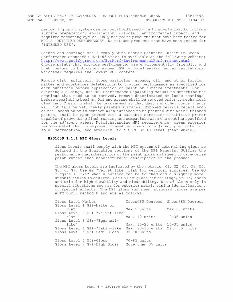
The MPI gloss Levels are indicated by the notation G1, G2, G3, G4, G5, G6, or G7. Use G2 "Velvet-like” flat for vertical surfaces. Use G3 "Eggshell-like" when a surface can be touched and a slightly more durable finish is desired, Use G5 Semigloss for ceilings, walls, doors and trim for high durability and cleanability. Use G6 Gloss only in special situations such as for exterior metal, piping identification, or special effects. The MPI gloss and sheen standard values are per ASTM D523, method D and are as follows:
Gloss Level Number Gloss@60 Degrees Sheen@85 Degrees Gloss Level 1(G1)–Matte or Flat Max.5 units Max.10 units Gloss Level 2(G2)–"Velvet-like" Flat Max. 10 units 10-35 units Gloss Level 3(G3)–"Eggshell- like" Max. 10-25 units 10-35 units Gloss Level 4(G4)-"Satin-like Max. 20-35 units Min. 35 units Gloss Level 5(G5)-Semi-Gloss 35-70 units
Gloss Level 6(G6)–Gloss 70-85 units Gloss Level 7(G7)–High Gloss More than 85 units
ENERGY EFFICIENCY IMPROVEMENTS - HADNOT POINT/FRENCH CREEK 13P1449B MCB CAMP LEJEUNE, NC EPROJECTS W.O.NO.: 1194507
PART 4 - SECTION B20 - Page 10
B201009 1.1.2 MPI System Designations and Table Abbreviations
The MPI coating system number description is found in either the MPI Architectural Painting Specification Manual or the Maintenance Repainting Manual and defined as an exterior system.
a. EXT - MPI short-term designation for an exterior coating system on a new surface.
b. REX - the MPI short term designation for an exterior coating system used in repainting projects or over existing coating systems.
c. DSD - the MPI short-term designation for Degree of Surface Degradation as defined in the Assessment sections in the MPI Maintenance Repainting Manual. Degree of Surface Degradation designates the MPI Standard for description and appearance of existing condition of surfaces to be painted. This DSD classification is used to determine the proper surface preparation necessary for painting.
d. DFT – The short-term designation for dry film thickness. DFT is the minimum acceptable depth or thickness of a coating or system in the dry state. The maximum acceptable DFT is not more than 50% greater than the minimum acceptable DFT (example... DFT = 2 mils, maximum DFT = 3 mils). The DFT indicated in the paint systems below relate to new coatings - MPI INT. MPI RIN will be less than the indicated DFT.
e. Paint Systems Abbreviations: BF – block filler; C – clear coat; SP – spot primer; P – primer coat; I – intermediate coat; T – topcoat.
B201009 1.1.3 Surface Preparation
Comply with the "Exterior Surface Preparation" section of the MPI Architectural Painting Specification Manual or the Exterior Surface Preparation” section of the MPI Maintenance Repainting Manual. All suggestive language such as "may" or "should" are deleted from the standard and "must" or "shall" inserted in its place. Suggestive language such as "recommended" or "advisable" is deleted from the standard and "require" or "required" inserted in its place. The results of these wording substitutions change this document to required procedures. For surface preparation, determine a MPI DSD Assessment of each surface and comply with the MPI Surface Preparation Requirements relating to the assessments.
B201009 1.2 EXTERIOR CONCRETE FINISHES
New concrete floors and walkways with low contact and traffic. Not for high abuse, wheel traffic, or high humid area applications:
a. Latex, System DFT: 3.5 mils. 1) MPI REX 3.2A-G2/G3 (Low gloss); P: MPI 60, I: MPI 60, T: MPI 60.
B201009 1.4 EXTERIOR METAL FINISHES
B201009 1.4.1 New steel that has been blast cleaned to SSPC SP 6 & 10:
a. Alkyd, System (in SSPC Zones 1B and 2A) DFT: 5.25 mils. 1) MPI EXT/ REX 5.1D-G5 (Semigloss); P:MPI 79, I:MPI 94,
T:MPI 9 b. Waterborne Light Industrial (in SSPC Zones 1B, 3A, 3B, and 3C), System DFT: 8.5 mils. 1) MPI EXT 5.1R-G5 (Semigloss); P:MPI 101, I:MPI 108,
T:MPI 163.
ENERGY EFFICIENCY IMPROVEMENTS - HADNOT POINT/FRENCH CREEK 13P1449B MCB CAMP LEJEUNE, NC EPROJECTS W.O.NO.: 1194507
PART 4 - SECTION B20 - Page 11
B201009 1.4.2 New Galvanized surfaces:
a. Epoxy P/Waterborne Light Industrial (Use MPI 25 cleaner), System DFT: 4.5 mils.
1) MPI EXT 5.3K-G5 (Semigloss); P:MPI 101, I:MPI 161, T:MPI 161.
B201010 EXTERIOR JOINT SEALANT Sealant joint design, priming, tooling, masking, cleaning and application shall be in accordance with the general requirements of Sealants: A Professionals' Guide from the Sealant, Waterproofing & Restoration Institute (SWRI). All sealant shall conform to ASTM C 920.
Joints shall include proper backing material for sealant support during application, control of sealant depth, and to act as a bond breaker. Use filler boards, backer rods and bond breaker tapes. Provide priming unless specifically not recommended by the sealant manufacturer. Applied sealant shall be tooled. Tooling shall not compact sealant too less than the minimum sealant thickness required. Mask adjacent surfaces to control sealant boundaries during sealant application.
B201012 SCREEN WALL Screen walls include attached or unattached walls adjacent to the main building. Screen walls shall conform to the applicable portions of Section B201001 EXTERIOR CLOSURE.
B2030 EXTERIOR DOORS Exterior doors shall be heavy duty insulated steel doors and frames for service access. Door frames shall be welded. Corner knockdown door frames are not permitted.
Use heavy-duty overhead holder and closer to protect doors from wind damage. Provide kickplates on the inside face of all exterior doors.
Weather-protect all exterior doors and related construction with low infiltration weatherstripping and sealants. Provide threshold with offset to stop water penetration while maintaining accessibility compliance.
Conform to the design criteria of ASCE 7.
See section B203008, EXTERIOR DOOR HARDWARE, for door hardware requirements. For all installations, provide a recessed key box (Knox Box) approximately 7 inches x 7 inches (175 mm x 175 mm) with 4-3/4 inches (120 mm) solid steel door at primary exterior entry for storage of keys and access cards accessible by the fire department.
B203001 SOLID DOORS B203001 1.1 STEEL DOORS
Hardware preparation shall be in accordance with ANSI A250.6. Doors shall be hung in accordance with ANSI A115.16.
B203001 1.1.1 Steel Doors
Steel doors shall be ANSI A250.8, Level 4, exterior, main entry doors, with a physical performance level of, Model 1 or 2.
ENERGY EFFICIENCY IMPROVEMENTS - HADNOT POINT/FRENCH CREEK 13P1449B MCB CAMP LEJEUNE, NC EPROJECTS W.O.NO.: 1194507
PART 4 - SECTION B20 - Page 12
Doors may be specified to be insulated. Door selection shall be specified in the project program according to the following:
a. Standard Duty Doors - Level 1, physical performance Level C, b. Heavy Duty Doors - physical performance Level B, c. Extra
Heavy Duty Doors – ANSI A250.8, Level 3, physical performance Level A, d. Maximum Duty Doors – ANSI A250.8, Level 4, physical performance Level A,
B203001 1.1.3 Insulation Cores Insulated cores shall be of type specified, and provide an apparent U-factor of .48 in accordance with SDI 113 and shall conform to:
a. Rigid Polyurethane Foam: ASTM C591, Type 1 or 2, foamed-in-place or in board form, with oxygen index of not less than 22 percent when tested in accordance with ASTM D2863; or
b. Rigid Polystyrene Foam Board: ASTM C578, Type I or II; or c. Mineral board: ASTM C612, Type I.
B203001 1.1.4 Accessories
a. Louvers shall comply with SDI 111-C, shall be stationary,
sight-proof type. Use lightproof louvers if function of room requires darkness. Louver frames shall be 20-gage steel with louver blades minimum 24 gage.
b. Astragals: For pairs of exterior steel doors that will not have aluminum astragals or removable mullions, provide overlapping steel astragals with the doors.
c. Moldings: Provide moldings around louvers. Provide non-removable moldings on outside of exterior doors. Secure inside moldings to stationary moldings, or provide snap-on moldings.
B203001 1.1.5 Standard Steel Frames
ANSI A 250.8. Form frames with welded corners for installation in exterior walls. Form stops and beads of 20 gage steel. Frames shall be set in accordance with ASTM A250.11.
B203001 1.1.6 Anchors
Anchor all frames with a minimum of three jamb anchors and base steel anchors per frame, zinc-coated or painted with rust-inhibitive paint, not lighter than 18 gage. Mortar infill frames in masonry walls, and infill with gypsum board compound at each jamb anchor in metal frame walls. Only use surface exposed bolted anchors in concrete walls.
B203001 1.1.7 Finishes
a. Exterior Doors, Factory-Primed and Field Painted Finish – Doors and frames shall be factory primed with a rust inhibitive coating as specified in ANSI A250.8. Factory prime doors on six sides of the door. Manufacturer's primer and field painting shall be compatible with finish system in the paragraph "EXTERIOR PAINTING AND SPECIAL COATINGS".
b. Exterior Doors Galvanized Finish – Shall be Commercial Quality, Coating Class A, zinc coating in accordance with ASTM A 591 when facility is located further than 300 feet (91 meters) from the ocean. When facility is located within 300 feet (91 meters) of the ocean, provide G60 galvanized coating in accordance with ASTM A 924/A 924M and ASTM A 653/A 653M.
ENERGY EFFICIENCY IMPROVEMENTS - HADNOT POINT/FRENCH CREEK 13P1449B MCB CAMP LEJEUNE, NC EPROJECTS W.O.NO.: 1194507
PART 4 - SECTION B20 - Page 13
B203008 EXTERIOR DOOR HARDWARE Provide the services of an Architectural Hardware Consultant (AHC), or a Certified Door Consultant(CDC) to assist the Designer of Record in preparation of the door hardware schedule and product selection. The hardware consultant shall sign and seal the door hardware construction submittal. Provide, as far as possible, door hardware of one manufacturer’s make. All hardware shall be clearly and permanently marked by the manufacturer where it will be visible after installation.
B203008 1.1 HINGES
BHMA A156.1, size to match door size, but in no case less than 4-1/2 x 4-1/2 inches (114 mm x 114 mm), with non-removable pin and anti-friction bearing hinges. Use two hinges for doors 60 inches (1500 mm) or less in height and one additional hinge for each additional 30 inches (750 mm), or fraction thereof, in door height.
B203008 1.3 LOCKS AND LATCHES
Commercial (all construction except family housing) buildings locks and latches shall be BHMA A 156.13, Series 1000, Operational Grade 1, Security Grade 2 for exterior building entrances and other high-use doors not requiring exit devices. Use BHMA A 156.2, Series 4000, Grade 1 for all Commercial buildings locks and latches not using Series 1000 hardware.
For Residential (family housing) projects, use Series 4000, Grade 2 hardware.
B203008 1.3.1 Combination Locks for Sensitive Areas
If required for exterior use, see C102007 1.1.6 "Combination Locks" for the specification. This installation may require special weather protection.
B203008 1.3.2 Pushbutton Combination Locks
Where required, provide a heavy-duty, mechanical combination lockset with 5 pushbuttons, standard-sized knob or lever, 3/4 inch (19 mm) deadlocking latch with 2-3/4 inch (70 mm) back-set. Provide deadbolt key override option. Safelock, Simplex, and Venn are acceptable manufacturers. Provide a hardware grade equivalent to Grade 1, series 4000. Include a 5-year parts and labor warranty.
B203008 1.4 CARD KEY SYSTEM
Where required, provide card key type access units. Provide lithium battery powered, magnetic stripe keycard locksets that are ANSI/BHMA A156.13, Series 1000, Grade 1, mortise or ANSI/BHMA A156.2, Series 4000, Grade 1, cylindrical locks, tamper resistant, UL listed with 1 inch (25 mm) throw deadbolt, 3/4-inch (19 mm) throw latch bolt, auxiliary deadlocking latch, and 2-3/4 inch (68.75 mm) backset. The latch bolt and the dead bolt shall be operated simultaneously by rotating inside lever. Locks with mechanical override lock cylinders are not acceptable. Locks shall be operated only by a correctly encoded keycard. Use of a newly issued keycard automatically re-keys the lock and voids the previous keycard. The lock shall re-lock immediately after outside lever is turned and latch retracted. Locks shall have memory that is capable of recording up to 140 entries into each room, identification of the keycard used to access the room, the date and time of entry. Entry information of the lock shall be retrievable by a data key that can be inserted into the lock and then taken to the front desk printer to display information. Other components that are required for this system at the front desk are a personal or laptop computer, printer and encoder to program each key.
ENERGY EFFICIENCY IMPROVEMENTS - HADNOT POINT/FRENCH CREEK 13P1449B MCB CAMP LEJEUNE, NC EPROJECTS W.O.NO.: 1194507
PART 4 - SECTION B20 - Page 14
System shall be capable of accepting a minimum of 12 keycard access levels, security auditing and computer interfacing with existing installations management system. Provide a single point of contact customer service representative accessible by telephone with a 10-digit telephone number without additional dialing hierarchies except that a maximum 4-digit extension is permissible. On-site service shall be provided within 3 hours from request within the first 12 months of occupancy. Provide a 5-year parts and labor warranty.
B203008 1.6 EXIT LOCKS WITH ALARM
BHMA A 156.5.
B203008 1.7 CYLINDERS AND CORES
If required, provide cylinders and cores for new locks, including locks provided under other sections of this specification. Cylinders and cores shall have seven pin tumblers. Cylinders shall be products of one manufacturer, and cores shall be the products of one manufacturer. Rim cylinders, mortise cylinders, and knobs of bored locksets shall have interchangeable cores, which are removable by special control keys. Stamp each interchangeable core with a key control symbol in a concealed place on the core.
B203008 1.8 KEYING SYSTEM
Keying system shall be a master key system for the facility, unless more than one tenant/tenant command shall reside in a facility, or a grand master keying system, or great, grand master keying system if multiple tenants or buildings are required. The keying system shall be an extension of the existing keying system for additions to existing facilities. The keying system shall allow for construction interchangeable cores when subcontractors require keys during construction. If required, provide a key cabinet.
The Contractor shall coordinate a keying system meeting. The Contractor's Project Manager, Superintendent, Hardware Subcontractor, Electrical Subcontractor (if keying hardware is electric), Designer of Record, Contracting Officer, Public Works Base Hardware Specialist, and the Using Activity shall attend this meeting to establish the keying system for the project. This meeting is intended to identify base limitations, the necessary security, and access control within the facility. The meeting shall produce a marked up copy of the floor plan indicating the doors to receive locks and the doors to be keyed together, and any master keying or grand master keying.
B203008 1.9 KEYS
Furnish one file key, one duplicate key and one working key for each key exchange and for each master and grand master keying system.
B203008 1.10 LOCK TRIM
Cast, forged or heavy wrought construction and commercial plain in design.
B203008 1.10.2 Lever Handles
Provide lever handles in lieu of knobs as required by DoD ABAAS. Lever handles shall meet the test requirements of BHMA A 156.13 for mortise locks. All lever handles (mortise or cylinder) shall be the freewheeling type.
ENERGY EFFICIENCY IMPROVEMENTS - HADNOT POINT/FRENCH CREEK 13P1449B MCB CAMP LEJEUNE, NC EPROJECTS W.O.NO.: 1194507
PART 4 - SECTION B20 - Page 15
B203008 1.11 DOOR BOLTS
BHMA A 156.16, Grade 1. Provide two flush bolts for each inactive leaf of a pair of doors.
B203008 1.12 CLOSERS
BHMA A 156.4, Series C02000, Grade 1, with PT 4C, 1-1/2 inch piston, heavy duty forged arm, full size case. Provide closers for all exterior doors, fire-rated doors, corridor doors, stairway doors, and secure area doors, for non-residential (commercial) construction, as a minimum.
B203008 1.13 OVERHEAD HOLDERS
BHMA A 156.8, Grade 1. Provide for exterior doors for non-residential (commercial) construction.
B203008 1.14 DOOR PROTECTION PLATES
Kick plates shall conform to BHMA A 156.6. Provide kick plates on all doors with closers and all doors leading to corridors or circulation spaces. Provide armor plates on all doors to receive cart traffic. Provide mop plates on all doors in rooms with a mopable floor finish that do not have kick plates.
B203008 1.15 DOOR STOPS AND SILENCERS
BHMA A 156.16. Provide silencers, Type L03011, three per single door and four per double door, for doors in hollow metal frames.
B203008 1.16 THRESHOLDS
BHMA A 156.21. Provide thresholds with offset to stop water infiltration, while maintaining accessibility requirements.
B203008 1.17 WEATHERSTRIPPING
BHMA A 156.22. Air leakage of weatherstripped doors shall not exceed 0.5 CFM of air per square foot of door for residential doors, and 1.25 CFM for non-residential doors (unless a more restrictive infiltration level is specified).
B203008 1.18 RAIN DRIPS
For all exterior doors that open to the outside, where the door swing area is not covered by an overhang, provide top and bottom rain drips complying with ANSI R3Y535 as a minimum. Greater weathersealing may be required by the geographic location of the project.
B203008 1.19 FINISHES
One of the following hardware finish systems shall be provided, and match the interior door hardware:
a. BHMA A156.18. Hardware shall have BHMA 630 finish (satin stainless steel), unless specified otherwise. Provide items not manufactured in stainless steel in BHMA 626 finish (satin chromium plated) over brass or bronze, except surface door closers which shall have aluminum paint finish, and except steel hinges which shall have BHMA 652 finish (satin chromium plated). Hinges for exterior doors shall be stainless steel with BHMA 630 finish or chromium plated brass or bronze with BHMA 626 finish. Exit devices may be provided in BHMA 626 finish in lieu of BHMA 630 finish. Exposed parts of concealed closers shall have finish to

ENERGY EFFICIENCY IMPROVEMENTS - HADNOT POINT/FRENCH CREEK 13P1449B MCB CAMP LEJEUNE, NC EPROJECTS W.O.NO.: 1194507
PART 4 - SECTION B20 - Page 16
match lock and door trim. Hardware for aluminum doors shall be finished to match the doors.
b. BHMA A156.18. Hardware shall have BHMA 612 finish (satin bronze), unless specified otherwise. Surface door closers shall have bronze paint finish. Steel hinges shall have BHMA 639 finish (satin bronze plated). Exposed parts of concealed closers shall have finish to match lock and door trim. Hardware for aluminum doors shall be finished to match the doors. Hardware showing on interior of bathrooms, shower rooms, toilet rooms, washrooms, laundry rooms, and kitchens shall have BHMA 629 finish (bright stainless steel) or BHMA 625 finish (bright chromium plated).
-- End of Section --
ENERGY EFFICIENCY IMPROVEMENTS - HADNOT POINT/FRENCH CREEK 13P1449B MCB CAMP LEJEUNE, NC EPROJECTS W.O.NO.: 1194507
PART 4 - SECTION B30 - Page 1
SECTION B30 ROOFING 11/10
B30 GENERAL RFP Part 3 including the Engineering System Requirements (ESR) provide project specific requirements. The RFP Part 4, Performance Technical Sections (PTS) provide generalized technical requirements that apply to multiple facility types and include more requirements than are applicable to any one project. Therefore, only the RFP Part 4 requirements that apply to the project and further define the RFP Part 3 project specific requirements are required.
B30 1.1 DESIGN GUIDANCE
Provide the design and installation in accordance with the following references. This Performance Technical Specification (PTS) adds clarification to the fundamental requirements contained in the following Government Standards. The general requirements of this PTS section are located in PTS Section Z10, General Performance Technical Specification.
Industry standards, codes, and Government standards that are referenced in the section text that are not found in the Unified Master Reference List (UMRL) in the Construction Criteria Base (CCB) at the Whole Building Design Guide Website are listed below for basic designation identification. Comply with the required and advisory portions of the current edition of the standard at the time of contract award.
B30 1.1.1 Government Standards
UNIFIED FACILITIES CRITERIA (UFC)
UFC 1-200-01
General Building Requirements(A reference in this PTS section to UFC 1-200-01 requires compliance with the Tri-Service Core UFCs that are listed in UFGS Section 01 33 10.05 20, which includes the following significant UFC(s):UFC 3-101-01 Architecture UFC 3-110-03 Roofing)
B30 1.2 PERFORMANCE VERIFICATION AND ACCEPTANCE TESTING
Verification of satisfactory roofing system performance shall be via Performance Verification Testing, and by field inspection as detailed in this section of the RFP. All performance and acceptance testing including final/warranty inspections shall be witnessed by the Contracting Officer on all significant roof projects.
A significant roof project is a single or group of buildings greater than 15,000 square feet (1,400 m2) in size, or where extenuating circumstances of the roof project such as building use, content, safety, or visibility determine the roof design.
ENERGY EFFICIENCY IMPROVEMENTS - HADNOT POINT/FRENCH CREEK 13P1449B MCB CAMP LEJEUNE, NC EPROJECTS W.O.NO.: 1194507
PART 4 - SECTION B30 - Page 2
B30 1.2.1 Pre-Roofing Design Conference
If required in RFP Part 3, the Contractor shall hold a Pre-Roofing Design Conference with the Contracting Officer. Schedule this conference prior to the roof design and roof layout of the facility. Attendee's shall include the DOR, DQC Manager, Roof Design Assurance Consultant (if applicable), Commissioning Authority, and Subcontractors directly responsible for installing the roof. Discuss and coordinate the following as a minimum:
a. Sustainable systems to be mounted on the roof and interface with building systems and utilities,
b. Impact of sustainable systems and building orientation to the suns path,
c. Waterproofing, flashing, and future reroofing considerations of the facility resulting from sustainable systems inclusion on the roof,
d. Measures taken to eliminate penetration of the roof membrane. NRCA roof details proposed for each necessary penetration,
e. Structural requirements to support roof mounted equipment, f. Maintenance and Commissioning requirements of the roof and roof
mounted equipment to facilitate final testing and provide proper access and roof membrane protection.
B30 1.2.2 Pre-Roofing Conference
Prior to beginning roofing work, the Contractor shall hold a Pre-Roofing Conference with the Contracting Officer. Attendees' shall include personnel directly responsible for the roofing systems design and construction, DQC Manager, Commissioning Authority, as well as the roofing manufacturer's technical representative, and Roof Design Consultant (if applicable). At this time the Contractor will address any conflicts between the proposed roofing system, the design documents, and the scheduling of work / workers (trades) to assure a watertight roofing installation. Resolutions will be obtained and documented in writing prior to the start of roofing work. A quality assurance/quality control plan shall also be established at this time, inclusive of the roofing manufacturer's recommended testing and inspections procedures, and in accordance with industry standard guidelines.
Contractor shall provide the following additional information at the pre-roofing conference: Procedure for the roof manufacturer’s technical representative's onsite inspection and acceptance of the roofing substrate roof insulation and installation of the roofing in accordance with the roof system warranty, the name of the manufacturer's technical representatives, the frequency of the onsite visits, copies of the roof status reports from the technical representatives to the roof manufacturer, and pertinent structural details to the roofing system.
ENERGY EFFICIENCY IMPROVEMENTS - HADNOT POINT/FRENCH CREEK 13P1449B MCB CAMP LEJEUNE, NC EPROJECTS W.O.NO.: 1194507
PART 4 - SECTION B30 - Page 3
B30 1.2.3 Roof Design Assurance
If the roofing project is significant (defined above) or where extenuating circumstances of the roof project such as building use, content, safety, or visibility require a roofing consultant, the Contractor shall utilize the services of a Registered Roof Consultant (RRC) certified by the Roof Consultant Institute, or a Registered Professional architect or Engineer who specializes in roofing, to approve the roof design. The roof consultant must be engaged in roofing design and roofing construction as his primary endeavor. The roof consultant shall verify in writing that the design for the project is in accordance with the current edition of NRCA Roofing and Waterproofing Manual, UFC's, and RFP, and standard industry practices and building codes.
If a Roof Design Assurance Consultant is needed, consider using a Registered Roof Observer as a QC specialist in UFGS Section 01 45 00.05 20, Design and Construction Quality Control.
B30 1.2.5 Tests for Surface Dryness
Prior to application of roofing materials, perform surface dryness tests in presence of DOR. Asphalt of 350 to 400 degrees F (177 to 204 degrees C) shall not foam upon contact with substrate. After foaming test is performed, test for strip ability (adherence).
B30 1.2.6 Quality Control Program
Contractor shall establish a quality control program to assure adherence to NRCA recommended Quality Control Guidelines for the Application of Roofing Systems and other specified application requirements. Compliance with UFGS Section 01 45 00.05 20, Design and Construction Quality Control, is required.
B30 1.3 DESIGN SUBMITTALS
Design submittals shall be in accordance with Z10, General Performance Technical Specifications, UFGS section 01 33 10.05 20, Design Submittal Procedures, UFC 1-300-09N, Design Procedures and UFC 3-101-01, Architecture.
B30 1.4 CONSTRUCTION SUBMITTALS
Submit construction submittals in accordance with PTS Section Z10, General Performance Technical Specifications. In addition to the Z10 requirements, the Designer of Record (DOR) shall approve the following submittals as a minimum:
Test reports, color samples, certificates of conformance, warranties, close out documentation, and manufacturer's instructions for application and installation on all products used on the roof. Products used on the roof consist of but are not limited to structural deck, insulation membrane or panels, Standing Seam Metal Roofing (SSMR), flashing, fasteners, nailers, accessories and equipment support curbs or equipment support stands for solar equipment maintenance access and paths.
ENERGY EFFICIENCY IMPROVEMENTS - HADNOT POINT/FRENCH CREEK 13P1449B MCB CAMP LEJEUNE, NC EPROJECTS W.O.NO.: 1194507
PART 4 - SECTION B30 - Page 4
B3010 ROOF COVERINGS Roof coverings shall comply with the requirements of UFC 3-110-03, Roofing, and NRCA, Roofing and Waterproofing Manual found at http://www.nrca.net/rp/technical/manual/manual.aspx as the primary NAVFAC roofing criteria. Roof selection shall comply with UFC 3-330-02A, Design: Commentary on Roof Systems. Determine wind uplift using wind speed in accordance with ASCE-7.
Submit the INFORMATION CARD (see "Form 1" at the end of this section) Provide a typewritten card, laminated in plastic and framed in a weather-tight frame, or a photoengraved 0.032-inch (0.81 mm) thick aluminum card for the roof. This card shall be a minimum size of 8 1/2 x 11 inch (216 x 280 mm) and contain information listed in the attached Form 1. Install the card where directed. Furnish framed card and a duplicate card to the Designer of Record.
B301001 STEEP SLOPE ROOF SYSTEMS B301001 1.2 ASPHALT SHINGLES
The shingle roofing system shall be installed in accordance with NRCA Roofing and Waterproofing Manual(Latest Edition), "Steep Roofing", closed cut valley flashing shall not be allowed and per ASTM D 3462.
B301001 1.2.1 Warranties
The contractor shall furnish to the Government the manufacturer's standard 30-year warranty for the asphalt shingles. The Contractor shall also warrant that the asphalt shingle roofing system, as installed, is free from defects in workmanship. Provide a minimum 10-year fungus resistance warranty in southern climate and areas susceptible to fungus growth on shingles.
B301001 1.2.2 Materials
a. Shingles - Shingles shall meet ASTM D 3018, Type I, and ASTM D 3462, and shall weigh not less than 210 pounds per 100 square feet (95 kg per 9.3 square meters). Shingles shall meet the fire resistance requirements of UL 790 for Class 'A' and resist winds in accordance with ASCE-7 when tested in accordance with UL 997.
b. Shingle Underlayment - Asphalt-saturated felt conforming to ASTM D 226, Type I.
c. Self-Adhering Membrane - Self-adhering rubberized asphaltic membrane, a minimum of 40 mils thick. Provide at all ridges, valleys, sidewalls and starter strips.
d. Nails - 11 or 12 gauge hot-dipped galvanized steel, corrosion resistant roofing nails, with sharp points and flat heads 3/8 inch to 7/16 inch (9.5 mm to 11 mm) diameter. Shank diameter shall be a minimum of 0.105 inch (2.7 mm) to a maximum of 0.135 inch (3.4 mm). Nails shall be long enough to penetrate through all layers of roofing materials and achieve secure anchorage into a roof deck. A minimum of 4 nails shall be used on a full width shingle, and six nails in high wind areas. Location of nails shall be as shown in manufacturers printed installation instructions. Staples are not permitted as a means of attachment.
e. Asphalt Roof Cement - ASTM D 4586, Type II. f. Asphalt Primer - ASTM D 41.
ENERGY EFFICIENCY IMPROVEMENTS - HADNOT POINT/FRENCH CREEK 13P1449B MCB CAMP LEJEUNE, NC EPROJECTS W.O.NO.: 1194507
PART 4 - SECTION B30 - Page 5
B301001 1.3.4 Substrate Panels for Application Over Metal Deck
a. Glass Mesh Mortar Units - ASTM E 84, exterior type panels of Portland cement.
b. Fiberglass-Faced Gypsum Roof Board - ASTM 1177/C 1177M
B301001 1.3.5 Fasteners
a. Nails for Applying Felt Underlayment - Hot dip galvanized steel, 11 gage, of sufficient length to penetrate through substrate panels.
B301001 1.3.6 Preservative-Treated Lumber - AWPA C1
B301001 1.4 METAL ROOF PANELS (ARCHITECTURAL STANDING SEAM METAL ROOFS ON SUPPORTED SUBSTRATE)
B301001 1.4.1 Manufactured Sheet Metal Roofing
Provide galvanized steel or aluminum-zinc coated steel or aluminum panels formed at the manufacturing plant and conditioned for flatness. Panel thickness shall be determined by the requirements of NRCA, Roofing and Waterproofing Manual, but not less than 24 gauge for panels less than 16 inches wide (400 mm), and 22 gauge for panels 16 inches (400 mm) wide or greater. All panels greater than 12 inches (300 mm) wide shall have preformed reinforcing ribs or embossed for stiffening. The minimum gauge for aluminum panels shall be 20-gauge, .032 inch thick (.8 mm thick) or greater. Roofing design shall meet deflection and wind load requirements per building code.
The SSMR system covered under this specification shall include the entire roofing system; the standing seam metal roof panels, fasteners, connectors, roof securement components, and assemblies tested and approved in accordance with ASTM E 1592. In addition, the system shall consist of panel finishes, slip sheet insulation vapor retarder, all accessories, components, and trim and all connections with roof panels. This includes roof penetration items such as vents, curbs, exterior gutters and downspouts; eaves, ridge, hip, valley, rake, gable, wall, or other roof system flashings installed and any other components specified within this contract to provide a weathertight roof system.
a. Provide inverted "L" Standing Seam shape roofing panels. b. Panel Protection - Treat exposed cut edges with compatible
coating comparable to the factory applied coating system for corrosion protection.
c. Sealants - Provide non-curing, non-skinning butyl based sealants and tapes for concealed locations such as within laps and under eaves. Provide polyurethane and curing butyl elastomeric sealants for exposed locations such as along top edge of surface mounted counter flashings.
ENERGY EFFICIENCY IMPROVEMENTS - HADNOT POINT/FRENCH CREEK 13P1449B MCB CAMP LEJEUNE, NC EPROJECTS W.O.NO.: 1194507
PART 4 - SECTION B30 - Page 6
d. Factory Color Finish - Provide factory applied, baked coating to the exterior and interior of metal wall panels and metal accessories. Provide exterior finish top coat of 70 percent polyvinylidene fluoride resin with not less than 0.8 mil dry film thickness. Provide exterior primer standard with panel manufacturer with not less than 0.8 mil dry film thickness. Interior finish shall consist of 0.5 mil dry film thick backer coat if permanently concealed from view by construction or the same coating and dry film thickness as the exterior coating if the panel interior side will be exposed. Provide factory-applied clear 70 percent PVF, 0.8 mil top coat and edge coating on all factory-cut or unfinished panel edges for projects within 300 feet (91 meters) of the ocean or industrial environments.
e. Warranty - Furnish manufacturer's no dollar limit materials and workmanship warranty for the roofing system. The warranty period shall be not less than 20 years from the date of Government acceptance of the work. The warranty shall be issued directly to the Government. The warranty shall provide that if within the warranty period the metal roofing system becomes non-watertight or shows evidence of corrosion, perforation, peeling paint, rupture or excess weathering due to deterioration of the roofing system resulting from defective materials or workmanship the repair or replacement of the defective materials and correction of the defective workmanship shall be the responsibility of the roofing system manufacturer. Repairs that become necessary because of defective materials and workmanship while roofing is under warranty shall be performed within 7 days after notification, unless additional time is approved by the Contracting Officer. Failure to perform repairs within the specified period of time will constitute grounds for having the repairs performed by others and the cost billed to the manufacturer. The Contractor shall also provide a 2 year contractor installation warranty. Coating shall not show a color change greater than 5 NBS color units per ASTM D2244, and not show chalking in excess of 10 per ASTM D4214.
f. Wind Uplift - Metal roofing systems shall be designed and attached to resist wind uplift pressures calculated in accordance with ASCE 7. Uplift resistance shall be validated by applicable Factory Mutual (FM), Underwriters Laboratories (UL), or ASTM uplift resistance test procedures.
B301001 1.4.2 Metal Roof Design Requirements
The design of the SSMR system shall be provided by the Contractor as a complete system. Roof panels, components, transitions, accessories, and assemblies shall be supplied by the same roofing system manufacturer. Provide to the DOR a design analysis signed by a Registered Professional Engineer employed by the SSMR manufacturer. The design analysis shall include a list of the design loads, and complete calculations for the roofing system and its components; valley designs, gutter/downspout calculations, screw pullout test results, and shall indicate how expected thermal movements are accommodated.
ENERGY EFFICIENCY IMPROVEMENTS - HADNOT POINT/FRENCH CREEK 13P1449B MCB CAMP LEJEUNE, NC EPROJECTS W.O.NO.: 1194507
PART 4 - SECTION B30 - Page 7
B301001 1.4.3 Accessories
Provide other sheet metal flashings, trim moldings, closure strips, caps and other preformed metal panel accessories, of the same material, thickness and finish as panels, except accessories that are concealed after installation, and are aluminum or zinc-coated steel may be provided unfinished. Provide molded closure strips of closed-cell or solid-cell synthetic rubber, neoprene, or polyvinyl chloride premolded to match configurations of preformed metal panels. All accessories shall be manufactured or approved by the roof panel manufacturer.
B301001 1.4.4 Fasteners
Provide concealed fasteners for attaching panels to structural supports and to adjoining panels as approved and in accordance with printed manufacturer's recommendations.
B301001 1.4.5 Field Quality Control
Install in accordance with the approved manufacturer's erection instructions, shop drawings, and diagrams. Panels shall be in full and firm contact with attachment clips. Where prefinished panels are cut in the field, or where any of the factory applied coverings or coatings are abraded or damaged in handling or installation, they shall, after necessary repairs have been made with material of the same color as the weather coating, be approved before being installed. Seal openings through panels. Correct defects or errors in the materials. Replace materials which cannot be corrected in an approved manner with nondefective materials. Provide molded closure strips where necessary to provide weathertight construction. Use shims as required to ensure attachment clip line is true. Use a spacing gage at each row of panels to ensure that panel width is not stretched or shortened. Provide 30 pound layer of asphalt-saturated felt placed perpendicular to roof slope, covered by a slip sheet. Overlap side and end laps 75 mm 3 inches, offset seams in building paper with seams in felt.
Apply roofing panels with the standing seams parallel to the slope of the roof. Provide roofing panels in longest practical lengths from ridge to eaves (top to eaves on shed roofs), with no transverse joints except at the junction of ventilators, curbs, and similar openings. Install flashing to assure positive water drainage away from roof penetrations. Locate panel end laps such that fasteners do not engage supports or otherwise restrain the longitudinal thermal movement of panels. Attach panels to the structure with concealed clips incorporated into panel seams. Clip attachment shall allow roof to move independently of the structure, except at fixed points as necessary.
ENERGY EFFICIENCY IMPROVEMENTS - HADNOT POINT/FRENCH CREEK 13P1449B MCB CAMP LEJEUNE, NC EPROJECTS W.O.NO.: 1194507
PART 4 - SECTION B30 - Page 8
B301004 FLASHINGS & TRIM B301004 1.1 FLASHING AND SHEET METAL
This paragraph covers the requirements for flashing and sheet metal work. Flashing and sheet metal shall be provided in accordance with roof manufacturer’s printed installation instructions and in compliance with NRCA and SMACNA recommendations.
B301004 1.1.1 Materials
Furnish sheet metal items in minimum 8 to 10 foot (2.44 to 3.05 meter) lengths. Sheet metal items include the following: gutters, including hangers; downspouts; counter-flashings; cap, valley, stepped, base and eave flashings and related accessories.
a. Copper, Sheet and Strip - ASTM B 370, cold-rolled temper. b. Lead-Coated Copper Sheet - ASTM B 101. c. Lead Sheet - Minimum weight 4 pounds per square foot (.19 kPa). d. Steel Sheet, Zinc-Coated (Galvanized) - ASTM A 653/ A 653M.
Galvanized steel items shall have a baked-on, factory applied finish of polyvinylidene fluoride or an equivalent fluorocarbon coating with a minimum thickness of 0.8 to 1.3 mils.
e. Stainless Steel - ASTM A 167, Type 302 or 304, 2D finish, fully annealed, dead-soft temper.
f. Aluminum Alloy Sheet and Plate - ASTM B 209. g. Pre-Finished Aluminum - Provide trim, gravel stops and fascias
of Pre-finished aluminum. Finish shall be baked-on factory applied color coating of polyvinylidene fluoride (PVF2) or other equivalent fluorocarbon coating with a minimum thickness of 0.8 to 1.3 mils.
h. Aluminum alloy, Extruded Bars, Rods, Shapes, and Tubes – ASTM B 221.
i. Solder - ASTM B 32. j. Polyvinyl Chloride Reglet - ASTM D 1784, Type II. k. Asphalt Primer - ASTM D 41. l. Fasteners - Fasteners shall be of the same or compatible metal
with the item being fastened. Stainless steel fasteners shall be used to fasten dissimilar materials.
B301004 1.1.2 Field Quality Control
Fabrication and installation of sheet metal items shall be as follows:
a. Install work with watertight and hairline joints, without waves, warps, buckles, fastening stresses, or distortion, allowing for expansion and contraction.
b. Make surfaces to receive sheet metal plumb and true, clean, even, smooth, dry and free of defects and projections that could affect the application.
c. Provide sheet metal flashing in angles formed where roof decks abut walls, curbs, ventilators, pipes, or other vertical surfaces and wherever indicated and necessary to make the work watertight.
d. Provide prefabricated inside and outside corners at all sheet metal intersection pieces. Minimum leg length shall be 12 inches (300 mm), maximum length shall be 18 inches (450 mm).
e. Sheet metal shall be fabricated to conform to the contours of surfaces to which applied.
f. All sheet metal cap flashings shall have waterproof membrane underlayment installed behind or below the metal components.
ENERGY EFFICIENCY IMPROVEMENTS - HADNOT POINT/FRENCH CREEK 13P1449B MCB CAMP LEJEUNE, NC EPROJECTS W.O.NO.: 1194507
PART 4 - SECTION B30 - Page 9
g. Provide conforming sheet metal closures at all flashing termination conditions.
h. Provide fastenings and accessories as required to provide a securely attached, watertight construction. Cleats shall be a minimum of one gage heavier than the component to be attached.
i. Where sheet metal components are to be embedded in the roofing system, prime both sides of all metal flanges prior to installation.
B301005 GUTTERS AND DOWNSPOUTS Provide gutters and downspouts compatible with roofing material and finish. Concealed (interior) gutters and downspouts are prohibited. The primary and secondary drainage systems shall be sized per applicable Plumbing and Building Codes. Finish shall be baked-on factory applied color coating of polyvinylidene fluoride (PVF2) or other equivalent fluorocarbon coating with a minimum thickness of 0.8 to 1.3 mils.
B301006 ROOF PENETRATIONS B301006 1.1 GENERAL REQUIREMENTS
Provide flashings for roof penetrations as recommended by the NRCA and as specified below:
For round penetrations, provide a metal umbrella cap clamped to the penetration.
Assure all penetration flashings extend minimum 8 inches (200 mm) above the finished roof surface.
B301090 OTHER ROOFING B301090 1.1 LIGHTNING PROTECTION
Lightning protection component penetrations and attachments shall be sealed and flashed and anchored in a permanent manner and in a manner to avoid the degradation of the watertight integrity of the roof system. Do not cut or otherwise disturb the roof membrane. Mastic seals in the plane of the roof are unacceptable. Anchor plates set in mastic shall be set on roof surface cleaned of aggregate and loose material prior to mastic application.
-- End of Section --

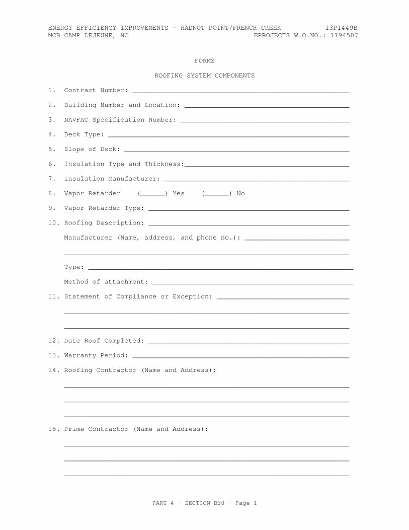
ENERGY EFFICIENCY IMPROVEMENTS - HADNOT POINT/FRENCH CREEK 13P1449B MCB CAMP LEJEUNE, NC EPROJECTS W.O.NO.: 1194507
PART 4 - SECTION B30 - Page 1
FORMS
ROOFING SYSTEM COMPONENTS
1. Contract Number: ______________________________________________________
2. Building Number and Location: _________________________________________
3. NAVFAC Specification Number: __________________________________________
4. Deck Type: ____________________________________________________________
5. Slope of Deck: ________________________________________________________
6. Insulation Type and Thickness:_________________________________________
7. Insulation Manufacturer: ______________________________________________
8. Vapor Retarder (______) Yes (______) No
9. Vapor Retarder Type: __________________________________________________
10. Roofing Description: __________________________________________________
Manufacturer (Name, address, and phone no.): __________________________
_______________________________________________________________________
Type: __________________________________________________________________
Method of attachment: __________________________________________________
11. Statement of Compliance or Exception: _________________________________
_______________________________________________________________________
_______________________________________________________________________
12. Date Roof Completed: __________________________________________________
13. Warranty Period: ______________________________________________________
14. Roofing Contractor (Name and Address):
_______________________________________________________________________
_______________________________________________________________________
_______________________________________________________________________
15. Prime Contractor (Name and Address):
_______________________________________________________________________
_______________________________________________________________________
_______________________________________________________________________
ENERGY EFFICIENCY IMPROVEMENTS - HADNOT POINT/FRENCH CREEK 13P1449B MCB CAMP LEJEUNE, NC EPROJECTS W.O.NO.: 1194507
PART 4 - SECTION B30 - Page 2
Contractor's Signature _______________________________ Date: _____________
Inspector's Signature ________________________________ Date: _____________
Form page 1
CONTRACTOR'S FIVE (5) YEAR NO PENAL SUM WARRANTY FOR STRUCTURAL STANDING SEAM METAL ROOF (SSSMR) SYSTEM
FACILITY DESCRIPTION_________________________________________________
ENERGY EFFICIENCY IMPROVEMENTS - HADNOT POINT/FRENCH CREEK 13P1449B MCB CAMP LEJEUNE, NC EPROJECTS W.O.NO.: 1194507
PART 4 - SECTION B30 - Page 3
BUILDING NUMBER:_____________________________________________________
CONTRACT NUMBER:_____________________________________________________
CONTRACTOR
CONTRACTOR:__________________________________________________________
ADDRESS:_____________________________________________________________
POINT OF CONTACT:____________________________________________________
TELEPHONE NUMBER:____________________________________________________
OWNER
OWNER:_______________________________________________________________
ADDRESS:_____________________________________________________________
POINT OF CONTACT:____________________________________________________
TELEPHONE NUMBER:____________________________________________________
CONSTRUCTION AGENT
CONSTRUCTION AGENT:__________________________________________________
ADDRESS:_____________________________________________________________
POINT OF CONTACT:____________________________________________________
TELEPHONE NUMBER:____________________________________________________
Warranty page 1
CONTRACTOR'S FIVE (5) YEAR NO PENAL SUM WARRANTY FOR STRUCTURAL STANDING SEAM METAL ROOF (SSSMR) SYSTEM (continued)
THE SSSMR SYSTEM INSTALLED ON THE ABOVE NAMED BUILDING IS WARRANTED BY _____________________________ FOR A PERIOD OF FIVE (5) YEARS AGAINST WORKMANSHIP AND MATERIAL DEFICIENCES, WIND DAMAGE, STRUCTURAL FAILURE, AND LEAKAGE. THE SSSMR SYSTEM COVERED UNDER THIS WARRANTY SHALL INCLUDE, BUT SHALL NOT BE LIMITED TO, THE
ENERGY EFFICIENCY IMPROVEMENTS - HADNOT POINT/FRENCH CREEK 13P1449B MCB CAMP LEJEUNE, NC EPROJECTS W.O.NO.: 1194507
PART 4 - SECTION B30 - Page 4
FOLLOWING: THE ENTIRE ROOFING SYSTEM, MANUFACTURER SUPPLIED FRAMING AND STRUCTURAL MEMBERS, METAL ROOF PANELS, FASTENERS, CONNECTORS, ROOF SECUREMENT COMPONENTS, AND ASSEMBLIES TESTED AND APPROVED IN ACCORDANCE WITH ASTM E 1592. IN ADDITION, THE SYSTEM PANEL FINISHES, SLIP SHEET, INSULATION, VAPOR RETARDER, ALL ACCESSORIES, COMPONENTS, AND TRIM AND ALL CONNECTIONS ARE INCLUDED. THIS INCLUDES ROOF PENETRATION ITEMS SUCH AS VENTS, CURBS, SKYLIGHTS; INTERIOR OR EXTERIOR GUTTERS AND DOWNSPOUTS; EAVES, RIDGE, HIP, VALLEY, RAKE, GABLE, WALL, OR OTHER ROOF SYSTEM FLASHINGS INSTALLED AND ANY OTHER COMPONENTS SPECIFIED WITHIN THIS CONTRACT TO PROVIDE A WEATHERTIGHT ROOF SYSTEM; AND ITEMS SPECIFIED IN OTHER SECTIONS OF THE SPECIFICATIONS THAT ARE PART OF THE SSSMR SYSTEM.
ALL MATERIAL DEFICIENCIES, WIND DAMAGE, STRUCTURAL FAILURE, AND LEAKAGE ASSOCIATED WITH THE SSSMR SYSTEM COVERED UNDER THIS WARRANTY SHALL BE REPAIRED AS APPROVED BY THE CONTRACTING OFFICER. THIS WARRANTY SHALL COVER THE ENTIRE COST OF REPAIR OR REPLACEMENT, INCLUDING ALL MATERIAL, LABOR, AND RELATED MARKUPS. THE ABOVE REFERENCED WARRANTY COMMENCED ON THE DATE OF FINAL ACCEPTANCE ON ____________________________ AND WILL REMAIN IN EFFECT FOR STATED DURATION FROM THIS DATE.
SIGNED, DATED, AND NOTARIZED (BY COMPANY PRESIDENT)
____________________________________________________________
(Company President) (Date)
Warranty page 2
CONTRACTOR'S FIVE (5) YEAR NO PENAL SUM WARRANTY FOR STRUCTURAL STANDING SEAM METAL ROOF (SSSMR) SYSTEM (continued)
THE CONTRACTOR SHALL SUPPLEMENT THIS WARRANTY WITH WRITTEN WARRANTIES FROM THE MANUFACTURER AND INSTALLER OF THE SSSMR SYSTEM, WHICH SHALL BE SUBMITTED ALONG WITH THE CONTRACTOR'S WARRANTY. HOWEVER, THE CONTRACTOR WILL BE ULTIMATELY RESPONSIBLE FOR THIS WARRANTY AS OUTLINED IN THE SPECIFICATIONS AND AS INDICATED IN THIS WARRANTY EXAMPLE.
ENERGY EFFICIENCY IMPROVEMENTS - HADNOT POINT/FRENCH CREEK 13P1449B MCB CAMP LEJEUNE, NC EPROJECTS W.O.NO.: 1194507
PART 4 - SECTION B30 - Page 5
EXCLUSIONS FROM COVERAGE
1. NATURAL DISASTERS, ACTS OF GOD (LIGHTNING, FIRE, EXPLOSIONS, SUSTAINED WIND FORCES IN EXCESS OF THE DESIGN CRITERIA, EARTHQUAKES, AND HAIL).
2. ACTS OF NEGLIGENCE OR ABUSE OR MISUSE BY GOVERNMENT OR OTHER PERSONNEL, INCLUDING ACCIDENTS, VANDALISM, CIVIL DISOBEDIENCE, WAR, OR DAMAGE CAUSED BY FALLING OBJECTS.
3. DAMAGE BY STRUCTURAL FAILURE, SETTLEMENT, MOVEMENT, DISTORTION, WARPAGE, OR DISPLACEMENT OF THE BUILDING STRUCTURE OR ALTERATIONS MADE TO THE BUILDING.
4. CORROSION CAUSED BY EXPOSURE TO CORROSIVE CHEMICALS, ASH OR FUMES GENERATED OR RELEASED INSIDE OR OUTSIDE THE BUILDING FROM CHEMICAL PLANTS, FOUNDRIES, PLATING WORKS, KILNS, FERTILIZER FACTORIES, PAPER PLANTS, AND THE LIKE.
5. FAILURE OF ANY PART OF THE SSSMR SYSTEM DUE TO ACTIONS BY THE OWNER TO INHIBIT FREE DRAINAGE OF WATER FROM THE ROOF AND GUTTERS AND DOWNSPOUTS OR ALLOW PONDING WATER TO COLLECT ON THE ROOF SURFACE. CONTRACTOR'S DESIGN SHALL INSURE FREE DRAINAGE FROM THE ROOF AND NOT ALLOW PONDING WATER.
6. THIS WARRANTY APPLIES TO THE SSSMR SYSTEM. IT DOES NOT INCLUDE ANY CONSEQUENTIAL DAMAGE TO THE BUILDING INTERIOR OR CONTENTS THAT IS COVERED BY THE WARRANTY OF CONSTRUCTION CLAUSE INCLUDED IN THIS CONTRACT.
7. THIS WARRANTY CANNOT BE TRANSFERRED TO ANOTHER OWNER WITHOUT WRITTEN CONSENT OF THE CONTRACTOR; AND THIS WARRANTY AND THE CONTRACT PROVISIONS WILL TAKE PRECEDENCE OVER ANY CONFLICTS WITH STATE STATUTES.
**
Warranty page 3
CONTRACTOR'S FIVE (5) YEAR NO PENAL SUM WARRANTY FOR STRUCTURAL STANDING SEAM METAL ROOF (SSSMR) SYSTEM (continued)
**REPORTS OF LEAKS AND SSSMR SYSTEM DEFICIENCIES SHALL BE RESPONDED TO WITHIN 48 HOURS OF RECEIPT OF NOTICE, BY TELEPHONE OR IN WRITING, FROM EITHER THE OWNER OR CONTRACTING OFFICER. EMERGENCY REPAIRS TO PREVENT FURTHER ROOF LEAKS SHALL BE INITIATED IMMEDIATELY; A WRITTEN PLAN SHALL BE SUBMITTED FOR APPROVAL TO REPAIR OR REPLACE THIS SSSMR SYSTEM WITHIN SEVEN (7) CALENDAR DAYS. ACTUAL WORK FOR PERMANENT REPAIRS OR REPLACEMENT SHALL BE STARTED WITHIN 30 DAYS AFTER RECEIPT OF NOTICE, AND COMPLETED WITHIN A REASONABLE TIME FRAME. IF THE CONTRACTOR FAILS TO ADEQUATELY RESPOND TO THE WARRANTY PROVISIONS, AS STATED IN THE CONTRACT AND AS CONTAINED HEREIN, THE CONTRACTING OFFICER MAY HAVE THE SSSMR SYSTEM REPAIRED OR REPLACED BY OTHERS AND CHARGE THE COST TO THE CONTRACTOR.
IN THE EVENT THE CONTRACTOR DISPUTES THE EXISTENCE OF A WARRANTABLE DEFECT, THE CONTRACTOR MAY CHALLENGE THE OWNER'S DEMAND FOR REPAIRS OR REPLACEMENT DIRECTED
ENERGY EFFICIENCY IMPROVEMENTS - HADNOT POINT/FRENCH CREEK 13P1449B MCB CAMP LEJEUNE, NC EPROJECTS W.O.NO.: 1194507
PART 4 - SECTION B30 - Page 6
BY THE OWNER OR CONTRACTING OFFICER EITHER BY REQUESTING A CONTRACTING OFFICER'S DECISION UNDER THE CONTRACT DISPUTES ACT, OR BY REQUESTING THAT AN ARBITRATOR RESOLVE THE ISSUE. THE REQUEST FOR AN ARBITRATOR MUST BE MADE WITHIN 48 HOURS OF BEING NOTIFIED OF THE DISPUTED DEFECTS. UPON BEING INVOKED, THE PARTIES SHALL, WITHIN TEN (10) DAYS, JOINTLY REQUEST A LIST OF FIVE (5) ARBITRATORS FROM THE FEDERAL MEDIATION AND CONCILIATION SERVICE. THE PARTIES SHALL CONFER WITHIN TEN (10) DAYS AFTER RECEIPT OF THE LIST TO SEEK AGREEMENT ON AN ARBITRATOR. IF THE PARTIES CANNOT AGREE ON AN ARBITRATOR, THE CONTRACTING OFFICER AND THE PRESIDENT OF THE CONTRACTOR'S COMPANY WILL STRIKE ONE (1) NAME FROM THE LIST ALTERNATIVELY UNTIL ONE (1) NAME REMAINS. THE REMAINING PERSON SHALL BE THE DULY SELECTED ARBITRATOR. THE COSTS OF THE ARBITRATION, INCLUDING THE ARBITRATOR'S FEE AND EXPENSES, COURT REPORTER, COURTROOM OR SITE SELECTED, ETC., SHALL BE BORNE EQUALLY BETWEEN THE PARTIES. EITHER PARTY DESIRING A COPY OF THE TRANSCRIPT SHALL PAY FOR THE TRANSCRIPT. A HEARING WILL BE HELD AS SOON AS THE PARTIES CAN MUTUALLY AGREE. A WRITTEN ARBITRATOR'S DECISION WILL BE REQUESTED NOT LATER THAN 30 DAYS FOLLOWING THE HEARING. THE DECISION OF THE ARBITRATOR WILL NOT BE BINDING; HOWEVER, IT WILL BE ADMISSIBLE IN ANY SUBSEQUENT APPEAL UNDER THE CONTRACT DISPUTES ACT.
A FRAMED COPY OF THIS WARRANTY SHALL BE POSTED IN THE MECHANICAL ROOM OR OTHER APPROVED LOCATION DURING THE ENTIRE WARRANTY PERIOD.
Warranty page 4
ENERGY EFFICIENCY IMPROVEMENTS - HADNOT POINT/FRENCH CREEK 13P1449B MCB CAMP LEJEUNE, NC EPROJECTS W.O.NO.: 1194507
PART 4 - SECTION C10 - Page 1
SECTION C10
INTERIOR CONSTRUCTION 11/10
C10 GENERAL RFP Part 3 including the Engineering System Requirements (ESR) provide project specific requirements. The RFP Part 4, Performance Technical Sections (PTS) provide generalized technical requirements that apply to multiple facility types and include more requirements than are applicable to any one project. Therefore, only the RFP Part 4 requirements that apply to the project and further define the RFP Part 3 project specific requirements are required.
C10 1.1 DESIGN GUIDANCE
Provide the design and installation in accordance with the following references. This Performance Technical Specification (PTS) adds clarification to the fundamental requirements contained in the following Government Standards. The general requirements of this PTS section are located in PTS Section Z10, General Performance Technical Specification.
Industry standards, codes, and Government standards that are referenced in the section text that are not found in the Unified Master Reference List (UMRL) in the Construction Criteria Base (CCB) at the Whole Building Design Guide Website, are listed below for basic designation identification. Comply with the required and advisory portions of the current edition of the standard at the time of contract award.
C10 1.1.1 Industry Standards and Codes
Sealant, Waterproofing & Restoration Institute
C10 1.1.2 Government Standards
UNIFIED FACILITIES CRITERIA (UFC)
UFC 1-200-01
General Building Requirements(A reference in this PTS section to UFC 1-200-01 requires compliance with the Tri-Service Core UFCs that are listed in UFGS Section 01 33 10.05 20, which includes the following significant UFC(s):UFC 3-101-01, Architecture UFC 3-120-10, Interior Design)
C10 1.2 PERFORMANCE VERIFICATION AND ACCEPTANCE TESTING
Verification of satisfactory interior construction assemblies' performance shall be via Performance Verification Testing, as detailed in this section of the RFP. Provide special tests and special inspections in accordance with UFGS Section 01 45 00.05 20, Design and Construction Quality Control. The Contractor shall pay the cost of all testing.
C10 1.2.1 Slump and Compressive Strength Tests for Grout
Slump between 8 and 11 inches (200 and 275 mm). Provide minimum grout strength of 2000 PSI in 28 days, as tested per ASTM C 1019.
ENERGY EFFICIENCY IMPROVEMENTS - HADNOT POINT/FRENCH CREEK 13P1449B MCB CAMP LEJEUNE, NC EPROJECTS W.O.NO.: 1194507
PART 4 - SECTION C10 - Page 2
C10 1.3 DESIGN SUBMITTALS
Design submittals shall be in accordance with Z10, General Performance Technical Specifications, UFGS section 01 33 10.05 20, Design Submittal Procedures, UFC 1-300-09N, Design Procedures, UFC 3-101-01, Architecture, and UFC 3-301-01, Structural Engineering.
C10 1.4 CONSTRUCTION SUBMITTALS
Submit construction submittals in accordance with PTS Section Z10, General Performance Technical Specifications. In addition to the Z10 requirements, the Designer of Record (DOR) shall approve the following submittals as a minimum:
Doors, door hardware, and fireproofing/firestopping.
All structural elements necessary for construction.
C1010 PARTITIONS For general use, metal studs and standard grade GWB, CMU with prime filler coat, are acceptable unless shown otherwise in the Project Program. Reinforce points where doorknobs can strike a wall and anchorage points for wall mounted equipment.
Provide control joints and installation techniques as recommended by the manufacturer. See PTS Section C30, Interior Finishes, for additional information.
Acceptable systems where "IMPACT RESISTANCE" (areas subject to physical abuse or wear) is designated in the project program requirements for impact resistance systems include:
a. CMU with or without surface applied impact resistant architectural coating system.
b. GWB/metal stud system reinforced for impact resistance with a double layer of gypsum board using at least one layer of impact resistant gypsum board to resist denting and puncturing on the impact surface. If wall is subjected to impact on both sides, both sides of the stud require a double layer of gypsum board. Structural, mechanical, and acoustical design requirements effect the metal stud/gypsum support configuration.
C101001 FIXED PARTITIONS Provide fixed partitions, to include metal studs, and GWB, or concrete masonry unit walls. Sound-rated partition assemblies shall have a minimum Sound Transmission Coefficient (STC) as required by the project program. Construct sound-rated bulkheads above partition assemblies for continuity to the deck above.
C101001 1.2 MASONRY PARTITIONS
Accomplish work in accordance with ACI 530.1/ASCE 6/TMS 602 and associated ASTM Standards for concrete masonry wall construction.
C101001 1.2.1 Testing
Masonry strength shall be determined in accordance with ACI 530.1. Where fire-rated assemblies are indicated, provide concrete masonry units that have been tested in conformance with ASTM E 119. Provide certificate of compliance to the Designer of Record (DOR) that the materials and assemblies meet the fire ratings indicated on the drawings.
ENERGY EFFICIENCY IMPROVEMENTS - HADNOT POINT/FRENCH CREEK 13P1449B MCB CAMP LEJEUNE, NC EPROJECTS W.O.NO.: 1194507
PART 4 - SECTION C10 - Page 3
C101001 1.2.2 Masonry Units Types
C101001 1.2.2.1 Concrete Masonry Units
Units of modular dimensions and air, water or steam cured. Surfaces of units to be painted shall be smooth and of uniform texture.
a. Hollow Load-Bearing Units: ASTM C 90, Type I or II, made of lightweight or normal weight aggregate.
b. Hollow Non-Load-Bearing Units: ASTM C 129, Type I or II, made with lightweight or normal weight aggregate.
c. Special Shapes: Provide special shapes as necessary to complete the work.
d. Fire-Rated CMU: Products shall be tested and approved by United Laboratories (UL) according to testing methods described in ASTM E 119, and listed as 2, 3 or 4-hour fire-rated.
C101001 1.2.3 Masonry Partition Materials
a. Mortar - Provide ASTM C 270, Type N or S for non-shear-wall
interior masonry. For Glass Block use Type S, White Portland cement.
b. Portland Cement - ASTM C 150, Type I, II, or III. c. Masonry Cement - ASTM C 91, Type N, S, or M. d. Sand - ASTM C144. e. Grout - ASTM C 476, Fine aggregate for grouting cells / spaces
3" (75 mm) or less, or coarse aggregate for grouting cells / spaces greater than 3" (75 mm). Slump between 8 and 11 inches (200 and 275 mm). Provide minimum grout strength of 2000 PSI in 28 days, as tested per ASTM C 1019.
C101001 1.2.4 Masonry Accessories
a. Horizontal Joint Reinforcement – Fabricate from cold drawn steel wire, ASTM A 82. Wire shall be hot-dipped galvanized after fabrication in accordance with ASTM A 153/ A 153M, Class B-2, 1.5 ounces of zinc per square foot (42.52 g / 0.0929 sq. meter).
b. Anchors and Wall Ties – Provide of stainless steel, ASTM A 167, Type 304, or zinc-coated steel.
c. Reinforcing Bars – ASTM A 615 / A 615M.
C101001 1.3 COLD-FORMED METAL FRAMING
Cold-Formed Metal Framing shall be designed and constructed in accordance with the provisions of UFC 1-200-01 and the International Building Code.
C101001 1.3.1 Studs
Galvanized steel, ASTM A 653 / A 653M, SS Grade 50, G60.
C101001 1.3.2 Framing Accessories
Fabricate steel-framing accessories of the same material and finish used for framing members, with minimum yield strength of 33,000 psi (230 Mpa). Accessories include, but are not limited to, the following: bracing, bridging, blocking, web stiffeners, end and foundation clips, gusset plates, stud kickers, knee braces, girts, joist hangers, reinforcing and backer plates.
ENERGY EFFICIENCY IMPROVEMENTS - HADNOT POINT/FRENCH CREEK 13P1449B MCB CAMP LEJEUNE, NC EPROJECTS W.O.NO.: 1194507
PART 4 - SECTION C10 - Page 4
Provide permanent metal-to-metal contact separation from stud to electrical conduits, plumbing pipes, and other internal wall system components, such as electrical wires.
C101001 1.4.2 Non-load-Bearing Wall Framing
ML/SFA MLF (for lath); ASTM C 645, but not thinner than 0.0179 inch (0.4547 mm) thickness. Provide 0.0329 inch (0.8357 mm) minimum thickness for supporting wall hung items such as cabinetwork, equipment and fixtures and for GWB.
C101008 INTERIOR JOINT SEALANT Sealant joint design and application shall be in accordance with the general requirements of Sealants: A Professionals’ Guide from the Sealant, Waterproofing & Restoration Institute. Refer to manufacturers' recommendations for chemical resistance.
C101008 1.1 JOINT SEALANT TYPES FOR INTERIOR WORK
Sealants shall be paintable, and shall match the color of adjacent surfaces.
a. Vertical Surfaces - ASTM C 920, Type M, Grade NS, Class 25, Use NT. b. Horizontal Surfaces - ASTM C 920, ASTM D 1190 for traffic surfaces,
Type M, Class 25, Use T. c. Chemical Resistance - Ensure that all sealants are chemically
compatible or resistant to adjacent materials, or materials that may come into contact with the sealants in the course of the building life.
C1020 INTERIOR DOORS Door hardware shall be as specified in "Interior Door Hardware" in this section.
C102001 STANDARD INTERIOR DOORS This paragraph covers all standard interior wood or hollow metal doors with frames, hardware, locks, and finish.
C102001 1.1 STEEL DOORS
Hardware preparation shall be in accordance with SDI 17, ANSI/DHI A115 and ANSI/SDI 100. Doors shall be hung in accordance with ANSI/SDI 100.
C102001 1.1.1 Standard Steel Doors
ANSI A 250.8, Level 1, (occasional use, low abuse types such as closet doors without locks); Level 2, (low use, moderate abuse types such as office/storeroom doors); Level 3, (moderate use, high abuse types such as sleeping room doors); Level 4, (high use, high abuse types such as corridors, stairways, assembly spaces, and main entry doors), with a physical performance level of 'A'. Maximum door undercut shall not exceed 3/4 inch (19 mm).
C102001 1.1.2 Sound Insulated Doors and Frames
Provide sound insulated door and frame assemblies into rooms requiring wall assemblies to be sound insulated with a Sound Transmission Class (STC) rating as required.
ENERGY EFFICIENCY IMPROVEMENTS - HADNOT POINT/FRENCH CREEK 13P1449B MCB CAMP LEJEUNE, NC EPROJECTS W.O.NO.: 1194507
PART 4 - SECTION C10 - Page 5
C102001 1.1.3 Accessories
a. Louver shall comply with SDI 111-C, shall be stationary, sight-proof type. Use lightproof louvers if function of room requires darkness. Louver frames shall be 20-gage steel with louver blades minimum 24 gage.
C102001 1.2 STANDARD STEEL FRAMES
ANSI A 250.8. Form frames with welded corners for installation in masonry partitions and knock-down field assembled corners for installation in metal stud and GWB partitions. Frames shall be set in accordance with SDI 105. Form stops and beads with 20 gauge steel.
Provide a minimum of three jamb anchors and base steel anchors per frame, zinc-coated or painted with rust-inhibitive paint, not lighter the 18 gauge. Secure frames to previously installed concrete or masonry with expansion bolts in accordance with SDI 11-F. Provide mortar infill of frames in masonry walls, and gypsum board compound infill at each jamb anchor in metal frame walls.
C102001 1.3 FINISHES
a. Zinc-Iron Alloy Coating (Galvanealed) and Factory Primed Finish. b. Fabricate interior doors and frames (for installation in humid areas
with frequent floor mopping, or corrosive chemical atmospheres) from zinc coated steel, alloyed type, complying with ASTM A 653/ A 653M. Factory prime doors and frames as specified in ANSI A 250.8.
c. Manufacturer’s primer shall be compatible with door finish system in C30, Interior Coatings.
C102003 FIRE DOORS This paragraph covers all interior fire doors, including all necessary frames, hardware, closing devices, and alarms associated with the door.
C102003 1.1 FIRE AND SMOKE DOORS AND FRAMES
Provide in conformance with NFPA 80 an NFPA 105. Fire doors and frames shall bear the label of UL, FM or WHI attesting to the rating required. Door and frame assemblies shall be tested for conformance per NFPA 252 or UL 10C (for positive pressure). Provide stainless steel astragals complying with NFPA 80 for fire-rated assemblies and NFPA 105 for smoke control assemblies.
C102007 INTERIOR DOOR HARDWARE C102007 1.1 DOOR HARDWARE
Provide the services of an Architectural Hardware Consultant (AHC), Certified Door Consultant (CDC), or an Electrified Hardware Consultant (EHC) to assist the Designer of Record in preparation of the door hardware schedule and product selection. The hardware consultant shall sign and seal the door hardware construction submittal. Provide, as far as feasible, locks, hinges, and closers from one lock, hinge, or closer manufacturer's make. All door hardware shall be clearly and permanently marked by the manufacturer, on a location to be visible after installation. Modify hardware as necessary to provide features indicated or specified. For necessary hardware items not indicated in these specification sections, provide ANSI/BHMA grade 1 rated hardware.
ENERGY EFFICIENCY IMPROVEMENTS - HADNOT POINT/FRENCH CREEK 13P1449B MCB CAMP LEJEUNE, NC EPROJECTS W.O.NO.: 1194507
PART 4 - SECTION C10 - Page 6
C102007 1.1.1 Hardware for Fire Doors
All hardware provided shall meet the requirements of NFPA 80 for Fire Doors and NFPA 101 for exit doors. Hardware shall bear the label of Underwriter's Laboratories, Inc., and be listed in UL BMD or labeled and listed by another testing laboratory acceptable to the contracting officer. Comply with NFPA 105 for smoke control assemblies.
C102007 1.1.2 Hinges
BHMA A156.1, Grade 1, 4-1/2 x 4-1/2 inches (108 x 108 mm) with non-removable pin or anti-friction bearing hinges.
C102007 1.1.3 Locks and Latches
For buildings use Series 1000, Operational Grade 1,
a. Mortise Locks and Latches - BHMA A 156.13, Series 1000, Operation Grade 1, Security Grade 2.
C102007 1.1.4 Combination Locks
BHMA A 156.2. Heavy-duty, mechanical combination lockset with 5 pushbuttons, standard-sized knob or lever, 3/4-inch (19 mm) deadlocking latch, 2-3/4 inch (70 mm) back-set. Provide deadbolt key override option. Safelock, Simplex, and Venn are acceptable manufacturers. Provide a hardware grade equivalent to Grade 1, series 4000. Provide a 5-year parts and labor warranty.
C102007 1.1.5 Card Key System
Provide card key type access units for specialized entries as required by the program. Provide lithium battery powered, magnetic stripe keycard locksets that are ANSI/BHMA A156.13, Series 1000, Grade 1, mortise or ANSI/BHMA A156.2, Series 4000, Grade 1, cylindrical locks, tamper resistant, UL listed with 1 inch (25 mm) throw deadbolt, 3/4-inch (19 mm) throw latch bolt, auxiliary dead-locking latch, and 2-3/4 inch (68.75 mm) backset. The latch bolt and the dead bolt shall be operated simultaneously by rotating inside lever. Locks with mechanical override lock cylinders are not acceptable. Locks shall be operated only by a correctly encoded keycard. Use of a newly issued keycard automatically re-keys the lock and voids the previous keycard. The lock shall re-lock immediately after outside lever is turned and latch retracted. Locks shall have memory that is capable of recording up to 140 entries into each room, identification of the keycard used to access the room, the date and time of entry. Entry information of the lock shall be retrievable by a data key that can be inserted into the lock and then taken to the front desk printer to display information. Other components that are required for this system at the front desk are a personal or laptop computer, printer and encoder to program each key.
System shall be capable of accepting a minimum of 12 keycard access levels, security auditing and computer interfacing with the existing or new management system. Provide a single point of contact customer service representative accessible by telephone with a 10-digit telephone number without additional dialing hierarchies except that a maximum 4-digit extension is permissible. On-site service shall be provided within 3 hours from request within the first 12 months of occupancy. Provide a 5-year parts and labor warranty.
ENERGY EFFICIENCY IMPROVEMENTS - HADNOT POINT/FRENCH CREEK 13P1449B MCB CAMP LEJEUNE, NC EPROJECTS W.O.NO.: 1194507
PART 4 - SECTION C10 - Page 7
C102007 1.1.7 Cylinders and Cores
Provide cylinders and cores for new locks, Cylinders and cores shall have seven pin tumblers. Cylinders shall be products of one manufacturer, and cores shall be the products of one manufacturer. Rim cylinders, mortise cylinders, and knobs of bored locksets shall have interchangeable cores, which are removable by special control keys. Stamp each interchangeable core with a key control symbol in a concealed place on the core.
C102007 1.1.8 Keying System
Provide a master key system for the facility unless more than one tenant/tenant command shall reside in a facility. Provide a grand master keying system, or great, grand master keying system if multiple tenants or multiple buildings are required. Provide an extension of the existing keying system for existing facility additions. Name the manufacturer of the existing locks, and indicate if they have interchangeable cores. Provide construction interchangeable cores when subcontractors require keys during construction.
The Contractor shall coordinate a keying system meeting. The Contractor's Project Manager, Superintendent, Hardware Subcontractor, Electrical Subcontractor (if keying hardware is electric), Designer of Record, Contracting Officer, Public Works Base Hardware Specialist, and the Using Activity shall attend this meeting to establish the keying system for the project. This meeting is intended to identify base limitations, the necessary security, and access control within the facility. The meeting shall produce a marked up copy of the floor plan indicating the doors to receive locks and the doors to be keyed together, and any master keying or grand master keying
C102007 1.1.9 Keys
Furnish one file key, one duplicate key and one working key for each key exchange and for each master and grand master keying system.
C102007 1.1.10 Key Cabinet and Control System
BHMA A 156.5 Provide key cabinet with 25% more key hooks than required for interior and exterior doors.
C102007 1.1.11 Lock Trim
Cast, forged or heavy wrought construction and commercial plain in design.
a. Lever Handles - Provide lever handles in lieu of knobs, as required by DoD ABAAS. All lever handles shall have the freewheeling feature.
C102007 1.1.12 Door Bolts
BHMA A 156.16. Provide automatic latching flush bolts for double doors with both door leafs active, BHMA A 156.3, Type 25.
C102007 1.1.13 Closers
BHMA A 156.4, Series C02000, Grade 1, with PT 4C, 1-1/2 inch piston, heavy duty forged arm, with full size cover.
ENERGY EFFICIENCY IMPROVEMENTS - HADNOT POINT/FRENCH CREEK 13P1449B MCB CAMP LEJEUNE, NC EPROJECTS W.O.NO.: 1194507
PART 4 - SECTION C10 - Page 8
C102007 1.1.14 Overhead Holders
BHMA A 156.8, Grade 1.
C102007 1.1.15 Closer Holder-Release Devices
BHMA A 156.15, Grade 1.
C102007 1.1.16 Door Protection Plates
Provide armor, mop, and kick plates conforming to BHMA A 156.6. Provide door kick plates on all doors with closers and doors leading to corridors or circulation spaces. Provide armor plates on all doors that receive cart traffic. Provide mop plates on all doors in rooms that have a mop-able floor finish.
C102007 1.1.17 Door Stops and Silencers
BHMA A 156.16, Type L03011, three per single door and four per double door.
C102007 1.1.18 Thresholds
BHMA A 156.21.
C102007 1.1.19 Door Gasketing
BHMA A 156.22. Use light-proof gasketing for room functions that require darkness and integral sound-proof gasketing on acoustically rated doors.
C102007 1.1.20 Finishes
Provide the following hardware finish systems, matching the exterior hardware finish system.
a. BHMA A156.18. Hardware shall have BHMA 630 finish (satin stainless steel), unless specified otherwise. Provide items not manufactured in stainless steel in BHMA 626 finish (satin chromium plated) over brass or bronze, except surface door closers which shall have aluminum paint finish, and except steel hinges which shall have BHMA 652 finish (satin chromium plated). Hinges for exterior doors shall be stainless steel with BHMA 630 finish or chromium plated brass or bronze with BHMA 626 finish. Exit devices may be provided in BHMA 626 finish in lieu of BHMA 630 finish except where BHMA 630 is specified under paragraph entitled "Hardware Sets". Exposed parts of concealed closers shall have finish to match lock and door trim. Hardware for aluminum doors shall be finished to match the doors.
C103004 IDENTIFYING DEVICES This paragraph covers all signs, plaques, and traffic markers.
C103004 1.1 ASSEMBLIES
The signage system assemblies shall consist of three primary elements; a structural rail (with coordinating rail joiners to increase sign height in the field), removable copy inserts, and interlocking end caps or frame, and trim.
ENERGY EFFICIENCY IMPROVEMENTS - HADNOT POINT/FRENCH CREEK 13P1449B MCB CAMP LEJEUNE, NC EPROJECTS W.O.NO.: 1194507
PART 4 - SECTION C10 - Page 9
C103004 1.1.1 Inserts
The signage rails shall be designed as to accept ABS plastic signage inserts.
C103004 1.1.1.1 Insert Fabrication
The insert is the signage member to which message signage copy in the form of letters, numbers, and symbols shall be applied, and shall be interchangeable with similar sized rails of any other sign of equal or greater width and height. The ends of the rail and insert assembly shall be enclosed by end caps of prefinished 6064T5 extruded aluminum. Inserts shall be fabricated from 0.090 minimum ultra-violet resistant thickness extruded ABS Acrylic sheet core with 20.003 polycarbonate non-glare clear cap bonded to the core during the extrusion texturing process.
C103004 1.1.2 End Caps
End caps shall be injection-molded ABS plastic with integral color. The end caps shall be interchangeable to either end of each sign type, and any other similar sign of equal height. The end caps shall be interlocking mechanically with the inserts, and rail, requiring no tools for assembly. End caps shall utilize straight corners (instead of radius corners). Spring clips shall be steel. Plastic spring clips are not acceptable.
C103004 1.1.3 Trim
Optional accessory top and bottom trim frames of prefinished (color as indicated 6063T5 extruded aluminum shall be provided to the signage types indicated.
C103004 1.1.4 Mounting
Mounting of the modular signage system shall include surface mounting with screw-on applications for interior and exterior walls and on selected doors as indicated, at the locations indicated, and other mounting devices as indicated.
C103004 1.1.5 Graphics Application
a. Tactile Letters and Symbols Chemically weld tactile letters and symbols to front surface of
signage inserts where indicated and where required by DoD ABAAS. Tactile letters and symbols shall be sized as indicated.
b. Braille Grade II Braille. Provide Grad II Braille inlaid strip as
indicated to match sign color.
C103004 1.2 ALUMINUM ALLOY PRODUCTS
Provide ASTM B 209 for aluminum sheet or plate, ASTM B 221 for aluminum extrusions and ASTM B 26/B 26M or ASTM B 108 for aluminum castings. Provide aluminum extrusions at least 1/8-inch (3.2 mm) thick and aluminum plate or sheet at least 16 gage thick. Provide aluminum castings of solid aluminum cast certified by AA 46 alloy designation B443.0. Where anodic coatings are specified, alloy shall conform to Aluminum Association’s alloy designation 514.0 or A514.0.
ENERGY EFFICIENCY IMPROVEMENTS - HADNOT POINT/FRENCH CREEK 13P1449B MCB CAMP LEJEUNE, NC EPROJECTS W.O.NO.: 1194507
PART 4 - SECTION C10 - Page 10
C103004 1.2.1 Aluminum Finishes
Provide exposed aluminum finishes with either mill finish, factory finished with anodic coating or organic coating. Anodized finishes shall conform to AA 45, Architectural Class I or II, with a coating thickness 0.7 mil or thicker. Organic coatings shall be a baked enamel finish with a dry film thickness not less than 1.2 mils, conforming to AAMA 605.2.
C103004 1.3 STEEL PRODUCTS
Provide ASTM A 36/A 36M for structural steel, ASTM A 167 for sheet and plates.
C103004 1.4 CAST METAL
a. Cast Aluminum, ASTM B 108 b. Cast Bronze, ASTM B 62
C103004 1.5 GLASS
ASTM C 1036, Type 1, Class 1, Quality q3
C103004 1.6 FIBER-REINFORCED POLYESTER (FRP)
ASTM D 3841, Type II, Grade 1
C103004 1.7 ACRYLIC SHEET
ASTM D 4802, Type III
C103004 1.8 POLYCARBONATE SHEET
SAE AMS 3611
C103004 1.9 EXTERIOR POST AND PANEL SIGNS
C103004 1.9.1 Posts and Panels
Provide one-piece extruded aluminum posts with not less than 0.125 inch (3.2 mm) wall thickness. Posts shall permit attachment of panel framing system. Provide cap for each post. Panel framing system shall consist of aluminum extrusions and interlocking track components designed to interlock with concealed fasteners. Panels shall be fabricated of rectangular extruded tubular aluminum with a minimum wall thickness of 0.125 inches. Panels shall be removable and interchangeable. Posts shall be embedded in solid concrete foundation.
C103007 FIRE EXTINGUISHER CABINETS Cabinet shall be constructed of 16 gauge cold-rolled steel door panel / front, and a 22 gauge cold-rolled steel tub. Cabinet shall be fire-rated if located in a fire rated wall assembly, and have a full-length piano hinge, and baked enamel finish. Provide a stainless steel cabinet door if cabinet is exposed to the environment. Size and locate fire extinguisher cabinets to encase extinguisher as required by NFPA 10 & 101.
ENERGY EFFICIENCY IMPROVEMENTS - HADNOT POINT/FRENCH CREEK 13P1449B MCB CAMP LEJEUNE, NC EPROJECTS W.O.NO.: 1194507
PART 4 - SECTION C10 - Page 11
C103012 1.1 FIRESTOPPING
Provide asbestos-free firestopping material capable of maintaining an effective barrier against flame, gases and temperature. Provide non-combustible firestopping that is non-toxic to human beings during installation or during fire conditions. Devices and equipment for firestopping service shall be UL FRD listed or FM P7825 approved for use with applicable construction, and penetrating items.
C103012 1.1.1 Fire Hazard Classification
Material shall have a flame-spread of 25 or less, a smoke developed rating of 50 or less when tested in accordance with UL 723 or UL listed and accepted.
C103012 1.1.2 Firestopping Rating
Firestopping materials shall be UL FRD listed or FM P7825 approved for "F" and "T" ratings at least equal to the fire-rating of the fire wall in which penetrated openings are to be protected.
-- End of Section --

ENERGY EFFICIENCY IMPROVEMENTS - HADNOT POINT/FRENCH CREEK 13P1449B MCB CAMP LEJEUNE, NC EPROJECTS W.O.NO.: 1194507
PART 4 - SECTION C30 - Page 1
SECTION C30
INTERIOR FINISHES
11/10
C30 GENERAL RFP Part 3 including the Engineering System Requirements (ESR) provide project specific requirements. The RFP Part 4, Performance Technical Sections (PTS) provide generalized technical requirements that apply to multiple facility types and include more requirements than are applicable to any one project. Therefore, only the RFP Part 4 requirements that apply to the project and further define the RFP Part 3 project specific requirements are required.
C30 1.1 DESIGN GUIDANCE
Provide the design and installation in accordance with the following references. This Performance Technical Specification (PTS) adds clarification to the fundamental requirements contained in the following Government Standards. The general requirements of this PTS section are located in PTS Section Z10, General Performance Technical Specification.
Industry standards, codes, and Government standards referenced in the section text that are not found in the Unified Master Reference List (UMRL) in the Construction Criteria Base (CCB) at the Whole Building Design Guide Website, are listed below for basic designation identification. Comply with the required and advisory portions of the current edition of the referenced standard at the time of contract award.
C30 1.1.2 Government Standards
UNIFIED FACILITIES CRITERIA (UFC)
UFC 1-200-01
General Building Requirements(A reference in this PTS section to UFC 1-200-01 requires compliance with the Tri-Service Core UFCs that are listed in UFGS Section 01 33 10.05 20, which includes the following significant UFC(s):UFC 3-101-01, Architecture UFC 3-120-10, Interior Design)
C30 1.2 QUALITY ASSURANCE
C30 1.2.1 Paint Applicators Qualifications
C30 1.2.1.1 SSPC QP 1 Certification
For the application of industrial coatings identified in the Project Program, all contractors and subcontractors that perform surface preparation or coating application shall be certified by the Society for Protective Coatings (formerly Steel Structures Painting Council) (SSPC) to the requirements of SSPC QP 1 prior to contract award, and shall remain certified while accomplishing any surface preparation or coating application. The painting contractors and painting subcontractors must remain so certified for the duration of the project. If a contractor's or subcontractor's certification expires, the firm will not be allowed to perform any work until the certification is reissued. Requests for extension of time for any delay to the completion of the project due to an inactive certification will
ENERGY EFFICIENCY IMPROVEMENTS - HADNOT POINT/FRENCH CREEK 13P1449B MCB CAMP LEJEUNE, NC EPROJECTS W.O.NO.: 1194507
PART 4 - SECTION C30 - Page 2
not be considered and liquidated damages will apply. Notify the Contracting Officer of any change in contractor certification status.
C30 1.4 DESIGN SUBMITTALS
Design Submittals shall be in accordance with Z10, General Performance Technical Specifications, UFGS section 01 33 10.05 20, Design Submittal Procedures, UFC 1-300-09N, Design Procedures and UFC 3-101-01, Architecture.
In addition, UFGS sections listed below or in the body of the PTS text are to be used by the Designer of Record (DOR) as a part of the design submittal. If the UFGS products or systems are applicable to the project, the DOR shall edit these referenced UFGS sections and submit them as a part of the design submittal specification. Edit the specification sections in accordance with the limitations stated in PTS section Z10, General Performance Technical Specifications.
C30 1.5 CONSTRUCTION SUBMITTALS
Submit construction submittals in accordance with PTS section Z10, General Performance Technical Specifications. In addition to the Z10 requirements, the Designer of Record (DOR) shall approve the following construction submittals as a minimum:
Paint, Finish materials, Finish colors Installation drawings for floors with carpet, tile, stone, architectural cast-in-place concrete or terrazzo to include locations and details of seams, color and material transitions, details of divider strips, control joints, and crack control solutions.
Changes shall not be made to the finishes that are submitted and approved by the Government during the design phase. In the event that revisions may be required because of unforeseen conditions such as discontinued product, the revisions must be approved by the DOR and then submitted to the Government Interior Designer for approval before substitutions can be made.
C3010 WALL FINISHES Interior wall finishes shall be moisture and mildew resistant, easily maintained, and suitable in accordance with industry standards for the architectural surface being finished. For painted wall finishes, refer to C3040 "INTERIOR PAINTING AND SPECIAL COATINGS".
C301003 GYPSUM WALLBOARD FINISHES Conform to specifications, standards and requirements in accordance with Gypsum Association GA 214, GA 216 and GA 224. Provide asbestos free materials only. Provide Type X gypsum board in fire rated assemblies. Provide a foil back gypsum board when a vapor retarder is required.
C301003 1.1 REGULAR GYPSUM BOARD
ASTM C36/C36M and ASTM C1396/C1396M 1/2 or 5/8 inch (12.7 mm or 15.9 mm) thick in residential construction, and 5/8 inch (15.9 mm) thick in non-residential construction, tapered edges for exposed layers, square edges for concealed backer layers.
ENERGY EFFICIENCY IMPROVEMENTS - HADNOT POINT/FRENCH CREEK 13P1449B MCB CAMP LEJEUNE, NC EPROJECTS W.O.NO.: 1194507
PART 4 - SECTION C30 - Page 3
C301003 1.2 MOISTURE RESISTANT GYPSUM BOARD
ASTM C630/C630M, 1/2 or 5/8 inch (12.7 mm or 15.9 mm) thick in residential construction, and 5/8 inch (15.9 mm) thick in non-residential construction. Use in humid areas or spaces but not as a substrate in tiled areas where wall tile is exposed to direct moisture contact or condensation accumulation.
C301003 1.5 IMPACT RESISTANT GYPSUM BOARD
Reinforced gypsum panel with imbedded fiber mesh or polycarbonate resin thermoplastic backing, 5/8 inch (15.9 mm) thick, tapered edges, in accordance with Structural Failure Test; ASTM E695 or ASTM D2394 and Indentation Test; ASTM D5420 or ASTM D1037. Provide metal framing of 20-gauge minimum. Provide fasteners that meet manufacturer requirements and specifications. Impact resistant gypsum board shall have a flame spread rating of 25 or less and a smoke developed rating of 50 or less, ASTM E84. Finish with a high strength plaster veneer. Refer to PTS C10 for further requirements on impact resistant wall construction.
C301003 1.6 JOINT TREATMENT
ASTM C475, Joint compound shall be specifically formulated and manufactured for use with and compatible with tape, substrate and fasteners as recommended by the manufacturer. Tape and finish gypsum board in accordance with ASTM C840, GA 214 and GA 216. Provide premanufactured joints at all structural expansion joints, crack control joints, and change of materials as recommended by the manufacturer and in accordance with GA 216.
C301003 1.7 FASTENERS
ASTM C514. Fasteners shall be compatible with each type of gypsum board material as recommended by the gypsum board manufacturer and in accordance with GA 216 and GA 224.
C301003 1.8 ACCESSORIES
ASTM C1047. Fabricate from corrosion protected steel or plastic designed for intended use. Accessories manufactured with paper flanges are not acceptable. Flanges shall be free of dirt, grease, and other materials that may adversely affect bond of joint treatment. Install as recommended by GA 214, GA 216 and GA 224.
C301003 1.9 LEVEL OF FINISH
C301003 1.9.1
Tape and finish gypsum board in accordance with ASTM C840, GA 214 and GA 216. Unless otherwise specified, all gypsum board walls, partitions shall be finished to GA 214 Level 5. Provide joint, fastener depression, and corner treatment. Do not use fiberglass mesh tape with conventional drying type joint compounds; use setting or hardening type compounds only. Provide treatment for water-resistant gypsum board as recommended by the gypsum board manufacturer.
C301003 1.9.2
Wherever gypsum board is to receive eggshell (MPI Gloss Level 3), semigloss (MPI Gloss Level 5), or gloss (MPI Gloss Level 6) paint finish, finish gypsum wall surface to GA 214 Level 5.
ENERGY EFFICIENCY IMPROVEMENTS - HADNOT POINT/FRENCH CREEK 13P1449B MCB CAMP LEJEUNE, NC EPROJECTS W.O.NO.: 1194507
PART 4 - SECTION C30 - Page 4
C3020 FLOOR FINISHES Refer to C3040 "INTERIOR PAINTING AND SPECIAL FINISHES" for painted floor coatings.
C302007 WALL BASE FINISHES Provide a wall base for transition between floor and wall finish. Provide rubber or vinyl cove base at exposed concrete
C302007 1.1 RESILIENT WALL BASE FINISHES
C302007 1.1.1
All rubber wall base shall be 4 inch (100 mm) high and 1/8 inch (3.2 mm) thick as required unless indicated otherwise. The wall base shall include inside and outside corners and shall conform to ASTM F1861-98, Type TS. Provide wall base in rolls and not 4 foot lengths.
C302010 HARDENERS AND SEALERS C302010 1.1 HARDENED AND SEALED CURE CONCRETE FLOORS
Harden and seal concrete floors in accordance with the finished floor manufacture requirements. Utilize other methods of concrete curing if the floor finish manufacturer does not recommend a chemical hardener or sealer. Concrete floors that can utilize a hardener-sealer and will be exposed to traffic shall receive a minimum of two coats of hardener-sealer curing agent for dust protection. These hardener-sealer-cured floors shall be finished with a curing agent that shall penetrate the concrete to permanently seal the floor against moisture and the penetration of contaminants. The curing agent shall be non-toxic, non-flammable, and non-combustible and shall be installed in accordance with the manufacturer’s printed instructions. The finished floor shall be dust-free.
C3040 INTERIOR COATINGS AND SPECIAL FINISHES The following coatings are applied directly to all surfaces of interior construction.
C304001 GENERAL REQUIREMENTS All paint shall be suitable in accordance with the Master Painter Institute (MPI) standards for the interior architectural surface being finished. The current MPI, "Approved Product List" as of the date of contract award, will be used to determine compliance with the submittal requirements of this specification. The Contractor may choose to use a more current MPI "Approved Product List"; however, only one list may be used for the entire contract. All coats on a particular substrate, or a paint system, must be from a single manufacturer. No variation from the MPI Approved Products List is acceptable.
Paints and coatings shall comply with Master Painters Institute Green Performance Standard GPS-1-08 which is available at the following website; http://www.specifygreen.com/EvrPerf/EnvironmentalPerformance.html. Provide Interior flat intermediate and topcoats of a maximum of 50 g/L VOC and interior non-flat intermediate and topcoats of a maximum 150 g/L VOC. Choose paints that provide performance and are environmentally friendly by using LEED VOC Budgeting to analyze the total impact of all flat, non-flat and special purpose coatings on the project.
ENERGY EFFICIENCY IMPROVEMENTS - HADNOT POINT/FRENCH CREEK 13P1449B MCB CAMP LEJEUNE, NC EPROJECTS W.O.NO.: 1194507
PART 4 - SECTION C30 - Page 5
MPI paint systems identified in the RFP take precedence over other available MPI systems. The RFP does not identify all paint system applicable to all painting of the facility; therefore utilize the MPI Architectural Painting, Interior Systems Manual to identify other appropriate paint systems for the project. Utilize the "Premium Grade" systems and comply with all limitations stated in the MPI "Approved Product List" for each paint product. Products having an MPI EPR 3 rating shall be given preferential consideration over lower EPR ratings. Use higher performing paint systems unless the lower performing paint system can be justified based on a lifecycle cost to include surface preparation, application, disposal, environmental impact, and required recoating cycles. Only use paint products that have been tested for MPI’S "DETAILED PERFORMANCE". Do not use products that have been tested for "INTENDED USE".
C304001 1.1 MPI GLOSS LEVELS
Gloss levels shall comply with the MPI system of determining gloss as defined in the Evaluation sections of the MPI Manuals. Utilize the performance characteristics of the paint gloss and sheen to categorize paint rather than manufactures' description of his product.
The MPI Gloss Levels are indicated by the notation G1, G2, G3, G4, G5, G6, or G7. Use G3 "Eggshell-like" in high traffic areas for walls, when human contact with the wall is limited,. Use G5 Semigloss for walls, doors and trim for high durability and clean ability when a surface is expected to have human contact and is routinely touched. Use G6 Gloss only in special situations such as for piping identification or special effects. The MPI Gloss and Sheen Standard values are measured per ASTM D523, method D and are as follows:
Gloss Level Number Gloss@ 60 Degrees Sheen@85 Degrees Gloss Level 1(G1) – Matte or Flat Max.5 units Max.10 units Gloss Level 2(G2) – "Velvet-like" Flat Max. 10 units 10-35 units Gloss Level 3(G3) – "Eggshell-like" Max. 10-25 units 10-35 units Gloss Level 4(G4) - "Satin-like" Max. 20-35 units Min. 35 units Gloss Level 5(G5) - Semi-Gloss 35-70 units Gloss Level 6(G6) – Gloss 70-85 units Gloss Level 7(G7) – High Gloss More than 85 units
C304001 1.2 MPI SYSTEM DESIGNATIONS AND ABBREVIATIONS
The MPI coating system number in each Division is found in either the MPI Architectural Painting Specification Manual or the Maintenance Repainting Manual and defined as an interior system (INT/RIN).
a. INT designates an interior coating system for new surfaces. b. RIN designates an interior coating system used in repainting projects
or over existing coating systems. c. DSD – the MPI short-term designation for Degree of Surface Degradation
as defined in the Assessment sections in the MPI Maintenance Repainting Manual. Degree of Surface Degradation designates the MPI Standard for description and appearance of existing condition of surfaces to be painted. This DSD classification is used to determine the proper surface preparation necessary for painting.
d. DFT – The short-term designation for dry film thickness. DFT is the minimum acceptable depth or thickness of a coating or system in the dry state. The maximum acceptable DFT is not more than 50% greater than the minimum acceptable DFT (example... DFT = 2 mils, maximum DFT = 3 mils). The DFT indicated in the paint systems below relate to new coatings - MPI INT. MPI RIN will be less than the indicated DFT.
e. Paint System Abbreviations: BF - Block Filler; C – Clear coat; P – Primer coat; I – Intermediate coat; T – Topcoat.
ENERGY EFFICIENCY IMPROVEMENTS - HADNOT POINT/FRENCH CREEK 13P1449B MCB CAMP LEJEUNE, NC EPROJECTS W.O.NO.: 1194507
PART 4 - SECTION C30 - Page 6
C304001 1.3 SURFACE PREPARATION
Comply with the "Interior Surface Preparation" section of the MPI Architectural Painting Specification Manual or the "Interior Surface Preparation” section of the MPI Maintenance Repainting Manual. All suggestive language such as "may" or "should" are deleted from the standard and "must" or "shall" inserted in its place. Suggestive language such as "recommended" or "advisable" is deleted from the standard and "require" or 'required" inserted in its place. The results of these wording substitutions change this document to required procedures. For surface preparation, determine a MPI DSD Assessment of each surface and comply with the MPI Surface Preparation Requirements relating to the assessments. Notwithstanding MPI requirements, clean interior ferrous metal to a SSPC SP 10 level (near white) that have aggressive chemical environments (SSPC Zones 3A, 3B, 3C, 3D, and 3E) or waterfront exposure to open structures (SSPC Zones 2A or 2B). Examples of these types of facilities are indoor water training facilities, indoor swimming pools, and open or mostly open waterfront maintenance buildings/ waterfront warehouses/ canopies.
C304002 CONCRETE FINISHES C304002 1.3
New concrete floors:
a. Latex Floor Paint (Not for heavy foot traffic or vehicular traffic - only use as recommended by MPI's Evaluation of Interior Systems for Architectural Painting), MPI INT/RIN 3.2A-G2 (Flat); System DFT: 5 mils, P: MPI 60, I: MPI 60, T: MPI 60.
b. Epoxy (not for vehicular traffic), DFT: 5 mils. 1) MPI INT 3.2L-G3/4 (Low gloss), System , P: MPI 108, I: N/A, T: MPI 108.
2) MPI INT 3.2M-G6 (Gloss), P: MPI 108, I: N/A, T: MPI 98 (Add slip resistant additive).
C304003 CONCRETE MASONRY FINISHES C304003 1.1
New Concrete masonry (not for profiled/split faced block):
a. High Performance Architectural Latex, System DFT: 11 mils. 1) MPI INT 4.2D-G2 (Flat); BF: MPI 4, P: N/A, I: MPI 138, T: MPI 138. 2) MPI INT 4.2D-G3 (Eggshell-like); BF: MPI 4, P: N/A, I: MPI 139,
T: MPI 139. 3) MPI INT 4.2D-G5 (Semigloss); BF: MPI 4, P: N/A, I: MPI 141,
T: MPI 141. b. Multi-color, MPI INT 4.2H, BF: MPI 4, P: MPI 125, I: MPI 112, T: MPI
112, C: MPI 121.
C304003 1.3
New Concrete masonry units in high humidity areas unless otherwise specified, (Patch imperfections and fill all masonry surface voids with block filler):
1. Epoxy, System DFT: 10 mils. 1) MPI INT 4.2R-G3/4 (Low gloss); BF: MPI 116, P: 108, I: N/A,
T: MPI 108. 2) MPI INT 4.2S-G6 (Gloss); BF: MPI 116, P: 108, I: N/A, T: MPI 98.
ENERGY EFFICIENCY IMPROVEMENTS - HADNOT POINT/FRENCH CREEK 13P1449B MCB CAMP LEJEUNE, NC EPROJECTS W.O.NO.: 1194507
PART 4 - SECTION C30 - Page 7
C304004 METAL FINISHES C304004 1.1
New steel/ferrous surfaces not otherwise specified:
a. High Performance Architectural Latex, System DFT: 5 mils. 1) MPI INT 5.1R-G3 (Eggshell-like); P: MPI 79, I: MPI 139, T: MPI 139. 2) MPI INT 5.1R-G5 (Semigloss); P: MPI 79, I: MPI 141, T: MPI 141.
C304006 GYPSUM WALL BOARD FINISHES C304006 1.2
New Gypsum Wallboard in high humidity areas not otherwise specified:
a. Epoxy, Use for high humidity areas requiring easy cleaning enamel finishes. System DFT: 4 mils,
1) MPI INT 9.2N-G3/4 / MPI RIN 9.2N-G3/4 (Low gloss) P: MPI 50, I: MPI 108, T: MPI 108. 2) MPI INT 9.2P-G6 / MPI RIN 9.2P-G6 (Gloss) P: MPI 50, I: MPI 98, T: MPI 98.
C304007 SPECIAL COATINGS TO WALLS AND FLOORS C304007 1.1 HIGH PERFORMANCE ARCHITECTURAL COATING (HIPAC)
HIPAC shall be a durable, organic system applied to a continuous (seamless) high-build film and cure to a hard glaze finish. They shall be resistant to continuous heat and humidity, abrasion, staining, chemicals, and biological growth. Coating shall be installed as a complete system, and as recommended by the manufacturer and have a flame spread index of not more than 25 and a smoke developed index of not more than 50 when tested in accordance with ASTM E84.
C304007 1.1.1
Two-component, epoxy-polyamide shall be chemical and corrosion-resistant, adhesive, alkali-resistant, and water-tolerant for metal, concrete, masonry surfaces, and painted surfaces where high gloss or glaze type finish, extreme workability and resistance to abrasion and stains is required. Minimum dry film thickness is 3 mils for each of two coats. Furnish Gloss or Semigloss finish. Maximum volatile organic compounds (VOC) shall be 340 grams/liter.
C304007 1.1.2
Single Component, Moisture-Curing Urethane shall be a flexible, abrasion- and impact-resistant, use for floors, walls, machinery, equipment and other surfaces where good abrasion resistance, color retention, gloss retention, and good resistance to acids, alkalis, solvents, strong cleaners and sanitizers, fuel and chemicals are necessary. Can also be used on concrete floors, masonry surfaces (properly conditioned), metals (properly primed), Minimum dry film thickness is 3 mils for each of 3 coats. Use Type II, Aromatic, for interior use.
-- End of Section --

ENERGY EFFICIENCY IMPROVEMENTS - HADNOT POINT/FRENCH CREEK 13P1449B MCB CAMP LEJEUNE, NC EPROJECTS W.O.NO.: 1194507
PART 4 - SECTION D20 - Page 1
SECTION D20
PLUMBING 11/10
D20 GENERAL RFP Part 3 including the Engineering System Requirements (ESR) provide project specific requirements. The RFP Part 4 Performance Technical Sections (PTS) provide generalized technical requirements that apply to multiple facility types and include more requirements than are applicable to this project. Therefore RFP Part 4 requirements that correspond and further define the RFP Part 3 requirements are specific to this project, other RFP Part 4 requirements are not required.
D20 1.1 NARRATIVE
This section must be used in conjunction with all parts of the Design Build (D/B) Request for Proposal (RFP) to determine the full requirements of this solicitation.
This section includes the construction of interior plumbing systems. This section covers installations inside the facility and out to the five foot line. See Section G30, Site Mechanical Utilities, for continuation of systems beyond the five foot line.
D20 1.2 PLUMBING DESIGN GUIDANCE
Provide the design and installation in accordance with the following references. This Performance Technical Specification (PTS) adds clarification to the fundamental requirements contained in the following Government Standards. The general requirements of this PTS section are located in PTS Section Z10, General Performance Technical Specification.
D20 1.2.1 Government Standards
Federal Energy Management Program (FEMP)
UNIFIED FACILITIES CRITERIA (UFC)
UFC 1-200-01
General Building Requirements(A reference in this PTS section to UFC 1-200-01 requires compliance with the Tri-Service Core UFCs that are listed in UFGS Section 01 33 10.05 20, which includes the following significant UFC(s):UFC 3-400-10N, Mechanical Engineering UFC 3-420-01, Design: Plumbing Systems)
D20 1.3 DESIGN SUBMITTALS
Design Submittals shall be in accordance with Z10, General Performance Technical Specifications, UFGS section 01 33 10.05 20, Design Submittal Procedures, UFC 1-300-09N, Design Procedures and UFC 3-400-10N, Mechanical Engineering.
ENERGY EFFICIENCY IMPROVEMENTS - HADNOT POINT/FRENCH CREEK 13P1449B MCB CAMP LEJEUNE, NC EPROJECTS W.O.NO.: 1194507
PART 4 - SECTION D20 - Page 2
D20 1.4 CONSTRUCTION SUBMITTALS
Submit construction submittals in accordance with PTS section Z10, General Performance Technical Specifications. In addition to the Z10 requirements, the Designer of Record (DOR) shall approve the following construction submittals as a minimum:
Fixtures, equipment, and OMSI information for all equipment and fixtures.
D2010 PLUMBING FIXTURES – NOT USED D2020 DOMESTIC WATER DISTRIBUTION D202001 PIPES & FITTINGS D202001 1.1 COPPER
Use copper tubing and fittings for pipe sizes 4 inches (100 mm) or smaller. Use type L tubing above ground with solder fittings. For buried piping, use type K tubing with solder fittings,.
Grooved and press type fittings shall not be used.
D202002 VALVES & HYDRANTS D202002 1.1 VALVES
Provide valves at water supplies to fixtures and to provide ease of maintenance as required in the IPC.
D202002 1.2 HOSE BIBBS & HYDRANTS
Use non-freeze wall hydrants where the winter design temperature is at or below freezing. Hose bibbs are acceptable for use elsewhere.
D202002 1.2.1 Hose bibbs
Angle type, copper alloy hose bibbs with vacuum breaker.
D202002 1.2.2 Wall Hydrants
Non-freeze, ASSE 1019, cast bronze, with vacuum breaker, locking shield and tee-handle.
D202003 DOMESTIC WATER EQUIPMENT D202003 1.1 BACKFLOW PREVENTERS
Furnish proof that each make, model/design, and size of backflow preventer being furnished for the project is approved by and has a current "Certificate of Approval" from the Foundation for Cross-Connection Control and Hydraulic Research (FCCCHR)-USC. Listing of the particular make, model/design, and size in the current FCCCHR-USC will be acceptable as the required proof.
After installation, all double check and reduce pressure zone type back flow preventers shall be inspected, tested and certified by a certified tester. Submit tester certification and Test Data Certification Sheet.
ENERGY EFFICIENCY IMPROVEMENTS - HADNOT POINT/FRENCH CREEK 13P1449B MCB CAMP LEJEUNE, NC EPROJECTS W.O.NO.: 1194507
PART 4 - SECTION D20 - Page 3
D202003 1.2 WATER HEATERS
D202003 1.2.1 Electric Water Heaters
Electric water heaters with double heating element per UL 174 for water heaters with less than 120 gallons of storage and 200,000 btuh input. Water heaters shall be equipped with glass-lined steel tanks, high efficiency type, insulated with polyurethane foam insulation, replaceable anodes, factory installed ASME Rated T&P relief valve and adjustable range thermostat to allow hot water settings between 110 and 160 degrees F (43 and 71 degrees C). Water heater warranty shall be a minimum of 10 years.
Heaters shall meet the efficiency and standby loss requirements of the U. S. Department of Energy and current edition of ASHRAE 90.1.
D202003 1.2.2 Natural Gas-Fired Water Heaters
High efficiency storage type water heaters per CSA/AM Z21.10.1 for water heaters with less than 120 gallons of storage and input ratings of 75,000 btuh or less. Provide water heater per CSA/AM Z21.10.3 for commercial water heaters with 120 gallons of storage or more and input ratings above 75,000 btuh.
Water heaters shall meet AGA requirements and be equipped with glass-lined steel tanks with a 160 PSI maximum working pressure rating, stainless steel heat exchangers, polyurethane foam insulation, replaceable anodes, factory installed ASME Rated T&P relief valve and adjustable range thermostat to allow hot water settings between 110 and 160 degrees F (43 and 71 degrees C). Water heater warranty shall be a minimum of 5 years. Provide stainless steel vent in accordance with NFPA 54 and condensate neutralization kits.
Heaters shall be fully condensing type with a minimum 93% thermal efficiency meeting the efficiency and standby loss requirements of the U. S. Department of Energy and current edition of ASHRAE 90.1.Recovery ratings shall be at 100°F rise.
Water heater shall be approved for 0 inch clearance to combustibles.
The control shall be an integrated solid-state temperature and ignition control device with integral diagnostics, graphic user interface, fault history display, and shall have digital temperature readout.
Heater shall comply with SCAQMD Rule 1146.2 for low NOx emissions. All venting shall terminate vertically a minimum of 14 feet above grade. All air intake and flue vents shall be seamless stainless steel.
D202003 1.2.5.1 Steam Generators
For kitchen and laundry equipment, provide separate steam boilers for the process loads (dishwashers, steam kettles, washer/dryer, etc). Size each boiler for 110% of the process load in an N+1 configuration. Boilers shall be 150 psig maximum allowable working pressure, wet back fire tube. Operate boiler at 50 psig with a minimum pressure of 25 psig (accounting for dead band during burner cycling). Burner shall be modulating type or two firing rate (hi/low fire) type. Provide steam pressure reducing station in a 1/3-2/3 configuration to reduce pressure to operating pressure of the equipment.
ENERGY EFFICIENCY IMPROVEMENTS - HADNOT POINT/FRENCH CREEK 13P1449B MCB CAMP LEJEUNE, NC EPROJECTS W.O.NO.: 1194507
PART 4 - SECTION D20 - Page 4
D202003 1.2.6 Storage Tanks
AWWA D100, glass-lined vertical steel tanks, minimum of 160 psig gage ASME working pressure.
D202003 1.3 PUMPS
D202003 1.3.1 Inline Pumps
In-line circulator for service water distribution system. Factory assembled and tested pumps constructed of materials suitable for hot domestic water service.
D202003 1.5 EXPANSION TANKS
Steel expansion tank with potable water rated polypropylene or butyl lined diaphragm at water heater.
D202004 INSULATION & IDENTIFICATION D202004 1.1 PIPING INSULATION
Provide mineral fiber insulation on domestic hot water supply and recirculation piping. Insulate domestic cold water piping with cellular glass insulation (ASTM C 552, Type II, and Type III).
D202004 1.2 PIPING & EQUIPMENT IDENTIFICATION
In addition to the requirements in Section Z10, General Performance Technical Specification, provide laminated plastic nameplates for valves. Stop valves in supplies to fixtures will not require nameplates. Identify above ground pipe with the type of service and direction of flow. Letter size, lengths and colors shall be per ANSI A13.1.
D202005 SPECIALTIES D202005 1.3 WATER HAMMER ARRESTORS
PDI WH 201, water hammer arrestors in lieu of air chambers.
D202090 OTHER DOMESTIC WATER SUPPLY D202090 1.1 SUPPORTS
Provide piping supports in accordance with the IPC.
D202090 1.2 INSPECTIONS
Prior to initial operation, inspect piping system for compliance with drawings, specifications, and manufacturer's submittals.
D202090 1.3 DISINFECTION
Upon completion of the installation, disinfect all systems per the IPC.
D202090 1.4 PLUMBING SYSTEMS TESTING
Upon completion of the installation test all systems per the IPC.
ENERGY EFFICIENCY IMPROVEMENTS - HADNOT POINT/FRENCH CREEK 13P1449B MCB CAMP LEJEUNE, NC EPROJECTS W.O.NO.: 1194507
PART 4 - SECTION D20 - Page 5
D2030 SANITARY WASTE D203001 WASTE PIPE & FITTINGS D203001 1.1 PIPING AND FITTINGS
Cast iron hub and spigot pipe and fittings, rubber compression gasket joints or cast-iron hubless pipe and fittings, CISPI 301 with CISPI 310 couplings. Provide cast iron hub and spigot for below ground installation. Provide cast iron hub and spigot or hubless for above ground installation.
D203001 1.2 CLEANOUTS
Provide cleanouts as required by the IPC. Material shall be consistent with the piping system materials.
D203002 VENT PIPE & FITTINGS Cast-iron hubless pipe and fittings, CISPI 301 with CISPI 310 couplings. Single drainage/vent stack systems (such as Philadelphia system) and mechanical air admittance valves are not acceptable. Provide cast iron hub and spigot for below ground installation. Provide cast iron hub and spigot or hubless for above ground installation.
D203003 FLOOR DRAINS Floor drains shall be flush strainer or extended rim type as required by the IPC. Provide in mechanical rooms.
D2040 RAIN WATER DRAINAGE – NOT USED D2090 OTHER PLUMBING SYSTEMS D209001 SPECIAL PIPING SYSTEMS D209001 1.1 NATURAL GAS PIPING
Coordinate location of gas meters with and conform to requirements of the local natural gas utility and ASME B31.8, Gas Transmission and Distribution Piping Systems, for exterior piping. Conform to requirements of NFPA 54, National Fuel Gas Code, for interior gas piping. Provide meter and pressure regulator in accordance with the requirements of the local utility. Provide swing joints at connection to gas meters. Provide earthquake valve where required by code.
All interior gas piping shall be sized for the total demand plus 15%. Interior pressure design shall be for 7 in. w.g. if able to handle the load. Otherwise, size for 2 psig and provide regulators at appliances.
Provide remotely operated emergency gas shutoff valve, red “mushroom” type, next to the exit door of every new and existing room with gas equipment.
-- End of Section --

ENERGY EFFICIENCY IMPROVEMENTS - HADNOT POINT/FRENCH CREEK 13P1449B MCB CAMP LEJEUNE, NC EPROJECTS W.O.NO.: 1194507
PART 4 - SECTION D30 - Page 1
SECTION D30
HVAC 11/10
D30 GENERAL RFP Part 3 including the Engineering System Requirements (ESR) provides project specific requirements. The RFP Part 4 Performance Technical Sections (PTS) provide generalized technical requirements that apply to multiple facility types and include more requirements than are applicable to this project. Therefore RFP Part 4 requirements that correspond and further define the RFP Part 3 requirements are specific to this project; other RFP Part 4 requirements are not required.
D30 1.1 NARRATIVE
This section includes the construction of interior mechanical systems. This section covers installations inside the facility and out to the five foot line. See Section G30, Site Civil/Mechanical Utilities, for continuation of systems beyond the five-foot line.
D30 1.2 MECHANICAL DESIGN GUIDANCE
Provide the design and installation in accordance with the following references. This Performance Technical Specification (PTS) adds clarification to the fundamental requirements contained in the following Government Standards. The general requirements of this PTS section are located in PTS Section Z10, General Performance Technical Specification.
D30 1.2.1 Government Standards
Federal Energy Management Program (FEMP)
UNIFIED FACILITIES CRITERIA (UFC)
UFC 1-200-01
General Building Requirements(A reference in this PTS section to UFC1-200-01 requires compliance with the Tri-Service Core UFCs that are listed in UFGS Section 01 33 10.05 20, which includes the following significant UFC(s):UFC 3-400-10N, Mechanical Engineering UFC 3-420-01,Plumbing Systems)
UNIFIED FACILITIES GUIDE SPECIFICATIONS (UFGS)
UFGS 23 05 93
Testing, Adjusting, and Balancing for HVAC
UFGS 23 09 23.13 22
BACNET Direct Digital Control Systems for HVAC
ENERGY EFFICIENCY IMPROVEMENTS - HADNOT POINT/FRENCH CREEK 13P1449B MCB CAMP LEJEUNE, NC EPROJECTS W.O.NO.: 1194507
PART 4 - SECTION D30 - Page 2
D30 1.3 PERFORMANCE VERIFICATION AND ACCEPTANCE TESTING
a. Verification of satisfactory HVAC system performance shall be via Performance Verification Testing, as detailed in this section.
b. The Government reserves the right to witness all Acceptance Tests and Inspections, review data, and request other such additional inspections and repeat tests as necessary to ensure that the system and provided services conform to the stated requirements.
c. The Qualified Testing Organization shall provide the Acceptance Tests and Inspections test plan and perform the acceptance tests and inspections. Test methods, procedures, and test values shall be performed and evaluated in accordance with appropriate standards, and the manufacturer's recommendations. Equipment shall be placed in service only after completion of required tests and evaluation of the test results have been completed. Contractor shall supply to the testing organization complete sets of shop drawings, settings of adjustable devices, and other information necessary for an accurate test and inspection of the system prior to the performance of any final testing. Perform acceptance tests and inspections on HVAC Testing/Adjusting/Balancing.
D30 1.4 HVAC COMMISSIONING
Commission the HVAC systems per the Commissioning Plan as required by UFGS Specification Section 01 45 00.05 20, Design & Construction Quality Control and Specification Section 23 08 00.00 10 Commissioning of HVAC Systems. The Designer of Record shall prepare UFGS Specification Section 23 08 00.00 10 as a part of the project specification and shall include the prepared specification section in the design submittal for the project. HVAC system commissioning shall coordinate with and incorporate the testing, reporting, training & O&M documentation requirements of UFGS 23 05 93, Testing, Adjusting, and Balancing for HVAC and UFGS 23 09 23.13 22 BACnet Direct Digital Control Systems for HVAC.
The Commissioning Agent shall be independent of the General Contractor.
D30 1.5 DESIGN SUBMITTALS
Design Submittals shall be in accordance with Z10, General Performance Technical Specifications, UFGS section 01 33 10.05 20, Design Submittal Procedures, UFC 1-300-09N, Design Procedures, and UFC 3-400-10N, Mechanical Engineering.
In addition, UFGS sections listed below or in the body of the PTS text are to be used by the Designer of Record (DOR) as a part of the design submittal. If the UFGS products or systems are applicable to the project, the DOR shall edit these referenced UFGS sections and submit them as a part of the design submittal specification. Edit the specification sections in accordance with the limitations stated in PTS section Z10, General Performance Technical Specifications.
UFGS 01 78 24.00 20, Facility Electronic Operation and Maintenance Support Information (eOMSI)
UFGS 23 08 00.00 10, Commissioning of HVAC Systems
UFGS 23 09 23.13 22 BACnet Direct Digital Control Systems for HVAC
UFGS 23 05 93, Testing, Adjusting, and Balancing for HVAC
ENERGY EFFICIENCY IMPROVEMENTS - HADNOT POINT/FRENCH CREEK 13P1449B MCB CAMP LEJEUNE, NC EPROJECTS W.O.NO.: 1194507
PART 4 - SECTION D30 - Page 3
D30 1.6 CONSTRUCTION SUBMITTALS
Submit construction submittals in accordance with PTS section Z10, General Performance Technical Specifications. In addition to the Z10 requirements, the Designer of Record (DOR) shall approve the following construction submittals as a minimum:
OMSI information for all equipment and fixtures.
D30 1.7 MOTORS
Single-phase fractional-horsepower alternating-current motors shall be high efficiency types corresponding to the applications listed in NEMA MG 11. Select polyphase motors based on high efficiency characteristics relative to the applications as listed in NEMA MG 10. Additionally, all polyphase squirrel-cage medium induction motors with continuous ratings shall meet or exceed energy efficient ratings per Table 12-10 of NEMA MG 1. Provide controllers for 3-phase motors rated 1 hp (0.75 kW) and above with phase voltage monitors designed to protect motors from phase loss and over/under-voltage. Provide means to prevent automatic restart by a time adjustable restart relay. For packaged equipment, the manufacturer shall provide controllers including the required monitors and timed restart. Provide reduced voltage starters for all motors 25 hp and larger.
D3010 ENERGY SUPPLY D301002 GAS SUPPLY SYSTEM D301002 1.1 NATURAL GAS PIPING
Conform to requirements of NFPA 54, National Fuel Gas Code, for interior gas piping. Coordinate with local utility to locate and provide meter and connection. Provide earthquake valve where required by code. Contractor is responsible for providing applications and permits.
D301002 1.2 MATERIALS AND EQUIPMENT
D301002 1.2.1 Aboveground Within Buildings
Black steel per ASTM A 53/A 53M, Schedule 40, and associated ASME fittings threaded ends for sizes 2 inches (50 mm) and smaller; otherwise, plain end beveled for butt welding.
D301002 1.3 PRESSURE TESTS
Pressure test per NFPA 54 at 1.5 times maximum working pressure, but in no case less than 50 PSI (350 kPa).
D3020 HEAT GENERATING SYSTEMS D302001 BOILERS Provide Boilers types as indicated in ESR Section D30.
D302001 1.1 REQUIREMENTS
Boiler shall be designed, tested, and installed per ASME CSD-1 (Controls and Safety Devices) and ASME BPVC (Boiler and Pressure Vessel Code). The boiler shall meet the requirements of the UL 795, ANSI Z83.3, and ASME CSD.
ENERGY EFFICIENCY IMPROVEMENTS - HADNOT POINT/FRENCH CREEK 13P1449B MCB CAMP LEJEUNE, NC EPROJECTS W.O.NO.: 1194507
PART 4 - SECTION D30 - Page 4
D302001 1.2 BOILER BURNER
Burners provided shall be the make, model and type certified and approved by the manufacturer of the boiler being provided. Burner controls and flame safety equipment shall conform to ASME CSD-1 and NFPA 58.
D302001 1.3 BOILER TRIM AND CONTROL EQUIPMENT
D302001 1.3.1 Boiler Controls
Mount controls, including operating switches, indicating lights, gages, alarms, motor starters, fuses, and circuit elements of the control systems, on a single control panel mounted on the burner or separate from the burner. Location of the separate panel shall be at the side of the boiler or in a freestanding control cabinet away from the front of the boiler.
Using BACnet MS/TP communication protocol, provide interface with the Building BACnet Direct Digital Control System in accordance with specification UFGS 23 09 23.13 22.
D302001 1.3.2 Boiler Trim
Comply with ASME BPVC SEC IV, ASME CSD-1, and additional appurtenances as specified herein.
D302001 1.3.3 Pressure Gages
Provide pressure gages with a scale equivalent to 1.5 times the outlet water pressure on supply water piping and return water piping.
D302001 1.3.4 Thermometers
Provide thermometers with a scale equivalent to 1.5 times the outlet water temperature on supply water piping and return water piping.
D302001 1.3.5 Drain Trapping
Provide drain valve and piping to a floor drain.
D302001 1.3.6 Air Vent Valve
Provide with screwed connection, stainless steel disk, and stainless steel seats to vent entrapped air.
D302003 FUEL-FIRED UNIT HEATERS D302003 1.1 GAS-FIRED UNIT HEATERS
ETL, ANSI Z83.8 and AGA label for commercial use. Equip each heater with individually adjustable package discharge louver, stainless steel burner, separated combustion and power vent. Provide with thermostat.
D302005 EQUIPMENT THERMAL INSULATION Insulate hot water pumps and equipment as suitable for the temperature and service in rigid block, semi-rigid board, or flexible unicellular insulation to fit as closely as possible to equipment.
ENERGY EFFICIENCY IMPROVEMENTS - HADNOT POINT/FRENCH CREEK 13P1449B MCB CAMP LEJEUNE, NC EPROJECTS W.O.NO.: 1194507
PART 4 - SECTION D30 - Page 5
D3030 COOLING GENERATING SYSTEMS D3030 1.1 PACKAGE EQUIPMENT EFFICIENCY Equipment energy efficiencies shall meet the Federal Energy Management Program (FEMP) and Energy Star minimum efficiencies. Refer to FEMP or Energy Star documentation for greater detail. D303002 DIRECT EXPANSION SYSTEMS D303002 1.1 HEAT PUMPS
D303002 1.1.1 Air to Air
Air-cooled, split system heat pumps with ducted air distribution. Provide units factory assembled, designed, tested, and rated in accordance with AHRI 210/240 or AHRI 340/360. Provide manufacturer's minimum recommended clearance around condensing units. Refrigerant piping size shall be per the manufacturer's recommendations. Insulate refrigerant piping suction lines and condensate drain. Provide duct smoke detectors for new systems greater than 2,000 cfm in accordance with NFPA 90A, section 6.4.
D303002 1.2 CONDENSING UNITS
Air-cooled, split system air conditioner with ducted air distribution. Provide units factory assembled, designed, tested, and rated in accordance with AHRI 210/240 or AHRI 340/360. Provide manufacturer's minimum recommended clearance around condensing units. Refrigerant piping size shall be per the manufacturer's recommendations.
D303002 1.4 DUCTLESS SPLIT SYSTEM
Air-cooled, ductless split system. Provide units factory assembled, designed, tested, and rated in accordance with ARI 210/240. Provide manufacturer's minimum recommended clearance around heat pump or condensing units. Refrigerant piping size shall be per the manufacturer's recommendations. Insulate refrigerant piping suction lines and condensate drain.
D3040 DISTRIBUTION SYSTEMS D304001 AIR DISTRIBUTION, HEATING & COOLING D304001 1.1 DUCTWORK
Provide galvanized steel ductwork constructed, braced, reinforced, installed, supported, and sealed per SMACNA standards.
D304001 1.4 INSULATION
Provide external thermal insulation for all ductwork. Insulate ductwork in concealed spaces with blanket flexible mineral fiber. Insulate ductwork in Mechanical Rooms and exposed locations with rigid mineral fiber insulation.
Provide insulation with factory applied all-purpose jacket with integral vapor retarder. In exposed locations, provide a jacket with white surface suitable for painting. Flame spread/smoke developed rating for all insulation shall not exceed 25/50. Minimum insulation thickness shall be the minimum thickness required by ASHRAE 90.1. Insulate the backs of all supply air diffusers with blanket flexible mineral fiber insulation.
ENERGY EFFICIENCY IMPROVEMENTS - HADNOT POINT/FRENCH CREEK 13P1449B MCB CAMP LEJEUNE, NC EPROJECTS W.O.NO.: 1194507
PART 4 - SECTION D30 - Page 6
D304002 STEAM DISTRIBUTION SYSTEMS D304002 1.1 STEAM PIPING
Steam piping shall be ASTM A 106/A 106M or ASTM A 53/A 53M Grade B, Schedule 40, black steel, electric-resistance welded or seamless.
D304002 1.2 CONDENSATE RETURN PIPING
Condensate return piping shall be ASTM A 106/A 106M or ASTM A 53/A 53M, Grade B, Schedule 80, black steel, electric-resistance welded or seamless.
D304002 1.3 STEEL PIPE FITTINGS
For piping 2 inch (50 mm) and smaller, provide ASME B16.3 malleable iron screwed fittings or ASME B16.11 socket welding (Class 3000) or threaded type (Class 2000). Provide ASME B16.9 butt-welding fittings or ASME B16.5 flanged type for piping 2-1/2 inch (63 mm) and larger.
D304002 1.4 INSULATION
Insulate steam and condensate return piping with mineral fiber or cellular glass insulation with all-purpose jacket.
D304002 1.5 STEAM PRESSURE REDUCING STATION
For each building, provide steam pressure reducing station(s).
D304002 1.6 STEAM TRAPS
Provide steam traps and accessories in accordance with UFC 3-400-10N.
D304003 HOT WATER DISTRIBUTION SYSTEMS D304003 1.1 HOT WATER PIPING
Hot water piping larger than 2 inch (50 mm) shall be electric resistance welded or seamless Schedule 40 black steel pipe conforming to ASTM A 53/A 53M. Piping 2 inch (50 mm) and smaller shall be ASTM B 88 Type K or L copper.
D304003 1.2 STEEL PIPE FITTINGS
For piping 2 inch (50 mm) and smaller, provide ASME B16.3 malleable iron screwed fittings or ASME B16.11 socket welding (Class 3000) or threaded type (Class 2000). Provide ASME B16.9 butt-welding fittings or ASME B16.5 flanged type for piping 2-1/2 inch (63 mm) and larger. Grooved joint or press type pipe coupling systems shall not be used.
D304003 1.3 COPPER FITTINGS
ASME B16.18 cast bronze solder joint type or ASME B16.22 wrought copper solder joint type.
ENERGY EFFICIENCY IMPROVEMENTS - HADNOT POINT/FRENCH CREEK 13P1449B MCB CAMP LEJEUNE, NC EPROJECTS W.O.NO.: 1194507
PART 4 - SECTION D30 - Page 7
D304003 1.4 ISOLATION VALVES
Provide isolation/service valves on supply and return lines where service enters and exits the mechanical room and at each piece of equipment including boilers, pumps, coils, etc. Valves, 2 inches and smaller, shall be ball type, brass/bronze body with stainless steel balls. Valves larger than 2” shall be butterfly lug wafer type, 200 PSI dead end rating, cast iron body with ductile iron disc.
D304003 1.5 INSULATION
Insulate hot water piping with mineral fiber insulation with factory-applied all-purpose jacket. Insulate dual temperature piping with cellular glass insulation with vapor barrier. Provide aluminum metal wrap over insulation for all exterior piping.
D304003 1.6 VALVES
Provide shut off valves, appropriately sized relief valves, and appropriately sized balancing valves as necessary to balance water flows, protect components, and isolate equipment for service and repairs.
D304003 1.7 APPURTENANCES
Provide appurtenances such as air separators, expansion tanks, suction diffusers, strainers, and other required features to allow for proper operation of hot water systems.
D304003 1.8 TEST PORTS
Provide test ports in piping at inlet and outlet of all major system components including boilers, pumps, and other equipment as required.
D304004 CHANGEOVER DISTRIBUTION SYSTEMS
Provide as specified for Hot Water Distribution Systems see D304003. On the dual temperature side of the system, all piping and equipment shall be insulated the same as required for chilled water systems using cellular glass insulation. Mineral fiber insulation shall not be used on any piping that conveys chilled water.
D304007 EXHAUST SYSTEMS D304007 1.1 FANS
Fans shall be AMCA 210 certified, with AMCA seal. Fan bearings shall have a minimum average life of 200,000 hours at design operating conditions. Provide bird screens for outdoor inlets and outlets. Provide direct-drive type fans with means for verifying operation via the building DDC system or with speed controllers
D304007 1.3 WALL FANS
Propeller fans with fan guards. Provide centrifugal fans with backdraft dampers and wall bracket.
ENERGY EFFICIENCY IMPROVEMENTS - HADNOT POINT/FRENCH CREEK 13P1449B MCB CAMP LEJEUNE, NC EPROJECTS W.O.NO.: 1194507
PART 4 - SECTION D30 - Page 8
D304090 OTHER DISTRIBUTION SYSTEMS D304090 1.1 PUMPS
Centrifugal circulating pumps with motor, motor starter, and motor enclosure conforming to the appropriate NEMA standards. Provide suction diffusers on base-mounted pumps. Insulate pumps used for hot service and chilled water service. In-line pumps are preferred. Use base mounted end suction pumps for larger flows beyond the capability of in-line pumps.
D304090 1.1.1 In-Line Pumps
Pumps constructed of manufacturer's standard materials suitable for chilled, condenser, and hot water heating systems.
D304090 1.1.2 Base Mounted Pumps
Single stage end suction pumps suitable for chilled, condenser, and hot water heating systems.
D304090 1.2 VARIABLE FREQUENCY DRIVES (VFD)
Factory-assembled variable frequency drive control systems for variable speed control. All air handling unit and pump VFD's shall be from the same manufacturer. Each VFD shall include motor starter, motor disconnects and controls as required for a complete system. Units shall be UL-listed and comply with the National Electric Code.
Provide the following accessories:
Disconnect switch
Control circuit transformer, with primary and secondary fuses
Manual bypass
System hand-off-auto switch with provisions for remote start/stop of the system
System initialized light
Run light
Failure alarm
LCD digital display with numeric keypad
Provide a control interface for remote monitoring of VFD functions and alarms from the DDC control system computer.
D304090 1.3 HOT WATER AIR SEPARATORS
ASME rated solids separator type air separators with tangential inlet and outlet connections and automatic air vent. Provide centrifugal solids separator with automatic drain in open systems.
D304090 1.5 EXPANSION TANKS
ASME rated expansion tanks with polypropylene or butyl diaphragm or compression tanks as indicated in UFC 3-400-10N.
ENERGY EFFICIENCY IMPROVEMENTS - HADNOT POINT/FRENCH CREEK 13P1449B MCB CAMP LEJEUNE, NC EPROJECTS W.O.NO.: 1194507
PART 4 - SECTION D30 - Page 9
D304090 1.6 MAKE-UP WATER STATION
Station shall consist of a water pressure-reducing valve, filter, and relief valve in the make-up water line to the chilled and hot water systems to maintain the operating pressure. Provide a 3/4 inch (20 mm) globe valve by-pass around this pressure reducing station. Provide reduced pressure backflow preventer upstream with strainer of the by-pass.
D304090 1.10 CHEMICAL TREATMENT
Provide shot-type feeders for manual chemical feed. Feeders shall be rated for use with pressures up to 130 PSI (900 kPa) (gage). Provide chemicals in accordance with EPA and equipment manufacturer’s recommendations.
D304090 1.11 PIPING IDENTIFICATION
Provide piping identification labels or Stencil names or code letters for piping systems in clearly visible letters and symbols. Provide arrow-shaped markings to indicate direction of flow.
D304090 1.12 PIPE SLEEVES
Provide pipe sleeves at each wall and floor penetration. The sleeve shall be of a material suitable to protect the carrier pipe (two pipe sizes larger) and sealed with an appropriate flexible material. Provide fire stopping in fire rated walls in accordance with IBC.
D304090 1.13 SYSTEM FLUSHING
Thoroughly flush hydronic systems prior to system startup. Isolate coils during initial flushing until water is clear.
D304090 1.14 HEAT TAPE
UL-Listed, self-regulating, heat tape on piping subject to freezing.
D3050 TERMINAL & PACKAGE UNITS D305002 UNIT HEATERS See D302003 for gas fired unit heaters.
D305002 1.2 HOT WATER
UL-Listed, factory assembled unit heaters.
D305002 1.3 CABINET UNIT HEATER
UL-Listed, factory assembled heaters.
D305003 FAN COIL UNITS UL-Listed, factory assembled and tested fan coils, AHRI 440 and AHRI certified.
ENERGY EFFICIENCY IMPROVEMENTS - HADNOT POINT/FRENCH CREEK 13P1449B MCB CAMP LEJEUNE, NC EPROJECTS W.O.NO.: 1194507
PART 4 - SECTION D30 - Page 10
D305004 FIN TUBE RADIATION D305004 1.1 FIN TUBE RADIATORS AND CONVECTORS
Fin tube radiators and Convectors shall be provided with copper tubes and aluminum fins. Provide normally open, spring return control valves.
D305005 ELECTRIC HEATING D305005 1.1 UNIT HEATERS
Factory assembled, UL-1025, unit heaters.
D305005 1.2 BASEBOARD HEATERS
Factory assembled, UL-1042, heaters.
D305005 1.3 WALL HEATERS
Factory assembled, UL-1025, cabinet heaters.
D305006 PACKAGE UNITS D305006 1.1 PACKAGED AIR HANDLERS
Factory packaged units in accordance with AHRI 430 and suitable for outdoor installation. Provide duct smoke detectors for new systems greater than 2,000 cfm of supply air in accordance with NFPA 90A, section 6.4.
D3060 CONTROLS AND INSTRUMENTATION D306001 HVAC CONTROLS D306001 1.1 DIRECT DIGITAL CONTROLS The new heating hot water (HHW) boiler controllers shall communicate
with the existing building DDC system where it exists using BACnet MS/TP protocol. Provide and comply with the requirements specified in UFGS Section 23 09 23.13 22, BACnet Direct Digital Control Systems for HVAC. Notwithstanding any other provisions of this contract, no other product will be acceptable other than that indicated in ESR Section D30. Integrate all new DDC points on the existing server providing a seamless logical flow from the existing facilities to the new integrated equipment. The Designer of Record shall use UFGS Section 23 09 23.13 22 using BACnet MS/TP protocol, and submit the edited specification section as a part of the project design submittal.
Design requirements shall be in accordance with all specification notes and the BAS Owner shall be identified and designated early in the design documentation.
ENERGY EFFICIENCY IMPROVEMENTS - HADNOT POINT/FRENCH CREEK 13P1449B MCB CAMP LEJEUNE, NC EPROJECTS W.O.NO.: 1194507
PART 4 - SECTION D30 - Page 11
The system shall have stand alone digital controllers and a communication network with software. Provide stand-alone control routines that operate without connection to the network during a loss of communication. Provide trending, scheduling, alarm tables and sequence of operation. Provide reset routines (based on outdoor air temperature or zone demand) for hot water loop temperature setpoints. Use alarming and trending services during performance testing or commissioning. Alarm every sequence routine when out-of-limits or control/response failure occurs. Display all equipment graphics, DDC ladder diagrams, and sequence of operations graphic pages.
All 120-volt wiring shall comply with NFPA 70. All 24-volt wiring shall comply with the IMC and terminal device manufacturer’s recommendations.
Provide training on the installed system according to the maximum training days in UFGS 23 09 23.13 22. All operator workstation functions requiring BACnet services, i.e., navigating through the graphic displays, trending, alarming and monitoring of the new controls system must be demonstrated from the existing operator workstation using only the existing application software and without the need to launch other applications or logon to other vendor applications.
D306001 1.2 ELECTRONIC CONTROLS D306001 1.2.1 THERMOSTATS
Provide all packaged and split system air conditioning/heat pump units with “Smartstat” type thermostats.. Thermostats shall be wireless and web programmable through the existing base management system. Only thermostats approved by Camp Lejeune MCB are acceptable.
Provide all unit heaters and exhaust fans with manufacturer’s line or low voltage thermostats with local fan on-auto-off switches.
D3070 SYSTEMS TESTING AND BALANCING D3070 1.1 HVAC SYSTEM
Provide HVAC systems testing and balancing that complies with the requirements specified in UFGS Specification Section 23 05 93, Testing, Adjusting, and Balancing for HVAC. The Designer of Record shall prepare UFGS Specification Section 23 05 93, as a part of the project specification and shall include the prepared specification section in the design submittal for the project.
D3090 OTHER HVAC SYSTEMS AND EQUIPMENT – NOT USED
-- End of Section --

ENERGY EFFICIENCY IMPROVEMENTS - HADNOT POINT/FRENCH CREEK 13P1449B MCB CAMP LEJEUNE, NC EPROJECTS W.O.NO.: 1194507
PART 4 - SECTION D40 - Page 1
SECTION D40
FIRE PROTECTION 11/10
D40 GENERAL RFP Part 3 including the Engineering System Requirements (ESR) provide project specific requirements. The RFP Part 4, Performance Technical Sections (PTS) provide generalized technical requirements that apply to multiple facility types and include more requirements than are applicable to any one project. Therefore, only the RFP Part 4 requirements that apply to the project and further define the RFP Part 3 project specific requirements are required.
D40 1.1 DESIGN GUIDANCE
Provide the design and installation of fire protection systems in accordance with the following references. This Performance Technical Specification (PTS) adds clarification to the fundamental requirements contained in the following Government Standards. The general requirements of this PTS section are located in PTS Section Z10, General Performance Technical Specification.
D40 1.1.1 Government Standards
UNIFIED FACILITIES CRITERIA (UFC)
UFC 1-200-01
General Building Requirements(A reference in this PTS section to UFC 1-200-01 requires compliance with the Tri-Service Core UFCs that are listed in UFGS Section 01 33 10.05 20, which includes the following significant UFC(s):UFC 3-600-01, Fire Protection Engineering for Facilities)
UFC 3-600-10N
Fire Protection Engineering
D40 1.2 QUALITY ASSURANCE
Materials and assemblies installed in the work shall be inspected and found to be in compliance with industry standards and these specifications prior to acceptance of the work. Items found not to be in compliance shall be removed, or corrective measures taken, to assure compliance with the referenced standard.
Qualifications, Training Plans, and Test Plans and Procedures indicated herein, shall be submitted 45 calendar days prior to the expected date of execution. Notify the Contracting Officer 14 calendar days prior to all testing. Submit test results within 7 calendar days of completion of testing.
D40 1.2.1 Qualified Workers
D40 1.2.1.1 Fire Protection Designer of Record
Services and qualifications of the FPDOR shall be as specified in UFC 3-600-01 and UFC 3-600-10N. The FPDOR shall review and approve all fire protection engineering submittals.
D40 1.2.1.2 Fire Protection Engineering Technicians
Workers required herein to be certified by the National
ENERGY EFFICIENCY IMPROVEMENTS - HADNOT POINT/FRENCH CREEK 13P1449B MCB CAMP LEJEUNE, NC EPROJECTS W.O.NO.: 1194507
PART 4 - SECTION D40 - Page 2
Institute for Certification in Engineering Technologies (NICET) as an engineering technician in the Fire Protection Engineering Technology program shall be thoroughly trained and experienced, and completely familiar with the specified requirements and the methods needed for proper performance of the work in this section. All documentation required to be submitted for record and/or approval shall include the NICET engineering technician's signature, along with the technician's current NICET certification number, certification subfield, and level.
Installation drawings, shop drawings or working plans, calculations, other required pre-construction documentation and as-built drawings shall be prepared by, or under the direct supervision of a NICET engineering technician as specified in Section 6 D40 of Part 3.
D40 1.2.1.3 Qualified System Installers
Fire Suppression System and Fire Alarm System installers shall be regularly engaged in the installation of the type and complexity of system specified in the Contract documents, and shall have served in a similar capacity for at least three systems that have performed in the manner intended for a period of not less than 6 months.
Installers of Chlorinated Poly Vinyl Chloride (CPVC) sprinkler systems shall be certified by the manufacturer and maintain a copy of their certification on hand at all times.
D40 1.2.1.4 Fire Protection QC Specialist
The Fire Protection (FP) QC Specialist shall be a U.S. Registered Fire Protection Engineer (FPE) and shall be an integral part of the Prime Contractor's Quality Control Organization. This FPE shall have no business relationships (owner, partner, operating officer, distributor, salesman, or technical representative) with any fire protection equipment device manufacturers, suppliers or installers for any such equipment provided as part of this project. The Fire Protection Designer of Record (FPDOR) may serve as the FPQC Specialist provided the following qualifications are met.
a. Qualifications/Experience: The FPQC Specialist shall have obtained their professional registration by successfully completing the Fire Protection Engineering discipline examination. This FPE shall have a minimum of 5 years full time and exclusive experience in every aspect of facility design and construction as it relates to fire protection, which includes, but is not limited to, building code analysis, life safety code analysis, design of automatic detection and suppression systems, passive fire protection design, water supply analysis, and a multi-discipline coordination reviews, and construction surveillance.
b. Area of Responsibility: The FPQC Specialist is responsible for assuring the proper construction and installation of life safety and fire protection features across all disciplines and trades. The FPQC Specialist shall be responsible for assuring that life safety and fire protection features are provided in accordance with the design documents, approved construction submittals, and manufacturer's requirements. Examples include, but are not limited to, water distribution systems including fire pumps and fire hydrants, fire resistive assemblies
ENERGY EFFICIENCY IMPROVEMENTS - HADNOT POINT/FRENCH CREEK 13P1449B MCB CAMP LEJEUNE, NC EPROJECTS W.O.NO.: 1194507
PART 4 - SECTION D40 - Page 3
such as spray-applied fire proofing of structural components and fire rated walls/partitions, fire alarm and detection systems, fire suppression and standpipe systems, and emergency and exit lighting fixtures.
c. Construction Surveillance: The FPQC Specialist shall visit the construction site as necessary to ensure life safety and fire protection systems are being constructed, applied, and installed in accordance with the approved design documents, approved construction submittals, and manufacturer's requirements. Frequency and duration of the field visits are dependent upon particular system components, system complexity, and phase of construction. At a minimum, field visits shall occur just prior to installation of suspended ceiling system to inspect the integrity of passive fire protection features and fire suppression system piping, preliminary inspections of fire alarm/detection and suppression systems, and final acceptance testing of fire alarm/detection and suppression systems. The FPQC Specialist shall prepare a written report detailing compliance of any outstanding submittal review comments, summarizing the results of all tests, detailing all discrepancies discovered, corrective action taken, all forms as required by the respective NFPA codes, and recommendations/certifications for acceptance. Forward one copy of the report with attachments to the Naval Facilities Engineering Command Fire Protection Engineer.
D40 1.2.2 Performance Verification Testing
All systems shall have operational tests to demonstrate compliance with contract requirements and respective NFPA codes, International Building Code and as noted below. Test procedures shall be in full compliance with the respective NFPA codes, the equipment manufacturer recommendations, and UFC 3-600-10N. Provide all personnel, equipment, and materials for tests. Return trips to witness repeat acceptance tests due to failure of previous tests will be at the Contractor’s expense.
D40 1.2.2.1 Preliminary Inspections and Final Acceptance Testing
The FPQC Specialist shall personally witness all preliminary inspections of fire alarm/detection and suppression systems. Once preliminary inspections have been successfully completed, the FPQC Specialist shall submit a signed certificate to the QC Manager that systems are ready for final inspection and testing. The Naval Facilities Engineering Command Fire Protection Engineer will witness formal tests and approve all systems before they are accepted. The QC Manager shall submit the request for formal inspection at least 15 days prior to the date the inspection is to take place. The QC manager shall provide 10 days advance notice to the Contracting Officer and the activity Fire Inspection Office of scheduled final inspections.
D40 1.2.2.2 Final Life Safety/Fire Protection Certification
The FPQC Specialist shall provide certification that all life safety and fire protection systems have been installed in accordance with the contract documents, approved submittals, and manufacturer's requirements. This certification shall summarize all life safety and fire protection features, and shall bear the professional seal of the FPQC Specialist.
ENERGY EFFICIENCY IMPROVEMENTS - HADNOT POINT/FRENCH CREEK 13P1449B MCB CAMP LEJEUNE, NC EPROJECTS W.O.NO.: 1194507
PART 4 - SECTION D40 - Page 4
D40 1.2.2.3 System Manufacturers Representatives
The systems manufacturer technical representative shall be present for the final inspection and test for the following systems: fire alarm and detection, fire pump, carbon dioxide, foam generating and clean agent extinguishing.
D40 1.2.2.4 Fire Suppression Water Supply and Equipment
The fire hydrants shall be inspected prior to backfilling the trench surrounding the fire hydrants. A report, including pictures, shall be provided to the Contracting Officer.
Fire pump tests shall be conducted in the presence of the pump, controller, and engine manufacturer technical representatives. The fire pump manufacturer shall also be present for the preliminary test of the fire pump system.
D40 1.2.3 Training
The contractor shall provide training for the active systems within 6 weeks of final acceptance of the systems. The training shall be scheduled at least 2 weeks in advance.
D40 1.3 DESIGN SUBMITTALS
Design Submittals shall be in accordance with Z10, General Performance Technical Specifications, UFGS section 01 33 10.05 20, Design Submittal Procedures, UFC 1-300-09N, Design Procedures and UFC 3-600-10N, Fire Protection Engineering.
D40 1.4 CONSTRUCTION SUBMITTALS
Submit construction submittals in accordance with PTS Section Z10, General Performance Technical Specifications. In addition to the Z10 requirements, the Designer of Record (DOR) shall approve the following construction submittals as a minimum:
All fire protection engineering submittals including:
a. Shop Drawings. Provide shop drawings for all systems. b. Product Data. Provide product data for all equipment. c. Design Data. Provide design data for all system calculations. d. Test Reports. e. Certificates.
D4010 FIRE ALARM AND DETECTION SYSTEMS D401001 FIRE ALARM DISTRIBUTION D401001 1.1 REMOTE ANNUNCIATORS
Remote annunciators shall have a minimum 80 character alphanumeric display with alarm acknowledge, alarm silence, and reset functions.
D401001 1.2 TRANSMITTED SIGNALS
Provide the following signals to be sent to the fire alarm receiving station:
a. Sprinkler Water Flow b. Smoke Detector
ENERGY EFFICIENCY IMPROVEMENTS - HADNOT POINT/FRENCH CREEK 13P1449B MCB CAMP LEJEUNE, NC EPROJECTS W.O.NO.: 1194507
PART 4 - SECTION D40 - Page 5
c. Manual Pull Station d. Supervisory (i.e., valve tamper switch, fire pump loss of power, fire
pump phase reversal) e. Duct Smoke Detector f. Fire Pump Running g. Sleeping Room Smoke Detector
D4020 FIRE SUPPRESSION WATER SUPPLY AND EQUIPMENT D402001 FIRE PROTECTION WATER PIPING AND EQUIPMENT The design point of connection to the existing water supply shall require the approval of the Contracting Officer. The FP DOR shall conduct additional flow tests after contract award prior to any design submissions. Tests shall be conducted under the supervision of the Contracting Officer.
D4040 SPRINKLERS D404001 SPRINKLERS & RELEASING DEVICES D404001 1.1 DESCRIPTION
Areas subject to freezing shall be provided with a dry pipe system. Loading docks may be protected with dry-type sidewall sprinklers supplied by the wet-pipe system.
D404001 1.2 REQUIREMENTS
Utilize upright sprinklers with ordinary temperature rating and color to match finish in normally occupied rooms without a finished ceiling (i.e., laboratories, and other spaces with exposed ceilings).
D409002 1.6 AUTOMATIC WATER CONTROL VALVE ASSEMBLY (DELUGE VALVE)
Where used, the water control valve shall be an electrically actuated type. Valve shall be resettable without opening the valve. Solenoid valve shall be of the normally closed, de-energized type, which opens when energized upon receipt of an electrical signal from the releasing control panel to which it is connected. Solenoid valves used with diaphragm-type valves shall be rated for a maximum pressure differential of 175 psi (1207 kPa). Water control valves used for low-level foam systems shall be capable of recycling to the closed position at an adjustable speed. Valves located in hazardous locations shall be approved for the hazard classification of the area where located.
D409002 1.7.2 Flame Detectors
Where used flame detectors shall operate on the infrared (IR) principle. Detector shall employ three IR sensors to provide multi-spectrum detection. Each detector shall have a manufacturer's swivel mounting bracket. Locate a permanent engraved rigid plastic or metal label at each detector with detector aiming information (degrees horizontal and vertical) for the corresponding detector.
-- End Of Section --

ENERGY EFFICIENCY IMPROVEMENTS - HADNOT POINT/FRENCH CREEK 13P1449B MCB CAMP LEJEUNE, NC EPROJECTS W.O.NO.: 1194507
PART 4 - SECTION D50 - Page 1
SECTION D50
ELECTRICAL
11/10
D50 GENERAL RFP Part 3 including the Engineering System Requirements (ESR) provide project specific requirements. The RFP Part 4, Performance Technical Sections (PTS) provide generalized technical requirements that apply to multiple facility types and include more requirements than are applicable to any one project. Therefore, only the RFP Part 4 requirements that apply to the project and further define the RFP Part 3 project specific requirements are required.
D50 1.1 NARRATIVE
This section covers installations inside the facility and out to the five foot line. See PTS Section G40, Site Electrical, for continuation of systems beyond the five foot line.
D50 1.2 ELECTRICAL DESIGN GUIDANCE
Provide the design and installation in accordance with the following references. This Performance Technical Specification (PTS) adds clarification to the fundamental requirements contained in the following Government Standards. The general requirements of this PTS section are located in PTS Section Z10, General Performance Technical Specification.
When all product Quality Control information is included in the Unified Facility Criteria (UFC) and there are requirement options identified in the ESR, then the Uniformat Level 4 titles (and possible subtitles) are included without additional verbiage. One example of this is D501090, OTHER SERVICE AND DISTRIBUTION.
D50 1.2.1 Government Publications
UNIFIED FACILITIES CRITERIA (UFC)
UFC 1-200-01
General Building Requirements(A reference in this PTS section to UFC 1-200-01 requires compliance with the Tri-Service Core UFCs that are listed in UFGS Section 01 33 10.05 20, which includes the following significant UFC(s):UFC 3-501-01, Electrical Engineering)
UFC 3-580-10
Navy and Marine Corps Intranet (NMCI) Standard Construction Practices
UNIFIED FACILITIES GUIDE SPECIFICATIONS (UFGS)
UFGS 26 00 00.00 20 Basic Electrical Materials and Methods
UFGS 26 20 00 Interior Distribution System
UFGS 26 05 00.00 40 Common Work Results for Electrical
UFGS 26 08 00 Apparatus Inspection and Testing
ENERGY EFFICIENCY IMPROVEMENTS - HADNOT POINT/FRENCH CREEK 13P1449B MCB CAMP LEJEUNE, NC EPROJECTS W.O.NO.: 1194507
PART 4 - SECTION D50 - Page 2
UFGS 26 27 14.00 20
Electricity Metering
UFGS 26 12 19.10 Three-Phase Pad-Mounted Transformers
UFGS 26 51 00.00 22 Interior Lighting
UFGS 26 56 00.00 20
Exterior Lighting
UFGS 26 41 00.00 20
Lightning Protection System
UFGS 26 23 00
Switchboards and Switchgear
UFGS 26 29 23
Variable Frequency Drive Systems Under 600 Volts
UFGS 26 32 13.00 20
Single Operation Generator Sets
UFGS 26 33 53.00 20
Uninterruptible Power Supply (UPS)
UFGS 26 35 43
400 Hertz Solid State Frequency Converters
UFGS 26 36 23.00 20 Automatic Transfer Switches
UFGS 28 20 00.00 20
Electronic Security System (ESS), Commercial
D50 1.3 QUALITY ASSURANCE
Qualifications, certifications, and Test Plans indicated herein shall be submitted 45 calendar days prior to the expected date of execution. Notify the Contracting Officer 14 calendar days prior to all testing. Submit test results within 7 calendar days of completion of testing.
The Designer of Record is responsible for approving the submittals listed below.
D50 1.3.1 Qualified Testing Organization
Contractor shall engage the services of a qualified testing organization to provide inspection, testing, calibration, and adjustment of the electrical distribution system and equipment listed in paragraph entitled "Acceptance Tests and Inspections" herein. Organization shall be independent of the supplier, manufacturer, and installer of the equipment. The organization shall be a first tier subcontractor.
Submit name and qualifications of organization. Organization shall have been regularly engaged in the testing of electrical materials, devices, installations, and systems for a minimum of 5 years. The organization shall have a calibration program, and test instruments used shall be calibrated in accordance with NETA ATS.
Submit name and qualifications of the lead engineering technician performing the required testing services. Include a list of three comparable jobs performed by the technician with specific names and telephone numbers for reference. Testing, inspection, calibration, and adjustments shall be performed by an engineering technician, certified by NETA or the National Institute for Certification in
ENERGY EFFICIENCY IMPROVEMENTS - HADNOT POINT/FRENCH CREEK 13P1449B MCB CAMP LEJEUNE, NC EPROJECTS W.O.NO.: 1194507
PART 4 - SECTION D50 - Page 3
Engineering Technologies (NICET) with a minimum of 5 years' experience inspecting, testing, and calibrating electrical distribution and generation equipment, systems, and devices.
D50 1.3.2 NEC Qualified Worker
Provide in accordance with NFPA 70. Qualified Workers shall be allowed to be assisted by helpers on a 1 to 1 ratio, provided such helpers are registered in recognized apprenticeship programs. Submit a certification confirming NEC Qualified Worker requirements.
D50 1.3.3 Qualified Telecommunications Worker
All installers assigned to the installation of telecommunications systems or any of its components shall be Building Industry Consulting Services International (BICSI) Registered Cabling Installation Technicians or have a minimum of 3 years experience in the installation of the specified copper and fiber optic cable and components. Include names and locations of two projects successfully completed using optical fiber and copper communications cabling systems. Include written certification from users that systems have performed satisfactorily for not less than 18 months. Include specific experience in installing and testing structured telecommunications distribution systems using optical fiber and Category 5e cabling systems.
D50 1.3.4 Material Standards
Ensure service support and provide manufacturer's nameplate in accordance with PTS Section Z10, General Performance Technical Specification.
D50 1.3.4.1 Warning Labels
Provide arc flash warning labels.
D50 1.3.4.2 Field-Required Nameplates
Provide laminated plastic nameplates for each switchboard, switchgear, panelboard, equipment enclosure, motor controller, relay, and switch. Each nameplate must identify the function and, when applicable, the position. Provide melamine plastic nameplates, 0.125 inch (3 mm) thick, white with black center core. Surface shall be matte finish. Corners shall be square. Accurately align lettering and engrave into the core. Minimum size of nameplates shall be 1-inch by 2-1/2 inches (25 mm by 65 mm). Lettering shall be a minimum of 0.25 inch (6.35 mm) high normal block style.
D50 1.3.5 Factory Testing
The Government reserves the right to witness all factory testing. The manufacturer shall have a calibration program that assures that all applicable test instruments are maintained within rated accuracy.
D50 1.3.6 Electrical System Startup and Testing
Submit test plans for approval. The test plans shall be tailored to the systems provided.
ENERGY EFFICIENCY IMPROVEMENTS - HADNOT POINT/FRENCH CREEK 13P1449B MCB CAMP LEJEUNE, NC EPROJECTS W.O.NO.: 1194507
PART 4 - SECTION D50 - Page 4
The test plan shall list make and model and provide functional description of the test instruments and accessories and shall describe the setup of the tests to be conducted. Test instruments shall be capable of measuring and recording or displaying test data at a higher resolution and greater accuracy than specified for the equipment's performance.
D50 1.3.6.1 Factory Trained Engineer
Provide a factory trained engineer to supervise start-up and testing as required in referenced specifications.
D50 1.3.6.2 Performance Verification Testing
The Contractor shall show by demonstration in service that all circuits and devices are in operating condition. Tests shall be such that each item of control equipment will function not less than five times. The Contractor shall provide all necessary test equipment, tools, fuel, load banks, labor, and materials for testing. As a minimum, all systems shall be tested in accordance with manufacturer's recommendations. Additional testing requirements for the various systems are described with those systems, hereinafter. The Contractor shall assure that all applicable test instruments are maintained within rated accuracy. Dated calibration labels shall be visible on all test equipment.
Submit a separate electrical field test plan in accordance with manufacturer's recommendations and that conforms to NETA ATS for each piece of Electrical Distribution Equipment and System requiring Performance Verification Testing.
The following items identify specific test requirements. Additional test requirements are contained in the applicable UFGS.
a. Panelboards - Field test each GFI and AFI circuit breaker with a UL 1436-certified outlet circuit tester to verify correct operation.
b. Motor controllers – Test combination motor controllers and motor starters in accordance with NETA ATS.
c. Surge Protective Device (SPD) 1) Inspect for physical damage and compare nameplate
data with the drawings and specifications, if applicable. Verify from the nameplate data that the PDS equipment is appropriate for the system voltage.
2) Verify lead length between the PDS equipment and the circuit connection is less than one foot.
3) Verify wiring between the PDS equipment and the circuit connection does not include high-inductance coils or sharp bends.
4) Confirm circuit breaker used for PDS circuit connection is sized in accordance with PDS manufacturer's requirements.
5) Ensure PDS equipment is grounded in accordance with TVSS manufacturer's requirements. Check the ground lead on each device for individual attachment to the ground bus or electrode.
6) Check tightness of connections in accordance with NETA ATS.
7) For PDS equipment with visual indications of proper operation, verify that it displays normal operating characteristics.
ENERGY EFFICIENCY IMPROVEMENTS - HADNOT POINT/FRENCH CREEK 13P1449B MCB CAMP LEJEUNE, NC EPROJECTS W.O.NO.: 1194507
PART 4 - SECTION D50 - Page 5
d. Busway – Conduct standard tests for busway in accordance with NETA ATS.
e. Receptacles – Test GFI receptacles with a UL 1436-certified outlet circuit tester to verify correct operation.
f. Lighting - Aim photocell switches and locate light level sensors in accordance with the manufacturer's recommendations. Verify that equipment operates in accordance with user's requirements and in accordance with manufacturer’s recommendations. Fluorescent lamps on electronic dimming ballast control shall be burned in at full light output for 100 hours before dimming.
g. Telecommunication - Test telecommunications systems in accordance with applicable EIA/TIA requirements.
h. Grounding systems - Test the grounding system in accordance with NETA ATS.
i. Lightning protection - Upon completion of the installation, Contractor shall furnish the UL Lightning Protection Inspection Certificate certified to UL 96A for the system.
j. Emergency lighting - Test emergency lighting that is intended for means of egress in accordance with NFPA 101, Section 5-9. Confirm the emergency lighting system operates for a minimum of 90 minutes and emergency illumination satisfies NFPA 101, Section 5-9, specified levels.
D50 1.3.6.3 Acceptance Tests and Inspections
The Government reserves the right to witness all Acceptance Tests and Inspections, review data, and request other such additional inspections and repeat tests as necessary to ensure that the system and provided services conform to the stated requirements.
The Qualified Testing Organization shall provide the Acceptance Tests and Inspections test plan and perform the acceptance tests and inspections. Test methods, procedures, and test values shall be performed and evaluated in accordance with NETA ATS, the manufacturer's recommendations, and paragraph entitled "Field Quality Control" of each applicable specification section. Tests identified as optional in NETA ATS are not required unless otherwise specified. Equipment shall be placed in service only after completion of required tests and evaluations of the test results have been completed. Contractor shall supply to the testing organization complete sets of shop drawings, settings of adjustable devices, and other information necessary for an accurate test and inspection of the system prior to the performance of any final testing. Perform acceptance tests and inspections on Diesel-Electric Generators, Uninterruptible Power Supply (UPS) Systems, 400-Hertz Motor Generator Sets, 400-Hertz Solid State Frequency Converters, Automatic Transfer Switches, and Switchboards and Switchgear.
D50 1.4 DESIGN SUBMITTALS
Design Submittals shall be in accordance with PTS Section Z10, General Performance Technical Specifications, UFGS Section 01 33 10.05 20, Design Submittal Procedures, UFC 1-300-09N, Design Procedures, and UFC 3-501-01, Electrical Engineering.
ENERGY EFFICIENCY IMPROVEMENTS - HADNOT POINT/FRENCH CREEK 13P1449B MCB CAMP LEJEUNE, NC EPROJECTS W.O.NO.: 1194507
PART 4 - SECTION D50 - Page 6
In addition, UFGS sections listed below or in the body of the PTS text are to be used by the Designer of Record (DOR) as a part of the design submittal. If the UFGS products or systems are applicable to the project, the DOR shall edit these referenced UFGS sections and submit them as a part of the design submittal specification. Edit the specification sections in accordance with the limitations stated in PTS Section Z10, General Performance Technical Specifications.
UFGS 26 00 00.00 20, Basic Electrical Materials and Methods
UFGS 26 05 00.00 40, Common Work Results for Electrical
UFGS 26 20 00, Interior Distribution System
UFGS 26 23 00, Switchboards and Switchgear
UFGS 26 29 23, Variable Frequency Drives System Under 600 Volts
UFGS 26 32 13.00 20, Single Operation Generator Sets
UFGS 26 33 53.00 20, Uninterruptible Power Supply (UPS)
UFGS 26 35 43, 400 Hertz Frequency Converters
UFGS 26 36 23.00 20, Automatic Transfer Switches
UFGS 28 20 00.00 20, Electronic Security System (ESS), Commercial
UFGS 26 08 00, Apparatus Inspection and Testing
UFGS 26 27 14.00 20,
Electricity Metering
UFGS 26 12 19.10, Three-Phase Pad-Mounted Transformers
UFGS 26 51 00.00 22, Interior Lighting
UFGS 26 56 00.00 20,
Exterior Lighting
UFGS 26 41 00.00 20,
Lightning Protection System
D50 1.5 CONSTRUCTION SUBMITTALS
Submit construction submittals in accordance with PTS Section Z10, General Performance Technical Specifications. In addition to the PTS Section Z10 requirements, the Designer of Record (DOR) shall approve the following construction submittals as a minimum:
Electrical Equipment, OMSI information for equipment, and Quality Assurance Submittals listed above.
Provide certification that all adjustable protective device settings have been set in accordance with the coordination study for the as-built equipment and configuration.
D5010 ELECTRICAL SERVICE AND DISTRIBUTION D501001 MAIN TRANSFORMERS Pad mounted distribution transformers shall be in accordance with PTS Section G40,
ENERGY EFFICIENCY IMPROVEMENTS - HADNOT POINT/FRENCH CREEK 13P1449B MCB CAMP LEJEUNE, NC EPROJECTS W.O.NO.: 1194507
PART 4 - SECTION D50 - Page 7
Site Electrical Utilities and ESR G40, Site Electrical Utilities.
D501002 SERVICE ENTRANCE EQUIPMENT When a switchboard or panel board or switchgear is required, the Designer of Record shall utilize UFGS Section 26 23 00 for the project specification, and shall submit the edited specification section as a part of the design submittal for the project.
D501003 INTERIOR DISTRIBUTION TRANSFORMERS D501004 PANELBOARDS Panelboards shall comply with UL 67 and UL 50. UL 869A shall apply if used as service entrance equipment. Panelboards for non-linear loads shall be UL listed, including heat rise tested, in accordance with UL 67, except with the neutral assembly installed and carrying 200 percent of the phase bus current during testing.
Provide molded case circuit breakers in accordance with UL 489. Ground fault circuit interrupting circuit breakers shall comply with UL 943. Arc fault circuit breakers shall comply with UL 489 and UL 1699.
D501005 ENCLOSED CIRCUIT BREAKERS Provide molded case circuit breakers in accordance with UL 489. UL 869A shall apply if used as service entrance equipment. Provide with solid neutral when grounded conductor is present.
D501006 MOTOR CONTROL CENTERS Motor control centers shall not be used. Combination starters or variable frequency drives shall be provided and installed to support new mechanical equipment.
D501006 1.1 VARIABLE FREQUENCY DRIVES (VFD)
When Variable Frequency Drives are required, the Designer of Record shall utilize UFGS Section 26 29 23 for the project specification, and shall submit the edited specification section as a part of the design submittal for the project.
D501090 OTHER SERVICE AND DISTRIBUTION D501090 1.1 Surge Protective Device (SPD) D501090 1.2 BUSWAY
Busway shall comply with NEMA BU 1 and UL 857.
D5020 LIGHTING AND BRANCH WIRING D502001 BRANCH WIRING Provide wiring and connections for special outlets where required.
All homerun circuits must contain no more than 3 phase conductors.
Switches shall comply with NEMA WD-1 and UL 20.
All branch wiring shall be insulated copper conductors in conduit. All conductors and conduit shall be sized in accordance with NFPA 70 requirements. Minimum raceway size shall be ¾” diameter.

ENERGY EFFICIENCY IMPROVEMENTS - HADNOT POINT/FRENCH CREEK 13P1449B MCB CAMP LEJEUNE, NC EPROJECTS W.O.NO.: 1194507
PART 4 - SECTION D50 - Page 8
D502002 LIGHTING EQUIPMENT Installation shall meet requirements of manufacturer's recommendations and the additional requirements for "Severe Seismic Disturbance" contained in ASTM E 580. Fixture support wires shall conform with ASTM A 641/A 641M, galvanized regular coating, soft temper.
D502002 1.1 BALLASTS
Electronic ballasts shall include a 5-year warranty.
D5030 COMMUNICATIONS AND SECURITY (NOT USED) D503001 TELECOMMUNICATIONS SYSTEMS (NOT USED) D503002 PUBLIC ADDRESS SYSTEMS (NOT USED) D503003 INTERCOMMUNICATIONS SYSTEMS (NOT USED) D503004 TELEVISION SYSTEMS (NOT USED) D503004 1.1 CLOSED CIRCUIT TELEVISION (CCTV) FOR VIDEO TRAINING D503004 1.2 COMMUNITY ANTENNA SYSTEM (CATV) D503005 SECURITY SYSTEMS (NOT USED) D503005 1.1 ELECTRONIC SECURITY SYSTEMS (ESS)
When an ESS system is required, the Designer of Record shall utilize UFGS Section 28 20 00.00 20 for the project specification and shall submit the edited specification section as a part of the design submittal for the project.
D503005 1.2 PROTECTED DISTRIBUTION SYSTEMS (PDS) (NOT USED) D503005 1.3 SENSITIVE COMPARTMENTED INFORMATION FACILITIES (SCIF) (NOT USED) D503090 OTHER COMMUNICATIONS AND ALARM SYSTEMS D5090 OTHER ELECTRICAL SERVICES D509001 GENERAL CONSTRUCTION ITEMS (ELECTRICAL) D509002 EMERGENCY LIGHTING AND POWER D509002 1.1 EMERGENCY LIGHTING D509002 1.2 EMERGENCY GENERATORS (NOT USED) D509002 1.3 AUTOMATIC TRANSFER AND BYPASS/ISOLATION SWITCHES (NOT USED) D509002 1.4 UNINTERRUPTIBLE POWER SUPPLY (UPS) SYSTEM (NOT USED) D509003 GROUNDING SYSTEMS D509004 LIGHTNING PROTECTION D509005 ELECTRIC HEATING

ENERGY EFFICIENCY IMPROVEMENTS - HADNOT POINT/FRENCH CREEK 13P1449B MCB CAMP LEJEUNE, NC EPROJECTS W.O.NO.: 1194507
PART 4 - SECTION D50 - Page 9
D509006 ENERGY MANAGEMENT CONTROL SYSTEM D509007 BUILDING PHOTOVOLTAIC SYSTEM (NOT USED) D509007 1.1 CODES AND STANDARDS
D509007 1.2 PHOTOVOLTAIC ROOFTOP APPLICATION ANALYSIS D509007 1.3 TECHNICAL REQUIREMENTS D509007 1.4 OPERATORS MANUALS AND TRAINING D509090 OTHER SPECIAL SYSTEMS AND DEVICES D509090 1.1 400 HERTZ SYSTEMS (NOT USED)
--End Of Section--

ENERGY EFFICIENCY IMPROVEMENTS - HADNOT POINT/FRENCH CREEK 13P1449B MCB CAMP LEJEUNE, NC EPROJECTS W.O.NO.: 1194507
PART 4 - SECTION F20 - Page 1
SECTION F20
SELECTIVE BUILDING DEMOLITION
02/11
F20 GENERAL RFP Part 3 including the Engineering System Requirements (ESR) provide project specific requirements. The RFP Part 4, Performance Technical Sections (PTS) provide generalized technical requirements that apply to multiple facility types and include more requirements than are applicable to any one project. Therefore, only the RFP Part 4 requirements that apply to the project and further define the RFP Part 3 project specific requirements are required.
F20 1.1 DESIGN GUIDANCE
Provide the design and installation in accordance with the following references. This Performance Technical Specification (PTS) adds clarification to the fundamental requirements contained in the following Government Standards. The general requirements of this PTS section are located in PTS Section Z10, General Performance Technical Specification.
Industry standards, codes, and government standards that are referenced in the section text that are not found in the Unified Master Reference List (UMRL) in the Construction Criteria Base (CCB) at the Whole Building Design Guide Website, are listed below for basic designation identification. Comply with the required and advisory portions of the current edition of the standard at the time of contract award.
F20 1.1.1 Industry Standards
Refer to UMRL for reference designation identification.
F20 1.1.2 Government Standards
UNIFIED FACILITIES CRITERIA (UFC)
UFC 1-200-01
General Building Requirements(A reference in this PTS section to UFC 1-200-01 requires compliance with the Tri-Service Core UFCs that are listed in UFGS Section 01 33 10.05 20, which includes the following significant UFC(s):UFC 3-101-01, Architecture)
UFC 3-800-10N
Environmental Engineering for Facility Construction
UNIFIED FACILITIES GUIDE SPECIFICATIONS (UFGS)
UFGS 01 57 19.00 20
Temporary Environmental Controls
UFGS 01 57 19.01 20
Supplementary Temporary Environmental Controls
UFGS 02 82 14.00 10
Asbestos Hazard Control Activities
UFGS 02 83 19.00 10
Lead Based Paint Hazard Abatement, Target Housing and Child Occupied Facilities
ENERGY EFFICIENCY IMPROVEMENTS - HADNOT POINT/FRENCH CREEK 13P1449B MCB CAMP LEJEUNE, NC EPROJECTS W.O.NO.: 1194507
PART 4 - SECTION F20 - Page 2
U.S. ARMY CORPS of ENGINEERS (USACE)
EM 385 -1-1
(2008) Safety -- Safety and Health Requirements or latest edition including changes
F20 1.2 QUALITY ASSURANCE
Materials and assemblies installed in the work shall be inspected and found to be in compliance with industry standards prior to acceptance of the work. Items found not to be in compliance shall be removed, or corrective measures taken, to assure compliance with the referenced standard. Disposal of materials shall be as specified and performed in a manner to protect workers and existing structures to remain.
F20 1.3 PERFORMANCE VERIFICATION AND ACCEPTANCE CRITERIA
Compliance with the requirements will be determined by a review of the design and construction submittals and by field inspection. See UFGS Section 01 33 10.05 20, Design Submittal Procedures, and UFGS Section 01 33 00.05 20, Construction Submittal Procedures, for additional requirements.
F20 1.4 DESIGN SUBMITTALS
Design Submittals shall be in accordance with Z10, General Performance Technical Specifications, UFGS section 01 33 10.05 20, Design Submittal Procedures, UFC 1-300-09N, Design Procedures, and UFC 3-800-10N, Environmental Engineering for Facility Construction.
F20 1.5 CONSTRUCTION SUBMITTALS
Submit construction submittals in accordance with PTS Section Z10, General Performance Technical Specifications. In addition to the Z10 requirements and if applicable to this project, the Designer of Record (DOR) shall obtain governing body approval for the construction submittals contained in the following UFGS sections and USACE Safety Manual as a minimum:
UFGS 01 57 19.05 20, Temporary Environmental Controls for Design-Build
UFGS 01 57 19.01 20, Supplementary Temporary Environmental Controls
UFGS 02 82 14.00 10, Asbestos Hazard Control Activities
EM 385-1-1, Safety and Health Requirements, latest edition including changes
a. Engineering Safety Survey b. Demolition Plan/ Deconstruction Plan
F2010 BUILDING ELEMENTS DEMOLITION All demolition materials and appurtenances shall be properly disposed and in accordance with all applicable regulations. Maximize the use of deconstruction and recycling services. Before demolition can commence, any hazardous materials shall be abated in accordance with the requirements of the ESR and other parts of the RFP. Provide a Demolition Plan/ Deconstruction Plan that is based on a Registered Engineers Survey in accordance with EM 385-1-1 and has been approved by the DOR. The Contractor shall obtain approval from the Contracting Officer for the proposed demolition plan and work/outage schedule prior to demolition activities.
ENERGY EFFICIENCY IMPROVEMENTS - HADNOT POINT/FRENCH CREEK 13P1449B MCB CAMP LEJEUNE, NC EPROJECTS W.O.NO.: 1194507
PART 4 - SECTION F20 - Page 3
F2010 1.1 GENERAL DEMOLITION
The work includes demolition, salvage of identified items and materials and removal of resulting rubbish and debris. Rubbish and debris shall be removed from Government property daily, unless otherwise directed. Materials that cannot be removed daily shall be stored in areas specified in the approved Demolition Plan as described in UFGS Section 01 57 19.00 20.
F2010 1.2 UTILITIES
Remove existing utilities and terminate in a manner conforming to the nationally recognized code covering the specific utility. Disturbance to utilities cannot cause a failure to utilities to remain operational, unless a planned outage is approved by the FEAD/ROICC and coordinated with on-site personnel.
F2010 1.3 DUST CONTROL
Perform dust control activities in accordance with approved Dirt and Dust Control Plan as described in UFGS Section 01 57 19.00 20.
F2010 1.4 TRAFFIC CONTROL
Where pedestrian, vehicle, aircraft safety is endangered, use traffic barricades.
F2010 1.5 WEATHER PROTECTION
For portions of the building to remain, protect building interior, materials, and equipment from weather at all times.
F2010 1.6 BURNING
Perform burning operations in accordance with the ESR.
F201001 SUBSTRUCTURE & SUPERSTRUCTURE Perform substructure or superstructure demolition work in accordance with the ESR.
F201004 INTERIOR CONSTRUCTION & FINISHES Perform interior construction & finishes demolition in accordance with the ESR.
F201006 MECHANICAL SYSTEMS Perform mechanical systems demolition in accordance with the ESR.
F201007 ELECTRICAL SYSTEMS Perform electrical systems demolition in accordance with the ESR.
F201008 EQUIPMENT & FURNISHINGS Perform special equipment and furnishing demolition in accordance with the ESR.
F201009 OTHER NON-HAZARDOUS SELECTIVE BUILDING DEMOLITION Perform non-hazardous selective building demolition in accordance with the ESR.
ENERGY EFFICIENCY IMPROVEMENTS - HADNOT POINT/FRENCH CREEK 13P1449B MCB CAMP LEJEUNE, NC EPROJECTS W.O.NO.: 1194507
PART 4 - SECTION F20 - Page 4
F2020 HAZARDOUS COMPONENTS ABATEMENT Prior to starting work, conduct any additional testing that may be needed to provide a final design and comply with all applicable Federal, regional, state and local regulations. Refer to UFC 3-800-10N, Environmental Engineering for Facility Construction, for restrictions and for additional requirements and criteria.
F2020 1.1 PRIVATE QUALIFIED PERSON (PQP)
The PQP must perform independent inspections, testing and verification of the hazardous components work as indicated in the ESR and the approved work plans as described in UFGS Section 01 57 19.00 20. The PQP shall be appropriately licensed in the state in which the work will be performed.
F2020 1.2 FURNISHINGS
The government shall remove all uncontaminated furnishings and equipment from the work area prior to the start of the work.
F2020 1.3 ASBESTOS
Perform asbestos related work as indicated in the RFP, in accordance with the ESR, and the approved asbestos removal work plan as described in UFGS Section 01 57 19.00 20.
For asbestos work in DoD schools the Designer of Record shall edit UFGS Section 02 82 14.00 10, Asbestos Hazard Control Activities, as described in UFGS Section 01 57 19.00 20. The Designer of Record must be an EPA accredited Asbestos Project Designer. Perform asbestos related work in DoD schools in accordance with the approved edited UFGS Section 02 82 14.00 10.
F2020 1.4 LEAD BASED PAINT
Perform lead based paint related work as indicated in the RFP, in accordance with the ESR and the approved lead based paint removal work plan as described in UFGS Section 01 57 19.00 20.
All federal, state and local regulations regarding lead based paint within a child occupied facility must be followed. For lead based paint work performed in child occupied facilities the Designer of Record shall edit UFGS 02 83 19.00 10, Lead Based Paint Hazard Abatement, Target Housing and Child Occupied Facilities, as described in UFGS Section 01 57 19.00 20. The Designer of Record must be an EPA accredited Lead Project Designer. Perform lead based paint related work in child occupied facilities in accordance with the approved edited UFGS Section 02 82 14.00 10.
F2020 1.5 PAINT RELATED WORK
Perform paint related work as indicated in the RFP, in accordance with the ESR and the approved paint removal work plan as described in UFGS Section 01 57 19.00 20.
F2020 1.6 MERCURY & LLR COMPONENTS
Perform work as indicated in the RFP, in accordance with the ESR and the approved mercury & LLR components removal work plan as described in UFGS Section 01 57 19.00 20.
ENERGY EFFICIENCY IMPROVEMENTS - HADNOT POINT/FRENCH CREEK 13P1449B MCB CAMP LEJEUNE, NC EPROJECTS W.O.NO.: 1194507
PART 4 - SECTION F20 - Page 5
F2020 1.7 PCB'S
Perform PCB related work as indicated in the RFP, in accordance with the ESR and the approved PCB removal work plan as described in UFGS Section 01 57 19.00 20. Notify the contracting officer immediately on discovery of any equipment leaking PCB containing fluid. Take reasonable preventative measures to contain the leak and prevent movement of the PCB containing fluids.
F2020 1.8 ODS
Perform ODS related work as indicated in the RFP, in accordance with the ESR and the approved ODS removal work plan as described in UFGS Section 01 57 19.00 20.
F2020 1.9 ANIMAL DROPPINGS
Perform animal droppings related work as indicated in the RFP, in accordance with the ESR and the approved animal droppings removal work plan as described in UFGS 01 57 19.00 20.
F2020 1.10 MOLDS AND SPORES
Perform mold and spore related work as indicated in the RFP, in accordance with the ESR and the approved mold and spore work plan.
F2020 1.11 DISPOSAL
All waste materials shall become the property of the Contractor and shall be transported, disposed of and recycled in accordance with the approved disposal plan as described in UFGS Section 01 57 19.00 20.
F202001 SUBSTRUCTURE & SUPERSTRUCTURE
F202004 INTERIOR CONSTRUCTION & FINISHES
F202006 MECHANICAL SYSTEMS
F202007 ELECTRICAL SYSTEMS
F202008 EQUIPMENT & FURNISHINGS
F202009 OTHER HAZARDOUS SELECTIVE BUILDING DEMOLITION
Perform all other building components abatement work in accordance with the ESR.
-- End of Section --

ENERGY EFFICIENCY IMPROVEMENTS - HADNOT POINT/FRENCH CREEK 13P1449B MCB CAMP LEJEUNE, NC EPROJECTS W.O.NO.: 1194507
PART 4 - SECTION G10 - Page 1
SECTION G10
SITE PREPARATION
11/10
G10 GENERAL RFP Part 3 including the Engineering System Requirements (ESR) provide project specific requirements. The RFP Part 4, Performance Technical Sections (PTS) provide generalized technical requirements that apply to multiple facility types and include more requirements than are applicable to any one project. Therefore, only the RFP Part 4 requirements that apply to the project and further define the RFP Part 3 project specific requirements are required.
G10 1.1 DESIGN GUIDANCE
Provide the design and installation in accordance with the following references. This Performance Technical Specification (PTS) adds clarification to the fundamental requirements contained in the following Government Standards. The general requirements of this PTS section are located in PTS Section Z10, General Performance Technical Specification.
G10 1.1.1 Industry Standards and Codes
Refer to UMRL for reference designation identification.
G10 1.1.2 Government Standards
CORPS OF ENGINEERS (COE)
COE EM 385-1-1
Safety and Health Requirements Manual
UNIFIED FACILITIES CRITERIA (UFC)
UFC 1-200-01
General Building Requirements(A reference in this PTS section to UFC 1-200-01 requires compliance with the Tri-Service Core UFCs that are listed in UFGS Section 01 33 10.05 20, which includes the following significant UFC(s):UFC 3-200-10N, Civil Engineering UFC 3-220-01N, Geotechnical Engineering)
UFC 3-800-10N
Environmental Engineering for Facility Construction
UFC-3-220-01N Geotechnical Engineering
UNIFIED FACILITIES GUIDE SPECIFICATIONS (UFGS)
UFGS 31 23 00.00 20
Excavation and Fill
ENERGY EFFICIENCY IMPROVEMENTS - HADNOT POINT/FRENCH CREEK 13P1449B MCB CAMP LEJEUNE, NC EPROJECTS W.O.NO.: 1194507
PART 4 - SECTION G10 - Page 2
G10 1.2 PERFORMANCE VERIFICATION AND ACCEPTABLE TESTING
Compliance with the requirements will be determined by a review of the design and construction submittals and by field inspection. See Section 01 33 10.05 20, Design Submittal Procedures, and Section 01 33 00.05 20, Construction Submittal Procedures, for additional requirements.
Verification of satisfactory earthwork performance shall be via testing detailed in the paragraph, "Field Quality Control", in UFGS Specification Section 31 23 00.00 20, Excavation and Fill.
G10 1.3 DESIGN SUBMITTALS
Design Submittals shall be in accordance with UFGS Section 01 33 10.05 20, Design Submittal Procedures, UFC 1-300-09N, Design Procedures, UFC 3-200-10N, Civil Engineering, and UFC 3-220-01N.
In addition, UFGS sections listed below or in the body of the PTS text are to be used by the Designer of Record (DOR) as a part of the design submittal. If the UFGS products or systems are applicable to the project, the DOR shall edit these referenced UFGS sections and submit them as a part of the design submittal specification. Edit the specification sections in accordance with the limitations stated in PTS section Z10, General Performance Technical Specifications.
UFGS 31 23 00.00 20 (02315N), Excavation and Fill
G10 1.4 CONSTRUCTION SUBMITTALS
Submit construction submittals in accordance with PTS Section Z10, General Performance Technical Specifications. In addition to the Z10 requirements, the Designer of Record (DOR) shall approve the following construction submittals as a minimum:
Submittals in UFGS 01 57 19.05 20 (01577N), Temporary Environmental Controls for Design-Build.
Submittals in UFGS Specification Section 31 23 00.00 20 (02315N), Excavation and Fill.
Demolition plan in accordance with Section 01 74 19, Construction and Demolition Waste Management.
G10 1.5 GEOTECHNICAL REPORT
G10 1.5.1 Subsurface Soils Information
Any provided subsurface soil information is included for the Contractor's information only, and is not guaranteed to fully represent all subsurface conditions. The data included in this RFP are intended for proposal preparation and preliminary design only. The Contractor shall perform, at his expense, such subsurface exploration, investigation, testing, and analysis as his Designer of Record deems necessary for the design and construction of the site improvements.
ENERGY EFFICIENCY IMPROVEMENTS - HADNOT POINT/FRENCH CREEK 13P1449B MCB CAMP LEJEUNE, NC EPROJECTS W.O.NO.: 1194507
PART 4 - SECTION G10 - Page 3
G10 1.5.2 Contractor-provided Geotechnical Engineer
The Contractor-provided Geotechnical Engineer is required to be experienced with soil conditions in the region where the project site is located. The Geotechnical Engineer shall evaluate the RFP data, obtain and evaluate all additional data as required to support the design and construction, and prepare a Geotechnical Report.
All work by the Contractor-provided Geotechnical Engineer at the project location, if required, shall be coordinated with the Contracting Officer and shall not interfere with normal base operations. A minimum of two weeks prior to the Foundation Work Design submittal, provide the Contractor's Geotechnical Report (an editable Adobe Acrobat PDF version on CD and two printed copies) for review and record keeping purposes. The report shall become the property of the Government. Provide the geotechnical reports generated during construction, such as pile driving results and analysis, to the Contracting Officer. In addition, provide an editable Adobe Acrobat PDF version and two printed copies for record keeping purposes.
G10 1.5.3 Contractor-Provided Geotechnical Report
Submit a written Geotechnical report based upon Government-provided subsurface investigation data and all additional field and laboratory testing accomplished at the discretion of the Contractor’s Geotechnical Engineer. The Geotechnical Report shall include the following:
a. The project site description, vicinity map and site map indicating the location of borings and any other sampling locations. Provide 24 hour groundwater observations for at least 20% of the borings, minimum one boring. Provide notes explaining any abbreviations or symbols used and describing any special site preparation requirements.
b. Results of all applicable field and laboratory testing, whether Government or Contractor-provided. Address existing subsurface conditions, selection and design of the foundation and floor slab, all underground construction including utility installation and all other site specific requirements (such as soil stabilization and slope stability).
c. Engineering analysis, discussion and recommendations Addressing:
1) Settlement analysis - Settlement shall be limited as required in EM 1110-1-1904 "Settlement Analysis".
2) Bearing Capacity analysis. 3) Foundation selection (shallow, deep, special) and
construction considerations; dimensions, and installation procedures.
4) Site preparation (earthwork procedures and equipment, compaction requirements, building slab preparation (as applicable), soil sensitivity to weather and equipment, groundwater influence on construction, mitigation of expansive soils or liquefaction potential, and dewatering requirements).
5) Sheeting and shoring considerations, as applicable. 6) Pavement design calculations with parameters defined, actual
or assumed, and recommended thicknesses and materials. 7) Haul routes and stockpile locations for earthwork, as
applicable. 8) Calculations to support conclusions and recommendations. 9) Recommendations shall be presented on a
structure-by-structure basis.
ENERGY EFFICIENCY IMPROVEMENTS - HADNOT POINT/FRENCH CREEK 13P1449B MCB CAMP LEJEUNE, NC EPROJECTS W.O.NO.: 1194507
PART 4 - SECTION G10 - Page 4
The Geotechnical Report shall be signed by a registered Geotechnical Engineer.
The submitted report shall be accompanied by a cover letter identifying any report recommendations proposed to be adopted into the design which are interpreted by the Contractor as a changed condition to the Geotechnical or Pavement related requirements of the RFP.
G10 1.5.4 Geotechnical Site Data required in Design Drawings
The Contractor's final design drawings shall include the Government-provided subsurface data presented in the RFP, as well as any additional borings and laboratory test result data performed by the Contractor. The data provided shall include:
a. Logs of Borings and related summary of laboratory test results and groundwater observations. Provide 24 hour groundwater observations for at least 20% of the borings, minimum one boring. Provide notes explaining any abbreviations or symbols used and describing any special site preparation requirements.
b. The locations of all borings shall be indicated on the drawings. The applicable design drawings shall be revised to reference the Contractor's Geotechnical Report as being a basis for design.
G1010 SITE CLEARING G1010 1.1 GENERAL
Clear and grub project site as required for project construction.
G1010 1.2 BURNING
Where burning is permitted, adhere to the applicable federal, state, and local regulations.
G101001 CLEARING G101001 1.1 CLEARING
The Contractor shall clear all trees, shrubs, brush and vegetation necessary for construction of the project. Clearing includes the felling, trimming, and cutting of trees into sections.
G101001 1.2 PRESERVATION
Preserve and protect trees, shrubs and vegetation not directly impacted by the construction in accordance with Section 01 57 19.00 20, Temporary Environmental Controls.
G101002 TREE REMOVAL Remove and dispose of trees to a depth of at least 18 inches (450 mm) below ground surface. Fill depressions with satisfactory material and compact. Mound fill 2 inches (50 mm) above adjacent surface to allow for settling when not part of a subbase.
ENERGY EFFICIENCY IMPROVEMENTS - HADNOT POINT/FRENCH CREEK 13P1449B MCB CAMP LEJEUNE, NC EPROJECTS W.O.NO.: 1194507
PART 4 - SECTION G10 - Page 5
G101003 STUMP REMOVAL Remove stumps to a depth of at least 18 inches (450 mm) below ground surface and grind stumps 18 to 30 inches (450 to 750 mm) below ground surface. Fill depressions with satisfactory material and compact. Mound fill 2 inches (50 mm) above adjacent surface to allow for settling when not part of a subbase.
G101004 GRUBBING Within the clearing limits, remove and dispose of all logs, shrubs, brush, matted roots, roots larger than 2 inches (50 mm) in diameter, and other debris to a depth of at least 18 inches (450 mm) below ground surface. Fill depressions made by grubbing with satisfactory material and compact to make the new surface conform to the adjacent surface of the ground.
G101005 SELECTIVE THINNING G101005 1.1 TREE THINNING
Trim trees to remain of dead branches 1-1/2 inches (38 mm) or more in diameter. Neatly cut limbs and branches to be trimmed close to the bole of the tree or main branches.
G101006 DEBRIS DISPOSAL Prevent spillage on pavements, streets, or adjacent areas. Dispose of all surplus and unsuitable material off of Government property.
G1020 SITE DEMOLITION & RELOCATIONS G1020 1.1 GENERAL
Demolition work shall include the demolition, removal and legal disposal of existing construction debris as required to accommodate the new construction. The Contractor shall take care to prevent damages to existing utilities, construction and materials not scheduled for demolition, repair or replacement, and shall repair damages to the construction and materials to the satisfaction of the Contracting Officer and at no additional cost to the Government.
G1020 1.2 AUTHORIZATION
Do not begin demolition until the Demolition Plan has been approved by and authorization is received from the Contracting Officer.
G1020 1.3 TITLE TO MATERIALS
Whenever possible, all features demolished shall be salvaged or recycled in lieu of being disposed of as waste in a landfill. Existing features to be demolished which are not salvageable or reused, shall become the property of the Contractor and shall be removed from project site. The Government will not be responsible for the condition, loss of, or damage to, such property after contract award. Materials and equipment shall not be viewed by prospective purchasers or sold on the site.
G1020 1.4 REUSE OF MATERIALS AND EQUIPMENT
Remove and store materials and equipment to be reused or relocated to prevent damage, and reinstall as the work progresses.
ENERGY EFFICIENCY IMPROVEMENTS - HADNOT POINT/FRENCH CREEK 13P1449B MCB CAMP LEJEUNE, NC EPROJECTS W.O.NO.: 1194507
PART 4 - SECTION G10 - Page 6
G1020 1.5 SALVAGED MATERIALS AND EQUIPMENT
Salvage materials and equipment that are to be removed by the Contractor and that are to remain the property of the Government, and deliver to a storage site on the station in accordance with instructions of the Contracting Officer.
G102001 BUILDING MASS DEMOLITION Refer to Section F20 for additional information.
G102002 ABOVEGROUND SITE DEMOLITION G102002 1.1 DUST AND DEBRIS CONTROL
Prevent the spread of dust and debris to occupied portions of a building or on pavements and avoid the creation of a nuisance or hazard in the surrounding area. Do not use water for dust control if it results in hazardous or objectionable conditions such as, but not limited to, ice, flooding, or pollution. Sweep pavements as often as necessary to control the spread of debris that may result in foreign object damage potential to aircraft.
G102002 1.2 PROTECTION
G102002 1.2.1 Traffic Control
G102002 1.2.2 Foreign Object Damage (FOD)
G102002 1.2.3 Existing Work
G102002 1.2.4 Noise Pollution G102002 1.3 PAVING AND SLABS
Remove concrete and asphaltic concrete paving and slabs as required for construction of project. Remove the existing aggregate base in areas to receive new pavement to the depth of the proposed pavement section below new finish grade. Remove the existing aggregate base in areas not to receive new pavement to a depth of 8 inches (200 mm) below existing adjacent grade and break remaining pavement (if any) to allow drainage. Provide neat sawcuts at limits of pavement removal; protect sawcuts so that new pavement will butt against the existing without feathering.
G102002 1.4 ABOVEGROUND STORAGE TANKS
Perform aboveground storage tank removal work as indicated in the RFP, in accordance with the ESR and the approved aboveground storage tank removal work plan as described in Section 01 57 19.00 20, Temporary Environmental Controls.
G102003 UNDERGROUND SITE DEMOLITION G102003 1.1 UTILITY TERMINATION
Terminate utilities in accordance with state and local rules and regulations; the nationally recognized code; and the requirements of the utility provider covering the specific utility; UFC 3-200-10N, Civil Engineering; and approved by the Contracting Officer.
ENERGY EFFICIENCY IMPROVEMENTS - HADNOT POINT/FRENCH CREEK 13P1449B MCB CAMP LEJEUNE, NC EPROJECTS W.O.NO.: 1194507
PART 4 - SECTION G10 - Page 7
G102003 1.2 PROTECTION OF EXISTING UTILITIES
Protect existing utilities to remain. Where removal of existing utilities and pavement is required, provide approved barricades, temporary covering of exposed areas, and temporary services or connections. Repair damage to existing utilities to remain at no additional expense to the government.
G102003 1.3 UNDERGROUND STORAGE TANKS
Perform underground storage tank removal work as indicated in the RFP, in accordance with the ESR and the approved underground storage tank removal work plan as described in Section 01 57 19.00 20, Temporary Environmental Controls.
G102004 BUILDING RELOCATION Refer to applicable portions of Section F20 for additional information.
G102005 UTILITY RELOCATION Repair relocated items that are damaged or replace damaged items with new undamaged items as approved by the Contracting Officer and at no additional expense to the government.
G102006 FENCING RELOCATION Remove and replace post foundations. Repair relocated items that are damaged or replace damaged items with new undamaged items as approved by the Contracting Officer and at no additional expense to the government. Refer to Section G204001 for requirements for new fence systems, as applicable.
G102007 SITE CLEANUP Remove rubbish and debris from the station daily; do not allow accumulations inside or outside the building(s) or on pavements. Store materials that cannot be removed daily in areas specified by the Contracting Officer.
G1030 SITE EARTHWORK G1030 1.1 GENERAL
This section includes the design and construction requirements for earthwork and grading related to construction of the roadways, parking, paved areas and other related sitework. Refer to Section A10 for earthwork related to construction of structures, including building, footings, foundations, retaining walls, slabs, tanks, and utility appurtenances.
The Designer of Record shall utilize UFGS Specification Section 31 23 00.00 20, Excavation and Fill, for the project specification, and shall submit the edited specification section as a part of the design submittal for the project.
G103001 GRADING G103001 1.1 ELEVATIONS
Establish finish floor elevations as required by UFC 3-200-10N, Civil Engineering.
ENERGY EFFICIENCY IMPROVEMENTS - HADNOT POINT/FRENCH CREEK 13P1449B MCB CAMP LEJEUNE, NC EPROJECTS W.O.NO.: 1194507
PART 4 - SECTION G10 - Page 8
G103001 1.2 SITE GRADING
The Contractor shall preserve natural topographic features to minimize the impact on the existing drainage patterns at and adjacent to the site. Provide site grading in accordance with the requirements of the UFC 3-200-10N, Civil Engineering.
G103001 1.3 FINISHED SURFACES
Finish grading shall provide drainage towards new and existing drainage features. Finish grading shall not result in low spots that hold water or that direct runoff towards new or existing facilities or site amenities. Finish grading shall be in accordance with the requirements of the UFC 3-200-10N, Civil Engineering.
G103002 COMMON EXCAVATION The Contractor shall preserve natural topographic features to minimize cut and fill requirements. All unsuitable material and surplus excavation shall become the property of the Contractor and shall be disposed of as indicated in the Project Program.
G103003 ROCK EXCAVATION If blasting is allowed, it shall be conducted in accordance with EM 385-1-1 and Federal, state, and local safety regulations. Blasting mats shall be provided, and non-electric blasting caps shall be used. Notify the Contracting Officer 24 hours prior to blasting.
Requests for additional compensation shall not be made by the Contractor for degree of hardness or difficulty encountered in removal of material. All unsuitable material and surplus excavation shall become the property of the Contractor and shall be disposed of as indicated in Project Program.
G103004 FILL & BORROW G103004 1.1 SOURCES
Where sufficient topsoil and satisfactory materials are not available on the project site, provide suitable borrow materials.
G103004 1.2 UNSATISFACTORY SOIL MATERIALS
Remove unsatisfactory soil materials from the site in accordance with the Project Program and replace with satisfactory soil materials in accordance with UFGS Specification Section 31 23 00.00 20, Excavation and Fill.
G103004 1.3 TOPSOIL
Refer to Section G2050, "Landscaping". Remove unsatisfactory, existing topsoil from the site in accordance with the Project Program.
G103005 COMPACTION Provide compaction in accordance with UFGS Specification Section 31 23 00.00 20, Excavation and Fill, and the recommendations of the Contractor's Geotechnical Engineer, whichever is greater.
ENERGY EFFICIENCY IMPROVEMENTS - HADNOT POINT/FRENCH CREEK 13P1449B MCB CAMP LEJEUNE, NC EPROJECTS W.O.NO.: 1194507
PART 4 - SECTION G10 - Page 9
G103006 SOIL STABILIZATION Provide soil stabilization designed to function as required by site conditions in accordance with the State Highway specifications and standards in the state where the project is located. Apply and install geosynthetics in accordance with the manufacturer's written instructions.
G103007 SLOPE STABILIZATION Provide slope stabilization methods in accordance with the State Highway specifications and standards in the state where the project is located. Design and install manufactured products, gabions, geogrids, rock anchors in accordance with the manufacturer's written instructions.
G103008 SOIL TREATMENT G103008 1.1 TERMITE CONTROL
Refer to Section A1010 1.2, "Termite Control".
G103008 1.2 RODENT AND VEGETATION CONTROL
Prevent and eliminate standing water.
G103009 SHORING Provide sheeting, shoring, bracing, cribbing and underpinning in accordance with the Army Corps of Engineer's Safety and Health Requirements Manual (COE EM 385-1-1), UFC 3-220-01N, Geotechnical Engineering, UFC 3-301-01N, Structural Engineering, and all other applicable Federal, State and local codes and requirements
Provide protection of existing structures.
G103010 TEMPORARY DEWATERING The design of the temporary dewatering system shall account for soil conditions, rainfall, fluctuations in the groundwater elevations and the potential settlement impact on adjacent facilities due to dewatering. Provide dewatering in accordance with UFGS Specification Section 31 23 00.00 20. While the excavation is open, the water level shall be maintained continuously, at least 1.0 foot (0.30 m) below the working level.
French drains, sumps, ditches or trenches will not be permitted within 3 feet (0.9 m) of the foundation of any structure without written approval of the NAVFAC Civil/Geotechnical Reviewer.
G103011 TEMPORARY EROSION & SEDIMENT CONTROL G103011 1.1 TEMPORARY EROSION & SEDIMENT CONTROL
Develop and implement temporary erosion and sediment control measures and other Best Management Practices (BMPs) prior to or in conjunction with commencement of earthwork in accordance with the state Erosion and Sediment Control Laws and Regulations. Remove all non-permanent erosion control measures after vegetation is fully established.
G103011 1.2 MAINTENANCE
Maintain temporary erosion control measures in accordance with state Erosion and Sediment Control Laws and Regulations throughout the project until areas are fully stabilized.
ENERGY EFFICIENCY IMPROVEMENTS - HADNOT POINT/FRENCH CREEK 13P1449B MCB CAMP LEJEUNE, NC EPROJECTS W.O.NO.: 1194507
PART 4 - SECTION G10 - Page 10
G103090 OTHER SITE EARTHWORK G103090 1.1 HISTORIC AND ARCHAEOLOGIC ARTIFACTS
Refer to Section 01 50 00.05 20, Temporary Facilities and Controls for Design-Build, in Part 2 of this RFP.
G103090 1.2 PIPELINE CASING UNDER RAILROADS OR PAVEMENTS
Where required by code or local practice provide casing for piping under railroads or pavements. The Contractor is responsible for obtaining permits from all government and nongovernment owners/agencies in designing and providing the work.
G103090 1.3 TOPSOIL AND SEED
Provide topsoil and seed according to UFGS Specification Section 31 23 00.00 20, Excavation and Fill, except when landscaping is required.
G1040 HAZARDOUS WASTE REMEDIATION G1040 1.1 EXCAVATION
Perform excavation of contaminated soil and groundwater as indicated in the RFP, in accordance with the ESR and the approved contaminated soil and groundwater removal work plan as described in Section 01 57 19.00 20, Temporary Environmental Controls. Areas of contamination shall be excavated to the depth noted elsewhere in the RFP. Select methods and equipment to minimize disturbance to areas beyond the limits of the excavation area. Material that becomes contaminated as a result of the Contractor's operations shall be removed and disposed of at no additional cost to the Government. Where excavation extends into groundwater levels, dewatering methods shall be employed on a localized basis to facilitate excavation operations. Water generated by dewatering during excavation shall be collected and tested in accordance with the ESR and the approved work plan.
Water that contains contaminants above the levels indicated in the ESR shall be disposed of in accordance with the ESR and the approved work plan.
Non-contaminated water may be disposed of on-site.
G1040 1.2 STOCKPILED SOILS
Soils determined to be contaminated in accordance with the criteria in the ESR must be stockpiled in accordance with the contaminated soil and groundwater removal work plan as described in Section 01 57 19.00 20, Temporary Environmental Controls, and shall be disposed of in accordance with the requirements of the ESR.
Soils that are determined to contain contaminants below the criteria listed in the ESR may be used as clean fill.
G1040 1.3 CLEAN FILL
Soils that are determined as clean fill via testing shall be backfilled and compacted in accordance with the requirements listed in the ESR.
ENERGY EFFICIENCY IMPROVEMENTS - HADNOT POINT/FRENCH CREEK 13P1449B MCB CAMP LEJEUNE, NC EPROJECTS W.O.NO.: 1194507
PART 4 - SECTION G10 - Page 11
G1040 1.4 SPILLS
In the event of a spill or release of hazardous substances, pollutant, contaminant or oil, notify the Contracting Officer immediately. Containment actions shall be taken immediately to minimize the effect of any spill or leak. Clean up shall be performed at the Contractor's expense in accordance with the ESR and the approved spill work plan as described in Section 01 57 19.00 20, Temporary Environmental Controls.
G1040 1.5 DISPOSAL
All waste materials shall become the property of the Contractor and shall be transported, disposed of in accordance with the criteria listed in the ESR and the approved disposal plan as described in Section 01 57 19.00 20, Temporary Environmental Controls.
-- End of Section --

ENERGY EFFICIENCY IMPROVEMENTS - HADNOT POINT/FRENCH CREEK 13P1449B MCB CAMP LEJEUNE, NC EPROJECTS W.O.NO.: 1194507
PART 4 - SECTION G20 - Page 1
SECTION G20
SITE IMPROVEMENTS
11/10
G20 GENERAL RFP Part 3 including the Engineering System Requirements (ESR) provide project specific requirements. The RFP Part 4, Performance Technical Sections (PTS) provide generalized technical requirements that apply to multiple facility types and include more requirements than are applicable to any one project. Therefore, only the RFP Part 4 requirements that apply to the project and further define the RFP Part 3 project specific requirements are required.
G20 1.1 DESIGN GUIDANCE
Provide the design and installation in accordance with the following references. This Performance Technical Specification (PTS) adds clarification to the fundamental requirements contained in the following Government Standards. The general requirements of this PTS section are located in PTS Section Z10, General Performance Technical Specification.
G20 1.1.1 Industry Standards and Codes
AMERICAN SOD PRODUCERS ASSOCIATION (ASPA)
NATIONAL FEDERATION OF STATE HIGH SCHOOL ASSOCIATIONS (NF)
U.S CONSUMER PRODUCT SAFETY COMMISSION, PUBLICATION NO. 325
G20 1.1.2 Government Standards
U.S. GENERAL SERVICES ADMINISTRATION (GSA)
FS RR-F-191
Fencing and Wire and Post Metal (and Gates, Chain-link Fence Fabric, and Accessories)
CORPS OF ENGINEERS (COE)
TM 5-822-5
Pavement Design for Roads, Streets, Walks, and Open Storage Areas
NAVAL FACILITIES ENGINEERING COMMAND (NAVFACENGCOM)
Military Handbook, MIL-HDBK-1013/14
Selection and Application of Vehicle Barriers

ENERGY EFFICIENCY IMPROVEMENTS - HADNOT POINT/FRENCH CREEK 13P1449B MCB CAMP LEJEUNE, NC EPROJECTS W.O.NO.: 1194507
PART 4 - SECTION G20 - Page 2
UNIFIED FACILITIES CRITERIA (UFC)
UFC 1-200-01
General Building Requirements(A reference in this PTS section to UFC 1-200-01 requires compliance with the Tri-Service Core UFCs that are listed in UFGS Section 01 33 10.05 20, which includes the following significant UFC(s):UFC 3-200-10N, Civil Engineering UFC 3-201-02, Landscape Architecture UFC 3-220-01N, Geotechnical Engineering))
UFC 3-210-04
Children's Outdoor Play Areas
UFC 3-220-01N UFC 3-270-01
Geotechnical Engineering O&M: Asphalt Maintenance and Repair
UFC 3-270-02
O&M: Asphalt Crack Repair
UFC 3-270-03
O&M: Concrete Crack and Partial Depth Spall Repair
UFC 3-270-04
O&M: Concrete Crack Repair
UFC 3-800-10N
Environmental Engineering for Facility Construction
UNIFIED FACILITIES GUIDE SPECIFICATIONS (UFGS)
UFGS 32 11 16.13
Sand-Clay [Base] [Subbase] Course
UFGS 32 11 16.16
[Base Course for Rigid] [and Subbase Course for Flexible] Paving
UFGS 32 11 24
Graded Crushed Aggregate Base Course for Flexible Pavement
UFGS 32 11 26.16
Bituminous Concrete Base Course
UFGS 32 11 30
Lime Treated Subgrade [Lime Modified Soils]
UFGS 32 11 33
Cement Stabilized [Base] [Subbase] Course at Airfields and Roads
UFGS 32 11 36.13
Lean Concrete Base Course
UFGS 32 12 17
Hot Mix Bituminous Pavement
UFGS 32 13 13.03
Airfields and Heavy-Duty Concrete Pavement Less Than 10,000 Cubic Yards
UFGS 32 13 13.16
Portland Cement Concrete Pavement for Roads and Site Facilities
ENERGY EFFICIENCY IMPROVEMENTS - HADNOT POINT/FRENCH CREEK 13P1449B MCB CAMP LEJEUNE, NC EPROJECTS W.O.NO.: 1194507
PART 4 - SECTION G20 - Page 3
G20 1.2 QUALITY ASSURANCE
G20 1.2.1 Qualifications of Tree Location Contractor
Contractor shall be a professional tree moving company holding landscape contractor's license in the state where the work is to be performed and have a minimum ten years of tree relocation experience.
G20 1.2.2 Qualifications of New Landscape Contractor
Construction company shall hold a landscape contractor's license in the state where the work is to be performed and have a minimum five years of landscape construction experience.
G20 1.3 PERFORMANCE VERIFICATION AND ACCEPTANCE TESTING
Compliance with the requirements will be determined by a review of the design and construction submittals and by field inspection. See Section 01 33 10.05 20, Design Submittal Procedures, and Section 01 33 00.05 20, Construction Submittal Procedures, for additional requirements.
Verification of satisfactory performance shall be via Performance Verification, as detailed in this section of the RFP. Verification of satisfactory performance shall also be via testing as detailed in the paragraph, Field Quality Control, in applicable UFGS Specification Sections utilized.
G20 1.3.1 Subgrade Preparation Performance Verification
Perform subgrade preparation in accordance with PTS Section G10. If required by the Designer of Record, perform proof rolling. Proof rolling shall be performed in the presence of the Contracting Officer. Rutting or pumping of material shall be undercut as directed by the Contracting Officer and replaced with satisfactory soil materials as defined in Section G10, Site Preparation.
G20 1.3.2 Base Course Performance Verification
G20 1.3.2.1 Aggregate Base Course
a. Sampling: ASTM D 75. b. Gradation: ASTM C 136. c. Thickness: Confirm in-place compacted thickness.
Acceptable tolerances are plus or minus 0.5 inches (13 mm). One test for every 500 square yards (418 square meters); minimum 2 tests.
d. Density: ASTM D 1556 or ASTM D 2922 and ASTM D 3017. One field test for every 1000 square yards (836 square meters); minimum 2 tests. ASTM D 1557, Method D; one laboratory test for the project.
e. Visual: Surface shall be smooth with no ruts.
G20 1.3.2.2 Other Types of Base Courses
For other types of base courses, provide field testing in accordance with the SHS.
G20 1.3.3 Bituminous Concrete Pavement Performance Verification
a. Visual: Finished surface shall be uniform in texture and appearance and free of cracks and creases.
ENERGY EFFICIENCY IMPROVEMENTS - HADNOT POINT/FRENCH CREEK 13P1449B MCB CAMP LEJEUNE, NC EPROJECTS W.O.NO.: 1194507
PART 4 - SECTION G20 - Page 4
b. Sampling: ASTM D 979. c. Job Mix: Determine gradation and bitumen content. One sample for
every 400 tons (362,500 kilograms); minimum 1 test. d. Thickness: ASTM D 3549. Confirm in-place compacted thickness.
Acceptable tolerances are plus or minus 0.5 inches (13 mm) for bituminous base course and plus or minus 0.25 inches (6 mm) for bituminous surface course. One test for every 500 square yards (418 square meters); minimum 2 tests.
e. Surface Smoothness: Test surface smoothness by using a 10 foot (3 meter) straightedge in transverse and longitudinal directions to pavement. Acceptable tolerances are plus or minus 0.25 inches (6 mm) for bituminous base and surface courses.
f. Density: Conduct field density of in-place compacted pavement in accordance with ASTM D 2950 and correlated with ASTM D 1188 or ASTM D 2726. One field test for every 1000 square yards (836 square meters); minimum 2 tests. One laboratory test for the project.
G20 1.3.4 Portland Cement Concrete Pavement Performance Verification
a. Visual: Finished surface shall be uniform in texture and
appearance and free of cracks. b. Sampling: ASTM C 31M (ASTM C 31). c. Thickness: Acceptable tolerances are plus or minus 0.5 inches
(13 mm). One test for every 500 square feet (418 square meters); minimum 2 tests.
d. Surface Smoothness: Test surface smoothness by using a 10 foot (3 meter) straightedge in transverse and longitudinal directions to pavement. The finished surfaces of the pavements shall have no abrupt change of 0.12 inch (3 mm) or more.
e. Strength: Samples for strength tests of each mix design of concrete placed each day shall be taken not less than once a day, nor less than once for each 100 cubic yards (120 cubic meters) of concrete, nor less than once for each 5000 square feet (500 square meters).
1) Compressive Strength: ASTM C 39. Make five test cylinders for each set of tests. Test two cylinders at 7 days, two cylinders at 28 days, and hold one cylinder in reserve. Each strength test result shall be the average of two cylinders from the same concrete sample tested at 28 days. If the average of any three consecutive strength test results is less than f'c or if any strength test result falls below f'c by more than 500 psi, take a minimum of three ASTM C 42/C 42M core samples from the in-place work represented by the low test cylinder results and test. Concrete represented by core test shall be considered structurally adequate if the average of three cores is equal to at least 85 percent of f'c and if no single core is less than 75 percent of f'c. Locations represented by erratic core strengths shall be retested.
2) Flexural Strength: ASTM C 78. Make four test specimens for each set of tests. Test two specimens at 28 days, and the other two at 90 days. Concrete strength will be considered satisfactory when the minimum of the 90-day test results equals or exceeds the specified 90-day flexural strength, and no individual strength test is less than the design strength. If the ratio of the 28-day strength test to the specified 90-day strength is less than 65 percent, make necessary adjustments for conformance.
f. Remove concrete not meeting strength criteria and provide new acceptable concrete at no expense to the government. Repair core holes with nonshrink grout. Match color and finish of adjacent concrete.
ENERGY EFFICIENCY IMPROVEMENTS - HADNOT POINT/FRENCH CREEK 13P1449B MCB CAMP LEJEUNE, NC EPROJECTS W.O.NO.: 1194507
PART 4 - SECTION G20 - Page 5
G20 1.3.5 Concrete Joint Performance Verification
Install a test section of 500 linear feet (150 m) at start of sealing operation for each type sealant to be used. Obtain approval of test section by Contracting Officer prior to installing additional joint seal. Joint sealer that fails to cure properly, or fails to bond to joint walls, or reverts to uncured state or fails in cohesion, or shows excessive air voids, blisters, or has surface defects, swells, or other deficiencies, or is not recessed within indicated tolerances shall be rejected. Remove rejected sealer and reclean and reseal joints.
G20 1.3.6 Topsoil Performance Verification
Prior to planting design, provide a commercial soil analysis. Amend planting areas based on the soil test's interpretation, amendment type, and quantity recommendations (including soil nutrients and texture, with percentages shown). Additional topsoil shall be used only in areas where soil analysis shows that the existing soil is inadequate for growth of plant materials.
G20 1.3.7 Final Inspection for Planting and Irrigation
Final inspection shall be made upon written request from the Contractor at least 10 days prior to the last day of the planting and irrigation Establishment Period. The Landscape Contractor shall attend the inspection with the Contracting Officer and document the inspection. The Landscape Architect-of-Record shall also attend the inspection and provide the Contracting Officer with a letter certifying that the planting and irrigation is installed per the plans and irrigation coverage is correct and appropriate for optimum plant survival. At the end of the Establishment Period, remove all stakes and guy cables.
G20 1.3.8 Landscape and Irrigation Establishment Period and Guarantee
All transplanted trees, newly planted trees, shrubs, ground covers, turf, and irrigation systems shall be guaranteed for a period of one year after the Contracting Officer's final acceptance. This acceptance, and the submittal of irrigation as-builts and controller charts, shall begin the Establishment Period. All trees, shrubs, and ground covers that die or have 20 percent or more of their crowns that die during planting operations or the guarantee period shall be replaced with healthy plants of the same species or variety during the appropriate planting season. The Landscape Architect-of-Record shall, along with the Contracting Officer, attend, approve and document the start of the Establishment Period and document quarterly and final inspections. During this period, the Contractor shall perform tasks which shall include, but not be limited to: watering, mowing, overseeding, fertilizing, mulching, pruning, weeding, eradicating pests (rodents, rabbits, insects, mammals and fungus), restaking, adjusting guy wires, adjusting irrigation systems, and replenishing mulch to assure all plant material is in a healthy and thriving condition or the Contractor shall replace plant material at his own expense. Broadcast seeded or hydro-seeded areas that do not achieve the 95-percent coverage by the end of the Establishment Period shall be reseeded by the same method and be maintained an additional 120 days to ensure coverage requirements are met. Turf shall be maintained in a manner that promotes proper health, growth, rich natural green color, and a neat, uniform, manicured appearance, free of bare areas, ruts, holes, weeds, pests, dead vegetation, debris, and unwanted vegetation that present an unsightly appearance. Mow weekly during the growing season and remove excess clippings.
ENERGY EFFICIENCY IMPROVEMENTS - HADNOT POINT/FRENCH CREEK 13P1449B MCB CAMP LEJEUNE, NC EPROJECTS W.O.NO.: 1194507
PART 4 - SECTION G20 - Page 6
G20 1.4 DESIGN SUBMITTALS
Design Submittals shall be in accordance with UFC 1-200-01, General Building Requirements, UFGS Section 01 33 10.05 20, Design Submittal Procedures, UFC 1-300-09N, Design Procedures, and UFC 3-200-10N, Civil Engineering.
In addition, UFGS sections listed below or in the body of the PTS text are to be used by the Designer of Record (DOR) as a part of the design submittal. If the UFGS products or systems are applicable to the project, the DOR shall edit these referenced UFGS sections and submit them as a part of the design submittal specification. Edit the specification sections in accordance with the limitations stated in PTS section Z10, General Performance Technical Specifications.
32 11 26.16, Bituminous Concrete Base Course
32 11 36.13, Lean Concrete Base Course
32 11 33, Cement Stabilized [Base] [Subbase] Course at Airfields and Roads
32 11 30, Lime Treated Subgrade [Lime Modified Soils]
32 11 16.16, [Base Course for Rigid] [and Subbase Course for Flexible] Paving
32 11 24, Graded Crushed Aggregate Base Course for Flexible Pavement
32 11 16.13, Sand-Clay [Base] [Subbase] Course
32 12 17, Hot Mix Bituminous Pavement
32 13 13.16, Portland Cement Concrete Pavement for Roads and Site Facilities
G20 1.5 CONSTRUCTION SUBMITTALS
Provide product data for all exterior furnishings.
Submit construction submittals in accordance with PTS Section Z10, General Performance Technical Specifications. In addition to the Z10 requirements, the Designer of Record (DOR) shall approve the following construction submittals as a minimum:
Provide product data for all exterior furnishings, field test reports. transporting plan, and irrigation plan.
G20 1.5.1 Transplanting Plan
A transplanting plan shall be submitted for all projects which include transplanting trees. The plan shall be submitted showing existing and proposed locations of transplanted trees. The plan shall delineate methods and times for root pruning, digging, balling, removing, storing, transporting, planting, watering, and maintenance to ensure survivability. The plan shall also include equipment, anti-desiccant, and pesticides to be used. A listing of the plant material to be transplanted shall be provided by common name and botanical name as listed under "Nomenclature" in ANSI Z60.1; classification; caliper; and height.
ENERGY EFFICIENCY IMPROVEMENTS - HADNOT POINT/FRENCH CREEK 13P1449B MCB CAMP LEJEUNE, NC EPROJECTS W.O.NO.: 1194507
PART 4 - SECTION G20 - Page 7
G20 1.5.2 As-Builts
Submit a complete set of irrigation as-builts to the Contracting Officer, to include the recording of measurements onto a record set of full-size project irrigation plans. Measurements shall locate water meters, pressure supply lines at 100 foot (30 m) intervals, backflow prevention devices, rain/freeze sensors, valves (including quick couplers and hose bibbs), controllers (and control wire, if routed separately from pressure supply line); all dimensioned from two permanent points of reference, such as building corners, sidewalks, and other permanent features.
G20 1.6 ANTITERRORISM (AT) STANDARDS
Incorporate the minimum at standards indicated in UFC 4-010-01, DOD minimum Antiterrorism Standard for Buildings.
G20 1.7 PROJECT LIMITATIONS
Prior to the start of design, the Contractor shall determine the exact limit-of-work line for the project periphery, considering items such as, but not limited to, utility work, landscape revegetation of disturbed areas, and laydown areas. The Designer of Record shall determine limit-of-work lines.
G2010 ROADWAYS G2010 1.1 PAVEMENT DESIGN
Provide geometric and pavement design, including minimum pavement sections, in accordance with UFC 3-200-10N, Civil Engineering, and the State Department of Transportation. Provide pavement calculations in accordance with UFC 1-300-09N, Design Procedures. Provide any required additional pavement design to provide a complete and useable facility.
For pavements subject to aircraft traffic or aircraft ground support equipment traffic consult Government Civil Reviewer for design criteria and requirements. State Department of Transportation standards are not acceptable for airfield pavements.
G2010 1.2 PAVEMENT AESTHETICS
Provide surfaces consistent in color and finish.
G2010 1.3 LANDSCAPING
Designs for streets and roads shall include adequate space for trees and other landscape material.
G2010 1.4 TRAFFIC CONTROL DEVICES
New traffic control devices (i.e., signs and markings) shall be provided and installed in accordance with the United States Department of Transportation Federal Highway Administration's Manual on Uniform Traffic Control Devices and their standard, "Rigid Sign Supports". New traffic control devices shall also be provided along/in the existing streets adjacent to the project site as necessary to provide complete traffic control to the new facilities.
G2010 1.5 EXISTING UTILITY STRUCTURES
Existing utility structures shall be adjusted to meet the new finished pavement grades as required.
ENERGY EFFICIENCY IMPROVEMENTS - HADNOT POINT/FRENCH CREEK 13P1449B MCB CAMP LEJEUNE, NC EPROJECTS W.O.NO.: 1194507
PART 4 - SECTION G20 - Page 8
G201001 BASES & SUBBASES Prepare subgrade in accordance with Section G10, Site Preparation. Geotextiles may be used for separation or reinforcement in accordance with manufacturer's instructions. Provide base course under paved areas in accordance with the State Highway specifications (SHS) in the state where the project is located.
Place base course in accordance with the SHS for that particular base course and in layers of equal thickness with no compacted layer more than 6 inches (150 mm) thick. Compact base course at optimum moisture content to 100 percent ASTM D 1557 maximum dry density.
Where SHS are not available or applicable, the Designer of Record shall utilize the applicable UFGS Specification Sections referenced under paragraph 1.1.2 entitled "Government Standards" for the project specification. Submit these specifications in edited form as a part of the design submittal for the project.
G201002 CURBS & GUTTERS Provide concrete curbs and gutters in accordance with the SHS and standards or as specified in UFC 3-200-10N, Civil Engineering, whichever is more stringent. Where the SHS do not include concrete materials for curbs and gutters, provide concrete in accordance with the applicable standard mix of the SHS for a minimum compressive strength at 28 days of 3500 psi (25 MPa) concrete.
G201003 PAVED SURFACES Where SHS are not available or applicable, the Designer of Record shall utilize the applicable UFGS Specification Sections referenced under paragraph 1.1.2 entitled "Government Standards" for the project specification. Submit these specifications in edited form as a part of the design submittal for the project.
G201003 1.1 PAVEMENT MIX
G201003 1.1.1 Bituminous Concrete Pavement
Provide bituminous concrete pavement in accordance with the applicable standard mix of the SHS based on the pavement design and vehicle loading indicated in this RFP.
G201003 1.1.1.1 Bituminous Concrete Placement
Bituminous concrete placement, including minimum temperature during placement, joints, and maximum lift thickness shall be in accordance with the SHS. Compact bituminous concrete in accordance with the SHS, modified to 96 percent of maximum laboratory density.
G201003 1.1.2 Portland Cement Concrete Pavement
If reinforced, the welded wire fabric shall conform to ASTM A 185. Bar reinforcement shall conform to ASTM A 615/A 615M, Grade 400 (Grade 60).
Provide concrete in accordance with the applicable standard mix of the SHS for the design strength plus any allowable deviations.
ENERGY EFFICIENCY IMPROVEMENTS - HADNOT POINT/FRENCH CREEK 13P1449B MCB CAMP LEJEUNE, NC EPROJECTS W.O.NO.: 1194507
PART 4 - SECTION G20 - Page 9
G201003 1.2 JOINTS FOR PORTLAND CEMENT CONCRETE PAVEMENT
Joints shall be in accordance with SHS and the applicable portions of TM 5-822-5, Pavement Design for Roads, Streets, Walks, and Open Storage Areas. Joints shall be installed in a manner and at such time to prevent random or uncontrolled cracking. Joints shall form a regular rectangular pattern. Wherever curved pavement edges occur, make joints to intersect tangents to curve at right angles.
G201003 1.2.1 Expansion Joints
Provide thickened edge expansion joints at the intersection of two rigid pavements. Use preformed joint filler, ASTM D 1751. Filler must be compatible with joint sealer material. Preformed joint filler shall be securely held in position during concreting operations.
G201003 1.2.2 Isolation Joints
Provide thickened edge isolation joints by placing a 1/2-inch (12 mm) preformed joint filler (ASTM D 1751) around each structure that extends into or through the pavement before concrete is placed at that location.
G201003 1.2.3 Contraction Joints
Joint lines shall be sawed within specified tolerance, straight, and extend for width of transverse joint, and for entire length of longitudinal joint.
G201003 1.2.4 Construction Joints
If an emergency stop occurs remove the concrete back to location of transverse joint and install a construction joint.
G201003 1.2.5 Joint Sealants
ASTM D 5893; Provide single component cold-applied silicone. Silicone sealant shall be self-leveling and non-acid curing.
G201003 1.2.6 Preformed Compression Seals
Use performed compression seals in areas where silicone joint sealant does not perform, such as areas subject to water inundation, blasts, or constant/repeated fuel spillage.
ASTM D 2628. ASTM D 2835, for lubricant.
G201003 1.3 PRIME COAT
Use prime coat in accordance with the SHS. Prime coat shall be emulsified asphalt materials.
G201003 1.4 TACK COAT
Tack coat is required for bituminous pavement overlays and on vertical cut faces of pavement patches. Tack coat shall be in accordance with the SHS.
ENERGY EFFICIENCY IMPROVEMENTS - HADNOT POINT/FRENCH CREEK 13P1449B MCB CAMP LEJEUNE, NC EPROJECTS W.O.NO.: 1194507
PART 4 - SECTION G20 - Page 10
G201003 1.5 PAVEMENT PATCHES
Provide pavement patches for existing pavements where required for installation of utility trenches. Sawcut 12 inches beyond edge of trench. Thicknesses of pavement materials shall be equal to or greater than the existing pavement section.
For spalls or repairs of existing concrete pavement, perform repairs in conformance with UFC 3-270-03, O&M: Concrete Crack and Partial Depth Spall Repair, and UFC 3-270-04, O&M: Concrete Repair. Spall repair materials shall be either Rapid Setting Cementitious Concrete (RSCC), epoxy concrete, or polymer-modified Portland Cement (non-sag mortar) products specially formulated for spall repairs, with a proven record (in service at least three years) of satisfactory use under loading and environmental conditions similar to those at the location of intended use. A manufacturer's data sheet and certificate supporting the satisfactory use shall be provided to the Contracting Officer with the design. A product manufacturer's representative shall be present during the initial two days of product application to verify that manufacturer's instructions for use are adhered to. The Contracting Officer shall be given 7 days notice prior to the initial application in order to be present.
G201004 MARKING & SIGNAGE G201004 1.1 MARKING
Pavement markings shall be in accordance with the SHS. Materials shall be designed for life expectancy of at least 3 years under an average daily traffic count per lane of approximately 9000 vehicles. Water based paints shall have durability rating of at least 4 when determined in the wheel path area.
Provide a half-rate initial marking application on bituminous pavements. Provide the remaining application at the end of the normal curing period.
G201004 1.2 SIGNAGE
Provide signage in accordance with the MUTCD.
G201005 GUARDRAILS & BARRIERS G201005 1.1 GUARDRAILS
Provide guard (guide) rails in accordance with the SHS. Where the SHS do not include materials for guardrails, provide guardrails in accordance with the applicable portions of the AASHTO Roadside Design Guide.
G201005 1.2 BOLLARDS
Bollards shall be 4-inch diameter minimum steel pipe filled with concrete and embedded in a portland cement concrete foundation. Bollards associated with passive barrier systems are specified in Section G204004, "Security Structures".
G201006 RESURFACING Adjust rims of existing utility structures to match proposed grades after resurfacing.
ENERGY EFFICIENCY IMPROVEMENTS - HADNOT POINT/FRENCH CREEK 13P1449B MCB CAMP LEJEUNE, NC EPROJECTS W.O.NO.: 1194507
PART 4 - SECTION G20 - Page 11
G201006 1.1 SLURRY SEAL
ASTM D 3910 and in accordance with the SHS.
G201006 1.2 BITUMINOUS CONCRETE OVERLAY
Remove old pavement by cold milling to depths required to provide new surface and leave underlying materials intact. Clean the pavement of excessive dirt, clay or other foreign matter with power brooms and hand brooms immediately prior to the milling operation.
Repair or replace damaged utility structures, valve boxes, or pavement that is torn, cracked, gouged, rutted, broken or undercut at no addition expense to the government.
Provide bituminous concrete overlay produced from hot or cold recycling of the milled material or from virgin materials in accordance with the applicable provisions of UFC 3-200-10N, Civil Engineering, and the standard mix of the SHS based on the pavement design and vehicle loading as indicated in this RFP.
G201006 1.3 CRACK SEALING
Fiber reinforced crack sealer shall be used for sealing cracks in asphalt pavement after milling and prior to resurfacing. Crack sealing shall conform to the following requirements in UFC 3-270-01, O&M: Asphalt Maintenance and Repair, and UFC 3-270-02, O&M: Asphalt Crack Repair.
G2020 PARKING LOTS G202001 BASES & SUBBASES Refer to Section G201001.
G202002 CURBS & GUTTERS Refer to Section G201002.
G202003 PAVED SURFACES Refer to Section G201003.
G202004 MARKING & SIGNAGE Refer to Section G201004. Provide water-based paints only.
Mark neatly to denote traffic lanes and parking spaces; mark in accordance with the requirements of UFC 3-200-10N, Civil Engineering.
G202005 GUARDRAILS & BARRIERS Refer to Section G201005.
G202005 1.1 WHEELSTOPS
Provide precast concrete wheelstops.
G202006 RESURFACING Refer to Section G201006.
ENERGY EFFICIENCY IMPROVEMENTS - HADNOT POINT/FRENCH CREEK 13P1449B MCB CAMP LEJEUNE, NC EPROJECTS W.O.NO.: 1194507
PART 4 - SECTION G20 - Page 12
G2030 PEDESTRIAN PAVING Locate new sidewalks such that they maintain continuity of pedestrian traffic to and from the existing sidewalks adjacent to the site(s).
G203001 BASES & SUBBASES Provide as required by local standards or geotechnical report; refer to Section G201001.
G203003 PAVED SURFACES G203003 1.1 SIDEWALKS
Sidewalks shall be portland cement concrete pavement, 4 inches (100 mm) thick minimum. Provide concrete in accordance with the applicable standard mix of the SHS for a minimum compressive strength at 28 days of 3500 psi (25 MPa) concrete. Sidewalks shall be at least 5 feet (1.5 meters) wide, except that sidewalks connecting entry points of housing units to the housing unit's parking shall be at least 36 inches (900 mm) wide. Use the maximum percentage of fly ash allowed in the applicable standard mix of the SHS. In housing areas, offset sidewalks paralleling streets to maintain a minimum grassed separation of 5 feet (1.5 meters) from the back face of the curb to the closest edge of the sidewalk.
Provide a broomed finish. Unless indicated otherwise, provide a transverse slope of 1/48. Limit variation in cross section to 0.25 inch in 5 feet (6 mm in 1.50 m).
G203003 1.1.1 Joints
Provide contraction joints spaced at intervals equivalent to the width of the sidewalk. Provide 0.5 inch (13 mm) thick transverse expansion joints at changes in direction where sidewalk abuts curb, steps, rigid pavement, or other similar structures; space expansion joints every 50 feet (15 m) maximum. Provide isolation joints by placing a 1/2-inch (12 mm) preformed expansion joint filler around each structure that extends into or through the sidewalk before concrete is placed at that location.
G203003 1.2 CONCRETE PAVERS G203003 1.3 HANDICAPPED RAMPS
Provide handicapped ramps of portland cement concrete pavement with a minimum compressive strength at 28 days of 3500 psi (25 MPa) and an exposed aggregate finish, truncated domes, or as required by the SHS at roadway intersections.
G203004 GUARDRAILS & BARRIERS Refer to Section G201005.
G2040 SITE DEVELOPMENT G204001 FENCING & GATES G204001 1.1 CHAIN LINK FENCE
Aluminum fabric, posts or accessories shall not be used.
ENERGY EFFICIENCY IMPROVEMENTS - HADNOT POINT/FRENCH CREEK 13P1449B MCB CAMP LEJEUNE, NC EPROJECTS W.O.NO.: 1194507
PART 4 - SECTION G20 - Page 13
Chain link fence fabric shall be at least 9 gauge (3 mm) steel wire mesh material (before any coating) with mesh openings not larger than 2 inches (51 mm). Install fence in accordance with ASTM F 567 and the manufacturer's written installation instructions.
G204001 1.1.1 Tensions Wires and Top Rails
Provide rails in accordance with FS RR-F-191/3, Class 1, steel pipe, Grade A.
G204001 1.1.2 Gates
Provide gates in accordance with FS RR-F-191/2 with posts and fabric as specified for fence.
G204001 1.1.3 Posts and Braces
Provide posts and braces in accordance with FS RR-F-191/3, Class 1, steel pipe, Grade A. Each gate, terminal and end post will be braced with truss rods.
G204001 1.1.4 Fencing Accessories
Provide fencing accessories in accordance with FS RR-F-191/4. If PVC coating is required, provide accessories with PVC color coating similar to that specified for chain-link fabric or framework.
G204001 1.2 ORNAMENTAL FENCE G204001 1.3 SECURITY FENCE
Provide security fencing systems in accordance with UFC 3-200-10N, Civil Engineering, and this RFP.
G204001 1.3.1 Chain Link Security Fence
Provide chain link fence in accordance with paragraph G204001 – 1.1, excepted as noted otherwise. Ensure that the fabric has twisted and barbed selvage at the top and bottom. Do not provide top rails. All posts and structural supports shall be located on the inner side of the fencing. Outriggers shall be installed facing outward except when the fence must be mounted directly on the property line.
G204001 1.3.2 Signage
Provide signage at a minimum of 200 foot (61 m) intervals along the entire perimeter.
G204001 1.3.3 Drainage Culverts and Utility Openings
Provide protective measures to prevent access through culverts, storm drains, sewers, air intakes, exhaust tunnels and utility openings or across drainage ditches or swales.
G204001 1.4 OPENINGS IN PERIMETER AND SECURITY FENCING
Openings in perimeter fencing and security fencing shall not be covered, blocked or laced with material which would prevent a clear view of personnel, vehicles or material in the outer or inner vicinity of the fence line.
ENERGY EFFICIENCY IMPROVEMENTS - HADNOT POINT/FRENCH CREEK 13P1449B MCB CAMP LEJEUNE, NC EPROJECTS W.O.NO.: 1194507
PART 4 - SECTION G20 - Page 14
G204001 1.5 FENCE GROUNDING
Ground fencing on either side of every gate and at other locations when the fencing is near and parallel to high tension power lines. Grounding shall also be at intervals of 1000 feet (305 meters) to 1500 feet (457 meters) when the fencing runs through isolated areas and at lesser distances depending on the proximity of the fencing to public roads, highways and buildings where the fencing is around or within any explosive storage, production, operating or handling areas.
G204001 1.6 ENCLOSURES FOR UTILITY EQUIPMENT
Where fencing is used to provide an enclosure for utility equipment, ensure a minimum clearance is provided no less than 3 feet (900 mm) around the equipment to permit maintenance access and ventilation. Provide stone, gravel or concrete paving within the enclosure.
G204002 RETAINING WALLS AND FREESTANDING WALLS Provide retaining walls to permanently resist soil pressures as well as live loads. Provide wall drainage to minimize lateral loading and protect wall materials against degradation.
G204003 EXTERIOR FURNISHINGS Refer to ESR G20 and other portions of the RFP for exterior furnishings required on this project. All site furnishings shall be permanently attached to concrete pads. Site furnishings shall conform to the Base Exterior Architecture Plan (BEAP) and or Installation Appearance Plan for each Activity. If no product guidance is given, coordinate material, finish and color with architecture (fiberglass and aluminum are not acceptable) and provide to the greatest extent possible, materials with industrial recycled content, preferably from regionally local manufacturers.
G204003 1.1 PICNIC AND PASSIVE RECREATION AREAS
Picnic areas shall include tables, with attached benches, on concrete bases sloped to drain and permanent barbecue grill(s). Additionally, separate receptacles shall be provided for trash, recycling and barbecue ashes. All site furnishings shall be permanently attached to concrete paving which shall extend a minimum of 12 inches (300 mm) past the furnishing, with the exception of picnic tables and benches, which shall extend 2 feet (600mm) minimum on all sides. The elevation of the finished concrete shall be plus 1 inch (25 mm) above adjacent grade.
G204003 1.2 TRASH RECEPTACLES
Trash receptacles, with drain hole, shall have stationary or self-closing lids with anchor chains secured to the receptacle to protect the contents from weather. Receptacles shall be designed to hold heavy-duty plastic or galvanized steel liners of the same manufacturer. Consideration shall be given to potential weight of full containers when deciding on 'top loading' or 'side loading' receptacles. Trash receptacles shall include a concrete pad 12 inches (300 mm) larger on all sides than the size of the trash receptacles.
G204003 1.3 BENCH
Minimum 6 feet (1.8 meter) length to match trash and recycling receptacle material & color, installed a minimum of 18 inches (450 mm) above finish grade, permanently installed with anchor bolts or in-ground.
ENERGY EFFICIENCY IMPROVEMENTS - HADNOT POINT/FRENCH CREEK 13P1449B MCB CAMP LEJEUNE, NC EPROJECTS W.O.NO.: 1194507
PART 4 - SECTION G20 - Page 15
G204003 1.4 RECYCLING RECEPTACLES
Single-piece with separate slots for cans, bottles, newspaper. Height, material, and style shall match trash receptacle.
G204003 1.5 BARBEQUE
Minimum 12 inches (300 mm) x 18 inches (450 mm) with heavy-duty grill and hinged stainless steel lid, factory primed and painted with rust-resistant paint. Install so coal height is a minimum of 36 inches (0.91 meter) above finish grade.
G204003 1.6 HOT ASH RECEPTACLE
Minimum 28 square inches (181 square centimeters) x 42 inches (1.1 meter) high pre-cast reinforced concrete with drain hole with steel ash grate and cast in "Hot Coals Only" logos on each side with white letters on a red background.
G204004 SECURITY STRUCTURES Where identified for project elsewhere in this RFP, provide active and passive vehicle barriers to effectively stop or detect penetration by explosive-laden vehicles through the perimeter of a protected area in accordance with MIL-HDBK-1013/14, Selection and Application of Vehicle Barriers.
G204005 SIGNAGE Provide facility signage as required by local code, the Installation and Appearance Guide, the Base Exterior Architectural Plan (BEAP) and this RFP.
Size messages and graphics on signs according to the functional viewing distance. Typically, at least 1 inch (25 mm) of letter height per 25 feet (7.62 meters) of viewing distance is required for readability.
Refer to Section G201004, "Marking & Signage" for traffic signage.
G204007 PLAYING FIELDS G204007 1.1 PLAYGROUNDS
Design playgrounds and provide surfacing and equipment in accordance with this RFP and U.S. Consumer Products Safety Commission Publication 325 and ASTM F 1487. Tot-Lots and Play-Lots shall be bordered with reinforced concrete curbing to a depth appropriate to the type safety surfacing utilized. Provisions for shade and wind protection shall be made where these elements may significantly limit the use of the facilities. Tot-lots and play-lots shall have separated areas with appropriately sized equipment and materials to serve their developmental levels. The areas shall be separated by a buffer zone, which can be an area of shrubs, hardscape or benches. Tot-lots and play-lots shall have signage to give guidance to adults as to the age appropriateness of the equipment.
G204007 1.1.1 Tot Lots
Design each "tot lot" to accommodate children from ages 2 through 5 to provide a variety of play activities and motor skill development opportunities which may include, as a minimum:

ENERGY EFFICIENCY IMPROVEMENTS - HADNOT POINT/FRENCH CREEK 13P1449B MCB CAMP LEJEUNE, NC EPROJECTS W.O.NO.: 1194507
PART 4 - SECTION G20 - Page 16
Multi-activity structures shall have a minimum of two platforms and two slides, one wheel chair accessible, swing set for young children, paired spring mounted 'riders' or other similar types of apparatus. At least two benches, with backs, on concrete bases, shall be located for convenience to, and observation of, the tot-lot.
G204007 1.1.2 Play Lots
Design each "play lot" to accommodate children from ages 5 to 12 which provide a wider range of activities and opportunities for greater motor skills development and improvement. These may include, as a minimum:
Multi-activity structure shall have a minimum of three platforms and two slides, one wheel chair accessible. A swing set, or other similar types of apparatus. At least two benches, with backs, on concrete bases, shall be located for convenience to, and observation of, the play-lot.
G204007 1.1.3 Equipment
Tot lot and play lot equipment shall be factory finished institutional quality, in compliance with ASTM F1487, the United States Consumer Products Safety Commission's Guidelines for Public Playgrounds, UFC 3-210-04, Design: Children's Outdoor Play Areas, and the UFC 3-200-10N, Civil Engineering. Use only equipment that has been approved by IPEMA and installed by a NPCA contractor.
Tot lot and play lot equipment shall be sited to provide use and no encroachment zones in accordance with ASTM F1487. A use zone is a clear, unobstructed area under and around play equipment where a child would be expected to land when jumping or falling from a piece of play equipment. Requirements for use zones vary for the age group and for different pieces of equipment. All use zones for play equipment shall be shown on the site plan to ensure there is no conflict between play activities on the ground and swinging or jumping from the equipment. The No-encroachment zone is an additional area beyond the use zone where children using the equipment can be expected to move about and should have no encroaching obstacles. This area will vary according to the types of adjacent equipment, and their orientation to one another.
G204007 1.1.4 CCA-Treated Lumber
CCA-treated lumber shall not be used in recreational facilities for children.
G204007 1.1.5 Playground Safety Surface
A playground safety surface, in accordance with ASTM F355 and ASTM F1292, shall be provided throughout all use zones and under all play equipment in tot lots and play lots. Natural wood products are not allowed for surfacing. Loose fill surfacing shall be a minimum of 4 inches (100 mm) below the top of edging. Local climate, soil conditions, location and size of area, type of activity, age of users, and intensity of use shall be considered when choosing surfacing material. Provide soil separator fabric between playground loose-fill material and subgrade soil. Provide 4 inch perforated pipe around perimeter of playground and slope to drain. Drain to sump a minimum of 20 feet out from the playground curbing or to storm drain.
ENERGY EFFICIENCY IMPROVEMENTS - HADNOT POINT/FRENCH CREEK 13P1449B MCB CAMP LEJEUNE, NC EPROJECTS W.O.NO.: 1194507
PART 4 - SECTION G20 - Page 17
G204007 1.2 PLAYING FIELDS
Provide playing surfaces in accordance with this RFP.
G204090 OTHER SITE IMPROVEMENTS Other site improvements shall conform to the BEAP or Installation Appearance Plan (whichever is applicable) and to the requirements of UFC 4-010-01.
G204090 1.1 DUMPSTER PADS AND ENCLOSURES G2050 LANDSCAPING G2050 1.1 DESIGN
The design of landscaped areas shall be in accordance with Presidential Executive Order 13148 of April 2000, with a goal to reduce fertilizers, pesticides, and water use. The intent is to achieve a base-wide ratio of 20 percent maximum non-native plants and 80 percent minimum locally or regionally native plants. Do not use plants deemed invasive by the project state or region's Exotic Pest Plant Council, State Department of Agriculture or local chapter of the American Society of Landscape Architects as a threat to ecosystems or agriculture. All non-paved site areas inside the project limits or outside the project limits disturbed by construction operations, after meeting plant quantity requirements, shall be covered with plant material or inorganic mulch. Stabilized soil or organic mulch is not acceptable as a ground cover. For NAVFAC Southwest projects, eliminate or minimize the use of turf, except when needed for active or passive recreation. Provide landscape architectural work in accordance with UFC 3-201-02, Landscape Architecture. All projects with planting and or irrigation areas shall utilize the design services of a Landscape Architect licensed in the state of the project. The Landscape Architect of Record shall visit the site at least once prior to design, twice during construction, and quarterly during the Establishment Period, including the Establishment Period start and completion.
G205001 FINE GRADING AND SOIL PREPARATION See Section G10, Site Preparation.
G205002 EROSION CONTROL MEASURES See Section G10, Site Preparation.
G205003 TOP SOIL AND PLANTING BEDS See paragraph titled, G205005 PLANTINGS.
G205004 SEEDING, SPRIGGING, AND SODDING Areas that are to be seeded that are larger than 1,000 square feet (92.90 square meters) shall be hydroseeded. Hydroseed mix composition shall be appropriate for surrounding land use and compatible and consistent with local application rates, seed availability and established practice in the project area. If project dates are unknown, specify required planting dates or alternative species for different seasons. Apply seed at a time best suited for germination of the selected species. Seeded areas shall achieve a 95-percent coverage of the selected species and be weed free at the end of the Establishment Period.
ENERGY EFFICIENCY IMPROVEMENTS - HADNOT POINT/FRENCH CREEK 13P1449B MCB CAMP LEJEUNE, NC EPROJECTS W.O.NO.: 1194507
PART 4 - SECTION G20 - Page 18
G205005 PLANTINGS G205005 1.1 EXISTING PLANT MATERIAL TO REMAIN OR BE TRANSPLANTED
Preserve existing trees to the greatest extent possible. The Contractor shall tag trees to be saved with plastic or vinyl tape tied to the tree caliper. The Contractor shall protect existing trees by fencing planting areas to remain from compaction and any other damage with a barrier of metal poles a maximum 8 feet (2.4 meter) on center with plastic netting to a minimum of 10 feet (3.0 meter) radius from outside of the tree’s trunk. Where tree drip lines are greater than 10 feet (3.0 meter) from the tree's trunk, locate barrier fencing at the drip line of the tree. The Contractor shall not allow debris from tree or stump removal operations to fall on or otherwise damage plants that are not scheduled for removal. Plastic tape and barrier fencing shall not be removed until planting operations are ready to begin and or instructed by the Contracting Officer. Existing trees to remain or to be transplanted that are unhealthy, that die, or have 20 percent or more of their crowns that die during the establishment period shall be replaced with healthy plants of the same species or variety during the appropriate planting season. During the landscape establishment period, trees, turf, shrubs, and ground cover that are damaged or destroyed during construction operations shall be replaced by the Contractor at no additional cost to the Government. The Contractor, at the direction of the Contracting Officer, shall remove the existing tree and stump and replace it with trees of the same genus and species equal to the total caliper of the existing tree. Minimum caliper of replacement trees shall be 4 inch (100 mm). Replace shrubs with 5 gallon (18.9 liter) size container, ground cover with flat containers planted at 8 inches (200 mm) on center, and turf with sod, all of the same genus and species.
G205005 1.2 UTILITIES
Trees shall not be placed within 10 feet (3 meter) of any above or below-grade utility line or structure. Within roadway sightlines, mature shrubs shall not be greater than 3 feet (1 m) in height and trees shall be limbed up a minimum of 6 feet (2 m) so their mature growth will not obstruct views from vehicle intersections or points of vehicle ingress or egress.
G205005 1.3 RECYCLING
Green waste: Contact the Public Works Department for potential green waste collection and hauling by the Government. Green waste not collected by the Government shall be separated from construction debris and delivered to the base's or local landfill's green waste recycling area. Quantify and report diverted waste to the Contracting Officer.
G205005 1.4 PLANTING
G205005 1.4.1 Plant Quantities
Provide trees at the rate of one (1) tree per 1,000 square feet (92.9 square meters) of Landscape Area. Landscape area is defined as all permeable areas within the project boundaries not covered by buildings, roads, parking lots, sidewalks, and other non-permeable areas. Total minimum quantities may be reduced only by the reviewing government landscape architect. For bioretention areas, minimum quantities of trees, shrubs, and ground covers shall be as required by State regulations. Provide a minimum tree size of 24 inch (600 mm) box/2 inch (50 mm) caliper, or if within an anti-terrorism zone provide a minimum size of 36 inch (910 mm) box/3 inch (76 mm) caliper. For trees within concrete or other non-permeable paved areas, allow a minimum non-paved planting area of 4 feet by 8 feet (1.2 m by 2.4 m) per tree.
ENERGY EFFICIENCY IMPROVEMENTS - HADNOT POINT/FRENCH CREEK 13P1449B MCB CAMP LEJEUNE, NC EPROJECTS W.O.NO.: 1194507
PART 4 - SECTION G20 - Page 19
For NAVFAC Southwest only: A minimum of forty percent (40%) of the landscaped areas shall be planted with shrubs and groundcover so that at 50 percent (50%) plant maturity, they will form mass plantings. Utilize a minimum ratio of 60 percent (60%) 5 gallon (18.9 liter) shrubs or groundcover and 40 percent (40%) 1 gallon (3.79 liter) shrubs or groundcover. The remaining sixty percent (60%) of the landscape area may be inorganic mulch, decomposed granite, planted or a combination. For inorganic mulch, provide 3 inch (76 mm) depth of 3/4-inch (19 mm) and smaller rock, and for larger than 3/4-inch (19 mm) size, assure complete ground surface coverage. For decomposed granite, provide 2 inch (50 mm) minimum depth. Do not use decomposed granite as a ground cover on slopes 5:1 and greater.
For all other NAVFAC Regions: Plant the majority of shrubs at major entrances to buildings and at other important planting zones that are specific to each site. The overall design intent should be to plant mostly trees and turf, with shrubs and ground covers used sparingly, to reduce maintenance costs while still providing for functional planting requirements (e.g., soil stabilization, energy conservation, force protection, and aesthetics). Provide a minimum size 3 gallon (11.4 liter) container for shrubs and 1 gallon (3.79 liter) container for ground covers.
G205005 1.4.2 Plant Quality
All plants shall comply with ANSI Z60.1 and ANSI Z133.1, current editions. All plants shall be in a healthy, disease and pest free condition. All seed, sod, and sprigs shall be State Certified.
G205005 1.4.3 Plant Selection
The reviewing Government Landscape Architect shall have final approval authority on all selected plant material. Species deemed unsuitable for planting by the Government Landscape Architect will not be allowed.
G205005 1.4.4 Plant Installation
Planting operations, including but not limited to planting soil mixes and fertilization, shall comply with local established practices and agricultural extension service recommendations. Stake or guy new or transplanted trees with three stakes [2 – 2 ½ inch(63.5 mm) x 8 feet (2.4 m) hardwood], or three guy cables [five-strand, 3/16 inch (5 mm) diameter galvanized steel cable].
G205005 1.4.5 Edging Materials and Mulching Materials
Provide 3/16 inch (5 mm) thick by 4 inch (100 mm) deep galvanized steel or 6 inch (150 mm) by 6 inch (150 mm) concrete edging dividing all turf and shrub areas and dividing all planted and non-planted inorganic mulch areas. Plastic edging is not allowed. Mulch planted areas not mulched with inorganic mulch or stabilized decomposed granite with a 3-inch (75 mm) depth of organic shredded hardwood mulch during the Establishment Period while plants are growing to form a mass.
G205005 1.4.6 Fertilizer
Fertilize all transplanted trees, new trees, shrubs, ground covers, turf, perennials and ornamental grasses as recommended by local agricultural extension services.
ENERGY EFFICIENCY IMPROVEMENTS - HADNOT POINT/FRENCH CREEK 13P1449B MCB CAMP LEJEUNE, NC EPROJECTS W.O.NO.: 1194507
PART 4 - SECTION G20 - Page 20
G205005 1.4.7 Weed Fabric and Erosion Control Fabric
Provide a weed barrier fabric of sheet polypropylene or polyester fabric specifically designed for weed control purposes beneath all planted or mulched non-planted areas. Fabric shall be treated for protection against deterioration due to ultraviolet radiation. Fabric shall be a minimum 99 percent opaque to prevent photosynthesis and seed germination from occurring, yet allowing air, water and nutrients to pass through to the roots. Minimum weight shall be 5 ounces per square yard (0.11 kg per square meter) with a minimum thickness of 20 mils (0.50 mm) with a 20 year minimum guarantee. Provide a biodegradable product designed specifically for erosion control on all sloped areas 3:1 and greater in slope.
G205005 1.4.8 Drainage
Provide for proper grading and drainage of turf and planting areas. Provide sub-surface drainage where soil or other conditions do not allow surface drainage. Do not drain roof gutters into planter areas.
G205007 IRRIGATION SYSTEMS G205007 1.1 IRRIGATION
Where irrigation system is required per other parts of this RFP, provide a permanent, below-grade system. Provide 100 percent sprinkler head to head coverage. Provide pop-up heads in turf and landscape zones when adjacent to walks, roads, parking lots, or in sparsely planted landscape areas where pedestrians may circulate. Provide pop-up heads project-wide on high-traffic sites such as, but not limited to, dining, housing, entertainment, daycare, education and recreation facilities. Verify adequate water pressure for irrigation purposes and provide booster pumps and or pressure regulation as required. Provide minimum 12 inch (300 mm) cover over PVC irrigation pipe. 1/2-inch (13mm) pipe is not allowed. The Landscape Contractor shall test the entire system in the presence of the Contracting Officer and Landscape Architect-of-Record to ensure proper performance. All irrigation components shall be commercial or institutional quality. Provide rain shut-off device and watertight splices. Sprinkler heads, bodies and nozzles shall be of the same manufacturer.
G205007 1.2 OPERATION AND CONTROL
Assure systems will automatically operate on an "irrigation window" between 2130-0530. Provide compatible and fully functional control if a central control system exists on base. Otherwise, provide evapotranspiration-measuring control with flow meter and master valve with controller capable of indicating visible or auditory notification, such as a blinking light or beeping sound, of system shut-off.
G205007 1.3 ZONING
Provide separate control valves for differing solar exposures, for areas with differing irrigation head types or differing precipitation rates, and top and bottom of slopes. Provide a separate irrigation backflow prevention device and water meter. Turf and shrubs/groundcover are not allowed on the same valve. Provide separate concrete valve box with cast iron lid and valve ID for each valve and wire splice. Provide quick coupling valves at 100 feet (30 m) on center. Provide in-head check valves for sloped areas with 0.5 feet (150 mm) or more in elevation change.
ENERGY EFFICIENCY IMPROVEMENTS - HADNOT POINT/FRENCH CREEK 13P1449B MCB CAMP LEJEUNE, NC EPROJECTS W.O.NO.: 1194507
PART 4 - SECTION G20 - Page 21
G205007 1.4 TEMPORARY IRRIGATION
Provide ultra-violet resistant pipe and fittings for above-grade, temporary irrigation. Only non-pressure pipe is allowed above grade. Irrigation systems intended to remain in place longer than one year shall be installed below grade.
G205007 1.5 NON-POTABLE IRRIGATION
Provide lavender-colored pipe, sprinkler head and quick coupler caps, valve tags, signage, and associated filtration equipment.
G205007 1.5.1 Controller Charts
Provide one chart for each new controller or existing re-sequenced controller. The chart shall be an actual plan reduced to fit inside maximum dimensions of the controller housing. Use black line print for chart and a different color to indicate each station area of coverage. After chart is completed and approved for final acceptance, seal chart between two 20 mil (0.5 mm) pieces of clear plastic. The chart shall be affixed to the inside of the controller cabinet door using approved mastic or fastening system.
-- End of Section --

ENERGY EFFICIENCY IMPROVEMENTS - HADNOT POINT/FRENCH CREEK 13P1449B MCB CAMP LEJEUNE, NC EPROJECTS W.O.NO.: 1194507
PART 4 - SECTION G30 - Page 1
SECTION G30
SITE CIVIL/MECHANICAL UTILITIES
11/10
G30 GENERAL RFP Part 3 including the Engineering System Requirements (ESR) provide project specific requirements. The RFP Part 4, Performance Technical Sections (PTS) provide generalized technical requirements that apply to multiple facility types and include more requirements than are applicable to any one project. Therefore, only the RFP Part 4 requirements that apply to the project and further define the RFP Part 3 project specific requirements are required.
G30 1.1 DESIGN GUIDANCE
Provide the design and installation in accordance with the following references. This Performance Technical Specification (PTS) adds clarification to the fundamental requirements contained in the following Government Standards. The general requirements of this PTS section are located in PTS Section Z10, General Performance Technical Specification.
G30 1.1.1 Industry Standards and Codes
AMERICAN SOCIETY OF MECHANICAL ENGINEERS (ASME)
G30 1.1.2 Government Standards
UNIFIED FACILITIES CRITERIA (UFC)
UFC 1-200-01
General Building Requirements(A reference in this PTS section to UFC 1-200-01 requires compliance with the Tri-Service Core UFCs that are listed in UFGS Section 01 33 10.05 20, which includes the following significant UFC(s):UFC 3-200-10N, Civil Engineering UFC 3-400-10N, Mechanical Engineering)
UFC 3-800-10N
Environmental Engineering for Facility Construction
G30 1.2 QUALITY ASSURANCE
Materials and assemblies installed in the work shall be inspected and found to be in compliance with industry standards and these specifications prior to acceptance of the work. Items found not to be in compliance shall be removed, or corrective measures taken, to assure compliance with the referenced standard. The Contractor shall perform field tests and provide labor, equipment and incidentals required for testing.
G30 1.2.1 Materials
All materials shall be new, and shall bear the label of standardizing agency whenever standards have been established and label service is normally and regularly furnished by the agency. All equipment provided shall be listed and labeled suitable for the specified purpose, environment, and application and installed in accordance with manufacturer’s recommendations.
ENERGY EFFICIENCY IMPROVEMENTS - HADNOT POINT/FRENCH CREEK 13P1449B MCB CAMP LEJEUNE, NC EPROJECTS W.O.NO.: 1194507
PART 4 - SECTION G30 - Page 2
G30 1.2.2 Additional Work
Provide such other labor and materials as are required for a complete and usable system in accordance with the requirements of the criteria listed, regardless of whether such materials and associated labor are called for elsewhere in this RFP.
G30 1.4 DESIGN SUBMITTALS
Design Submittals shall be in accordance with UFGS Section 01 33 10.05 20, Design Submittal Procedures, UFC 1-300-09N, Design Procedures, UFC 3-200-10N, Civil Engineering, and UFC 3-400-10N, Mechanical Engineering.
G30 1.5 CONSTRUCTION SUBMITTALS
Submit construction submittals in accordance with PTS Section Z10, General Performance Technical Specifications. In addition to the Z10 requirements, the Designer of Record (DOR) shall approve the following construction submittals as a minimum:
All test reports.
G30 1.6 COORDINATION
To the extent that site work is indicated on the RFP drawings, the Contractor shall verify that the locations and inverts of all site utility lines are coordinated with building utility lines. If necessary, the Contractor shall make adjustments to the locations and inverts indicated on the RFP drawings in accordance with applicable codes and standards.
G30 1.7 ANTITERRORISM (AT) STANDARDS
Incorporate the minimum AT standards indicated in UFC 4-010-01, DoD Minimum Antiterrorism Standards for Buildings.
G30 1.8 BACKFLOW PREVENTION
The Contractor shall submit backflow prevention training certificates and backflow preventer devices certification in accordance with Section 01 50 00.05 20 (01501N), Temporary Facilities and Controls for Design-Build.
G304003 UNDERGROUND HOT WATER SYSTEMS G304003 1.1 PIPING & FITTINGS
Direct buried, factory pre-fabricated, pre-insulated, piping systems shall consist of a service pipe with polyurethane insulation and a high-density polyethylene (HDPE) jacket. Provide factory fabricated fittings and components. Field insulation of fittings will not be allowed.
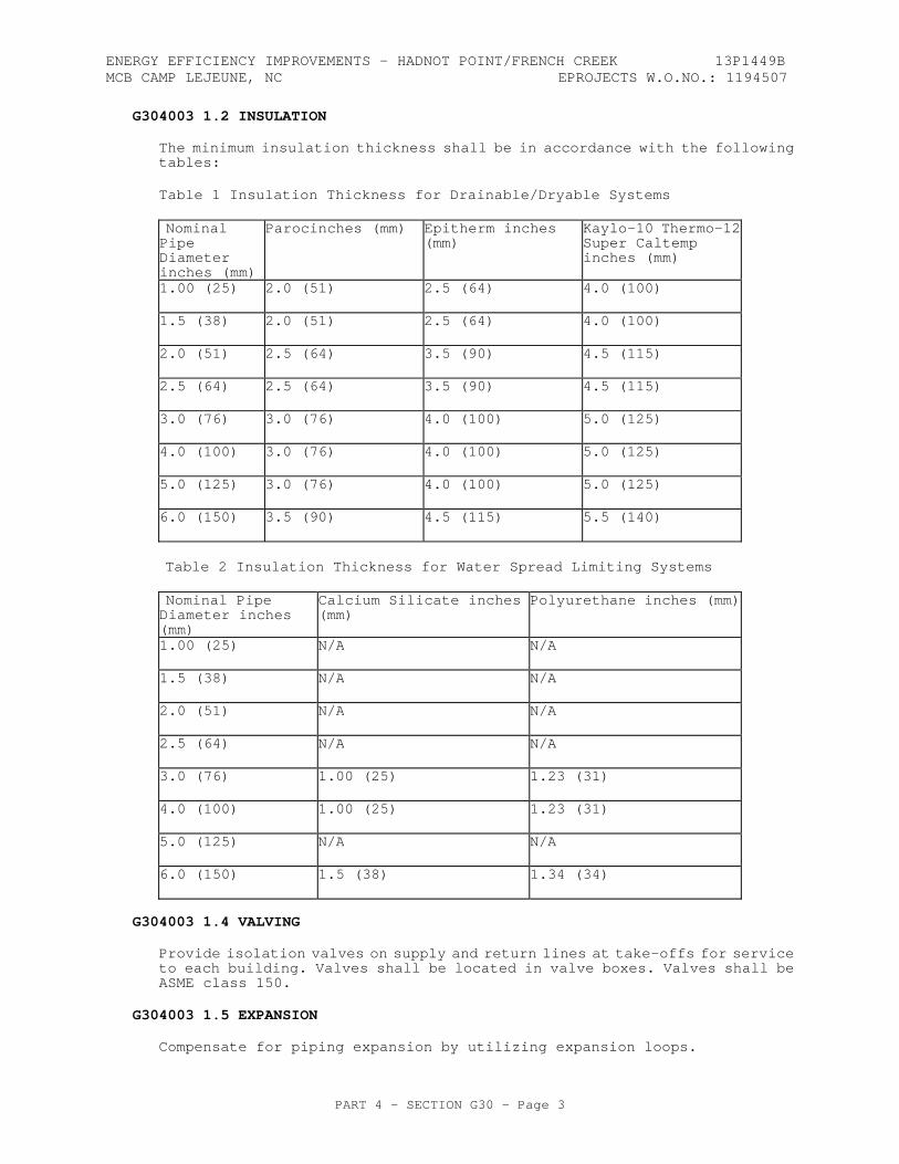
ENERGY EFFICIENCY IMPROVEMENTS - HADNOT POINT/FRENCH CREEK 13P1449B MCB CAMP LEJEUNE, NC EPROJECTS W.O.NO.: 1194507
PART 4 - SECTION G30 - Page 3
G304003 1.2 INSULATION
The minimum insulation thickness shall be in accordance with the following tables:
Table 1 Insulation Thickness for Drainable/Dryable Systems
Nominal Pipe Diameter inches (mm)
Parocinches (mm)
Epitherm inches (mm)
Kaylo-10 Thermo-12Super Caltemp inches (mm)
1.00 (25)
2.0 (51)
2.5 (64)
4.0 (100)
1.5 (38)
2.0 (51)
2.5 (64)
4.0 (100)
2.0 (51)
2.5 (64)
3.5 (90)
4.5 (115)
2.5 (64)
2.5 (64)
3.5 (90)
4.5 (115)
3.0 (76)
3.0 (76)
4.0 (100)
5.0 (125)
4.0 (100)
3.0 (76)
4.0 (100)
5.0 (125)
5.0 (125)
3.0 (76)
4.0 (100)
5.0 (125)
6.0 (150)
3.5 (90)
4.5 (115)
5.5 (140)
Table 2 Insulation Thickness for Water Spread Limiting Systems
Nominal Pipe Diameter inches (mm)
Calcium Silicate inches (mm)
Polyurethane inches (mm)
1.00 (25)
N/A
N/A
1.5 (38)
N/A
N/A
2.0 (51)
N/A
N/A
2.5 (64)
N/A
N/A
3.0 (76)
1.00 (25)
1.23 (31)
4.0 (100)
1.00 (25)
1.23 (31)
5.0 (125)
N/A
N/A
6.0 (150)
1.5 (38)
1.34 (34)
G304003 1.4 VALVING
Provide isolation valves on supply and return lines at take-offs for service to each building. Valves shall be located in valve boxes. Valves shall be ASME class 150.
G304003 1.5 EXPANSION
Compensate for piping expansion by utilizing expansion loops.
ENERGY EFFICIENCY IMPROVEMENTS - HADNOT POINT/FRENCH CREEK 13P1449B MCB CAMP LEJEUNE, NC EPROJECTS W.O.NO.: 1194507
PART 4 - SECTION G30 - Page 4
G306006 GAS DISTRIBUTION PIPING (NATURAL & PROPANE) G306006 1.1 STEEL PIPE
Gas piping shall be ASTM A 53, Type E (electric-resistance welded, Grade A or B) or Type S (seamless, Grade A or B), black steel. Provide Weight Class STD (Standard) for welding end connections. Provide Weight Class XS (Extra Strong) for threaded end connections.
G306006 1.2 POLYETHYLENE (PE)
PE pipe and heat fusion fittings shall conform to ASTM D 2513, Grade PE2406 or PE3408.
G306009 OTHER GAS DISTRIBUTION G306009 1.1 WARNING & IDENTIFICATION TAPE
Detectable aluminum foil, plastic backed tape or detectable magnetic plastic tape manufactured specifically for warning and identifying buried piping.
-- End of Section --
ENERGY EFFICIENCY IMPROVEMENTS - HADNOT POINT/FRENCH CREEK 13P1449B MCB CAMP LEJEUNE, NC EPROJECTS W.O.NO.: 1194507
PART 4 - SECTION G40 - Page 1
SECTION G40
SITE ELECTRICAL UTILITIES
11/10
G40 GENERAL RFP Part 3 including the Engineering System Requirements (ESR) provide project specific requirements. The RFP Part 4, Performance Technical Sections (PTS) provide generalized technical requirements that apply to multiple facility types and include more requirements than are applicable to any one project. Therefore, only the RFP Part 4 requirements that apply to the project and further define the RFP Part 3 project specific requirements are required. G40 1.1 NARRATIVE
This section covers installations exterior to the facility up to the five foot line. See PTS Section D50, Electrical, for continuation of systems into the building.
G40 1.2 ELECTRICAL DESIGN GUIDANCE
Provide the design and installation in accordance with the following references. This Performance Technical Specification (PTS) adds clarification to the fundamental requirements contained in the following Government Standards. The general requirements of this PTS section are located in PTS Section Z10, General Performance Technical Specification.
When all product Quality Control information is included in the Unified Facility Criteria (UFC) and there are requirement options identified in the ESR, then the Uniformat Level 4 titles (and possible subtitles) are included without additional verbiage. One example of this is G401008, GROUNDING SYSTEMS.
G40 1.2.1 Government Standards
UNIFIED FACILITIES CRITERIA (UFC)
UFC 1-200-01
General Building Requirements(A reference in this PTS section to UFC 1-200-01 requires compliance with the Tri-Service Core UFCs that are listed in UFGS Section 01 33 10.05 20, which includes the following significant UFC(s):UFC 3-501-01, Electrical Engineering)
UFC 3-570-02N
Electrical Engineering Cathodic Protection
UNIFIED FACILITIES GUIDE SPECIFICATIONS (UFGS)
UFGS 26 12 19.10
Three-Phase Pad-Mounted Transformers
UFGS 26 12 19.20
Single-Phase Pad-Mounted Transformers
UFGS 26 13 00.00 20
SF6/High-Firepoint Fluid Insulated Pad-Mounted Switchgear
ENERGY EFFICIENCY IMPROVEMENTS - HADNOT POINT/FRENCH CREEK 13P1449B MCB CAMP LEJEUNE, NC EPROJECTS W.O.NO.: 1194507
PART 4 - SECTION G40 - Page 2
UFGS 33 71 01
Overhead Transmission and Distribution
UFGS 33 71 02.00 20
Underground Electrical Distribution
UFGS 26 28 00.00 10 Motor Control Centers, Switchboards
and Panelboards G40 1.3 QUALITY ASSURANCE
Qualifications, certifications, and Test Plans indicated herein shall be submitted 45 calendar days prior to the expected date of execution. Notify the Contracting Officer 14 calendar days prior to all testing. Submit test results within 7 calendar days of completion of testing.
The Designer of Record is responsible for approving the submittals listed below.
G40 1.3.1 Qualified Testing Organization
Contractor shall engage the services of a qualified testing organization to provide inspection, testing, calibration, and adjustment of the electrical distribution system and equipment listed in paragraph entitled "Acceptance Tests and Inspections" herein. Organization shall be independent of the supplier, manufacturer, and installer of the equipment. The organization shall be a first tier subcontractor.
a. Submit name and qualifications of organization. Organization shall have been regularly engaged in the testing of electrical materials, devices, installations, and systems for a minimum of 5 years. The organization shall have a calibration program, and test instruments used shall be calibrated in accordance with NETA ATS.
b. Submit name and qualifications of the lead engineering technician performing the required testing services. Include a list of three comparable jobs performed by the technician with specific names and telephone numbers for reference. Testing, inspection, calibration, and adjustments shall be performed by an engineering technician, certified by NETA or the National Institute for Certification in Engineering Technologies (NICET) with a minimum of 5 years' experience inspecting, testing, and calibrating electrical distribution and generation equipment, systems, and devices.
G40 1.3.2 NEC Qualified Worker
Provide in accordance with NFPA 70. Qualified Workers shall be allowed to be assisted by helpers on a 1 to 1 ratio, provided such helpers are registered in recognized apprenticeship programs. Submit a certification confirming NEC Qualified Worker requirements.
G40 1.3.3 Qualified Medium Voltage Electrician
All workers on medium voltage electrical crews shall have 5 years experience working medium voltage systems on similar projects involving the same or higher voltage.
ENERGY EFFICIENCY IMPROVEMENTS - HADNOT POINT/FRENCH CREEK 13P1449B MCB CAMP LEJEUNE, NC EPROJECTS W.O.NO.: 1194507
PART 4 - SECTION G40 - Page 3
G40 1.3.4 Qualified Cable Splicer (Medium Voltage Cable)
The cable splicer/terminator must have a certification from the National Cable Splicing Certification Board (NCSCB) in the field of splicing and terminating shielded medium voltage (5 kV to 35 kV) power cable using pre-manufactured kits (pre-molded, heat-shrink, cold-shrink). Proof of certification for the individuals that will be performing cable splicer and termination work shall be submitted 30 days before splices or terminations are to be made.
G40 1.3.8 Material Standards
Ensure service support and provide manufacturer's nameplate in accordance with PTS Section Z10, General Performance Technical Specification.
G40 1.3.8.1 Warning Labels
Each enclosure of electrical equipment, including, pad-mounted transformers, pad-mounted switches, pad-mounted sectionalizing termination cabinets, and switchgear, shall have a warning label identifying the enclosure as 1) containing energized electrical equipment and 2) an arc flash hazard.
G40 1.3.9 Factory Testing
The Government reserves the right to witness all factory testing. The manufacturer shall have a calibration program that assures that all applicable test instruments are maintained within rated accuracy.
G40 1.3.10 Electrical System Startup and Testing
Submit test plans for approval. The test plans shall be tailored to the systems provided.
The test plan shall list make and model and provide functional description of the test instruments and accessories and shall describe the setup of the tests to be conducted. Test instruments shall be capable of measuring and recording or displaying test data at a higher resolution and greater accuracy than specified for the equipment's performance.
G40 1.3.10.1 Factory Trained Engineer
Provide a factory trained engineer to supervise start-up and testing as required in referenced specifications.
G40 1.3.10.2 Performance Verification Testing
The Contractor shall show by demonstration in service that all circuits and devices are in operating condition. Tests shall be such that each item of control equipment will function not less than five times. The Contractor shall provide all necessary test equipment, tools, fuel, load banks, labor, and materials for testing. As a minimum, all systems shall be tested in accordance with manufacturer's recommendations. Additional testing requirements for the various systems are described with those systems, hereinafter. The Contractor shall assure that all applicable test instruments are maintained within rated accuracy. Dated calibration labels shall be visible on all test equipment.
ENERGY EFFICIENCY IMPROVEMENTS - HADNOT POINT/FRENCH CREEK 13P1449B MCB CAMP LEJEUNE, NC EPROJECTS W.O.NO.: 1194507
PART 4 - SECTION G40 - Page 4
Submit a separate electrical field test plan in accordance with manufacturer's recommendations and that conforms to NETA ATS for each piece of Electrical Distribution Equipment and System requiring Performance Verification Testing.
The following items identify specific test requirements. Additional test requirements are contained in the applicable UFGS.
a. Cable – Test cable in accordance with the manufacturer's recommendations and NETA ATS. Adhere to precautions and limits as specified in the applicable NEMA/ICEA Standard for the specific cable.
b. Grounding - Test ground systems in accordance with the manufacturer's recommendations and NETA ATS.
c. Site Lighting - Contractor's Quality Control (CQC) representative shall perform a field survey of site lighting systems in accordance with IESNA for acceptance. Show that the lighting system operates in accordance with the user’s requirements and is in accordance with designed levels. Provide certification that the measured lighting levels conform to the design requirements.
d. Telecommunications wiring - Test all cables in accordance with industry standards.
G40 1.3.10.3 Acceptance Tests and Inspections
The Qualified Testing Organization shall provide the Acceptance Tests and Inspections test plan and procedures and perform the acceptance tests and inspections. Test methods, procedures, and test values shall be performed and evaluated in accordance with NETA ATS, the manufacturer's recommendations, and paragraph entitled "Field Quality Control" of each applicable specification section. Tests identified as optional in NETA ATS are not required unless otherwise specified. Equipment shall be placed in service only after completion of required tests and evaluation of the test results have been completed. Contractor shall supply to the testing organization complete sets of shop drawings, settings of adjustable devices, and other information necessary for an accurate test and inspection of the system prior to the performance of any final testing.
Specific test requirements are contained in the UFGS for equipment.
G40 1.4 DESIGN SUBMITTALS
Design Submittals shall be in accordance with PTS Section Z10, General Performance Technical Specifications, UFGS Section 01 33 10.05 20, Design Submittal Procedures, UFC 1-300-09N, Design Procedures, and UFC 3-501-01, Electrical Engineering.
In addition, UFGS sections listed below or in the body of the PTS text are to be used by the Designer of Record (DOR) as a part of the design submittal. If the UFGS products or systems are applicable to the project, the DOR shall edit these referenced UFGS sections and submit them as a part of the design submittal specification. Edit the specification sections in accordance with the limitations stated in PTS Section Z10, General Performance Technical Specifications.
UFGS 26 12 19.10, Three-Phase Pad-Mounted Transformers
UFGS 26 12 19.20, Single-Phase Pad-Mounted Transformers
ENERGY EFFICIENCY IMPROVEMENTS - HADNOT POINT/FRENCH CREEK 13P1449B MCB CAMP LEJEUNE, NC EPROJECTS W.O.NO.: 1194507
PART 4 - SECTION G40 - Page 5
UFGS 26 13 00.00 20, SF6/High-Firepoint Fluids Insulated Pad-Mounted Switchgear
UFGS 26 23 00, Switchboards and Switchgear
UFGS 33 71 01, Overhead Transmission and Distribution
G40 1.5 CONSTRUCTION SUBMITTALS
Submit construction submittals in accordance with PTS Section Z10, General Performance Technical Specifications. In addition to the PTS Section Z10 requirements, the Designer of Record (DOR) shall approve the following construction submittals as a minimum:
OMSI Information for Electrical Equipment (if OMSI Manual for the entire project is not already required); all "G" item submittals listed in the submittals of the specifications sections identified in the Design Submittals paragraph above; and all "G" item submittals listed in Government Surveillance UFGS Section 01 33 00.05 20, Construction Submittal Procedures.
Provide certification that all adjustable protective device settings have been set in accordance with the coordination study for the as-built equipment and configuration.
G4010 ELECTRICAL DISTRIBUTION G401002 TRANSFORMERS When transformers are required, the Designer of Record shall utilize UFGS Section 26 12 19.10, Three-Phase Pad Mounted Transformers, UFGS Section 26 12 19.20, Single-Phase Pad Mounted Transformers, or UFGS Section 33 71 01, Overhead Transmission and Distribution, for the project specification, and shall submit the edited specification section as a part of the design submittal for the project.
G401003 SWITCHES, CONTROLS AND DEVICES When switches or control devices are required, the Designer of Record shall utilize UFGS Section 26 13 00.00 20, SF6/High-Firepoint Fluids Insulated Pad-Mounted Switchgear, or UFGS Section 33 71 01, Overhead Transmission and Distribution, for the project specification, and shall submit the edited specification section as a part of the design submittal for the project.
G401004 OVERHEAD ELECTRIC CONDUCTORS Power line conductors shall be strung in accordance with manufacturer's standard sag and tension recommendations.
G401005 TOWERS, POLES, CROSSARMS AND INSULATORS Wood poles shall comply with ANSI 05.1 and RUS 1728F-700. Pressure treat poles in accordance with AWPA C1 and AWPA C4 as referenced in RUS 1728F-700. The quality of each pole shall be ensured with "WQC" (wood quality control) brand on each piece or by an approved inspection agency report. Do not use creosote treated poles, lodgepole pine, and western larch pine poles.
Concrete poles shall comply with ANSI loadings for distribution poles.
ENERGY EFFICIENCY IMPROVEMENTS - HADNOT POINT/FRENCH CREEK 13P1449B MCB CAMP LEJEUNE, NC EPROJECTS W.O.NO.: 1194507
PART 4 - SECTION G40 - Page 6
The size of poles required, class, height and other data, shall be determined by the designer of record to meet requirements of the pole line. Crossarms shall be wood, steel or fiberglass in accordance with industry and local standards. Insulators, cutouts and associated equipment shall be determined by the Designer of Record to meet system requirements.
G401006 UNDERGROUND ELECTRIC CONDUCTORS Route underground cables to minimize splices. Cable pulling tensions shall not exceed the maximum pulling tension recommended by the cable manufacturer. Medium voltage cable termination shall be suitable for the location installed and meet IEEE Std. 48 Class 1 requirements.
G401007 DUCTBANKS, MANHOLES, HANDHOLES AND RACEWAYS Concrete manholes and handholes shall be standard type pre-cast concrete. Composite/Fiberglass handholes shall be polymer concrete reinforced with a heavy weave fiberglass reinforcing as indicated. Load ratings of manholes and handholes shall be suitable for the location installed.
G401008 GROUNDING SYSTEMS G401009 METERING
Provide each new transformer with metering equipment compatible with the existing AMI (BACnet) metering system. Provide each new secondary service entrance switchboard or panelboard with a separate digital circuit monitor/analyzer. Equipment shall have capabilities to connect to the existing AMI (BACnet) monitoring system. Make connections to the existing metering network and support Government efforts to integrate new meter data into the network. Metering shall adhere to requirements defined in “Advanced Metering System MCB Camp Lejeune/ MCAS New River” December 3, 2012 which is included in Part 6 of this RFP.
G401010 CATHODIC PROTECTION SYSTEMS Cathodic protection systems shall be in accordance with UFC 3-570-02N.
G401011 EQUIPMENT REQUIREMENTS FOR COASTAL AND HIGH HUMIDITY AREAS G4020 SITE LIGHTING G402001 EXTERIOR LIGHTING FIXTURES AND CONTROLS Maintained mean area lighting levels shall be 6 lux (0.5 fc).
G402002 SPECIAL SECURITY LIGHTING SYSTEM G402003 OTHER AREA LIGHTING G402004 LIGHTING POLES Poles shall meet Uniform Building Code for street lighting poles, and AASHTO loadings for highway and sports lighting poles taking into account the effective projected areas of the luminaries provided. Poles shall be direct set or anchor-base type designed for use with underground supply conductors.
G402005 UNDERGROUND ELECTRIC CONDUCTORS Provide in accordance with Paragraph G401006.
ENERGY EFFICIENCY IMPROVEMENTS - HADNOT POINT/FRENCH CREEK 13P1449B MCB CAMP LEJEUNE, NC EPROJECTS W.O.NO.: 1194507
PART 4 - SECTION G40 - Page 7
G402006 DUCTBANKS, MANHOLES AND HANDHOLES Handholes and underground conduits for site lighting shall be in accordance with Paragraph G401007.
G402007 GROUNDING SYSTEMS G4030 SITE COMMUNICATION AND SECURITY G403001 TELECOMMUNICATIONS SYSTEMS G403002 CABLE TV SYSTEMS (CATV) G403003 CABLES AND WIRING Provide underground copper cable pair in accordance with RUS 345-67. Provide aerial cable in accordance with RUS 345-67 except that it shall be suitable for aerial installation and shall be Figure 8 distribution wire with 6,000 pound (26,700 N) Class A galvanized steel or 6,000 pound (26,700 N) aluminum-clad steel strand. Screen-compartmental core cable shall be filled cable meeting the requirements of RUS 345-67. Fiber optic media shall meet all performance requirements of EIA/TIA-568-A and the physical requirements of ICEA S 87-640 and EIA/TIA-598-A.
G403004 DUCTBANKS, MANHOLES AND HANDHOLES Provide in accordance with paragraph G401007.
G403005 TOWERS, POLES AND STANDS Provide in accordance with paragraph G401005.
G403006 TV CAMERAS AND MONITORS G403007 ELECTRONIC SECURITY SYSTEM (ESS) G403008 OTHER COMMUNICATION AND ALARM G403009 GROUNDING SYSTEMS G4090 OTHER ELECTRICAL UTILITIES --End of Section--

ENERGY EFFICIENCY IMPROVEMENTS - HADNOT POINT/FRENCH CREEK 13P1449B MCB CAMP LEJEUNE, NC EPROJECTS W.O.NO.: 1194507
PART 4 - SECTION Z10 - Page 1
SECTION Z10
GENERAL PERFORMANCE TECHNICAL SPECIFICATION 11/10
Z10 GENERAL RFP Part 3 including the Engineering System Requirements (ESR) provide project specific requirements. The RFP Part 4, Performance Technical Sections (PTS) provide generalized technical requirements that apply to multiple facility types and include more requirements than are applicable to any one project. Therefore, only the RFP Part 4 requirements that apply to the project and further define the RFP Part 3 project specific requirements are required.
Z10 1.1 NARRATIVE
All Performance Technical Specification (PTS) sections must be used in conjunction with all parts of the Design Build (D/B) Request for Proposal (RFP) to determine the full requirements of this solicitation. This PTS section provides general requirements for the other PTS sections of this RFP and is used in conjunction with the other PTS sections.
Refer to UFGS section 01 33 10.05 20, Design Submittal Procedures for the Order of Precedence of the RFP Parts. Requirements listed in the Project Program take precedence over the PTS sections requirements; therefore, requirements identified in the Project Program eliminate options related to that requirement in the PTS sections.
Z10 1.2 DESIGN GUIDANCE
Provide work in compliance with the following design standards and codes, as a minimum. Government standards listed in this RFP take precedence over industry standards.
The PTS Sections reference published standards, the titles of which can be found in the Unified Master Reference List (UMRL)on the Whole Building Design Guide at the Unified Facilities Guide Specification (UFGS) Website. The publications referenced form a part of this specification to the extent referenced. The publications are referred to in the section text by the basic designation only. Industry standards, codes, and Government standards referenced in the section text, and not found in the UMRL, are listed at the beginning of the PTS sections.
The advisory provisions of all referenced codes, standards, and specifications shall be mandatory; substitute words such as "shall", "must", or "required" for words such as "should", "may", or "recommended," wherever they appear. The results of these wording substitutions incorporate these code and standard statements as requirements. Reference to the "authority having jurisdiction" for variance from criteria shall be interpreted to mean the "Chief Engineer, NAVFAC" and for contractual obligations on this project shall be interpreted to mean the "Contracting Officer". Comply with the required and advisory portions of the current edition of the standard at the time of contract award.
ENERGY EFFICIENCY IMPROVEMENTS - HADNOT POINT/FRENCH CREEK 13P1449B MCB CAMP LEJEUNE, NC EPROJECTS W.O.NO.: 1194507
PART 4 - SECTION Z10 - Page 2
The following list of codes and standards is not comprehensive and is augmented by other codes and standards referenced and cross-referenced in the RFP.
Z10 1.2.1 INDUSTRY CODES
INTERNATIONAL BUILDING CODE (IBC) as modified by UFC 1-200-01. UFC 1-200-01 applies the IBC to the project and references other commercial standards and UFC criteria that become part of the contract.
Z10 1.2.2 INDUSTRY REQUIREMENTS
WHOLE BUILDING DESIGN GUIDE (WBDG)
WHOLE BUILDING DESIGN GUIDE, Ensure Occupant Safety and Health (Systems Safety Engineering) at http://www.wbdg.org/design/ensure_health.php
Z10 1.2.3 GOVERNMENT STANDARDS
Z10 1.2.3.1 UNIFIED FACILITIES CRITERIA (UFC)
UFC 1-200-01
General Building Requirements(UFC 1-200-01 is a hub document that provides general building requirements and references other critical UFCs. A reference to UFC 1-200-01 requires compliance with the Tri-Service Core UFCs. A complete list of these Tri-Service Core UFCs is located in UFGS section 01 33 10.05 20)
UFC 1-300-09N
Design Procedures
Z10 1.2.3.2 FEDERAL STANDARDS
DoD Architectural Barriers Act Accessibility Standard with DEPSECDEF Memorandum.
Occupational Safety and Health Association (OSHA).
Z10 1.3 MATERIALS AND EQUIPMENT REQUIREMENTS IDENTIFICATION
Z10 1.3.1 MATERIALS STANDARD
Refer to the Project Program for identification of Government Furnished Equipment.
The equipment items shall be supported by service organizations that are convenient to the equipment installation in order to render satisfactory service to the equipment on a regular and emergency basis during the warranty period of the contract.
ENERGY EFFICIENCY IMPROVEMENTS - HADNOT POINT/FRENCH CREEK 13P1449B MCB CAMP LEJEUNE, NC EPROJECTS W.O.NO.: 1194507
PART 4 - SECTION Z10 - Page 3
Materials, equipment, fixtures, and other appurtenances shall comply with applicable Underwriters Laboratories, (UL) Inc., American National Standards Institute, Inc., and National Electrical Manufacturer's Association standards or applicable standards of a similar independent testing organization. All materials shall be new, and shall bear the label of Underwriters Laboratories whenever standards have been established and label service is normally and regularly furnished by the agency. All equipment provided shall be listed and labeled suitable for the specified purpose, environment, and application and installed in accordance with manufacturer’s recommendations. Insulation shall be asbestos free.
Z10 1.3.2 EQUIPMENT NAMEPLATE IDENTIFICATION
Each item of equipment shall have a nameplate bearing the manufacturer's name, address, model number, and serial number securely affixed in a conspicuous place. The nameplate of the distributing agent will not be acceptable.
Z10 1.3.3 FIELD-APPLIED NAMEPLATES
Provide laminated plastic nameplates for each piece of equipment. Each nameplate must identify the function and, when applicable, the number designation of that piece of equipment as used in the design documents. Provide melamine plastic nameplates, 0.125 inch (3 mm) thick, white with black center core.
Z10 1.4 COMMISSIONING
Commission the building systems identified in the Project Program paragraph 2.2.3. Refer to UFGS section 01 45 00.05 20, Design and Construction Quality Control for commissioning requirements. Test reports must be certified by the Commissioning Authority (CA), that work is in compliance with requirements of the RFP.
Z10 1.5 PERFORMANCE VERIFICATION AND ACCEPTANCE TESTS
Verification of satisfactory construction and system performance shall be via Performance Verification Testing, Acceptance Tests, and submittal of test reports certified by the Designer of Record (DOR), that work is in compliance with requirements of the RFP. The Government reserves the right to witness all Performance Verification and Acceptance Tests, review data, and request other such additional inspections and repeat tests as necessary to ensure that the work and provided services conform to the stated requirements. Contractor shall pay the cost of all testing.
Refer to each PTS section to identify Performance Verification and Acceptance Testing required by the work specified in that PTS section.
Z10 1.6 SUBMITTALS
Contractor's design submittals that combines design and construction submittals, must jointly comply with UFGS sections 01 33 00.05 20, Construction Submittal Procedures and 01 33 10.05 20, Design Submittal Procedures. Contractor's construction submittals that submitted separate from the design submittals must comply with UFGS 01 33 00.05 20, Construction Submittal Procedures.
Refer to “"Construction Quality Control" in UFGS 01 33 00.05 20, Construction Submittal Procedures and 01 45 00.05 20, Design and Construction Quality Control to define reviewing and approving Authority of design and construction submittals.
ENERGY EFFICIENCY IMPROVEMENTS - HADNOT POINT/FRENCH CREEK 13P1449B MCB CAMP LEJEUNE, NC EPROJECTS W.O.NO.: 1194507
PART 4 - SECTION Z10 - Page 4
Utilize the same materials and equipment that are approved and provided for an initial facility design, on all follow-on facilities that use the same design with-in this contract. Once the initial facility design is approved by the Government, the Contractor must obtain Government approval to change materials and equipment when designing and constructing follow-on facilities utilizing the same design.
Z10 1.6.1 DESIGN SUBMITTALS
Design submittals shall be in accordance with Unified Facility Guide Specification (UFGS) section 01 33 10.05 20, Design Submittal Procedures, UFC 1-300-09N, Design Procedures, and other discipline-specific guidelines listed in the applicable PTS sections.
UFGS Section 01 33 10.05 20, Design Submittal Procedures and some PTS sections requires the use of UFGS sections in the development on the contractor originated specification. The Designer of Record (DOR) shall edit the UFGS sections for the project and submit the edited specification as a part of the design submittal. The DOR shall edit the UFGS as follows:
(1) Prepare UFGS Specifications as part of the project specification,
(2) Delete only portions of the UFGS specification that are not applicable to the project,
(3) Edit only the bracketed choices that are within the UFGS specification text,
(4) Edit blank bracketed options to include requirements that exercise prudence and adherence to acceptable industry standards,
(5) Comply with the directions, directives, and requirements of all UFGS Criteria Notes. The UFGS Criteria Notes are typically bordered on the top and bottom by a line of asterisks to highlight their location.
(6) If proprietary information is provided or required to streamline the construction submittal process, include proprietary information in the edited UFGS sections and added to the end of each UFGS section. Confirm that the proprietary products, materials, and systems listed in the specifications are in compliance with the requirements of the RFP.
Z10 1.6.2 CONSTRUCTION SUBMITTALS
Submit for approval to the Designer of Record (DOR), construction submittals, product data, manufacturer's information, shop drawings, and test reports on all materials and systems installed in the project, unless the DOR designates submittal for QC approval. Refer to each PTS section for further construction submittal requirements relating to the work identified in that particular PTS section. Some PTS sections reference UFGS sections that will require more construction submittals for DOR approval than is stated above. Refer to Section 01 33 00.05 20 for the list of construction submittals reserved for Government Approval and Government Surveillance.
--End of Section--
ENERGY EFFICIENCY IMPROVEMENTS - HADNOT POINT/FRENCH CREEK 13P1449B MCB CAMP LEJEUNE, NC EPROJECTS W.O.NO.: 1194507
PART FIVE - PRESCRIPTIVE SPECIFICATIONS - Page 1
PART FIVE - PRESCRIPTIVE SPECIFICATIONS

ENERGY EFFICIENCY IMPROVEMENTS - HADNOT POINT/FRENCH CREEK 13P1449BMCB CAMP LEJEUNE, NC EPROJECTS W.O.NO.: 1194507
SECTION 02 82 16
REMOVAL AND DISPOSAL OF ASBESTOS MATERIALS(CAMP LEJEUNE COMPLEX)
03/10
PART 1 GENERAL
1.1 APPLICABLE NORTH CAROLINA LAW
North Carolina State General Statues 130A, Article 19-444-452 and 10A North Carolina Administrative Chapter (NCAC) 41C .0600 through .0611.
1.1.1 N.C. (DHHS-HHCU) Asbestos Accreditation
All personnel involved in asbestos removal shall be currently accredited for asbestos removal by N.C. (DHHS-HHCU). An application for accreditation may be requested from the State of North Carolina, Health Hazards Control Unit, Department of Health and Human Services, Division of Public Health,; 1912 Mail Service Center, Raleigh, NC 27699-1912; (919) 707-5950. Out of State accreditation will not be accepted.
1.2 REFERENCES
The publications listed below form a part of this specification to the extent referenced. The publications are referred to in the text by the basic designation only.
AMERICAN NATIONAL STANDARDS INSTITUTE (ANSI)
ANSI Z88.2 (1992) Respiratory Protection
AMERICAN SOCIETY FOR TESTING AND MATERIALS (ASTM)
ASTM C 732 (1995) Aging Effects of Artificial Weathering on Latex Sealants
ASTM D 1331 (1989; R 1995) Surface and Interfacial Tension of Solutions of Surface-Active Agents
ASTM E 84 (2000a) Surface Burning Characteristics of Building Materials
ASTM E 96 (1997; Rev A) Water Vapor Transmission of Materials
ASTM E 119 (1998) Fire Tests of Building Construction and Materials
ASTM E 736 (1992) Cohesion/Adhesion of Sprayed Fire-Resistive Materials Applied to Structural Members
ASTM E 1368 (1997) Visual Inspection of Asbestos
SECTION 02 82 16 Page 1
ENERGY EFFICIENCY IMPROVEMENTS - HADNOT POINT/FRENCH CREEK 13P1449BMCB CAMP LEJEUNE, NC EPROJECTS W.O.NO.: 1194507
Abatement Projects
U.S. NATIONAL ARCHIVES AND RECORDS ADMINISTRATION (NARA)
29 CFR 1910.103 Respiratory Protection
29 CFR 1926.59 Hazard Communication
29 CFR 1926.1101 Asbestos
40 CFR 61, SUBPART A General Provisions
40 CFR 61, SUBPART M National Emission Standard for Hazardous Air Pollutants
U.S. ENVIRONMENTAL PROTECTION AGENCY (EPA)
EPA 560/5-85-024 (1985) Guidance for Controlling Asbestos Containing Materials in Buildings
EPA SW-846 (Rev O; Updates I, II, IIA, IIB, and III) Test Methods for Evaluating Solid Waste (Vol IA, IB, IC, and II)
UNDERWRITERS LABORATORIES (UL)
UL 586 (1996; Rev thru Aug 1999) High-Efficiency, Particulate, Air Filter Units
1.3 DEFINITIONS
1.3.1 Asbestos Containing Material (ACM)
All building materials that have more than 1% of chrysotile, amosite, crocidolite, tremolite, anthopyhlite, or any other form of asbestos in the serpentine or anthobole class.
1.3.2 Action Level/Permissive Exposure Limit (PEL)
An airborne concentration of asbestos fibers, in the breathing zone of a worker equaling 0.1 fibers per cubic centimeter of air calculated as an 8-hour time weighted average.
1.3.3 Amended Water
Water containing a wetting agent or surfactant with a surface tension of 29 dynes per square centimeter when tested in accordance with ASTM D 1331 shall be utilized. In the event where wetting operations are suspended due to freezing temperatures, the operator or abatement contractor shall record the temperature on Form DHHS 3787.
1.3.4 Area Sampling
Sampling of asbestos fiber concentrations within the asbestos control area and outside the asbestos control area which approximates the concentrations of asbestos in the theoretical breathing zone but is not actually collected in the breathing zone of an employee.
SECTION 02 82 16 Page 2
ENERGY EFFICIENCY IMPROVEMENTS - HADNOT POINT/FRENCH CREEK 13P1449BMCB CAMP LEJEUNE, NC EPROJECTS W.O.NO.: 1194507
1.3.5 Asbestos
The term asbestos includes chrysotile, amosite, crocidolite, tremolite, anthophyllite, and actinolite and any of these minerals that has been chemically treated or altered. Materials are considered to contain asbestos if the asbestos content is more than 1% of the material by area.
1.3.6 Asbestos Control Area
That area where asbestos removal operations are performed which is isolated by physical boundaries which assist in the prevention of the uncontrolled release of asbestos dust, fibers, or debris. Two examples of an asbestos control area are: a full containment and a "glovebag."
1.3.7 Asbestos Fibers
Those fibers having an aspect ratio of at least 3:1 and longer than 5 micrometers as determined by National Institute for Occupational Safety and Health (NIOSH) Method 7400.
1.3.8 Asbestos Permissible Exposure Limit
0.1 fibers per cubic centimeter of air as an 8-hour time weighted average as defined by 29 CFR 1926.1101 or other federal legislation having legal jurisdiction for the protection of workers health.
1.3.9 Background
Normal airborne asbestos concentration in an area similar to the asbestos abatement area but in an uncontaminated (with asbestos) state.
1.3.10 Contractor
The Contractor is that individual, or entity under contract to the Navy to perform the herein listed work.
1.3.11 Encapsulants
Specific materials in various forms used to chemically entrap asbestos fibers in various configurations to prevent these fibers from becoming airborne. There are four types of encapsulants as follows which must comply with performance requirements as specified herein.
a. Removal Encapsulant (can be used as a wetting agent)
b. Bridging Encapsulant (used to provide a tough, durable surface coating to asbestos containing material)
c. Penetrating Encapsulant (used to penetrate the asbestos containing material down to substrate, encapsulating all asbestos fibers)
d. Lock-Down Encapsulant (used to seal off or "lock-down" minute asbestos fibers left on surfaces from which asbestos containing material has been removed)
1.3.12 Friable Asbestos Material
Material that contains more than 1% asbestos by area and that can be crumbled, pulverized, or reduced to powder by hand pressure when dry.
SECTION 02 82 16 Page 3
ENERGY EFFICIENCY IMPROVEMENTS - HADNOT POINT/FRENCH CREEK 13P1449BMCB CAMP LEJEUNE, NC EPROJECTS W.O.NO.: 1194507
1.3.13 Full Containment
Those engineering control techniques described in 29 CFR 1926.1101 for major asbestos removal, renovation and demolition operations.
1.3.14 Glovebag Technique
Those asbestos removal and control techniques put forth in 29 CFR 1926.1101.
1.3.15 HEPA Filter Equipment
High efficiency particulate air (HEPA) filtered vacuum and/or exhaust ventilation equipment with a filter system capable of collecting and retaining asbestos fibers. Filters shall retain 99.97 percent of particles 0.3 microns or larger as indicated in UL 586.
1.3.16 Navy Industrial Hygienist (NIH)
That industrial hygienist employed by the Navy to monitor, sample, and/or inspect the work separate from the original construction contract. The NIH can be either a Federal civil servant or a private consultant as determined by the Navy. In some instances the NIH shall perform assigned duties vicariously through a trained subordinate but only with the specific consent of the Contracting Officer.
1.3.17 Nonfriable Asbestos Material
Material that contains asbestos in which the fibers have been temporarily locked in by a bonding agent, coating, binder, or other material so that the asbestos is well bound and will not normally release asbestos fibers during any appropriate use, handling, storage or transportation. It is understood that asbestos fibers will be released under other conditions such as demolition or removal.
1.3.18 PCM - Phased Contrast Microscopy
A method of analyzing air samples for fibers using a light microscope.
1.3.19 PLM - Polarized Light Microscopy
A method of analyzing bulk samples for asbestos in which the sample is illuminated with polarized light (light which vibrates in only one plane) and viewed under a light microscope.
1.3.20 Personal Sampling
Air sampling to determine asbestos fiber concentrations within the breathing zone of a specific employee, performed in accordance with 29 CFR 1926.1101.
1.3.21 Supervising Air Monitor (SAM)
That supervising air monitor hired by the Contractor to perform the herein listed industrial hygiene tasks. In some instances, the SAM can perform this role vicariously through a trained subordinate, but only with the specific consent of the Contracting Officer. Under N.C. Statue, the SAM must make a site visit on any project exceeding 10 days and once every 30 days thereafter.
SECTION 02 82 16 Page 4

ENERGY EFFICIENCY IMPROVEMENTS - HADNOT POINT/FRENCH CREEK 13P1449BMCB CAMP LEJEUNE, NC EPROJECTS W.O.NO.: 1194507
1.3.22 TEM
Refers to Transmission Electron Microscopy (TEM). Technique whereby a beam of electrons is transmitted through an ultra think specimen, interacting with the specimen as it passes through. An image is formed from the interaction of the electrons transmitted through the specimen; the image is magnified and focused onto an imaging device, such as a fluorescent screen, on a layer of photographic film, or to be detected by a sensor such as a CCB camera.
1.3.23 Time Weighted Average (TWA)
The TWA is an 8-hour time weighted average airborne concentration of asbestos fibers. At least three full shift samples per person are required to establish that person's TWA exposure.
1.3.24 Wetting Agent
That specific agent used to reduce airborne asbestos levels by physically bonding asbestos fibers to material to be removed. An equivalent wetting agent must have a surface tension of at least 29 dynes per square centimeter as tested in accordance with ASTM D 1331. In the event where wetting operations are suspended due to freezing temperatures, the operator or abatement contractor shall record the temperature on Form DHHS 3787.
1.4 REQUIREMENTS
1.4.1 Description of Work
The work covered by this section includes the handling of asbestos containing materials which are encountered during repair, construction and demolition projects and describes some of the resultant procedures and equipment required to protect workers and occupants of the building or area, or both, from contact with airborne asbestos fibers. The work also includes the disposal of the generated asbestos containing materials. Under normal conditions non-friable or chemically bound materials containing asbestos would not be considered hazardous; however, this material will release airborne asbestos fibers during demolition and removal and therefore must be handled in accordance with North Carolina Regulations.
1.4.2 N. C. (DHHS-HHCU) North Carolina Department of Health and Human Services - Health Hazards Control Unit
Obtain necessary permits in conjunction with asbestos removal, hauling, and disposition, and furnish timely notification of such actions required by federal, state, regional, and local authorities. A permit is only required when you will be abating more than 260 linear feet, 160 square feet, or 35 cubic feet of an asbestos-containing building material. Also, if mechanical means of removing non-friable asbestos is utilized the contractor will need to provide permit. Notify the N.C. (DHHS-HHCU) and the Contracting Officer in writing 10 days prior to the commencement of work. Submit a copy of the permit to the Contracting Officer.
1.4.2.1 N.C. (DHHS-HHCU) mailing address is:
Health Hazards Control Unit N.C. Department of Health and Human Services
SECTION 02 82 16 Page 5
ENERGY EFFICIENCY IMPROVEMENTS - HADNOT POINT/FRENCH CREEK 13P1449BMCB CAMP LEJEUNE, NC EPROJECTS W.O.NO.: 1194507
Division of Public Health1912 Mail Service CenterRaleigh, NC 27699-1912Phone: (919) 733-0820
1.4.2.2 Changes in Work
Changes in Work which affect items on the attached form shall be covered by an amended form submitted to the same address.
1.4.3 Safety and Health Compliance
In addition to detailed requirements of this specification, comply with those applicable laws, ordinances, criteria, rules, and regulations of federal, state, regional, and local authorities regarding handling, storing, transporting, and disposing of asbestos waste materials. Comply with the applicable requirements of the current issue of 29 CFR 1926.1101, 40 CFR 61, SUBPART A, 40 CFR 61, SUBPART M. Submit matters of interpretation of standards to the appropriate administrative agency for resolution before starting the work. Where the requirements of this specification, applicable laws, rules, criteria, ordinances, regulations, and referenced documents vary, the most stringent requirement as defined by the Contracting Officer shall apply.
1.4.4 Respiratory Protection Program
Establish and implement a respirator program as required by ANSI Z88.2 and 29 CFR 1910.103.
1.4.5 Supervising Air Monitor (SAM)
Conduct personal area/environmental air sampling and training under the direction of a North Carolina accredited supervising air monitor. For the purpose of this contract, the Contractor shall retain the services of a SAM to perform the Contractor's industrial hygiene tasks.
1.5 SUBMITTALS
Submit 4 copies of the following in accordance with Section 01 33 00, "Submittal Procedures."
SD-06 Test Reports
Air sampling results
Pressure differential recordings for local exhaust system
Clearance sampling
SD-07 Certificates
Asbestos hazard abatement plan (Abatement Design)
SD-11 Closeout Submittals
Asbestos Waste Shipment Record N.C. (DHHS-HHCU) Form 3787
Daily log
SECTION 02 82 16 Page 6
ENERGY EFFICIENCY IMPROVEMENTS - HADNOT POINT/FRENCH CREEK 13P1449BMCB CAMP LEJEUNE, NC EPROJECTS W.O.NO.: 1194507
North Carolina permit
Modifications to the North Carolina permit
Asbestos Inspection Reporting Form
Closeout submittals shall be submitted within 60 days of asbestos activity completion.
1.5.1 Asbestos Hazard Abatement Plan (NC Abatement Design)
An asbestos abatement design shall be prepared by a N.C. accredited asbestos abatement designer for each individually permitted removal of more than 260 linear feet, 160 square feet, or 35 cubic feet of regulated asbestos containing materials. The plan shall be prepared, signed, and sealed, including accreditation number and date, by an accredited abatement designer. The respirator program and air monitoring strategies portion of this plan shall be prepared by the supervising air monitor. Such plan shall include but not be limited to the precise personal protective equipment to be used, the location of asbestos control areas including clean and dirty areas, buffer zones, showers, storage areas, change rooms, removal method, interface of trades involved in the construction, sequencing of asbestos related work, disposal plan, type of wetting agent and asbestos sealer to be used, locations of local exhaust equipment, planned air monitoring strategies, and a detailed description of the method to be employed in order to control pollution. The plan shall also include (both fire and medical emergency) response plans. The Contractor and designer shall meet with the Contracting Officer prior to beginning work, to discuss in detail the asbestos plan, including work procedures and safety precautions. The plan will be enforced as if an addition to the specification. Any changes required in the specification as a result of the plan shall be identified specifically in the plan. The plan shall comply with all federal and state requirements and this specification, and shall serve as the North Carolina Abatement Design. Submit a copy of plan to the Contracting Officer.
1.5.2 Air Sampling Results
Complete fiber counting and provide results to the SAM for review within 16 hours. Notify the Contracting Officer immediately of any airborne levels of asbestos fibers in excess of the acceptable limits. Submit sampling results to the Contracting Officer and the affected Contractor employees within 3 working days, signed by the employee performing air sampling, the employee that analyzed the sample, and the SAM.
1.5.3 Pressure Differential Recordings for Local Exhaust System
Provide a local exhaust system that creates a negative pressure of at least 0.02 inches of water relative to the pressure external of the enclosure and operate it continuously, 24 hours a day, until the enclosure of the asbestos control area is removed. Provide continuous 24-hour per day monitoring of the pressure differential with a pressure differential automatic recording instrument. Submit pressure differential recordings for each work day to the SAM for review and to the Contracting Officer within 24 hours from the end of each work day. Notify the Contractor and the Contracting Officer immediately of any variance in the pressure differential which could cause adjacent unsealed areas to have asbestos fiber concentrations in excess of 0.01 fibers per cubic centimeter or background whichever is higher. In no circumstance shall levels exceed 0.1
SECTION 02 82 16 Page 7
ENERGY EFFICIENCY IMPROVEMENTS - HADNOT POINT/FRENCH CREEK 13P1449BMCB CAMP LEJEUNE, NC EPROJECTS W.O.NO.: 1194507
fibers per cubic centimeter.
1.5.4 Asbestos Waste Shipment Record N.C. (DHHS-HHCU) Form 3787
Record and report, to the Contracting Officer, the amount of asbestos containing material removed and released for disposal. Deliver the report for the previous day at the beginning of each day shift with amounts of material removed during the previous day reported in linear feet or square feet as described initially in this specification and in cubic feet for the amount of asbestos containing material released for disposal. Use "Asbestos Waste Shipment Record N.C. (DHHS-HHCU) Form 3787 for this report. A copy of the (DHHS-HHCU) Form 3787 must accompany any asbestos waste shipment to the Base sanitary landfill.
1.5.5 Daily Log
A daily log documenting work practices, sample locations, and all other asbestos related job conditions shall be maintained, by the testing lab and be available for Government examination throughout the course of work. At the completion of testing, a copy of this log shall be immediately delivered to the Government.
1.5.6 North Carolina Permit
Submit one copy of the North Carolina Permit before beginning abatement activities to the Contracting Officer.
1.5.7 Modifications to the North Carolina Permit
Submit a copy of all permit modifications to the Contracting Officer. These must be received before they become effective. The Contractor is responsible for proper permit modification notification to the State. Modifications may be delivered to the Contracts Office or transmitted by facsimile to (910) 411-5899.
1.5.8 Asbestos Inspection Reporting Form
This Asbestos Inspection Reporting Form is included at the end of this section and shows the homogeneous areas involved with this project. The Contractor shall mark the line "confirmed ACM from this HA:" as either "Abated" or "Managed in Place." Abated shall be defined as removed. If an HA is partially abated, approximate the percentage of asbestos removed and mark in the comments area. Provide any other descriptive data, such as rooms/areas removed or rooms/areas where asbestos not removed. The intent of this requirement is to report "as built" conditions. The Contractor is not required to perform any additional asbestos surveys or inspections as a result of this paragraph. Include this report with drawing of abated areas with other closeout documentation.
1.6 PRE-ABATEMENT MEETING
The Contractor and designer shall meet with the Contracting Officer prior to beginning work, to discuss in detail the asbestos plan, including work procedures and safety precautions.
1.7 ASBESTOS INSPECTION REPORTING FORM AND ASBESTOS SAMPLE REPORTING FORM
These two forms are included at the end of this section for informational purposes. They do not define or modify the scope of work.
SECTION 02 82 16 Page 8
ENERGY EFFICIENCY IMPROVEMENTS - HADNOT POINT/FRENCH CREEK 13P1449BMCB CAMP LEJEUNE, NC EPROJECTS W.O.NO.: 1194507
PART 2 PRODUCTS
2.1 ENCAPSULANTS
Shall conform to current USEPA requirements, shall contain no toxic or hazardous substances as defined in 29 CFR 1926.59, and shall conform to the following performance requirements. Use of encapsulants is generally restricted to the surface of the temporary enclosure and to areas that are not to be refinished such as attics and crawlspaces. The proposed use of encapsulants shall be included in the abatement design.
2.1.1 Removal Encapsulants
Requirement Test Standard
Flame Spread - 25, Smoke ASTM E 84 Emission - 50
Life Expectancy - 20 years ASTM C 732, Accelerated Aging Test
Permeability - Minimum 0.4 perms ASTM E 96
2.1.2 Lock-down Encapsulant
Requirement Test Standard
Flame Spread - 25, Smoke ASTM E 84 Emission - 50
Life Expectancy - 20 years ASTM C 732 Accelerated Aging Test
Permeability - Minimum 0.4 perms ASTM E 96 Fire Resistance - Negligible affect ASTM E 119 on fire resistance rating over 3 hour test (Tested with fireproofing over encapsulant applied directly to steel member)
Bond Strength - 100 pounds of force/ ASTM E 736 foot (Tests compatibility with cementitious and fibrous fire-proofing)
2.1.3 Plastic Sheet
Plastic sheet, polyethylene, 6 mil minimum thickness, unless otherwise specified, in sizes to minimize the frequency of joints. All asbestos material or debris will be at least double bagged or wrapped in two layers of 6 mil poly sheeting.
2.1.4 Tape
Capable of sealing joints of adjacent sheets or plastic sheets and for attachment of plastic sheet to finished or unfinished surfaces of dissimilar materials and capable of adhering under dry and wet conditions, including use of amended water.
SECTION 02 82 16 Page 9
ENERGY EFFICIENCY IMPROVEMENTS - HADNOT POINT/FRENCH CREEK 13P1449BMCB CAMP LEJEUNE, NC EPROJECTS W.O.NO.: 1194507
2.1.5 Disposal Bags
Bags shall be a minimum of 6 mil thick polyethylene. Affix a warning and Department of Transportation (DOT) label to each bag or use bags with the approved warnings and DOT labeling preprinted on the bag.
2.1.6 Warning Labels
Provide labels conforming to 29 CFR 1926.1101 of sufficient size to be clearly legible, displaying the following legend:
DANGERCONTAINS ASBESTOS FIBERS
AVOID CREATING DUSTCANCER AND LUNG DISEASE HAZARDBREATHING ASBESTOS DUST MAYCAUSE SERIOUS BODILY HARM
PART 3 EXECUTION
3.1 DISPOSAL SITE
CAMP LEJEUNE SANITARY LANDFILL982 PINEY GREEN ROAD
CAMP LEJEUNE, NC 28542(910) 451-5011
Base Sanitary Landfill shall be used for disposal of all asbestos waste. The Base Sanitary Landfill is approved and is available for use by the Contractor providing the following requirements are satisfied:
a. The Contracting Officer must be informed at least five working days in advance of the anticipated delivery date of the asbestos material to the Landfill. On larger projects, the notification should be accompanied by a cubic yard estimate of the anticipated volume, updated weekly if the disposal period extends for more than one week. The Government will be responsible for digging the trenches and covering the debris at the end of the working day. Debris will not be accepted before 8:00 AM or after 10:00 AM, except in an emergency situation.
b. Asbestos will be accepted only if adequately wet and double bagged in heavy-duty 6 mil plastic bags which are clearly marked "Asbestos." If a Contractor desires to handle the asbestos in a manner other than double-bagged, written application, along with a description of the proposed deviation, must be submitted to the OICC and Landfill Manager for approval.
c. Asbestos insulated piping with the asbestos insulation intact will be accepted if the following requirements are met:
1. The pipe is cut in eight foot or shorter lengths
2. Each section of pipe is double wrapped, sealed, and labeled as asbestos.
3. All pipe is palletized on a 7/8-inch, 4- by 8-foot sheet of plywood. The whole pallet is banded with a minimum of three
SECTION 02 82 16 Page 10
ENERGY EFFICIENCY IMPROVEMENTS - HADNOT POINT/FRENCH CREEK 13P1449BMCB CAMP LEJEUNE, NC EPROJECTS W.O.NO.: 1194507
1-inch wide metal bands with the coupling on top and wrapped with 6-mil plastic. The pallet is not higher than 3-inches.
d. All asbestos, except palletized pipe will be off loaded and placed in the trench pipe hand.
e. Asbestos disposal is restricted to one designated location in the Landfill and the landfill operators must be informed of and direct each delivery. Asbestos shall be disposed of from 0800 to 1000 hours daily, except holidays and weekends. Trucks hauling asbestos must be properly covered with tarpaulins or equivalent. Trucks not covered properly must be parked until the Contracting Officer approves corrective actions.
f. The Contractor will ensure asbestos contaminated material delivered to the Base Sanitary Landfill contain no free liquids. Free liquids are defined as material which fails the EPA SW-846 free liquids test.
g. The Contractor will include all asbestos waste shipment records (DHHS-HHCU Form 3787) that are filled out completely with the correct information, to the project manager after abatement job is completed.
3.2 EQUIPMENT
Make available to the Contracting Officer or the Contracting Officer's Representative, two complete sets of personal protective equipment as required herein for entry to the asbestos control area at all times for inspection of the asbestos control area. Provide equivalent training to the Contracting Officer or a designated representative as provided to Contractor employees in the use of the required personal protective equipment. Provide manufacturer's certificate of compliance for all equipment required to contain airborne asbestos fibers.
3.2.1 Respirators
Comply with 29 CFR 1926.1101.
3.3 WORK PROCEDURE
Remove all friable and non-friable ACM in accordance with all Federal, State, and local Marine Corps regulations. Ensure that the asbestos abatement plan is followed throughout all aspects of the abatement process.
3.3.1 Furnishings
Furniture and equipment will remain in the building. Cover and seal furnishings with 6-mil plastic sheet or remove from the work area and store in a location on site approved by the Contracting Officer.
Furnishings listed below and located in the work area are considered to be contaminated with asbestos fibers. Transfer these items to an area on site approved by the Contracting Officer, decontaminate (wet methods where possible), and then store until the room from which they came is declared clean and safe for entry. Carpets, draperies, and other items which may not be suitable for on-site wet cleaning methods shall be properly laundered as recommended by the SAM so as to remove all asbestos contamination or disposed of at the Contracting Officer's discretion. At
SECTION 02 82 16 Page 11
ENERGY EFFICIENCY IMPROVEMENTS - HADNOT POINT/FRENCH CREEK 13P1449BMCB CAMP LEJEUNE, NC EPROJECTS W.O.NO.: 1194507
the conclusion of the asbestos removal work and cleanup operations, transfer all objects so removed and cleaned back to the area from which they came and re-install them.
3.3.2 Pipe Insulation
Pipe may be removed with the asbestos insulation in place by wrapping the entire length of pipe and associated insulation with double thickness 6 mil plastic secured with duct tape. Mechanically cutting of asbestos containing insulation is prohibited. When using the "candy-stripe" method the abatement contractor must use glovebag operations to establish an "asbestos free" area to cut the pipe into appropriate lengths. Cut piping simultaneously into lengths suitable for transportation to disposal area, but no greater than 8 feet in length. Continuously wet the cutting site during the process. As soon as a length of pipe is completely cut loose, cover exposed ends with double thickness 6 mil plastic secured with duct tape. If the pipe is to remain in service, the removed pipe must be replaced in accordance with this Specification, with a pipe of the same size that is removed.
3.3.2.1 Attic Insulation
In those buildings indicated on the drawings, attic insulation consisting of any combination of blown-in or batt fiberglass or rockwool material, has been contaminated with asbestos materials, and is to be removed as contaminated asbestos material. The insulation material shall be wet with a fine mist of amended water. The material shall be placed immediately in double thickness 6 mil plastic bags for disposal as asbestos waste.
3.3.2.2 Contaminated Soil
In those buildings so indicated on the drawings, asbestos materials are located in the building crawl spaces and deterioration of the asbestos material has resulted in contamination of the soil under the building. Under the indicated area of these buildings, asbestos material and 2 inches of soil shall be removed and one sheet of plastic, 6 mils thick, spread over the area with seams lapped a minimum of 4 inches. Removal shall occur just prior to clean-up operations. All debris in the crawl space shall be disposed of with the soil as asbestos materials. Workers shall be equipped with respirators and protective clothing during the removal of soil and debris.
3.3.2.3 Non-Organic Bound (NOB) Asbestos Materials
These kind of materials include floor tile, mastic, caulking, roofing material, and other non-friable material. Materials are to be adequately wet before removal and double bagged with a 6 mil poly bag. Ensure that bags have been labeled properly before they are taken to the Base Landfill.
3.3.3 Air Sampling
Sampling of airborne concentrations of asbestos fibers shall be performed in accordance with 29 CFR 1926.1101 and as specified herein. Sampling performed in accordance with 29 CFR 1926.1101 shall be performed by the SAM. Sampling performed for environmental and quality control reasons shall be performed by the SAM. Unless otherwise specified, use NIOSH Method 7400 for sampling and analysis. Monitoring may be duplicated by the Government at the discretion of the Contracting Officer. If the air sampling results obtained by the Government differ from those results
SECTION 02 82 16 Page 12
ENERGY EFFICIENCY IMPROVEMENTS - HADNOT POINT/FRENCH CREEK 13P1449BMCB CAMP LEJEUNE, NC EPROJECTS W.O.NO.: 1194507
obtained by the Contractor, the Government results shall prevail.
3.3.3.1 Sampling During Asbestos Work
The SAM shall provide personal and area sampling as indicated in 29 CFR 1926.1101 and governing environmental regulations. Thereafter, provided the same type of work is being performed, provide area sampling at least once every work shift close to the work inside the containment, outside the clean room entrance to the containment, and at the exhaust opening of the local exhaust system. Also, where an enclosure is not provided, conduct area monitoring of airborne asbestos fibers during the work shift at the designated limits of the asbestos work area at such frequency as recommended by the SAM and conduct personal samples of each worker engaged in asbestos handling (removal, disposal, transport and other associated work). If the quantity of airborne asbestos fibers monitored at the breathing zone of the workers or designated limits at any time exceeds background or 0.01 fibers per cubic centimeter whichever is lesser outside of the containment area, stop work, evacuate personnel in adjacent areas or provide personnel with approved protective equipment at the discretion of the Contracting Officer. This sampling may be duplicated by the government at the discretion of the Contracting Officer. If the air sampling results obtained by the government differ from those obtained by the Contractor, the government results shall prevail. If adjacent areas are contaminated as determined by the Contracting Officer, clean the contaminated areas, monitor, and visually inspect the area as specified herein. If sampling outside the containment shows airborne levels have exceeded background or 0.01 fibers per cubic centimeter, whichever is greater, stop all work, correct the condition(s) causing the increase, and notify the Contracting Officer immediately.
3.3.3.2 Sampling After Final Clean-Up (Clearance Sampling) For All Areas Unless Noted Otherwise
Provide area sampling of asbestos fibers using aggressive air sampling techniques as defined in the EPA 560/5-85-024 and establish an air borne asbestos concentration of less than 70 structures per square millimeter after final clean-up but before removal of the containment or the asbestos work control area. After final cleanup and the asbestos control area is dry but prior to clearance sampling, the SAM shall perform a visual inspection, in accordance with ASTM E 1368, to insure that the asbestos control and work area is free of any accumulations of dirt, dust, or debris. Use transmission electron microscopy (TEM) to analyze clearance samples and report the results in accordance with current NIOSH criteria. The asbestos fiber counts from these samples shall be less than 70 structures per square millimeter or be not greater than the background, whichever is greater. Should any of the final samples indicate a higher value, the Contractor shall take appropriate actions to re-clean the area and shall repeat the sampling and TEM analysis at the Contractor's expense.
3.3.4 Lock Down
Prior to removal of plastic barriers and after pre-clearance clean up of gross contamination, a visual inspection by the SAM, of all areas affected by the removal of the asbestos contaminated materials for any visible fibers, shall be conducted and approved by the SAM. A post removal (lock down) encapsulant shall then be spray applied to ceiling, walls, floors and other areas exposed in the removal area. The exposed area shall include but not be limited to plastic barriers, furnishings and articles to be discarded as well as dirty change room, air locks for bag removal and decon
SECTION 02 82 16 Page 13
ENERGY EFFICIENCY IMPROVEMENTS - HADNOT POINT/FRENCH CREEK 13P1449BMCB CAMP LEJEUNE, NC EPROJECTS W.O.NO.: 1194507
chambers.
3.3.5 Site Inspection
While performing asbestos removal work, the Contractor shall be subject to on-site inspection by the Contracting Officer who may be assisted by or represented by safety or industrial hygiene personnel. If the work is found to be in violation of this specification, the Contracting Officer or his representative will issue a stop work order to be in effect immediately and until the violation is resolved. Standby time required to resolve the violation shall be at the Contractor's expense.
3.4 CLEAN-UP AND DISPOSAL
3.4.1 Housekeeping
Essential parts of asbestos dust control are housekeeping and clean-up procedures. Maintain surfaces of the asbestos control area free of accumulations of asbestos fibers. Give meticulous attention to restricting the spread of dust and debris; keep waste from being distributed over the general area. Use HEPA filtered vacuum cleaners. Do not blow down the space with compressed air. When asbestos removal is complete, all asbestos waste is removed from the work-site, final clean-up is completed, and final air sampling results are reported, the SAM will certify the area as safe and the Contracting Officer will approve the abatement completion, before the signs can be removed. After final clean-up and acceptable airborne concentrations are attained but before the HEPA unit is turned off and the containment removed, remove all pre-filters on the building HVAC system and provide new pre-filters. Dispose of filters as asbestos-contaminated materials. Reestablish HVAC mechanical, and electrical systems in proper working order. The Contracting Officer will visually inspect all surfaces within the containment for residual material or accumulated dust or debris. The Contractor shall re-clean all areas showing dust or residual materials. If re-cleaning is required, air sample and establish an acceptable asbestos airborne concentration after re-cleaning. The SAM will provide written certification that the work area is safe within all standards as referenced within this contract before unrestricted entry is permitted. The Government shall have the option to perform monitoring to certify the areas are safe before entry is permitted.
3.4.2 Title to Materials
All materials resulting from demolition work, except as specified otherwise, shall become the property of the Contractor and shall be disposed of as specified in applicable local, state, and Federal regulations and herein. All building materials that are cross contaminated must be disposed of as an ACM at Base Landfill.
3.4.3 Disposal of Asbestos
3.4.3.1 Procedure for Disposal
Collect asbestos waste, asbestos contaminated water, scrap, debris, bags, containers, equipment, and asbestos contaminated clothing which may produce airborne concentrations of asbestos fibers and place in sealed fiberproof, waterproof, non-returnable containers (e.g. double plastic bags 6 mils thick, cartons, drums or cans). Wastes within the containers must be wetted to insure the security of the material in case of container breeching. Affix a warning and Department of Transportation (DOT) label to
SECTION 02 82 16 Page 14

ENERGY EFFICIENCY IMPROVEMENTS - HADNOT POINT/FRENCH CREEK 13P1449BMCB CAMP LEJEUNE, NC EPROJECTS W.O.NO.: 1194507
each bag or use at least 6 mil thick bags with the approved warnings and DOT labeling preprinted on the bag. For temporary storage, store sealed impermeable bags in asbestos waste drums or skids. An area for interim storage of asbestos waste-containing drums or skids will be assigned by the Contracting Officer or his authorized representative. Procedure for hauling and disposal shall comply with 40 CFR 61, SUBPART M, state, regional, and local standards.
3.4.3.2 Disposal Material Shall Contain No Free Liquid
The Contractor will ensure asbestos contaminated material delivered to the Base Sanitary Landfill contain no free liquids. Free liquids are defined as material which fails the EPA SW-846 Free Liquids Test.
-- End of Section --
SECTION 02 82 16 Page 15

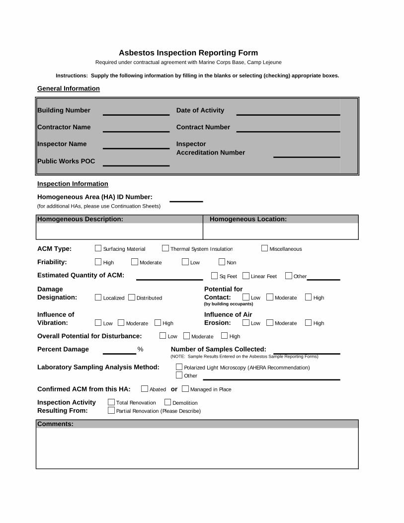
Inspector
Homogeneous Location:
Damage Contact:(by building occupants)
Erosion:
Percent Damage % Number of Samples Collected:(NOTE: Sample Results Entered on the Asbestos Sample Reporting Forms)
Laboratory Sampling Analysis Method:
or
Asbestos Inspection Reporting FormRequired under contractual agreement with Marine Corps Base, Camp Lejeune
Instructions: Supply the following information by filling in the blanks or selecting (checking) appropriate boxes.
General Information
Building Number
Contractor Name
Inspector Name
Resulting From:
Overall Potential for Disturbance:
Confirmed ACM from this HA:
Inspection Activity
Inspection Information
Homogeneous Area (HA) ID Number:(for additional HAs, please use Continuation Sheets)
Contract Number
Accreditation Number
Date of Activity
Public Works POC
Homogeneous Description:
Potential for
Influence ofVibration:
Influence of Air
ACM Type:
Friability:
Estimated Quantity of ACM:
Designation:
Comments:
Surfacing Material Thermal System Insulation Miscellaneous
High Moderate Low Non
Sq Feet Linear Feet Other
Localized Distributed Low Moderate High
Low Moderate High Low Moderate High
Low Moderate High
Polarized Light Microscopy (AHERA Recommendation)Other
Abated Managed in Place
Total Renovation DemolitionPartial Renovation (Please Describe)
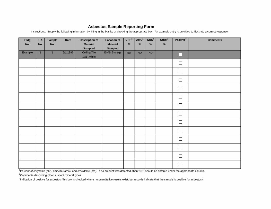
Bldg HA Sample Date Description of Location of CHR1 AMO1 CRO1 Other2 Positive3
No. No. No. Material Material % % % %Sampled Sampled
Example 1 1 5/1/1996 Ceiling Tile ISMD Storage ND ND ND1'x1', white
2Comments describing other suspect mineral types.3Indication of positive for asbestos (this box is checked where no quantitative results exist, but records indicate that the sample is positive for asbestos).
Instructions: Supply the following information by filling in the blanks or checking the appropriate box. An example entry is provided to illustrate a correct response.
1Percent of chrysotile (chr), amocite (amo), and crocidolite (cro). If no amount was detected, then "ND" should be entered under the appropriate column.
Asbestos Sample Reporting Form
Comments
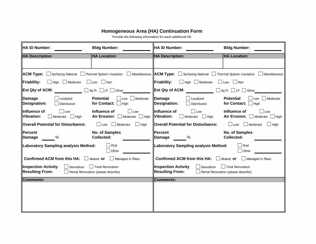
Bldg Number: Bldg Number:
HA Location: HA Location:
Friability: Friability:
Damage Potential Damage Potentialfor Contact: for Contact:
Influence of Influence of Influence of Influence ofAir Erosion: Air Erosion:
Percent No. of Samples Percent No. of SamplesDamage % Collected: Damage % Collected:
or or
Overall Potential for Disturbance:
Laboratory Sampling analysis Method:
Comments:
Confirmed ACM from this HA:
Inspection ActivityResulting From:
Est Qty of ACM:
Vibration:
Est Qty of ACM:
Designation:
Vibration:
Comments:
Resulting From:Inspection Activity
Designation:
Overall Potential for Disturbance:
Confirmed ACM from this HA:
Laboratory Sampling analysis Method:
HA Description: HA Description:
ACM Type: ACM Type:
Homogeneous Area (HA) Continuation FormProvide the following information for each additional HA
HA ID Number: HA ID Number:
Surfacing Material Thermal System Insulation Miscellaneous Surfacing Material Thermal System Insulation Miscellaneous
High Moderate Low Non High Moderate Low Non
Sq Ft LF Other
Localized
Distributed
Low Moderate
High
Low
HighModerate
Low
Moderate High
Low Moderate High
PLM
Other
Abated Managed in Place
Demolition Total Renovation
Partial Renovation (please describe)
Sq Ft LF Other
Localized
Distributed
Low Moderate
High
Low
HighModerate
Low
Moderate High
Low Moderate High
PLM
Other
Abated Managed in Place
Demolition Total Renovation
Partial Renovation (please describe)
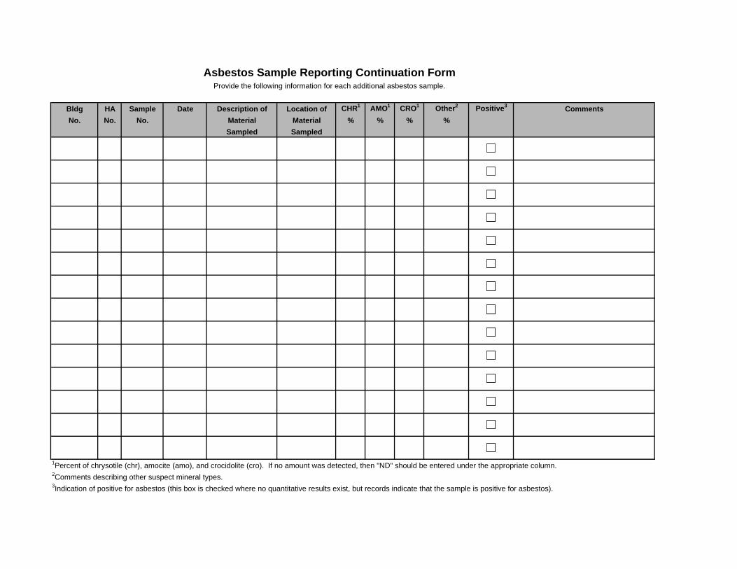
Bldg HA Sample Date Description of Location of CHR1 AMO1 CRO1 Other2 Positive3
No. No. No. Material Material % % % %Sampled Sampled
Asbestos Sample Reporting Continuation FormProvide the following information for each additional asbestos sample.
Comments
2Comments describing other suspect mineral types.3Indication of positive for asbestos (this box is checked where no quantitative results exist, but records indicate that the sample is positive for asbestos).
1Percent of chrysotile (chr), amocite (amo), and crocidolite (cro). If no amount was detected, then "ND" should be entered under the appropriate column.
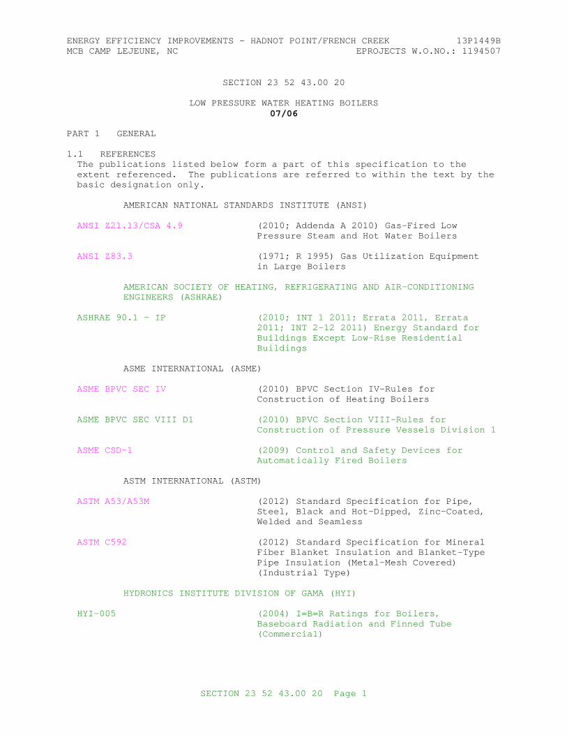
ENERGY EFFICIENCY IMPROVEMENTS - HADNOT POINT/FRENCH CREEK 13P1449BMCB CAMP LEJEUNE, NC EPROJECTS W.O.NO.: 1194507
SECTION 23 52 43.00 20
LOW PRESSURE WATER HEATING BOILERS07/06
PART 1 GENERAL
1.1 REFERENCESThe publications listed below form a part of this specification to the extent referenced. The publications are referred to within the text by the basic designation only.
AMERICAN NATIONAL STANDARDS INSTITUTE (ANSI)
ANSI Z21.13/CSA 4.9 (2010; Addenda A 2010) Gas-Fired Low Pressure Steam and Hot Water Boilers
ANSI Z83.3 (1971; R 1995) Gas Utilization Equipment in Large Boilers
AMERICAN SOCIETY OF HEATING, REFRIGERATING AND AIR-CONDITIONING ENGINEERS (ASHRAE)
ASHRAE 90.1 - IP (2010; INT 1 2011; Errata 2011, Errata 2011; INT 2-12 2011) Energy Standard for Buildings Except Low-Rise Residential Buildings
ASME INTERNATIONAL (ASME)
ASME BPVC SEC IV (2010) BPVC Section IV-Rules for Construction of Heating Boilers
ASME BPVC SEC VIII D1 (2010) BPVC Section VIII-Rules for Construction of Pressure Vessels Division 1
ASME CSD-1 (2009) Control and Safety Devices for Automatically Fired Boilers
ASTM INTERNATIONAL (ASTM)
ASTM A53/A53M (2012) Standard Specification for Pipe, Steel, Black and Hot-Dipped, Zinc-Coated, Welded and Seamless
ASTM C592 (2012) Standard Specification for Mineral Fiber Blanket Insulation and Blanket-Type Pipe Insulation (Metal-Mesh Covered) (Industrial Type)
HYDRONICS INSTITUTE DIVISION OF GAMA (HYI)
HYI-005 (2004) I=B=R Ratings for Boilers, Baseboard Radiation and Finned Tube (Commercial)
SECTION 23 52 43.00 20 Page 1
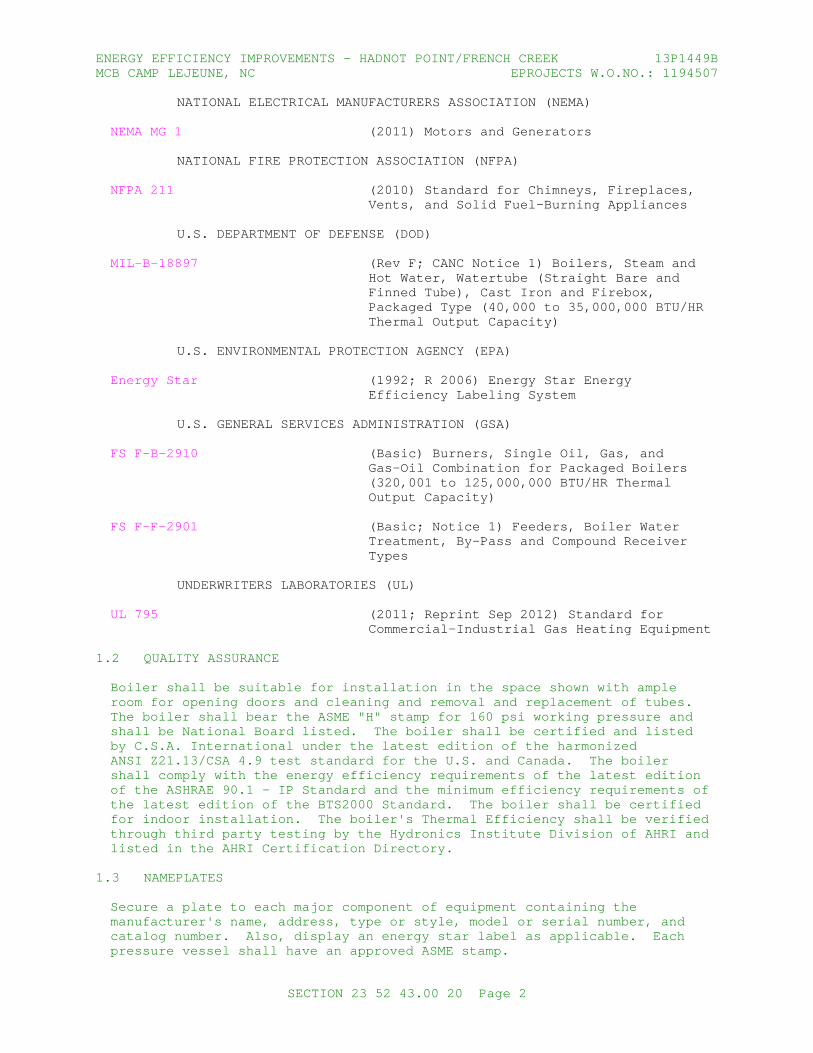
ENERGY EFFICIENCY IMPROVEMENTS - HADNOT POINT/FRENCH CREEK 13P1449BMCB CAMP LEJEUNE, NC EPROJECTS W.O.NO.: 1194507
NATIONAL ELECTRICAL MANUFACTURERS ASSOCIATION (NEMA)
NEMA MG 1 (2011) Motors and Generators
NATIONAL FIRE PROTECTION ASSOCIATION (NFPA)
NFPA 211 (2010) Standard for Chimneys, Fireplaces, Vents, and Solid Fuel-Burning Appliances
U.S. DEPARTMENT OF DEFENSE (DOD)
MIL-B-18897 (Rev F; CANC Notice 1) Boilers, Steam and Hot Water, Watertube (Straight Bare and Finned Tube), Cast Iron and Firebox, Packaged Type (40,000 to 35,000,000 BTU/HR Thermal Output Capacity)
U.S. ENVIRONMENTAL PROTECTION AGENCY (EPA)
Energy Star (1992; R 2006) Energy Star Energy Efficiency Labeling System
U.S. GENERAL SERVICES ADMINISTRATION (GSA)
FS F-B-2910 (Basic) Burners, Single Oil, Gas, and Gas-Oil Combination for Packaged Boilers (320,001 to 125,000,000 BTU/HR Thermal Output Capacity)
FS F-F-2901 (Basic; Notice 1) Feeders, Boiler Water Treatment, By-Pass and Compound Receiver Types
UNDERWRITERS LABORATORIES (UL)
UL 795 (2011; Reprint Sep 2012) Standard for Commercial-Industrial Gas Heating Equipment
1.2 QUALITY ASSURANCE
Boiler shall be suitable for installation in the space shown with ample room for opening doors and cleaning and removal and replacement of tubes. The boiler shall bear the ASME "H" stamp for 160 psi working pressure and shall be National Board listed. The boiler shall be certified and listed by C.S.A. International under the latest edition of the harmonized ANSI Z21.13/CSA 4.9 test standard for the U.S. and Canada. The boiler shall comply with the energy efficiency requirements of the latest edition of the ASHRAE 90.1 - IP Standard and the minimum efficiency requirements of the latest edition of the BTS2000 Standard. The boiler shall be certified for indoor installation. The boiler's Thermal Efficiency shall be verified through third party testing by the Hydronics Institute Division of AHRI and listed in the AHRI Certification Directory.
1.3 NAMEPLATES
Secure a plate to each major component of equipment containing the manufacturer's name, address, type or style, model or serial number, and catalog number. Also, display an energy star label as applicable. Each pressure vessel shall have an approved ASME stamp.
SECTION 23 52 43.00 20 Page 2
ENERGY EFFICIENCY IMPROVEMENTS - HADNOT POINT/FRENCH CREEK 13P1449BMCB CAMP LEJEUNE, NC EPROJECTS W.O.NO.: 1194507
1.4 SAFETY STANDARDS
Hot water boilers, burners and supplementary control devices, safety interlocks, or limit controls required under this specification, shall meet requirements of the following standards as applicable:
a. Gas-Fired Units: ANSI Z83.3, ANSI Z21.13/CSA 4.9 or UL 795.
b. All Units: ASME BPVC SEC IV and ASME CSD-1.
Controls not covered by the above shall have a UL label, UL listing mark, or shall be listed in the Factory Mutual Approval Guide.
1.5 SUBMITTALS
Government approval is required for submittals with a "G" designation; submittals not having a "G" designation are for Contractor Quality Control approval. The following shall be submitted in accordance with Section 01 33 00 SUBMITTAL PROCEDURES:
SD-02 Shop Drawings
Fuel train; G
SD-03 Product Data
Boilers; G
Provide power output, thermal efficiency, ASME certification, allowable working pressure, model number, documentation for ASHRAE 90.1 - IP Energy Star qualifications or meeting FEMP requirements
Boiler trim and control equipment; G
Burners and control equipment; G
Stack, breeching, and supports; G
Direct Vent; G
Boiler Circulating Pump; G
Expansion Tank; G
Air Separator; G
SD-06 Test Reports
Operational tests; G
SD-07 Certificates
Boilers
Boiler trim and control equipment
Burners and control equipment
SECTION 23 52 43.00 20 Page 3
ENERGY EFFICIENCY IMPROVEMENTS - HADNOT POINT/FRENCH CREEK 13P1449BMCB CAMP LEJEUNE, NC EPROJECTS W.O.NO.: 1194507
Boiler manufacturer's certificate of boiler performance including evidence that the burners provided shall be a make, model, and type certified and approved by the manufacturer of the boiler being provided.
SD-08 Manufacturer's Instructions
Boilers; G
Feedwater treatment feeder; G
SD-10 Operation and Maintenance Data
Boilers; G
SD-11 Closeout Submittals
Posted operating instructions for heating water boilers; G
PART 2 PRODUCTS
2.1 BOILERS
2.1.1 MANUFACTURER
All boilers shall be provided by a single manufacturer. Provide materials and equipment which are the standard products of a manufacturer regularly engaged in the manufacture of the products and that essentially duplicate items that have been in satisfactory use for at least 10 years prior to bid opening. Equipment shall be supported by a service organization that is, in the opinion of the Contracting Officer, reasonably convenient to the site.
2.1.2 GENERAL
MIL-B-18897. Provide hot water heating boiler complete with firing equipment, combustion chamber, insulation with steel jacket, safety and operating controls, integral electrical wiring and other appurtenances, to make the boiler a complete, self-contained, fully-automatic unit, ready for service upon completion of utility connections.
Factory-fabricated, -assembled, and -tested, fin tube condensing boiler with heat exchanger sealed pressure tight, built on a steel base; including insulated jacket; flue-gas vent; combustion-air intake connections; water supply, return, and condensate drain connections; and controls. Heat Exchanger shall be stainless steel. Pressure vessel shall be carbon steel with welded heads and tube connections. Burner shall be natural gas with forced draft fan and prepurge and postpurge sequences.
Gas Train shall comply with ASME CSD-1 combination gas valve with manual shutoff and pressure regulator. Provide spark ignition with 100 percent main-valve shutoff with electronic flame supervision.
Each boiler shall conform to the commercial design used by the manufacturer and shall permit free thermal expansion without placing undue stress on any part of the boiler.
Each boiler shall be specifically designed for condensing application. The
SECTION 23 52 43.00 20 Page 4
ENERGY EFFICIENCY IMPROVEMENTS - HADNOT POINT/FRENCH CREEK 13P1449BMCB CAMP LEJEUNE, NC EPROJECTS W.O.NO.: 1194507
boiler and its accessories shall be designed and installed to permit ready accessibility for operation, maintenance, and service. The boiler capacity shall be based on the ratings shown in HYI-005 or as certified by the American Boiler Manufacturers Association, or American Gas Association. The boiler shall comply with the energy efficiency requirements of the latest edition of the ASHRAE 90.1 - IP Standard and the minimum efficiency requirements of the latest edition of the BTS2000 Standard.
The boiler shall operate at a minimum of 94 percent thermal efficiency at full fire.
The boiler shall have an independent laboratory rating for Oxides of Nitrogen (NOx) of 20 ppm or less corrected to 3% O2.
2.2 BURNERS AND CONTROL EQUIPMENT
2.2.1 Gas-Fired Power Burner
Gas-fired power burner. FS F-B-2910. Direct spark (pilotless) type ignition system electrode-ignited natural gas type. Design burner and combustion control equipment for firing natural gas having a specific gravity of 0.6 and a heating value of approximately 1000 BTU per cubic foot and be an integral part of the boiler. Burner controls and safety equipment shall conform to applicable requirements of FS F-B-2910. Mount controls; including operating switches, indicating lights, gages, alarms, motor starters, fuses, and circuit elements of control systems on a single control panel or cabinet designed for separate mounting not on the burner in accordance with FS F-B-2910. Locate flame scanner such that testing and cleaning of scanner can be accomplished without disassembly of burner. Provide fuel train as indicated.
2.3 BOILER TRIM AND CONTROL EQUIPMENT
Provide in accordance with MIL-B-18897 and FS F-B-2910 and additional requirements specified below.
2.3.1 Emergency Disconnect Switch
Provide and locate on wall outside boiler room entrance or just inside door, when boiler room door is on building exterior to allow rapid and complete shutdown of the boiler in the event of an emergency. Emergency switch shall be a fuse-type safety switch. Switch shall be red and furnished with a label indicating function of switch.
2.3.2 Relief Valves
Provide relieving capacity for the full output of boiler installed. Relief-valve piping shall conform to ASTM A53/A53M, schedule 40 steel pipe and be piped full-size to a floor drain.
2.3.3 Pressure and Altitude Gage or Combination Pressure/Altitude Gage
MIL-B-18897. Provide one located on supply water piping and one on return water piping.
2.3.4 Thermometer
Provide thermometer with a scale equivalent to 1.5 times outlet water temperature. Provide one located on supply water piping and one on return
SECTION 23 52 43.00 20 Page 5
ENERGY EFFICIENCY IMPROVEMENTS - HADNOT POINT/FRENCH CREEK 13P1449BMCB CAMP LEJEUNE, NC EPROJECTS W.O.NO.: 1194507
water piping.
2.3.5 Drain Tapping
Provide drain valve and piping to a floor drain.
2.3.6 Make-up Water Station
2.3.6.1 Pressure Reducing Station
Provide a water pressure-reducing valve and relief valve, or a combination of the two in the makeup water line to the boiler to maintain a water pressure in the hot water system. Provide a 3/4 inch globe valve by-pass around this valve.
2.3.6.2 Backflow Preventers
Provide strainer and reduced pressure backflow preventer upstream of bypass and pressure reducing valve.
2.3.7 Feedwater Treatment Feeder
Provide in accordance with FS F-F-2901, Type II - Shot-Type Feeder (manual, intermittent feed), Style A - for use with pressures up to 200 psig maximum.
2.3.8 Combustion Regulator
Provide adjustable temperature, thermostatic immersion type that shall limit boiler water temperature to a maximum of 250 degrees F. Control shall actuate burner through an electric relay system to maintain boiler water temperature within normal prescribed limits at loads within rated capacity of boiler.
2.3.9 Air Vent Valve
Provide with screwed connection, stainless steel disk, and stainless steel seats to vent entrapped air.
2.3.10 High Temperature Limit Switch
Provide immersible aquastat type with a temperature setting above that of the combustion regulator and below that of the lowest relief valve setting. Aquastat shall function to cause a safety shutdown by closing fuel valves, and shutting down burner equipment in the event that boiler water temperature rises to the high temperature limit setting. A safety shutdown due to high temperature shall require manual reset before operation can resume and prevent recycling of burner equipment.
2.3.11 Low Water Pressure Control
Provide mercury switch type. Control shall have a main scale, adjusting screws at the top of the case, and have an internal or external bellows. Control shall be the type which will open an electric circuit on a drop in pressure below a set minimum. Control shall be set and installed to cause a safety shutdown by closing fuel valves, and shutting down burner equipment in the event that water pressure in the system drops below setpoint. A safety shutdown due to low water pressure shall require manual reset before operation can resume and prevent recycling of burner equipment.
SECTION 23 52 43.00 20 Page 6
ENERGY EFFICIENCY IMPROVEMENTS - HADNOT POINT/FRENCH CREEK 13P1449BMCB CAMP LEJEUNE, NC EPROJECTS W.O.NO.: 1194507
2.3.12 Low Water Level Cutoff Switch
Provide float actuated type. Low water level cutoff shall cause a safety shutdown by closing fuel valves, and shutting down burner equipment in the event that water level drops below the lowest safe permissible water level established by the boiler manufacturer and ASME BPVC SEC IV. A safety shutdown due to low water shall require manual reset before operation can resume and prevent recycling of burner equipment.
2.3.13 Boiler Safety Control Circuits
Provide boiler safety control circuits, including control circuits for burner and draft fan, shall be single-phase, two-wire one-side grounded, and not over 120 volts. Provide safety control switching in ungrounded conductors. Provide overcurrent protection. In addition to circuit grounds, ground metal parts which do not carry current to a grounding conductor.
2.3.14 Indicating Lights
Provide indicating lights as follows. Each safety interlock requiring a manual reset shall have an individually-labeled indicating light. Non-recycling controls/interlocks shall have the reset located on control/interlock itself. Indicating lights shall have colors as follows in lieu of those required by FS F-B-2910:
a. Amber: Ignition on
b. Green: Main fuel safety shut-off valves open
c. Red (One for Each): Safety lockout, flame failure, low water pressure, low water level, and high temperature
2.3.15 Alarm Bell
Provide alarm bell not less than 4 inches in diameter, electrically operated, with a manual disconnect switch. Disconnect switch shall be type and wired so that switching off alarm following a safety shutdown will not prevent alarm from sounding again upon recurrence of a subsequent safety shutdown condition.
2.3.16 Post-Combustion Purge
Provide controls and wiring necessary to ensure operation of draft fan for a period of not less than 15 seconds or of sufficient duration to provide four complete air changes in the boiler combustion chamber (whichever is greater) following shutdown of burner upon satisfaction of heat demand. Upon completion of post-combustion purge period, draft fan shall automatically shutdown until next restart.
2.3.17 Draft
Comply with boiler manufacturer's recommendations.
2.3.18 Stack, Breeching, and Supports
Provide boiler stack constructed of stainless sheet steel having a thickness of not less than 0.0972 inches with welded joints. Insulate stack located inside the building with 1 1/2 inches of mineral wool
SECTION 23 52 43.00 20 Page 7
ENERGY EFFICIENCY IMPROVEMENTS - HADNOT POINT/FRENCH CREEK 13P1449BMCB CAMP LEJEUNE, NC EPROJECTS W.O.NO.: 1194507
conforming to applicable requirements of ASTM C592, Class II - for use up to 1200 degrees F. Insulation shall receive a finish coat of finishing cement not less than 3/4 inch thick, trowelled to a smooth finish. Provide stack supports, umbrella collar and flue transition piece. Stack diameter and height shall be in accordance with manufacturer's recommendations and conform to NFPA 211.
Provide drain and condensate neutralization kit.
2.3.19 Direct Vent
Each individual boiler shall be provided with a direct vent vertical system with a vertical roof top termination of both the vent and combustion air. The flue shall be Stainless Steel sealed vent material terminating at the roof top with the manufacturers specified vent termination. A separate pipe shall supply combustion air directly to the BOILER from the outside. The air inlet pipe shall be stainless steel. The air inlet must terminate on the roof top with the manufacturer's specified air inlet cap.
2.3.20 Stack Thermometer
Provide flue gas thermometer with scale calibrated from 150 to 750 degrees F and mounted in flue gas outlet.
2.4 ELECTRIC MOTORS
Electric motors shall meet requirements of NEMA MG 1. Motors less than 1 hp shall meet NEMA High Efficiency requirements. Motors 1 hp and larger shall meet NEMA Premium Efficiency requirements. Motors which are an integral part of the packaged boiler system shall be the highest efficiency available by the manufacturer of the packaged boiler.
2.5 BOILER CIRCULATING PUMPS
Circulating pumps for hot water shall be electrically driven single-stage centrifugal type. Boiler circulating pumps shall be supported by the piping on which installed and shall be closed-coupled shaft. The pump shaft shall be constructed of corrosion-resistant alloy steel, sleeve bearings and glands of bronze designed to accommodate a mechanical seal, and the housing of close-grained cast iron. Pump seals shall be capable of withstanding 240 degrees F temperature without external cooling. The motor shall have sufficient power for the service required, shall be of a type approved by the manufacturer of the pump and shall be suitable for the available electric service. Each pump suction and discharge connection shall be provided with a pressure gauge.
2.6 FITTINGS AND ACCESSORIES
2.6.1 Expansion Tank
The hot water pressurization system shall include a bladder-type expansion tank welded steel, constructed, tested, and stamped in accordance with ASME BPVC SEC VIII D1 for a working pressure of 125 psi and precharged to the minimum operating pressure. The tank's air chamber shall be fitted with an air charging valve and pressure gauge. The tank shall be supported by steel legs or bases for vertical installation or steel saddles for horizontal installations. The tank shall have lifting rings and a drain connection. All components shall be suitable for a maximum operating temperature of 250 degrees F.
SECTION 23 52 43.00 20 Page 8
ENERGY EFFICIENCY IMPROVEMENTS - HADNOT POINT/FRENCH CREEK 13P1449BMCB CAMP LEJEUNE, NC EPROJECTS W.O.NO.: 1194507
2.6.2 Air Separator
External air separation tank shall be steel combination air and sediment separator with internal coalescing medium to remove entrained air and suspended solids. It shall be constructed, tested and stamped in accordance with ASME BPVC SEC VIII D1 for a working pressure of 125 psi.
PART 3 EXECUTION
3.1 EQUIPMENT INSTALLATION
Install equipment in accordance with manufacturer's installation instructions. Grout equipment mounted on concrete foundations before installing piping. Install piping in such a manner as not to place a strain on equipment. Do not bolt flanged joints tight unless they match. Grade, anchor, guide, and support piping without low pockets. Feedwater treatment feeders shall be mounted so that the top of the feeder is no higher than 48 inches above the finished floor.
3.2 EQUIPMENT FOUNDATIONS
Locate equipment foundations as indicated, designed, and made of sufficient size and weight to preclude shifting of equipment under operating conditions or under abnormal conditions that could be imposed upon the equipment. Foundations shall meet requirements of the equipment manufacturer.
3.3 BOILER CLEANING
Before being placed in service, boiler shall be boiled out for a period of 24 hours at a pressure not exceeding 12 psig. Solution to be used in the boiler for the boiling out process shall consist of two pounds of trisodium phosphate per 100 gallons of water. Upon completion of boiling out, flush out boiler with potable water, drain, and charge with chemically treated water. Protect boiler and appurtenances against internal corrosion until testing is completed and boiler is accepted. Professional services are required for cleaning/treatment process.
3.4 FIELD QUALITY CONTROL
Perform and furnish everything required for inspections and tests as specified herein to demonstrate that boiler and auxiliary equipment, as installed, are in compliance with contract requirements. Start-up and operate the system. During this time, clean strainers until no further accumulation of foreign material occurs. Exercise care to minimize loss of water when strainers are cleaned. Adjust safety and automatic control instruments as necessary to place them in proper operation and sequence. Test instrumentation shall be calibrated and have full scale readings from 1.5 to 2 times test values.
3.4.1 Operational Tests
Operate each boiler and appurtenances prior to final testing and insure that necessary adjustments have been made. Provide testing equipment required to perform tests. During this testing period, provide operating instructions and training to persons tasked with operation of the boiler. Tests shall be accomplished with both fuels on dual fuel units and include the following:
SECTION 23 52 43.00 20 Page 9
ENERGY EFFICIENCY IMPROVEMENTS - HADNOT POINT/FRENCH CREEK 13P1449BMCB CAMP LEJEUNE, NC EPROJECTS W.O.NO.: 1194507
3.4.1.1 Preliminary Operational Test
Operate the boilers continuously for a period of at least 8 hours to demonstrate proper operability of the combustion control, flame safeguard control, and safety interlocks.
3.4.1.2 Acceptance Operational Test and Inspection
Conduct a preliminary operational test prior to requesting an acceptance operational test and inspection by a Naval Facilities Engineering Command Boiler inspector. The Contracting Officer, upon receipt of the notice from the Contractor, shall request the boiler be inspected by Naval Facilities Engineering Command. Fifteen days advance notice is required for scheduling inspector to conduct acceptance operational test and inspection.
3.4.1.3 TEST OF BACKFLOW PREVENTION ASSEMBLIES
Backflow prevention assemblies shall be tested/certified by the installing contractor. After installation all double check and reduce pressure zone type back flow preventers shall be inspected, tested and certified by a certified tester and a tester certification and Test Data Certification Sheet submitted.
3.5 WASTE MANAGEMENT
Separate waste in accordance with the Waste Management Plan. Close and seal tightly all partly used adhesives and solvents; store protected in a well-ventilated, fire-safe area at moderate temperature.
-- End of Section --
SECTION 23 52 43.00 20 Page 10
ENERGY EFFICIENCY IMPROVEMENTS - HADNOT POINT/FRENCH CREEK 13P1449BMCB CAMP LEJEUNE, NC EPROJECTS W.O.NO.: 1194507
TELECOMMUNICATIONS INFRASTRUCTURE STANDARDSMARINE CORPS BASE CAMP LEJEUNE
SECTION 27 10 00
BUILDING TELECOMMUNICATIONS CABLING SYSTEM11/12
PART 1 GENERAL
1.1 REFERENCES
The publications listed below form a part of this specification to the extent referenced. The publications are referred to within the text by the basic designation only.
ASTM INTERNATIONAL (ASTM)
ASTM D709 (2001; R 2007) Laminated Thermosetting Materials
ASTM E814 (2011a) Standard Test Method for Fire Tests of Through-Penetration Fire Stops
ELECTRONIC COMPONENTS ASSOCIATION (ECA)
ECA EIA/ECA 310 (2005) Cabinets, Racks, Panels, and Associated Equipment
INSTITUTE OF ELECTRICAL AND ELECTRONICS ENGINEERS (IEEE)
IEEE 100 (2000; Archived) The Authoritative Dictionary of IEEE Standards Terms
INSULATED CABLE ENGINEERS ASSOCIATION (ICEA)
ICEA S-90-661 (2008) Category 3, 5, & 5e Individually Unshielded Twisted Pair Indoor Cables for Use in General Purpose and LAN Communications Wiring Systems Technical Requirements
NATIONAL ELECTRICAL MANUFACTURERS ASSOCIATION (NEMA)
ANSI/NEMA WC 66 (2001; Errata 2003) Performance Standard for Category 6 and Category 7 100 Ohm Shielded and Unshielded Twisted Pairs
NATIONAL FIRE PROTECTION ASSOCIATION (NFPA)
NFPA 70 (2011; Errata 2 2012) National Electrical Code
TELECOMMUNICATIONS INDUSTRY ASSOCIATION (TIA)
TIA J-STD-607 (2002a) Commercial Building Grounding (Earthing) and Bonding Requirements for Telecommunications
SECTION 27 10 00 Page 1
ENERGY EFFICIENCY IMPROVEMENTS - HADNOT POINT/FRENCH CREEK 13P1449BMCB CAMP LEJEUNE, NC EPROJECTS W.O.NO.: 1194507
TIA-492AAAA (2009b) 62.5-um Core Diameter/125-um Cladding Diameter Class 1a Graded-Index Multimode Optical Fibers
TIA-526-14 (2010b) OFSTP-14A Optical Power Loss Measurements of Installed Multimode Fiber Cable Plant
TIA-526-7 (2002; R 2008) OFSTP-7 Measurement of Optical Power Loss of Installed Single-Mode Fiber Cable Plant
TIA-568-2 (2009c; Errata 2010) Commercial Building Telecommunications Cabling Standard - Part 2: Balanced Twisted Pair Cable Components
TIA-568-C.1 (2009; Add 2 2011; Add 1 2012) Commercial Building Telecommunications Cabling Standard
TIA-568-C.3 (2008; Corrections 2008) Optical Fiber Cabling Components Standard
TIA-569 (2012c) Commercial Building Standard for Telecommunications Pathways and Spaces
TIA/EIA-604-2 (2004b) FOCIS 2 Fiber Optic Connector Intermateability Standard
TIA/EIA-606 (2002a; Errata 2007; R 2007; Adm 1 2008) Administration Standard for the Telecommunications Infrastructure
U.S. DEPARTMENT OF AGRICULTURE (USDA)
RUS Bull 345-83 (1979; Rev Oct 1982) Gas Tube Surge Arrestors (PE-80)
U.S. FEDERAL COMMUNICATIONS COMMISSION (FCC)
FCC Part 68 Connection of Terminal Equipment to the Telephone Network (47 CFR 68)
UNDERWRITERS LABORATORIES (UL)
UL 1286 (2008; Reprint Sep 2011) Office Furnishings
UL 1666 (2007; Reprint May 2011) Test for Flame Propagation Height of Electrical and Optical-Fiber Cables Installed Vertically in Shafts
UL 1863 (2004; Reprint Aug 2008) Communication Circuit Accessories
UL 444 (2008; Reprint Apr 2010) Communications Cables
SECTION 27 10 00 Page 2
ENERGY EFFICIENCY IMPROVEMENTS - HADNOT POINT/FRENCH CREEK 13P1449BMCB CAMP LEJEUNE, NC EPROJECTS W.O.NO.: 1194507
UL 467 (2007) Grounding and Bonding Equipment
UL 497 (2001; Reprint Apr 2009) Protectors for Paired Conductor Communication Circuits
UL 50 (2007; Reprint Apr 2012) Enclosures for Electrical Equipment, Non-environmental Considerations
UL 514C (1996; Reprint Novy 2011) Nonmetallic Outlet Boxes, Flush-Device Boxes, and Covers
UL 969 (1995; Reprint Nov 2008) Standard for Marking and Labeling Systems
1.2 RELATED REQUIREMENTS
D-B Contractor prepared Section 26 20 00 INTERIOR DISTRIBUTION SYSTEM and Section 33 82 00 TELECOMMUNICATIONS, OUTSIDE PLANT, apply to this section with additions and modifications specified herein.
1.3 DEFINITIONS
Unless otherwise specified or indicated, electrical and electronics terms used in this specification shall be as defined in TIA-568-C.1, TIA-568-2, TIA-568-C.3, TIA-569, TIA/EIA-606 and IEEE 100 and herein.
1.3.1 Main Distribution Frame (MDF)
A physical structure at a central location for terminating permanent backbone cables to interconnect with service provider (SP) equipment at the activity minimum point of presence. The MDF generally includes vendor specific components to support voice and data circuits, building surge protector assemblies, main cross connect blocks, equipment support frames, and fire rated plywood backboard. Depending upon local site conditions, the MDF and BDF may be the same space.
1.3.2 Building Distribution Frame (BDF)
A structure with terminations for connecting backbone, campus, and horizontal cabling. The BDF generally includes a cross connect, equipment support frame or lockable terminal cabinet, cable supports, and fire rated plywood backboard. The BDF shall include building protector assemblies when used for campus backbone or SP cabling.
1.3.3 Intermediate Distribution Frame (IDF)
An intermediate termination point for horizontal wiring and cross- connections within telecommunications rooms. Shall be connected to MDF with both fiber and copper. Secure Internet Protocol (SIPR) vault or cabinet is considered an IDF.
1.3.4 Telecommunications Room (TR)
An enclosed space for telecommunications equipment, terminations, and cross-connect wiring for horizontal cabling, minimum size shall be 8' x 10' unless a local waiver is provided by Base Telephone via the Contracting Officer. Telecommunications room could be much larger depending on
SECTION 27 10 00 Page 3
ENERGY EFFICIENCY IMPROVEMENTS - HADNOT POINT/FRENCH CREEK 13P1449BMCB CAMP LEJEUNE, NC EPROJECTS W.O.NO.: 1194507
building size and customer requirements. Telecommunications rooms should be centrally located unless multiple rooms are used. Access to Rooms shall be from a common area such as a hallway / open office space and the door should swing out. Additional/ Multiple Telecommunications Rooms are required if the usable floor space to be served exceeds 10,000 square feet, or the cable length between the horizontal cross-connect and the telecommunications outlet, including slack, exceeds 295 feet (90m). Multiple telecommunications rooms will be connected by a minimum of two 75mm (3 inch) conduits overhead, if under slab it is considered OSP, see Section 33 82 00 TELECOMMUNICATIONS OUTSIDE PLANT (OSP). The minimum clear height in the room shall be 2.4 m (8 ft) without obstructions. The height between the finished floor and the lowest point of the ceiling should be a minimum of 3 m (10 ft) to accommodate overhead pathways. The flooring shall be sealed concrete to reduce dust and static electricity; no carpet or tile. Two separate dedicated 20 amp electrical outlet will be installed for each communications equipment rack needed. Outlets should be installed on the same wall as the conduits or communications backboard. There should not be an electrical panel within the telecommunications room unless it serves only the room. The room requires a lockable door keyed or key padded to restrict access to Base Telephone personnel only. Room should not have any windows or skylights. The long wall farthest from door where the point of presence is should be covered with plywood backboard for mounting equipment; additional boards may be needed for mounting additional equipment (see BACKBOARDS below). Light, as measured within the telecommunications room, should be a minimum of 500 lx (50 foot-candles). Lighting design should seek to minimize shadows within the telecommunications room. Equipment not related to the support of the telecommunications room (e.g., piping, ductwork, pneumatic tubing) shall not be installed in, pass through, or enter the telecommunications room. See Encl C Telecomm Room Typical Layout.
1.4 ENVIRONMENTAL REQUIREMENTS
Connecting hardware shall be rated for operation under ambient conditions of 0 to 60 degrees C (32 to 140 degrees F) and in the range of 0 to 95 percent relative humidity, non-condensing. Provide HVAC tied into building system or separate that will maintain continuous cooling environmental control (24 hours per day, 365 days per year). If emergency power is available, consider connecting it to the HVAC system.
1.5 SYSTEM DESCRIPTION
The structured telecommunications pathway system shall include permanently installed horizontal and backbone pathways, service entrance facilities, work area pathways, telecommunications outlet boxes, conduit, and raceway, and hardware for splicing, terminating, and interconnecting. The horizontal system includes the pathway between the telecommunications room and the work area telecommunications outlet. The horizontal system shall be suitable for star topology with the MDF/IDF at the center or hub of the star. The backbone pathway system includes intrabuilding and interbuilding interconnecting pathway to provide connectivity between the MDF's, BDF's, and IDF's. The backbone system shall be suitable for star topology with the MDF at the center or hub of the star.
1.6 SUBMITTALS
Government approval is required for submittals with a "G" designation; submittals not having a "G" designation are for Contractor Quality Control approval. The following shall be submitted in accordance with Section
SECTION 27 10 00 Page 4
ENERGY EFFICIENCY IMPROVEMENTS - HADNOT POINT/FRENCH CREEK 13P1449BMCB CAMP LEJEUNE, NC EPROJECTS W.O.NO.: 1194507
01 33 00.05 20 CONSTRUCTION SUBMITTAL PROCEDURES and Section 01 33 10.05 20 DESIGN SUBMITTAL PROCEDURES:
SD-02 Shop Drawings
Telecommunications drawings; G
Distribution frames; G
In addition to Section 01 33 00.05 20 CONSTRUCTION SUBMITTAL PROCEDURES and Section 01 33 10.05 20 DESIGN SUBMITTAL PROCEDURES, provide shop drawings in accordance with paragraph SHOP DRAWINGS.
SD-03 Product Data
Telecommunications cabling (backbone and horizontal); G
Patch panels; G
Telecommunications outlet/connector assemblies; G
Equipment support frame; G
Building protector assemblies; G
Connector blocks; G
Protector modules; G
Submittals shall include the manufacturer's name, trade name, place of manufacture, and catalog model or number. Include performance and characteristic curves. Submittals shall also include applicable federal, military, industry, and technical society publication references. Should manufacturer's data require supplemental information for clarification, the supplemental information shall be submitted as specified in paragraph REGULATORY REQUIREMENTS and as required in Section 01 33 00.05 20 CONSTRUCTION SUBMITTAL PROCEDURES and Section 01 33 10.05 20 DESIGN SUBMITTAL PROCEDURES.
SD-06 Test Reports
Telecommunications cabling testing; G
Factory reel tests; G
Furnish factory reel tests for optical fiber cables.
SD-07 Certificates
Telecommunications Contractor Qualifications; G
Manufacturer Qualifications; G
Test plan; G
SD-10 Operation and Maintenance Data
Telecommunications cabling and pathway system Data Package 5; G
SECTION 27 10 00 Page 5
ENERGY EFFICIENCY IMPROVEMENTS - HADNOT POINT/FRENCH CREEK 13P1449BMCB CAMP LEJEUNE, NC EPROJECTS W.O.NO.: 1194507
Submit operations and maintenance data in accordance with Section 01 78 23 OPERATION AND MAINTENANCE DATA and Section 01 78 24.00 20 FACILITY ELECTRONIC OPERATION AND MAINTENANCE SUPPORT INFORMATION (eOMSI) and as specified herein.
1.7 ADDITIONAL SUBMITTAL REQUIREMENTS
All submittals of material, equipment and design must be approved by the Base Telephone Office via the Contracting Officer prior to installing any telecommunications wiring and equipment.
1.7.1 Telecommunications Drawings
Provide Registered Communications Distribution Designer (RCDD) approved drawings complete with wiring diagrams and details required to prove that the distribution system shall properly support connectivity from the telecommunications equipment room to telecommunications work area outlets. Show the entrance facility and layout of cabling and pathway runs, cross connect points, MDF, BDF, IDF, grounding system, rack elevations, terminating block arrangements and type. Drawings shall depict final telecommunications cabling configuration, including location, color coding, gage, pair assignment, polarization, and terminating blocks layout at cross connect points and patch panels after telecommunications cable installation. Provide a plastic laminated schematic of the as-installed telecommunications cable system showing cabling, MDF's, BDF's, IDF's, and equipment rooms keyed to floor plans by room number. Mount the laminated schematic in each telecommunications room as directed by Base Telephone. The Telecommunications Contractor shall receive design approval from the Base Telephone Office via the Contracting Officer prior to installation.
1.7.2 Distribution Frames
Provide shop drawing showing layout of applicable equipment including incoming cable stub or connector blocks, building protector assembly, outgoing cable connector blocks and equipment spaces and racks. (See Encl A Rack Elevation Example, Encl B Backboard Example, and Encl C Telecomm Room Typical Layout.)
1.7.3 Qualifications
1.7.3.1 Minimum Contractor Qualifications
Prior to installation, submit data of provider's experience and qualifications. All work under this section shall be performed by and all equipment shall be provided by a certified Telecommunications Contractor, hereinafter referred to as the Contractor. The Contractor shall have the following qualifications in Telecommunications Systems installation:
a. Contractor shall have a minimum of 3 years experience in the application, installation and testing of the specified systems and equipment to be installed.
b. All supervisors and installers assigned to the installation of this system or any of its components shall be Building Industry Consulting Services International (BICSI) Certified Cabling Installation Technicians, Installer Level 2, or have a minimum of 3 current consecutive years experience in the installation of the specified copper and fiber optic cable and components.
SECTION 27 10 00 Page 6
ENERGY EFFICIENCY IMPROVEMENTS - HADNOT POINT/FRENCH CREEK 13P1449BMCB CAMP LEJEUNE, NC EPROJECTS W.O.NO.: 1194507
c. Contractor shall include names and locations of two projects successfully completed using optical fiber and copper communications cabling systems. Include specific experience in installing and testing structured telecommunications distribution systems using optical fiber and Category 5E/6 cabling systems. Include written correspondence from users that systems have performed satisfactorily for not less than 18 months.
1.7.3.2 Minimum Manufacturer Qualifications
The equipment and hardware provided under this contract will be from manufacturers that have a minimum of 3 years experience in producing the types of systems and equipment specified.
1.7.4 Test Plan
Provide a complete and detailed test plan for the telecommunications cabling system including a complete list of test equipment for the UTP and optical fiber components and accessories 60 days prior to the proposed test date. Include procedures for certification, validation, and testing.
1.7.5 Additions to Operation and Maintenance Manuals
In addition to requirements of Data package 5 for the telecommunications cabling and pathway system, include the requirements of paragraph entitled "Telecommunications Drawings."
1.8 DELIVERY AND STORAGE
Provide protection from weather, moisture, extreme heat and cold, dirt, dust, and other contaminants for telecommunications cabling and equipment placed in storage.
PART 2 PRODUCTS
2.1 PATHWAYS (BACKBONE AND HORIZONTAL)
TIA-569. Pathway shall be conduit, cable tray, or access flooring. Under floor duct and wireway is not recommended. Cantilever-type center hung tray or Poke-Thru devices shall not be used. Provide grounding and bonding as required by TIA J-STD-607. Cable wiring shall comply with NFPA 70. All conduits entering the Telecommunications Room should be grouped and consolidated, conduits can be "Home Run" or stubbed to cable tray, all should have bonding bushing / plastic insert, and shall extend down from the ceiling 3 to 4 inches or extended to ladder rack or onto the backboard. Conduit will be bonded to the TMGB or TGB by minimum #6 AWG green sheathed stranded conductors. All penetrations will be sealed with firestopping material in accordance with the requirements of D-B Contractor prepared Section 07 84 00 FIRESTOPPING. A minimum of two 3 inch conduits overhead will be installed between the Main Telecommunications Room and other communication rooms (IDFs).
2.1.1 Work Area Pathways
Comply with TIA-569, except minimum 1¼ -inch diameter conduit will be used. System furniture pathways shall comply with UL 1286. Horizontal cabling for open offices shall comply with TIA-568-C.1. In system furniture that blocks access to telecommunications wall outlets: each
SECTION 27 10 00 Page 7
ENERGY EFFICIENCY IMPROVEMENTS - HADNOT POINT/FRENCH CREEK 13P1449BMCB CAMP LEJEUNE, NC EPROJECTS W.O.NO.: 1194507
system furniture desk/cubical shall be equipped with system furniture communications outlets that are plugged into the telecommunications wall outlets. Every port that is blocked from access shall be extended into the furniture.
2.1.2 Pull Boxes
Construct of galvanized sheet steel with screw-fastened covers. Minimum size of boxes shall be not less than 4-11/16-inches wide by 4-11/16-inches in length by 2 1/8-inches deep for individual 1-1/4-inch diameter conduit; minimum size of boxes shall be not less than 12"W x 48"L x 5"D for 3" conduit, 15"W x 60"L x 8"D for 4" conduit per TIA-569, provide pull boxes where length of conduit exceeds 100 feet or where there are more than two 90 degree bends, or equivalent. Align conduit ends on opposite sides of pull boxes as in a pull through, do not turn or change direction in pull boxes. Provide pull boxes in straight lengths of conduit; pull points, LC, LB, condulets are not authorized.
2.2 BENDS
Inside radius of conduit bend shall be a minimum of 6 times the internal diameter of conduit for conduits of 2 inches or less. Inside radius of conduit bend shall be a minimum of 10 times the internal diameter of conduit for conduits larger than 2 inches.
2.3 TELECOMMUNICATIONS OUTLET BOXES
Telecommunications outlet boxes should be placed in all work areas and any area that can be converted to work areas; so any furniture package configuration will have a connection along the wall with a 6' base cord. Good practice is 6" to the left or right of every electrical outlet box in workable office areas or any area that could be converted into workable office area such as a storage closet; also any conference room should have one floor and one ceiling box. Boxes shall be standard type 5 inches square by 2 7/8 inches deep for CAT6 with 1¼-inch diameter side knock-outs, with a single gang plaster ring. Mount flush in finished walls at height indicated by drawings. Outlet boxes for wall-mounted telephones shall be 2 by 4 by 2 1/8 inches deep with 1 CAT6 cable terminated in a standard wall phone plate; mounted at 54 inches above finished floor. Outlet boxes for handicapped telephone station or work counter area shall be mounted at a height 48 inches above finished floor. Outlet boxes installed in floor for classrooms or open spaces shall be telecommunications floor boxes large enough to support a surge of users with proper cable protection and ports that are not parallel to the floor. Floor boxes and under slab cabling should not be used on the first floor in wet areas. Tele electric poles or furniture managed pathways fed from above the wet area should be used. Multi-user Telecommunications Outlet Assembly i.e. Multimedia Outlet Assemblies (MUTOA) should be placed where best suited for the furniture used in open office spaces.
2.3.1 Telecommunications Cabling
Cabling shall be UL listed for the application and shall comply with TIA-568-C.1, TIA-568-2, TIA-568-C.3 and NFPA 70. Provide a labeling system in accordance with Paragraph "LABELING" and Base Telephone via the Contracting Officer guidance for cabling as required by TIA/EIA-606 and UL 969. Cable specifications must be provided in submittal and approved by Base Telephone via the Contracting Officer before installation. Cabling manufactured more than 12 months prior to date of installation shall not be
SECTION 27 10 00 Page 8
ENERGY EFFICIENCY IMPROVEMENTS - HADNOT POINT/FRENCH CREEK 13P1449BMCB CAMP LEJEUNE, NC EPROJECTS W.O.NO.: 1194507
used.
2.3.1.1 Backbone Copper
ICEA S-90-661, TIA-568-C.1, TIA-568-2, ANSI/NEMA WC 66 and UL 444, copper backbone cable shall be solid conductor, 24 AWG, 100 ohm, CAT6, XX-pair UTP (Unshielded twisted pair); NFPA 70 CMR rated formed into 25 pair binder groups covered with a thermoplastic jacket. NFPA 70 type CMP may be substituted for type CMR. Pair twist-lengths and frequency per unit length shall be determined by the manufacturer. A minimum of two conductor twists per foot is required. Color coding shall comply with industry standards for all cables. Sufficient pair count CAT6 riser (25, 50, 100, 200...) and two 4 pair 24 AWG Category 6 riser (CMR) rated cable will be installed between the MDF and each of the IDF's. Voice Riser shall be terminated on 50 pair 89D-Style Insulation Displacement Contact cross connect blocks with industry standard 110 blade punch down and two CAT6 cables terminated in the patch panels last position. Any Backbone Copper run in under slab conduit shall be rated for outdoor use in accordance with AHJ and have lightning protection at each end.
2.3.1.2 Backbone Optical Fiber Between Closets
TIA-492AAAA, TIA-568-C.3, UL 1666, NFPA 70. Optical fiber cable shall be 12-fiber multimode 62.5/125-um and 12-fiber single mode 8/125-um, terminated on ST type connectors, with a non-conductive optical fiber riser cable (OFNR) rating. Nonconductive optical fiber Plenum (OFNP) cable may be substituted for type nonconductive optical fiber riser cable (OFNR). The cable jacket shall be orange and yellow. Terminate in a rack mounted fiber distribution center with sufficient slack for maintenance operations (minimum 36" in FDC and 18' coil on backboard). Fiber should be run to each IDF from the MDF.
2.3.2 Horizontal Cabling
Comply with NFPA 70, and performance characteristics in TIA-568-C.1.
2.3.2.1 Horizontal Copper
TIA-568-2, ANSI/NEMA WC 66, NFPA 70, UTP (unshielded twisted pair), 100 ohm. Provide a minimum of four cables to each work area outlet (faceplate), each individually twisted pair, 24/23 AWG conductors, Category 6 general purpose cable, with white PVC jacket for all odd numbered jacks, and blue PVC jacket for all even numbered jacks (unclassified service). Plenum (CMP) or riser (CMR) cable may be substituted for general purpose cable. If the cabling passes thru a plenum air space then plenum (CMP) rated cable is required. If the cabling is run in under slab conduit, outdoor rated cable shall be used. Contact Base Telephone via the Contracting Officer for special requirements on classified service, unclassified service, under slab cabling, using water block, and any item not covered in this document.
2.3.2.2 Horizontal Optical Fiber
TIA-492AAAA, TIA-568-C.3, NFPA 70. Optical fiber cable shall be 62.5/125-um, 2-fiber multimode, rated nonconductive optical fiber cable (OFN). Plenum (OFNP) or riser (OFNR) cable may be substituted for general purpose cable. The cable jacket shall be orange and be of single jacket construction. If the cabling passes thru a plenum air space then plenum (CMP) rated cable is required. Currently Camp Lejeune does not install any
SECTION 27 10 00 Page 9
ENERGY EFFICIENCY IMPROVEMENTS - HADNOT POINT/FRENCH CREEK 13P1449BMCB CAMP LEJEUNE, NC EPROJECTS W.O.NO.: 1194507
Horizontal Optical Fiber to the work area outlet.
2.4 DISTRIBUTION FRAMES
Provide building distribution frames (BDF's), intermediate distribution frames (IDF's), and main distribution frames (MDF's) as shown on design drawings for terminating and cross connecting permanent cabling.
2.4.1 Equipment Support Frame
Provide in accordance with ECA EIA/ECA 310 and UL 50.
a. Bracket, wall mounted (for buildings with very low jack/pair count and no secured equipment requirement), provide 8 gauge aluminum hinged bracket compatible with 482.6 mm panel mounting. (Not preferred by Camp Lejeune Base Telephone.)
b. Rack, wall mounted (for buildings with low jack/pair count and a secured equipment requirement), 16 gauge steel construction treated to resist corrosion. Rack should be swing gate type, minimum 38" High x 25" Depth with standard 19" panel mounts. Must be in secured Telephone Room.
c. Racks, floor mounted modular type, 16 gauge steel construction, treated to resist corrosion. Provide rack with vertical and horizontal cable management channels, top and bottom cable troughs, grounding lug and a surge protected power strip with 6 duplex 20 amp receptacles. Racks should be large enough to support all telephone / data equipment required plus 25 percent spare. Rack shall be compatible with 19 inches panel mounting. Racks should have a maximum of 7’ height.
d. Cabinets should be used in areas that are not secured. Cabinets, freestanding modular type, 16 gauge steel construction, minimum, treated to resist corrosion. Cabinets shall be no smaller than 24"W X 48"H X 30"D but can be as large as 7'H X 24"W X 30"D. Cabinet shall have removable and lockable side panels, front and rear doors. Cabinet shall be vented in the roof and rear door. Cabinet shall have cable access in the roof and base and be compatible with 19 inches panel mounting. Provide cabinet with grounding bar, roof mounted 550 CFM fan with filter and a surge protected power strip with 6 duplex 20 amp receptacles and cord long enough to reach dedicated building power. All cabinets shall be lockable (keyed to current base key) and large enough to support all telephone / data equipment required in the building plus 25 percent spare. Dedicated electrical outlets should be installed on backboard within 6' of thecabinet. A backboard for mounting equipment is still needed when a cabinet is installed (see paragraph "BACKBOARDS" below).
2.4.2 Building Protector Assemblies
Building protector assembly are required on all OSP cables and shall have 710 type connector blocks for connection to the exterior cable at full capacity. M150-66 type IDC for connection to the voice cross connect blocks. 110 type IDC protector assemblies are not approved.
2.4.2.1 Protector Modules
UL 497, RUS Bull 345-83, three-electrode gas tube or solid state type rated for the application. Provide the number of surge protection modules equal
SECTION 27 10 00 Page 10
ENERGY EFFICIENCY IMPROVEMENTS - HADNOT POINT/FRENCH CREEK 13P1449BMCB CAMP LEJEUNE, NC EPROJECTS W.O.NO.: 1194507
to the number of pairs of exterior cable of the building protector assembly.
2.4.3 Connector Blocks
Provide insulation displacement connector (IDC) 50 pair 89D-Style with industry standard 110 blade punch down for Category 5e and higher systems. Provide blocks for the number of backbone cables terminated on the block plus 25 percent spare. Also provide sufficient blocks for cross connects for all IDFs.
2.4.4 Patch Panels
Provide ports for the number of horizontal and backbone cables terminated on the panel plus 25 percent spare within the top 2/3 of the equipment support frame (bottom 1/3 is reserved for DATA equipment). Provide pre-connectorized ST type Optical fiber and copper patch cords for patch panels. Provide patch cords, as complete assemblies, with matching connectors as specified. Patch cords shall meet minimum performance requirements specified in TIA-568-C.1, TIA-568-2, and TIA-568-C.3 for cables, cable length and hardware specified.
2.4.4.1 Modular to Patch Panel
Provide in accordance with TIA-568-C.1 and TIA-568-2. Panels shall be third party verified and shall comply with EIA/TIA Category 6 requirements. Panel shall be constructed of 0.09 inches minimum aluminum and shall be cabinet mounted and compatible with an ECA EIA/ECA 310 19 inches equipment cabinet. Each panel shall provide 48 port, non-keyed, dual 8-pin modular ports, wired to T568A. Patch panels shall terminate the building cabling on Type 110 IDCs and shall utilize a printed circuit board interface. The rear of each panel shall have incoming cable strain-relief and routing guides. DO NOT USE ZIP TIES. Panels shall have each port factory numbered and be equipped with manufacturer's labels and laminated plastic covers above each port.
2.4.4.2 Fiber Optic Patch Panel
Provide panel for maintenance and cross-connecting of optical fiber cables. Panel shall be constructed of 16 gauge steel or 11 gauge aluminum minimum and shall be compatible with a ECA EIA/ECA 310 19 inch equipment rack. Each panel shall provide 12 multimode and 12 single-mode adapters as ST in accordance with TIA/EIA-604-2 with metallic alignment sleeves. Provide dust cover for unused adapters. The rear of each panel shall have a cable management tray a minimum of 8 inches deep with removable cover, incoming cable strain-relief and routing guides. DO NOT USE ZIP TIES. Panels shall have each adapter factory numbered.
2.4.4.3 Special Network Requirements
Buildings with Special Networks Requirements such as Secured Internet Protocol, American Warrior Network, MCCS.org, and Naval Blue Network may require additional guidance outside this specification. Secured areas or secured networks in non secured areas may require Protected Distribution System which is also outside this specification. In these cases contact Base Telephone for Guidance at (910) 451-9439 or (910) 451-4760.
2.4.5 Optical Fiber Distribution Panel
Rack mounted optical fiber distribution panel (OFDP) shall be constructed
SECTION 27 10 00 Page 11
ENERGY EFFICIENCY IMPROVEMENTS - HADNOT POINT/FRENCH CREEK 13P1449BMCB CAMP LEJEUNE, NC EPROJECTS W.O.NO.: 1194507
in accordance with ECA EIA/ECA 310 utilizing 11 gauge aluminum minimum. Panel shall have strain relief, routing guides, splice tray and shall have a cover for patch cord protection. Each panel shall provide 12 multimode and 12 single-mode adapters. Provide adapters as ST with metallic alignment sleeves. Provide dust covers for adapters. Provide patch cords as specified in the paragraph PATCH PANELS. Pigtails are not recommended.
2.5 TELECOMMUNICATIONS OUTLET BOXES
Standard type 5" x 5" x 2 7/8" square box with a single gang plaster ring. Mount flush in finished walls at height indicated by drawings. Depth of boxes shall be large enough to allow manufacturer's recommended conductor bend radii normally 2 7/8".
2.6 TELECOMMUNICATIONS OUTLET/CONNECTOR ASSEMBLIES
2.6.1 Outlet/Connector Copper
Outlet/connectors shall comply with FCC Part 68.5, TIA-568-C.1, and TIA-568-2. UTP Outlet/connectors shall be UL 1863 listed, non-keyed, 4-pair, dual 8-pin modular, constructed of high impact rated thermoplastic housing and shall be third party verified and shall comply with TIA-568-2 Category 6 requirements. Provide outlet/connectors in indicated color (normally ivory or white and should match electrical coverplates). Outlet/connectors provided for Category 6 UTP cabling shall meet or exceed the requirements for the cable provided. Outlet/connectors shall be terminated using a Type 110 IDC PC board connector, color-coded for both T568A and T568B wiring. Each outlet/connector shall be wired T568A. UTP outlet/connectors shall comply with TIA-568-2 for 750 mating cycles. UTP outlet/connectors installed in outdoor or marine environments shall be rated for that use or protected with weatherproof enclosure.
2.6.2 Cover Plates
Telecommunications cover plates shall comply with UL 514C, and TIA-568-C.1, TIA-568-2, TIA-568-C.3; flush or oversized design constructed of high impact thermoplastic material, equipped with laminated plastic cover for label, and able to accept 2 dual 8-pin modular couplers. Color should match color of receptacle/switch cover plates specified in D-B Contractor prepared Section 26 20 00 INTERIOR DISTRIBUTION SYSTEMS. Provide labeling in accordance with the paragraph LABELING in this section.
2.7 BACKBOARDS
Provide void-free, interior grade plywood 19 mm (3/4 inch) thick as indicated. Backboards shall be fire rated, with the fire stamp visible, or covered with two coats of gray or a lighter color, nonconductive, fire-retardant paint on all sides. Boards should be installed 4'Width x 8'Height and cover at least an 8' x 8' area on the long wall farthest from the door in the telecomm room. Additional boards may be needed anywhere electronic equipment is to be mounted. (See Encl for backboard layout.)
2.8 GROUNDING AND BONDING PRODUCTS
Comply with UL 467, TIA J-STD-607, and NFPA 70. Components shall be identified as required by TIA/EIA-606. Ground rods shall be in accordance with D-B Contractor prepared Section 26 20 00 INTERIOR DISTRIBUTION SYSTEMS. The preferred ground for the Telephone Main Grounding Bus (TMGB) bar will be to the Main electrical Distribution Panel (MDP) bus bar and
SECTION 27 10 00 Page 12
ENERGY EFFICIENCY IMPROVEMENTS - HADNOT POINT/FRENCH CREEK 13P1449BMCB CAMP LEJEUNE, NC EPROJECTS W.O.NO.: 1194507
building steel. In most cases a #6 AWG bonding conductor is recommended for telecommunications. All grounding and bonding conductors within the Telecommunications room will be green sheathed copper conductor, stranded, and labeled as suitable for use as such and tagged "DO NOT REMOVE". All grounding and bonding conductors running outside of the Telecommunications room should be protected in conduit and sized according to references. The minimum size of the TMGB shall be no smaller than 4" by 10" by 1/4 inch thick; bus bar should be factory made and factory drilled - not fabricated or drilled onsite. Holes should be double pattern with both 5/16 and 7/16 size holes. All bonding and grounding terminations shall be irreversible and secured with a double hole crimp termination. Do not exceed minimum bend radius on bonding and grounding conductors.
2.9 FIRESTOPPING MATERIAL
Provide in accordance with D-B Contractor prepared Section 07 84 00 FIRESTOPPING. Provide asbestos-free fire stopping system capable of maintaining an effective barrier against flame and gases. System shall be UL listed and comply with ASTM E814. Include UL system number UL listed print from manufacturer for each type of floor, wall, and ceiling penetration.
2.10 MANUFACTURER'S NAMEPLATE
Each item of equipment shall have a nameplate bearing the manufacturer's name, address, model number, and serial number securely affixed in a conspicuous place; the nameplate of the distributing agent will not be acceptable.
2.11 FIELD FABRICATED NAMEPLATES
ASTM D709. Provide nameplates for equipment rooms and telecommunication room doors in accordance with schedule provided on drawings. Provide laminated plastic nameplates for each equipment enclosure, relay, switch, and device; as specified or as indicated on the drawings. Each nameplate inscription shall identify the function and, when applicable, the position. Nameplates shall be melamine plastic, 0.125 inch thick, white with black center core. Surface shall be matte finish. Corners shall be square. Accurately align lettering and engrave into the core. Minimum size of nameplates shall be one by 2.5 inches. Lettering shall be a minimum of 0.25 inch high normal block style.
PART 3 EXECUTION
3.1 INSTALLATION
Telecommunications pathway systems, including the horizontal and backbone pathway systems, telecommunications outlet/connector assemblies, and associated hardware shall be installed in accordance with TIA-568-C.1, TIA-568-2, TIA-568-C.3, TIA-569, NFPA 70, manufacturer instructions, current industry best practices, UL standards as applicable, and approval of Base Telephone via the Contracting Officer. Base Telephone requirements will be coordinated through the Contracting Officer. Metal raceway bases, covers, and dividers shall be bonded and grounded in accordance with TIA J-STD-607. Pathways shall be installed in accordance with the following minimum clearance distances of 1.2 meters(4 feet) from motors, generators, frequency converters, transformers, x-ray equipment or uninterruptible power system, 300 mm (12 in) from power conduits and cable systems, 125 mm (5 inches) from fluorescent or high frequency lighting
SECTION 27 10 00 Page 13
ENERGY EFFICIENCY IMPROVEMENTS - HADNOT POINT/FRENCH CREEK 13P1449BMCB CAMP LEJEUNE, NC EPROJECTS W.O.NO.: 1194507
system fixtures.
3.1.1 Cabling
Install Category 6 UTP and optical fiber telecommunications cabling and pathway system as detailed in TIA-568-C.1, TIA-568-2, and TIA-568-C.3. Use an approved insulation displacement connection (IDC) tool kit for copper cable terminations. Screw terminals shall not be used. Do not untwist Category 6 UTP cables more than 1/2 inch (12 mm) from the point of termination to maintain cable geometry. Provide service loop on each end of the cable, 10 feet (3 meters) in the telecommunications room, 6" (150mm) in or close to the work area outlet for UTP. Do not exceed manufacturers' cable pull tensions for copper cables. Provide a device to monitor cable pull tensions. Do not exceed 110 Newton pull tension for four pair copper cables. Do not chafe or damage outer jacket materials. Use only lubricants approved by cable manufacturer. Do not over cinch cables, or crush cables with staples. Only Velcro type cable straps are allowed on Category 6 cable and optical fiber cable. DO NOT USE ZIP TIES. UTP cable bend radii shall not be less than four times the cable diameter.
3.1.1.1 Backbone Cable
a. Copper Backbone Cable. Install backbone copper cable in 3" conduit pathways between MDF, BDF, and IDF equipment as indicated in this spec and on drawings. All under slab cables shall be rated for outdoor use and protected at both ends.
b. Optical fiber Backbone Cable. Install backbone optical fiber in one of three 1" inter ducts inside 3" conduit pathways between MDF, BDF, and IDF equipment as indicated in this spec and on drawings. Do not exceed manufacturer's recommended bending radii and pull tension. Prepare cable for pulling by cutting outer jacket 10" (250 mm) leaving strength members exposed for approximately 10" (250 mm). Twist strength members together and attach to pulling eye. Vertical cable support intervals shall be in accordance with Manufacturer's recommendations.
3.1.1.2 Horizontal Cabling
Install horizontal cabling in an approved pathway as indicated in this specification and on drawings between MDF, BDF, IDF, and telecommunications outlet assemblies at workstations. All under slab cables shall be rated for outdoor use.
3.1.2 Pathway Installations
Comply with TIA-569, except provide 1-1/4 inch (32 mm) diameter conduit to each work area outlet from cable tray or telecommunication room backboard. Conceal conduit within finished walls, ceilings, and floors (not in wet areas). Keep conduit minimum 305 mm (12 inches) away from parallel runs of electrical power equipment, flues, steam, light ballast, and hot water pipes. Install conduit parallel with or at right angles to ceilings, walls, and structural members where located above accessible ceilings and where conduit is visible after completion of project. Run conduits in crawl spaces as if exposed. Install no more than two 90 degree bends for a single horizontal cable run. All bends/turns in conduits will be in straight runs of conduit; a pull box shall be installed after every 180 degrees of bends or 100'; in no case will a turn be made within a pull box. The minimum size for a pull box for a single 1 1/4" conduit will be 4 11/16" long by 4 11/16" wide by 2 1/8" deep, and for a 3" conduit 30"W x
SECTION 27 10 00 Page 14
ENERGY EFFICIENCY IMPROVEMENTS - HADNOT POINT/FRENCH CREEK 13P1449BMCB CAMP LEJEUNE, NC EPROJECTS W.O.NO.: 1194507
54"L x9"D. All conduits should contain a bushing at the end to protect the cable from damage and required bonding. Pull points, LC, LB, condulets and consolidation points are not authorized.
3.1.2.1 Under Floor Duct Pathway Systems
Under floor cabling and under floor duct are not recommended in wet areas. If approved by Base Telephone via the Contracting Officer, they shall be installed in accordance with manufacturers' recommendations. Use CMP in plenum spaces and CMX or water block cable designed for outdoor applications in wet areas.
3.1.2.2 Conduit Installed Under Floor Slabs
Conduit under floor slabs should be avoided in the Greater Camp Lejeune area due to wet area close to coastal waters. If under slab installation is approved by Base Telephone via the Contracting Officer, conduit shall be located a minimum of 300 mm (12 inches) below the vapor barrier. Seal all conduit connections and at penetrations through vapor barrier. Use a CMX or water block cable designed for outdoor applications.
3.1.3 Service Entrance Conduit, Overhead
Galvanized rigid steel or IMC from service entrance to service entrance fitting or weather head outside of building. Ensure entrance fitting or weather head is sized to ensure minimum bend radius for largest cable is maintained.
3.1.4 Service Entrance Conduit, Underground
PVC Type EPC-40, galvanized rigid steel, or steel IMC. Underground portion shall be encased in minimum of 75 mm (3 inches) of concrete extending from the building entrance to 1500 mm (5 feet) out from the building footer or walkway and shall be a minimum of 450 mm (18 inches) below slab or grade. Mark the end with a durable marking source so it can be tied to the Outside Plant distribution.
3.1.5 Cable Tray Installation
Install cable tray components in accordance with TIA-569 and manufacturer's instructions. Ensure proper bonding as required by TIA J-STD-607. Only CMP and OFNP type cable shall be installed in a plenum space. A continuous, stranded, bonding conductor shall be run along the tray tapped to each section to ensure bonding. Remove all sharps from cable tray and pathways. Ensure bonding is on the pathway so as not to obstruct horizontal cabling.
3.1.6 Work Area Outlets
All work areas will contain a minimum of two face plates. Any work area larger than 80 sq feet will require additional face plates to service any work location in the room within 6 feet of a faceplate. This also applies to any area that could be converted to work space in the future. Recommend a Telecommunications outlet box be placed 6" to the left or right of every electrical outlet box in workable office areas or any area that could be converted into workable office area such as a storage closet. All work area faceplates will contain four category 6 jacks/ports unless otherwise approved by Base Telephone via the Contracting Officer.
SECTION 27 10 00 Page 15
ENERGY EFFICIENCY IMPROVEMENTS - HADNOT POINT/FRENCH CREEK 13P1449BMCB CAMP LEJEUNE, NC EPROJECTS W.O.NO.: 1194507
3.1.6.1 Terminations
Terminate UTP cable in accordance with TIA-568-C.1, TIA-568-2, TIA-568-C.3 and wiring configuration as specified, T568A.
3.1.6.2 Faceplates
As a minimum, each jack shall have manufacturer labels numbered and be equipped with laminated plastic cover over the label. Also it shall be labeled as to its function with a blue computer icon on all even ports and a red phone icon on all the odd ports. (For secured networks contact Base Telephone via the Contracting Officer.)
3.1.6.3 Cables
Unshielded twisted pair shall have a minimum of 152 mm (6 inch) slack cable loosely coiled in or close to the telecommunications outlet boxes. Minimum manufacturer's bend radius for each type of cable shall not be exceeded. All telecommunications outlet boxes should have 4 cables to a double gang box if wiring is included in contract (no rough in or future use allowed).
3.1.6.4 Pull Cords
Pull cords shall be installed in all conduit serving telecommunications outlets if wiring is not included in contract, label each end.
3.1.7 Telecommunications Room Termination
Install termination hardware required for Category 6 and optical fiber system. A single punch insulation displacement tool shall be used for terminating copper cable to insulation displacement connectors (no multi punch tools).
3.1.7.1 Equipment Support Frames
Install in accordance with TIA-569:
a. Bracket / lockable cabinet, wall mounted, approved by Base Telephone. Mount to plywood backboard per manufacturer's recommendations. Mount so height of highest panel does not exceed 1980 mm (76 inches) above floor. Mount so there is sufficient space remaining on backboard to mount lightning protection, bonding, and cable managers, or install additional backboard. Ensure proper low voltage clearance in accordance with NFPA 70.
b. Racks / lockable cabinet, floor mounted modular type. Permanently anchor rack to the floor per manufacturer's recommendations. Mount so there is sufficient space remaining on backboard to mount lightning protection, bonding, and cable managers, or install additional backboard. Install sections of ladder rack anchored to telephone rack/cabinet and at least two walls. Ensure proper low voltage clearance in accordance with NFPA 70.
3.1.8 Electrical Penetrations
Seal openings around electrical penetrations through fire resistance-rated wall, partitions, floors, or ceilings as specified in D-B Contractor prepared Section 07 84 00, FIRESTOPPING.
SECTION 27 10 00 Page 16
ENERGY EFFICIENCY IMPROVEMENTS - HADNOT POINT/FRENCH CREEK 13P1449BMCB CAMP LEJEUNE, NC EPROJECTS W.O.NO.: 1194507
3.1.9 Grounding and Bonding
Will be conducted in accordance with TIA J-STD-607, and NFPA 70 except only two hole compression lugs will be accepted.
3.1.10 Firestopping
Seal openings around raceway penetrations through fire resistance rated walls, partitions, floors and ceiling utilizing proper firestopping materials to maintain fire resistive integrity in accordance with D-B Contractor prepared Section 07 84 00 FIRESTOPPING.
3.2 LABELING
3.2.1 Labels
All labels shall be in accordance with TIA/EIA-606; except jacks will be numbered in a logical, sequential, clockwise numbering system from 1 to X with a closet designator. Example would be 145 C 146, would be the 145th & 146th jacks from the C comm. room. All labels shall be numbered with manufacturers labeling system (not fabricated or P-touch) and be equipped with laminated plastic cover. All terminations that are not to work area outlets should be in the last patch panel locations and labeled accordingly, i.e. DDC, FACP, Elevator, Wall phones.
3.2.2 Cable
Cables shall be labeled using color labels on both ends with encoded identifiers per TIA/EIA-606.
3.2.3 Termination Hardware
Workstation outlets and patch panel connections shall be labeled using manufacturer labeling system, color coded with identifiers in accordance with TIA/EIA-606.
3.3 TESTING
3.3.1 Telecommunications Cabling Testing
Perform telecommunications cabling inspection, verification, and performance tests in accordance with TIA-568-C.1, TIA-568-2, and TIA-568-C.3. Perform optical fiber field inspection tests via attenuation measurements on factory reels and provide results along with manufacturer certification for factory reel tests. Remove failed cable reels from project site upon attenuation test failure.
3.3.1.1 Inspection
Visually inspect cabling jacket materials for UL or third party certification markings. Visually inspect UTP and optical fiber jacket materials for UL or third party certification markings. Inspect cabling terminations in telecommunications rooms and at workstations to confirm color code for tip and ring pin assignments, and inspect cabling connections to confirm compliance with TIA-568-C.1, TIA-568-2, and TIA-568-C.3. Visually confirm Category 6 marking of outlets, wallplates, outlet/ connectors, cables, and patch panels.
SECTION 27 10 00 Page 17
ENERGY EFFICIENCY IMPROVEMENTS - HADNOT POINT/FRENCH CREEK 13P1449BMCB CAMP LEJEUNE, NC EPROJECTS W.O.NO.: 1194507
3.3.1.2 Verification Tests
UTP backbone copper cabling shall be tested for DC loop resistance, shorts, opens, intermittent faults, and polarity between conductors, and between conductors and shield, if cable has overall shield. Test operation of shorting bars in connection blocks. Test cables after termination but not cross connected. Perform 100 MHz near-end-cross-talk (NEXT) and attenuation tests for Category 6 systems installations.
Perform optical fiber end to end attenuation tests using a power meter and light source and optical time domain reflectometer (OTDR) and manufacturer's recommended test procedures. Perform tests in accordance with TIA-526-14, Method A for horizontal, multimode optical fiber and TIA-526-7, Method A for backbone, single mode optical fiber. Perform verification acceptance tests and factory reel tests.
3.3.1.3 Performance Tests
a. Category 6 Links. Perform UTP permanent link tests in accordance with TIA-568-C.1, TIA-568-2, TIA-568-C.3. Tests shall include wire map, length, attenuation, NEXT, and propagation delay. A channel test is not acceptable.
b. Optical Fiber Links. Perform optical fiber end-to-end attenuation tests and reel tests at jobsite.
c. As built drawings (not hand written, AutoCAD and .pdf preferred) showing all telecommunications outlets and their numbers.
3.3.1.4 Final Verification Tests
Perform verification tests for UTP and optical fiber systems after the complete telecommunications cabling and workstation outlet/connectors are installed. Provide summary in .pdf and detailed test results in tester format .flw, as built drawings in .pdf and .dwg, and fiber power meter/OTDR reports on a CD/CDRW to Base Telephone office. All Test reports should have a building or project number on it. The final QC and certification of installation will be performed by Base Telephone after the contractor has provided passing and acceptable results on all test and As Built drawings showing all telecommunications outlets and their numbers. Test results that are a marginal may not be accepted. Also Fiber tests that pass the link budget but exceed tolerance on any connector or splice are considered a failure. All discrepancies shall be repaired and retested.
3.3.1.5 Records
a. Records to be provided for copper shall include the cable specification sheets from the manufacturer, the cable routing and locations, all splice point locations, patch panel and jack locations, cable length, cable reel numbers and installation location, building or project number. The test results shall be submitted in an electronic version on a CD/CDRW (do not e-mail).
b. Records to be provided for fiber shall include the cable specification sheets from the manufacturer, the cable routing and locations, all splice point locations, patch panel and jack locations, cable length, cable reel numbers and installation location, building or project number. The test results shall be submitted in an electronic version on a CD/CDRW (do not e-mail).
SECTION 27 10 00 Page 18
ENERGY EFFICIENCY IMPROVEMENTS - HADNOT POINT/FRENCH CREEK 13P1449BMCB CAMP LEJEUNE, NC EPROJECTS W.O.NO.: 1194507
c. As built drawings showing all telecommunications outlets and their numbers, Rack Elevations, communication room locations, building or project number, and pathways should be submitted in an electronic version on a CD/CDRW (do not e-mail) and a hard copy should be posted in the communication room.
3.4 SCHEDULE
Some metric measurements in this section are based on mathematical conversion of inch-pound measurements, and not on metric measurement commonly agreed to by the manufacturers or other parties. The inch-pound and metric measurements are as follows:
PRODUCTS INCH-POUND METRIC
Outlet Boxes 1. Standard - Length/width 5 inches (square) 127 mm (square) - Depth 2 1/8 inches 55 mm
2. Telephone Outlet - Length 4 inches 100 mm - Width 2 inches 50 mm - Depth 2 1/8 inches 55 mm - Depth 1 1/2 inches 38 mm
-- End of Section --
SECTION 27 10 00 Page 19

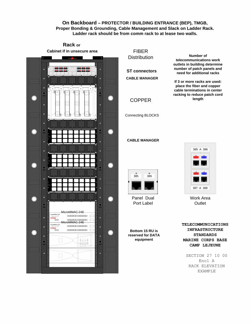
SIEMON SYSTEMcabling
SDTHE SIEMON COMPANY
SD SD SD SD SD
SD
THESIEMONCOMPANY
1 2
3 4
5 6
7 8
9 10
11 12
13 14
15 16
17 18
19 20
21 22
23 24
25 26
27 28
29 30
31 32
33 34
35 36
37 38
39 40
41 42
43 44
45 46
47 48
SDTHE SIEMON COMPANY
SD SD SD SD SD
SDTHE SIEMON COMPANY
SD SD SD SD SD
SDTHE SIEMON COMPANY
SD SD SD SD SD
SD
CABLE MANAGER
CABLE MANAGER
TELECOMMUNICATIONS INFRASTRUCTURE
STANDARDS MARINE CORPS BASE
CAMP LEJEUNE
SECTION 27 10 00 Encl A
RACK ELEVATION EXAMPLE
SDTHE SIEMON COMPANY
SD SD SD SD SD
FIBER Distribution
COPPER
Connecting BLOCKS
MicroMMAC-24EMicroMMAC-24E
EPIM
EPIM
MicroMMAC-24EMicroMMAC-24E
EPIM
EPIM
ST connectorsA
B
C
D
On Backboard – PROTECTOR / BUILDING ENTRANCE (BEP), TMGB,Proper Bonding & Grounding, Cable Management and Slack on Ladder Rack.
Ladder rack should be from comm rack to at lease two walls.
Rack or Cabinet if in unsecure area
Number of telecommunications work
outlets in building determine number of patch panels and
need for additional racks
If 3 or more racks are used: place the fiber and copper
cable terminations in center racking to reduce patch cord
length
Bottom 15 RU is reserved for DATA
equipment
SD
THESIEMONCOMPANY
1 2
3 4
5 6
7 8
9 10
11 12
13 14
15 16
17 18
19 20
21 22
23 24
25 26
27 28
29 30
31 32
33 34
35 36
37 38
39 40
41 42
43 44
45 46
47 48
SD
THESIEMONCOMPANY
1 2
3 4
5 6
7 8
9 10
11 12
13 14
15 16
17 18
19 20
21 22
23 24
25 26
27 28
29 30
31 32
33 34
35 36
37 38
39 40
41 42
43 44
45 46
47 48
Work Area Outlet
387 A 388
385 A 386
Panel Dual Port Label
385 386

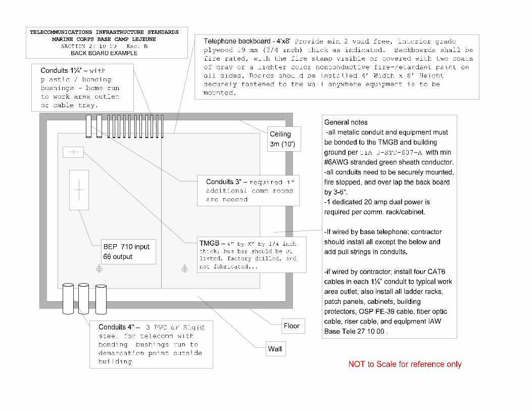

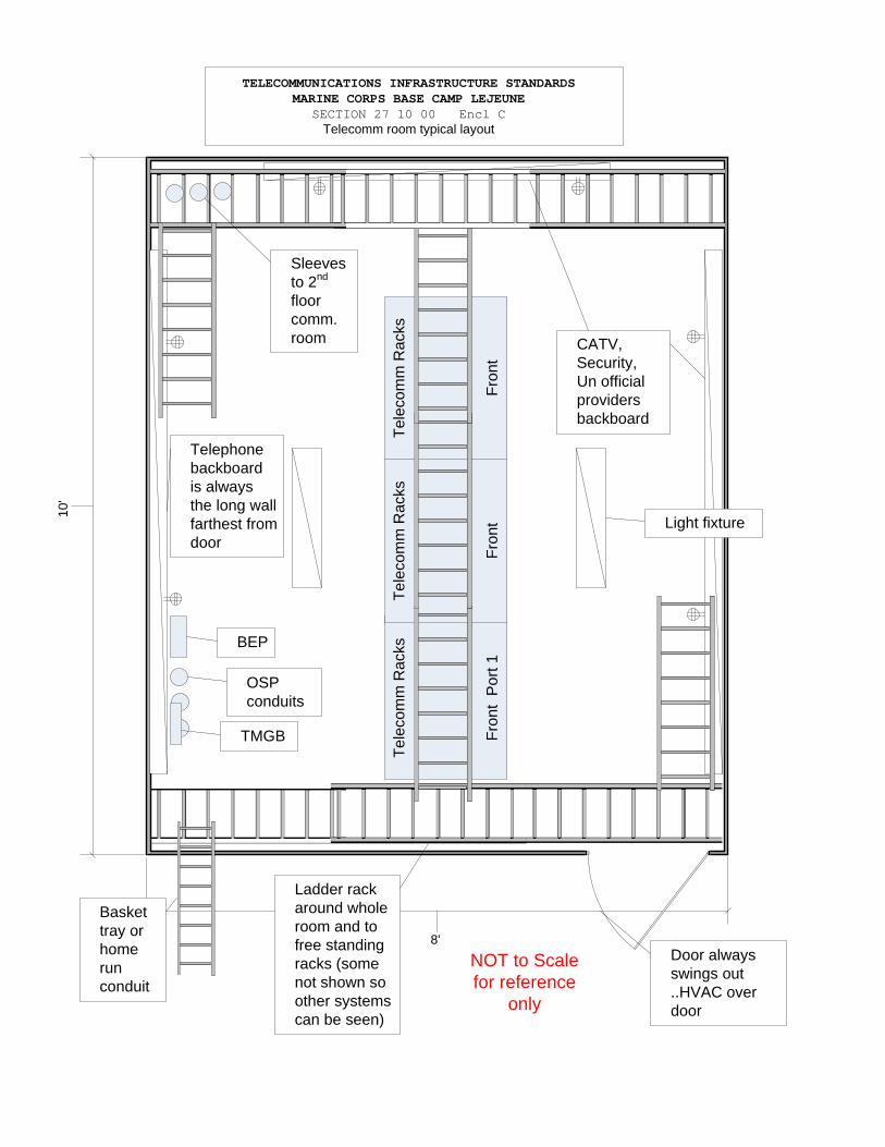
Tele
com
m R
acks
Fron
t P
ort 1
10'
8'
Telephone backboard is always the long wall farthest from door
CATV, Security,Un official providers backboard
Ladder rack around whole room and to free standing racks (some not shown so other systems can be seen)
Door always swings out ..HVAC over door
Tele
com
m R
acks
Fron
t
Tele
com
m R
acks
Fron
t
TMGB
OSP conduits
Sleeves to 2nd
floor comm. room
BEP
NOT to Scale for reference
only
TELECOMMUNICATIONS INFRASTRUCTURE STANDARDS MARINE CORPS BASE CAMP LEJEUNE
SECTION 27 10 00 Encl CTelecomm room typical layout
Light fixture
Basket tray or home run conduit

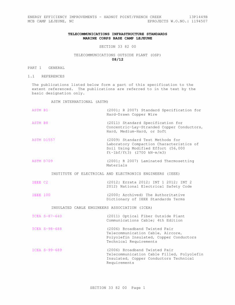
ENERGY EFFICIENCY IMPROVEMENTS - HADNOT POINT/FRENCH CREEK 13P1449BMCB CAMP LEJEUNE, NC EPROJECTS W.O.NO.: 1194507
TELECOMMUNICATIONS INFRASTRUCTURE STANDARDSMARINE CORPS BASE CAMP LEJEUNE
SECTION 33 82 00
TELECOMMUNICATIONS OUTSIDE PLANT (OSP)08/12
PART 1 GENERAL
1.1 REFERENCES
The publications listed below form a part of this specification to the extent referenced. The publications are referred to in the text by the basic designation only.
ASTM INTERNATIONAL (ASTM)
ASTM B1 (2001; R 2007) Standard Specification for Hard-Drawn Copper Wire
ASTM B8 (2011) Standard Specification for Concentric-Lay-Stranded Copper Conductors, Hard, Medium-Hard, or Soft
ASTM D1557 (2009) Standard Test Methods for Laboratory Compaction Characteristics of Soil Using Modified Effort (56,000 ft-lbf/ft3) (2700 kN-m/m3)
ASTM D709 (2001; R 2007) Laminated Thermosetting Materials
INSTITUTE OF ELECTRICAL AND ELECTRONICS ENGINEERS (IEEE)
IEEE C2 (2012; Errata 2012; INT 1 2012; INT 2 2012) National Electrical Safety Code
IEEE 100 (2000; Archived) The Authoritative Dictionary of IEEE Standards Terms
INSULATED CABLE ENGINEERS ASSOCIATION (ICEA)
ICEA S-87-640 (2011) Optical Fiber Outside Plant Communications Cable; 4th Edition
ICEA S-98-688 (2006) Broadband Twisted Pair Telecommunication Cable, Aircore, Polyolefin Insulated, Copper Conductors Technical Requirements
ICEA S-99-689 (2006) Broadband Twisted Pair Telecommunication Cable Filled, Polyolefin Insulated, Copper Conductors Technical Requirements
SECTION 33 82 00 Page 1
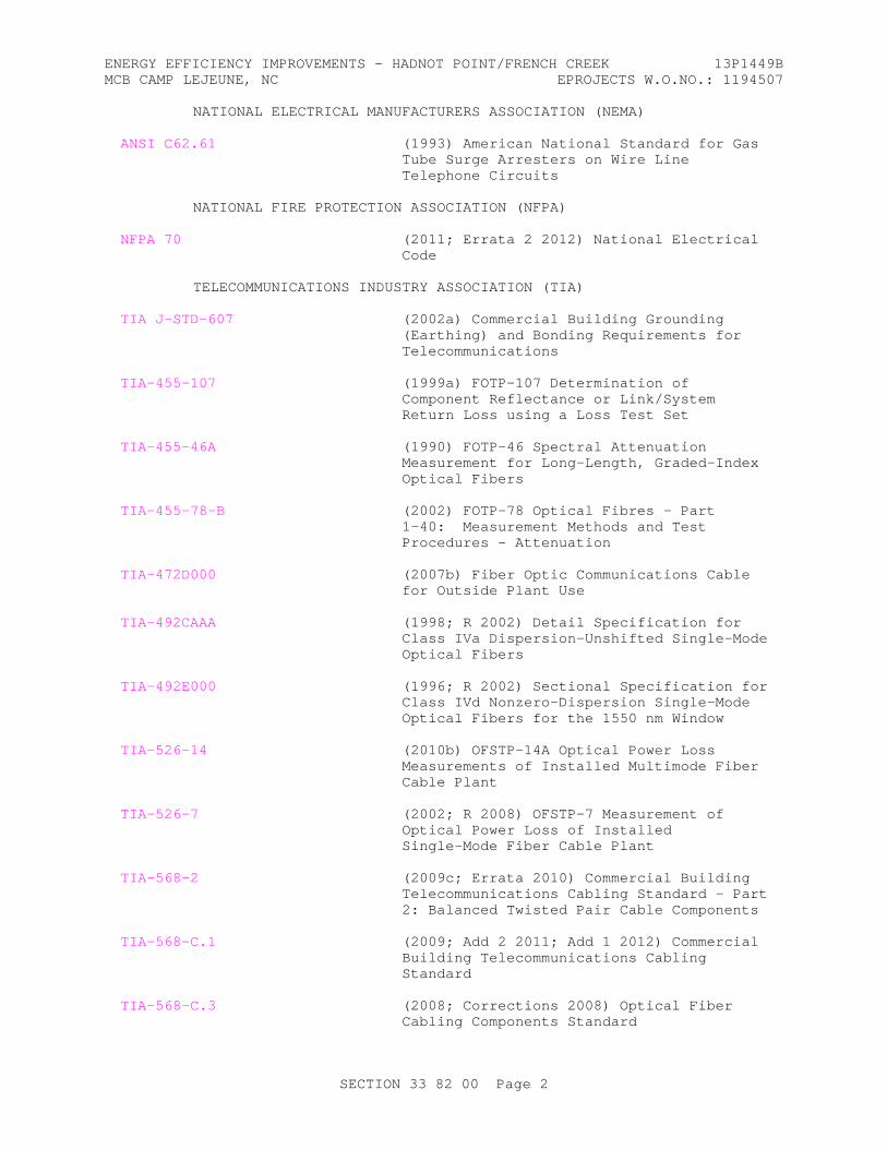
ENERGY EFFICIENCY IMPROVEMENTS - HADNOT POINT/FRENCH CREEK 13P1449BMCB CAMP LEJEUNE, NC EPROJECTS W.O.NO.: 1194507
NATIONAL ELECTRICAL MANUFACTURERS ASSOCIATION (NEMA)
ANSI C62.61 (1993) American National Standard for Gas Tube Surge Arresters on Wire Line Telephone Circuits
NATIONAL FIRE PROTECTION ASSOCIATION (NFPA)
NFPA 70 (2011; Errata 2 2012) National Electrical Code
TELECOMMUNICATIONS INDUSTRY ASSOCIATION (TIA)
TIA J-STD-607 (2002a) Commercial Building Grounding (Earthing) and Bonding Requirements for Telecommunications
TIA-455-107 (1999a) FOTP-107 Determination of Component Reflectance or Link/System Return Loss using a Loss Test Set
TIA-455-46A (1990) FOTP-46 Spectral Attenuation Measurement for Long-Length, Graded-Index Optical Fibers
TIA-455-78-B (2002) FOTP-78 Optical Fibres - Part 1-40: Measurement Methods and Test Procedures - Attenuation
TIA-472D000 (2007b) Fiber Optic Communications Cable for Outside Plant Use
TIA-492CAAA (1998; R 2002) Detail Specification for Class IVa Dispersion-Unshifted Single-Mode Optical Fibers
TIA-492E000 (1996; R 2002) Sectional Specification for Class IVd Nonzero-Dispersion Single-Mode Optical Fibers for the 1550 nm Window
TIA-526-14 (2010b) OFSTP-14A Optical Power Loss Measurements of Installed Multimode Fiber Cable Plant
TIA-526-7 (2002; R 2008) OFSTP-7 Measurement of Optical Power Loss of Installed Single-Mode Fiber Cable Plant
TIA-568-2 (2009c; Errata 2010) Commercial Building Telecommunications Cabling Standard - Part 2: Balanced Twisted Pair Cable Components
TIA-568-C.1 (2009; Add 2 2011; Add 1 2012) Commercial Building Telecommunications Cabling Standard
TIA-568-C.3 (2008; Corrections 2008) Optical Fiber Cabling Components Standard
SECTION 33 82 00 Page 2
ENERGY EFFICIENCY IMPROVEMENTS - HADNOT POINT/FRENCH CREEK 13P1449BMCB CAMP LEJEUNE, NC EPROJECTS W.O.NO.: 1194507
TIA-569 (2012c) Commercial Building Standard for Telecommunications Pathways and Spaces
TIA-590 (1997a) Standard for Physical Location and Protection of Below Ground Fiber Optic Cable Plant
TIA-758 (2012b) Customer-Owned Outside Plant Telecommunications Infrastructure Standard
TIA/EIA-455 (1998b) Standard Test Procedure for Fiber Optic Fibers, Cables, Transducers, Sensors, Connecting and Terminating Devices, and Other Fiber Optic Components
TIA/EIA-455-204 (2000) Standard for Measurement of Bandwidth on Multimode Fiber
TIA/EIA-598 (2005c) Optical Fiber Cable Color Coding
TIA/EIA-606 (2002a; Errata 2007; R 2007; Adm 1 2008) Administration Standard for the Telecommunications Infrastructure
THE SOCIETY FOR PROTECTIVE COATINGS (SSPC)
SSPC SP 6/NACE No.3 (2007) Commercial Blast Cleaning
U.S. DEPARTMENT OF AGRICULTURE (USDA)
RUS 1755 Telecommunications Standards and Specifications for Materials, Equipment and Construction
RUS Bull 1751F-630 (1996) Design of Aerial Plant
RUS Bull 1751F-640 (1995) Design of Buried Plant, Physical Considerations
RUS Bull 1751F-643 (2002) Underground Plant Design
RUS Bull 1751F-815 (1979) Electrical Protection of Outside Plant
RUS Bull 1753F-201 (1997) Acceptance Tests of Telecommunications Plant (PC-4)
RUS Bull 1753F-401 (1995) Splicing Copper and Fiber Optic Cables (PC-2)
RUS Bull 345-50 (1979) Trunk Carrier Systems (PE-60)
RUS Bull 345-65 (1985) Shield Bonding Connectors (PE-65)
RUS Bull 345-72 (1985) Filled Splice Closures (PE-74)
RUS Bull 345-83 (1979; Rev Oct 1982) Gas Tube Surge Arrestors (PE-80)
SECTION 33 82 00 Page 3
ENERGY EFFICIENCY IMPROVEMENTS - HADNOT POINT/FRENCH CREEK 13P1449BMCB CAMP LEJEUNE, NC EPROJECTS W.O.NO.: 1194507
UNDERWRITERS LABORATORIES (UL)
UL 497 (2001; Reprint Apr 2009) Protectors for Paired Conductor Communication Circuits
UL 510 (2005; Reprint Apr 2008) Polyvinyl Chloride, Polyethylene and Rubber Insulating Tape
UL 83 (2008) Thermoplastic-Insulated Wires and Cables
1.2 RELATED REQUIREMENTS
Section 27 10 00 BUILDING TELECOMMUNICATIONS CABLING SYSTEM, and D-B Contractor prepared Section 33 71 01 OVERHEAD TRANSMISSION AND DISTRIBUTION, and D-B Contractor prepared Section 33 71 02.00 20 UNDERGROUND ELECTRICAL DISTRIBUTION apply to this section with additions and modifications specified herein.
1.3 DEFINITIONS
Unless otherwise specified or indicated, electrical and electronics terms used in this specification shall be as defined in TIA-568-C.1, TIA-568-2, TIA-568-C.3, TIA-569, TIA/EIA-606, and IEEE 100 and herein.
1.3.1 Campus Distributor (CD)
A distributor from which the campus backbone cabling emanates. (International expression for main cross-connect - (MC).) On Camp Lejeune the main cross-connect is established in network operation centers, owned by Base Telephone, serving predestinated areas of the base. Designers should not design any new main cross-connects without approval from Base Telephone. The campus backbone is outside plant back to Base Telephone network operations center.
1.3.2 Entrance Facility (EF) (Telecommunications)
An entrance to the building for both private and public network service cables (including antennae) including the entrance point at the building wall and continuing to the entrance room or space.
1.3.3 Entrance Room (ER)
A centralized space for telecommunications equipment that serves the occupants of a building. Equipment housed therein is considered distinct from a telecommunications room because of the nature of its complexity.
1.3.4 Building Distributor (BD)
A distributor in which the building backbone cables terminate and at which connections to the campus backbone cables may be made. (International expression for intermediate cross-connect - (IC).)
1.3.5 Pathway
A physical infrastructure utilized for the placement and routing of telecommunications cable.
SECTION 33 82 00 Page 4
ENERGY EFFICIENCY IMPROVEMENTS - HADNOT POINT/FRENCH CREEK 13P1449BMCB CAMP LEJEUNE, NC EPROJECTS W.O.NO.: 1194507
1.4 SYSTEM DESCRIPTION
The telecommunications outside plant consists of cable, conduit, manholes, etc. required to provide signal paths from the closest point of presence to the new facility, including free standing frames or backboards, interconnecting hardware, terminating cables, lightning and surge protection modules at the entrance facility. The work consists of providing, testing and making operational cabling, interconnecting hardware and lightning and surge protection necessary to form a complete outside plant telecommunications system for continuous use. The telecommunications contractor must coordinate with Base Telephone concerning layout and configuration of the EF telecommunications and OSP. The telecommunications contractor may be required to coordinate work effort for access to the EF telecommunications and OSP with Base Telephone.
1.5 SUBMITTALS
Government approval is required for submittals with a "G" designation; submittals not having a "G" designation are for Contractor Quality Control approval. The following shall be submitted in accordance with Section 01 33 00.05 20 CONSTRUCTION SUBMITTAL PROCEDURES and Section 01 33 10.05 20 DESIGN SUBMITTAL PROCEDURES:
a. Submittals shall include the manufacturer's name, trade name, place of manufacture, and catalog model or number. Submittals shall also include applicable federal, military, industry, and technical society publication references. Should manufacturer's data require supplemental information for clarification, the supplemental information shall be submitted as specified in paragraph "Regulatory Requirements" and as required for certificates in Section 01 33 00.05 20 CONSTRUCTION SUBMITTAL PROCEDURES and Section 01 33 10.05 20 DESIGN SUBMITTAL PROCEDURES.
b. Commercial off-the-shelf manuals shall be provided for operation, installation, configuration, and maintenance of products provided as a part of the telecommunications outside plant (OSP). Submit operations and maintenance data in accordance with Section 01 78 23 OPERATION AND MAINTENANCE DATA and Section 01 78 24.00 20 FACILITY ELECTRONIC OPERATION AND MAINTENANCE SUPPORT INFORMATION (eOMSI), and as specified herein not later than 2 months prior to the date of beneficial occupancy. In addition to requirements of Section 01 78 23 OPERATION AND MAINTENANCE DATA and Section 01 78 24.00 20 FACILITY ELECTRONIC OPERATION AND MAINTENANCE SUPPORT INFORMATION (eOMSI), include the requirements of paragraphs "Telecommunications Outside Plant Shop Drawings" and "Telecommunications Entrance Facility Drawings."
SD-02 Shop Drawings
Telecommunications Outside Plant; G
Telecommunications Entrance Facility Drawings; G
SD-03 Product Data
Wire and cable; G
Cable splices, and connectors; G
Closures; G
SECTION 33 82 00 Page 5
ENERGY EFFICIENCY IMPROVEMENTS - HADNOT POINT/FRENCH CREEK 13P1449BMCB CAMP LEJEUNE, NC EPROJECTS W.O.NO.: 1194507
Building protector assemblies; G
Protector modules; G
Cross-connect terminal cabinets; G
Spare Parts; G
SD-06 Test Reports
Pre-installation tests; G
Acceptance tests; G
Outside Plant Test Plan; G
SD-07 Certificates
Telecommunications Contractor Qualifications; G
Key Personnel Qualifications; G
Minimum Manufacturer's Qualifications; G
SD-08 Manufacturer's Instructions
Building protector assembly installation; G
Cable tensions; G
Fiber Optic Splices; G
Submit instructions prior to installation.
SD-09 Manufacturer's Field Reports
Factory Reel Test Data; G
SD-10 Operation and Maintenance Data
Telecommunications outside plant (OSP), Data Package 5; G
SD-11 Closeout Submittals
Record Documentation; G
In addition to other requirements, provide in accordance with paragraph "Record Documentation".
1.5.1 Additional Submittal Requirements
All submittals of material, equipment and design must be approved by the Base Telephone Office prior to installing any telecommunications cabling and equipment.
SECTION 33 82 00 Page 6
ENERGY EFFICIENCY IMPROVEMENTS - HADNOT POINT/FRENCH CREEK 13P1449BMCB CAMP LEJEUNE, NC EPROJECTS W.O.NO.: 1194507
1.6 QUALITY ASSURANCE
1.6.1 Shop Drawings
Include wiring diagrams and installation details of equipment indicating proposed location, layout and arrangement, control panels, accessories, piping, ductwork, and other items that must be shown to ensure a coordinated installation. Wiring diagrams shall identify circuit terminals and indicate the internal wiring for each item of equipment and the interconnection between each item of equipment. Drawings shall indicate adequate clearance for operation, maintenance, and replacement of operating equipment devices. Submittals shall include the nameplate data, size, and capacity. Submittals shall also include applicable federal, military, industry, and technical society publication references.
1.6.1.1 Telecommunications Outside Plant Shop Drawings
Provide Outside Plant Design in accordance with TIA-758, RUS Bull 1751F-630 for aerial system design, RUS Bull 1751F-643 for underground duct system design and for direct buried system design. Provide T0 shop drawings that show the physical and logical connections from the perspective of an entire campus, such as actual building locations, exterior pathways and campus backbone cabling on plan view drawings, major system nodes, and related connections on the logical system drawings in accordance with TIA/EIA-606. Drawings shall include wiring and schematic diagrams for fiber optic and copper cabling and splices, copper conductor gauge and pair count, fiber pair count and type, pathway duct and innerduct arrangement, associated construction materials, and any details required to demonstrate that cable system has been coordinated and will properly support the switching and transmission system identified in specification and drawings. Provide Registered Communications Distribution Designer (RCDD) approved drawings of the telecommunications outside plant. Update existing telecommunication Outside Plant T0 drawings to include information modified, deleted or added as a result of this installation in accordance with TIA/EIA-606. The telecommunications outside plant (OSP) shop drawings shall be included in the operation and maintenance manuals.
1.6.1.2 Telecommunications Entrance Facility Drawings
Provide T3 drawings for EF Telecommunications in accordance with TIA/EIA-606 that include telecommunications entrance facility plan views, pathway layout (cable tray, racks, ladder-racks, etc.), mechanical/electrical layout, and cabinet, rack, backboard, and wall elevations. Drawings shall show layout of applicable equipment including building protector assembly, incoming cable connector blocks, patch panels and equipment spaces, and cabinet/racks. Drawings shall include a complete list of equipment and material, equipment rack details, proposed layout and anchorage of equipment and appurtenances, and equipment relationship to other parts of the work including clearance for maintenance and operation. Drawings may also be an enlargement of a congested area of T1 or T2 drawings. Provide T3 drawings for EF Telecommunications as specified in the paragraph "Telecommunication Space Drawings" of Section 27 10 00 BUILDING TELECOMMUNICATIONS CABLING SYSTEM. The telecommunications entrance facility shop drawings shall be included in the operation and maintenance manuals.
1.6.2 Telecommunications Qualifications
Work under this section shall be performed by and the equipment shall be
SECTION 33 82 00 Page 7
ENERGY EFFICIENCY IMPROVEMENTS - HADNOT POINT/FRENCH CREEK 13P1449BMCB CAMP LEJEUNE, NC EPROJECTS W.O.NO.: 1194507
provided by the approved telecommunications contractor and key personnel. Qualifications shall be provided for: the telecommunications system contractor, the telecommunications system installer, the supervisor (if different from the installer), and the cable splicing and terminating personnel. A minimum of 30 days prior to installation, submit documentation of the experience of the telecommunications contractor and of the key personnel.
1.6.2.1 Telecommunications Contractor Qualifications
The telecommunications contractor shall be a firm which is regularly and professionally engaged in the business of the applications, installation, and testing of the specified telecommunications systems and equipment. The telecommunications contractor shall demonstrate experience in providing successful telecommunications systems that include outside plant and broadband cabling within the past 3 years. Submit documentation for a minimum of three and a maximum of five successful telecommunication system installations for the telecommunications contractor. Each of the key personnel shall demonstrate experience in providing successful telecommunications systems in accordance with TIA-758 within the past 3 years.
1.6.2.2 Key Personnel Qualifications
Provide key personnel who are regularly and professionally engaged in the business of the application, installation and testing of the specified telecommunications systems and equipment. There may be one key person or more key persons proposed for this solicitation depending upon how many of the key roles each has successfully provided. Each of the key personnel shall demonstrate experience in providing successful telecommunications systems within the past 3 years.
Cable splicing and terminating personnel assigned to the installation of this system or any of its components shall have training in the proper techniques and have a minimum of 3 years experience in splicing and terminating the specified cables. Modular splices shall be performed by factory certified personnel or under direct supervision of factory trained personnel for products used.
Supervisors and installers assigned to the installation of this system or any of its components shall have factory or factory approved certification from each equipment manufacturer indicating that they are qualified to install and test the provided products.
Submit documentation for a minimum of three and a maximum of five successful telecommunication system installations for each of the key personnel. Documentation for each key person shall include at least two successful system installations provided that are equivalent in system size and in construction complexity to the telecommunications system proposed for this solicitation. Include specific experience in installing and testing telecommunications outside plant systems, including broadband cabling, and provide the names and locations of at least two project installations successfully completed using optical fiber and copper telecommunications cabling systems. All of the existing telecommunications system installations offered by the key persons as successful experience shall have been in successful full-time service for at least 18 months prior to the issuance date for this solicitation. Provide the name and role of the key person, the title, location, and completed installation date of the referenced project, the referenced project owner point of
SECTION 33 82 00 Page 8
ENERGY EFFICIENCY IMPROVEMENTS - HADNOT POINT/FRENCH CREEK 13P1449BMCB CAMP LEJEUNE, NC EPROJECTS W.O.NO.: 1194507
contact information including name, organization, title, and telephone number, and generally, the referenced project description including system size and construction complexity.
Indicate that all key persons are currently employed by the telecommunications contractor, or have a commitment to the telecommunications contractor to work on this project. All key persons shall be employed by the telecommunications contractor at the date of issuance of this solicitation, or if not, have a commitment to the telecommunications contractor to work on this project by the date that the bid was due to the Contracting Officer.
Note that only the key personnel approved by the Contracting Officer in the successful proposal shall do work on this solicitation's telecommunications system. Key personnel shall function in the same roles in this contract, as they functioned in the offered successful experience. Any substitutions for the telecommunications contractor's key personnel requires approval from the Contracting Officer.
1.6.2.3 Minimum Manufacturer's Qualifications
Cabling, equipment and hardware manufacturers shall have a minimum of 3 years experience in the manufacturing, assembly, and factory testing of components which comply with, TIA-568-C.1, TIA-568-2 and TIA-568-C.3. In addition, cabling manufacturers shall have a minimum of 3 years experience in the manufacturing and factory testing of cabling which comply with ICEA S-87-640, ICEA S-98-688, and ICEA S-99-689.
1.6.3 Outside Plant Test Plan
Prepare and provide a complete and detailed test plan for field tests of the outside plant including a complete list of test equipment for the copper conductor and optical fiber cables, components, and accessories for approval by Base Telephone via the Contracting Officer. Include a cut-over plan with procedures and schedules for relocation of facility station numbers without interrupting service to any active location. Submit the plan at least 30 days prior to tests for Contracting Officer approval. Provide outside plant testing and performance measurement criteria in accordance with TIA-568-C.1 and RUS Bull 1753F-201. Include procedures for certification, validation, and testing that includes fiber optic link performance criteria.
1.6.4 Standard Products
Provide materials and equipment that are standard products of manufacturers regularly engaged in the production of such products which are of equal material, design and workmanship and shall be the manufacturer's latest standard design that has been in satisfactory commercial or industrial use for at least two years prior to bid opening. The two year period shall include applications of equipment and materials under similar circumstances and of similar size. The product shall have been on sale on the commercial market through advertisements, manufacturer's catalogs, or brochures during the two year period. Products supplied shall be specifically designed and manufactured for use with outside plant telecommunications systems. Where two or more items of the same class of equipment are required, these items shall be products of a single manufacturer; however, the component parts of the item need not be the products of the same manufacturer unless stated in this section. Product submission must be approved for use prior to install by Base Telephone via the Contracting Officer.
SECTION 33 82 00 Page 9
ENERGY EFFICIENCY IMPROVEMENTS - HADNOT POINT/FRENCH CREEK 13P1449BMCB CAMP LEJEUNE, NC EPROJECTS W.O.NO.: 1194507
1.6.4.1 Alternative Qualifications
Products having less than a two-year field service record will be acceptable if a certified record of satisfactory field operation for not less than 6000 hours, exclusive of the manufacturer's factory or laboratory tests, is provided.
1.6.4.2 Material and Equipment Manufacturing Date
Products manufactured more than 3 years prior to date of delivery to site shall not be used, unless specified otherwise.
1.6.5 Regulatory Requirements
In each of the publications referred to herein, consider the advisory provisions to be mandatory, as though the word, "shall" had been substituted for "should" wherever it appears. Interpret references in these publications to the "authority having jurisdiction," or words of similar meaning, to mean Base Telephone via the Contracting Officer. Equipment, materials, installation, and workmanship shall be in accordance with the mandatory and advisory provisions of NFPA 70 unless more stringent requirements are specified or indicated.
1.6.5.1 Independent Testing Organization Certificate
In lieu of the label or listing, submit a certificate from an independent testing organization, competent to perform testing, and approved by the Contracting Officer. The certificate shall state that the item has been tested in accordance with the specified organization's test methods and that the item complies with the specified organization's reference standard.
1.7 DELIVERY, STORAGE, AND HANDLING
Ship cable on reels in 5000 foot lengths for 25, 50 or 100 pair configuration and 1250 feet length for larger cables. Radius of the reel drum shall not be smaller than the minimum bend radius of the cable. Wind cable on the reel so that unwinding can be done without kinking the cable. Two meters of cable at both ends of the cable shall be accessible for testing. Attach permanent label on each reel showing length, cable identification number, cable size, cable type, and date of manufacture. Provide water resistant label and the indelible writing on the labels. Apply end seals to each end of the cables to prevent moisture from entering the cable. Reels with cable shall be suitable for outside storage conditions when temperature ranges from minus 40 degrees C to plus 65 degrees C, with relative humidity from 0 to 100 percent. Equipment, other than cable, delivered and placed in storage shall be stored with protection from weather, humidity and temperature variation, dirt and dust, or other contaminants in accordance with manufacturer's requirements.
1.8 MAINTENANCE
1.8.1 Record Documentation
Provide the activity responsible for telecommunications system maintenance and administration (Base Telephone via the Contracting Officer) a single complete and accurate set of record documentation for the entire telecommunications system with respect to this project.
SECTION 33 82 00 Page 10
ENERGY EFFICIENCY IMPROVEMENTS - HADNOT POINT/FRENCH CREEK 13P1449BMCB CAMP LEJEUNE, NC EPROJECTS W.O.NO.: 1194507
Provide record documentation as specified in Section 27 10 00 BUILDING TELECOMMUNICATIONS CABLING SYSTEM.
Provide T5 drawings including documentation on cables and termination hardware in accordance with TIA/EIA-606. T5 drawings shall include schedules to show information for cut-over and cable plant management, patch panel layouts, cross-connect information and connecting terminal layout as a minimum. T5 drawings shall be provided in both hard copy format and on electronic media using Windows based computer cable management software. A licensed copy of the cable management software including documentation shall be provided. Update existing record documentation to reflect campus distribution T0 drawings and T3 drawing schedule information modified, deleted or added as a result of this installation. Provide the following T5 drawing documentation as a minimum:
a. Cables - A record of installed cable shall be provided in accordance with TIA/EIA-606. The cable records shall include only the required data fields on the hard copy and the required data fields for each cable and complete end-to-end circuit report for each complete circuit from the assigned outlet to the entry facility for the soft copy in accordance with TIA/EIA-606. Include manufacture date of cable with submittal.
b. Termination Hardware - Provide a record of installed patch panels, cross-connect points, campus distributor and terminating block arrangements and type in accordance with TIA/EIA-606. Documentation shall include the required data fields in accordance with TIA/EIA-606.
1.8.2 Spare Parts
In addition to the requirements of Section 01 78 23 OPERATION AND MAINTENANCE DATA and Section 01 78 24.00 20 FACILITY ELECTRONIC OPERATION AND MAINTENANCE SUPPORT INFORMATION (eOMSI), provide a complete list of parts and supplies, with current unit prices and source of supply, and a list of spare parts recommended for stocking. Spare parts shall be provided no later than the start of field testing.
1.9 WARRANTY
The equipment items shall be supported by service organizations which are reasonably convenient to the equipment installation in order to render satisfactory service to the equipment on a regular and emergency basis during the warranty period of the contract.
PART 2 PRODUCTS
2.1 MATERIALS AND EQUIPMENT
Products supplied shall be specifically designed and manufactured for use with outside plant telecommunications systems. All product data must be supplied in the submittal process and no product can be used without approval from Base Telephone via the Contracting Officer.
2.2 TELECOMMUNICATIONS ENTRANCE FACILITY
2.2.1 Building Protector Assemblies
Building protector assembly shall be self-contained and have interconnecting hardware (710 input and 66 output) for connection to
SECTION 33 82 00 Page 11
ENERGY EFFICIENCY IMPROVEMENTS - HADNOT POINT/FRENCH CREEK 13P1449BMCB CAMP LEJEUNE, NC EPROJECTS W.O.NO.: 1194507
exterior cabling at full capacity. Provide manufacturers instructions for building protector assembly installation. Provide copper cable interconnecting hardware as specified in Section 27 10 00 BUILDING TELECOMMUNICATIONS CABLING SYSTEM. There will be no service loops or splicing of copper cable outside of the building protector assembly.
2.2.2 Protector Modules
Provide in accordance with UL 497 three-electrode gas tube or solid state type, 5 pin rated for the application. Provide gas tube protection modules in accordance with RUS Bull 345-83 and shall be heavy duty, A>10kA, B>400, C>65A, where A is the maximum single impulse discharge current, B is the impulse life and C is the AC discharge current in accordance with ANSI C62.61. The gas modules shall shunt high voltage to ground, fail short, and be equipped with an external spark gap and heat coils in accordance with UL 497. Provide the number of surge protection modules equal to the number of pairs of exterior cable of the building protector assembly.
2.2.3 Fiber Optic Terminations
Provide fiber optic cable terminations as specified in Section 27 10 00 BUILDING TELECOMMUNICATIONS CABLING SYSTEM.
2.2.4 Pathways
Underground applications for single buildings: provide a minimum of three (3) four inch ducts, one of which contains (2)- three cell fabric or (4)- 1" HDDPE inner ducts. The underground ducts must have 3" concrete encasing (orange in color), 24 inches below grade minimum from the Telecommunications Entrance Facility to the maintenance hole that will be providing service to the building (Demarcation point). For campus distribution between maintenance holes ducts may need to be 5" or 6" to support larger cables. Also there will be no less than 4 and up to 50 ducts as needed for distribution to the area serviced. All new ducts will be plugged at both ends with a backing and a thin layer of hydraulic cement and visibly marked or provided on area map with GPS coordinates.
For direct buried applications, provide a minimum of three (3) four inch ducts from the Telecommunications Entrance Facility to outside the building footprint past any obstructions, footers, or sidewalks by at least 5 feet into clear soil / entryway, 24 inches below grade. The ducts will be plugged at both ends and clearly marked on outside end. For distribution to demarcation, between handholes, and riser points, cables need to be 36" below grade with metal locating tape at 24" below grade. Cables need to be in HDDPE direct bored, concrete encased in conduit, or concrete encased split duct under all roadways and pavement. All new cables need to be provided on area map with GPS coordinates for riser points or handholes.
Handholes and maintenance holes shall be traffic rated (MIN tier 22). Handhole size min 4'x4'x4'. Maintenance hole size min 6'x7'x8' and all penetrations should be splayed.
SECTION 33 82 00 Page 12
ENERGY EFFICIENCY IMPROVEMENTS - HADNOT POINT/FRENCH CREEK 13P1449BMCB CAMP LEJEUNE, NC EPROJECTS W.O.NO.: 1194507
2.3 CLOSURES
2.3.1 Copper Conductor Closures
2.3.1.1 Aerial Cable Closures (Off-Base)
Provide cable closure assembly consisting of a frame with clamps, a lift-off polyethylene cover, cable nozzles, and drop wire rings. Closure shall be suitable for use on Figure 8 cables. Closures shall be free breathing and suitable for housing either straight-through type or the branch type splices of non-pressurized communications cables and shall be sized as indicated. The closure shall be constructed with ultraviolet resistant PVC.
NOTE: The installation of aerial telecommunications cabling aboard Marine Corps Base, Camp Lejeune and Marine Corps Air Station, New River is not authorized.
2.3.1.2 Underground Cable Closures
a. Aboveground. Provide aboveground closures constructed of not less than 14 gauge steel and acceptable pole or stake mounting in accordance with RUS 1755.910. Closures shall be sized and contain a marker as indicated. Covers shall be secured to prevent unauthorized entry. PVC type closures are to be used in beach areas. All pedestals shall contain a minimum 4 foot x 3/8 inch pigtailed ground rod.
b. Direct burial. Provide buried closure suitable for enclosing a straight, butt, and branch splice in a container into which can be poured an encapsulating compound. Closure shall have adequate strength to protect the splice and maintain cable shield electrical continuity in the buried environment. Encapsulating compound shall be re-enterable and shall not alter the chemical stability of the closure. Provide filled splice cases in accordance with RUS Bull 345-72.
c. In vault or manhole. Provide underground closure suitable to house a straight, butt, and branch splice in a protective housing into which air can be pumped for flash testing. Closure shall be of suitable thermoplastic, thermoset, or stainless steel material supplying structural strength necessary to pass the mechanical and electrical requirements in a vault or manhole environment. Heat shrinkable type closures should not be used in vault or manhole. Provide splice cases in accordance with RUS Bull 345-72.
2.3.2 Fiber Optic Closures
2.3.2.1 Aerial (Off-Base)
Provide aerial closure that is free breathing and suitable for housing splice organizer of non-pressurized cables. Closure shall be constructed from heavy PVC with ultraviolet resistance.
NOTE: The installation of aerial telecommunications cabling aboard Marine Corps Base, Camp Lejeune and Marine Corps Air Station, New River is not authorized.
2.3.2.2 Direct Burial
Provide buried closure suitable to house splice organizer in protective
SECTION 33 82 00 Page 13
ENERGY EFFICIENCY IMPROVEMENTS - HADNOT POINT/FRENCH CREEK 13P1449BMCB CAMP LEJEUNE, NC EPROJECTS W.O.NO.: 1194507
housing into which can be poured an encapsulating compound. Closure shall have adequate strength to protect the splice and maintain cable shield electrical continuity, when metallic, in buried environment. Encapsulating compound shall be reenterable and shall not alter chemical stability of the closure.
2.3.2.3 Vaults or Manholes
Provide underground closure suitable to house splice organizer in a protective housing into which air can be pumped for flash testing. Closure shall be of thermoplastic, thermoset, or stainless steel material supplying structural strength necessary to pass the mechanical and electrical requirements in a vault or manhole environment. Provide 60' slack coils on fiber in every 3rd manhole / handhole or in any which a turn is made.
2.4 PAD MOUNTED CROSS-CONNECT TERMINAL CABINETS
Provide in accordance with RUS 1755.910 and the following:
a. Constructed of 14 gauge steel.
b. Equipped with a double set of hinged doors with closed-cell foam weatherstripping. Doors shall be locked and contain a marker as indicated.
c. Equipped with spool spindle bracket, mounting frames, binding post log, jumpering instruction label, and load coil mounting provisions.
d. Complete with cross connect modules to terminate number of pairs as indicated.
e. Sized as indicated.
2.5 CABLE SPLICES, AND CONNECTORS
2.5.1 Copper Cable Splices
In vaults or manholes provide multi-pair, in-line fold back or single pair, in-line splices of a moisture resistant, three-wire insulation displacement connector held rigidly in place to assure maximum continuity in accordance with RUS Bull 1753F-401. Cables greater than 25 pairs shall be spliced using multi-pair splicing connectors, which accommodate 25 pairs of conductors at a time. Provide correct connector size to accommodate the cable gauge of the supplied cable. Provide enough cable slack suitable for splicing operations, but in no case less than 10 feet. In above ground splices use three wire insulation displacement single pair connectors no matter what size the cable.
2.5.2 Copper Cable Splice Connector
Provide splice connectors with a polycarbonate body and cap and a tin-plated brass contact element. Connector shall accommodate 19 to 26 AWG solid wire with a maximum insulation diameter of 0.065 inch. Fill connector with sealant grease to make a moisture resistant connection, in accordance with RUS Bull 1753F-401.
2.5.3 Fiber Optic Cable Splices
Provide fiber optic cable splices and splicing materials for fusion methods
SECTION 33 82 00 Page 14
ENERGY EFFICIENCY IMPROVEMENTS - HADNOT POINT/FRENCH CREEK 13P1449BMCB CAMP LEJEUNE, NC EPROJECTS W.O.NO.: 1194507
at locations shown on the construction drawings. The splice insertion loss shall be 0.3 dB maximum when measured in accordance with TIA-455-78-B using an Optical Time Domain Reflectometer (OTDR). Splices shall be designed for a return loss of 0.3 db max for single mode fiber when tested in accordance with TIA-455-107. Physically protect each fiber optic splice by a splice kit specially designed for the splice. Provide enough cable slack suitable for splicing operations, but in no case less than 30 feet.
2.5.4 Fiber Optic Splice Organizer
Provide splice organizer suitable for housing fiber optic splices in a neat and orderly fashion. Splice organizer shall allow for a minimum of 1 m (3 feet) of fiber for each fiber within the cable to be neatly stored without kinks or twists. Splice organizer shall accommodate individual strain relief for each splice and allow for future maintenance or modification, without damage to the cable or splices. Provide splice organizer hardware, such as splice trays, protective glass shelves, and shield bond connectors in a splice organizer kit. All fiber optic cable shall be installed according to Manufacturer's product Standard Recommended Procedure (SRP).
2.5.5 Shield Connectors
Provide connectors with a stable, low-impedance electrical connection between the cable shield and the bonding conductor in accordance with RUS Bull 345-65.
2.6 CONDUIT
Provide conduit as specified in D-B Contractor prepared Section 33 71 02.00 20 UNDERGROUND ELECTRICAL DISTRIBUTION.
2.7 PLASTIC INSULATING TAPE
UL 510.
2.8 WIRE AND CABLE
2.8.1 Copper Conductor Cable
Solid copper conductors, covered with an extruded solid insulating compound. Insulated conductors shall be twisted into pairs which are then stranded or oscillated to form a cylindrical core. For special high frequency applications, the cable core shall be separated into compartments. Cable shall be completed by the application of a suitable core wrapping material, a corrugated copper or plastic coated aluminum shield, and an overall extruded jacket. Telecommunications contractor shall verify distances between splice points, slack required, and pair count required prior to ordering cable. Gauge of conductor shall be determined by the distance from the central office. In all cases the installed cable shall be of the same gauge as the cable it is being spliced into at the Demarcation point. The cable range available is; numbers of pairs specified; 19 gauge (6 to 400 pairs), 22 gauge (6 to 1200 pairs), 24 gauge (6 to 2100 pairs), and 26 gauge (6 to 3000 pairs). 26 AWG is not used on Camp Lejeune. Copper conductors shall conform to the following: All copper conductor cable from 6 to 1200 pair shall be PE-39 type, 1201-2400 pair shall be PE-89.
SECTION 33 82 00 Page 15
ENERGY EFFICIENCY IMPROVEMENTS - HADNOT POINT/FRENCH CREEK 13P1449BMCB CAMP LEJEUNE, NC EPROJECTS W.O.NO.: 1194507
2.8.1.1 Underground
Provide filled cable (type PE-39/89) meeting the requirements of ICEA S-99-689 and RUS 1755.390. Provide enough cable slack suitable for splicing operations, but in no case less than 10 feet.
2.8.1.2 Aerial (Off-Base)
Provide filled cable meeting the requirements of ICEA S-99-689, ICEA S-98-688, and RUS 1755.390 except that it shall be suitable for aerial installation and shall be Figure 8 distribution wire with 26,700 N (6,000 pound) Class A galvanized steel or 26,700 N (6,000 pound) aluminum-clad steel strand.
NOTE: The installation of aerial telecommunications cabling aboard Marine Corps Base, Camp Lejeune and Marine Corps Air Station, New River is not authorized.
2.8.1.3 Screen
Provide screen-compartmental core cable filled cable meeting the requirements of ICEA S-99-689 and RUS 1755.390.
2.8.2 Fiber Optic Cable
Provide single-mode, 8/125-um, 0.10 aperture 1310 & 1550 nm fiber optic cable in accordance with TIA-492CAAA, TIA-492E000, TIA-472D000, and ICEA S-87-640 including any special requirements made necessary by a specialized design. Provide min 24 optical fibers or as indicated by drawings. Fiber optic cable shall be specifically designed for outside use with preferred double jacket (if buried), single armor, loose tube buffer construction, corning glass, and must be shielded. Provide fiber optic color code in accordance with TIA/EIA-598. Provide min 60' slack coil in every 3rd manhole or any one where a turn is made.
2.8.2.1 Strength Members
Provide central/non-central, and non-metallic/metallic strength members with sufficient tensile strength for installation and residual rated loads to meet the applicable performance requirements in accordance with ICEA S-87-640. The strength member is included to serve as a cable core foundation to reduce strain on the fibers, and shall not serve as a pulling strength member.
2.8.2.2 Shielding or Other Metallic Covering
Provide bare aluminum or coated aluminum single tape covering and shield in accordance with ICEA S-87-640 on all cables.
2.8.2.3 Performance Requirements
Provide fiber optic cable with optical and mechanical performance requirements in accordance with ICEA S-87-640.
2.8.3 Grounding and Bonding Conductors
Provide grounding and bonding conductors in accordance with RUS 1755.200, TIA J-STD-607, IEEE C2, and NFPA 70. Solid bare copper wire meeting the requirements of ASTM B1 for sizes No. 8 AWG and smaller and stranded bare
SECTION 33 82 00 Page 16
ENERGY EFFICIENCY IMPROVEMENTS - HADNOT POINT/FRENCH CREEK 13P1449BMCB CAMP LEJEUNE, NC EPROJECTS W.O.NO.: 1194507
copper wire meeting the requirements of ASTM B8, for sizes No. 6 AWG and larger. Insulated conductors shall have 600-volt, Type TW insulation meeting the requirements of UL 83.
2.9 T-SPAN LINE TREATMENT REPEATERS
Provide as indicated. Repeaters shall be pedestal mounted with pressurized housings, sized as indicated and shall meet the requirements of RUS Bull 345-50.
2.10 POLES AND HARDWARE (OFF-BASE)
Provide poles and hardware as specified in D-B Contractor prepared Section 33 71 01 OVERHEAD TRANSMISSION AND DISTRIBUTION.
NOTE: The installation of aerial telecommunications cabling aboard Marine Corps Base, Camp Lejeune and Marine Corps Air Station, New River is not authorized.
2.11 CABLE TAGS IN MANHOLES, HANDHOLES, AND VAULTS
Provide tags for each telecommunications cable or wire located in manholes, handholes, and vaults. Cable tags shall be stainless steel or polyethylene and labeled in accordance with TIA/EIA-606. Handwritten labeling is unacceptable.
2.11.1 Stainless Steel
Provide stainless steel, cable tags 41.25 mm (1 5/8 inches) in diameter 1.58 mm (1/16 inch) thick minimum, and circular in shape. Tags shall be die stamped with numbers, letters, and symbols not less than 6.35 mm (0.25 inch) high and approximately 0.38 mm (0.015 inch) deep in normal block style.
2.11.2 Polyethylene Cable Tags
Provide tags of polyethylene that have an average tensile strength of 22.4 MPa (3250 pounds per square inch); and that are two millimeter (0.08 inch) thick minimum, non-corrosive non-conductive; resistive to acids, alkalis, organic solvents, and salt water; and distortion resistant to 77 degrees C (170 degrees F). Provide 1.3 mm (0.05 inch) minimum thick black polyethylene tag holder. Provide a one-piece nylon, self-locking tie at each end of the cable tag. Ties shall have a minimum loop tensile strength of 778.75 N (175 pounds). The cable tags shall have black block letters, numbers, and symbols 25 mm (one inch) high on a yellow background. Letters, numbers, and symbols shall not fall off or change positions regardless of cable tag orientation.
2.12 BURIED WARNING AND IDENTIFICATION TAPE
Provide metallic fiber optic media marking and protection in accordance with TIA-590. Provide color, type and depth of tape as specified in paragraph "Buried Warning and Identification Tape" in D-B Contractor prepared Section 31 23 00.00 20 EXCAVATION AND FILL.
2.13 GROUNDING BRAID
Provide grounding braid that provides low electrical impedance connections for dependable shield bonding in accordance with RUS 1755.200. Braid
SECTION 33 82 00 Page 17
ENERGY EFFICIENCY IMPROVEMENTS - HADNOT POINT/FRENCH CREEK 13P1449BMCB CAMP LEJEUNE, NC EPROJECTS W.O.NO.: 1194507
shall be made from flat tin-plated copper.
2.14 MANUFACTURER'S NAMEPLATE
Each item of equipment shall have a nameplate bearing the manufacturer's name, address, model number, and serial number securely affixed in a conspicuous place; the nameplate of the distributing agent will not be acceptable.
2.15 FIELD FABRICATED NAMEPLATES
Provide laminated plastic nameplates in accordance with ASTM D709 for each patch panel, protector assembly, rack, cabinet and other equipment or as indicated on the drawings. Each nameplate inscription shall identify the function and, when applicable, the position. Nameplates shall be melamine plastic, 3 mm (0.125 inch) thick, white with black center core. Surface shall be matte finish. Corners shall be square. Accurately align lettering and engrave into the core. Minimum size of nameplates shall be 25 by 65 mm (one by 2.5 inches). Lettering shall be a minimum of 6.35 mm (0.25 inch) high, and of normal block style.
2.16 TESTS, INSPECTIONS, AND VERIFICATIONS
2.16.1 Factory Reel Test Data
Test 100 percent OTDR test of FO media at the factory in accordance with TIA-568-C.1 and TIA-568-C.3. Use TIA-526-7 for single mode fiber and TIA-526-14 Method B for multi mode fiber measurements. Calibrate OTDR to show anomalies of 0.2 dB minimum. Enhanced performance filled OSP copper cables, referred to as Broadband Outside Plant (BBOSP), shall meet the requirements of ICEA S-99-689. Enhanced performance air core OSP copper cables shall meet the requirements of ICEA S-98-688. Submit test reports, including manufacture date for each cable reel and receive approval before delivery of cable to the project site.
PART 3 EXECUTION
3.1 INSTALLATION
Install all system components and appurtenances in accordance with manufacturer's instructions IEEE C2, NFPA 70, and as indicated. Provide all necessary interconnections, services, and adjustments required for a complete and operable telecommunications system.
3.1.1 Contractor Damage
Promptly repair indicated utility lines or systems damaged during site preparation and construction. Damages to lines or systems not indicated, which are caused by Contractor operations, shall be treated as "Changes" under the terms of the Contract Clauses. When Contractor is advised in writing of the location of a nonindicated line or system, such notice shall provide that portion of the line or system with "indicated" status in determining liability for damages. In every event, immediately notify Base Telephone via the Contracting Officer of damage.
3.1.2 Cable Inspection and Repair
Handle cable and wire provided in the construction of this project with care. Inspect cable reels for cuts, nicks or other damage. Damaged cable
SECTION 33 82 00 Page 18
ENERGY EFFICIENCY IMPROVEMENTS - HADNOT POINT/FRENCH CREEK 13P1449BMCB CAMP LEJEUNE, NC EPROJECTS W.O.NO.: 1194507
shall be replaced or repaired to the satisfaction of the Contracting Officer. Reel wraps shall remain intact on the reel until the cable is ready for placement.
3.1.3 Direct Burial System
Installation shall be in accordance with RUS Bull 1751F-640. Under railroad tracks, paved areas, and roadways install cable in conduit encased in concrete. Slope ducts to drain. Excavate trenches by hand or mechanical trenching equipment after proper locates and pothole methods are used. Provide a minimum cable cover of 915mm (36 inches) below finished grade for both fiber and copper cable. Trenches shall be not less than 155 mm (6 inches) wide and in straight lines between cable markers. Do not use cable plows. Bends in trenches shall have a radius of not less than 915 mm (36 inches). Where two or more cables are laid parallel in the same trench, space laterally at least 78 mm (3 inches) apart. When rock is encountered, remove it to a depth of at least 78 mm (3 inches) below the cable and fill the space with sand or clean earth, free from particles larger than 6 mm (1/4 inch). Do not unreel and pull cables into the trench from one end. Cable may be unreeled on grade and lifted into position. Provide color, type and depth of metallic warning tape as specified in paragraph "Buried Warning and Identification Tape" in D-B Contractor prepared Section 31 23 00.00 20 EXCAVATION AND FILL. Fiber optic cable shall not be direct buried, it shall be installed in a smooth wall HDPE type duct.
3.1.3.1 Cable Placement
a. Prior to design and installation of any copper or optical fiber cable systems, cable routes and pathways must be approved by Base Telephone via the Contracting Officer. Manhole layouts (butterflies) should be provided for review and approval.
b. Separate cables crossing other cables or metal piping from the other cables or pipe by not less than 78 mm (3 inches) of well tamped earth. Do not install circuits for communications under or above traffic signal loops.
c. Cables shall be in one piece without splices between connections except where the distance exceeds the lengths in which the cable is furnished.
d. Avoid bends in cables of small radii and twists that might cause damage. Do not bend cable and wire in a radius less than 10 times the outside diameter of the cable or wire.
e. Leave a horizontal slack of approximately 3048 mm (10 feet) for copper in the ground on each end of cable runs, on each side of connection boxes, and at points where connections are brought aboveground. Where cable is brought above ground, leave additional slack to make necessary connections. For fiber provide a min of 30 feet on each end.
3.1.3.2 Identification Markers
Provide a marker at each change of direction of the cable, over the ends of ducts or conduits which are installed under paved areas and roadways and over each splice. Identification markers shall be of concrete, approximately 20 inches square by 6 inches thick.
SECTION 33 82 00 Page 19
ENERGY EFFICIENCY IMPROVEMENTS - HADNOT POINT/FRENCH CREEK 13P1449BMCB CAMP LEJEUNE, NC EPROJECTS W.O.NO.: 1194507
3.1.3.3 Backfill for Rocky Soil
When placing cable in a trench in rocky soil, the cable shall be cushioned by a fill of sand or selected soil at least 2 inches thick on the floor of the trench before placing the cable or wire. The backfill for at least 4 inches above the wire or cable shall be free from stones, rocks, or other hard or sharp materials which might damage the cable or wire. If the buried cable is placed less than 24 inches in depth, a protective cover of concrete shall be used.
3.1.4 Cable Protection
Provide direct burial cable protection in accordance with NFPA 70 and as specified in D-B Contractor prepared Section 33 71 02.00 20 UNDERGROUND ELECTRICAL DISTRIBUTION. Galvanized conduits which penetrate concrete (slabs, pavement, and walls) shall be PVC coated and shall extend from the first coupling or fitting outside either side of the concrete minimum of 155 mm per 305 mm (6 inches per 12 inches) burial depth beyond the edge of the surface where cable protection is required; all conduits shall be sealed on each end. Where additional protection is required, cable may be placed in galvanized iron pipe (GIP) sized on a maximum fill of 40 percent of cross-sectional area, or in concrete encased 103 mm (4 inches) PVC pipe. Conduit may be installed by jacking or trenching. Trenches shall be backfilled with earth and mechanically tamped at 155 mm (6 inches) lift so that the earth is restored to the same density, grade and vegetation as adjacent undisturbed material.
3.1.4.1 Cable End Caps
Cable ends shall be sealed at all times with coated heat shrinkable end caps. Cables ends shall be sealed when the cable is delivered to the job site, while the cable is stored and during installation of the cable. The caps shall remain in place until the cable is spliced or terminated. Sealing compounds and tape are not acceptable substitutes for heat shrinkable end caps. Cable which is not sealed in the specified manner at all times will be rejected.
3.1.5 Underground Duct
Provide underground duct and connections to existing manholes, handholes, concrete pads, or existing ducts as specified in D-B Contractor prepared Section 33 71 02.00 20 UNDERGROUND ELECTRICAL DISTRIBUTION with any additional requirements as specified herein. Minimum size of ducts shall be 103mm (4 inch) and minimum number will be three (3).
3.1.6 Reconditioning of Surfaces
Provide reconditioning of surfaces as specified in D-B Contractor prepared Section 33 71 02.00 20 UNDERGROUND ELECTRICAL DISTRIBUTION.
3.1.7 Penetrations
Caulk and seal cable access penetrations in walls, ceilings and other parts of the building. Seal openings around electrical penetrations through fire resistance-rated wall, partitions, floors, or ceilings in accordance with D-B Contractor prepared Section 07 84 00 FIRESTOPPING.
SECTION 33 82 00 Page 20
ENERGY EFFICIENCY IMPROVEMENTS - HADNOT POINT/FRENCH CREEK 13P1449BMCB CAMP LEJEUNE, NC EPROJECTS W.O.NO.: 1194507
3.1.8 Cable Pulling
Test duct lines with a mandrel and swab out to remove foreign material before the pulling of cables. Avoid damage to cables in setting up pulling apparatus or in placing tools or hardware. Do not step on cables when entering or leaving the manhole. Do not place cables in ducts other than those shown without prior written approval of Base Telephone via the Contracting Officer. Roll cable reels in the direction indicated by the arrows painted on the reel flanges. Set up cable reels on the same side of the manhole as the conduit section in which the cable is to be placed. Level the reel and bring into proper alignment with the conduit section so that the cable pays off from the top of the reel in a long smooth bend into the duct without twisting. Under no circumstances shall the cable be paid off from the bottom of a reel. Check the equipment set up prior to beginning the cable pulling to avoid an interruption once pulling has started. Use a cable feeder guide of suitable dimensions between cable reel and face of duct to protect cable and guide cable into the duct as it is paid off the reel. As cable is paid off the reel, lubricate and inspect cable for sheath defects. When defects are noticed, stop pulling operations and notify the Contracting Officer to determine required corrective action. Cable pulling shall also be stopped when reel binds or does not pay off freely. Rectify cause of binding before resuming pulling operations. Provide cable lubricants recommended by the cable manufacturer. Avoid bends in cables of small radii and twists that might cause damage. Do not bend cable and wire in a radius less than 10 times the outside diameter of the cable or wire.
3.1.8.1 Cable Tensions
Obtain from the cable manufacturer and provide to the Contracting Officer, the maximum allowable pulling tension. This tension shall not be exceeded.
3.1.8.2 Pulling Eyes
Equip cables 1.25 inches in diameter and larger with cable manufacturer's factory installed pulling-in eyes. Provide cables with diameter smaller than 1.25 inches with heat shrinkable type end caps or seals on cable ends when using cable pulling grips. Rings to prevent grip from slipping shall not be beaten into the cable sheath. Use a swivel of 3/4 inch links between pulling-in eyes or grips and pulling strand.
3.1.8.3 Installation of Cables in Manholes, Handholes, and Vaults
Do not install cables utilizing the shortest route, but route along those walls providing the longest route and the maximum spare cable lengths. Do not install slack coils in copper unless approved or requested by the AHJ. Fiber slack coils should be min 60 feet in every 3rd manhole or any manhole where a turn is made. Form cables to closely parallel walls, not to interfere with duct entrances, and support cables on brackets and cable insulators at a maximum of 4 feet. Install cable or cables in corresponding ducts entering and exiting the manholes in straight lines, do not cross ducts or manhole. In manholes, handholes, and vaults where new ducts are to be terminated, or where new cables are to be installed, modify the existing installation of cables, cable supports, and grounding as required with cables arranged and supported as specified for new cables. Identify each cable with corrosion-resistant embossed metal tags. All fiber optic cables will be installed in an innerduct measuring min 1 inch in diameter or in a fabric innerduct with three - three inch cells.
SECTION 33 82 00 Page 21
ENERGY EFFICIENCY IMPROVEMENTS - HADNOT POINT/FRENCH CREEK 13P1449BMCB CAMP LEJEUNE, NC EPROJECTS W.O.NO.: 1194507
3.1.9 Aerial Cable Installation (Off-Base)
Pole installation shall be as specified in D-B Contractor prepared Section 33 71 01 OVERHEAD TRANSMISSION AND DISTRIBUTION. Where physical obstructions make it necessary to pull distribution wire along the line from a stationary reel, use cable stringing blocks to support wire during placing and tensioning operations. Do not place ladders, cable coils, and other equipment on or against the distribution wire. Wire shall be sagged in accordance with the data shown. Protect cable installed outside of building less than 8 feet above finished grade against physical damage.
NOTE: The installation of aerial telecommunications cabling aboard Marine Corps Base, Camp Lejeune and Marine Corps Air Station, New River is not authorized.
3.1.9.1 Figure 8 Distribution Wire
Perform spiraling of the wire within 24 hours of the tensioning operation. Perform spiraling operations at alternate poles with the approximate length of the spiral being 4575 mm (15 feet). Do not remove insulation from support members except at bonding and grounding points and at points where ends of support members are terminated in splicing and dead-end devices. Ground support wire at poles to the pole ground.
3.1.9.2 Suspension Strand
Place suspension strand as indicated. Tension in accordance with the data indicated. When tensioning strand, loosen cable suspension clamps enough to allow free movement of the strand. Place suspension strand on the road side of the pole line. In tangent construction, point the lip of the suspension strand clamp toward the pole. At angles in the line, point the suspension strand clamp lip away from the load. In level construction place the suspension strand clamp in such a manner that it will hold the strand below the through-bolt. At points where there is an up-pull on the strand, place clamp so that it will support strand above the through-bolt. Make suspension strand electrically continuous throughout its entire length, bond to other bare cables suspension strands and connect to pole ground at each pole.
3.1.9.3 Aerial Cable (Off-Base)
Keep cable ends sealed at all times using cable end caps. Take cable from reel only as it is placed. During placing operations, do not bend cables in a radius less than 10 times the outside diameter of cable. Place temporary supports sufficiently close together and properly tension the cable where necessary to prevent excessive bending. In those instances where spiraling of cabling is involved, accomplish mounting of enclosures for purposes of loading, splicing, and distribution after the spiraling operation has been completed.
NOTE: The installation of aerial telecommunications cabling aboard Marine Corps Base, Camp Lejeune and Marine Corps Air Station, New River is not authorized.
3.1.10 Cable Splicing
3.1.10.1 Copper Conductor Splices
Perform splicing in accordance with requirements of RUS Bull 1753F-401
SECTION 33 82 00 Page 22
ENERGY EFFICIENCY IMPROVEMENTS - HADNOT POINT/FRENCH CREEK 13P1449BMCB CAMP LEJEUNE, NC EPROJECTS W.O.NO.: 1194507
except that direct buried splices and twisted and soldered splices are not allowed. Exception does not apply for pairs assigned for carrier application.
3.1.10.2 Fiber Optic Splices
Fiber optic splicing shall be in accordance with manufacturer's recommendation and shall exhibit an insertion loss not greater than 0.3 dB for fusion splices.
3.1.11 Surge Protection
All cables and conductors, except fiber optic cable, which serve as communication lines through off-premise lines, shall have surge protection installed at each end which meet the requirements of RUS Bull 1751F-815.
3.1.12 Grounding
Provide grounding and bonding in accordance with RUS 1755.200, TIA J-STD-607, IEEE C2, and NFPA 70. Ground exposed noncurrent carrying metallic parts of telephone equipment, cable sheaths, cable splices, and terminals.
3.1.12.1 Telecommunications Master Ground Bar (TMGB)
The TMGB is the hub of the basic telecommunications grounding system providing a common point of connection for ground from outside cable, CD, and equipment. Establish a TMGB for connection point for cable stub shields to connector blocks and CD protector assemblies as specified in D-B Contractor prepared Section 26 20 00 INTERIOR DISTRIBUTION SYSTEM. The TMGB will at a minimum be 4 inches by 10 inches by 1/4 inch.
3.1.12.2 Incoming Cable Shields
Shields shall not be bonded across the splice to the cable stubs at the main distribution frame. Ground shields of incoming cables in the EF Telecommunications to the TMGB.
3.1.12.3 Campus Distributor Grounding
a. Protection assemblies: Mount CD protector assemblies directly on the telecommunications backboard. Connect assemblies mounted on each vertical frame with number 6 AWG copper conductor to provide a low resistance path to TMGB.
b. TMGB connection: Connect TMGB to TGB with copper conductor with a total resistance of less than 0.01 ohms.
3.1.13 Cut-Over
All necessary transfers and cut-overs, shall be accomplished by the telecommunications contractor.
3.2 LABELING
3.2.1 Labels
Provide labeling for new cabling and termination hardware located within the facility in accordance with TIA/EIA-606. Handwritten labeling is unacceptable. Stenciled lettering for cable and termination hardware shall
SECTION 33 82 00 Page 23
ENERGY EFFICIENCY IMPROVEMENTS - HADNOT POINT/FRENCH CREEK 13P1449BMCB CAMP LEJEUNE, NC EPROJECTS W.O.NO.: 1194507
be provided using either thermal ink transfer process or laser printer.
3.2.2 Cable Tag Installation
Install cable tags for each telecommunications cable or wire located in manholes, handholes, and vaults including each splice. Tag new wire and cable provided under this contract and existing wire and cable which are indicated to have splices and terminations provided by this contract. The labeling of telecommunications cable tag identifiers shall be in accordance with TIA/EIA-606. Tag legend shall be as indicated. Do not provide handwritten letters. Install cable tags so that they are clearly visible without disturbing any cabling or wiring in the manholes, handholes, and vaults.
3.2.3 Termination Hardware
Label patch panels, distribution panels, connector blocks and protection modules using color coded labels with identifiers in accordance with TIA/EIA-606.
3.3 FIELD APPLIED PAINTING
Provide ferrous metallic enclosure finishes in accordance with the following procedures. Ensure that surfaces are dry and clean when the coating is applied. Coat joints and crevices. Prior to assembly, paint surfaces which will be concealed or inaccessible after assembly. Apply primer and finish coat in accordance with the manufacturer's recommendations. Provide ferrous metallic enclosure finishes as specified in D-B Contractor prepared Section 09 90 00 PAINTS AND COATINGS.
3.3.1 Cleaning
Clean surfaces in accordance with SSPC SP 6/NACE No.3.
3.3.2 Priming
Prime with a two component polyamide epoxy primer which has a bisphenol-A base, a minimum of 60 percent solids by volume, and an ability to build up a minimum dry film thickness on a vertical surface of 5.0 mils. Apply in two coats to a total dry film thickness of 5 to 8 mils.
3.3.3 Finish Coat
Finish with a two component urethane consisting of saturated polyester polyol resin mixed with aliphatic isocyanate which has a minimum of 50 percent solids by volume. Apply to a minimum dry film thickness of 2 to 3 mils. Color shall be the manufacturer's standard.
3.4 FIELD FABRICATED NAMEPLATE MOUNTING
Provide number, location, and letter designation of nameplates as indicated. Fasten nameplates to the device with a minimum of two sheet-metal screws or two rivets.
3.5 FIELD QUALITY CONTROL
Provide the Contracting Officer 10 working days notice prior to each test. Provide labor, equipment, and incidentals required for testing. Correct defective material and workmanship disclosed as the results of the tests.
SECTION 33 82 00 Page 24
ENERGY EFFICIENCY IMPROVEMENTS - HADNOT POINT/FRENCH CREEK 13P1449BMCB CAMP LEJEUNE, NC EPROJECTS W.O.NO.: 1194507
Furnish a signed copy of the test results to the Contracting Officer within 3 working days after the tests for each segment of construction are completed. Perform testing as construction progresses and do not wait until all construction is complete before starting field tests.
3.5.1 Pre-Installation Tests
Perform the following tests on cable at the job site before it is removed from the cable reel. For cables with factory installed pulling eyes, these tests shall be performed at the factory and certified test results shall accompany the cable.
3.5.1.1 Cable Capacitance
Perform capacitance tests on all pairs within a cable to determine if cable capacitance is within the limits specified.
3.5.1.2 Loop Resistance
Perform DC-loop resistance on all of the pairs within a cable to determine if DC-loop resistance is within the manufacturer's calculated resistance.
3.5.1.3 Pre-Installation Test Results
Provide results of pre-installation tests to the Contracting Officer at least 5 working days before installation is to start. Results shall indicate reel number of the cable, manufacturer, size of cable, pairs tested, and recorded readings. When pre-installation tests indicate that cable does not meet specifications, remove cable from the job site.
3.5.2 Acceptance Tests
Perform acceptance testing in accordance with RUS Bull 1753F-201 and as further specified in this section. Provide personnel, equipment, instrumentation, and supplies necessary to perform required testing. Notification of any planned testing shall be given to the Contracting Officer at least 14 days prior to any test unless specified otherwise. Testing shall not proceed until after the Contractor has received written Contracting Officer's approval of the test plans as specified. Test plans shall define the tests required to ensure that the system meets technical, operational, and performance specifications. The test plans shall define milestones for the tests, equipment, personnel, facilities, and supplies required. The test plans shall identify the capabilities and functions to be tested. Provide test reports to Base Telephone via the Contracting Officer in soft and hard copy in .pdf or .xls form showing all field tests performed, upon completion and testing of the installed system. Measurements shall be tabulated on a pair by pair or strand by strand basis. Blank forms can be provided from Base Telephone upon request.
3.5.2.1 Copper Conductor Cable
Perform the following acceptance tests in accordance with TIA-758:
a. Wire map (pin to pin continuity)
b. Continuity to remote end
c. Crossed pairs
SECTION 33 82 00 Page 25
ENERGY EFFICIENCY IMPROVEMENTS - HADNOT POINT/FRENCH CREEK 13P1449BMCB CAMP LEJEUNE, NC EPROJECTS W.O.NO.: 1194507
d. Reversed pairs
e. Split pairs
f. Shorts between two or more conductors
g. Grounded pairs.
3.5.2.2 Fiber Optic Cable
Test fiber optic cable in accordance with TIA/EIA-455 and as further specified in this section. Two optical tests shall be performed on all optical fibers: Optical Time Domain Reflectometry (OTDR) Test, and Attenuation Test. These tests shall be performed on the completed end-to-end spans which include the near-end pre-connectorized single fiber cable assembly, outside plant as specified, outside plant field un-terminated at demarcation point, and the far-end pre-connectorized single fiber cable assembly.
a. OTDR Test: The OTDR test shall be used to determine the adequacy of the cable installations by showing any irregularities, such as discontinuities, micro-bendings or improper splices for the cable span under test. Hard copy fiber signature records shall be obtained from the OTDR for each fiber in each span and shall be included in the test results. The OTDR test shall be measured in both directions. A reference length of fiber, 1000 feet minimum, used as the delay line shall be placed before the new end connector and after the far end patch panel connectors for inspection of connector signature. Conduct OTDR test and provide calculation or interpretation of results in accordance with TIA-526-7 for single-mode fiber and TIA-526-14 for multimode fiber. Splice losses shall not exceed 0.3 db.
b. Attenuation Test: End-to-end attenuation measurements shall be made on all fibers, in both directions, using a 850 & 1300 nanometer light source for 62.5 multi-mode fiber and 1310 & 1550 nanometer light source for single mode fiber at one end and the optical power meter on the other end to verify that the cable system attenuation requirements are met in accordance with TIA-455-46A for multimode and TIA-526-7 for single-mode fiber optic cables. The measurement method shall be in accordance with TIA-455-78-B. Attenuation losses shall not exceed 0.5 db/km at 1310 nm and 1550 nm for single-mode fiber. Attenuation losses shall not exceed 5.0 db/km at 850 nm and 1.5 db/km at 1300 nm for multimode fiber.
c. Bandwidth Test: The end-to-end bandwidth of all multimode fiber span links shall be measured by the frequency domain method. The bandwidth shall be measured in both directions on all fibers. The bandwidth measurements shall be in accordance with TIA/EIA-455-204.
3.5.3 Soil Density Tests
a. Determine soil-density relationships for compaction of backfill material in accordance with ASTM D1557, Method D.
b. Determine soil-density relationships as specified for soil tests in D-B Contractor prepared Section 31 23 00.00 20 EXCAVATION AND FILL.
-- End of Section --
SECTION 33 82 00 Page 26
ENERGY EFFICIENCY IMPROVEMENTS - HADNOT POINT/FRENCH CREEK 13P1449B MCB CAMP LEJEUNE, NC EPROJECTS W.O.NO.: 1194507
PART SIX - ATTACHMENTS - Page 1
PART SIX - ATTACHMENTS
Chapter A – Miscellaneous Documents
MCB Camp Lejeune Open Burn Policy Bul 5090
Base Exterior Architectural Plan
Chapter B – Environmental
Chapter C – Not Used
Chapter D – Not Used
Chapter E – Mechanical
Schematics – Heating Hot Water and Domestic Hot Water
MCB Camp Lejeune Mechanical Policies, January 18, 2013
NAVFAC Design Strategies for Energy Use Reduction
NAVFAC Humid Area HVAC Design Criteria
Seismic Design for Mechanical Systems
Specification Section 23 09 23.13 22 BACnet Direct Digital Control Systems for HVAC
Energy Audit Reports
CO Detection Guidance
Chapter F – Not Used
Chapter G – Not Used
Chapter H – Not Used
Chapter I - Forms
Permits Record of Decision (PROD)
Chapter J – Metering
MCB Camp Lejeune Advanced Metering Guide Specifications
Chapter K – Not Used
Chapter L - Asbestos Reports

Chapter A
Miscellaneous Documents

MCB Camp Lejeune
Open Burn Policy Bul 5090

1
UNITED STATES MARINE CORPS MARINE CORPS BASE
PSC BOX 20004 CAMP LEJEUNE, NC 28542-0004
Canc: Mar 11 BBul 50902 BEMD BASE BULLETIN 50902 From: Commanding Officer To: Distribution List Subj: ENVIRONMENTAL COMPLIANCE AND PROTECTION STANDING OPERATING
PROCEDURES (SHORT TITLE: ECPSOP) Ref: (a) MCO 5090.2A Ch 2 Encl: (1) Outline of Marine Corps Base Camp Lejeune ECPSOP 1. Situation. The reference requires Commanders of Marine Corps installations to publish an ECPSOP. This Bulletin establishes procedures to fully implement the reference and serve as a guide for identifying specific installation or command unique environmental requirements. These procedures should be adequately clear, completely accessible and sufficiently detailed to ensure that each command/unit, tenant and contractor aboard Marine Corps Base, Camp Lejeune (MCB CamLej) can perform its mission in an environmentally responsible manner. As an integral part of the Base’s Environmental Management System (EMS), the ECPSOP assists in integrating environmental considerations and accountability into day-to-day decision-making and long-term planning processes. 2. Mission. To establish an ECPSOP that includes all applicable organizational and environmental compliance policies and procedures. 3. Execution a. An ECPSOP for an installation ensures continuity of effort and prevents conflicts in policies between various environmental media programs. The ECPSOP is complementary to, but not redundant with the reference and contains material compiled from existing Base Orders, environmental plans and Environmental Standing Operating Procedures (ESOPs).
BBul 50902
2
b. This ECPSOP will be reviewed and updated annually. In order to be accessible to each MCB CamLej command/unit/ organization, the ECPSOP has been published on the MCB CamLej EM Portal located at https://intranet.emportal.usmc.mil/sites/le/ECP_SOP/default.aspx . For those organizations without access to the MCB CamLej intranet site, ECPSOP information can be obtained from http://www.lejeune.usmc.mil/emd/ or by contacting EMD directly for specific document access. Related information can be accessed by contractors from the MCB CamLej Contractor Environmental Guide which can be downloaded from http://www.lejeune.usmc.mil/emd/. c. The ECPSOP is divided into 5 components (outlined in enclosure (1)): (1) Environmental Management System (EMS) Manual and Procedures. The Base's Environmental Management System (EMS) provides a systematic approach to ensure activities aboard MCB CamLej are well managed and continually improve with respect to environmentally-related risks to the mission. The EMS Manual and Procedures include the Commanding Officer’s Environmental Policy Statement and describes the EMS elements and procedures to implement them. (2) Environmental Base Orders. A link is provided to Environmental Base Orders that have concurrence from all subordinate commands/organizations and tenant commands aboard MCB CamLej, and serve as the "Do" portion of the Plan-Do-Check-Act model required for EMS implementation. A current list is provided in enclosure (1). (3) Environmental Plans & Studies. These are management and/or response plans that are required by the reference. A current list is provided in enclosure (1).
(4) Environmental Shop-Level SOPs (ESOPs). ESOPs are
established for practices that have the potential to affect the environment and, along with the Base Orders, provide specific installation requirements. These ESOPs include instructions for operational control, emergency response, inspection and corrective action and training and awareness applicable to the practice. A listing of current ESOPs is provided in enclosure (1).
(5) Comprehensive Environmental Training & Education
Program (CETEP). The CETEP information serves as the training element of EMS, and ensures that training and information are available, efficient, and effective in preparing personnel to
BBul 50902
3
competently perform the environmental responsibilities that are part of their primary jobs -- thereby, supporting Headquarters Marine Corps (HQMC) and MCB CamLej environmental objectives. MCB CamLej has implemented the HQMC Environmental Learning Management System (ELMS) to allow Marines the opportunity to conduct online training, keep track of environmental training courses completed and register for environmental classes conducted on Base. 4. Administration and Logistics. Not applicable. 5. Command and Signal
a. Command
(1) Applicability. This Bulletin is applicable to all commands, units, tenants and contractors aboard MCB CamLej, and Marine Corps Outlying Landing Field (MCOLF) Oak Grove. (2) Concurrence. This Bulletin has been coordinated with and concurred by the Commanding Generals, II Marine Expeditionary Force; Marine Corps Installations East, U.S. Marine Corps Forces, Special Operations Command and the Commanding Officer, Naval Hospital. (3) Cancellation. The contents of this Bulletin will remain in effect until publication of a revised Bulletin. b. Signal. This Bulletin is effective the date signed. W. A. MEIER By direction DISTRIBUTION: A
BBul 50902
1 Enclosure (1)
Outline of Marine Corps Base, Camp Lejeune ECPSOP
Located at https://intranet.emportal.usmc.mil/sites/le/ECP_SOP/default.aspx
Or http://www.lejeune.usmc.mil/emd/
Environmental Management System (EMS) Manual & Procedures
• EMS Manual • EMS Procedures • EMS Awareness Training • EMS Working Groups • BO 5090.2 – EMS Implementation
Environmental Base Orders 5090.2 Environmental Management System
Implementation 5090.4 Solid Waste Reduction-Qualified Recycling Program (QRP) 5090.5 Grease Control Plan 5090.6A Air Quality Management 5090.8 Archeological & Historic Properties Management 5090.9 Hazardous Material/Waste Management 5090.91 Used Oil/Used Fuel & Pollution Abatement Facility Management 5090.10 Installation Restoration Program/Hazardous Waste Site Cleanup Implementation 5090.11 Protected Species Program 5090.111 Use Of Off-Road Recreational Vehicles (ORRV) 5090.113 Wildland Fire Management Program 5090.115 Hunting, Fishing and Trapping Regulations 11000.1D Environmental Impact Review Procedures 11015.4A Conservation Volunteer Program 11015.8E Use of Nonmarketable Timber for Firewood 11162.1A Management of Underground Storage Tanks (USTs) Base Bulletin 5090 Open Burning of Vegetative Debris Environmental Plans & Studies (As required by MCO P5090.2A)
• MCBCL Clean Air Act Risk Management Plan (RMP) • MCBCL Comprehensive Environmental Training & Education
Program (CETEP) Plan • MCBCL Hazardous Waste Management Plan • MCBCL Integrated Cultural Resources Plan (ICRMP)
BBul 50902
2
• MCBCL Integrated Natural Resources Plan (INRMP) • MCBCL Pollution Prevention (P2) Plan + 04 & 06 Updates • MCBCL Solid Waste Management Plan • MCBCL/MCASNR Affirmative Procurement Plan • MCBCL/MCASNR Stormwater Management Plan • MCBCL/MCASNR Stormwater P2 Plan • MCBCL/MCASNR Tank Management Plan • MCBCL/MCASNR Integrated Contingency Plan
Environmental Shop-Level SOPs (ESOPs)
• The Management & Storage of 55-Gallon Containers • The Management of Facility Containment/Drainage Systems • The Management & Storage of Batteries • Armory Debris • Env Mgmt Preparations for Deploying Forces • Petroleum & Non-Petroleum Tank Delivery Operations • Solvent Parts Washers • Vehicle Wash Racks • Use of Ready-to-Use RoundUp through Self-Help Program • Fire Training Pit Exercises • Guidelines for Historic Building Management • HM/HW Mgmt Program (BO 5090.9, Encl 1) • Medical Waste Mgmt Program (BO 5090.9, Encl 2) • Used Oil Management Program (BO 5090.91, Encl 1) • Management of Pollution Abatement Facilities (BO 5090.91,
Encl 2) • Env Compliance Coordinator Responsibilities • Env Compliance Officer Responsibilities • HM Site Manager Responsibilities • HW Site Manager Responsibilities • HM Handler Responsibilities • HW Handler Responsibilities • MW Handler Responsibilities • UST Operator Responsibilities
BBul 50902
3
Environmental Training • CETEP Plan – Located in Env Plans & Studies section • CETEP Training Classes (Online & Classroom)
Link to the HQMC Environmental Learning Management System (ELMS)
• Shop-Level Training Modules Mgmt & Storage of 55-Gallon Containers Camp Lejeune Shelf-Life Program Procedures for Storage & Mgmt of Batteries Mgmt of Pollution Abatement Facilities
Base Exterior
Architectural Plan

Page 1 of 142BEAP
6/15/2011mhtml:file://K:\Active Projects\Federal\NAVFAC Midatlantic N40085-08-D-2134\TO JN...
Prepared by:
HBA Architecture & Interior Design, Inc. One Columbus Center, Suite 1000 Virginia Beach, Virginia 23462 757-490-9048 www.HBAonline.com
Vanasse Hangen Brustlin, Inc. 5544 Greenwich Road, Suite 302 Virginia Beach, Virginia 23462 757-490-0132 www.VHB.com
Page 2 of 142BEAP
6/15/2011mhtml:file://K:\Active Projects\Federal\NAVFAC Midatlantic N40085-08-D-2134\TO JN...

Page 3 of 142BEAP
6/15/2011mhtml:file://K:\Active Projects\Federal\NAVFAC Midatlantic N40085-08-D-2134\TO JN...
CONTENTS
EXECUTIVE SUMMARY
ES-1 USING THE BEAP
ES-2 INTRODUCTION
ES-2.1 STUDY PURPOSE AND FOCUS
ES-2.2 BASE MISSION
ES-2.3 STUDY AREA
ES-2.4 BEAP OBJECTIVES
ES-3 EXISTING CONDITIONS SUMMARY
ES-3.1 VISUAL ENVIRONMENT DEFINED
ES-3.2 DISTRICTS
ES-3.3 ARCHITECTURAL STYLE
ES-3.4 DISTRICT ENTRYWAYS
ES-3.5 LANDMARKS AND REFERENCE POINTS
ES-3.6 SIGNIFICANT VIEWS
ES-3.7 ACTIVITY NODES
ES-3.8 CIRCULATION ROUTES
ES-3.9 INSTALLATION OR DISTRICT EDGES
ES-4 DESIGN GUIDELINES OVERVIEW
ES-4.1 THEME ANALYSIS
ES-4.2 THEME DEFINITIONS
1.0 INTRODUCTION
1.1 REGION
1.2 BASE MISSION
1.3 STUDY AREA
1.4 STUDY PURPOSE AND FOCUS
1.5 METHODOLOGY
1.6 GUIDELINE ELEMENTS
1.7 OVERALL PROJECT OBJECTIVES
2.0 EXISTING CONDITIONS SUMMARY
2.1 HISTORICAL BACKGROUND
2.2 PREVIOUS DESIGN GUIDELINES
2.3 VISUAL ENVIRONMENT DEFINED
2.3.1 SPECIAL DISTRICTS
2.3.2 ARCHITECTURAL STYLES
2.3.3 ENTRIES
2.3.4 LANDMARKS AND REFERENCE POINTS
2.3.5 SIGNIFICANT VIEWS
2.3.6 ACTIVITY NODES
2.3.7 CIRCULATION ROUTES
2.3.8 INSTALLATION OR DISTRICT EDGES
2.4 VISUAL STRUCTURE OVERVIEW
2.4.1 NATURAL ENVIRONMENT AND OPEN SPACE OVERVIEW
2.4.2 DEVELOPED ENVIRONMENT OVERVIEW
2.5 SPECIAL DISTRICT OVERVIEW
HADNOT POINT
FRENCH CREEK
COURTHOUSE BAY
PARADISE POINT
CAMP GEIGER
MCAS NEW RIVER
STONE BAY
Page 4 of 142BEAP
6/15/2011mhtml:file://K:\Active Projects\Federal\NAVFAC Midatlantic N40085-08-D-2134\TO JN...

CAMP JOHNSON
2.6 HISTORIC DISTRICT OVERVIEW
2.6.1 HISTORIC BUILDINGS AND LANDMARKS
2.6.2 HISTORIC DISTRICT
2.6.3 ADJUSTMENTS TO HISTORIC DISTRICT
2.6.4 ARCHITECTURAL STYLES
2.7 ASSETS AND LIABILITIES OVERVIEW
2.7.1 ASSETS
2.7.2 LIABILITIES
3.0 INSTALLATION WIDE DESIGN GUIDELINES
3.1 FRAMEWORK FOR THE OVERALL DESIGN THEME
3.1.1 DESIGN THEME FRAMEWORK
3.1.2 INTRODUCTION TO THE MECHANICS OF THE GUIDELINES
3.1.3 NATURAL AND CULTURAL RESOURCES
3.1.4 ANTI-TERRORISM AND FORCE PROTECTION
3.1.5 SUSTAINABLE PLANNING AND DESIGN
3.2 SITE DESIGN
3.2.1 GATES
3.2.2 PERIMETER EDGES
3.2.3 ROADWAYS AND ACCESS – VEHICULAR CIRCULATION
3.2.4 BUILDING SITING – BUILDING LAYOUT ORIENTATION
3.2.5 PARKING
3.2.6 BICYCLE CIRCULATION
3.2.7 PEDESTRIAN CIRCULATION
3.2.8 PLAZAS AND COURTYARDS – EXTERIOR USE AREAS
3.2.9 COMMON AREAS, ACTIVITY NODES, OPEN SPACES AND PARKS – EXTERIOR USE AREA
3.2.10 MAINTENANCE AND IMPROVEMENTS (COLS)
3.2.11 STORMWATER MANAGEMENT AND LOW IMPACT DEVELOPMENT
3.3 ARCHITECTURAL DESIGN
3.3.1 ARCHITECTURAL STYLE AND ROOF FORMS
3.3.2 COLOR CHARTS
3.3.3 ARCHITECTURAL COMPONENTS
3.3.4 BUILDING ENTRANCES
3.3.5 BUILDING ADDITIONS AND RENOVATIONS
3.3.6 GUIDELINES FOR HISTORIC BUILDINGS, HISTORIC BUILDINGS PRIORITY TREATMENT
3.4 LANDSCAPE ARCHITECTURE
3.4.1 FOCAL POINT DEVICES
3.4.2 MEMORIALS, MONUMENTS, STATUES, AND STATIC DISPLAYS
3.4.3 FLAGPOLES
3.4.5 PLANT MATERIAL
3.4.6 SIGNAGE
3.4.7 PAVING SURFACES – PAVING
3.4.8 SITE FURNISHINGS
3.4.9 WALLS AND FENCES
3.4.10 UTILITIES – SITE UTILITY / TRASH ENCLOSURE
3.4.11 LIGHTING
4.0 DESIGN GUIDELINES FOR SPECIAL DISTRICTS
4.1 COMMON DISTRICT
4.1.1 TRAINING FACILITIES
4.1.2 BACHELOR ENLISTED QUARTERS
4.2 HADNOT POINT
4.2.1 HADNOT POINT
Page 5 of 142BEAP
6/15/2011mhtml:file://K:\Active Projects\Federal\NAVFAC Midatlantic N40085-08-D-2134\TO JN...

4.2.2 INDUSTRIAL AREA
4.2.3 MARINE CORPS EXCHANGE COMPLEX
4.3 HOSPITAL POINT
4.4 FRENCH CREEK
4.5 COGDELS CREEK
4.6 WALLACE CREEK
4.7 COURTHOUSE BAY
4.8 PARADISE POINT
4.8.1 BREWSTER ROAD
4.8.2 WOUNDED WARRIOR COMPLEX
4.9 ONSLOW BEACH
4.10 CAMP GEIGER
4.11 NEW RIVER
4.12 STONE BAY
4.12.1 STONE BAY COMMON SUPPORT AREA
4.12.2 RIFLE RANGE HISTORIC AREA
4.12.3 MARSOC
4.13 CAMP JOHNSON
4.14 ENTRY GATES
4.15 GREATER SANDY RUN
4.16 CAMP DEVIL DOG
5.0 SPECIAL BEAP AREAS
5.1.1 DODEA SCHOOLS
5.1.2 PRIVATE VENDORS
5.1.3 HOUSING
6.0 ARCHITECTURAL REVIEW BOARD
6.1 COMPOSITION
6.2 MEETINGS
6.3 DUTIES AND RESPONSIBILITIES
6.3.1 MATTERS WITHIN PURVIEW OF THE BOARD
6.4 CERTIFICATE OF COMPLIANCE PROCEDURES
6.4.1 NEW CONSTRUCTION SUBMITTAL REQUIREMENTS
6.4.2 MAJOR ALTERATIONS OR ADDITIONS TO EXISTING BUILDINGS
6.4.3 DATES AND PROCESS
6.4.4 REASONS FOR DENIAL
6.4.5 PROCESS FLOW CHART
6.5 CERTIFICATE OF COMPLIANCE
REVIEW BOARD USE ONLY
APPENDICES
APPENDIX A – SUMMARY OF FIELD WORK
SCOPE OF DATA COLLECTION
APPENDIX B – COMMON OPERATING LEVELS (COLS)
APPENDIX C – REGIONAL MATERIALS RADIUS
APPENDIX D – PLANT PALETTE
DUNE RESTORATION PLANTS – GRASSES
DUNE RESTORATION PLANTS – TREES AND SHRUBS
APPENDIX E - COLOR BOARDS
APPENDIX F – BEAP PAMPHLET
OBJECTIVE
SITE AND LANDSCAPING
ARCHITECTURE
MODIFICATIONS
Page 6 of 142BEAP
6/15/2011mhtml:file://K:\Active Projects\Federal\NAVFAC Midatlantic N40085-08-D-2134\TO JN...

RESTRICTIONS
REFERENCES AND RESOURCES
ACRONYMS AND ABBREVIATIONS
BIBLIOGRAPHY
Page 7 of 142BEAP
6/15/2011mhtml:file://K:\Active Projects\Federal\NAVFAC Midatlantic N40085-08-D-2134\TO JN...

Page 8 of 142BEAP
6/15/2011mhtml:file://K:\Active Projects\Federal\NAVFAC Midatlantic N40085-08-D-2134\TO JN...
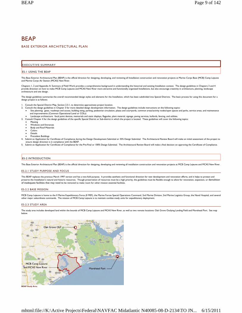
BEAP BASE EXTERIOR ARCHITECTURAL PLAN
EXECUTIVE SUMMARY
ES-1 USING THE BEAP
This Base Exterior Architectural Plan (BEAP) is the official direction for designing, developing, and reviewing all Installation construction and renovation projects at Marine Corps Base (MCB) Camp Lejeune and Marine Corps Air Station (MCAS) New River.
Chapters 1, 2 and Appendix A: Summary of Field Work provides a comprehensive background in understanding the historical and existing Installation context. The design guidelines in Chapters 3 and 4 provide direction on how to make MCB Camp Lejeune and MCAS New River more attractive and functionally organized Installations, but also encourage creativity in architecture, planning, landscape architecture and site design.
The design guidelines summarize the overall recommended design styles and elements for the Installation, which has been subdivided into Special Districts. The basic process for using this document for a design project is as follows:
1. Consult the Special District Map, Section 2.3.1, to determine approximate project location. 2. Consult the design guidelines in Chapter 3 for more detailed design development information. The design guidelines include instructions on the following topics:
Site planning: gates, roadways and access, building siting, parking, pedestrian circulation, plazas and courtyards, common areas/activity nodes/open spaces and parks, service areas, and maintenance and improvements (Common Operational Level or COLs)
Landscape architecture: focal point devices, memorials and static displays, flagpoles, plant material, signage, paving services, bollards, fencing, and utilities. 3. Consult Chapter 4 for the design guidelines of the specific Special District or Sub-district in which the project is located. These guidelines will cover the following topics:
Massing Windows and Entrances Body and Roof Materials Colors Details Precedent Buildings
4. Submit an Application for Certificate of Compliance during the Design Development Submittal or 35% Design Submittal. The Architectural Review Board will make an initial assessment of the project to ensure design direction is in compliance with the BEAP.
5. Submit an Application for Certificate of Compliance for the Pre-Final or 100% Design Submittal. The Architectural Review Board will make a final decision on approving the Certificate of Compliance.
ES-2 INTRODUCTION
This Base Exterior Architectural Plan (BEAP) is the official direction for designing, developing and reviewing all installation construction and renovation projects at MCB Camp Lejeune and MCAS New River.
ES-2.1 STUDY PURPOSE AND FOCUS
This BEAP replaces the previous March 1997 version and has a two-fold purpose. It provides aesthetic and functional direction for new development and renovation efforts, and it helps to protect and preserve the Installation’s natural and historic resources. Though preservation of resources must be a high priority, the guidelines must be flexible enough to allow for renovation, expansion, or demolition of inadequate facilities that may need to be removed to make room for other mission essential facilities.
ES-2.2 BASE MISSION
MCB Camp Lejeune is home to the II Marine Expeditionary Force (II MEF), the Marine Forces Special Operations Command, 2nd Marine Division, 2nd Marine Logistics Group, the Naval Hospital, and several other major subordinate commands. The mission of MCB Camp Lejeune is to maintain combat-ready units for expeditionary deployment.
ES-2.3 STUDY AREA
The study area includes developed land within the bounds of MCB Camp Lejeune and MCAS New River, as well as two remote locations: Oak Grove Outlying Landing Field and Morehead Port. See map below.
BEAP Study Area
Page 9 of 142BEAP
6/15/2011mhtml:file://K:\Active Projects\Federal\NAVFAC Midatlantic N40085-08-D-2134\TO JN...
ES-2.4 BEAP OBJECTIVES
1. Identify and strengthen the formal site planning elements at MCB Camp Lejeune and MCAS New River.
2. Improve wayfinding for Installation occupants, their customers and visitors by developing a hierarchy of roadways and pedestrian paths, and establishing visual wayfinding elements including signage systems.
3. Identify visual assets and liabilities on MCB Camp Lejeune and MCAS New River. Provide direction to maintain assets and change liabilities.
4. Recognize and analyze the unique visual districts within Installations’ boundaries to classify the built environment style and a harmonizing theme to strengthen each district.
5. Initiate a process to control the architectural style and direction for all planned and imminent construction.
6. Establish clear visual environment design guidance both in a general sense and specific to individual districts.
7. Establish a process by which the guidance in the plan is routinely and effectively administered and implemented within each new modification or project.
8. Develop guidelines that apply to all built environment elements including buildings, walls, fencing, landscaping, utilities and pavements related to personnel and vehicular movement.
9. Recommend materials and construction elements that can realistically be maintained by local resources.
ES-3 EXISTING CONDITIONS SUMMARY
ES-3.1 VISUAL ENVIRONMENT DEFINED
This section defines the major perceptual environment components and the terminology used in analyzing those components at MCB Camp Lejeune and MCAS New River. They include Special Districts, architectural styles, entries, landmarks and reference points, significant views, activity nodes, circulation routes, and Installation edges.
ES-3.2 DISTRICTS
Humans typically utilize a mental visual-spatial map that helps them navigate and interact with their environment. We rely heavily on the visual environment and tend to organize areas into perceptual units. To visually comprehend the complexities associated with a Marine Base, it is appropriate to subdivide the Installation into units or Special Districts. Special Districts are pre-existing neighborhoods of development which are part of the formal and informal spatial maps at Camp Lejeune.
There are 13 Special Districts, some of which also have sub-districts with unique characteristics.
Hadnot Point Hospital Point French Creek Cogdels Creek Wallace Creek Courthouse Bay Paradise Point Onslow Beach Camp Geiger Marine Corps Air Station New River Stone Bay Camp Johnson Entry Gates
ES-3.3 ARCHITECTURAL STYLE
There are three common architectural styles on Camp Lejeune by which some, not all, buildings may be classified.
Georgian. A formal arrangement of classical details, including pediments, pilasters, or columns.
Colonial Revival. Fashioned after the Georgian style, commonly with broken pedements and somewhat less detailed classical ornament
Shingle Style. Uniform covering of unpainted shingles, porch coverings and small groups of windows.
ES-3.4 DISTRICT ENTRYWAYS
Entries are those areas an individual passes through to go from one district to another. For the purposes of this study, entries are gates that lead from off base to on base or from one major district to another.
ES-3.5 LANDMARKS AND REFERENCE POINTS
Landmarks are points on the Installation that can be used for cognitive reference. Generally, a landmark is a physical object such as a tower, building, monument, or natural feature so distinctive from its surroundings that it becomes easily recognizable and memorable. Major landmarks on MCB Camp Lejeune and MCAS New River include:
Parade deck at Hadnot Point Round-abouts at MCB Camp Lejeune Marine Corps Exchange complex Officers’ Club at Paradise Point Flight line at MCAS New River
ES-3.6 SIGNIFICANT VIEWS
MCB Camp Lejeune and MCAS New River benefit from views along the banks of the New River where development gives the greatest access to the water. These occur along large expanses of the river's edge, such as at Paradise Point, as well as in sheltered inlets in Courthouse Bay. A multitude of uses exist along these views, such as bachelor housing, recreation, and parking.
ES-3.7 ACTIVITY NODES
Activity nodes are definable areas that support high concentrations of activity. They generally coincide with major facility landmarks or buildings that house important functions such as headquarters. They can also occur in areas where a high level of vehicular or pedestrian traffic converges and interacts within spaces between facilities. Nodes can occur outside facilities in plazas, entrances or other outdoor spaces. Recreation and commercial functions can also generate high levels of activity and are commonly indicated as nodes. Nodes are often where the convergence of two major circulation routes occur.
ES-3.8 CIRCULATION ROUTES
Circulation routes determine the basis for much of what a person sees, which includes all roads, walkways and unimproved paths. The primary circulation routes, the roadways, become a framework for the organization of the Installation. Circulation routes provide physical access to all areas of the Installation and are used for wayfinding purposes.
Page 10 of 142BEAP
6/15/2011mhtml:file://K:\Active Projects\Federal\NAVFAC Midatlantic N40085-08-D-2134\TO JN...
ES-3.9 INSTALLATION OR DISTRICT EDGES
Edges consist of definable elements that separate unlike districts. These edges can be open spaces, streets, walls, fences, rows of trees, sides of buildings, water bodies or landforms. In this analysis, edges are primarily limited to the Installation edge and areas between major districts. An edge attains significant visual strength if it has long lateral visibility and is impenetrable to cross movement, such as the Installation boundary fencing. Conversely, penetrable edges usually serve to join two districts together.
ES-4 DESIGN GUIDELINES OVERVIEW
ES-4.1 THEME ANALYSIS
An overall Installation architectural theme sets the framework for guidelines and standards. This theme integrates the goals for the built environment with the broader non-facility goals and objectives of the mission at MCB Camp Lejeune and MCAS New River. Existing settings, buildings and structures were analyzed to determine the factors to provide the framework for the overall theme. (See Appendix A: Summary of Field Work.) This analysis concluded:
An overall predominant architectural style presently exists at MCB Camp Lejeune, but some districts do not represent this style as much as others. Predominant materials, color, and forms do exist at MCB Camp Lejeune, but are not always consistently applied. Architectural character and positive visual impressions can be found in many areas of Camp Lejeune and are examples of proper treatment of historical districts and integration of contemporary
architecture.
In addition to architecture, other visual support or infrastructure elements have been evaluated. This analysis concluded:
The major roadways The larger scale landscape elements (trees and other mature vegetation including natural areas) Streetscape and site elements Signage and graphics Currently existing lighting
ES-4.2 THEME DEFINITIONS
Defining a design theme for the Installation is one of the functions of this Base Exterior Architectural Plan. Assigning prominence to specific areas enhances orientation and wayfinding by highlighting their distinctiveness and sense of place within an overall coherent physical arrangement that visually and cognitively unifies the Installation. Extensive field work has revealed that the elements that appear most frequently throughout MCB Camp Lejeune are:
1. Red to red-brown brick, modular size 2. Concrete or stone foundation base and window sills 3. White door and window trim, eaves, gutters and downpouts 4. Gray aphalt or standing seam metal roofing 5. Gable-on-hip roof
Using the common items listed above as a nucleus, and taking into account the existing elements from the previous section, the overall architecture theme is traditional early American design and can be implemented through guidelines and standards that recognize the dominant character. Because of the visual and/or spatial separation that exists between several of the districts, separate standards are appropriate under a Special District design approach. Though the standard may vary among districts, common harmonizing elements are intended to unify the entire Installation. At the same time, wayfinding, district delineation, and spatial clarity depend on uniqueness. The guidelines must accommodate and encourage variety and uniqueness while incorporating harmonizing elements.
It is appropriate that some areas be treated as districts, independently or collectively, by function, use, density, topography, orientation, and/or architectural character. The dominant positive characteristics of the district are intended to be repeated to further reinforce and strengthen the definition of the district. Districts with historical or near-historical significance are intended to be reinforced through preservation or retrofit methods that support the area character. This methodology is used throughout the design guidelines.
1.0 INTRODUCTION
Those serving aboard and visiting the Installation invest emotional qualities in the environmental design. This means each person’s surroundings comprise of connotations, memories, experiences, feeling, hopes and dramas. This forms a collective image, or urban legibility, and is not only the basis of spatial orientation but the key to providing a stimulating and healthy environment.
Improvements to the overall visual organization and aesthetics of MCB Camp Lejeune and MCAS New River will not occur by simply writing a generalized set of guidelines. Likewise, changes to the visual environment will not be positive unless they are following a prescribed format and intended direction. Guidelines are the starting point, but the implementation of a review process that directs development must be part of the process to positively affect the base. This BEAP is intended to cover the first few steps in the process that will eventually help to improve the overall visual environment and to contribute to protecting the positive elements that are already present.
This BEAP is a working document that will function as a guide to physical development and urban legibility, while at the same time, is flexible enough to account for changing conditions, priorities and programs. The decision making process for physical development must address site planning and design issues, as well as the financial and functional requirements of physical design and development. Aesthetic improvements cannot be achieved on a site-by-site or problem-by-problem basis, but must be based on a master plan which is properly conceived to allow each problem to be resolved as part of a total concept.
This document is MCB Camp Lejeune and MCAS New River’s official direction on facility and site development. It shall be used in developing, designing, and reviewing all construction and renovation projects on the Installation. The guidelines are meant to be specific enough to provide direction on how to make both Installations more attractive and functionally organized, but they are also meant to encourage creativity in site design, planning, architecture, and landscape architecture. The guidelines do not cover all physical elements commonly addressed by facility development. They only cover those elements needed to produce a historically correct design theme, where appropriate, and coherent physical development of the Base.
1.1 REGION
Marine Corps Base Camp Lejeune is located in Onslow County within the coastal plains of North Carolina and sits adjacent to the City of Jacksonville. The New River runs north and south through the Base, separating MCB Camp Lejeune from MCAS New River and the Greater Sandy Run training area.
MCB Camp Lejeune serves approximately 150,000 active duty, dependent, retiree and civilian employees, which is a significant part of the Jacksonville and Onlsow County populations. Over 25 percent of the county is part of the Armed Forces.
MCB Camp Lejeune and MCAS New River are surrounded by predominantly rural agricultural lands, which diversify into higher density areas near the urban centers of Jacksonville, Swansboro and Topsail Beach.
1.2 BASE MISSION
MCB Camp Lejeune is home to the II Marine Expeditionary Force (II MEF). The major commands include:
II Marine Expeditionary Force (II MEF) Marine Corps Special Operations Forces Command
Page 11 of 142BEAP
6/15/2011mhtml:file://K:\Active Projects\Federal\NAVFAC Midatlantic N40085-08-D-2134\TO JN...
2nd Marine Division 2nd Marine Logistics Group Naval Hospital Camp Lejeune 22nd, 24th, and 26th Marine Expeditionary Units Marine Corps Engineer School Joint Maritime Training Center School of Infantry – East Marine Corps Combat Service Support School Field Medical Training Battalion – East Wounded Warrior Battalion – East
The mission of MCB Camp Lejeune is to maintain combat-ready units for expeditionary deployment. Marine Corps Base owns all the real estate, hosts entry-level and career-level formal schools and provides support and training for tenant commands – II Marine Expeditionary Force conducts operational planning for Fleet Marine Force commands; 2nd Marine Division is the ground combat element of II MEF; 2nd Marine Logistics Group is the combat service support element of II MEF; and 2nd Marine Air Wing, headquartered at Cherry Point, North Carolina, is the air combat element of II MEF. Additionally, the naval hospital provides primary medical care to service members and their families stationed at Camp Lejeune and Marine Corps Air Station New River. Marine Corps Special Operations Forces Command is the Marine Corps force provider for the US Special Operations Command (USSOCOM).
Among many other support units, MCAS New River is home to two groups of the 2nd Marine Air Wing: Marine Aircraft Group 26 which consists of tiltrotor squadrons, and Marine Aircraft Group 29 which comprises both heavy and light/attack helicopters.
1.3 STUDY AREA
The study area includes developed land within the bounds of MCB Camp Lejeune and MCAS New River, as well as two remote locations.
MCB Camp Lejeune: The largest contiguous portion of MCB Camp Lejeune consists of approximately 56,000 acres and occupies the land immediately to the east of the New River. Commonly referred to as “main side”, this part of the study area contains the majority of the Special Districts, administration, personnel support, and family and bachelor housing facilities.
Stone Bay: Stone Bay District is 2,700 acres of range training areas, administration and support facilities, as well as encompassing the Marine Corps Forces Special Operations Command complex.
MCAS New River and Camp Geiger: Collectively this area consists of 4,507 acres, including land dedicated to the Marine Corps School of Infantry East and the subordinate units of the 2nd Marine Air Wing, flight line, aprons, and supporting areas.
Camp Johnson: An ancilliary camp located between MCAS New River and MCB Camp Lejeune. Camp Johnson is approximately 1,552 acres consisting of primarily military education facilities.
Oak Grove: An outlying landing field (OLF) to the north of MCB Camp Lejeune located outside of Pollocksville, North Carolina.
Morehead Port: Located in Morehead City, North Carolina, this area consists of a small cluster of buildings for use by the Marine Corps during port operations.
Camp Devil Dog: Approximately 134 acres of austere training facilities primarily used by the School of Infantry. Camp Devil Dog is located to the south of MCAS New River along Highway 17.
Greater Sandy Run: A vast manuever area of 41,227 acres, Sandy Run is on the western edge of the military reservation and represents the largest expanse of training area for the Marine Corps on the east coast.
1.4 STUDY PURPOSE AND FOCUS
This BEAP replaces the previous BEAP version (dated March 1997) and has a two-fold purpose. It provides aesthetic and functional direction for new development and renovation efforts, and it helps to protect and preserve the Installation’s natural and historic resources. Though preservation of resources must be a high priority, the guidelines must be flexible enough to allow for renovation, expansion or demolition of inadequate facilities that may need to be removed to make room for other mission essential facilities.
1.5 METHODOLOGY
Major phases for the BEAP include:
Identify the overall project goals Complete field work to determine assets, liabilities, dominant elements, perceptual districts and spatial structure Develop objectives for site planning, architecture, landscape architecture, signage and lighting Map perceptual districts and spatial structure Map assets and liabilities Map historic structures and districts Map road hierarchy and structure Develop specific guidelines Develop examples of what to do and not to do Describe acceptable building materials Develop a review process Obtain consensus and approval on the guidelines Produce a final document and brochure
1.6 GUIDELINE ELEMENTS
Design guidelines are developed for the following:
Site planning: gates, roadways and access, building siting, parking, pedestrian circulation, plazas and courtyards, common areas/activity nodes/open spaces and parks, service areas, and maintenance and improvements
Architecture: building design, building entrances, building renovations and additions, historic architecture, and the Building Color Design Guide Landscape architecture: focal point devices, memorials and static displays, flagpoles, plant material, signage, paving services, bollards, fencing, and utilities.
1.7 OVERALL PROJECT OBJECTIVES
1. Identify and strengthen the formal site planning elements at MCB Camp Lejeune and MCAS New River.
2. Identify and protect the Historic District’s significant resources. This BEAP will focus on the exterior visual environment where buildings form the edges of spaces as well as the site “grounds” within the Historic District.
Page 12 of 142BEAP
6/15/2011mhtml:file://K:\Active Projects\Federal\NAVFAC Midatlantic N40085-08-D-2134\TO JN...
3. Improve wayfinding for Installation occupants, their customers and visitors by developing a hierarchy of roadways and pedestrian paths, and establishing visual wayfinding elements including signage systems.
4. Identify visual assets and liabilities on MCB Camp Lejeune and MCAS New River. Provide direction to maintain assets and change liabilities.
5. Recognize and analyze the unique visual and historic districts within MCB Camp Lejeune and MCAS New River boundaries to classify the built environment style and a harmonizing theme to strengthen each district.
6. Initiate a process to control the architectural style and direction for all planned and imminent construction.
7. Establish clear visual environment design guidance both in a general sense and specific to individual districts.
8. Establish a process by which the guidance in the plan is routinely and effectively administered and implemented within each new modification or project.
9. Develop guidelines that apply to all built environment elements including buildings, walls, fencing, landscaping, utilities and pavements related to personnel and vehicular movement.
10. Recommend materials and construction elements that can realistically be maintained by local resources.
2.0 EXISTING CONDITIONS SUMMARY
2.1 HISTORICAL BACKGROUND
MCB Camp Lejeune is located in eastern North Carolina adjacent to the City of Jacksonville. The base consists of 14 miles of beach front along the Atlantic Ocean. The New River runs north/south through the base and Highway 24 separates MCB Camp Lejeune from Jacksonville. The Base serves approximately 150,000 active and retired military, their dependents, and civilian employees.
Originally Marine Barracks New River, established 1 May 1941, the Base’s first warehouse was a converted tobacco barn and the Base Headquarters a summer cottage. In December 1942, the Base was renamed MCB Camp Lejeune in honor of Lieutenant General John A. Lejeune 13th Commandant of the Marine Corps. Today, MCB Camp Lejeune and the adjacent New River Air Station are the largest concentration of Marines and Sailors in the world.
2.2 PREVIOUS DESIGN GUIDELINES
Camp Lejeune instituted its first BEAP in 1997. Because no formal documentation existed prior to that time, architecture and landscape evolved as a mixture of different forms, colors, materials, and styles. The first BEAP was designed to establish basic standards of appearance where none previously existed.
While the previous BEAP was successful at establishing color and material standards, it left other areas of building and landscape to the designer. When facility acquisition shifted to the Design-Build process, these areas became significant gaps in controlling aesthetics. Where the Design-Bid-Build process gave the Installations a large role in the design of a facility, Design-Build did not, and occassionally resulted in less desireable architecture and landscapes.
The primary difference in this BEAP is to address new methods of facility acquisition, incorporate newly developed areas of the Base, and provide more specific guidelines to control the physical appearances of the Installation.
2.3 VISUAL ENVIRONMENT DEFINED
This section defines the major perceptual environment components and the terminology used in analyzing those components at MCB Camp Lejeune and MCAS New River. They include Special Districts, architectural styles, entries, landmarks and reference points, significant views, activity nodes, circulation routes, and Installation edges.
2.3.1 SPECIAL DISTRICTS
The NAVFAC Installation Appearance Guide (IAG) uses functional district to analyze areas of an installation. Functional districts are areas unified by common functions, such as as administrative/ training, airfield, industrial, personnel support and waterfront. Instead of functional districts, MCB Camp Lejeune uses a system of distinct neighborhood areas, known as Special Districts. Special Districts are based on unique geographical areas, which, over time, have developed as separate districts as well as unique variations on the predominant architectural theme. Therefore, the BEAP uses Special Districts defined by elements such as architectural style, color schemes, and landscaping. The Special Districts this BEAP addresses are:
Hadnot Point Hospital Point French Creek Cogdels Creek Wallace Creek Courthouse Bay Paradise Point Onslow Beach Camp Geiger Marine Corps Air Station New River Stone Bay Camp Johnson Entry Gates Greater Sandy Run Camp Devil Dog
These Special Districts contain sub-districts:
Hadnot Point − Industrial Sub-district − Marine Corps Exchange
Paradise Point − Brewster Street − Wounded Warrior Complex
Stone Bay − Historic Rifle Range − MARSOC
Page 13 of 142BEAP
6/15/2011mhtml:file://K:\Active Projects\Federal\NAVFAC Midatlantic N40085-08-D-2134\TO JN...
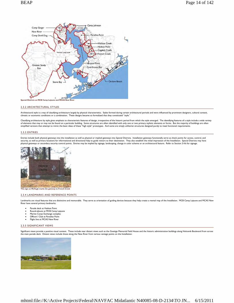
Special Districts on MCB Camp Lejeune and MCAS New River
2.3.2 ARCHITECTURAL STYLES
Architectural style is a way of classifying architecture largely by physical characteristics. Styles formed during certain architectural periods and were influenced by prominent designers, cultural context, climatic or economic conditions or a combination. These designs became so formalized that they constituted “style.”
Classifying architecture by style gives emphasis to characteristic features of design, irrespective of the historic period from which the style emerged. The identifying features of a style include a wide variety of elements that may or may not be found on a particular building. Some structures are often identified with only one or two primary stylistic elements or forms. But the majority of buildings are often simplified versions that attempt to mimic the basic ideas of these “high style” prototypes. And some are simply utilitarian structures designed purely to meet functional requirements.
2.3.3 ENTRIES
Entries include both physical gateways into the installation as well as physical or implied gateways into Special Districts. Installation gateways functionally serve as check points for access, control, and security, as well as primary locations for informational and directional help to guide visitors to their destination. They also establish the initial impression of the Installation. Special Districts may have physical gateways or secondary security control points. Entries may be implied by signage, landscaping, change in color scheme or an architectural feature. Refer to Section 3.4.6 for signage.
This sign on McHugh marks the gateway to French Creek
2.3.4 LANDMARKS AND REFERENCE POINTS
Landmarks are visual features that are distinctive and memorable. They serve as orientation of guiding devices because they help create a mental map of the Installation. MCB Camp Lejeune and MCAS New River have several primary landmarks:
Parade deck at Hadnot Point Round-abouts at MCB Camp Lejeune Marine Corps Exchange complex Officers’ Club at Paradise Point Flight line at MCAS New River
2.3.5 SIGNIFICANT VIEWS
Significant views provide a positive visual context. These include near distant views such as the Goettge Memorial Field House and the historic administration buildings along Holcomb Boulevard from across the main parade deck. Distant views include those along the New River from various vantage points on the Installation.
Page 14 of 142BEAP
6/15/2011mhtml:file://K:\Active Projects\Federal\NAVFAC Midatlantic N40085-08-D-2134\TO JN...
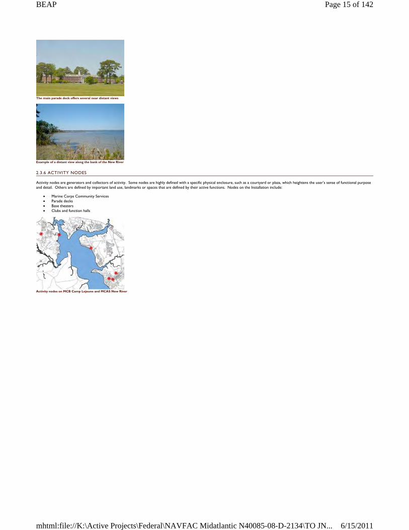
The main parade deck offers several near distant views
Example of a distant view along the bank of the New River
2.3.6 ACTIVITY NODES
Activity nodes are generators and collectors of activity. Some nodes are highly defined with a specific physical enclosure, such as a courtyard or plaza, which heightens the user’s sense of functional purpose and detail. Others are defined by important land use, landmarks or spaces that are defined by their active functions. Nodes on the Installation include:
Marine Corps Community Services Parade decks Base theaters Clubs and function halls
Activity nodes on MCB Camp Lejeune and MCAS New River
Page 15 of 142BEAP
6/15/2011mhtml:file://K:\Active Projects\Federal\NAVFAC Midatlantic N40085-08-D-2134\TO JN...
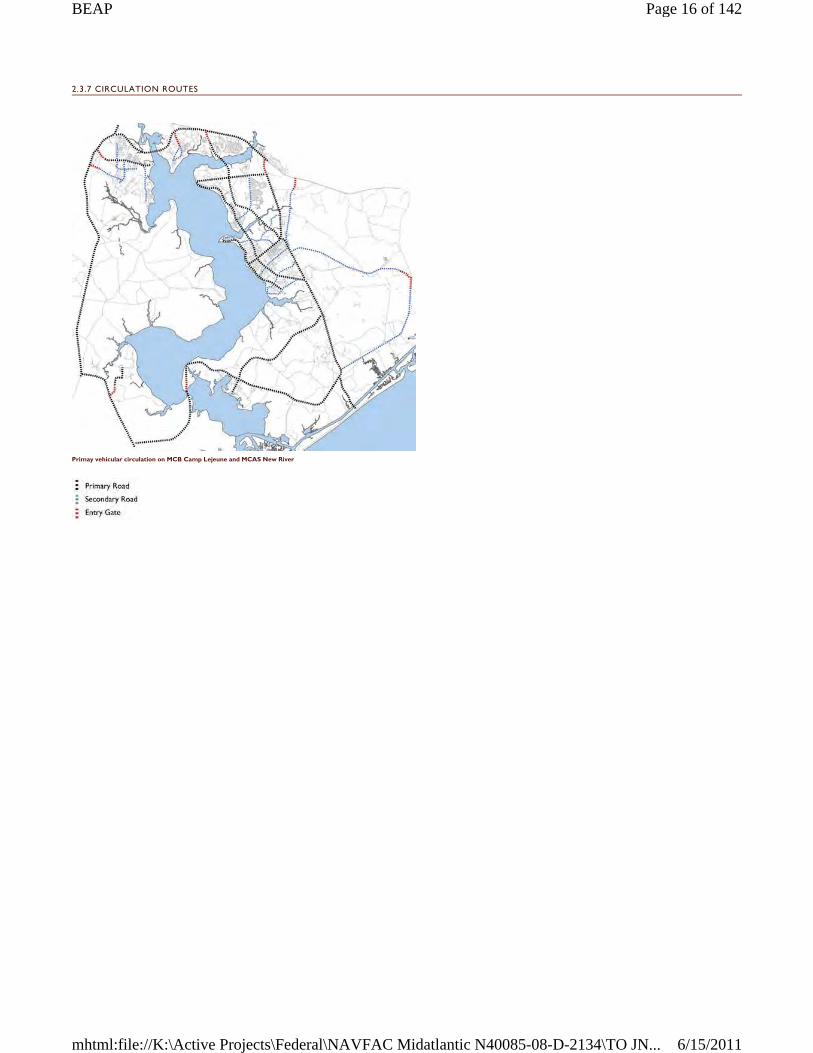
2.3.7 CIRCULATION ROUTES
Primay vehicular circulation on MCB Camp Lejeune and MCAS New River
Page 16 of 142BEAP
6/15/2011mhtml:file://K:\Active Projects\Federal\NAVFAC Midatlantic N40085-08-D-2134\TO JN...
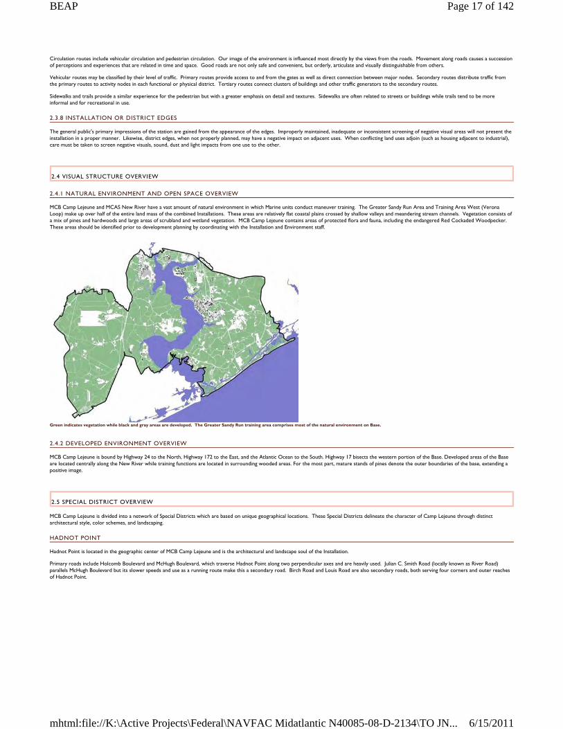
Circulation routes include vehicular circulation and pedestrian circulation. Our image of the environment is influenced most directly by the views from the roads. Movement along roads causes a succession of perceptions and experiences that are related in time and space. Good roads are not only safe and convenient, but orderly, articulate and visually distinguishable from others.
Vehicular routes may be classified by their level of traffic. Primary routes provide access to and from the gates as well as direct connection between major nodes. Secondary routes distribute traffic from the primary routes to activity nodes in each functional or physical district. Tertiary routes connect clusters of buildings and other traffic generators to the secondary routes.
Sidewalks and trails provide a similar experience for the pedestrian but with a greater emphasis on detail and textures. Sidewalks are often related to streets or buildings while trails tend to be more informal and for recreational in use.
2.3.8 INSTALLATION OR DISTRICT EDGES
The general public's primary impressions of the station are gained from the appearance of the edges. Improperly maintained, inadequate or inconsistent screening of negative visual areas will not present the installation in a proper manner. Likewise, district edges, when not properly planned, may have a negative impact on adjacent uses. When conflicting land uses adjoin (such as housing adjacent to industrial), care must be taken to screen negative visuals, sound, dust and light impacts from one use to the other.
2.4 VISUAL STRUCTURE OVERVIEW
2.4.1 NATURAL ENVIRONMENT AND OPEN SPACE OVERVIEW
MCB Camp Lejeune and MCAS New River have a vast amount of natural environment in which Marine units conduct maneuver training. The Greater Sandy Run Area and Training Area West (Verona Loop) make up over half of the entire land mass of the combined Installations. These areas are relatively flat coastal plains crossed by shallow valleys and meandering stream channels. Vegetation consists of a mix of pines and hardwoods and large areas of scrubland and wetland vegetation. MCB Camp Lejeune contains areas of protected flora and fauna, including the endangered Red Cockaded Woodpecker. These areas should be identified prior to development planning by coordinating with the Installation and Environment staff.
Green indicates vegetation while black and gray areas are developed. The Greater Sandy Run training area comprises most of the natural environment on Base.
2.4.2 DEVELOPED ENVIRONMENT OVERVIEW
MCB Camp Lejeune is bound by Highway 24 to the North, Highway 172 to the East, and the Atlantic Ocean to the South. Highway 17 bisects the western portion of the Base. Developed areas of the Base are located centrally along the New River while training functions are located in surrounding wooded areas. For the most part, mature stands of pines denote the outer boundaries of the base, extending a positive image.
2.5 SPECIAL DISTRICT OVERVIEW
MCB Camp Lejeune is divided into a network of Special Districts which are based on unique geographical locations. These Special Districts delineate the character of Camp Lejeune through distinct architectural style, color schemes, and landscaping.
HADNOT POINT
Hadnot Point is located in the geographic center of MCB Camp Lejeune and is the architectural and landscape soul of the Installation.
Primary roads include Holcomb Boulevard and McHugh Boulevard, which traverse Hadnot Point along two perpendicular axes and are heavily used. Julian C. Smith Road (locally known as River Road) parallels McHugh Boulevard but its slower speeds and use as a running route make this a secondary road. Birch Road and Louis Road are also secondary roads, both serving four corners and outer reaches of Hadnot Point.
Page 17 of 142BEAP
6/15/2011mhtml:file://K:\Active Projects\Federal\NAVFAC Midatlantic N40085-08-D-2134\TO JN...
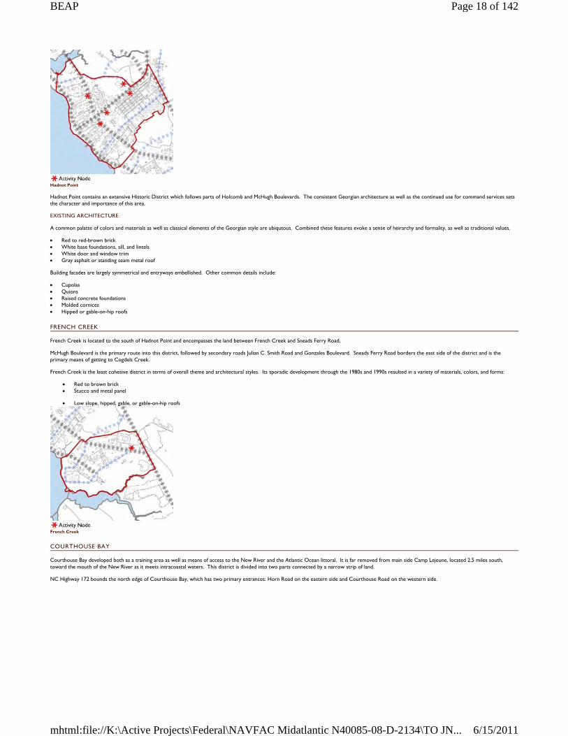
Hadnot Point
Hadnot Point contains an extensive Historic District which follows parts of Holcomb and McHugh Boulevards. The consistent Georgian architecture as well as the continued use for command services sets the character and importance of this area.
EXISTING ARCHITECTURE
A common palatte of colors and materials as well as classical elements of the Georgian style are ubiqutous. Combined these features evoke a sense of heirarchy and formality, as well as traditional values.
Red to red-brown brick White base foundations, sill, and lintels White door and window trim Gray asphalt or standing seam metal roof
Building facades are largely symmetrical and entryways embellished. Other common details include:
Cupolas Quions Raised concrete foundations Molded cornices Hipped or gable-on-hip roofs
FRENCH CREEK
French Creek is located to the south of Hadnot Point and encompasses the land between French Creek and Sneads Ferry Road.
McHugh Boulevard is the primary route into this district, followed by secondary roads Julian C. Smith Road and Gonzales Boulevard. Sneads Ferry Road borders the east side of the district and is the primary means of getting to Cogdels Creek.
French Creek is the least cohesive district in terms of overall theme and architectural styles. Its sporadic development through the 1980s and 1990s resulted in a variety of materials, colors, and forms:
Red to brown brick Stucco and metal panel
Low slope, hipped, gable, or gable-on-hip roofs
French Creek
COURTHOUSE BAY
Courthouse Bay developed both as a training area as well as means of access to the New River and the Atlantic Ocean littoral. It is far removed from main side Camp Lejeune, located 2.5 miles south, toward the mouth of the New River as it meets intracoastal waters. This district is divided into two parts connected by a narrow strip of land.
NC Highway 172 bounds the north edge of Courthouse Bay, which has two primary entrances: Horn Road on the eastern side and Courthouse Road on the western side.
Page 18 of 142BEAP
6/15/2011mhtml:file://K:\Active Projects\Federal\NAVFAC Midatlantic N40085-08-D-2134\TO JN...
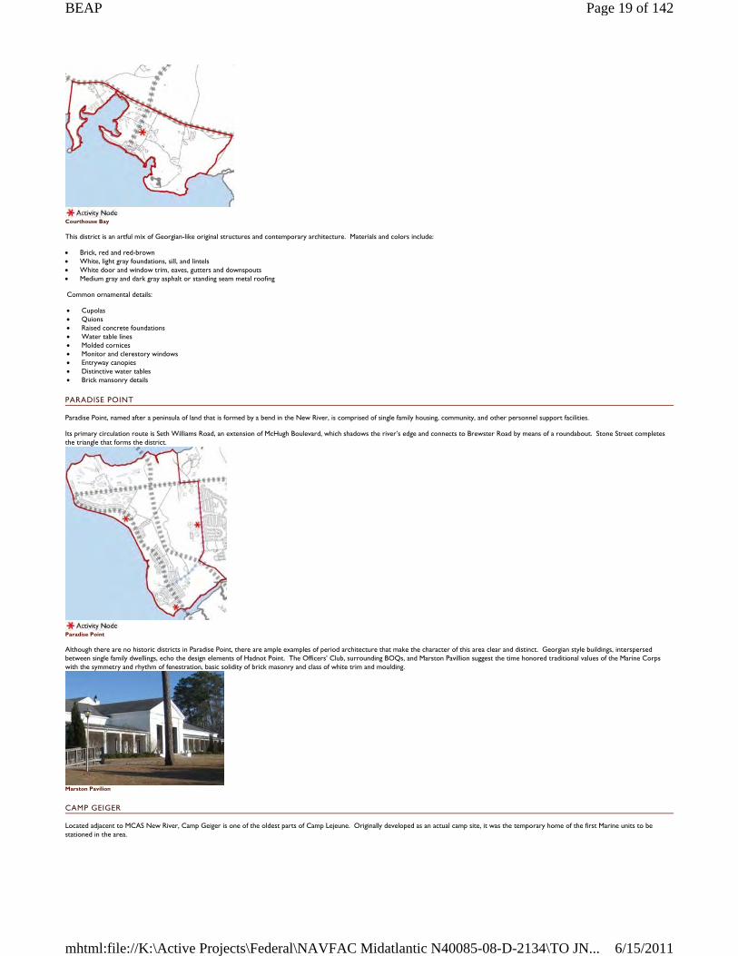
Courthouse Bay
This district is an artful mix of Georgian-like original structures and contemporary architecture. Materials and colors include:
Brick, red and red-brown White, light gray foundations, sill, and lintels White door and window trim, eaves, gutters and downspouts Medium gray and dark gray asphalt or standing seam metal roofing
Common ornamental details:
Cupolas Quions Raised concrete foundations Water table lines Molded cornices Monitor and clerestory windows Entryway canopies Distinctive water tables Brick mansonry details
PARADISE POINT
Paradise Point, named after a peninsula of land that is formed by a bend in the New River, is comprised of single family housing, community, and other personnel support facilities.
Its primary circulation route is Seth Williams Road, an extension of McHugh Boulevard, which shadows the river’s edge and connects to Brewster Road by means of a roundabout. Stone Street completes the triangle that forms the district.
Paradise Point
Although there are no historic districts in Paradise Point, there are ample examples of period architecture that make the character of this area clear and distinct. Georgian style buildings, interspersed between single family dwellings, echo the design elements of Hadnot Point. The Officers’ Club, surrounding BOQs, and Marston Pavillion suggest the time honored traditional values of the Marine Corps with the symmetry and rhythm of fenestration, basic solidity of brick masonry and class of white trim and moulding.
Marston Pavilion
CAMP GEIGER
Located adjacent to MCAS New River, Camp Geiger is one of the oldest parts of Camp Lejeune. Originally developed as an actual camp site, it was the temporary home of the first Marine units to be stationed in the area.
Page 19 of 142BEAP
6/15/2011mhtml:file://K:\Active Projects\Federal\NAVFAC Midatlantic N40085-08-D-2134\TO JN...
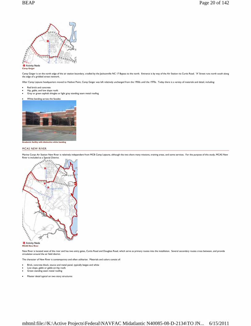
Camp Geiger
Camp Geiger is on the north edge of the air station boundary, cradled by the Jacksonville NC 17 Bypass to the north. Entrance is by way of the Air Station via Curtis Road. 'A' Street runs north south along the edge of a gridded street network.
After Camp Lejeune headquarters moved to Hadnot Point, Camp Geiger was left relatively unchanged from the 1950s until the 1970s. Today there is a variety of materials and detail, including:
Red brick and concrete Hip, gable, and low slope roofs Gray or green asphalt shingles or light gray standing seam metal roofing
White banding across the facades
Academic facility with distinctive white banding
MCAS NEW RIVER
Marine Corps Air Station New River is relatively independent from MCB Camp Lejeune, although the two share many missions, training areas, and some services. For the purpose of this study, MCAS New River is included as a Special District.
MCAS New River
New River is located west of the river and has two entry gates, Curtis Road and Douglass Road, which serve as primary routes into the installation. Several secondary routes cross between, and provide circulation around the air field district.
The character of New River is contemporary and often utilitarian. Materials and colors consist of:
Brick, concrete block, stucco and metal panel, typically beiges and white Low slope, gable or gable-on-hip roofs Green standing seam metal roofing
Pilaster detail typical on two story structures
Page 20 of 142BEAP
6/15/2011mhtml:file://K:\Active Projects\Federal\NAVFAC Midatlantic N40085-08-D-2134\TO JN...
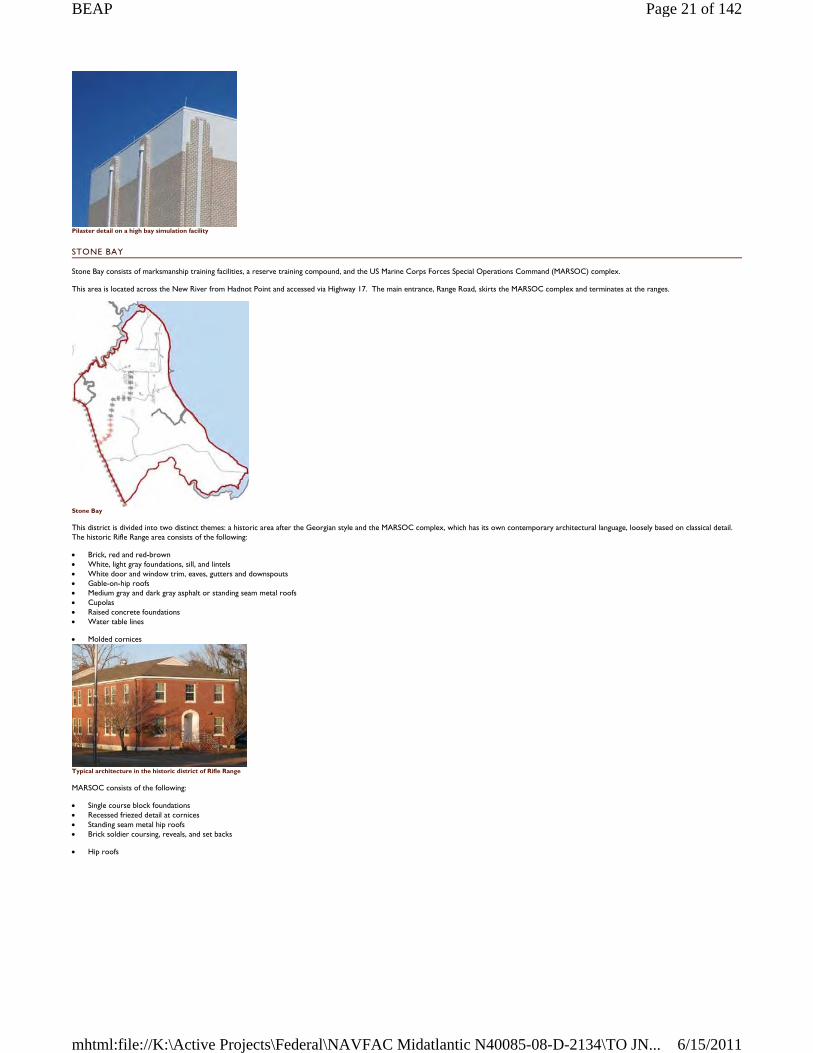
Pilaster detail on a high bay simulation facility
STONE BAY
Stone Bay consists of marksmanship training facilities, a reserve training compound, and the US Marine Corps Forces Special Operations Command (MARSOC) complex.
This area is located across the New River from Hadnot Point and accessed via Highway 17. The main entrance, Range Road, skirts the MARSOC complex and terminates at the ranges.
Stone Bay
This district is divided into two distinct themes: a historic area after the Georgian style and the MARSOC complex, which has its own contemporary architectural language, loosely based on classical detail. The historic Rifle Range area consists of the following:
Brick, red and red-brown White, light gray foundations, sill, and lintels White door and window trim, eaves, gutters and downspouts Gable-on-hip roofs Medium gray and dark gray asphalt or standing seam metal roofs Cupolas Raised concrete foundations Water table lines
Molded cornices
Typical architecture in the historic district of Rifle Range
MARSOC consists of the following:
Single course block foundations Recessed friezed detail at cornices Standing seam metal hip roofs Brick soldier coursing, reveals, and set backs
Hip roofs
Page 21 of 142BEAP
6/15/2011mhtml:file://K:\Active Projects\Federal\NAVFAC Midatlantic N40085-08-D-2134\TO JN...
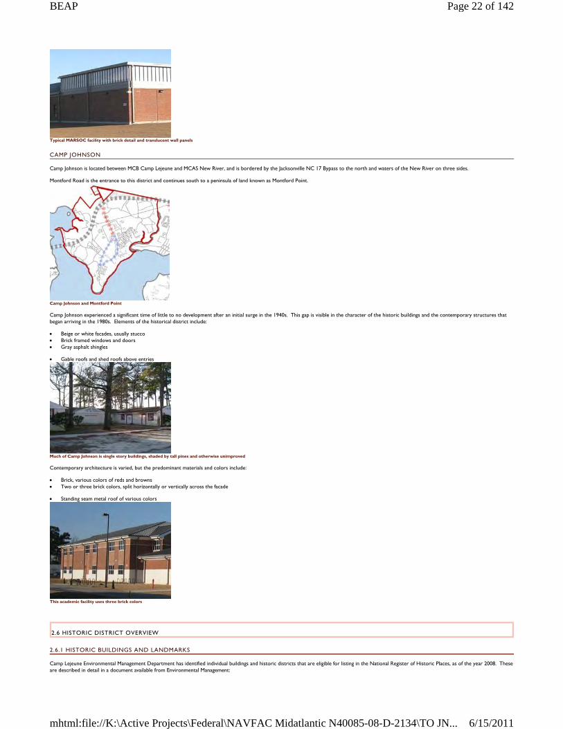
Typical MARSOC facility with brick detail and translucent wall panels
CAMP JOHNSON
Camp Johnson is located between MCB Camp Lejeune and MCAS New River, and is bordered by the Jacksonville NC 17 Bypass to the north and waters of the New River on three sides.
Montford Road is the entrance to this district and continues south to a peninsula of land known as Montford Point.
Camp Johnson and Montford Point
Camp Johnson experienced a significant time of little to no development after an initial surge in the 1940s. This gap is visible in the character of the historic buildings and the contemporary structures that began arriving in the 1980s. Elements of the historical district include:
Beige or white facades, usually stucco Brick framed windows and doors Gray asphalt shingles
Gable roofs and shed roofs above entries
Much of Camp Johnson is single story buildings, shaded by tall pines and otherwise unimproved
Contemporary architecture is varied, but the predominant materials and colors include:
Brick, various colors of reds and browns Two or three brick colors, split horizontally or vertically across the facade
Standing seam metal roof of various colors
This academic facility uses three brick colors
2.6 HISTORIC DISTRICT OVERVIEW
2.6.1 HISTORIC BUILDINGS AND LANDMARKS
Camp Lejeune Environmental Management Department has identified individual buildings and historic districts that are eligible for listing in the National Register of Historic Places, as of the year 2008. These are described in detail in a document available from Environmental Management:
Page 22 of 142BEAP
6/15/2011mhtml:file://K:\Active Projects\Federal\NAVFAC Midatlantic N40085-08-D-2134\TO JN...
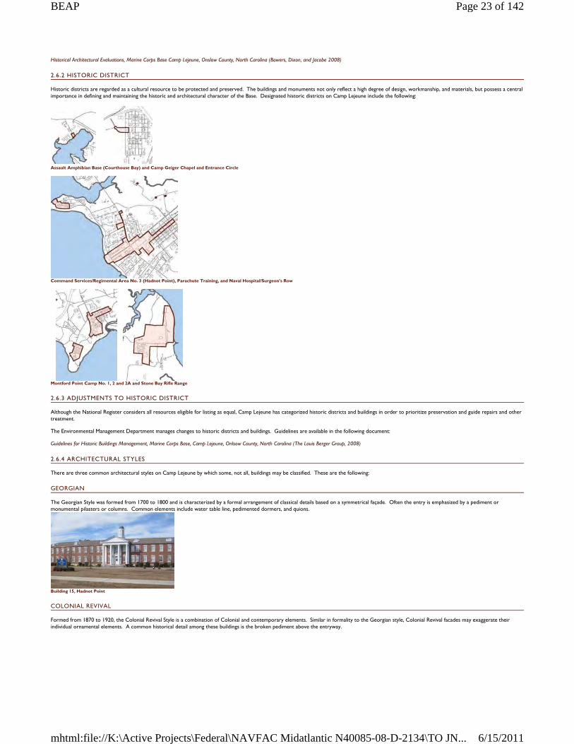
Historical Architectural Evaluations, Marine Corps Base Camp Lejeune, Onslow County, North Carolina (Bowers, Dixon, and Jacobe 2008)
2.6.2 HISTORIC DISTRICT
Historic districts are regarded as a cultural resource to be protected and preserved. The buildings and monuments not only reflect a high degree of design, workmanship, and materials, but possess a central importance in defining and maintaining the historic and architectural character of the Base. Designated historic districts on Camp Lejeune include the following:
Assault Amphibian Base (Courthouse Bay) and Camp Geiger Chapel and Entrance Circle
Command Services/Regimental Area No. 3 (Hadnot Point), Parachute Training, and Naval Hospital/Surgeon’s Row
Montford Point Camp No. 1, 2 and 2A and Stone Bay Rifle Range
2.6.3 ADJUSTMENTS TO HISTORIC DISTRICT
Although the National Register considers all resources eligible for listing as equal, Camp Lejeune has categorized historic districts and buildings in order to prioritize preservation and guide repairs and other treatment.
The Environmental Management Department manages changes to historic districts and buildings. Guidelines are available in the following document:
Guidelines for Historic Buildings Management, Marine Corps Base, Camp Lejeune, Onlsow County, North Carolina (The Louis Berger Group, 2008)
2.6.4 ARCHITECTURAL STYLES
There are three common architectural styles on Camp Lejeune by which some, not all, buildings may be classified. These are the following:
GEORGIAN
The Georgian Style was formed from 1700 to 1800 and is characterized by a formal arrangement of classical details based on a symmetrical façade. Often the entry is emphasized by a pediment or monumental pilasters or columns. Common elements include water table line, pedimented dormers, and quions.
Building 15, Hadnot Point
COLONIAL REVIVAL
Formed from 1870 to 1920, the Colonial Revival Style is a combination of Colonial and contemporary elements. Similar in formality to the Georgian style, Colonial Revival facades may exaggerate their individual ornamental elements. A common historical detail among these buildings is the broken pediment above the entryway.
Page 23 of 142BEAP
6/15/2011mhtml:file://K:\Active Projects\Federal\NAVFAC Midatlantic N40085-08-D-2134\TO JN...
Walsh Hall, Rifle Range
SHINGLE STYLE
The Shingle Style dates between 1880 and 1900 and is characterized by a uniform covering of unpainted wood shingles, including roof and façade. Roof lines typically continue to create porch coverings. Windows are usually small and grouped in twos and threes.
General Officers’ beach house, Onslow Beach, is in the Shingle Style
2.7 ASSETS AND LIABILITIES OVERVIEW
2.7.1 ASSETS
The visual setting and natural environment of the Carolina coastal plains is one the greatest assets of MCB Camp Lejeune and MCAS New River. The Installation invests in the recreation facilities at Onslow Beach and continues to take great care in preserving the shore.
Onslow Beach
Greater view access to the edges of the New River on MCB Camp Lejeune would further take advantage of this asset.
The historic districts, closely associated with the growth of the Marine Corps, are another asset which the Base should continue to take advantage of. These districts offer not only good examples of early American architectural styles, but a window into past significant events.
Base Theater at Hadnot Point
Water recreation opportunities at both MCB Camp Lejeune and MCAS New River are assets that the Installations have recognized and are using. Marinas provide access to the river waters and shoreline via piers, boat slips, and basic marina buildings. Investment in upgrading these facilities would further enhance the Installations' enjoyment of the New River.
Page 24 of 142BEAP
6/15/2011mhtml:file://K:\Active Projects\Federal\NAVFAC Midatlantic N40085-08-D-2134\TO JN...
Marina at MCAS New River
2.7.2 LIABILITIES
The primary liabilities of MCB Camp Lejeune are a result of the core industrial functions of the Installation. Although efficiently located along the railroad and central to the cantonment, the Industrial Sub-district shares many of the same view scapes as the ceremonial center of MCB Camp Lejeune. This is not likely to change, but can be controlled through the preservation and renovation of the remaining perimeter surrounding the parade deck.
View of steam plant from across the parade deck
Vehicle barriers at MCAS New River are ubiquitous. Although placed for necessary protection or access control of key facilities, these barriers take away from the character of the district and become a memorable negative image of New River. Access control may be provided by other types of devices which have less visual impact, such as high curbs. If anti-ram passive barriers are required, decorative bollards may be installed around existing facilities without great impact on the Installation's architectural character.
Vehicle barriers are prevalent on MCAS New River
Similarly, above ground steam lines obscure building facades and become both a physical and visual barrier to the appearance of MCAS New River and parts of Courthouse Bay. When opportunities arise, steam lines may be routed below grade to free the visual and physical space which they currently occupy.
Elevated steam lines obscure building facades
3.0 INSTALLATION WIDE DESIGN GUIDELINES
3.1 FRAMEWORK FOR THE OVERALL DESIGN THEME
An overall installation architectural theme sets the framework for guidelines and standards. This theme integrates the goals for the built environment with the broader non-facility goals and objectives of the missions at MCB Camp Lejeune and MCAS New River. Existing settings, buildings and structures were analyzed to determine the factors to provide the framework for the overall theme. (See Appendix A: Summary of Field Work.) This analysis concluded:
An overall predominant architectural style presently exists at MCB Camp Lejeune, but is weakened by designs which dilute the formal rules of the style. Predominant materials, color, and forms do exist at MCB Camp Lejeune and MCAS New River in most districts, but some areas lack cohesion. Architectural character and positive visual impressions can be found in many areas of Camp Lejeune and are early American design styles.
In addition to architecture, other visual aspects of infrastructure elements have been evaluated. This analysis includes:
The major roadways The larger scale landscape elements (trees and other mature vegetation including natural areas) Streetscape and site elements Signage and graphics Existing lighting Camp Lejeune environmental setting
3.1.1 DESIGN THEME FRAMEWORK
The architectural foundation of MCB Camp Lejeune and MCAS New River is based on a surge of construction during the 1940s when designers used Georgian and Colonial Revival styles for command, administrative, and support facilities across much of what is now mainside. Many of these structures are now in historic districts, as they are considered windows into the significant past of the military and the country. They also represent values found in the Marine Corps: solid fundamentals, tradition, order, and an affinity for the country’s roots. Therefore, the design theme for MCB Camp Lejeune and MCAS New River is based on early American design.
3.1.2 INTRODUCTION TO THE MECHANICS OF THE GUIDELINES
The purpose of these design guidelines is to establish standards for improving MCB Camp Lejeune and MCAS New River’s physical environment. The guidelines provide a framework for the enhancement of the visual setting of the installations through the siting, design, style and color of building and landscape elements for all improvements to the physical environment.
These guidelines are based on the BEAP goals and objectives, Section 1.7: Overall Project Objectives, and general operations and maintenance considerations. The design guidelines also refer to separate criteria specific to the MCB Camp Lejeune Historic District, and the remainder of the installation, when necessary.
Page 25 of 142BEAP
6/15/2011mhtml:file://K:\Active Projects\Federal\NAVFAC Midatlantic N40085-08-D-2134\TO JN...
Design guidelines have been developed for the following:
Site planning: gates, roadways and access, building siting, parking, pedestrian circulation, plazas and courtyards, common areas/activity nodes/open spaces and parks, service areas, and maintenance and improvements (Common Operational Level or COLs -- See Appendix B)
Architecture: building design, building entrances, building renovations and additions, historic architecture, and the Building Color Design Guide Landscape architecture: focal point devices, memorials and static displays, flagpoles, plant material, signage, paving services, bollards, fencing, utilities
3.1.3 NATURAL AND CULTURAL RESOURCES
Natural and cultural resources must be maintained, protected, and possibly enhanced. Every designer must be aware of the impact each new project will have on these resources and must design their project to complement or coordinate with the existing environment of the Installation. These resources give the Installations character and aesthetic appeal:
Historic districts Waters edge along New River and tributaries Onslow Beach Monuments and statues Military equipment static displays Preservation areas
3.1.4 ANTI-TERRORISM AND FORCE PROTECTION
Incorporate antiterrorism and force protection (AT/FP) design with other design elements so that protection is attractive and unapparent. Elements that occur in site design which can unobtrusively protect the building and its inhabitants include:
Drainage ditches and bio swales Ponds Open lawn and ground covers Lighting and mass notification systems Vehicle circulation
Other AT/FP devices can be incorporated into the site design without creating a fortress appearance:
Berms and ditches Setbacks Fences and walls; seat walls Bollards and planters
Within the framework of the AT/FP planning standards, design all modifications and enhancements to existing facilities to be cohesive and compatible with the Installation's character.
BERMS AND DITCHES
Berms and ditches offer an effective means of protection against vehicle-borne threats and have less visual impact than fences and other barriers. Soil berms on the protected side of ditches improve its effectiveness. Refer to UFC 4-022-02 Selection and Application of Vehicle Barriers for more information on ditches and berms.
Berms, when combined with ditches, can be integrated into site design and provide an effective vehicle barrier without detracting from the building design
FENCES AND WALLS
Fences and walls provide both physical protection and a visual barrier to the building beyond. When an anti-ramming fence is required, use decorative black finished metal pickets to reduce the visual impact. Steel cable reinforcement should be integrated with the fence design such that it’s less visible.
Crash-rated vehicle barrier across service driveway. If this type of barrier is required, it should be tied into a system of barriers which prevent by-pass.
Page 26 of 142BEAP
6/15/2011mhtml:file://K:\Active Projects\Federal\NAVFAC Midatlantic N40085-08-D-2134\TO JN...
The cable reinforcing in this fence design is hidden in the three rails and anchored to the ground through the post
This fence design uses exposed cable reinforcing
Anti-ramming knee walls are an alternative to re-inforced fencing. Knee walls must have minimum dimensions and steel reinforcement to provide adequate protection, but may be veneered with the same materials as the building facade in order to blend into the design. Refer to UFC 4-022-02 Selection and Application of Vehicle Barriers for more information on anti-ram walls.
Knee walls, when properly constructed, serve as a vehicle barrier, but also provide the designer an opportunity to add visual interest to the site
BOLLARDS AND PLANTERS
Bollards and planters provide protection from vehicles while still allowing pedestrian traffic to move through. They must be constructed to specific construction standards as well as match the character of the Special District. Planters may be veneered in the same way as knee walls. Bollards designed for anti-ramming are substantial structures, constructed from structural steel pipe, and filled with concrete.
Anti-ram bollard indicating the structure required below grade; bollards shall have a decorative exterior
The character of these decorative bollards is appropriate for most districts
Page 27 of 142BEAP
6/15/2011mhtml:file://K:\Active Projects\Federal\NAVFAC Midatlantic N40085-08-D-2134\TO JN...
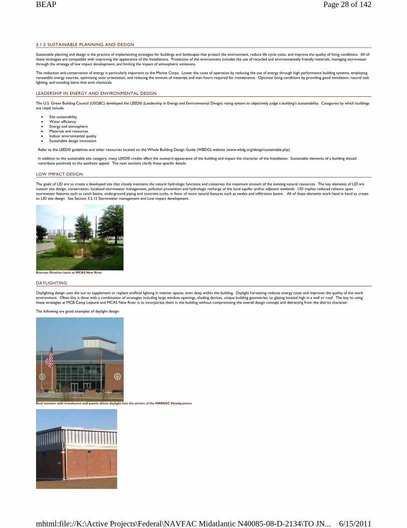
3.1.5 SUSTAINABLE PLANNING AND DESIGN
Sustainable planning and design is the practice of implementing strategies for buildings and landscapes that protect the environment, reduce life cycle costs, and improve the quality of living conditions. All of these strategies are compatible with improving the appearance of the Installations. Protection of the environment includes the use of recycled and environmentally friendly materials, managing stormwater through the strategy of low impact development, and limiting the impact of atmospheric emissions.
The reduction and conservation of energy is particularly important to the Marine Corps. Lower the costs of operation by reducing the use of energy through high performance building systems, employing renewable energy sources, optimizing solar orientation, and reducing the amount of materials and man hours required for maintenance. Optimize living conditions by providing good ventilation, natural task lighting, and avoiding items that emit chemicals.
LEADERSHIP IN ENERGY AND ENVIRONMENTAL DESIGN
The U.S. Green Building Council (USGBC) developed the LEED® (Leadership in Energy and Environmental Design) rating system to objectively judge a building’s sustainability. Categories by which buildings are rated include:
Site sustainability Water efficiency Energy and atmosphere Materials and resources Indoor environmental quality Sustainable design innovation
Refer to the LEED® guidelines and other resources located on the Whole Building Design Guide (WBDG) website (www.wbdg.org/design/sustainable.php).
In addition to the sustainable site category, many LEED® credits affect the outward appearance of the building and impact the character of the Installation. Sustainable elements of a building should contribute positively to the aesthetic appeal. The next sections clarify these specific details.
LOW IMPACT DESIGN
The goals of LID are to create a developed site that closely maintains the natural hydrologic functions and conserves the maximum amount of the existing natural resources. The key elements of LID are custom site design, conservation, localized stormwater management, pollution prevention and hydrologic recharge of the local aquifer and/or adjacent wetlands. LID implies reduced reliance upon stormwater features such as catch basins, underground piping and concrete curbs, in favor of more natural features such as swales and infiltration basins. All of these elements work hand in hand to create an LID site design. See Section 3.2.12 Stormwater management and Low impact development.
Biomass filtration basin at MCAS New River
DAYLIGHTING
Daylighting design uses the sun to supplement or replace artificial lighting in interior spaces, even deep within the building. Daylight harvesting reduces energy costs and improves the quality of the work environment. Often this is done with a combination of strategies including large window openings, shading devices, unique building geometries, or glazing located high in a wall or roof. The key to using these strategies at MCB Camp Lejeune and MCAS New River is to incorporate them in the building without compromising the overall design concept and detracting from the district character.
The following are good examples of daylight design:
Roof monitor with translucent wall panels allows daylight into the atrium of the MARSOC Headquarters.
Page 28 of 142BEAP
6/15/2011mhtml:file://K:\Active Projects\Federal\NAVFAC Midatlantic N40085-08-D-2134\TO JN...
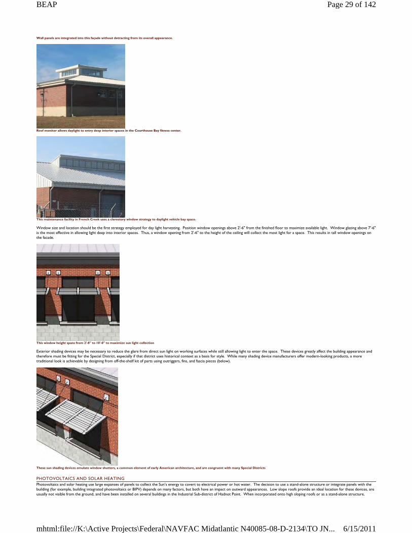
Wall panels are integrated into this façade without detracting from its overall appearance.
Roof monitor allows daylight to entry deep interior spaces in the Courthouse Bay fitness center.
This maintenance facility in French Creek uses a clerestory window strategy to daylight vehicle bay space.
Window size and location should be the first strategy employed for day light harvesting. Position window openings above 2'-6" from the finished floor to maximize available light. Window glazing above 7'-6" is the most effective in allowing light deep into interior spaces. Thus, a window opening from 2'-6" to the height of the ceiling will collect the most light for a space. This results in tall window openings on the facade.
This window height spans from 2'-8" to 10'-0" to maximize sun light collection
Exterior shading devices may be necessary to reduce the glare from direct sun light on working surfaces while still allowing light to enter the space. These devices greatly affect the building appearance and therefore must be fitting for the Special District, especially if that district uses historical context as a basis for style. While many shading device manufacturers offer modern-looking products, a more traditional look is achievable by designing from off-the-shelf kit of parts using outriggers, fins, and fascia pieces (below).
These sun shading devices emulate window shutters, a common element of early American architecture, and are congruent with many Special Districts
PHOTOVOLTAICS AND SOLAR HEATING Photovoltaics and solar heating use large expanses of panels to collect the Sun’s energy to covert to electrical power or hot water. The decision to use a stand-alone structure or integrate panels with the building (for example, building integrated photovoltaics or BIPV) depends on many factors, but both have an impact on outward appearances. Low slope roofs provide an ideal location for these devices, are usually not visible from the ground, and have been installed on several buildings in the Industrial Sub-district of Hadnot Point. When incorporated onto high sloping roofs or as a stand-alone structure,
Page 29 of 142BEAP
6/15/2011mhtml:file://K:\Active Projects\Federal\NAVFAC Midatlantic N40085-08-D-2134\TO JN...
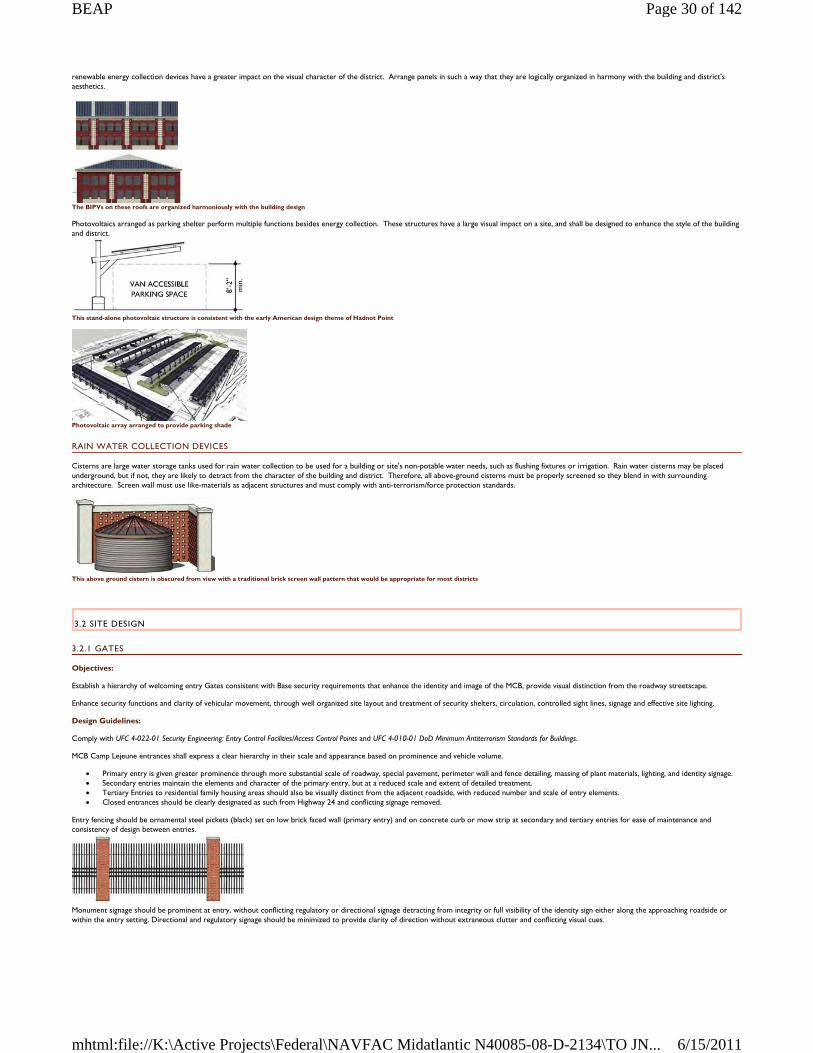
renewable energy collection devices have a greater impact on the visual character of the district. Arrange panels in such a way that they are logically organized in harmony with the building and district's aesthetics.
The BIPVs on these roofs are organized harmoniously with the building design
Photovoltaics arranged as parking shelter perform multiple functions besides energy collection. These structures have a large visual impact on a site, and shall be designed to enhance the style of the building and district.
This stand-alone photovoltaic structure is consistent with the early American design theme of Hadnot Point
Photovoltaic array arranged to provide parking shade
RAIN WATER COLLECTION DEVICES
Cisterns are large water storage tanks used for rain water collection to be used for a building or site's non-potable water needs, such as flushing fixtures or irrigation. Rain water cisterns may be placed underground, but if not, they are likely to detract from the character of the building and district. Therefore, all above-ground cisterns must be properly screened so they blend in with surrounding architecture. Screen wall must use like-materials as adjacent structures and must comply with anti-terrorism/force protection standards.
This above ground cistern is obscured from view with a traditional brick screen wall pattern that would be appropriate for most districts
3.2 SITE DESIGN
3.2.1 GATES
Objectives:
Establish a hierarchy of welcoming entry Gates consistent with Base security requirements that enhance the identity and image of the MCB, provide visual distinction from the roadway streetscape.
Enhance security functions and clarity of vehicular movement, through well organized site layout and treatment of security shelters, circulation, controlled sight lines, signage and effective site lighting.
Design Guidelines:
Comply with UFC 4-022-01 Security Engineering: Entry Control Facilities/Access Control Points and UFC 4-010-01 DoD Minimum Antiterrorism Standards for Buildings.
MCB Camp Lejeune entrances shall express a clear hierarchy in their scale and appearance based on prominence and vehicle volume.
Primary entry is given greater prominence through more substantial scale of roadway, special pavement, perimeter wall and fence detailing, massing of plant materials, lighting, and identity signage. Secondary entries maintain the elements and character of the primary entry, but at a reduced scale and extent of detailed treatment. Tertiary Entries to residential family housing areas should also be visually distinct from the adjacent roadside, with reduced number and scale of entry elements. Closed entrances should be clearly designated as such from Highway 24 and conflicting signage removed.
Entry fencing should be ornamental steel pickets (black) set on low brick faced wall (primary entry) and on concrete curb or mow strip at secondary and tertiary entries for ease of maintenance and consistency of design between entries.
Monument signage should be prominent at entry, without conflicting regulatory or directional signage detracting from integrity or full visibility of the identity sign either along the approaching roadside or within the entry setting. Directional and regulatory signage should be minimized to provide clarity of direction without extraneous clutter and conflicting visual cues.
Page 30 of 142BEAP
6/15/2011mhtml:file://K:\Active Projects\Federal\NAVFAC Midatlantic N40085-08-D-2134\TO JN...
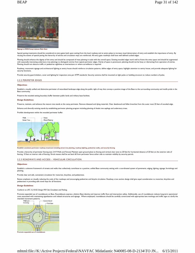
Signage at MCB Camp Lejeune Main Gate
Special paving treatments should be considered at entry gates both upon exiting from the local roadway and at sentry plaza to increase visual demarcation of entry and establish the importance of entry. By varying the extent of special paving the hierarchy of entries and circulation ways are reinforced. All entry gate roadways shall have well defined curbed edges.
Planting should enhance the dignity of the entry and should be composed of mass planting in scale with the overall space. Existing wooded edges work well to frame the entry space and should be augmented with seasonally interesting understory tree plantings to distinguish entries from typical perimeter edges. Clarity of space is paramount; planting should not be fussy or distracting from operation of entries. Planting should not obscure traffic or pedestrian sightlines at intersections or where surveillance is required.
Roadway, monument signage and architectural lighting at sentry house should reinforce circulation patterns, define edges of entry space, highlight attention to sentry house, and provide adequate lighting for security functions.
Provide security guard shelters, cover and lighting for inspection area per ATFP standards. Security cameras shall be mounted on light poles or building structure to reduce numbers of poles.
3.2.2 PERIMETER EDGES
Objectives:
Establish a visually unified and distinctive perimeter of naturalized landscape edge along the public right of way that conveys a positive image of the Base to the surrounding community and instills pride in the Base community.
Preserve the wooded setting boundary buffer between public lands and military base facilities.
Design Guidelines:
Preserve, maintain, and enhance the mature tree stands at the camp perimeter. Remove diseased and dying materials. Clear deadwood and fallen branches from the outer most 25 feet of wooded edge.
Enhance and diversify existing stands by establishing perimeter planting program including planting of shade tree saplings and understory trees.
Prohibit development within the wooded perimeter buffer.
Establish consistent perimeter roadway treatment including street tree planting, roadway lighting, pedestrian walks, and security fencing
Provide a hierarchy of perimeter fencing (see 3.4.9 Walls and Fences) Maintain open ground plane to fencing and vertical clear zone to 20 feet for horizontal distance of 20 feet on the exterior side of fencing, 10 feet on interior side of fencing. Shrub masses shall be set back 60 from perimeter fence either side to maintain visibility by security patrols.
3.2.3 ROADWAYS AND ACCESS – VEHICULAR CIRCULATION
Objectives:
Establish a coherent framework of streets and walks that collectively contribute to a positive, unified Base community setting with a coordinated system of pavements, edging, lighting, signage, furnishings and planting.
Provide clear and safe, convenient circulation for motorists, bicyclists, and pedestrians.
Renew emphasis on visually reducing the scale of the roadways and encouraging pedestrian and bicycle circulation. Roadway cross section design shall give equal consideration to motorists, bicyclists and pedestrians in providing safe travel ways for all functions.
Design Guidelines
Conform to UFC 3-210-02 Design POV Site Circulation and Parking.
Promote expanded use of roundabouts on Base. Roundabouts express a distinct Base identity and improve traffic flow and intersection safety. Additionally, use of roundabouts reduces long-term operational costs associated with maintaining signalization and related structures and signage. Where employed, roundabouts should be carefully constructed with appropriate lane markings and traffic signs to clarify the intended movement patterns.
Promote expanded use of roundabouts
Page 31 of 142BEAP
6/15/2011mhtml:file://K:\Active Projects\Federal\NAVFAC Midatlantic N40085-08-D-2134\TO JN...
Priority consideration should be given to replacing signalized intersections at ceremonial locations and roadway focal points and to poorly performing interactions. Smaller scaled roundabouts should be considered for secondary and tertiary road intersections as a means of improving the overall aesthetic of the area and emphasis on non-motorized environment.
Intersection setbacks
Maintain sight lines and pedestrian crosswalks at intersections. Locate driveways and curb cuts a minimum of 50 feet from the intersection. Provide setbacks between roadway edges and building or parking areas at 30 foot (minimum) on primary roadways and 25 foot (minimum) on secondary roadways.
On street parking will not be permitted on primary or secondary roadways. On street parking will not be permitted on tertiary roadways without review and approval of the BEAP Review Board. In the event the Review Board approves on-street parking for a specific tertiary roadway setting, the following guidelines shall be met: on-street parking will be limited to parallel parking, one side of the road only, applying set back of 30 feet from the corner or 15 feet from the edge of any crosswalk, whichever is greater.
Recommended clearances at streetscape
Signs, hydrants, poles, headwalls, fences, and similar obstructions should be set back from the edge of road and walk/bicycle ways a minimum of two feet.
As street and pathway trees mature, branches extending over roadway shall be limbed up 12 feet (minimum) and at walks/bicycle ways 10 feet (minimum) from paved travel surface.
3.2.3.1 PRIMARY ROADWAY
Primary roadways include: Highway 24 (four lane divided highway), Highway 172, and Highway 17, Holcomb Boulevard, Main Service Road (McHugh and Seth Williams Boulevard), Brewster Avenue and Sneads Ferry Road.
Primary Roadways
New primary roadways greater than two travel lanes each direction are discouraged.
On street parking is prohibited.
Bicycle travel within the curb line is discouraged and shall be accommodated through off-road multi-use or dedicated bicycle ways.
Primary Roadway Section
Primary roadways shall include pedestrian travel way (six foot width minimum) on either side of road. Multiuse pathways (minimum 10 feet width) should be considered in lieu of separate pedestrian and off road bicycle travel ways.
Street edges shall include a deciduous tree planting strip (six foot width minimum, eight feet or more preferred) at the curb edge. Deciduous shade trees reduce the perceived scale of roadway, slow traffic and create a more welcoming environment for pedestrians through separation from traffic and introduction of shade. Primary road street trees shall be formally aligned with the street and spaced at 40 to 50 feet on center typically, but may be closer in heavily trafficked pedestrian areas as part of a larger landscape plan. Mixed, informal grouping of trees and shrubs shall be provided at the rear side of the walk (eight foot minimum width) either to screen adjacent parking or as part of a larger “greenbelt” planting. Roadway medians ten foot width or greater shall be planted with ornamental and/or columnar tree plantings.
Page 32 of 142BEAP
6/15/2011mhtml:file://K:\Active Projects\Federal\NAVFAC Midatlantic N40085-08-D-2134\TO JN...
Street lighting should contribute to streetscape character, hierarchy and consistency in pole/fixture and quality of lighting. Consider using a combined approach of taller street and lower pedestrian level lighting or dual fixture lighting on shared poles in higher density pedestrian/commercial zones.
Primary roadways shall have reinforced/turfed shoulders and, only where absolutely required for stormwater management, vertical curbed edges/concrete curb and gutter edge.
Roadway signage and billboards shall be limited to reduce visual clutter and establish clarity for safe movement and improved way finding.
3.2.3.2 SECONDARY ROADWAY
Provide one (11 foot width) or two (22 foot width) travel lanes in each direction. If there is no bicycle lane within the curb line, consideration should be given to providing an additional one foot shoulder at each curb edge.
Secondary Roadway Section
On street parking is prohibited.
Third, center turning lanes should be considered for secondary roadways that include several vehicle entrances for safe maneuver of left turns. Turning radii should consider movement of large tactical vehicles, especially at operational areas.
Bicycle travel may be accommodated within the curb line through dedicated bicycle lane (five foot width) adjacent to the curb edge or through separate off-road multi-use (10 foot width) or dedicated bicycle ways.
Provide tree planting strip at the street edge, walks, and mixed planting landscape edge at rear of walk and lighting as in primary roadway section.
3.2.3.3 TERTIARY ROADWAY
Provide one travel lane each direction.
Alternatively, pedestrian and bicycle travel may be accommodated through a combined multi-use pathway. Roadways shall be edged with tree planting strip (six foot width minimum) and planted with shade trees spaced 40 feet on center (maximum). Adjacent landscape –either to rear of walk or contiguous to street tree planting - shall be composed of mixed stands of shade and understory trees as part of “greenbelt” planting.
Lighting shall be provided for combined roadway and pedestrian functions in character and scale with reduced roadway width.
On street parking will not be permitted on tertiary roadways without review and approval of the Architectural Review Board. In the event the Review Board approves on-street parking for a specific tertiary roadway setting, the following guidelines shall be met: on-street parking will be limited to parallel parking, one side of the road only, applying set back of 30 feet from the corner or 15 feet from the edge of any crosswalk, whichever is greater. Parking “bump outs” are encouraged to minimize road width at intersections, reduce extent of impervious pavement and improve pedestrian and vehicle safety.
Bicycle travel shall be accommodated within the roadway in “shared” vehicular/bicycle travel lane or through off-road pathways.
Pedestrian walkways (six foot width) shall be provided on at least one side of roadway.
Tertiary Roadway Section
Tertiary Roadway Plan Diagram
3.2.3.4 SERVICE ROADWAY
Provide service roadways and driveways from secondary or tertiary roadways to adjacent parking areas or building service zones as required and allowed by ATFP requirements.
Page 33 of 142BEAP
6/15/2011mhtml:file://K:\Active Projects\Federal\NAVFAC Midatlantic N40085-08-D-2134\TO JN...
Maximum pavement width shall be 18 feet on typical access routes with intermittent use. Access road layout and related loading dock and service functions shall be designed for efficient movement and to minimize extent of impervious paved surfaces.
Align service drives to minimize service/ pedestrian crossings and visibility of service functions from public areas. Provide screening from public areas through planting or architectural quality screen walls.
3.2.4 BUILDING SITING – BUILDING LAYOUT ORIENTATION
Objectives:
Site buildings in positive physical and functional relationship to each other and surrounding site developments, circulation systems and open space to strengthen community identity and activity.
Establish clarity in site design, with logical order and sequence of spaces from site arrival to building entry.
Respond to the natural environment by limiting the extent of development-related disturbance, and preserving and enhancing the natural setting.
Reduce development related storm water runoff and enhance the stability of natural environment. Increase shade and reduce the need for infrastructure through wise siting and design of buildings and treatment of surroundings including implementation of extensive tree planting program.
Design Guidelines
Increase emphasis on creation of buildings segregated fro parking and site-focused design in response to ATFP requirements, with parking and roadways to the periphery and contiguous pedestrian/ bicycle open spaces and building environments at the core of community settings. Conform to UFC 4-010-01 DoD Minimum Antiterrorism Standards for Buildings.
Group built facilities in positive relationship to each other and adjacent exterior space within contiguous standoff zones to maximize site land use options and preserve the greatest amount of continuous impervious land.
Siting Diagram
Orient building entries onto shared space and connect entries to each other by convenient pedestrian ways. Siting buildings to open onto pedestrian dominated open spaces is encouraged.
Present inviting and favorable articulated building facades toward adjacent streets and parking, even if not providing an entry at that face due to ATFP requirements. Avoid “fortress-like” appearances or otherwise minimally animated exterior facades.
Establish visible “entry forecourts” to provide welcoming exterior arrival spaces that lead one from off site to building entries.
Provide pedestrian and bicycle connections between buildings, to adjacent parking areas and to local roadway, pedestrian, and bicycle systems. Minimize conflicts between vehicular and non-vehicular circulation by providing separation and clarity in routes.
Provide convenient service, delivery and emergency access that is visually screened from public areas.
Site buildings in proximal relationship to other facilities to maximize efficiency of shared resources including walks, lighting, utilities and infrastructure, common facilities, roadways, parking, and long term care and maintenance of grounds.
Site buildings for maximum solar orientation benefit, daylighting opportunity, and reduced heating and cooling demand.
When determining location of development, protect existing natural resources. Avoid development within 50 feet of a water body, five feet of floodplain, and 100 feet from wetland edge.
When planning facilities, give consideration to future expansion of buildings, parking and stormwater management features.
3.2.5 PARKING
3.2.5.1 SURFACE PARKING
Objectives:
Provide attractive, well organized, safe parking areas.
Reduce the overall need for surface parking area through efficient design and decreased use of vehicles on Base.
Reduce the environmental impact of parking and related amenities such as lighting.
Design Guidelines
All parking areas shall conform to UFC 3-210-02 Design: POV Site Circulation and Parking guidelines. Standard off-street parking layouts, curbing and striping shall be applied Base-wide. Restripe non-conforming areas, and areas with inefficient layouts or unclear circulation to gain stall count and/or reduce lot size. Remove unneeded pavement and create planting beds where removal of “painted islands” allow.
Prohibit on-street parking on all primary and secondary roadways. On-street parking on tertiary roadways will not be permitted without review and approval of the BEAP Review Board. In the event the Review Board approves on-street parking for a specific tertiary roadway setting, the following guidelines shall be met: on–street parking shall be limited to parallel parking, one side of the road only, applying set back of 30 feet from corner or 15 feet from edge of crosswalks, whichever is greater. Maintain fire lanes and safe pedestrian crossings.
Maximize parking efficiency and clarity of movement. Utilize standard 90 degree parking layout with two way access aisles.
Where possible, consolidate parking for multiple facilities so that buildings may be sited in clusters without separation by individual parking areas that may result in increased standoff zones.
Reduce visual impact of parking from roadways and adjacent use areas by establishing planting strips (eight foot width minimum) of informal planting of varied heights – shrub, ornamental trees and shade
Page 34 of 142BEAP
6/15/2011mhtml:file://K:\Active Projects\Federal\NAVFAC Midatlantic N40085-08-D-2134\TO JN...
trees. Situate planting islands within the parking area to maximize screening potential and overall shade coverage.
Plant trees to shade parking areas. Provide 15 percent minimum shade coverage measured 10 years after installation of trees. Within the parking limits, provide pervious planting bed equal to or greater than five percent of the total square footage of paving area.
Provide defined curbed edge to all parking perimeters and planting islands. Curbed edge may include regular breaks or notched inlets as part of stormwater management design. If curb is not provided due to stormwater management design requirements, provide pre-cast parking bumpers at all parking stalls and provide edge of pavement line markings to discourage travel at the edge of pavement.
Provide two foot clearance at back of curb (bumper edge) for safety and ease of maintenance. Bollards, signage and other vertical objects shall be placed outside this two foot zone. Plant materials within this area should be 6 inch height maximum.
Opportunities to reduce stormwater management infrastructure demands through Low Impact Design features, including bio swales, infiltration basins and pervious pavement, shall be considered. Pervious pavement shall not be used in tactical vehicle paving areas or along delivery or trash pick-up routes within POV parking lots.
In order to limit the spread of light to adjacent facilities and restrict upward light spill, all parking area lighting fixtures shall be full-cutoff type. The use of LED lighting fixtures is encouraged.
Provide universal accessible parking spaces and associated pedestrian walks to facilities as required by State and Federal ADA regulation.
Provide designated motorcycle parking spaces 4 ½ feet wide by 12 feet long where need is demonstrated.
3.2.5.2 PARKING GARAGES
Objectives:
Provide attractive, efficient structured parking where demand justifies.
Reduce the visual impact of structures on adjacent buildings and outdoor use areas through effective siting, design and landscape treatment of adjacent standoff zone.
Reduce the overall demand for surface parking and related impacts including greater land disturbance, increased impervious surface, and heat island effect.
Design Guidelines
Establish “greenbelt” treatment in standoff zone between parking structure and unobstructed space of adjacent facilities. Greenbelt planting shall include mixed tree planting of understory and deciduous shade and/ or evergreen trees.
Consider approaches to grading that reduce the visual impact of structured parking through combining berming and naturalized planting.
Include pedestrian walkways linking structured parking to adjacent facilities, roadway and existing walk system in the implementation of new parking structures. Include bicycle parking and shower facilities within structured parking facilities and connections to the bicycle route system.
Parking garages shall be designed with the same style and characteristics as the Special District or sub-district in which they are built. This is particularly important because parking garages will be large, dominant structures on any site and its character will over-power other small adjacent structures.
Above illustration shows a three story parking deck appropriate for Hadnot Point, Wallace Creek, or other Special District where the Georgian or Colonial Revival style is called for. The pre-cast stair or elevator tower is used to break up the expanse of the structure.
The exterior of parking garages shall be level and not express inclined ramps on the façade, in order to blend the structure's appearance with surrounding buildings.
3.2.6 BICYCLE CIRCULATION
Objectives:
Bicycle transportation provides an alternative to vehicular use on Base and results in reduced demand for roadway, parking and utility infrastructure.
Provision of safe, enjoyable bicycle travel ways encourages bicycle use for transportation and recreation.
Design Guidelines
Multi-use trails (10 foot width) for use by pedestrians and bicyclists shall be included within all primary streetscape sections. Primary roadway related multi –use trails may run parallel to roadways or more informally with curving alignments. Alignment design should respect nature of safe travel for both pedestrians and bicyclists.
Multi-use trails reintroduce bicycles to traffic at roadway intersections. Intersection and crosswalks design shall consider safety of all users.
Continued implementation of Base-wide multi-use trail and “Greenway” system serving bicyclists, joggers, and pedestrians and linking roadway system, areas of development, and natural areas is encouraged. The Greenway Master Plan allows planned incremental development. All Base projects shall include both pedestrian and bicycle connections to adjacent roadways and facilities.
Within secondary roadway sections, bicycle travel shall be accommodated within the roadway in dedicated bicycle travel lane (five foot width) or through adjacent off-road multi-use trail if one exists as part of overall trail system. On tertiary roads, bicycles “share” the vehicular travel lane.
All bicycle ways, whether dedicated bicycle trail, multi-use trail or bicycle roadway lane, shall have minimum two foot clear zone to either side of the travel way without vertical obstruction or abrupt grade drop.
As trees adjacent to bikeways mature, branches extending over travel way shall be limbed up 10 feet (minimum) from travel surface.
Multi-use trails and dedicated bike lanes intended for use after dark shall be lighted as appropriate for general street conditions with special emphasis on lighting at intersections and road crossings.
Page 35 of 142BEAP
6/15/2011mhtml:file://K:\Active Projects\Federal\NAVFAC Midatlantic N40085-08-D-2134\TO JN...
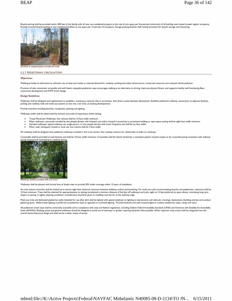
Bicycle parking shall be provided within 200 feet of the facility with all new non-residential projects at the rate of one space per five percent (minimum) of all building users based at peak regular occupancy. Provide covered bicycle parking at new residential facilities at one space per 15 percent of occupants. Garage parking facilities shall include provision for bicycle storage and showering.
Continue to expand system of multi-use trails
3.2.7 PEDESTRIAN CIRCULATION
Objectives:
Walking provides an alternative to vehicular use on base and results in reduced demand for roadway, parking and utility infrastructure, conserved resources and reduced vehicle pollution.
Provision of safe, convenient, accessible and well linked, enjoyable pedestrian ways encourages walking as an alternative to driving, improves physical fitness, and supports healthy well functioning Base community development and ATFP driven design.
Design Guidelines
Walkways shall be designed and implemented to establish a continuous network that is convenient, with direct routes between destinations. Establish pedestrian walkway connections to adjacent facilities, parking and roadway walk and multi-use systems at new and, over time, at existing developments.
Provide amenities including benches, receptacles, planting and lighting.
Walkways width shall be determined by function and scale of importance within setting.
Troop Movement Walkways: four abreast shall be 10 foot width minimum. Major walkways: commonly traveled by two people abreast with frequent use and/or located in proximity to prominent building or open space setting shall be eight foot width minimum. Standard walkways: typical walkway use, single person, or two people abreast with lower frequency use shall be six foot width. Minor walk: infrequent, limited or local use, low volume shall be 4 foot width.
All roadways shall be designed with pedestrian walkways included in the cross section. See roadway sections for relationship of walks to roadways.
Crosswalks shall be provided at intersections and shall be 10 foot width minimum. Crosswalks shall be clearly marked by a consistent pattern of paint stripes or by crosswalk paving consistent with walkway paving material and contrasting to roadway paving.
Walkways shall be provided with tree cover.
Walkways shall be planted with formal lines of shade trees to provide 50% shade coverage within 10 years of installation.
As trees mature, branches shall be limbed up to ensure eight foot minimum clearance between walkway surface and branching. For multi-use trails accommodating bicycles and pedestrians, clearance shall be 10 foot minimum. Trees shall be selected for appropriateness to setting and planted a minimum distance of five feet off walkways and trails, eight to 12 feet preferred as space allows, minimizing long term impact on paving. In tighter planting conditions, consideration should be given to installing root barrier at the walkway edge.
Multi-use trails and dedicated pedestrian walks intended for use after dark shall be lighted with special emphasis on lighting at intersections and vehicular crossings, destinations (building entries) and outdoor gathering spots. Bollard-style lighting is preferred at pedestrian ways as opposed to overhead lighting. Provide handrails and wall-recessed lights at outdoor pedestrian steps, ramps and stairs.
All pedestrian travel ways shall be universally accessible and in compliance with state and federal regulations, including Uniform Federal Accessibility Standards (UFAS) and Americans with Disability Act Accessibility Guide (ADAAG). Building access and general walkways should be designed to avoid use of stairways or grades requiring handrails when possible. When required, ramp access shall be integrated into the overall site/architectural design and shall not be a lesser means of access.
Page 36 of 142BEAP
6/15/2011mhtml:file://K:\Active Projects\Federal\NAVFAC Midatlantic N40085-08-D-2134\TO JN...
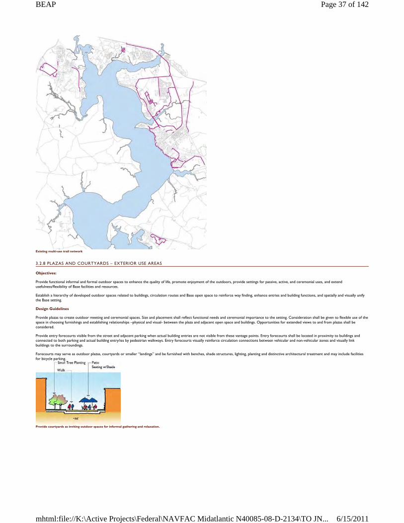
Existing multi-use trail network
3.2.8 PLAZAS AND COURTYARDS – EXTERIOR USE AREAS
Objectives:
Provide functional informal and formal outdoor spaces to enhance the quality of life, promote enjoyment of the outdoors, provide settings for passive, active, and ceremonial uses, and extend usefulness/flexibility of Base facilities and resources.
Establish a hierarchy of developed outdoor spaces related to buildings, circulation routes and Base open space to reinforce way finding, enhance entries and building functions, and spatially and visually unify the Base setting.
Design Guidelines
Provide plazas to create outdoor meeting and ceremonial spaces. Size and placement shall reflect functional needs and ceremonial importance to the setting. Consideration shall be given to flexible use of the space in choosing furnishings and establishing relationships –physical and visual- between the plaza and adjacent open space and buildings. Opportunities for extended views to and from plazas shall be considered.
Provide entry forecourts visible from the street and adjacent parking when actual building entries are not visible from these vantage points. Entry forecourts shall be located in proximity to buildings and connected to both parking and actual building entry/ies by pedestrian walkways. Entry forecourts visually reinforce circulation connections between vehicular and non-vehicular zones and visually link buildings to the surroundings.
Forecourts may serve as outdoor plazas, courtyards or smaller “landings” and be furnished with benches, shade structures, lighting, planting and distinctive architectural treatment and may include facilities for bicycle parking.
Provide courtyards as inviting outdoor spaces for informal gathering and relaxation.
Page 37 of 142BEAP
6/15/2011mhtml:file://K:\Active Projects\Federal\NAVFAC Midatlantic N40085-08-D-2134\TO JN...
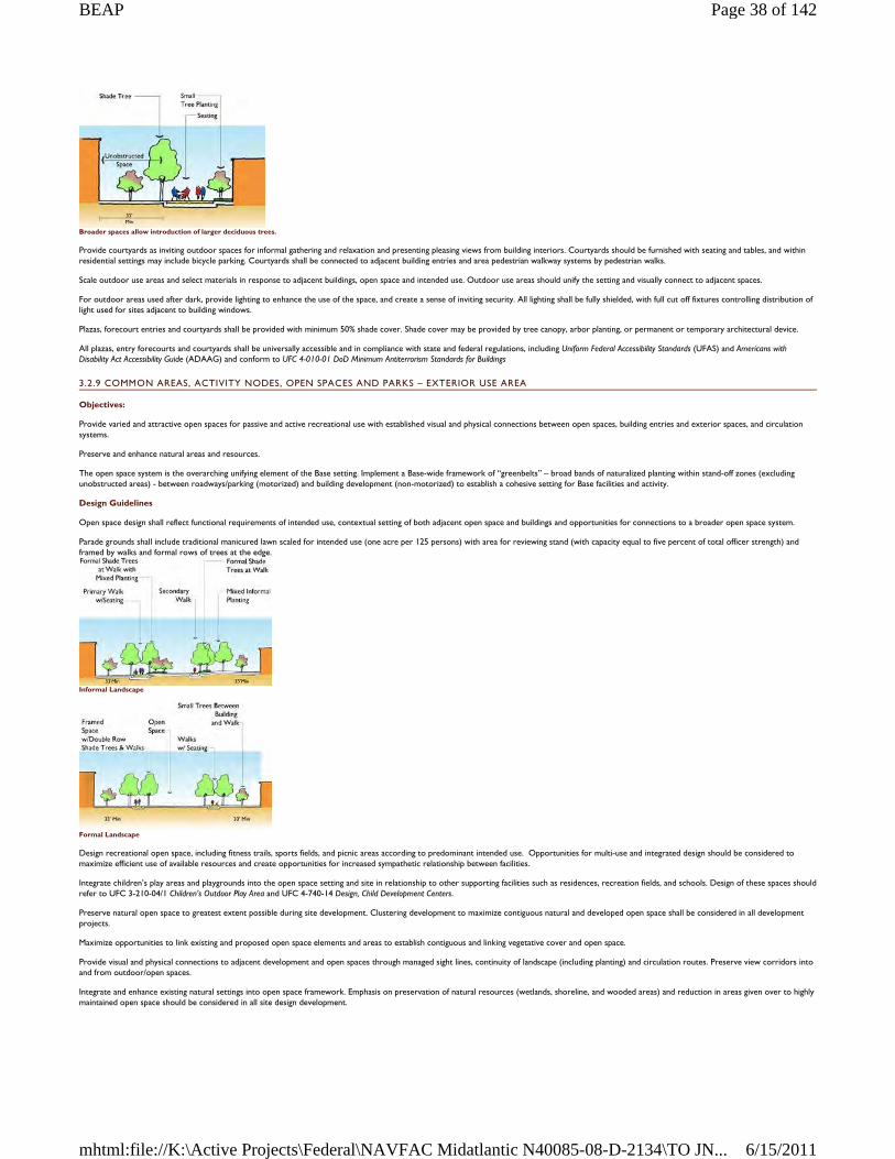
Broader spaces allow introduction of larger deciduous trees.
Provide courtyards as inviting outdoor spaces for informal gathering and relaxation and presenting pleasing views from building interiors. Courtyards should be furnished with seating and tables, and within residential settings may include bicycle parking. Courtyards shall be connected to adjacent building entries and area pedestrian walkway systems by pedestrian walks.
Scale outdoor use areas and select materials in response to adjacent buildings, open space and intended use. Outdoor use areas should unify the setting and visually connect to adjacent spaces.
For outdoor areas used after dark, provide lighting to enhance the use of the space, and create a sense of inviting security. All lighting shall be fully shielded, with full cut off fixtures controlling distribution of light used for sites adjacent to building windows.
Plazas, forecourt entries and courtyards shall be provided with minimum 50% shade cover. Shade cover may be provided by tree canopy, arbor planting, or permanent or temporary architectural device.
All plazas, entry forecourts and courtyards shall be universally accessible and in compliance with state and federal regulations, including Uniform Federal Accessibility Standards (UFAS) and Americans with Disability Act Accessibility Guide (ADAAG) and conform to UFC 4-010-01 DoD Minimum Antiterrorism Standards for Buildings
3.2.9 COMMON AREAS, ACTIVITY NODES, OPEN SPACES AND PARKS – EXTERIOR USE AREA
Objectives:
Provide varied and attractive open spaces for passive and active recreational use with established visual and physical connections between open spaces, building entries and exterior spaces, and circulation systems.
Preserve and enhance natural areas and resources.
The open space system is the overarching unifying element of the Base setting. Implement a Base-wide framework of “greenbelts” – broad bands of naturalized planting within stand-off zones (excluding unobstructed areas) - between roadways/parking (motorized) and building development (non-motorized) to establish a cohesive setting for Base facilities and activity.
Design Guidelines
Open space design shall reflect functional requirements of intended use, contextual setting of both adjacent open space and buildings and opportunities for connections to a broader open space system.
Parade grounds shall include traditional manicured lawn scaled for intended use (one acre per 125 persons) with area for reviewing stand (with capacity equal to five percent of total officer strength) and framed by walks and formal rows of trees at the edge.
Informal Landscape
Formal Landscape
Design recreational open space, including fitness trails, sports fields, and picnic areas according to predominant intended use. Opportunities for multi-use and integrated design should be considered to maximize efficient use of available resources and create opportunities for increased sympathetic relationship between facilities.
Integrate children’s play areas and playgrounds into the open space setting and site in relationship to other supporting facilities such as residences, recreation fields, and schools. Design of these spaces should refer to UFC 3-210-04/1 Children’s Outdoor Play Area and UFC 4-740-14 Design, Child Development Centers.
Preserve natural open space to greatest extent possible during site development. Clustering development to maximize contiguous natural and developed open space shall be considered in all development projects.
Maximize opportunities to link existing and proposed open space elements and areas to establish contiguous and linking vegetative cover and open space.
Provide visual and physical connections to adjacent development and open spaces through managed sight lines, continuity of landscape (including planting) and circulation routes. Preserve view corridors into and from outdoor/open spaces.
Integrate and enhance existing natural settings into open space framework. Emphasis on preservation of natural resources (wetlands, shoreline, and wooded areas) and reduction in areas given over to highly maintained open space should be considered in all site design development.
Page 38 of 142BEAP
6/15/2011mhtml:file://K:\Active Projects\Federal\NAVFAC Midatlantic N40085-08-D-2134\TO JN...
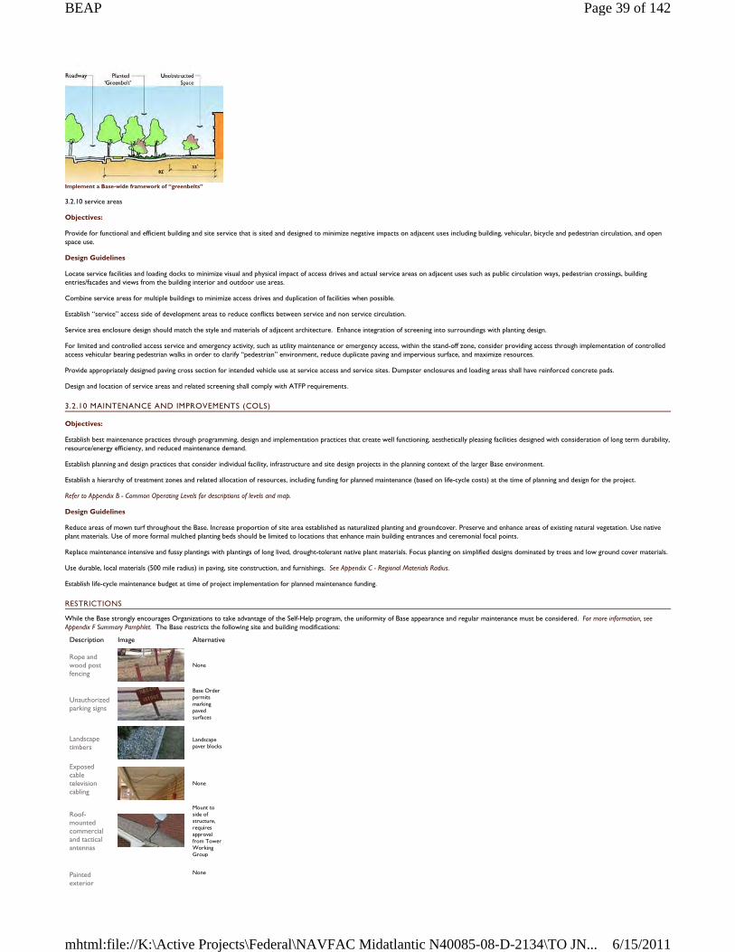
Implement a Base-wide framework of “greenbelts”
3.2.10 service areas
Objectives:
Provide for functional and efficient building and site service that is sited and designed to minimize negative impacts on adjacent uses including building, vehicular, bicycle and pedestrian circulation, and open space use.
Design Guidelines
Locate service facilities and loading docks to minimize visual and physical impact of access drives and actual service areas on adjacent uses such as public circulation ways, pedestrian crossings, building entries/facades and views from the building interior and outdoor use areas.
Combine service areas for multiple buildings to minimize access drives and duplication of facilities when possible.
Establish “service” access side of development areas to reduce conflicts between service and non service circulation.
Service area enclosure design should match the style and materials of adjacent architecture. Enhance integration of screening into surroundings with planting design.
For limited and controlled access service and emergency activity, such as utility maintenance or emergency access, within the stand-off zone, consider providing access through implementation of controlled access vehicular bearing pedestrian walks in order to clarify “pedestrian” environment, reduce duplicate paving and impervious surface, and maximize resources.
Provide appropriately designed paving cross section for intended vehicle use at service access and service sites. Dumpster enclosures and loading areas shall have reinforced concrete pads.
Design and location of service areas and related screening shall comply with ATFP requirements.
3.2.10 MAINTENANCE AND IMPROVEMENTS (COLS)
Objectives:
Establish best maintenance practices through programming, design and implementation practices that create well functioning, aesthetically pleasing facilities designed with consideration of long term durability, resource/energy efficiency, and reduced maintenance demand.
Establish planning and design practices that consider individual facility, infrastructure and site design projects in the planning context of the larger Base environment.
Establish a hierarchy of treatment zones and related allocation of resources, including funding for planned maintenance (based on life-cycle costs) at the time of planning and design for the project.
Refer to Appendix B - Common Operating Levels for descriptions of levels and map.
Design Guidelines
Reduce areas of mown turf throughout the Base. Increase proportion of site area established as naturalized planting and groundcover. Preserve and enhance areas of existing natural vegetation. Use native plant materials. Use of more formal mulched planting beds should be limited to locations that enhance main building entrances and ceremonial focal points.
Replace maintenance intensive and fussy plantings with plantings of long lived, drought-tolerant native plant materials. Focus planting on simplified designs dominated by trees and low ground cover materials.
Use durable, local materials (500 mile radius) in paving, site construction, and furnishings. See Appendix C - Regional Materials Radius.
Establish life-cycle maintenance budget at time of project implementation for planned maintenance funding.
RESTRICTIONS
While the Base strongly encourages Organizations to take advantage of the Self-Help program, the uniformity of Base appearance and regular maintenance must be considered. For more information, see Appendix F Summary Pamphlet. The Base restricts the following site and building modifications:
Description Image Alternative
Rope and wood post fencing
None
Unauthorized parking signs
Base Order permits marking paved surfaces
Landscape timbers
Landscape paver blocks
Exposed cable television cabling
None
Roof-mounted commercial and tactical antennas
Mount to side of structure, requires approval from Tower Working Group
Painted exterior
None
Page 39 of 142BEAP
6/15/2011mhtml:file://K:\Active Projects\Federal\NAVFAC Midatlantic N40085-08-D-2134\TO JN...
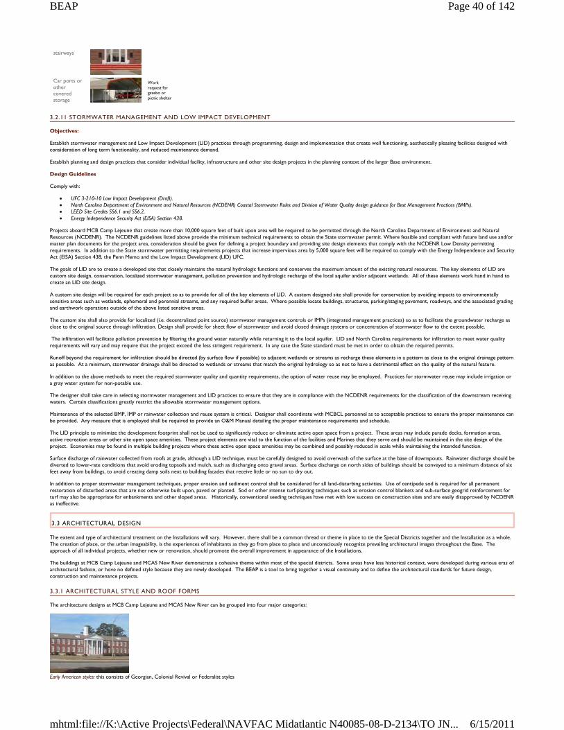
3.2.11 STORMWATER MANAGEMENT AND LOW IMPACT DEVELOPMENT
Objectives:
Establish stormwater management and Low Impact Development (LID) practices through programming, design and implementation that create well functioning, aesthetically pleasing facilities designed with consideration of long term functionality, and reduced maintenance demand.
Establish planning and design practices that consider individual facility, infrastructure and other site design projects in the planning context of the larger Base environment.
Design Guidelines
Comply with:
UFC 3-210-10 Low Impact Development (Draft). North Carolina Department of Environment and Natural Resources (NCDENR) Coastal Stormwater Rules and Division of Water Quality design guidance for Best Management Practices (BMPs). LEED Site Credits SS6.1 and SS6.2. Energy Independence Security Act (EISA) Section 438.
Projects aboard MCB Camp Lejeune that create more than 10,000 square feet of built upon area will be required to be permitted through the North Carolina Department of Environment and Natural Resources (NCDENR). The NCDENR guidelines listed above provide the minimum technical requirements to obtain the State stormwater permit. Where feasible and compliant with future land use and/or master plan documents for the project area, consideration should be given for defining a project boundary and providing site design elements that comply with the NCDENR Low Density permitting requirements. In addition to the State stormwater permitting requirements projects that increase impervious area by 5,000 square feet will be required to comply with the Energy Independence and Security Act (EISA) Section 438, the Penn Memo and the Low Impact Development (LID) UFC.
The goals of LID are to create a developed site that closely maintains the natural hydrologic functions and conserves the maximum amount of the existing natural resources. The key elements of LID are custom site design, conservation, localized stormwater management, pollution prevention and hydrologic recharge of the local aquifer and/or adjacent wetlands. All of these elements work hand in hand to create an LID site design.
A custom site design will be required for each project so as to provide for all of the key elements of LID. A custom designed site shall provide for conservation by avoiding impacts to environmentally sensitive areas such as wetlands, ephemeral and perennial streams, and any required buffer areas. Where possible locate buildings, structures, parking/staging pavement, roadways, and the associated grading and earthwork operations outside of the above listed sensitive areas.
The custom site shall also provide for localized (i.e. decentralized point source) stormwater management controls or IMPs (integrated management practices) so as to facilitate the groundwater recharge as close to the original source through infiltration. Design shall provide for sheet flow of stormwater and avoid closed drainage systems or concentration of stormwater flow to the extent possible.
The infiltration will facilitate pollution prevention by filtering the ground water naturally while returning it to the local aquifer. LID and North Carolina requirements for infiltration to meet water quality requirements will vary and may require that the project exceed the less stringent requirement. In any case the State standard must be met in order to obtain the required permits.
Runoff beyond the requirement for infiltration should be directed (by surface flow if possible) to adjacent wetlands or streams as recharge these elements in a pattern as close to the original drainage pattern as possible. At a minimum, stormwater drainage shall be directed to wetlands or streams that match the original hydrology so as not to have a detrimental effect on the quality of the natural feature.
In addition to the above methods to meet the required stormwater quality and quantity requirements, the option of water reuse may be employed. Practices for stormwater reuse may include irrigation or a gray water system for non-potable use.
The designer shall take care in selecting stormwater management and LID practices to ensure that they are in compliance with the NCDENR requirements for the classification of the downstream receiving waters. Certain classifications greatly restrict the allowable stormwater management options.
Maintenance of the selected BMP, IMP or rainwater collection and reuse system is critical. Designer shall coordinate with MCBCL personnel as to acceptable practices to ensure the proper maintenance can be provided. Any measure that is employed shall be required to provide an O&M Manual detailing the proper maintenance requirements and schedule.
The LID principle to minimize the development footprint shall not be used to significantly reduce or eliminate active open space from a project. These areas may include parade decks, formation areas, active recreation areas or other site open space amenities. These project elements are vital to the function of the facilities and Marines that they serve and should be maintained in the site design of the project. Economies may be found in multiple building projects where these active open space amenities may be combined and possibly reduced in scale while maintaining the intended function.
Surface discharge of rainwater collected from roofs at grade, although a LID technique, must be carefully designed to avoid overwash of the surface at the base of downspouts. Rainwater discharge should be diverted to lower-rate conditions that avoid eroding topsoils and mulch, such as discharging onto gravel areas. Surface discharge on north sides of buildings should be conveyed to a minimum distance of six feet away from buildings, to avoid creating damp soils next to building facades that receive little or no sun to dry out.
In addition to proper stormwater management techniques, proper erosion and sediment control shall be considered for all land-disturbing activities. Use of centipede sod is required for all permanent restoration of disturbed areas that are not otherwise built upon, paved or planted. Sod or other intense turf-planting techniques such as erosion control blankets and sub-surface geogrid reinforcement for turf may also be appropriate for enbankments and other sloped areas. Historically, conventional seeding techniques have met with low success on construction sites and are easily disapproved by NCDENR as ineffective.
3.3 ARCHITECTURAL DESIGN
The extent and type of architectural treatment on the Installations will vary. However, there shall be a common thread or theme in place to tie the Special Districts together and the Installation as a whole. The creation of place, or the urban imageability, is the experiences of inhabitants as they go from place to place and unconsciously recognize prevailing architectural images throughout the Base. The approach of all individual projects, whether new or renovation, should promote the overall improvement in appearance of the Installations.
The buildings at MCB Camp Lejeune and MCAS New River demonstrate a cohesive theme within most of the special districts. Some areas have less historical context, were developed during various eras of architectural fashion, or hove no defined style because they are newly developed. The BEAP is a tool to bring together a visual continuity and to define the architectural standards for future design, construction and maintenance projects.
3.3.1 ARCHITECTURAL STYLE AND ROOF FORMS
The architecture designs at MCB Camp Lejeune and MCAS New River can be grouped into four major categories:
Early American styles: this consists of Georgian, Colonial Revival or Federalist styles
stairways
Car ports or other covered storage
Work request for gazebo or picnic shelter
Page 40 of 142BEAP
6/15/2011mhtml:file://K:\Active Projects\Federal\NAVFAC Midatlantic N40085-08-D-2134\TO JN...
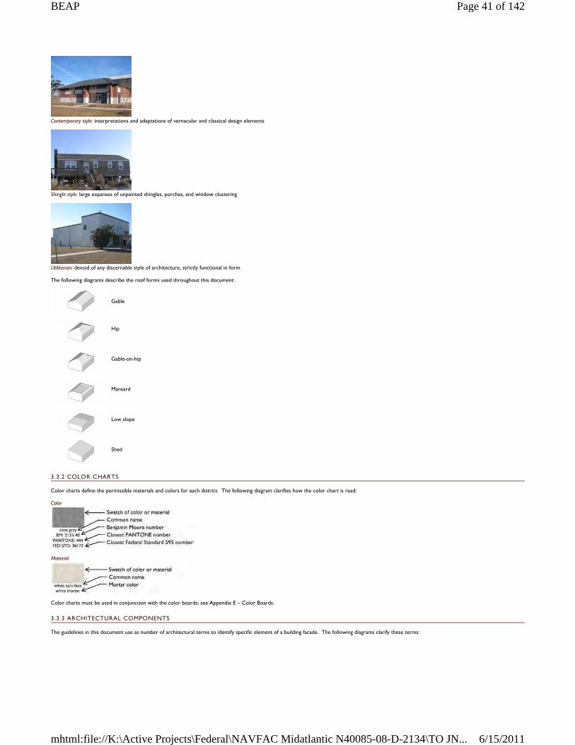
Contemporary style: interpretations and adaptations of vernacular and classical design elements
Shingle style: large expanses of unpainted shingles, porches, and window clustering
Utilitarian: devoid of any discernable style of architecture, strictly functional in form
The following diagrams describe the roof forms used throughout this document:
3.3.2 COLOR CHARTS
Color charts define the permissible materials and colors for each district. The following diagram clarifies how the color chart is read:
Color
Material
Color charts must be used in conjunction with the color boards; see Appendix E – Color Boards.
3.3.3 ARCHITECTURAL COMPONENTS
The guidelines in this document use as number of architectural terms to identify specific element of a building facade. The following diagrams clarify these terms:
Gable
Hip
Gable-on-hip
Mansard
Low slope
Shed
Page 41 of 142BEAP
6/15/2011mhtml:file://K:\Active Projects\Federal\NAVFAC Midatlantic N40085-08-D-2134\TO JN...
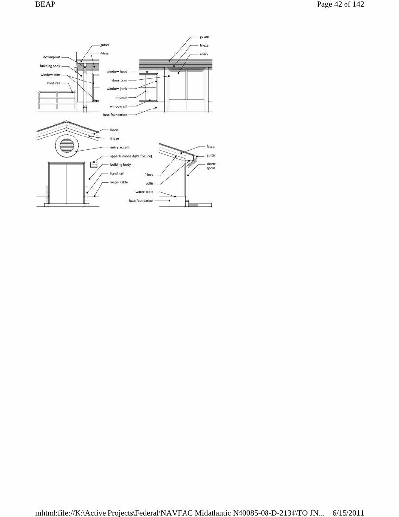
Page 42 of 142BEAP
6/15/2011mhtml:file://K:\Active Projects\Federal\NAVFAC Midatlantic N40085-08-D-2134\TO JN...
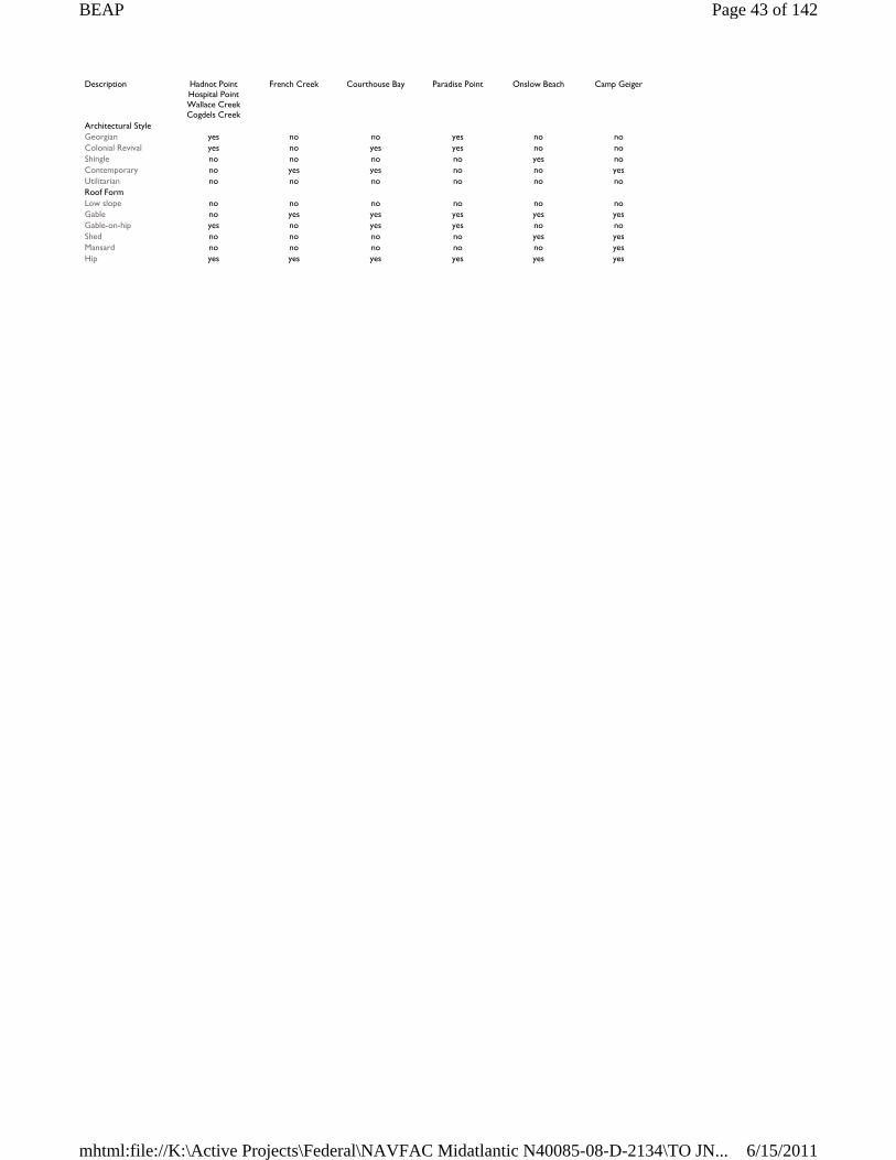
Description Hadnot Point Hospital Point Wallace Creek Cogdels Creek
French Creek
Courthouse Bay Paradise Point Onslow Beach Camp Geiger
Architectural Style Georgian yes no no yes no no Colonial Revival yes no yes yes no no Shingle no no no no yes no Contemporary no yes yes no no yes Utilitarian no no no no no no Roof Form Low slope no no no no no no Gable no yes yes yes yes yes Gable-on-hip yes no yes yes no no Shed no no no no yes yes Mansard no no no no no yes Hip yes yes yes yes yes yes
Page 43 of 142BEAP
6/15/2011mhtml:file://K:\Active Projects\Federal\NAVFAC Midatlantic N40085-08-D-2134\TO JN...
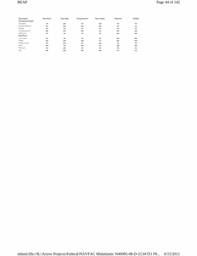
Description New River Stone Bay Camp Johnson Entry Gates Industrial Airfield Architectural Style Georgian no yes no yes no no Colonial Revival no yes yes yes no no Shingle no no no no no no Contemporary yes yes yes no yes yes Utilitarian no no no no yes yes Roof Form Low slope no no no no yes yes Gable yes yes yes no yes yes Gable-on-hip no yes no yes no no Shed yes no yes no yes yes Mansard no yes no no no no Hip yes yes yes yes no no
Page 44 of 142BEAP
6/15/2011mhtml:file://K:\Active Projects\Federal\NAVFAC Midatlantic N40085-08-D-2134\TO JN...
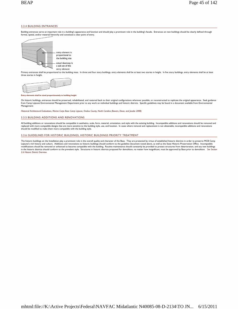
3.3.4 BUILDING ENTRANCES
Building entrances serve an important role in a building's appearance and function and should play a prominent role in the building's facade. Entrances on new buildings should be clearly defined through formal, spatial, and/or material hierarchy and constitute a clear point of entry.
Primary entrances shall be proportional to the building mass. In three and four story buildings, entry elements shall be at least two stories in height. In five story buildings, entry elements shall be at least three stories in height.
Entry elements shall be sized proportionately to building height
On historic buildings, entrances should be preserved, rehabilitated, and restored back to their original configurations wherever possible, or reconstructed to replicate the original appearance. Seek guidance from Camp Lejeune Environmental Management Department prior to any work on individual buildings and historic districts. Specific guidelines may be found in a document available from Environmental Management:
Historical Architectural Evaluations, Marine Corps Base Camp Lejeune, Onslow County, North Carolina (Bowers, Dixon, and Jacobe 2008)
3.3.5 BUILDING ADDITIONS AND RENOVATIONS
All building additions or renovations should be compatible in aesthetics, scale, form, material, orientation, and style with the existing building. Incompatible additions and renovations should be removed and replaced with more compatible designs that are more sensitive to the building style, use, and location. In cases where removal and replacement is not obtainable, incompatible additions and renovations should be modified to make them more compatible with the building style.
3.3.6 GUIDELINES FOR HISTORIC BUILDINGS, HISTORIC BUILDINGS PRIORITY TREATMENT
The historic buildings on the Installation play a prominent role in the overall quality and character of the Base. They are protected by virtue of established historic districts in order to preserve MCB Camp Lejeune's rich history and culture. Additions and renovations to historic buildings should conform to the guideline document noted above, as well as the State Historic Preservation Office. Incompatible modifications should be removed or enhanced to become compatible with the building. Routine maintenance should constantly be provided to protect structures from deterioration, and any new buildings in the historic districts should conform to the prevalent style. Structures in historic districts proposed for demolition, no matter how insignificant, must be approved by Base prior to demolition. See Section 2.6 Historic District Overview.
Page 45 of 142BEAP
6/15/2011mhtml:file://K:\Active Projects\Federal\NAVFAC Midatlantic N40085-08-D-2134\TO JN...
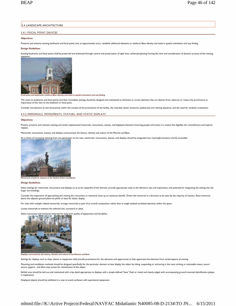
3.4 LANDSCAPE ARCHITECTURE
3.4.1 FOCAL POINT DEVICES
Objectives:
Preserve and enhance existing landmarks and focal points and, as opportunities occur, establish additional elements to reinforce Base identity and assist in spatial orientation and way finding.
Design Guidelines
Existing landmarks and focal points shall be preserved and enhanced through control and preservation of sight lines, enhanced planting framing the view and consideration of dynamic process of the viewing sequence.
Focal point and landmarks reinforce Base identity and assist in spatial orientation and way finding
The views to landmarks and focal points and their immediate settings should be designed and maintained to eliminate or screen elements that are distract from, obstruct or reduce the prominence or importance of the view to the landmark or focal point.
Consider introduction of new focal points within the context of the prominence of the facility, the intended viewer (motorist, pedestrian) and viewing sequence, and the need for symbolic orientation.
3.4.2 MEMORIALS, MONUMENTS, STATUES, AND STATIC DISPLAYS
Objectives:
Present, preserve and maintain existing and newly implemented memorials, monuments, statues, and displayed elements honoring people and events in a means that dignifies the remembrance and inspires respect.
Memorials, monuments, statues, and displays communicate the history, identity and culture of the Marines and Base.
As a means of conveying meaning from one generation to the next, memorials, monuments, statues, and displays should be integrated into meaningful locations and be accessible.
Monument of John A. Lejeune at the Hadnot Point roundabout
Design Guidelines
Select settings for memorials, monuments and displays so as to be respectful of the element, provide appropriate scale to the element’s size and importance, and potential for integrating the setting into the larger surroundings.
Consider the experience of approaching and viewing the monument or memorial close up to maximum benefit. Orient the memorial in a direction to be seen by the majority of viewers. Raise memorial above the adjacent ground plane on plinth or base for better display.
For sites with multiple related memorials, arrange memorials as part of an overall composition rather than as single isolated unrelated elements within the space.
Locate memorials to enhance the selected site, courtyard or plaza.
Select monument and memorial materials for long term quality of appearance and durability.
Displays communicate the history, identity and culture of the Marines and Base
Settings for displays such as ships, planes or equipment shall provide prominence for the elements and opportunity to fully appreciate the elements from varied aspects of viewing.
Mounting and installation methods should be designed specifically for the particular element to best display the object by tilting, suspending or anchoring in the most striking or noticeable means, assure secure support, and allow easy access for maintenance of the object.
Exhibit area should be laid out and maintained with crisp detail appropriate to displays with a simple defined “base” flush or raised and cleanly edged with accompanying ground mounted identification plaque in explanation.
Displayed objects should be exhibited in a way to avoid confusion with operational equipment.
Page 46 of 142BEAP
6/15/2011mhtml:file://K:\Active Projects\Federal\NAVFAC Midatlantic N40085-08-D-2134\TO JN...
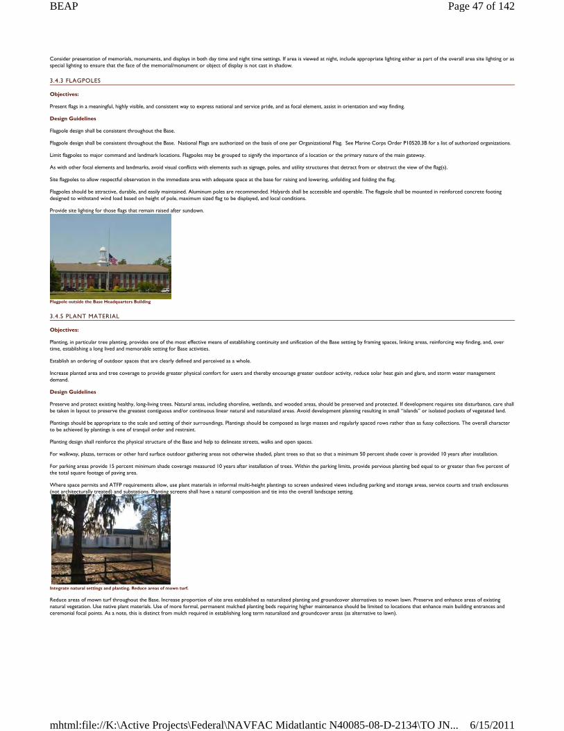
Consider presentation of memorials, monuments, and displays in both day time and night time settings. If area is viewed at night, include appropriate lighting either as part of the overall area site lighting or as special lighting to ensure that the face of the memorial/monument or object of display is not cast in shadow.
3.4.3 FLAGPOLES
Objectives:
Present flags in a meaningful, highly visible, and consistent way to express national and service pride, and as focal element, assist in orientation and way finding.
Design Guidelines
Flagpole design shall be consistent throughout the Base.
Flagpole design shall be consistent throughout the Base. National Flags are authorized on the basis of one per Organizational Flag. See Marine Corps Order P10520.3B for a list of authorized organizations.
Limit flagpoles to major command and landmark locations. Flagpoles may be grouped to signify the importance of a location or the primary nature of the main gateway.
As with other focal elements and landmarks, avoid visual conflicts with elements such as signage, poles, and utility structures that detract from or obstruct the view of the flag(s).
Site flagpoles to allow respectful observation in the immediate area with adequate space at the base for raising and lowering, unfolding and folding the flag.
Flagpoles should be attractive, durable, and easily maintained. Aluminum poles are recommended. Halyards shall be accessible and operable. The flagpole shall be mounted in reinforced concrete footing designed to withstand wind load based on height of pole, maximum sized flag to be displayed, and local conditions.
Provide site lighting for those flags that remain raised after sundown.
Flagpole outside the Base Headquarters Building
3.4.5 PLANT MATERIAL
Objectives:
Planting, in particular tree planting, provides one of the most effective means of establishing continuity and unification of the Base setting by framing spaces, linking areas, reinforcing way finding, and, over time, establishing a long lived and memorable setting for Base activities.
Establish an ordering of outdoor spaces that are clearly defined and perceived as a whole.
Increase planted area and tree coverage to provide greater physical comfort for users and thereby encourage greater outdoor activity, reduce solar heat gain and glare, and storm water management demand.
Design Guidelines
Preserve and protect existing healthy, long-living trees. Natural areas, including shoreline, wetlands, and wooded areas, should be preserved and protected. If development requires site disturbance, care shall be taken in layout to preserve the greatest contiguous and/or continuous linear natural and naturalized areas. Avoid development planning resulting in small “islands” or isolated pockets of vegetated land.
Plantings should be appropriate to the scale and setting of their surroundings. Plantings should be composed as large masses and regularly spaced rows rather than as fussy collections. The overall character to be achieved by plantings is one of tranquil order and restraint.
Planting design shall reinforce the physical structure of the Base and help to delineate streets, walks and open spaces.
For walkway, plazas, terraces or other hard surface outdoor gathering areas not otherwise shaded, plant trees so that so that a minimum 50 percent shade cover is provided 10 years after installation.
For parking areas provide 15 percent minimum shade coverage measured 10 years after installation of trees. Within the parking limits, provide pervious planting bed equal to or greater than five percent of the total square footage of paving area.
Where space permits and ATFP requirements allow, use plant materials in informal multi-height plantings to screen undesired views including parking and storage areas, service courts and trash enclosures (not architecturally treated) and substations. Planting screens shall have a natural composition and tie into the overall landscape setting.
Integrate natural settings and planting. Reduce areas of mown turf.
Reduce areas of mown turf throughout the Base. Increase proportion of site area established as naturalized planting and groundcover alternatives to mown lawn. Preserve and enhance areas of existing natural vegetation. Use native plant materials. Use of more formal, permanent mulched planting beds requiring higher maintenance should be limited to locations that enhance main building entrances and ceremonial focal points. As a note, this is distinct from mulch required in establishing long term naturalized and groundcover areas (as alternative to lawn).
Page 47 of 142BEAP
6/15/2011mhtml:file://K:\Active Projects\Federal\NAVFAC Midatlantic N40085-08-D-2134\TO JN...
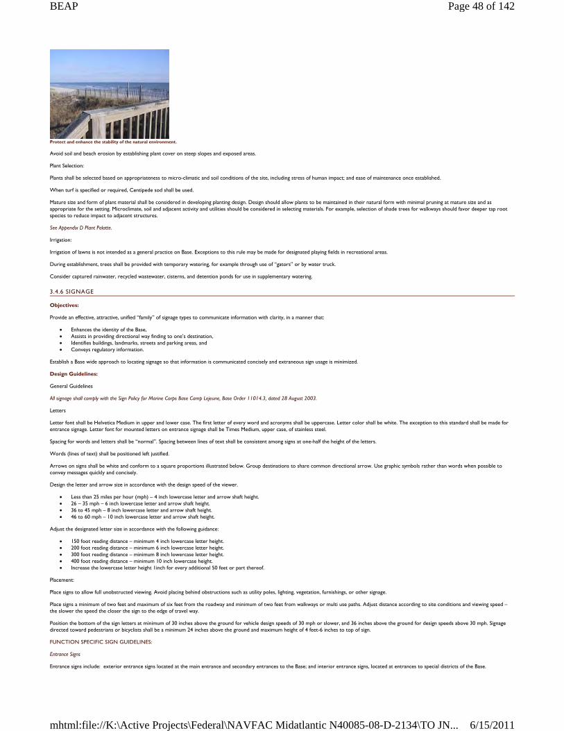
Protect and enhance the stability of the natural environment.
Avoid soil and beach erosion by establishing plant cover on steep slopes and exposed areas.
Plant Selection:
Plants shall be selected based on appropriateness to micro-climatic and soil conditions of the site, including stress of human impact; and ease of maintenance once established.
When turf is specified or required, Centipede sod shall be used.
Mature size and form of plant material shall be considered in developing planting design. Design should allow plants to be maintained in their natural form with minimal pruning at mature size and as appropriate for the setting. Microclimate, soil and adjacent activity and utilities should be considered in selecting materials. For example, selection of shade trees for walkways should favor deeper tap root species to reduce impact to adjacent structures.
See Appendix D Plant Palatte.
Irrigation:
Irrigation of lawns is not intended as a general practice on Base. Exceptions to this rule may be made for designated playing fields in recreational areas.
During establishment, trees shall be provided with temporary watering, for example through use of “gators” or by water truck.
Consider captured rainwater, recycled wastewater, cisterns, and detention ponds for use in supplementary watering.
3.4.6 SIGNAGE
Objectives:
Provide an effective, attractive, unified “family” of signage types to communicate information with clarity, in a manner that:
Enhances the identity of the Base, Assists in providing directional way finding to one’s destination, Identifies buildings, landmarks, streets and parking areas, and Conveys regulatory information.
Establish a Base wide approach to locating signage so that information is communicated concisely and extraneous sign usage is minimized.
Design Guidelines:
General Guidelines
All signage shall comply with the Sign Policy for Marine Corps Base Camp Lejeune, Base Order 11014.3, dated 28 August 2003.
Letters
Letter font shall be Helvetica Medium in upper and lower case. The first letter of every word and acronyms shall be uppercase. Letter color shall be white. The exception to this standard shall be made for entrance signage. Letter font for mounted letters on entrance signage shall be Times Medium, upper case, of stainless steel.
Spacing for words and letters shall be “normal”. Spacing between lines of text shall be consistent among signs at one-half the height of the letters.
Words (lines of text) shall be positioned left justified.
Arrows on signs shall be white and conform to a square proportions illustrated below. Group destinations to share common directional arrow. Use graphic symbols rather than words when possible to convey messages quickly and concisely.
Design the letter and arrow size in accordance with the design speed of the viewer.
Less than 25 miles per hour (mph) – 4 inch lowercase letter and arrow shaft height. 26 – 35 mph – 6 inch lowercase letter and arrow shaft height. 36 to 45 mph – 8 inch lowercase letter and arrow shaft height. 46 to 60 mph – 10 inch lowercase letter and arrow shaft height.
Adjust the designated letter size in accordance with the following guidance:
150 foot reading distance – minimum 4 inch lowercase letter height. 200 foot reading distance – minimum 6 inch lowercase letter height. 300 foot reading distance – minimum 8 inch lowercase letter height. 400 foot reading distance – minimum 10 inch lowercase height. Increase the lowercase letter height 1inch for every additional 50 feet or part thereof.
Placement:
Place signs to allow full unobstructed viewing. Avoid placing behind obstructions such as utility poles, lighting, vegetation, furnishings, or other signage.
Place signs a minimum of two feet and maximum of six feet from the roadway and minimum of two feet from walkways or multi use paths. Adjust distance according to site conditions and viewing speed – the slower the speed the closer the sign to the edge of travel way.
Position the bottom of the sign letters at minimum of 30 inches above the ground for vehicle design speeds of 30 mph or slower, and 36 inches above the ground for design speeds above 30 mph. Signage directed toward pedestrians or bicyclists shall be a minimum 24 inches above the ground and maximum height of 4 feet-6 inches to top of sign.
FUNCTION SPECIFIC SIGN GUIDELINES:
Entrance Signs
Entrance signs include: exterior entrance signs located at the main entrance and secondary entrances to the Base; and interior entrance signs, located at entrances to special districts of the Base.
Page 48 of 142BEAP
6/15/2011mhtml:file://K:\Active Projects\Federal\NAVFAC Midatlantic N40085-08-D-2134\TO JN...
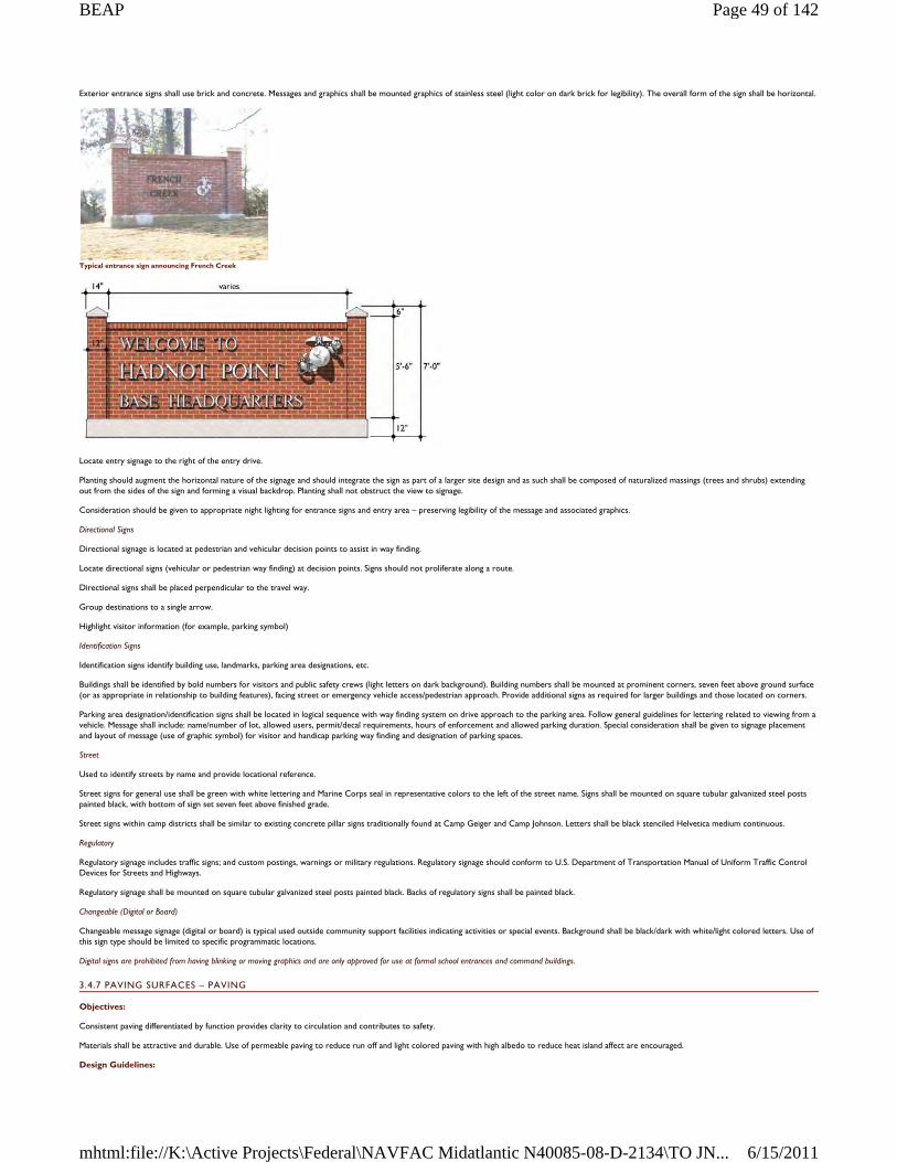
Exterior entrance signs shall use brick and concrete. Messages and graphics shall be mounted graphics of stainless steel (light color on dark brick for legibility). The overall form of the sign shall be horizontal.
Typical entrance sign announcing French Creek
Locate entry signage to the right of the entry drive.
Planting should augment the horizontal nature of the signage and should integrate the sign as part of a larger site design and as such shall be composed of naturalized massings (trees and shrubs) extending out from the sides of the sign and forming a visual backdrop. Planting shall not obstruct the view to signage.
Consideration should be given to appropriate night lighting for entrance signs and entry area – preserving legibility of the message and associated graphics.
Directional Signs
Directional signage is located at pedestrian and vehicular decision points to assist in way finding.
Locate directional signs (vehicular or pedestrian way finding) at decision points. Signs should not proliferate along a route.
Directional signs shall be placed perpendicular to the travel way.
Group destinations to a single arrow.
Highlight visitor information (for example, parking symbol)
Identification Signs
Identification signs identify building use, landmarks, parking area designations, etc.
Buildings shall be identified by bold numbers for visitors and public safety crews (light letters on dark background). Building numbers shall be mounted at prominent corners, seven feet above ground surface (or as appropriate in relationship to building features), facing street or emergency vehicle access/pedestrian approach. Provide additional signs as required for larger buildings and those located on corners.
Parking area designation/identification signs shall be located in logical sequence with way finding system on drive approach to the parking area. Follow general guidelines for lettering related to viewing from a vehicle. Message shall include: name/number of lot, allowed users, permit/decal requirements, hours of enforcement and allowed parking duration. Special consideration shall be given to signage placement and layout of message (use of graphic symbol) for visitor and handicap parking way finding and designation of parking spaces.
Street
Used to identify streets by name and provide locational reference.
Street signs for general use shall be green with white lettering and Marine Corps seal in representative colors to the left of the street name. Signs shall be mounted on square tubular galvanized steel posts painted black, with bottom of sign set seven feet above finished grade.
Street signs within camp districts shall be similar to existing concrete pillar signs traditionally found at Camp Geiger and Camp Johnson. Letters shall be black stenciled Helvetica medium continuous.
Regulatory
Regulatory signage includes traffic signs; and custom postings, warnings or military regulations. Regulatory signage should conform to U.S. Department of Transportation Manual of Uniform Traffic Control Devices for Streets and Highways.
Regulatory signage shall be mounted on square tubular galvanized steel posts painted black. Backs of regulatory signs shall be painted black.
Changeable (Digital or Board)
Changeable message signage (digital or board) is typical used outside community support facilities indicating activities or special events. Background shall be black/dark with white/light colored letters. Use of this sign type should be limited to specific programmatic locations.
Digital signs are prohibited from having blinking or moving graphics and are only approved for use at formal school entrances and command buildings.
3.4.7 PAVING SURFACES – PAVING
Objectives:
Consistent paving differentiated by function provides clarity to circulation and contributes to safety.
Materials shall be attractive and durable. Use of permeable paving to reduce run off and light colored paving with high albedo to reduce heat island affect are encouraged.
Design Guidelines:
Page 49 of 142BEAP
6/15/2011mhtml:file://K:\Active Projects\Federal\NAVFAC Midatlantic N40085-08-D-2134\TO JN...
All walks shall be paved with scored concrete, tooled edges, light broom finish perpendicular to direction of travel. Cross slopes shall not exceed two percent.
When connecting to an existing walk, saw cut the existing walk at the control joint, meet and blend grade of new walk to existing. Implement consistent scoring pattern with each segment of new walk.
Provide detectable warning strip at base of ramps, and at flush meeting of vehicular and walk surfaces as required by Americans with Disability Act Accessibility Guide (ADAAG). Detectable warning strip shall be precast concrete or manufactured detectable warning concrete paver.
Materials:
Roadways and parking areas (typical):
Bituminous concrete
Special vehicular areas including ceremonial drives, drop-offs, car courts, and parking areas:
Concrete pavers (light grey mix) Permeable pavers (light grey mix)
Emergency drives through open space/landscape:
Concrete scored as walkway (w/ reinforced lawn to provide additional required width) Concrete pavers light grey mix (w/ reinforced lawn to provide additional required width) Reinforced lawn
Bicycle lanes (within roadway)
Bituminous concrete with blue painted markings
Walkways, Courtyard, Plazas:
Scored concrete (typical) Scored colored concrete (light warm grey) Concrete pavers (light grey mix) Do not paint concrete or paver walk, stairs or other pedestrian areas.
Multi-use pedestrian/bicycle way:
Scored concrete (typical within developed areas when used in combination as a sidewalk)
Recreational multi-use trail:
Bituminous concrete (Use of permeable paving is encouraged.)
Crosswalks
Consider use of scored concrete as continuation of walkway for greater visual definition of pedestrian travel/crossing for aesthetic and traffic calming in higher visibility or trafficked areas. At minimum crosswalk shall be 10 foot width with 12 inch width painted bars.
3.4.8 SITE FURNISHINGS
Objectives:
Consistent use of a selected family of site furnishings throughout the Base reinforces Base identity and provides greater flexibility and efficiency in reuse, addition, and maintenance.
Furnishings shall be attractive, durable and present an image of permanence and quality.
Use of common finishes and colors, especially consistent use of black for all metal and plastic coated metal will lend to a more refined look that will tie dissimilar elements together during a phasing implementation, ease in matching furnishing purchased over time, and present a fitting color for varied architectural styles, and understated integration into the landscape.
Design Guidelines
ATFP Devices
Bollards
Black powder coated galvanized steel finish in removable and permanent styles. May be combined with low level bollard lighting. Two forms; ornamental bollard for formal and high profile settings and simpler concrete filled steel post painted black.
Low fencing as pedestrian or edge definition. Bollards may be combined with steel cable or chain for restricted edging, though other longer lasting, less obtrusive alternatives may be considered such as curbing or grade change.
Avoid use of wood posts/bollards and rope as these are not durable, nor do they maintain their appearance over time.
Benches and Tables
Black powder coated galvanized steel mesh tables and chairs (movable) for residential courtyards and outdoor dining patios, may be combined with table umbrellas for shade to encourage use during warmer months.
Black plastic coated steel mesh picnic tables for use in recreational and casual outdoor settings. Black plastic coated metal mesh bench for use throughout Base.
In addition to benches, tables and chairs, consideration should be given to incorporating informal seating opportunities in site design through use of seat walls, broad “landscape” steps, and gentle slopes facing onto active use areas such as play fields or waterfront.
Bicycle Racks:
Galvanized powder coated black “bike hoop” design. Alternative: “Lightning Bolt” rack which is straightforward to install at new and pre-existing paved sites, has a low profile, may be double loaded, and is efficient in layout.
Trash Receptacles:
Black powder coated galvanized steel mesh with removable cover. Provide receptacles as required for trash collection/recycling programs.
Drinking Fountains
Black powder coated galvanized steel with stainless steel bowl. Simple post and bowl design with paving at base to prevent ground rutting from runoff.
Planters:
Concrete or cast stone with natural finish pots and cast planter boxes. Pots: Use in formal line or clustered in group with varied sizes. Within furnishing family identify three sizes. Planting within pots should be equal or greater than height dimension of pot. For
possible use as ATFP barrier. Boxes: Use as architectural edge to space, for example, at formal plazas or in courtyards. If an extension of building design, finish may be chosen to match architectural finish and style. For possible
Page 50 of 142BEAP
6/15/2011mhtml:file://K:\Active Projects\Federal\NAVFAC Midatlantic N40085-08-D-2134\TO JN...
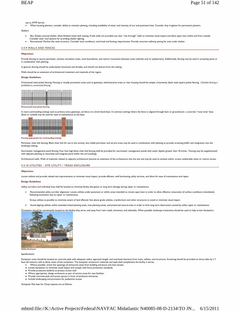
use as ATFP barrier. When locating planters, consider ability to maintain planting, including availability of water and intensity of sun and pavement heat. Consider drip irrigation for permanent planters.
Shelters
Bus: Simple covered shelter, black finished metal with seating. If side walls are provided use clear “see through” walls to minimize visual impact and allow open view within and from outside. Consider solar roof options for providing shelter lighting.
Recreational: Pavilion like steel structure. Consider local conditions, wind load and footing requirements. Provide concrete walkway paving for area under shelter.
3.4.9 WALLS AND FENCES
Objectives:
Provide fencing to secure perimeter, enclose recreation areas, mark boundaries, and restrict movement between areas (vehicles and /or pedestrians). Additionally, fencing may be used in screening alone or in combination with planting.
In general, fencing should be understated, functional and durable, and should not detract from the setting.
Walls should be an extension of architectural treatment and materials of the region.
Design Guidelines
Ornamental steel picket fencing: Fencing in visually prominent areas such as gateways, administrative areas or near housing should be simple, ornamental, black steel square picket fencing. Chainlink fencing is prohibited as ornamental fencing.
Ornamental steel picket fencing
In more commanding settings such as primary entry gateways, set fence on a brick faced base. In common settings where the fence is aligned through lawn or groundcover, a concrete “mow strip” base (flush or curbed) may be used for ease of maintenance at the base.
Fencing appropriate for commanding settings
Perimeter chain link fencing: Black chain link for use in low activity, less visible perimeter and service areas may be used in combination with planting to provide screening buffer and integration into the landscape setting.
Stormwater management pond fencing: Four foot high black chain link fencing shall be provided for stormwater management ponds with water depths greater than 18 inches. Fencing may be supplemented with adjacent planting to naturalize and integrate pond within the surroundings.
Architectural walls: Walls of materials related to adjacent architecture become an extension of the architecture into the site and may be used to enclose and/or screen undesirable views or restrict access.
3.4.10 UTILITIES – SITE UTILITY / TRASH ENCLOSURE
Objectives:
Locate utilities and provide related site improvements to minimize visual impact, provide efficient, well functioning utility services, and allow for ease of maintenance and repair.
Design Guidelines
Utility corridors and individual lines shall be located to minimize facility disruption or long term damage during repair or maintenance.
Recommended utility corridor alignment: Locate utilities under pavement or within areas intended to remain open lawn in order to allow effective restoration of surface conditions immediately following excavation due to repair or maintenance.
Group utilities as possible to minimize extent of land affected. Site above grade utilities, transformers and other structures to avoid or minimize visual impact.
Avoid aligning utilities within intended mixed planting areas, tree planting zones, and preserved natural areas in order to limit long term destruction caused by utility repair or maintenance.
Dumpsters should be conveniently located to the facility they serve, and away from main roads, entrances, and sidewalks. When possible, landscape treatments should be used to help screen dumpsters.
Utility Enclosure
Specifications:
Dumpster areas should be located on concrete pads with adequate radius, approach length, and overhead clearance from trees, utilities, and structures. Screening should be provided on three sides by a 7 foot tall masonry wall to block views of the containers. The dumpster enclosure's materials and style shall complement the facility it serves.
Where possible, orient the openings of enclosures away from building entrances and main streets. Locate dumpsters to minimize visual impact and comply with force protection standards. Provide protective bollards to protect screen wall. Where appropriate, design enclosures as part of service areas for new facilities. Provide concrete pads and access aprons in front of enclosure entrances. Include landscaping and provisions for pedestrian access.
Dumpster Pad sizes for Camp Lejeune are as follows:
Page 51 of 142BEAP
6/15/2011mhtml:file://K:\Active Projects\Federal\NAVFAC Midatlantic N40085-08-D-2134\TO JN...
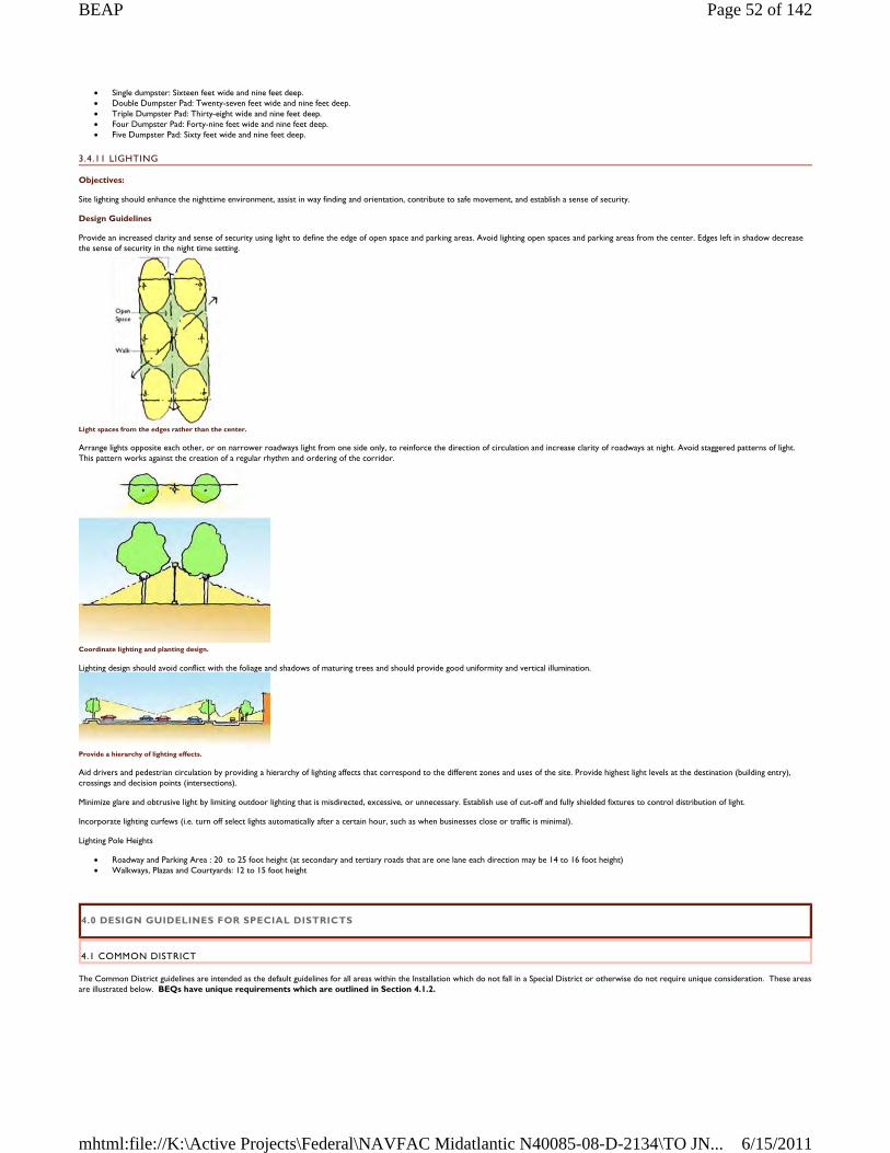
Single dumpster: Sixteen feet wide and nine feet deep. Double Dumpster Pad: Twenty-seven feet wide and nine feet deep. Triple Dumpster Pad: Thirty-eight wide and nine feet deep. Four Dumpster Pad: Forty-nine feet wide and nine feet deep. Five Dumpster Pad: Sixty feet wide and nine feet deep.
3.4.11 LIGHTING
Objectives:
Site lighting should enhance the nighttime environment, assist in way finding and orientation, contribute to safe movement, and establish a sense of security.
Design Guidelines
Provide an increased clarity and sense of security using light to define the edge of open space and parking areas. Avoid lighting open spaces and parking areas from the center. Edges left in shadow decrease the sense of security in the night time setting.
Light spaces from the edges rather than the center.
Arrange lights opposite each other, or on narrower roadways light from one side only, to reinforce the direction of circulation and increase clarity of roadways at night. Avoid staggered patterns of light. This pattern works against the creation of a regular rhythm and ordering of the corridor.
Coordinate lighting and planting design.
Lighting design should avoid conflict with the foliage and shadows of maturing trees and should provide good uniformity and vertical illumination.
Provide a hierarchy of lighting effects.
Aid drivers and pedestrian circulation by providing a hierarchy of lighting affects that correspond to the different zones and uses of the site. Provide highest light levels at the destination (building entry), crossings and decision points (intersections).
Minimize glare and obtrusive light by limiting outdoor lighting that is misdirected, excessive, or unnecessary. Establish use of cut-off and fully shielded fixtures to control distribution of light.
Incorporate lighting curfews (i.e. turn off select lights automatically after a certain hour, such as when businesses close or traffic is minimal).
Lighting Pole Heights
Roadway and Parking Area : 20 to 25 foot height (at secondary and tertiary roads that are one lane each direction may be 14 to 16 foot height) Walkways, Plazas and Courtyards: 12 to 15 foot height
4.0 DESIGN GUIDELINES FOR SPECIAL DISTRICTS
4.1 COMMON DISTRICT
The Common District guidelines are intended as the default guidelines for all areas within the Installation which do not fall in a Special District or otherwise do not require unique consideration. These areas are illustrated below. BEQs have unique requirements which are outlined in Section 4.1.2.
Page 52 of 142BEAP
6/15/2011mhtml:file://K:\Active Projects\Federal\NAVFAC Midatlantic N40085-08-D-2134\TO JN...
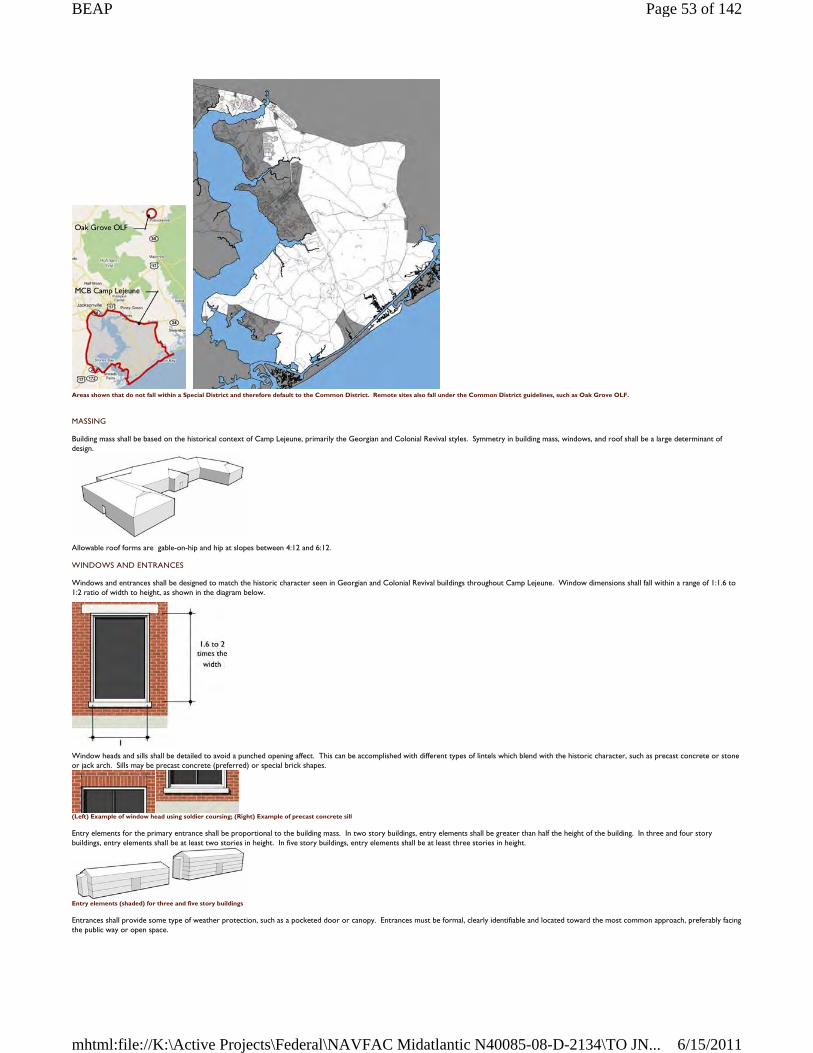
Areas shown that do not fall within a Special District and therefore default to the Common District. Remote sites also fall under the Common District guidelines, such as Oak Grove OLF.
MASSING
Building mass shall be based on the historical context of Camp Lejeune, primarily the Georgian and Colonial Revival styles. Symmetry in building mass, windows, and roof shall be a large determinant of design.
Allowable roof forms are gable-on-hip and hip at slopes between 4:12 and 6:12.
WINDOWS AND ENTRANCES
Windows and entrances shall be designed to match the historic character seen in Georgian and Colonial Revival buildings throughout Camp Lejeune. Window dimensions shall fall within a range of 1:1.6 to 1:2 ratio of width to height, as shown in the diagram below.
Window heads and sills shall be detailed to avoid a punched opening affect. This can be accomplished with different types of lintels which blend with the historic character, such as precast concrete or stone or jack arch. Sills may be precast concrete (preferred) or special brick shapes.
(Left) Example of window head using soldier coursing; (Right) Example of precast concrete sill
Entry elements for the primary entrance shall be proportional to the building mass. In two story buildings, entry elements shall be greater than half the height of the building. In three and four story buildings, entry elements shall be at least two stories in height. In five story buildings, entry elements shall be at least three stories in height.
Entry elements (shaded) for three and five story buildings
Entrances shall provide some type of weather protection, such as a pocketed door or canopy. Entrances must be formal, clearly identifiable and located toward the most common approach, preferably facing the public way or open space.
Page 53 of 142BEAP
6/15/2011mhtml:file://K:\Active Projects\Federal\NAVFAC Midatlantic N40085-08-D-2134\TO JN...
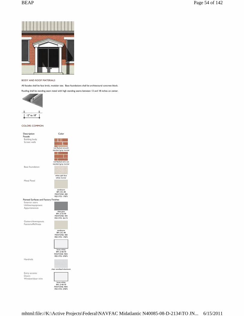
BODY AND ROOF MATERIALS
All facades shall be face brick, modular size. Base foundations shall be architectural concrete block.
Roofing shall be standing seam metal with high standing seams between 12 and 18 inches on center.
COLORS COMMON
Description Color Facade Building body Screen walls
red flashed smooth
standard gray mortar
red flashed wire cut standard gray mortar
Base foundation
white split face white mortar
Metal Panel
sandstone
BM: OC-48 PANTONE: 400 FED STD: 17875
Painted Surfaces and Factory Finishes Exterior stairs Utilities/equipment Appurtenances
slate gray
BM: 2133-40 PANTONE: 444 FED STD: 36173
Gutters/downspouts Fascia/soffit/frieze
sandstone
BM: OC-48 PANTONE: 400 FED STD: 17875
bone white
BM: 2140-70 PANTONE: 9041 FED STD: 37875
Handrails
clear anodized aluminum
Entry accents Doors Window/door trim
bone white
BM: 2140-70 PANTONE: 9041 FED STD: 37875
Page 54 of 142BEAP
6/15/2011mhtml:file://K:\Active Projects\Federal\NAVFAC Midatlantic N40085-08-D-2134\TO JN...
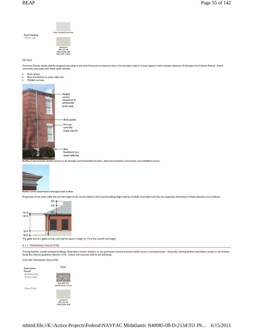
DETAILS
Common District details shall be designed according to the early American architecture that is the prevalent style on Camp Lejeune, which includes elements of Georgian and Colonial Revival. Detail commonly associated with these styles includes:
Brick quions Base foundations to water table line Molded cornices
Building 15 demonstrates details common to the Georgian and Colonial Revival styles: white base foundation, brick quoins, and embellished cornice
Molded cornice detail found in Georgian styles on Base
Proportion of the water table line and the height of the cornice detail to the overall building height shall be carefully controlled such that the respective dimensions of these elements are as follows:
The gable end on a gable-on-hip roof shall be equal in height to 1/3 of the overall roof height.
4.1.1 TRAINING FACILITIES
Training facilities include enclosed buildings, observation towers, shelters, or any permanent vertical structure which serves a training function. Generally, training facilities shall follow closely to the Greater Sandy Run District guidelines (Section 4.14). Colors and materials shall be the following:
COLORS TRAINING FACILITIES
clear anodized aluminum
Roof Cladding Metal roof
sandstone
BM: OC-48 PANTONE: 400 FED STD: 17875
Description
Color
Facade Building body Screen walls
gray split face
standard gray mortar Metal Panel
sandstone
BM: OC-48 PANTONE: 400
Page 55 of 142BEAP
6/15/2011mhtml:file://K:\Active Projects\Federal\NAVFAC Midatlantic N40085-08-D-2134\TO JN...
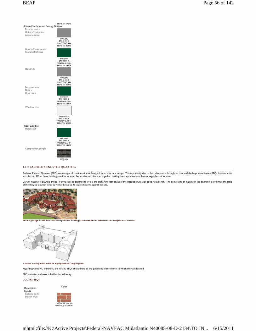
4.1.2 BACHELOR ENLISTED QUARTERS
Bachelor Enlisted Quarters (BEQ) require special consideration with regard to architectural design. This is primarily due to their abundance throughout base and the large visual impact BEQs have on a site and district. Often these buildings are four or even five stories and clustered together, making them a predominant feature regardless of location.
Careful massing of BEQs is critical. Forms shall be designed to evoke the early American styles of the installation, as well as be visually rich. The complexity of massing in the diagram below brings the scale of the BEQ to a human level, as well as break up its large silhouette against the site.
This BEQ design for the west coast exemplifies the blending of the Installation's character and a complex mass of forms.
A similar massing which would be appropriate for Camp Lejeune.
Regarding windows, entrances, and details, BEQs shall adhere to the guidelines of the district in which they are located.
BEQ materials and colors shall be the following:
COLORS BEQS
FED STD: 17875 Painted Surfaces and Factory Finishes Exterior stairs Utilities/equipment Appurtenances
slate gray
BM: 2133-40 PANTONE: 444 FED STD: 36173
Gutters/downspouts Fascia/soffit/frieze
evergreen
BM: 2040-10 PANTONE: 7484 FED STD: 14109
Handrails
slate gray
BM: 2133-40 PANTONE: 444 FED STD: 36173
Entry accents Doors Door trim
evergreen BM: 2040-10
PANTONE: 7484 FED STD: 14109
Window trim
bone white
BM: 2140-70 PANTONE: 9041 FED STD: 37875
Roof Cladding Metal roof
evergreen
BM: 2040-10 PANTONE: 7484 FED STD: 14109
Composition shingle
slate gray
Description
Color
Facade Building body Screen walls
red flashed wire cut
standard grey mortar
Page 56 of 142BEAP
6/15/2011mhtml:file://K:\Active Projects\Federal\NAVFAC Midatlantic N40085-08-D-2134\TO JN...
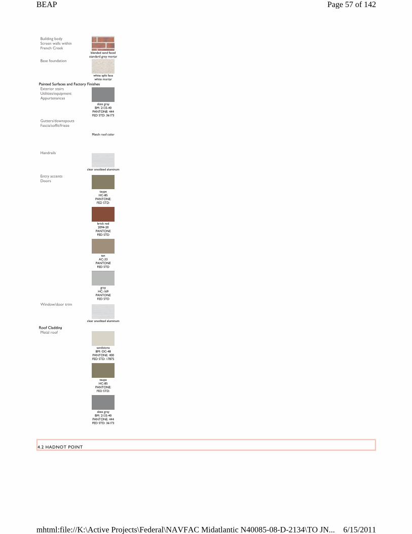
4.2 HADNOT POINT
Building body Screen walls within French Creek
blended sand faced standard grey mortar
Base foundation
white split face white mortar
Painted Surfaces and Factory Finishes Exterior stairs Utilities/equipment Appurtenances
slate gray
BM: 2133-40 PANTONE: 444 FED STD: 36173
Gutters/downspouts Fascia/soffit/frieze
Match roof color
Handrails
clear anodized aluminum
Entry accents Doors
taupe HC-85
PANTONE: FED STD:
brick red 2094-20
PANTONE FED STD
tan
AC-33 PANTONE FED STD
gray
HC-169 PANTONE FED STD
Window/door trim
clear anodized aluminum
Roof Cladding Metal roof
sandstone
BM: OC-48 PANTONE: 400 FED STD: 17875
taupe HC-85
PANTONE: FED STD:
slate gray
BM: 2133-40 PANTONE: 444 FED STD: 36173
Page 57 of 142BEAP
6/15/2011mhtml:file://K:\Active Projects\Federal\NAVFAC Midatlantic N40085-08-D-2134\TO JN...
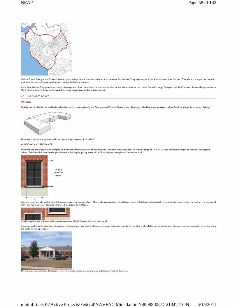
Hadnot Point’s Georgian and Colonial Revival style buildings are the dominant architectural precedent for much of Camp Lejeune, particularly for administrative facilities. Therefore, it is important that this area be preserved and future development respect the historic context.
Aside from Hadnot Point proper, this district is comprised of two sub-districts and an historic district: the Industrial Area, the Marine Corps Exchange Complex, and the Command Services/Regimental Area No. 3 historic district. Refer to Section 2.6 for more information on this historic district.
4.2.1 HADNOT POINT
MASSING
Building mass in this district shall be based on historical context, primarily the Georgian and Colonial Revival styles. Symmetry in building mass, windows, and roof shall be a large determinant of design.
Allowable roof forms are gable-on-hip and hip at slopes between 4:12 and 6:12.
WINDOWS AND ENTRANCES
Windows and entrances shall be designed to match the historic character of Hadnot Point. Window dimensions shall fall within a range of 1:1.6 to 1:2 ratio of width to height, as shown in the diagram below. Windows shall have evenly spaced muntins dividing the glazing into 6, 8, or 12 equal parts to emphasize the historic look.
Window heads and sills shall be detailed to avoid a punched opening affect. This can be accomplished with different types of lintels which blend with the historic character, such as the jack arch or segmental arch. Sills may be precast concrete (preferred) or special brick shapes.
(Left) Example of jack arch using brick or precast concrete; (Right) Example of precast concrete sill
Entrances shall provide some type of weather protection, such as a pocketed door or canopy. Entrances must be formal, clearly identifiable and located toward the most common approach, preferably facing the public way or open space.
The primary entry element to Building 66 is covered, centrally located on a parking area, and faces on Holcomb Boulevard.
Page 58 of 142BEAP
6/15/2011mhtml:file://K:\Active Projects\Federal\NAVFAC Midatlantic N40085-08-D-2134\TO JN...
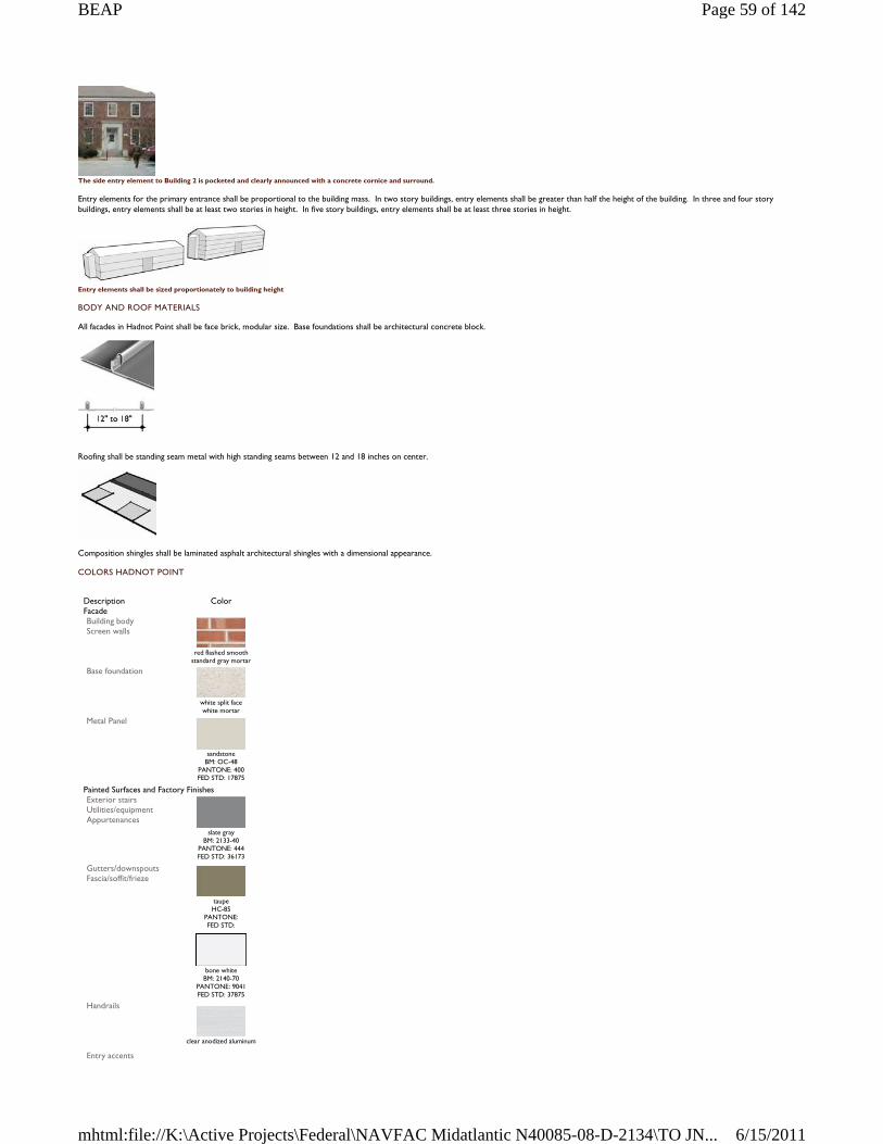
The side entry element to Building 2 is pocketed and clearly announced with a concrete cornice and surround.
Entry elements for the primary entrance shall be proportional to the building mass. In two story buildings, entry elements shall be greater than half the height of the building. In three and four story buildings, entry elements shall be at least two stories in height. In five story buildings, entry elements shall be at least three stories in height.
Entry elements shall be sized proportionately to building height
BODY AND ROOF MATERIALS
All facades in Hadnot Point shall be face brick, modular size. Base foundations shall be architectural concrete block.
Roofing shall be standing seam metal with high standing seams between 12 and 18 inches on center.
Composition shingles shall be laminated asphalt architectural shingles with a dimensional appearance.
COLORS HADNOT POINT
Description Color Facade Building body Screen walls
red flashed smooth
standard gray mortar Base foundation
white split face white mortar
Metal Panel
sandstone
BM: OC-48 PANTONE: 400 FED STD: 17875
Painted Surfaces and Factory Finishes Exterior stairs Utilities/equipment Appurtenances
slate gray
BM: 2133-40 PANTONE: 444 FED STD: 36173
Gutters/downspouts Fascia/soffit/frieze
taupe HC-85
PANTONE: FED STD:
bone white
BM: 2140-70 PANTONE: 9041 FED STD: 37875
Handrails
clear anodized aluminum
Entry accents
Page 59 of 142BEAP
6/15/2011mhtml:file://K:\Active Projects\Federal\NAVFAC Midatlantic N40085-08-D-2134\TO JN...
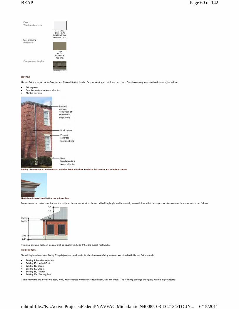
DETAILS
Hadnot Point is known by its Georgian and Colonial Revival details. Exterior detail shall re-inforce this trend. Detail commonly associated with these styles includes:
Brick quions Base foundations to water table line Molded cornices
Building 15 demonstrates details common to Hadnot Point: white base foundation, brick quoins, and embellished cornice
Molded cornice detail found in Georgian styles on Base
Proportion of the water table line and the height of the cornice detail to the overall building height shall be carefully controlled such that the respective dimensions of these elements are as follows:
The gable end on a gable-on-hip roof shall be equal in height to 1/3 of the overall roof height.
PRECEDENTS
Six building have been identified by Camp Lejeune as benchmarks for the character-defining elements associated with Hadnot Point, namely:
Building 1, Base Headquarters Building 15, Medical Clinic Building 16, Chapel Building 17, Chapel Building 19, Theater Building 236, Training Pool
These structures are mostly two-story brick, with concrete or stone base foundations, sills, and lintels. The following buildings are equally valuable as precedents:
Doors Window/door trim
bone white
BM: 2140-70 PANTONE: 9041 FED STD: 37875
Roof Cladding Metal roof
taupe HC-85
PANTONE: FED STD:
Composition shingles
weathered wood
Page 60 of 142BEAP
6/15/2011mhtml:file://K:\Active Projects\Federal\NAVFAC Midatlantic N40085-08-D-2134\TO JN...
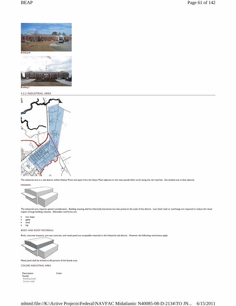
Building 66
Building 2
4.2.2 INDUSTRIAL AREA
The industrial area is a sub-district within Hadnot Point and spans from the Steam Plant adjacent to the main parade field, north along the rail road line. See shaded area in blue (above).
MASSING
The industrial area requires special consideration. Building massing shall be inherently functional, but also preserve the scale of the district. Low shed roofs or overhangs are required to reduce the visual impact of large building volumes. Allowable roof forms are:
low slope gable shed hip
BODY AND ROOF MATERIALS
Brick, concrete masonry, pre-cast concrete, and metal panel are acceptable materials in the Industrial sub-district. However the following restrictions apply:
Metal panel shall be limited to 60 percent of the facade area.
COLORS INDUSTRIAL AREA
Description Color Facade Building body Screen walls
Page 61 of 142BEAP
6/15/2011mhtml:file://K:\Active Projects\Federal\NAVFAC Midatlantic N40085-08-D-2134\TO JN...
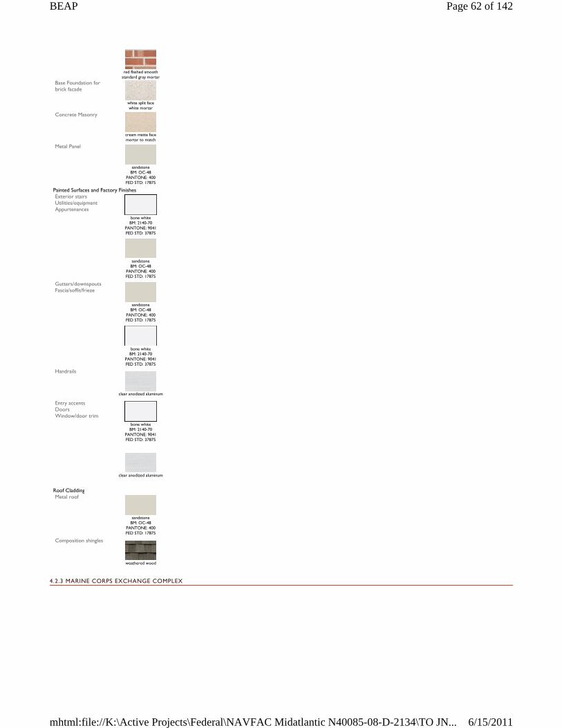
4.2.3 MARINE CORPS EXCHANGE COMPLEX
red flashed smooth
standard gray mortar Base Foundation for brick facade
white split face white mortar
Concrete Masonry
cream matte face mortar to match
Metal Panel
sandstone
BM: OC-48 PANTONE: 400 FED STD: 17875
Painted Surfaces and Factory Finishes Exterior stairs Utilities/equipment Appurtenances
bone white
BM: 2140-70 PANTONE: 9041 FED STD: 37875
sandstone
BM: OC-48 PANTONE: 400 FED STD: 17875
Gutters/downspouts Fascia/soffit/frieze
sandstone
BM: OC-48 PANTONE: 400 FED STD: 17875
bone white
BM: 2140-70 PANTONE: 9041 FED STD: 37875
Handrails
clear anodized aluminum
Entry accents Doors Window/door trim
bone white
BM: 2140-70 PANTONE: 9041 FED STD: 37875
clear anodized aluminum
Roof Cladding Metal roof
sandstone
BM: OC-48 PANTONE: 400 FED STD: 17875
Composition shingles
weathered wood
Page 62 of 142BEAP
6/15/2011mhtml:file://K:\Active Projects\Federal\NAVFAC Midatlantic N40085-08-D-2134\TO JN...
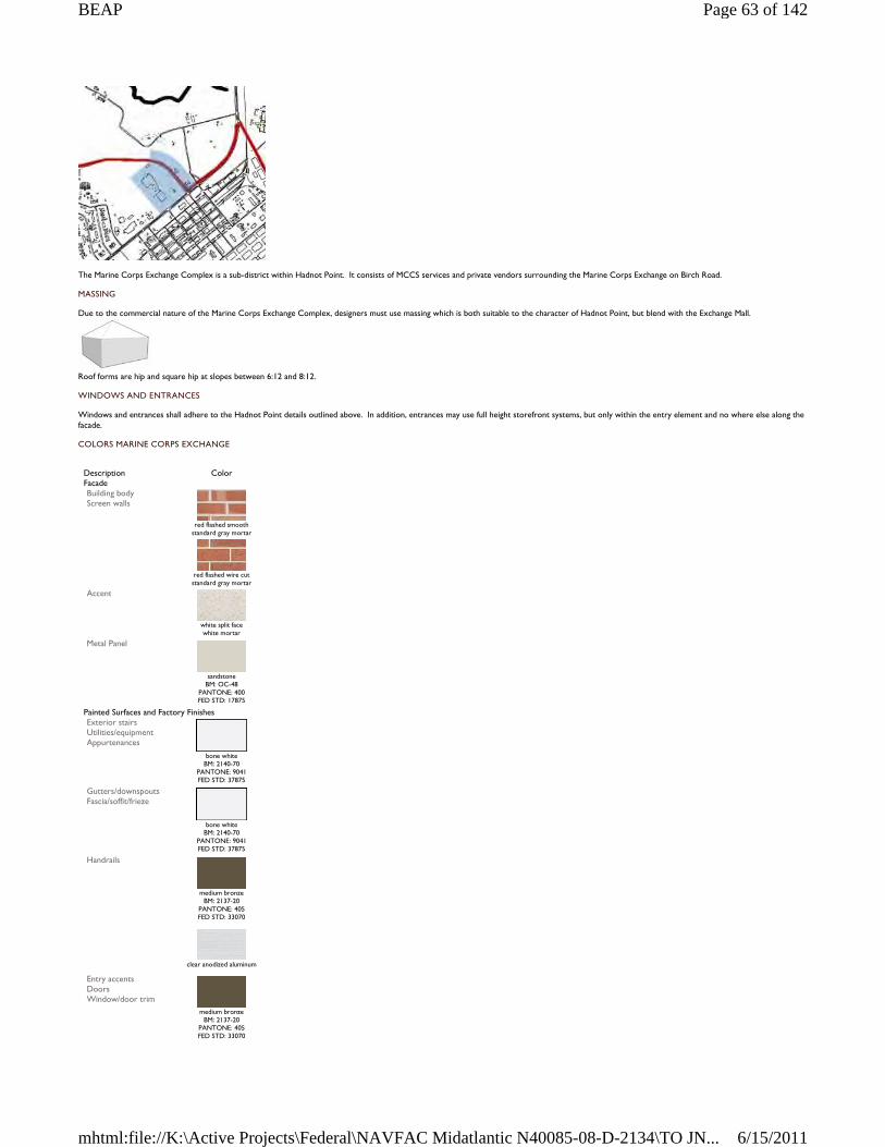
The Marine Corps Exchange Complex is a sub-district within Hadnot Point. It consists of MCCS services and private vendors surrounding the Marine Corps Exchange on Birch Road.
MASSING
Due to the commercial nature of the Marine Corps Exchange Complex, designers must use massing which is both suitable to the character of Hadnot Point, but blend with the Exchange Mall.
Roof forms are hip and square hip at slopes between 6:12 and 8:12.
WINDOWS AND ENTRANCES
Windows and entrances shall adhere to the Hadnot Point details outlined above. In addition, entrances may use full height storefront systems, but only within the entry element and no where else along the facade.
COLORS MARINE CORPS EXCHANGE
Description Color Facade Building body Screen walls
red flashed smooth
standard gray mortar
red flashed wire cut standard gray mortar
Accent
white split face white mortar
Metal Panel
sandstone
BM: OC-48 PANTONE: 400 FED STD: 17875
Painted Surfaces and Factory Finishes Exterior stairs Utilities/equipment Appurtenances
bone white
BM: 2140-70 PANTONE: 9041 FED STD: 37875
Gutters/downspouts Fascia/soffit/frieze
bone white
BM: 2140-70 PANTONE: 9041 FED STD: 37875
Handrails
medium bronze
BM: 2137-20 PANTONE: 405 FED STD: 33070
clear anodized aluminum
Entry accents Doors Window/door trim
medium bronze
BM: 2137-20 PANTONE: 405 FED STD: 33070
Page 63 of 142BEAP
6/15/2011mhtml:file://K:\Active Projects\Federal\NAVFAC Midatlantic N40085-08-D-2134\TO JN...
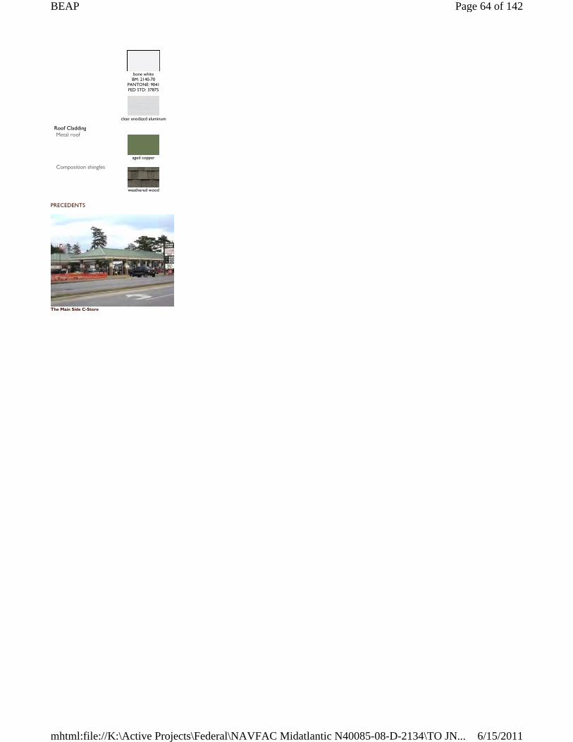
PRECEDENTS
The Main Side C-Store
bone white
BM: 2140-70 PANTONE: 9041 FED STD: 37875
clear anodized aluminum
Roof Cladding Metal roof
aged copper
Composition shingles
weathered wood
Page 64 of 142BEAP
6/15/2011mhtml:file://K:\Active Projects\Federal\NAVFAC Midatlantic N40085-08-D-2134\TO JN...
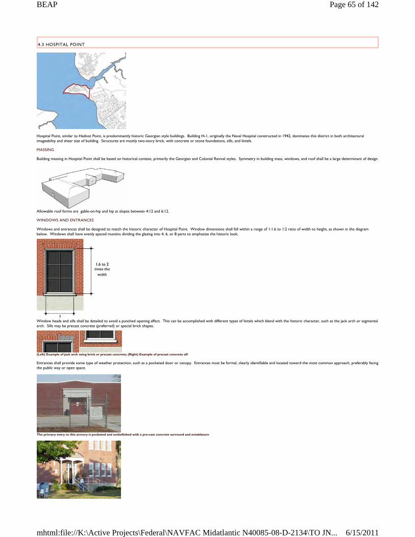
4.3 HOSPITAL POINT
Hospital Point, similar to Hadnot Point, is predominantly historic Georgian style buildings. Building H-1, originally the Naval Hospital constructed in 1942, dominates this district in both architectural imageability and shear size of building. Structures are mostly two-story brick, with concrete or stone foundations, sills, and lintels.
MASSING
Building massing in Hospital Point shall be based on historical context, primarily the Georgian and Colonial Revival styles. Symmetry in building mass, windows, and roof shall be a large determinant of design.
Allowable roof forms are gable-on-hip and hip at slopes between 4:12 and 6:12.
WINDOWS AND ENTRANCES
Windows and entrances shall be designed to match the historic character of Hospital Point. Window dimensions shall fall within a range of 1:1.6 to 1:2 ratio of width to height, as shown in the diagram below. Windows shall have evenly spaced muntins dividing the glazing into 4, 6, or 8 parts to emphasize the historic look.
Window heads and sills shall be detailed to avoid a punched opening affect. This can be accomplished with different types of lintels which blend with the historic character, such as the jack arch or segmental arch. Sills may be precast concrete (preferred) or special brick shapes.
(Left) Example of jack arch using brick or precast concrete; (Right) Example of precast concrete sill
Entrances shall provide some type of weather protection, such as a pocketed door or canopy. Entrances must be formal, clearly identifiable and located toward the most common approach, preferably facing the public way or open space.
The primary entry to this armory is pocketed and embellished with a pre-cast concrete surround and entablature
Page 65 of 142BEAP
6/15/2011mhtml:file://K:\Active Projects\Federal\NAVFAC Midatlantic N40085-08-D-2134\TO JN...
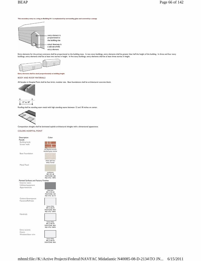
This secondary entry to a wing on Building H-1 is emphasized by surrounding glass and covered by a canopy
Entry elements for the primary entrance shall be proportional to the building mass. In two story buildings, entry elements shall be greater than half the height of the building. In three and four story buildings, entry elements shall be at least two stories in height. In five story buildings, entry elements shall be at least three stories in height.
Entry elements shall be sized proportionately to building height
BODY AND ROOF MATERIALS
All facades in Hospital Point shall be face brick, modular size. Base foundations shall be architectural concrete block.
Roofing shall be standing seam metal with high standing seams between 12 and 18 inches on center.
Composition shingles shall be laminated asphalt architectural shingles with a dimensional appearance.
COLORS HOSPITAL POINT
Description Color Facade Building body Screen walls
red flashed smooth
standard gray mortar Base Foundation
white split face white mortar
Metal Panel
sandstone
BM: OC-48 PANTONE: 400 FED STD: 17875
Painted Surfaces and Factory Finishes Exterior stairs Utilities/equipment Appurtenances
slate gray
BM: 2133-40 PANTONE: 444 FED STD: 36173
Gutters/downspouts Fascia/soffit/frieze
bone white
BM: 2140-70 PANTONE: 9041 FED STD: 37875
Handrails
bone white
BM: 2140-70 PANTONE: 9041 FED STD: 37875
Entry accents Doors Window/door trim
bone white
BM: 2140-70 PANTONE: 9041
Page 66 of 142BEAP
6/15/2011mhtml:file://K:\Active Projects\Federal\NAVFAC Midatlantic N40085-08-D-2134\TO JN...
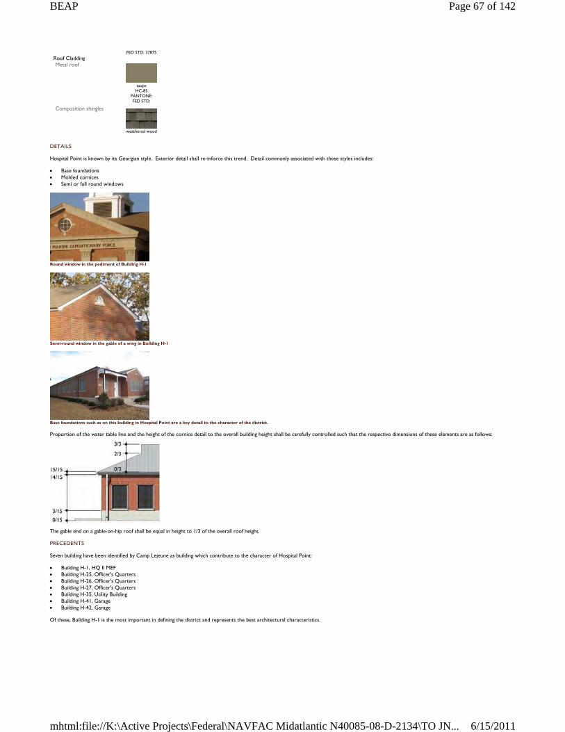
DETAILS
Hospital Point is known by its Georgian style. Exterior detail shall re-inforce this trend. Detail commonly associated with these styles includes:
Base foundations Molded cornices Semi or full round windows
Round window in the pediment of Building H-1
Semi-round window in the gable of a wing in Building H-1
Base foundations such as on this building in Hospital Point are a key detail to the character of the district.
Proportion of the water table line and the height of the cornice detail to the overall building height shall be carefully controlled such that the respective dimensions of these elements are as follows:
The gable end on a gable-on-hip roof shall be equal in height to 1/3 of the overall roof height.
PRECEDENTS
Seven building have been identified by Camp Lejeune as building which contribute to the character of Hospital Point:
Building H-1, HQ II MEF Building H-25, Officer's Quarters Building H-26, Officer's Quarters Building H-27, Officer's Quarters Building H-35, Utility Building Building H-41, Garage Building H-42, Garage
Of these, Building H-1 is the most important in defining the district and represents the best architectural characteristics.
FED STD: 37875 Roof Cladding Metal roof
taupe HC-85
PANTONE: FED STD:
Composition shingles
weathered wood
Page 67 of 142BEAP
6/15/2011mhtml:file://K:\Active Projects\Federal\NAVFAC Midatlantic N40085-08-D-2134\TO JN...

Building H-1
Page 68 of 142BEAP
6/15/2011mhtml:file://K:\Active Projects\Federal\NAVFAC Midatlantic N40085-08-D-2134\TO JN...
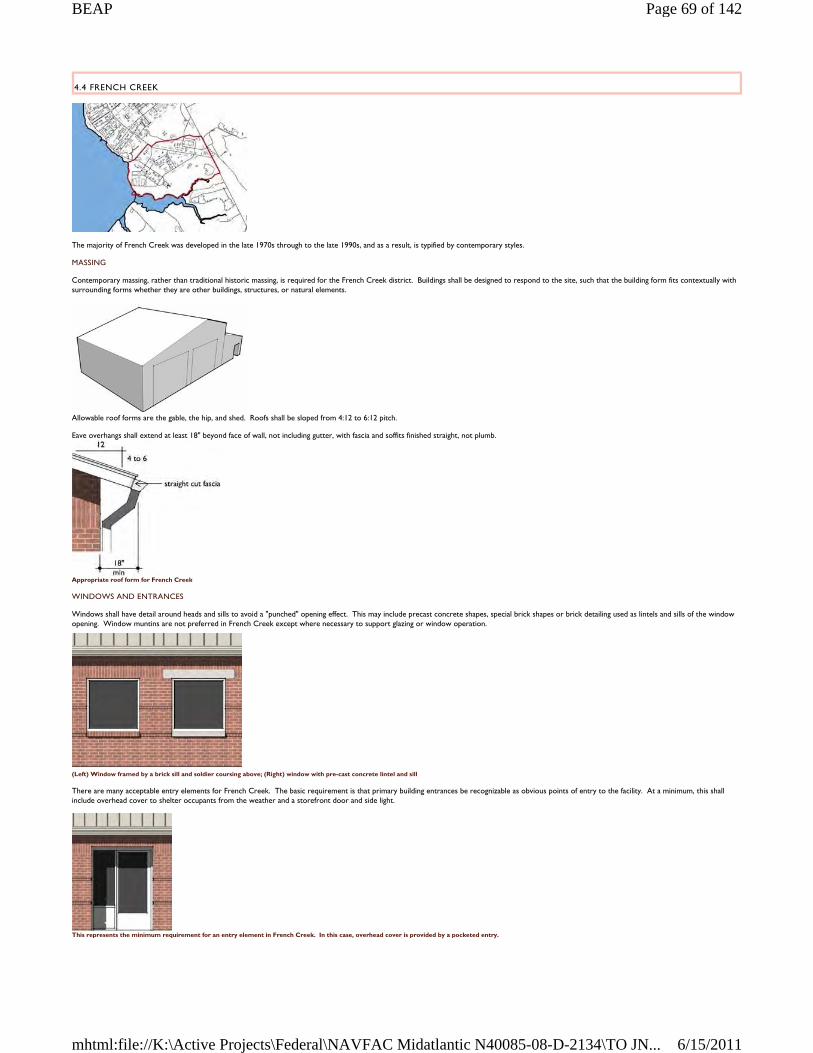
4.4 FRENCH CREEK
The majority of French Creek was developed in the late 1970s through to the late 1990s, and as a result, is typified by contemporary styles.
MASSING
Contemporary massing, rather than traditional historic massing, is required for the French Creek district. Buildings shall be designed to respond to the site, such that the building form fits contextually with surrounding forms whether they are other buildings, structures, or natural elements.
Allowable roof forms are the gable, the hip, and shed. Roofs shall be sloped from 4:12 to 6:12 pitch.
Eave overhangs shall extend at least 18" beyond face of wall, not including gutter, with fascia and soffits finished straight, not plumb.
Appropriate roof form for French Creek
WINDOWS AND ENTRANCES
Windows shall have detail around heads and sills to avoid a "punched" opening effect. This may include precast concrete shapes, special brick shapes or brick detailing used as lintels and sills of the window opening. Window muntins are not preferred in French Creek except where necessary to support glazing or window operation.
(Left) Window framed by a brick sill and soldier coursing above; (Right) window with pre-cast concrete lintel and sill
There are many acceptable entry elements for French Creek. The basic requirement is that primary building entrances be recognizable as obvious points of entry to the facility. At a minimum, this shall include overhead cover to shelter occupants from the weather and a storefront door and side light.
This represents the minimum requirement for an entry element in French Creek. In this case, overhead cover is provided by a pocketed entry.
Page 69 of 142BEAP
6/15/2011mhtml:file://K:\Active Projects\Federal\NAVFAC Midatlantic N40085-08-D-2134\TO JN...
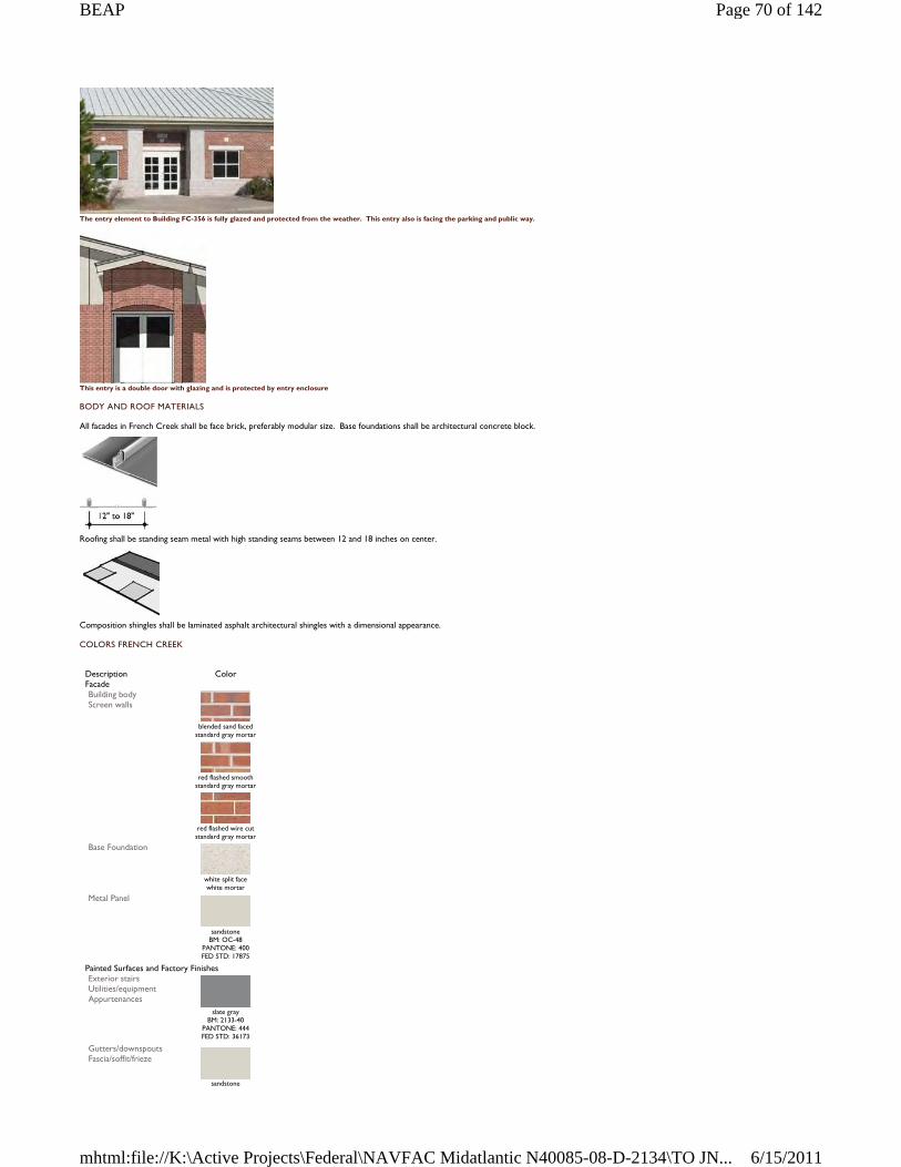
The entry element to Building FC-356 is fully glazed and protected from the weather. This entry also is facing the parking and public way.
This entry is a double door with glazing and is protected by entry enclosure
BODY AND ROOF MATERIALS
All facades in French Creek shall be face brick, preferably modular size. Base foundations shall be architectural concrete block.
Roofing shall be standing seam metal with high standing seams between 12 and 18 inches on center.
Composition shingles shall be laminated asphalt architectural shingles with a dimensional appearance.
COLORS FRENCH CREEK
Description Color Facade Building body Screen walls
blended sand faced
standard gray mortar
red flashed smooth
standard gray mortar
red flashed wire cut standard gray mortar
Base Foundation
white split face white mortar
Metal Panel
sandstone
BM: OC-48 PANTONE: 400 FED STD: 17875
Painted Surfaces and Factory Finishes Exterior stairs Utilities/equipment Appurtenances
slate gray
BM: 2133-40 PANTONE: 444 FED STD: 36173
Gutters/downspouts Fascia/soffit/frieze
sandstone
Page 70 of 142BEAP
6/15/2011mhtml:file://K:\Active Projects\Federal\NAVFAC Midatlantic N40085-08-D-2134\TO JN...
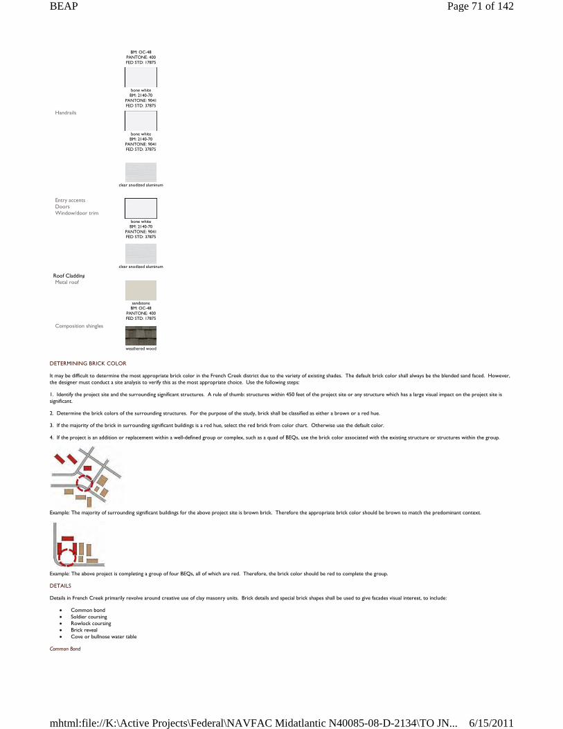
DETERMINING BRICK COLOR
It may be difficult to determine the most appropriate brick color in the French Creek district due to the variety of existing shades. The default brick color shall always be the blended sand faced. However, the designer must conduct a site analysis to verify this as the most appropriate choice. Use the following steps:
1. Identify the project site and the surrounding significant structures. A rule of thumb: structures within 450 feet of the project site or any structure which has a large visual impact on the project site is significant.
2. Determine the brick colors of the surrounding structures. For the purpose of the study, brick shall be classified as either a brown or a red hue.
3. If the majority of the brick in surrounding significant buildings is a red hue, select the red brick from color chart. Otherwise use the default color.
4. If the project is an addition or replacement within a well-defined group or complex, such as a quad of BEQs, use the brick color associated with the existing structure or structures within the group.
Example: The majority of surrounding significant buildings for the above project site is brown brick. Therefore the appropriate brick color should be brown to match the predominant context.
Example: The above project is completing a group of four BEQs, all of which are red. Therefore, the brick color should be red to complete the group.
DETAILS
Details in French Creek primarily revolve around creative use of clay masonry units. Brick details and special brick shapes shall be used to give facades visual interest, to include:
Common bond Soldier coursing Rowlock coursing Brick reveal Cove or bullnose water table
Common Bond
BM: OC-48 PANTONE: 400 FED STD: 17875
bone white
BM: 2140-70 PANTONE: 9041 FED STD: 37875
Handrails
bone white
BM: 2140-70 PANTONE: 9041 FED STD: 37875
clear anodized aluminum
Entry accents Doors Window/door trim
bone white
BM: 2140-70 PANTONE: 9041 FED STD: 37875
clear anodized aluminum
Roof Cladding Metal roof
sandstone
BM: OC-48 PANTONE: 400 FED STD: 17875
Composition shingles
weathered wood
Page 71 of 142BEAP
6/15/2011mhtml:file://K:\Active Projects\Federal\NAVFAC Midatlantic N40085-08-D-2134\TO JN...
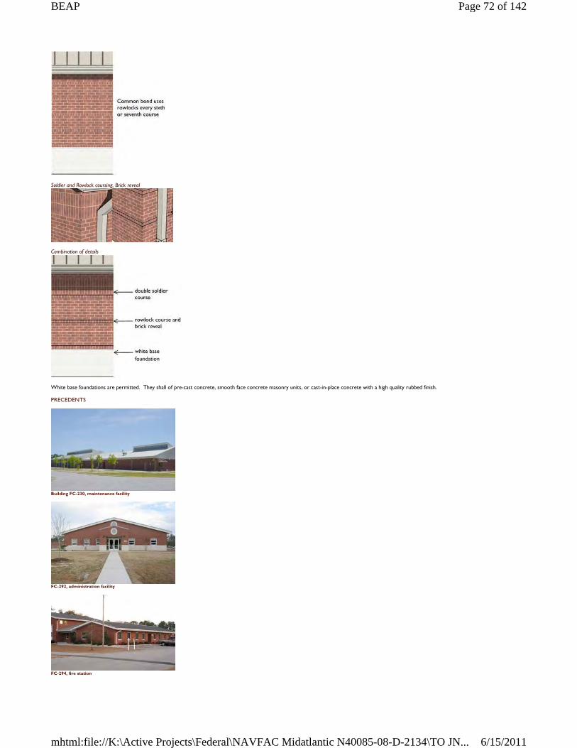
Soldier and Rowlock coursing, Brick reveal
Combination of details
White base foundations are permitted. They shall of pre-cast concrete, smooth face concrete masonry units, or cast-in-place concrete with a high quality rubbed finish.
PRECEDENTS
Building FC-230, maintenance facility
FC-292, administration facility
FC-294, fire station
Page 72 of 142BEAP
6/15/2011mhtml:file://K:\Active Projects\Federal\NAVFAC Midatlantic N40085-08-D-2134\TO JN...
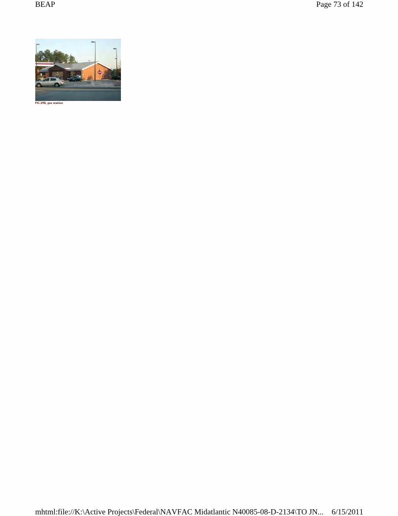
FC-298, gas station
Page 73 of 142BEAP
6/15/2011mhtml:file://K:\Active Projects\Federal\NAVFAC Midatlantic N40085-08-D-2134\TO JN...
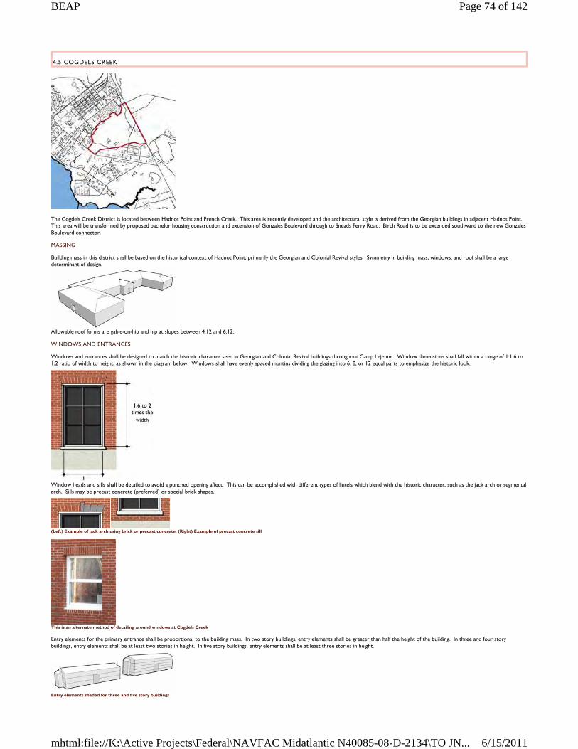
4.5 COGDELS CREEK
The Cogdels Creek District is located between Hadnot Point and French Creek. This area is recently developed and the architectural style is derived from the Georgian buildings in adjacent Hadnot Point. This area will be transformed by proposed bachelor housing construction and extension of Gonzales Boulevard through to Sneads Ferry Road. Birch Road is to be extended southward to the new Gonzales Boulevard connector.
MASSING
Building mass in this district shall be based on the historical context of Hadnot Point, primarily the Georgian and Colonial Revival styles. Symmetry in building mass, windows, and roof shall be a large determinant of design.
Allowable roof forms are gable-on-hip and hip at slopes between 4:12 and 6:12.
WINDOWS AND ENTRANCES
Windows and entrances shall be designed to match the historic character seen in Georgian and Colonial Revival buildings throughout Camp Lejeune. Window dimensions shall fall within a range of 1:1.6 to 1:2 ratio of width to height, as shown in the diagram below. Windows shall have evenly spaced muntins dividing the glazing into 6, 8, or 12 equal parts to emphasize the historic look.
Window heads and sills shall be detailed to avoid a punched opening affect. This can be accomplished with different types of lintels which blend with the historic character, such as the jack arch or segmental arch. Sills may be precast concrete (preferred) or special brick shapes.
(Left) Example of jack arch using brick or precast concrete; (Right) Example of precast concrete sill
This is an alternate method of detailing around windows at Cogdels Creek
Entry elements for the primary entrance shall be proportional to the building mass. In two story buildings, entry elements shall be greater than half the height of the building. In three and four story buildings, entry elements shall be at least two stories in height. In five story buildings, entry elements shall be at least three stories in height.
Entry elements shaded for three and five story buildings
Page 74 of 142BEAP
6/15/2011mhtml:file://K:\Active Projects\Federal\NAVFAC Midatlantic N40085-08-D-2134\TO JN...
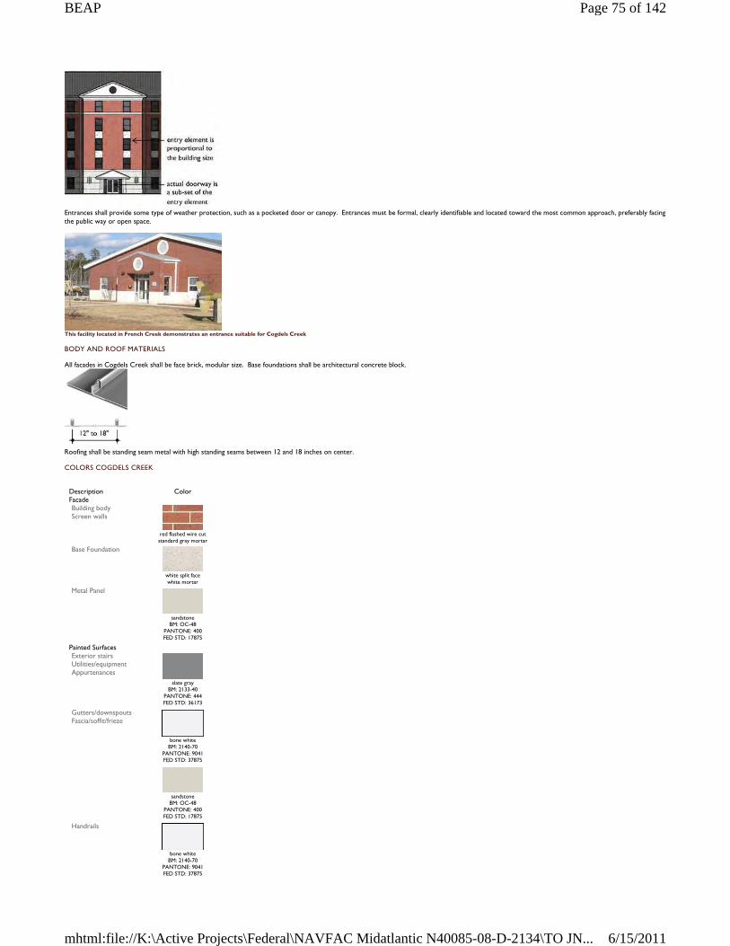
Entrances shall provide some type of weather protection, such as a pocketed door or canopy. Entrances must be formal, clearly identifiable and located toward the most common approach, preferably facing the public way or open space.
This facility located in French Creek demonstrates an entrance suitable for Cogdels Creek
BODY AND ROOF MATERIALS
All facades in Cogdels Creek shall be face brick, modular size. Base foundations shall be architectural concrete block.
Roofing shall be standing seam metal with high standing seams between 12 and 18 inches on center.
COLORS COGDELS CREEK
Description Color Facade Building body Screen walls
red flashed wire cut standard gray mortar
Base Foundation
white split face white mortar
Metal Panel
sandstone
BM: OC-48 PANTONE: 400 FED STD: 17875
Painted Surfaces Exterior stairs Utilities/equipment Appurtenances
slate gray
BM: 2133-40 PANTONE: 444 FED STD: 36173
Gutters/downspouts Fascia/soffit/frieze
bone white
BM: 2140-70 PANTONE: 9041 FED STD: 37875
sandstone
BM: OC-48 PANTONE: 400 FED STD: 17875
Handrails
bone white
BM: 2140-70 PANTONE: 9041 FED STD: 37875
Page 75 of 142BEAP
6/15/2011mhtml:file://K:\Active Projects\Federal\NAVFAC Midatlantic N40085-08-D-2134\TO JN...
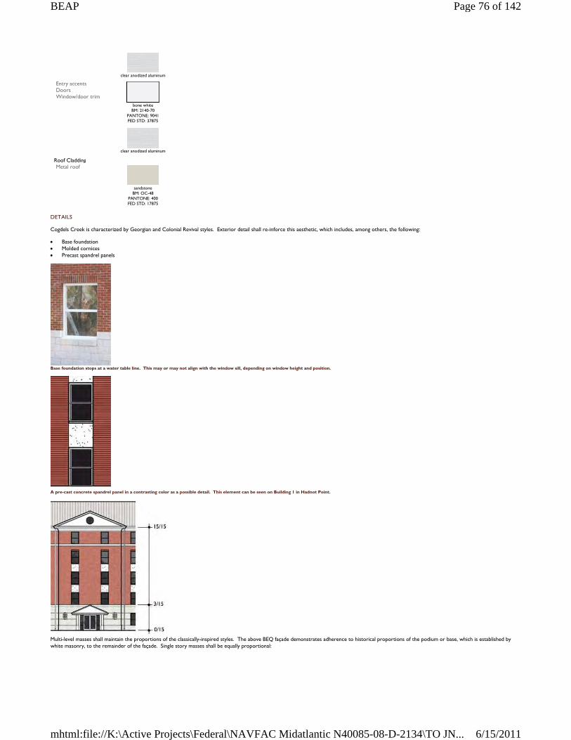
DETAILS
Cogdels Creek is characterized by Georgian and Colonial Revival styles. Exterior detail shall re-inforce this aesthetic, which includes, among others, the following:
Base foundation Molded cornices Precast spandrel panels
Base foundation stops at a water table line. This may or may not align with the window sill, depending on window height and position.
A pre-cast concrete spandrel panel in a contrasting color as a possible detail. This element can be seen on Building 1 in Hadnot Point.
Multi-level masses shall maintain the proportions of the classically-inspired styles. The above BEQ façade demonstrates adherence to historical proportions of the podium or base, which is established by white masonry, to the remainder of the façade. Single story masses shall be equally proportional:
clear anodized aluminum
Entry accents Doors Window/door trim
bone white
BM: 2140-70 PANTONE: 9041 FED STD: 37875
clear anodized aluminum
Roof Cladding Metal roof
sandstone
BM: OC-48 PANTONE: 400 FED STD: 17875
Page 76 of 142BEAP
6/15/2011mhtml:file://K:\Active Projects\Federal\NAVFAC Midatlantic N40085-08-D-2134\TO JN...
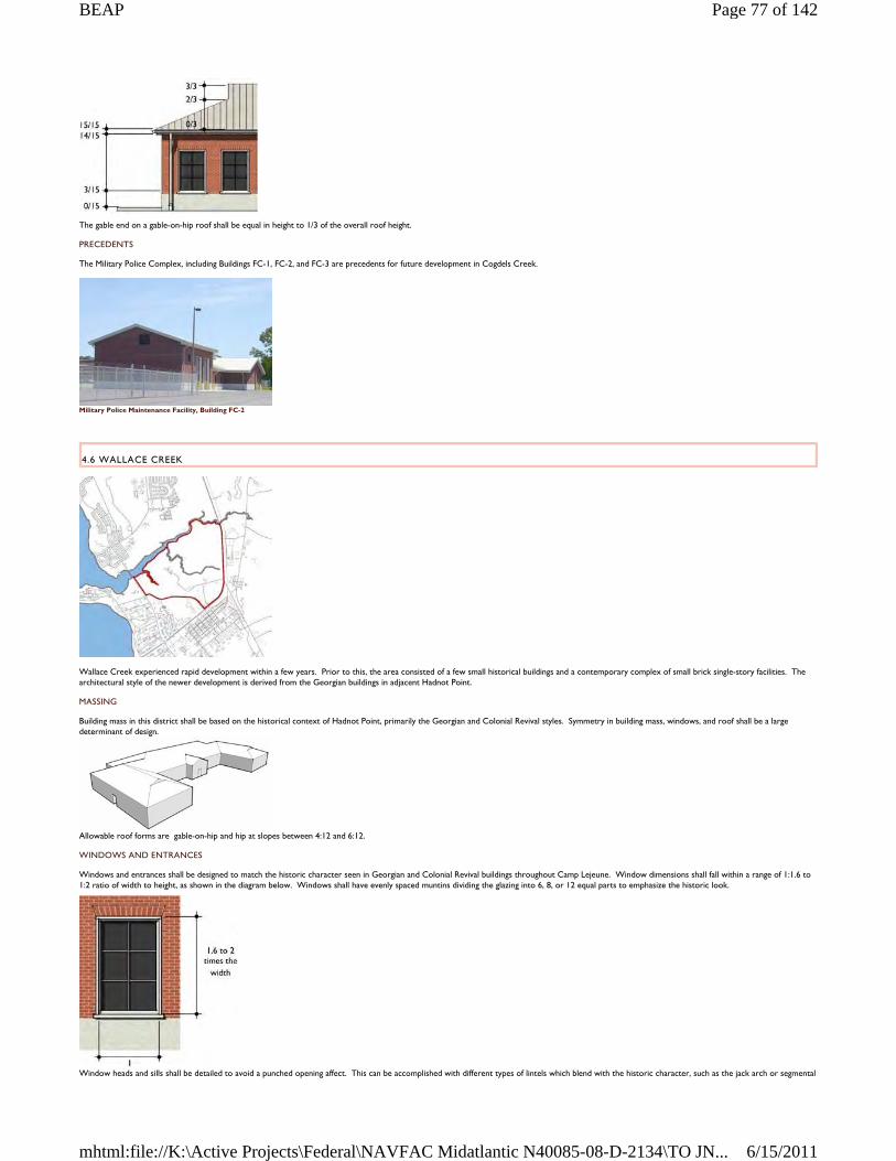
The gable end on a gable-on-hip roof shall be equal in height to 1/3 of the overall roof height.
PRECEDENTS
The Military Police Complex, including Buildings FC-1, FC-2, and FC-3 are precedents for future development in Cogdels Creek.
Military Police Maintenance Facility, Building FC-2
4.6 WALLACE CREEK
Wallace Creek experienced rapid development within a few years. Prior to this, the area consisted of a few small historical buildings and a contemporary complex of small brick single-story facilities. The architectural style of the newer development is derived from the Georgian buildings in adjacent Hadnot Point.
MASSING
Building mass in this district shall be based on the historical context of Hadnot Point, primarily the Georgian and Colonial Revival styles. Symmetry in building mass, windows, and roof shall be a large determinant of design.
Allowable roof forms are gable-on-hip and hip at slopes between 4:12 and 6:12.
WINDOWS AND ENTRANCES
Windows and entrances shall be designed to match the historic character seen in Georgian and Colonial Revival buildings throughout Camp Lejeune. Window dimensions shall fall within a range of 1:1.6 to 1:2 ratio of width to height, as shown in the diagram below. Windows shall have evenly spaced muntins dividing the glazing into 6, 8, or 12 equal parts to emphasize the historic look.
Window heads and sills shall be detailed to avoid a punched opening affect. This can be accomplished with different types of lintels which blend with the historic character, such as the jack arch or segmental
Page 77 of 142BEAP
6/15/2011mhtml:file://K:\Active Projects\Federal\NAVFAC Midatlantic N40085-08-D-2134\TO JN...
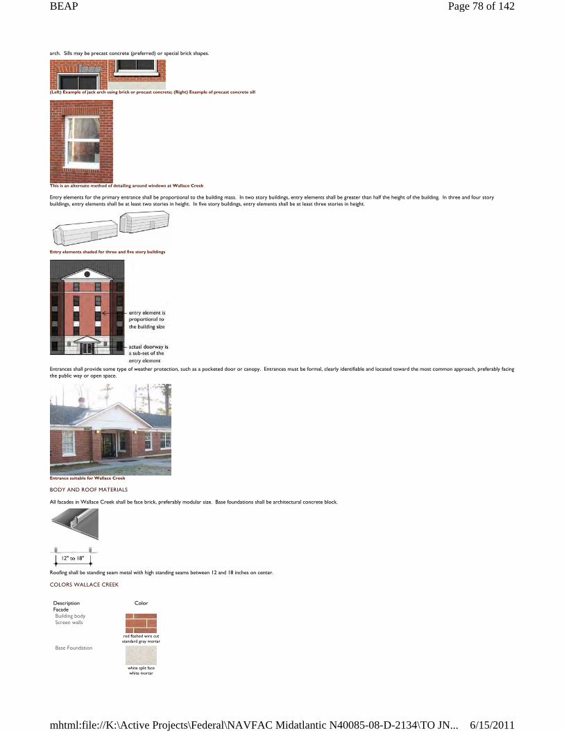
arch. Sills may be precast concrete (preferred) or special brick shapes.
(Left) Example of jack arch using brick or precast concrete; (Right) Example of precast concrete sill
This is an alternate method of detailing around windows at Wallace Creek
Entry elements for the primary entrance shall be proportional to the building mass. In two story buildings, entry elements shall be greater than half the height of the building. In three and four story buildings, entry elements shall be at least two stories in height. In five story buildings, entry elements shall be at least three stories in height.
Entry elements shaded for three and five story buildings
Entrances shall provide some type of weather protection, such as a pocketed door or canopy. Entrances must be formal, clearly identifiable and located toward the most common approach, preferably facing the public way or open space.
Entrance suitable for Wallace Creek
BODY AND ROOF MATERIALS
All facades in Wallace Creek shall be face brick, preferably modular size. Base foundations shall be architectural concrete block.
Roofing shall be standing seam metal with high standing seams between 12 and 18 inches on center.
COLORS WALLACE CREEK
Description Color Facade Building body Screen walls
red flashed wire cut standard gray mortar
Base Foundation
white split face white mortar
Page 78 of 142BEAP
6/15/2011mhtml:file://K:\Active Projects\Federal\NAVFAC Midatlantic N40085-08-D-2134\TO JN...
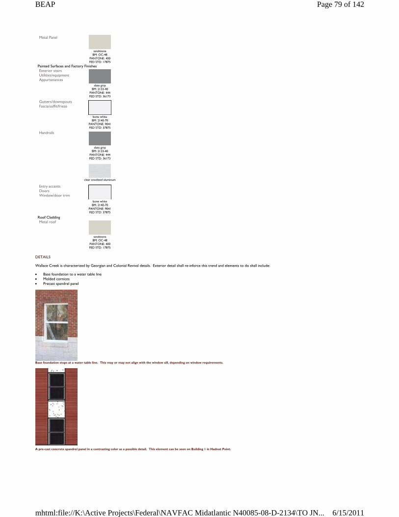
DETAILS
Wallace Creek is characterized by Georgian and Colonial Revival details. Exterior detail shall re-inforce this trend and elements to do shall include:
Base foundation to a water table line Molded cornices Precast spandrel panel
Base foundation stops at a water table line. This may or may not align with the window sill, depending on window requirements.
A pre-cast concrete spandrel panel in a contrasting color as a possible detail. This element can be seen on Building 1 in Hadnot Point.
Metal Panel
sandstone
BM: OC-48 PANTONE: 400 FED STD: 17875
Painted Surfaces and Factory Finishes Exterior stairs Utilities/equipment Appurtenances
slate gray
BM: 2133-40 PANTONE: 444 FED STD: 36173
Gutters/downspouts Fascia/soffit/frieze
bone white
BM: 2140-70 PANTONE: 9041 FED STD: 37875
Handrails
slate gray
BM: 2133-40 PANTONE: 444 FED STD: 36173
clear anodized aluminum
Entry accents Doors Window/door trim
bone white
BM: 2140-70 PANTONE: 9041 FED STD: 37875
Roof Cladding Metal roof
sandstone
BM: OC-48 PANTONE: 400 FED STD: 17875
Page 79 of 142BEAP
6/15/2011mhtml:file://K:\Active Projects\Federal\NAVFAC Midatlantic N40085-08-D-2134\TO JN...
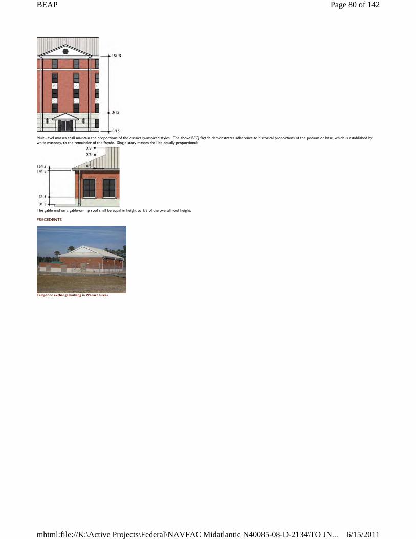
Multi-level masses shall maintain the proportions of the classically-inspired styles. The above BEQ façade demonstrates adherence to historical proportions of the podium or base, which is established by white masonry, to the remainder of the façade. Single story masses shall be equally proportional:
The gable end on a gable-on-hip roof shall be equal in height to 1/3 of the overall roof height.
PRECEDENTS
Telephone exchange building in Wallace Creek
Page 80 of 142BEAP
6/15/2011mhtml:file://K:\Active Projects\Federal\NAVFAC Midatlantic N40085-08-D-2134\TO JN...
4.7 COURTHOUSE BAY
Courthouse Bay is characterized by single-story brick structures designed after the Georgian or Federalist styles. On newer buildings, these styles have been abstracted or exaggerated. The resultant character is a cohesive mix of old and new construction.
MASSING
Buildings in Courthouse Bay shall be respectful of the district’s historic character. However a strict adherence to a set of stylistic rules in not necessarily required. Massing shall be largely symmetrical with contemporary interpretations of the Georgian and Colonial Revival styles.
Allowable roof forms include the gable, gable-on-hip, and hip at slopes between 4:12 and 6:12.
WINDOWS AND ENTRANCES
Windows and entrances shall be designed to match the historic character of Courthouse Bay. Windows shall have evenly spaced muntins dividing the glazing into 4, 6, or 8 parts to emphasize the historic look.
Window heads and sills shall be detailed to avoid a punched opening affect. This can be accomplished with different types of lintels which blend with the historic character, such as the jack arch or pre-cast concrete. Sills may be precast concrete (preferred) or special brick shapes.
Entrances shall provide some type of weather protection, such as a pocketed door or canopy. Entrances must be formal, clearly identifiable and located toward the most common approach, preferably facing the public way or open space.
The MCCS Military Clothing Facility has a covered entrance announced with a gable end
Page 81 of 142BEAP
6/15/2011mhtml:file://K:\Active Projects\Federal\NAVFAC Midatlantic N40085-08-D-2134\TO JN...
The covered entryway of the Joint Maritime Academic Facility
BODY AND ROOF MATERIALS
All facades in Hadnot Point shall be face brick, preferably modular size. Base foundations shall be architectural concrete block.
Roofing shall be standing seam metal with high standing seams between 12 and 18 inches on center.
Composition shingles shall be laminated asphalt architectural shingles with a dimensional appearance.
COLORS COURTHOUSE BAY
Description Color Facade Building body Screen walls
red flashed smooth
standard gray mortar
red flashed wire cut standard gray mortar
Base Foundation
white split face white mortar
Metal Panel
sandstone
BM: OC-48 PANTONE: 400 FED STD: 17875
Painted Surfaces and Factory Finishes Exterior stairs Utilities/equipment Appurtenances
slate gray
BM: 2133-40 PANTONE: 444 FED STD: 36173
Gutters/downspouts Fascia/soffit/frieze
bone white
BM: 2140-70 PANTONE: 9041 FED STD: 37875
sandstone
BM: OC-48 PANTONE: 400 FED STD: 17875
slate gray
BM: 2133-40 PANTONE: 444 FED STD: 36173
Handrails
clear anodized aluminum
Page 82 of 142BEAP
6/15/2011mhtml:file://K:\Active Projects\Federal\NAVFAC Midatlantic N40085-08-D-2134\TO JN...
DETAILS
Courthouse Bay shares many details with Hadnot Point and Hospital Point, such as base foundations and molded cornices. But the district also owes much of its character to roof details such as:
Dormers (gable fronted and eyebrow) Gable-on-hip Monitor Gable and monitor Clarestory windows
These roof details above enrich the visual impression of Courthouse Bay and shall be incorporated into design. From top left to bottom right: monitor, eyebrow, dormer with gable end, gable and monitor.
PRECEDENTS
The fitness center, Building BB2
Engineer School Headquarters
Entry accents Doors Window/door trim
bone white BM: 2140-70
PANTONE: 9041 FED STD: 37875
clear anodized aluminum
Roof Cladding Metal roof
sandstone
BM: OC-48 PANTONE: 400 FED STD: 17875
slate gray
BM: 2133-40 PANTONE: 444 FED STD: 36173
Composition shingles
slate gray
Page 83 of 142BEAP
6/15/2011mhtml:file://K:\Active Projects\Federal\NAVFAC Midatlantic N40085-08-D-2134\TO JN...
4.8 PARADISE POINT
Paradise Point is the natural continuation of Hadnot and Hospital Point in regard to architectural style. However, its residential district and concentration of educational facilities gives Paradise Point a unique quality.
The significant character of Paradise Point is defined along Seth Williams Road, specifically from Marston Pavilion, the Officers Club, and the bachelor and visiting officers’ quarters. These buildings embody the Georgian styles seen elsewhere on Base.
Along Brewster Road, the district takes on a more residential appearance, particularly from the vernacular housing areas, the golf course club house, and the schools.
MASSING
Building mass in this district shall be based on historical context, primarily the Georgian and Colonial Revival styles. Symmetry in building mass, windows, and roof shall be a large determinant of design.
Allowable roof forms are gable-on-hip and hip at slopes between 4:12 and 6:12.
WINDOWS AND ENTRANCES
Windows and entrances shall be designed to match the historic character of Paradise Point. Window dimensions shall fall within a range of 1:1.6 to 1:2 ratio of width to height, as shown in the diagram below. Windows shall have evenly spaced muntins dividing the glazing into 6, 8, or 12 equal parts to emphasize the historic look.
Window heads and sills shall be detailed to avoid a punched opening affect. This can be accomplished with different types of lintels which blend with the historic character, such as the jack arch or segmental arch. Sills may be precast concrete (preferred) or special brick shapes.
(Left) Example of jack arch using brick or precast concrete; (Right) Example of precast concrete sill
Entrances shall provide some type of weather protection, such as a pocketed door or canopy. Entrances must be formal, clearly identifiable and located toward the most common approach, preferably facing the public way or open space.
This entrance to the BOQ, Building 2603, is richly embellished with side lights, cornice detail, and a broken pediment
Page 84 of 142BEAP
6/15/2011mhtml:file://K:\Active Projects\Federal\NAVFAC Midatlantic N40085-08-D-2134\TO JN...
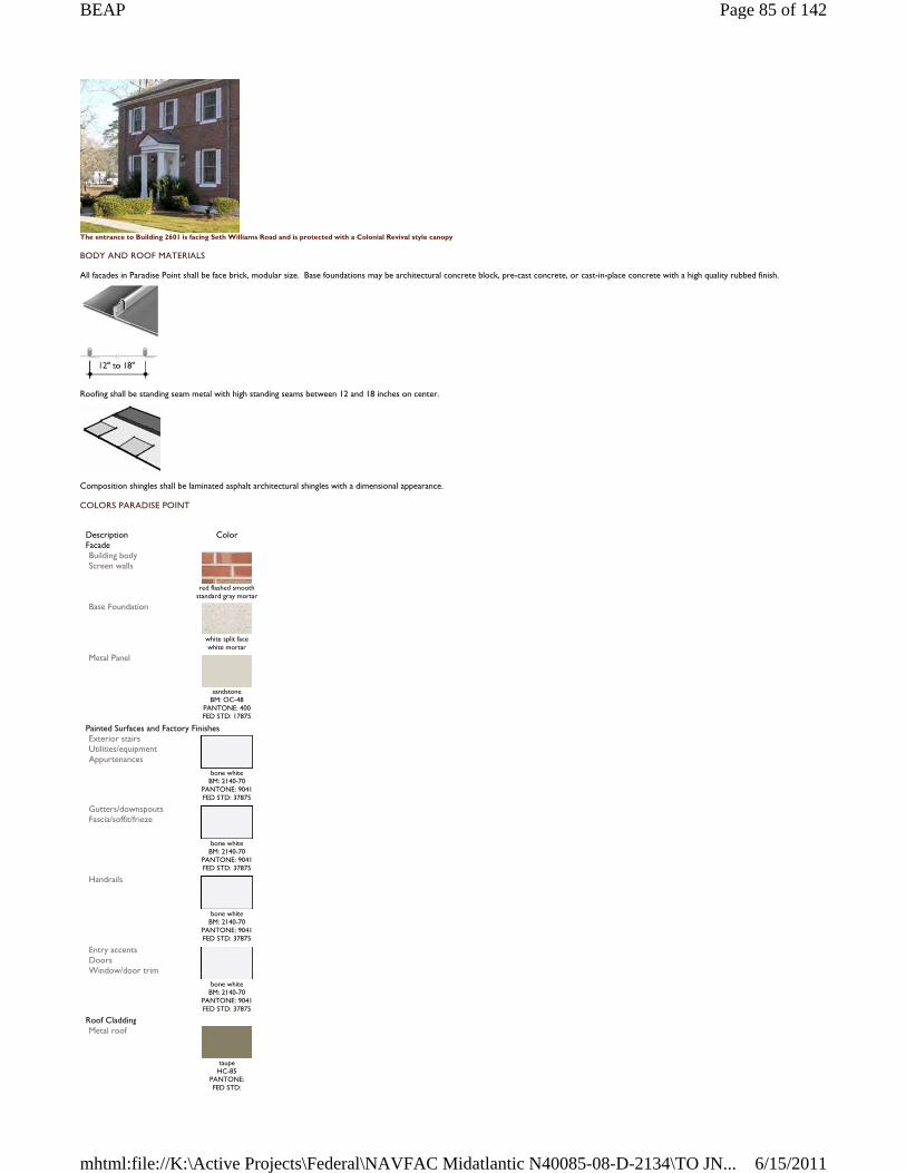
The entrance to Building 2601 is facing Seth Williams Road and is protected with a Colonial Revival style canopy
BODY AND ROOF MATERIALS
All facades in Paradise Point shall be face brick, modular size. Base foundations may be architectural concrete block, pre-cast concrete, or cast-in-place concrete with a high quality rubbed finish.
Roofing shall be standing seam metal with high standing seams between 12 and 18 inches on center.
Composition shingles shall be laminated asphalt architectural shingles with a dimensional appearance.
COLORS PARADISE POINT
Description Color Facade Building body Screen walls
red flashed smooth
standard gray mortar Base Foundation
white split face white mortar
Metal Panel
sandstone
BM: OC-48 PANTONE: 400 FED STD: 17875
Painted Surfaces and Factory Finishes Exterior stairs Utilities/equipment Appurtenances
bone white
BM: 2140-70 PANTONE: 9041 FED STD: 37875
Gutters/downspouts Fascia/soffit/frieze
bone white
BM: 2140-70 PANTONE: 9041 FED STD: 37875
Handrails
bone white
BM: 2140-70 PANTONE: 9041 FED STD: 37875
Entry accents Doors Window/door trim
bone white
BM: 2140-70 PANTONE: 9041 FED STD: 37875
Roof Cladding Metal roof
taupe HC-85
PANTONE: FED STD:
Page 85 of 142BEAP
6/15/2011mhtml:file://K:\Active Projects\Federal\NAVFAC Midatlantic N40085-08-D-2134\TO JN...
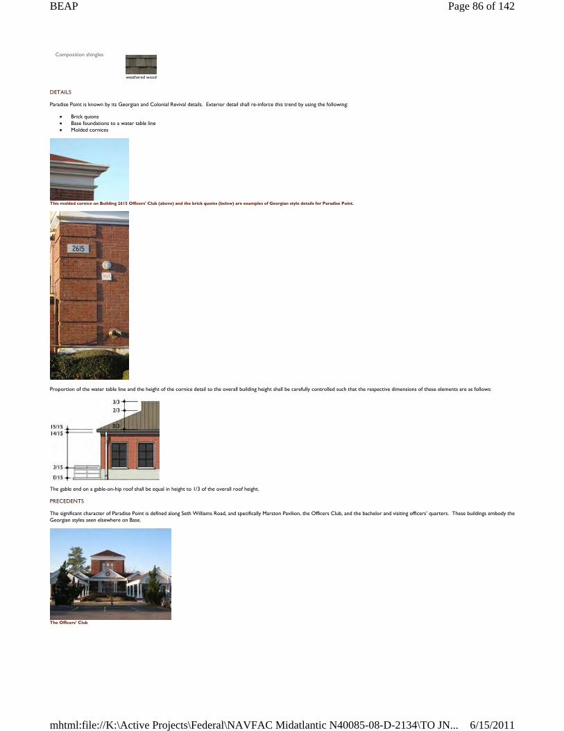
DETAILS
Paradise Point is known by its Georgian and Colonial Revival details. Exterior detail shall re-inforce this trend by using the following:
Brick quions Base foundations to a water table line Molded cornices
This molded cornice on Building 2615 Officers' Club (above) and the brick quoins (below) are examples of Georgian style details for Paradise Point.
Proportion of the water table line and the height of the cornice detail to the overall building height shall be carefully controlled such that the respective dimensions of these elements are as follows:
The gable end on a gable-on-hip roof shall be equal in height to 1/3 of the overall roof height.
PRECEDENTS
The significant character of Paradise Point is defined along Seth Williams Road, and specifically Marston Pavilion, the Officers Club, and the bachelor and visiting officers’ quarters. These buildings embody the Georgian styles seen elsewhere on Base.
The Officers’ Club
Composition shingles
weathered wood
Page 86 of 142BEAP
6/15/2011mhtml:file://K:\Active Projects\Federal\NAVFAC Midatlantic N40085-08-D-2134\TO JN...
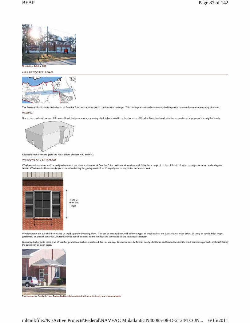
Fire station, Building 2600
4.8.1 BREWSTER ROAD
The Brewster Road area is a sub-district of Paradise Point and requires special consideration in design. This area is predominantly community buildings with a more informal contemporary character.
MASSING
Due to the residential nature of Brewster Road, designers must use massing which is both suitable to the character of Paradise Point, but blend with the vernacular architecture of the neighborhoods.
Allowable roof forms are gable and hip at slopes between 4:12 and 6:12.
WINDOWS AND ENTRANCES
Windows and entrances shall be designed to match the historic character of Paradise Point. Window dimensions shall fall within a range of 1:1.6 to 1:2 ratio of width to height, as shown in the diagram below. Windows shall have evenly spaced muntins dividing the glazing into 6, 8, or 12 equal parts to emphasize the historic look.
Window heads and sills shall be detailed to avoid a punched opening affect. This can be accomplished with different types of lintels such as the jack arch or soldier brick. Sills may be special brick shapes (preferred) or precast concrete. Shutters provide added emphasis to the window and contribute to the residential character.
Entrances shall provide some type of weather protection, such as a pocketed door or canopy. Entrances must be formal, clearly identifiable and located toward the most common approach, preferably facing the public way or open space.
This entrance to Family Services Center, Building 40, is pocketed with an arched entry and transom window
Page 87 of 142BEAP
6/15/2011mhtml:file://K:\Active Projects\Federal\NAVFAC Midatlantic N40085-08-D-2134\TO JN...
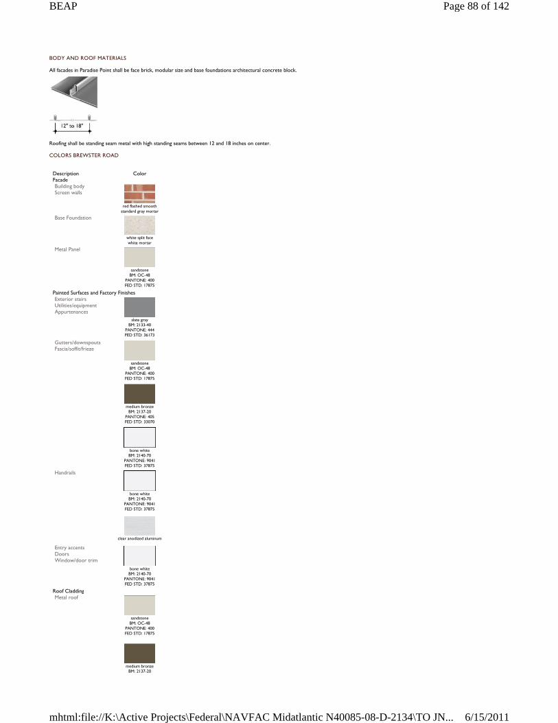
BODY AND ROOF MATERIALS
All facades in Paradise Point shall be face brick, modular size and base foundations architectural concrete block.
Roofing shall be standing seam metal with high standing seams between 12 and 18 inches on center.
COLORS BREWSTER ROAD
Description Color Facade Building body Screen walls
red flashed smooth
standard gray mortar Base Foundation
white split face white mortar
Metal Panel
sandstone
BM: OC-48 PANTONE: 400 FED STD: 17875
Painted Surfaces and Factory Finishes Exterior stairs Utilities/equipment Appurtenances
slate gray
BM: 2133-40 PANTONE: 444 FED STD: 36173
Gutters/downspouts Fascia/soffit/frieze
sandstone
BM: OC-48 PANTONE: 400 FED STD: 17875
medium bronze
BM: 2137-20 PANTONE: 405 FED STD: 33070
bone white
BM: 2140-70 PANTONE: 9041 FED STD: 37875
Handrails
bone white
BM: 2140-70 PANTONE: 9041 FED STD: 37875
clear anodized aluminum
Entry accents Doors Window/door trim
bone white
BM: 2140-70 PANTONE: 9041 FED STD: 37875
Roof Cladding Metal roof
sandstone
BM: OC-48 PANTONE: 400 FED STD: 17875
medium bronze
BM: 2137-20
Page 88 of 142BEAP
6/15/2011mhtml:file://K:\Active Projects\Federal\NAVFAC Midatlantic N40085-08-D-2134\TO JN...
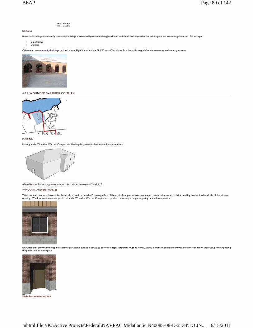
DETAILS
Brewster Road is predominantly community buildings surrounded by residential neighborhoods and detail shall emphasize this public space and welcoming character. For example:
Colonnades Shutters
Colonnades on community buildings such as Lejeune High School and the Golf Course Club House face the public way, define the entrances, and are easy to enter.
4.8.2 WOUNDED WARRIOR COMPLEX
MASSING
Massing in the Wounded Warrior Complex shall be largely symmetrical with formal entry elements.
Allowable roof forms are gable-on-hip and hip at slopes between 4:12 and 6:12.
WINDOWS AND ENTRANCES
Windows shall have detail around heads and sills to avoid a "punched" opening effect. This may include precast concrete shapes, special brick shapes or brick detailing used as lintels and sills of the window opening. Window muntins are not preferred in the Wounded Warrior Complex except where necessary to support glazing or window operation.
Entrances shall provide some type of weather protection, such as a pocketed door or canopy. Entrances must be formal, clearly identifiable and located toward the most common approach, preferably facing the public way or open space.
Single door pocketed entrance
PANTONE: 405 FED STD: 33070
Page 89 of 142BEAP
6/15/2011mhtml:file://K:\Active Projects\Federal\NAVFAC Midatlantic N40085-08-D-2134\TO JN...
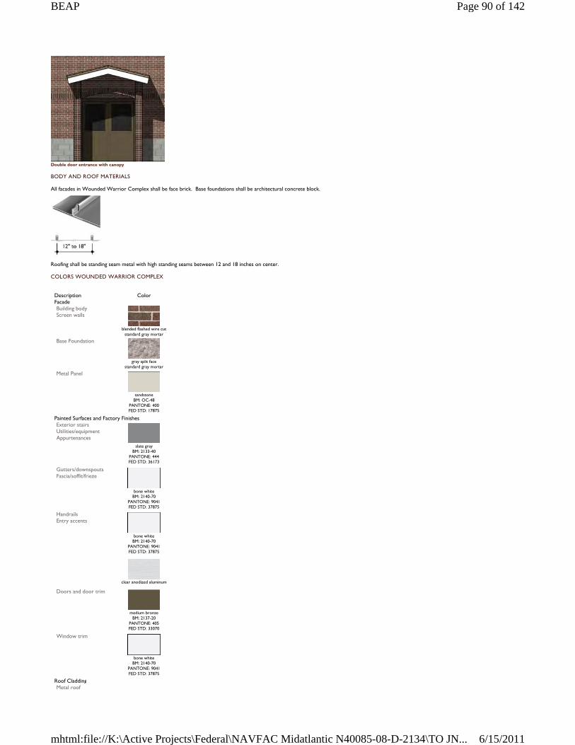
Double door entrance with canopy
BODY AND ROOF MATERIALS
All facades in Wounded Warrior Complex shall be face brick. Base foundations shall be architectural concrete block.
Roofing shall be standing seam metal with high standing seams between 12 and 18 inches on center.
COLORS WOUNDED WARRIOR COMPLEX
Description Color Facade Building body Screen walls
blended flashed wire cut
standard gray mortar Base Foundation
gray split face
standard gray mortar Metal Panel
sandstone
BM: OC-48 PANTONE: 400 FED STD: 17875
Painted Surfaces and Factory Finishes Exterior stairs Utilities/equipment Appurtenances
slate gray
BM: 2133-40 PANTONE: 444 FED STD: 36173
Gutters/downspouts Fascia/soffit/frieze
bone white
BM: 2140-70 PANTONE: 9041 FED STD: 37875
Handrails Entry accents
bone white
BM: 2140-70 PANTONE: 9041 FED STD: 37875
clear anodized aluminum
Doors and door trim
medium bronze
BM: 2137-20 PANTONE: 405 FED STD: 33070
Window trim
bone white
BM: 2140-70 PANTONE: 9041 FED STD: 37875
Roof Cladding Metal roof
Page 90 of 142BEAP
6/15/2011mhtml:file://K:\Active Projects\Federal\NAVFAC Midatlantic N40085-08-D-2134\TO JN...
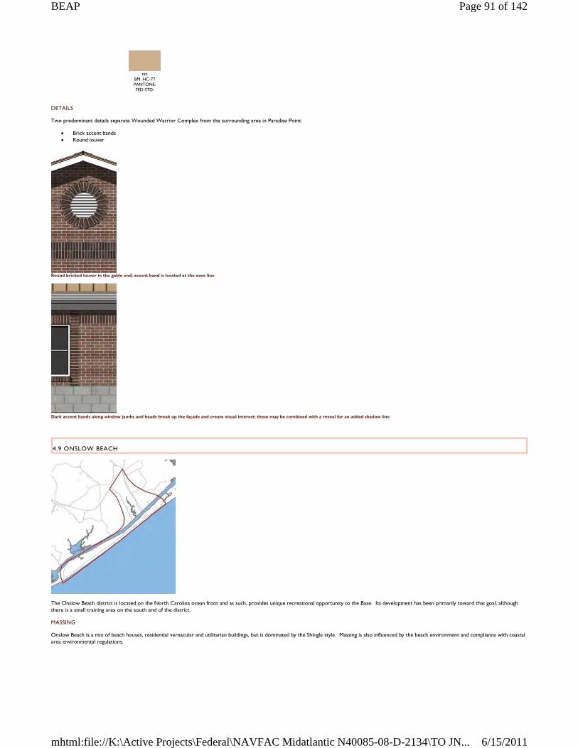
DETAILS
Two predominant details separate Wounded Warrior Complex from the surrounding area in Paradise Point:
Brick accent bands Round louver
Round bricked louver in the gable end; accent band is located at the eave line
Dark accent bands along window jambs and heads break up the façade and create visual interest; these may be combined with a reveal for an added shadow line
4.9 ONSLOW BEACH
The Onslow Beach district is located on the North Carolina ocean front and as such, provides unique recreational opportunity to the Base. Its development has been primarily toward that goal, although there is a small training area on the south end of the district.
MASSING
Onslow Beach is a mix of beach houses, residential vernacular and utilitarian buildings, but is dominated by the Shingle style. Massing is also influenced by the beach environment and compliance with coastal area environmental regulations.
tan
BM: HC-77 PANTONE: FED STD:
Page 91 of 142BEAP
6/15/2011mhtml:file://K:\Active Projects\Federal\NAVFAC Midatlantic N40085-08-D-2134\TO JN...
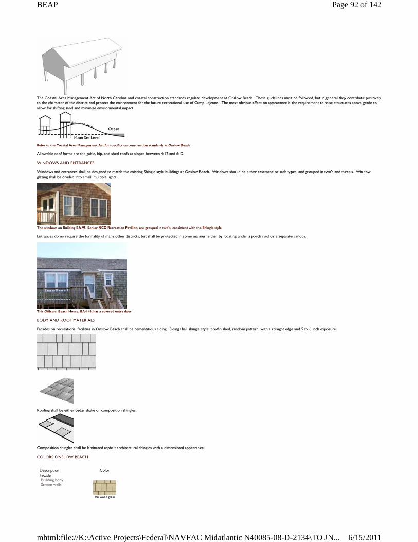
The Coastal Area Management Act of North Carolina and coastal construction standards regulate development at Onslow Beach. These guidelines must be followed, but in general they contribute positively to the character of the district and protect the environment for the future recreational use of Camp Lejeune. The most obvious affect on appearance is the requirement to raise structures above grade to allow for shifting sand and minimize environmental impact.
Refer to the Coastal Area Management Act for specifics on construction standards at Onslow Beach
Allowable roof forms are the gable, hip, and shed roofs at slopes between 4:12 and 6:12.
WINDOWS AND ENTRANCES
Windows and entrances shall be designed to match the existing Shingle style buildings at Onslow Beach. Windows should be either casement or sash types, and grouped in two's and three's. Window glazing shall be divided into small, multiple lights.
The windows on Building BA-95, Senior NCO Recreation Pavilion, are grouped in two's, consistent with the Shingle style
Entrances do no require the formality of many other districts, but shall be protected in some manner, either by locating under a porch roof or a separate canopy.
This Officers' Beach House, BA-146, has a covered entry door.
BODY AND ROOF MATERIALS
Facades on recreational facilities in Onslow Beach shall be cementitious siding. Siding shall shingle style, pre-finished, random pattern, with a straight edge and 5 to 6 inch exposure.
Roofing shall be either cedar shake or composition shingles.
Composition shingles shall be laminated asphalt architectural shingles with a dimensional appearance.
COLORS ONSLOW BEACH
Description Color Facade Building body Screen walls
tan wood grain
Page 92 of 142BEAP
6/15/2011mhtml:file://K:\Active Projects\Federal\NAVFAC Midatlantic N40085-08-D-2134\TO JN...
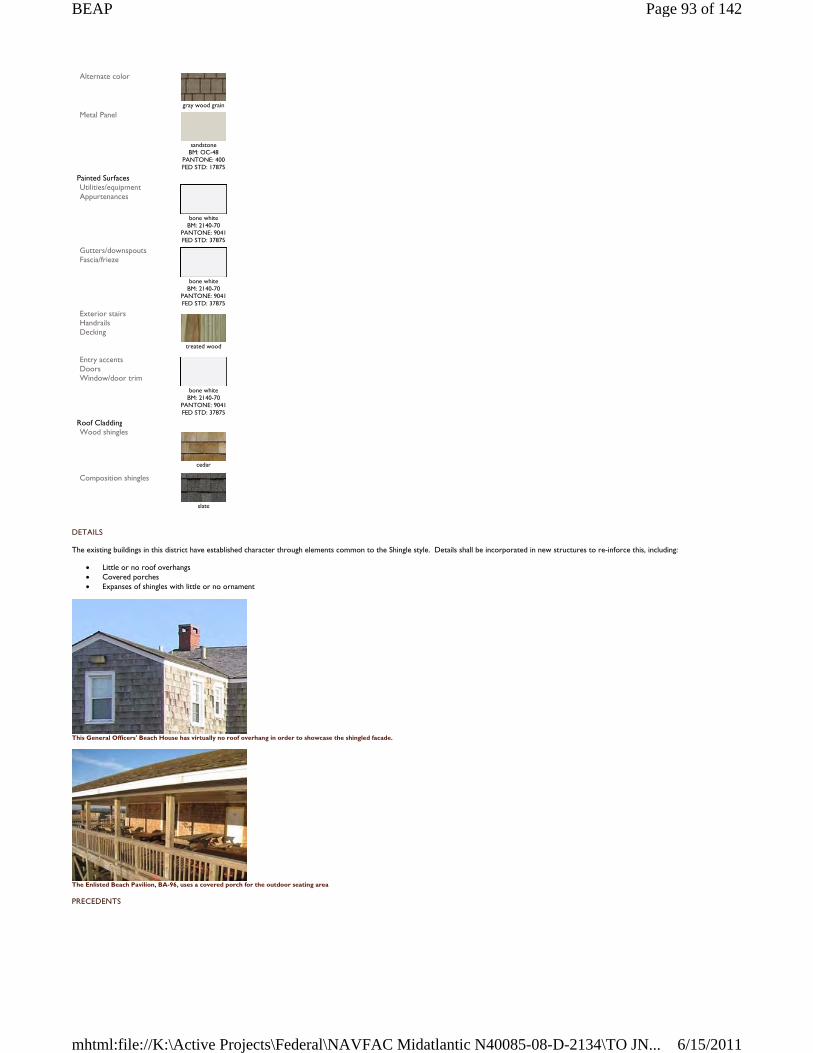
DETAILS
The existing buildings in this district have established character through elements common to the Shingle style. Details shall be incorporated in new structures to re-inforce this, including:
Little or no roof overhangs Covered porches Expanses of shingles with little or no ornament
This General Officers' Beach House has virtually no roof overhang in order to showcase the shingled facade.
The Enlisted Beach Pavilion, BA-96, uses a covered porch for the outdoor seating area
PRECEDENTS
Alternate color
gray wood grain
Metal Panel
sandstone
BM: OC-48 PANTONE: 400 FED STD: 17875
Painted Surfaces Utilities/equipment Appurtenances
bone white
BM: 2140-70 PANTONE: 9041 FED STD: 37875
Gutters/downspouts Fascia/frieze
bone white
BM: 2140-70 PANTONE: 9041 FED STD: 37875
Exterior stairs Handrails Decking
treated wood
Entry accents Doors Window/door trim
bone white
BM: 2140-70 PANTONE: 9041 FED STD: 37875
Roof Cladding Wood shingles
cedar
Composition shingles
slate
Page 93 of 142BEAP
6/15/2011mhtml:file://K:\Active Projects\Federal\NAVFAC Midatlantic N40085-08-D-2134\TO JN...
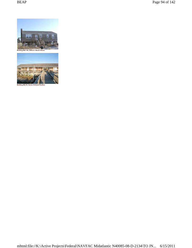
Building BA-146, Officers' Beach House
Building BA-95, Senior Enlisted Pavilion
Page 94 of 142BEAP
6/15/2011mhtml:file://K:\Active Projects\Federal\NAVFAC Midatlantic N40085-08-D-2134\TO JN...
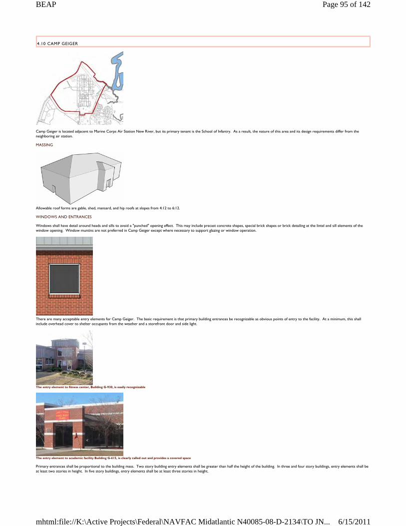
4.10 CAMP GEIGER
Camp Geiger is located adjacent to Marine Corps Air Station New River, but its primary tenant is the School of Infantry. As a result, the nature of this area and its design requirements differ from the neighboring air station.
MASSING
Allowable roof forms are gable, shed, mansard, and hip roofs at slopes from 4:12 to 6:12.
WINDOWS AND ENTRANCES
Windows shall have detail around heads and sills to avoid a "punched" opening effect. This may include precast concrete shapes, special brick shapes or brick detailing at the lintel and sill elements of the window opening. Window muntins are not preferred in Camp Geiger except where necessary to support glazing or window operation.
There are many acceptable entry elements for Camp Geiger. The basic requirement is that primary building entrances be recognizable as obvious points of entry to the facility. At a minimum, this shall include overhead cover to shelter occupants from the weather and a storefront door and side light.
The entry element to fitness center, Building G-930, is easily recognizable
The entry element to academic facility Building G-615, is clearly called out and provides a covered space
Primary entrances shall be proportional to the building mass. Two story building entry elements shall be greater than half the height of the building. In three and four story buildings, entry elements shall be at least two stories in height. In five story buildings, entry elements shall be at least three stories in height.
Page 95 of 142BEAP
6/15/2011mhtml:file://K:\Active Projects\Federal\NAVFAC Midatlantic N40085-08-D-2134\TO JN...
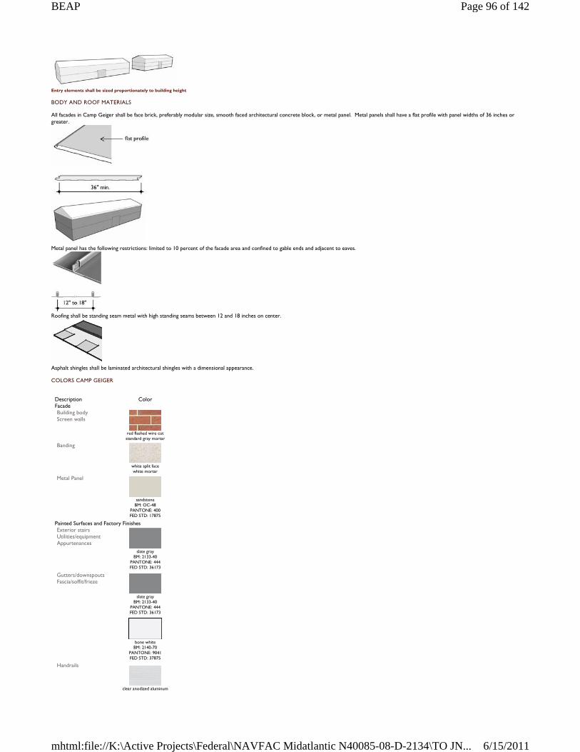
Entry elements shall be sized proportionately to building height
BODY AND ROOF MATERIALS
All facades in Camp Geiger shall be face brick, preferably modular size, smooth faced architectural concrete block, or metal panel. Metal panels shall have a flat profile with panel widths of 36 inches or greater.
Metal panel has the following restrictions: limited to 10 percent of the facade area and confined to gable ends and adjacent to eaves.
Roofing shall be standing seam metal with high standing seams between 12 and 18 inches on center.
Asphalt shingles shall be laminated architectural shingles with a dimensional appearance.
COLORS CAMP GEIGER
Description Color Facade Building body Screen walls
red flashed wire cut standard gray mortar
Banding
white split face white mortar
Metal Panel
sandstone
BM: OC-48 PANTONE: 400 FED STD: 17875
Painted Surfaces and Factory Finishes Exterior stairs Utilities/equipment Appurtenances
slate gray
BM: 2133-40 PANTONE: 444 FED STD: 36173
Gutters/downspouts Fascia/soffit/frieze
slate gray
BM: 2133-40 PANTONE: 444 FED STD: 36173
bone white
BM: 2140-70 PANTONE: 9041 FED STD: 37875
Handrails
clear anodized aluminum
Page 96 of 142BEAP
6/15/2011mhtml:file://K:\Active Projects\Federal\NAVFAC Midatlantic N40085-08-D-2134\TO JN...
DETAILS
Camp Geiger is an area of intense training activity for relatively new and young Marines, a particularly transient population. It is especially important to establish a sense of place that provides grounding for the experience of living and working at Camp Geiger.
Banding
The distinctive white banding on many buildings contributes to the theme of the district and evokes a sense of rhythm, order, and discipline.
Two bands on a single story building is enough to convey the intent but not over-do the detail.
PRECEDENTS
This academic instruction facility, Building G-615, is good example of many design elements at Camp Geiger.
These open bay barracks, Building G-702, set a good precedent for multi-story design.
The horizontal banding on this BEQ, which is a structural element, sets the precedent for the distinctive detail on future buildings.
Entry accents Doors Window and door trim
bone white BM: 2140-70
PANTONE: 9041 FED STD: 37875
clear anodized aluminum
Roof Cladding Prefinished metal roof
slate gray
BM: 2133-40 PANTONE: 444 FED STD: 36173
Composition shingles
slate gray
Page 97 of 142BEAP
6/15/2011mhtml:file://K:\Active Projects\Federal\NAVFAC Midatlantic N40085-08-D-2134\TO JN...
4.11 NEW RIVER
Marine Corps Air Station New River is largely an independent installation, but has a common history with Camp Lejeune and MCAS Cherry Point. It continues to share some support services with Camp Lejeune and is included in the BEAP as a separate district.
MASSING
There is a wide range of architecture at New River, as well as facility types that are unique to an airfield. The utilitarian theme of the airfield function should not influence other areas of the Installation. Two types of massings are required:
Administration and Support Buildings
These buildings include offices, conference spaces, command functions, batchelor housing, base support services and any structure not solely associated with the flight line. Massing of these buildings shall be clean, simple, and contemporary forms. Use submassing for larger structures to break up the building volume.
Allowable roof forms include the gable, shed, and hip roofs at slopes between 4:12 and 6:12.
Airfield Facilities and Hangars
These buildings include facilities in the airfield area such as aircraft maintenance hangars, simulator buildings, and warehouses. Massing shall be largely functional, with exposed structure. Submassing to enclose ancillary functions helps reduce the monumental scale of these buildings.
Roofs shall be gable, hip, or shed at slopes greater than 2:12 (to reduce roof heat island effects) and less than 4:12.
This massing diagram illustrates a hanger with a cantilevered truss roof
WINDOWS AND ENTRANCES
Windows shall have detail around heads and sills to avoid a "punched" opening effect. This may include special brick shapes or brick detailing as lintel and sill elements of the window opening. Window muntins are not preferred in New River except where necessary to support glazing or window operation.
Window framed by brick pilasters and soldier coursing above
There are many acceptable entry elements for New River. The basic requirement is that primary building entrances be recognizable as obvious points of entry to the facility. At a minimum, this shall include overhead cover to shelter occupants from the weather and a storefront door and side light.
Page 98 of 142BEAP
6/15/2011mhtml:file://K:\Active Projects\Federal\NAVFAC Midatlantic N40085-08-D-2134\TO JN...
The entry element to the fitness center, Building AS-4000, is emphasized with contrasting color and covered by a canopy
The entry to this community center is formally placed and faces the public open space and parking.
The entry to this operational trainer facility, AS-255, is facing the parking area and provides a covered area adjacent to the door.
BODY AND ROOF MATERIALS
Administration, Support, and Airfield Facilities
These buildings shall be face brick, preferably modular size, smooth faced architectural concrete block, or metal panel. Alternate colors are permitted where building type and location warrant – see color chart. Metal panels shall have a flat profile with panel widths of 36 inches or greater.
Metal panel has the following restrictions: limited to 10 percent of the facade area and confined to gable ends and adjacent to eaves.
Roofing shall be standing seam metal with high standing seams between 12 and 18 inches on center.
Asphalt shingles shall be laminated architectural shingles with a dimensional appearance.
Hangars
All hangers and other airfield district buildings in New River shall be face brick, modular size, smooth faced architectural concrete block, or metal panel. Metal panels shall have a flat profile with panel widths of 36 inches or greater.
Metal panel may consist of 100 percent of the facade.
Page 99 of 142BEAP
6/15/2011mhtml:file://K:\Active Projects\Federal\NAVFAC Midatlantic N40085-08-D-2134\TO JN...
Roofing may be either standing seam metal or built-up roofing. Standing seam metal shall have high standing seams between 12 and 18 inches on center.
Built-up roofing shall have as high a solar reflectance as possible without affecting aircraft operations.
COLORS NEW RIVER
Description
Color
Facade Building body Screen walls
red flashed wire cut standard gray mortar
Alternate building body
beige wire cut
standard gray mortar
white matte face
white mortar Metal panel
almond
BM: OC-32 PANTONE: 9583 FED STD: 27722
sandstone
BM: OC-48 PANTONE: 400 FED STD: 17875
Painted Surfaces and Factory Finishes Exterior stairs Utilities/equipment Appurtenances
slate gray
BM: 2133-40 PANTONE: 444 FED STD: 36173
Gutters/downspouts Fascia/soffit/frieze
evergreen
BM: 2040-10 PANTONE: 7484 FED STD: 14109
slate gray
BM: 2133-40 PANTONE: 444 FED STD: 36173
Handrails
medium bronze
BM: 2137-20 PANTONE: 405 FED STD: 33070
clear anodized aluminum
Entry accents Doors Window/door trim
medium bronze
BM: 2137-20 PANTONE: 405 FED STD: 33070
evergreen
BM: 2040-10 PANTONE: 7484 FED STD: 14109
Roof Cladding Metal roof
evergreen
BM: 2040-10 PANTONE: 7484 FED STD: 14109
Low slope roof
white
Page 100 of 142BEAP
6/15/2011mhtml:file://K:\Active Projects\Federal\NAVFAC Midatlantic N40085-08-D-2134\TO JN...
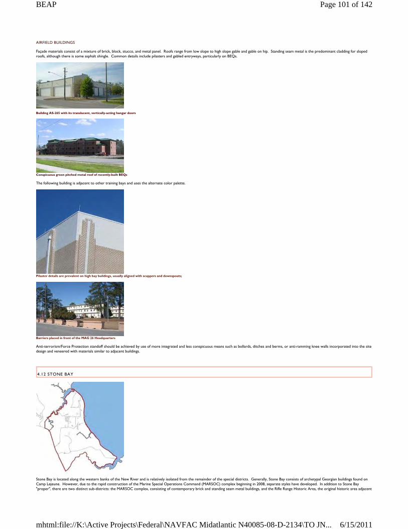
AIRFIELD BUILDINGS
Façade materials consist of a mixture of brick, block, stucco, and metal panel. Roofs range from low slope to high slope gable and gable on hip. Standing seam metal is the predominant cladding for sloped roofs, although there is some asphalt shingle. Common details include pilasters and gabled entryways, particularly on BEQs.
Building AS-265 with its translucent, vertically-acting hangar doors
Conspicuous green pitched metal roof of recently-built BEQs
The following building is adjacent to other training bays and uses the alternate color palette.
Pilaster details are prevalent on high bay buildings, usually aligned with scuppers and downspouts;
Barriers placed in front of the MAG 26 Headquarters
Anti-terrorism/Force Protection standoff should be achieved by use of more integrated and less conspicuous means such as bollards, ditches and berms, or anti-ramming knee walls incorporated into the site design and veneered with materials similar to adjacent buildings.
4.12 STONE BAY
Stone Bay is located along the western banks of the New River and is relatively isolated from the remainder of the special districts. Generally, Stone Bay consists of archetypal Georgian buildings found on Camp Lejeune. However, due to the rapid construction of the Marine Special Operations Command (MARSOC) complex beginning in 2008, separate styles have developed. In addition to Stone Bay "proper", there are two distinct sub-districts: the MARSOC complex, consisting of contemporary brick and standing seam metal buildings, and the Rifle Range Historic Area, the original historic area adjacent
Page 101 of 142BEAP
6/15/2011mhtml:file://K:\Active Projects\Federal\NAVFAC Midatlantic N40085-08-D-2134\TO JN...
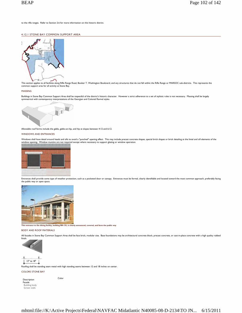
to the rifle ranges. Refer to Section 2.6 for more information on this historic district.
4.12.1 STONE BAY COMMON SUPPORT AREA
This section applies to all facilities along Rifle Range Road, Booker T. Washington Boulevard, and any structures that do not fall within the Rifle Range or MARSOC sub-districts. This represents the common support area for all activity at Stone Bay.
MASSING
Buildings in Stone Bay Common Support Area shall be respectful of the district’s historic character. However a strict adherence to a set of stylistic rules is not necessary. Massing shall be largely symmetrical with contemporary interpretations of the Georgian and Colonial Revival styles.
Allowable roof forms include the gable, gable-on-hip, and hip at slopes between 4:12 and 6:12.
WINDOWS AND ENTRANCES
Windows shall have detail around heads and sills to avoid a "punched" opening effect. This may include precast concrete shapes, special brick shapes or brick detailing at the lintel and sill elements of the window opening. Window muntins are not required except where necessary to support glazing or window operation.
Entrances shall provide some type of weather protection, such as a pocketed door or canopy. Entrances must be formal, clearly identifiable and located toward the most common approach, preferably facing the public way or open space.
This entrance to the dining facility, building RR-135, is clearly announced, covered, and faces the public way
BODY AND ROOF MATERIALS
All facades in Stone Bay Common Support Area shall be face brick, modular size. Base foundations may be architectural concrete block, precast concrete, or cast-in-place concrete with a high quality rubbed finish.
Roofing shall be standing seam metal with high standing seams between 12 and 18 inches on center.
COLORS STONE BAY
Description
Color
Facade Building body Screen walls
Page 102 of 142BEAP
6/15/2011mhtml:file://K:\Active Projects\Federal\NAVFAC Midatlantic N40085-08-D-2134\TO JN...
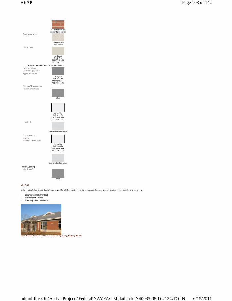
DETAILS
Detail suitable for Stone Bay is both respectful of the nearby historic context and contemporary design. This includes the following:
Dormers (gable fronted) Downspout accents Masonry base foundation
Gable fronted dormers on the roof of the dining facility, Building RR-135
red flashed wire cut standard gray mortar
Base foundation
white split face white mortar
Metal Panel
sandstone
BM: OC-48 PANTONE: 400 FED STD: 17875
Painted Surfaces and Factory Finishes Exterior stairs Utilities/equipment Appurtenances
slate gray
BM: 2133-40 PANTONE: 444 FED STD: 36173
Gutters/downspouts Fascia/soffit/frieze
silver
bone white
BM: 2140-70 PANTONE: 9041 FED STD: 37875
Handrails
clear anodized aluminum
Entry accents Doors Window/door trim
bone white
BM: 2140-70 PANTONE: 9041 FED STD: 37875
clear anodized aluminum
Roof Cladding Metal roof
silver
Page 103 of 142BEAP
6/15/2011mhtml:file://K:\Active Projects\Federal\NAVFAC Midatlantic N40085-08-D-2134\TO JN...
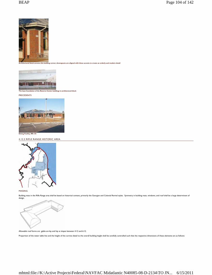
Architectural block accents this building corner; downspouts are aligned with these accents to create an orderly and modern detail
The base foundation of the Reserve Center buildings is architectural block
PRECEDENTS
Dining Facility, RR-135
4.12.2 RIFLE RANGE HISTORIC AREA
MASSING
Building mass in the Rifle Range area shall be based on historical context, primarily the Georgian and Colonial Revival styles. Symmetry in building mass, windows, and roof shall be a large determinant of design.
Allowable roof forms are gable-on-hip and hip at slopes between 4:12 and 6:12.
Proportion of the water table line and the height of the cornice detail to the overall building height shall be carefully controlled such that the respective dimensions of these elements are as follows:
Page 104 of 142BEAP
6/15/2011mhtml:file://K:\Active Projects\Federal\NAVFAC Midatlantic N40085-08-D-2134\TO JN...
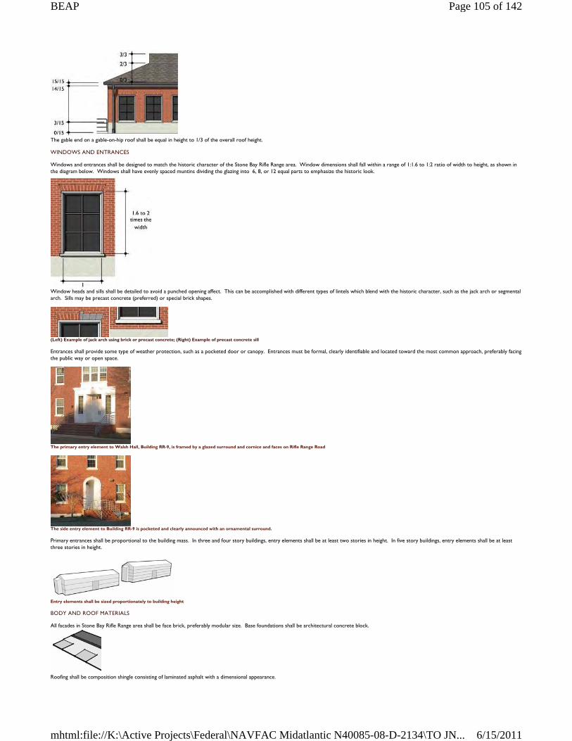
The gable end on a gable-on-hip roof shall be equal in height to 1/3 of the overall roof height.
WINDOWS AND ENTRANCES
Windows and entrances shall be designed to match the historic character of the Stone Bay Rifle Range area. Window dimensions shall fall within a range of 1:1.6 to 1:2 ratio of width to height, as shown in the diagram below. Windows shall have evenly spaced muntins dividing the glazing into 6, 8, or 12 equal parts to emphasize the historic look.
Window heads and sills shall be detailed to avoid a punched opening affect. This can be accomplished with different types of lintels which blend with the historic character, such as the jack arch or segmental arch. Sills may be precast concrete (preferred) or special brick shapes.
(Left) Example of jack arch using brick or precast concrete; (Right) Example of precast concrete sill
Entrances shall provide some type of weather protection, such as a pocketed door or canopy. Entrances must be formal, clearly identifiable and located toward the most common approach, preferably facing the public way or open space.
The primary entry element to Walsh Hall, Building RR-9, is framed by a glazed surround and cornice and faces on Rifle Range Road
The side entry element to Building RR-9 is pocketed and clearly announced with an ornamental surround.
Primary entrances shall be proportional to the building mass. In three and four story buildings, entry elements shall be at least two stories in height. In five story buildings, entry elements shall be at least three stories in height.
Entry elements shall be sized proportionately to building height
BODY AND ROOF MATERIALS
All facades in Stone Bay Rifle Range area shall be face brick, preferably modular size. Base foundations shall be architectural concrete block.
Roofing shall be composition shingle consisting of laminated asphalt with a dimensional appearance.
Page 105 of 142BEAP
6/15/2011mhtml:file://K:\Active Projects\Federal\NAVFAC Midatlantic N40085-08-D-2134\TO JN...
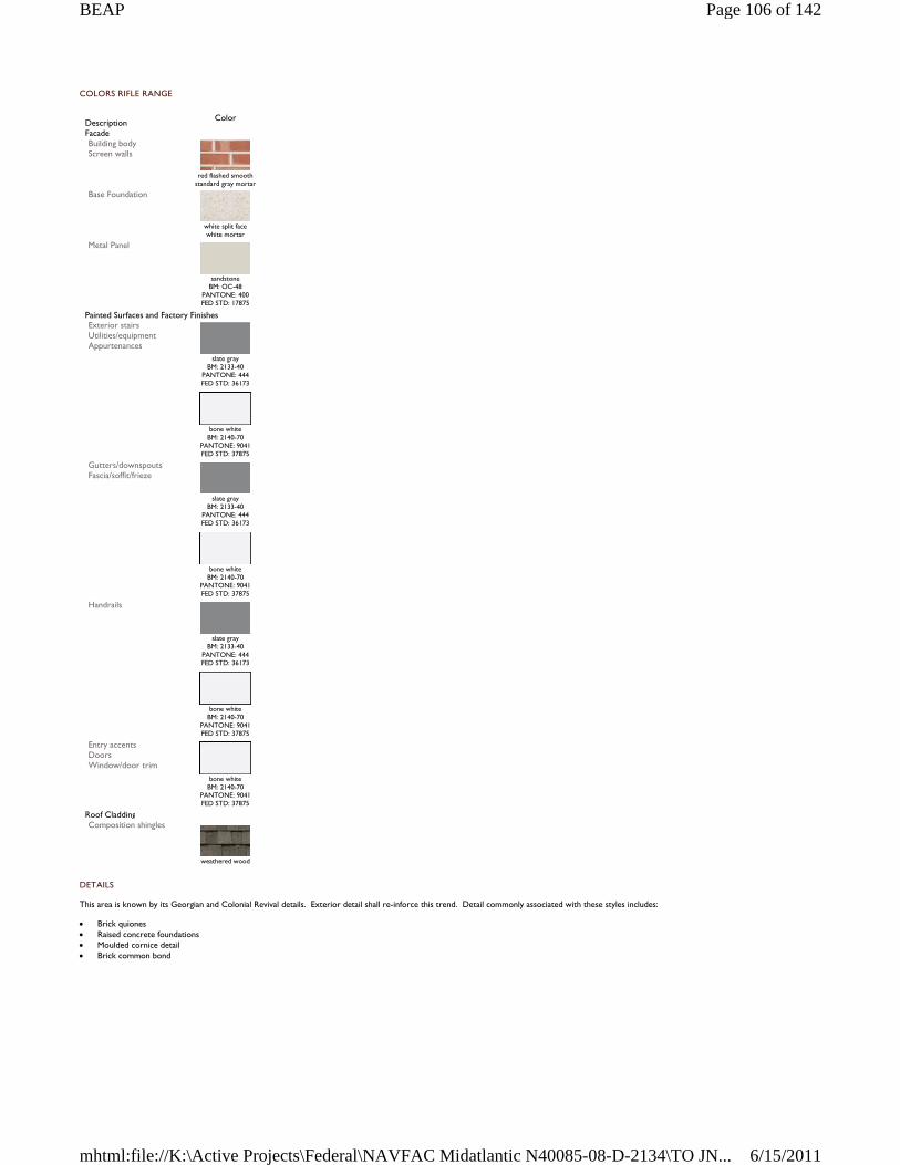
COLORS RIFLE RANGE
DETAILS
This area is known by its Georgian and Colonial Revival details. Exterior detail shall re-inforce this trend. Detail commonly associated with these styles includes:
Brick quiones Raised concrete foundations Moulded cornice detail Brick common bond
Description
Color
Facade Building body Screen walls
red flashed smooth
standard gray mortar Base Foundation
white split face white mortar
Metal Panel
sandstone
BM: OC-48 PANTONE: 400 FED STD: 17875
Painted Surfaces and Factory Finishes Exterior stairs Utilities/equipment Appurtenances
slate gray
BM: 2133-40 PANTONE: 444 FED STD: 36173
bone white
BM: 2140-70 PANTONE: 9041 FED STD: 37875
Gutters/downspouts Fascia/soffit/frieze
slate gray
BM: 2133-40 PANTONE: 444 FED STD: 36173
bone white
BM: 2140-70 PANTONE: 9041 FED STD: 37875
Handrails
slate gray
BM: 2133-40 PANTONE: 444 FED STD: 36173
bone white
BM: 2140-70 PANTONE: 9041 FED STD: 37875
Entry accents Doors Window/door trim
bone white
BM: 2140-70 PANTONE: 9041 FED STD: 37875
Roof Cladding Composition shingles
weathered wood
Page 106 of 142BEAP
6/15/2011mhtml:file://K:\Active Projects\Federal\NAVFAC Midatlantic N40085-08-D-2134\TO JN...
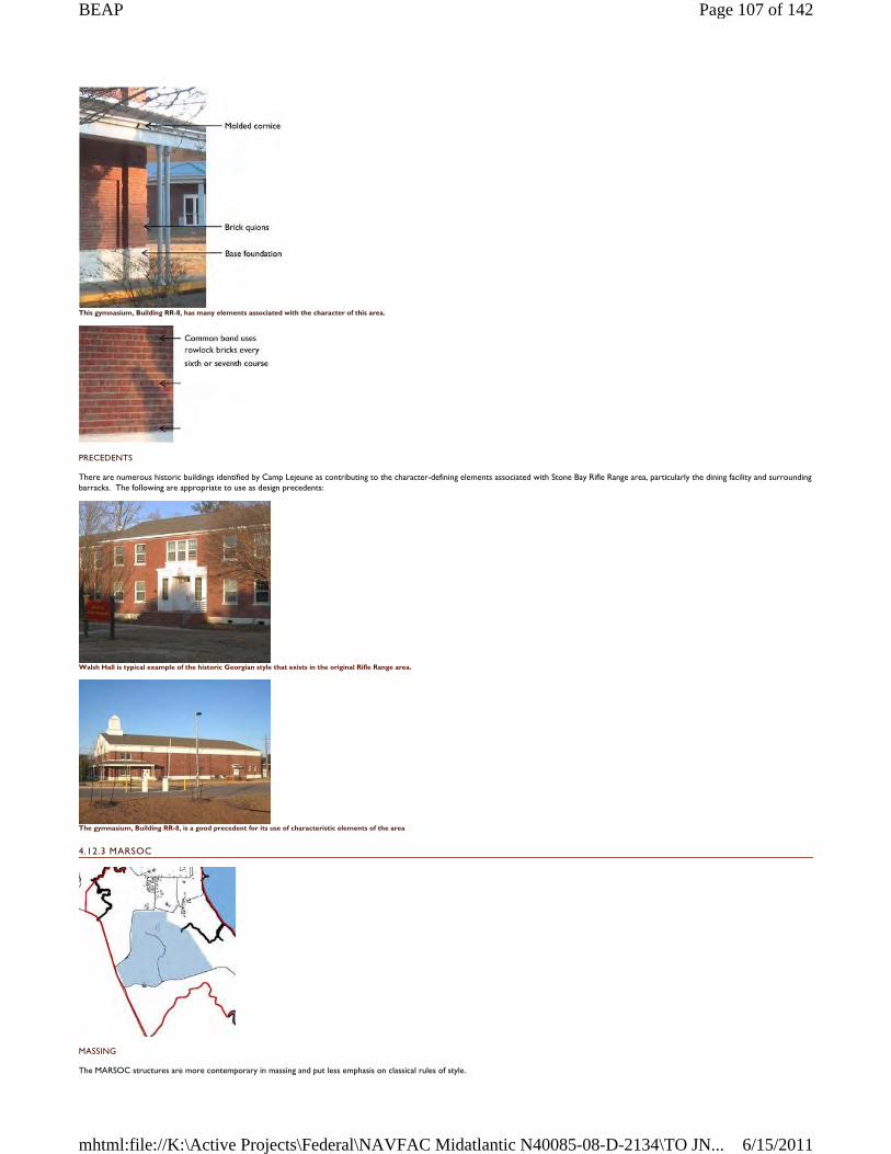
This gymnasium, Building RR-8, has many elements associated with the character of this area.
PRECEDENTS
There are numerous historic buildings identified by Camp Lejeune as contributing to the character-defining elements associated with Stone Bay Rifle Range area, particularly the dining facility and surrounding barracks. The following are appropriate to use as design precedents:
Walsh Hall is typical example of the historic Georgian style that exists in the original Rifle Range area.
The gymnasium, Building RR-8, is a good precedent for its use of characteristic elements of the area
4.12.3 MARSOC
MASSING
The MARSOC structures are more contemporary in massing and put less emphasis on classical rules of style.
Page 107 of 142BEAP
6/15/2011mhtml:file://K:\Active Projects\Federal\NAVFAC Midatlantic N40085-08-D-2134\TO JN...
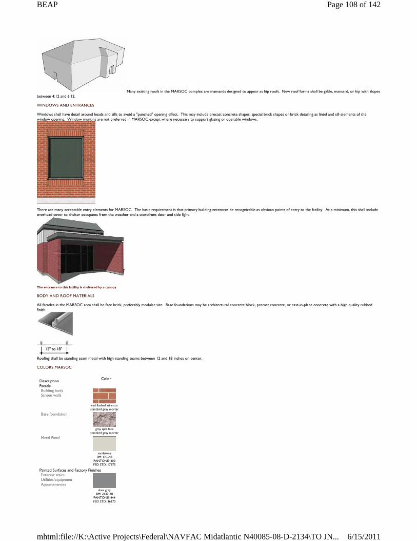
Many existing roofs in the MARSOC complex are mansards designed to appear as hip roofs. New roof forms shall be gable, mansard, or hip with slopes between 4:12 and 6:12.
WINDOWS AND ENTRANCES
Windows shall have detail around heads and sills to avoid a "punched" opening effect. This may include precast concrete shapes, special brick shapes or brick detailing as lintel and sill elements of the window opening. Window muntins are not preferred in MARSOC except where necessary to support glazing or operable windows.
There are many acceptable entry elements for MARSOC. The basic requirement is that primary building entrances be recognizable as obvious points of entry to the facility. At a minimum, this shall include overhead cover to shelter occupants from the weather and a storefront door and side light.
The entrance to this facility is sheltered by a canopy
BODY AND ROOF MATERIALS
All facades in the MARSOC area shall be face brick, preferably modular size. Base foundations may be architectural concrete block, precast concrete, or cast-in-place concrete with a high quality rubbed finish.
Roofing shall be standing seam metal with high standing seams between 12 and 18 inches on center.
COLORS MARSOC
Description
Color
Facade Building body Screen walls
red flashed wire cut standard gray mortar
Base foundation
gray split face
standard gray mortar Metal Panel
sandstone
BM: OC-48 PANTONE: 400 FED STD: 17875
Painted Surfaces and Factory Finishes Exterior stairs Utilities/equipment Appurtenances
slate gray BM: 2133-40
PANTONE: 444 FED STD: 36173
Page 108 of 142BEAP
6/15/2011mhtml:file://K:\Active Projects\Federal\NAVFAC Midatlantic N40085-08-D-2134\TO JN...
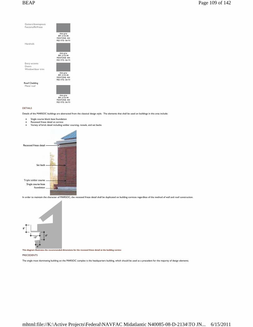
DETAILS
Details of the MARSOC buildings are abstracted from the classical design style. The elements that shall be used on buildings in this area include:
Single course block base foundation Recessed frieze detail at cornice Variety of brick detail including soldier coursing, reveals, and set backs
In order to maintain the character of MARSOC, the recessed frieze detail shall be duplicated on building cornices regardless of the method of wall and roof construction.
This diagram illustrates the recommended dimensions for the recessed frieze detail at the building cornice
PRECEDENTS
The single most dominating building on the MARSOC complex is the headquarters building, which should be used as a precedent for the majority of design elements.
Gutters/downspouts Fascia/soffit/frieze
slate gray
BM: 2133-40 PANTONE: 444 FED STD: 36173
Handrails
slate gray
BM: 2133-40 PANTONE: 444 FED STD: 36173
Entry accents Doors Window/door trim
slate gray
BM: 2133-40 PANTONE: 444 FED STD: 36173
Roof Cladding Metal roof
slate gray
BM: 2133-40 PANTONE: 444 FED STD: 36173
Page 109 of 142BEAP
6/15/2011mhtml:file://K:\Active Projects\Federal\NAVFAC Midatlantic N40085-08-D-2134\TO JN...
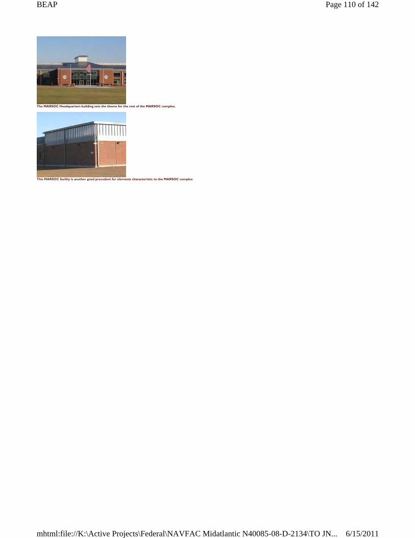
The MARSOC Headquarters building sets the theme for the rest of the MARSOC complex.
This MARSOC facility is another good precedent for elements characteristic to the MARSOC complex
Page 110 of 142BEAP
6/15/2011mhtml:file://K:\Active Projects\Federal\NAVFAC Midatlantic N40085-08-D-2134\TO JN...
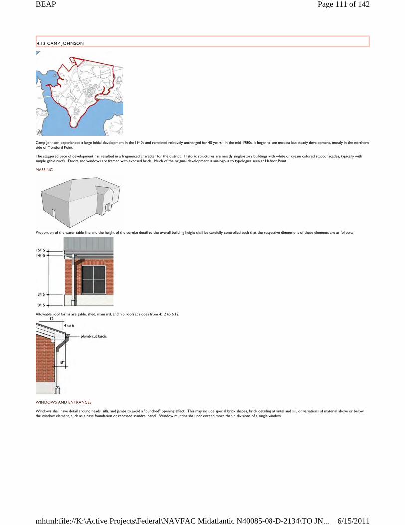
4.13 CAMP JOHNSON
Camp Johnson experienced a large initial development in the 1940s and remained relatively unchanged for 40 years. In the mid 1980s, it began to see modest but steady development, mostly in the northern side of Montford Point.
The staggered pace of development has resulted in a fragmented character for the district. Historic structures are mostly single-story buildings with white or cream colored stucco facades, typically with simple gable roofs. Doors and windows are framed with exposed brick. Much of the original development is analogous to typologies seen at Hadnot Point.
MASSING
Proportion of the water table line and the height of the cornice detail to the overall building height shall be carefully controlled such that the respective dimensions of these elements are as follows:
Allowable roof forms are gable, shed, mansard, and hip roofs at slopes from 4:12 to 6:12.
WINDOWS AND ENTRANCES
Windows shall have detail around heads, sills, and jambs to avoid a "punched" opening effect. This may include special brick shapes, brick detailing at lintel and sill, or variations of material above or below the window element, such as a base foundation or recessed spandrel panel. Window muntins shall not exceed more than 4 divisions of a single window.
Page 111 of 142BEAP
6/15/2011mhtml:file://K:\Active Projects\Federal\NAVFAC Midatlantic N40085-08-D-2134\TO JN...
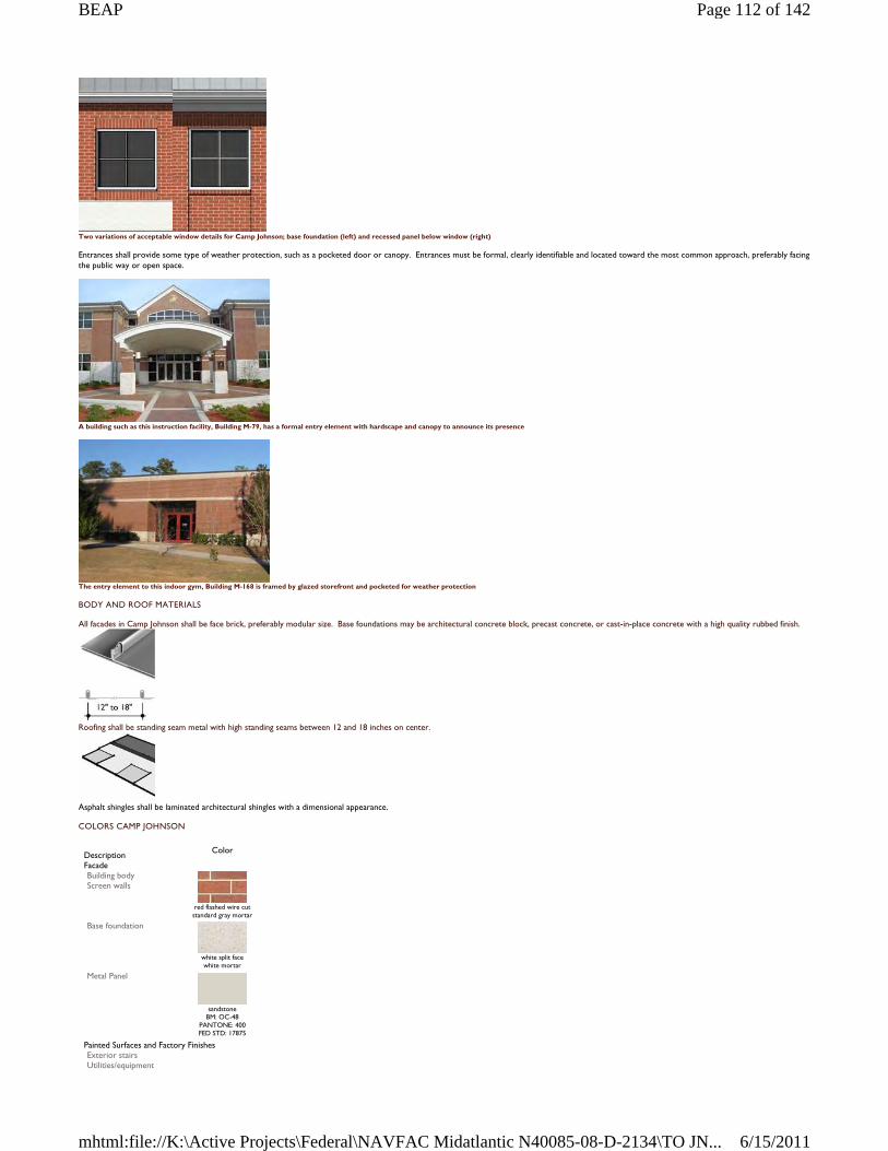
Two variations of acceptable window details for Camp Johnson; base foundation (left) and recessed panel below window (right)
Entrances shall provide some type of weather protection, such as a pocketed door or canopy. Entrances must be formal, clearly identifiable and located toward the most common approach, preferably facing the public way or open space.
A building such as this instruction facility, Building M-79, has a formal entry element with hardscape and canopy to announce its presence
The entry element to this indoor gym, Building M-168 is framed by glazed storefront and pocketed for weather protection
BODY AND ROOF MATERIALS
All facades in Camp Johnson shall be face brick, preferably modular size. Base foundations may be architectural concrete block, precast concrete, or cast-in-place concrete with a high quality rubbed finish.
Roofing shall be standing seam metal with high standing seams between 12 and 18 inches on center.
Asphalt shingles shall be laminated architectural shingles with a dimensional appearance.
COLORS CAMP JOHNSON
Description
Color
Facade Building body Screen walls
red flashed wire cut standard gray mortar
Base foundation
white split face white mortar
Metal Panel
sandstone
BM: OC-48 PANTONE: 400 FED STD: 17875
Painted Surfaces and Factory Finishes Exterior stairs Utilities/equipment
Page 112 of 142BEAP
6/15/2011mhtml:file://K:\Active Projects\Federal\NAVFAC Midatlantic N40085-08-D-2134\TO JN...
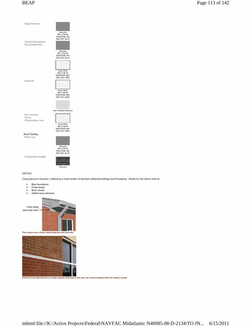
DETAILS
Camp Johnson's character is defined by a small number of dominant influential buildings (see Precedents). Details for this district shall be:
Base foundations Frieze details Brick reveals Gabled entry elements
This cornice uses a frieze detail along the eave and rake
A brick reveal adds interest to a large expanse of facade; in this case, the reveal is aligned with the window muntin
Appurtenances
slate gray
BM: 2133-40 PANTONE: 444 FED STD: 36173
Gutters/downspouts Fascia/soffit/frieze
slate gray
BM: 2133-40 PANTONE: 444 FED STD: 36173
bone white
BM: 2140-70 PANTONE: 9041 FED STD: 37875
Handrails
bone white
BM: 2140-70 PANTONE: 9041 FED STD: 37875
clear anodized aluminum
Entry accents Doors Window/door trim
bone white
BM: 2140-70 PANTONE: 9041 FED STD: 37875
Roof Cladding Metal roof
slate gray
BM: 2133-40 PANTONE: 444 FED STD: 36173
Composition shingles
slate gray
Page 113 of 142BEAP
6/15/2011mhtml:file://K:\Active Projects\Federal\NAVFAC Midatlantic N40085-08-D-2134\TO JN...
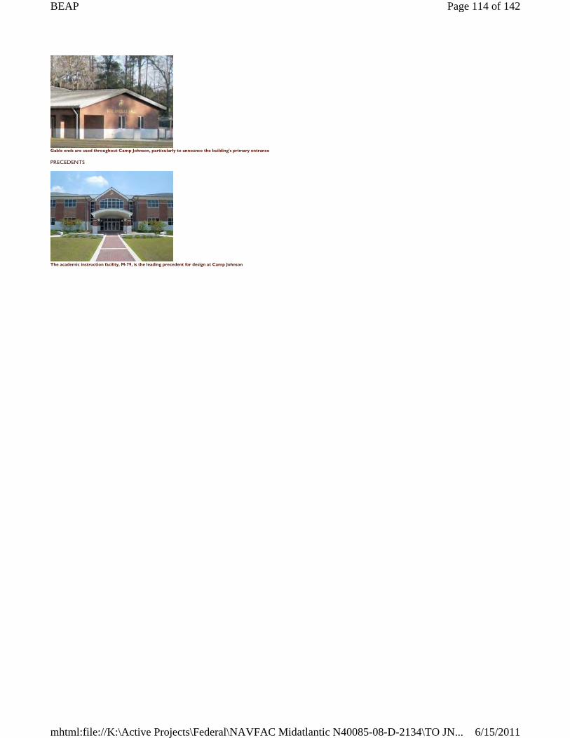
Gable ends are used throughout Camp Johnson, particularly to announce the building's primary entrance
PRECEDENTS
The academic instruction facility, M-79, is the leading precedent for design at Camp Johnson
Page 114 of 142BEAP
6/15/2011mhtml:file://K:\Active Projects\Federal\NAVFAC Midatlantic N40085-08-D-2134\TO JN...
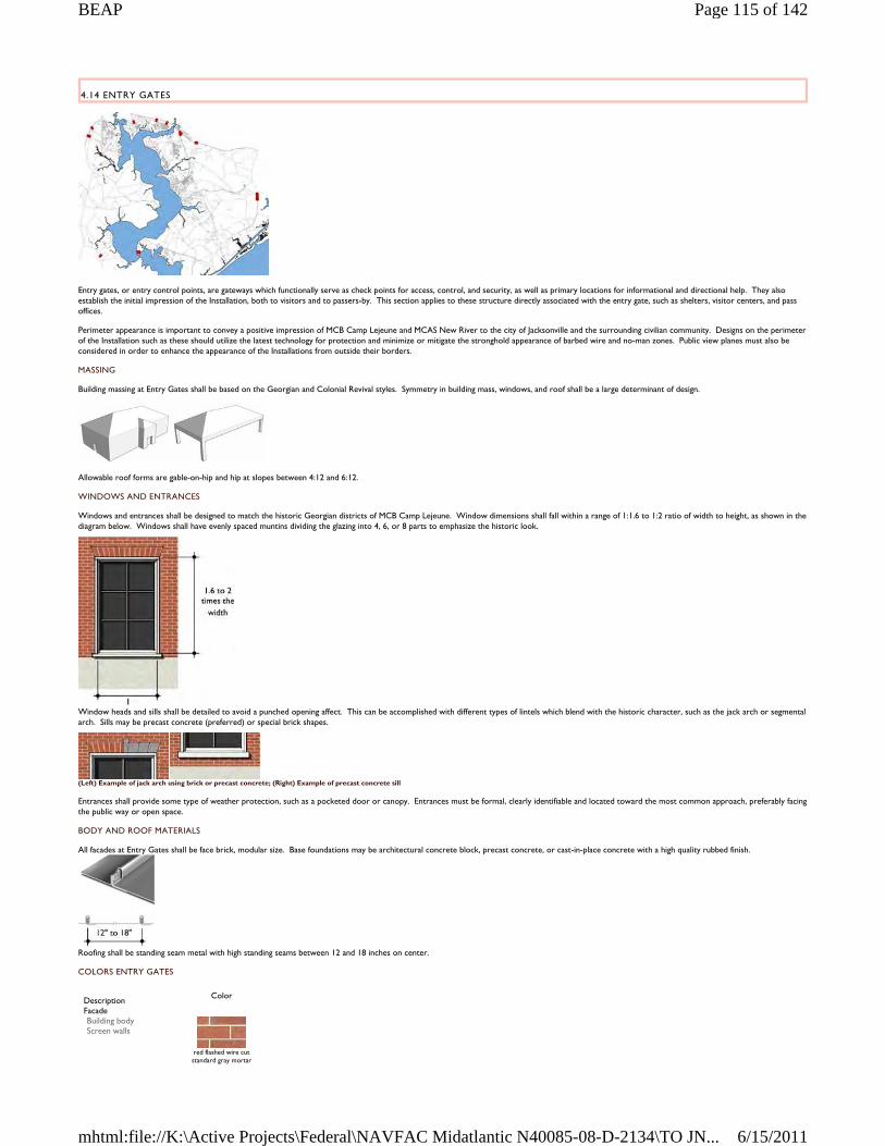
4.14 ENTRY GATES
Entry gates, or entry control points, are gateways which functionally serve as check points for access, control, and security, as well as primary locations for informational and directional help. They also establish the initial impression of the Installation, both to visitors and to passers-by. This section applies to these structure directly associated with the entry gate, such as shelters, visitor centers, and pass offices.
Perimeter appearance is important to convey a positive impression of MCB Camp Lejeune and MCAS New River to the city of Jacksonville and the surrounding civilian community. Designs on the perimeter of the Installation such as these should utilize the latest technology for protection and minimize or mitigate the stronghold appearance of barbed wire and no-man zones. Public view planes must also be considered in order to enhance the appearance of the Installations from outside their borders.
MASSING
Building massing at Entry Gates shall be based on the Georgian and Colonial Revival styles. Symmetry in building mass, windows, and roof shall be a large determinant of design.
Allowable roof forms are gable-on-hip and hip at slopes between 4:12 and 6:12.
WINDOWS AND ENTRANCES
Windows and entrances shall be designed to match the historic Georgian districts of MCB Camp Lejeune. Window dimensions shall fall within a range of 1:1.6 to 1:2 ratio of width to height, as shown in the diagram below. Windows shall have evenly spaced muntins dividing the glazing into 4, 6, or 8 parts to emphasize the historic look.
Window heads and sills shall be detailed to avoid a punched opening affect. This can be accomplished with different types of lintels which blend with the historic character, such as the jack arch or segmental arch. Sills may be precast concrete (preferred) or special brick shapes.
(Left) Example of jack arch using brick or precast concrete; (Right) Example of precast concrete sill
Entrances shall provide some type of weather protection, such as a pocketed door or canopy. Entrances must be formal, clearly identifiable and located toward the most common approach, preferably facing the public way or open space.
BODY AND ROOF MATERIALS
All facades at Entry Gates shall be face brick, modular size. Base foundations may be architectural concrete block, precast concrete, or cast-in-place concrete with a high quality rubbed finish.
Roofing shall be standing seam metal with high standing seams between 12 and 18 inches on center.
COLORS ENTRY GATES
Description
Color
Facade Building body Screen walls
red flashed wire cut standard gray mortar
Page 115 of 142BEAP
6/15/2011mhtml:file://K:\Active Projects\Federal\NAVFAC Midatlantic N40085-08-D-2134\TO JN...
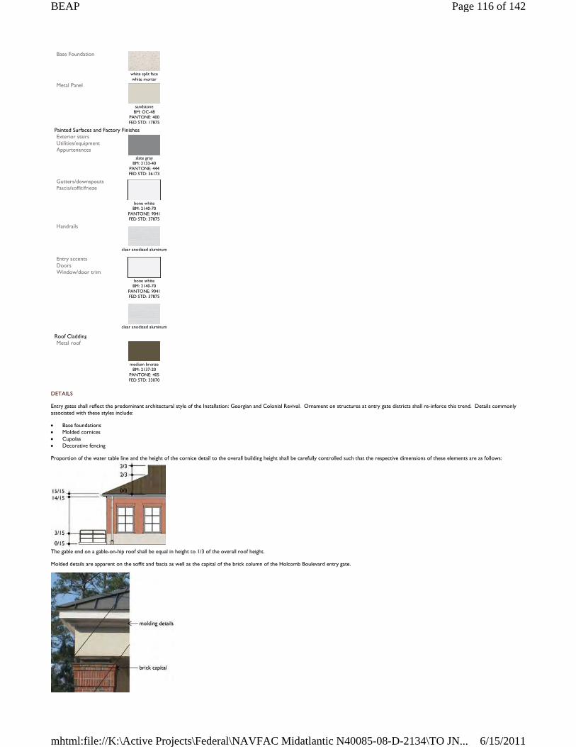
DETAILS
Entry gates shall reflect the predominant architectural style of the Installation: Georgian and Colonial Revival. Ornament on structures at entry gate districts shall re-inforce this trend. Details commonly associated with these styles include:
Base foundations Molded cornices Cupolas Decorative fencing
Proportion of the water table line and the height of the cornice detail to the overall building height shall be carefully controlled such that the respective dimensions of these elements are as follows:
The gable end on a gable-on-hip roof shall be equal in height to 1/3 of the overall roof height.
Molded details are apparent on the soffit and fascia as well as the capital of the brick column of the Holcomb Boulevard entry gate.
Base Foundation
white split face white mortar
Metal Panel
sandstone
BM: OC-48 PANTONE: 400 FED STD: 17875
Painted Surfaces and Factory Finishes Exterior stairs Utilities/equipment Appurtenances
slate gray
BM: 2133-40 PANTONE: 444 FED STD: 36173
Gutters/downspouts Fascia/soffit/frieze
bone white
BM: 2140-70 PANTONE: 9041 FED STD: 37875
Handrails
clear anodized aluminum
Entry accents Doors Window/door trim
bone white
BM: 2140-70 PANTONE: 9041 FED STD: 37875
clear anodized aluminum
Roof Cladding Metal roof
medium bronze
BM: 2137-20 PANTONE: 405 FED STD: 33070
Page 116 of 142BEAP
6/15/2011mhtml:file://K:\Active Projects\Federal\NAVFAC Midatlantic N40085-08-D-2134\TO JN...
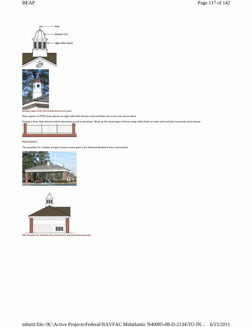
Existing cupola at the Holcomb Boulevard entry gate.
Most cupolas on MCB Camp Lejeune are eight sided with domical roofs and finials such as the ones shown above.
Fencing in Entry Gate districts shall be decorative as well as functional. Break up the visual impact of fences using a black finish on metal work and piers to provide visual interest.
PRECEDENTS
The precedent for canopies and gate houses at entry gates is the Holcomb Boulevard entry control point.
Side elevation of a standard entry control point with guard house beneath.
Page 117 of 142BEAP
6/15/2011mhtml:file://K:\Active Projects\Federal\NAVFAC Midatlantic N40085-08-D-2134\TO JN...
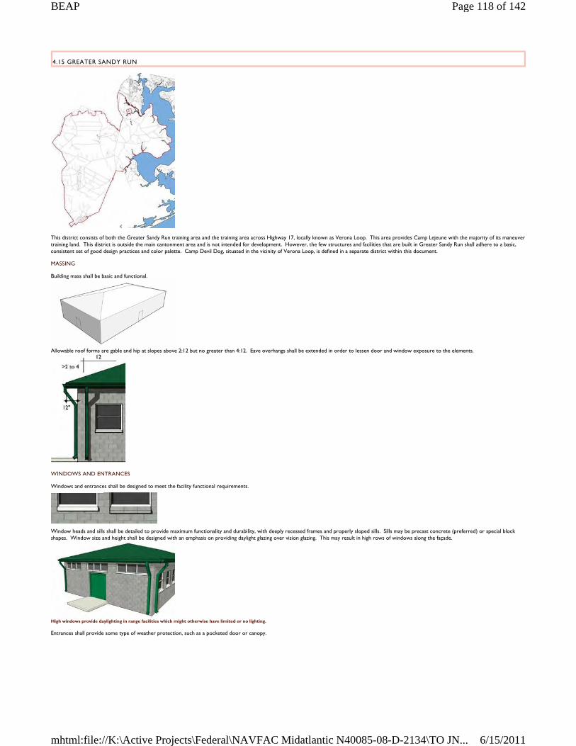
4.15 GREATER SANDY RUN
This district consists of both the Greater Sandy Run training area and the training area across Highway 17, locally known as Verona Loop. This area provides Camp Lejeune with the majority of its maneuver training land. This district is outside the main cantonment area and is not intended for development. However, the few structures and facilities that are built in Greater Sandy Run shall adhere to a basic, consistent set of good design practices and color palette. Camp Devil Dog, situated in the vicinity of Verona Loop, is defined in a separate district within this document.
MASSING
Building mass shall be basic and functional.
Allowable roof forms are gable and hip at slopes above 2:12 but no greater than 4:12. Eave overhangs shall be extended in order to lessen door and window exposure to the elements.
WINDOWS AND ENTRANCES
Windows and entrances shall be designed to meet the facility functional requirements.
Window heads and sills shall be detailed to provide maximum functionality and durability, with deeply recessed frames and properly sloped sills. Sills may be precast concrete (preferred) or special block shapes. Window size and height shall be designed with an emphasis on providing daylight glazing over vision glazing. This may result in high rows of windows along the façade.
High windows provide daylighting in range facilities which might otherwise have limited or no lighting.
Entrances shall provide some type of weather protection, such as a pocketed door or canopy.
Page 118 of 142BEAP
6/15/2011mhtml:file://K:\Active Projects\Federal\NAVFAC Midatlantic N40085-08-D-2134\TO JN...
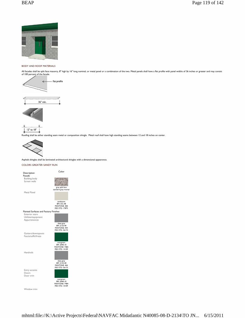
BODY AND ROOF MATERIALS
All facades shall be split face masonry, 8" high by 16" long nominal, or metal panel or a combination of the two. Metal panels shall have a flat profile with panel widths of 36 inches or greater and may consist of 100 percent of the facade.
Roofing shall be either standing seam metal or composition shingle. Metal roof shall have high standing seams between 12 and 18 inches on center.
Asphalt shingles shall be laminated architectural shingles with a dimensional appearance.
COLORS GREATER SANDY RUN
Description
Color
Facade Building body Screen walls
gray split face
standard gray mortar Metal Panel
sandstone
BM: OC-48 PANTONE: 400 FED STD: 17875
Painted Surfaces and Factory Finishes Exterior stairs Utilities/equipment Appurtenances
slate gray
BM: 2133-40 PANTONE: 444 FED STD: 36173
Gutters/downspouts Fascia/soffit/frieze
evergreen
BM: 2040-10 PANTONE: 7484 FED STD: 14109
Handrails
slate gray
BM: 2133-40 PANTONE: 444 FED STD: 36173
Entry accents Doors Door trim
evergreen BM: 2040-10
PANTONE: 7484 FED STD: 14109
Window trim
Page 119 of 142BEAP
6/15/2011mhtml:file://K:\Active Projects\Federal\NAVFAC Midatlantic N40085-08-D-2134\TO JN...
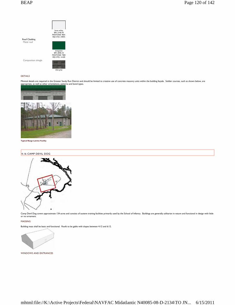
DETAILS
Minimal details are required in the Greater Sandy Run District and should be limited to creative use of concrete masonry units within the building façade. Soldier courses, such as shown below, are appropriate, as well as other orientations, patterns and bond types.
Typical Range Latrine Facility
4.16 CAMP DEVIL DOG
Camp Devil Dog covers approximate 134 acres and consists of austere training facilities primarily used by the School of Infantry. Buildings are generally utilitarian in nature and functional in design with little or no ornament.
MASSING
Building mass shall be basic and functional. Roofs to be gable with slopes between 4:12 and 6:12.
WINDOWS AND ENTRANCES
bone white
BM: 2140-70 PANTONE: 9041 FED STD: 37875
Roof Cladding Metal roof
evergreen
BM: 2040-10 PANTONE: 7484 FED STD: 14109
Composition shingle
slate gray
Page 120 of 142BEAP
6/15/2011mhtml:file://K:\Active Projects\Federal\NAVFAC Midatlantic N40085-08-D-2134\TO JN...
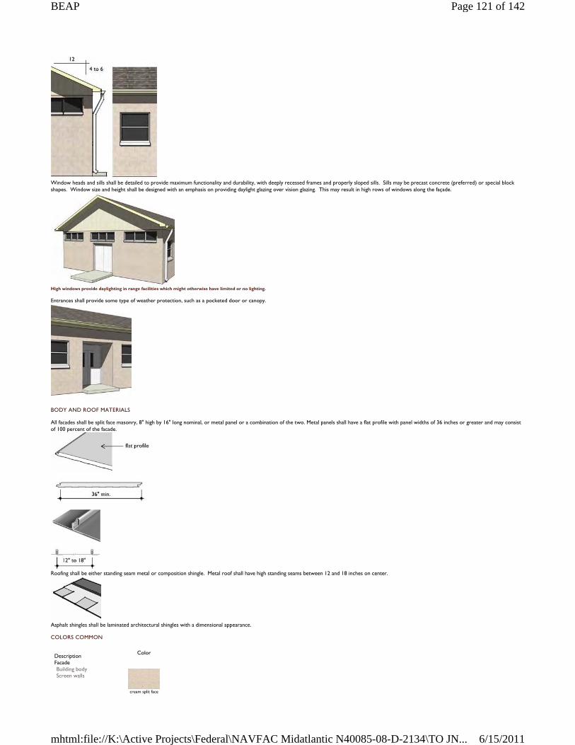
Window heads and sills shall be detailed to provide maximum functionality and durability, with deeply recessed frames and properly sloped sills. Sills may be precast concrete (preferred) or special block shapes. Window size and height shall be designed with an emphasis on providing daylight glazing over vision glazing. This may result in high rows of windows along the façade.
High windows provide daylighting in range facilities which might otherwise have limited or no lighting.
Entrances shall provide some type of weather protection, such as a pocketed door or canopy.
BODY AND ROOF MATERIALS
All facades shall be split face masonry, 8" high by 16" long nominal, or metal panel or a combination of the two. Metal panels shall have a flat profile with panel widths of 36 inches or greater and may consist of 100 percent of the facade.
Roofing shall be either standing seam metal or composition shingle. Metal roof shall have high standing seams between 12 and 18 inches on center.
Asphalt shingles shall be laminated architectural shingles with a dimensional appearance.
COLORS COMMON
Description
Color
Facade Building body Screen walls
cream split face
Page 121 of 142BEAP
6/15/2011mhtml:file://K:\Active Projects\Federal\NAVFAC Midatlantic N40085-08-D-2134\TO JN...
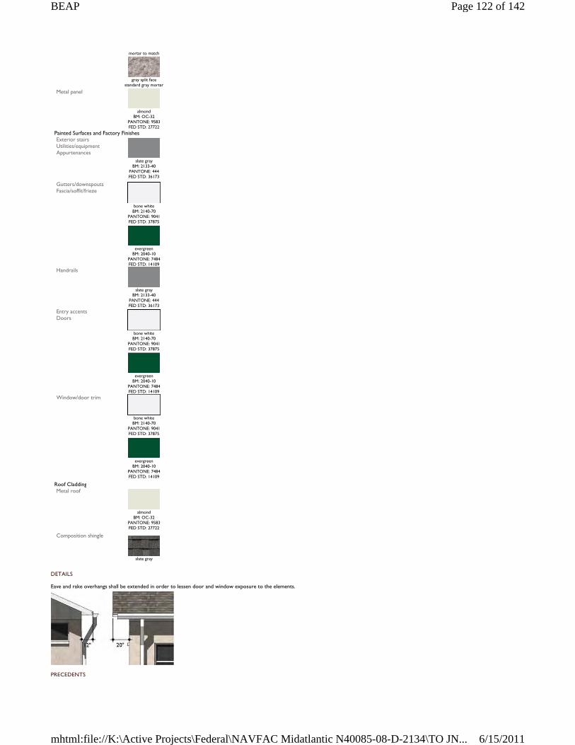
DETAILS
Eave and rake overhangs shall be extended in order to lessen door and window exposure to the elements.
PRECEDENTS
mortar to match
gray split face
standard gray mortar Metal panel
almond
BM: OC-32 PANTONE: 9583 FED STD: 27722
Painted Surfaces and Factory Finishes Exterior stairs Utilities/equipment Appurtenances
slate gray
BM: 2133-40 PANTONE: 444 FED STD: 36173
Gutters/downspouts Fascia/soffit/frieze
bone white
BM: 2140-70 PANTONE: 9041 FED STD: 37875
evergreen
BM: 2040-10 PANTONE: 7484 FED STD: 14109
Handrails
slate gray
BM: 2133-40 PANTONE: 444 FED STD: 36173
Entry accents Doors
bone white
BM: 2140-70 PANTONE: 9041 FED STD: 37875
evergreen
BM: 2040-10 PANTONE: 7484 FED STD: 14109
Window/door trim
bone white
BM: 2140-70 PANTONE: 9041 FED STD: 37875
evergreen
BM: 2040-10 PANTONE: 7484 FED STD: 14109
Roof Cladding Metal roof
almond
BM: OC-32 PANTONE: 9583 FED STD: 27722
Composition shingle
slate gray
Page 122 of 142BEAP
6/15/2011mhtml:file://K:\Active Projects\Federal\NAVFAC Midatlantic N40085-08-D-2134\TO JN...
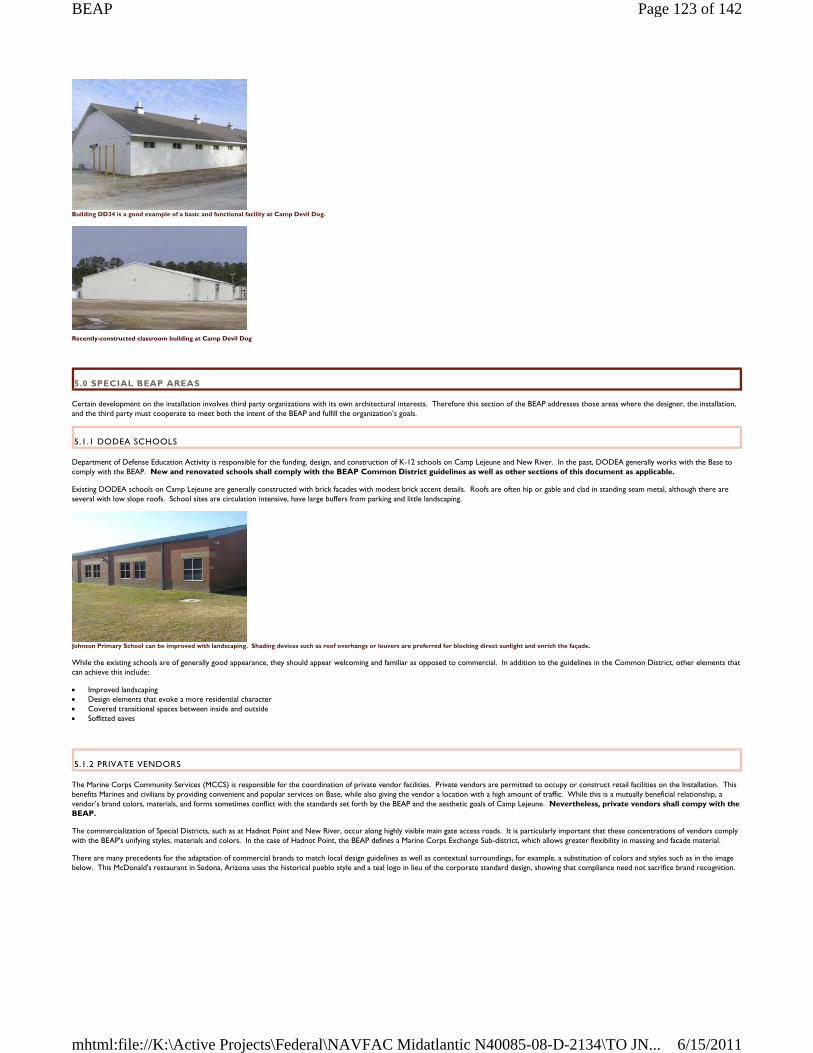
Building DD34 is a good example of a basic and functional facility at Camp Devil Dog.
Recently-constructed classroom building at Camp Devil Dog
5.0 SPECIAL BEAP AREAS
Certain development on the installation involves third party organizations with its own architectural interests. Therefore this section of the BEAP addresses those areas where the designer, the installation, and the third party must cooperate to meet both the intent of the BEAP and fulfill the organization’s goals.
5.1.1 DODEA SCHOOLS
Department of Defense Education Activity is responsible for the funding, design, and construction of K-12 schools on Camp Lejeune and New River. In the past, DODEA generally works with the Base to comply with the BEAP. New and renovated schools shall comply with the BEAP Common District guidelines as well as other sections of this document as applicable.
Existing DODEA schools on Camp Lejeune are generally constructed with brick facades with modest brick accent details. Roofs are often hip or gable and clad in standing seam metal, although there are several with low slope roofs. School sites are circulation intensive, have large buffers from parking and little landscaping.
Johnson Primary School can be improved with landscaping. Shading devices such as roof overhangs or louvers are preferred for blocking direct sunlight and enrich the façade.
While the existing schools are of generally good appearance, they should appear welcoming and familiar as opposed to commercial. In addition to the guidelines in the Common District, other elements that can achieve this include:
Improved landscaping Design elements that evoke a more residential character Covered transitional spaces between inside and outside Soffitted eaves
5.1.2 PRIVATE VENDORS
The Marine Corps Community Services (MCCS) is responsible for the coordination of private vendor facilities. Private vendors are permitted to occupy or construct retail facilities on the Installation. This benefits Marines and civilians by providing convenient and popular services on Base, while also giving the vendor a location with a high amount of traffic. While this is a mutually beneficial relationship, a vendor’s brand colors, materials, and forms sometimes conflict with the standards set forth by the BEAP and the aesthetic goals of Camp Lejeune. Nevertheless, private vendors shall compy with the BEAP.
The commercialization of Special Districts, such as at Hadnot Point and New River, occur along highly visible main gate access roads. It is particularly important that these concentrations of vendors comply with the BEAP's unifying styles, materials and colors. In the case of Hadnot Point, the BEAP defines a Marine Corps Exchange Sub-district, which allows greater flexibility in massing and facade material.
There are many precedents for the adaptation of commercial brands to match local design guidelines as well as contextual surroundings, for example, a substitution of colors and styles such as in the image below. This McDonald's restaurant in Sedona, Arizona uses the historical pueblo style and a teal logo in lieu of the corporate standard design, showing that compliance need not sacrifice brand recognition.
Page 123 of 142BEAP
6/15/2011mhtml:file://K:\Active Projects\Federal\NAVFAC Midatlantic N40085-08-D-2134\TO JN...
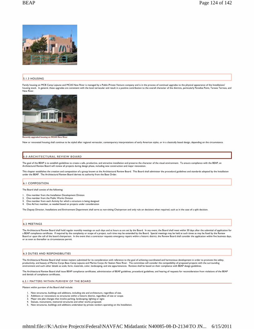
5.1.3 HOUSING
Family housing on MCB Camp Lejeune and MCAS New River is managed by a Public-Private Venture company and is in the process of continual upgrades to the physical appearance of the Installations' housing stock. In general, these upgrades are consistent with the local vernacular and result in a positive contribution to the overall character of the districts, particularly Paradise Point, Tarawa Terrace, and New River.
Recently upgraded housing on MCAS New River
New or renovated housing shall continue to be styled after regional vernacular, contemporary interpretations of early American styles, or in a classically based design, depending on the circumstance.
6.0 ARCHITECTURAL REVIEW BOARD
The goal of the BEAP is to establish guidelines to create a safe, productive, and attractive installation and preserve the character of the visual environment. To ensure compliance with the BEAP, an Architectural Review Board will review all projects during design phase, including new construction and major renovation.
This chapter establishes the creation and composition of a group known at the Architectural Review Board. This Board shall administer the procedural guidelines and standards adopted by the Installation under the BEAP. The Architectural Review Board derives its authority from the Base Order.
6.1 COMPOSITION
The Board shall consist of the following:
1. One member from the Installation Development Division 2. One member from the Public Works Division 3. One member from each Activity for which a structure is being designed 4. One Ad hoc member, as needed based on projects under consideration
The Deputy Director, Installations and Environment Department shall serve as non-sitting Chairperson and only rule on decisions when required, such as in the case of a split decision.
6.2 MEETINGS
The Architectural Review Board shall hold regular monthly meetings on such days and at hours as are set by the Board. In any event, the Board shall meet within 30 days after the submittal of application for a BEAP compliance certificate. If required by the complexity or scope of a project, such time may be extended by the Board. Special meetings may be held at such times as may be fixed by the Review Board or upon the call of the board chairperson. In the event that a contractor requests emergency repairs within a historic district, the Review Board shall consider the application within five business days, or as soon as thereafter as circumstances permit.
6.3 DUTIES AND RESPONSIBILITIES
The Architectural Review Board shall review matters submitted for its consideration with reference to the goal of achieving coordinated and harmonious development in order to promote the safety, productivity, and beauty of Marine Corps Base Camp Lejeune and Marine Corps Air Station New River. The committee will consider the compatibility of proposed projects with the surrounding environment and such other details as scale, form, materials, color, landscaping, and site appurtenances. Reviews shall be based on their compliance with BEAP design guidelines.
The Architectural Review Board shall issue BEAP compliance certificates, administration of BEAP guidelines, procedural guidelines, and hearing of requests for reconsideration from violations of the BEAP and denials of compliance certificates.
6.3.1 MATTERS WITHIN PURVIEW OF THE BOARD
Matters within purview of the Board shall include:
1. New structures, buildings and additions, including site and architecture, regardless of size. 2. Additions or renovations to structures within a historic district, regardless of size or scope. 3. Major site plan changes that involve parking, landscaping, lighting or signs 4. Statues, monuments, memorial structures and other works proposed. 5. New structures, buildings and additions undertaken by private vendors operating on the Installation.
Page 124 of 142BEAP
6/15/2011mhtml:file://K:\Active Projects\Federal\NAVFAC Midatlantic N40085-08-D-2134\TO JN...
6. Other requests by the Director, Installations and Environment Department
Exceptions:
1. Rehabilitation projects where the work involves restoration of existing materials or repair and replacement with the same materials. 2. Projects as declared exempt by the Director, Installations and Environment Department.
6.4 CERTIFICATE OF COMPLIANCE PROCEDURES
Projects require a two-stage application process (see Dates and Process). Applicants should include one original and 4 copies of the application form, all descriptions, specifications, plans, photographs, and sketches. Provide one set of physical samples. Submittal requirements are the same for each stage of the process.
See Section 6.5 - Application for Certificate of Compliance
6.4.1 NEW CONSTRUCTION SUBMITTAL REQUIREMENTS
Site plan with proposed building(s) indicated, as well as adjacent streets, on-site parking, stormwater management features, landscaping and proposed plant list, and all site improvements as needed Color-rendered front and side elevations drawn at not less than 1/8”=1’-0” scale Proposed project exterior signage Physical samples of the primary exterior materials, which may include masonry, concrete, siding, paint finishes, and roofing material Samples, photographs, and/or brochures of doors, windows, ornamentation, and other exterior materials Photos of all adjoining or opposite buildings
Submittal materials may be used by the Board for comparison to adjacent architectural context and will not be returned.
6.4.2 MAJOR ALTERATIONS OR ADDITIONS TO EXISTING BUILDINGS
Site plan with addition(s) shown if a change in the building footprint of the main structure is involved Elevations of front and/or sides at not less than 1/8”=1’-0” scale to show intended alterations Physical samples of the primary exterior materials, which may include masonry, concrete, siding, paint finishes, and roofing material Samples, photographs, and/or brochures of doors, windows, ornamentation, and other exterior materials Photos of all adjoining or opposite buildings
Submittal materials may be used by the Board for comparison to the existing architecture and will not be returned.
6.4.3 DATES AND PROCESS
1. Submit applications and all supporting information to the Director, Installations and Environment Department, MCB Camp Lejeune. Address to the attention of the Architectural Review Board. In case of emergencies, the Board will hear applications no later than five business days after the filing of a complete application. Only complete applications will be considered.
2. The Architectural Review Board will consider a project twice during design: at the Design Development and the Pre-Final Design Submittals. At Design Development or 35% Submittal, the Board will be largely concerned with site, massing, windows, entrances, and materials. At Pre-Final or 100% Submittal, the Board will be concerned with all aspects of site and architecture, and particularly ornamental details and colors. This two-stage process ensures that the design direction is in compliance with the BEAP.
3. The Architectural Review Board will meet to review applications regularly at such time as the Board deems appropriate. Special meetings may be held upon notification by the Chairperson of the Board to all members that an emergency application has been filed. At this meeting, the application will be considered.
4. Upon receipt of an application, the Architectural Review Board may permit modifications of an original proposal if such modifications are clearly indicated by the applicant and recorded by the Board. 5. The Architectural Review Board will visit the project site to verify it’s architectural and environmental context and judge the appropriateness of the design's form, materials, and colors. 6. Architectural Review Board meetings are not public and there is no requirement for applicants to be present. If applicants wish to meet with Board members, they may request to do so in writing to
the Board Chairperson. Applicants will be informed of the Board decision within five business days after the meeting has occurred.
6.4.4 REASONS FOR DENIAL
The Architectural Review Board shall deny the application for a certificate of compliance if it finds:
That the action proposed would adversely affect or be incompatible with the character of the district in which it is to be taken That the action proposed would not be consistent with the character of a historic district That the proposed action would not be consistent with the Base Exterior Architectural Plan adopted by the Installation
Where certification is denied, the Architectural Review Board shall record its reasons for denial. There shall be no re-considerations until the applicant properly addresses the reasons for denial.
6.4.5 PROCESS FLOW CHART
Page 125 of 142BEAP
6/15/2011mhtml:file://K:\Active Projects\Federal\NAVFAC Midatlantic N40085-08-D-2134\TO JN...
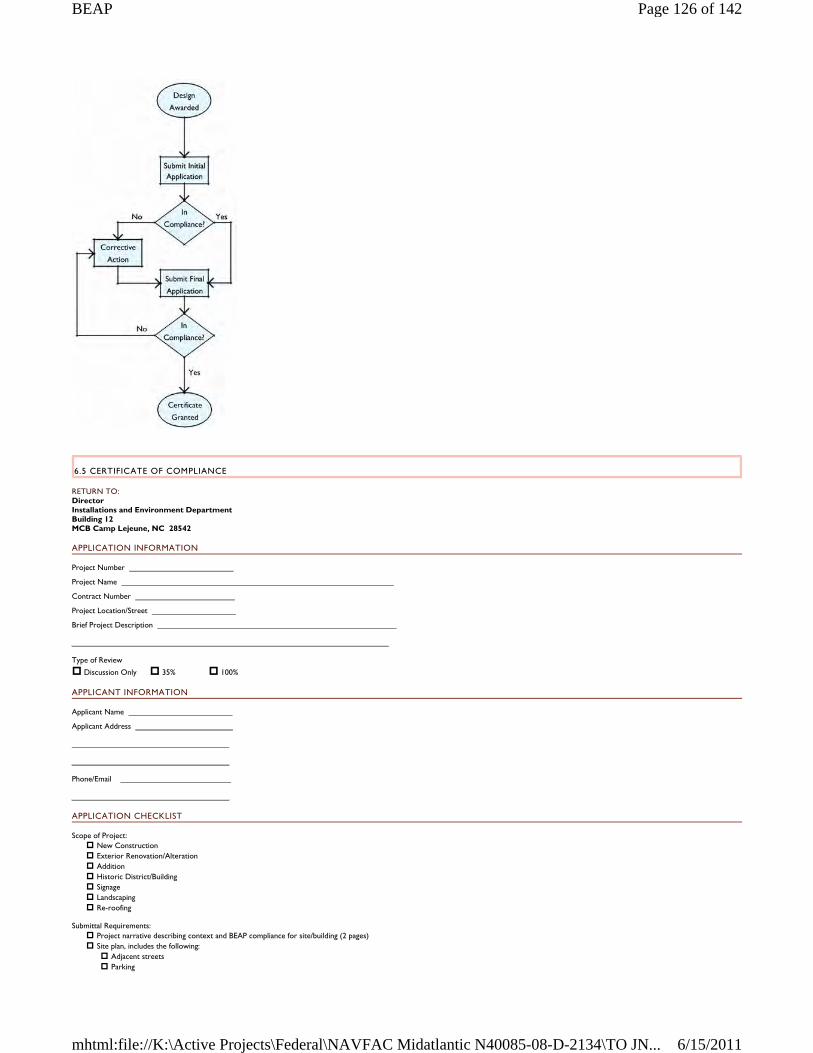
6.5 CERTIFICATE OF COMPLIANCE
RETURN TO: Director Installations and Environment Department Building 12 MCB Camp Lejeune, NC 28542
APPLICATION INFORMATION
Project Number
Project Name
Contract Number
Project Location/Street
Brief Project Description
Type of Review
Discussion Only 35% 100%
APPLICANT INFORMATION
Applicant Name
Applicant Address
Phone/Email
APPLICATION CHECKLIST
Scope of Project: New Construction Exterior Renovation/Alteration Addition Historic District/Building Signage Landscaping Re-roofing
Submittal Requirements: Project narrative describing context and BEAP compliance for site/building (2 pages) Site plan, includes the following: Adjacent streets Parking
Page 126 of 142BEAP
6/15/2011mhtml:file://K:\Active Projects\Federal\NAVFAC Midatlantic N40085-08-D-2134\TO JN...
Stormwater management features Landscaping Plant list
Front elevation color rendering 1/8" scale Side elevations color rendering 1/8" scale Exterior signage Samples of primary exterior materials Samples of doors, windows, ornament Color photographs of adjoining or adjacent buildings
Signature of Applicant Date
REVIEW BOARD USE ONLY
For This Review Only
IN COMPLIANCE
NOT IN COMPLIANCE
CERTIFICATE GRANTED
Remarks
Whom to contact for more information:
Name
Phone/Email
APPENDICES
APPENDIX A – SUMMARY OF FIELD WORK
Field work for the BEAP Study consisted of several phases:
Initial kickoff meeting included all stakeholders and established the scope of the study and the districts to be included A Windshield Survey reviewed the significant structures on the Installations and prioritized future survey work; a representative sample of buildings and landscapes were identified and provided to
the Installations An in-depth Special District Survey of each district studied individual buildings in regards to style, form, context, and site; this survey covered 300 buildings Final site visit and individual interviews provided details on planning, operations, and maintenance
SCOPE OF DATA COLLECTION
The scope of work for the survey closely followed the Naval Facilities Engineer Command Installation Appearance Guide, found at https://portal.navfac.navy.mil/portal/page/portal/iag
Comprehensive data collection gathered information on the Installations' history, historic structures, artifacts, community and culture. The primary sources of information for data collection included:
Real Property Inventory Internet Naval Facilities Assets Data Store (iNFADS) Facility Surveys Design Criteria Development Plans Building Plans Zoning Maps Base Orders Stakeholder Interviews GIS Data
The land area of interest covered by the scope of work included the coastal plains region of North Carolina, Onslow County, and the City of Jacksonville. The specific land area surveyed included:
MCB Camp Lejeune cantonment area, including: − Onslow Beach − Courthouse Bay − Stone Bay
MCAS New River cantonment area Sandy Run Training Area Camp Devil Dog Training Area Camp Geiger Camp Johnson Tarawa Terrace Housing Area Port Facilities at Morehead City Outlying Landing Field at Oak Grove
The Windshield Survey identified significant buildings which contributed to the character of the Installation. The team developed a Survey Matrix which contained the following items to describe each building: name, number, function, date constructed, district, materials, colors, form, style, scale, historic nature, and relationship to context. A total of 313 buildings were addressed in the matrix, located in 19 Special Districts or named areas. The iNFADS data base and GIS Data were instrumental in developing the matrix.
The in-depth Special District Survey was conducted at MCB Camp Lejeune and MCAS New River over a period of one week with several follow-up visits. The Survey Matrix was used to guide this effort, where the majority of the physical information, including photographs, was collected.
The team conducted interviews with stakeholders during the Special District Survey, follow-up visits and over the phone. These individuals included planners, property managers, maintenance personnel, and other administrative officers of the Base and Special Districts. Specifically from:
Page 127 of 142BEAP
6/15/2011mhtml:file://K:\Active Projects\Federal\NAVFAC Midatlantic N40085-08-D-2134\TO JN...
Installation Development Environmental Management Family Housing Marine Corps Community Services MCB Camp Lejeune Public Works MCAS New River Public Works Base Operations DODEA Schools Onslow Beach General Management School of Infantry -- East
The field work concluded with a presentation to stakeholders on the team's findings and recommendations on how to proceed with the BEAP study.
Page 128 of 142BEAP
6/15/2011mhtml:file://K:\Active Projects\Federal\NAVFAC Midatlantic N40085-08-D-2134\TO JN...
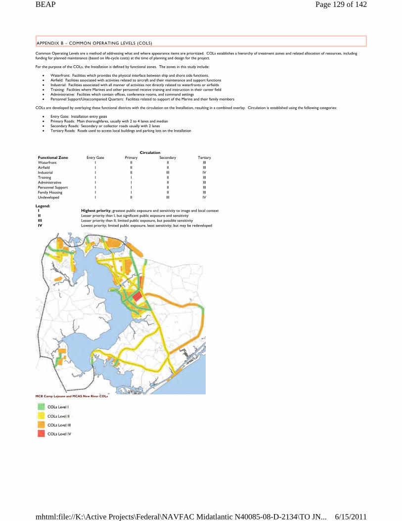
APPENDIX B – COMMON OPERATING LEVELS (COLS)
Common Operating Levels are a method of addressing what and where appearance items are prioritized. COLs establishes a hierarchy of treatment zones and related allocation of resources, including funding for planned maintenance (based on life-cycle costs) at the time of planning and design for the project.
For the purpose of the COLs, the Installation is defined by functional zones. The zones in this study include:
Waterfront: Facilities which provides the physical interface between ship and shore side functions. Airfield: Facilities associated with activities related to aircraft and their maintenance and support functions Industrial: Facilities associated with all manner of activities not directly related to waterfronts or airfields Training: Facilities where Marines and other personnel receive training and instruction in their career field Administrative: Facilities which contain offices, conference rooms, and command settings Personnel Support/Unaccompanied Quarters: Facilities related to support of the Marine and their family members
COLs are developed by overlaying these functional districts with the circulation on the Installation, resulting in a combined overlay. Circulation is established using the following categories:
Entry Gate: Installation entry gates Primary Roads: Main thoroughfares, usually with 2 to 4 lanes and median Secondary Roads: Secondary or collector roads usually with 2 lanes Tertiary Roads: Roads used to access local buildings and parking lots on the Installation
Legend:
MCB Camp Lejeune and MCAS New River COLs
Circulation Functional Zone Entry Gate Primary Secondary Tertiary Waterfront I II II III Airfield I II II III Industrial I II III IV Training I I II III Administrative I I II III Personnel Support I I II III Family Housing I I II III Undeveloped I II III IV
I Highest priority; greatest public exposure and sensitivity to image and local context II Lesser priority than I, but significant public exposure and sensitivity III Lesser priority than II; limited public exposure, but possible sensitivity IV Lowest priority; limited public exposure, least sensitivity; but may be redeveloped
Page 129 of 142BEAP
6/15/2011mhtml:file://K:\Active Projects\Federal\NAVFAC Midatlantic N40085-08-D-2134\TO JN...
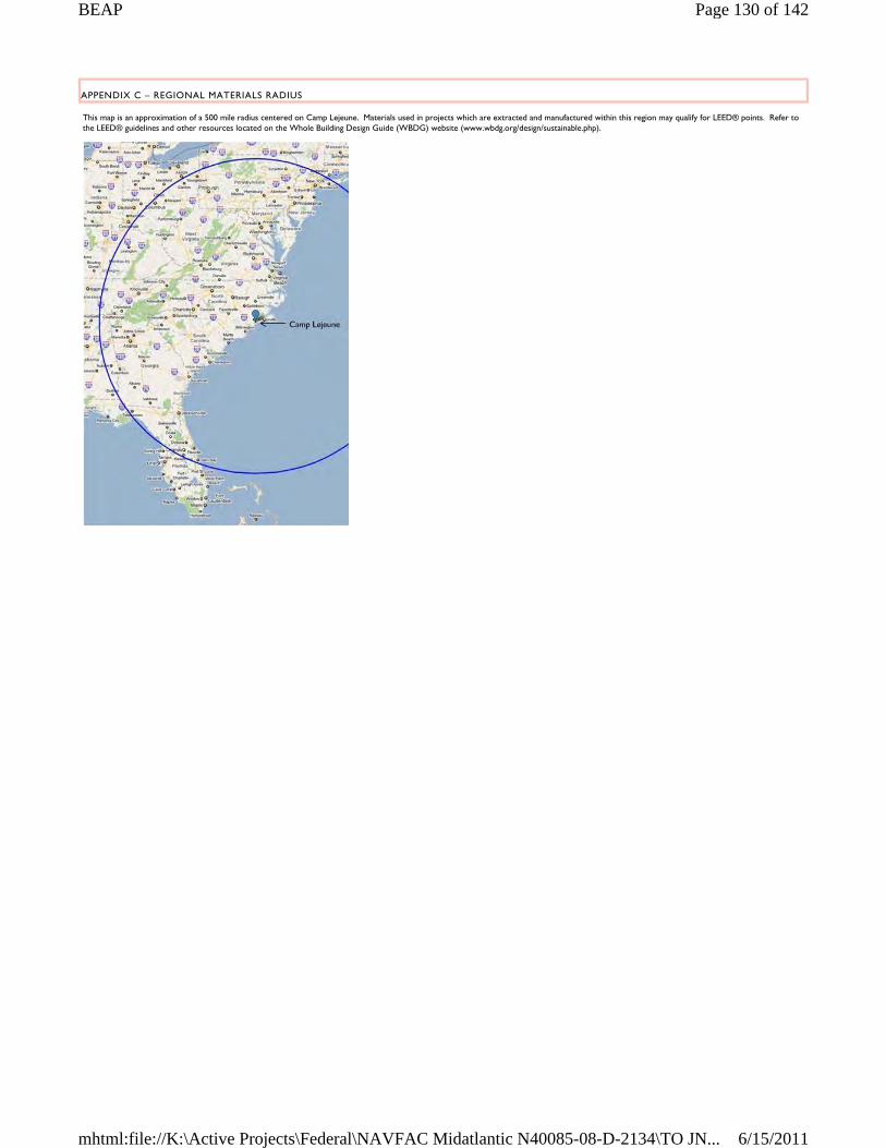
APPENDIX C – REGIONAL MATERIALS RADIUS
This map is an approximation of a 500 mile radius centered on Camp Lejeune. Materials used in projects which are extracted and manufactured within this region may qualify for LEED® points. Refer to the LEED® guidelines and other resources located on the Whole Building Design Guide (WBDG) website (www.wbdg.org/design/sustainable.php).
Page 130 of 142BEAP
6/15/2011mhtml:file://K:\Active Projects\Federal\NAVFAC Midatlantic N40085-08-D-2134\TO JN...


