Embed Size (px)
Citation preview


FOUR user selectable operating modes and a 90 number autodialer make Private Patch V
the ONLY choice! +:'"&d& - 3 ~ e w t 3 < -
?/H, " I
Private Patch IZ . MULTI-MODE INTERCONNECT 4
%
rn . CONNFCT SYSTEMS INC N O I S E ~ e c e oTMF xMT c DI a d Q LPOWER
SELECT AN OPERATING MODE Private Patch V is a totally new concept in automatic phone patches. A built-in keyboard and menu driven
USING THE BUILT-IN KEYBOARD. . . display allow you to customize all modes, features. and functions specifically to your application.
1. SIMPLEX SAMPLING PATCH Private Patch V achieves a level of sampling patch performance unobtainable in any other product. Crucial to performance is the noise squelch filter. Compare our five pole filter to the com~et i t ion 's two ole filter. Advanced software alaorithms
noise correiation tests which result i n greate;useable range than the competition. Nine selectable VOX enhancement ratios allow you to vary performance from straight sampling to highly VOX enhanced. (sampling rate decreased while the land party is speaking). The mobile is in full control and can break- in at anv time.
2. SIMPLEX VOX PATCH VOX mode offers superb simplex operation with any radio, including synthesized and relay switched models. VOX mode has other advantages too. 1. A linear amplifier can be used to extend straight simplex range. 2. You can operate through any remotely located repeater to greatly extend range. 3. If desired you can connect Private Patch V to the MIC and speaker jack of your radio. NO INTERNAL CONNECTIONS ARE REOUIRED. Control is maintained automatically with built-in dial tone detection, busy signal detection and fully programmable activity and time out timers. An optional electronic voice delay board eliminates first word clipping with slow switching radios.
3. DUPLEX PATCH Select duplex mode when connecting Private Patch V to your existing repeater or duplex base station. Many features including semi-duplex privacy mode are user programmable. The mobile is in full control at all times.
Private Patch V can be a sampling patch today. A VOX patch tomorrow. And a repeater controller next year!
You may never need another patch again.
COMPARE THESE FEATURES. . . 90 phone number autodialer Last number redial
Regenerated tonelpulse dialing Toll restrict: 1st and 2nd digit restrict, prefix lockout and digit counting 1-5 digit connectldisconnect code 2-5 digit secret toll override code
User programmable CW ID Remote hook flash Auto disconnect on dialtonelbusy signals
Telephone remote base Remote controlled relay (relay optional)
Lightning protected
Call or write today for your FREE brochure.
Ir I I /
CONNECT SYSTEMS INC. 23731 Madison St. Torrance. CA 90505
Phone: (213) 373-6803
4. REPEATER CONTROLLER AMATEUR ELECTRONICSUPPLY M,l lau&nr\ ' l i W < r * l t I ~ 0 ) s Onanno T L C l r ~ r w . l l r r F L I ar V~ ,< l .v , NV BARRY ELECTRONICS CORP Nnw Yl,!k N I . ERICKSON COMMUNICATIONS
private patch V will convert any receiver and transmitter into " , tram IL ' HAM RADIO OUTLET, hn.$l?~.#nl I:A Lliitl,nlidnll. <.tI Ll.lilanll C A I 'horn l~ A 2
!..mIlrwloCA Y.8nNtw5C.P. All.tnlaGh . HENRY RADIO LI?..AC?I~<,I~-.CA . INTERNAllONAL an outstanding performing repeater with duplex autopatch. RAD,svsTEMs MlamlrL . JUNSELECTRONICS c,,~L...c,~.c.+ . MADISONELECTRONICS
,ceatures such as repeater onloff code, hangtime, activity timer SUPPLY H ~ ~ ~ ~ ~ I ~ ~ ~ T X . MIAM, RI\DIO CENTER CORP ~ , r . n , r l . MIKES ELECTRONICS
'I ~ . ~ ~ ~ r l . r r t , ~ i r r i . N&G DISTRIBUTING CORP M#ar,\, F I . OMNl ELECTRONICS time, CW ID interval etc. are fully user programmable. Private ,,,,.,,,,,, . pAcEENGIN,E,lN, ,,,..,,,,., :. T,E.A,sTAT,oN ,,., ,,.,.,,,,.,, . Patch V is the right choice for your club system. RADIOCENTER H.nll#nrjrn I I . CANADA-COM WEST RADIO SYSTEMS. LTD V.olli nllr", RT
# 208 C S I 1s o r c q ~ s l c r r c l traclrrnarr n l C;onnr.cl S y s l e m s , lhrc


NOVEMBER 1988
1. H. Tenney, Jr., WlNLB publisher
and editor-in-chief
Terry Nonhup managing editor
Marty Durham, NBlH technical editor
Robert D. Wilson, WAlTKH consulting editor
Tom McMullen. WlSL Joseph J. Schroeder. WSJUV
Alfred Wilson. WSNIF associate edltors
Susan Shorrock production editor
Peggy Tenney. KAlODG copy ed~tor
Beth McCormack editorial aoslnanl
editorial review board Peter Benini. K l t l H
Farren Gehrke. K2BT Michael Gruchalla, P.E.
Bob Lew~s. W E B S Mason Logan. K4MT
Vern R~panella. WAZLOO Ed Wetherhold. W3NON
publishing staff J. Craig Clark, Jr., N lACH
assistant publisher
Henry S. Gallup, KAlRYG advertising sales manager
Dorothy Sargent, KAlZK advenising product!on manager
Susan Shorrock circulation manager
Therese Bourgault circ~lstion
Phil Alix. NlFPX traffic manager
Maribeth Buchanan H A M RADIO Bwkstore
Hans Evers. PA0CX cover
HAM RAOIO Megaztna npubllshad monthhl by Commun~calans Technology. Inc
Greenv~llc. New Hampsh1rsOJ)48 0498 Telwhone 603 878 1441
subacri~tion rates UniIed States:
om! year. $22.95: ~wo years. 138%: threevean. 549.95 Euraoe lvia KLM alr mall. 540.00
Canada. Japan. Swlh Ahicsand 0the;counlne. Iv. rurlnce malll. om! year. $31.W two yeen. 955.00: three yeerr. 974.00
Allsubsctbt~on wdaspayabla in U.S. funds, via intermtianal m t a l monev ovder or check drawn on U.S. bank
international subscription agents: paw 1 X
Microfilm copies are available from Buckmastrn PuMirhiog Mmsral. V~rgtnas 23117
C a m e t a m of laleetad # n i c k from HAM RADIO are evaileMa to the blind and ph~ical ly hsndicspped
from Recorded Parmdcels. 919Walnul Sam. Philadelphm. Pennsvlvanka 19107
Cc+yv@ht 1988 by Communocatons Technolq?~, inc. Titleregistwed at U S . Patent Offlca
Second-dau pwtaga pad a1 Gr-Yille. New Hampshirs(UDas-MSB
and st additanal mailing O ~ ~ C ~ J 1SSN0148 558)
Smd clungsof addnu to HAM RADIO Grmvl l la. N a Harnpshlre W D ( S B
10 Simple Receivers from Complex ICs Bill Parrott. W6VEH
24 The Weekender: Improving Operation wi th the MFJ 989Transmatch L.B. Cebik. W4RNL
KF7M. page 67
26 Ham Radio Techniques: The radio boys in the Pacific, or, working DX for Uncle Sam Bill Orr, W6SAI
33 The Pepperdyne Receiver Jim Pepper, W6QlF
. . THE
60 The Weekender: WEEKENDER A 1296-MHz Low Noise Amplifier W4RNL, page 24 Norman J Foot, WASHUV WASHUV, page 60
67 A Solid-State 75A-4 Receiver James M. Larson, KWM
See page 97 for the winners of September's handheld radio
100 Practically Speaking: contest. An Overview of Operational Amplifiers: Part 1 Joe Carr, K41PV
117 Elmer's Notebook: SSB Basics: Generating the Signal Tom McMullen, WlSL
Backscatter 4 Flea Market 112 Comments 9 New Products 120 Ham Notebook 98 Advertiser's Index 126 Ham Mart 106 Reader Service 126 DX Forecaster 108
November 1988 3

A potential danger.. . Recently a great amount of attention has been given to the effects of electromagnetic radiation on the
human body. Dr Samuel Milham of the Washington State Department of Social and Health Services (as well as several others*) has written a number of studies indicating that there may be a link between elec- tromagnetic radiation and several forms of cancer. Lately Milham's studies have been picked up by the wire services and articles have appeared in newspapers nationwide. While this isn't a revelation (we all know that at certain frequencies electromagnetic energy can be harmful) it is cause for concern, because one of Milham's study groups consisted of male Radio Amateurs in the States of Washington and California.
In a paper published in the American Journalof Epidemiology (Vol. 127, No. 1, January, 19881, Milham observed there was an elevated rate of mortality from several different forms of cancer in male Radio Amateurs in Washington and California, during the years 1979 through 1984.
Looking at the broader field of danger from all forms of electromagnetic radiation, Milham published a paper in Environmental Health Perspectives (Vol. 22, pages 297-300, 1985) which included an occupa- tional mortality analysis of 486,000 adult male death records filed in Washington State from 1952 to 1982. He looked at electrical and electronic technicians, radio and telegraph operators, radio and TV repairmen, telephone and power company linemen, power station operators, welders, aluminum reduction workers, motion picture projectionists, and electricians. He states that: "In the 1952 to 1982 data set, men whose occupations were associated with electric or magnetic fields had more deaths due to leukemia than would be expected."
Now before anyone jumps to an erroneous conclusion, let me add that at the end of the first paper, Milham states that the overall mortality for Radio Amateurs compares quite favorably with that of the rest of the population. It's also important to note that these studies are very preliminary and will require addi- tional years of exhaustive work before any firm conclusion can be reached.
One of the biggest dangers with reports like Milham's is that the casual reader may be misled by media reports on the subject written without all the facts. Everyone knows of stories that have appeared on TV or in print, giving only partial information, which have created a great degree of unwarranted concern. Paul Brodeur's 1977 book The Zapping of America, while informing us of a potential danger, was written in this kind of sensational vein. Credibility is what's required - not sensationalism!
A number of hams around the world are very concerned about the bio-effects of electromagnetic radia- tion. In response to earlier concerns, the ARRL has formed a bio-effects committee a number of years ago. Wayne Overbeck, Ph.D., NGNB, and Stu Cowan, W2LX, are also concerned and are cooperating with a number of other concerned amateurs and organizationsx* in an in-depth study. While neither Over- beck or Cowan are physicians, both are experienced amateurs and want to get to the truth of the matter. Dave Rodman, M.D., KN2M, a medical doctor who is researching the bio-effects of electromagnetic radia- tion - specifically 60-Hz radiation.
At the ARRL National in Portland, Oregon on September loth, 1988, Overbeck presented his prelimi- nary findings to a packed audience of interested Amateurs. He summarized the dangers as follows: radio frequency energy, 60-hertz electromagnetic fields, and chemical agents. (See HR's December 1983 issue on the dangers of PCBs.) Overbeck did add some caveats to his research. First, it's difficult to prove cause and effect due to the myriad hazards that we face, both in the workplace and home. Secondly, with cancer, the long latent periods and subtle signs and symptoms often don't become apparent until long after exposure.
Overbeck then presented his audience with a list of common sense precautions: don't run high power into a low directional antenna or more than 25 watts on VHF/UHF mobile installations without first meas- uring the RF power densities;+** make sure that no one is near a ground-mounted antenna or mobile antenna when it is transmitting; and make sure that all power amplifiers are fully shielded when in use. Overbeck
(continued on page 114/
4 November 1988

- - . \ . I
,--I- - k - . - 7 L - - ---
Co~r'!*3eti iop clasr HF transceiver TS-940s-the standard o f performance by which al l other transceivers are judged. Pushing the state-of-the-art in HF transceiver design and construction, no one has been able to match theTS-940s in performance, value and reli- ability.The product reviews glow with superlatives, and the field-proven performance shows that the TS-940s is "The Number One Rated HF Transceiver!"
: ' , ' cycle transmitter.
HI-Cut Lo.CuI SLOPE t 4 p j S L O P E A TUNE
hl- W 6 .rwl rsse); Y2 E?:
I rn,rtr*4 um.1 ', ICW,
,,LA: -LI-* L
SSR SLOPE TUNE
~T' i~i i . l - . ; , l 1 ,11:1 , l l - x ' '
trnnscri~rer wlth ctrrirlal coverage recerver. Recc!lver covers 150 k l i r -30 Mtl7All modes t,urll-ln: AM. FM, CW. FSK. LSB, USB. Superb. human engineered front panel layout for the DX-mlnded or contesting ham. Lor(]c! Iluorescenl l u l ~e maln d~splay w~ lh d~mrner: d~rect keyboard Input of frequency: flywheel type main lun~ng knob wllh optical encoder mechantsrn all combme to make the TS-940s a joy to operate One-touch frequency check (T-F SET) during split operations.
9 Unrque LCD sub display indi- cates VFO. graph~c lndicat~on
Ki'nwtJo'l transrnlt duty I ) CWYariabls Bandwidth Tuning.Vary Ihe 3)SSBSlopeTuning.Olrelat1ng1ntheLSBand O f and SSB 'lope tuning. 'yclc TS-940S Is guar- passband wldlh conl~nuously In the CW, FSK. USB ~nuder,th!s I lon l panel control al lows and lime
l')operate at power and AM modes, w~ thou l a l lec l lnq Ihe center lnr lependent .conl~nuouslyvar~ableadiusl - Simple One step mode chang- otltpul for t)erlods exceeding I frequency This e l f e c t ~ v e l y mlnymrzes ORM mentol lheh~ghorlowtrequencyslopesolthe I In9 wlth CW announcement. one hour. (14 250 MH/ CW 110 lrom nearby SSBand CWs~qnals If pasyhand T ~ P LCD sub display llluslrates Other v ~ t a l operatlnq func- w;~lts.) Pi!rfect lor RTTY, SSTV, and other long-duration modes. First with a full one-year l~mi ted warranty. Elxtremely stable phase lock- ed loop (PLL) "~0 . ~~f~~~~~~
Irrqr,ency accuracy Is measured ~n parts per million!
Optional accessor~es: crystal oscrllalor MC-43s UPIDOWN hand AT-940 11~11 range (160-10m) autoniat~c mlc: MC-60A. MC-80. MC-85 deluxe base
antenna Irrner SP-940 external speaker stalron mlcs: PC-1A phone patch TL~922A W I ~ ~ I ;~ r jd~n flller~ng YG-455C-1 (500 Hz). l~r~ear arnpl~fler* SM 220 stabon mon~tor
KENWOOD YC; 455Cblb11250 H7).YK-88C-l(500 H7) CW BS-8 pan display* SW-200Aand SW-2000 KENWOOD U.S.A. CORPORATION frltcrs: YK-98A-1 (6 kH7) AM ftlter* VS-1 volcc? SWR and power melers- IF-232CllF~10B 2201 E Dornlnguer St., Long Beach.CA90810 synthesizt~r SO-1 temperature cornpensateti computer 1nterf;lce. PO. Box 22745. Long Beach. CA 90801-5745 (:,,,, ljI~.l,, ,,t,,",, (.,,I ,,,, ,,,dl, .,,, ~ . , " ; , ~ f , , t , l < ~ f < , r , , ; l K , ~ , l , % ~ ~ ~ t ~ ~ l 1, ,,,I , ~ ~ , ~ , " < ~ , ~ , , , 8 , ~ 1 < , ~ < , ~ . ! , , ~ a S,,,,,", ,., .'l,ll'l '111 ,111(111 . f l ' r l lO l f ' \ .lilt) fl,i?l'', ,111' ' , i l l i~C< I 1 0 ( . lU l lOP ~'illlll llil 11111I( I ' Ol (rlllii/,llill'l
2)AFTune,EnabledwilhIhepusholabutton, the l ~ l t e r ~ n g pos~l ron I ~ I S CWlnter terence lrghler Inser ts a tun- 4) IF ~otch Filter. The tunable notch f i l ter able . lhreepoleact~vel~ l lerbelweentheSSBl sharply attenuates lnlerferlng signals by as CWdemodulalor and Ihe aud~oarnpl~lter Our- much as 40 dB Asshown here.thernterlering Ing CW OSOs, thls cont ro l can be used l o slgnal IS reduced, whlle the deslred slgnal reduce lnterlering signals and notse. and rernalns unallected The notch l l l l e l worksln peaks audlo lrequency response lo r opllmum all modesexcept FM CW perlormance
tions. Seleclable sem~~ or full break-ln CW (OSK). RIT/XIT,all mode squelch. RF atlenualor,filter select SWIIC~. seleclahle AGC. cwvarlable pllch control,speech processor,and RF powerou~p~l~ control, programrnablt? band scan or 40 channel memory scan

6 a November 1988 Tt!ll 'em you saw II [ t i H A M RADIO'

r / 207 November 1988 7

MFJ 3 KW Roller Inductor Tuner . . . lets you get your SWR down to absolute minimum -- something a tapped inductor tuner just can't do . . . . . . plus you get a peak reading Cross-Needle SWR/Wattmeter, 6-position antenna switch, balun for balanced lines and 1.8-30 MHz coverage ... $239.95
MFJ-986
$239'"
MFJ's InnovaUve new DifferenUal-T Tunercm uses a dlfferentlal capacltor that makes tuning foolproof and easler than evrr. It ends constant re-tuning wlth broadband coverage and glves you mlnlmum SWR at only one settlng.
The new MFJ-986 I s a rugged no. compromlse 3 KW PEP Roller Inductor antenna tuner that covers 1.8-30 MHz continuously, lncludlng MARS and all the WARC bands. The roller inductor lets you tane your SWR d o m to the absolute minimum -- something a tapped Inductor runer]ust can't do.
A 3-dlglt turns counter plus a splnner knob glves you preclse Inductance control -- so you can qulckly return to your favorite frequency.
You get a llghled Cross-Needle meter thal not only glves you SWR, forward and reflected power at a glance -- but also glves you a peak-reading function! A new dlrectlonal coupler glves you even more accurate readings over a wlder frequency range.
YOU get a 6-pasltlon ceramlc antenna switch that lets you select two coax llnes andlor random wtres (dlrect or through tuner), balanced llne and external dummy load.
A new current balun for balanced lines mlnlmlzes Redllne radlatlon that causes fleld pattern dlstortlon. TVI and RF In your shack. Ceramlc feedthru Insulators for balanced lines wllhstand hlgh voltages and temperatures.
New Antemu Tuner Technology YFJ brings you three innovations In antenna tuner technology. a nrw Dlfferentlal-Tcm circult slmpllfles tuning: a new dlrectlonal coupler glves you more accurate SWR, forward and reflected power readlngs; and a new current balun reduces feedllne radlation.
Dlfferentlal-T Tnnerlm: A New M s t on a Proven Technology
By replacing the two variable capacitors wlth a slngle dffferentlal capacltor you get a wide range T-network tmcr with only two controls - - the dlfferentlal capacitor and a roller inductor.
That's how you get the new MFJ Dlfferrntlal-T Tuner'm that makes tunlng easler lhan ever, glves you mlnlmum SWR at only one settlng and has a broadband response that ends constant re-tunine. You'll wend vour tlme QWlng
Instead of foollng with your tuner. The compact JO'h x 4% x 15 Inch
cabinet has plenty of room to mount the silver-plated roller lnductor away from metal surfaces for maximum Q -- you gel hlgh emclency and more power lnto your antenna.
The wlde spaced alr gap dlfferentlal transmiltlng capacitor lets you run a full 3 KW PEP -- no worries about arcing.
A New Dlrectlonal Coupler: Accurate SWR and Power Reading MFJ's Crcss-Needle SWRNattmeler
glves you more accurate SWR and power readlngs over a wlder frequency range wlth no frequency senslttve adjustments.
That's because MFJ's new dlrecllonal coupler glves you up to an order of magnitude hlgher dlrectlvlty and coupllng factor lhan conventional clrcults . . . plus It glves you a flat frequency response that requlres no frequency compensation.
The cross-needle meter lets you read forwardlreflected power In 2 ranges: 200150 and 20001500 watts. The meter lamp Is front-panel swltched and requlres 12 volts.
A swltch lets you select peak or average power readlngs.
A New Current Balun: Reduces Feedline Radlatlon
Nearly all commercially bull1 tuners use a "voltage" balun. The "voltage" balun forces the rwltages to be equal on the two antenna halves. It mtnlmlzes unbalanced currents only If the antenna Is perfectly balanced --not the case wlth practical antennas.
The MFJ-986 uses a true current balun to force equal currents lnto the two antenna halves -- even If your antrnna Is not perfectly balanced -- so you gel mlnlmum unbalanced currents.
The current balun glves superlor balance over the "voltage" balun.
Minimum unbalanced current reduces fleld pattern dlstortlon -- whlch concentrates your power for a stronger
MFJ ENTERPRISES. INC. H
Box 494. Miss. Statr. MS 39762 601-323-5869 Telex: 53-4590 MFJSTKV
signal - - plus It reduces TVI and RF In your shack caused by feedllne radlauon. The MFJ-888 Mfferentlal-T Tnnertm:
Get absolute minimum SWR Qet the tuner that Incorporates the
latest innovations by the world's leader In antenna tuner technology.
See your dealer loday for the new MFJ-986 DlfTerential-Ttm 3 KW Roller Inductor Tuner. Include $10 shlpplng/handllng If ordering dlrect.
WAY CHOOSE AN MFJ TUNER7 Hard-earned Reputation: There's
Just no shortcut. MFJ Is a name you can trust -- more hams trust MFJ tuners throughout the world than all other tuners comblned.
Proven Reliability: MFJ has made more tuners for more years than anyone else -- wlth MFJ tuners you get a hlghly-developed product wlth proven rellablllty.
Flrst-rate Performance: MFJ tuners have earned thelr reputatlon for being able to match Just about anythlng -- anywhere.
One full year unconditional guarantee: That means we wlll repalr or replace your tuner (at our optlon) no matter what for a full year.
Contlnulng Service: MFJ Customer Service Technicians are available to help you keep your MFJ tuner performing flawlessly -- no matter how long you have It -]us1 call 601-323-5869.
Your very best value: MFJ tuners give you the most for your money. Not only do you get a proven tuner at the lowest cost -- you also get a one year uncondltlonal guarantee and contlnulng service. That's how MFJ became the world's leadlng tuner manufacturer -- by glvlng you your very best value.
Choose your MFJ tuner wlth confldrnce! You're gettlng proven performance and rellabillty from the most trusted name In antenna tunen. Don't settle for less.
Call or write for a free full-Hne MFJ catalog with all 10 of our tuners and tons of ham radio accessories!
FOR YOUR NEAREST DEALER or to order call toll free
800-647-1800 One Year Unconditional Guarantee -
MFJ . . . making quality affordable 8 November 1988

COMMENTS Priceless covers Dear HR:
My wife Ginger, N5LTH, and I look forward to the HAM RADIO covers! PA0CX really understands the hobby and seems to always come up with a clever idea or humorous slant. He is great at using body language to tell a story. Your July "cover story" for instance is familiar to anyone who has built something from scratch-the ham is proud of his fantastic VHF cir- cuit (his nose says so) but he's wor- ried that people will laugh because he's used an old teapot as his resonant cavity! (crossed arms, knees together). The September cover, also cracked us up; the guy is pretending to be asleep, hoping that someone will try to make off with his treasures (note the unmistakable BC-348 and 811A) so that he can press the foot switch and zap them with the old spark coil. (See the half open eyelids and the little wires connecting all the goodies?) This is priceless. Your covers completely out- class those of any other ham maga- zine.
Since you are soliciting feedback on the technical and construction format - please keep up the technical emphasis. HAM RADIO and QST are the only "technical" magazines left. Please keep it up - we need you!
Don Murray, WSVE, Dallas, Texas 75218
Congratulations! Dear HR:
The all new HAM RADIO is superb. Your editorial staff has achieved a remarkably well-balanced publica- tion - one that should appeal to just about every segment of the Amateur Radio community.
The universe of Amateur Radio presents a major challenge to those engaged in producing a technically, applications-oriented magazine. Clearly you have found the formula to yield a useful and meaningful contri- bution to those of us who enjoy not only operating our equipment, but also for those who still enjoy the thrill of experimentation and "rolling our own" equipment.
Your new graphics are excellent and so professionally tied in with the main theme of the story. The return of the reader service card is welcomed. It is efficient and effective.. .though it appears limiting the number of inquiries to 15 may dismay some of your advertisers. I usually seem to find a desire to exceed the limit.
I have every issue of HAM RADIO in binders, so I find your mailing wrap- per a nice touch in eliminating the damage previously inflicted upon your great magazine by the postal service.
Your shorter stories are refreshing, but do run the occasional longer, in- depth story when the subject matter warrants the treatment.
In summary, the HAM RADIO staff deserves a round of prolonged applause for your response to your readers needs and in producing one of the finest Amateur Radio magazines available anywhere on our globe.
Kenneth M. Miller, K61R, President,
National Capitol DX Association, Rockville, Maryland 20853-1128
Big is better Dear HR:
I have been a subscriber of HAM RADIO for many years and my sub-
scription, I believe, runs until 1991. However, the new format, in my opin- ion, is "lousy"!!! I would much rather have the usual "BIG" technical (arti- cles) with depth than the smaller ones as depicted in the September, 1988 Issue.
The interspersing of advertising with editorials turns what was once an excellent technical publication into a QST (which is okay for what it is sup- posed to achieve) or a CQ.
Perry Pollins, Lexington, Massachusetts
021 73-0362 Our advertising has always been mixed with our editorial content. Ed.
Schematics and parts list are vital information Dear HR:
I just received my September 1988 issue of HAM RADIO and would like to congratulate you on the new for- mat, with one exception. I was disap- pointed in the article entitled, "A Direct Synthesis VFO," by Robert J. Zavrel, W S X . Don't get me wrong, I found the article very informative and well written. However, there were no schematics or parts lists accompany- ing it.
I have always enjoyed reading HAM RADIO for its technical content and construction articles but, I viewed this article more as an advertisement than
/continued on page 104)
November 1988 9

FROM COMPLEX ICs By Bill Parrott, WGVEH, 7662 Bellaire Avenue, N. Hollywood, California 91605
A s integrated circuits become more complex, ARRL Handbook, but it needed a receiver as a noise ham designs can become correspondingly sim- detector. Dragging a large expensive receiver out into pler and smaller. Multifunction ICs open the the driveway was clumsy, so I decided to build my own.
door to a whole new world of simple "weekender" What I needed was a simple, low-power receiver that receivers for Novices and old-timers alike. wasquick and easy to build. I considered several of the
Who needs a simple receiver? "one-IC" receiver designs, but decided that while the chips were simple, the layout and debug problems were
Simple receivers, like the ones I'll describe, are good not. I settled dn the good old direct conversion (DC) ones for beginners. They help bridge the "if you want approach. Then I discovered the Signetics NE602N, one to be a ham, you have to make a major investment" gap. of those "magic" chips that unlocked both of thefollow- But simple receivers shouldn't just be dismissed as Nov- ing designs. ice devices. They can be used in homebrew test equip- ment, timestandards, net monitors, panadaptors, and A magic mixer other gadgets where the main shack receiver isn't The NE602N shown in fig. 1 is a combination chip, appropriate. consisting of a double-balanced mixer and an internally
connected bipolar oscillator with built-in buffering. The Design goals mixer portion issimilar to the MC14966, except that the
My projects started with a need to test some mobile eight external resistors usually required with the MC1496 antennas. I built a noise bridge, using the circuit in the have been moved on-chip. The oscillator isalso internally
OOUBLI BALANCED MIXER
TYPICAL OPERATING VALUES
' OPERATING VOLTAGE: bVOC OPERATING CURRENT. 2.4mA ' MAX FREOUENCI. 2 0 0 M . H ~ NOISE NGURE: 5dB
TOP VIEW MIXER GAIN: 20dB
3rd ORDER INTERCEPT: -1SdBM INPUT IMPEOANCE Z x 1.5hSl OUTPUT IMPEDANCE. Z X 1.5 hn
One of the possible configurations of the NE602N. Balanced circuits are preferred, but may be difficult to implement. Cx: Blockinglbypass capacitors, 0.001 to 0.1 pF, depending on operating frequency. RFC 1: Ferrite beads or RFC, recommended at higher frequencies. Unmarked components are tuned circuit elements.
10 November 1988

However, the information included here is really all you need. The chip is very easy to hook up and the oscilla-
INPUT
TYPICAL OPERATING VALUES
SUPPLY VOLTAGE 4 5 TO I3VDC
CURRENT Q 9VOC 5 O m A (NO SIGNAL CONOITION) VOLTAGE GAIN 7 0 d B
OUTPUT INTO Bf l 4 0 0 m W AT 9VOC
TOP VIEW
Plessey SL6310-DP high-gain audio amplifier. All capacitor values are pF. The values shown are for "hi-fi" operation. The low frequency response can be raised by decreasing C1, C2, and C3. The high frequency response can be decreased by increasing C4. The mute pins are internally biased, and may be left open. Grounding "A" or connecting "B" to pin 5 will mute the output. The mute connections must include a lWk series resistor.
1 2 0 6 8 ) 1IOdBl FET 140681 170681 TUNED PROOUCT LO-NOISE OUTPUT CIRCUIT DETECTOR AMP OP-AMP PREAMP AMP
I\ r\ I\
L .A
Sl.6310
b u
4 BUFFER
REGULATOR /--& ~ 6 v D c
- -- - - -
Block diagram of the 3 x 8 direct conversion receiver. Hav- ing more than one function per chip is advantageous.
biased, with the cathode and base connections brought out. The circuits shown in fig. 1 are examples of some of the waysto use the chip; many other versions are pos- sible. If you compare these circuits with the usual front- end designs and then review the performance specifi- cations, you'll see why it can be a magic chip for very simple low-power receivers!
A word of caution is in order: the internal biasing of the NE602N requires that the external circuits be isolated from ground and power, or that blocking capacitors be used. The mixer outputs are an exception; they can be connected to the positive source voltage through the output circuit.
Signetics has published only a preliminary data sheet1, and their application noteZ adds very little information.
tor seemsto work with almost any breadboard lash-up.
A magic audio amplifier I wasencouraged by finding the NE602N and started
looking fora good audioamplifier to go with it. Most DC receivers use a chain of high-gain audio stages followed by some compromise design for the output stage. After a lot of searching, I finally discovered the Plessey SL6310C, another magic chip - at least for thisdesign.
The SL6310C (see fig. 2) can be described as a nonin- verting op amp, with an 8-ohm power output. In one eight-pin package I had a high-gain preamp, and more than enough audio output. The device can be muted, using pin 7 (active low) or pin 8 (active high), but these pins may be left open if you don't need the mute func- tion. With 70 dB of gain and 400 mW of audio output, it's a great device.
A magic regulator Because the NE602N is optimized for 6-volt operation,
and since I wanted to use a &volt (2U6) transistor radio battery, some kind of voltage dropping and regulation was required. Zener diodes are fine for some applica- tions, but proper operation requires that they draw heavy (10mA) current. Most of the common integrated regulators also consume a fair amount of current. My third magic chip was the National LM2931, an adjusta- ble voltage regulator. Its quiescent current is only 400 FA, and its "headroom," or input/output differential, is only0.6 volts! It's an "automotive" regulator and isself- protecting against shorts, overloads, reversed input vol- tages, and60-volt transients. It wasan ideal part forthe purpose.
The 3 x 8 + 2 design Armed with these chips, I started my noise-bridge
detector design. The shortcomings of DC receivers, like microphonics and poor selectivity, are well known. However, the shortcomings had to be balanced against the advantages of small size, low current, and freedom from image problems.
Images would be a major problem with a superhet. There would be a high noise level at the image fre- quency, and with simple input circuits, the desired null might be masked by the image noise. Here's one of those rare occasions wherea DC receiver could outperform a superhet.
I tried to keep the number of components to a mini- mum, but with only 20 dB of mixer gain and 70 dB of audio, the results were marginal. I added an op amp to pick up the needed gain, but I found that other authors were correct when they put a low-noise FET amplifier in front of theaudio chain. Without it you have S9 + 40 op amp noise. I could have used a low-noise op amp
November 1988 11

+9V L , 19 TURNS, AMIDON T-50-12 01 MPFIOZ. MPFlO6 OR SIMILAR FET TI 3 TURNS PRIMARY. 31 TURNS SECONDARY TAP AT 21 TURNS. AMIDON T-50-12 Tz MINIATURE 2b 101 AUDIO TRANSFORMER
Uz SIGNETICS NE52JON. LOW W W E R a0 AMP NOTE THAT P INS SHOULD NOT BE GROUNDED IF ANOTHER OP AMP IS SUBSTITUTE0
flq5-;{ + 9 v
F !i UI
2
m
+ 9 v BOTTOM VIEW
.
Schematic of the 3 x 8 direct conversion receiver. The tuned circuit values shown are for the 10-meter version, but they are easily scaled for other frequencies. Whole numbered capacitor values are pF, except for polarized capacitors which are eF. Decimal capacitors are also CF. Components marked 1s (stable) are polystryene, silver mica, or NPO ceramic. The audio and regulator circuits are "recycled" from fig. 9.
instead, but thegood low-noise onesdraw about 14 mA. This would have exceeded my power budget.
The final DC receiver design is shown in figs. 3 and 4. The block diagram is expanded to show the many functions available from the few chips.
the front-end circuits are "no frills". The mixer shows the usual tuned circuit input, but for noise bridge use I detuned this circuit. Signals in the CB, 10 meter, and commercial ranges made the null hard to find. For noise bridge applications you can leave the capacitor out; you'll need the usual tuned circuit for other applications.
The oscillator is a simple Colpitts, which inherently provides the necessary isolation for the base and emit- ter input pins. For my application, bandspread tuning wasn't needed. With the componentsshown, the oscil- lator tuned from about 26 to 32 MHz. Note that thissim- ple tuning arrangement is adequate for some test equip- ment, but not for communications reception. Tuning in an SSB signal on this receiver required the "freeze and hold your breath" technique. Better circuits are shown for the 5 x 8design below, and can besubstituted here.
To provide a load for the mixer output, I used one of the common 10k:2k (Radio Shack) audio transformers, with primary and secondary reversed. Terminating the secondary in a 10k resistor reflects a reasonable load back into the mixer. The transformer frame must be grounded, because its stray capacitance helps to keep RF out of the audio circuits.
The FET amplifier is straightforward; you can substi- tute almost any other type of low-noise FET for the one specified. The op amp circuit is also straight from the books. Note, however, that the op amp is oneof the new
low-current (1 mA) types, which helps to keep the overall current drain to a minimum.
The SL6310C (See fig. 9; both designs use the same audio and regulator circuits.) provides the remaining audio gain, and also supplies the power needed to drive earphones or a speaker. Most simple receivers have weak audio outputs, but not this one. If your results duplicate mine, you'll seldom turn theaudio gain all the way up!
For simplicity you would use a 6-volt battery and elim- inate the voltage regulator, but the oscillator would be unregulated and the frequency would drift slowly asthe batteryvoltage dropped. I included the regulator in my design so I could use a 9-volt transistor radio battery.
Construction Sorry, no circuit board layout. I built the receiver on
some computer prototype circuit board scraps. You can use almost any of the usual assembly tech-
niques. There are only a few special precautions to observe, provided you follow the usual ones like keep- ing the outputs well away from the inputs. One precau- tion concerns the audio output power circuit. Be sure to use heavy leads and run them directly back to the bat- tery; this circuit can pull heavy current on audio peaks. Also, the 100-pF filter capacitor should be mounted very close to pin 8 because its purpose is to supply these peak currents.
The other precaution is to build the oscillator "like a battleship," since the high audio gain makes the receiver microphonic. This effect is characteristic of DC receivers in general. Careful attention to mechanical details is
12 November 1988

You're' In A Separate "Class" With The SB-1400 Transceiver -
The world is at your fingertips with the NEW Heath SB-1400 All-Mode Transceiver featuring dual VFOs and 20 memorv channels. With a price tuned into your budget, the^^-1400 is an assembled SSB/CW/AM and o~t ional FM transceiver that delivers IOOW of PEP output on all nine HF amateur bands, with 100kHz-30MHz general coverage reception.
The SB-1400 is the latest addition to Heath Company's full line of amateur radio equipment - everything you need to complete vour ham shack.
Heath Company also canies an extcnsivc line of other electronic products. From computer; to television sets, hum test instruments to stereos, evev HeathkitRP product - kit and assembled - is backed bv 40 vear; of dedicated attention to design, quality and durability.
For a FREE Heathkit catalog, send in your QSL card, mail thc coupon b~low, o r call 24 hours a dav TOLL FREE:
1-800-44-HEATH (1-800-444-3284) --------------------------- I I Yes, send me a FREE Heathkit Catalog. I Send to: Heath Company, Dept.122-714 I Benton Harbor, Michigan 49022 I
I Address Apt. - I
I State Zip I AM-451R1 A svb8ld88ry 01 Zenith EIe~ l ronl~s Corprsllan
I
Heath Company
!

well into the VHF range, you can use this receiver any- I 1 where between 20 kHz and 200 MHz by changing the
DOUBLY
PRODUCT DETECTOR OUTPUT
CIRCUI 7 FILTER r -1 AMP PRE AMP AMP
REGULATOR
b545-L745MHz
% OSC
I I
Block diagram of the 5 x 8 40-meter superhet receiver. There are ten functional stages in five 8-pin ICs.
mixer and oscillator components.
The 5 x 8 + 1 design OK, so I got hooked. If my DC receiver was that easy
to build, a simple superhet should take only a few more parts. About this time, I found a low-cost source for Toko i-f transformers and slug-tuned coils. That did it. With the above chips, and low-cost RF and i-f coils, the superhet receiver almost designed itself.
In this second design, I kept most of the previous design goals: small size, simplicity, low cost, and low current drain. 1 decided to switch to 9 volts of AA-size batteries, since the life of the2U6s would be too short.
OETOUT
- OETOUT
f I I ANT TUNE
z z o n I I r , ,
LI 4 0 TURNS. TAPPED AT ZS TURNS. AMlOON T-50-10
L2 8 . 2 ~ H . TOKO TK1206 TI PRIMARY: 4 TURNS; SECONDARY: 4 0 TURNS
AMIDON T -50 -10
I 1
Mixerlfirst oscillator circuits for the 5 x 8 receiver. Decimal capacitor values of pF; whole capacitor values are in pF. Capacitors marked /s are polystryene. silver mica, or NPO ceramic. Values are for 40 meters.
necessary to keep the receiver from living up to its name as a "boing box."
There's little to debug other than wiring errors or defective components. The only adjustment is to the local oscillator.Tweak the coil and capacitor until the proper tuning range is obtained.
Performance I've built several DC receivers, and this design seems
much less microphonic than theothers - probably due to the20-dB mixer gain. With a 5dB noise figureand 400 mW of auc'io it is a "hot performer." Selectivity is typi- cal; stability depends on the oscillator circuit and oscil- lator components used.
The version shown, a broad-tuning 10-meter receiver, is of limited use. However since the NE602N will work
The goals that 1 chose imposed some performance limi- tations, and I had to leave out some of the usual extras, like AGC and audio filtering. However, the basic circuits are easy to modify and the design can be expanded to meet other objectives and purposes.
The block diagram of the 5 x 8 is shown in fig. 5. An eight-pin mixer/oscillator buffer, two eight-pin i-f stages, an eight-pin product detector1 L.O. buffer, and an eight-pin audio amploutput stage, plus an IC regu- lator make up the whole design. While the schematic lookscomplicated, try comparing it to other designs with the functions listed above and you'll seethe difference!
If you add up the stage gains, the result seems like overkill - and it would be, except for the insertion losses in the interstage networks. I didn't include the losses in the block diagram because I couldn't measure them
14 November 1988

mit its tubes 1
w"ml?-+--7~'~41 Cards and plaque cowtea
EIMAC's new DX champion! I'le 3CX800A7. .,,,,,, EIMACcontinues to com- 2% inches (6.35 cm) high. L,.
development of reliable ing requirements are modest lor HAM radio. and a matching socket, air
chimney and anode clamp are The new, rugged 3CX800A7 available. power triode provides kW PEP
A data sheet and more informa- input for voice service or l kW tion is available from Varian cw rating up to 30 MHz. Two
tubes will meet the new, higher EIMAC. Or the nearest Electron power ratings authorized by the Device Group sales office. Call FCC. or write today.
Varian EIMAC Designed for today's low profile, 301 Industrial Way compact linear amplifiers, the San Carlos, California 94270 3CX800A7 powerhouse is only Telephone: 415.592-"fl
November 1988 15

THE FUTURE OF AMATEUR COMMUNICATIONS Once in a lifetime, a transceiver is intre
duced that's so extraordinary and innova- tive that it opens a totally new era in HF communications. ICOM's pacesetting IC-781 proudly exhibits that hallmalk achievement with futuristic designs and features of true legendary proportions. Whether DX'ing, contesting, pioneering new interests or enjoying unquestionable topof- the-line performance, the IC-781 is ~ndeed today's standard of excellence!
Multi-Function Five Inch CRT. Displays frequencies, modes, memoly contents. operating notes, RIT, two menu screens. plus a panoramic view of all signals in a selected range. A portion of the screen also serves as a display for data modes like RTP(. AMTOR, and PACKET
Unique Spectrum Scope. Continuously indicates all signal activities and DX pileups with your operatin frequency in the center. Selectable horizon 7 ai frequency spans of 50.
100, and 200KHz for each side of the fre quency you're listening to. Vertical range indicates relative signal strengths. A contes- ter's dream!
Dual Width Noise Blanker includes MCF filter plus level and width controls to elimi- nate pulse and woodpecker noise with min- imum adjacent-signal interference.
Incomparable Filter Flexibility. Independent selection of w~de and narrow SSB filters plus CW filters. Second and third CW IF filters are independently selectable!
Dual Watch. Simultaneously receives two frequencies in the same band! Balance control adjusts VK) A/B receive strength lev- els. You can check additional band activity, even tune In your next contact, while in QSO without missing a single word!
DX Rated! 150 watts of exceptionally clean RF output. Easily drives big amplifiers to maximum power.
Twln Passband Tuni with separate "8 controls for second an third IF stages! Increases selectivity and narrows bond- width, independently varies low and high fr uency response, or functions as IF shift. It's "8 X'ing Dynamite!
A Total CornmunicaHons System1 Includes built-in 100% duty AC supply, high speed automatic antenna tuner, iambic keyer, semi-automatic or full QSK CW break- in to 60 wpm, Audio Peaking Filter (AN RF speech processor, multiscanning. 105d h dynamic range, ali-band/all-mode receiver with general coverage, and much more!
ICOM Dependability. The phenomenal IC-781 is built for action and tacked with the most extensive warranty in the industry.
See the IC-781 at your local lCOM dealer.
0 ICOM
First In Comrnunicat~ons lCOMAmencaInc nBO116mAvenwNE M W W A S B W I Cuatoma Smim Hotline (206) 454-7619 31% Plemler h e Sune 126 lhng TX 75063 1777 Phoentx Parhvay Sune 201 AHanla GA 3M(9 COM CANADA A Dtv~slan d ICOM Amenca Inc. 3071 115 Road Unil9 R~chmond BC V6X 2T4 MI smw rpec~fcauoos sububec! n ch vmorn ram a Wrn All lCOM radkm r~gnnzantv exceed ~i%regulalm bmtlng rpLnaa emtuons 781 188

OETOUT - I - OETOUT
T I . T I . T4 455 &Hz I-F TRANSFORYER TOKO F L I UURATA ERIE C F S 4 5 5 H
BOTTOM VIEW
I I -C GAIN
5 x 8 i-f amplifier.
accurately. Better impedance matching would cut these The i-f stage design (fig. 7) is right out of the book. lossesand improve the gain, but it'san unnecessary step I could have used hotter i-f amplifiers than the MC1590, since there's gain to spare. but, it was the optimum choice based on a gain/mA
The front-end circuits The front end (fig. 6) is an expansion of the circuit
used in the 3 x 8 design. The mixer is double tuned to reduce images. Varactor tuning is an added frill that's handy but not really necessary. If you plan to use the receiver with one antenna, and on one part of the band, you can use trimmer capacitors. Peak them once and forget them. If you want optimum performance with random antennas, use either panel-mount capacitors, or varactors as I did. The controls serve a dual purpose; you can peak them for best DX reception, or use them asattenuators when the guy down the street fires up his kW rig.
The oscillator is a standard Colpitts with components added to providethe required bandspread. Thecompo- nentvalues I used areshown in thediagram. You should expect some cut-and-tryadjustments; component toler- ances make the values given simply approximations.
Using a Toko slug-tuned coil for L2, instead of the usual solenoid or toroid coil, wasa gamble that paid off. I was concerned with possible drift problems, but the results (at least in my case) wereexcellent. Having a slug- tuned coil in theoscillator makesalignment a quick, sim- ple task. My guess is that while this little slug-tuned coil is electrically inferior to a toroid or solenoid, its thermal performance is superior due to its small size, shielding, and bonding to the circuit board.
Many authors report glowing success with their par- ticular oscillator designs, but unless several identical units have been built with consistant results, you can suspect that theauthor may have been lucky. When you build a new receiver you should be prepared to swap partsand moveand bond leadsuntil you get the oscilla- tor performance you want - even if your circuit is an "exact copy" of a published design. A good oscillator is part science, part art, and part luck.
criterion and my design goals. Some authors use resistance-coupled designs, and rely on the filter to pro- vide all the selectivity. I chose to use transformer coup- ling instead, because a resistance-coupled amplifier will amplify anything presented to it. With more than80dB available, any stray signal that happens to get into the amplifier chain will appear at the detector. Transformer coupling limits the passband to the signals of interest, and reduces the requirementsfor shielding, filtering, and decoupling.
The Toko i-f transformers aren't special parts. I used them because they were inexpensive and easy to obtain. If you havea scrap transistor radio in your junk box which has 455-kHz transformers in it, use your transformers instead of the Toko ones. Because the filter sets the bandwidth, the transformer parametersare not critical.
I used a 6-kHz ceramic filter to set the receiver band- width. You might arguesuccessfully thata narrowerfil- ter would be a better choice. The filter I used was more of a "procurement opportunity" than a deliberate choice, but the selection turned out to be a good one. Ideally you should use a much narrower filter, but then you'd have to switch the product-detector local- oscillator frequency and the accuracy and stability requirements would increase. The choice, and the resulting complications, depend on your needs and incli- nations.
The product detector (fig. 8) also uses the NE602N; the mixer portion is a repeat of the above. For the oscillator-tuned circuit, I used one of the Toko i-f trans- formers in a Hartley configuration. I assumed correctly that the transformer's built-in tuning capacitor had NPO characteristics and that the frequency drift would be minimal.
Note that the capacitor at pin 7 is0.001 pF, while the other blocking capacitors are larger. In the whole designldebug cycle I had only one unexpected problem.
November 1988 17

Construction
T 5 455 kHz I -F TRANSFORMER TOICO TK1306 T 6 MINIATURE Zh !Oh 4UOIO TRANSFORMER
IFOUT
- IFOUT
5 x 8 product detectorlsecond oscillator. See text for com- ments on the capacitor at U4-7. The oscillator could be made
Again, there is no circuit board artwork, because I built the receiver modular fashion. The circuits are ideal for a printed circuit layout; perhaps someone will contrib- ute one. I would recommend building the receiver on two boards, one for the front end and one for the rest, as only the front end needs to be changed to move the receiver to different bands.
One construction problem arose when I mounted the Toko coils and the filter, because their mounting dimen- sions are metric. I saved a lot of time and frustration by making drill templates on small pieces of brass. The coil dimensionsare shown in fig. 10. Dimensionsfor thefil- ter depend on the one you choose - there is no one standard size. The effort required to make the templates is quickly repaid when you drill a circuit board.
tunable by adding a varicap diode across T5, using the cir- cuit of fig. 4. Assembly precautions
The same audio amplifier precautions mentioned
LM2931 T
T""
- - - - - - - --
Audio and regulator circuits for both the 3 x 8 and 5 x 8 designs.
With a larger value capacitor, the circuit acted like a blocking oscillator and put out RF in short bursts. Reducing the capacitor to the value shown cured the problem. It's a point to consider if you use the NE602N in other designs.
The audio amplifier and regulator circuits (fig. 9) are identical to those used in the3X8 design, and the same comments and precautions apply. When using ear- phones, be sure that you turn the audio gain down before you turn on the power!
above forthe3 x 8design apply here. It'sa good idea to put brass shields across the filter, the MC1590Gs, and between each mixer and its oscillator. These shields aren't shown on the schematics because I'm not certain that they are required. Shielding never hurts, and shields are easier to build in at the beginning than to add later.
If you are new at construction, I strongly recommend that you resist the temptation to crowd everything into a tiny, tightly packed assembly. If you use reasonable spacing, lotsof shielding, plenty of decoupling, and keep outputs well away from inputs, your receiver should work the first time.
If you're experienced, you can make the receiver very small. The i-f transformers are available in 7-mm sizes; varactor tuning capacitors can be used; and Motorola has just announced the MC1490G, a flat-pack equiva- lent of the MC1590G. I suggest you build a largerversion first, just to get a feel for the circuits.
L I Mounting dimensions for the Toko transformers. The meas- urements are in mm. Drill the center hole for a standard-sized screw to hold the template on your circuit board while drilling.
18 November 1988

- - -
November 1988 0 19
- Rad~e /haci he Technology StoreTM - IMPROVE YOUR STATION WITH OUR QUALITY ACCESSORIES
LCD Digital VOM
-
99'' Our Best-Ever Multttester Autorang~nglmanual wtth blg dlg~tal readout and an analog bargraph Bullt-ln transistor gatn checker conttnu~ty buzzer and more Compare1 #22195
Antenna Rotator
Super Calculator
3gg5 d - L -
I:+::: Built-In T~~ L - Electronic ,,,ou
Engineering p u m p p
EC-4035 makes ttcket-upgrade math a snap Displays electrtcal unlts-v, A, mA, mW, n-along w~th the answer Tr~g and base converslon-l10 functions In all with case, batteries #65-983
RS-232 Helpers
Great 39" Gtft
Crystal controlledt Rece~ves WWV tlme on 5,10 or 15 MHz plus VHF weather stattons up to 50 miles away #12-148
Keep It Cool
Novice and General Exam Study Guides Complete! Prepared by Gordon West, WBGNOA
Include Two Self-paced Code Cassettes
Sample Test Questions And Answers . Durable Molded Binden
FCC Form 610 Included . Clubs-Ask About Discounts On Quantities of 6-Up 19%
Novice Exam Study Package. #62-2402 General Exam Study Package. #62-2404
1- -7
Protect Your Rig c
5gg5 Why Pay More?
Filtered 6-Outlet
Our famous Archer TV rotator IS lust rlght for many VHF and small HF beams Bull1 to last1 UL l~sted AC #15-1225 100' 3 Cond Cable Yt5 1150 7 95
Gas-Powered Iron
WWVlWX Radio
-- 2gg5 Solder
Anywhere
There's noth~ng better for an- tenna bu~ldlng and repalr Up to one hour per charge and re- ftlls tn seconds wrth ordtnary butane ltghter fuel Adjustable temperature equtvalent-10 to 60 watts #64-2160
"Snap" Toroid Core
-
kg ot 2 ow AS 18' ,!lit
Easy-to-lnstali and effecttve RFl ellmlnator Slmply wtnd ca- ble through core and snap Handles Up to 1 kW
Reads SWR and doubles as a
Over 1000 items in stock1 Binding Posts. Books. Breadboards. Buzzers. Capacttors, Chokes, clips. coax. Connectors. ~uses, Hardware. ics. ~acks, Knobs. Lamps. Multitesters. PC Boards. Rad[e /hack Plugs. Recrifiers. Reststors. Switches. Tools. Transformers. Trans~stors, Wlre Zeners. Morel
Prices apply al partlclpallng Rad~o Shack slores and dealers The Technology Store"
/ 203 A r j 2 i i i
lnline Tester. LEDsshow status of seven data ltnes #276-1401 lnline Splke Protector. Stops voltage sptkes cold #276-1402
Hookup Helpers
k (2) ( 3 )
(1) 8-pin ~ i k s Plug #274 025 2 19 ( 1 ) 3" 12VDC Fan. Low nolse
(2) 'Phone Adapter Stereo to Really Improves aud~o from mo- 27 CFM #273-243 14.95
Converlsone grounded outlet to SIX wfth notse fllter, breaker and sp~ke protector 13A at 120VAC UL ltsted AC #61-2786
Add-on Speaker
mono v4 ~274 348 1 99 (3) M~~~ ~ d ~ ~ t ~ ~ ,r,,japts to 114 #274 325 1 59 (4) H-T ~ d ~ ~ t ~ ~ t leW stereo to q32 mono #274 381 1 99
RF Connectors
blles. HTs and compact rlgs Ftve-watt4" speaker ~n an extra- durable enclosure Prewtred 10- f t cord, ' / B " plug Adjustable metal bracket #21-549
High-Grade Coax
(2) 3" 12OVAC Fan. Whisper qutet. 32 CFM output 11 watts #273-342 15 95 ( 3 ) Heavy-Duty MOV. Sptke protect~onl #276-568 1 99
SWRlFS Meter

Alignment The first alignment step is to get the product detec-
tor and i-f strip adjusted. If you have a signal or sweep generator that covers455 kHz, just clip it to the output of the mixer and tune up the transformers and the prod- uct detector.
If you don't have the proper equipment, you could steal a signal from the second detector of any battery- operated transistor radio. Don't interconnect the grounds; with one clip lead between radios you can get enough stray signal for a preliminary alignment.
With front-end alignment comes the familiar problem of setting the oscillator on the proper frequency (455 kHz below the input) and getting the required bandspread. You will need a calibrated test oscillator or a general coverage receiver to do this properly. I used an old, but accurate, grid-dip meter. With the oscillator tuning capacitor set to maximum, adjust L1 for the low- frequency setting. Then with the tuning capacitor set to minimum, adjust the series capacitor for the high- frequency setting. Thesettings interact and several tries will be necessary. You may need to change or pad a capacitor if you can't get the desired range.
Front-end adjustment is simple. Hook an antenna to the rig, find a strong signal, set the varactor controls to middle range, and peak the input capacitors. If you want bandpass tuning, use a sweep generator to set C1 to its optimum value. A fair job can be done by setting C1 to minimum, peaking theantenna and mixeradjustments, and then increasing C1 until theoutput signal just starts to drop.
Once you can tune in signals, you can retouch the i-f transformersfor peak performance. Use a weak signal to prevent amplifier overload. Because the filter's characteristics control the passband, you can't miss the proper adjustment points.
Performance As I pointed out in the beginning, this was a com-
promise design and some tradeoffs had to be made to meet the design goals. The hardest one to accomplish wasgetting reasonable performance while keeping the current drain to a minimum.
On the @-meter band, the input noise figure isn't important becauseexternal noise predominates. How- ever, it's nice to know that the mixer does have 5-dB capability. Gain is always important, but that's not a problem here. When the controlsare turned all the way up, the audio output limits on antenna noise.
The overall receiver performance is limited by the i-f bandwidth. In the weakest signal case, it is the noise rid- ing through with the signal that limits the sensitivity. A narrower filter would improve this, but as pointed out above, you would then have second-detector oscillator problems to solve.
The receiver was designed for casual use, not for
DXCC. However, when the band is open, WAS would be easy. From my area, with a dipole antenna pointing EW and up about 15 feet, the W2s and W4s are S9 + most of the time, and the W5s and W7s are S9 +@.
Battery drain is about 26 mA. While the design value for the power source is9volts, I actually use NiCds (7.2 volts) which work equally well. One evening while try- ing out the breadboard version, the receiverwent mushy and quit soon afterward. I checked the battery packand found that I had been listening to the receiver until the batteries had dropped to about 3.2 volts! Goal achieved.
Stability, as I've mentioned, dependson several con- struction factors and adjustments. My "statistical sam- ple of one" sat on W87PAX, the Pan-American Games station, for overtwo hours, copying SSB withoutadjust- ment. This was outside, with no cover on the receiver.
One unsolved problem is the feedthrough of images from strong commercial and SWBC stations that can be S9 + when the band is open. However, since I have seen the same problem in some very expensive commercial receivers, I don't feel that I'm alone. A better front end design could help cut the interference down somewhat, but it would complicate construction.
You'll find the SL6310 a real performer as an output amplifier. With a 4-inch speaker you should have arm- chair copy 10 feet away. When I use the receiver outside, my XYL keeps reminding me to "Turn that thing down before the neighbors complain!"
I've tried to provide a detailed description of the receiver performance. If you decide to build the receiver, you'll either be delighted or disappointed, depending on what you expect. If you expect this receiver to outper- form its $500 commercial counterpart, you will be dis- appointed. On the other hand, if you think that a receiver builtfromfiveeight-pin chips is just a toy, you could be quite surprised and pleased with the performance.
Room for improvement Home construction projects are never really finished,
but at some point you just have to draw the line. This one is no exception. Here are a few things I didn't do, that could improve the performance of the receiver:
The filter wants to be terminated in 2,000 ohms. I didn't consider the shunt and series impedances of the source and load when I designed the circuit. The input 2k resistor could be reduced, and the output2k resistor increased for a better match. The result would bea flat- ter passband.
The antenna and mixer tuned circuits were not optimized for impedance match. I did some calculations on the computer and built the circuit accordingly. When winding these coils, you might add a few extra tapsand then try to find the optimum tap combinationsfor best performance.
The impedance match between the i-f transformers and the mating circuitsare undoubtedly incorrect. I tried
20 November 1988

RADIO TELEGRAPH TERMINAL 0 - 0 . a*.. . - - .---- MORSE CODE DECODER ELECTRONIC KEYER AR.501
MORSE CODE TRAINER
I DECODER 1 Input level lOmV to 2V RMS. Input impedance 8 to lkf1-60011 Decoding speed 5 WPM to 30 WPPical Audio filter 800Hz ~80Hz
Acttve and PLL lilters 700 Hz to 900 Hz internalty
I adlustable. I
ELECTRONIC KEYER Paddle input *TTL level
- L O Actuat~ng. HIiStop Contact tnput --ON Actuattng. OFFIStop
K q Input TTL level - L O Mark. HIiSpace Contact tnput --ON Mark. OFFiSpace
K q i q speed -5 WPM to 30 WPM 1 WPM Increment
Ksyer output .Transtslor swttchtng, fln~n rnllPrlnr tvnp
SPECIFICATIONS Model AR-501 Radio telwraoh
Pmsr roume Size Weight Controls
Fmnt connections
Rear connectlone
- . termlnal OC 12Vto 13.8V-165mA 4 5"-W x 2.24-H x 6.25"-D 12.5 or (358 g) Power 0n:Off and om code enerator OnIOff ~rlnt-out On 071 Monltor weaker level Eleclronlc keyer mode select
Speed Up 8 Down LCD 32 characters-16 per line Power Om-Green LED T~~ntna-Red LED Piad "+~landard larnb~c Oro nary te eqraonlc (ey Headphone Earphone DC 138V Inout
*Audio Input' External speaker Keyer output Prlnter output I
TRAINER Code generator Random code generator
5 charactersicode roup Speed -5 WPM to 30 W P ~
1 WPM Increment
I PRINTER PORT 1 Compatlote w In Centronics 8-blt parallel prlnter At least .tK oyte data ouller IS requ~red In a printer
BACK TO BASICS - - But far more advanced - - - The AR-501, triple mode CW terminal in a small package, is a powerful gear to practice and play with. For the Novice. SWL and Ama- teur radio Operators it detects Morse code between 5 to 30WPM. Just plug the AR-501 to your receiver to start translating the Morse code onto full 32 character LCD display. Very simple and easy to operate. You ask; for code practice?, both receive and transmit? Yes. the AR-501 does just that It will improve your cord reception and keying technique at the speed you want More?. it operates as an electronic keyer both standard and iambic. More Yet? How about a printer port? You bet, the AR-501 provides parallel printer port for hard copy. You can Log the QSO, and Practice. It will help you immeasureably. We even offer a standalone Nicad operated thermal printer as an option. ACCESSORIES SUPPLIED: The AR-501 Radio telegraph terminal comes complete with Receiver cable. DC Power cable, Miniature Phone plug, Miniature stereo phone plug. Spare fuse. Wall receptacle style power adaptor and Instruction man- ual. ACCESSORIES AVAILABLE: CC-501 Parallel printer cable - $30.00/DPU-41 1 Standalone Thermal printer with 8K buffer.-$235.00 ORDERING INFORMATION: For fastest service, call 800-523-6366 from 9 A.M. to 4 P.M. P.S.T. Send mail orders to: ACE Communications. Inc. 225 1 1 Aspan Street. Lake Forest, CA 92630. VlSA and Mastercard orders and certified or cashier's check or money order shipped within 48 hours of receipt Rush s-vtce by UPSIOvemight, UPSRnd Day Air and Federal Express is available at extra shipping charges. Purchase orders accepted lrorn Government ai ncies. CA residents add 6% sales tax. COD Is 53.00 extra. WARRAN'TY INFORMATION: The AR-501 covered by One Year War- ranty. Extended warranty service available at the following rates: 3 Years-$25.00.2 Years-$1 5.00. SATlSFACTlON GUARANTEE: If, for any rea- son, the ORIGINAL PURCHASER, is not satisfied with the unlt purchased, a full refund of the purchase prlce w~ll be issued if the unit and all acces~ries are returned to us UNDAMAGED WITHIN 25 DAYS of the date of original purchase (Invoice date). This policy excludes any addtllonal freight that may be incurred, and in no event modifies or limits the llrnited warranty.
2251 1 Aspan Street Lake Forest California 92630-6321 (714) 581-4900 Toll Free 1-800-523-6366
r / 202

Simple converters using the NEB02N. IA) shows the circuit for fundamental crystals; (61 shows the circuit for overtoale crystals. Component values for (A) depend on the frequency being converted. The (6) circuit oscillator is appropriate for 10 meters. L1 and C1 should be rough-tuned to 30 MHz, to assure operation on the proper a rertone frequency.
/$7 EARTH (CAR1 GND
I A
A recommended preregulator circuit for use with auton - tive systems or 12-volt DC wall adapters. Note that a con- nection to car body or earth ground is shown to reduce stray noise and signal inputs.
to get a data street on the transformers, but all Toko had was one of those half-English short-form sheets, with no useful desic , information on it.
Additions and changes Rather than load this discussion with detailed foot-
notes, I'll just point out that "Everything you everwanted to know ..." can be found in the ARRL Handbook, in Solid State Design for the Radio Amateur, and in the back issuesof HAMRADIOmagazine. You can find cir- cuits for AGC, tuning meters, coil designs for other bands, crystal calibrators, and the other typical options.
For CW operation, the most valuable addition would be a sharp audio filter. If you plan to usean op amp active filter, and are using a battery supply, be sure to check the op amp current requirements; some c- p amps are real current hogs.
-7r maximum utility you might want to add a switch
at the i-f output and provide diode AM detection and FM detection in addition to the SSB product detector.
Thos.3 higher frequencies Rece~ver performance will drop off abovc 7 meters,
due to oscillator stability requirements and it . .jge prob- lems. The solution is to use a front end converter. Here again the NE602N ,an be pressed into service. Two such sonverters are shown in fig. 11: one for fundamental crystal oscillators, and the other for overtone ~scill,,~ors. Because there is a wide range of inexpensive micro- processor crystals available, and since the converter will draw less than 3 mA, using one of these convertcbs makes it easy to move your receiver anywhere you want - up to the 200-MHz converter limit.
As an example, Digi-Key offers a 23.4-MHz fundp- mental crystal ($1.62) Using this crystal in the fig. 11
Paris ~ 1 s t
Mlr Pad number ME CFW455H ME CFW4551 KY KBF455R-7A KY KBF455R-4A NTK LF-H6 NTK LF-H4 NTK LF-C4 NTK LF-C6 ME CFM455H ME CFM4551 NTK . 54 NTK .. E6 ME CFR455H ME CFR4551 ME CFR455J ME CFS455J. ME CFS455H NTK LF-D6 ME CFS4551 NTK LF-D4 ME CFK455H ME CFK4551
6 dB 8 . W. 6 k M 4 kHz 7 kHz 4 kHz 6 kHz 4 kHz d kHz 6 kHz 6 kHz 4 kHz 4 kHz 6 kHz 6 kHz 4 kHz 3 kHz 3 kHz 6 kHz 6 kHz 4 kHz 4 kHz 6 kHz 4 kHz
50 dB B. w. 18 kHz 15 kHz 18 kHz 15 kHz 18 k M 15 kHz 12 kHz 16 kHz 15 kHz 10 kHz 12 kHz 16 kHz 15 k M 10 kHz 9 kHz 9 kHz
15 kHz 15 kHz 10 kHz 10 kHz 15 kHz 10 kHz
S.B. A t 35 35 37 37 40 40 40 45 45 45 50 55 55 55 55 60 70 70 70 70 80 60
Term Zk Zk 2k Zk Zk Zk Zk
1.5k Zk Zk 2k
1.5k Zk Zk Zk 2k 2k
1.5k Zk 2k Zk 2k
Case P P P P P P M M 1' & M M M M M M M M M M M M
22 November 1988

converter, with the 5 x 8 set around 5.1 MHz, will pro- duce a 10-meter receiver. The exact frequency of the 5 x 8 will depend on the part of the 10-meter band you want to receive.
If you plan to use the receiver only with a converter, you won't need the elaborate double-tuned mixer cir- cuits. A simple single-tuned circuit is adequate. Unfor- tunately, you'll probably need a double-tuned circuit at the converter's input to reduce imagesand strong stray signals.
Instead of adding a converter, you can use one of the circuitsof fig. 11 asthe mixer/oscillator input stage for fixed-frequency operation. This can be handy for nets or for frequency-standard reception. If you use this approach for WWVH or a similar station, consider using a diode detector in place of the product detector.
Alternate power sources In addition to operation from dry cells or NiCds, you
could run these receivers from many other sources because the current drain is low and thevoltage require- ments aren't strict. However, there are a few things to consider. If you plan to rob power from some existing supply, be certain the supply voltage is "clean." If the supply also powers digital circuits or a microprocessor, you could have switching noise on the power supply lines. These receivers are hot; even a few microvolts of RF on the supply lines could show up in the receiver. A preregulator helps a lot (see fig. 12) to clean up a con- taminated supply. If you still have problems, add some RF chokes and filter capacitors as required.
Parts procurement Unless you arevery lucky, you won't find the ICs that
I used (see parts list) through surplus channels. They are available through the usual distributor channels, but most distributors have a $20-$30 minimum charge. Many ham clubs have a group purchase plan to get around this problem.
The same is true for the ceramicfilters. I can't recom-
mend a reliable source, but they are common flea mar- ket items. As with crystal filters, the more elements used the better the performance and the higher the price. Because the catalogsfor these partsare hard to obtain, I've listed some selected example. The parts list key fol- lows: ME: Murata Erie KY: Kyocera NTK: NTK Technical Ceramics 6 dB B.W.: Filter bandwidth at the 6 dB points 50 dB B.W.: Filter bandwidth at the 50 dB points S.B. Attn: Stop Band Attenuation, performance of
the filter outside its passband. Term: Input and output termination impedance,
ohms. Case: P = plastic, M = metal
The filters shown are ranked in order of increasing per- formance. Expect to pay $5 to $25, depending on the characteristics. The first few on the list are not really recommended, but you can trythem if you find them at the right price.
The Toko coils are available from Digi-Key3. The same company also sells inexpensive crystals.
Summing things up I hope my work encourages you to plug in your sol-
dering iron. These designs are simple, fun to build, and easy to modify. You can get a lot of satisfaction per hour of assembly effort.
If you have problems or questions (other than where to find the parts), drop me a line and I'll try to help. (Please include an SASE.) But if you come up with improvements, don't write me; drop a line to Marty Durham, NB1 H, at HAM RADIO, so he can print them and we can all share your findings. References 1. Signetics Linear Data and Applications Manual, Volume 11, 1985, page 5-3. 2. Signetics Application Note AN198 (included in above Manual). 3. Digi-Key, P.O. Box 677, Thief River Falls, Minnesota 56701. Order only: 1- 800-344-4539 ($10 minimum). Article A HAM RADIO
NO RADIALS! NO RESISTORS!
NO COMPROMISE! THREE EXCELLENT REVIEWS JUST
DON'T HAPPEN BY CHANCE. CALL US FOR A FREE CATALOGUE.
* S e e r e v l e w I n Oct 7 % 1904 ' 5 e p t 73 1985 ' M a r c h 73 1986
NEW LOCATION! BlLAL COMPANY
(3P 137 Manchester Dr. Florissant, Colo. 80816
(719) 687-0650 / 1W -
BATTERIES Nickel-Cadmium,Alkaline, Lithium, Etc. INDUSTRIAL QUALITY
YOU NEED BATTERIES? WE'VE GOT BATTERIES!
CALL US FOR FREE CATALOG fl 199
E.H.YOST & CO. EVERETT H. YOST KB9X1
7344 TETIVA RD SAUK CITY, WI 53583
ASK FOR FREE CATALOG
(608) 643-31 94
the antenna. They are designed for 3-30 MHz op. eration. (See ARRL Handbook pages 19-9 or 6-20 for construction details.)
loo Wme(4 I , s.l.9.l.or 1:I Impedenca-s.leslonel Unlv.r.al rr.nsm.leh 1 KW (4.1 lmp.denc*) Unlr.rs.1 Transmatch 2 KW (4:I 1mpedenc.I unlr.r.al ~mnsmalch 1 KW (6:l. s:?. or I:?-select one) Unlv.ra.1 Transmaleh 2 KW (6:l. 9.1. or 1:l-ulecl onel
Please send large SASE for ~ n l o
November 1988 5 23
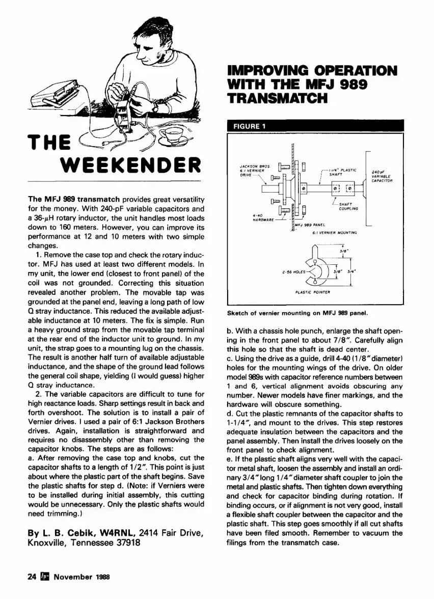
WEEKENDER The MFJ 989 transmatch provides great versatility for the money. With 240-pF variable capacitors and a 36yH rotary inductor, the unit handles most loads down to 160 meters. However, you can improve its performance at 12 and 10 meters with two simple changes.
1. Remove the case top and check the rotary induc- tor. MFJ has used at least two different models. In my unit, the lower end (closest to front panel) of the coil was not grounded. Correcting this situation revealed another problem. The movable tap was grounded at the panel end, leaving a long path of low Q stray inductance. This reduced the available adjust- able inductance at 10 meters. The fix is simple. Run a heavy ground strap from the movable tap terminal at the rear end of the inductor unit to ground. In my unit, the strap goes to a mounting lug on the chassis. The result is another half turn of available adjustable inductance, and the shape of the ground lead follows the general coil shape, yielding (I would guess) higher Q stray inductance.
2. The variable capacitors are difficult to tune for high reactance loads. Sharp settings result in back and forth overshoot. The solution is to install a pair of Vernier drives. I used a pair of 6: l Jackson Brothers drives. Again, installation is straightforward and requires no disassembly other than removing the capacitor knobs. The steps are as follows: a. After removing the case top and knobs, cut the capacitor shafts to a length of 112". This point is just about where the plastic part of the shaft begins. Save the plastic shafts for step d. (Note: if Verniers were to be installed during initial assembly, this cutting would be unnecessary. Only the plastic shafts would need trimming.
By L. 6. Cebik, W4RNL, 2414 Fair Drive, Knoxville, Tennessee 37918
IMPROVING OPERATION WITH THE MFJ 989 TRANSMATCH
COUPLING
. .- HARDWARE AIL I
L
' F J '" ~ ~ ~ R N I E R MOUNTING
2 4 0 pF VARIABLE CAPACITOR
I PLASTIC POINTER I Sketch of vernier mounting on MFJ 9E9 panel.
b. With a chassis hole punch, enlarge the shaft open- ing in the front panel to about 718". Carefully align this hole so that the shaft is dead center. c. Using the drive as a guide, drill 4-40 (1 18"diameter) holes for the mounting wings of the drive. On older model 989s with capacitor reference numbers between 1 and 6, vertical alignment avoids obscuring any number. Newer models have finer markings, and the hardware will obscure something. d. Cut the plastic remnants of the capacitor shafts to 1-1/4", and mount to the drives. This step restores adequate insulation between the capacitors and the panel assembly. Then install the drives loosely on the front panel to check alignment. e. If the plastic shaft aligns very well with the capaci- tor metal shaft, loosen the assembly and install an ordi- nary 314"long 114"diameter shaft coupler to join the metal and plastic shafts. Then tighten down everything and check for capacitor binding during rotation. If binding occurs, or if alignment is not very good, install a flexible shaft coupler between the capacitor and the plastic shaft. This step goes smoothly if all cut shafts have been filed smooth. Remember to vacuum the filings from the transmatch case.
24 November 1988

f. If the drive is equipped for a secondary marker (two screws into a brass plate), cut a marker pointer from thin, stiff plastic. Plastic file folder material is ideal; it's stiff, but can be cut with shears or an Xactos knife. Then add the original knob, align the capacitor for mark 1 or 6 (or 10 on the latest models), and reclose the .case.
The result will be easier capacitor setting with no overshoot beyond minimum SWR. This speeds up resetting the transmatch when changing bands. Outside of the 4-40 mounting hardware and small pointers emerging from behind the capacitor knobs, you haven't altered the appearance of the 989 at all. The improved operation of the transmatch makes this 2-hour effort well worth the energy. - The Jackson Brothers 6:l Vernier dials (part no. 4511-DAF) are available through Radiokit, Pelham, New Hampshire. Ed. Article 8 HAM RADIO
HI.PERFORMANCE DIPOLES r . . . L. >. , -!. vm , . _,. . . ..1 ~ ~ m ~ ~ , mar all, c.,uom .,urna,a I,, ,uu. i*na , m e aorlu -1 o!
sun on,, ,,mi, n. ,n".l,ro V nol.:nnt.,l .*r, dlW" 'irn."rr 0,rnl" r.,n*.,ral,lu"<,,r ,Il."ll.Illl"l*"l" 1411,"rr. ""ll.,, nrnl...lllr"r)drryn
n~..rufi.~ cnerl UO n. i o n (11,
rsoG0i U P 0 2 W U Y n.. mtorn.os. dtpol.. I S 8-u $61 S S ) M l e HPOS. 1 ~ 8 0 (OM h~p.lfo,m.nr.d~p~. ?>l 8 - n ~ s 1 9 ~ p a I ~ D V 1608om1011 m~.p.c....natw!.~! I- $1119~6 SSD I. 10 4020 I S IOU...r. ..r.lOlpol. s F l $ y L 4I'S$M 1? 110111p6 SSD1' 104020 15Usp.c. s.v.rdlOOl. .P.CilvL *C III W 1 9BPm
b.ndl"l,h Wid. m.lrhmg ..no. ,un.r ~
SASE IDI snl.lonu. o l 10 dlp0l.s. .10D.!.. .nd .P.c.-savI"O, URN". ."l."n.. -
NOVICES: NOW YOU CAN TRANSMIT VIDEO WlTH OUR NEW TX23-1
Did you know that you as well as all classes of licensed amateurs can easily transmit live action color and sound video just like broadcast TV with our TX23-1 transmitter. Use any home TV camera and/ or VCR, computer, etc. by plugging the composite video and audio into the front 10 pin or rear phono jacks. Call orwrite now for ourcomplete ATVcatalog including downconverters, transceivers, linear amps, and antennas for the 70,33, & 23cm bands.
Only
I.. I. "I.0 9.-
; 4@ & f 7 ,<?-B-.:h * - * - r/ 197
TX23-1 one watt A N transmitter crystaled for 1289.25 MHz runs on 12-14 Vdc @ .5A. PTL T/R switching. 7~7~2.5". Transmitters sold only to licensed amateurs for legal purposes verified in the latest Callbook or with copy of license sent with order. - a (81 8) 447-4565 m-f8am5:30pm pmt. - P.C. ELECTRONICS Tom (W60RG) 2522 Paxson Ln Arcadia CA 91006 UI-..... IWICVCC\
29th ANNUAL
TROPICAL HAMBOREE A.R.R.L. FLORIDA STATE CONVENTION
FEBRUARY 4-5,1989 TAMlAMl PARK FAIR GROUNDS
10901 S.W. 24th Street (Coral Way), Miami, F lor ida HOURS: 9 A.M.-5 P.M. SATURDAY 9 A.M:4 P.M. SUNDAY
FREE PARKING 15,000 VEHICLES 200 COMMERCIAL EXHIBIT BOOTHS 1,000 INDOOR SWAP TABLES COMPUTERS & SOFTWARE
300 CAMPSITES WITH FULL HOOKUPS LICENSE EXAMS
Registrat~on: 55.00 Advance - 56.00 Door. Val~d Both Days. (Advance deadline January 30th.) Swap Tables, 2 Days: 516.00 each. Power: 510.00 per User.
All swap table holders must have registration t~cket. Camps~tes: 512.00 per Day Includes Water, Power, Sanitary Hookups & Showers. (All RV vehicles, tent campers, vans, traders welcome - no ground tents, please.)
Make Checks for Registration, Swap Tables 81 Campsites Payable to: Dade Radio Club & Mail As Follows:
Tickets& Hotel Info Only: Evelyn Gauzens, W4WYR. 2780 N.W. 3rd St., Miarnl, FL 33125 Swap Tables, RV, Tickets 81 Hotel: John Hall, WD4SFG. 8670 S.W. 29th St., Mlami, FL 33155
RV& Tickets Only: D~ck Leisy, W400H, 650 W. 63rd Dr., Hialeah, FL 33012 Exhibit Booth & General Info: Evelyn Gauzens (address above) or Call (305) 642-41 39 or (305) 233-0000
(BROCHURE WlTH FULL DETAILS AVAILABLE DECEMBER 1st) L

UES
The radio boys in the Pacific, or, working DX for Uncle Sam The year was 1934. Many thoughtful Americans felt that war with Japan was inevitable, but the international political atmosphere tied their hands. Japan, in defiance of treaties, was for- tifying Micronesia and busy turning the island of Truk into a large naval base. Other Japanese bases existed at Koror, Ponape, and Saipan. The mili- tary analysts in Washington thought the next thrust of Japanese military power might be in the direction of Hawaii, though a smattering of small islands lay in the path. The United States was faced with the problem of protecting and converting these islands into advance air or naval bases, without upsetting relations with Japan.
The Pan-American "smoke screen"
The proposed flights of the legen-
Macao or the Phillippines, stopping at various US.-controlled Pacific islands for refueling and to allow the pas- sengers to rest. The uninhabited islands had to be surveyed and deter- mination made as to which ones would be suitable as landing sites for the Clip pers. A deep lagoon was needed on each island, with sufficient land area to accomodate the necessary support facilities. Survey crews were hired quickly to start the project. This is where Radio Amateurs played their fateful role.
The China Clippers The Martin M-130 flying boats were
titans. Over 90-feet long and with a
130-foot wing spread, the four-engine, 26-ton giants were the first planes powerful enough to carry their equiva- lent weight as payload. They could fly an astounding 3,200 miles nonstop at 130 miles per hour. No other aircraft could duplicate this feat. The time was ripe for these Clippers to island-hop from the American West Coast to the Orient. Aided by covert military funds, the U.S. government set about estab- lishing island bases to accomodate the flying boats.
Each flying boat was equipped with duplicate shortwave receivers and crystal-controlled transmitters (CW) in addition to a battery-operated emer- gency trans-receiver. Long-wire
dary Pan-American Airways flying boat "China Clipper" (see Photo A) provided a smoke screen behind which American preparations in the Pacific could take place without arousing the Japanese government. The huge fly- ing boat with its requirements for . . .* fm island refueling bases was thought to be the ideal cover for preliminary inves- tigation and eventual fortification of
The Martin M-130 "China Clipper" in flight over San Francisco Bay, bound for Honolulu. the "lands to the west of Hawaii' The Hawaii. The =ton flying boat carried 16 passengers and took 18 hours for the first leg of Clipper would fly on a regular c~mmer- the fliaht to Hawaii. one-wav fare to Honolulu was $360. Round trio to China and back - cia1 schedule from San Francisco to was slm.
26 November 1988


1 commun~catlons, telemetry. ~ndustr~al, or sctent~flc P O B O X 26330 701 w Sher~dan appllcat1ons7 Let ICM s Oklahoma CIIY OK 73126.0330 sales department ass~st you Phone 14051 236 3741
to determine whlch type o f Tc'lex 747-147 Facs~mnle 14051 235-1904
crystal IS best for you
Affo~dable Packet
pc~/i~-rllrlcc . Y t f l r l f / r r f / , / r ~ l / l r l ~ k c / I - MICROP<IWER-L I,$ ore. ~~~~rr l [~ .k ( lh ! l~ tn~llc~rs 7%?rrtrs~1r1rl.v rrlwrrc11~ ill trse c~r~rtr/)rtc~I, 1~~-1111rtcc~ 11rrit rtsirr'y t~/),qr(~(led u ~ r / / i . I / I l i r r ~ c r t i . 7;llJK 1:\'<:-2 Ic,t./,~lo/(~~v,~ 1/1(1t rc.(,lt;l.c,.v
Cornplc~tc: ~c'irrcl $ lcsb ~ I J ~ I I I 4 1 rr~illic~tr~/~.s! 1?1r v c ~ / ~ r ~ r t ~ ~ h l c o0c~rrtliotl. solrrr or I)rrttc,r-~! t r ~ r r r r r ~ ~ l rrot ~ ~
/;(I,I, llrrrr~,>w ' I 7:\1<; t11~1t i2>011t t/>c,.~ize BENEFITS andfeatt4rcs ? f h ~ t ! ) units: t ! f ~ q r l l r IW l r t~ t sl-o, 95, s159.95 LI Optional Rrsonal Meswge System
(mini-RRS) ... Add $10.00 l l r r l l ~ (It (1 lrlll~
7i.1i)~c~rror~~~i1r/~r~c~/~c~w/p)rtnhh .)r.1 O I:trlt)* cnnr/~ul i l~/~~ rc0itli RflW G .WT/ 1r11~e C I I ( I I I ~ ! I . / ~ I ~ ~ V I . ~ I ~ e.v/tc~rir~tc,trt~t- h'0.11 EI'h'0,lls. ti1111 or ITJ/I(II'I: .Vh' h'.4,11, .Uh' R0.11, 4.9 rrrffz CPI!.
U I- .)Y'R~ linritc~rl u~arrut~tl: e.wellerzt [I! Strrl cr~t~lrnllt~cl n~orlc~rrt. cr~t~t/)atihIe ctcstomer srr/~port. tt'itl~ rtse, oil 1/lt?1 t f F / l ' f f ~ / I 1 f ? ~
O RS-ZZ.? and 7'7% mrnpatihle-aN TO ORDER, h~N.,/ir>e cr*ith rr~ujor conr~ectom src/>plic~rl. cl~crvc' crt,d. c-rrll: 1-800-223-35 11 lrrtest AX. 25 sr!flrc~ctrr, 7i~c~/~11ie~(tl sr~/>/~r~rt 1i11e: 7CI'/ff' (K1.S.Y) Pac-Comm ,7l.j-#-.t-20#0 morlrrle irtcl~rrletl.
we. 3652 \Vtl.vt Qpress St.. 'lirnrp(r /:I. .(.ihO7
l'lc,rscJ .~<~r~rl: 13 7i1i1' 2 1 I ,111' V O / ' I , I I , I , ~ ~ ~ I I;\,( 221 I I I I / O I;/</</: / J ( ~ ( . b ~ s ~ (:(IIII/O,Q.
Moncy RackGuanntcc. &Id S.j s l ~ i l r p i r ~ ~ N ~ ~ ~ r I t i ~ ~ ~ / ~ i ~ r ~ ~ r ~ I ~ ~ r FI i r r l r t n ~ s s ~ ~ s r i f / f l f i ' % . i t r l ( I I I I I . I I ~ I I I I 1 1 1 1 s111111r t-1.Y X I L'4-2-XOf)b
-"
28 November 1988
5a.e ."3C* so .er,<<,t <'rl.""' ,our ,anlo rmm fir! !he prolc l~~nn81 ImL hnr r~ns., .cc.n to \our kern v.,ur tqtlmprncnl 1 3 1 ~ m d rlrrn D84r 151 the un,aghlly rbrtr
srnrrit ,nu, ,nrrll,rnent
NOVEX rack mounts are standard EIA 19 inch size aluminum panels and are optionally equipped with handler and/or forward facing speakers,
N o w ava i l ab le f o r m o s t I C O M . KENWOOD, and YAESU radios and ~ C C ~ S S O ~ ~ E I .
Prices r ts r t a t a low $79.95 each.
Flectronic Equipment Bank 5 t h l l \<#I1 SI % I . Vlcnn>. V I ::I10
I,... ' Il"l.ln I . " 1 *"*."'lo". "C,
/ 201
antennas were strung between the air- craft's nose and tail. A group of fre- quencies in the 3-10 MHz region were allocated to the Pacific chain of bases with whom the Clippers could easily and quickly communicate. The Clip- pers' flights could be tracked across the Pacific by direct CW contact every half hour, as well as by direction finders placed on the islands.
lsland colonization
facility, radio and beacon stations, and a weather station. The Howland lsland airstrip was built first as a navigation aid for the Earhart flight. The supply ship "ltaska" was stationed near Howland as the principal navigation system for the flight. The loss of the Earhart plane and the radio navigation problems of the "ltaska" convinced the Navy that only permanent, well- organized facilities would do. A better island was needed; that turned out to
One of the first steps to establish be Canton Island. ownership of the islands was the The stage was set. Americans Coman Oceanographic Expedition of 1935. Kenneth Lum King, K6BAZ was with this expedition. He was replacing K6GNW who had been stationed on Howland lsland in connection with the tragic flight of Amelia Earhart. K6ODC was on Johnston Island, while K6INF was on Baker Island. Howland, Jarvis, and Baker lslands were being "colonized" to justify a U.S. claim on the group. The claim was supported by the fact that Americans had visited the islands between 1860 and 1880 to dig guano (fertilizer). In addition to laz- ing in the sun, the radio Amateurs han- dled commercial traffic and worked DX on 7 and 14 MHz.
Other tiny islands were also being colonized by American expeditions. They, too, had hams serving as radio operators. Kingman Reef, Canton Island, Christmas Island, and Olosenga lsland (Samoa) were about to be put on the air. The islands of Hull, Swain, Atafu, and Puka Puka were also inves- tigated as possible military sites.
Beginning in 1934, Pan-American and U.S. government crews started to work on air bases the Navy needed but couldn't get. Baker, Jarvis, and Howland lslands were claimed by the British, but in 1935 the U.S. State Department decided not to waste time discussing the matter with the British. It began to colonize the islands immediately instead. Commercial avi- ation supplied the "cover story".
Canton Island-American or British?
Each island base was to be self- sufficient, complete with maintenance
landed on canton lsland in February 1935, only to find British settlers there. A peaceful truce came about, but in May 1939 a British cruiser blocked the American supply ship and prevented it from reaching the island. Diplomatic cables flew back and forth between Washington and London, and the cruiser eventually sailed away. Sover- eignty was placed in abeyance.
While the international political game was being played between America and England, Japan watched the colonization of the islands with apprehension. These islands would be used as advance bases for the forth- coming war with Japan! The Japanese Navy began to study how to eliminate these danger spots. Perhaps the best way would be to bypass them with a direct attack on the Hawaiian Islands.. . The islands are Americanized
Once the islands were declared U.S. territory, the Federal Communications Commission quickly assigned prefixes: KB6 (Guam) previously OM1 and K6 KC6 (Wake) KD6 (Midway) KEG (Johnston) KF6 (Baker, Canton, Howland, and Phoenix Islands) KG6 (Jarvis and Palmyra) KH6 (Hawaii, previously K6).
Even so, the situation was confus- ing. Some of the islands were under the control of the Department of the Interior (Jawis, Baker, and Howland), while others were supervised by the Commerce Department. Others had no direct supervision other than that
of the colonists, guided by the U.S. Navy.
During 1940-1941, while American Amateurs were banned from working foreign countries, the new Pacific islands provided a welcome source of DX. Most of the island hams worked on 7 or 14-MHz CW; a few of them were on 14-MHz phone. Some of the stations heard on the air during that period are listed in table 1.
Partial list o f Radio Amateur activity in the Pacific (19351940):
KBG-Guam KBGRWZ KBGCBN
KCG-Wake lsland KCGQA KGLHAIKCG KGTEIKCG
KDG-Midway lsland KDGFOU KDGOHX
KEG-Johnston lsland KEGSRA
KFG-Baker, Canton, Howland, and Phoenix Islands
KGBAZ KGJRN KGHCO KGODC KGJRN K6JEG KF6ROV KFGSJJ KFGJEG KFGPUL W7DBRIKFG
KGG-Jawis and Palmyra lsland KGODC KG6MV KGGNVIKGG
War! By late 1941, the new Pacific pos-
sessions were highly visible on the Amateur bands. There was talk of other exotic islands ready to come on the air any day, but the advent of World War II quickly put the hams off the air. Most of the islands were evacuated to protect the personnel and the installations were destroyed. Only Midway and Wake lslands were
November 1988 29

POSITIONS MICROWAVE RADIO CORP is experiencing rapid growth in the telecommunication field and is seeking to fill the following positions.
Microwave Radio Development Engineer
Individual must be experienced in design of radio communication equipment with strong back- ground in Qeneral circuit design and communi- cation theory. Actual microwave experience desirable, but not necessary. Hands on design experience as well as experience with introducing new products into production required. Positions exist for several levels within the engineering group.
Quality Control Engineer Position requires highly motivated individual with electrical engineering background. Responsibil- ities include working with company top manage- ment on a variety of projects such as setting up Q.A. standards and reporting procedures for the company; working with and evaluating vendors and resolving quality related problems. This is both a staff and hands on position.
Product Line Manager Opening for a unique individual to assume total product responsibility for small, low volume, semi- custom steerable and tracking microwave antenna system products used in television elec- tronic news gathering. Responsibilities include: inventory maintenance; supervision of electro- mechanical techs; trouble-shooting microproces- sor based antenna controllers; design of control circuitry and software modifications for custom applications. Should be proficient in microproces- sor control system and telephone modems. Basic understanding of microwave receiving and trans- mitting systems required. Due to the custom nature of this product, customer contact is required.
Operations Manager Will have responsibility for all aspects of schedul- ing, material control, manufacturing and test for a product line of microwave transmitters and receivers. Individual should have a minimum of 5 years manufacturing experience with a techni- cal background.
Senior Buyer tor New Product Area Experienced professional with a minimum of 5 years experience purchasing electronic com- ponents, mechanical parts and sub-assemblies. Technical background and experience in the radio communication industry highly desirable. Will be responsible for purchasing and assisting in vendor selection and setting up long term pur- chasing agreements with various suppliers.
RF Test Technician Minimum of 3 years experience in test and align- ment of microwave modules such as multipliers, sold state microwave amps, filters and mixers.
Interested persons should send resumes to the attention of Mary Morancie or call (508) 4597655 for further information.
Microwave Radio offers competitive pay and excellent benefits package. Microwave Radio is an equal opportunity employer.
mlCROWAVC R A D I O corporaton 847 Rogers Sbeet Lowell. MA 0 1859
thought to be of any use to the Navy in the long, hard days ahead.
Post-war Amateur operation
As soon as Amateurs were allowed back on the air, some of the Pacific islands became active. In particular, Canton, Wake, and Christmas Islands were represented on 20-meter phone. An interesting situation developed on Canton lsland (re-christened with the new prefix KB6). British settlers arrived to strengthen the British claim on the islands. The American contingent was represented by KBGAD (Ken Neifert) and the British by VR2AZlVRI (Don Schroder). As far as DXCC was con- cerned, Canton lsland counted for two countries, depending upon whom you worked!
Present day listing o f prefixes f r om the Pacific.
KH2, (KB61 ...... Guam KH9, (KW6) ..... Wake lsland KH4, (KD6) ..... Midway lsland KH3, (KD61 ..... Johnston lsland KHI, (KF61 ...... Baker, Canton,
Howland, and Phoneix KH5, (KG61 ..... Jawis and Palmyra
lsland
The end of the China Clippers
The last China Clipper flight took place in April 1946. Newer, four-engine post-war transports could fly quicker, carry a heavier load, and cost less to operate than the old flying boats. Most of the island bases were no longer needed. The facility on Canton was abandoned in 1945, but partially retained as a weather station. Later, it was used as a down-range tracking station for the U.S. Air Force. By 1970 this activity ceased, but the island is still under joint U.S.-British administra- tion.
Now most of the islands are deserted. Wind, wave, and sand have obliterated the old bases. Jet aircraft
make contrails over the islands as they fly past locations once thought vitally important in the hectic, pre-war days, but now merely relics of a forgotten period of American history.
An occasional DXpedition visits one or two of the islands. The F.C.C. has assigned new prefixes to the islands (see table 2) and hopeful Dxers still keep an ear open for radio activity from the little spots of sand that loomed so large in pre-war America planning.
The "Dead Band ContestM- "Elementary, my dear Watson"
In my July 1988 column I challenged my readers to identify a quotation from a famous work of fiction, thus prov- ing that alert and active hams are not "couch potatoes", but are avid readers when the band is dead. The quote was: "You have been in Afghanistan, I perceive."
I was pleased and gratified at the many correct responses to this quiz and I was impressed by the depth of knowledge of the "Sacred Writings". As Bob Rosenquist, WBEHF, put it, "These were the first words spoken to John H. Watson, M.D., late of the Army Medical Department, by Sher- lock Holmes in January 1881, in the laboratory at St. Bartholomew's Hospital in London."
Harry Hyder, Wi'IV, also illustrated his knowledge of "The Canon" and informed me he was a member of the "Sherlock Holmes Wireless Society."
Congratulations to the other readers who were kind enough to enter this contest. Within the first week of pub- lication of the July issue of HAM RADIO, the following had correctly identified the quotation. The asterisk ( * I after the call indicates the individual had exceptional knowledge of the famous works of Sir Arthur Conan Doyle.
George Marts, WBTDH; George Goldstone, W8AP(*); Donn Baker, WA2VOI; Bob Harmiston, WBGJOP; Dan Pierson, WGNTX(*); Fred Linn, W9NZF; Bill Calderwood, K1 CT; Steve Trapp, ND4G; Russ Webster, K6WM; John Mise, AA6FK; Mike
30 November 1988

Helm, WCSZ; Carl Scherer, VE3MDM; Ed Wetherhold, WBNQN; John Peak, KEGHS; "Doc" Roberts, K9BX; Ralph Turner, W8HXC; Bob Locker, WSKNI; Ken Morgan, KCSDW; Bob Houf, KD9UX; Steve Twiggs, KM7U; Gary Grebus, K8LT.
Another "Dead Band" Contest
Smart readers, eh? Well, try this one on for size. Identify the subject, verb, and object of this portion of the follow- ing popular song:
"Oh, say, can you see, by the dawn's early light, what so proudly we hailed at the twilight's last gleaming"
This quiz was given by Jon Carroll in his column in The San Francisco Chronicle of July 1 , 1988. References 1. Ronald W. Jackson. " C h i n a Clipper.'' Everest House, New York. 1980. 2. Kenneth Lum King. "Pounding Brass for Uncle Sam," Radio. November 1938, page 18-22.
Article C HAM RADIO
f \
WORLD'S SMALLEST WEATHER STATION
\ H-L L ; /'
3
77fE AMAZING WFATHER COMPUnR THAT YOU CAN HOLD IN TliE PALM OFYOUR HAND.
DICITAR'r norlWR-3 Mi- W u l b e r Stal lon i n c l u d w a mmputer, p m l s l n n r ind n n e and s p e d rcnrer wilh tnaun l ing hardware. and 40 r e 1 of rah i t . Far only m. W i l h the optional. amlomatic-cmplying RG-2 Rain ( 'n l l cnar 1519.95) you n n even l non i la r n i n f s l l !
WINII S E E D . I*INVNL<Opllrxull WIN11 I l lRECnON .TIME (B D A I WINU C l l l U . llml SCAN . WIHI) I:I:ST mnw M~~RICIST~DARD . TXMRRATIIRF: . NII'AD n m n v . III~1.I)H TTMP RECORD . LINE WLAR WARRANN
MA(;NA).HASE INDUSTRILS, INC. I502 PIKE Sl'RECT NW.
M m E I Y U S A *II.I1RN,WA rnl m e w s ORDERS ON1.Y: X00-.?U-IS02
INFORMATION: 20b73Sat74 PU(: 20bN*DU C
/ 192
November 1988 31
HI-Q BALUN -Q- . 8 li,. . "d , . . . . I ,... ,,,,,: !#,,,, . 1/,./,1.,1.. <.1,!,. . .., 1.,,,11 . 1) 8 . ,,,,ll.. a , .,l.!lll~l-,, . I<, ,,,r,,,.,< PI,,,, , .%C b.*,t! . .,,,,,,, ,,,,, YW,.,,> ,,, ,), , ,I
*l.dln<.*jJ,nf 7 . I 1 , I 1 .> /..1,,,.l,anr(. . . , , ,I, . F.8, I , , , , , . , l . I.'"'.. .,nil nlilrn . ,,,.,,,%<,I,,!>,< , ,I, , ,", W I I $<I (1" 1 r.nt-1.1 n r . c~,,,,! ,r, r,,. ,,r,,,,no tm,.tn., .. -- ,I, , , , , . , , ,,,,.,,,>.,# ,,,,hlr>,r,"
Only $14.95 HI-Q BALUN 9 I cmpendance ratto 5 K W PEP
ONLY $34.95 HI-(I ANTENNA CENTER INSULATOR
SHORTY ALL-BANDER
GSRV ,.-,
Center ~nsulalor rrlllt Ens msufalo,
Tr.nslormer co"pl*r - - 70 pual#ly RG8X
. ,,,; ,,,,,q,;e,.,,,,,
. I r r PTP . h,, bar:,1 3 1 1.) M,,: w-PL.259 *'4'ccre - un. a, ,, marrnm ~ r r , ,r,v~,., *,,I ., lu.,,,.
M a r nr ,nr,.,,,,.o " .! ?".,:<...la ,,. .,"r.,ro .,,." 4 ,,nl,q,,r~,,,,n
Only $49.95
SLOPERS MODEL BANDS I FNGTH PRICE SLA-1 l l0 .80 $0 LO 149 95 SLA.11 80.40 10 a4 95 SLA.111 80.40.20.10 2 7 69 95
f?@@n- DIPOLES
LENGTH PRICE
, " I ' C I ' T C 1 " . ! c a l m .WIIM*A l u ~ I l ) \ wmln . I ~ ~ L A W C I I ) U U ~ ~ U ,
. Con>pl<,!ely Inrlorv s%remnleo lrnOv IO ure . Lil"lll l,qn,rP,,,"' *<.,,lnrr,,lu,l ....a,,." .0Th"ll(."PI~ *el" S,dl"i,~l, *or, ,."",PI, . 14 , '-?;,, <,,,<,01. rllanOe" rnnnrl an,rnr,a w,,.. 10 5"l""r ,1>I,\C /C""f* ,!"lrn.. . C D ~ I P I Im r.cli roo le8.l i l l in* 80%- JI.0 ,>nni r b ~ l , ~ r ~ r n r ~re. ,rsi~r<~on bnc . 1,,, r mj.,, ,nro~.,ll>, ~ 1 1 7 .I,, *,re noor $0,
3 <.'>!..I .$,pi"", . 8nr8,,~e~, ,,..~c~rn twtoldvn I ~ S Y ~ , I ~ O , ~ maoeo nl !OD <1,,,I#.,, malCII11 *I," ll."h OIClClrlllr 011.41111). an<, '..<"I,,."! *P.,lrl*l.lOilil. . C t~mt,lrlr r~r lr l la i lor ~v>ll,ucf#onr mcludnd . Il.oi>\fi '0 ll.rl If.%\ r h v n *rrc!crl .,<an ,ll"~.ll'.d ",.'. 0, o<,,wt H.tni(l6.r i k * PFI, i o r r ~ l IM t n r o ~ q h 10 mrlcrr . M,," ,I,. ,,,",*"., 1,- I ! ..">.,81 C,!" $"7<
Only $39.95 The ALL-BANDER DIPOLE, lul ly assembled overal l
l eng lh 135 feel wl lh 100 I re1 450 OHM leeal lne
$29.95
DIPOLES MODEL RIINII5 LENGTH Olpole. 0.160 360 260 536.95 D 80 ID i I5 130 31.95 D-40 l o i l l 66 28.95 0-30 30 4 6 0.20 20 33' :: i: 0-16 IS 22 0-10 I 0 16' ,
shortened d1p01es S 0 ~ 8 0 10175 9 0 35.95 SO40 a0 45 3395 Parallal dlpalss Po-8010 80.40.20.10115 130' 43.95 PO 4010 40.20 10115 66 37.95 PD-8040 80 40115 730' PD 4020 40.20115 66' :::: ~ , p o l r shomsner.-only u m c as Included ~n SD modal. 5.80 80115 113.951pr. S.10 40 12 951pr.
A N .ln~enrlnr romc,r.~e W , I ~ a H1 o BALUN {HI-o ~ n f c n n a cen~er ,n..ulalur lrmr Mwlelr ,nt-l,,<llng 1 6 4 nw.lrrrl No 14 7127 s!rilnr(Bd haro dt.orl< LOUD'., .~nl<.nnl w ra. mnsuldlorr IM 4506 test ,111011 antenna 3 ,llllwit* lIIIIv 1,111111 101 1,,11 ~ v q i l ~ wwet
ALL PRICES ARE UPS PAID AVAILABLE AT YOUR FAYORITF D l
WS0.160 160 130 149 95 "SO-80 10 68 46 95 HSO-40 40 34 44 95 Loaded dlpoles - usmg cod, LD-l 80.40 80 159 95 LO-I1 160.80.40 122 79 95 LD.111 80 ~0.20.10 53 89 95 LD-IV 160.80 164 69.95 LD-V 110.40 l l 5 ' 14 95 LO-VI 80.40 78 59 95
Trap dlpolcs T0.2010.2 20.15.10 28 119 95 TD-2010-4 20.15 10 25' 11 95 T0.4OlO.2 40.20.15.10 57' 54 95 TD-4010-4 40.20.15.10 48 7.95 10-8010-2 80.40.20.15.10 106' 59.95 10.8010.4 80.40.20.l5.10 99 79 95 10-8010-6 80.40.20.15.10 84 99 95 TD.16080.1 160.80 210' 7 1 95 TO-16010-8 160.80.~0.20.15.10 148 129 95 ~ ~ ~ o ~ m " " " " c " c r
Standard wnndom 80.40.20.15.10 130' 117 95
wonaom ,uned ,.Me, 80.40.20.15.lO 130' 49 95
Super Wmdom.opllmlrCd lor 80 and a0 meters 80.40.20.15.10 130 54 95
Trap wure vrnlcalr (may also be used as Slopem1 TV-2010-l 20.15.10 1 5 139 95 TV.lOl0.l 40.20.15.10 . 29' 44.95 TV.8010.3 80.40.20.15.10 44 ' 67 95 TV.16010.4 160.80.40.20 15.10 75' 79 45 Sul l l l number Indaatcr nvmbcr ol Irmps oqpo~e snoneners-only. -me as included ~n HSD rnc-jels SOC-160 160 119 951pr SDC-80 80175 18.95lpr SOC.40 60 I 7 95,p,
Anlmna Accc~.orles..vail~blc roln antcnne orders Nylon guy rope. 450lb lest. lOO lkl 4.95 Molded dogbone type antenna msulalan I OOlpr SO-239 coax connectors 65 PL-259 75 UG I75 or UG I76 mduccr .lacrcs 25 No '122 sIrand=d hard drawn *n'enna 08'f'
/ 193
CONTINENTAL U S A . ALFR OR ORDEA DIRECT FROM
Van Gorden Engineering P.O. Box 21305 South Euclid, Ohio 44121 DEALER i N O U l R l k S I N V l r E D
Iron Powder and Ferrite
TOROIDAL CORES Shielding Beads, Shielded Coil Forms Ferr i te Rods, Pot Cores,
Small Orders Welcome Free 'Tech-Data' Flyer
12033 Otsego Street, North Hollywood, Calif. 91607 / 194

L..., 1 ,,P- - List $560
Save $181
20MHz Dual Trace Oscilloscope Al l Hl lachi scopes include probes, schernallcs and Hl lachl 's 3 year guaranty o n parts and labor. Many accessories available for a l l
DC l o 40MHz - - DC l o 100MHz Dual Channel . Dual Channel . CRT Readout - . . Delayed Sweep Cursor Meas CRT Readout DC Offset 4
11111 9 Al l Magn~ f i e r Au lorang~ng
V-425 $835 Compact S u e V.1060 Tugger Lock
List $995 Llst 51595 $1,285 2rnv Senslt~vl ty
LIST PRICE SAVE - - ~- - -
V.223 20MHz D T . lmV sens, Delayed Sweep. DC Ollsel. Vert Mode Trlgger 1770 1695 175 V.422 40MHz D.T.. ImV rens. DC011sel Verl Mode Trtgger. 1\11 Mag 1875 1695 $Is0 V.423 40MHz D.T.. 1mV sens. Delayed Sweep. DC 011sel. All Mag 1955 1795 1160 V.6M 80MHz D.T.. 2mV sens. Delayed Sweep. CRT Readoul 11.195 5990 5205 V.1065 IWMHz D l . . 2mV sens. Delayed Sweep. CRT Readoul. Cursor Msas 11.895 11.575 1320 V.1100AlWMHz 0.1.. 1mV sens. Delaved Swaso. CRT Readoul. DVM. Counler 12.295 11.995 13W
I 35MHz Dual Trace Oscilloscooe I 9
I TL.3 BNC lo Minigrabber $3.48 1 c - < I - h.1 uperar lon - L AX
Delayed Triggering ~ w e e p l
Four-Functlon Frequency Counters 1.- F-1000 1.20H
................... . . . . . . . . .
.. _.". . . . . . . . . . . . . . . . . . . .
32 November 1988 e 191

THE PEPPERDYNE RECEIVER
Build mis six-part receiver as a series of weekend projects
By Jim Pepper, W6QlF. 44 El Camino Moraga, Orinda, California 94563
T here have been many articles on receiver construction. Some were good, some were beyond
the capability of the average homebrewer; and some lacked suffi- cient information to complete the con- struction (e.g., pin information on spe- cial ICs and on troubleshooting). A receiver can be quite an undertaking if you're not given enough data. I'vealso found that itcan takeasubstantial time investment to complete the project.
1 decided to design and build a receiver that, although not in the same class as the present commercial receivers, would have some of their fea- turesand comparable performance. But most important, the builder would be able to repair it. Although this receiver is not a weekend project, it's designed to be built in sections; each takesabout a weekend to build. To fulfill these
requirements, I had threegoalstomeet: the circuitry had to be simple, be easily serviced or modifed, and use readily available parts.
Circuit description The receiver consistsof six basic sec-
tions: the mixer, the local oscillator, the i-f section, the audio board, the counter board, and the power supply.
The mixer is a dual-gate MOSFET 40673 that uses a single coil to tune from 40-160 meters. A fixed capacitor is switched in parallel with the mixer- tuning capacitor to cover the lmmeter band. Using a single coil simplifies the coil-switching circuitry. Theantenna is coupled to this coil through a series- tuned trap to reject 5 MHz, the fre- quency of the i-f. The5MHz trap works wellasa notch filter rejecting theSMHz WWV broadcast; a front panel switch is
provided toshuntoutthetrapandallow WWV reception.
The local oscillator isa standard Col- pins circuit using a MPF102 JFET. The circuit is tuned by a varicapdiodeand a ten-turn potentiometer. The varicap capacitance is a nonlinear function of the applied voltage, making the fre- quency change per turn of the tuning pot different at oneend of the dial from the other. I have compensated for this variation by usinga technique knownas "pot loading." A resistor is connected from the pot arm to ground and, with the right choice of resistance, the vari- ation can be greatly reduced. (This method can also be used togivea pot an output approaching an audio taper from a linear pot. )
The local oscillator operates 5 MHz above the incoming signal and has three coils to cover the three bands. In
November 1988 33

POWER SUPPLY
Complete block diagram of the receiver.
effect, there are four bands covered with the 75180-meter band handled by one coil. The actual frequency range covered by each coil is up to you.
Using a varicap diode for a tuning device requires that the tuning voltage source output be very clean. The LM723 voltage regulator is ideal. It's also better to use a ten-turn cermet pot for this cir- cuit, because some wire wound pots produce objectionable turn-to-turn noise when tuning. I used a 100k pot. Any value from 10k to 100k will work, but you must use a different pot-loading resistor.
The i-f amplifier stage consists of an MC1350 IC that operatesat5MHz with a two-pole ladder-crystal network on both the input and output. I experimented first with a single two- pole network and found the skirt selec- tivity very p ~ o r . l - ~ . ~ I then tried a three- pole network to find that crystal match- ing was very critical and the desired bandwidth was difficult to achieve. Finally, I decided to trythe input/output configuration; it gave very good rejec- tion and the bandwidth needed for phone operation. I chose theSMHzfre- quency because of the availability of low-cost crystals and the WWV recep- tion capability. You can use other fre- quencies, but you may have to alter the network components to achieve the desired bandwidth characteristics.
The MC1350 providesabout 50dB of gain and an AGC range of 60 dB. The AGC voltage is derived from the audio
signal and there is little difference in the audio output level of signals registering from F2 to F9. I included an i-f gain control, but I don't use it very much.
The product detector in this receiver is a CA3028. I experimented with a num- ber of different detectors and found the CA3028 to be the best from a gain stand- point. It also required the least number of parts. The BFO for the product detec- tor is generated by a 5MHz crystal oscil- lator. To keep the circuitry simple, only lower sideband reception is available. This is no real problem since99 percent of the stations on the three bands use the lower sideband for transmission.
The audio section consists of an audio amplifier, an AGC circuit, a peak- null filter circuir, and a LM380 power amplifier. The peak-null circuit can give either a sharp rejection of a given fre- quency, or peaking - which is very effective on CW operation. The selected frequencies are variable and controlled from the front panel. The two are independent of each other.
The counter circuit, with a few changes, was copied from an old issue of Popular Electronics6. Thecircuit con- sists of a timebase and a programmable counter that allows the i-f frequency to be subtracted from the local oscillator frequency, giving the frequency of the incoming signal. The circuit is designed todispby to the kHz level. By adding an- other divide-by-10 counter, the display will read to the 100-Hz level. The two ranges are accessed by a switch on the front panel.
l 8G4 ALUMINUM nl"1 OSC
I 1
Dimensions of the receiver cabinet, and pc board placement within the cabinet.
BOARD RPDlD SHACK 276-158 I Power supply parts placement guide.
i
4
TO PIN I TO TO 7812 PIN 2 PIN 3
Power supply foil-side connections.
Receiver construction For serviceability, the receiver is bro-
ken down into six parts; four are made on plug-in boards. The fifth board, the local oscillator, is mounted on the chas- sisfor stabilityand the sixth is the power
34 November 1988

Quality American made amplifiers for those who demand the best
U T I L I ~ LINE: Reliable, moderate cost, 100% duty cycle amplifiers
Catalog and custom units in low noise MOSFETand economy bipolar designs. For: FM repeaters, base stations, ACSSB, data links. TV, medical research, broadcast FM, etc.
FEATURES INCLUDE =+E - - Maximum power outputs from 50 to 150 Watts - - Thermostatically controlled fan on most models - - 13.8 Volt operation (Other voltages for custom units) Overtemperature protection "Straight through" mode when overheated or turned off - ""- ?-
Standard 83/4" x 1 9 rack panel mounting - -. - I z..
See UTILITY LINE catalog sheet for details y s ~ ?
PRESTIGE LINE: Premium 100% duty cycle amplifiers
MOSFET devices, conservatively used, assure long life and low noise. Use in; FM repeaters, base stations, data links. ACSSB, medical research, TV, broadcast FM, satellite uplinks, etc.
Full monitoringof amplifier performance. Amplifier will shut down in thefaceof certain abuses and status can bedetermined from front panel LED'S and signals at a rear connector.
OTHER FEATURES INCLUDE Maximum power outputs from 100 to 250 Watts Forced air cooling for low temperatures and long life Line voltage operation - Power supply built in Overtemperature, overdrive, excess power and VSWR protection "Straight through" mode when shut down or turned off Standard 3'/2" x 19" rack or table top mounting
See PRESTIGE LlNE catalog sheet for details
MOBILE LINE: Reliable, moderate cost, intermittent duty amplifiers
Catalw and custom units in low noise MOSFET and economy bipolar designs available. Use for FM, SSB, CW, etc.
FEATURES INCLUDE Maximum power output from 50 to 150 Watts Adjustable delay for SSB Optional plug-in receive preamplifier Overtemperature protection
See MOBILE LlNE catalog sheet for details
P.O. Box 8979 Newport Beach. CA 92658 COMMUNICATIONS (71 4) 760-3622

The partscan be purchased from the supply houses listed on the figures. (You mayfind many ofthem in yourjunk box. 1 I would advise you to send for the suppliers' catalogs before ordering; some have a minimum purchase amount.
Construction hints The tools required are those ordinar-
ily used for homebrew work. I would suggest that your soldering iron have a small tip to be used on the pc boards. These boards, obtained from Radio Shack (no. 276-1521, aresimilartovec- tor boardsand come with multiple holes and pads for mounting parts.
The power supply pc board and trans- former are mounted on the rear panel of the cabinet, which also acts as a heat sink for the 12-volt regulator. Theplug- in board sockets (Radio Shack no. 276- 1551 mount on the bottom plate with 0.5"spacers. The pc board components are mounted on push-in terminalsfrom Circuit Specialists (no. T421. Before mounting any parts, I tinned the fingers on the board that was used for intercon- nects. Do this by first heating and then wiping each finger with a cloth. The tinned surfaces should be thin.
My cabinet came from Radio Shack, but it is no longer available. In order to house the pc boards, the cabinet height
C 1
Audio board parts placement guide.
must be at least 5", and to house the rest of the components, at least 7"deep by 9"wide. (See fig. 2.) Beforestarting on the pc boards, I suggest that you mount and wire the partsfor the front and rear panels and the sockets for the boards, so each pc board can be checked for operation as it is completed. The 7812 voltage regulator is mounted directly to the rear chassis. No isolation is required.
Power supply Build the power supply shown in fig.
3A-Cfirst. The board isattached to the rear panel by two 0.5"spacers over the 7812 voltage regulator. When com- pleted, the AC power can beapplied and the power supply output voltages can be checked with a voltmeter for proper operation.
Audio board Before starting on any of the follow-
ing boards (figs. 4A. 4B,4C), I would suggest that you make a copy of the assembly drawings. You can mark the
components and wires you have installed on these sheets. This makes it easier to stop your work and then pick up where you left off.
Audio board construction The audio board consists of a pre-
amplifier, an audio-derived AGC, an S- meter driver, a peak-null circuit, and an LM380 power amplifier. The LM380 and similar amplifiers are prone to oscillate under certain loads. I found that a 10- ohm resistor in series with the speaker makes the circuit stable, with little out- put loss. The voltage for the output is obtained from the unregulated power supply (16 volts) to allow greater output without distortion.
The audio-derived AGC controls the gain of the MC1350 i-f amplifier. An off- set voltage of 5 volts is required when there is no signal and the AGC voltage moves in a positive direction for an incoming signal. This offset is gener- ated on theaudio board. The S meter is also connected to this voltage. No zero
36 November 1988

Audio board foll-side connections.
adjustment is required with this design; Next, wire all short jumpers. The same however, a full scale adjustment is wirecanbeusedonlongerleads, ifthere provided. The values shown are for an are no crossovers. Where there are old CB S meter with a 250 pA move- crossovers, I used wire-wrap type. ment. You can useany movement up to Remember to mark off all work done. 1 mA, but you'll have to reduce the series resistor. Testing the audio board
Following the parts layout for the audio board (fig.48 and C), mountthe IC socketsand push-in terminals as indi- cated. Check the size of your compo- nents; they may be different than the type I used. This is especially true for capacitors. Mount all of the compo- nents on the push-in terminals. This makes identification of pointsfor wiring theother side of the board easier. Save the wire clippings; they can be used for jumpers on the wire side of the board.
Insert the required ICs into their sockets and plug the pc board into socket J4. Tum on the power and check thevoltagesagainst theschematic. Set R2 (the S-meter sensitivitypot), to max- imum resistance. The peakswitch (S1) should beclosed, and the null potset at the maximum clockwise position. You'll need to connect a speaker for this test. If an audio oscillator is available, con- nect it to pin C on the pc socket, J4. A 20 mVpeak-to-peak 1-kHzsignalshould
"First in Shortwave, first in service to the world's S WLers"
Datong Multi-Mode Filter I t 5eparatt.s the slgnals you wan1 trom those you don't - with multi funchons. Fully automatic notch filter removes het- erodynes and other steady tone interfer- ence. Independent low and high pass filters stop "monkey chatter" and other off-tune interference, tunin 200 3500 Hz. Second notch filter manuayly tines 200- 3500 Hz. For s y h ! a(l filters work inde- pendently for lextb~l~ty As ecial mode for CW and RTTY combines t l e filters into a 12-pole filter with super skirt selectivity and non-interacting controls. Works with any re- ceiver, easy to install. Features 29 ICs with latest switched capacitor filter technology. F L - 3 . . . . . . . . . . . . . . . . . . . . $229.95 t +%)
Dressler Active Antennas Model ara 30 . . . . . . . . . . . . $159.95 (+$8) For HF use up to 30 MHz and more. Fea- tures low noise field effect transistor acting as an impedance transformer together with a hieh linear C A T transistor. A push-
ull amp ~ f ~ e r w~ th no~seless negative feed- gack roduces high linearity for low noire. lnstalt vert icd~~~, outdoors or in. Includes 26' cable, ~nterface, and AC adaptor. Model ara 900 . . . . . . . . . . . $1 89.95 ( + $8) For VHF-UHF and Scanners. Range 5 0 900MHz and more. Has low noise hi h ?!in ?-stage amp With 1 gHz bandwid%. ,an IS 15-1hdR. Mounts indoorsorout. In-
v 190 November 1988 37

Easiest Packet Radio Ever! Is F E A R keeping you from joining the thousands of hams who are having the time of A A A their lives with packet? FEAR no more! Here's the easiest packet radio set up yet - and you don't even need to buy one of those TNCs -just let your PC do the work. The DRSl PC*Packet Adapter plugs into your IBM PC (or clone) and gets you on the air in min- utes. Seconds even. The one-page Quick-Start-Guide will have you instantly going like an expert. It doesn't even keep you from using your PC for other work! Now. in addition to everything else. you'll haw a dual-port TNC with cross-band digipeating ... even if you don't even know what that means right now. Find out why thousands of hams are so excited - get your feet wet in ., packet with the DRSl system. It's only $1 39.95.
To get going on the HF bands you'll want the DRSl HF* Modem/ '> . Tuning Indicator - an extra $79.95. Go first class and get both or stick to VHF with the basic PC*Packet Adapter. Find out for self why packet is the fastest growing phase of amateur radio It's a ball! See it at your dealer today.
A A A Packet Radio without a
FDRSI Packet Radio TNC
Digital Radio Systems, Inc. (8001 999-0204 2065 Range Rd. A Clearwater, FL 34625 A (81 31 461 -0204
I New Mod Kit for Bird Model 43 Wattmeter
I Wattmeter to measure audlo peak power
MEASURES PEAK POWER r . & OF SSB AND OTHER AM SIGNALS I?-' Blrd Model 4300-400 rnodtftcatlon tl. " 11 klt qutckly adapts any Blrd Model 43 5 =&\I?!
4
Once modified, you can measure peak power to an 8% F.S. accuracy, without affectina cw oaeration or I
ot slngle sldeband - - and other AM modulated signals.
The 4300-400 kit pc board mounts inside the Model 43 housing, on the meter studs. Estimated conversion time is only 15 minutes from start to finish.
- accuracy.
And, the Model 4300-400 is surprisingly inexpensive. - - Contact your Bird distributor or factory for details.
30303 Aurora Rd Cleveland (Solon) Oh10 44139 - 2794 86248 1200 TLX 706898 B~rd Elec UD FAX 216248.5426 WESTERN REGION OFFICE Elrd Eleclronlc Corp 611 Olnl Ave Sulle F PO Bar 28 Olal CA 91023 805646 7255
Eluctronic Corporation
38 GI/I November 1988
r
Ham Radio & Computer EXPO '88
presented by
THE ALFORD MEMORIAL RADIO CLUB of Stone Mounta~n
November 5 & 6, 1988 Gwinnett County
Fairgrounds Lawrenceville, Georgia
Just 20 mmutes Northeast 01 Atlanta
# Large Indoor Dealer Area Concession Stands
RV S~tes wlth Hook-ups 24 Hour Securlty
Cookout Saturday N~ght
VEC EXAMS BOTH DAYS! Talk-In W4BOC 146.16176
$5.00 FREE ADMISSION PARKING
FOR MORE INFO CONTACT EXPO '88
P. 0. Box 1282 Stone Mountain. GA 30086 ..

Audio board schematic.
drive the audio to full output. The S meter should also vary as a function of the input signal. If no oscillator is avail- able, touch your finger to pin C. You should hear a loud hum.
Building the i-f board The i-f board construction, shown in
figs. 5A-C, is similar to the audio board. The parts associated with the ladder networks should be close to the given values to obtain the proper bandwidth characteristics. The BFO for the prod- uct detector is located on the counter board because its strong field, i f mounted on the i-f board, will swamp the AGC circuit.
Testing the i-f board To check the i-f board, insert it in J2.
The audio board should also be plugged in and a speaker connected. Turn on the power and check the voltages against the schematic. Reset the AGC pot
(audio board) to approximately 5 volts. Connect an antenna of approximately 25' or longer to pin V of the i-f board. You should hear WWV under nighttime conditions. An adjustment can be made to the trimmer capacitor across the out- put coil of the MC1350 to give maximum output.
The counter board Construct the counter board (See
fig. 6A, B, C ) next; you'll use it toadjust the oscillator coils to the correct fre- quency.
The counter is designed as a mul- tiplexing device - so the display must be designed for multiplexing, or for dis- cretedisplays having their common seg- ments tied together. I useda multiplex- ing type and was able to cut the line to the unwanted decimals, leaving just one for the 100-Hz range. Unless you are familiar with this type of display, I recommend using discrete ones. I used
ribbon cable, with its multicolored wires, to aid in wiring the segments.
The counter programming as wired is for 5 MHz, but it can be programmed for other frequencie~.~ The counter clock uses a 3.2678-MHz crystal. Figure 6D showsa meansfor shifting its frequency slightly is provided for additional calibra- tion accuracy.
The counter board also contains the 5-MHz BFO circuit for the product detector. It too has a means to shift its frequency a bit to calibrate it with WWV.
To check the counter board, do not insert any IC until you havechecked the voltages present on the various IC sockets. Plug the board into socket J3. Be sure that the voltage is 5 volts to pre- vent any damageto the ICs - in partic- ularthe counter, which costsabout $10. Remember to turn the power offbefore inserting the ICs.
November 1988 39

NOTE G 1 . 0 a P NOT PRESENT ON CONNECTOR
I I-F board parts placement guide.
-
COMPUTERIZE YOUR SHACK
YAESU 747, 757GX, 7570x11, 767, 9600. KENWOOD TS 140, 440, 940, 660, R5WO. ICOM R71A, R7W0, 735, 751A, 761, 781, AND ALL VHF, UHF, CI-V. DRIVERS FOR RADIOS ARE MODULAR. JRC NRO 525. COMPLETE PROGRAM ENVIRONMENT. MENU DRIVEN AND DESIGNED FOR EASE OF USE. SCAN FUNCTION ADDED TO RADIOS THAT DO NOT SUPPORT IT. ERGONOMETRICALIY DESIGNED FOR EASE OF OPERATION. MOST FUNCTIONS REQUIRE SINGLE KEYSTROKES. PROGRAM COLOR CODED FOR EASE OF USE. ALTHOUGH WILL STILL
RUN IN A MONOCHROME SYSTEM. MENUS FOR THE FOLLOWING:
AMATEUR HF-AMATEUR VHF- AMATEUR UHF AM BROADCAST-FM BROADCAST-TELEVISION BROADCAST SHORT WAVE BROADCAST AVIATION HF SSB)-AVIATION VHF-AVIATION UHF HIGH SEAS AARINE-vHF MARINE MISCELLANEOUS HF, VHF, UHF MOST POPULAR FREQUENCIES ALREADY STORED ADDITIONAL LIBRARIES AVAILABLE COMPLETE LOGGING FACILITY ALL FREQUENCY FILES MAY BE ADDED TO, EDITED OR DELETED
AVAILABLE FOR IBM PC. XT. AT. 80386 256K RAM 1 SERIAL PORT AND 1 FLOPPY MINIMUM
PROGRAM WITH INITIAL LIBRARIES 90.95 AS-232 TO TTL INTERFACE ONLY (NEEDED IF DON'T HAVE MANUFACTURERS INTERFACE) EXTERNAL INTERFACE ALLOWS 4 RADIOS 99.95 INTERNAL PC INTERFACE WH SERIAL 6 1 RADIO PORT 129.95 SPECTRUM ANALYZER MODULE (CALL FOR PRICE) COMPLETE SYSTEMS INCL. RADIO. INTERFACE. COMPUTER. AVAILABLE (CALL FOR PRICE)
DATACOM, INT. 8081 W. 21ST LANE HIALEAH, FL 33016
AREA CODE (305) 822-6028 f l 187
cuit is working is to connect the out- put of the 4060 (pin 3) to pin C of the audio board. You should hear a buzz- ing sound. The frequency should be 200 Hz. Next plug in the rest of the ICs. If the counter is working, check it by grounding pin P of J3. The range switch should be on the kHz position. The display should read 5000If: one count if the circuit is working. If it comes up with some unreadable num- bers, chances are that there is a wir- ing error. On the 100-Hz range, the dis- play should go blank.
Now you can check the 5-MHz BFO. Plug in the i-f and audio boards with a speaker connected. Once again, connect an antenna to the i-f board input (pin V ) . Use WWV, which should be receivable during the even- ing hours. During voice announce- ments adjust the capacitor on the cir- cuit to zero beat to WWV. If you can't do this, you may have to try another crystal. When the capacitor is set cor- rectly, the voice on WWV should sound natural.
NOW BACK IN STOCK
HAM RADIO LDG BOOKS back by popular demand! Room for over 21 00 QSO-that's over twice as many as the other log books. For contesters, each page con- tains 30 QSO's for easy counts. You alsoget the latest uptodate frequency spectrum chart. ITU callsign list and ARRL DXCC list. Spiral bound to lay flat on your desk. Unquestionably the best log book value around. 0 1 9 8 8 . HR-LB.. .. . .. . .. .. . . . .. . .. . . . .. . . .. . . . S p l r a u n d $2.95 HR3LB Special Buy 3 Price. Save 22% ............ Get 3 offer $6.95
I PIaru ~ d d $3.50 tor rhlpplng and hmdllng.
( ~~"~~o-..-.-BooKs~oRE ( GREENVILLE, NH 03048

2 3 - L 10 U I I C I I
CHLSSIS 11-12 = GNO
10 TRANSMITTER MUTE
I-F board foil-side connections.
Rear view of receiver
Mixer board The mixer board in figs. 7A-C is
next because it has the adjustment pots for setting the oscillator frequen- cies. They could have been placed on the oscillator board, but my original design had the oscillator on the plug- in board. The stability of the oscillator was very poor, so I put it on a separate board attached directly to the chassis. I didn't have room for the pots, so they remained on the plug-in board. The 9- volt supply is also located on the mixer board. The mixer coil is wound on a T50-6 toroid with 80 turns of no. 30 AWG and ten turns on the primary. The number of turns on the secondary will be adjusted later to give about 10
DOWN EAST MICROWAVE
F MICROWAVE ANTENNAS AND EQUIPMENT L m p V . p k . P o m M v ( d e n . L l n u r * m p l l R s n . ~ Amy.. Mlsmwave 1nruvsrt.n. Gab FET P n m p e . TROPO. EWE -Weak SIgn.1. OSCAR. 902. 1269.12W
23M.24W. 3456 MHz I315LV 45.1 ImpV.01 11WYH2 ZMBl -7 1345LI 45.1 l w v . p l 23MMHz 1MBt W U33LV 33.1 Implap1 802MHz 18.5dBI 597 mmn, mtennar -bled and lsaRd Kllo a v a l l a . Id6 YI UPS SIH. I 1 I West 01 liw MlaslsalpDl
MICROHYVE LINEAR AMPLIFIERS SSB. AW. REPEATER. OSCAR
=ISPA l w l n 1 8 w w f 121(0-0WMHz 13.W Sl55 1335PA 10* In 3 5 w w l 1240-13W MHz 13.IV W 5 3518PA 1w b20w oul -930 MHz 13.W $255 3335PA 10rtn40waul WO-330MHZ 13.OV 1305 2JLNA -0 0.7dB N.F. 1296 MHz 1 W ULNA p u l p 0.MB N.F. P02 MHz 1 80
Idd,sw"..m..
I*lb"..&
W W N E A S T Y I C R O V W E Blll O l u n . WJHOT
BOx2310,RR 1. Troy. ME04SS7 , (207) 948-3741
THE MULTIPLE RECEIVER SOLUTION
4 Channel Slgnal-lo-Nolse Voter irpardaolc 111 17 ?tlsn!l~l by Jusl Ad08no Cdrds . C""ll"",,t,\ Vnllnu
LID Indlmlnrr ol COR nndVoled Slgnals
Rulll tn I nllbralnr . Rrrnale Voled lnd~calors Plnned Out
s 4" x 6llatbleSlded Gold Plaled 44 Pln Card
Remote Dlsable Inputs
MORE
Ru~lt, tested and callbrared wlth manual $350.00
T~lephone ~ntertace now ava~lable
For more ~nformatlon call or wrlte
DOUG HAU ELECTRONICS Voter Department
815 E Hudson Street Columbus. Ohlo 43211
(614) 261-8871
1 1 m 1 1 1 1 1 1 q
FREE CATALOG! I Features Hard-to-Flnd Tools 1
and Test Equipment I
J e n s e n ' s new catalog f e a t u r e s hard-to- t~nd preclslon tools, tool klts, tool cases and test equipment used by ham rad~o I operators, hobbyists, sc ten t l s t s , en- g lnee rs , laborator~es and government
I agencies. C a l l o r wrlte tor your tree copy todav -
November 1988 [rm 41

The industry standard RC-850 Repeater Controller can now talk with your computer.
I
And Uluc's sa much for them to say1
'Ihe '850 computer Interface Improves the management of your wlce r e p a l r r system It a l low you to command and program lntcrartlvely from your t rmlnal or personal computer uslne. a MODEM Or parkcl TNC Even prcvlcw and rdlt rcpcatcr messapcs by typlng words lrom thr controller 5 ~Ocshularv dlrectlv lnto rnrssape slots
and prlnt oul the InlormaUon programmed lnto your controller, And vlw your system 'front panel- on your computer screen.
You'll nnd the RC-850 controller on the leadlnp volre repealers around the world. ACC ploncercd rcmole propmmmlne. of rrpraters - and conunurs to plonecr Wth rcnlole computer avcrss. While Ihc rest or the world Just talks about catehlng up. ACC contlnurs lo lrad the way In advanced repeater lerhnolofiv.
I ReVleve and catalog data rclauna to your sttr mraeummmls, cqulpmcnt slatus. and Now. w l h Its vompulrr Inlerfarr. the '850 rrpratrr and command acuvlly Download ran be best rrlrnd- vllh ynur comp!ttcr. I
advanced computer controls, inc.
2356 walih Avenue. Sanla Clara. CA 95051 (408) 727-3330
I ATV CONVERTERS HF LINEAR AMPLIFIERS
I m W ~ L M ~ ~ e Y L U M R A N e U E ~ S M z f M 3 I Y KER61LPK (KI!) (In95 KERhi PCR ( P C Bnzldl I !IN, L k l l i l - l (Mrn".,, I ll*,
la, d .,.,I *d ,"lnm.,,"n ."d ",,in. r.,, or *?,I. 1t.1
Oui b" ~ll.lrX
FiRMA<UBi OiVICES wlrn rn 4 8 ~i u l o k r U 190 65 1" rn,,,. 8.M
HEAT SlN<HATWUAL -99 H u l 1mk165.11.1 61 CHI-'<- 5~..6*16~6.1111 AM 8 , m .sd,tan.~ S ~ . P P , O C
W.~$.JISII M ~ r d - l d r n ( U n ~
munication lnc fl ,m
171 nrnrn ? t r r r t D . ~ o ~ . o ~ , ~ ~ U O ? (111) 110 ~n
I EVERY ISSUE of I
I now available on microfiche! I I The entire run of Ham Radio Magazine
I (March, 1968 thru last year) is ready to ship to you in one, easy to use 1 format.
Our 24x microfiche is easy to read and very compact. We offer a hand held reader for $75, and a desk model for $200. Libraries have these readers.
As a bonus, you will receive Ham Radio Horizons (3177 thru 12/80) free.
Everything is included, front cover to back - ads too!
Annual updates will be offered for $10.
Send $185 payment (visalmc accepted) to:
BUCKMASTER PUBLISHING Route 3. Box 56
Mlneral. Vlrglnla 23117 7031894-5777 v l d r n c 8001282-5621
42 November 1988 L-----l

IWOI. OR 'O
I-F GaIN IUINUALI IN4I.B 391
u - YPF102 Cb3028
TO BOlTOY BOTTOM V l E W V l E W
C, AUOIO OUT
TO M'xEn
5 YWI BFO IN 3 3K 0002 I
I ,I
I-F board schematic.
Six Function DTMF Controller I ( "NEW" SUPER LINEAR ANTENNA SYSTEM
. Outputs 2 or 3 latched. 1 or 2 momentav. 1 t~med and 1 manually reset group-call latched far remote alarm . Ormnnt odu lor lumlng outputs onloll NOT brill onldl lhke nlost othml .Wrong number, reset 4.d1011 acess code. can use I: up X down
I Multlple group-call response 0n.board 1-amp relay m I
AK.4K ~baadrktll. . . . . . . . $69.95 MoTron L=] AK 4w Iw~~rd l l a led tmd l . . $89.95 Electronics ,,.,, ,,,, 1,1,,,1 mmsjai .ncln
695 W. 21 st Ave, sure w11h m i o u ~ lacks bull1 ~n
Eugene. OR 97405 6 d ; h k ; ~ ~ h 3 , ~ d ~ ~ Call r o l l reel -800-338-9058 or(503) 687-21 18
MODEL FREQUENCY s!!!! POWER LENGTH USE PRICE
146 MHz 8.248 200W 15'4" Base - $192.85 I 446 MHZ 1 1.568
CA-1243E 446 MHz 8.5dB 100 W 4'8" Base $ 85.95 1.2GHZ 10.ldB
CA-901 146144611.26GHZ 31618.4dB 150 W 3'5" Base $ 91.55
CFC-771 900-930MHZ 7.1468 50W 4'5" Base S 97.40
CA-1221 S 126011 300 15.5dB 100 W 7'8" Base $151.90
CA-2422s 240012450 15.3dB 100 W 4'8" Base $173.55
NEW! SWR Power Minimeters
CM 200- 144 - 150 MHz $ 82.50 300 - 200 - 230 MHz $ 62.50 400 - 420 - 460 MHz $ 62.50 900 - 900 - 930 MHz S 93.50
1200- 1200- 1300MHZ S 93.50
DUAL 8 TRI BAND MOBILE ANTENNA'S DUPLEXERS . TRI PLEXERS Dealer inqui r ies weloomes.
(71 4) 630-4541 S p e c i i i i and prices s u b ' j to 1275 N. Grove St.. Anaheim. CA 92806 c h a n g e without n d i or o b l i g a t m .
f l 1K
November 1988 43

THE C)SL BOOK! I Continuing a 68 Year tradition, we bring you three new Callbooks for 1989. bigger and better than ever!
The North American Callbook lists the calls. names. and address information for 495.000 licensed radio amateurs in all countries o f North America, f rom Canada to Panama including Greenland. Bermuda. and the Caribbean islands plus Hawaii and the U.S. possessions.
The lnternatlonal Callbook lists 500.000 licensed radio amateurs in countries outside North Amerlca. Its coverage includes South America. Europe. Africa. Asla, and the Paciflc area (exclusive o f Hawali and the U.S. Possessions).
The 1989 Callbook Supplement Isa new idea in Callbook updates, listing the activity In both the North American and lnternatlonal Callbooks. Published June 1.1989. this com- bined Supplement wi l l include thousands o f new licenses, address changes, and call sign changes for the preceding 6 months.
Every active amateur needs the Callbook! The 1989 Calhbooks wi l l be Published December 1. 1988. Order early t o avoid disappointment (last Year's Callbooks sold out). See your dealer now or order directly f rom the Publisher.
ONorth American Callbook lnct. shipping wi th in USA $29.00 incl. shipping t o foreign countries 35.00
o lnternatlonal Callbook incl. shipping wi th in USA $32.00 incl. shipping t o foreign countries 38.00
o Callbook Supplement, published June 1st incl. shipping wi th in USA $13.00 incl. shipping t o forelgn countries 14.00
SPECIAL OFFER n Both N.A. & International Callbooks
lncl. shipping wi th in USA $58.00 incl. shipping t o foreign countries 68.00
* * * * * * * * . * * * Illinois residents Please add 6'12% tax. Al l payments must be In U.S. funds.
RADIO AMATEUR
rlent. f ac Z! Lake !br::k.,'::x Bluff, I L 60044, USA 247
Counter board parts placement guide.
percent of the value of the 360-pF vari- able for peaking the 40-meter band. Experiment to find the 160-meter switched-in capacitor. I used a 550-pF capacitor, but a lot depends on other circuit capacitances. You'll have to retune the mixer capacitor as you go across the 160 and 80175 bands, but this greatly simplifies the circuitry.
When the board is completed, check it out by plugging it in J1. The rest of the boards should also be in. Short out the WWV trap by closing the switch across the trap coil. Con- nect an antenna to the input jack. With power on, you should hear WWV with the mixer-tuning capacitance set about 40 percent. (Of course this should be done during nighttime conditions when WWV comes in best.) The receiver may oscillate at this point because there are three stages tuned to the same frequency. Just detune the mixer capacitance a small amount. Some of this oscillation will be reduced
when a shield is placed between J1 and J2. A shield will also be placed between J2 and J3. Please note that there is a capacitor 'between pin 1 and chassis ground on both J1 and J2. I found these caps helped reduce the multiplexing noise from the counter board.
You can also check theeffectiveness of the trap at this time. Open the trap switchand tune thecapacitanceacross thecoil for minimum signal. If you have successfully completed this board, the next board is the last - you're almost there!
Oscillator board The board (seefig.8A. B, C) consists
of a conventional Colpitts oscillator and buffer with the three oscillator coilsfor 160, 80/75, and 40 meters tuned by a varicap and a ten-turn pot. The upper end of each band is adjusted by trim- mers located on the mixer board. The lower end is done by adjusting the num-

Covers 27-54 MHz. 108 174 MHz 406-512 MHz. and 800-950MHz.
ARgOO 5 Scan B a x h and 5 Search Banks ~otdPrlce. ~ r e ~ g h f ~repald . 25 Day Satu;Iact~on Guarantee. ( E x ~ ~ r r r Sh~ppmg Dpllonal) FUU ~ ~ f ~ ~ d ~ ~ f ~ f i ~ d . $299 .oo . No Frequencm cut out. . Sze: 2'xSYCx l'/; wt 1202
I TO JZ-3 TO LOCAL OSC I
Counter board foil-side connections.
ber of turns on the coils. It sounds like a tedious task, but you can perform it rapidly if you use a counter.
The board used for the oscillator is a Radio Shack (no. 276-1401. It's mounted to the bottom plate with four stand-offs. Thesame type of construc- tion is useq as on the plug-in boards. Because of the limited space, the toroids are mounted vertically. I used polystyrene capacitorsfor temperature stability but they may be hard to find. Use, in place, any capacitor that has a low temperature coefficient.
When the board is wired and checked, mount it to the bottom plate and connect the band switch and ten- turn pot. Set the band switch to 160 meters. With all boards in and the power on, the counter should indicate a fre- quency somewhere between 1.5 and 2.5 MHz. Turn the tuning dial; the fre- quency should change. Turn thedial to give the highest reading. Adjust the trim resistor on the mixer board designated
160 M trim. Adjust it in a direction towards 2.0 MHz. Turn the dial to the other end and add or remove turns until the counter approaches 1.8 MHz. Repeat the process until adjustments give 1.795 and 2.005 MHz. Final adjust- ments can be made by spreading the turns. Repeat the same process for 80 and 40. The 75-meter band has two adjustments. Set the upper to 4.005 and the lower at 3.790 MHz. I have set the @-meter band to cover 3.600 to 3.805.
Final adjustments With the oscillator working, it's time
to connect the receiver to an antenna. During theday, the best band totry is40 meters. Set the bandswitch to40 M. Be sure the mixer capacitor for 160 is out of the circuit. Adjust the mixer capacitor to about 10 percent of full scale. You should hear an increase in background noise. Signals should be audible, and the display should indicate the right fre- quency.
10101 E. 106th St. Indpls., IN 46256 Toll Free 800-445-1111
Bring things down for safety and convenience.
Never climb your :ower again with thus elevator system An- tennasand rotatormount on HAZER,complete system trams tower tn verhcal uprtght posittan Safety lock system ap- erates while raislnp or lowenng Never can fall
Complete klt Includes wlnch. 100 ft of cable, hardware and lnstructlons For Rohn 20and 25G Towers
Hazer 2-Heay duty alum. 12 sq fl load 1311.95 ppd. Hazer 3Stsndard alum. 8 sq, n. load sz2s.e~ ppd. Hazer &Heavy gaC steal 18 sq. tt load (291.95 ppd.
NEW for ROHN 45 and 55 Towers Ha.zer8.Heavy duly gal" stsel l6sq ft load CALL Ball Thrust Bearing TB-25 lor any 01 above Call for price
Sbnd lor Ire* drtalls 01 alumlnum lowers sp.clllrally rnalnrrrrd lor us* wlth thr Hazar.Tw0 elas: M.lS k3"w1dr1
I r n d ~ . t ~ ~ t e . wldr).AII bol!rdconatrucllon, no wrld.. Easy to In.tall hlnp. ban. walk up rnct lon. Complrtr 1ow.r UPS or rIr trrlght shlpprblr. Pm.a.umbIrdor klt form. I I Sallsfactlon guannkrd. Call today and c h q s lo Vba. M.st.rCard or mall check or rnonnv ordrr. I
November 1988 45

' m ,.< ,' , ,,, '.,,,, z <
10 '*L1,.l , U J C O I L ' ' / . I
"I ' 4 L S 1 0 f , J US UUSJ69tSl #: 33
" G ??,,n,P, O 01 2 U ? 7 . l r \ (<,
I 8 5 Oil"U+I, (.I)
77 ,5/9U*, (,;>
CI. t l 5 li,os( i a)
uRl ,805 ('> DI ( - 0 5 9 I?!tR I, '!
OR
nr I -ns 4 u u r r l ~ ~ t r N585Bsl C? P C B P I D l O 5 H L I C 1 2 7 6 - 1 5 2
5 1 J P D i t 5 I I T C u
Counter board schematic.
Editor's Note: As the November issue was going to press, Jim found out that Radio Shack has discontinued pc board no. 276-152. He has redesigned the printed circuit assemblies to fit Radio Shack's board no. 276-154. Jim will be happy to send copies of the new drawings to anyone who sends him one dollar in stamps to cover the cost of printing and postage.
Panadaptor especially designed for the R-7000 receiver. For use with a standard scope. Variable span width from 1 to 10 Mhz. Uncover unknown elusive signals. Complete with all cables. 8 90 day warranty. $349.95 Shipped. Pa. res. add 6%.
GTI Electronics RD 1 BOX 272
Lehighton, Pa. 18235 71 7-386-4032
46 November 1988
Class 'C' brick modules
Linear power amplifiers Linear brick modules 900 Mhz. Preamps. 440 Mhz. Preamps.
9W Mhz. FM TRANSMITfERS ANTENNA SWITCH BOXES
FM TRANSCEIVERS
Tel. 1-716-692-5451
Discover 7

NEW BOOKS ARRLANTENNA BOOK by Jsry Hafl , KITD. NEW 15th EdHbn Tne all new 15!h edlllon 01 l h ~ s antenna class~c represenls over hvo years ol hard work by ed~lor KITD. I t s dwbled In sue loo -4rom over 300 to over 700 pages b ~ g ! 950 l~gures and chans cover lust about every sublect ~mag~nable. Some of the hlghllghls are Chapters on L w p anlennas. mulll-band anlennas, low Ire- quency antennas, portable antennas. VHF and UHF systems. coupllng Ihe antenna lo Ihe lransmlner and Ihe anlenna, plus pl. e-n-1-y more. Llke Ihe 1988 HANDBOOK and new OPERATING MANUAL, the new ANTENNA BOOK IS golng to be a smash hll Order yours loday l51h edltlon 900 + pages C.1988 AR-AM Sonbwnd 117.95
NOVICE ANTENNA NOTEBOOK by Owg DaMaw WlFB Nov~ces have long wondered what is tne besl all around antenna for them lo Install u p unttl now, t h ~ s was a dilllcull queslton lo answer. Atmed at Ihe newly llcensed Ham. OeMaw wrlles for the non-englneer In clear conctse language w ~ t h emphasls on easy-!@ bulld antennas Readers WIII learn how antennas operate and what governs performance. Also great readlng lor all levels of Amateur tnlerest 1st Edlllon (ii1988 AR-N AN Softbound 17.95
THE 1989 ARRL HANDBOOK FOR THE RADIO AMATEUR (Avail. Me OOd. 1988) Revtsed and updated wlth the lalesl In Amaleur lechnology. now 1s Ihe llme to order your very own copy ol Ihe world lamous ARRL HANDBOOK In addlllon to belng the deltn~l~ve relerence volume lor your Ham shack. there are plenty ol projects lor every lnleresl In Amateur Radto - lrom antennas lor every appltcal~on 10 Ihe lalesl state-ol.lhe-an prolecls - you'll ftnd I all In Ihe 1989 HANDBOOK. Order now and we will ship as soon as Ihe b w k s arrlve lrom the prlnler. They make perlecl gtlls for Ihe hollday season lor y w r hard-Wbuy lor Ham lrlends or for yoursell Over 1100 pages K'1988 3AR-HE89 Htrdb~urrd $20.95
N6Rl's ELECTRONIC SECOND OP for MS-DOS computers by Jim Raflalty N6RJ The world lamous SFCONO OP is now available In a stale-01-lhe. an compulerlzed dala base Th~s program, wrltten lor MS-DOS computers. IS a musl lor OX'ers, conleslers and all Amaleurs In- leresled In rellable OX communlcatlon Oala can be dtsplayed ellher In columnar lormal or In lull screen displays. Unknown callstgns can be entered and ccinpared to Ihe ITU calls~gn alloca. lton lor easy tdenl~ltcalton There's plenty more 1w such as postal rates. beam headlngs and OSL bureaus to name lust a lew Greal program lo have In your Shack. Order your's loday 01988 MS-DOS computers. 5% and 3% verslons available Please spec~fy on your order CCERJ (MS-DOS Compulars) $59.95
1989 AMATEUR CALLBOOKS (Available l a b Navsmbar 1988)
NORTH AMERICAN EDITION Fully updated and edlled lo Include all Ihe lalesl FCC and lore~qn government callslgns and addresses tor Hams In North Amertca Includes plenty 01 handy operallng a~ds such as tlme charls OSL bureau addresses census ~nlormalton and much more Calls lrom Nonhern Canada to Iroplcal Panama Now IS the tlme lo buy a new Callbwk when you II gel !he mosl use oul ol your Invest. men1 c 1988 OCEUS89 Sonba~ld $25 95
INTERNATIONAL EDITION OSL s are a very Imponan1 pan of our hobby All sorts 01 awards ~ncludtng Ihe coveted OXCC requlre conl~rmalton of con lac1 before the award can be Issued 01 spec~al tnleresl ad dresses are betng added dally for Hams In the USSR and olher counlrles Whlle In no means complele II s a slan and WIII b e d tremendous help In qenlng O S L ~ Handy operallng alds round OUI I ~ I S super book value 1988 CCB-F89 SDflbwnd 128 95
BUY 'EM BOTH SPECIAL Reg. $54.90 Only $49.95
SAVE $4.95
Please enclose 53.50 shlpplng 8 handling.

NEW BOOKS PASSPORT TO WORLDBANO RADIO 1989 Edition Brand neb and 'ully i ?v~s rd . S\V. s p~pr jwherv w ~ l l via11 a copy lor lhelr lhnrary Expanded lo 416 pages Ihe bwk now includes a btgger and belter buyer s gulde, an lnlervlew w ~ l h James M~chener, an exctltng real l ~ l e drama 01 one SWL s escape lrom Iran plus much more Also Includes all Ihe latest broadcasl SCheduleS ltom counlrles around Ihe world You're up-lo-dale 11 you have a copy ol l h ~ s new book by your radlo 416 pages 1989 Edlllon 1988
IBS-RDI89 Sd lbwnd $11.95
MASTERING PACKEl RADIO: the hands on guide by Dave lngram K4TWJ Packel radto conllnues lo grow a l a rate lhal baggles Ihe mlnd T h ~ s new book appeals lo all levels of packel radto enlhuslasls lrom novlces lo expens altke Full ol lllustraltonsend wrlllen In a s~mple. easy.to.understand slyle Top~cs covered include a baslc prlmer. home compulers and dala communlcallons lerm~nals. a survey 01 equtpmenl avatlable. how lo sel up a slallon plus much more Greal compl!menl l o Ihe olher packel books ava~lable 208 pages '? 1988 ISI edtl~on
22567 SOltboMd 112.95
THEARRLSATELLITEANTHOLOGY Taken lrom Ihe pages ol Ihe ' Amateur Salell~te News" column In OST Includes Ihe lalesl ~nlormal~on available on OCSARs 9 lhrough 13 as well as the Russ~an AS sdlelllles Full coverage IS glven lo Phase I l l . OSCAR 10 and 13 salell~les Also ~ncludes an unpublished article detalllng UoSAT.OSCAR I 1 operallon O~gtlal modes. lracklng, anlennas. RUDAK. mlcrocompurer processtng ol lelemelry plus much more IS conlatned In l h ~ s valuable new volume I 12 pages c I 988
AR-SA SoflboundS4.95
22nd CENTRAL STATES VHF SOCIETY CONFERENCEPAPERS Papers In lnis o w k were subm~tted for Ihe 1988 Central Stales VHF Socbely meellng Includes M~crowave EME, predlcllng 144 MHz ' E s ' openings, malchlng versus nolse l~gure trade-otls In pre-amps. 902 MHz Iransverter, power ampl~ l~er and anlennas. how lo measure your own K rndex plus much more A must publlcal~on lor lhe acllve VHF'er . 1988
AR-22CS S d l b w n d 111.95
GENIUS AT RIVERHEAD a pro f i l e ol H. H. Beverage by Albstla Wallan Born at the very beglnnlng 01 Ihe rad~o age. Harold Beverage IS
one 01 radlo s ploneefs Mosl know hlm lrom h ~ s developmenl ol Ihe Beverage or wave type recelvlng antenna Learn aboul the Career 01 lhls brllllanl engtneer !n lhls easy-lo-read btography Slarl~ng w ~ l h GE in 1917 and movlng lo RCA In 1920. Beverage was Involved In swne ol Ihe mosl exctllng aspects ol radlo 01 parllcular tnlerest IS a reprint 01 Ihe lamous November 1922 OST afllcle descrlblng lhe waveantenna Includes 35 pho~os 130 pages , 1988 NH.BEV Hardbwnd115.95
THE "GROUNDS" FOR LIGHTNING & EMP PROTECTION by Roger Block. PalyPhlssr Corpmtlon Here s a sublecl thal has never really been lully covered In Amaleut lklrralure Thts 116 page lexl conlalns a comprehens~ve analys~s ol proper grounding and prolecl~on agalnsl llghlntng and olher EMP dlsaslers Includes ~nlormal~on for all klnds ol elec- trontc gear radtos. telephones, compulers. Elhernel. CATV TVRO, and securlty systems to name lusl a lew Of speclal In. leresl lo Hams are chapters on low lnduclance grounds and con- necllons. guy anchor groundtng, and now lo ground ~ n s ~ d e the Shack Every Ham should have a copy l s l edlllon 116 pages
1987 PP-GLEP Sonbound 119.95
Please enclose $3.50 s h l ~ ~ l ~ w 81
GREENVILLE, N.H. 03048
DATATEL 800"

Yaesu's mini HB. The smallest, smartest,
tougjhest radios. Anywhere.
Whet,her you'n, a Novicc or Extra class operator, you're sure tn appreci- ate the high power, durabilit,y and size of Yaesuk FT-2XR St?rics mini-IITs. . 'Ih begin with, you'll find a model ihat's rigtii, on your wavelength. The 2-meter FT-23R.The 220-MHz FT-3YR. Or t,he 440-MHz FT-7:lR.
Whichevctr you choose, you bene- fit from incredibly small packaging. Ilhkc a look at the actual size oholo.)
You can choose the miniature 7.2-volt, 2-wat,t pack shown in the photo below. And all battery packs an: inter- changeable, too.
And consider these options: Dry cell hattely case for 6 AAA-size cells. Dry ccll battcry case for 6 M-size cells. DC car adapterlchager. Pro- gmmmahle CTCSS (PL tnnr) encoder1 tlecodrr. DTMF keypad encoder. Mobile hanger bracket. External ~~eakerlmicrophnne. And more.
Check out, the FT-23R Series at, your Yaesu dealer today. Because although we can tell you ahout. their incredible performance, tough-
ness and small sizc:.
I seeing is really believing.
2.5-watt battery pack.The FT-73R witah a 72-volt, 2-wa1.t pack. And thc FT-3YR with a powerfill 12-volt, 5-wat,t pack. I
Priecs nr~d spec~tlral~u~~s sub y pack.

1-1000 HF PACKET MODEM
I ne verdict is in and the opinion ot HF Packet operators is clear.. . . he HAL SF7000 is a winner!
ther fwh, res of the nclude: The HF ot forgiv~ng. beleawe taalng, nose, an( iterference coupled with poor tuning idicators and simplistic phone line lodems contribute to the poor performanc
: Pocket . - , rications ; world i commur .. * sign assu Packet s
.-I.-lA la . .
A new tu and acc~
lning indicator de! rate tuning of HF
res quick ignals
Lu trul, ierdetect) and thre.,lulu mrrru c ~ ~ ~ u - ~ .
d specifically for3C IF Packet tf packe
he SF700
t control
HI makes I
lers on I
HF Packet
HE
Work
)O baud H
lave synthesized tr generaror assures minimum unose ulsvorvlun and splc The SF7000 is designed specifically to great1
mprove the 300 baud HF Packet performanc ,f all packet and multi-mode controllers. rechniques developed for our government an nilitary ST-8000 (MD-1232/G) HF modem arc lpplied to the speciol problems of HF Packel adio. It's simple . . . just connect the ST-7000 lour existing packet or multi-modecontroller . ~ n d you're ready to send data, not repeats.
The "standard" 200 Hz shift mode of the 3T-7000 has a 6-pole input bandposs filter, a1 )ptimized detector circuit, plus a 40 db AGC ,ystem. These design features make 200 Hz HF 'acket work!
The ST-7000 also includes a 600 HZ shift mode or even better performance than is he 200 HZ "standard" shift mode.
Easily in mode controllers vla K>-LJLL, I I L,
TNC VHF audio
terfaces . ,, with all p . m+. m d multi- . or
Best of all, the s I-luvu IS manutacrurec nd tested entirely in the United States by IAL Communications, a compan: nown and trusted for years. TheST-7000 is availabledirectly l lv, , ,
factory at o price of $299.00, which a 12VDC, 0.25A power supply.
you've
I.,, th,
I include
HAL COMMUNILAI I O N S CORP. P.O. BOX 365 1201 W. KENYON ROAD URBANA, ILLINOIS 61801 PHONE: (217) 367-7373 FAX: (217) 367-17"'

SUBTRICT THE FROM 10.000
10,000 - 5069 ;
YSB : 4
2 n d - 9 - 0 ' 1
3 r d - 3 - 2 ' 1
158 ' I
I -F FREO
4931
1 1
Detail for slightly changing the counter to 4 MHz and 6 MHz.
Before making any further adjust- ments to the receiver, add the shields between J1 and J2, and J2and J3. The shield on the side of the oscillator should also be in place. Thisshield prevents the oscillator frequency from shifting when
QRZ CONTEST!'" VHF Contest Software
for PC Compatibles $39.95 postage paid
- Covers all VHF and UHF contests - Includes the 70 MHz European band - Menu driven and user friendly - Color and options user configured - Grids worked display on-line! - Full dupe checking - Complete log editor included - Handles 4000 contacts with 5 12K - Demo-version available $5.00 + HF Version to be available soon!
ATFAB Computers and Electronics I P.O. Box 4766 1- Maineville, OH 45039 1
NOTE G I 0 B 0 NOT PRESENT a3 CONNECTOR
-- --- - -- - - - - - - -
Mixer board parts placement guide. b
November 1988 51
NEMAL ELECTRONICS -- .Complete Cabk Assembly facilities MIGSI1)45208 +Commercial Accounts welcome- Quantity pricing + Same day shipp' most orders *Factory authorized distributor for Alpha, Amphenol, Belden, Kings,?imes Fiber
CaU NEMAL for computer cabk, CATV cabk, Flat cabk, semi-rigid cabk, tekphone cabk, crimping tools, D-sub connectors, heat shrink, cable ties, h i voltage connectors
HARDLINE 50 OHM ........................ EC4tz r p AknrJnn, Bkck Jacket .89/ft
...... FLCl2 l p C.blecnus cm. oappw blC 1.69m ........ FLC78 7 p C l b h w m c c n . c w Wk JM 3.92&
N M I X C N corm l / r cm ccpp.r mfl ............ 25.00 NM7KX N ~ v n 7 p c w c v m/l ............ 54.00
COAXIAL CABLES (par n) 1160 BELDEN m13 m y low 1068 .......................... .52 1102 RGB/V B59L s W low lars foam 11gm ........ .36 1110 RQ8K W% duWd (dml 8) ............................. .17 1130 ffi213P @5% rN.M d l u p c W V /kt ........ .39
.................. 1140 RG214/V dbl rlkv rNd dl .psc 1.85 ........... 1705 ffi142B/V dbl d k sM. toilon Ins 1.50 ......... 1310 RGZ17/21 50 dm WOO wdt dbl dJd .98
1 * 5 0 R G ~ 7 4 / V 5 o d m . i a r o d d l s p . o .......... .14
ROTOR CABLE4 CONDUCTOR .................................... 821622 2-1Bg. .nd 622gr .21 ~ 1 6 2 0 2-1- .nd 6- .................................... .39
CONNECTORSMADE IN USA ...................... NE710 TIP. N phg kf 8.M.n 8913 UB5
.......................... NE723 Typ. N /a& kf B8.ldm 9810 1W .......................... W 5 9 standud UHF plcrO kf RG8213 65
.............................................. W W - W Y I E3 ...................... W S T S PL250 k h Ily/dhw plat& 1.59 K 2 W - IbnWe-hmJ. (6vdJ ................... 1.65 UCi175/Vli176 nduoer ~ b r w / s o ( w b ) ............... 22 (K~ZTDS N plug kf R G ~ Z ~ ~ Z T ~ ~/krr ...................... 335 UGW9 N /.ck LD PL250 d@w, tellon .................... 650
................. ffi1484 SO239 to N plug .dqDlu, k h aJO m 2 5 5 SO238 to BNC d@W, ......... 020
........... S 0 2 W UHF chudr / W e p h C m .BB
GROUND STRAP-GROUND WIRE (per fl.) 0 5 3 8 3 p U m o d ~ b n M ................................ .40
................................ GS12 l p U m d c v bmhl .50 .............. ~ m m 1 - r / r h ~ ~ y u m d bnld 2.00
........................... W&3 Bg. In8ul.L.d &mdd vln .35 ................. Awl4 14ga sbnd.d khnv dm CCS .14
Prices do not include shipping, $3 minimum, Visa/Mmtercard $30 min, COD add $3.00 Cdl or mtte I& conplot8 pice llst N m W s new 38 pago CABLE AND CONNECTOH SEECTIQN WIDE b .vdabh . I n o c h s r g e w l l h w d e n o t t 5 0 o r m o r q o r . ( m ~ t d U w l l h c n d l t ~ J n r t M & r y i n p o r d . r .
NEMAL ELECTRONICS, INC. 12240 NE 14th Avc N. Miami, FL 33161 (305) 8933924 Telex 6975377 24hr FAX (305)895-8178
A

I 41 DAY NOVICE 2 code topes
World mops
I
Course certlflcote
I Frequency chorts a
I I $70 In equipment certlf~cotes from ICOM.
HCNWOOD ond YflESU $19.95 l I -*-a --a-
I I COMPL€l€ NOVKE COUAS€ $49.95 I
4 code topes. 2 theory topes, P text books. l code oxdlotor set. exomlner test pocket, ond 170 d~wount coupons
NOVICE Tfnsbon ' Wntten bu Gordon West. thls 1 I 2 oooe book I contoms dl1 Nowce questions and answers NOVICE COM COURSE ' $39.95 I ; 6 tope stereo code course for leomlnq the ;
code from scrotch Includes certlflcotes I ~ N W A M MIIV COUP- n 9 . m ( 2 theory topes & 2 tertb
$19.95 I Combbned tech & generol course wlth4 tope5 ond 1 bO&.
$49.91 4 topes & 2 books for t ..,,, ,.,, 6 tope stereo code set for CUJ sped bulldlnn
6 tope stereo code course f a CW butldtng from S wpm to 13 upm. I T M f COMPlClE IDVINCED W9.95 4 toper & 2 books for theory plus 6 tope stereo oenerol or ertro closs code course.
l (~~ectfy'tuhtch CUJ topes you wont.) I ADVRNCED TMOAV CLASS $19.95
p l w speed bulc
1 4 tope stereo theory course plus fully ~llus- troted theory book
w.m 4 topes & 2 books for I 6 tope stereo code m t for CW hng 13 wpm to PO wpm+)
6 tape stereo code c o u w mr r w bullding from 13 wpm to 92 wpm*
4 tope stereo theory plus fully lllwwoteo I """** 139.H speed
r1v.n
theory book. l GORDON WCST R~CIIIOMU soon
I 200 poge morlne electronics book plus motme rnob~le ontenno hlnts. 119.95 . COMM(ACIAL TEST PMP soon t w . 9 ~ -
sn~ss COM ntv sl osaimroa $1 9.95 I PinsTIc coM ntv a osoiisron si4.95 I I COPPZA GROUND F O N (LO(F00T 1
' u~,m l u c Tvu5 . 5 lupm R< nJorn ( hle
5 7 +ec Ou8td 7 I 0 krerl Omld 10 Himp lump 10 I 2 $eed Ruld . I 9 15 (011s 6 Numberr
13CorCde.1515SpeedBuld-15 17SpeedBuld
I 13 R o d o m . 1 3 Test Prep - 5 15 General Om2 l
1719beed&Ild.PORon9om*POTeYPrep I - . PO Cm Code 1@P4 Cma C*Iz 1 - -- -~ ~-~~ - -
I a I l ,I,,\,, ,,X,'. ,5e< 1 3 ,,,pm, <ll<?r<><te, ~ C , V , l %I,"< ,I""
I %erurce Nrf %300 UPS for rowre5 ol $ 1 00 IN vn01e I
Mixer board foil-side connections.
the unit is enclosed in a cabinet. When theshieldsare in place, makethefollow- ing adjustments: 1. Set the AGC bias voltage.
Turn the i-f gain pot to minimumvolt- age. Measure thevoltage on pin 5 of the MC1350. The voltage should be set to 5.0voltsusing the biasadjust poton the output board. 2. Adjust the mixer coil.
Set the receiver to themmeter band. With an antenna connected, adjust the turns on the mixer coil so the mixer capacitor peaks at about 10 percent of full scale. Switch to the80-meter band and check the mixer capacitor setting. It should be about 60 percent of full scale. Repeat theoperation for the 160- meter band. Clip lead a 470-pF capaci- tor across the mixer capacitor. Set the tuning dial to read 1.900 MHz. Vary the
mixer capacitor until a peaking in back- ground noiseis heard. If thetrim capac- itor is of the correct value, the mixer capacitor will be about mid-scale. It should read about 90 percent at 1.800 MHz. 3. Set the WWV trap.
If you have been doing some checks in the evening, you have undoubtedly heard WWV in the background. If you have, either the WWV switch is in the shorting position or the trap needs fur- ther adjustment. Setthe bandswitch to 40 M and the mixer capacitor to about 30percentxale. Adjustthetrap capac- itortogiveminimum feedthrough. The 5.000-MHz BFO setting can be rechecked at this time. Wait until the steady tone is off, then adjust the BFO trimmer on the counter board to zero beat with WWV.
r / 170 52 November 1988

I Manufac tu rers o f Qual i ty Commun ica t i ons Egu ipment
Hi PRO VHF-UHF REPEATERS
SUPERIOR RECEIVER AND TRANSMllTER SPECIFICALLY DESIGNED FOR REPEATER SERVICE.
ADJUSTABLE TRANSMITTER POWER. FROM 1 TO 25 WATTS MINIMUM OUTPUT WlTH EXTREMELY COOL 0PERATION.- AUTOMATIC BATTERY BACK UP SYSTEM CAPABILITY WlTH BATTERY CHARGING AND REVERSE POLARITY PROTECTION.- NOW WlTH A FULLCOMPLIMENTOF INDICATORSAND STATUS LIGHTS.-100% DUTY CYCLE-ADVANCED REPEATER SQUELCH NO CHOPPING, POPPING, OR ANNOYING REPEATER KEY UPS DURING LIGHTNING STORMS.-DIE CAST ALUMINUM R.F. ENCLOSURES -SMALL SIZE 5% x 19 x 13 "-HIGH QUALITY LONG LIFE DESIGN.
AMATEUR DISCOUNTS AVAILABLE
I
I Hi Pro Receivers I
The Hi Pro Recetver $5 Ihe heart ol Ihe HI Pro Repealer spec~t~cally deslgned lo commercial speclfcallons lor Repealer seruce and b o a l s hfgh 0 mullt luned orculls .n both Ihe r l and oscallator stages lo ,"sure low desensP mlrrrnod and spurtous along wllh cholce 01 varysnq dp grees ol il select~v#ty Supemor squelch acl8on a necPsslly tor Repealer servfce extreme sens,llv#Iy frequency and Ihelmal slablllly This receiver not only can be used as ln~llal receiver bul also lo replace lhal lroublesome receiver 8n your presenl repealer Esslly adapts lo any syslem The small sue allows lo! easy mounllng even where space IS at a premium The excetlenl lranl end relectlon ~ 8 t h wide dyamlc range quaranlees excettenl de5~nse. lnlelmod and spur~ous response relecltan
Advanced squelch clrcultry lo produce mtn squelch chopprng even wllh weak slqnals a1 high devqaltor such as weak mobole or rapld ladlng slqnals and also hlgh eleclx,Cal noise releclinn such as eI~clr#crl l storms 1gnl18on pulses elc
ASK ABOUT OUR COMPUTER CONTROL SYSTEM. AND MICROCONTROL AUTO PATCH. AND REPEATER KITS.
FEATURES: Hlgll sen<ltlu#ly Surler8or retpcllon Double ~ 8 d ~ d m ~ l spec G.10 l8berqla~s bodrds Exlr~mely qlable operalion Ercellcnl adlacent rnannel relec18on Squelch ccrcull des,qnPd lor rrlllcal repeater use . Small size
Choice 01 passbands W I ~ P srlerlton n l IrPnuFrrcv ranoes -~ -~ ~~ . Separate open collpc~or C O R dutput . Separate lone control squelch tnpul Separate looe control oulput . D~scrlm,natar meler oupul . Srgnal level mete, outpul Mull, channel capab\l8ty Up to 6 cllannels Multiple Voltage Requlal~nn Avallabte with prm 8~inn grade hlgh slab~llly Seleclable C O S nlqh or low oulpul l yea, warranly
SPECIFICATIONS:
Selectivity: ElA lwn slqnal melhnn Slandald . 15 kHz 8 0 dB . 30 kHz 130 dB Optional Narrow . 15 kH> 100 dB
.no kH> 130 dB
Spurlous Response: 85 dB Inlermodulal!on. 70 dB
Mod~ la t lon Acceptance: Slandard . 6 0 kHz Narrow . 5 0 kHz
Squelch Sensitivity: 0 10 lo 0 20 uv
Frequency Response: . 2 lo 3 dB 016 dBlOclave (In emphasts lrom 300-3000 H I 1000 H I rrterence
cryslat Aud80 Oulpul: (In 8 ohm speakell 2 0 walls mar 5 " , ~ dislnrl~lro 81 15 wall5 ma.
RI mput impedance: 50 ohms
Frequency Range: VH F I30 $50 MHz 144.175 MHz 220.250 MHz U H F 406.450 MHz 450-490 MHz
Operating Voltage: . l l lo . I4 5 V D C . I 3 8 VDC nominal Current. 90 mA nomln;ll squelched
S~ze: 3 * W x 6 ' " L i 1 H
. Duly Cycle: IOOr a! 60 C
O ~ e r a t ~ n e TemD. Ranee: 3 0 C lo .60 C
Maggiore Electronic Laboratory / ir Mia W E S l l W N RD., WEST CHESTER, PA 19382 PHONE: 215-43&6051 TELEX: 499.07bl.MELCO MX: 2lM36-62611
Reader Service CHECK-OFF Page 126 November 1988 53

.9Y OUT
ro o s c + w (-4- 1 ?
I 2 ";
A I L RESISTORS I I I I 5 %
BOTTOM V l f W S
LI. 40, 5 0 6 TOlOlOS @ L2.407 3 0 - 6 TOROlDS
L 1 . 8 0 1 5 0 - 6 TOROiDS
L a . 4 0 7 50-6 TOROIOJ
Mixer board schematic.
4. Mixerandi-f outputcapacitoradjust- 5. Testing the peak-null circuit. ments. Tuneinasteady carriersettoanaudio
With the receiver set on any fre- tone of about 1 kHz. Switch on the quencywhere thereisnoiseonly, adjust peaking switch, and rotate the peaking each of these capacitors to give maxi- pot until a pronounced increase in sig- mum output. . nal is present. Now rotate the null pot
10 C T R
-E BOM
0 4 0 Y
-C 511 61"
I Oscllletor board parts placement guide.
Upper left, mixer; upper right i-f; lower left. counter; end lower right, audio.
until the signal is reduced in amplitude. If these actions are noted, these circuits are operating correctly. 6. Final calibration.
Tune the receiver to 2.000 MHz. A weak signal will be heard that is a sub- harmonic of 5.000 MHz. Tune the
I 54 November 1988

Do the Hop; up to 2400 Baud Packet! Faster is Better, FREE Advanced
Speedy 2400 Kantronics' Feature List Baud FASTTILET" The KPC-2400 is not only the fastest
packet on four rubber feet, but has all Faster is better for files. FASTFILE'" is a powerful terminal these "Designed and Built in the U.SA."
program for PCs and compatibles that features: 2400 baud is twice as fkst forfires as performs neat, fast file transfers. formerly speedy 1200 baud, reducing *Watchdog timer chances for error during transmission. You'll receive FASTFILE free, but you *personal packet ~ ~ ~ l b ~ ~ n And speeding along long data strings, should also look at its big brother, which helps keep the airwaves open. PACFILEm, an exclusive Kantronics *WEFAX command
And you can still select 300 or 1200 file transfer program for only $29.95. *Software-selectable baud in seconds. 300/1200/2400 baud rate
*KA-NODEw *TCP/IP compatibiliv
New! *32K RAM
VERY Sp Also "built in" is Kantronics' uncom-
Suggested parable commitment to service. SO
there's no better time than now to get into Packet. Jump in or up with the
Normal suggested retail for our Kantronics KPC-2400wI
KPC-2400" unit was $329.00. new breakthrough suggested re just $199.00! A 40,% savings! W Kantronics
RF Data Communications Specialists
1202 E. 23 St., Lawrence, KS, 66044 (913) 842-i745

No other repeaters or controllers match Create messages just by tal king. Speak any phrases or
Mark 4 in capability and features. That's words in any languages or dialect and your own voice why Mark 4 is the performance leader at is stored instantly in solid-state memory. Perfect for amateur and commercial repeater sites emergency warnings, club news bulleiins, and DX around the world. Only Mark 4 gives you Message Masterru real speech voice alerts. Create unique ID and tail messages, and the readout of received signal strength, ultimate in a real speech User mailbox - only with a deviation, and frequency error 4- Mark 4. channel receiver voting clock time
.announcements and function control 7- helical filter receiver extensive phone patch functions. Unlike others, ark 4 even includes power supply and a handsome cabinet.
Call or write for specifications on the repeater, controller, and receiver winners.
MICRO CONTROL SPECIALT Dlvlsion of Kendecom Inc.
..
TELEX 4932256 Kendecom
23 Elm Park, Groveland, MA 01834 (508) 372-3442 FAX 508-373-7304 1
Measure Up With Coaxial Dynamics Model
83000A RF Peak Reading Wattmeter Take a PEAK wlth Coaxlal Dynamics "NEW" Model 83000A, designed to measure both FWDlRFL power In CW and FM systems simply and quickly. Then with a "FLIP of a swltch, measure "PEAK POWER" In most AM, SSB or pulse systems. Our Model 83000A features a complete se- lectlon of plug-in-elements plus a2 I
year warranty. Thls makes the Model 83000A an investment worth looking at. So go ahead, take a "PEAK", you'll like "WATT" you see!
Contact us for your nearest autho- rized Coaxial Dynamics representa- tive or distributor in our world-wide sales network.
15210 Industrial Parkway Cleveland, Ohlo 44135 216-267-2233 1800-COAXIAL Telex 984630
Service and Dependability.. . a Part of Every Product See us at Dayton Booths P400-401 fl 188
I NOVEX I I DM4061 Dip Meter every ham n e d \ vnr I
anl?nnnl. urr o. HI vl.nl.nl"r . ,nlrrn.l mc*lull,,on. 1,11,1
lor hrrmnntrr I $ :(O L l l l r 6 o l u g l n cnll.
PM330 RF Power McterlDummy Load r-- -
. <,>W ,,m-, 1 b, J ,ec 111 B V l l l In*",, . I l r r ~ ~ r n n rur audio
I AC mwrc adantrr P A I P ,ncludl<l
only $129.95 + $4 S&H

. . . t o niakc oprration easy. \\> II.IV,.II.I II~.L:I~.L.ICII 1I1c I.L.~CIYI.I t . 1111 t~ \\'1111 I\.~IL'II ~ ( ~ I ~ ~ I I I V I I ~ 111
,~ l l Iv 2 j p\, l , ~ I t 1 d l \ 4 'i 111 ( \\' ,11111 \\I: I~IOCIL.\, ~ l i c I !I< 2. i lO li:~, 11ic ( w r ~ m c \~,I~\IIIVII\ ~ i c t ~ l t , t l I~II- r)~>l~l..l11011 \\.l1I1 11~\\ 111,111 111~~11 111~>~111t' ,11111~1111.1 4\'51<'1111. 111(.11"- , l I ~ . t l ,I Ill$IlI\ L'IIL'LIIYc ~ \ \ . l l ~ ~ l , l ~ l ~ ~ N I ~ I ~ C I:l.l~llicr 101 rhc LIIIIIII.II,. 111 111(\1~11t. 11:11111011 11,'1~,. .111111r1~311111 \;\(I ;IIVI XCI IL.LCIV(. ~C..IIII~II~<. I\L,II~ 1 1 1 1 ~ 10 1<1 I: ~ l ~ . l ~ ~ n ~ . l \ l . .~ncl I<I I (I<CLL.I\ .~I I n L r t . l l ~ t . ~ ~ l . ~ l IIIIIIII~) ti 11rcc1\t.I\ x r t ~ \)(..I! 011 \IILI~ re~c1v1.
... with lots o f stancli~rci fr>iti~rrs, 01 L , N ~ I \ L ~ , ,111 C,I\~ I,, r t~ , l c l IIIII~[I~IIIIL.~I~II~ I ( I1 LII~I>I.~~ \\111i
~ ~ l ~ . t ~ . i l > I ~ . el1111 or OI.I<I~I l \ ~ ~ l i l ~ < l i ~ ~ ~ i ~ . II~~IIIII~III, 111111 111(,1~.1.1111: ,111 t11c 1 ( 11 \\.II~I 4 [<I:, " \ l i ) ~ l u l . ~ ~ ~ t ~ ~ l . \\\'I< ( .II, ,In11 \\\'I< ILII~~II,III~. I<!- ( ,.IIII r o ~ i ~ ~ ~ , ~ l , l r e t 1 1 1 c 1 1 ~ \ I.o~li. .111cl ( l1.11111~.1 1'11 Ih1\ \ .11 \\\.IIc 11(., ,111 IIIC I ' l l
. . . to nlakc the Prcsiclrr 1'rt.\11Ie111 15 .I IT.I~~II~< II~.II~III,L~III~C~ f-IR 2510 thr hcst I0 (11 I~:II~W.I~IV~I~. c l ~ ~ t I \vt.'\.l. ~ L I I
Mctrr Mohilc Trans- t h ~ ~ I~IIO\V I l t n v t o \ v o r l i 111 1111.
I ll< 2510 t o II~III< ~ I L I 1111, IIII~,~ 10 111ctcr ~ l i , ~ l r ~ l c 111 114 LI.I\\
' I I t , .,I,,, r,,
fl 164 1 I I,.,, 1 , , , I i ,', ' , , 1 1 1 , 1 , 1 1 . , , , , 1 I , " i I , , , , , 1 1 ,.I, \ \ . , , , I , I \ . 01"
I \ l l n I I l r r . l l l t r r I)cp.tr ln!rnl l : \m. l lc l l r 1<.ltI11*)

31 3-469-4656 HAVE 13 28360 South River Rd.
Mt. Clemens, MI 48045 SALES 1 SERVICE
m 'ALL PRICES SUnJl CTTOCHANGE
~~ ~~ .. lL 48. C m p n nll*I .*o.WIUr YDW aY)Q5
. a . l , n l C O I Y * I N * r n p . I*CL",I 1*rClcs*,PL,lll
1c.11. .11- l<*-.l". tw9m -95
* R ~ O lOCLl.ll T " I I O U r 1 IC 1 7 s ~ ~ ~ . . ~ ~ ~ ~ n m ~ - ~ ~ p i n - ~ c o . s u ~ ~ y l y l y l ~ ~ , r a m 3,s.-
T 275" NL W ,IU~.,-.llnw--,mT%G(i(i5a5a5a5aDDD. 114Pm 11')P95 C 115 NI W I m . u ^ r . U l l % - l l x l w ~ , I,.s!t.-COM, 1- W 119991 s < .I,* NI * n"mYIYI*;I,"/m I m m Ilre9, I C l Z l " nt W l a n rr*ni,l,m,r.,mmu(R.I pm*l"*Fl , sww I,!. 9, '< a3 NI*..mnrm,i,*null,a.wfU.rrl "Err.,, e1sm w391 '( 111 I *.2n.",'nn,m", llnm 2r .9 ,
. * E z A l " . . ~ n m ~ l O w l W I I " * ~ , " , Pm4lr.d l C l D . *.mnyl.nyl Illll..l.e. ,".e.* Inylnylnylnyl
tL M7 2X,.~,.">~,,,,<f 7.8 " I l l .."".,.,,,"",,< >A, ?.sm r a m
".02.1 ,n*li!"m.."x,~.m~,"s ,.ow m e , .moo ,a')*%
ws %,a- r r u l ~ uurarccrrwvl,rsraqr*r r o r ~ l ~ r s (111 C W tNIOIIU1110n rllCOUWCWOLlloNI AND DUI D * Y M I I D PRTE4'.
l l ' I I 4W.D)6 I POCKET 11- L ~ T -1 HANDHELDS 15 910\ SUP w l r v l ~ . e n IDLY(.Y~IW.-. -8.9 24.9 95 201. 95
",8$- ., ?>'9PI I b l P O I 1 5 9 h G n ~ l r n g .cnlDYmcnd.oDI~-~ "sl95 101495 I S A M , c a w .cnmmm(l
I0ld.d.- nw1 . l a ! 1119% I t b l 9 5 .,,,"w, "3 ' ( r n 9 5 w9,
1s IM &-.=I pl~oe... .C"I sn% fl 161
D.<ll lp~.l l l ! '
IUrnI. m - . o n o l t / l ~~ . . ... ..
U P 95 i l 9 lJ l Y . l l l ,,rmn**.w.ml.unr It" 95 li* ') T l i,l. hn",m.*&lr we95 5.9s IS r v l * ~ * ~ . . , n . n r m - m 1541 1 1 l amw - - 8 ~ .
I D A 9 5 - 9 , ' 2 x 9 , Ion95
W ~ I E I I I I I I A ~ W A V U . r 1 ~ 1 1 * 1 0 0 0 7 1 * 1 . 1 1 1 1 ~ 1 1 1 b"c S1OL"ACOY"IFI1 L'NE 01 " B W O M A C C E 6 M I E I
YECOYYENDATlONS ANLl t l lU 1<1W PUICl l l b P l b %
R H l E C M I OYsSl YI) ~ 1 ~ 6 0 ~ b. *r tl.ny.*r mr llanX.n nasm ~ m s . ~ )hl CURSIIRII *PI.-.... t..5w ,23995 I15DAYGOS" I, finam, "6 ,,.*..-. i l l m u m n I" us CarnDTl PlnrrlOl... swm ,..us ,510 S.l*l*. .,.,an ,rsm . r a n
WT LTOC* I M E F u i l llNE W TtN I C C I C C L S S W I T S C ILL Y S F W INFOIIUITION IECOMUFNDAIION'. IHLIVIIHOlSCWNT PIllC65.1.
..IS" L S T OVI)., " rei S u p . . r - l w . u n r r r q l . ~ d n ~ m " " ~ ~ " F *em* I-95 n r l r b l rr ,molmar..mn rw 61 1.?O" NeW.,ttonUn* *r XCV"
1tm95 *,as,
r r - , m nd!~nmr"*ra"' 88991 I" "5
F H G W Gnllcn.t.ilO-myl"".mw 1"9.*I I..*.,,
P R O W *.m~*IV"rm*l lrllr
157 pi &.A "5 6- 95 .-.q,
n i?,a* ~ . ~ ~ O ~ ~ W E W C ~ U ~ T ~ ~ ~ W W ~ I I I I I I .TI~,S , . . Q ~ I rr ,ma* Imn,rr",x""n..ynm.*a m m a * *m*m-~r.nn."wnm~~,
,w 75 3.7 "5
n >maw . o ~ r n ~ . , . . , . , . ~ - - , , . , ~ U195 IR 91
n na U." S m * 7 1 ~ I M , "* Y I ,..I II,
r l 11ll U.".lm"II,IIY* 31. q, 7"" 95
n i l / l Y."..O*II,1IUI YI) V I L"> "I
".,ill* >",rl-..,,m,.l".- U Y 9 5 ,,OW
n I I l R Y ,ml,-r.,r.~.rr *,,a* l.19, *"I
n rl!a" rolr.ru""l,d.u.- .w V. M I _ a m * .,a')
rn~,an.mu..lu,m..Ix.- -m. m>lI . . l - r m l q * i < m n I l a * U - l * , n . I I O D * m < l - W. - . , m m , l ~ n Y m ~ d , n ~ n . I D ( I . ~ , n , n . W J m , * m ' F l >,la" nq,. l m l , r 2 n w . , . r , ,!.in* ","" T * " I..- r r r - n n w
r s e s mw, 1899s .,*%
M 57mn ICMIPLCTE LIU a vrcru ACCESSW~ES~ CALL UPFUI1INtOHLIIIIUN UBCOYMENDAIIONS ANDDUn LOVPRKcS"I
~11>>66n46&4
nR 8
I TOWERS hA,u.Al
I 1 1 HIGHEST QUALITY ALUMINUM I
I TELESCOPING ILHANI(-UPI GUYED I:!arn UP) I TILT-OVEA MODELS
Easy to install. Low Prices. fl Crank-ups lo 100 feel. (1 $1
QUARTZ CRYSTALS FOR Industrial Equipmentlln~t~mentation 5 . ? l ; I " , , , .,,," , , ' , . , I I t ~ ~ ~ ~ ! ~ ~ ~ ! ~ ~ ~ ~ M ~ v l ~ ! I \ . I~~~.,/LI<~.$.,,,,I~I?,~~III M~YI , ,~ , I Stabilit and r
General Communications ~ e h a b i i t ~ in '%,- . CI,.,,,,~.I P I P ~ ~ ~ kYvnl. ~VI I IJ I I I I I ) Freque I I M . 1.3nif Mot18lc 2 wdy . Mailnr Management
EXCELLENT FOR i [ 7.4;" 1 40' M m *
ncv v I
wrele lor details
. . . .... - ..2..rri r , . ' . t '. me , !, .?. y ;*l'i
- gr .. I.;;, Mob~~e lrailtr Tw -.. : ? I
- J . ., . . .,. - -- , . . !..::I
AmateurslZ-MetnlGeneral Coverage CBIHobbiestlExperimenter
The Pulse of Dependable Communications ... , I w l l F R € € , , l x l , l I l ~ i ~ I ~ ~ ~ l . ~ ! ~ - . ~ t ~ , l r i ~ ~ ~ ~ ~ l ~ ~ ~ I ~ t r ~ i r ~ ~ l , i ~ , lu~1111111l!~..#r~rw~it~1# 1311lll~ ~ , l l , , lo, ., Ilflrlllll\llll.~1III".,~11~1,1I,11iI~l~lrXlr."l.ln,lllltl.1,11."I .,,<.I' 11,.l.. i 1..1...1 11" 11... I .,'III,IWIIII~ " I I I I 111 ldll 1<.111/.'
CRYSTEK CORPORATION I ~ I Y I ~ , ~ ( ~ ~ ~ I I I W I ~ I I I I ~ A ~ I I I ~ V I * I Y A ~ I O ~ ! j :.,ll, %,'I <ri%:,gl rlriw. . 1 1 Myrr,. I L 11907
Y O Ilnx OU,I I', 1 1 Myrr,, I I 3 140h.61 15 TOU FREE 1-800-237-3061
pH 813-936-2109rTWX 510-951.74481FAX 813-939-4226 mu FREE IN THE U.S.A. EX= ROWDA. AWKA HAWAJ~
58 November 1988

problems, I'll indicate what has to be done to correct the fault. Go to it! - .
Oscillator board foil-side connections.
Acknowledgments Thanks Francisco Moreno, a photo
enthusiast, for taking and enlarging the photos, and toTom Fattarusofor acting as a sounding board for some of my ideas and coming up with helpful solu- tions. Note:
The photo showing the printed circuit assembly of the counter board has been changed slightly to use a different crys- tal frequency than the original circuit.
u I Cl
3 POLE 4 POS ROT @ @ ;
BOTTOM VIEW
I I I
169 I
L1=14T t 3 0 AWG ON 7 - 5 0 - 6 TOROID @ CIRCUIT SPECIALISTS
L 2 ~ 2 5 T L 3 0 AWG ON T - 5 0 - 6 TOR010 @ DICK SMITH
L3:36T L 3 0 AWG ON 7 - 5 0 - 6 TOROIO @ JAMECO
L C = 4 0 T t 3 0 AWG WOUND ON A 112W @ DIG!-KEY
10K RESISTOR
Oscillator board schematic.
receiver to zero beat. Then adjust the counter-oscillator trimmer so the counter reads 2.000 MHz.
Conclusion Although this receiver is not a single
weekend project, each board can be constructed in a weekend. It's a far cry from the first superhet I built before WW II using Miller coils. I've made a number
since, but this one outperforms them all. In the future, I'm going to build con- verters to coverthe20,15, and a portion of the 10-meter band.
If you have any problem with any of the boards and you've followed the same pin connections that I've used, I will gladly troubleshoot your board for a small fee of $5 per board (postage prepaid). If you've only made a small error, I'll make the correction. On major
References 1. J.A. Hardcastle, GBJIR, "Ladder Crystal Filter Design," QST, November 1980. 2. J.A. Hardcastle, G3JIR. "Some Experiments With High Frequency Ladder Crystal Filters," OST, Decem- ber 1978. 3. Wes Hayward, W O l , "A Unified Approach to the Design of Crystal Ladder Filters," OST, May 1982. 4. Jim Pepper, W601F, "The Magic Filter," 73, Novern- ber 1983. 5. Gary Mclellan, "Tune Your Receiver by the Numbers." Popular Electronics, October 1981.
Article D HAM RADIO
November 1988 59

THE WEEKENDER
A 1296-MHz LOW NOISE AMPLIFIER By Norman J. Foot, WASHUV, 293 East Madison Avenue, Elmhurst, Illinois 60126
The noise figureof an RFampliier can beelusive, espe- cially at VHF and above. This is true unless you are for- tunate enough to have sophisticated (and very expen- sive) test equipment at your disposal.
Specifications Transistors are ordinarily specified by the manufac-
turer in termsof their scattering S parameters. Theseare the electrical characteristics seen at their interfaces. Scattering parametersallow you to design an amplifier with approximately the same gain and noisefigurespeci- fied by the manufacturer, as long as you follow certain rulesof analysis. Unfortunately, for most of us, follow- ing these rules by longhand can bean exceedingly ambi- tious and time-consuming task.
Computer needed If you have access toa personal computeranda suita-
ble program, you can accomplish designs quickly and with relative ease. Even so, you wouldn't expect to develop a design from scratch on a weekend.
Some years ago I wrote a relatively simple computer program in BASIC for purposes of designing low noise amplifiers. With this program, using data specified by the manufacturer, I found that I could realize a design in short order.
I've built and tested a number of amplifiers with this program, employing various types of transistors - including both bipolar and GaAsFETs. My designs agreed with the manufacturer'sdata sheets, increasing my confidence in the program.
1 I Trace aids of PCB.
B I
Groundplane side of PCB. Sw page 97 for pc board groundplane and trace layout.
The weekender This article is about one of these designs. Centered
near 1296 MHz, it employsa NEC-70083 GaAsFET. The 70083 was introduced a number of yearsagoand isnow availableat reasonablecost. Itusesa0.5microngateand is hermetically sealed in a stripline package.
To duplicate this amplifier, copy the microstrip layout shown in fig. 1. Notice that all traces are 50 ohms, printed on G-10 (glass-epoxy) double copper-clad pc board. No tweaking or tuning is required.
Figure 2 shows how the amplifier is powered. A + 5Vdc potential isobtained by usinga78L12 regulator and a series-pass transistor driving an lntersil7660volt- age inverter for negative gate bias. A safety circuit' is included; thisshutsoff thedrain voltage in case the bias circuit fails. Figure3isa schematic diagram of the GaAs- FET amplifier.
A curve of gain-vs-frequency is illustrated in fig. 4. The gain is flat within a half dB from about 1250-1320 MHz. (Theimproved pc board layout in fig. 1 maintains flatness over a narrower band - approximately 100 MHz.) Awordof caution; the layoutof fig. 1 should not be scaled to another frequency because scattering parameters are frequency sensitive.
60 November 1988

tl5V OC INPUT
0.1 25 V I2 V
POSITIVE t3V OC
2N236SA R8
I.5h
NEG 101 BIAS
2N2J69A
- -
Schematic diagram of power supply/regulator.
I00 nF CHIP 01
RF T'$p7f gTpuT INPUT
15) l /8 W
I NEG. +>v BIAS
Schematic diegram of GaAsFET amplifier.
20
18
I6
14
12 2 g 10
3 8
6
4
2
O 800 900 1000 1100 1200 1300 1400 1800 FREOUENCI- YHr
-
Chart showing curve of gain versus frequency.
It should be recognized that while the manufacturer specifies the optimum noise figure to be about 0.7 dB at 1296 MHz with an associated gain of 18.5dB,2theactual noise figure will be somewhat higher and the gain lower. This is due to such factors as pc board dielectric loss, source lead inductance, or inaccuracies in microstrip dimensions. Measured gain for this particular amplifier is 17dB when Ids= 10 mA. Differencesin dielectric con-
Capacitors 2 700-pF chip (Mouser-ZlCC610)
1 2 470-DF chi^ IMouser-21CC647) 1 0.7-;~disc% volts 2 0. 7-pFdisc 10 volts 2 70-pFalecMlyfic 76V
I Potentiometers
I 7 70k multiturn (Mouser-ME323~4230W~lOkl 7 SOk multiturn (Mouser- ME323-42SUW-SOkl
Resisto~s 1 10 ohm 114 wan 7 i.5k 118wen 1 1.5k 7Nwan 1 4.7k I l l w a n 1 15k 714wati 7 I W ~ 714wan I 7 m 714wan
Semiconductors 1 7N756Zener Diode 7 IN748 Zener Diode 2 2369A Transistor 1 766DIC r 7BL 12 Regulator 7 NECmaBJ Planar Transistor (California Eastern Labs1
Miscellanaous 2 SMA Connectors 7 8-Pin DIP Socket 7 PCB /FAR Clrcults $6251
I Parts Sources C.llfornia Eastern Labs, 3160 Fay Street, Ssnta Clara. California Dioi-Kw. W7 Brooks Avenue South. P. 0. Box B n , Thief Rlver Falls, Minnesota I s % 1 . FAR Circuits, 18NMO Field Court, Dundw, llli1~0ls 60118 Mouser Electronics, ZlOl Hlphway~7North, Mans field, Texas 78063 Radloklt. P 0. BOXOR PeIhm, Naw tiampshin 0.5076 Radio Shack /see your local store1
stant between one manufacturer's board material and another's, or between different production runsfrom a given manufacturer, can influence performance. Avalue of e, = 4.4 was selected from a published table.=
Gain increases with drain current, peaking out at 19.5 dB at about40 mA, but the manufacturer's data callsfor a drain current of 10 mA for minimum noise figure.
Through-grounds are made on the pc board in fig. 1 by passing no. 26 tinned copper busbar through the ground holes and soldering on both sides. In this way, the ground on the trace side of the board is connected to the ground plane with minimum inductance. This is particularly important where the stub on the gate side of the transistor is connected via a through hole to the ground-plane sideof the board, and where the transis-
November 1988 61

to ground, or if the7660is removedfrom itssocket, the positive 3 Vdc ramps down to zero.
FERRITE #EAD IC1164-101)
SOLDER I
Ferrite bead placement on the + 15 volt Vdc line.
torsourcesare similarly through-grounded (See fig. 5for details on RFI proofing the + 15 Vdc input line.
C1 and C3 are 100-pF chip capacitors; C2 and C4 are 470-pF chips. R1 is a 1.5k 118-wan resistor soldered
' directly to the traces with short leads. L1 is wound, using
1 a 1116"drill bit as a mandrel, with 9 turns of no. 24 enamel copper magnet wire; the turns are spaced slightly. R3 is the gate bias pot; R5 sets the drain volt-
; age to + 3 volts. I
Adjustments Beforesoldering the GaAsFETto thepc board, adjust
the negative bias and protective circuit. Temporarily connect a 270-ohm resistor from the junction of L1 and R4and ground to simulate transistor-drain current. Then adjust R6 until the drain voltage across the 270-ohm resistor is3.0Vdc. When pin 5 of the7660 is then shorted
Shielding The 1296-MHz amplifier performs noticeably better
when the assembly is enclosed in a shielded box. Form brassstrip 1 /4"wideandO.O32"thick intoa2"x3"rec- tangleandsolder i t to thecopper band around the trace side of the board. Now form a 0.01 5"thick pieceof alu- minum into a tight-fitting cover. Usea pair of 2-56screws to hold the cover in place through tapped holes in the brass rectangle.
A final note I make no particular claimsfor superior performance
fortheamplifierdescribed here. Itwil l win fewcontests for the lowest noise figure, but on-the-air tests make it clear that "store-bought" or homebrew converters come to life when you use it. You be the judge.
References 1. Norm Foot. WASHUV. "SafePawerforvrGaPsFETAmdifier."hamnrdio. November 1982, page 20. 2. California Eastem Laboratories, Inc., NEC Data Sheet, NEMOSeries. Janu- ary 1W. 3. Tri T. Ha. "Solid State Microwave Amplifier Design," John Wiley 8 Sons. New York, 1981, page292.
Bibliography 1. GewgsO. Vandalin. " W n o f AmpliCmandOacillatmBy rheS.Paramaa Mahod." John Wilsy h Sons. Naw York. 1981. 2. T.C. Edwards. "Foundations FM MimripCircui( Dein."John Wday b Som. Nsw Ymh. 1981.
Article E HAM RADIO
f A r i e s - 1 Alt-Y..xdLoi..=..grneld eer s,.-~..~
A S L 0 L F
T M W
A 0 D R
E E FOR IBM P C / X T / A T PS/Z a COMPATIBLES - ~39.95 -
fAries-1.. . ... h a d 8 D~II / IIU[ lrom Cornpuler - IR[IMHCY / UCO~ ~ l o m I r a n t r w (crrlom K r n m o d and k o m m o d e ) inlo log. ... hlerlocer n l h Konlronicr KAY and MA PK-237 l n m m o l Unilsfor l o l ob inlqroled ON-ICRLFN 110. ... Worls n l h o Ywro ondlor iunclmn Km f w l o d ond e o q conlrol o l lefmhol h i l s ond Dolo Fnlry. ... b d u l mih a d h c u l i l r r i o m q l o l n m h l W s and In& ... Chonqrs 1U Modes, owo lmq poromrtas and l iks dolo mlo Ihe Log lk i l h Ihr pm 01 o k q w Ihr c k k o l o m o u r . ... Has o C o n l r d Uodr ond oulwnolic slimq r r ~ c e m m l copobilily . O i h <m new mronmq l o pick erhonqn . ... Hos h l o m o l ~ Dup chrckmq ond Ihr obilily lo roorch / pfml dolo b o a by Col. Cwnlry. frw, ML mlo, rlr. ... LeIs pu run olhrr pfoqroms (or w c m DM) rh le s l w q reden l m m m q . okmq "Ih,pur dolo. ... Logs w i re conlorls. rhdr m u H o n e w k ronnrclrd lo o pocket mo i bor and dom-bodmq m m q n inlo o raplurr k. An Extremely useful program! Most Aries-1 Users 'fire up' the program when-
ever they are in the shack. Whether operating Voice, AMTOR, Packet or any other mode, you will enjoy having your Log available on screen simultaneously with your Terminal Unit and access to your other ham software just a keypress away.
VISA - - Our I M h Year of de l lwnng Qusllly Solkwsm l o the In lernal lonal m a r k r l - - YesterCsrd
# 15( ~ ~ 8 a s # ~ I ! m \
€W C B
J PO Box 1067 - Vestal, NY 13851 - (607-748-9028)
THE LAST AMPLIFIER YOU
WILL EVER NEED!
ONE AMPLIFIER MANY APPLICATIONS:
Receiving-Ultra high dynamic range-Low noise. Transmitting-Driver or finat ... 1 watt linear output.
Gain 15dB f ldB I P3 + 44dBm IP2 + 73dBm N.F HF-UHF 4.5dB (typ) Id6 C0mp + 30dBm Connectors BNC
PRICE $199 lda Y m shop USA
CA Re* aed 6%
ADVANCED MlLLlWAVE LABORATORIES. INC. r, 1M
620 HAMPSHIRE RD.. A3 WESTLAKE VILLAGE. CALIFORNIA 81361
TEL. (805) 495-7858

UYou'l.e miles ahead with -sen Rick woodsome Comm~mrcotionsCo~~Itont
Woodsomeand W a f € . ~ , Boulder, Colorado
When the directors of the Coors International Bicycle Classic needed . . ~ -~
a sophisticated mobile communications system, theyturned to commu- nications consultant Rick Woodsome. As a communications specialist,. Woodsome knows what it takes to make a communication system work.
That's why he turned to Larsen Antennas. "You don't pull offthe largest s orts event in the Western Hemisphere
without good communication. An 8' you don't have good communication without the right equipment.
"Larsen antennas were instrumental in making last summer's Coors Classic an overwhelming success. They were key to our entire communication network.
"Without Larsen, it would have been uphill all the way." Rick Woodsome
0
(Q) rsen nntenncrs f l lss
The Amateur's Professional See your fav<~rite amatcur dealcr or wli lc Ik r t ,I l icc ;1111ateur catalog.
IN USA: Larsen Electronics, Inc.. 11611 N.E. 50th Avenue. PO. Box 1799. Vancouver, Washington 981 IN CANADA: Canadian Larsen Electronics. Ltd.. 149 West 6th Avenue. Vancouver, B.C. V5Y 1 K3 (6C
THE AMATEUR'S PROFESSIONAL. Larsen KOlrode and KOlduckie" antennas
provide amateurs the same advanta es enjoyed by B commercial two radio users. 0th combine lop per fo rmance3 the long range dependab~llly you want.
See your dealer lor the com-
fk:ot Larsen antennas and per- malient and tempo-
, rary mounts. You can buy with conlidence. because they're all backed b Larsen's No Nonsense Warranty for a lulysix months.
For a professional approach to amateur radio, tune in to Larsen.

INTRODUCES THREE NEW STATE-OF- THE-ART ALPHA LINEAR AMPLIFIERS 'ALPHA 86-Continuous HF coverage, manually tuned *ALPHA 87-Amateur H F band coverage, bandpass no-tune-up *ALPHA 88.Continuous H F coverage, fully automatic band selection and tuning under microprocessor control
Thc am thr~
Thc . .
cal ind eaz
Thf the -- am ing an(
ALI cuii trni -. -. f ac mic Dro r -
mu Pre imc o f r
All 1
3 ALPHA fashion
8 ,'-
!d band! 78 moc . - - J L -
:hoke, ar nanual t i
-- - - - . - - . ,-=--.-=- - - ~ - -.----a-
, -.~ -.. . . - - . ___ - - ;v_ - ____ =..-
. e ALPHA 86, 87, and 88 are new, state-of-tne-an riF linear plifiers designed for the most demanding radio amateur. The ee models differ only in the manner by which output tuning 1 loading is accomplished.
1 ALPHA 86 is adjusted manually by the operator (like earlier ALPHA 76lA series amplifiers) for optimum performance at any frequency between 1.8 and 22 or 30 MHz*. Smooth and easy manual tuning is provided by a combination of custom split
lacitor, vernier drives, bandswitched RF ( i d level- ependent LED tuning indicator. Accurate n ~neup is jier and quicker than ever before.
87employs fixed, pretunt its after of earlier ALPHA 374 an( ~vers all
areur n i bands permitted by FCC'- ana nas no manual tun- controls. You simply turn a knob to the desired amateur band 1 begintransmitting-with no waiting and nothing to adjust.
PHA 88 combines the full frequency coverage* amplifier cir- try of the '86 with a microprocessor-basedautomatic con- I system. Nominal settings for all frequency ranges are
E tory-loaded in memory; when drive is applied the - :roprocessor system samples the incoming RF, selects the I per frequency range, and trims tuning and loading for opti-
'OROID, I m performance-all within afew seconds. Tune-up isalways cisely correct for your actual operating frequency and load L" COIL ~edance. You always have maximum efficiencv and 1.5 kW
trp RF output without ever touchii
SWI RF (
TCHED ;HOKE
:ne new ALPHA'S use a pair of Eimac 3CXbuu~l Irfoaes ro provlae maximum legal power in all modes I plentyof reserve. Tuned inputs assure ea ltion to full rated output i rity and ?rb linea
.-. -8- aavanced PIN dioaesysrem providessilent ana u~rra-fast (1 ma) vun, usn, ana AM Iun I I ~ switching. !se models also share instant-response LED bargraph metering of all critical parameters, full-cabinet :ed air cooling, and ETO's unmatched THREE YEAR factory limited warranty.

SPECIFICATIONS, ALL MODELS
POWER OUTPUT 1500 watts PEP, keyed CW, or carrier (RTTY, SSTV, etc.) up to 100% duty cycle, no time limit. Optional auxiliary cooling sd for operation of ALPHA I 1000 watts average for more than :inuously.
fan reco 30 mini
mmende rtes con1
)ut power
DRIVE POWER: 50 to 80 watts PEP or carrler tor 1500 watts RF output.
INPUT VSWR: 1.5:l maximum wil maximum elsev
smic-metal, grounded gri
vhere.
d triode: rUBE COMPLEMENT Two ElMAl
'OWER SELECTION: HllLO panel switch selects nominal 1500W or 750W RF outp
C . - - - - - . - -& . . - TRANSMIFRECEIV IN diodes,
1 mS max. switching rlme. ~ecnanical relay G BLCJW~H-FULL CABINET GUULI )asses a1 vhen in STANDBh ING mplifier v
. . . - - - . - - des.
*...,---a ALL. luayauva yolrly, UIIU-uar~vau, aulustauta sshold. thrc
CC] IOLING: PUII camnet, aucted, rear intalceltop laust.
- - ext
3.5 nvr .TRANSFORM WITH TAPE-V HIPER!
rR PROTECTION: ALPHA 86 & 88-Automatic tripout for VSWR ALPHA 87-Automat @ 1500W I?
> 2.5:l ic tripoul
I @ 15 t for VSVs
OOW PC IR> 1.5:
CORE .ate mu1 , lg: switc , . - --
ITERING: Separ ti-color LED bar- phsfor Pout, Prefl :hed LED bargraph
Tor Ip, HV, and ( A L P ~ A ee only) manual tuning indicator.
~ARMONICOUTPUT: Betterthan 55dB belop ?d outpu dB elsev
ton all a1 vhere.
mateur b ands; bc !tter than
'ERMODULATIOI dB below rated c
letter tha~
PRIMARY POWER REQUIRED: 220-250V, 5C 60 Hz, 20A.maximum (internal jumpers for 110 125V; requires 40A primary service or reducec
ver).
E & WE1 & 87-17" x IJ IJ ahcluding feat. UJ IL
ALPHA 88-Same e PHA 86 D; 70 Ib.
- P VIEW Shippable via UPS (Hipersilo transforme, removed for shipping).
GHT AL .. . VERNIER-DRI' SPLIT TUNIN( CAPACITOR
VEN 5
*Continuous frequency coverage in the '86 and '88 permits MARS and other special uses far removed from standard amateur frequencies. Units delivered in USA cover 1.8-22 MHz only, as required by FCC rules. Appropriately licensed amateurs may easily modify to restore full 1.8-30 MHz operation. ALPHA 88 pending FCC type acceptance.
D EHRHORN IECHNOLOGICAL OPERATIONS. INC
4975 North 30th Street Colorado Sorinos. CO 80919 Telephone i71$260- 1191 For Sales and Service caN
la (719) 5 9 9 . ~ ~ 0 1

' WEX-DISC. I OVERLAND PARK. KANSAS 66204
I EVERY DAY A HA1 BUY - SELL - TRADE
C f .
,L BRANDS NEW AND RECONDITIONED
i'LL BUY YOUR EXTRA RIG I STATIONS-ESTATES ETC. I
call 91 3/381-5900 FAX 91 3 648 3020
SEND SO FOR CATALO AN0 WHOLESALE LIS'
ICOM I N C 5 I ' l ,,,,,. ,, ,,,, SUPERVALUE YA~," ,,%,< 537Y
Introductory price $79.95 1. .h.p".", . h .M l . " l
l l l , , , i ~ . ~ . ..~,I>,I . i l l ,11.411v1 ,>,,L,I.C,, mrer 1 1 .
66 November 1988

7544-4 RECEIVER By James M. Larson, KWM, 2245 Ross Avenue, ldaho Falls, ldaho 83406
Complete details for updating this classic radio
have done a solid-state conversion of the Collins 75A-4 receiver. My intention was to "get the tubes out," yet retain or improve the original operating fea-
turesand performance. I wanted a receiver that looked and felt likea 75A-4, but with negligible frequency drift and improved intermodulation distortion (IMD) and overload capability. I wasalso looking for steeper skirts on the i-f assb band anda noiselimiterthatwaseffective on the "woodpecker."
I wanted to keepall theoriginal RF, oscillator, i-f, BFO and VFO coil structures, and their associated band-
Front view of the 75A-4 receiver
switches. The original mixing schemewould remain. An additional mechanical filter would be inserted in series with the'existing i-f filters.
The end result is a receiver that, from all external appearances, isa 75A4 (Photo A). But when you open the lid, you see the uncluttered view in Photo B - and no tubes!
The lack of background interference and hash is noticeable when you compare the new receiverwith the unmodified version. The measured IMD and blocking capability are also greatly improved.
Performance characteristics Table 1 shows performance specifications for the
more important parameters of the solid-state receiver, compared to the vacuum tube original. The data is the result of comparative measurements made on a vacuum tube 75A-4 and the solid-state version.
With the exception of receiver sensitivity, all other parameters of the solid-state conversion are improve- Top inside view of the 75A-4 receiver.
November 1- 87

Overall circuit diagram of the receiver.
ments over the original. The high sensitivity of the vacuum tube receiver was reduced to enhance the IMD and overload capability. The input noise of the solid- state version still remains below the typical background and galactic noise from the antenna.',*
Getting started The first thing I did wasacquiretwo75A-4s. One unit
was used as the comparison standard. I removed every- thing from the other 75A-4 except the RF coils, oscilla- tor coils, variable i-f coils, crystal sockets, bandswitch assembly, and thesocketsand switch forthe mechani- cal filters.
The wiring that remained included the interconnect- ing wires between the bandswitch, its associated coils and crystal sockets, the mechanical filter selection switch, and the interconnecting wiring to the filter
sockets. I had removed everything else, leaving an almost bare chassis.
I also stripped out the tube sockets and all wiring at the base of the tube sockets in the permeability tuned oscillator (PTO). I didn't disturb the oscillator circuit in the PTO hermetic enclosure at this time. Next I opened, cleaned, and checked the i-f cans, BFO enclosure, and the rejection filter enclosure. The megacycle dial drum, the kilocycle dial, and their pointers were cleaned and temporarily stored with the front panel. I cleaned the chassis to remove dust and stains, then remounted the i-f cans, BFO enclosure, and rejection filter enclosure.
I cut an aluminum plate to cover the portion of the chassis on the right side as viewed from the front that was riddled with holes from remnants of tube sockets, transformers, and other hardware I'd removed. The tube socketson the left chassis, and those not easily covered
68 November 1988

on the right, were filled with button-type hole covers. A nine-pin tubesocket wasmounted on the right side (see Photo C) for the additional 3. I-kHz mechanical filter to be added to the i-f section.
Much of the circuit was built "daub-a-gob" style on unetched copper-clad vector board. These boards are still in place, but I hope to replace them in the future.
Circuit description The overall circuit diagram for the receiver is shown
in fig. 1A-D. Components retained from the original receiver are also shown in fig. 1, accompanied by an asterisk and the component designators used by Collins on the original receiver schematic. The new solid-state circuits are shown only as circuit blocks on this diagram. The solid-state circuits comprising these blocks are described in more detail later. If you own a 75A-4, you might be interested in comparing fig. 1 with the block diagram and schematic in your75A-4instruction book.
The circuit diagram shows that the new solid-state version retains the same mixing scheme and the same basic topology as the original. It differs from the origi- nal as follows:
An AGC-controlled input attenuator has been added at the receiver input.
There is no RF amplifier. The antenna and RF coils are now capacitively coupled, forming a double-tuned network ahead of the first mixer. .
An additional 3.1-kHz mechanical filter has been placed in the i-f amplifier to improve shape factor and i-f rejection.
I used a gated noise limiter that has its own separate i-f amplifier for impulse noise identification.
The S meter is driven from a special driver board.
Crystal calibrator Figure2showstheschematicof the 100-kHz crystal-
calibrator circuit. The active element isa CD4011 CMOS
November 1988 69

AMPLIFIER 2
CO*YO* - NL *LC NL l r GNO
NL A 6 C O U T IN OUT
NOISE L IMITER I - F AND NOISE PULSE DETECTOR BOARD f FIG 18)
OUT COMMON
M I 1 2 MUTING STANDBY J
quad nand gate. Gate U1,. crystal Y 1, resistors R1 and R3, and capacitors C1 and C3 comprise a Pierce oscilla- tor, Gates Ulb through U ld buffer the oscillator output and square up the oscillator signals to enhance its har- monic output. Positive 15volts is applied to the calibra- tor when the front panel AC power switch, S6, is in CAL position.
Capacitor C1 and crystal Y 1 are components from the original receiver. The new oscillator was built on a small piece of vector board that was mounted close to the antenna connector. This board is mounted underneath the input attenuator board and may be seen in the lower righthand corner of Photo D. The output signal from the calibrator circuit is coupled to the antenna input connec- tor through capacitor C5, as shown in fig. 1A.
Input attenuator The conversion transconductance first-mixer is high
enough that an RF amplifier is not needed. AGC ahead
of the first mixer is provided by a voltage-controlled input attenuator in series with the antenna input and antenna coils. The input attenuator is mounted on the input attenuator board (fig. 1A). This board is shown sche- matically in fig. 3.
The input attenuator board consistsof a Mini Circuits SAY-1 high-level, double-balanced diode mixer and transistor, 01. The double-balanced mixer acts as an attenuator by feeding its DC-coupled i-f port with a DC voltage derived from the AGC bus. The SAY-1 has an insertion loss of about3dB and providesabout 40 dB of attenuation with full AGC.
The SAY-1 requiresabout 20 mA of DC into its i-f port for minimum attenuation. This current is provided by emitter follower 01. Resistors R1 and R2 limit the cur- rent into the i-f port to about20 mAfor an AGC input of 10voltsto the base of Q1. CapacitorsC1 and C2filterthe AGC input to the SAY-1. Resistor R2 provides a 50-ohm termination to the SAY-1 i-f port.
70 November 1988

- .
/-
N SVNC FILTER
DELAYLD AND SINGLE SWEEP MODES
EXCEPTIONALLY BRIGHT 5'
X-V OPERATION
\ 25x1s INTENSITY MODULATION ~ A S T lONS RISE TIME
DMM-300 3 5 DlGlTDMMfMULTITESTER
$79.95 113, h I Iuncl .# :I 5 dog11 DMM ollers highly accurate p ~ ~ v t o ~ ~ ~ ! a n c e ~ n d a nost 01 added lealures lake aud b e contm.. I" cap,+% stance. transtslor lempetaluro. and con o ~ ~ l . l n ~ e l ~ h e l ~ y ~ ~ d D l n e ~ o b lasl PmpcraIut@pfobe CSI ledus and h a l l ~ r y I I C I J ~ C ~ . Baszc DC accoracy p 2s rnnnus 0 25%
DC vollaqe 200mv- IOOOV 5 langes 6 AC vo tag* 700mv-750V Sranger . Resostance zlroohms 2OMahms Blanges
Cdpac IdnCe 7000~1-70 +1.3ranges . Trdnr slol Testel U -2000 F . CoocI.vl~n~:r 2OOns . FL y O V P ~ oddprutec~oa . Inp..t mpr<lrlt>l.v lOMohm
DMM-100 3.5 DIGIT POCKETSIZEDMM
$29.95 Perlecl for Ihe'lleld service technician. Shlrt pockel slze w8lhoul com romlslng lealures or accuracy. Large. easy loread 1 YL$dlsplay. Fullyoverloadproteeledlorsalcly 2000 hour baltery lhle ~ 8 t h standard 9v Cell Probes and ballery ~ncluded . Bast DC accuracy: plusiminus 0.5% . DC vollage Zv-1000v.4 ranges t AC vollage200v-750v. 2 ranges
Resistance 2kohms-2M ohms. 4 ranges r DCcurrenl2mA-2A. 4 ranges r Input ~mpedance: IOM ohm . Fully overload protecled . Approx 5 ' x 3 ' 2 1" Underlozs.
mdc Ddm* 191, r t .. ... rt.c,, 2". l " l V 1 r \, n*,1wny ML. the Mods13Wrrmro. d a)n. .1. In 1r.8 ~ . t q n e u f r a tmmaans a, d lemallrt r " 8 < I. I,. . I ,* . III.,(1C1 nu ., ,I, an"MtllOn01
MODEL 2000 $389.95 - - - - - - -- 20 MHz DUAL TRACE OSCILLOSCOPE Madel 2000 makes lrequeney CdlCYlallon and phnre measuremen1 qutck and easy Thecmponenl leslw B8d5 1n last froublenhwlmg Servlce lachntaans awraoala Ihe TV Sync ! clrculls 10, vtorlng TV-v and w.H
I and accurate ~yn~hlon~zst80n 01
. X-Y""nral,"n'rl"rr9our,,.
DMM-200 $49.95 3.5 DIGIT FULL FUNCTION DMM Go1 hlghly accurale pedwrnam a a wry allordsble puce Rugged conslruct!on, 20 amp currenl capabtllly and 22 ranqes make 11 a perlecl cholca lor sercous lheld or bench Work Lowballery ~nd~calOrandlill.sland Probesand2000 hour batlery included
Bast DC accuracy:plvsor mlnvs0.25% DC vallaoe: 200mv-1000V. 5 rames
r FU~G ov&l&d protected Approx 7 r 3 ' 2 ' r 1'2. WI 11 o n
DPM-1000 3 5 DIGIT PROBE T r r c UMM
Custom80pln LSI chlppnwldes accuracyamrell~l layIn such a compact see Aulorangmg audlbleconlnnullv and aala hold lealure help you plnpolnl the I1Y
* P ~ R l P L A L B H B M W A i W l A n r r Y Case and baller~es ~ncluded . Beslc DC accuracy pluslmlnus I %
* 30 DAY MONEY BACK 6UARANTEE . DC voltage ZV-SWV, aumrang~nq * TOLL FREE TECrYNIUU SUPPORT * NEXT DAYAI PAWAILABLE

the 230A Linear Amplifier Something new in a high power, high quality, HF linear amplifier
The Advanced Radio Devices (ARD) 230 series represents a new generation in high power , linear amplifiers. Utilizing microprocessor control, the 230 provides full "HANDS OFF"
automatic operation.
N Full power is always available Frequency: all amateur (1.8 - 21 MHz) Completely automatic Drive: 60 - 80 watts for full output Microprocessor controlled tuning Output: 1500 watts PEP
N No time limit for QRO Input Impedence: 50 ohms unbalanced v Full QSK Input VSWR: 1.5:l (higher on WARC) N LCD metering Output Impedence: 50 ohms unbalanced w VSWR readout Harmonic Supp: greater than -45 dB m Microprocessor controlled protection Intermod prods: more than -35 dB down r Automatic tube monitoring Duty: CCS (cont. commercial svc.) * Easy modification for 10 metern lhbes: EIMAC 3CX800A7 (two) * RS-232C output for external control ALC: 0 to -6 VDC * Modular construction Output Configuration: Pi-L * Export/commercial versions available AC Power: 230 VAC at 20A v Remote antenna switching control Sine (WHD in inches) & Weight * Remote control up to 250 feet away Microcontroller: 1 0 x 6 ~ 9 at 5 Ibs v UPS shippable (3 boxes) RF/AC unit: 14x22~13 at 86 Ibs
I Orders: 800-368-3270 Local & tech info 703-938-3350
EEB Electronic Equipment Bank - 51 6H Mill S t NE, Vienna, VA 221 80 */ 152
(just minutes from Washington, DC)
R9100 SUPER ROTATOR The Advanced Radio Devices (ARD) R9100 is the heavy duty antenna rotator designed for the big gun with antenna loads to one ton. All components are designed and selected for durability and long life, a quality often over looked. ,
The control system provides both analog and digital readout of direction to within f 1 degree. Provisions for external computer control which allows rotor positioning by the mere keyboard entry of a target countryb prefix. Software is provided for use with most popular computers.
This quality rotor is the most capable and powerful unit designed for the amateur market today. You can pay more and get leas. ,-, .%.~ -38. "- er;"
SPECIFICATIONS
d+?2 Rotating torque: 10,000 inch Ibs.
*- ' v Braking torque: 24,000 inch Ibs. Vertical load: 2000 Iba. Mast sines: 2.0 to 3.5 inch O.D. Motor: 113 HP
. Rotation speed: 1 RPM Weight: 230 Iba. Sine: 14 .9~25~15 .1 inches (wlh)
Write for complete specs and installation information
Distributed Exclusively by EEB
( Orders: 800-368-3270 Local & tech info 703-938-3350
EEB Electronic Equipment Bank u 51 6H Mill St. NE, Vienna, VA 221 80 Ir 163
(just minutes from Washington. DC)

A Power-Packed r for Your Station.. .
Reads Wind Speed (MPH/KPH) Hi Gusts Wind Direction Temperature (Present-Hi-Low) Wind Chill Scans All!
K
ABC News cov
I
An Absolitte Must for Every Ama- teurs Rad~o Stat~on! G~ves You Important Changlng Weather Condl- ttons That Can Be Cntfcal To Your Antenna System!
Protect your antenna svstem and home. I
atop Mount Krska
I
A must In every shack Now you can scan heavy Wlnd Gusts Wind Dlrect~on Temp Hl/Lo and morel Get your own computer~zed weather statlon at an lncred~bly low, affordable prlce Thp New Azlmuth Weather Star bv Dla~tar IS a blah tluallty, power- . , packed weather computer, lust l i d e ; w ~ t h features Glves you accu- rate weather data rlght ln your shack at a touch of a flnger Order TOO/'
.' Created w ~ t h the latest CMOS mlcro c h ~ p technology
Yoo 6 e l All These E ~ c i t l n g FUNCTlOWS 6 FEATURES wtth the TW2 HANDY. COMPACT SIZE: 2'hWx2'h~xt'a' LARGE. EASY TO READ LCD READOUT
K'
I Gr'! !!it, /.,i~ri~ri.\ Atrrrrritlr Wirrri: Trriro ;Jtrnl-Zone24-Hour Slalron Clock 01splays LIIC,I/ A /!I!/ rrr 15 Crtrr!s Iorres. Retail Value $29.95 I
WIND SPEED-calculates pulses lrom lull-function anemometer included ! - W I I ~ S ~ S ~ P I I I
W IND DIRECTION-Wind-senslng weather vane relays direction to Computer I WIND CHILL FACTOR-Automatically lactors wind speed and outstde lem
f l & ? i ? i e WEATHER STAR ppraiurt readinqs 11845 W O l y l r l p ~ ~ HI Sulte 1100 Los Anr)~ IPS CA 900&1 (Dept0108)
.TEMPERATURE-R~~O~~ external sensor (included) readsoulsldetemperature YES! PIensP Fetid mp Azl~rlllth Wealh~r stdl TW2 MIL~U WealI1~1 ~ t a
.HIGH/LOW-T~~C~S hlghest Wind ~ u s t s plus highllowexternal temperature ! tlarIi.,~ (i 1 REE "DNUS-lhe Azimulh 24 our Our1 Lon? Trnvrl Slatlon Clack at llie touch of a button. I ~nclosed is my check or money order lor 111e IUII amount p~lrs opt~ons x postage
.F/C-Automattcally Converts Fahrenheit to Celsius-Mllesto Kilometers. I g handllnq (Call1 resldenls please add sales tax r Programmable SCAN-Lets you select & display luncttons you need. 1 OR Charge my VISA Mastercard Expires
OPERATES ON BATTERY or AC POWER I Card : InterBank s YOUR TWZ SYSTEM COMESCOMPLETE wlTH'Anemometer 8 Wind Vane 1 Check Optlolls you are order~ng Aziflllilh Wealher Computer 1TW2) $159 95 made 01 high impact. Ultra Vlolet resistant plastic. with stainless steel bear- I Slalnless Stand (DKS 221 S9 95 NI.Cad Balfery ings X shall for yearsot trouble lree servtce-Forty leetof cable lead-ln wllh convenient connectors. External temperature sensor. Mountlng hardware I Pack (BP3)$6 95 40 Ft Extenslo" Control Cable (Requires 2) (EC40) 514 95
I I AC Power Adapter IPS121 $9 95 EXTRA OPTIONS. DKS-22/Desk Stand Crafted in Beauttlul I eel-BP-3 Rechargeable NI-Cad Battery Pack. AC Power Adapter(PS12) 1 pSUhTotal - Sales Tax Call1 Res A~~I~ '~MADEINAMER~CA!~URSAT~SFACT~ONGUARANTEED! I ~ d d Stllpping and Handltng ($3 95 Wvathrr Statloo Oiily R $1 95 lor Or return rn lodays for a complete retundl each optlonl
n i t ed WARRANTY t r r n Manolacturer! I Total Due FOREIGN ORDERS-U S SONLY R Pleasedouble S R H Charges
CALL TOLL-FREE(8OOJ 882-7388 1 s e n d ~ o Pr~ntNmie Call
I Address Apl - I Cllv Slate - - ZIP I DaytinlePhoneI I
! ORDER YOUR OWN WEATHER STAR-CALL OR SEND TODAY!
ALSO AVAILABLE AT HENRY RADIO & ALL HAM RADIO OUTLETS!

ALINCO ALR72T CALL BOOKS 1989 BK141 EXTRA CLASS
lCOM UZAT 2M HANDY ICOM HS10 HEADSET lCOM HSlOSAlSB KANTRONICS KAM
KENWOOD TH205AT KENWOOD TH25AT MFJ 989 3KW TUNER
UNIDEN 760XLT SCANNER 299.95 YAESU FT23R 2M HANDY 259.95 YAESU FTZ~RITT m HH 289.95 YAESU Fr33R 220MHz HH 299.95 YAESU FT73R 440MHz HH 269.95
VANGODEN D l0 lOM VANGORDEN Dl5 r 5M VANGORDEN D2O 2 0 ~
BENCHERBYZCHROME
ALLIANCE Ul lO ANT SPEC AP1513G ANT SPEC AP4503G CUSHCRAFT CS147M 38.95 CUSHCRAFT A R X ~ B 40.95 CUSHCRAFT ARX450B 40.95 CUSHCRAFT 124WB 38.95 ICOM HM46 SPKR MIC 31.99 ICOM HM46L SPKR MIC 31.99 KZRAG RAG10,15,20 35.95 K2RAG RAG4 2KW BALUN 24.95 K2RAG RAG40 40MDIPOLE 45.95 K2RAG RAG8OeoM DIPOLE 49.95 KANTRONICS KANTERM 29.95
49.95 KENWOOD SMC30 KENWOOD SMC31 49.95 KETSU5 ENCODER 49.95 KETSU6 ENCODER 45.95 LARSEN KG144 49.95 LARSEN KG144PL 44.95 LARSEN AD2170 43.95 LARSEN KD14142HW 29.95 MFJ 250 1KW WET 40.95 MFJ 260 3oW DRY 26.95 MFJ 1286 GREY LINE ADV. 29.95 NYE 020001LOW PASSFILT. 31.95 NYE 4040020SCIL.W/KEY 29.95 VAN GORDEN G5RV 45.95 YAESU FNBIO BATTERY 41.95 YAESU MHIZAZB 41.95 YAESU MH18A2B 41.95
Orders & Quotes Toll Free 800-444-4799 / 150 Riwa ue wbjlct to change without mtiw or obligation
EGE VIRGINIA EGE NEW ENGLAND 14803 Build America Drive, Bldg B 224 N. Broadway Woodbridge, Virginia 221 91
I-1 [@I Salem, New Hamshire 03079
Information: (703) 643-1 063 New England (NH Included) mr Sewice Dept: (703) 494-8750 Toll Free: 800444-0047 Lacornbe Distributors Fax: (703) 494-3679 Info & Service: (603) 898-3750 ~ ~ ~ & J ~ ~
New Fa111988 Buyers Lawmbe. Louisiana 70445
GuiddCatalog Store Hours: M - F 10-6: Sat: 10-4 Store Hours: MTuWF: 10-5 Phone:(504) 882-5355 Aval lableSend $1 Order Hours: M - F 9-6. Sat: 10-4 Th: 12-8; Sat: 10-4 11/88
- -
KENWOOO HS5 MFJ 931 GRNDTUNER 73.95 SHURE 444D DESK MIC 59.95 YAESU FNB4 OR FNB4A 64.95 YAESU FNB12 BATTERY 59.95 YAESU FTSl2 ENCODER 61.95
UNDER $100 ALlNCO EUl23OD 2M AMP 89.95 ASTRON RSlZM 92.95 ASTRON RS20A PWR SPLY 91.95 B I W AS60 BOM DIPOLE 94.95 CUSHCRAR A743 84.95 CUSHCRAFT A744 84.95 CUSHCRAFT 215WB 83.95 HYGAIN 40M KIT EXP.14 99.95 ICOM BC35 CHARGER 79.00 ICOM BP7 OR BP8 79.95 ICOM GC5 24HR WORLDCLK 79.00 ICOM SM8 DESK MIC 89.00 MFJ 4820 MEMORY KEYER 91 95 MFJ 941D TUNER 92.95 SANGEAN ATSWl RECVR. 89.95 SONY AN1 ACTIVE ANTENNA 79.95 TELEX PROCOM250 72.90
129.95
UNDER$200 CUSHCRAFT APE HF VERT. 153.95 DOCKING BOOSTERWPZO 169.95 HYGAIN lO5BAS IOM BEAM 173.95 HYGAIN CD4511 ROTOR 199.95 ICOM FL44A SS8 FILTER 164.95 ICOM PSI5 PWR SUPPLY 156.95 KENWOOD AT130 TUNER 184.95 KENWOOD PS430S 175.00 MFJ 1274 PACKET 152.95 SANGEAN AT903 RCVR 179.95 UNIDEN 70XLT SCANNER 174.95
UNDER $250
C U S H C R A ~ AS HF BEAM 249.95 CUSHCRAFT R4 HF VERT. 249.95 DIAWA c ~ W 4 i g TUNER 225.95 HEATHKIT HK21 PACKET 215.95 KENWOOD TH31BT 220 HH 239.95 MFJ 1278 ALL MODE TNC 225.95 SONY ZOO3 SWL RECEIVER 249.95 YAESU 6 ~ 7 3 6 s~ MODULE 234.95
UPS Borwn Shipping EGE One Year Extended
Warranty
MFJ 1278 $244.95
includes MFJ 1278 TNC
1284 Starter Package UPS Brown Shipping
TS440AT $1 379.95
includes TS440AT HF Transceiver
MC80 Desk Mic Astron RS20A Power Supply
UPS Brown Shipping EGE one year ~ ~ t ~ ~ d ~ d
Warranty CALL FOR OTHER
PACKAGES

-1SV + M V +ZSV
1.F BUFFER AND GATED-LIMITER ? ? ? 7 BOARD IF16 I41 IFIG. 161 GNO
+r5v- P I - F IN GND AMPLIFIER AUDIO
1
lFlO.20) -1sv-
4 - l 5 V 0 - A - Y A-Y
p 1-F, ,NO
SPK OUT
A J2
B PHONES
C
0 - -tv5 E
F ,LqALL, P 6 4 500
t
6 V R Y S .
H ,,OV*C
I 1 POWER SUPPLY fFIC.211
-
Double-tuned input network Originally the 75A-4 had an RF amplifier stage
between the antenna and RF coils. This stage has been replaced with the passive-coupling network shown in fig. 4. The antenna coilsand the first RF coils now com- prise a double-tuned input network on the 10 through 80-meter bands. The purpose of switch S1-G is to change the coupling capacitance between the antenna and RF coils when different bands are selected. The S1-G switch isa Centralab YD waferthat you must add to the original bandswitch.
As shown in fig. 4, wafer switch S1 -G is positioned on the existing bandswitch assembly. Its location is crit- ical because the stray capacitance between the wafer switch and antenna coils L3, T2, and T7 isusedfor coup- ling. This capacitance is the right amount for coupling on 20 through 10 meters. Additional capacitance is added (asshown in fig.7) for40and80meters. The input network is single tuned on 160 meters.
It's not difficult to add the wafer switch S1-G to the bandswitch assembly. Collins provides access holes on the back of the receiver that allow the bandswitch wafer-
- - - -
supporting hardware to be disassembled. Part of the added wafer switch, S1-G, must be cut away for lack of room; coil T2 gets in the way. I did this with a Dremel tool.
I'd like to re-emphasize that even with the insertion loss of the attenuator and the absence of an RF ampli- fier, the receiver still provides an input sensitivity of approximately 0.6 pV. This input noise level is quite acceptable because it's small when compared with the noise from a typical resonant antenna. The small loss of sensitivity, as compared with the original 75A-4, is repaid by improved IMD and overload capability.
First mixer The output signal from the RF coils is mixed with that
from the band-select crystal oscillator to derive a signal falling between 1.5 and 2.5 MHz. This is the frequency of the variable i-f of this receiver. Mixing is accomplished in the first mixer located on the first mixer board of fig. 18. The schematic of this board is shown in fig. 5.
The mixer is a dual-gate MOSFET ((21). Q1 is con- nected in cascode with Q2, which has a high collector breakdown voltage. Its collector is powered from an80-
November 1988 75

/ Comparative performance specifications
Specification Sensitivity
Original vacuum tube 75A-4 Solid state 75A-4
measured at 29.5 MHz 7.3 MHz I-F selectivity 6 to 60 dB 3.1-kHz filter
0.4 pV for (s + n)/n = 10 dB 0.28 pV for !s+ n)/n = 10 dB 3.1 kHz at - 6 dB 5.1 kHz at - 60dB Shape factor = 1.65 Greater than 80 dB Approximately 50 dB above 21 MHz Greater than 80 dB below 14.5 MHz
0.6 pV for (s + n)/n = 10 dB 0.6 pV for (s+ n ) l n = 10 dB 3.0 kHz at- 6 dB 4.1 kHz at - 60 dB Shape factor = 1.37 Greater than 130 dB Same
I-F rejection Image suppression
IMD Level of two-tone RF inputs at 14.02 and 14.04 MHz to produce Third order IMD product at 14.06 MHz giving (IMD product + n) /n = 3 dB 1-dB compression desired signal of 10 V at 14.02 MHz; undesired signal at 14.04 MHz AGC
1-dB compression of the desired signal occurs for undesired signal amplitude of -47 dBm
1-dB compression of the desired signal occurs for undesired signal amplitude of - 20 dBm Audio rise < 3 dB for RF inputs of 3 &V to > 1 volt
Audio rise < 3 dB for RF inputs of 5 uV to 0.2 volt
AGC time constants AGC fast Rise time = 10 ms Rise time equivalent to 10
ms or less for 60-dB step. Release time = 0.2 sec Rise time equivalent to 10 ms or less for 60-dB step. Release time 1 2 sec -3 dB 300 Hz to 3 kHz Gated diode limiter in
Release time = 0.1 sec Rise time = 10 ms AGC slow
Release time = 1 sec - 3 d B 100Hz t o 5 kHz Passive diode limiter
Audio bandwidth Noise limiter
in audio circuit i-f circuit Frequency stability After 30-minute warmup,
drift during any 10- 15 Hz in first minute following a cold start. Approximately 30 Hz per hour thereafter
minute period does not exceed 100 Hz
For line voltage change of f 10 percent Power input at 115 VAC
Does not exceed 100 Hz
85 watts
Less than 1 Hz
35 watts
volt power supply. 0 1 is biased to optimize conversion transconductance.
The local oscillator signal is applied to gate 2 of Q1. Slug-tuned inductor L18 is terminated on the 80-volt supply through decoupling network C3 through C5and resistors R3 and R4. Capacitor C47, which was con- nected across L18in theoriginal vacuum tube receiver, was increased to390 pF and connected directly to (22's collector.
The oscillator signal at gate 2 of MOSFET Q1 is approximately 5volts peak-to-peak on all bands. The 1-
pF capacitor, C9, connected to gate2 of Q1 provides an isolating test point for measuring local oscillator signal amplitude with an oscilloscope and test probe. The oscil- lator voltage at gate2 is the measured value read by the oscilloscope multiplied by the ratio (Cprobe + C9)/C9. This test point is useful for setting local oscillator output level.
This cascode technique was so effective that I used it again in thesecond mixer and the last i-f stage, because these stages are also susceptible to output saturation with large amplitude signals.
76 November 1988

100-kHz crystal calibrator schematic.
Band-select crystal oscillator This oscillator is shown schematically in fig. 6. The
topology of the solid-state oscillator is much the same as that of the vacuum tube version in the original receiver.
The active element in this circuit is a dual JFET, U431. In the original receiver, L11 and L17 (fig. 1Al were paralleled by 47-pF capacitors. These capacitors were removed and a single 47-pF capacitor, C1, was con- nected to the drain of 01,. (See fig. 6.) This was to elim- inate a high-frequency parasitic oscillation caused by the long wire runsfrom the bandswitch tocoils L11 through L17. This parasitic just couldn't be tamed satisfactorily in any other way. Capacitors CX and CY were added at the bottom terminals of L11 and L12, as shown in fig. 1A. This additional bypassing also helped cure the para- sitic problem.
The parallel capacitance acrosscoils L14 through L16 was reduced by approximately 47 pF so that they would resonate properly. No change was required in the capac- itance paralleling L12 and L13, as these coils had suffi- cient adjustment range to resonate.
Second mixer The output signal from coil L22of the variable i-f (fig.
18) is fed, through wafer switch S1-H. This signal is mixed in the second mixer with the VFO output to develop the455-kHz i-f. Theschematic isshown in fig. 7. The design of the second mixer is similar to the one
1 I Input attenuator schematic.
L ------------ ------------- J CAPACITORS C 3 THROUGH C 7 CONSIST O f STRAY COUPLING CAPACITANCE FROM ANTENNA COILS L3. TZ AND T I I
I I
Water switch and coupling capacitors between antenna and RF coils.
used in the first mixer. The VFO output voltage is con- nected to gate2 of Q1. The voltage amplitude at gate 2 is approximately 8 volts peak-to-peak.
The S1-H switch is a Central Lab YD wafer that's added to the original band switch at the partition separat- ing L18 and L22. S1-H is used to switch in additional attenuation when you select the 160-meter band.
Permeability tuned VFO The permeability tuned oscillators used in Collins
VFOs have always been outstanding for their smooth- ness, freedom from backlash, and frequency stability. The VFO shown in fig. 8 is even better because its fre- quency drift isalmost nil. At constant temperature this
November 1988 77
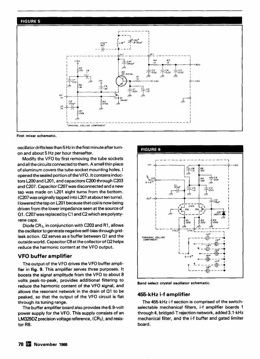
I h I L -------------------------------------- J 'ORIGINAL COLLINS COMPONENT
First mixer schematic.
oscillator drifts less than 5 Hz in the first minute after turn- on and about 5 Hz per hour thereafter.
Modify the VFO by first removing the tube sockets and all the circuitsconnected to them. A small thin piece of aluminum covers the tube-socket mounting holes. I opened thesealed portion of theVFO. It contains induc- tors L200 and L201, and capacitors C200 through C203 and C207. Capacitor C207 was disconnected and a new tap was made on L201 eight turns from the bottom. (C207 was originally tapped into L201 at about ten turns). I lowered the tap on L201 because that coil is now being driven from the lower impedance seen at the source of Q1. C207 was replaced by C1 and C2 which are polysty- rene caps.
Diode CR1, in conjunction with C203 and R1, allows the oscillator to generate negative self-bias through grid- leak action. Q2 serves as a buffer between Q1 and the outside world. Capacitor C8at the collector of 02 helps reduce the harmonic content at the VFO output.
VFO buffer amplifier The output of the VFO drives the VFO buffer ampli-
fier in fig. 9. This amplifier serves three purposes. It boosts the signal amplitude from the VFO to about 8 volts peak-to-peak, provides additional filtering to reduce the harmonic content of the VFO signal, and allows the resonant network in the drain of 01 to be peaked, so that the output of the VFO circuit is flat through its tuning range.
The buffer amplifier board also provides the 6.9-volt power supply for the VFO. This supply consists of an LM329DZ precision voltage reference, (CR1), and resis- tor R8.
coi J '+ +15V
1 I I
I I I I
*ORIGINAL COLLINS COMPONENT
I 1 Band select crystal oscillator schematic.
455-kHz i-f amplifier The 455-kHz i-f section is comprised of the switch-
selectable mechanical filters, i-f amplifier boards 1 through 4, bridged-T rejection network, added 3.1 -kHz mechanical filter, and the i-f buffer and gated limiter board.
78 November 1988

Now Your 2-Way Has a New Way to Communicate!
Actual S ~ i e 6" w x 2" h x 8" d
Introducing the first digital audio recorder for %way radio. With the new Palomar VC-300. you can now record, broadcast and receive any type of message-up to 34 seconds-with any type of 2-way radio ... amateur, marine, commercial or CB.
to truckers having breakfast. wrecker operators hooking up a car. fishermen landing the big one. amateur ham operators away from the shack or RV club members out on the road.
wide for innovative 2-way radio products.
One D-Ram (25610 Memory or 8.5 Seconds Recording Time. For only 59.50 each, we can supply you with up to 3 more D-Rams for a total of 34 seconds. Or purchase them at any electronics hobby store.
product line catalog and the name of your nearest area distributor. Or visit your local 2-way radio retailer. Suggested retail is $239.95.
@I -@! 4 r'EA4,;hm,+q Fax: 206.392-8413 Tel.: 206 -392-0399 . P.O. Box 1124
,--A- v - . -6.4, ./ /
Issaquah, WA 98027

HAM RADIO The Perfect MAGAZINE Holiday Gift!
Every issue is chock-full of the kind of articles Hams are looking for. Each month there'll be at least two Weekenders - the kind of projects you really want to build. Extra emphasis is also given to excellent short technical ~ ieces. In addition, HAM RADIO will continue to carry high quality technical articles.
HAM RADIO Magazine has monthly columns from some .:,hi, 4
of the best authors in the radio field: Bill Orr, WGSAI, on /-' \,. antennas and general radio subjects; Joe Reisert, W l JR, spotlighting VHFIUHF technology; Garth Stonehocker, KORYW's monthly propagation fore- casts; Joe Carr. K41PV. concentrating an repair and Tom McMullen, WlSL, operating procedures and theory.
You also get four, highly regarded, very special issues. January brings the Annual Construction issue - put together to exemplify Ham Radio's new emphasis on building. In May, there's our annual Antenna Special-antenna designs and ideas from some of the world's best
- . l ' , , , ! ! , ! ( k t , , 14<r>:-,,
. antenna experts. July means VHF and UHF a w y - - with the latest in state-of-the-art. And in November, you'll receive the annual Receiver issue, full of high performance designs and technology. They all come absolutely FREE as part of your subscription.
HAM RADIO Magazine also has new graphics, design and layout that enhance HR's readability and give it a pizzazz not found elsewhere in the Amateur Radio field.
There's no time like now to give a HAM RADIO Magazine subscription as a present for that hard-to-buy-for Ham friend. While you're at it - why not renew your own subscription and take advantage of the special low one year rate.
An attractive gift card will be sent if your order is received before December 16, 1988
~c Name - - C a l l _ _ Q *
Please enter my one year glftlrenewal w Address --
subscr~pt~on(s) to HAM RADIO Magazlne as follows: X * C 4 C~ty - - _ State ZIP - -
First gift renewal $19.95 SAVE $3 V) I NEW 1-1 RENEWAL
Two or more $1 5.95 SAVE $7 TI Start I1 Renew my Subscrlptlon to HR
c', Name Call -- I I Enclosed is a check or money order Ctft Charge: I J Mastercard I I VISA W, Address -- z> Card # -- Expires Y $ City State Zip --
My Name --- Address - -- ,. Name Call - - C~ty - State Zip -__- -
z- --- HAM CALL TOLL FREE 0 Address
$ S c ~ t y -- State ZIP RADIO 800-341-1 522 V)V)
M-F 8-9 EST Sat 9-5 I? NEW r~ RENEWAL MAGAZINE
GREENVILLE, NH 03048 DATATEL n $ 0,"
FOR EXTRA FAST SERVICE. CALL TOLL FREE ORDERS ONLY
TO ORDER YOUR GIFT SUBSCRIPTIONS OR BOOKS Prices U.S. only. Foreign prices upon request.

YOU COULD WIN ...
a hand-held radio. Here's how.
Please fill out the Magazine evalua- tion card and mail
it to us. We'll tabulate all the
responses to see what you do and
do not like.
There will be a drawing of evalua-
tion cards. The person whose card is picked will win a hand-held. Help us make the best
Amateur magazine even better. You could WIN a radio for your efforts!
Also, each month the author of the
most popular WEEKENDER will be given a hand-
held radio.
MAGAZINE EVALUATION & SWEEPS ENTRY CARD Here's YOUR chance to comment on this issue of HR and enter our monthly radio drawing. Carefully read all the articles in this issue. Then, rate each article in thls issue. Also let us know what you think of our changes to the magazine. Each article is marked with a letter on the last page.
Article A B C D E F G H I J K L M N O P Q R S T
MAGAZINE OVERALL GOOD- OK Nor sooooo- I like the Old ONew HR Better Class
NAME License Age
ADDRESS
CITY STATE-- ZIP
Please run more:
Please run less: NOV. 88
Subscribe to HAM RADIO today. Tap into Amateur Radio's # I technical and building
'journal. You'll also save $7.05 off the news- stand price ($30 per year)! Fill out this card and mail it in. For even more prompt service, call TOLL FREE (800) 341-1522, Mastercard, VISA and Bill Me orders accepted. Phone lines open Monday thru Friday 8 a.m. to 9 p.m. Please, orders only.
Bill me Payment enclosed
& Name Address
SPECIA L HOLIDA Y RATES City State First Gift or Renewal Check if this is a renewal NOV. 88
$19.95, Save $3.00 Please allow 4-6 weeks for dellvery of first issue. TWO O r more Gift Or Renewals FOREIGN RATES: Europe vla Air Forwarding Sewlce
$1 5.95, Save $7.00 $40 per year. All other countries $31.00 per year.
HAM For FREE literature or more Information, flrst locate the company number at the bottom of
RADIO the ad. Circle the appropriate number on thls card, affix postage and drop Into the mall. We'll hustle your request off to the com- Reader Service panies you are interested in!
101 113 125 137 149 161 173 185 197 209 221 233 245 251 269 281 293 305 317 329 341 102 114 126 138 150 162 174 186 198 210 222 234 246 258 270 282 294 306 318 330 342 103 115 127 139 151 163 175 187 199 211 223 235 247 259 271 283 295 307 319 331 343 104 116 128 140 152 164 176 186 200 212 224 236 248 260 272 284 296 308 320332 344 105 117 129 141 153 165 177 189 201 213 225 237 249 261 273 285 297 309 321 333 345 106 118 130 142 154 166 178 190 202 214 226 238 250 262 274 286 298 310 322 334 346 107 119 131 143 155 167 179 191 203 215 227 239 251 263 275 287 299 311 323 335 347 108 120 132 144 156 168 180 192 204 216 228 240 252 264 276 288 300 312 324 336 348 109 121 133 145 157 169 181 193 205 217 229 241 253 265 277 77 2891 313 325 337 349 110 122 134 146 158 170 182 194 206 218 230 242 254 266 278 290 302 314 326 338 350 111 123 135 147 159 171 183 195 207 219 231 243 255 267 279 B 1 303 315 327 339 112 124 136 148 1M) 172 184 196 M8 220 232 2 M 256 268 280 292 304 316 328 340
L i d 15inguiries psrquest .
NAME C A L l
ADDRESS
CITY STATE ZlP
PLEASE USE BEFORE JANUARY 31,1989 NOVEMBER 1988

MAIN STREET GREENVILLE, N.H. 03048
BUSINESS REPLY CARD Flrst C lass Perm11 N o . 1 Greenv l l le . NH 1 Postage Will B e P a ~ d By Addressee
HAM RADIO
READER SERVICE CENTER P.O. BOX 2558 WOBURN, MASS. 01888
ATTN: Reader Service Dept.
AFFIX POSTAGE
POST OFFICE WlLL NOT DELIVER
N E C E S S A R Y I F M A I L E D
I N THE
AFFIX POSTAGE
POST OFFICE WlLL NOT DELIVER
I

455hHz ' OUT
Second mixer schematic.
The output of the second mixer is fed to the switch- selectable mechanical filters through the front panel selectivity switch, S2. The output of the selected filter drivestheinput of i-f amplifier board 1, shown in fig. 10.
Dual-gate MOSFET 01 on i-f amplifier board 1 is the first amplifier in the i-f chain. AGC isapplied togate2of this FET. Dual-gate MOSFET Q2 is the first amplifier in the noise-limiter i-f chain. The noise limiter i-f and its sep- arate AGC bus will be described later.
The output of i-f amplifier 1 drives i-f amplifier 2 and the Q multiplier. This board is shown in fig. 11.01 pro-
vides additional i-f gain and AGC capability. It drives the Q multiplier rejection filter comprised of Q2 and exter- nal bridged-T network L26; capacitors C72, C73, and C74; and resistors R34, R35, and R36. The 0 multiplier is an exact equivalent of the circuit in the original vacuum-tube receiver. The only difference is that Q2 is used in place of the dual triode in the original.
The bridged-T network drives i-f amplifier 3. This board is shown in fig. 12. 01 provides additional gain and AGC capability. Capacitors C75and C139and resis- tor R37 terminate the bridged-T, and are identical to the
'ORIGINAL COLLINS COMPONENT
VFO schematic.
November 1988 83

I I
VFO buffer amplifier schematic.
components used in the original receiver. Q1 drives the added 3.1 -kHz mechanical filter. The mechanical filter output drives the last i-f stage, made up of the compo- nents on i-f amplifier board 4 (see fig. 13).
Q1, on i-f amplifier board 4, is connected in cascode with 02. The collector voltage for Q2 is derived from the 80-volt power supply. I-F transformerT3 provides coup- ling between 02's collector and the i-f buffer and gated noise limiter. I used the cascode connection, with its80- volt collector supply, for the last i-f stage. Thisallowsfor a large voltage swing.
AGC NOISE LIMITER
I I
- TO I - F AMPLIFIER
0 0 0 1
I L ---- ----------- J
AGC IN
I-F amplifier 1 schematic.
I-F buffer The last i-f stage output is derived from the secondary
of i-f transformer T3, which drives the i-f buffer and gated noise limiter. This board is shown in fig. 14.
Buffer amplifier U1 on this board provides a high-
-- -- p~
I-F amplifier 2 schematic,
84 November 1988

1 AGC *ORIGINAL COLLINS COMPONENT
I-F amplifier 3 schematic.
impedance termination for the secondary of T3. In addi- tion, it provides a low-impedance source of i-f output for the AM detector, product detector, AGC amplifier, and gated noise limiter. The product detector, AM detector, and the AGC amplifier receive their input signals through resistors R7, R6, and R5, respectively.
Gated noise limiter The noise limiter works as follows (see fig. 14 for
details): U2and U4are high-speed, solid-state switches. The internal switch contacts of U2a and U4 are normally closed, and the internal switch of U2b is normally open. Capacitor C1 charges to, and closely follows, the posi- tive peaks of the i-f signal output of U1 through CR1. Similarly, capacitor C2 charges to the negative peaks of the i-f output signal. The voltage developed across capa- citors C1 and C2 also appears at the outputs of unity-gain buffers U3, and U3b.
U5 is a retriggerable single shot driven by the noise limiter i-f and pulse-detection circuit (described later). When a noise pulse is detected, U5outputsa negative- going pulse which lastsfor theduration of the noise pulse plus 5 milliseconds. This pulse causes the internal switch contacts of U2, and U4 to open and the internal contacts of Uzb to close.
When the contacts of U2, and U4 open, capacitors
L 1 I-F amplifier 4 schematic.
i-f signal at the input of buffer U1 to the envelope volt- age that existed just prior to the noise impulse.
The advantages of this circuit over other automatic i-f noise limiter circuits are:
The voltage across C1 and C2 closely follows the envelope of the i-f output because R2, C1 and R3, C2 time constants are short.
Capacitors C1 and C2are buffered and their voltage doesn't change during the clamping interval.
The forward voltage drops across CR1-CR4 cancel. As a result, the noise pulse is clamped to the exact enve- lope of the i-f signal just before the noise event.
The actual interval of clamping is determined by a noise i-f amplifier having its own AGC separate from the receiver i-f section.
This circuit is extremely effective on the woodpecker, and on narrow ignition-type impulse noise. In fact, its effectiveness improves with increasing noise amplitude, because i-f AGC swamping is eliminated.
The method of generating the strobe pulses that feed U5 is very important in relation to the overall operation of the gated limiter. This will bediscussed in moredetail later when the noise limiter i-f circuit is described.
The 5volt power for U5 is developed across the 5-volt zener, CR5.
C1 and C2 hold thevoltageto which they were charged. Thisvoltage is the plus and minus i-f signal envelope prior AM detector and AGC amplifier to the noise pulse. When the internal contact of U2b AGC and AM detection are developed on the AM closes, diodes CR3 and CR4 are enabled and clamp the detector and AGC amplifier board (see fig. 15). AM
November 1988 86

- - -
I-F buffer and gated noise limiter schematic.
detection is accomplished by rectifying the i-f output voltage with CR1. The output is filtered by R2 and C2 and is buffered by op amp U1. Trimpot R3 provides an attenuation adjustment so that the AM output can be adjusted to the same amplitude as the SSB output from the product detector. The AM output from this board is routed tothefront panel SSBIAMswitch, S3 (fig. ID).
The AGC voltage is developed by rectifying the i-f out- put voltage with CR2. The AGC voltage developed across C7 and R8 is buffered by U2. U2, CR3, CR4, and resistor R9 comprise a "super diode" circuit that eliminates the forward-voltage drop of CR3.
Similarly U3,, in conjunction with CR5, CR6, and R12 eliminate the forward-voltage drop of CRg. This circuit also buffers the output of RF-gain control R99.
The anodes of CR3 and CR6 are connected together when AGC switch S5 is in its fast or slow position. The two diodes form a linear ''OR'' gate. The voltage devel-
oped at the anodes of CR3 and CRg is equal to the out- put voltage at the RF-gain control wiper, R99, or to the AGC voltage developed at R8, whichever is the most negative. Thisvoltagecontrolsthe RFand i-f gain by way of the AGC bus.
If front panel AGC switch S5 is placed in its off posi- tion, the connection between the anodes of CR3 and CR6 is opened. In this mode the receiver gain is con- trolled only by the setting of the RF-gain control.
CR6's anode drives op amp U3b. U3b is a level shifter that sets the quiescent "no signal" i-f gain through trim- pot R13. R13 is adjusted for an i-f output amplitude of 15 volts peak-to-peak at test point 1 on the i-f buffer and gated limiter board (see fig. 14).
U3,drives the AGC bus. CR7 through CRll clamp the output of U3, so that its voltage doesn't exceed approx- imately 3.5 volts, or drop below approximately -2.1 volts. The mute input at the anode of CR13 is normally
86 November 1988

K COMM., INC. THE HAM STORE
Stocking all major lines. San Antonio's Ham Store. Great Prices-Great Service. Factory authorized sales and service. Hours: M-F 10-6, SAT 9-3
KENWOD VAESU W r n i ~ ~ o ~ l "
5707A Mobud San Antonio, TX 78238
800-344-3 1 44 Orders Only H 147
[XI Ml# m

A M detector and AGC amplifier schemetfc.
Covers 100 MHz to 199.999 MHz in 1 kHz steps w ~ t h thumbwheel dial Accuracy +/- 1 part per 1 0 million at all frequencies Internal FM adjustable from 0 to 100 kHz at a 1 kHz rate External FM input accepts tones or voice Spurs and noise at least 6 0 dB below carrier Out- put adjustable from 5-500 mV at 5 0 Ohms
Operates on 12 Vdc @ % Amp Available for immediate delivery $429.95 delivered Add-on accessories available to extend freq range, add infinite resolu- tion. AM. and a precision 120 dB attenuator
Call or write for details Phone in your order for fast COD shi~ment.
1/ 145 VANGUARD LABS
196.23 Jamalca Avo.. Hollls. NY 11423 Phone: (718) 468-2720 Won. thm Thu.
88 November 1988
BLACK DACRON0 POLYESER ANTENNA ROPE
UV-PROTECTED HIGH ABRASION RESISTANCE REQUIRES NO EXPENSIVE POTTING HEADS EASY TO TIE & UNTIE KNOTS EASY TO CUT WITH OUR HOT KNIFE SIZES: 3/32" 3/16" 5/16" SATISFIED CUSTOMERS DECLARE EXCEL- LENCE THROUGHOUT U.S.A.
LET US INTRODUCE OUR DACRON" ROPE TO YOU SEND YOUR NAME AND ADDRESS AND WE'LL SEND YOU FREE SAMPLES OF EACH SIZE AND COMPLETE ORDERING INFORMATION.
Dealer Inquiries Invited I
Electronic Repair Center Servicing
Amateur Commercial Radio
The m o s t comple te repair facil i ty on t h e East Coast.
La rge par ts inventory and factory author ized warranty service for
Kenwood, l c o m and Yaesu.
SEND US YOUR PROBLEMS Sew~cng "Hams" for 30 years, no ng
too old or new for us.
i#sJK 4033 Brownsville Road
Trevose, Pa. 19047
21 5-357-1 400 m

BFO IN
Product detector schematic.
I
'ORIGINAL COLLINS COYPONENI
-- -
BFO oscillator and tank circuit assembly schematic.
kept at ground potential so that CR13 is reverse biased. When the front panel AGC power switch is in the standby position, the mute input is opened and CR13 conducts. The conduction current through CR13 drives the output of U3, and the AGC bus to - 2.1 volts; this effectively mutes the receiver.
The standby mode of the receiver may be overridden by shorting standby terminal 2 of the rear panel termi- nal strip E3 to ground (see fig. 1C).
The input attenuator has its own AGC voltage, which is developed at the output of U3d. R20 is adjusted so that the attenuator AGC voltage is approximately 5 volts when a 100-pV signal is injected at the receiver input. This voltagedecreases to about2 voltsfor 100 mV input to the receiver.
CR12 in the feedback circuit of U3d preventsthe input attenuator AGC voltage from going more negative than about - 0.6volt. C13and C14slow the output response
November 1988 89

I *ORIGINAL CaLLlNS COMPONENT
I 1 I I I I
Noise limiter i-f and noise pulse detector schematic.
of U3d to keep the AGC bus from motorboating when the input attenuator is active.
Buffer amplifier U1 (fig. 14) also functions as an i-f limiter. This limiting effect is important; it prevents unpleasant noise and leading-edge signal bursts.
In the general case, the amplitude of fast-rising i-f sig- nalsand noise is limited by a fast-responding AGC. How- ever, in this receiver design, I couldn't obtain a stable AGC loop and at the same time have an AGC attack time much faster than about 30 milliseconds. This occurs because of the delay introduced by the mechanical filters and experienced by the i-f signal as it responds to the effects of AGC.
The i-f limiting action of U1 limits the leading edge of fast-rising i-f signals and noise to an acceptable level dur- ing the time interval required for the AGC tooperate. The overall effect is to make the AGC appear to have an attack time on the order of a few milliseconds.
Product detector The product detector is shown in fig. 16. 1 used a
Motorola MC1496 balanced modulator. This IC requires
a lot of external components, but provides linear detec- tion and little455-kHzoutput component. The CW/ SSB signal is taken from terminal 6 of U1, through C8. This output signal goes to the front panel AM JSSB switch, S3, as shown in fig. 1 D.
The BFO output isattenuated by carrier-level trimpot R4. This pot isadjusted for a carrier level of 300 mV rms at U l , pin 8.
BFO The BFO is comprised of the original BFO tuned-
circuit assembly and the BFO board shown in fig. 1B. The BFO board is shown schematically in fig. 17. It's nearly identical to that used in the VFO described earlier.
The BFO has its own regulator comprised of voltage reference CR2 and resistor R4. The 15-volt power is routed to the BFO through front panel AMISSB switch, S3.
The stability of the BFO circuit is only slightly lessthan that of the VFO. At constant temperature, itsdrift is less than 10 Hz in the first minute after turn-on, and about 10 Hz per hour thereafter.
90 November 1988

ASTRON 9Autry Irv~ne, CA 9271 8
CORPORATION [714]458-7277
'~~-lnt.rrnittent tnrnrnun~mt~nn Serv~ce 150% Dub Cvcle 5min. on 5 min. OM
INSIDE VIEW - RS-12A
MODEL RS-5OA
RM SERIES
a
MODEL RM-35M
ASTRON POWER SUPPLIES HEAVY DUTY HIGH OUALITY RUGGED RELIABLE
SPECIAL FEATURES PERFORMANCE SPECIFICATIONS SOLID STATE ELECTRWICALLY REGULATED INPUT VOLTAGE: 105-125 VAC . MLO-BACK CURRENT LIMITING Proteas Power Supply OUTPUT VOLTAGE: 13.8 VDC t 0.05 volls hom excessive current 8 continuous shorted output (Inlernally Adjustable: 11-15 VDC) CROWBAR OVER VOLTAGE PROTECTION on all Models 9 RIPPLE Less lhan 5mv peak lo peak (full load 8 excepl RS.3A. RS-44. RS.5I. low line) MAINTAIN REGULATION 8 LOW RIPPLE a1 low line input AltD ereilebl8 Wllh 220 VAC i n p l V O l l l l l Voltage HEAVY DUTY HEAT SINK CHASSIS MOUNT FUSE THREE CONDUCTOR POWER CORD ONE YEAR WARRANTY. MADE IN U.S.A.
MODtL RS-5OM
19" X 5'1. RACK MOUNT POWER SUPPLIES
Centinmoms ICS' Slze l l W l shipping MODEL OIIV (Amps) l r m r r l H X W X D WI. (1bs.1 RM-12A 9 12 5'u x 19 X 8% 16 RM-35A 25 35 5'4 X 19 X 12\j 38 RM-5OA 37 50 5':' X 19 X 12'% 50
Separate Volt and Am" Meters RM-12M 9 12 5h r 19 x 8'h 16 RM-35M 25 35 5% x 19 x 12% 38 RM-5OM 37 50 5 b x 19 x 12% 50
Continmom: ICS' Size (IN) Shippin(
3',? x 6'.a x 7C 3='1 x 6 % x 9 4 x 7% x 10% 4 X 7'4 X 10%
4 H X 8 X 9 4 x 7'il X lo'!'
Separate voll and Amp meters
4 X 7'1 X 1034

UNADILLA
Amateur Antenna Baluns For 20 years, preferred by Amateur, Commercial and Military Operators. First with built-in lightning arrester-minimizes TVI, maximizes power.
I "America's Weekly Guide to Satellite N" I satellite uring: * The best in
ming! Feat1 program- Over 120
Channels listed + Weekly, Updated Listings * Magazine Format + Complete Alpha- betical Movie Listings + Sports Specials * Prime Time Grids + Specials +Programming Updates!
- .
$17.95 $19.95 $19.95
W2AU Bromllmnd Ferrlte Core Balun6 For medium power (1000 wans RF mln )and broadband operation 3-40 MHz
W ~ D U on-~erdte Very Hlgh Pwer Balun8 WPDU-HF (High Power) ' 1.8-30 MHz '3000-9000 wans with I :l antenna SWR '1500-5000 wans with 2:l antenna SWR
WDU-VHF (Hiah Power
Only $45.00 per year (52 weekly issues) 2 Years $79.00 (104 weekly issues) $1 .OO for sample copy
'NC Residents must add 59'0 Sales Tax I and ~xtended Range) '30-300 MHz '2MM4000 wans with 1 :1 antenna SWR '1200-2400 watts with 2:l antenna SWR
W9All 1.1 )scribe Today! call roll free 1-800-234-0021
3nd MasterCardu' accepted
'0 Box 2347 Shelby, NC 28151-2347
. . -. . - . . . '50 to 50 or 75 to 75 ohms 'For dipoles. V's, beams, quads Purchase from any of ove
W2AU 4:l 300 dealers nationwide
'200 to 50 or 300 to 75 ohms or order direct 'For high impedance antennas such as folded dipoles
fl 141
To request Informational brochure, call
61 7-475-7831 write
ANTENNA'S ETC. PO Box 215 BV, Andover, MA 01810-0814
Switch All Your Antennas Over One Coaxial Feedline I Guide con-
tams valuable ~nformation on regulations, scram-
ew STV . . . . $20.15 Antenna 1 Antenna 2
106 12 VDC Y
zoning bling, I . . 0,.
plus technical tips for lnsralllng or updating a satel- lite system-and now a pre- cise monthly guide to satel- lite N with the latest pro-
listings for over 90 els!
Energizer (Optional)
C105B 2 Position
. . . - $52.00
00
Radro ,.-.. >. .~
gram chann~
A I nll this in each complete issue of STV Guide! I Only $48.00 per year (1 2 monthly issues) $2.00 for a sample copy
'NC Res~dents must add 5'0 sales tax I (injects DC (tnsroe your
onto coax) shack)
This system operates from 1.5 to 180 MHz and handles 1250 RF wafts. Use our antenna switching kit and eliminate excess coax runs.
With this kit and a single run of coax, you can switch between your antennas remotely. Use to add an antenna at modest cost. or change array direction.
Other types and comblnatlons of relays are available. Please call or write us for more Information, and save on your coax runs1
30 day MONEY BACK GUARANTEE on all products UnadillalReycollnllne Is now a Division of ANTENNA'S ETC.
I Subscribe Today! 1 234-002' " accepte
92 November 19BB V 142

Noise limiter i-f and noise pulse detector
As stated earlier, the gated noise limiter has its own separate i-f amplifier. This amplifier with the noise pulse detection circuit is enclosed in a small chassis located on the top deck of the receiver. The position of this chas- sis isshown in Photos A, Band C. Photo Cshowsthe i-f chassis opened with the i-f circuitry exposed.
The noise limiter i-f and the pulsedetection circuit are shown in fig. 18. Theinterconnection of thiscircuitwith
the front panel noise limiter switch, S4; control pot R67: i-f buffer and gated-noise limiter board; and the i-f amplifier are shown in the circuit diagram of fig. 1C.
Q1 and Q2and their associated circuits comprise the i-f amplifier. Q3 isa unity-gain buffer between the out- put of the lasti-f stageand the AGC and pulse-detection circuit. CRI and CR2 make up the AGC rectifier. AGC voltage is developed across C13 and applied to the sec- ond gate of 01 and Q2. AGC voltage is also applied to the first stageof thenoise limiter i-f, which is located on i-f amplifier board 1 (see fig. 10).
Noise pulse detection is accomplished by U1 and reference-voltage buffer U2. Thiscircuitryfunctions as follows:
Top inside view showing exposed noise limiter, i-f circuit, and added 3.1-kHz mechanical filter.
Partial bonom view showing location of switch S-1-G, input anenuator board. crystal-calibrator board, and oscillator board.
November 1988 93

Audio amplifier schematic.
A variable threshold voltage is developed across front-panel noise limiter control R67 and is applied to the noninverting input of unity-gain buffer U2.
Threshold voltage at the output of U2 is applied to thenoninverting input of U1 through R21. R20and R21 provide hysteresis, so that the comparator switches cleanly.
The output of U1 goes to zero for the duration of any half cycle of the i-f signal that exceeds the threshold volt- age developed at the output of U2.
The output signal from U1 is routed to U5 in the i-f buffer and gated noise limiter, (fig. 14). Because thissin- gle shot is retriggerable, it doesn't complete its time out until 5 milliseconds after the last pulse enters.
S-meter driver board
of the S meter. I didn't want to change the appearance of the receiver by making a new face. My only choice was to make some type of nonlinear circuit that would match the meter face to the solid-state receiver's AGC bus voltage. This is the circuit on the S-meter driver board in fig. 19.
U1, of this circuit is driven from the AGC bus, as shown in fig. 1C. Trimpot R1 on the S-meter driver board adjusts the zero offset of the S meter. R1 is adjusted so that the S meter readszero for0.5 microvolts of RF input to the receiver. The resistor-diode network made up of CR1 through CR7 and resistors R5, R6, and R7 comprise what is equivalent to a nonlinear resistor having high resistance at low negative voltages, and the converse.
This circuit provides excellent S-meter calibration The voltage developed by the AGC bus of the solid- throughout its range. An S9 meter reading in the origi-
state receiver isn't compatible with thescale on the face nal receiver corresponded to a 100-mV signal. I prefer
94 ldlJ November 1988

Subscribe Today
Call Toll Free (orders only)
1 (800) 341-1522 Have your credit card
ready Ham Radio Magazine
HamcaN sewice gives you ell hams via your computer 8 modem. Updated each month! Only $29.95 per year. Unlimited use - you pay for phone call.
BUCKMASTER PUBLISHING Route 3, BOX 56
Mineral. Vlrglnla 231 17 7031894-5777 vlsdmc 800/!282-5628
\ J
November 1988 [rm 95

256 pV for an S9 reading and calibrated the meter accordingly.
Audio amplifier The output of the product and AM detectors is routed
through the front panel switch and from there through front panel af gain control R62 (see fig. ID) . The af gain-control output is routed to the audio-amplifier cir- cuits shown in fig. 20.
The first audio stage, Ul,, is a unity-gain buffer whose output drivesa unity-gain, two-pole active low- pass filter. This filter consists of Ulb and its associated components. U l drives an SK3435 amplifier module. Feedback resistors R5 and R8 give the amplifier a gain of 10. The module is powered from the unregulated25- volt supply and has a power capability in excess of 5 watts. The3-db bandwidth of theaudio amplifier is300 to 3000 Hz. The output of the audio stages feeds the speaker terminals and headphone jack as shown in fig. ID .
Power supply The power supply is shown in fig. 21. T I and T2 are
Radio Shack filament transformers having a 12.6-volt center-tapped secondary rated at 3A. Transformer T3 has a 36-volt secondary rated at 60 mA. The 80-volt unregulated output isobtained by connecting all of the secondaries in series. The input to the rectifiers for the f 15 volt three-terminal regulators comes from the ten-
ter tap of T2. Simple half-wave rectifier circuitsare used for all the supplies. The 6-volt AC power for the panel lamps is taken from the center tap of transformer TI.
VFO alignment I did a lot of experimenting with the permeability tuned
section of the VFO whiledesigning thisoscillator. By the time I had decided on the design described above, VFO linearity wasn't what it was supposed to be.
I recalibrated the oscillator by measuring the VFO out- put frequency with a frequency counter, then plotted the output frequency asa function of dial setting. This plot gave a clear indication of those areas on the dial where the VFO's frequency needed to be increased or decreased.
I first adjusted the trimming stud of L200 to get the end points of the VFO dial lined up. I then opened the her- metic enclosure and adjusted the PTO tracking washers to restore the linearity between the end points. I had to repeat this process a number of times before the VFO linearity and alignment were restored.
The next time I make this modification, I won't change the location of the tap on L201 of the VFO. I suspect that the drift characteristics will be almost as good, and I'm surea lot less effortwill be necessary in the realignment of the VFO after the modifications are made.
General alignment The balance of the alignment, with a fewdifferences,
can be done in the same order and way as that described in the 75A-4 operator's manual. The more important differences are listed as follows:
When measuring i-f output amplitude, I madeall my measurements with an oscilloscope connected through a probe to TP1 of the i-f buffer and gated limiter board, fig. 14.
I adjusted the output of the band-select crystal oscil- lator to 5 volts peak-to-peak on all bands. This adjust- ment was made with the oscilloscopeand probe through the 1 -pF isolating test point on the band-select crystal oscillator board of fig. 6. The method of computing the crystal oscillator output amplitude was described in the band-select crystal oscillator section above.
Performance measurements Comparative measurements of sensitivity, two-tone
intermodulation distortion (IMD), and blocking were made using the methods and test setup described in Chapter 25 of the 1987 ARRL Handbook.
I used a Hewlett-Packard HP606A RF generator and a Boonton Radio Corporation 240A RF generator as the signal sources for these tests. Both of these generators have excellent precision attenuators. A Wavetek 5080.1 precision step attenuator, a Mini Circuits ZSC-2-1 hybrid combiner, and a Ballantine 323 true rms-reading volt- meter made up the balance of the test setup. A Tektro- nix2235 100-MHz oscilloscope was used to verify all ini- tial signal amplitudes before adding attenuation.
The combined drift of the BFO and VFO was meas- ured by placing the receiver in the SSB mode and tun- ing in an external crystal calibrator. The audio-frequency output tone was measured for8 hours, beginning from a cold start. The drift amounted to 13 Hz in the first min- ute, followed by a slow drift of about 26 Hz per hour. The slow drift stabilized after about 3 hours, giving a total drift of 91 Hz in that 3-hour period. Once stabilized, receiver drift was approximately f 10 Hz per hour.
The major source of drift appears to be heat generated by the transformers located on the chassis near the BFO. This heat warms the chassis in the location of the BFO tuned-network assembly. A purist would probably mount these transformers on a heat sink above the chas- sis to improve the receiver's long-term drift. I haven't felt a need to do this because the driftthat does occur seems innocuous.
Conclusion As you might guess, this was a long-term project. I
don't recommend that you take on this conversion unless you have another receiver to use in the meantime. A good oscilloscope and signal generator are essential.
96 November 1988

On the other hand, if you have theexperience and equip- ment, you will find thisa satisfying project - particularly if you have a 75A-4 that isn't being used because of cir- cuit problems or lack of good tubes.
References 1. James R. Fisk. WIOTY, "Receiver Noise Figure. Sensitivityand Dynamic Range- What the Numbers Mean," ham radio, October 1975. page 8. 2. Ulrich L. Rohde, DJZLR, "OptimumDmign For High-Frequency Communi- cations Receivers," ham radio, October 1976, page 10.
Bibliography 1. S i n a y Ksirsr, WB7ClW. "Measuring Rscsinn Dynamic Ranga."hamradb, Novan-
ba 1979. psps58. 2. JsnK. M d k . KWM. "Undsmandii PafamacsDamof High.FmqwncyRsceivaP."
hammd,i,. N0Mmba 1981. -a. 3. TheMbhnur'sHandbmh. American Radii Ralw Leagua. Nswigmn. Connsctim.
Article F H A M RADIO
0 0 PC board layout f o r groundplane a n d trace sides, con t inued
from page 60.
AND, THE WINNER IS ... Congratulations to Norman Roller. WBEOD, the winner of September's
sweeps drawing and to Richard Measures. AGGK, author of September's most popular WEEKENDER - "An Easy-to-Build NiCd Pulse Charger. Bolh will receive a handheld radio. Want a chance to win? Just send us the evalu- ation card bound into this isue to enter for November's drawing, or submit a WEEKENDER project. Who knows; the next winner could be you1
Many thanks to all of you who've been supponing us during this time of change. Your insightful letters, comments on the evalution cards. and man- uscript submissions will all play a pan in creating the best HAM RADIO ever. Keep'em coming1
1 -SMILE! YOU'RE ON TV I Only $299
Designed and built in the USA Value + Quality from over 25years in ATV ... W6ORG
With our all in one box TC70-1 70cm A N Trans- ceiver you can easily transmit and receive live action color and sound video just like broadcast TV. Use any home N camera or VCR by plugging the com- posite video and audio into the front VHS 10 pin or rearphono jacks. Add70cm antenna,coax, 13.8 Vdc and N s e t and you are on the air ... it's that easy!
TC70-1 has >1 watt p.e.p. with one xtal on 439.25, 434.0 or426.25 MHz. runs on 12-1 4 Vdc @ .5A. and hot GaAsfet downconverter tunes whole 420-450 MHz band down to ch3. Shielded cabinet only 7~7~2.5". Transmitters sold 1 only to licensed amateurs,for legal purposes. verified in the
1 latest Callbook or with copy of license sent with order.
Call or write now for our complete A N catalog including downconverters, transceivers, linear amps, and antennas for the 70,33, & 23cm bands. (81 8) 447-4565 rn-f 8am-5:30prn pat. Visa, MC, COD
P.C. ELECTRONICS Tom (W60RG) 2522 Paxson Ln Arcadia C A 91006 M~~~~~~ (WB6YSS)
r / 137
LET THE SUN DO THE WORK Charge batterlee on
stored machinery Llght your tent Run fans Run remote trnnn- mitters ~ i g h t signs Pump water for your
I \ \ , animals Power for your motor home Run your radio w i thwt batteriw Light your home Yard llghts Charge flashlight bat- teries
I Llaht vour cabln - , Run electric kncem
E1ectricit~ Charge your boat from the battev
Run appllancea i n your - Sun with home Charge hand held
- . . -. = - , - -. - -. . . Solar Systems corder bettery pack
I ALSO: OUTSTANDING PRICES ON IBM XT COMPATIBLE SYSTEMS1 I
HAL-TRONIX, INC. (313) 201-7773 Hwn
12671 Dla.Tol.do Hwy 1 2 : ~ . u-, P.O. Boa 1101
I/ 138 "HAL" HAROLD C. NOWLAND Swthar ta . MI 40195 wazxn I

THE HAM NOTEBOOK
TS-440 interface for keying linears with high voltage biasing I recently had a problem posed to me involving keying the relay of a Heathkit low-band linear from a Ken- wood TS-440. The relay power in the linear is obtained from the - 120 volt bias supply, and the transmit keying
01 ECG 3 2 160V TO 9 2 3 P 100Y TO 126 output from the Kenwood is + 12 volts 2 4 0 300" TO 2 0 2 N 2 8 8 3OOV TO 9 2 2 9 6 3OOV TO 2 0 2
at 10 mA, maximum. The circuit below 3 7 4 i 8 0 V TO 126 3 9 7 35OV TO 3 9 3 9 8 200" TO 2 2 0
solved the problem. The key ingredient O2 2 N 4 4 0 3 OR L O U , V A L E N T is the PNP driver transistor, which
must be capable of handling at least
IN914 OR 150 volts at about 250 mA. I've indi-
IN4148
KENWOOD cated several ECG types that meet the
TS 4 4 0 circuit requirements.
I'm sure others are running into the same or similar problem; I hope this
Schematic of the circuit used to interface from the + l2Vdc keying output of the TS440S circuit S O ~ V ~ S it! to the - 120 volt bias supply of the Heathkit amplifier. Hugh Wells, W6WTU
Two simple 80-meter radiators for short and long skip Getting the optimum performance from his equipment and antenna sys- tem is every ham's greatest desire - at least it should be! With this in mind, I want to share two simple but efficient radiators I've used during my 27 years in Amateur Radio.
The first is a high-angle radiator, the second a low-angle radiator. The first is for contests, local round tables, and other local communications. It produces a strong signal because it's really a two-element antenna. This is because the earth appears as a reflec- tor to the antenna when the antenna is mounted at the proper height. On-
the-air comparative reports were made between the "lazy loop" mounted at approximately 25 feet and an 80-meter dipole mounted higher. Both receive and transmit reports consistently favored the loop.
The lazy loop construction is very basic (see fig. 1). The total length of the loop is approximately one wave- length. Because the loop is actually square, each side is 66' 5"for a total wire length of 265' 8". The optimum height above ground should be in the neighborhood of 0.15 wavelength or 41'. Because of the effect of the ground on the antenna, the feed impedance is between 50 and 60 ohms. You should have no problems feeding the antenna directly with 50- ohm coax; however, you can use a balun if you wish. The loop can be
constructed from copper wire of 16 AWG and up.
The second antenna, known as the "delta loop, " provides exceptional low-angle radiation, which is useful for working DX. Construction again is very straightforward; you use a suita- ble gauge of copper wire cut to approximately 270' in length. Provided the antenna is laid out as shown in fig. 2, the feed impedance will be close to 50 ohms, allowing a direct feed with 50-ohm coax. Some of the pluses of this antenna are:
Will fit anywhere a full-size 80 meter dipole will. Can be physically lower than an 80 meter dipole, and still perform as well or better. Can be fed directly with 50-ohm coax.
98 November 1988


PRACTICALLY SPEAKING
Joe Carr. K4IPV
An overview of opera- tional amplifiers: part 1 This month's topic is a discussion of the basics of operational amplifiers and other linear IC devices. Because the role of these devices is so great in radio communications equipment and cir- cuits, it's important to understand them. Op-amps can be used for audio applications, in electronic measure- ment instruments, and in control cir- cuits.
Operational amplifiers Figure 1A shows the usual circuit
symbol of the op amp. An alternate symbol is shown in fig. 1B. (Burr- Brown and some ARRL literature use the alternate symbol.) This symbol is technically the "correct" one to use. It uses a curved back to which the input leads are attached. However, the version shown in fig. 1A is used almost universally, even though it is the generic amplifier symbol, and could denote any amplifier stage - including the operational amplifier. Because it's the industry standard, I'll use the symbol in fig. 1A here.
Note the pin-outs for the amplifiers in fig. 1. The pin numbers given are for the 741 device, but have become something of an industry standard. There are two input connections, two power supply connections, and one output connection. There is no "ground" or common connection. The
Standard op-amp symbol. The pin outs are "industry standard" 741-family and fit a large number of different devices.
B
OUTPUT
+IN- -IN+- V -
'Official" symbol used in some catalogs and ARRL publications.
signal common is taken from the power supply common line. More on this in a moment.
The two power supply connections are V + and V - . The V + supply is positive with respect to common; the V - is negative. The range for these voltages is typically f 4 volts to f 18 volts, although a number of examples exist with wider (or slightly different)
voltage ranges. A GE RCA CA-3140 BiMOS device, for example, operates at potentials up to f 22 volts for V- and V + , while certain "low-power" or "micropower" op amps operate down to ? 1.5 volts DC.
In addition to the absolute voltage limits, there are sometimes relative limitations. For example, older 741 devices have a 30-volt limit for the volt- age defined by the expression [(V + ) - (V - 11, even though each V - and V + can be as high as 18 volts. As a result, if V + is + 18 volts, then V - must be not greater than - 12 volts in order that the differential not be greater than 30 volts [( + 181 - ( - 12) = + 30 voltsl.
The selection of power supply vol- tages might also depend on the maxi- mum anticipated output voltage. If the amplifier is being designed for use with an analog-to-digital converter that has an input voltage range of - 10 to + 10 volts input, then I certainly want the output of the amplifier to be capable of achieving those values. But there is a limit on how high the output voltage can reach; that limit is a function of the power supply voltage. In general, the limitation is based on the number of PN junctions between the output ter- minal on the IC and each power sup- ply terminal. Each PN junction has a 0.7-volt drop which must be accounted for. If there are four PN junctions between the output terminal and the V + power supply terminal, for
100 5 November 1988

example, then the maximum allowable output voltage will be [(V + - (4 x
engineering practice. Because there are low-cost three-terminal fixed-
0.711 volts, or2.8 volts lower than V + . When I want the output terminal to swing to + 10 volts, She absolute mini- mum V + power supply voltage will be 10 + 2.8 volts, or + 12.8 volts DC. Obviously, a + 12 volt DC power sup- ply won't work in this case. In general, ordinary bipolar transistor op amps (like the 741 require a supply voltage 2 to 4.5 volts higher than the maximum required output voltage, but must also remain within the V + and V - con- straints of the device. Some BiMOS and BiFET devices are available in which the maximum output signal voltage can be as low as 0.5 volts below the power supply potential.
Operational amplifier inputs and outputs
The two inputs for the operational amplifier form a "differential pair" because they are 180 degrees out of phase with each other. The inverting input ( - ) produces a 180-degree phase shift between the input signal and output signal (in other words, a positive-going input signal produces a negative-going output signal, and vice versa). The noninverting input ( + produces a zero-degree phase shift in the output signal. Since one input produces an in-phase output and the other produces an out-of-phase out- put, simultaneous application of the same voltage to both inputs produces a zero net output potential. I'll use this information in a later section to form the differential amplifier. The two inputs on the op amp offer a very high impedance, which is infinite in the ideal model. On paper, they are a perfect- voltage amplifier input.
The output of the operational ampli- fier is also suited to a perfect-voltage amplifier circuit. The output impedance of the typical op amp is usually quite low (10-100 ohms), so it forms a nearly perfect voltage source.
Operational amplifier DC power supplies
Figure 2 shows a model of the typi- cal operational amplifier power supply.
DC power supplies for the op amp.
Either batteries or electronic power supplies operated from the AC power lines can be used. Recall that you have two different voltages in the op amp power supply: V + and V - . Voltage V + is supplied by B1; V - is supplied by 82. The common (or ground) con- nection is the junction between the two batteries. Normally, B1 and B2 will have the same voltage rating, but that is not a strict requirement unless other circuit considerations apply.
The capacitors shown in fig. 2 are used for decoupling, especially when multiple stages are fed from the same power supply. Capacitors C1 and C2 are normally 1-100 pF electrolytics, and are used for decoupling low-frequency signals. Capacitors C3 and C4 are used for decoupling higher frequency sig- nals. You can't normally use the higher value C1 IC2 for high-frequency signals because these are ordinarily electro- lytic capacitors, which are ineffective at high frequencies. Fortunately, some new capacitors will operate to the fre- quencies covered by the gain- bandwidth product of most op amps.
The power supply common or "ground" connection is used as the zero-reference point for input and out- put signals on the operational ampli- fier. Whether the common is actually grounded or not depends upon circuit design considerations. In most cases it is grounded for the sake of simplicity.
In most applications, electronic power supplies used for B1 and B2 must be voltage regulated. Although there are certainly numerous applica- tions where voltage-regulated DC power supplies are not strictly required, they are almost always good
voltage regulators now on the market, it's easy to obtain regulated power supplies.
The ideal operational amplifier
Before getting further into opera- tional amplifier circuits, let's set the stage for a simplistic circuit analysis by discussing the properties of the "ideal" op amp. This ideal device has the fol- lowing:
lnfinite open-loop gain Zero-output impedance lnfinite input impedance Zero-noise contribution lnfinite bandwidth Differential inputs which "stick
together." Let's define these properties and com- pare them with those found in practi- cal IC operational amplifiers.
lnfinite open-loop gain. This means that the voltage gain of the ideal oper- ational amplifier in the open-loop (i.e., no feedback) configuration is infinite. Real op amps don't even approach the ideal, but are still good enough approx- imations to make the device function properly. The ability of practical op amps to approach the ideal depends on having extremely high open-loop gain, othewise the equations behave badly. In practical devices, you'll find that the open-loop voltage gain (AvoI) will be 20,000 in low-cost devices, and well over 1,000,000 in premium ones.
Zero-output impedance. The oper- ational amplifier is supposed to be a perfect-voltage amplifier, so it should offer an output impedance of zero. Real devices have output impedances of 10-100 ohms, with most being around 50.
lnfinite input impedance. This par- ameter means that the input will nei- ther sink nor source electrical current. Recall that input impedance is Z = Vin/lin, so for input impedance to be infinite, li, must be zero. In real oper- ational amplifiers, the input current is non-zero. This is one of the primary differences between premium and low- cost devices. Low-cost amplifiers use
November 1988 101

' 1500 + WATT TRANSMATCI
I . BASIC KIT: INDIVIDUAL ITEh
KIT $169.95 OTHER KITS ............. A?ticle Reprints (refundable). .S1.50
GJRUH. PSK Packet Modem. Satl.KerrestrialS99.00 PC Board for above only, delivered.. ...... .S27.99 Ten-Tec Designer Cabinet for above. ...... .S12.00
. . . . . . . . . KSCW Memory Contest Keyer.. .SlG9.00 . Yaesu FRG-9600, .1 to 80 MHz Converter.. .$94.95
. . . . . 20m CW. lqw Transceiver (H.R. 6/87). .$159.95 ................. SOW 75M SSB XCVR.. .$199.95
S FcctoryWlmd ................ 1 .rotary Inductor 2 B r h . . . . . . . . . $59 00 Nr . 1 ech DVK. 100A (New Model). $269.00
2.6:1 ball drives. . . . . . . . . . . . . . .$9 00 ea. B a w PT-2500~ Amp . . . . . . . . . . . . . . . . . . $1.670.00 1 . 0.100 ttlrns counter. . . . . . . . . . . .a65 75 B g w ~ ~ 1 5 0 0 ~ Tuner ........................ $388 00
........................... 2. variable capacitors Amp SupplylAmeritron Llnears CALL 25-245 DI 4500 v. . . . . . . . . . . ,544 00 ea. Shlpplnp Extra Unkaa Noled
OPTIONS- cataiog s l .OO I enclosure (picturn in ~ p t 86 m ) . s r . m RAolorlr P.0. Box 973-H ( 4:1 balm k11 . . . . . . . . . . . . . . . ,522 50 Pelham. NH 03076 (603) 635-2235- dials. tcrmlnals, chassis, cwamk rtlnlolfs, hardwarn. toro~dr. amp componanlr. B I W C0ll Stock. mtc.
bipolar transistor input stages and have input bias and leakage currents of up to 1 or 2 nl,~liarnps to contend with. Certain others have the input currents in the nano- to picoamr -ange. The RCA BiMOS op amps (1 IRCA CA- 3140, etc.) use MOSFET input transis- tors to produce an input impedance of loi2 ohms. For most practical purposes that impedance is "infinite."
Zero-noise contributio The noise referred to here is internal device- generated noise added to the signal. This is another difference between low-cost and premium devices. The low-cost amplifiers add considerable "hiss" noise, making them unusable on low-signal applications.
Infinite bandwidth. This parameter means that there is no limit to the oper- ating f r e q ~ :ncy of the device, which is patently absurd in the case of real operational amplifiers. Unconditionally stable, frequency-compensated devices like the 741 may have an upper frequency limit of only a few kilohertz, while other op amps operate to several megahertz. Only a few aavices are available for tile high HF or low VHF frequency ranges. They are usually labeled "video operational amplifiers," or something similar. Some devices with gain-bandwidth products that imply HF operation don't operate as op arrps per se, but will work to somc degree even though they don't oper- ate in accordance with standard op amp rules and equations.
Differential inputs which ''stick together. "This property is essev 'al to the simplified circuit analysis used. It's also used in some circuit appiications, like "bridge audio." The property implies ,at a voltage applied to one input will also appear on the other. You must treat both inputs mathemat- ically the same in this regard. If you apply a voltage to the noninverting input, then you must treat the Invert- ing input as if it also sees that voltage. This statement is not merely some t h e oretical device used to make equations work. If you apply a real voltage to a real noninverting input, and then con- nect a real voltmeter to the inv- 'ng
J 134
102 November 1988
input, you will measure the sam: It-


Wideband Preamp 10.1 000 Mhz
D u a l G a s F e t l o w n o i s e preamplifier for HF, UHF or VHF systems. Just perfect for the R- 7000. Exce l l en t f o r Spec Analyzers. Scanners, etc. Gain 20 Db +/- 1 DB. -3 Db at 2 8 1100 Mhz. 1 Db compression of -10 Dbm. Intercept points A 5 Dbm. New shipped price of only $124.95. Pa. residents please add 6% state tax.
GTI Electronics RD 1 BOX 272
Lehighton, Pa. 18235
# b Mobiler's Dream!
c. , ~ n ?,w U\L. ,, 1 % dl< \ l r o n ~ c r \1cn:8I"
Would 50"; marc h i ~ n d u d t h h r hrlpful" Our Sl:.4ll rn<~hiIc ;tn~cnr~a i\ ll~r anwer. I I;~~CIIC, OCH) W>$II, ~CII another i, dl<. SI.. .JIl. ,411 - Ill rnrtrr*: SI -75. 75 - IF mrtcr\.
County Hunters Software I ) r \ ~an rd h r .n top rout>!\ hunlcr ltar ct,unli h t l n t ~ n Wurhs on ;#I1 I I IM 1)1lc n,mpulcr\
R-4C Enhancements \\ r i l r fur ritlulop
From the performance company :
Sherwood Engin~ering Inc. l:f,h \<,,,Ill I )~<Ic,I SI,CCI, l ) ~ " , ~ r , c . 0 ~ll.!lll (:II:I 722-2257 MOncl;,, . I.~ILI,I? A h! - i I, h!
Sales. Sewice. Installations available from:
Ihssign Elcclrunicn Ohio. Kh'l(%. I)ajr Shelkr (18l.t) Xjh-571 1 I);~yr. (1tl.t) S36~3371~ I:\.eninp\
LTA Industrirs. K31.11. 'I'irn 1)llffv (412) C2h.9701 or (110) 33.791h a
lcontinusd from p8ge 91
an article. The material in it was a rehash (for the most part) of an appli- cation written in QST(April1984) and featured in the ARRL 1987 Handbook by a TRW engineer Fred Williams (credit was given in the bibliography). The article did go into more detail con- cerning phase noise and other prob- lems associated with PLLs and how the DDS system overcame these prob- lems. But, at least the Williams article published schematics and a parts list so "roll your own'ers" like me could play with it.
So please keep your standards high for the experimenter that your maga- zine addresses. Any articles that are a construction or any general theory content should have schematics and not a paragraph at the end saying, "send money." I do support an author offering to supply boards, "hard to find parts" or a complete kit for a fee, but at least require the article to supply enough information for a person to go from the article itself.
Please keep up the good work and I look forward to more informative issues.
Jeff Pierce Jr., WD4NMQ. Kingsport, Tennessee 37663
Rave review! Dear HR:
I will try to be succinct, but I gotta tell you.
My book shelves were getting over- loaded with ham magazines so I decided to catalog those articles which were of interest to me and throw the rest away. I subscribe to two other popular ham magazines besides HAM RADIO.
After throwing away eighty percent of the other two as having no continu- ing interest, I then looked at the HAM RADIO file. I hadn't realized it before, but after going through all of them, I found an article of continuing interest in each one of them. Although HAM RADIO did not contribute to my house cleaning efforts I did end up with more room to hold future issues.
As I was writing this letter the Sep- tember issue of HAM RADIO arrived.
All I can say is - WOW - you have outdone yourself.
As a ham who built his first radio over 60 years ago from Popular Mechanics magazine, first transmitter from Radio News, and has been licensed for fifty-five years, I have a magazine that helps me keep up-to- date on the latest technology.
Kenneth L. Freeland, WlANF, Raymond, N e w Hampshire 03077
All constructive criticism welcome Dear HR:
I read the September, 1988 issue with trepidation. I thought of the old adage, "If it ain't broke, don't fix it," as I read the issue. I am for changes in the magazine to keep pace with the "technology and standards in the graphic arts field." I do take exception to this issue as a showcase of your efforts, however.
The new layout of articles as dis- played by the easy-to-spot heavy bar danoting the figures was not used in the articles obviously set up before the (seeming last minute) decision to go with the new style. No reason came to mind to not follow through with the new style throughout the magazine.
I really applaud the inclusion of the reader service card back in he maga- zine, as well as the plastic bag.
I just thought I'd give you my thoughts as I finish reading the issue and they are still fresh on my mind. Keep up the good magazine! and GOOD LUCK!
Richard Herndon, KBFNI, Austin, Texas 78757-2424
We thought we'd give you some of the new and some of the old as a compar- ison. Glad you like o w new style! Ed.
A round of applause Dear HR:
I wanted to express my applause to the crew for some great graphics creating a fresh, exciting new look to HAM RADIO! It is the best face-lift HR has had since I've seen the publication.
Ed Buffington, WBlAMU, Tustin, California 92681-3946
104 November 1988


Ham Radio's guide to help you find your local AH+ California
A-TECH ELECTRONICS 1033 HOLLYWOOD WAY BURBANK, CA 91505 (8 18) 845-9203 New Ham Store and Ready to Make a Deal!
i AMATEUR ELECTRONIC SUPPLY 621 COMMONWEALTH AVE.
1 ORLANDO, FL 32803 305-894-3238 Fla. Wats: 1 (800) 432-9424 Outside Fla: 1 (800) 327-1917 Hours M-F 9-530, Sat. 9-3
Maryland
MARYLAND RADIO CENTER 8576 LAURELDALE DRIVE LAUREL, MD 20707 301 -725-1 21 2 Kenwood, Ten-Tec, Kantronics. Full service dealer. M-F 10-7 SAT 9-5
I Georgia JUN'S ELECTRONICS 3919 SEPULVEDA BLVD. CULVER CITY, CA 90230 21 3-390-8003 800-882-1 343 Trades Habla Espanol
DOC'S COMMUNICATIONS 702 CHICKAMAUGA AVENUE ROSSVILLE, GA 30741 (404) 866-2302 1 861 -561 0 ICOM, Yaesu, Kenwood, Bird.. 9AM-5:30PM We service what we sell.
Massachusetts Colorado
TEL-COM, INC. 675 GREAT ROAD, RTE. 119 LITTLETON, MA 01460 61 7-486-3400 61 7-486-3040 The Ham Store of New England You Can Rely On.
COLORADO COMM CENTER 525 EAST 70th AVE. SUITE ONE WEST DENVER, CO 80229 (303) 288-7373 (800) 227-7373 Stocking all major lines Kenwood Yaesu, Encomm, ICOM
Hawaii HONOLULU ELECTRONICS 819 KEEAUMOKU STREET HONOLULU, HI 96814 (808) 949-5564 Kenwood, ICOM, Yaesu, Hy-Gain, Cushcraft, AEA, KLM, Tri-Ex Towers, Fluke, Belden, Astron, etc.
Connecticut Missouri HATRY ELECTRONICS 500 LEDYARD ST. (SOUTH) HARTFORD, CT 061 14 203-527-1 881 Call today. Friendly one-stop shopping at prices you can afford.
MISSOURI RADIO CENTER 102 NW BUSINESS PARK LANE
ROSS DISTRIBUTING COMPANY 78 SOUTH STATE STREET P.O. BOX 234 PRESTON, ID 83263 (208) 852-0830 M 9-2; T-F 9-6; S 9-2 Stock All Major Brands Over 7000 Ham Related Items on Hand
. .. . . -. - - . . , - - . -
(800) 821 -7323 Missouri: (816) 741-81 18 ICOM, Kenwood, Yaesu
Delaware Same day service, low prices.
AMATEUR 8 ADVANCED COMMUNI- CATIONS 3208 CONCORD PIKE WILMINGTON. DE 19803 Nevada (302) 478-2757 Delaware's Friendliest Ham Store.
DELAWARE AMATEUR SUPPLY 71 MEADOW ROAD NEW CASTLE, DE 19720 302-328-7728 800-441 -7008 Icom, Ten-Tec, Microlog, Yaesu, Kenwood, Santec. KDK, and more. One mile off 1-95, no sales tax.
Illinois AMATEUR ELECTRONIC SUPPLY 1072 N. RANCHO DRIVE LAS VEGAS, NV 89106 702-647-31 14 Dale Porray "Squeak," AD7K Outside Nev: 1 (800) 634-6227 Hours M-F 9-5:30, Sat. 9-3
ERICKSON COMMUNICATIONS, INC. 5456 N. MILWAUKEE AVE. CHICAGO, IL 60630 312-631-5181 Hours: 9:30-5:30 Mon, Tu, Wed & Fri; 9:30-8:00 Thurs; 9:OO-3:00 Sat.
Florida AMATEUR ELECTRONIC SUPPLY 1898 DREW STREET CLEARWATER, FL 33575 81 3-461 -4267 Clearwater Branch West Coast's only full service Amateur Radio Store. Hours M-F 9-530. Sat. 9-3
Indiana New Hampshire THE HAM STATION 220 N. FULTON AVE. EVANSVILLE, IN 47710 (800) 523-7731 (81 2) 422-0231 ICOM, Yeasu; Ten-Tec, Cushcraft, Hy- Gain. AEA & others.
RIVENDELL ELECTRONICS 8 LONDONDERRY ROAD DERRY, N. H. 03038 603-434-5371 Hours M-S 10-5; THURS 10-7 Closed SunlHolidavs
YOU SHOUL D BE HERE TOO! Dealers: c ontact o am Radio now for comdete details.
106 (1IP November 1988

Amateur Radio Dealer
New Jersey ABARIS SYSTEMS 276 ORIENTAL PLACE LYNDHURST, NJ 07071 201 -939-0015 Don WB2GPU ARRL. Astatic. Astr~n. BBW. Belden. Bencher. Hustler Kenwood. Larsen. RF Concepts. Tonna~ i d much. much more! Tues-Frl 10 am-7:30 pm Thurs 10 am-9:00 pm Sat ! 0 am4:00 pm VlSAlMC
KJl ELECTRONICS 66 SKYTOP ROAD CEDAR GROVE. NJ 07009 (201) 239-4389 Gene K2KJl Maryann K2RVH Distributor of: KLM, Mirage, ICOM. Lar- sen, Lunar. Astron. Wholesale - retail.
New York BARSY ELECTRONICS 512 aAOADWA\ NEW YORK. ' Y 10012 21 2-925-7OOt New York City s Largest Full Service Ham and Commercial Radio Store.
VHF COMMUNICATIONS 91 5 NORTH MAIN STREET JAMLSTOWN. NY 14701 71 6-664-6345 Call after 7 PM and save! Supplying all of your Amateur needs. Featuring ICOM "The Worl System." Western New York's finest Amateur dealer.
Ohio
AMATEUR CLECTRONIC SUPPLY 28940 EUC 3 AVE. WICKLIFFE. JH44092(ClevelandArea) 21 6-585-7388 Ohlo Wats: 1 (800) 362-0290 Outside Ohio: 1 , ,00) 321-3594 Hours M-F 9-5:30, Sat. 9-3
DEBCO ELECTRONICS, INC. 3931 EDWARDS RD. CINCINNATI. OHIO 45209 (51 3) 531 -4499 Mon-Sat 10AM-9PM
Sun 12-6PM We buv and sell a*! types of electronic parts. -
UNIVERSAL AMATEUR RADIO. INC. 1280 AlDA DRIVE REYNOLDSBURG (COLUMBUS). OH
43068 I 614-866-4267 Featuring Kenwood. Yaesu. Icom, and other fine gear. Factory author- ized sales and service. Shortwave specialists. Near 1-270 and airport.
Pennsylvania HAMTRONICS, DIV. OF TREVOSE ELECTRONICS 4033 BROWNSVILLE ROAD TREVOSE. PA 19047 2 15-357- 1400 Same Location for over 30 Years
Texas MADISON ELECTRONICS SUPPLY 3621 FANNIN HOUSTON. TX 77004 71 3-520-7300 Christmas?? Now??
K COMM dba THE HAM STORE
5707A MOBUD SAN ANTONIO, TX 78238 512-680-61 10 800-344-31 44 Stocking all major lines. San Antonio's Ham Store. Great Prices - Great Service. Factory authorized sales and service. Hours: M-F 10-6: SAT 9-3
MISSION COMMUNICATIONS 11903 ALElF CLODINE SUITE 500 (CORNER HARWIN & KIRKWOOD) HOUSTON, TEXAS 77082 (71 3) 879-7764 Now in Southwest Houston-full line of equipment. All the essentials and extras for the "ham."
Wisconsin AMATEUR ELECTRONlr SUPF Y 4828 W. FOND DU LAC AVE. MILWAUKEE. WI 53216 4 14-442-4200 Wisc. Wats: 1 (800) 242-5195 Outside Wisc: 1 (800) 558041 1 M-F 9-5:30 Sat 9-3
RELY ON JAN FOR 3-WAY HELP: 1. TECHNICALLY
CORRECT CRYSTALS TO YOUR SPECS.
2. QUICK TURNAROUND WITH HUGE INVENTORY, PROMPT SERVICE, AND OUR EMERGENCY ORDER PLAN.
3. LOW PRICES. " QUART7 CRYFTALS FOR TWO-WAY - MDU!STRY MARINE - AMATEURS
SCANNERS - CBS MICROPROCESSORS
FOR FREE CATALOG. CALL OR WRITE
JAN CRYSTALS PO. BOX 06017
FORT MYERS FL 33906 (813) 936-2397 - 1-800-237-3063
IN FLORIDA: 1-800.226-XTAL FAX ORDERS: 1-813-936-3750
NOVEX RF Signal i ;enerator/Counter
m-- i I - 150 h l l l z
NOVEX SG4162AD only $249.95 + $4 S&H
AF Audio Generator/Counter - ' ". ,. - r-%. '--- i , l o l l z I h l l l ~ - : : : / 8 ° C 3 9 ur,r
NOVEX AG2603AD only $249.95 + $4 SLH
Function Generator
.. . -- i 120 "A,' narc.
I mrlud-, lrrf Irrds F x r ~ r n r l #nnul< i l l ! control A M I V C A l or FH l V r l l znrl nrnlvrr AM. Fhl. trcm. ASK. or FSK ro~nrlr
NOVEX FG2020A only $149.95 + 4 SLH
Orders: 800268-2270 'q::';,,;" E Ekctronic Equipment Bank (
11611 Mill St NF. Ylcnna. VA 22180 (,v., m,nY~- I.̂ - wlhlllsQn. i>r>
'' 1 8
November 1988 107

OX FORECASTER Garth Stonehockor, KBRY W
local time, eliminate one whole earth of November. Lunar perigee is on the bounce and its accompanying double- 20th and a full moon falls on the 23rd. D region transits for one-long-hop propagation - real DXing. Band-by-band summary
Another advantage during the win- Ten and 12 meters, the highest day- ter season is the increased stability of only DX bands, are nearest the MUF signal strengths resulting from the for Southern Hemisphere paths. They decrease in the number and intensity will be open most days during the 3 to of geomagnetic field disturbances. 5-hour ~er iod after local noon for the
WINTER DX SEASON November through February is the winter DX season. Less ionization occurs because the D and E regions of the ionosphere receive less energy from the sun in the Northern Hemisphere. Attenuation resultsfrom signal energy being absorbed by ions in the D region (35-50 miles or 60-80 km above the earth) where your path crosses the D region. On any propagation path, absorption increases with the number of transits of the D region, and varies inversely with frequency. So in working DX, it pays to use the higher frequency bands to obtain more distance per hop (resulting in fewer transits) and lesssig- nal loss. But you can't always count on this; signals traveling a high-latitude path may be poor for several days at a time. This is known as the winter anomaly.
Along with lower signal attenuation, QRN decreases as fewer local thunder- storms pass through. As the large thunderstorm areas near the equator move farther south, their noise decreases by about 6-8 dB. This is par- ticularly noticeable on the 160,80, and 40-meter bands.
Even though ion production in the D, E, and lower F regions is less, ions are better able to diffuse and drift upward along the geomagnetic field lines into the F region. The F layer is the major factor in defining the maxi- mum usable frequency (MUF) and the maximum on each side of the geomag- netic equator (see my October 1983 column). These maximums, which are reached most evenings at about 2200
his-is attributable to the eccentricity of the earth's orbit. When the earth is closer to the sun, the solar flux pres- sure on the magnetosphere surround- ing the earth tends to hold the mag- netosphere steadier. So, the geomag- netic field is least disturbed during November and December, and there is less variation of the magnitude and direction of the geomagnetic field lines in a minute's time. Consequently, there are fewer periods of instability during the month, and better DXing.
Last-minute forecast The higher frequency bands, 10-30
meters, are expected to be best dur- ing the third and fourth weeks of the month. During these days the solar flux should be highest and give good openings to the south, particularly in late evening and if a geomagnetic dis- turbance should occur to enhance the opening. Look for enhancement around November 5th, 15th, 22nd, and 31st. On the lower bands during these days look for lower MUFs, particularly during the night on east-west paths to Europe and Japan. These decreases may amount to 20 percent on the third night. Listen for DX openings from unusual QTHs also. Otherwise the lower bands are expected to be the best during the first and last weeks. Thanksgiving weekend (CQWW) is expected to have good openings on the higher bands and good nighttime conditions as well.
The Taurids meteor showers will occur from October 26th to November 22nd, with a maximum count of ten per hour from the 3rd through the 10th
solar flux available this November. These bands open on paths toward the east and close toward the west. The paths are up to 4000 km (2400 miles) in single-hop length and, on occasion, double that during evening transe- quatorial openings.
Fifteen meters, a day-only DX band open most of each day, has lower sig- nal strengths and greater multipath variability than 10 and 12 meters. It will be best when the MUF is resting just above this band, until it drops below it (a transition period that occurs after sunrise and just before sunset). Tran- sequatorial openings will occur, with distances similar to 10 and 12 meters.
Twenty, 30, and 40 meters are both daytime and nighttime DX bands. Twenty is the maximum usable band for DX in the northern directions dur- ing the day. In combination with 30 meters, it provides nighttime paths for the day-only bands. Forty meters becomes the main over-the-pole DX daytime band, with some hours covered by 30 meters. This path and east-west paths may be affected by 10- 20 dB of anomalous absorption during a few days of the month.
Eighty and 160 meters, the night- only DX bands, exhibit short-skip propagation during daylight hours, then lengthen at dusk. These bands follow the darkness path, opening to the east just before local sunset, swinging more to the north-south near midnight, and ending up in the Pacific areas for a few hours before dawn. Remember the DX window of 3790 to 3800.
Article I
108 November 1988

The italicized numbers signify the bands to try during the transition and early morning hours, while the standard type provides MUF during "normd" hours. '~ook at next hlgher band for possible openings. HAM RADho
November 1988 109
NOVEMBER ASIA FAR EAST
EUROPE
S. AFRICA
S.AMERIC*
i
0 o u o o o v 'U N a ~ Q O O Q O O O O ~ ~ N N O J g m ~ w P F P P P P W N ~ ~ ~ ~ ~ N N N F F W F W W
31 ANTARCTICA ~ ~ w ~ m m m m m o ~ o o O O O O O M ~ U ~ N N N + ~
x. r r r r r r b b b b b b N + r + r r + ~ + + + +
C NEWZEALAND ~ w v m m m ~ ~ ~ ~ Q O O C n t n C n m m N N o o o N
%
OCEANIA N b b b b b N N N N N N r r F r
A A A A A A L J L J W N N N N N P ' - + " - JAPAN ~ P W N V U m p p o o p O O Q O o O O O o o o o o o ~ ~ ~ ~
- 2 2 A A
3
S. AFRICA r r r r r r - r r l - ' r + r b b b u b b b b N N N
P r r r r F r r r r u b ~ b b b N N ~ - - ~ S.AMERICA 0 0 0
L
8
ANTARCTICA
NEWZEALAND
OCEANIA AUSTRALIA
JAPAN
_ A A A - a -
3
yy
0
m m m - Q ~ O O O
rn 3
ASIA A A A P W W O FAR EAST
W W W W N N N N N N N N N N A A A A A A A A * EUROPE O O O O O O O O O O O O O O O O O O O O O O ~ ~ \ ~
~ v r r r r r r r r r r r r b u b u u b b N v S. AFRICA O O ~ N N O O O O O N N N ~ Q O O O O ~ ~
l - ' r l - ' r l - ' r r r l - ' r r b b b b b b b N N
S. AMERICA
ANTARCTICA
OCEANIA AUSTRALIA
JAPAN
~ t - - ~ P ~ P r r
.y
V
r ~ + r r + r r r N N b b b b u b b N N r + P + 3 N v N r \ ) N m m m m O O O 0 0 o o m m m m c u , z * * C r C - l r r r r r N N N N N b F 3 E y l y b b N N N N v C - r V)
r ~ r W W N N N N N r r b b b b b b N N N - ~ c - '
N - ~ ~ N N N N N N N A A A A A A ~ U C J W W 0 p ~ ~ 0 0 0 0 O O O O O O Q O O O ~ ~ ~ ~
A A A + P P W W W A A A A A P P W W W W W N N N O O O O O O O O O O O O O O O O O O O O O O O O ~ z
W W W W W V W W N N W A A A A P A A Q A A P P W O O ~ O O O O O O O O O O O O 0 % O O Q O O O O O
r r b b b b b b b b N N N N
r r r r P r P r r r b b b b b b N N ~ P r r w
m
.y
w m
N N C n C n m
0 0
A A A
0 %
0 Q O
p L b r r r r r r N b b b b b b N N N + P - - -
+ - P r w F r N N b b b u b b N r r r w r - - r ~ ~ ' U m m m m O O o Q o O O O O m ~ m ~ N N O O
+ - P w r N N N N b b b b b b b N N N N r - + - O
r - V N N N N w W A A A A A A b W W N N N N + +
Y
O
m n o o o o o o o o o o o o ~ o o o ~ o o o m m / f
g g z 8 g i g g g g g g ; g g E . i 8 g g g g a l g l m
O O O
V I O O O O O O O O O O C n C n C n N N C V ,
0 0 0
A d - .
* 0 m N
V) C
>
0
0
-I

m HAM , @j$b RADIO BOOKSrORE
HOLIDAY GIFT IDEAS NEW BOOK PAGE
\RRL ANTENNA BOOK ~y Jerry Hall. KITD. NEW 15th Ednlon 'he all new 15th edltlon ot l h ~ s antenna CIassIc represents over wo years of hard work by ed~tor K I T 0 It's doubled In slze Iw .Irom over 300 l o over 700 pages blg! 950 llgures and charts over lust about every subiect lmag~nable. Some ot the h~ghllghls re Chapters on Loop antennas, multl-band antennas. low Ire- uency antennas, portable antennas. VHF and UHF systems. oupllng the antenna to me lransmttter and the antenna, plus p-l- -n-I-y more. Llke the 1988 HANDBOOK and new OPERATING
IANUAL, the new ANTENNA BOOK IS oolna to be a smash hll. rder yours today 15th edlllon 900 +-pa& L 1988
Sonbound $17.95
OVICEANTENNANOTEBOOK y Doug O8Maw WIFE ovlces have long wondered what IS the best all around antenna r them to Install Up unlll now. t h ~ s was a d~ f l~cu l t questlon lo
nswer Almed at the newly llcensed Ham. DeMaw wrltes lor the on-enalneer In clear conclse lanauaae w ~ t h emphasls on easy-to. F
THE 1989 ARRL HANDBOOK FOR THE RAOlO AMATEUS Revlsed and updated w ~ t h the latest In Amateur technology now IS Ihe Itme to order your very own copy ot Ihe world famous ARRL HANDBOOK In addlllon to being the delln~llve reterence volume for your Ham shack there are plenty ol prolects for every Interest In Amateur Rad~o - lrom antennas tor every appl~callon l o the lalesl slate-ot the art prolects - you II llnd 11 all In the 1989 HANOBOOK Order now and we WIII s h ~ p as s w n as the b w k s arrlve lrom the prlnter They make perfect gltts lor the holrday season lor your hard twbuy tor Ham tr~ends or tor yoursell Over I t 00 pages c 1988 ZAR-HE89 Hardbound $20 95
NGRJ's ELECTRONIC SECOND OP lor MS-DOS c o r n p u t e n by Jlm Ranerly NBRJ The world lamous SECOND OP IS now avallable in a state-of-the a n computerized dala base Thls program wrltten for MS-DOS comouters IS a must tor DX ers contesters and all Amateurs ln-
110 antennas Readers a learn n i w antennas ooerate and lerested n re aole O X co rnm~nca t~on Data can oe dlspayed nat aoverns performance A so great reaC nq lor a eve S 01 e lqer n co Jmnar tormal or In IJ I screen dlspays l lnrnown 1- "
E maliur lnteresl 1st EdltlOn C 1988 R-NAN Softbound $7.95
988-89 ARRL REPEATER DIRECTORY igger and better than everq Over 13 300 ltstlngs ~nc lud~ng 1400
Ilglpeaters-every Ham should have a copy ot thls b w k In thelr ar or Shack Handy resource book has lhstlngs by treauency and ?callon Invaluable ald whlle lravelllng 'C 1988 LR-RD88 Sonbound $4.95 IR-2RDBB (Byr 2.3 Saw) 17.95
\NTENNAS ~y John Kraus. WBJK, New 2nd Ednion :ram s classlc antenna b w k has been extensively rev~sed and p dated to reflect the latest state-ot the-an In anlenna deslgn nd theory lncludes over 1 000 llluslrallons and nearly 600 dorked examples and problem solutions Chapters cover b a s t oncepts polnl sources and polnf source arrays d~uoles hel~xes roadband and frequency Independent antennas specla1 apphca ons and tons more ol lnlormal~on A~so lncludes 5 appendices ?terence tables compuler programs bwYs and vldeo tapes nswers to problems and a problem supplement College level XI tor the Amateur 2nd e d ~ t ~ o n 917 pages 1988 ,H-35422 HARDBOUNDS59 95
I 98s CALLBOMSPPLEMENT . he CALLBOOK SUPPLEMENT conlains all d the new l~censes, ddress an? ca! s q l chaagppc lrom a1 I r e cw.r*r es aroLnd me I orla I' a so nc .cer a ot lrr. new pcsta 1a.e cnanges. c-,rent SL bureaus. and many other helplul handy lealures A musl r the actlve Ham - - 11 s the only way to haveall the c resses and caltslgns 320 pages 19 t - 8-S88 I urrenl ad-
tound 19.93
ASY-UP ANTENNAS for Radio Li.,.,m.n. nd Hams y Ed Noll W3FOJ 011 has long been known tor easy-lwbu~ld antenna anlcles tor all vets of Amateur operatlon T ~ I S b w k covers baSC dwll~yourself Vennas lor SWLs. AM and FM BCB ers, present and prospec. ve Hams and scanner listeners lncludes alDoles. vertlcats. earns, long wlres, and several spec~al types and conl~gurallons ISO has tlme savlng look.up dlmenslon tables constants and her helpful h ~ n l s lor antenna des~gn It 's nlce lo have Noll back orlnt as h ~ s Other two best selltnq antenna books have been t.ol-prlnt tor years 1st edltlon 164 pages . 1988
Soltbound 516.95
EAD a profi
taday s avallable.
$59.9!
callslgns can be entered and compared to Ihe ITU calls~gn alloca lion tor easy ~denlll~catlon There s plenty more too such as postal rales beam headlngs and OSL bureaus to name lust a few Great program to have In your shack Order your s c 1988 MS.DOS computers 5% and 3% versaon
Please spec~fy on your order TCB-RJ (MS-DOS Comp~t8f t ) 5
THE "GROUNDS" FOR LlGHTl EMP PROTECTION by Roger Block. Polypha Here s a suDlec1 that ha. .,.,. .,. , been tulty COI Amateur Illeralure Thls 116 page texl contalns a comprenenstve awlysls at proper grounding and protection agalnst llghlnlng and other EMP dlSaSlerS lncludes ~nlormal~on for all klnds ol eleC trontc gear ral'los. telephones computers Ethernet CATV TVRO, and securlty syslems to name just a tew 01 specbl In ieresl lo Hams are chapters on low Inductance ground5 and con- necllons, guy anchor grounding and how lo ground lns~delhe shack Every Ham shouta navea copy 1st edlllon 116 pages
1987 PP-GLEP Sonbound $19 95
GENIUS AT RIVERH b of H H. Bwerage by Alberta wallen Born at the very baglnnlng of the rad~o age Harold Beverage IS
one 01 radlo's otoneers Most know h ~ m lrom hls development of the Beverage or wave type reielvlng anlenna Learn about the career 01 t h ~ s brltltanl englneer 11 this easy twread biography Starting w11h bF In 1917 and movlng lo RCA In 1920 Beverage was tnvolvea In some ot the most exctllng aspecls ol radlo OI panlcular ~nterest IS a reprlnt ot the lamous November 1922 OST d.ticle aescrtb~na the wave anlenna lncludes 35 photos 130 pages 1988 NH-BEV
SHORTWAVE DIRECTORY by Bob Grovs. 1988 Edllion NOW includes b o ~ h VLF and broadcasting ~nlormat~on' T h ~ s SWL's blble IS crammed w ~ l h all the lalesl up.lo.dale lrequencles and cattstgn mtormal~on Covers 10 kHz to 30 MHz and nas Ilsllngs tor IUSI aboul every user posslble lrom the US Governmenl to as many clandestine slatlons as you can lmaglne Most stallons are cross.relerenced by agency and trequency lor rapld ~denl~llcallon. Also conta~ns a glossary 01 terms, acronyms and abbrev~al~ons commonly heard on.the.alr 41h ed~llon 500 + pages l L 1988 GbSD Sollbound 117.95
1989 RADIO AMATEUR CALLBOOKS (Available late November 1988)
NORTH AMERICAN EDITION Fultv UOdated and edlled lo Include all Ihe latest FCC r n d toreian
I gov;rnment callslgns and addresses tor Hams In North ~ m e r l c i I Includes olenlv 01 handv ooerattna alds such as tlme charts. OSL
I . . -
o j r e a j adorekes census ntorrnatlon an0 mLcn more Calls lrom Northern Canaaa to IIOD ca Panama how IS tne t me lo buy a new Callbwk when you'll gel the most use oul of your Invest- ment L 1988 LCB-US89 Sonbound $25.95
INTERNATIONAL EDITION OSL s are a very lmporlant part ot our hcbby All sorts ot awards lncludlno the coveted DXCC reoulre conl~rmat~on ol con- . . .. tact before tne a\;ard can De w e d 01 spectal nteresl ad dresses are Demo added dallv lor hams n Ihe USSR anc other countries ~ h ~ l e ~ n no mean; complete. 11 s a slarl and will be ot tremendous help In genlng OSLs Handy Operating alds round out t h ~ s super b w k value ~81988
CB-Fa9 Sonbound $28.95
BUY 'EM BOTH SPECIAL Reg. 554.90 Only $49.95
SAVE 54.95
MASTERING PACKET RADIO: the hands on guide by Dave lngram K4TWJ Packet radlo continues to grow a1 a rate Ihal boggles the mlnd. T ~ I S new bock appeals l o all levels-ol packet radro enthuslasts trom novices to experts al~ke. Full of illustrallons and wrllten In a stmple, easy-lo-understand Style Toplcs covered Include. a baslc prlmer, home computers and dala cornmunlcallons terminals. a survey ot equipment avallable how lo set up a stallon plus much more. Greal compl~ment to Ihe other packet books ava~lable. 208 pages 1988 1 st edlt~on
,22567 Softbound $12.95
THE ARRL SATELLITE ANTHOLOGY Taken lrom Ihe pages ot Ihe ' Amateur Satell~te News" column In OST Includes the latest information avallable on OCSARs 9 through 13 as well as the Russlan RS salell~les. Full coverage IS
glven to Phase I l l . OSCAR 10 and 13 Satell~les. Also includes an unpublished article detatllng UoSAT.OSCAR 11 operatlon D~gltal modes. Iracklng. antennas. RUDAK, microcomputer processing ot lelemetry plus much more is contained In l h ~ s valuable new volume. 11 2 pages '" 1988 L AR-SA Softbound $4.95
22nd CENTRAL STATES VHF SOCIETY CONFERENCEPAPERS Pnuer~ in this book were submitted for the 1988 Central Slates VHF Soctety meetlng lncludes M~crowave EME, predlctlng 144 MHz Es openings, matchlng versus nolse t~gure trade-otts In pre-amps. 902 MHz Iransverter, power ampllt~er and antennas. how to measure your own K Index plus much more A must publtcat~on lor Ihe acllve VHF'er 1988
AR-22CS Softbound S 11.95
PASSPORT TO WORLDBANO RADIO 1989 E d l i o n Brand new and fully revlsed SWL s everywhere wlll want a copy tor thebr l~brary Expanded lo 416 pages. Ihe book now Includes a blgger and better buyer s gulde, an ~nlervlew wllh James M~chener, an excltlng real tlle drama of one SWL's escape lrom Iran plus much more Also lncludes all the latest broadcast Schedules lrom counlrles around the world You're up.to.date 11 you have a copy ol thls new b w k by your rad~o 416 pages 1989 EdlllOn . 1988
IBS-RDIB9 Sonbound S14.95
CONFIDENTIAL FREQUENCY LIST 7th EDITION now inc ludes RTTY stations Compiled by Geoft Hulligeg T ~ I S new edlllon IS 1.lm packed w ~ l h all the lalesl Irequenc~es. callslgns and other lmportanl ~nlormat~on lnslde you I1 llnd l~s t~ngs tor aeronautical, m~ll lary, embassy. VOLMET. INTERPOL. wealher and RTTY slattons Also Included 1s a lhorough discus. slon on how to llslen l o RTTY stations, explanations of the ab- brevlal~ons used by utl l~ty slallons. Ihe reasons behlnd Interna- tlonal lamming and much. much more Every radlo enthuslast should have a copy In thelr shack 1988 7th edltlon. 376 paws GL-CF Sonbound S19.95
Please enclose $3.5(1


UHF PARTS. GaAs Fets, mmics. chip caps, fesdthrus, teflon pcb, high Q trimmers. Moonbounce quality preamps. Electronic sequencer boards. Send SASE for complete list or call I3131 753- 4581 evenings. MICROWAVE COMPONENTS, PO Box 1697. Taylor. MI 48180.
KENWOOD TS 12O.S. with microphone. excellent. $376. Barker b Williamson 300 wan antenna tuner, new, $65. Mike. WB6CNE. (818) 707-0083.
NOVICE RIG FOR SALE. Ten-Tec Century 21 with 12V circuit breaker. $180.00. Paul Newland. AD71, POB 2%. Holmdel. NJ 07733. 1201) 834-1149. RACAL RECEIVERS1 RA-6790 forwardlgm. $3500.00. (416)
661-0008. Nights I4161 225-5221. RTTY JOURNAL-Now in our 38th year. Read about RTTY. AMTOR, PACKET, MSO'S, RTTY CONTESTING, RTTY DX and much more. Year's subscription to RTP/ JOURNAL $10.00, foreign slightly higher. Order from: RTTY JOURNAL, 9085 La Casita Ave.. Fountain Valley, CA 92708.
- CUSTOM EMBROIDERED EMBLEMS. b Enameled Pins. vour deslgn, excellent quality. low pnces free booklet A T PATCH CO Box 682 Dept 19. Llttleton. NH 03561 I6031 444 34231
QUALITY HAM SOFTWARE for the IBM-PC and compatibles. CHRISTIAN AIRCRAFT MECHANIC wants family out of b ~ g city. Seeking farm, ranch, logging, other country opportunities. Call (512) 695-3006. N5MPW.
RUBBER STAMPS: 3 lines $5.00 PPD. Send check or MO to G.L. Pierce, 5521 Birkdale Way. San Diego, CA 92117. SASE brings information.
Many sharewareana publlc domaln d~sks for all aspects of ham radlo Bus~ness SASE lor catalog JKbS, Dept HE, PO Box 50521 lnd~anauol~s IN 46250 0521 . . - PALOMAR MODEL LA-1 Loop Amplifier with 550-1600 kHz plug-in loop, mint condition, original box, instructions $1 15 plus shipping. Nate Williams, WGXR. 6915 Prairie Drive. Middle- ton, WI 53562.
ELECTRON TUBES: Receiving, transmlnlng, microwave.. all types available Large stock. Next day delivery. most cases. DAILY ELECTRONICS. PO Box 5029. Compton. CA 9WY24.12131 774- 1255.
CLOSED CIRCUIT TELEVISION EQUIPMENT. Discount pric- Ing on cameras, monitors, sequential switches, pan tilt units, etc. Expert design assistance available. Dan Marshall. DETEC- TION DYNAMICS. 4700 Loyola Lane. X119, Austin. Texas 78723. 15121 345-8401. CUSTOM MADE EM,BROlDERED PATCHES. Any size, shape,
colors. Ftve patch mmtmum. Free sample, prices and ordering information. HElN SPECIALTIES, Inc., Dept 301,4202 N. Drake, Chicago, IL 60618. - KENWOOD TS-520 transceiver $345. Hallicrafters Cyclone xcvr $195. D. Heise, AAGEE, 16832 Whirlwind, Ramona, CA 92065. 1619) 789-3674.
TEKTRONIX EQUIPMENT: All 100% workino. 1Al 50 MHz pGg-ln "nn, ~atemode~ GFET Inputs. EXC. SE iype-M. +trace. 575. Type-82. 75 MHz, dual trace. $75. Tektronix 56144.6 Ghz dual sampling system. mint w12 S-2 heads. probes, $550. ALSO: GR-l611A capacitance bridge $150. HP-140Tspectrum analyzer display. $275. HP-lM2A solid state lab scope w1lM)uV sensi- tivity. $175. HP-628A microwave generator, 1521 Ghz, $275. Alfred 650 Swplgen $125. Jerrold 602 Swplgen, 4-1 12 MHz $55. Collectorslusers: Simpson 479 RFIGen. old, beautiful. $75. Tek- tronix manuals: new 475A. $25. Set15 rare sampling manuals, 661.4S2A13, 5TlA13. 550lall. Send SASE for list other equip.. manuals. FOB Joseph Cohen, 200 Woodside. Wintrhop, MA 02152. (6171 846-6312.
FLEA MARKET
HAMMARLUND SUPER-PRO Model SPMO with manual and spare tubes. $75 pickup only. W. Deily. 841 Yale, DeLand, FL 32724. 19041 738-3418.
RECONDITIONED TEST EQUIPMENT 51.25 for catalog. Walter, 2887 Nickel, San Pablo, CA 94806.
HAM IV CONTROL BOX and two rotors $225. Ralph, K l U I , I7031 237-0321 nights.
- COMMODOREIAMIGA chips, parts, repairs, diagnostics, hard to find items. Low cost, fast turn around on Commodore repairs, leg. $49.95 plus UPSI. Heavy duty power supplies for the C64- $28.00 plus UPS. KASARA MICROSYSTEMS. INC. 24 West Street, Spring Valley, NY 10977. 1-800-248-2983 (outside NYI or 914-362-3131.
RATES Noncommercial ads 100 per word; commercial ads 600 per word both payable in advance. No cash discounts or agency com- missions allowed.
HAMFESTS Sponsored by non-profit or- ganizations receive one free Flea Market ad (subject to our editing) on a space available basis only. Repeat insertions of hamfest ads pay the non-commercial rate.
COPY No special layout or arrangements available. Material should be typewritten or clearly printed (not all capitals) and must in- clude full name and address. We reserve the right to reject unsuitable copy. Ham Radio can- not check each advertiser and thus cannot be held responsible for claims made. Liability for correctness of material limited to corrected ad in next available issue.
DEADLINE 15th of second preceding month.
SEND MATERIAL TO: Flea Market, Ham Radio, Greenville, N. H. 03048.
Activities - "Places to go . . ." SPECIAL REQUEST TO ALL AMATEUR RADIO PUBLICITY COORDINATORS: PLEASE INDICATE IN YOUR ANNOUNCE- MENTS WHETHER OR NOT YOUR HAMFEST LOCATION. CLASSES EXAMS. MEETINGS. FLEA MARKETS. ETC. ARE DIGITAL AUTOMATIC DISPLAYS. All radios. GRAND SYS-
TEMS. POB 2171. Blaine. WA 98230. w ~ ~ ~ ~ c ~ A I ~ ACCESS~BLE.-THIS INFORMATION WOULD BE GREATLY APPRECIATED BY OUR BROTHERISISTER HAMS WITH LIMITED PHYSICAL ABILITY. FLOOD YOUR MAILBOX! You get 100's of radio and elec-
tronics specialty catalogs. Send $2, name and address to: Elec- tronic List Sewices. Dept C. PO Box 1683, Brookline, MA 02146. NORTH CAROLINA: November 6. The Cabarrus Amateur
Radio Societv's 10th annual COUNTRY HAMfest. New National IBM-PC RTTYICW. New CompRtty II is the complete RTTYICW program for IBM-PC's and compatibles. Now with larger buffers, better suppon for packet units, pictures, much more. Virtually any speed ASCII, BAUDOT. CW. Text entry via built-in screen editor1 Adiustable solit screen disolav. Instant
Guard ~ r m o w . Hwv49 and Old Charlone Road. Concord. Ama- teur exams. ~oncessions, forums. For information Concord Hamfest, 2015 Applegate Drive, Concord. NC 28025. - WISCONSIN: November 12. The Milwaukee Repeater Club's 4th annual "6.91 Friendly Fest", Serb Hall. 51st and Oklahoma Avenue, Milwaukee. 8 AM to 1 PM. Ticket8 $3. 4' tables 94. To save $1 SASE with payment to The Milwaukee Repeater Club, POB 2123. Milwaukee. WI 53201 before 11/5/88. Talk in on 146.91.
m o d e l s d chanoe. ~ardioov. diskcoov. break-in buffer. k t callino.'text file t k s f e r . cuiidmizablb hll screen looo~no. 24 progGmmable 1WO character messages Ideas for ~ T ~ c a n d traff~c handllng Requ~res 256k PC or AT cornpetlMe serial p a l AS i32C TU $65 Send call letters llncludlcg MARS1 W h order Davld A Rlce KC2HO 144 N Putt Corners Rd New Paltz NY
INDIANA: November 13. The Allen County Amateur Radio Technical Society's 16th annual Fon Wayne Hamfest, Allen County Memorial Coliseum, Coliseum Blvd. US 30. 8 AM to 4 PM. Admission 63.50ladvance; W.M)/dwr. Children 11 and under free. Tables $10 each. AC extra. Forum, non-ham activi- ties. Talk in on 146.281.88. For reservation info AC-ARTS Ham- fest, PDB 1W42, FofI Wayne, IN 46851. No phone reservations. For information ONLY Becky Glaser. KASGWE, Chairman, (2191 432-6851. 6 PM-10 PM EST.
-
HAMLOG COMPUTER PROGRAMS. Full features. 17 mod- ules, auto-logs, 7-band WAS/DXCC. Apple $19.95, IBM or CPIM. KAYPRO, Tandy, C128 $24.95. HR-KAlAWH, POB 2015, Peabody, MA 01960.
VHF-UHF-SHF. Lans SASE. West Coast VHFer, POB 685, Hol- brook. AZ 86025.
CUSTOMIZED BROADCAST TV-FM STATION LISTS with distances, beam headings from your location. US tV, $10. FM, S51state. Samples available. WEEDEN RADIO. 5833 Balsam Road. Madison WI 53711.
SOUTH CAROLINA: November 19. The Sumter Amateur Radio ~&ociation's all Hamfest, SC National guard Armory, North Pike Road. Sumter. 8:30 AM to 4:30 PM. VE exams, indoor flea market, ATV seminar. Wheelchair access. Tickets Miadvance, 831door. Talk in on 147.015. Contact SARA. POB 193, Sum- ter, SC 29151-0193. George Mudd. KK4QZ 18031 773-5053.
BEGINNER'S RADIO CLEARINGHOUSE. On a space avail- able basis. we are ooina to offer you. OUR SUBSCRIBER, free of charge, a chance t o find a home for your used equipment with a new Ham. Please send us a short descriotion of what CHASSIS & CABINET KITS. SASE. K3IWK. 5120 Harmony
Grove Rd. Dover, PA 17315. - HAMSHELP. Handicapped Ham needs working HF rig with 10 meters, reasonably priced. Please help. Clem. KA30UE. CaN any time (412) 531-7443 EST. - TEN-TEC. new boxed latest 1988 production models. USA made 585 Paragon 561 Corsair 11,425 Titan 1.5 kW linear ampli- fier, 2298 antenna tuner, TT920 air band aviation HT, mobile HF antennas. plus accessories all models, take clean Ten-Tec gear in trade. VlSAlMC or check. For best deal, write or phone Bill Slep 1704) 524-7519, SLEP ELECTRONICS COMPANY, Highway 441. Otto, NC 28763. - WANTED: Collins KWM-2A, power supply, accessoriis. Heath Mohican, Apache, also Drake TR-4CW. E.F. Johnson Ranger II, Hammarlund SP-600. Very good to excellent shape only. Steve Stutman. KL7JTIl. (6171 494-9393.27 Lillian. Sudbury, MA 01776.
you want to sell along with price, name, address and phone num- ber. We'll run it once in a special section of the classified ads under the headino of BEGINNER'S RADIO CLEARINGHOUSE. ALABAMA: November 19. The Montgomery ARC will host the
11th annual Central Alabama Hamfest. Garren Coliseum. Mont- gomery. 8 AM to 3 PM. Free admission, free parkmg. overnight RV parking with hookup (51night. Flea market. dealer setup 6
Please llmlt your-ad to 20 words or less
AM. Tables S7leach. Novice ihru Extra license exams begin- nlng 9 AM. For information write Montgomery Hamfest. POB 3141. Montgomery. AL 36l09 or call Al. W4CNO (2051 272-9130.
- HARDLINE BARGAIN! Andrews 718" heliax, brand new 1WO +foot spool S2.50Ift. Murray Lampert. VE3HI. 1416) 861-0008. Nights 14161 2255221.
DlGlCOM 64: a software-based PACKET radio system for the Commodore 64 by W2UP. Aug 88 issue of 73 magazine, page 22. The software is public domain and requires a simple mod- ern interface to the C64 which is provided by our kit. The board plugs directly into the cassette pon or remote mounted via a cable. A watchdog timer, reed relay PTT and PTT inversion ootions are included. Circuit Dower is derived from the computer
OPERATING EVENTS "Things to do . . ."
December 17-23: The lowa Radiospon Society will be oper- ating special event station K2M)RW in celebration of the Con- stitutional Bicentennial end the 150th e n n i v e ~ w of Burlington, lowa as the first territorial capitol. CW and SSB. Special QSL cards will be available for SASE. SAE and IRC sent to 923 N. 9th Street. Burlington, IA 52801. - THE MIT UHF REPEATER ASSOCIATION and the MIT Radm Society offer monthly HAM EXAMS. All clarses Novice to Extra. Wednesday, November 23, 7 PM, MIT Room 1-150. 77 Mass Avenue, Cambridge, MA. Reservations requested 2 days in advance. Contact Ron Hoffmann at 1617) 484-2098. Exam fee $4.50. Bring a copy of your current license (if any). two forms of picture ID, and a completed form 610 available from the FCC in Quincy, MA I6171 770-4023,
and uses 7910 chip so no alignment is required. A switch allows HF or VHF operation. Order KIT XI54 for 549.95 or Assembly XI54 for $79.95, both include FREE DISC. Add $2.50 slh. A Et A ENGINEERING. 2521 W. LaPalma XK. Anaheim. CA 92801.
- CALL SIGN BADGES: Custom license plate holders. Personal, distinctive. Club discounts. SASE. WB3GND. Box 750. Clinton, MD 20735. 13011 248-7302. 1714) 952-2114 MC or VISA acccepted. -
COMPUTER CODE COURSE: Apple I1 + IcIeIGS. C-641128. 37 modes, graphics. 1-100 WPM, menus, proportional spacing, variibk, frequency. more ($29.951. With word processor 1939.961. Manual ($101. CheckIMD. LARESCO, POB 2081-HR. Calumet City. IL 60409. 1-312-891-3279.
ANALOG AND RF CONSULTING for the San Francisco Bay area. Commercial and milhary circuits and systems. James Long. Ph.D., N6YB 14081 733-8329.
WANTED: MiniMiner or other small SSBlCW transceiver. &so want small telemetry rcvr and xmtr system. Charles King, 120 Miner St, Middletown. CT 06457.
112 November 1988

You've waited a long time for a simple, reliable, low-cost 9600 baud PACKET NETWORKING system. Now you've got it! Our new MO-96 MODEM and direct I KIT, ONLY $675
WIRED $97S FSK Transmttters and Rece~vers for 220 or 440 MHz Interface
VHF OR UHF d~rectly wtth most TNC's Fast
FEATURES:
I ) SENSITIVITY SECOND TO NONE! GaAsFET front end on vhf ! I models gives 12dB SlNADof 0.12uV (vhf), 0.15uV (220). UHF model
0.25uV std, 0. luV with optional helical resonator ~ r e a r n ~ . I *SELECTIVITY THAT CAN'T BE BEATI 130th &pole i t a ~ filter ceramic filter for > 199dB at only k 12kHz. Helical resonator front end to combat desense & intermod. *CLEAN, STABLE TRANSMITTER, up to 18W output standard; 50W with accessory power amplifier. *FCC TYPE ACCEPTED for commercial high band and uhf. *Courtesy beep, field-programmable CWID. fiutter-woof sauelch. automatic frequency control to compensate 1 . - mitters (all standard features). *Full range of optlons available, such as autopatch, phone line or radio remote control, sub-audible tones, duplexers.
I I
ONLY $59! Wiredhested I diode switched PA's output 15
or 50W. Call for complete Info I FEATURES: *Very Low Noise: 0.748 VHF. 0.8dB UHF
*High Galn: 13-20d8, depending on frequency *Wide Dynamic Range: to reslst overload *Stable: new-type dual-gate GaAs FE1
* Speofy run~ng range des~red 26-30. 46-56. 137-150, 150.1 72, 210-230, 400-470, or 800-960 MHz
on the right system~for your application. I
, .... ,-.-- - 7 - - - . . . for off-freauencv trans- I I r m m r , I .L 1 *COR-3 Kit. ~ o n t r 7 c k t s and
audio mixers needed to make a I
*FM EXCITERS: Kits $99, Wlt $179. 2W continuous duty. TCXO & xtal oven options available. *TAU for 19M, 6M, 2M, 159-1 74,229 MHz. *TA4Sl for uhf. FCC type accepted for commercial
repeater. Tail & time-out timers, I local spkr ampl, courtesy beep
- --------- I
i . . . . . . . . . . . . . . . . . . . . . . . . $49
PREAMP I *CWID Kit. Field programmable, . . . . . . . .
.J timers. the works $59
I ,&9A,. ., I * T D - 2 D T M F DECODER1 I unr r . p r T t n l r ,
$39 Wlrednested GaAs FET Preamp similar to LNG, except designed for low cost &small size. Only 518"W x 1-518"Lx 314"H. Easily mounts in many radios.
CONTROLLER Kit. Full 16 digits, switches 5 functions, toll call restrictor, programmable, much more. Great for selective calling I too! . . . . . . . . . . . . . . . . . . . . $79 1 *AP-3 AUTOPATCH Kit. Use with above for repeater auto- I
*VHF & UHF AMPLIFIERS. For FM, SSB, ATV. Output from 10 to 50 Watts. Several models, kits starting at $79.
line remote control std. . . . $79 I 3s-YU. YU-l2U. 11u-lSU. ISV-IUU. ZUU-ZIU, or 400-500 MHz.
*AP-2 SIMPLEX AUTOPATCH - TIMING BOARD Kit. Use with I
*Rl44/R229 FM RECEIVERS for 21 150-1 74, or 220 MHz. GaAs FET front end, 0.12uV sensitivity! Both crystal & ceramic filters plus helical resonator front end for exceptional selectivity: > 100dB at f 12kHz (best available anywhere)! Flutter-proof squelch. AFC tracks drifting transmitters. Kit $149, wlt $229.
I MODULATOR Kit. Run up to 1200 baud digi tal signals through any fm transmitter with full handshakes. Radio link I
7 ( computers, telemetry gear, (
. . . . . . . . . . . . . . . . . . . . I $99 Wirednested I etc. $39 O D E - 2 0 2 F S K D A T A
GaAs FET Preamp with features s~milar to LNG DEMODULATOR Kit for rcvr end I I ser~es, except automatically switches out of ( of l~nk $39 (
4 4 5 1 UHF FM RCVR. Similar to above. Tuned line front end, 0.25uV sens. (0.luV with optional hel. res. preamp). Kit $149.
3- ".A,-..-.
WII SLLY. *R901 FM RCVR FOR 999 MHz. Triple-conversion, GaAs FET front end, 0.2uV sens. Kit $169, wlt $259. *R76 ECONOMY VHF FM RCVR for 10M, 6M, 2M, 220. Without he1 res or afc. Kits only $129. *Weather satellite & AM Aircraft receivers also avall.
FCC TYPE-ACCEPTED TRANSMITTERS & RECEIVERS AVAILABLE I FOR HIGH-BAND AND UHF. CALL FOR DETAILS.
I line during transmlt. Use w~th base or moblle transceivers ~p to 25W.
'Soec~fv tunrne ranPC desjred 120- 175.
Low-noise preamps with helical resonators reduce Intermod & cross-band Interference In critlcal applications. MODELHRA-(*), $49 vhf, $84 uhf.
Spec~fy tunrng range desrred 143.150. 150- 158. 158-162, 162-1 74. 213-233. 420-450, 450-465, or 465-475 MHz
.......... MODELS I ~ s - I ~ ? 28-30 I nitw-e $59 146-148 28.30 I
220.222 28-30 Hit IesrCase $39 ,,, ,,,, Wired wlcase $89 222.224 28 30
UHF MODELS S69 :::::: :: i: Kit wlth Case 439.418 144-1611 . . . . . nlt lesscase $49 432 436 50 54
439 25 81 25 Wired wlcase $99 ,,, ,,, ,,, ,,, 902-921 430450
See catalog for full line of 2w transmlttlng converters for vhf & uhf. KIM only $79.
Linear Ampllflers avail. up to 50 w.

THE RF CONNECTION "SPECIALIST IN RF CONNECTORS AND COAX Rlt l o . Omcfl~l lon PIIW 321-llDU.3 BWC 2 PST 28 roll waxial nlw.
Ampkal ln%eltIon I-: 0 to 0.1501h. 0 lWB Porrr m l l a ~ 0 m 0.561h. 100 wan* CW. 2 kw peat Isalillon: 0.1 GHu45db. 0.2 BW hl ad 400b. 0.4 GHU35db IeUd
83-@2 Pi i 5 9 1ello1~ Ar~~phenol 150 PL-2591ST 11141 Male Sliver Ir.llon. USA 150 UG-2lDIU N MxI? RG 8 213.214. Amphenol 2 95 UG-218IU N Male RG 8213.714. Ktngs 4 W 9913lPIN N Malr Plrl lor 99139086.R214
lllc UG 2101U L UG 210IU N S 150 UG-210Et913 N M.lle lor RG8 wtlh 5913 Ptn 3 95 UG-21819913 N Male tor RG 8 wllh 9313Ptn 4 75 UG-146111 N Male loSO 239, lcllo!~ USA 5 W UG-83lU Frrrlale lo SO 239. Tcllon USA 5 W
"THIS LIST REPRESENTS ONLY A FRACTION OF OUR HUGE INVENTORY"
THE R.F. CONNECTION 21 3 North Frederick Ave. #l 1
Ga~thersburg, MD 20877
(301) 840-5477 f l 12' VlSAiMASTERCARD Add 4% Prlces D o No l include Shbpp~ng
NEW! The clmie "Anlcnna Bible"
now In a thoroughly-rcvisd, much-enlrrgcd dilion
ANTENNAS 2nd edition
by John Kraus, WWRJK Ohio St l l e I !n ivmi ly
Covers bob lheory and its applicar~ons to practical systems. Over 1WO ~llushal~ons and nearly 600 worked examples and poblems. Over 100 new topics. Complete with design formulas, tables and references
91 7 pages. hardcover. $51.95 Add S2.SO per book for shipping and handling U.S.. $5.00 elsewhere.
CYGNUS-QUASAR ROOKS P.O. ilox 85, Powell, Ohio 43065: f l Tcl. 614-541.7895
lconrinued from psge 41
also urged that studies continue to be
CALL FOR ORDERS done by qualified medical researchers 1 (800) 231-3057 OLD RADIOS, YOU NEED ... on the effects of all forms of elec- 1-71 3-520-7300 OR 1-713-520-0550 TEXAS ORDERS CALL COLLECT
tromagnetic energy on the human FAX 1-713-771-7759 body, and that we quantify what ALL ITEMS ARE GUARANTEED OR power densities are involved in com- SALES PRICE REFUNDED mon Amateur activities. Only with this New lcoir IC: 1111 Trades wanled K~r~wo"(1 TH215A. TH25AT Trade ~n your old HT knowledge can we be informed as to
FREE SAMPLE COPY! the true nature of the danger we face Classilieds - ~ d s for Pans 6 Services and minimize their impact.
Articles - Auction Prices-Flea Market Info. Also: Early TV. Ham Equip.. Books. Telegraph. How about you; are you concerned?
Are you aware of any other studies that would be of interest? This is a
6-Month Trial - $11. problem that won't go away. It's bet- 1-Year: $19 ($28 by 1st Class)
Forelgn by sir - Canada: $30; Mexlco: $28: Olher: $55. ter that we be knowledgeable about the hazards than to succumb to media hysteria, ignore situation, or take
r / 123 little or no action and investigate fur- ther. Drop us a line and let us know
Shure 4 4 4 0 56 95 HElL BM 10 Boom Mrke wired H i~ ln 6900 HElL HM5 Desk Mlhe 62 00 Cumcrah 124 W B ~ I ~ ~ M H Z ) 39 00 8unernu1 HFGVX 80 10 verlcal 125 w Husller G7 144 12900 Larsen 2 meter on glass 49 95 Anlecn ZM. 518. Maq Mounl comp 25 00 Varl Gordon G5RV 44 00 Valor A05 mobfle 7 9 W Thousands01 panel melars 3 95 upCALL Aerovox 1000 ~11500 V leedthrough caps 195 Translormer 120 V P I , . 1050 VllA (Sec # I 8 Wire) 50 00 100 rnlrll450V Axla1 Cap 2 20 1 M mht1450V Axla1 Cap 3 W Arfsla SWR Bridge 3 30 MHI 19 95 831SP PL259 S~lverflale (Ampnewd) 150 82-61 N Male (Amphenol) 3 50 82202 I m N Male199131 3 50 DouWe Female UHF 1 00 UG176 RG8X each 40 Rece~v8ng trrbes M 9O%oli llel prce Sanrec Bwm Mckebieadsel (bls ICOM) 20 00 Rohn SA 25G 67 (67 nnssde arm) each 125 W
what you think. Craig Clark N l ACH
'A bibliography of what we know has been pub- lished and is available from HAM RADIO for a SASE and twenty-five cents postage. "Other concerned groups, include: Electric Power Research Institute, National Career Insti- tute, NASA, Institute of Electrical and Elec- tronics Engineers and ARRL. "'Unfortunately, an inexpensive RF power meter isn't available. How about one of you readers designing one for use in HR as a followup article.
SAY YOU
IC 781 Call USED EOUlPMENl All equlpmenl. u s e d dean. ~ 8 t h 90 day warranly and 30 day lrlal S8x manlhs lull lrade agalnsl new equlpmenl Sale price relunded 11 no1 sal~sl~ed
Call lor lalesl used gear (8001 231 3057
GNU PROD TE Syslems2m Amp 30 1Ml uanr GaAslel 1229 W POLICIES M,n#mumwder 110 W Maslercard.VISA.orC 0 0 All Drlces FOB H m I m . exceplasmec PrZesYlbRnlochanQewdhoul mlm I l e m s u b ~ l l o ~ ~ s a k C l l l l a n Y l r m l o ~ l l w ~ l a l u 5 01 your Order Texasres<danlsadd sales lax All llerns full lac lory warranty plus Mad~son warranly Blrd and M d e n products In stock. WII lodw. f l lm
SAW IT IN
HAM RADIO


the 75th anniversary of ARRL with a new Handbook!
- 1989 marks the 75th anniversary of the founding of the League. - There's no better way of celebrating this momentous occasion, than with the new 1989 ARRL Handbook for the Radio Amateur!
The 1200-page sixty-sixth edition contains over 2100 tables, figures and charts. The new Handbook is better than ever with revised information on phase noise measurement, direct frequency synthasis and spread spectrum communication techniques. The section on repeaters has been updated including a new CW identifier circuit. You'll find new spectrum analyzer and oscilloscope material, as well as several new projects in the test equipment chapter.
As always, we've added a host of new construction projects to .-. this new edition. Just some of the new projects include: A 500-MHz frequency counter, 160 through 10 meter legal limit amplifier, simple - -..# -
--= - CMOS keyer project, digital audio memory keyer and a UQ meter for measuring coil inductance.
But that's not all. You'll find many other popular construction projects that can be built in a weekend such as power supplies and VHF/UHF preamps. Forthe more ambitious builder there are projects like the 1.8 MHz QSK transverter (there are VHWUHF tranSVerter Here isa description of what iscovered in projects too) and there are many amplifier designs to suit your needs the Handbook:
from HF through microwaves. The first 5 chapters serveas an introduction and cover: basics of Amateur Radio, electri-
The Handbook has always been famous as a reference for cal fundamentals, radio design techn~que component data and you will find an entire chapter devoted to g~~,","U;,";;a;~;;~~,"~,"~u;~p","~; everything from t~ansmitting tube and transistor specifications to primariliytohigh poweramplifierdesignare aluminum tubing sizes. Satellite enthusiasts will find that the digital also presented in these introductory
chapters. There are 12 chapters devoted TR sequencer will add operating convenience to your station. Of primarily to these radio principles: power course, you'll find the most up-to-date information On digital supplies,audioandvideo,digitalbasics.mo- techniques, and the video communications chapter is packed with dulation and demodulation RF transmitters.
receivers, transceivers repeaters, power information not only on SSTV, ATV and FAX but Weather FAX as amplifiers, transmissior; lines and antenna well. QRP enthusiasts will find the famous"Cubic incher" transmitter; fundamentals. Another 4 chapters cover
not much bigger are the QRP SWR indicator and QRP Transmatch. : ~ ~ $ i ~ ~ ~ ~ ' ; ~ $ ~ ~ ~ ~ , " t ~ ~ ~ , " , " ~ ~ ~ ~ ~ ~
There is also a VXO-controlled 6-watt CW transmitter for your and space communications are covered in favorite band between 80 and 15 meters. Therearea number of useful 2 chapters. The construction and mainte-
nance section has 12 chapters of useful station accesories that you can build like DTMF encoders and projects ranging from power supplies and decoders, PIN-diode TR switch, digital PEP wattmeter and SWR antennas through digital equipment. You'll
calculator, Transmatches and dummy loads. find up-to-date component data that the Handbook IS famous for. The final 5
For $21. The ARRL 1989 Handbook for the Radio Amateur, chapters cover how to obtain your license, remains an exceptional value for a hardcover technical publication. station design and operation, interference.
monitoring and direction finding. An The price outside the US is $23. For postage and handling, add $2.00 abbreviations list, huge index and etching (or $3.50 for insured mail or UPS - please specify) patterns make up the balance of the book.
The American Radio Relay League, Inc., 225 Main St., Newington, CT 0611 1 USA

NOTEBOOK Tom McMullen. WlSL
SSB basics: generating the signal The mode of choice for much of today's voice DX activity is single side- band, abbreviated SSB in literature, and shortened to "sideband" in the vernacular. It started out as a much larger mouthful: "single-sideband, suppressed carrier". Even the abbrevi- ation "SSSC" didn't make it palatable to the glib of tongue, so SSB and side- band it became. It is one of the great leaps forward in radio communications and has made a great difference in our Amateur world.
Why? The popularity of SSB, and the
rapid growth of equipment that could handle this sometimes tricky mode, achieved two resounding successes almost simultaneously. First, because it eliminated the need to transmit an RF carrier, it eliminated that nerve- wracking, ear-splitting beat note that is created when two carriers are within a few Hz of each other. Second, it more than tripled our band space - three or more SSB stations can now use the same space that one ampli- tude-modulated (AM) signal used before.
As if those two gains were not enough, it also contributed to the lon- gevity of final amplifiers by reducing the power dissipated in just maintain- ing an RF carrier. In an AM signal of 100 watts, modulated 100 percent by a tone, half the power is in the RF car-
rier and the other half is shared between the two sidebands. When there is no modulation, as in pauses between words, the carrier is still there, making demands on the final amplifier. For a 100-watt carrier from a final amplifier that has perhaps 65 percent efficiency (most were much worse than that due to aging, design, or poor drivelloading), you can burn up close to 155 watts of DC just to get 100 watts of RF out, without modula- tion. Add modulation, and the power dissipation goes up along with it. Thus, it makes sense that if you can eliminate the steady drain of the RF carrier, your final should run cooler. By eliminating one of the sidebands, you can realize more economy in power and decrease the bandwidth required for the signal as well.
How That sounds great, but how can you
get rid of the carrier and one sideband7 To understand that, first take a look
at the relationships between the car- rier and the sidebands, as shown in fig. 1A. Let's assume an RF carrier at some nice round figure like 1 MHz, or 1000 kHz to make things easier to fol- low. To keep it easy, assume that the modulation is a sine wave at 1 kHz. This provides the classic profile of an AM signal, which has the carrier right in the middle between two sidebands. Because the frequencies both add and subtract, the product is a lower side- band at 999 kHz (1000-kHz carrier
CARRIER 1 0 0 0 hHr
CARRIER SUPPRESSED
I I I
- -
A normal A M carrier supports two side- bands, one below and one above, shown at A. Removing the carrier, as at 6, leaves the sidebands, which are the elements that transmit information. After generating the sidebands, the carrier is no longer necessary for transmission.
SIOEBANO
minus the 1-kHz modulation), and an upper sideband at 1001 kHz (1000-kHz carrier plus the 1-kHz modulation).
Now, suppose you had a modula- tion circuit that could cause the car- rier to cancel itself, leaving only the two sidebands, as in fig. 1B. Think about a basic bridge circuit for a moment - that very sensitive meas- uring circuit that allows only a differ- ence between two voltages (signals) to appear at its output. Aha! The possi- bilities arise. Of course nobody wanted to call such a circuit a "bridge modu- lator," even if that's what it was - much too obvious. They're called "balanced modulators," and a sample circuit is shown in fig. 2. The carrier,
November 1988 5 117
I
I I
SIOEBANO

the cost. Crystals, on the other hand, are simpler and less expensive. Just
A simplified balanced modulator circuit. The RF carrier does not appear at the out- put, but the products of modulation - side- bands - do appear.
applied equally across the bridge, does not appear at the output. The modu- lation reacts with the carrier in the
switch the crystals in the oscillator that generates the (suppressed) carrier. If you have two crystals with frequencies spaced just right, you'll have the upper sideband in the filter window when using one crystal, and the lower side- band in it when using the other. Neat!
Let's look at an example from a common scheme used in several past and present transmitters. Figure 4 will
I
A crystal filter can be used to pass one side- I give YOU the idea. The oscillator has a
band and reject the other. The suppressed switch select between an RF carrier (F,) is usually placed on one MHz crystal and a 9.0015-MHz one. AS slope of the fiier's response curve as shown shown, the 8.9985 crystal is selected in order to pass the band of frequencies in and the sidebands are at 8.9970 and the sideband. 9.0000 MHz. The filter, at 9.0000 MHz,
I riese appear a1 ~cie U U L ~ U L as uppar
and lower sidebands, just as in fig. 1B. Many of the modern transmitters
and transceivers used today have cir- cuits more sophisticated than this, and some have a special integrated circuit that combines a balanced modulator and other functions on one chip. All have some means of adjusting for best carrier rejection (best bridge balance), either by varying a DC bias or by a vari- able capacitance to "tweak" the car- rier for an exact phase shift or balance. The amount of carrier rejection can sometimes be very high in experimen- tal circuits, but in practice it is in the range of 40-60 dB as measured at the output of the transmitter. That's still very good. A 100-watt carrier attenu- ated by 40 dB is only 0.0001 watt. That will cause far less interference than the original 100-watt AM earbuster did.
One sideband goes away The next puzzler is how to get rid of
one (and only one) sideband. There are RF and audio-phasing circuits that pro- vide single-sideband output, but the bulk of today's transmitters rely on selective filters to pass one sideband and reject the other. Designers can do marvelous things with crystals, cer- amics, and inductors, along with impedance matching and something I've recently talked about called "Q". The result is that a window can be
8 . 9 9 8 5 MHz
BALANCED 9.OMHz CRYSTAL 9.0 MHz
MIXER FILTER SSB OUT
9 0 0 1 5 M H r b AUDIO IN
A simplified diagram of a system to select between upper and lower sideband by switch- ing oscillator crystals. The 8.9985 MHz crystal provides upper sideband; the 9.0015 MHz one is for the lower sideband.
placed right over a sideband, as shown in fig. 3. Actually, fig. 3 shows "side- bands," because it's hard to talk in a sine wave - voices are made up of many frequencies. This creates a range of sidebands, which must be transmit- ted intact if the guy at the other end is going to understand what you're saying. Communications equipment generally limits the frequencies in voice transmissions to 300-3000 Hz, so I've used that range in the illustration. The resulting output is simply treated as one "sideband" - the upper one is shown in fig. 3.
But, how do you. .. Select between upper and lower
sidebands? It can be done by using different filters, one for the upper and one for the lower. Just switch them in and out of the circuit as needed. For- tunately, there's an easier and less expensive way. Filters are made up of several elements and each one adds to
lets the upper sideband pass. Switch to the other crystal, 9.0015 MHz, and the sidebands are at 9.0000 and 9.0030 MHz. Again, the filter lets only one sideband through, in this case the lower one which is at 9.000 MHz. (These figures assume that an audio tone at 1500 Hz is used for modulation. With voice, this system will provide "sidebands" centered at 9.000 MHz.)
From here on, its just a matter of amplifying the few milliwatts that come out of the filter. This must be done carefully, using linear amplifiers to prevent signal distortion, which could cause splatter and irritate fellow hams. Tubes, transistors, integrated circuits, and "amplifier blocks" can be used here to build the power up to any level needed.
Oh, yes, there's one other thing. There is no Amateur band at 9.000 MHz, so a few conversions need to be performed to make the signal useful. Mixer circuits are used, and they can
118 November 1988

vary from simple to complex. A m balanced mixer (almost identical to the balanced modulator) is a aood bet - because it helps reject the local oscil- lator at the output, making life easier for following stages. For example, to get that 9.000-MHz sideband signal up to 28.5 MHz, you mix it with another signal at 19.5 MHz. The SSB signal is crystal controlled, so, in order to be able to move around on the band, the 19.5-MHz signal must be variable. A variable-frequency oscillator (VFO) at this frequency tends to be unstable, so . the solution is to make the VFO oper- ate at a much lower frequency, then mix it with a different crystal-controlled signal to provide stable output at 19.5 MHz (or other frequencies to use on different bands). VFOs and mixers are worthy of a greater discussion than I have space for this month, so I'II get
m. m-wmn rssocrataa 10 GHz Gunnplaxer. T w o l thew b communlcatlon aystem lor voln. mcw, vldeo or data tnnsmlb -.-... ..-. .- mnt lon mou .......,. ,,..... MA87141.1 (pa l ro l l0 mW transcalven) $251.96. Hlgher powar unlts (up l o 200 mW) available. a. Mlcm wave Asaalalaa 24 QHz Gunnplexer. Slmllar characterlstlcs to 10 GHz unlt. MA87820.4 (pair 0120 mW tran.calvsn) 1738.20. C. Thls supporl module Is deslgned lor use with the MA87141 and MA87820 and pmvldes all o l the clrcultry for a lull duplex audlo transcelva system. The board contalns a low.nolsa. 30MHz Im receiver, modulalon for volce and mcw operallon. Gunn dloda regulator and varactor supply. Meter outputs are pmvldnd lor monllorlng rscelvad slgnal levala, dlecrlmlnalor output and varaetor tunlng voltage. RXMRDVD sswmbled and teatad 1119.95. D. Complete, ready to uae communlcallon sy8I.m tor volce or mcw opratlon. ldaal for mpaatar Ilnklng. A power supply capable o l dellverlng 13 volta dc st 250 mA(for a 10 rnW venlon), mlcmphone. and headphone andlor loudspeaker am the only addltlonal
back to them in a later issue. Receiving SSB? That too is a sub-
ject worthy of a complete article, and I'II cover that in next month's column, along with an explanation of why SSB sounds so funny when you tune it in
Items nwdad lor opratlon. The Qunnplexer can be removed lor remote mountlnp to a l o i e r or 2 or 4 loot parabollcantenna. TR10QA(10 QHz. 10 mW) $399.05. Hlgher power unlts avallsble. TR24QA(24 GHz,
3 mW) 5639.95. Also avsllable: horn. 2 and 4 loot para ollc antannas. Gunn, vsractor and detector dlodes, march and l a k systems, oscillator modules, wave0ulde, anges, etc. Call or wrlte lor addltlonal Inlormatlon. Let RR take you h i g h vi lh quallty 10 and 24 QHr w u l ~ m n t l
wrong. HAM RADIO Box 124
. . . . ... . . . . . . The K1 FO 12 element
144 MHz YAGl I MAKE CIRCUIT BOARDS THE NEW, EASY WAY
WITH TEC-200 FILM JUST 3 EASY STEPS:
Copy c i rcu i t on TEC-200 film using a n y plain paper copier Iron f i lm on t o copper clad board Peel off film and e tch
SATISFACTION GUARANTEED convenienl 8112 x 11 size
5-Sheets for $3.95 10 sheets only $5.95 Idd $1.25 poslape - NY res. add sales lax
The MEADOWLAKE Corp. DEPT. G. P.O. B o x 497
Northport. New York 11768 / 115
EME - TROPO - WEAK SIGNAL
MODEL FO.12-I44
/ ELECTRICAL IPECllilCAIIOW5
D , n I., h 08" r 'l,.,"rnn*,,i"~,n ., . 3 Id""
,,'.,. nr*mr.".n 7 " %a 5"- <,""."L,, ..,,,, ,,,,. #,,""
, . , I P*,." l l n R 111,1 C1,.",. l.,,"
r " ,.,I... 7: C%"
V5,"P? , 1 1 ,
LC"L*ICAL s l tCl r lCLI1oYI
,",,",P, ,," ',,, w.,,., ..,,,,,>A# .,.". UP11 , .,,,. , ,,",,*, ,,,, 14 1,,"(
,.1./,, ",, 1,. > ",,111.(.1.. /i $134 95 8 ,.,m..t .,.,,,,.,,.. ~ r v ~ ~ ~ ~ ~ . ~ ~ ~ ~ ,,.>,, /111#111
.< ,,,., ,.<~ \mt,,,, h,,,,3*,.*
,,.. ,",., t,t.lll,., C," ,,,,..,,. . .,"nl~n.,m ..*,
ALSO AVAILABLE FO I h 220 FO 22-432 FO 25.432 m(l FO.33432
STACKING FRAMES POWER DIVIDERS
-
""1" 8"d ill Ihl. ra in* I,"" ,r.r!"Le lusreston m,nlmurn Corrrmnq 144 lhru 1296MHI , lh lE Ie l l eSOlVHF / ~ l l F p o w ~ ! d ~ ~ ~ d e r r a r e ~ r e r n ~ a t RF dev~cerdeslgnedloralonqsOrvlce Ilta rmln lo*. SWR and bmnd op- orallno bandwidth
txttvded alummnum body wtlh a dur~bl~enamPll~n~Sh~n~dddltOOlo I st~~con seallog a! conneclor llnnyer r s s v ~ f r ~n n nlqgsdved unll lor all array ~n61atIal<onl Available ~ 0 t h N~,"PB EonnerlolL only, there unlls are ~n~ondll lonal lv Quaran. tee0 tor 2 years
MODEL 144.2P 144.4P 220.2P 220.4P 430.2P 430-4P 902-2P 902.4P
1296-2P 1296-4P
CONFIG. 12 pons! 14 eons) 12 ports1 14 pons) I 2 pOn51 14 POflSl 12 Pons) 14 pons1 12 Pons) 14 DOrlEI
SHiPOING
PRICE $54 0 0 $61 W $53 00 $60 00 % I 00 $59 00 $51 0 0 $59 00 $52 00 $80 00
NOT lNCLUDfD ~ ~
PA 1*1100">l 30" 6% 51n11. %I)\ ,.I.
RUTLAND ARRAYS STRlOSBERG ENGINEERING. CO. c PO. Box 7973 . Shleveporl . LA 71 107 . USA
Phone (3181 865.0523 rap 1703 Warren Streel New Cumberland PA 17070 (717) 774-5298 7-10 P.M. ES\
November 1988 119

products
New mini mobile scanner from AOR
AOR, Ltd. of Tokyo, Japan has introduced a new miniature mobile scanner with frequency synthesized keyboard control. The new radio (model AR160) measures 1.5"x4.62"x6.5"and weighs 25 ounces. The receiver's frequency coverage is 29-52, 136-174, and 436-512 MHz.
The unit has a suggested retail price of $189: this includes a fused dc power cable, telescopic whip antenna, mobile mounting bracket with complete hardware, plus an ac-to-dc converter for indoor use.
Twenty front keys on the top access the onboard microcomputer which controls the unit. Light emining diodes provide bright, read-at-a- glance channel information and verify frequen- cies through a count-off system. A battery retains memory in the event of power loss.
For further information contact Ace Commu- nications, Monitor Division. 10707 East 106th Street, Indianapolis, Indiana 46256.
Circle 1303 on Reader Service Card.
Radio Shack offers new catalogs
Radio Shack", a division of Tandy Corpora- tion, highlights its line of 1989 computer prod- ucts in two new catalogs: the 1989 TandP Computer Catalog and Express Order Software Buyer's Guide.
The 52-page Tandy Computer Catalog fea- tures the new Tandp 5000 MC, Tandp 4000 W, Tandp 3000 NL. Tandp 1000 TL and Ta# 1OOO SL computers, plus a complete line of printers, peripherals, accessories and soft- ware.
Tandy Corportion's E x p m Order Software Buyer's Guide is an &page catalog filled with
programsfor MS-DOSm, XENIXm, TRSDOS", and Microsow Windows and MSmOS/2 oper- ating systems as well as titles for Tandy's popular Color Computer family and portables.
MS-DOS software, at up to 35 percent off the manufacturer's suggested retail price, may be ordered either through Radio Shack's outlets nationwide or by calling 800-321-3133 for ship- ment directly to you.
The Radio Shack computer catalogs are avail- able free of charge from Radio Shack Computer centers, Plus Computer Centers. and participat- ing stores and dealers, or by writing Radio Shack Circulation Department, 300 One Tandy Center, Fort Worth. Texas 76102.
Circle 8304 on Reader Service Card.
New Aries- f Aries- lrY developed by Ashton ITC, is a soft-
ware program which integrates Amateur Radio equipment with an electronic Logbook (data- base). The program ties together multi-+ ter- minal units, computer capable transceivers, and a real time logging function.
In addition to controlling terminal units with simple key presses or mouse clicks (pressing the up or down arrow on the keyboard increases or decreases CW speed and RTTY baud rates1 and providing for replaceable string parameters within pre-written text files (Log entries such as Name, City, Report, etc. may be automatically pulled from the on-line log and inserted into an existing text file during transmiasion through the
include the AEA PK-232, Heathkit HK-232, and Kantronics KAM all-mode units.
Aries-1 includes sample message files, a demo-log, and printed Users Guide. The pro- gram is available on 5114 or 5 1 12-inch disks and runs on IBM PC/XTIAT.PS-2s or compatibles with at least 256K of memory. A serial port is required for connection to a compatible termi- nal unit or transceiver. A second serial port is necessary if you want simultaneous interface to both units. An optional mouse (Microsoft" bus version recommended) is also supported for even faster TU control and data entry. The price is $89.95. plus shipping and handling. For more details, contact Ashton ITC, PO Box 1067, VEs- tal New York 13851: 607-748-9028.
Circle t X 6 on Reader Service Card.
New digital storage oscilloscope
The new Philips PM 3320A Digital Storage Oscilloscope from John Fluke Mfg. Co., Inc., caotures sinale events with its 200-mhz band- .--~- -- - "~ ~ ~ ~
width, real-time sampling rate of 250 MSls and 10-bit resolution.
Two acquisition modes are available to cap- ture signal details exceeding preset limits - Save-on-Difference and Stopon-Difference. They compare the incoming waveform with one in memory and record the new waveform (not- ing the time of capture) as soon as a diierence due to jitter, spikes, or amplitude variation appears b e w n the two signals. Another func-
Terminal Unitl, Aries-1 allows for simultaneous tion, Absolute MinlMax, creates a historical rec- display of the TUs input/output on the same ord of a large number of traces and can be used screen with the Logbook and Tran-r status. to set the Save/Stopon-Dierence parameters.
The electronic Logbook features data search Other functions include digital filtering and the capability and automatic entry of date and time display of histograms, showing the amplitude from the computer's clock. Frequencyand + distribution of a captuied signal. are also automatically entered into the log when using a compatible transceiver. By clicking an optional mouse on the appropriate log entry, other data such as Station ID, City, State or Country, Name, etc. may be entered into the log from data received through a terminal unit with- out the need to re-type the information.
Aries-1 supports a Contest Mode which has instant dupe checking (displayed dupe informa- tion includes Frequency, mode, dateltime, RST and optional exchange).
Other features include: the ability to run other programs from Aries-1 while staying resident in memory; a capture buffer for selectively saving to disk inputloutput data from a terminal unit; searching and printing of log data by band, mode, country, etc.; updating QSO information within the log; and uploading and downloading of files through Packet, RTTY, etc.
Transceivers currently suppMled am Kenwood Model: TS-940s. 440s. 140s. 640s. 711A, and 811A (with appropriate Kenwood IC-10 Kit and IF-232C interface), and lcom models: IC-735, 761, 275, 375, 475, and 575 (with lcom CT-17 interface). Terminal units currently supported
The PM 3320A DSO offers an on-board Fasc Fourier Transform IFFTI option with an wenriew of the incoming signal's frequency spectrum. Other automatic measurement functions are: RMS voltage, percentage overshoot and preshoot for step functions, and continuously variable rise and fall times - including the two pre-set options of 10 to 90 percent and 20 to 80 percent of ECL applications. It also provides
(continued on page 1221
120 November 1988

It's a lesson you learn very early in life. Many can be good, sotne may be better, but only one can be the best. The PK-232 is the best multi-mode data controller you can buy.
1 Versatility The PK-232 should be listed in the
amateur radio dictionary under the word Versatile. One data controller that can transmit and receive in six digital modes, and can be used with almost every computer or data ter- minal. You can even monitor Navtex, the new marine weather and naviga- tional system. Don't forget two radio ports for both VHF and HF. and a no compromise VHF/HF/CW internal modem with an eight pole bandpass filter followed by a limiter dis- criminator with automatic threshold control.
The internal decoding program (S IAM'~ ' feature can even identify different types of signals for you, in- cluding some simple types of RTTY encryption. The only software your computer needs is a terminal program.
PC l';~kri~tt I'achet l'X/RX Display
I. - P -. - . ...a B" LI t
Facsimile Screen Display
2 Software Support While you can use most modem or
communications programs with the PK-232, AEA has two very special packages available exclusively for the PK-232 .... PC Pakratt with Fax for IBM PC and compatible computers, and Corn Pakratt with Fax for the Commodore 64 and 128.
Each package includes a terminal program with split screen display, QSO buffer, disk storage of received data, and printer operation, and a second program for transmis- sionlreception and screen display of facsimile signals. The IBM programs are on 5 - 114" disk and the Com- modore programs are plug-in ROM cartridges.
3 Proven Winner No matter what computer or ter-
minal you plan to use, the PK-232 is the best choice for a multi-mode data controller. Over 20,000 amateurs around the world have on-air tested the PK-232 for you. They, along with most major U.S. amateur magazines, have reviewed the PK-232 and found it to be a good value and excellent ad- dition to the ham station.
No other multi-mode controller of- fers the features and performance of the PK-232. Don't be fooled by imita- tions. Ask your friends. or call the local amateur radio store. We're con- fident the PK-232 reputation will con- vince you that it's time to order your very own PK-232.
Call an authorized AEA dealer today. You deserve the best you can buy, you deserve the PK- 232.
Advanced Electronic Applications, Inc.
- -
P.0. Box C-2 160 Lvnnwood. WA 98036
Brin s you the Brea through! AEA a

Iconrinued from page 1201
automatic pulse width. duty cycle and phase measurements, d i for ratio measurements, integration, and differentiation.
The Philips PM 3320A Digital Storage Oscil- loscope suggested U.S. list price starts at 58,990. Allow six weeks for delivery. For more informa- tion in North America, write to John Fluke Mfg. Co., Inc., P.O. Box C9090, Everett. Washing- ton 98208.
Circle m8 on Ruder Servlce Card.
Hands-free cellular microphone
Shure Brothers Inc. has introduced the new Shure ClearVoiceN Hands-Free System. Designed to fit on the driver's seatbelt, it pro- vides the cellular car phone user clear voice transmission while keeping both hands on the steering wheel.The system features a highly directional, supercardioid pickup pattern that makes the microphone 60 percent less sensitive to undesirable a m b i t noise such as that created by a defroster fan, radii, car engine, or even sur- rounding traffii.
The Shure Clearvoice System can be used with most cellular car phones equipped with hands-free circuitry. Installation takes about 30 minutes and can be done by any qualified cellu- lar installer. The suggested retail price is $134.75.
For more information contact Shure Brothers Inc., 222 Hartrey Avenue, Evanston, Illinois 60202-3696.
Circle 8307 on Ruder Sewice Cnrd.
RFImicrowave prototyping
For more information, contact RF Prototype Systems. 12730 Kestrel Street, San Diego, California 92129.
Circle IJD9 on Reader Sewice Card.
Improved electro- mechanical tool kit
Jensen has improved the popular JTK-79 Electro-Mechanical Tool Kit. Designed for the performance of a wide variety of electronic and mechanical repair tasks, the kit now contains a full 14piece socket set, 7-piece jewelers screw- driver set, 10-piece hex key set, 4 screwdriver blades (two Phillips, two slotted), full-size han- dle, circuit tester, wire stripperlcutter, adjusta- ble wrench, variety of pliers, and more.
The tools come in a compact 7 x 9 x 2' pad- ded zipper case with Velcro snap closure to hold an optional Beckman DM 73 Meter.
The JTK-79 is priced at $79.00. For more infor- mation and free catalog, write Jensan Took Inc., 7815 S. 46th Street, Phoenix. Arizona 85044.
Circh IJO on Reader Sewice Card.
Digicom 64 Digicom 64 is a disk-based TNC emulator pro-
gram for the Commodore 64 (or C1281 computer. It is a public domain program written by hams in Germany that eliminates the need for a TNC and requires only an external modem for full . . -
hnardc packet radio operation. "V". ..-
RF Prototype Systems introduces QUICK BOARDS for rapid evaluation and verifiunion of designs. The double-sided, FR4 board, with plated through holes, is useful when breadboard- ing commonly used circuits/devices.
Three boards are offered. The LR l is a g ~ ~ ~ l l filter that accommodates several filter topologies up to seven sections, including low pass, high pass, and namm band pass. it is sized to fe stan- dard enclosures. The GB1, a gain block layout, provides 50-ohm interconection and dc bias for
The displayed modem circuit is based on the AM7910 chip; it supports both hf and VHF packet tones. No alignment is required. The cir- cuit includes a "watchdog" timer as a failsafe for unattended operation and reed relay output. Power for the modem is taken directly from the C64; no external supply is necessary. The pc boardis configured so that it may be plug!pd directly into the cassette port, or mounted remotely using a &conductor cable. Connectors for both configurations are included with each L :.
common MMIC ampliimrs, like the Avantek ""A board is priced The for waluating To- at $49.95, plus $2.50 shipping and handling. An
8 vdesge controlled oscillators and amplimn and assembledltested unit is $79.95. plus 3.50 ship comes complete with holes for SMA connectors
5-1000 MHZ PREAMPLIFIERS
NF G P(1dB) $ WLA2lm 3dB 13dB 8dBm 57 WLA22m 4 11 12 61 WLA23m 4 23 12 87 WLA24m 3 20 18 109
430150MHZ CONVERTER RCX431 .lSpV 20dB 99 - - ., . -.
WlLAM TECHNOLOGY, Dlv. of
WI-COMM ELECTRONICS INC. P.O. Box 5174, MASSENA. N.Y. 13662
(315) 769-8334 fl 110
WEATHER SOFTWARE
ACCU-WEATHER FORECASTER is a menu drtven program lhat allom the user lo lap lnlo ACCU- WEATHER'S ertenslve computer- ized database
Maps, graphs, piclures, chaos. and narrat!vedescrlpllonsarejusl partolwhal can bedownloaded to your computer.
Several d~flerenl sewtces are ava~lablelrom ACCU-WEATHER. Pr~ce varies w~th the se~tce and l!me ol day that Ihe computer IS accessed. Add 1350 lor shlpptng and handlrng i MC-IBM 589.95 I I MC-MAC
meme ma3mlol s8g.95 lam Shl~Pmq ac-3 dh.ndllng
ham - radto-., BOOKSTORE GRC F N V I L L E . NH 03048 603-878-1441
Labels, f l o w disks. CD-ROM, mag tape. 9 Newly licensed hams
All upgrades Updated each week
BUCKMASTER PUBLISHING R w t . 3. Box 56
Mineral. Vlrglnle 23117 703/894-5777 v ldmc 800/282-5628
and power supply decoupling components. lconrinued on page 1251
122 November 1988

NEW ENGLAND5 E2CTORY- AUTHORIZED SALES & SERVICE
FOR
KENWOD H-I A l s o c / i .sp l i r ,v i r~~ 1l1r p o p c c l t r r trc~c.c,ssoric,s trc~c.clc~cl to c.ottr l~lc~rc, tr HAM STATION . . .
ARRL PUBLICATIONS AEA PRODUCTS AMPHENOL ALPHA DEI.TA ASTRON AUSTIN ANTENNAS AVANT1
HELIWN BENCHER B & W DAIWA ALINCO HUST1,ER KLM LARSEN MIRAGE ROHN
TEI,E:X/HY-GAIN TOKYO HY-POWER I.AHS ICF2010 THAC KE:YI.:RS VIRROP1,EX WELZ ETC. J 108
~ W ~ S A I BOOKS publ~shed by 6111 Orr, W G S A I a n d Stu C o w a n , W2LX
BEAM ANTENNA HANDBOOK Completely revlsed and updated w~th the latest computer generated lnforma tlon on BEAM Antenna des~gn Covers HF and VHF Yagls and 10 18 and 24 MHz WARC bands Everything you need to know 204 lllustrabons 268 pages 1985 Revlsed 1st edltlon
RP-BA Soltbaund $11.95
SIMPLE LOW-COST WIRE ANTENNAS Prlmer on how to-bu~ld slmple low cost wore antennas Includes lnvlstble destqns for apartment dwellers Full ol d~agrarns and schematics 192 Rags 1.11972 2nd edlbon I RP.WA SoHbound $11.95
ALL ABOUT CUBICAL OUAD ANTENNAS Slmple to bulld, Ihghlwe~ght, and hlgh performance make the Ouad at OX'en del~ghl Everylhmg from me slngle element to a multr element monster A wealth of lnlorrnatlon on construction feedlng tunlng and lnstalllng the quad antenna 112 pages (<)I982 3rd edltlon 1 RP.CO SolHmund $9.95
THE RADIO AMATEUR ANTENNA HANDBOOK A wealth ot prolects that covers vemcals long wlres beams as well as plenty ol other lnterestlng deslgns It tncludes an honest ludgement of galn flgures how to stte your antenna for the best performance a look at the Yagt Ouad controversy baluns slopers and delta loops Pracncal antenna ProlecfF that work1 190 pages 1978 1st edlt~on 1 IRP-IH Sa(lbeunlS11.95
Please enclose $3 YI for shlpp~ng and handltng
HAM RADIO BOOKSrORE
GREENVILLE NH 03048 (603) 878 1441
I A maea71nc dedicated t o (~ua l i t v and snorrsrnanshir, In amatcur I rad io om;dt in@. l r c s h . timclv. ;racli&al and bourn t o c2rI.h rcadtnp lor . ,.. ~
- ~ ~ ~ " -~
l i t t l e ;5tols a:d-6 guns. Wr i t t en h y the world's best I n their fields: 0 ~ 4 8 ~ . S M P ) A G ~ , LZZCI, V I 3 R M V . K l lblYLF. DJYLD. 77%13R% W l W Y , NZSS, K 7 G C O . K 4 Z N . W4G17, VE3JTQ. W B 4 Z N I 1 , WDYI'BU. K 0 2 M . NS6X. WZXO. W31:Ci. K A 3 D . KIP1.R. N 3 1 K , ~~- . N7CKI>, VWXN, AUC?X, J ~ l ~ K i ' a n d others.
lncludes D X News, QSL Info, l m m , 80m, 10m, 6 m columns, D X editioning, Propa tion, Awards, Contest Rules and Results, ~nPfi~ - Emewencv. F P C News. N e w Products. Antennas. Technical News and artic'ies, h u i p m e n t Reviews and ~ o d i f i c a t i o n s , ~ o m ~ u t e r Programs, Radio Funnies, C lub L i fe , SWL, R'ITY, VHFNHF. M a i l Dox. Classified Adsand much more i n a magazine format w i th the speed o f a bul let in. R A D I O S P O R T I N G sponsors D X Centur ion Award. Contest I t a l l o f Fame and W o r l d Radio Championship contest.
I "Your publ icat ion is superb! Keep i t up!' J o e Reisert. WlJR "Your W 2 P V articles arc priceless. Y o u r magazine is super!"
Rush Drake. W'IRM ' k t m e congratulate u on a very imprrssive magazine. Just what I i \ r b e e n l m l u n g f o r a s a & r a n d Contester!* I)IcL Mocn, N 7 R O
I "RADIOSPORTING, once received, cannot b e tossed aside un t i l i t is read f r o m cover t o cover. T h e n reviewed again a n d again.'
Chas Browning, W 4 P K A
I "I take cvely h a m magazine and can say w t h o u l reset&ion hat R A D I O S P O R T I N G is the first one read each month.' I
J o e Rudi, N K 7 U , "Oakland A's" Subgcription rates: 1 r U S A $18, Canada C D N S Z , Overseas
USSZS; 2 y e a s 333. $50, d? respectmly. . Single issue $2. U S A First Class M a i l add SlOlyear, D X Air M a i l add SZO/ycar.
TRY US! SUBSCRIRE OR SEND $1 FOR YOUR SAMPLE COPY. VISA, MASTERCARD accepted. RADIOSPORTING Magazine PO Box 282, Pine Brook, NJ 07058, USA Tel. (201) 2274712

We just struck gold with a miniature, high qual- ity and very reliable DTMF decoder at a rock bottom price of $59.95. Our DTD-I will decode 5040, 4 digit codes with the security of wrong digit reset. It contains a crystal controlled, single chip DTMF decoder that works great in bad sig- nal to noise environments and provides latched and momentary outputs. Why carry that heavy gear when its size is only 1.25 x 2.0 x .4 inches - and it comes with our etched in stone, legendary, one year warranty.
#COMMUNICATIONS I SPECIALISTS I' Instead of sifting through the field...search- J2,, ,, I ,,,, ,,vc, Or.,nec, C.,, <)ZMfi-+2%
ing, use our super quick one day delivery and -,,.,I ~ ~ I J I ~ H X - Z ~ ~ I I A X (714)974-.~?0
a' Entire U.S. A. 1-800-854-0547
- cash in on a rare find. -'
H 107

(continued from page 1221
ping and handling. Both include a program disk and documentation at no charge.
Program disks with documentation and blank printed circuit boards with construction details are also available.
For further information contact Barry Kutner, W2UP. 614-8 Palmer Lane, Yardley, Pennsyl- vania 19067. Please enclose a SASE for reply.
Circle 1310 on Reader Sewice Card.
Foreign Subscription Agents for Ham Radio Magazine
"YO RWlO A"*,". I(.,," uMsr PmIl.ch 2454 07l)yl Lar lnch W a ! Osrman*
"."I R.do w w m S l r m a u W Blm3elus3rm*) I l O B 9218 <*n, Emglum
W.m I..,. I, "<a k,an<.w 2 I-rnlW U18.m 1III"
HYn R W ,awn Hem R M o H U M I.,."",, E m m r co L11
POIIDYI 413 27 5 ll8gaml
NL 7 e m A! Em- 4 CMmO 0Ia.U" Holland TO*w 116 Japan
Tslapmns 103) 15>2=
"YO Fad* E " W "am ~ a d c sn!zm.m 80.m u.nn "we
5 1 9 4 02 u w m v n 4 ;y;g;::ch W.', C.rm.n" I
uam ~h k e r n nam ~ r r m ~ q . m SM EWllrnc L I O R S G B mas r n a c m m U~M. H- F 89MO Au~ame D.nmms A d F,awe PoIIe!. Bar
Hens EN6 U W EnOlsnd
J 105
November 1988 125
4
f
7
~ V H F C 0 M M U N l CAT I0 N S
INlliODUCING WZDRZ VHFIUHF MODULES
NOW AVAILAHLE
NOW AVAILABLE 900 MHz Transvener $299 W
Call for our specla1 NOW
ICOM AEA LARSEN VAN GORDEN VIBROPLEX. NYE VIKING FALCON
;::,Ne::;: ~ ~ ; ; : ; y : g 915 North Main Street v d . . ~ ~ . ~ U ~ . ~ A . % . ~
Jarnestown, N e w York 14701 pH. (716)664-6345 -- --

MODEL mZSOOA LINEAR AMPLIFIER
ThRIb l h w & A . .omnr~I'l2'LOAt1neorAmfl~ fjet . \ < I c ~ m p - r t e l v wn c o n t o n M t o b e t o p bn 1 o n s a n r a lor contcn&s SSR CW. RlTV. AM or ~ f i ooerot ion I n tended far c a v e r a m 01 0 0 n r n o l r u l bonds be tween 1 8 Mtiz aEd 21 Mhz 11 con be readf ly m x l ~ f m d for he quenctes outslde t h e oma teu r bands for commerc ia l or m~ l~ tan ,app l~ca t t on Twohrpe 95032 glossenvelope Modes p~%4deeloblr(y and raptd f u rwon time
FEATURES INCLUDE: FUII 1.500 won ou tpu t PI network ~ n p u t far m a x l m u m drive Pressurized plenum coolbng s r j t em DC on tenno rebv fahum(ree0Deratkm
a l l l "m#noted SWR and powm meters Vernlet t d n ~ n g la accu ra te senlngs
a PI . oulpuf 101 greater nornwnc
R u g w l y c ~ ~ s t r u c t e d o f (raven besign. t h ~ s o m v l lnet reflects t h o manu fac tu rMs c r l t r a l anen t~on tode ta i l s - wch asthesi lver-plated tonk co i l for m a x i m u m efficiency C a t h o d e Zener fuse and ~nternal/externol cooling o r e amng t h e protect ive and safety devices emp loyed Input and output impedances are 50 ohms.
D~mensions: 17" wide x 19" deep x 8'"h high W e ~ g h t 80 Ibs (shipped in 3 cartons t o m e e t
UPS reqi~irements)
Rice $2 1 75." Foe f o c t o v . Price ~nc ludes one year l im i ted warranty
Call ar w i t e foctory far comp le te speci- f k a t m s
MODEL VSICWA AMENNA COUPLER
The Barker & W ~ l l ~ o m s o n VS1500A on fenno coup ler IS des lgned b m a t c h virtually a n y recelvar tronsrn~ner or t r an re l ve r In the 160 t o '0 rneter r o n g r (1 8 t o 30 M~iz) w t h up t o I 151Y) wc~tts Rr power t o almost a n y on tnnna l n c l u d ~ n g dlpoles. inverted vees, verticals mob i l e IDS b a r n s . r o n d o m wlror and , others f ed b y c w x cable. W l a n c e d lhnes ar o slngle wire A 1 4 &fun 1s bul i t In for connect ion t o balanced lines
FEATURES INCLUDE: Ssr~es parol lel capoc l tar connection (01 greater horrnonlc anenua t l on ~ l t c ~ r c u ~ t wonrneter far con t~nuous mon~ to r l ng
a Vernler tun lng for easy adlustmenf
Front p a n e l w i t c h i n g allows rap id selection o f antennas. or t o an external d u m m y load ar pe rm~ ts byWsstng t h e tuner
I Dlmonslon (Approx ) 11" w lde x 13" deep x 6 h lgh
Welght 6% Ibs
Pnce S499.w FOBFactow Fullywarranted for one yeor I
ADVERTISER'S INDEX AND READER SERVICE NUMBERS Listed below are the page and reader sarvice number for each adverriser in this issue. For more information on their products, select the appropriite reader service number make a check mark in the spece provided. Mail this form t o hem radio Reader Service, I.C.A.. P.O. Box 2558. Woburn. M A 01801.
Name Call
Address
State Zip
.Please contact this advertiser directly.
RUDER SERVICE X PAGE #
-202 . AceCommunral~ons. CA ............................... 21 -179 -Advanced Cwnpuler ConIrma ........................... 42 -160 -Advanced M~ll~vave Laboratories. Inc ............... 62 -1 I 4 -Advanced Receaver Research ....................... 119
21 p .................................. 02
.......................................... 58 -181 -AMCSah.Inc ................................................ 42 -194 -Amldon 1 -104 - AMSAT 5 -142 -Antenna 2 -106 -AnlennasW 5 -123 - Anlque Rad~,Classilied.. ........................... 114 -118 -ARRL..... .................................................. 116
-151 -&am
-198 . Bllal Company -189 - Bnrd Eleclro
..................................... -140 -0u~kmasterP~b11shi. . ....................... 95 -112 . B~ckmaster Publfshlng ................................ 122
............................... . -122 Buckmaster PubllshlnD 115 ' . Bullernul EI%ctrontcs.. ........................ ..87
-191 .C&SSales 2 3
-131 -CIE ........................................ 103 -166 -Coaxla1 Dynarn*. 1% .......................... 56 -180 -Comm~ntcalmn C~ncepts. IK .......................... 42 -107 . Communicalans Speclallsts .................... .I24 loB. Connecl Syslem -162 -CfystekCnptaIs -125 -Cygnus-Ouasar -187 . Dalacom, lnlernalmnal.. ................................ 40 -155 . DlgtMax InstrumentsCorp. ............................... 66 -1 32 -Doppler Syslems 03 -185 -Doug HallEleclronics .... . . . . . . . . . . . . . . . . . . . ..41 -184 . Davn Easl Mrrowave ...................................... 41 -188 -DRSI -150 -EGE. A 1 . Eleclr -167 -EIeclr -156 . Ek l ron~c Equtpmenl Bank . . . . . . . . . . . . . . . . . 66 -152 . E k t r o n r Equtpment Bank ........................ ..72 -153 . Eleclronc Equlpmenl Bank ..................... 72 -128 -Eleclrm#cEqu~pmenl Bank. .......................... 107
. ........................... 115
Please use before December 31, 1988.
READER SERVICE N PAGE N
-139 - Jun's Eleclron -16B - Kantron -147 - KComm.
' . Kenwood USA Corwral#on . . . . . . . . . . . 2.5. CIV - 158 - Larsen Antenn
--169 . Magg~ore Eleclronr Laboralwy . . . . . . . . . . . 53 -192 - Mamaohas9 lndustnes. Inc . . . . . . . . . . . . . ..31 -17? Glen Man," Engomrlng Inc 45 -1 15 The Meadowlake C o r ~ 119 -161 - Mtchtgan Radl
-200 - MFJ Enlerprlses
1 9 7 . PC. Elec
. -164 - Prestdenl
--134 - RadloX~I.
-1 I 6 . Slridoburg Engoneering Co . . . . . . . . . . . . 119 -143 - STVlOnSa
-105. VHF Commv 1 9 6 . WSINN Antennas. . . . 25
. . . . . . . . . -1 19 .Western Electron~cs.. 115 -110. W~Comm Eleclron~cs Inc . . . . . In 1 7 3 .Yae~uuSA . . . . . 4 9 -101 -Yaesu USA . . . . . . . . . . . . . . . . . . . . . . . . Clll
-305 . Ashton ITC -306 .John Fluke Mlg Co lm .......................... 120 3 0 8 - Jensen T d s Inc
-304 . Radm Shack -309 . RF Prototype Systems ............................ 122 -307 . ShureBrothe~sInc ...................................... 122

r, 103 Dependable Service
rt The Right Price.. . Everytimc L
aei YAESU 0
ICOM
Moblle 10 Meter Transceiver
, i f V W F UCF FT-767GX BASL srnrloN IC.761 HF..PERFORMANCE-RIG
9 160 10MIGeneral Coverage Rece~ver B u ~ l l - ~ n Power Supply and Automatic AntennaTuner SSB. CW. FM. AM. RTTY OSK to 60 WPM
All Band, All Mode Transceivel Direct Keyboard Entry Engineered for the DX-Minded and Contesting Ham Its Got It All!
Add Opt1onal6m. 2m 8 70cm Modules Dual VFO's Full CW Breakm Lots More Features I I SSBlAMlFMlCW
25 Walls PEP Computer Controlled Operation
SALE PRICED
0 ICOM KENWOOD
2m and 220 MHz Arnpllf~ers GaAsFET Recelve Pre.Amps and High SWR Shuldown Prctect ton
144MHz S MODEL A
FT.736R VHF UHF BASESTATION
SSB. CW, FM on 2 Meters and 70 cm Optlonal50 MHz. 220 MHzor 1.2 GHz 25 Watts Output on 2 Meters. 220 and 70 cm 10 WattsOutput on 6 Meters and 1.2GHz 100 Memor~es
TS-140s AFFORDABLE DX tngl . HF Transceiver Wlth General Coverage Recelver All HF Amateur Bands 100 W Output Compact. Lots o f Features
5 Function Display Screen Built-in Spectrum Scope 150 Watts Output Built-in PS and AT
3.22 2 1n120 out I 2211 2tnlllOoul C 3 - 3 2 30 !nllZUoul E
CALL D
ASTRON
2 Meters (138.000-173.995 MHz) 70 cm (438.000-449.995 MHz) Receiver Range 45 Watts on 2 Meters 35 Watts on 70 cm 30 Memory Channels
Rx: 138.174 MHz Speaker, Mic and Cables
Tx: 144-148 MHz 45W Output Digital Voice Recorder Programmable Band Scan
FT.712 RH for 70cm Fiber O ~ t i c Technology
KENWOOD K2 Kantronics . TH-25AT
POCKET SIZED AND POWERFUL
Frequency Cover. age: 141-163 MHz (Rx). 144-148 MHz (Tx) Front Panel DTMF Pad 5 Watts Output 14 Memories
, , . TH-45AT Available for 440 MHz
am - 6pm In Mi! - Zpm Sat.
741-8118 102 N.W. Business Park Lane Kansas City, MO 64150 Call For Best Trade-In Deal
DAlWA HUSTLER I MOST ORDERS SHIPPED SAME 01 ,
Call Toll I Mon.-Fr ssouri C: -

e"' OPTOELECTRONICS IIYC.
POCKET SIZE FREQUENCY
SIZE:4" Hx3.5" Wx1" D MADE IN USA COUNTERS
TO 2.4 GHZ
#TA-100s 1 8 LED DIGITS 2 GATE TIMES
I ALUMINUM CABINET
1 INTERNAL NI-CAD -ERIES INCLUDED
AC ADAPTER/CHARGER INCLUDED w . . * 6
EXCELLENT S ENSrrlVlTY & ACCURACY
AC-DC PORTABLE OPERATION
Small enough to fit into a shirt pocket, our new 1.3 GHzand 2.4 GHz, 8 digit frequency counters are not toyslThey can actually out perform units many times their size and price1 Included are rechargeable Ni-Cad batteries installed inside the unit for hours of portable, cordless operation. The batteries are easily recharged using the AC adapter/charger supplied with the unit.
The excellent sensitivity of the 1300H/A makes it ideal for use with the telescoping RF pick-up antenna; accurately and easily measure transmit frequencies from handheld, fixed, or mobile radios such as: Police, firefighters, Ham, taxi, car telephone, aircraft, marine, etc. May be used for canter surveillance, locating hidden "bug" transmitters. Use with grid dip oscillator when designing and tuning antennas. May be used with a probe for measuring clock frequencies in computers, various digital circuitry or oscillators. Can be built into transmitters, signal generators and other devices to accurately monitor frequency
The size, price and performance of these new instruments make them indispensible for technicians, engineers, schools, Hams, CBers, electronic hobbyists, short wave listeners, law enforcement personnel and many others.
- - - #1300H/A Model 1300H/A 1- 1300 MHzcounterwrthpreanp. scnslt~v~ty. < 1mV
27MHz to450MHz ~ncludes NI-Cad batterm and AC adapter . $169.91
#24OOH Model 2400H 10-2400 MHz microwave counter includes Ni-Cad . . . . . . . . . . . . . . . . . . . . . . . . . . . . . . . . . . . . . . . batteriaand AC adapter $299.95
#CCA Model CCAcounter/cmter. fordebugghg, ultra smsitive. < 50 mcro vats at I SOMHzl l -600 MHz with adlustable threshold. RF lndlcator ...... LED. lncludes~i~ad batteriesand~t adapter . . . . . . . . . . . . . . . . . . . . .S2W.95
ACCESSORIES: #TA-100s Telescoping RF pick-up antenna with BNC connector . . . . . . . . . . . . . . . $12.00
XP-100 Probe, direct connection 50 oh. BNC connectu . . . . . . . . . . . . . . . . . . $20.00
#CC-12 Carrying case. gray vhyl with zipper openhg. W~ll hold a counter and . . . . . . . . . . . . . . . . . . . . . . . . . . . . . . . . . . . . . . . . . . XTA-1000Santcnna. $10.00
f l im
ORDER FACTORY DImn FLA (305) 771-2050
I
1-800-327-591 2 I
u AVAILABLE NOW1
1 OPTOELECTRONICS INC. I
Orders to US and Canada add 5% of total ($2 min, $10 maw) 5821 N.E. 14th Avenue Florida residents add 6% sales tax. COD fee $2.
Ft. Lauderdale. Florida 33334 Foreign orders add 75%

FT-4700RH control head ( l ' S l ~ ~ " x 5 '/pi1' x 1 " )
IntroducingllaesukFT-4700RH dual-band mobile. Choose Yarsu:~ FT- 4SOORH, arid you open t,he door to a lot of tight spaces.
While other dual banders just won't, fit in today's small cars, the FT-4700RH utilizes a versatile "remote head" design. So you can mount the "brains" on your dash, visor, or door, and hide the "muscle" under your seat.
High-performance package. Packing a solitl 50-watt punch on 2 meters (40 watts on 70 cm), the FT-4700RH includes Dual-Band Watch for simultaneous moni- t,oring of both hands, with independent squelch settings on the main and second- ary bands. When you I.ransmit, opposite band monitoring goes on in a full-duplex mode.
You can adjust the relative volume of the two receive channels with the balance cont,rol, too. And with Yaesu's bright LCD display, transceiver status is clearly visible in sunlight or shade.
of the PT- 4700RH design.The ten-button front panel keypad includes a "do-re-mi" audible com- mand verification, and all important con- trols are backlit for night operation. Plus you get extended receive coverage of 140-174 MHz (MARSICAP permit required for transmit on 140-150 MHz, or 430-450 MHz on 70 cm). Nine memory channels on each band. Highllow power selection (low power: five wat,ts). One-tauch reverse repeater shift but,ton.Optional CTCSS module.And 16-key DTMF microphone.
Optional accessories. FTS-8 CTCSS unit. XllI.151)8 Aut.odi;~ler Microphone with 10-telephone number memory SP-3 or SP-4 External Speakers. And YH-I HeadsetlBoom Mic or MF-lA3R Flex-Arm Boom Mic, both with SR-I0 PTT Switch Unit.
Discover &suS FT-43NRH today. And sce what "high performancr" reall! means. For dual-hand mohile operation, Yaesu's FT-47OORH really fits!
Yaeso USA 17210 Edwards Road, Cerritos, CA 90701 ('I:{) 404-2700. Repair Service: (213) 404-4884, Part$: (213) 404-4X.l' P r i r ~ s and specifications snl~jc'cl 111 changr willloul notice.
YAE SU

Four to Go! r 321Al421A!521A
144/220/450/1300 MHz TM-321A covers 220-224.905 MHz. Kenwood non-volatile operating The Hottest Selling Compact TM-42lA rovers 43R-Ad9995 MHz. system. All functions remain intact
FM MobileTransceivers and tho TtA-521A covers 1240-1300 even when lithum battery back-up MHz. (Soec~ficat~ons aunmnteed for falls. (L~th~um cell memorv back-up.
The all-new TM-221A, TM-321A, Arni te i i hand use onTy ) est. life 5 yrs.) TM-421A and TM-521A FM trans- 4 eullt-ir3 front panel sr.lection of 38 • 14 full-function memory channels ceivers represent the "New Genera- CTCSS tones. TSU-5 programmable store frequency, repeater offset. tion" in Amateur radio equipment. dec0df.r ol~tlonal. sub-tone frequencies, and repeater The superior Kenwood GaAs FET . Simpltfirtr front panel controls reverse ~nforrnation. Repeater offset front end receiver; reliable and rnakes oprral~ng n snapt on 2 m is automatically selected. clean RF amplifier circuits, and new . 16 key DT'LflF hand niic.. mic, hook. There are two channels for "odtl features all add up to an outstand- mo~rn!~nc! bracket, and DC, power spllt" opernt~i~n. ing value for mobile FM stations! cable ~nc!.rded. Super compact: The optional RC-10 handsetlcontrol . Selectabl.? frequency steps for approx. 1-1/2"Hx5-1/2"Wx7"D. unit is an exciting new accessory qulck and easy OSY. Microphone test function on low that will increase your mobile TM-2:lA r~rovides 45 W. TM-321A power. operating enjoyment! 25 W. TM d?lA 35 W. and TM-521A High quality, top-mounted speaker.
' M-2: I?, rc..: gel. :rom 138- 10 W. All models have adjustable low Rugqed die-cast chassis and 173.995 MHz. Th i s includes the power. heat sink.
dcslgned for rnoblle convenience and safety. All front panel controls (except DC power and RF output select~on) are controllable from the RC-10. One RC-10 can be attached to a combination of two trans- ceivers w~tti !tic opt~onal PC;-4G cal,le. When two transce~vers are conriected to the RC-10, cross band, full duplex repeater opera-
- 2 , ; : , , ., : , , , , , , , : ! ,, , , . RC-10 , , , ,> 11 , ,,,, ; . , , ,I,,, I ,,.,. 1, , , 8 . , ' , , ,. , , I \'! 1 I swc-4 ! , ~ O , , b.11 I,, I l'lt., !, ,ll,,l . p ~ - 4 ~ 1 yl,,j, f , t , ! f , , l , ,!1,1,,1,,r ,,,., , , - I $ ~ ! , ; ! I L , , t,~:,.,, , : t ~ ~ l , l t , , - SP-40 , 1 5 1 l , : t < I ' 1 8 < 8 1 1 1 1 ~ ~ ~ , 1 t < ~ . ~ k r ~ t . P S - ~ O ~ P S - ~ ~ O I ] ( : . ,II,I,II,. , . TSU-5 . SP-SOB': 1 , . . !> ' , . lh '~. PG-ZN I "11.1 l1C.1 .i l~l i ,
I I ,,;,,,I# II~I.II>I,, I I(,';'> ,!v 4 ~ c l 6 . 1 SW-100A . PG-JB 1 1 18, t , . ) . , r , ' 11 lc . r - MC-6OA. MC-80, , ! , I ; i l l , I I I I MC-85 ii.!,., .I..II. :: II!:. .. . MC-55 I:' I ,~ ' I I F . ? t , ! ~ i l r . . SW-100~ ( ,,I,,~,:,, I :;w!{ r,,,w,rrv,,~! .,.,.',.r 1 1 . 1 0 ., I . , , k I ~ ! ! I I I ! S , I - MA-4000
.ti, h,.l)l;. SW-2OOA ,,V,II: 1 , w . r ,,,.I,.I ,li; I f f : I > ) :!I r :! 0 : 1 . 1 1 1 .1!,(1 ~!llv!!?l.l wltll ~ l l l l > l ~ . . . r I r ! l f I 1 l r I I
hll I .I SW-POOB ! . \ t / l i , l ~ ~ , w ~ ~ r I!II,II,. 11.10 I',II ,>),I ~ , o l ~ r 8 1 ~ , ~ !>. MB-201 I . l t . t I , , !>! I ( . I l ~ ~ w t t l !
KENWOD KENWOOD U.S.A. CORPORATION
, . . , , . ; , , .!,,,., .I, l , , l l j l ,: .1 , , , , , , :,, 1 l ,.,i,l!.8 . 1 I I I ~ ~ r r i ~ n g ~ r ~ ~ / St.. ILon~j f31>;1r.ll.CA 90810 , I,,,i ,.,, , , , , , . , . , . ,,, ,,, ,. , , : . . I . , ' . -.., , . , , , , , , , I , t 1'0 HOY :J?;.?~I. I ~ c i g f i ~ i ~ r l r , (;A 90801 5 i 4 5