Embed Size (px)
Citation preview
IOSR Journal of Electrical and Electronics Engineering (IOSR-JEEE)
e-ISSN: 2278-1676,p-ISSN: 2320-3331, Volume 9, Issue 6 Ver. II (Nov – Dec. 2014), PP 99-108 www.iosrjournals.org
www.iosrjournals.org 99 | Page
Hardware Implementation of a Digital Watermarking System
Using 3d Dct
Mohammad Riyas, Umesh A.C, PG (MTech)Scholar, Department of ECE, MG University College of Engineering, Thodupuzha, Kerala -685587
Associate Professor, Department of ECE, Rajiv Gandhi Institute of Technology, Kottayam, Kerala - 686502
Abstract: Real-time video authentication is a major concern for surveillance video cameras. In this thesis, I
present a secure, low power and low hardware video watermarking system that inserts an invisible semi-fragile
watermark into the video stream for real-time surveillance video authentication during the commonly used
MPEG-4 encoding process with insignificant video quality degradation. The watermark embedding is processed
in the discrete cosine transform domain. To achieve high performance, the proposed system architecture
employs pipeline structure and uses parallelism. I am planning to do an Hardware implementation using field
programmable gate array. Hardware-based video authentication system using this watermarking technique
features minimum video quality degradation and can withstand certain potential attacks, i.e., cover-up attacks,
cropping, and segment removal on video sequences. Furthermore, the proposed hardware-based watermarking
system features low power consumption, low cost implementation, high processing speed, and reliability.
Index Terms: Digital Watermarking, Field Programmable Gate Array (FPGA), 3Dimensional Discrete Cosine
Transform (3D DCT).
I. Introduction The advances in electronics and information technology, together with the rapid growth of techniques
for powerful digital signal and multimedia processing, have made the distribution of video data much easier and
faster. The concept of digital watermark has been derived from the real life example. Whenever any artist does
some kind of paintings, he puts his signature to attest the copyright i.e; no other person could claim to be the
owner of that painting. Like that watermark is a digital signature which is used to protect the ownership right of
a digital data. Additionally, identifying information within a host multimedia object, such as text, audio, image,
or video. By adding a transparent watermark to the multimedia content it is possible to detect hostile alterations,
as well as to verify the integrity and the ownership of the digital media.
There are many video applications for digital video watermarking in today’s world [1]-[6]. For video authentication, WM can ensure that the original content has not been altered. WM is used in fingerprinting to
track back a malicious user and also in a copy control system with WM capability to prevent unauthorized
copying [1], [4]. Because of its commercial potential applications, current digital WM techniques have focused
on multimedia data and in particular on video contents. Over the past few years, researchers have investigated
the embedding process of visible or invisible digital watermarks into raw digital video [6], uncompressed digital
video both on software [6]–[7], and hardware platforms [8]–[12]. Contrary to still image WM techniques, new
problems and new challenges have emerged in video WM applications. Shoshan et al. [3] and Li et al. [4]
presented an overview of the various existing video WM techniques and showed their features and specific
requirements, possible applications, benefits, and drawbacks.
The main objective of this paper is to describe an efficient hardware-based concept of a digital video
WM system, which features low power consumption, efficient and low cost implementation, high processing
speed, reliability and invisible and semifragile watermarking in compressed video streams. It works in the discrete cosine transform (DCT) domain in real time. The proposed WM system can be integrated with video
compressor unit, and it achieves performance that matches complex software algorithms [13] within a simple
efficient hardware implementation. The system also features minimum video quality degradation and can
withstand certain potential attacks, i.e., cover-up attacks, cropping, segment removal on video sequences. The
above-mentioned design objectives were achieved via combined parallel hardware architecture with a simplified
design approach of each of the components. This can enhance the suitability of this design approach to fit easily
in devices that require high tampering resistance, such as surveillance cameras and video protection
apparatus.The proposed WM system is implemented using the Verilog hardware description language (HDL)
synthesized into a field programming gate array (FPGA) and then experimented usinga custom versatile
breadboard for performance evaluation.
The remainder of this paper is organized as follows.
Hardware Implementation of a Digital Watermarking System Using 3d Dct
www.iosrjournals.org 100 | Page
Section II provides a survey on the previous related work on video WM technologies. The details of the
proposed novel video WM system solution are described in Section III. Section IV discusses the experimental
setup and verification methodology used to analyze the FPGA experimental results. Conclusions are presented
in Section V.
II. Related Work On Video Watermarking Systems A. Robustness Level of WM for Video Authentication
The level of robustness of the WM can be categorized into three main divisions: fragile, semifragile,
and robust. A watermark is called fragile if it fails to be detectable after the slightest modification. A watermark
is called robust if it resists a designated class of transformations. A semifragile watermark is the one that is able
to withstand certain legitimate modifications, but cannot resist malicious transformations [14], [15]. There is no
absolute robustness scale and the definition is very much dependent on the requirements of the applications at
hand, as well as the set of possible attacks. Different applications will have different requirements. In copyright
protected applications, the attacker wishes to remove the WM without causing severe damage to the image. This
can be done in various ways, including digital-to-analog and analog-to-digital conversions, cropping, scaling, segment removal, and others [16], [17]. Robust WM is used in these applications so that it remains detectable
even after these attacks are applied, provided that the host image is not severely damaged. For image integrity
applications, fragile watermarks are commonly used so that it can detect even the slightest change in the image.
Most of the fragile WM methods perform the embedding of added information in the spatial domain.
Unlike the fragile WM techniques, a semifragile invisible watermark, such as that proposed in this
paper, is designed to withstand certain legitimate manipulations, i.e., lossy compression, mild geometric changes
of images, but is capable of rejecting malicious changes, i.e., cropping, segment removal, and so on.
Furthermore, the semifragile approaches are generally processed in the frequency domain. Frequency-domain
WM methods are more robust than the spatial-domain techniques [5]. In practical video storage and distribution
systems, video sequences are stored and transmitted in a compressed format, and during compression the image
is transformed from spatial domain to frequency domain. Thus, a watermark that is embedded and detected directly in the compressed video stream can minimize computationally demanding operations. Therefore,
working on compressed rather than uncompressed video is beneficial for practical WM applications.
B. Watermark Implementations-Hardware Versus Software
A WM system can be implemented on either software or hardware platforms, or some combinations of
the two. In software implementation, the WM scheme can simply be implemented in a PC environment. The
WM algorithm’s operations can be performed as machine code software running on an embedded processor. By
programming the code and making use of available software tools, it can be easy to design and implement any
WM algorithm at various levels of complexity.
Over the last decade, numerous software implementations of WM algorithms for relatively low data
rate signals (such as audio and image data) have been invented [6],[7]. While the software approach has the
advantage of flexibility, computational limitations may arise when attempting to utilize these WM methods for video signals or in portable devices. Therefore, there is a strong incentive to apply hardware-based
implementation for real-time WM of video streams [8]. The hardware-level design offers several distinct
advantages over the software implementation in terms of low power consumption, reduced area, and reliability.
It enables the addition of a tiny, fast and potentially cheap watermark embedder as a part of portable consumer
electronic devices. Such devices can be a digital camera, camcorder, or other multimedia devices, where the
multimedia data are watermarked at the origin. On the other hand, hardware implementations of WM techniques
require flexibility in the implementation of both computational and design complexity. The algorithm must be
carefully designed to minimize any susceptibility, as well as maintaining a sufficient level of security.
C. Past Research on Video Watermarking
In the past few years, research effort has been focused on efficient WM systems implementation using hardware platforms. For example, Strycker et al. [8] proposed a well known video WM scheme, called just
another watermarking system (JAWS), for TV broadcast monitoring and implemented the system on a Philips’s
Trimedia TM-1000 very long instruction word (VLIW) processor. The experimental results proved the
feasibility of WM in a professional TV broadcast monitoring system. Mathai et al. [9], [10] presented an
application-specific integrated circuits (ASIC) implementation of the JAWS WM algorithm using 1.8 V, 0.18-
μm complementary metal oxide semiconductor technology for real-time video stream embedding. With a core
area of 3.53 mm2 and an operating frequency of 75 MHz, that chip implemented watermarking of raw digital
video streams at a peak pixel rate of over 3 Mpixels/s while consuming only 60mW power. A new real-time
WM very large scale integration (VLSI) architecture for spatial and transform domain was presented by Tsai
Hardware Implementation of a Digital Watermarking System Using 3d Dct
www.iosrjournals.org 101 | Page
and Wu [11]. Maes et al. [12] presented the millennium watermarking system for copyright protection of DVD
video and some specific issues, such as watermark detector location and copy generation control, were also
addressed in their work. An FPGA prototype was presented for HAAR-wavelet-based real-time video
watermarking by Jeong et al. [18]. A real-time video watermarking system using DSP and VLIW processors
was presented in [39], which embeds the watermark using fractal approximation by Petitjean et al. Mohanty et
al. [19] presented a concept of secure digital camera with a built-in invisible-robust watermarking and
encryption facility. Also, another watermarking algorithm and corresponding VLSI architecture that inserts a broadcasters logo (a visible watermark into video streams in real time was presented [20] by the same group. A
paper was presented by Sonjoy Deb Roy and Xin Li [21] where the hardware implementation of the invisible
semi fragile watermarking system for video authentication is done . For video compression, namely MJPEG-x
(ISO standard) standard is used. Here the basic hybrid coding schemes that apply the principle of motion-
estimation and block-based transform coding using DCT is used for compression
In general, digital WM techniques proposed so far for media authentication are usually designed to be
visible or invisible-robust or invisible-fragile watermarks according to the level of required robustness. Each of
the schemes is equally important due to its unique applications. In the last paper we present the hardware
implementation of the invisible semi fragile watermarking system for video authentication. The motivation here
is to integrate the video watermarking system with a surveillance video camera for real-time watermarking in
the source end. The first semi fragile watermarking scheme for video streams with hardware architecture was done using hybrid DCT coding scheme. In this project 3D DCT is used for data compression. This is the first
time this technology is used for hardware implementation of watermark generation. In this work the
modification proposed is to replace the reference memory, motion estimation, summation and 2D- DCT by a
single unit 3-D DCT thereby reducing the complexity of the architecture and also the computation time.
III. Procedure For The Digital Video Watermarking System In this section, the details of the watermarking process of the proposed digital video watermarking
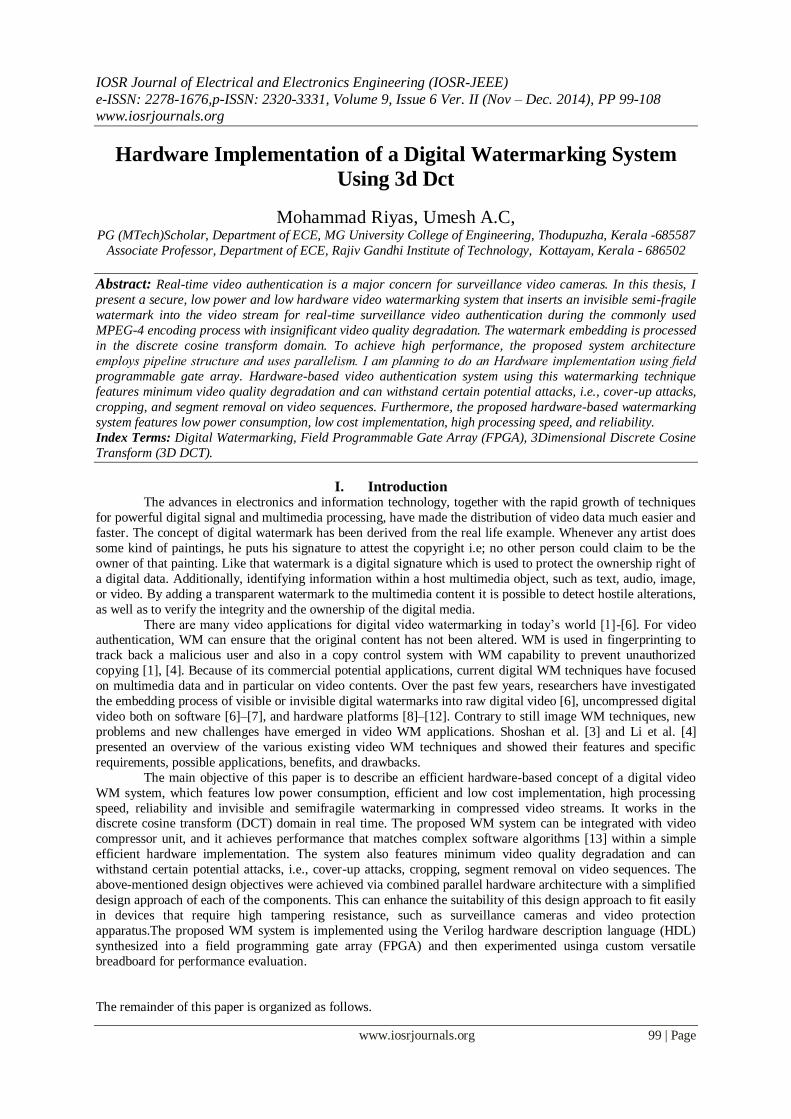
system are provided. Figure 3.1 illustrates the general block diagram of the proposed system which is comprised
of three main modules: video compression unit, watermark generation and watermark embedding units. According to the watermarking algorithm described in Chapter 2, the watermark embedding is performed in the
Discrete Cosine Transform (DCT) domain. There are several advantages of doing this. DCT is used in the most
popular image/video compression formats including JPEG, MJPEG, MPEG-x and H.26x. This allows the
integration of both watermarking and compression into a single system. Compression is divided into three
elementary phases: DCT transformation, quantization and Huffman encoding. Embedding the watermark after
quantization makes the watermark robust to the DCT compression with a quantization of equal or lower degree
used during the watermarking process. Another advantage of this approach is that in image or video
compression the image or frames are first divided into 8×8 blocks. By embedding the watermark into each 8×8
DCT block, tamper localization and better detection ratios are achieved.
Fig. 1. Overview of the proposed video WM system.
Each of the video frames is divided into 8×8 pixel blocks and DCT and quantization are performed on
each of those 8×8 pixel blocks. After that the quantized DCT coefficients are passed to the watermark embedder
unit in 8×8 blocks. The watermark generator unit, initialized by a predefined secret key, produces a
pseudorandom watermark sequence. The watermark embedder module inserts the watermark data into the
quantized DCT coefficients for each video frame. The watermarked and quantized DCT coefficients of each
video frame are encoded by the entropy coder. Finally, the compressed and encoded video frames with the embedded watermark information are read out of the system.
A. Video Compression
Hardware Implementation of a Digital Watermarking System Using 3d Dct
www.iosrjournals.org 102 | Page
Currently all popular standards for video compression, namely MPEG-x (ISO standard) and H.26x
formats (ITU-T standard), use the same basic hybrid coding schemes that apply the principle of motion-
compensated prediction and block-based transform coding using DCT. In this paper, we have focused on
implementing our video watermarking system with non-standard MJPEG video encoder due to the simplicity of
its implementation.
Generally, a video sequence is divided into multiple Group of Pictures (GOPs), representing sets of
video frames which are neighbouring in display order. An encoded MPEG-2 video sequence is made up of two types of frame-encoded pictures: Intra-frames (I frames) and Inter-frames (P frames or B frames). P frames are
forward prediction frames and B frames are bidirectional prediction frames. Two types of redundancies are
possible in video frames: temporal redundancy and spatial redundancy. 3D DCT video compression technique
reduces these redundancies to compress the images.
Within a GOP, the temporal redundancy among the video frames is reduced by applying temporal
differential pulse code modulation (DPCM). The major video coding standards like H.261, H.263, MPEG-1,
MPEG-2, MPEG-4 and H.264 are all based on the Hybrid DPCM/DCT CODEC, which incorporates motion
estimation and motion compensation function, a transform stage and an entropy encoder. The spatial
redundancy is reduced by applying 2D DCT. Video can also be viewed as 3D data with two spatial dimensions
and a time dimension. In this paper we reduce both redundancies by using 3D DCT.
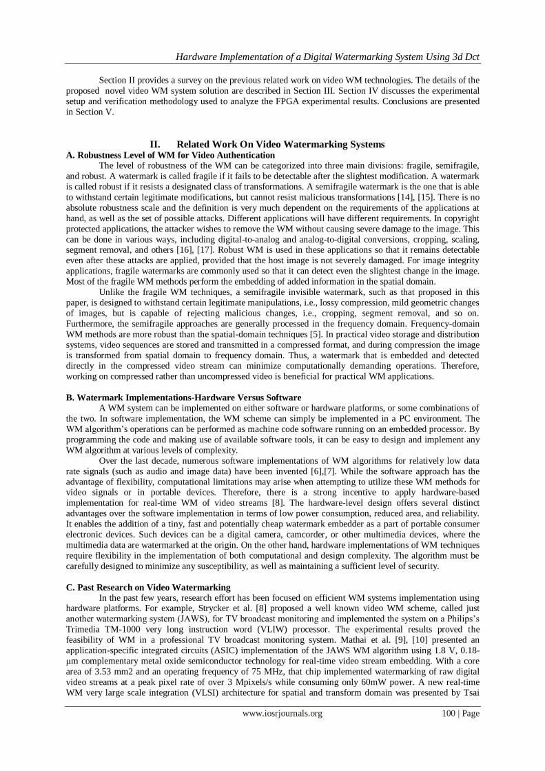
A block diagram of a 3D DCT coder for video is shown in Figure 3.2. N × N × N data cubes that are N pixels wide, N pixels high, and N frames deep are extracted from the video sequence. The N × N × N 3D DCT
is applied on each data cube.
Fig 2. 3D DCT based video coder
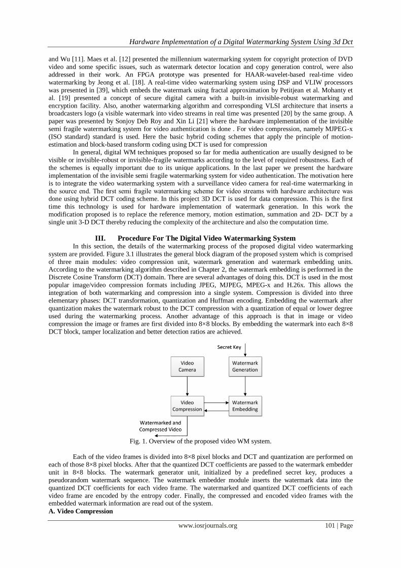
The 3D DCT can make the account of the neighboring pictures correlation in the video cube the same as the 2D DCT uses the correlation of the neighboring pixels in 2D matrix [6]. The input video sequence can be
divided into so-called video cubes. The principle of a video cube composition from video sequence frames is
shown in the Figure 3.3; each video cube contains 512 video elements.
The three-dimensional variant of the DCT is a composition of three 1D DCT along each dimension.
The formal definition is
X (l,m,n) = (x i, j, k . Cli . Cmj . CnkN−1k=0
N−1j=0
N−1i=0 (3.1)
where x(i, j, k ) is a value of the video cube element which is positioned at the coordinates i, j, k , X
(l,m,n) is a 3D DCT coefficient at the position l,m,n and indexes take values l,m,n = 0,1,...,N −1.
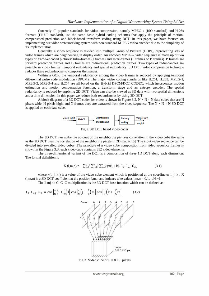
The li mj nk C ⋅C ⋅C multiplication is the 3D DCT base function which can be defined as
Cli . Cmj . Cnk = cos π
N i +
1
2 l .cos
π
N j +
1
2 m .cos
π
N k +
1
2 n (3.2)
Fig 3. Video cube of 8 × 8 × 8 pixels
Hardware Implementation of a Digital Watermarking System Using 3d Dct
www.iosrjournals.org 103 | Page
A cube of frequency components is the product of the 3D DCT. It contains one DC coefficient X
(0,0,0) at zero coordinates, the remaining 511 coefficients are called AC coefficients. The most important
elements of the signal are concerned near this DC coefficient.
Quantization
The human eye characteristics allow removing a lot of redundant information in higher frequency
coefficients. It can be done by dividing each frequency component by a suitable constant and by consecutive rounding to the nearest integer. As a result, many of higher frequency coefficients are rounded to zero. The
quantized 3D DCT coefficients can be computed with
Xq (l, m, n) =(X (l,m,n))/ (Q (l, m, n)) (3.3)
Where X (l,m,n) are the frequency coefficients before quantizing, Xq (l,m,n) are the frequency
coefficients after quantizing and Q(l,m,n) are the quantizing coefficients. This operation is lossy as a result of
this division therefore these components cannot be restored in the decompression process. However it causes
decreasing amount of data to store. It is necessary to decide which constant will be used for quantizing each
frequency component therefore the quantization cube must be defined. Its segments determine the compression
ratio and the quality of output video sequence.
Entropy Coding
Entropy coding is a lossless data compression. One of the most common is the Huffman coding which
is also used in JPEG and MPEG. Data in the quantized cube must be rearranged into a zig-zag order. The more
zeros will be in the straight-line the less data will be necessary to store. Consequently it also influences the final compression ratio. In this paper we do entropy coding after watermark embedding.
B. Watermark Generation
Simple watermark data can be easily cracked. Therefore, it is essential to XOR the primitive watermark
sequence with a pseudorandom sequence generated by a cryptographically pseudorandom number generator
(CSPRNG). This ensures that the watermark sequence to be embedded into each video frame is unpredictable.
In this chapter, we describe our earlier proof-of-concept implementation that used a non cryptographically
secure but hardware efficient PRNG. In subsequent chapters, we describe our improved version that does use a
CSPRNG. There are different available approaches to convert a primitive watermark into a secret pattern
[6],[22]. According to the recommendation by J. Dittman et al, a primitive watermark pattern can be defined as
a meaningful identifying sequence for each video frame in case of video watermarking [23]. In our design, the
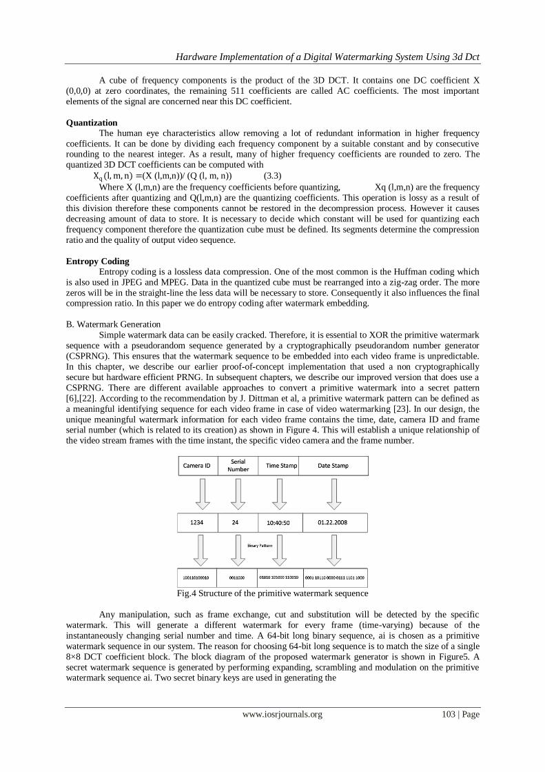
unique meaningful watermark information for each video frame contains the time, date, camera ID and frame serial number (which is related to its creation) as shown in Figure 4. This will establish a unique relationship of
the video stream frames with the time instant, the specific video camera and the frame number.
Fig.4 Structure of the primitive watermark sequence
Any manipulation, such as frame exchange, cut and substitution will be detected by the specific
watermark. This will generate a different watermark for every frame (time-varying) because of the
instantaneously changing serial number and time. A 64-bit long binary sequence, ai is chosen as a primitive
watermark sequence in our system. The reason for choosing 64-bit long sequence is to match the size of a single
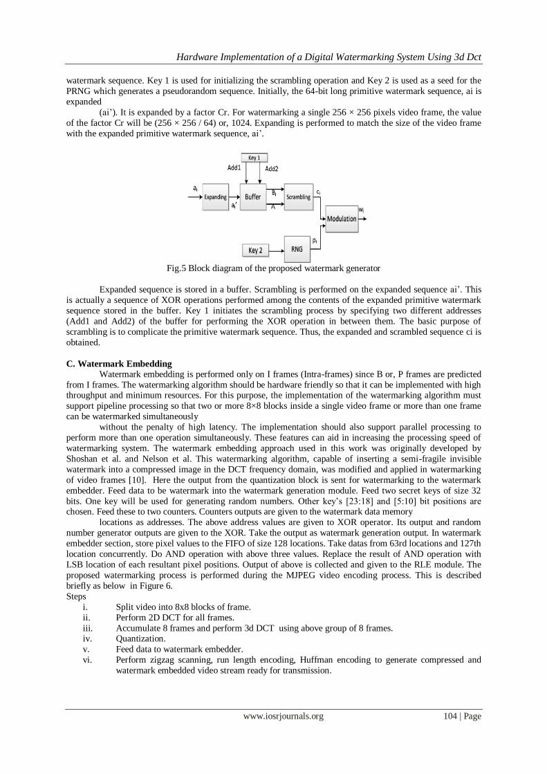
8×8 DCT coefficient block. The block diagram of the proposed watermark generator is shown in Figure5. A
secret watermark sequence is generated by performing expanding, scrambling and modulation on the primitive watermark sequence ai. Two secret binary keys are used in generating the
Hardware Implementation of a Digital Watermarking System Using 3d Dct
www.iosrjournals.org 104 | Page
watermark sequence. Key 1 is used for initializing the scrambling operation and Key 2 is used as a seed for the
PRNG which generates a pseudorandom sequence. Initially, the 64-bit long primitive watermark sequence, ai is
expanded
(ai’). It is expanded by a factor Cr. For watermarking a single 256 × 256 pixels video frame, the value
of the factor Cr will be (256 × 256 / 64) or, 1024. Expanding is performed to match the size of the video frame
with the expanded primitive watermark sequence, ai’.
Fig.5 Block diagram of the proposed watermark generator
Expanded sequence is stored in a buffer. Scrambling is performed on the expanded sequence ai’. This
is actually a sequence of XOR operations performed among the contents of the expanded primitive watermark
sequence stored in the buffer. Key 1 initiates the scrambling process by specifying two different addresses
(Add1 and Add2) of the buffer for performing the XOR operation in between them. The basic purpose of
scrambling is to complicate the primitive watermark sequence. Thus, the expanded and scrambled sequence ci is
obtained.
C. Watermark Embedding
Watermark embedding is performed only on I frames (Intra-frames) since B or, P frames are predicted
from I frames. The watermarking algorithm should be hardware friendly so that it can be implemented with high throughput and minimum resources. For this purpose, the implementation of the watermarking algorithm must
support pipeline processing so that two or more 8×8 blocks inside a single video frame or more than one frame
can be watermarked simultaneously
without the penalty of high latency. The implementation should also support parallel processing to
perform more than one operation simultaneously. These features can aid in increasing the processing speed of
watermarking system. The watermark embedding approach used in this work was originally developed by
Shoshan et al. and Nelson et al. This watermarking algorithm, capable of inserting a semi-fragile invisible
watermark into a compressed image in the DCT frequency domain, was modified and applied in watermarking
of video frames [10]. Here the output from the quantization block is sent for watermarking to the watermark
embedder. Feed data to be watermark into the watermark generation module. Feed two secret keys of size 32
bits. One key will be used for generating random numbers. Other key’s [23:18] and [5:10] bit positions are chosen. Feed these to two counters. Counters outputs are given to the watermark data memory
locations as addresses. The above address values are given to XOR operator. Its output and random
number generator outputs are given to the XOR. Take the output as watermark generation output. In watermark
embedder section, store pixel values to the FIFO of size 128 locations. Take datas from 63rd locations and 127th
location concurrently. Do AND operation with above three values. Replace the result of AND operation with
LSB location of each resultant pixel positions. Output of above is collected and given to the RLE module. The
proposed watermarking process is performed during the MJPEG video encoding process. This is described
briefly as below in Figure 6.
Steps
i. Split video into 8x8 blocks of frame.
ii. Perform 2D DCT for all frames.
iii. Accumulate 8 frames and perform 3d DCT using above group of 8 frames. iv. Quantization.
v. Feed data to watermark embedder.
vi. Perform zigzag scanning, run length encoding, Huffman encoding to generate compressed and
watermark embedded video stream ready for transmission.
Hardware Implementation of a Digital Watermarking System Using 3d Dct
www.iosrjournals.org 105 | Page
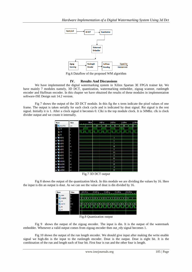
Fig.6 Dataflow of the proposed WM algorithm
IV. Results And Discussions We have implemented the digital watermarking system in Xilinx Spartan 3E FPGA trainer kit. We
have mainly 7 modules namely, 3D DCT, quantization, watermarking embedder, zigzag scanner, runlength
encoder and Huffman encoder. In this chapter we have obtained the results of these modules in implementation
software-ISE Design suit 14.2 version.
Fig 7 shows the output of the 3D DCT module. In this fig the x term indicate the pixel values of one
frame. The output is taken serially for each clock cycle and is indicated by dout signal. Rst signal is the rest
signal. Initially it is 1. After a clock signal it becomes 0. Clki is the top module clock. It is 50Mhz. clk is clock
divider output and we create it internally.
Fig.7 3D DCT output
Fig 8 shows the output of the quantization block. In this module we are dividing the values by 16. Here
the input is din an output is dout. As we can see the value of dout is din divided by 16.
Fig.8 Quantization output
Fig 9 shows the output of the zigzag encoder. The input is din. It is the output of the watermark
embedder. Whenever a valid output comes from zigzag encoder then out_rdy signal becomes 1.
Fig 10 shows the output of the run length encoder. We should give input after making the write enable
signal we high.din is the input to the runlength encoder. Dout is the output. Dout is eight bit. It is the
combination of the run and length each of four bit. First four is run and the other four is length.
Hardware Implementation of a Digital Watermarking System Using 3d Dct
www.iosrjournals.org 106 | Page
Fig.9 Output of zigzag encoder.
Fig.10 Output of run length encoder.
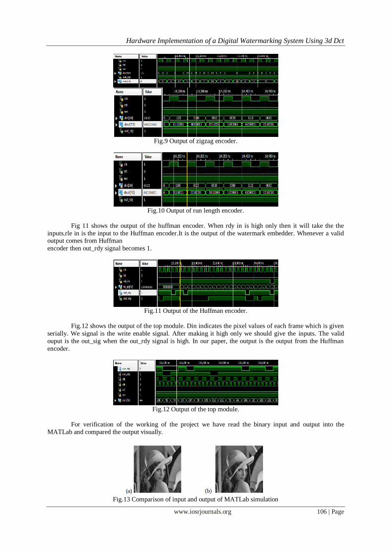
Fig 11 shows the output of the huffman encoder. When rdy in is high only then it will take the the
inputs.rle in is the input to the Huffman encoder.It is the output of the watermark embedder. Whenever a valid output comes from Huffman
encoder then out_rdy signal becomes 1.
Fig.11 Output of the Huffman encoder.
Fig.12 shows the output of the top module. Din indicates the pixel values of each frame which is given
serially. We signal is the write enable signal. After making it high only we should give the inputs. The valid
ouput is the out_sig when the out_rdy signal is high. In our paper, the output is the output from the Huffman
encoder.
Fig.12 Output of the top module.
For verification of the working of the project we have read the binary input and output into the
MATLab and compared the output visually.
Fig.13 Comparison of input and output of MATLab simulation
Hardware Implementation of a Digital Watermarking System Using 3d Dct
www.iosrjournals.org 107 | Page
The Fig.13 shows the input and output of the MATLab simulation. Here we can compare the input and
output of this project visually. We can compare single frames. To confirm that we have done the watermarking,
we are checking the PSNR value. If the PSNR value is infinity means nothing has been done on the input image.
Here we obtain a PSNR value of 48 and thus we can assure that watermarking has been one.
V. Conclusion A. Summary and Conclusion
In this paper, we present a hardware implementation of a digital watermarking system that can insert
invisible, semi-fragile watermark information in compressed video streams in real time. This paper provides a
security to the video recorded and at the same time this hardware implementation of digital watermarking can be
used for authentication of the video footage. The existing semi fragile watermarking scheme for video streams
with hardware architecture was done using hybrid DCT coding scheme for data compression. In this work the
modification proposed is to replace the reference memory, motion estimation, summation and 2D- DCT by a
single unit 3-D DCT thereby reducing the complexity of the architecture and also the computation time. The
delimitations of the proposed model was also analyzed clearly. Future work lies in simplifying this paper project
by clustering the three entropy coding modules.
B. Future Research
Future research should concentrate on applying the watermarking algorithm to other modern video
compression standards, such as MPEG-4/H.264, so that it can be utilized in various commercial applications as
well. Embedding the watermark information within high resolution video streams in real time is another
challenge.
References [1] A. D. Gwenael and J. L. Dugelay, “A guide tour of video watermarking,” Signal Process. Image Commun., vol. 18, no. 4, pp. 263–
282, Apr. 2003.
[2] A. Piva, F. Bartolini, and M. Barni, “Managing copyright in open networks,” IEEE Trans. Internet Comput., vol. 6, no. 3, pp. 18–
26, May– Jun. 2002.
[3] Y. Shoshan, A. Fish, X. Li, G. A. Jullien, and O. Yadid-Pecht, “VLSI watermark implementations and applications,” Int. J.
Information Technol. Knowl., vol. 2, no. 4 pp. 379–386, Jun. 2008.
[4] X. Li, Y. Shoshan, A. Fish, G. A. Jullien, and O. Yadid-Pecht, “Hardware implementations of video watermarking,” in International
Book Series on Information Science and Computing, no. 5. Sofia, Bulgaria: Inst. Inform. Theories Applicat. FOI ITHEA, Jun. 2008,
pp. 9–16 (supplement to the Int. J. Inform. Technol. Knowledge, vol. 2, 2008).
[5] I. J. Cox, J. Kilian, F. T. Leighton, and T. Shamoon, “Secure spread spectrum watermarking for multimedia,” IEEE Trans. Image
Process., vol. 6, no. 12, pp. 1673–1687, Dec. 1997.
[6] S. P. Mohanty. (1999). Digital Watermarking: A Tutorial Review [Online]. Available: http://www.linkpdf.com/download/dl/
digital-watermarking-a-tutorial-review-.pdf
[7] L. Qiao and K. Nahrstedt, “Watermarking methods for MPEG encoded video: Toward resolving rightful ownership,” in Proc. IEEE
Int. Conf. Multimedia Comput. Syst., Jun. 1998, pp. 276–285.
[8] L. D. Strycker, P. Termont, J. Vandewege, J. Haitsma, A. Kalker, M. Maes, and G. Depovere, “Implementation of a real -time
digital watermarking process for broadcast monitoring on Trimedia VLIW processor,” Proc. Inst. Elect. Eng. Vision, Image Signal
Process., vol. 147, no. 4, pp. 371–376, Aug. 2000.
[9] N. J. Mathai, A. Sheikholesami, and D. Kundur, “Hardware implementation perspectives of digital video watermarking algorithms,”
IEEE Trans. Signal Process., vol. 51, no. 4, pp. 925–938, Apr. 2003.
[10] N. J. Mathai, A. Sheikholesami, and D. Kundur, “VLSI implementation of a real-time video watermark embedder and detector,” in
Proc. Int. Symp. Circuits Syst., vol. 2. May 2003, pp. 772–775.
[11] T. H. Tsai and C. Y. Wu, “An implementation of configurable digital watermarking systems in MPEG video encoder,” in Proc. Int.
Conf. Consumer Electron., Jun. 2003, pp. 216–217.
[12] M. Maes, T. Kalker, J. P. Linnartz, J. Talstra, G. Depoyere, and J. Haitsma, “Digital watermarking for DVD video copy protection,”
IEEE Signal Process. Mag., vol. 17, no. 5, pp. 47–57, Sep. 2000.
[13] X. Wu, J. Hu, Z. Gu, and J. Huang, “A secure semifragile watermarking for image authentication based on integer wavelet
transform with parameters,” in Proc. Australian Workshop Grid Comput. E-Research, vol. 44. 2005, pp. 75–80.
[14] (2012, Jul. 28) [Online]. Available: http://en.wikipedia.org/wiki/ Digital−watermarking
[15] S. Saha, D. Bhattacharyya, and S. K. Bandyopadhyay, “Security on fragile and semifragile watermarks authentication,” Int. J.
Comput. Applicat., vol. 3, no. 4, pp. 23–27, Jun. 2010.
[16] V. M. Potdar, S. Han, and E. Chang, “A survey of digital image watermarking techniques,” in Proc. 3rd IEEE Int. Conf. Ind.
Informatics, 2005, pp. 709–716.
[17] F. Petitcolas, R. J. Anderson, and M. G. Kuhn, “Information hiding: A survey,” Proc. IEEE, vol. 87, no. 7, pp. 1062–1078, 1999.
[18] Y.-J. Jeong, K.-S. Moon, and J.-N. Kim, “Implementation of real time video watermark embedder based on Haar wavelet transform
using FPGA,” in Proc. 2nd Int. Conf. Future Generation Commun. Networking Symp., 2008, pp. 63–66.
[19] S. P. Mohanty, “A secure digital camera architecture for integrated realtime digital rights management,” J. Syst. Architecture, vol.
55, nos. 10– 12, pp. 468–480, Oct.–Dec. 2009.
[20] S. P. Mohanty and E. Kougianos, “Real-time perceptual watermarking architectures for video broadcasting,” J. Syst. Softw., vol.
84, no. 5, pp. 724–738, May 2011.
[21] Sonjoy Deb Roy and Xin Li, “Hardware Implementation of a Digital Watermarking System for Video Authentication,” Feb 2013.
[22] F. Hartung and B. Girod, “Watermarking of uncompressed and compressed video,” IEEE Trans. Signal Process., vol. 66, no. 3, pp.
283–302, May 1998.
Hardware Implementation of a Digital Watermarking System Using 3d Dct
www.iosrjournals.org 108 | Page
[23] T. L. Wu and S. F. Wu, “Selective encryption and watermarking of MPEG video,” in Proc. Int. Conf. Image Sci. Syst. Technol.
(CISST), Jun. 1997, pp. 0–9.
BIOGRAPHY
Mohammad Riyas received his Bachelor’s degree in Electronics and Instrumentation Engineering from Federal Institute of Science And Technology, Kerala, India. He is currently pursuing his M.Tech degree in Applied Electronics at Mahatma Gandhi University College of Engineering, Thodupuzha,
Kerala Under MG University Kottayam. He is working as Project Engineer in Vimal Fire Controls Pvt Ltd. He
was born on11th December 1990 in Ernakulam.
Mr. Umesh A.C received his M.Tech degree from College of Engineering, Guindy,Anna University in
Medical Electronics. Now he is working as Associate Professor in ECE Dept. in Rajiv Gandhi Institute of
Technology, Kottayam, Kerala.


