Embed Size (px)
Citation preview
micromachines
Article
High-Performance Pure Sine Wave Inverter withRobust Intelligent Sliding Mode Maximum PowerPoint Tracking for Photovoltaic Applications
En-Chih Chang
Department of Electrical Engineering, I-Shou University, No.1, Sec. 1, Syuecheng Rd., Dashu District,Kaohsiung City 84001, Taiwan; [email protected]; Tel.: +886-7-657-7711 (ext. 6642); Fax: +886-7-657-7205
Received: 22 March 2020; Accepted: 10 June 2020; Published: 11 June 2020
Abstract: Photovoltaic (PV) power generation has been extensively used as a result of the limitedpetrochemical resources and the rise of environmental awareness. Nevertheless, PV arrays havea widespread range of voltage changes in a variety of solar radiation, load, and temperaturecircumstances, so a maximum power point tracking (MPPT) method must be applied to get maximumpower from PV systems. Sliding mode control (SMC) is effectively used in PV power generation due toits robustness, design simplicity, and superior interference suppression. When the PV array is subjectto large parameter changes/highly uncertain conditions, the SMC leads to degraded steady-stateperformance, poor transient tracking speed, and unwanted flutter. Therefore, this paper proposesa robust intelligent sliding mode MPPT-based high-performance pure sine wave inverter for PVapplications. The robust SMC is designed through fast sliding regime, which provides fixed timeconvergence and a non-singularity that allows better response in steady-state and transience. To avoidthe flutter caused by system unmodeled dynamics, an enhanced cuckoo optimization algorithm(ECOA) with automatically adjustable step factor and detection probability is used to search controlparameters of the robust sliding mode, thus finding global optimal solutions. The coalescence of bothrobust SMC and ECOA can control the converter to obtain MPPT with faster convergence rate andwithout untimely trapping at local optimal solutions. Then the pure sine wave inverter with robustintelligent sliding mode MPPT of the PV system delivers a high-quality and stable sinusoidal wavevoltage to the load. The efficacy of the proposed method is validated on a MPPT pure sine waveinverter system by using numerical simulations and experiments. The results show that the output ofthe proposed PV system can improve steady-state performance and transient tracking speed.
Keywords: maximum power point tracking (MPPT); flutter; robust intelligent sliding mode;pure sine wave inverter; enhanced cuckoo optimization algorithm (ECOA)
1. Introduction
The petrochemical energy indispensable to produce electricity has increasingly depleted.The environmental protection awareness has risen, and the application of solar photovoltaic (PV) cellsis becoming more and more prevalent. How to improve the conversion efficiency of PV energy andoutput accessible power will be significant issues for PV power generation applications. For the sakeof achieving the maximum efficiency of the PV power generation system, the DC (direct current)–DC(direct current) converter is used to process maximum power point tracking (MPPT) and regulatethe voltage of DC load. When the connection of the grid exists, the power is created via solarpanel and converted from DC (direct current)–AC (alternating current) pure sine wave inverterto AC power [1–4]. Therefore, a MPPT-based high-performance pure sine wave inverter mustbe required to get low AC output-voltage total harmonic distortion (THD), and speedy dynamic
Micromachines 2020, 11, 585; doi:10.3390/mi11060585 www.mdpi.com/journal/micromachines
Micromachines 2020, 11, 585 2 of 15
behavior. Many MPPT control methods have been put forward to fulfill these requirements, includingdisturbance observation method, linear iteration method, fuzzy control method, etc. [5–8]. However,the changes in the maximum power output of PV panels are virtually related to solar illuminationand ambient temperature. Most of these MPPT algorithms lack a strict stability and convergenceanalysis, and only provide close to the maximum power point. Sliding mode control (SMC) hasbeen known to be insensitive to changes in internal parameters and external interferences [9–12].That is during its sliding motion, the system trajectory is robust to uncertain intrusions; A greatdeal of SMC publishing literature has been applied to the control of PV systems [13–16]. It is worthnoting that the PV system is affected by assorted environments (temperature, humidity, illumination,and load) and extremely nonlinearities. At this time, the stability of the convergence and performanceof the system will be significantly degenerated. This paper proposes a robust intelligent SMC witha simple architecture and a clear design methodology for MPPT-based high-performance pure sinewave inverters. The robust SMC using nonlinear regime not only ensures that the system state can reachthe sliding surface in a limited time, but also demonstrates the capability to suppress severe intrusionsin a closed-loop feedback system, which can allow the control more accurate and ensure the stabilityof the system [17–20]. The steady-state performance and tracking speed during transients in MPPTinverter system can be improved indeed [21–23]. Troublesomely, the high-frequency flutter problemstill exists in the robust SMC. This problem may trigger unmodeled plant dynamics, and sometimeseven effectuates system instability. The adaptability of the system may depreciate and the adjustmentof control parameters is arduous, resulting in unsatisfactory control effect in the PV system. Severalmethodologies have been proposed to ameliorate flutter problems, such as observer schemes and smartcontrol methods. Notwithstanding that these methodologies dwindle the flutter and mend the transientresponse under external intrusions and unmodeled dynamics, there are either time-consuming orcalls for elaborated mathematics [24–27]. To slacken the impact of the flutter, an enhanced cuckoooptimization algorithm (ECOA) is used to automatically adjust the control parameters of robust SMC,thus maintaining PV system’s splendid performance. The cuckoo optimization algorithm (COA) isa swarm intelligence technology proffered in 2009. The unsophisticated structure, speedy convergencespeed and easy completion disclose its characteristics [28–34]. However, the traditional COA cannotwell adjust the control parameters during the feedback control search process, which gives rise tothe high-frequency nonlinear factors excited by the flutter of robust SMC. This results in greater changesin system parameters and affects control performance. The traditional COA degrades the convergencerate and prematurely falls into the local optimal solution. There are some approaches that have beentried to solve this problem, such as Tabu search schemes and Greedy algorithms [35–39]. The Tabusearch can find a better solution except slow solution speed and long search time. The solution speedof Greedy algorithm is swift, but it is limited to local search and there is a flaw in easy convergenceto local solution. Therefore, an enhanced COA (ECOA) is proposed to meliorate the step size factorand the discovery probability of the traditional COA. That is, this paper uses the ECOA to detectthe best global solution in the control parameters of robust SMC, and then furnishes the PV maximumpower tracking system with great adaptability. The proposed method is simple to understand, easy toprogram, fast to converge, and effective in slackening flutter. It leads to a more precise tracking controland a more robust and stable system. Computer simulation and experimentation results uncover thatthe proposed method enables the PV maximum power tracking system to improve the steady-stateefficiency and transient tracking speed, even under non-matching intrusions or in highly uncertaincircumstances. The proposed PV maximum power tracking system is also compared with linearsliding regime-based sliding mode controlled PV maximum power tracking system, exposing thatthe proposed system possesses superior performance.
2. Dynamic Modeling of MPPT-Based Pure Sine Wave Inverter
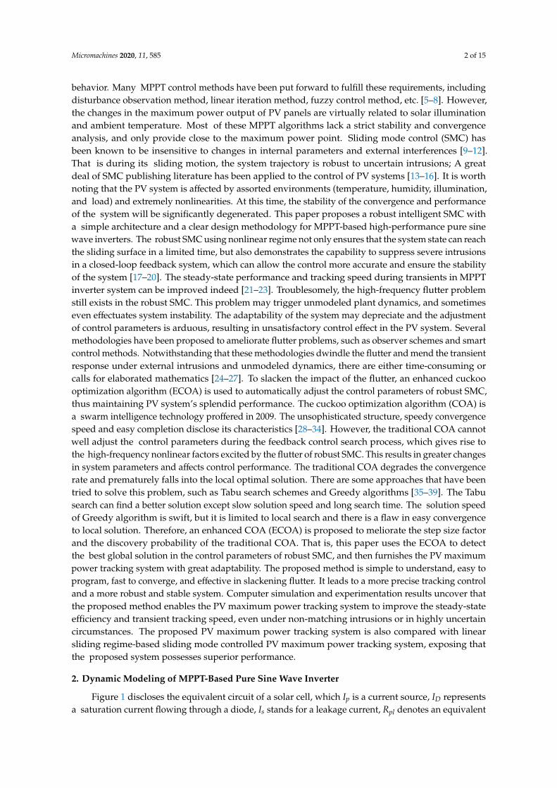
Figure 1 discloses the equivalent circuit of a solar cell, which Ip is a current source, ID representsa saturation current flowing through a diode, Is stands for a leakage current, Rpl denotes an equivalent
Micromachines 2020, 11, 585 3 of 15
parallel resistance, Rse signifies an equivalent series resistance, I indicates an output current, and Vsymbolizes an output voltage.
Micromachines 2020, 11, x FOR PEER REVIEW 3 of 15
Figure 1 discloses the equivalent circuit of a solar cell, which pI is a current source, DI
represents a saturation current flowing through a diode, sI stands for a leakage current, plR
denotes an equivalent parallel resistance, seR signifies an equivalent series resistance, I indicates
an output current, and V symbolizes an output voltage.
DIpI
sII
seR
+
VplR Load
Figure 1. Equivalent circuitry of single solar cell.
The output current of a single solar cell can be formulated as
)()1( )(plse
IRVKsap RIRVeIII seo (1)
where )/( KTBAK sso , sA stands for the amount of charge contained in an electron, sB
represents the ideal factor of a solar cell (1 to 5), K denotes the Boltzmann constant, T is the
absolute temperature, and the reverse saturation current can be written as )/1/1(3)(
TTEKrefrssa
refgpoeTTII
; here, rsI indicates the reverse saturation current at reference
temperature refT and gpE is the energy gap of the semiconductor material. The current source
pI yielded by a solar cell changes with sunlight intensity and ambient temperature variations that
is expressed as follows, 1000)]([ srefisccp LTTKII ; here, sccI implies the short-circuit
current of the solar cell under the reference temperature and illumination condition 2W/m1000 , iK
means the temperature coefficient during the short-circuit current of the solar cell ( CmA/ ), and sL
connotes for the sunlight intensity ( 2kW/m ).
By specifying the output current pvi and output voltage pvv of the solar array, the PV output
power yields
)1(/
spvo nvKpvsappvpppv evInvinP (2)
where pn signifies the number of solar cells connected in series and sn points to the number of
solar cells connected in parallel. The solar cell output-power can be expressed as
pvpvpv viP (3)
The maximum power point satisfies the following,
0 pvpvpvpvpvpv vivivP (4)
The Equation (4) deduces that after repeated adjustment, a reference voltage value ref
x1
derived from incremental conductance method is close to a maximum power point voltage maxpvv ,
and then attains to the maximum output. A SEPIC (single-ended primary-inductor converter)
DC-DC converter can be utilized to adjust the maximum power point voltage is illustrated as
Figure 2, where the capacitor iC aims to enhance response, 1lR symbolizes the equivalent
internal resistance of the 1L , fv is the forward conduction voltage of power diode, mR
Figure 1. Equivalent circuitry of single solar cell.
The output current of a single solar cell can be formulated as
I = Ip − Isa · (eKo(V+IRse) − 1) − (V + IRse/Rpl) (1)
where Ko = As/(BsKT), As stands for the amount of charge contained in an electron, Bs representsthe ideal factor of a solar cell (1 to 5), K denotes the Boltzmann constant, T is the absolute temperature,and the reverse saturation current can be written as Isa = Irs · (T/Tre f )
3eKoEgp(1/Tre f−1/T); here, Irs
indicates the reverse saturation current at reference temperature Tre f and Egp is the energy gap ofthe semiconductor material. The current source Ip yielded by a solar cell changes with sunlight intensityand ambient temperature variations that is expressed as follows, Ip = [Iscc +Ki(T−Tre f )] ·Ls/1000; here,Iscc implies the short-circuit current of the solar cell under the reference temperature and illuminationcondition 1000 W/m2, Ki means the temperature coefficient during the short-circuit current of the solarcell (mA/C), and Ls connotes for the sunlight intensity (kW/m2).
By specifying the output current ipv and output voltage vpv of the solar array, the PV outputpower yields
Ppv = npipvpv − npIsavpv · (eKovpv/ns − 1) (2)
where np signifies the number of solar cells connected in series and ns points to the number of solarcells connected in parallel. The solar cell output-power can be expressed as
Ppv = ipvvpv (3)
The maximum power point satisfies the following,
∂Ppv/∂vpv = ipv + vpv · ∂ipv/∂vpv = 0 (4)
The Equation (4) deduces that after repeated adjustment, a reference voltage value xre f1 derived
from incremental conductance method is close to a maximum power point voltage vmaxpv , and then attains
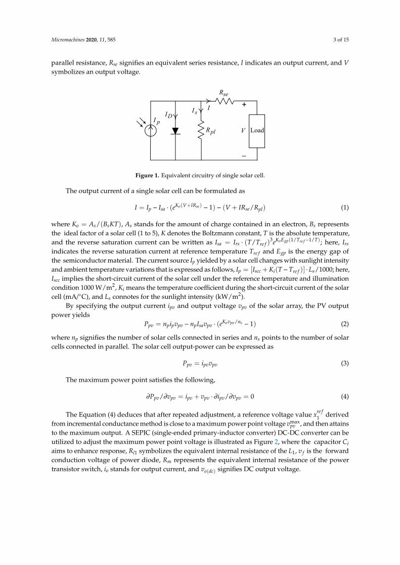
to the maximum output. A SEPIC (single-ended primary-inductor converter) DC-DC converter can beutilized to adjust the maximum power point voltage is illustrated as Figure 2, where the capacitor Ciaims to enhance response, Rl1 symbolizes the equivalent internal resistance of the L1, v f is the forwardconduction voltage of power diode, Rm represents the equivalent internal resistance of the powertransistor switch, io stands for output current, and vo(dc) signifies DC output voltage.
Micromachines 2020, 11, 585 4 of 15
Micromachines 2020, 11, x FOR PEER REVIEW 4 of 15
represents the equivalent internal resistance of the power transistor switch, oi stands for output
current, and )(dcov signifies DC output voltage.
1lRpvi
pvv )(dcov
1L
iC
D
2L
2lR
1C
2C
mR
fv oi
Converter DC-DC SEPIC
Panel PV
Load
1cv1Li
2Li
2cvSiCT
Figure 2. Circuitry structure of SEPIC (single-ended primary-inductor converter) DC-DC converter.
From the Figure 2, and using the state-space averaging method, one yields
])()[(
)(
2122212111
12
21
uvvviRxRvvvxRxLx
Cxix
fccLmmdccl
ipv
(5)
where pvvx 1 and 12 Lix denote state variables, and u is the control signal of the converter.
The 1x tracking the reference voltage value ref
x1 is the control target. However, the output
response is affected by the external load intrusions, the interventions of sunshine and temperature
changes, and the nonlinearities of the converter components. As above-noted uncertainties are
considered, a robust SMC with an ECOA for a MPPT-based pure sine wave inverter is designed to
produce speedier and more robust output response. Also, Figure 3 depicts a single-phase pure sine
wave inverter composed of SiC (silicon carbide) power MOSFET (metal-oxide-semiconductor
field-effect transistor), low-pass filter and loading. The L , C , and R symbolize the inductor,
capacitor and load, respectively. The acv stands for the AC output-voltage, aci infers the output
current, and invv is the pulse-width modulation voltage of magnitude DCV or DCV , with saT
centered in the sampling interval saT . The acv must follow a necessitated sinusoidal waveform
)sin( , tVv mrefac , here mV and are the peak value and the angular frequency, respectively.
By the use of the Kirchhoff's voltage law and Kirchhoff's current law, the dynamics of the inverter
can be generated as LCvRCvLCvv invacacac . Then, the tracking error refacac vve ,1~
and its derivative refacac vvee ,21~~ are obtained. The error dynamic equations of the inverter
can be expressed as refacrefacrefacin vRCvLCvLCuRCeLCee ,,,212~~~ ; here,
DCssinvin VTTvu )( stands for the control signal of the inverter. To ensure the tracking error
converged to zero, the inu is designed by employing proportional–integral scheme formulated as
skT
j
IsP jeKkTeK
0
11 )(~)(~ ; here, sT represents sampling period, PK denotes proportional gain,
and IK means integral gain.
Figure 2. Circuitry structure of SEPIC (single-ended primary-inductor converter) DC-DC converter.
From the Figure 2, and using the state-space averaging method, one yields .x1 = (ipv − x2)/Ci.x2 = L−1
1 [(x1 −Rl1x2 − vc1 − vc2 − vd) + (Rmx2 −RmiL2 + vc1 + vc2 + v f )u](5)
where x1 = vpv and x2 = iL1 denote state variables, and u is the control signal of the converter.
The x1 tracking the reference voltage value xre f1 is the control target. However, the output response is
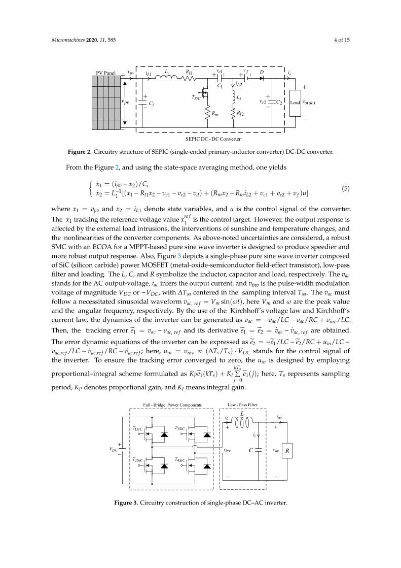
affected by the external load intrusions, the interventions of sunshine and temperature changes, andthe nonlinearities of the converter components. As above-noted uncertainties are considered, a robustSMC with an ECOA for a MPPT-based pure sine wave inverter is designed to produce speedier andmore robust output response. Also, Figure 3 depicts a single-phase pure sine wave inverter composedof SiC (silicon carbide) power MOSFET (metal-oxide-semiconductor field-effect transistor), low-passfilter and loading. The L, C, and R symbolize the inductor, capacitor and load, respectively. The vac
stands for the AC output-voltage, iac infers the output current, and vinv is the pulse-width modulationvoltage of magnitude VDC or −VDC, with ∆Tsa centered in the sampling interval Tsa. The vac mustfollow a necessitated sinusoidal waveform vac, re f = Vm sin(ωt), here Vm and ω are the peak valueand the angular frequency, respectively. By the use of the Kirchhoff’s voltage law and Kirchhoff’scurrent law, the dynamics of the inverter can be generated as
..vac = −vac/LC −
.vac/RC + vinv/LC.
Then, the tracking error e1 = vac − vac, re f and its derivative.e1 = e2 =
.vac −
.vac, re f are obtained.
The error dynamic equations of the inverter can be expressed as.e2 = −e1/LC − e2/RC + uin/LC −
vac,re f /LC −.vac,re f /RC −
..vac,re f ; here, uin = vinv ≈ (∆Ts/Ts) · VDC stands for the control signal of
the inverter. To ensure the tracking error converged to zero, the uin is designed by employing
proportional–integral scheme formulated as KPe1(kTs) + KIkTs∑j=0
e1( j); here, Ts represents sampling
period, KP denotes proportional gain, and KI means integral gain.Micromachines 2020, 11, x FOR PEER REVIEW 5 of 15
aciLi
ci
acv
ComponentsPower Bridge-Full
R
L
C
SiCT1
SiCT2
SiCT3
SiCT4
DCV
Filter Pass-Low
invv
Figure 3. Circuitry construction of single-phase DC–AC inverter.
3. Proposed Controller
It can be seen that the output-voltage of the solar PV cells will be the same as the demanded
reference voltage, even if the PV maximum power tracking system occurs under violent external
intrusions or great internal parameter changes or rigorous uncertainties. Based on the conception of
terminal attractor [17,22,23], this section derives the control law u of the robust SMC, and use the
ECOA to unearth the globally optimal parameters of the robust SMC. The MPPT-based pure sine
wave inverter can meliorate the performance in steady state and the tracking speed in transient
state, thus carrying out the high-quality AC output. From the system dynamics (5) and defining the
tracking error 1e and its derivative 1e , the following error-state equation can be stated as
)(])()([(
11
2
1121
tdxuxgxfiCe
xxee
refpvi
ref
(6)
where )()( 212111
1 fccl vvvxRxLxf , )()( 21221
1 fccLmm vvviRxRLxg , and )(td
signifies the sunshine and temperature variations as well as external load intrusions. The )(td is
restricted to wtd )( , here w is positive constant.
The sliding regime of a nonsingular robust SMC is constructed as
12
21 )1(zz
ee (7)
where is positive real number, and 1z as well as 2z advise positive odd numbers which
agrees with 21 12 zz .
A power reaching law of sliding mode is designed as
321321 )()(
ssssatsat (8)
where 01 , 02 , 03 , 10 1 s , 12 s , 03 s , and a saturation function )(sat ,
1, -1 for , , ( 10 ), respectively.
From the Equations (6)–(8), the control law of robust SMC becomes
)()()()([)()( 211221
22211
1 sszzref
ipv satsatezzxCixfxgtu
(9)
Theorem 1: For the system dynamics (6), once the control is adopted as the Equation (9) with
the sliding regime in the Equation (7) and a sliding-mode power reaching law (8), the swift
nonsingular convergence of the system state to the equilibrium in finite time will be fulfilled.
Proof: Choose the following Lyapunov function
22V (10)
Figure 3. Circuitry construction of single-phase DC–AC inverter.
Micromachines 2020, 11, 585 5 of 15
3. Proposed Controller
It can be seen that the output-voltage of the solar PV cells will be the same as the demandedreference voltage, even if the PV maximum power tracking system occurs under violent externalintrusions or great internal parameter changes or rigorous uncertainties. Based on the conceptionof terminal attractor [17,22,23], this section derives the control law u of the robust SMC, and usethe ECOA to unearth the globally optimal parameters of the robust SMC. The MPPT-based pure sinewave inverter can meliorate the performance in steady state and the tracking speed in transient state,thus carrying out the high-quality AC output. From the system dynamics (5) and defining the trackingerror e1 and its derivative
.e1, the following error-state equation can be stated as
.e1 = e2 =
.x1 −
.xre f
1.e2 = C−1
i [(.ipv − f (x) − g(x)u] −
..xre f
1 + d(t)(6)
where f (x) = L−11 (x1 − Rl1x2 − vc1 − vc2 − v f ), g(x) = L−1
1 (Rmx2 − RmiL2 + vc1 + vc2 + v f ), and d(t)signifies the sunshine and temperature variations as well as external load intrusions. The d(t) isrestricted to ‖d(t)‖ ≤ w, here w is positive constant.
The sliding regime of a nonsingular robust SMC is constructed as
σ = e1 + (1/ρ) · ez2/z12 (7)
where ρ is positive real number, and z1 as well as z2 advise positive odd numbers which agrees with1 < z2/z1 < 2.
A power reaching law of sliding mode is designed as
.σ = −η1|σ|
s1sat(σ) − η2|σ|s2sat(σ) − η3|σ|
s3σ (8)
where η1 > 0, η2 > 0, η3 > 0, 0 < s1 < 1, s2 > 1, s3 > 0, and a saturation function sat(σ) = σ/∆, 1, −1 for−∆ < σ ≤ ∆, σ ≥ ∆, σ < −∆ (0 < ∆ << 1), respectively.
From the Equations (6)–(8), the control law of robust SMC becomes
u(t) = −g(x)−1[ f (x) −.ipv + Ci
..xre f
1 + (z1/ρz2) · e2−z2/z12 − η1|σ|
s1sat(σ) − η2|σ|s2sat(σ) − η3|σ|
s3σ] (9)
Theorem 1. For the system dynamics (6), once the control is adopted as the Equation (9) with the sliding regimeσ in the Equation (7) and a sliding-mode power reaching law (8), the swift nonsingular convergence of the systemstate to the equilibrium in finite time will be fulfilled.
Proof. Choose the following Lyapunov function
V = σ2/2 (10)
Get the time derivative for Equation (10):
.V = σ
.σ
= σ( .e1 + (z2/ρz1) · e
z2/z1−12
.e2
)≤ −(z2/ρz1) · e
z2/z1−12 [(η1/∆)|σ|s1+2 + (η2/∆)|σ|s2+2 + η3|σ|
s3+2−w|σ|)]
(11)
Because σ and e2 do not equal zero,.
V is smaller than zero. Equation (11) conforms to Lyapunov’sstability theorem, and the robust SMC system briskly converges to the equilibrium region withinthe limited time. It can be found more subtly that the−η1|σ|
s1sat(σ) and−η2|σ|s2sat(σ) signify the system
dynamic behavior near the sliding regime and away from the sliding regime, respectively; the η1
Micromachines 2020, 11, 585 6 of 15
and η2 gains infer that the nonlinearities formulated in Equation (5) can be compensated, showingthe characteristic of robust SMC against system uncertainties. Once the varied illumination, loading,temperature and humidity, and uncertain nonlinearity impact on the PV system, the high-frequencyflutter or steady-state error occurs and may incur tracking imprecision. The adjustment of the robustSMC parameters presents the obstacle and the system adaptability declines. By the use of the ECOA,flutter relief and swiftness search are accomplished. The control parameters of the robust SMC canbe adaptively adjusted to acquire the best solution, avoiding premature falling into the local’s bestsolution.
The COA uses the following two mechanisms to generate offspring,xk+1 = xk + β · ζl ⊗ (xk
i − xh) ⊗ rh
xk+1i = xk
i + rg · (xkm − xk
z) ⊗He(pa − rg)(12)
where β is the step size factor; ζl stands for the L´evy distribution [40–42]; xh signifies the historical bestsolution; rh indicates the normal distribution; xi, xm, and xz denote random select solutions; rg infersthe uniform distribution on [0, 1], He(·) symbolizes the Heaviside function [43–45]; and pa meansthe discovery probability. The next-generation solution of the COA can reflect the configurationof the population; it is passive and does not the capability to dynamically learn and adapt duringthe searching process. The flutter phenomenon agitates the high-frequency nonlinear factors,which yield greater parametric changes. The control performance and accuracy are swayed, therebydisplaying slow convergence rate in unearthing solution and falling into the local optimum. The stepsize factor and discovery probability can be adjusted to effectuate speedy convergence speed, anduncover the solution of global optimization. The step size factor βk+1 and discovery probability pk+1
βchanging with step size factor of the ECOA are restructured as
βk+1; pk+1β =
βkLβ; pk
βLp, Pr > ∆
βk; pkβ, ∆ ≤ Pr ≤ 2∆
βkL−1β ; pk
βL−1p , Pr < ∆
(13)
where Lβ is the step size learning factor, and Lp indicates the discovery probability learning factor,Pr denotes the proportion of new solution, and ∆ = 0.01 represents the boundary layer thicknessof the saturation function. The step flow of the ECOA is depicted as follows. Step 1: Initializethe population and count the fitness of all individuals. Step 2: For each individual, engendera new solution according to the Equation (12). If the new solution is preferable to the old solution,supersede the old solution and augment the number of the improvement. Step 3: For each individual,a new solution is engendered in accordance with the similarity and discovery probability. If the newsolution is better, the old solution is supplanted; the number of the improvement increases whilethe already improved solution is no longer calculated repeatedly. Step 4: Count the proportion ofthe improved individuals in the population, and decide the step size factor and discovery probabilityof the next-generation population according to the Equation (13). Step 5: Enroll the best solution.If the termination condition is not met, reiterate Step 2 to Step 4. From the mathematical derivationand proof of robust SMC described in Equations (9) and (11), they represent the equivalent controlterm with non-singularity, and the sliding control term with intrusion compensation. Equations (7)and (8) can be allowed to converge to the equilibrium for a limited time. Then, the system dynamics (5)will also be converged to the equilibrium for a limited time while the sliding regime is approached.Eventually, the robust SMC parameters can be adaptively adjusted through the ECOA expressed inthe Equation (13), so as to ensure the stability of the global system subject to parameter changes anduncertain intrusions.
Micromachines 2020, 11, 585 7 of 15
4. Results and Analysis
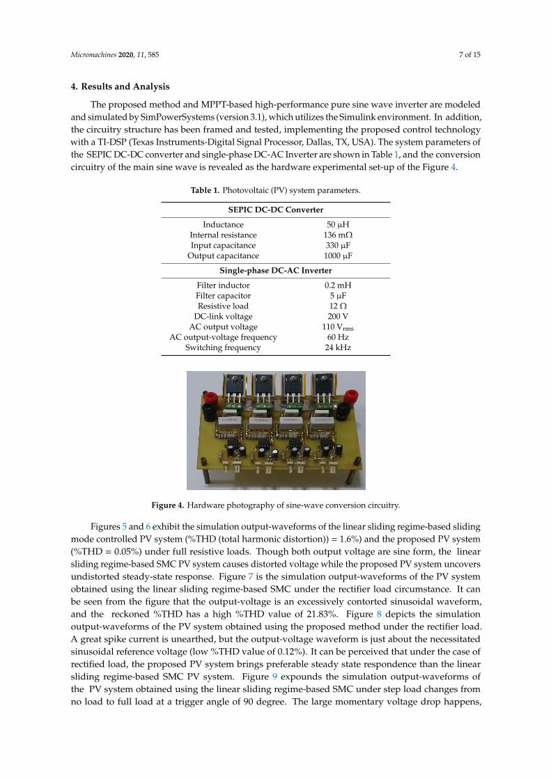
The proposed method and MPPT-based high-performance pure sine wave inverter are modeledand simulated by SimPowerSystems (version 3.1), which utilizes the Simulink environment. In addition,the circuitry structure has been framed and tested, implementing the proposed control technologywith a TI-DSP (Texas Instruments-Digital Signal Processor, Dallas, TX, USA). The system parameters ofthe SEPIC DC-DC converter and single-phase DC-AC Inverter are shown in Table 1, and the conversioncircuitry of the main sine wave is revealed as the hardware experimental set-up of the Figure 4.
Table 1. Photovoltaic (PV) system parameters.
SEPIC DC-DC Converter
Inductance 50 µHInternal resistance 136 mΩInput capacitance 330 µF
Output capacitance 1000 µF
Single-phase DC-AC Inverter
Filter inductor 0.2 mHFilter capacitor 5 µFResistive load 12 Ω
DC-link voltage 200 VAC output voltage 110 Vrms
AC output-voltage frequency 60 HzSwitching frequency 24 kHz
Micromachines 2020, 11, x FOR PEER REVIEW 7 of 15
Step 4: Count the proportion of the improved individuals in the population, and decide the step
size factor and discovery probability of the next-generation population according to the Equation
(13). Step 5: Enroll the best solution. If the termination condition is not met, reiterate Step 2 to Step
4. From the mathematical derivation and proof of robust SMC described in Equations (9) and (11),
they represent the equivalent control term with non-singularity, and the sliding control term with
intrusion compensation. Equations (7) and (8) can be allowed to converge to the equilibrium for a
limited time. Then, the system dynamics (5) will also be converged to the equilibrium for a limited
time while the sliding regime is approached. Eventually, the robust SMC parameters can be
adaptively adjusted through the ECOA expressed in the Equation (13), so as to ensure the stability of
the global system subject to parameter changes and uncertain intrusions.
4. Results and Analysis
The proposed method and MPPT-based high-performance pure sine wave inverter are
modeled and simulated by SimPowerSystems (version 3.1), which utilizes the Simulink
environment. In addition, the circuitry structure has been framed and tested, implementing the
proposed control technology with a TI-DSP (Texas Instruments-Digital Signal Processor, Dallas,
Texas, United States). The system parameters of the SEPIC DC-DC converter and single-phase
DC-AC Inverter are shown in Table 1, and the conversion circuitry of the main sine wave is
revealed as the hardware experimental set-up of the Figure 4.
Table 1. Photovoltaic (PV) system parameters.
SEPIC DC-DC Converter
Inductance 50 μH
Internal resistance 136 mΩ
Input capacitance 330 μF
Output capacitance 1000 μF
Single-phase DC-AC Inverter
Filter inductor 0.2 mH
Filter capacitor 5 μF
Resistive load 12 Ω
DC-link voltage 200 V
AC output voltage 110 Vrms
AC output-voltage frequency 60 Hz
Switching frequency 24 kHz
Figure 4. Hardware photography of sine-wave conversion circuitry.
Figures 5 and 6 exhibit the simulation output-waveforms of the linear sliding regime-based
sliding mode controlled PV system (%THD (total harmonic distortion)) = 1.6%) and the proposed
PV system (%THD = 0.05%) under full resistive loads. Though both output voltage are sine form,
the linear sliding regime-based SMC PV system causes distorted voltage while the proposed PV
system uncovers undistorted steady-state response. Figure 7 is the simulation output-waveforms of
Figure 4. Hardware photography of sine-wave conversion circuitry.
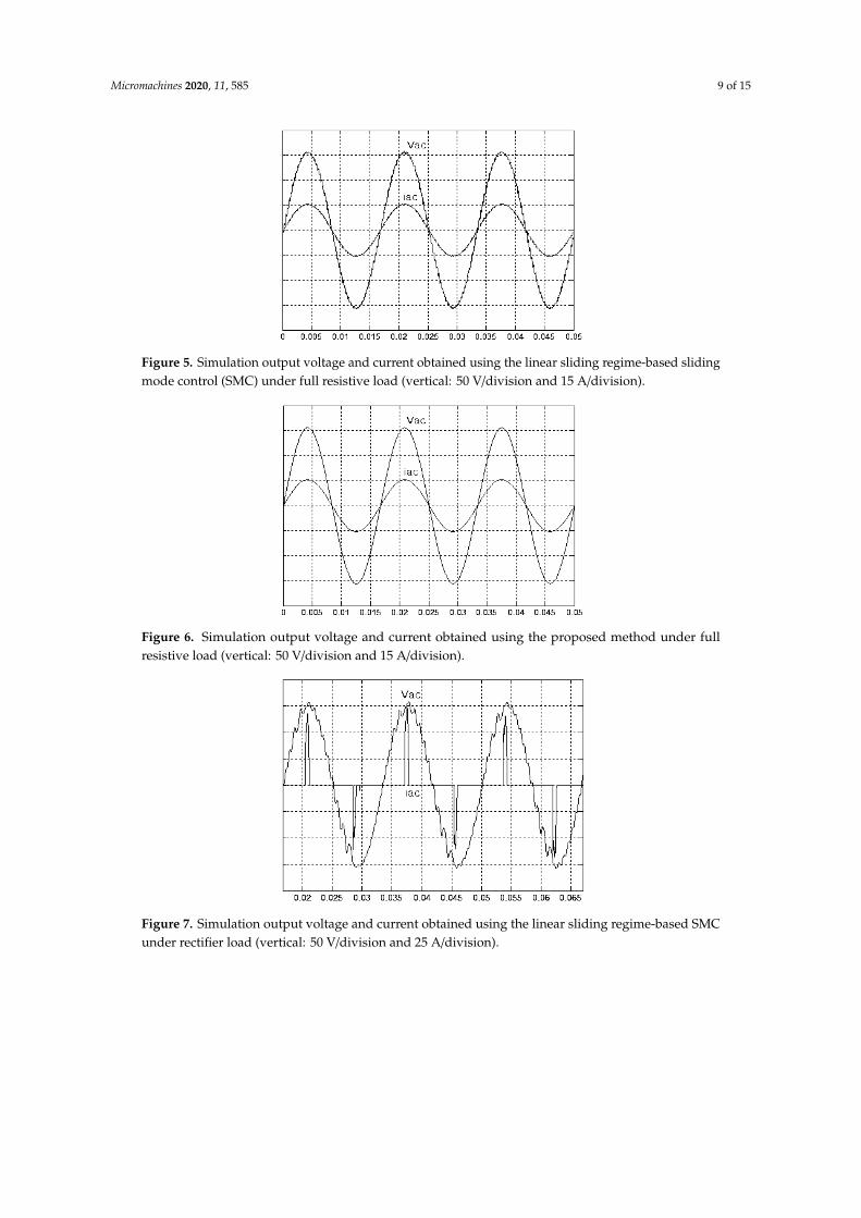
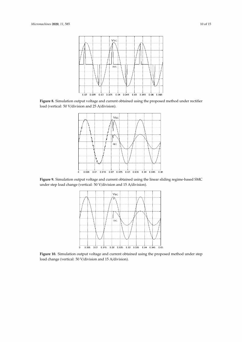
Figures 5 and 6 exhibit the simulation output-waveforms of the linear sliding regime-based slidingmode controlled PV system (%THD (total harmonic distortion)) = 1.6%) and the proposed PV system(%THD = 0.05%) under full resistive loads. Though both output voltage are sine form, the linearsliding regime-based SMC PV system causes distorted voltage while the proposed PV system uncoversundistorted steady-state response. Figure 7 is the simulation output-waveforms of the PV systemobtained using the linear sliding regime-based SMC under the rectifier load circumstance. It canbe seen from the figure that the output-voltage is an excessively contorted sinusoidal waveform,and the reckoned %THD has a high %THD value of 21.83%. Figure 8 depicts the simulationoutput-waveforms of the PV system obtained using the proposed method under the rectifier load.A great spike current is unearthed, but the output-voltage waveform is just about the necessitatedsinusoidal reference voltage (low %THD value of 0.12%). It can be perceived that under the case ofrectified load, the proposed PV system brings preferable steady state respondence than the linearsliding regime-based SMC PV system. Figure 9 expounds the simulation output-waveforms ofthe PV system obtained using the linear sliding regime-based SMC under step load changes fromno load to full load at a trigger angle of 90 degree. The large momentary voltage drop happens,
Micromachines 2020, 11, 585 8 of 15
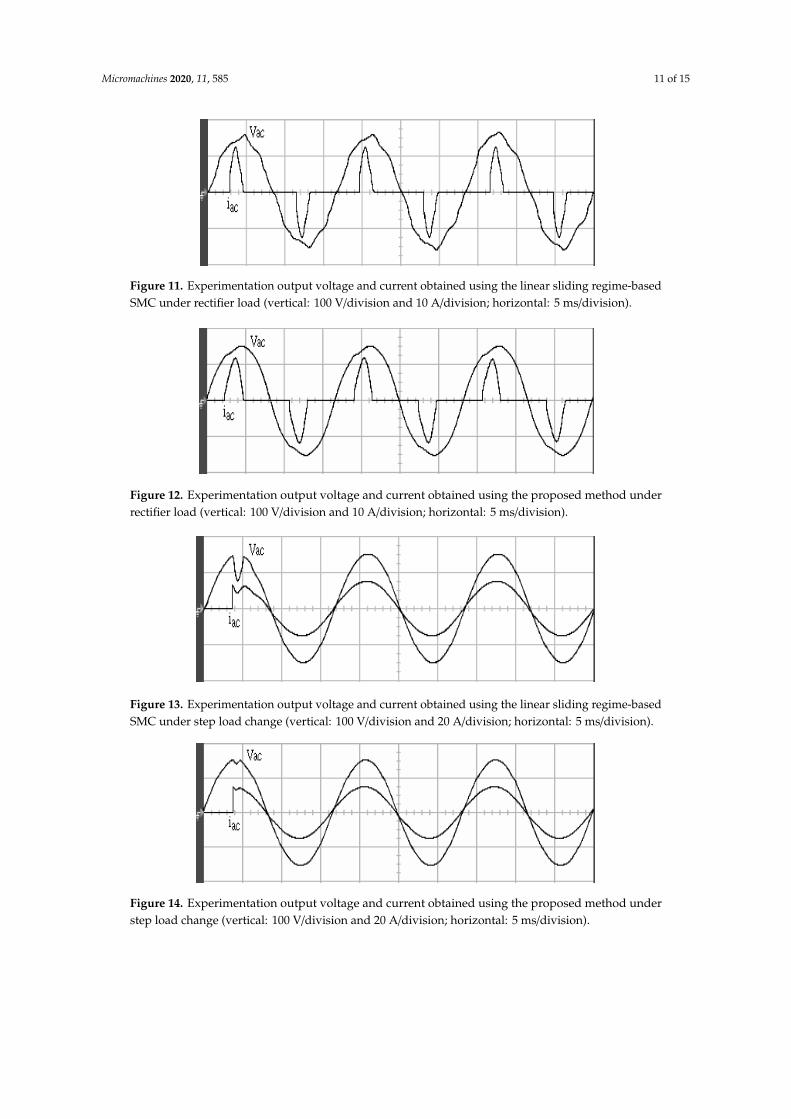
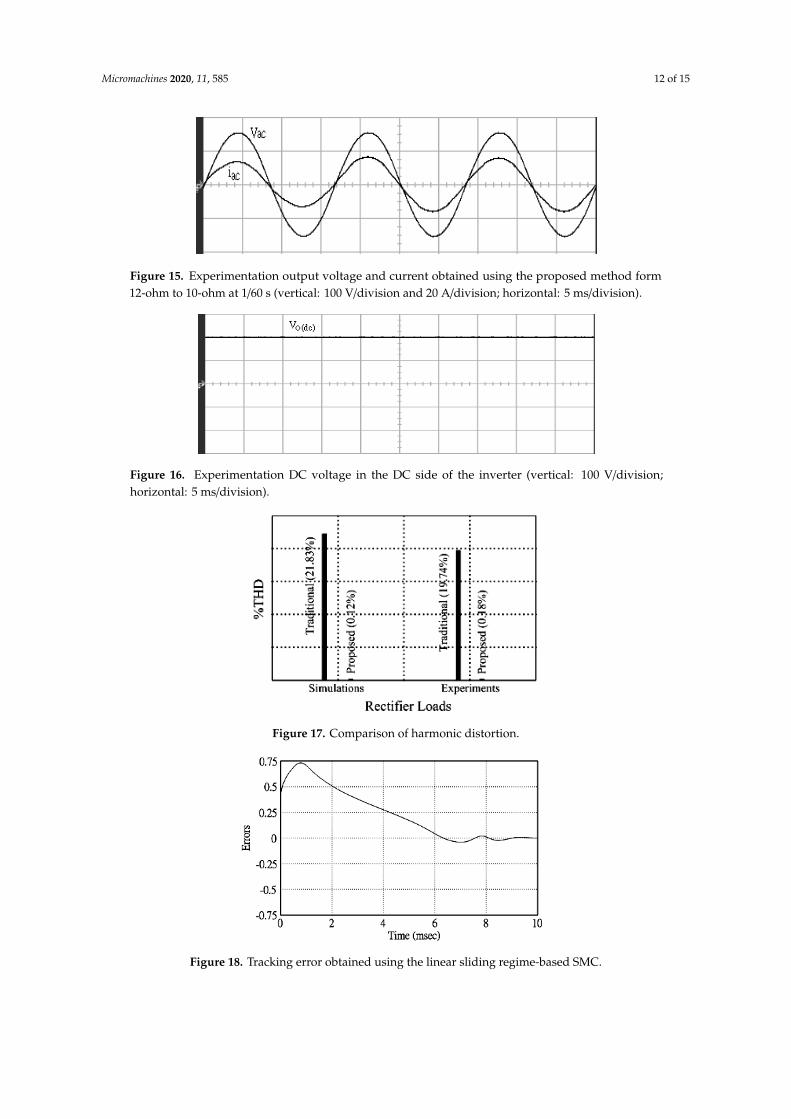
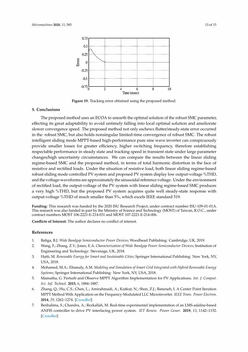
i.e., the compensation capability of the linear sliding regime-based SMC remains to be reinforced.Figure 10 manifests the simulation output-waveforms of the PV system obtained using the proposedmethod under the same loading environment at a trigger angle of 90 degree. The little voltage dropis remarked and the voltage recuperates to the desired sine level for a very short time, pointing topleasing transient respondence. Figure 11 depicts the experimentation output-waveform of the PVsystem controlled by the linear sliding regime-based SMC under the condition of rectifier load.The output-voltage shows a contortion of the sine wave, and its measured %THD takes on a highvalue of 19.74%. Figure 12 recites the proposed experimentation output-waveforms at rectifier typeload. A pure sine-wave steady-state response (0.18% voltage THD) with the necessitated sinusoidalform voltage is seen, even though a sharply rising current occurs. The PV system controlled bythe linear sliding regime-based SMC at a 90-degree trigger angle, changing from no load to fullload yields the experimentation output-waveforms of the Figure 13. Owing to the tardy retrieve ofthe sudden voltage drop, the transient output-voltage discloses defective behavior response. Figure 14illustrates the experimentation output-waveforms of the proposed PV system, when it confrontsload-changing from no load to full load at 90-degree trigger angle; we can make out that the strongsine trajectory is non-oscillatory before and after speedy recovery voltage drop. To verify once againthe dynamic performance of the proposed method, Figure 15 displays the experimentation outputwaveforms from 12-ohm to 10-ohm conditions at 1/60 s, confirming exceptional transience response.In the DC side of the inverter, the experimentation output-voltage of the DC–DC converter is shownin Figure 16. With the use of the Agilent E4360A solar simulator, the PV modules can be emulatedand then demonstrated the system operation. It can be clearly observed from the output-voltage thatthe nearly ripple-free DC waveform has been obtained. This verifies that even if the PV module isdisturbed, the DC-DC converter can still provide a stable and robust DC output to the DC-AC inverter.Figure 17 plots a comparison of the %THD obtained using the linear sliding regime-based SMC andproposed method under rectifier loads. Figures 18 and 19 are the tracking errors of the linear slidingregime-based SMC and proposed method. Distinctly, as compared with the linear sliding regime-basedSMC, the proposed method holds high-precision tracking and limited-time convergence characteristics.In other words, in the early stage of the proposed algorithm, the learning value of the step size islarge enough and the value of the discovery probability is relatively small to enhance the diversity ofthe solution. On account of the update of the relatively large number in the bird nests, the proposedalgorithm maintains a strong global search capability; in the later stage of the proposed algorithm,the step size learning value cuts down and a relatively large discovery probability value is used toadjust the solution variables and uphold a strong local search capability. In the conclusive synopsis,a comparative analysis with other literature is discussed below. An H-infinity control technology isrecommended to ensure the global stability in small signal model for power converters. Its robustnessand ascendant performance in steady state as well as transient response can be acquired. Regrettably,this technology has the requirement of intricate calculations [46]. For the sake of overcoming systemuncertainties, a higher-order repetitive approach is developed to regulate a two-level grid-connectedinverter. This design structure encompassing the phase lead compensator shows the simplificationand provides the tracking response of zero-phase error, but the tracking behavior in the transienceis not satisfactory [47]. An unsophisticated deadbeat control with the use of a current observerhas been presented for hybrid energy storage systems. Although the exceptional performance indynamics as well as steady state can be obtained, this strategy relies heavily on the preciseness ofthe system parameters [48]. The mu-synthesis technique attempts to improve the system stability inthe wind farm model; this methodology addresses the nonlinear intrusion faced by the system, but it istime-consuming to calculate and has a complex structure is not easy to understand [49].
Micromachines 2020, 11, 585 9 of 15
Micromachines 2020, 11, x FOR PEER REVIEW 9 of 15
unsophisticated deadbeat control with the use of a current observer has been presented for hybrid
energy storage systems. Although the exceptional performance in dynamics as well as steady state
can be obtained, this strategy relies heavily on the preciseness of the system parameters [48]. The
mu-synthesis technique attempts to improve the system stability in the wind farm model; this
methodology addresses the nonlinear intrusion faced by the system, but it is time-consuming to
calculate and has a complex structure is not easy to understand [49].
Figure 5. Simulation output voltage and current obtained using the linear sliding regime-based
sliding mode control (SMC) under full resistive load (vertical: 50 V/division and 15 A/division).
Figure 6. Simulation output voltage and current obtained using the proposed method under full
resistive load (vertical: 50 V/division and 15 A/division).
Figure 7. Simulation output voltage and current obtained using the linear sliding regime-based SMC
under rectifier load (vertical: 50 V/division and 25 A/division).
Figure 5. Simulation output voltage and current obtained using the linear sliding regime-based slidingmode control (SMC) under full resistive load (vertical: 50 V/division and 15 A/division).
Micromachines 2020, 11, x FOR PEER REVIEW 9 of 15
unsophisticated deadbeat control with the use of a current observer has been presented for hybrid
energy storage systems. Although the exceptional performance in dynamics as well as steady state
can be obtained, this strategy relies heavily on the preciseness of the system parameters [48]. The
mu-synthesis technique attempts to improve the system stability in the wind farm model; this
methodology addresses the nonlinear intrusion faced by the system, but it is time-consuming to
calculate and has a complex structure is not easy to understand [49].
Figure 5. Simulation output voltage and current obtained using the linear sliding regime-based
sliding mode control (SMC) under full resistive load (vertical: 50 V/division and 15 A/division).
Figure 6. Simulation output voltage and current obtained using the proposed method under full
resistive load (vertical: 50 V/division and 15 A/division).
Figure 7. Simulation output voltage and current obtained using the linear sliding regime-based SMC
under rectifier load (vertical: 50 V/division and 25 A/division).
Figure 6. Simulation output voltage and current obtained using the proposed method under fullresistive load (vertical: 50 V/division and 15 A/division).
Micromachines 2020, 11, x FOR PEER REVIEW 9 of 15
unsophisticated deadbeat control with the use of a current observer has been presented for hybrid
energy storage systems. Although the exceptional performance in dynamics as well as steady state
can be obtained, this strategy relies heavily on the preciseness of the system parameters [48]. The
mu-synthesis technique attempts to improve the system stability in the wind farm model; this
methodology addresses the nonlinear intrusion faced by the system, but it is time-consuming to
calculate and has a complex structure is not easy to understand [49].
Figure 5. Simulation output voltage and current obtained using the linear sliding regime-based
sliding mode control (SMC) under full resistive load (vertical: 50 V/division and 15 A/division).
Figure 6. Simulation output voltage and current obtained using the proposed method under full
resistive load (vertical: 50 V/division and 15 A/division).
Figure 7. Simulation output voltage and current obtained using the linear sliding regime-based SMC
under rectifier load (vertical: 50 V/division and 25 A/division).
Figure 7. Simulation output voltage and current obtained using the linear sliding regime-based SMCunder rectifier load (vertical: 50 V/division and 25 A/division).
Micromachines 2020, 11, 585 10 of 15Micromachines 2020, 11, x FOR PEER REVIEW 10 of 15
Figure 8. Simulation output voltage and current obtained using the proposed method under rectifier
load (vertical: 50 V/division and 25 A/division).
Figure 9. Simulation output voltage and current obtained using the linear sliding regime-based SMC
under step load change (vertical: 50 V/division and 15 A/division).
Figure 10. Simulation output voltage and current obtained using the proposed method under step
load change (vertical: 50 V/division and 15 A/division).
Figure 8. Simulation output voltage and current obtained using the proposed method under rectifierload (vertical: 50 V/division and 25 A/division).
Micromachines 2020, 11, x FOR PEER REVIEW 10 of 15
Figure 8. Simulation output voltage and current obtained using the proposed method under rectifier
load (vertical: 50 V/division and 25 A/division).
Figure 9. Simulation output voltage and current obtained using the linear sliding regime-based SMC
under step load change (vertical: 50 V/division and 15 A/division).
Figure 10. Simulation output voltage and current obtained using the proposed method under step
load change (vertical: 50 V/division and 15 A/division).
Figure 9. Simulation output voltage and current obtained using the linear sliding regime-based SMCunder step load change (vertical: 50 V/division and 15 A/division).
Micromachines 2020, 11, x FOR PEER REVIEW 10 of 15
Figure 8. Simulation output voltage and current obtained using the proposed method under rectifier
load (vertical: 50 V/division and 25 A/division).
Figure 9. Simulation output voltage and current obtained using the linear sliding regime-based SMC
under step load change (vertical: 50 V/division and 15 A/division).
Figure 10. Simulation output voltage and current obtained using the proposed method under step
load change (vertical: 50 V/division and 15 A/division).
Figure 10. Simulation output voltage and current obtained using the proposed method under stepload change (vertical: 50 V/division and 15 A/division).
Micromachines 2020, 11, 585 11 of 15
Micromachines 2020, 11, x FOR PEER REVIEW 10 of 15
Figure 8. Simulation output voltage and current obtained using the proposed method under rectifier
load (vertical: 50 V/division and 25 A/division).
Figure 9. Simulation output voltage and current obtained using the linear sliding regime-based SMC
under step load change (vertical: 50 V/division and 15 A/division).
Figure 10. Simulation output voltage and current obtained using the proposed method under step
load change (vertical: 50 V/division and 15 A/division).
Figure 11. Experimentation output voltage and current obtained using the linear sliding regime-basedSMC under rectifier load (vertical: 100 V/division and 10 A/division; horizontal: 5 ms/division).
Micromachines 2020, 11, x FOR PEER REVIEW 11 of 15
Figure 11. Experimentation output voltage and current obtained using the linear sliding
regime-based SMC under rectifier load (vertical: 100 V/division and 10 A/division; horizontal:
5ms/division).
Figure 12. Experimentation output voltage and current obtained using the proposed method under
rectifier load (vertical: 100 V/division and 10 A/division; horizontal: 5ms/division).
Figure 13. Experimentation output voltage and current obtained using the linear sliding
regime-based SMC under step load change (vertical: 100 V/division and 20 A/division; horizontal:
5ms/division).
Figure 14. Experimentation output voltage and current obtained using the proposed method under
step load change (vertical: 100 V/division and 20 A/division; horizontal: 5ms/division).
Figure 15. Experimentation output voltage and current obtained using the proposed method form
12-ohm to 10-ohm at 1/60 sec (vertical: 100 V/division and 20 A/division; horizontal: 5ms/division).
Figure 12. Experimentation output voltage and current obtained using the proposed method underrectifier load (vertical: 100 V/division and 10 A/division; horizontal: 5 ms/division).
Micromachines 2020, 11, x FOR PEER REVIEW 11 of 15
Figure 11. Experimentation output voltage and current obtained using the linear sliding
regime-based SMC under rectifier load (vertical: 100 V/division and 10 A/division; horizontal:
5ms/division).
Figure 12. Experimentation output voltage and current obtained using the proposed method under
rectifier load (vertical: 100 V/division and 10 A/division; horizontal: 5ms/division).
Figure 13. Experimentation output voltage and current obtained using the linear sliding
regime-based SMC under step load change (vertical: 100 V/division and 20 A/division; horizontal:
5ms/division).
Figure 14. Experimentation output voltage and current obtained using the proposed method under
step load change (vertical: 100 V/division and 20 A/division; horizontal: 5ms/division).
Figure 15. Experimentation output voltage and current obtained using the proposed method form
12-ohm to 10-ohm at 1/60 sec (vertical: 100 V/division and 20 A/division; horizontal: 5ms/division).
Figure 13. Experimentation output voltage and current obtained using the linear sliding regime-basedSMC under step load change (vertical: 100 V/division and 20 A/division; horizontal: 5 ms/division).
Micromachines 2020, 11, x FOR PEER REVIEW 11 of 15
Figure 11. Experimentation output voltage and current obtained using the linear sliding
regime-based SMC under rectifier load (vertical: 100 V/division and 10 A/division; horizontal:
5ms/division).
Figure 12. Experimentation output voltage and current obtained using the proposed method under
rectifier load (vertical: 100 V/division and 10 A/division; horizontal: 5ms/division).
Figure 13. Experimentation output voltage and current obtained using the linear sliding
regime-based SMC under step load change (vertical: 100 V/division and 20 A/division; horizontal:
5ms/division).
Figure 14. Experimentation output voltage and current obtained using the proposed method under
step load change (vertical: 100 V/division and 20 A/division; horizontal: 5ms/division).
Figure 15. Experimentation output voltage and current obtained using the proposed method form
12-ohm to 10-ohm at 1/60 sec (vertical: 100 V/division and 20 A/division; horizontal: 5ms/division).
Figure 14. Experimentation output voltage and current obtained using the proposed method understep load change (vertical: 100 V/division and 20 A/division; horizontal: 5 ms/division).
Micromachines 2020, 11, 585 12 of 15
Micromachines 2020, 11, x FOR PEER REVIEW 11 of 15
Figure 11. Experimentation output voltage and current obtained using the linear sliding
regime-based SMC under rectifier load (vertical: 100 V/division and 10 A/division; horizontal:
5ms/division).
Figure 12. Experimentation output voltage and current obtained using the proposed method under
rectifier load (vertical: 100 V/division and 10 A/division; horizontal: 5ms/division).
Figure 13. Experimentation output voltage and current obtained using the linear sliding
regime-based SMC under step load change (vertical: 100 V/division and 20 A/division; horizontal:
5ms/division).
Figure 14. Experimentation output voltage and current obtained using the proposed method under
step load change (vertical: 100 V/division and 20 A/division; horizontal: 5ms/division).
Figure 15. Experimentation output voltage and current obtained using the proposed method form
12-ohm to 10-ohm at 1/60 sec (vertical: 100 V/division and 20 A/division; horizontal: 5ms/division). Figure 15. Experimentation output voltage and current obtained using the proposed method form12-ohm to 10-ohm at 1/60 s (vertical: 100 V/division and 20 A/division; horizontal: 5 ms/division).Micromachines 2020, 11, x FOR PEER REVIEW 12 of 15
Figure 16. Experimentation DC voltage in the DC side of the inverter (vertical: 100 V/division;
horizontal: 5ms/division).
Figure 17. Comparison of harmonic distortion.
Figure 18. Tracking error obtained using the linear sliding regime-based SMC.
Figure 19. Tracking error obtained using the proposed method.
5. Conclusions
Figure 16. Experimentation DC voltage in the DC side of the inverter (vertical: 100 V/division;horizontal: 5 ms/division).
Micromachines 2020, 11, x FOR PEER REVIEW 12 of 15
Figure 16. Experimentation DC voltage in the DC side of the inverter (vertical: 100 V/division;
horizontal: 5ms/division).
Figure 17. Comparison of harmonic distortion.
Figure 18. Tracking error obtained using the linear sliding regime-based SMC.
Figure 19. Tracking error obtained using the proposed method.
5. Conclusions
Figure 17. Comparison of harmonic distortion.
Micromachines 2020, 11, x FOR PEER REVIEW 12 of 15
Figure 16. Experimentation DC voltage in the DC side of the inverter (vertical: 100 V/division;
horizontal: 5ms/division).
Figure 17. Comparison of harmonic distortion.
Figure 18. Tracking error obtained using the linear sliding regime-based SMC.
Figure 19. Tracking error obtained using the proposed method.
5. Conclusions
Figure 18. Tracking error obtained using the linear sliding regime-based SMC.
Micromachines 2020, 11, 585 13 of 15
Micromachines 2020, 11, x FOR PEER REVIEW 12 of 15
Figure 16. Experimentation DC voltage in the DC side of the inverter (vertical: 100 V/division;
horizontal: 5ms/division).
Figure 17. Comparison of harmonic distortion.
Figure 18. Tracking error obtained using the linear sliding regime-based SMC.
Figure 19. Tracking error obtained using the proposed method.
5. Conclusions
Figure 19. Tracking error obtained using the proposed method.
5. Conclusions
The proposed method uses an ECOA to unearth the optimal solution of the robust SMC parameter,effecting its great adaptability to avoid untimely falling into local optimal solution and ameliorateslower convergence speed. The proposed method not only eschews flutter/steady-state error occurredin the robust SMC, but also holds nonsingular limited-time convergence of robust SMC. The robustintelligent sliding mode MPPT-based high-performance pure sine wave inverter can conspicuouslyprovide smaller losses for greater efficiency, higher switching frequency, therefore establishingrespectable performance in steady state and tracking speed in transient state under large parameterchanges/high uncertainty circumstances. We can compare the results between the linear slidingregime-based SMC and the proposed method, in terms of total harmonic distortion in the face ofresistive and rectified loads. Under the situation of resistive load, both linear sliding regime-basedrobust sliding mode controlled PV system and proposed PV system display low output-voltage %THD,and the voltage-waveforms are approximately the sinusoidal reference voltage. Under the environmentof rectified load, the output-voltage of the PV system with linear sliding regime-based SMC producesa very high %THD, but the proposed PV system acquires quite well steady-state response withoutput-voltage %THD of much smaller than 5%, which excels IEEE standard 519.
Funding: This research was funded by the 2020 ISU Research Project, under contract number ISU-109-01-01A.This research was also funded in part by the Ministry of Science and Technology (MOST) of Taiwan, R.O.C., undercontract numbers MOST 106-2221-E-214-031 and MOST 107-2221-E-214-006.
Conflicts of Interest: The author declares no conflict of interest.
References
1. Baliga, B.J. Wide Bandgap Semiconductor Power Devices; Woodhead Publishing: Cambridge, UK, 2019.2. Wang, F.; Zhang, Z.Y.; Jones, E.A. Characterization of Wide Bandgap Power Semiconductor Devices; Institution of
Engineering and Technology: Stevenage, UK, 2018.3. Hatti, M. Renewable Energy for Smart and Sustainable Cities; Springer International Publishing: New York, NY,
USA, 2018.4. Mohamed, M.A.; Eltamaly, A.M. Modeling and Simulation of Smart Grid Integrated with Hybrid Renewable Energy
Systems; Springer International Publishing: New York, NY, USA, 2018.5. Mamatha, G. Perturb and Observe MPPT Algorithm Implementation for PV Applications. Int. J. Comput.
Sci. Inf. Technol. 2015, 6, 1884–1887.6. Zhang, Q.; Hu, C.S.; Chen, L.; Amirahmadi, A.; Kutkut, N.; Shen, Z.J.; Batarseh, I. A Center Point Iteration
MPPT Method With Application on the Frequency-Modulated LLC Microinverter. IEEE Trans. Power Electron.2014, 29, 1262–1274. [CrossRef]
7. Benhalima, S.; Chandra, A.; Rezkallah, M. Real-time experimental implementation of an LMS-adaline-basedANFIS controller to drive PV interfacing power system. IET Renew. Power Gener. 2019, 13, 1142–1152.[CrossRef]
Micromachines 2020, 11, 585 14 of 15
8. Fannakh, M.; Elhafyani, M.L.; Zouggar, S. Hardware implementation of the fuzzy logic MPPT in an Arduinocard using a Simulink support package for PV application. IET Renew. Power Gener. 2019, 13, 510–518.[CrossRef]
9. Steinberger, M.; Horn, M.; Fridman, L. Variable-Structure Systems and Sliding-Mode Control; SpringerInternational Publishing: New York, NY, USA, 2020.
10. Bartoszewicz, A. Recent Developments in Sliding Mode Control; IntechOpen: London, UK, 2017.11. Liu, J.K. Sliding Mode Control Using MATLAB; Academic Press: Cambridge, MA, USA, 2017.12. Chinnappan, R.; Logamani, P.; Ramasubbu, R. Fixed frequency integral sliding-mode current-controlled
MPPT boost converter for two-stage PV generation system. IET Circuits Devices Syst. 2019, 13, 793–805.[CrossRef]
13. Feshara, H.F.; Ibrahim, A.M.; El-Amary, N.H.; Sharaf, S.M. Performance Evaluation of Variable StructureController Based on Sliding Mode Technique for a Grid-Connected Solar Network. IEEE Access 2019, 7,84349–84359. [CrossRef]
14. Pahari, O.P.; Subudhi, B. Integral sliding mode-improved adaptive MPPT control scheme for suppressinggrid current harmonics for PV system. IET Renew. Power Gener. 2018, 12, 1904–1914. [CrossRef]
15. Haq, I.U.; Khan, Q.; Khan, I.; Akmeliawati, R.; Nisar, K.S.; Khan, I. Maximum power extraction strategyfor variable speed wind turbine system via neuro-adaptive generalized global sliding mode controller.IEEE Access 2020. [CrossRef]
16. Alsumiri, M. Residual Incremental Conductance Based Nonparametric MPPT Control for Solar PhotovoltaicEnergy Conversion System Performance Evaluation of Variable Structure Controller Based on Sliding ModeTechnique for a Grid-Connected Solar Network. IEEE Access 2019, 7, 87901–87906. [CrossRef]
17. Zhu, Y.K.; Fei, J.T. Adaptive Global Fast Terminal Sliding Mode Control of Grid-connected PhotovoltaicSystem Using Fuzzy Neural Network Approach. IEEE Access 2017, 5, 9476–94849. [CrossRef]
18. Ma, H.F.; Li, Y.M. Multi-Power Reaching Law Based Discrete-Time Sliding-Mode Control. IEEE Access 2019,7, 49822–49829. [CrossRef]
19. Mojallal, A.; Lotfifard, S. Enhancement of Grid Connected PV Arrays Fault Ride Through and Post FaultRecovery Performance. IEEE Trans. Smart Grid. 2019, 10, 546–555. [CrossRef]
20. Mishra, J.; Wang, L.P.; Zhu, Y.K.; Yu, X.H.; Jalili, M. A Novel Mixed Cascade Finite-Time Switching ControlDesign for Induction Motor. IEEE Trans. Ind. Electron. 2019, 66, 1172–1181. [CrossRef]
21. Pradhan, S.; Singh, B.; Panigrahi, B.K.; Murshid, S. A Composite Sliding Mode Controller for Wind PowerExtraction in Remotely Located Solar PV–Wind Hybrid System. IEEE Trans. Ind. Electron. 2019, 66, 5321–5331.[CrossRef]
22. Yazıcı, I.; Yaylacı, E.K. Discrete-time integral terminal sliding mode based maximum power point controllerfor the PMSG-based wind energy system. IET Power Electron. 2019, 12, 3688–3696. [CrossRef]
23. Mojallizadeh, M.R.; Badamchizadeh, M.; Khanmohammadi, S.; Sabahi, M. Chattering free full-order terminalsliding-mode control for maximum power point tracking of photovoltaic cells. IET Renew. Power Gener. 2017,11, 85–91. [CrossRef]
24. Yang, B.; Zhong, L.; Yu, T.; Shu, H.C.; Cao, P.L.; An, N.; Sang, Y.Y.; Jiang, L. PCSMC design of permanentmagnetic synchronous generator for maximum power point tracking. IET Gener. Transm. Distrib. 2019, 13,3115–3126. [CrossRef]
25. Wang, S.Y.; Li, S.Q.; Gu, R.J.; Ma, L.Y.; Li, M.J. Adaptive sliding mode based active disturbance rejectioncontrol method for a direct-driven wind power conversion system. J. Eng. 2019, 2019, 8365–8369. [CrossRef]
26. Zolfaghari, M.; Hosseinian, S.H.; Fathi, S.H.; Abedi, M.; Gharehpetian, G.B. A New Power ManagementScheme for Parallel-Connected PV Systems in Microgrids. IEEE Trans. Sustain. Energy 2018, 9, 1605–1617.[CrossRef]
27. Bag, A.; Subudhi, B.; Ray, P.K. A combined reinforcement learning and sliding mode control scheme for gridintegration of a PV system. CSEE J. Power Energy Syst. 2019, 5, 498–506.
28. Yang, X.S.; Deb, S. Cuckoo search: Recent advances and applications. Neural Comput. Appl. 2014, 24, 169–174.[CrossRef]
29. Huang, X.L.; Xie, Z.Y.; Huang, X.Y. Fault Location of Distribution Network Base on Improved Cuckoo SearchAlgorithm. IEEE Access 2020, 8, 2272–2283. [CrossRef]
Micromachines 2020, 11, 585 15 of 15
30. Zhang, Z.C.; Hong, W.C.; Li, J.C. Electric Load Forecasting by Hybrid Self-Recurrent Support Vector RegressionModel With Variational Mode Decomposition and Improved Cuckoo Search Algorithm. IEEE Access 2020, 8,14642–14658. [CrossRef]
31. Wang, D.Y.; Zhou, L.J.; Dai, C.J.; Guo, L.; Liao, W. Insulation Defect Diagnostic Method for OIP BushingBased on Multiclass LS-SVM and Cuckoo Search. IEEE Trans. Instrum. Meas. 2020, 69, 163–172. [CrossRef]
32. Wang, R.Q.; Jiao, Y.C. Synthesis of Sparse Linear Arrays With Reduced Excitation Control Numbers Using aHybrid Cuckoo Search Algorithm With Convex Programming. IEEE Antennas Wirel. Propag. Lett. 2020, 19,428–432. [CrossRef]
33. Gao, S.Z.; Gao, Y.; Zhang, Y.M.; Xu, L.T. Multi-Strategy Adaptive Cuckoo Search Algorithm. IEEE Access2019, 7, 137642–137655. [CrossRef]
34. Ji, J.C.; Pang, W.; Li, Z.R.; He, F.; Feng, G.Z.; Zhao, X.W. Clustering Mixed Numeric and Categorical DataWith Cuckoo Search. IEEE Access 2020, 8, 30988–31003. [CrossRef]
35. Liu, H.; Zhang, J.Y.; Zhang, X.D.; Kurniawan, A.; Juhana, T.; Ai, B. Tabu-Search-Based Pilot Assignment forCell-Free Massive MIMO Systems. IEEE Trans. Veh. Technol. 2020, 69, 2286–2290. [CrossRef]
36. Lai, X.J.; Fu, Z.H. A Tabu Search Approach With Dynamical Neighborhood Size for Solving the MaximumMin-Sum Dispersion Problem. IEEE Access 2019, 7, 181357–181368. [CrossRef]
37. Zhang, W.F.; Feng, W.Q.; Zhao, H.B.; Zhao, Q.A. Rapidly Learning Bayesian Networks for Complex SystemDiagnosis: A Reinforcement Learning Directed Greedy Search Approach. IEEE Access 2020, 8, 2813–2823.[CrossRef]
38. Zhou, J.; Zhao, X.Z.; Zhang, X.P.; Zhao, D.D.; Li, H.H. Task Allocation for Multi-Agent Systems Basedon Distributed Many-Objective Evolutionary Algorithm and Greedy Algorithm. IEEE Access 2020, 8,19306–19318. [CrossRef]
39. Musiał, K.; Kotowska, J.; Górnicka, D.; Burduk, A. Tabu Search and Greedy Algorithm Adaptation to LogisticTask. In Proceedings of the 16th International Conference on Computer Information Systems and IndustrialManagement Applications (CISIM 2017), Bialystok, Poland, 16–18 June 2017; pp. 39–49.
40. Gokhale, S.S.; Kale, V.S. Time overcurrent relay coordination using the Levy flight Cuckoo searchalgorithm. In Proceedings of the 2015 IEEE Region 10 Conference (TENCON 2015), Macau, China,1–4 November 2015; pp. 1–6.
41. Gálvez, A.; Iglesias, A.; Cabellos, L. Cuckoo Search with Lévy Flights for Weighted Bayesian EnergyFunctional Optimization in Global-Support Curve Data Fitting. Sci. World J. 2014, 2014, 1–11. [CrossRef][PubMed]
42. Yang, X.S.; He, X.S. Mathematical Foundations of Nature-Inspired Algorithms; Springer International Publishing:Cham, Switzerland, 2019.
43. Wang, J.; Zhou, B.H.; Zhou, S.D. An Improved Cuckoo Search Optimization Algorithm for the Problem ofChaotic Systems Parameter Estimation. Comput. Intell. Neurosci. 2016, 2016, 1–8. [CrossRef] [PubMed]
44. El Gmili, N.; Mjahed, M.; El Kari, A.; Ayad, H. Particle Swarm Optimization and Cuckoo Search-BasedApproaches for Quadrotor Control and Trajectory Tracking. Appl. Sci. 2019, 9, 1719. [CrossRef]
45. Iglesias, A.; Gálvez, A.; Suárez, P.; Shinya, M.; Yoshida, N.; Otero, C.; Manchado, C.; Gomez-Jauregui, V.Cuckoo Search Algorithm with Lévy Flights for Global-Support Parametric Surface Approximation inReverse Engineering. Symmetry 2018, 10, 58. [CrossRef]
46. Huang, L.B.; Xin, H.H.; Dörfler, F. H∞-Control of Grid-Connected Converters: Design, Objectives andDecentralized Stability Certificates. IEEE Trans. Smart Grid 2020, 1. [CrossRef]
47. Jamil, M.; Waris, A.; Gilani, S.O.; Khawaja, B.A.; Khan, M.N.; Raza, A. Design of Robust Higher-OrderRepetitive Controller Using Phase Lead Compensator. IEEE Access 2020, 8, 30603–31614. [CrossRef]
48. Wang, B.F.; Manandhar, U.; Zhang, X.N.; Gooi, H.B.; Ukil, A. Deadbeat Control for Hybrid Energy StorageSystems in DC Microgrids. IEEE Trans. Sustain. Energy 2019, 10, 1867–1877. [CrossRef]
49. Ghafouri, M.; Karaagac, U.; Karimi, H.; Mahseredjian, J. Robust subsynchronous interaction dampingcontroller for DFIG-based wind farms. J. Mod. Power Syst. Clean Energy 2019, 7, 1663–1674. [CrossRef]
© 2020 by the author. Licensee MDPI, Basel, Switzerland. This article is an open accessarticle distributed under the terms and conditions of the Creative Commons Attribution(CC BY) license (http://creativecommons.org/licenses/by/4.0/).


