Embed Size (px)
Citation preview

Hw
AHa
b
c
a
ARRAA
KMAHEB
1
atfdatbtlp
aea
62f
0d
Journal of Membrane Science 341 (2009) 203–213
Contents lists available at ScienceDirect
Journal of Membrane Science
journa l homepage: www.e lsev ier .com/ locate /memsci
ollow fiber bioartificial liver: Physical and biological characterizationith C3A cells
ude Gautier a, Aïssa Ould-Dris b, Murielle Dufresne a, Patrick Paullier a, Bodo Von Harten c,orst-Dieter Lemke c, Cécile Legallais a,∗
University of Technology of Compiègne, UMR CNRS 6600, Biomechanics and Bioengineering, Compiègne, FranceUniversity of Technology of Compiègne, EA 4297, Transformation Intégrée de la Matière Renouvelable, Compiègne, FranceMembrana GmbH, Wuppertal, Germany
r t i c l e i n f o
rticle history:eceived 9 January 2009eceived in revised form 31 May 2009ccepted 5 June 2009vailable online 12 June 2009
eywords:
a b s t r a c t
Liver assist devices have been developed in the last few decades to support patients with liver failure on theroad to either recovery or transplantation. The efficiency of hollow fiber based bioartificial livers dependsgreatly on the choice of membrane in terms of permeability, cut off and biocompatibility. The aim of thisstudy was thus to investigate the impact of different fiber types (micro filtration, plasma fractionation,ultra filtration) and of mass transfer on the functions of cells cultivated in the outer cartridge.
After assessing the membrane’s hydraulic resistance and porosity, mass transfer studies were firstperformed with a marker – vitamin B12 – and completed by a mathematical model in order to deter-
embranertificial liverepatocytencapsulationioreactor
mine the preponderant transfer effect for each type of module (diffusion vs convection). C3A humanhepatoblastoma cells were then studied during 72 h of culture, with regard to their colonization in thebioreactor cell compartment, viability and metabolic activities (glucose consumption, ammonia, lactateand �-fetoprotein synthesis). Mass transfers were significantly influenced by both the type of hollow fiberand the operating conditions. Finally, certain criteria were discussed for the final choice of membrane for
liver supply application.. Introduction
Hollow fiber membranes are commonly used in hemodialysiss artificial kidneys to treat renal disease. In the late 1990s, thisechnology was tentatively transferred to bioartificial applicationsor treating patients with liver disease, or other metabolic disor-ers [1,2]. 600,000 patients with acute or chronic liver failure Bre waiting for a healthy available liver graft yet die each year inhe world. Up to now, no bioartificial liver support system has fullyeen proven to be a total success in liver therapy, although the initialrials were promising [3–5]. Consequently, it is still a scientific chal-enge to define and design a bioartificial liver support that allowsatients to survive until transplantation or recovery.
Bioartificial liver systems require the use of hepatic cells in andequate framework. The cells must be isolated from the externalnvironment and cultured on a favorable biomaterial (Fig. 1a). Theim of a three-dimensional structure is to promote the organization
∗ Corresponding author at: Universite de Technologie de Compiegne, UMR CNRS600, Biomechanics and Bioengineering, Centre de Recherche de Royallieu, BP0529, F-60205 Compiegne Cedex, France. Tel.: +33 3 44 23 44 01;
ax: +33 3 44 23 79 42.E-mail address: [email protected] (C. Legallais).
376-7388/$ – see front matter © 2009 Elsevier B.V. All rights reserved.oi:10.1016/j.memsci.2009.06.007
© 2009 Elsevier B.V. All rights reserved.
of cells to mimic in vivo conditions, leading to high cell viability andfunctions. This porous structure must also ensure efficient masstransfer of nutrients, oxygen and metabolites [6].
Since the pioneering work of Wolf [7], many clinical teams haveused hollow fiber technology in order to satisfy the requirementsfor the design of a bioartificial liver system [8]. Hepatic cells canbe placed outside of the fibers (Fig. 1b), i.e. in the extracapillaryspace and are either in direct contact with the membrane’s outersurface, such as in the ELAD [9] and Oxy-HFB [10] systems, or areattached to microcarriers or microspheres, as in the HepatAssistsystem [11,12]. Alternatively, they can be incorporated into a gelsurrounding the fibers, as in the BLSS [13] and LIVERaid [14] systemsor put inside the hollow fibers as shown in LIVERx2000 (Fig. 1c)[15,16]. The MELS system developed in Berlin uses different types ofhollow fiber, some of which make possible gas exchange (of oxygen,carbon dioxide. . .) [17]. Other teams have used perfused porousmatrices such as the RFB-BAL [18], BLSS and AMC-BAL systems [19](Fig. 1d). In the case of the BLSS system, hollow fibers are used forblood circulation and in the AMC-BAL system for gas exchange. The
hepatocytes are located in the matrix.These systems have been developed at the macro-scale (humanscale) in order to find a direct application in clinical practice. How-ever, some teams now recognize that this approach has not alwaysled to definitive, positive conclusions about the efficacy of the

204 A. Gautier et al. / Journal of Membrane Science 341 (2009) 203–213
F h hepP ) Prine
tiisdtl
pcpcTpfBciitOgf
2
2
2
owm
2.1.2. Semi-permeable membranesAll the semi-permeable membranes (MicroPES®, SYNCLEAR®
and DIAPES®) were made of polyethersulfone and produced by
Fig. 2. (a) Hollow fiber bioartificial liver bioreactor equipped with semi-permeable(red connectors) and oxygenation membranes (blue connectors). (b) Experimental
ig. 1. (a) Principles of bioartificial organs. (b) Principle of the bioartificial liver witrinciple of the bioartificial liver with hepatocytes cultivated in the fiber lumen. (dxtraluminal space.
reatment [20]. This is partially due to the lack of characterizationn the behavior of such large systems. A new approach thus consistsn developing micro-scale bioreactors to better understand theystem before scaling up for clinical application. Some teams haveesigned bioreactors which have produced encouraging results inerms of cultivating hepatic cells, such as SlideReactor [21,22], oreukemic cells [23,24] outside hollow fibers.
Our bioengineering approach was to understand mass transferhenomena occurring within micro-scale hollow fiber bioartifi-ial liver (HFBL) modules equipped with different types of theolyethersulfon (PES) hollow fibers classically used in biomedi-al applications (dialysis, plasmafractionation, or plasmapheresis).his characterization was achieved in two different ways: (i) from ahysical point of view, with electronic microscopy and mass trans-
er studies with a well-defined molecular weight marker (vitamin12); (ii) from a biological point of view, with C3A hepatoblastomaells cultured outside of the fibers, with regard to their behaviorn the HFBL in terms of proliferation and activities. A mathemat-cal model was also developed to analyze the preponderant massransfers occurring in the HFBL, in relation to the type of fiber used.ur goal was thus to assess whether and how mass transfers canovern or affect the general behavior of HFBL in terms of biologicalunction.
. Materials and methods
.1. Materials
.1.1. Hollow fiber bioartificial liver bioreactorThe hollow fiber bioartificial liver (HFBL) module was composed
f a transparent chamber (cell compartment) in polycarbonatehich made cell colonization easy to observe. The chamber was her-etically closed by a cap equipped with an O-ring. The cap could be
atocytes cultivated as aggregates or on microcarriers in the extraluminal space. (c)ciple of the bioartificial liver with hepatocytes attached to a matrix located in the
opened to seed the cells, to collect supernatant and to collect cellsat the end of the experiment.
In the cell compartment, two types of fiber formed a crossed net-work (Fig. 2a): (i) semi-permeable membranes for culture mediumcirculation and (ii) OXYPHAN® oxygenation membranes that couldbe used for gas exchange [23,24]. Their purpose was not to actas a substrate for cells, as the cells were expected to seed on thechamber’s bottom surface. In the present study, oxygenation mem-branes were not connected to oxygen supply. The modules weremanufactured by Membrana GmbH (Wuppertal, Germany).
set-up for dynamic assessment of mass transfer or dynamic culture of C3A cellswithin the HFBL bioreactor. The part limited by the dotted frame is only necessaryfor mass transfer experiments without cells. When dynamic culture is conducted,the whole set-up except the pump is placed inside an incubator at 37 ◦C and 5% CO2.(For interpretation of the references to colour in this figure legend, the reader isreferred to the web version of the article.)

mbran
MiS
2
(NwFleccwr
R
Tm
2
2
(lH(w4cotc
su
2
fl
••••
•
•
A. Gautier et al. / Journal of Me
embrana GmbH. External diameter, wall thickness and the poros-ty of the fibers were controlled by means of Environmentalcanning Electron Microscope (ESEM-FEG XL 30, Philips, France).
.2. Physical characteristics of the membranes
The membrane’s hydraulic resistance was determined using PBSphosphate buffered saline) solution (0.15 M NaCl, 3 mM KCl, 8 mMa2HPO4 (12H2O), 15 mM KH2PO4, pH 7.4). The hydraulic set-upas composed of a tank, a peristaltic pump (ISM834C, Ismatec,
rance), and two pressure sensors (DP15-38, Validyne, California),inked to a computer to record pressure at the entrance (P1in) andxit (P1out) every 10 min. The flow rate was fixed at 3 ml/min. Theap of the HFBL bioreactor was open to collect the filtrate and cal-ulate the filtration flow rate (UF). The transmembrane pressureas thus the mean value between P1in and P1out. The hydraulic
esistance (Rm) can then be determined with Eq. (1):
m = TMP × A
� × UF(1)
he porosity of each type of membrane was qualitatively deter-ined by ESEM.
.3. Mass transfer with vitamin B12
.3.1. ExperimentalVitamin B12 was used as a medium molecular weight marker
1355 Da) to assess mass transfer phenomena between the closedoop circuit and the chamber. The set-up was composed of theFBL bioreactor, a peristaltic pump and a spectrophotometric cell
Hellma, France) (Fig. 2b). The chamber of the bioreactor was filledith ultra pure water and the closed loop circuit was filled with
.5 ml of vitamin B12 solution (in ultrapure water) at the initial con-entration of 73 �mol/l. In order to focus on the effect of fiber typen vitamin B12 transfer (due to diffusive or convective effects), cul-ure medium was not used so as to avoid any plugging effects thatould be caused by the presence of other substances.
Vitamin B12 concentration in the closed loop circuit was mea-ured in the spectrophotometric cell at 360 nm. Two flow rates weresed (3 and 10 ml/min) for each type of semi-permeable membrane.
.3.2. Mathematical modelA number of hypotheses were established before describing the
uid and mass balance:
Osmotic pressure was neglected (in culture medium).Pressure (P2) was uniform in the cell chamber (closed tank).Concentration (C2) was uniform in the chamber.Solute concentration was uniform along the fibers (C1), since theamounts transferred were low compared to the overall amountof solute.Overall fluid balance (circuit + chamber): the overall volumeremained constant throughout the experiment:
dV1
dt+ dV2
dt= dV1
dt= dV2
dt= 0 (2)
Overall solute mass balance: the solute amount remained con-stant throughout the experiment; there was no adsorption on thevessel walls or within the membrane:
d(V1C1) d(V2C2) dC1 dC2 dC1 V2
dt+
dt=0 ⇒ V1 dt
+V2 dt=0 ⇒
dC2= −
V1(3)
At t = 0, C1 = C10 and C2 = 0 (there was no vitamin B12 in the cellchamber and the vitamin B12 concentration in the cell chamberwas zero at the beginning of the mass transfer experiment).
e Science 341 (2009) 203–213 205
After integration over time, this led to Eq. (4):
C10 − C1
C2= V2
V1⇒ C2 = (C10 − C1)
V1
V2(4)
• Fluid balance in the cell compartment:
dV2
dt=
∫ L
0
NJf �D dx = N
∫ L
0
P1 − P2
�Rm�D dx = 0 (5)
This led to calculating the pressure in the cell compartment (Eq.(6)):
P2 = 1L
∫ L
0
P1 dx (6)
• Pressure loss in the lumen along the membrane:Locally, the pressure loss in a cylindrical fiber followed the
Hagen–Poiseuille law:
dP1
dx= −32
�vD2
(7)
At x = 0 (fiber inlet), P1 = P1in.The perfusion velocity (v) was considered as being constant
over the length of the membrane (as the filtration flux Jf was muchsmaller than v), resulting in:
dP1
dx= constant
Combining (6) and (7) led to:
P2 = P1in + �P
2, P2 = P1in + �P
2(8)
In line with these assumptions, the local transmembrane pres-sure was positive in the first half of the device, and negative inthe second. Therefore, if x < L/2, P1–P2 was positive, the filtra-tion flux occurred from the supernatant to the cell chamber (alsonamed internal filtration). If x > L/2, the filtration flux occurred inthe opposite direction (also named back filtration).
• Solute mass balance over the supernatant volume:
The mass transfer occurring through the membrane was consid-ered as being due to both diffusion and convection. In the first part(x < L/2), the convective transfer occurred from the supernatant tothe chamber; in the second part (x > L/2), the convective transferwas in the opposite direction:
V1dC1
dt= −N
∫ L/2
0
[Jf (x)C1(x) + Dm
ı(C1(x) − C2)
]�D dx
− N
∫ L
L/2
[Jf (x)C2 + Dm
ı(C1(x) − C2)
]N�D dx (9)
Leading to:
V1dC1
dt= −N�D
[C1
∫ L/2
0
Jf (x) dx + C2
∫ L
L/2
Jf (x) dx +∫ L
0
Dm
ı(C1 − C2) dx
](10)
The internal filtration flow rate (from the supernatant to the cellchamber) was named Qf:
N�D
∫ L/2
0
Jf (x) dx = Qf = −N�D
∫ L
L/2
Jf (x) dx (11)
For diffusion, the overall diffusive mass transfer coefficient K0 wasintroduced:
N�D
∫ L
0
Dm
ı(C1 − C2) dx = N�DLK0(C1 − C2) = K0A(C1 − C2) (12)

2 mbran
wt
V
W
w
C
2
2
Awiccs0rbcflm
2
itorAcEtirubdcmpanbm
TM
FNMM
06 A. Gautier et al. / Journal of Me
hich, finally, led to the differential equation for C1 and C2 overime:
1dC1
dt= − (K0A + Qf )(C1 − C2) (13)
ith (4), the differential equation for C1(t) became:
dC1
dt+ (K0A + Qf )
(1V1
+ 1V2
)C1 = K0A + Qf
V2C10 (14)
hich can be solved as:
1(t) = V2C10
V1 + V2exp
[−(K0A + Qf )
(1V1
+ 1V2
)t]
+ V1
(V1 + V2)C10 (15)
.4. Biological characterization
.4.1. Cell subcultureC3A human hepatocellular carcinoma cells provided by the
merican Type Culture Collection (ATCC, reference CRL 10-741)ere used to complete the study. C3A cells were cultivated
n a 37 ◦C and 5% CO2 incubator using standard T75 Falconulture flasks (Merk Eurolab, Strasbourg, France) in 15 ml ofomplete culture medium: Minimum Essential Medium Earlesalts (MEM) supplemented with 0.2% l-glutamine (200 mM),.5% penicillin–streptomycin (10,000 units/ml and 10,000 �g/ml,espectively), 1% nonessential amino acids (10 mM), 1% Hepesuffer solution (1 M), 1% sodium pyruvate (100 mM) and 10% fetalalf serum, from Gibco (Cergy Pontoise, France). Cell numbers perask ranged from 25 to 30 million at 80–90% confluence. The cultureedium was replaced every 2–3 days.
.4.2. Cell culture in HFBLAfter trypsinization, 0.5 million C3A cells (viability >95%) were
solated and placed in the cell compartment of each HFBL bioreac-or. Cells were seeded for 24 h, settled down on the bottom surfacef the cell compartment and did not adhere to the fibers. For eachun, 6 HFBL bioreactors with the same type of membrane were used.fter 24 h-cell seeding, the cell compartment was filled with newulture medium, in order to remove the cells that had not adhered.ach HFBL bioreactor was then integrated into a closed loop circuito start kinetics studies. Three HFBL bioreactors were randomly des-gnated to perform the dynamic study where a culture medium flowate of 3 or 10 ml/min was applied, and the remaining three weresed in static conditions, where the peristaltic pump was replacedy a clamp. One HFBL bioreactor in static conditions and one inynamic conditions were stopped at different time points in theourse of the experiment after 24, 48 and 72 h, respectively. Theedium culture from the circuit and the chamber were then inde-
endently sampled for further analysis (Fig. 2b). Oxygenation waschieved by diffusion through the circuit’s silicone tubings and aon-hermetic closure of the tank in all cases. The pH in the cham-er was controlled by phenol red directly included in the cell cultureedium.
able 1embrane resistance experimentally determined and provided by the manufacturer for t
MicroPES®
iber wall thickness � (m) 100 × 10−6
umber of fibers 12easured Rm (m−1) 1.97 × 10¹⁰ ± 0.31 × 10¹⁰
anufacturer Rm (m−1) 1.21 × 10¹⁰
e Science 341 (2009) 203–213
2.4.3. Cell proliferation and viabilityCell proliferation was monitored in the cell compartment of the
HFBL at different times in the course of the experiments (0, 24,48 and 72 h) using a contrast phase microscope. Cell viability wasevaluated after cells were detached by tryspsinization and countedin a Malassez cell using the trypan blue test (0.4%). The cap of theHFBL could be opened to recover cells.
2.4.4. Biochemical assaysThe biochemical assays were performed on samples taken
from the supernatant. Ammonia and glucose concentrations weredetermined with a biochemical analyzer (Konelab 20, Thermo,Cergy-Pontoise, France). Alpha-fetoprotein and lactate levels wereevaluated using a biochemical analyzer (Modular Analytics E170,Roche, Meylan, France), using a sandwich ELISA method and anenzymatic reaction, respectively.
2.5. Statistical analysis
Statistical analysis was performed using the Kruskal–Wallisnon-parametric test in order to compare the differences betweengroups. Differences were considered as significant when p < 0.05and are identified by *. The results are expressed as mean ± standarderror of the mean.
3. Results
3.1. Membrane resistance and porosity
Although these data are usually provided by the manufacturerafter quality measurements performed in large scale modules afterthe sterilization procedure, it seemed necessary to determine thesevalues in the case of the micro-scale modules. This also made itpossible to assess the variability inherent to the production of these“manually made” devices.
Table 1 shows the membrane resistance measured for each typeof membrane. As expected, the lowest membrane resistance wasfound with the plasma separation membrane – MicroPES® – fol-lowed by the plasma fractionation membrane – SYNCLEAR® – andthe haemodialysis membrane – DIAPES®. Our own measurementscorrelated with those of the manufacturers, except for the lastmembrane which appeared less permeable than expected.
External fiber diameter, wall thickness and external surfaceporosity were observed and measured for each type of membraneusing ESEM (Fig. 3) for further use in the mass transfer model. Foreach type, the membrane appeared to be quite dense, with selectivelayers near the inner and outer surfaces.
The MicroPES® membrane had surface porosity with a porediameter of about 0.2–0.5 �m, which was larger than the diametersobserved with SYNCLEAR® and DIAPES®. We were mostly inter-ested in outer surface characterization since hepatic cells may bein contact with this side of the membrane.
3.2. Mass transfers with vitamin B12
The decrease in vitamin B12 concentration over time illus-trated its transfer from the lumen of the hollow fiber to the
he MicroPES®, SYNCLEAR® and DIAPES® membranes.
SYNCLEAR® DIAPES®
35 × 10−6 30 × 10−6
22 224.27 × 10¹¹ ± 0.41 × 10¹¹ 2.12 × 10¹³ ± 1.48 × 10¹³
4.79 × 10¹¹ 3.96 × 10¹²
A. Gautier et al. / Journal of Membrane Science 341 (2009) 203–213 207
F nmen(
cbr
cT
FS
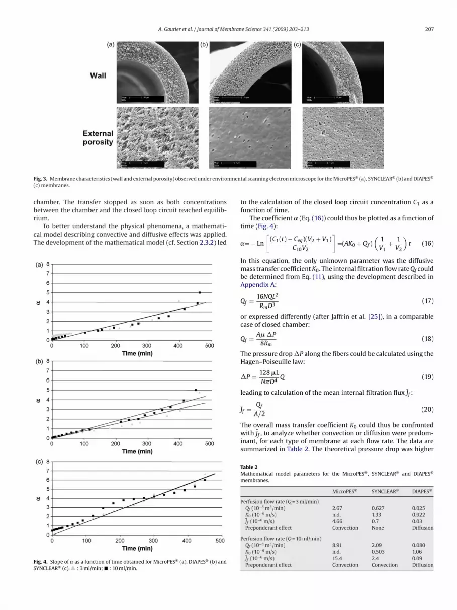
ig. 3. Membrane characteristics (wall and external porosity) observed under enviroc) membranes.
hamber. The transfer stopped as soon as both concentrationsetween the chamber and the closed loop circuit reached equilib-
ium.To better understand the physical phenomena, a mathemati-al model describing convective and diffusive effects was applied.he development of the mathematical model (cf. Section 2.3.2) led
ig. 4. Slope of ˛ as a function of time obtained for MicroPES® (a), DIAPES® (b) andYNCLEAR® (c). : 3 ml/min; � : 10 ml/min.
tal scanning electron microscope for the MicroPES® (a), SYNCLEAR® (b) and DIAPES®
to the calculation of the closed loop circuit concentration C1 as afunction of time.
The coefficient ˛ (Eq. (16)) could thus be plotted as a function oftime (Fig. 4):
˛= − Ln
[(C1(t) − Ceq)(V2 + V1)
C10V2
]=(AK0 + Qf )
(1V1
+ 1V2
)t (16)
In this equation, the only unknown parameter was the diffusivemass transfer coefficient K0. The internal filtration flow rate Qf couldbe determined from Eq. (11), using the development described inAppendix A:
Qf = 16NQL2
RmD3(17)
or expressed differently (after Jaffrin et al. [25]), in a comparablecase of closed chamber:
Qf = A� �P
8Rm(18)
The pressure drop �P along the fibers could be calculated using theHagen–Poiseuille law:
�P = 128 �LN�D4
Q (19)
leading to calculation of the mean internal filtration flux J̄f :
J̄f = Qf
A/2(20)
The overall mass transfer coefficient K0 could thus be confrontedwith J̄f , to analyze whether convection or diffusion were predom-inant, for each type of membrane at each flow rate. The data aresummarized in Table 2. The theoretical pressure drop was higher
Table 2Mathematical model parameters for the MicroPES®, SYNCLEAR® and DIAPES®
membranes.
MicroPES® SYNCLEAR® DIAPES®
Perfusion flow rate (Q = 3 ml/min)Qf (10−8 m3/min) 2.67 0.627 0.025K0 (10−6 m/s) n.d. 1.33 0.922J̄f (10−6 m/s) 4.66 0.7 0.03Preponderant effect Convection None Diffusion
Perfusion flow rate (Q = 10 ml/min)Qf (10−8 m3/min) 8.91 2.09 0.080K0 (10−6 m/s) n.d. 0.503 1.06J̄f (10−6 m/s) 15.4 2.4 0.09Preponderant effect Convection Convection Diffusion

2 mbran
fdmbstbf
ftJ̄tp
uibbash
3
t
Ffl
08 A. Gautier et al. / Journal of Me
or SYNCLEAR® and DIAPES® (1220 Pa) than for MicroPES® (356 Pa),ue to a smaller inner diameter. The internal filtration flow rate wasuch higher with MicroPES® as it was the most permeable mem-
rane. The unknown K0, reflecting diffusive mass transfer, could beuccessfully determined for SYNCLEAR® and DIAPES®. However, inhe case of MicroPES®, it appeared that K0 was equal to zero, proba-ly because all of the transfers occurred through the high convectiveorce.
When the perfusion flow rate was moderate (Q = 3 ml/min), dif-usion appeared to be the major driving process for mass transfer inhe case of DIAPES® for Vitamin B12, as K0 was 30 times higher thanf . For the intermediate membrane SYNCLEAR®, it was not possibleo determine the major mass transport phenomena, as there wasrobably comparable kinetics for both.
When the perfusion flow rate increased, only the DIAPES® mod-le remained in a diffusion driven process. It should be noted that
ncreased perfusion velocity had only a poor impact on K0, probablyecause the main resistance to transfer took place in the mem-rane itself. For the intermediate membrane (SYNCLEAR®), it alsoppeared that convection might become the major driving force,uggesting for the future that an adapted perfusion flow rate mightave a significant influence on the efficiency of the HFBL.
.3. Hollow fiber bioartificial liver with cells
The preponderant effect of mass transfer based on convec-ion (MicroPES®) or diffusion (DIAPES®) or of both forces together
ig. 5. Cell colonization and adhesion at the surface of the chamber in HFBL at 0, 24, 48 aow rate applied was 3 ml/min (b) or 10 ml/min (a, c and d).
e Science 341 (2009) 203–213
(SYNCLEAR®) might have an impact on C3A cell culture with regardto their proliferation and metabolic activities within the HFBL.
In fact, the nature of transfers may play an important role innutrient and oxygen supply and either improve or alter cell behav-ior. On the one hand, a preponderant convective effect such asthrough the MicroPES® membrane should fully ensure the supplyof nutrients and oxygen, leading to enhanced cell activity. On theother, flow rates that are too high might damage the cells because ofexternal mechanical forces and alter their essential activities withina bioartificial liver. The benefits and drawbacks of slow kinetics, asobserved with the DIAPES® membrane, must also be assessed. Thetransfer of essential solutes might not be sufficient, or might, onthe contrary, be perfectly adapted. The SYNCLEAR® membrane withboth physical effects might thus be the most appropriate for HFBLapplication with its intermediate behavior. All of these aspects areaddressed experimentally in the following section.
3.3.1. Cell proliferation and viabilityCell colonization was observed in the cell compartment at 0, 24,
48 and 72 h in the experiment with the contrast phase microscope(Fig. 5). The cells seemed to maintain the same colonization kineticswithin the three types of HFBL and concentrated at the center of the
surface of the bioreactor at the beginning, proliferating towards theperiphery of the HFBL (data not shown). The increase in cell densityreflected cell proliferation over time.Cell viability was excellent at the different time points and wascomparable for all types of membrane (>95%).
nd 72 h-perfusions with MicroPES® (a), SYNCLEAR® (b and c) and DIAPES® (d). The

mbrane Science 341 (2009) 203–213 209
3
mittblAaewmiaco
3
ao
3s
tidlwhsro
timwt
md
stwictwctcfas
ctbtSf
tesy
nth
esiz
ed(a
mm
onia
,lac
tate
and
AFP
)or
con
sum
ed(g
luco
se)
byC
3Ace
lls
inth
e4
8h
-exp
erim
ent
inth
eH
FBL
equ
ipp
edw
ith
the
Mic
roPE
S®(M
),SY
NC
LEA
R®
(S)
and
DIA
PES®
(D)
mem
bran
esin
stat
ican
dio
ns
(wit
hfl
owra
tes
of3
and
10m
l/m
in).
Am
mon
ia(�
mol
)La
ctat
e(�
mol
)G
luco
se(�
mol
)A
FP(n
g)
MS
DM
SD
MS
DM
SD
min
)1.
39±
0.60
1.32
±0.
241.
15±
0.06
18.6
5±
3.31
18.7
7±
2.42
19.6
6±
0.91
7.28
±1.
079.
13±
0.99
8.4
9±
0.33
3.16
±0.
887.
06±
2.60
3.51
±0.
67l/
min
)–
0.72
±0.
45–
–13
.39
±2.
09–
–5.
28±
1.58
––
3.34
±1.
38–
ml/
min
)0.
99±
0.29
0.50
±0.
380.
96±
0.19
21.1
1±
5.40
16.1
8±
8.52
21.4
6±
±4.
435.
77±
3.19
7.04
±4.
286.
20±
0.6
43.
21±
1.95
3.37
±2.
102.
66±
0.50
A. Gautier et al. / Journal of Me
.3.2. Cell activitiesCell functions were assessed via the follow-up of specific
etabolic product concentrations both in the perfusion fluid andn the cell chamber (Table 3). Initial and final (after 48 h) concen-rations of ammonia, lactate, AFP and glucose were measured inhe complete set-up (circuit + chamber) with all types of mem-rane in different experimental conditions. Simple mass balance
ed to calculation of the amounts synthesized (ammonia, lactate,FP) or consumed (glucose) by the cells. The results show that thectivities of the C3A were not statistically different for the differ-nt solutes measured (even for AFP, despite the higher value foundith SYNCLEAR®), regardless of the type of hollow fiber or environ-ental conditions (static or dynamic) were applied. At this level,
ncreasing flow rate did not alter C3A cell behavior in HFBL biore-ctors equipped with SYNCLEAR® membranes. Consequently, C3Aell activity could be considered to be independent of both the typef hollow fiber membrane and the experimental conditions.
.3.3. Mass transferOne of our reasons for using hepatic cells in the chamber was to
nalyze bi-directional mass transfer for different solutes, as somef them were consumed and others were released by the cells.
.3.3.1. Membrane effect. We first focused on low molecular weightolutes, such as glucose and ammonia.
Glucose was consumed by cells as their energy supply, leadingo decreased concentration in the cell chamber, in turn resultingn mass transfer from the closed loop circuit to the chamber. Bothiffusive and convective effects contributed to restoring the equi-
ibrium. Our measurements indicated that glucose concentrationsere balanced between both compartments at the 0-, 24- and 48-perfusions (Fig. 6a). At t0, the equilibrium was expected as the
ame culture medium was introduced into both compartments. Theesults obtained with the DIAPES® membrane were similar to thosebtained with the other membranes (data not shown).
Mass transfer of ammonia occurred in the opposite direction, ashis molecule was synthesized by the liver cells. Its concentrationncreased over time and was balanced between both HFBL compart-
ents at the 24- and 48-h perfusions (Fig. 6b). The results obtainedith the DIAPES® membrane were identical to those of the other
ypes of membrane (MicroPES® and SYNCLEAR®) (data not shown).Ammonia, glucose and lactate could easily cross all types of
embrane because of their low molecular weight. No significantifference was observed between any of the membrane types.
Secondly, we analyzed mass transfer of high molecular weightolutes. Table 3 shows that AFP secretion was comparable for allypes of membrane in dynamic conditions at 10 ml/min. At t0, thereas a very low concentration in the culture medium. Fig. 7 (a, b, c)
llustrates the concentrations in the perfusion circuit and in theell chamber, at 24 and 48 h perfusions (Q = 10 ml/min) with thehree types of module. In the chamber, concentrations increasedith time as this protein was synthesized by the C3A cells. The
oncentrations found in the perfusion medium depended on theype of membrane used. After the 48 h-perfusion, the balance inoncentrations between both compartments was almost attainedor the MicroPES® membrane. This did not occur for SYNCLEAR®
nd DIAPES®, where the AFP concentration in the circuit remainedignificantly lower than that determined in the chamber.
In line with classical membrane processes, an overall sievingoefficient (SC) was defined as the ratio of concentrations between
he circuit and the chamber (SC = C1/C2). A real time SC could note calculated as these concentrations reflected 24 or 48 h of massransfer. After 24 h, the SC was 0.534 for MicroPES®, 0.092 forYNCLEAR® and 0.009 for DIAPES®. After 48 h, the SC reached 0.878or MicroPES®, 0.177 for SYNCLEAR® and 0.003 for DIAPES®. Table
3A
mou
nt
ofso
lud
ynam
icco
nd
it
Stat
ic(Q
=0
ml/
Dyn
amic
(Q=
3m
Dyn
amic
(Q=
10

210 A. Gautier et al. / Journal of Membrane Science 341 (2009) 203–213
F amberb
maatmdc
3tmAhsTm
4
dowwhda
P
F(
ig. 6. Glucose (a) and ammonia (b) concentrations measured in the circuit and chlack: chamber.
This behavior was expected for DIAPES®, as this hemodialysisembrane should not allow high molecular weight protein (e.g.
lbumin) loss. As albumin has almost the same molecular weights AFP, this last protein was retained in the cell compartment. Forhe intermediate membrane SYNCLEAR®, it seemed that partial
ass transfer might occur, but was delayed in time because of hin-ered mass transfer. It was therefore interesting to assess whetherhanges in convection could affect its transfer.
.3.3.2. Flow effect. Due to the geometry of the module, convec-ion could only be modified by changing the perfusion flow rate. To
agnify the kinetic effects, experiments were prolonged up to 72 h.fter 72 h, the AFP concentration in the supernatant was slightlyigher when convection was enhanced (Fig. 7b and d). The overallieving coefficient was 0.184 for 3 ml/min and 0.289 for 10 ml/min.hus, increasing the flow rate enhanced mass transfer through theembrane.
. Discussion
To complete the mass transfer analysis, a mathematical model toescribe mass transfers in HFBL hosting cells could have been devel-ped, in line with the model established for vitamin B12. However, itould require accounting for cell secretion or consumption rates,hich was not direct. The Peclet number (Pe) could nevertheless
elp in distinguishing between diffusive and convective effects. This
imensionless number represented the ratio between convectionnd diffusion in the membrane, with the formula:e = J̄f ı
Dm(21)
ig. 7. AFP concentration measured in the circuit and chamber at 24 and 48 h-perfusionsc). The flow rate applied was 3 ml/min (d) or 10 ml/min (a–c). Gray: circuit; black: chamb
at 0, 24 and 48 h-perfusions at a flow rate of 10 ml/min for DIAPES®. Gray: circuit;
To determine the diffusion coefficient for each solute, the dif-fusional Stokes radius Rd was calculated according to Dionne et al.[26]:
Rd = 0.305 × (MW)0.47 (22)
The diffusion coefficient was then calculated using theStokes–Einstein law:
Dm = RT
6��RdNA(23)
Table 4 summarizes all the parameters based on the mathematicalmodel or the Pe number calculations for the different solute (ammo-nia, lactate, glucose, vitamin B12 and AFP) transfers through theMicroPES®, SYNCLEAR® and DIAPES® membranes with an appliedflow rate of 10 ml/min.
The MicroPES® membrane, which is the most permeable, mainlypromoted convective mass transfer, regardless of the molecularweight of the solute of interest. The greater the molecular weight,the higher the convective effect for molecule transfer across themembrane, as indicated by the Peclet numbers.
For the SYNCLEAR® membrane (the intermediate membranein terms of permeability), the governing phenomenon for masstransfer was molecule size. For low molecular weight solutes suchas ammonia, lactate or glucose, diffusion was the preponderanteffect. Flow rate did not significantly affect mass transport, as shear-
enhanced diffusion in the perfusion fluid did not result in highertransfer, as might occur with a dialysis membrane. For mediumand high molecular weight molecules such as vitamin B12 and AFP,transfer seemed to be driven mainly by convective forces, as wasthe case for MicroPES®.with the flow rate of 10 ml/min for MicroPES® (a), SYNCLEAR® (b and d), DIAPES®
er.

A. Gautier et al. / Journal of Membrane Science 341 (2009) 203–213 211
Table 4Mass transfer parameters for the MicroPES®, SYNCLEAR® and DIAPES® membranes in the flow rate of 10 ml/min.
Ammonia Lactate Glucose Vit B12 AFP
Characteristics of the solute and experimental conditionsMolecular weight (Da) 17 90 180 1355 70,000Stokes radius (nm) 1.15 2.53 3.50 9.04 57.74Diffusion coefficient (m2/s) 2.16 × 10⁻¹⁰ 9.82 × 10⁻¹¹ 7.09 × 10⁻¹¹ 2.23 × 10⁻¹¹ 4.30 × 10⁻¹²
MicroPES®
J̄f (10−4 m/min) 7.90 7.90 7.90 9.26 7.90Pe 5.49 12.1 16.7 62.3 276Predominant effect Convection Convection Convection Convection Convection
SYNCLEAR®
J̄f (10−4 m/min) 1.38 1.38 1.38 1.44 1.38Pe 0.372 0.818 1.13 3.76 18.7Predominant effect Diffusion Diffusion None Convection Convection
DIAPES®
J̄f (10−4 m/min) 0.054 0.054 0.054 0.056 0.054−2
bwc
cwllamot
bcmi
oatgala
MisttmaetwpH4srhcw
Pe 1.25 × 10⁻² 2.75 × 10Predominant effect Diffusion Diffusion
Finally, for the DIAPES® membrane (the least permeable mem-rane), the transfer of low and medium molecular weight solutesas mainly achieved by means of diffusion, and the sieving effects
ompletely retained the AFP in the cell chamber.Our initial hypothesis, regarding the impact of mass transfer on
ell viability and functions, was not confirmed in the present study,here cells adhered to the bottom of the HFBL. Even in the case of
ow permeability membranes, essential nutrients and oxygen wereikely to reach the cells, as correct cell adhesion, very high viabilitynd efficient cell function were observed. However, membrane per-eability had an impact on protein exchange, and more specifically
n the release into the supernatant of the proteins synthesized byhe C3A cells.
For SYNCLEAR®, due to a retention effect and slow convectionecause of intermediate membrane hydraulic permeability, the AFPould only reach the supernatant after a significant delay. This delayight be reduced by increasing the perfusion flow rate and thus the
nternal filtration and concomitant back filtration.With MicroPES®, convective transfer was very efficient. All types
f solute equilibrated in less than 24 h between the cell chambernd the perfusion fluid. There was no evidence of cell alteration dueo the flow in the chamber. Although this aspect was not investi-ated in the present study, it should be mentioned that MicroPES®,plasmapheresis membrane, is also permeable to immunoglobu-
ins. This is in principle not acceptable for future bioartificial liverpplications.
In the literature, several types of HFBL have been investigated.any studies have focused on membrane material and their phys-
cal and chemical properties [2,27,28,29]. However, a systematictudy of the effect of membrane sieving properties on cell func-ion was lacking. With the present results, it now seems obvioushat all the devices based on 60–80 kDa molecular weight cut off
embranes will be unable to fully succeed in liver supply ther-py. Whatever the operating conditions, the membrane sievingffects would be deleterious for the transport of many proteinshat might be essential to liver function. The devices equippedith plasmapheresis membranes have, until now, shown the most
romising results, thanks to highly convective mass transfer. Theepatassist device operating at high plasma flow rates (about00 ml/min) favored this effect, which could explain its potential
uccess. Although such membranes could not prevent an immuneeaction, neither adverse effects nor porcine virus back transferave been reported up until now [11]. It should nevertheless beonsidered as a limitation in the future, especially if mammal cellsere to be employed.3.81 × 10−2 0.127 0.629Diffusion Diffusion No transfer
Thanks to their intermediate cut-off estimated at roughly themolecular weight of AFP, plasmafractionation membranes such asSYNCLEAR® could be advantageously integrated into bioartificialliver support systems. This type of membrane could make possi-ble the release of high molecular weight solutes such as albumin(69 kDa) while sieving immunoglobulins to prevent immune reac-tions. In addition, increasing the flow rate could switch the modulefrom a diffusion mass transfer regimen to a convective regimen,thus enhancing its efficacy.
5. Conclusions
Membranes made from the same material (PES) with differ-ent degrees of permeability (from ultrafiltration to microfiltration)were investigated in vitro within mini-modules representing a par-ticular type of hollow fiber-based bioartificial liver system. Togetherwith a mathematical model for mass transfer, it could be demon-strated that nutrients were adequately transported to the cellslocated in a closed compartment equipped with hollow-fiber mem-branes, regardless of membrane porosity. However, the membranescould be differentiated in relation to their sieving and mass trans-fer properties, especially for proteins synthesized by the liver cells.With microporous membranes, transfers were governed by convec-tion. With hemodialysis membranes, solute transfers were purelydiffusive and restricted to low to medium molecular weight solutes.With an intermediate plasmafractionation membrane, the type oftransfer depended both on solute size and operating conditions. Anadequate perfusion flow rate might lead to enhanced kinetics via aconvective effect.
Besides better understanding of the hydrodynamic and masstransfer behavior of potential hollow fiber bioartificial liver sys-tems, the use of such mini-modules hosting a small number of cellsmight be beneficial for evaluating and selecting the adequate mem-brane and operating conditions to be used with these liver supplydevices.
Acknowledgements
The authors would like to thank Dr. Delavenne for his kind assis-
tance, as well as Dr. Sanchez (Compiègne Hospital), whose precioushelp in analyzing the AFP marker was greatly appreciated. Theywould also like to thank P. Georgin, M. Gouet and G. Le Pape fordeveloping the statistical analysis tools accessible on AnaStats.fr,and Kirsty Snaith (Médicis Traduction) for reading and revising the
2 mbrane Science 341 (2009) 203–213
Eu
A
Q
J
P
d
P
Q
Q
Q
R constant for perfect gaz (Pa m3 K−1)Rd diffusional Stokes radius (m)Rm hydraulic resistance (m−1)T temperature (K)TMP mean transmembrane pressure (Pa) (TMP = (P1in +
P1out)/(2))UF filtration flow rate (m3/s)V volume (m3)v fluid velocity in one fiber (m/s)
Greek letters� fluid viscosity (Pa s)ı membrane thickness (m)
Subscript1 for the supernatant (perfusion fluid)2 for the chamber (cell compartment)
[
[
[21] I.M. Sauer, R. Schwartlander, J. Schmid, et al., The SlideReactor—a simple hollow
12 A. Gautier et al. / Journal of Me
nglish of the manuscript. Certain parts of Fig. 2 were producedsing Servier Medical Art (www.servier.com).
ppendix A.
dP
dx= − 32
�V
D2
V = Q
�D2/4
⎫⎬⎭
dP
dx= − 128
�Q
�D4⇒ �P=128
�Q
�D4L = P1ext − P1sat
f = N
∫ x∗
0
�DJf (x) dx = N
∫ L/2
0
�DJf (x) dx
f (x) = P1(x) − P̄2
�Rm
1(x) = P1 +(
dP
dx
)x = P1 − 128
�Q
�D4x
P̄2 = 1L
∫ L
0
P1(x) dx = 1L
∫ L
0
(P1 − 128
�Q
�D4x)
x = 1L
[P1L − 128
�Q
�D4
L2
2
]
¯2 = P1 − 64�Q
�D4L
Jf (x) =[
P1 − 128�Q
�D4x −
(P1 − 64
�Q
�D4L)]
1�Rm
Jf (x) = 64�Q
�Rm�D4(L − 2x) = 64
Q
Rm�D4(L − 2x)
f = N
∫ L/2
0
64Q
RmD3(L − 2x) dx = 64NQ
RmD3[Lx − x2]
L/20
f = 64NQ
RmD3
[L2
2− L2
4
]= 64
NQ
RmD3
L2
4
f = 16NQ
RmD3L2
Nomenclature
A exchange surface area (m2)C solute concentrationD fiber diameter (m)Dm solute diffusivity in the membrane (m2/s)Jf(x) local filtration flux (m/s)K0 mass transfer coefficient (m/s)L effective fiber length (m)MW molecular weight solute (Da)N number of fibers in the mini-moduleNA Avogadro numberP pressure (Pa)�P pressure drop between the fiber inlet and outlet (Pa)
(�P = P − P1out)
1inPe Peclet numberQf internal filtration flow rate (m3/s)[
in inlet of the hollow fiberout outlet of the hollow fiber
References
[1] D.F. Stamatialis, B.J. Papenburg, M. Girones, et al., Medical applications of mem-branes: drug delivery, artificial organs and tissue engineering, J. Membr. Sci. 308(2008) 1.
[2] C. Legallais, B. David, E. Dore, Bioartificial livers (BAL): current technologicalaspects and future developments, J. Membr. Sci. 181 (2001) 81.
[3] A.A. Demetriou, J. Rozga, L. Podesta, et al., Early clinical experience with a hybridbioartificial liver, Scand. J. Gastroenterol. 208 (1995) 111.
[4] S.C. Chen, W.R. Hewitt, F.D. Watanabe, et al., Clinical experience with a porcinehepatocyte-based liver support system, Int. J. Artif. Organs 19 (1996) 664.
[5] F.D. Watanabe, C.J.P. Mullon, W.R. Hewitt, et al., Clinical experience with a bioar-tificial liver in the treatment of severe liver failure. A phase I clinical trial, Ann.Surg. 225 (1997) 484.
[6] G. Catapano, Mass transfer limitations to the performance of membrane bioar-tificial liver support devices, Int. J. Artif. Organs 19 (1996) 18.
[7] Wolf, et al., Bilirubin conjugation by an artificial liver composed of culturedcells and synthetic capillaries, Trans. Am. Soc. Artif. Int. Organs 21 (1975)16.
[8] A. Gautier, B. Carpentier, C. Legallais, Microencapsulation d’hépatocytes pourla suppléance hépatique, in: Lavoisier, T. Vandamme, D. Poncelet, P. Subra-Paternault (Eds.), Microencapsulation: des sciences aux technologies, 2007, pp.295–312.
[9] R.D. Hughes, R. Williams, Use of bioartificial and artificial liver support devices,Semin. Liver Dis. 16 (1996) 435.
[10] I. Jasmund, A. Langsch, R. Simmoteit, et al., Cultivation of primary porcine hep-atocytes in an OXY-HFB for use as a bioartificial liver device, Biotechnol. Prog.18 (2002) 839.
[11] C. Mullon, Bioartificial organs may help reduce risk of zoonosis in xenotrans-plantation, Artif. Organs 23 (1999) 366.
12] C. Mullon, Z. Pitkin, The HepatAssist bioartificial liver support system: clinicalstudy and pig hepatocyte process, Expert Opin. Invest. Drugs 8 (1999) 229.
[13] J.F. Patzer, G.V. Mazariegos, R. Lopez, Preclinical evaluation of the Excorp Med-ical, Inc, Bioartificial Liver Support System, J. Am. Coll. Surg. 195 (2002) 299.
[14] J. Rozga, Liver support technology: an update, Xenotransplantation 13 (2006)380.
[15] S.L. Nyberg, R.A. Shatford, M.V. Peshwa, et al., Evaluation of ahepatocyte—entrapment hollow fiber bioreactor: a potential bioartificialliver, Biotechnol. Bioeng. 41 (1993) 194.
[16] S.L. Nyberg, S.P. Misra, Hepatocyte liver assist systems a clinical update, MayoClin. Proc. 73 (1998) 765.
[17] J.C. Gerlach, Bioreactors for extracorporeal liver support, Cell Transplant 15(2006) 91.
[18] E. Morsiani, P. Pazzi, A.C. Puviani, et al., Early experiences with a porcinehepatocyte-based bioartificial liver in acute hepatic failure patients, Int. J. Artif.Organs 25 (2002) 192.
[19] M.P. Van de Kerkhove, P.P. Poyck, T. Deurholt, et al., Liver support therapy: anoverview of the AMC-bioartificial liver research, Dig. Surg. 22 (2005) 254.
20] J.K. Park, D.H. Lee, Bioartificial liver systems: current status and future perspec-tive, J. Biosci. Bioeng. 99 (2005) 311.
fiber based bioreactor suitable for light microscopy, Artif. Organs 29 (2005) 264.22] R. Schwartlander, J. Schmid, B. Brandenburg, et al., Continuously microscop-
ically observed and process-controlled cell culture within the SlideReactor:proof of a new concept for cell characterization, Tissue Eng. 13 (2007)187.

mbran
[
[
[
[
[
[28] L. De Bartolo, S. Morelli, A. Piscioneri, et al., Novel membranes and surfacemodification able to activate specific cellular responses, Biomol. Eng. 24 (2007)
A. Gautier et al. / Journal of Me
23] H. Gloeckner, T. Jonuleit, H.D. Lemke, Monitoring of cell viability and cell growthin a hollow-fiber bioreactor by use of the dye Alamar BlueTM, J. Immunol. Meth-ods 252 (2001) 131.
24] H. Gloeckner, H.D. Lemke, New miniaturized hollow-fiber bioreactor for in
vivo like cell culture, cell expansion, and production of cell-derived products,Biotechnol. Prog. 17 (2001) 828.25] M.Y. Jaffrin, G. Reach, D. Notelet, Analysis of ultrafiltration and mass transfer ina bioartificial pancreas, J. Biomech. Eng. 110 (1988) 1.
26] K.E. Dionne, B.M. Cain, R.H. Li, et al., Transport characterization of membranesfor immunoisolation, Biomaterials 17 (1996) 257.
[
e Science 341 (2009) 203–213 213
27] S. Morelli, S. Salerno, M. Rende, et al., Human hepatocyte functions in a galac-tosylated membrane bioreactor, J. Membr. Sci. 302 (2007) 27.
23.29] E. Curcio, L. De Bartolo, G. Barbieri, et al., Diffusive and convective transport
through hollow fiber membranes for liver cell culture, J. Biotechnol. 117 (2005)309.


