Embed Size (px)
Citation preview
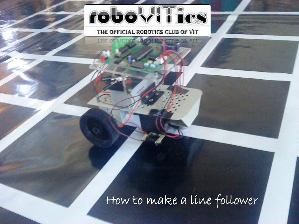
How to make a line follower
(c) Copyright, roboVITics club
2013
2
Introduction
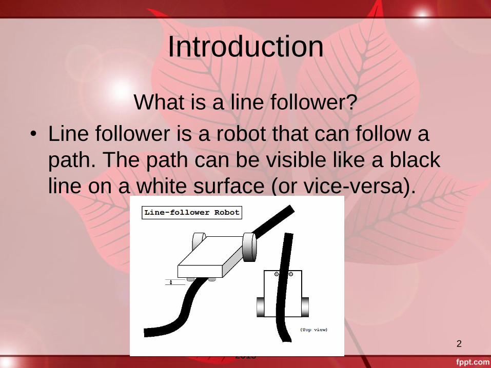
What is a line follower?
• Line follower is a robot that can follow a
path. The path can be visible like a black
line on a white surface (or vice-versa).
(c) Copyright, roboVITics club
2013
3
Hardware Components
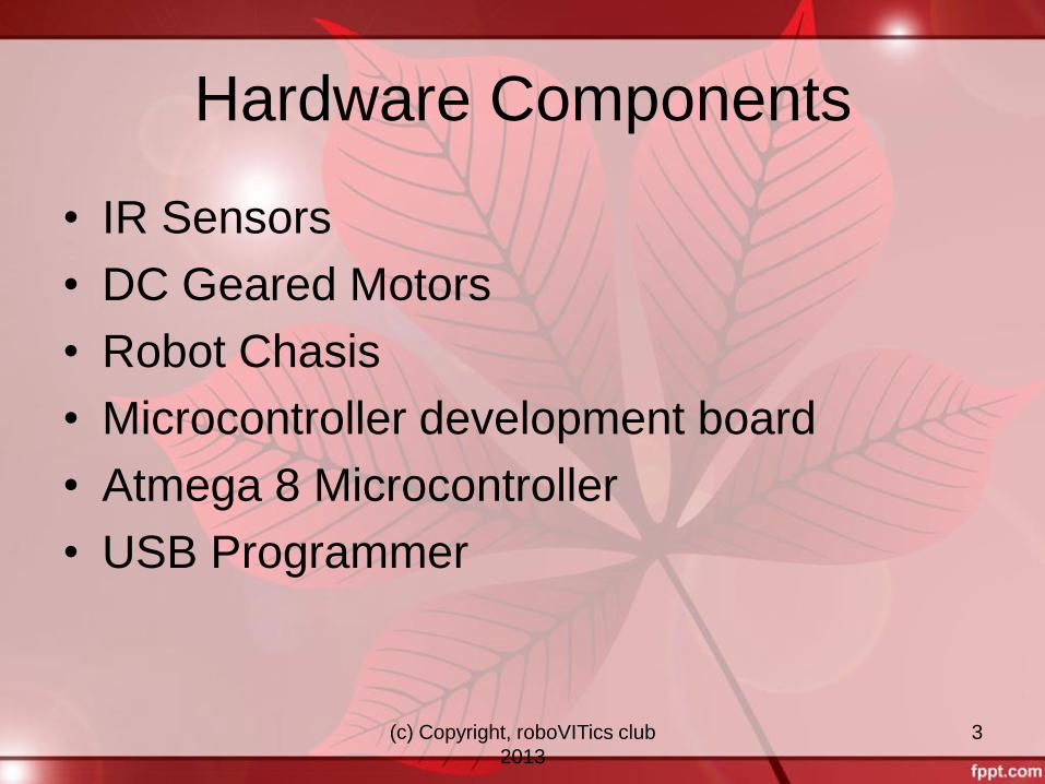
• IR Sensors
• DC Geared Motors
• Robot Chasis
• Microcontroller development board
• Atmega 8 Microcontroller
• USB Programmer
(c) Copyright, roboVITics club
2013
4
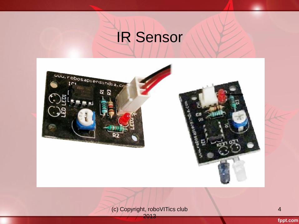
IR Sensor
(c) Copyright, roboVITics club
2013
5
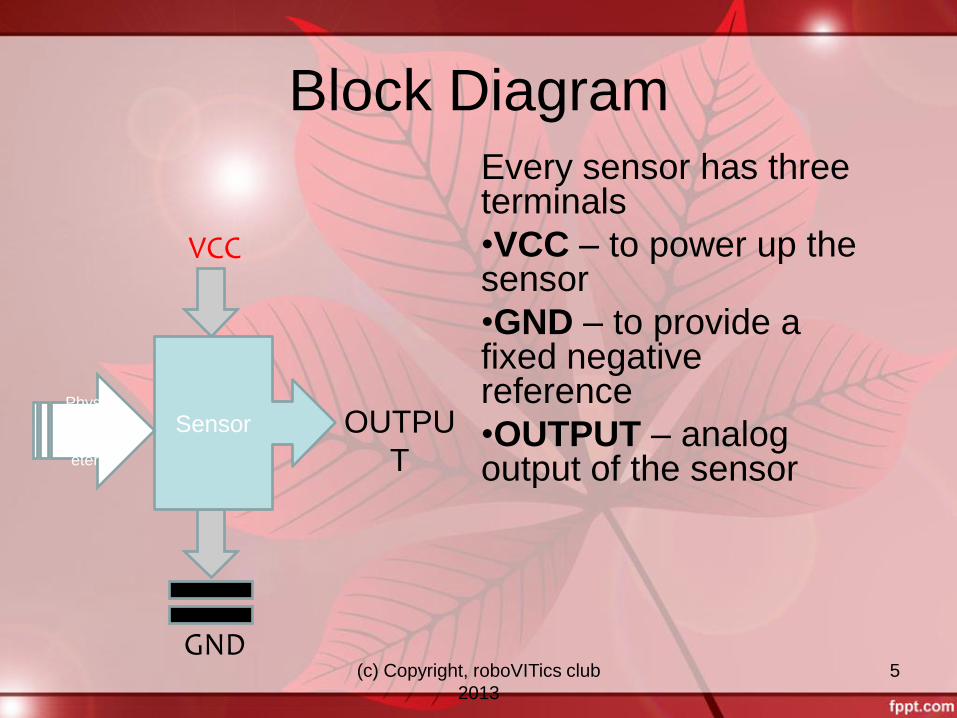
Block Diagram Every sensor has three terminals
•VCC – to power up the sensor
•GND – to provide a fixed negative reference
•OUTPUT – analog output of the sensor
VCC
Sensor
GND
OUTPU
T
Physic
al
Param
eters
(c) Copyright, roboVITics club
2013
6
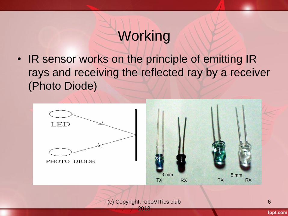
Working
• IR sensor works on the principle of emitting IR
rays and receiving the reflected ray by a receiver
(Photo Diode)
(c) Copyright, roboVITics club
2013
7
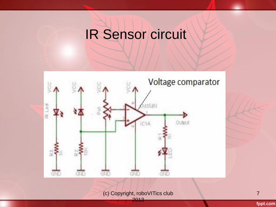
IR Sensor circuit
(c) Copyright, roboVITics club
2013
8
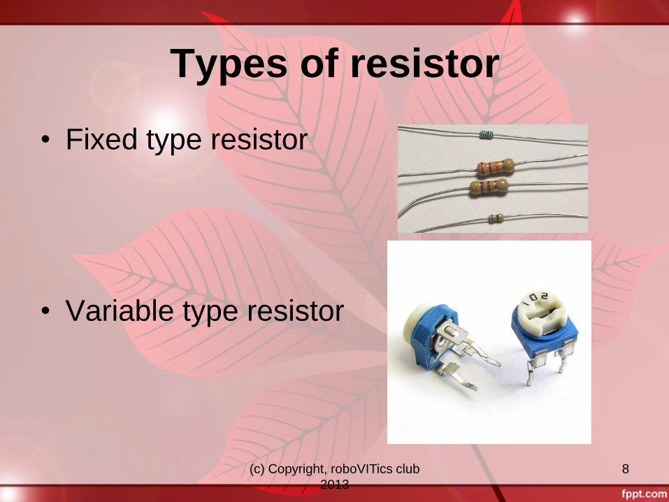
Types of resistor
• Fixed type resistor
• Variable type resistor
(c) Copyright, roboVITics club
2013
9
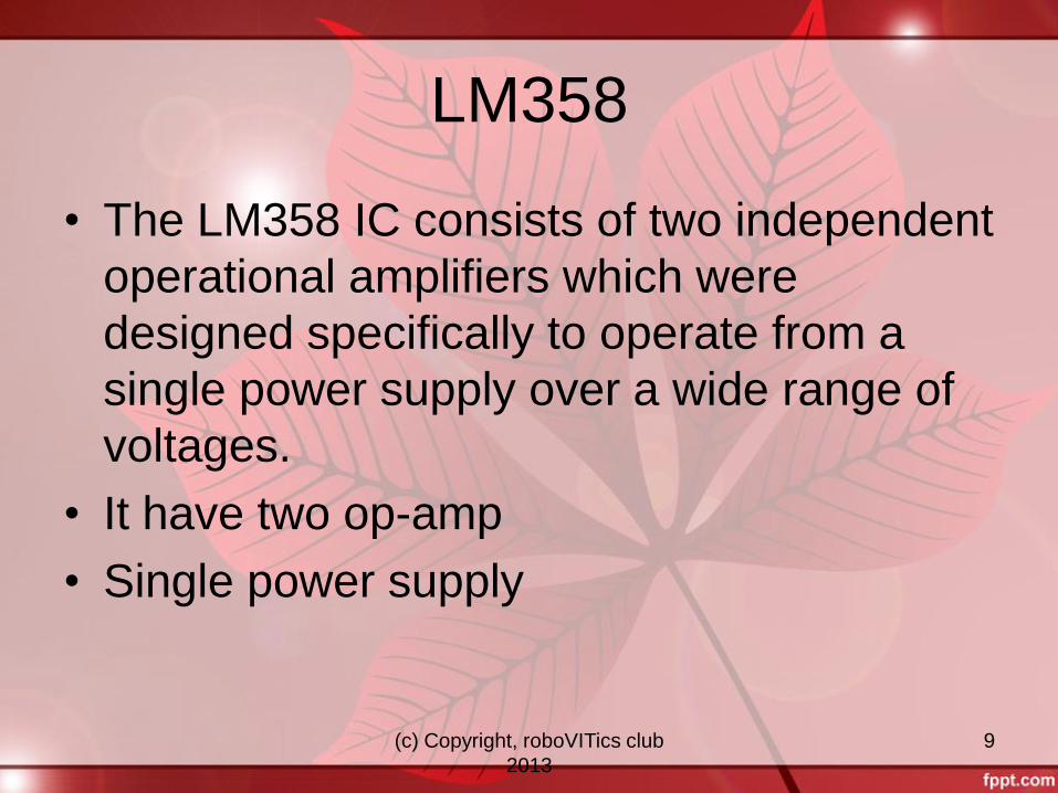
LM358
• The LM358 IC consists of two independent
operational amplifiers which were
designed specifically to operate from a
single power supply over a wide range of
voltages.
• It have two op-amp
• Single power supply
(c) Copyright, roboVITics club
2013
10
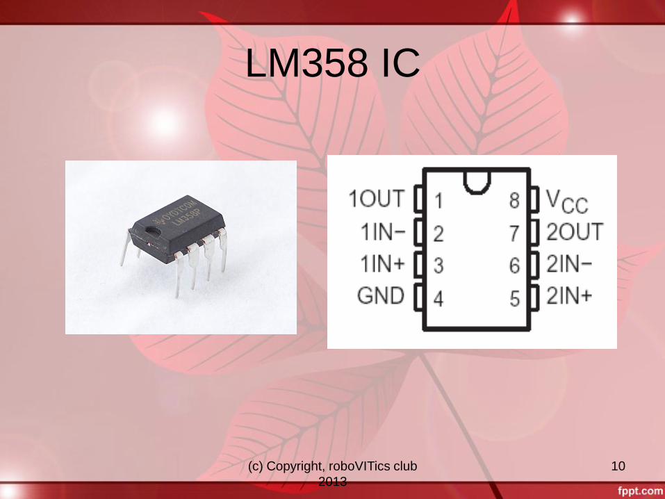
LM358 IC
(c) Copyright, roboVITics club
2013
11
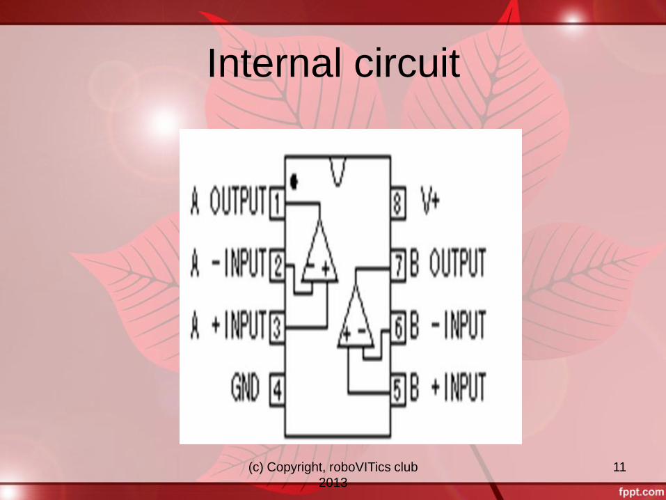
Internal circuit
(c) Copyright, roboVITics club
2013
12
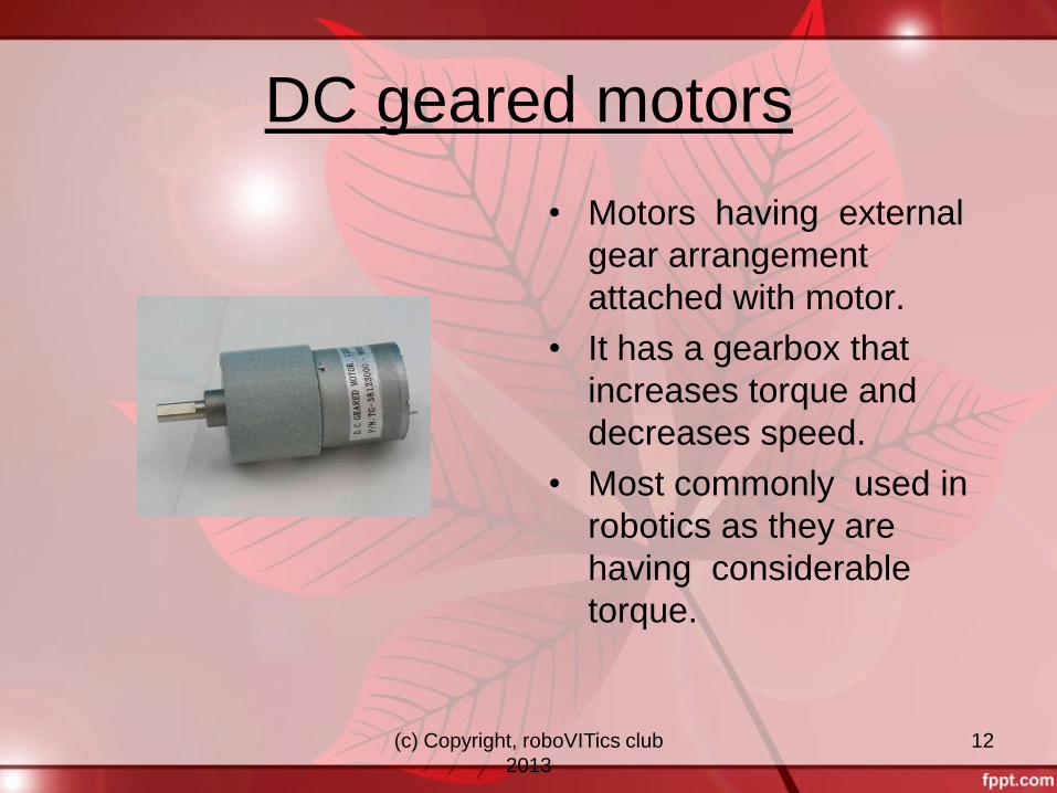
DC geared motors
• Motors having external
gear arrangement
attached with motor.
• It has a gearbox that
increases torque and
decreases speed.
• Most commonly used in
robotics as they are
having considerable
torque.
(c) Copyright, roboVITics club
2013
13
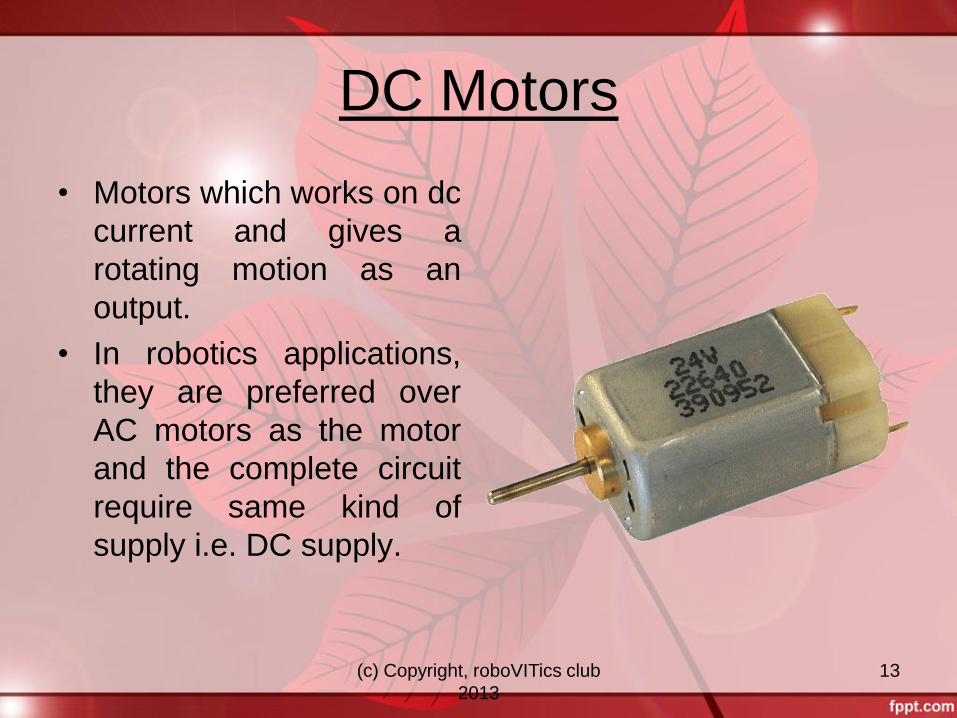
DC Motors
• Motors which works on dc
current and gives a
rotating motion as an
output.
• In robotics applications,
they are preferred over
AC motors as the motor
and the complete circuit
require same kind of
supply i.e. DC supply.
(c) Copyright, roboVITics club
2013
14
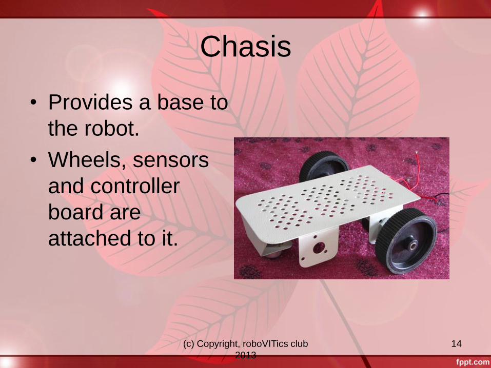
Chasis
• Provides a base to
the robot.
• Wheels, sensors
and controller
board are
attached to it.
(c) Copyright, roboVITics club
2013
15
IC’s
• L293D
• LM358
• IC 7805(voltage controlled)
(c) Copyright, roboVITics club
2013
16
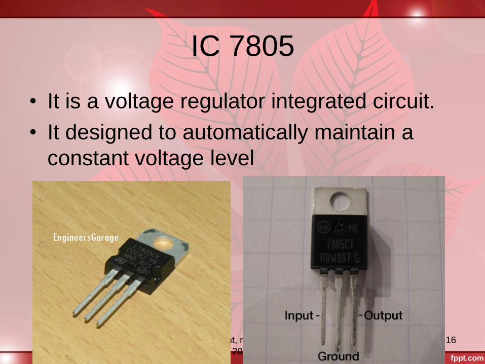
IC 7805
• It is a voltage regulator integrated circuit.
• It designed to automatically maintain a
constant voltage level
(c) Copyright, roboVITics club
2013
17
Features
• Output current range up to 1A
• Output voltage 5V
• Input voltage range up to 12V
• Short circuit protection
(c) Copyright, roboVITics club
2013
18
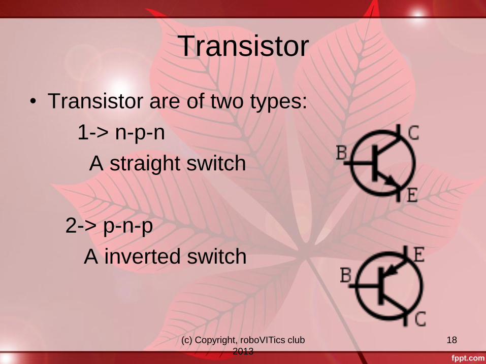
Transistor
• Transistor are of two types:
1-> n-p-n
A straight switch
2-> p-n-p
A inverted switch
(c) Copyright, roboVITics club
2013
19
n-p-n as a switch
• When base of n-p-n is connected with
logic high voltage then it short circuit
emitter and collector (SWITCH ON).
• When base of n-p-n is connected with
logic low voltage then it open circuit both
emitter and collector (SWITCH OFF).
(c) Copyright, roboVITics club
2013
20
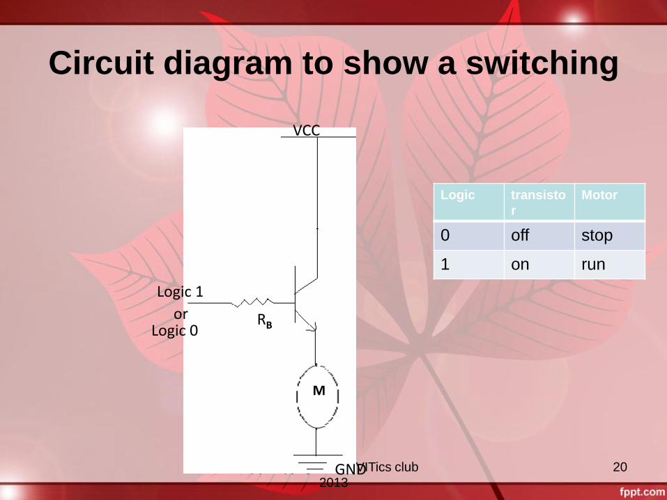
Circuit diagram to show a switching
RB
M
VCC
Logic 0
Logic 1
or
GND
Logic transisto
r
Motor
0 off stop
1 on run
(c) Copyright, roboVITics club
2013
21
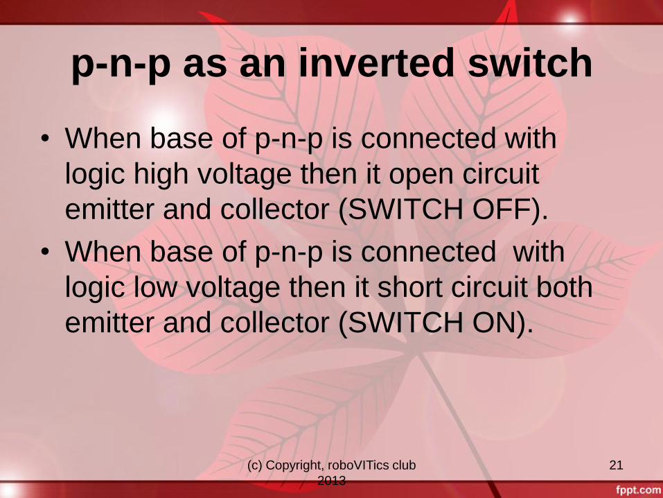
p-n-p as an inverted switch
• When base of p-n-p is connected with
logic high voltage then it open circuit
emitter and collector (SWITCH OFF).
• When base of p-n-p is connected with
logic low voltage then it short circuit both
emitter and collector (SWITCH ON).
(c) Copyright, roboVITics club
2013
22
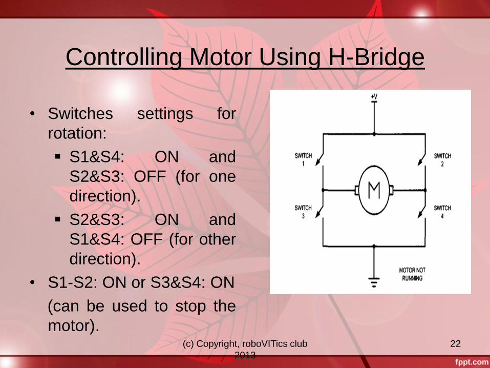
Controlling Motor Using H-Bridge
• Switches settings for
rotation:
S1&S4: ON and
S2&S3: OFF (for one
direction).
S2&S3: ON and
S1&S4: OFF (for other
direction).
• S1-S2: ON or S3&S4: ON
(can be used to stop the
motor).
(c) Copyright, roboVITics club
2013
23
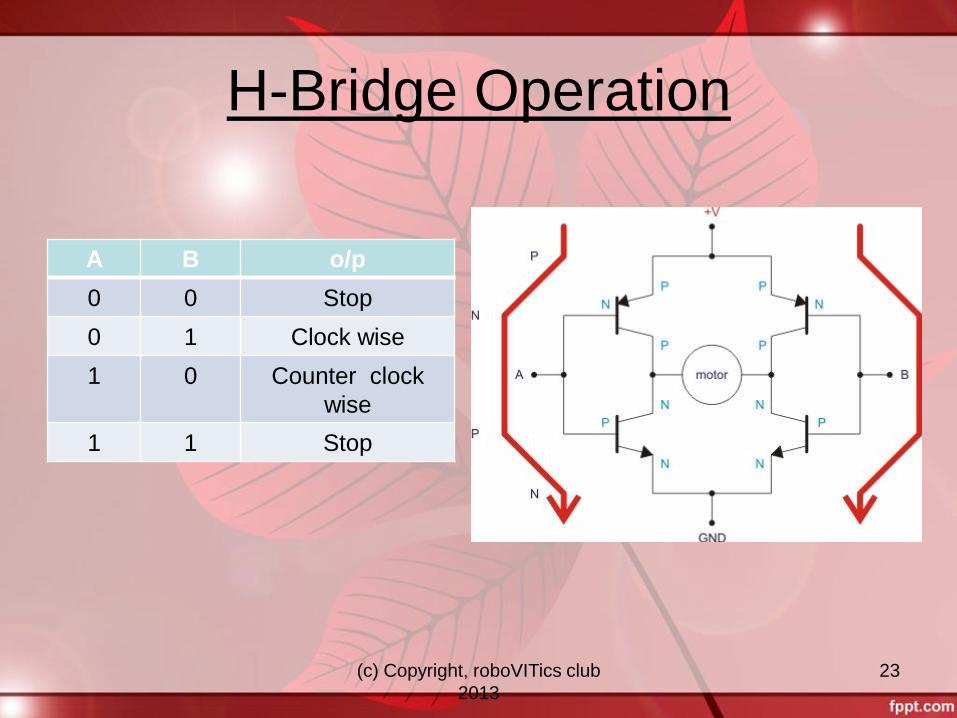
H-Bridge Operation
A B o/p
0 0 Stop
0 1 Clock wise
1 0 Counter clock
wise
1 1 Stop
(c) Copyright, roboVITics club
2013
24
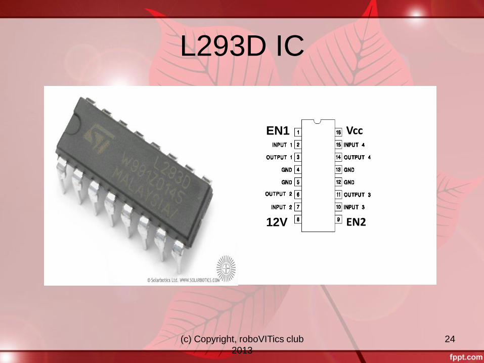
L293D IC
Vcc EN1
EN2
12V
EN1
12V
(c) Copyright, roboVITics club
2013
25
Conti….
• L293D is a dual H-Bridge motor driver.
• So with one IC we can interface two DC motors which can be controlled in both clockwise and counter clockwise direction
• If you have motor with fix direction of motion then you can make use of all the four I/Os to connect up to four DC motors.
• L293D has output current of 600mA.
• Moreover for protection of circuit from back EMF output diodes are included within the IC.
(c) Copyright, roboVITics club
2013
26
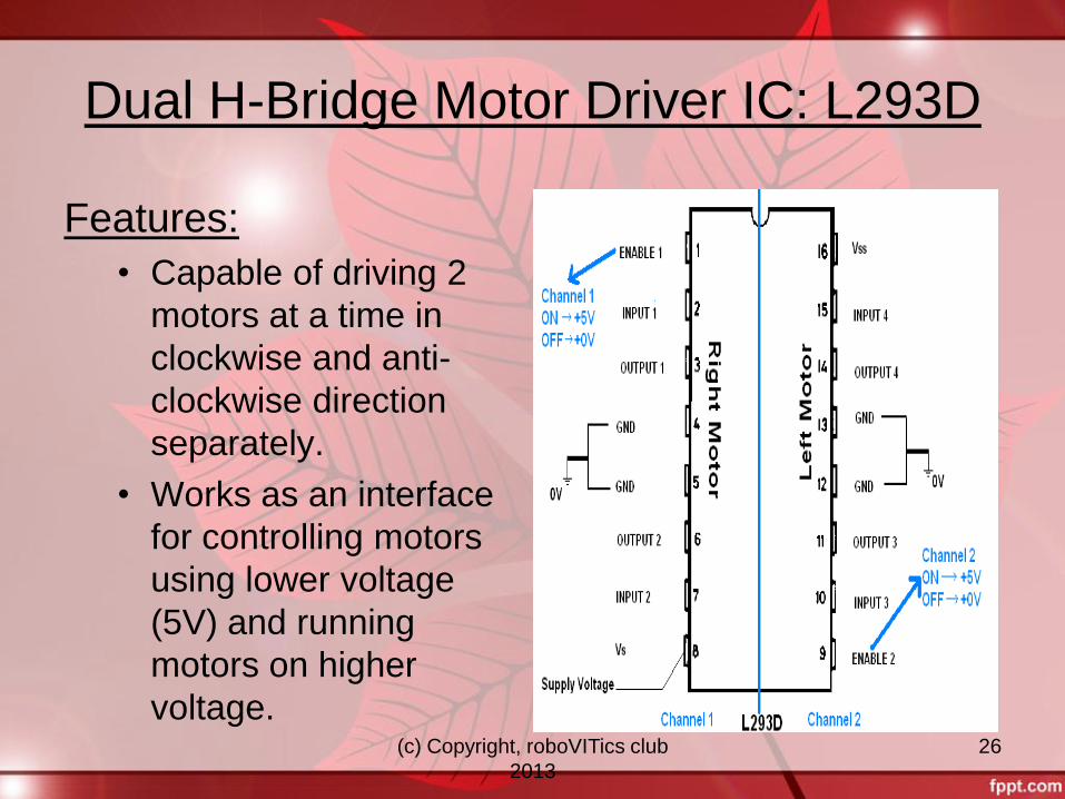
Dual H-Bridge Motor Driver IC: L293D
Features:
• Capable of driving 2
motors at a time in
clockwise and anti-
clockwise direction
separately.
• Works as an interface
for controlling motors
using lower voltage
(5V) and running
motors on higher
voltage.
(c) Copyright, roboVITics club
2013
27
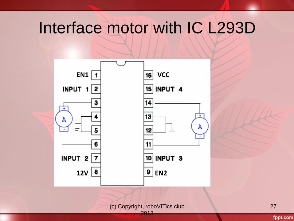
Interface motor with IC L293D
EN1
EN2 12V
VCC
(c) Copyright, roboVITics club
2013
28
What is a Microcontroller?
A microcontroller (sometimes abbreviated µC or MCU) is a small computer on a single IC containing a processor core, memory, and programmable input/output peripherals.
It is a decision making device used widely in embedded systems and all intelligent devices.
(c) Copyright, roboVITics club
2013
29
Difference between Microcontroller
and Microprocessor
Microcontroller has I/O ports, Memory,
timers etc all integrated on chip itself
In Microprocessors, I/O ports, memory,
timer etc are to be connected externally
(c) Copyright, roboVITics club
2013
30
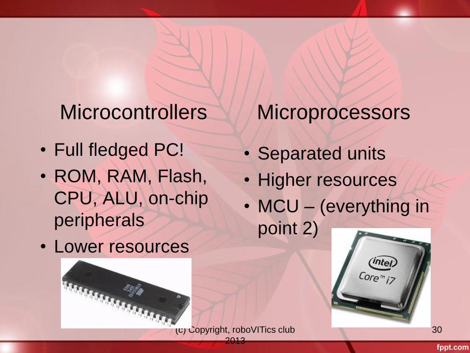
Microcontrollers
• Full fledged PC!
• ROM, RAM, Flash,
CPU, ALU, on-chip
peripherals
• Lower resources
Microprocessors
• Separated units
• Higher resources
• MCU – (everything in
point 2)
(c) Copyright, roboVITics club
2013
31
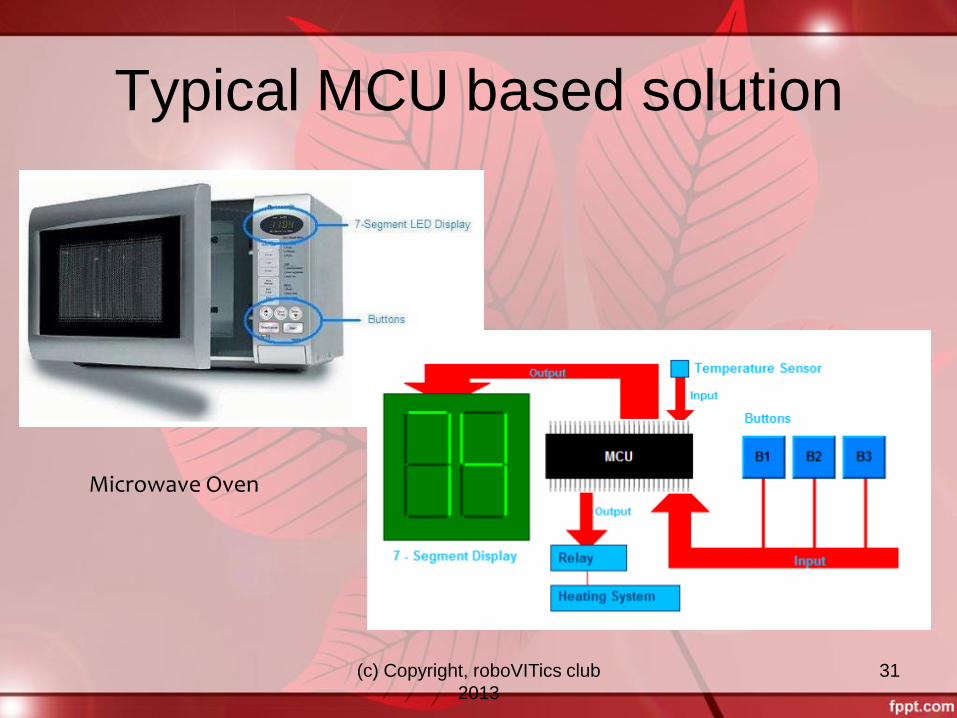
Typical MCU based solution
Microwave Oven
(c) Copyright, roboVITics club
2013
32
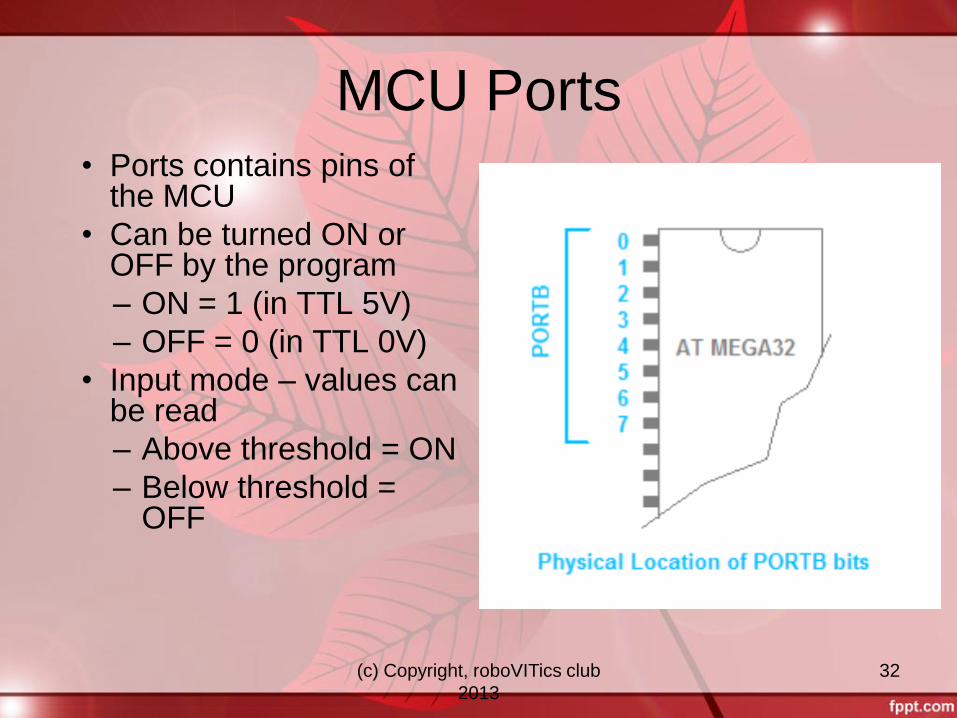
MCU Ports • Ports contains pins of
the MCU
• Can be turned ON or OFF by the program
– ON = 1 (in TTL 5V)
– OFF = 0 (in TTL 0V)
• Input mode – values can be read
– Above threshold = ON
– Below threshold = OFF
(c) Copyright, roboVITics club
2013
33
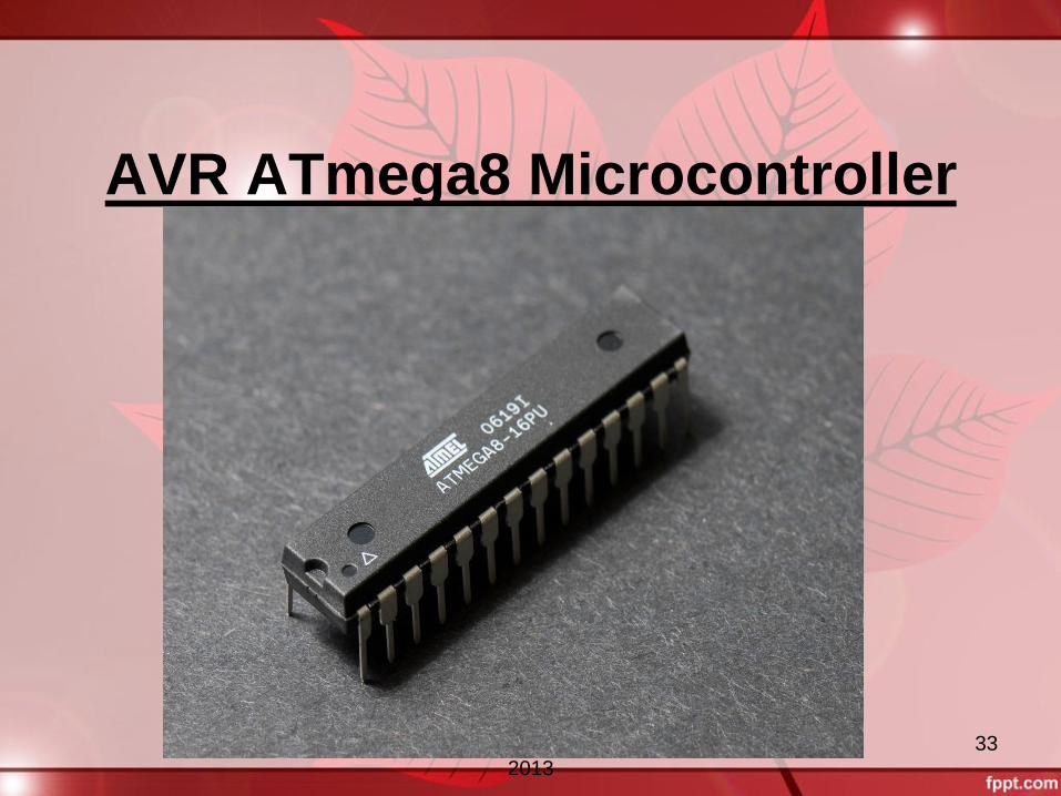
AVR ATmega8 Microcontroller
(c) Copyright, roboVITics club
2013
34
How AVR ATmega8 got its
name? It was developed by Atmel Corporation
AVR implies it belongs to AVR family.
‘8’ in Atmega8 means this microcontroller
has 8Kb of flash memory
(c) Copyright, roboVITics club
2013
35
TYPES OF PACKAGES
28-lead PDIP (Plastic Dual In-line
Package)
32-lead TQFP (Thin Quad film Package)
(c) Copyright, roboVITics club
2013
36
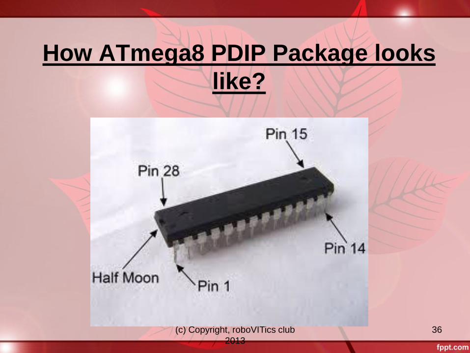
How ATmega8 PDIP Package looks
like?
(c) Copyright, roboVITics club
2013
37
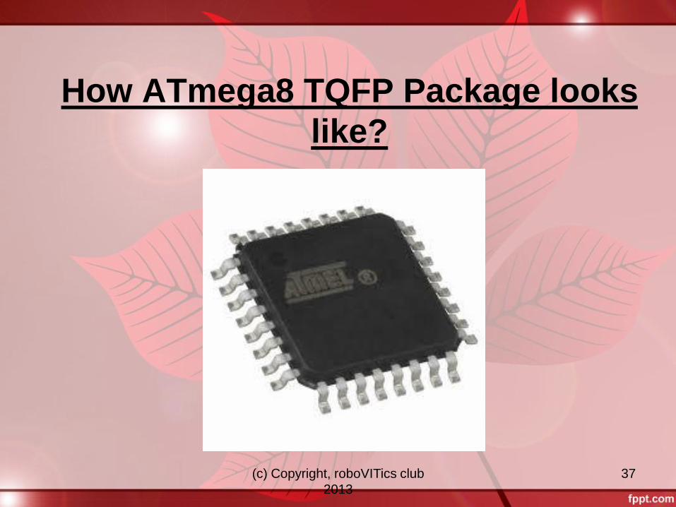
How ATmega8 TQFP Package looks
like?
(c) Copyright, roboVITics club
2013
38
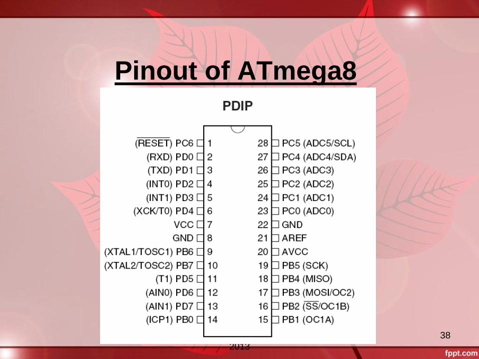
Pinout of ATmega8
(c) Copyright, roboVITics club
2013
39
PORT B(PB7-PB0)
It is a 8-bit bi-directional I/O port.
It can be used either as a input port or as
output port ( direction must be specified in
programming).
(c) Copyright, roboVITics club
2013
40
PORT C(PC6-PC0)
It is a 7-bit bi-directional I/O port.
It can be used either as a input port or as
output port ( direction must be specified in
programming).
(c) Copyright, roboVITics club
2013
41
PORTD(PD7-PD0)
It is a 8-bit bi-directional I/O port.
It can be used either as a input port or as
output port ( direction must be specified in
programming).
(c) Copyright, roboVITics club
2013
42
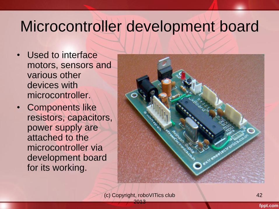
Microcontroller development board
• Used to interface motors, sensors and various other devices with microcontroller.
• Components like resistors, capacitors, power supply are attached to the microcontroller via development board for its working.
(c) Copyright, roboVITics club
2013
43
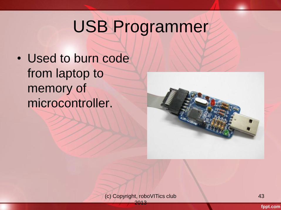
USB Programmer
• Used to burn code
from laptop to
memory of
microcontroller.
(c) Copyright, roboVITics club
2013
44
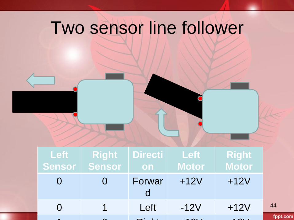
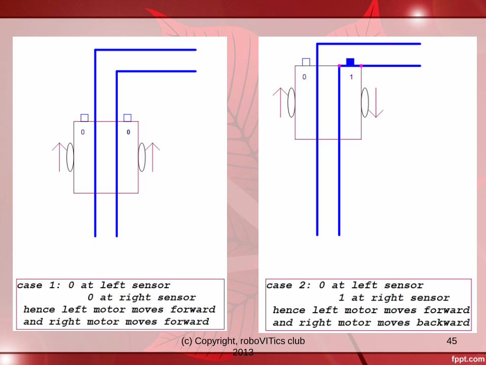
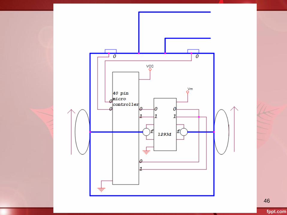
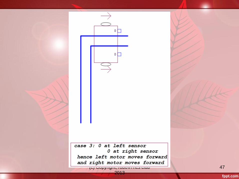
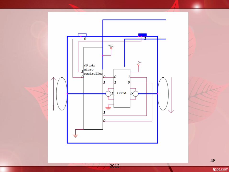
Left
Sensor
Right
Sensor
Directi
on
Left
Motor
Right
Motor
0 0 Forwar
d
+12V +12V
0 1 Left -12V +12V
1 0 Right +12V -12V
Two sensor line follower
(c) Copyright, roboVITics club
2013
45
(c) Copyright, roboVITics club
2013
46
(c) Copyright, roboVITics club
2013
47
(c) Copyright, roboVITics club
2013
48

(c) Copyright, roboVITics club
2013
49
Getting Started
Selecting Hardware
• PC / Mac
• In-System
Programmer (ISP)
• Target Board (MCU
Dev Board)
• Lastly, a MCU!!
Selecting Software
• OS – Windows / Mac
OS / Linux
• “Free” Compiler
• “Free” Programmer
Software
(c) Copyright, roboVITics club
2013
50
Softwares needed
• AVR Studio – for programming
• Compiler – for compiling the code
• eXtreme Burner or avrloader – for buring
code generated to microcontroller.
(c) Copyright, roboVITics club
2013
51
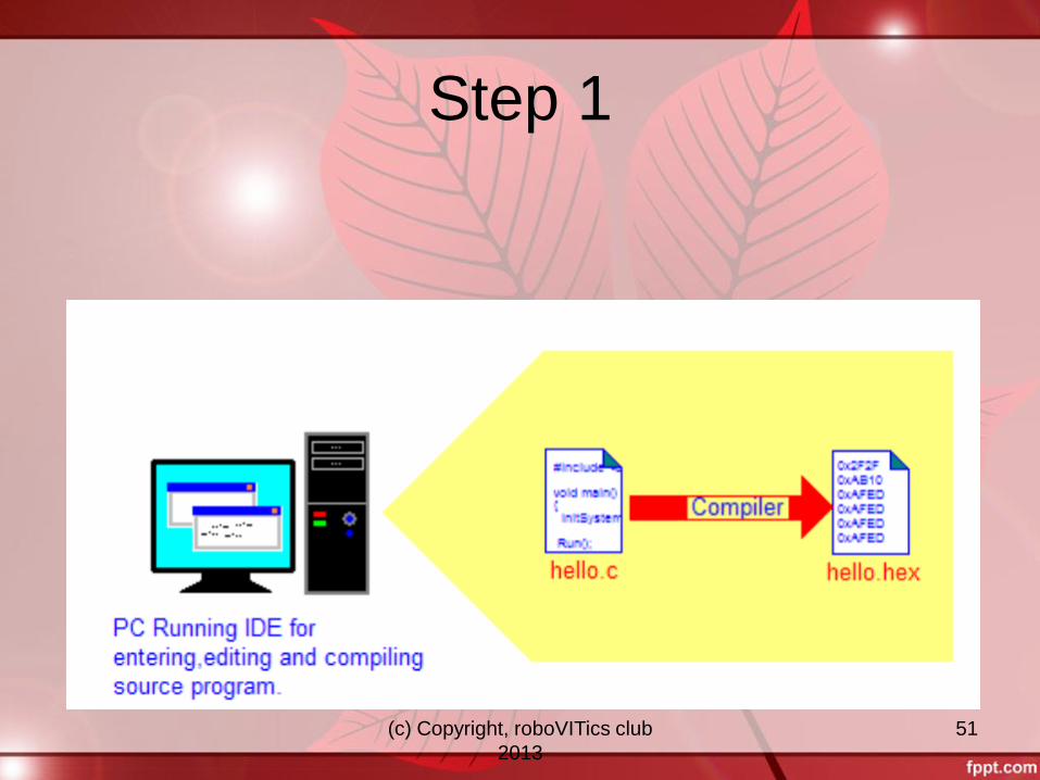
Step 1
(c) Copyright, roboVITics club
2013
52
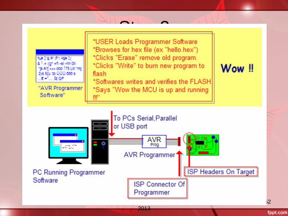
Step 2
(c) Copyright, roboVITics club
2013
53
• Manufacturer gives information regarding the
product to its users
• Data given is in detail
• Features, Technical Specs, Design, Register
Summary, Expected Usage, Troubleshooting,
Pin details, etc.
• Best source of info!!
• All electronic components have a datasheet for
them
• Google them out!!
Datasheet
(c) Copyright, roboVITics club
2013
54
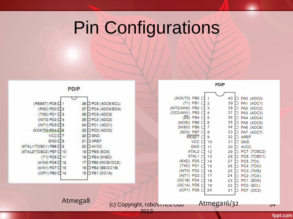
Pin Configurations
Atmega8 Atmega16/32
(c) Copyright, roboVITics club
2013
55
• Most popular C compiler for AVR
• Its official!
• Unlike other compilers/emulators, its totally
free
• The code written will be common to all AVR
mcu’s
• AVR Studio 4 has been used
• AVR Studio 5 beta and AVR Studio 6 has
been released
AVR Studio
(c) Copyright, roboVITics club
2013
56
INTRODUCTION TO EMBEDDED SYSTEM
AND
EMBEDDED C
(c) Copyright, roboVITics club
2013
57
What is Embedded C?
• Embedded C is nothing but a subset of C
language which is compatible with certain
microcontrollers.
• Some features are added using header files like
<avr/io.h>, <util/delay.h>.
• scanf() and printf() are removed as the inputs
are scanned from the sensors and outputs are
given to the ports.
• Control structures remain the same like if-
statement, for loop, do-while etc.
(c) Copyright, roboVITics club
2013
58
Development process of Embedded C
projects • Write C programs in AVR Studio IDE(Integrated
Development Environment)
• Compile them into a .hex file using the AVR-GCC
compiler (which integrates into AVR Studio)
• Simulate the target AVR program and debug the code
within AVR Studio
• Program the actual chip using the USBasp device, which
is attached to our target board with a special 6-pin cable
• Once programmed, the chip runs the program in your
circuit

(c) Copyright, roboVITics club
2013
59
Registers to Communicate with I/O
Ports
To communicate with the ports of
Atmega8, we use three registers:
PINx
PORTx
DDRx
Where x would be either B,C or D.
(c) Copyright, roboVITics club
2013
60
DDRx Register
It stands for Data Direction Register.
It is used to define Port as Input or Output.
In order to make Port as Input Port:
DDRx=0x00 (In Hexadecimal)
DDRx=0b00000000(In Binary)
In order to make Port as output Port:
DDRx=0xFF (In Hexadecimal)
DDRx=0b11111111(In Binary)
(c) Copyright, roboVITics club
2013
61
PORTx Register
If DDRx=0xFF(Output port)
Writing logic 1 to PORTx will make output
high i.e 5v for that particular pin.
Writing 0 to PORTx will make output low
i.e 0v for that particular pin.
(c) Copyright, roboVITics club
2013
62
Continued..
If DDRx=Ox00(Input port):
If corresponding PORTx bit is set to 1, Internal pull up resistors are enabled i.e if we do not connect this pin to anything it still reads as 1.
If corresponding PORTx bit is set to 0, internal pull up resistors are disabled i.e the pin will enter a high impedance state and will become unpredictable.
(c) Copyright, roboVITics club
2013
63
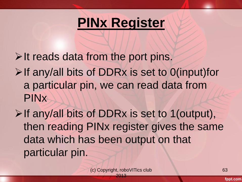
PINx Register
It reads data from the port pins.
If any/all bits of DDRx is set to 0(input)for
a particular pin, we can read data from
PINx
If any/all bits of DDRx is set to 1(output),
then reading PINx register gives the same
data which has been output on that
particular pin.
(c) Copyright, roboVITics club
2013
64 (c) Copyright, roboVITics club 2013
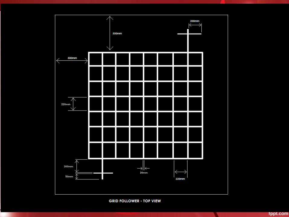
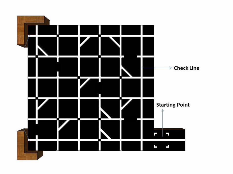
Grid Follower
(c) Copyright, roboVITics club
2013
65
(c) Copyright, roboVITics club
2013
66
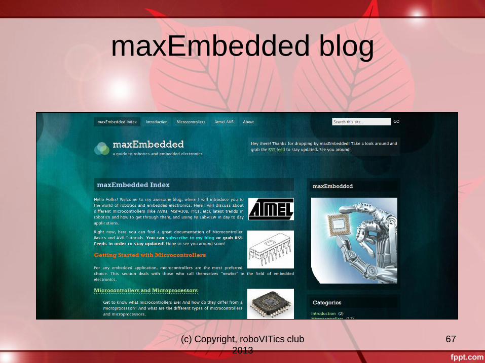
maxEmbedded.com
For Details, visit
A guide to robotics and embedded electronics AVR Guide and Tutorials
Basics of Microcontrollers, Sensors, Timers, ADC, Serial Communication, etc
(c) Copyright, roboVITics club
2013
67
maxEmbedded blog

(c) Copyright, roboVITics club
2013
68
• store.extremeelectronics.co.in
• nex-robotics.com
• embeddedmarket.com
• rhydolabz.com
• thinklabs.in
• sparkfun.com
• ietestore4u.com
Online Stores

(c) Copyright, roboVITics club
2013
69
That’s all for today
Suggestions and Doubts are welcome
For more info, visit Mayank bhaiya’s blog maxEmbedded.wordpress.com
© maxEmbedded 2013
Thank you

(c) Copyright, roboVITics club
2013
70


