Embed Size (px)
Citation preview

HP Archive
This vintage Hewlett Packard document was preserved and distributed by
www. h parch ive.com
Please visit us on the web !
On-line curator: Glenn Robb
FOUR EASY WAYS TO USE THIS CATALOG
1. Check headings on opposite page for general type of instrument. Use convenient edge marks to find
2. Turn to pages 1b through 5 for five pages of “Short Form Catalog” listing hp instruments by type or
3. Find equipment by its model number in the numerical index, beginning on page 262 at back of this
4. Find equipment by its name or title, alphabetical index back of this catalog, pages 258-261 (example --“Digital Voltmeter”).
proper pages.
function (example-“Signal Generators 50 KC to 40 GC”).
catalog (exampIe--“400D Voltmeter”).
Other Important Information This catalog includes detailed information on all instruments available from Hewlett-Packard and Harrison Laboratories. Information is also provided on complete lines or selected instruments and systems manufactured by Hewlett-Packard divisions and affiliates. Ask your hp representative for in- formation on new instruments introduced after catalog publication date.
PLACING YOUR ORDER OR RETURNING INSTRUMENTS. Page l a contains timesaving suggestions for ordering. Pages 20 and 21 have information on service and repairs.
@ DIVISIONS, AFFILIATES. Page% contains a summary of equipment available f rom Hewlett-Packard divisions and affiliates, indexed on the opposite page. Pages 9 through 17 offer brief descriptions of specific instruments and systems manufactured by each member of t he hp family. A special section on power supplies, pages 243 through 257, gives complete technical data on instruments available from Harrison Laboratories.
OTHER INFORMATION ON @ INSTRUMENTS. In addition ro data in this catalog, information about application and operation of hp equipment is found in hp Data Sheets, Application Notes and the Hewlett-Packard Journal, monthly technical periodical from the Research and Development 1 aboratories. These publications are offered without charge; see page 22 for details.
COMMUNICATING WITH CO M M U N ICATl N G WITH HEWLETT-PACKARD. ENGINEER-SALESMAN. HEWLETT-PACKARD 5. A. Mail: 1501 Page Mill Road, Hewlett-Packard engineer-salesmen Mail: 54 Route des Acacias, Palo Alto, California, U. S. A. are located in most major manufactur- Geneva, Switzerland. Telephone: 326-7000, ha Code 415. ing centers in the United States and Telephone: (022) 42. 81. 50. TWX: 415-492-9200. Canada, and principal cities overseas. Telex: 2. 24. 86. Cable: HEWPACK. Names and complete addresses of Cable: HEWPACKSA.
Hewlett-Packard representatives and sales offices are listed inside the back cover of this catalog.
COMMUNICATING WITH @
_--
Hewlett-Packard Catalog No. 24, 4-63 Printed in U. S. A.
Al l data in this catalog subject to change without notice. Prices f .0 .b . factory.
Instruments in this catalog are grouped by type or ficnction. Each group is generally preceded by “Technical Data” pages which summarize the equipment ofered in the group and discuss circuit theory and latest measuring techniques.
. . . . . . . . . . . . . . . . . . . . . . . . . . . . . . . . . . . .
. . . . . . . . . . . . . . . . . . . . . . . . . . . . . . . . . . . . .
. . . . . . . . . . . . . . . . . . . . .
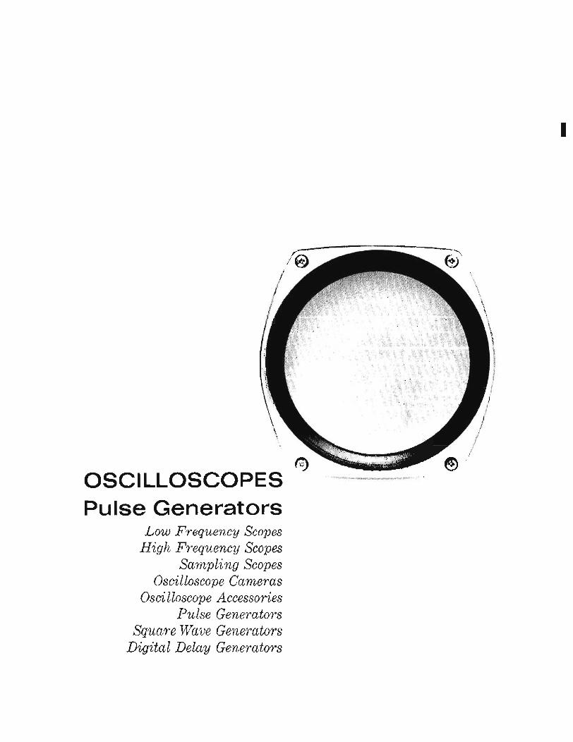
OSCILLOSCOPES - PULSE GENERATORS Oscilloscopes
LOW Frequency Scopes
Sampling Scopes High Frequency Scopes . . . . . . . . . . . . . . . . . .
Pulse Generators
. . . . . . . . . . . . . . . . . . . . . . . . . . . . . . . . AUDIO-VIDEO INSTRUMENTATION
Oscillators and Audio Signal Generators Wave and Distortion Analyzers . . . . . . . . . . . . . . . . . Voltmeters, Ohmmeters, Ammeters Voltmeter Calibrators and Accessories . . . . . . . . . . . . . . . . Amplifiers Attenuators
. . . . . . . . . . . . . . . . . . . . . . . . . . . . . . . . . . . . . . . . . . . . . . . . . . . . . . . . . . . .
FREQUENCY AND TIME MEASURING INSTRUMENTATION . . . . . . . . . . . Solid State Electronic Counters . . . . . . . . . . . . . . . . . . Vacuum Tube Electronic Counters . . . . . . . . . . . . . . . . Digital Recorders . . . . . . . . . . . . . . . . . . . . . Frequency and Time Standards . . . . . . . . . . . . . . . . . Freqzcency Synthesizer . . . . . . . . . . . . . . . . . . .
MICROWAVE INSTRUMENTATION . . Microwave Test Equipment Summaries
S-Band . . . . . . G, J-Bands . . . . . H, X-Bands . . . . . P-Band . . . . . . K, R-Bands . . . . . M-Band . . . . . . Coaxial Instrumentation . . .
Noise Figure Measurement Instruments Power Measurement Instruments . . Wavemeters . . . . . . . Signal Generators, Modulators . . Impedance Measurement Instruments .
T W T Amplifiers . . . . .
Sweep Oscillators . . . . .
. . . . . . . . . . . . . . . . . . . . . . . . . . . . . . . . . . . . . . . . . . . . . . . . . . . . . . . . . . . . . . . . . . . . . . . . . . . . . . . . . . . . . . . . . . . . . . . . . . . . . . . . . . . . . . . . . . . . . . . . . . . . . . . . . . . . . . . . . . . . . . . . . . . . . . . . . . . . . . . . . . . . . . . . . . . . . . . . . . . . . . . . . . . . . . . . . . . . . . . . . . . . . . . . . . . . . . . . . . . . . . .
POWER SUPPLIES . . . . . . . . . . . . . . . . . . . . .
ADDITIONAL PRODUCT LISTINGS
BOONTON RADIO COMPANY . . . . . . . . . . . . . . . . . . DYMEC D I V I S I O N . . . . . . . . . . . . . . . . . . . . F. 1. MOSELEY CO. . . . . . . . . . . . . . . . . . . . . SANBORN COMPANY . . . . . . . . . . . . . . . . . . . .
SUGGESTIONS FOR ORDERING
Order by Model Number When you order, please specify the catalog model number
and name of instrument desired. For example, “Model 400D Vacuum Tube Voltmeter.” To prevent misunderstanding, include significant specifications and specific instructions in your order whenever you desire special options or special features such as special color, nonstandard power line volt- age, etc.
Many Hewlett-Packard instruments are available in cabi- nets for bench use or with 19” panels for rack mounting. The letter “R” after the model number indicates a rack mounting instrument. For example, “400DR.” Catalog list- ings indicate availability of cabinet or rack mounting arrange- ments. Please be sure your order indicates which you desire. With many instruments, bench and rack mount models are identical.
Where to Send Your Order Your order should be made out to the Hewlett-Packard
Company and sent to Hewlett-Packard, through your local @ representative (see inside of back cover). See additional information below if you are located outside the United States.
Local Technical Assistance Technical assistance in selecting equipment and preparing
orders is available without charge from engineering repre- sentatives at authorized @ sales offices in the United States and in principal areas throughout the world (see inside back cover for names aizd addresses.) In addition, a staff of qualified engineers is maintained at @ offices in Palo Alto, California, and Geneva, Switzerland, to supplement the serv- ices available from your local representatives.
Shipping Methods Shipments to destinations within the United States and
Western Europe are made directly from local factories or warehouses. Unless specifically requested otherwise, express or truck transportation is used, whichever is cheaper and most serviceable to you. Small items are sent via parcel post. If rapid delivery is needed, we will gladly ship by the more expensive methods of air freight, air express or air parcel post when specified on your order.
Terms U. S. terms are 30 days net. Unless credit has already been
established, shipments will be made C.O.D., or on receipt of cash in advance. See additional information below if you are located outside the United States.
Quotations and Pro Forma Invoices Upon request, quotations, or pro forma invoices, will be
furnished to you by your local authorized @ sales office, the Hewlett-Packard Company or Hewlett-Packard S. A. Prices will be specified on an F.O.B. factory basis unless otherwise requested.
Repairs An extensive service facility is maintained in Palo Alto,
California, to repair and recalibrate any Hewlett-Packard instrument. In most cases repairs can also be made in the field, either by your own service technicians or by factory- trained personnel at one of the field repair facilities main- tained by your local Hewlett-Packard representative or dis- tributor (see inside of back cover for loratioits aitd addres- ses).
Field servicing of instruments is normally faster since transportation time to the factory is eliminated. If, however, you wish to return an instrument to the factory for repairs, recalibration, or for any other reason, please contact Custo- mer Service, Hewlett-Packard Company, 395 Page Mill Road, Palo Alto, California, phone: 326-3950, before ship- ment for instructions. Please give model number, name, serial number, and as much other information as possible concerning the reason for return. Non-warranty repairs are made at the cost of labor and materials, plus a small service charge. See page 20 for information on warranty repairs.
Repair Parts Repair parts are ordered in the same way as instruments.
Please identify parts by the @ stock number shown in the instruction manual, and if possible, by the schematic diagram circuit reference number. Model number and serial number of the instrument, and original purchase date should also be given, if known. See page 20 for additional information.
Additional Information For Customers Outside the United States
Where to Send Your Order In many countries, your order can be placed directly on
your local @ distributor or representative (see inside back cover). Alternatively, your order can be made out to Hew- lett-Packard Company, (Hewlett-Packard s. A. if you are in Western Europe) and sent to the appropriate Hewlett- Packard office, either directly or through your local @ au- thorized sales offices.
If m @ representative or distributor has, as yet, been appointed for your area, your order should be placed di- rectly on the Hewlett-Packard Co., 1501 Page Mill Road, Palo Alto, California, U. S. A.
Shipping Methods Shipments to customers outside the United States or West-
ern Europe are made from the appropriate @ facility by either surface or air, as requested. Sea shipments generally
require special export packaging at a nominal surcharge of $5.00 per instrument.
Terms Terms for orders from countries outside the United States
which are placed on the Hewlett-Packard Company, or Hew- lett-Packard S. A. are irrevocable letter of credit or cash in advance unless other terms have been arranged previously. Terms for orders placed on authorized Hewlett-Packard dis- tributors are mutually determined between the customer and the distributor.
Quotations and Pro Forma Invoices FAS, CIF, C & F, etc., quotations or pro forma invoices,
as well as exportation assistance, are available on request from your local authorized @ sales office, the Hewlett-Pack- ard Co., Palo Alto, California, or Hewlett-Packard S. A., Geneva, Switzerland.
l a
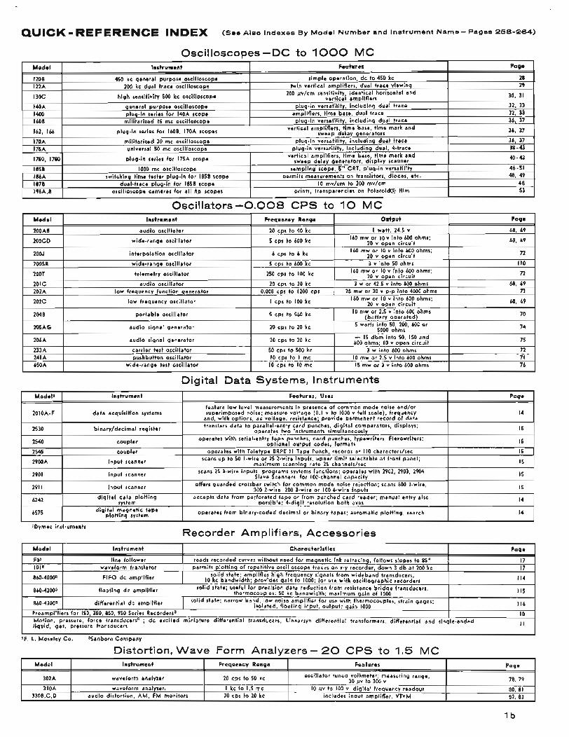
QUICK - REFERENCE INDEX (See Also Indexes BY Model Number and Instrument Name- Pages 258-264)
Oscilloscopes-DC to 1000 MC
Oscillators-0.008 CPS to 1 0 MC
Model Instrument Characteristics
F32 1012
860-40003 FIFO dc amplifier
860-42003 floating dc amplifier
860-43003 differential dc amplifier
line follower waveform translator
reads recorded curves without need for magnetic ink retracing, follows slopes to 85' permits plotting of repetitive oscilloscope traces on x-y recorder, down 3 db a t 200 kc
solid state; amplifies high frequency signals from wideband transducers I O kc bandwidth; provides gain to 1000; for use with oscillographic recorders
solid state; useful for precision data reduction from resistance bridge transducers, thermocouples: 50 kc bandwidth: maximum gain of 1000
solid state: narrow band, low noise amplifier for use with thermocouples, strain gages; isolated, floating input, output; gain I000
.
Preamplifiers for 150, 350, 850, 950 Series Recorders3
Qymec instruments Recorder Amplifiers, Accessories
Page
17 17
I I4
I I5
I16
I O
~~~ ~
Model Instrument
302A waveform analyzer
310A waveform analyzer: 330B,C,D audio distortion, AM, FM monitors
Distortion. Wave Form Analvzers- 20 CPS to 1.5 MC Frequency Range Features Page
oscillator tuned voltmeter; measuring range, 30 fiv to 300 v 78, 79
80, 81 82, 83
20 cps to 50 kc
I kc to 1.5 mc 20 cps to 20 kc
I O fiv to 100 v, digital frequency readout includes input amplifier, VTVM
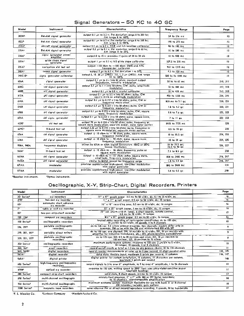
Signal Generators - 50 KC to 40 G C
?F. L. Moreley Co. 8SSanborn Company 'Hewlett-Packard Co.
2
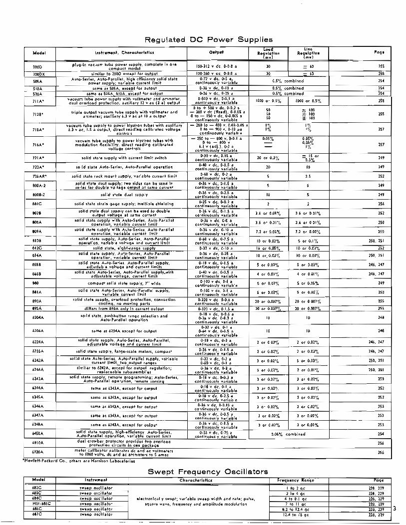
Regulated DC Power Supplies
'Hewlett-Packard C o . , others are Harrison Laboratories
SweDt Freauencv Oscillators Model Instrument Characteristics Frequency Range Page
228, 229 b83C sweep osci1lato.r 2 to 4 gc 228, 229 b84C sweep oscillator electronically swept; variable sweep width and rate: pulse, 4 to 8.1 gc 228, 229 HO I -b8bC sweep oscillator square wave, frequency and amplitude modulation 7 to I I gc 228, 229 b8bC sweep oscillator 8.2 to 12.4 gc 228 , 229 b87C sweep oscillator 12.4 to I8 gc 228, 229
I to 2 gc b82C sweep oscillator
3
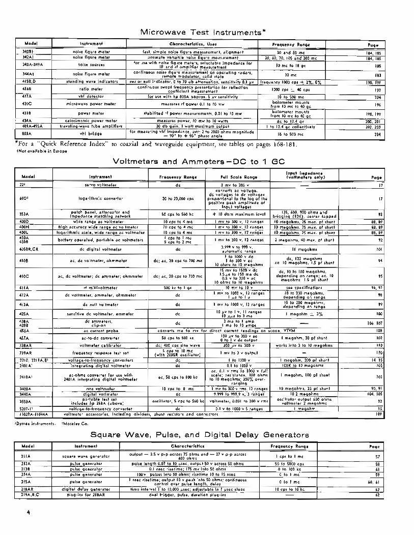
Microwave Test Instruments*
Model
21 I A
212A 2138 214A
215A
218AR 2 I 9A, 8 ,C
. . tNot available in Europe
Instrument Characteristics Frequency Range Page
57 58
pulse generator 0.1 nsec risetime; I75 mv i n t o h m s 0 to 100 kc 61
pulse generator 0 to I mc 60, 61
62 62
I cps to I rnc
50 to 5000 cps
output - 3.5 v p-p across 75 ohms and - 27 v p-p across 600 ohms square wave generator
pulse generator
pulse generator lOOv pulses into 50 ohms: risetime I O to 15 nsec 0 to I mc 59
pulse length 0.07 to I O psec, output 50 v across 50 ohms
I nsec risetime; output I O v peak into 50 ohms: continuous control over pulse lenqth, delay
time interval I to 10,000 psec; adjustable - .______ in I bsec steps digital delay generdtor I O cps to I O kc plug-ins for 218AR dual trigger, pulse, duration plug-ins -
Voltmeters and Ammeters-DC to 1 GC
logarithmic converter 20 to 20,000 cps
I30
5262A
5275A time interval counter 7-digit display, IO nsec resolution
signal: eliminates drift problems 57961
'Dvmec instruments
I O nsec to 0.1 sec 131
transfer sync~ronirer phase-locks hp H06-5408 Transfer Oscillator to unknown 200 mc to 12.4 gc 141
Other I nstru ments and Accessories
solid state dc amplifier
~
'Dymec instruments Registered Trademark of t h e Hewlett.Packard Company. 5
ABOUT HEWLETT-PACKARD
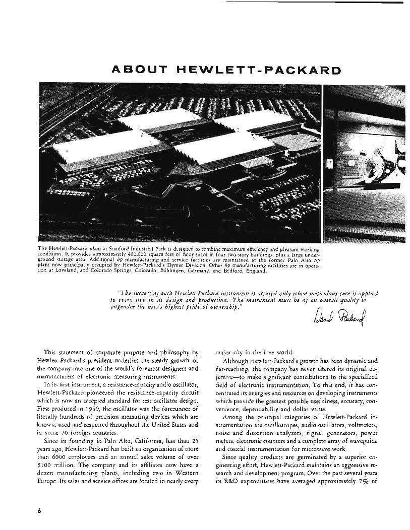
The Hewlett-Packard plant at Stanford Industrial Park is designed to combine maximum efficiency and pleasant working conditions. I t provides approximately 400,000 square feet of floor space in four two-story buildings, plus a large under- ground storage area. Additional hp manufacturing and service facilities are maintained at the former Palo Alto hp plant now principally occupied by Hewlett-Packard’s Dyrnec Division. Other hp manufacturing facilities are in opera- tion at Loveland, and Colorado Springs, Colorado; Boblingen, Germany, and Bedford, England.
“The success of each Hewlett-Parkard instrument i s assured only when meticulous care is applied to every step in its design and production. The instrument must be of an overall quality to engender the user’s highest pride of ownership.”
This statement of corporate purpose and philosophy by Hewlett-Packard’s president underlies the steady growth of the company into one of the world’s foremost designers and manufacturers of electronic measuring instruments.
In its first instrument, a resistance-capacity audio oscillator, Hewlett-Packard pioneered the resistance-capacity circuit which is now an accepted standard for test oscillator design. First produced in 1939, the oscillator was the forerunner of literally hundreds of precision measuring devices which are known, used and respected throughout the United States and in some 70 foreign countries.
Since its founding in Palo Alto, California, less than 25 years ago, Hewlett-Packard has built an organization of more than 6000 employees and an annual sales volume of over $100 million. The company and its affiliates now have a dozen manufacturing plants, including two in Western Europe, Its sales and service offices are located in nearly every
major city in the free world. Although Hewlett-Packard’s growth has been dynamic and
far-reaching, the company has never altered its original ob- jective-to make significant contributions to the specialized field of electronic instrumentation. T o this end‘, it has con- centrated its energies and resources on developing instruments which provide the greatest possible usefulness, accuracy, con- venience, dependability and dollar value.
Among the principal categories of Hewlett-Packard in- strumentation are oscilloscopes, audio oscillators, voltmeters, noise and distortion analyzers, signal generators, power meters, electronic counters and a complete array of waveguide and coaxial instrumentation for microwave work.
Since quality products are germinated by a superior en- gineering effort, Hewlett-Packard maintains an aggressive re- search and development program. Over the past several years its R&D expenditures have averaged approximately 7% of
6
its gross income. As a result of this consistently high invest- ment, its engineering staff and laboratory facilities are con- sidered among the finest in the electronics industry.
On the production end of its operations, the company is manufacturing an increasing number of its own precision components, including photoconductors, semiconductor diodes and other solid state devices, These components con- tribute an unparalleled degree of accuracy, dependability and sophistication to Hewlett-Packard products.
The market for the company’s instruments covers a broad spectrum of science and industry. From electronic develop- ment laboratories to radio and T V studios, from chemical research facilities to aircraft plants, from paper mills to medi- cal laboratories, from hi-fi repair shops to space vehicle in- stallations-Hewlett-Packard equipment is found in a wide variety of applications.
To fulfill the varying needs of its many thousands of cus- tomers, the company employs a large staff of factory-trained field engineers. These engineers, whose primary responsibility is to provide technical data and assistance to customers, are backed by a Palo Alto-based customer service group including more than 150 technicians and specialists. Together they as- sure Hewlett-Packard customers of prompt, efficient service in meeting their instrumentation requirements.
As Hewlett-Packard enters its second quarter-century of growth and progress, the company intends to continue pro- viding instruments which represent the utmost in elegant de- sign and f ine craftsmanship-a standard of quality un- matched in the electronic test equipment field,
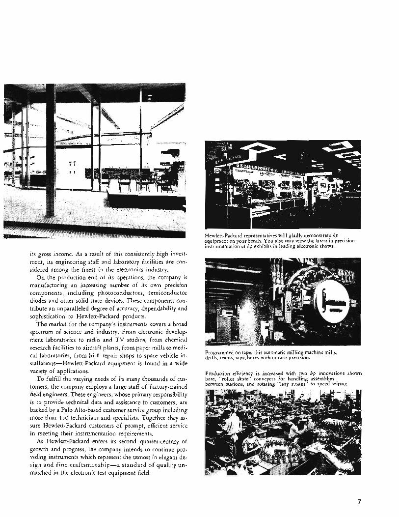
Hewlett-Packard representatives will gladly demonstrate hp equipment on your bench, You also may view the latest in precision instrumentation at hp exhibits in leading electronic shows.
Programmed on tape, this automatic milling machine mills, drills, reams, taps, bores with utmost precision.
Production efficiency is increased with two hp innovations shown here, “roller skate” conveyers for handling assemblies between stations, and rotating “lazy susans” to speed wiring.
7
TO assure that each instrument is the outgrowth of specialized engineering knowledge and manufacturing techniques, Hewlett-Packard has established four major product-oriented divisions - oscilloscopes, audio- video, frequency and time, and microwave. Operations of these four divisions are in Palo Alto, California; Loveland, Colorado; and Colorado Springs, Colorado.
In 1958 the company acquired 8074 of the stock of the F. L. Moseley Co. of Pasadena, California. Since then it has acquired several other firms whose activities and products are directly related to the parent com- pany’s field of interest. These divisions and affiliates include:
BOONTON RADIO DIVISION - Founded in 1935, this firm was acquired by Hewlett-Packard in 1959. Lo- cated in Boonton, New Jersey, the division designs and manufactures instruments for measuring electrical circuit quality and testing aircraft guidance systems. It has gained wide recognition for its top quality imped- ance measuring equipment, particularly its Q meters.
DYMEC DIVISION - Founded as a separate company in 1956, Dymec became a Hewlett-Packard division in 1959. Located in Palo Alto, the division produces instruments and systems in two broad categories of elec- tronic instrumentation - digital data and radio frequency. Using a unique approach to standard system design, Dymec instruments are combined with other Hewlett-Packard devices to form relatively inexpensive, pre-packaged instrument assemblies.
H P ASSOCIATES - This affiliated organization was formed by Hewlett-Packard in 1961. Headquartered in Palo Alto, it is engaged in a most important activity-solid state research and development. Its prime objective is to apply the highest level of technical competence to solid state R&D problems and to transform the results of its scientific endeavor into new and improved devices for electronic instrumentation. Informa- tion on available semiconductor devices can be obtained by writing directly to H P Associates, 2900 Park Boule- vard, Palo Alto, California.
HARRISON LABORATORIES DIVISION - Founded in 1954, this firm was originally engaged in the produc- tion of television studio equipment. It later entered the power supply field, and today specializes in the de- sign and manufacture of highly regulated dc power supplies. Located in Berkeley Heights, New Jersey, Harrison Laboratories became a division of Hewlett-Packard in 1961.
F. L. MOSELEY CO. - Founded in 1951, F. L. Moseley became an affiliate of Hewlett-Packard in 1958. The company is a leading manufacturer of precision X-Y recorders and related instruments. It is particu- larly noted for its top-quality line of Autograf recorders and accessory devices. The company has two plants in Pasadena, California.
PAECO DrvrsIoN-Originally founded in 1951 as the Palo Alto Engineering Company, Paeco became a division of Hewlett-Packard in 1962. Located in Palo Alto, the division designs and manufactures Hewlett- Packard ac power supplies, static inverters, voltage regulators and frequency changers.
SANBORN COMPANY - Founded in 1917, this well-established company became an affiliate of Hewlett- Packard in 1961. The firm is a leading producer of medical diagnostic apparatus and since 1949 has also designed and manufactured a broad line of industrial instruments for measuring and recording such phys- ical phenomena as stress, strain, pressure, speed, sound, vibration and temperature. Sanborn is head- quartered in Waltham, Massachusetts.
8
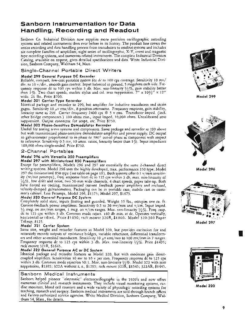
Sanborn Instrumentation for Data Handling, Recording and Readout Sanborn Co. Industrial Division now supplies more precision oscillographic recording systems and related instruments than ever before in its history. The product line covers the entire recording and data handling process from transducers to readout systems and includes six complete families of amplifiers; eight series of oscillographic, X-Y, event and magnetic tape recording systems, and numerous related instruments. The complete Industrial Division Catalog, available on request, gives detailed specifications and data. Write Industrial Divi- sion, Sanborn Company, Waltham 54, Mass.
Single-Channel Portable Direct Writers Model 299 General Purpose DC Recorder Reliable, compact, low-cost portable system for dc to 100 cps coverage. Sensitivity 10 mv/ div. to 10 v/div., smooth gain control. Input balanced to ground, 5 megohms each side. Fre- quency response dc to 100 cps within 3 db. Max. non-linearity y2%, gain stability better than 1%. Two chart speeds, marker stylus and cal. zero suppression. 7” x l O l / ” x 12” wide. 2 1 Ibs. Price $700. Model 301 Carrier-Type Recorder Identical package and recorder to 299, but amplifier for inductive transducers and strain gages. Sensitivity 10 pv rms/div., 8-position attenuator. Frequency response, gain stability, linearity same as 299. Carrier frequency 2400 cps @ 5 v rms. Transducer imped. (incl. other bridge components.) 100 ohms min., input imped. 10,000 ohms. Uncalibrated zero suppression. Output connector for scope, etc. Price $750. Model 302 Phase-Sensitive Demodulator Recorder Useful for testing servo systems and components. Same package and recorder as 299 above but with transistorized phase-sensitive demodulator-amplifier and power supply. DC output to galvanometer proportional to in-phase or 180’ out-of-phase ac component with respect to reference. Sensitivity 0.5 mv, 10 atten. ratios, linearity better than 1%. Input impedance 100,000 ohms single-ended. Price $750.
Model 296 with Versatile 350 Preamplifiers Model 297 with Miniaturized 850 Preamplifiers Except for preamplifiers, Models 296 and 297 are essentially the same 2-channel direct writing systems. Model 296 uses the highly developed, max. performance 350 type; Model 297 the miniaturized 850 type (see table on page l o ) . Both systems offer 0.1 v/mm sensitiv- Ity (w/out preamps), freq. response from dc to 125 cps within 3 db, max. non-linearity of 1/2%, low drift and noise, two 50-mm wide channels, 4 chart speeds, paper take-up. Both have forced air cooling, transistorized current feedback power amplifiers and enclosed, velocity-damped galvanometers. Packaging can be in portable case, mobile cart or custo- mer’s cabinet. Less Preamps, Model 296, $1575; Model 297, $1675. Model 320 General Purpose DC System Completely solid state, inputs floating and guarded. Weight 55 Ibs., occupies one cu. ft. Current-feedback power amplifiers. Sensitivity 0.5 to 20 mv/mm and v/cm. Input imped. yz meg. on mvjmm ranges, 1 meg. on v/cm ranges. Max. non-linearity 1/%. Freq. resp. dc to 125 cps within 3 db. Common mode reject. 140 db min. at dc. Operates vertically, horizontal or t i l ted. Price $1650; rack mount 320R, $1800. Model 320-300 Paper Takeup, $12 5. Model 321 Carrier System Same size, weight and recorder features as Model 320, but provides excitation for and accurately records outputs of resistance bridges, variable reluctance, differential transform- ers and other ac-excited transducers. Sensitivity 10 Fv rms/mm to 100 mv/mm in 7 ranges. Frequency response dc to 125 cps within 3 db. Max. non-linearity y2”/0. Price $1495; rack mount 321R, $1645. Model 322 General Purpose AC or DC System Identical package and recorder features as Model 320, but with moderate gain direct- coupled amplifiers. Sensitivities 10 mv to 10 v per mm. Frequency response dc to 125 cps within 3 db. Common mode rejection 50:1. Max. non-linearity ’/%. Model 322 with zero suppression, $1395; 322A without z. s., $1295; rack mount 322R, $1545; 322AR, $1445.
2-Chan ne1 Portables
Sanborn Medical Instruments Sanborn helped pioneer “electronic” electrocardiographs in the 1920’s and now offers numerous clinical and research instruments. They include visual monitoring systems, car- diac monitors, blood cell counters and a wide variety of physiologic recording systems for teaching, research and surgery. Sanborn medical instruments are sold through branch offices and factory-authorized service agencies. Write Medical Division, Sanborn Company, Wal- tham 54, Mass., for details.
Model 299
4 Model 296
Model 297
Model 320
9
150 Series
350 Series
8 5 0 Series
950 Series
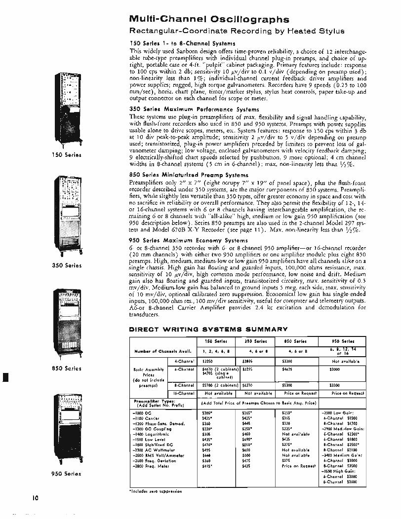
Multi-Channel Oscillographs Rectangular-Coordinate Recording by Heated Stylus
150 Series 1- to 8-Channel Systems This widely used Sanborn design offers time-proven reliability, a choice of 12 interchange- able tube-type preamplifiers with individual channel plug-in preamps, and choice of up- right, portable case or 4-ft. “pulpit” cabinet packaging. Primary features include: response to 100 cps within 2 db; sensitivity 10 pv/div to 0.1 v/div (depending on preamp used); non-linearity less than 1 % ; individual-channel current feedback driver amplifiers and power supplies; rugged, high torque galvanometers. Recorders have 9 speeds (0.25 to 100 mm/sec) , horiz. chart plane, timer/marker stylus, stylus heat controls, paper take-up and output connector on each channel for scope or meter.
350 Series Max imum Performance Systems These systems use plug-in preamplifiers of max. flexibility and signal handling capability, with flush-front recorders also used in 850 and 950 systems. Preamps with power supplies usable alone to drive scopes, meters, etc. System features: response to 150 cps within 3 db at 10 div peak-to-peak amplitude; sensitivity 2 pv/div to 5 v/div depending on preamp used; transistorized, plug-in power amplifiers preceded by limiters to prevent loss of gal- vanometer damping; low voltage, enclosed galvanometers with velocity feedback damping; 9 electrically-shifted chart speeds selected by pushbutton, 9 more optional; 4 cm channel widths in 8-channel systems ( 5 cm in 6-channel); max. non-linearity less than y2%. 8 5 0 Series Miniaturized Preamp Systems Preamplifiers only 2” x 7” (eight occupy 7’’ x 19” of panel space), plus the flush-front recorder described under 350 systems, are the major components of 850 systems. Preampli- fiers, while slightly less versatile than 350 types, offer greater economy in space and cost with no sacrifice in reliability or overall performance. They also permit the flexibility of 12-, 14- or 16-channel systems with 6 or 8 channels having interchangeable amplification, the re- maining 6 or 8 channels with “all-alike” high, medium or low gain 950 amplification (see 950 description below), Series 850 preamps are also used in the 2-channel Model 297 sys- tem and Model 670B X - Y Recorder (see page 11). Max. non-linearity less than 1/2%. 950 Series Max imum Economy Systems 6- or 8-channel 350 recorder with 6- or 8-channel 950 amplifier-or 16-channel recorder (20 mm channels) with either two 950 amplifiers or one amplifier module plus eight 850 preamps. High, medium, medium-low or low gain 950 amplifiers have all channels alike on a single chassis. High gain has floating and guarded inputs, 100,000 ohms resistance, max. sensitivity of 10 pv/div, high common mode performance, low noise and drift. Medium gain also has floating and guarded inputs, transistorized circuitry, max. sensitivity of 0.5 mv/div. Medium-low gain has balanced to ground inputs 5 meg. each side, max. sensitivity of I O mv/div, optional calibrated zero suppression. Economical low gain has single-ended inputs, ~ 0 0 , 0 0 0 ohm res., 100 mv/div sensitivity, useful for computer and telemetry outputs. Ab-or 8-channel Carrier Amplifier provides 2.4 kc excitation and demodulation for transducers.
DIRECT WRITING SYSTEMS SUMMARY
I
Basic Assembly 6-Channel $4870 (2 cabinets) $5215 $4625 $3000
(do not include . $4705 (single
cabinet) Prices
preamps) 8-Channel $5780 (2 cabinets) $6270 $5300 $3300 I 1 1 1
16-Channel I N o t available 1 Not available I Price on Reauest 1 Price on Requerc
PreamplMiar Types: (Add Series No. Prefix)
-1000 D C -I 100 Carrier -1200 Phase-Sens. Demod. -1300 D C Coupling -1400 Logarithmic -1500 Low Level -1800 Stabilized D C -2300 AC Wattmeter -2500 RMS VolVAmmeter -2600 Freq. Deviation -2800 Freq. Meter
Price of Preamps Chosen t o Basic Assy. Price)
$2b5’ $425’ $445 $250: $450 $690’ $550’ $600 $600 $475 $425
$250* $365 $320 $225’ N o t available $435 $375’ N o t available N o t available $375 Price on Request
-2000 Low Gain: 6-Channel $1500 %Channel $1700
6-Ch a n ne I $2200* 6-Channel $1800 &Channel $2500* 8-Channel $2100
-3400 Medium Gain: 6-Channel $3000 8-Channel $3500
6-Channel $3000 8-Channel $3600
-2900 Med.-low Gain
-1500 H igh Gain:
IO ‘Includes zero suppression
Instrumentation Tape Systems, Other Multichannel Recording Systems,
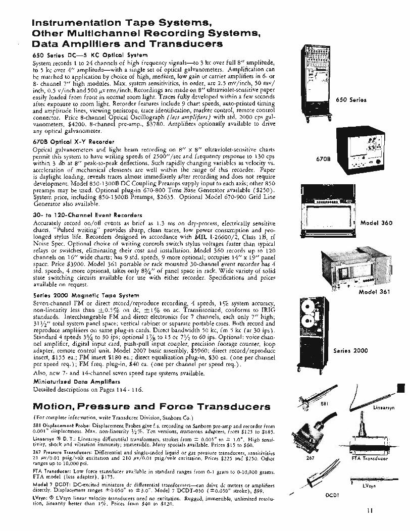
- Data Amplifiers and Transducers 650 Series DC-5 KC Optical System System records 1 to 24 channels of high frequency signals-to 3 kc over full 8’’ amplitude, to 5 kc over 4’’ amplitude-with a single set of optical galvanometers. Amplification can be matched to application by choice of high, medium, low gain or carrier amplifiers in 6- or 8- channel 7” high modules. Max. system sensitivities, in order, are 2.5 mv/inch, 50 mv/ inch, 0.5 v/inch and 500 ,,.v rms/inch. Recordings are made on 8’’ ultraviolet-sensitive paper easily loaded from front in normal room light. Traces fully developed within a few seconds after exposure to room light. Recorder features incIude 9 chart speeds, auto-printed timing and amplitude lines, viewing periscope, trace identification, marker control, remote control connector. Price 8-channel Optical Oscillograph (less amplifiers) with std. 2000 cps gal- vanometers, $4200. 8-channel pre-amp., $3780. Amplifiers optionally available to drive any optical galvanometer.
670B Optical X-Y Recorder Optical galvanometers and light beam recording on 8” x 8” ultraviolet-sensitive charts permit this system to have writing speeds of 2500”/sec and frequency response to 130 cps within 3 db at 8” peak-to-peak deflections. Such rapidly changing variables as velocity vs. acceleration of mechanical elements are well within the range of this recorder. Paper is daylight loading, reveals traces almost immediately after recording and does not require development. Model 850-1300B DC Coupling Preamps supply input to each axis; other 850 preamps may be used. Optional plug-in 670-800 Time Base Generator available ($250). System price, including 850-1 300B Preamps, $2635. Optional Model 670-900 Grid Line Generator also available.
30- to 120-Channel Event Recorders Accurately record on/off events as brief as 1.3 ms on dry-process, electrically sensitive charts. “Pulsed writing” provides sharp, clean traces, low power consumption and pro- longed stylus life. Recorders designed in accordance with MIL I-26600/2, Class 1B, rf Noise Spec. Optional choice of writing controls switch stylus voltages faster than typical relays or switches, eliminating their cost and installation. Model 360 records up to 120 channels on 16” wide charts; has 9 std. speeds, 9 more optional; occupies 14” x 19” panel space. Price $3900. Model 361 portable or rack mounted ?&channel event recorder has 4 std. speeds, 4 more optional, takes only 874” of panel space in rack. Wide variety of solid state switching circuits available for use with either recorder. Specifications and price? available on request.
Series 2000 Magnetic Tape System Seven-channel FM or direct record/reproduce recording, 4 speeds, 1 % system accuracy, non-linearity less than f 0 . 5 % on dc, +I% on ac. Transistorized, conforms to IRIG standards. Interchangeable FM and direct electronics for 7 channels, each only 7” high; 3 I$$’’ total system panel space; vertical cabinet or separate portable cases. Both record and reproduce amplifiers on same plug-in cards. Direct bandwidth 50 kc, fm 5 kc (at 30 ips). Standard 4 speeds 3% to 30 ips; optional 1% to 1 5 or 7y2 to 60 ips. Optional: voice chan- nel amplifier, digital input card, push-pull input coupler, precision footage counter, loop adapter, remote control unit. Model 2007 basic assembly, $5960; direct record/reproduce insert, $155 ea.; FM insert $180 ea.; direct equalization plug-in, $30 ea. (one per channel per speed req.) ; FM freq. plug-in, $40 ea. (one per channel per speed req.) . Also, new 7- and 14-channel seven speed tape systems available. Miniaturized Data Amplifiers Detailed descriptions on Pages 114 - 116.
Motion, Pressure and Force Transducers (For complete information, write Transducer Division, Sanborn Co.) 581 Displacement Probe: Displacement Probes give f.s. recording on Sanborn pre-amp and recorder from 0.001‘’ displacement. Max. non-linearity 1/2%. Ten versions, numerous adapters, from $125 to $185. Linearsyn C3 D. T.: Linearsyn differential transformers, strokes from * 0.005” to t 1.0”. High sensi- tivity, shock and vibration immunity; immersible. Many specials available. Prices $15 to $60. 267 Pressure Transducers: Differential and single-ended liquid or gas pressure transducers, sensitivities 21 $v/O.O1 psig/volt excitation and 210 $v/O.Ol psig/volt excitation. Prices $225 and $250. Other ranges up to 10,000 psi. FTA Transducer: Low force transducer available in standard ranges from 0-1 gram to 0-10,000 grams. FTA model (less adapter), $175. M o d e l 7 DCDT: DC-excited miniature dc differential transformers--can drive dc meters or amplifiers directly. Displacement ranges C0.050” to f 3.0”. Model 7 DCDT-050 (+0.050” stroke), $99. LVsyn: Q3 LVsyn linear velocity transducers need no excitation. Rugged, immersible, unlimited resolu- tion, linearity better than 1%. Prices from $40 to $120.
670B
Model 360
Model 361 ‘ I! -
/ DCDT
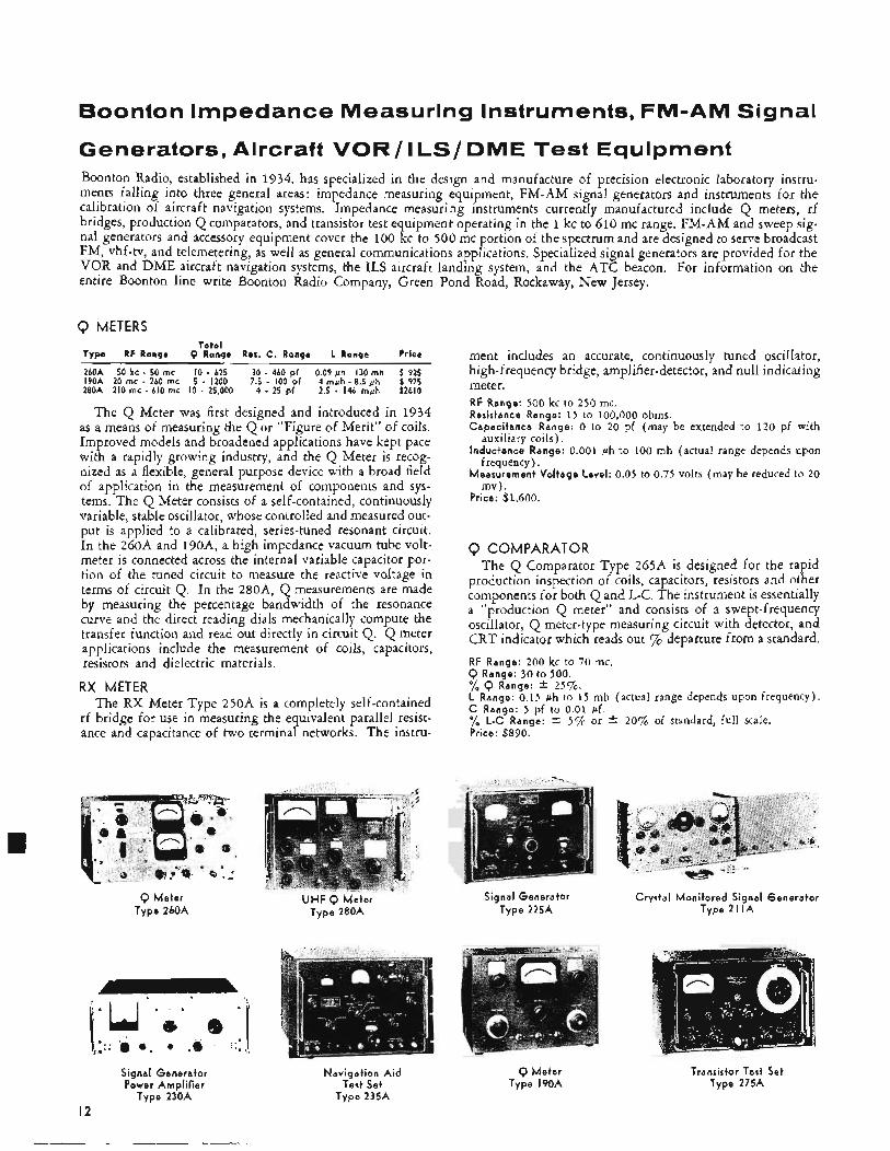
Boonton Impedance Measuring Instruments, FM-AM Signal
Generators, Aircraft VOR/ ILS/ DME Test Equipment Boonton Radio, established in 1934, has specialized in the design and manufacture of precision electronic laboratory instru- ments falling into three general areas : impedance measuring equipment, FM-AM signal generators and instruments for the calibration of aircraft navigation systems. Impedance measuri ng instruments currently manufactured include Q meters, rf bridges, production Q comparators, and transistor test equipment operating in the 1 kc to 610 mc range. FM-AM and sweep sig- nal generators and accessory equipment cover the 100 kc to 500 mc portion of the spectrum and are designed to serve broadcast FM, vhf-tv, and telemetering, as well as general communications applications. Specialized signal generators are provided for the VOR and DME aircraft navigation svstems. the ILS aircraft landing system, and the ATC beacon. For information on the entire Boonton line write BGonton Radio Company, Green
Q METERS Total
Type RF Range Q Range Res. C. Range L Range Price
260A 50 kc - 50 mc I O - 625 30 - 460 pf 0.09 y h 130 mh f 925 l9OA 20 rnc - 260 rnc 5 - 1200 7.5 - 100 pf 4 m&h - 8.5 &h $ 975 280A 210 mc - 610 mc IO - 25,000 4 - 25 pf 2.5 - 146 myh $2610
The Q Meter was first designed and introduced in 1934 as a means of measuring the Q or “Figure of Merit” of coils. Improved models and broadened applications have kept pace with a rapidly growing industry, and the Q Meter is recog- nized as a flexible, general purpose device with a broad field of application in the measurement of components and sys- tems. The Q Meter consists of a self-contained, continuously variable, stable oscillator, whose controlled and measured out- put is applied to a calibrated, series-tuned resonant circuit. In the 260A and 190A, a high impedance vacuum tube volt- meter is connected across the internal variable capacitor por- tion of the tuned circuit to measure the reactive voltage in terms of circuit Q. In the 280A, Q measurements are made by measuring the percentage bandwidth of the resonance curve and the direct reading dials mechanically compute the transfer function and read out directly in circuit Q. Q meter applications include the measurement of coils, capacitors, resistors and dielectric materials.
RX METER The RX Meter Type 250A is a completely self-contained
rf bridge for use in measuring the equivalent parallel resist- ance and capacitance of two terminal networks. The instru-
Q Meter Type 260A
Signal Generator Power Amplifier
Type 230A
I 2
UHF Q Meter Type 280A
Navigation A i d Test Set
Type 235A
Pond Road, Rockaway, New Jersey.
ment includes an accurate, continuously tuned oscillator, high-frequency bridge, amplifier-detector, and null indicating meter. RF Range: 500 kc to 250 mc. Resistance Range: 15 to 100,000 ohms. Capacitance Range: 0 to 20 pf (may be extended to 120 pf with
Inductance Range: 0.001 ph to 100 mh (actual range depends upon
Measurement Voltage Level: 0.05 to 0.75 volts (may be reduced to 20
Price: $1,600.
auxiliary coils).
frequency).
rnv) .
Q COMPARATOR The Q Comparator Type 265A is designed for the rapid
production inspection of coils, capacitors, resistors and other components for both Q and L-C. The instrument is essentially a “production Q meter” and consists of a swept-frequency oscillator, Q meter-type measuring circuit with detector, and CRT indicator which reads out % departure from a standard. RF Range: 200 kc to 70 mc.
%$ Range: i. 2 5 % . L Range: 0.15 ph to 15 mh (actual range depends upon frequency). C Range: 5 pf to 0.01 pf. yo L-C Range: +- 5 % or t- 209% of standard, ful l scale. Price: $890.
ange: 30 to 500.
Signal Generator Type 225A
Q Meter Type 190A
Crystal Monitored Signal Generator Type 21 I A
Transistor Test Set Type 275A
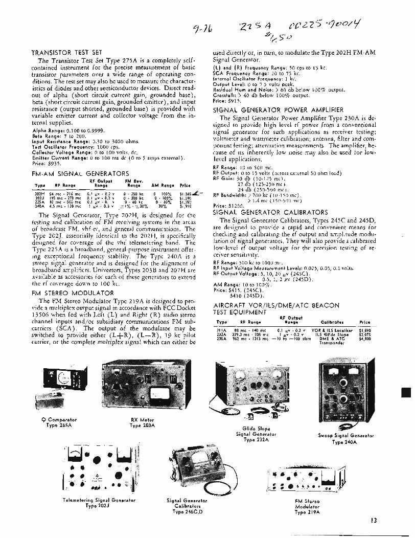
TRANSISTOR TEST SET The Transistor Test Set Type 275A is a completely self-
contained instrument for the precise measurement of basic transistor parameters over a wide range of operating con- ditions. The test set may also be used to measure the character- istics of diodes and other semiconductor devices. Direct read- out of alpha (short circuit current gain, grounded base), beta (short circuit current gain, grounded emitter), and input resistance (output shorted, grounded base) is provided with variable emitter current and collector voltage from the in- ternal supplies. Alpha Range: 0.100 to 0.9999. Beta Range: ? to 200. I n p u t Resistance Range: 0.30 to 3000 ohms, Test Osci l la tor Frequency: 1000 cps. Co l lec to r Vol tage Range: 0 to 100 volts, dc. Emit ter Cur ren t Range: 0 to 100 ma dc ( 0 to 5 amps external). Price: $935.
FM-AM SIGNAL GENERATORS RF Output FM Dev.
Type RF Range Range Range AM Range Price
202H 54 mc - 216 mc 0.1 fiv - 0.2 v 0 . 250 k c 0 - 100% $l,365&- 202J 195 rnc - 270 rnc 0.1 f iv . 0.2 v 0 - 300 k c C . 100% $: ,39C. 225A I C mc - 500 mc 0.1 uv - 0.1 v 0 - 60 k c 0 - 30% $1,052 240A 4.5 mc - I20 mc I uv . 0.3 v 51% - ~ 3 0 % 30% $1,910
The Signal Generator, Type 202H, is designed for the testing and calibration of FM rereiving systems in the areas of broadcast FM, Yhf-tl-, and general communications, The Type 2021, essentially identical to the 202H, is specifically designed for coverage of the vhf telemetering band. The Type 22 iA is a broadband, general-purpose instrument offer. ing exceptional frequency stability. The Type 240A i s a sweep sigqal generator and is designed for the alignment of broadband amplifiers. Univerters, Types 203B and 207H are available as accessories for each of these generators to extend the rf coverage down to 100 kc. FM STEREO MODULATOR
The FM Stereo Modulator Type 219A is designed to pro- vide a multiplex output signal in accordance with FCC Docket 13506 when fed with Left (L) and Right (R) audio stereo channel inputs and/or subsidiary communications FM sub- carriers (SCA). The output of the modulator may be switched to provide either (L+R) , (L-R), 19 kc pilot carrier, or the complete multiplex signal which can either be
used directly or, in turn, to modulate the Type 202H FM-AM Signal Generator. ( L ) and ( R ) Frequency Range: 50 cps to 15 kc. SCA Frequency Range: 20 to 75 kc. In ternal Osci l la tor Frequency: 1 kc. O u t p u t Level: 0 to 7.5 volts peak. Residual H u m and Noise: > 60 db below 100% output. Crosstalk: > 40 db below 100vc output. Price: $915.
SIGNAL GENERATOR POWER AMPLIFIER The Signal Generator Power Amplifier Type 230A is de-
signed to provide high level rf power from a conventional signal generator for such applications as receiver testing; voltmeter and wattmeter calibration; antenna, filter and com- ponent testing; attenuation measurements. The amplifier, be- cause of its inherently low noise may also be used for low- level applications. RF Range: 10 to 500 mc. RF O u t p u t : 0 to 1 5 volts ( m o s s external 50 ohm load) RF Ga in : 30 db (10-125 m c l .
27 db (125-250 m c ) . 24 db (250-500 mc!.
RF Bandwidth: > 700 kc (10-150mcj . > 1.4 mc (150-50:) m r ) Price: $1200. SIGNAL GENERATOR CALIBRATORS
The Signal Generator Calibrators, Types 245C and 245D, are designed to provide a rapid and convenient means for checking and calibrating the rf output and amplitude modu- lation of signal generators. They will also provide a calibrated low-level rf output voltage for the precision testing of re- cei ver semi ti vi ty. RF Range: 500 kc to 1000 mi . RF Inpu t Vol tage Measurement Levels: 0.025, 0.05, 0.1 volts. RF O u t p u t Vol tage: 5, 10, 20 u.v (245C).
AM Ranae: 10 to 100%. 0.5, 1, 2 pv (2452)).
Price: $ i l 5 . (245C). $410 (245D)
AIRCRAFT VOR/ILS/DME/ATC BEACON TEST EQUIPMENT
RF Output Type RF Range Range Calibrates Price
~~~ - 211A 88 mc - 140 mc 0.1 uv - 0.2 v VOR 8 ILS Localizer $1,890 232A 329.3 mc - 335 mc I uv - 0.2 v ILS Glide Slope $2,075 235A 962 mc - 1213 mc - I O to -I00 dbm DME & ATC $4,900
Transponder
Q Compara to r RX M e t e r Type 265A Type 250A
G l i d e Slope Signal Genera to r
Type 232A Type 240A
Telemeter ing Signal Genera to r Signal Genera to r Type 202J Cal ibrators
Type 245C,D
FM Stereo Modu la to r Type 2 I P A
13
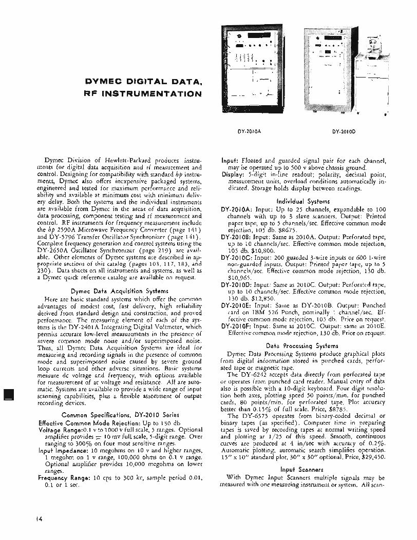
DYMEC DIGITAL DATA,
RF INSTRUMENTATION
DY-20 I OA DY-20 I OD
Dymec Division of Hewlett-Packard produces instru- ments for digital data acquisition and rf measurement and control. Designing for compatibility with standard hp instru- ments, Dymec also offers inexpensive packaged systems, engineered and tested for maximum performance and reli- ability and available at minimum cost with minimum deliv- ery delay. Both the systems and the individual instruments are available from Dymec in the areas of data acquisition, data processing, component testing and rf measurement and control. RF instruments for frequency measurement include the hp 2590A Microwave Frequency Converter (page 141) and DY-5796 Transfer Oscillator Synchronizer (page 1 4 1 ) . Complete frequency generation and control systems using the DY-2650A Oscillator Synchronizer (page 2 19) are avail- able. Other elements of Dymec systems are described in ap- propriate sections of this catalog (pages 103, 117, 183, and 230). Data sheets on all instruments and systems, as well as a Dymec quick reference catalog are available on request.
Dyrnec Data Acquisition Systems Here are basic standard systems which offer the common
advantages of modest cost, fast delivery, high reliability derived from standard design and construction, and proved performance. The measuring element of each of the sys- tems is the: DY-2401A Integrating Digital Voltmeter, which permits accurate low-level measurements in the presence of severe common mode noise and/or superimposed noise. Thus, all Dymec Data Acquisition Systems are ideal for measuring and recording signals in the presence of common mode and superimposed noise caused by severe ground loop currents and other adverse situations. Basic systems measure dc voltage and frequency, with options available for measurement of ac voltage and resistance. All are auto- matic. Systems are available to provide a wide range of input scanning capabilities, plus a flexible assortment of output recording devices.
Common Specifications, DY-20 I O Series Effective Common Mode Rejection: Up to 130 db Voltage Ran9e:O.l v to 1000 v full scale, 5 ranges. Optional
amplifier provides f 10 mv full scale, >-digit range. Over ranging to 30070 on four most sensitive ranges.
Input Impedance: 10 megohms on 10 v and higher ranges, 1 megohm on 1 v range, 100,000 ohms on 0.1 v range. Optional amplifier provides 10,000 megohms on lower ranges.
Frequency Range: 10 cps to 300 kc, sample period 0.01, 0.1 or 1 sec.
Input: Floated and guarded signal pair for each channel, may be operated up to 500 v above chassis ground.
Display: 5-digit in-line readout; polarity, decimal point, measurement units, overload conditions automatically in- dicated. Storage holds display between readings.
Individual Systems DY-20IOA: Input: U p to 25 channels, expandable to 100
channels with up to 3 slave scanners. Output: Printed paper tape, up to 5 channels/sec. Effective common mode rejection, 105 db. $8675.
DY-20106: Input: Same as 2010A. Output: Perforated tape, up to 10 channels/sec. Effective common mode rejection, 105 db. $10,800.
DY-20 I OC: Input: 200 guarded 3-wire inputs or 600 1-wire non-guarded inputs. Output: Printed paper tape, up to 5 channels/sec. Effective common mode rejection, 130 db. $10,965.
DY-20 10D: Input: Same as 201OC. Output: Perforated tape, up to 10 channels/sec. Effective common mode rejection, 130 db. $12,850.
DY-20 I OE: Input: Same as DY-2010B. Output: Punched card on IHM 526 Punch, nominally 1 channel/sec. Ef- fective common mode rejection, 105 db. Price on request.
DY-20IOF: Input: Same as 2010C. Output: same as 2010E. Effective common mode rejection, 130 db. Price on request.
Data Processing Systems Dymec Data Processing Systems produce graphical plots
from digital information stored in punched cards, perfor- ated tape or magnetic tape.
The DY-6242 accepts data directly from perforated tape or operates from punched card reader. Manual entry of data also is possible with a 10-digit keyboard. Four digit resolu- tion both axes, plotting speed 50 points/min. for punched cards, 80 points/min. for perforated tape. Plot accuracy better than 0.15% of full scale. Price, $8785.
The DY-6575 operates from binary-coded decimal or binary tapes (as specified). Computer time in preparing tapes is saved by recording tapes at normal writing speed and plotting at 1 /25 of this speed. Smooth, continuous curves are produced at 4 in/sec with accuracy of 0.2%. Automatic plotting, automatic search simplifies operation. 15‘‘ x 10” standard plot, 30” x 30” optional. Price, $29,450.
Input Scanners With Dymec Input Scanners multiple signals may be
measured with one measuring instrument or system. All scan-
14
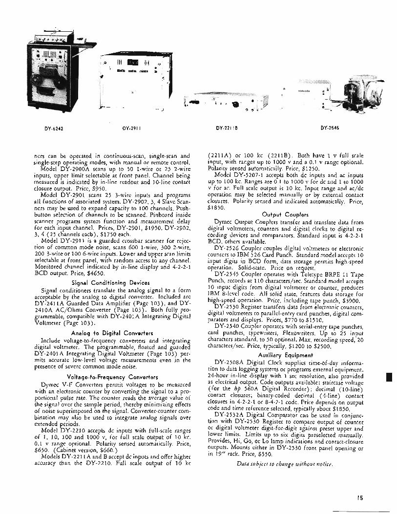
DY-6242 DY-29 I I
ners can be operated in continuous-scan, single-scan and single-step operating modes, with manual or remote control.
Model DY-2900A scans up to 50 1-wire or 25 2-wire inputs, upper limit selectable at front panel. Channel being measured is indicated by in-line readout and 10-line contact closure output. Price, $950.
Model DY-2901 scans 25 3-wire inputs and programs all functions of associated system. DY-2902, 3, 4 Slave Scan- ners may be used to expand capacity to 100 channels. Push- button selection of channels to be scanned. Pinboard inside scanner programs system function and measurement delay for each input channel. Prices, DY-2901, $1950. DY-2902, 3, 4 (25 channels each), $1750 each.
Model DY-2911 is a guarded crossbar scanner for rejec- tion of common mode noise, scans 600 1-wire, 300 2-wire, 200 3-wire or 100 6-wire inputs. Lower and upper scan limits selectable at front panel, with random access to any channel. Monitored channel indicated by in-line display and 4-2-2-1 BCD output. Price, $4650.
Signal Conditioning Devices Signal conditioners translate the analog signal to a form
acceptable by the analog to digital converter. Included are DY-2411A Guarded Data Amplifier (Page 103) , and DY- 2410A AC/Ohms Converter (Page 103). Both fully pro- grammable, compatible with DY-2401A Integrating Digital Voltmeter (Page 103) .
Analog to Digital Converters Include voltage-to-frequency converters and integrating
digital voltmeter. The programmable, floated and guarded DY-2401A Integrating Digital Voltmeter (Page 103) per- mits accurate low-level voltage measurements even in the presence of severe common mode noise.
Voltage-to-Frequency Converters Dymec V-F Converters permit voltages to be measured
with an electronic counter by converting the signal to a pro- portional pulse rate. The counter reads the average value of the signal over the sample period, thereby minimizing effects of noise superimposed on the signal. Converter-counter com- bination may also be used to integrate analog signals over extended periods.
Model DY-2210 accepts dc inputs with full-scale ranges of 1, 10, 100 and 1000 v, for full scale output of 10 kc. 0.1 v range optional. Polarity sensed automatically. Price, $650. (Cabinet version, $660.)
Models DY-2211A and B accept dc inputs and offer higher accuracy than the DY-2210. Full scale output of 10 kc
DY-22 I I B DY-2545
(2211A) or 100 kc (2211B). Both have 1 v full scale input, with ranges up to 1000 v and a 0.1 v range optional. Polarity sensed automatically. Price, $1250.
Model DY-5207-1 accepts both dc inputs and ac inputs up to 100 kc. Ranges are 0.1 to 1000 v for dc and 1 to 1000 v for ac. Full scale output is 10 kc. Input range and ac/dc operation may be selected manually or by external contact closures. Polarity sensed and indicated automatically. Price, $1850.
Output Couplers Dymec Output Couplers transfer and translate data from
digital voltmeters, counters and digital clocks to digital re- cording devices and comparators. Standard input is 4-2-2-1 BCD, others available.
DY-2526 Coupler couples digital voltmeters or electronic counters to IBM 526 Card Punch. Standard model accepts 10 input digits in BCD form, data storage permits high-speed operation. Solid-state. Price on request.
DY-2545 Coupler operates with Teletype BRPE 11 Tape Punch, records at 110 characters/sec. Standard model accepts 10 input digits from digital voltmeter or counter, produces IBM 8-level code, All solid state, features data storage for high-speed operation. Price, including tape punch, $3900.
DY-25 30 Register transfers data from electronic counters, digital voltmeters to parallel-entry card punches, digital com- parators and displays. Prices, $770 to $1510.
DY-2540 Coupler operates with serial-entry tape punches, card punches, typewriters, Flexowriters. Up to 25 input characters standard, to 50 optional. Max. recording speed, 20 characters/sec. Price, typically, $1 200 to $2500.
Auxiliary Equipment DY-2508A Digital Clock supplies time-of-day informa-
tion to data logging systems or programs external equipment. 24-hour in-line display with 1 sec resolution, also provided as electrical output. Code outputs available: staircase voltage (for the hp 560A Digital Recorder); decimal (lo-line) contact closures; binary-coded decimal (4-line) contact closures in 4-2-2-1 or 8-4-2-1 code. Price depends on output code and time reference selected, typically about $1850,
DY-2532A Digital Comparator can be used in conjunc- tion with DY-2530 Register to compare output of counter or digital voltmeter digit-for-digit against preset upper and lower limits. Limits up to six digits preselected manually. Provides, Hi, Go, or Lo lamp indications and contact-closure outputs. Mounts either in DY-2530 front panel opening or in 19’’ rack. Price, $550.
Data subject t o chatzge without tzotice.
15
OSELEV AUTOGRAF X-V, STRIP-CHART
RECORDERS, A C C E S S O R I E S
F. L. Moseley Co. offers a complete line of x-y and strip-chart recorders, program controllers, servo voltmeters, digital translators, analog converters and accessories. Data plotted in Cartesian coordinate form on graph paper is used today in almost every field of science and industry, and Moseley was a pioneer and today is a leading manufacturer of high accuracy servo driven x-y recorders and strip-chart recorders. Accessories available from Moseley include magnetic and optical line followers, ac/dc and logarithmic converters, character printers and keyboards, all of which greatly increase the flexibility and application of the basic instruments. A complete catalog of instruments is available by writing F. L. Moseley Co., 409 No, Fair Oaks, Pasadena. Calif.
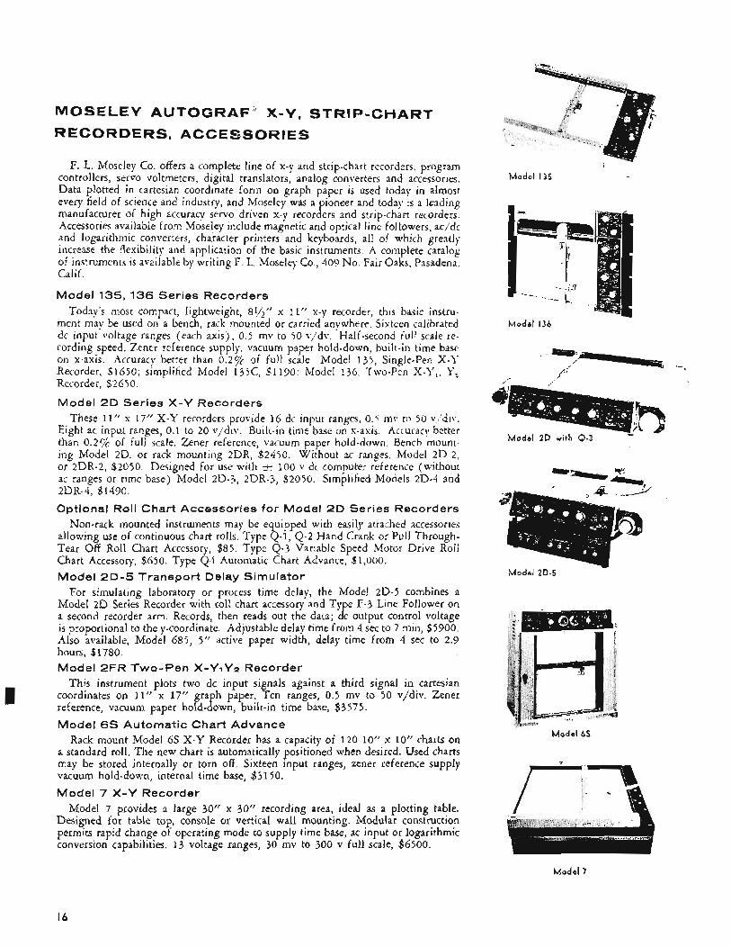
Model 135,136 Series Recorders Today’s most compact, lightweight, 8y2” x 11” x-y recorder, this basic instru-
ment may be used on a bench, rack mounted or carried anywhere. Sixteen calibrated dc input voltage ranges (each axis), 0.5 mv to 50 v,/dv. Half-second full scale re- cording speed. Zener reference supply, wcuum paper hold-down, built-in time base on x-axis. Accuracy better than 0.27; of ful! scale, Mode! 137, Single-Pen X-Y Recorder, $1650; simplified Model 135c, $1190: Model 136. Two-Pen X-Y,, Y, Recorder, $2650.
Model 2D Series X - Y Recorders These 11” x 17” X - Y recorders provide 16 dc input ranges, 0.5 mv to 50 v,‘div.
Eight ac input ranges, 0.1 to 20 vjdiv. Built-in time base or! x-axis. Accuracy better than 0.29h of full scale. Zener reference, vacuum paper hold-down, Bench mount- ing Model 2D, or rack mounting 2DR, $2450. Without ac ranges, Model 2D-2, or 2DR-2, $2050. Designed for use with 2 100 I- dc computer reference (without ac ranges or time base) Model 2D-3, 2DR-3, $2050. Simplified Models 2D-4 and
Optional Roll Chart Accessories for Model 2D Series Recorders Non-rack mounted instruments may be equipped with easily attaihed accessories
allowing use of continuous chart rolls. Type Q-1, 4 - 2 Hand Crank or Pull Through- Tear Off Roll Chart Accessory, $85. Type 4 - 3 Variable Speed Motor Drive Rol: Chart Accessory, $650. Type 44 Automatic Chart Advance, $1,000.
Model 2 D - 5 Transport Delay Simulator For simulating laboratory or process time delay, the Mode! 2D-5 combines a
Model 2D Series Recorder with roll chart accessory and Ty e F-3 Line Follower on a second recorder arm. Records, then reads out the data; 4 output control voltage is proportional to the y-coordinate. Adjustable delay time from 4 sec to 7 min, $5900. Also available, Model 685, 5” active paper width, delay time from 4 sec to 2.9 hours, $1780. Model 2FR Two-Pen X - Y ~ Y P Recorder
This instrument plots two dc input signals against a third signal in Cartesian coordinates on 11’’ x 17” graph paper. Ten ranges, 0.5 mv to 50 v/div. Zener reference, vacuum paper hold-down, built-in time base, $3575. Model 6s Automatic Chart Advance
Rack mount Model 6 s X - Y Recorder has a capacity of 120 10” x 10” charts on a standard roll. The new chart is automatically positioned when desired. Used charts may be stored internally or torn off. Sixteen input ranges, zener reference supply vacuum hold-down, internal time base, $3150. Model 7 X - Y Recorder
Model 7 provides a large 30” x 30” recording area, ideal as a plotting table. Designed for table top, console or vertical wall mounting. Modular construction permits rapid change of operating mode to supply time base, ac input or logarithmic conversion capabilities. 13 voltage ranges, 30 mv to 300 v full scale, $6500.
2DR-4. $1490.
I
M o d e l 135 ~
M o d e l 136
-t P
M o d e l 2D w i t h 0-3 *
M o d e l ZD-5
M o d e l 65
M o d e l 7
16
Model 680
Type A- I
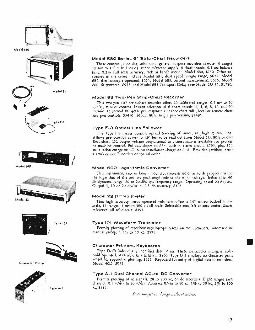
Model 680 Series 6” Strip-Chart Record rs These compact, modular, solid state, general purpose recorders feature 10 ranges
( 5 mv to 100 v ful1 scale), zener reference supply, 8 chart speeds, 0.5 sec balance time, 0.27; full scale accuracy. rack or bench mount. Model 680, $750. Other re- corders in the series include Model 681, dual speed, single range, $625; Model 682, thermocouple operated, $675 ; Model 683, current measurement, $625; Model 680, dc powered, $975, and Model 685 Transport Delay (see Model 2D-5) , $1780.
Model 83 Two-Pen Strip-Chart Recorder This two-pen 10” strip-chart recorder offers 1 5 calibrated ranges, 0.5 mv to 20
vjdiv.; vernier control Instant selection of 6 chart speeds, 2, 4, 6, 8, 1 5 and 60 in/min. ‘/4 second fu!!-scale pen response 1 ?@foot chart rolls, local or remote chart and pen controls, $3450 Model 80A, single pen version, $2495.
Type F -3 Optical Line Follower The Type F-3 makes possible optical tracAinp of almost any high contrast line.
Aliows prerecorded curve< to 1 2 0 feet to be read out from Model 2D, 80A or 680 Recorders. DC outpuf voltage proportionai to y-coordinate 15 available for process or machine control Foliow slopes to 85’, built-in alarm circuit. $795, plus $50 installation charge on 2D, $ 1 S O installation charge on 80A. Provided (without error alarm) on 680 Recorders on special order
Model 60D Logarithmic Converter This instrument, rack or bench mounted, converts dc or ac to d, proportional to
the logarithm of the positive peak amplitude of the input voltage. Better than 60 db dynamic range, 2 0 to 20,000 cps frequency range. Operating speed 20 db/sec. Output 5 , 10 or 20 db/in t 0.5 db accuracy, $575.
Model 22 D C Voltmeter This high accuracy, servo operated voltmeter offers a 14” mirror-backed linear
scale, 11 ranges, 3 mv to 300 v full scale. Selectable zero left or zero center. Zener reference, all solid state, $595.
Type 101 Waveform Translator
manual sweep, 1 cps to 20 kc, $575. Permits plotting of repetitive oscilloscope traces on x-y recorders, automatic or
Character Printers, Keyboards Type D-1B individually identifies data points. Three 2-character plungers, sole-
noid operated. Available as a field kit, $160. Type D-2 employs six-characterprint wheel for sequential plotting, $525. Keyboard for entry of digital data to recorders. Model 40D, $975.
Type A-1 Dual Channel AC-to-DC Converter Permits plotting of ac signals, 20 to 200 kc, on dc recorders. Eight ranges each
channel, 0.1 v/div to 20 v/div. Accuracy 0.5% to 20 kc, 1% to 50 kc, 2% to 100 kc, $585.
Data subject t o chatzge without notice.
17
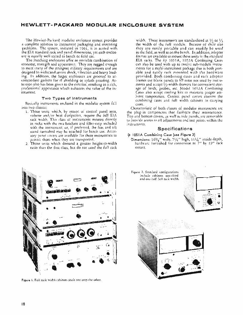
HEWLETT-PACKARD MODULAR ENCLOSURE SYSTEM
The Hewlett-Packard modular enclosure system provides a complete solution to instrument packaging and mounting problems. The system, initiated in 1961, is in accord with the EIA standard rack and panel dimensions, yet each enclos- ure is equally well suited to bench or field use.
The matching enclosures offer an enviable combination of economy, strength and appearance. They are rugged enough to meet many of the stringent military requirements and are designed to withstand severe shock, vibration and heavy load- ing. In addition, the larger enclosures are grooved to ac- commodate gaskets for rf shielding or splash proofing. At- tention also has been given to the exterior, resulting in a rich, professional appearance which enhances the value of the in- strument.
Two Types of Instruments Basicdlly instruments enclosed in the modular system fall
1. Those units which, by reason of control panel area, volume and/or heat dissipation, require the full EIA rack width. This class of instruments mounts directly in racks with the two brackets and filler-strip included with the instrument; or; if preferred, the feet and tilt stand furnished may be attached for bench use. Acces- sory panel covers are available for these instruments to protect them when they are transported.
2. Those units which demand a greater height-to-width ratio than the first class, but do not need the full rack
into two classes:
width. These instruments are standardized at y2 or y3 the width of the full module. Because of their size they a re easily portable and can readily be used in the field, as well as on the bench. In addition, adapter frames are available to mount these units in the standard EIA racks. The hp IoSIA, 1052A Combining Cases can also be used with up to twelve sub-module instru- ments for a multi-instrument package that is both port- able and easily rack mounted with the hardware provided. Both combining cases and rack adapter frames use blank panels to fill areas not used by instru- ments and accept li,-width drawers for convenient stor- age of leads, probes, etc. Model 1052A Combining Cases also accept cooling kits to maintain proper am- bient temperature. Control panel covers convert the combining cases and full width cabinets to carrying cases.
Characteristic of both classes of modular instruments are the plug-in components that facilitate their maintenance. Top and bottom covers, as well as side panels, are removable to provide access to all adjustments and test points within the instruments.
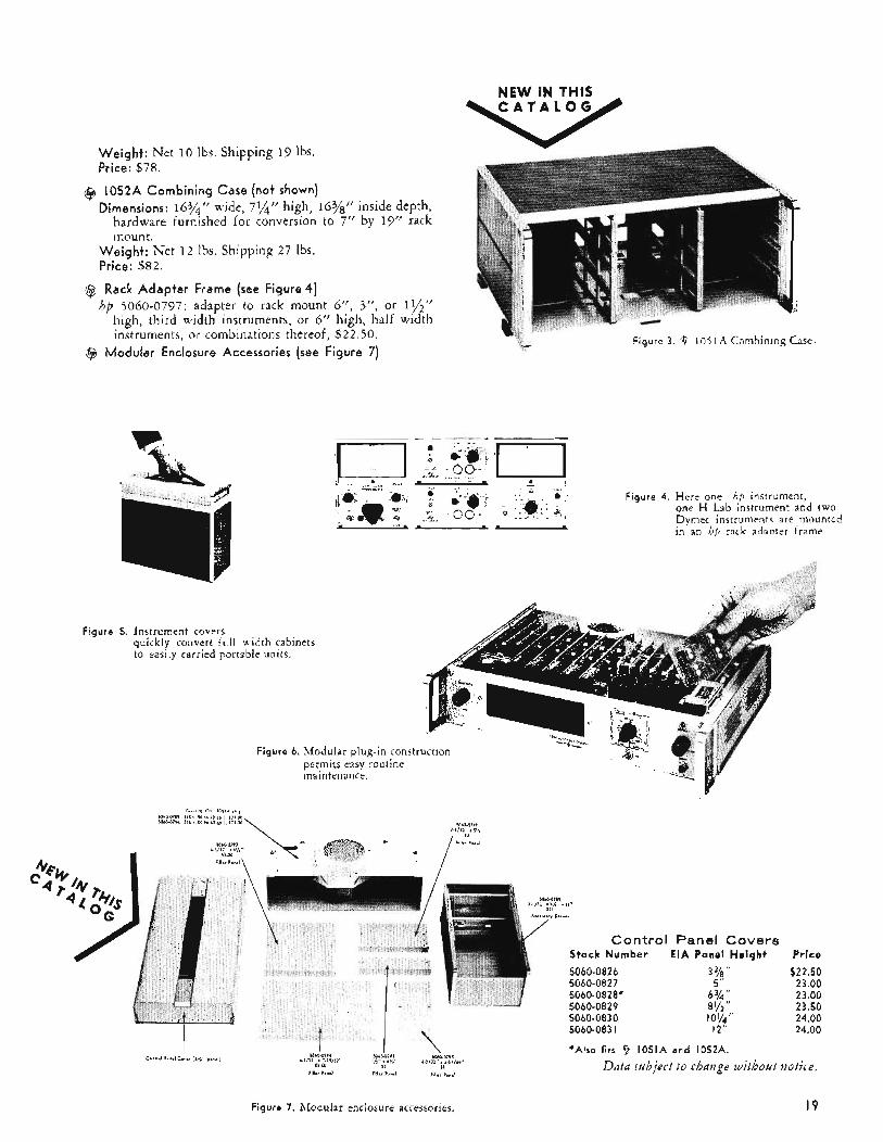
Specifications 9 I05 I A Combining Case (see Figure 3)
Dimensions: 163/4” wide, 7$4” high, 1 1v4” inside depth, hardware furnished for conversion to 7” by 19” rack mount.
Figure 2. Standard configurations include cabinets one-third and one-half full rack width.
Figure I . Full rack width cabinets stack one atop the other.
18
NEW IN THIS C A T A L O G v
Weight: Net 10 Ibs. Shipping 19 lbs. Price: $78.
@ 1052A Combining Case (not shown) Dimensions: 16%" wide, 7%" high, 163/8" inside depth,
hardware furnished for conversion to 7" by 19" rack mount.
Weight: Net 1 2 Ibs. Shipplng 27 lbs. Price: $82.
@ Rack Adapter Frame (see Figure4) hp 5060-0797; adapter to rack mount 6", 3", or I$$''
high, third width instruments, or 6" high, half width instruments, or combinations thereof, $ 2 2 . 5 0 Figure 3. '@ 1 0 5 l A Combining Case
@ Modular Enclosure Accessories (see Figure 7)
Figure 5. Instrument covers quickly convert full width cabinets to easily carried portable units.
Figure 4. Here one h,p instrument, one H Lab instrument and two Dymec instruments are mounted in an hp rack adapter frame.
Figure 6. Modular plug-in construction permits easy routine maintenance.
5060-0826 5060-0827 5060-0828*
I c.nir.1 P.*.! C."., 16%"
Ill*," Draw.,
/
Control Stock N u m b e r
Panel Covers EIA Panel H e i g h t Price
$22.50 23.00
6%;: 23.00 8 1/2 23.50 log" 24.00
12 24.00
3%" 5
*Also f i t s 9 1051A a n d 1052A.
Data subject to rhaizge without izotire.
Figure 7. Modular enclosure accessories. 19
SERVICE INFORMATION Hewlett-Packard's obligation to provide a reliable instrument for you begins while the
instrument is being designed and manufactured, and it continues for as long as you own that instrument. Over the years, Hewlett-Packard has carefully built a service concept second-to-none for providing round-the-world assistance to instrument users. W e expect and want to provide those services which will help you keep all of your Hewlett-Packard instruments performing faithfully.
Who to contact 1. Hewlett-Packard engineering representatives are located throughout North America
and in major cities around the world. For information, replacement parts, and repair and calibration services for your Hewlett-Packard instruments, please contact the rep- resentative nearest you. He is listed on the inside back cover of this catalog.
2. Although pour nearby Hewlett-Packard representative offers immediate attention to your needs, you are aiways welcome to contact the factory:
Customer Service Hewlet t -Packard Company 395 Page Mill Road Palo A l t o , Cali fornia TELEPHONE: (A rea C o d e 415) 326-3950 T W X : 4 15-492-9363 TELEX: 03-38 I I CABLE: H E W P A C K
What services are available
Training Hewlett-Packard offers both field service training and factory service training (with-
out charge) for personnel engaged in instrument maintenance. Field service training seminars are arranged by your Hewlett-Packard engineering representative and may be held at his office or at your company location. Factory service training seminars are held at Palo Alto, California; your only cost is for transportation, lodging and meals. Your representative has full information on these seminars.
Publications In addition to the publications described on page 22 of this catalog, two additional
publications are designed specifically to help you with maintenance and service work on your Hewlett-Packard instruments.
Bemh Briefs, Customer Service newsletter, published periodically, covering such sub- jects as new modifications, service shortcuts and other data that will help keep in- struments in good operating order. Bench Briefs is sent by mail, without charge, to persons directly concerned with repair and maintenance of instruments. Just ask your Hewlett-Packard representative.
Operatitzg and Service Manuals, supplied with each new Hewlett-Packard instrument. Extra copies are available at a nominal charge, usually $2.50 to $5.00 each. They may be ordered from your representative or from Customer Service in Palo Alto.
Parts Services When you need a replacement part, you generally want it fast! That's why Hewlett-
Packard engineering representatives maintain Field Service Centers to supplement the Customer Service parts depot at the factory. Both your nearby Field Service Center and Customer Service stand ready to rush parts for your instruments, and orders are usually filled the same day as received.
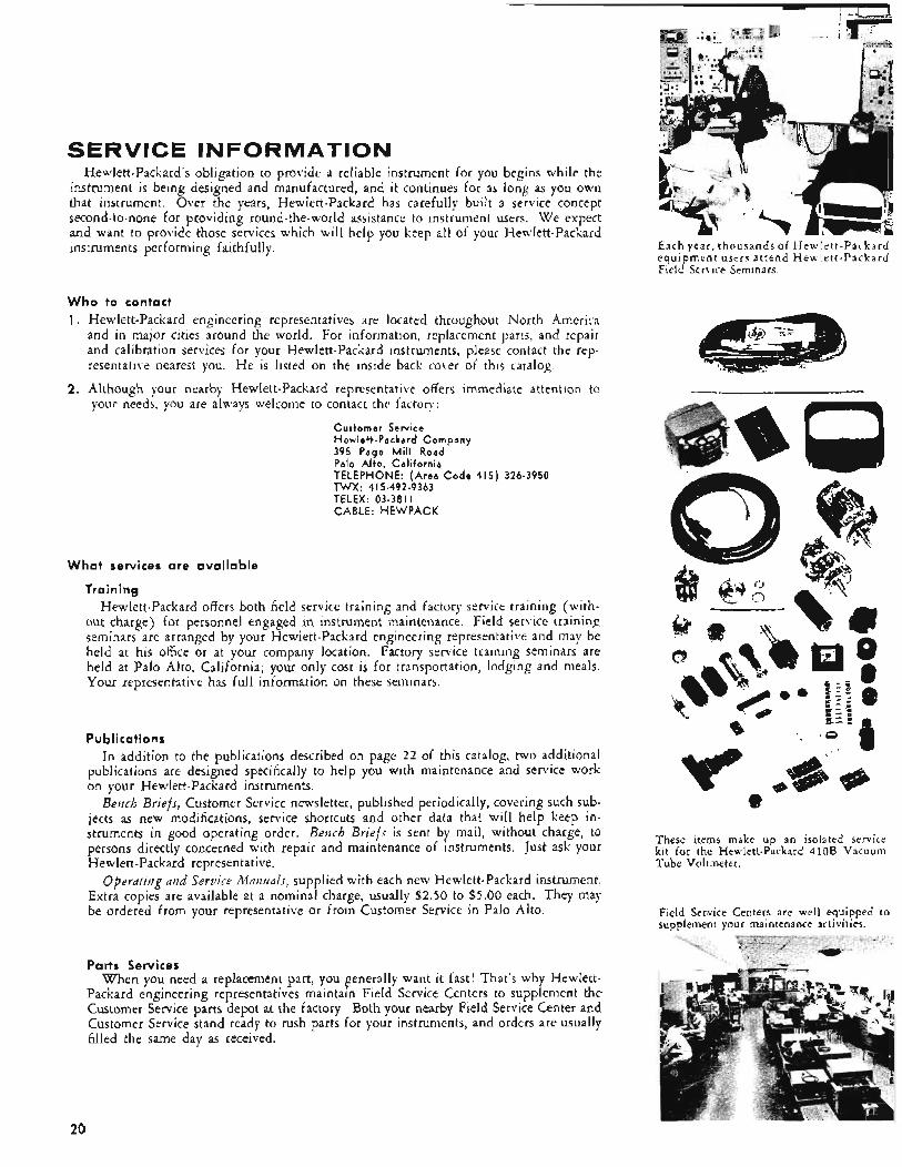
Each year , thousands of Hewlet t -Packard equipment users a t tend Hewle t t -Packard Field Service Seminars.
These items make up an isolated service kit for the Hewlett-Packard 410B Vacuum Tube Voltmeter.
Field Service Centers are well equipped to supplement your maintenance activities.
20
When ordering a replacement part, please specify the fo l lowing information (see the Operat ing and Service Manual’s “Table of Replaceable Parts”) to insure your get- ting the right part in the shortest possible time. 1. Instrument model number and complete serial number.
2. Hewlett-Packard stock number for the part.
3. The part’s circuit reference designator (R?, C7, etc.).
4. A description of the part. (If for some reason the stock number and circuit refer-
ence designator for the desired part are unknown, please in- clude the instrument model and serial numbers - and a complete description of the part, its function and its location within the instrument.)
All replacement parts are carefully packaged to protect the part and prevent shipping or storage damage. These parts can be packaged in rugged military type containers, however. and your representative will be happy to discuss this service with you.
Several types of parts kits are avdablc. to assure con- tinuous operation from your instruments when they are being used in an isolated area, or where ioss of instrument use would be extremely critical (on a production line. for in- stance). “Field Repair,” “Running Spares. ’ and “Isolated Service” Kits offer &-ying degrees of completeness, and you can t71c.k the kit that most ne:trly satisfies your requirements. I n ahdirion to spare parts kits. modification kits arc available to change the original characteristics or specifications of cer- tain Hewlett-Packard instruments. If you have a requirement for either type of kit, please contact your representative. Instrument services
Your Hewlett-Packard instruments may be sent to your nearest Field Service Center or to the factory for repair. Com- plete instructions should be accompanied by a purchase order or other “authorization to proceed.” Your instructions should
include “symptoms” if the instrument is not operating prop- erly. Information also should include the address to which the instrument is to be returned and the addresses to use for correspondence and billing purposes. Repair charges are derived from labor plus materials, and charges are the same in the field as at the factory. Repair work is guaranteed, subject to the terms of the standard Hewlett-Packard war- ranty. Quotations on repair costs can be made before repair is undertaken.
Instrument modification is soiiietinies made to satisfy special requirements or to update instruments that have been in the field for many years. YOU can easily perform most of these modifications yourself, and modification kits are available for many of them. Or you may request that modi- fications be made at your Field Service Center or at the fac- tory. New modifications are announced in the Customer Service newsletter, Be/zclj Dyiefs .
Instrument overhaul is possible on older instruments that have been in operation a number of years. If a particular model is no ionger n~anufactured, it can be put in a con- dition equivalent to that when it was originally purchased. In many cases, you can perform an overhaul yourself, and many representatives also offer an instrument overhaul serv- ice. Any Hewlett-Packard instrument can be overhauled at the factory.
The Opercriiizp nzd Service Mmzicri for each instrument provides the information required for field recalibration of the instrument. However, your representative will arrange for prompt recalibration of your instrument if it is not con- venient for you to undertake the task yourself.
Special “Standards C:alibration” services are available in some areas of the United States. In these cues, a report is made describing the measurement conditions. the measure- ments made and accuracy and, where applicable, traceability to the National Bureau of Standards.
21
USEFUL INFORMATION AVAILABLE TO YOU
ON REQUEST
FROM HEWLETT-PACKARD
TECHNICAL DATA SHEETS. O n standard @ instruments, these sheets contain complete information on instruments de- scribed in this catalog. For complete published data on any particular instrument, and for up-to-date data on instruments developed after publication of this catalog, T E C H N I C A L DATA SHEETS are useful. They may be obtained either from your local @ engineering representative, or by writing @ direct.
APPLICATION NOTES. A series of APPLICATION NOTES describe measuring methods, techniques, efficient test instrument application, Many APPLICATION NOTES are referenced in this catalog; write for an index of all APPLICATION NOTES available, or for titles you desire; watch new literature announce- ments and @ advertising for announcements of other titles.
HEWLETT-PACKARD JOURNAL. Published monthly by the @ R & D laboratories, the Hewlett-Packard JOURNAL is devoted to detailed, academic discussion of new measuring ap- proaches, most productive methods of employing test instrurnen- tation, latest instrumentation for complex as well as routine measurements. For your free subscription simply write on your letterhead to Hewlett-Packard JOURNAL, Hewlett-Packard Company, 1501 Page Mill Road, Palo '41t0, California.
From HEWLETT- PACKARD Divisions and Affiliates
DATA SHEETS, CATALOGS, AppLlCATlON NOTES. Each of the Hewlett-Packard divisions and affiliates, whose products are briefly described on Pages 9 through 17, publish detailed data sheets and catalog material describing their products. These may be obtained from your nearest Hewlett-Packard sales engineering representative, or by writing directly to Dymec, Boonton Radio Company, F. L. Moseley Company, or Sanborn Company.
SANBORN RIGHT ANGLE. Published periodically by the Sanborn Company as a source of helpful technical information for users and potential users of Sanborn Oscillographic Recording Equipment. For sample copies or a free subscription write directly to the Industrial Division, Sanborn Company, Waltham 54, Massachusetts.
THE BRC NOTEBOOK. Published several times a year by Boonton Radio Company, THE BRC NOTEBOOK pro- vides detailed technical information on operation and application of Boonton products. Copies are available by writing directly to Boonton Radio Company, P.O. Box 390, Boonton, New Jersey.
22
I
Pulse Generators Low Frequency Scopes
High Frequency Scopes Sampling Scopes
Oscilloscope Cameras Osci 1 loscope Accessories
Pulse Generators Square Wave Generators
Digital Delay Generators
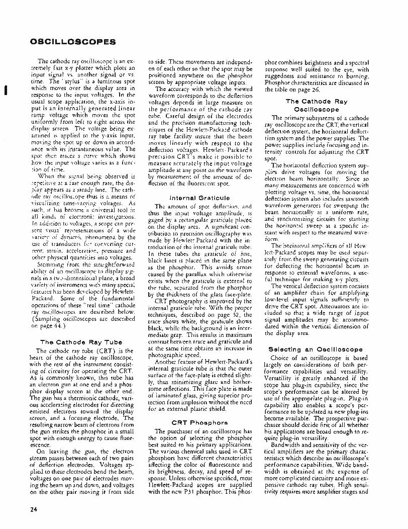
OSCILLOSCOPES
The cathode ray oscilloscope is an ex- tremely fast x-y plotter which plots an input signal vs. another signal or vs. time. The “stylus” is a luminous spot which moves over the display area in response to the input voltages. In the usual scope application, the x-axis in- pu t is a n internally generated linear ramp voltage which moves the spot uniformly from left to right across the display screen. The voltage being ex- amined is applied to the y-axis input, moving the spot up or down in accord- ance with its instantaneous value. The spot thec traces a curve which shows hoa, the input \oltage varies as a func- tion of time.
ai being observed is enough rate, the dis-
play appears as a steady line. The cath- ode ray oscilloscope thus is a means of visualizin~q time-varyinp vo!tages. As such, it has become a universal tool ir? all kin& o i eiectrmi: investigations. In addition to v o l r a p , a scope can pre- sen: visua. represenrations of a wide varie:!, af dynamic !>henoniena by the use of transducers fw convertine cur- rent. strain, acceleration, pressure and other physical quanti:ies into voltages.
Stemming from the straightforward iliascope to display sig-
nals in a two-dimensional plane, a broad variety o i instruments wich many special features has been developed by Hewlett- Packard. Some of the fundamental operations of these “real time” cathode ray oscilloscopes are described below. (Sampling oscilloscopes are described on page 44 . )
The Cathode Ray Tube The cdthode ray tube (CRT) is the
heart of the cathode ray oscilloscope, with the rest of the instrument consist- ing of circuitry for operating the CRT. As is commonly known, this tube has an electron gun at one end and a phos- phor display screen at the other end. The gun has a thermionic cathode, vari- ous accelerating electrodes for directing emitted electrons toward the display screen, and a focusing electrode. The resulting narrow beam of electrons from the gun strikes the phosphor in a small spot with enough energy to cause fluor- escence.
On leaving the gun, the electron stream passes between each of two pairs of deflection electrodes. Voltages ap- plied to these electrodes bend the beam, voltages on one pair of electrodes mov- ing the beam up and down, and voltages on the other pair moving it from side
to side. These movements are independ- en of each other so that the spot may be positioned anywhere on the phosphor screen by appropriate voltage inputs,
The accuracy with which the viewed waveform corresponds to the deflection voltages depends in large measure on the performance of t he cathode ray tube. Careful design of the electrodes and the precision manufacturing tech- niques of the Hewlett-Packard cathode ray tube facility insure that the beam moves linearly with respect to the deflection voltages. Hewlett - Packard’s precision CRT’s make i t possible to measure accurately the input voltage amplitude at any point on the waveform by measurement of the amount of de- flection of the fluorescent spot.
Internal Graticule The amount of spot deflection, and
thus the input voltage amplitude, IS paged by a rectangular graticule placed on the display area. A significant con- tribution to precision oscillography was made by Hewlett-Packard with the in- troduction of the internai graticuic tube. In these tubes the graticule of rine, black lines is placed in the same plane as the phosphor. This avoids errors caused by the parallax which otherwise exists when the graticule is external to the tube, separated from the phosphor by the thickness of the glass face-plate.
CRT photography is improved by the internal graticule tube. With the proper techniques, described on page 52, the trace shows white, the graticule shows black, while the background is an inter- mediate gray. This results in maximum contrast between trace and graticule and at the same time obtains an increase in photographic speed.
Another feature of Hewlett-Packard’s internal graticule tube is that the outer surface of the face-plate is etched slight- ly, thus minimizing glare and bother- some reflections. This face-plate is made of laminated glass, giving superior pro- tection from implosion without the need for an external plastic shield.
CRT Phosphors The purchaser of an oscilloscope has
the option of selecting the phosphor best suited to his primary applications. The various chemical salts used in CRT phosphors have different characteristics affecting the color of fluorescence and its brightness, decay, and speed of re- sponse. Unless otherwise specified, most Hewlett-Packard scopes are supplied with the new P31 phosphor. This phos-
phor combines brightness and a spectral response well suited to the eye, with ruggedness and resistance to burning. Phosphor characteristics are discussed in the table on page 26.
The Cathode Ray Oscilloscope
The primary subsystems of a cathode ray oscilloscope are the CRT, the vertical deflection system. the horizontal deflect- tion system and the power supplies. The power supplies include focusing and in- tensity controls for adjusting the CRT spot.
The horizontal deflection system sup- plies drive voltages for moving the electron beam horizontally. Since so many measurements are concerned with plotting voltage vs. time, the horizonta! deflection system also includes sawtooth waveform generators for sweeping the beam horizontally at a uniform rate, and synchronizing circuits for starting the horizontal sweep at a specific in- stant with respect to the measured wave- form.
The horizontal amplifiers of all Hew- lett-Packard scopes may be used separ- ately from the sweep generating circuits for deflecting the horizontal beam in response t o external waveforms, a use- ful technique for making x-y plots.
The vertical deflection system consists of an amplifier chain for amplifying low-level input signals sufficiently to drive the CRT spot. Attenuators are in- cluded so that a wide range of input signal amplitudes may be accommo- dated within the vertical dimension of the display area,
Selecting an Oscilloscope Choice of an oscilloscope is based
largely on considerations of both per- formance capabilities and versatility. Versatility is greatly enhanced if the scope has plug-in capability, since the scope’s performance can be altered by use of the appropriate plug-in. Plug-in capability also enables a scope’s per- formance to be updated as new plug-ins become available. The prospective pur- chaser should decide first of all whether his applications are broad enough to re- quire plug-in versatility.
Bandwidth and sensitivity of the ver- tical amplifiers are the primary charac- teristics which describe an oscilloscope’s performance capabilities, W i d e band- width is obtained at the expense of more complicated circuitry and more ex- pensive cathode ray tubes. High sensi- tivity requires more amplifier stages and
24
added refinements for minimizing dc drift and noise.
Detailed discussions of the various Hewlett-Packard oscilloscopes are grouped in later sections according to the capabilities of the vertical amplifier. These discussions are divided as fol- lows: 1 ) low-frequency scopes ( to 500 kc), useful for the majority of industrial and laboratory applications (page 27) ; 2 ) high-frequency scopes (to 50 mc) having the additional features required for high frequency or fast pulse work (page 3 4 ) ; and 3 ) sampling oscillo- scopes, which extend scope measure- ments to frequencies of 1 gc and above and to pulses with rise times measured in nanoseconds while still retaining a large, bright display, high sensitivity and a high input impedance (page 44).
The reader is referred to these sec- tions for detailed discussions of scope characteristics. Certain other features, common to most Hewlett-Packard scopes, are described here.
Features of the Vertical Deflection System
The amplifiers in Hewlett-Packard oscilloscopes are stable enough to per- mit voltage measurements with confid- ence to at least -+ 3% accuracy. To verify amplifier accuracy, all Hewlett- Packard scopes have built-in calibrators which supply precisely controlled sig- nals for use as calibrating test signals.
D C coupling, included on all Hew- lett-Packard scopes, preserves the wave- form of slowly varying signals and also permits a dc reference line to be estab- lished on the display, facilitating precise amplitude measurements. D C coupling is not desirable, though, when a small ac component on a relatively large dc voltage is to be examined. All hp scopes (except the Model 185B) have switches for inserting decoupling capacitors into the signal line when dc coupling is not desired.
A widely used option in oscilloscope vertical deflection systems is the pro- vision for two signal channels, Dual channel operation is obtained most con- veniently by electronic switching be- tween signal channels, resulting in al- ternate displays of the two signals. Switching may occur between sweeps so that the waveform of one channel is displayed during one sweep, and the other waveform is displayed on the next sweep; or switching may occur rapidly (40 kc to 1 rnc) for displaying samples of both channels during one sweep. This latter method, frequently referred
to as “chopped” presentation, is most often used for low frequency wave- forms which otherwise would flicker with alternate sweep presentation.
Dual channel presentation enables comparison studies of two signals, such as phase measurements or studies of an amplifier’s output signal vs. its input. The two inputs of dual channel oscil- loscopes have separate preamps and at- tenuators for independent adjustment of the amplitudes of the two signals.
Horizontal Section Triggered sweeps, used in all Hew-
lett-Packard oscilloscopes, cycle only in response to a trigger signal, otherwise remaining in a “locked out” state, This is in contrast to the so-called recurrent sweep which operates continuously and is synchronized by varying its repetition rate until it locks in on some submul- tiple frequency of the triggering wave- form.
The advantage of the triggered sweep is that sweep duration can be any frac- tion or multiple of the input waveform period (recurrent sweeps cannot display less than a whole period). The trig- gered sweep is most useful when only short segments of the input signal need to be examined in detail, the sweep speed being set so that this small por- tion of the waveform is expanded to occupy the whole trace.
The fastest horizontal sweep should be commensurate with the vertical am- plifier response. That is to say, sweep should be fast enough to “spread out” fast moving changes in vertical deflec- tion. Sweep controls on hp scopes are designed to indicate sweep speed direct- ly for ease in trace evaluation. All hp scopes have easy-to-use synchronizing controls.
The sweep magnifier, a useful feature found on all hp oscilloscopes, expands the sweep width. A x5 magnifier, for instance, expands the normal 10-centi- meter trace to 50 centimeters. By mov- ing the horizontal positioning control, any part of the expanded sweep may be brought into the viewing area.
Other features of the horizontal de- flection system, such as sweep delay, single-sweep operation and the like, are discussed in later sections.
Other Features T h e Beam Finder button, a con-
venience feature found on Hewlett- Packard scopes, simplifies trace center- ing. Pressing this button reduces the gain of both horizontal and vertical am-
plifiers while simultaneously brighten- ing and defocusing the trace. In this way, the trace is brought on screen, regardless of the settings of the posi- t ioning, intensity and sweep trigger controls.
Reliability through conservative de- sign is built into all Hewlett-Packard scopes. Reduction of tube types to a few reliable frame grid tubes and Nuvistors reduces tube failures, the most common source of instrument breakdown. Sili- con rectifiers and transistorized regula- tors in the power supplies result in less power dissipation and few heat prob- lems.
Hewlett-Packard oscilloscopes are de- signed for ease of servicing, with all components readily accessible. In par- ticular, the hp Model 175A 50-mc os- cilloscope eliminates the many dis- tributed amplifier adjustments found on other high-frequency scopes. Late model scopes use edge-on connectors for ease in removal of entire circuit sec- tions for replacement or repair,
The newer hp scopes are packaged in the hp modular cabinets. These in- struments can be stacked on the bench with other hp instruments or quickly converted to rack mounting. A tilting bail raises either end for easier viewing on the bench.
Accessories Accessories for Hewlett-Packard oscil-
loscopes include probes, viewing hoods and testmobiles (see pages 54, 5 5 ) . A separate group of accessories is available for making maximum use of the capa- bilities of the Model 185B Sampling Oscilloscope (see pages 50, 5 1 ) .
Voltage probes are of the slim, pen- holder style with pushbutton jaws for easy connection to small contact points in tight places. These probes include one for straight-through connection from circuit to scope and compensated voltage-divider probes for high-imped- ance input.
Current probes make examination of ac currents as easy as voltage measure- ments. These probes clamp around the conductor or small component without disturbing the circuit and convert the current to a voltage for oscilloscope dis-
TheModels l l l 5 A and 111GA Test- mobiles accommodate oscilloscopes and other instruments on an easily-rolled cart. The carts have tilting platforms for easy viewing of the CRT.
Oscilloscope cameras and related tech- niques are discussed on pages 52 and 53.
play.
25
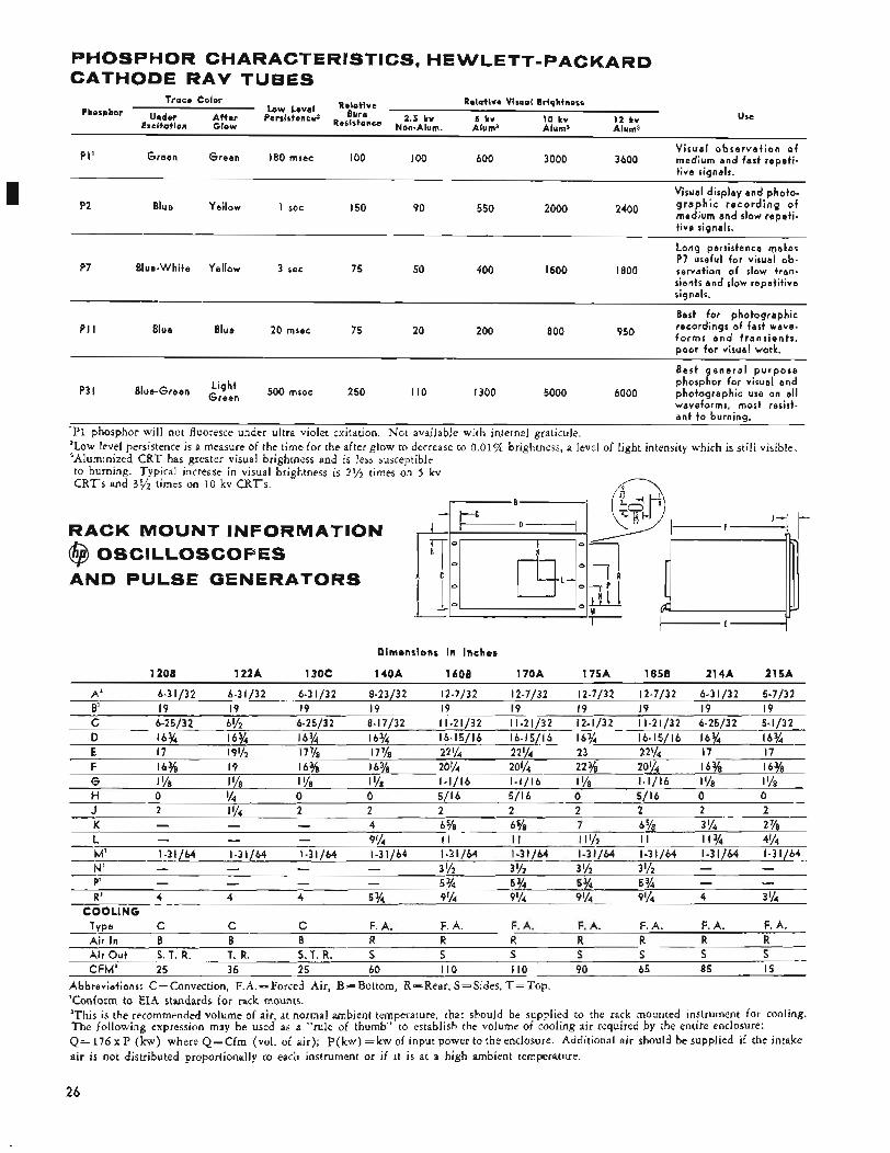
PHOSPHOR CHARACTERISTICS, HE WLETT-PACKARD CATHODE RAY TUBES
I
Relative Visual Brightness Trace Color
Use LOW Level Relo+ive
After Persistence2 Burn 2.5 kv 5 kv 10 kv 12 kv Excitation Glow Resistance Non-Alum. Alums Alums Alums
Phosphor Under
V i s u a l o b s e r v a t i o n o f PI ' G reen Green 180 msec IO0 IO0 600 3000 3 600 medium and fast repet i -
t ive signals.
Visual d isplay and photo- 2400 g r a p h i c r e c o r d i n g of
medium and slow repet i - t ive signals.
P2 Blue Yellow I sec I 5 0 90 550 2000
Long persistence makes P7 useful f o r visual ob-
P7 Blue-White Yellow 3 sec 75 50 400 I500 I800 servation o f slow tran- sients and slow repet i t i ve signals.
P I I Best f o r photograph ic recordings o f fast wave- f o r m s a n d t r a n s i e n t s , Blue Blue 20 msec 75 20 200 800 950 poor fo r visual work.
~~~~~
Best a e n e r a l wurwose phospGor fo r visual' and
P3 I Blue-Green Green 500 msec 250 I10 I300 5000 6000 photograph ic use on a l l waveforms, most resist-
L igh t
ant t o burning.
'PI phosphor will not fluoresce under ultra violet exitation. Not available with internal graticule. 'Low level persistence is a measure of the time for the after glow to decrease to 0.01% brightness, a level of light intensity which is still visible. 3Aluminized CRT has greater visual brightness and is less susceptible to burning. Typical increase in visual brightness is 2 % times on 5 kv CRT's and 355 times on 10 kv CRT's.
RACK MOUNT INFORMATION @ OSClLLOSCOPES AND PULSE GENERATORS
Dimensions in Inches
1 2 0 8 1 2 2 A 1 3 0 C 1 4 Q A 1608 1 7 0 A 1 7 5 A 1 8 5 8 2 1 4 A 2 1 5 A
A ' 6-31/32 6-31/32 6-31/32 8-23/32 12-7/32 12-7/32 12-7/32 12-7/32 6-31/32 5-7/32 E' 19 19 19 19 19 19 19 I9 19 19 C 6-25/32 6'/2 6-25/32 8-17/32 11-21/32 11-21/32 12-1/32 11-21/32 6-25/32 5-1/32
D 16% 16% 16% 16% 16-15/16 16-15/16 16% 16-15/16 16% 16% E 17 1% 17% 17% 22% 22% 23 22% 17 17
F 16% 19 16% 16% 20% ~~ 20% 22 % 20% 16% 16% G I Y8 I Ye 1 % I Ye 1-1/16 1-1/16 lye 1-1/16 l'/8 I Y8
H 0 Y4 0 0 5/16 5/16 0 5/16 0 0 J 2 1 % 2 2 2 2 2 2 2 2 K - - - 4 6 5/s 6 5/s 7 6 - 5/a 3 Y4 2 Y8 L - - - 9% I I I I I I '/2 I I 1 1 % 4%
P' - - - - 5% 5 % 5 % 5 % R' 4 4 4 5 % 9% 9 Y4 9 Y4 9 '/4 4 3 '/4
Mi 1-31/64 1-31/64 1-31/64 I -31 /b4 1-31/64 1-31/64 1-31/64 1-31/64 1-31/64 1-31/64 - - N' - - - - 3 '/2 3 Y2 3 '/2 3 Yz - -
COOLING Type C C C F. A. F. A. F. A. F. A . F. A. F. A. F. A. A i r In B B 8 R R R W D R R . .
A i r O u t S.T. R. T. R. S. T. R. S S S s S S S CFM' 25 35 25 60 I10 I10 90 65 85 15
Abbreviat ions: C=Convection, F.A.= Forced Air, B=Bottom, R=Rear, S=Sides, T = T o p . 'Conform to EIA standards for rack mounts. *This is the recommended volume of air, at normal ambient temperature, that should be supplied to the rack mounted instrument for cooling. The following expression may be used as a "rule of thumb" to establish the volume of cooling air required by the entire enclosure: Q= 176 x P (kw) where Q=Cfm (vol. of air); p ( k w ) = k w of input power to the enclosure. Additional air should be supplied if the intake air is not distributed proportionally to each instrument or if it is at a high ambient temperature.
26
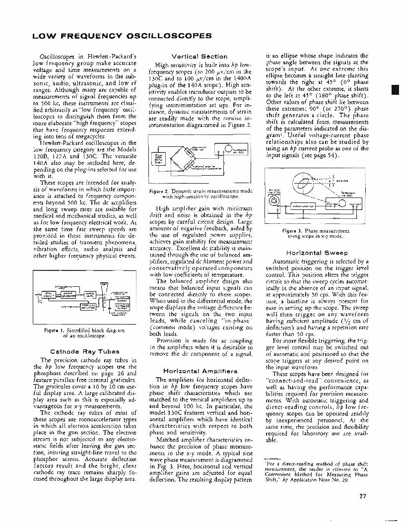
LOW FREQUENCY OSCILLOSCOPES
Oscilloscopes in Hewlett - Packard's low frequency group make accurate voltage and time measurements on a wide variety of waveforms in the sub- sonic, audio, ultrasonic, and low rf ranges. Although many are capable of measurements of signal frequencies up to 500 kc, these instruments are classi- fied arbitrarily as "low frequency" oscil- loscopes to distinguish them from the more elaborate "high frequency" scopes that have frequency responses extend- ing into tens of megacycles.
Hewlett-Packard oscilloscopes in the low frequency category are the Models 120B, 122A and 130C. The versatile 140A also may be included here, de- pending on the plug-ins selected for use with it.
These scopes are intended for analy- sis of waveforms in which little import- ance is attached to frequency compon- ents beyond 500 kc. The dc amplifiers and long sweep rates are suitable for medical and mechanical studies, as well as for low frequency electrical work. At the same time fast sweep speeds are provided in these instruments for de- tailed studies of transient phenomena, vibration effects, audio analysis and other higher frequency physical events.
Figure I. Simplified block diagram of an oscilloscope.
Cathode Ray Tubes The precision cathode ray tubes in
the hp low frequency scopes use the phosphors described on page 26 and feature parallax-free internal graticules. The graticules cover a 10 by 10 cm use- ful display area. A large calibrated dis- play area such as this is especially ad- vantageous for x-y measurements.
The cathode ray tubes of most of these scopes are monoaccelerator types in which all electron acceleration takes place in the gun section. The electron stream is not subjected to any electro- static fields after leaving the gun sec- tion, insuring straight-line travel to the phosphor screen. Accurate deflection factors result and the bright, clear cathode ray trace remains sharply fo- cused throughout the large display area.
Vertical Section High sensitivity is built into hp low-
frequency scopes (to 200 pv/cm in the 130C and to 100 pv/cm in the 1400A plug-in of the 140A scope). High sen- sitivity enables transducer outputs to be connected directly to the scope, simpli- fying instrumentation set ups. For in- stance, dynamic measurements of strain are readily made with the concise in- strumentation diagrammed in Figure 2 .
I I
Figure 2. Dynamic strain measurements made with high-sensitivity oscilloscope.
High amplifier gain with minimum drift and noise is obtained in the hp scopes by careful circuit design. Large amounts of negative feedback, aided by the use of regulated power supplies, achieves gain stability for measurement accuracy. Excellent dc stability is main- tained through the use of balanced am- plifiers, regulated dc filament power and conservatively operated components with low coefficients of temperature.
The balanced amplifier design also means that balanced input signals can be connected directly to these scopes. When used in the differential mode, the scope displays the voltage difference be- tween the signals on the two input leads, while canceling "in-phase" (common mode) voltages existing on both leads.
Provision is made for ac coupling in the amplifiers when it is desirable to remove the dc component of a signal.
Horizontal Amplifiers The amplifiers for horizontal deflec-
tion in hp low frequency scopes have phase shift characteristics which are matched to the vertical amplifiers up to and beyond 100 kc. In particular, the model 13OC features vertical and hori- zontal amplifiers which have identical characteristics with respect to both phase and sensitivity.
Matched amplifier characteristics en- hance the precision of phase measure- ments in the x-y mode. A typical sine wave phase measurement is diagrammed in Fig. 3. Here, horizontal and vertical amplifier gains are adjusted for equal deflection. The resulting display pattern
is an ellipse whose shape indicates the phase angle between the signals at the scope's input . At one extreme this ellipse becomes a straight line slanting towards the right at 45' ( O o phase shift). At the. other extreme, it slants to the left at 45' (180' phase shift). Other values of phase shift lie between these extremes; goo (or 270') phase shif t generates a circle. T h e phase shift is calculated from measurements of the parameters indicated on the dia- gram1. Useful voltage-current phase relationships also can be studied by using an hp current probe as one of the input signals (see page 54).
I I
Figure 3. Phase measurement using scope in x-y mode.
Horizontal Sweep Automatic triggering is selected by a
switched position on the trigger level control. This position alters the trigger circuit so that the sweep cycles automat- ically in the absence of an input signal, at approximately 50 cps. With this fea- ture, a baseline is always present for ease in setting up the scope. The sweep will then trigger on any waveform having sufficient amplitude (1/2 cm of deflection) and having a repetition rate faster than 50 cps.
For more flexible triggering, the trig- ger level control may be switched out of automatic and positioned so that the scope triggers at any desired point on the input waveform,
These scopes have been designed for "connect-and-read" convenience, as well as having the performance capa- bilities required for precision measure- ments. With automatic triggering and direct-reading controls, hp low fre- quency scopes can be operated readily by inexperienced personnel. At the same time, the precision and flexibility required for laboratory use are avail- able.
'For a direct-reading method of phase shift measurement, the reader is referred to "A Convenient Method for Measuring Phase Shift," hp Application Note No. 29.
27
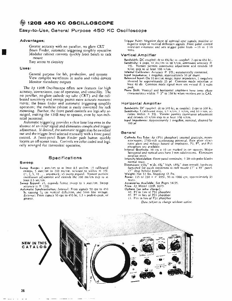
@ 120B 450 K C OSCILLOSCOPE
Easy-to-Use, General Purpose 450 KC Oscilloscope
Advantages: Tr igger Point: Negative slope of external sync signals, positive or negative slope of vertical deflection signals. Front panel control overrides automatic and sets trigger point from - 10 to + 10 volts.
Greater accuracy with no parallax, no glare CRT Beam Finder, automatic triggering simplify operation Modular cabinet converts quickly from bench to rack Vertical Amplifier
mount Easy access to circuitry
Uses:
General purpose for lab, production, and systems View complex waveforms in audio and video devices Monitor transducer outputs
The hp 120B Oscilloscope offers new features for high accuracy, convenience, ease of operation, and versatility. The no parallax, no-glare cathode ray tube (CRT) and the cali- brated sensitivity and sweeps permit more accurate measure- ments; the beam finder and automatic triggering simplify operation; the modular cabinet is easily converted for rack mounting. Further, the front panel controls are logically ar- ranged, making the 120B easy to operate, even by non-tech- nical personnel.
Automatic triggering provides a clear base line even in the absence of an input signal and eliminates complicated trigger adjustment. If desired, the automatic trigger may be switched out and the trigger level selected manually with a front panel control. A front-panel Beam Finder push button quickly locates an off-screen trace. Controls are color coded and logi- cally arranged for convenient operation.
Specifications Sweep Sweep Range: 1 psec/cm to at least 0.5 sec/cm. 15 calibrated
sweeps, 5 psec/cm to 200 ms/cm, accurate to within * 57% (1, 2 , 5 , 10 , , , sequence); x5 sweep expand. Vernier permits continuous adjustment and extends the 200 ms/cm step to d t least 0.5 sec/cm.
Sweep Expand: x5, expands fastest sweep to 1 psec/cm. Sweep accuracy is * 10%.
Automat i c Synchronization: Internal: From signals 50 cps to 450 kc causing cm vertical deflection, and from line voltage. External: From signals 50 CPS to 450 kc. 1.5 v peak-to-peak. or
Bandwidth: DC coupled; dc to 450 kc; ac coupled: 2 cps to 450 kc.. Sensitivity: 4 steps, 10 mv/cm to 10 v/cm, attenuator accuracy *
3%. Vernier permits continuous adjustment and extends 10 v/cm step to at least 100 v/cm.
In ternal Ca l i b ra to r : Accuracy * 2 % ; automatically connected, I npu t Impedance: 1 megohm, approximately 50 pf shunt. Balanced inpu t : O n 10 mv/’cm range; input impedance, 2 megohms
shunted by approximately 2 5 pf. Common mode rejection at least 40 db. Common mode signal must not exceed * 3 volts peak.
Phase Shift: Vertical and horizontal amplifiers have same phase characteristics within t 2 “ to 100 kc when verniers are in CAL.
Horizontal Amplifier Bandwidth: DC coupled: dc to 300 kc; ac coupled: 2 cps to 300 k,. Sensit ivi ty: 3 calibrated steps, 0.1 v/cm, 1 v/cm, and 10 v/cm, ac-
curate within 2 5 % . Vernier permits continuous adjustment and extends 10 v/cm step to at least 100 v/cm.
i n p u t Impedance: Approximately 1 megohm, nominal, shunted by 100 pf.
General Cathode Ray Tube: hp ( P I 1 phosphor) internal graticule, mono-
accelerator; 2700-volt accelerating potential. Face plate elimi- nates glare and reduces hazard of implosion. P2, P7, and P11 phosphors are available.
Internal Grat icu le : to cm x IO cm marked in cm squares. Major horizontal and vertical axes have 2 mm subdivisions. Eliminates parallax error.
intensity Modu la t i on : Front panel terminals; i- 20 volt pulse blanks normal trace.
Dimensions: 16%’’ wide, 6%’‘ high, 183/8” deep overall; hardware furnished for quick conversion to rack mount (7” x 19“ panel, 17” deep behind panel).
W e i g h t : Net 32 Ibs. Shipping 45 Ibs. Power: 115 or 230 v * lo%, 50 to 1000 cps; approximately 95
Accessories Avai lab le: See Pages 54-55. Price: hp Model 120B, $475. Opt ions ( n o extra cha rge ) :
watts.
02 . P2 in lieu of P31 phosphor 07. Pi’ in lieu of P31 phosphor
greater. . ,
11. P I 1 in lieu of P3lphosphor Data subject f o change without notice.
28
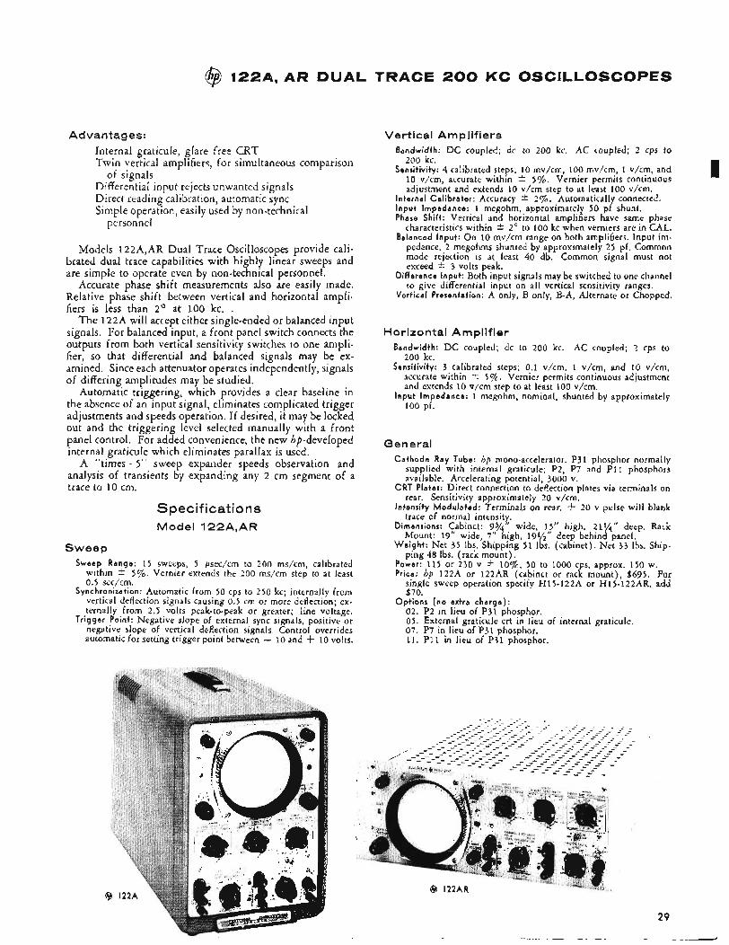
@ 122A,AR DUAL TRACE 200 KC OSCILLOSCOPES
Advantages: Internal graticule, glare free CRT Twin vertical amplifiers, for simultaneous comparison
Differential input rejects unwanted signals Direct reading calibration, automatic sync Simple operation, easily used by non-technical
of signals
personnel
Models 122A,AR Dual Trace Oscilloscopes provide cali- brated dual trace capabilities with highly linear sweeps and are simple to operate even by non-technical personnel.
Accurate phase shift measurements also are easily made. Relative phase shift between vertical and horizontal ampIi- fiers is less than 2' at 100 kc. .
The 122A will accept either single-ended or balanced input signals. For balanced input, a front panel switch connects the outputs from both vertical sensitivity switches to one ampli- fier, so that differential and balanced signals may be ex- amined. Since each attenuator operates independently, signals of differing amplitudes may be studied.
Automatic triggering, which provides a clear baseline in the absence of an input signal, eliminates complicated trigger adjustments and speeds operation. If desired, it may be locked out and the triggering level selected manually with a front panel control. For added convenience, the new hp-developed internal graticule which eliminates parallax is used.
A "times - 5" sweep expander speeds observation and analysis of transients by expanding any 2 cm segment of a trace to 10 cm.
Spec if icatio ns Model 122A,AR
Sweep Sweep Range: 1 5 sweeps, 5 psec/cm to 200 ms/cm, calibrated
within * 5%. Vernier extends the 200 ms/cm step to at least 0.5 sec/cm.
Synchronization: Automatic from 50 cps to 250 kc; internally from vertical deflection signals causing 0.5 cm or more deflection; ex- ternally from 2.5 volts peak-to-peak or greater; line voltage.
Trigger Point: Negative slope of external sync signals, positive or negative slope of vertical deflection signals. Control overrides automatic for setting trigger point between - 10 and f 10 volts.
Vertical Amplifiers Bandwidth: D C coupled; dc to 200 kc. AC coupled; 2 CPS to
200 kc. Sensitivity: 4 calibrated steps; 10 mv/cm, 100 mv/cm, 1 v/cm, and
10 v/cm, accurate within -+ 5%. Vernier permits continuous adjustment and extends 10 v/cm step to at least 100 v/cm.
Internal Calibrator: Accuracy * 2%. Automatically connected. Input Impedance: 1 megohm, approximately 50 pf shunt. Phase Shift: Vertical and horizontal amplifiers have same phase
characteristics within * 2' to 100 kc when verniers are in CAL. Balanced Input: On 10 mv/cm range on both amplifiers. Input im-
pedance, 2 megohms shunted by approximately 25 pf. Common mode rejection is at least 40 db. Common signal must not exceed 2 3 volts peak.
Difference Input: Both input signals may be switched to one channel to give differential input on all vertical sensitivity ranges.
Vertical Presentation: A only, B only, B-A, Alternate or Chopped.
Horizontal Amplifier Bandwidth: D C coupled; dc to 200 kc. AC coupled; 2 cps to
200 kc. Sensitivity: 3 calibrated steps; 0.1 v/cm, I v/cm, and 10 v/cm,
accurate within t 5%. Vernier permits continuous adjustment and extends 10 v/cm step to at least 100 v/cm.
Input Impedance: 1 megohm, nominal, shunted by approximately 100 pf.
General Cathode Ray Tube: hp mono-accelerator. P31 phosphor normally
supplied with internal graticule; P2, P7 and P I 1 phosphors available. Accelerating potential, 3000 v.
CRT Plates: Direct connection to deflection plates via terminals on rear. Sensitivity approximately 20 v/cm.
Intensity Modulated: Terminals on rear. f 20 v pulse will blank trace of normal intensity.
Dimensions: Cabinet: 9%" wide, 15" high, 21%" deep. Rack Mount: 19" wide, 7" high, 191/," deep behind panel.
Weight : Net 35 Ibs. Shipping 5 1 Ibs. (cabinet). Net 33 Ibs. Ship- ping 48 Ibs. (rack mount).
Power: 115 or 230 v * lo%, 50 to 1000 cps, approx. 150 w. Price: hp 122A or 122AR (cabinet or rack mount), $695. For
single sweep operation specify H15-122A or H15-122AR, add $70.
Options (no extra charge): 02. P2 in lieu of P31 phosphor. 05. External graticule crt in lieu of internal graticule. 07. P7 in lieu of P31 phosphor. 11. P11 in lieu of P31 phosphor.
29
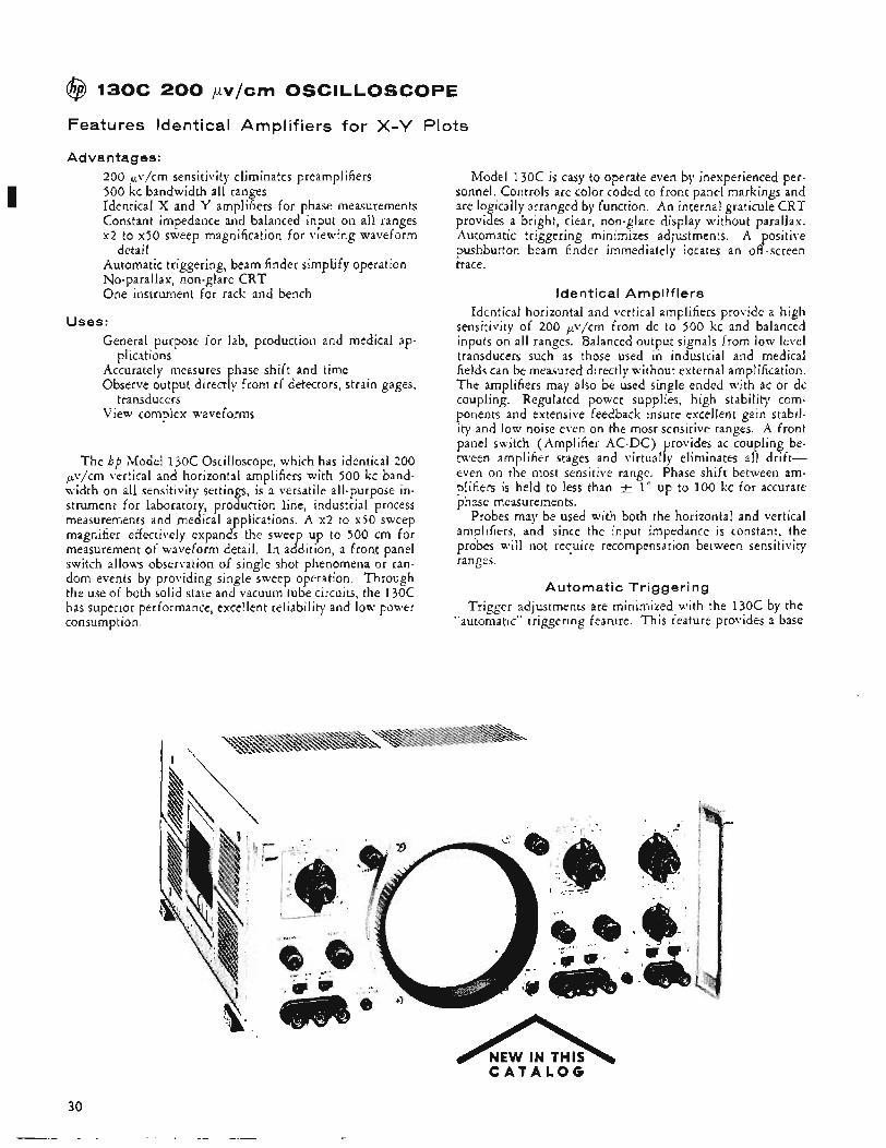
@ 130C 200 pv/em OSCILLOSCOPE
Features Identical Amplifiers for X - Y Plots
Advan tag es: 200 pv/cm sensitivity eliminates preamplifiers 500 kc bandwidth all ranges Identical X and Y amplifiers for phase measurements Constant impedance and balanced input on all ranges x2 to x50 sweep magnification for viewing waveform
Automatic triggering, beam finder simplify operation No-parallax, non-glare CRT One instrument for rack and bench
detail
Uses: General purpose for lab, production and medical ap-
Accurately measures phase shift and time Observe output directly from rf detectors, strain gages,
View complex waveforms
plications
transducers
The hp Model 130c Oscilloscope, which has identical 200 kv/cm vertical and horizontal amplifiers with 500 kc band- width on all sensitivity settings, is a versatile all-purpose in- strument for laboratory, production line, industrial process measurements and medical applications. A x2 to x50 sweep magnifier effectively expands the sweep up to 500 cm for measurement of waveform detail. In addition, a front panel switch allows observation of single shot phenomena or ran- dom events by providing single sweep operation. Through the use of both solid state and vacuum tube circuits, the 130C has superior performance, excellent reliability and low power consumption.
n NEW IN THIS
Model 130c is easy to operate even by inexperienced per- sonnel. Controls are color coded to front panel markings and are logically arranged by function. An internal graticule CRT provides a bright, clear, non-glare display without parallax. Automatic triggering minimizes adjustments. A positive pushbutton beam finder immediately iocates an off -screen trace.
Identical Amplifiers Identical horizontal and vertical amplifiers provide a high
sensitivity of 200 pv/cm from dc to 500 kc and balanced inputs on all ranges. Balanced output signals from low level transducers such as those used in industrial and medical fields can be measured directly without external amplification. The amplifiers may also be used single ended with ac or dc coupling. Regulated power supplies, high stability com- ponents and extensive feedback insure excellent gain stabil- ity and low noise even on the most sensitive ranges. A front panel switch (Amplifier AC-DC) provides ac coupling be- tween amplifier stages and virtually eliminates all drift- even on the most sensitive range. Phase shift between am- plifiers is held to less than + 1” up to 100 kc for accurate phase measurements.
Probes may be used with both the horizontal and vertical amplifiers, and since the input impedance is constant, the probes will not require recompensation between sensitivity ranges.
Automatic Trigger i ng Trigger adjustments are minimized with the l 3 0 c by the
“automatic” triggering feature. This feature provides a base
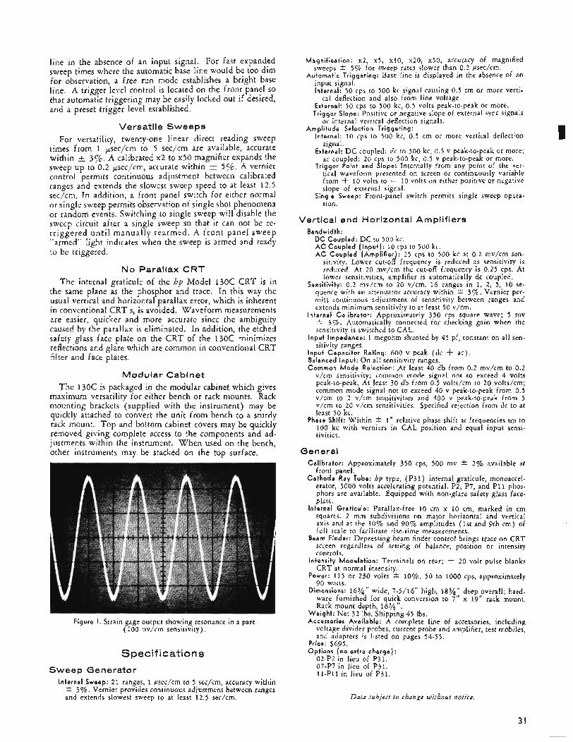
line in the absence of an input signal. For fast expanded sweep times where the automatic base line would be too dim for observation, a free run mode establishes a bright base line, A trigger level control is located on the front panel SO that automatic triggering may be easily locked out if desired, and a preset trigger level established.
Versatile Sweeps For versatility, twenty-one linear direct reading sweep
times from 1 pec/cm to 5 sec/cm are available, accurate within I+ 3%. A calibrated x2 to x50 magnifier expands the sweep up to 0.2 pec/cm, accurate within 57~. A vernier control permits continuous adjustment between calibrated ranges and extends the slowest sweep speed to at least 12 .5 sec/cm. In addition, a front panel switch for either normal or single sweep permits observation of single shot phenomena or random events, Switching to single sweep will disable the sweep circuit after a single sweep so that it can not be re- tr iggered unt i l manually rearmed. A front panel sweep "armed" light indicates when the sweep is armed and ready to be triggered.
No Parallax CRT The internal graticule of the hp Model 1 3 0 c CRT is in
the same plane as the phosphor and trace. In this way the usual vertical and horizontal parallax error, which is inherent in conventional CRT's, is avoided. Waveform measurements are easier, quicker and more accurate since the ambiguity caused by the parallax is eliminated. In addition, the etched safety glass face plate on the CRT of the 1 3 0 c minimizes reflections and glare which are common in conventional CRT filter and face plates.
Modular Cabinet The 130C is packaged in the modular cabinet which gives
maximum versatility for either bench or rack mounts. Rack mounting brackets (supplied with the instrument) may be quickly attached to convert the unit from bench to a sturdy rack mount. Top and bottom cabinet covers may be quickly removed giving complete access to the components and ad- justments within the instrument. When used on the bench, other instruments may be stacked on the top surface.
Figure I . Strain gage output showing resonance in a part (200 uv/cm sensitivity).
Specifications Sweep Generator
Internal Sweep: 2 1 ranges, 1 Psec/cm to 5 sec/cm, accuracy within i: 3%. Vernier provides continuous adjustment between ranges and extends slowest sweep to at least 12.5 sec/cm.
Magni f icat ion: x2, x5, x10, x20, x50, accuracy of magnified sweeps i. 5% for sweep rates slower than 0.2 psec/cm.
Automat i c Tr igger ing: Base line is displayed in the absence of an input signal. Internal: 50 cps to 500 kc signal causing 0.5 cm or more verti-
External: 50 cps to 500 kc, 0.5 volts peak-to-peak or more. Tr igger Slope: Positive or negative slope of external sync signals
cal deflection and also from line voltage.
or internal vertical deflection signals.
I Ampl i t ude Selection Tr igger ing: Internal: 10 cps to 500 kc, 0.5 cm or more vertical deflection
signal. External: D C coupled: dc to 500 kc, 0.5 v peak-to-peak or more;
ac coupled: 20 cps to 500 kc, 0.5 v peak-to-peak or more. Tr igger Point and Slope: Internally from any point of the ver-
tical waveform presented on screen or continuously variable from + 10 volts to - 10 volts on either positive or negative slope of external signal.
Single Sweep: Front-panel switch permits single sweep opera- tion.
Vertical and Horizontal Amplifiers Bandwidth:
DC Coup led : D C to 500 kc. AC Coup led ( I n p u t ) : 10 cps to 500 kc. AC Coup led ( A m p l i f i e r ) : 25 cps to 500 kc at 0.2 mv/cm sen-
sitivity. Lower cut-off frequency is reduced as sensitivity is reduced. At 20 mv/cm the cut-off frequency is 0.25 cps. At lower sensitivities, amplifier is automatically dc coupled.
Sensit ivi ty: 0.2 mv/cm to 20 v/cm. 16 ranges in 1, 2, 5, 10 se- quence with an attenuator accuracy within t 3%. Vernier per- mits continuous adjustment of sensitivity between ranges and extends minimum sensitivity to at least 50 v/cm.
In ternal Ca l i b ra to r : Approximately 350 cps square wave; 5 mv i 3%. Automatically connected for checking gain when the sensitivity is switched to CAL.
I npu t Impedance: 1 megohm shunted by 45 pf, constant on all sen- sitivity ranges.
I npu t Capac i to r Rating: 600 v peak (dc f ac) . Balanced Input : On all sensitivity ranges. Common M o d e Rejection: At least 40 db from 0.2 mv/cm to 0.2
v/cm sensitivity; common mode signal not to exceed 4 volts peak-to-peak. At least 30 db from 0.5 volts/cm to 20 volts/cm; common mode signal not to exceed 40 v peak-to-peak from 0.5 v/cm to 2 v/cm sensitivities and 400 v peak-to-peak from 5 v/cm to 20 v/cm sensitivities. Specified rejection from dc to at least 50 kc.
Phase Shift: Within i: 1' relative phase shift at frequencies up to 100 kc with verniers in CAL position and equal input sensi- tivities.
General Ca l ib ra to r : Approximately 350 cps, 500 mv i: 2% available at
front panel. C a t h o d e Ray Tube: hp type, ( P 3 l ) internal graticule, monoaccel-
erator, 3000 volts accelerating potential. P2, P7, and P I 1 phos- phors are available. Equipped with non-glare safety glass face- plate.
In ternal Grat icu le : Parallax-free 10 cm x 10 cm, marked in cm squares. 2 mm subdivisions on major horizontal and vertical axis and at the 10% and 90% amplitudes (1st and 9th cm) of full scale to facilitate rise-time measurements.
Beam Finder: Depressing beam finder control brings trace on CRT screen regardless of setting of balance, position or intensity controls.
Intensity Modulat ion: Terminals on rear; -t 20 volt pulse blanks CRT at normal intensity.
Power: 115 or 230 volts * lo%, 50 to 1000 cps, approximately 90 watts.
Dimensions: 16%'' wide, 7-5/16" high, 18%" deep overall; hard. ware furnished for quick conversion to 7" x 19" rack mount. Rack mount depth, 16% ,
W e i g h t : Net 32 Ibs. Shipping 45 Ibs. Accessories Avai lab le: A complete line of accessories, including
voltage divider probes, current probe and amplifier, test mobiles, and adapters is listed on pages 54-55.
Price: $695. ODtions [no extra charae) :
'02-PZ in lieu of ~ 3 i . ' 07-P7 in lieu of P31. 11-P11 in lieu of P31.
Data subject to change without notice.
31
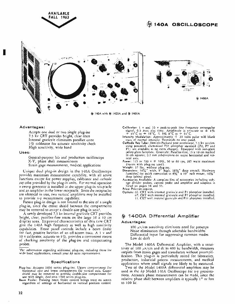
A V A l LABLE FALL 1963
@ 140A OSCILLOSCOPE
@ 140Awi th @ 1420Aand @ 1401A
Advantages : Accepts one dual or two single plug-ins 7.5 kv CRT provides bright, clear trace Internal graticule eliminates parallax error 17~ calibrator for accurate sensitivity check High sensitivity, wide band
General-purpose lab and production oscilloscope X - Y , phase shift measurements Strain gage measurements, medical applications
Unique dual plug-in design in the 140A Oscilloscope provides maximum measurement capability, with all active functions except for power supplies, calibrator and cathode ray tube provided by the plug-in units. For normal operation a sweep generator is installed in the upper plug-in receptacle and an amplifier in the lower receptacle. Since the receptacles are identical in size, two vertical am lifiers may be installed to provide x-y measurement capabi Y ity.
Future plug-in design is not limited to the size of a single plug-in, since the center shield between the compartments may be removed to accept a double-size plug-in unit1.
A newly developed 7.5 kv internal graticule CRT provides bright, clear, parallax-free traces on the large 10 x 10 cm display area. Improved characteristics of this new CRT give the 140A high frequency as well as high sensitivity capabilities. Front panel controls include a beam finder for fast, positive location of an off-screen trace. A 1 v and 10 v calibrator, accurate to I%, provides a convenient means of checking sensitivity of the plug-ins and compensating probes. 'For information regarding additional plug-ins, including those for wide band applications, consult your hp sales representative.
Uses:
Specifications Plug-Ins: Accepts 1400 series plug-ins. Upper compartment for
horizontal axis and lower compartment for vertical axis. Center shield may be removed to provide double-size compartment for use with single, dual-axis 1400 series plug-ins.
Beam Finder: Pressing beam finder control brings trace on screen regardless of settings of horizontal or vertical position control.
@ 1400A
Calibrator: 1 v and 10 v peak-to-peak line frequency rectangular signal, 0.5 ksec rise time. Amplitude is accurate to +- 1% -k 15°C to -k 35"C, 2 3.9% 0°C to -k 55°C.
Intensity Modulation: Approximately -k 20 volts pulse will blank trace of normal intensity. Terminals on rear panel.
Cathode Ray Tube: Hewlett-Packard post accelerator, 7.5 kv acceler- ating potential, aluminized P31 phosphor standard (P2, P7 and P I 1 are available at no extra charge). Equipped with non-glare safety-glass faceplate. Graticule: Parallax-free, 10 x 10 cm marked in cm squares; 0 .2 mm subdivisions on major horizontal and ver- tical axis.
Power: 115 or 230 v * l o % , 50 to 60 cps, 285 watts maximum (varies with plug-ins used) ,
Weight : 37 Ibs., without plug-ins. Dimensions: 16%" wide, 9" high, 183/," deep overall. Hardwar;
furnished for quick conversion to 8% deep behind panel.
Accessories Available: A complete line of accessories including volt- age divider probes, current probe and amplifier and adapters is listed on pages 54 and 5 5 .
Price: Price on request. Options: 02. CRT with internal graticule and P2 phosphor installed.
07. CRT with internal graticule and P7 phosphor installed. 11. CRT with internal graticule and P11 phosphor installed.
x 19" rack mount, 16%
($3 1 4 0 0 A Differential Amplifier Advantages:
100 pvjcm sensitivity eliminates need for preamps Noise elimination through selectable bandwidths Differential input for suppressing common modes Low dc drift
The Model 1400A Differential Amplifier, with a sensi- tivity of 100 pvjcm and dc to 400 kc bandwidth, measures outputs from strain gages and transducers without preampli- fication. This plug-in is particularly suited for laboratory, production, industrial process measurements, and medical applications where small signals are likely to be measured.
Two of the Model 1400A differential amplifiers may be used in the hp Model 140A Oscilloscope for x-y presenta- tions. Accurate phase measurements can be made, since the relative phase shift between amplifiers is typically l o or less to 100 kc.
32
Specifications Bandwidth:
Upper Limit: 400 kc, 40 kc, 4 kc, selectable with front panel switch.
Lower Limit: D C with amplifier and input coupling in dc. AC coupled ( input) ; 2 cps. AC coupled (amplifier); dc from 20 v/cm to 50 mv/cm sensitivities. Approx. 0.1 cps on 20 mv/cm sensitivity, increasing with sensitivity to approximately 20 cps at 0.1 mv/cm.
Sensitivity: 0.1 mv/cm to 20 v/cm in 17 calibrated ranges in a 1, 2, 5, 10 sequence, Vernier allows continuous adjustment between calibrated ranges and extends minimum sensitivity to at least 50 v/cm.
Attenuator Accuracy: * 3%. Internal Calibrator: 6 cm line frequency rectangular signal when at-
tenuator switched to CAL. Accuracy * 35%. Input Impedance: 1 megohm shunted by 45 pf, constant on all at-
tenuator ranges. Input Capacitor Rating: 600 volts dc (input ac coupled). Dual Inputs: Two signal input jacks (BNC, 2 polarity). AC, DC,
or OFF on either input selectable with front panel switches. Iso- lation between inputs at least 80 db.
Differential Input: Differential input may be selected on all attenua- tor ranges. Common mode rejection at least 40 db on 0.1 mv/cm to 0.2 v/cm ranges, signal not to exceed 4 v p-p. On 0.5 v/cm to 20 v/cm ranges, at least 30 db, signal not to exceed 40 v p-p on 0.5, 1 and 2 v/cm ranges and 400 v p-p on 5, 10, and 20 v/cm ranges. Measured at 1 kc.
Phase Shift: When used with another 1400A plug-in, typically within * 1' relative phase shift at frequencies up to 100 kc with x and y sensitivities the same and verniers in CAL.
Power: Supplied by 140A Oscilloscope. W e i g h t : Net 4 Ibs. Price: Price on request.
@ 1 4 0 1 A Dual Trace Amplifier
Advantages: 1 mv/cm sensitivity for low level measurements Dual channel for time and waveform comparisons Differential input suppresses common mode signals
The Model 1401A permits simultaneous comparison of two electrical signals, such as input and output of amplifiers and filters, with ease and accuracy. Its two 450 kc channels, each with a sensitivity of 1 mv/cm, may be used inde- pendently, together in chopped or alternate modes for simul- taneous display of two signals, or in a differential mode of operation for measurements on balanced lines when common mode suppression is desired.
Specifications Mode of Operation:
Channel A alone. Channel B alone. Channels A and B displayed on alternate sweeps. Channels A and B displayed by switching at approximately 100 kc rate, with blanking during switching. Chan- nel A minus Channel B (differential input) .
Each Channel: Sensitivity: 1 mv/cm to 10 v/cm in 13 calibrated ranges in a 1,
2 , 5, 10 sequence. Vernier allows continuous adjustment be- tween calibrated ranges and extends minimum sensitivity to at least 2 5 v/cm.
Attenuator Accuracy: f 37c. Pass Band:
Upper Limit: 450 kc al! sensitivities. Lower Limit: D C with amplifier and input coupling in dc. AC coupled ( input ) : 2 cps. AC coupled (amplifier): D C on 10 v/cm to 20 mv/cm sensitivity
ranges. Approx. 1 cps at 10 mv/cm increasing with sensi- tivity to approx. 10 cps at 1 mv/cm.
Input Impedance: 1 megohm shunted by 45 pf, constant on all at:
Input Capacitor Rating: 600 volts dc (ac coupled input) . Polarity of Presentation: 4- up or - up selectable for A Channel.
tenuator ranges.
Differential Input: Both channels, with their input attenuators, may be switched to
Amplifier: Channel A. Display: A minus B. Common M o d e Rejection: Common mode rejection at least 40 db
on 1 mv/cm to 0.1 v/cm ranges, signal not to exceed 4 v p-p. O n 0.2 v/cm to 10 v/cm, at least 30 db, signal not to exceed 40 v p-p on 0.2, 0.5, and 1 v/cm ranges and 400 v p-p on 2, 5, 10 v/cm ranges. Measured at 1 kc.
one channel to give differential input.
General: Internal Calibrator: 6 cm line frequency rectangular wave when
Weight : 5 Ibs. Power: Supplied by 140A Oscilloscope. Price: Price on request.
sensitivity switch at CAL. Accuracy 2 3%.
@ 1 4 2 0 A Time Base
Advantages: Stable triggering to greater than 10 mc Automatic triggering locks in waveforms Sweep speeds to 0.1 psec/cm for fast phenomena Single swee-p for observing transients
The Model 1420A Time Base supplies sweep time, trigger and horizontal input functions to the 140A Oscillosco e.
on the sweep time switch and a x5 magnifier increases fastest speed to 0.1 pec/cm. The magnifier expands the trace that is around the center of the CRT permitting examination of waveform detail. Adjusting the horizontal position control allows examination of any portion of the trace.
Both automatic triggering, for connect and read con- venience from 40 cps to 500 kc, and amplitude selection triggering are employed. In amplitude selection triggering the instrument has trigger capabilities from dc to greater than 10 mc. Single sweep operation for viewing transients and single shot phenomena is established by a front panel switch.
Spec if i cat i o n s
Sweep speeds from 0.5 pec/cm to 5 sec/cm are provi if ed
Internal Sweep: 2 2 ranges, 0.5 psec/cm to 5 sec/cm, accuracy within f 3%. Vernier provides continuous adjustment between ranges and extends slowest sweep to at least 12.5 sec/cm.
Magnification: x5, accuracy * 55%. Expands fastest sweep to 0.1 psec/cm.
Automatic Triggering: Base line displayed in the absence of an input signal. Internal: 40 cps to 500 kc signal causing 0.5 cm or more vertical
External: 40 cps to 500 kc, 0.5 volts peak-to-peak or more. Trigger Slope: Positive or negative slope of external trigger source
signals or internal vertical deflection signals,
Internal: 10 cps to greater than 10 mc. 0.5 cm or more vertical deflection at approximately 1 mc and below. Increasing to 2
deflection; also from line voltage.
Amplitude Selection Triggering:
_. - cm at 10 mc.
External: D C coupled: DC to 10 mc with 0.5 v peak-to-peak or more. AC coupled: 10 cps to 10 mc with 0.5 v peak-to-peak or more.
Trigger Point and Slope: Internally from any point of the vertical waveform presented on screen or continuously variable from + 10 volts to - 10 volts on external signal; positive or negative slope.
Single Sweep: Front panel switch permits single sweep operation. Horizontal Input: D C coupled. Approximately 1 v/cm or 5 v/cm
sensitivity depending on magnifier setting. Input impedance 1 meg- ohm shunted by less than 50 pf.
Weight : 5 lbs. Power: Supplied by 140A Oscilloscope, Price: Price on request.
Data subject to change without notice.
33
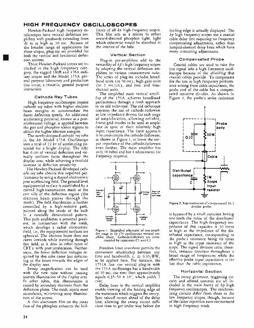
HIGH FREQUENCV OSCILLOSCOPES Hewlett-Packard high frequency os-
cilloscopes have vertical deflection am- plifiers with passbands extending from dc to as high as 50 mc. Because of the broader range of applications for these scopes, plug-ins are provided for both the vertical and horizontal deflec- tion systems.
Three Hewlett-Packard scopes are in- cluded in the high frequency cate- gory, the rugged l6OB and 170A mili- tary scopes and the Model 175A gen- eral purpose laboratory and production line scope, a versatile, general purpose instrument.
Cathode Ray Tubes High frequency oscilloscopes require
cathode ray tubes with higher electron beam energies to accommodate the faster deflection speeds. An additional accelerating potential, known as a post- acceleration voltage, is applied between the gun and phosphor screen regions to obtain the higher electron energies.
The newly-designed cathode ray tube in the hp Model 175A Oscilloscope uses a total of 1 2 kv of accelerating po- tential for a bright display. The tube has 6 cm of vertical deflection and vir- tually uniform focus throughout the display area, while achieving a twofold increase in deflection sensitivity.
The Hewlett-Packard developed cath- ode ray tube obtains this improved per- formance by using a shaped electrostatic post-accelerating field. The ground level equipotential surface is established by a curved high-transmission mesh at the exit side of the deflection region (the electron beam passes through the mesh). The field distribution is further controlled by a high-resistive path, painted along the inside of the bulb in a carefully dimensioned pattern. This path establishes a potential gradi- ent, in conjunction with the mesh, which develops a radial electrostatic field, Le., the equipotential surfaces are spherical. The electron beam does not curve inwards while traveling through this field, as it does in other types of CRT's with post-acceleration. Further- more, the lower deflection voltages re- quired by this tube cause less defocus- ing of the beam towards the edges of the display area.
Sweep magnification can be used with the new tube without causing uneven illumination of the display area. In other tubes, this illumination is caused by secondary electrons from the deflection plates. The mesh rejects most secondaries, minimizing stray illumina- tion of the screen.
A thin aluminum film on the inner face of the phosphor enhances the bril-
liance of all hp high-frequency scopes. This film acts as a mirror to reflect inward-directed phosphor light, light which otherwise would be absorbed in the interior of the tube.
Vertical Section Plug-in pre-amplifiers add to the
versatility of hp's high frequency scopes by adapting the vertical deflection am- plifiers to various measurement tasks. The series of plug-ins includes broad- band units ( to 50 mc), high gain units (to 5 mv/cm), and two- and four- channel units.
The simplified main vertical ampli- fier of the 175A achieves broadband performance through a fresh approach to an old technique. The old technique concerns the use of cathode-followers as low impedance drivers for each stage of amp 1 if ica t i o n, a1 1 owing reliable, frame-grid triodes to be used as ampli- fiers in spite of their relatively high input capacitance. The fresh approach is to cross-couple the cathode-followers, as shown in Figure 1, to lower the out- put impedance of the cathode-followers even further. The main amplifier has only 10 tubes and but 4 adjustments for frequency response,
I *+l
I - C J I
Figure I. Simplified schematic of one ampli- fier stage in hp 175 oscilloscope vertical am- plifier chain. Cathode-followers are cross-
coupled by capacitors C1 and C2.
Freedom from overshoot permits the convenient relationship between rise time and bandwidth, t,. z 0.35/BW, to be applied here. For instance, the, 1751A fast rise vertical plug-in with the 175A oscilloscope has a bandwidth of 50 mc; rise time then approximately equals 0.35150 x loG, which yields 7 nsec.
Delay lines in the vertical amplifier enable viewing of the leading edge of the waveform which triggers the sweep. Sync takeoff occurs ahead of the delay line, allowing the sweep circuit suffi- cient time to get under way before the
leading edge is actually displayed. The hp high frequency scopes use a coaxial cable delay line requiring no frequency compensating adjustments, rather than lumped-element delay lines which have many interacting adjustments,
Compensated Probe Coaxial cables are used to take the
test signal into a high frequency oscil- loscope because of the shielding that coaxial cables provide. To compensate for the loss in high frequency perform- ance arising from cable capacitance, the probe end of the cable has a compen- sated resistive divider. As shown in Figure 2, the probe's series resistance
t "-1 r-- -- - - --
I r - - , t W I Distributed I .
c a p a c i t a n c L
$Eop* I '
- Figure 2. Representation of compensated 10: 1
divider probe.
is bypassed by a small capacitor having one-tenth the value of the distributed capacitance. The high frequency im- pedance of this capacitor is 10 times as high as the impedance of the dis- tributed capacitance, corresponding to the probe's resistance being 10 times as high as the input resistance of the scope. The signal division ratio, there- fore, remains constant throughout a broad range of frequencies while the effective probe input capacitance is far less than the cable capacitance.
Horizon tal Section The sweep generator, triggering cir-
cuits and related controls are all in- cluded in the main frame of hp high frequency oscilloscopes. The synchron- izing circuits differ from those in the low frequency scopes, though, because of the faster repetition rates encountered in high frequency work.
34
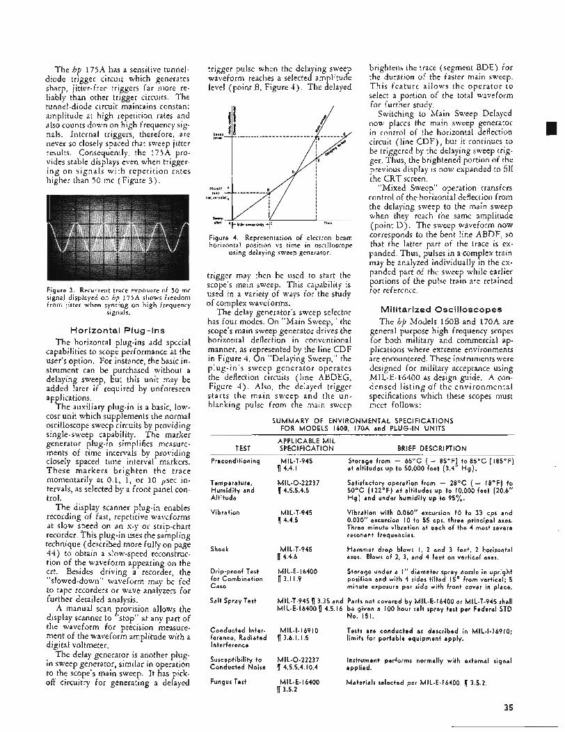
The hp 175A has a sensitive tunnel- diode trigger circuit which generates sharp, jitter-free triggers far more re- liably than other trigger circuits. The tunnel-diode circuit maintains constant amplitude at high repetition rates and also counts down on high frequency sig- nals. Internal triggers, therefore, are never so closely spaced that sweep jitter results. Consequently, the 175A pro- vides stable displays even when trigger- ing on signals with repeti t ion rates higher than 50 mc (Figure 3 ) .
Figure 3. Recurrent trace exposure of 50 mc signal displayed on hp 175A shows freedom from jitter when syncing on high frequency
signals.
H o r i z o n t a l P l u g - I n s The horizontal plug-ins add special
capabilities to scope performance at the user’s option. For instance, the basic in- strument can be purchased without a delaying sweep, but this unit may be added later if required by unforeseen applications.
The auxiliary plug-in is a basic, low- cost unit which supplements the normal oscilloscope sweep circuits by providing single-sweep capability. The marker generator plug-in simplifies measure- ments of time intervals by providing closely spaced time interval markers. These markers brighten the trace momentarily at 0.1, 1, or 10 p e c in- tervals, as selected by a front panel con- trol.
The display scanner plug-in enables recording of fast, repetitive waveforms at slow speed on an x-y or strip-chart recorder. This plug-in uses the sampling technique (described more fully on page 44) to obtain a slow-speed reconstruc- tion of the waveform appearing on the crt. Besides driving a recorder, the “slowed-down” waveform may be fed to tape recorders or wave analyzers for further detailed analysis.
A manual scan provision allows the display scanner to “stop” at any part of the waveform for precision measure- ment of the waveform amplitude with a digital voltmeter.
The delay generator is another plug- in sweep generator, similar in operation to the scope’s main sweep. It has pick- off circuitry for generating a delayed
trigger pulse when the delaying sweep waveform reaches a selected amplitude level (point B, Figure 4 ) . The delayed
Figure 4. Representation of electron beam horizontal position vs time in oscilloscope
using delaying sweep generator.
trigger may then be used to start the scope’s main sweep. This capability is used in a variety of ways for the study of complex waveforms.
The delay generator’s sweep selector has four modes. On “Main Sweep,” the scope’s main sweep generator drives the horizontal deflection in conventional manner, as represented by the line CDF in Figure 4. On “Delaying Sweep,” the plug-in’s sweep generator operates the deflection circuits (line ABDEG, Figure 4 ) . Also, the delayed trigger starts the main sweep and the un- blanking pulse from the main sweep
brightens the trace (segment BDE) for the duration of the faster main sweep. This feature allows the operator to select a portion of the total waveform for further study.
Switching to Main Sweep Delayed now places the main sweep generator in control of the horizontal deflection circuit (line CDF) , but it continues to be triggered by the delaying sweep trig- ger. Thus, the brightened portion of the previous display is now expanded to fill the CRT screen.
“Mixed Sweep” operation transfers control of the horizontal deflection from the delaying sweep to the main sweep when they reach the same amplitude (point D ) . The sweep waveform now corresponds to the bent line ABDF, SO that the latter part of the trace is ex- panded. Thus, pulses in a complex train may be analyzed individually in the ex- panded part of the sweep while earlier portions of the pulse train are retained for reference.
M i l i t a r i z e d O s c i l l o s c o p e s The hp Models l6OB and 170A are
general purpose high frequency scopes for both military and commercial ap- plications where extreme environments are encountered. These instruments were designed for military acceptance using MIL-E-la6400 as design guide. A con- densed listing of the environmental specifications which these scopes must meet follows :
SU M M A R Y O F ENVl R O N M ENTAL SPEC I FI C A T ION S FOR MODELS 160B, 170A and P L U G - I N UNITS
~
APPLICABLE MIL SPEC I Fl CAT1 ON TEST BRIEF DESCRIPTION
Precondit ioning
Temperature, H u m i d i t y and A l t i t ude
Vibrat ion
Shock
Dr ip-proof Test f o r Combinat ion Case
Sa l t Spray Test
Conducted In ter - ference, Rad ia ted Interference
Susceptibi l i ty t o C o n d u c t e d Noise
Fungus Test
M I L-T-945 Storage f rom - 6 5 ° C ( - 85OF) t o 85’C (185OF) a t alt i tudes u p t o 50,000 fee t (3.4” H g ) . 1 4.4. I
MI L-0-22237 Satisfactory operat ion f rom - 2 8 ° C ( - 18OF) t o 14.5.5.4.5 50’C (122’F) a t alt i tudes u p t o 10,000 fee t (20.6”
H g ) and under humid i ty up t o 95%.
Vibrat ion w i t h 0.060” excursion I O t o 33 cps and 0.030” excursion I O t o 55 cps, three pr inc ipa l axes. Three minute v ibrat ion a t each o f the 4 most severe resonant frequencies.
Hammer d rop blows I, 2 and 3 feet , 2 horizontal axes. Blows of 2, 3, and 4 fee t on ver t ica l axes.
Storage under a I ” d iameter spray nozzle in up r igh t posit ion and wi th 4 sides t i l ted 15’ f rom vert ical: 5 minute exposure per side wi th f ron t cover in place.
MIL-T-945 13.35 and Parts not covered by MIL-E- I6400 or MIL-T-945 shall MIL-E- I6400 14.5.16 b e given a 100 hour salt spray test per Federal STD
MI L-T-945 1 4.4.5
MI L-T-945 14.4.6
MI L-E- I6400 13.1 1.9
No . 151.
Tests are conducted as descr ibed i n MIL-1-16910; l imi ts fo r por tab le equ ipment apply.
MI L-I- I 6 9 I O 1 3.6. I, I .5
MI L-0-22237 1 4.5.5.4.10.4 appl ied.
Instrument performs normally wi th external signal
M I L-E- I6400 Mater ia ls selected per MIL-E-16400, 1 3.5.2. 13.5.2
35
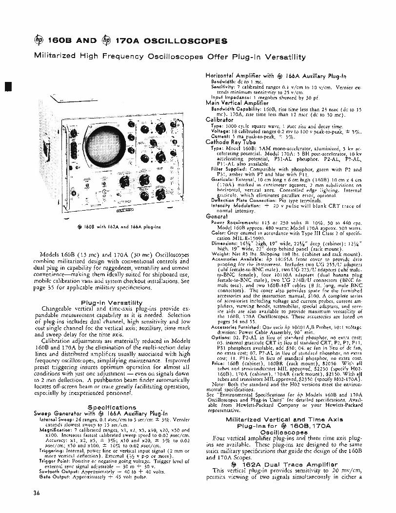
@ 1606 AND @ 170A OSCILLOSCOPES
Militarized High Frequency Oscilloscopes Offer Plug-In Versatility
@ 1608 wi th 162A and 166A plug-ins
Models l6OB (15 mc) and 170A (30 mc) Oscilloscopes combine militarized design with conventional controls and dual plug-in capability for ruggedness, versatility and utmost convenience-making them ideally suited for shipboard use, mobile calibration vans and system checkout installations. See page 35 for applicable military specifications.
PI ug -I n Versatility Changeable vertical and time-axis plug-ins provide ex-
pandable measurement capability as it is needed. Selection of plug-ins includes dual channel, high sensitivity and low cost single channel for the vertical axis; auxiliary, time mark and sweep delay for the time axis.
Calibration adjustments are materially reduced in Models l60B and 170A by the elimination of the multi-section delay lines and distributed amplifiers usually associated with high frequency oscilloscopes, simplifying maintenance. Improved preset triggering insures optimum operation for almost all conditions with just one adjustment - even on signals down to 2 mm deflection. A pushbutton beam finder automatically locates off -screen beam or trace greatly facilitating operation, especially by inexperienced personnel.
Specifications Sweep Generator with @ 166A Auxiliary Pluglln
Internal Sweep: 24 ranges, 0.1 psec/cm to 5 sec/cm * 3%. Vernier extends slowest sweep to 1 5 sec/cm.
Magn i f i ca t i on : ? calibrated ranges, XI, x2, x5, x10, x20, x50 and ~ 1 0 0 . Increases fastest calibrated sweep speed to 0.02 psec/cm. Accuracy: XI, x2, x5, * 3%; x10 and x20, * 5 % to 0.02 psec/cm; x50 and x100, * 1 0 % ~ to 0.02 psec/cm.
Tr igger ing: Internal, power line or vertical input signal ( 2 mm or more vertical deflection). External (x v p-p or more).
Tr igge r Point: Positive or negative going voltage. Trigger level of external sync signal adjustable - 30 to 4- 30 v.
Sawtooth Ou tpu t : Approximately - 40 to 4- 40 volts. G a t e Ou tpu t : Approximately 4- 45 volt pulse.
Horizontal Amplifier with @ 166A Auxiliary Plug-In Bandwidth: dc to 1 mc. Sensitivity: ? calibrated ranges 0.1 v/cm to 10 v/cm. Vernier ex-
I npu t Impedance: 1 megohm shunted by 30 pf.
Bandwidth Capab i l i t y : 160B, rise time less than 23 nsec (dc to 15
tends minimum sensitivity to 2 5 v/cm.
Main Vertical Amplifier
Calibrator mc). 1?0A, rise time less than 12 nsec (dc to 30 mc) .
Type: 1000 cycle square wave, 1 Psec rise and decay time. Voltage: 18 calibrated ranges 0.2 mv to 100 v peak-to-peak, * 37;. Current : 5 ma peak-to-peak, * 3%.
Type: Model 160B: 5AM mono-accelerator, aluminized, 5 kv ac- celerating potential. Model 170A: 5 BH post-accelerator, 10 kv accelerating potential, P31-AL phosphor. P2-AL, P7-AL. PI1 -AL also available.
Fi l ter Supplied: Compatible with phosphor, green with P2 and P31, amber with P7 and blue with P11.
Grat icu le : External, 10 cm long x 6 cm high (16OB) 10 cm x 4 cm (170A) marked in centimeter squares; 2 mm subdivisions on horizontal, vertical axes. Controlled edge lighting. Internal graticule, which eliminates parallax error, optional.
normal intensity.
Cathode Ray Tube
Def lect ion Plate Connect ion: Pin type terminals. Intensity Modu la t i on : -t- 20 v pulse wi l l blank C R T trace of
General Power Requirements: 115 or 230 volts * IOqc, 50 to 440 cps.
Model l6OB approx. 480 watts; Model 170A approx. 500 watts. Co lo r : Grey enamel in accordance with Type I11 Class 2 of specifi-
cation MIL-E- ;,5 090. Dimensions: 1478 high, 19” wide, 221/8” deep (cabinet); 12%”
high, 19“ wide, 2 2 ” deep behind panel (rack mount) . W e i g h t : Net 85 Ibs. Shipping 108 lbs. (cabinet and rack mount) . Accessories Avai lab le: hp 10165A front cover to provide drip
proofing for the instrument. Includes two U G 255/U adapters (uhf female-to-BNC male), two U G 273/U adapters (uhf male- to-BNC female), four 1OllOA adapters (dual banana plug female-to-BNC male), two UG 2?4B/U connectors (BNC fe- male tees), and two 16OB-16T cables ( 8 i t . long, male BNC connectors). The cover also provides space for the furnished accessories and the instruction manual, $100. A complete series of accessories including voltage and current probes, current am- plifiers, viewing hoods, testmobiles, special adapters, and serv- ice aids are also available to provide maximum versatility of the 160B, 170A Oscilloscopes. These accessories are listed on pages 54 and 55 .
Accessories Furnished: One each hp 10001A,B Probes, 1 O : l voltage division; Power Cable Assembly, 90” min.
Opt ions: 02. P2-AI in lieu of standard phosphor, no extra cost; 03. internal graticule CRT in lieu of standard CRT, P2, P7, P11, P31 phosphors available, add $30; 04. ac fan in lieu of dc fan, no extra cost; 07. P7-AL in lieu of standard phosphor, no extra cost; 11. P11-AL in lieu of standard phosphor, no extra cost.
Price: l6OB (cabinet), 160BR (rack mount) , $2050. With all tubes and semiconductors MIL approved, $2250 (specify H02- 160B). 170A (cabinet), 170AR (rack mount) , $2150. With a!] tubes and transistors MIL approved, $2350 (specify H02-170A).
Note: Both the standard and the H02 versions meet the environ- mental specifications. See “Environmental Specifications for hp Models 160B and 170A Oscilloscopes and Plug-in Units” for detailed specifications. Avail- able from Hewlett-Packard Company or your Hewlett-Packard representative.
Militarized Vertical and Time Axis Plug-Ins for @ 160B, 170A
Oscilloscopes Four vertical amplifier plug-ins and three time axis plug-
ins are available. These plug-ins are designed to the same strict military specifications that guide the design of the 16oB and 170A Scopes.
@ 162A Dual Trace Amplifier This vertical plug-in provides sensitivity to 20 mv/cm,
permits viewing of two signals simultaneously in either a
36
chopped or alternate presentation and offers differential input for common mode rejection.
S pec if i cat i o n s Each Channel
Sensitivity Range: 0.02 v/cm to 20 v/cm, 10 calibrated ranges in 1, 2, 5 , 10 sequence. Vernier to at least 50 v/cm.
Attenuator Accuracy: * 3%. Pass Band: With 170A: dc coupled, dc to 2 2 mc; ac coupled; 2
cps to 22 mc. With 16OB: dc coupled, dc to 14 mc; ac coupled, 2 cps to 14 mc.
Rise Time: Less than 16 nsec in 170.4 and 2 5 nsec in 160B. Input Impedance: 1 megohm (nominal) shunted by less than 30 pf. Polarity of Presentation: 4- up or - up, selectable.
Differential Input: Both input attenuators may be switched to one channel to give differential input. The input attenuators may be set separately to allow mixing signals of different levels. Common M o d e Rejection: At least 40 db at maximum sensitivity,
Price: $375; with all tubes and semiconductors MIL approved $420 at least 30 db when using attenuators.
(specify H02-162A). @ 1 6 2 6 Dual Trace Vertical Amplifier
Model 162B permits dual channel measurements over the full bandwidth of the l60B (15 mc) and 170A (30 mc). Maximum accuracy and reliability is obtained through the use of simplified circuitry. Chopped, alternate and diff eren- tial inputs provide maximum user versatility.
Specifications Each Channel
Sensitivity Range: 0.05 v/cm to 20 v/cm. Nine calibrated ranges in 1, 2 , 5, 10 sequence. Vernier extends minimum sensitivity to at least 50 v/cm and provides continuous adjustment between ranges.
Attenuator Accuracy: * 3%. Pass Band: In 170A: dc coupled, dc to 30 mc, ac coupled, 2 cps
to 30 mc. In 16OB: dc coupled, dc to 1 5 mc; ac coupled, 2 cps to 15 mc.
Rise Time: Less than 1 2 nsec in 170A, 23 nsec in 16OB. Dynamic Range: Input amplifiers may be overloaded by 18 cm
signal without causing noticeable signal distortion. Vertical Position Control Range: t . 9 cm. Input Impedance: 1 megohm (nominal) shunted by 28 pf. Input Capacitor Rating: 600 v dc. Polarity of Presentation: -t up or - up, selectable.
Differential Input: Both inputs, with their associated attenuators, may be switched to one channel to give differential input, The input attenuators may be set separately to allow mixing signals of dif- ferent levels. Common M o d e Rejection: At least 40 db at maximum sensitivity
Price: $350; with all tubes and semiconductors MIL approved $390 (specify H02-162B).
@ 1 6 2 D High Gain Vertical Amplifier Sensitivity of the l60B or 170A is increased to 5 mv/cm
with this versatile plug-in. At this sensitivity the 162D,170A combination has a rise time of less than 19 nsec. Differential input is included.
Sensitivity: 5 mv/cm to 20 v/cm, 1 2 ranges in 1, 2, 5 , 10 sequence.
Attenuator Accuracy: 3 7 ~ . Dual Inputs: Two jacks (BNC) ; ac or de coupling, isolation between
inputs at least 80 db. Differential Input: 5 mv/cm to 50 mv/cm, common mode rejection
at least 40 db. Pass Band:
With 170A: D C Coupled AC Coupled
up to 1 mc, or 30 db when using attenuators.
S peci f i cations
Vernier extends minimum sensitivity to at least 50 v/cm.
50 mv/cm and above: 20 mv/cm to 5 mv/cm:
50 mv/cm and above: 20 mv/cm to 5 mv/cm:
dc to 2 2 mc dc to 18 mc
dc to 14 mc dc to 1 2 mc
2 cps to 2 2 mc 2 cps to 18 mc
2 cps to 14 mc 2 cps to 1 2 rnc
Rise Time: In 170A: 20 mv/cm range and below, 19 nsec; 50 mv/cm range and above, 16 nsec. In 160B: 20 mv/cm range and below, 29 nsec; 50 mv/cm range and above, 25 nsec.
Price: $250; with all tubes and semiconductors MIL approved $260 (specify H02-162D).
@ 162F Fast Rise Preamplifier The low cost 162F allows full use of the excellent tran-
sient response of the 160B and 170A main vertical ampli- fiers. Rise time with the 170A is 12 nsec, bandpass dc to 30 mc ( 3 db points). With the 16OB, rise time is 23 nsec,
With 160B:
bandwidth dc to 1 5 mc. Sensitivity is 50 mv/cm with either 170A or 16oB.
Specifications Parr Band: With 170A: dc coupled, dc to 30 mc; ac coupled, 2 CPS
to 30 mc. With 16OB: dc coupled, dc to 1 5 mc; ac coupled, 2 cps to 1 5 mc.
Rise Time: Less than 1 2 nsec in the 170~4, 23 nsec in the 160B. Sensitivity Ranges: 0.05 v/cm to 20 v/cm. Nine ranges in 1, 2, 5,
10 sequence. Vernier to at least 50 v/cm. Attenuator Accuracy: * 35%. Input Impedance: 1 megohm (nominal) shunted by 25 pf. Price: $170; with all tubes and semiconductors MIL approved
@ 1 6 6 A Auxiliary Plug-In The l66A Auxiliary Plug-in fits into the receptacle for
l6OB and 170A time axis plug-in units and provides the connections for normal oscilloscope operation. This plug-in also provides single sweep capability with provisions for either manual or electrical arming.
Specifications
$185 (specify H02-162F).
Intensity Modulation: Normal or external; f 20 v pulse will blank
Sweep Occurrence: Normal or single sweep. Sweep Arming: Internal or external pulse. External Arming Pulse Required: 1 to 200 psec, approximately f 15
Price: $35; with MIL approved components $35 (specify H02-
@ 1 6 6 6 Marker Generator Precise time measurements are easy to make with the hp
l66B Marker Generator, which provides intensity modulated time markers on the oscilloscope trace. External output feat- ures make possible the use of markers as triggers or for cali-
CRT trace of normal intensity.
to + 2 5 volts peak.
166A).
_ _ bration of &her devices.
Intensity Modulation Markers Specifications
Range: 10 psec, 1 psec, or 0.1 psec intervals. Accuracy: * 0 . 5 7 ~ . Presentation: Trace-intensifying marks with duration a function of
Synchronization: Triggered by sweep gate; synchronized to CRT intensity, but always less than 40% of marker interval.
presentation. External Output Markers
Range: 10 psec, 1 psec, or 0.1 psec intervals. Accuracy: * 0 . 5 7 ~ . Amplitude: 0 to 1 volt peak (positive) into open circuit, adjustable. Waveform: Positive polarity clipped sine wave with duration a
function of amplitude, but always less than 40% of marker interval.
Price: $15 5 ; with tubes and semiconductors MIL approved $165 Output Impedance: Approximately 75 ohms.
(specify H02-166B). @ 1 6 6 D Sweep Delay Generator
Detailed examination of a complex signal or pulse train is possible with this time-axis plug-in. A unique mixed sweep feature permits viewing of an expanded waveform segment while still retaining a presentation of earlier portions of the waveform.
Specifications Delay Time: 1 psec to 10 sec. Delaying Sweep: 18 calibrated ranges from 2 psec/cm to 1 sec/cm
in 1, 2 , 5, 10 sequence. Delayed Length: 0 to 10 cni. Accuracy: t 15% on 2 psec to 0.1 see ranges; -t 3% on 0.2, 0.5,
1 sec ranges. k 0.2% linearity, all but 2 , 5, and 10 gsec ranges. * 0.5% linearity, 2 , 5, and 10 psec ranges. Jitter: Less than 0.01 Gsec or k 0.005% of total delay. Delay Functions: ( a ) Trigger main sweep; ( b ) Arm main sweep. Triggering: Internal, power line or vertical input signal (9'2 cm or
more vertical deflection). External, 9'2 volt peak-to-peak or more. Triggering Point: Positive or negative going voltage. Trigger level
of external sync signal adjustable from - 30 to + 30 volts. Sweep Selector: ( a ) Main Sweep; ( b ) Delaying Sweep, brightened
segment of trace indicates time relationship between Delaying Sweep display and Main Sweep display; (c ) Main Sweep Delayed; ( d ) Mixed Sweep.
Delayed Trigger Output : Approximately 20 volts positive, Price: $400; with all tubes and semiconductors MIL approved $435
(specify H02-166D).
Data subject to change without notice.
37
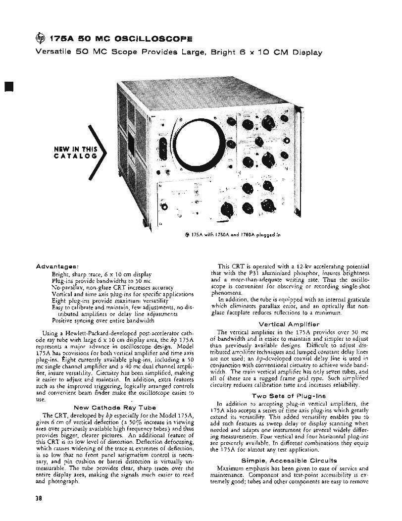
@ 175A 50 MC OSCILLOSCOPE
Versatile 50 MC Scope Provides Large, Bright 6 x 1 0 CM Display
NEW IN THIS C A T A L O G
@ I75A with I750A and I780A plugged in
Advantages: Bright, sharp trace, 6 x 10 cm display Plug-ins provide bandwidths to 50 mc No-parallax, non-glare CRT increases accuracy Vertical and time axis plug-ins for specific applications Eight plug-ins provide maximum versatility Easy to calibrate and maintain, few adjustments, no dis-
Positive syncing over entire bandwidth tributed amplifiers or delay line adjustments
Using a Hewlett-Packard-develo ed post-accelerator cath- ode ray tube with large 6 x 10 cm !isplay area, the hp 175A represents a major advance in oscilloscope design. Model 175A has provisions for both vertical amplifier and time axis plug-ins. Eight currently available plug-ins, including a 50 mc single channel amplifier and a 40 mc dual channel ampli- fier, insure versatility. Circuitry has been simplified, making it easier to adjust and maintain. In addition, extra features such as the improved triggering, logically arranged controls and convenient beam finder make the oscilloscope easier to use.
New Cathode Ray Tube The CRT, developed by hp especially for the Model 175A,
gives 6 cm of vertical deflection (a 50% increase in viewing area over previously available high frequency tubes) and thus provides bigger, clearer pictures. An additional feature of this CRT is its low level of distortion. Deflection defocusing, which causes widening of the trace at extremes of deflection, is so low that no front panel astigmatism control is neces- sary, and pin cushion or barrel distortion is virtually un- measurable. The tube provides clear, sharp traces over the entire display area, making the signals much easier to read and photograph.
This CRT is operated with a 12-kv accelerating potential that with the P31 aluminized phosphor, insures brightness and a more-than-adequate writing rate. Thus the oscillo- scope is convenient for observing or recording single-shot phenomena.
In addition, the tube is equipped with an internal graticule which eliminates parallax error, and an optically flat non- glare faceplate reduces reflections to a minimum,
Vertical Amplifier The vertical amplifier in the 175A provides over 50 mc
of bandwidth and is easier to maintain and simpler to adjust than previously available designs. Difficult to adjust dis- tributed amplifier techniques and lumped constant delay lines are not used; an hp-developed coaxial delay line is used in conjunction with conventional circuitry to achieve wide band- width. The main vertical amplifier has only seven tubes, and all of these are a rugged frame grid type. Such simplified circuitry reduces calibration time and increases reliability.
Two Sets of Plug-Ins In addition to accepting plug-in vertical amplifiers, the
175A also accepts a series of time axis plug-ins which greatly extend its versatility. This added versatility enables you to add such features as sweep delay or display scanning when needed and adapts one instrument for several widely differ- ing measurements. Four vertical and four horizontal plug-ins are presently available. In different combinations they equip the 175A for almost any test application.
Simple, Accessible Circuits Maximum emphasis has been given to ease of service and
maintenance, Component and test-point accessibility is ex- tremely good; tubes and other components are easy to remove
30
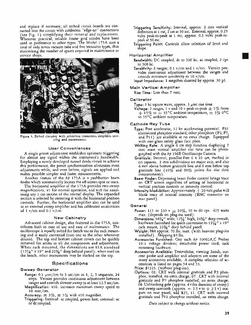
and replace if necessary; all etched circuit boards are con- nected into the circuit with solderless “edge-on” connections (see Fig, 1) simplifying their removal and replacement. Wherever practical, reliable frame grid triodes have been used in preference to other types. The Model 175A uses a total of only seven vacuum tube and five transistor types, thus minimizing the number of spares required in maintenance or service shops.
Figure I, Etched circuitry with solderless connectors simplifies serv- icing and maintenance.
User Conveniences A single preset adjustment establishes optimum triggering
for almost any signal within the instrument’s bandwidth. Employing a newly developed tunnel diode circuit to achieve this performance, the preset synchronization eliminates most adjustments while, and even before, signals are applied and makes possible simpler and faster measurements.
Another feature of the hp 175A is a pushbutton beam finder which automatically locates the off -screen spot or trace.
The horizontal amplifier of the 175A provides two sweep magnifications; x l for normal operation, and x10 for exam- ining any 1 cm section of the normal display. The expanded section is selected by centering it with the horizontal osition controls. Further, the horizontal amplifier also can !e used as an external sweep amplifier and has calibrated sensitivities of 1 v/cm and 0.1 v/cm.
New Cabinetry Advanced cabinet design, also featured in the 175A, con-
tributes both to ease of use and ease of maintenance. The oscilloscope is equally suited for bench use or for rack mount- ing and is easily converted from one to the other whenever desired. The top and bottom cabinet covers can be quickly removed for access to all the components and adjustments. W h e n rack mounted, the dimensions are EIA standard (121/4” x 19” and 22Yg” deep behind panel) ; when used on the bench, other instruments may be stacked on the top.
Spec if i cat i o ns Sweep Generator
Range: 0.1 psec/cm to 5 sec/cm in 1, 2, 5 sequence, 24 steps. Vernier provides continuous adjustment between ranges and extends slowest sweep to at least 12.5 sec/cm.
Magnification: x10: increases maximum sweep speed to 10 nsec/cm.
Accuracy: f 3’j%, Trigge,ring: Internal: ac coupled, power line; external: ac
or dc coupled.
5% with x10 magnifier.
Triggering Sensitivity: Internal, approx. 2 mm vertical deflection at 1 mc, 2 cm at 50 mc. External, a prox. 0.25
peak at 50 mc.
slope.
volts peak-to-peak at 1 mc, approx. 0.5 vo P ts peak-to-
Triggering Point: Controls allow selection of level and
Horizontal Amplifier Bandwidth: DC coupled, dc to 500 kc; ac coupled, 2 cps
to 500 kc. Sensitivity: 2 ranges; 0.1 v/cm and 1 v/cm. Vernier pro-
vides continuous adjustment between the ranges and extends minimum sensitivity to 10 v/cm.
Input Impedance: 1 megohm shunted by approx. 30 pf. Main Vertical Amplifier
Rise Time: Less than 7 nsec.
C al i b rat0 r Type: 1 kc square wave, approx. 3 psec rise time. Voltage: 2 ranges, 1 v and 10 v peak-to-peak t 1% from + 15% to + 35OC ambient temperature, r+ 3% O°C
to 55OC ambient temperature.
Cathode Ray Tube Type: Post accelerator, 1 2 kv accelerating potential. P31
aluminized phosphor standard, other phosphors (P2, P7, and P11) are available at no extra charge. Equipped with non-glare safety glass face plate,
Writing Rate: A single 6 cm step function displaying 7 nsec main vertical amplifier rise time can be photo- graphed with the hp 196B Oscilloscope Camera.
Graticule: Internal, parallax-free 6 x 10 cm, marked in cm squares. 2 mm subdivisions on major axis, and also 6 mm above bottom graticule line and 6 mm below top graticule line (10% and 90% points for rise time measurements),
Beam Finder: Depressing beam finder control brings trace on CRT screen regardless of setting of horizontal or vertical position controls or intensity control.
Intensity Modulation: Approximately + 20 volt pulse will blank trace of normal intensity (BNC connector on rear panel).
Ge n era1 Power: 115 or 230 v C l o%, 50 to 60 cps. 425 watts
max. (depends on plug-ins used). Dimensions: 16%” wide, 12%” high, 24Y8” deep overall;
hardware furnished for quick conversion to 1254‘’ x 19” rack mount, 22Y8” deep behind panel.
Weight: Net approx. 70 Ibs. max. (with heaviest plug-ins installed), Shipping 84 lbs.
Accessories Furnished: One each hp 10003A,C Probes 10: 1 voltage dividers; detachable power cord; rack mounting hardware.
Accessories Available: Testmobiles, viewing hoods, cur- rent probe and amplifier and adapters are some of the many accessories available. A complete selection of ac- cessories is listed on pages 54 and 55.
Price: $1325. (without plug-ins). Options: 02. CRT with internal graticule and P2 phos-
phor, installed, no extra charge; 07. CRT with internal graticule and P7 phosphor installed, no extra charge; 08. Unblanking gate (approx. 4 v for duration of sweep) and sweep sawtooth (approx. - 2.5 v to + 2.5 v) out- puts on rear panel, add $25; 11. CRT with internal graticule and P I 1 phosphor installed, no extra charge.
Data subject to change without notice.
39
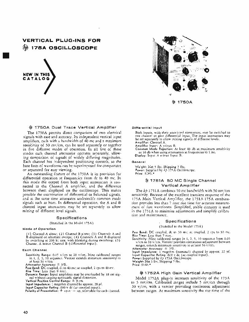
VERTICAL PLUG-INS FOR
@ 175A OSCILLOSCOPE
@ 1750A Dual Trace Vertical Amplifier The 1750A permits direct comparison of two electrical
signals with ease and accuracy. Its independent vertical input amplifiers, each with a bandwidth of 40 mc and a maximum sensitivity of 50 mv/cm, can be used separately or together in five different modes of operation. In all five of these modes each channel attenuator operates separately, allow- ing comparison of signals of widely differing magnitudes. Each channel has independent positioning controls, so the base lines of waveforms can be superimposed for comparison or separated for easy viewing.
An outstanding feature of the 1750A is its provision for differential operation at frequencies from dc to 40 mc. In this mode the output from both input attenuators is con- nected to the Channel A amplifier, and the difference between them displayed on the oscilloscope. This makes possible the examination of differential or balanced signals, and at the same time attenuates undesirable common mode signals such as hum. In differential operation, the A and B channel input attenuators may be set separately to allow mixing of different level signals.
Specifications (Installed in the Model 175A)
Mode of Operation
( l ) ,Channel A alone; ( 2 ) Channel B alone; ( 3 ) Channels A and B displayed on alternate sweeps; ( 4 ) Channels A and B displayed by switching at 200 kc rate, with blanking during switching; ( 5 ) Channel A minus Channel B (differential input) ,
Each Channel
Sensit ivi ty Range: 0.05 v/cm to 20 v/cm. Nine calibrated ranges in 1, 2, 5 , 10 sequence. Vernier extends minimum sensitivity to at least 50 v/cm.
At tenua to r Accuracy: -C 37‘. Pass Band: D C coupled, dc to 40 mc; ac coupled, 2 cps to 40 mc. Rise Time: Less than 9 nsec. Dynamic Range: Input amplifiers may be overloaded by 18 cm sig-
Vert ica l Position Con t ro l Range: * 9 cm. I npu t Impedance: 1 megohm shunted by approx. 28 pf. I n p u t Capac i to r Rating: 600 v dc (ac coupled input) . Polari ty of Presentation: -I- up or - up, selectable for each channel.
nal without causing noticeable signal distortion.
@ 1750A
Differential Input
Both inputs, with their associated attenuators, may be switched to one channel to give differential input, The input attenuators may be set separately to allow mixing signals of different levels. Ampl i f i e r : Channel A. Ampl i f i e r Input : A minus B. Common M o d e Rejection: At least 40 db at maximum sensitivity
Display: Input A minus Input A. or 30 db when using attenuators at frequencies to 1 mc.
General
W e i g h t : Net 5 Ibs. Shipping 7 Ibs. Power: Supplied by hp 175A Oscilloscope. Price: S 2 8 5 . *
@ 1751A 50 MC Single Channel Vertical Am p I if ier
The hp 1751A combines 50 mc bandwidth with 50 mv/cm sensitivity. Because of the excellent transient response of the 175A Main Vertical Amplifier, the 1751A-175A combina- tion provides less than 7 nsec rise time for accurate measure- ment of fast waveforms. Simplified, stable circuitry is used in the 175 1A to minimize adjustments and simplify calibra- tion and maintenance.
Specifications (Installed in the Model 175A)
Pass Band: D C coupled, dc to 50 mc; ac coupled, 2 cps to 50 mc. Rise Time: Less than 7 nsec. Sensit ivi ty: Nine calibrated ranges in 1, 2 , 5, 10 sequence from 0.05
v/cm to 20 v/cm. Vernier provides continuous adjustment between ranges, extends minimum sensitivity to at least 50 v/cm.
At tenua to r Accuracy: * 3%. I npu t Impedance: 1 megohm (nominal) shunted by approx. 2 2 pf. I npu t Capac i to r Rating: 600 v dc (ac coupled input) . Power: Supplied by hp 175A Oscilloscope. W e i g h t : Net 5 Ihs. Shipping 7 Ibs. Price: Slhn.”
@ 1752A High Gain Vertical Amplifier Model 1752A plug-in increases sensitivity of the 175A
to 5 mv/cm. Calibrated ranges include 5 mv/cm through 20 v/cm, with a vernier providing continuous adjustment between ranges. At maximum sensitivity the rise time of the
40
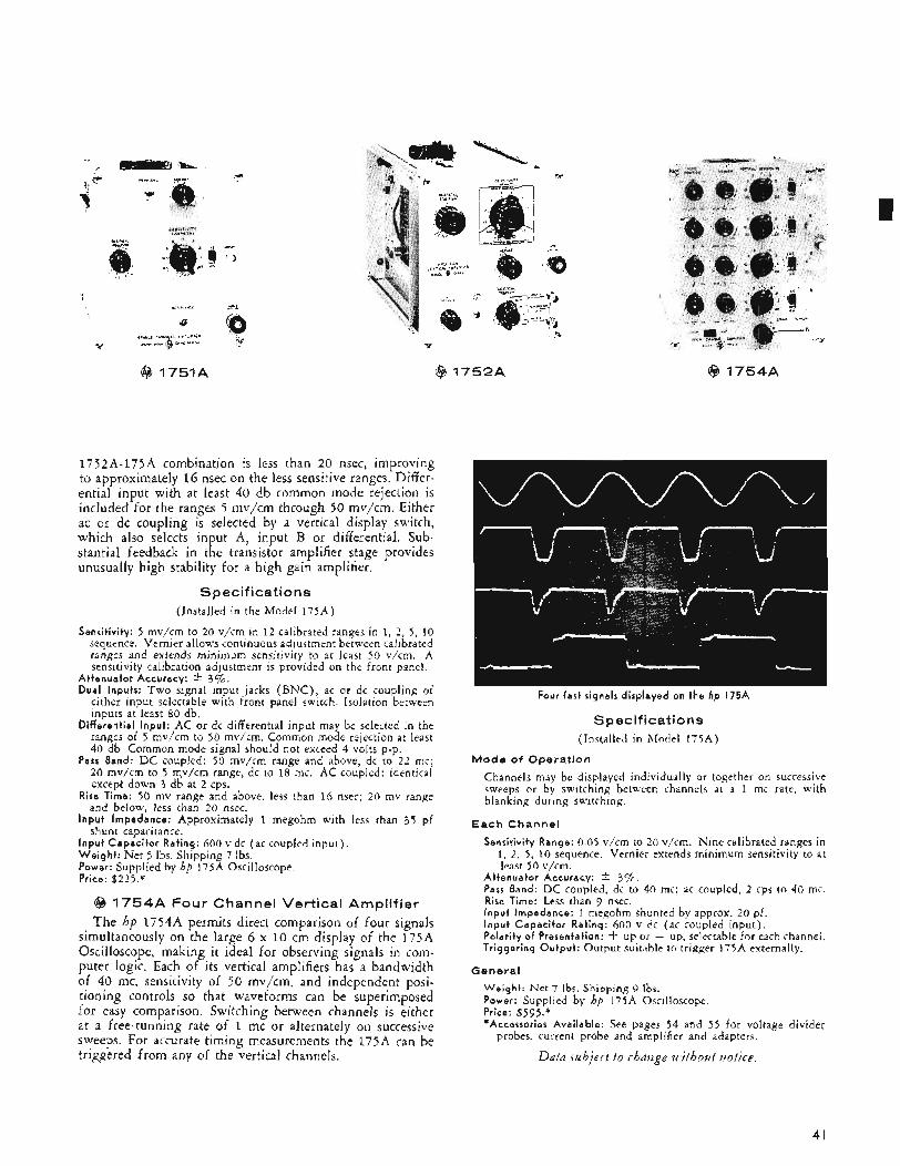
@ 1751A
P
1752A-175A combination is less than 20 nsec, improving to approximately 16 nsec on the less sensitive ranges. Differ- ential input with at least 40 db common mode rejection is included for the ranges 5 mv/cm through 50 mv/cm. Either ac or dc coupling is selected by a vertical display switch, which also selects input A, input B or differential. Sub- stantial feedback in the transistor amplifier stage provides unusually high stability for a high gain amplifier.
Specifications (Installed in the Model 175A)
Sensitivity: 5 mv/cm to 20 v/cm in 12 calibrated ranges in 1, 2 , 5, 10 sequence. Vernier allows continuous adjustment between calibrated ranges and extends minimum sensitivity to at least 50 v/cm. A sensitivity calibration adjustment is provided on the front panel.
Attenuator Accuracy: * 3.a. Dual Inputs: Two signal input jacks ( B N C ) , ac or dc coupling of
either input selectable with front panel switch. Isolation between inputs at least 80 db.
Differential Input: AC or dc differential input may be selected in the ranges of 5 mv/cm to 50 mv/cm. Common mode rejection at least 40 db. Common mode signal should not exceed 4 volts p-p.
Pass Band: DC coupled: 50 mv/cm range and above, dc to 2 2 mc; 20 mv/cm to 5 m,v/cm range, dc to 18 mc. AC coupled: identical except down 3 db at 2 cps.
Rise Time: 50 mv range and above, less than 16 nsec; 20 mv range and below, less than 2 0 nsec.
Input Impedance: Approximately 1 megohm with less than 3 5 pf shunt capacitance.
Input Capacitor Rating: 600 v dc (ac coupled input) . Weight : Net 5 Ibs. Shipping 7 lbs. Power: Supplied by hp 175A Oscilloscope. Price: $225.*
@ 1 7 5 4 A Four Channel Vertical Amplifier The hp 17544 permits direct comparison of four signals
simultaneously on the large 6 x 10 cm display of the 175A Oscilloscope, making it ideal for observing signals in com- puter logic. Each of its vertical amplifiers has a bandwidth of 40 mc, sensitivity of 50 mv/cm, and independent posi- tioning controls so that waveforms can be superimposed for easy comparison. Switching between channels is either at a free-running rate of 1 mc or alternately on successive sweeps. For accurate timing measurements the 175A can be triggered from any of the vertical channels.
($3 1 7 5 2 A @ 1 7 5 4 A
Four fast signals displayed on the hp 175A
Specifications (Installed in Model 175A)
Mode of Operation
Channels may be displayed individually or together on successive sweeps or by switching between channels at a 1 mc rate, with blanking during switching.
Each Channel
Sensitivity Range: 0.05 v/cm to 20 v/cm. Nine calibrated ranges in 1, 2, 5 , 10 sequence. Vernier extends minimum sensitivity to at least 50 v/cm.
Attenuator Accuracy: * 3%. Pass Band: DC coupled, dc to 40 mc; ac coupled, 2 cps to 40 mc. Rise Time: Less than 9 nsec. Input impedance: 1 megohm shunted by approx. 20 pf, Input Capacitor Rating: 600 v dc (ac coupled input) . Polarity of Presentation: -t up or - up, selectable for each channel. Triggering Output: Output suitable to trigger 175A externally.
General
Weight: Net 7 Ibs. Shipping 9 lbr. Power: Supplied by hp 175A Oscilloscope, Price: $595.* *Accessories Available: See pages 54 and 55 for voltage divider
probes. current probe and amplifier and adapters.
Datn .subject to rhnuge without uotice.
41
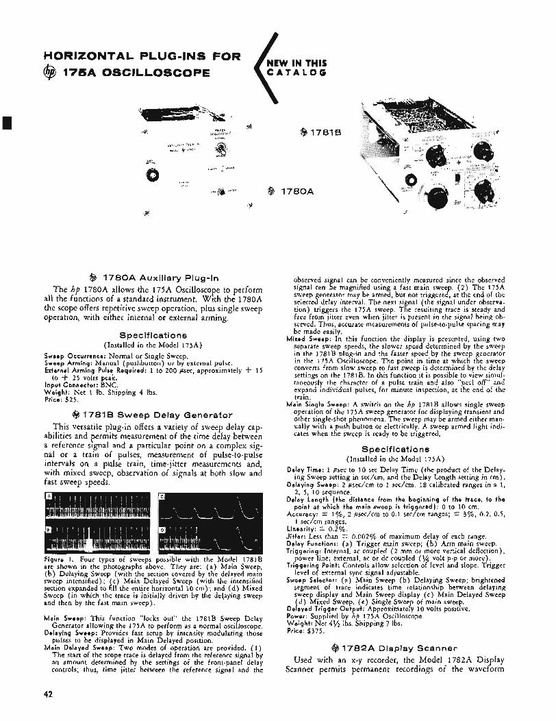
@ 1 7 8 1 B
@ 1 7 8 0 A Auxiliary Plug-In The hp 1780A allows the 175A Oscilloscope to perform
all the functions of a standard instrument. With the 1780A the scope offers repetitive sweep operation, plus single sweep operation, with either internal or external arming,
Specifications (Installed in the Model 175A)
Sweep Occurrence: Normal or Single Sweep. Sweep Arming: Manual (pushbutton) or by external pulse. External Arming Pulse Required: 1 to 200 gsec, approximately -k 1 5
to f 2 5 volts peak. InDut Connector: BNC. W’eight: Net 1 lb. Shipping 4 Ibs. Price: $ 2 5 .
@ 1781 B Sweep Delay Generator This versatile plug-in offers a variety of sweep delay cap-
abilities and permits measurement of the time delay between a reference signal and a particular point on a complex sig- nal or a train of pulses, measurement of pulse-to-pulse intervals on a pulse train, time-jitter measurements and, with mixed sweep, observation of signals at both slow and fast sweep speeds.
Figure I . Four types of sweeps possible with the Model 1781B are shown in the photographs above. They are: ( a ) Main Sweep, ( b ) Delaying Sweep (with the section covered by the delayed main sweep intensified); (c) Main Delayed Sweep (with the intensified section expanded to fill the entire horizontal 10 cm) ; and ( d ) Mixed Sweep (in which the trace is initially driven by the de1,aying sweep and then by the fast main sweep).
M a i n Sweep: This function “locks out” the 1781B Sweep Delay Generator allowing the 175A to perform as a normal oscilloscope.
Delaying Sweep: Provides fast setup by intensity modulating those pulses to be displayed in Main Delayed position.
Main Delayed Sweep: Two modes of operation are provided. (1 ) The start of the scope trace is delayed from the reference signal by an amount determined by the settings of the front-panel delay controls; thus, time jitter between the reference signal and the
observed signal can be conveniently measured since the observed signal can be magnified using a fast main sweep. ( 2 ) The 175A sweep generator may be armed, but not triggered, at the end of the selected delay interval. The next signal (the signal under observa- tion) triggers the 175A sweep. The resulting trace is steady and free from jitter even when jitter is present in the signal being ob- served. Thus, accurate measurements of pulse-to-pulse spacing may be made easily.
Mixed Sweep: In this function the display is presented, using two separate sweep speeds, the slower speed determined by the sweep in the 1781B plug-in and the faster speed by the sweep generator in the 175A Oscilloscope. The point in time at which the sweep converts from slow sweep to fast sweep is determined by the delay settings on the 1781B. In this function it is possible to view simul- taneously the character of a pulse train and also “peel off” and expand individual pulses, for minute inspection, at the end of the train.
Main Single Sweep: A switch on the hp 1781B allows single sweep operation of the 175A sweep generator for displaying transient and other single-shot phenomena. The sweep may be armed either man- ually with a push button or electrically. A sweep armed light indi- cates when the sweep is ready to be triggered.
Specifications (Installed in the Model 175A)
Delay Time: 1 asec to 10 sec Delay Time (the product of the Delay- ing Sweep setting in sec/cm, and the Delay Length setting in cm) .
Delaying Sweep: 2 psec/cm to 1 sec/cm. 18 calibrated ranges in a 1, 2, 5 , 10 sequence.
Delay Length (the distance from the beginning of the trace, to the point a t which the main ,sweep is t r iggered): 0 to 10 cm.
Accuracy: +- 1%, 2 psec/cm to 0.1 sec/cm ranges; * 3%, 0.2, 0.5, 1 sec/cm ranges.
Linearity: * 0.2%. Jitter: Less than +. 0.002% of maximum delay of each range. Delay Functions: ( a ) Trigger main sweep; ( b ) Arm main sweep. Triggering: Internal, ac coupled ( 2 mm or more vertical deflection),
power line; external, ac or dc coupled ( 1 / 4 volt p-p or more). Triggering Point: Controls allow selection of level and slope. Trigger
level of external sync signal adjustable. Sweep Selector: ( a ) Main Sweep ( b ) Delaying Sweep; brightened
segment of trace indicates time relationship between delaying sweep display and Main Sweep display (c ) Main Delayed Sweep ( d ) Mixed Sweep. ( e ) Single Sweep of main sweep.
Delayed Trigger Output: Approximately 10 volts positive. Power: Supplied by hp 175A Oscilloscope. Weight: Net 4% Ibs. Shipping 7 Ibs. Price: $375.
@ 1 7 8 2 A Display Scanner Used with an x-y recorder, the Model 1782A Display
Scanner permits permanent recordings of the waveform
42
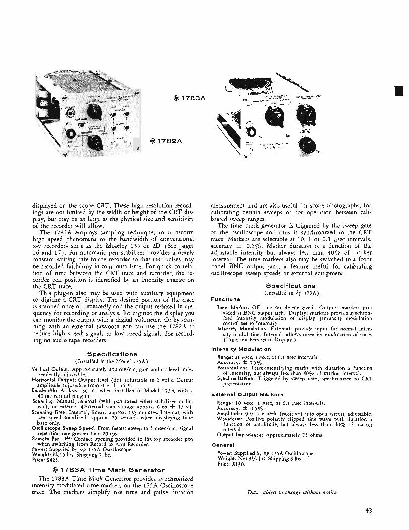
@ 1783A
@ 7782A -Jr
Y
displayed on the sco e CRT. These high resolution record-
play, but may be as large as the physical size and sensitivity of the recorder will allow.
The 1782A employs sampling techniques to transform high speed phenomena to the bandwidth of conventional x-y recorders such as the Moseley 135 or 2D (See pages 16 and 17) . An automatic pen stabilizer provides a nearly constant writing rate to the recorder so that fast pulses may be recorded faithfully in minimum time. For quick correla- tion of time between the CRT trace and recorder, the re- corder pen position is identified by an intensity change on the CRT trace.
This plug-in also may be used with auxiliary equipment to digitize a CRT display. The desired portion of the trace is scanned once or repeatedly and the output reduced in fre- quency for recording or analysis. To digitize the display you can monitor the output with a digital voltmeter. Or by scan- ning with an external sawtooth you can use the 1782A to reduce high speed signals to low speed signals for record- ing on audio tape recorders.
ings are not limited ! y the width or height of the CRT dis-
Specifications (Installed in the Model 175A)
Vertical Output : Approximately 200 mv/cm, gain and dc level inde- pendently adjustable.
Horizontal Output: Output level (dc) adjustable to 0 volts. Output amplitude adjustable from 0 v + 1 5 v.
Bandwidth: At least 30 mc when installed in Model 175A with a 40 mc vertical plug-in.
Scanning: Manual, internal (with pen speed either stabilized or lin- ear) , or external (External scan voltage approx. 0 to f 15 v ) .
Scanning Time: Internal, linear: approx. 11/2 minutes. Internal, with pen speed stabilized: approx. 25 seconds when displaying time .. base only.
repetition rate greater than 20 cps.
when switching from Record to Arm Recorder.
Oscilloscope Sweep Speed: From fastest sweep to 5 msec/cm; signal
Remote Pen Lift: Contact opening provided to lift x-y recorder pen
Power: Supplied by hp 175A Oscilloscope. Weight : Net 5 lbs. Shipping 7 Ibs. Price: $425.
@ 1783A Time Mark Generator The 1783A Time Mark Generator provides synchronized
intensity modulated time markers on the 175A Oscilloscope trace. The markers simplify rise time and pulse duration
measurement and are also useful for scope photographs, for calibrating certain sweeps or for operation between cali- brated sweep ranges.
The time mark generator is triggered by the sweep gate of the oscilloscope and thus is synchronized to the CRT trace. Markers are selectable at 10, 1 or 0.1 p e c intervals, accuracy & 0.5%. Marker duration is a function of the adjustable intensity but always less than 40% of marker interval. The time markers also may be switched to a front panel BNC output jack, a feature useful for calibrating oscilloscope sweep speeds or external equipment.
Specifications (Installed in hp 175A)
Functions
Time Marker: Off: marker de-energized. Output: markers pro- vided at BNC output jack. Display: markers provide synchron- ized intensity modulation of display (intensity modulation control set to Internal).
Intensity Modulation: External: provide input for normal inten- sity modulation, Internal: allows intensity modulation of trace. (Time markers set to Display.)
lntenslty Modulation
Range: 10 psec, 1 psec, or 0.1 psec intervals. Accuracy: t 0.5%. Presentation: Trace-intensifying marks with duration a function
Synchronization: Triggered by sweep gate; synchronized to CRT of intensity, but always less than 40% of marker interval.
presentation.
External Output Markers
Range: 10 psec, 1 psec, or 0.1 psec intervals. Accuracy: * 0.5%. Amplitude: 0 to 1 v peak (positive) into open circuit, adjustable. Waveform: Positive polarity dipped sine wave with duration a
function of amplitude, but always less than 40% of marker interval.
Output Impedance: Approximately 75 ohms.
General
Power: Supplied by hp 175A Oscilloscope. Weight : Net 3% lbs. Shipping G Ibs. Price: $130.
Data subject to change without notice.
43
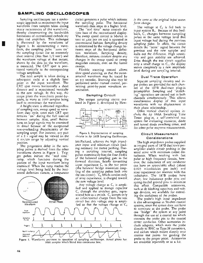
SAMPLING OSCILLOSCOPES Sampling oscilloscopes use a strobo-
scopic approach to reconstruct the input waveform from samples taken during many recurrences of the waveform, thereby circumventing the bandwidth limitations of conventional cathode ray tubes and amplifiers. This technique is illustrated by the waveforms of Figure 1. In reconstructing a wave- form, the sampling pulse “turns on” the sampling circuit for an extremely short interval (less than 1/2 nsec) and the waveform voltage at that instant, shown by the dots on the waveform, is measured. The CRT spot is posi- tioned vertically to the corresponding voltage amplitude.
The next sample is taken during a subsequent cycle at a slightly later point in the input waveform. The CRT spot moves horizontally a short distance and is repositioned vertically to the new voltage. In this way, the scope plots the waveform point-by- point, as many as 1000 samples being used to reconstruct the waveform.
A bright trace is obtained regardless of sampling rate, sweep speed or wave- form duty cycle, since each CRT spot remains “on” during the full interval between samples. Also, small fluctua- tions on large signals may be examined in detail because of the exceptional non-overloading characteristics of the sampling scope. For instance, any part of a 2 v signal may be viewed on the 4 mv/cm range by adjusting vertical position.
The progressive delay in the sam- pling pulses is derived from the other waveforms shown in Figure 1. Trig- ger pulses initiate the “real time” ramp, which functions during the portion of the input waveform being examined. When the ramp reaches the voltage level being held by the hori- zontal deflection circuits, a comparator
Reconstructed Actual Photo Waveform
circuit generates a pulse which initiates the sampling pulse. The horizontal waveform then steps to a higher level.
The “real time” ramp controls the time base of the reconstructed display. The sweep speed control is labeled in nsec or p e c per cm and is operated in conventional fashion. Sampling density is determined by the voltage change be- tween steps of the horizontal deflec- tion waveform. Sampling density, therefore, remains constant despite any changes in the sweep speed or sweep magnifier controls, even on the fastest sweeps.
Flexible scanning control allows slow speed scanning, so that the recon- structed waveform may be traced by an x-y recorder. Scanning also may be performed under manual control, per- mitting point-by-point waveform ex- amination,
Sampling Circuit The unique sampling circuit out-
lined in Figure 2, developed by Hew-
l , . ~ ~ ........................ , P,* , > , +
JE~? ’1 ~
1 %rl;oG“ , 1 ] j
r ~! 8.. . .. . . . . . . . .. . . - -. . -.. I r i l l
Tr ,*.,.*,mv -R1 ri 1 !
%sm
Figure 2. Representation of sampling circuity in hp 185B Sampling Oscilloscope.
lett-Packard, achieves the high imped- ance input and minimum circuit load- ing necessary for circuit probing. Dur- ing a sampling interval, sampling pulses momentarily bias the four diodes of the balanced sampling gate in the forward direction, briefly connecting input capacitance C, to the test point (the balanced bridge minimizes coup- ling of the sampling pulses back into the test circuit), C, which consists only of stray capacitance, is charged toward the new voltage level.
Any voltage change at C, is ampli- fied and applied to storage capacitor C, through the stretcher gate, repre- sented here as a switch. C, accepts only an infinitesimal charge from the test circuit but this voltage step is ampli- fied so that the voltage change at C,
n n n n Waveform J w u u Sampling
Pulses A h A A n A TrlggWS h h n h h n n h h
Real Time Ramp
Horizontal Deflection
Figure I . Waveforms pertinent to operation of sampling oscilloscope. Actual photo has 1000 samples which blend into continuous line.
is the same as the original input wave- form change.
The voltage at C, is fed back to input resistor R,. Because of this feed- back, C, charges between sampling pulses to the same voltage level that input voltage had during the previous sampling pulse. In effect, the circuit detects the “error” signal between the previous and the new samples and nulls out the difference. High sensiti- vity and gain stability are achieved. Even though the test circuit supplies only a small charge to C,, the display moves completely to a new amplitude level during one sampling interval.
Dual Trace Operation Separate sampling circuitry and in-
put probes are provided for each chan- nel of the 187B dual-trace plug-in preamplifier. Sampling and “stretch- ing” operations are carried out in both channels simultaneously. This allows simultaneous display of two input waveforms with no displacement in their phase relationship.
Other vertical channel options in- clude the hp 186A Switching Time Tester plug-in, a self-contained test system for evaluating transistor, diode and tunnel diode switching times, and for other pulse response measurements.
Circuit Measurement Considerations
The high impedance probes supplied as integral parts of 187B dual trace pre- amplifier enable circuit probing in the usual sense with minimum circuit dis- turbance. When working with fast pulse or high frequency circuits, how- ever, the inductance of any conductor can have an appreciable effect (about 0.025 microhenries per inch) and stray capacitance can resonate with this inductance. The 187B probes have short, low inductance probe pins and spring-loaded ground pins to minimize this effect. Compatible accessories, such as dc blocking capacitors and volt- age dividers, are available for extend- ing the usefulness of the probes.
The probe’s high input impedance is also advantageous in 50-ohm coaxial systems, since the system does not have to terminate at the probe. The probe can “bridge” the system at any point through the use of a coaxial tee which connects the probe pin to the coaxial center conductor. Other accessories in- clude adapters, which mate the probe directly to BNC or Type N connectors, and sockets which mount directly over routine test points for guiding the probe to the proper point. Accessories are available separately or as a kit.
44
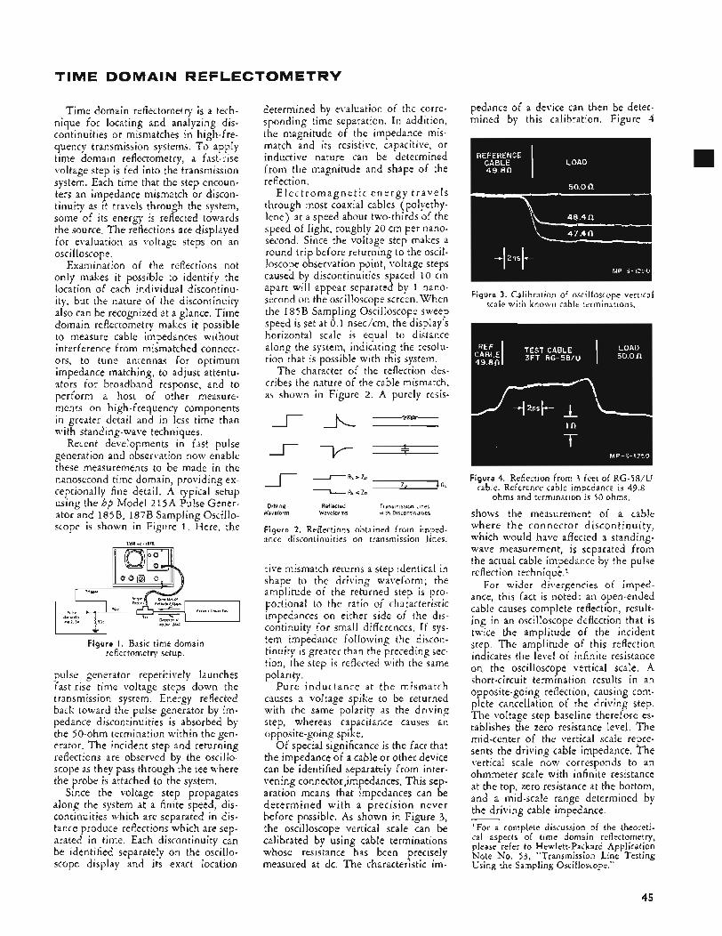
TIME DOMAIN REFLECTOMETRY
Time domain reflectometry is a tech- nique for locating and analyzing dis- continuities or mismatches in high-fre- quency transmission systems. To apply time domain reflectometry, a fast-rise voltage step is fed into the transmission system. Each time that the step encoun- ters an impedance mismatch or discon- tinuity as it travels through the system, some of its energy is reflected towards the source. The reflections are displayed for evaluation as voltage steps on an oscilloscope.
Examination of the reflections not only makes it possible to identify the location of each individual discontinu- ity, but the nature of the discontinuity also can be recognized at a glance. Time domain reflectometry makes it possible to measure cable impedances without interference from mismatched connect- ors, to tune antennas for optimum impedance matching, to adjust attentu- ators for broadband response, and to perform a host of other measure- ments on high-frequency components in greater detail and in less time than with standing-wave techniques.
Recent developments in fast pulse generation and observation now enable these measurements to be made in the nanosecond time domain, providing ex- ceptionally fine detail. A typical setup using the hp Model 215A Pulse Gener- ator and 185B, 187B Sampling Oscillo- scope is shown in Figure 1. Here, the
Figure I. Basic time domain reflectometry setup.
pulse generator repetitively launches fast rise time voltage steps down the transmission system. Energy reflected back toward the pulse generator by im- pedance discontinuities is absorbed by the 50-ohm termination within the gen- erator. The incident step and returning reflections are observed by the oscillo. scope as they pass through the tee where the probe is attached to the system.
Since the voltage step propagates along the system at a finite speed, dis- continuities which are separated in dis- tance produce reflections which are sep- arated in time. Each discontinuity can be identified separately on the oscillo- scope display and its exact location
determined by evaluation of the corre- sponding time separation. In addition, the magnitude of the impedance mis- match and its resistive, capacitive, or inductive nature can be determined from the magnitude and shape of the reflection.
E l e c t r o m a g n e t i c e n e r g y t r ave l s through most coaxial cables (polyethy- lene) at a speed about two-thirds of the speed of light, roughly 20 cm per nano- second. Since the voltage step makes a round trip before returning to the oscil- loscope observation point, voltage steps caused by discontinuities spaced 10 cm apart will appear separated by 1 nano- second on the oscilloscope screen. When the 185B Sampling Oscilloscope sweep speed is set at 0.1 nsec/cm, the display's horizontal scale is equal to distance along the system, indicating the resolu- tion that is possible with this system.
The character of the reflection des- cribes the nature of the cable mismatch, as shown in Figure 2 . A purely resis-
rA-------
I -RL'Zo Z O I R L \ R L < Z O
Driving Reflected Transmission Lines Waveforms with Discontinuities Waveform
Figure 2. Reflections obtained from imped- ance discontinuities on transmission lines.
tive mismatch returns a step identical in shape to the driving waveform; the amplitude of the returned step is pro- portional to the ratio of characteristic impedances on either side of the dis- continuity for small differences. If sys- tem impedance following the discon- tinuity is greater than the preceding sec- tion, the step is reflected with the same polarity.
Pure inductance at the mismatch causes a voltage spike to be returned with the same polarity as the drivinp step, whereas capacitance causes an opposite-going spike.
Of special significance is the fact that the impedance of a cable or other device can be identified separately from inter- vening connectorjmpedances. This sep- aration means that impedances can be determined wi th a precision never before possible. As shown in Figure 3, the oscilloscope vertical scale can be calibrated by using cable terminations whose resistance has been precisely measured at dc. The characteristic im-
pedance of a device can then be deter- mined by this calibration. Figure 4
Figure 3. Calibration of oscilloscope vertical scale with known cable terminations.
Figure 4. Reflection from 3 feet of RG-58/U cable. Reference cable impedance is 49.8
ohms and termination is 50 ohms,
shows the measurement of a cable where the connect o r discontinuity, which would have affected a standing- wave measurement, is separated from the actual cable impedance by the pulse reflection technique.l
For wider divergencies of imped- ance, this fact is noted: an open-ended cable causes complete reflection, result- ing in an oscilloscope deflection that is twice the amplitude of the incident step. The amplitude of this reflection indicates the level of infinite resistance on the oscilloscope vertical scale. A short-circuit termination results in an opposite-going reflection, causing com- plete cancellation of the driving step. The voltage step baseline therefore es- tablishes the zero resistance level. The mid-center of the vertical scale repre- sents the driving cable impedance. The vertical scale now corresponds to an ohmmeter scale with infinite resistance at the top, zero resistance at the bottom, and a mid-scale range determined by the driving cable impedance. 'For a complete discussion of the theoreti- cal aspects of time domain reflectometry, please refer to Hewlett-Packard Application Note No. 53, "Transmission Line Testing Using the Sampling Oscilloscope."
45
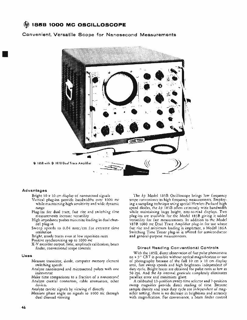
@ 1858 1000 MC OSCILLOSCOPE
Co nven ient, Versati le Scope for Nanosecond Measurements
@ 185B with @ I 8 7
Advantages Bright 10 x 10 cm display of nanosecond signals Vertical plug-ins provide bandwidths over 1000 mc
while maintaining high sensitivity and wide dynamic range
Plug-ins for dual trace, fast rise and switching time measurements increase versatility
High impedance probes minimize loading in dual chan- nel plug-in
Sweep speeds to 0.04 nsec/cm for extreme time resolution
Bright, steady traces even at low repetition rates Positive synchronizing up to 1000 mc X-Y recorder output; time, amplitude calibrators; beam
finder; conventional scope controls
Uses Measure transistor, diode, computer memory element
Analyze nanosecond and microsecond pulses with one
Make time comparisons to a fraction of a nanosecond Analyze coaxial connectors, cable attenuators, other
Analyze carrier signals by viewing rf directly Measure phase angle on signals to 1000 mc through
switching speeds
instrument
devices
dual channel viewing
The hp Model 185B Oscilloscope brings low frequency scope convenience to high frequency measurements. Employ- ing a sampling technique using special Hewlett-Packard high speed diodes, the hp 185B offers extremely wide bandwidth while maintaining large bright, easy-to-read displays. TWO plug-ins are available for the Model 185B giving it added versatility for fast measurements. In addition to the Model 187B 1000 mc Dual Trace Amplifier plug-in for use where fast rise and minimum loading is important, a Model l86A Switching Time Tester plug-in is offered for semiconductor and general-purpose measurements.
Direct Reading Conventional Controls With the 185B, direct observation of fast pulse phenomena
on a 5” CRT is possible without optical magnification or use of photography because of the full 10 cm x 10 cm display area, fast sweep speeds and high brightness independent of duty cycle. Bright traces are obtained for pulse rates as low as 50 cps. And the hp internal graticule completely eliminates parallax error and minimizes glare.
A calibrated 10-position sweep time selector and 7-position sweep magnifier provide direct reading of time. Because sample density and trace duty cycle are independent of mag- nifier setting, there is no decrease in brightness and accuracy with magnification. For convenience, a beam finder control
46
quickly locates off screen traces and facilitates its positioning to center screen, no matter how far the position or intensity controls may have been misadjusted.
Versatile Trig geri ng The Model 185B Oscilloscope will synchronize on signals
with repetition rates from 50 cps to 1000 mc. At most sweep speeds the maximum sampling rate is 100 kc, and on these sweeps the oscilloscope synchronizes independently on each input signal from 50 cps to 100 kc. The instrument will thus present a steady display even when signals are randomly spaced. Above 100 kc, hold-off and count-down circuitry is used to provide synchronization on a sub-harmonic of the input wave at a frequency less than 100 kc.
The Model 1lOOA Delay Line is available for viewing the leading edge of the signal used to trigger the 185B. Versa- tility can be further increased with a combination of the delay line and a resistive divider probe that increases input resist- ance. Trigger sensitivity of the 185B is such that “internal” triggering can be obtained over the entire dynamic range of the 187B amplifier.
Recorder Output Because of the sampling method used in synthesizing the
185B display, it is possible to reduce the rate of advance of the x-axis scan to a speed low enough so that even a relatively slow-speed x-y recorder can follow the trace. X-axis and y-axis recorder outputs are provided, as are three types of scanning: Record, x-axis automatically scanned over a 60- second interval; Manual, scanning by a front-panel control: and, for special applications, External, scanning programmed with external voltages fed to rear panel terminals,
Sync Pulse Output A fast-rise 1.5 v sync pulse at the oscilloscope’s sampling
rate, suitably delayed from the start of the scope trace, is available for triggering or testing external circuits. Where this pulse triggers the circuit under test, the leading edge of the output signal may be viewed on the screen without the need for a delay line.
Spec if icat io ns Horizontal
Sweep Speeds: 10 ranges, 10 nsec/cm to 10 psec/cm, calibrated to * 5 % . Vernier gives continuous adjustment between ranges and increases fastest unmagnified sweep speed to 4 nsec/cm. Accuracy of the basic sweep is maintained at all magnifier settings with the exception of time represented by first % cm of the unmagnified sweep.
Magnification: 7 calibrated ranges x l , x2, x5, x10, x20, x50 and ~ 1 0 0 . Increases maximum calibrated sweep speed to 0.1 nsec/cm; with vernier, maximum sweep speed is further ex- tended to 0.04 nsec/cm. Intensity and sample density are not affected by magnification.
Delay Control: Three-turn variable delay control is available when using magnified sweep. Permits any magnified portion of un- magnified trace to be viewed.
Minimum Delay (input trigger to start of t race ) : Less than 120 nsec at 100 nsec/cm sweep and faster. On slower sweep speeds, minimum delay increases to a maximum of approximately 5 psec on the 10 psec/cm range.
Sample Density: Continuously adjustable from approximately 70 samples per trace to 1000 samples per trace.
Scanning Functions: Internal: x-axis driven by internal staircase for normal viewing. Record: x-axis driven by internal slow ramp; approximately 60 seconds for one trace. Manual: x-axis driven by manual scan control knob. External: x-axis driven by external voltage; approx. 12 v for 10 cm deflection, input impedance > 25K.
Trigger Functions Normal-External Trigger:
Amplitude: pk will not damage input circuit.
W i d t h : 5 nsec at minimum amplitude. Rate: 50 cps to 1 mc on the 10 psec/cm sweep speed setting.
Maximum rate increases to 100 mc on the 200 nsec/cm and faster ranges.
Jitter: Less than 0.03 nsec or 0.02% of the time represented by the unmagnified sweep, whichever is greater (fast rise trigger signals). Reduced approx. 5 : 1 in the “smoothed” response
150 mv to * 2 v pk. U p to 5 v rms or 100 v
I position.
a step of ‘/z nsec rise time is less than 8%. Input Impedance: 50 ohms nominal, dc coupled. Reflection from
Sensitive-External Trigger: Amplitude: * 15 mv to * 200 mv pk. Up to 5 v rms or 10 v
peak will not damage input circuit. Width: 5 nsec at minimum amplitude. Rate: Same as normal. Jitter: Same as normal. Input Impedance: 50 ohms nominal, dc coupled,
Input Frequency: 50 mc to 1000 mc for sweep speeds of 200 nsec/cm and faster.
Sensitivity: 200 mv p-p. Operates from smaller signals at some increase in jitter. Up to 5 v rms or 15 v peak will not damage the input circuit.
Jitter: 5% of cycle from 50 to 400 mc; 8% of cycle from 400 to 1000 mc.
Internal Signal appearing a t Input Connector: Less than 15 mv p-p, approx. 10 mc.
Input Impedance: 50 ohms nominal, ac coupled. Reflection from a step of nsec rise time is less than 8%.
H i g h Frequency:
Sync Probe
The 10200B (use with any trigger function) increases input im- pedance to more than 750 ohms, ac coupled; reduces sensitivity by approximately 4:1 at 10 mc and higher and by approximately 20:1 at low frequencies.
Sync Pulse Output Amplitude: Positive. At least 1.5 v into 50 ohms. Rise Time: Less than 2 nsec. Width: Approximately 5 psec. Recurrence: One pulse per sample.
General Cal ibrator:
Voltage: 20 mv, 100 mv, 200 mv and 1000 mv; + 3%. Time: Approximately 5 psec burst of 50 mc sinewave. Frequency
X-Y Recorder Output: X- and y-axis signals are available at rear terminals in all positions of the Scanning Control. In the Manual and Record positions the voltage can be used to make pen record- ings with a conventional x-y recorder.
Horizontal Output : Approximately 0 v at start of sweep to + 1 3 v at end of sweep ( 1 . 2 v/cm) . Source impedance approximately 20,000 ohms.
Vertical Output : Approximately f 1 v at top of graticule, - 1 v at bottom (0.2 v/cm) . Source impedance approximately 10,000 ohms.
Cathode Ray Tube: hp 3 kv mono-accelerator CRT with P2 phos- phor. Other phosphors are optional.
Internal Graticule (S tandard) : Graticule in same plane as phosphor eliminates parallax. 10 cm x 10 cm, major axes and 1st and 9th cm lines (10% and 90%) have 2 mm subdivisions.
Power: 115 or 230 volts * ,,105&, 50 to 60 cps, approx. 300 watts. Dimensions: Cabinet: 1478 high, 19” wide. 22%‘’ deep. Rack
Weight : Net, 75 Ibs. Shipping, 99 Ibs. Accessories Furnished: 10200B Sync Probe. Price: hp 185B (cabinet) or 185BR (rack mount), $2300 (vertical
Options (no extra charael:
accuracy i 2 % .
Mount: 12%’’ high, 19“ wide, 21” deep behind panel.
plug-in required),
‘01 . P i in lieu of GZ’phosphor (not available with internal graticule CRT) ,
0 5 . External graticule CRT in lieu of internal graticule CRT. 07. P7 in lieu of P2 phosphor. 11. P I 1 in lieu of P2 phosphor 31. P31 in heu of P2 phosphor (not available with external
graticule C R T ) ,
47
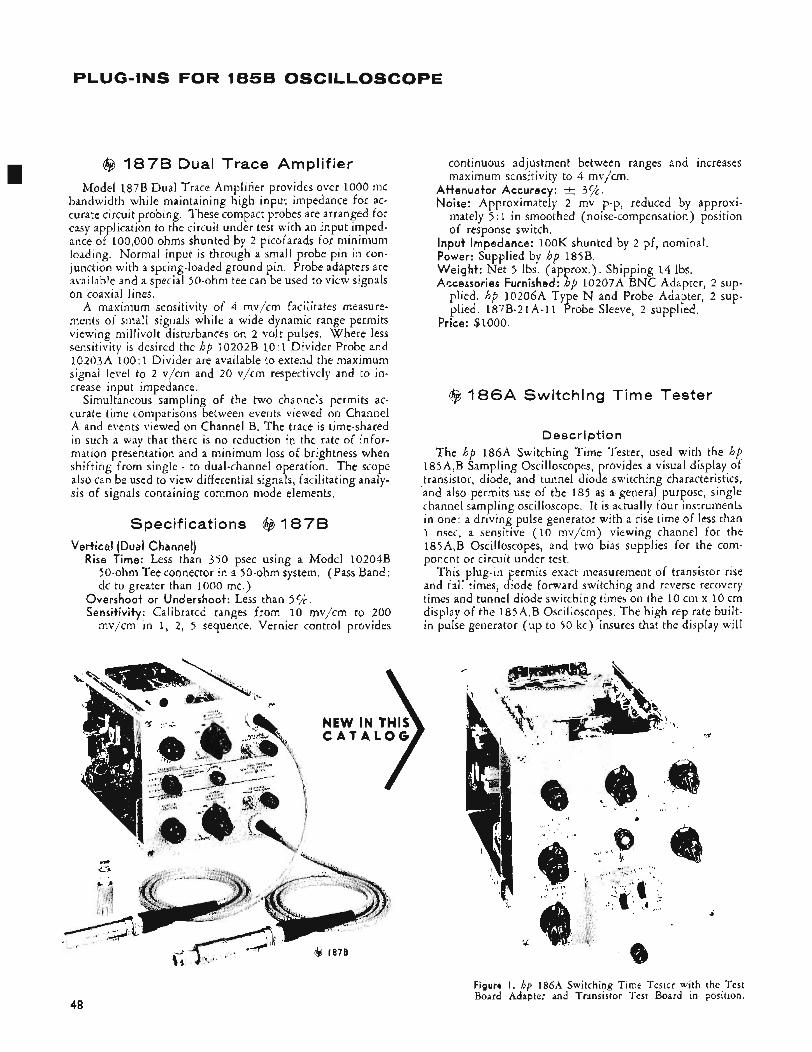
PLUG-INS FOR 1858 OSCILLOSCOPE
I @ 1878 Dual Trace Amplifier Model 187B Dual Trace Amplifier provides over 1000 mc
bandwidth while maintaining high input impedance for ac- curate circuit probing. These compact probes are arranged for easy application to the circuit under test with an input imped- ance of 100,000 ohms shunted by 2 picofarads for minimum loading. Normal input is through a small probe pin in con- junction with a spring-loaded ground pin. Probe adapters are airailable and a special >@ohm tee can be used to view signals on coaxial lines.
A maximum sensitivity of 4 mv/cm facilitates measure- ments of small signals while a wide dynamic range permits viewing millivolt disturbances on 2 volt pulses. Where less sensitivity is desired the hp 10202B 10:1 Divider Probe and 10203A 100:1 Divider are available to extend the maximum signal level to 2 v/cm and 20 v/cm respectively and to in- crease input impedance.
Simultaneous sampling of the two channels permits ac- curate time comparisons between events viewed on Channel A and events viewed on Channel B. The trace is time-shared in such a way that there is no reduction in the rate of infor- mation presentation and a minimum loss of brightness when shifting from single - to dual-channel operation. The scope also can be used to view differential signals, facilitating analy- sis of signals containing common mode elements.
Specifications @ 1878 Vertical (Dual Channel)
Rise Time: Less than 350 psec using a Model 102043 jo-ohm Tee connector in a 50-ohm system. (Pass Band: dc to greater than 1000 mc.)
Overshoot or Undershoot: Less than 5 % . Sensitivity: Calibrated ranges from 10 mv/cm to 200
mv/cm in 1, 2, 5 sequence. Vernier control provides
NEW IN THIS C A T A L O G
continuous adjustment between ranges and increases maximum sensitivity to 4 mv/cm.
Attenuator Accuracy: t 3%. Noise: Approximately 2 mv p-p, reduced by approxi-
mately 5 : 1 in smoothed (noise-compensation) position of response switch.
input Impedance: 1OOK shunted by 2 pf, nominal. Power: Supplied by hp 185B. Weight: Net 5 Ibs. (approx.). Shipping 14 Ibs. Accessories Furnished: hp 10207A BNC Adapter, 2 sup-
plied. hp 10206A Type N and Probe Adapter, 2 sup- plied. 187B-21A-11 Probe Sleeve, 2 supplied.
Price: $1000.
@ 1 8 6 A Switching Time Tester
Description The hp l86A Switching Time Tester, used with the hp
185A,B Sampling Oscilloscopes, provides a visual display of transistor, diode, and tunnel diode switching characteristics, and also permits use of the 185 as a general purpose, single channel sampling oscilloscope. It is actually four instruments in one: a driving pulse generator with a rise time of less than 1 nsec, a sensitive (10 mv/cm) viewing channel for the 185A,B Oscilloscopes, and two bias supplies for the com- ponent or circuit under test.
This plug-in permits exact measurement of transistor rise and fall times, diode forward switching and reverse recovery times and tunnel diode switching times on the 10 cm x 10 cm display of the 185A,B Oscilloscopes. The high rep rate built- in pulse generator (up to 50 kc) insures that the display will
Figure I . hp 186A Switching Time Tester with the Test Board Adapter and Transistor Test Board in position.
48
-
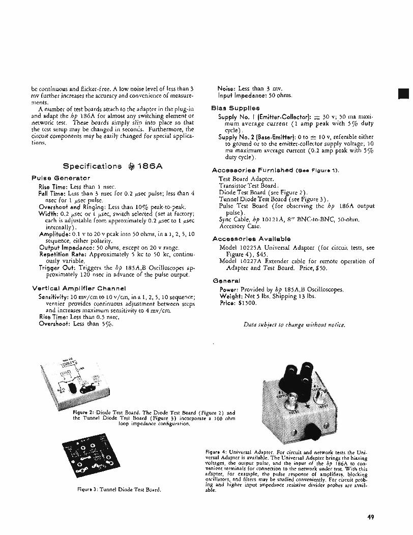
be continuous and flicker-free. A low noise level of less than 3 mv further increases the accuracy and convenience of measure- ments.
A number of test boards attach to the adapter in the plug-in and adapt the hp l86A for almost any switching element or network test. These boards simply slip into place so that the test setup may be changed in seconds. Furthermore, the circuit components may be easily changed for special applica- tions.
Specifications @ 1 8 6 A Pulse Generator
Rise Time: Less than 1 nsec. Fall Time: Less than 3 nsec for 0.2 psec pulse; less than 4
Overshoot and Ringing: Less than 10% peak-to-peak. Width: 0.2 psec or 1 p e c , switch selected (set at factory;
each is adjustable from approximately 0.2 psec to 1 ,pet internally).
Amplitude: 0.1 v to 20 v peak into 50 ohms, in a 1 , 2 , 5, 10 sequence, either polarity.
Output Impedance: 50 ohms, except on 20 v range. Repetition Rate: Approximately 5 kc to 50 kc, continu-
ously variable. Trigger Out: Triggers the hp 185A,B Oscilloscopes ap-
proximately 120 nsec in advance of the pulse output.
nsec for 1 p e c pulse.
Vertical Amplifier Channel Sensitivity: 10 mv/cm to 10 v/cm, in a 1 , 2 , 5 , 10 sequence;
vernier provides continuous adjustment between steps and increases maximum sensitivity to 4 mv/cm.
Rise Time: Less than 0.5 nsec. Overshoot: Less than 5%.
Noise: Less than 3 mv. Input Impedance: 50 ohms.
Bias Supplies Supply No, I (Emitter-Collector): c 30 v; 50 ma maxi-
mum average current (1 amp peak with 5 % duty cycle).
Supply No. 2 (Base-Emitter): 0 to r+ 10 v, referable either to ground or to the emitter-collector supply voltage; 10 ma maximum average current (0.2 amp peak with 5 % duty cycle).
Accessories Furnished (See Figure 1).
Test Board Adapter. Transistor Test Board. Diode Test Board (see Figure 2 ) . Tunnel Diode Test Board (see Figure 3 ) . Pulse Test Board (for observing the hp 186A output
Sync Cable, hp 10121A, 8’’ BNC-to-BNC, 50-ohm. Accessory Case.
pulse).
Accessories Available Model 10225A Universal Adapter (for circuit tests, see
Model 10227A Extender cable for remote operation of Figure 4 ) , $45.
Adapter and Test Board. Price, $50.
General Power: Provided by hp 185A,B Oscilloscopes. Weight: Net 5 lbs. Shipping 1 3 Ibs. Price: $1500.
Ddtd subject to change without notice.
ure 2: Diode Test Board. The Diode Test Board (Figure 2 ) and the Turmel Diode Test Board (Figure 3 ) incorporate a 100 ohm
loop impedance configuration.
Figure 4: Universal Adapter. For circuit and network tests the Uni- versal Adapter is available. The Universal Adapter brings the biasing voltages, the output pulse, and the input of the hp 186A to con- venient terminals for connection to the network under test. With this adapter, for example, the pulse response of amplifiers, blocking oscillators, and filters may be studied conveniently. For circuit prob- ing and higher input impedance resistive divider probes are avail- able. Figure 3: Tunnel Diode Test Board.
49
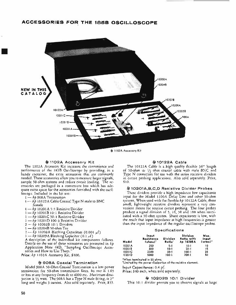
ACCESSORIES FOR THE 185B OSCILLOSCOPE
NEW IN C A T A l
2A Accessory K i t
@ 1102A Accessory Ki t The 1102A Accessory Kit increases the convenience and
performance of the 185B Oscilloscope by providing, in a handy container, the extra accessories that are commonly needed. These accessories allow you to measure larger signals, sample 50-ohm systems and reduce circuit loading. The ac- cessories are packaged in a convenient box which has ade- quate extra space for the accessories furnished with the oscil- loscope. Included in the kit are:
1 - hp 908A Termination 1 - hp 10122A Cable Coaxial Type N male to BNC
1 - hp 10201A 5 : 1 Resistive Divider 1 -hp 10201B 10:1 ResistiveDivider 1 -hp 10201C 50:l ResistiveDivider 1 -hp 10201D 100:1 Resistive Divider 2 - hp 10202B 10:1 Dividers 1 - hp 10204B 50-ohm Tee 2 - hp 10208A Blocking Capacitors (0.001 Ff) 1 - hp 10209A Blocking Capacitor (0.1 p f ) A description of the individual kit components follows. Details on the use of these accessories are presepted in hp Application Note 44D, “Sampling Oscilloscope Acces- sories and How to Use Them.”
female
Price: hp 1102A Accessory Kit, $300.
($3 9 0 8 A Coaxial Termination Model 908A 50-Ohm Coaxial Termination is a low-power
termination for 50-ohm transmission lines. Its swr is 1.05 or less at any frequency from dc to 4000 mc. Maximum dissi- pation is y2 watt. The 908A has a Type N male fitting, is 2” long and weighs 3 ounces. Also sold separately. Price, $35.
@ 10122A Cable The 10122A Cable is a high quality flexible 36” length
of 50-ohm t 34 ohm coaxial cable with male BNC and Type N connectors for use with the series resistive dividers in circuit probing applications. Also sold separately. Price, $10.
@ 10201A,B,C,D Resistive Divider Probes These dividers provide a high impedance low capacitance
input for the Model 1loOA Delay Line and other 50-ohm systems. When used with the flexible hp 10122A Cable, these small, lightweight resistive dividers represent a very con- venient means for routine circuit probing. The four probes produce a signal division of 5, 10, 50 and 100 when termi- nated with a 50-ohm system. Shunt capacitance is low, with the result that input impedance at high frequencies is greater than the input impedance of the regular oscilloscope probes.
Spec if icat i o n s
I n p u t Div is ion M a x . Resistance Div is ion R a t i o w i t h I n p u t
M o d e l (ohms)’ Rat io ’ hp 10205A ( v r m s ) ’ 10201A 250 5: I 1O: l I O 102018 500 1O:l 20: I 15 10201c 2500 50: I 1OO: l 35 10201D 5000 1OO: l 200: I 50
‘When terminated in 50 ohms. ‘L imited by t h e power dissipation of the resistive element.
Input Capacitance: 0.4 pf. Price: $40 each, when sold separately.
($3 102029 1O:l Divider This 10:1 divider permits you to observe signals as large
50
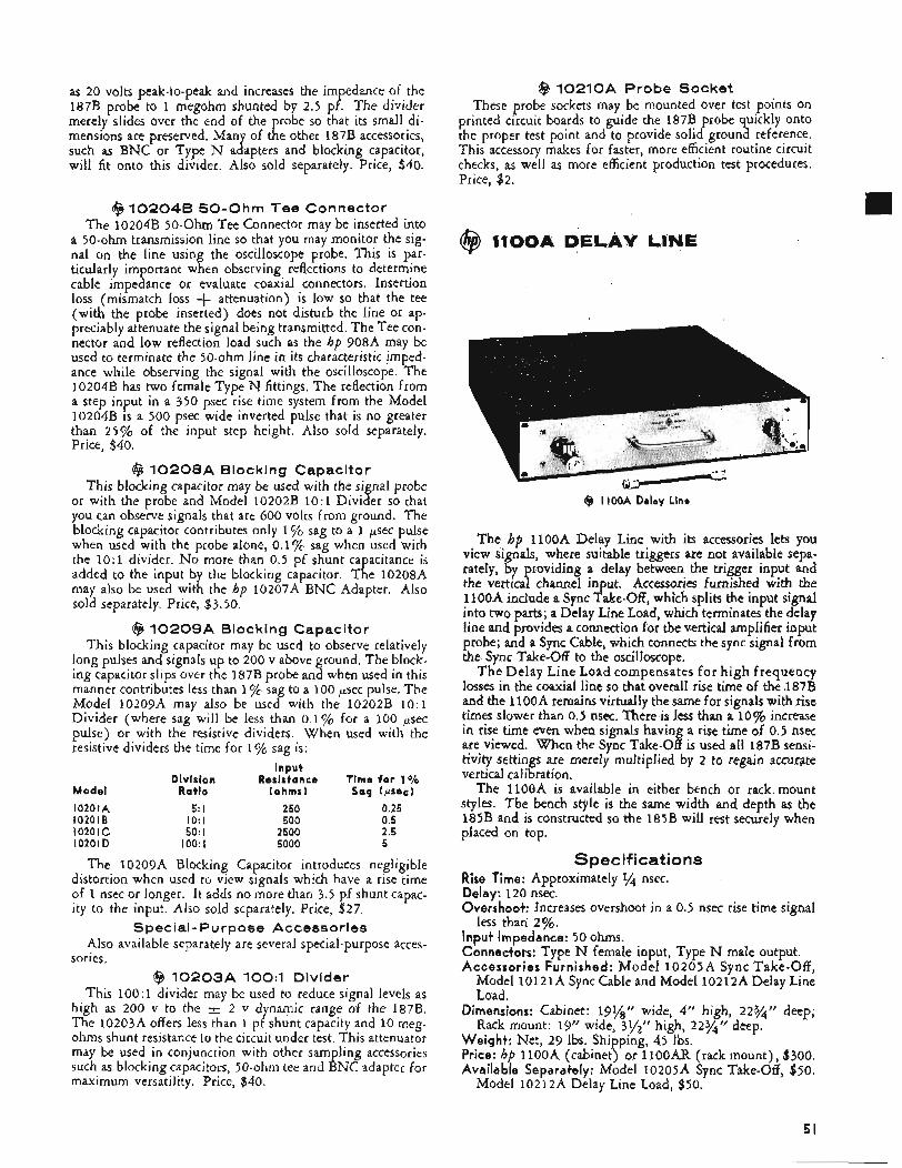
as 20 volts peak-to-peak and increases the impedance of the 187B probe to 1 megohm shunted by 2.5 pf. The divider merely slides over the end of the robe so that its small di-
such as BNC or Type N adapters and blocking capacitor, will fit onto this divider. Also sold separately. Price, $40.
mensions are preserved. Many of t 1 e other 187B accessories,
@ 102046 SO-Ohm Tee Connector The 10204B 50-Ohm Tee IConnector may be inserted into
a 50-ohm transmission line so that you may monitor the sig- nal on the line using the oscilloscope probe. This is par- ticularly important when observing reflections to determine cable impedance or evaluate coaxial connectors. Insertion loss (mismatch loss + attenuation) is low so that the tee (with the probe inserted) does not disturb the line or ap- preciably attenuate the signal being transmitted. The Tee con- nector and low reflection load such as the hp 908A may be used to terminate the 50-ohm line in its characteristic imped- ance while observing the signal with the oscilloscope. The 10204B has two female Type N fittings. The reflection from a step input in a 350 psec rise time system from the Model 10204B is a 500 psec wide inverted pulse that is no greater than 25% of the input step height. Also sold separately. Price, $40.
@ 10208A Blocking Capacitor This blocking capacitor may be used with the signal probe
or with the probe and Model 10202B 10:1 Divider so that you can observe signals that are 600 volts from ground. The blocking capacitor contributes only 1% sag to a 1 p e c pulse when used with the probe alone, 0.1% sag when used with the 10:1 divider. No more than 0.5 pf shunt capacitance is added to the input by the blocking capacitor. The 10208A may also be used with the hp 10207A BNC Adapter. Also sold separately. Price, $3.50.
@ 10209A Blocking Capacitor This blocking capacitor may be used to observe relatively
long pulses and signals up to 200 v above ground, The block- ing capacitor slips over the 187B probe and when used in this manner contributes less than 1 "/c sag to a 100 psec pulse. The Model 10209A may also be used with the 10202B 10:1 Divider (where sag will be less than 0.1% for a 100 p e c pulse) or with the resistive dividers. When used with the resistive dividers the time for 1 "/c sag is :
Input Division Resisfance Time for 1 O/O
Model Ratio (ohms) Sag (wee) 10201A 5 : l 250 0.25 102018 1O: l 500 0.5 10201c 50: I 2500 2.5 10201D 1OO:l 5000 5
The 10209A Blocking Capacitor introduces negligible distortion when used to view signals which have a rise time of 1 nsec or longer. It adds no more than 3.5 pf shunt capac- ity to the input. Also sold separately. Price, $27.
Special - Pu rpose Accessories Also available separately are several special-purpose acces-
sories. @ 10203A 1OO:l Divider
This 100 : 1 divider may be used to reduce signal levels as high as 200 v to the -+ 2 v dynamic range of the 187B. The 10203A offers less than 1 pf shunt capacity and 10 meg- ohms shunt resistance to the circuit under test. This attenuator may be used in conjunction with other sampling accessories such as blocking capacitors, 50-ohm tee and BNC adapter for maximum versatility. Price, $40.
@ 10210A Probe Socket These probe sockets may be mounted over test points on
printed circuit boards to guide the 187B probe quickly onto the proper test point and to provide solid ground reference. This accessory makes for faster, more efficient routine circuit checks, as well as more efficient production test procedures. Price, $2.
Dimensions: Cabinet: 19%" wide, 4" high, Rack mount: 19" wide, 3,/" high, 22y4'?
Weight: Net, 29 Ibs. Shipping, 45 lbs. Price: hp 1lOOA (cabinet) or 1lOOAR (rack mount), $300. Available Separafeely: Model l0205A Sync Take-Off, $50.
Model 10212A Delay Line Load, $50.
51
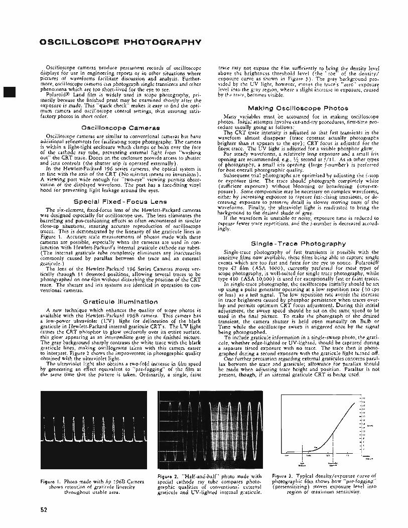
OSCILLOSCOPE PHOTOGRAPHY
Oscilloscope cameras produce permanent records of oscilloscope displays for use in engineering reports or in other situations where pictures of waveforms facilitate discussion and analysis. Further- more, oscilloscope cameras can photograph single transients and other phenomena which are too short-lived for the eye to see.
Polaroid8 Land film I s widely used in scope photography, pri- marily because the finished print may be examined shortly after the exposure is made. This “quick check” makes it easy to find the opti- mum camera and oscilloscope control settings, thus assuring satis- factory photos in short order.
Oscilloscope Cameras Oscilloscope cameras are similar to conventional cameras but have
additional refinements for facilitating scope photography. The camera is within a light-tight enclosure which clamps or bolts over the face of the cathode ray tube, preventing external light from “washing out” the CRT trace. Doors on the enclosure provide access to shutter and lens controls (the shutter trip is operated externally),
In the Hewlett-Packard 196 series cameras, the optical system is in line with the axis of the CRT (No mirrors means no inversions). A viewing port wide enough for “two-eye” viewing permits obser- vation of the displayed waveform. The port has a face-fitting vinyl hood for preventing light leakage around the eyes.
Special Fixed - Focus Lens The six-element, fixed-focus lens of the Hewlett-Packard cameras
was designed especially for oscilloscope use. The lens eliminates the barrelling and pin-cushioning effects so often encountered in similar close-up situations, insuring accurate reproduction of oscilloscope traces. This is demonstrated by the linearity of the graticule lines in Figure 1. Accurate scale measurements of photos made with these cameras are possible, especially when the cameras are used in con- junction with Hewlett-Packard’s internal graticule cathode ray tubes. (The internal graticule tube completely eliminates any inaccuracies commonly caused by parallax between the trace and an external graticule. )
The lens of the Hewlett-Packard 196 Series Cameras moves ver- tically through 11 detented positions, allowing several traces to be photographed on one film without disturbing the position of the CRT trace. The shutter and iris systems are identical in operation to con- ventional cameras.
Graticule Illumination A new technique which enhances the quality of scope photos is
available with the Hewlett-Packard 196B camera. This camera has a low-power ultraviolet (LJV) light for delineation of the black graticule in Hewlett-Packard internal graticule CRT’s. The U V light causes the CRT phosphor to glow uniformly over its entire surface, this glow appearing as an intermediate gray in the finished picture. The gray background sharply contrasts the white trace with the black graticule lines, making oscillograms taken with this camera easier to interpret. Figure 2 shows the improvement in photographic quality obtained with the ultraviolet light.
The ultraviolet light also obtains a two-fold increase in film speed by generating an effect equivalent to “pre-fogging” of the film at the same time that the picture is taken. Ordinarily, a single, faint
Figure I. Photo made with hp l96B Camera shows retention of graticule linearity
throughout usable area.
trace may not expose the film sufficiently to bring the density level above the brightness threshold level ( the “toe” of the density/ exposure curve as shown in Figure 3 ) . The gray background pro- vided by the UV light, however, moves the trace’s “zero” exposure level into the gray region, where a slight increase in exposure, caused by the trace, becomes visible.
Making Oscilloscope Photos Many variables must be accounted for in making oscilloscope
photos. Initial attempts involve cut-and-try procedures, first-time pro- cedure usually going as follows:
The CRT trace intensity is adjusted so that fart transients in the waveform almost disappear (trace contrast actually photographs brighter than it appears to the eye); CRT focus is adjusted for the finest trace. The UV light is adjusted for a visible phosphor glow.
For steady waveforms, a relatively long exposure and a small iris opening are recommended, e.g., ’/2 second at f/11. As in other types of photography, a small iris opening (large f-number) is preferred for best overall photographic quality.
Subsequent trial photographs are optimized by adjusting the f-stop or exposure time. The trace should photograph completely white (sufficient exposure) without blooming or broadening (over-ex- posure). Some compromise may be necessary on complex waveforms, either by increasing exposure to capture fast-rising transients, or de- creasing exposure to preserve detail in slower moving parts of the waveforms. Finally, the ultraviolet light is readjusted to bring the background to the desired shade of gray.
If the waveform is unstable or noisy, exposure time is reduced to capture fewer trace repetitions, and the f-number is decreased accord- ingly.
Single -Trace Photography Single-trace photography of fast transients is possible with the
sensitive films now available, these films being able to capture single events which are too fast and faint for the eye to notice. Polaroid@ type 47 film (ASA 3000) , currently preferred for most types of scope photography, is well-suited for single trace photography, while type 410 (ASA 10,000) is used for exceptionally fast or faint traces.
In single-trace photography, the oscilloscope initially should be set up using a pulse generator operating at a low repetition rate (30 cps or less) as a test signal. The low repetition rate avoids the increase in trace brightness caused by phosphor persistence when traces over- lap and permits optimum CRT focus adjustment. During this initial adjustment, the sweep speed should be set on the same speed to be used in the final picture. T o make the photograph of the desired transient, the camera shutter is held open manually on Bulb or Time while the oscilloscope sweep is triggered once by the signal being photographed.
To include graticule information in a single-sweep photo, the grati- cule, whether edge-lighted or UV-lighted, should be captured during a separate timed exposure with no trace. The trace then is photo- graphed during a second exposure with the graticule light turned off.
One further precaution regarding external graticules concerns paral- lax between the tEace and graticule; allowance for parallax should be made when adjusting trace height and position. Parallax is not present, though, if an internal graticule CRT is being used.
Figure 2. “Half-and-half” photo made with special cathode ray tube compares photo- graphic qualities of conventional external graticule and UV-lighted internal graticule.
Figure 3. Typical density/exposure curve of photographic film shows how “pre-fogging” (presensitizing) moves exposure level into
region of maximum sensitivity.
52
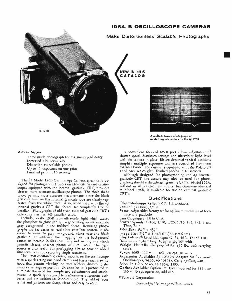
196A, B OSCILLOSCOPE CAMERAS
Advantages: Three shade photograph for maximum readability Increased film sensitivity Distortionless scalable photos Up to 11 exposures on one print Finished print in 10 seconds
The hp Model 196B Oscilloscope Camera, specifically de- signed for photographing traces on Hewlett-Packard oscillo- scopes equipped with the internal graticule CRT, provides clearer, more accurate oscilloscope photos. The three shade photo permits more accurate measurements since the black graticule lines on the internal graticule tube are clearly sep- arated from the white trace. Also, when used with the hp internal graticule CRT the photos are completely free of parallax. Photographs of old style, external graticule CRT’s exhibit as much as 5 % parallax error.
Included in the l96B is an ultraviolet light which causes the phosphor to glow gently - generating an intermediate gray background in the finished photo. Resulting photo- graphs are far easier to read since excellent contrast is ob- tained between the gray background, white trace and black graticule. In addition, the “fogging” of the background causes an increase in film sensitivity and writing rate which permits clearer, sharper photos of dim traces. The light source is also useful for prefogging film to provide added film sensitivity for capturing single transients,
The l96B oscilloscope camera mounts on the oscilloscope with a quick acting one hand clamp and has a vinyl viewing hood that permits viewing the trace without disturbing the camera’s settings or position. In addition, it is prefocused to eliminate the need for complicated adjustments and attach- ments. A specially designed lens eliminates distortion; both barrel and pin cushion are imperceptible. The field of focus is flat and pictures are sharp, clean and easy to read.
tortic
IN TH ‘ A L O
,nl
INS G
e ss Scalable Photographs
A mult i-exposure pho tog raph of re la ted signals made wi th the @ 1968
A convenient forward access port allows adjustment of shutter speed, diaphram settings and ultraviolet light level with the camera in place. Eleven detented vertical positions simplify multiple exposures and are controlled from one external knob. The camera is equipped with the Polaroid8 Land back which gives finished photos in 10 seconds.
Although designed for photographing the hp internal graticule CRT, the camera may also be used for photo- graphing the old style external graticule CRT’s. Model 196~4, without an ultraviolet light source, but otherwise identical to Model 196B, i s available for use on external graticule CRT’s.
Object-to-image Ratio: 1 :0 .9; 1 :I available. Lens: 3” (75 mm) , f / l .9 . Focus: Adjustable; factory set for optimum resolution of both
trace and graticule, Lens Opening: f/1.9 to f/16. Shutter Speeds: 1/100, 1/50, 1 /25 , 1/10, 1/5, 1/2, 1 sec,
Print Size: 3%’’ x 4%”. Image Size: 2%” x 3-13/16” (7.3 x 9.6 cm). Film: Polaroid8 Land film, types 42, 56, 46-L, 47 and 410. Dimensions: 131/2” long, 10%” high, 10’’ wide. Weight: Net 9 Ibs. Shipping 18 Ibs. (32 Ibs. with carrying
Power: 196B: 115 v t lo%, 60 cps, 10 watts. Accessories Available: hp l0350A Adapter for Tektronix
Price: bp 196B, $445; hp 196A, $395. Options Available: Option 12: 196B modified for 115 v or
230 v, 50 cps operation, add $15.
@Polaroid Corporation
Specifications
Time, Bulb.
case).
Oscilloscopes, $4.50; hp 10351A Carrying Case, $40.
Data subject to change ulithozlt notice.
53
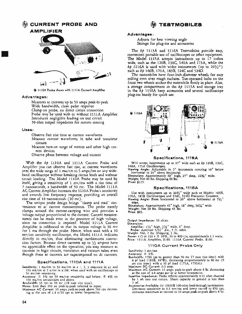
@ CURRENT PROBE AND AMPLIFIER
@ I I IOA Probe shown with I I I I A Current Amplifier
Advantages: Measures ac currents up to 50 amps peak-to-peak Wide bandwidth, clean pulse response Clamp-on probe, no direct circuit connection Probe may be used with or without 11 11A Amplifier Introduces negligible loading on test circuit 50-ohm output impedance for remote sensing
Uses: Observe fast rise time ac current waveforms Measure current waveforms in tube and transistor
Measure turn-on surge of motors and other high cur-
Observe phase between voltage and current
circuits
rent devices
With the hp 111oA and l l l l A Current Probe and Amplifier you can observe fast rise, ac current waveforms over the wide range of 1 ma/cm to 5 amps/cm on any wide- band oscilloscope without breaking circuit leads and without circuit loading. The Model 111oA Probe may be used by itself, giving a sensitivity of 1 mv/ma with a rise time of 7 nanoseconds, a bandwidth of 50 mc. The Model l l l l A AC Current Amplifier increases the 11 1OA Probe's sensitivity and extends low frequency response, providing an overall rise time of 18 nanoseconds (20 mc) ,
The unique probe design brings "clamp and read" con- venience to ac current measurements. The probe merely clamps around the current-carrying wire and provides a voltage output proportional to the current, Current measure- ments can be made even in the presence of high voltage, since no connection is required. Model 1 1 l l A Current Amplifier is calibrated so that its output voltage is 50 mv for 1 ma through the probe. Hence, when used with a 50 mv/cm sensitivity oscilloscope, the Model 111 1A indicates directly in ma/cm, thus eliminating cumbersome conver- sion factors. Because direct currents up to y2 ampere have no appreciable effect on the operation, you may measure ac currents in logic circuits, transistors and vacuum tubes even though these ac currents are superimposed on dc currents.
Specifications, 1110A and 1111A Sensitivity: 1 ma/cm to 50 ma/cm in a 1, 2 , 5 sequence in xl and
100 ma/cm to 5 a/cm in ~ 1 0 0 ; when used with an oscilloscope at 50 mv/cm sensitivity.
Accuracy: 3% on 50 ma/cm sensitivity and below. * 4% on 100 ma/cm sensitivities and above.
Bandwidth: 35 cps to 20 mc (18 nsec rise time). Noise: Less than 100 pa peak-to-peak referred to input. Maximum AC Current: 50 amps peak-to-peak above 700 cps decreas-
ing at the rate of 1.4 a/20 cps at lower frequencies.
@ I115A
i
i Q 1116A
ib
Specifications, 1115A Will accept instruments u p to 17" wide such as hp 12OB, 130c,
140A, 175A Oscilloscopes. Viewing Angle: Adjustable in 5" increments covering 10'' below
horizontal to 20' above horizontal. Dimensions: Approximately 38" high, 27" deep, 22%'' wide. Weight: Net 40 Ihs. Shipping 44 Ibs. Price: $115.
Specifications, 1116A Use with instruments up to 201/2" wide such as Models 160B,
170A, 185B Oscilloscopes and 524C, 554D Electronic Counters. Viewing Angle: From horizontal to 30 above horizontal in 7%"
steps. Dimensions: Approximately 45" high, 18" deep, 261/" wide. Weight: Net 39 Ibs. Shipping 45 Ibs. Prico: $85.
Output Impedance: 50 ohms. Dimensions:
Amplifier: 1,/2" high, Sl/g" wide, 6" deep. Probe: Aperture 5/32" dia., 5 ft. cable.
Weight : Net, 2 Ibs. Shipping, 3 Ibs. Power: 115 or 230 v * l o % , 50 to 400 cps, approximately 1.5 watts. Price: 1 l l l A Amplifier, $160. 111oA Current Probe, $100.
1110A Current Probe Only Sensitivity: 1 mv/ma. Accuracy: * 37%. Bandwidth: 1700 cps to greater than 50 mc (7 nsec rise time) with 4 pf load (185B, 187B), decreasing proportionately to 40 mc (9 sec rise time) with a 30 pf load (175A, 1750A).
Maximum DC Current: 0.5 amp. Maximum AC Current: 15 amps peak-to-peak above 4 kc decreasing
at the rate of 3.8 amps per kc at lower frequencies. Insertion Impedance: Probe reflects approximately 0.01 ohm shunted
by 1 ph into test circuit. Shunt capacity to ground is less than
Accessories Available: hp 1OlOOB 100-ohm feed-through termination. Decreases sensitivity to 0.5 mv/ma and lower cut-off to 850 cps, increases maximum ac current to 30 amps peak-to-peak above 4 kc.
3 pf.
54
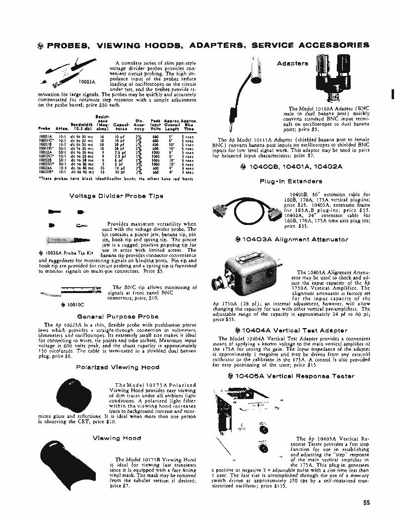
@ PROBES, VIEWING HOODS, ADAPTERS, SERVICE ACCESSORIES
A complete series of slim pen-style voltage divider probes provides con- venient circuit probing. The high im- pedance input of the probes reduce loading of oscilloscopes on the circuit under test, and the probes provide at-
tenuation for large signals, The probes may be quickly and accurately compensated for optimum step response with a simple adjustment on the probe barrel; price $30 each.
'0003A
Resist. once Dlv. Peak Approx.Approx.
Bandwidth ( M e w Capaci- Accu- Input Overall Rlre Probe Attan. (0.5 dbl ohms1 tance racy Volts Length Time
IOOOIA 1O:l de to 30 rnc IO I O pf 600 5' 5 nsec IOOOIC' 1O:l de to 30 rnc IO I O pf $ 600 5' 5 nsec IOOOIB 1O:l de to 30 rnc IO 20 pf 600 IO' 5 nsec 10001D' 1O:l dc to 30 rnc IO 600 IO' 5 nsec 10002A 50:l de to 30 rnc 9 i05';f 2.p 1000 5' 5 nsec 10002C' 50:l de to 30 rnc 9 2.5 pf # 1000 5' 5 nsec 100028 50:l de to 30 rnc 9 1000 IO' 5 nsec IOOO2D' 50:l de to 30 rnc 9 ! $ 39 1000 IO' 5 nsec 10003A 1 O : l de to 40 me IO IO pf $ 600 4' 3 nsec 100038' 1O:l de to 40 rnc I O IO pf 600 4' 3 nsec 'These probes have black identification boots: the others have red boots
Voltage Divider Probe Tips
- m Provides maximum versatility when
used with the voltage divider probe. The kit contains a pincer jaw, banana tip, pin tip, hook tip and spring tip. The pincer jaw is a rugged, positive gripping tip for use in areas with limited access. The
@ Probe Tip K i t banana tip provides connector convenience and ruggedness for monitoring signals on binding posts. Pin tip and hook tip are provided for circuit probing and a spring tip is furnished to monitor signals on multi-pin connectors. Price $5.
The BNC tip allows monitoring of signals at front panel BNC connectors; price, $10.
$8 lO0lOC
General Purpose Probe The hp lOO25A is a thin, flexible probe with pushbutton pincer
jaws which provides a straight-through connection to voltmeters, ohmmeters and oscilloscopes. Its extremely small size makes it ideal for connecting to wires, tie points and tube sockets, Maximum input voltage is 600 volts peak, and the shunt capacity is approximately 150 picofarads. The cable is terminated in a shielded dual banana plug; price $9.
Polarized Viewing Hood
mizes glare and reflections. is observing the CRT; pricc
T h e M o d e l 1 0 1 7 5 A P o l a r i z e d Viewing Hood provides easy viewing of dim traces under all ambient light conditions. A polarized light filter w i t h i n t h e v iewing hood increases trace to background contrast and mini-
It is ideal when more than one person ? $10.
Viewina Hood
Adapters
7 The Model 101 10A Adapter (BNC male to dual banana post) quickly converts standard BNC input termi- nals on oscilloscopes to dual banana posts; price $5.
The hp Model 1 o l l l A Adapter (shielded banana post to female BNC) converts banana post inputs on oscilloscopes to shielded BNC inputs for low level signal work. This adapter may be used in pairs for balanced input characteristics; price $7.
@ 10400B,10401A, 1 0 4 0 2 A
Plug-In Extenders
10400B. 30" extension cable for IGOB, 170A, 175A vertical plug-ins; price $25. 10401~4, extension frame for 185A,B plug-ins; pr ice $ 3 5 . 10402A, 24" extension cable for 160B, 1704, 1 7 5 6 time axis plug ins; price $35.
($3 1 0 4 0 3 A Alignment Attenuator
The l0403A Alignment Attenu- ator may be used to check and ad- lust the input capacity of the hp 1750A Vertical Amplifier. T h e alignment attenuator is factory set f o r t h e i n p u t capacity o f - t h e
hp 1750A ( 2 8 p f ) ; an internal adjustment, however, will allow changing the capacity for use with other vertical pre-amplifiers. The adjustable range of the capacity is approximately 24 pf to 60 pf; price $35.
@ 1 0 4 0 4 A Vertical Test Adapter The Model 104044 Vertical Test Adapter provides a convenient
means of applying a known voltage to the main vertical amplifier of the 175A for setting the gain. The input impedance of the adapter is approximately 1 megohm and may be driven from any external calibrator or the calibrator in the 175A. A control is also provided for easy positioning of the trace; price $15.
$3 1 0 4 0 5 A Vertical Response Tester
The hp 10405A Vertical Re- sponse Tester provides a fast step function for use in establishing and adjusting the "step" response of the main vertical amplifier in the 175A. This plug-in generates
a positive or negative 2 v adjustable pulse with a rise time less than 1 nsec. The fast rise is accomplished through the use of a mercury switch driven at approximately 250 cps by a self-contained tran- sistorized oscillator; price $125.
~
v
55
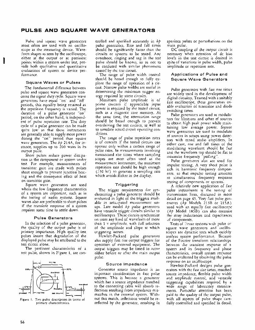
PULSE AND SQUARE
Pulse and square wave generators most often are used with an oscillo- scope as the measuring device. Wave- form shapes as seen by the oscilloscope, either at the output or at pertinent points within a system under test, pro- vide both qualitative and quantitative evaluations of system or device per- formance.
Square Waves or Pulses The fundamental difference between
pulse and square wave generators con- cerns the signal duty cycle. Square wave generators have equal “on” and “off” periods, this equality being retained as the repetition frequency is varied. The duration of a pulse generator “on” period, on the other hand, is independ- ent of pulse repetition rate. The duty cycle of a pulse generator can be made quite low so that these instruments are generally able to supply more power during the “on” period than square wave generators. The hp 214A, for in- stance, supplies up to 200 watts in its output pulse.
Short pulses reduce power dissipa- tion iil the component or system under test. For example, measurements of transistor gain are made with pulses short enough to prevent junction heat- ing and the consequent effect of heat on transistor gain.
Square wave generators are used where the low frequency characteristics of a system are important, such as in the testing of audio systems. Square waves also are preferable to short pulses if the transient response of a system requires some time to settle down.
Pulse Generators In the selection of a pulse generator,
the quality of the output pulse is of primary importance. High quality test pulses insure that degradation of the displayed pulse may be attributed to the test circuit alone.
The pertinent characteristics of a test pulse, shown in Figure 1, are con-
overshoot
Figure I . Test pulse description in terms of primary characteristics.
W A V E GENERATORS
trolled and specified accurately in hp pulse generators. Rise and fall times should be significantly faster than the circuits or systems to be tested. Any overshoot, ringing and sag in the test pulse should be known, so as not to be confused with similar phenomena caused by the test circuit.
The range of pulse width control should be broad enough to fully ex- plore the range of operation of a cir- cuit, Narrow pulse widths are useful in determining the minimum trigger en- ergy required by some circuits.
Maximum pulse amplitude is of prime concern if appreciable input power is required by the tested circuit, such as a magnetic core memory. At the same time, the attenuation range should be broad enough to prevent overdriving the test circuits, as well as to simulate actual circuit operating con- ditions,
The range of pulse repetition rates is of concern if the tested circuits can operate only within a certain range of pulse rates. In measurements involving nanosecond rise times where sampling scopes are most often used as the measurement instrument, the maximum repetition rate should be high enough 0 3 0 kc) to generate a sampling rate which avoids flicker in the display.
Triggering The trigger requirements for syn-
chronizing a pulse generator should be evaluated in light of the triggers avail- able in anticipated measurement set- ups. Late model hp pulse generators have versatile trigger circuits similar to oscilloscopes. These circuits synchronize on most any kind of waveform of more than 1 v amplitude, with full selection of the amplitude and slope at which triggering occurs.
Hewlett-Packard pulse generators also supply fast rise output triggers for operation of external equipment. The output triggers may be timed to occur either before or after the main output pulse.
Source Impedance Generator source impedance is an
important consideration in fast pulse systems. This is because a generator which has a source impedance matched to the connecting cable will absorb re- flections resulting from impedance mis- matches in the external system. With- out this match, reflections would be re- reflected by the generator, resulting in
spurious pulses or perturbations on the main pulse.
DC coupling of the output circuit is necessary when retention of dc bias levels in the test circuit is desired in spite of variations in pulse width, pulse amplitude or repetition rate.
Applications of Pulse and Square Wave Generators
Pulse generators with fast rise times are widely used in the development of digital circuitry, Teamed with a suitably fast oscilloscope, these generators en- able evaluation of transistor and diode switching times.
Pulse generators are used as modula- tors for klystrons and other rf sources to obtain high peak power while main- taining low average power. Square wave generators are used to modulate rf sources in setups using power detec- tors with tuned audio amplifiers. In either case, rise and fall times of the modulating waveform should be fast and the waveform top should be flat to minimize frequency “pulling”.
Pulse generators also are used for impulse testing. A very short pulse is rich in harmonic frequency compon- ents, so that impulse testing amounts to simultaneous frequency response testing of components or systems.
A relatively new application of fast pulse instruments is the testing of transmission lines, discussed in more detail on page 45. Very fast pulse gen- erators (hp Models 213B or 215A) used with an equally fast oscilloscope ( h p Model 185B) can also measure the stray inductances and capacitances af components.
Tests of linear systems with pulse or square wave generators and oscillo- scopes are dynamic tests which quickly analyze system performance. Because of the Fourier transform relationships between the transient response of a system and its frequency and phase characteristics, overall system response can be evaluated by observing the pulse response on an oscilloscope.
Hewlett-Packard designs pulse gen- erators with the fast rise times, matched source impedance, flexible pulse width and amplitude control, and versatile triggering capabilities required by a wide range of laboratory measure- ments. Particular attention has been paid to the quality of the output pulse, with all aspects of pulse shape care- fully controlled and specified in detail.
56
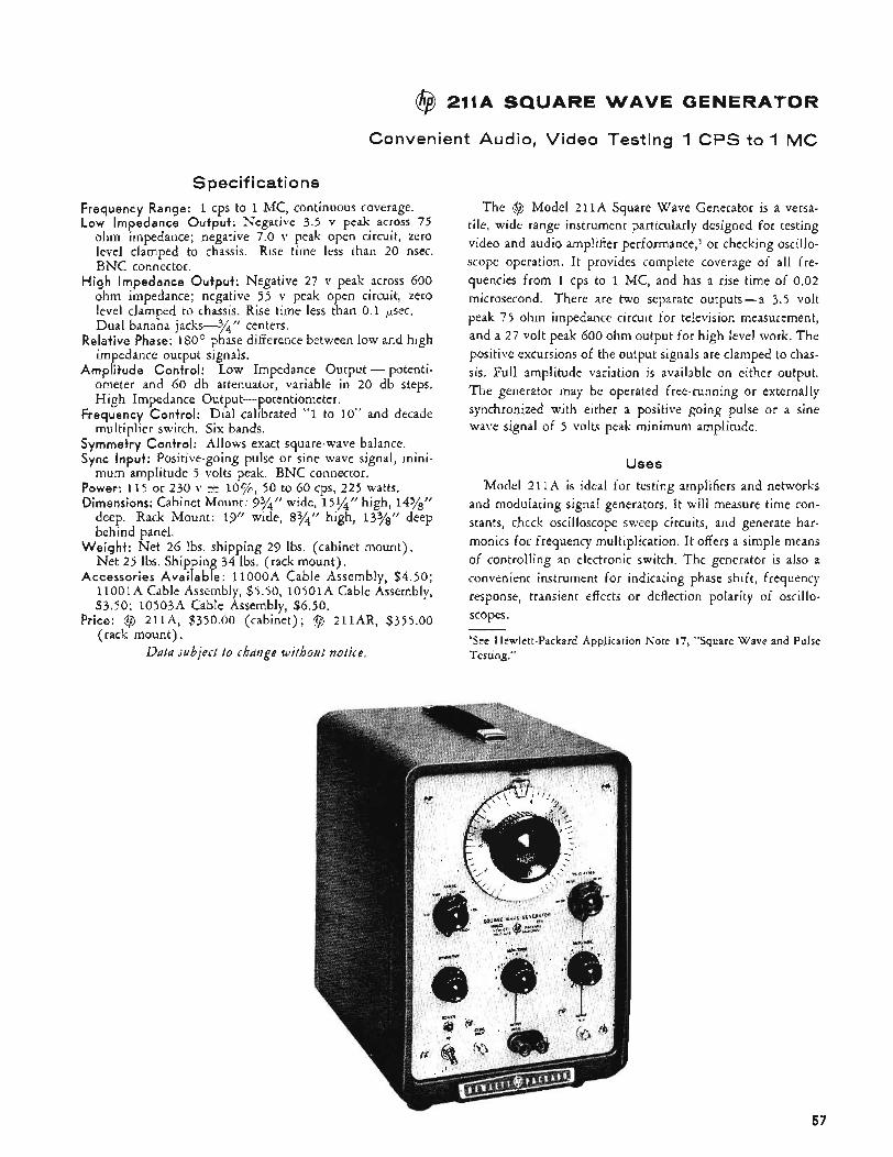
@ 211A SQUARE WAVE GENERATOR
Convenient Audio, Video Testing 1 CPS to 1 MC
Specifications Frequency Range: 1 cps to 1 MC, continuous coverage. Low Impedance Output: Negative 3.5 v peak across 75
ohm impedance; negative 7.0 v peak open circuit, zero level clamped to chassis. Rise time less than 20 nsec. BNC connector.
High Impedance Output: Negative 27 v peak across 600 ohm impedance; negative 55 v peak open circuit, zero level clamped to chassis. Rise time less than 0.1 p e c . Dual banana jacks--%” centers.
Relative Phase: 180’ phase difference between low and high im edance output signals.
A m p P itude Control: Low Impedance Output - potenti- ometer and 60 db attenuator, variable in 20 db steps. High Impedance Output-potentiometer.
Frequency Control: Dial calibrated “1 to 10’’ and decade multiplier switch. Six bands.
Symmetry Control: Allows exact square-wave balance. Sync Input: Positive-going pulse or sine wave signal, mini-
Power: 115 or 230 v k l O C / c , 50 to 60 cps, 225 watts. Dimensions: Cabinet Mount: 93/4f’ wide, 15%” high, 14Ygf’
deep. Rack Mount: 19” wide, 83/?! high, 13%” deep behind panel.
Weigh+: Net 26 Ibs. shipping 29 lbs. (cabinet mount). Net 25 Ibs. Shipping 34 lbs. (rack mount).
Accessories Avai lable: 1loooA Cable Assembly, $4.50; 11OOlA Cable Assembly, $5.50, l050lA Cable Assembly, $3.50; 10503A Cable Assembly, $6.50.
Price: @ 211A, $350.00 (cabinet); @ 211AR, $355.00 (rack mount),
Data subject to chdizge without notice.
mum amplitude 5 volts peak. BNC connector.
I The @ Model 211A Square Wave Generator is a versa- tile, wide range instrument particularly designed for testing video and audio amplifier performance,l or checking oscillo- scope operation. It provides complete coverage of all fre- quencies from 1 cps to 1 MC, and has a rise time of 0.02 microsecond. There are two separate outputs - a 3.5 volt peak 75 ohm impedance circuit for television measurement, and a 27 volt peak 600 ohm output for high level work. The positive excursions of the output signals are clamped to chas- sis. Full amplitude variation is available on either output. The generator may be operated free-running or externally synchronized with either a positive going pulse or a sine wave signal of 5 volts peak minimum amplitude.
U s e s Model 211A is ideal for testing amplifiers and networks
and modulating signal generators, It will measure time con- stants, check oscilloscope sweep circuits, and generate har- monics for frequency multiplication. It offers a simple means of controlling an electronic switch, The generator is also a convenient instrument for indicating phase shift, frequency response, transient effects or deflection polarity of oscillo- scopes.
‘See Hewlett-Packard Application Note 17, “Square Wave and Pulse Testing.”
57
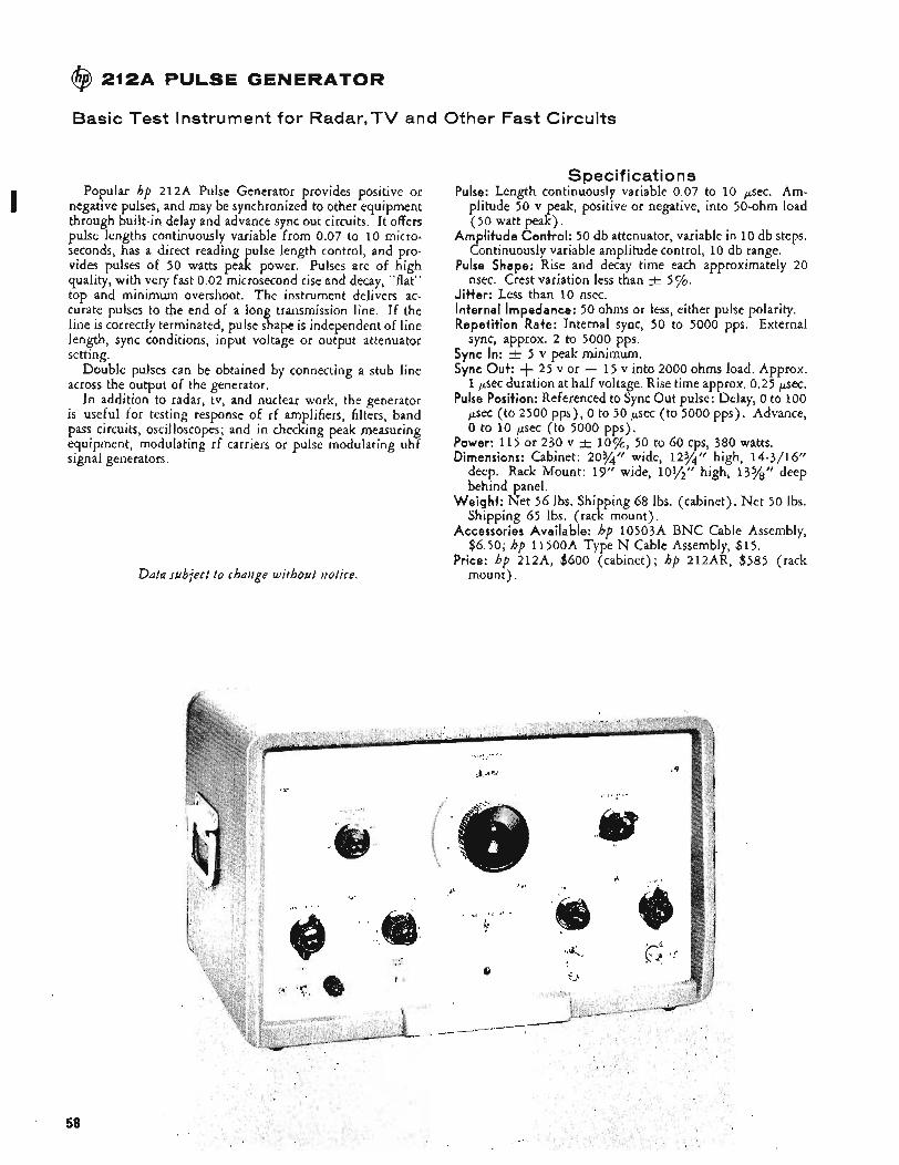
@ 212A PULSE GENERATOR
Basic Test Instrument for Radar,TV and Other Fast Circuits
Popular hp 212A Pulse Generator provides positive or negative pulses, and may be synchronized to other equipment through built-in delay and advance sync out circuits. It offers pulse lengths continuously variable from 0.07 to 10 micro- seconds, has a direct reading pulse length control, and pro- vides pulses of 50 watts peak power. Pulses are of high quality, with very fast 0.02 microsecond rise and decay, “flat” top and minimum overshoot. The instrument delivers ac- curate pulses to the end of a long transmission line. If the line is correctly terminated, pulse shape is independent of line length, sync conditions, input voltage or output attenuator setting.
Double pulses can be obtained by connecting a stub line across the output of the generator.
In addition to radar, tv, and nuclear work, the generator is useful for testing response of rf amplifiers, filters, band pass circuits, oscilloscopes; and in checking peak measuring equipment, modulating rf carriers or pulse modulating uhf signal generators.
I
Data subject t o chatige without uotice.
Spec if i cat i o ns Pulse: Length continuously variable 0.07 to 10 psec. Am-
plitude 50 v peak, positive or negative, into 50-ohm load (50 watt peak).
Amplitude Control: 50 db attenuator, variable in 10 db steps. Continuously variable amplitude control, 10 db range.
Pulse Shape: Rise and decay time each approximately 20 nsec. Crest variation less than A 5 %.
Jitter: Less than 10 nsec. Internal Impedance: 50 ohms or less, either pulse polarity. Repetition Rate: Internal sync, 50 to 5000 pps. External
sync, approx. 2 to 5000 pps. Sync In: 5 v peak minimum. Sync Out: + 25 v or - 15 v into 2000 ohms load. Approx.
1 psec duration at half voltage. Rise time approx. 0.25 psec. Pulse Position: Referenced to Sync Out pulse: Delay, 0 to 100
psec (to 2500 pps), 0 to 50 psec (to 5000 pps). Advance, 0 to 10 psec (to 5000 pps).
Power: 115 or 230 v 2 l o%, 50 to 60 cps, 380 watts. Dimensions: Cabinet: 203/4” wide, 12%” high, 14-3/16”
deep. Rack Mount: 19” wide, 10?/”” high, 135/88” deep behind panel.
Weight: Net 56 Ibs. Shipping 68 Ibs. (cabinet). Net 50 Ibs. Shipping 65 Ibs. (rack mount),
Accessories Available: hp 10503A BNC Cable Assembly, $6.50; hp ll5OOA Type N Cable Assembly, $15.
Price: hp 212A, $600 (cabinet); hp 212AR, $585 (rack mount).
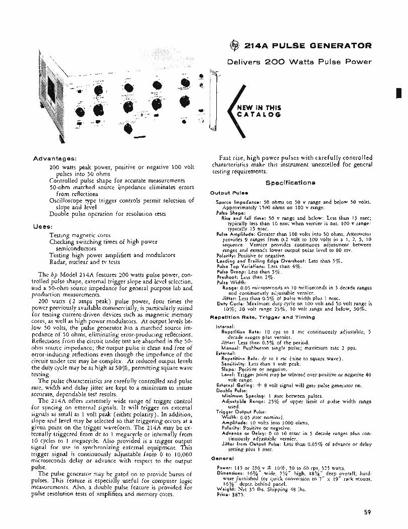
Advantages: 200 watts peak power, positive or negative 100 volt
Controlled pulse shape for accurate measurements 50-ohm matched source impedance eliminates errors
Oscilloscope type trigger controls permit selection of
Double pulse operation for resolution tests
pulses into 50 ohms
from reflections
slope and level
Uses: Testing magnetic cores Checking switching times of high power
Testing high power amplifiers and modulators Radar, nuclear and tv tests
semiconductors
The hp Model 214A features 200 watts pulse power, con- trolled pulse shape, external trigger slope and level selection, and a 50-ohm source impedance for general purpose lab and production measurements.
200 watts ( 2 amps peak) pulse power, four times the power previously available commercially, is particularly suited for testing current-driven devices such as magnetic memory cores, as well as high power modulators. At output levels be- low 50 volts, the pulse generator has a matched source im- pedance of 50 ohms, eliminating error-producing reflections. Reflections from the circuit under test are absorbed in the 50- ohm source impedance; the output pulse is dean and free of error-inducing reflections even though the impedance of the circuit under test may be complex. At reduced output levels the duty cycle may be as high as 50%, permitting square wave testing.
The pulse characteristics are carefully controlled and pulse rate, width and delay jitter are kept to a minimum to insure accurate, dependable test results.
The 214A offers extremely wide range of trigger control for syncing on external signals. It will trigger on external signals as small as 1 volt peak (either polarity). In addition, slope and level may be selected so that triggering occurs at a given point on the trigger waveform. The 214A may be ex- ternally triggered from dc to 1 megacycle or internally from 10 cycles to 1 megacycle. Also provided is a trigger output signal for use in synchronizing external equipment. This trigger signal is continuously adjustable from 0 to 10,000 microseconds delay or advance with respect to the output pulse.
The pulse generator may be gated on to provide bursts of pulses. This feature is especially useful for computer logic measurements. Also, a double pulse feature is provided for pulse resolution tests of amplifiers and memory cores.
@ 214A PULSE GENERATOR
Delivers 200 Watts Pulse Power
Fast rise, high power pulses with carefully controlled characteristics make this instrument unexcelled for general testing requirements.
Specifications
Output Pulse
Source Impedance: 50 ohms on 50 v range and below 50 volts. Approximately 1500 ohms on 100 v range.
Pulse Shape: Rise and fall time: 50 v range and below: Less than 13 nsec;
typically less than 10 nsec when vernier is out. 100 v range: typically 15 nsec.
Pulse Amplitude: Greater than 100 volts into 50 ohms:Attenuator provides 9 ranges from 0.2 volt to 100 volts in a 1, 2, 5, 10 sequence. Vernier provides continuous adjustment between ranges and extends lower output pulse level to 8 0 mv.
Polarity: Positive or negative. Leading and Trailing Edge Overshoot: Less than 5 % . Pulse Top Variations: Less than 4%. Pulse Droop: Less than 5%. Preshoot: Less than 2%. Pulse Width :
Range: 0.05 microseconds to 10 milliseconds in 5 decade ranges
Jitter: Less than 0.5% of pulse width plus 1 nsec. Duty Cycle: Maximum duty cycle on 100 volt and 50 volt range is
10%; 20 volt range 25%, 10 volt range and below, 50%.
and continuously adjustable vernier.
Repetition Rate, Trigger and Timing
Internal: Repetition Rate: 10 cps to 1 mc continuously adjustable, 5
Jitter: Less than 0.5% of the period. Manual: Pushbutton single pulse; maximum rate 2 pps.
decade ranges plus vernier.
External: Repetition Rate: dc to 1 mc (sine to square wave). Sensitivity: Less than 1 volt peak. Slope: Positive or negative. Level: Trigger point may be selected over positive or negative 40
volt range. External Gat ing: -k 8 volt signal will gate pulse generator on. Double Pulse:
Minimum Spacing: 1 psec between pulses. Adjustable Range: 2 5 % of upper limit of pulse width range
used. Trigger Output Pulse:
Width: 0.05 psec nominal, Amplitude: 10 volts into 1000 ohms. Polarity: Positive or negative. Advance or Delay: 0 to 10 msec in 5 decade ranges plus con-
Jitter from Output Pulse: Less than 0.05% of advance or delay tinuously adjustable vernier.
setting plus 1 nsec.
General
Power: 115 or 230 v * l o % , 50 to 60 cps, 325 watts. Dimensions: 16%'' wide, 7% high, 18%" deep overall; hard-
ware furnished for quick conversion to 7" x 19" rack mount, 16%'' depth behind panel.
Weight : Net 35 Ibs. Shipping 48 Ibs. Price: $875.
59
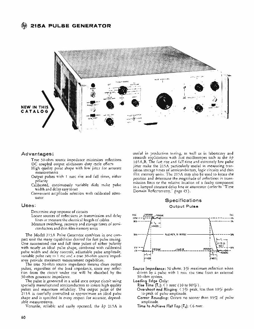
@ 215A PULSE GENERATOR
NEW C A T
Advantages: True 50-ohm source impedance minimizes reflections DC coupled output eliminates duty cycle effects High quality pulse shape with low jitter for accurate
measurements Output pulses with 1 nsec rise and fall times, either
polarity Calibrated, continuously variable dials make pulse
width and delay easy to set Convenient amplitude selection with calibrated atten-
uator
Uses: Determine step response of circuits Locate sources of reflections in transmission and delay
Measure switching, recovery and storage times of semi-
The Model 215A Pulse Generator combines in one com- pact unit the many capabilities desired for fast pulse testing. One nanosecond rise and fall time pulses of either polarity with nearly an ideal pulse shape, combined with calibrated pulse width and delay controls, adjustable pulse amplitude, variable pulse rate to 1 mc and a true 50-ohm source imped- ance provide maximum measurement capabilities.
The true 50-ohm source impedance insures clean output pulses, regardless of the load impedance, since any reff ec- tion from the circuit under test will be absorbed by the 50-ohm generator impedance.
The pulse is generated in a solid state output circuit using specially manufactured semiconductors to insure high quality pulses and maximum reliability. The output pulse of the 215A is carefully controlled to approximate an ideal pulse shape and is specified in every respect for accurate, depend- able measurements.
Versatile, reliable and easily operated, the hp 215A is
lines or measure the electrical length of cables
conductors and thin film memory units
useful in production testing, as well as in laboratory and research applications with fast oscilloscopes such as the hp 185A,B. The fast rise and fall time and extremely low pulse jitter make the 215A particularly useful in measuring tran- sition storage times of semiconductors, logic circuits and thin film memory units. The 215A may also be used to locate the position and determine the magnitude of reflections in trans- mission lines or the relative location of a faulty component in a lumped constant delay line or attenuator (refer to “Time Domain Reflectometry,” page 45) .
Specifications O u t p u t Pulse
[I<INSECH I ’
Source Impedance: 50 ohms; 3% maximum reflection when driven by a pulse with 1 nsec rise time from an external 50-ohm system.
Leading Edge Only: Rise Time (T,): < 1 nsec (10 to 90%). Overshoot and Ringing: < 596 peak, less than 10% peak-
Corner Rounding: Occurs no sooner than 95% of pulse
Time t o Achieve Flat Top (TJ: < 6 nsec.
to-peak of pulse amplitude.
amplitude.
60
Trailing Edge Only: Fall Time (Tf): < 1 nsec (10 to 9 0 % ) . Overshoot: < 5 % . Rounding: Occurs no sooner than 95% of fall. Time to Settle within 2% of Baseline (Tb): 10 to 2 5 nsec,
varies with width setting. Baseline Shift: < 0.1% under all conditions. Preshoot: < 1%. Perturbations on Flat Top: < 2% of pulse amplitude. Peak Voltage: > 10 volts into 50 ohms. > 20 volts open
Polarity: Positive or negative. Attenuator: 0 to 1 2 db in 1 db steps, absolute accuracy
within 0.1 db. Pulse Width (between 50% Points): Continuously adjustable
to 100 nsec. Dial accuracy within t 55% k 3 nsec, width jitter < 50 psec.
Exfernal Bias: Up to -t 100 ma (k 5 v dc) may be safely applied to the output. At 0 db attenuator setting, up to 10 ma (0.5 v dc) may be applied without significant change in pulse shape (5 ‘/o droop), increasing to 40 ma at 1 2 db setting. In most cases, adjusting the front panel pulse-shape controls will restore original pulse shape.
circuit.
Repetition Rate, Trigger and Tim i n g Spec if i cati 0 ns
Repetition Rate Sources: Internal Repetition Rate: < 100 cps to > 1 mc in 4 ranges,
continuously variable between ranges. Period jitter < 3 x IO-‘ of one period.
Manual: Pushbutton single pulse. External Triggering: AC coupled. Sine waves from 10 cps
to 1 mc; pulses from o to 1 mc; either positive or negative slope. Trigger Level: External trigger ievel continuously variable
from approximately + 8 to - 8 volts. Sensitivity: 1 volt peak-to-peak minimum. External pulses
must be at least 30 nsec wide. Maximum input 50 v peak, y2 watt maximum average power.
Input Impedance: Approximately 50 ohms or High Z available by front panel switch. High Z is approximately loOK for negative slope setting, approximately 5K for positive slope setting.
Countdown: Counts down from frequencies to 100 mc, 2 v rms amplitude; resulting pulse repetition rate is always less than 1.3 mc. Jitter is less than 10% of one period of the triggering signal,
External Trigger Delay: Approximately 300 nsec between leading edge of trigger pulse (2 volt step, 2 nsec rise time into 50 ohms) and leading edge of output pulse; < 50 psec jitter.
External Gating: Gates on with a + 1 volt pulse. Maximum
Trigger Output Pulse: input 50 v peak, 20 v rms.
Width: 50 nsec -t- 20% into 50 ohms. Amplitude: > 1 volt peak into 50 ohms, Rise Time: < 5 nsec. Polarity: Positive or negative.
Triggering Timing: Adjustable from 10 nsec delay to 140 nsec advance with respect to leading edge of output pulse. Dial accuracy within % 10% 5 nsec. Jitter < 50 pico- seconds.
General
Power Consumption: 115 or 230 volts 2 lo%, 50 to 60 cps, 60 watts.
Dimensions: 5y2” high, 16%” wide, 183/8” deep. Hardware furnished for quick conversion to 5%’’ x 19” rack mount, 163/8” deep behind panel.
Weight: Net 33 Ibs. Shi ping 49 lbs. Accessories Furnished: !p 10120A Cable, 3 feet, BNC to
BNC, 50 ohms f y2 ohm. Accessories Available: hp 10122A Cable, 3 feet, BNC to
Type N, 50 ohms k y2 ohm, $10. hp 908A, 50Ohm Coaxial Termination, $35. hp 10240A Coaxial Blocking Capacitor to eliminate external dc from the 215A output circuitry, price on request.
Price: $1875.
@ 2136 Pulse Generator NEW IN THIS
The hp 21% Pulse Generator provides 0.1 nsec rise time pulses at repetition rates to 100 kc for testing 185A,B oscilloscopes or other fast circuits. The pulse has minimum overshoot and is flat for 100 nsec after the very fast rise. Since the rise time of the 213B is much faster than that of most circuits, step response of these circuits may be measured directly without considering the rise time of the 213B. Exter- nal trigger capabilities from 0 to 100 kc and a free-run rate above 100 kc give more versatility to this fast-pulse source.
The fast rise, low overshoot and 50-ohm source imped- ance of this compact pulse generator provide matched sys- tem capabilities for all fast pulse work. With the hp 185A,B Sampling Oscilloscopes this pulse generator may be used to determine cable impedances, locate and measure connector or cable discontinuities and evaluate cable terminations.
Specifications o u t p u t :
Rise Time: Less than 0.1 nsec. Top Droop: Less than 2% in first 100 nsec following the rise. W i d t h : Approximately 2 psec. Amplitude: Greater than 175 mv into 50 ohms, 350 mv open cir-
Source Impedance: 50 ohms. Jitter: Less than 20 psec when triggered with the 185A or 185B
Repetition Rate: Free runs at a rate greater than 100 kc, or may
cuit, either polarity.
sync pulse.
be triggered. Trigger Input:
Amplitude: 0.5 v peak, either polarity. Rise Time: 20 nsec or faster. W i d t h : At least 2 nsec. Maximum Current: 200 ma peak. Impedance: 200 ohms for signals less than 0.75 volt peak. Limit-
Repetition Rate: 0 to 100 kc.
Power: 115 or 230 volts. * lo%, 50 to 1000 cps, approximately
Dimensions: 11/2‘’ high, 51/8” wide, 5” deep. Weight : Net 2 lbs. Shipping 3 Ibs. Price: $215.
ing lowers impedance to larger signals.
General:
1 watt.
Data subject to rhaiige without notice.
61
@ 218AR DIGITAL DELAY GENERATOR
k 1 Count Ambiguity Eliminated in Time Interval, Pulse Generation
The hp 218AR Digital Delay Generator is designed to generate precise time intervals and single, double or super- imposed pulses. It is useful as a general purpose laboratory pulse generator and because of its versatile plug-in pulse gen- erators, it can often take the place of several special purpose instruments.
The 218AR consists of (1) a pulsed crystal oscillator which is started in known phase by the initial trigger (start) pulse, eliminating the +. 1 count error; ( 2 ) a dual-preset digital counter which counts the crystal or externally applied frequency, and operates ( 3 ) two preset gates which pass the selected pulses.
Plug -ins Increase Versatility Plug-ins include the 219A Dual Trigger Unit to supply
trigger pulses for controlling auxiliary equipment, $125 ; the 219B Dual Pulse Unit to deliver fast rise time, high power pulses that are digitally delayed, $490; and the 219C Digital Pulse Duration Unit which produces a high power output pulse whose delay and duration may be digitally controlled, $375. Output pulses of the 219A are identical to the sync output of the 218AR. The 219B pulses are in- dividually adjustable, 0 to t 50 v peak open circuit. Pulses from the 219c are 90 ‘i’ peak (or more), open circuit, from a 500-ohm source or adjustable from 0 to 1 5 v peak from a 90- ohm source. The positive excursion of the pulses is clamped to ground, and both positive - and negative - going pulses are available simultaneously.
Specifications f@ 218AR
(Plug-in necessary to operate) Time Interval Range: (TU to TI and To to T1) 1 to 10,000 psec.
Dig i ta l Adjustment : 1 to 9999 psec in 1 Psec steps. Interpolat ion: Continuously adjustable. Adds 0 to 1 psec to digital
setting. Inpu t Tr igger: Internal: 10 cps to 10 kc, 3 decade ranges. External:
Sine wave, 5 to 40 v rms, 10 to 100 cps; 2 to 40 v rms, 100 cps to 10 kc. Pulse, 0 to 10 kc, positive or negative, 2 to 40 v peak. For trigger rise time of 0.05 psec or less, delay between external trigger and TU is less than 0.5 psec. Manual: Pushbutton operation.
J i t ter : 0.02 psec or less. Recovery Time: 70 psec or 10% of selected interval, whichever is
greater. Sync Output : Positive pulse, 50 to 70 v peak, open circuit, 0.1 psec
rise time. Width more than 1.5 psec. Available at To, TI or T2. I MC Output : 1 nic positive pulses ( 1 v from 500-ohm source) pro-
vide timing comb synchronized to start pulses. Available at panel connector for duration of longer delay when counting internal 1 mc oscillator.
External Count ing: External sine waves, 2 v rms minimum, 100 cps to 1 mc; 5 v rms minimum, 10 to 100 cps, and positive pulses, periodic or random, 2 v peak, 0 to 1 mc can be counted instead of internal standard. Time interval range becomes 1 to 9999 periods in 1-period steps and accuracy is * 0.1 psec & 1 period.
Power: 115 or 230 v * 1 0 7 ~ ~ 50 to 60 cps, 555 watts. Dimensions: 14” high, 19” wide, 21%” deep behind panel. W e i g h t : Net, 75 Ibs. Shipping, 103 Ibs. Price: $2,000. Data subject t o chaizge without uot ice.
Accuracy * 0.1 psec & 0.001% of time interval selected.
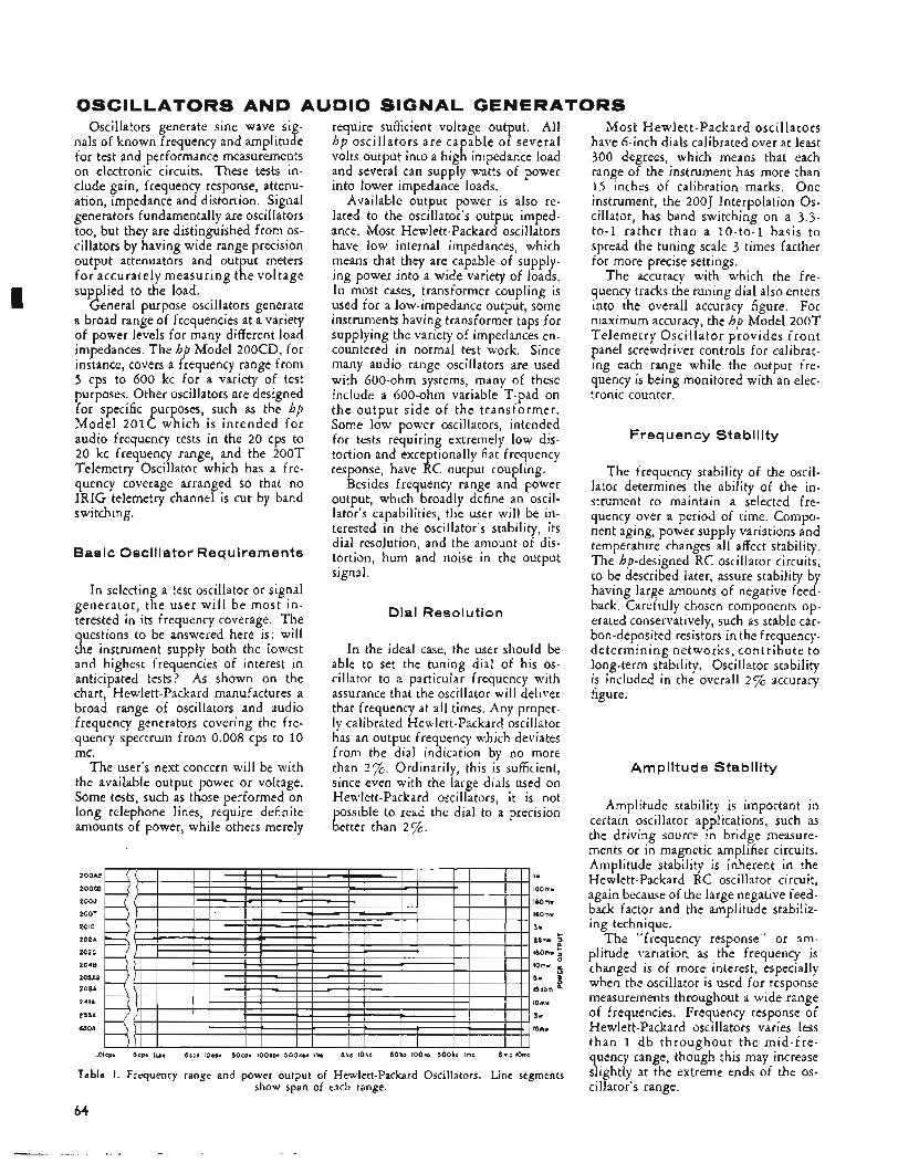
OSCILLATORS AND AUDIO SIGNAL GENERATORS
I
Oscillators generate sine wave sig- nals of known frequency and amplitude for test and performance measurements on electronic circuits. These tests in- clude gain, frequency response, attenu- ation, impedance and distortion. Signal generators fundamentally are oscillators too, but they are distinguished from os- cillators by having wide range precision output attenuators and output meters for accurately measuring the voltage supplied to the load.
General purpose oscillators generate a broad range of frequencies at a variety of power levels for many different load impedances. The hp Model 200CD, for instance, covers a frequency range from 5 cps to 600 kc for a variety of test purposes. Other oscillators are designed for specific purposes, such as the hp Model 201C which is intended for audio frequency tests in the 20 cps to 20 kc frequency range, and the 200T Telemetry Oscillator which has a fre- quency coverage arranged so that no IRIG telemetry channel is cut by band switching.
Basic Oscillator Requirements
In selecting a test oscillator or signal generator, the user will be most in- terested in its frequency coverage. The questions to be answered here is: will the instrument supply both the lowest and highest frequencies of interest in anticipated tests? As shown on the chart, Hewlett-Packard manufactures a broad range of oscillators and audio frequency generators covering the fre- quency spectrum from 0.008 cps to 10 mc.
The user’s next concern will be with the available output power or voltage. Some tests, such as those performed on long telephone lines, require definite amounts of power, while others merely
require sufficient voltage output. All hp oscillators are capable of several volts output into a high impedance load and several can supply watts of power into lower impedance loads.
Available output power is also re- lated to the oscillator’s output imped- ance. Most Hewlett-Packard oscillators have low internal impedances, which means that they are capable of supply- ing power into a wide variety of loads. In most cases, transformer coupling is used for a low-impedance output, some instruments having transformer taps for supplying the variety of impedances en- countered in normal test work. Since many audio range oscillators are used with 600-ohm systems, many of these include a 600-ohm variable T-pad on the output side of the transformer. Some low power oscillators, intended for tests requiring extremely low dis- tortion and exceptionally flat frequency response, have RC output coupling.
Besides frequency range and power output, which broadly define an oscil- lator’s capabilities, the user will be in- terested in the oscillator’s stability, its dial resolution, and the amount of dis- tortion, hum and noise in the output signal.
Dial Resolution
In the ideal case, the user should be able to set the tuning dial of his os- cillator to a particular frequency with assurance that the oscillator will deliver that frequency at all times. Any proper- ly calibrated Hewlett-Packard oscillator has an output frequency which deviates from the dial indication by no more than 270. Ordinarily, this is sufficient, since even with the large dials used on Hewlett-Packard oscillators, it is not possible to read the dial to a precision better than 2%.
2OOAB I*
2OOCD 160mr
ZOOJ 160mr
200T 160mr
ZOIC 3 r
202A 26mw 2 202c I6Omw 2 2048 l O m r e
206A l5dbm ’ 241A lOmw
233A 3v
650A lSmv
c
205AG 5 * Y
.OIcpi .5cpl 1cp. 5 e p i IOsp. 50eps IOOcpi 5 O O f p i I k e 5 h o l O h c 50kc lOOke 5 0 0 k c Imc 5mc lOmC
Table I . Frequency range and power output of Hewlett-Packard Oscillators. Line segments
64
show span of each range.
Most Hewlett-Packard oscillators have 6-inch dials calibrated over at least 300 degrees, which means that each range of the instrument has more than 1 5 inches of calibration marks. One instrument, the 200J Interpolation Os- cillator, has band switching on a 3.3- to-1 rather than a 10- to-1 basis to spread the tuning scale 3 times farther for more precise settings.
The accuracy with which the fre- quency tracks the tuning dial also enters into the overall accuracy figure. For maximum accuracy, the hp Model 200T Telemetry Oscillator provides f ront panel screwdriver controls for calibrat- ing each range while the output fre- quency is being monitored with an elec- tronic counter.
Frequency Stability
The frequency stability of the oscil- lator determines the ability of the in- strument to maintain a selected fre- quency over a period of time. Compo- nent aging, power supply variations and temperature changes all affect stability. The hp-designed RC oscillator circuits, to be described later, assure stability by having large amounts of negative feed- back. Carefully chosen components op- erated conservatively, such as stable car- bon-deposited resistors in the frequency- determining networks, contribute to long-term stability. Oscillator stability is included in the overall 2% accuracy figure.
Am pl it ude Sta bi I ity
Amplitude stability is important in certain oscillator applications, such as the driving source in bridge measure- ments or in magnetic amplifier circuits. Amplitude stability is inherent in the Hewlett-Packard RC oscillator circuit, again because of the large negative feed- back factor and the amplitude stabiliz- ing technique.
The “frequency response” or am- plitude variation as the frequency is changed is of more interest, especially when the oscillator is used for response measurements throughout a wide range of frequencies. Frequency response of Hewlett-Packard oscillators varies less than 1 d b throughout the mid-fre- quency range, though this may increase slightly at the extreme ends of the os- cillator’s range.
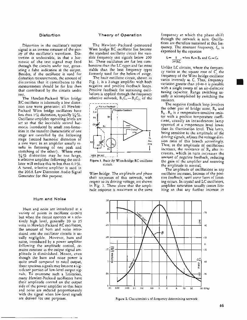
Distortion
Distortion in the oscillator's output signal is an inverse measure of the pur- ity of the oscillator's waveform. Dis- tortion is undesirable, in that a har- monic of t h e test signal may feed through the circuits under test, gener- ating a false indication at the output. Besides, if the oscillator is used for distortion measurements, the amobnt of distortion that it contributes to the measurements should be far less than that contributed by the circuits under test.
The Hewlett-Packard Wien bridge RC oscillator is inherently a low distor- tion sine wave generator; all Hewlett- Packard Wien bridge oscillators have less than 17c distortion, typically 1/4'/c. Oscillator-amplifier operating levels are set so that the inevitable second har- monic introduced by small non-linear- ities in the transfer characteristic of one stage are cancelled by the following stage (second harmonic distortion of a sine wave in an amplifier usually re- sults in flattening of one peak and stretching of the other). Where even 1/4% distortion may be too large, a selective amplifier following the oscil- lator will reduce this to less than 0.1%. A tuned, selective amplifier is used in the 206A Low Distortion Audio Signal Generator for this purpose.
Hum and Noise
Hum and noise are introduced at a variety of points in oscillator circuits but when the circuit operates at a rela- tively high level, generally 20 to 2 5 volts in Hewlett-Packard RC oscillators, the amount of hum and noise intro- duced into the oscillator circuits is us- ually negligible. However, hum and noise, introduced by a power amplifier following the amplitude control, re- mains constant as the output signal am- pl i tude is diminished. Hence, even though the hum and noise power is quite small compared to rated output, these spurious signals may become a sig- nificant portion of low-level output sig- nals. To overcome such a limitation, many Hewlett-Packard oscillators have their amplitude control on the output side of the power amplifier so that hum and noise are reduced proportionately with the signal when low-level signals are desired for test purposes.
Theory of Operation
T h e Hewlett - Packard - pioneered Wien bridge RC oscillator has become the standard oscillator circuit for vari- able frequency test signals below 200 kc. These oscillators are far less cum- bersome than the LC types and far more stable than the beat frequency types formerly used for the below-rf range.
The basic oscillator circuit, shown in Fig. 1, is a 2-stage amplifier with both negative and positive feedback loops. Positive feedback for sustaining oscil- lations is applied through the frequency selective network, R,C, - R,C,, of the
I L I - 1 IL?E!! E K E - - - - -I Figure I . Basic hp Wien-bridge RC oscillator
- circuit.
Wien bridge. The amplitude and phase shift responses of this network, with respect to its driving voltage, are shown in Fig. 2. These show that the ampli- tude response is maximum at the same
frequency at which the phase shif t through the network is zero. Oscilla- tions are therefore sustained at this fre- quency. The resonant frequency, f,, is expressed by the equation
f o = - 1 , when RI=Rz and C,=CZ 2TRC
Unlike LC circuits, where the frequen- cy varies as the square root of C, the frequency of the Wien bridge oscillator varies inversely as C. Thus, frequency variation greater than 10-to-1 is possible with a single sweep of an air-dielectric tuning capacitor. Range switching us- ually is accomplished by switching the resistors.
The negative feedback loop involves the other pair of bridge arms, R, and R, . R, is a temperature-sensitive resis- tor with a positive temperature coeffi- cient, usually an incandescent lamp operated at a temperature level lower than its illumination level, This lamp, being sensitive to the amplitude of the driving signals, adjusts the voltage divi- sion ratio of this branch accordingly. Thus, as the amplitude of oscillations increases, the resistance of R, also in- creases, which in turn increases the amount of negative feedback, reducing the gain of the amplifier and restoring the amplitude to normal.
The amplitude of oscillations in any oscillator increases, because of the posi- tive feedback, until some form of limit- ing occurs. In crystal and LC oscillators, amplifier saturation usually causes lim- iting so that any further increase in
.Ol 0.02 0.05 0.1 0 2 0.5 I 2 5 10 20 50 (f/fo)
Figure 2. Characteristics of frequency determining network.
65
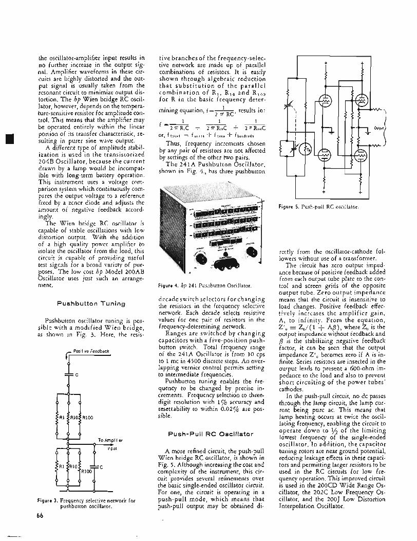
the oscillator-amplifier input results in no further increase in the output sig- nal. Amplifier waveforms in these cir- cuits are highly distorted and the out- put signal is usually taken from the resonant circuit to minimize output dis- tortion. The hp Wien bridge RC oscil- lator, however, depends on the tempera- ture-sensitive resistor for amplitude con- trol. This means that the amplifier may be operated entirely within the linear portion of its transfer characteristic, re- sulting in purer sine wave output.
A different type of amplitude stabil- ization is used in the transistorized 204B Oscillator, because the current drawn by a lamp would be incompat- ible with long-term battery operation. This instrument uses a voltage com- parison system which continuously com- pares the output voltage to a reference fixed by a zener diode and adjusts the amount of negative feedback accord-
I
.~ ingly. The Wien bridge RC oscillator is
capable of stable oscillations with low distortion output. With the addition of a high quality power amplifier to isolate the oscillator from the load, this circuit is capable of providing useful test signals for a broad variety of pur- poses. The low cost hp Model 200AB Oscillator uses just such an arrange- ment.
Pushbutton Tuning
Pushbutton oscillator tuning is pos- sible with a modified Wien bridge, as shown in Fig. 3. Here, the resis-
Positive Feedback
F . 7 f TC
ifiet
t
Figure 3. Frequency selective network for pushbutton oscillator.
66
tive branches of the frequency-selec- tive network are made up of parallel combinations of resistors. It is easily shown through algebraic reduction t h a t s u b s t i t u t i o n of t h e p a r a l l e l c o m b i n a t i o n of R, , R,, a n d R,,, f o r R in the basic frequency deter-
mining equation, f=- results in: 2 ‘iT RC’
1 1 I 2 T R I C + 2 T R I O ~ -I- m C
Thus, frequency increments chosen by any pair of resistors are not affected by settings of the other two pairs.
T h e 241A Pushbutton Oscillator, shown in Fig. 4., has three pushbutton
f =-
or, f t o t a l = f u n i t s + f t m s + fhundyeds
Figure 4. hp 241 Pushbutton Oscillator.
decade switch selectors fo r changing the resistors in the frequency selective network. Each decade selects resistive values for one pair of resistors in the frequency-determining network.
Ranges are switched by changing capacitors with a five-position push- button switch. Total frequency range of the 241A Oscillator is from 10 cps to 1 mc in 4500 discrete steps. An over- lapping vernier control permits setting to intermediate frequencies.
Pushbutton tuning enables the fre- quency to be changed by precise in- crements. Frequency selection to three- digit resolution with 1% accuracy and resettability to within 0.02c/o are pos- sible.
Push-Pull RC Oscillator
A more refined circuit, the push-pull Wien bridge RC oscillator, is shown in Fig. 5 . Although increasing the cost and complexity of the instrument, this cir- cuit provides several refinements over the basic single-ended oscillator circuit. For one, the circuit is operating in a push-pull mode, which means that push-pull output may be obtained di-
I Figure 5. Push-pull RC oscillator.
rectly from the oscillator-cathode fol- lowers without use of a transformer.
The circuit has zero output imped- ance because of positive feedback added from each output tube plate to the con- trol and screen grids of the opposite output tube. Zero output impedance means that the circuit is insensitive to load changes. Positive feedback effec- tively increases the amplifier gain, A, to infinity. From the equation, Z’, = Z,/( 1 + AB), where 2, is the output impedance without feedback and p is the stabilizing negative feedback factor, it can be seen that the output impedance Z’, becomes zero if A is in- finite. Series resistors are inserted in the output leads to present a 600-ohm im- pedance to the load and also to prevent short circuiting of the power tubes’ cathodes.
In the push-pull circuit, no dc passes through the lamp circuit, the lamp cur- rent being pure ac. This means that lamp heating occurs at twice the oscil- lating frequency, enabling the circuit to operate down to 1/* of the l imiting lowest frequency of the single-ended oscillator. I n addition, the capacitor tuning rotors are near ground potential, reducing leakage effects in these capaci- tors and permitting larger resistors to be used in the RC circuits for low fre- quency operation. This improved circuit is used in the 200CD Wide Range Os- cillator, the 202C Low Frequency Os- cillator, and the 20OJ Low Distortion Interpolation Oscillator.
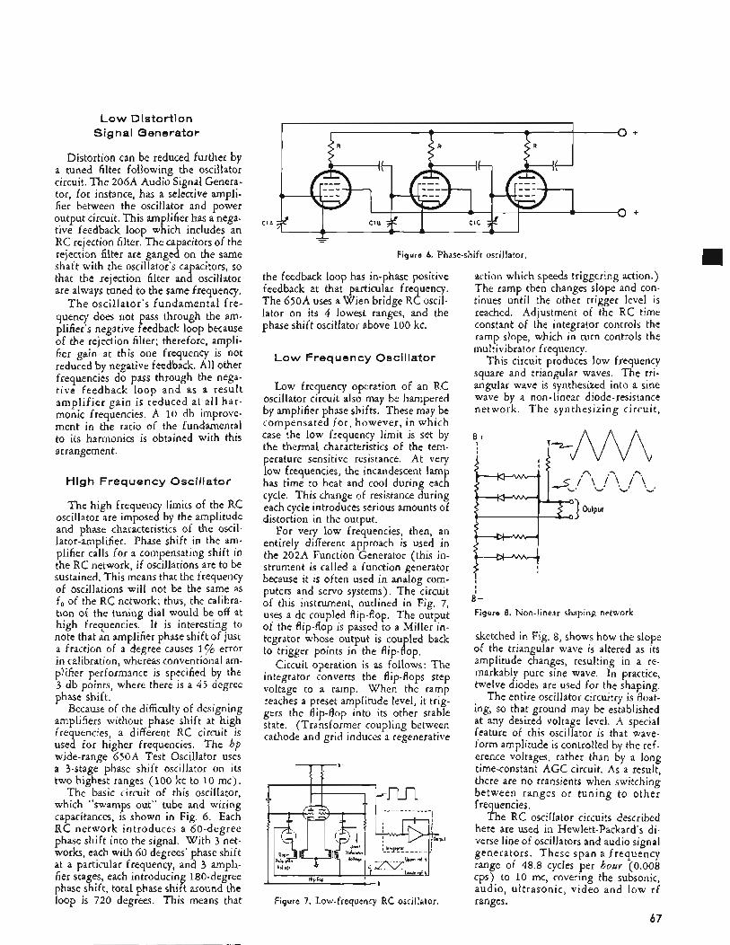
Low Distortion Signal Generator
Distortion can be reduced further by a tuned filter following the oscillator circuit. The 206A Audio Signal Genera- tor, for instance, has a selective ampli- fier between the oscillator and power output circuit. This amplifier has a nega- tive feedback loop which includes an RC rejection filter. The capacitors of the rejection filter are ganged on the same shaft with the oscillator's capacitors, so that the rejection filter and oscillator are always tuned to the same frequency.
T h e oscillator's fundamental f re- quency does not pass through the am- plifier's negative feedback loop because of the rejection filter; therefore, ampli- fier gain at this one frequency is not reduced by negative feedback. All other frequencies do pass through the nega- tive feedback loop and as a result amplif ier gain is reduced at all har- monic frequencies. A 10 db improve- ment in the ratio of the fundamental to its harmonics is obtained with this arrangement.
High Frequency Oscillator
The high frequency limits of the RC oscillator are imposed by the amplitude and phase characteristics of the oscil- lator-amplifier. Phase shift in the am- plifier calls for a compensating shift in the RC network, if oscillations are to be sustained. This means that the frequency of oscillations will not be the same as f, of the RC network; thus, the calibra- tion of the tuning dial would be off at high frequencies. It is interesting to note that an amplifier phase shift of just a fraction of a degree causes 1% error in calibration, whereas conventional am- plifier performance is specified by the 3 db points, where there is a 45 degree phase shift.
Because of the difficulty of designing amplifiers without phase shift at high frequencies, a different RC circuit is used for higher frequencies. The hp wide-range 650A Test Oscillator uses a 3-stage phase shift oscillator on its two highest ranges (100 kc to 10 mc).
The basic circuit of this oscillator, which "swamps out" tube and wiring capacitances, is shown in Fig. 6. Each RC network introduces a 60-degree phase shift into the signal. With 3 net- works, each with 60 degrees' phase shift at a particular frequency, and 3 ampli- fier stages, each introducing 180-degree phase shift, total phase shift around the loop is 720 degrees. This means that
T O +
I f I f , If
I
cln # CIB ClC -2 O +
1 - - - - - Figure 6. Phase-shift oscillator.
the feedback loop has in-phase positive feedback at that particular frequency. The 650A uses a Wien bridge RC oscil- lator on its 4 lowest ranges, and the phase shift oscillator above 100 kc.
Low Frequency Oscillator
Low frequency operation of an RC oscillator circuit also may be hampered by amplifier phase shifts. These may be compensated for , however, in which case the low frequency limit is set by the thermal characteristics of the tem- perature sensitive resistance. At very low frequencies, the incandescent lamp has time to heat and cool during each cycle. This change of resistance during each cycle introduces serious amounts of distortion in the output,
For very low frequencies, then, an entirely different approach is used in the 202A Function Generator (this in- strument is called a function generator because it is often used in analog com- puters and servo systems). The circuit of this instrument, outlined in Fig. 7, uses a dc coupled flip-flop. The output of the flip-flop is passed to a Miller in- tegrator whose output is coupled back to trigger points in the flip-flop.
Circuit operation is as follows: The integrator converts the flip-flops step voltage to a ramp. When the ramp reaches a preset amplitude level, it trig- gers the flip-flop into its other stable state. (Transformer coupling between cathode and grid induces a regenerative
Figure 7. Low-frequency RC oscillator.
action which speeds triggering action.) The ramp then changes slope and con- tinues until the other trigger level is reached. Adjustment of the RC time constant of the integrator controls the ramp slope, which in turn controls the multivibrator frequency.
This circuit produces low frequency square and triangular waves. The tri- angular wave is synthesized into a sine wave by a non-linear diode-resistance network. T h e synthesizing circuit,
3 output
B- Figure E. Non-linear shaping network.
sketched in Fig. 8, shows how the slope of the triangular wave is altered as its amplitude changes, resulting in a re- markably pure sine wave. In practice, twelve diodes are used for the shaping.
The entire oscillator circuitry is float- ing, so that ground may be established at any desired voltage level. A special feature of this oscillator is that wave- form amplitude is controlled by the ref- erence voltages, rather than by a long time-constant AGC circuit. As a result, there are no transients when switching between ranges or tuning to other frequencies,
The RC oscillator circuits described here are used in Hewlett-Packard's di- verse line of oscillators and audio signal generators. These span a frequency range of 48.8 cycles per hoar (0.008 cps) to 10 mc, covering the subsonic, audio, ultrasonic, video and low rf ranges.
67
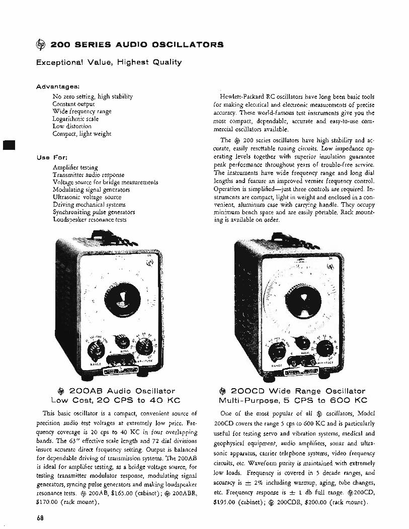
@ 200 SERIES AUDIO OSCILLATORS
Exceptional Value, Highest Quality
Advantages:
Use
No zero setting, high stability Constant output Wide frequency range Logarithmic scale Low distortion Compact, light weight
For:
Amplifier testing Transmitter audio response Voltage source for bridge measurements Modulating signal generators Ultrasonic voltage source Driving mechanical systems Synchronizing pulse generators Loudspeaker resonance tests
@J 2 0 0 A B Audio Oscillator Low Cost, 20 CPS to 40 KC
This basic oscillator is a compact, convenient source of precision audio test voltages at extremely low price. Fre- quency coverage is 20 cps to 40 KC in four overlapping bands. The 63” effective scale length and 72 dial divisions insure accurate direct frequency setting. Output is balanced for dependable driving of traiismission systems. The 200AB is ideal for amplifier testing, as a bridge voltage source, for testing transmitter modulator response, modulating signal generators, syncing pulse generators and making loudspeaker resonance tests. @ 200AB, $165.00 (cabinet); @ 200ABR, $170.00 (rack mount).
Hewlett-Packard RC oscillators have long been basic tools for making electrical and electronic measurements of precise accuracy. These world-famous test instruments give you the most compact, dependable, accurate and easy-to-use com- mercial oscillators available.
The @ 200 series oscillators have high stability and ac- curate, easily resettable tuning circuits. Low impedance op- erating levels together with superior insulation guarantee peak performance throughout years of trouble-free service. The instruments have wide frequency range and long dial lengths and feature an improved vernier frequency control. Operation is simplified-just three controls are required. In- struments are compact, light in weight and enclosed in a con- venient, aluminum case with carrying handle. They occupy minimum bench space and are easily portable. Rack mount- ing is available on order.
@ 2 0 0 C D Wide Range Oscillator Multi-Purpose, 5 CPS to 600 KC
One of the most popular of all @ oscillators, Model 200CD covers the range 5 cps to 600 KC and is particularly useful for testing servo and vibration systems, medical and geophysical equipment, audio amplifiers, sonar and ultra- sonic apparatus, carrier telephone systems, video frequency circuits, etc. Waveform purity is maintained with extremely low loads. Frequency is covered in 5 decade ranges, and accuracy is & 2% including warmup, aging, tube changes, etc. Frequency response is -+ 1 db full range. @200CD, $195.00 (cabinet) ; @ 200CDR, $200.00 (rack mount).
68
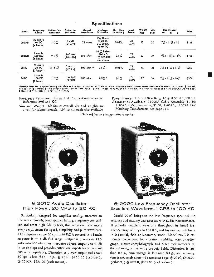
Specifications
Mode, Frequency Calibration Output to Out ut Maximum Max. Hum input Weight-Lba. Sire (inches) Ronge Accuracy 600 ohms Impe8ance Distortion & Noise II Power Net Ship w H D
I yo 20 cps 20 CDS to
t o 40 K C ,-l umr,us,
Z O I C 20 cps to
20 K C ( 3 bandr l
* l % t 3 watts (42.5 v ) 600 ohms* 0.5% 4 0.03 % 75
watts 16 23 $250
75 27 34 71/.x 111/2x 14% $300 2 0 2 C l 0 0 K C * 2% lovolts 600 ohms 0.5% 5 O.l”,(o watts 160 mw I cps t o
( 5 bands)
‘Internal impedance approximately 600 ohms with output attenuator at 10 db or more. Approximately 75 ohms below 5 000 cps with attenuator at zero. t Internal non-operating controls permit precise calibration of each band. t O S % , 50 cps to 20 KC at I watt output. 1.0% over iull range at 3 watts output. 5 Above 5 cp;. 1 Measured with respect to fu l l rated output.
Frequency Response: Flat & 1 db over instrument range. Reference level at 1 KC.
Size and Weight: Maximum overall size and weights are given for cabinet models. 19” rack models also available.
Power Source: 115 or 230 volts k 10% at 50 to 1,000 cps. Accessories Available: 1loooA Cable Assembly, $4.50;
1lOOlA Cable Assembly, $5.50; 11004A, 11005A Line Matching Transformers, see page 1 1 I ,
Data subject to chdnge without notice.
@ 201C Audio Oscillator High Power, 20 CPS to 20 KC
Particularly designed for amplifier testing, transmission line measurements, loud speaker testing, frequency compari- son and other high fidelity tests, this audio oscillator meets every requirement for speed, simplicity and pure waveform. The frequency range 20 cps to 20 KC is covered in 3 bands; response is rt 1 db full range. Output is 3 watts or 42.5 volts into 600 ohms; an attenuator adjusts output 0 to 40 db in 10 db steps and provides either low impedance or constant 600 ohm impedance. Distortion at 1 watt output and above 50 cps is less than 0.5%. @ 201C, $250.00 (cabinet) ; @ 201CR, $255.00 (rack mount).
@ 2 0 2 C Low Frequency Oscillator Excellent Waveform, 1 CPS to 100 KC
Model 202C brings to the low frequency spectrum the accuracy and stability you associate with audio measurements. It provides excellent waveform throughout its broad fre- quency range of 1 cps to 100 KC, and has unique usefulness in industrial, field or laboratory work. Model 202C is ex- tremely convenient for vibration, stability, electro-cardio- graph, electro-encephalograph and other measurements in the subsonic, audio and ultrasonic fields. Distortion is less than 0.5%, hum voltage is less than 0.1%, and recovery time is extremely short-5 seconds at 1 cps. @ 202C, $300.00 (cabinet); @202CR, $305.00 (rack mount).
69
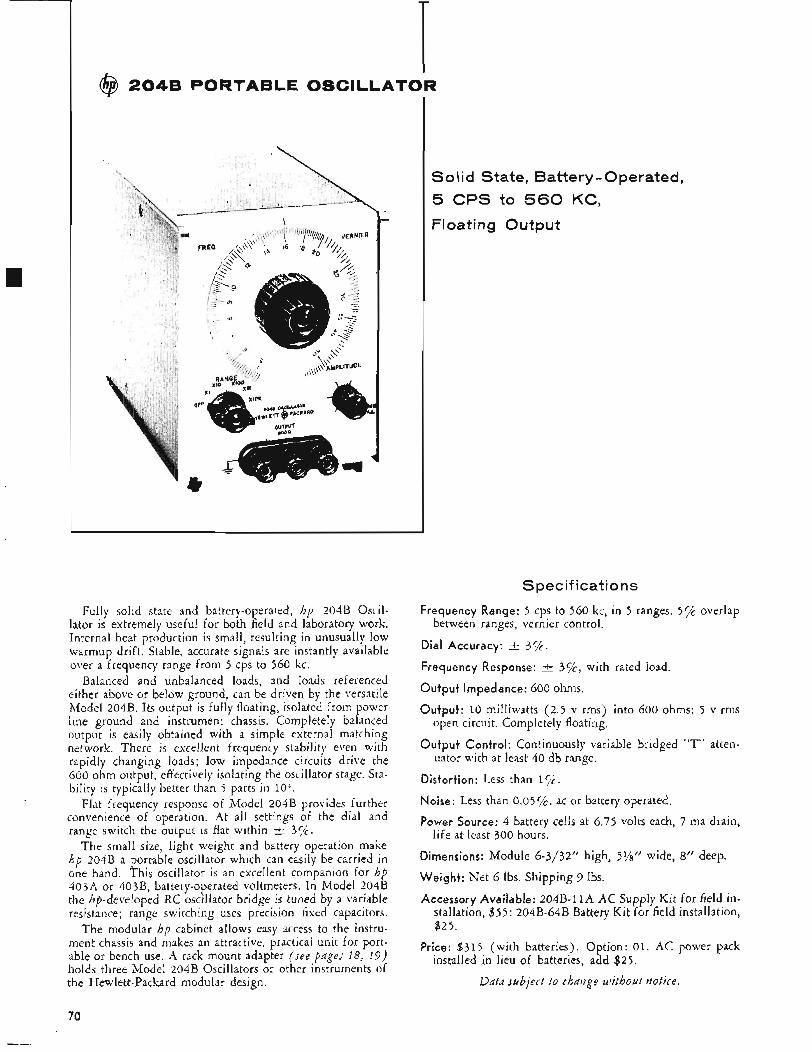
@ 204B PORTABLE OSCILLATOR
L
Fully solid state and battery-operated, hp 204B Oscil- lator is extremely useful for both field and laboratory work. Internal heat production is small, resulting in unusually low warmup drift. Stable, accurate signals are instantly available over a frequency range from 5 cps to 560 kc.
Balanced and unbalanced loads, and loads referenced either above or below ground, can be driven by the versatile Model 2043. Its output is fully floating, isolated from power line ground and instrument chassis. Completely balanced output is easily obtained with a simple external matching network, There is excellent frequency stability even with rapidly changing loads; low impedance circuits drive the 600 ohm output, effectively isolating the oscillator stage. Sta- bility is typically better than 5 parts in 10'.
Flat frequency response of Model 204B provides further convenience of operation. At all settings of the dial and range switch the output is flat within t 3yi.
The small size, light weight and battery operation make hp 204B a portable oscillator which can easily be carried in one hand. This oscillator is an excellent companion for hp 403A or 403B, battery-operated voltmeters. In Model 204B the hp-developed RC oscillator bridge is tuned by a variable resistance; range switching uses precision fixed capacitors.
The modular hp cabinet allows easy access to the instru- ment chassis and makes an attractive, practical unit for port- able or bench use. A rack mount adapter ( s e e pager 18, 1 9 ) holds three Model 204B Oscillators or other instruments of the Hewlett-Packard modular design.
S o I id State, Battery- Operated, 5 CPS to 560 KC,
Floating Output
Specifications
Frequency Range: 5 cps to 560 kc, in 5 ranges. 5% overlap
Dial Accuracy: -t- 3 % .
Frequency Response: & 3c/c, with rated load.
Output Impedance: 600 ohms.
Output: 10 milliwatts (2.5 v rms) into 600 ohms; 5 v rms
Output Control: Continuously variable bridged "T" atten-
Distortion: Less than 17;. Noise: Less than 0.05c/c, ac or battery operated.
Power Source: 4 battery cells at 6.75 volts each, 7 ma drain,
Dimensions: Module 6-3/32'' high, 5%" wide, 8" deep.
Weight: Net 6 Ibs. Shipping 9 Ibs.
Accessory Available: 204B-11A AC Supply Kit for field in- stallation, $55 ; 204B-64B Battery Kit for field installation, $2 5.
Price: $315 (with batteries), Option: 01. AC power pack installed in lieu of batteries, add $25.
Data Jubject to chdizge without notice.
between ranges, vernier control.
open circuit. Completely floating.
uator with at least 40 db range.
life at least 300 hours.
70
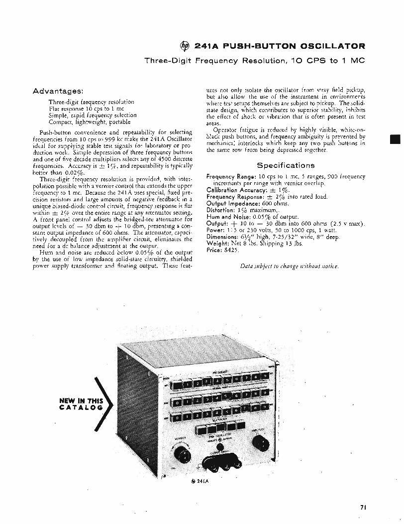
@ 241A PUSH-BUTTON OSCILLATOR
Three-Digit Frequency Resolution, 1 0 CPS to 1 MC
Advantages: Three-digit frequency resolution Flat response 10 cps to 1 mc Simple, rapid frequency selection Compact, lightweight, portable
Push-button convenience and repeatability for selecting frequencies from 10 cps to 999 kc make the 241A Oscillator ideal for supplying stable test signals for laboratory or pro- duction work. Simple depression of three frequency buttons and one of five decade multipliers selects any of 4500 discrete frequencies. Accuracy is and repeatability is typically better than 0.02%.
Three-digit frequency resolution is provided, with inter- polation possible with a vernier control that extends the upper frequency to 1 mc. Because the 241A uses special, fixed prc- cision resistors and large amounts of negative feedback in a unique biased-diode control circuit, frequency response is flat within 2 yc over the entire range at any attenuator setting. A front panel control adjusts the bridged-tee attenuator for output levels of - 30 dbm to + 10 dbm, presenting a con- stant output impedance of 600 ohms. The attenuator, capaci- tively decoupled from the amplifier circuit, eliminates the need for a dc balance adjustment at the output.
Hum and noise are reduced below 0.05% of the output by the use of low impedance solid-state circuitry, shielded power supply transformer and floating output. These feat-
ures not only isolate the oscillator from stray field pickup, but also allow the use of the instrument in environments where test setups themselves are subject to pickup. The solid- state design, which contributes to superior stability, inhibits the effect of shock or vibration that is often present in test areas.
Operator fatigue is reduced by highly visible, white-on- black push buttons, and frequency ambiguity is prevented by mechanical interlocks which keep any two push buttons in the same row f r o n being depressed together.
Specifications Frequency Range: 10 cps to 1 mc, 5 ranges, 900 frequency
increments per range with vernier overlap. Calibration Accuracy: A 1%. Frequency Response: I 2% into rated load. Output Impedance: 600 ohms. Distortion: 1 % maximum, Hum and Noise: 0.05% of output. Output: + 10 to - 30 dbm into 600 ohms (2.5 v max). Power: 115 or 230 volts, 50 to 1000 cps, 1 watt. Dimensions: 61/2” high, 7-25/32“ wide, 8” deep. Weight: Net 8 Ibs. Shipping 13 Ibs. Price: $425.
Data subject to change withozlt notice.
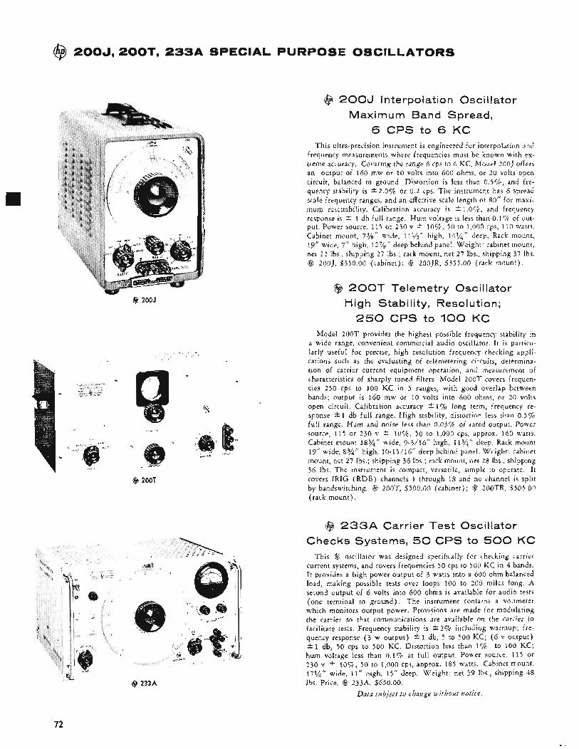
@ 2004 200T. 2 3 3 A SPECIAL PURPOSE OSCILLATORS
@ 2OOJ
@ 2001
@ 2003 Interpolation Oscillator Maximum Band Spread,
6 CPS to 6 KC This ultra-precision instrument is engineered for interpolation and
frequency measurements where frequencies must be known with ex- treme accuracy. Covering the range 6 cps to 6 KC, Model 200J offers an output of 160 mw or 10 volts into 600 ohms, or 20 volts open circuit, balanced to ground. Distortion is less than 0 .5%, and fre- quency stability is *2.Ov0 or 0.2 cps. The instrument has 6 spread scale frequency ranges, and an effective scale length of 80” for maxi- mum resettability. Calibration accuracy is * l .Oc/‘c , and frequency response is * 1 db f u l l range. Hum voltage is less than 0.1% of out- put. Power source, 115 or 230 v ? l o % , 50 to 1,000 cps, 110 watts. Cabinet mount, 7%’’ wide, 111/2’’ high, 14%’’ deep. Rack mount, 19” wide, 7” high, 1 2 7 / ” deep behind panel. Weight: cabinet mount, net 2 2 lbs., shipping 27 Ibs.; rack mount, net 27 Ibs., shipping 37 Ibs. @ 200J, S350.00 (cabinet); @ 200JR, $355.00 (rack mount).
@ 2 0 0 T Telemetry Oscillator High Stability, Resolution;
250 CPS to 100 KC Model 200T provides the highest possible frequency stability in
a wide range, convenient commercial audio oscillator. It is particu- larly useful for precise, high resolution frequency checking appli- cations such as the evaluating of telemetering circuits, determina- tion of carrier current equipment operation, and measurement of characteristics of sharply tuned filters. Model 200T covers frequen- cies 250 cps to 100 KC in 5 ranges, with good overlap between bands; output is 160 mw or 10 volts into 600 ohms, or 20 volts open circuit. Calibration accuracy * 1% long term, frequency re- sponse * 1 db full range. High stability, distortion less than 0.5% full range. Hum and noise less than 0.03% of rated output. Power source, 115 or 230 v * l o % , 50 to 1,000 cps, approx. 160 watts. Cabinet mount 18%” wide, 9-3/16” high, 113/4” deep, Rack mount 19” wide, 8 3 / ” high, 10-15/16” deep behind panel. Weight: cabinet mount, net 27 Ibs.; shipping 36 Ibs.; rack mount, net 28 lbs., shipping 36 Ibs. The instrument is compact, versatile, simple to operate. I t covers IRIG (RDB) channels 1 through 18 and no channel is split by bandswitching. $ 200T, $500.00 (cabinet); $t ZOOTR, $505.00 (rack mount).
@ 2 3 3 A Carrier Test Oscillator Checks Systems, 50 CPS to 500 KC
This @ oscillator was designed specifically for checking carrier current systems, and covers frequencies 50 cps to 500 K C in 4 bands. It provides a high power output of 3 watts into a 600 ohm balanced load, making possible tests over loops 100 to 200 miles long. A second output of 6 volts into 600 ohms is available for audio tests (one terminal to ground). The instrument contains a voltmeter which monitors output power. Provisions are made for modulating the carrier so that communications are available on the carrier to facilitate tests, Frequency stability is i 2% including warmup; fre- quency response ( 3 w output) 2 1 db, 5 to 500 KC; ( 6 v output) rtl db, 50 cps to 500 KC. Distortion less than 1% to 100 KC; hum voltage less than 0.1% at full output. Power source, 115 or 230 v * i o % , 50 to 1,000 cps, approx. 185 watts. Cabinet mount, 17%“ wide, 11” high, 1 5 ” deep. Weight: net 39 Ibs., shipping 48 Ibs. Price, @ 233A, $650.00.
Data subject to change without zotice.
72
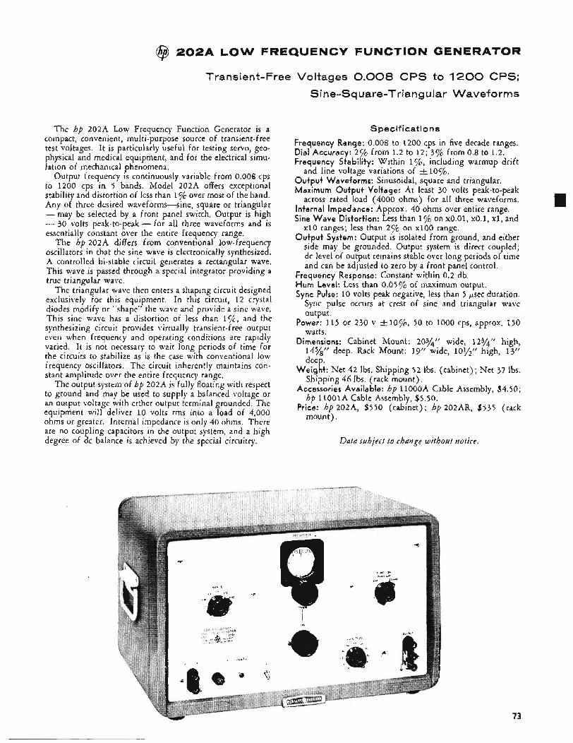
@ 2 0 2 A LOW FREQUENCY FUNCTION GENERATOR
Transient-Free Voltages 0.008 CPS to 1200 CPS;
Sine-Square-Triangular Waveforms
The hp 202A Low Frequency Function Generator is a compact, convenient, multi-purpose source of transient-free test voltages. It is particularly useful for testing servo, geo- physical and medical equipment, and for the electrical simu- lation of mechanical phenomena.
Output frequency is continuously variable from 0.008 cps to 1200 cps in 5 bands. Model 202A offers exceptional stability and distortion of less than 1% over most of the band. Any of three desired waveforms-sine, square or triangular -may be selected by a front panel switch. Output is high - 30 volts peak-to-peak - for all three waveforms and is essentially constant over the entire frequency range.
The hp 202A differs from conventional low-frequency oscillators in that the sine wave is electronically synthesized. A controlled bi-stable circuit generates a rectangular wave. This wave is passed through a special integrator providing a true triangular wave.
The triangular wave then enters a shaping circuit designed exclusively for this equipment. In this circuit, 1 2 crystal diodes modify or “shape” the wave and provide a sine wave. This sine wave has a distortion of less than and the synthesizing circuit provides virtually transient-free output even when frequency and operating conditions are rapidly varied. It is not necessary to wait long periods of time for the circuits to stabilize as is the case with conventional low frequency oscillators. The circuit inherently maintains con- stant amplitude over the entire frequency range.
The output system of hp 202A is fully floating with respect to ground and may be used to supply a balanced voltage or an output voltage with either output terminal grounded. The equipment will deliver 10 volts rms into a load of 4,000 ohms or greater. Internal impedance is only 40 ohms. There are no coupling capacitors in the output system, and a high degree of dc balance is achieved by the special circuitry.
Specifications
Frequency Range: 0.008 to 1200 cps in five decade ranges. Dial Accuracy: 2 % from 1.2 to 12; 37% from 0.8 to 1.2. Frequency Stability: Within 1 %, including warmup drift
Output Waveforms: Sinusoidal, square and triangular. Maximum Output Voltage: At least 30 volts peak-to-peak
across rated load (4000 ohms) for all three waveforms. Internal Impedance: Approx. 40 ohms over entire range. Sine Wave Distortion: Less than 1% on ~ 0 . 0 1 , ~ 0 . 1 , XI, and
x10 ranges; less than 2% on xlo0 range. Output System: Output is isolated from ground, and either
side may be grounded. Output system is direct coupled; dc level of output remains stable over long periods of time and can be adjusted to zero by a front panel control.
and line voltage variations of + lo%.
Frequency Response: Constant within 0.2 db. Hum Level: Less than 0.05% of maximum output. Sync Pulse: 10 volts peak negative, less than 5 psec duration.
Sync pulse occurs at crest of sine and triangular wave output.
Power: 115 or 230 v +-lo%, 50 to 1000 cps, approx. 150
Dimensions: Cabinet Mount: 2074‘’ wide, 1274” high, high, 13”
Weight: Net 42 lbs. Shipping 5 2 lbs. (cabinet); Net 37 lbs.
Accessories Available: hp 1loOoA Cable Assembly, $4.50;
Price: hp 202A, $550 (cabinet); hp 202AR, $535 (rack
watts.
1478’’ deep. Rack Mount: 19” wide, deep.
Shipping 46 Ibs. (rack mount).
hp 11oolA Cable Assembly, $5.50.
mount).
Data subject to change without notice.
73
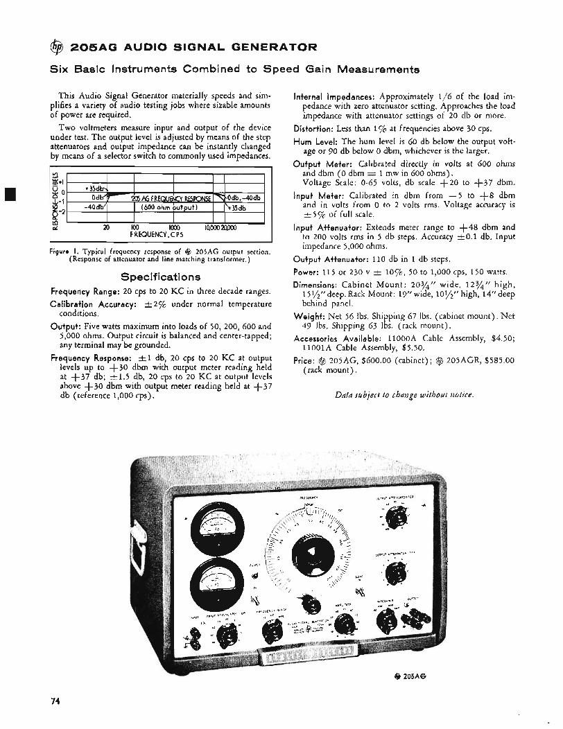
@ 2 0 5 A G AUDIO SIGNAL GENERATOR
Six Basic Instruments Combined to Speed Gain Measurements
This Audio Signal Generator materially speeds and sim- plifies a variety of audio testing jobs where sizable amounts of power are required.
Two voltmeters measure input and output of the device under test. The output level is adjusted by means of the step attenuators and output impedance can be instantly changed by means of a selector switch to commonly used impedances.
Figure I. Typical frequency response of (3 205AG output section. (Response of attenuator and line matching transformer.)
Specifications Frequency Range: 20 cps to 20 KC in three decade ranges. Calibration Accuracy: -+ 2 % under normal temperature
conditions. Output: Five watts maximum into loads of 50, 200, 600 and
5,000 ohms. Output circuit is balanced and center-tapped; any terminal may be grounded.
Frequency Response: 2 1 db, 20 cps to 20 KC at output levels up to +30 dbm with output meter reading held at +37 db; k 1 . 5 db, 20 cps to 20 KC at output levels above +30 dbm with output meter reading held at $37 db (reference 1,000 cps).
Internal Impedances: Approximately 1/6 of the load im- pedance with zero attenuator setting. Approaches the load impedance with attenuator settings of 20 db or more.
Distortion: Less than 1% at frequencies above 30 cps. Hum Level: The hum level is 60 db below the output volt-
age or 90 db below 0 dbm, whichever is the larger. Output Meter: Calibrated directly in volts at 600 ohms
and dbm ( 0 dbm = 1 mw in 600 ohms). Voltage Scale: 0-65 volts, db scale + 2 O to +37 dbm.
Input Meter: Calibrated in dbm from - 5 to +8 dbm and in volts from o to 2 volts rms. Voltage accuracy is t 5 % of full scale.
Input Attenuator: Extends meter range to +48 dbm and to 200 volts rms in 5 db steps. Accuracy k O . 1 db. Input impedance 5,000 ohms.
Output Attenuator: 110 db in 1 db steps. Power: 115 or 230 v t lo%, 50 to 1,000 cps, 150 watts. Dimensions: Cabinet Mount : 203/4” wide, 123.4‘’ high,
1 5y2’? deep. Rack Mount: 19” wide, lOl/,” high, 14” deep behind panel.
Weight: Net 56 Ibs. Shipping 67 lbs. (cabinet mount). Net 49 Ibs. Shipping 63 Ibs. (rack mount).
Accessories Available: llOOOA Cable Assembly, $4.50; 110OlA Cable Assembly, $5.50.
Price: @ 205AG, $600.00 (cabinet) ; @ 205AGR, $585.00 (rack mount).
Ddfa subject to chaiige without notice.
@ 205AG
74
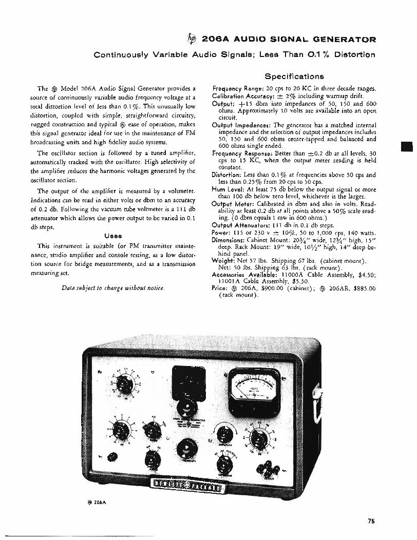
@ 2 0 6 A AUDIO SIGNA GENERATOR
Continuously Variable Audio Signals; Less Than 0.1 % Distortion
The @ Model 206A Audio Signal Generator provides a source of continuously variable audio frequency voltage at a total distortion level of less than 0.1 %. This unusually low distortion, coupled with simple, straightforward circuitry, rugged construction and typical @ ease of operation, makes this signal generator ideal for use in the maintenance of FM broadcasting units and high fidelity audio systems.
The oscillator section is followed by a tuned amplifier, automatically tracked with the oscillator. High selectivity of the amplifier reduces the harmonic voltages generated by the oscillator section.
The output of the amplifier is measured by a voltmeter. Indications can be read in either volts or dbm to an accuracy of 0.2 db. Following the vacuum tube voltmeter is a 111 db attenuator which allows the power output to be varied in 0.1 db steps.
Uses
This instrument is suitable for FM transmitter mainte- nance, studio amplifier and console testing, as a low distor- tion source for bridge measurements, and as a transmission measuring set.
Data subject to change without notice.
Specifications Frequency Range: 20 cps to 20 KC in three decade ranges. Calibration Accuracy: Output: +15 dbm into impedances of 50, 150 and 600
ohms. Approximately 10 volts are available into an open circuit.
Output Impedances: The generator has a matched internal impedance and the selection of output impedances includes 50, 150 and 600 ohms center-tapped and balanced and 600 ohms single ended.
Frequency Response: Better than 2 0 . 2 db at all levels, 30 cps to 15 KC, when the output meter reading is held constant.
Distortion: Less than 0.1% at frequencies above 50 cps and less than 0.25% from 20 cps to 50 cps.
Hum Level: At least 75 db below the output signal or more than 100 db below zero level, whichever is the larger.
Output Meter: Calibrated in dbm and also in volts. Read- ability at least 0.2 db at all points above a 50% scale read- ing. ( 0 dbm equals 1 mw in 600 ohms.)
Output Attenuators: 111 db in 0.1 db steps. Power: 115 or 230 v t lo%, 50 to 1,000 cps, 140 watts. Dimensions: Cabinet Mount: 20%’’ wide, 123/4” high, 15”
deep. Rack Mount: 19” wide, lo$$’’ high, 14” deep be- hind panel.
Weight: Net 57 Ibs. Shipping 67 Ibs. (cabinet mount). Net: 50 Ibs. Shipping 63 Ibs. (rack mount).
Accessories Available: 1lOooA Cable Assembly, $4.50; 1loOlA Cable Assembly, $5.50.
Price: @ 206~4, $900.00 (cabinet); @ 206AR, $885.00 (rack mount).
2% including warmup drift.
@ 206A
75
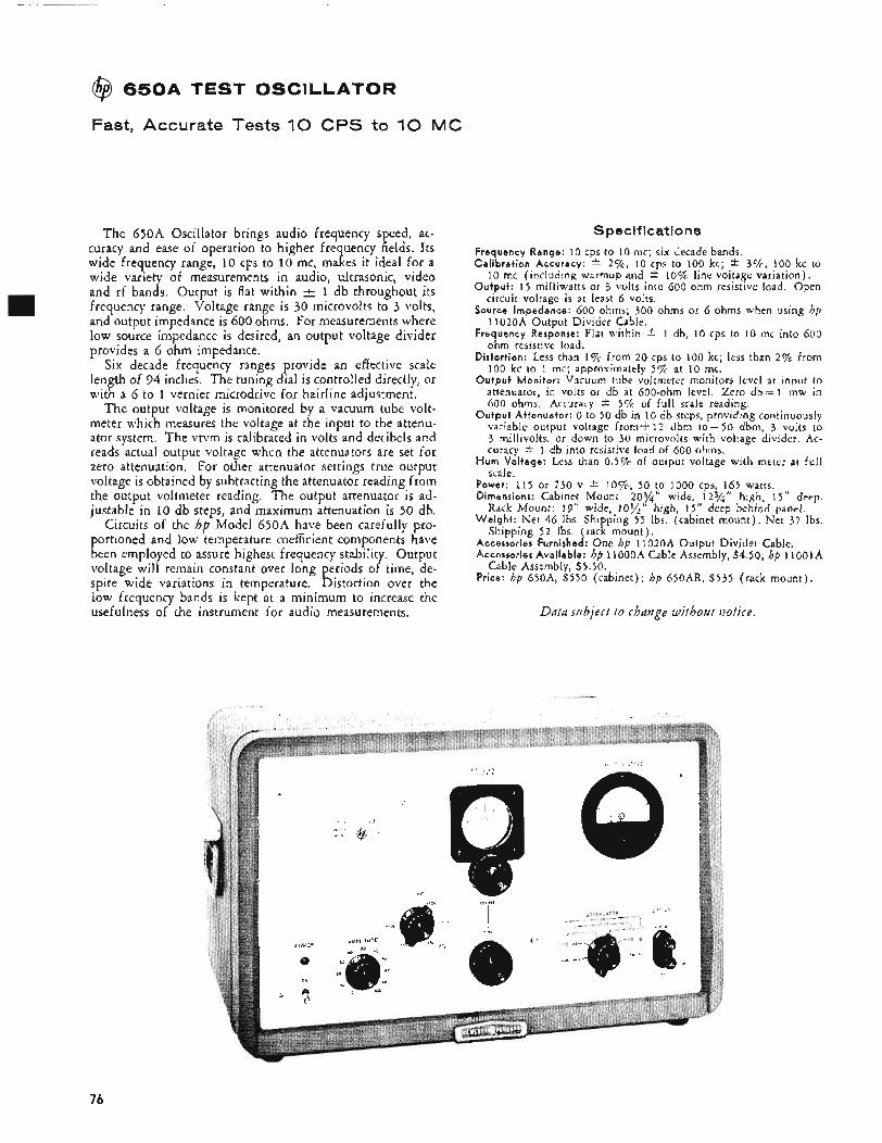
@$ 6 5 0 A TEST OSCILLATOR
Fast, Accurate Tests 1 0 CPS to 1 0 MC
The 650A Oscillator brings audio frequency speed, ac- curacy and ease of operation to higher frequency fields. Its wide frequency range, 10 cps to 10 mc, makes it ideal for a wide variety of measurements in audio, ultrasonic, video and rf bands. Output is flat within -+- 1 db throughout its frequency range. Voltage range is 30 microvolts to 3 volts, and output impedance is 600 ohms. For measurements where low source impedance is desired, an output voltage divider provides a 6 ohm impedance.
Six decade frequency ranges provide an effective scale length of 94 inches. The tuning dial is controlled directly, or with a 6 to 1 vernier microdrive for hairline adjustment.
The output voltage is monitored by a vacuum tube volt- meter which measures the voltage at the input to the attenu- ator system. The vtvm is calibrated in volts and decibels and reads actual output voltage when the attenuators are set for zero attenuation. For other attenuator settings true output voltage is obtained by subtracting the attenuator reading from the output voltmeter reading. The output attenuator is ad- justable in 10 db steps, and maximum attenuation is 50 db.
Circuits of the hp Model 650A have been carefully pro- portioned and low temperature coefficient components have been employed to assure highest frequency stability. Output voltage will remain constant over long periods of time, de- spite wide variations in temperature. Distortion over the low frequency bands is kept at a minimum to increase the usefulness of the instrument for audio measurements.
Specifications Frequency Range: 10 cps to 10 mc; six decade bands. Ca l ib ra t i on Accuracy: -C 2%, 10 cps to 100 kc; * 3%, 100 kc to
10 mc (including warmup and * 10% line voltage variation). Outpu t : 15 milliwatts or 3 volts into 600 ohm resistive load. Open
circuit voltage is at least 6 volts. Source Impedance: 600 ohms; 300 ohms or 6 ohms when using hp
11020A Output Divider Cable. Frequency Response: Flat within * 1 db, 10 cps to 10 mc into 600
ohm resistive load. Distor t ion: Less than I f f from 20 cps to 100 kc; less than 2% from 100 kc to 1 mc; approximately 5% at 10 mc.
O u t p u t Monitor: Vacuum tube voltmeter monitors level at input to attenuator, in volts or db at 600-ohm level. Zero d b = 1 mw in 600 ohms. Accuracy -C 5% of full scale reading.
O u t p u t At tenuator : 0 to 50 db in 10 db steps, providing continuously variable output voltage fromi-12 dbm to-50 dbm, 3 volts to 3 millivolts, or down to 30 microvolts with voltage divider, Ac- curacy * 1 db into resistive load of 600 ohms.
H u m Voltage: Less than 0.5% of output voltage with meter at full scale.
Power: 115 or 230 v 2 l o % , 50 f,o 1000 cps, IP5 watts. Dimensions: Cabinet Mount: 20?4 wide, 1 2 % high, 15" deep.
W e i g h t : Net 46 Ibs. Shipping 55 Ibs. (cabinet mount). Net 37 Ibs.
Accessories Furnished: One bp 11020A Output Divider Cable. Accessories Avai lab le: hp 11OOOA Cable Assembly, $4.50; hp IIOOIA
Price: hp 65OA, $550 (cabinet): bp 650AR, $535 (rack mount).
Rack Mount: 19" wide,,10%
Shipping 5 2 Ibs. (rack mount) .
Cable Assembly, $5.50.
high, 15" deep behind panel.
Data subject to chaiige without notice.
,
76
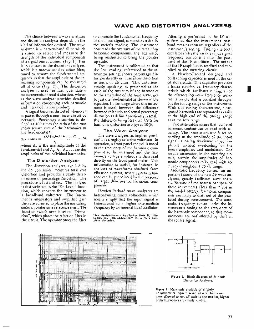
WAVE AND DISTORTION ANALYZERS
The choice between a wave analyzer and distortion analyzer depends on the kind of information desired. The wave analyzer is a narrow-band filter which is tuned to select and measure the strength of the individual components of a signal one at a time. (Fig. 1) This is in contrast to the distortion analyzer, which is a narrow-band rejection filter, tuned to remove the fundamental fre- quency so that the amplitude of the re- maining components can be measured all at once (Fig. 2 ) . The distortion analyzer is used for fast, quantitative measurements of total distortion, where- as the wave analyzer provides detailed information concerning each harmonic and intermodulation product.
A signal becomes distorted whenever it passes through a non-linear circuit or network. Percentage distortion is de- fined as 100 times the ratio of the root mean square sum of the harmonics to the fundamental*.
(A,2+Aj+A:+ . . .)% loo % distortion =
AI
where A, is the rms amplitude of the fundamental and A,, A,, A,, . . . are the amplitudes of the individual harmonics.
The Distortion Analyzer The distortion analyzer, typified by
the hp 330 series, measures total rms distortion and provides a ready deter- mination of percentage distortion. The procedure is fast and easy. The analyzer is first switched to the “Set Level” func- tion, which converts the instrument to a broadband voltmeter. The instru- ment’s attenuators and amplifier gain then are adjusted to place the indicating meter’s pointer on a reference mark, The function switch next is set to “Distor- tion”, which laces the rejection filter in the circuit. T ph e operator tunes the filter
to eliminate the fundamental frequency of the input signal, as noted by a dip in the meter’s reading. The instrument now reads the rms sum of the remaining harmonic components, the attenuator being readjusted to bring the pointer up-scale.
The instrument is calibrated so that the final reading, referenced to the at- tenuator setting, shows percentage dis- tortion directly or it can show distortion in terms of db units. This distortion, strictly speaking, is presented as the ratio of the rms sum of the harmonics to the rms value of the total wave, not to just the fundamental as shown in the equation. In the range where this instru- ment is used, however, the difference between this ratio and actual percentage distortion as defined previously is small, the difference being less than $”% for harmonic distortion as high as 10%.
The Wave Analyzer The wave analyzer, as implied previ-
ously, is a highly selective voltmeter. In operation, a front panel control is tuned to the frequency of the harmonic com- ponent to be measured and the har- monic’s voltage amplitude is then read directly on the front panel meter. This information is useful, for instance, in analyses of waveforms obtained from vibration systems, where system reson- ance can be pinpointed by the presence of larger than normal harmonic coin- ponents.
Hewlett-Packard wave analyzers are heterodyning tuned voltmeters, which means simply that the input signal is heterodyned to a higher intermediate frequency by an internal local oscillator.
*See Hewlett-Packard Application Note 15, “Dis- tortion and Intermodulation.” for a more com- plete discussion.
Filtering is performed in the IF am- plifiers so that the instrument’s pass- band remains constant regardless of the instrument’s tuning. Tuning the local oscillator shifts the various input signal frequency components into the pass- band of the IF amplifiers. The output of the I F amplifiers is rectified and sup- plied to the metering circuit.
A Hewlett-Packard designed and built tuning capacitor is used in the os- cillator circuits. This capacitor provides a linear rotation vs. frequency charac- teristic which facilitates tuning, since the distance between frequency incre- ments on the dial is constant through- out the tuning range of the instrument. With this tuning characteristic, close- spaced harmonics are separated as easily at the high end of the tuning range as at the low range.
Two attenuators insure that low level harmonic content can be read with ac- curacy. The input attenuator is set ac- cording to the amplitude of the input signal, allowing maximum input am- plitude without overloading of the linear amplifiers and modulator. The second attenuator, in the metering cir- cuit, permits the amplitudes of har- monic components to be read with ac- curacy throughout a 75 db range.
Automatic frequency control, an im- portant feature of the new hp wave an- alyzers, greatly facilitates wave analy- sis. Because of the narrow bandpass of these instruments (less than 7 cps in the model 302A), harmonic compon- ents are likely to drift out of the pass- band during measurement. The auto- matic frequency control locks the in- strument’s tuning to the frequency of the harmonic component, so that meas- urements are not affected by drift in the source signal.
I
0
NECATlYF F E E D B A C K
Figure 2. Block diagram of @ 330B Distortion Analyzer.
Figure I . Harmonic analysis of slightly unsymmetrical square wave. Several harmonics were allowed to run off scale so the smaller, higher order harmonics are clearly visible.
77
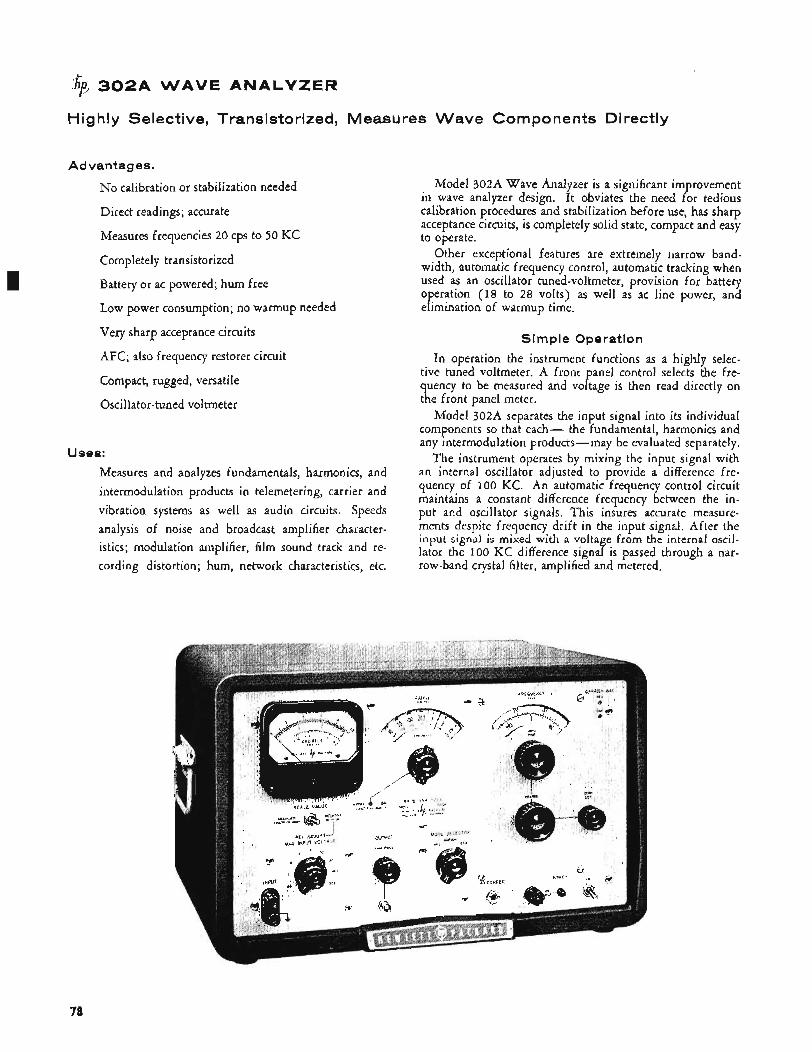
AVE ANALYZER
Highly Selective, Transistorized, Measures Wave Components Directly
Advantages.
No calibration or stabilization needed
Direct readings; accurate
Measures frequencies 20 cps to 50 KC
Completely transistorized
Battery or ac powered; hum free
Low power consumption; no warmup needed
Very sharp acceptance circuits
AFC; also frequency restorer circuit
Compact, rugged, versatile
Oscillator-tuned voltmeter
Uses:
Measures and analyzes fundamentals, harmonics, and intermodulation products in telemetering, carrier and vibration systems as well as audio circuits. Speeds analysis of noise and broadcast amplifier character- istics; modulation amplifier, film sound track and re- cording distortion; hum, network characteristics, etc.
Model 302A Wave Analyzer is a significant improvement in wave analyzer design. I t obviates the need for tedious calibration procedures and stabilization before use, has sharp acceptance circuits, is completely solid state, compact and easy to operate.
Other exceptional features are extremely narrow band- width, automatic frequency control, automatic tracking when used as an oscillator tuned-voltmeter, provision for battery operation (18 to 28 volts) as well as ac line power, and elimination of warmup time.
Simple Ope rat ion
In operation the instrument functions as a highly selec- tive tuned voltmeter. A front panel control selects the fre- quency to be measured and voltage is then read directly on the front panel meter.
Model 302A separates the input signal into its individual components so that each- the fundamental, harmonics and any intermodulation products-may be evaluated separately.
The instrument operates by mixing the input signal with an internal oscillator adjusted to provide a difference fre- quency of 100 KC. An automatic frequency control circuit maintains a constant difference frequency between the in- put and oscillator signals. This insures accurate measure- ments despite frequency drift in the input signal. After the input signal is mixed with a voltage from the internal oscil- lator the 100 KC difference signal is passed through a nar- row-band crystal filter, amplified and metered.
78
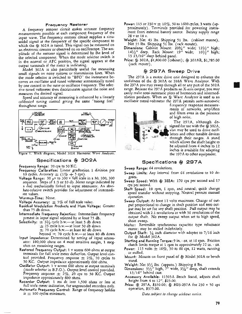
Frequency Restorer A frequency restorer circuit makes accurate frequency
measurements possible at each component frequency of the input wave. The frequency restorer circuit supplies a sinu- soidal signal at the frequency of the specific component to which the @ 302A is tuned. This signal can be measured on an electronic counter or observed on an oscilloscope. The am- plitude of the restorer signal is determined by the level of the selected component. When the mode selector switch is in the normal or AFC position, the signal appears at the output terminals if the meter is indikating.
Model 302A is also particularly useful for measuring small signals on noisy systems or transmission lines. When the mode selector is switched to “BFO” the instrument be- comes an oscillator and tuned voltmeter automatically tuned by one control to the same or oscillator frequency. The selec- tive tuned voltmeter then discriminates against the noise and measures the desired signal.
Speed and accuracy of measuring is enhanced by a linearly calibrated tuning control giving the same “tuning feel” throughout range.
I (0:Y::b)Q p y#$LE)
I
18-21” T d Q K G IOYA ’4 WlFW
‘Figure I . Block diagram, Model 302A Harmonic Wave Analyzer.
Specifications @ 3 0 2 A Frequency Range: 20 cps to 50 KC. Frequency Calibration: Linear graduation 1 division per
10 cycles. Accuracy t (1% + 5 cps). Voltage Range: 30 pv to 300 v full scale in a 30, 100, 300
sequence, Steps of 1 : 3 or 10 db. Meter range indicated by a dial mechanically linked to input attenuator. An abso- lute-relative switch provides for adjustment of intermedi- ate values.
Warmup-Time: None. Voltage Accuracy: e 5% of full scale value. Residual Modulation Products and Hum Voltage: Greater
Intermediate Frequency Rejection: Intermediate frequency
Selectivity:
than 75 db down.
present in input signal rejected by at least 75 db. 31/2 cycle b.w.-at least 3 db down 25 cycle b.w.-at least 50 db down
t 70 cycle b.w.-at least 80 db down beyond 70 cycle b.w.-at least 80 db down
Input Impedance: Determined by setting of input attenu- ator: 100,000 ohms on 4 most sensitive ranges, 1 meg- ohm on remaining ranges.
Restored Frequency Output: 1 v across 600 ohms at output terminals for full scale meter deflection. Output level con- trol provided. Frequency response * 2%) 20 cycles to 50 KC. Output impedance approximately 600 ohms.
Oscillator Output: 1 v across 600 ohms at output terminals (mode selector in B.F.O.). Output level control provided. Frequency response f 276, 20 cps to 50 KC. Output impedance approximately 600 ohms.
Recorder Output: 1 ma dc into 1,500 ohms or less at full scale meter indication, for ungrounded recorders only.
Automatic Frequency Control: Range of frequency holdin is 100 cycles minimum.
Power: 115 or 230 v k lo%, 50 to 1600 cycles, 3 watts (ap- proximately). Terminals provided for powering instru- ment from external battery source. Battery supply range 28 v to 18 v.
Weight: Net 43 Ibs. Shipping 51 Ibs. (cabinet mount). Net 35 Ibs. Shipping 51 Ibs. (rack mount).
Dimensions: Cabinet Mount: 203/4” wide; 121/2” high; 141/2” deep. Rack Mount: 19” wide; 101/2” high; 13 13/16” deep behind panel.
Price: @ 302A, $1,800.00 (cabinet); @ 302AR, $1,785.00 (rack mount).
@ 2 9 7 A Sweep Drive The 297A is a motor drive unit designed to enhance the
usefulness of the @ 302A or 310A Wave Analyzer. With the 297A you may sweep through all or any part of the 302A range. Because the 297A produces an X-axis output, you may easily make semi-automatic plots of harmonics and intermod- ulation products. When an @ Wave Analyzer is used as an oscillator tuned-voltmeter the 297A permits semi-automatic
frequency response measure- ments of networks. amdifiers and filters even in the piesence of high noise.
T h e 297A, although de- signed for use with the @ 302A, also may be used to drive oscil- lators and other tunable devices through their ranges. A stand which allows the shaft height to be adjusted from 4 inches to 12 inches is available for adapting the 297A to other equipment.
Specifications @ 2 9 7 A Sweep Range: 64 revolutions. Sweep Limits: Any interval from 64 revolutions to 10 de-
grees. Sweep Speed: With @ 302A: 170 cps per second and 17
cps per second. Shaft Speed: 10 rpm, 1 rpm, and neutral; quick change
speed transfer without stopping. Neutral permits manual operation.
Sweep Output: At least 12 volts maximum. Change of out- put proportional to change in shaft position and zero out- put may be set for any shaft position. Full output may be obtained with 2.1 revolutions or with 50 revolutions of the output shaft. N o sweep output when set to high speed, short sweep.
Motor: Reversible synchronous capacitor type reluctance motor; may be stalled indefinitely.
Output Shaft: 1/4 inch diameter with adapter to 7/16 inch for @ Model 302A.
Starting and Running Torque: 9 in. - 02. at 10 rpm. Friction clutch limits torque at 1 rpm to approximately 22 in. - 02.
Power: 115 volts t 10%) 50 to 60 cps, 12 watts, running or stalled.
Mount: Mounts on front panel of @ Model 302A or bench stand.
Weight: Net 3% lbs. (approx.) Shipping 8 Ibs. Dimensions: 31/2” high, 7’’ wide, 5%” deep, shaft extends
Accessory Available: 11505A Bench Stand, adjusts shaft
Price: @I 297A, $350.00; @ H03-297A for 230 v 50 cps
Data subject to change without notice.
13/16” behind case.
height from 4 to 12”, $25.00.
operation, $375 .OO.
79
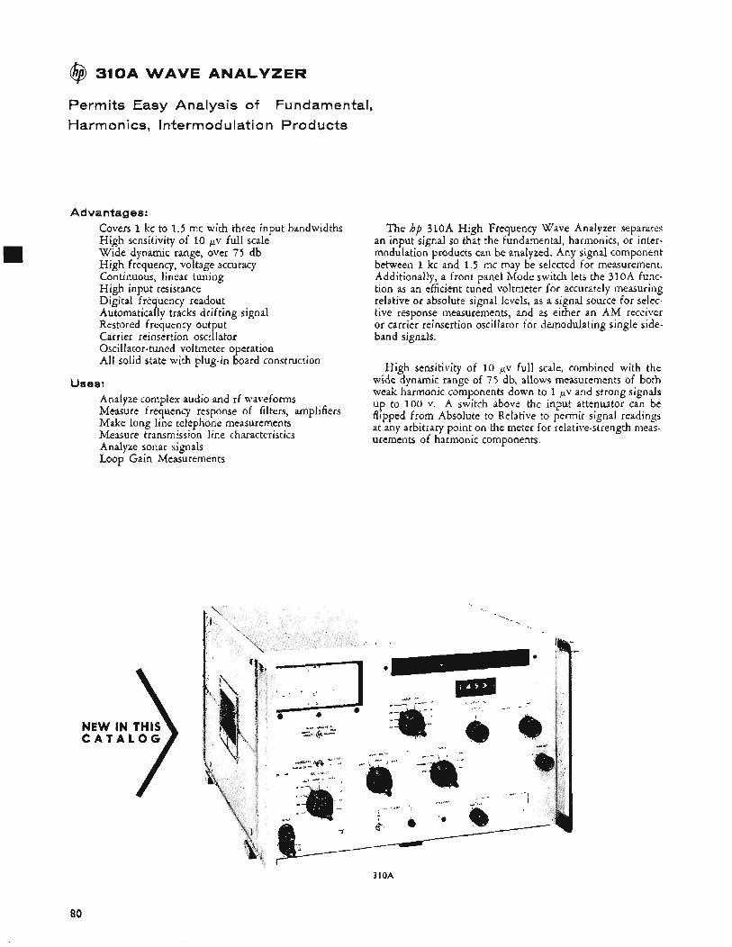
@ 310A WAVE ANALYZER
Permits Easy Analysis of Fundamental, Harmonics, lntermodulation Products
Advan tag es: Covers 1 kc to 1.5 mc with three input bandwidths High sensitivity of 10 pv full scale Wide dynamic range, over 75 d b High frequency, voltage accuracy Continuous, linear tuning High input resistance Digital frequency readout Automatically tracks drifting signal Restored frequency output Carrier reinsertion oscillator Oscillator-tuned voltmeter operation All solid state with plug-in board construction
Uses: Analyze complex audio and rf waveforms Measure frequency response of filters, amplifiers Make long line telephone measurements Measure transmission line characteristics Analyze sonar signals Loop Gain Measurements
C A T A L O G
The hp 310A High Frequency Wave Analyzer separates an input signal so that the fundamental, harmonics, or inter- modulation products can be analyzed. Any signal component between 1 kc and 1.5 mc may be selected for measurement. Additionally, a front panel Mode switch lets the 310A func- tion as an efficient tuned voltmeter for accurately measuring relative or absolute signal levels, as a signal source for selec- tive response measurements, and as either an AM receiver or carrier reinsertion oscillator for demodulating single side- band signals.
High sensitivity of 10 pv full scale, combined with the wide dynamic range of 75 db, allows measurements of both weak harmonic components down to 1 pv and strong signals up to 100 v. A switch above the input attenuator can be flipped from Absolute to Relative to permit signal readings at any arbitrary point on the meter for relative-strength meas- urements of harmonic components.
310A
80
Three Bandwidths Three bandwidths, selected with a front-panel control, in-
crease the versatility of the 3lOA. The 200-cps bandwidth discriminates betyeen harmonics for exact identification. The 1-kc bandwidth simplifies calculations of noise power per cycle bandwidth. The 3-kc bandwidth admits carrier channel signals for evaluation and is wide enough to pass intelligible voice signals, but contributes so little noise that even the 10 pv range can be used.
The 3lOA is extremely easy to use. To prevent ambiguity of reading, the voltage range corresponding to full scale sensitivity is automatically shown on an illuminated 1 >-place range indicator. Tuning is linear throughout the 3lOA‘s range, with no band switching. Frequency can be easily read from a 4-place digital dial which has a resolution of better than 200 cps over the entire band, with any setting accurate to k (1% + 300 cps) .
AFC An automatic frequency control has a dynamic hold-in
range of 3 kc (at 100 kc) with response rapid enough to lock signals with drift rates in excess of 100 cps/second.
Restored frequency output permits use of an electronic counter to measure the frequency to which the 310A is tuned. This output contains those input frequencies which fall with- in a selectable passband (200 cps, 1 kc, 3 kc) that is centered at the 310A’s tuned frequency. (With the 310A tuned to 1 mc and the input bandwidth at 1 kc, restored frequency out- put contains all input components between 999.5 kc and 1000.5 kc.)
A dc output proportional to meter deflection also is avail- able and can be used to drive a recorder.
Useful BFO Output The output from the beat frequency oscillator is a sine
wave that corresponds to the tuning indicator’s setting, and it can be used effectively to make selective or narrow-band response tests on filter circuits and transmission systems. The BFO and tuned voltmeter are simultaneously controlled by the frequency indicator, tracking together, and can be con- veniently used as a self-contained measuring system - the BFO output fed through a device under test, then back to the tuned voltmeter for analysis.
A carrier reinsertion oscillator is included to demodulate single sideband signals, either normal or inverted. The de- modulated signal is available for aural or recording purposes.
Specifications
Frequency Range: 1 kc to 1.5 mc (2OO-cps passband). 5 kc to 1.5 mc (1OOO-cps passband). 10 kc to 1.5 mc (3000-cps passband).
Frequency Accuracy: k (1 % + 300 cps).
Frequency Calibration: Linear graduation, 1 division/200 cps .
Selectivity: Nominal 200 cps bandwidth: At least 3 db down at k 108 cps. At least 50 db down at k 500 cps. At least 75 db down at t 1000 cps*.
At least 3 db down at t 540 cps. At least 50 db down at t 2400 cps. At least 75 db down at f 5000 cps*.
At least 3 db B own at k 1550 cps. At least 50 db down at t 7000 cps. At least 75 db down at k 17,000 cps*.
tinguished by a rejection region 1 cps wide.
Nominal 1000 cps bandwidth:
Nominal 3000 c s bandwidth:
T h e midpoint of the passband is readily dis-
Voltage Range: 10 pvolts to 100 volts full scale. Ranges provided by input attenuator and meter range switch in steps of 1 :3 or 10 db.
Voltage Accuracy: 2 6% full scale.
Internal Calibrator Stability: f 1% of full scale.
Dynamic Range: Greater than 75 db. Input Resistance: Determined by input attenuator; 10K ohms
on most sensitive range; 30K ohms on next range; 1OOK ohms on other ranges.
Noise and Spurious Response: At least 75 db below a full- scale reference set on the 0-db position of range switch.
Automatic Frequency Control: Dynamic hold-in range is t 3 kc, minimum, at 100 kc. Tracking speed is approxi-
mately 100 cps/sec. Locks on signals as low as 70 db be- low a full-scale reference set on the 0-db position of the range switch.
Restored Frequency Output: Restored frequency output is at least 0.25 volts maximum across 135 ohms with ap- proximately 30 db of level control provided. Output im- pedance, approximately 135 ohms.
BFO Output: 0.5 volt across 135 ohms with approximately 30 db of level control provided. Output impedance ap- proximately 135 ohms.
Recorder Output: 1 ma dc into 1500 ohms or less for single- ended recorders.
Receiver Function (aural or recording provision): Internal carrier reinsertion oscillator is provided for demodulation of either normal or inverted single sideband signals. AM signal also can be detected.
Power: 115 or 230 volts k lo%, 50 to 1000 cps; approxi- mately 16 watts.
Dimensions: 16%” wide, lo$$’’ high, 183/8” deep. Hard- ware furnished converts panel to 10%” x 19” rack mount.
Weight: Net 44 Ibs. Shipping 59 Ibs.
Accessories Available: hp 297A Sweep Drive (see page 791,
Price: $2000. *Rejection decreases smoothly beyond the - 75 db points.
$350.
Data subject to change without notice.
81
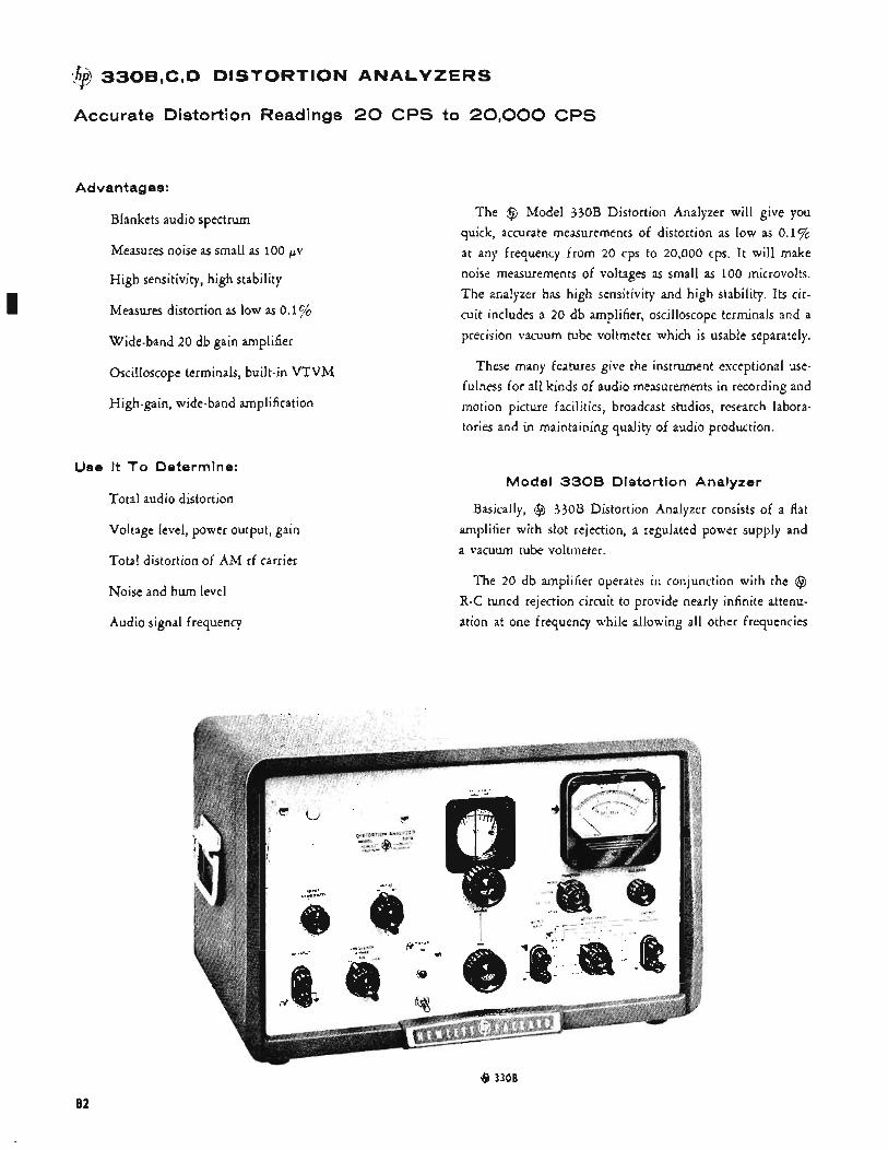
I
$f 330B,C,D DISTORTION ANALYZERS
Accurate Distortion Readings 20 CPS to 20,000 CPS
Advan tag es:
Blankets audio spectrum
Measures noise as small as 100 pv
High sensitivity, high stability
Measures distortion as low as 0.1%
Wide-band 20 db gain amplifier
Oscilloscope terminals, built-in VTVM
High-gain, wide-band amplification
Use It To Determine:
Total audio distortion
Voltage level, power output, gain
Total distortion of AM rf carrier
Noise and hum level
Audio signal frequency
The @ Model 330B Distortion Analyzer will give you quick, accurate measurements of distortion as low as 0.1%
at any frequency from 20 cps to 20,000 cps. It will make noise measurements of voltages as small as 100 microvolts. The analyzer has high sensitivity and high stability. Its cir- cuit includes a 20 db amplifier, oscilloscope terminals and a precision vacuum tube voltmeter which is usable separately.
These many features give the instrument exceptional use- fulness for all kinds of audio measurements in recording and motion picture facilities, broadcast studios, research labora- tories and in maintaining quality of audio production.
Model 3308 Distortion Analyzer
Basically, @ 330B Distortion Analyzer consists of a flat amplifier with slot rejection, a regulated power supply and a vacuum tube voltmeter.
The 20 db amplifier operates in conjunction with the @ R-C tuned rejection circuit to provide nearly infinite attenu- ation at one frequency while allowing all other frequencies
@ 3308
a2
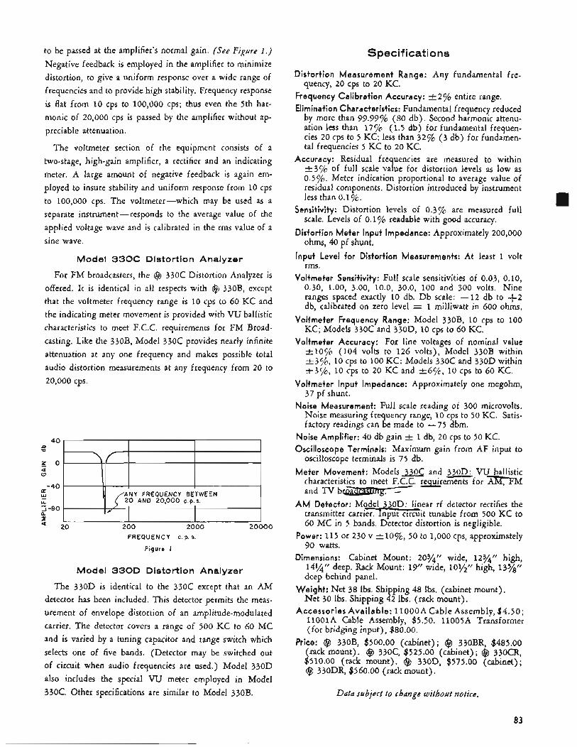
to be passed at the amplifier’s normal gain. (See Figure I . )
Negative feedback is employed in the amplifier to minimize distortion, to give a uniform response over a wide range of frequencies and to provide high stability. Frequency response is flat from 10 cps to 100,000 cps; thus even the 5th har- monic of 20,000 cps is passed by the amplifier without ap- preciable attenuation.
The voltmeter section of the equipment consists of a two-stage, high-gain amplifier, a rectifier and an indicating meter, A large amount of negative feedback is again em- ployed to insure stability and uniform response from 10 cps to 100,000 cps. The voltmeter-which may be used as a separate instrument-responds to the average value of the applied voltage wave and is calibrated in the rms value of a sine wave,
Model 3 3 0 C Distortion Analyzer
For FM broadcasters, the @ 330C Distortion Analyzer is offered. It is identical in all respects with @ 330B, except that the voltmeter frequency range is 10 cps to 60 KC and the indicating meter movement is provided with VU ballistic characteristics to meet F.C.C. requirements for FM Broad- casting. Like the 330B, Model 330C provides nearly infinite attenuation at any one frequency and makes possible total audio distortion measurements at any frequency from 20 to 20,000 cps.
n V
z 0 ’ 4 0
-40 a w 5-80 a LL
2
40 I I I I
ANY FREQUENCY BETWEEN 20 AND 20,000 C.P.S. \ / L ’ I
FREQUENCY c. p. s
Figure I
Model 330D Distortion Analyzer
The 330D is identical to the 330C except that an AM detector has been included. This detector permits the meas- urement of envelope distortion of an amplitude-modulated carrier. The detector covers a range of 500 KC to 60 MC and is varied by a tuning capacitor and range switch which selects one of five bands. (Detector may be switched out of circuit when audio frequencies are used.) Model 330D also includes the special W meter employed in Model 330C. Other specifications are similar to Model 330B.
Specifications
Distortion Measurement Range: Any fundamental fre-
Frequency Calibration Accuracy: -+ 2% entire range. Elimination Characteristics: Fundamental frequency reduced
by more than 99.99% (80 db) . Second harmonic attenu- ation less than 1770 (1.5 db) for fundamental frequen- cies 20 cps to 5 KC; less than 32% (3 db) for fundamen- tal frequencies 5 KC to 20 KC.
Accuracy: Residual frequencies are measured to within t 3 7 ~ of full scale value for distortion levels as low as 0.5%. Meter indication proportional to average value of residual components. Distortion introduced by instrument less than 0.1 ”/c.
Sensitivity: Distortion levels of 0.3% are measured full scale. Levels of 0.1 ”/o readable with good accuracy,
Distortion Meter Input Impedance: Approximately 200,000 ohms, 40 pf shunt.
Input Level for Distortion Measurements: At least 1 volt rms .
Voltmeter Sensitivity: Full scale sensitivities of 0.03, 0.10, 0.30, 1.00, 3.00, 10.0, 30.0, 100 and 300 volts, Nine ranges spaced exactly 10 db. D b scale: -12 db to +2 db, calibrated on zero level =I 1 milliwatt in 600 ohms.
Voltmeter Frequency Range: Model 330B, 10 cps to 100 KC; Models 330C and 330D, 10 cps to 60 KC.
Voltmeter Accurac : For line voltages of nominal value t l O C / c (104 voLs to 126 volts), Model 330B within -+3c/o, 10 cps to 100 KC: Models 330c and 330D within t 3 c / o , 10 cps to 20 KC and -+694, 10 cps to 60 KC.
Voltmeter Input Impedance: Approximately one megohm, 37 pf shunt.
Noise Measurement: Full scale reading of 300 microvolts. Noise measuring frequency range, 10 cps to 50 KC. Satis- factory readings can be made to -75 dbm.
quency, 20 cps to 20 KC.
Noise Amplifier: 40 db gain t 1 db, 20 cps to 50 KC. Oscilloscope Terminals: Maximum gain from AF input to
oscilloscope terminals is 75 db. Meter Movement: M o d e l s a c and 330D: VU ballistic
characteristics to meet F.C.C. requirements for m M
AM Detector: Model 330D: linear rf detector rectifies the transmitter carrier. Input circuit tunable from 500 KC to 60 MC in 5 bands. Detector distortion is negligible.
Power: 115 or 230 v + lo%, 50 to 1,000 cps, approximately 90 watts.
Dimensions: Cabinet Mount: 203/4“ wide, 12%” high, 14%‘’ deep. Rack Mount: 19” wide, 101/” high, 13%’’ deep behind panel.
Weight: Net 38 Ibs. Shipping 48 Ibs. (cabinet mount). Net 30 Ibs. Shipping 42 Ibs. (rack mount).
Accessories Available: 1lOOOA Cable Assembly, $4.50; 11oolA Cable Assembly, $5.50. 11005A Transformer (for bridging input), $80.00.
Price: @ 330B, $500.00 (cabinet); @ 330BR, $485.00 (rack mount). @ 330c, $525.00 (cabinet); @ 330CR, $510.00 (rack mount). @ 330D, $575.00 (cabinet); @ 330DR, $560.00 (rack mount).
and TV b-mg . -
Data subject to change without notice.
83
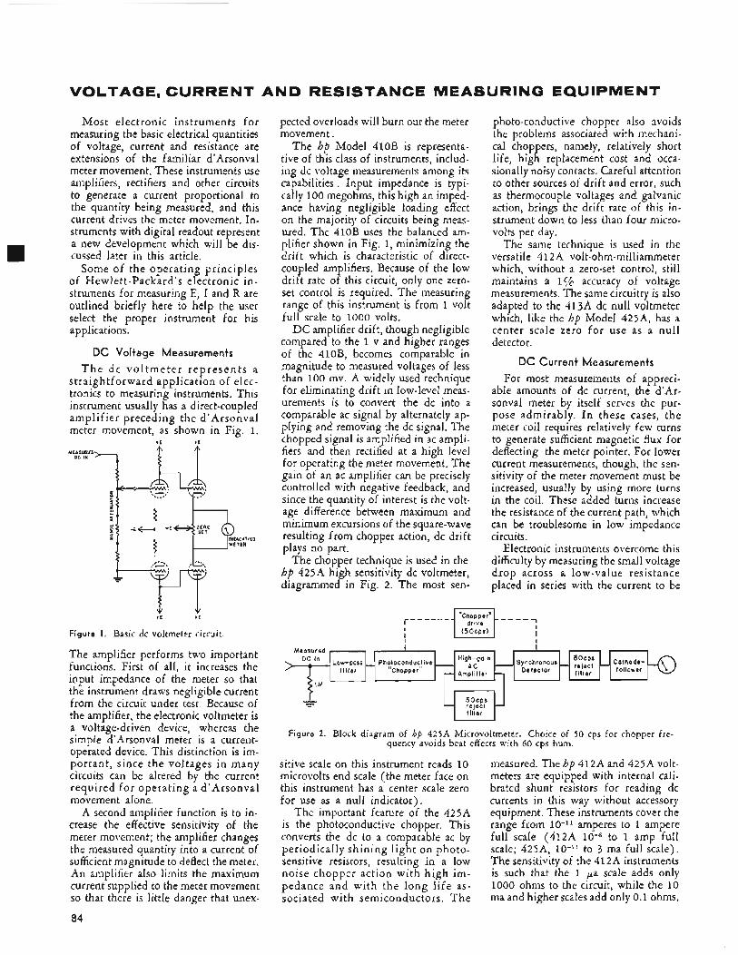
VOLTAGE, CURRENT AND RESISTANCE MEASURING EQUIPMENT
D C in
Most electronic instruments f o r measuring the basic electrical quantities of voltage, current and resistance are extensions of the familiar d’Arsonval meter movement. These instruments use amplifiers, rectifiers and other circuits to generate a current proportional to the quantity being measured, and this current drives the meter movement. In- struments with digital readout represent a new development which will be dis- cussed later in this article.
Some of the operating principles of Hewlett-Packard’s electronic in- struments for measuring E, I and R are outlined briefly here to help the user select the proper instrument for his applications.
DC Voltage Measurements
T h e d c v o l t m e t e r r e p r e s e n t s a straightforward application of elec- tronics to measuring instruments. This instrument usually has a direct-coupled amplifier preceding the d’ Arsonval meter movement, as shown in Fig. 1.
+ E t E
Low-pass - Photoconduc t i ve High-ga1n A C
“Chopper ” Amp l i f i e r -
f i l t e r
+E +E
Figure I . Basic dc voltmeter circuit.
The amplifier performs two important functions. First of all, it increases the input impedance of the meter so that the instrument draws negligible current from the circuit under test, Because of the amplifier, the electronic voltmeter is a voltage-driven device, whereas the simple d’Arsonval meter is a current- operated device. This distinction is im- portant , since the voltages in many circuits can be altered by the current required for operating a d’ Arsonval movement alone.
A second amplifier function is to in- crease the effective sensitivity of the meter movement; the amplifier changes the measured quantity into a current of sufficient magnitude to deflect the meter. An amplifier also limits the maximum current supplied to the meter movement so that there is little danger that unex-
84
pected overloads will burn out the meter movement.
The hp Model 410B is representa- tive of this class of instruments, includ- ing dc voltage measurements among its capabilities . Input impedance is typi- cally 100 megohms, this high an imped- ance having negligible loading effect on the majority of circuits being meas- ured. The 410B uses the balanced am- plifier shown in Fig. 1, minimizing the drift which is characteristic of direct- coupled amplifiers. Because of the low drift rate of this circuit, only one zero- set control is required. The measuring range of this instrument is from 1 volt full scale to 1000 volts.
DC amplifier drift, though negligible compared to the 1 v and higher ranges of the 410B, becomes comparable in magnitude to measured voltages of less than 100 mv. A widely used technique for eliminating drift in low-level meas- urements is to convert the dc into a comparable ac signal by alternately ap- plying and removing the dc signal, The chopped signal is amplified in ac ampli- fiers and then rectified at a high level for operating the meter movement, The gain of an ac amplifier can be precisely controlled with negative feedback, and since the quantity of interest is the volt- age difference between maximum and minimum excursions of the square-wave resulting from chopper action, dc drift plays no part,
The chopper technique is used in the hp 425A high sensitivity dc voltmeter, diagrammed in Fig. 2. The most sen-
photo-conductive chopper also avoids the problems associated with mechani- cal choppers, namely, relatively short life, high replacement cost and occa- sionally noisy contacts. Careful attention to other sources of drift and error, such as thermocouple voltages and galvanic action, brings the drift rate of this in- strument down to less than four micro- volts per day.
The same technique is used in the versatile 412A volt-ohm-milliammeter which, without a zero-set control, still maintains a 1% accuracy of voltage measurements. The same circuitry is also adapted to the 413A dc null voltmeter which, like the hp Model 425A, has a center scale zero for use as a null detector.
DC Current Measurements
For most measurements of appreci- able amounts of dc current, the d’Ar- sonval meter by itself serves the pur- pose admirably. I n these cases, the meter coil requires relatively few turns to generate sufficient magnetic flux for deflecting the meter pointer. For lower current measurements, though, the sen- sitivity of the meter movement must be increased, usually by using more turns in the coil. These added turns increase the resistance of the current path, which can be troublesome in low impedance circuits.
Electronic instruments overcome this difficulty by measuring the small voltage drop across a low-value resistance placed in series with the current to be
Chopper” _ _ _ _ ~ 5 O C P S l
I I I
Figure 2. Block diagram of hp 425A Microvoltmeter. Choice of 50 cps for chopper fre- quency avoids beat effects with 60 cps hum.
sitive scale on this instrument reads 10 microvolts end scale (the meter face on this instrument has a center scale zero for use as a null indicator).
The important feature of the 425A is the photoconductive chopper. This converts the dc to a comparable ac by periodically shining l ight on photo- sensitive resistors, resulting in a low noise chopper action with h igh im- pedance and with the long l i fe as- sociated with semiconductors. T h e
measured. The hp 412A and 425A volt- meters are equipped with internal cali- brated shunt resistors for reading dc currents in this way without accessory equipment. These instruments cover the range from 10-11 amperes to 1 ampere full scale (412A to 1 amp full scale; 425A, 1O-I’ to 3 ma full scale). The sensitivity of the 412A instruments is such that the 1 pa scale adds only 1000 ohms to the circuit, while the 10 ma and higher scales add only 0.1 ohms.
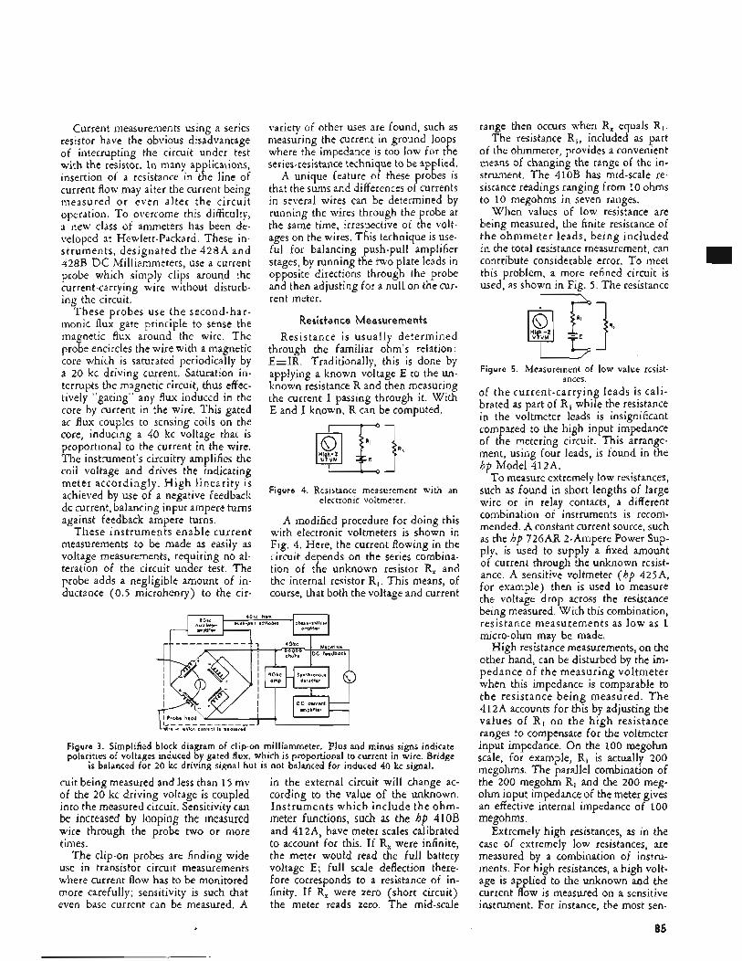
Current measurements using a series resistor have the obvious disadvantage of interrupting the circuit under test with the resistor. In many applications, insertion of a resistance in the line of current flow may alter the current being measured or even alter the circuit operation. To overcome this difficulty, a new class of ammeters has been de- veloped at Hewlett-Packard. These in- struments, designated the 428A and 428B D C Milliammeters, use a current probe which simply clips around the current-carrying wire without disturb- ing the circuit.
These probes use the second-har- inonic flux gate principle to sense the magnetic flux around the wire. The probe encircles the wire with a magnetic core which is saturated periodically by a 20 kc driving current. Saturation in- terrupts the magnetic circuit, thus eff ec- tively “gating” any flux induced in the core by current in the wire. This gated ac flux couples to sensing coils on the core, inducing a 40 kc voltage that is proportional to the current in the wire. The instrument’s circuitry amplifies the coil voltage and drives the indicating meter accordingly. High linearity is achieved by use of a negative feedback dc current, balancing input ampere turns against feedback ampere turns,
These instruments enable current measurements to be made as easily as voltage measurements, requiring no al- teration of the circuit under test. The probe adds a negligible amount of in- ductance (0.5 microhenry) to the cir-
variety of other uses are found, such as measuring the current in ground loops where the impedance is too low for the series-resistance technique to be applied.
A unique feature of these probes is that the sums and differences of currents in several wires can be determined by running the wires through the probe at the same time, irrespective of the volt- ages on the wires. This technique is use- ful for balancing push-pull amplifier stages, by running the two plate leads in opposite directions through the probe and then adjusting for a null on the cur- rent meter.
Resistance Measurements
Resistance is usually determined through the familiar ohm’s relation: E A R . Traditionally, this is done by applying a known voltage E to the un- known resistance R and then measuring the current I passing through it. With E and I known, R can be computed.
Figure 4. Resistance measurement with an
A modified procedure for doing this with electronic voltmeters is shown in Fig. 4. Here, the current flowing in the circuit depends on the series combina- tion of the unknown resistor R, and the internal resistor R i . This means, of course, that both the voltage and current
electronic voltmeter.
Figure 3. Simplified block diagram of clip-on milliammeter. Plus and minus signs indicate polarities of voltages induced by gated flux, which is proportional to current in wire. Bridge
is balanced for 20 kc driving signal but is not balanced for induced 40 kc signal.
cuit being measured and less than 15 mv of the 20 kc driving voltage is coupled into the measured circuit. Sensitivity can be increased by looping the measured wire through the probe two or more times.
The clip-on probes are finding wide use in transistor circuit measurements where current flow has to be monitored more carefully; sensitivity is such that even base current can be measured. A
in the external circuit will change ac- cording to the value of the unknown. Instruments which include the ohm- meter functions, such as the hp 410B and 412~4, have meter scales calibrated to account for this. If R, were infinite, the meter would read the full battery voltage E; full scale deflection there- fore corresponds to a resistance of in- finity. If R, were zero (short circuit) the meter reads zero. The mid-scale
range then occurs when R, equals R i . The resistance Ri , included as part
of the ohmmeter, provides a convenient means of changing the range of the in- strument. The 410B has mid-scale re- sistance readings ranging from 10 ohms to 10 megohms in seven ranges.
When values of low resistance are being measured, the finite resistance of the ohmmeter leads, being included in the total resistance measurement, can contribute considerable error. To meet this problem, a more refined circuit is used, as shown in Fig. 5. The resistance
Figure 5. Measurement of low value resist- ances.
of the current-carrying leads is cali- brated as part of R i while the resistance in the voltmeter leads is insignificant compared to the high input impedance of the metering circuit. This arrange- ment, using four leads, is found in the hp Model 412A.
To measure extremely low resistances, such as found in short lengths of large wire or in relay contacts, a different combination of instruments is recom- mended. A constant current source, such as the hp 726AR 2-Ampere Power Sup- ply, is used to supply a fixed amount of current through the unknown resist- ance. A sensitive voltmeter (hp 425A, for example) then is used to measure the voltage drop across the resistance being measured. With this combination, resistance measurements as low as 1 micro-ohm may be made.
High resistance measurements, on the other hand, can be disturbed by the im- pedance of the measuring voltmeter when this impedance is comparable to the resistance being measured. T h e 412A accounts for this by adjusting the values of R , on the high resistance ranges to compensate for the voltmeter input impedance. On the 100 megohm scale, for example, Ri is actually 200 megohms. The parallel combination of the 200 megohm Ri and the 200 meg- ohm input impedance of the meter gives an effective internal impedance of 100 megohms.
Extremely high resistances, as in the case of extremely low resistances, are measured by a combination of instru- ments. For high resistances, a high volt- age is applied to the unknown and the current flow is measured on a sensitive instrument. For instance, the most sen-
85
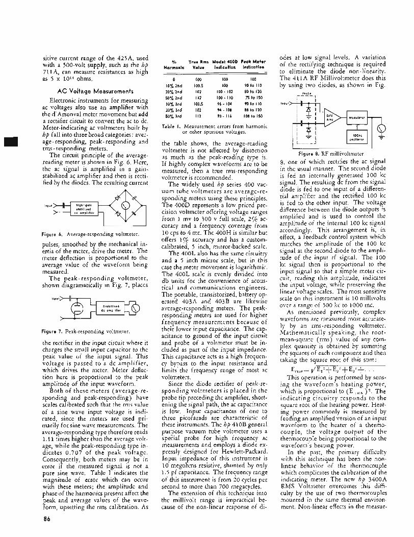
sitive current range of the 425A, used with a 500-volt supply, such as the hp 711A, can measure resistances as high as 5 x ioi4 ohms.
AC Voltage Measurements
Electronic instruments for measuring ac voltages also use an amplifier with the d'Arsonva1 meter movement but add a rectifier circuit to convert the ac to dc. Meter-indicating ac voltmeters built by hp fall into three broad categories: aver- age - responding, peak- responding and rms - responding meters.
The circuit principle of the average- reading meter is shown in Fig. 6. Here, the ac signal is amplified in a gain- stabilized ac amplifier and then is recti- fied by the diodes. The resulting current
Figure 6. Average-responding voltmeter.
pulses, smoothed by the mechanical in- ertia of the meter, drive the meter. The meter deflection is proportional to the average value of the waveform being measured.
T h e peak-responding voltmeter, shown diagramatically in Fig. 7, places
d c ampl i f ie r
Figure 7. Peak-responding voltmeter.
the rectifier in the input circuit where it charges the small input capacitor to the peak value of the input signal. This voltage is passed to a dc amplifier, which drives the meter. Meter deflec- tion here is proportional to the peak amplitude of the input waveform.
Both of these meters (average-re- sponding and peak-responding) have scales calibrated such that the rms value of a sine wave input voltage is indi- cated, since the meters are used pri- marily for sine wave measurements. The average-responding type therefore reads 1.1 1 times higher than the average volt- age, while the peak-responding type in- dicates 0 .707 of the peak voltage. Consequently, both meters may be in error if the measured signal is not a pure sine wave. Table I indicates the magnitude of error which can occur with these meters; the amplitude and phase of the harmonics present affect the peak and average values of the wave- form, upsetting the rms calibration. As
% True Rms Harmonic Value
0 IO0 10% 2nd 100.5 20%2nd 102 50Y'Znd I12 10% 3rd 100.5 20%3rd 102 50% 3rd I12
Modal 400D Peak Meter Indication Indication
IO0 IO0 IO0 90 to I IO
100 - 102 80 to 120 100 - I10 75 to 150 9 6 - 1 0 4 90to110 94 - 108 88 to 120 90 ~ I16 108 to 150
-
Table I . Measurement errors from harmonic or other spurious voltages.
the table shows, the average-reading voltmeter is not affected by distortion as much as the peak-reading type is. If highly complex waveforms are to be measured, then a true rms-responding voltmeter is recommended.
The widely used hp series 400 vac- uum tube voltmeters are average-re- sponding meters using these principles. The 400D represents a low priced pre- cision voltmeter offering voltage ranges from 1 mv to 300 v full scale, 2% ac- curacy and a frequency coverage from 10 cps to 4 mc. The 400H is similar but offers 1% accuracy and has a custom- calibrated, 5 inch, mirror-backed scale.
The 400L also has the same circuitry and a j inch mirror scale, but in this case the meter movement is logarithmic. The 400L scale is evenly divided into db units for the convenience of acous- tical and communications engineers. The portable, transistorized, battery op- erated 403A and 403B are likewise average-responding meters. The peak- responding meters are used for higher frequency measurements because of their lower input capacitance. The cap- acitance to ground of the input circuit and probe of a voltmeter must be in- cluded as part of the input impedance. This capacitance acts as a high frequen- cy bypass to the input resistance and limits the frequency range of most ac voltmeters.
Since the diode rectifier of peak-re- sponding voltmeters is placed in the probe tip preceding the amplifier, short- ening the signal path, the ac capacitance is low. Input capacitances of one to three picofarads are characteristic of these instruments. The hp 410B general purpose vacuum tube voltmeter uses a special probe for high frequency ac measurements and employs a diode ex- pressly designed for Hewlett-Packard. Input impedance of this instrument is 10 megohms resistive, shunted by only 1.5 pf capacitance. The frequency range of this instrument is from 20 cycles per second to more than 700 megacycles.
The extension of this technique into the millivolt range is impractical be- cause of the non-linear response of di-
odes at low signal levels. A variation of the rectifying technique is required to eliminate the diode non-linearity. The 411A RF Millivoltmeter does this by using two diodes, as shown in Fig.
Probe
1 - oscillator
Figure 8. RF millivoltmeter. 8 , one of which rectifies the ac signal in the usual manner. The second diode is fed an internally generated 100 kc signal. The resulting dc from the signal diode is fed to one input of a differen- tial amplifier and the rectified 100 kc is fed to the other input. The voltage difference between the diode outputs is amplified and is used to control the amplitude of the internal 100 kc signal accordingly. This arrangement is, in effect, a feedback control system which matches the amplitude of the 100 kc signal at the second diode to the ampli- tude of the input rf signal. The 100 kc signal then is proportional to the input signal so that a simple meter cir- cuit, reading this amplitude, indicates the input voltage, while preserving the linear voltage scales. The most sensitive scale on this instrument is 10 millivolts over a range of 500 kc to 1000 mc.
As mentioned previously, complex waveforms are measured most accurate- ly by a n rms-responding voltmeter. Mathematically speaking, the root- mean-square (rms) value of any com- plex quantity is obtained by summing the squares of each component and then taking the square root of this sum:
E,.,,,,= r/E1''+E2'+Es'+. . . This operation is performed by sens-
ing the waveform's heating power, which is proportional to (E ,.,lls ) z . The indicating circuitry responds to the square root of the heating power. Heat- ing power commonly is measured by feeding an amplified version of an input waveform to the heater of a thernio- couple, the voltage output of the thermocouple being proportional to the waveform's heating power.
In the past, the primary difficulty with this technique has been the non- linear behavior of the thermocouple which complicates the calibration of the indicating meter. The new hp 3400A RMS Voltmeter overcomes this diffi- culty by the use of two thermocouples mounted in the same thermal environ- ment. Non-linear effects in the measur-
~-
86
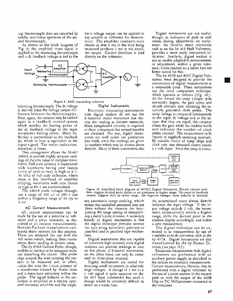
ing thermocouple then are cancelled by similar non-linear operation of the sec- ond thermocouple.
As shown in the block diagram of Fig. 9, the amplified input signal is applied to the measuring thermocouple and a dc feedback voltage is fed to the
fier's voltage output can be applied to any suitable ac voltmeter for measure- ment. T h e amplifier constants were chosen so that 1 ma in the wire being measured produces 1 mv at the ampli- fier output. Current therefore is read directly on the voltmeter,
t h er mo co u pl d
Balancing "I, thermocouple-
Figure 9 . RMS responding voltmeter. balancing thermocouple. The dc voltage is derived from the voltage output dif- ference between the thermocouples. Here, again, the circuitry may be looked upon as a feedback control system which matches the heating power of the dc feedback voltage to the input waveform's heating power. Meter de- flection is proportional to the feedback dc, which in turn is eqxivalent to the input signal. T h e meter indication, therefore, is linear.
This arrangement allows the Model 3400A to provide highly accurate read- ings of the rms value of complex wave- forms. Full scale accuracy is maintained with waveforms having crest factors (ratio of peak-to-rms) as high as 8 : l . At 10% of full scale deflection, where t h x e is less likelihood of amplifier clipping, waveforms with crest factors as high as 80: 1 are accommodated.
The 3400A reads voltages through- out a range of 100 pv to 300 v rms within a frequency range of 10 cps to 8 mc.
AC Current Measurements AC current measurements can be
made by the use of a sensitive ac volt- meter and a series resistance, as des- cribed in dc current measurements. Hewlett-Packard manufactures cali- brated shunt resistors for this purpose. These are designed for use with the 400 series meters, making these instru- ments direct reading in current units.
The hp 456A Current Probe, though, enables ac current to be measured with- out d i s tu rb ing t h e circuit. This probe clips around the wire carrying the cur- rent to be measured and, in effect, makes the wire the 1-turn primary of a transformer formed by ferrite cores and a many-turn secondary within the probe. The signal induced in the sec- ondary is amplified in a battery oper- ated transistor amplifier and the ampli-
- Digital Instruments
Electronic measuring instruments with digital readout do not use the d'Arsonval meter movement but dis- play the reading as discrete numerals. More complicated circuitry is required in these instruments but several benefits are obtained. For one, digital instru- ments are well suited for production line work, since the readings are given in numbers which may be written down directly. Many of these instruments also
Digital instruments are not useful, though, as indicators of peak or null values during adjustments on equip- ment; the familiar meter movement such as on the hp 413 Null Voltmeter, provides a more easily interpreted in- dication. Similarly, digital readout is not as readily adapted to measurements or adjustments within a given toler- ance; limits marked on a meter face are better suited for this.
The hp 405B and 405C Digital Volt- meters were designed to provide the convenience of digital measurements at a reasonable price. These instruments use the ramp comparison technique, which operates as follows (Fig. l o ) : At the instant the ramp (single cycle sawtooth) begins, the gate opens and decade counters start totalizing the in- ternally generated clock pulses. The ramp voltage is compared continuously to the input dc voltage and at the in- stant that they are equal, the circuitry closes the gate while the readout holds and indicates the number of clock pulses counted. The measurement cycle repeats at regularly recurring intervals. By suitable choice of ramp slope and clock rate, one thousand counts equals a 1 volt input. Since the ramp is linear,
Figure IO. Simplified block diagram of 405B,C Digital Voltmeters. Decade counter over- flow triggers decimal point shifter to set attenuator to higher range. No-count in hundreds counter triggers shift to lower range. On negative voltages ramp polarity is inverted.
are automatic range seeking, which means that unskilled personnel may use them without the necessity for inter- preting the range setting or interpolat- ing a meter's scale division. A secondary benefit of digital instruments is that the digital technique provides outputs for operating automatic printers or punched card or punched tape mechan- isms.
Digital instruments also are capable of extremely high accuracy since digital readouts can provide readings to four or five places. d ' Arsonval movements, on t h e o the r hand, can only be est im- ated to three-place accuracy.
Digital instruments are useful for detecting small increments in relatively large voltages. A change of 1 mv in a 1 volt signal is quite apparent on the hp 405 type voltmeters but such a change would be extremely difficult to detect on a meter face.
the accumulated count always directly indicates the input voltage. If the in- put voltage exceeds 1 volt, the instru- ment automatically selects a higher range, shifts the decimal point in the readout display accordingly, and makes a new measurement.
T h e digital technique can be ex- tended to ac measurements by use of a suitable ac-to-dc converter, such as the hp 457A. Digital instruments are also manufactured by the hp Dymec D i - vision (seepuge 103) .
Resistance measurements with digital v o l t m e t e r s are performed with an auxiliary power supply as described in the section on resistance measurements. Current measurements, likewise, may be performed with a digital voltmeter by the use of a series resistor in the current path or with the output of the 428B Clip-on DC Milliammeter connected to the voltmeter.
87
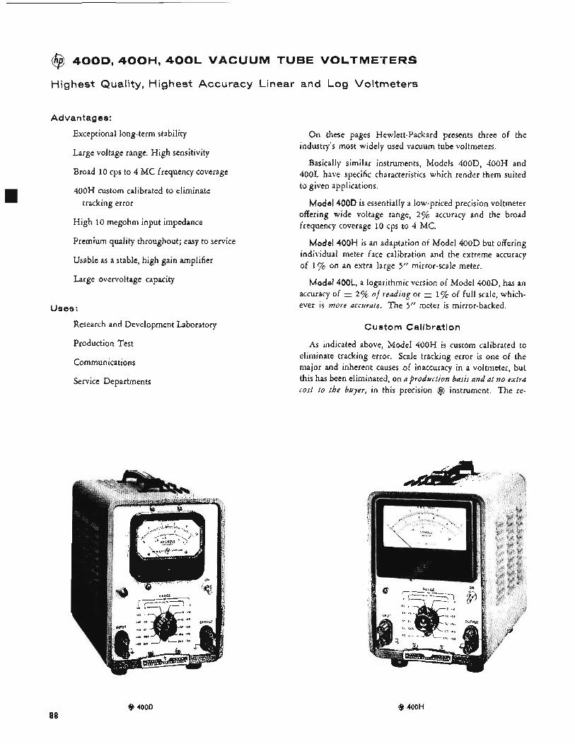
@ 400D, 400H, 400L VACUUM TUBE VOLTMETERS
Highest Quality, Highest Accuracy Linear and Log Voltmeters
Advantages:
Exceptional long-term stability
Large voltage range. High sensitivity
Broad 10 cps to 4 MC frequency coverage
400H custom calibrated to eliminate tracking error
High 10 megohm input impedance
Premium quality throughout; easy to service
Usable as a stable, high gain amplifier
Large overvoltage capacity
Uses :
On these pages Hewlett-Packard presents three of the
Basically similar instruments, Models 400D, 400H and 400L have specific characteristics which render them suited to given applications.
industry’s most widely used vacuum tube voltmeters.
Model 400D is essentially a low-priced precision voltmeter offering wide voltage range, 2% accuracy and the broad frequency coverage 10 cps to 4 MC.
Model 400H is an adaptation of Model 400D but offering individual meter face calibration and the extreme accuracy of 1% on an extra large 5” mirror-scale meter.
Model 400L, a logarithmic version of Model 400D, has an 1 % of full scale, which- accuracy of
ever is more accurate. The 5’’ meter is mirror-backed. 2 “/c of reading or
Research and Development Laboratory Custom Calibration
Production Test
Communications
Service Departments
As indicated above, Model 400H is custom calibrated to eliminate tracking error. Scale tracking error is one of the major and inherent causes of inaccuracy in a voltmeter, but this has been eliminated, on a production basis and at no extra cost t o the buyer, in this precision @ instrument. The re-
@ 4000 88
@ 400H
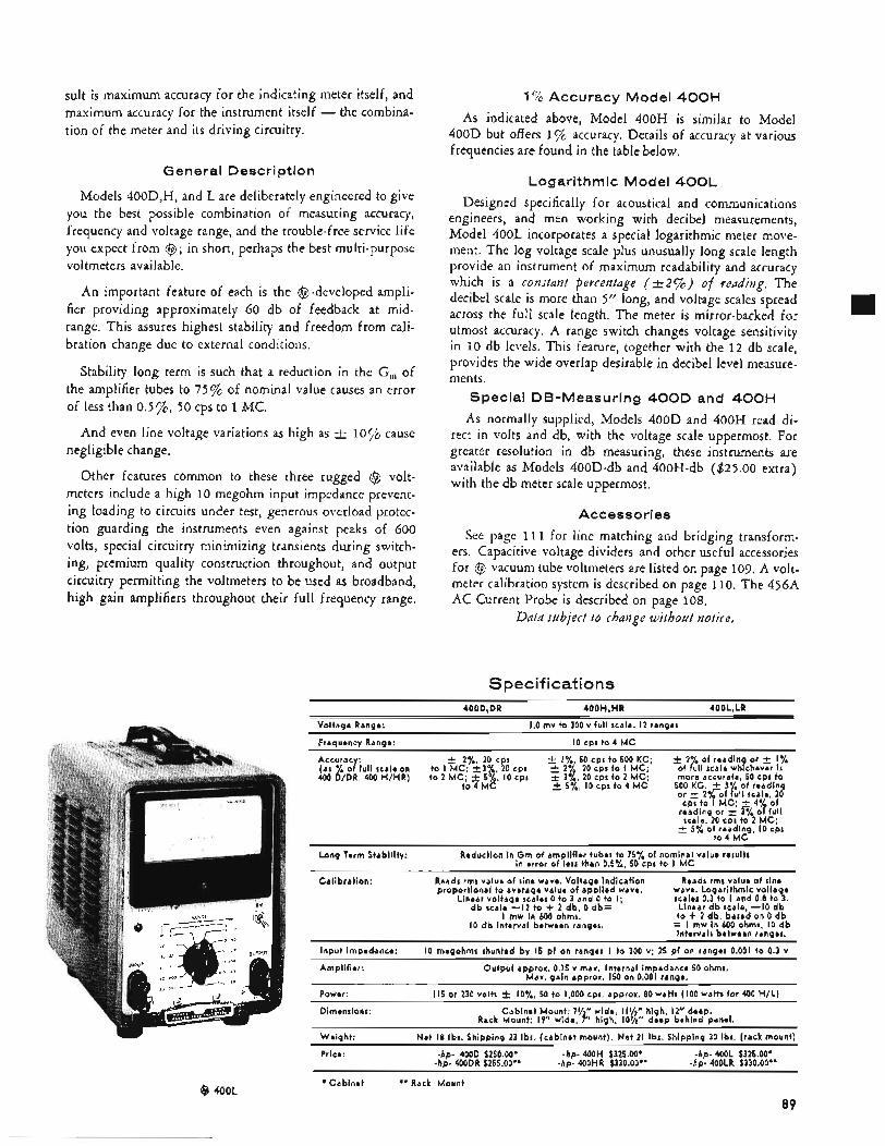
sult is maximum accuracy for the indicating meter itself, and maximum accuracy for the instrument itself - the combina- tion of the meter and its driving circuitry.
General Description
Models 400D,H, and L are deliberately engineered to give you the best possible combination of measuring accuracy, frequency and voltage range, and the trouble-free service life you expect from @; in short, perhaps the best multi-purpose voltmeters available,
An important feature of each is the @-developed ampli- fier providing approximately 60 db of feedback at mid- range. This assures highest stability and freedom from cali- bration change due to external conditions.
Stability long term is such that a reduction in the G,, of the amplifier tubes to 75% of nominal value causes an error of less than 0.5%, 50 cps to 1 MC.
negligible change. And even line voltage variations as high as -+ 10% cause
Other features common to these three rugged @ volt- meters include a high 10 megohm input impedance prevent- ing loading to circuits under test, generous overload protec- tion guarding the instruments even against peaks of 600 volts, special circuitry minimizing transients during switch- ing, premium quality construction throughout, and output circuitry permitting the voltmeters to be used as broadband, high gain amplifiers throughout their full frequency range.
1% Accuracy Model 400H
As indicated above, Model 400H is similar to Model 400D but offers 1% accuracy. Details of accuracy at various frequencies are found in the table below.
Logarithmic Model 400L
Designed specifically for acoustical and communications engineers, and men working with decibel measurements, Model 400L incorporates a special logarithmic meter move- ment. The log voltage scale plus unusually long scale length provide an instrument of maximum readability and accuracy which is a constant percentage (-+.2%) of readiizg. The decibel scale is more than 5” long, and voltage scales spread across the full scale length. The meter is mirror-backed for utmost accuracy. A range switch changes voltage sensitivity in 10 db levels. This feature, together with the 12 db scale, provides the wide overlap desirable in decibel level measure- ments.
Special DB-Measuring 400D and 4 0 0 H
As normally supplied, Models 400D and 400H read di- rect in volts and db, with the voltage scale uppermost. For greater resolution in db measuring, these instruments are available as Models 400D-db and 400H-db ($25.00 extra) with the db meter scale uppermost.
Accessories
See page 11 1 for line matching and bridging transform- ers. Capacitive voltage dividers and other useful accessories for @ vacuum tube voltmeters are listed on page 109. A volt- meter calibration system is described on page 110. The 456A AC Current Probe is described on page 108.
Data subject to change without notice.
Specifications 400D,DR 400H,HR 4001,LR
1.0 mv to 300 v full scale. I2 ranges
I O cps to 4 M C
Voltage Range:
Frequency Range:
Accuracy: (as % of full scale on 400 D/DR, 400 H/HR)
f 2y0, 20 cps to I MC. +3%, 20 cps t o 2 MC;’ 5 % I O cps
to 4 MC
+ 17 50 cps to 500 KC: 2 27:, 20 cps to I MC; i 3 7 20 cpr to 2 MC.
59*’, I O cps to 4 M d
Long Term Stability:
Calibration:
Reduction in G m of amplifier tubes to 75% of nominal value results in error of less than 0.5%, 50 cps to I M C
Reads rms value of sine wave. Voltage indication proportional to average value of applied wave.
Linear voltage scales 0 to 3 and 0 to I; db scale -I2 to + 2 db, 0 db=
I mw in 600 ohms. IO d b interval between ranges.
Reads rmr value of sine wave. Logarithmic voltage scales 0.3 to I and 0.8 to 3.
Linear db scale -IO d b t o + 2 db, basek on 0 d b = I mw in 600 ohms, I O d b intervals between ranges.
IO megohms shunted by 15 pf on ranges I to 300 v; 25 pf on ranges 0.001 to 0.3 v
Output approx. 0.15 v max. Internal impedance 50 ohms. Max. gain approx. 150 on 0.001 range.
I15 or 230 volts f IO%, 50 to 1,000 cps. approx. 80 watts (100 watts for 400 H/L)
Rack Mount: IP” wide, 7” high,’ IO’/*’’ deep behind panel.
Net 18 Ibs. Shipping 23 Ibs. (cabinet mount). Net 21 Ibs. Shipping 30 Ibs. (rack mount)
-hD- 400DR $255.00’. -hD- 400HR $330.00” -hp. 400LR $330.00**
Input Impedance:
Amplifier:
Power:
Dimensions: Cabinet Mount: 7%” wide I11/2” high, 12” deep.
Weight:
Price: -hp- 400D $250.00’ -hp- 400H $325.00’ -hp- 400L $325.00’
@ 400L *Cabinet **Rack Mount
89
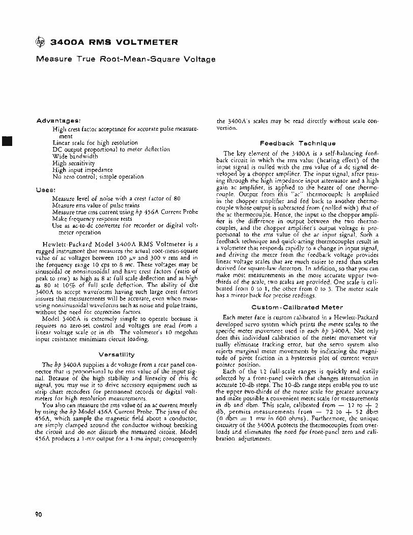
@ 3 4 0 0 A RMS VOLTMETER
Measure True Root-Mean-Sq uare Voltage
Advantages: High crest factor acceptance for accurate pulse measure-
Linear scale for high resolution D C output proportional to meter deflection Wide bandwidth High sensitivity High input impedance No zero control; simple operation
ment
Uses: Measure level of noise with a crest factor of 80 Measure rms value of pulse trains Measure true rms current using hp 456A Current Probe Make frequency response tests Use as ac-to-dc converter for recorder or digital volt-
Hewlett-Packard Model 3 4 0 0 A RMS Voltmeter is a rugged instrument that measures the actual root-mean-square value of ac voltages between 100 pv and 300 v rms and in the frequency range 10 cps to 8 mc. These voltages may be sinusoidal or nonsinusoidal and have crest factors (ratio of peak to rms) as high as 8 at full scale deflection and as high as 80 at 10% of full scale deflection, The ability of the 3400A to accept waveforms having such large crest factors insures that measurements will be accurate, even when meas- uring nonsinusoidal waveforms such as noise and pulse trains, without the need for correction factors.
Model 3400A is extremely simple to operate because it requires no zero-set control and voltages are read from a linear voltage scale or in db. The voltmeter’s 10 megohm input resistance minimizes circuit loading.
meter operation
Versatility
The hp 3400A supplies a dc voltage from a rear panel con- nector that is proportional to the rms value of the input sig- nal. Because of the high stability and linearity of this dc signal, you may use it to drive accessory equipment such as strip chart recorders for permanent records or digital volt- meters for high resolution measurements.
You also can measure the rms value of an ac current merely by using the hp Model 4564 Current Probe. The jaws of the 456A, which sample the magnetic field about a conductor, are simply clamped around the conductor without breaking the circuit and do not disturb the measured cirkit . Model 456A produces a 1-mv output for a 1-ma input; consequently
the 3400A’s scales may be read directly without scale con- version.
Feed back Technique
The key element of the 3400A is a self-balancing feed- back circuit in which the rms value (heating effect) of the input signal is nulled with the rrns value of a dc signal de- veloped by a chopper amplifier. The input signal, after pass- ing through the high impedance input attenuator and a high gain ac amplifier, is applied to the heater of one thermo- couple, Output from this “ac” thermocouple is amplified in the chopper amplifier and fed back to another thermo- couple whose output is subtracted from (nulled with) that of the ac thermocouple. Hence, the input to the chopper ampli- fier is the difference in output between the two thermo- couples, and the chopper amplifier’s output voltage is pro- portional to the rms value of the ac input signal. Such a feedback technique and quick-acting thermocouples result in a voltmeter that responds rapidly to a change in input signal, and driving the meter from the feedback voltage provides linear voltage scales that are much easier to read than scales derived for square-law detectors, In addition, so that you can make most measurements in the more accurate upper two- thirds of the scale, two scales are provided. One scale is cali- brated from 0 to 1, the other from 0 to 3. The meter scale has a mirror back for precise readings.
Custom-Calibrated Meter
Each meter face is custom calibrated in a Hewlett-Packard developed servo system which prints the meter scales to the specific meter movement used in each hp 3400A. Not only does this individual calibration of the meter movement vir- tually eliminate tracking error, but the servo system also rejects marginal meter movements by indicating the magni- tude of pivot friction in a hysteresis plot of current versus pointer position.
Each of the 1 2 full-scale ranges is quickly and easily selected by a front-panel switch that changes attenuation in accurate 10-db steps. The lo-db range steps enable you to use the upper two-thirds of the meter scale for greater accuracy and make possible a convenient meter scale for measurements in db and dbm. This scale, calibrated from - 1 2 to + 2 db, permits measurements f rom - 72 to + 5 2 dbm ( 0 dbm 1 mw in 600 ohms). Furthermore, the unique circuitry of the 3400A protects the thermocouples from over- loads and eliminates the need for front-panel zero and cali- bration adjustments.
90
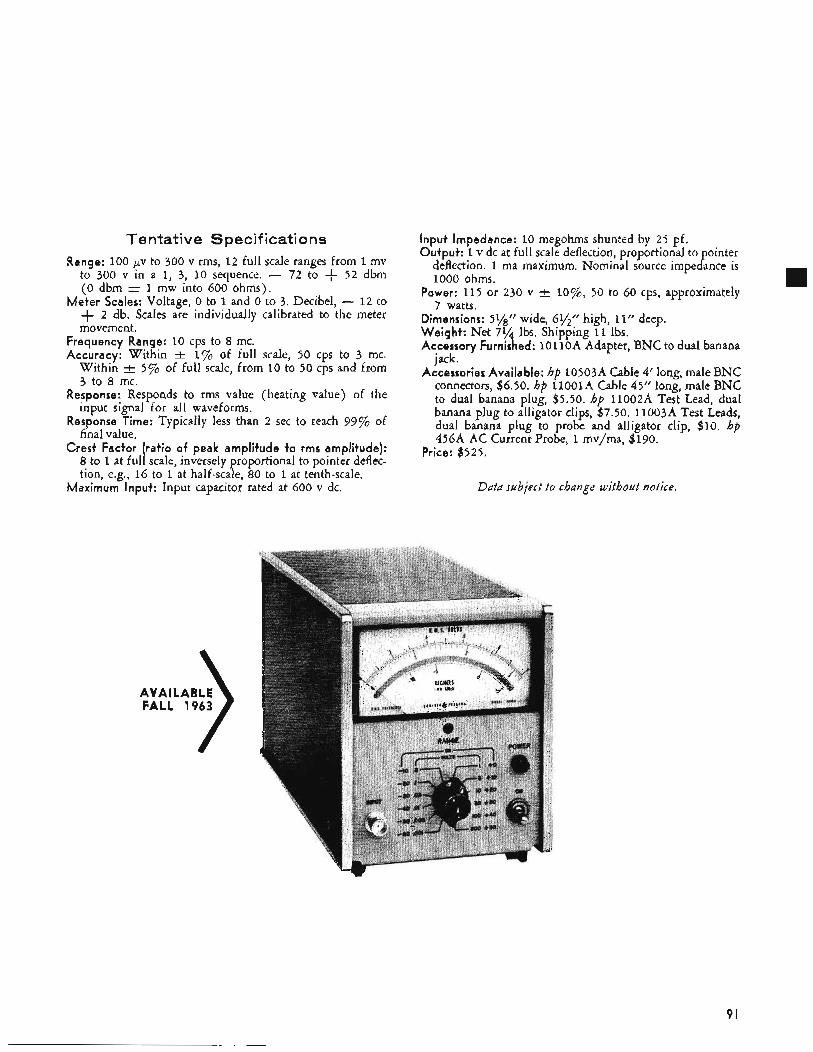
Tentative Specifications Range: 100 ,UV to 300 v rms, 12 full scale ranges from 1 mv
to 300 v in a 1, 3, IO sequence. - 72 to + 52 dbm ( 0 dbm = 1 mw into 600 ohms).
Meter Scales: Voltage, 0 to 1 and 0 to 3. Decibel, - 1 2 to + 2 db. Scales are individually calibrated to the meter movement.
Frequency Range: 10 cps to 8 mc. Accuracy: Within + 1% of full scale, 50 cps to 3 mc.
Within 5 % of full scale, from 10 to 50 cps and from 3 to 8 mc.
Response: Responds to rms value (heating value) of the input signal for all waveforms.
Response Time: Typically less than 2 sec to reach 99% of final value.
Crest Factor (ratio of peak amplitude to rms amplitude): 8 to 1 at full scale, inversely proportional to pointer deflec- tion, e.g., 16 to 1 at half-scale, 80 to 1 at tenth-scale.
Maximum Input: Input capacitor rated at 600 v dc.
Input Impedance: 10 megohms shunted by 25 pf. Output: 1 v dc at full scale deflection, proportional to ointer
Power: 115 or 230 v f lo%, 50 to 60 cps, approximately
Dimensions: 5y8” wide, 6y2” high, 11” deep. Weight: Net 754 Ibs. Shipping 11 Ibs. Accessory Furnished: 1 o l l o A Adapter, BNC to dual banana
jack. Accessories Available: hp l0503A Cable 4’ long, male BNC
connectors, $6.50. hp 11oolA Cable 45’’ long, male BNC to dual banana plug, $5.50. hp 11002A Test Lead, dual banana plug to alligator clips, $7.50. llOO3A Test Leads, dual banana plug to probe and alligator clip, $10. hp 456A AC Current Probe, 1 mvjma, $190.
deflection. 1 ma maximum, Nominal source impe cr ance is 1000 ohms.
7 watts.
Price: $525.
Data subject to change without notice.
AVAILABLE FALL 1963
91
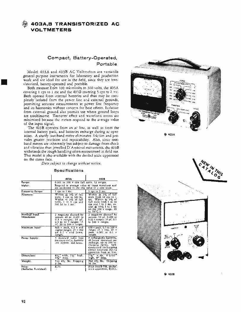
@ 403A,B TRANSISTORIZED AC VOLTMETERS
Frequency Range: Accuracy:
Nominal Input Impedance:
Maximum Input:
Compact, Battery-Operated, Portable
1 cps to 1 mc. 5 cps to 2 mc. With in t 3% of ful l Wi th in i- 2% of full scale, 5 cps to 500 kc. scale from 10 cps to 1 With in j, 5 % of full mc. Wi th in i. 5 % of scale, 1 to 5 cps and full scale from 5 to 10 500 kc to 1 mc. cps and 1 to 2 rnc, ex.
cept t 10% 1 to 2 mc on the 300 v range. (0 to 50°C.)
2 megohms shunted by 2 megohms shunted by approx. 40 pf 0.001 to approx. 5 0 pf, 0.001 to 0.1 v r a n g e s ; 2 0 p f , 0.03 v ranges: 2 5 pi, 0.1 0.3 to 10 v ranges: 15 to 300 v ranges. pf, 30 to 300 v ranges. 600 v peak, 0 .3 v and 600 v peak, 0 .3 to 300 v higher ranges: 2 5 v rms range; 2 5 v rms, 60 v o n 0 . 1 v a n d l o w e r peak, 0.001 to 0.1 v
Model 403A and 403B A C Voltmeters are versatile general-purpose instruments for laboratory and production work and are ideal for use in the field, since they are tran- sistorized, battery-operated and portable.
Both measure from 100 microvolts to 300 volts, the 403A covering 1 cps to 1 mc and the 403B covering 5 cps to 2 mc. Both operate from internal batteries and thus may be com- pletely isolated from the power line and external grounds, permitting accurate measurements at power line frequency and its harmonics without concern for beat effects. Isolation from external ground also permits use where ground loops are troublesome. Turnover effect and waveform errors are minimized because the meters respond to the average value of the input signal.
The 403B operates from an ac line, as well as from the internal battery pack, and batteries recharge during ac oper- ation. A sturdy taut-band meter eliminates friction and pro- vides greater precision and repeatability. Also, since taut- band meters are inherently less subject to damage from shock and vibration than jewelled D’Arsonval movements, the 403B withstands the rough handling often encountered in field use. This model is also available with the decibel scale uppermost on the meter face.
Data subject t o rhauge without notice.
Specifications
Power Supply:
I 403A I 403B Ranae: I 0.001 to 300 v rms full scale, 12 ranges.
ranges. ranges. 5 standard radio type 4 rechargeable batteries. m e r c u r y ce l l s , b a t t e r y 40 hours’ operation per life approx. 400 hours. recharge, up to 500 re.
charging cycles. Self- c o n t a i n e d r e c h a r g i n g
Meter: I Respond to average value of input waveform and are calibrated in the rms value of a sine wave.
@ 403A
I I circuit functions during
Dimensions:
92
@ 403B
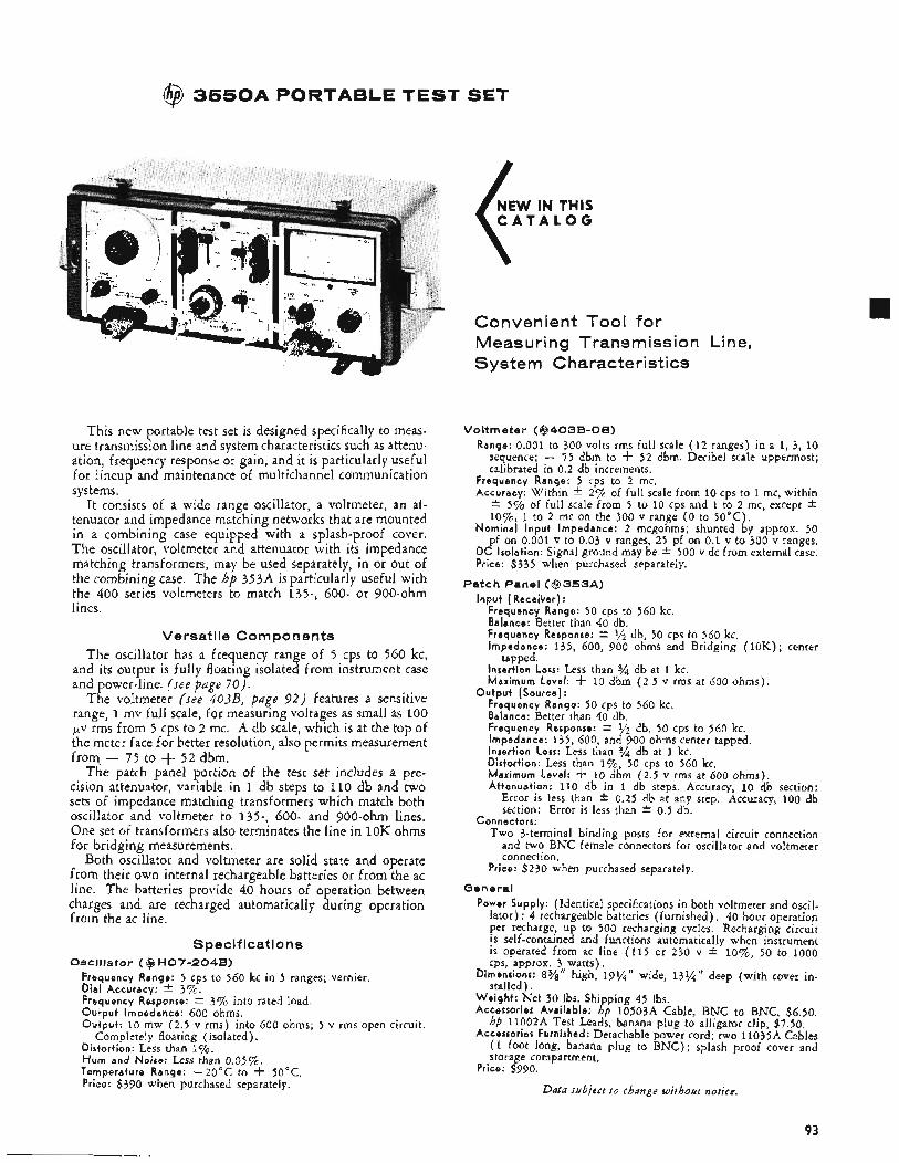
@ 3 5 5 0 A PORTABLE TEST SET
This new portable test set is designed specifically to meas- ure transmission line and system characteristics such as attenu- ation, frequency response or gain, and it is particularly useful for lineup and maintenance of multichannel communication systems.
It consists of a wide range oscillator, a voltmeter, an at- tenuator and impedance matching networks that are mounted in a combining case equipped with a splash-proof cover. The oscillator, voltmeter and attenuator with its impedance matching transformers, may be used separately, in or out of the combining case. The hp 353A is particularly useful with the 400 series voltmeters to match 135-, 600- or 900-ohm lines.
Versatile Components The oscillator has a frequency range of 5 cps to 560 kc,
and its output is fully floating isolated from instrument case and power-line. (see page 70).
The voltmeter (see 403B, page 9 2 ) features a sensitive range, 1 mv full scale, for measuring voltages as small as 100 pv rms from 5 cps to 2 mc. A db scale, which is at the top of the meter face for better resolution, also permits measurement from, - 75 to + 5 2 dbm.
The patch panel portion of the test set includes a pre- cision attenuator, variable in 1 db steps to 110 db and two sets of impedance matching transformers which match both oscillator and voltmeter to 135-, 600- and 900-ohm lines. One set of transformers also terminates the line in 1oK ohms for bridging measurements.
Both oscillator and voltmeter are solid state and operate from their own internal rechargeable batteries or from the ac line. The batteries provide 40 hours of operation between charges and are recharged automatically during operation from the ac line.
Specifications Oscillator ( @ HO7-2048)
Frequency Range: 5 cps to 560 kc in 5 ranges; vernier. Dial Accuracy: * 3 7 ~ . Frequency Response: * 3% into rated load. Output Impedance: 600 ohms. Output: 10 mw (2.5 v rms) into 600 ohms; 5 v rms open circuit.
Distortion: Less than 1%. H u m and Noire: Less than 0.05’$%. Temperature Range: -20°C to 4- 50°C. Price: $390 when purchased separately.
Completely floating (isolated).
NEW IN THIS C A T A L O G
Convenient Tool for Measuring Transmission Line, System Characteristics
Voltmeter (@403B-DB) Range: 0.001 to 300 volts rms full scale (12 ranges) in a 1, 3, 10
sequence; - 7 5 dbm to + 5 2 dbm. Decibel scale uppermost; calibrated in 0.2 db increments.
Frequency Range: 5 cps to 2 mc. Accuracy: Within * 2% of full scale from 10 cps to 1 mc, within * 5 % of full scale from 5 to 10 cps and 1 to 2 mc, except I:
l o%, 1 to 2 mc on the 300 v range ( 0 to 50°C) . Nominal Input Impedance: 2 megohms; shunted by approx. 50
pf on 0.001 v to 0.03 v ranges, 25 pf on 0.1 v to 300 v ranges. D C Isolation: Signal ground may be -C 500 v dc from external case. Price: $335 when purchased separately.
Input (Receiver) : Patch Panel ( @ 3 5 3 A )
Frequency Range: 50 cps to 560 kc. Balance: Better than 40 db. Frequency Response: t 1/2 db, 50 CPS to 560,kc. Impedance: 135, 600, 900 ohms and Bridging (10K) ; center
Insertion Loss: Less than % db at 1 kc. Maximum Level: f 10 dbm ( 2 . 5 v rms at 600 ohms).
Frequency Range: 50 cps to 560 kc. Balance: Better than 40 db. Frequency Response: k ‘/2 db, 50 cps to 560 kc. Impedance: 135, 600, and 900 ohms center tapped. Insertion Loss: Less than Distortion: Less than I % , 50 cps to 560 kc. Maximum Level: f 10 dbm (2.5 v rms at 600 ohms). Attenuation: 110 db in 1 db steps. Accuracy, 10 db section:
Error is less than f 0.25 db at any step. Accuracy, 100 db section: Error is less than -C 0.5 db.
Connectors: Two 3-terminal binding posts for external circuit connection
and two BNC female connectors for oscillator and voltmeter connection.
tapped.
Output (Source):
db at 1 kc.
Price: $230 when purchased separately.
General Power Supply: (Identical specifications in both voltmeter and oscil-
lator) : 4 rechargeable batteries (furnished). 40 hour operation per recharge, up to 500 recharging cycles. Recharging circuit is self-contained and functions automatically when instrument is operated from ac line (115 or 230 v * l o%, 50 to 1000 cps, approx. 3 watts).
Dimensions: 8%” high, 19%’’ wide, 13%” deep (with cover in- stalled).
Weight : Net 30 Ibs. Shipping 45 Ibs. Accessories Available: hp 10503A Cable, BNC to BNC, $6.50.
hp 11002A Test Leads, banana plug to alligator clip, $7.50. Accessories Furnished: Detachable power cord; two 11035A Cables
(1 foot long, banana plug to BNC) ; splash proof cover and storage compartment.
Price: $990.
Data subject to change without notice.
93
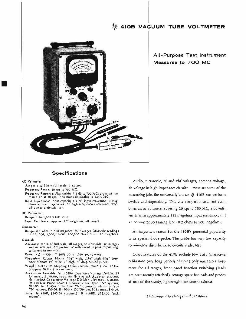
All-Purpose Test Instrument
Measures to 700 MC
Spec if i cat i o n s
AC Voltmeter: Range: 1 to 300 v full scale, 6 ranges. Frequency Range: 20 cps to 700 MC. Frequency Response: Flat within -C 1 db to 700 MC; drops off less
than 1 db at 20 cps. Indications obtainable to 3,000 MC. input impedance: Input capacity 1.5 pf, input resistance 10 meg-
ohms at low frequencies. At high frequencies resistance drops off due to dielectric loss.
DC Voltmeter: Range: 1 to 1,000 v full scale. Input Resistance: Approx. 1 2 2 megohms, all ranges.
Ohmmeter: Range: 0.2 ohm to 500 megohms in 7 ranges. Midscale readings
of 10, 100, 1,000, 10,000, 100,000 ohms, 1 and 10 megohms.
Accuracy: +. 3% of full scale, all ranges, on sinusoidal ac voltages and dc voltages. AC portion of instrument is peak-responding, calibrated in rms volts.
General:
Power: 115 or 230 v f l o % , 50 to 1,000 cps, 40 watts. Dimensions: Cabinet Mount: 73/s“ wide, 11?/2’’ high, 8%” deep,
Rack Mount: 19” wide, 7” high, 6” deep behind panel. Weight : Net 1 2 Ibs. Shipping 17 Ibs. (cabinet mount). Net 1 2 Ibs.
Shipping 20 Ibs. (rack mount). Accessories Available: @ 11039A Capacitive Voltage Divider, 25
kv max. , $150.00 , requires @ 11018A Adapter , $25.00. @ 1 l 0 4 0 A Capaci t ive Vol tage Div ider , 2 kv max., $30.00. @ 11042A Probe Coax T Connector for Type “N” systems, $40.00. @ 11043A Probe Coax “ N ” Connector adapts to Type “N”systems, $30.00. @ 11044A D C Divider, 30 kv max., $50.00.
Price: @ 410B, $245.00 (cabinet); @ 410BR, $265.00 (rack mount) .
Audio, ultrasonic, rf and vhf voltages, antenna voltage,
dc voltage in high impedance circuits-these are some of the
measuring jobs the universally-known @ 410B can perform
swiftly and dependably. This one compact instrument com-
bines an ac voltmeter covering 20 cps to 700 MC, a dc volt-
meter with approximately 122 megohms input resistance, and
an ohmmeter measuring from 0.2 ohms to 500 megohms.
An important reason for the 410B’s perennial popularity
is its special diode probe. The probe has very low capacity
to minimize disturbance to circuits under test.
Other features of the 410B include low drift (maintains
calibration over long periods of time) only one zero adjust-
ment for all ranges, front panel function switching (leads
are permanently attached), storage space for leads and probes
at rear of the sturdy, lightweight instrument cabinet.
Data subject to change without notice.
94
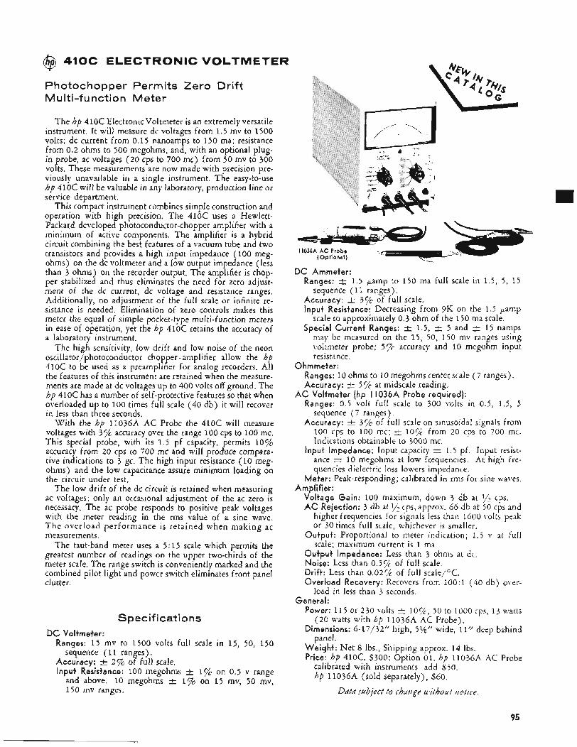
@ 410C ELECTRONIC VOLTMETER
Photochopper Permits Zero Drift M u Iti -f u nctio n Meter
The hp 410C ElectronicVoltmeter is an extremely versatile instrument. It will measure dc voltages from 1.5 mv to 1500 volts; dc current from 0.15 nanoamps to 150 ma; resistance from 0.2 ohms to 500 megohms, and, with an optional plug- in probe, ac voltages (20 cps to 700 mc) from 50 mv to 300 volts. These measurements are now made with precision pre- viously unavailable in a single instrument. The easy-to-use hp 410C will be valuable in any laboratory, production line or service department.
This compact instrument combines simple construction and operation with high precision. The 410C uses a Hewlett- Packard developed photoconductor-chopper amplifier with a minimum of active components. The amplifier is a hybrid circuit combining the best features of a vacuum tube and two transistors and provides a high input impedance (100 meg- ohms) on the dc voltmeter and a low output impedance (less than 3 ohms) on the recorder output. The amplifier is chop- per stabilized and thus eliminates the need for zero adjust- ment of the dc current, dc voltage and resistance ranges. Additionally, no adjustment of the full scale or infinite re- sistance is needed. Elimination of zero controls makes this meter the equal of simple pocket-type multi-function meters in ease of operation, yet the hp 410C retains the accuracy of a laboratory instrument.
The high sensitivity, low drift and low noise of the neon oscillator/photoconductor chopper - amplifier allow the hp 410c to be used as a preamplifier for analog recorders. All the features of this instrument are retained when the measure- ments are made at dc voltages up to 400 volts off ground. The hp 410c has a number of self-protective features so that when overloaded up to 100 times full scale (40 db) it will recover in less than three seconds.
With the hp 11036A AC Probe the 410C will measure voltages with 3% accuracy over the range 100 cps to 100 mc. This special probe, with its 1.5 pf capacity, permits 10% accuracy from 20 cps to 700 mc and will produce compara- tive indications to 3 gc. The high input resistance (10 meg- ohms) and the low capacitance assure minimum loading on the circuit under test.
The low drift of the dc circuit is retained when measuring ac voltages; only an occasional adjustment of the ac zero is necessary. The ac probe responds to positive peak voltages with the meter reading in the rms value of a sine wave. T h e overload performance is retained when making ac measurements.
The taut-band meter uses a 5:15 scale which permits the greatest number of readings on the upper two-thirds of the meter scale. The range switch is conveniently marked and the combined pilot light and power switch eliminates front panel clutter.
Spec if i cat i o n s DC Voltmeter:
Ranges: 1 5 mv to 1500 volts full scale in 15, 50, 150
Accuracy: _t 2 % of full scale. Input Resistance: 100 megohms f 1% on 0.5 v range
and above. 10 megohms f 170 on 1 5 mv, 50 mv, 150 mv ranges.
sequence ( 11 ranges).
I1036A AC Probe (Optional)
DC Ammeter: Ranges: t 1.5 pamp to 150 ma full scale in 1 .5 , 5, 15
Accuracy: 2 3% of full scale. Input Resistance: Decreasing from 9K on the 1.5 pamp
scale to approximately 0.3 ohm of the 150 ma scale. Special Current Ranges: 1.5, t 5 and t 1 5 namps
may be measured on the 1 5 , 50, 150 mv ranges using voltmeter probe; 57k accuracy and 10 megohm input resistance.
sequence ( 11 ranges).
Ohmmeter: Ranges: 10 ohms to 10 megohms center scale (7 ranges). Accuracy: t 5% at midscale reading.
Ranges: 0.5 volt fuII scale to 300 volts in 0.5, 1.5, 5 sequence (7 ranges).
Accuracy: 3% of full scale on sinusoidal signals from 100 cps to 100 mc; -+ 10% from 20 cps to 700 mc. Indications obtainable to 3000 mc.
Input Impedance: Input capacity = 1.5 pf. Input resist- ance = 10 megohms at low frequencies. At high fre- quencies dielectric loss lowers impedance.
Mefer: Peak-responding; calibrated in rms for sine waves.
Voltage Gain: 100 maximum, down 3 db at y2 cps. AC Rejection: 3 db at y2 cps, approx. 66 db at 50 cps and
higher frequencies for signals less than 1600 volts peak or 30 times full scale, whichever is smaller.
Ou+puf: Proportional to meter indication; 1 . 5 v at full scale; maximum current is 1 ma.
Output Impedance: Less than 3 ohms at dc. Noise: Less than 0.5% of fulI scale. Drift: Less than 0.02% of full scale/OC. Overload Recovery: Recovers from 100:1 (40 db) over-
AC Voltmeter (hp I1036.A Probe required):
Amplifier:
load in less than 3 seconds. General:
Power: 115 or 230 volts _t 50 to 1000 cps, 13 watts
Dimensions: 6-17/32” high, >YEf’ wide, 11” deep behind
Weight: Net 8 Ibs., Shipping approx. 14 Ibs. Price: hp 410C, $300; Option 01. hp 11036A AC Probe
(20 watts with hp llO36A AC Probe).
panel.
calibrated with instruments add $50. hp llO36A (sold separately), $60.
Datd subject to chairge without iiotit-e.
95
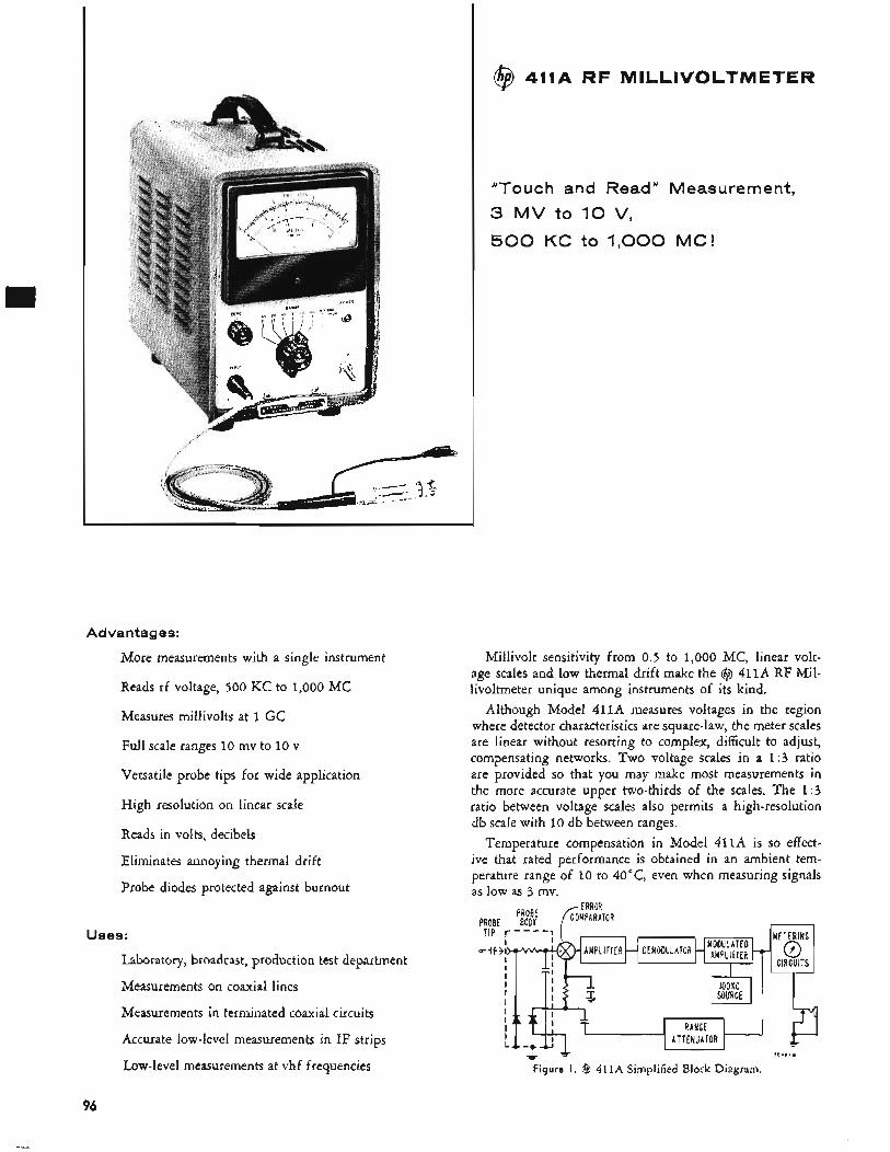
Advantages:
More measurements with a single instrument
Reads rf voltage, 500 KC to 1,000 MC
Measures millivolts at 1 GC
Full scale ranges 10 mv to 10 v
Versatile probe tips for wide application
High resolution on linear scale
Reads in volts, decibels
Eliminates annoying thermal drift
Probe diodes protected against burnout
UtATOR HM~~~~$~ERO *
Uses:
Laboratory, broadcast, production test department
Measurements on coaxial lines
Measurements in terminated coaxial circuits
Accurate low-level measurements in IF strips
Low-level measurements at vhf frequencies
METERING
CIRCUITS 0 *
@ 411A RF MILLIVOLTMETER
"Touch and Read'' Measurement, 3 MV to 10 V ,
500 K C to 1,000 MC!
Millivolt sensitivity from 0.5 to 1,000 MC, linear volt- age scales and low thermal drift make the @ 411A RF Mil- livoltmeter unique among instruments of its kind,
Although Model 411A measures voltages in the region where detector characteristics are square-law, the meter scales are linear without resorting to complex, difficult to adjust, compensating networks. Two voltage scales in a 1 : 3 ratio are provided so that you may make most measurements in the more accurate upper two-thirds of the scales. The 1:3 ratio between voltage scales also permits a high-resolution db scale with 10 db between ranges.
Temperature compensation in Model 411A is so effect- ive that rated performance is obtained in an ambient tem- perature range of 10 to 40"C, even when measuring signals as low as 3 mv.
PROBE BODY fil%:TOR -
96
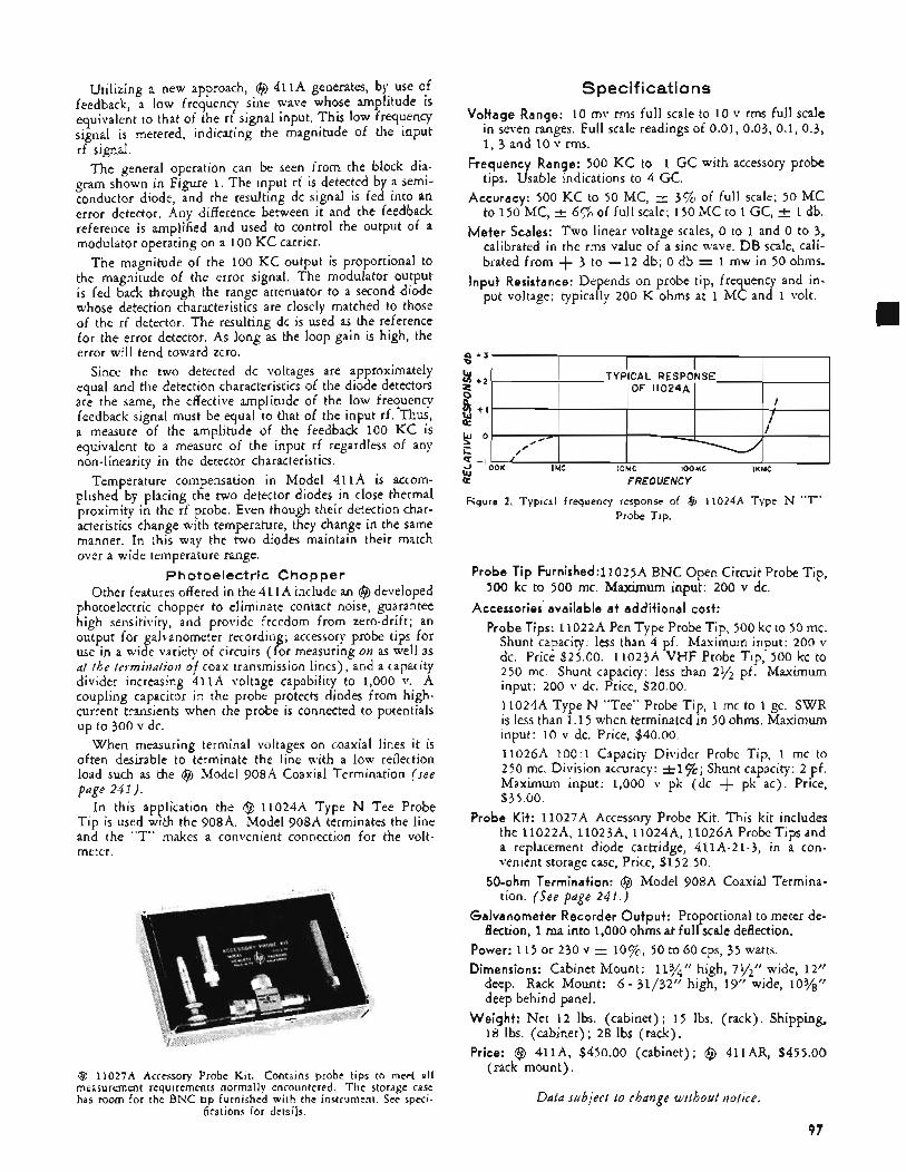
Utilizing a new approach, @ 411A generates, by use of feedback, a low frequency sine wave whose amplitude is equivalent to that of the rf signal input. This low frequency signal is metered, indicating the magnitude of the input rf signal.
The general operation can be seen from the block dia- gram shown in Figure 1. The input rf is detected by a semi- conductor diode, and the resulting dc signal is fed into an error detector. Any difference between it and the feedback reference is amplified and used to control the output of a modulator operating on a 100 KC carrier.
The magnitude of the 100 KC output is proportional to the magnitude of the error signal. The modulator output is fed back through the range attenuator to a second diode whose detection characteristics are closely matched to those of the rf detector. The resulting dc is used as the reference for the error detector. As long as the loop gain is high, the error will tend toward zero.
Since the two detected dc voltages are approximately equal and the detection characteristics of the diode detectors are the same, the effective amplitude of the low frequency feedback signal must be equal to that of the input rf. Thus, a measure of the amplitude of the feedback 100 KC is equivalent to a measure of the input rf regardless of any non-linearity in the detector characteristics.
Temperature compensation in Model 411A is accom- plished by placing the two detector diodes in close thermal proximity in the rf probe. Even though their detection char- acteristics change with temperature, they change in the same manner. In :his way the two diodes maintain their match over a wide temperature range.
Photoelectric Chopper Other features offered in the 411A include an @ developed
photoelectric chopper to eliminate contact noise, guarantee high sensitivity, and provide freedom from zero-drift; an output for galvanometer recording; accessory probe tips for use in a wide variety of circuits (for measuring on as well as at the termination of coax transmission lines), and a capacity divider increasing 411A voltage capability to 1,000 v. A coupling capacitor in the probe protects diodes from high- current transients when the probe is connected to potentials up to 300 v dc.
When measuring terminal voltages on coaxial lines it is often desirable to terminate the line with a low reflection load such as the @ Model 908A Coaxial Termination (see page 24 I ) .
In this application the @ l l 024A Type N Tee Probe Tip is used with the 908A. Model 908A terminates the line and the “T” makes a convenient connection for the volt- meter.
@ 11027A Accessory Probe Kit. Contains probe tips to meet all measurement requirements normally encountered. The storage case has room for the BNC tip furnished with the instrument. See speci-
fications for details.
Specifications Voltage Range: 10 mv rms full scale to 10 v rms full scale
in seven ranges, Full scale readings of 0.01, 0.03, 0.1, 0.3, 1, 3 and 10 v rms.
Frequency Range: 500 KC to 1 GC with accessory probe tips. Usable indications to 4 GC.
Accuracy: 500 KC to 50 MC, k 3% of full scale; 50 MC to 150 MC, t 6% of full scale; 150 MC to 1 GC, k 1 db.
Meter Scales: Two linear voltage scales, 0 to 1 and 0 to 3, calibrated in the rms value of a sine wave. DB scale, cali- brated from + 3 to -12 db; 0 db = 1 mw in 50 ohms.
Input Resistance: Depends on probe tip, frequency and in- put voltage; typically 200 K ohms at 1 MC and 1 volt. rn
3 t 3 I I I I 1 TYPICAL RESPONSE
OF 11024A 2 t 2 -
I 0 P v) + I I 2 I
2 t2- I I
0 P v) + I I 2 I
I 9 O- .# c /’
IMC IOMC IOOMC IKMC - -I ’ ,+ IOOK
s FREQUENCY
Figure 2. Typical frequency response of @ 11024.4 Type N “T’ Probe Tip.
Probe Tip Furnished:11025A BNC Open Circuit Probe Tip,
Accessories available a t additional cost:
500 kc to 500 mc. Maximum input: 200 v dc.
Probe Tips: 11022A Pen Type Probe Tip, 500 kc to 50 mc. Shunt capacity: less than 4 pf. Maximum input: 200 v dc. Price $25.00. 11023A VHF Probe Tip, 500 kc to 250 mc. Shunt capacity: less than 21/* pf. Maximum input: 200 v dc. Price, $20.00.
11024A Type N “Tee” Probe Tip, 1 mc to 1 gc. SWR is less than 1.15 when terminated in 50 ohms. Maximum input: 10 v dc. Price, $40.00. 11026A 100:1 Capacity Divider Probe Tip, 1 mc to 250 mc. Division accuracy: Shunt capacity: 2 pf. Maximum input: 1,000 v pk (dc + pk ac). Price, $35.00.
Probe Kit: 11027A Accessory Probe Kit. This kit includes the 11022A, 11023A, 11024A, 11026A ProbeTips and a replacement diode cartridge, 411A-21-3, in a con- venient storage case, Price, $152.50,
50-ohm Termination: @ Model 908A Coaxial Termina- tion. (See page 241 .)
Galvanometer Recorder Output: Proportional to meter de-
Power: 115 or 230 v k l o%, 50 to 60 cps, 35 watts. Dimensions: Cabinet Mount: 113/” high, 7%’’ wide, 12”
deep. Rack Mount: 6 - 31/32” high, 19” wide, 103/8” deep behind panel.
Weight: Net 1 2 lbs. (cabinet); 15 lbs. (rack). Shipping, 18 lbs. (cabinet); 2 8 lbs (rack).
Price: @ 411~4, $450.00 (cabinet); @ 411AR, $455.00 (rack mount).
flection, 1 ma into 1,000 ohms at full scale deflection.
Data subject to change without notice.
97
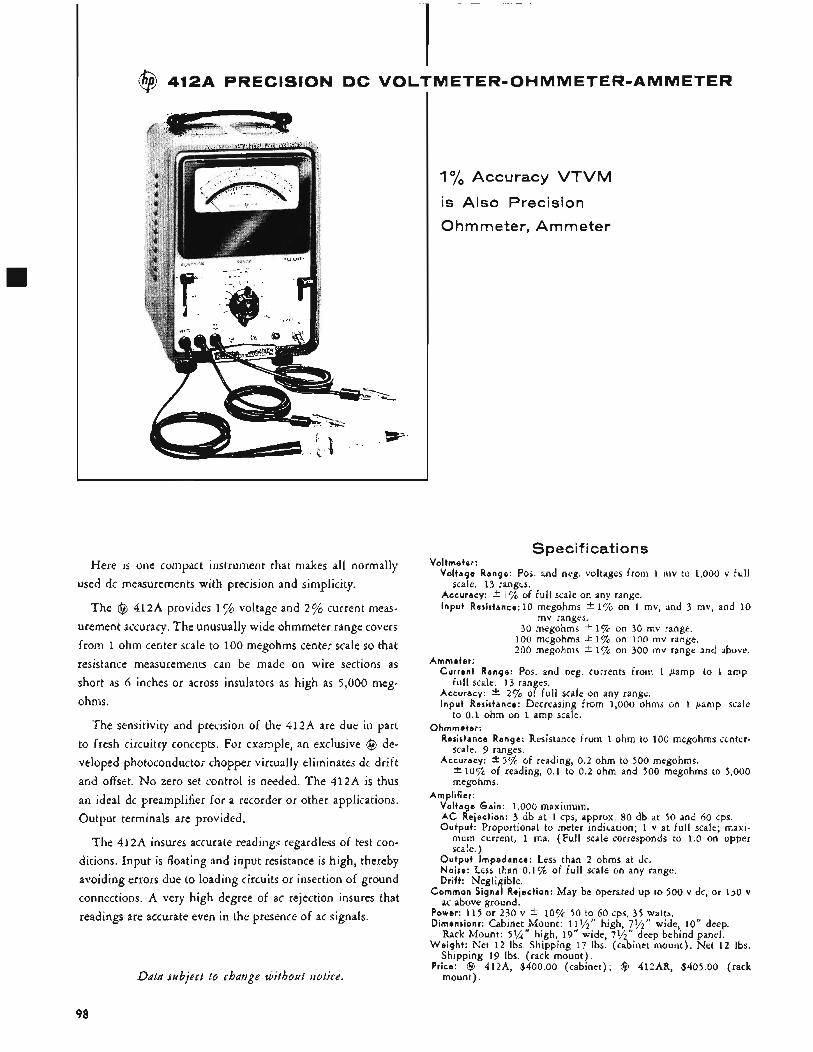
Here is one compact instrument that makes all normally used dc measurements with precision and simplicity.
The @ 412A provides 1% voltage and 2% current meas- urement accuracy. The unusually wide ohmmeter range covers from 1 ohm center scale to 100 megohms center scale so that resistance measurements can be made on wire sections as short as 6 inches or across insulators as high as 5,000 meg- ohms.
The sensitivity and precision of the 412A are due in part to fresh circuitry concepts. For example, an exclusive @ de- veloped photoconductor chopper virtually eliminates dc drift and offset. No zero set control is needed. The 412A is thus an ideal dc preamplifier for a recorder or other applications. Output terminals are provided.
The 412A insures accurate readings regardless of test con- ditions. Input is floating and input resistance is high, thereby avoiding errors due to loading circuits or insertion of ground connections. A very high degree of ac rejection insures that readings are accurate even in the presence of ac signals.
Data subject to change without notice.
1% Accuracy VTVM
is Also Precision
Ohm meter, Am meter
Specifications Vol tmeter :
Vol tage Range: Pos. and neg. voltages from 1 mv to 1,000 v f u l l
Accuracy: k I VG of f u l l scale on any range. I npu t Resistance: 10 megohms f l"/o on 1 mv, and 3 mv, and 10
scale. 13 ranges.
mv ranges. 30 megohms *17~ on 30 mv range.
100 megohms 2 1% on 100 mv range. 200 megohms 2 1% on 300 mv range and above.
Cur ren t Range: Pos. and neg. currents from 1 pamp to 1 amp
Accuracy: * 27G of full scale on any range. I npu t Resistance: Decreasing from 1,000 ohms on 1 pamp scale
Ammeter :
ful l scale. 13 ranges.
to 0.1 ohm on 1 amp scale. Ohmmete r :
Resistance Range: Resistance from 1 ohm to 100 megohms ccnter-
Accuracy: +- 5% of reading, 0.2 ohm to 500 megohms. scale. 9 ranges.
* 1 0 7 ~ of reading, 0.1 to 0.2 ohm and 500 megohms to 5,000 megohms.
Ampl i f ier : Vol tage Gain: 1,000 maximum. AC Rejection: 3 db at 1 cps, approx. 80 db at 50 and 60 cps. Outpu t : Proportional to meter indication; 1 v at full scale; maxi-
mum current, 1 ma. (Full scale corresponds to 1.0 on upper scale. )
O u t p u t Impedance: Less than 2 ohms at dc. Noise: Less than 0.170 of full scale on any range. Dr i f t : Negligible.
Common Signal Rejection: May be operated up to 500 v dc, or 130 v ac above ground.
Power: 115 or 230 v f 10% 50 tq,60 cps, 35 watts. Dimensions: Cabinet Mount: 111/2
Rack Mount: 5 % " high, 19" wide, 79'2" deep behind panel. W e i g h t : Net 12 Ibs. Shipping 17 Ibs. (cabinet mount) . Net 1 2 Ibs.
Shipping 19 Ibs. (rack mount). Price: @ 412A, $400.00 (cabinet); @ 412AR, $405.00 (rack
mount).
high, 71/2" wide, 10" deep.
98
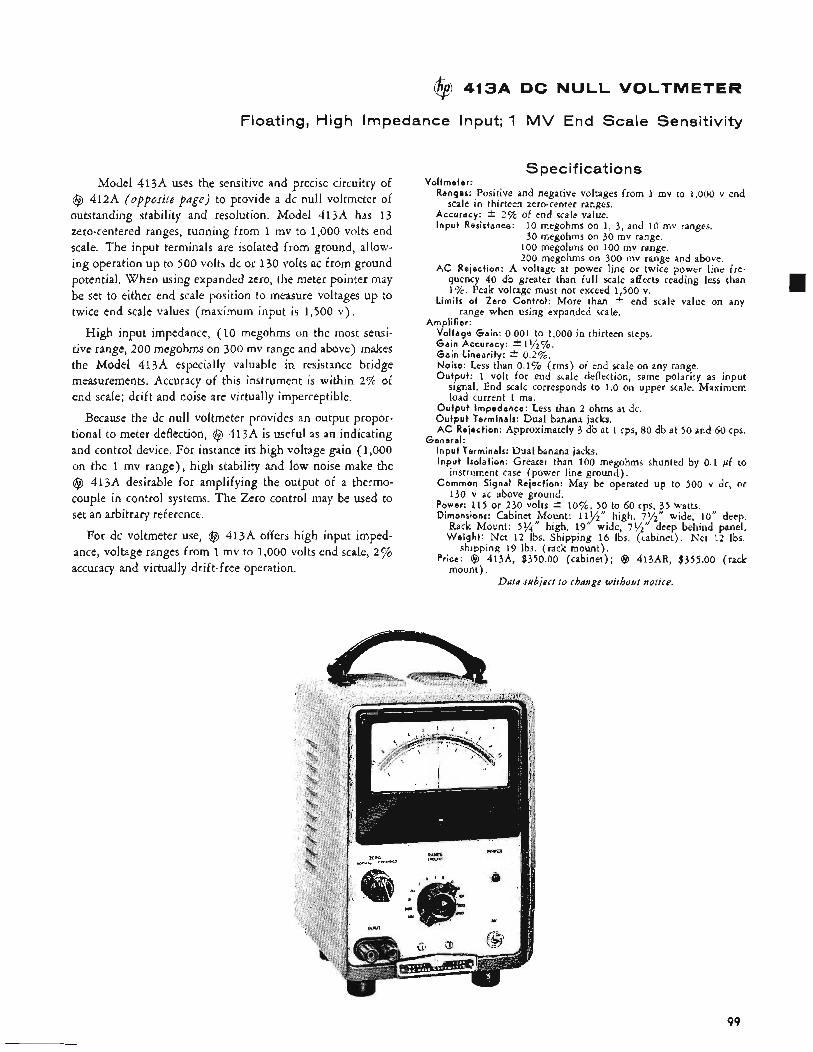
413A DC NULL VOLTMETER
Floating, High Impedance Input; 1 MV End Scale Sensitivity
Model 413A uses the sensitive and precise circuitry of @ 412A (opposite page) to provide a dc null voltmeter of outstanding stability and resolution. Model 413A has 13 zero-centered ranges, running from 1 mv to 1,000 volts end scale. The input terminals are isolated from ground, allow- ing operation up to 500 volts dc or 130 volts ac from ground potential. When using expanded zero, the meter pointer may be set to either end scale position to measure voltages up to twice end scale values (maximum input is 1,500 v) ,
High input impedance, (10 megohms on the most sensi- tive range, 200 megohms on 300 mv range and above) makes the Model 41 3A especially valuable in resistance bridge measurements, Accuracy of this instrument is within 2% of end scale; drift and noise are virtually imperceptible.
Because the dc null voltmeter provides an output propor- tional to meter deflection, @ 413A is useful as an indicating and control device, For instance its high voltage gain (1,000 on the 1 mv range), high stability and low noise make the @ 413A desirable for amplifying the output of a thermo- couple in control systems. The Zero control may be used to set an arbitrary reference.
For dc voltmeter use, @ 413A offers high input imped- ance, voltage ranges from 1 mv to 1,000 volts end scale, 2 % accuracy and virtually drift-free operation.
Specifications Vol tmeter :
Ranges: Positive and negative voltages from 1 mv to 1,000 v end
Accuracy: + 25% of end scale value. I npu t Resistance:
scale in thirteen zero-center ranges.
10 megohms on 1, 3, and 10 mv ranges. 30 megohms on 30 mv range.
100 megohms on 100 inv range. 200 megohms on 300 mv range and above.
AC Rejection: A voltage at power line or twice power line fre- quency 40 db greater than full scale affects reading less than 1%. Peak voltage must not exceed 1,500 v.
Limi ts of Zero Contro l : More than t end scale value on any range when using expanded scale,
Ampl i f ier : Vol tage Gain: 0.001 to 1,000 in thirteen steps. G a i n Accuracy: * 11/2c/o. G a i n Linearity: * 0 . 2 7 0 . Noise: Less than 0.1% (rms) of end scale on any range. Outpu t : 1 volt for end scale deflection, same polarity as input
signal. End scale corresponds to 1.0 on upper scale. Maximum load current 1 ma.
O u t p u t Impedance: Less than 2 ohms at dc. O u t p u t Terminals: Dual banana jacks. AC Rejection: Approximately 3 db at 1 cps, 80 db at 50 and 60 cps.
I npu t Terminals: Dual banana jacks. I npu t Isolat ion: Greater than 100 megohms shunted by 0.1 pf to
Common Signal Rejection: May be operated up to 500 v dc, or
Power: 115 or 230 volts * l o % , 50 to 60 cps, 35 watts. Dimensions: Cabinet , p u n t : 11%" high, 79"" wide, 10'' deep.
Rack Mount: 5 % high, 19" wide, 7%" deep behind panel. W e i g h t : Net 1 2 Ibs. Shipping 16 Ibs. (cabinet). Net 12 lbs.
Price: @ 413A, $350.00 (cabinet); @ 413AR, $355.00 (rack mount) .
Genera l :
instrument case (power line ground).
130 v ac above ground.
shipping 19 Ibs. (rack mount).
Data subject to change without notice.
99
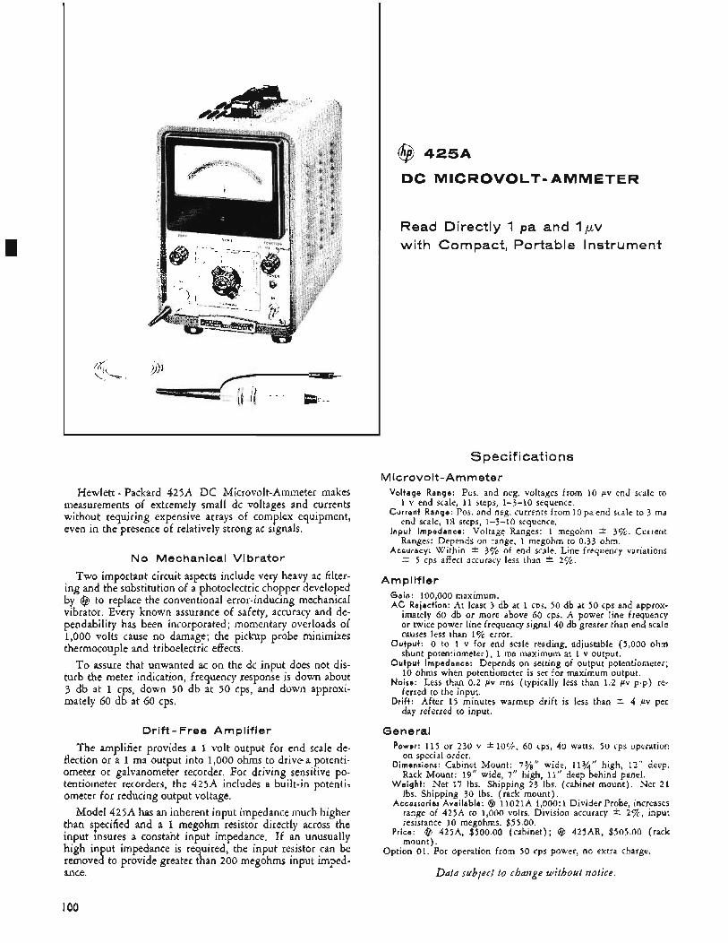
Hewlett - Packard 425A DC Microvolt-Ammeter makes measurements of extremely small dc voltages and currents without requiring expensive arrays of complex equipment, even in the presence of relatively strong ac signals.
No Mechanical Vibrator
Two important circuit aspects include very heavy ac filter- ing and the substitution of a photoelectric chopper developed by @ to replace the conventional error-inducing mechanical vibrator, Every known assurance of safety, accuracy and de- pendability has been incorporated; momentary overloads of 1,000 volts cause no damage; the pickup probe minimizes thermocouple and triboelectric effects.
To assure that unwanted ac on the dc input does not dis- turb the meter indication, frequency response is down about 3 db at 1 cps, down 50 db at 50 cps, and down approxi- mately 60 db at 60 cps.
Drift- Free Amplifier
The amplifier provides a 1 volt output for end scale de- flection or a 1 ma output into 1,000 ohms to drivea potenti- ometer or galvanometer recorder. For driving sensitive po- tentiometer recorders, the 425A includes a built-in potenti: ometer for reducing output voltage.
Model 425A has an inherent input impedance much higher than specified and a 1 megohm resistor directly across the input insures a constant input impedance, If an unusually high input impedance is re uired, the input resistor can be
ance. removed to provide greater R t an 200 megohms input imped-
@ 4 2 5 A
DC MICROVOLT-AMMETER
Read Directly 1 pa and 1pv with Compact, Portable Instrument
Specifications M icrovolt-Am meter
Vol tage Range: Pos. and neg. voltages from 10 pv end scale to
Cur ren t Range: Pos. and neg. currents from l o p a e n d scale to 3 ma
I npu t Impedance: Voltage Ranges: 1 megohm * 3%. Current
Accuracy: Within I. 3% of end scale. Line frequency variations
1 v end scale, 11 steps, 1-3-10 sequence.
end scale, 18 steps, 1-3-10 sequence.
Ranges: Depends on range, 1 megohm to 0.33 ohm.
2 5 cps affect accuracy less than I. 2%.
Amplifier Gain: 100,000 maximum. AC Rejection: At least 3 db at 1 CDS, 50 db at 50 cps and approx-
imately 60 db or more above 60 cps. A power line frequency or twice power line frequency signal 40 db greater than end scale causes less than 1% error.
Outpu t : 0 to 1 v for end scale reading, adjustable (5,000 ohm shunt potentiometer), 1 ma maximum at 1 v output.
O u t p u t Impedance: Depends on setting of output potentiometer; 10 ohms when potentiometer is set for maximum output.
No i re : Less than 0.2 pv rms (typically less than 1.2 pv p-p) re- ferred to the input.
Drift: After 15 minutes warmup drift is less than * 4 pv per day referred to input.
General Power: 115 or 230 v * lo%, 60 cps, 40 watts. 50 cps operation
on special order. Dimensions: Cabinet Mount: 7%" wide, 113/4" high, 1 2 " deep.
Rack Mount: 19" wide, 7" high, 11" deep behind panel. W e i g h t : Net 17 Ibs. Shipping 23 lbs. (cabinet mount). Net 2 1
Ibs. Shipping 30 Ibs. (rack mount). Accerror iea Avai lab le: @ l l O 2 l A 1,OOO:l Divider Probe, increases
range of 425A to 1,000 volts. Division accuracy * 27%, input resistance 10 megohms. $55.00.
Price: @ 425A, $500.00 (cabinet); @ 425AR, $505.00 (rack mount) .
Option 01. For operation from 50 cps power, no extra charge.
Data sublect to change without notice.
IO0
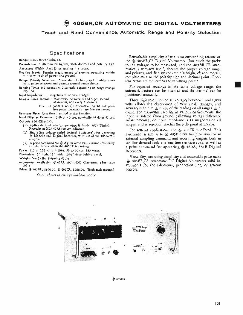
@ 405BR,CR AUTOMATIC DC DIGITAL VOLTMETERS
Touch and Read Convenience, Automatic Range and Polarity Selection
Specifications Range: 0.001 to 999 volts, dc. Presentation: 3 illuminated figures, with decimal and polarity sign. Accuracy: Within k O . 2 7 ~ of reading * 1 count. Floating Input: Permits measurement of systems operating within * 500 volts dc of power line ground. Range, Polarity Selection: Automatic. Hold control disables auto-
matic range selection and permits manual range choice. Ranging Time: 0.2 seconds to 2 seconds, depending on range change
required. Input Impedance: 11 megohms to dc on all ranges. Sample Rate: Internal: Maximum, between 4 and 5 per second.
Minimum, one every 5 seconds.
tive pulse, maximum rate five per second. External (405CR only): Controlled by 20 volt posi-
Response Time: Less than 1 second to step function. Input Filter ac Rejection: 3 db at 1.5 cps, nominally 44 db at 60 cps. Output: (405CR only).
(1) 10-line decimal code for operating (8 Model 561B Digital Recorder or K05-405A remote indicator.
( 2 ) Single-line voltage coded decimal (staircase), for operating @ Model 560A Digital Recorder, with use of the 405A-95C adapter.
( 3 ) A print command for ($3 digital recorders is issued after every sample, except when the 405CR is ranging.
Power: 115 or 230 volts Dimensions: 7" high, 19" wide, 13%" deep behind panel. Weight : Net 31 Ibs. Shipping 46 Ibs. Accesscrier Available: (2 457A AC-to-DC Converter. (See page
Price: @ 405BR, $890.00. @ 405CR, $960.00. (Both rack mount.)
Data subject to change without notice.
1070, 50 to 60 cps, 180 watts.
102.)
Remarkable simplicity of use is an outstanding feature of the @ 405BR,CR Digital Voltmeters. Just touch the probe to the voltage to be measured, and the 405BR,CR auto- matically zero-sets itself, chooses the proper voltage range and polarity, and displays the result in bright, clear numerals, complete even to the polarity sign and decimal point. Oper- ator errors are reduced to the vanishing point !
For repeated readings in the same voltage range, the automatic feature can be disabled and the decimal can be positioned manually.
Three digit resolution on all voltages between 1 and 1,000 volts allows the observation of very small changes, and accuracy is held to a 0.2% of the reading on all ranges 1 count. For maximum usability in various environments, the input is isolated from ground (allowing voltage difference measurements), dc input impedance is 11 megohms on all ranges, and ac rejection reaches the 3 db point at 1.5 cps.
For systems applications, the @ 405CR is offered. This instrument is similar to @ 405BR but has provision for an external sampling command and recording outputs both in ten-line decimal code and one-line staircase code, as well as a print command fo r operating @ 560A, 561B Digital Recorders.
Versatility, operating simplicity and reasonable price make @ 405BR,CR Automatic D C Digital Voltmeters solid in- vestments for the laboratory, production line, or systems console.
@ 405CR
101
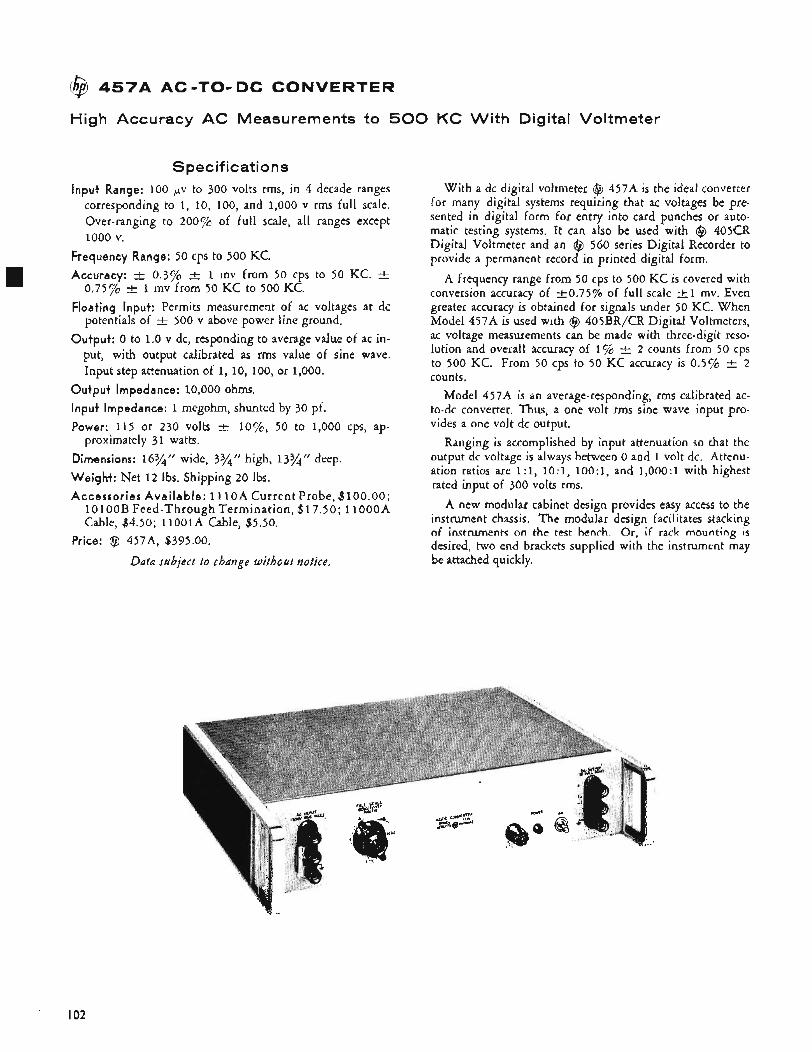
\@ 45749 AC-TO- DC CONVERTER
High Accuracy AC Measurements to 500 KC With Digital Voltmeter
Specifications Input Range: 100 pv to 300 volts rms, in 4 decade ranges
corresponding to 1, 10, 100, and 1,000 v rms full scale. Over-ranging to 200% of full scale, all ranges except 1000 v.
Frequency Range: 50 cps to 500 KC. Accuracy: -t 0.3% -t 1 mv from 50 cps to 50 KC. k
0.75% Floating Input: Permits measurement of ac voltages at dc
potentials of -+ 500 v above power line ground. Output: 0 to 1.0 v dc, responding to average value of ac in-
put, with output calibrated as rms value of sine wave. Input step attenuation of 1, 10, 100, or 1,000.
Output Impedance: IO,OOO ohms. Input impedance: 1 megohm, shunted by 30 pf. Power: 115 or 230 volts 2 lo%, 50 to 1,000 cps, ap-
Dimensions: 16%'' wide, 3%'' high, 13%" deep. Weight: Net 12 Ibs. Shipping 20 Ibs. Accessories Avai lab le: 1 1 1oA Current Probe, $ ~ O O . O O ;
1OlOOB Feed-Through Termination, $17.50; 1 l o o o A Cable, $4.50; 11oolA Cable, $5.50.
1 mv from 50 KC to 500 KC.
proximately 31 watts.
Price: @ 457A3, $395.00.
Data subject t o change without notice.
With a dc digital voltmeter @ 457A is the ideal converter for many digital systems requiring that ac voltages be pre- sented in digital form for entry into card punches or auto- matic testing systems. It can also be used with @ 405CR Digital Voltmeter and an @ 560 series Digital Recorder to provide a permanent record in printed digital form.
A frequency range from 50 cps to 500 KC is covered with conversion accuracy of +0.75% of full scale t l mv. Even greater accuracy is obtained for signals under 50 KC. When Model 457A is used with @ 405BR/CR Digital Voltmeters, ac voltage measurements can be made with three-digit reso- lution and overall accuracy of 1% r+ 2 counts from 50 cps to 500 KC. From 50 cps to 50 KC accuracy is 0.5% t 2 counts.
Model 457A is an average-responding, rms calibrated ac- to-dc converter. Thus, a one volt rms sine wave input pro- vides a one volt dc output.
Ranging is accomplished by input attenuation so that the output dc voltage is always between 0 and 1 volt dc. Attenu- ation ratios are 1:1, 10:1, 100:1, and 1,000:1 with highest rated input of 300 volts rms.
A new modular cabinet design provides easy access to the instrument chassis. The modular design facilitates stacking of instruments on the test bench. Or, if rack mounting is desired, two end brackets supplied with the instrument may be attached quickly.
I02
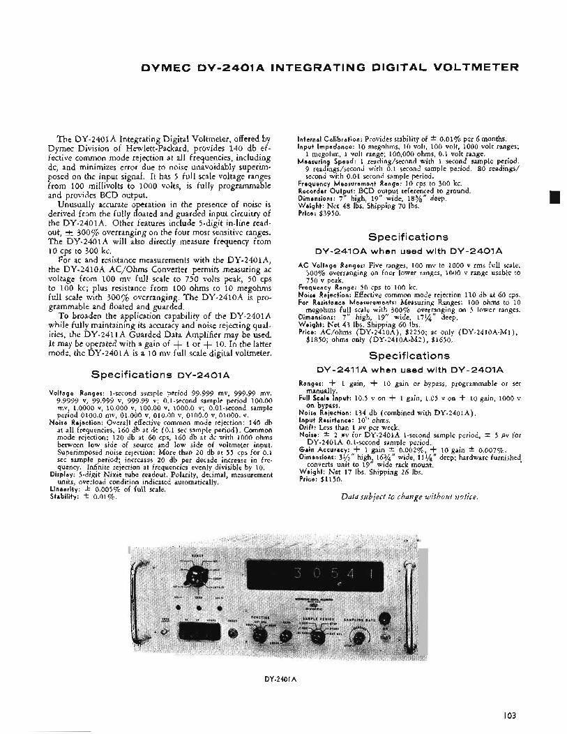
DYMEC DV-2401A INTEGRATING DIGITAL VOLTMETER
The DY-2401A Integrating Digital Voltmeter, offered by Dymec Division of Hewlett-Packard, provides 140 db ef- fective common mode rejection at all frequencies, including dc, and minimizes error due to noise unavoidably superim- posed on the input signal. It has 5 full scale voltage ranges from 100 millivolts to 1000 volts, is fully programmable and provides BCD output.
Unusually accurate operation in the presence of noise is derived from the fully floated and guarded input circuitry of the DY-2401A. Other features include 5-digit in-line read- out, & 300% overranging on the four most sensitive ranges. The DY-2401A will also directly measure frequency from 10 cps to 300 kc.
For ac and resistance measurements with the DY-2401A, the DY-2410A AC/Ohms Converter permits measuring ac voltage from 100 mv full scale to 750 volts peak, 50 cps to 100 kc; plus resistance from 100 ohms to 10 megohms full scale with 300% overranging. The DY-2410A is pro- grammable and floated and guarded.
To broaden the application capability of the DY-2401A while fully maintaining its accuracy and noise rejecting qual- ities, the DY-2411A Guarded Data Amplifier may be used. It may be operated with a gain of + 1 or + 10. In the latter mode, the DY-2401A is a 10 mv full scale digital voltmeter.
Specifications DY-2401A
Voltage Ranges: 1-second sample period 99.999 mv, 999.99 mv, 9.9999 v, 99.999 v, 999.99 v; 0.1-second sample period 100.00 mv, 1.0000 v, 10.000 v, 100.00 v, 1000.0 v; 0.Ol-second sample period 0100.0 mv, 01.000 v, 010.00 v, 0100.0 v, 01000. v.
Noise Rejection: Overall effective common mode rejection: 140 db at all frequencies, 160 db at dc (0.1 sec sample period). Common mode rejection: 120 db at 60 cps, I60 db at dc with 1000 ohms between low side of source and low side of voltmeter input. Superimposed noise rejection: More than 20 db at 55 cps for 0.1 sec sample period; increases 20 db per decade increase in fre- quency. Infinite rejection at frequencies evenly divisible by 10.
Display: 5-digit Nixie tube readout. Polarity, decimal, measurement units, overload condition indicated automatically.
Linearity: f 0.00570 of full scale. Stability: f 0.01%.
Internal Calibration: Provides stability of Input Impedance: 10 megohms, 10 volt, 100 volt, 1000 volt ranges;
1 megohm, 1 volt range; 100,000 ohms, 0.1 volt range. Measuring Speed: 1 reading/second with 1 second sample period.
9 readings/second with 0.1 second sample period. 80 readings/ second with 0.01 second sample period.
0.01% per 6 months.
Frequency Measurement Range: 10 cps to 300 kc. Recorder Output: BCD output referenced to ground. Dimensions: 7 “ high, 19” wide, 18%” deep. Weight : Net 48 Ibs. Shipping 70 Ibs. Price: $3950.
Spec if i cat io ns DY-2410A when used with DY-2401A
AC Voltage Ranges: Five ranges, 100 mv to 1000 v rms full scale, 30070 overranging on four lower ranges, 1000 v range usable to 750 v peak.
Frequency Range: 50 cps to 100 kc. Noise Rejection: Effective common mode rejection 110 db at 60 cps. For Resistance Measurements: Measuring Ranges: 100 ohms to 10
megohms full scale with 300% over5mging on 5 lower ranges. Dimensions: 7“ high, 19” wide, 17% deep. Weight: Net 43 Ibs. Shipping 60 Ibs. Price: AC/ohms (DY-2410A), $2250; ac only (DY-2410A-M1),
$1850; ohms only (DY-2410A-M2), $1650.
Specifications DY-2411A when used with DY-2401A
Ranges: -I- 1 gain, -I- 10 gain or bypass, programmable or set
Full Scale Input: 10.5 v on -k 1 gain, 1.05 v on -k 10 gain, 1000 v
Noise Rejection: 134 db (combined with DY-2401A). Input Resistance: 10” ohms. Drift: Less than 1 pv per week. Noise: * 2 pv for DY-2401A 1-second sample period, 2 5 pv for
Gain Accuracy: -k 1 gain f 0.00276, -k 10 gain f 0.007%. Dimensions: 39”’’ high, 16%” wide, 111/8’‘ deep; hardware furnished.
Weight : Net 17 Ibs. Shipping 26 Ibs. Price: $1150.
manually.
on bypass.
DY-2401A 0.1-second sample period.
converts unit to 19“ wide rack mount.
Data subject t o change without notice.
DY-240 I A
I03
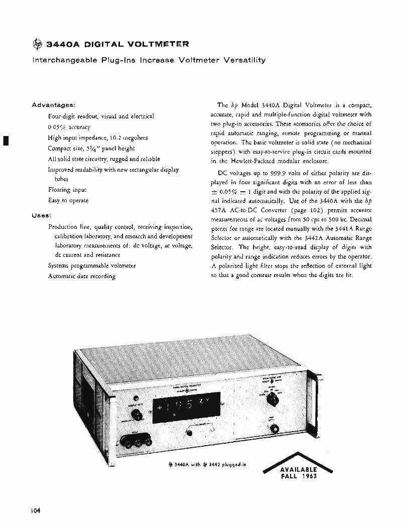
@ 3 4 4 0 A DIGITAL VOLTMETER
Interchangeable Plug-Ins Increase Voltmeter Versatility
Advantages:
Four-digit readout, visual and electrical
0.05 accuracy
High input impedance, 10.2 megohms
Compact size, 51/4)/ panel height
All solid state circuitry, rugged and reliable
Improved readability with new rectangular display tubes
Floating input
Easy to operate
Uses:
Production line, quality control, receiving inspection, calibration laboratory, and research and development laboratory measurements of: dc voltage, ac voltage, dc current and resistance
Systems programmable voltmeter
Automatic data recording
The hp Model 3440A Digital Voltmeter is a compact, accurate, rapid and multiple-function digital voltmeter with two plug-in accessories. These accessories offer the choice of rapid automatic ranging, remote programming or manual operation. The basic voltmeter is solid state (no mechanical steppers) with easy-to-service plug-in circuit cards mounted in the Hewlett-Packard modular enclosure.
DC voltages up to 999.9 volts of either polarity are dis- played in four significant digits with an error of less than & 0.05 "/c i 1 digit and with the polarity of the applied sig- nal indicated automatically. Use of the 3440.4 with the hp 457A AC-to-DC Converter (page 102) permits accurate measurements of ac voltages from 50 cps to 500 kc. Decimal points for range are located manually with the 3441A Range Selector or automatically with the 3442A Automatic Range Selector. The bright, easy-to-read display of digits with polarity and range indication reduces errors by the operator. A polarized light filter stops the reflection of external light so that a good contrast results when the digits are lit.
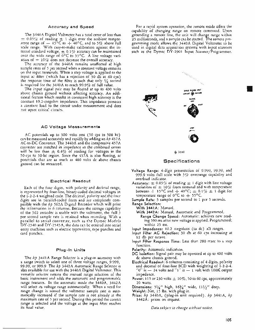
Accuracy and Speed
The 3440A Digital Voltmeter has a total error of less than -+ 0.05Yc of reading 1 digit over the ambient temper- ature range of + 15OC to + 40°C, and to 5 % above full scale range. With easy-to-make calibration against the in- ternal standard voltage, k 0.1 Y G accuracy can be maintained over the wide range of O°C to 55OC. A line voltage vari- ation of t 10% does not decrease the overall accuracy.
The accuracy of the 3440A remains unaffected at high sample rates of 5 per second when a constant voltage remains on the input terminals. When a step voltage is applied to the input ac filter (which has a rejection of 30 db at 60 cps) the response time of the filter is such that only % second is required for the 3440A to reach 99.9y~ of full value.
air may be floated at up to 400 volts above chassis grouns without affecting accuracy, An addi- tional feature which results in consistent high accuracy is the constant 10.2-megohm impedance. This impedance presents a constant load to the circuit under measurement and does not upset critical circuits.
The input signal
A C Voltage Measurements
AC potentials up to 300 volts rms (50 cps to 500 kc) can be measured accurately and rapidly by adding an hp 457A AC-to-DC Converter. The 3440A and the inexpensive 457A converter are matched in impedance so the combined errors will be less than -I: 0.4% of reading for voltages in the 5O-cps to 50-kc region. Since the 457A is also floating, ac potentials that are as much as 400 volts dc above chassis ground can be measured.
Electrical Readout
Each of the four digits, with polarity and decimal range, is represented by four-line, binary-coded decimal voltages in the 1-2-2-4 weighted code. The decimal, polarity and the four digits are in parallel-coded form and are completely com- patible with the hp 562A Digital Recorder which will print the information in 6 columns. Because the storage capability of the 562 recorder is usable with the voltmeter, the full 5 per second sample rate is retained when recording. With a parallel to serial converter, such as the Dymec Models DY-2540 and DY-2545A, the data can be entered into serial entry machines such as electric typewriters, tape punches and card punches.
Plug-In Units
The hp 3441A Range Selector is a plug-in accessory with a range switch to select one of three voltage ranges, 9.999, 99.99, or 999.9 The hp 3442A Automatic Range Selector is also available for use with the 3440A Digital Voltmeter. This versatile selector retains the manual range selection of the basic instrument and adds the automatic and programmable range features. In the automatic mode the 3440A, 3442A will select its voltage range automatically. When a need for range change is sensed the voltmeter sample rate is auto- matically increased if the sample rate is not already at the maximum rate of 5 per second. During this period the correct range is selected and the voltage at the input filter reaches its final value.
For a rapid system operation, the remote mode offers the capability of changing range on remote command. Upon grounding a remote line, the unit will change range within 25 milliseconds, and a sample can be started. The remote pro- gramming mode allows the 3440A Digital Voltmeter to be used in digital data acquisition systems with input scanners such as the Dymec DY-2901 Input Scanner/Programmer.
8 3441
Spec if icatio ns
Voltage Range: 4-digit presentation of 9.999, 99.99, and 999.9 volts full scale with 5 % overrange capability and overload indicator.
1 digit with line voltage variations of F 1oyc from nominal and with temperature between + 15OC and + 4OOC; t 0.1% -+ 1 digit for temperature range of OOC to + 55OC.
Accuracy: F 0.05yc of reading
Sample Rate: 5 samples per second to 1 per 5 seconds. Range Selection:
With 3441A: Manual. With 3442A: Manual, Automatic and Programmed.
Range Change Speed: Automatic; achieves new read- ing 500 ms after new voltage is applied. Programmed; within 25 ms.
Input Impedance: 10.2 megohms (to dc) all ranges. Input Filter AC Rejection: 30 db at 60 cps increasing at
Input Filter Response Time: Less than 280 msec to a step
Polarity: Automatic indication. DC Isolation: Signal pair may be operated at up to 400 volts
dc above chassis ground. Electrical Readout: 6 columns consisting of 4 digits, polarity
and decimal of four-line BCD with weighting of 1-2-2-4. “0” is - 24 volts and “1” is - 1 volt with 1OOK output impedance.
Power: 1 1 5 or 230 volts t 1070, 50 to 60 cps, approximately 20 watts.
Dimensions: 5%’’ high, 16%” wide, 11$’”’’ deep. Weight: Net, 1 5 Ibs. with plug-in. Price: hp 3440A, (plug-in unit required), hp 3441A, hp
12 db per octave.
function.
3442A: prices on request.
Data subject to change without tzotice.
I05
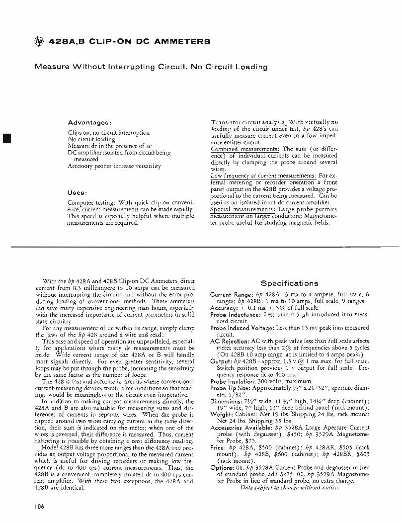
8 428A,B CLIP-ON DC AMMETERS
Measure Without Interrupting Circuit, No Circuit Loading
Ad vantages :
Clips on, no circuit interruption No circuit loading Measure dc in the presence of ac DC amplifier isolated from circuit being
Accessory probes increase versatility measured
Transistor circuit analysis: W i t h virtually no loading of the circuit under test, hp 428’s can usefully measure current even in a low imped- ance emitter circuit. Combined measurements: The sum (or differ- ence) of individual currents can be measured directly by clamping the probe around several wires. LOIV frequency ac currcnt measurements: For ex- ternal meterine or recorder oneration a front
0
panel output on the 428B provides a voltage pro- portional to the current being measured. Can be used as an isolated innut dc current amdifier.
Uses:
ComDuter testine: With auick cliD-on conveni- u
ence,’current measurement; can be’rnade rapidly. This speed is especially helpful where multiple
Special measurements : Large probe permits measurement on larger conductors; Magnetome-
< I
measdements are required. ter probe useful forstudying magnetic-fields.
With the hp 428A and 428B Clip-on DC Ammeters, direct current from 0.3 milliampere to 10 amps can be measured without interrupting the circuits and without the error-pro- ducing loading of conventional methods. These ammeters can save many expensive engineering man hours, especially with the increased importance of current parameters in solid state circuitry.
For any measurement of dc within its range, simply clamp the jaws of the hp 428 around a wire and read !
This ease and speed of operation are unparalleled, especial- ly for applications where many dc measurements must be made. Wide current range of the 428A or B will handle most signals directly. For even greater sensitivity, several loops may be put through the probe, increasing the sensitivity by the same factor as the number of loops.
The 428 is fast and accurate in circuits where conventional current-measuring devices would alter conditions so that read- ings would be meaningless or the circuit even inoperative.
In addition to making current measurements directly, the 428A and B are also valuable for measuring sums and dif- ferences of currents in separate wires. When the probe is clipped around two wires carrying current in the same direc- tion, their sum is indicated on the meter; when one of the wires is reversed, their difference is measured. Thus, current balancing is possible by obtaining a zero difference reading.
Model 428B has three more ranges than the 428A and pro- vides an output voltage proportional to the measured current which is useful for driving recorders or making low fre- quency (dc to 400 cps) current measurements. Thus, the 428B is a convenient, completely isolated dc to 400 cps cur- rent amplifier. With these two exceptions, the 428A and 428B are identical.
Specifications Current Range: hp 428A: 3 ma to 1 ampere, full scale, 6
ranges; hp 428B: 1 ma to 10 amps, full scale, 9 ranges. Accuracy: AI 0.1 ma -+ 3% of full scafe. Probe Inductance: Less than 0.5 ph introduced into meas-
ured circuit. Probe Induced Voltage: Less than 1 5 mv peak into measured
circuit. AC Rejection: AC with peak value less than full scale affects
meter accuracy less than 270 at frequencies above 5 cycles (On 428B 10 amp range, ac is limited to 4 amps peak.)
Output: hp 428B - approx. 1.5 v @ 1 ma max. for full scale. Switch position provides 1 v output for full scale. Fre- quency response dc to 400 cps.
Probe Insulation: 300 volts, maximum. Probe Tip Size: Approximately $‘z” x 21/32”, aperture diam-
eter 5/32!‘. Dimensions: 7%” wide, 11 ?h” high, 14%” deep (cabinet);
19” wide, 7” high, 13” deep behind panel (rack mount). Weight: Cabinet: Net 19 Ibs. Shipping 24 lbs. rack mount:
Net 24 Ibs. Shipping 35 lbs. Accessories Available: hp 3528A Large Aperture Current
probe (with degausser), $450; hp 3529A Magnetome- ter Probe, $75.
Price: hp 428~4, $500 (cabinet); hp 428AR, $505 (rack mount). hp 428B, $600 (cabinet); hp 428BR, $605 (rack mount).
Options: 01. hp 3528A Current Probe and degausser in lieu of standard probe, add $375. 02. hp 3529A Magnetome- ter Probe in lieu of standard probe, no extra charge.
Data subject to change without notice.
I06
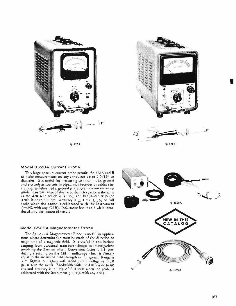
@ 428A
Model 3 5 2 8 A Current Probe
@ 428B
This large aperture current probe permits the 42814 and B to make measurements on any conductor up to 2-9/16” in diameter. It is useful for measuring common mode, ground and electrolysis currents in pipes, multi-conductor cables (in- cluding lead-sheathed) , ground straps, even microwave wave- guide. Current range of this large diameter probe is the same as the 428 with which it is used, and bandwidth with the 428B is dc to 300 cps. Accuracy is t 1 ma t 3% of full scale when the probe is calibrated with the instrument ( t 5 % with any 428B). Inductance less than 3 ph is intro- duced into the measured circuit.
C A T A L O G Model 3 5 2 9 A Magnetometer Probe
The hp 3529A Magnetometer Probe is useful in applica- tions where determination must be made of the direction or magnitude of a magnetic field. It IS useful in applications ranging from acoustical transducer design to investigations involving the Zeeman effect. Conversion factor is 1 : 1, pro- ducing a reading on the 428 in milliamps which is directly equal to the measured field strength in milligauss. Range is 3 milligauss to 1 gauss with 428A and 1 milligauss to 10 gauss with the 428B. Bandwidth with the 428B is dc to 80 cps and accuracy is t 3% of full scale when the probe is calibrated with the instrument (A 5% with any 428).
@ 3529A
I
I07
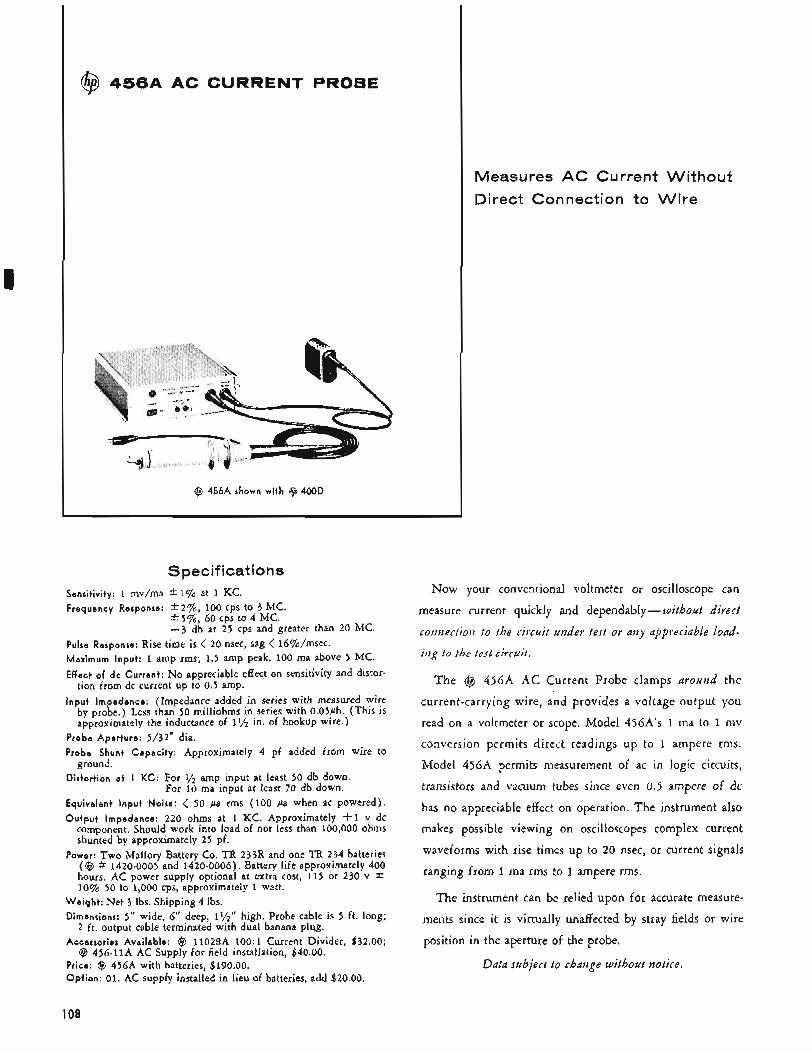
Specifications Sensitivity: 1 mv/ma * 1% at 1 KC. Frequency Response: * 2 % , 100 cps to 3 MC. * 59'0, 60 cps to 4 MC.
-3 db at 25 cps and greater than 20 MC. Pulse Response: Rise time is < 20 nsec, sag < 16%0/msec. Maximum Input: 1 amp rms; 1.5 amp peak. 100 ma above 5 MC. Effect of d c Current: No appreciable effect on sensitivity and distor-
tion from dc current up to 0.5 amp. Inpu t Impedance: (Impedance added in series with measured wire
by probe.) Less than 50 milliohms in series with 0.05ph. (This is approximately the inductance of I$'" in. of hookup wire.)
Probe Aper tu re : 5/32" dia. Probe Shunt Capac i ty : Approximately 4 pf added from wire to
Distort ion a t I K C : For '/2 amp input at least 50 db down.
Equivalent i n p u t Nloise: < 50 pa rms (100 pa when ac powered). O u t p u t Impedance: 220 ohms at 1 KC. Approximately +1 v dc
component. Should work into load of not less than 100,000 ohms shunted by approximately 25 pf.
Power: Two Mallory Battery Co. TR 233R and one TR 234 batteries (Q # 1420-0005 and 1420-0006). Battery life approximately 400 hours. AC power supply optional at extra cost, 115 or 230 v 10% 50 to 1,000 cps, approximately 1 watt.
ground.
For 10 ma input at least 70 db down.
W e i g h t : Net 3 Ibs. Shipping 4 Ibs. Dimensions: 5" wide, 6" deep, 11/2'' high. Probe cable is 5 ft. long;
Accessories Avai lable: @ 11028A 100: 1 Current Divider, $32.00;
Price: Q 456A with batteries, $190.00. O p t i o n : 01. AC supp1y installed in lieu of batteries, add $20.00.
2 ft. output cable terminated with dual banana plug.
@ 456-11A AC Supply for field installation, $40.00.
@ 4 5 6 A AC CURRENT PROBE
(8 456A shown with 9 400D
Measures AC CI rrent Witho Direct Connection to Wire
Now your conventional voltmeter or oscilloscope can
measure current quickly and dependably- without direct
cotitiectiotz to the circuit under test or any appreciable load-
itzg to the test circuit.
The @ 4 5 6 A AC Current Probe clamps around the
current-carrying wire, and provides a voltage output you
read on a voltmeter or scope. Model 456A's 1 ma to 1 iiiv
conversion permits direct readings up to I ampere rills.
Model 456A permits measurement of ac in logic circuits,
transistors and vacuum tubes since even 0.5 ampere of dc
has no appreciable effect on operation. The instrument also
makes possible viewing on oscilloscopes complex current
waveforms with rise times up to 20 nsec, or current signals
ranging from 1 ma rms to 1 ampere rms.
The instrument can be relied upon for accurate measure-
ments since it is virtually unaffected by stray fields or wire
position in the aperture of the probe.
Data subject to change without notice.
I08
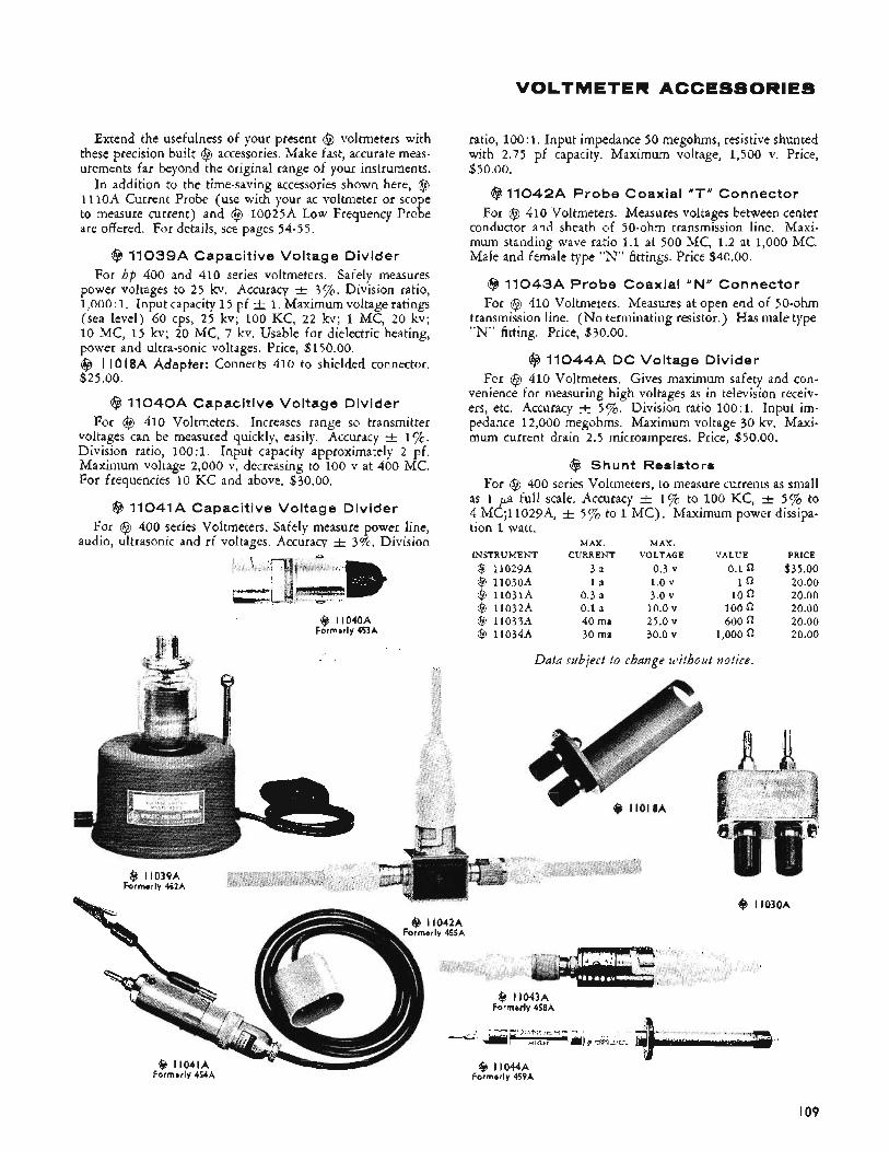
VOLTMETER ACCESSORIES
Extend the usefulness of your present @ voltmeters with these precision built @ accessories. Make fast, accurate meas- urements far beyond the original range of your instruments.
In addition to the time-saving accessories shown here, @I 111oA #Current Probe (use with your ac voltmeter or scope to measure current) and @ 10025A Low Frequency Probe are offered. For details, see pages 54-55.
@ 11039A Capacitive Voltage Divider For hp 400 and 410 series voltmeters. Safely measures
power voltages to 2 5 kv. Accuracy t 3c/~. Division ratio, 1,000 : 1. Input capacity 15 pf t 1. Maximum voltage ratings (sea level) 60 cps, 25 kv; 100 KC, 2 2 kv; 1 MC, 20 kv; 10 MC, 1 5 kv; 20 MC, 7 kv. Usable for dielectric heating, power and ultra-sonic voltages. Price, $1 50.00. Q I I O 18A Adapter: Connects 410 to shielded connector. $25.00.
@ 11040A Capacitive Voltage Divider For @ 410 Voltmeters. Increases range so transmitter
voltages can be measured quickly, easily. Accuracy t 1%. Division ratio, 100 : 1. Input capacity approximately 2 pf. Maximum voltage 2,000 v, decreasing to 100 v at 400 MC. For frequencies 10 KC and above, $30.00.
@ 11041A Capacitive Voltage Divider For @ 400 series Voltmeters. Safely measure power line,
audio,, ultrasonic and rf voltages. Accuracy -+ 3%. Division
ratio, 100: 1. Input impedance 50 megohms, resistive shunted with 2.75 pf capacity. Maximum voltage, 1,500 v. Price, $50.00.
@ 11042A Probe Coaxial “T“ Connector For @I 410 Voltmeters. Measures voltages between center
conductor and sheath of 50-0hm transmission line. Maxi- mum standing wave ratio 1.1 at 500 MC, 1.2 at 1,000 MC. Male and female type “N” fittings. Price $40.00.
6$11043A Probe Coaxial “N” Connector For @ 410 Voltmeters. Measures at open end of 50-ohm
transmission line. (No terminating resistor.) Has male type “N” fitting. Price, $30.00.
@ 11044A DC Voltage Divider For @ 410 Voltmeters. Gives maximum safety and con-
venience for measuring high voltages as in television receiv- ers, etc. Accuracy t 570. Division ratio 10O:l. Input im- pedance 12,000 megohms. Maximum voltage 30 kv. Maxi- mum current drain 2.5 microamperes. Price, $50.00.
@ Shunt Resistors For @ 400 series Voltmeters, to measure currents as small
as 1 pa full scale. Accuracy -t. 1% to 100 KC, -+ 5 % to 4 MC;11029A, t 5% to 1 MC) , Maximum power dissipa- tion 1 watt.
MAX. MAX. INSTRUMENT CURRENT VOLTAGE VALUE PRICE
@ 11029A 3 a 0.3 v 0.1 $35.00 @ 11030~4 l a 1.0 v 19 20.00 @ l l031A 0.3 a 3.0 v 10 n 20.00 @ 1103214 0.1 a 10.0 v 100 n 20.00 @ 11033A 40ma 2 5 . 0 ~ 600 20.00 @ 11034% 30 ma 30.0 v 1,000 0 20.00
Data subject to change without notice.
Formerly 453A
A @ 11042A mnerlv 455A
@ I l043A Formerly 458A
@ I1044A Formerly 454A Formerly 459A
@ I 1030A
I09
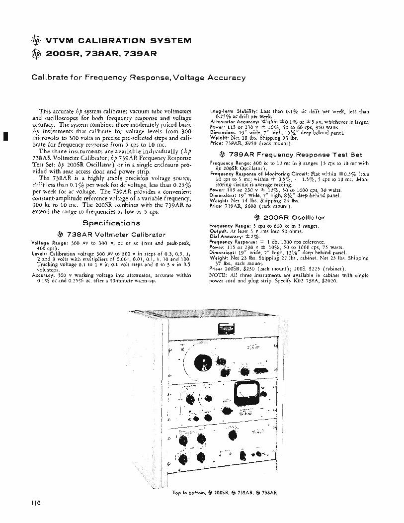
I
@ VTVM CALIBRATION SYSTEM
@ 2 0 0 S R , 7 3 8 A R , 7 3 9 A R
Calibrate for Frequency Response, Voltage Accuracy
This accurate hp system calibrates vacuum tube voltmeters and oscilloscopes for both frequency response and voltage accuracy. The system combines three moderately priced basic hp instruments that calibrate for voltage levels from 300 microvolts to 300 volts in precise pre-selected steps and cali- brate for frequency response from 5 cps to 10 mc.
T h e three instruments are available individually ( h p 738AR Voltmeter Calibrator; hp 739AR Frequency Response Test Set; hp 200SR Oscillator) or in a single enclosure pro- vided with rear access door and power strip.
The 738AR is a highly stable precision voltage source, drift less than 0.1% per week for dc voltage, less than 0.25% per week for ac voltage. The 739AR provides a convenient constant-amplitude reference voltage of a variable frequency, 300 kc to 10 mc. The 200SR combines with the 739AR to extend the range to frequencies as low as 5 cps.
Specifications @ 738AR Voltmeter Calibrator
Vol tage Range: 300 pv to 300 v, dc or ac (rms and peak-peak, 400 cps).
Levels: Calibration voltage 300 pv to 300 v in steps of 0.3, 0.5, 1, 2 and 3 volts with multipliers of 0.001, 0.01, 0.1, 1, 10 and 100. Tracking voltage 0.1 to 1 v in 0.1 volt steps and 0 to 3 v in 0.5 volt steps.
Accuracy: 300 v working voltage into attenuator, accurate within 0.1% dc and 0.25% ac, after a 30-minute warm-up.
Long-term Stabi l i ty : Less than 0.1% dc drift per week, less than
At tenua to r Accuracy: Within *o.l% or * 5 PV, whichever is larger. Power: 115 or 230 v * lo%, 50 to 60 cps, 350 watts. Dimensions: 19” wide, 7“ high, 15%’’ deep behind panel. W e i g h t : Net 38 lbs. Shipping 53 Ibs. Price: 738AR, $950 (rack mount).
0.25% ac drift per week.
@ 739AR Frequency Response Test Set Frequency Range: 300 kc to 10 mc in 3 ranges ( 5 cps to 10 mc with
hp 200SR Osci!lator). Frequency Response of Mon i to r i ng Ci rcu i t : Flat within *0.5% from
10 cps to 5 mc; within t 0.5%, - 1.5%, 5 cps to 10 mc. Mon- itoring circuit is average reading.
Power: 115 or 230 v * lo%, 50 to 1000 cps, 30 watts. Dimensions: 19” wide, 7“ high, 8%” deep behind panel. W e i g h t : Net 14 Ibs. Shipping 24 lbs. Price: 739AR, $600 (rack mount) ,
@ 200SR Oscillator Frequency Range: 5 cps to 600 kc in 5 ranges. Outpu t : At least 3 v rms into 50 ohms. Dia l Accuracy: +2%. Frequency Response: * 1 db, 1000 cps reference. Power: 115 or 230 v zk 1070, 50 to 1000 cps, 75 watts. Dimensions: 19” wide, 7” high, 131/S’’ deep behind panel. W e i g h t : Net 23 Ibs. Shipping 27 lbs., cabinet. Net 25 Ibs. Shipping
Price: 200SR, $230 (rack mount) ; 20OS, $225 (cabinet). NOTE: All three instruments are available in cabinet with single power cord and plug strip. Specify KO2 738A, $2020.
37 Ibs., rack mount.
Top t o bo t tom, @ 200SR, @ 739AR, ($9 738AR
I10
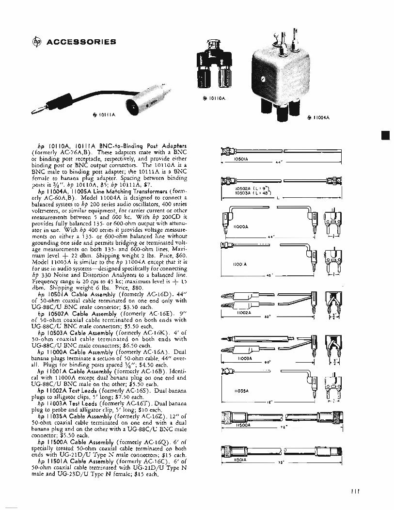
@ ACCESSORIES
hp 101 IOA, 101 I I A BNC-to-Binding Post Adapters (formerly AC-76A,B). These adapters mate with a BNC or binding post receptacle, respectively, and provide either binding post or BNC output connectors. The 1OlloA is a BNC male to binding post adapter; the l O l l l A is a BNC female to banana plug adapter. Spacing between binding posts is 3/". hp l o l l o A , $5; hp 10111A, $7.
hp I 1004A, I 1005A Line Matching Transformers (form- erly AC-GoA,B). Model 11004A is designed to connect a balanced system to hp 200 series audio oscillators, 400 series voltmeters, or similar equipment, for carrier current or other measurements between 5 and 600 kc. With hp 200CD it provides fully balanced 135- or 600-ohm output with attenu- ator in use. With hp 400 series it provides voltage measure- ments on either a 135- or 600-ohm balanced line without grounding one side and permits bridging or terminated volt- age measurements on both 135- and 600-ohm lines. Maxi- mum level + 22 dbm. Shipping weight 2 lbs. Price, $60. Model 11005A is similar to the hp 11004A except that it is for use in audio systems-designed specifically for connecting hp 330 Noise and Distortion Analyzers to a balanced line. Frequency range is 20 cps to 45 kc; maximum level is + 1 5 dbm. Shipping weight 6 lbs. Price, $80.
hp 10501A Cable Assembly (formerly AC-16D). 44" of 50-ohm coaxial cable terminated on one end only with UG-88C/U BNC male connector; $3.50 each,
hp 10502A Cable Assembly (formerly AC-16E). 9'' of 50-ohm coaxial cable terminated on both ends with UG-88C/U BNC male connectors; $5.50 each.
hp 10503A Cable Assembly (formerly AC-16K). 4' of 50-ohm coaxial cable terminated on both ends with UG-88C/U BNC male connectors; $6.50 each.
hp I IOOOA Cable Assembly (formerly AC-l6A). Dual banana plugs terminate a section of 50-ohm cable, 44" over- all. Plugs for binding posts spaced 3/4"; $4.50 each.
hp I IO0 I A Cable Assembly (formerly AC-16B) . Identi- cal with 1lOOOA except dual banana plug on one end and UG-88C/U BNC male on the other; $5.50 each.
hp I I002A Test Leads (formerly AC-16s). Dual banana plugs to alligator clips, 5' long; $7.50 each.
hp I 1003A Test Leads (formerly AC-16T). Dual banana plug to probe and alligator clip, 5' long; $10 each.
hp I 1035A Cable Assembly (formerly AC-162). 12" of 50-0hm coaxial cable terminated on one end with a dual banana plug and on the other with a UG-88C/U BNC male connector; $5.50 each.
hp I1500A Cable Assembly (formerly AC-16Q). 6' of specially treated 50-ohm coaxial cable terminated on both ends with UG-21D/U Type N male connectors; $15 each.
hp I1501A Cable Assembly (formerly AC-16C). 6' of 50-ohm coaxial cable terminated with UG-21D/U Type N male and UG-23D/U Type N female; $15 each.
10501A
10502A ( L = 9") 10503A ( L = 48")
c L *
-9 44".
=7l I 11002A
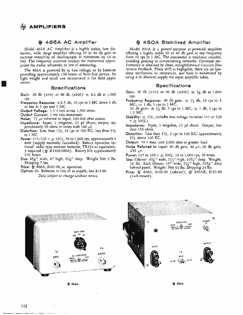
@
h
AMPLIFIERS
@ 4 6 6 A AC Amplifier idel 466A AC Amplifier is a highly stable, low dis-
tortion, wide range amplifier offering 20 or 40 db gain to increase sensitivity of oscilloscopes or voltmeters by 10 or 100, Flat frequency response renders the instrument appro- priate for audio, ultrasonic or low rf measuring.
The 466A is powered by ac line voltage, or by batteries providing approximately 150 hours of hum-free service. Its light weight and small size recommend it for field appli- cation.
Spec if icat i o n s I
Gain: 20 db ( ~ 1 0 ) or 40 db ( ~ 1 0 0 ) t 0.2 db at 1,000 cps *
Frequency Response: f 0 . 5 db, 10 cps to 1 MC down 3 db; or less at 5 cps and 2 MC.
Output Voltage: 1.5 v rms across 1,500 ohms. Output Current: 1 ma rms maximum. Noise: 75 pv referred to input, 100,000 ohm source. Impedance: Input, 1 megohm, 25 pf shunt; output, ap-
proximately 50 ohms in series with 100 pf. Distortion: Less than I%, 10 cps to 100 KC; less than 5 5 4
to 1 MC. Power: 115/230 v f 10c/o, 50 to 1,000 cps, approximately 1
watt (sup ly normally furnished), Battery operation op-
3 required ( @ # 1420-0006). Battery life approximately 150 hours.
Size: 6%” wide, 4” high, 6$4” deep. Weight Net 3 Ibs. Shipping 7 Ibs.
Price: @ 466A, $165.00, ac operation. Option: 01. Batteries in lieu of ac supply, less $15.00.
tional: ra I! io type mercury batteries, TR234 or equivalent,
Data subject to change without notice.
@J 4 5 0 A Stabilized Amplifier Model 450A is a general-purpose ac-powered amplifier
offering a highly stable 20 or 40 db gain at any frequency from 10 cps to 1 MC. The instrument is resistance coupled, avoiding peaking or compensating networks. Optimum per- formance is obtained by clean, straightforward circuitry plus inverse feedback. Phase shift is negligible, there are no spu- rious oscillations or resonances, and hum is minimized by using a dc filament supply for input amplifier tubes.
Specifications Gain: 20 db ( ~ 1 0 ) or 40 db ( ~ 1 0 0 ) t 1/8 db at 1,000
cps. Frequency Response: 40 db gain: ‘/2 db, 10 cps to 1
MC; f 1 db, 5 cps to 2 MC. 20 db gain: t q’ db, 5 cps to 1 MC; t 1 db, 2 cps to 1.2 MC.
Stability: t 2c/c, includes line voltage variation 115 or 230
Impedance: Input, 1 megohm, 1 5 pf shunt. Output, less than 150 ohms.
Distortion: Less than 2 cps to 100 KC; approximately 2 % above 100 KC.
Output: 10 v max. into 3,000 ohm or greater load, Noise Referred to Input: 40 db gain, 40 pv; 20 db gain,
Power: 115 or 230 v t lo%, 50 to 1,000 cps, 50 watts. Size: Cabinet: 8%” wide, 51/2’r high, 103/” deep. Weight, 10 Ibs. Rack Mount: 19” wide, 5 X r r high, 10s/,rr deep behind panel. Weight: Net 11 Ibs. Shipping 24 Ibs.
Price: @ 450A, $160.00 (cabinet); @ 450AR, $165.00 (rack mount).
v & l O C / o ) .
250 p ~ .
t L POWER
AMPLIFIER --. ON
OUTPUT
x
GAiN
@ 4bbA
I I 2 ~
@ 450A
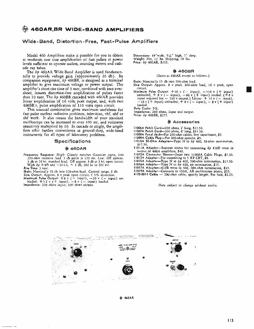
@ 460AR,BR WIDE-BAND AMPLIFIERS
Wide- Band, Distortion- Free, Fast- Pulse
Model 460 Amplifiers make it possible for you to obtain at moderate cost true amplification of fast pulses at power levels sufficient to operate scalers, counting meters and cath- ode ray tubes.
The hp 460AR Wide-Band Amplifier is used fundamen- tally to provide voltage gain (approximately 20 db). Its companion equipment, hp 460BR, is designed as a terminal amplifier to give maximum voltage or power output. The amplifier's short rise time of 3 nsec, combined with zero over- shoot, insures distortion-free amplification of pulses faster than 10 nsec. The hp 460BR cascaded with 460AR provides linear amplification of 16 volts peak output, and, with two 460BR's, pulse amplification of 11 0 volts open circuit.
This unusual combination gives maximum usefulness for fast-pulse nuclear radiation problems, television, vhf, uhf or shf work. It also means the bandwidth of your standard oscilloscope can be increased to over 100 mc, and voltmeter sensitivity multiplied by 10. In cascade or singly, the ampli- fiers offer further convenience as general-duty, wide-band instruments for all types of laboratory problems.
Specifications @ 460AR
Frequency Response: High: Closely matches Gaussian curve, into 200-ohm resistive load. 3 db point is 120 mc. Low; Off approx. 3 db at 20 kc, matched load. Off approx. 3 db at 3 kc, open circuit. With hp 410B and I l o l l A , i: 1 db, 200 kc to 200 mc.
Rise Time: 3 nsec. Gain: Nominally 20 db into 200-ohm load. Control range, 6 db. Sine Output: Approx. 8 v peak o en circuit. < 5 % distortion. Maximum Pulse Output: +8 v (e input) , -20 v ( - input) un-
Impedance: 200 ohms input; 300 ohms output. loaded; +3.2 v (+ input), -8 v ( - input) loaded.
Amp1 if iers
Dimensions: 19"wide, 51/4'' high, 7" deep. Weight: Net, 12 lbs. Shipping, 18 Ibs. Price: hp 460AR, $225.
@ 460BR (Same as 46OAR except as follows:)
Gain: Nominally 15 db into 200-ohm load. Sine Output: Approx. 8 v peak, 200-ohm load; 16 v peak, open
circuit. Max imum Pulse Output: +16 v ( - input) , -110 v (+ in ut)
unloaded; + 8 v ( - input) , -60 v (f input) loaded. ($8 v input required for - 110 v output.) Linear: -k 16 v ( - input) , - 16 v ( f input) unloaded; -k 8 v ( - input), - 8 v (+ input) loaded.
Duty Cycle: 5%. Impedance: 200 ohms, input and output. Price: hp 460BR, $275.
@ Accessories 1006A Patch Cord-200 ohms, 2' long, $22.50. 1007A Patch Cord-200 ohms, 6' long, $31.50. 1008A Panel Jack-For 200-ohm cables, low capacitance, $5. 1009A Cable Plug-For 200-ohm systems, $ 5 . IOIOA 50-Ohm Adapter-Type N to hp 460, 50-ohm termination,
101 IA Adapter-Bayonet sleeve for connecting hp 410B vtvm to
lOl2A Connector Sleeve-Joins two 11009A Cable Plugs, $7.50. 1013A Adapter-For connecting to 5 X P CRT, $9. 1015A Adapter-Type N to hp 460, 200-ohm termination, $17.50.
$17.50.
output of 460A amplifiers, $40.
I1016A Adapter-Type N to hp 460, no termination, $15. I1017A A d a p t e r 4 1 0 B vtvm to 460, 200-ohm termination, $35. I 1019A Adap te rxonnec t s to 15OA, AR oscilloscope plates, $35. 8120-0014 Cable - 200-ohm cable, specify length, Per foot, $2.25.
Data subject t o change without notice.
8 460AR
I I 3
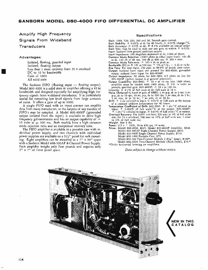
SANBORN MODEL 860-4000 FIFO DIFFERENTIAL DC AMPLIFIER
Amplify High Frequency
Signals From Wideband
Transducers
Advantages:
Isolated, floating, guarded input Isolated, floating output Less than 1 msec recovery from 20 v overload D C to 10 kc bandwidth Gain of 1000 All solid state
The Sanborn FIFO (floating input - floating output) Model 860-4000 is a solid state dc amplifier offering a 10 kc bandwidth and designed especially for amplifying high fre- quency signals from wideband transducers. It is particularly useful for extracting low level signals from large amounts of noise. It offers a gain of up to 1000.
A single FIFO used with an input scanner can amplify data from many transducers, or the outputs of any number of FIFO's may be sampled. A Model 860-4OOOP (grounded output isolated from the input) is available to drive high frequency galvanometers and has an output capability of 10 volts at & 100 ma. Both models have a high common mode rejection ratio and an exceptional recovery time.
The FIFO amplifier is available in a portable case with in- dividual power supply, and two channels with individual power supplies are available on a 3y2" panel for rack mount- ing. Eight amplifiers can be mounted in a 7" x 19" space with a Sanborn Model 868-500AF 8-Channel Power Supply. Each amplifier weighs only four pounds and requires only 2" x 7'' of front panel space.
Specifications
Gain: 1000, 500, 200, 100 and 50; Smooth gain control. G a i n Stabi l i ty : f 0.05% at dc for 40 hours; * 0.01% change/"C. G a i n Accuracy: zk 0.5% at dc; i 0.1% available on special order. G a i n Trim: Can be used to trim any one gain to within f 0.03%. Input : Isolated from ground and from output. I n p u t Impedance: 100 megohms minimum at dc, 0.001 pf shunt. Common M o d e Rejection: (1000 ohms in either input lead) : 160 db
at dc, 120 db at 60 cps, 100 db at 400 cps, f 300 v max. Common M o d e Tolerance: f 300 v dc or peak ac. Bandwidth: D C to f 1% at 500 cps; f 5 % at 5 kc; - 3 db at 10 kc. Rise Time: For step input, 250 psec. to 99.9% of steady state value. Outpu t : Isolated from input and ground for 860-4000; grounded
output isolated from input for 860-4OOOP. O u t p u t Impedance: 60 ohms for 860-4000, 0.5 ohms or less for
860-4000P (power output is at ground potential). O u t p u t Capab i l i t y : 860-4000: f 10 v at 10 ma into 1000 ohms,
amplifier must be loaded with 1000 ohms, f 5 % In order to provide specified gain. 860-4OOOP: f 10 v at 100 ma.
Linearity: f 0.1% of full scale at dc; full scale is 10 v. Noise (Referred t o i n p u t a t ga in o f 1000): 1 PV p-p, dc to 3 CPS; 3 PV
p-p, dc to 20 cps; 10 fiv, p-p, dc to 200 cps; 3 pv rms, dc to 1 kc; 5 pv rms, dc to 10 kc; 7 pv rms, dc to 30 kc.
Dr i f t : * 2 pv referred to input * 0.019% of full scale at the output of a constant ambient temperature for 40 hours.
Temperature Coef f ic ient o f Drift: 860-4000: * 1 pv/"C referred to input, * 0.002% of full scale/"C at the output. 860-4OOOP: * 1 pv/"C referred to input, * 0.01% of full scale/"C at output.
Over load Recovery: For 500% overload, 300 psec to 1% of full scale out; for 20 v overload, 500 psec to 10% of full scale out, 1 msec to 1% of full scale out.
W e i g h t : Net 4 Ibs. Power: 115 v f lo%, 50 to 400 cps, 14 watts. Prices: Model 860-4000, $825. Model 860-4OOOP Amplifier, $900.
Model 868-500AF Eight-Channel Power Supply, $650. Model 860-500F Single-Channel Power Supply, $250. Model 860-1400 Portable Case, $75. Model 860-200 Two-Channel Module (191/s" deep) , $loo*. Model 860-200A Two-Channel Module (flush front) , $75.*
"Order horizontal lettering on amplifiers.
Data subject to change without notice.
I14
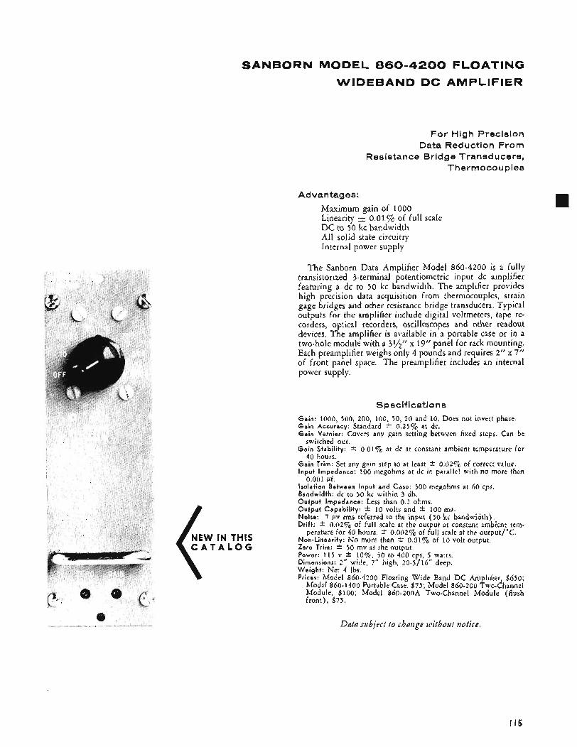
SANBORN MODEL 860-4200 FLOATING
WIDEBAND DC AMPLIFIER
For High Precision Data Reduction From
Resistance Bridge Transducers, Thermocouples
Advantages:
Maximum gain of 1000 Linearity e 0.01% of full scale D C to 50 kc bandwidth All solid state circuitry Internal power supply
The Sanborn Data Amplifier Model 860-4200 is a fully transistorized 3-terminal potentiometric input dc amplifier featuring a dc to 50 kc bandwidth. The amplifier provides high precision data acquisition from thermocouples, strain gage bridges and other resistance bridge transducers. Typical outputs for the amplifier include digital voltmeters, tape re- corders, optical recorders, oscilloscopes and other readout devices. The amplifier is available in a portable case or in a two-hole module with a 3y2” x 19” panel for rack mounting. Each preamplifier weighs only 4 pounds and requires 2” x 7” of front panel space. The preamplifier includes an internal power supply.
NEW IN THIS C A T A L O G
Specifications Ga in : 1000, 500, 200, 100, 50, 20 and 10. Does not invert phase. G a i n Accuracy: Standard * 0.2570 at dc. G a i n Vernier: Covers any gain setting between fixed steps. Can be
G a i n Stabi l i ty : * 0.01% at dc at constant ambient temperature for
G a i n Trim: Set any gain step to at least * 0.02% of correct value. I npu t Impedance: 100 megohms at dc in parallel with no more than
Isolat ion Between I n p u t and Case: 500 megohms at 60 cps. Bandwidth: dc to 50 kc within 3 db. O u t p u t Impedance: Less than 0.2 ohms. O u t p u t Capab i l i t y : * 10 volts and -t 100 ma. Noise: 7 pv rms referred to the input (50 kc bandwidth). Dr i f t : 2 0.027O of full scale at the output at constant ambient tem-
perature for 40 hours. * 0.002yO of full scale at the output/”C. Non-L inear i ty : No more than t 0.01% of 10 volt output. Zero Trim: * 50 mv at the output. Power: 115 v * lo%, 50 to 400 cps, 5 watts. Dimensions: 2 “ wide, 7 ” high, 20-5/16“ deep. W e i g h t : Net 4 Ibs. Prices: Model 860-4200 Floating Wide Band D C Amplifier, $650;
Model 860-1400 Portable Case, $75; Model 860-200 Two-Channel Module, $100; Model 860-200A Two-Channel Module (flush front) , $75.
switched out.
40 hours.
0.001 pf.
Data subject to change without notice.
I I 5
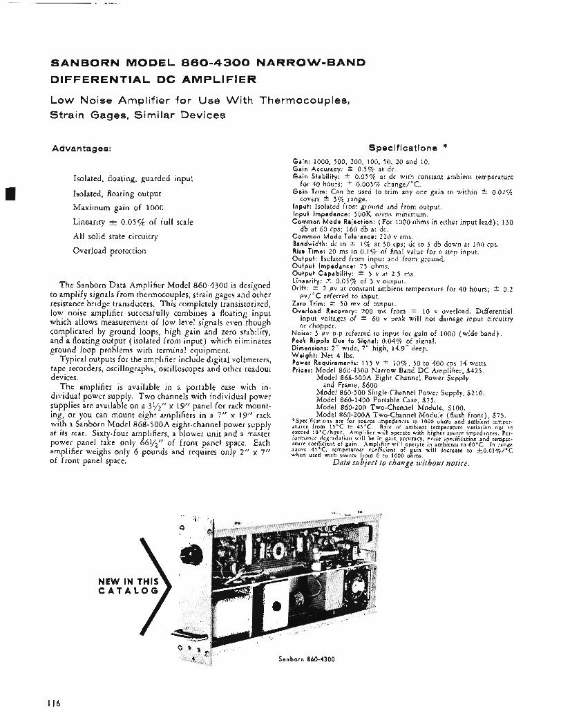
SANBORN MODEL 860-4300 NARROW-BANQ
DIFFERENTIAL QC AMPLIFIER
Low Noise Amplifier for Use With Thermocouples, Strain Gages, Similar Devices
Advantages:
Isolated, floating, guarded input
Isolated, floating output Maximum gain of 1000
Linearity t 0.0572 of full scale
All solid state circuitry
Overload protection
The Sanborn Data Amplifier Model 860-4300 is designed to amplify signals from thermocouples, strain gages and other resistance bridge transducers. This completely transistorized, low noise amplifier successfully combines a floating input which allows measurement of low level signals even though complicated by ground loops, high gain and zero stability, and a floating output (isolated from input) which eliminates ground loop problems with terminal equipment.
Typical outputs for the amplifier include digital voltmeters, tape recorders, oscillographs, oscilloscopes and other readout devices.
The amplifier is available in a portable case with in- dividual power supply. Two channels with individual power supplies are available on a 395” x 19” panel for rack mount- ing, or you can mount eight amplifiers in a 7” x 19” rack with a Sanborn Model 8 6 8 - 5 0 0 A eight-channel power supply at its rear. Sixty-four amplifiers, a blower unit and a master power panel take only 661/2” of front panel space. Each amplifier weighs only 6 pounds and requires only 2“ x 7” of front panel space.
Specifications * Ga in : 1000, 500, 200, 100, 50, 20 and 10. G a i n Accuracy: 0.5% at dc. G a i n Stabi l i ty : * 0.05% at dc with constant ambient temperature
for 40 hours; * 0.005% change/”C. G a i n Trim: Can be used to trim any one gain to within * 0.02%
covers * 35% range. Input : Isolated from ground and from output. I npu t Impedance: 500K ohms minimum. Common M o d e Rejection: (For 1000 ohms in either input lead) ; 130
Common M o d e Tolerance: 220 v rms. Bandwidth: dc to 2 1% at 30 cps; dc to 3 db down at 100 cps. Rise Time: 20 ms to 0.1% of final value for a step input. Outpu t : Isolated from input and from ground. O u t p u t Impedance: 75 ohms. O u t p u t Capab i l i t y : * 5 v at 2.5 ma. Linearity: * 0.05% of 5 v output. Dr i f t : * 2 pv at constant ambient temperature for 40 hours;
Zero Trim: * 50 mv of output. Over load Recovery: 200 ms from k 10 v overload. Differential
input voltages of * 60 v peak will not damage input circuitry or chopper.
db at 60 cps; 160 db at dc.
0.2 pv/OC referred to input.
Noise: 3 pv p-p referred to input for gain of 1000 (wide band) . Peak Ripple Due to Signal: 0.04% of signal. Dimensions: 2“ wide, 7 ” high, 14.9” deep. W e i g h t : Net 4 Ibs. Power Requirements: 115 v 2 l o % , 50 to 400 cps 14 watts. Prices: Model 860-4300 hlarrow Band D C Ampliher, $425.
Model 868-500A Eight Channel Power Supply
Model 860-500 Single-Channel Power Supply, $2 10. Model 860-1400 Portable Case, 575. Model 860-200 Two-Channel Module, $100. Model 860-200A Two-Channel Module (flush front) , 575.
and Frame, $600.
‘:‘Specifications are for source impedances to 1000 ohms and ambient temper- atures from 15°C to 45°C. Rate of ambient temperature variation not to exceed 10°C/hour . Amplifier will operate with higher source impedances. Per- formance degradation will be in gain accuracy, noise specification and temper- ature coefficient of gain. Amplifier a d 1 operate in ambients to 60°C. In range above 45’C, ,temperature coefficient of gain will increase to ~ O . O l ~ o / o C when used with source from 0 to 1000 ohms,
Data subject to change without notice.
NEW IN C A T A
Sanborn 860-4300
I16
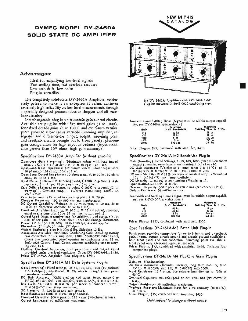
DYMEC MODEL D V - 2 4 6 0 A SOLID STATE DC AMPLIFIER
Advantages: Ideal for amplifying low-level signals Fast settling time, fast overload recovery Low zero drift, low noise Plug-in versatility
The completely solid-state DY-2460A Amplifier, moder- ately priced to make i t an exceptional value, achieves extremely high reliability on low-level measuremenbs through a specially designed photoconductive chopper and all-trans- istor circuitry.
Interchangeable plug-in units contain gain control circuits. Available are plug-ins with: five fixed gains (1 to 1000) ; four fixed decade gains (1 to 1000) and multi-turn vernier; patch panel to allow use as versatile summing amplifier, in- tegrator and diff erentiator (input, output, summing point and feedback circuits brought out to front panel) ; plus-one gain configuration for high input impedance (input resist- ance greater than 1 O 1 O ohms, high gain accuracy),
Specifications DY-2460A Amplifier (without plug-in) Open-Loop Ga in ( Invert ing): (Minimum values with load imped-
ance > 1K.) 5 x 10' at dc; 7 x 10' at 40 cps; 1 at 1 mc. Open-Loop Input Impedance: (Minimum values. Shunt capacitance
60 pf max.) 1M at dc; l5OK at 1 kc. Open-Loop Output Impedance: 10 ohms max., dc to 10 kc; 50 ohms
max., 10 kc to 1 mc. Input Noise: (Referred to summing point, < lOOK to ground.) 4 pv
p-p max., o to 1 cps; 10 pv rms max., 0 to 1 kc. Zero Drift: (Referred to summing point, < lOOK to ground; 12-hr.
warmup]). Constant temp., 1 pv/week max.; temp. coeff., 0.5 pv/"C max.
Zero Adjustment: (Referred to summing point.) f 20 pv. Chopper Frequency: 190 to 300 cps, non-synchronous. DC Output Capabi l i ty: Voltage, f 10 v; current, f 10 ma, dc to
10 kc ( 6 db/octave decrease, 10 kc to 1 mc). Overload: Amplifier Limiting, f 10.5 to f 11.5 v output; recovery,
equal to rise time plus 20 ps ( 5 ma max. to sum point). Output Load: Max. capacitive load for stability, 0.1 pf for gain ) 10;
0.01 pf for gain < 10. Short circuit does not damage instrument. Power: 115 or 230 v f l o % , 50 to 1000 cps, 4 watts approx. Dimensions: 3" high, 5" wide, 17" deep. W e i g h t (includes a plug-in): Net 6 Ibs. Shipping 1 2 Ibs. Accessories Available: 8048-0029 Combining Case, including mating
rear connectors for six amplifiers, $200. 5060-0792 Filler Panel, covers one unoccupied panel opening in combining case, $3 ea, 5060-0828 Control Panel Cover, converts combining case to carry. ing case, $23.
Options: Overload Indication, front panel lamp and output signal provided under overload conditions. Order DY-2460A-M1, $430.
Price: DY-2460A Amplifier (less plug-in), $395.
specifications DY-246 I A - M I Data Systems Plug-in Gain ( Invert ing): Fixed settings, 10, 30, 100, 300, 1000 (x0 position
shorts output) ; adjustment, f 2% on each range (front panel screwdriver control).
DC Gain Accuracy: (Calibrated on x10 range, temp. range 0 to 55'c.) x30f 0.6%, xlOO*O.6%, x300* 1.3%, xlOOOf 1.3%.
DC G a i n S t a b i l i t y : f 0.01% per week a t constant temp.; f O.ol%/"C max. temp. coefficient.
DC Linearity: * 0.01% at any gain setting. Input Resistance: lOOK f O.2"Jo0, 50 pf nominal. Overload Capacity: 300 v peak or 220 v rms (whichever is less), O u t p u t Resistance: 50 milliohms maximum.
NEW IN THIS C A T A L O G
Six DY-2460A Amplifiers with DY-2461-A-Ml plug-ins mounted in 8048-0029 combining case.
X I 0 x 3 0
XI00 x 3 0 0 XI000
50 kc 15 kc 5 kc
1.5 kc 500 cpr
Bandwidth and Settling Time: (Signal must be within output capabil- ity, see DY-2460A specifications.)
Minimum Maximum Gain 3 db Bandwidth Settling Time to 0.1%
25 ps 75 ps 250 ps 750 ps 2.5 rns
Price: Plug-in, $85; combined with amplifier, $480.
Specifications DY-246 I A - M 2 Bench-Use Plug-in Gain ( Invert ing): Fixed Settings, 1, 10, 100, 1000 (x0 position shorts
output) ; vernier, extends gain, each setting, from X I to x10. DC Gain Accuracy: (Vernier at 1; temp. range 0 to 55°C) : x l f
0.6%; x10 f 0.6%; xl00 f 1.3%; xl000 * 2%. DC Gain Stability: f 0.01% per week at constant temp. (Vernier at
1 ) ; f o.ol%/"C max. temp. coefficient. DC Linearity: f 0.01% at each setting (Vernier at 1 ) . Input Resistance: lOOK f 0.2%. Overload Capacity: 300 v peak or 220 v rms (whichever is less). Output Resistance: 50 milliohms max.
Bandwidth and Settling Time: (Sighal must be within output capabil- ity; see DY-2460A specifications.)
Maximum Minimum Gain 3 db Bandwidth Settling Time to 0.1%
X I 50 ke 25 us X I 0
XI00 x IO00
50 kc 25 iLs 5 kc 250 pi
500 cpr 2.5 rns
Price: Plug-in $125; combined with amplifier, $520.
Specifications DY-246 I A - M 3 Patch Unit Plug-in Patch panel provides connections for up to 3 inputs and 1 feedback path. Inputs, output, circuit ground and chassis ground available at both front panel and rear connector. Summing point available at front panel only. Overload signal at rear only. Price: Plug-in, $75; combined with amplifier, $470. Includes four
Specifications DY-246 I A - M 4 Plus-One Gain Plug-in Gain: x l . Non-inverting. DC Gain Accuracy: (Includes linearity, long term stability, 0 to
Input Resistance: 1 O 1 O ohms, for relative humidity up to 70% at
Overload Capacity: 300 volts peak or 220 volts rms (whichever is
Output Resistance: 50 milliohms maximum. Overload Recovery: Maximum input for 1 ms recovery (to 0.1%)
Price: Plug-in, $35; combined with amplifier, $430.
component plugs.
55°C) f 0.005% into 1K; f 0.0002% into 100K.
40 C.
less),
f 300 v.
Data subject to change without notice.
I I 7
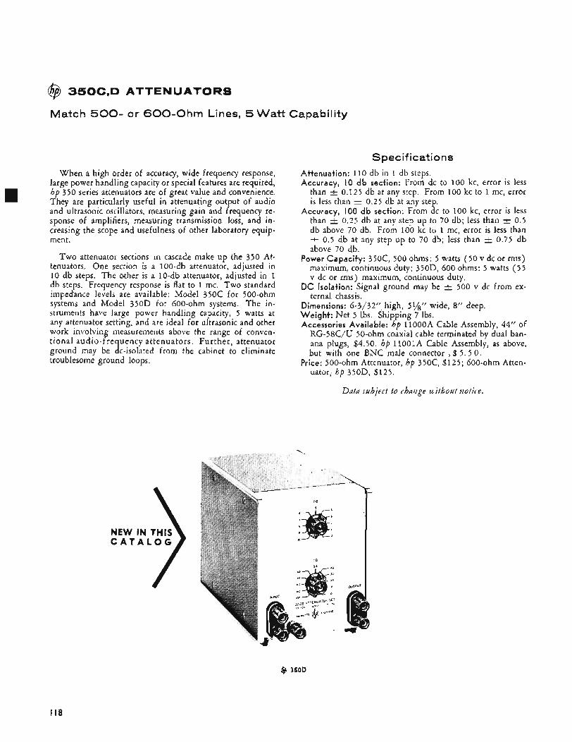
@ 350C,D ATTENUATORS
Match 500- or 6 0 0 - O h m Lines, 5 Watt Capability
When a high order of accuracy, wide frequency response, large power handling capacity or special features are required, hp 350 series attenuators are of great value and convenience. They are particularly useful in attenuating output of audio and ultrasonic oscillators, measuring gain and frequency re- sponse of amplifiers, measuring transmission loss, and in- creasing the scope and usefulness of other laboratory equip- ment.
Two attenuator sections in cascade make up the 350 At- tenuators. One section is a 100-db attenuator, adjusted in 10 db steps. The other is a 10-db attenuator, adjusted in 1 db steps. Frequency response is flat to 1 mc. Two standard impedance levels are available: Model 350C for 500-ohm systems and Model 350D for 600-ohm systems. The in- struments have large power handling capacity, 5 watts at any attenuator setting, and are ideal for ultrasonic and other work involving measurements above the range of conven- tional audio-frequency attenuators. Further, attenuator ground may be dc-isolated from the cabinet to eliminate troublesome ground loops.
Spec if i cat i o ns Attenuation: 110 db in 1 db steps. Accuracy, IO db section: From dc to 100 kc, error is less
than t 0.125 db at any step. From 100 kc to 1 mc, error is less than i- 0.25 db at any step.
Accuracy, 100 db section: From dc to 100 kc, error is less than i- 0.25 db at any step up to 70 db; less than 2 0.5 db above 70 db. From 100 kc to 1 mc, error is less than
0.5 db at any step up to 70 db; less than -+ 0.75 db above 70 db.
Power Capacity: 350c, 500 ohms: 5 watts (50 v dc or rms) maximum, continuous duty; 350D, 600 ohms: 5 watts (55 v dc or rms) maximum, continuous duty.
DC Isolation: Signal ground may be -+ 500 v dc from ex- ternal chassis.
Dimensions: 6-3/32” high, 51/8ff wide, sf f deep. Weight: Net 5 lbs. Shipping 7 lbs. Accessories Available: hp 1 loooA Cable Assembly, 44” of
RG-58C/U 50-ohm coaxial cable terminated by dual ban- ana plugs, $4.50. hp 11OOlA Cable Assembly, as above, but with one BNC male connector , $ 5 . 5 0 .
Price: 500-Ohm Attenuator, hp 350C, $125; 600-ohm Atten- uator, hp 350D, $125.
Data subject to chaiige toitbout notice.
NEW C A T
Q 350D
I I8
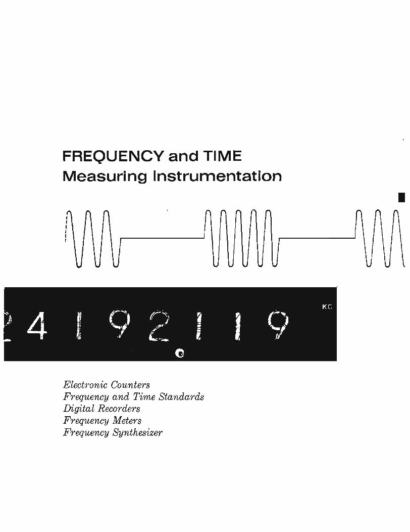
FREQUENCY and TIME Measuring Instrumentation
Electronic Counters Frequency and Time Standards Digita 1 Recorders Frequency Meters Frequency Synthesizer
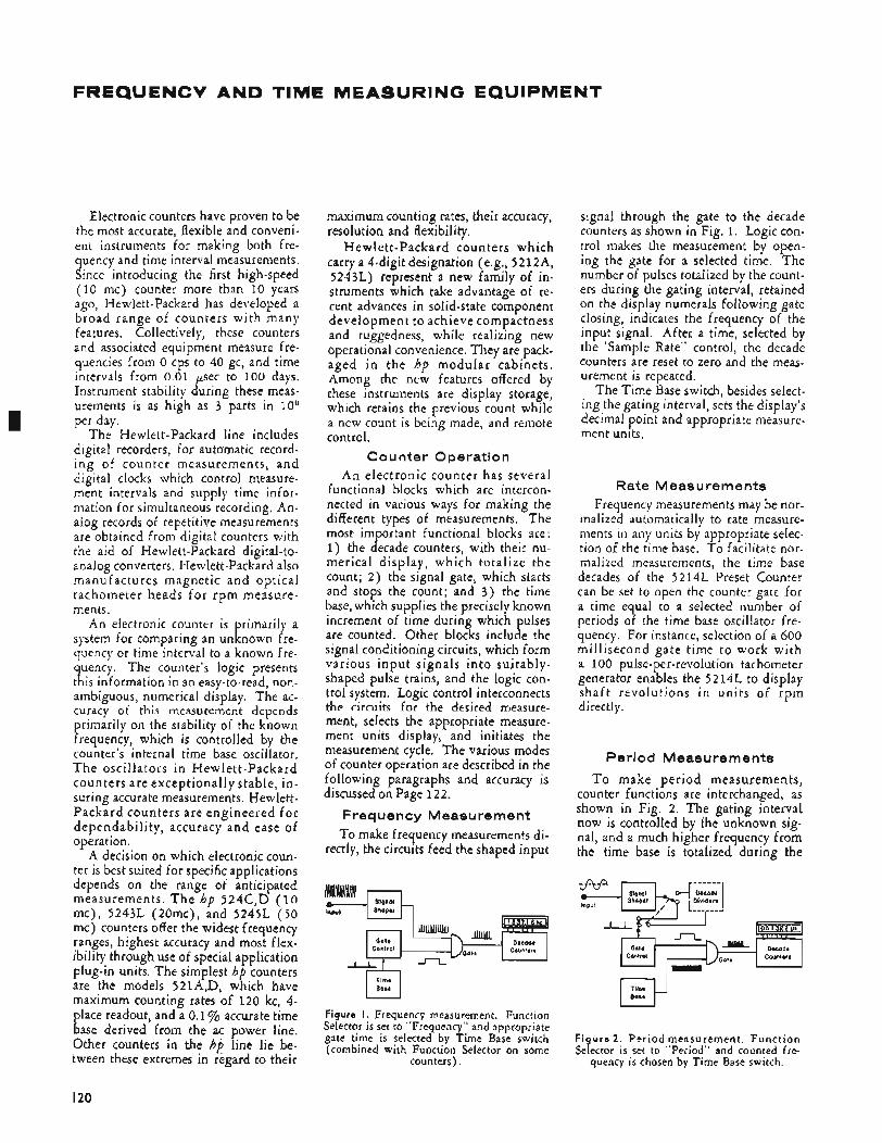
FREQUENCV AND TIME MEASURING EQUIPMENT
, fP.t
I
Slqnol S h o w - I IS37.1 6 kc I
- U U U U U U l GO(.
contr.a1 C.a"nl.rs
Electronic counters have proven to be the most accurate, flexible and conveni- ent instruments for making both fre- quency and time interval measurements. Since introducing the first high-speed (10 mc) counter more than 10 years ago, Hewlett-Packard has developed a broad range of counters wi th many features. Collectively, these counters and associated equipment measure fre- quencies from 0 cps to 40 gc, and time intervals from 0.01 psec to 100 days. Instrument stability during these meas- urements is as high as 3 parts in IOg per day.
The Hewlett-Packard line includes digital recorders, for automatic record- i ng of counter measurements, and digital clocks which control measure- ment intervals and supply time infor- mation for simultaneous recording, An- alog records of repetitive measurements are obtained from digital counters with the aid of Hewlett-Packard digital-to- analog converters. Hewlett-Packard also manufactures magnetic and optical tachometer heads for rpm measure- ments.
An electronic counter is primarily a system for comparing an unknown fre- quency or time interval to a known fre- quency. The counter's logic presents this information in an easy-to-read, non- ambiguous, numerical display, The ac- curacy of this measurement depends primarily on the stability of the known frequency, which is controlled by the counter's internal time base oscillator. T h e oscillators i n Hewlett-Packard counters are exceptionally stable, in- suring accurate measurements. Hewlett- Packard counters are engineered fo r dependability, accuracy and ease of operation.
A decision on which electronic coun- ter is best suited for specific applications depends on the range of anticipated measurements. T h e hp 524C,D (10 mc), 5243L (20mc), and 5245L (50 mc) counters offer the widest frequency ranges, highest accuracy and most flex- ibility through use of special application plug-in units. The simplest hp counters are the models 521A,D, which have maximum counting rates of 120 kc, 4- place readout, and a 0.1 % accurate time base derived from the ac power line. Other counters in the hp line lie be- tween these extremes in regard to their
maximum counting rates, their accuracy, resolution and flexibility.
Hewlett-Packard counters which carry a 4-digit designation (e.g., 5212A, 5243L) represent a new family of in- struments which take advantage of re- cent advances in solid-state component development to achieve compactness and ruggedness, while realizing new operational convenience. They are pack- aged in the hp modular cabinets. Among the new features offered by these instruments are display storage, which retains the previous count while a new count is being made, and remote control.
Counter Operation A n electronic counter has several
functional blocks which are intercon- nected in various ways for making the different types of measurements. The most im ortant functional blocks are:
merical display, which totalize the count; 2) the signal gate, which starts and stops the count; and 3) the time base, which supplies the precisely known increment of time during which ulses
signal conditioning circuits, which form various input signals in to suitably- shaped pulse trains, and the logic con- trol system. Logic control interconnects the circuits for the desired measure- ment, selects the appropriate measure- ment units display, and initiates the measurement cycle. The various modes of counter operation are described in the following paragraphs and accuracy is discussed on Page 122.
Frequency Measurement To make frequency measurements di-
rectly, the circuits feed the shaped input
1) the B ecade counters, with their nu-
are counted. Other blocks inch B e the
signal through the gate to the decade counters as shown in Fig. 1. Logic con- trol makes the measurement by open- ing the gate for a selected time, The number of pulses totalized by the count- ers during the gating interval, retained on the display numerals following gate closing, indicates the frequency of the input signal. After a time, selected by the 'Sample Rate" control, the decade counters are reset to zero and the meas- urement is repeated,
The Time Base switch, besides select- ing the gating interval, sets the display's decimal point and appropriate measure- ment units,
Rate Meas u rements Frequency measurements may be nor-
malized automatically to rate measure- ments in any units by appropriate selec- tion of the time base. To facilitate nor- malized measurements, the time base decades of the 5214L Preset Counter can be set to open the counter gate for a time equal to a selected number of periods of the time base oscillator fre- quency. For instance, selection of a 600 millisecond gate time to work with a 100 pulse-per-revolution tachometer generator enables the 5 2 14L to display sha f t revolutions in units of rpm directly.
Period Measurements
To make period measurements, counter functions are interchanged, as shown in Fig. 2. The gating interval now is controlled by the unknown sig- nal, and a much higher frequency from the time base is totalized during the
F igu re 2. Period measurement . Funct ion Selector is set to "Period" and counted fre-
quency is chosen by Time Base switch.
I20
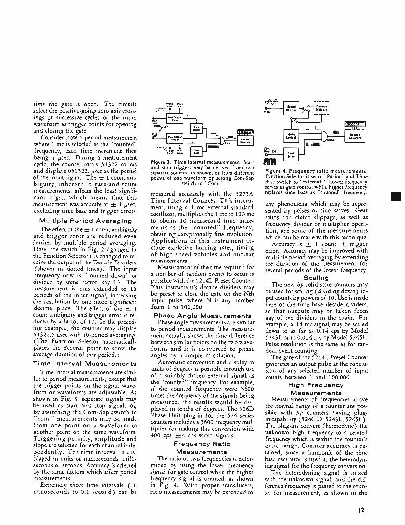
time the gate is open. The circuits select the positive-going zero axis cross- ings of successive cycles of the input waveform as trigger points for opening and closing the gate.
Consider now a period measurement where 1 mc is selected as the “counted” frequency, each time increment then being 1 pec . During a measurement cycle, the counter totals 51322 counts and displays 051322. p e c as the period of the input signal. The + 1 count am- biguity, inherent in gate-and-count measurements, affects the least signifi- cant digit, which means that this measurement was accurate to k 1 pec , excluding time base and trigger errors.
Multiple Period Averaging The effect of the 1 count ambiguity
and trigger error are reduced even further by multiple period averaging. Here, the switch in Fig. 2 (ganged to the Function Selector) is changed to re- ceive the output of the Decade Dividers (shown in dotted lines). The input frequency now is “counted down’’ or divided by some factor, say 10. The measurement is thus extended to 10 periods of the input signal, increasing the resolution by one more significant decimal place. The effect of the k 1 count ambiguity and trigger error is re- duced by a factor of 10. In the preced- ing example, the counter may display 51322.5 psec with 10-period averaging. (The Function Selector automatically places the decimal point to show the average duration of one period.) Time Interval Measurements
Time interval measurements are simi- lar to period measurements, except that the trigger points on the signal wave- form or waveforms are adjustable. As shown in Fig. 3, separate signals may be used as start and stop signals or, by switching the Com-Sep switch to “com,” measurements may be made f rom one point on a waveform to another point on the same waveform. Triggering polarity, amplitude and slope are selected for each channel inde- pendently. T h e time interval is dis- played in units of microseconds, milli- seconds or seconds. Accuracy is affected by the same factors which affect period measurements.
Extremely short time intervals (10 nanoseconds to 0 .1 second) can be
Figure 3. Time Interval measurements. Start and stop triggers may be derived from two separate sources, as shown, or from different points of one waveform by setting Com-Sep
switch to “Corn.”
measured accurately with the 5275~4 Time Interval Counter. This instru- ment, using a 1 mc external standard oscillator, multiplies the 1 mc to 100 mc to obtain 10 nanosecond time incre- ments as the “counted” frequency, obtaining exceptionally fine resolution. Applications of this instrument in- clude explosive burning rates, timing of high speed vehicles and nuclear measurements.
Measurement of the time required for a number of random events to occur is possible with the 5214L Preset Counter. This instrument’s decade dividers may be preset to close the gate on the Nth input pulse, where N is any number from 1 to 100,000. Phase Angle Measurements
Phase angle measurements are similar to period measurements. The measure- ment actually shows the time difference between similar points on the two wave- forms and it is converted to phase angles by a simple calculation.
Automatic conversion and display in units of degrees is possible through use of a suitably chosen external signal as the “counted” frequency. For example, if the counted frequency were 3600 times the frequency of the signals being measured, the results would be dis- played in tenths of degrees. The 526D Phase Unit plug-in for the 524 series counters includes a 3600 frequency mul- tiplier for making this conversion with 400 cps k 4 cps servo signals.
Frequency Ratio Measurements
The ratio of two frequencies is deter- mined by using the lower frequency signal for gate control while the higher frequency signal is counted, as shown in Fig. 4. With proper transducers, ratio measurements may be extended to
Figure 4. Frequency rat io measurements. Function Selector is set to “Period” and Time Base switch to “external.” Lower frequency serves as gate control while higher frequency replaces time base as “counted” frequency.
any phenomena which may be repre- sented by pulses or sine waves. Gear ratios and clutch slippage, as well as frequency divider or multiplier opera- tion, are some of the measurements which can be made with this technique.
Accuracy is f 1 count k trigger error. Accuracy may be improved with multiple period averaging by extending the duration of the measurement for several periods of the lower frequency.
Scaling The new hp solid-state counters may
be used for scaling (dividing down) in- put counts by powers of 10. Use is made here of the time base decade dividers, so that outputs may be taken from any of the dividers in the chain. For example, a 14 mc signal may be scaled down to as far as 0.14 cps by Model 5243L or to 0.014 cps by Model 5245L. Pulse resolution is the same as for ran- dom event counting.
The gate of the 52 14L Preset Counter generates an output ulse at the conclu-
counts between 1 and 100,000. sion of any selecte a number of input
High Frequency Measurements
Measurements of frequencies above the normal range of a counter are pos- sible with hp counters having plug- in capability (524C,D, 5243L, 5245L). The plug-ins convert (heterodyne) the unknown high frequency to a related frequency which is within the counter’s basic range. Counter accuracy is re- tained, since a harmonic of the time base oscillator is used as the heterodyn- ing signal for the frequency conversion.
The heterodyning signal is mixed with the unknown signal, and the dif- ference frequency is passed to the coun- ter for measurement, as shown in the
I2 I
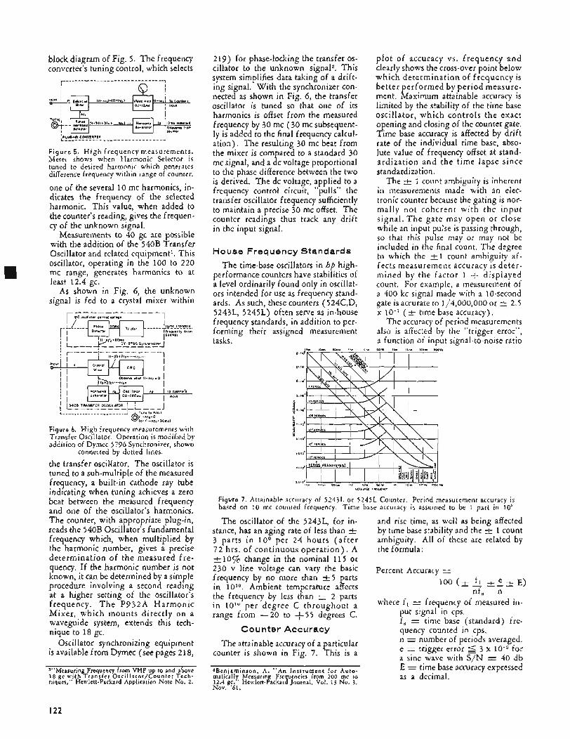
block diagram of Fig. 5. The frequency converter's tuning control, which selects
1,,,*
F i g u r e 5 . H i g h frequency measurements. Meter shows when Harmonic Selector is tuned to desired harmonic which generates difference frequency within range of counter.
one of the several 10 mc harmonics, in- dicates the frequency of the selected harmonic. This value, when added to the counter's reading, gives the frequen- cy of the unknown signal.
Measurements to 40 gc are possible with the addition of the 540B Transfer Oscillator and related equipment1. This oscillator, operating in the 100 to 220 mc range, generates harmonics to at least 12.4 gc.
As shown in Fig. 6, the unknown signal is fed to a crystal mixer within
I
1 r, ---_---__-- DC O ~ C l I l ~ f O r Sonfro, Y d 9 P t -.
,O~P. . iOOl 1 PERlon t ' MELISUREHEWT ~ '1 1xA.6
Figure 6. High frequency measurements with Transfer Oscillator. Operation is modified by addition of Dymec 5796 Synchronizer, shown
connected by dotted lines.
the transfer oscillator. The oscillator is tuned to a sub-multiple of the measured frequency, a built-in cathode ray tube indicating when tuning achieves a zero beat between the measured frequency and one of the oscillator's harmonics. The counter, with appropriate plug-in, reads the 540B Oscillator's fundamental frequency which, when multiplied by the harmonic number, gives a precise determination of the measured fre- quency. If the harmonic number is not known, it can be determined by a simple procedure involving a second reading at a higher setting of the oscillator's frequency. T h e P932A Harmonic Mixer, which mounts directly on a waveguide system, extends this tech- nique to 18 gc.
Oscillator synchronizing equipment is available from Dymec (see pages 2 18,
1"Measuring Frequency from VHF up to and above 18 gc w i t h T r a n s f e r O s c i l l a t o r / C o u n t e r T e c h - niques," Hewlett-Packard Application Note No. 2.
219) for phase-locking the transfer OS- cillator to the unknown signal2. This system simplifies data taking of a drift- ing signal. With the synchronizer con- nected as shown in Fig. 6, the transfer oscillator is tuned so that one of its harmonics is offset from the measured frequency by 30 mc (30 mc subsequent- ly is added to the final frequency calcul- ation). The resulting 30 mc beat from the mixer is compared to a standard 30 mc signal, and a dc voltage proportional to the phase difference between the two is derived. The dc voltage, applied to a frequency control circuit, "pulls" the transfer oscillator frequency sufficiently to maintain a precise 30 mc offset. The counter readings thus track any drift in the input signal.
Y E * I " R C D iRE0"LNC"
Figure 7. Attainable accuracy of 5 2 4 3 L or 5245L Counter. Period measurement accuracy is based on 10 mc counted frequency. Time base accuracy is assumed to be 1 part in 10'
The oscillator of the 5243L, for in- stance, has an aging rate of less than k 3 parts in i o 9 per 24 hours (after 72 hrs. of continuous operation). A & l o % change in the nominal 115 or 230 v line voltage can vary the basic frequency by no more than -+5 parts in Ambient temperature affects the frequency by less than -I 2 parts in lo1" per degree C throughout a range from -20 to +55 degrees C.
Counter Accuracy
The attainable accuracy of a particular counter is shown in Fig. 7. This is a
2Benjaminson A . "An I n s t r u m e n t for A u t o - matically, Meashing Fre uencies from 200 mc to 12.4 g c , Hewlett-Packar] Journal, Vol. 13 No. 3, Nov. '61.
and rise time, as well as being affected by time base stability and the -+ 1 count ambiguity. All of these are related by the formula:
Percent Accuracy = 100 (t f i + e + E)
nf, n where f i = frequency of measured in-
put signal in cps. f , = time base (standard) fre- quency counted in cps. n = number of periods averaged. e = trigger error 5 3 x for a sine wave with S/N = 40 db E = time base accuracy expressed as a decimal.
I22
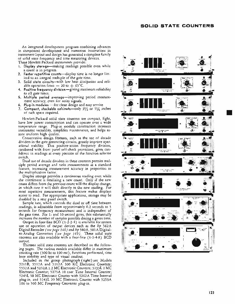
SOLID STATE COUNTERS
An integrated development program combining advances in component development and numerous innovations in instrument layout and design has generated a complete family of solid state frequency and time measuring devices. These Hewlett-Packard instruments urovide: I.
2.
3.
4.
5.
6. 7.
Display storage-making readiAgs possible even while a count is in progress. Faster repetitive counts-display time is no longer lim- ited to an integral multiple of the gate time. Solid state circuits-with low heat dissipation and reli- able operation from - 20 to + 65'C. Positive frequency division -giving maximum reliability to all gate times. Multiple period average-improving period measure- ment accuracy, even for noisy signals. Plug-in modules - for clean design and easy service. Compact, stackable cabinets-only 31/2 or 554 inches of rack space required.
Hewlett-Packard solid state counters are compact, light, have low power consumption and can operate over a wide temperature range. Plug-in module construction increases instrument versatility, simplifies maintenance, and helps as- sure uniform high quality.
Conservative design features, such as the use of decade dividers in the gate generating circuits, greatly improve oper- ational stability. This positive-action frequency division, combined with front panel self-check provisions, gives con- fidence in readings at every position of the function selector switch.
Dual use of decade dividers in these counters permits mul- tiple period average and ratio measurements as a standard feature, increasing measurement accuracy in proportion to the multiplication factor.
Display storage provides a continuous reading even while the instrument is totalizing a new count. Only if the new count differs from the previous count will the display change, in which case it will shift directly to the new reading. For most repetitive measurements, this feature makes displays easier to read. For appropriate applications, storage may be disabled by a rear panel switch.
Sample rate, which controls the dead or off time between readings, is adjustable from approximately 0.2 seconds to 5 seconds for frequency measurement and is independent of the gate time. For 1- and 10-second gates, this substantially increases the number of samples possible during a given time.
Output in four-line BCD (1-2-2-4) is available for system use or operation of output devices such as the hp 562A Digital Recorder (see page 146) and hp 580A, 581A Digital- to-Analog Converters (see puge 149) . These solid state counters are also available with a four-line (1-2-4-8) BCD output.
Thirteen solid state counters are described on the follow- ing pages. The various models available differ in maximum counting rate (300 kc to 100 mc), functions performed, time base stability and type of visual readout.
Included in the group photograph (right) are Models 5211B, 5512A and 5212A 300 KC Electronic Counters; 5532A and 5232A 1.2 MC Electronic Counters; 5233L 2 MC Electronic Counter; 5275A 10 nsec Time Interval Counter; 5245L 50 MC Electronic Counter with 5262A Time Interval plug-in, and 5243L 20 MC Electronic Counter with 52554 100 to 500 MC Frequency Converter plug-in.
A
I 23
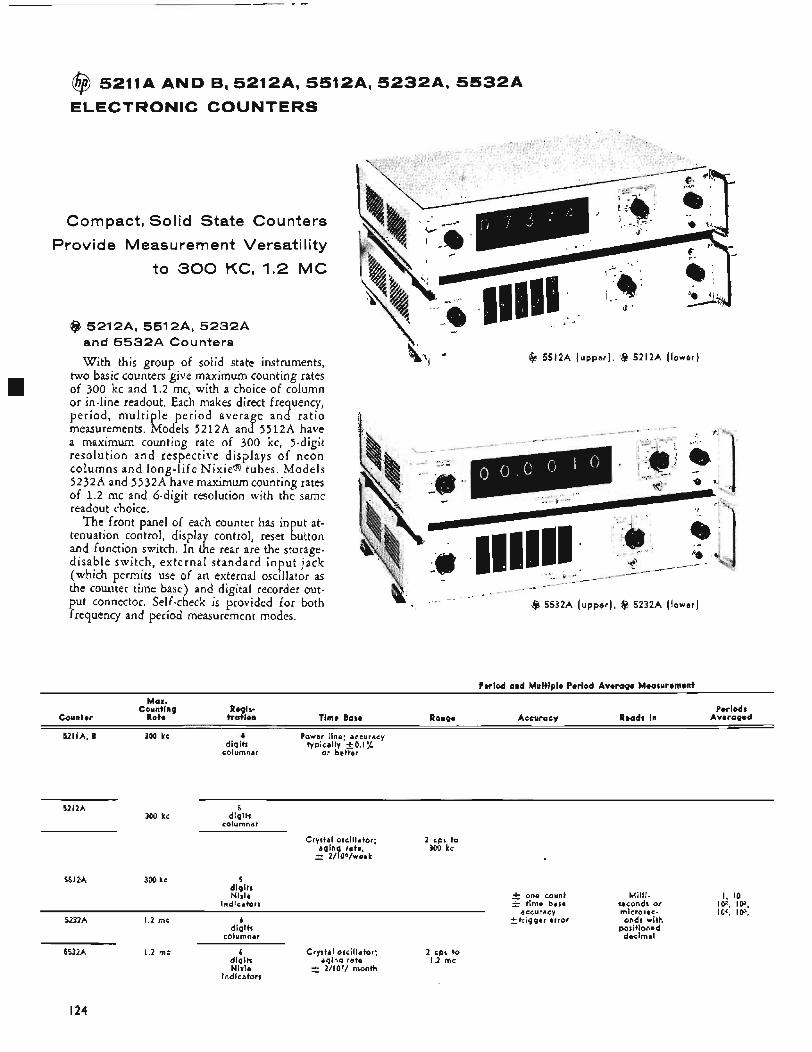
@ 5211A A N D B, 5 2 1 2 A , 5 5 1 2 A , 5 2 3 2 A , 5 5 3 2 A
E L E C T R O N I C C O U N T E R S
Compact, Solid State Counters
Provide Measurement Versat i I i ty
to 300 KC, 1.2 M C
@ 5212A, 5512A, 5 2 3 2 A and 5 5 3 2 A Counters
With this group of solid state instruments, two basic counters give maximum counting rates of 300 kc and 1.2 mc, with a choice of column or in-line readout. Each makes direct frequency, period, multiple period average and ratio measurements. Models 5212A and 5512A have a maximum counting rate of 300 kc, ?-digit resolution and respective displays of neon columns and long-life Nixie@ tubes. Models 5232A and 5532A have maximum counting rates of 1.2 mc and 6-digit resolution with the same readout choice.
The front panel of each counter has input at- tenuation control, display control, reset button and function. switch. In the rear are the storage- disable switch, external standard input jack (which permits use of an external oscillator as the counter time base) and digital recorder out-
frequency and period measurement modes.
c @ 5512A (upper ) , @ 5212A (lower)
put connector. Self-check is provided for both @ 5532A (upper ) , @ 5232A (lower)
Period and Multiple Period Average Measurement
Max. Counting Regis- Periods
Counter Rate tration Time Base Ronge Accuracy Reads in Averaged
5211A, B 300 kc 4 Power line. accuracy digits typically 'k0.17~
columnar or better
5212A 5 300 kc digits
columnar
Crystal oscillator; 2 cps to aging rate 304 kc F 2/10"/w;ak
5512A 300 kc 5 digits Nixie 2 one count
Indicators & time base accuracy
*trigger error 5232A 1.2 mc 6 digits
columnar
5532A 1.2 mc b Crystal oscillator; 2 cps to digits agina rate 1.2 mc Nixie +- Z/ lOT/ month
Indicators
Milli- seconds or microsec- onds with
positioned decimal
I24
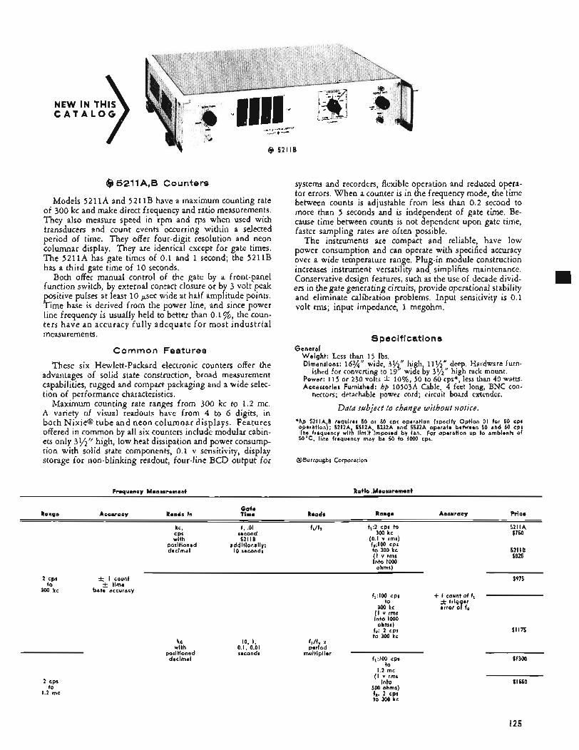
NEW IN THIS C A T A L O G
@ 52118
@J 5211A,B Counters
Models 5211A and 5211B have a maximum counting rate of 300 kc and make direct frequency and ratio measurements. They also measure speed in rpm and rps when used with transducers and count events occurring within a selected period of time. They offer four-digit resolution and neon columnar display, They are identical except for gate times. The 5211A has gate times of 0.1 and 1 second; the 5211B has a third gate time of 10 seconds.
Both offer manual control of the gate by a front-panel function switch, by external contact closure or by 3 volt peak positive pulses at least 10 psec wide at half amplitude points. Time base is derived from the power line, and since power line frequency is usually held to better than 0.1 %, the coun- ters have an accuracy fully adequate for most industrial measurements.
Common Features
These six Hewlett-Packard electronic counters offer the advantages of solid state construction, broad measurement capabilities, rugged and compact packaging and a wide selec- tion of performance characteristics.
Maximum counting rate ranges from 300 kc to 1.2 mc. A variety of visual readouts have from 4 to 6 digits, in both Nixie@ tube and neon columnar displays. Features offered in common by all six counters include modular cabin- ets only 3Yzrr high, low heat dissipation and power consump- tion with solid state components, 0.1 v sensitivity, display storage for non-blinking readout, four-line BCD output for
systems and recorders, flexible operation and reduced opera- tor errors. When a counter is in the frequency mode, the time between counts is adjustable from less than 0.2 second to more than 5 seconds and is independent of gate time. Be- cause time between counts is not dependent upon gate time, faster sampling rates are often possible.
The instruments are compact and reliable, have low power consumption and can operate with s ecified accuracy
increases instrument versatility and. simplifies maintenance. Conservative design features, such as the use of decade divid- ers in the gate generating circuits, provide operational stability and eliminate calibration problems. Input sensitivity is 0.1 volt rms; input impedance, 1 megohm.
over a wide temperature range. Plug-in mo B ule construction
Specifications General
Weight: Less than 15 Ibs. Dimensions: 16%" wide, 31/2" high, 11%" deep. Hardware furn-
Power: 115 or 230 volts * lo%, 50 to 60 cps*, less than 40 watts. Accessories Furnished: hp 10503A Cable. 4 feet long, BNC con-
ished for converting to 19" wide by 39"'' high rack mount.
nectors; detachable power cord; circuit board extender.
Data subject t o change witbozrt notice. ' h p 5211A B requires 50 or 60 cps operation (specify Option 01 for 50 cps operation\* 5212A 55l2A 5232A and 5532A operate between 50 and 60 CPS line frequincy witb limit 'imposed by fan. For operation up to ambients of 50°C, line frequency may be 50 to 1000 cps.
@Burroughs Corporation
Frequency Measurement Ratlo Measurement
2 cps to
300 kc
Gate Range Accuracy Reads In Time Reads Range Accuracy Price
I , .01 h/f? f1:2 cpr to 5211A $750 300 kc
kc, CPS second with 52118 (0.1 v rmr)
f*:100 cps positioned additionally: decimal I O seconds to 300 kc 52116
$825 ( I v rms into I000
ohms)
* I count $975 -i- time
base accuracy f1:10O cps + I count of fi
to + trig er 300 kc Gror 04 fs
!tOv I% ohms)
f ' 2 cpr t g 3 W kc
fJf* x period
multiplier f,:IM) cps
to 1.2 mc
( 1 ;,rp
500 ohms) fg. 2 cps to 300 kc
kc with
positioned decimal
10, 1, 0.1, 0.01 seconds
$I 175
$1300
2 cps to
1.2 me
$ I550
I25
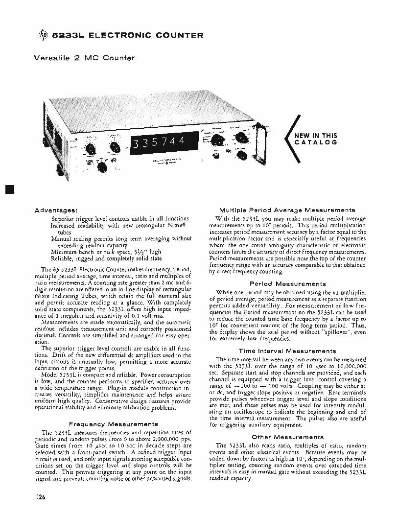
I@ 5233L ELECTRONIC COUNTER
Versatile 2 MC Counter
Advantages: Superior trigger level controls usable in all functions Increased readability with new rectangular Nixie@
Manual scaling permits long term averaging without
Minimum bench or rack space, 3%’’ high Reliable, rugged and completely solid state
tubes
exceeding readout capacity
The hp 5233L Electronic Counter makes frequency, period, multiple period average, time interval, ratio and multiples of ratio measurements. A counting rate greater than 2 mc and 6- digit resolution are otiered in an in-line display of rectangular Nixie Indicating Tubes, which retain the full numeral size and permit accurate reading at a glance. With completely solid state components, the 5233L offers high input imped- ance of 1 megohm and sensitivity of 0.1 volt rms.
Measurements are made automatically, and the automatic readout includes measurement unit and correctly positioned decimal. Controls are simplified and arranged for easy oper- ation.
The superior trigger level controls are usab!e in all func- tions. Drift of the new differential dc amplifiers used in the input circuits is unusually low, permitting a more accurate definition of the trigger points.
Model 5233L is compact and reliable. Power consumption is low, and the counter performs to specified accuracy over a wide temperature range. Plug-in module construction in- creaSes versatility, simplifies maintenance and helps assure uniform high quality. Conservative design features provide operational stability and eliminate calibration problems.
Freq ue ncy M eas u re men ts The 5233L measures frequencies and repetition rates of
periodic and random pulses from 0 to above 2,000,000 pps. Gate times f rom 10 p e c to 10 sec in decade steps are selected with a front-panel switch. A refined trigger input circuit is used, and only input signals meeting acceptable con- ditions set on the trigger level and slope controls will be counted. This permits triggering at any point on the input signal and prevents counting noise or other unwanted signals.
NEW IN THIS C A T A L O G
Multiple Period Average Measurements With the 5233L you may make multiple period average
measurements up to io7 periods. This period multiplication increases period measurement accuracy by a factor equal to the multiplication factor and is especially useful at frequencies where the one count ambiguity characteristic of electronic counters limits the accuracy of direct frequency measurements. Period measurements are possible near the top of the counter frequency range with an accuracy comparable to that obtained by direct frequency counting.
Period Measurements While one period may be obtained using the X I multiplier
of period average, period measurement as a separate function permits added versatility. For measurement of l ow fre- quencies the Period measurement on the 5233L can be used to reduce the counted time base frequency by a factor up to io7 for convenient readout of the long term period. Thus, the display shows the total period without “spillover”, even for extremely low frequencies.
Time Interval Measurements The time interval between any two events can be measured
with the 5233L over the range of 10 psec to 10,000,000 sec. Separate start and stop channels are provided, and each channel is equipped with a trigger level control covering a range of -100 to + 100 volts. Coupling may be either ac or dc, and trigger slope positive or negative. Rear terminals provide pulses whenever trigger level and slope conditions are met, and these pulses may be used for intensity modul- ating an oscilloscope to indicate the beginning and end of the time interval measurement. The pulses also are useful for triggering auxiliary equipment.
Other Measurements The 523% also reads ratio, multiples of ratio, random
events and other electrical events. Because events may be scaled down by factors as high as lo7, depending on the mul- tiplier setting, counting random events over extended time intervals is easy in manual gate without exceeding the 5233L readout capacity.
I26
Self-check provisions controlled from the front panel are incorporated in the 5233L, and display storage provides a non-blinking readout of the most recent measurement, shift- ing directly to a new reading only if the actual count changes. Display storage may be disabled by a rear panel switch.
The 5233L provides a four-line BCD code output for systems or recorder use. Hewlett-Packard modular construc- tion provides bench and rack mount counter in a single in- strument.
Spec if i cat i o ns
Input Channels (A and B) Range: D C coupled: 0 to more than 2 mc; ac coupled: 10 CPS to
Impedance: Approximately 1 megohm, 80 pf shunt. Sensitivity: 0.1 volt rms, sine wave; 1 volt pulse, 0.2 psec minimum
width. Trigger Level: - 100 to + 100 volts, adjustable, either positive or
negative slope; independent controls on each channel. Channel Inputs: Common, Separate, Check. Marker Output : Available at rear panel for oscilloscope intensity
modulation to mark trigger points on input waveforms; 1 psec duration and - 15 volts peak.
more than 2 mc.
Time Base: Frequency ( internal) : 1 mc. Stability: Aging rate: Less than C 2 parts in 10' per month. As a
function of line voltage: Less than rt 1 part in 10' for changes of C 10%. As a function of ambient temperature: Less than f 2, parts in lo6 (+ 10' to -k 50' C ) , * 20 parts in 10' ( - 20 to + 65°C).
External Input: Sensitivity: 1 volt rms sine wave, Range: 100 cps to 1 mc, sine wave.
Outputs, Rear Panel: Oscillator: 1 mc, 3 volts peak-to-peak. Time Base (separate BNC connector) : 0.1 cps to 1 mc in decade steps, 5 volts peak- to-peak, 600-ohm source. Available in Period, Time Interval, and Manual without reset interruptions.
B C D Output Output: 4-line BCD (1-2-2-42. Impedance: lOOK each line. 0" State Level: approximately - 8
Reference Levels: Approx. + 17 volts, 350-ohm source impedance;
Print Command: Step from - 9 volts to + 19 volts, dc coupled,
Hold-Of f Requirements: Anywhere from + 2 volts to - 20 volts.
volts. "1" State Level: approximately -t- 18 volts.
and approx. - 6 volts, 1000-ohm source impedance.
2700-ohm source impedance.
Manual Input: Channel A. Multiplier: Prescales input of Channel A in decades, 1 to lo'. Totalize: Periodic events at rates to more than 2 x lO'/sec except
1 .2 x 10"/sec when Multiplier is used to prescale. Random events with pulse spacing no less than 0.5 p s (0.8 ps when Multiplier is used to prescale).
Frequency Input: Channel A. Accuracy: f 1 count * time base accuracy. Reads In: KC or mc with positioned decimal. G a t e Time: 10 psec to 10 sec in decades. Self Check: Counts 1 mc for the gate time chosen by Time Base
seleztor.
Period Range: 0 to 100 kc. Input: Channel A.
Accuracy: +- 1 count k time base accuracy * trigger error.* Reads In: MS or sec with positioned decimal. Frequency Counted: 1 mc to 0.1 cps in decade steps. Self Check: Gate time is 1 sec; frequency counted is 0.1 cps to 1
mc as selected by Time Base switch.
Period Average Range: 0 to 1.2 mc. Input: Channel A. Accuracy: i: 1 count * time base accuracy * trigger error.* Reads In: p s or ns with positioned decimal. Periods Averaged: 1 to 10' in decade steps. Frequency Counted: 1 mc. Self Check: Gate time is 10 psec to 10 sec (10 to 10' periods of 1
mc) ; counts 1 mc.
Ratio Input: Channels A and B. Range: Channel A (FA) : 0 to more than 2 mc. Channel B (Fn) :
Measures: FA (Multiplier) 0 to 1.2 mc.
FB
Reads: - FA or - depending on Multiplier setting. FB FB
trigger error of FB Multiplier setting ' Accuracy: * 1 count of FA f
Multiplier: 1 to 10' in decade steps. Self Check: Counts 1 mc for 10 ps to 10 seconds depending on
Multiplier setting.
Time Interval Input: Channels A and B. Range: 10 ps to 10' seconds. Accuracy: f 1 count f time base accuracy *' trigger error.** Reads In: MS or sec with positioned decimal. Measurement: Time from A to B. Self Check: Period Self Check above applies, when levels and slopes
of both channels are identical.
Scaling Function Setting: Manual. Input: Channel A. Range: 0 to 1 .2 mc. Facior: By decades up to lo'. Output : Rear panel in place of time base output frequencies.
General Registration: 6 longlife in-line indicator tubes with display storage. Measurements Unit: Unit readout for Frequency, Period, Period
Average, and Time Interval with positioned decimal point. Sample Rate: Time following a gate closing during which the gate
may not be reopened is continuously variable from less than 0.2 sec to 5 secs; independent of gate time; display can be held in- definitely.
Self Check: In all function and multiplier positions. Operat ing Temperature Range: -20°C to +65"C. Dimensions: 16%" wide, 3,/2" high, 119'2" deep; rack mounting
Weight : Net 19 Ibs. Shipping 25 Ibs. Power Requirements: 115 or 230 volts * Io%, 50 to 60 cps,***
50 watts. Price: $1850.
* With trigger level set at zero, either slope, trigger error for sinewave input
hardware furnished.
Data subject t o change wi thout notice. .____
* 0'3% Of One period for signals with 40 db signal-to.noise ratio. is periods averaged 0.0025 * * For any waveshape, trigger error is C ~-
s i g n a ~ Slope (voIts/'sec) ''e'. Below 0.1 cps maximum error may increase up to 10 fold depending on line voltage and environmental conditions.
* * * Line frequenc limit imposed by fan. For operation up to ambient' temperature o r 5 O " C , line frequency may be 50 to 1000 cps.
127
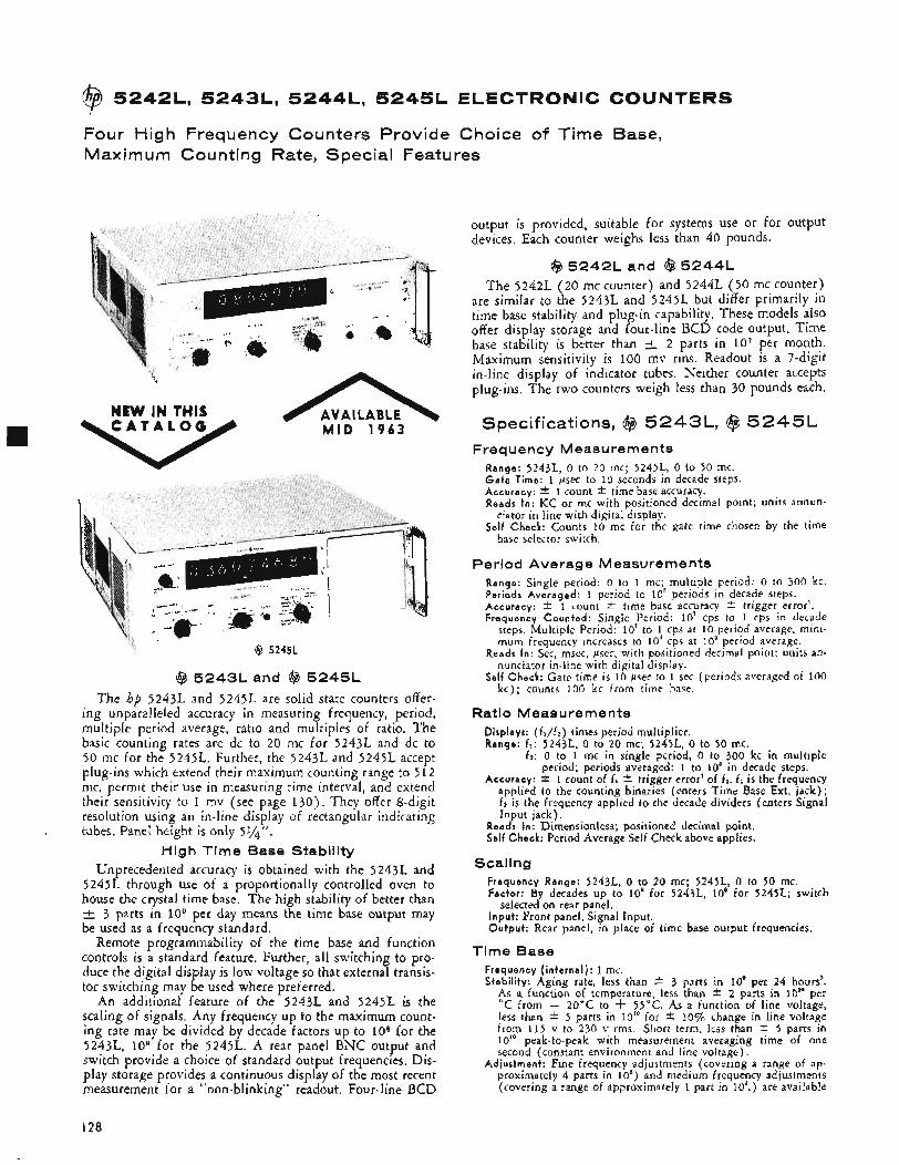
@ 5242L, 5243L, 5244L, 5245L ELECTRONIC COUNTERS
Four High Frequency Counters Provide Choice of Time Base, Maximum Counting Rate, Special Features
x
NEW IN THIS C A T A L O G MID 1 9 6 3
@ 5245L
@ 5243L and @ 5245L The hp 5243L and 52451. are solid state counters offer-
ing unparalleled accuracy in measuring frequency, period, multiple period average, ratio and multiples of ratio. The basic counting rates are dc to 20 mc for 5243L and dc to 50 mc for the 5245L. Further, the 5243L and 5245L accept plug-ins which extend their maximum counting range to 5 1 2 mc, permit their use in measuring time interval, and extend their sensitivity to 1 mv (see page 130) . They offer 8-digit resolution using an in-line display of rectangular indicating tubes. Panel height is only 51/4".
High Time Base Stability Unprecedented accuracy is obtained with the 5243L and
52451. through use of a proportionally controlled oven to house the crystal time base. The high stability of better than
3 parts in io9 per day means the time base output may be used as a frequency standard,
Remote programmability of the time base and function controls is a standard feature. Further, all switching to pro- duce the digital display is low voltage so that external transis- tor switching may be used where preferred.
An additional feature of the 5243L and 5245L is the scaling of signals. Any frequency up to the maximum count- ing rate may be divided by decade factors up to l o s for the 5243L, lo9 for the 5245L. A rear panel BNC output and switch provide a choice of standard output frequencies. Dis- play storage provides a continuous display of the most recent measurement for a "non-blinking" readout, Four-line BCD
output is provided, suitable for systems use or for output devices. Each counter weighs less than 40 pounds.
@ 52421, and @ 5244L The 5242L ( 2 0 mc counter) and 5244L ( 5 0 mc counter)
are similar to the 52431. and 5245L but differ primarily in time base stability and plug-in capability. These models also offer display storage and four-line BCD code output. Time base stability is better than 1+ 2 parts in IO7 per month. Maximum sensitivity is 100 mv rms. Readout is a 7-digit in-line display of indicator tubes. Neither counter accepts plug-ins. The two counters weigh less than 30 pounds each.
Specifications, @ 5 2 4 3 L , @ 5 2 4 5 L Frequency Measurements
Range: 5243L, 0 to 20 mc; 5245L, 0 to 50 mc. G a t e Time: 1 psec to 10 seconds in decade steps. Accuracy: * 1 count f time base accuracy. Reads In: KC or mc with positioned decimal point; units annun-
Self Check: Counts 10 mc for the gate time chosen by the time ciator in line with digital display.
base selector switch.
Period Average Measurements Range: Single period: 0 to 1 mc; multiple period: 0 to 300 kc. Periods Averaged: 1 period to 10' periods in decade steps. Accuracy: f 1 count * time base accuracy * trigger error'. Frequency Counted: Single Period: 10' cps to 1 cps in decade
steps. Multiple Period: 10' to 1 cps at 10-period average, mini- mum frequency increases to 10' cps at io5 period average.
Reads In: Sec, msec, psec, with positioned decimal point; units an- nunciator in-line with digital display.
Self Check: Gate time is 10 psec to 1 sec (periods averaged of 100 kc) ; counts 100 kc from time base.
Ratio Measurements Displays: (fJf2) times period multiplier. Range: 6: 5243L, 0 to 20 mc; 5245L, 0 to 50 mc.
f z : 0 to 1 mc in single period, 0 to 300 kc in multiple period; periods averaged: 1 to IO5 in decade steps.
Accuracy: * 1 count of f1 * trigger error' of 6. 6 is the frequency applied to the counting binaries (enters Time Base Ext. jack) ; fi is the frequency applied to the decade dividers (enters Signal Input jack).
Reads In: Dimensionless; positioned decimal point. Self Check: Period Average Self Check above applies.
Scaling Frequency Range: 5243L, 0 to 20 mc; 5245L, 0 to 50 mc. Factor: By decades up to 10' for 5243L, 10' for 5245L; switch
Input: Front panel, Signal Input. Output: Rear panel, in place of time base output frequencies.
selected on rear panel.
Time Base Frequency ( internal) : 1 mc. Stability: Aging rate, less than +- 3 parts in 10' per 24 hours'.
@ a function of temperature, less than * 2 parts in 10" per C from - 20°C to + 55°C. As a function of line voltage,
less than * 5 parts in 10" for f 10% change in line voltage from 115 v to 230 v rms. Short term, less than * 5 parts in 10" peak-to-peak with measurement averaging time of one second (constant environment and line voltage),
Adjustment: Fine frequency adjustments (covering a range of ap- proximately 4 parts in 10') and medium frequency adjustments (covering a range of approximately 1 part in IO',) are available
I28
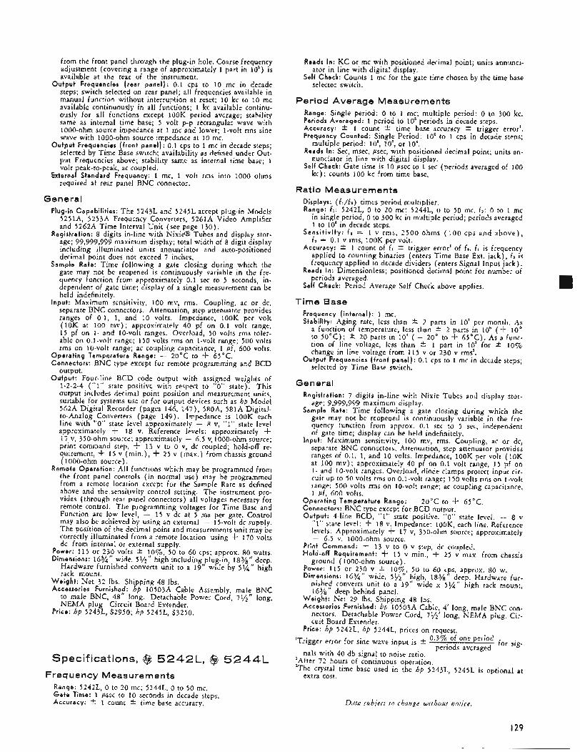
from the front panel through the plug-in hole. Coarse frequency adjustment (covering a range of approximately 1 part in lo5) is available at the rear of the instrument.
Output Frequencies (rear panel) : 0.1 cps to 10 mc in decade steps; switch selected on rear panel; all frequencies available in manual function without interruption at reset; 10 kc to 10 mc available continuously in all functions; 1 kc available continu- ously for all functions except 1OOK peIiod average; stability same as internal time base; 5 volt p-p rectangular wave with 1000-ohm source impedance at 1 mc and lower; 1-volt rms sine wave with 1000-ohm source impedance at 10 mc.
Output Frequencies (front panel) : 0.1 cps to 1 mc in decade steps; selected by Time Base switch; availability as defined under Out- put Frequencies above; stability same as internal time base; 1 volt peak-to-peak, ac coupled.
External Standard Frequency: 1 mc, 1 volt rms into 1000 ohms required at rear panel BNC connector.
General Plug-in Capabilities: The 5243L and 5245L accept plug-in Models
5251A, 5253A Frequency Converters, 5261A Video Amplifier and 5262A Time Interval Unit (see page 130) .
Registration: 8 digits in-line with Nix@ Tubes and display stor- age; 99,999,999 maximum display; total width of 8 digit display including illuminated units annunciator and auto-positioned decimal point does not exceed 7 inches.
Sample Rate: Time following a gate closing during which the gate may not be reopened is continuously variable in the fre- quency function from approximately 0.1 sec to 5 seconds, in- dependent of gate time; display of a single measurement can be held indefinitely.
Input: Maximum sensitivity, 100 mv, rms. Coupling, ac or dc, separate BNC connectors. Attenuation, step attenuator provides ranges of 0.1, 1, and 10 volts. Impedance, 1OOK per volt (10K at 100 m v ) ; approximately 40 pf on 0.1 volt range, 1 5 pf on 1- and 10-volt ranges. Overload, 50 volts rms toler- able on 0.l-volt range; 150 volts rms on 1-volt range; 500 volts rms on 10-volt range; ac coupling capacitance, 1 pf, 600 volts.
Operat ing Temperature Range: - 20°C to f 65°C. Connectors: BNC type except for remote programming and BCD
output. Output: Four-line BCD code output with assigned weights of
1-2-2-4 (“1” state positive with respect to “0” state). This output includes decimal point position and measurement units, suitable for systems use or for output devices such as hp Model 562A Digital Recorder (pages 146, 147) , 580A, 581A Digital- to-Analog Converters (page 149) . Impedance is lOOK each line with “0” state level approximately - 8 v, “1” state level approximately -t 18 v. Reference levels: approximately + 17 v, 350-ohm source; approximately - 6.5 v, 1000-ohm source; print command step, + 13 v to 0 v, dc coupled; hold-off re- quirement, f 15 v (min.) , f 2 5 v (max.) from chassis ground ( 1000-ohm source).
Remote Operat ion: All functions which may be programmed from the front panel controls ( in normal use) may be programmed from a remote location except for the Sample Rate as defined above and the .sensitivity control setting. The instrument pro- vides (through rear panel connectors) all voltages necessary for remote control. The programming voltages for Time Base and Function are low level, - 1 5 v dc at 5 ma per gate. Control may also be achieved by using an external - 15-volt dc supply. The position of the decimal point and measurements unit may be correctly illuminated from a remote location using -k 170 volts dc from internal or external supply.
Power: 115 or 230 volts 2 lo%, 50 to 60 cps; approx. 80 watts. Dimensions: 16%‘’ wide, 59”” high including plug-in, 18%’’ deep.
Hardware furnished converts unit to a 19” wide by 5%” high rack mount.
Weight : Net 32 lbs. Shipping 48 lbs. Accessories Furnished: hp 10503A Cable Assembly, male BNC
to male BNC, 48” long. Detachable Power Cord, 79”’’ long, NEMA plug. Circuit Board Extender,
Price: hp 5243L, $2950; hp 5245L, $3250.
Specifications, ($4 5 2 4 2 L , @ 5 2 4 4 L Frequency Measurements
Range: 5242L, 0 to 20 mc; 5244L, 0 to 50 mc. G a t e Time: 1 psec to 10 seconds in decade steps. Accuracy: * 1 count * time base accuracy.
Reads In: KC or mc with positioned decimal point; units annunci-
Self Check: Counts 1 mc for the gate time chosen by the time base ator in line with digital display.
selector switch.
Period Average Measurements Range: Single period: 0 to 1 mc; multiple period: 0 to 300 kc. Periods Averaged: 1 period to 10’ periods in decade steps. Accuracy: f 1 count * time base accuracy f trigger error’. Frequency Counted: Single Period: 10‘ to 1 cps in decade steps;
Reads In: Sec, msec, psec, with positioned decimal point; units an-
Self Check: Gate time is 10 psec to 1 sec (periods averaged of 100
multiple period: lo‘, IO5, or 10‘.
nunciator in line with digital display.
kc) ; counts 100 kc from time base.
Ratio Measurements Displays: (fl/fz) times period multiplier. Range: f,: 5242L, 0 to 20 mc; 5244L, 0 to 50 mc. fz: 0 to 1 mc
in single period, 0 to 300 kc in multiple period; periods averaged 1 to 10’ in decade steps.
Sens i t iv i ty : f , = 1 v rms, 2500 ohins (100 cps and above ) , f z = 0.1 v rms, lOOK per volt.
Accuracy: f 1 count of f , f trigger error’ of fz. f l is frequency applied to counting binaries (enters Time Base Ext. jack), f z is frequency applied to decade dividers (enters Signal Input jack).
Reads In: Dimensionless; positioned decimal point for number of periods averaged.
Self Check: Period Average Self Check above applies.
Time Base Frequency (internal): 1 mc. Stability: Aging rate, less than * 2 parts in 10’ per month. A,s
a function of temperature, less than * 2 parts in 10‘ ( f 10 to 50°C); f 20 parts in 10‘ ( - 20” to + 65°C). As a func- tion of line voltage, less than 2 1 part in lo’ for f 1070 change in line voltage from 115 v or 230 v rms3.
Output Frequencies (front panel) : 0.1 cps to 1 mc in decade steps; selected by Time Base switch.
General Registration: 7 digits in-line with Nixie Tubes and display stor-
age; 9,999,999 maximum display. Sample Rate: Time following a gate closing during which the
gate may not be reopened is continuously variable in the fre- quency function from approx. 0.1 sec to 5 sec, independent of gate time; display can be held indefinitely.
Input: Maximum sensitivity, 100 mv, rms. Coupling, ac or dc, separate BNC connectors. Attenuation, step attenuator provides ranges of 0.1, 1, and 10 volts. Impedance, 1OOK per volt (10K at 100 m v ) ; approximately 40 pf on 0.1 volt range, 15 pf on 1- and 10-volt ranges. Overload, diode clamps protect input cir- cuit up to 50 volts rms on 0.1-volt range; 150 volts rms on 1-volt range; 500 volts rms on 10-volt range; ac coupling capacitance, 1 pf, 600 volts.
Operat ing Temperature Range: - 20°C to f 65°C. Connectors: BNC tvDe exceDt for BCD output. Output: 4-line BCD, “1” state positive. .“O” state level: - 8 v
“1” state level: f 18 v. Impedance: 100K, each line. Reference levels: Approximately f 17 v, 350-ohm source; approximately - 6.5 v, 1000-ohm source.
Print Command: f 13 v to 0 v step, dc coupled. Hold-off Requirement: f 15 v min., + 25 v max. from chassis
Power: 115 or 230 v * l o%, 50 to 60 c y , approx. 80 w. Dimensions: 16%‘’ wide, 51/2“ high, 18%
ground ( 100o-ohm source).
d;ep. Hardware fur- nished converts unit to a 19” wide x 5% high rack mount, 16%” deep behind panel.
Weight : Net 29 Ibs. Shipping 48 Ibs. Accessories Furnished: hp 10503A Cable, 4’ long, male BNC con-
nectors. Detachable Power Cord, 795’ long, NEMA plug. Cir- cuit Board Extender.
Price: hp 5242L, hp 5244L, prices on request. 0.3% of one period
periods avcraged ’Trigger error for sine wave input is *
nals with 40 db signal to noise ratio. for sig-
‘After 72 hours of continuous operation. 3The crystal time base used in the hp 5243L, 5245L is optional at
extra cost.
Data strbject t o change without notice.
I29
@I 5 2 5 1 A , 5 2 5 3 A , 5 2 6 1 A , 5 2 6 2 A COUNTER PLUG-IN UNlTS
Increase Versatility of @ 5243L, 52451, Electronic Counters
@ 5251A @ 5253A @ 5261A @ 5262A
@ 5251A Frequency Converter The Model 5251A Frequency Converter plugs directly in-
to the front panel of the hp 5243L and 5245L (see pages 128 and 129) to extend measuring capability to 100 mc. The stability and accuracy of the basic counter is retained because the converter uses a multiple of the crystal oscillator fre- quency from the counter to beat with the signal to be meas- ured.
The basic measurement ranges of the counter also are re- tained with the converter installed. Measurements to 20 mc (5243L) or 50 mc (5245L) are obtained simply by moving the counter sensitivity control off the “plug-in” position and connecting the input signal directly to the counter input.
Specifications Range: As converter for 5243L or 5245L counters, 20 mc to 100 mc
using mixing frequencies of 20 mc to 90 mc in 10 mc steps. Accuracy : Retains accuracy of 52431. and 5245L counters, Registrat ion: First place indicated on converter switch, remainder
displayed by counter. I npu t Voltage: 50 mv rrns to 1 volt rrns for optimum performance
under worst-case conditions; typical signal dropout level with hp 52431. or 5245L is 20 mv rms.
Over load: ac signals in excess of 2 volts rms may damage the in- strument; up to * 100 volts dc is tolerable.
I npu t Impedance: Approximately 50 ohms. Level Ind icator : Meter aids frequency selection; indicates usable volt-
age level. W e i g h t : Net 29’2 Ibs. Shipping 7 Ibs. Price: $300.
@ 5253A Frequency Converter Model 525 3A Frequency Converter extends the measuring
capability of the 5243L or 5245L to 512 mc. Operating on the same principle as the 525 1A Frequency Converter, it retains the basic stability and accuracy of the counter. It operates from 88 to 5 12 mc as a frequency converter, although meas-
urements to 20 mc (5243L) or 50 mc (5245L) may be made directly.
Specifications Range: As converter for 5243L or 5245L counters, 88 mc to 512 mc,
using mixing frequencies of 100 mc to 500 mc in 10 mc steps, Accuracy : Retains accuracy of 5243L or 5245L counters. I npu t Voltage: 50 mv to 1 v rrns for optimum operation under worst-
case conditions. Typical signal dropout level (with hp 524)L or 5245L) is 20 mv rms.
I npu t Impedance: Approximately 50 ohms. Over load: Signals in excess of 2 v rms may damage the converter;
up to f 100 v dc is tolerable. Level Ind icator : Meter aids frequency selection; indicates acceptable
voltage level. Registrat ion: Counter display is added to or subtracted from con-
verter dial reading depending on whether the mixing frequency is below or above the measured frequency.
W e i g h t : Net 5 lbs. Shipping 9 Ibs. Accessory Furnished: hp l0503A Cable, 4 feet long. male BNC con-
nectors. Price: $500.
($4 5261A Video Amplifier The 5261A Video Amplifier plugs into the 5243L or
5245L counters to increase their sensitivity to 1 millivolt rrns over the range from 10 cps to 20 or 50 mc. An input signal level meter is provided to assure that the input signal is ade- quate to operate the counter and to guard against errors which might result from signal distortion through amplifier over- load. The plug-in also provides an output jack for monitor- ing the unknown voltage being measured.
Specifications Bandwidth: 10 cps to 50 mc. Maximum Sensitivity: 1 rnv rms. I npu t Impedance: Approximately 1 megohm, 15 pf shunt.hp l0003A
Attenuator Ranges: 1, 3, 10, 30 and 100 mv rms. Maximum Input : 300 rnv for proper operation. Over load: 5 v rrns 100 v dc.
Probe increases impedance to 10 megohms, 10 pf shunt.
I30
@I 5 2 7 5 A TIME INTERVAL COUNTER
Monitor: Meter shows when the signal level is acceptable to the
Accuracy: Retains accuracy of 5243L or 5245L Electronic Counter. Auxiliary Output: Separate BNC front panel output for oscilloscope
monitoring or for driving external equipment: 50 ohm source impedance. On amplifier's most sensitive attenuator range, 1 mv rms at input results in at least 100 mv rms at auxiliary output into 50 ohm load. Max. undistorted output is 300 mv rms into 50 ohm load.
Accessory Furnished: hp 10507A Low Microphonic 50-Ohm Cable,
counter.
4' long, BNC connectors. Accessories Available: hp 10003~4 10: 1 Divider Probe 10 pf shunt,
600 v max.. $30: hb lOlOOA 50-ohm Feed-thru Termination, $15. Weight: Net 2 Ibs. Shipping 6 Ibs. Power: Supplied by 5243L or 5245L Electronic Counter. Price: hp 5261A, $325.
@ 5 2 6 2 A Time interval Unit This plug-in converts the 5243L or 5245L into an accurate
time interval counter with a resolution of 0.1 microsecond. It permits measurement of pulse length, pulse spacing and time between electrical events. Time is read directly on the counter with the units and decimal indicated. Counter time base accuracy is retained. Further, the 5262A can be used as an amplitude discriminator for the counter so that only sig- nals meeting the requirements set by the trigger level controls are counted. In this mode of operation the frequency range is 0 to 2 mc.
Specifications Range: 1 psec to 10'sec. Accuracy (pulse): t 1 period of standard frequency counted t time
Registration: On 5243L or 5245L counters. Input Voltage: 0.3 volt, peak-to-peak, minimum, direct coupled in-
Input Impedance and Overload:
base accuracy.
put.
Multiplier Input Impedance Overload Resistance Capacitance
xo. I IOK 80 pf x0.2 IOK 80 pf m 7 3OK 40 Df
50 v rmr i. 150 v peak
X I IOOK 20 pf 150 v rms x3 300K 20 pf t 250 v peak r i n I mea 20 Df
x30 3 meq 20 pf t 250 v peak XI00 10 meq 20 pf
Start Stop: Separate or common channels. T r i g g e r S lope: Positive or negative on Star t and Stop channels,
independently selected.
- 250 v to +250 V. Trigger Amplitude: Both channels continuously adjustable from
Frequency Range of 5262A used as input signal discriminator: 0 to 2 mc.
Standard Frequency Counted: 10' to 1 cps in decades from 5243L/ 5245L, or externally applied frequency.
Markers: Separate output voltage steps, 0.5 volts peak-to-peak from source impedance of approximately 7 K , 100 pf; available at rear panel of 5243L with negative step coincident with trigger points on input waveforms for positive slope and positive step coincident for negative slope.
Reads in: p s , ms, sec with measurements unit indicated and decimal point positioned.
Accessories Furnished: hp 10503A Cable Assembly, male BNC to male BNC, 4' long.
Weight: Net 255 Ibs. Shipping 9 lbs. Price: $300.
Data subject to change without notice.
The Model 5275A permits time interval measurements with 10 nanosecond resolution, providing information pre- viously unavailable in digital form. Range is 10 nanoseconds to 0.1 second, and counted frequency is 100 mc, obtained from an external 1 mc standard by a 100-to-1 multiplying circuit within the counter.
The 5275A is ideally suited for precise digital measure- ments of short time intervals between events that can be rep- resented by suitable electrical pulses. Applications for this instrument include the measurement of explosive burning rates, speed and acceleration timing of test vehicles in free- flight wind tunnels and nuclear measurements of various kinds.
Standard features included in the 5275A are remote reset, rear-mounted trigger terminals and 4-line BCD output. (The hp 562A Digital Recorder or hp 580A, 581A Digital-to- Analog Converter are compatible with the BCD output from the 5275A.) For system installation a Model lOlA 1 MC Oscillator (see page 156) can supply the time base for as many as twenty 5275A counters.
Specifications Range: 10 nsec to 0.1 sec. Resolution: 10 nsec. Accuracy: 2 10 nsec +- time base accuracy. Time Base Input: ( h p lOlA Oscillator recommended).
Frequency: 1 mc. Amplitude: 1 v rms into 1000 ohms. Stability: Compatible with measurement needs.
Registration: 7 places, digital, neon columns. Reads in: Microseconds, with decimal point. Start and Stop Trigger Ipput: Separate channels.
input Impedance: 50 ohms. Minimum Trigger Pulse Requirements: 3 v peak, 0.5 v/nsec rise
Trigger Polarity: Selectable, positive or negative. time, 5 nsec width.
Reset: Manual, or remote using rear terminals. Standard Frequency Counted: 100 mc. Output: 4-line BCD (1-2-2-4).
"0" state: - 8 volts. ' ' 1 " state: + 18 volts. Impedance: loOK, each line. Print Command: Step from -6 to +13 volts, dc coupled, 2000
ohm source. Hold-off Requirements: Any voltage from ground to 3- 12 volts, in-
External Reset: - 13 volt pulse, 30 psec minimum duration. Operat ing Temperature Range: - 20°C to -k 65°C. Power Requirements: 115 or 230 -colts f. lo%, 50 to 60 cps, 50
Dimensions: 16%" wide, 39'"'' high, 111/2'' deep. Weight: Net 15 Ibs. Shipping 21 Ibs. Accessories Furnished: Two 10503A Cables, 4 ft. long, male BNC
connectors; rack mount hardware. Price: $2750.
clusive.
watts.
131
@ 52141, PRESET COUNTER
f i NEW IN THIS C A T A L O G
Advantages:
Adjustable gate time allows readout in practical units Display storage BCD output for recording, data processing Rack mounts in just 35‘” inches Gate time adjustable in 10 psec, 100 psec and t msec
steps
Uses:
Frequency and rate measurement Measure period and multiple period
A Measure ratio in the form - N x Multiplier B
Measure time for N events High speed batch counting and control Preset counting
Model 5214L Preset Counter is one of the most versatile electronic counters ever produced. It not only measures fre- quency and period and totalizes, as do most universal elec- tronic counters, but the 5214L also: measures N, ION, or 1OON periods; measures ratio; measures normalized ratio; measures time for N events to occur; counts N, ION or 1OON events giving an output pulse at the start and end of the count.
In these measurements, N may be set to any integer from 1 to 100,000; N = 100,000 is obtained when all the N switches are set to zero.
Such versatility is achieved by using two sets of decades: one set registers the signal being counted, the other, which may be preset to any integer from 1 to 100,000, controls the gate. Provision has been made so that the number N can be remotely programmed. Separate output signals are also avail- able to operate external equipment whenever the gate opens or closes. Self-check rovisions, operable from the front panel, are incorporatecf for the rate, time, preset at N and ratio functions. Also on the front panel are the input sensi- tivity control, sample rate control, manual reset button, gate lamp, N “preset” switches and input connectors.
Rate Measurement In rate measurements, the gate, through which the measured
signal is passed, is controlled by the time base, the preset decades and the Multiplier. The preset decades may be set to keep the gate open for N cycles of the input frequency from the time base (N = 1 to N = ~00,000) . If the internal 100 kc time base is connected directly to the preset decades (Muliplier at X I ) , the gate time may be set from 10 p e c to 1 sec in lo-psec steps. Setting the Muliplier to x10 or xloo divides the time base frequency by 10 or 100 respectively, so that gate time may be set in 100 psec or 1 msec steps as well.
Being able to select gate time allows you to normalize readings or to convert frequencies into practical units. For instance, if a tachometer generator, which produces 100 pulses per revolution, is connected to a rotating shaft, you can set the gate to 10.000 msec (0.01 sec) and measure rps directly or you can set the gate for 600.00 msec (0.6 sec) and measure rpm.
The long gate times that are available (up to 100 seconds) allow you to measure low frequencies or register the least significant digits of an input signal better to observe small variations of rate.
I32
Ratio Model 5 2 1 4 . measures ratio over a wide range of fre-
quencies and with a wide choice of normalizing factors. The signal connected to in ut B goes through the Multiplier and the preset decades anJcontrols the gate time; the signal con- nected to input A goes to the readout decades. Consequently, signal A is counted for N (times the Multiplier setting) cycles of signal B.
The number displayed by the readout decades is N x A/B x Multiplier, where A is the frequency of the signal connected to input A, and B is the frequency of the signal connected to input B. Preset numbers from 1 to 100,000 can be chosen in steps of 1, from 10 to 106 in steps of 10 and from 1 0 2 to i o7 in steps of 100. Hence, input B can be used as an external time base input for extending gate time or for normalizing an input signal so that percent change of input signal A may be read directly.
Time Measurement Model 5 2 1 4 measures the time in milliseconds for N
events to occur. The measurement may be made in increments of 0.01, 0.1 or 1 msec by setting the Multiplier to XI, x10, or xloo respectively.
The ability to choose the number of input cycles measured and to choose time increments of 0.01, 0.1 or 1 msec allows the operator to achieve the greatest accuracy possible, or to obtain a required accuracy in the shortest measurement time.
Preset Counting When the function switch is set to Preset at N, the 5214L
counts N events, ION events, or 1ooN events depending on the setting of the Multiplier. This feature is useful in batch- ing; the gate signal can be used to control external equipment. An output pulse occurs at the beginning and at the end of the preset count for use with external equipment.
Other Features All hp solid state electronic counters are arranged for read-
out storage which provides a continuous display of the most recent measurement. This display is held even while the instrument is gated for a new count. If the new count differs from the stored count, the display will shift to the new read- ing directly. Where desirable, the storage feature may be disabled by a rear panel switch.
The 5 2 1 4 . provides a four-line BCD output with assigned weights of 1-2-2-4 ("1" state positive with respect to "0" state). This output is suitable for systems use or for output devices such as hp Model 562A Digital Recorder ( p a g e l+(i), or the Model 580A or 581A Digital-to-Analog Con- verters (page 149) .
Spec if icati o ns
Functions Totalize [input A ) :
Range: 2 cps to 300 kc. Sensitivity: 0.1 volt rms sine wave; 1 volt negative pulse, 1 psec
G a t e Time: Manual control. Input Impedance: 1 megohm, 50 pf shunt. Capacity: 99,999 counts x Multiplier (1, 10 or 100). Check: Counts 1 kc, 100 cps or 10 cps.
Range: 2 cps to 300 kc. Sensitivity: 0.1 volt rms sine wave; 1 volt negative pulse, 1 psec
G a t e Time: 10 psec to 1 sec in 10-psec steps; 100 psec to 10 sec
Accuracy: f 1 count f time base accuracy.
minimum width.
Rate (input A ) :
minimum width,
in 100-psec steps; 1 msec to 100 sec in 1-msec steps.
Input Impedance: 1 megohm, 50 pf shunt. Check: Counts internal 100 kc for gate time.
Input Frequency Range: 2 cps to 100 kc. Sensitivity: 0.1 volt rms sine wave; 1 volt negative pulse, 1 psec
Preset a t N (input A ) :
minimum width. Preset Range: 1 to 10' in steps of one, 10 to 10' in steps of ten,
100 to io' in steps of 100. Input Impedance: 1 megohm, 50 pf shunt. Outputs: Positive pulse approximately 10 volts high and 5 psec
wide at gate opening and gate closing. Check: 100 kc counted, reads N x Multiplier.
Input Frequency Range: 2 cps to 100 kc. Sensitivity: 0.1 volt rms sine wave; 1 volt negative pulse, 1 p s e ~
Reads: Time for N events in msec. Time Base: 10 psec 0.1 msec, or 1 msec. Input Impedance: 1 megohm, 50 pf shunt. Accuracy: * 1 count f time base accuracy 2 trigger error". Check: 100 kc counted, reads time in msec for N cycles.
Input A:
Time (input A ) :
minimum width.
Ratio (input A and B ) :
Frequency Range: 2 cps to 300 kc. Sensitivity: 0.1 volt rms sine wave; 1 volt negative pulse,
Input Impedance: 1 megohm, 50 pf shunt.
Frequency Range: 2 cps to 100 kc on x l ( 2 cps to 300 kc
Sensitivity: 0.1 volt to 10 volts rms. Input Impedance: 1 megohm, 50 pf shunt. Reads: N x A/B x Multiplier. Accuracy: * 1 count. Check: Reads N x Multiplier (requires an input to B ) ,
I psec minimum width.
Input B:
on x10 and ~ 1 0 0 ) .
Time Base Internal: Aging Rate: f 2 parts in 1oB/week. Temperature: z i 20
parts in lo6 -k 15°C to -k 35"C, k 100 parts in 10' - 20°C to -k 65°C.
Line Voltage: 1 part in 10' for f 10% line voltage.
Printer Output Output: 4-line BCD (1-2-2-4). Impedance: 1OOK each line. "0" State Level: Approximately - 28 volts. "I" State Level: - 2 volts. Reference Levels: Approximately - 2.4 volts, 350-ohm source im-
Print Command: Step from - 29 volts to - 1 volt from 2700-ohm
Hold-off Requirements: Chassis ground to -k 1 2 volts maximum.
pedance and - 26.9 volts, 1000-ohm source.
source in series with 1000 pf.
General Registration: 5 long-life digital display tubes with display storage. Sample Rate: Sample rate control determines length of time after
gate closure before gate can be reopened. Adjustable from 0.2 second (minimum) to at least 5 seconds (maximum). With counter in Rate, it is independent of gate time; display can be held indefinitely.
Operat ing Temperature: - 20" to -k 65°C. Remote Operat ion: Number "N" can be remotely preset by ap- . _ . .
propriate contact closure. Dimensions: 16%" wide, 3-13/16" high 13%" deep. Quickly con-
verts to rack mount 19" wide, 395" high, 111/4'' deep behind mounting surface.
Weight: Net, 15 Ibs. Power: 115 or 230 v * l o % , 50 to 60 cps, 35 watts (line fre-
quency limit imposed by fan; for operation up to ambients of 50°C, line frequency can be 50 to 1000 cps).
Accessories Provided: Two 10503A cables, 4 feet long, BNC con. nectors, circuit board extender, detachable power cord.
Price: $1475.
0.3% of one period for 40 db signal- number of Deriods *Trigger error (sine wave) =
to-noise ratio. Trigger error decreases with increased signal am- plitude and slope.
Data subject to chanxe without notice.
I 33
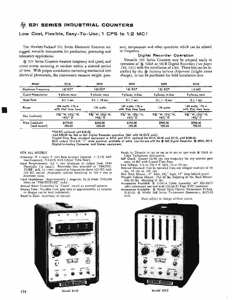
@$ 521 SERIES INDUSTRIAL COUNTERS
Low Cost, Flexible, Easy-To-Use; 1 CPS to 1.2 MC!
The Hewlett-Packard 521 Series Electronic Counters are rugged, versatile instruments for production, processing and laboratory applications. Digital R e c o r d e r O p e r a t i o n
@ 521 Series Counters measure frequency and speed, and
of time. With proper transducers converting mechanical into electrical phenomena, the instruments measure weight, pres-
sure, temperature and other quantities which can be related to frequency.
Versatile 521 Series Counters may be adapted easily to
the installation of a kit. These kits can be in- 560A or 561B Digital Recorders (see puges count events occurring at random within a selected period
stalled by the @ factory before shipment (slight extra charge), or can be purchased for field installation later.
Model 521A 521C 521D 521L 521G
Maximum Frequency 120 K C * I 2 0 K C * I 2 0 K C * I 2 0 K C * 1.2 MC
C o u n t Presentation 4 places, neon 5 places, neon 4 places, in-l ine 5 places, in- l ine 5 places, neon
G a t e Time 0. I, I sec 0.1, I, 10sec 0.1, I sec 0.1, I, IOsec 0. I, I sec
160 watts, 170 w w i th X t a l t i m e base
I 6 0 watts, I 7 0 w w i th X t a l t i m e base
160 watts, I70 w wi th X t a l t i m e base Power
9%' ' W, 15%'' H, 9 % " W , 15%"H, 9%' ' W, 15%'' H, 9%' ' W, 15%" H, 9%'' W, 15%'' H, 141/2'' D 141/4" D I51/2" D 151/2" D 141/4" D
Size (cab ine t )
Price (cab ine t ) $475.00 $650.00 $750.00 $950.00 $700.00 (rack m o u n t ) 480.00 655.00 755.00 955.00 705.00
170 watts 170 watts
*220 K C opt ional , a d d $35.00. A d d $45.00 fo r 560 or 561 D ig i ta l Recorder operat ion (561 w i th 521D/E on ly ) . Crystal Time Base, standard equipment in 521C and 521E, op t iona l f o r 521A, 5 2 1 0 and 5216 , a d d $100.00. BCD outpu t (1-2-2-4; " I ' I state posi t ive) avai lable a t extra cost f o r use w i th the @ 562 D ig i ta l Recorder, Q 580A, 581A Dig i ta l - to -Ana log Conver ter and Dymec equipment.
FOR A L L M O D E L S
Accuracy: * 1 count t time base accuracy (approx. * 0.1% with line frequency, * 0.01% with Crystal Time Base).
Inpu t Requirements: 0.2 v rms minimum or output from 1P41 Phototube (or equal). Phototube bias provided at "PHOTO- TUBE" jack. '/z v rms required at frequencies above 120 KC with 220 KC option. Attenuator reduces sensitivity to 100 v rms to overcome noise.
I n p u t Impedance: Approximately 1 megohm, 50 pf shunt (S00,OOO ohms on "PHOTOTUBE" jack).
Manual Gate : Controlled by "Count" switch or external contacts. Display Time: Variable from gate time to approximately 15 seconds;
or display can be held indefinitely. Reset t o Zero: Automatic or manual.
Reads In: Directly in cps or rps or in rps or rpm with @ 506A or 508A Tachometer Accessories.
Self Check: Counts 50/60 cps line frequency for any selected gate time. 10 KC with Crystal Time Base.
Line Vol tage: 115 or 230 v * lo%, 50 or 60 cps. External Standard: Can be operated from any integral multiple of 10
cps, 10 cps to 100 cps. Size: Rack Mount: 19" wide, 8%" high, 14" deep behind panel. Weigh t : Cabinet Mount: Net 28 Ibs. Shipping 41 lbs. Rack Mount:
Net 28 Ibs. Shipping 35 Ibs. Accessories Provided: @ lO5OlA Cable Assembly, 44" RG-S8/U
cable terminated one end with UG-88/U Type BNC connector. . Pickup.
$12 5 .bo Accessories Avai lable: @ Model 506A Opticd Tachometei
$150.00. @ Model 508 Series Tachometer Generators, each.
Data subject to change without notice.
I34 -
M o d e l 521D M o d e l 521C
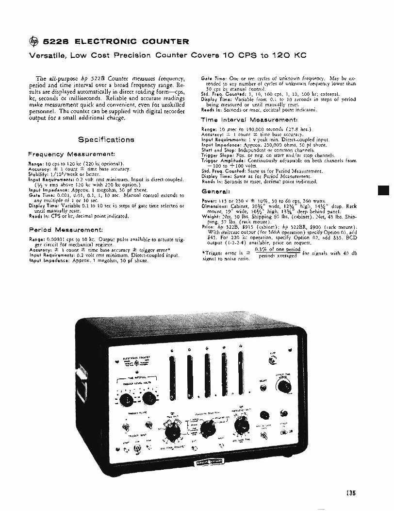
@ 5226 ELECTRONIC COUNTER
Versatile, Low Cost Precision Counter Covers 10 CPS to 120 KC
The all-purpose hp 5 2 2 B Counter measures frequency, period and time interval over a broad frequency range. Re- sults are displayed automatically in direct reading form-cps , kc, seconds or milliseconds. Reliable and accurate readings make measurement quick and convenient, even for unskilled personnel. The counter can be supplied with digital recorder output for a small additional charge.
Specifications
Freq uericy Measure men t:
Range: I O cps to 120 kc (220 kc optional). Accuracy: i: 1 count i: time base accuracy. Stabi l i ty : 1/105/week or better. I n p u t Requirements: 0.2 volt rms minimum. Input is direct-coupled.
(y2 v rms above 120 kc with 2-20 kc option.) I n p u t Impedance: Approx. 1 megohm, 50 pf shunt. G a t e Time: 0.001, 0.01, 0.1, 1, 10 sec. Manual control extends to
any multiple of 1 or 10 sec. Display Time: Variable 0.1 to 10 sec in steps of gate time selected or
until manually reset. Reads In: CPS or kc, decimal point indicated.
Period Measure men t: Range: 0.00001 cps to 10 kc. Output pulse available to actuate trig-
Accuracy: * 1 count * time base accuracy -t trigger error* Inpu t Requirements: 0.2 volt rms minimum. Direct-coupled input. I n p u t Impedance: Approx. 1 megohm, 50 pf shunt.
ger circuit for mechanical register.
Gate Time: One or ten cycles of unknown frequency. May be ex- tended to any number of cycles of unknown frequency lower than 50 cps by manual control.
Std. Freq. Coun ted : 1, 10, 100 cps; 1, 10, 100 kc; external. Display Time: Variable from 0.1 to 10 seconds in stem of period
being measured or until manually reset. Reads In: Seconds or msec, decimal point indicated.
Time Interval Measurement:
Range: 10 psec to 100,000 seconds (27.8 hrs.) . Accuracy: f 1 count 2 time base accuracy. Inpu t Requirements: 1 v peak min. Direct-coupled input. I n p u t Impedance: Approx. 250,000 ohms, 50 pf shunt. Start and Stop: Independent or common channels. Tr igger Slope: Pos. or neg. on start and/or stop channels. Tr igger Ampl i tude: Continuously adjustable on both channels from
Std. Freq. Coun ted : Same as for Period Measurement. Display Time: Same as for Period Measurement. Reads In: Seconds or msec, decimal point indicated.
- 100 to + 100 volts.
General: Power: 115 or 230 v * lop, 50 to 60 cps, 260 watts. Dimensions: Cabinet, 203/,, wide, 12%” high, 14%” deep. Rack
mount, 19” wide, 10% W e i g h t : Net, 50 Ibs. Shipping 60 lbs. (cabinet). Net, 43 Ibs. Ship-
ping, 57 Ibs. (rack mount). Price: hp 522B, $915 (cabinet); hp 522BR, $900 (rack mount).
With staircase output (for 560A operation) specify Option 01, add $45. For 220 kc operation, specify Option 02, add $35. BCD output (1-2-2-4) available, price on request.
high, 13S/,’’ deep behind panel.
0.3% of one period *Trigger error is periods averaged for signals with 40 db signal to noise ratio.
I35
c
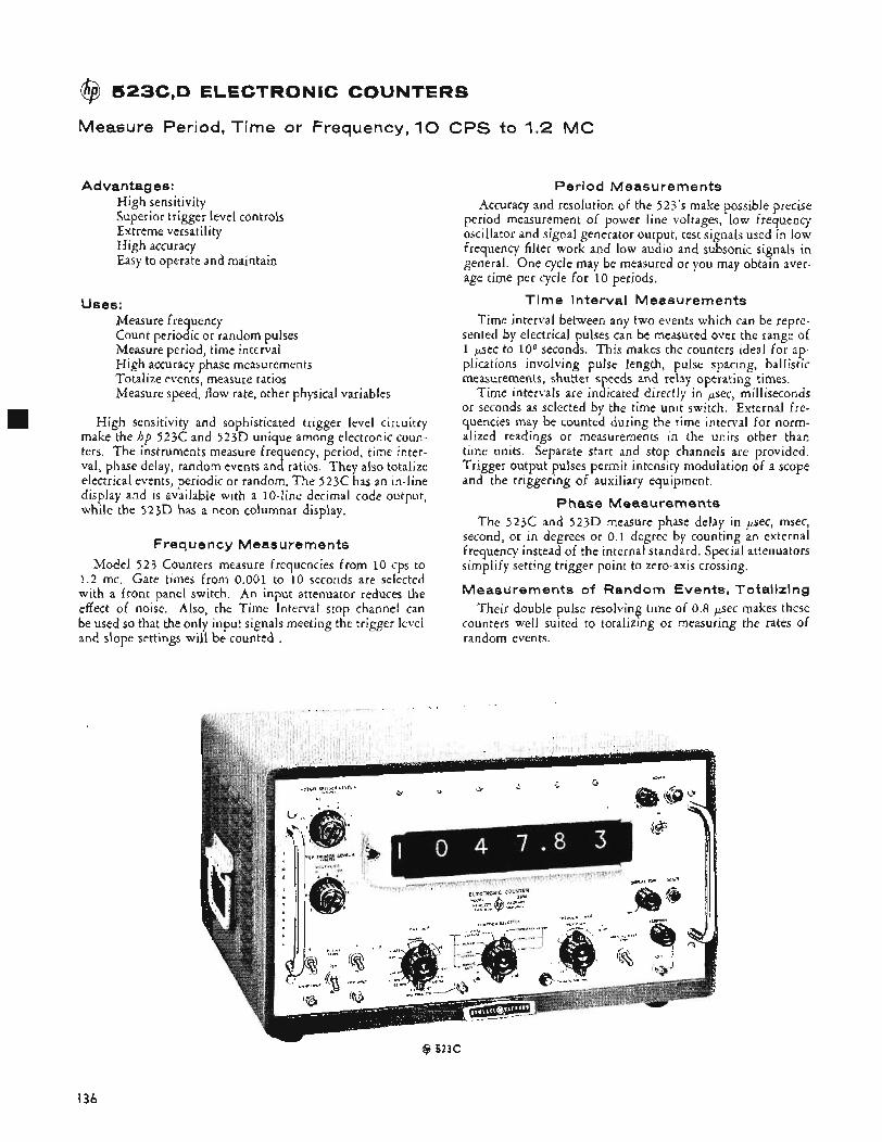
@ 523C,D ELECTRONIC COUNTERS
Measure Period, Time or Frequency, 10 CPS to 1.2 MC
Advantages: High sensitivity Superior trigger level controls Extreme versatility High accuracy Easy to operate and maintain
Uses: Measure frequency Count periodic or random pulses Measure period, time interval High accuracy phase measurements Totalize events, measure ratios Measure speed, flow rate, other physical variables
High sensitivity and sophisticated trigger level circuitry make the hp 523c and 523D unique among electronic coun- ters. The instruments measure frequency, period, time inter- val, phase delay, random events and ratios. They also totalize electrical events, periodic or random. The 523c has an in-line display and is available with a 10-line decimal code output, while the 523D has a neon columnar display.
Frequency Measurements Model 523 Counters measure frequencies from 10 cps to
1.2 mc. Gate times from 0.001 to 10 seconds are selected with a front panel switch. An input attenuator reduces the effect of noise. Also, the Time Interval stop channel can be used so that the only input signals meeting the trigger level and slope settings will be counted .
Period Measurements Accuracy and resolution of the 523's make possible precise
period measurement of power line voltages, low frequency oscillator and signal generator output, test signals used in low frequency filter work and low audio and subsonic signals in general. One cycle may be measured or you may obtain aver- age time per cycle for 10 periods.
Time Interval Measurements Time interval between any two events which can be repre-
sented by electrical pulses can be measured over the range of 1 p e c to lo6 seconds. This makes the counters ideal for ap- plications involving pulse length, pulse spacing, ballistic measurements, shutter speeds and relay operating times.
Time intervals are indicated directly in psec, milliseconds or seconds as selected by the time unit switch. External fre- quencies may be counted during the time interval for norm- alized readings or measurements in the units other than time units. Separate start and stop channels are provided. Trigger output pulses permit intensity modulation of a scope and the triggering of auxiliary equipment.
Phase Measurements The 523c and 523D measure phase delay in p e c , msec,
second, or in degrees or 0.1 degree by counting an external frequency instead of the internal standard. Special attenuators simplify setting trigger point to zero-axis crossing.
Measurements of Random Events, Totalizing Their double pulse resolving time of 0.8 p e c makes these
counters well suited to totalizing or measuring the rates of random events.
($3 523C
I36
Pulses at rates from 0 to 1.2 x 10⁶ pps may be totalized for any of the gate times 0.001 to 10 sec or for longer periods by using the manual gate. Events which can be represented by electrical pulses can be totalized to a maximum of 999,999, so long as the minimum time between events is at least 0.8 pec .
Rat io Measurements Ratio measurements may involve any phenomena which
can be represented by electrical impulses in the proper fre- quency range. One signal, f,, may be used to open and close the signal gate while another signal, f,, is counted. f, may be counted for 1 or 10 periods of f,, providing the ratio of f,/f, or 10 f,/f,.
Digital Recorder Remote Indicator Operation An assortment of modification kits are available for fac-
tory or field installation to permit use of the 523 counters with digital recorders, digital-to-analog converters, remote indicators, etc.
Spec if i cati o ns
Frequency Measurement: Range: 10 cps to 1.2 mc. Accuracy: f 1 count L- time base accuracy. Input Sensitivity: 0.1 v rms, adjustable to 150 v rms max.
input. Input Trigger Levels: Stop channel may be used so that
only signals meeting conditions set by trigger level con- trols are counted. Slope may be + or -, level -300 to +300 volts.
Input Impedance: Approx. 1 megohm, 50 pf shunt. G a t e Time: 0.001, 0.01, 0.1, 1, 10 seconds. Reads In: Kilocycles; automatic decimal,
Period Measurement: Range: 0.00001 cps to 100 kc. Accuracy Measuring Sine Waves: f 1 count
accuracy f trigger error”. Input Requirements: 0.1 v rms min., direct coupled. Input Impedance: Approx. 1 megohm shunted by 50 pf. Measurement Period: 1 or 10 cycles of unknown. Standard Frequency Counted: 1 cps to 1 mc in decade
steps or externally applied signal, 10 cps to 1.2 mc, 0.1 v rms minimum.
time base
Reads In: Seconds, msec or Fsec. Positioned decimal
Range: 1 p e c to I O G sec. Accuracy (Pulse Input): -+ 1 count r+ time base accuracy. Input Impedance: Approx. 1 megohm, 50 pf shunt. Input Requirements: 0.1 v rms minimum. Direct or ac
coupled input. Start and Stop Input: Separate channels with independent
controls. Separate or common input. Start and Stop Marker Output: Separate output pulses,
each approximately 5 psec duration and -20 v peak, available at rear of instrument for oscilloscope intensity modulation to mark start and stop points on input waveform. May be combined with SEP-COM switch on rear of instrument.
Trigger Slope: Positive or negative on start and stop channels.
Trigger Amplitude: Continuously adjustable on both input channels from -300 to +300 v.
Standard Frequency Counted: 1 cps, I O cps, 100 cps, 1 kc, 10 kc, 100 kc, 1 mc; external.
Time Interval Measurement:
Reads In: Seconds, msec or p e c . Decimal positioned auto- matically.
Phase Measurement: Range: 1 cps to 20 kc, dc coupled; 50 cps to 20 kc, ac
Input Voltage: 5 to 10 7.7 rms, pure sinusoidal signal.
Accuracy: a 0.1 O -t- (k) x 360° where f , is thecounted
coupled.
frequency and f, the measured frequency.
Displays f,/f,, or 10 f,/f,, with accuracy of Ratio Measurement:
1 count. f,: 10 cps to 1 .2 mc; f,: 0.00001 cps to 100 kc. ( f l> fZ) .
Totalize: Electrical events, periodic or random to 999999 at rates to
1,200,000/sec. General:
Registration: 523c: Six Nixie@ Tubes, single line; 523D: Six decimal places each indicated by lighted numbers.
Stability: 2/1,000,000 per week. Display Time: Variable from approximately 0.1 to 10
Self-check: Counts of 100 kc or 1 mc. Output Frequencies: Secondary standard frequencies avail-
able at front panel; 1 cps, 10 cps, 100 cps, 1 kc, 10 kc, rectangular; 100 kc and 1 mc sine wave, 0.5 v p-p. Stability 2/1oG per week.
External Standard: 100 kc from external primary standard can be applied to unit for highest accuracy; minimum in- put, 1 v rms.
Power supply: 115 or 230 volts k IO%, 50 to 60 cps, ap- prox. 350 watts.
Accessories Furnished: 2 hp 10503A Cable Assemblies. Dimensions: 201/2” wide, 111/” high, 18%“ deep (cab-
inet); 19” wide, 8%” high, 16%’’ deep behind panel (rack mount).
Weight: Net 48 Ibs., shipping 70 lbs. (cabinet). Net 48 lbs., shipping 62 lbs. (rack mount).
Accessories Available: Remote Indicator for 5 2 3 c , 523CR and interconnecting cable (100’ max.), prices on request.
Digital Recorder Kits for field installation: 523D-95A Adapter Kit for operating hp 560A Digital Recorder from 523C or 523D, $45. 523C-95B Adapter Kit for operating Model 561B Digital Recorder from Model
Price: hp Model 523c, $1575 (cabinet); 523CR, $1550 (rack mount). hp Model 523D, $1350 (cabine t ) ; 523DR, $1325 (rack mount).
Options: 01. Single line decimal code (staircase) for oper- ating hp 560A Digital Recorder, 523D-95A installed, add $45. 02. 10-line decimal code output for operating hp 561B Digital Recorder or Remote Indicator, 523c, only, (523C-95B installed), add $45. 4-line BCD output (“1” state positive) available for driving hp 562A Digital Recorder; 580A, 581A Digital- to-Analog Converters; Dymec instruments, or data pro- cessing equipment, price on request.
*Trigger error is * o ’ ~ ~ , $ s o ~ ~ e ~ ~ ~ ~ d when S/N ratio i s 40 db, de-
seconds; display can be held until manually reset.
523c, $45.
creases with increasing signal amplitude and slope.
Data subject to change without notice.
137
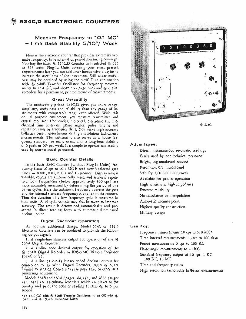
@ 524C,D ELECTRONIC COUNTERS
Measure Frequency to 10.1 MC* -Time Base Stability 5/108/ Week
Here is the electronic counter that provides extremely ver- satile frequency, time interval or period measuring coverage. You buy the basic @ 524C,D Counter with selected @ 525 or 526 series Plug-In Units covering your exact present requirements; later you can add other inexpensive plug-ins to increase the usefulness of the instrument. Still wider useful- ness may be obtained by using the 524C,D in conjunction with @ 540B Transfer Oscillator for frequency measure- ments to 12.4 GC, and above ( see pdge 142) and @ digital recorders for a permanent, printed record of measurements.
Great Versatility The moderately priced 524C,D gives you more range,
simplicity, usefulness and reliability than any group of in- struments with comparable range ever offered. With this one all-purpose equipment, you measure transmitter and crystal oscillator frequencies, electrical, electronic and me- chanical time intervals, phase angles, pulse lengths and repetition rates or frequency drift. You make high accuracy ballistics time measurements or high resolution tachometry measurements. The instrument also serves as a house fre- quency standard for many users, with a long-term stability of 5 parts in lo8 per week. It is simple to operate and readily used by non-technical personnel.
Basic Counter Details In the basic 524c Counter (without PlugIn Units) fre-
quency from 10 cps to 10.1 MC is read over 5 selected gate times - 0.001, 0.01, 0.1, 1 and 10 seconds. Display time is variable, counts are automatically reset, and action is repeti- tive. Low frequencies (below approximately 300 cps) are more accurately measured by determining the period of one or ten cycles. Here the unknown frequency operates the gate and the internal standard frequency is applied to the counter. Thus the duration of a low frequency cycle is measured in time units. A 10-cycle sample may also be taken to improve accuracy. The result is determined automatically and pre- sented in direct reading form with automatic illuminated decimal point.
Digital Recorder Operation At nominal additional charge, Model 524c or 524D
Electronic Counters can be modified to provide the follow- ing output signals:
1. A single-line staircase output for operation of the @ 560A Digital Recorder.
2. A 10-line code decimal output for operation of the @ 56lB Digital Recorder or K05-524C Remote Indicator (524C only),
3. A 4-line (1-2-2-4) binary coded decimal output for connection to @ 562A Digital Recorder, 580A or 58lA Digital to Analog Converters ( s e e Page 149) or other data processing equipment.
Models 561B and 560A (pages 144,145) and 562A (pnges 146, 147) are 11-column recorders which are slaves to the counter and print the counter reading at rates up to 5 per second. *To 12.4 GC with @ 540B Transfer Oscillator; to 18 GC with (3 540B and @ P932A Harmonic Mixer.
@ 524C
Advantages:
Direct, instantaneous automatic readings Easily used by non-technical personnel Bright, big-numbered readout Resolution 0.1 microsecond Stability 5/100,000,000/week Available for printer operation High sensitivity, high impedance Extreme reliability No calculation or interpolation Automatic decimal point Highest quality construction Military design
Use For:
Frequency measurements 10 cps to 510 MC* Time interval measurements 1 p e c to 100 days Period measurements 0 cps to 100 KC Phase angle measurements to 20 KC Standard frequency output of 10 cps, 1 KC
Time and frequency ratios High resolution tachometry ballistics measurements
100 KC, i o MC
I38
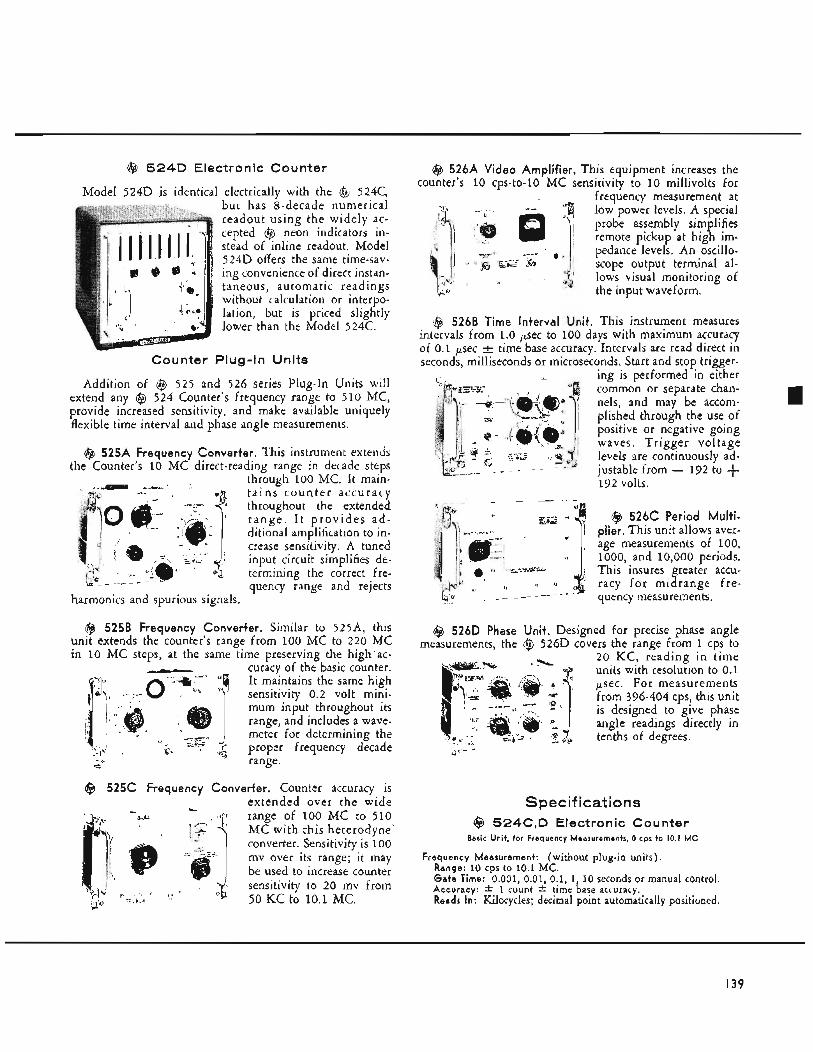
@ 524D Electronic Counter
Model 524D is identical electrically with the @ 524C, but has 8-decade numerical
stead of 'inline readout. Model 524D offers the same time-sav- ing convenience of direct instan- taneous, automatic readings without calculation or interpo- Idtion, but is priced slightly lower than the Model 524C.
ounter Plug-In Units
Addition of @ 525 and 526 series Plug-In Units will extend any @ 524 Counter's frequency range to 510 MC, provide increased sensitivity, and make available uniquely flexible time interval and phase angle measurements.
@ 525A Frequency Converter. This instrument extend5 the Counter's 10 MC direct-reading range in decade steps
through 100 MC. It main- td ins c o u n t e r accuracy throughout the extended r a n g e . I t p rov ides a d - ditional amplification to in- crease sensitivity. A tuned input circuit simplifies de- termining the correct fre- quency range and rejects
harmonics and spurious signals.
@ 525B Frequency Converter. Siinildr to 525A, this unit extends the counter's range from 100 MC to 220 MC in 10 MC steps, at the same time preserving the high ac-
curacy of the basic counter. It maintains the same high sensitivitv 0.2 volt mini- - , mum input throughout its range, and includes a wave- meter for determining the
G h proper frequency decade CL ' C range.
@ 525C Frequency Converter. Counter accuracy is extended over the wide range of 100 MC to 510 MC with this heterodyne. converter. Sensitivity is 100 mv over its range; it may be used to increase counter sensitivity to 20 mv from 50 KC to 10.1 MC.
@ 526A Video Amplifier. This equipment increases the counter's 10 cps-to-10 MC sensitivity to 10 millivolts for
frequency measurement at low power levels. A special probe assembly simplifies remote pickup at high im- pedance levels. An oscillo- scope output terminal al- lows visual monitoring of the input waveform.
@ 5268 Time Interval Unit. This instrument measures intervals from 1 0 p e c to 100 days with maximum accuracy of 0.1 psec +- time base accuracy. Intervals are read direct in seconds, milliseconds or microseconds. Start and stop trigger-
ing is performed in either common or separate chan- nels, and may be accom- plished through the use of positive or negative going waves. Trigger voltage levels are continuously ad- justable from - 192 to + 192 volts.
@ 526C Period Multi- plier. This unit allows aver- age measurements of 100, 1000, and 10,000 periods. This insures greater accu- racy fo r midrange fre-
_ - - quency measurements,
@ 526D Phase Unit. Designed for precise phase angle measurements, the @ 526D covers the range from 1 cps tu
20 KC, reading in time units with resolution to 0.1 Wsec. For measurements from 396-404 cps, this unit is designed to give phase angle readings directly in tenths of degrees.
SDecifications @ 5 2 4 C , D Electronic Counter
Basic Unit, for Frequency Measurements, 0 cps to 10.1 MC
Frequency Measurement: (without plug-in units). Range: 10 cps to 10.1 MC. G a t e Time: 0.001, 0.01, 0.1, 1, 10 seconds or manual control. Accuracy: * 1 count 2 time base accuracy. Reads In: Kilocycles; decimal point automatically positioned.
I39
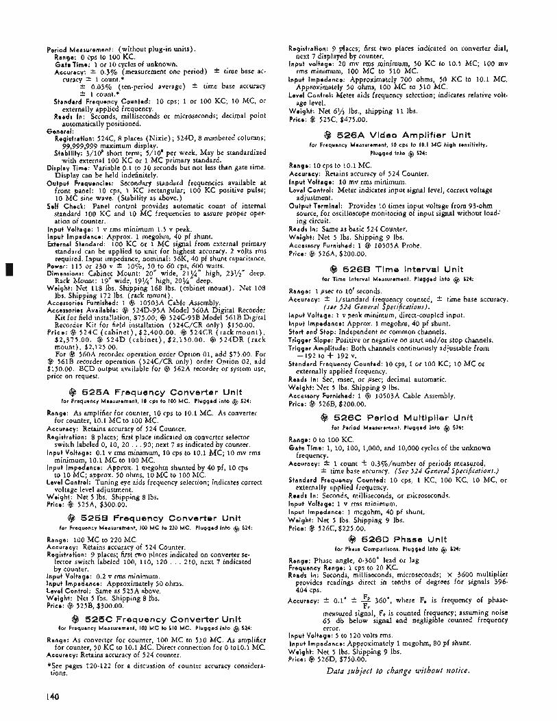
I
Period Measurement: (without plug-in units). Range: 0 cps to 100 KC. G a t e Time: 1 or 10 cycles of unknown. Accuracy: k 0.3% (measurement one period) * time base ac-
curacy +- 1 count.* * 0.03% (ten-period average) f time base accuracy * 1 count.* Standard Frequency Counted: 10 cps; 1 or 100 KC; 10 MC, or
Reads In: Seconds, milliseconds or microseconds; decimal point
Registration: 524C, 8 places (Nixie); 524D, 8 numbered columns;
Stability: 3/108 short term; 5/10’ per week. May be standardized
Display Time: Variable 0.1 to 10 seconds but not less than gate time. Display can be held indefinitely.
Output Frequencies: Secondary standard frequencies available at front panel: 10 cps, 1 KC rectangular; 100 KC positive pulse; 10 MC sine wave. (Stability as above.)
Self Check: Panel control provides automatic count of internal standard 100 KC and 10 MC frequencies to assure proper oper- ation of counter.
externally applied frequency.
automatically positioned.
99,999,999 maximum display.
with external 100 KC or 1 MC primary standard.
General:
Input Voltage: 1 v rms minimum 1.5 v peak. Input Impedance: Approx. 1 megohm, 40 pf shunt. External Standard: 100 KC or 1 MC signal from external primary
standard can be applied to unit for highest accuracy. 2 volts rms required. Input impedance, nominal: 56K, 40 pf shunt capacitance.
Power: 115 or 230 v f l o%, 50 to 60 cps, 600 watts. Dimensions: Cabinet Mount: 20” wide, 21%” high, 231/2” deep.
Rack Mount: 19” wide, 19%’’ high, 20%” deep. Weight: Net 118 Ibs. Shipping 168 Ibs. (cabinet mount). Net 108
Ibs. Shipping 172 Ibs. (rack mount), Accessories Furnished: 1 @ 10503A Cable Assembly. Accessories Available: @ 524D-95A Model 560A Digital Recorder
Kit for field installation, $75.00; @ 524C-95B Model 561B Digital Recorder Kit for field installation (524C/CR only) $150.00.
Pr ice : Q 524C (cab ine t ) , $2,400.00. Q 524CR ( r a c k m o u n t ) , $2,375.00. @ 524D (cab ine t ) , $2,150.00. Q 524DR (rack mount), $2,125.00. For @ 56OA recorder operation order Option 01, add $75.00. For
@ 561B recorder operation (524C/CR only) order Option 02, add $150.00. BCD output available for Q 562A recorder or system use, price on request.
@ 5 2 5 A Frequency Converter Unit for Frequency Measurement, IO cpr to 100 MC. Plugged into Q 524:
Range: As amplifier for counter, 10 cps to 10.1 MC. As converter
Accuracy: Retains accuracy of 524 Counter. Registration: 8 places; first place indicated on converter selector
switch labeled 0, 10, 20 . , . 90; next 7 as indicated by counter. Input Voltage: 0.1 v rms minimum, 10 cps to 10.1 M C ; 10 mv rms
minimum, 10.1 MC to 100 MC. Input Impedance: Approx. 1 megohm shunted by 40 pf, 10 cps
to 10 MC; approx. 50 ohms, 10 MC to 100 MC. Level Control: Tuning eye aids frequency selection; indicates correct
voltage level adjustment, Weight : Net 5 Ibs. Shipping 8 Ibs. Price: @ 525A, $300.00.
for counter, 10.1 MC to 100 MC.
@ 525B Frequency Converter Unit for Frequency Measurement, 100 MC to 220 MC. Plugged into Q 524:
Range: 100 MC to 220 MC. Accuracy: Retains accuracy of 524 Counter. Registration: 9 places; first two places indicated on converter se-
lector switch labeled 100, 110, 120 . . . 210, next 7 indicated by counter.
Input Voltage: 0.2 v rms minimum. Input Impedance: Approximately 50 ohms, Level Control: Same as 525A above. Weight : Net 5 Ibs. Shipping 8 Ibs. Price: @ 52SB, $300.00.
@ 525C Frequency Converter Unit for Frequency Measurement, 100 M C to 510 MC. Plugged into @ 524:
Range: As converter for counter, 100 MC to 510 MC. As amplifier for counter, SO KC to 10.1 MC. Direct connection for 0 tolO.1 MC.
Accuracy: Retains accuracy of 524 counter. *See pages 120-122 for a discussion of counter accuracy considera- tions.
Registration: 9 places; first two places indicated on converter dial,
Input v,oltage: 20 mv rms minimum, 50 KC to 10.1 MC; 100 mv
Input Impedance: Approximately 700 ohms, 50 KC to 10.1 MC.
Level Control: Meter aids frequency selection; indicates relative volt.
Weight: Net 6% Ibs., shipping 11 Ibs. Price: @ 525C, $475.00.
next 7 displayed by counter.
rms minimum, 100 MC to 510 MC.
Approximately 50 ohms, 100 MC to 510 MC.
age level.
@ 5 2 6 A Video Amplifier Unit for Frequency Measurement, IO cpr to 10.1 MC high sensitivity.
Plugged into Q 524:
Range: 10 cps to 10.1 MC. Accuracy: Retains accuracy of 524 Counter. Input Voltage: 10 mv rms minimum. Level Control: Meter indicates input signal level, correct voltage
adjustment. Output Terminal: Provides 10 times input voltage from 93-ohm
source, for oscilloscope monitoring of input signal without load-’ ing circuit.
Reads In: Same as basic 524 Counter. Weight : Net 5 Ibs. Shipping 9 Ibs. Accessory Furnished: 1 @ 1050SA Probe. Price: ($3 526A, $200.00.
@ 526B Time Interval Unit for Time Interval Measurement. Plugged into Q 524:
Range: 1 psec to 10’ seconds, Accuracy: * l/standard frequency counted, i- time base accuracy.
(see 124 General Specifications). Input Voltage: 1 v peak minimum, direct-coupled input. Input Impedance: Approx. 1 megohm, 40 pf shunt. Start and Stop: Independent or common channels. Trigger Slope: Positive or negative on start and/or stop channels. Trigger Amplitude: Both channels continuously adjustable from
Standard Frequency Counted: 10 cps, 1 or 100 KC; 10 MC or externally applied frequency.
Reads In: Sec, msec, or psec; decimal automatic. Weight : Net 5 Ibs. Shipping 9 Ibs. Accessory Furnitshed: 1 Q 10503A Cable Assembly, Price: @ 526B, $200.00.
-192 to + 192 V.
@ 526C Period Multiplier Unit for Period Measurement. Plugged into Q 524:
Range: 0 to 100 KC. G a t e Time: 1, 10, 100, 1,000, and 10,000 cycles of the unknown
Accuracy: f 1 count +- 0.3%/number of periods measured, * time base accuracy. (See 124 General Specifications.) Standard Frequency Counted: 10 cps, 1 KC, 100 KC, 10 MC, or
externally applied frequency. Reads In: Seconds, milliseconds, or microseconds, Input Voltage: 1 v rms minimum. Input Impedance: 1 megohm, 40 pf shunt. Weight: Net 5 Ibs. Shipping 9 Ibs. Price: @ 526C, $225.00.
frequency.
@ 526D Phase Unit for Phase Comparisons. Plugged into Q 524:
Range: Phase angle, 0-360” lead or lag Frequency Range: 1 cps to 20 K C Reads In: Seconds, milliseconds, microseconds; X 3600 multiplier
provides readings direct in tenths of degrees for signals 396- 404 cps.
360’, where F, is frequency of phase-
measured signal, F, is counted frequency; assuming noise 65 db below signal and negligible counted frequency error.
Accuracy: i- 0.1” i- F C
Input Voltage: 5 to 120 volts rms. Input Impedance: Approximately 1 megohm, 80 pf shunt. Weight: Net 5 Ibs. Shipping 9 Ibs. Price: @ 526D, $750.00.
Data subject to change without notice.
I40
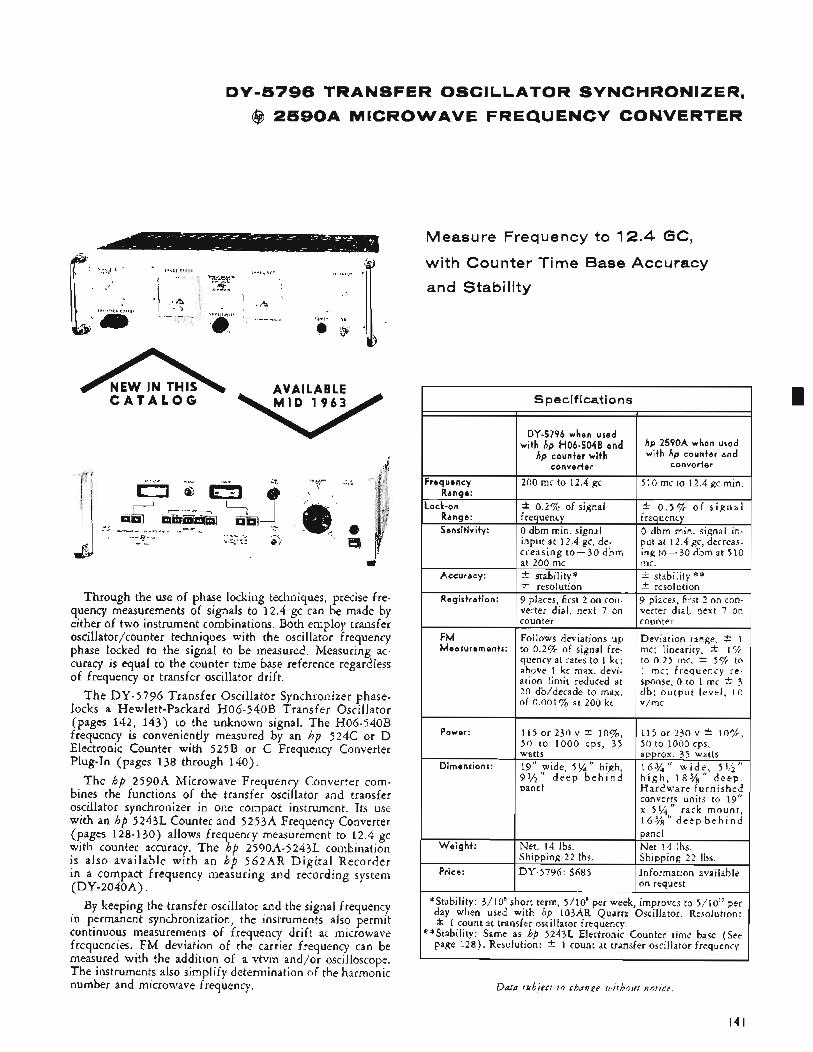
DY-5796 TRANSFER OSCILLATOR SYNCHRONIZER,
@ 2 5 9 0 A MICROWAVE FREQUENCY CONVERTER
n C A T A L O G NEW IN THIS AVAILABLE
Through the use of phase locking techniques, precise fre- quency measurements of signals to 12.4 gc can be made by either of two instrument combinations. Both employ transfer osdlator/counter techniques with the oscillator frequency phase locked to the signal to be measured. Measuring ac- curacy is equal to the counter time base reference regardless of frequency or transfer oscillator drift.
The DY-5796 Transfer Oscillator Synchronizer phase- locks a Hewlett-Packard H06-540B Transfer Oscillator (pages 142, 143) to the unknown signal. The H06-540B frequency is conveniently measured by an hp 524C or D Electronic Counter with 525B or C Frequency Converter Plug-In (pages 138 through 140).
The hp 2590A Microwave Frequency Converter com- bines the functions of the transfer oscillator and transfer oscillator synchronizer in one compact instrument. Its use with an hp 5243L Counter and 5253A Frequency Converter (pages 128-130) allows frequency measurement to 12.4 gc with counter accuracy. The hp 2590A-5243L combination is also available with an h b 562AR Digital Recorder " in a compact frequency measuring and recording system (DY-204OA).
By keeping the transfer oscillator and the signal frequency in permanent synchronization, the instruments also permit continuous measurements of frequency drift at microwave frequencies. FM deviation of the carrier frequency can be measured with the addition of a vtvm and/or oscilloscope. The instruments also simplify determination of the harmonic number and microwave frequency.
Measure Frequency to 12.4 GC,
with Counter Time Base Accuracy
and Stability
S pecif icat io ns
I I DY-5796 when used
wi th hp H06-5048 and hp counter wi th
b 2590A when used with hp counter and
conver ter conver ter
requency 510 mc to 12.4 gc min. Range:
ock-on * 0.2% of signal f 0 . 5 % of s i g n a l Range: frequency frequency Sensit ivi tv: 0 dbm min. signal 0 dbm min. signal in-
put at 12.4 gc, decreas- ing to-30 dbm at 510
200 mc to 12.4 gc
input at 12.4 gc, de- creasing to-30 dbm at 200 mc mc.
* resolution f resolution 9 places, first 2 on con- verter dial, next 7 on counter counter
Accuracy: -C stability" * stability #:*
Registrat ion: 9 places, first 2 on con- verter dial, next 7 on
FM Follows deviations up Deviation range, 2 1 Measurements: to 0.2% of signal fre- mc; linearity * 1%
to 0.25 mc, 2 55% to 1 mc; frequency re- sponse, 0 to 1 mc * 3 d b ; ou tput level . 1 0 v/rnc
quency at rates to 1 kc; above 1 kc max. devi- ation limit reduced at 20 db/decade to max. of 0.001% at 200 kc
Power: 115 or 230 v f l o % , 5 0 t o 1000 cps, 35 watts
Dimensions: 19'' ,Fide, 5 % " high, 99'2 d e e p b e h i n d panel
115 or 230 v * I O % , 50 to 1000 cps,
Hardware furn ished converts units to 19" x 5%,," rack mount , 1 6 % d e e p b e h i n d
Price: on request
"Stability: 3/10' short term, 5/10* per week, improves to 5/10'' per day when used with hp 103AR Quartz Oscillator. Resolution: f 1 count at transfer oscillator frequency.
*Stability: Same as hp 52431. Electronic Counter time base (See page 128) . Resolution: * 1 count at transfer oscillator frequency.
I4 I
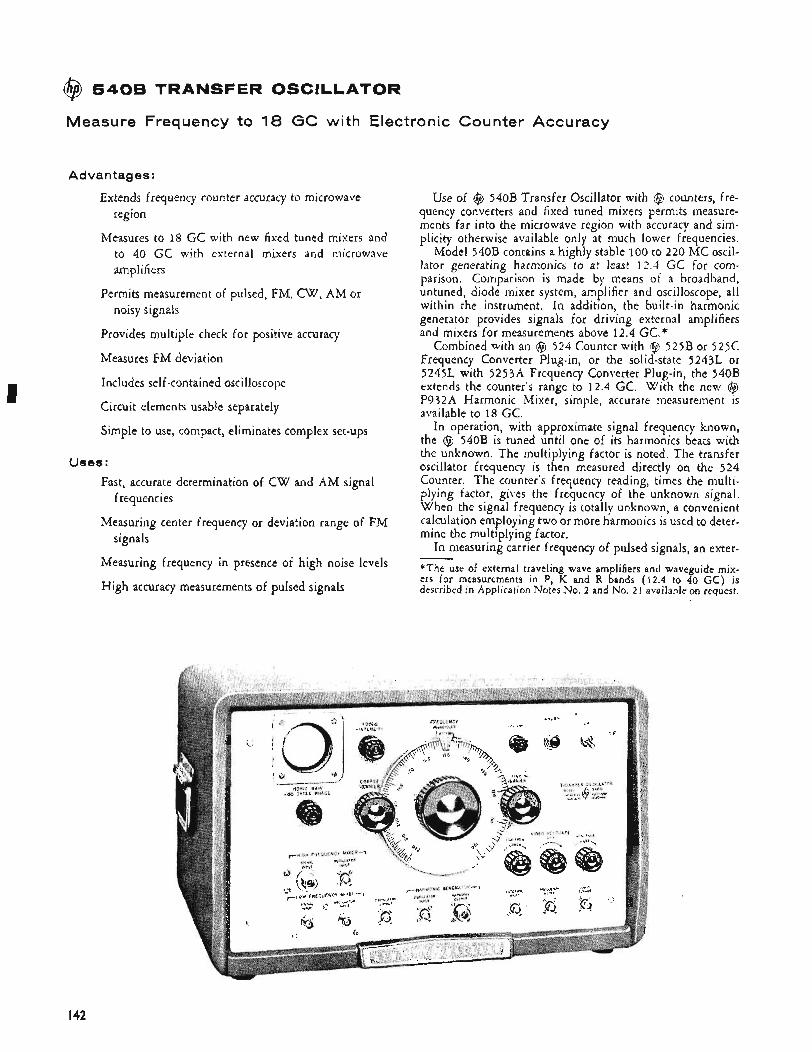
I
@ 5408 TRANSFER OSCILLATOR
Measure Frequency to 18 GC with Electronic Counter Accuracy
Advantages:
Extends frequency counter accuracy to microwave region
Measures to 18 GC with new fixed tuned mixers and to 40 GC with external mixers and microwave amplifiers
Permits measurement of pulsed, FM, CW, AM or noisy signals
Provides multiple check for positive accuracy
Measures FM deviation
Includes self-contained oscilloscope
Circuit elements usable separately
Simple to use, compact, eliminates complex set-ups
Uses : Fast, accurate determination of C W and AM signal
Measuring center frequency or deviation range of FM
Measuring frequency in presence of high noise levels
High accuracy measurements of pulsed signals
frequencies
signals
Use of @ 540B Transfer Oscillator with @ counters, fre- quency converters and fixed tuned mixers permits measure- ments far into the microwave region with accuracy and sim- plicity otherwise available only at much lower frequencies.
Model 540B contains a highly stable 100 to 220 MC oscil- lator generating harmonics to at least 12.4 GC for com- parison. Comparison is made by means of a broadband, untuned, diode mixer system, amplifier and oscilloscope, all within the instrument. In addition, the built-in harmonic generator provides signals for driving external amplifiers and mixers for measurements above 12.4 GC.*
Combined with an @ 524 Counter with @ 525B or 525C Frequency Converter Plug-in, or the solid-state 5243L or 5245L with 5253A Frequency Converter Plug-in, the 540B extends the counter's range to 12.4 GC. With the new @ P932A Harmonic Mixer, simple, accurate measurement is available to 18 GC.
In operation, with approximate signal frequency known, the @ 540B is tuned until one of its harmonics beats with the unknown. The multiplying factor is noted. The transfer oscillator frequency is then measured directly on the 524 Counter. The counter's frequency reading, times the multi- plying factor, gives the frequency of the unknown signal. When the signal frequency is totally unknown, a convenient calculation employing two or more harmonics i s used to deter- mine the multiplying factor,
In measuring carrier frequency of pulsed signals, an exter- *The use of external traveling wave amplifiers and waveguide mix- ers for measurements in P, K and R bands ( 1 2 . 4 to 40 GC) is described in Application Notes No. 2 and No. 21 availableon request.
-
I42
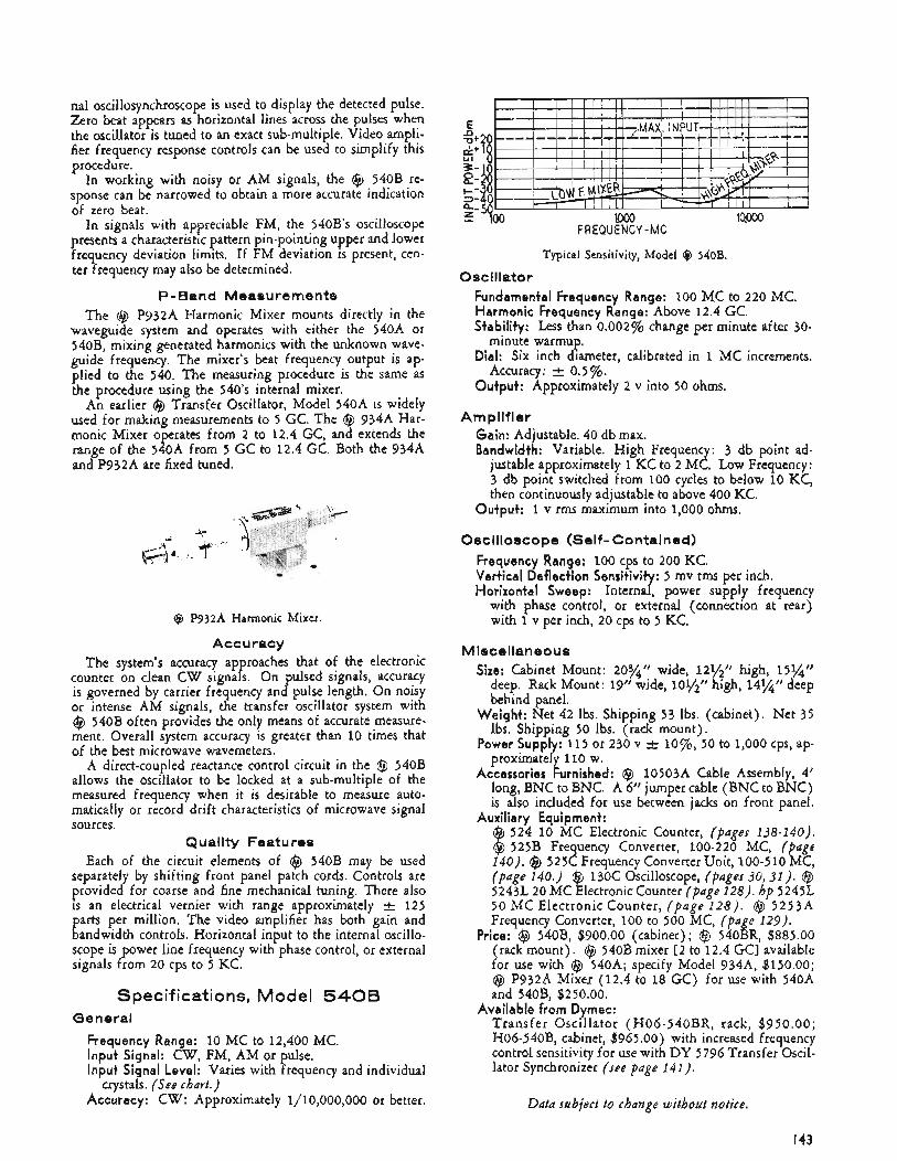
nal oscillosynchroscope is used to display the detected pulse. Zero beat appears as horizontal lines across the pulses when the oscillator is tuned to an exact sub-multiple. Video ampli- fier frequency response controls can be used to simplify this procedure.
In working with noisy or AM signals, the @ 540B re- sponse can be narrowed to obtain a more accurate indication of zero beat.
In signals with appreciable FM, the 540B’s oscilloscope resents a characteristic pattern pin-pointing upper and lower
Frequency deviation limits. If FM deviation is present, cen- ter frequency may also be determined.
P-Band Measurements The Clc, P932A Harmonic Mixer mounts directly in the
waveguide system and operates with either the 540A or 540B, mixing generated harmonics with the unknown wave- guide frequency. The mixer’s beat frequency output is ap- plied to the 540. The measuring procedure is the same as the procedure using the 540’s internal mixer.
An earlier @ Transfer Oscillator, Model 540A is widely used for making measurements to 5 GC. The @ 934A Har- monic Mixer operates from 2 to 12.4 GC, and extends the range of the 540A from 5 GC to 12.4 GC. Both the 934A and P932A are fixed tuned.
@ P932A Harmonic Mixer.
Accuracy The system’s accuracy ap roaches that of the electronic
is governed by carrier frequency and pulse length. On noisy or intense AM signals, the transfer oscillator system with @ 540B often provides the only means of accurate measure- ment. Overall system accuracy is greater than 10 times that of the best microwave wavemeters.
A direct-coupled reactance control circuit in the @ 540B allows the oscillator to be locked at a sub-multiple of the measured frequency when it is desirable to measure auto- matically or record drift characteristics of microwave signal sources.
Quality Features Each of the circuit elements of @ 540B may be used
separately by shifting front panel patch cords. Controls are provided for coarse and fine mechanical tuning, There also is an electrical vernier with range approximately 125 parts per million. The video amplifier has both gain and bandwidth controls. Horizontal input to the internal oscillo- scope is power line frequency with phase control, or external signals from 20 cps to 5 KC.
counter on clean C W signa P s. On pulsed signals, accuracy
Specifications, Model 5 4 0 B General
Frequency Range: 10 MC to 12,400 MC. Input Signal: CW, FM, AM or pulse. Input Signal Level: Varies with frequency and individual
Accuracy: CW: Approximately 1/10,000,000 or better. crystals. (See chart.)
FREQUENCY - M C
Typical Sensitivity, Model 9 540B. Oscillator
Fundamental Frequency Range: 100 MC to 220 MC. Harmonic Frequency Range: Above 12.4 GC. Stability: Less than 0.002% change per minute after 30-
Dial: Six inch diameter, calibrated in 1 MC increments.
Output: Approximately 2 v into 50 ohms.
minute warmup.
Accuracy: A 0.5%.
Amplifier Gain: Adjustable. 40 db max. Bandwidth: Variable. High Frequency: 3 db point ad-
justable approximately 1 KC to 2 MC. Low Frequency: 3 db point switched from 100 cycles to below 10 KC, then continuously adjustable to above 400 KC.
Output: 1 v rms maximum into 1,000 ohms,
Oscilloscope (Self-contained) Frequency Range: 100 cps to 200 KC. Vertical Deflection Sensitivit : 5 mv rms per inch, Horizontal Sweep: Internar power supply frequency
with phase control, or external (connection at rear) with 1 v per inch, 20 cps to 5 KC.
Miscellaneous Size: Cabinet Mount: 203/*‘‘ wide, 121/2” high, 15%‘’
deep. Rack Mount: 19“ wide, 101/2” high, 14%” deep behind panel.
Weight: Net 42 Ibs. Shipping 53 lbs. (cabinet). Net 35 lbs. Shipping 50 Ibs. (rack mount),
Power supply: 115 or 230 v -t lo%, 50 to 1,000 cps, ap- proximately 110 w.
Accessories Furnished: @ 10503A Cable Assembly, 4’ long, BNC to BNC. A 6” jumper cable (BNC to BNC) is also included for use between jacks on front panel.
@ 524 10 MC Electronic Counter, (pages 138-140). @ 525B Frequency Converter, 100-220 MC, (page 140). @ 525C Frequency Converter Unit, 100-510 MC, (page 140.) @ 130C Oscilloscope, (pages 30, 31). @ 5243L 20 MC Electronic Counter (page 128). hp 5245L 50 M C Electronic Counter, (page 128) . @ 5 2 5 3 ~ 4 Frequency Converter, 100 to 500 MC, (page 129).
Price: @ 540B, $900.00 (cabinet); @ 540BR, $885.00 (rack mount), @ 540B mixer 12 to 12.4 GC] available for use with @ 540A; specify Model 934A3, $150.00; @ P932A Mixer (12.4 to 18 GC) for use with 540A and 540B, $250.00.
Available from Dymec: Transfer Oscillator (H06-540BR, rack, $950.00; H06-540B, cabinet, $965 .OO) with increased frequency control sensitivity for use with DY 5796 Transfer Oscil- lator Synchronizer (see page 141).
Auxiliary Equipment:
Data subject to change without notice.
I43
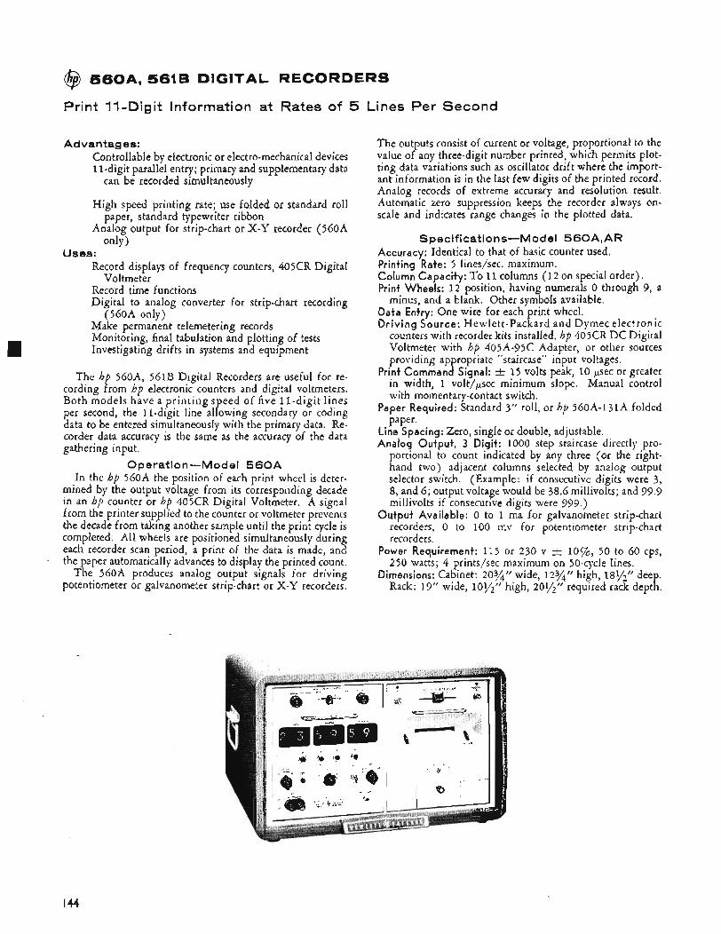
@ 5 6 0 A , 5618 DIGITAL RECORDERS
8 1 Print 11-Digit Information at Rates of 5 Lines Per Second
Advantages: Controllable by electronic or electro-mechanical devices 11-digit parallel entry; primary and supplementary data
High speed printing rate; use folded or standard roll
Analog output for strip-chart or X-Y recorder (560A
can be recorded simultaneously
paper, standard typewriter ribbon
only 1 Uses:
Record displays of frequency counters, 405CR Digital
Record time functions Digital to analog converter for strip-chart recording
Make permanent telemetering records Monitoring, final tabulation and plotting of tests Investigating drifts in systems and equipment
Voltmeter
(560A only)
The hp 560A, 561B Digital Recorders are useful for re- cording from hp electronic counters and digital voltmeters. Both models have a pr int ing speed of five 11-digit lines per second, the Il-digit line allowing secondary or coding data to be entered simultaneously with the primary data. Re- corder data accuracy is the same as the accuracy of the data gathering input.
0 perati o n -M od el 5 6 0 A In the hp 560A the position of each print wheel is deter-
mined by the output voltage from its corresponding decade in an hp counter or hp 405CR Digital Voltmeter. A signal from the printer supplied to the counter or voltmeter prevents the decade from taking another sample until the print cycle is completed. All wheels are positioned simultaneously during each recorder scan period, a print of the data is made, and the paper automatically advances to display the printed count.
The 560i4 produces analog output signals for driving potentiometer or galvanometer strip-chart or X - Y recorders.
The outputs consist of current or voltage, proportional to the value of any three-digit number printed, which permits plot- ting data variations such as oscillator drift where the import- ant information is in the last few digits of the printed record. Analog records of extreme accuracy and resolution result. Automatic zero suppression keeps the recorder always on- scale and indicates range changes in the plotted data.
Specifications-Model 560A,AR Accuracy: Identical to that of basic counter used. Printing Rate: 5 lines/sec. maximum. Column Capacity: To 11 columns (12 on special order). Print Wheels: 12 position, having numerals 0 through 9, a
Data Entry: One wire for each print wheel. Driving Source: Hewlett-Packard and Dymec electronic
counters with recorder kits installed. hp 405CR DC Digital Voltmeter with hp 405A-95C Adapter, or other sources providing ap ropriate “staircase” input voltages.
15 volts peak, 10 psec or greater in width, 1 volt/psec minimum slope. Manual control with momentary-contact switch.
Paper Required: Standard 3” roll, or hp 560A-131A folded paper.
Line Spacing: Zero, single or double, adjustable. Analog Output, 3 Digit: 1000 step staircase directly pro-
portional to count indicated by any three (or the right- hand two) adjacent columns selected by analog output selector switch. (Example: if consecutive digits were 3, 8, and 6; output voltage would he 38.6 millivolts; and 99.9 millivolts if consecutive digits were 999.)
Output Available: 0 to 1 ma for galvanometer strip-chart recorders, 0 to 100 mv for potentiometer strip-chart recorders.
Power Requirement: 115 or 230 v 2 lo%, 50 to 60 cps, 250 watts; 4 prints/sec maximum on 50-cycle lines.
Dimensions: Cabinet: 20%’’ wide, 1234’‘ high, 18Y2‘’ deep. Rack: 19” wide, 1034‘’ high, 201/2’1 required rack depth.
minus, and a blank. Other symbols available.
Print Comman B Signal:
144
Weight: Net 63 Ibs. Shipping 79 Ibs. (cabinet mount). Net 5 5 Ibs. Shipping 7 9 Ibs. (rack mount).
Accessories Furnished: 1 56OA-l6H Input Cable (accom- modates 8 columns); 560A-95N Service Kit; 1 packet 9281-0018 folded paper tape; 1 9283-0002 inked ribbon,
Accessories Available: Digital recorder kits for field instal- lation in:
hp Model Kit Number Price 521-Series 521D-95A $45 522B 522B-95A $45 523B 523B-95A $45 523C,D 523D-95A $45
524C,D 524D-95A $75 5 24B 524B-95C $175
405-95C Adapter, connects 560A to 405CR Digital Volt- meter, $70. 560A-16H Cable, $60. 560A-16P Ex- tension Cable, 6’, 20-conductor, $65. 560A-16Q Ex- tension, 6’ 26-conductor, $85. 560A-131A folded Paper Tape, 24-packet carton, $20. No. 9283-0002 inked rib- bon, $3.50. Additional comparators are available to in- crease print-out of basic 560A from 6 columns to a maxi- mum of 11 columns. These comparators plug into sockets in the 560A. 56OA-58 Plug-in Comparator Unit, $25 each.
Price: hp 560A, $1400 (cabinet); hp 560AR, $1385 (rack mount). Includes 6 plug-in comparators. Also available for 50-cycle power line operation retaining 5 prints/sec maximum, and/or 570A Digital Clock installed and/or 12-column operation, prices on request.
Operation-Model 561 B Model 561B Digital Recorder differs from the 560A in
that input is a 10-line coded decimal entry; that is, one con- nection is made for each osition of each print wheel. The 561B is normally operate! from an hp 405CR Digital Volt- meter or by in-line readout frequency counters with 10-line output kits installed. The 561B also can be operated from relays, stepping switches and beam switching tubes.
When a print command is received by the 561B, the clutch engages, turning the print wheels. Each print wheel turns until its armature contacts a voltage which shuts off current to the pawl magnet, thus stopping the print wheel in the ap- propriate position. To prevent changes in input informa-
tion during the recorder scan cycle, the 561B supplies an in- hibit signal to hp counters while the print wheels are being positioned. This same inhibit signal may be used to prevent data changes during the recorder scan cycle with instruments other than hp counters and digital voltmeters.
Specifications-Model 561B,BR
Same as 560A except: Column Capacity: 11 columns (12 on special order). Input: Decimal code, 10 lines plus 2 lines for blank and
minus sign from each column. Driving Source: Hewlett-Packard in-line readout counters
having 561B recorder kits installed. (See counter specifica- tions,) hp Digital Voltmeter. (See voltmeter specifica- tions.) Stepping switches, relays, beam switching tubes, contact closure, or - 15 to - 100 volts connected to ap- propriate number wire. Operates from 10-line coded sys- tems.
Print Command: -C 15 volts peak or more, 10 psec mini- mum width, 1 volt/psec minimum slope, or external clos- ure. Manually controlled by a momentary contact toggle switch. Print commands during scan and print action have no effect.
Power: 115 or 230 v 2 lo%, 50 to 60 cps, approximately 75 watts. 4 prints/sec maximum on 50-cycle lines.
Weight: Net 35 Ibs., shipping 70 Ibs. (cabinet). Net 30 Ibs., shipping 65 Ibs. (rack mount).
Accessories Furnished: 1 561B-16A Input Cable (accom- modates 6 columns); 1 packet 9281-0018 folded paper tape; 1 9283-0002 inked ribbon; 560A-95N Service Kit.
Accessories Available: Digital recorder kits for field instal- lation: 521D-95B, $45, for 521D and 521E Counters; 523C-95B, $45, for 523C; 524C-95B, $150, for 524C. 560A-131A Folded Paper Tape, 24 packets, $20; No. 9283-0002 Inked Ribbon, $3.50; 561B-16A Cable, $100; 561B-95D Connector, $8.50.
Price: hp 561B, $1150 (cabinet); hp 561BR, $1135 (rack mount), Also available for 50-cycle operation retaining 5 prints/sec, and/or with 571B Digital Clock installed. and/or 12-column operation. Prices on request.
Data subject to chnnge without notice.
I45
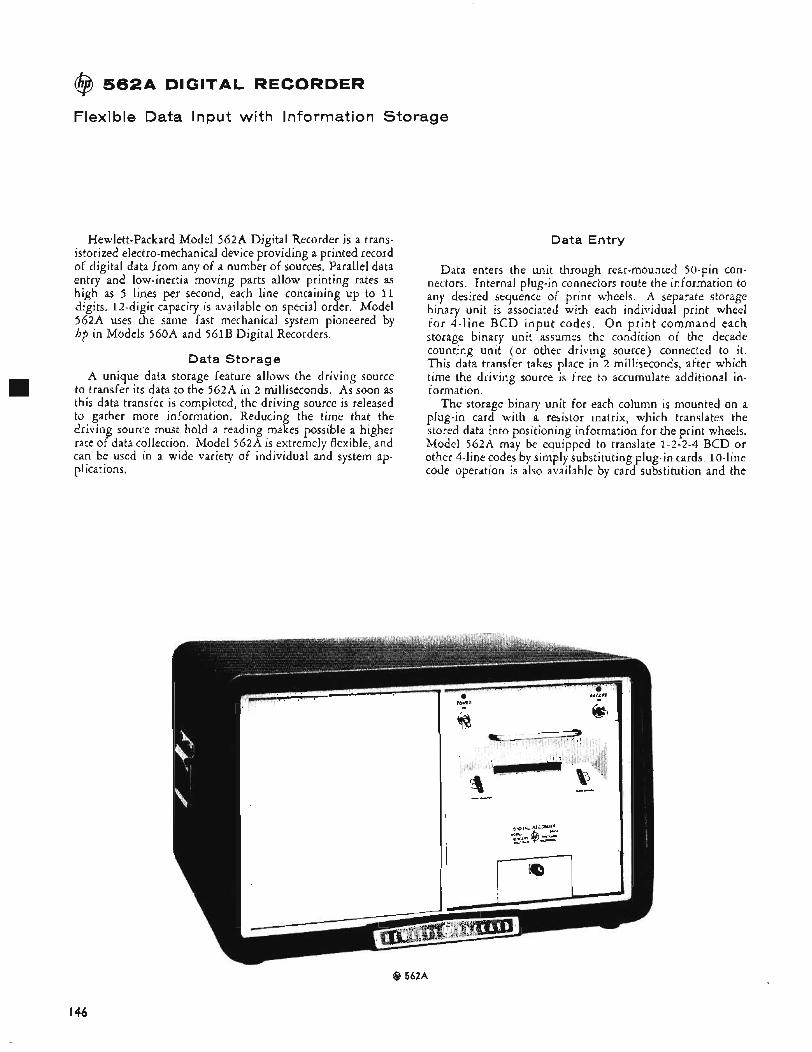
@I 5 6 2 A DIGITAL RECORDER
Flexible Data Input with Information Storage
Hewlett-Packard Model 562A Digital Recorder is a trans- istorized electro-mechanical device providing a printed record of digital data from any of a number of sources. Parallel data entry and low-inertia moving parts allow printing rates as high as 5 lines per second, each line containing up to 11 digits. 12-digit capacity is available on special order. Model 562A uses the same fast mechanical system pioneered by hp in Models 560A and 561B Digital Recorders.
Data Storage A unique data storage feature allows the driving source
to transfer its data to the 562A in 2 milliseconds. As soon as this data transfer is completed, the driving source is released to gather more information. Reducing the time that the driving source must hold a reading makes possible a higher rate of data collection. Model 562A is extremely flexible, and can be used in a wide variety of individual and system ap- plications.
Data Entry
Data enters the unit through rear-mounted 50-pin con- nectors. Internal plug-in connectors route the information to any desired sequence of print wheels. A separate storage binary unit is associated with each individual print wheel for 4-line BCD input codes. O n print command each storage binary unit assumes the condition of the decade counting unit (or other driving source) connected to it. This data transfer takes place in 2 milliseconds, after which time the driving source is free to accumulate additional in- formation.
The storage binary unit for each column is mounted on a plug-in card with a resistor matrix, which translates the stored data into positioning information for the print wheels. Model 562A may be equipped to translate 1-2-2-4 BCD or other 4-line codes by simply substituting plug-in cards. 10-line code operation is also available by card substitution and the
@ 562A
I46
mounting of additional input plugs; however, information storage is not available for 10-line data.
Flexible Options Since each print wheel operates with its own plug-in card,
different input codes may be used for separate wheels. Also, the capacity for dual input coupling is an inherent feature of the 562A which permits data from two unsynchronized sources to be printed simultaneously.
In addition to the standard print wheels which have numerals “0” through “9,” a minus sign and a blank, a wide variety of special character wheels may now be obtained from st0ck.l
Analog Output An analog output, suitable for driving potentiometer or
galvanometer recorders, is available as an option for 562 models which have 1-2-2-4 or 1-2-4-8 BCD column boards installed. A switching arrangement utilizes the stored binary data from three consecutive columns of the printed data. Any three of the first nine columns may be used for a 1000-step analog, or the two righthand digits may be used for a 100-step analog. The analog function is available to drive potentiom- eter or galvanometer strip-chart recorders without having the print mechanism in operation. Signals from the three columns are weighted in a 100 : 10 : 1 ratio and summed so that the analog output signal is a 1000-step staircase as the numer- als printed change from 000 to 999. Controls are provided for recorder calibration and zero adjustment.
Spec if i cat i o ns Accuracy: Identical to input device used. Printing Rate: 5 lines per second, maximum. Column Capacity: To 11 columns (12 available on special order). Print Wheels: 1 2 positions, numerals 0 through 9, a minus sign, and
a blank. Other symbols available.’ Input Requiremenfs:
Data Input: Parallel entry,% BCD (1-2-2-4, 1-2-4-8, or 1-2-4-2) ur 10-line, see Options. 1” state must differ from “0” state by at least 4 v but by no more than 75 v.
Reference Voltages: BCD codes require both “0” and “1” state references. 10-line codes require reference voltage for “0” state. Reference voltages may not exceed f 150 v to chassis.’ Input impedance is approximately 270K.
Hold-off Signals: Both polarities are available simultaneously for BCD codes and are diode coupled; 10 ma maximum load, + 1 5 v open circuit from 1K source, -5 v open circuit from 2.2K source. 160 ms hold-off is provided for lo-line codes,
Print Command: + or - pulse, 6 to 20 volts amplitude, 1 v/psec minimum rise time, 20 p s or greater in width, ac coupled.
Analog Output (Opt iona l ) : (From 1-2-2-4 or 1-2-48 boards.) Ac- curacy is f 0.5% of full scale or better. 100 mv for potentiome- ter recorder; 50K minimum load resistance. 1 ma into 1.5K maxi- mum for galvanometer recorder.
Transfer Time: 2 ins for BCD input. Paper Required: hp folded paper tape (15,000 prints per packet
with single spacing), or standard 3-inch roll tape. Line Spacing: Zero, single or double. In “zero”, does not print,
paper does not advance. Power Requirements: 115 or 230 v f lo%, 50 to 60 cps, approxi-
mately 130 watts. ( 4 prints per sec. maximum at 50 cps; 50 cps mod$ with 5 prints per second available:)
Dimensions: 20%” wide, 121/2” high, 18%” deep (cabinet); 19” wide, 10%” high, 20’’ deep behind panel, with connector allow- ance (rack mount).
W e i g h t : Cabinet: Net 35 lbs. Shipping 80 lbs. Rack Mount: Net 30 Ibs. Shipping 63 lbs.
Accessories Furnished: One packet folded paper tape. 560A-95N Service Kit: Contains machine oil, moly oil, moly grease and type
cleaner.
Accessories Available: 56OA-131A folded paper tape, 24-packet car- ton, $20. 560A-l31B, paper for diazo copies, 24-packet carton, $35. No. 9283-0002 Inked Ribbon, $3.50. Also available, H03- 571B Digital Clock, price on request.
Price: Basic unit with 11-column capacity. Column boards, input connector assemblies, and cables required for operation are not included, see Options. hp 562A (cabinet, base unit), $1085; hp 562AR (rack mount, base unit), $1060.
Options: Group 1. Equipped for operation with hp and Dymec in- struments. These options include the required Column Boards, In- put Connector Assemblies, and Input Cables.
Option 11. Equips 562A for 6-column operation from 1 - 2 - 2 4 “ I ” state positive code, add $540.
Option 1 2 . Equips 562A for 9-column operation from 1 - 2 - 2 4 , “1” state positive code, add $765.
Option 13. Equips 562A for 11-column operation from 1-2-2-4. “1” state positive code, add $993.
Option 14. Equips 562A for operation with 5243L or 5245L. 10-column operation; prints measurement unit and indicates decimal position, e.g., 16942.496 kc would be printed as 3KC16942496. The first digit shows how far to move the decimal to the left, add $865.
Group 2. Column Boards. Option 21. 1-2-2-4 “1” state positive, $75 per board. Option 2 2 . 1-2-4-8 “1” state positive, $75 per board. Option 23. 1-2-4-8 “1” state negative, $75 per board. Option 24. 1-2-2-4 ‘;;” state negative, $75 per board. Option 25. lO-line 1” state positive (no storage), $50 per
Option 26. 10-line “1” state negative (no storage), $50 per
Option 27. 1-2-4-2 “1” state negative, $75 per board. NOTE: Input Connector Assemblies and Input Cables (Group 3 Options) are required for use with Group 2 Column Boards.
Option 30. BCD Input Connector Assembly for up to nine
board.
board.
Group 3. Connector Assemblies.
columns, $55.
columns, $43.
10-line columns, $35 ea.
columns, $35 ea.
Option 31. BCD Input Connector Assembly for up to six
Option 32. Input Cable, for up to nine BCD columns or three
Option 33. 10-line Input Connector Assembly for up to three
NOTE: More than one Input Connector Assembly and Input Cable are required for: ( 1 ) More than nine BCD columns; ( 2 ) Operation from two sources; ( 3 ) More than three 10-line columns.
Group 4. Analog Output. Option 41. Analog Output (from 1-2-2-4 boards), $175. Option 42. Analog Output (from 1-2-48 boards), $175.
Typical Orders: One hp Model 562AR Digital Recorder to print six columns from an hp counter which provides a BCD (1-2-2-4 “1” state positive) output and with analog output.
hp 562AR $1060 Option 11. 540 Option 41. 175
Total $1775 One hp Model 562A Digital Recorder to print columns 1 through 8 from an hp counter which provides a BCD (1-2-2-4 “1” state posi- tive) output and columns 9 through 11 from a lo-line “1” state positive source which holds its data for at least 160 ms after the print command.
hp 562A $1085 8 Option 21. 600 3 Option 25. 150
Option 30. 5 5 Option 33. 35
2 Option 32. 70 Total $1995 -
One hp Model 562AR Digital Recorder to operate with hp Model 5243L Electronic Counter and to have an analog output.
hp 562AR $1060 Option 14. 865
175 Option 41. Total $2100 -
‘See hp Application Note 32 for information on special print wheels. ‘Reference voltage requirements in the range of -9 to + 16 volts may be obtained from a resistive voltage divider added to the 562A power supply module. Deriving the reference voltages from the driving source is highly recommended, however, so that recorder reference voltages will follow changes in the “0” and “1” references of the driving source,
Data subject to change without notice.
I47
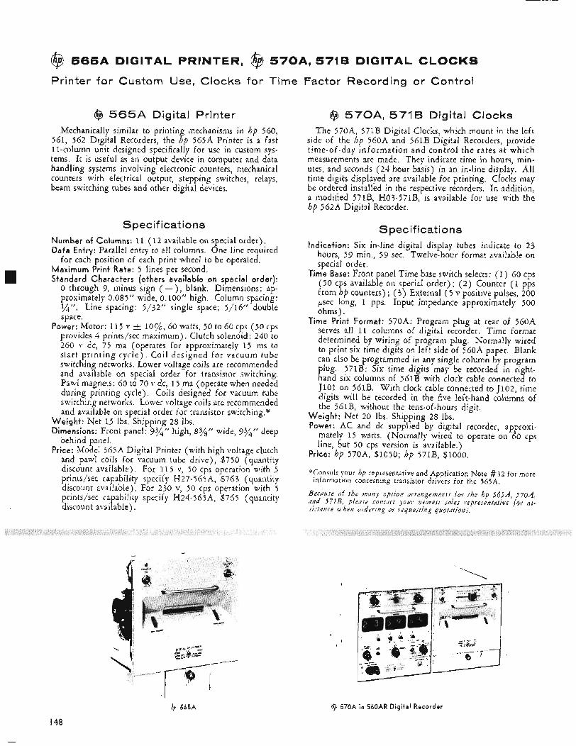
@ 5 6 5 A DIGITAL PRINTER, @ 5 7 0 A , 5716 DIGITAL CLOCKS
Printer for Custom Use, Clocks for Time Factor Recording or Control
@ 5 6 5 A Digital Printer Mechanically similar to printing mechanisms in hp 560,
561, 562 Digital Recorders, the hp 565A Printer is a fast 11-column unit designed specifically for use in custom sys- tems. It is useful as an output device in computer and data handling systems involving electronic counters, mechanical counters with electrical output, stepping switches, relays, beam switching tubes and other digital devices.
Spec if i cat i o ns Number of Columns: 11 ( 1 2 available on special order), Data Entry: Parallel entry to all columns. One line required
for each position of each print wheel to be operated. Maximum Print Rate: 5 lines per second. Standard Characters (others available on special order):
0 through 9, minus sign ( - ) , blank. Dimensions: ap- proximately 0.085” wide, 0.100’’ high. Column spacing: %”, Line spacing: 5/32” single space; 5/16” double space.
Power: Motor: 115 v i loyk, 60 watts, 50 to 60 cps (50 cps provides 4 prints/sec maximum). Clutch solenoid: 240 to 260 v dc, 75 ma (operates for approximately 1 5 ms to start printing cycle). Coil designed for vacuum tube switching networks. Lower voltage coils are recommended and available on special order for transistor switching. Pawl magnets: 60 to 70 v dc, 1 5 ma (operate when needed during printing cycle). Coils designed for vacuum tube switching networks. Lower voltage coils are recommended and available on special order for transistor switching.*
Weight: Net 1 5 Ibs. Shipping 28 Ibs. Dimensions: Front panel: 93/” high, 8y’“ wide, 93/4’f deep
behind panel. Price: Model 565A Digital Printer (with high voltage clutch
and pawl coils for vacuum tube drive), $750 (quantity discount available). For 11 5 v, 50 cps operation with 5 prints/sec capability specify H27-565A, $763 (quantity discount available). For 230 v, 50 cps operation with 5 prints/sec capability specify H24-565A, $765 (quantity discount available).
@ 570A, 571B Digital Clocks The 570A, 571B Digital Clocks, which mount in the left
side of the hp 560A and 561B Digital Recorders, provide time-of-day information and control the rates at which measurements are made. They indicate time in hours, min- utes, and seconds (24 hour basis) in an in-line display. All time digits displayed are available for printing. Clocks may be ordered installed in the respective recorders. In addition, a modified 571B, H03-571B, is available for use with the hp 562A Digital Recorder.
Spec if icat i o ns Indication: Six in-line digital display tubes indicate to 2 3
hours, 59 min., 59 sec. Twelve-hour format available on special order.
Time Base: Front panel Time base switch selects: (1) 60 cps (50 cps available on special order) ; (2) Counter (1 pps from hp counters) ; ( 3 ) External ( 5 v positive pulses, 200 psec long, 1 pps. Input impedance approximately 500 ohms).
Time Print Format: 570A: Program plug at rear of 560A serves all 11 columns of digital recorder. Time format determined by wiring of program plug. Normally wired to print six time digits on left side of 560A paper. Blank can also be programmed in any single column by program plug. 571B: Six time digits may be recorded in right- hand six columns of 56lB with clock cable connected to J l O l on 561B. With clock cable connected to J102, time digits will be recorded in the five left-hand columns of the 561B, without the tens-of-hours digit.
Weight: Net 20 Ibs. Shipping 28 Ibs. Power: AC and dc supplied by digital recorder, approxi-
mately 15 watts. (Normally wired to operate on 60 cps line, but 50 cps version is available,)
Price: hp 570A, 31050; hp 571B, $1000.
*;Consult your hp representative and Application Note #32 for more
Because of the many option arrangements f o r the hp 56fiA, 570A, and 571B, please contuct jour nearest Jales representative for as- sistance uhen ordering or requesting quotations.
information concerning transistor drivers for the 565A.
$ 565A 9 570A i n 560AR Digital Recorder
148
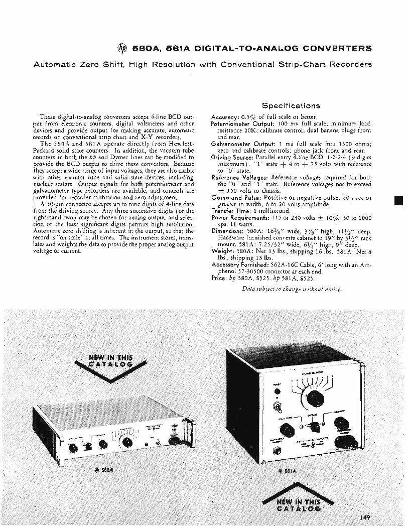
@ 5 8 0 A , 581A DIGITAL-TO-ANALOG CONVERTERS
Automatic Zero Shift, High Resolution with Conventional Strip-Chart Recorders
These digital-to-analog converters accept 4-line BCD out- put from electronic counters, digital voltmeters and other devices and provide output for making accurate, automatic records on conventional strip chart and X-Y recorders.
T h e 580A and 581A operate directly f rom Hewlett- Packard solid state counters. In addition, the vacuum tube counters in both the hp and Dymec lines can be modified to provide the BCD output to drive these converters. Because they accept a wide range of input voltages, they are also usable with other vacuum tube and solid state devices, including nuclear scalers. Output signals for both potentiometer and galvanometer type recorders are available, and controls are provided for recorder calibration and zero adjustment.
A >@pin connector accepts up to nine digits of 4-line data from the driving source. Any three successive digits (or the right-hand two) may be chosen for analog output, and selec- tion of the least significant digits permits high resolution. Automatic zero shifting is inherent in the output, so that the record is “on scale” at all times. The instrument stores, trans- lates and weights the data to provide the proper analog output voltage or current.
Spec if i cat i o n s Accuracy: 0.5% of full scale or better. Potentiometer Output: 100 mv full scale; minimum load
resistance 20K; calibrate control; dual banana plugs front and rear.
Galvanomete,r Output: 1 ma full scale into 1500 ohms; zero and calibrate controls; phone jack front and rear.
Driving Source: Parallel entry 4-line BCD, 1-2-2-4 ( 9 digits maximum). “1” state + 4 to + 75 volts with reference to “0” state.
Reference Voltages: Reference voltages required for both the “0” and “1” state. Reference voltages not to exceed t 150 volts to chassis.
Command Pulse: Positive or negative pulse, 20 p e c or greater in width, 6 to 20 volts amplitude.
Transfer Time: 1 millisecond. Power Requirements: 115 or 230 volts lo%, 50 to 1000
cps, 11 watts. Dimensions: 580A: 16%” wide, 37/” high, 111/2’’ deep.
Hardware furnished converts cabinet to 19” by 3Y2” rack mount. 581A: 7-25/32‘‘ wide, 6$$” high, 9” deep.
Weight: 580A: Net 13 lbs., shipping 16 Ibs. 581A: Net 8 Ibs., shipping 13 lbs.
Accessory Furnished: 562A-16C Cable, 6’ long with an Ani- phenol 57-30500 connector at each end,
Price: hp 580A, $525. hp 581A, $525.
Data subject to change uithout notice,
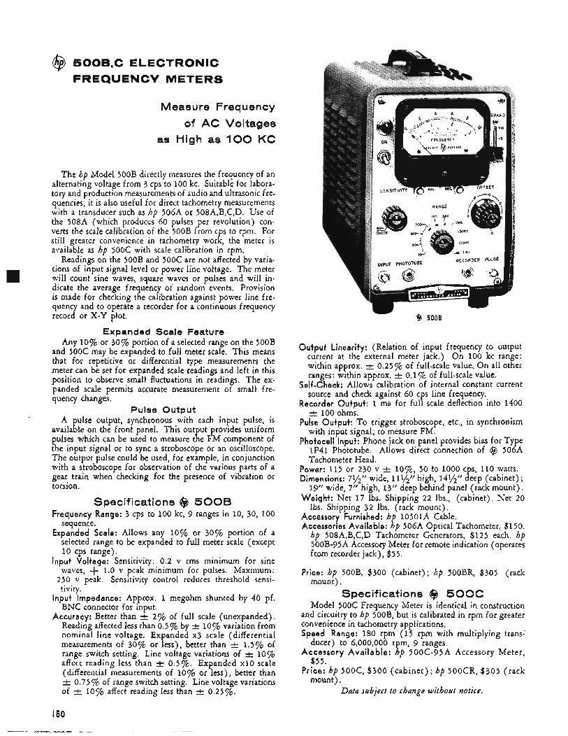
@ 5OOB,C ELECTRONIC FREQUENCV METERS
Measure Frequency
of AC Voltages as High as 100 KC
The hp Model 500B directly measures the frequency of an alternating voltage from 3 cps to 100 kc. Suitable for labora- tory and production measurements of audio and ultrasonic fre- quencies, it is also useful for direct tachometry measurements with a transducer such as hp 50GA or 508A,B,C,D. Use of the 508A (which produces 60 pulses per revolution) con- verts the scale calibration of the 500B from cps to rpm. For still greater convenience in tachometry work, the meter is available as hp 500C with scale calibration in rpm.
Readings on the 500B and 500c are not affected by varia- tions of input signal level or power line voltage. The meter will count sine waves, square waves or pulses and will in- dicate the average frequency of random events. Provision is made for checking the calibration against power line fre- quency and to operate a recorder for a continuous frequency record or X-Y plot,
Expanded Scale Feature Any 10% or 30% portion of a selected range on the 500B
and 500C may be expanded to full meter scale. This means that for repetitive or differential type measurements the meter can be set for expanded scale readings and left in this position to observe small fluctuations in readings. The ex- panded scale permits accurate measurement of small fre- quency changes,
Pulse Output ulse output, synchronous with each input pulse, is
availa le on the front panel. This out ut provides uniform pulses which can be used to measure t e FM component of the input signal or to sync a stroboscope or an oscilloscope. The output pulse could be used, for example, in conjunction with a stroboscope for observation of the various parts of a gear train when checking for the presence of vibration or torsion.
A
ph !
Specifications @ 5008 Frequency Range: 3 cps to 100 kc, 9 ranges in 10, 30, 100
sequence. Expanded Scale: Allows any 10% or 30% portion of a
selected range to be expanded to full meter scale (except 10 cps range).
Input Voltage: Sensitivity: 0.2 v rms minimum for sine waves, + 1.0 v peak minimum for pulses. Maximum:
250 v peak. Sensitivity control reduces threshold sensi- tivity.
Input Impedance: Approx. 1 megohm shunted by 40 pf. BNC connector for input.
Accuracy: Better than t 2% of full scale (unexpanded). Reading affected less than 0.5% by f 10% variation from nominal line voltage. Expanded x3 scale (differential measurements of 30% or less), better than f 1.5% of range switch setting. Line voltage variations of 10% affect reading less than t 0.5%. Expanded x10 scale (differential measurements of 10% or less), better than
0.75% of range switch setting. Line voltage variations of & 10% affect reading less than t 0.25%.
- $3 5008
Output Linearity: (Relation of input frequency to output current at the external meter jack.) On 100 kc range: within approx. 0.25 % of full-scale value. On all other ranges: within approx. t 0.1% of full-scale value.
Self-check: Allows calibration of internal constant current source and check against Go cps line frequency.
Reco,rder Output: 1 ma for full scale deflection into 1400 f 100 ohms.
Pulse Output: To trigger stroboscope, etc., in synchronism with input signal; to measure FM.
Photocell Input: Phone jack on panel provides bias for Type 1P41 Phototube. Allows direct connection of @ 506A Tachometer Head.
Power: 115 or 230 v f l o%, 50 to 1000 c s, 110 watts. Dimensions: 7%” wide, 111/2” high, 141/2” Beep (cabinet) ;
19” wide, 7’’ high, 13” deep behind panel (rack mount). Weight: Net 17 Ibs. Shipping 22 Ibs., (cabinet). Net 20
Ibs. Shipping 32 Ibs. (rack mount). Accessory Furnished: h 10501A Cable.
hp 508A,B,C,D Tachometer Generators, $125 each. hp 500B-95A Accessory Meter for remote indication (operates from recorder jack), $ 5 5 .
mount), Specifications @J 500C
Model 500c Frequency Meter is identical in construction and circuitry to hp 500B, but is calibrated in rpm for greater convenience in tachometry applications. Speed Range: 180 rpm (15 rpm with multiplying trans-’
ducer) to G,OOO,OOO r m, 9 ranges,
$55.
mount).
Accessories Available: R p 50GA Optical Tachometer, $150.
Price: hp 500B, $300 (cabinet); hp 500BR, $305 (rack
Accessory Available: K p 500C-95A Accessory Meter,
Price: hp 5 0 0 c , $300 (cabinet) ; hp 500CR, $305 (rack
Data subject to change without notice.
I60
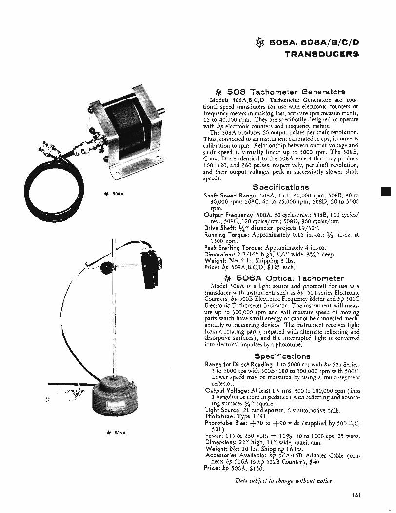
@ 506A. 508A/B/C/D TRANSDUCERS
2 /
@ 508A
9 506A
@ 508 Tachometer Generators Models 508A,B,C,D, Tachometer Generators are rota-
tional speed transducers for use with electronic counters or frequency meters in making fast, accurate rpm measurements, 15 to 40,000 rpm. They are specifically designed to operate with hp electronic counters and frequency meters.
The 508A produces 60 output pulses per shaft revolution. Thus, connected to an instrument calibrated in cps, it converts calibration to rpm. Relationship between output voltage and shaft speed is virtually linear up to 5000 rpm. The 508B, C and D are identical to the 508A except that they produce 100, 120, and 360 pulses, respectively, per shaft revolution, and their output voltages peak at successively slower shaft speeds.
Shaft Speed Range: 508~4, 15 to 40,000 rpm; 508B, 30 to 30,000 rpm; 508C, 40 to 25,000 rpm; 508D, 50 to 5000 rpm.
Output Frequency: 508-4, 60 cycles/rev.; 508B, 100 cycles/ rev.; 508c, 120 cycles/rev.; 508D, 360 cycles/rev.
Drive Shaft: %’’ diameter, projects 19/32”. Running Torque: Approximately 0.15 in.-oz.; 1/2 in.-oz. at
Peak Starting Torque: A proximately 4 in.-oz. Dimensions: 2-7/16” big!, 3%’‘ wide, 33/4// deep. Weight: Net 2 lb. Shipping 3 Ibs. Price: hp 508A,B,C,D, $125 each.
Spec if i cat i o ns
1500 rpm.
@ 5 0 6 A Optical Tachometer Model 506A is a light source and photocell for use as a
transducer with instruments such as hp 5 2 1 series Electronic Counters, hp 500B Electronic Frequency Meter and hp 500c Electronic Tachometer Indicator. The instrument will meas- ure up to 300,000 rpm and will measure speed of moving parts which have small energy or cannot be connected mech- anically to measuring devices. The instrument receives light from a rotating part (prepared with alternate reflecting and absorptive surfaces), and the interrupted light is converted into electrical impulses by a phototube.
Spec if i cat i ons Range for Direct Reading: 1 to 5000 rps with hp 521 Series;
3 to 5000 rps with 50OB; 180 to 300,000 rpm with 500C. Lower speed may be measured by using a multi-segment reflector.
Output Voltage: At least 1 v rms, 300 to 100,000 rpm (into 1 megohm or more impedance) with reflecting and absorb- ing surfaces %!, s uare.
Light Source: 2 1 can ?I lepower, 6 v automotive bulb, Phototube: Type 1P41. Phototube Bias: +70 to +90 v dc (supplied by 500 B,C,
Power: 115 or 230 volts l o%, 50 to 1000 cps, 25 watts, Dimensions: 22” high, 11’’ wide, maximum. Weight: Net 10 Ibs. Shi ping 16 lbs. Accessories Available: g p 56A-16B Adapter Cable (con-
nects hp 506A to hp 522B Counter), $40. Price: hp 506A, $150.
521).
Data subject to change without notice.
151
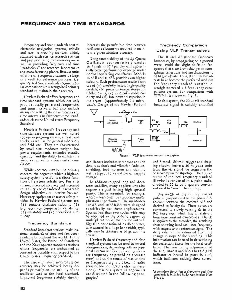
FREQUENCY AND TIME STANDARDS
Amp (20kc) Flop
Frequency and time standards control electronic navigation systems, missile and satellite tracking stations, widely scattered earth science research stations and precision radio transmissions - as well as providing frequency and time "yardsticks" for research laboratories and manufacturing plants. Because units of time or frequency cannot be kept in a vault for reference purposes, fre- quency and time standards require regu- lar comparisons to a recognized primary standard to maintain their accuracy.
Hewlett-Packard offers frequency and time standard systems which not only provide locally generated frequencies and time intervals, but also include means for relating these frequencies and time intervals to frequency/time stand- ards such as the United States Frequency Standard.
Hewlett-Packard's frequency and time standard systems are well suited for use in seagoing vessels, aircraft and trucks, as well as for general laboratory and field use. They are characterized by small size, moderate weight, low power requir'ements, extended standby operation and the ability to withstand a wide range of environmental con- ditions.
While accuracy may be the primary concern, the degree to which a high-ac- curacy system is useful is a direct func- t ion of system reliability. For this reason, increased accuracy and increased reliability are considered inseparable design objectives at Hewlett-Packard. Necessary equipment characteristics pro- vided by Hewlett-Packard systems are: (1) suitable oscillator stability, ( 2 ) high-accuracy comparison capability, ( 3 ) reliability and (4) operational sim- plicity.
Frequency Standards
Standard broadcast stations make na- tional standards of time and frequency available throughout the world. In the United States, the Bureau of Standards and the Navy operate standards stations whose frequencies are maintained as constant as possible with respect to the United States Frequency Standard.
The ease with which required system accuracy may be achieved locally de- pends primarily on the stability of the oscillator used as the local standard. Improved long-term stability directly
increases the permissible time between Frea u e ncv C o m par iso n oscillator adjistments required to main- tain a given absolute accuracy. Using' VLF-Trans~issions
Long-term stability of the hp Quartz Oscillators is conservatively rated at
5 parts in 10'" per day with substan- tially better performance expected under normal operating conditions, Models 107AR and 107BR provide even higher stability. Such performance results from use of (a) carefully tested, high-quality crystals, (b) precision temperature-con- trolled ovens, (c) inherently stable cir- cuitrv and f d', low-Dower dissiDation in
The If and vlf standard frequency broadcasts, by propagating on a ground wave, avoid the slight shifts in frc- quency that stem from changes in iono- spheric reflections and are characteristic of hf broadcasts. Thus, If and vlf broad- casts have become the preferred medium fo r frequency standard transfer. A s t r a i g h t f o r w a r d vl f frequency co ni - parison system, for comparison with WWVL, is shown in Fig. 1.
In this system, the 20 kc vlf standard broadcast signal is suitably amplified
the krystal' (ipprohmately 0.5 micro- watt). Design of the Hewlett-Packard
u7 --+- 20kc
.c dc
Recorder
....
-5 Oscillator Trigger .hp.IOBAR Ckt
w' Figure I . VLF frequency comparison system.
oscillators includes attention to such details as shock and vibration isolation, shielding, load isolation and stability with respect to variation of supply voltage.
In addition to good long and short- term stability, many applications also require a signal having high spectral purity. This is essential, for example, where a high order of frequency multi- plication is performed. The hp Models 104AR and 107AR,BR were designed specifically for these applications. Spectra less than two cycles wide may be obtained in the X-band region by multiplication of their 5 mc output. Signal-to-noise ratios of 23 db or better, as measured in a 6 cps bandwidth, typi- cally may be obtained at 10 gc with the 104AR.
Hewlett-Packard frequency and time standard systems can be used in several configurations, depending both on prin- cipal systems use (Le., providing accur- ate frequency o r providing accurate time) and on the source of master time or frequency signals (i.e., hf radio transmission or If/vlf radio transmis- sions), Various system arrangements are discussed in the following para- graphs.'
and filtered. Schmitt trigger and shap- ing circuits derive a 20 kc pulse train from the vlf signal for triggering the phase-comparator flip-flop. The 100 kc output of the local frequency s tandad likewise is converted to a pulse train, divided to 20 kc by a quinary counter and used to "reset" the flip-flop.
The width of the flip-flop output pulse is proportional to the phase dif- ference between the received vlf and derived 20 kc signals. These pulses are converted to slowly varying dc in the RC integrator, which has a relatively long time constant (>-second). The dc is applied to the recorder, the resulting chart showing local oscillator frequency with respect to the reference signal. The drift rate can be estimated from the change in slope of the recording. This information can be used in determining the correction factor for the local oscil- lator. The fine tuning adjustment of the 103, 104AR oscillators has a digital indicator calibrated in parts in lo lo , which facilitates making these correc- tions.
'A complete discussion of frequency and time standards is included in hp Application Note No. 52.
I52
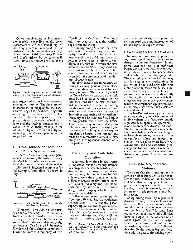
Other combinations of instruments are possible, depending on the user’s requirements and the availability of other equipment in the laboratory. For instance, the vlf system shown in Fig. 2 uses the hp 11 5BR Frequency Divider and Clock, driven by the local oscil- lator. Its output pulses are used as the
Figure 2. VLF frequency using 115BR Fre- quency Divider, Clock and digital electronic
counter. start triggers of a time interval measure- ment in the counter. The time interval measurement is stopped by the zero- axis crossing of the next-occurring cycle of the signal from the vlf receiver. The counter reading is proportional to the phase difference between the local oscil- lator and the received standard and is converted to an analog voltage in the hp 560A Digital Recorder or a digital- to-analog converter for operation of the strip-chart recorder.
HF Time Comparison Methods and Clock Synchronization If accurate time-keeping is of para-
mount importance, the high frequency standard broadcasts can synchronize a local clock to an accuracy of better than 1 millisecond. Suggested equipment for calibrating a local clock is shown in Fig. 3.
m
Figure 3. Time camparison for frequency standard calibration.
“Time ticks” (typically 5 msec bursts of an audio frequency at 1 sec intervals) from a standard broadcast of precise time signals are detected by the receiver and applied to the vertical input of the oscilloscope. The hp 11 5BR Frequency Divider and Clock derives “local ticks” from the output frequency of the
103AR Quartz Oscillator’. The “local ticks” are used to trigger the oscillos- cope horizontal sweep.
At the beginning of a test, the “time tick” and “local ticks” may be as much as 1/* second apart. By successive ad- justment of the 115BR and the oscil- loscope sweep speed, a reference con- dition is established in which the time between the two ticks is very short and is known accurately. The Time Refer- ence control on the clock is adjusted to re-establish the reference condition dur- ing subsequent tests.
H F time comparison techniques, al- though serving primarily fo r clock synchronization, are also used for fre- quency transfer. The amount by which the Time Reference control on the clock must be adjusted to re-establish the reference condition indicates the time drift of the local oscillator. By plotting the data obtained over a period of time, drift rate and frequency error may be determined accurately and the oscillator frequency can be readjusted to keep it within predetermined accuracy limits. This method requires several days to achieve a high degree of precision, in contrast to vlf techniques which require less than 24 hours. Time comparisons made by hf techniques over several days can yield a comparison accuracy of a few parts in
Reliability and Fail-safe 0 peratio n
Minimum down-time in any system is important, but the accuracy attained in a frequency or time standard depends directly on continuity of operation. Furthermore, the system must be fail- safe to prevent the accumulation of in- sidious frequency or time errors. Hew- lett-Packard frequency and time stand- ards employ simplified, optimized designs which display a high order of inherent dependability.
Fail-safe operation results mainly irom three Hewlett-Packard equipment characteristics: (1) a standby power supply employs batteries to provide con- tinued operation in event of line failure; ( 2 ) dividers in hp quartz oscillators and frequency divider and clock will not respond to spurious signals, and ( 3 )
*Dexter Hartke, “A New Clock for Improv- ing the Accuracy of Local Frequency and Time Standards”. @ Journal, vol. 11 No. 3-4, Nov. - Dec., 1959.
the divider output signals stop and re- main stopped upon any interruption of driving signal or supply power.
Power S u pp ly Considerations Interruptions in primary power to
any quartz oscillator can cause serious changes in output frequency. If the power interruption is of sufficient length, cooling causes strains in the crys- tal which can cause a frequency offset and which may alter the aging rate. The new aging cycle thus incurred may last for days or even weeks, since the strains can be relieved only with time at the proper operating temperature. Be- cause the accuracy attained in time com- parison measurements depends directly on the length of time over which the measurements are made, power inter- ruptions to comparison equipment, such as the frequency divider and clock, are also undesirable.
Hewlett-Packard standby power sup- plies, operating over wide ranges of ac line voltage and frequency, supply regulated dc to operate the quartz oscil- lator and frequency divider and clock. The batteries in the supplies assume the load immediately, without switching or undesirable transients, whenever ac line power fails. When line power is re- stored, the supplies immediately re- assume the load and automatically re- charge the batteries. Alarm systems in- clude local indication of operating con- ditions and provisions fo r remote alarms.
Fai I - Safe, Reg en e rati ve Dividers
To insure that short interruptions in power or other irregularities do not af- fect the time indication, hp frequency and time standard equipment uses re- generative frequency dividers. These circuits, if ever interrupted, will not restart unless triggered by a push-but- ton starter.
Sharp tuning makes hp regenerative dividers virtually invulnerable to noise bursts or other spurious signals which would cause pulse counters or phantas- tron dividers to “gain” in time. Since properly designed regenerative dividers have no output in the absence of an input signal, the presence of output from a regenerative divider of the non- selfstarting type is a positive indication that the divider output has not “lost” time with respect to the driving signal.
I53
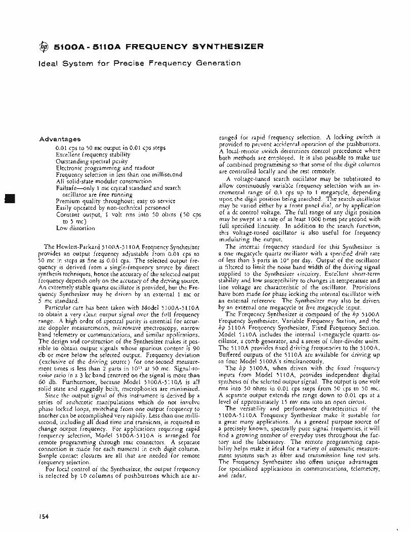
@ 5100A- 5110A FREQUENCY SYNTHESIZER
Ideal System for Precise Frequency Generation
Advantages 0 . 0 1 cps to 50 mc output in 0 .01 cps steps Excellent frequency stability Outstanding spectral purity Electronic programming and readout Frequency selection in less than one millisecond Al l solid-state modular construction Failsafe-only 1 mc crystal standard and search
Premium quality throughout; easy to service Easily operated by non-technical personnel Constant output, 1 volt rms into 50 ohms ( 5 0 cps
to 5 mc) Low distortion
oscillator are free running
The Hewlett-Packard 5 100A-5 1 l o A Frequency Synthesizer provides an output frequency adjustable from 0.01 cps to 50 mc in steps as fine as 0 .01 cps. The selected output fre- quency is derived from a single-frequency source by direct synthesis techniques, hence the accuracy of the selected output frequency depends only on the accuracy of the driving source. An extremely stable quartz oscillator is provided, but the Fre- quency Synthesizer may be driven by an external 1 mc or 5 mc standard.
Particular care has been taken with Model 5 1 0 0 A - 5 1 1 0 A to obtain a very clean output signal over the full frequency range. A high order of. spectral purity is essential for accur- ate doppler measurements, microwave spectroscopy, narrow band telemetry or communications, and similar applications. The design and construction of the Synthesizer makes it pos- sible to obtain output signals whose spurious content is 90 db or more below the selected output. Frequency deviation (exclusive of the driving source) for one-second measure- ment times is less than 2 parts in lo l l at 50 mc. Signal-to- noise ratio in a 3 kc band centered on the signal is more than 60 db. Furthermore, because Model 5 1 0 0 A - 5 1 1 0 A is all solid state and ruggedly built, microphonics are minimized.
Since the output signal of this instrument is derived by a series of arithmetic manipulations which do not involve phase locked loops, switching from one output frequency to another can be accomplished very rapidly. Less than one milli- second, including all dead time and transients, is required to change output frequency. For applications requiring rapid frequency selection, Model 5 100A-5 1 l O A is arranged for remote programming through rear connectors. A separate connection is made for each numeral in each digit column. Simple contact closures are all that are needed for remote frequency selection.
For local control of the Synthesizer, the output frequency is selected by 10 columns of pushbuttons which are ar-
ranged for rapid frequency selection. A locking switch is provided to prevent accidental operation of the pushbuttons. A local-remote switch determines control precedence where both methods are employed. It is also possible to make use of combined programming so that some of the digit columns are controlled locally and the rest remotely.
A voltage-tuned search oscillator may be substituted to allow continuously variable frequency selection with an in- cremental range of 0 . 1 cps up to 1 megacycle, depending upon the digit position being searched. The search oscillator may be varied either by a front panel dial, or by application of a dc control voltage. The full range of any digit position may be swept at a rate of at least 1000 times per second with full specified linearity. In addition to the search function, this voltage-tuned oscillator is also useful for frequency modulating the output.
The internal frequency standard for this Synthesizer is a one megacycle quartz oscillator with a specified drift rate of less than 3 parts in 10" per day. Output of the oscillator is filtered to limit the noise band width of the driving signal supplied to the Synthesizer circuitry. Excellent short-term stability and low susceptibility to changes in temperature and line voltage are characteristic of the oscillator. Provisions have been made for phase locking the internal oscillator with an external reference. The Synthesizer may also be driven by an external one megacycle or five megacycle input.
The Frequency Synthesizer is composed of the hp 5 1 0 0 A Frequency Synthesizer, Variable Frequency Section, and the hp 5 1 l O A Frequency Synthesizer, Fixed Frequency Section. Model 5 1 l o A includes the internal 1-megacycle quartz. os- cillator, a comb generator, and a series of filter-divider units. The 5 1 1 0 A provides fixed driving frequencies to the 5 1oOA. Buffered outputs of the 5110A are available for driving up to four Model 5 100A's simultaneously.
The hp 5100A, when driven with the fixed frequency inputs from Model 5 110A, provides independent digital synthesis of the selected output signal. The output is one volt rms into 50 ohms in 0 .01 cps steps from 50 cps to 50 mc. A separate output extends the range down to 0 .01 cps at a level of approximately 1 5 mv rms into an open circuit.
The versatility and performance characteristics of the 5 100A-5 1 lOA Frequency Synthesizer make it suitable for a great many applications. As a general purpose source of a precisely known, spectrally pure signal frequencies, it will find a growing number of everyday uses throughout the fac- tory and the laboratory. The remote programming capa- bility helps make it ideal for a variety of automatic measure- ment systems such as filter and transmission line test sets. The Frequency Synthesizer also offers unique advantages for specialized applications in communications, telemetery, and radar.
I54
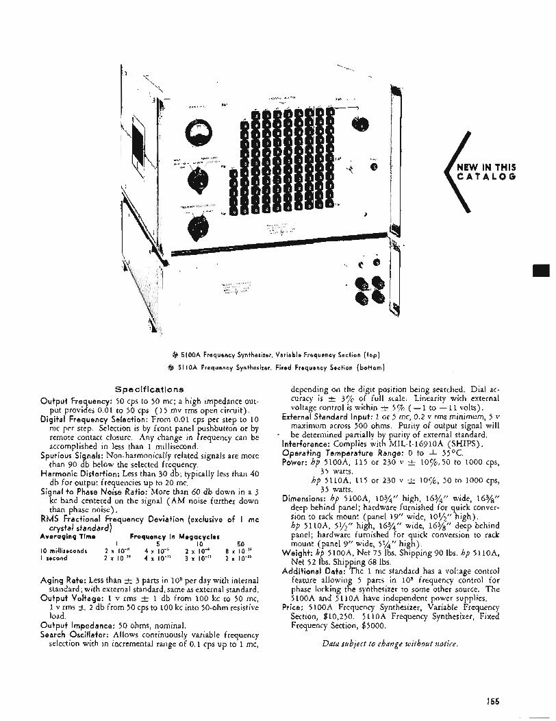
@ 5100A Frequency Synthesizer, Variable Frequency Section ( t o p )
@ 51 IOA Frequency Synthesizer, Fixed Frequency Section (bot tom)
Specifications Output Frequency: 50 cps to 50 mc; a high impedance out-
put provides 0.01 to 50 cps (15 mv rms open circuit). Digital Frequency Selection: From 0.01 cps per step to 10
mc per step. Selection is by front panel ushbutton or by
accomplished in less than 1 millisecond. Spurious Signals: Non-harmonically related signals are more
than 90 db below the selected frequency. Harmonic Distortion: Less than 30 db; typically less than 40
db for output frequencies up to 20 mc. Signal t o Phase Noise Ratio: More than 60 db down in a 3
kc band centered on the signal (AM noise further down than phase noise).
RMS Fractional Frequency Deviation (exclusive of I mc crystal standard)
A v e r a g i n q T i m e F r e q u e n c y in M e g a c y c l e s
I O milliseconds 2 x IO-’ 4 x IO-’ 2 x IO-’ 8 x IO-’’ I second 2 x Io-iu 4 x lo-” 3 x lo-“ 2 x Io-”
remote contact closure. Any change in P requency can be
I 5 I O 50
Aging Rate: Less than t 3 parts in io9 per day with internal standard; with external standard, same as external standard.
Output Voltage: 1 v rms k 1 db from 100 kc to 50 mc, 1 v rms -t 2 db from 50 cps to 100 kc into 50-ohm resistive load.
Output Impedance: 50 ohms, nominal. Search Oscillator: Allows continuously variable frequency
selection with in incremental range of 0.1 cps up to 1 mc,
C A T A L O G
depending on the digit position being searched. Dial ac- curacy is k 3% of full scale. Linearity with external voltage control is within
External Standard Input: 1 or 5 mc, 0.2 v rms minimum, 5 v maximum across 500 ohms. Purity of output signal will be determined partially by purity of external standard.
5 % ( - 1 to - 11 volts),
- Interference: Complies with MIL-I-16910A (SHIPS). Operating Temperature Range: 0 to + 55OC. Power: hp 5100~4, 115 or 230 v 3. 10%,50 to 1000 cps,
hp 5110~4, 115 or 230 v -+ lo%, 50 to 1000 cps,
Dimensions: hp 5100~4, 103/4’’ high, 16%” wide, 16%‘‘ deep behind panel; hardware furnished for quick conver- sion to rack mount (panel 19” wide, lo’+!’’ high). hp 5110A, 5’+’” high, 163/4” wide, 16%’’ deep behind panel; hardware furnished for quick conversion to rack mount (panel 9” wide, 5%” high).
Weight: hp 5100A, Net 75 Ibs. Shipping 90 Ibs. hp 5110A, Net 52 Ibs. Shipping 68 Ibs.
Additional Data: The 1 mc standard has a voltage control feature allowing 5 parts in 108 frequency control for phase locking the synthesizer to some other source. The 5100A and 5 1 lOA have independent power supplies.
Price: 5 1OOA Frequency Synthesizer, Variable Frequency Section, $10,250. 5 1lOA Frequency Synthesizer, Fixed Frequency Section, $5000.
35 watts.
35 watts.
Ddtd subject t o change withozrt notice,
I55
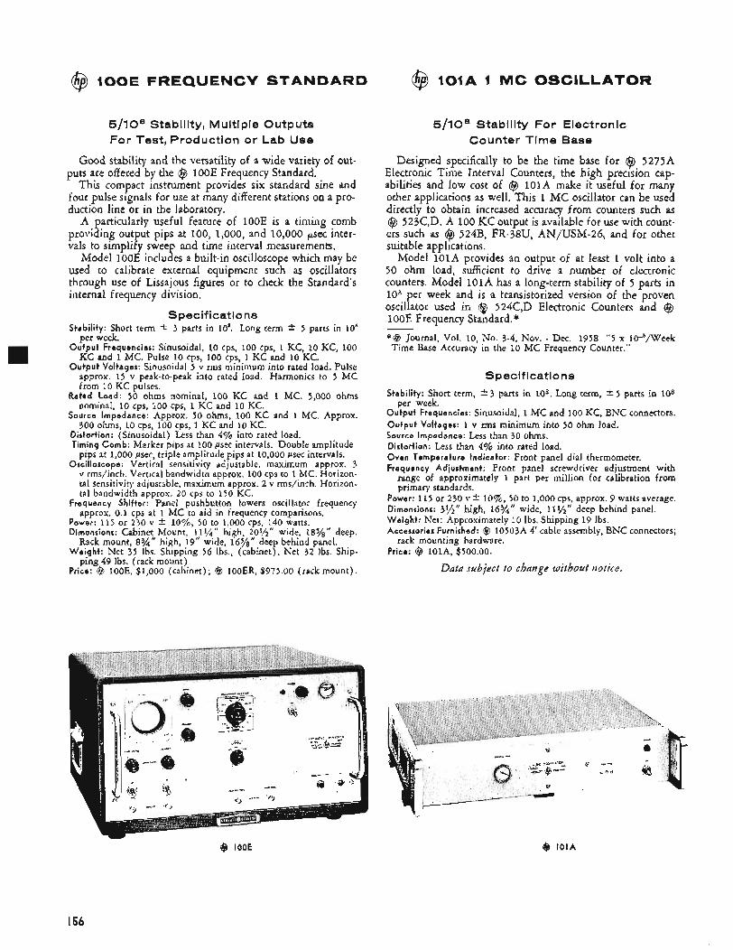
@ 1OOE FREQUENCY STANDARD
5/108 Stability, Multiple Outputs For Test, Production or Lab Use
Good stability and the versatility of a wide variety of out- puts are offered by the @ 1OOE Frequency Standard.
This compact instrument provides six standard sine and four pulse signals for use at many different stations on a pro- duction line or in the laboratory.
A particularly useful feature of 1OOE is a timing comb providing output pips at 100, 1,000, and 10,000 psec inter- vals to simplify sweep and time interval measurements.
Model 1ooE includes a built-in oscilloscope which may be used to calibrate external equipment such as oscillators through use of Lissajous figures or to check the Standard’s internal frequency division.
Specifications Stability: Short term * 3 parts in 10’. Long term * 5 parts in 10’
per week. Output Frequencies: Sinusoidal, 10 cps, 100 cps, 1 KC, 10 KC, 100
KC and 1 MC. Pulse 10 cps, 100 cps, 1 KC and 10 KC. Output Voltages: Sinusoidal 5 v rms minimum into rated load. Pulse
approx. 15 v peak-to-peak into rated load. Harmonics to 5 MC
@ 101A 1 MC OSCILLATOR
from 10 KC pulses.
nominal, 10 cps, 100 cps, 1 KC and 10 KC.
300 ohms, 10 cps, 100 cps, 1 KC and 10 KC.
Rated Load: 50 ohms nominal, 100 KC and 1 MC. 5,000 ohms
Source Impedance: Approx. 50 ohms, 100 KC and 1 MC. Approx.
Distortion: (Sinusoidal) Less than 4% into rated load. Timing Comb: Marker pips at 100 psec intervals. Double amplitude
pips at 1,000 psec, triple amplitude pips at 10,000 psec intervals. Oscilloscope: Vertical sensitivity adjustable, maximum approx. 3
v rms/inch. Vertical bandwidth approx. 100 cps to 1 MC. Horizon- tal sensitivity adjustable, maximum approx. 2 v rms/inrh. Horizon- tal bandwidth approx. 20 cps to 150 KC.
Frequency Shifter: Panel pushbutton lowers oscillator frequency approx. 0.1 cps at 1 MC to aid in frequency comparisons.
Power: 115 or 230 v k lo%, 50 to 1,000 cps, 140 watts. Dimensions: Cabinet Mount, 1114” high, 209’2’’ wide, 1878” deep.
Rack mount, 8%” high, 19” wide, 16%” deep behind panel. Weight : Net 3 5 Ibs. Shipping 56 Ibs., (cabinet). Net 32 Ibs. Ship-
ping 49 Ibs. (rack mount). Price: @ 100E, $1,000 (cabinet); @ 100ER, $975.00 (rackmount).
5/10’ Stability For Electronic Counter Time Base
Designed specifically to be the time base for @ 5275A Electronic Time Interval Counters, the high precision cap- abilities and low cost of @ 1OlA make it useful for many other applications as well. This 1 MC oscillator can be used directly to obtain increased accuracy from counters such as @ 523C,D. A 100 KC output is available for use with count- ers such as @ 524B, FR-38U, AN/USM-26, and for other suitable applications.
Model 1olA provides an output of at least 1 volt into a 50 ohm load, sufficient to drive a number of electronic counters. Model 1olA has a long-term stability of 5 parts in IO8 per week and is a transistorized version of the proven oscillator used in @ 524C,D Electronic Counters and @ 1 O O E Frequency Standard.*
*Q Journal, Vol. 10, No. 3-4, Nov. - Dec. 1958 “ 5 x lO-*/Week Time Base Accuracy in the 10 MC Frequency Counter.”
-
Specifications
Stability: Short term, +- 3 parts in 108. Long term, 5 5 parts in 108
Output Frequencies: Sinusoidal, 1 MC and 100 KC, BNC connectors. Output Voltages: 1 v rms minimum into 50 ohm load. Source Impedance: Less than 30 ohms. Distortion: Less than 4% into rated load. Oven Temperature Indicator: Front panel dial thermometer. Frequency Adjustment: Front panel screwdriver adjustment with
range of approximately 1 part per million for calibration from primary standards.
Power: 115 or 230 v * l o%, 50 to 1,000 cps, approx. 9 watts average. Dimensions: Weight : Net: Approximately 10 Ibs. Shipping 19 lbs. Accessories Furnished: @ 10503A 4’ cable assembly, BNC connectors;
Price: @ 101A, $500.00.
per week.
high, 16%’’ wide, 111/” deep behind panel,
rack mounting hardware.
Data subject to chdnge without notice.
Q IOOE
I56
@ I O l A
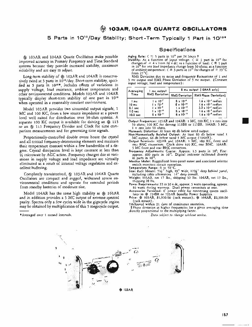
@ 103AR, 104AR QUARTZ OSCILLATORS
5 Parts in 10l0/Day Stability; Short-Term Typically 1 Part in lolo*
Averag ing I mc outpu t Time RMS Deviation
@ 103AR and 104AR Quartz Oscillators make possible improved accuracy in Primary Frequency and Time Standard systems because they provide increased stability, maximum reliability and are easy to adjust.
Long-term stability of @ 103AR and 104AR is conserva- tively rated at 5 parts in 10IO/day. Short-term stability, speci- fied as 5 parts in 1010*, includes effects of variations in supply voltage, load resistance, ambient temperature and other environmental conditions. Models 103AR and 104AR typically display short-term stability of one part in 10'O when operated in a reasonably constant environment.
Model 103AR provides two sinusoidal output signals, 1 MC and 100 KC, from a low source impedance at a power level well suited for distribution over 50-ohm systems. A separate 100 KC output is available for driving an @ 113 or an @ 115 Frequency Divider and Clock for time com- parison measurements and for generating time signals.
Proportionally-controlled double ovens house the crystal and all critical frequency-determining elements and maintain their temperature constant within a few hundredths of a de- gree. Crystal dissipation level is kept constant at less than '/4 microwatt by AGC action. Frequency changes due to vari- ations in supply voltage and load impedance are virtually eliminated as a result of internal voltage regulation and ex- cellent buffering.
Completely transistorized, @ 103AR and 104AR Quartz Oscillators are compact and rugged, withstand severe en- vironmental conditions and operate for extended periods from standby batteries of moderate size.
Model 104AR has the same high stability as @ 103AR and in addition provides a 5 MC output of extreme spectral purity. Spectra only a few cycles wide in the gigacycle region may be obtained by multiplication of this 5 megacycle output.
*Averaged over 1 second intervals. -
5 mc outpu t (104AR only)
RMS Deviat ion 1 RMS Phase Deviat ion$
Specifications A g i n g Rate: < -C 5 parts in 10" per 24 hours t Stabi l i ty : As a function of input voltage: < i- 1 part in 10" for
changes of i 4 v from 26 v dc; as a function of load: < * 1 part in 10'' for any load impedance change from 50 ohms; as a function of ambient temperature: < * 3 parts in 10'' for changes of * 25°C from 25°C. RMS Deviation due to noise and frequency fluctuations of 1 and
5 rnc output and RMS Phase Deviation of 5 mc output. (Constant input voltage, load and temperature) :
I ms 10 ms 0.1 sec 1.0 sec 10.0 sec
I x IO-' 5 x IO-s 1.6 x IO-' radian I x Io-8 5 x IO-'O 1.6 x IO-'radian I IO-^ I x IO-'O 3.2 x IO-' radian I x IO-'O I .6 x IO-' radian 5 x IO-" I .6 x IO-' radian
5 x IO-" 5 x lo-11
O u t p u t Frequences: 103AR and 104AR: 1 MC, 100 KC, 1 v rms into 50 ohms; 100 KC for driving 113BR or 115BR. 104AR: 5 MC, 1 v rms into 50 ohms.
Harmonic Distort ion: At least 40 db below rated output. Non-Harmon ica l l y Related O u t p u t : At least 80 db below rated 1
MC output, 66 db below rated 5 MC output (104AR). O u t p u t Terminals: 103AR and 104AR: 1 MC, 100 KC, front and
rear BNC connectors. Clock drive 100 KC, rear BNC. 104AR: 5 MC front and rear BNC connectors.
Frequency Adjustments: Coarse: Approx. 1.5 parts in 10'; Fine: approx. 600 parts in 10''. Digital indicator calibrated directly in parts in 10".
M o n i t o r Meter : Ruggedized front-panel meter and associated selector switch monitors circuit operation.
Temperature Range: 0 to 50°C. Size: Rack Mount: 5 % " high, 19" wide, 121/g'' deep behind panel,
including cable allowances. 14" deep overall. W e i g h t : 103AR, net 17 Ibs., shipping 32 Ibs. 104AR, net 17 lbs.,
shipping 28 Ibs. Power Requirements: 22 to 30 v dc, approx. 5 watts operating, approx.
10 watts during warmup. Dual power connectors at rear. Accessories Furnished: 6' power cable for connecting quartz oscil-
lator to Q 724BR or 725AR Standby Power Supplies. Price: @ 103AR, $1,900.00 (rack mount); @ 104AR, $2,300.00
(rack mount). ?Achieved within 2 1 davs of continuous oaeration.
Phase deviation at higher frequencies for a given averaging time directly proportional to the multiplying factor.
Data subject to chaiige without notice.
\ c1
I57
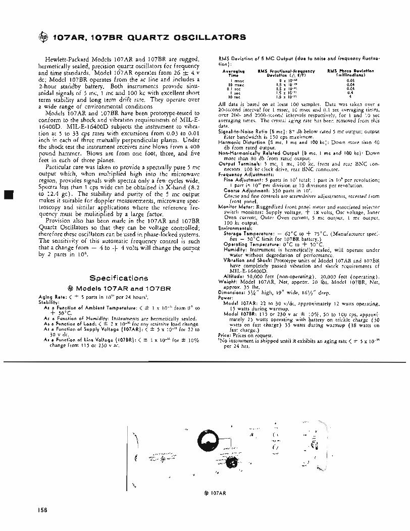
@ 107AR. 1076R QUARTZ OSCILLATORS
Hewlett-Packard Models 107AR and 107BR are rugged, hermetically sealed, precision quartz oscillators for frequency and time standards. Model 107AR operates from 26 k 4 v dc; Model 107BR operates from the ac line and includes a 2-hour standby battery. Both instruments provide sinu- soidal signals of 5 mc, 1 mc and 100 kc with excellent short term stability and 180ng term drift rate. They operate over a wide range of environmental conditions.
Models 107AR and 107BR have been prototype-tested to conform to the shock and vibration requirements of MIL-E- 16400D. MIL-E-16400D subjects the instrument to vibra- tion at 5 to 33 cps rates with excursions from 0.03 to 0.01 inch in each of three mutually perpendicular planes. Under the shock test the instrument receives nine blows from a 400 pound hammer. Blows are from one foot, three, and five feet in each of three planes.
Particular care was taken to provide a spectrally pure 5 mc output which, when multiplied high into the microwave region, provides signals with spectra only a few cycles wide. Spectra less than 1 cps wide can be obtained in X-band (8.2 to 12.4 gc). The stability and purity of the 5 mc output makes it suitable for doppler measurements, microwave spec- troscopy and similar applications where the reference fre- quency must be mulitiplied by a large factor,
Provision also has been made in the 107AR and 107BR Quartz Oscillators so that they can be voltage controlled; therefore these oscillators can be used in phase-locked systems. The sensitivity of this automatic frequency control is such that a change from - 4 to + 4 volts will change the output by 2 parts in 108.
Specifications @ Models 107AR and 107BR
A g i n g Rate: < * 5 parts in 10'" per 24 hours'. Stabil i ty:
As a Function of A m b i e n t Temperature: < * 1 x lo-'" from 0' to
As a Function of Humid i t y : Instruments are hermetically sealed. A s a Function of Load: < * 2 x IO-'' for any resistive load change. As a Function of Supply Vol tage (107AR) : < 2 5 x 10-l' for 2 2 to
As a Function of Line Vol tage ( I07BR): < 2 1 x lo-" for 2 10%
f 50°C.
30 v dc.
change from 115 or 230 v ac.
RMS Deviat ion of 5 MC O u t p u t ( d u e t o noise and f requency f luctua- t ion ) :
Averaging RMS Fractional.Frequency RMS Phase Deviation Time Deviation I f /f 1 lmi l l i radianr 1 I msec 8 x IC-'" 0.03
I O mrec 1.5 x I O - ' O 0.04 0.1 sec 1.5 x IO-" 0.04
I sec 1.5 x IO-" 0.4 10 rec 1.5 x IO-" 4
All data is based on at least 100 samples. Ddta was taken over a 20-second interval for 1 msec, 10 msec and 0.1 sec averaging times, over 200- and 2000-second intervals respectively, for 1 and 10 sec averaging times. The crystal aging rate has been removed from this data. Signal-to-Noise Rat io (5 m c ) : 87 db below rated 5 mc output; output
Harmon ic Dis tor t ion (5 mc, I mc and 100 k c ) : Down more than 40 filter bandwidth is 150 rps maximum.
db from rated output.
more than 80 db from rated output.
nectors. 100 kc clock drive, rear BNC connector.
Fine Adjustment : 5 parts in loR total; 1 part in 10" per revolution;
Coarse Adjustment : 350 parts in 10". Coarse and fine controls are screwdriver adjustments, recessed from
M o n i t o r Me te r : Ruggedized front panel meter and associated selector switch monitors: Supply voltage. -k 18 volts, Osc voltage, Inner Oven current, Outer Oven current, 5 mc output, 1 mc output, 100 kc output.
Storage Temperature: - 62°C to f 75°C. (Manufacturer speci- fies - 50°C limit for 107BR battery.)
O p e r a t i n g Temperature: 0°C to f 50°C. Humid i t y : Instrument is hermetically sealed, will operate under
water without degredation of performance. Vibrat ion and Shock: Prototype units of Model 107AR and 107BR
have completely passed vibration and shock requirements of MIL-E-16400D.
Al t i t ude : 50,000 feet (non-operating). 20,000 feet (operating). W e i g h t : Model 107AR, Net, approx. 20 Ibs. Model 107BR. Net.
approx. 35 Ibs. Dimensions: 5 % " high, 19" wide, 16%'' deep. Power:
M o d e l 107AR: 22 to 30 v/dc, approximately 1 2 watts operating, 15 watts during warmup.
M o d e l 107BR: 115 or 230 v ac * lo%, 50 to 100 cps, approxi- mately 2 5 watts operating with battery on trickle charge (30 watts on fast charge) 33 watts during warmup (38 watts on fast charge.)
Price: Prices on request. 'No instrument is shipped until it exhibits an aging rate < * 5 x io-'"
Non-Harmonica l ly Related O u t p u t [5 mc, I rnc and 100 k c ) : Down
O u t p u t Terminals: 5 mc, 1 mc, 100 kc, front and rear BNC ton-
Frequency Adjustments:
1 part in 10"' per division at 10 divisions per revolution.
front panel.
Environmental:
per 24 hrs.
c
@ 107AR
I58
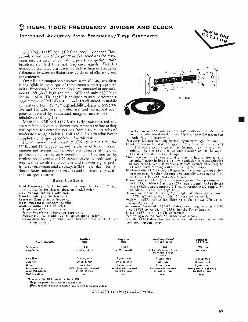
@ 115BR, 115CR FREQUENCY DIVIDER AND CLOCK
Increased Accuracy from Frequency/Time Standards
The Model 11 5BR or 11 jCR Frequency Divider and Clock permits adjustment of frequency or time standards for maxi- mum absolute accuracy by making precise comparisons with broadcast standard time and frequency signals.’ Detailed records of oscillator drift rates, as well as time or frequency differences between oscillators can be obtained efficiently and conveniently.
~ v e r a l l time comparison accuracy is t 10 p e c , and jitter is negligible in the output of these compact battery-operated units. Frequency divider and clock are contained in one rack- mount unit 3y2” high for the 115CR and only 5%” high for the 115BR. The 115BR is designed to meet performance requirements of MIL-E-16400? and is well suited to mobile applications. For maximum dependability, design is conserva- tive and fail-safe. Premium electrical and mechanical coni- ponents, derated by substantial margins, insure maximum reliability and long life,
Models 1 I j B R and 1 1 5 C R are fully transistorized and operate from 26 volts dc. Power requirements are low SO they will operate for extended periods from standby batteries of moderate size. hp Models 724BR and 7 2 5 A R Standby Power Supplies are designed specifically for this task.
For con\,enience and maximum efficiency in operation, the 1 1 5 B R and 1 l j C R provide in-line display of time in hours, minutes and seconds, with an additional drum revolving once per second to permit time resolution of 0 . 1 second or, by stroboscope or camera to 0.01 second, Use of non-self starting regenerative dividers avoids noise and spurious signal prob- lems, for maximum total accuracy. BCD time-of-day informa- tion in hours, minutes and seconds and milliseconds is avail- able on special order.
Specifications
I n p u t Frequency: 100 kc for solar time, input bandwidth -i. 300
I n p u t Vol tage: 0.5 to 5 volts rnis. Pulse Outputs: (see attached chart). Accuracy : Same as input frequency. I n p u t Impedance: 300 ohms nominal. Auxi l iary O u t p u t : ( I 15 BR only) :
Ampl i tude: 0 . 2 5 v rms minimum. Source Impedance: 1200 ohms (approx.). Frequency: 100, 10 and 1 kc (60 cps on special order), Connectors: BKC (100 and 1 kc at front and rear panels; 10 kc
cps. 100.3 kc for sidereal time. on special order.
a t front panel).
Characteristic
Pulse rate Amplitude
Rise Time Duration Jitter Recommended Load Impedance BNC Location
Positive Tick
I PPI + 10 v, mintt
2 psec, max 20 psec, min I psec, rnax
4700 ohms min shunted by 200 pf max
rear
Time Reference: Continuously adjustable, calibrated in 10 ps in- crements. Numerical display from 999.9 ms to 000.0 ms, in-line vernier in 10 ps increments.
Frequency Divider: Manually started, regenerative type. fail-safe. Effect of Transients: Will not gain or lose time because of: ( 1 )
5 300 volt step function on 100 kc input; ( 2 ) 0 to 50 volt pulses, 0 to 5 0 0 pps, 1 to 10 psec duration on 100 kc input; ( 3 )
Clock Mechanism: 24-hour digital display in hours, minutes, and seconds. Vernier in-line scale allows resolution (stroboscopicallv) to 0.01 second. Clock is manually started; seconds wheel may be stt with clock running without affecting tick output.
M o n i t o r M e t e r ( I15 BR o n l y ) : Ruggedized meter and selector switch on front panel for checking supply voltage, divider operation (100 kc, 1 0 kc, 1 kc) and total clock current.
Power Required: 2 2 to 30 v dc, positive ground for operating with he 103AR or 104AR (see page 157) (neg. ground may be selected hv a switch), aDproximately 2 . 5 watts, recommended supply, hp ’24BR or 725AR (see page 16?,).
Dimensions: 115BR: 19’’ wide, 5 % high. 14” deep behind panel. 115CR: 19” wide, 31.5” high, 12’’ deep behind panel.
W e i g h t : 115BR: Piet 3 5 Ibs. Shipping 51 Ibs. 115CR: Net 15 Ibs.
4 volt step in 26 v dc input.
Shipping 25 Ibs.
or 115CR to 724BR or 725AR Standbv Power Supply . Accessories Furnished: 1 13A-lhE Cable, 6 feet long, connects l l5BR
Price: 115RR. $2750; 115CR. on request. ‘See hp Application Note 52 , available on request. ‘See the l15BR data sheet for mote detailed information on mili- tary environmental testc.
Ne at ive #Ck
2 psec, max 20 psec, min i psec, max
IM ohm min shunted by 100 p i max
front
Auxil iar Pulse* ( 1 1 5 E 4 only)
I PPS + 4 v min open circuit +2 v min into 50
ohms i Irsec, max
200 psec I psec max
50 ohms min shunfed by 5000 pf max
rear
Positive? 1-KC Pips
1000 pps +4 v min
2 gsec, max 20 psec, min I psec, max
IO00 ohms min shunted by 1000 pf max
rear
*Standard for I 1 5 B , available for i 15CR. $Negative pulses available on special order. ??For any load impedance higher than minimum recommended.
Datu subject to change without notice.
I59
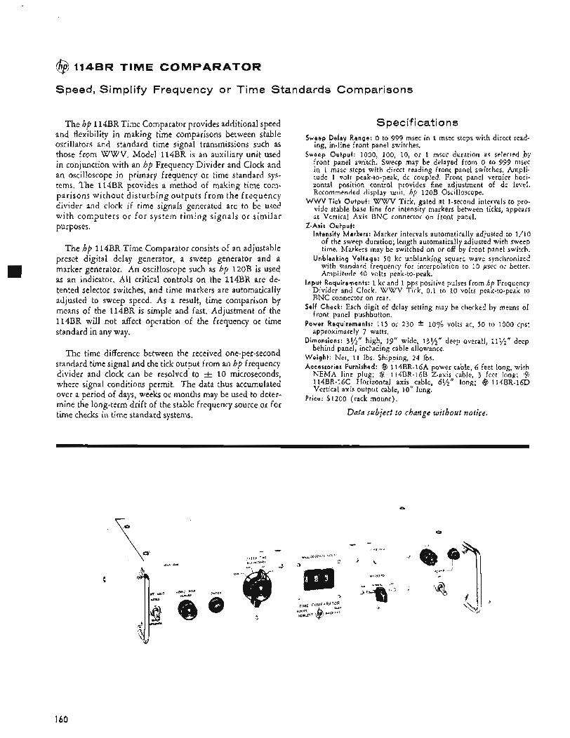
TlME COMPARATOR
Speed, Simplify Frequency or Time Standards Comparisons
The hp 114BR Time Comparator provides additional speed and flexibility in making time comparisons between stable oscillators and standard time signal transmissions such as those from WWV. Model 114BR is an auxiliary unit used in conjunction with an hp Frequency Divider and Clock and an oscilloscope in primary frequency or time standard sys- tems, The 114BR provides a method of making time com- parisons without disturbing outputs f rom the frequency divider and clock if time signals generated are to be used with computers or for system timing signals or similar purposes.
The hp 114BR Time Comparator consists of an adjustable preset digital delay generator, a sweep generator and a marker generator. An oscilloscope such as hp 120B is used as an indicator. All critical controls on the 114BR are de- tented selector switches, and time markers are automatically adjusted to sweep speed. As a result, time comparison by means of the 114BR is simple and fast. Adjustment of the 114BR will not affect operation of the frequency or time standard in any way.
The time difference between the received one-per-second standard time signal and the tick output from an hp frequency divider and clock can be resolved to A 10 microseconds, where signal conditions permit. The data thus accumulated over a period of days, weeks or months may be used to deter- mine the long-term drift of the stable frequency source or for time checks in time standard systems.
Specifications Sweep Delay Range: 0 to 999 msec in 1 msec steps with direct read-
ing, in-line front panel switches. Sweep Output: 1000, 100, 10, or 1 msec duration as selected .by
front panel switch. Sweep may be delayed from 0 to 999 msec in 1 msec steps with direct reading front panel switches. Ampli- tude 1 volt peak-to-peak, dc coupled. Front panel vernier hori- zontal position control provides fine adjustment of dc level. Recommended display unit, hp 120B Oscilloscope.
WWV Tick Output: WWV Tick, gated at 1-second intervals to pro- vide stable base line for intensity markers between ticks, appears at Vertical Axis BNC connector on front panel.
Intensity Markers: Marker intervals automatically adjusted to 1/10 of the sweep duration; length automatically adjusted with sweep time. Markers may be switched on or off by front panel switch.
Unblanking Voltage: 50 kc unblanking square wave synchronized with standard frequency for interpolation to 10 psec or better. Amplitude 40 volts peak-to-peak.
Input Requirements: 1 kc and 1 pps positive pulses from hp Frequency Divider and Clock. W W V Tick, 0.1 to 10 volts peak-to-peak to BNC connector on rear.
Self Check: Each digit of delay setting may be checked by means of front panel pushbutton.
Power Requirements: 115 or 230 i: 10% volts ac, 50 to 1000 cps; approximately 7 watts.
Dimensions: 3%” high, 19” wide, 13%” deep overall, 11?,$‘‘ deep behind panel, including cable allowance.
Weight : Net, 11 Ibs. Shipping, 24 Ibs. Accessories Furnished: @ 114BR-1GA power cable, G feet long, with
NEMA line plug; (6 114BR-16B Z-axis cable, 3 feet long; @ I14BR-lGC Horizontal axis cable, 6%“ long; @ 114BR-1GD Vertical axis output cable, 10” long.
Z-Axis Output:
Price: $1200 (rack mount).
Data subject to change without notice.
Q
I60
@, 7246R, 7 2 5 A R STANDBY POWER SUPPLIES
Avoid AC Problems in Frequency, Time Standard Systems
Specifications
Output Voltage: 24 i 1 volts dc at rated current.
Rated Current ( tota l external load) : 300 ma, nomina1.t
Over-Current Protection: Current limiter provides short-circuit pro- tection, eliminates need for load fuses.
Alarm Indicators: Panel lamps indicate ( 1 ) OPEN AC LINE FUSES, or ( 2 ) AC OFF, indicating ac is not reaching power transformer and load is being supplied by standby battery.
Remote Alarm Provisions: D P D T relay contacts (form C ) provided at rear terminals for operating remote alarm from separate power system. Contacts rated at 3 amps (resistive) at 115 v ac or 28 v dc.
Panel Meters: Voltmeter and ammeter indicate battery voltage and battery charge/discharge current,
Power Requirements: 1 I5 or 230
Output Connectors: MS type female connectors at rear mate with @ 103AR, l04AR, 113BR, l l5BR power cables.
Battery (supplied): @ 724BR, Vented Nickel-Cadmium, 16 am- pere hour: @ 725AR, Sealed Nickel-Cadmium, 2 ampere hour.
Additional (external ) Battery Provision: MS3102R14S-ZS female con- nector, with cap, at rear. Mating connector supplied.
W e i g h t : 8 724BR, net 75 Ibs., shipping 101 Ibs., including battery. ’@ 725AR, net 20 Ibs., shipping 36 Ibs., including battery.
Dimensions: @ 724BR, 19” wide, 7“ high, 14” deep behind panel, including allowance for cables. @ 725AR, 19” wide, 3%“ high, 12%” deep behind panel, including allowance for cables.
10% v ac, 50 to 1,000 cps.
Accessories Furnished: Power cable, 6 feet long.
Price: @ 724BR, including battery, $950.00 (rack mount), @ 725AR, including battery, $645.00 (rack mount).
Hewlett-Packard Standby Power Supplies, Models 724BR and 725AR, improve performance and reliability of frequen- cy and time standard systems by assuring continued operation in the event of ac line power failure. Also, with these stand- by supplies you can use a standard at various locations, since the system can be kept in operation for extended periods dur- ing transport.
Models 724BR and 725AR are completely automatic, solid-state supplies specially designed to power an @ 11 3BR or @ 115BR Frequency Divider and Clock and an @ 103AR or 104AR Quartz Oscillator‘. These supplies are designed to operate with standby batteries. The standby battery is kept charged and instantly assumes the load, without switching, in case of ac failure. When line power is restored the supply reassumes the load and automatically recharges the battery.
After a week of operation @ 724BR provides a minimum of 48 hours standby operation at an average temperature of 25OC for an @ Quartz Oscillator and a 113BR or 115BR Frequency Divider and Clock. Under similar conditions, Model 725AR provides at least six-hour standby operation. A switch at the rear of the 724BR increases standby period at least 50S/c.
Output is voltage-regulated and current-limited, eliminat- ing the need for output fuses. Operating aids include alarm lamps, contacts for remote alarms and connectors for addi- tional standby batteries.
Both supplies will withstand severe environmental condi- tions*. Model 724BR is equipped with heavy-duty chassis tracks.
tSuitable for operating @ 113BR, 115BR or l l 5CR and 103AR or 104AR at any temperature from 0 to 30°C.
Data subject i o change without notice.
~
‘$9 724AR, required for operation with @ 113AR Frequency Di- vider and Clock, available on special order.
‘For information regarding the ability of the 724BR and 72SAR to meet environmental specifications write to Hewlett-Packard CO., 1501 Page Mill Road, Palo Alto, Calif.
@ 724813 @ 725AR
MICROWAVE INSTRUMENTATION
e Signal Generators
e Modulators
e Sweep Oscillators
Power Measurement Instruments
e Impedance Measurement Instruments
Noise Figure Measurement Instruments
e Waveguide Test Equipment
Coaxial Instrumentation
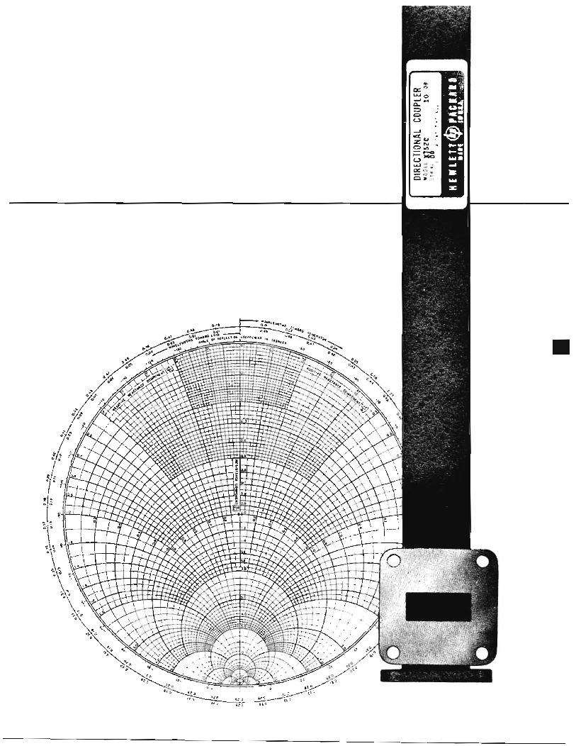
Hewlett-Packard microwave test equipment includes a wide range of high-quality, low-cost instruments for measurement of microwave parameters, Basic measurements easily made with Wewlett-Packard equipment include power, im edance, noise figure, attenua-
Coaxial and waveguide instrumenta- tion provides broadband frequency coverage to 40 gc. Each instrument has been designed to provide simplest pos- sible operation in a broad range of applications. Each unit is thoroughly tested before leaving the factory, and it is warranted to conform with, or exceed, published specifications.
tion and P requency.
Letter Designations Model numbers of hp waveguide
components are normally preceded by a prefix letter, which designates the wave- guide size and frequency band of the instrument. Standard waveguide speci- fications for these bands are shown in the chart below:
indicates specific attenuation or COLI- pling, as follows:
A 3db D 20db B 6 d b E 30db C lOdb F 40db
Thus, the 20 db coupling version of hp 750 Cross-Guide Coupler will be designated as hp 750D. The model of the 750 built for 1” x ?/Zft waveguide will, of course, have the prefix “X,” so that the complete model number of a 750 Series Coupler with 20 db coupling for use with 1” x $$!’ waveguide is hp X750D Cross-Guide Coupler,
Flanges All Hewlett-Packard waveguide in-
struments have precision cover flanges which are carefully lapped to assure a f la t (or slightly convex) surface. Lapped flanges assure that reflections and leakage will be negligible when- ever two Hewlett-Packard waveguide items are joined together.
with circular flanges which may still be in use. Both the cover-to-choke flange adapters and the rectangular to circular flange adapters have lapped flanges to assure negligible reflection when prop- erly installed.
How to Locate Microwave Equipment
Hewlett-Packard equipment for op- eration in each frequency band is listed in convenient tables on pages 168 through 18 1. The tables include the most pertinent specifications for each item and, in some cases, reference to other catalog pages where more com- plete specifications are provided.
Photographs of typical measuring setups accompany the equipment tables. Larger photos of most individual items are included on subsequent pages where instruments are described individually with additional specifications.
Design Objectives Hewlett-Packard broadband wave-
guide instruments are the result of a
DESIGNATIONS DIMENSIONS TEm OPERATING RANGE FREESPACE THEORETICAL THEORETICAL PK WAVELENGTH ATTENUATION POWER RATING
( 9 c l (em) (gc ) (cml Low to High Freq. Low to High Freq. JAN ID (inches) Frequency Wavelength Cutoff Freq. db/100 ft. megawatts hp EIA
S W R 284 RG-48/U 2.840 x 1.340 2.60 - 3.95 19.18 - 8.92 2.078 I I .53 - 7.59 I .478 - I .008 2.2 - 3.2 2.79 - 1.93 0.94 - 1.32
J WR 137 RG-50/U 1.372 x 0.622 5.30 - 8.20 9.68 - 4.29 4.30 I 5.66 - 3.66 4.61 - 3.08 0.56 - 0.71 H W R I12 RG-5I/U 1.122 x 0.497 7.05 - 10.0 6.39 - 3.52 5.259 4.25 - 3.00 5.51 - 4-31 0.35 - 0.46 X W R 90 RG-52/U 0.900 x 0.400 8.20 - 12.4 6.09 - 2.85 6.557 3.66 - 2.42 8.64 - 6.02 0.20 - 0.29
0.17 - 0.23 M WR 75 - 0.750 x 0.375 10.0 - 15.0 4.86 - 2.35 7.868 3.00 - 2.00 10.07 - 7.03 P WR 62 RG-9I/U 0.622 x 0.31 I 12.4 - 18.0 3.75 - 1.96 9.487 2.42 - 1.67 12.76- 11.15 0.12 - 0.16
0.08 - 0. I07 N W R 5 1 - 0.510 x 0.255 15.0 22.0 3.1 I - 1.60 11.571 2.00 - 1.36 17.3 - 12.6 K W R 42 RG-66/U 0.420 x 0.170 18.0 - 26.5 2.66 - 1.33 14.048 1-67 - 1.13 13.3 - 9.5 0.043 - 0.058 R W R 28 RG-96/U 0.280 x 0.140 26.5 - 40.0 I .87 - 0.88 21.075 I. I3 - 0.749 21.9 - 15.0 0.022 - 0.03 I
G W R 187 RG-49/U 1.872 x 0.872 3.95 - 5.85 12.59 - 6.08 3.152 7.59 - 5.12
Many hp instruments also have suffix letters in the complete model number. Normally an “A” suffix identifies the original instrument, while “B,” “C” and other suffixes indicate a revised, modified or special version of the basic model. However, in the case of certain hp microwave elements, the suffix letter
Model 290A Cover-to-Choke Flange Adapters may be used for connecting Hewlett-Packard instruments and a choke flange system under actual oper- ating conditions. Hewlett-Packard also manufactures adapters for connecting K- and R-band equipment with modern rectangular flanges to older equipment
time- and performance- roven design
are : 1. Each instrument is of simplest
construction consistent with its basic function and covers the en- tire frequency range of its wave- guide size.
approach. Fundamental B esign concepts
I64
2.
3.
An integrated set of instruments is available for each commonly used waveguide frequency from S- to R-band. Simple mechanical design, incor- porating novel electrical circuitry, insures highest accuracy, stability and quality and yet makes pos- sible quantity production at low cost.
Calibration and Certification The Hewlett-Packard Standards Lab-
oratory devotes full time to advancing the art of standards measurements. The techniques used are painstaking and tedious, but the results make these tech- niques completely worthwhile. Continu- ing correlation of the Hewlett-Packard house standards with the available certi- fication services of the National Bureau of Standards assures that high accuracy is built into all hp microwave equip- ment. Traceability to the national stand- ards, wherever the certification service is available, can be supplied for the appli- cable hp microwave instruments.
One of the services available from the Hewlett-Packard standards labora- tory is calibration of hp waveguide equipment at specific frequencies to higher accuracy than specified on a broadband basis in this catalog. Infor- mation on availability of this service and on the charges for it is available through your local hp field engineer.
Microwave Measuring Techniques
There are two basic types of micro- wave measuring techniques-( 1) fixed frequency and ( 2 ) swept frequency.
One typical example of a fixed fre- quency system is a slotted section which is used to make swr measurements, one frequency at a time. Fixed frequency measuring systems of this nature are perfectly satisfactory if one is operating at a single frequency or within a very narrow band. T o meet requirements for fixed frequency measurements, Hewlett- Packard builds a com lete line of both
and tuners. coaxial and wavegui B e slotted sections
Fixed frequency techniques a te widely used in “standards” laboratories -ranging from those of the National Bureau of Standards to smaller installa- tions maintained by individual con- tractors. Most standards measurements are made at discrete frequencies.
Swept frequency techniques are used to obtain measurements quickly and easily for a range of frequencies. In this type of system, typified by the swept fre- quency reflectometer, a frequency source is swept through the band over which measurements are desired. Signals prop- agating to the unknown are separated by directional couplers into incident and reflected components. These can then be equated to swr, reflection coefficient or other similar terms.
Although, as explained below, swept frequency techniques have been refined to a high degree of accuracy, fixed fre- quency methods continue to offer the highest precision attainable for indi- vidual measurements. In a fixed fre- quency system the small inherent mis- match ambiguities, which must be tol- erated in a broadband, swept frequency system, may be individually tuned out.
Attenuation Measurement Attenuation measurements are made
by a number of different methods such as power ratio or either rf or IF sub- stitution.
In the power ratio method the signal source is connected to a detector mount through a length of lossless transmis- sion system-in whose place the un- known attenuator may be substituted. A reading is obtained on the output indi- cator with a section of lossless line in the circuit. The lossless line is then re- placed by the attenuator being meas- ured. The power reduction at the output indicator is a measure of the attenua- tion. This measurement requires, first, that the law of the detector is known over the complete frequency range of the measurement, and, second, that re- flection effects in the system are essen- tially the same both with and without the attenuator.
T h e type of detecting equipment used will depend on the range of the attenuation measurement. A range of attenuation measurement up to 20 or 30 db can be achieved with a detector mount employing a barretter and an hp 415 series standing wave indicator (high sensitivity, tuned voltmeter), In this case, the signal source must be modulated, and the rf power level must be kept below 200 microwatts for square law detector characteristics. The 415D, with its 2.5 db steps and 0.02 db tracking accuracy, is especially useful for these measurements,
To eliminate effects of reflections be- tween generator and attenuator, and at- tenuator and load, it is desirable to use pads. Pads should be well matched to the transmission system,
The homodyne method permits meas- uring attenuation as high as 100 db. In this system a signal generator furnishes local oscillator ower to a mixer and at the same time g rives a TWT amplifier which is modulated to produce an off- set frequency. The offset frequency is fed through the attenuator to be meas- ured and combined with the local os- cillator frequency in the mixer, The difference frequency is amplified in a tuned amplifier and applied to an in- dicating meter, Because the TWT am- plifier is serrodyne modulated, the dif- ference frequency from the mixer is constant and a narrow-band tuned am- plifier such as the hp 415 may be used even though the signal generator fre- quency drifts.
RF substitution depends on substitut- ing an attenuator of known charac- teristic for the unknown, For instance, a signal generator attenuator may be used. When using this method the out- put of the signal generator is fed to the attenuator being measured and then into the detector. The attenuator being meas- ured is removed, and a reading is ob- tained upon the detector. The setting of the signal generator attenuator is noted. The attenuator is then inserted, and the signal generator output is ad- justed to obtain the same reading as before. The difference between the sig-
I65
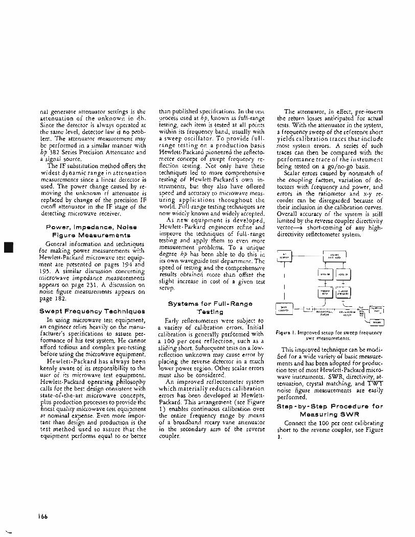
nal generator attenuator settings is the attenuation of the unknown in db. Since the detector is always operated at the same level, detector law is no prob- lem. The attenuator measurement may be performed in a similar manner with hp 382 Series Precision Attenuator and a signal source.
The IF substitution method offers the widest dynamic range in attenuation measurements since a linear detector is used. The power change caused by re- moving the unknown rf attenuator is replaced by change of the precision IF cutoff attenuator in the IF stage of the detecting microwave receiver.
Power, Impedance, Noise Figure Measurements
General information and techniques for making power measurements with Hewlett-Packard microwave test equip- ment are presented on pages 194 and 195. A similar discussion concerning microwave impedance measurements appears on page 231. A discussion on noise figure measurements appears on page 182.
Swept Frequency Techniques In using microwave test equipment,
an engineer relies heavily on the manu- facturer’s s ecifications to assure per-
afford tedious and complex pre-testing before using the microwave equipment,
Hewlett-Packard has always been keenly aware of its responsibility to the user of its microwave test equipment. Hewlett-Packard operating philosophy calls for the best design consistent with state-of-the-art microwave concepts, plus production processes to provide the finest quality microwave test equipment at nominal expense. Even more impor- tant than design and production is the test method used to assure that the equipment performs equal to or better
4
formance o P his test system. He cannot
than published s ecifications. In the test
testing, each item is tested at all points within its frequency band, usually with a sweep oscillator. T o provide full- range testing on a production basis Hewlett-Packard pioneered the reflecto- meter concept of swept frequency re- flection testing. Not only have these techniques led to more comprehensive testing of Hewlett-Packard’s own in- struments, but they also have offered speed and accuracy to microwave meas- uring applications throughout the world. Full-range testing techniques are now widely known and widely accepted.
As new equipment is developed, Hewlett - Packard engineers refine and improve the techniques of full-range testing and apply them to even more measurement problems. To a unique degree hp has been able to do this in its own waveguide test department. The speed of testing and the comprehensive results obtained more than offset the slight increase in cost of a given test setup.
process used at K p , known as full-range
Systems for Full-Range Testing
Early reflectometers were subject to a variety of calibration errors. Initial calibration is generally performed with a 100 per cent reflection, such as a sliding short. Subsequent tests on a low- reflection unknown may cause error by placing the reverse detector in a much lower power region, Other scalar errors must also be considered.
An improved reflectometer system which materially reduces calibration errors has been developed at Hewlett- Packard. This arrangement (see Figure 1 ) enables continuous calibration over the entire fre uency range by means
in the secondary arm of the reverse coupler.
of a broadban 1 rotary vane attenuator
The attenuator, in effect, pre-inserts the return losses anticipated for actual tests. With the attenuator in the system, a frequency sweep of the reference short yields calibration traces that include most system errors. A series of such traces can then be compared with the performance trace of the instrument being tested on a go/no-go basis.
Scalar errors caused by nonmatch of the coupling factors, variation of de- tectors with frequency and power, and errors in the ratiometer and x-y re- corder can be disregarded because of their inclusion in the calibration curves. Overall accuracy of the system is still limited by the reverse coupler directivity vector-a short-coming of any high- directivity reflectometer system.
ILJ q
I $3 Figure I . Improved setup for sweep frequency
swr measurements.
This improved technique can be modi- fied for a wide variety of basic measure- ments and has been adopted for produc- tion test of most Hewlett-Packard micro- wave instruments. SWR, directivity, at- tenuation, crystal matching, and TWT noise figure measurements are easily performed. Step-by-step Procedure f o r
Measuring SWR Connect the 100 per cent calibrating
short to the reverse coupler, see Figure 1.
I66
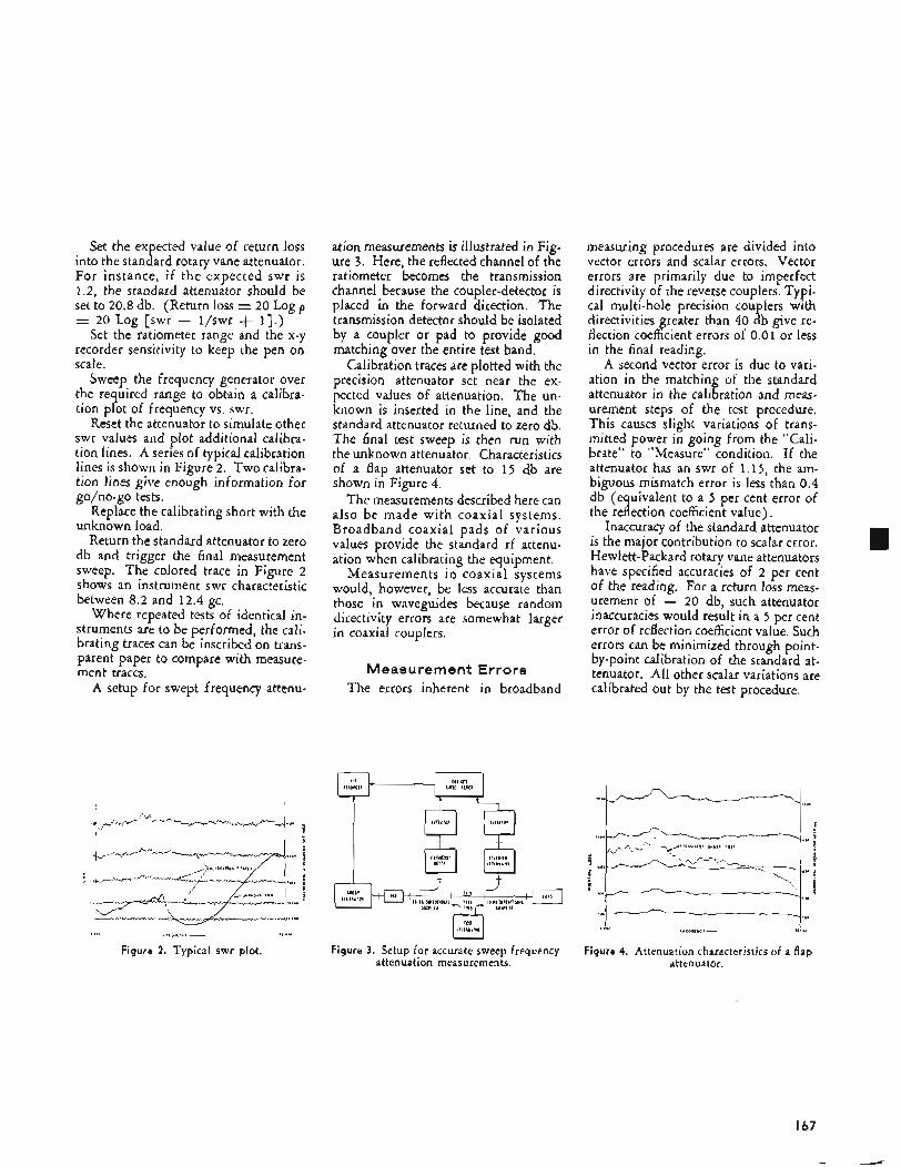
Set the expected value of return loss into the standard rotary vane attenuator. For instance, if the expected swr is 1.2, the standard attenuator should be set to 20.8 db. (Return loss = 20 Log p = 20 Log {swr - l/swr + I ) . )
Set the ratiometer range and the x-y recorder sensitivity to keep the pen on scale.
Sweep the frequency generator over the required range to obtain a calibra- tion plot of frequency vs. swr.
Reset the attenuator to simulate other swr values and plot additional calibra- tion lines. A series of typical calibration lines is shown in Figure 2. Two calibra- tion lines give enough information for go/no-go tests.
Replace the calibrating short with the unknown load.
Return the standard attenuator to zero db and trigger the final measurement sweep. The colored trace in Figure 2 shows an instrument swr characteristic between 8.2 and 12.4 gc.
Where repeated tests of identical in- struments are to be performed, the cali- brating traces can be inscribed on trans- parent paper to compare with measure- ment traces.
A setup for swept frequency attenu-
ation measurements is illustrated in Fig- ure 3. Here, the reflected channel of the ratiometer becomes the transmission channel because the coupler-detector is placed in the forward direction. The transmission detector should be isolated by a coupler or pad to provide good matching over the entire test band.
Calibration traces are plotted with the precision attenuator set near the ex- pected values of attenuation. The un- known is inserted in the line, and the standard attenuator returned to zero db. The final test sweep is then run with the unknown attenuator. Characteristics of a flap attenuator set to 15 db are shown in Figure 4,
The measurements described here can also be made with coaxial systems. Broadband coaxial pads of various values provide the standard rf attenu- ation when calibrating the equipment.
Measurements in coaxial systems would, however, be less accurate than those in waveguides because random directivity errors are somewhat larger in coaxial couplers.
Measurement Errors The errors inherent in broadband
measuring procedures are divided into vector errors and scalar errors. Vector errors are primarily due to imperfect directivity of the reverse couplers. Typi- cal multi-hole precision couplers with directivities greater than 40 db give re- flection coefficient errors of 0.01 or less in the final reading.
A second vector error is due to vari- ation in the matching of the standard attenuator in the calibration and meas- urement steps of the test procedure. This causes slight variations of trans- mitted power in going from the "Cali- brate" to "Measure" condition. If the attenuator has an swr of 1.15, the am- biguous mismatch error is less than 0.4 db (e uivalent to a 5 per cent error of
Inaccuracy of the standard attenuator is the major contribution to scalar error. Hewlett-Packard rotary vane attenuators have specified accuracies of 2 per cent of the reading. For a return loss meas- urement of - 20 db, such attenuator inaccuracies would result in a 5 per cent error of reflection coefficient value, Such errors can be minimized through point- by-point calibration of the standard at- tenuator. All other scalar variatiom are calibrated out by the test procedure.
the re 1 ection coefficient value),
167
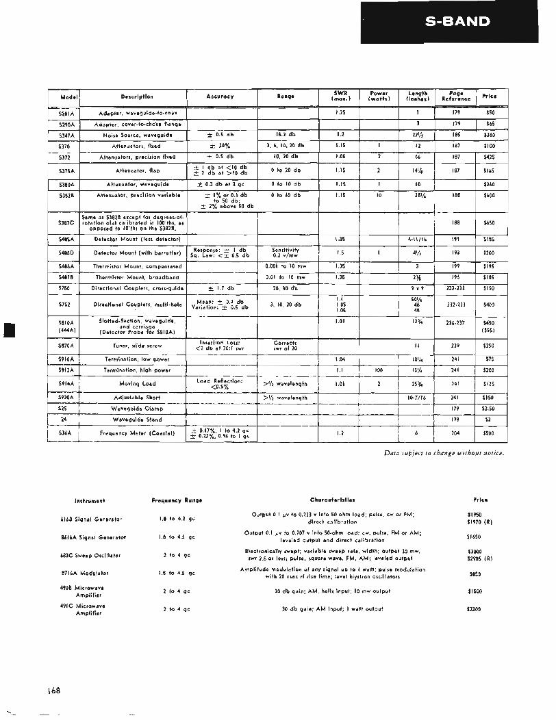
Slotted-Section, waveguide, and carriage
($55)
1 536A , Frequency Meter (Coaxial) 1 $ :;;;$; d,P',",',: :t ! 6 1 204 1 $500
Instrument Frequency Range
616B Signal Generator 1.8 t o 4.2 gc
8616A Siqnal Generator 1.8 to 4.5 gc
683C SweeD Oscillator 2 to 4 gc
8716A Modulator 1.8 to 4.5 gc
4908 Microwave Amplifier
Amplifier 491C Microwave
2 t o 4 gc
2 t o 4 gc
Data sublect t o change wzthout notice.
Characteristics
Output 0.1 pv to 0.233 v into 50 ohm load; pulse, cw or FM; direct calibration
Output 0.1 p v to 0.707 v into 50-ohm load; cw, pulse, FM or AM; leveled output and direct calibration
Electronically swept; variable sweep rate, width; output 30 mw, swr 2.5 or less; pulse, square wave, FM, AM; leveled output
Amplitude modulation of any signal up to I watt; pulse modulation with 20 nsec rf rise time; level klystron oscillators
30 db gain; AM, helix input; I O mw output
30 db gain; A M input; I watt output
Price
$1950 $1970 (R )
S I650
$3000 $2985 (R )
$850
$ I500
$2300
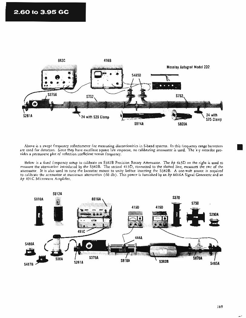
6836 4166
- .
Moseley Autograf Model 202
S4850
S375A S752, S752, 1 .
S281A ' 24 with S25 Clamp
S914A S920A
Above is a swept frequency reflectometer for measuring discontinuities in S-band systems. In this frequency range barretters are used for detectors. Since they have excellent square law response, no calibrating attenuator is used. The x-y recorder pro- vides a permanent plot of reflection coefficient versus frequency.
Below is a fixed frequency setup to calibrate an S382B Precision Rotary Attenuator. The hp 415D on the right is used to measure the attenuation introduced by the S382B. The second 415D, connected to the slotted line, measura the swr of the attenuator. It is also used to tune the barretter mount to unity before inserting the S382B. A one-watt source is required to calibrate the attenuator at maximum attenuation (60 db) . This power is furnished by an hp 8616A Signal Generator and an hp 491C Microwave Amplifier.
S912A S91 OA 8616A \ S370
S750
I69
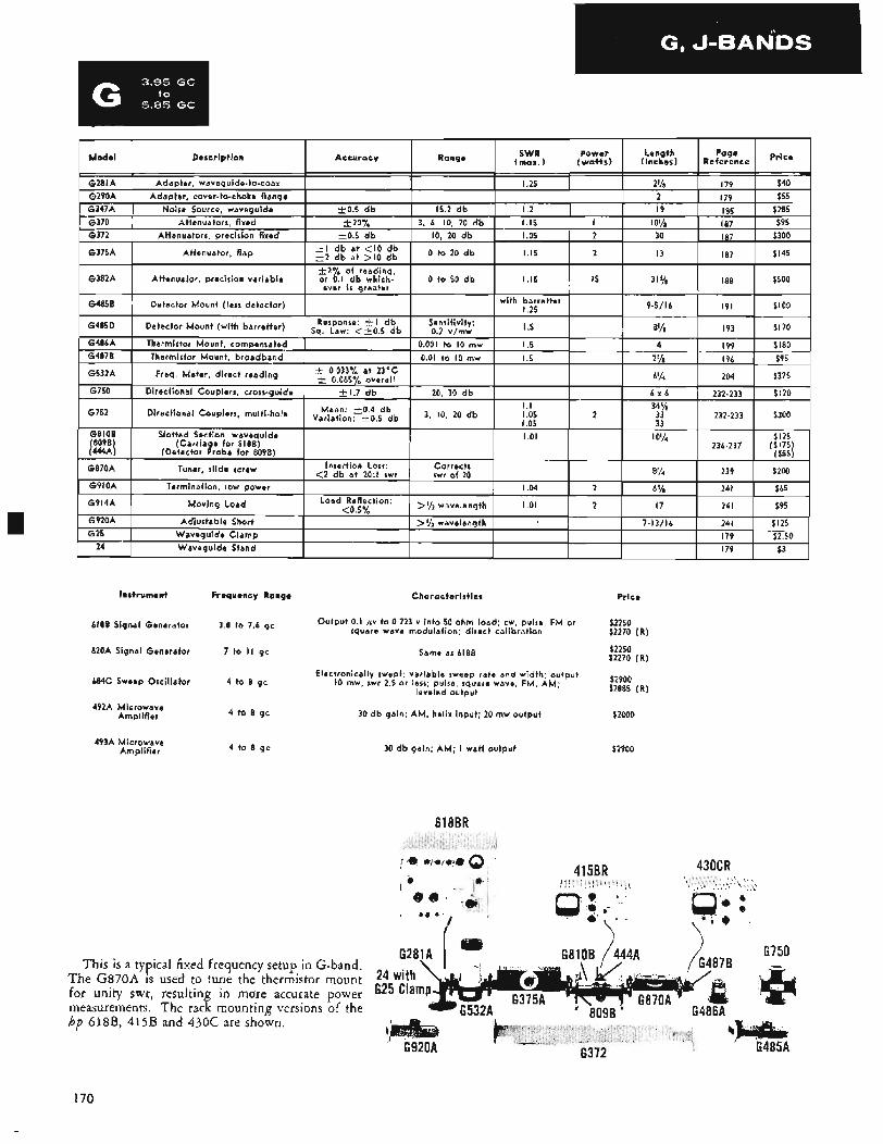
Instrument
6188 Signal Generator
620A Signal Generator
684C Sweep Oscillator
492A Microwave Amplifier
493A Microwave Amplifier
Frequency Range Characteristics Price
Output 0.1 gv to 0.223 v into 50 ohm load: cw, pulse, FM or square wave modulation; direct calibration
$2250 $2270 (R )
$2250 Same as 6188 $2270 ( R )
3.8 to 7.6 gc
7 to II gc
$2900 $2885 ( R )
Electronically swept; variable sweep rate and width. output IO mw, swr 2.5 or less; pulse, square wave, FM, AM:
leveled output 4 to 8 gc
4 to 8 gc
4 to 8 gc
This is a typical fixed frequency setup in G-band. The G870A is used to tune the thermistor mount for unity swr, resulting in more accurate power measurements. The rack mounting versions of the hp 618B, 415B and 430C are shown.
30 db gain; AM, helix input; 20 mw outpui
30 d b gain; AM; I watt output
618BR
$2000
$2900
G281A I
415BR
G810B / 444A
430CR
6750
G920A
I70
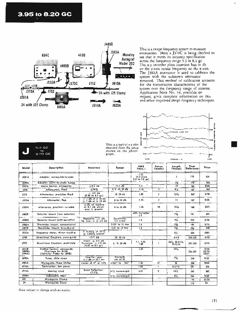
14850
6846 41 6B
i i
Model 202 I-
This is a swept frequency system to measure attenuation. Here a J370C is being checked to see that it meets its accuracy specification across the frequency range 5.3 to 8.2 gc. The x-y recorder plots insertion loss in db on the y-axis versus frequency on the x-axis. The J382A attenuator is used to calibrate the system with the unknown attenuator removed. This method of calibration accounts for the transmission characteristics of the system over the frequency range of interest. Application Note No, 54, available on request, gives complete information on this and other improved swept frequency techniques.
v__ -1108 2
This is a typical x-y plot obtained from the setup "De
shown in the photo- graph. i s o n
Z l P D B - . . . -. - _ _
5.30C r'EO"L*C"- 8 2GC
Adapter, waveguide-to-coax '
Load < Ref'ection: 0.s % 1 >f/z wavelength I 1.01 I 2 1 13'/z 1 241 1 $85 1
Dafil iubject t o change without notice.
171
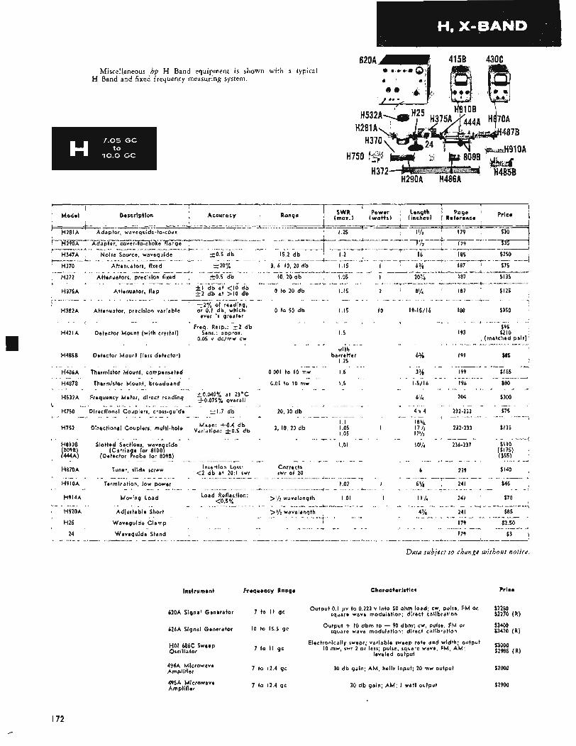
4158 430C Miscellaneous hp H Band equipment is shown with a typical
H Band and fixed frequency measuring system.
620A
I
H281A H37
I Model Description 1 SWR ' Power Length ' Page
(max.) (wa t t s ) (inches1 1 Reference Price i Accuracy Range I I_._. -.-II _l_l_l_... 4.=:.:-=--: .-" .__I"_.__y_._x _I_.-.
^I ______.__^_____l______.____^_ l_ll
er, waveguide-to-coax I 1.25 _I ~ __I". ~ ...._I_ ~ ~ .. .. -~ +-
!=- e .."-".--+-..- j H290A Adapter, cover-to-c )'..-..-- ~- ...I, I I . . ~ ___I _I_,..I
8 10.5 d b 15.2 db ' 1.2 16 I85
-4 H347A Noise Source, waveguide ".. ...--"+. .. _ _ _.." .,__x__._.__I. . , . . ._I_I..__.. &. ~
... .. .L........ _....... ^_.. ," --i. ....._l.ll_. ~* "_
' H370 Attenuators, fixed 220% 3, 6, I O , 20 db 1.15 I 63/8 I87 $75 - -. *.. _ _ _ _ - " I ^ _ - - -"-- I_ - . - - _ I _ _ . _ I - __* ~ --_- ___, ~ - - /
187 $135
0 to 20 d b 1.15 2 8% I87 $125 I - _ - .( "_ "
H372 Aitenuators, precision fixed 10.5 d b I O , 20 db I 05 I 20% ~~ - .( - ~ - - - I I . -, - _.
' ki db a t < I O db H375A Attenuator, f lap + 2 d b at > I O d b
'
. -_ . I . I _*^_ - I _ - i I ". 2 2 % of reading,
ever i s greater H382A Attenuator, precision variable or 0.1 db, which- 0 to 50 d b I 15 I O 19-15/16 I 88 $350
Freq Resp : 1 2 db
0.05 v dc/mw cw H421A Detector Mount (with crystal) Sens.: approx.
H485B Detector Mount (less detector)
I .5
._ $95
I93 $210 (matched pair) - ., _I
with
I 25 barretter 6% 191 $85
. * - $165 _ _ I .-
I99 ~ _ - H486A Thermistor Mount, compensated 0 001 to IO mw I .5 3%
H487B Thermistor Mount, broadband 0 01 to I O mw I .5 1-5/16 I96 $80 - ,
H532A Frequency Meter, direct reading $\olopo"l! ~ ~ ~ ~ a ~ f 6% 204 $300
- I
H750 Directional Couplers, cross-guide k1.7 db 20, 30 d b 4 x 4 232-233 $75 * - i-
$135 1 . 1 I as/,
H752 Directional Couplers, multi-hole Y ~ i ~ ~ ~ n ~ $ ; f , ~ ~ b 3, I O , 20 db I .05 I 17% 232-233 I 05 17% . "< r
H8lOB Slotted Sections wave uide 1.01 10% 236-237 $ 1 I O ($175) ($55)
8096) (Carria e fbr ~ I O B ~
- I > _ 1444A) (Detector ?robe for 8098)
H070A Tuner, slide screw
H9lOA Termination, low power
H914A Moving Load
H92OA Adjustable Short >%wavelength 4 '/s 24 I
H25 Waveguide Clamp I79
6 239 $140 Insertion Loss: Corrects swr of 20
I -_I_ I -- , - _--- - .- - * ~ -* <2 db a t 20.1 swr - -
-..-..e I .02 I 5 Y8 24 I $45
1.01 I 1 1 % 24 I $70
$85
$2.50
- "~ -- ... -I_ ~- 4 " r
Load Reflection: ,y2 wavelength
I - --i ~ - - ~- " - - . . _ _ - - * <0.5%
~I _.
_ I . - - 24 Waveguide Stand I79 $3
Data subject to change without notice.
Instrument Frequency Ranqe Characteristics Price
6ZoA Signal Generator
626A Signal Generator I O to 15.5 gc
HOI 686C Sweep Oscillator
to I I gc Output 0.1 fiv to 0.223 v into 50 ohm load: cw, pulse, FM or. square wave modulation; direct calibration
Output + I O dbm to - 90 dbm; cw, pulse, FM or square wave modulation: direct calibration
Electronically swept; variable sweep rate and width: output I O mw, swr 2 or less: pulse, square wave, FM, AM:
leveled output
$2250 $2270 (R)
$3400 $3420 (R)
53000 $2985 ( R ) 7 to II gc
7 to 12.4 gc 30 db gain; AM, helix input; 20 mw output $2000 494A Microwave Amplifier
495A Microwave 7 to 12.4 gc 30 d b gain; AM; I watt output $2904 Amplifier
I72
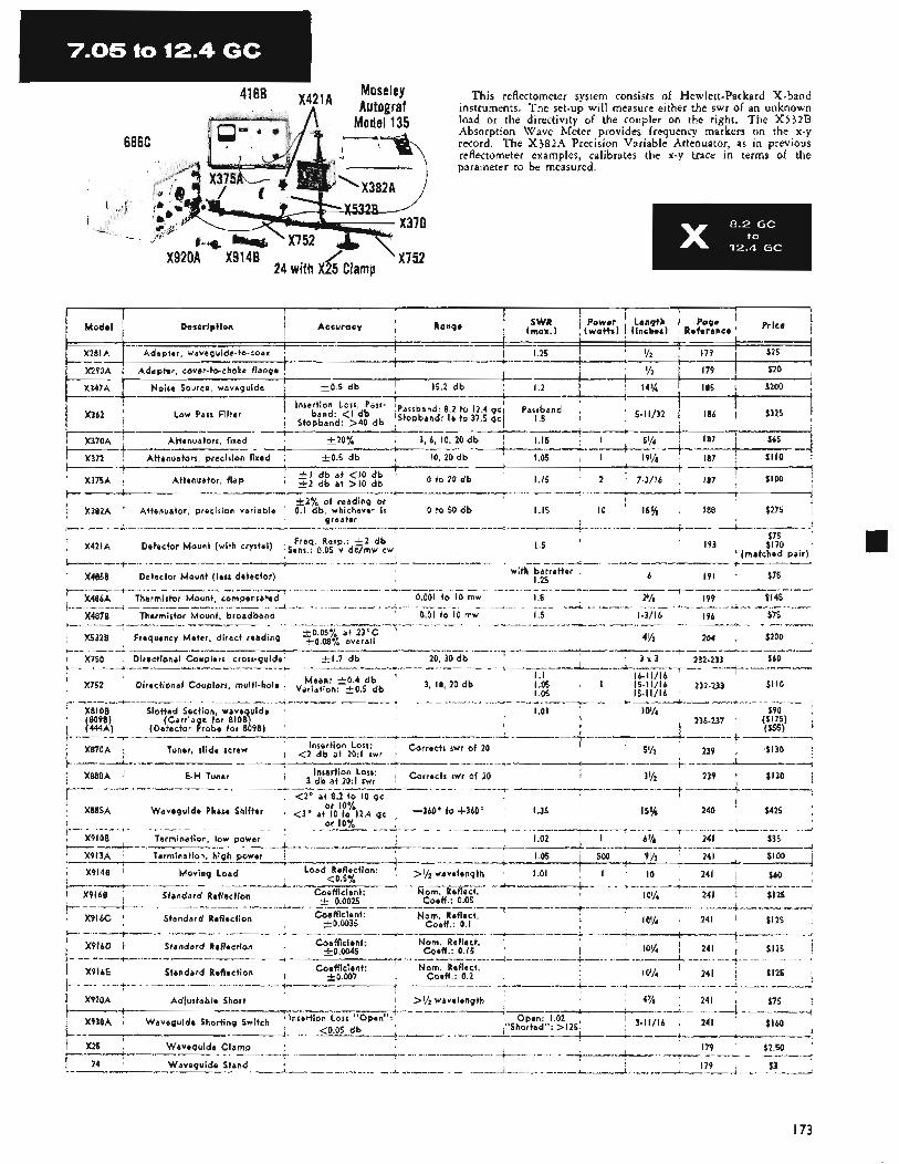
/- 'X752 24 with X25 Clamp
X920A X914B
This reflectometer system consists of Hewlett-Packard X-band instruments. The set-up will measure either the swr of an unknown load or the directivity of the coupler on the right. The X532B Absorption Wave Meter provides frequency markers on the x-y record. The X382A Precision Variable Attenuator, as in previous reflectometer examples, calibrates the x-y trace in terms of the parameter to be measured.
Low Parr Filter
b-.. -.&------" -J.---.--------- + -..----.j. -XI_--___ .--.+------.li---->--- --i
I87 $100 ! f ~ _--- +.--- --t----------------t
I 15 2 7-3/16 *I d b a t < I O d b ' X375A Attenuator, f lap i 2 db a t > I O d b
t 2 % of reading or
greater
0 to 20 d b _ _ _I__ I - -4 ___ __ _l__l -__ +--- I_-"-I "", " _A I_ I-~-I--d"-"-.I----
$275
$75 I .5 I93 $170
6 191 $75
X382A Attenuator, precision variable 0.1 db, whichever i s 0 to 50 db 1.15 IO 15% I88
~ - - - _c x- - l - - - l -__ I - - - - -x _ ^ - - I _ -- -- I - # -- --- ".+ "-+I --- +- - X421A Detector Mount (with crystal) s ~ ~ : q ' o ~ ~ i$$:kw I (matched pair) - - - -. - *-* ~ ---- - _* ------ - x_ ~__-- -- --I- I -_-_ -....,---- I- X485B Detector Mount (less detector) 1.25
+ CI---- --I
with barretter
* __ ._..__l_ + "___. , . ._I^__._ _ _ . .~,._.I_"I ." ~ I" . __I .. .___ ~ _._ - ,._/..I_ .+.I___x -".* ..-----.--&--.-.I . --a .~ ~ - , ' X486A , Thermistor Mount, compensated 0.001 to IO mw I .5 21/8 ' I99 $145
X532B Frequency Meter, direct reading so,08yo +0.05% a t Overal l 23'C ' 4% ' 204 , $200
..... "/ ._.,.__I..___ . ..I" . ...... ~ *... .. "-i ". __....- J
X487B , Thermistor Mount, broadband 0.01 to IO mw I .5 1-3/16 I96 $75 .*--..__I___ *_,"___._I_ I.__ ,.., _." ~ ^-" " . . I _ r - - _ - _ . . _ _ _ _ _ " .".-e-- . *... -*- " . .- .
*--. . ...__.I .I l__l ..__-_- +--.,.--".~..--'.. ---".--- .I ._.. -. . _ _ " --__.I___ ._ ---b--,-. -. .4 _-,_" --"._lq.l_l.."--"" I.L_. .-_--r__^X
. X750 ~ Directional Couplers, cross-guides t 1 . 7 d b 20, 30 d b 3 x 3 2 3 2 - 2 3 3 $60 i .. " _l_l___I_._._ ~ -----.".-&--- ._____.,l_l" ._ . , I_ x. .~...I.- +"" "_I i- --
10% , 241 $125 . Coefficient: Nom. Reflect.
Coefficient: Nom. Reflect.
+0.0045
t0.007
j X916D Standard Reflection
i X9I6E Standard Reflection , A -
10% 241 $125 Coeff : 0.2
X920A Adiustable Short >% wavelength 24 I $75
I73
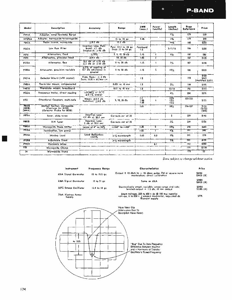
over-to-choke flange --------+. r__l
1 P362A ' Low Pass Filter
Attenuators, fixed k P372 I A t 4.-- l_l__l -----+ I _ s 1.11- +I.___^_- +.-.-..- 1 P375A ; Attenuator, f lap 1.15 I
r f-----+------ -.A_--. _11+1. T-----'-+---'-- i
I- --I__ , +I sb at < I O d b * to 2o db E 2 db at > I O d b -+-.--- ----".----+ I - - - - 3 2 9 * of reading or l__ll
I / P382A , Attenuator, precision variable 0.1 /db whichever is 0 to 50 db 1.15 5 greater I
I .5 ~ 193 1 $320 (matched pair)
i P421A , Detector Mount (with crystal) i s f : : q ~ o R ~ ~ b e , l P , ~ $ ~ ~ ~ w 1
' P486A Thermistor Mount, compensated I 0001 to I O mw
b%%- - i y---i------- -- t O 1 % overall
1 P752 Directional Couplers, multi-hole y ~ ~ ~ ~ n ~ q ~ ;bdb 3, \0, 20 d b 1 I nr, I
---. Thermistor Mount, brom- -----.----c I--- o 01 __-l_ to 1 0 mw ,.--.-+- P532A Frequency Meter, direct reading -+o 068% at 23°C
+- --____--I
Instrument Frequency Range Characteristics Price
626A
628A Signal Generator 15 to 21 gc Same as 626A
687C Sweep Oscillator
to 15,5 gc Output + I O dbm to - 90 dbm. pulse FM or square wave $3400 modulation; d i re i t calibration $3420 (R )
$3400 $3420 (R)
$3400 $3385 ( R )
Electronically swept; variable sweep range and rate; leveled output f 1.5 db; I O mw output 12.4 to 18 gc
716A Klystron Power Supply
Beam voltage, 250 to 800 v dc @ 100 ma; repeller voltage, 0 to 800 v, clamped modulator, regulated dc
filament supply $715
(Attenuation Due To Absorption Wave Meter)
"Bug" Due To Zero Frequency Difference Between Klystron and a Harmonic of Transfer Oscillator's Tuned Frequency
I74
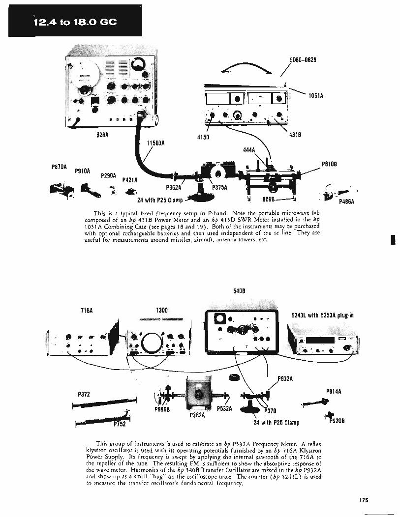
1051A
4511 41 50
\
This is a typical fixed frequency setup in P-band. Note the portable microwave lab composed of an hp 431B Power Meter and an hp 415D SWR Meter installed in the hp 1051A Combining Case (see pages 18 and 19). Both of the instruments may be purchased with optional rechargeable batteries and then used independent of the ac line. They are useful for measurements around missiles, aircraft, antenna towers, etc.
5408
71 6A
This group of instruments is used to calibrate an hp P532A Frequency Meter. A reflex klystron oscillator is used with its operating potentials furnished by an hp 716A Klystron Power Supply. Its frequency is swept by applying the internal sawtooth of the 716A to the repeller of the tube. The resulting FM is sufficient to show the absorptive response of the wave meter. Harmonics of the hp 540B Transfer Oscillator are mixed in the hp P932A and show up as a small "bug" on the oscilloscope trace. The counter ( h f , 5243L) is used to ineasure the transfer oscillator's fundainental frequency.
I75
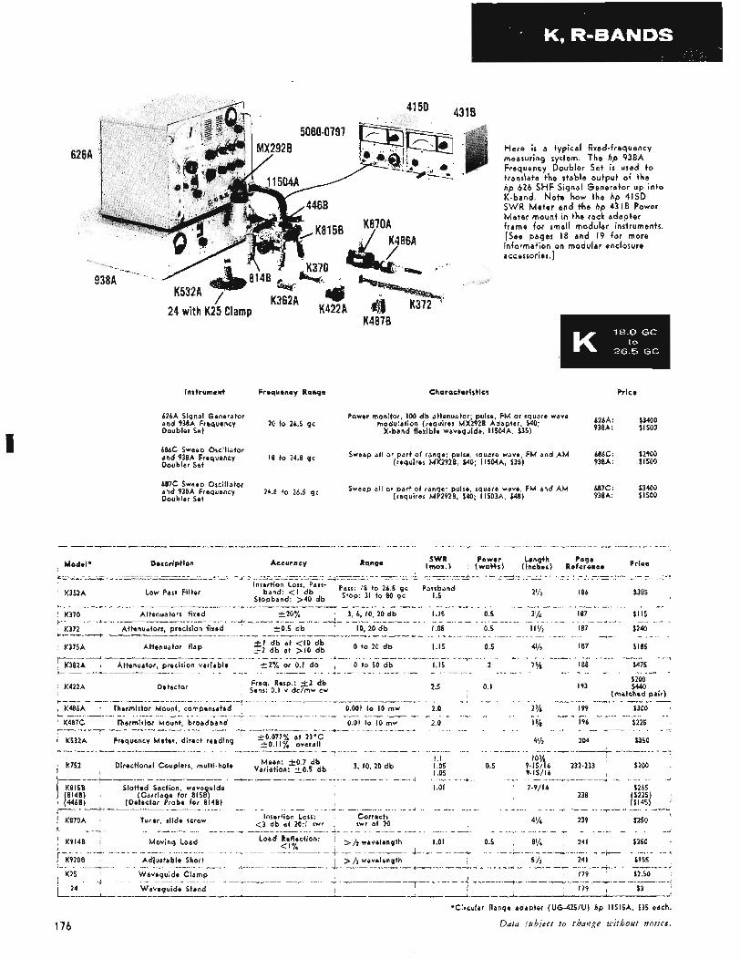
I
K487B
H e r e i s a t y p i c a l f ixed-frequency measuring system. The h p 938A Frequency Doubler Set i s used to translate the stable ou tpu t of the h p 626 SHF Signal Genera to r u p i n t o K-band. SWR M e t e r and the h p 4318 Power M e t e r moun t in the rack adap te r f rame f o r small modular instruments. (See pages I 8 and 19 f o r more in format ion o n modular enclosure accessories.)
N o t e how the h p 415D
Instrument Frequency Range Characterist ics Price
626A: $3400 938A: $1500
626A Signal Generator Power monitor 100 d b attenuator. pulse FM or square wave and 938A Frequency Doubler Set
20 to 26.5 gc modul;tion (requires MXi92B Adapter, $40; X-band flexible waveguide, I1504A, $35)
Sweep all or part of range: pulse, square wave, FM and A M 686C: $2900 686C Sweeo Oscillator and 938A Frequency 18 to 24.8 gc (requires MX2928, $40; I1504A, $35) 938A: $1500 Doubler Set
687C SweeD Oscillator and 9 3 8 ~ F~~~~~~~~ Doubler Set
24.8 to 26,5 gc Sweep all or part of range: pulse, square wave, FM and AM (requires MP2928, $40; I1503A, $48)
687C: $34W 938A: $1500
Model* Description Accuracy Range SWR Power Length Page (max.) (watts) (inches) Reference Price
- K362A Low Pass Filter 2% I86 $385 band: <I db Insertion Loss' Pass- Pass 18 to 26 5 gc Passband
S t o ~ b ~ ~ d : >4O d b Stop: 3 1 to gc 1.5 _- * ~---_.II--_-__I- _ ._I_ --- + I_ - - * _.
Attenuators, fixed *20% 3, 6, I O , 20 db 1.15 0.5 3% I87 $I I5 K370
I87 $240 K372
K375A Attenuator, f lap 1.15 0.5 4 Y2 I87 $185 to 2o db
^U&A
4 . - - " L - - - I _ - _ _ +-- _".t - - __ ~ " - - r - - "--+ --lll-_ .--.I-- I_I --- - -_ - , _I ~ - " _-_ I_ ~ I _I , - -.4
Attenuators, precision fixed 10.5 db IO, 20 d b I .05 0.5 I I Y2 - - _ " . +I d b a t < I O d b E2 d b a t > I O d b - "- + - 7 _ _ - ~- -- -_-+ .l--.--._-_.___II_I _ ^ - ~ ~ ____I
Attenuator, precision variable &2% or 0.1 db , 0 to 50 d b 1.15 2 7% I88 $475 c - .& - I * __lr - - _I - - __ - _ _
$200 I93 $440
(matched pair) 2.5 0. I Freq. Resp.: 1-2 d b
Sens: 0.1 v dc/mw cw K422A Detector
K486A Thermistor Mount, compensated 0001 to I O rnw 2.0 2 '/s I99 $300 * $- - _ . - - - ^ - .- - "I .,- I - - I- - _ _ - _ _ ^- 7
K487c.- - - ~ - - -_ - - _c - I __ -I- _- _ _ - I
Thermistor Mount, broadband 0 0 1 to I O mw 2.0 I 78 * 196 ~ $225 - - * . - _-_ I_ -7 ^I - - ? - - - 1 - -- - - - I_-
K532A Frequency Meter, direct reading 3°:i;z ~ v ~ ~ ~ l ~ 4% 204 $350 - * I - - -- _ _ ^ _ - - a - r - * - _ - ^ I _ _ - - _ _
$200 1.1 10%
K752 Directional Couplers, multi-hole , $ i ~ ~ ~ ~ n ~ $ ~ . ~ \ b 3, I O , 20 d b I .05 0.5 9-15/16 232-233 I .05 9-15/ I6
Insertion Loss: Corrects < 3 db at 2O:l swr swr of 20 Tuner, slide screw
I76
*Circular flange adapter (UG-425/U) hp I1515A, $35 each.
Data .iubject to change ui thout notice.
H e r e i s a b road band swept f requency system using the hp 940A Frequency
Doubler. The doubler takes the ou tpu t o f a P-band sweep osci l lator
(hp 687C) and translates it u p t o R-band. The equ ipment i s set u p t o
measure ref lect ions in terms of the magn i tude o f a 1000 cps modulat ion
signal displayed on an oscilloscope. The hp 415D i s used a.s a pre-
ampl i f ier f o r t he oscilloscope. Below i s a t yp i ca l trace; the dashed l ine
was drawn on the CRT face as a ca l ibrat ion mark. 24 with R25 Clamp R532A
Instrument
626A Signal Generator and 940A Frequency Doubler Set
628A Signal Generator and 940A Frequency Doubler Set
687C Sweep Oscillator and 940A Frequency Doubler Set
Frequency Range Characteristics Price
Power monitor, 100 d b attenuator. pulse FM or square wave 626A: $3400 26.5 to 31 gc modulation (requires NP2dZA Adapter, $40: 940A: $1500
P-band flexible waveguide, I1503A, $48)
628A: $3400 940A: $1500 Same as above 30 to 40 gc
Sweep all or part of range. pulse square wave, FM and A M 687C: $3400 26.5 to 36 gc (requires MPZhB, $46; 11503A, $48) 940A: $1500
Data subject t o chanxe without notice. I77
M
24
This photograph shows a fixed frequency setup for measuring power. Such a setup, for example, could be used to measure the resonant dip of the M532A Wavemeter. The M870A Slide Screw Tuner tunes the M487B Thermistor Mount to unity swr for improving measuring accuracy.
I78
$$ 281A, 2 9 0 A , 292A,B ADAPTERS, 24 WAVEGUIDE STAND,
25 WAVEGUIDE CLAMPS
Fitted with a standard Type N female connector and a plain A N flange, bp 281A Waveguide-to-Coaxial A d a p m use a probe with a low-loss dielectric sheath to transform waveguide impedance into coaxial impedance. Power may be transmitted in either direction, and each adapter covers the full frequency range of its waveguide band with swr less than 1.25.
The & 290A Cover-to-Choke Flange Adapter consists of a short waveguide section with a precision A N cover flange on one end and a choke flange on the other. The hp 290A is used to connect between non-precision cover flanges (such as those found in choke flange systems) and hp precision cover flange equipment. The choke section of the 290A mates with the non-precision flange to prevent loss of energy through the joint.
Models 292A and B Waveguide-to-Waveguide Adapters connect two different waveguide sizes with overlapping fre- quency ranges. The 292A consists of a short tapered section of waveguide. The 292B is a broached casting with a step transition between waveguide sizes, Letter prefixes on the ac- companying chart indicate band mating.
Cast and machined from zinc alloy, the hp 24 Waveguide - Stand locks the hp 2 5 clamp-at any height from 23/4rr to 5Srr. The stand is 21/2” high, and the base measures 43/4rr in diameter. Price, $3.
Offered in 9 sizes to fit waveguide equipment covering frequencies from 2.6 to 40 gc, hp 2 5 Waveguide Clamps are designed for use with hp 24 stands. They consist of a rubber molding with a steel insert. Price, $2.50.
Model 525 6 2 5 J25 H25 X25 M25 P25 K25 R25
Waveguide Size (outside dimensions)
3” x lfi’, 2” x I I1/$’ x 3/!‘ I1/4!f x I If x I/*’’ 0.850“ x 0.475; 0.702” x 0.391 0.500” x 0.250” 0.360” x 0.220”
@ 281A Adapters @ 290A Adapters Frequency Fits Range Waveguide
Model Price Model Price Length gc Size (in.)
S281A $50 S290A $65 3 2.60 - 3.95 3 x I l /2 G28JA $40 G290A $55 2 J281A* $35 J290A** $40 1 % 5.30- 6.2 11/2 x % H281A $30 H29OA $35 1 % 7.05 - 10.0 11/4 x 5/s
(in.)
3.95. 5.85 2 x I
XZ8lA $25 XZ9OAJ $20 1/2 8.2 - 12.4 I x ‘/2 P290A $30 I!/* 12.4 - 18.0 ,702 x .391
*SWR 1.30 from 5.3 to 5.5 gc **Frequency Range 5.2 to 8.2 gc
@ 292A Adapters
Model SWR Frequency
Range 9c
Length (in.) Price
HX292B I .05 I !/2 8.2 - 10.0 $25 MX292B I .05 2% 10.0. 12.4 $40 MP292B I .05 2% 12.4. 15.0 $40 NP292A I .05 2 3~ 15.0 - 18.0 $40 N K292A I .05 2% 18.0 - 22.0 $40
Ddtd subject to change without uotire.
25
24
I79
dp’ COAX I A L I N STR U M E N TAT IO N
Instrument Name
Hewlett-Packard offers an extensive I ine of instruments for coaxial systems operating t o 12.4 gc. The tables and descriptive material on these t w o pages indicate the frequency range and function of these instruments. Addi- tional specifications will be found on the pages referenced in the tables.
Uses Frequency Coverage by M o d e l
I O 55 215 450 500 940 I 2 3 4 10 12.‘ D C m c mc mc mc mc mc g c 9c 9c 9c 9 c 9 c
c 2 8 1 A Series-
- 360A - + 3608 - 4 360C - + 360D b
.-I_- _- - 3 5 5 c * -355D -L + 393A *
+ 3 9 4 +
Page
I79
XI
I 86
1_11
I89
Wavegu ide t o 1 These adapters connect coaxial
They are made fo r S- (2.6 t o 3.95 g c ) , G- (3.95 t o 5.85 g c ) , J- 15.3 to 8.2 g c ) , H- 17.05 t o
) and X- (8.2 t o 12.4 g c )
mask a nul l when measur ing standing wave rat io. These fil- ters have a reject ion o f 2 50 db a t 1.25 times their cut-of f f requency and ef fect ively el i- minate harmonics.
-------,-I-. 4ttenuatorr Precis ion v a r i a b l e a t t e n u a t o r s
are part icular ly useful fo r meas- ur ing the insertion loss o f com- p o n e n t s b y r f s u b s t i t u t i o n . I n t h i s m e t h o d , p o w e r i s f e d through the at tenuator t o a de- tec to r and t o a reference meter. Then the unknown component i s inserted and the at tenuat ion o f the var iable at tenuator i s re- duced t o ob ta in the previous meter reading. The di f ference in attenuator settings i s t h e in- sertion loss o f the unknown com- ponent. Insertion loss measure- ments u p t o 80 or 90 db are e a s i l y m a d e i f t h e d e t e c t o r (which may b e a receiver) has adequate sensitivity. RF substi- tu t ion has the advantage t h a t t h e d e t e c t o r c h a r a c t e r i s t i c s need no t b e known, since t h e i n - p u t t o the de tec tor i s constant.
I80
- .

Frequency Coverage by M o d e l
I O 55 215 450 500 940 I 2 3 4 I O 12.4 DC m c m c mc mc mc mc g c gc g c g c gc g c
+ 420A t
-476A- -420B-
- 4 4 0 A +
4. 477 B t * 478A *
- 5 3 6 A -
+ 7 7 4 D + +-775[3+
4 7 7 6 D + + 777D+
7 906A - 908A t
Page
- I93
I91 237
- I 96 I99
204
232
234
235
237
239 -
- 24 I
nstrument Name Uses
I
Basically, these d e t e c t o r s a r e square-law devices fo r demodu- la t ing r f signals. The 4208 and 476A exhibit excellent square- law propert ies hence they are
Me te rs respectively fo r measur- i ng power in Type N systems. M o d e l 4 7 8 A i s t e m p e r a t u r e - compensated and permits meas- urements as low as I gw.
Navemeter M o d e l 536A i s a react ion wave- meter fo r measuring f requen- cies f r o m 960 m c t o 4.2 gc. Resonance i s i n d i c a t e d b y a sharp d i p in the output.
Because of their extremely high d i r e c t i v i t y ( > 30 d b ) , t h e s e dua l d i r e c t i o n a l coup lers a re especially useful in coaxial re- f lectometer applications. Their l o w i n s e r t i o n loss a n d h i g h p o w e r h a n d l i n g c a p a b i l i t y make t h e m s u i t a b l e f o r p e r - manent instal lat ion in a trans- miss ion l i n e f o r p o w e r m o n i - tor ing. They may be used t o increase the range of the 430C or 43 I B.
able signal generator, such as an hp 608C (page 2 1 2 ) , permi t
and f rom 0' t o d lines fo r th is
t t ed l ines are used t o meas- ure swr and t o determine ref lec- t ion coefficient, return loss, mis- match loss and impedance.
Slide Screw A slide-screw tuner i s an im- runer pedance matching device, usu-
al ly used t o maximize the power del ivered t o a load. Slide-screw tuners have less loss than single or double stub tuners: also, the adjustments d o not interact .
axial systems in their character- i s t i c i m p e d a n c e d u r i n g swr measurements and as produc- t ion line impedance standards. M o d e l 906A has a sliding load so tha t i t s small ref lect ion may b e separated f rom other ref lec- t ions in a system.
181
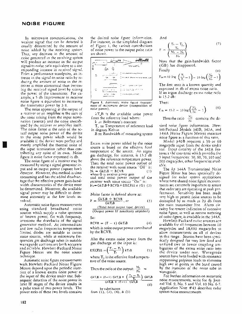
NOISE FIGURE
In microwave communications, the weakest signal that can be detected is usually determined by the amount of noise added by the receiving system. Thus, any decrease in the amount of noise generated in the receiving system will produce an increase in the output signal-to-noise ratio equivalent to a cor- responding increase in received signal. From a performance standpoint, an in- crease in the signal-to-noise ratio by re- ducing the amount of noise in the re- ceiver is more economical than increas- ing the receii.ed signal level by raising the power of the transmitter. For ex- ample, a 5 db improvement in receiver noise figure is equivalent to increasing the transmitter power by 3 : 1.
The noise appearing at the output of a receiver or an amplifier is the sum of the noise arising from the input termi- nation (source) and the noise contrib- uted by the receiver or amplifier itself. The noise factor is the ratio of the ac- tual output noise power of the device to the noise power which would be available if the device were perfect and merely amplified the thermal noise of the input termination rather than con- tributing any noise of its own. Noise figure is noise factor expressed in db.
The noise figure of a receiver may be measured by using a signal generator in- put and an output power (square law) detector. However, this method is time consuming and has the added disadvan- tage that the effective power gain-band- width characteristics of the device must be determined. Moreover, the available signal power may be difficult to deter- mine accurately at the low levels in- volved.
Automatic noise figure measurements using standard broadband noise sources which supply a noise spectrum of known power, flat with frequency, overcome the drawbacks of the signal generator method. A t intermediate and low radio frequencies temperature limited diodes are suitable as excess noise sources, while at microwave fre- quencies gas discharge tubes in suitable waveguide sections are both accurate and reliable. Hewlett-Packard Noise Figure Meters use the noise source technique.
Automatic noise figure measurements with Hewlett-Packard Noise Figure Meters depend upon the periodic inser- tion of a known excess noise power at the input of the device under test. Sub- sequent detection of the noise power in later IF stages of the device results in a pulse train of two power levels. The power ratio of these two levels contains
the desired noise figure information. For instance, in the simplified diagram of Figure 1, the various contributions of noise power to the output pulse ratio are shown.
Figure I . Automatic noise figure measure- ment of microwave device (composition of noise power),
kT,B is the available noise power from the reference load where: k = Bolttmann's constant T, = Temperature of reference load
B = Bandwidth of measuring system in degrees Kelvin
Excess noise power added by the noise source is based on the effective fired temperature of the source. An argon gas discharge, for instance, is 15.2 db above the reference temperature power. Then the total noise power output of the receiver with noise source "Off" is: Ni = GkToB + RCVR (1 ) where G is receiver power gain and total noise power output of the receiver with noise source "On" is: N*=GkToB+RCVR+EXCESS x ( G ) ( 2 )
Noise factor is defined above as:
( 3 ) GkToB + RCVR , or F =
GkToB (Total noise output from device)
(Output power IF noiselessly amplified)
so : RCVR = ( F - 1) GkToB ( 4 ) which is noise output power contributed by the RCVR.
Also the excess noise power from the gas discharge at the input is:
where T, is the effective fired tempera- ture of the noise source.
Then the ratio at the output: 3 = N1
GkT,B + (F-1) GkT,B + (v) GkT,B _ _ GkToB + (F-1) GkToB
( 6 ) by substitution
from ( I ) , ( 2 ) ) ( 4 ) , & ( 5 )
And
( 7 )
Note that the gain-bandwidth factor (GB) has disappeared. Finally ( 8 )
Ai Fllb=10 log (2-1)- 10 I o g ( G - 1 )
The first term is a known quantity and expressed in db of excess noise ratio. If an argon discharge excess noise ratio is 15.2 db: Then :
Thus the ratio Y contains the de- N L
sired noise figure information. Hew- lett-Packard Models 340B, 342A, and 344A Noise Figure Meters measure noise figure as a function of this ratio.
Model 340B requires a 30 or 60 megacycle input from the device under test. Input circuitry of the 342A fea- tures a vhf converter which provides for 5 input frequencies: 30, 60, 70, 105 and 200 megacycles, other frequencies avail- able.
The hp 344A Transistorized Noise Figure Meter has been specifically de- signed for radar system applications where time-shared noise figure nieasure- ments are extremely important to assure that radar sets are operating at peak per- formance. Sensitivity has been made very high to permit noise sources to be decoupled by as much as 20 db from the main transmitter line. Alarm cir- cuitry for remote indication of excessive noise figure, as well as remote metering of noise figure, is available in the 344A.
Hewlett-Packard noise sources are available for all frequencies between 10 megacycles and 18,000 megacycles to allow measurements on all rf devices in this range. Sources have been speci- fically designed for very low fired and unfired swr to lower coupling am- biguities of the excess noise ratio into the device under test. Waveguide sources have been loaded with resonance suppressing polyiron loads to eliminate high swr at points in the band caused by the insertion of the noise tube in waveguide.
For further information on automatic noise measurements, write for @ Jour- nal Vol. 9, No. 5 and Vol. 10 No. 6-7. Application Note #43 describes radar system noise measurements.
I82
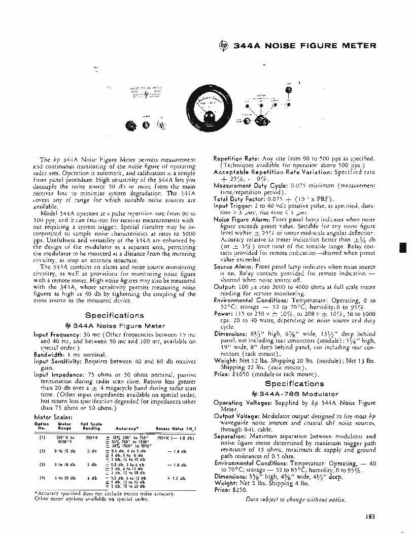
@ 3 4 4 A NOlSE FIGURE METER
1
The hp 344A Noise Figure Meter permits measurement and continuous monitoring of the noise figure of operating radar sets. Operation is automatic, and calibration is a simple front panel procedure. High sensitivity of the 344A lets you decouple the noise source 20 db or more from the main receiver line to minimize system degradation, The 344A covers any rf range for which suitable noise sources are available.
Model 344A operates at a pulse repetition rate from 90 to 500 pps, and it can free-run for receiver measurements with- out requiring a system trigger. Special circuitry may be in- corporated to sample noise characteristics at rates to 5000 pps. Usefulness and versatility of the 344A are enhanced by the design of the modulator as a separate unit, permitting the modulator to be mounted at a distance from the metering circuitry, as atop an antenna structure.
The 344A contains an alarm and noise source monitoring circuitry, as well as provisions for monitoring noise figure with a remote meter. High noise figures may also be measured with the 344A, whose sensitivity permits measuring noise figures as high as 40 db by tightening the coupling of the noise source to the measured device.
Specifications @ 3 4 4 A Noise Figure Meter
Input Frequency: 30 mc (Other frequencies between 15 mc and 40 mc, and between 50 mc and 100 mc, available on special order.)
Bandwidth: 1 mc nominal. Input Sensitivity: Requires between 40 and 80 db receiver
gain. Input Impedance: 75 ohms or 50 ohms nominal, passive
termination during radar scan time. Return loss greater than 20 db over a t 4 megacycle band during radar scan time. (Other input impedances available on special order, but return loss specification degraded for impedances other than 75 ohms or 50 ohms.)
Meter Scales: Option Meter Full Scale
No. Range Reading Accuracy* Excess Noise (N,) ___ (I ) 200’K to 2OOOK i 10% 200’ to 75OoO I 9 2 0 K (- 1.8 db)
5000’ K i 20% 750’ to 1500 - 30% 1500’ to 2500’
( 2 ) 0 to 15 db 0 db t 0.5 db, 0 to 5 db - 1.8 db f I db, 5 to IO db i 2 db, I O to 15 db
(3) 3 to 18 db 3 db 3z 0.5 db, 3 to 6 db - 1.8 db i I db, 6 to I 2 db i. 2 db, I 2 to 18 db
(4) 6 to 20 db 6 db i. 0.5 db, 6 to I 2 db + 1.2 db f I db, I2 to 15 db i 2 db, 15 to 20 db
*Accuracy specified does not include excess noise accuracy. Other meter options available on special order.
Repetition Rate: Any rate from 90 to.500 pps as specified. (Techniques available for operation above 500 pps. )
Acceptable Repeti t ion Rate Variation: Specified rate +- 2572, - 0%. Measurement Duty Cycle: 0.075 minimum (measurement
time/repetition period) . Total Duty Factor: 0.075 + (10.’ x PRF). Input Trigger: 2 to 40 volt positive pulse, as specitied, dura-
tion > 3 psec, rise time < 1 psec. Noise Figure Alarm: Front panel lamp indicates when noise
figure exceeds preset value. Settable for any noise figure level within _i 25% of meter mid-scale angular deflection. Accuracy relative to meter indication better than i l / 4 db (or i 5%) over most of the settable range. Relay con- tacts provided for remote indication-shorted when preset value exceeded.
Source Alarm: Front panel lamp indicates when noise source is on. Relay contacts provided for remote indication -- shorted when noise source off.
Output: 100 pa into 2000 to 4000 ohms at full scale meter reading for remote monitoring.
Environmental Conditions: Temperature: Operating, 0 to 52OC; storage - 52 to 70OC; humidity,O to 95%.
Power: 1 1 5 or 230 v t l O C / ; , or 208 v i lOC/c, 50 to 1000 cps. 20 to 40 watts, depending on noise source and duty cycle.
Dimensions: 81/2” high, 67/8” wide, 15Y2” deep behind panel, not including rear connectors (module) ; 5Y4” high, 19” wide, 8” deep behind panel, not including rear con- nectors (rack mount),
Weight: Net 1 2 lbs. Shipping 20 Ibs. (module) ; Net 13 lbs. Shipping 22 lbs. (rack mount),
Price: $1650 (module or rack mount). Specifications
@ 3 4 4 A - 7 8 6 Modulator Operating Voltages: Supplied by hp 344A Noise Figure
Meter. Output Voltage: Modulator output designed to fire most hp
waveguide noise sources and coaxial uhf noise sources, through 6-ft. cable.
Separation: Maximum separation between modulator and noise figure meter determined by maximum trigger path resistance of 15 ohms, maximum dc supply and ground path resistances of 0.5 ohm.
Environmental Conditions: Temperature: Operating, - 40 to 7 O o c ; storage - 52 to 85OC; humidity, 0 to 95%.
Dimensions: 378’’ high, 478” wide, 4,/;” deep. Weight: Net 2 Ibs. Shipping 4 Ibs. Price: $250.
Ddta subject to change without notice.
I83
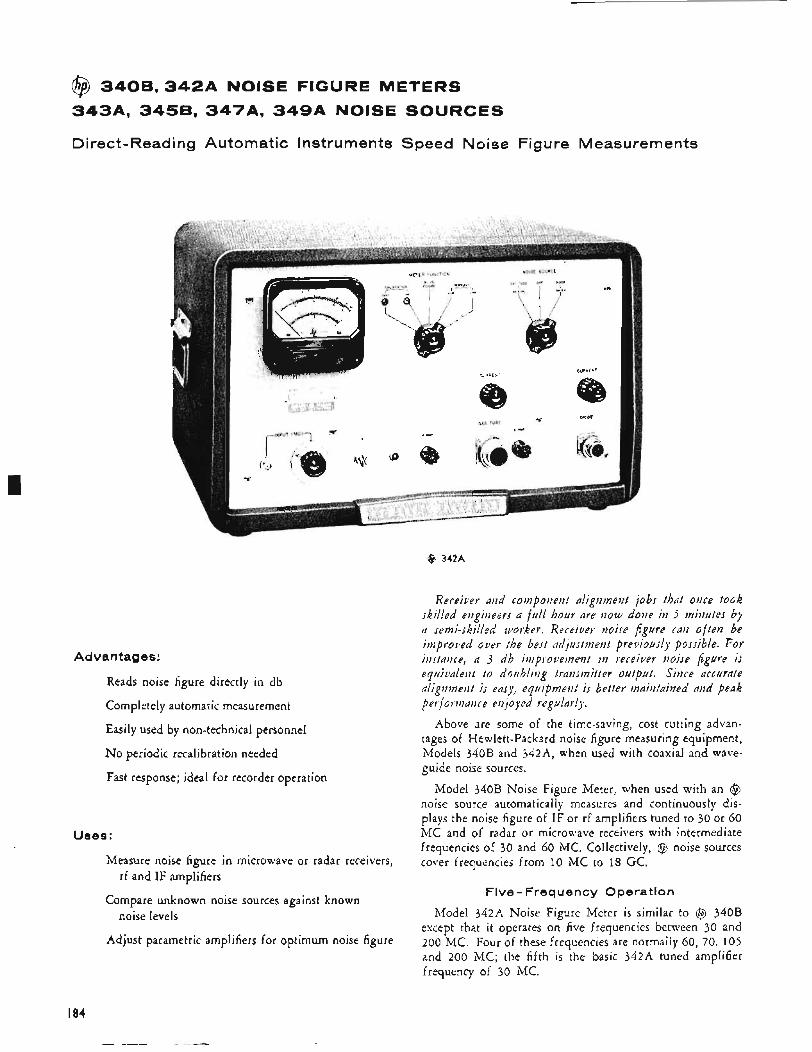
@ 3 4 0 8 , 3 4 2 A NOISE FIGURE METERS 3434 3 4 5 8 , 347A, 3 4 9 A NOISE SOURCES
Direct-Reading Automatic Instruments Speed Noise Figure Measurements
Advantages:
Reads noise figure directly in db
Completely automatic measurement
Easily used by non-technical personnel
No periodic recalibration needed
Fast response; ideal for recorder operation
Uses:
Measure noise figure in microwave or radar receivers,
Compare unknown noise sources against known
Adjust parametric amplifiers for optimum noise figure
rf and IF amplifiers
noise levels
@ 342A
Receiver and component alignment jobs that once took skilled engineers a full hour are now done in 5 minutes by a semi-skilled worker. Receiver noise figure can often be improved over the best adjustment previously possible. For instance, a 3 d b improz?ement i n receiver noise figure is equivalent to doubling transmitter output. Since accurate alignment is easy, equipment is better maintained and peah perf ormance en joyed regularly.
Above are some of the time-saving, cost cutting advan- tages of Hewlett-Packard noise figure measuring equipment, Models 340B and 342A, when used with coaxial and wave- guide noise sources.
Model 340B Noise Figure Meter, when used with an @ noise source automatically measures and continuously dis- plays the noise figure of IF or rf amplifiers tuned to 30 or 60 MC and of radar or microwave receivers with intermediate frequencies of 30 and 60 MC. Collectively, @ noise sources cover frequencies from 10 MC to 18 GC.
Five - Frequency Operation
Model 342A Noise Figure Meter is similar to @ 340B except that it operates on five frequencies between 30 and 200 MC. Four of these frequencies are normally 60, 70, 105 and 200 MC; the fifth is the basic 342A tuned amplifier frequency of 30 MC.
I84
In operation, a noise source, either a gas discharge tube or a diode, is connected to the input of a device under test. The device’s IF amplifier output is connected to the 340B or 342A. The Noise Figure Meter gates the noise source on and off. When the source is on the noise level is that of the receiver plus the noise source. When the source is off, the noise level is that of the device and its termination. The Noise Figure Meter automatically compares these two conditions and pre- sents noise figure directly on a front panel meter. Rate of response is such that changes in noise figure are constantly indicated on the meter.
@ Noise Sources @ 343A VHF Noise Source. Specifically for IF and rf
amplifier noise measurement, a temperature-limited diode source with broadband noise output from 10 to 600 MC.
@ 345B IF Noise Source. Operates at either 30 or 60 MC, as selected by a switch. Another selector permits matching 50, 100, 200 and 400 ohm impedances.
@ 347A Waveguide Noise Source. Argon gas discharge tubes mounted in waveguide sections. For waveguide bands 2.6 through 18.0 GC, provide uniform noise throughout range; maximum SWR 1.2.
@ 349A UHF Noise Source. Argon discharge tubes pro- viding 15.2 db excess noise for automatic noise figure read- ings 400 to 4,000 MC. Also available with 18.2 db excess noise.
Specifications @ 3408 Noise Figure Meter
Frequency Range: Depends on noise source used. Noise Figure Range: 3 to 30 db, indication to * with
Waveguide Noise Source. 0 to 15 db, indication to * with IF Noise Source.
Zero Offset: Permits low values to be read on sensitive external meter.
Accuracy (excluding source accuracy): k 0.5 db, 10 to 25 db; t 1 db, 3 to 10 db, 25 to 30 db with Waveguide Noise Source. k 0.5 db, 0 to 15 db with IF Noise Source.
Input Frequency: 30 and 60 MC. Other frequencies be- tween 10 and 70 MC on special order.
Input Requirements: -60 dbm to -10 dbm (noise source on) . Corresponds to system gain before 340B of approxi- mately 40 to 90 db with 347A or 349A noise source; ap- proximately 50 to 100 db with 343A or 345B noise source.
Bandwidth: 1 MC nominal. Input Impedance: 50 ohms, nominal. AGC Output: Nominally 0 to -6 volts from rear binding
Recorder Output: Maximum of 1 ma into maximum of
Power In ut: 115 or 230 v &lo%, 50 to 60 cps, 184-435
Power Output: Sufficient to operate @ 347A, @ 349A,
Dimensions: Cabinet Mount: 203/qPt wide, 12%” high, high, 137/8“
posts.
2,000 ohms to operate a recorder or remote meter.
watts cp epending on line voltage and noise source.
@ 345B, or @ 343A Noise Sources.
14%” deep. Rack Mount: 19” wide, deep behind panel.
Rack Mount: Net 34 lbs. Shipping 49 lbs.
340B to an @347A or 349A Noise Source.
(rack mount). (Not available in Western Europe.)
Weight: Cabinet Mount: Net 40 lbs. Shipping 51 Ibs.
Accessories Furnished: @ 340A-l6A, 6’ cable connects @
Price: @ 340B, $715.00 (cabinet); @ 340BR, $700.00
@ 3 4 2 A Noise Figure Meter (Same as 340B except as shown below)
frequencies on special order.) Frequency selector switch.
(rack mount). (Not available in Western Europe.)
Input Frequency: 30, 60, 70, 105 and 200 MC. (Other
Price: @ 342~4, $815.00 (cabinet); @ 342AR, $800.00
@ 3 4 3 A VHF Noise Source
Frequency Range: 10 to 600 MC. Excess Noise: 5.2 k 0.1 db, 10 to 200 MC.
5.2 2 0.25 db, 200 to 400 MC. 5.2 & 0.35 db, 400 to 600 MC.
Source Impedance: 50 ohms, SWR less than 1.2,10 to 400 MC; less than 1.3, 400 to 600 MC.
Dimensions: 2%” wide, 295” high, 5” deep. Weight: Net y* Ib. Shipping 2 lbs. Price: @ 343A, $~oO.oo. Option 01. Spare noise diodes calibrated with the instru-
ment, $40.00 each.
@ 3458 IF Noise Source (Same as 343A except as shown below)
Spectrum Center: 30 or 60 MC, selected by switch. Other
Excess Noise: Nominally 5.2 db into conjugate load. Source Impedance: 50, 100, 200 and 400 ohms &4% as
Price: @ 345B, $100.00.
frequencies between 10 and 60 MC on special order.
I selected by switch. Less than 1 pf shunt capacitance.
@ 3 4 7 A Waveguide Noise Source
Ronqe, Noise, Excess db Approx. Lenqth Prlce GC Model
S347A 2.6 - 3.95 15.2 22%” $360.00 i 0.5
G347A 3.95 - 5.85 15.2 19“ 285.00 -C 0.5
J347A 5.3 - 8.2 15.2 19“ 265.00 k 0.5
15.2 16“ 250.00 H347A 7.05 - IO + 0.5
X347A 8.2 - 12.4 15.2 14%‘‘ ,200.00 -C 0.5
P341A 12.4 - 18 15.2 14%’’ 250.00 k 0.5
SWR all models, fired or unfired, 1.2 max., less than 1 . 1 average.
@ 3 4 9 A UHF Noise Source Frequency Range: 400 to 4,000 MC; wider with correction. Excess Noise: 15.2 k 0.5 db, including insertion loss. 18.2
SWR: Up to 2,600 MC: less than 1.35 (fired); less than 1.5
2,600 to 3,000 MC: less than 1.5 (fired); less than 1.5
3,000 to 4,000 MC: less than 2.0 (fired); less than 3.0
(Source terminated in coaxial load with less than 1.05
db available on special order.
(unfired)
(unfired)
(unfired)
SWR.) Dimensions: 15” long, Y‘wide, 2’’ high. Weight: Net approximately 3%” lbs. Shipping 6 lbs. Price: @ 3494, $325.00.
Data subject to change without notice.
I85
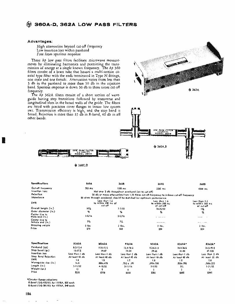
@ 360A-D, 3 6 2 A LOW PASS FILTERS
Advantages: High attenuation beyond cut-off frequency Low insertion loss within passband Free from spurious response
These hp low pass filters facilitate microwave measure- ments by eliminating harmonics and permitting the trans- mission of energy at a single known frequency. The hp 360 filters consist of a brass tube that houses a multi-section CO- axial type filter with the ends terminated in Type N fittings, one male and one female. Attenuation varies from less than 3 db in the passband to more than 50 db in the rejection band, Spurious response is down 50 db to three times cut-off frequency.
The hp 362A filters consist of a short section of wave- guide having step transitions followed by transverse and longitudinal slots in the broad walls of the guide. The filters are fitted with precision cover flanges to insure low system swr. Transmission efficiency is high, and the stop band is broad. Rejection is more than 35 db in R-band, 40 db in all other bands.
Specifications
Cut-off frequency Insertion Loss Reiection Impedance
SWR
Overall length [in.) Outer diameter (in.) Center line to male end (in.) Center line t o female end [in.) Shipping weight Price
Specifications Passband (gc) Stop band (gc) Insertion loss Stop Band Reiection SWR Waveguide size [in.) Length (in.) Weight (01.) Price
360A 360B 3bOC 360D
700 mc I200 mc 2200 mc 4100 mc Not over 3 d b throughout passband (dc to cut-off)
50 db or more attenuation from 1.25 times cut-off frequencv to 3-times cut-off frequency . . 50 ohms through passband: should be matched for optimum performance
Less than 1.6 Less than 1.6
cut-off of cut-off to within 100 mc of to within 200 mc
X362A 8.2-12.4 16-37.5
Less than I d b A t least 40 d b
I .5 1x.5
I3 $325
5-1 1/32
M362A 10.0- 15.5
19-47 Less than I db A t least 40 d b
I .5 .850x.475 4- 15/32
9 $350
7-7/32 5/8
2-5/16
2% 2 Ibs.
$60
P362A 12.4- 16.0
23-54 Less than db A t least 40 d b
I .5 ,702 x ,391
3-11/16 6
$350
IO-25/32 s/a
. . ... . .. . .. . . 2 Ibt.
$50
N362A 15.0-21 .O
29-63 Less than I d b A t least 40 d b
I .5 .59Ox.335 3-1/32
5 $350
K362A* i6.0-26.5
3 1-80 Less than I d b A t least 40 d b
I .5 .500x.250
2% 2
$385
Less than 1.6 to within 300 mc
of cut-off 7% %
2 Ibs. $50
R362A* 16.5-40.0
47-120 Less than 2 d b A t least 35 d b
I .8 ,360x.220 1-2 1/32
I $385
*Circular flange adapters: K-Band (UG-425/U) hp 11515A, $35 each R-Band (UG-381/U) hp I I516A, $40 each
I86
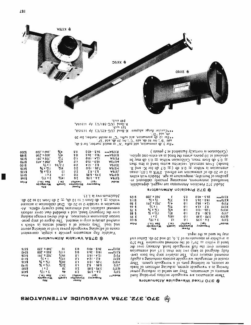
L8 I
9'0 5'0 0' I 0' I O'Z O'Z O'Z O'Z O'Z
(S++DM) UO!+Dd!SS!a
JoMOd
O'OP - 9'9Z 9'9Z - 0'8 I 0'81 - P ' Z l 0'81 - 0'01 P'ZI - Z'8 0'01 - SO'L
1'8 - E'S 98'4 - 96E 96'E - 9'Z
( ' 6 ) AauenbaJd
***VSLEtl
V9L Ed VSLEW VSLEX V9L EH
VSLES VSLES PPOW
* * *vsLEn
v s L E r
OZZ' X 09E' 01 9'0 O'OP - 9'9Z 092' x 009' z/, I I 9'0 9'9Z - 0'8 I I6E' X ZOL' z/lS I 0'1 0'81 - t * Z I
Z A I 'A61 0'1 P'Zl - 1'8 8!s x %I %oz 0'1 0'01 - 90'L % z/i I % Z Z 0'1 Z'8 - 98'9
I X Z Of O'Z 58's - S6.E 9 t O'Z 96'E - 9'Z
***ZLEU
ZLEd ZLEX ZLEH
ZLES ZLES
*zLEn
zLEr
S Z l S S I I $ 08 S 99 S SL S 98 $ 96 $ 001s a V d
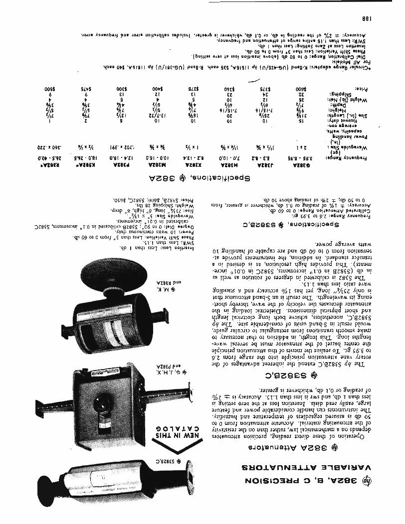
88 I
OSC$ EZ 01
02 01
4Lt f ooef b El t 4
%E "At '/IS %L
VIZ I %L 9 Z
SLZt E l
ii %SI 01
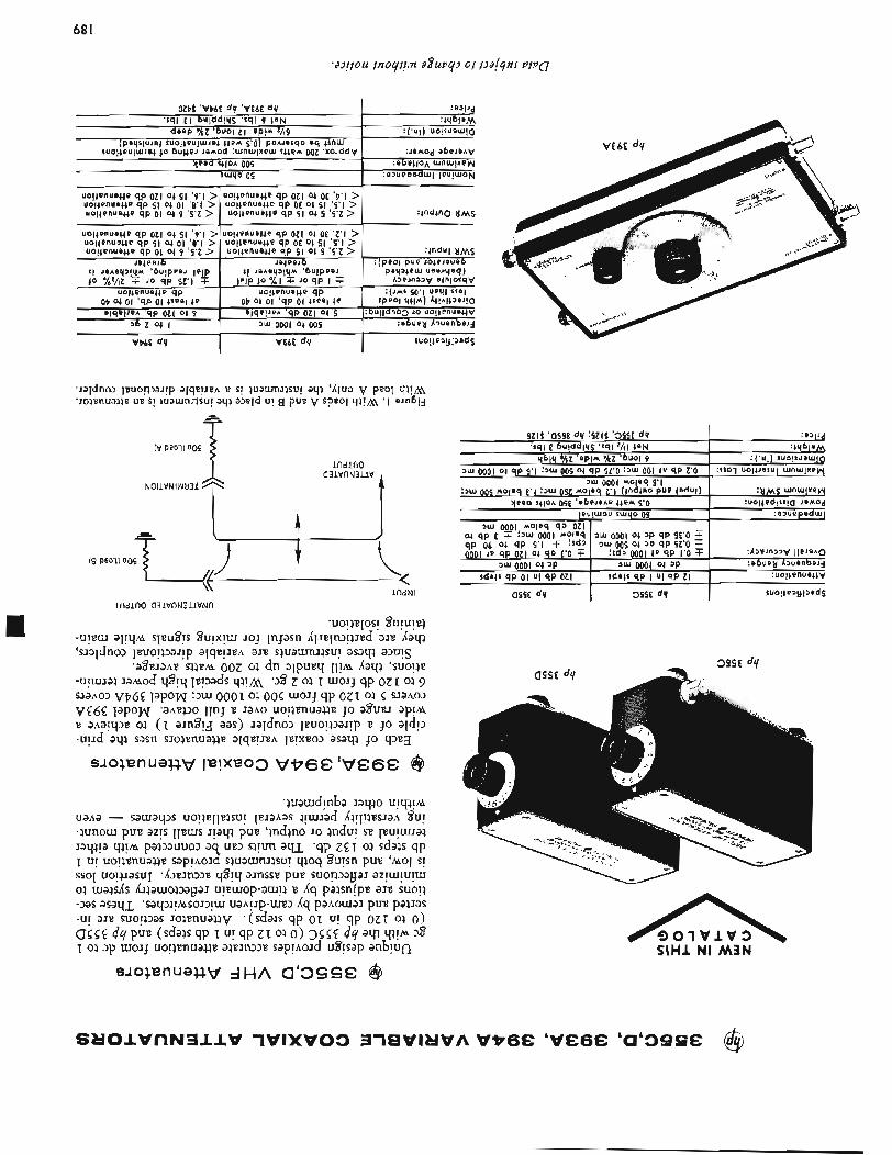
68 I
n SlHl 6 0 1 V l V 3 NI M 3 N
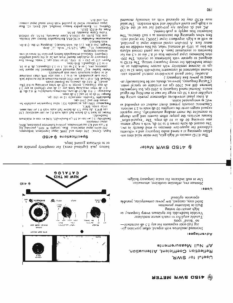
06 I
SlHl NI M3N
asi t @
L Ir- c u
:sasn
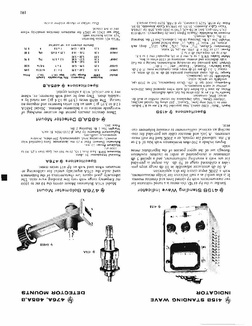
09'9 - OE'S 05' I
OZ'8 - 58'9 42' I 5 6 $ %L 9L'O x 4 ' 1 98'4 - OS'S S E ' I Lasaw
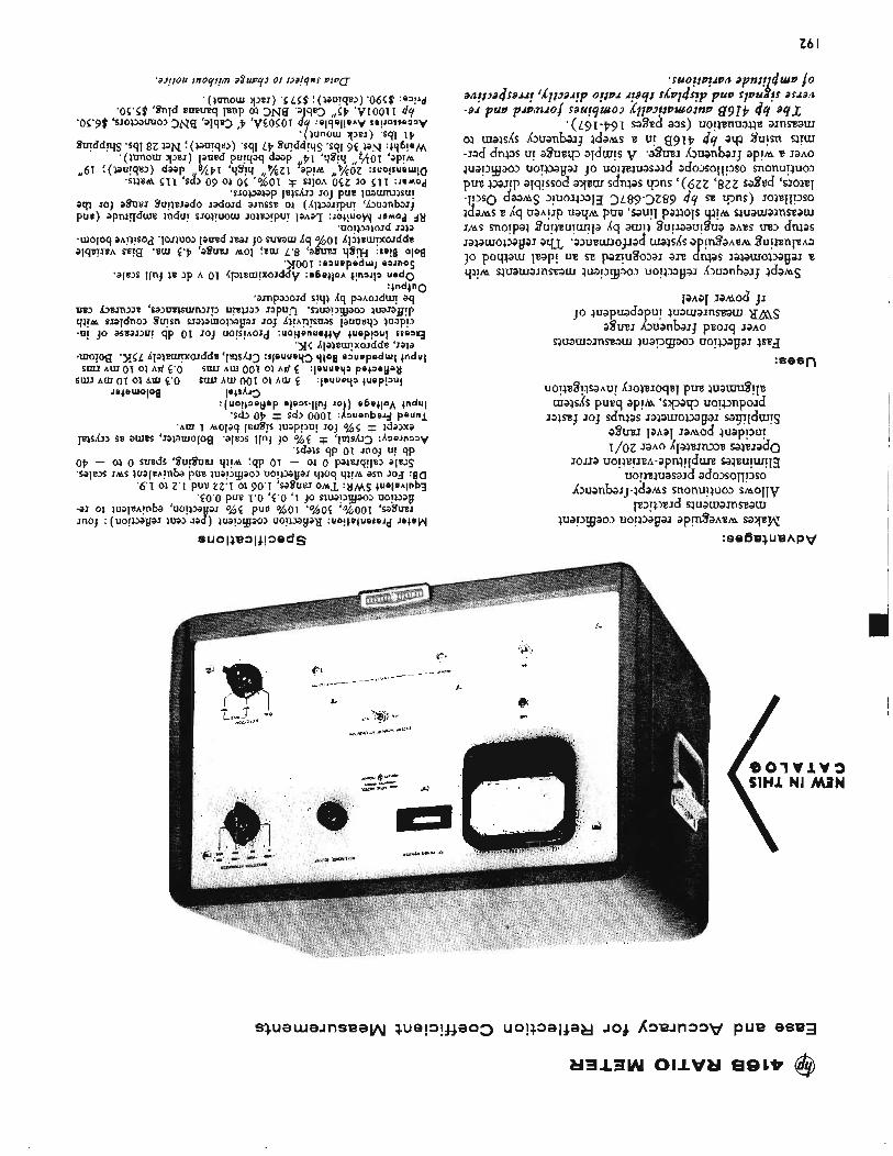
Z6 I
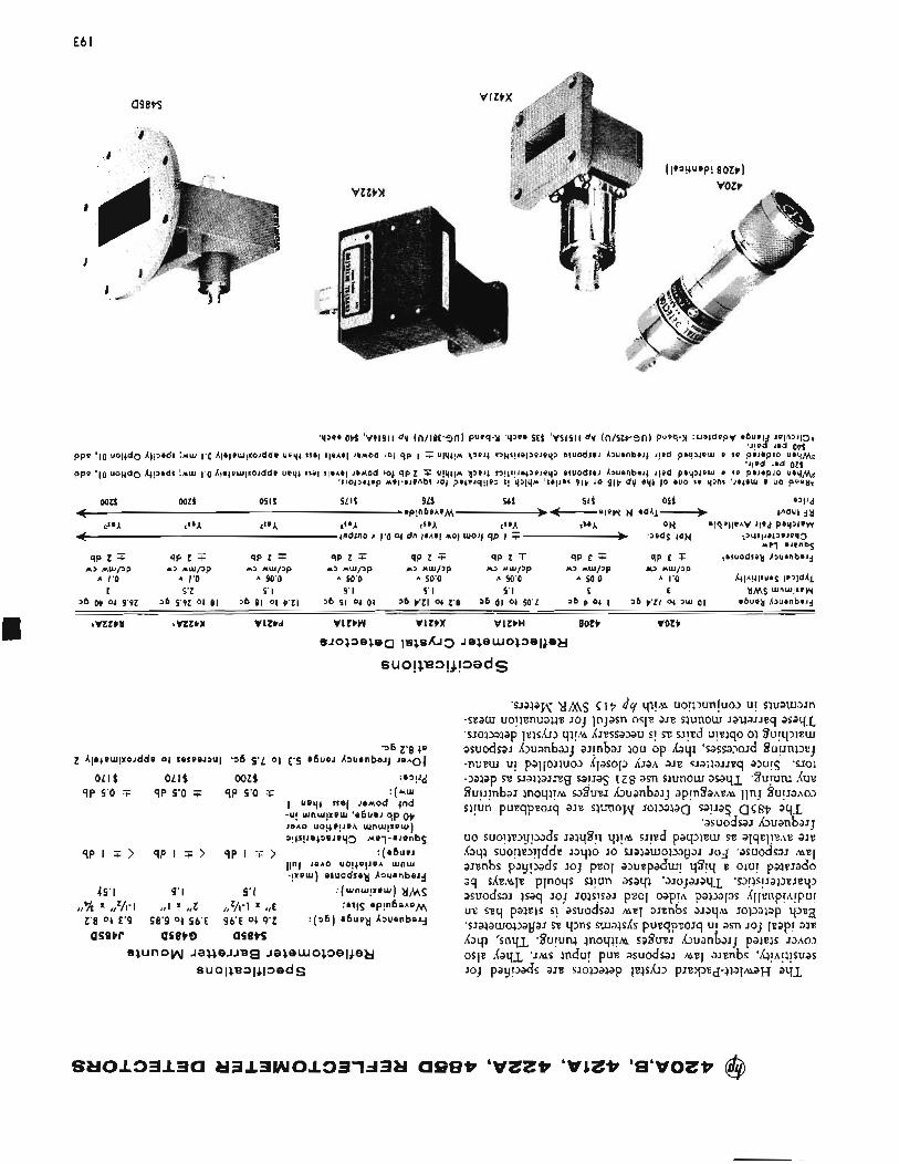
E6 I
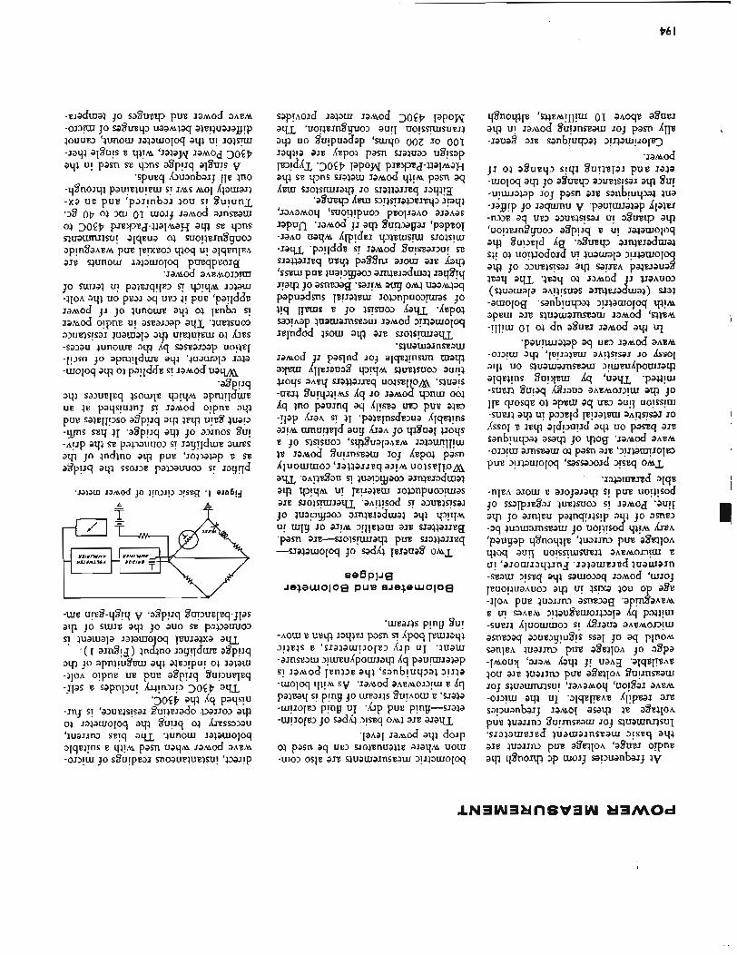
I76 I
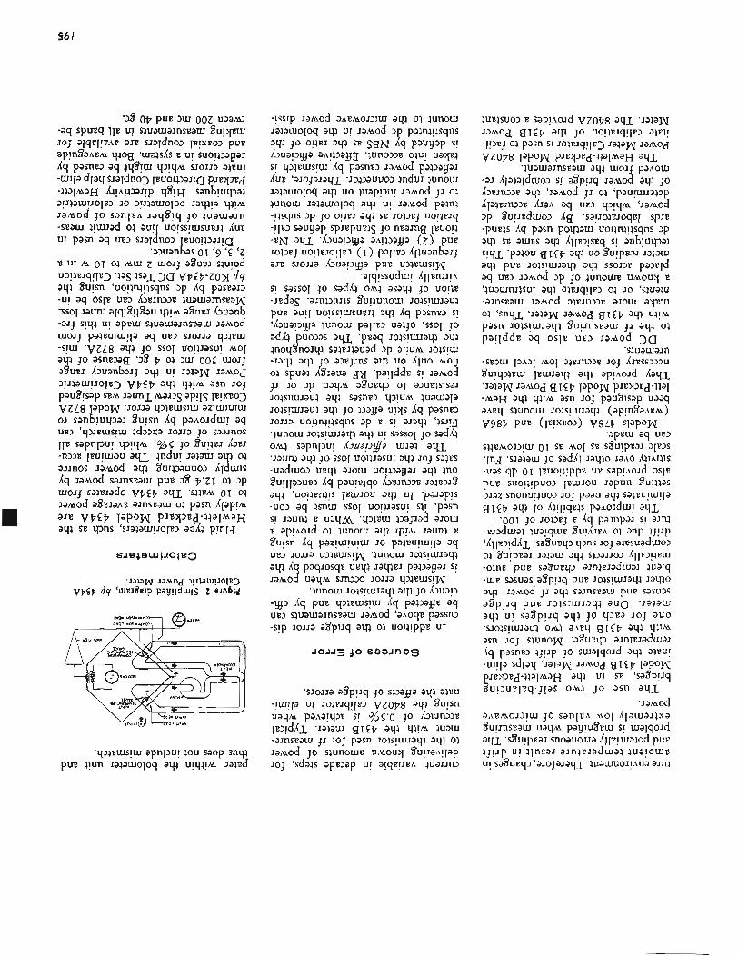
96 I
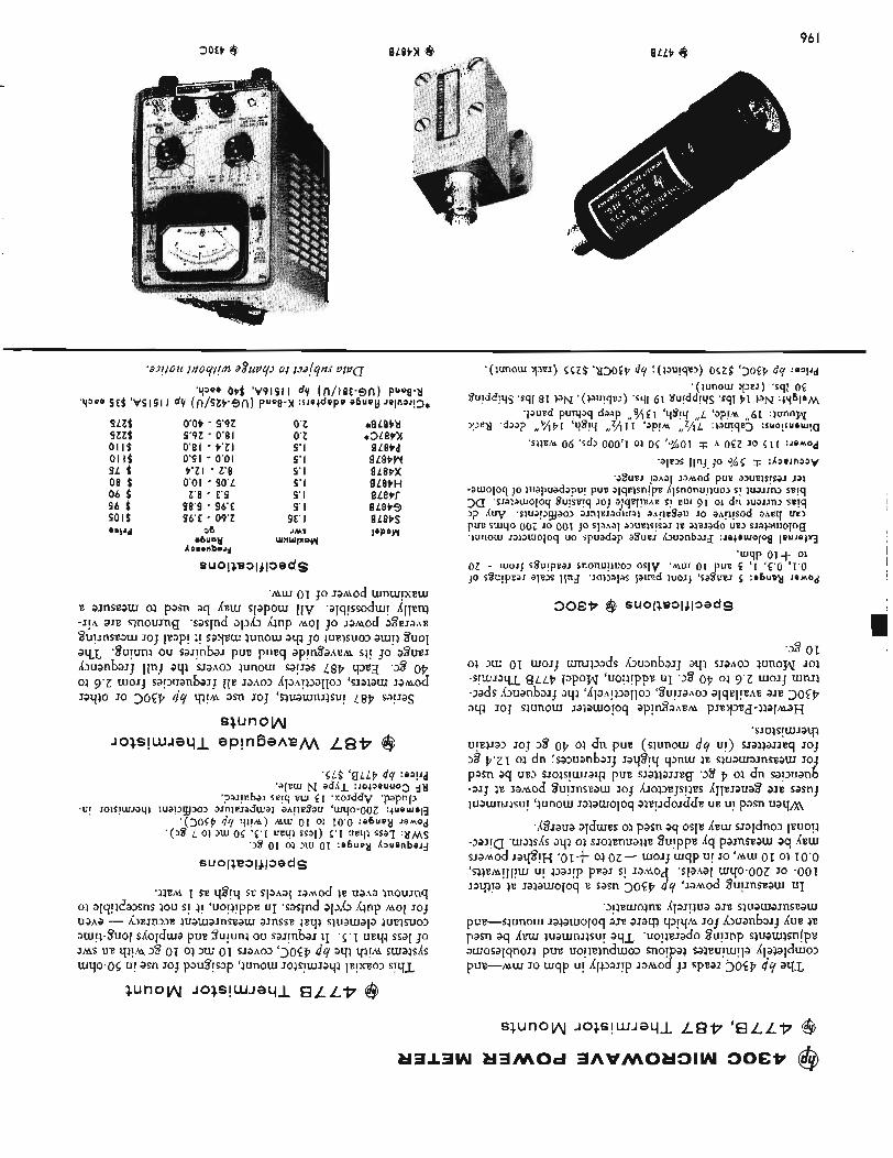
30EP 6 96 I BLLP 6
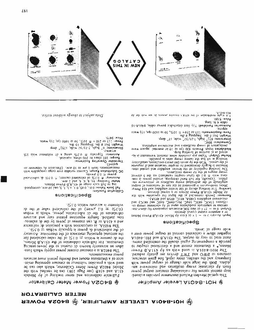
L6 I
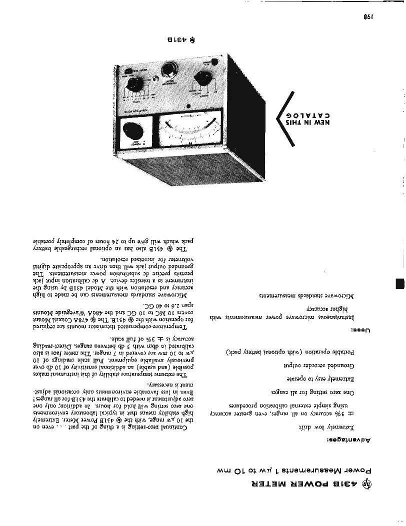
86 I
I
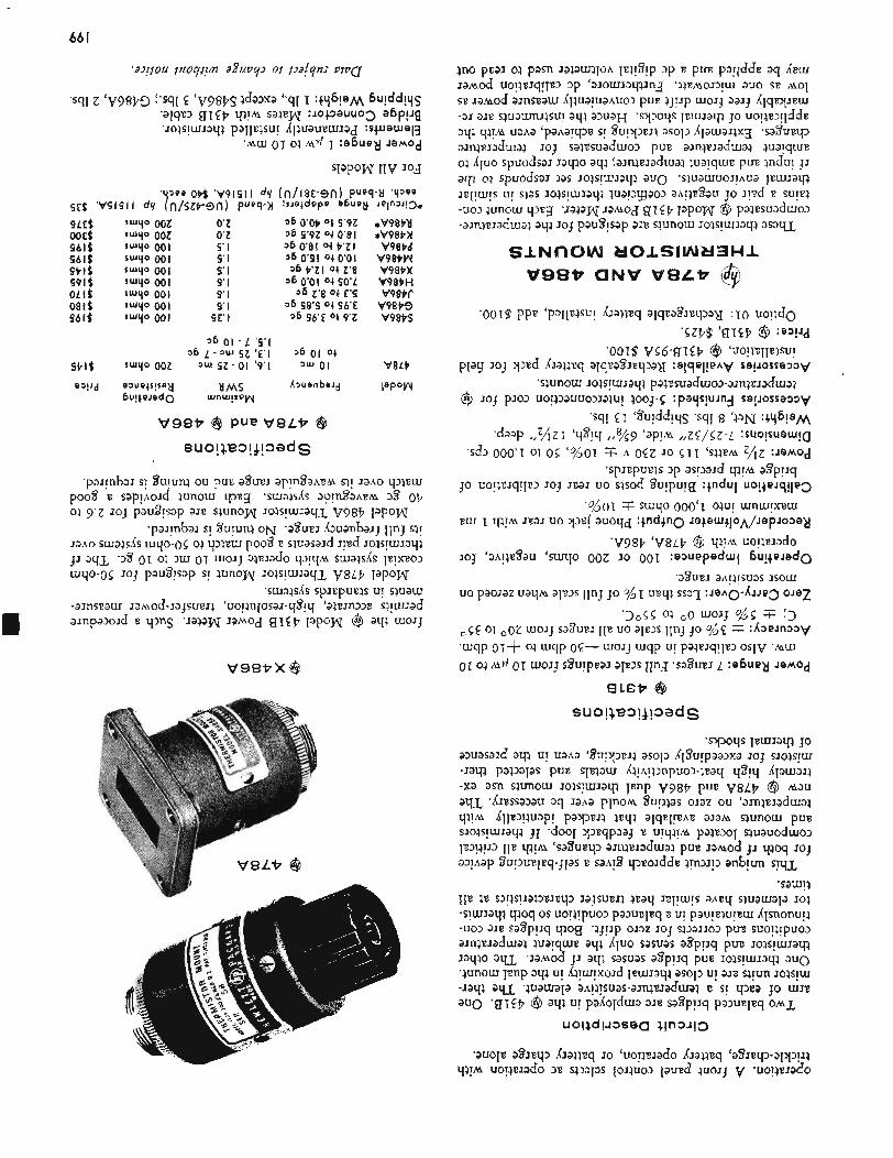
*V98P‘ti *V98P>1 V98Pd
V98PW V98tX V98PH
V98P9 V98PS
v9wr
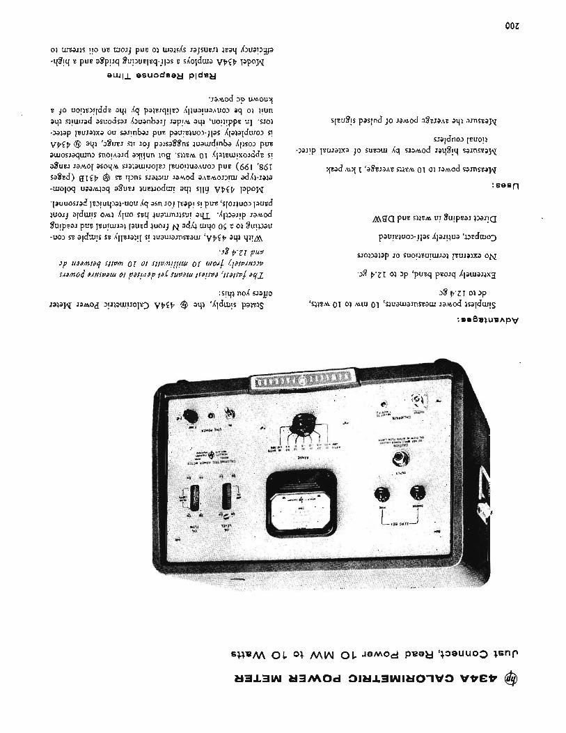
002
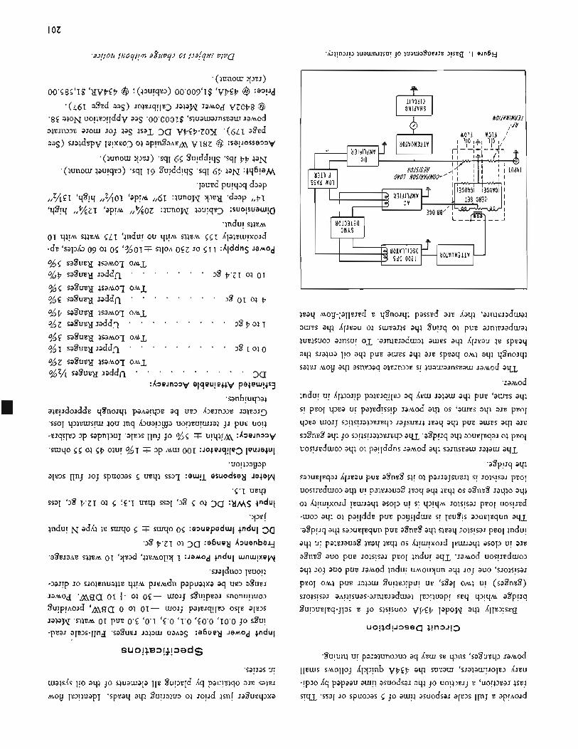
I OZ
I
1
L
LO2
3 A V M - ON113AVltl.l VS6t7-V68t7 @b Y
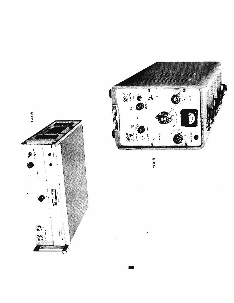
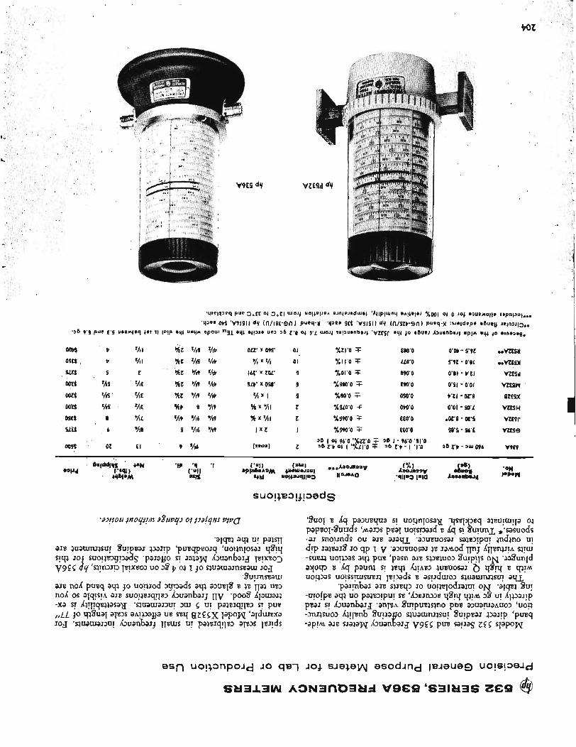
9oz
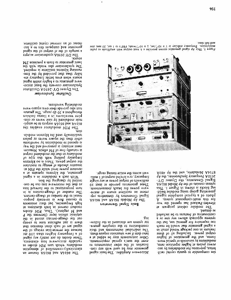
90Z
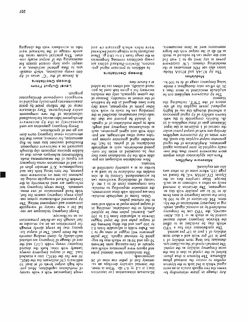
LOZ
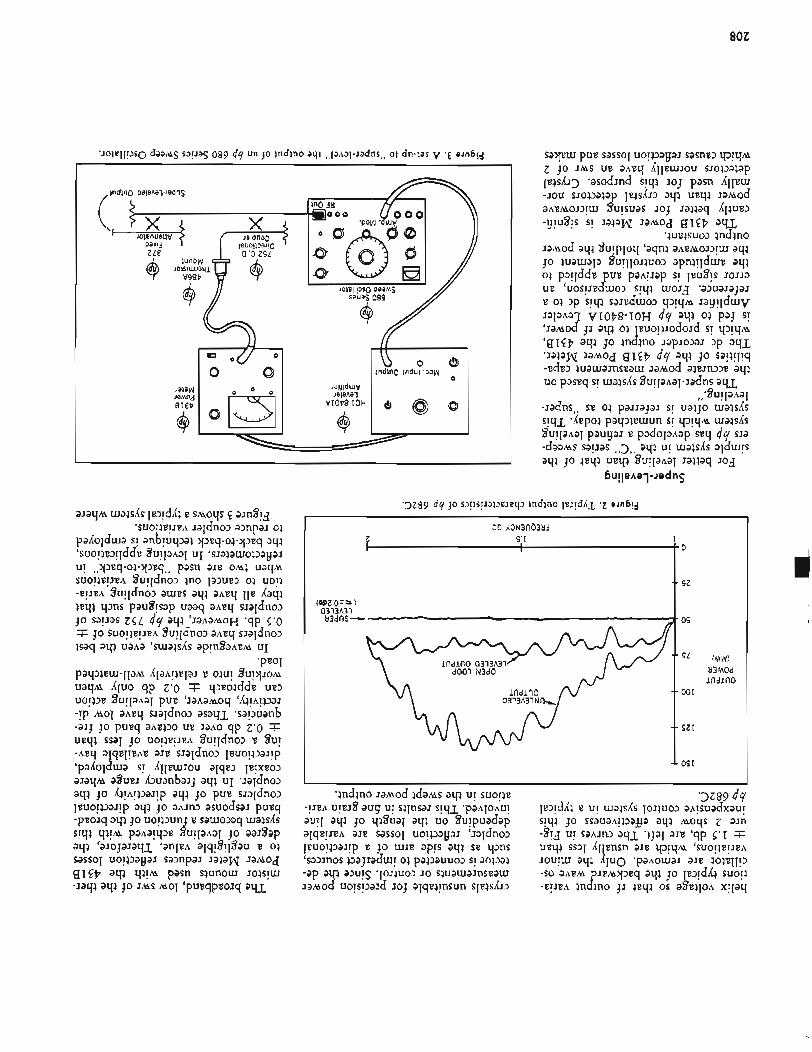
80Z
I 0
- - sz
. os
‘ O f (MW) ti3MOd i n d i n o
. 001
. OZI
1 0 5 1
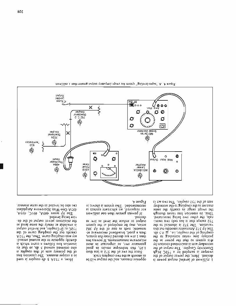
60Z
indino
Lr
x
I
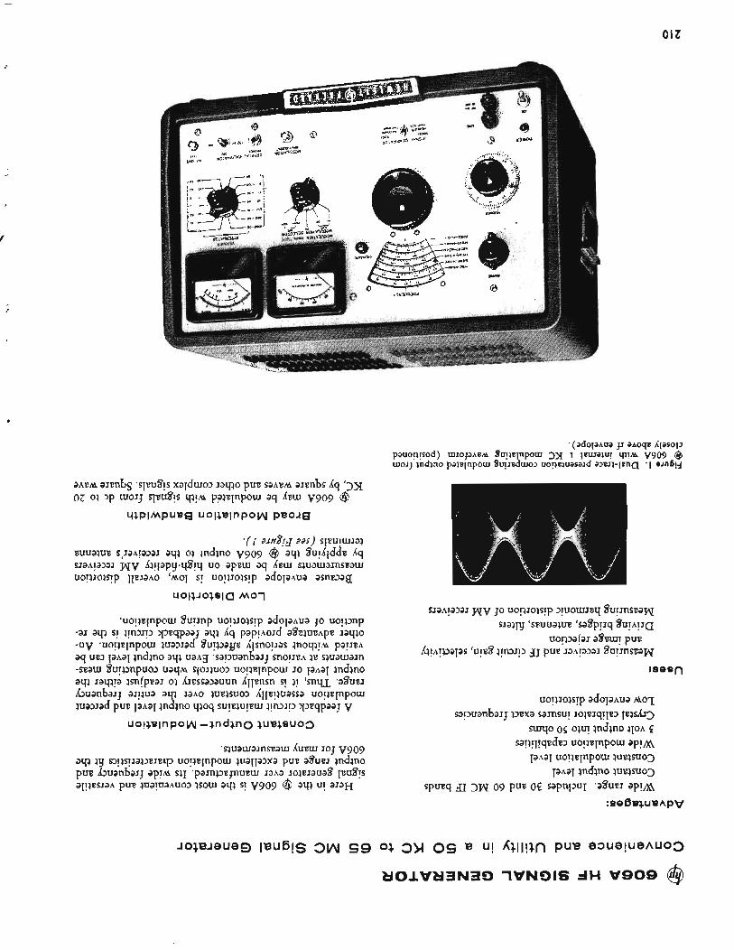
O l Z
f
4
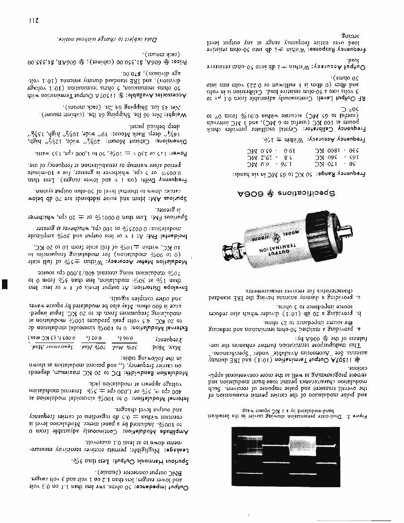
I It
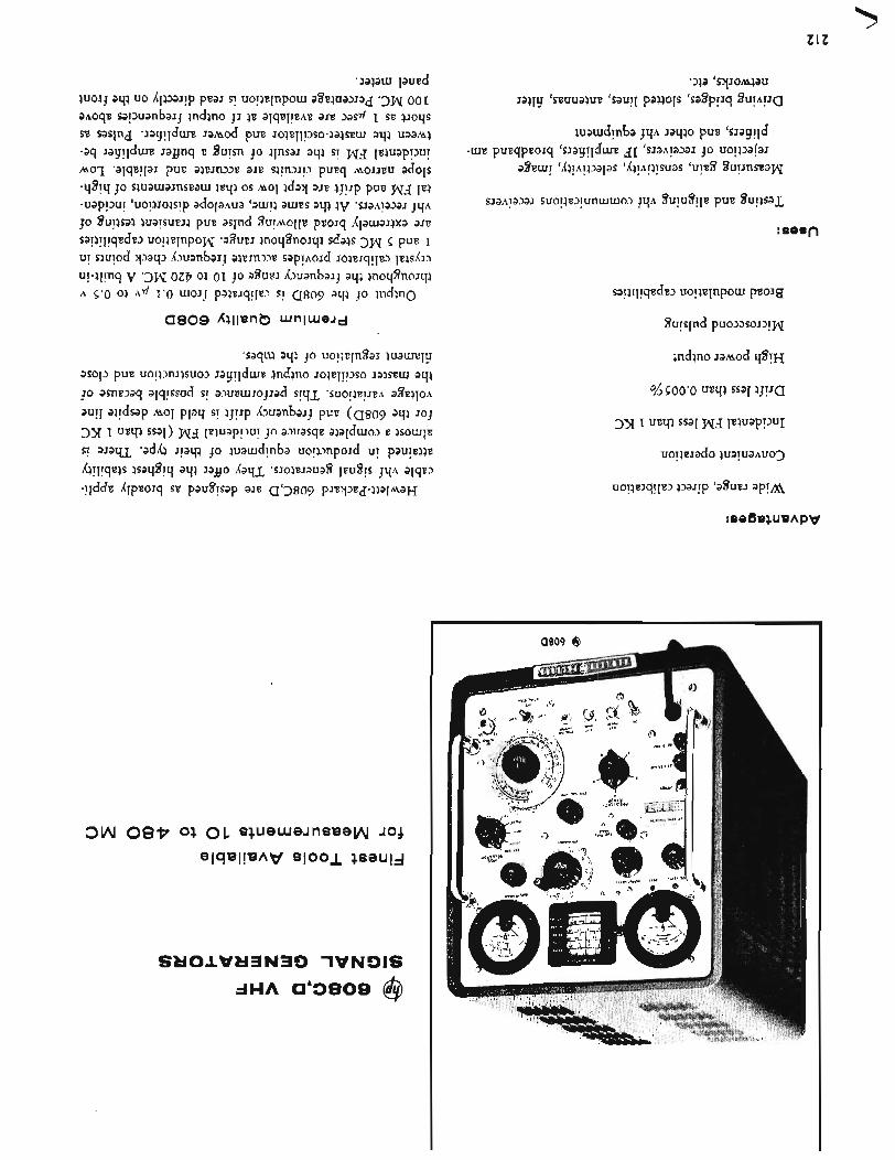
E I Z
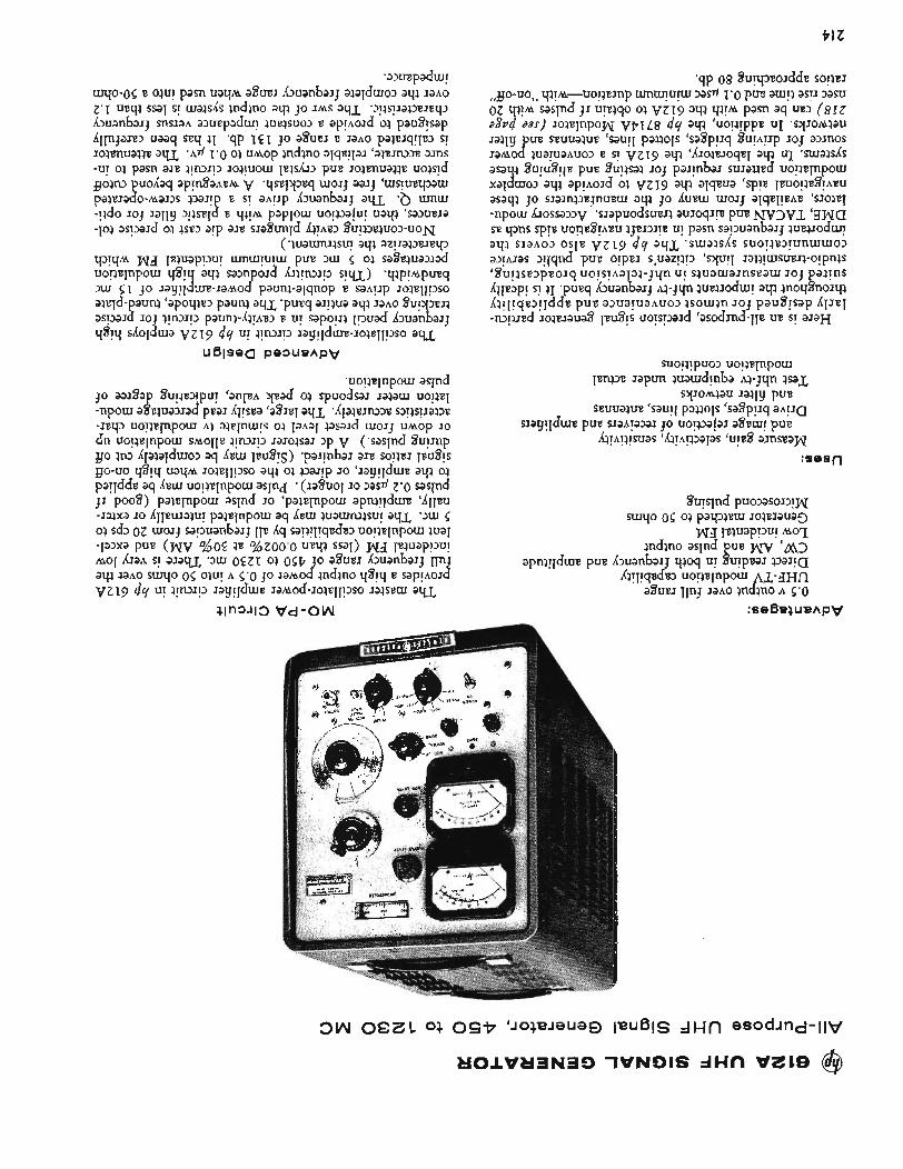
PI z
:sesn
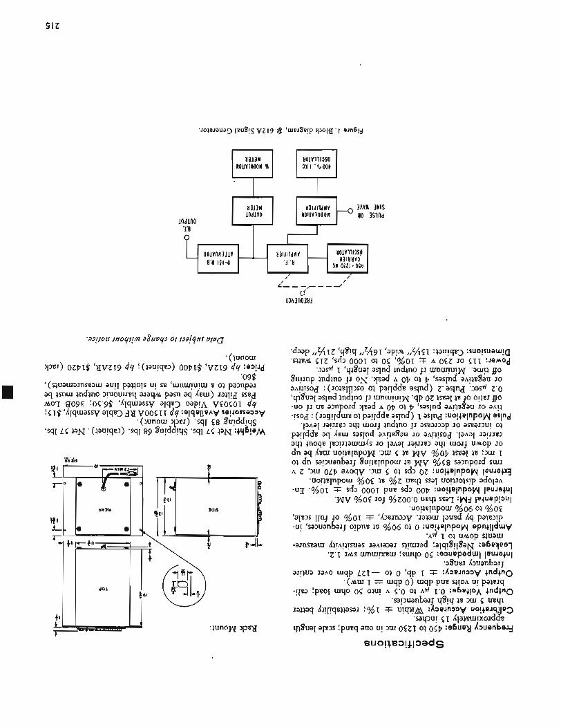
I ’ I
U O l V l l l l S O 83118V3
L I O l V R N 3 l l V 831411dHV - 31 OEZI - OS^ 8’0 LEI-0 * A ‘LI
, /‘
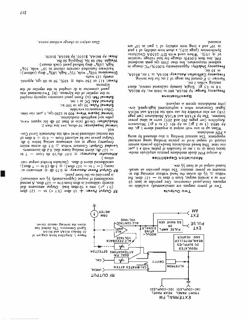
L I Z
t
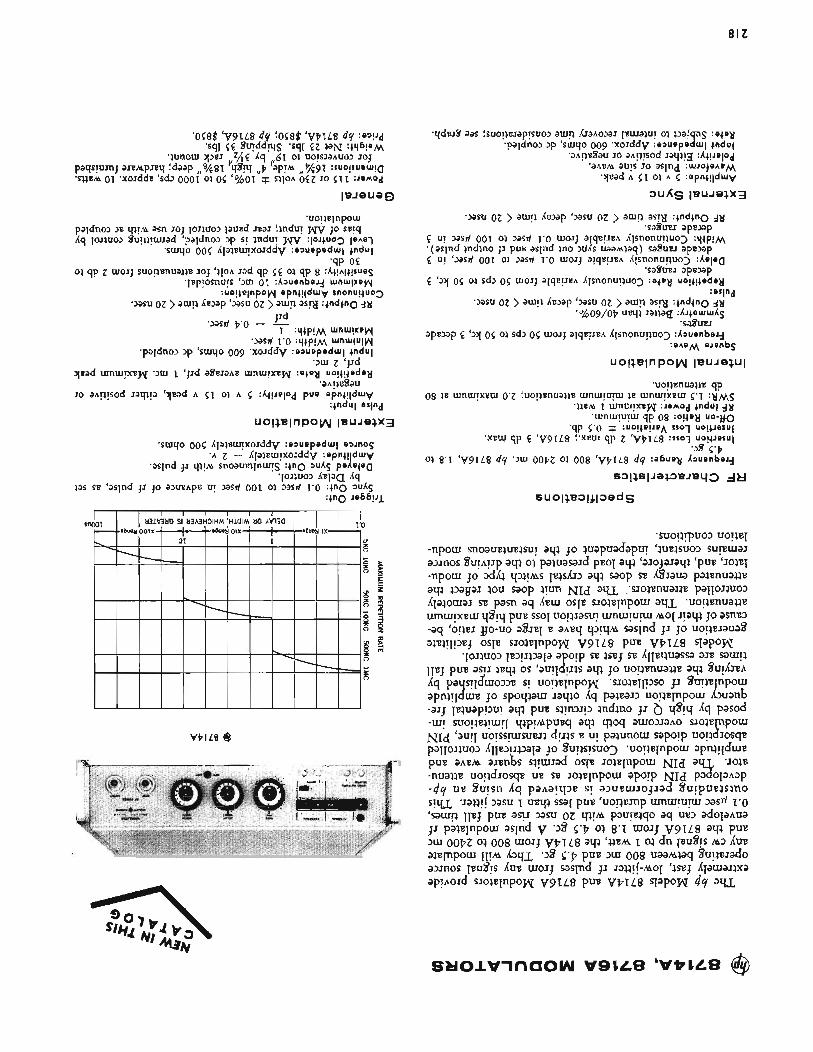
81Z
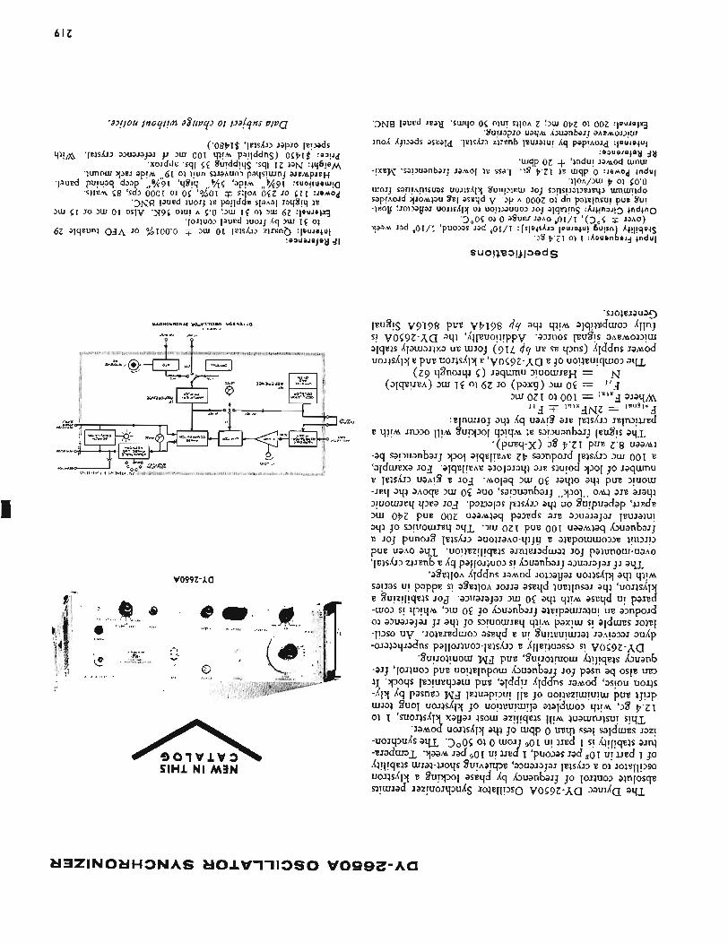
61Z
vowz-~a
ElHl N l M l N
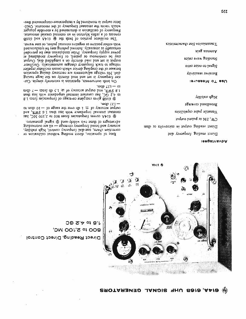
OZZ
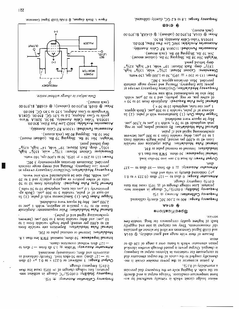
I ZZ
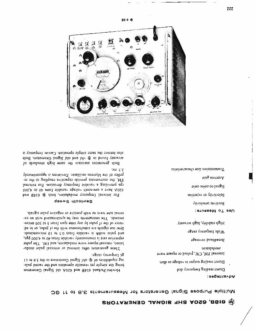
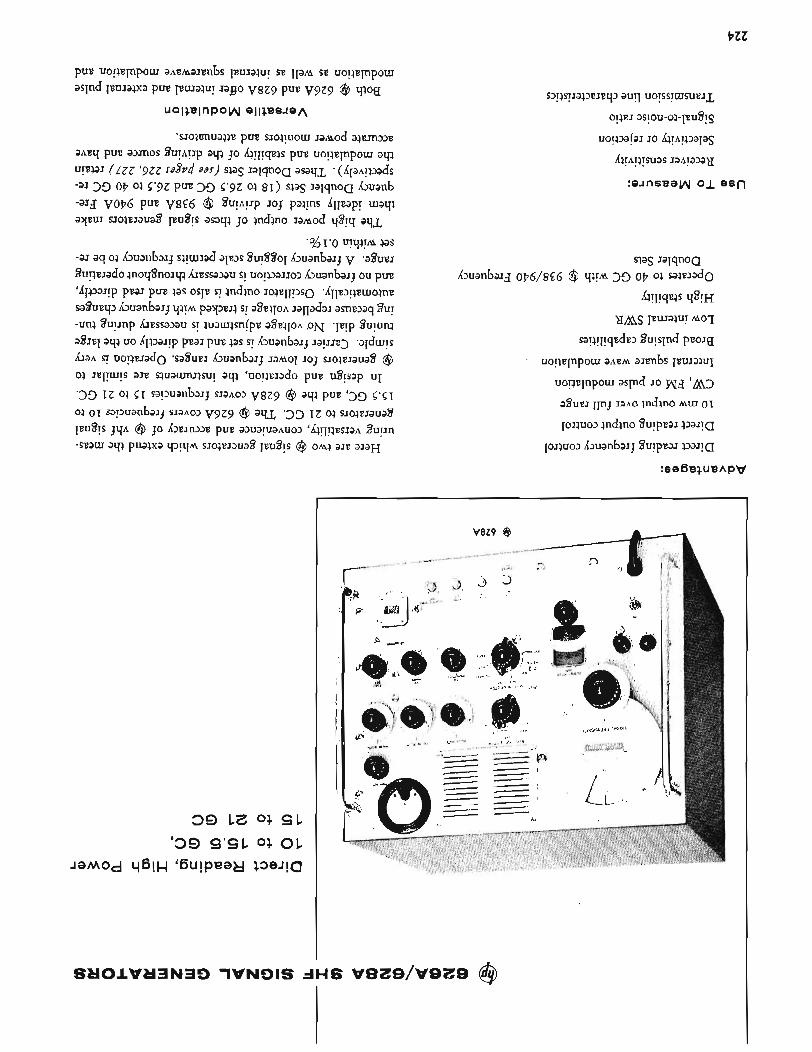
t z z
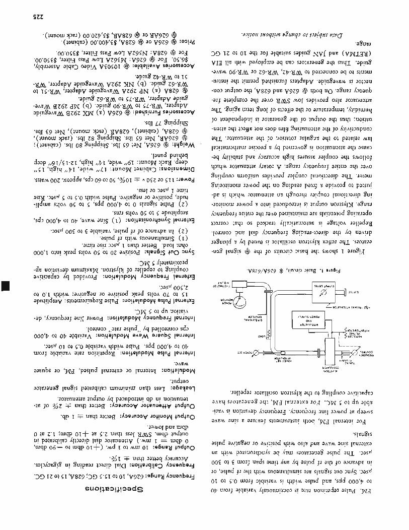
SZZ
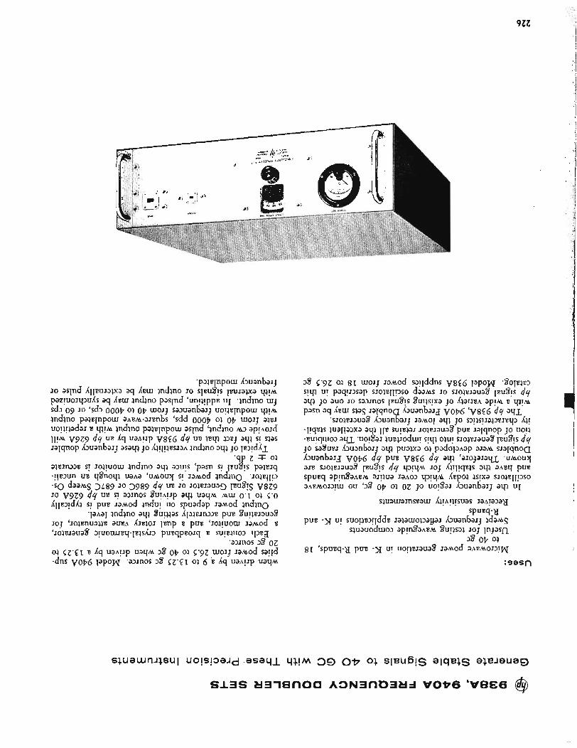
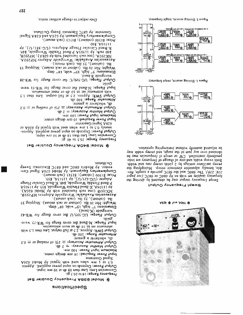
LZZ
V8Z9 @ Pup VoP6 @
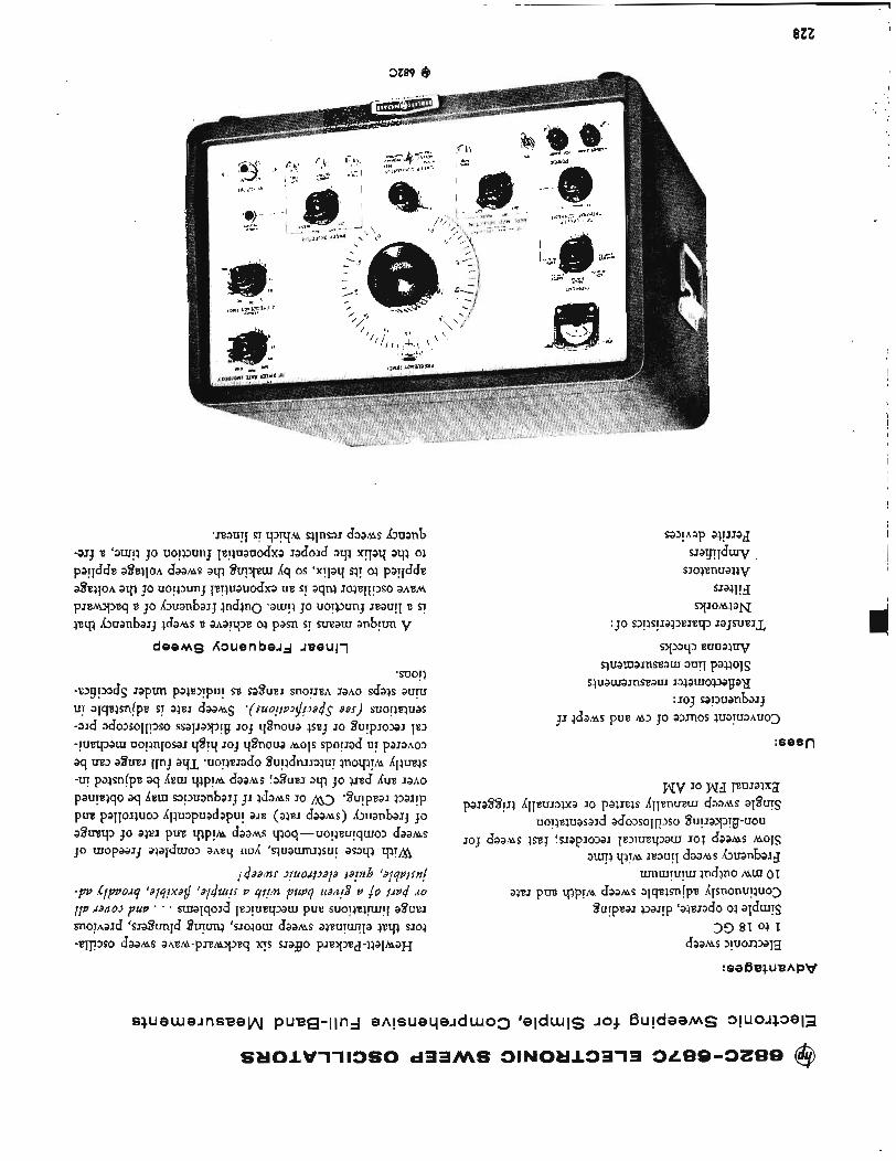
8ZZ
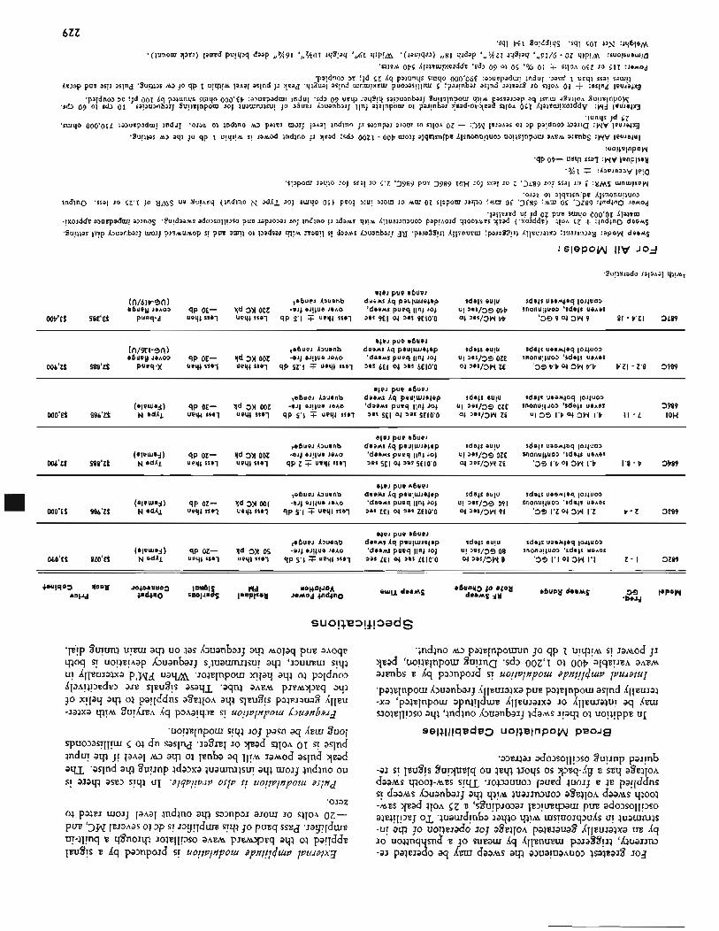
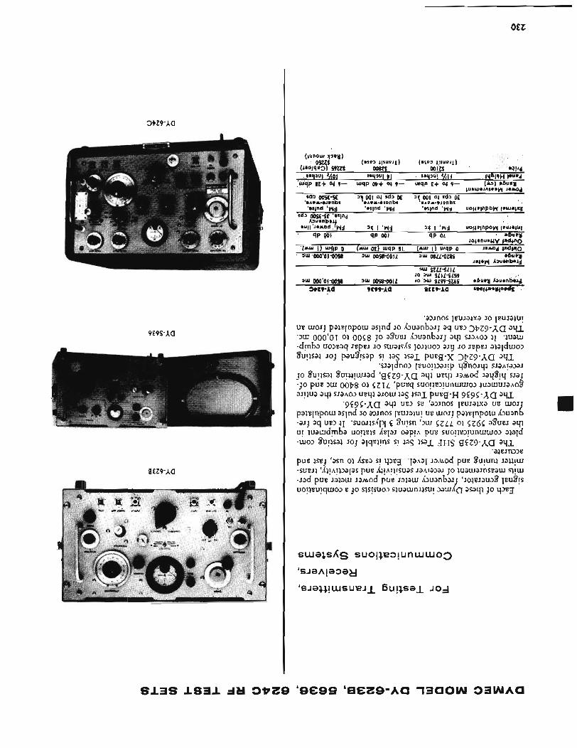
OEZ
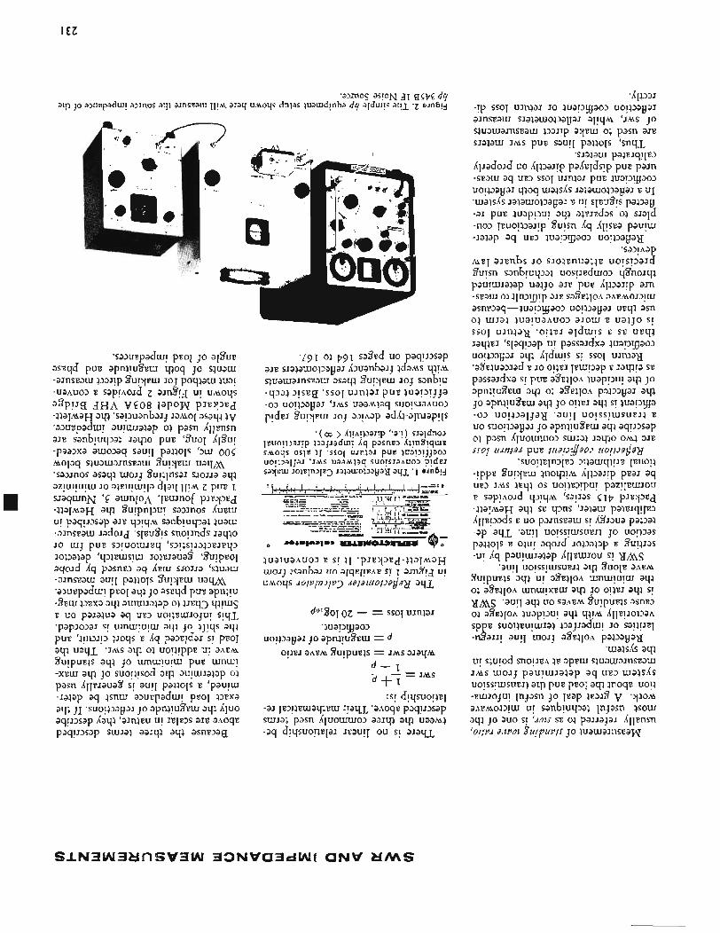
I EZ
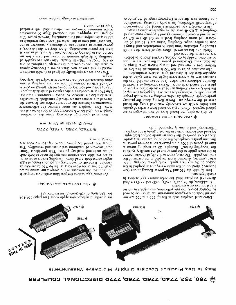
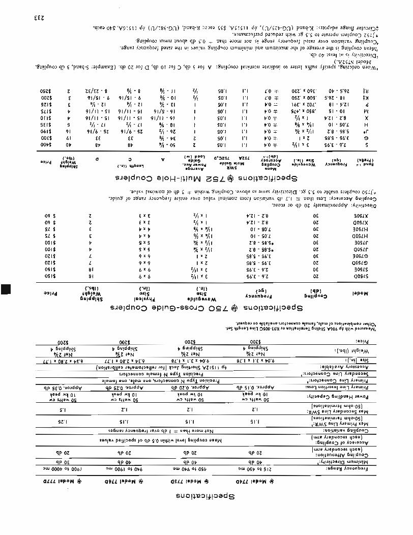
EEZ
04ze z ooze E S E I S E 9L18 P 0118 P S E I S 9 0619 91 OOE$ 61 OOPt OP
Z E I E Z - 8
% - Z I 91/11 - 91 91/11 - 91
Z/I - L I
91/41 - 6
9116 - SZ EE 8P
% - 8 a/i - I I z/l
91/91 - 6 % - 0 1 VI % - Z I % - E l I
91/11 - 91 9119 - 91 I 9111 I - 51 9111 I - 91 I
Z/I - L I % - 81 I 9116 - 9Z z/I - 9Z I
EE % - PE z 8P % - 04 Z
90 I 1.1 L'O T SO' I 1.1 1.0 T 9 0 I 1.1 P'O t 90 I 1.1 P'O F 90' I I'I P'O T 90 I 1.1 P'o 3 90' I 1.1 P 'O T 90' I 1.1 P'o 3 90' I 1.1 P'O 3
OZZ' X 09E' Ot - 9'9Z #d
16E' X ZOL' 81 - V Z I d 9LP' x 098' 91 - 01 W
X %I 01 - 90'L H
I X Z 48'9 - 96E 9
09Z' x 009' 9'9Z - 81 #n
z/I X I P 'Z I - Z'8 X
% x %I z'8 - 48.4 *r
Z/Il x E 96E - 9'z S
09 $ 09 $ 9L e 4L e oore O O l $ OZl$ OZl$ osle O S l $
Z Z E E P P L L 81 81
E X &
E X E
P X P P X P 9 x 9 9 x 9 9 x 9 9 x 9 6 x 6 6 x 6
XIOUI JO qp 0 2 dpwu!xoJddV : A + ! A ! + m ! a
P'ZI - Z'8 OE 309LX P'ZI - 2'8
01 - 90'L OE 309LH 01 - 40'L oz a 0 9 f H
OZ a o s L x
Z'8 - 48'9* OE 3osLr Z'8 - 98'9* oz a o w
98'9 - 46'E OE 3 0 9 L 9 48'9 - 96E oz a o s L 9 96'E - 9'Z OE 309LS 96E - 9'Z oz aous
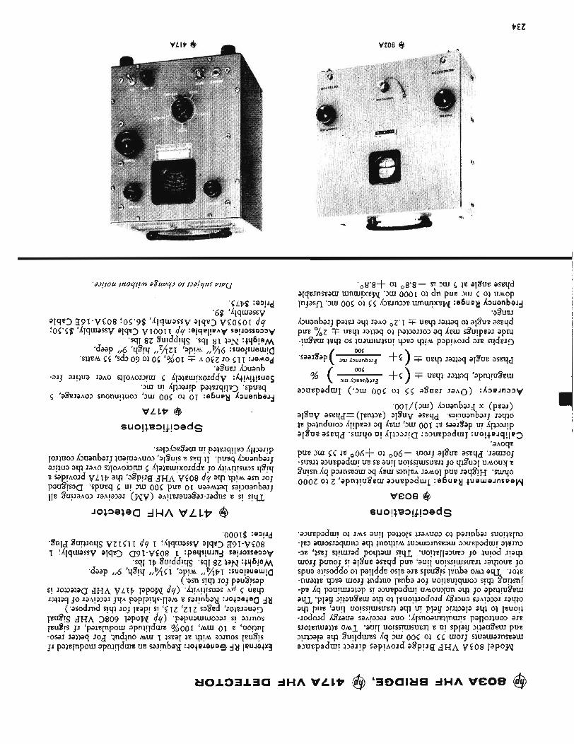
PEZ
VE08 @
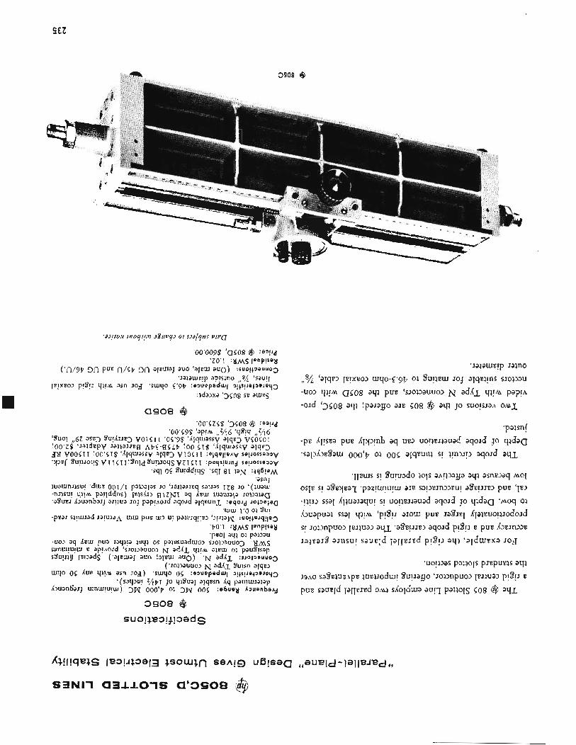
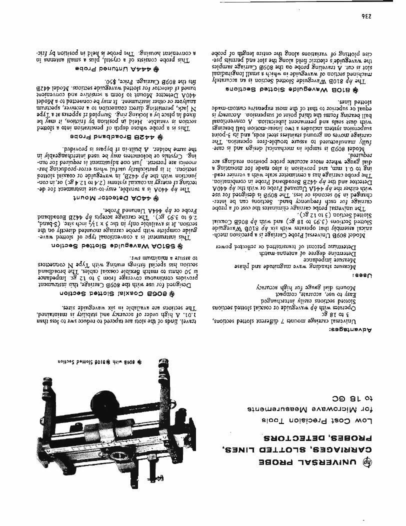
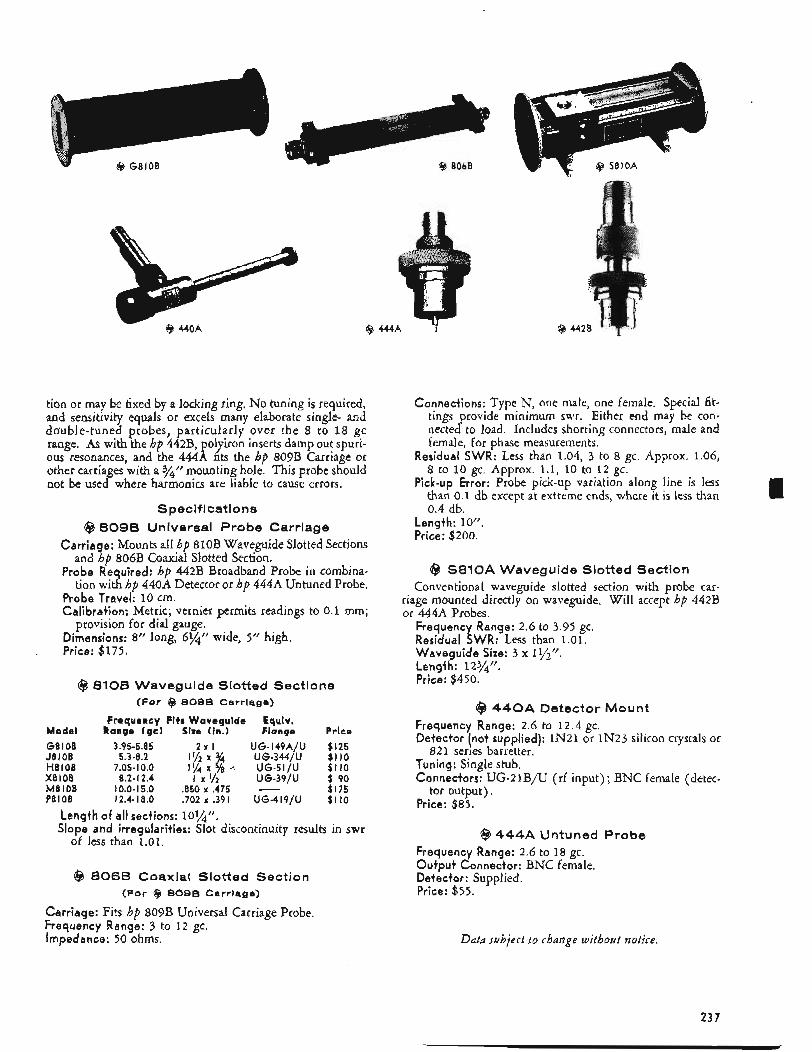
tion or may be fixed by a locking ring. No tuning is required, and sensitivity equals or excels many elaborate single- and double-tuned probes, particularly over the 8 to 18 gc range. As with the hp 442B, polyiron inserts damp out spuri- ous resonances, and the 444A fits the hp 809B Carriage or other carriages with a 3/4” mounting hole. This probe should not be used where harmonics are liable to cause errors,
Specifications @ 8098 Universal Probe Carriage
Carriage: Mounts all hp 810B Waveguide Slotted Sections and hp 806B Coaxial Slotted Section.
Probe Required: hp 442B Broadband Probe in combina- tion with hp 440A Detector or hp 444A Untuned Probe.
Probe Travel: 10 cm. Calibration: Metric; vernier permits readings to 0.1 mm;
provision for dial gauge. Dimensions: 8” long, 6%” wide, 5‘’ high, Price: $175.
@ 8108 Waveguide Slotted Sections (For $3 8096 Carriage)
Frequency Fits Waveguide Eqciv. Model Range (gel Size (in.) Flange Price 6 8 I OB 3.95-5.85 z x I U G - I 4 9 A / U $125 J8 I OB 5.3-8.2 1 ’ / ~ x 3/4 U G - 3 4 4 / U $110
X8 I OB 8.2- 12.4 I x 1/2 U G - 3 9 / U $ 90
P810B 12.4-18.0 .702 x ,391 U G - 4 1 9 / U $ 1 IO
H810B 7.05- 10.0 l l j q x 5/s 4 U G - 5 1 / U $110
M8 I OB 10.0-15.0 .E50 x .475 - $175
Length of all sections: 10%”. Slope and irregularities: Slot discontinuity results in swr
of less than 1.01.
@ 8066 Coaxial Slotted Section (For @ 809B Carriage)
Carriage: Fits hp 809B Universal Carriage Probe. Frequency Range: 3 to 12 gc. Impedance: 50 ohms.
Connections: Type N, one male, one female, Special fit- tings provide minimum swr. Either end may be con- nected to load. Includes shorting connectors, male and female, for phase measurements.
Residual SWR: Less than 1.04, 3 to 8 gc. Approx. 1.06, 8 to 10 gc. Approx. 1.1, 10 to 1 2 gc.
Pick-up Error: Probe pick-up variation along line is less than 0.1 db except at extreme ends, where it is less than 0.4 db.
Length: IO”. Price: $200.
@ S810A Waveguide Slotted Section Conventional waveguide slotted section with probe car-
riage mounted directly on waveguide. Will accept hp 442B or 44414 Probes.
Frequency Range: 2.6 to 3.95 gc. Residual SWR: Less than 1.01. Waveguide Size: 3 x 11/2”. Lengfh: 1234”. Price: $450.
@ 440A Detector Mount Frequency Range: 2.6 to 12.4 gc. Detector (not supplied): IN21 or IN23 silicon crystals or
Tuning: Single stub. Connectors: UG-21B/U (rf input) ; BNC female (detec-
Price: $85.
821 series barretter.
tor output).
@ 444A Untuned Probe Frequency Range: 2.6 to 18 gc. Output Connector: BNC female. Detector: Supplied. Price: $ 5 5 .
Data ~ubject t o chamge without notice.
237
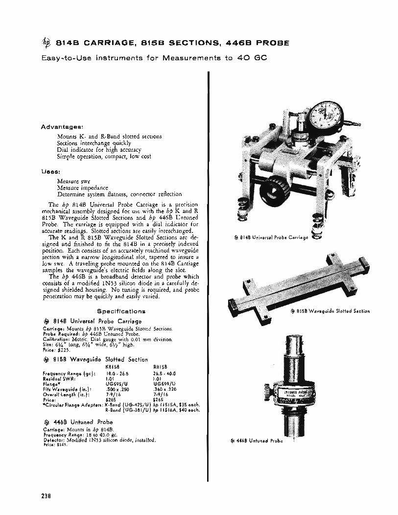
@ 8148 CARRIAGE, 8156 SECTIONS, 4468 PROBE
Easy-to-Use Instruments for Measurements to 40 GC
Advantages:
Mounts K- and R-Band slotted sections Sections interchange quickly Dial indicator for high accuracy Simple operation, compact, low cost
U s e s : Measure swr Measure impedance Determine system flatness, connector reflection
The hp 8143 Universal Probe Carriage is a precision mechanical assembly designed for use with the hp K and R 815B Waveguide Slotted Sections and hp 446B Untuned Probe. The carriage is equipped with a dial indicator for accurate readings. Slotted sections are easily interchanged.
The K and R 815B Waveguide Slotted Sections are de- signed and finished to fit the 814B in a precisely indexed
section with a narrow longitudinal slot, tapered to insure a low swr. A traveling probe mounted on the 814B Carriage samples the waveguide’s electric fields along the slot.
The hp 446B is a broadband detector and probe which consists of a modified IN53 silicon diode in a carefully de- signed shielded housing. No tuning is required, and probe
I position. Each consists of an accurately machined waveguide
I
I penetration may be quickly and easily varied.
Specifications
@ 814B Universal Probe Carriage Carr iage: Mounts hp 815B Waveguide Slotted Sections. Probe Required: hp 446B Untuned Probe. Calibration: Metric. Dial gauge with 0.01 rnm division. Size: 6%’’ long, 6%’’ wide, 61/2” high. Price: $225.
@ 8158 Waveguide Slotted Section
Frequency Range ( g c ) : 18.0 - 26.5 26.5 - 40.0 Residual SWR: 1.01 1.01 Flange* U G 5 9 5 / U U G 5 9 9 / U Fits Waveguide ( in.): .500 x .250 .360 x .220
Price: $265 $265 *Circular Flange Adapters: K-Band ( U G - 4 2 5 / U ) hp I1515A, $35 each.
R-Band ( U G - 3 8 1 / U ) hp 11516A, $40each.
K8 I 5 8 R8 15B
Overall Length (in.): 7-?/ I 6 7-9/ I 6
@ 4468 Untuned Probe Carr iage: Mounts in hp 814B. Frequency Range: 18 to 40.0 gc. Detector: Modified IN53 silicon diode, installed, Price: $145.
(2 8148 Universal Probe Carr iage
Q 446B Untuned Probe 7
238
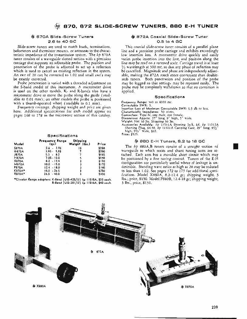
?$ 870, 872 SLIDE-SCREW TUNERS, 880 E-H TUNER
@ 870A Slide-Screw Tuners 2.6 to 40 GC
Slide-screw tuners are used to match loads, terminations, bolometers and thermistor mounts, or antennas to the charac- teristic impedance of the transmission system. The hp 870A tuner consists of a waveguide slotted section with a precision carriage that supports an adjustable probe. The position and penetration of the probe is adjusted to set up a reflection which is used to cancel an existing reflection in the system. An swr of 20 can be corrected to 1.02 and small swr's may be exactly corrected.
Probe penetration is varied with a threaded adjustment on the S-band model of this instrument, A micrometer drive is used on the other models. K- and R-bands also have a micrometer drive to move the probe along the guide (read- able to 0.01 mm) ; on other models the probe is positioned with a thumb-operated wheel (readable to 0.1 mm) .
Frequency coverage, shipping weight and price are given here. Additional specifications for each model appear on pages 168 to 178 in the microwave section of this catalog.
Spec if i catio n s
Model S870A G 8 7 0 A J870A H 8 7 0 A X870A M870A P870A K870Af R870A'
Frequency Range (qc)
2.6 - 3.95 3.95 - 5.85 5.3 - 8.2 7.05 - 10.0 8.2 - 12.4
10.0 - 15.0 12.4 - 18.0
26.5 -40.0 18.0 - 26.5
Shipping Weight (lbs.)
I 5 7 7 4 3 3 3 3 3
Price $250 $200 $165 $140 $130 $170 $140 $250 $300
*Ci rcu lar f lange adapters: K-Band UG-425/U) hp I1515A, $35 each. R-Band [ U G - 3 8 1 / U ) hp I1516A, $40 each.
@ 872A Coaxial Slide-Screw Tuner 0.5 to 4 G C
This coaxial slide-screw tuner consists of a parallel plane line and a precision probe carriage and exhibits exceedingly low insertion loss. A micrometer drive quickly and easily varies probe insertion into the line, and position along the line may be read on a recessed scale. Carriage travel is at least v2 wavelength at 500 mc, so that any phase of reflection may be cancelled. Magnitude and phase are independently adjust- able, making the 872A much more convenient than double- stub tuners. Both penetration and position of the probe may be logged so that settings may be repeated easily. The probe may be completely withdrawn so that no correction is applied,
S pec if i cat i o n s Frequency Range: 500 to 4000 mc. Correctable SWR: 5. Insert ion Loss a t Maximum Correctable SWR: 0.5 db or less. Characterist ic Impedance: 50 ohms. Connectors: Type N, one male, one female. Dimensions: Approx. 27" long, 9" high, 5" wide. W e i g h t : Net 10 lbs. Shipping 30 lbs. Accessories Avai lable: hp 11Sl lA Shorting Jack, $ 4 . h p 11512A
Shorting Plug, 54.50. hp 1lSloA Carrying Case, 29" long, 9% high, 99'2'' wide, $65.
Price: $525.
@ 880 E-H Tuners, 8.2 to 18 G C The h 880A,B tuners consist of a straight section of
tached. Each arm has a movable short circuit which may be positioned by a fine tuning control. Tuners of the E-H configuration are particularly useful where rf leakage is un- desirable. Standing wave ratios as high as 20 may be reduced to less than 1.02. See pages 172 to 175 for additional speci- fications. Model X880A, 8.2-12.4 gc; shipping weight, 3 Ibs.; price, $130. Model P880B, 12.4-18 gc; shipping weight, 3 Ibs., price, $150.
wavegui B e to which series and shunt tuning arms are at-
239
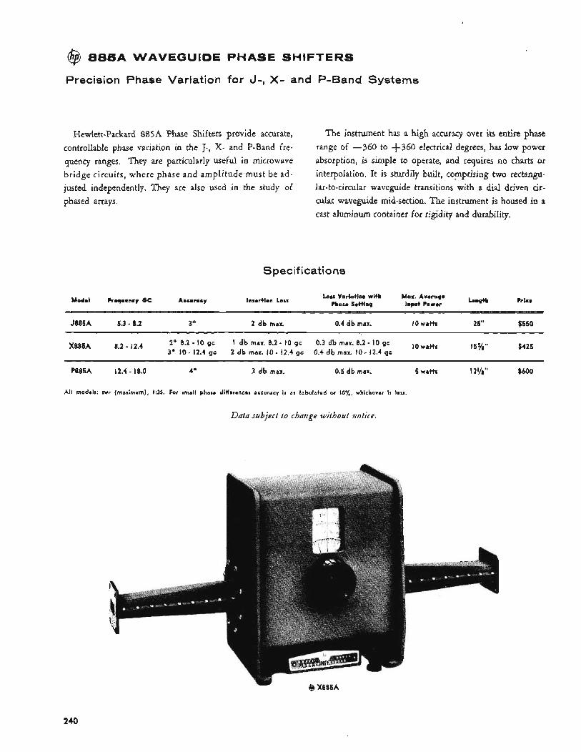
@ 8 8 5 A WAVEGUIDE PHASE SHIFTERS
Precision Phase Variation for 3-, X- and P-Band Systems
Hewlett-Packard 885A Phase Shifters provide accurate, controllable phase variation in the J-, X- and P-Band fre- quency ranges. They are particularly useful in microwave bridge circuits, where phase and amplitude must be ad- justed independently. They are also used in the study of phased arrays.
The instrument has a high accuracy over its entire phase range of -360 to f360 electrical degrees, has Iow power absorption, is simple to operate, and requires no charts or interpolation. It is sturdily built, comprising two rectangu- lar-to-circular waveguide transitions with a dial driven cir- cular waveguide mid-section. The instrument is housed in a cast aluminum container for rigidity and durability.
Spec if i cat i o ns
Accuwcy Insertion Loss Loss Variation with Max. Avorape Phase Setting Input Power Model Frequency GC
J885A 5.3 - 8.2 30 2 db max. 0.4 db max. 10 Wdt)S 25" $550
8.2 15%'' $425 12.4 X885A 2' 0.2 - 10 gc 3' IO- 12.4 gc
I db max. 8.2 - IO gc 2 db max. IO- 12.4 gc
0.3 db mdX. 8.2 - 10 gc 0.4 db msx. IO - 12.4 gc
I I P885A 12.4 - 18.0 40 3 db max. 0.5 db max. 5 Watts 12!/8'' $600
All models: swr (maximum), 135. For small phase differences accuracy i s as tabulated or IO%, whichever i s less.
Data subject to change without notice.
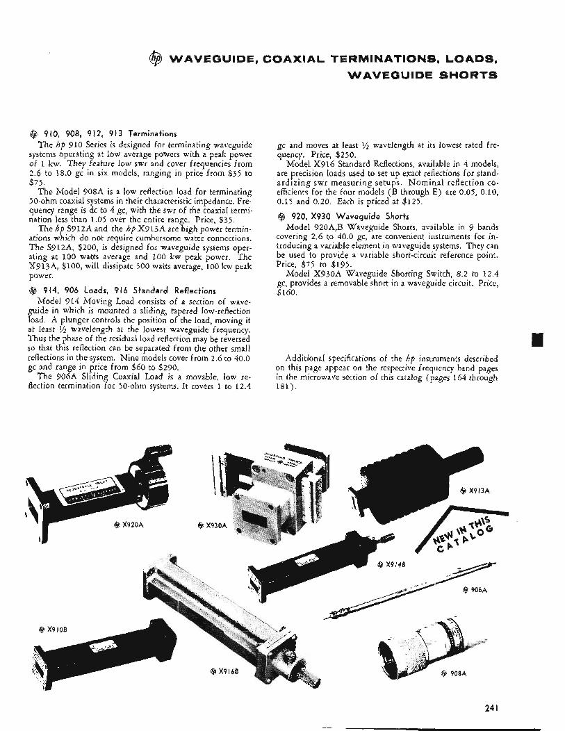
@ WAVEGUIDE, COAXIAL TERMINATIONS, LOADS, WAVEGUIDE SHORTS
Q 910, 908, 912, 913 Terminations The hp 910 Series is designed for terminating waveguide
systems operating at low average powers with a peak power of I kw. They feature low swr and cover frequencies from 2.6 to 18.0 gc in six models, ranging in price from $35 to $75.
The Model 908A is a low reflection load for terminating 50-ohm coaxial systems in their characteristic impedance. Fre- quency range is dc to 4 gc, with the swr of the coaxial termi- nation less than 1.05 over the entire range. Price, $35.
The hp S912A and the hp X913A are high power termin- ations which do not require cumbersome water connections. The S912A, $200, is designed for waveguide systems oper- ating at 100 watts average and 100 kw peak power. The X913A, $100, will dissipate 500 watts average, 100 kw peak power.
@ 914, 906 Loads, 916 Standard Reflections Model 914 Moving Load consists of a section of wave-
guide in which is mounted a sliding, tapered low-reflection load. A plunger controls the position of the load, moving it a t least 1/2 wavelength at the lowest waveguide frequency. Thus the phase of the residual load reflection may be reversed so that this reflection can be separated from the other small reflections in the system. Nine models cover from 2.6 to 40.0 gc and range in price from $60 to $290.
The 906A Sliding Coaxial Load is a movable, low re- flection termination for 50-ohm systems. It covers 1 to 12.4
gc and moves at least '/2 wavelength at its lowest rated fre- quency. Price, $250.
Model X916 Standard Reflections, available in 4 models, are precision loads used to set up exact reflections for stand- ardizing swr measuring setups. Nominal reflection co- efficients for the four models (B through E) are 0.05, 0.10, 0.15 and 0.20. Each i s priced at $125.
@ 920, X930 Waveguide Shorts Model 920A,B Waveguide Shorts, available in 9 bands
covering 2.6 to 40.0 gc, are convenient instruments for in- troducing a variable element in waveguide systems. They can be used to provide a variable short-circuit reference point. Price, $75 to $195.
Model X930A Waveguide Shorting Switch, 8.2 to 12.4 gc, provides a removable short in a waveguide circuit. Price, $160.
Additional specifications of the hp instruments described on this page appear on the respective frequency band pages in the microwave section of this catalog (pages 164 through 181).
@ 906A
@ 908A
24 I
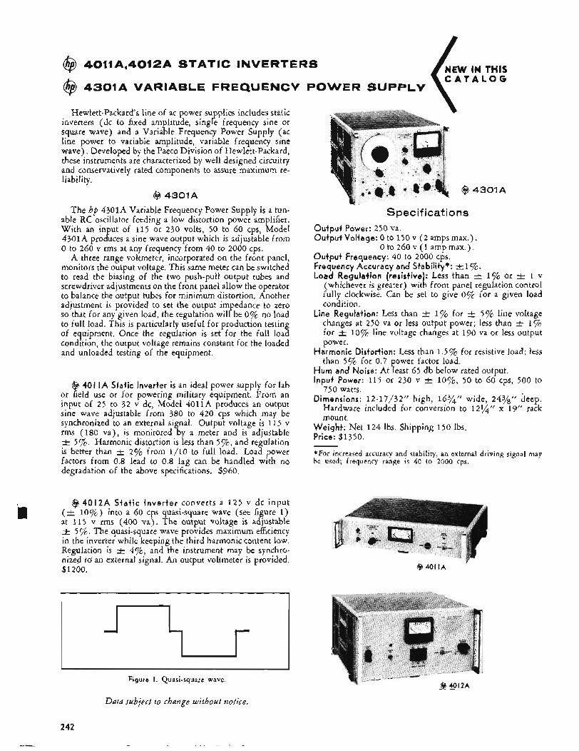
NEW IN THIS C A T A L O G
@ 4011A,4012A STATIC INVERTERS
POWER SUPPLY @ 4301A VARIABLE FREQUENCY
Hewlett-Packards line of ac power supplies includes static inverters (dc to fixed amplitude, single frequency sine or square wave) and a Variable Frequency Power Supply (ac line power to variable amplitude, variable frequency sine wave), Developed by the Paeco Division of Hewlett-Packard, these instruments are characterized by well designed circuitry and conservatively rated components to assure maximum re- liability,
@ 4301A
The hp 4301A Variable Frequency Power Supply is a tun- able RC oscillator feeding a low distortion power amplifier. With an input of 115 or 230 volts, 50 to 60 cps, Model 4301A produces a sine wave output which is adjustable from 0 to 260 v rms at any frequency from 40 to 2000 cps.
A three range voltmeter, incorporated on the front panel, monitors the output voltage. This same meter can be switched to read the biasing of the two push-pull output tubes and screwdriver adjustments on the front panel allow the operator to balance the output tubes for minimum distortion. Another adjustment is provided to set the output impedance to zero so that for any given load, the regulation will be 0% no load to full load. This is particularly useful for production testing of equipment. Once the regulation is set for the full load condition, the output voltage remains constant for the loaded and unloaded testing of the equipment.
@ 401 IA Static Inverter is an ideal power supply for lab or field use or for powering military equipment, From an input of 25 to 32 v dc, Model 4011A produces an output sine wave adjustable from 380 to 420 cps which may be synchronized to an external signal. Output voltage is 11 5 v rms (180 va), is monitored by a meter and is adjustable -+ 5%. Harmonic distortion is less than 5 % , and regulation is better than -+ 2% from 1/10 to full load. Load power factors from 0.8 lead to 0.8 lag can be handled with no degradation of the above specifications. $960.
@ 4012A Static Inverter converts a 125 v dc input (t 10%) into a 60 cps quasi-square wave (see figure 1) at 115 v rms (400 va). The output voltage is adjustable -t 5 ‘/o. The quasi-square wave provides maximum efficiency in the inverter while keeping the third harmonic content low. Regulation is -+ 4%, and the instrument may be synchro- nized to an external signal. An output voltmeter is provided. $1200.
n 1 J
Figure I. Quasi-square wave.
@ 4301A
Spec if kat ions Output Power: 250 va. Output Voltage: 0 to 150 v ( 2 amps max.) .
0 to 260 v (1 amp max.). Output Frequency: 40 to 2000 cps. Frequency Accuracy and Stability*: el$%. Load Regulation (resistive): Less than t_ 1% or 1 v
(whichever is greater) with front panel regulation control fully clockwise. Can be set to give 0% for a given load condition.
Line Regulation: Less than c 1% for -t 5% line voltage changes at 250 va or less output power; less than +. 1% for 3- 10% line voltage changes at 190 va or less output power.
Harmonic Distortion: Less than 1.5% for resistive load; less than 5% for 0.7 power factor load.
Hum and Noise: At least 65 db below rated output. Input Power: 115 or 230 v t lo%, 50 to 60 cps, 500 to
750 watts. Dimensions: 12-17/32” high, 16%” wide, 243/!’ deep.
Hardware included for conversion to 121/q” x 19” rack mount.
Weight: Net 124 Ibs. Shipping 150 Ibs. Price: $1350.
*For increased accuracy and stability, an external driving signal may be used; frequency range is 40 to 2000 cps.
@ 401 I A 7
Data subject to change without notice.
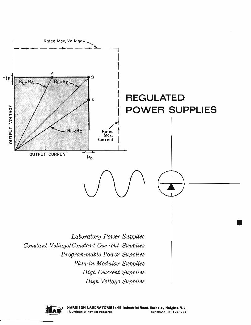
Rated Max. Voltage
1 -- - - -+- - --t .ir, - I t I I t I I 4
I-
Rated / t Max.
Current 1 2
REGULATED POWER SUPPLIES
-
Laboratory Power Supplies Constant VoltagelConstant Curren t Supplies
Programmable Power Suppl ies Plug-in Modular Supplies
High Curren t Suppl ies High Voltage Supplies
HARRISON LABORATORIES 45 Industrial Road, Berkeley Heights, N.J. ( A Divislon of Hewlett-Packard) Telephone 201.464-1234
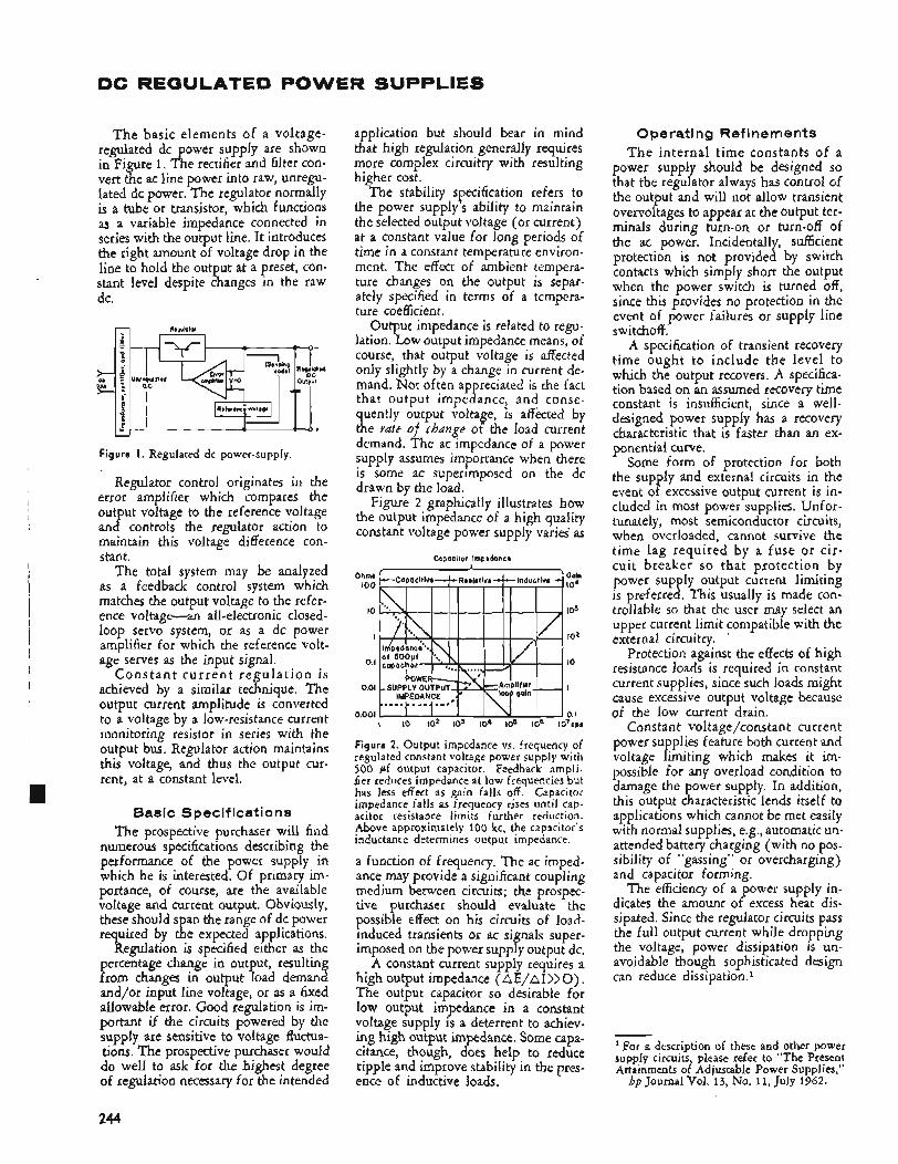
DC REGULATED POWER SUPPLIES
T h e basic elements of a voltage- regulated dc power supply are shown in Figure 1. The rectifier and filter con- vert the ac line power into raw, unregu- lated dc power. The regulator normally is a tube or transistor, which functions as a variable impedance connected in series with the output line. It introduces the right amount of voltage drop in the line to hold the output at a preset, con- stant level despite changes in the raw dc.
Figure I . Regulated dc power-supply.
Regulator control originates in the error amplifier which compares the out ut voltage to the reference voltage an g controls the regulator action to maintain this voltage difference con- stant.
The total system may be analyzed as a feedback control system which matches the output voltage to the refer- ence voltage-an all-electronic closed- loop servo system, or as a dc power amplifier for which the reference volt- age serves as the input signal.
C o n s t a n t c u r r e n t r e g u l a t i o n is achieved by a similar technique. The output current amplitude is converted to a voltage by a low-resistance current monitoring resistor in series with the output bus. Regulator action maintains this voltage, and thus the output cur- rent, at a constant level.
Sasic Specifications The prospective purchaser will find
numerous specifications describing the performance of the power supply in which he is interested. Of primary im- portance, of course, are the available voltage and current output. Obviously, these should span the range of dc power required by the expected applications.
Regulation is specified either as the percentage change in output, resulting from changes in output load demand and/or input line voltage, or as a fixed allowable error. Good regulation is im- portant if the circuits powered by the supply are sensitive to voltage fluctua- tions. The prospective purchaser would do well to ask for the highest degree of regulation necessary for the intended
application but should bear in mind that high regulation generally requires more complex circuitry with resulting higher cost.
The stability specification refers to the power supply’s ability to maintain the selected output voltage (or current) at a constant value for long periods of time in a constant temperature environ- ment. The effect of ambient tempera- ture changes on the output is separ- ately specified in terms of a tempera- ture coefficient.
Output impedance is related to regu- lation. Low output impedance means, of course, that output voltage is affected only slightly by a change in current de- mand. Not often appreciated is the fact that output impedance, and conse- quently output voltage, is affected by the fate of change of the load current demand. The ac impedance of a power supply assumes importance when there is some ac superimposed on the dc drawn by the load.
Figure 2 graphically illustrates how the output impedance of a high quality constant voltage power supply varies as
Ohms 100
10
I
0. I
0.01
0.001
Capacitor impedonce
I io 102 103 104 10s 108 I O ~ C P S
Figure 2. Output impedance vs. frequency of regulated constant voltage power supply with 500 pf output capacitor. Feedback ampli- fier reduces impedance at low frequencies but has less effect as gain falls off. Capacitor impedance falls as frequency rises until cap- acitor resistance limits further reduction. Above approximately 100 kc, the capacitor’s inductance determines output impedance.
a function of frequency. The ac imped- ance may provide a significant coupling medium between circuits; the prospec- tive purchaser should evaluate the possible effect on his circuits of load- induced transients or ac signals super- imposed on the power supply output dc.
A constant current supply requires a high output impedance ( AE/AI >> 0). The output capacitor so desirable for low output impedance in a constant voltage supply is a deterrent to achiev- ing high output impedance. Some capa- citance, though, does help to reduce ripple and improve stability in the pres- ence of inductive loads.
Operating Refinements T h e internal time constants of a
power supply should be designed so that the regulator always has control of the output and will not allow transient overvoltages to appear at the output ter- minals during turn-on or turn-off of the ac power. Incidentally, sufficient protection is not provided by switch contacts which simply short the output when the power switch is turned off, since this provides no protection in the event of power failures or supply line switchoff.
A specification of transient recovery time ought to include the level to which the output recovers. A specifica- tion based on an assumed recovery time constant is insufficient, since a well- designed power supply has a recovery characteristic that is faster than an ex- ponential curve.
Some form of protection for both the supply and external circuits in the event of excessive output current is in- cluded in most power supplies. Unfor- tunately, most semiconductor circuits, when overloaded, cannot survive the time lag required by a fuse or cir- cuit breaker so that protection by power supply output current limiting is preferred. This usually is made con- trollable so that the user may select an upper current limit compatible with the external circuitry.
Protection against the effects of high resistance loads is required in constant current supplies, since such loads might cause excessive output voltage because of the low current drain.
Constant voltage/constant current power supplies feature both current and voltage limiting which makes it im- possible for any overload condition to damage the power supply. In addition, this output characteristic lends itself to applications which cannot be met easily with normal supplies, e.g., automatic un- attended battery charging (with no pos- sibility of “gassing” or overcharging) and capacitor forming.
The efficiency of a power supply in- dicates the amount of excess heat dis- sipated. Since the regulator circuits pass the full output current while dropping the voltage, power dissipation is un- avoidable though sophisticated design can reduce dissipation.1
‘ For a description of these and other power supply circuits, please refer to “The Present Attainments of Adjustable Power Supplies,”
hp Journal Vol. 13, No. 11, July 1962.
244

Additional Power Supply Feat u res
Remote Sensing. Certain operational refinements contribute to the usefulness of dc power supplies. Remote sensing, for instance, prevents degradation of regulation at the load when there is an appreciable IR drop in the connecting leads. Remote sensing is effected simply by disconnecting the control leads, shown attached to the output buses in Figure 1, and extending them for re- attachment directly at the load.
Remote Programming. Remote pro- gramming, or remote control of the output, is desirable in a number of situa- tions, particularly in automatic check- out equipment where sequences of volt- ages or currents are required for test purposes.
Series Operation. Automatic series operation ( Auto-Series) of regulated supplies with total output control com- ing from one supply enables several power supplies to be “cascaded” for higher voltage output.
Parallel Opesation. Parallel opera- tion (Auto-Parallel) permits several power supplies to be used in parallel for higher current output, again with one knob control. Parallel operation may be extended to any number of the same supply.
Design Details The regulator circuit of Figure 3 is
representative of present H Lab design practice in power supplies. The tech- nique of deriving the reference voltage, however, differs from the regulator cir- cuit of Figure 1. Here (in Figure 3),
Figure 3. Constant voltage/constant current regulated power supply.
circuit action brings the voltage error amplifier inputs to the same level by matching the output voltage and the voltage at point P. Note that when the system is in balance, the voltage drop across resistor R, equals the reference voltage. This means that the current I, through R, is constant, regardless of the value of resistor R,. Because of this constant current, the voltage drop across R, depends on its resistance value. Since regulator action matches the output
voltage to the voltage drop across R,, the output voltage is a linear and pre- dictable function of the resistance value of R,. The output voltage therefore is adjusted simply by changing the resist- place of R,.
A power supply using this type of regulator may be programmed remotely by an external resistance connected in place of R,.
Constant current control is achieved with the other amplifier loop shown in Figure 3. In this case, the current error amplifier matches the voltage drop across series resistor R, to the voltage across current programming resistor RPi (RPi may also be an external resistance for remote current programming). The two error amplifiers are isolated by dis- connect diodes D1 and D2 so that the power supply functions as a con- stant voltage source up to a maximum current output selected by the front panel current control. Any tendency to- ward an increase in output current causes the constant current regulator to seize control and adjust the output volt- age to constrain the current to the selected level.
Parallel operation of these supplies is accomplished by reconnecting the voltage error amplifiers. The regulator of each slave supply adjusts its current output to match the voltage drop across its current monitoring resistor to the voltage drop across the current moni- toring resistor in the master supply.
Heavy-Duty SCR Supplies The block diagram of Figure 4 shows
another H Lab regulating circuit for supplying large amounts of current with high efficiency. This type of supply does not use a conventional series regulating element but depends instead on phase control of the rectifying elements to maintain a regulated voltage output.
The rectifier bridge includes two sili- con controlled rectifiers (SCR’s) . These pass no current until triggered by a “gate” signal and then continue con- duction until the applied anode voltage is removed. The “firing” angle during each ac cycle is controlled so that the charge supplied to the input capacitor is just sufficient to maintain the output voltage at the desired level.
The error amplifier controls the firing angle by means of a voltage ramp, the ramp being generated by charging the ramp capacitor with a constant current. The ramp voltage triggers the SCR cir- cuit when it reaches a fixed voltage level, and then resets to start again at the beginning of the next ac half cycle.
T h e rate at which the capacitor charges is controlled by the current out- put of the error amplifier. The error amplifier is responsive to the output voltage error, so that the SCR firing angle is adjusted by the feedback action to maintain the output voltage at a con- stant level.
AC bias added to the ramp makes the firing angle sensitive to the amplitude of the ac line voltage. The change in firing angle caused by a change in line voltage means that the SCR’s continue to supply essentially the same amount of charge during each cycle despite the changes in line voltage. This circuit reacts to line voltage changes within one half cycle of ac input and therefore shows remarkable immunity to line transients.
High current power supplies using this type of control are able to maintain better than 0.570 regulation. For even tighter regulation, a transistor regulator may be placed in series with the output from an SCR supply. The series regula- tor functions as described previously, but in this case the SCR control circuit simply monitors the voltage drop across the series regulator and controls the SCR firing angle to maintain this volt- age at a low value, nominally two to three volts.
These supplies can be made respon- sive to sudden changes in output cur- rent by addition of the current monitor- ing control link shown as a dotted line in Figure 4. Other variations in the ap-
Figure 4. SCR regulated power supply.
plication of series regulator control to SCR su plies allow up to 320 volts out- put to K e obtained without the use of expensive high voltage transistors.
This necessarily brief description of H Lab dc power supplies suggests the adaptability and flexibility designed into the control circuits. Reliable, long-lived performance is designed through cir- cuitry which minimizes transistor dis- sipation and through conservative use of components. These supplies achieve a remarkably high level of performance per dollar invested.
245
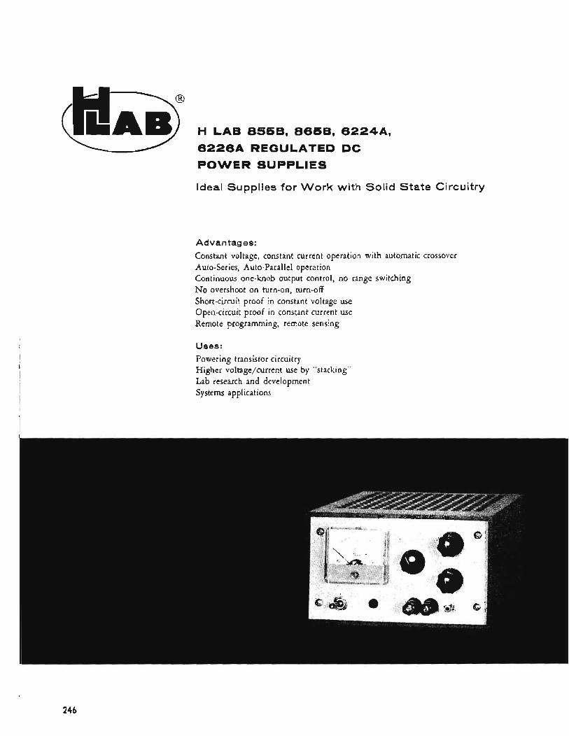
(!!A$ H LAB 8558, 8658, 622449, 1-1 6 2 2 6 A REGULATED DC
POWER SUPPLIES
Ideal Supplies for Work with Solid State Circuitry
Advantages:
Constant voltage, constant current operation with automatic crossover Auto-Series, Auto-Parallel operation Continuous one-knob output control, no range switching No overshoot on turn-on, turn-off Short-circuit proof in constant voltage use Open-circuit proof in constant current use Remote programming, remote sensing
Uses: Powering transistor circuitry Higher voltage/current use by “stacking” Lab research and development Systems applications
244
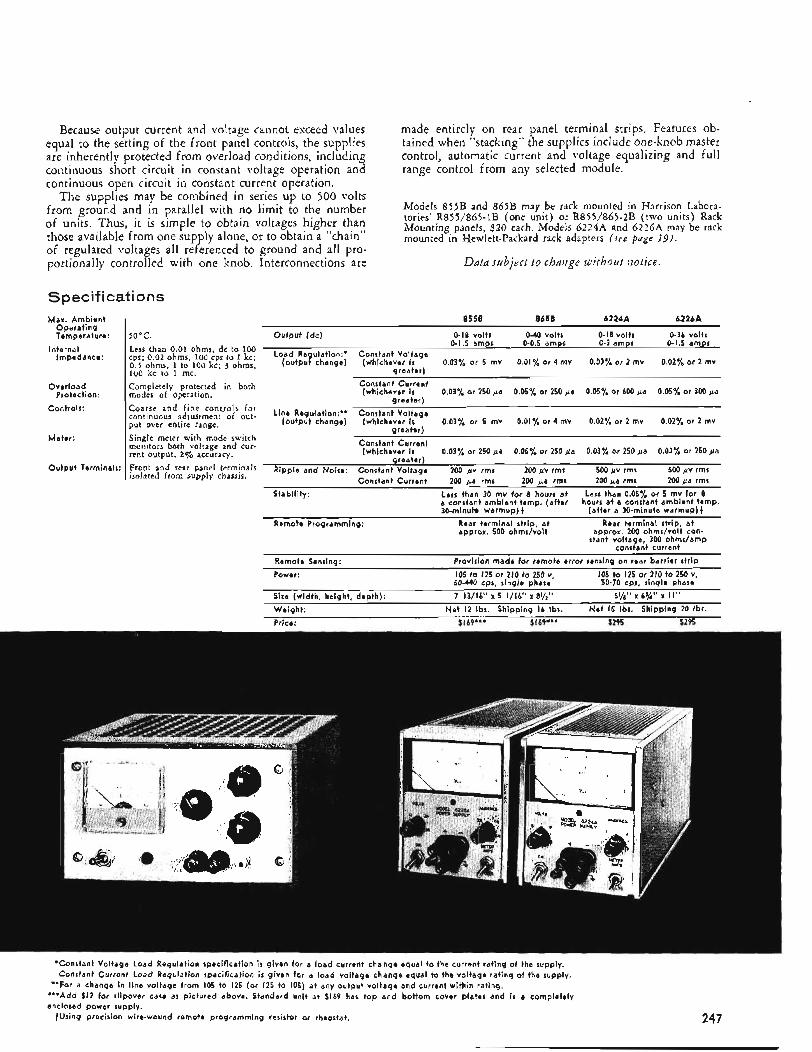
Because output current and voltage cannot exceed values equal to the setting of the front panel controls, the supplies are inherently protected from overload conditions, including coctinuous short circuit in constant voltage operation and continuous open circuit in constant current operation.
The supplies may be combined in series up to 500 volts from ground and in parallel with no limit to the number of units. Thus, it is simple to obtain voltages higher than those available from one supply alone, or to obtain a "chain" of regulated voltages all referenced to ground and all pro- portionally controlled with one knob. Interconnections are
Spec if i cat i o n s Max. Ambient
Operating Temperature:
Impedance: Internal
Overload
Controls:
Protection:
Meter:
Output Terminals:
made entirely on rear panel terminal strips. Features ob- tained when "stacking" the supplies include one-knob master control, automatic current and voltage equalizing and full range control from any selected module.
Models 855B and 865B may be rack mounted in Harrison Labora- tories' R855/865-1B (one unit) or R855/865-2B (two units) Rack Mounting panels, $20 each. Models 6224A and 6226A may be rack mounted in Hewlett-Packard rack adapters ( see puge 1.9).
Ddta subject to change iuithout fzotice.
8558 8658 6224A 6226A ~ ~~ ~
50°C Output (dc) 0-18 volts 0-40 volts 0-18 0-3 amps volts 0-1.5 0-36 volts amps
Less than 0.01 ohms dc to 100 cps; o , ~ ~ ohms, loo ips to 1 kc; o , ) ohms, 1 to loo kc; ohms, (output change) (whichever is 0.03% or 5 mv 0.01% or 4 mv 0.03% or 2 mv 0.02% or 2 mv loo kc to 1 mc. Completely protected in both modes of operation. Coarse and fine controls for continuous adjustment of out- put over entire range. Single meter with mode switch monitors both voltage and cur. rent output, 29'0 accuracy.
0-1.5 amps 0-0.5 amps Load Regulation:. Constant Voltage
areaterl
Front and rear panel terminals isolated from suppiy chassis.
Constant Current (whichever i s 0.03% or 250 pa 0.05% or 250 pa 0.05% or 600 pa 0.05% or 300 pa
greater) Line Regulation:** Constant Voltage
(output change) (whichever i s 0.03% or 5 mv 0.01% or 4 mv 0.02% or 2 mv 0.02% or 2 mv greater)
Constant Current (whichever is 0.03% or 250 &a 0.05% or 250 &a 0.03% or 250 pa 0.03% or 250 pa
greater) Ripple and Noise: Constant Voltage 200 pv rms 200 pv rms 500 uv rms 500 &v rms
cons tan t Currant 200 ua rms 200 ua rms 200 va rms 200 ua rms ~~~
Stability: Less than 30 mv for e hours a t a constant ambient temp. (after 30-minute warmup) t
Less than 0.05% or 5 mv for 8 hours at a constant ambient temp.
(after a 30-minute warmup){ ~ Remote Fogr&ming: Rear terminal strip, a t
approx. 500 ohms/voit Rear terminal strip, a t
approx. 200 ohms/volt con- stant voltage, 300 ohms/amp
constant current Provision made for remote error sensing on rear barrier strip
105 to 125 or 210 t o 250 v, 105 to 125 or 210 to 250 v, 50-440 cps, single phase 50-70 cps, single phase 7 13/16" x 5 1/16" x 8Yz" 5%'' x 6%" x I I "
Remote Sensing: Power:
Size (width, height, depth): Weight: Net I2 lbs. Shipping 16 Ibs. Net 15 Ibs. Shipping 20 Ibs. Price: $169*** $ 1 69*** $295 $295
*Constant Voltage Load Regulation specification i s given for a load current change equal to the current rating of the supply. Constant Current Load Regulation specification is given far a load voltage change equal t o the voltage rating of the supply.
'"Add $12 for slipover case as pictured above. Standard unit a t $169 has top and bottom cover plates and i s a completely enclosed power supply.
**For a change in line voltage from 105 to 125 (or 125 t o 10s) a t any output voltage and current within rating.
tUsing precision wire-wound remote programming resistor or rheostat. 247
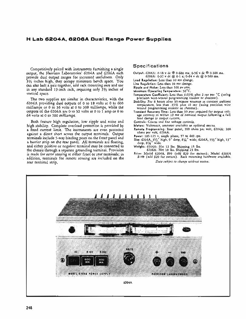
H Lab 6 2 0 4 A , 6 2 0 6 A Dual Range Power Supplies
Competitively priced with instruments furnishing a single output, the Harrison Laboratories’ 6204A and 62064 each provide dual output ranges for increased usefulness. Only 3% inches high, they occupy minimum bench space. You can also bolt a pair together, add rack mounting ears and use in any standard 19-inch rack, requiring only 3% inches of vertical space.
The two supplies are similar in characteristics, with the 6204A providing dual outputs of 0 to 18 volts at 0 to 600 milliamps or 0 to 36 volts at 0 to 300 milliamps, while the outputs of the 6206A are 0 to 32 volts at 0 to 1 amp or 0 to 64 volts at 0 to 500 milliamps.
Both feature high regulation, low ripple and noise and high stability. Complete overload protection is provided by a fixed current limit. The instruments are even protected against a direct short across the output terminals. Output terminals include 5-way binding posts on the front panel and a barrier strip on the rear panel. All terminals are floating,
the chassis through a separate grounding terminal. Provision is made for error sensing at either front or rear terminals; in
l and either positive or negative terminal may be connected to
addition, terminals for remote sensing are included on the I
\ rear terminal strip. ,
Specifications Output: 6204A: 0-18 v dc @ 0-600 ma; 0-36 v dc @ 0-300 ma.
Load Regulation: Less than 10 mv change. Line Regulation: Less than 10 mv change. Ripple and Noise: Less than 500 pv rms. Maximum Operat ing Temperature: 50°C. Temperature Coefficient: Less than 0.03% plus 2 mv per “C (using
precision wire-wound programming resistor or rheostat). Stability: For 8 hours after 30-minute warmup at constant ambient
temperature, less than .15% plus 10 mv (using precision wire wound programming resistor or rheostat).
Transient Recovery Time: Less than 50 psec required for output volt- age recovery to within 10 mv of nominal output following a full load change in output current.
6206A: 0-32 v dc @ 0-1 a; 0-64 v dc @ 0-500 ma.
Controls: Coarse and fine voltage controls, Meters: Voltmeter, ammeter available as optional extras. Remote Programming: Rear panel, 200 ohms per volt, 6204A; 300
Power: 105-125 v, single phase, 57 to 440 cps. Size: 6204A, 395” high, 9” deep, 8%” wide; 6206A, 3%” high, 13”
Weight : 6204A; Net 12 Ibs. Shipping 15 lbs.
Price: Model 6204A, $99 (add $20 for meters); Model 6206A $149 (add $20 for meters). Rack mounting hardware available.
ohms per volt, 6206A.
deep, 8%” wide.
620614: Net 18 Ibs. Shipping 23 Ibs.
Data subjert t o change without notice.
6204A
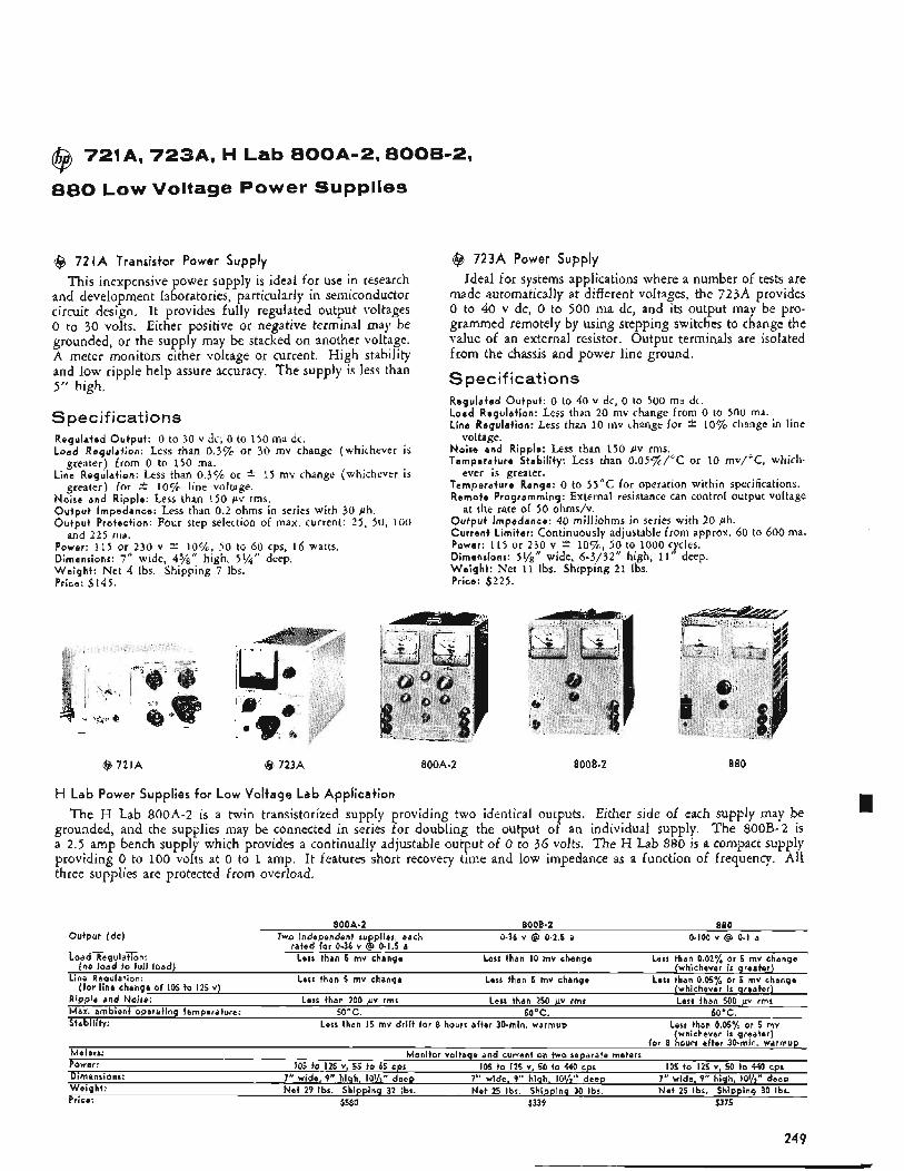
@ 721A, 7 2 3 A , H Lab 8 0 0 A 1 2 , 8 0 0 B - 2 ,
880 Low Voltage Power Supplies
@ 72 I A Transistor Power Supply This inexpensive power supply is ideal for use in research
and development laboratories, particularly in semiconductor circuit design. It provides fully regulated output voltages 0 to 30 volts, Either positive or negative terminal may be grounded, or the supply may be stacked on another voltage. A meter monitors either voltage or current. High stability and low ripple help assure accuracy. The supply is less than 5" high.
Spec if icati ons Regulated O u t p u t : 0 to 30 v dc; 0 to 150 md dc. L o a d Regulat ion: Less than 0,3% or 30 rnv change (whichever is
greater) from 0 to 150 ma. Line Regulat ion: Less than 0.3% or * 15 rnv change (whichever is
greater) for i 10% line voltage. Noise and Ripple: Less than 150 pv rms. O u t p u t Impedance: Less than 0.2 ohms in series with 30 ph. O u t p u t Protection: Four step selection of rnax. current: 2 5 , 50, 100
Power: 115 or 230 v * lo%, 50 to 60 cps, 16 watts. Dimensions: 7" wide, 43/8" high, 5%'' deep. W e i g h t : Net 4 Ibs. Shipping 7 Ibs. Price: $145.
and 225 ma.
Q 723A Power Supply Ideal for systems applications where a number of tests are
made automatically at different voltages, the 723A provides 0 to 40 v dc, 0 to 500 ma dc, and its output may be pro- grammed remotely by using stepping switches to change the value of an external resistor. Output terminals are isolated from the chassis and power line ground.
Specifications Regulated O u t p u t : 0 to 40 v dc, 0 to 500 ma dc. Load Regulat ion: Less than 20 mv change from 0 to 500 md. Line Regulat ion: Less than 10 niv change for * 10% change in line
Noise and Ripple: Less than 150 pv rms. Temperature Stabi l i ty: Less than 0.05%/"C or 10 rnv/"C, which-
Temperature Range: 0 to 55°C for operation within specifications. Remote Programming: External resistance can control output voltage
O u t p u t Impedance: 40 rnilliohms in series with 20 ph. Cur ren t L imi ter : Continuously adjustable from approx. 60 to 600 ma. Power: 115 or 230 v * l o%, 50 to 1000 cycles. Dimensions: 5%'' wide, 6-3/32" high, I t " deep. W e i g h t : Net 11 lbs. Shipping 2 1 Ibs. Price: $225.
voltage.
ever is greater.
at the rate of 50 ohms/v.
@ 721A @ 723A 800A-2 EOOB-2 880
H Lab Power Supplies for Low Voltage Lab Application The H Lab 800A-2 is a twin transistorized supply providing two identical outputs. Either side of each supply may be
grounded, and the supplies may be connected in series for doubling the output of an individual supply. The 800B-2 is a 2.5 amp bench supply which provides a continually adjustable output of 0 to 36 volts. The H Lab 880 is a compact supply providing 0 to 100 volts at 0 to 1 amp. It features short recovery time and low impedance as a function of frequency. All three supplies are protected from overload.
800A-2 8006.2 880 Output (dc)
Load Regulation:
Line Requlation:
Ripple and Noise: Max. ambient operating temperature: 50°C. 50°C. 50'C. Stability:
Two independent supplies, each rated for 0-36 v @ 0-1.5 a
Less than 5 mv change
Less than 5 mv change
Less than 200 pv rms
0-36 v @ 0-2.5 a
Less than IO mv change
Less than 5 mv change
Less than 250 pv rms
0-100 v @ 0-1 a
Less than 0.02% or 5 mv change (whichever i s greater)
Less than 0.05% or 5 mv change (whichever is qreater) Less than 500 pv rms
Less than 0.05% or 5 mv (whichever i s greater)
for 8 hours after 3O-min. warmup Meters: Power: 105 to 125 v, 50 to 440 cps Dimensions: 7" wide, 9" high, 10%" deep Weight: Net 29 Ibs. Shipping 32 Ibs. Net 25 Ibs. Shipping 30 Ibs. Net 25 Ibs. Shipping 30 Ibr.
(no load to full load)
(for line change of 105 to 125 v)
Less than 15 mv drift for 8 hours after 30-min. warmup
Monitor voltage and current on two separate meters 105 io 125 v, 55 to 65 cps
7" wide, 9" hiah. 10%" deep 105 to 125 v, 50 to 440 cps
7" wide, 9" high, IO%" deep
Price: $580 $339 $375
24 9
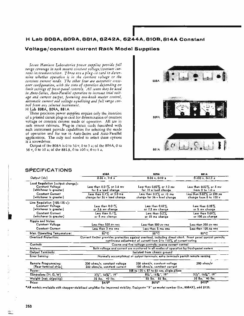
H Lab 8 0 8 A , 8 0 9 A , &81A, 6 2 4 2 A , 6 2 4 4 A , 8108,814A Constant
Voltage/constant current Rack Model Supplies
Seveii Harrison Laboratories power supplies provide full range coverage in rack mount constant uoltage/constant cur- ren t ins t rumenta t ion . Three use a p l u g - i n card t o de ter - mine whether operatioti is in the constant voltage or the constant current mode. T h e other four are automatic cross- ouer configuration, with the state of operation depending on limit settings of front-panel controls. All seuen mdy be used in Auto-Series, Auto-Parallel operation to increase total volt- age and current output, featuring one-knob master control, automatic current and voltdge e yudizing and f ull range con- trol f r o m any selected instrument. H Lab 808A, 809A, 881A
These precision power supplies require only the insertion of a printed circuit plug-in card for determination of constant voltage or constant current mode of operation. All are in rack mount cabinets. Plug-in circuit cards furnished with each instrument provide capabilities for selecting the mode of operation and for use in Auto-Series and Auto-Parallel applications. The only tool needed to select these options is a screwdriver.
Output of the 808A is 0 to 36 v, 0 to 5 a; of the 809A, 0 to 36 v, 0 to 10 a; of the 881A, 0 to 100 v, 0 to 1 a;
0Q0A
. _...,.I , . . .
8QQA
*All models available with chopper-stabilized amplifier for improved stability. Designate "X" on model number [Le., SOSAX), add $125.
250
- _ _ _ ~ - - ---- . - -
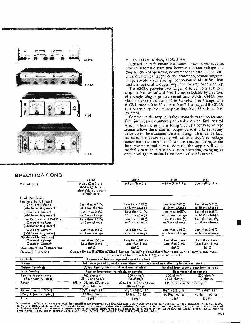
6242A
810B
814A
H Lab 6242A, 6244A, 8 I OB, 8 14A Offered in rack mount enclosures, these power supplies
provide automatic transition between constant voltage and constant current operation, no overshoot on turn-on and turn- off, short circuit and open circuit protection, remote program- ming, remote error sensing, continuously adjustable limit controls, optional chopper amplifier for improved stability.
The 6 2 4 2 4 provides two ranges, 0 to 32 volts at 0 to 2 amps or 0 to 64 volts at 0 to 1 amp, selectable by insertion of a single plug-in printed circuit card. Model 6244A pro- vides a standard output of 0 to 36 volts, 0 to 3 amps. The 810B furnishes 0 to 60 volts at 0 to 7.5 amps, and the 8 1 4 A is a heavy duty instrument providing 0 to 36 volts at 0 to 25 amps.
Common to the supplies is the automatic transition feature. Each includes a continuously adjustable current limit control which, when the supply is being used as a constant voltage source, allows the maximum output current to be set at any value up to the maximum current rating. Thus, as the load increases, the power supply will act as a regulated voltage source until the current limit point is reached. Then, as the load resistance continues to decrease, the supply will auto- matically transfer to constant current operation, changing its output voltage to maintain the same value of current.
SPEC1 FlCATlONS 6242A 6244A 8106 814A
0-32 v @ 0-2 a, or
selectablc b y plug- in c i rcu i t c a r d
0-36 v @ 0-3 a 0-60 v @ 0-7.5 a 0-36 v @ 0-25 a O u t p u t ( d c ) 0 - 6 4 ~ @ 0-1 a,
Load Regulat ion (no l o a d t o fu l l l o a d )
Constant Vol tage Lass than 0.02% Less than 0.02% Less than 0.0270 Less than 0.03% (whichever i s g rea ter ) or 3 mv change o r 5 mv change o i I O mv change o r 10 mv change
Constant Cur ren t Less than 0.1% Less than 0.1% Less than 0.05% Less than 0.05% (whichever i s g rea ter ) or 2 ma change or 3 ma change or 3.5 ma change or I 2 ma change
Line Regulat ion ( 105- I 2 5 v ) Less than 0.03% Less than 0.01% Less than O . O l ~ o Less than 0.03y0 Constant Vol tage or 5 mv change o r 2 mv change o r 5 mv change or 10 mv change
(whichever i s g rea ter ) Constant Cur ren t Less than 0.1% Less than 0.1% Less than 0.05% Less than 0.05%
(whichever i s g rea ter ) or 2 ma change or 3 ma change o r 3.5 ma change o r I 2 ma change
Less than I mv Less than I O ma
Cur ren t l imi ter prevents over load damage, inc lud ing d i rec t short; f r on t panel con t ro l permits continuous adjustment o f l im i t f rom 0 t o I lOyo o f ra ted current
Both vol tage and current are mon i to red in al l modes o f operat ion by front-panel meters
Isolated f rom ground, f ron t and rear terminal Rear or f ront-panel terminals, or remote
R ipp le and Noise (rms) Less than 500 p v Less than 3 ma
Less than I mv Less than 3 ma
Constant Vol tage Constant Cur ren t
Less than 200 PV Less than 2 ma
Max. O p e r a t i n g Temperature 50°C 5OoC 5OoC 5OoC Over load Protect ion
Controls Me te rs O u t p u t Terminals Error Sensing Remote Programming 300 ohms/v 200 ohms/v 300 ohms v 200 ohmr/v
(Rear te rmina l s t r ip) 125 - 250 ohrns/a 80 ohms/a 20-25 ohm$a 10 ohms/a
Power 105 t o 1 2 5 , 2 1 O t o 2 5 0 v a c , 1 0 5 t o 1 2 5 , 2 l O t o 2 5 0 v a c , 1 0 5 t o 1 2 5 v a c , 5 7 t o 6 3 c p s
Dimensions (H, D, W) 31/2", 163/4", 19" 3'/2", l6%", 19" 51/4", 163/4", 19" 7", 18%", 19" W e i g h t (net, shipping) 25 Ibs. 30 Ibs. 25 Ibs. 30 Ibs. 60 Ibs. 67 Ibs. 90 Ibs. 100 Ibr. Price $349* $365* $795* $775*
Coarse and fine vo l tage and current controls
Isolated f r o m ground, rear terminal only Rear terminal o r remote
50 t o 400 cps 50 t o 70 cps
'All models available with chopper-stabilizer amplifier for improved stability. Chopper stabilization improves only constant voltage operation in Models 6242A, 6244A and 81OB, and designation "X" should be added to model.number when ordering. On Model 814A, either desi.gnation "XV" or "XC" should be used to indicate whether improvement in performance i s desired i n constant volta e operation or constant current operatmn. On Model SIOBX, improvement in performance is obtained i n constant voltage only. Prices 6242AX, $474; 6244AX, 1490: 8108X, $920; 814AX, $900.
25 I
I
H Lab 802s. 812C, @ 7 2 6 A R Low Voltage Rack Power Supplies
These three utility power supplies, offered at modest cost, are ideal for low voltage applications such as large scale com- ponent and module testing. All are highly regulated, dependable instrumenks.
802 B
H Lab 8026 Twin Transistorized Supply
The 802B furnishes two independent outputs, 0 to 36 volts at 0 to 1.5 amps, that may be connected in series to furn- ish 0 to 72 volts at any current up to 1.5 amps. Its short re- covery time and low impedance as a function of frequency make it suitable for applications involving square wave or pulsed loading and insure a minimum of mutual coupling effects between circuits using a common dc source. Ideai for work on transistor circuitry, it will exhibit no output voltage overshoot when the ac power is turned on or off.
Spec if icat io ns Outpu t : Two independent supplies, each rated for 0 to 36 v dc @ ..
0 to 1.5 a.
greater, no load to full load.
greater, 105 to 125 v line voltage change.
Load Regulation: Less than 0.017~ or 3.6 mv change, whichever is
Line Regulation: Less than 0.01% or 3.6 mv change, whichever is
Ripple and Noise: Less than 200 pv rms. Maximum A m b i e n t O p e r a t i n g Temperature: 50°C. Stabi l i ty : Less than 15 mv total drift for 8 hours after 20-minute
Over load Protection: Current limiter protects supply from all over-
Controls: Coarse and vernier for continuous control of each supply. Meters: Voltmeter and ammeter monitor output of either supply. Remote Error Sensing: At rear panel. Power: 105 to 1 2 5 v, 55 to 440 cps. Dimensions: 395” high, 15” deep, 19” wide. Weigh t : Net 28 lbs. Shipping 34 lbs. Price: $580.
warmup.
loads, including direct short.
812C
H Lab 812C High Current Supply
This reliable transistorized rack mount supply is designed primarily for high current fixed voltage applications. The output voltage is variable (by means of a front panel screw- driver control) over any of a number of narrow spans which cover the entire output range of 0 to 32 v. The output cur- rent rating is 0 to 10 amps at any output voltage,
When ordering, be sure to specify last number (e.g., 812c1 or 812c2, etc.). Any 812C supply may later be changed to a supply of a different suffix by changing a transformer tap and following strapping instructions given in the manual.
Spec if ications Output : 0 to 10 amps at any fixed voltage from 0 to 32 v:
M o d e l Range M o d e l Range 812CI 0-6 v 8 1 2 C I X 1-7 v 8 I 2 C 2 5-11 v 8 I 2 C 2 X 6-12 v 8 I 2 C 3 11-17 v 8 I 2 c 3 x 8 I 2 C 4 17-21.5 v 8 I 2 c 4 x 18-22.5 v 8 I 2 C 5 21.5-25 v 8 I 2 C 5 X 22.5-26 v
8 I 2 C 6 X 26-29 v 8 I 2 c 7 x 29-31.5 v
12-18 V
25-28 v 8 l 2 C 6 8 I 2 C 7 28-30.5 v 812C8 30.5-32 v
Load Regulation: Less than 0.05% or 0.016 v change, whichever is
Line Regulation: Less than 0.03% or 0.01 v change, whichever is
Ripple and Noise: Less than 1 mv rms. Stabi l i ty : Less than 20 mv drift for 8 hours after 30-minute warmup. Over load Protection: Current limited for complete protection, even
with a direct short. Also fuse protected from prolonged overload. Controls: Front-panel screwdriver for variation within limits of each
model number above. Meters: Voltmeter and ammeter monitor output. Error Sensing: Front or rear terminal. Remote error sensing at rear
Power: 105 to 125 v, 50 to 65 cps. Dimensions: 5 % ” high, 16” deep, 19’’ wide. W e i g h t : Net 52 Ibs. Shipping 65 lbs. Price: $550.
greater, no load to full load.
greater, 105 to 125 v line voltage change.
terminal.
@ 726AR Power Supply
Remote programming capability and a full 2-amp current capacity make the 726AR ideal for large scale component testing. Remote programming allows output voltage, 0 to 60 v, to be selected by the value of resistance applied be- tween two rear panel terminals. In operation this resistance can be applied by a stepping switch.
S pecif icat io ns Output : 0 to 60 v at 0 to 2 a. Load Regulation: Less than 5 mv change, no load to full load. Line Regulation: Less than 2.5 mv change for -t 10% line voltage
Ripple and Noise: Less than 250 pv rms. Temperature Range: 0 to 55°C. Remote Programming: Rear panel terminals, 100 ohms/volt. Over load Protection: Current limiter adjustable 100 ma to 2 amps. Meters: Separate meters monitor voltage and current output. Power: 115 or 230 v * lo%, 50 to 60 cps, 40 to 250 watts. Dimensions: 5%’’ high, 12” deep, 19” wide, W e i g h t : Net 25 lbs. Shipping 38 lbs. Price: $545.
change.
Data subject t o chartge without notice.
252
H Lab Modular Plug-In Power Supplies
6343A Series
Harrison Laboratories 6340 Series dc supplies are well regulated chassis-mounting power sources at modest cost. These supplies can also be efhciently grouped on rack panels. All input connections are made by means of an Il-pin plug mounted at one end of each supply. Since the output oi the supply is determined by the resistance connected between two of the pins, the, output can be made continuously variable over its entire range, variable over a limited range, or fixed,
All supplies.offer local and remote error sensing and re- mote programming. Overload protection is supplied by a continuously variable current limiter covering the entire out- put range of each instrument. Auto-Series operation is pos- sible using a modified strapping pattern on the connecting plug, as is Auto-Parallel operation.
The supplies are designed so that each unit requires twice the mounting area of the next smaller unit (e.g., two A size supplies will fit in the space required for one B size supply). This greatly facilitates the packaging of mixed model numbers in a limited space for multl-voltage systems. Rack mounting assemblies are available for mixed model accom- modation, where the user intends other than chassis-mount application.
Specifications Weight (!bs:J
Model Sixe Output Rating Net Shipping Price
6344A B 0-18 v @ 0-1 a 15 21 $165 6345A C 0-18 v @ 0-2.5 a 25 35 $225
6347A B 0-36 v @ 0-500 ma 15 21 $165 6348A C 0-36 v @ 0-1.5 a 25 35 $225
6343A A 0-18 v @ 0-300 ma 5 I O $120
6346A A 0-36 v @ 0-150 ma 5 10 $120
Guide to Dimensions: A-2$5‘‘ high x 8” deep x 3%’’ wide.
c-51/s” high x 9“ deep x 6%” wide.
(Overall B-51/s” high x 9” deep x 3y8” wide. screwheads but not including plug.)
greater, no load to full load.
greater, 105-125 v change.
Load Regulation: Less than 3 rnv or 0.025% change, whichever is
Line Regulation: Less than 3 mv or 0 . 0 2 7 ~ change, whichever is
Ripple and Noise: Less than 1 mv rms. Operat ing Temperature Range: 0 to 50°C. Storage Temperature Range: - 2 0 to +65”C. Stability: Less than 0.1% plus 6 rnv total drift for 8 hours after 30-
Power: 105 to 1 2 5 v, 210 to 250 v, 57 to 63 cps. Terminal Designations: 1
minute warmup.
A2 (for remote programming, Auto-Ser- ies, etc.)
2 Positive Sensing 3 Positive Output 4 Positive Output 5 A C i n 6 Ground 7 AC Common 8 Negative Output 9 Negative Output
10 Negative Sensing 11
Data subject to change without notice.
A I (strapped to A2 in normal operation)
H Lab 5 0 5 A . 510A, 5 2 0 A . 645519
Rugged SCR Supplies
6455A
505A
510A
r
520A
Here are four SCR supplies for applications which re- quire a fixed or continuously variable dc power with moderate regulation and high efficiency and reliability. The unique circuitry in these sup lies has a degree of im-
amplifier type power supplies and better than that found in other supplies having comparable static regula- tion characteristics.
Features include small size and reduced weight, output voltage continuously variable from 0 to maximum, 50 millisecond recovery for load current changes, continu- ously variable current limit control, remote programming
tion, 75% efficiency at full load. munity to line voltage transients P ar in excess of magnetic and error sensing, Auto-Series and Auto-Parallel opera-
Data stlbject to chaiige without notice.
SprsMcationr 505A 510A 520A b455A Output (dc) 0-72 v 0-36 v 0-36 v 0-36 v
0-5 a 0-10 a 0-25 a 0-75 a Combined Load and Line Regulation for a change in
output current from half to full load or full to half 0.5% 0.5% 0.5% 0.5% load with a &IO% change in line voltage
Ripple and Noise (rmc maximum) 1% 1 % I % 0.5% Maximum Ambient Operating Temperature 50'C 50°C 40"C, derated 50°C
linearlv to 22.5 ,, a o u t i t 50'C
Meters (2% accuracy) EO v, 5 a 40 v, 25 a 4 o v 8 0 a 40 v, IO a
254
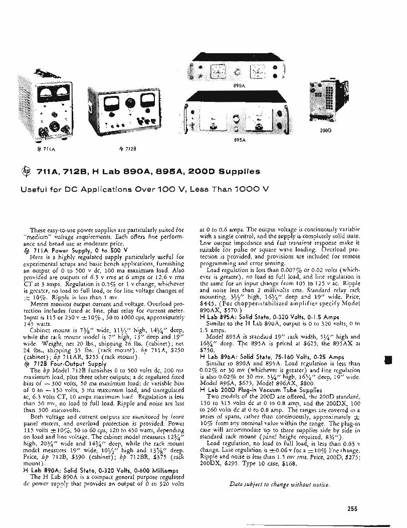
890A
200D
@ 711A @ 7128
$$ 711A, 7128, H Lab 8 9 0 A , 8 9 5 A , 200D Supplies
Useful for DC Applications Over 100 V, Less Than 1000 V
These easy-to-use power supplies are particularly suited for “medium” voltage requirements, Each offers fine perform- ance and broad use at moderate price. @ 71 IA Power Supply, 0 to 500 V
Here is a highly regulated supply particularly useful for experimental setups and basic bench applications, furnishing an output of 0 to 500 v dc, 100 ma maximum load. Also provided are outputs of 6.3 v rms at 6 amps or 12.6 v rms CT at 3 amps. Regulation is 0.5% or 1 v change, whichever is greater, no load to full load, or for line voltage changes of I+ 10%. Ripple is less than 1 mv.
Meters monitor output current and voltage. Overload pro- tection includes fused ac line, plus relay for current meter. Input is 115 or 230 v & l o % , 50 to 1000 cps, approximately 145 watts.
Cabinet mount is 73/“ wide, 11?12” high, 14%’‘ deep, while the rack mount model is 7” high, 13” deep and 19” wide. Weight, net 20 lbs., shipping 26 lbs. (cabinet) ; net 24 lbs., shipping 35 lbs. (rack mount). hp 711A, $250 (cabinet) ; hp 711AR, $255 (rack mount). @ 712B Four-Output Supply
The hp Model 712B furnishes 0 to 500 volts dc, 200 ma maximum load, plus three other outputs; a dc regulated fixed bias OE -300 volts, 50 ma maximum load; dc variable bias of 0 to -150 volts, 5 ma maximum load, and unregulated ac, 6.3 volts CT, 10 amps maximum load. Regulation is less than 50 mv, no load to full load. Ripple and noise are less than 500 microvolts.
Both voltage and current outputs are monitored by front panel meters, and overload protection is provided. Power 115 volts +IO%, 50 to 60 cps, 120 to 450 watts, depending on load and line voltage. The cabinet model measures 12%’’ high, 20%’’ wide and 14y4!! deep, while the rack mount model measures 19” wide, lOl/,” high and 1378rr deep. Price, hp 712B, $390 (cabinet); hp 712BR, $375 (rack mount). H Lab 890A: Solid State, 0-320 Volts, 0-600 Milliamps
The H Lab 890A is a compact general purpose regulated dc power supply that provides an output of 0 to 320 volts
at 0 to 0.6 amps. The output voltage is continuously variable with a single control, and the supply is completely solid state. Low output impedance and fast transient response make it suitable for pulse or square wave loading. Overload pro- tection is provided, and provisions are included for remote programming and error sensing.
Load regulation is less than 0.007% or 0.02 volts (which- ever is greater), no load to full load, and line regulation is the same for an input change from 105 to 125 v ac. Ripple and noise less than 2 millivolts rms. Standard relay rack mounting, 3y2” high, 163/4” deep and 19” wide. Price, $445. (For chopper-stabilized amplifier specify Model 890AX, $570.) H Lab 895A: Solid State, 0-320 Volts, 0-1.5 Amps
Similar to the H Lab 890A, output is 0 to 320 volts, 0 to 1.5 amps.
Model 895A is standard 19” rack width, 51/4/! high and 1674’’ deep. The 895A is priced at $625, the 895AX at $750. H Lab 896A: Solid State, 75-160 Volfs, 0-25 Amps
Similar to 890A and 895A. Load regulation is less than 0.02% or 30 mv (whichever is greater) and line regulation is also 0.02% or 30 my. 5%” high, 163/4?’ deep, 19” wide, Model 8964, $675, Model 896AX, $800. H Lab 200D Plug-in Vacuum Tube Supplies
Two models of the 200D are offered, the 200D standard, 150 to 315 volts dc at 0 to 0.8 amp, and the 200DX, 100 to 260 volts dc at 0 to 0.8 amp. The ranges are covered in a series of spans, rather than continuously, approximately -+ 10% from any nominal value within the range. The plug-in case will accommodate up to three supplies side by side in standard rack mount (panel height required, 8 % ” ) .
Load regulation, no load to full load, is less than 0.03 v change. Line regulation is k 0 . 0 6 v for a +10$6 line change, Ripple and noise is less than 1.5 rnv rms. Price, 200D, $275; 200DX, $295. Type 10 case, $168.
Data subject t o change without notice.
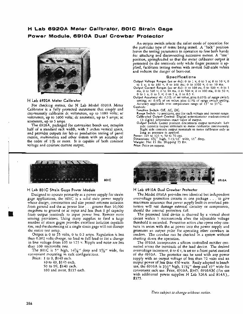
i
H Lab 6 9 2 0 A Meter Calibrator, 801C Strain Gage Power Module, 6910A Dual Crowbar Protector
An output switch selects the safest mode of operation for the particular type of meter being tested. A “lock” position leaves the testing parameters in operation to free both hands for attaching and disconnecting successive meters. A “test” position, springloaded so that the meter calibrator output is presented on the terminals only while finger pressure is ap- plied, facilitates testing meters with several full-scale values and reduces the danger of burn-out.
Specifications Output Voltage Ranges (ac or d c ) : 0 to 1 v, 0 to 5 a; 0 to 10 v, 0
to 1 a; 0 to 100 v, 0 to 100 ma; 0 to 1000 v, 0 to 10 ma. Output Current Ranges (ac or dc ) : 0 to 100 pa, 0 to 500 v; 0 to 1
ma, 0 to 500 v; 0 to 10 ma, 0 to 500 v; 0 to 100 ma, 0 to 50 v; 0 to 1 a, 0 to 5 v; 0 to 5 a, 0 to 0.5 v.
Output Accuracy: dc: 0.2% of set value, plus 0.05% of range switch setting; ac: 0.4% of set value, plus 0.1% of range switch setting. Accuracy applicable over temperature range of 15 O to 35°C.
Controls: Function Switch: Off, AC, DC. Range Switch: 10 positions, one for each voltage and current range. Calibrated Output Control: Digital potentiometer readout-control
( 3 digits) determines exact value of output. Output Switch: Center position disconnects output terminals. Left
side connects output terminals to meter calibrator continuously. Right side connects output terminals to meter calibrator only as long as pressure is applied.
Power: 105 to 1 2 5 v, 50 to 70 cps. Dimensions: 6%“ high, 7-1,3/16” wide, 11” deep, Weight: Net 15 Ibs. Shipping 23 Ibs. Price: Price on request.
H Lab 6920A Meter Calibrator For checking meters, the H Lab Model 6920A Meter
Calibrator is a fully protected instrument that simply and conveniently calibrates dc voltmeters, up to 1000 volts; ac voltmeters, up to 1000 volts; dc ammeters, up to 5 amps; ac ammeters, u p to 5 amps.
The 6920A, packaged for convenient bench use, occupies half of a standard rack width, with 7 inches vertical space, and provides outputs for lab or production testing of panel meters, multimeters and other meters with an accuracy of the order of 1% or more. It is capable of both constant voltage and constant current output.
801C
H Lab 80 I C Strain Gage Power Module Designed to operate primarily as a power supply for strain
gage applications, the 8OlC is a solid state power supply whose design, construction and size permit extreme isolation from ground and the ac power line . . . greater than 10,000 megohms to ground or ac input and less than 1 pf capacity from output terminals to input power line. Remote error sensing provisions. Using many supplies to feed a large number of strain gages provides excellent isolation capabili- ties, and the shortening of a single strain gage will not disrupt the entire test setup.
Output is 0 to 25 volts, 0 to 0.2 amps. Regulation is less than 0.002 volts change, no load to full load or for a change in line voltage from 105 to 125 v. Ripple and noise are less than 100 microvolts rms.
The 8OlC is 5” high, 14%” deep and 15/s” wide, for convenient mounting in rack configurations.
Price: 1 to 9, $149 each. 10 to 49, $145 each. 50 to 99, $140 each. 100 and more, $135 each.
69 I OA
H Lab 6910A Dual Crowbar Protector The Model 6910A provides two identical but independent
overvoltage protection circuits in one package , , . to give maximum assurance that power supply built-in overload pro- tectors will not damage external circuitry or components, should the internal protectors fail.
The protected load device is shunted by a virtual short circuit within 5 microseconds after the adjustable voltage threshold is exceeded. Protection action also opens relay con- tacts in series with the ac power into the power supply and generates an output pulse for operating other crowbars in tandem. The crowbar can be checked in a system without shutting down the operation.
The 6910A incorporates a silicon controlled rectifier con- nected across the terminals of the load device. The desired overvoltage increment, 0 to 6 v, is set on a front panel control of the 6910A. The protector can be used with any power supply with an output voltage of less than 72 volts and an output power of less than 450 watts. Easily adapted to bench use, the 6910A is 31/“ high, 111/” deep and 19” wide for convenient rack use. Price, 6910A, $345; 6910AM (for use with additional power supplies H Lab 520A and 814A),. $375.
Data subject to change without notice.
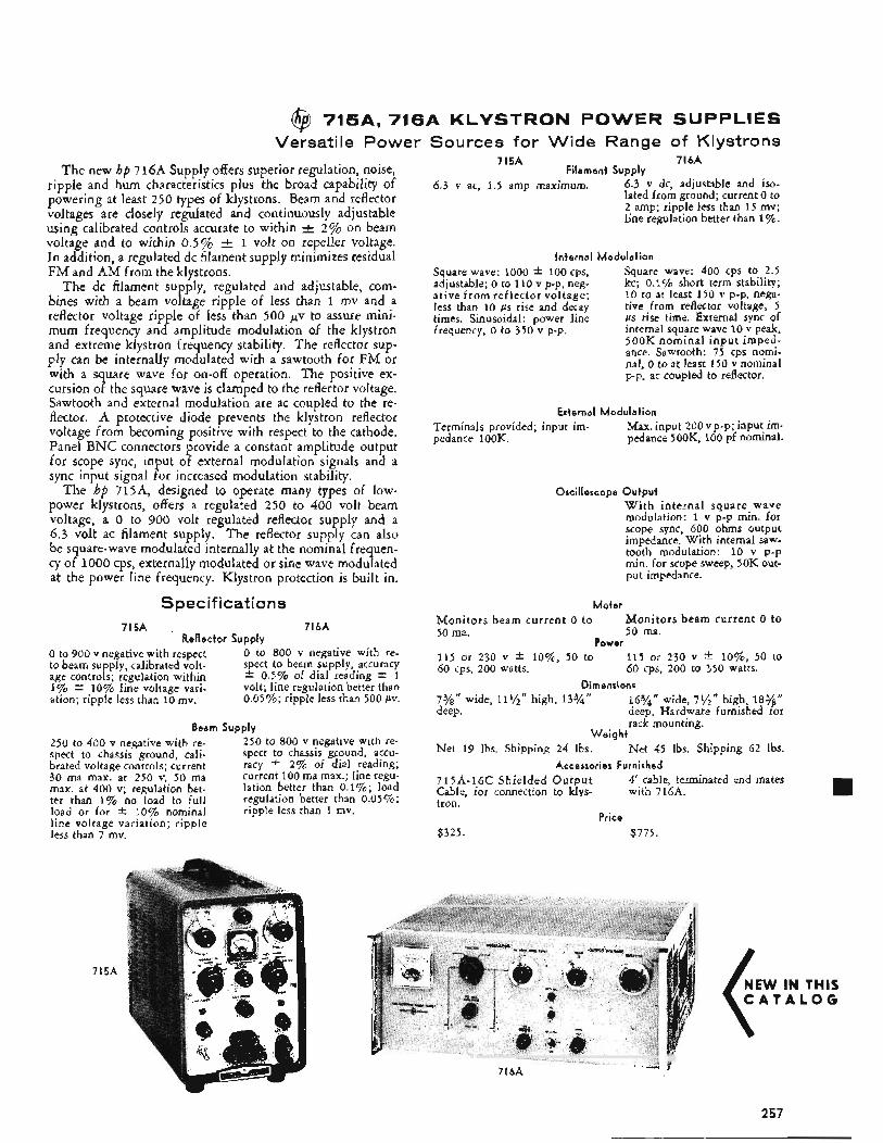
@ 715A, 716A KLYSTRON POWER SUPPLIES Versatile Power Sources for Wide Range of Klystrons
The new hp 716A Supply offers superior regulation, noise, ripple and hum characteristics plus the broad capability of powering at least 250 types of klystrons. Beam and reflector voltages are closely regulated and continuously adjustable using calibrated controls accurate to within -+ 2% on beam voltage and to within 0.5% & 1 volt on repeller voltage. In addition, a regulated dc filament supply minimizes residual FM and AM from the klystrons.
The dc filament supply, regulated and adjustable, com- bines with a beam voltage ripple of less than 1 mv and a reflector voltage ripple of less than 500 pv to assure mini- mum frequency and amplitude modulation of the klystron and extreme klystron frequency stability. The reflector sup- ply can be internally modulated with a sawtooth for FM or with a square wave for on-off operation. The positive ex- cursion of the square wave is clamped to the reflector voltage. Sawtooth and external modulation are ac coupled to the re- flector. A protective diode prevents the klystron reflector voltage from becoming positive with respect to the cathode. Panel BNC connectors provide a constant amplitude output for scope sync, input of external modulation signals and a sync input signal for increased modulation stability.
The hp 715A, designed to operate many types of low- power klystrons, offers a regulated 250 to 400 volt beam voltage, a 0 to 900 volt regulated reflector supply and a 6.3 volt ac filament supply. The reflector supply can also be square-wave modulated internally at the nominal frequen- cy of 1000 cps, externally modulated or sine wave modulated at the power line frequency. Klystron protection is built in.
Specifications 715A 71bA
Reflector Supply 0 to 900 v negative with respect to beam supply, calibrated volt- age controls; regulation within 1% f 10% line voltage vari- ation; ripple less than 10 mv.
0 to 800 v negative with re- spect to beam supply, accuracy f 0.5% of dial reading * 1 volt; line regulation better than 0.05%; ripple less than 500 PV.
Beam Supply 250 to 400 v negative with re- 250 to 800 v negative with re- spect to chassis ground, Cali- spect to chassis ground, accu- brated voltage controls; current racy f 2% of dial reading; 30 ma max. at 250 V, 50 ma current 100 ma max.; line regu- max. at 400 v; regulation bet- lation better than 0.1%; load ter than 1% no load to full regulation better than 0.05%; load or for i: 10% nominal ripple less than 1 mv. line voltage variation; ripple less than 7 rnv.
715A
715A 71bA Filament Supply
6.3 v ac, 1.5 amp maximum. 6.3 v dc, adjustable and iso- lated from ground; current 0 to 2 amp; ripple less than 15 mv; line regulation better than 1%.
Internal Modulation
Square wave: 1000 k 100 cps, adjustable; 0 to 110 v p-p, n e e ative from reflector voltage; less than 10 p s rise and decay times. Sinusoidal: power line frequency, 0 to 350 v p-p.
Square wave: 400 cps to 2.5 kc; 0.1% short term stability; 10 to at least 150 v p-p, nega- tive from reflector voltage; 5 p s rise time. External sync of internal square wave 10 v peak, 500K nominal i npu t imped- ance. Sawtooth: 75 cps nomi- nal, 0 to at least 150 v nominal p-p. ac coupled to reflector.
External Modulation Max. input 200 v p-p; input im- pedance 500K, 100 pf nominal.
TerminaIs provided; input im- pedance 100K.
Oscilloscope Output W i t h internal square wave modulation: 1 v p-p min. for scope sync, 600 ohms output impedance. With internal saw- tooth modulation: 10 v p-p min. for scope sweep, 50K out- put impedance.
M e t e r Moni tors beam current o to 50 ma. 50 ma.
115 or 230 v f lo%, 50 to 115 or 230 v * lo%, 50 to 60 cps, 200 watts. 60 cps, 200 to 350 watts.
Dimensions 7%” wide, 11%’’ high, 13%’’ 16%” wide, 7,/2‘’ high, 18%“ deep. deep. Hardware furnished for
rack mounting. W e i g h t
Net 45 Ibs. Shipping 62 Ibs. Accessories Furnished
4‘ cable, terminated end mates with 716A.
Moni tors beam curren t 0 to
Power
Net 19 lbs. Shipping 24 Ibs.
715A-16C Shielded Ou tpu t Cable, for connection to klys- tron.
Price $325. $775.
-. j 71bA
NEW IN THIS C A T A L O G
257
INDEX BY INSTRUMENT FUNCTION
Instrument Page
Accessories . . . . . . . . . . . . . . 11 1 Modular Enclosure . . . . . . . . . 18-19 Oscilloscope . . . . . . . . . . 50-5 1. 54-55 Voltmeter . . . . . . . . . . . . . . 109
AC Power Supply. Variable . . . . . . . . 242
AC Voltmeters . . . . . . . . . . 88-92.9 4-97 AC-to-DC Converter . . . . . . . . . . 17. 102
AC/Ohms to DC Converter . . . . . . . . . 103 Adapters :
BNC-to-Binding Post . . . . . . . . . 55. 111 Cover-to-Choke Flange . . . . . . . . . 179 Rack (for small modular instruments) . . . 18-19 Waveguide-to-Coaxial . . . . . . . . . . 179
Adjustable Short. Waveguide . . . . . . . . 241 Ammeters . . . . . . . . 95.98.100.10 6-108
Amplifiers :
Waveguide- to . Waveguide . . . . . . . . 1 7 9
Aircraft Communications Test Equipment . . . . 13
AC. Transistorized . . . . . . . . . . . 112 Bridging . . . . . . . . . . . . . . 112 Data . . . . . . . . . . . . . 114-116 Distributed. Wideband . . . . . . . . . 113 DC . . . . . . . . . . . . . 114-117 Fast-Pulse . . . . . . . . . . . . . 11 3 FIFO . . . . . . . . . . . . . 114-116 General Purpose. Stabilized . . . . . . . . 11 2 Guarded Data . . . . . . . . . . . . 103 Leveler . . . . . . . . . . . . . . 197 Narrow-band DC . . . . . . . . . . . 116 Oscilloscope Plug-in . . 32-33. 36-37. 40-41. 48-49 Traveling-Wave Tube . . . . . . . 2 02-2 0 3 Video (for hp 524. 5243L. 5245L
Counters) . . . . . . . . 130-131.13 9-140 Analyzers. Distortion and Waveform . . . . 78-83 Attenuators :
Fixed. Waveguide . . . . . . . . . . . 187 Precision . . . . . . . . . . . . 187-189 Tee . . . . . . . . . . . . . . 118. 189 Variable. Coaxial . . . . . . . . . . . 189 Variable. Waveguide . . . . . . . . 187-188
Distortion . . . . . . . . . . . . . 82-83 Wave . . . . . . . . . . . . . . 78-79
Audio Frequency Oscillators . . . . . . . 68-76 Audio Frequency Signal Generators:
High Power Audio Tests . . . . . . . . . 74 High Quality. High Accuracy Tests . . . . . 75
Barretter Mounts . . . . . . . . . . 191. 193 Bolometer Mounts . . . . . . . 191. 193. 196. 199
Audio Frequency Analyzers :
258
Instrument Page
Bridge. VHF . . . . . . . . . . . . . 234 Bridging Amplifier . . . . . . . . . . . 112 Bridging Transformer . . . . . . . . . . 111
Broadband Probe . . . . . . . . . . 236-238 Cabinets. Modular . . . . . . . . . . . 18-19 Cables. Test Leads . . . . . . . . . . . . 111 Calibrators :
Ammeter . . . . . . . . . . . . . . 256 Power Meter . . . . . . . . . . . . . 197 Signal Generator . . . . . . . . . . . 13 Voltmeter . . . . . . . . . . . . 110. 256
Calorimetric Power Meter . . . . . . . 200-201 Cameras. Oscilloscope . . . . . . . . . . . 53 Capacitive Voltage Dividers . . . . . . . . . 109 Carriages. Universal Probe . . . . . . . 236-238 Carrier Test Oscillator . . . . . . . . . . 72 Carrier-type Recorder . . . . . . . . . . . 9 Chart Advance. X - Y Recorders . . . . . . . . 16 Choke-to-Cover Flange Adapter . . . . . . . 179 Clamps. Waveguide . . . . . . . . . . . 179 Clip-on DC Milliammeters . . . . . . . 106-107 Clocks. Digital . . . . . . . . . . . . 15. 148 Clocks. Frequency Dividers and . . . . . . . 159 Coaxial :
Adapters. Waveguide . . . . . . . . . . 179 Attenuators . . . . . . . . . . . . . 189 Detector Mounts . . . . . . . . 193. 236-237 Directional Couplers . . . . . . . 189. 232-233 Frequency Meters . . . . . . . . . . . 204 Low Pass Filters . . . . . . . . . . . . 186 Shorts . . . . . . . . . . . . . . . 239 Slide-Screw Tuner . . . . . . . . . . . 239 Slotted Sections . . . . . . . . . . 235-237 Terminations . . . . . . . . . . . . . 241
Combining Cases . . . . . . . . . . . 18-19
Converter: Communications Systems Test Set . . . . . . 93
Frequency . . . . . . . . . . 130.13 9-143
Peak Voltage to Logarithm . . . . . . . . 17 Microwave Frequency . . . . . . . . . . 141 Voltage to Frequency . . . . . . . . . . 15
Counters. Electronic . . . . . . . . 103. 124-140 Couplers. Card Punch. Tape Punch . . . . . . 15 Couplers. Directional . . . . . . . . 189. 232-233 Crystal Detectors . . . . . . . 191. 193. 236-237 Current Probe . . . . . . . . . . 54. 106-108 Data Handling Systems . . . . . . . 9-1 1. 14-1 5
AC-to-DC . . . . . . . . . . . . 17. 102 AC/Ohms to DC . . . . . . . . . . . 103
Cooling Kits . . . . . . . . . . . . . 18-19
. -. i-
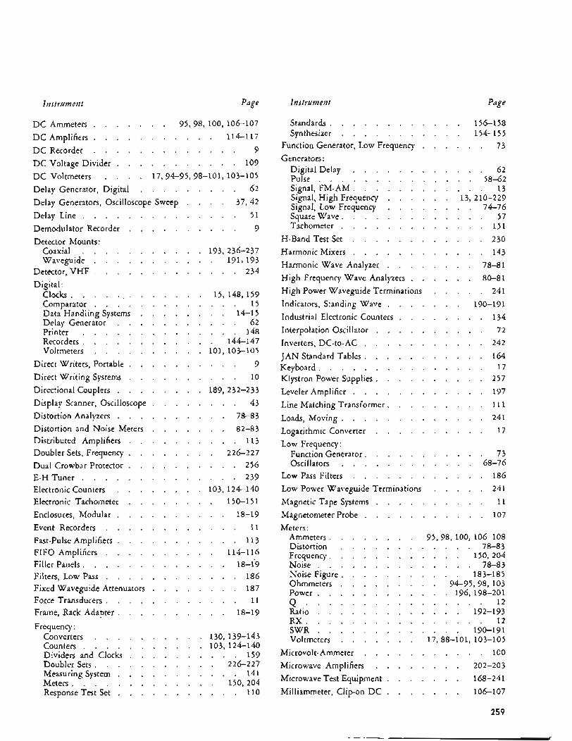
Instrument Page
D C Ammeters . . . . . . .
DC Recorder . . . . . . . . . . . . .
95.98. 100. 106-107 DC Amplifiers . . . . . . . . . . . 114-1 17
DC Voltage Divider . . . . . . . . . . . 109
Delay Generator. Digital . . . . . . . . . 62 Delay Generators. Oscilloscope Sweep . . . . 37. 42 Delay Line . . . . . . . . . . . . . . 51
9
DC Voltmeters . . . . 17.94-95. 98-101. 103-105
Demodulator Recorder . . . . . . . . . . 9
Detector Mounts: Coaxial . . . . . . . . . . . 193. 2 3 6-2 37 Wavemide . . . . . . . . . . . 191. 193 "
Detector. VHF . . . . . . . . . . . . . 234
Digital: Clocks . . . . . . . . . . . . . Comparator . . . . . . . . . . Data Handling Systems . . . . . . Delay Generator . . . . . . . . Printer . . . . . . . . . . . Recorders . . . . . . . . . . . Voltmeters . . . . . . . . . .
Direct Writers. Portable . . . . . . . Direct Writing Systems . . . . . . . Directional Couplers . . . . . . . . Display Scanner. Oscilloscope . . . . . Distortion Analyzers . . . . . . . . Distortion and Noise Meters . . . . . Distributed Amplifiers . . . . . . . Doubler Sets. Frequency . . . . . . . Dual Crowbar Protector . . . . . . . E-H Tuner . . . . . . . . . . . Electronic Counters . . . . . . . . Electronic Tachometer . . . . . . . Enclosures. Modular . . . . . . . .
15. 148. 159 . . . 15 . . 14-15 . . . 62 . . . 148 . 144-147 101. 103-105 . . . 9 . . * 10
189.23 2-233 . . . 43 . . 78-83 . . 82-83 . . . 113 . 226-227 . . . 256 . . * 239 103. 124-140 . 150-151 . . 18-19
Event Recorders . . . . . . . . . . . . 11 Fast-Pulse Amplifiers . . . . . . . . . . . 11 3 FIFO Amplifiers . . . . . . . . . . 114-1 16 Filler Panels . . . . . . . . . . . . . 18-f9 Filters. Low Pass . . . . . . . . . . . . 186 Fixed Waveguide Attenuators . . . . . . . . 187 Force Transducers . . . . . . . . . . . . 11 Frame. Rack Adapter . . . . . . . . . . 18-19
Frequency : Converters . . . Counters . . . . Dividers and Clocks Doubler Sets . . . Measuring System . Meters . . . . . Response Test Set . . . . . . . . . . . 110
130.13 9.143 103. 124-140 . . . 159 . 226-227 . . . 141 . 150. 204
Instrumeut Page
Standards . . . . . . . . . . . . 156-1 58 Synthesizer . . . . . . . . . . . 154-1 5 5
Function Generator. Low Frequency . . . . . . 73
Generators : Digital Delay . . . . . . . Pulse . . . . . . . . . . Signal. FM-AM . . . . . . . Signal. High Frequency . . . . Signal. Low Frequency . . . . Square Wave . . . . . . . . Tachometer . . . . . . . .
H-Band Test Set . . . . . . . HarmonicMixers . . . . . . . Harmonic Wave Analyzer . . . . High Frequency Wave Analyzers . . High Power Waveguide Terminations Indicators. Standing Wave . . . . Industrial Electronic Counters . . . Interpolation Oscillator . . . . . Inverters. DC-to-AC . . . . . . JAN Standard Tables . . . . . . Keyboard . . . . . . . . . . Klystron Power Supplies . . . . . Leveler Amplifier . . . . . . . Line Matching Transformer . . . . Loads. Moving . . . . . . . . Logarithmic Converter . . . . .
. . . . . 62
. . . . 58-62
. . . . . 13
. . 13. 210-229
. . . . 74-76
. . . . . 57
. . . . . 1 5 1
. . . . . 230
. . . . . 143
. . . . 78-81
. . . . 80-81
. . . . . 241
. . . 190-191
. . . . . 134
. . . . . 72
. . . . . 242
. . . . . 164
. . . . . 17
. . . . . 257
. . . . . 197
. . . . . 111
. . . . . 241
. . . . . 17 Low Frequency:
Function Generator . . . . . . . . . . . 73 Oscillators . . . . . . . . . . . . 68-76
Low Pass Filters . . . . . . . . . . . . 186 Low Power Waveguide Terminations . . . . . 241 Magnetic Tape Systems . . . . . . . . . . 11 Magnetometer Probe . . . . . . . . . . . 107
Meters : Ammeters . . Distortion . Frequency . . Noise . . . Noise Figure . Ohmmeters . Power . . .
95.98. 100. 106-108 . . . . . 78-83 . . . . 150. 204 . . . . . 78-83 . . . . 183-185 . . 94-95.98. 103 . . . 196. 198-201
Q . . . . . . . . . . . . . . . . 1 2 Ratio . . . . . . . . . . . . . 192-193 RX . . . . . . . . . . . . . . . . 1 2 SWR . . . . . . . . . . . . . 190-191 Voltmeters . . . . . . . 17.88-101. 103-105
Microvolt- Ammeter . . . . . . . . . . . 100 Microwave Amplifiers . . . . . . . . 202-203 Microwave Test Equipment . . . . . . . 168-241 Milliammeter. Clip-on D C . . . . . . . 106-107
259
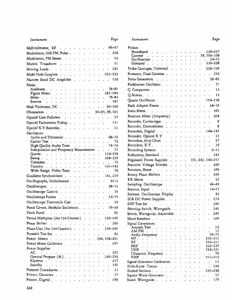
t
Instrument Page
Millivoltmeter. RF . . . . . . . . . . 96-97
Modulators. AM.FM. Pulse . . . . . . . . . 218
Modulators. FM Stereo . . . . . . . . . . 13
Motion Transducer . . . . . . . . . . . 11
Moving Loads . . . . . . . . . . . . . 241
Multi-Hole Couplers . . . . . . . . . 2 32-2 3 3 Narrow Band DC Amplifier . . . . . . . . 116
Analyzers . . . . . . . . . . . . . 78-8 1 Figure Meter . . . . . . . . . . . 183-184 Meter . . . . . . . . . . . . . . 78-83 Sources . . . . . . . . . . . . . . 185
Null Voltmeter. DC . . . . . . . . . . 99-100
ohmmeter^ . . . . . . . . . . 94-95.98. 103
Optical Line Follower . . . . . . . . . . 17
Optical Tachometer Pickup . . . . . . . . . Optical X-Y Recorder . . . . . . . . . . . 11
Noise:
1 5 1
Oscillators : Audio and Ultrasonic . . . . . . . . . 68-76 Carrier Test . . . . . . . . . . . . . 72 High Quality Audio Tests . . . . . . . 74-76
Quartz . . . . . . . . . . . . . 1 5 4-1 5 8
Telemeter . . . . . . . . . . . . . . 72 Transfer . . . . . . . . . . . . 141-143 Wide.Range. Video Tests . . . . . . . . 76
Oscillator Synchronizers . . . . . . . . 141. 2 19
Oscillographs. Multichannel . . . . . . . . 9-1 1
oscilloscopes . . . . . . . . . . . . 28-5 1
Oscilloscope Probes . . . . . . . . . . 54-55
Interpolation and Frequency Measurement . . . 72
Sweep . . . . . . . . . . . . . 228-2 29
Oscilloscope Camera . . . . . . . . . . . 5 3
Oscilloscope Testmobile Cart . . Panel Covers. Modular Enclosures . Patch Panel . . . . . . . . Period Multiplier (for 524 Counter) Phase Shifter . . . . . . . Phase Unit (for 524 Counter) . . PortableTestSet . . . . . . Power Meters . . . . . . . Power Meter Calibrator . . . . Power Supplies :
AC . . . . . . . . . . General Purpose (dc) . . . . Klystron . . . . . . . . Standby . . . . . . . .
PressureTransducers . . . . . Printer. Character . . . . . . Printer. Digital . . . . . . .
. . . . . . 54
. . . . . 18-19
. . . . . . 93
. . . . 139-140
. . . . . . 240
. . . . 139-140
. . . . . . 93
. . . 196.19 8.201
. . . . . . 197
. . . . . . 242
. . . . 246-256
. . . . . . 257
. . . . . . 161
. . . . . . 11
. . . . . . 17
. . . . . . 148
Instrument Page
Probes : Broadband . . . . . . . . . . Current . . . . . . . . . . . Untuned . . . . . . . . . . .
Protector. Dual Crowbar . . . . . . . Pulse Generators . . . . . . . . . Pushbutton Oscillator . . . . . . . .
Q Meters . . . . . . . . . . . .
Oscilloscope . . . . . . . . . .
Probe Carriages. Universal . . . . . .
Q Comparator . . . . . . . . . .
Quartz Oscillators . . . . . . . . . Rack Adapter Frame . . . . . . . .
Reaction Meter (frequency) . . . . .
Recorders. Digital . . . . . . . . .
Recorders. X-Y . . . . . . . . . . Recording Systems . . . . . . . . . Reflections. Standard . . . . . . . .
Ratio Meter . . . . . . . . . . .
Recorder. Carrier-type . . . . . . . . Recorder. Demodulator . . . . . . .
Recorder. Optical X-Y . . . . . . . Recorders. Strip Chart . . . . . . . .
Regulated Power Supplies . . . . 161. Resistive Voltage Divider . . . . . . Resistors. Shunt . . . . . . . . . . Rotary Phase Shifters . . . . . . . . RXMeter . . . . . . . . . . . Sampling Oscilloscope . . . . . . . Scanner. Input . . . . . . . . . . Scanner. Oscilloscope Display . . . . . SCR DC Power Supplies . . . . . . . SHF Test Set . . . . . . . . . . Shorting Switch. Waveguide . . . . . Shorts. Waveguide. Adjustable . . . . . Shunt Resistors . . . . . . . . . . Signal Generators :
Aircraft Test . . . . . . . . . . AM-FM . . . . . . . . . . . HF . . . . . . . . . . . . . RF . . . . . . . . . . . . . SHF . . . . . . . . . . . . UHF . . . . . . . . . . . . Ultrasonic Frequency . . . . . . . VHF . . . . . . . . . . . .
Signal Generator Calibrators . . . . . Slide-Screw Tuners . . . . . . . . Slotted Sections . . . . . . . . . . Square Wave Generator . . . . . . . Stand. Waveguide . . . . . . . . .
Audio Frequency . . . . . . . .
. 236-237 54.10 6-108 . . 54-55 . 236238
. 236238
. . . 256
. . 58-62
. . . 71
. . . 12
. . . 12
. 154-158
. . 18-19
. . . 192
. . . 204
. . . 9
. . . 9
. 144-147
. . . 11
. . . 17
. . . 16
. . 9-11
. . . 241 242.24 6-257 . . . 109 . . . 109 . . . 240 . . * 1 2 . . 46-49 . . 14-15 . . . 43 . . . 254 . . . 230 . . . 241 . . . 241 . . . 109
. . . 1 3
. . . 13
. . 74-75
. 210-211
. 210-211
. 222-225
. 214-221
. . . 76
. 212-213 * . . 1 3 . . . 239 . 235-238 . . . 57 . . . 179
260
. L .
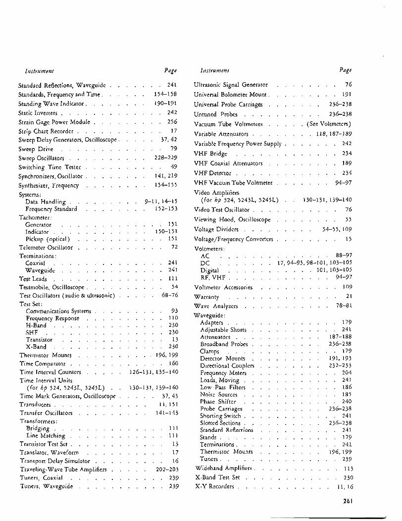
Instrument Page
Standard Reflections. Waveguide . . . . . . . 241
Standards. Frequency and Time . . . . . . Standing Wave Indicator . . . . . . . . 190-191 Static Inverters . . . . . . . . . . . . . 242
Strain Gage Power Module . . . . . . . . . Strip Chart Recorder . . . . . . . . . . . 17 Sweep Delay Generators. Oscilloscope . . . . . Sweep Drive . . . . . . . . . . . . . 79 Sweep Oscillators . . . . . . . . . . 228-229 Switching Time Tester . . . . . . . . . . 49 Synchronizers. Oscillator . . . . . . . . 141. 219 Synthesizer. Frequency . . . . . . . . 1 5 4 1 55
Data Handling . . . . . . . . . 9-1 1. 1 4 1 5 Frequency Standard . . . . . . . . 152-1 5 3
Generator . . . . . . . . . . . . . 1 5 1 Indicator . . . . . . . . . . . . 150-15 1 Pickup (optical) . . . . . . . . . . . 1 5 1
Telemeter Oscillator . . . . . . . . . . . 72
Coaxial . . . . . . . . . . . . . . 24 1 Waveguide . . . . . . . . . . . . . 2 4 1
Test Leads . . . . . . . . . . . . . . 11 1 Testmobile. Oscilloscope . . . . . . . . . . 54 Test Oscillators (audio & ultrasonic)
Communications Systems . . . . . . . . . 93 Frequency Response . . . . . . . . . . 11 0 H-Band . . . . . . . . . . . . . . 230 SHF . . . . . . . . . . . . . . . Transistor . . . . . . . . . . . . . 13 X-Band . . . . . . . . . . . . . .
Thermistor Mounts . . . . . . . . . . 196. 199
Time Interval Counters . . . . . 126-131. 135-140
Time Mark Generators. Oscilloscope . . . . . 37. 43 Transducers . . . . . . . . . . . . 11. 151 Transfer Oscillators . . . . . . . . . 141-143 Transformers :
Bridging . . . . . . . . . . . . . . 11 1 Line Matching . . . . . . . . . . . . 11 1
Transistor Test Set . . . . . . . . . . . . 13 Translator. Waveform . . . . . . . . . . 17 Transport Delay Simulator . . . . . . . . . 16 Traveling-WaveTubeAmplifiers . . . . . 202-203 Tuners. Coaxial . . . . . . . . . . . . 239 Tuners. Waveguide . . . . . . . . . . . 239
154-1 5 8
256
37. 42
Systems :
Tachometer:
Terminations :
. . . . . 68-76 Test Set:
230
230
Time Comparator . . . . . . . . . . . . 160
Time Interval Units (for hp 524. 524%. 5245L) . . 130-131. 139-140
Page Instrument
Ultrasonic Signal Generator . . . . . . . . 76 Universal Bolometer Mount . . . . . . . . . 191 Universal Probe Carriages . . . . . . . 236-238 Untuned Probes . . . . . . . . . . 2 36-2 38
Vacuum Tube Voltmeters . . . . . (See Voltmeters) Variable Attenuators . . . . . . . . 118. 187-189
Variable Frequency Power Supply . . . . . . . VHF Bridge . . . . . . . . . . . . . 234 VHF Coaxial Attenuators . . . . . . . . . 189 VHF Detector . . . . . . . . . . . . . 234 VHF Vacuum Tube Voltmeter . . . . . . . 94-97
242
Video Amplifiers (for hp 524. 524%. 5245L) . . 130-131. 139-140
Video Test Oscillator . . . . . . . . . . . 76 Viewing Hood. Oscilloscope . . . . . . . . 55 Voltage Dividers . . . . . . . . . 54-55. 107 Voltage/Frequency Converters . . . . . . . . 1 5
88-97 . . . . . . . . . Voltmeters :
AC . . . . . D C . . . . . . . 17.94-95.98-101. 103-105 Digital . . . . . . . . . . . 101. 103-105 RF. VHF . . . . . . . . . . . . . 94-97
Voltmeter Accessories . . . . . . . . . . 109 Warranty . . . . . . . . . . . . . . 21
Wave Analyzers . . . . . . . . . . . 78-81
Adapters . . . . . . . . . . . . . . 179 Adjustable Shorts . . . . . . . . . . . 241 Attenuators . . . . . . . . . . . 187-188 Broadband Probes . . . . . . . . . 236-238 Clamps . . . . . . . . . . . . . . 179 Detector Mounts . . . . . . . . . 191. 193 Directional Couplers . . . . . . . . 232-233 Frequency Meters . . . . . . . . . . . 204 Loads. Moving . . . . . . . . . . . . 241 LOW P~SS Filters . . . . . . . . . . . 186 Noise Sources . . . . . . . . . . . . 185 Phase Shifter . . . . . . . . . . . . 240 Probe Carriages . . . . . . . . . 236-238 Shorting Switch . . . . . . . . . . . . 241 Slotted Sections . . . . . . . . . . 236-238 Standard Reflections . . . . . . . . . . 241 Stands . . . . . . . . . . . . . . . 179 Terminations . . . . . . . . . . . . . 241 Thermistor Mounts . . . . . . . . 196. 177 Tuners . . . . . . . . . . . . . . . 239
Wideband Amplifiers . . . . . . . . . . . 113 X-Band Test Set . . . . . . . . . . . . 230 X-Y Recorders . . . . . . . . . . . . 11. 16
Waveguide:
26 I
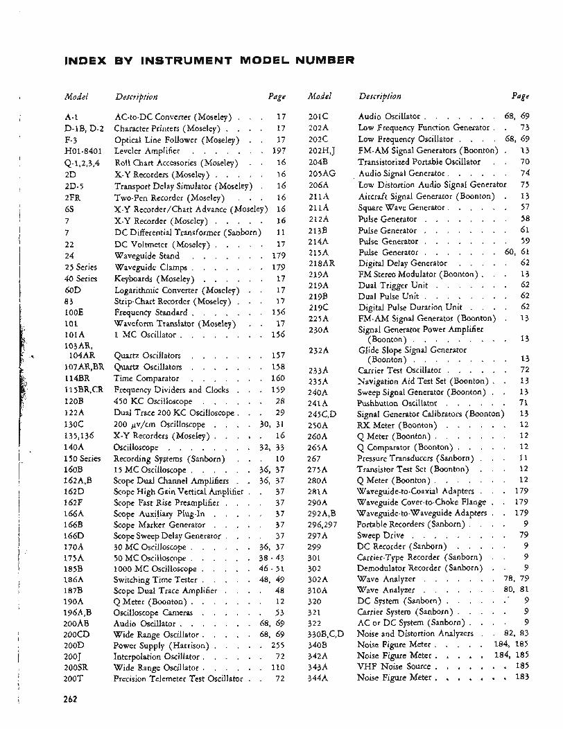
INDEX BY INSTRUMENT MODEL NUMBER
P
Model Description Page Model Description Page
A-1 D.1B. D-2 F- 3 H01-840 1
Q- 1.2.3. 4 2D
2FR 6s 7 7 22 24 25 Series 40 Series 60D 83 1 OOE 101 lOlA 103AR.
104AR 1 O7AR. BR 114BR 11 5BR. CR 120B 122A 130c 135. 136 140A 150 Series 1 GOB 16214. B 162D 162F 166A 166B lG6D 170A 175A 185B 186A 187B 190A 196A. B 200AB 200CD 200D 200 J 200SR
2D-5
200T
AC-to-DC Converter (Moseley) . . . 17 Character Printers (Moseley) . . . . 17 Optical Line Follower (Moseley) . . 17 Leveler Amplifier . . . . . . . 197 Roll Chart Accessories (Moseley) . . 16
Transport Delay Simulator (Moseley) . 16 Two-Pen Recorder (Moseley) . . . 16 X-Y Recorder/Chart Advance (Moseley) 16
DC Differential Transformer (Sanborn) 11 DC Voltmeter (Moseley) . . . . . 17 Waveguide Stand . . . . . . . 179 Waveguide Clamps . . . . . . . 179 Keyboards (Moseley) . . . . . . 17 Logarithmic Converter (Moseley) . . 17 Strip-Chart Recorder (Moseley) . . . 17 Frequency Standard . . . . . . . 156 Waveform Translator (Moseley) . . 17 1 MC Oscillator . . . . . . . . 156
X-Y Recorders (Moseley) . . . . . 16
X-Y Recorder (Moseley) . . . . . 16
Quartz Oscillators . . . . . . Quartz Oscillators . . . . . . Time Comparator . . . . . . Frequency Dividers and Clocks . . 450 KC Oscilloscope . . . . . Dual Trace 200 KC Oscilloscope . . 200 p / c m Oscilloscope . . . . X-Y Recorders (Moseley) . . . . Oscilloscope . . . . . . . . Recording Systems (Sanborn) . . 15 MC Oscilloscope . . . . . . Scope Dual Channel Amplifiers . . Scope High Gain Vertical Amplifier . Scope Fast Rise Preamplifier . . .
Scope Marker Generator . . . . Scope Sweep Delay Generator . . . 30 MC Oscilloscope . . . . . . 50MCOscilloscope . . . . . . 1000 MC Oscilloscope . . . . . Switching Time Tester . . . . . Scope Dual Trace Amplifier . . . Q Meter (Boonton) . . . . . .
Audio Oscillator . . . . . . .
Power Supply (Harrison) . . . . Interpolation Oscillator . . . . . Wide Range Oscillator . . . . . Precision Telemeter Test Oscillator .
Scope Auxiliary Plug-In . . . .
Oscilloscope Cameras . . . . .
Wide Range Oscillator . . . . .
. 157
. 158
. 160
. 159
. 28
. 29 30. 31 . 16 32. 33 . 10 36. 37 36. 37 . 37 . 37 . 37 . 37 . 37 36. 37 38 . 43 46 . 51 48. 49 . 48 . 12 . 53 68. 69 68. 69 . 255 . 72 . 110 . 72
201c 202A 202c 202H. J 204B 205AG 206A 211A 211A 212A 213B 2 14A 215A 218AR 219A 219A 2 l9B 219c 225A 230A
2324
233A 235A 240A 241A 245C. D
260A 265A 267 275A 280A 281A 290A 292A. B 296. 297 297A 299 301 302 302A 310A 320 321 322 330B.C. D 340B 342A 3 4.3 A 344A
250A
Audio Oscillator . . . . . . . 68. 69 Low Frequency Function Generator . . 73 Low Frequency Oscillator . . . . 68. 69 FM-AM Signal Generators (Boonton) . 13 Transistorized Portable Oscillator . . 70 Audio Signal Generator . . . . . . 74 Low Distortion Audio Signal Generator 75 Aircraft Signal Generator (Boonton) . 13 Square Wave Generator . . . . . . 57 Pulse Generator . . . . . . . . 58 Pulse Generator . . . . . . . . 61 Pulse Generator . . . . . . . . 59 Pulse Generator . . . . . . . 60. 61 Digital Delay Generator . . . . . 62 FM Stereo Modulator (Boonton) . . . 13 Dual Trigger Unit . . . . . . . 62 Dual Pulse Unit . . . . . . . . 62 Digital Pulse Duration Unit . . . . 62 FM-AM Signal Generator (Boonton) . 13 Signal Generator Power Amplifier
(Boonton) . . . . . . . . . 1 3 Glide Slope Signal Generator
(Boonton) . . . . . . . . . 13 Carrier Test Oscillator . . . . . . 72 Navigation Aid Test Set (Boonton) . . 1 3 Sweep Signal Generator (Boonton) . . 1 3 Pushbutton Oscillator . . . . . . 71 Signal Generator Calibrators (Boonton) 13 RX Meter (Boonton) . . . . . . 1 2 Q Meter (Boonton) . . . . . . . 12 Q Comparator (Boonton) . . . . . 1 2 Pressure Transducers (Sanborn) . . . 11 Transistor Test Set (Boonton) . . . 1 2 QMeter (Boonton) . . . . . . . 12 Waveguide-to-Coaxial Adapters . . . 179
Portable Recorders (Sanborn) . . . . 9
DC Recorder (Sanborn) . . . . . 9
Wave Analyzer . . . . . . . 78. 79 Wave Analyzer . . . . . . . 80. 81 DC System (Sanborn) . . . . . . . 9 Carrier System (Sanborn) . . . . . 9 AC or DC System (Sanborn) . . . . 9 Noise and Distortion Analyzers . . 82. 83 Noise Figure Meter . . . . . 184. 185 Noise Figure Meter . . . . . 184. 185 VHF Noise Source . . . . . . . 185 Noise Figure Meter . . . . . . . 183
Waveguide Cover-to-Choke Flange . . 179 Waveguide-to-Waveguide Adapters . . 179
Sweep Drive . . . . . . . . . 79
Carrier-Type Recorder (Sanborn) . . 9 Demodulator Recorder (Sanborn) . . 9
262
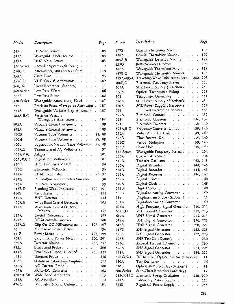
Model
345B 347A 349A 350 Series 350C. D 353A 355C. D 360. 361 360 Series 362A 370 Series 372
382A.B. C 375A
393A 394A 400D 400H 400L 403A. B
40 5 BR. CR 410B 410C 411A 412A 41 3A 415B. D 416B 417A 420A. B 421A
405A-95C
422A 425A 428A. B 430C 431B 434A 440A 442B 444A 446B 450A 45 6A 457A 460AR. BR 466A 476A
D escvip tio n Page
IF Noise Source . . . . . . . . 185 Waveguide Noise Source . . . . . 185 UHF Noise Source . . . . . . . 185 Recorder Systems (Sanborn) . . . . 10 Attenuators. 500 and 600 Ohm . . . 118 Patch Panel . . . . . . . . . 93 VHF Coaxial Attenuators . . . . . 189 Event Recorders (Sanborn) . . . . 11 Low Pass Filters . . . . . . . . 186 Low Pass Filter . . . . . . . . 186 Waveguide Attenuators. Fixed . . . 187 Precision Fixed Waveguide Attenuator . 187 Waveguide Variable Flap Attenuator . 187 Precision Variable
Variable Coaxial Attenuator . . . . 189 Variable Coaxial Attenuator . . . . 189 Vacuum Tube Voltmeter . . . . 88. 89 Vacuum Tube Voltmeter . . . . 88. 89 Logarithmic Vacuum Tube Voltmeter 88. 89 Transistorized AC Voltmeters . . . . 92
Waveguide Attenuators . . . . . 188
Adapter . . . . . . . . . . 101 Digital DC Voltmeters . . . . . . 101 High Frequency VTVM . . . . . 94 Electronic Voltmeter . . . . . . 95 RF Millivoltmeter . . . . . . 96. 97 DC Voltmeter-Ohmmeter-Ammeter . . 98 DC Null Voltmeter . . . . . . . 99
190. 191 Ratio Meter . . . . . . . . . 192 VHF Detector . . . . . . . . 2 34
Waveguide Crystal Detector
Standing Wave Indicators . . .
WideBandCrystalDetectors . . . . 193
Crystal Detectors . . . . . . . . 193 DC Microvolt-Ammeter . . . . . . 100
Mounts . . . . . . . . . . 193
Clip-On D C Milliammeters . . 106. 107 Microwave Power Meter . . . . . 196 Power Meter . . . . . . . 198. 199 Calorimetric Power Meter . . . 200. 201 Detector Mount . . . . . . 236. 237 Broadband Probe . . . . . . . . 236 Broadband Probe. Untuned . . 236. 237 Untuned Probe . . . . . . . . 238 Stabilized Laboratory Amplifier . . . 112 AC Current Probe . . . . . . . 108 AC-to-DC Converter . . . . . . 102 Wide Band Amplifiers . . . . . . 113 AC Amplifier . . . . . . . . . 11 2 Bolometer Mount. Untuned . . . . 191
Model
477B 478A . 485A. B 485D 486A 487B. C
500B. C 505A 506A 508 510A 520A 521 522B 523 524 5 2 5 A.B. C 526A 526B 5 26C 526D 532 series 536A 540B 5 60A 561B 562A 565A 570A 571B 580A 581 581A 606A 608C. D 61 2A 614A 61 6B 618B 620A 623B 624C 626A 628A 650 Series 650A 670B 680 Series
711A 712B
489A-495A
682C-687C
Description Page
Coaxial ThermistorMount . . . . . 196 Coaxial Thermistor Mount . . . . . 199 Waveguide Detector Mounts . . . . 191 Reflectometer Detectors . . . . . . 193 Waveguide Thermistor Mount . . . 199 Waveguide Thermistor Mounts . . . 196
Electronic Frequency Meters . . . . 150 SCR Power Supply (Harrison) . . . 254 Optical Tachometer Pickup . . . . 151 Tachometer Generators . . . . . . 151 SCR Power Supply (Harrison) . . . 254 SCR Power Supply (Harrison) . . . 254 Industrial Electronic Counters . . . . 134 Electronic Counter . . . . . . . 135 Electronic Counters . . . . . 136. 137 Electronic Counters . . . . . 138 . 140 Frequency Converter Units . . . 139. 140 Video Amplifier Unit . . . . 139. 140 Time Interval Unit . . . . . 139. 140 Period Multiplier . . . . . 139. 140 Phase Unit . . . . . . . . 139. 140 Waveguide Frequency Meters . . . . 204 Coaxial Wavemeter . . . . . . . 204 Transfer Oscillator . . . . . 142. 143 Digital Recorder . . . . . . 144. 145 Digital Recorder . . . . . . 144. 145 Digital Recorder . . . . . . 146. 147 Digital Printer . . . . . . . . 148 Digital Clock . . . . . . . . . 148
Displacement Probe (Sanborn) . . . 11
Traveling-Wave Tube Amplifiers . 202. 203
Digital Clock . . . . . . . . . 148 Digital-to-Analog Converter . . . . 149
Digital-to-Analog Converter . . . . 149 High Frequency Signal Generator 210. 211 VHF Signal Generators . . . . 212. 213 UHF Signal Generator . . . . 214. 215 UHF Signal Generator . . . . 220. 221 UHF Signal Generator . . . . 220. 221 SHF Signal Generator . . . . 222. 223 SHF Signal Generator . . . . 222. 223 SHFTestSet (Dymec) . . . . . . 230 X-Band Test Set (Dymec) . . . . . 230 SHF Signal Generator . . . . 224. 225 SHF Signal Generator . . . . 224. 225 DC to 5 KC Optical System (Sanborn) 11 Test Oscillator . . . . . . . . 76 Optical X - Y Recorder (Sanborn) . . 11 Strip-Chart Recorders (Moseley) . . . 17 Electronic Sweep Oscillators . . 228. 229 Laboratory Power Supply . . . . . 255 Regulated Power Supply . . . . . 255
263
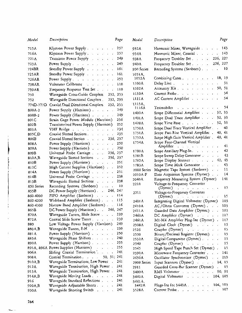
Model Description Page
715A Klystron Power Supply . . . . . . 257 716A Klystron Power Supply . . . . . . 257 721A Transistor Power Supply . . . . . 249 723A Power Supply . . . . . . . . . 249 724BR Standby Powersupply . . . . . . 161 725AR Standby Powersupply . . . . . . 161 726AR Power Supply . . . . . . . . . 252 738AR Voltmeter Calibrator . . . . . . 110 739AR Frequency Response Test Set . . . . 110 750 Waveguide Cross-Guide Couplers 232. 2 33 75 2 Waveguide Directional Couplers . 232. 233 774D-777D Coaxial Dual Directional Couplers 232. 233 800A-2 Power Supply (Harrison) . . . . . 249 800B-2 Power Supply (Harrison) . . . . . 249 801C Strain Gage Power Module (Harrison) 256 802B Transistorized Power Supply (Harrison) 25 2 803A VHF Bridge . . . . . . . . . 234 805C. D Coaxial Slotted Sections . . . . . . 235 806B Coaxial SlottedSection . . . . 236. 237 808A Power Supply (Harrison) . . . . . 250 809A Power Supply (Harrison) . . . . . 250 809B Universal Probe Carriage . . . 236. 237 810A. B waveguide Slotted Sections . . 236. 237 810B Power Supply (Harrison) . . . . . 251 812C High Current Supplies (Harrison) . . 252 814A Power Supply (Harrison) . . . . . 251 814B Universal Probe Carriage . . . . . 238 815B Waveguide Slotted Sections . . . . 238 850 Series Recording Systems (Sanborn) . . . . 10 855B DC Power Supply (Harrison) . . 246. 247 860-4000 FIFO Amplifier (Sanborn) . . . . 114 860-4200 Wideband Amplifier (Sanborn) . . . 115 860-4300 Narrow Band Amplifier (Sanborn) . . 11 6 865B DCPower Supply (Harrison) . . 246. 247 870A Waveguide Tuners. Slide Screw . . . 239 872A Coaxial Slide Screw Tuner . . . . . 239 880 Low Voltage Power Supply (Harrison) 249 880A. B Waveguide Tuners. E-H . . . . . 239 881A Power Supply (Harrison) . . . . . 250 885A Waveguide Phase Shifters . . . . . 240 890A Power Supply (Harrison) . . . . . 255 895A. 896A Powersupplies (Harrison) . . . . 255 906A Sliding Coaxial Termination . . . . . 241 908A Coaxial Termination . . . . 50. 51; 241 910A. B Waveguide Terminations. Low Power . 241 912A Waveguide Termination. High Power . 241 91 3A Waveguide Termination. High Power . 241 914A. B Waveguide Moving Loads . . . . . 241 916 Waveguide Standard Reflections . . . 241 920A. B Waveguide Adjustable Shorts . . . . 241 930A Waveguide Shorting Switch . . . . 241
Model
932A 934A 938A 940A 950 Series lO5lA. 1052A
1lOOA 1102A 1l lOA 1 l l l A 1115A.
l l l 6 A 1400A 1401A 1420A 1750A 1751A 1752A 17544
1780A 1781B 1782A 1783A 2000 Series 2010A-F 2040A 2210
2211
2401A 2410A 241114 2460A 2461A 2508A 2526 2530 2532A 2540 2545 2590A 2650A 2900 Series 291 1 3400A 3440A 3441A.
3442A 3528A
Description Page
HarmonicMixer. Waveguide . . . . 143 Harmonic Mixer. Coaxial . . . . . 143 Frequency Doubler Set . . . . 226. 227 Frequency Doubler Set . . . . 226. 227 Recording Systems (Sanborn) . . . . 10
Combining Cases . . . . . . . 18. 19 Delay Line . . . . . . . . . 51 Accessory Kit . . . . . . . . 50. 51 Current Probe . . . . . . . . . 54 AC Current Amplifier . . . . . . 54
Testmobiles . . . . . . . . . 54 32. 33 32. 33 32. 33
Scope Dual Trace Vertical Amplifier . . 40 Scope Fast-Rise Vertical Amplifier . 40. 41 Scope High Gain Vertical Amplifier . 40. 41 Scope Four-channel Vertical
Scope Differential Amplifier . . . Sccpe Dual Trace Amplifier . . . Scope Time Base . . . . . . .
Amplifier . . . . . . . . . 41 ScopeAuxiliary Plug.1n . . . . . . 42 ScopeSweepDelay Generator . . . . 42 Scope Display Scanner . . . . . 42. 43 Scope Time Mark Generator . . . . 43 Magnetic Tape System (Sanborn) . . 11 Data Acquistion Systems (Dymec) . . 14 Frequency Measuring System (Dymec) 141 Voltage-to-Frequency Converter
Voltage-to-Frequency Converter
Integrating Digital Voltmeter (Dymec) 103
Guarded Data Amplifier (Dymec) . . 103
M1-M4 Amplifier Plug-Ins (Dymec) . 117 Digital Clock (Dymec) . . . . . 15
Binary/Decimal Register (Dymec) . . 1 5
(Dymec) . . . . . . . . . 15
(Dymec) . . . . . . . . . 1 5
AC/Ohms Converter (Dymec) . . . 103
DC Amplifier (Dymec) . . . . . 117
Coupler (Dymec) . . . . . . . 1 5
Digitalcomparator (Dymec) . . . . 15 Coupler (Dymec) . . . . . . . 1 5 High Speed Tape Punch Set (Dymec) . 1 5 Microwave Frequency Converter . . . 141 Oscillator Synchronizer (Dymec) . . 219 Input Scanners (Dymec) . . . . 14. 15 Guarded Cross-Bar Scanner (Dymec) . 1 5 RMS Voltmeter . . . . . . . 90. 91 Digital Voltmeter . . . . . 104. 105
Plugs-Ins for 3440A . . . . . 104. 105 Current Probe . . . . . . . . . 107
264
..... _c.. L_. . . . .
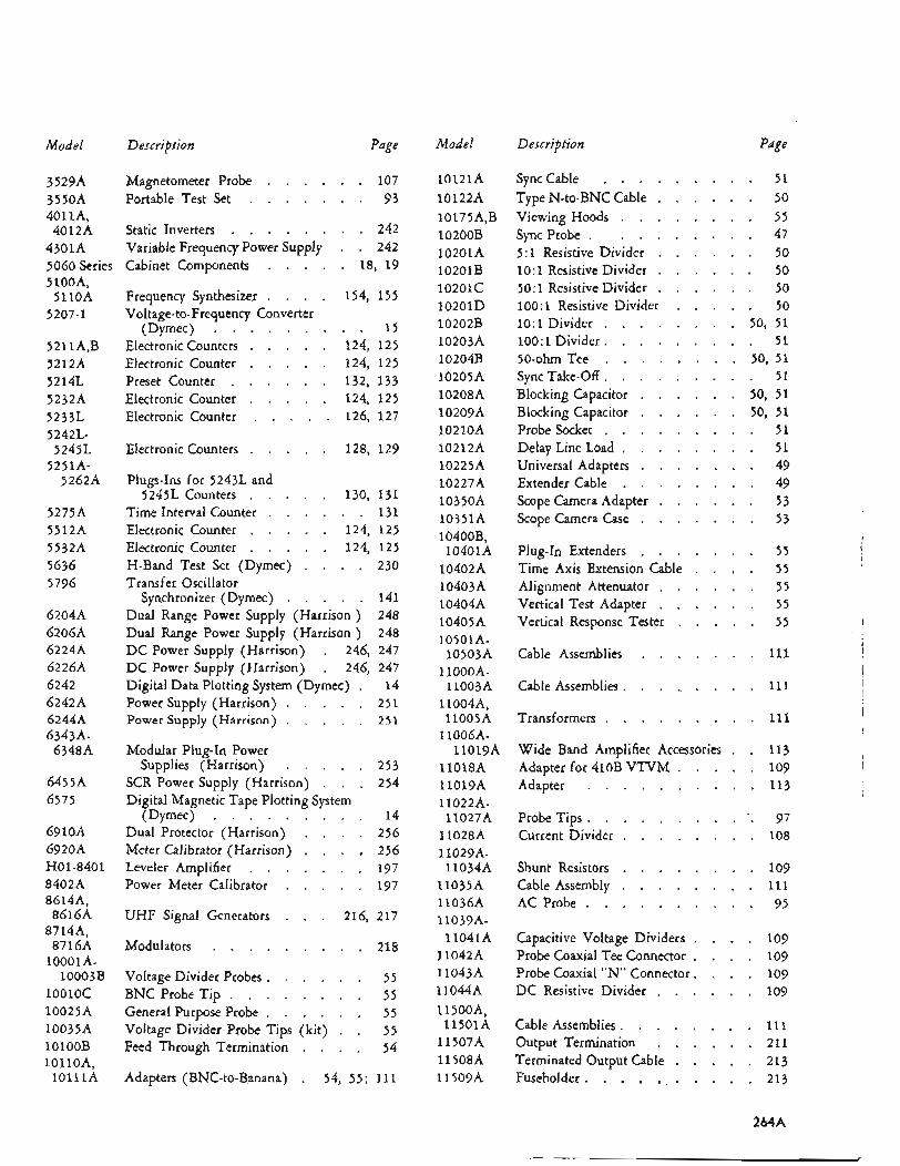
Model
3529A 3550A 4011A.
4012A 4301A 5060 Series 5 lOOA.
5110A 5207-1
521 1A. B 5212A 5214 L 5232A 5233L 5242L-
5245L 5251A-
5262A
5275A 5512A 5532A 5636 5796
6204A 6206A 6224A 6226A 6242 62424 6244A 6343A-
63484
645 5A 6575
691oA 6920A €301-8401 8402A 8614A.
8616A 87144.
8716A 1000 1 A-
lO0lOC 10025A 10035A 1OlOOB
10003B
i o i i o A . i o i i i A
Description Page
Magnetometer Probe . . . . . . 107 Portable Test Set . . . . . . . 93
Static Inverters . . . . . . . . 242
Cabinet Components . . . . . 18. 19
Frequency Synthesizer . . . . 154. 155
(Dymec) . . . . . . . . . 1 5 Electronic Counters . . . . . 124. 125 Electronic Counter . . . . . 124. 125 Preset Counter . . . . . . 132. 133 Electronic Counter . . . . . 124. 1 2 5 Electronic Counter . . . . . 126. 127
Variable Frequency Power Supply . . 242
Voltage-to-Frequency Converter
Electronic Counters . . . . . 128. 129
Plugs-Ins for 52432. and 5245L Counters . . . . . 130. 131
Time Interval Counter . . . . . . 131 Electronic Counter . . . . . 124. 125 Electronic Counter . . . . . 124. 125 H-Band Test Set (Dymec) . . . . 230 Transfer Oscillator
Synchronizer (Dymec) . . . . . 141 Dual Range Power Supply (Harrison ) 248 Dual Range Power Supply (Harrison ) 248 DC Power Supply (Harrison) . 246. 247 DC Power Supply (Harrison) . 246. 247 Digital Data Plotting System (Dymec) . 14 Power Supply (Harrison) . . . . . 251 Power Supply (Harrison) . . . . . 2 5 1
Modular Plug-In Power Supplies (Harrison) . . . . . 253
SCR Power Supply (Harrison) . . . 254 Digital Magnetic Tape Plotting System
Dual Protector (Harrison) . . . . 256 Meter Calibrator (Harrison) . . . . 256
Power Meter Calibrator . . . . . 197
(Dymec) . . . . . . . . . 14
Leveler Amplifier . . . . . . . 197
UHF Signal Generators . . . 216. 217
Modulators . . . . . . . . . 218
Voltage Divider Probes . . . . . . 55 BNC Probe Tip . . . . . . . . 55 General Purpose Probe . . . . . . 55 Voltage Divider Probe Tips (kit) . . 55 Feed Through Termination . . . . 54
Adapters (BNC-to-B.anana) . 54, 55; 111
Model Description Page
10121A 10122A 10175A. B 10200B 10201A 10201B 10201c 10201D 10202B 10203A 10204B 10205A 10208A 1020914 10210A 10212A 10225A 10227A 10350A 10351A
Synccable . . . . . . . . . 51 TypeN-to-BNCCable . . . . . . 50
Sync Probe . . . I . . * . . 47 Viewing Hoods . . . . . . . . 55
5:1 Resistive Divider . . . . . . 50 1O:l Resistive Divider . . . . . . 50 50:l Resistive Divider . . . . . . 50 100:1 Resistive Divider . . . . . 50 1 O : l Divider . . . . . . . . 50. 51 100:1 Divider . . . . . . . . . 5 1 50-ohm Tee . . . . . . . . 50. 51 Sync Take-Off . . . . . . . . . 51 Blocking Capacitor . . . . . . 50. 51 Blocking Capacitor . . . . . . 50. 51
Delay LineLoad . . . . . . . . 51
Scope Camera Adapter . . . . . . 53
Probe Socket . . . . . . . . . 51
Universal Adapters . . . . . . . 49 Extender Cable . . . . . . . . 49
Scope Camera Case . . . . . . . 53 10400B.
10401~4 Plug-In Extenders . . . . . . . 55 v
10402A Time Axis Extension Cable . . . . 5 5 104054 Alignment Attenuator . . . . . . 55 10404A Vertical Test Adapter . . . . . . 55 10405A Vertical Response Tester . . . . . 55
10503A Cable Assemblies . . . . . . . 111
1
10501A- I
1loOOA- 1 l003A Cable Assemblies . . . . . . . . . 111
11004A. 11005A
1 l006A-
11018A l lOl9A 11022A-
11027A 11028A 11029A- 11034A
11035A 11036A 11039A-
11041A 11042A 1 1043A 11044A 11500A.
l l5OlA 11 507A 11 508A 11509~4
l lOl9A
1 I Transformers . . . . . . . . . 111
Wide Band Amplifier Accessories . . 113 Adapterfor410BVTVM . . . . . 109 I
Adapter . . . . . . . . . . 113
Probe Tips . . . . . . . . . . 97 Current Divider . . . . . . . . 108
Shunt Resistors . . . . . . . . 109
AC Probe . . . . . . . . . . 95 Cable Assembly . . . . . . . . 111
Capacitive Voltage Dividers . . . . 109 Probe Coaxial Tee Connector . . . . 109 Probe Coaxial “N” Connector . . . . 109 DC Resistive Divider . . . . . . 109
Cable Assemblies . . . . . . . . 111 Output Termination . . . . . . 211 Terminated Output Cable . . . . . 213 Fuseholder . . . . . . . . . . . 213
2b4A
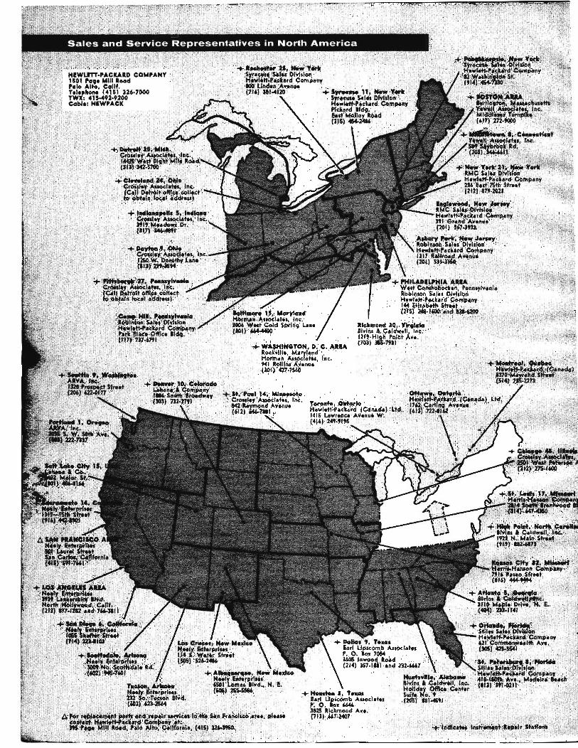
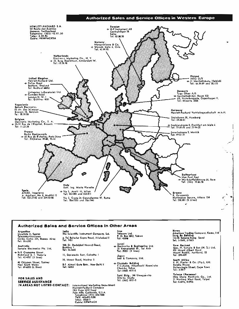
+
HEWLETT-PACKARD S.A. 54 Route des Acacias Geneva, Switzerland Telephone: (022) 42.81.50 Telex: 2.24.86 Cable: HEWPACKSA
United Kin dom Hewlett-Paclard Ltd.
Bedford, England Tel: Bedford 68052 Livingrton Laboratories Ltd.
London N. W. I Tel: GUlliver 4191
+ Dallas Road Tel: 66.39.09 and 35.125
Denmark
+ Camden Road
Yugoslavio Eelram Electronics 83 Av. Des Mimosas Brurrelr 15, Belgium Tel: 35 29 58
Belgium Electronic Marketing CO., S. A. 20-24 Rue de I 'Hopital, Brusrelr Tel : I 1.22 20
Sophienstrarre 8, Frankfurt am Main 6 Tel. 77-31-75 and 77-94-25
Fronce Radio Equipements
Tel: RlChelieu 49-88, 95-41 + 65 Rue de Richelieu, Paris ZBme
+ Wankdorffeldrtrasre 66, Bern Tel: (031) 42.00.78
. Ing. Mario Vianello
Via S. Croce in Gerusalemme 97, Rome Tel: 756-7250 and 156-7941
~~ ~
Authorized Sales and Servlcre ani Korea American Trading Company, Korea, Ltd
11235 Sokong-Dong, Seoul
New Zeoland Geo. H. Sample & Son (N. 2.) Ltd. 431 Mount Albert Road Mount Rorkill, Auckland, 53 Tel: 898-439
South Afr ica F. H. flanter & Co. (Pty.), Ltd. Rorella House Buitencin le Street, Cape Town Tal: 3-3817
Argentlna India I ran
P. 0. Box 1812, Tehran Mauricio A. Suarez Telecomunicaciones carlor calve 224, B~~~~~ ~i~~~ $p/ f i hadur SaPru Road, A h h a b a d 1 Tet: 43850 Tel: 3-7WP, 3-7613 Tel: 30-6312
Israel
16 Kremenetrki St., Tel gviv Austral ia
Tel: 35021 ( 3 lines) Sample Electronicr Pty. Ltd.
Richmond E. I, Victoria It, Esplanade East, Calcutta I Japan Tel: 42-4757 ( 3 liner) Seki & Company, Ltd.
48 Chippen Street, Sydney New South Wales 9 2-chome, Nihonbashi Koami-cho Tel: 69-6338 (6 liner) Tel: 26053 Chuo-ku, Tokyo
Tel: 1860) 4121-5
The Scientific Instrument Company, Ld. Telecom Ltd. Son Bo Building
240 Dr. Dadabhai Naoroii Road, + Electronics & Engineerin Ltd. Bombay I Tel: 26-2642 + 9-1 I Cremorne Street
30, Mount Road, Madras 2
8-7, Aimeri Gate Extn., New Delhi I + Churhoku
Taiwan ffarmosa) Hwa Sheng Electronic Co., Ltd. 21 Nanking West Road, Taipei Tel: 4-6076, 4-5936
Sumi Bid 106 Umegse-cho Kita-ku, &:aka Tel: (362) 8151-5 FOR SALES AND
IN AREAS NOT LISTED CONTACT: SERVICE ASSISTANCE
International Marketing Department Hewlett-Packard Company 1501 Page Mi l l Road Palo Al to California U.S.A.
Telephdne: 415) 316-7000 TWX: 41549!2-9200 Telex: 03381 I Cable: HEWPACK


