Embed Size (px)
Citation preview
HPLD Single ScrewBare Shaft CompressorInstallation, Operation and Service Manual


iHPLD Single Screw Compressor • Installation, Operation and Service Manual • Emerson • 35391HP
What is covered & how long it is covered: Subject to the other terms of this Warranty Statement, Seller warrants to its direct purchasers (and to no others) that the Products it manufactures will be free from defects in material and work-manship under normal use, regular service and maintenance. This warranty only applies when such defect appears in the Products within 12 months (“m”) from the date such Products are placed in service and when such Products are returned to and received by Seller within 18m from the date of manufacture by Seller (“12m/18m”), except that defects in the following Products different than 12m/18m are covered by the number of months indicated below if returned to Seller within the following number of months (“m Ship”) from shipment by Seller—
What is not covered: This warranty does not extend to any losses or damages due to misuse; corrosion; accident; abuse; neglect; normal wear and tear; negligence (other than Seller’s); unauthorized alteration; use beyond rated ca-pacity; acts of God; war or terrorism; unsuitable power sources or environmental conditions; operation with refrigera-tion or lubricants which are not suitable for use with the Product; improper installation, repair, handling, maintenance or application; substitution of parts not approved by Seller; or any other cause not the fault of Seller. This warranty is only applicable to Products properly maintained and used according to Seller’s instructions, the use of genuine Vilter™ replacement parts and recommended oil in all repairs, and when Buyer has demonstrated adherence to a scheduled maintenance program as detailed in the applicable operating manual. The Buyer must use Vilter approved oil only and provide oil analysis results to Vilter. To the extent the Buyer has supplied specifications, information, representation of operating conditions or other data to Seller in the selection or design of the Products and the preparation of Seller’s quotation, and in the event that actual operating conditions or other conditions differ from those represented by Buyer, any warranties or other provisions contained herein which are affected by such conditions will be null and void. Seller does not warrant that the Products comply with any particular law or regulation not explicitly provided in the Product specifications, and Buyer is responsible for ensuring that the Products contain all features necessary to safely perform in Buyer’s and its customers’ plants and operations. If the Products are for a gas compression application, this warranty does not apply if the Products are operated in conjunction with a gas with an H2S level above 100 PPM.
ProductCompressor Type
Reciprocating Compressors
VSS / VSM Refrigeration Compressors
VSG / VSSG Gas Compressors
New Unit 24m Ship 24m Ship 12m/18m
Compressor (New Unit Only)
24m Ship 60m Ship 12m/18m
New Bareshaft Compressor
24m Ship 24m Ship 12m/18m
Remanufactured Compressor
12m/18m 12m/18m 12m/18m
Any Engineered to Order (ETO) packaged system (including Heat Pumps and Process Chillers) not described above carry the 12m/18m warranty.
VSS / VSM single screw compressors installed and shipped on New Units carry an internal Product component warranty of 5 years from shipment date and a warranty of 15 years from shipment date for compressor bearings only. Does not include actuator motors and shaft seals.
Vilter™ Genuine OEM Parts, retrofit Vission 20/20 panels, retrofit PLC panels and any other supplied equipment not described above carry a 12m warranty from shipment date.
New Vapor Recovery Units (“VRU Units”) and its Compressors carry the stan-dard 12m/18m warranty—all other VRU parts carry a 6 m warranty from ship-ment date.
Standard VILTER™ Warranty Statement

ii HPLD Single Screw Compressor • Installation, Operation and Service Manual • Emerson • 35391HP
Third Party Motors & Starters: Motors and starters or Motor & Starter Parts purchased by Seller from a third party for resale to Buyer or for incorporation into Seller’s Product will carry only the warranty extended by the original manufacturer (“OEM”). Motor manufacturer warranties cover only the repair or replacement of the motor, and do not cover removal and installation charges, incidental charges associated with the removal and installation process, loss of product, or shipping to and from the manufacturer or approved shop. The individual motor manufacturer warranty terms can be found on the manufacturer’s associated websites.
Other limitations: Seller will not be liable under the above warranty if Buyer is in default of its payment obligations to Seller under any purchase order or credit agreement. Except with Seller’s written permission given after receipt of Buyer’s request within 60 days of an event, Seller will not be responsible for costs of dismantling, lost refrigerant, reas-sembling, repair labor and expenses, travel cost or transporting the Product. Products repaired or replaced under this warranty will be warranted for the unexpired portion of the warranty applying to the original Products. Buyer agrees that all instructions and warnings supplied by Seller will be passed on to those persons who use the Products. Products are to be used in their recommended applications and all warning labels adhered to the Products by Seller must be left intact. Any technical advice furnished by Seller before or after delivery in regard to the use, application or suitability of the Products may not be construed as an express warranty unless confirmed by Seller in writing, and Seller assumes no obligation or liability for the advice given or results obtained—all advice given and accepted at Buyer’s sole risk.
Exclusive Remedy: Within (10) ten days after Buyer’s discovery of any warranty defects within the warranty period, Buyer will notify Seller of such defect in writing. Seller will, at its option and as Buyer’s exclusive remedy, repair, correct, or replace F.O.B. point of manufacture, or issue credit or refund the purchase price for, that portion of the Products found by Seller to be defective. Failure by Buyer to give such written notice within the applicable time period will be deemed an absolute and unconditional waiver of Buyer’s claim for such defects. Buyer assumes all other responsibility for any loss, damage, or injury to persons or property arising out of, connected with, or resulting from the use of the Products, either alone or in combination with other products/components. If so required, Products or parts for which a warranty claim is made are to be returned transportation prepaid to Seller’s factory. THE FOREGOING CONSTITUTES THE SOLE AND EXCLUSIVE REMEDY FOR BREACH OF ANY WARRANTY HEREUNDER.
SOLE WARRANTY: THE WARRANTIES ABOVE CONSTITUTE SELLER’S SOLE AND EXCLUSIVE WARRANTIES WITH RESPECT TO THE PRODUCTS AND ARE IN LIEU OF AND EXCLUDE ALL OTHER WARRANTIES, EXPRESS OR IMPLIED, ARISING BY OPERATION OF LAW OR OTHERWISE, INCLUDING MERCHANTABILITY AND FITNESS FOR A PARTICULAR PURPOSE WHETHER OR NOT THE PURPOSE OR USE HAS BEEN DISCLOSED TO SELLER IN SPECIFICATIONS, DRAWINGS OR OTHERWISE, AND WHETHER OR NOT SELLER’S PRODUCTS ARE SPECIFICALLY DESIGNED AND/OR MANUFACTURED BY SELLER FOR BUYER’S USE OR PURPOSE.
LIMITATION OF LIABILITY: SELLER SHALL NOT BE LIABLE FOR DAMAGES CAUSED BY DELAY IN PERFORMANCE AND THE REMEDIES OF BUYER HEREIN ARE EXCLUSIVE. IN NO EVENT, REGARDLESS OF THE FORM OF THE CLAIM OR CAUSE OF ACTION (WHETHER BASED IN CONTRACT, INFRINGEMENT, NEGLIGENCE, STRICT LIABILITY, OTHER TORT OR OTHERWISE) SHALL SELLER’S LIABILITY TO BUYER AND/OR ITS CUSTOMERS EXCEED THE PRICE PAID BY BUYER FOR THE SPECIFIC PRODUCTS OR PORTION OF THE PRODUCTS PROVIDED BY SELLER GIVING RISE TO THE CLAIM OR CAUSE OF ACTION, AND BUYER SHALL INDEMNIFY AND HOLD HARMLESS SELLER FOR ANY DAMAGES INCURRED BY SELLER IN EXCESS THEREOF. BUYER AGREES THAT IN NO EVENT SHALL SELLER’S LIABILITY TO BUYER AND/OR ITS CUSTOMERS EXTEND TO INCLUDE INCIDENTAL, CONSEQUENTIAL OR PUNITIVE DAMAGES. The term “consequential damages” includes loss of anticipated profits, business interruption, loss of use, revenue, reputation and data, costs in-curred, including for capital, fuel, power and loss or damage to capital or equipment. Buyer agrees that all instructions and warnings supplied by Seller will be passed on to those persons who use the Products. Seller’s Products are to be used in their recommended applications and all warning labels adhered to the Products by Seller are to be left intact.
Standard VILTER™ Warranty Statement

iiiHPLD Single Screw Compressor • Installation, Operation and Service Manual • Emerson • 35391HP
! WARNINGRead and understand operator´s manuals before using this machine.
Failure to follow operating instructions could result in serious injury.
Important Message
READ CAREFULLY BEFORE INSTALLING AND STARTING YOUR COMPRESSOR.
The following instructions have been prepared to assist in installation, operation and removal of VilterTM HPLD Single Screw Bare Shaft Compressors. Following these instructions will result in a long life of the compressor with satisfac-tory operation.
The entire manual should be reviewed before attempting to install, operate, service or repair the compressor.
Only qualified personnel shall operate, install and maintain the equipment.
Qualified personnel shall be accredited by a local regulatory agency, which requires that they are continually scruti-nized by an organization whose sole mission is to establish, maintain and assure that the highest industry standards are set and met in a continuous and ongoing basis. The credentials shall address topics ranging from plant safety, operating concepts and principles and operations through the basics of refrigeration compliance and PSM (Process Safety Management) requirements.
Follow local workplace occupational safety and health regulations.
A compressor is a positive displacement machine. It is designed to compress gas. The compressor must not be subjected to liquid carry over. Care must be exercised in properly designing and maintaining the system to prevent conditions that could lead to liquid carry over. VilterTM Manufacturing is not responsible for the system or the controls needed to prevent liquid carry over and as such VilterTM Manufacturing cannot warrant equip-ment damaged by improperly protected or operating systems.
VilterTM HPLD Single Screw Compressor components are thoroughly inspected at the factory. However, dam-age can occur in shipment. For this reason, the equipment should be thoroughly inspected upon arrival. Any damage noted should be reported immediately to the Transportation Company. This way, an authorized agent can examine the unit, determine the extent of damage and take necessary steps to rectify the claim with no serious or costly delays. At the same time, the local VilterTM representative or the home office should be noti-fied of any claim made.
All inquires should include the VilterTM sales order number, compressor serial and model number. These can be found on the compressor name plate on the compressor.
All requests for information, services or parts should be directed to:
Vilter Manufacturing LLCCustomer Service Department
5555 South Packard AveCudahy, WI 53110-8904 USA
Telephone: 1-800-862-2677; Fax:1-414-744-3483E-mail: [email protected]; Web: Emerson.com/Vilter
Equipment Identification Numbers:Vilter Order Number: _______________________Compressor Serial Number: _________________Vilter Order Number: _______________________Compressor Serial Number: _________________

iv
EC Declaration of Incorporation
We hereby declare that the following machinery is intended to be incorporated into other machinery, and must not be put into service until the relevant machinery into which it is to be incorporated has been declared in con-formity with the essential requirements of the Machinery Directive 2006/42/EC.
Machine Description: Industrial Compressor Make: Vilter
Type: VSM / VSS / VSH / VSSH / VSG & VSSG Single Screw Compressor
Model Size: 97, 113, 127, 128, 145, 160, 180, 204, 222, 243, 152, 182, 202, 301, 361, 401, 501, 601, 701, 291, 341, 451, 601, 751, 901, 791, 891, 1051, 1201, 1301, 1551, 1851, 2101, 2401, 2601, 2801, 3001
Manufactured by: Vilter Manufacturing, LLC. The following transposed harmonised European Standards have been used:
EN ISO 12100-1:2010
- Safety of Machinery - General principles for design-Risk assessment and risk reduction.
EN ISO 13857:2008
- Safety of Machinery - Safety distances to prevent danger zones being reached by the upper and lower limbs.
EN349: 1993 + A1:2008
- Safety of Machinery - Minimum gaps to avoid crushing hazards.
EN ISO 13850:2015
- Safety of Machinery - Emergency stop equipment - Principles for design.
IEC/EN60204-1 (2016) - Safety of Machinery - Electrical equipment of machines - Specification for general requirements
A technical construction file for this machinery is retained at the following address:
Vilter Manufacturing, LLC.5555 South Packard AvenueP.O. Box 8904, Cudahy Wisconsin 53110-8904 Signed for and on behalf of Vilter Manufacturing, LLC.:
Last update: May 2019
Vilter Manufacturing, LLC.5555 South Packard Avenue t P.O. Box 8904 t Cudahy, Wisconsin 53110-8904
001-414- 744-0111 t FAX: 001-414-744-3483

TOC − 1
Table of Contents
Section Title Page Number
HPLD Single Screw Compressor • Installation, Operation and Service Manual • Emerson • 35391HP
Standard Vilter Warranty Statement ...................................................................................................... iImportant Message................................................................................................................................ iiiEC Declaration of Incorporation ............................................................................................................. iv
Section 1 • General Information
How To Use This Manual ......................................................................................................................... 1-1Additional Important Notes ................................................................................................................... 1-1System Unit Identification ..................................................................................................................... 1-2Bare Shaft HPLD Compressor Model Designations .................................................................................. 1-3
Section 2 • Theory of Operation
Introduction .......................................................................................................................................... 2-1Compressor ........................................................................................................................................... 2-1Capacity and Volume Control ................................................................................................................. 2-2Description of a Gas System For a Standard Compressor Set ................................................................... 2-3Description of an Oil System For a Standard Compressor Set .................................................................. 2-3Critical Application Guidelines ............................................................................................................... 2-4Procedure For System Pressurization...................................................................................................... 2-5Alarm and Shutdown Readings .............................................................................................................. 2-6HPLD Package Requirements ................................................................................................................. 2-7
Section 3 • Installation
Delivery Inspection ................................................................................................................................ 3-1Rigging and Lifting of the Compressor ................................................................................................... 3-1Compressor Inspections Prior to Installation ..........................................................................................3-2Long Term Storage Recommendations ................................................................................................... 3-2
Long Term Storage Log ...............................................................................................................3-3Notice on Using Non-Vilter Oils .............................................................................................................. 3-4Instrumentation Requirements .............................................................................................................. 3-4
Pressure .....................................................................................................................................3-4Temperature ..............................................................................................................................3-5Miscellaneous.............................................................................................................................3-5
Piping .................................................................................................................................................... 3-6Testing System For Leaks ........................................................................................................................ 3-7
Hydrocarbon Systems ................................................................................................................3-7CO2 Systems ...............................................................................................................................3-7
Oil for Single Screw Compressors ........................................................................................................... 3-7
Section 4 • Operation
Notice on Using Non-Vilter Oils .............................................................................................................. 4-1Operation .............................................................................................................................................. 4-1Control System ...................................................................................................................................... 4-1
Starting, Stopping and Restarting the Compressor ..................................................................... 4-1Safety Setpoints .........................................................................................................................4-1
HPLD Control with Vission20/20™ Micro-Controller ............................................................................... 4-2

TOC − 2
Table of Contents
Section Title Page Number
HPLD Single Screw Compressor • Installation, Operation and Service Manual • Emerson • 35391HP
Section 5 • Maintenance/Service
Maintenance and Service Schedule ........................................................................................................ 5-1Recommendations When Servicing ........................................................................................................ 5-2Preparation of Unit for Servicing ............................................................................................................ 5-2Oil Sampling .......................................................................................................................................... 5-3
Recommendations .....................................................................................................................5-3Installation of The Oil Sampler Valve ........................................................................................... 5-3Pre-Sampling .............................................................................................................................5-3Sampling Procedure ...................................................................................................................5-4Oil Sample Analysis Report ......................................................................................................... 5-6
Compressor Inspection .......................................................................................................................... 5-7Bearing Inspection .....................................................................................................................5-7
Determining Maximum Applied Force For Main Rotor Bearings And Gaterotor Bearings .. 5-7Method of Inspection .....................................................................................................5-7 A) Preparation .................................................................................................. 5-7 B) Main Rotor Bearing Inspection ......................................................................5-7 C) Gaterotor Bearing Inspection .......................................................................5-9
Gaterotor Inspection ..................................................................................................................5-10A) Gaterotor - Main Housing Shelf Clearance ...................................................................5-10B) Gaterotor Float Measurement .....................................................................................5-11C) Gaterotor Backlash Inspection ....................................................................................5-12
Important notes .........................................................................................................................5-14Additional Inspections ................................................................................................................5-14Post Inspection...........................................................................................................................5-14
Gaterotor Removal and Installation ........................................................................................................ 5-15Removal ....................................................................................................................................5-15Installation .................................................................................................................................5-19Gaterotor Blade Removal ............................................................................................................5-21Gaterotor Blade Installation ........................................................................................................ 5-21Gaterotor Ball Bearing Removal .................................................................................................. 5-22Gaterotor Ball Bearing Installation .............................................................................................. 5-22Gaterotor Roller Bearing Removal ............................................................................................... 5-22Gaterotor Roller Bearing Installation ........................................................................................... 5-22
Compressor Shaft Seal Replacement ...................................................................................................... 5-24Shaft Seal Assembly ...................................................................................................................5-24Handling Seal Face with Care ...................................................................................................... 5-24Shaft Seal Removal .....................................................................................................................5-25Prior to Shaft Seal Installation (For all HPLD shaft seal models).................................................... 5-26Shaft Seal Installation ................................................................................................................5-27
Main Rotor Assembly ............................................................................................................................. 5-28Torque Specifications ............................................................................................................................. 5-28Using A Torque Wrench Correctly ........................................................................................................... 5-29Nord-Lock® Washers .............................................................................................................................. 5-29
Section 6 • Troubleshooting
Troubleshooting Guide, General Problems and solutions ........................................................................ 6-1
Section 7 • Warranty and Parts
Warranty Claim Processing .................................................................................................................... 7-1Motor Warranty Procedure .................................................................................................................... 7-2On-Site Service Support ......................................................................................................................... 7-3
TOC − 3
Table of Contents
Section Title Page Number
HPLD Single Screw Compressor • Installation, Operation and Service Manual • Emerson • 35391HP
Remanufactured HPLD Bare Shaft Single Screw Compressor ................................................................. 7-3Explanation of Rebuild Levels ...................................................................................................... 7-3
Section 8 • Spare Parts List
HPLD Recommended Spare Parts List ..................................................................................................... 8-1HPLD Compressor Kits ........................................................................................................................... 8-2
Gaterotor Kits .............................................................................................................................8-2Shaft Seal Kit ..............................................................................................................................8-2Compressor Gasket and O-Ring Kit ............................................................................................. 8-2Tool Kit .......................................................................................................................................8-2
Suction Covers ...................................................................................................................................... 8-3Discharge Manifold ............................................................................................................................... 8-4Housing ................................................................................................................................................ 8-5
Appendices
Appendix A Torque Specifications ......................................................................................................A-1Appendix B Vilter Oil .........................................................................................................................B-1

Table/Figure Page Number
TOC − 4 HPLD Single Screw Compressor • Installation, Operation and Service Manual • Emerson • 35391HP
Table of Contents
List of Tables and Figures
Tables
Table 2-1. HPLD Compressor Specifications ............................................................................................2-1Table 2-2. HPLD Compressor Volume Ratio Options ............................................................................... 2-3
Table 3-1. Bare Shaft Compressor Weights ............................................................................................. 3-1
Table 5-1. Maintenance/Service Schedule .............................................................................................. 5-1Table 5-2. Maximum Main Rotor Bearing Clearance ................................................................................5-7Table 5-3. Maximum Gaterotor Bearing Clearance .................................................................................. 5-9Table 5-4. Gaterotor Float ...................................................................................................................... 5-11Table 5-5. Backlash Range ...................................................................................................................... 5-13Table 5-6. HPLD Shaft Seals .................................................................................................................... 5-25Table 5-7. Torque Specifications (All units, Ft.-Lbs) ................................................................................. 5-28
Table 6-1. Troubleshooting Guide - General Problems and Solutions ....................................................... 6-1
Figures
Figure 2-1. Basic Single Screw Compressor System ................................................................................ 2-4Figure 2-2. Tubing Line To Pressurize The Unit (Bypassing The Compressor) ........................................... 2-5
Figure 3-1. Rigging and Lifting Points (Top View) ................................................................................... 3-1Figure 3-2. Additional Instruments ......................................................................................................... 3-5
Figure 4-1. Compressor and Model Setup with Vission 20/20 ................................................................. 4-2
Figure 5-1. Oil Analysis Kit (VPN 3097A) ................................................................................................. 5-3Figure 5-2. Oil Sampler Valve (VPN #3708A) For Gas Compression Applications ..................................... 5-4Figure 5-3. Oil Sampling Valve (VPN #3709A) For Ammonia and Refrigerant Compressors ..................... 5-4Figure 5-4. Operating the Oil Sampling Valve .........................................................................................5-5Figure 5-5. Stages of the Oil Sample Taking Process ............................................................................... 5-5Figure 5-6. Bearing Radial Clearance Inspection .....................................................................................5-7Figure 5-7. Bearing Axial Clearance Inspection .......................................................................................5-8Figure 5-8. Gaterotor Bearing Clearance ................................................................................................ 5-9Figure 5-9. Gaterotor and Shelf Clearance .............................................................................................. 5-10Figure 5-10. Gaterotor and Shelf Clearance Measurement Steps ............................................................. 5-10Figure 5-11. Visual Inspection Between Gaterotor and Bushing .............................................................. 5-11Figure 5-12. Gaterotor Float Dial Location .............................................................................................. 5-11Figure 5-13. Gaterotor Float ................................................................................................................... 5-12Figure 5-14. Alignment of Gaterotor ...................................................................................................... 5-12Figure 5-15. Location of Dial Indicator Magnetic Base ............................................................................. 5-12Figure 5-16. Placement of Dial Indicator ................................................................................................. 5-13Figure 5-17. Measuring Backlash ............................................................................................................ 5-13Figure 5-18. Chipped Edge of Gaterotor ................................................................................................. 5-14Figure 5-19. Rotor Position for Gaterotor/Support Assembly Removal .................................................... 5-15Figure 5-20. Gaterotor/Support Assembly Removal ............................................................................... 5-15Figure 5-21. Gaterotor Assembly ............................................................................................................ 5-16Figure 5-22. Tool (A24061A) To Handle Suction Tee Assembly ............................................................... 5-17Figure 5-23. Tool To Remove Bearing Housing Assembly ........................................................................ 5-18Figure 5-24. Tool To Install and Remove Bearing Housing Assembly........................................................5-18

TOC − 5HPLD Single Screw Compressor • Installation, Operation and Service Manual • Emerson • 35391HP
Table of Contents
Table/Figure Page Number
Figure 5-25. Tool To Install Bearing Housing Assembly ........................................................................... 5-19Figure 5-26. Check the Clearance Between the Gaterotor and Shelf ........................................................ 5-20Figure 5-27. Gaterotor and Support Assembly ........................................................................................5-21Figure 5-28. Gaterotor Top Face Identification ........................................................................................5-21Figure 5-29. Gaterotor Ball Bearing ........................................................................................................ 5-22Figure 5-30. Gaterotor Roller Bearing Assembly ..................................................................................... 5-23Figure 5-31. Shaft Seal Assembly............................................................................................................ 5-24Figure 5-32. Handling Seal Face with Care .............................................................................................. 5-24Figure 5-33. Shaft Seal Breakdown ......................................................................................................... 5-25, 5-27Figure 5-34. Shaft with Pin ..................................................................................................................... 5-26Figure 5-35. Shaft Seal Housing.............................................................................................................. 5-26Figure 5-36. The Alignment of Compressor Shaft and Mating Ring ......................................................... 5-26

TOC − 6 / Blank HPLD Single Screw Compressor • Installation, Operation and Service Manual • Emerson • 35391HP

1 – 1
Section 1 • General Information
HPLD Single Screw Compressor • Installation, Operation and Service Manual • Emerson • 35391HP
How To Use This Manual
This manual contains instructions for HPLD bare shaft compressors. It has been divided into eight sections and Appendices:
Section 1: General Information
Section 2: Theory of Operation
Section 3: Installation
Section 4: Operation
Section 5: Maintenance & Service
Section 6: Troubleshooting
Section 7: Warranty and Parts
Section 8: Spare Parts List
Appendices
Appendix A - Torque Specifications
Appendix B - Vilter Oil
It is highly recommended that the manual be reviewed prior to servicing system parts.
Figures and tables are included to illustrate key concepts.
Safety precautions are shown throughout the manual. They are defined as the following:
NOTICE - Notice statements are shown when there are important information that shall be followed. Not fol-lowing such notices may result in void of warranty, seri-ous fines, serious injury and/or death.
WARNING - Warning statements are shown when there are hazardous situations, if not avoided, will result in se-rious injury and/or death.
CAUTION - Caution statements are shown when there are potentially hazardous situations, if not avoided, will result in damage to equipment.
NOTE - Notes are shown when there are additional infor-mation pertaining to the instructions explained.
Additional Important Notes• Installation, operation and maintenance instructions
can be found in the associated software manual.
• Due to continuing changes and unit updates, always refer to the website Emerson.com/Vilter to make sure you have the latest manual.
• Any suggestions of manual improvements can be made to VilterTM Manufacturing at the contact information on page iii.

1 – 2
Section 1 • General Information
HPLD Single Screw Compressor • Installation, Operation and Service Manual • Emerson • 35391HP
System Unit Identification
To keep definitions of units simple and consistent, Vilter has defined the following three:
• Bare Shaft Compressor
• Compressor Unit
• Package Unit
Bare Shaft CompressorA bare shaft compressor is just the compressor with no coupling and motor nor foundation.
Compressor UnitA compressor unit consists of the bare shaft compressor with the coupling, motor, oil separator, frame, micro-control-ler system and oil system. A compressor unit typically a single screw compressor unit, is not mounted on a structural steel base.
Package UnitA package unit is a complete system mounted on a structural steel base with interconnecting piping.

1 – 3
Section 1 • General Information
HPLD Single Screw Compressor • Installation, Operation and Service Manual • Emerson • 35391HP
VSG–160–STH–STD–FV–AFH–SS
Compressor Type
STH = Steel Compressor Material w/ Discharge
Connection Horizontal
Special Designations
SS = Stainless Steel Internal Hardware
C = Ceramic Bearings
EO = External Oil Feed
VIB = Main Housing with Vibration Mounting
N = 900# Flange
Drive Shaft Type
STD = Standard Straight Drive Shaft
Slide Design Type
FV = Fixed Volume
Size
CFM = Nominal CFM displacement of the compressor at 3600 rpm
128, 145, 160, 180, 204, 222, 243
Seal Type
AF = Aflas O-rings
HV = High Pressure Design w/ Viton O-rings
AHF = Ammonia Service High Pressure
Aflas O-ring
Compressor Model
VSG= Vilter Single Screw Compressor (Gas Compression)
VSH = Vilter Single Screw Heat Pump
VSS= Vilter Single Screw Compressor
(Refrigeration)
Bare Shaft HPLD Compressor Model Designations
The compressor bare shaft model designation can be found on the nameplate.

1 – 4 / Blank HPLD Single Screw Compressor • Installation, Operation and Service Manual • Emerson • 35391HP

2 – 1
Section 2 • Theory of Operation
HPLD Single Screw Compressor • Installation, Operation and Service Manual • Emerson • 35391HP
Table 2-1. HPLD Compressor Specifications
COMPRESSOR MODELVSG128 VSH128 VSS128
VSG145 VSH145 VSS145
VSG160 VSH160 VSS160
VSG180 VSH180 VSS180
VSG204 VSH204 VSS204
VSG222 VSH222 VSS222
VSG243 VSH243 VSS243
DISPLACEMENT AT 3560 RPM (CFM) 128 145 160 180 204 222 243
MAXIMUM ESTIMATED HORSEPOWER AT 3550 RPM 865
Introduction
Vilter’s HPLD Single Screw Compressors are designed to fit high pressure applications, with special emphasis on those using CO2 (both transcritical and subcritical), but including as well gas compression applications and in-dustrial heat pumps. See Table 2-1 for specifications.
The use of constant torque VFD to control the compres-sor’s capacity saves energy by matching variable load requirements, which, added to its low displacement, provides inherent efficiency under part-load conditions. On top of that, VFD capacity control has the advantage of providing natural soft starts, preventing any type of surges and transients from being present at start-up.
CO2 ApplicationsWorking at high pressure (for both suction and dis-charge) gives HPLD compressors the option to use CO2 as refrigerant, and to take advantage of all its features.
High Pressure ApplicationsHPLD compressors are suited for applications that re-quire high pressure.
Heat Pump ApplicationsWith a housing designed to withstand high pressures, and reliable bearings when handling the higher loads of heat pump applications, plus flexibility when choosing the type of refrigerant to be used, HPLD compressors are a good match for these applications.
Compressor
The Vilter HPLD Single Screw Compressor is a positive displacement, capacity and volume controlled, oil flood-ed, rotary compressor which uses a single main screw intermeshed by two opposing gaterotors. Gas compres-sion occurs when the individual teeth of each gaterotor sweep through the grooves, or flutes, of the main screw as the screw rotates. Compression occurs from the time the screw flute is firstclosed off by the gaterotor finger, until the time when the screw flute has rotated to the point of lining up withthe discharge port in the compressor housing. A laby-rinth type seal is used to prevent gas at discharge pres-sure from leaking past the end of the screw. Any dis-charge gas leakage past the labyrinth seal is vented back to suction via four longitudinal holes drilled through the body of the screw.
By venting the discharge end of the main screw back tosuction, forces on each end of the screw are equal. This results in zero net axial forces on the main bearings. With twin opposing gaterotors, all radial forces are cancelled out also. Main shaft bearings have no net forces except the weight of the screw and the shaft assembly.
HPLD compressors are comprised of three rotating assemblies: the main screw assembly and the two gaterotor assemblies. Each of these rotating assemblies use a common bearing configuration consisting of a single, cylindrical rolling element bearing at one end, and three angular contact ball bearings at the other end. The three angular contact ball bearings are used to axially fix one end of the rotating shafts, and to absorb the thrust loads on the shafts. The inner races of the ball bearings are securely clamped to the rotating shafts, while the outer races are securely held in the bearing housing, thus fixing the axial position of the shaft in relation to the bearing housings. The cylindrical roller bearings at the opposite end of the shafts allow for axial growth of the shafts while supporting the radial loads from the shafts.

2 – 2
Section 2 • Theory of Operation
HPLD Single Screw Compressor • Installation, Operation and Service Manual • Emerson • 35391HP
The suction gas enters the compressor housing throughthe inlet flange, at the driven end of the unit. The driven end of the compressor housing is flooded with gas at suction pressure. The gas enters the open end of the main screw flutes at the driven end, and becomes trapped in the screw flute as the screw rotates and the gaterotor tooth enters the end of the flute. At this point, the compression process begins. Directly after the screw flute is closed off by the gaterotor tooth, oil is injected into the groove.
The oil enters the compressor through a connection at thetop of the compressor. The purpose of the injected oil isto absorb the heat of compression, to seal the gaterotortooth in the groove, and to lubricate the moving parts.
Additional internal oiling ports are provided at the mainand gaterotor bearings to cool and lubricate the bearings.The mechanical shaft seal housing also contains oiling ports to lubricate, cool and provide a sealing film of oil for the mechanical shafts seal. This oil is directed at the main rotor roller bearing, which cools and lubricates the front roller bearing.
As the main screw rotates, the gaterotor is also driven, causing the gaterotor tooth to sweep the groove in themain screw. This sweeping action reduces the volume of the groove ahead of the gaterotor tooth and causes the trapped gas and oil to be compressed in the reducedvolume. As the main screw continues to rotate, the gaterotor tooth continues to reduce the groove volume to a minimum, thus compressing the trapped gas to a maximum pressure. A labyrinth seal arrangement prevents the compressed gas from leaking past the end ofthe screw. As the gaterotor tooth reaches the end of thegroove, the groove rotates to a position that lines up withthe discharge port in the compressor housing and the gas/oil mixture is discharged from the screw at high pressure.This completes the compression cycle for a single flute of the main screw.
Once the gas is swept from the main screw flute throughthe discharge port, it passes into the discharge manifoldof the compressor. From the discharge manifold, the gas/oil exits the compressor housing.
Capacity and Volume Control
The Vilter HPLD compressor’s capacity is driven by a variable frequency drive (VFD), which responds to a con-troller’s commands based on the feedback provided by readings from instruments and gauges placed on the system. When the controller drives the VFD to its maxi-mum speed (100% position), the compression process begins immediately after the gaterotor tooth enters the screwflute and closes off the end of the groove. In this situation, the maximum volume of gas is trapped in the screw flute at the start of the compression process.
As the speed of the VFD reduces, this causes a reduced volume of gas to be trapped in the screw flute when the compression process begins. In this way, the capacity of the compressor is reduced from 100% down to as low as 10% of the full rated capacity.
The use of VFD provides the means to control based on specific process setpoints. By continuously adjusting the flow of gas through the compressor, either suction or discharge pressure in a particular process can be controlled.
When coupled with a micro-processor controller, the adjustable speed of the VFD allows for precise and continuous automatic control of any parameter in the process to a chosen setpoint.
The compressor’s volume is controlled by different ratio-sized plugs, thus determining a specific fixed volume ratio for the compressor. Once the volume ratio has been chosen and the plug placed, this value would be established.
See Table 2-2 for the different volume ratio options for HPLD compressors.

2 – 3
Section 2 • Theory of Operation
HPLD Single Screw Compressor • Installation, Operation and Service Manual • Emerson • 35391HP
Table 2-2. HPLD Compressor Volume Ratio Options
COMPRESSOR MODELVSG128 VSH128 VSS128
VSG145 VSH145 VSS145
VSG160 VSH160 VSS160
VSG180 VSH180 VSS180
VSG204 VSH204 VSS204
VSG222 VSH222 VSS222
VSG243 VSH243 VSS243
Volume Ratio
8.3 7.3 6.5 6.1 5.1 5.3 4.8
5.3 4.9 4.5 4.2 3.6 3.6 3.5
3.9 3.6 3.4 3.2 2.8 2.9 2.7
2.5 2.5 2.3 2.2 2 2 1.9
1.9 1.9 1.9 1.8 1.6 1.6 1.6
Description of a Gas System For a Standard Compressor Set
The gas passes through a stop valve and a check valve and then through a mesh strainer mounted directly to the inlet flange. The check valve is necessary to prevent reverse rotation and potential damage or oil loss at shut down. The suction gas enters the compressor housing through the inlet flange, at the driven end of the unit.
After compression, the gas is discharged from the discharge manifold directly into a oil separator tank. On the discharge of the oil separator tank another check valve is positioned to prevent the entry of gas or liquid refrigerant in to the separator when the compressor is shut down. The separator should be allowed to equalize slowly to suction pressure through a small bypass line around the suction check or combination stop/check valve. This will allow the compressor to start without a pressure differential across it, reducing the starting power requirements.
From the discharge manifold, the gas/oil exits the compressor housing and passes into the oil separator through a pipe elbow. The separator vessel serves to separate the oil from the gas as the gas stream moves from one end of the separator to the other. The majority of the oil is separated from the gas in the primary chamber of the vessel due to changes in direction and velocity reduction. Any remaining oil mist is separated from the gas stream as the stream passes through the coalescing elements and into the secondary chamber of the vessel. The gas at discharge pressure then exits at the far end of the separator.
Oil collected in the bottom of the separator is drained off to be recirculated in the oil injection system. The injection oil temperature is controlled by several means the first of which is a three-way mixing valve, which mixes hot oil directly from the separator with oil which has passed through the oil cooler to obtain oil at the desired temperature.
This oil then passes through a filter to remove any contaminants, which may have been picked up from the process gas, and is injected back into the compressor.
Description of an Oil System For a Standard Compressor Set
At the start, oil is drawn from the oil separator tank by the oil pump, and passes through a oil cooler and mi-cronic filters to the oil supply inlet on the compressor frame. From there it lubricates all points internal to the compressor. After start-up, when the compressor devel-ops sufficient differential pressure, the oil pump can be shut down and the oiling can take place without the use of the oil pump. On units with low pressure differentials such as booster and low pressure differential high stage compressors, the oil pump must remain on whenever the unit is running to maintain sufficient oil flow.

2 – 4
Section 2 • Theory of Operation
HPLD Single Screw Compressor • Installation, Operation and Service Manual • Emerson • 35391HP
Figure 2-1. Basic Single Screw Compressor System
Critical Application Guidelines
To ensure the successful operation of the HPLD compressor, the guidelines described below should be followed.
1. Proper lubrication is critical to the operation of the HPLD compressor. The compressor relies on the injected oil to absorb and remove the heat of compression, to seal the compression chambers formed in the flutes of the screw, and to lubricate all moving parts. For this reason, it is imperative that the oil chosen be of correct viscosity, and that sufficient oil flow be provided at all times, using an auxiliary oil pump when necessary. The oil chosen must be compatible with the process gas as well, to prevent absorption of the gas into the oil, which would dilute the oil and reduce the viscosity. Also, oil filtration to 25 micron nominal particle size is required to ensure that only clean oil is injected into the compressor. For assistance in choosing the correct oil for the application and in sizing an auxiliary oil pump, consult a VilterTM representative.
2. Injection oil temperature must be closely controlled for optimum performance. Oil temperature must be maintained a minimum of 15 - 20°F above the gas mixture dew point at anytime to prevent condensation or liquid knockout from occurring within the compressor.
Note for CO2 and Heat Pump ApplicationsBecause the oil system on the HPLD compressors utilizes discharge gas pressure as the means to move the injection oil through the system, it must be remembered that all components of the oil system are exposed to full discharge
pressure and must be pressure rated accordingly.
3. Gas composition plays a role in the performance of the HPLD compressor as well. While the HPLD is capable of handling a wide variety of gases, it is required that the concentration of H2S in the process gas not exceed 100 PPM. If H2S is present in the process gas in any concentration, special oil additives are required to protect the compressor from corrosion.

2 – 5
Section 2 • Theory of Operation
HPLD Single Screw Compressor • Installation, Operation and Service Manual • Emerson • 35391HP
Figure 2-2. Tubing Line To Pressurize The Unit (Bypassing The Compressor)
Procedure For System Pressurization
If the differential between the suction pressure before the suction shutoff valve, and the discharge pressure is above 60 PSID, all HPLD single screw compressor units must be brought up to pressure via the oil separator/discharge side of the unit.
A tubing line connected before the suction shutoff valve and the top of the separator is provided with the units to pressurize the unit bypassing the compressor (see Figure 2-2).
If a pressurizing line is not present on the unit, a tubing line (3/8” to 1/2”) can be added before the suction shut off valve and the top of the separator (see #2 on Figure 2-2) with a shut off valve for the operator/technician to use to bring up system pressure (see #1 on Figure 2-2).
1
2

2 – 6
Section 2 • Theory of Operation
HPLD Single Screw Compressor • Installation, Operation and Service Manual • Emerson • 35391HP
Alarm and Shutdown Readings
WARNINGSoftware programming credentials shall only be made available by the supplier. The user will only have access to operational features established by the supplier. Failure to comply may result in serious injury
or death.
The control system for the HPLD compressor must protect the machine from damage caused by running outside of normal operating conditions by providing operators with alarms when operating parameters have reached an abnormal condition, and by automatically stopping the compressor before these conditions can cause a unit failure. Pressures and temperatures of the process gas and the oil, as well as motor amperage and VFD frequency must all be continuously monitored to ensure the compressor is operating properly.
1. Low Gas Suction Temperature - This point protects the compressor from suction gas entering the compressor at too low of a temperature, and is activated by a direct reading from the suction temperature RTD located at the suction tee.
2. High Gas Discharge Temperature - This point protectsthe compressor against high gas temperature at the discharge of the unit, and is activated by a direct reading from the RTD located at the compressor discharge manifold.
3. Low Oil Separator Start Temperature - This point protects the compressor from starting with low oil temperature in the separator, and is activated by a direct reading from the RTD located at the bottom of the oil separator.
4. Low Oil Separator Run Temperature - Similar to the Low Oil Separator Start Temperature described above, however this point only becomes active after a predetermined period of running time, and uses a higher setpoint.
5. Low Oil Injection Temperature - This point protectsthe compressor from running with cold oil being injected into the screw housing, and is activated by a direct reading from the RTD located at the oil injection line. This point is bypassed for a predetermined period of time after starting to allow the unit time to start and warm up.
6. High Oil Injection Temperature - This point protectsthe compressor from running with hot oil being injected into the screw housing, and is activated by a direct reading from the RTD located at the oil injection line.
7. Low Suction Pressure - This point protects the compressor from drawing low suction pressure and is activated by a direct reading from the suction pressuretransducer, which reads the pressure from a tap located at the suction stop/check valve housing.
8. High Discharge Pressure - This point protects the compressor from developing high discharge pressure and is activated by a direct reading from the discharge pressure transducer, which reads the pressure from a tap located at the oil separator. In addition to this alarm and shutdown, the compressor package is ultimately protected from damage due to over pressurization by at least one discharge pressure relief valve located on the oil separator. The purpose of this safety setpoint is to allow for a lower setpoint to conform to a process requirement, and to prevent the relief valve from opening.
9. Prelube Oil Pressure - This point acts as a permissiveto start the compressor, and protects against the compressor starting with no oil lubrication. If, during a start sequence, the prelube oil pressure fails to rise above 4.0 PSID, the compressor will fail to start. The prelube oil pressure is a calculated value obtained by subtracting the discharge pressure reading from the oil manifold pressure (oil filter outlet pressure) reading.
10. Low Oil Pressure - This point protects the compressorfrom running with insufficient lubrication pressure, and becomes active after a predetermined period of running, usually sixty seconds. The oil pressure is a calculated value obtained by subtracting the suction pressure from the oil manifold pressure (oil filter outlet pressure) reading, which results in the actual pressure under which the oil is entering the screw housing.
11. High Running Oil Filter Differential Pressure - Thispoint alerts operators to clogging oil filters. When the oil filters develop a high differential pressure while running at normal operating temperatures, it is an indication that they are becoming dirty and must be changed. An alarm initially warns of dirty filters; if the situation worsens before the filters are changed a shutdown will stop the compressor.

2 – 7
Section 2 • Theory of Operation
HPLD Single Screw Compressor • Installation, Operation and Service Manual • Emerson • 35391HP
In most cases, the safety setpoints described above will have settings which are dictated by process requirements, and not necessarily mechanical constraints of the compressor. Process pressures and temperatures may vary considerably depending on the application of the compressor, and the HPLD compressor is designed to work well in a broad range of applications. For this reason, it is impractical to suggest “initial” setpoints to fit all applications. Instead, minimum and maximum values for each safety setpoint are provided, while precise settingsfor the safety setpoints must be derived for each installation.
HPLD Package Requirements
Process Gas Circuit
1. Suction Gas Stop/Check Valve - The HPLD compressorrequires a manually operated stop valve on the suction line to the compressor to allow for isolating the compressor package from process gas. Also, a check valve is required in the suction line to limit reverse rotation of the compressor on shutdown.
2. Suction Line Strainer - VilterTM strongly recommendsthe use of an in-line suction gas strainer to protect the HPLD compressor from foreign material which may enter the compressor with the suction gas. This strainer is generally of stainless steel mesh construction.
3. Process Gas/Oil Separator - A separator vessel capable of removing the oil from the discharge gas stream with an efficiency down to at least 5 PPM oil carryover is required. Vilter’s own available horizontal or vertical separator is an ASME-coded vessel which uses five stages of separation to achieve an oil loss of as little as 3 to 4 PPM.
4. Discharge Gas Relief Valve - To protect the compressorpackage from damage due to over pressurization, a relief valve must be installed inside of any discharge line hand block valves. The relief valve must be set to open at a pressure lower than the Maximum Allowable Working Pressure (MAWP) of the separator.
5. Oil Prelube Pump - Usually a direct driven gear type pump, the oil pump is required to prelube the compressorprior to starting and to maintain oil pressure during anyperiods of low compression ratio operation.
6. Oil Cooler/ Temperature Control Valve - An oil cooler, either air or water cooled, must be used to remove the heat of compression from the oil stream. A temperaturecontrol valve is used to maintain constant oil injection temperature to the compressor.
7. Oil Filtration - Large capacity micronic oil filters are required to filter the oil before injection into the HPLD compressor. Filtration down to 25 microns nominal or lessis generally acceptable. Dual filters are recommended toallow replacement of one cartridge while the compressorcontinues running with the other cartridge in service. If needed, separate oil filtration can be available for bearings and shaft seal.
8. Oil Heater - An oil heater is generally required and must be sized to maintain oil temperature of at least 90°F when the compressor is not running. For outdoor installations,low ambient temperatures and winds must be considered when sizing the oil heater. Also, insulating the separator and oil piping may be required in low temperature ambient conditions.

2 – 8 / Blank HPLD Single Screw Compressor • Installation, Operation and Service Manual • Emerson • 35391HP

3 – 1
Section 3 • Installation
HPLD Single Screw Compressor • Installation, Operation and Service Manual • Emerson • 35391HP
NOTICEVilter compressors are to be installed and connected to the customer-provided piping. Vilter expects this piping to be designed and built following ASME B31.3 Process Piping Guide, plus any other local applicable codes, and that the installation will be performed by
qualifi ed personnel only.
Delivery Inspection
Every equipment supplied by Vilter is thoroughly in-spected at the factory. However, damage can occur in shipment. For this reason, the compressor should be thoroughly inspected upon arrival, prior to off-loading. Any damage noted should be photographed and report-ed immediately to the transportation company. This way, an authorized agent can examine the compressor, determine the extent of damage and take necessary steps to rectify the claim with no serious or costly delays. At the same time, the local Vilter representative or the home office should be notified of any claims made with-in ten (10) days after its discovery. Refer to long term storage for additional recommendations.
Rigging and Lifting of the Compressor
WARNINGWhen rigging and lifting a compressor unit, use proper lifting device capable of lifting and maneuvering the weight and size of the compressor unit. Use only qualifi ed personnel and additional personnel and lifting equipment (i.e. spreader bar) as required. Failure to comply may result in death, serious injury
and/or damage to equipment.
Only qualified personnel shall operate rigging and lifting equipment. Ensure that the lifting device is capable of lifting the weight of the compressor, refer to the sup-plied Vilter General Assembly (GA) drawing, and to Table 3-1 for weights of bare shaft compressors.
To lift the compressor, use lifting points on compressor frame to attach the lifting device, see Figure 3-1. There are a few points to consider prior to moving it:
• Ensure that the weight is evenly distributed amongst the lifting device (i.e. lifting chains and spreader bar) prior to lifting.
• Ensure that the lifting device is not obstructed by any parts of the compressor to prevent damage to components.
• Use additional personnel as needed to spot and aid in maneuvering the compressor.
• Ensure there is plenty of space to maneuver the com-pressor, and a clear path to its location.
To place lifting eyebolts
Main Compressor Assembly
Center of gravity may differ slightly between models 128-243. Adjust main lift point within the range to keep bare shaft compressor as leveled as possible when lifting.
To place a lifting eyebolt
Table 3-1. Bare Shaft Compressor Weights
COMPRESSOR MODEL
VSG128 VSH128 VSS128
VSG145 VSH145 VSS145
VSG160 VSH160 VSS160
VSG180 VSH180 VSS180
VSG204 VSH204 VSS204
VSG222 VSH222 VSS222
VSG243 VSH243 VSS243
Weight 1095 LBS 1095 LBS 1095 LBS 1090 LBS 1090 LBS 1090 LBS 1090 LBS
Figure 3-1. Rigging and Lifting Points (Top View)
3 – 2
Section 3 • Installation
HPLD Single Screw Compressor •Installation, Operation and Service Manual • Emerson • 35391HP
base skid so that water does not collect inside the base perimeter or low spots in the tarp.
• All compressor stop valves are to be closed to isolate the compressor from the remainder of the system. All other valves, except those venting to atmosphere, are to be open. The unit is shipped with dry nitro-gen holding charge of approximately 5 psi above at-mospheric pressure. It is essential that the nitrogen holding charge be maintained.
• Cover all bare metal surfaces (main rotor shaft, cou-pling, flange faces, etc.) with rust inhibitor.
• Desiccant is to be placed in the control panel. If the panel is equipped with a space heater, it is to be ener-gized. Use an approved electrical spray-on corrosion inhibitor for panel components (relays, switches, etc.)
• All pneumatic controllers and valves (Fisher, Taylor, etc.) are to be covered with plastic bags and sealed with desiccant bags inside.
• Before leaving Vilter™ Manufacturing the compres-sor is evacuated and pressurized, with dry nitrogen, to 5 psig. Pressure must be monitored with the gauge (provided by Vilter™) and checked on a regular basis (at least monthly).
• It is essential that the nitrogen or clean dry gas hold-ing charge be maintained. If not already installed, it is required that a gauge is to be added to help moni-tor the nitrogen holding charge pressure. If a drop in pressure occurs, the source of leakage must be found and corrected. The system must be evacuated and recharged with dry nitrogen to maintain the package integrity.
• Manually rotate the compressor shaft 6 ½ revolutions every month to prevent flat spots on the bearing sur-faces. If the compressor unit is installed, wired, and charged with oil, open all oil line valves and run the oil pump for 10 seconds prior to rotating the compres-sor shaft. Continue running the oil pump while the compressor shaft is being turned to help lubricate the surfaces of the shaft seal. For cool compression, there is no pre-lube pump, so the driveshaft must be turned by hand.
• Maintenance log to be kept with documenting dates to show all the procedures have been completed (see next page).
Compressor Inspections Prior to Installation
The compressor must be inspected prior to installation since components could have come loose and/or dam-aged during shipment or moving.
• Check for loose bolts, particularly the compressor mounting nuts.
• Look into the suction and discharge connections and inspect for any signs of corrosion on parts.
• Check for bent or damaged components. The com-pressor should have also been inspected prior to off-loading, see Delivery Inspection.
• Check that the nitrogen pressure is still holding pres-sure. Any leaks must be fixed and the system purged and re-charged with dry nitrogen.
• Prelube the compressor with the main oil pump and rotate by hand several revolutions prior to start.
• Notify VilterTM Service and Warranty Department when the compressor is started.
NOTE
For Pre Start-Up and Start-Up checklists, please contact Vilter Service and Warranty Department.
CAUTIONBefore installation, follow the proper procedures to
depressurize the compressor.
Long Term Storage Recommendations
The procedure described is a general recommendation for long term storage (over one month of no operation) of Vilter compressors. It is the responsibility of the instal-lation firm and end user to address any unusual condi-tions. Use the supplied long term storage log sheet to help with record keeping, see section page 3-3.
Warranty of the system remains in effect as described at the beginning of this manual.
The following are recommendations regarding long term storage:
• If the compressor is designed for indoor duty, it must be stored in a heated building, preferably air condi-tioned to control moisture, to prevent corrosion of the main rotor shaft and for the compressor.
• If the unit is designed for outdoor duty and is to be stored outdoors, a canvas tarp is recommended for protection until installation. Adequate drainage should be provided. Place wood blocks under the

Long Term Storage Log
Company: Sales Order Number:
Serial Number:
Name (Please Print): Initial:
Date (M/D/Y):
PSI Nitrogen Pressure - Current
PSI Nitrogen Pressure - Recharged (If pressure is low, identify and fix leak prior to recharging, see Compressor Unit Leak Check procedure in Section 5)
Nitrogen Leak Location (Briefly explain nature of leak):
Compressor Shaft (Rotate shafts at least 6 revolutions)
Motor Shaft (Rotate shafts at least 6 revolutions)
Motor Bearings Greased
Air Cooled Oil Cooler Rotated
Bare Metal Surfaces (Check all bare metal surfaces for rust and ensure they are covered with rust inhibitor)
Desiccants (Are desiccants still effective? If not, replace. Check control panel, motor, pneumatic controllers and valves)
Cover Bags/Tarp (Ensure bags and tarps are not torn and are sealed over components correctly, replace if damaged)
Valves (Stop valves are in closed position so the compressor unit is isolated. All other valves, except those venting and draining to atmo-sphere are to be open)
Space Heater & Panel Components (Ensure space heater is energized and panel components are rust-free)

3 – 4
Section 3 • Installation
HPLD Single Screw Compressor •Installation, Operation and Service Manual • Emerson • 35391HP
Instrumentation Requirements
Pressure
There are four pressure transducers required to read sys-tem pressures as listed below:
1. Suction pressure transducer (15.0 - 1000 PSIG)measures the gas suction pressure into the compressorhousing, which provides the permissive to start at reach-ing minimum suction pressure, and is used to detect low suction pressure while running and in the capacity con-trol logic.
2. Discharge pressure transducer (15 – 1000 psig)measures the discharge pressure of the process gas in the separator, which provides detection of high dis-charge pressure, and may also be used for capacity con-trol logic.
3. Oil Filter Inlet pressure transducer (15 – 1000 psig) measures the oil pressure as it enters the oil filter canis-ters and is used to calculate oil filter differential pressure to provide detection of high filter differential pressure.
4. Oil Manifold pressure transducer (15 – 1000 psig) measures the oil pressure downstream of the oil filter as the oil is injected into the compressor, and provides de-tection and protection against low prelube oil pressure, and low running oil injection pressure.
Additional pressure transducers may be required and installed by the customer for pressure readings at cus-tomer specified points such as process gas discharge pressure from the package boundary, cooling water pressure to and/or from the oil cooler, etc.
Notice on Using Non-Vilter Oils
CAUTIONDo not mix oils. Failure to comply may result in
damage to equipment.
NOTICEVilter does not approve non-Vilter oils for use with Vilter compressors. Use of oils not specifi ed or supplied by Vilter will void the compressor warranty.
Due to the need for adequate lubrication, Vilter rec-ommends only the use of Vilter lubricants, designed specifically for Vilter compressors. With extensive research that has been performed, we are able to of-fer per each specific application lubricating oils. Use of oil not specified or supplied by Vilter will void the compressor warranty.
Please contact your local Vilter representative or the Home Office for further information.

3 – 5
Section 3 • Installation
HPLD Single Screw Compressor • Installation, Operation and Service Manual • Emerson • 35391HP
OIL SEPARATOR
OPTIONAL DUAL OIL FILTERS
STANDARD SINGLEOIL FILTER
COMPRESSOR
FILTER
FILTER
DRAIN
DRAIN
BLEED
FILTER
BLEED
DRAIN
DRAIN
BLEED
SUCTION GAS
1/4” OIL CHARGING
1/4”
100#
DISCHARGE STOP VALVE
MOTOR
BLEED
S
MOTOR
M
PUMP
CHECK VALVE
TE
TE
TE
TE
FG1
OPTIONAL REMOTE AIR COOLED OIL COOLER
STANDARD WATER COOLED OIL COOLER
OIL COOLER
DRAIN
VENT
OILDRAIN
Miscellaneous: One additional instrument required is a current transformer mounted around one phase of the drive motor leads to measure main motor amperage. The amperage signal provides detection of high motor amper-age, and is used in the capacity control logic. Also, additional input points may be required for customer connection of remote signals such as Start and Stop commands, and capacity setpoint control.
If a VFD is used, then amps are fed from the VFD starter to the PLC, therefore a current transformer is not needed.
Figure 3-2. Additional Instruments
TemperatureThere are four pressure temperature readings required for processor control, as listed below:
5. Suction temperature RTD measures the temperature of the incoming suction gas, and is used to provide de-tection of low suction temperature when the unit is run-ning.
6. Discharge temperature RTD measures the tempera-ture of the gas/oil mixture as it is discharged from the compressor housing, and provides detection of high running discharge temperature.
7. Oil Separator temperature RTD measures the tem-perature of the oil in the separator sump, and produces the oil temperature start permissive and detection of low running separator temperature.
8. Oil Injection temperature RTD measures the tem-perature of the oil as it is injected into the compressor, which provides detection of either high or low running oil injection temperature.
* Additional RTD’s may be required and installed by the customer for temperature readings at customer speci-fied points such as discharge gas temperature from the package boundary, cooling water temperature to and/or from the oil cooler, gas aftercooler temperature, etc.
3 – 6
Section 3 • Installation
HPLD Single Screw Compressor •Installation, Operation and Service Manual • Emerson • 35391HP
Piping
• Before installing piping, the compressor inlet and outlet ports should be inspected to ensure no dirt is present.
• Piping should be supported so that no piping loads are transmitted to the compressor casings.
• All piping should be inspected for cleanliness before installation. As each pipe is connected to the compressor, the coupling alignment should be checked to ensure that no alteration has taken place.
• If alignment has altered, the compressor is being strained and the piping supports must be adjusted.
• It is not sufficient merely to re-align the drive coupling, as this will not correct the cause of the strain.
• Care must be taken to avoid trapping the lines except for specific purposes. When traps are used, the horizontal dimensions should be as short as possible to avoid excessive oil trapping.
• Steel pipe is generally used in large installations when joints are welded.
In making up joints for steel pipe, the following procedures should be followed:
• For threaded connections, all threads on the pipe and fitting should be carefully cleaned to remove all traces of grease or oil. Threads should then be wiped dry with a lintless cloth. Only thread filling compounds suitable for service should be used for making steel pipe joints. These compounds should be used sparingly, and on the pipe only. Do not put any on the first two threads to prevent any of the thread sealing compound from entering the piping system. Acetylene or arc welding is frequently used in making steel pipe joints, however, only a skilled welder should attempt this kind of work. Take care to see no foreign materials are left in the pipes and remove all burrs formed when cutting pipe.
• For halocarbon piping, only wrought copper fittings should be used. Cast fittings as used for water service are porous and will allow the refrigerant to escape. Note this exception: In larger pipe sizes, wrought fittings are not available. However, specially tested cast fittings are available and these may be used with complete safety.
• It is important to avoid short, rigid pipe lines that do not allow any degree of flexibility. This must be done to prevent vibration being transmitted through the pipe lines to the buildings. One method of providing the needed flexibility to absorb the vibration is to provide long lines that are broken by 90° Ells in three directions.
• A second method would be to install flexible pipe couplings as close to the compressor unit as possible with connections run in two different directions, 90° apart. These flexible connections should be installed on both the high and low side lines of the compressor unit.
• Hangers and supports for coils and pipe lines should receive careful attention. During prolonged operation of the coils, they may become coated with ice and frost, adding extra weight to the coil The hangers must have ample strength and be securely anchored to withstand the vibration from the compressor and adequately support the pipe lines.
• For CO2 piping, the pipes can have smaller diameters and they will require a greater thickness to withstand the higher pressures.
This information is taken from ANSI B31.3. The installing contractor should be thoroughly familiar with these codes, as well as any local codes.
NOTE
Refer to ANSI/ASME B31.5 Codes for Refrigeration Piping.
CAUTIONAccumulated liquid in the suction header can damage the compressor if not drained. Always drain headers (suction and discharge headers) prior to start-ups. Failure to comply may result in damage to equipment.

3 – 7
Section 3 • Installation
HPLD Single Screw Compressor • Installation, Operation and Service Manual • Emerson • 35391HP
Testing System For Leaks
CAUTIONDo not hydro test compressor unit. Failure to comply
may result in damage to equipment.
CAUTIONThe compressor unit along with other system units contain many components with various pressure ratings. Pressure relief protection provided considers the design pressure of a system components. Before replacing a pressure relief valve with a relief valve having a higher pressure setting, all system
components must be evaluated for acceptability.
VilterTM equipment is tested for leaks at the factory. One of the most important steps in putting the system into operation is field testing for leaks. This must be done to assure a tight system that will operate without any ap-preciable loss of gas.
First, if test pressures exceed the settings of the system, relief valves or safety devices, they must be removed and the connection plugged during the test. Secondly, all valves should be opened except those leading to the at-mosphere. Then, open all solenoids and pressure regula-tors by the manual lifting stems. All bypass arrangements must also be opened.
Hydrocarbon Systems“Oil pumped” dry nitrogen, or anhydrous CO2 in this order of preference may be used to raise the pressure to the proper level for testing.
When the proper pressure is attained, test for leaks with a mixture of four parts water to one part liquid soap, with a few drops of glycerin added. After all leaks are found and marked, relieve the system pressure and repair the leaks. Never attempt to repair soldered or welded joints while the system is under pressure. Soldered joints should be opened and re soldered.
Do not simply add more solder to the leaking joint. After all the joints have been repaired and the system is con-sidered “tight”.
Remove the drum and bring the pressure to the recom-mended test level with oil pumped dry nitrogen or CO2. Then check the entire system again for leaks, using a halide torch or electronic leak detector. Be sure to check all flanged, welded, screwed and soldered joints, all gas-keted joints, and all parting lines on castings. If any leaks are found, they must be repaired and rechecked before
the system can be considered tight again, remembering that no repair should be made to welded or soldered joins while the system is under pressure.
CO2 Systems A CO2 system will tend to be more prone to leaks due to the higher working pressures, and therefore its leak detection should become a regular maintenance proce-dure. For a charge size of above 661 lbs, for example, the recommendation would be to perform the leak detection procedure about 4 times a year.
An oil stain will be a visual indicator of a CO2 leak, but there are also leak detection sprays available in the market (such as Weicon´s or Bulleye´s), infrared hand held leak detec-tors (such as D-TEK CO2), and ultrasonic leak detectors of several brands1.
Oil For Single Screw Compressors
Due to the need for adequate lubrication, VilterTM rec-ommends only the use of VilterTM lubricants, designed specifically for VilterTM compressors. With the extensive research that has been performed, we are able to offer specific lubricating oils. Use of oil not specified or supplied by VilterTM will void the compressor warranty.
1 Information taken from Commercial CO2 Refrigera-tion Systems Guide for Subcritical and Transcritical CO2 Ap-plications, by Emerson

3 – 8 / Blank HPLD Compressor Unit • Installation, Operation and Maintenance Manual • Emerson • 35391HPU

4 – 1
Section 4 • Operation
HPLD Single Screw Compressor • Installation, Operation and Service Manual • Emerson • 35391HP
If the compressor is in the automatic mode, it will now load and unload in response to the system demands, at the volume ratio specified by the plug.
Stopping the compressor unit can be accomplished a number of ways. Any of the safety setpoints will stop the compressor unit if an abnormal operating condition exists. The compressor unit “On-Off” or stop button will turn the compressor unit off as will the low pressure setpoint. If there is a power failure, the compressor unit will stop. Then the master control button (the white button/light) will need to be pressed first. • If the manual start on power failure option is selected
(see appropriate controller instruction manual), restarting from this condition is accomplished by pushing the reset button to insure positive operator control.
• If the auto start on power failure option is selected (see appropriate controller instruction manual), the compressor unit will start-up after a waiting period.
Safety SetpointsFor a more detailed explanation of all safety setpoints, check the controller instruction manual.
1. Oil Pressure Low oil pressure differential stops the compressor
unit when there is an insufficient difference in pres-sure between the oil manifold and suction.
2. Discharge PressureHigh discharge pressure cutout stops the compressor unit, when the discharge pressure in the oil separator exceeds the setpoint.
3. Suction PressureLow suction pressure cutout stops the compressor unit when the suction pressure drops below the setpoint.
4. Oil Filter DifferentialHigh oil filter differential cutout stops the compressor unit when the difference between the outlet and inlet of the filter exceeds the setpoint.
5. Oil TemperatureThe oil temperature cutout stops the compressor unit when the oil temperature is too high or too low.
6. Discharge TemperatureThe high discharge temperature cutout stops the compressor unit when the discharge temperature exceeds the setpoint.
Notice on Using Non-Vilter Oils
CAUTIONDo not mix oils. Failure to comply may result in
damage to equipment.
NOTICEVilter does not approve non-Vilter oils for use with Vilter compressors. Use of oils not specifi ed or supplied by Vilter will void the compressor warranty.
Due to the need for adequate lubrication, Vilter rec-ommends only the use of Vilter lubricants, designed specifically for Vilter compressors. With extensive re-search that has been performed, we are able to offer per each specific application lubricating oils. Use of oil not specified or supplied by Vilter will void the com-pressor warranty.
Please contact your local Vilter representative or the Home Office for further information.
OperationAll operation (set-point adjustments, calibrations, moni-toring) of the compressor is done through the micro-processor. For additional procedural information, refer to micro-processor manual (35391SC for Vission 20/20 Operating Manual or 35391CM for Compact Logix PLC Software Manual).
Control System
WARNINGSoftware programming credentials shall only be made available by the supplier. The user will only have access to operational features established by the supplier. Failure to comply may result in serious injury
or death.
Starting, Stopping and Restarting the CompressorBefore the screw compressor unit may start, certain condi-tions must be met. All of the safety setpoints must be in a normal condition, and the suction pressure must be above the low suction pressure setpoint to assure that a load is present. When the “On-Off” switch or “Manual-Auto” button is pressed, the oil pump will start. When sufficient oil pressure is built up, the VFD-controlled compressor motor can start.

4 – 2
Section 4 • Operation
HPLD Single Screw Compressor • Installation, Operation and Service Manual • Emerson • 35391HP
HPLD Control with Vission20/20™ Micro-controller
The Vission20/20™ panel can control an HPLD compres-sor as long as Analog Output Board #10 is present and selected in the Configuration screen.
The user must select either VSG/VSH or VSS from the Compressor combo box in page 2 of the Configuration Menu, and then the Model from the next box, see Figure 4-1.
The choice of an HPLD compressor will cause the refriger-ant combo box to be grayed out.
Once the compressor has been selected, the Vis-sion20/20™ panel touchscreen will show an indicator of VFD speed percentage, and buttons to increase and decrease it.
For more information on VFD capacity control, please check the Vission20/20™ manual (35391SC).
FIgure 4-1. Compressor and Model Setup with Vission 20/20

5 – 1
Section 5 • Maintenance/Service
HPLD Single Screw Compressor • Installation, Operation and Service Manual • Emerson • 35391HP
Maintenance and Service ScheduleFollow this table for maintaining and servicing the compressor at hourly intervals.
Tabl
e 5-
1. M
aint
enan
ce/S
ervi
ce S
ched
ule
Gro
upIn
spec
tion
/M
aint
enan
ce **
Serv
ice
Inte
rval
(Hou
rs) *
(Bas
ed o
n dr
y cl
ean
gas)
200
5,000
10,000
20,000
30,000
40,000
50,000
60,000
70,000
80,000
90,000
100,000
110,000
120,000
Oil
Cir
cuit
Oil
Cha
nge
Repl
ace
oil b
ased
on
oil a
naly
sis
repo
rt o
r vis
ual c
onta
min
atio
n.
Oil
Ana
lysi
s
Not
e: O
il A
naly
sis/
Sam
plin
g is
bas
ed o
n th
e ga
s st
ream
. It
is a
t th
e cu
stom
er’s
dis
cret
ion
to in
crea
se t
he t
ime
perio
d be
twee
n oi
l sam
plin
g if
cont
amin
atio
n of
oil
is u
nlik
ely,
and
to
decr
ease
the
tim
e pe
riod
betw
een
oil
sam
plin
g if
oil c
onta
min
atio
n is
like
ly o
r ev
iden
t. A
n oi
l sam
ple
mus
t be
tak
en w
hen
ther
e is
rea
son
to b
elie
ve
the
oil i
s co
ntam
inat
ed a
nyti
me
durin
g op
erat
ion.
In la
ndfil
l, co
rros
ive,
and
wet
gas
con
diti
ons,
oil
sam
plin
g is
re
com
men
ded
ever
y 3-
4 m
onth
s.
The
life
of t
he o
il is
dire
ctly
aff
ecte
d by
the
qua
lity
of t
he g
as. P
rope
r sep
arat
ion
of a
ny li
quid
s m
ust
be a
ccom
-pl
ishe
d to
pre
vent
dro
plet
s of
liqu
id a
t th
e co
mpr
esso
r su
ctio
n. T
he d
isch
arge
tem
pera
ture
of t
he c
ompr
esso
r m
ust b
e ke
pt a
min
imum
of 3
0°F
abov
e th
e di
scha
rge
gas
dew
poi
nt to
pre
vent
the
cond
ensi
ng o
f liq
uids
in th
e oi
l sep
arat
or. T
he o
il se
para
tor
shel
l and
legs
mus
t be
insu
late
d w
hen
the
gas
stre
am h
as a
hig
h pr
obab
ility
of
havi
ng c
onde
nsab
les
Oil
Filt
ers
Prep
are
to re
plac
e w
hen
the
pres
sure
dro
p re
ache
s th
e gi
ven
limit
s.
Oil
Stra
iner
II
II
II
II
II
II
II
Com
pres
sor
Uni
t
Coa
lesc
ing
Elem
ents
--
--
R-
-R
--
R-
-R
Coa
lesc
ing
Dra
in L
ine
II
II
II
II
II
II
II
Suct
ion
Scre
enI
II
II
II
II
II
II
I
Liqu
id L
ine
Stra
iner
sI
II
II
II
II
II
II
I
Cou
plin
g A
lignm
ent
and
Inte
grit
yI
II
II
II
II
II
II
I
Mot
or (C
ompr
esso
r)Se
e M
otor
Man
ual f
or p
rope
r lub
ricat
ion
proc
edur
es a
nd s
ervi
ce in
terv
als.
Con
trol
C
alib
rati
onTr
ansd
ucer
sI
II
II
II
II
II
II
I
RTD
s/TT
sI
II
II
II
II
II
II
I
Com
pres
sor (1
)
Com
pres
sor
-I
-I
-I
-I
-I
-I
-I
Insp
ect f
or B
ack
Spin
Insp
ect E
very
5,0
00 H
ours
or
As
Nee
ded
Insp
ect f
or L
eak
Che
ck M
onth
ly
Bear
ings
--
II
RI
IR
II
R-
-I
I = In
spec
t
S
= S
ampl
ing
R
= R
epla
ce*
Vilt
er re
com
men
ds th
at a
Pre
vent
ativ
e M
aint
enan
ce P
rogr
am b
e de
velo
ped
by V
ilter
Ser
vice
Cen
ter.
**D
aily
reco
rds
shou
ld b
e ke
pt o
n su
ctio
n, d
isch
arge
, oil
pres
sure
s &
tem
pera
ture
s, a
long
wit
h en
surin
g Te
mp
Leav
ing
Oil
Sepa
rato
r is
abov
e D
ew P
oint
.(1
) The
life
of t
he c
ompr
esso
r will
be
incr
ease
d by
pur
ging
the
com
pres
sor u
nit w
ith
dry
nitr
ogen
or s
wee
t, d
ry n
atur
al g
as a
t shu
tdow
n.

5 – 2
Section 5 • Maintenance/Service
HPLD Single Screw Compressor • Installation, Operation and Service Manual • Emerson • 35391HP
Recommendations When Servicing
When working on the compressor, care must be taken to ensure that contaminants (i.e. water from melting ice, dirt and dust) do not enter the compressor while it is be-ing serviced. It is essential that all dust, oil or ice that has accumulated on the outside of the compressor be removed before servicing the compressor.
After servicing the compressor, all gaskets, O-rings, roll pins and lock washers must be replaced when reassem-bling the compressor.
Preparation of Unit For Servicing
WARNINGFollow local lock-out/tag-out procedure. Compressors must be depressurized before attempting to do any work on them. Failure to comply may result in serious
injury, death and/or damage to equipment.
A. Shut down the unit, open the electrical disconnect switch and pull the fuses for the compressor motor to prevent the unit from starting. Put a lock on the disconnect switch and tag the switch to indicate that maintenance is being performed.
WARNINGBe cautious when isolating sections of CO2 piping.CO2 has a very steep pressure curve, and as sections containing CO2 warm up, pressures can rise
dramatically & well beyond system design.
WARNINGWhen working with LFG, NG or other dangerous or fl ammable gases, ensure there are adequate ventilation and vapor detectors. Refer to national fi re and building codes. Failure to comply may result in
serious injury or death.
WARNINGAvoid skin contact with any condensate or oil. Wear rubber gloves and a face shield when working with condensate or oil. Failure to comply may result in
serious injury or death.
WARNINGIf the high stage refrigeration system is shut off, CO2 system pressures will gradually rise with the potential to open pressure relief valves & vent excessive CO2
pressure.
B. Isolate the unit by manually closing the discharge Stop valve. Allow the unit to equalize to suction pressure before closing the Suction Bypass. After the unit has equalized to suction pressure and suction valve closed, use an acceptable means to depressurize the unit that complies with all Local, State and Federal Ordinances.
WARNINGAt shutdown, open any other valves that may trap liquids to prevent serious injury and/or damage to
equipment.
NOTICERecover or transfer all gas vapor in accordance with local ordinances before opening the compressor unit
to the atmosphere.
C. Remove drain plugs from the bottom of compressor housing. Drain the oil into appropriate containers.

5 – 3
Section 5 • Maintenance/Service
HPLD Single Screw Compressor • Installation, Operation and Service Manual • Emerson • 35391HP
Oil Sampling
WARNINGWhen working with LFG, NG or other dangerous or fl ammable gases, ensure there are adequate ventilation and vapor detectors. Refer to national fi re and building codes. Failure to comply may result in
serious injury or death.
WARNINGImproper selection or application of fl uid diagnostic products can cause serious injury or damage. The user is solely responsible for making the fi nal selection of products to ensure that the overall system performance and safety requirements are met. These include reviewing fl uid compatibility with materials
and seals.
WARNINGAvoid skin contact with any condensate or oil. Wear rubber gloves and a face shield when working with condensate or oil. Failure to comply may result in
serious injury or death.
Recommendations1. Make sure you´re aware of the risks associated with
the fluid being sampled or worked with. Check with the manufacturer.
2. If you have not been trained to sample, service, re-pair, or troubleshoot a pressurized fluid system, especially a hydraulic system, you are at risk of suf-fering an accident. Seek the proper training before proceeding.
Installation of The Oil Sampler Valve1. Lubricate the threads (1/4”-18 NPT) with Teflon
tape.
2. Tighten to the max. torque 25 ft-lbs (34 N-m). Use 11/16” open wrench. Avoid over tightening.
Pre-SamplingUse the Vilter Oil Analysis Kit (VPN 3097A) to collect an oil sample for analysis, see Figure 5-1.
Once the sample has been taken, the label must be filled out and pasted on the bottle, and both must be placed inside the mailing tube and sealed with the pre-addressed mailing label.
Figure 5-1. Oil Analysis Kit (VPN 3097A)DANGER
Sampling often releases hot fl uid under high velocity/pressure.
1. Hot fl uid can cause severe burn injuries.2. Skin penetration from high-pressure fl uid
can occur, causing severe injury, gangrene and/or death. If this happens, immediate-ly contact an experienced medical practi-tioner.
3. Hot fl uid escaping to the atmosphere can ignite if it comes into contact with an igni-tion source. This can lead to severe property damage.
Below are a few points to remember when taking a sample:
• Sample running compressor units, not cold units. Sample after minimum 30 minutes of compressor operating time.
• Sample after the oil filter.
• Sample according to the sampling procedure below.
• Ensure sampling valves and devices are thoroughly flushed prior to taking a sample.
• Ensure samples are taken as scheduled in the Maintenance and Service Schedule.
• Send samples to the oil analysis lab immediately af-ter sampling, do not wait 24 hours.

5 – 4
Section 5 • Maintenance/Service
HPLD Single Screw Compressor • Installation, Operation and Service Manual • Emerson • 35391HP
(a) Oil Sampler Valve for Ammonia and Other
Refrigerants Applications
(b) Valve shown ready for oil sampling
(c) Valve shown in lockout position
Sampling ProcedureTHE SAMPLING PRESSURE RANGE IS LIMITED BETWEEN 5 TO 750 PSI (0.03 – 5.17 MPa). IF THE OPERATING PRESSURE IS ABOVE 750 PSI (5.17 MPa), THE OIL SAMPLING MUST BE DONE WHEN THE COMPRESSOR IS NOT RUNNING AND ENSURE THE SYSTEM PRESSURE IS WITHIN THE 5 TO 750 PSI (0.03 – 5.17 MPa) SAMPLING RANGE.
A 1/4” NPT oil sampling valve is provided either in the oil filter canister cover or in the piping after the filter (See Figure 5-2 or 5-3(a) according to application).
1. Unthread the oil sampling valve cap. For valve #3709A, you also need to turn the knurled locknut clockwise, see Figure 5-3 (b).
Figure 5-2. Oil Sampler Valve (VPN #3708A) For Gas Compression Applications
Figure 5-3. Oil Sampling Valve (VPN #3709A) For Ammonia and Refrigerant Compressors

5 – 5
Section 5 • Maintenance/Service
HPLD Single Screw Compressor • Installation, Operation and Service Manual • Emerson • 35391HP
NOTE
DO NOT remove the valve from the piping or filter housing.
2. Remove the cap of the oil analysis bottle and posi-tion it carefully under the valve spout. (Make sure the valve spout is rotated to the downward position)
SLOWLY AND VERY CAREFULLY press the “PUSH BUTTON” with your finger to open the valve, and release the button to close it, see Figure 5-4.
WARNINGIf the valve is opened too rapidly, a foamy pressurized jet of oil will gush out and splash outside the container.
Figure 5-4. Operating the Oil Sampling Valve
Button being pressed, valve open
Button released, valve closed
3. In most cases there will be foam in the oil, so you must fill the bottle up to the top and then wait for the foam to dissipate. Repeat this step as many times as necessary (around 4 to 6 times) until the clear oil level reaches ¾ full, see sequence in Figure 5-5.
4. After all the foam dissipates, tighten the sample bottle cap.
5. Tighten the oil sampling valve cap.
6. For valve #3709A only: back seat the knurled lock-nut by turning it counter-clockwise. This is to pre-vent any accidental release, see Figure 5-3 (c) .
7. Attach the filled sampling information label to the bottle and mail the sample out to the oil analysis lab immediately.
NOTE
Missing information from the sampling label may result in longer turnaround time as the laboratory will need to request the info before the sample can
be tested.
Figure 5-5. Stages of the Oil Sample Taking Process

5 – 6
Section 5 • Maintenance/Service
HPLD Single Screw Compressor • Installation, Operation and Service Manual • Emerson • 35391HP
Oil Sample Analysis Report
NOTE
A copy of the oil analysis report is also sent to Vilter. See Appendices for a sample of the oil analysis
report.
An oil analysis report will show the physical properties of the oil, such as:
• Water content
• Viscosity
• Acid number
• Particle count
• Antioxidant level
• Wear metals
• Contaminating/additive metals

5 – 7
Section 5 • Maintenance/Service
HPLD Single Screw Compressor • Installation, Operation and Service Manual • Emerson • 35391HP
Method of Inspection
A) Preparation
Shut down and de-pressurize the unit (please see Preparation of Unit for Servicing on page 5-2 for proce-dure details).
B) Main Rotor Bearing Inspection
1. Remove the coupling guard, then remove the cen-ter member (optional) from the coupling.
2. To measure the radial bearing clearance, attach a dial indicator to the compressor shaft as shown in Figure 5-6 and zero the indicator. Place a lever arm and fulcrum as shown in Figure 5-6 and apply force at the other end of the lever (record the measure-ment). See Table 5-2 for the maximum radial clear-ance value.
Compressor Inspection
VilterTM HPLD Single Screw Bare Shaft Compressors are designed for long periods of trouble free operation with a minimum of maintenance. However, a yearly inspec-tion is recommended so any irregular wear is noted and rectified. At this time, the bearing clearance is measured for the main rotor and gaterotors, and gaterotor back-lash and float should also be inspected.
The following procedures are used when measuring the main rotor and gaterotor bearing clearance, gaterotor backlash and float.
Bearing Inspection
NOTICEIf clearance measurements are out of tolerance,
contact Vilter Service Department for further assistance.
CAUTIONWhen taking the measurements, do not exceed
100 lbs of force at point of contact or damage may result to the bearings.
Determining Maximum Applied Force For Main Rotor Bearings And Gaterotor Bearings
To determine maximum applied force, take the maxi-mum applied force at hub/shaft multiplied by length of A and divide by the length of B.
This is the maximum force that should be applied on the lever.
(Applied Force x A)/B = Applied Force (Maximum)
So, using a 36” (or 91.4 cm) lever with pivot space of 6” (or 15.2 cm) would make the maximum applied force to be 20 lbf (or 89 N). Calculation is as follows:
(100 lbf x 6”)/30” = 20 lbf (Max. Applied Force)
(445 N x 15.2 cm)/76.2 cm = 89 N (Max. Applied Force)
BA
Lever
Wooden Block or Fulcrum
Applied Force
Force at Hub/Shaft
Pivot PointAs a quick reference, Table 5-2 shows the maximum ap-plied forces for 36” lever with 6” pivot for all HPLD com-pressor models.
Table 5-2. Maximum Main Rotor Bearing Clearance
Side View
Rigidly attach dial indicator.
Direction of shaftmovement.
Applied Force
Shaft being pushed by use of lever.
Figure 5-6. Bearing Radial Clearance Inspection
ModelsVSS, VSG, VSH
Max. Axial
Clearancein. (mm)
Max. Radial
Clearancein. (mm)
Max. Force
at Hub/Shaftlbf (N)
Max. Applied
Force (36” Lever, 6”
Pivot)
lbf (N)
128, 145, 160, 180, 204, 222,
243
0.002”(0.051 mm)
0.006” (0.152 mm)
100 lb (445 N)
20 lb(89 N)

5 – 8
Section 5 • Maintenance/Service
HPLD Single Screw Compressor • Installation, Operation and Service Manual • Emerson • 35391HP
3. To measure the axial bearing clearance, attach a dial indicator to the compressor shaft as shown in Figure 5-7 (a) and zero the indicator. Place a lever arm and fulcrum as shown in Figure 5-7(a) and ap-ply force at the other end of the lever (record the measurement).
4. Without re-zeroing the indicator, now position the fulcrum on the motor as shown Figure 5-7 (b) and use the lever arm to push the compressor shaft to-wards the compressor (record measurement).
5. Add both readings, the total indicator movement is the bearing axial clearance and this should not exceed 0.002” (see Table 5-2 for maximum bearing clearance values).
Top View
Small wooden block or fulcrum.
Direction of shaft movement.
Shaft being pushed by use of lever.
Applied Force
Rigidly attach dial indicator.Position on axis of compressor.
Top View
Wooden block or fulcrum
Direction of shaft movement.
Rigidly attach dial indicator.Position on axis of compressor.
Applied Force
Shaft being pushed by use of lever.
Figure 5-7. Bearing Axial Clearance Inspection
Figure 5-7 (a) Figure 5-7 (b)

5 – 9
Section 5 • Maintenance/Service
HPLD Single Screw Compressor • Installation, Operation and Service Manual • Emerson • 35391HP
C) Gaterotor Bearing Inspection
Position a one gallon (at least) plastic oil collection bin beneath the side cover. Carefully pry open the side cover to allow the oil to drain before finally re moving the side cover.
1. To measure the gaterotor radial bearing clearance, position a dial indicator to the gaterotor shaft as shown in Figure 5-8 (a) and zero the indicator. Put a hand as shown and firmly move the shaft in the direction shown in Figure 5-8 (a). Record the mea-surement. See table 5-3 for the maximum radial clearance value.
2. To measure the gaterotor axial bearing clearance, position a dial indicator on the gaterotor, as shown in Figure 5-8 (b).
3. To check axial bearing clearance use a lever arm piv-oting on a bolt with a small block of wood against the gaterotor to protect it, as shown in Figure 5-8 (b). Record the measurement. See table 5-3 for the maximum axial clearance value.
Models VSG, VSH, VSS
Max. Axial Clearance
in (mm)
Max. Radial Clearance in (mm)
128, 145, 160, 180, 204, 222,
243
0.002” (0.051 mm)
0.004” (0.102 mm)
Table 5-3. Maximum Gaterotor Bearing Clearance
Figure 5-8. Gaterotor Bearing Clearance
Force to be determined by length of lever arm.
Use bolt for fulcrum.
Rigidly at tach dial indicator.
Side V iew
Wooden block to preventdamage to gaterotor blade.
Showing gaterotor bearing clearancebeing measured.
Direction of gaterotor movement.Axial force at gaterotor to not exceed 100 lbs.
Figure 5-8 (a): Radial Figure 5-8 (b): Axial
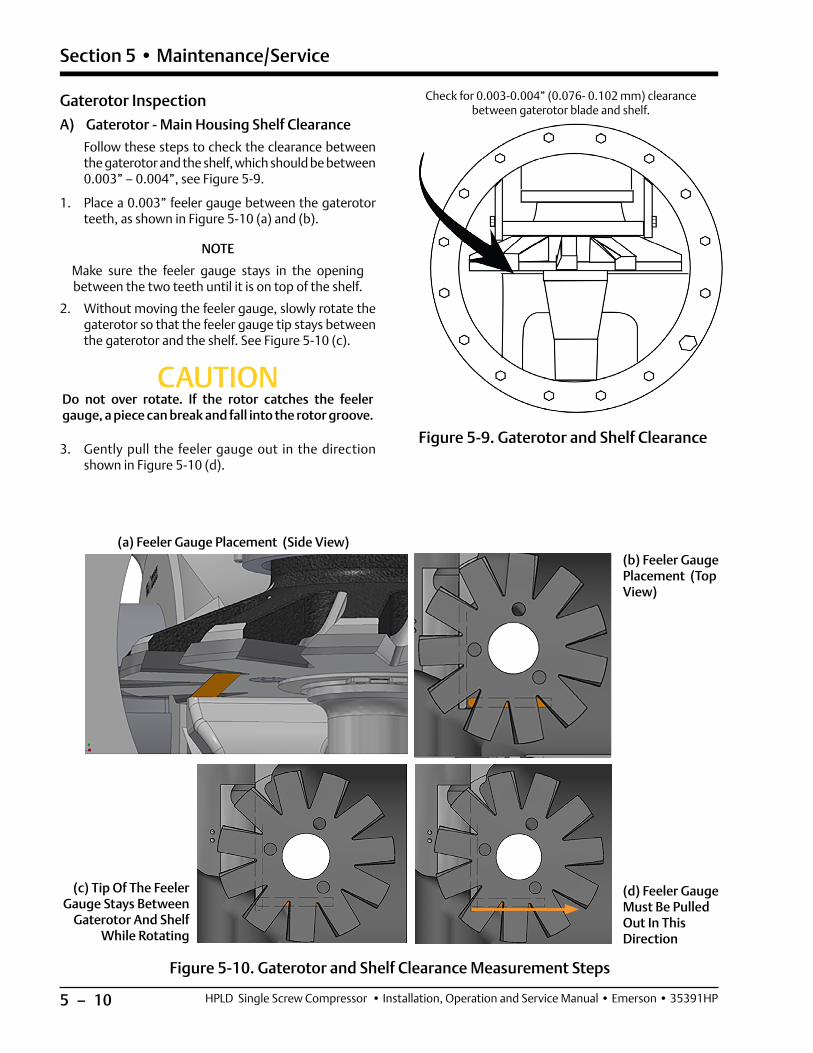
5 – 10
Section 5 • Maintenance/Service
HPLD Single Screw Compressor • Installation, Operation and Service Manual • Emerson • 35391HP
Gaterotor Inspection A) Gaterotor - Main Housing Shelf Clearance
Follow these steps to check the clearance between the gaterotor and the shelf, which should be between 0.003” – 0.004”, see Figure 5-9.
1. Place a 0.003” feeler gauge between the gaterotor teeth, as shown in Figure 5-10 (a) and (b).
NOTE
Make sure the feeler gauge stays in the opening between the two teeth until it is on top of the shelf.
2. Without moving the feeler gauge, slowly rotate the gaterotor so that the feeler gauge tip stays between the gaterotor and the shelf. See Figure 5-10 (c).
CAUTIONDo not over rotate. If the rotor catches the feeler gauge, a piece can break and fall into the rotor groove.
3. Gently pull the feeler gauge out in the direction shown in Figure 5-10 (d).
Figure 5-9. Gaterotor and Shelf Clearance
Check for 0.003-0.004” (0.076- 0.102 mm) clearance between gaterotor blade and shelf.
Figure 5-10. Gaterotor and Shelf Clearance Measurement Steps
(a) Feeler Gauge Placement (Side View)(b) Feeler Gauge Placement (Top View)
(c) Tip Of The Feeler Gauge Stays Between
Gaterotor And Shelf While Rotating
(d) Feeler Gauge Must Be Pulled Out In This Direction

5 – 11
Section 5 • Maintenance/Service
HPLD Single Screw Compressor • Installation, Operation and Service Manual • Emerson • 35391HP
4. If it is easy to pull out the feeler gauge, then increase the feeler gauge thickness by 0.001” and repeat above steps 1-3. If it is slightly tight to pull it out, then the clearance corresponds to the feeler gauge thickness.
NOTE
Replacement gaterotors are the same dimensionally as the gaterotors installed at the factory. Therefore, the same shims can be reused when replacement is needed to preserve the 0.003” – 0.004” clearance.
Figure 5-11. Visual Inspection Between Gaterotor and Bushing
Figure 5-12. Gaterotor Float Dial Location
Models VSG, VSH, VSS
Max. Floatin. (mm)
128, 145, 160, 180, 204, 222, 243
0.065 (1.651)
Table 5-4. Gaterotor Float
NOTICEIf clearance measurements are out of tolerance,
contact Vilter Service Department for further assistance.
Clearance and ShimsUnder 0.003” 0.003” – 0.004” Over 0.004”
Remove shims (103 in Figure 5-21)
to achieve 0.003” – 0.004”
Perfect!
Add shims (103 in Figure 5-21)
to achieve 0.003” – 0.004”
B) Gaterotor Float Measurement
1. Before doing any measurements, first conduct a vi-sual check to see if there is any noticeable clearance between the gaterotor and its bushing, see Figure 5-11. If there is noticeable clearance, please contact Vilter Service Department.
NOTE
The number of bushings on a gaterotor can be anywhere from one to three.
2. To measure the float between the gaterotor bush-ing and the support damper pin (see Figure 5-13), position a dial indicator at the tip of the support as shown in Figure 5-12. Hold the gaterotor in place, then gently move the support teeth back and forth with two fingers (and record measurement). Refer to Table 5-4 to find the maximum float value.
Dial Indicator
Gaterotor Support
Gaterotor Blade
Main Rotor
Damper Pin and Bushing

5 – 12
Section 5 • Maintenance/Service
HPLD Single Screw Compressor • Installation, Operation and Service Manual • Emerson • 35391HP
C) Gaterotor Backlash Inspection
Gaterotor Backlash is the clearance between the gatero-tor teeth width and the main rotor groove.
Follow these steps to perform the gaterotor backlash inspection:
1. The Gaterotor should be aligned so that a tooth in the rotor is perpendicular to the Main Axis as shown in Figure 5-14. The tooth should be in the center axis of the housing.
2. A dial indicator with magnetic base can be used (Vilter part numbers 9994ARE or 9994ARJ for the dial indicator, and 9994ARD for the magnetic base). See Figure 5-15 for location.
Figure 5-13. Gaterotor Float
Figure 5-14. Alignment of Gaterotor
Inside Tooth is Perpendicular to the Rotor
Figure 5-15. Location of Dial Indicator Magnetic Base
Gaterotor Support
Gaterotor
Shelf
Location for Dial Indicator Magnetic Base
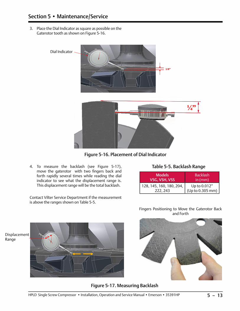
5 – 13
Section 5 • Maintenance/Service
HPLD Single Screw Compressor • Installation, Operation and Service Manual • Emerson • 35391HP
Figure 5-16. Placement of Dial Indicator
3. Place the Dial Indicator as square as possible on the Gaterotor tooth as shown on Figure 5-16.
Dial Indicator
4. To measure the backlash (see Figure 5-17), move the gaterotor with two fingers back and forth rapidly several times while reading the dial indicator to see what the displacement range is. This displacement range will be the total backlash.
Contact Vilter Service Department if the measurement is above the ranges shown on Table 5-5.
Models VSG, VSH, VSS
Backlash in (mm)
128, 145, 160, 180, 204, 222, 243
Up to 0.012” (Up to 0.305 mm)
Table 5-5. Backlash Range
Figure 5-17. Measuring Backlash
Displacement Range
Fingers Positioning to Move the Gaterotor Back and Forth

5 – 14
Section 5 • Maintenance/Service
HPLD Single Screw Compressor • Installation, Operation and Service Manual • Emerson • 35391HP
Important Notes1. Backlash cannot be checked if:
• The gaterotor is damaged in any way.
• The clearance between the gaterotor and the shelf is too tight.
2. Make sure you check the backlash, not the float:
• The backlash is the clearance between the gaterotor teeth width and the rotor groove.
• The float is the amount of play between the gaterotor bushing and the damper pins.
Additional InspectionsIn addition, visually inspect the main rotor and gatero-tors for signs of abnormal wear due to dirt or other contaminants.
If some chipping is present on the edges of the gatero-tor, this will not influence the compressor performance. If chipping is more than what´s shown on Figure 5-18, take pictures and contact Vilter Service Department.
Post InspectionAfter all the inspections are complete, the gaterotor cov-er, suction tee, coupling center member and coupling guard can be reinstalled and the unit can be evacuated and leak checked before starting.
Figure 5-18. Chipped Edge of Gaterotor

5 – 15
Section 5 • Maintenance/Service
HPLD Single Screw Compressor • Installation, Operation and Service Manual • Emerson • 35391HP
Gaterotor Removal and Installation Use gaterotor tool set: A25205G and A24061A
WARNINGFollow local lock-out/tag-out procedure. Compressors must be depressurized before attempting to do any work on them. Failure to comply may result in serious
injury, death and/or damage to equipment.
Figure 5-19. Rotor Position for Gaterotor/Support Assembly Removal
Figure 5-20. Gaterotor/Support Assembly Removal
Position of rotor before removing the gaterotor/
support assembly
Discharge end
Removal1. Prepare the compressor for servicing (please see
Preparation of Unit for Servicing on page 5-2 for procedure details). Use Tool Kit A24061A to re-move suction tee. See Figure 5-22 for details.
NOTE
Each gaterotor assembly must be reassembled on the same side that it is disassembled from.
2. Position at least a one gallon plastic oil collection bin beneath the side cover. Carefully pry open the side cover to allow the oil to drain before finally re-moving the side cover.
3. Rotate the main rotor to the position indicated in Figure 5-19.

5 – 16
Section 5 • Maintenance/Service
HPLD Single Screw Compressor • Installation, Operation and Service Manual • Emerson • 35391HP
Figure 5-21. Gaterotor Assembly
4. Using Figure 5-21 as a guide, remove the screws (110), and the washers (115).
5. Remove ball bearing housing cover screws (112 & 113), washers (116) and cover (106).
6. Remove ball bearing retainer screws (111), washer (114), and retainer (109).
7. Remove shim pack (103) and O-ring (104-2).
8. Remove roller bearing housing (105).
9. Remove O-ring (104-3).

5 – 17
Section 5 • Maintenance/Service
HPLD Single Screw Compressor • Installation, Operation and Service Manual • Emerson • 35391HP
NOTES:1. TOOLING ASSEMBLY APPROX. WEIGHT 37 LBS.2. INSTALL BY HAND TIGHTENING EACH ITEM #103 ON TWO LIFTING HOLES ON COMPRESSOR HOUSING.MAKE SURE ITEM #103 DO NOT WOBBLE AFTER INSTALLATION.
109
2X TORQUE 68 FT-LBS
108
107
105
104
107
106
101
102 2X TORQUE 87 FT-LBS
103
See Note 2
4X TORQUE 96 IN-LBS (8 FT-LBS)
105
110
111
ALL DIMENSIONS ARE FOR REFERENCE ONLY
SHAFT
32.2
23.2
11.118.7
16.214.9
TORQUE AS PER TORQUE VALUE STAMPED ON THE
HOIST RING
WARNINGDo not use this tooling to lift objects weighing more
than 140 LBS.
Figure 5-22. Tool (A24061A) To Handle Suction Tee Assembly
NOTES:
1. Tooling assembly approx. Weight 37 lbs.2. Install by hand tightening each item #103 on two lifting holes on
compressor housing. Make sure item #103 do not wobble after installation.

5 – 18
Section 5 • Maintenance/Service
HPLD Single Screw Compressor • Installation, Operation and Service Manual • Emerson • 35391HP
Figure 5-23. Tool To Remove Bearing Housing Assembly
Note on tool
Make sure that gaterotor is not in contact with the housing shelf while installing and
removing the bearing housing assembly.
10. Use the tool set A25205G (shown in Figure 5-23) to remove ball bearing housing (102 in Figure 5-21):
Install the tool set as shown in Figure 5-24 by hand tightening the bolt (109) - this will hold the gaterotor support in place. Turn the jacking screw (105 in Figure 5-23) clockwise. The ball bearing housing assembly will be pulled off the gaterotor support. Remove entire tool set.
11. Remove O-ring (104-1 in Figure 5-21).
12. Make sure the rotor is in position as shown in Figure 5-19. Remove support assembly (101 in Figure 5-21) as shown in Figure 5-20.
Figure 5-24. Tool To Install and Remove Bearing Housing Assembly
NOTE
O-rings and Nord-Lock washers (114 in Figure 5-21) will need to be replaced each time.
See Note on tool
Gaterotor Support
See Note on tool
Gaterotor Support
Ball Bearing Housing

5 – 19
Section 5 • Maintenance/Service
HPLD Single Screw Compressor • Installation, Operation and Service Manual • Emerson • 35391HP
Installation (Refer to Figure 5-21)
Torque values for screws:
- 110: 20 ft-lbs
- 112: 35 ft-lbs
- 113: 10 ft-lbs
- 111: 20 ft-lbs (use blue Loctite)
• The beveled side of the retaining ring (101.14) must face away from gaterotor, see Figure 5-27.
• Make sure O-rings are placed in the proper grooves, see Figure 5-21.
• Washer 114 has fine and coarse serrations, and those fine serrations must be facing out. See “NORD-LOCK Washers” on page 5-29 for more details.
13. Install gaterotor support by carefully tilting the roll-er bearing end of the gaterotor support towards the suction end of the compressor, see Figure 5-20. The compressor input shaft may have to be rotated to facilitate the installation of the gaterotor support, see Figure 5-19.
14. When installing the ball bearing housing (102), a new O-ring (104-1) must be used when the housing is installed, see Figure 5-21. Lubricate the outside of the housing and bearings with clean compressor oil to aid in the installation. Due to the way the bear-ings fit on the gaterotor support, the gaterotor tool set (A25205G) must be used. Assemble the tool set according to Figure 5-25 and 5-19 by hand tighten-ing the bolt (109) - this will hold the gaterotor sup-port in place. Evenly turn the jacking studs (102) clockwise. This will push the ball bearing housing onto the gaterotor support. Remove entire tool set.
15. Install the inner retainer (109), washers (114) and bolts (111) using Loctite® 242 thread locker. Tighten bolts to 20 ft-lbs.
16. Install the roller bearing housing (105) with a new O-ring (104-3).
17. Tighten bolts (110) to 20 ft-lbs.
18. Set clearance between gaterotor blade and shelf.
19. Place a piece of 0.003”-0.004” shim stock between gaterotor blade and shelf.
NOTE
This measurement determines the number of shims needed for the correct clearance.
20. Measure depth from top of compressor case to top of ball bearing housing.
21. Use factory installed shim pack (103) and ball bear-ing housing cover (106) without the O-ring (104-2).
NOTE
Replacement blades are precisely the same dimensionally as blades installed originally at factory. Therefore, the same number of shims will
be required for replacement blades.
Note on toolMake sure that gaterotor is not in contact with the housing shelf while installing and removing the
bearing housing assembly.
Figure 5-25. Tool To Install Bearing Housing Assembly
See Note on
tool

5 – 20
Section 5 • Maintenance/Service
HPLD Single Screw Compressor • Installation, Operation and Service Manual • Emerson • 35391HP
22. Check the clearance between the entire gatero-tor blade and the shelf, rotate the gaterotor to find the tightest spot. It should be between 0.003-0.004“(0.076-0.102 mm). Make adjustments, if necessary. It is preferable to shim the gaterotor blade looser rather than tighter against the shelf, see Figure 5-26.
23. After clearance has been set install a new O-ring (104-2) on ball bearing housing cover, install cover (106), and tighten the bolts (112 and 113) to the recommended torque values.
24. Install side cover with a new gasket. Tighten the bolts to the recommended torque value. The unit can then be evacuated, and leak checked.
Torque values for screws:
- 110: 20 ft-lbs
- 112: 35 ft-lbs
- 113: 10 ft-lbs
- 111: 20 ft-lbs (use blue Loctite)
Figure 5-26. Check the Clearance Between the Gaterotor and Shelf
Check for 0.003 - 0.004” (0.076 - 0.102 mm) clearance between gaterotor blade and partition

5 – 21
Section 5 • Maintenance/Service
HPLD Single Screw Compressor • Installation, Operation and Service Manual • Emerson • 35391HP
101.12
101.14
101.13
101.11Ensure gaterotor
float after assembly
Install with beveled side facing away from
gaterotor
Gaterotor Blade Removal 1. Remove the retaining ring (101.14) and washer
(101.13) from the assembly, see Figure 5-27.
2. Lift gaterotor blade assembly (101.12) off the gaterotor support (101.11).
3. Check damper pin and bushing for excessive wear. Replace if required (see page 5-11 for gaterotor float details.)
Figure 5-27. Gaterotor and Support Assembly
Gaterotor Blade Installation 1. Install bushings (101.12b) in gaterotor blade
(101.12a) from the back side of the blade. Be sure bush ing is fully seated and torqued to 5 ft-lbs. using red Loctite (271), see Figure 5-28.
2. Place blade assembly (101.12) on gaterotor sup-port (101.11). Locate bushing over pin, see Figure 5-27.
3. After the gaterotor and support are assem bled, there should be a small amount of rotational move-ment between the gaterotor and support.
4. Install washer (101.13) and retaining ring (101.14).
NOTE
Retaining ring (101.14) must be installed with bevel side facing away from the gaterotor, see Figure 5-27.
Figure 5-28. Gaterotor Top Face Identification
101.12a
101.12b
Top face of gaterotor

5 – 22
Section 5 • Maintenance/Service
HPLD Single Screw Compressor • Installation, Operation and Service Manual • Emerson • 35391HP
Figure 5-29. Gaterotor Ball bearing
Gaterotor Ball Bearing Removal1. Remove bolts (102.4) from the outer retainer
(102.3), see Figure 5-29.
2. Remove ball bearing outer retainer (102.3).
3. Using a press, remove ball bearings (102.2) from housing (102.1).
Gaterotor Ball Bearing Installation1. Install three ball bearings (102.2) in the housing
(102.1) so the first two bearings are back to back, and the second and third bearings are face to face (the larger sides of the inner races are placed to-gether, as shown in Figure 5-29). A light applica-tion of clean compressor lubricating oil should be used to ease the installation of the bearings into the housing.
2. Center the bearing outer retainer (102.3) on hous-ing (102.1), use Loctite® 242-thread locker and evenly tighten the bolts (102.4) to the recom-mended torque value (4 lb-ft), see Figure 5-29.
Back to Back Arrangement of
BearingsFace to Face Arrangement
of Bearings
102.1
102.2
102.3102.4

5 – 23
Section 5 • Maintenance/Service
HPLD Single Screw Compressor • Installation, Operation and Service Manual • Emerson • 35391HP
Gaterotor Roller Bearing Removal1. Remove the snap ring (107), which retains the roll-
er bearing in the bearing housing, see Figure 5-30.
2. Remove the baffle washer (108) and the roller bear-ing (101.3b) from the bearing housing (105).
3. Remove the retaining ring (101.2) from the gatero-tor support (101.1). Use a bearing puller to remove the roller bearing inner race (101.3a) from the gaterotor support (101.1).
Figure 5-30. Gaterotor Roller Bearing Assembly
Gaterotor Roller Bearing Installation1. Match up the part numbers on the inner race and
outer race of the bearing (101.3a & 101.3b).
2. Install the outer race (101.3b) into the bearing housing (105). Install baffle washer (108) with in-ner bevel facing the bearing rollers (101.3b). Install the snap ring retainer (107) in the housing. The bevel on the snap ring must face away from the roller bearing.
3. Heat Roller bearing inner race (101.3a) to 250 °F, then quickly install on gaterotor support (101.1). Once cool, install retaining ring (101.2).
105
101.3b
108
107
101.2
101.3a
101.1

5 – 24
Section 5 • Maintenance/Service
HPLD Single Screw Compressor • Installation, Operation and Service Manual • Emerson • 35391HP
Compressor Shaft Seal Replacement
Shaft Seal AssemblyThe shaft seal is made up of a mating ring and a carbon or silicon carbide (SC) component.
The mating ring is the rotating part of the seal and is in-stalled against the shaft shoulder. It has a drive notch on one end which aligns with the drive pin inserted in the shaft.
Carbon or SC component is the stationary part of the seal and is installed into the shaft seal housing using an O-ring.
The shaft seal housing with the stationary part is assem-bled in the compressor main housing using an O-ring, see Figure 5-31.
The shaft seal needs to be carefully handled and installed to function properly. Please see Figure 5-32 for details.
Figure 5-31. Shaft Seal Assembly
Figure 5-32. Handling Seal Face with Care
Handling Seal Face with Care
• Avoid touching seal faces as much as possible during installation.
• Be sure to always keep seal faces face-up, rather than face-down, see image on the right.

5 – 25
Section 5 • Maintenance/Service
HPLD Single Screw Compressor • Installation, Operation and Service Manual • Emerson • 35391HP
Shaft Seal Removal (see Table 5-6 and Figure 5-33)
WARNINGFollow local lock-out/tag-out procedure. Compressors must be depressurized before attempting to do any work on them. Failure to comply may result in serious
injury, death and/or damage to equipment.
NOTE
There will be a small amount of oil drainage as the shaft seal housing is removed.
1. Remove bolts (281) securing shaft seal housing (218) to compressor.
2. Insert two bolts (281) into threaded jacking holes to assist in removing shaft seal housing (218).
3. Remove silicon carbide rotating face (219.6) & O-ring (219.7) from shaft.
4. Remove spring holder (219.8) from shaft.
5. Remove oil seal (230) from shaft seal housing (218).
6. Remove retaining ring (219.5) from seal housing.
7. Flip the seal housing over and carefully tap the stationary silicon carbide piece (219.3), retainer (219.4), and O-ring (219.2) out of the seal housing using brass drift and hammer.
8. Remove O-ring (260).
NOTE
HPLD compressors are designed for two shaft seals, see Table 5-6 for their VPN and pressure ranges
Shaft SealPressure (PSI)
O-Ring MaterialStatic Dynamic
25985Y 1800 1350 Fluoroelastomer
25985YA 1800 1350 EPDM
Table 5-6. HPLD Shaft Seals
Figure 5-33. Shaft Seal Breakdown

5 – 26
Section 5 • Maintenance/Service
HPLD Single Screw Compressor • Installation, Operation and Service Manual • Emerson • 35391HP
Prior to Shaft Seal Installation (For all HPLD shaft seal models)
WARNINGFollow local lock-out/tag-out procedure. Compressors must be depressurized before attempting to do any work on them. Failure to comply may result in serious
injury, death and/or damage to equipment.
NOTE
Care must be taken when handling the cup assembly and mating ring when installing. See Figure 5-32 for
Handling Seal Face with Care.
Suggestion:
A spray bottle filled with clean compressor oil may be used to lubricate the faces of the seals without touching the seal.
Follow these steps to verify the integrity of a shaft seal:
1. Check lead chamfer and outer diameter of shaft for deep scratches that may potentially damage the O-ring on the inner diameter of the shaft seal, see Figure 5-34.
Figure 5-35. Shaft Seal Housing
Figure 5-34. Shaft with Pin
Drive Pin on Shaft Lead Chamfer on Outer Diameter of Shaft
Shoulder to Which Seal Will Bottom on
Figure 5-36. The Alignment of Compressor Shaft and Mating Ring
Shoulder on Compressor Shaft
Align slot in mating ring (219C) with Drive
pin on compressor shaft
219C O-ring
2. Check lead chamfer and inner diameter of shaft seal housing for burrs and/or deep scratches that may potentially damage the O-ring on the outer diam-eter of the shaft seal, see Figure 5-35.
3. Clean compressor shaft and shaft seal cavity in compressor housing.
4. Apply clean compressor lubricating oil to the com-pressor shaft in mating ring seating area, see Figure 5-36.
Notch in shaft seal for alignment with drive pin on
the shaft
Shaft Seal See Table 5-6
Anti-rotation pin
Back wall of housing to which shaft seal/shim
will bottom on
Lead chamfer on inner diameter of
housing
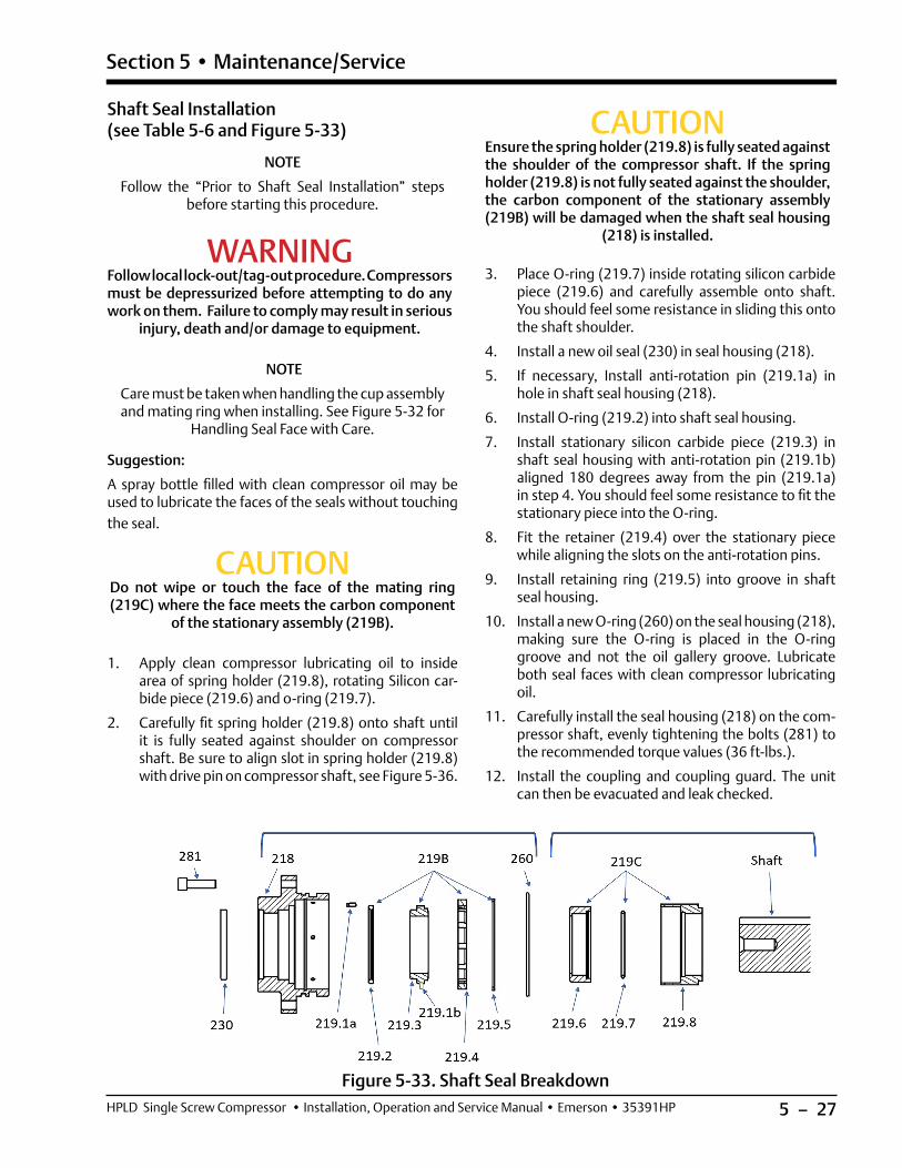
5 – 27
Section 5 • Maintenance/Service
HPLD Single Screw Compressor • Installation, Operation and Service Manual • Emerson • 35391HP
Shaft Seal Installation (see Table 5-6 and Figure 5-33)
NOTE
Follow the “Prior to Shaft Seal Installation” steps before starting this procedure.
WARNINGFollow local lock-out/tag-out procedure. Compressors must be depressurized before attempting to do any work on them. Failure to comply may result in serious
injury, death and/or damage to equipment.
NOTE
Care must be taken when handling the cup assembly and mating ring when installing. See Figure 5-32 for
Handling Seal Face with Care.
Suggestion:
A spray bottle filled with clean compressor oil may be used to lubricate the faces of the seals without touching the seal.
CAUTIONDo not wipe or touch the face of the mating ring (219C) where the face meets the carbon component
of the stationary assembly (219B).
1. Apply clean compressor lubricating oil to inside area of spring holder (219.8), rotating Silicon car-bide piece (219.6) and o-ring (219.7).
2. Carefully fit spring holder (219.8) onto shaft until it is fully seated against shoulder on compressor shaft. Be sure to align slot in spring holder (219.8) with drive pin on compressor shaft, see Figure 5-36.
CAUTIONEnsure the spring holder (219.8) is fully seated against the shoulder of the compressor shaft. If the spring holder (219.8) is not fully seated against the shoulder, the carbon component of the stationary assembly (219B) will be damaged when the shaft seal housing
(218) is installed.
3. Place O-ring (219.7) inside rotating silicon carbide piece (219.6) and carefully assemble onto shaft. You should feel some resistance in sliding this onto the shaft shoulder.
4. Install a new oil seal (230) in seal housing (218).
5. If necessary, Install anti-rotation pin (219.1a) in hole in shaft seal housing (218).
6. Install O-ring (219.2) into shaft seal housing.
7. Install stationary silicon carbide piece (219.3) in shaft seal housing with anti-rotation pin (219.1b) aligned 180 degrees away from the pin (219.1a) in step 4. You should feel some resistance to fit the stationary piece into the O-ring.
8. Fit the retainer (219.4) over the stationary piece while aligning the slots on the anti-rotation pins.
9. Install retaining ring (219.5) into groove in shaft seal housing.
10. Install a new O-ring (260) on the seal housing (218), making sure the O-ring is placed in the O-ring groove and not the oil gallery groove. Lubricate both seal faces with clean compressor lubricating oil.
11. Carefully install the seal housing (218) on the com-pressor shaft, evenly tightening the bolts (281) to the recommended torque values (36 ft-lbs.).
12. Install the coupling and coupling guard. The unit can then be evacuated and leak checked.
Figure 5-33. Shaft Seal Breakdown
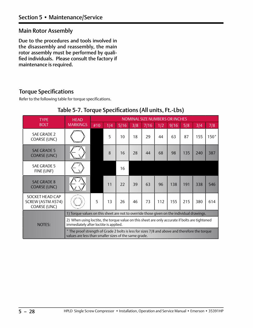
5 – 28
Section 5 • Maintenance/Service
HPLD Single Screw Compressor • Installation, Operation and Service Manual • Emerson • 35391HP
Table 5-7. Torque Specifications (All units, Ft.-Lbs)
TYPEBOLT
HEADMARKINGS
NOMINAL SIZE NUMBERS OR INCHES
#10 1/4 5/16 3/8 7/16 1/2 9/16 5/8 3/4 7/8
SAE GRADE 2 COARSE (UNC)
5 10 18 29 44 63 87 155 150*
SAE GRADE 5 COARSE (UNC)
8 16 28 44 68 98 135 240 387
SAE GRADE 5 FINE (UNF)
16
SAE GRADE 8 COARSE (UNC)
11 22 39 63 96 138 191 338 546
SOCKET HEAD CAP SCREW (ASTM A574)
COARSE (UNC)5 13 26 46 73 112 155 215 380 614
NOTES:
1) Torque values on this sheet are not to override those given on the individual drawings.
2) When using loctite, the torque value on this sheet are only accurate if bolts are tightened immediately after loctite is applied.
* The proof strength of Grade 2 bolts is less for sizes 7/8 and above and therefore the torque values are less than smaller sizes of the same grade.
Main Rotor Assembly
Due to the procedures and tools involved in the disassembly and reassembly, the main rotor assembly must be performed by quali-fied individuals. Please consult the factory if maintenance is required.
Torque SpecificationsRefer to the following table for torque specifications.

5 – 29
Section 5 • Maintenance/Service
HPLD Single Screw Compressor • Installation, Operation and Service Manual • Emerson • 35391HP
Using A Torque Wrench Correctly
Torque Wrenches
USING A TORQUE WRENCH CORRECTLY INVOLVES FOUR PRIMARY CONCERNS:
A. A smooth even pull to the break point is required. Jerking the wrench can cause the pivot point to break early leaving the bolt at a torque value lower then required. Not stopping when the break point is reached results in an over torque condition.
B. When more than one bolt holds two surfaces together there is normally a sequence that should be used to bring the surfaces together in an even manner. Generally bolting is tightened incrementally in a diametrically stag-gered pattern. Some maintenance manuals specify a tightening scheme. If so, the manual scheme shall be fol-lowed. Just starting on one side and tightening in a circle can cause the part to warp, crack, or leak.
C. In some cases threads are required to be lubricated prior to tightening the bolt/nut. Whether a lubricant is used or not has considerable impact on the amount of torque required to achieve the proper preload in the bolt/stud. Use a lubricant, if required, or not if so specified.
D. Unlike a ratchet wrench a torque wrench is a calibrated instrument that requires care. Recalibration is required periodically to maintain accuracy. If you need to remove a bolt/nut do not use the torque wrench. The clockwise/counterclockwise switch is for tightening right hand or left hand threads not for loosening a fastener. Store the torque wrench in a location where it will not be bumped around.
Nord-Lock® Washers
A. The Nord-Lock® lock washer sets are used in many areas in the HPLD screw compressors that require a vibration proof lock washer.
B. The lock washer set is assembled so the coarse serrations that resemble ramps are mated together.
C. Once the lock washer set is tightened down, it takes more force to loosen the bolt that it did to tighten it. This is caused by the washers riding up the opposing ramps.
Fine Serration Face Out
Coarse Serration Mate Together

5 – 30 / Blank HPLD Compressor Unit • Installation, Operation and Maintenance Manual • Emerson • 35391HPU

6 – 1HPLD Single Screw Compressor • Installation, Operation and Service Manual • Emerson • 35391HP
Section 6 • Troubleshooting
Problem Solution
Low Oil Pressure at Start
• After failing to start compressor with “Prelube Oil Pump Inhibit”, first allow Discharge pressure, Oil Filter In pressure and Out pressure to equalize. Then restart compressor. If compressor fails to start due to low oil pressure, contin-ue troubleshooting with items below.
• Reset Prelube Oil Pressure Setpoint in Alarms and Trip Setpoints screen to lowest recommended setpoints.
• Check calibration of oil manifold transducer, discharge pressure transducer, and suction transducer.
• Check for correct oil pump motor rotation and operation.
• Ensure transducer isolation valves are open.
• Verify that the correct transducer ranges are selected.
• Check to see all oil line valves are open except the oil dump valve used to fill the lines and oil cooler.
• Check oil strainer for dirt.
• Check oil filter pressure drop.
• Check “Prelube Oil Pump Time Limit” setpoint is sufficient in Compressor Timer Setpoints screen.
• Prelube pressure is manifold pressure minus discharge pressure.
Low Run Oil Pressure
• Check solutions in “Low Oil Pressure at Start”.
• Check that there is proper discharge pressure ratio to create differential pres-sure, otherwise oil pressure can’t be maintained. Oil pressure is manifold oil pressure minus the suction pressure. It is a net pressure.
• If the oil pump is selected to be a part time oil pump in the “Setup” menu, then ensure that it only shuts off at an appropriate pressure ration that takes into account pressure drops through the oil cooler. This is a set point in the “Compressor Control Setpoints” menu called “Oil Pump Restart.” It is a pres-sure ratio. (discharge pressure in psia/suction pressure in psia) Default ratio is a pressure ratio of 3.00:1 that stops the pump and 2.80:1 that restarts the pump. This ratio can be increased. Do not decrease without consulting Vilter.
Oil flow or oil pressure problems
• Clean oil strainer screen.
• Change oil filter, maybe plugged or collapsed.
• Oil pump gears worn internally, excessive end-clearance.
• Oil priming valve used on air-cooled cooler units is open.
• Relief in-line check valve stuck open.
• Pressure ratio too low, oil pump should be on.
Faulty pressure or temperature readings
• Check that the correct pressure or temperature range is selected in the Instrument Calibration menu.
• Check cable connections at device, terminal strips, and PLC input card for correct wiring and shielding (RF noise).
• Check calibration of RTDs and transducers.
Table 6-1. Troubleshooting Guide - General Problems & Solutions (1 of 3)

6 – 2 HPLD Single Screw Compressor • Installation, Operation and Service Manual • Emerson • 35391HP
Section 6 • Troubleshooting
Problem Solution
Oil Loss Issues
• Oil return line from coalescing side of oil separator to suction is closed, not open enough 3/4 turn should be sufficient), or plugged with debris.
• The check valve in the oil return line could be stuck closed or the flow is in the wrong direction.
• There may be water in the oil affecting the coalescing elements.
• Coalescent elements in need of replacement due to age or damage (water contamination).
• The operating conditions are not correct (too high of suction and/or too low discharge pressure) This creates increased gas flow which could make the oil separator too small.
• The suction or discharge check valve is not working correctly causing oil to escape when the unit stops.
• Viscosity of oil incorrect; send sample for testing.
• There is an oil leak somewhere in the system.
High oil temperature (liquid injection)
• Check for correct setting of all manual values.
• Check for correct operation of 2-way automatic oil mixing valve.
• In the “Vilter Only” menu, ensure that you select “Yes this unit has the oil mixing valve” to enable it.
• If your are controlling a step type oil cooler or a VFD oil cooler, verify the correct one is selected in the “Vilter Only” menu and the amount of steps are entered in the menu screen “Oil Cooler Step Control” menu.
• Check the oil cooler and associated piping to make sure it is full of oil before starting.
• Check the oil strainer for debris and clean if necessary.
• Verify that the correct compressor size (type) is selected in the “Vilter Only” menu.
• Check that all fans are working.
• Check for correct fan rotation on the oil cooler.
• Check that your operating conditions are within the “As Sold” design conditions.
Table 6-1. Troubleshooting Guide - General Problems & Solutions (2 of 3)

6 – 3HPLD Single Screw Compressor • Installation, Operation and Service Manual • Emerson • 35391HP
Section 6 • Troubleshooting
Problem Solution
High Amp Draw • Check Main Motor Amps scaling and PLC.
Vibration
• Check that unit is leveled and secured to mounting pad or floor.
• Check supported pipes (i.e. suction and discharge pipe) and make sure they are adequately supported.
• Check for loose bolts and nuts.
• Check condition of compressor and motor (i.e. alignments)
Excessive Motor Backspin• If there is more than normal motor backspin at shutdown, check suction
check valve for proper operation.
Table 6-1. Troubleshooting Guide - General Problems & Solutions (3 of 3)

6 – 4 / Blank HPLD Compressor Unit • Installation, Operation and Maintenance Manual • Emerson • 35391HPU

7 – 1HPLD Single Screw Compressor • Installation, Operation and Service Manual • Emerson • 35391HP
Section 7 • Warranty and Parts
Warranty Claim Processing
This section explains how the warranty claim is pro-cessed and to help clear any questions that may arise prior to contacting customer service. For additional war-ranty information, refer to the Standard Vilter Warranty Statement on page i. Vilter contact information can be found on page iii.
1. The warranty process starts with contacting a Vilter Service and Warranty (S&W) department represen-tative. Ensure to have the original Vilter sales order number for the equipment available to better assist you.
2. Our Vilter S&W representative will confirm if the equipment is within the warranty time frame as de-scribed in the warranty statement.
If the equipment (Part/Compressor/Compressor Motor) is within the warranty time frame, proceed to the follow-ing section regarding the type of equipment:
Process for returning Products covered by the warranty:
STEP 1. To return a defective Product or part under this warranty, you will need to provide the Vilter™ compres-sor order number on all submitted documents.
For a parts warranty request, you will also need to provide:
• The Vilter™ serial number of the compressor;
• A detailed and accurate description of the issue;
• A valid purchase order for the new part(s)—you must pay the freight;
• One copy of Return Merchandise Authorization (RMA) sent to you for your records;
• One copy of RMA sent to you to include in the return shipment of parts back to Vilter™ for warranty consideration.
STEP 2. Return the parts (freight prepaid) to:
VILTER MANUFACTURING CORPORATION
5555 South Packard Avenue
Cudahy, WI 53110-8904
STEP 3. Upon receipt of the returned part(s), Vilter™ will complete a timely evaluation of the part(s).
STEP 4. You will be contacted with Vilter’s decision once the final report is completed.
STEP 5. If approved, the approved warranty will be credited (excluding freight) to your account. Vilter™ will retain the returned part(s) for final disposition. If a warranty request is not approved, you will be provided with a written response and the parts will be held for 30 days. After such time, Vilter™ will dispose of the parts. If you wish to have the part(s) returned, you will need to contact Vilter™ and the part(s) will be returned freight collect.
Procedure for parts not manufactured by Vilter™:
Although Vilter™ does not provide any warranty for parts and products that are not manufactured by Vilter™, Vilter™ does pass through any manufacturer’s warranty to you (to the maximum extent permitted by the manufacturer). Vilter™ will work with you in facilitat-ing your warranty claim with the manufacturer.
To facilitate your warranty claim, please follow the fol-lowing four steps:
STEP 1. Determine if the part or product is within the OEM’s warranty.
STEP 2. If the defective part or product is not a motor, send a description containing the specifications of the part/product and the defect to:
If the defective part or product is a motor or starter, please complete the form on the next page and return it to:
STEP 3. Vilter™ will communicate with you, if necessary, to ascertain additional information and will reasonably assist with the OEM to determine the part/product’s warranty status.

7 – 2 HPLD Single Screw Compressor • Installation, Operation and Service Manual • Emerson • 35391HP
Section 7 • Warranty and Parts
Mot
or W
arra
nty
Proc
edur
eTo
faci
litat
e yo
ur w
arra
nty
clai
m, p
leas
e fo
llow
the
step
s ou
tlin
ed b
elow
:1.
Det
erm
inat
ion
if m
otor
is w
ithi
n th
e O
EM w
arra
nty.
2. P
leas
e co
mpl
ete
the
follo
win
g an
d re
turn
to S
ervi
ce.V
ilter
@Em
erso
n.co
m, a
long
wit
h a
pict
ure
of th
e m
otor
’s n
amep
late
.3.
Vilt
er w
ill a
ssis
t wit
h th
e m
otor
OEM
to d
eter
min
e th
e m
otor
’s w
arra
nty
stat
us.
Des
crib
e M
otor
Sym
ptom
s:
Mod
el:
__
____
____
__
Seri
al N
umbe
r:
___
____
____
_
Man
ufac
ture
r:
___
____
____
_ R
un H
ours
:
____
____
____
Sta
rt D
ate:
___
___/
____
_/__
__
M
onth
D
ay
Yea
rG
reas
e Ty
pe:
____
____
____
Alig
nmen
t Dat
a A
vaila
ble:
Y
es, p
leas
e in
clud
e w
ith
info
rmat
ion
No
Lubr
icat
ion
Reco
rds
Ava
ilabl
e:
Y
es, p
leas
e in
clud
e w
ith
info
rmat
ion
No
Vib
rati
on R
epor
t:
Y
es, p
leas
e in
clud
e w
ith
info
rmat
ion
No
4. If
the
mot
or fa
lls w
ithi
n th
e O
EM’s
war
rant
y ti
me
fram
e:•
Th
e m
otor
will
nee
d to
be
take
n to
a m
anuf
actu
rer a
ppro
ved
shop
for d
iagn
osis
. Vilt
er c
an h
elp
wit
h lo
cati
ng m
otor
sho
ps th
at a
re m
anuf
actu
rer
appr
oved
in y
our a
rea.
The
sho
p w
ill d
iagn
ose
the
root
cau
se, s
ubm
it a
repo
rt to
the
OEM
, and
the
mot
or O
EM w
ill m
ake
the
dete
rmin
atio
n of
w
arra
nty
cove
rage
.•
If
war
rant
y is
app
rove
d, th
e O
EM w
ill e
ithe
r hav
e th
e m
otor
repa
ired
by
the
mot
or s
hop
or s
end
a ne
w re
plac
emen
t mot
or to
the
site
.
Not
e: M
otor
war
rant
y is
a “
pass
thru
war
rant
y” a
s st
ated
in V
ilter
Man
ufac
turi
ng’s
sta
ndar
d w
arra
nty
stat
emen
t whi
ch m
eans
that
the
orig
inal
mot
or
OEM
is th
e pr
ovid
er o
f the
war
rant
y. V
ilter
doe
s as
sist
wit
h th
e ex
pedi
ting
of t
he c
laim
but
any
dis
pens
atio
n of
war
rant
y is
pro
vide
d so
lely
by
the
mot
or
OEM
.M
otor
man
ufac
ture
r w
arra
nty
cove
rs o
nly
repa
ir o
r re
plac
emen
t of
the
mot
or. I
t do
es n
ot c
over
rem
oval
and
inst
alla
tion
cha
rges
, inc
iden
tal c
harg
es
asso
ciat
ed w
ith
the
rem
oval
and
inst
alla
tion
pro
cess
, los
s of
pro
duct
or s
hipp
ing
to a
nd fr
om th
e m
anuf
actu
rer o
r app
rove
d sh
op. T
his
is s
tand
ard
mo
-to
r man
ufac
ture
r war
rant
y po
licy
rega
rdle
ss o
f bra
nd o
r app
licat
ion.
If th
e en
d us
er re
quir
es a
ddit
iona
l inf
orm
atio
n re
gard
ing
war
rant
y co
vera
ge, t
he
indi
vidu
al m
otor
man
ufac
ture
r war
rant
y te
rms
can
be fo
und
on th
eir a
ssoc
iate
d w
ebsi
tes.
Star
ter T
ype:
S
oft S
tart
A
cros
s th
e Li
ne
VFD
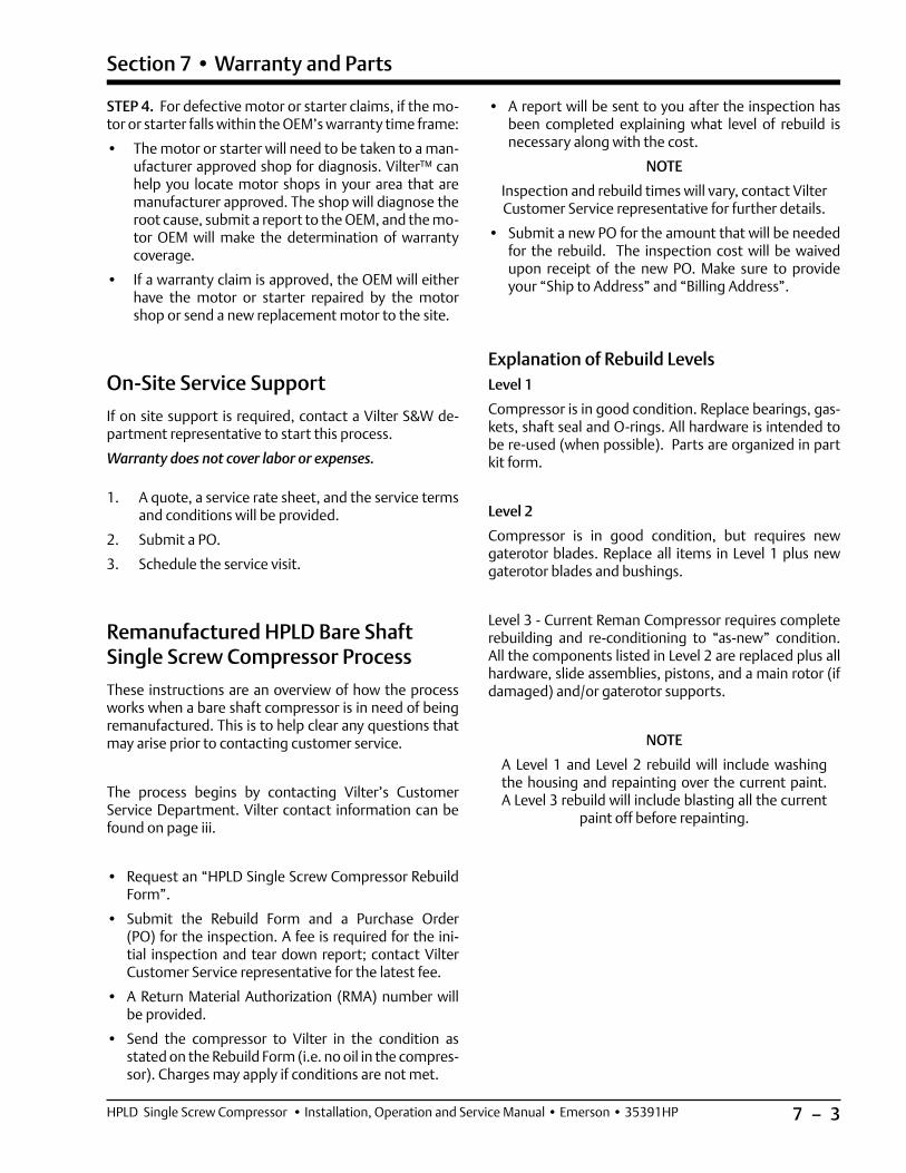
7 – 3HPLD Single Screw Compressor • Installation, Operation and Service Manual • Emerson • 35391HP
Section 7 • Warranty and Parts
STEP 4. For defective motor or starter claims, if the mo-tor or starter falls within the OEM’s warranty time frame:
• The motor or starter will need to be taken to a man-ufacturer approved shop for diagnosis. Vilter™ can help you locate motor shops in your area that are manufacturer approved. The shop will diagnose the root cause, submit a report to the OEM, and the mo-tor OEM will make the determination of warranty coverage.
• If a warranty claim is approved, the OEM will either have the motor or starter repaired by the motor shop or send a new replacement motor to the site.
On-Site Service Support
If on site support is required, contact a Vilter S&W de-partment representative to start this process.
Warranty does not cover labor or expenses.
1. A quote, a service rate sheet, and the service terms and conditions will be provided.
2. Submit a PO.
3. Schedule the service visit.
Remanufactured HPLD Bare Shaft Single Screw Compressor Process
These instructions are an overview of how the process works when a bare shaft compressor is in need of being remanufactured. This is to help clear any questions that may arise prior to contacting customer service.
The process begins by contacting Vilter’s Customer Service Department. Vilter contact information can be found on page iii.
• Request an “HPLD Single Screw Compressor Rebuild Form”.
• Submit the Rebuild Form and a Purchase Order (PO) for the inspection. A fee is required for the ini-tial inspection and tear down report; contact Vilter Customer Service representative for the latest fee.
• A Return Material Authorization (RMA) number will be provided.
• Send the compressor to Vilter in the condition as stated on the Rebuild Form (i.e. no oil in the compres-sor). Charges may apply if conditions are not met.
• A report will be sent to you after the inspection has been completed explaining what level of rebuild is necessary along with the cost.
NOTE
Inspection and rebuild times will vary, contact Vilter Customer Service representative for further details.
• Submit a new PO for the amount that will be needed for the rebuild. The inspection cost will be waived upon receipt of the new PO. Make sure to provide your “Ship to Address” and “Billing Address”.
Explanation of Rebuild LevelsLevel 1
Compressor is in good condition. Replace bearings, gas-kets, shaft seal and O-rings. All hardware is intended to be re-used (when possible). Parts are organized in part kit form.
Level 2
Compressor is in good condition, but requires new gaterotor blades. Replace all items in Level 1 plus new gaterotor blades and bushings.
Level 3 - Current Reman Compressor requires complete rebuilding and re-conditioning to “as-new” condition. All the components listed in Level 2 are replaced plus all hardware, slide assemblies, pistons, and a main rotor (if damaged) and/or gaterotor supports.
NOTE
A Level 1 and Level 2 rebuild will include washing the housing and repainting over the current paint. A Level 3 rebuild will include blasting all the current
paint off before repainting.

7 – 4 / Blank HPLD Compressor Unit • Installation, Operation and Maintenance Manual • Emerson • 35391HPU

8 – 1
Section 8 • Spare Parts List
HPLD Single Screw Compressor • Installation, Operation and Service Manual • Emerson • 35391HP
HPLDRecommended Spare Parts List
Refer to the Custom ManualSpare Parts Section for Specific Applications
Please have your Model # and Sales Order # available when ordering.
These are found on the compressor’s Name Plate.

8 – 2
Section 8 • Spare Parts List
HPLD Single Screw Compressor • Installation, Operation and Service Manual • Emerson • 35391HP
HPLD Compressor Kits
DESCRIPTIONPART NUMBERQTYITEMGATEROTOR 175MM VSS22224003F1101DAMPER 165/175MM VSS THREADED25760FT3102
1
1
2
2
3
3
4
4
5
5
6
6
7
7
8
8
9
9
10
10
A
B
C
D
E
F
3X TORQUE 60 IN-LBS (5 FT-LBS) USE RED LOCTITE
TOP FACE OF GATEROTOR
101
102
1 ITEM#102 WAS: 25760FT QTY 01, NOW: 25760FT QTY 03ECO: S-008320 PVP ANP JLP 03/15/2019
0 INITIAL RELEASEECO: S-007546 PVP ANP JLP 1/17/2018
REVISION HISTORYREV DESCRIPTION DWN BY CHK BY APPR BY DATE
102
*Aflas**Viton
Gaterotor Kits
Gaterotor Kits
Compressor Model
With Bearings Without Bearings
128KT712ABAAF* KT712ABAV**
KT713ABAAF* KT713ABAV**
145KT712ABBAF* KT712ABBV**
KT713ABBAF* KT713ABBV**
160KT712ABCAF* KT712ABCV**
KT713ABCAF* KT713ABCV**
180KT712ABDAF* KT712ABDV**
KT713ABDAF* KT713ABDV**
204KT712ABEAF* KT712ABEV**
KT713ABEAF* KT713ABEV**
222KT712ABFAF* KT712ABFV**
KT713ABFAF* KT713ABFV**
243KT712ABGAF* KT712ABGV**
KT713ABGAF* KT713ABGV**
All HPLD Models
Application Description VPN Qty
Shaft Seal #25985Y
HPLD Shaft Seal Kit
KT709BHPFAF 1
All HPLD Models
Application Description VPN Qty
For Gaterotor Removal and Installation
Gaterotor Tool Kit
A25205G 1
Suction Tee Tool Kit
A24061A 1
All HPLD Models
Application Description VPN Qty
All Gaskets and O-Rings
HPLD Gasket and O-Ring
KitKT710MAF 1
Shaft Seal Kit
Compressor Gasket and O-Ring Kit
Tool Kit

8 – 3
Section 8 • Spare Parts List
HPLD Single Screw Compressor • Installation, Operation and Service Manual • Emerson • 35391HP
107
108
101
105
105
104
103
106
16X
TOR
QUE
87 FT
-LBS
INST
ALL R
ETAI
NING
RIN
G W
ITH
BEV
EL S
IDE
FACI
NG C
OMPR
ESSO
R HO
USIN
G
109
102
107
110
111
16X
TORQ
UE 8
7 FT
-LBS
8X T
ORQU
E 30
FT-
LBS
112
Suction Covers
Suction Covers Components
MODELS VSG/VSH/VSS128 to VSG/VSH/VSS243
ITEM DESCRIPTION VPN QUANTITY
103 SCREEN 205MM SUCTION 25920A 1
104 RING 4.500X0.109 RETAINING INT BEVELED 2867AS 1
105 O-RING 8.484 X 8.762 AFLAS VP101 3547AD 2
106 SPRING SSB0433 WAVE SMALLEY 2912G 1

8 – 4
Section 8 • Spare Parts List
HPLD Single Screw Compressor • Installation, Operation and Service Manual • Emerson • 35391HP
Discharge Manifold
DESC
RIPT
ION
PART
NUM
BER
QTY
ITEM
MAN
IFOL
D 16
5/17
5MM
DIS
CHAR
GE M
ACH
2400
5A1
101
O-R
ING
11.9
84 X
12.
262
AFLA
S VP
101
3547
AA1
102
O-R
ING
3.48
4 X
3.76
2 AF
LAS
VP10
135
47AB
210
3SC
REW
1/2
-13N
CX2
CAP
SOCK
ET H
D AS
TM A
574
2795
AL24
104
WAS
HER
1/2
HIGH
STR
ENGT
H PL
AIN
2826
E24
105
PLUG
7/1
6 HE
X SA
E FO
R J1
926
PORT
AFL
AS36
47E
110
61 1
2 2
3 3
4 4
5 5
6 6
7 7
8 8
9 9
10 10
A B C D E F
104
105
101
103
102
103
0IN
ITIA
L RE
LEAS
EEC
O: S
-005
797
PVP
AN
PJL
P3/
11/2
016
REVI
SIO
N HI
STO
RYRE
VDE
SCRI
PTIO
NDW
N BY
CHK
BYAP
PR B
YDA
TE
24X
TOR
QUE
87
FT-L
BS
106
TOR
QUE
84
IN-L
BS (7
FT-
LBS)
Discharge Manifold ComponentsMODELS VSG/VSH/VSS128 to VSG/VSH/VSS243
ITEM DESCRIPTION VPN QUANTITY
102 O-RING 11.984 X 12.262 AFLAS VP101 3547AA 1
103 O-RING 3.484 X 3.762 AFLAS VP101 3547AB 2

8 – 5
Section 8 • Spare Parts List
HPLD Single Screw Compressor • Installation, Operation and Service Manual • Emerson • 35391HP
Housing
Housing Components
MODELS VSG/VSH/VSS128 to VSG/VSH/VSS243
ITEM DESCRIPTION VPN QUANTITY
103 O-RING .796X1.074 AFLAS VP101 3547M 3
104 PLUG 1/4-18NPTF FLUSH SEAL SOC HD 2606C 1
105 PLUG 5/16 HEX SAE FOR J1926 PORT AFLAS 3647A 1
106 PLUG 9/16 HEX SAE FOR J1926 PORT AFLAS 3647D 5

8 − 6 / Blank HPLD Compressor Unit • Installation, Operation and Maintenance Manual • Emerson • 35391HPU
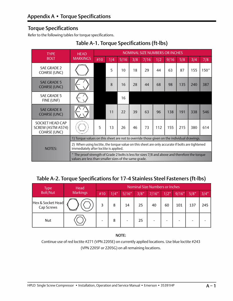
A − 1HPLD Single Screw Compressor • Installation, Operation and Service Manual • Emerson • 35391HP
Appendix A • Torque Specifications
Table A-2. Torque Specifications for 17-4 Stainless Steel Fasteners (ft-lbs)
TypeBolt/Nut
HeadMarkings
Nominal Size Numbers or Inches
#10 1/4” 5/16” 3/8” 7/16” 1/2” 9/16” 5/8” 3/4”
Hex & Socket Head Cap Screws 3 8 14 25 40 60 101 137 245
Nut - 8 - 25 - - - - -
Table A-1. Torque Specifications (ft-lbs)
TYPEBOLT
HEADMARKINGS
NOMINAL SIZE NUMBERS OR INCHES
#10 1/4 5/16 3/8 7/16 1/2 9/16 5/8 3/4 7/8
SAE GRADE 2 COARSE (UNC)
5 10 18 29 44 63 87 155 150*
SAE GRADE 5 COARSE (UNC)
8 16 28 44 68 98 135 240 387
SAE GRADE 5 FINE (UNF)
16
SAE GRADE 8 COARSE (UNC)
11 22 39 63 96 138 191 338 546
SOCKET HEAD CAP SCREW (ASTM A574)
COARSE (UNC)5 13 26 46 73 112 155 215 380 614
NOTES:
1) Torque values on this sheet are not to override those given on the individual drawings.
2) When using loctite, the torque value on this sheet are only accurate if bolts are tightened immediately after loctite is applied.
* The proof strength of Grade 2 bolts is less for sizes 7/8 and above and therefore the torque values are less than smaller sizes of the same grade.
NOTE:
Continue use of red loctite #271 (VPN 2205E) on currently applied locations. Use blue loctite #243
(VPN 2205F or 2205G) on all remaining locations.
Torque SpecificationsRefer to the following tables for torque specifications.

A − 2 / Blank HPLD Single Screw Compressor • Installation, Operation and Service Manual • Emerson • 35391HP

B − 1HPLD Single Screw Compressor • Installation, Operation and Service Manual • Emerson • 35391HP
Appendix B • Vilter Oil
Oil Analysis Report

B − 2 / Blank HPLD Single Screw Compressor • Installation, Operation and Service Manual • Emerson • 35391HP


Emerson.com/Vilter
Vilter Manufacturing LLC reserves the right to make changes in design and specifications without notice.35391HP Rev. 01(06/21) Emerson and Vilter are trademarks of Emerson Electric Co. or one of its affiliated companies.©2021 Emerson Climate Technologies, Inc. All rights reserved.
About Vilter
Vilter is a technology leader in energy-efficient, environ-
mentally conscious solutions in its industry. The 150-year
history of the Vilter brand tells a rich story of perseverance
and drive to cultivate continuous innovation within the
industrial refrigeration and gas compression industries. Vilter
offers unprecedented efficiency, productivity and reliability
in cooling, recovery, and compression. It combines best-
in-class technology with proven engineering and design to
create quality products and latest solutions for customers
worldwide.
About Emerson
Vilter Manufacturing LLC is a business segment of Emerson,
a global leader in bringing technology and engineering
together to provide innovative solutions for customers in
industrial, commercial and consumer markets around the
world. Our Emerson Automation Solutions business helps
process, hybrid, and discrete manufacturers maximize
production, protect personnel and the environment while
optimizing their energy and operating costs. Our Emerson
Commercial and Residential Solutions business helps ensure
human comfort and health, protect food quality and safety,
advance energy efficiency, and create sustainable infrastruc-
ture. For more information please visit
Emerson.com