Embed Size (px)
Citation preview

HS 754 - Drafting Standard Page 1 of 59 Revision Level - 2 - Published Security Level - Public Standard No. HS 754
_________________________________________________________________________________________________________________ © 2022 Husky Technologies TM Printed copies are uncontrolled NO INTELLECTUAL PROPERTY RIGHTS ARE GRANTED INCLUDING ANY LICENSE, IMPLIED OR OTHERWISE. ALL RIGHTS RESERVED. ALL INFORMATION IS MERELY FOR EDUCATIONAL AND/OR INFORMATIONAL PURPOSES AND IS NOT INTENDED TO BE RELIED UPON AS A SUBSTITUTE FOR PROFESSIONAL ADVICE.
HS 754 - DRAFTING STANDARD Document Description
This drafting standard is a Corporate Operations initiative to establish drafting standards and practices across all Husky businesses and third parties engaged in the creation of data for Husky.
Document No. HS754
Table of Contents 1 SCOPE .......................................................................................................................................... 6 2 PURPOSE ..................................................................................................................................... 6 3 EXCLUSIONS ................................................................................................................................ 6 4 ACKNOWLEDGMENTS ................................................................................................................. 7
4.1 TEC-EASE INC. REPRESENTATIVE ACKNOWLEDGMENT ............................................................... 7
4.2 REFERENCE DOCUMENT ACKNOWLEDGEMENT ........................................................................... 7
5 DOCUMENT CONTROL ................................................................................................................ 7 5.1 STRUCTURE OF DOCUMENT ...................................................................................................... 7
5.2 FIGURES .................................................................................................................................. 8
5.3 NOTES ..................................................................................................................................... 8
6 REFERENCED STANDARDS ....................................................................................................... 9 7 GENERAL DRAWING PRACTICES ............................................................................................ 11
7.1 GENERAL ............................................................................................................................... 11
7.1.1 Scope ............................................................................................................................... 11
7.2 DEFINITIONS .......................................................................................................................... 11
7.2.1 Acceptance ....................................................................................................................... 11
7.2.2 Altered item ...................................................................................................................... 11
7.2.3 Assembly .......................................................................................................................... 11
7.2.4 Bulk Items......................................................................................................................... 11
7.2.5 Copy ................................................................................................................................. 11
7.2.6 Design Activity .................................................................................................................. 11
7.2.7 Digital Data ....................................................................................................................... 12
7.2.8 Document ......................................................................................................................... 12
7.2.9 Drawing ............................................................................................................................ 12
7.2.10 Drawing Format ............................................................................................................ 12
7.2.11 Duplicate Original ......................................................................................................... 12
7.2.12 Engineering Data .......................................................................................................... 12

HS 754 - Drafting Standard Page 2 of 59 Revision Level - 2 - Published Security Level - Public Standard No. HS 754
_________________________________________________________________________________________________________________ © 2022 Husky Technologies TM Printed copies are uncontrolled NO INTELLECTUAL PROPERTY RIGHTS ARE GRANTED INCLUDING ANY LICENSE, IMPLIED OR OTHERWISE. ALL RIGHTS RESERVED. ALL INFORMATION IS MERELY FOR EDUCATIONAL AND/OR INFORMATIONAL PURPOSES AND IS NOT INTENDED TO BE RELIED UPON AS A SUBSTITUTE FOR PROFESSIONAL ADVICE.
7.2.13 Inseparable Assembly .................................................................................................. 12
7.2.14 Interchangeable Item .................................................................................................... 12
7.2.15 Item .............................................................................................................................. 13
7.2.16 Item Identification.......................................................................................................... 13
7.2.17 Master Drawing ............................................................................................................ 13
7.2.18 Nonpart Drawing ........................................................................................................... 13
7.2.19 Original ......................................................................................................................... 13
7.2.20 Part ............................................................................................................................... 13
7.2.21 Part or Identifying Number (PIN) ................................................................................... 13
7.2.22 Product ......................................................................................................................... 13
7.2.23 Referenced Documents ................................................................................................ 13
7.2.24 Specification ................................................................................................................. 14
7.2.25 Standard ....................................................................................................................... 14
7.2.26 Standardization Document ............................................................................................ 14
7.2.27 Subassembly ................................................................................................................ 14
7.2.28 Symmetrically Opposite Parts ....................................................................................... 14
7.2.29 System (General).......................................................................................................... 14
7.2.30 Unit ............................................................................................................................... 14
7.3 DRAWING PRACTICES ............................................................................................................. 14
7.3.1 Types and Applications Of Engineering Drawings ............................................................ 14
7.3.2 Bills Of Materials............................................................................................................... 15
7.3.3 Revisions of Engineering Drawings and Bills Of Materials ................................................ 15
7.3.4 Size and Format of Engineering Drawings ........................................................................ 15
7.3.5 Line Conventions and Lettering ........................................................................................ 15
7.3.6 Isometric and Pictorial Views ............................................................................................ 15
7.3.7 Projection Systems ........................................................................................................... 15
7.3.8 Dimensioning and Tolerancing ......................................................................................... 15
7.3.9 Surface Texture ................................................................................................................ 15
7.3.10 Screw Thread Representation ...................................................................................... 15
7.3.11 Gears............................................................................................................................ 15
7.3.12 Mechanical Springs ...................................................................................................... 15
7.3.13 Castings and Forgings .................................................................................................. 15
7.3.14 Welding Symbols .......................................................................................................... 16
7.3.15 Abbreviations ................................................................................................................ 16
7.3.16 Drawing Marking For Item Identification ........................................................................ 16

HS 754 - Drafting Standard Page 3 of 59 Revision Level - 2 - Published Security Level - Public Standard No. HS 754
_________________________________________________________________________________________________________________ © 2022 Husky Technologies TM Printed copies are uncontrolled NO INTELLECTUAL PROPERTY RIGHTS ARE GRANTED INCLUDING ANY LICENSE, IMPLIED OR OTHERWISE. ALL RIGHTS RESERVED. ALL INFORMATION IS MERELY FOR EDUCATIONAL AND/OR INFORMATIONAL PURPOSES AND IS NOT INTENDED TO BE RELIED UPON AS A SUBSTITUTE FOR PROFESSIONAL ADVICE.
7.3.17 Drawing Notes .............................................................................................................. 16
7.4 DRAWING TITLES .................................................................................................................... 19
7.4.1 General Rules .................................................................................................................. 19
7.5 NUMBERING, CODING, AND IDENTIFICATION .............................................................................. 20
7.5.1 Drawing Numbers ............................................................................................................. 20
7.5.2 Special Characters ........................................................................................................... 20
7.5.3 Drawing Identification ....................................................................................................... 20
7.5.4 Part or Identifying Number (PIN or HPN) .......................................................................... 20
7.5.5 Reference To Items .......................................................................................................... 20
7.5.6 Item Identification ............................................................................................................. 21
7.5.7 Model Number or Catalog Number ................................................................................... 21
7.5.8 Serial Number .................................................................................................................. 21
7.5.9 Version Number................................................................................................................ 21
7.5.10 Data Base Number ....................................................................................................... 21
8 ABBREVIATIONS AND ACRONYMS .......................................................................................... 22 8.1 Y14.38-1999 AMENDMENT ..................................................................................................... 22
9 REVISION OF ENGINEERING DRAWINGS & ASSOCIATED DOCUMENTATION ..................... 24 9.1 ASME Y14.35M-1997 AMENDMENT ....................................................................................... 24
10 LINE CONVENTIONS AND LETTERING ..................................................................................... 26 10.1 ASME Y14.2M-1992 AMENDMENT ......................................................................................... 26
11 METRIC DRAWING SHEET SIZE AND FORMAT ....................................................................... 28 11.1 ASME Y14.1M-1995 AMENDMENT ......................................................................................... 28
12 MULTIVIEW & SECTIONAL VIEW DRAWINGS .......................................................................... 42 12.1 Y14.3M-1994 AMENDMENT .................................................................................................... 42
13 PICTORIAL DRAWING ................................................................................................................ 45 13.1 Y14.4M-1989 AMENDMENT .................................................................................................... 45
14 SCREW THREAD REPRESENTATION ....................................................................................... 46 14.1 Y14.6-2001 AMENDMENT ....................................................................................................... 46
15 SURFACE TEXTURE SYMBOLS ................................................................................................ 47 15.1 Y14.36M-1996 AMENDMENT .................................................................................................. 47
16 DIMENSIONING AND TOLERANCING ....................................................................................... 49 16.1 SCOPE ................................................................................................................................... 49
16.2 DRAWING/CAD MODEL PRECEDENCE...................................................................................... 49
16.3 GENERAL TOLERANCE BLOCK NOTES ...................................................................................... 49
16.4 ASME Y14.5-2009 AMENDMENT ............................................................................................ 51
1 Scope, Definitions, and General Dimensioning ................................................................. 51
HS 754 - Drafting Standard Page 4 of 59 Revision Level - 2 - Published Security Level - Public Standard No. HS 754
_________________________________________________________________________________________________________________ © 2022 Husky Technologies TM Printed copies are uncontrolled NO INTELLECTUAL PROPERTY RIGHTS ARE GRANTED INCLUDING ANY LICENSE, IMPLIED OR OTHERWISE. ALL RIGHTS RESERVED. ALL INFORMATION IS MERELY FOR EDUCATIONAL AND/OR INFORMATIONAL PURPOSES AND IS NOT INTENDED TO BE RELIED UPON AS A SUBSTITUTE FOR PROFESSIONAL ADVICE.
1.1 Scope ........................................................................................................................... 51
1.1.1 General ......................................................................................................................... 51
1.1.7 Symbols [NEW] ............................................................................................................ 51
1.5 Units of Measure .......................................................................................................... 51
1.5.1 SI (Metric) Linear Units [NEW] ...................................................................................... 51
1.5.2 U.S. Customary Linear Units [REPLACE] ..................................................................... 51
1.5.4 Combination SI (Metric) and U.S. Customary Linear Units [REPLACE] ........................ 51
1.7 Application of Dimensions [NEW] ................................................................................. 51
1.7.1 Dimension Lines [REPLACE] ........................................................................................ 53
1.7.5 Reading Direction ......................................................................................................... 53
1.7.5.2 Dimensions [REPLACE] ........................................................................................... 53
1.7.8 Dimensioning Within the Outline of a View [NEW] ........................................................ 54
1.7.9 Dimensions Not to Scale [REPLACE] ........................................................................... 54
1.8 Dimensioning Features [REPLACE] ............................................................................. 54
1.8.4 Rounded Ends and Slotted Holes [REPLACE] .............................................................. 54
1.8.9 Symmetrical Outlines [REPLACE] ................................................................................ 54
1.8.16.1 Chamfers Specified by Note [REPLACE] ............................................................... 54
2 General Tolerancing and Related Principles ..................................................................... 54
2.17 Statistical Tolerancing [NEW] ....................................................................................... 54
2.17.2 Identification [REPLACE] .......................................................................................... 55
3 Symbology ....................................................................................................................... 55
3.3 Symbol Construction ..................................................................................................... 55
3.3.2 Datum Feature Symbol [NEW] ...................................................................................... 55
3.3.11 Between Symbol [NEW] ............................................................................................ 55
3.3.13 Spotface Symbol [REPLACE] ................................................................................... 55
3.3.18 Taper and Slope Symbols [REPLACE] ..................................................................... 55
3.3.31 Restraint Feature Symbol [NEW] .............................................................................. 55
4.20 Restrained Condition [NEW] ......................................................................................... 56
4.20.1 Datum Referencing for Restrained Parts [NEW] ....................................................... 56
7 Tolerances of Location ..................................................................................................... 56
7.4.3 Closer Control at One End of a Feature of Size ............................................................ 56
7.6.4 Concentricity [REPLACE] ............................................................................................. 57
7.7 Tolerancing for Symmetrical Relationships [REPLACE] ..................................................... 57
9 Type of Runout Tolerances .............................................................................................. 57
9.4.2.4 Total Runout Tolerance Applied on Unit Basis [NEW] ............................................... 57

HS 754 - Drafting Standard Page 5 of 59 Revision Level - 2 - Published Security Level - Public Standard No. HS 754
_________________________________________________________________________________________________________________ © 2022 Husky Technologies TM Printed copies are uncontrolled NO INTELLECTUAL PROPERTY RIGHTS ARE GRANTED INCLUDING ANY LICENSE, IMPLIED OR OTHERWISE. ALL RIGHTS RESERVED. ALL INFORMATION IS MERELY FOR EDUCATIONAL AND/OR INFORMATIONAL PURPOSES AND IS NOT INTENDED TO BE RELIED UPON AS A SUBSTITUTE FOR PROFESSIONAL ADVICE.
Revision Log
Rev Revision Description 2 Section 1.7.9 Dimensions Not to Scale updated. Due to the deformation of the plastic parts
during ejection, it’s almost impossible to re-design the “reality” by 100%. To be able to have the steel and plastic part models (which should always be the “Absolute”) connected by a shrinkage factor, it’s important to report the real dimensions measured in our lab, on the plastic part drawing.
1 Section 16.3 General Tolerance Block updated. Notes 5 & 6 on chamfers and fillets updated to reflect new tolerance practice: Husky is moving away from using “SHARP” callouts on any drawing not covered by the SIM and will be adding the edge condition symbol as defined in ISO 13715
0 Original issue (this document supersedes HS 254)

HS 754 - Drafting Standard Page 6 of 59 Revision Level - 2 - Published Security Level - Public Standard No. HS 754
_________________________________________________________________________________________________________________ © 2022 Husky Technologies TM Printed copies are uncontrolled NO INTELLECTUAL PROPERTY RIGHTS ARE GRANTED INCLUDING ANY LICENSE, IMPLIED OR OTHERWISE. ALL RIGHTS RESERVED. ALL INFORMATION IS MERELY FOR EDUCATIONAL AND/OR INFORMATIONAL PURPOSES AND IS NOT INTENDED TO BE RELIED UPON AS A SUBSTITUTE FOR PROFESSIONAL ADVICE.
1 SCOPE Husky Injection Molding Systems Ltd. has adopted an amended version of the American Society of Mechanical Engineers (ASME) Y14 series of standards (amended by this addendum) for use by all businesses and suppliers, on all technical documentation. This addendum was created to address the following areas:
• Select an option from Y14,
• Clarify a concept from Y14,
• Discourage/disallow the use of a concept from Y14,
• Include a concept not covered by Y14.
All other standards referenced in the Y14 series of Standards have not necessarily been adopted by Husky and shall not be assumed to be automatically invoked. This is not intended to be a stand-alone document but used in conjunction with the standards adopted by this Addendum.
2 PURPOSE This Drafting Standard is a Corporate Operations initiative to establish drafting standards and practices across all Husky businesses and third parties engaged in the creation of data for Husky. The creation of such standards will have the following benefits for Husky:
• Common training for all engineering personnel,
• Reduced/elimination of standard document management at the business level,
• Use of industry accepted standards for design, drafting, and manufacturing,
• Efficiencies gained through best practices,
• Common drawing language between manufacturing sites and suppliers to all businesses,
• Increased quality,
• Increased speed and consistency.
3 EXCLUSIONS None.
HS 754 - Drafting Standard Page 7 of 59 Revision Level - 2 - Published Security Level - Public Standard No. HS 754
_________________________________________________________________________________________________________________ © 2022 Husky Technologies TM Printed copies are uncontrolled NO INTELLECTUAL PROPERTY RIGHTS ARE GRANTED INCLUDING ANY LICENSE, IMPLIED OR OTHERWISE. ALL RIGHTS RESERVED. ALL INFORMATION IS MERELY FOR EDUCATIONAL AND/OR INFORMATIONAL PURPOSES AND IS NOT INTENDED TO BE RELIED UPON AS A SUBSTITUTE FOR PROFESSIONAL ADVICE.
4 ACKNOWLEDGMENTS This document represents the consensus of representatives from the following Husky businesses:
Product Development Bolton
Product Development Milton
Global Supply Chain
Engineering Production Hot Runners
Production Machines Bolton
Engineering Production PET Molds Bolton
Luxembourg Mold and Hot Runners, Operation
Bolton Mold and Hot Runners, Operation
Hot Runner Operations, Milton
Table 1 – Husky Businesses
4.1 TEC-EASE INC. REPRESENTATIVE ACKNOWLEDGMENT “Section 16 - Dimensioning and Tolerancing (ASME Y14.5-2009 Addendum)” also represents input of Frank Bakos, a representative from Tec-Ease.
4.2 REFERENCE DOCUMENT ACKNOWLEDGEMENT Husky would like to also acknowledge the material used from the General Motors Engineering Standards – GLOBAL DIMENSIONING AND TOLERANCING ADDENDUM – 2001.
5 DOCUMENT CONTROL The Husky business representatives shall authorize revisions to this document.
5.1 STRUCTURE OF DOCUMENT The paragraph numbering in this addendum is as follows:
• Paragraphs are generally numbered to coincide with numbers in Y14 Standard,
• Paragraph numbers with the [NEW] callout are additions to Y14 Standard,
• Paragraphs with the [REPLACE] callout obsolete the paragraph in the Y14 Standard, which is identified by the same number,
• Italicized text may be added, following the paragraph title noting whether the paragraph is a deletion, addition or to describe the changes to an existing paragraph in Y14 Standard,
• Figures referenced in the text but not shown in this addendum are found in Y14 Standard,

HS 754 - Drafting Standard Page 8 of 59 Revision Level - 2 - Published Security Level - Public Standard No. HS 754
_________________________________________________________________________________________________________________ © 2022 Husky Technologies TM Printed copies are uncontrolled NO INTELLECTUAL PROPERTY RIGHTS ARE GRANTED INCLUDING ANY LICENSE, IMPLIED OR OTHERWISE. ALL RIGHTS RESERVED. ALL INFORMATION IS MERELY FOR EDUCATIONAL AND/OR INFORMATIONAL PURPOSES AND IS NOT INTENDED TO BE RELIED UPON AS A SUBSTITUTE FOR PROFESSIONAL ADVICE.
• The words “shall/must/required” describe strict requirements. Procedural steps defined by these words must be followed,
• The words “should/preferred/recommended” describe preferences. Procedural steps defined by these words must be followed whenever there is no valid reason to do otherwise,
• The words “acceptable/allowed/may/can” grant permission. They do not require or recommend the practice they specify; neither do they forbid or discourage alternative practices.
5.2 FIGURES • Any concept/practice not indicated or not clearly defined within the standard should be clarified &
illustrated within the addendum.
• Figures and application drawings are shown intentionally incomplete in this document.
• Figure titles are formatted as follows: Fig. XXX – Description of Drawing [New]
This is on the drawing: Means this:
5.3 NOTES Notes depicted in this Standard in capital letters are intended to reflect actual drawing entries. Notes in lower case letters are to be considered supporting data to the contents of this Standard and are, therefore, not intended for literal entry on drawings.

HS 754 - Drafting Standard Page 9 of 59 Revision Level - 2 - Published Security Level - Public Standard No. HS 754
_________________________________________________________________________________________________________________ © 2022 Husky Technologies TM Printed copies are uncontrolled NO INTELLECTUAL PROPERTY RIGHTS ARE GRANTED INCLUDING ANY LICENSE, IMPLIED OR OTHERWISE. ALL RIGHTS RESERVED. ALL INFORMATION IS MERELY FOR EDUCATIONAL AND/OR INFORMATIONAL PURPOSES AND IS NOT INTENDED TO BE RELIED UPON AS A SUBSTITUTE FOR PROFESSIONAL ADVICE.
6 REFERENCED STANDARDS The following ASME Standards are considered in use and amended as noted in this Standard:
Standard Name Standard Number Accepted as is or Amended
ABBREVIATIONS AND ACRONYMS HS 302 (Y14.38-1999)
Y14.38-1999 amended by section
8.1 Basic Rules for the Design of Graphical Symbols for Use in the Technical Documentation of Products
Y14.40.0-2002 Accepted as is
Castings And Forgings Y14.8M-1996 Accepted as is
Dimensioning and Tolerancing Y14.5-2009 Amended by section 16
Drawing Notes HS 303 N/A
Engineering Drawings And Associated Documents – Revision of
Y14.35M-1997 Amended by section 9.1
Gear Drawing Standards Parts 1: For Spur, Helical, Double Helical And Rack
Y14.7.1-1971 Accepted as is
Line Conventions and Lettering Y14.2M-1992 Amended by section 10.1
Mechanical Spring Representation Y14.13M-1981 Accepted as is
Metric Drawing Sheet Size And Format Y14.1M-1995 Amended by section 11.1
Multiview And Sectional View Drawings Y14.3M-1994 Amended by section 12.1
Pictorial Drawing Y14.4M-1989 Amended by section 13.1
Screw Thread Representation Y14.6-2001 Amended by section 14.1

HS 754 - Drafting Standard Page 10 of 59 Revision Level - 2 - Published Security Level - Public Standard No. HS 754
_________________________________________________________________________________________________________________ © 2022 Husky Technologies TM Printed copies are uncontrolled NO INTELLECTUAL PROPERTY RIGHTS ARE GRANTED INCLUDING ANY LICENSE, IMPLIED OR OTHERWISE. ALL RIGHTS RESERVED. ALL INFORMATION IS MERELY FOR EDUCATIONAL AND/OR INFORMATIONAL PURPOSES AND IS NOT INTENDED TO BE RELIED UPON AS A SUBSTITUTE FOR PROFESSIONAL ADVICE.
Screw Thread Representation Metric Supplement Y14.6 AM-1981 Accepted as is
Spline Drawing Standards Part 2: Bevel And Hypoid Gears
Y14.7.2-1978 Accepted as is
Surface Texture Symbols
Y14.36M-1996 Amended by section 15.1
Types And Applications Of Engineering Drawings
Y14.24-1999 Accepted as is
Welding Symbols AWS A2.4-1998 Accepted as is
Supplier Quick Reference – Common Drawing Features and Manufacturing Practices
HS 534 N/A
Digital Product Definition Data Practices Y14.41-2012 N/A
Statistical Tolerancing Standard HS 760 N/A
Technical Drawings – Edges of Undefined Shape – Vocabulary and Indications
ISO 13715 Accepted as is
Table 2 – List of Drafting Standards

HS 754 - Drafting Standard Page 11 of 59 Revision Level - 2 - Published Security Level - Public Standard No. HS 754
_________________________________________________________________________________________________________________ © 2022 Husky Technologies TM Printed copies are uncontrolled NO INTELLECTUAL PROPERTY RIGHTS ARE GRANTED INCLUDING ANY LICENSE, IMPLIED OR OTHERWISE. ALL RIGHTS RESERVED. ALL INFORMATION IS MERELY FOR EDUCATIONAL AND/OR INFORMATIONAL PURPOSES AND IS NOT INTENDED TO BE RELIED UPON AS A SUBSTITUTE FOR PROFESSIONAL ADVICE.
7 GENERAL DRAWING PRACTICES 7.1 GENERAL
7.1.1 SCOPE This Standard establishes the essential requirements and reference documents applicable to the preparation and revision of engineering drawings and bills of materials. It is essential that this Standard be used in close conjunction with all standards referenced in section 6.
7.2 DEFINITIONS
7.2.1 ACCEPTANCE The act of an authorized representative of the receiving activity to take ownership of supplies tendered, or approved specific services rendered, as partial or complete performance of the contract.
7.2.2 ALTERED ITEM An existing item, under the control of another design activity or defined by a nationally recognized standardization document that is subject to alteration to meet the design requirements.
7.2.3 ASSEMBLY A number of parts, or subassemblies, or combination thereof, that are joined together to perform a specific function and subject to disassembly without degradation of any of the parts (e.g., power shovel front, fan assembly, audio-frequency amplifier). NOTE: The distinction between an assembly and a subassembly is determined by individual application. An assembly in one instance may be a subassembly in another instance where it forms a portion of a higher assembly.
7.2.4 BULK ITEMS Those constituents of an assembly or part (such as oil, wax, solder, cement, ink, damping fluid, grease, flux, welding rod, twine, or chain) that satisfy one or more of the following criteria: the quantity required cannot readily be predetermined; the physical nature of the material is such that it is not adaptable to pictorial representation; the finished size is obtainable through use of such tools as shears, pliers, or knives, without further machining operation; and the final con-figuration is such that it can be described in writing without the necessity of pictorial representation.
7.2.5 COPY Any reproduction or duplication, in any media, of an original.
7.2.6 DESIGN ACTIVITY An organization that has, or has had, responsibility for the design of an item.
7.2.6.1 CURRENT DESIGN ACTIVITY The design activity currently responsible for the design of an item. This may be the original design activity or a design activity to which the design responsibility has been transferred.

HS 754 - Drafting Standard Page 12 of 59 Revision Level - 2 - Published Security Level - Public Standard No. HS 754
_________________________________________________________________________________________________________________ © 2022 Husky Technologies TM Printed copies are uncontrolled NO INTELLECTUAL PROPERTY RIGHTS ARE GRANTED INCLUDING ANY LICENSE, IMPLIED OR OTHERWISE. ALL RIGHTS RESERVED. ALL INFORMATION IS MERELY FOR EDUCATIONAL AND/OR INFORMATIONAL PURPOSES AND IS NOT INTENDED TO BE RELIED UPON AS A SUBSTITUTE FOR PROFESSIONAL ADVICE.
7.2.6.2 ORIGINAL DESIGN ACTIVITY The design activity originally responsible for the design and identification of an item whose drawing number and activity identification is shown in the title block of the drawings and associated documents. layouts, drawings, numerical control tapes, or other engineering data.
7.2.6.3 DESIGN ACTIVITY IDENTIFICATION A unique identifier that distinguishes an activity or organization from another activity or organization. Examples of activity identification include activity name, activity name and address.
7.2.7 DIGITAL DATA Data stored on a computer system that employs a display on which the user and the computer interact to create or alter entities for the production of layouts, drawings, numerical control tapes, or other engineering data.
7.2.8 DOCUMENT A term applicable to the specifications, drawings, lists, standards, pamphlets, reports, and printed, typewritten, or otherwise created information relating to the design, procurement, manufacture, testing, or acceptance inspection of items or services.
7.2.9 DRAWING An engineering document or digital data file(s) that discloses (directly or by reference), by means of graphic or textual presentations, or by combinations of both, the physical or functional requirements of an item.
7.2.10 DRAWING FORMAT The arrangement and organization of information within a drawing. This includes such features as the size and arrangement of blocks, notes, lists, and revision information, and the use of optional or supplemental blocks.
7.2.11 DUPLICATE ORIGINAL A replica of an engineering drawing created to serve as the official record of the item when the original has been lost.
7.2.12 ENGINEERING DATA Engineering documents such as drawings, bills of materials, accompanying documents, specifications, standards, or other information prepared or used by a design activity and relating to the design, manufacture, procurement, testing, or inspection of items.
7.2.13 INSEPARABLE ASSEMBLY Same as part
7.2.14 INTERCHANGEABLE ITEM An item that possesses functional and physical characteristics equivalent in performance to another item of similar or identical purposes, and is capable of being exchanged for the other item without selection for fit or performance, and without alteration of the items themselves or of adjoining items, except for adjustment.

HS 754 - Drafting Standard Page 13 of 59 Revision Level - 2 - Published Security Level - Public Standard No. HS 754
_________________________________________________________________________________________________________________ © 2022 Husky Technologies TM Printed copies are uncontrolled NO INTELLECTUAL PROPERTY RIGHTS ARE GRANTED INCLUDING ANY LICENSE, IMPLIED OR OTHERWISE. ALL RIGHTS RESERVED. ALL INFORMATION IS MERELY FOR EDUCATIONAL AND/OR INFORMATIONAL PURPOSES AND IS NOT INTENDED TO BE RELIED UPON AS A SUBSTITUTE FOR PROFESSIONAL ADVICE.
7.2.15 ITEM A nonspecific term used to denote any unit or product including materials, parts, assemblies, equipment, accessories, and computer software.
7.2.16 ITEM IDENTIFICATION The part, identifying number, or descriptive identifier for a specific item along with the original design activity identification.
7.2.17 MASTER DRAWING A document that shows the dimensional limits or locations applicable to any or all parts of a Part Family, including the arrangements of patterns, elements, size, type, and location of holes; and any other information necessary to describe the products to be fabricated. Dimensions and/or tolerances may be displayed using non-associative alphanumeric labels with the corresponding values and presented on the drawing in a Tabular Note. See HS 289, the Husky CAD Standard.
7.2.18 NONPART DRAWING An engineering drawing that provides requirements, such as procedures or instructions, applicable to an item when it is not convenient to include this information on the applicable part drawing (e.g., a test requirements drawing or logic diagram).
7.2.19 ORIGINAL The current design activity’s drawing on which the official revision record is kept.
7.2.20 PART One item, or two or more items joined together, that is not normally subject to disassembly without destruction or impairment of designed use (e.g., transistor, composition resistor, screw, transformer, and gear).
7.2.21 PART OR IDENTIFYING NUMBER (PIN) The identifier assigned by the original design activity, or by the controlling standard, that uniquely identifies (relative to that design activity) a specific item.
7.2.22 PRODUCT Includes materials, parts, components, subassemblies, assemblies, and equipment. The term product whenever used in this document shall also encompass a family of products.
7.2.22.1 FAMILY OF PRODUCTS All products of the same classification, design, construction, material, type, etc., produced with the same production facilities, processes, and quality of material, under the same management and quality controls, but having the acceptable variety of physical and functional characteristics defined and specified in the applicable engineering documentation.
7.2.23 REFERENCED DOCUMENTS Design activity standards, drawings, specifications, or other documents referenced on drawings or lists.

HS 754 - Drafting Standard Page 14 of 59 Revision Level - 2 - Published Security Level - Public Standard No. HS 754
_________________________________________________________________________________________________________________ © 2022 Husky Technologies TM Printed copies are uncontrolled NO INTELLECTUAL PROPERTY RIGHTS ARE GRANTED INCLUDING ANY LICENSE, IMPLIED OR OTHERWISE. ALL RIGHTS RESERVED. ALL INFORMATION IS MERELY FOR EDUCATIONAL AND/OR INFORMATIONAL PURPOSES AND IS NOT INTENDED TO BE RELIED UPON AS A SUBSTITUTE FOR PROFESSIONAL ADVICE.
7.2.24 SPECIFICATION A document that describes essential technical requirements for material and the criteria for determining whether those requirements are met.
7.2.25 STANDARD A document that establishes technical criteria, methods, processes, and practices.
7.2.25.1 COMPANY STANDARD A document produced by a company that establishes engineering and technical limitations and applications for items, materials, processes, methods, designs, and engineering practices unique to that particular company.
7.2.26 STANDARDIZATION DOCUMENT A document developed for the purpose of standardizing items, materials, processes, or procedures.
7.2.27 SUBASSEMBLY Two or more parts that form a portion of an assembly or a unit replaceable as a whole but having a part or parts that are individually replaceable [e.g., gun mount stand, window sash, recoil mechanism, floating piston, telephone dial, Intermediate Frequency (IF) strip, terminal board with mounted parts.]
7.2.28 SYMMETRICALLY OPPOSITE PARTS Those parts that are mirror images of each other.
7.2.29 SYSTEM (GENERAL) A composite of equipment, skills, and techniques capable of performing or supporting an operational role or both. A complete system includes all equipment, related facilities, material, software, services, and personnel required for its operation and support to the degree that it can be considered a self-sufficient unit in its intended operational environment.
7.2.30 UNIT An assembly or any combination of parts, subassemblies, and assemblies mounted together normally capable of independent operation in a variety of situations (e.g., hydraulic jack, electric motor, electronic power supply, internal combustion engine, electric generator, radio receiver). NOTE: The size of an item is a consideration in some cases. An electric motor for a clock may be considered as a part because it is not normally subject to disassembly.
7.3 DRAWING PRACTICES This Section establishes the essential general requirements for the preparation of engineering drawings and Bills of Materials.
7.3.1 TYPES AND APPLICATIONS OF ENGINEERING DRAWINGS Hardware and software drawings shall be in accordance with ASME Y14.24.

HS 754 - Drafting Standard Page 15 of 59 Revision Level - 2 - Published Security Level - Public Standard No. HS 754
_________________________________________________________________________________________________________________ © 2022 Husky Technologies TM Printed copies are uncontrolled NO INTELLECTUAL PROPERTY RIGHTS ARE GRANTED INCLUDING ANY LICENSE, IMPLIED OR OTHERWISE. ALL RIGHTS RESERVED. ALL INFORMATION IS MERELY FOR EDUCATIONAL AND/OR INFORMATIONAL PURPOSES AND IS NOT INTENDED TO BE RELIED UPON AS A SUBSTITUTE FOR PROFESSIONAL ADVICE.
7.3.2 BILLS OF MATERIALS Bills of Materials shall be in accordance with HS 305.
7.3.3 REVISIONS OF ENGINEERING DRAWINGS AND BILLS OF MATERIALS Revisions of engineering drawings and bills of materials shall be in accordance with ASME Y14.35M, amended by section 9.1 and HS 288 Part Number Change Guideline.
7.3.4 SIZE AND FORMAT OF ENGINEERING DRAWINGS
7.3.4.1 METRIC Metric drawing sheet sizes and format shall be in accordance with ASME Y14.1M, amended by section 11.1.
7.3.5 LINE CONVENTIONS AND LETTERING Lines and lettering shall be in accordance with ASME Y14.2M, amended by section 10.1.
7.3.6 ISOMETRIC AND PICTORIAL VIEWS Isometric or pictorial views shall be in accordance with ASME Y14.4M, amended by section 13.1 and may be shown on engineering drawings provided that clarity is not degraded.
7.3.7 PROJECTION SYSTEMS Projection systems and associated symbols shall be in accordance with ASME Y14.3M, amended by section 12.1.
7.3.8 DIMENSIONING AND TOLERANCING Dimensioning and tolerancing shall be in accordance with ASME Y14.5-2009, amended by section 16.
7.3.9 SURFACE TEXTURE Surface texture, waviness, and lay shall be indicated in accordance with ASME B46.1. Surface texture symbols shall be in accordance with Y14.36M-1996.
7.3.10 SCREW THREAD REPRESENTATION Screw threads shall be represented in accordance with ANSI Y14.6, amended by section 14.1 and ANSI Y14.6aM.
7.3.11 GEARS Gears shall be delineated in accordance with ANSI Y14.7.1 and ANSI Y14.7.2.
7.3.12 MECHANICAL SPRINGS Mechanical springs shall be delineated in accordance with ANSI Y14.13M.
7.3.13 CASTINGS AND FORGINGS Castings and forgings shall be delineated in accordance with ASME Y14.8M.

HS 754 - Drafting Standard Page 16 of 59 Revision Level - 2 - Published Security Level - Public Standard No. HS 754
_________________________________________________________________________________________________________________ © 2022 Husky Technologies TM Printed copies are uncontrolled NO INTELLECTUAL PROPERTY RIGHTS ARE GRANTED INCLUDING ANY LICENSE, IMPLIED OR OTHERWISE. ALL RIGHTS RESERVED. ALL INFORMATION IS MERELY FOR EDUCATIONAL AND/OR INFORMATIONAL PURPOSES AND IS NOT INTENDED TO BE RELIED UPON AS A SUBSTITUTE FOR PROFESSIONAL ADVICE.
7.3.14 WELDING SYMBOLS Welding symbols shall be in accordance with ANSI/AWS A2.4, together with terms and definitions in accordance with ANSI/AWS A3.0.
7.3.15 ABBREVIATIONS Abbreviations shall be in accordance with the list of Husky Approved Abbreviations (HS 302 standard) which includes abbreviations from ASME Y14.38.
7.3.16 DRAWING MARKING FOR ITEM IDENTIFICATION When required, drawings shall specify marking requirements for items, including item identification.
7.3.16.1 DRAWING REQUIREMENTS FOR PART IDENTIFICATION MARKING Delineation of item markings on drawings shall be clear on such details as content, method of application (e.g., stamp, stencil, bag, or tag), and materials.
7.3.16.2 MARKING LOCATION AND SIZE The location and size of the identification marking shall be specified on the depiction of the item if it must be controlled due to functional or fit requirements, or subsequent finish application. The location of identification marking on items that are subsequently coated and finished shall also be controlled, and should be specified on surfaces that are not subjected to the coating or finish. For example, the location may be identified by a leader pointing to a chain line box or the actual information to be marked, indicating approximate marking location; or, if necessary, by dimensionally locating the marking where it will be applied.
7.3.16.3 TAGS AND PLATES Tags and plates shall be defined separately as parts by an applicable specification, standard, or drawing. The requirements for attaching an identification plate shall be specified on the using assembly drawing. The information to be included on the identification plate or tag when installed in the using item shall be specified on the assembly drawing; or, if applicable, on the identification plate drawing.
7.3.17 DRAWING NOTES Drawing notes provide information that clarifies the requirements for the item delineated. They apply to either a portion of the drawing or to the entire drawing, providing additional treatment, finish, protection, and other considerations. The notes area of a drawing shall be identified with the heading “NOTES”. Standard notes can be found in the HS 303 standard.
7.3.17.1 LANGUAGE Unless otherwise specified, drawings and bills of materials shall be in the English language.
7.3.17.2 LANGUAGE STYLE Notes shall be concise statements using the simplest words and phrases for conveying the intended meaning.
7.3.17.3 COMMONLY USED WORDS AND PHRASES Certain words and phrases are frequently used on a drawing. The following rules shall be applied.
HS 754 - Drafting Standard Page 17 of 59 Revision Level - 2 - Published Security Level - Public Standard No. HS 754
_________________________________________________________________________________________________________________ © 2022 Husky Technologies TM Printed copies are uncontrolled NO INTELLECTUAL PROPERTY RIGHTS ARE GRANTED INCLUDING ANY LICENSE, IMPLIED OR OTHERWISE. ALL RIGHTS RESERVED. ALL INFORMATION IS MERELY FOR EDUCATIONAL AND/OR INFORMATIONAL PURPOSES AND IS NOT INTENDED TO BE RELIED UPON AS A SUBSTITUTE FOR PROFESSIONAL ADVICE.
(a) Reference documents shall be cited using “per,” “conforming to,” “as specified in,” and “in accordance with” (or “IAW”). (b) The phrase “unless otherwise specified” shall be used to indicate the generally applied requirements, and should appear at the beginning of the note or denoted at the head of the “NOTES” column. This phrase shall be used when providing a reference to another document, or requirement on the drawing, that clearly specifies the exception(s).
7.3.17.4 INDEFINITE TERMS Indefinite terms such as “and/or,” “etc.,” “e.g.,” and “i.e.” shall not be used.
7.3.17.5 LOCATION OF NOTES Notes shall be located on top of the title block (unless space is limited), on sheet 1 or a reference shall be included on sheet 1 indicating note location (e.g., “SEE SEPARATE PARTS LIST FOR PARTS AND NOTES”). When notes are continued beyond a given drawing sheet, information to that effect shall be inserted in the next note position of the applicable sheet (e.g., “NOTES CONTINUED ON SHEET 4”).
7.3.17.6 DRAWING NOTES - CONTENTS Drawing notes are pertinent data given in word form and used to complement the delineation of other given data. Drawing notes shall be concise, grammatically correct statements. The arrangement of notes shall not be interpreted as an order of precedence, or sequence in manufacturing or assembly, unless specified as such on the drawing. The following shall be applicable in the preparation or use of notes. (a) General notes apply to the entire drawing or Bills of materials. (b) Local notes are notes that are located at the specific area or point of application. Requirements specified by local notes apply only to the areas or points indicated. (c) Flagnotes are notes that are located with the general notes but apply only at specific areas or points on the drawing. A flagnote shall be identified with a flagnote symbol in accordance with (f) below. The flagnote symbol, including the note number, shall be shown at each point of application. The flagnote symbol is placed around the note number in the notes area to indicate that it applies at specific areas on the drawing. The flagnote symbol, however, need not be shown in the “NOTE” column of the parts list, or in the “NOTE” column in a table. (d) General notes and flagnotes shall be numbered consecutively as a single listing starting with Note 1. Filling in voids (open spaces) to accommodate deletions is not required. Note numbers of deleted notes shall not be reused. (e) Reference to standardization documents shall be by basic identifier, excluding revision level, except where identification of a specific issue is essential to drawing interpretation.
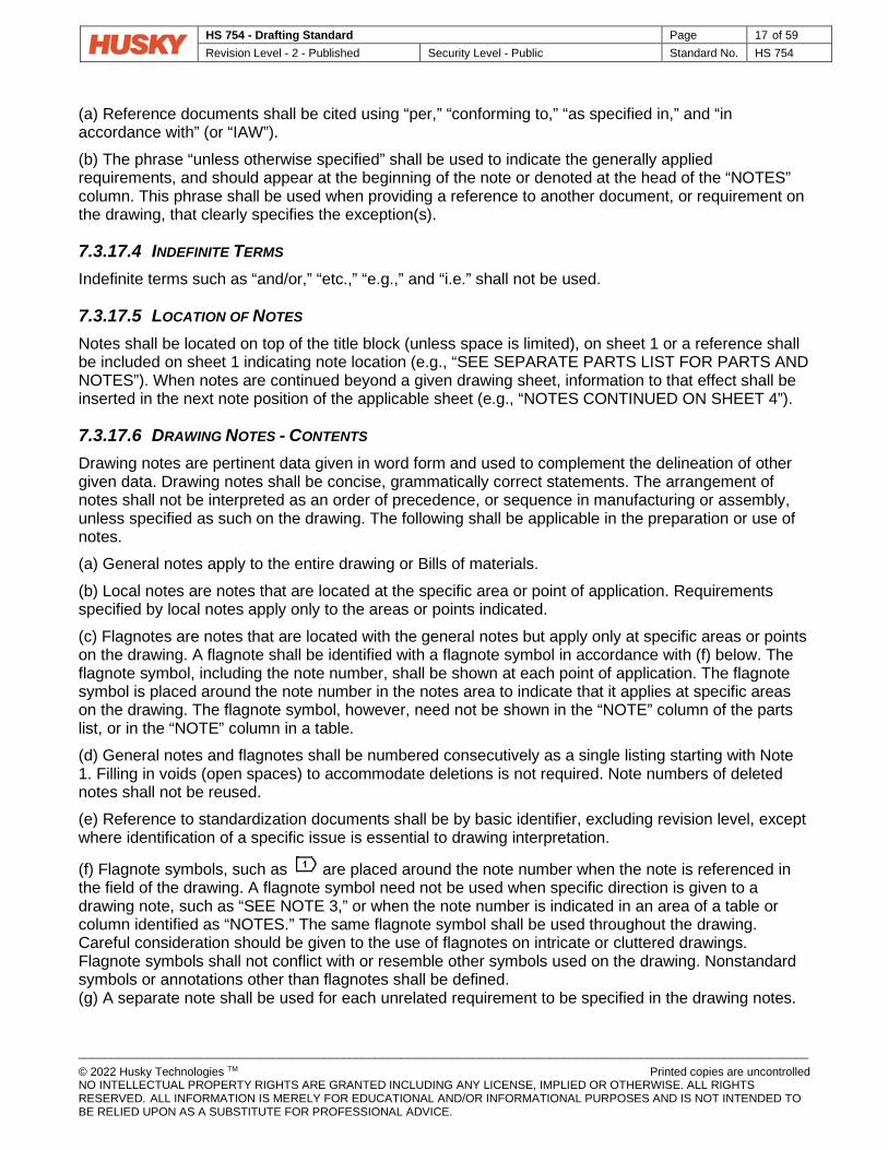
(f) Flagnote symbols, such as are placed around the note number when the note is referenced in the field of the drawing. A flagnote symbol need not be used when specific direction is given to a drawing note, such as “SEE NOTE 3,” or when the note number is indicated in an area of a table or column identified as “NOTES.” The same flagnote symbol shall be used throughout the drawing. Careful consideration should be given to the use of flagnotes on intricate or cluttered drawings. Flagnote symbols shall not conflict with or resemble other symbols used on the drawing. Nonstandard symbols or annotations other than flagnotes shall be defined. (g) A separate note shall be used for each unrelated requirement to be specified in the drawing notes.

HS 754 - Drafting Standard Page 18 of 59 Revision Level - 2 - Published Security Level - Public Standard No. HS 754
_________________________________________________________________________________________________________________ © 2022 Husky Technologies TM Printed copies are uncontrolled NO INTELLECTUAL PROPERTY RIGHTS ARE GRANTED INCLUDING ANY LICENSE, IMPLIED OR OTHERWISE. ALL RIGHTS RESERVED. ALL INFORMATION IS MERELY FOR EDUCATIONAL AND/OR INFORMATIONAL PURPOSES AND IS NOT INTENDED TO BE RELIED UPON AS A SUBSTITUTE FOR PROFESSIONAL ADVICE.
(h) Reference to other documents for the purpose of specifying requirements or drawing interpretation shall be as specific as possible. The whole of a given document shall not be made applicable by reference unless all of its provisions are required. When a portion of a document is applicable, the extent of its applicability shall be stated. However, reference to paragraph numbers in other documents shall not be made. Reference shall be made to a method, identified requirement, class, grade, or type. Reference shall be made only to documents whose technical accuracy and availability are assured. (i) Drawing notes may provide the basis for the special item and process or make direct or parenthetical reference to documentation that provides such information. (j) Notes shall not include contractual requirements, such as statements of costs; time and place of delivery; methods of payment; and requirements for submission, approval, or distribution of data, reports, or plans.
7.3.17.7 DRAWING VERIFICATION The design activity shall verify that engineering drawings and bills of materials are technically accurate, in conformance with all requirements, and have been checked. Checking shall be signified in the signature block on the original by signature or checking indicator established by the design activity. An checking indicator may be any symbol adopted by the design activity. A signature or approval indicator may be either hand written or electronically affixed as long as it is unique to an individual, capable of verification, and under the individual’s sole control.
7.3.17.8 DATING DRAWINGS The method of specifying dates on drawings shall be numerical by year-month-day for entry in the “DATE” block. For example, June 10, 1989 would be indicated as 1989-06-10.
7.3.17.9 USE OF SPECIFICATIONS AND STANDARDS When applicable specifications and standards do not completely fulfill the design requirements of the item, engineering drawings may specify the requirements of the specifications and standards and the variations necessary to fulfill the design requirements of the item, in lieu of preparing new documentation.
7.3.17.10 METRIC PRACTICES
7.3.17.10.1 METRIC DESIGNS The measurement system in which the part, item, or any of its features is designed shall be used in the documentation for that part, item, or feature. It may be necessary for any one drawing or associated document to contain both metric units and inch-pound units to accommodate the interfacing of items. When a document contains some features in rounded, rational metric units and other features in rounded, rational inch-pound units, each measurement shall be appropriately labelled with the applicable measurement units; or, a general note shall be used for the most predominant unit and the other measurement system units shall be clearly marked on the appropriate measurement.
7.3.17.10.2 METRICS Metric units, practices, and uses for the documentation shall be in accordance with the International System of Units (SI).

HS 754 - Drafting Standard Page 19 of 59 Revision Level - 2 - Published Security Level - Public Standard No. HS 754
_________________________________________________________________________________________________________________ © 2022 Husky Technologies TM Printed copies are uncontrolled NO INTELLECTUAL PROPERTY RIGHTS ARE GRANTED INCLUDING ANY LICENSE, IMPLIED OR OTHERWISE. ALL RIGHTS RESERVED. ALL INFORMATION IS MERELY FOR EDUCATIONAL AND/OR INFORMATIONAL PURPOSES AND IS NOT INTENDED TO BE RELIED UPON AS A SUBSTITUTE FOR PROFESSIONAL ADVICE.
7.4 DRAWING TITLES This Section establishes procedures for creating titles for engineering drawings and names for items detailed thereon.
7.4.1 GENERAL RULES The title is the name by which the drawing or item will be known and consists of a basic name and modifier, when required, to differentiate like items. The following rules apply to all titles: (a) The title shall be as brief as possible, describe the item, and distinguish between similar items. (b) The title shall consist of a noun or noun phrase (basic name). Modifiers may be used to distinguish between items with the same basic name.
(1) A modifier may be a single word or phrase. The first modifier narrows the concept established by the basic name and succeeding modifiers continue the process. (2) The conjunction “or” and preposition “for” shall not be used.
(c) The noun or noun phrase establishes the basic concept of an item. (1) A compound noun or noun phrase is used when a single noun is not adequate. (2) The noun or noun phrase describes the part and the usage of the part, not material or method of fabrication.
(d) The noun or noun phrase shall be used in singular form, except as follows: (1) Where the only form of the noun is plural, as in “TONGS.” (2) Where the nature of the item requires the plural form, as in “GLOVES.” (3) Where multiple single items appear on the same drawing, as in “FUSES.”
(e) An ambiguous noun is not used alone, but may be used as part of a noun phrase. For example:
Preferred Not Preferred CIRCUIT CARD ASSEMBLY ASSEMBLY, CIRCUIT CARD PRINTED CIRCUIT BOARD BOARD, PRINTED CIRCUIT
(f) When an item is neither container nor material, but its name involves the use of a noun that ordinarily designates a container or material, a noun phrase shall be used as the basic name. For example:
Preferred Not Preferred JUNCTION BOX BOX, JUNCTION SOLDERING IRON IRON, SOLDERING
(g) Abbreviations should be avoided. (h) The title shall be consistent with the title of the next assembly. (i) When titles are used on continuation sheets, the title shall be the same on each sheet.

HS 754 - Drafting Standard Page 20 of 59 Revision Level - 2 - Published Security Level - Public Standard No. HS 754
_________________________________________________________________________________________________________________ © 2022 Husky Technologies TM Printed copies are uncontrolled NO INTELLECTUAL PROPERTY RIGHTS ARE GRANTED INCLUDING ANY LICENSE, IMPLIED OR OTHERWISE. ALL RIGHTS RESERVED. ALL INFORMATION IS MERELY FOR EDUCATIONAL AND/OR INFORMATIONAL PURPOSES AND IS NOT INTENDED TO BE RELIED UPON AS A SUBSTITUTE FOR PROFESSIONAL ADVICE.
(j) Reference to major assemblies or end items shall not be used except when necessary to differentiate similar items. (k) Non-part drawings, such as schematic diagrams, shall include the drawing type as part of the title. For example:
TRANSFORMER ASSY, SCHEMATIC DIAGRAM
7.5 NUMBERING, CODING, AND IDENTIFICATION This Section identifies the minimum essential requirements for establishing a numbering, coding, and identification system for application to engineering drawings and bills of materials.
7.5.1 DRAWING NUMBERS Drawing numbers consist of numeric, alpha, or special characters, or combinations thereof. Spaces are not used between any of the elements of a drawing number. The drawing number is developed, assigned, and controlled by the original design activity. The drawing numbering system used may be significant or non-significant. A non-significant numbering system is preferred.
7.5.2 SPECIAL CHARACTERS Special characters may consist of keyboard entries such as dash (-), slash (/), or asterisk (*). Special characters should be selected in a manner that does not hinder drawing interpretation or have adverse effect on legibility or information systems.
7.5.3 DRAWING IDENTIFICATION In recognition of the fact that drawing numbers are assigned and controlled by a design activity and not by some national or industry wide issuing authority, a drawing number in itself does not establish a unique identity, or drawing identification, for the drawing. Drawing identification is established through the association of a drawing number and a design activity identification.
7.5.4 PART OR IDENTIFYING NUMBER (PIN OR HPN) The Husky Part Number (HPN) is equivalent to the Part or Identifying Number (PIN). The PIN is an identification assigned by the original design activity or by the controlling nationally recognized standard for the purpose of uniquely identifying a specific item. A PIN is the same as, or is based on, the controlling drawing number. The PIN does not include the drawing revision identifier, drawing size, or activity identification.
7.5.5 REFERENCE TO ITEMS Each item (detailed part, assembly, installation, or software) shall be identified as follows: (a) An item defined by a standardization document shall be identified by the document PIN. (b) An item defined by a standardization document containing a part identification system and used without alteration shall be identified by that specification part identification and applicable specification number. For example:
GD&T PER ASME Y14.5-2009

HS 754 - Drafting Standard Page 21 of 59 Revision Level - 2 - Published Security Level - Public Standard No. HS 754
_________________________________________________________________________________________________________________ © 2022 Husky Technologies TM Printed copies are uncontrolled NO INTELLECTUAL PROPERTY RIGHTS ARE GRANTED INCLUDING ANY LICENSE, IMPLIED OR OTHERWISE. ALL RIGHTS RESERVED. ALL INFORMATION IS MERELY FOR EDUCATIONAL AND/OR INFORMATIONAL PURPOSES AND IS NOT INTENDED TO BE RELIED UPON AS A SUBSTITUTE FOR PROFESSIONAL ADVICE.
(c) Design activities using items other than their design without alteration or selection shall identify such items by the original design activity item identification. (d) All other items shall be assigned an item identification.
7.5.6 ITEM IDENTIFICATION The combination of the original design activity HPN and activity identification establishes an identification unique to that item.
7.5.7 MODEL NUMBER OR CATALOG NUMBER The model number or catalog number identifies a product line and may be used in lieu of a PIN. The number consists of alpha, numeric, or special characters, or combination thereof, and may include suffix identifiers for identifying design characteristics and options.
7.5.8 SERIAL NUMBER A serial number is a unique number identifying individual units within a series of like items. The serial number does not establish the PIN, but tracks the number of items that were produced under the PIN. Serial numbers should be assigned to all functional and major assemblies requiring special tracking.
7.5.9 VERSION NUMBER Version numbers are usually used to identify changes to software. The first digit of a version number (reading left to right) identifies a major revision of an issue of software, and subsequent numbers, separated from the major revision by a dot, identify minor revisions (e.g., 3.1.1).
7.5.10 DATA BASE NUMBER A data base number may itself be a drawing number, or part or cross reference number, that is used to identify design data related to a drawing. When selecting a data base number system, computer system limitations should be considered.

HS 754 - Drafting Standard Page 22 of 59 Revision Level - 2 - Published Security Level - Public Standard No. HS 754
_________________________________________________________________________________________________________________ © 2022 Husky Technologies TM Printed copies are uncontrolled NO INTELLECTUAL PROPERTY RIGHTS ARE GRANTED INCLUDING ANY LICENSE, IMPLIED OR OTHERWISE. ALL RIGHTS RESERVED. ALL INFORMATION IS MERELY FOR EDUCATIONAL AND/OR INFORMATIONAL PURPOSES AND IS NOT INTENDED TO BE RELIED UPON AS A SUBSTITUTE FOR PROFESSIONAL ADVICE.
8 ABBREVIATIONS AND ACRONYMS
8.1 Y14.38-1999 AMENDMENT 1.2 Purpose [NEW] (Addition to the paragraph 1.2 of ASME Y14.38-1999)
A list of abbreviations commonly used in the plastics industry and a list of abbreviations specific to Husky have been added to the list of abbreviations specified in the ASME Y14.38-1999 standard. 1.3 Abbreviations and Symbols [NEW] (Addition to the standard to clarify paragraph 1.3 of ASME Y14.38-1999)
The use of pictorial symbols is preferred over abbreviations (e.g. DIA to be replaced by “diameter symbol”) and letter symbols (e.g. DEG to be replaced by “degree symbol”). Therefore, abbreviations shall not be used where a letter and/or pictorial symbol is available. 2.2 Duplicate Abbreviations [NEW] (Addition to the paragraph 1.2 of ASME Y14.38-1999)
• If an abbreviation for a term is found on the list of abbreviations specific to Husky, that abbreviation should be used. Extra care should be exercised to assure that the proper meaning will be interpreted clearly by the intended reader when using Husky-specific abbreviations.
• If an abbreviation for a term is not found on the list of abbreviations specific to Husky, either the abbreviation specified in the ASME Y14.38-1999 standard or the plastics industry list may be used.
• Abbreviations on the ASME Y14.38-1999 list and the plastics industry list that have been superseded by a Husky-specific abbreviation are shown with a note [SUPERSEDED].
7 Where and How to Find the Information [NEW] (Addition to the standard to facilitate searching of information)
A single and complete list of abbreviations (see Approved Abbreviations.xls file, Full List of Abbreviations sheet) has been created to facilitate information retrieval. Searching is also possible on each individual list. The complete list of abbreviations consists of:
• The abbreviations listed in the ASME Y14-38-1999 standard (sheet 2 - Approved Abbreviations.xls file),
• The chemical elements listed in the ASME Y14-38-1999 standard (sheet 3 - Approved Abbreviations.xls file),
• The engineering societies and industrial associations listed in the appendix of the ASME Y14-38-1999 standard (sheet 4 - Approved Abbreviations.xls file),

HS 754 - Drafting Standard Page 23 of 59 Revision Level - 2 - Published Security Level - Public Standard No. HS 754
_________________________________________________________________________________________________________________ © 2022 Husky Technologies TM Printed copies are uncontrolled NO INTELLECTUAL PROPERTY RIGHTS ARE GRANTED INCLUDING ANY LICENSE, IMPLIED OR OTHERWISE. ALL RIGHTS RESERVED. ALL INFORMATION IS MERELY FOR EDUCATIONAL AND/OR INFORMATIONAL PURPOSES AND IS NOT INTENDED TO BE RELIED UPON AS A SUBSTITUTE FOR PROFESSIONAL ADVICE.
• The abbreviations commonly used in the plastics industry listed in the matweb web site (sheet 5 - Approved Abbreviations.xls file),
• The abbreviations specific to Husky (sheet 6 - Approved Abbreviations.xls file). 8 Information not Included in the Standard [NEW] (Addition to the standard to clarify content)
The list of approved abbreviations does not include:
• Mathematical symbols (=, sum, etc.),
• Non-letter symbols (e.g. diameters, counterbores, countersink, etc.),
• SI unit symbols (m for meter, mm for millimeters, s for second, kg for kilogram, K for Kelvin, etc.),
• Steel designations.

HS 754 - Drafting Standard Page 24 of 59 Revision Level - 2 - Published Security Level - Public Standard No. HS 754
_________________________________________________________________________________________________________________ © 2022 Husky Technologies TM Printed copies are uncontrolled NO INTELLECTUAL PROPERTY RIGHTS ARE GRANTED INCLUDING ANY LICENSE, IMPLIED OR OTHERWISE. ALL RIGHTS RESERVED. ALL INFORMATION IS MERELY FOR EDUCATIONAL AND/OR INFORMATIONAL PURPOSES AND IS NOT INTENDED TO BE RELIED UPON AS A SUBSTITUTE FOR PROFESSIONAL ADVICE.
9 REVISION OF ENGINEERING DRAWINGS & ASSOCIATED DOCUMENTATION
9.1 ASME Y14.35M-1997 AMENDMENT 1.1 Scope [REPLACE] This Standard defines the practices for revising drawings and associated documentation and establishes methods for identification and recording revisions. The revision practices of this Standard apply to any form of original drawing and associated documentation. 4.1 Revision Methods [REPLACE] Changes shall be made by adding or deleting the information or re-creating the drawing. 4.1.2 Crossing out [REPLACE] (Delete - Crossing out shall not be used)
4.3.3 Historical Annotations [REPLACE] (Delete – Historical Annotations shall not be used)
4.4 Superseding a Drawing [REPLACE] The following procedure may be used. 4.4.1 Superseding (New) Drawing [REPLACE] (Delete – Superseding (New) Drawings shall not be used. Fig. 2 deleted)
5 Identifying Revisions on Drawings [REPLACE] The method of identifying revisions is numerically. The original release is to be revision 0, then 1, 2, 3 etc. for subsequent revisions. Where the use of letters is required (E-Plan), Para 5.1 shall be followed. 5.2 Identifying Revision Locations [REPLACE] (Modification) Sub-paragraphs (a) AND (b) shall be used.
5.3.1 Sequence Number Use [REPLACE] (Delete – Sequence Number Use shall not be used. Fig. 4 deleted)

HS 754 - Drafting Standard Page 25 of 59 Revision Level - 2 - Published Security Level - Public Standard No. HS 754
_________________________________________________________________________________________________________________ © 2022 Husky Technologies TM Printed copies are uncontrolled NO INTELLECTUAL PROPERTY RIGHTS ARE GRANTED INCLUDING ANY LICENSE, IMPLIED OR OTHERWISE. ALL RIGHTS RESERVED. ALL INFORMATION IS MERELY FOR EDUCATIONAL AND/OR INFORMATIONAL PURPOSES AND IS NOT INTENDED TO BE RELIED UPON AS A SUBSTITUTE FOR PROFESSIONAL ADVICE.
5.4.1 Symbol Application [REPLACE] A revision symbol shall be used to indicate changes to the drawing field for the current revision. Symbols for previous revisions are to be deleted when that revision is no longer shown in the Revision Block. The revision number shall be enclosed in an upright equilateral triangle. See Fig. 5. Leaders may be used to indicate a specific location. Symbols shall not be located inside the title blocks or borders.
Fig. 5 - Revision Symbol [REPLACE] 6.1.3 Description Column [REPLACE] (Modify) Sub-paragraph (c)(1) shall be used.
7 Revision Control Methods [REPLACE] Revisions and changes to drawings and associated documents shall be accomplished only by or through the authority of the current design activity. Para 7.2 is the preferred method for electrical, pneumatic, water and software controls drawings. Para 7.3 is the preferred method for all mechanical drawings. 7.4 Revision Status of Sheets [REPLACE] (Delete section and Fig. 8)
7.5.1 Adding Sheets [REPLACE] (Modify) The phrase “THIS SHEET ADDED” shall be substituted with “SHEET X ADDED”. Sub-paragraph a) shall be used.
7.5.2 Deleting Sheets [REPLACE] (Modify) Sub-paragraph a) shall be used.

HS 754 - Drafting Standard Page 26 of 59 Revision Level - 2 - Published Security Level - Public Standard No. HS 754
_________________________________________________________________________________________________________________ © 2022 Husky Technologies TM Printed copies are uncontrolled NO INTELLECTUAL PROPERTY RIGHTS ARE GRANTED INCLUDING ANY LICENSE, IMPLIED OR OTHERWISE. ALL RIGHTS RESERVED. ALL INFORMATION IS MERELY FOR EDUCATIONAL AND/OR INFORMATIONAL PURPOSES AND IS NOT INTENDED TO BE RELIED UPON AS A SUBSTITUTE FOR PROFESSIONAL ADVICE.
10 LINE CONVENTIONS AND LETTERING 10.1 ASME Y14.2M-1992 AMENDMENT 1.1 Scope [REPLACE] This Standard establishes the line and lettering practices for use in the preparation of engineering drawings, including the recognition of the requirements for CAD (Computer Aided Design) and manual preparation for their reduction and reproduction. 2.1 Line Widths [REPLACE] Three widths of lines are recommended for use on drawings. (See Fig. 1) The line widths are preset in the CAD program as Thin = 0.3mm, Normal = 0.5mm and Thick = 0.7mm. All lines of the same type shall be uniform throughout the drawing. Fig. 1 is replaced. 3 Arrowheads [REPLACE] Dimension arrowheads are to be 20degx2.5 (2.8:1 ratio). The preferred style for arrowheads is per Figure 13, 1st option, filled. 4.1.1 Font [NEW] “PWFONT” in NX (or equivalent in other programs) shall be used. This is similar in style to the previous standard “BLOCKFONT”, with modifications to 6 and 9 that eliminates readability issues when reproduced. 4.1 Letter Style [REPLACE] (The inclined letter style shall not be used. Fig.14, 16 and Appendix 1 is deleted)
4.4 Letter Height [REPLACE] Text and dimensions shall be 2.5mm. Section and view titles shall be 5mm. Text in the borders shall be as per Y14.1M. (Table 1 and Appendix 1 are deleted)

HS 754 - Drafting Standard Page 27 of 59 Revision Level - 2 - Published Security Level - Public Standard No. HS 754
_________________________________________________________________________________________________________________ © 2022 Husky Technologies TM Printed copies are uncontrolled NO INTELLECTUAL PROPERTY RIGHTS ARE GRANTED INCLUDING ANY LICENSE, IMPLIED OR OTHERWISE. ALL RIGHTS RESERVED. ALL INFORMATION IS MERELY FOR EDUCATIONAL AND/OR INFORMATIONAL PURPOSES AND IS NOT INTENDED TO BE RELIED UPON AS A SUBSTITUTE FOR PROFESSIONAL ADVICE.
Fig. 1 - Width and Types of Lines [Replace]
HS 754 - Drafting Standard Page 28 of 59 Revision Level - 2 - Published Security Level - Public Standard No. HS 754
_________________________________________________________________________________________________________________ © 2022 Husky Technologies TM Printed copies are uncontrolled NO INTELLECTUAL PROPERTY RIGHTS ARE GRANTED INCLUDING ANY LICENSE, IMPLIED OR OTHERWISE. ALL RIGHTS RESERVED. ALL INFORMATION IS MERELY FOR EDUCATIONAL AND/OR INFORMATIONAL PURPOSES AND IS NOT INTENDED TO BE RELIED UPON AS A SUBSTITUTE FOR PROFESSIONAL ADVICE.
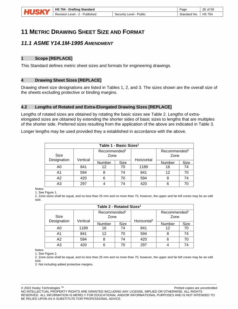
11 METRIC DRAWING SHEET SIZE AND FORMAT 11.1 ASME Y14.1M-1995 AMENDMENT 1 Scope [REPLACE] This Standard defines metric sheet sizes and formats for engineering drawings. 4 Drawing Sheet Sizes [REPLACE] Drawing sheet size designations are listed in Tables 1, 2, and 3. The sizes shown are the overall size of the sheets excluding protective or binding margins. 4.2 Lengths of Rotated and Extra-Elongated Drawing Sizes [REPLACE] Lengths of rotated sizes are obtained by rotating the basic sizes see Table 2. Lengths of extra-elongated sizes are obtained by extending the shorter sides of basic sizes to lengths that are multiples of the shorter side. Preferred sizes resulting from the application of the above are indicated in Table 3. Longer lengths may be used provided they a established in accordance with the above.
Table 1 - Basic Sizes1
Size Designation Vertical
Recommended2 Zone
Horizontal
Recommended2 Zone
Number Size Number Size A0 841 12 70 1189 16 74 A1 594 8 74 841 12 70 A2 420 6 70 594 8 74 A3 297 4 74 420 6 70
Notes: 1. See Figure 1. 2. Zone sizes shall be equal, and no less than 25 mm and no more than 75; however, the upper and far left zones may be an odd size.
Table 2 - Rotated Sizes1
Size Designation Vertical
Recommended2 Zone
Horizontal3
Recommended2 Zone
Number Size Number Size A0 1189 16 74 841 12 70 A1 841 12 70 594 8 74 A2 594 8 74 420 6 70 A3 420 6 70 297 4 74
Notes: 1. See Figure 2. 2. Zone sizes shall be equal, and no less than 25 mm and no more than 75; however, the upper and far left zones may be an odd size. 3. Not including added protective margins.

HS 754 - Drafting Standard Page 29 of 59 Revision Level - 2 - Published Security Level - Public Standard No. HS 754
_________________________________________________________________________________________________________________ © 2022 Husky Technologies TM Printed copies are uncontrolled NO INTELLECTUAL PROPERTY RIGHTS ARE GRANTED INCLUDING ANY LICENSE, IMPLIED OR OTHERWISE. ALL RIGHTS RESERVED. ALL INFORMATION IS MERELY FOR EDUCATIONAL AND/OR INFORMATIONAL PURPOSES AND IS NOT INTENDED TO BE RELIED UPON AS A SUBSTITUTE FOR PROFESSIONAL ADVICE.
Table 3 - Extra Elongated Sizes1
Size Designation Vertical
Recommended2 Zone
Horizontal3
Recommended2 Zone
Number Size Number Size 2A0X2 1682 24 70 2387 32 74 A0X2 1189 16 74 1682 24 70 A1X3 841 12 70 1783 24 74 A2X3 594 8 74 1261 18 70 A2X4 594 8 74 1682 24 70 A2X5 594 8 74 2102 30 70
Notes: 1. See Figure 3 2. Zone sizes shall be equal, and no less than 25 mm and no more than 75; however, the upper and far left zones may be an odd size. 3. Not including added protective margins.

HS 754 - Drafting Standard Page 30 of 59 Revision Level - 2 - Published Security Level - Public Standard No. HS 754
_________________________________________________________________________________________________________________ © 2022 Husky Technologies TM Printed copies are uncontrolled NO INTELLECTUAL PROPERTY RIGHTS ARE GRANTED INCLUDING ANY LICENSE, IMPLIED OR OTHERWISE. ALL RIGHTS RESERVED. ALL INFORMATION IS MERELY FOR EDUCATIONAL AND/OR INFORMATIONAL PURPOSES AND IS NOT INTENDED TO BE RELIED UPON AS A SUBSTITUTE FOR PROFESSIONAL ADVICE.
Figure 1 - Basic Sheet Size Formats, A0 Through A3 Sizes
1. Title Block 2. Projection Method and Intellectual Property Note Block 3. Material - Weight Block 4. General Tolerance Block 5. Torque Notes Block 6. Revision History Block 7. ID Block 8. General Note
14
3
2
1
4
5 6
A3 Size Horizontal
A2 Size Horizontal
A1 Size Horizontal
A0 Size Horizontal
8
Detail Drawings
Assembly Drawings
91
91
7
Detail Drawings
Assembly Drawings
3

HS 754 - Drafting Standard Page 31 of 59 Revision Level - 2 - Published Security Level - Public Standard No. HS 754
_________________________________________________________________________________________________________________ © 2022 Husky Technologies TM Printed copies are uncontrolled NO INTELLECTUAL PROPERTY RIGHTS ARE GRANTED INCLUDING ANY LICENSE, IMPLIED OR OTHERWISE. ALL RIGHTS RESERVED. ALL INFORMATION IS MERELY FOR EDUCATIONAL AND/OR INFORMATIONAL PURPOSES AND IS NOT INTENDED TO BE RELIED UPON AS A SUBSTITUTE FOR PROFESSIONAL ADVICE.
Figure 2 - Basic Vertical Sheet Size Formats, A0 Through A3 Sizes
A3R Size Vertical
A2R Size Vertical
A1R Size Vertical
A0R Size Vertical

HS 754 - Drafting Standard Page 32 of 59 Revision Level - 2 - Published Security Level - Public Standard No. HS 754
_________________________________________________________________________________________________________________ © 2022 Husky Technologies TM Printed copies are uncontrolled NO INTELLECTUAL PROPERTY RIGHTS ARE GRANTED INCLUDING ANY LICENSE, IMPLIED OR OTHERWISE. ALL RIGHTS RESERVED. ALL INFORMATION IS MERELY FOR EDUCATIONAL AND/OR INFORMATIONAL PURPOSES AND IS NOT INTENDED TO BE RELIED UPON AS A SUBSTITUTE FOR PROFESSIONAL ADVICE.
Figure 3 - Extra Elongated Sizes, 2A0X2 Through A2X5 Sizes 5.6 Continuation Sheets [REPLACE] Continuation sheets are used for second and subsequent sheets of a multiple sheet drawing. All sheets of a multiple sheet drawing should be the same size. All title blocks of a multiple sheet drawing should be identical. The title block shown in Figure 4 should be used. Zone requirements for continuation sheets are in accordance with para. 5.3 ASME Y14-1M. See Figs. 1, 2 and 3.
A2X3 Size A2X4 Size A2X5 Size
A1X2 Size
A0X2 Size
2A0X2 Size

HS 754 - Drafting Standard Page 33 of 59 Revision Level - 2 - Published Security Level - Public Standard No. HS 754
_________________________________________________________________________________________________________________ © 2022 Husky Technologies TM Printed copies are uncontrolled NO INTELLECTUAL PROPERTY RIGHTS ARE GRANTED INCLUDING ANY LICENSE, IMPLIED OR OTHERWISE. ALL RIGHTS RESERVED. ALL INFORMATION IS MERELY FOR EDUCATIONAL AND/OR INFORMATIONAL PURPOSES AND IS NOT INTENDED TO BE RELIED UPON AS A SUBSTITUTE FOR PROFESSIONAL ADVICE.
6 Title Blocks [REPLACE] 6.2 Contents [REPLACE] Certain information common to all drawings is shown in the title block. See Fig. 4 for block letter references given below.
• A - Husky company logo.
• B - Drawing title. Font Size 3.0mm, centered in space provided.
• C - Drawing number. Font Size 4.0mm, centered in space provided.
• D - Revision number. Font Size 4.0mm, centered in space provided.
• E - Drawing size designation. See Tables 1, 2 and 3. Font Size 4.0mm, centered in space provided.
• F - Predominant scale of the drawing sheet. Enter “NONE” when no scale is used. Each sheet may have a different predominant scale. Font Size 2.5mm, centered in space provided.
• G - Sheet number for multiple sheet drawings shall be entered in the sheet number blocks. The total number of sheets shall be shown. Font Size 2.5mm, centered in space provided.
• All label font sizes are 1.75mm normal.
Figure 4 - Title Block
7 Revision History Block [REPLACE] 7.1 Location [REPLACE]
A B
C D E G
F

HS 754 - Drafting Standard Page 34 of 59 Revision Level - 2 - Published Security Level - Public Standard No. HS 754
_________________________________________________________________________________________________________________ © 2022 Husky Technologies TM Printed copies are uncontrolled NO INTELLECTUAL PROPERTY RIGHTS ARE GRANTED INCLUDING ANY LICENSE, IMPLIED OR OTHERWISE. ALL RIGHTS RESERVED. ALL INFORMATION IS MERELY FOR EDUCATIONAL AND/OR INFORMATIONAL PURPOSES AND IS NOT INTENDED TO BE RELIED UPON AS A SUBSTITUTE FOR PROFESSIONAL ADVICE.
The revision history block, as shown in Fig. 5 and 6, is located in the lower left corner of the drawing. See Figs. 1, 2 and 3. Space shall be reserved to extend the revision history block downward as required. When additional space for the revision history block is needed, a supplemental revision history block may be located above of the original revision history block. Revision history blocks should be included on continuation sheets. 7.2 Contents [REPLACE] The revision history block provides space for revision data, description or identification of the change authorization document, date, and approvals. The revision history block contains the description on all detail drawings and may be used on assembly drawings, as shown in Fig 5. Customer drawings should include the revision block without description, as Fig 6. • Label Font sizes for REV; DATE; DESCRIPTION; and NAME are 1.75mm.
• Label Font sizes for DRWN: and CHKD: are 2.0mm.
• A and B - Font size 2.5mm, centered in space provided.
• C and D - Font size 2.0mm left justified in space provided.
Figure 5 - Revision Block with Description
A
B C D

HS 754 - Drafting Standard Page 35 of 59 Revision Level - 2 - Published Security Level - Public Standard No. HS 754
_________________________________________________________________________________________________________________ © 2022 Husky Technologies TM Printed copies are uncontrolled NO INTELLECTUAL PROPERTY RIGHTS ARE GRANTED INCLUDING ANY LICENSE, IMPLIED OR OTHERWISE. ALL RIGHTS RESERVED. ALL INFORMATION IS MERELY FOR EDUCATIONAL AND/OR INFORMATIONAL PURPOSES AND IS NOT INTENDED TO BE RELIED UPON AS A SUBSTITUTE FOR PROFESSIONAL ADVICE.
Figure 6 - Revision Block Without Description
Figure 7 - ID Block
• Label Font sizes for DRAWING and REV are 1.75mm.
• Drawing- and Revision number - Font size 4.0mm, centered in space provided. 8 Revision Status of Drawing [REPLACE] Revision status of drawing is indicated in the title, revision and ID blocks of each sheet. See Fig. 4, 5, 6 and 7. The revision status must be the same on each sheet of the drawing.

HS 754 - Drafting Standard Page 36 of 59 Revision Level - 2 - Published Security Level - Public Standard No. HS 754
_________________________________________________________________________________________________________________ © 2022 Husky Technologies TM Printed copies are uncontrolled NO INTELLECTUAL PROPERTY RIGHTS ARE GRANTED INCLUDING ANY LICENSE, IMPLIED OR OTHERWISE. ALL RIGHTS RESERVED. ALL INFORMATION IS MERELY FOR EDUCATIONAL AND/OR INFORMATIONAL PURPOSES AND IS NOT INTENDED TO BE RELIED UPON AS A SUBSTITUTE FOR PROFESSIONAL ADVICE.
10.1 Angle of Projection Block and Copyright [REPLACE] The angle of projection symbol will be as illustrated in ASME Y14.3M. See Figs. 1, 2, 3 and 8 for its location.
Figure 8 - Copyright Block
• Font size is 1.75mm 10.2 Dimensioning and Tolerancing Block [REPLACE] Information relative to dimensioning and Tolerancing, such as angular and dimensional tolerances, are given in this block. See figure 9. Contents of block are defined in the Dimensioning and Tolerancing section of this document. See Figs. 1, 2 and 3 for its location.
Figure 9 - Dimensioning and Tolerancing Block • Font size is 1.75mm
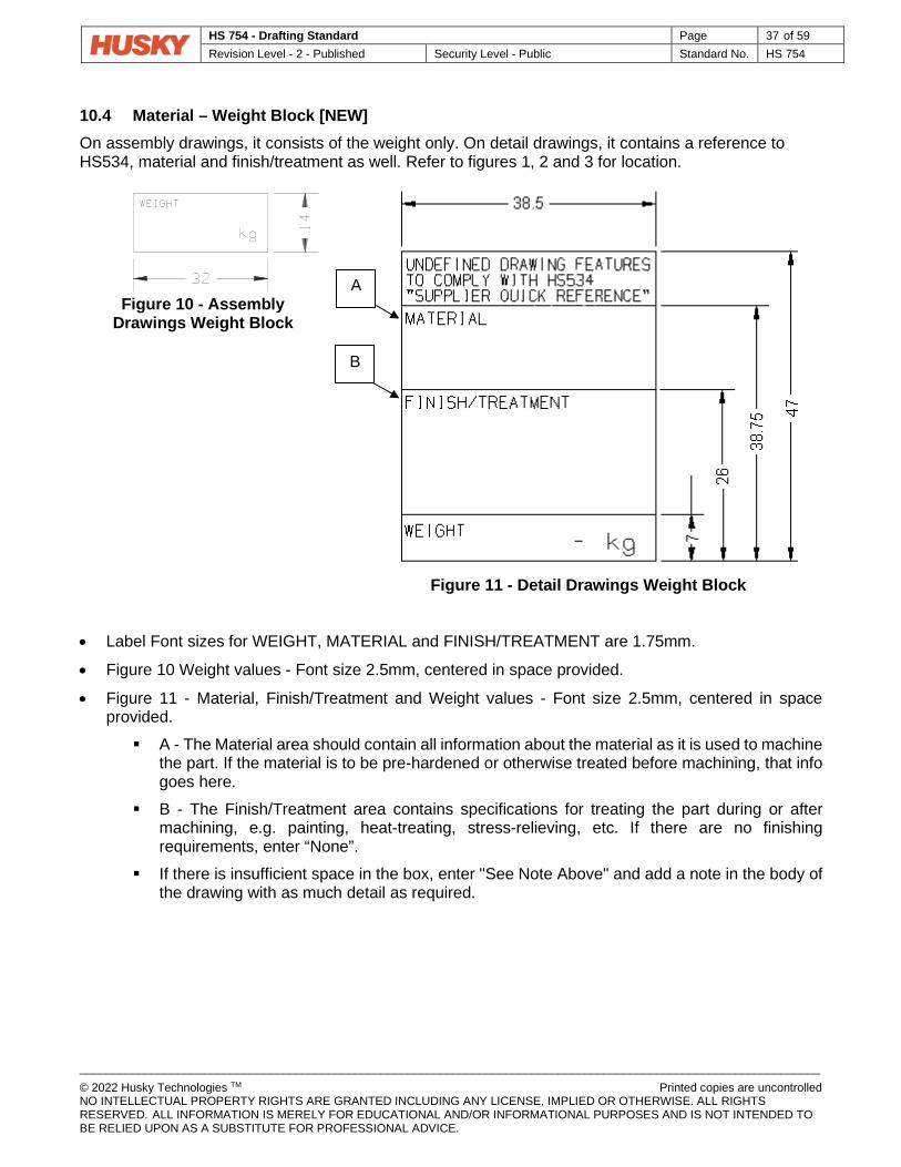
HS 754 - Drafting Standard Page 37 of 59 Revision Level - 2 - Published Security Level - Public Standard No. HS 754
_________________________________________________________________________________________________________________ © 2022 Husky Technologies TM Printed copies are uncontrolled NO INTELLECTUAL PROPERTY RIGHTS ARE GRANTED INCLUDING ANY LICENSE, IMPLIED OR OTHERWISE. ALL RIGHTS RESERVED. ALL INFORMATION IS MERELY FOR EDUCATIONAL AND/OR INFORMATIONAL PURPOSES AND IS NOT INTENDED TO BE RELIED UPON AS A SUBSTITUTE FOR PROFESSIONAL ADVICE.
10.4 Material – Weight Block [NEW] On assembly drawings, it consists of the weight only. On detail drawings, it contains a reference to HS534, material and finish/treatment as well. Refer to figures 1, 2 and 3 for location.
Figure 10 - Assembly Drawings Weight Block
Figure 11 - Detail Drawings Weight Block
• Label Font sizes for WEIGHT, MATERIAL and FINISH/TREATMENT are 1.75mm.
• Figure 10 Weight values - Font size 2.5mm, centered in space provided.
• Figure 11 - Material, Finish/Treatment and Weight values - Font size 2.5mm, centered in space provided. A - The Material area should contain all information about the material as it is used to machine
the part. If the material is to be pre-hardened or otherwise treated before machining, that info goes here.
B - The Finish/Treatment area contains specifications for treating the part during or after machining, e.g. painting, heat-treating, stress-relieving, etc. If there are no finishing requirements, enter “None”.
If there is insufficient space in the box, enter "See Note Above" and add a note in the body of the drawing with as much detail as required.
A
B

HS 754 - Drafting Standard Page 38 of 59 Revision Level - 2 - Published Security Level - Public Standard No. HS 754
_________________________________________________________________________________________________________________ © 2022 Husky Technologies TM Printed copies are uncontrolled NO INTELLECTUAL PROPERTY RIGHTS ARE GRANTED INCLUDING ANY LICENSE, IMPLIED OR OTHERWISE. ALL RIGHTS RESERVED. ALL INFORMATION IS MERELY FOR EDUCATIONAL AND/OR INFORMATIONAL PURPOSES AND IS NOT INTENDED TO BE RELIED UPON AS A SUBSTITUTE FOR PROFESSIONAL ADVICE.
14 Standard View Scales (Section consistent with ISO 5455) [NEW] 14.1 Scope and Definition [NEW] This International Standard specifies recommended scales and their designation for use on all technical drawings in any field of engineering. 14.2 Definitions [NEW] 14.2.1 Scale [NEW] Ratio of linear dimension of an element of an object as represented in the original drawing to the real linear dimension of the same element of the object itself.
• NOTE - The scale of a print may be different from that of the original drawing. 14.2.2 Full Size [NEW] A scale with ratio 1:1 14.2.3 Enlargement Scale [NEW] A scale where the ratio is larger than 1:1 14.2.4 Reduction Scales [NEW] A scale where the ratio is smaller than 1:1 14.2.5 Drawings Not to Scale [NEW] When the scale is not to be identified on the view and/or for the drawing, the value noted in the scale field on the title block shall be noted as NONE. 14.3 Designation [NEW] The complete designation of scale shall consist of the word “SCALE” (or its equivalent in the language used on the drawing) followed by the indication of its ratio, as follows: SCALE 1 : 1 for full size SCALE x : 1 for enlargement scales SCALE 1 : x for reduction scales SECTION A-A for multiple scales SCALE x:x SCALE NONE for not to scale drawings/views If there is no likelihood of misunderstanding, the word “SCALE” may be omitted.

HS 754 - Drafting Standard Page 39 of 59 Revision Level - 2 - Published Security Level - Public Standard No. HS 754
_________________________________________________________________________________________________________________ © 2022 Husky Technologies TM Printed copies are uncontrolled NO INTELLECTUAL PROPERTY RIGHTS ARE GRANTED INCLUDING ANY LICENSE, IMPLIED OR OTHERWISE. ALL RIGHTS RESERVED. ALL INFORMATION IS MERELY FOR EDUCATIONAL AND/OR INFORMATIONAL PURPOSES AND IS NOT INTENDED TO BE RELIED UPON AS A SUBSTITUTE FOR PROFESSIONAL ADVICE.
14.4 Inscription [NEW] 14.4.1 Main Scale Location [NEW] The designation of the scale used on the drawing shall be inscribed in the title block of the drawing. 14.4.2 Multiple Scales Locations [NEW] Where it is necessary to use more than one scale on the drawing, the main scale only shall be indicated in the title block, and all other scales adjacent to the item reference number of the part concerned, or adjacent to the reference letter of a detail view (or section). 14.5 Scale Values [NEW] 14.5.1 Recommended Scale Values [NEW] The recommended scales for use on technical drawings are specified in table 4.
Designation Recommended Scales
Enlargement Scales 50 : 1 20 : 1 10 : 1
5 : 1 2 : 1
Full Size 1 : 1
Reduction Scales 1 : 2 1 : 5 1 : 10
1 : 20 1 : 50 1 : 100
1 : 200 1 : 500 1 : 1 000
1 : 2 000 1 : 5 000 1 : 10 000
Table 4 - Recommended Scale
• Note: The recommended scales should never take precedence over the clarity of the drawing. Scales other than in the table above may be used as necessary (e.g. 3 : 1, 2.5 : 1, etc.)
14.5.2 Scale Selection [NEW] The scale to be chosen for a drawing will depend upon the complexity of the object to be depicted and the purpose of the representation. In all cases, the selected scale shall be large enough to permit easy and clear interpretation of the information depicted. The scale and the size of the object, in turn will decide the size of the drawing. 14.5.3 Details Not Clearly Depicted [NEW]
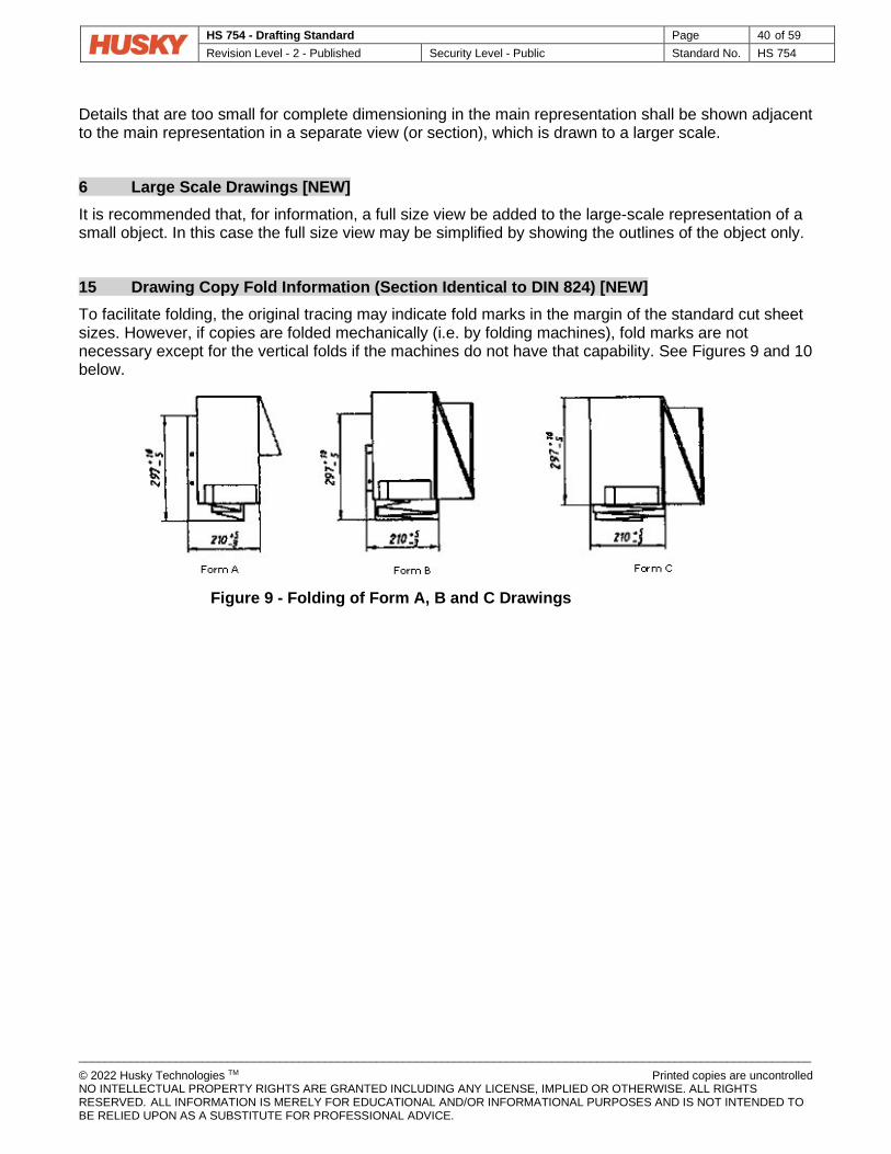
HS 754 - Drafting Standard Page 40 of 59 Revision Level - 2 - Published Security Level - Public Standard No. HS 754
_________________________________________________________________________________________________________________ © 2022 Husky Technologies TM Printed copies are uncontrolled NO INTELLECTUAL PROPERTY RIGHTS ARE GRANTED INCLUDING ANY LICENSE, IMPLIED OR OTHERWISE. ALL RIGHTS RESERVED. ALL INFORMATION IS MERELY FOR EDUCATIONAL AND/OR INFORMATIONAL PURPOSES AND IS NOT INTENDED TO BE RELIED UPON AS A SUBSTITUTE FOR PROFESSIONAL ADVICE.
Details that are too small for complete dimensioning in the main representation shall be shown adjacent to the main representation in a separate view (or section), which is drawn to a larger scale. 6 Large Scale Drawings [NEW] It is recommended that, for information, a full size view be added to the large-scale representation of a small object. In this case the full size view may be simplified by showing the outlines of the object only. 15 Drawing Copy Fold Information (Section Identical to DIN 824) [NEW] To facilitate folding, the original tracing may indicate fold marks in the margin of the standard cut sheet sizes. However, if copies are folded mechanically (i.e. by folding machines), fold marks are not necessary except for the vertical folds if the machines do not have that capability. See Figures 9 and 10 below.
Figure 9 - Folding of Form A, B and C Drawings
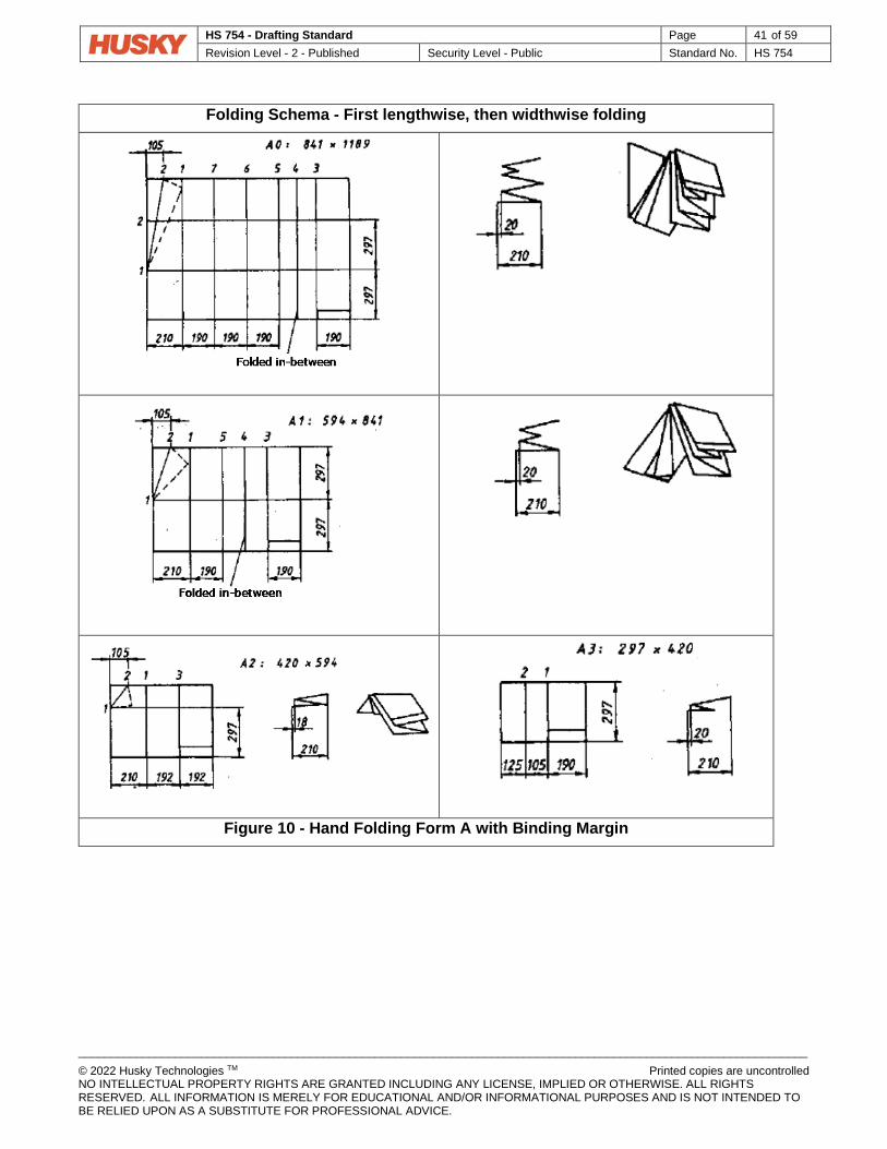
HS 754 - Drafting Standard Page 41 of 59 Revision Level - 2 - Published Security Level - Public Standard No. HS 754
_________________________________________________________________________________________________________________ © 2022 Husky Technologies TM Printed copies are uncontrolled NO INTELLECTUAL PROPERTY RIGHTS ARE GRANTED INCLUDING ANY LICENSE, IMPLIED OR OTHERWISE. ALL RIGHTS RESERVED. ALL INFORMATION IS MERELY FOR EDUCATIONAL AND/OR INFORMATIONAL PURPOSES AND IS NOT INTENDED TO BE RELIED UPON AS A SUBSTITUTE FOR PROFESSIONAL ADVICE.
Folding Schema - First lengthwise, then widthwise folding
Figure 10 - Hand Folding Form A with Binding Margin

HS 754 - Drafting Standard Page 42 of 59 Revision Level - 2 - Published Security Level - Public Standard No. HS 754
_________________________________________________________________________________________________________________ © 2022 Husky Technologies TM Printed copies are uncontrolled NO INTELLECTUAL PROPERTY RIGHTS ARE GRANTED INCLUDING ANY LICENSE, IMPLIED OR OTHERWISE. ALL RIGHTS RESERVED. ALL INFORMATION IS MERELY FOR EDUCATIONAL AND/OR INFORMATIONAL PURPOSES AND IS NOT INTENDED TO BE RELIED UPON AS A SUBSTITUTE FOR PROFESSIONAL ADVICE.
12 MULTIVIEW & SECTIONAL VIEW DRAWINGS 12.1 Y14.3M-1994 AMENDMENT 1.1 Scope [REPLACE] This standard establishes the requirements for creating orthographic views for item description. The topics covered include the multiview system of drawing, selection, and arrangement of orthographic views, auxiliary views, sectional views, details, and conventional drawing practices. Space geometry and space analysis and applications are included in the appendices for informational purposes. 1.6 Projection Systems [NEW] (Add the following text to paragraph.1.6 of ASME Y14.3M-1994)
Third angle projection shall be used on all drawings. 1.7.3 Identifying Removed Views [REPLACE] (Replace the text in paragraph 1.7.3 of ASME Y14.3M-1994 with the following)
To relate the viewing plane or cutting plane to its removed view, capital letters such as A, B, C etc., are placed near each arrowhead. The corresponding removed views are identified as VIEW A, VIEW B, VIEW C, etc. VIEW letters should be used in alphabetical order excluding I, O, Q, S, X and Z. If the alphabet is exhausted, additional removed views shall be indicated by double letters in alphabetical order, as in AA, AB, AC. Alphabet letters for Details, Sections or Views shall only be used once on a drawing.
Fig. 1-7 - Removed Views [REPLACE] 1.7.5 Cross-Referencing of Views [REPLACE] (Replace the text in paragraph 1.7.5 of ASME Y14.3M-1994 with the following)

HS 754 - Drafting Standard Page 43 of 59 Revision Level - 2 - Published Security Level - Public Standard No. HS 754
_________________________________________________________________________________________________________________ © 2022 Husky Technologies TM Printed copies are uncontrolled NO INTELLECTUAL PROPERTY RIGHTS ARE GRANTED INCLUDING ANY LICENSE, IMPLIED OR OTHERWISE. ALL RIGHTS RESERVED. ALL INFORMATION IS MERELY FOR EDUCATIONAL AND/OR INFORMATIONAL PURPOSES AND IS NOT INTENDED TO BE RELIED UPON AS A SUBSTITUTE FOR PROFESSIONAL ADVICE.
Cross-reference should be used to indicate the location of an indicated view, and to reference a view back to the viewing location when views are located on different sheets. The sheet number shall be indicated. See Fig. 1-9.
Fig. 1-9 - Removed View on Multiple Sheet Drawing [REPLACE] 3.3 Section Lining [REPLACE] (Replace the text in paragraph 3.3 of ASME Y14.3M-1994 with the following)
A uniformly patterned appearance should be evident where section lining is used. The lining shall not indicate material. Only the general purpose section lining (uniformly spaced lines) is shown on the drawing. See Fig. 3-1. 4.2.1 Conventional Representation Applied to Sections [REPLACE] (The method in paragraph 4.2.1 of ASME Y14.3M-1994 shall not be used)

HS 754 - Drafting Standard Page 44 of 59 Revision Level - 2 - Published Security Level - Public Standard No. HS 754
_________________________________________________________________________________________________________________ © 2022 Husky Technologies TM Printed copies are uncontrolled NO INTELLECTUAL PROPERTY RIGHTS ARE GRANTED INCLUDING ANY LICENSE, IMPLIED OR OTHERWISE. ALL RIGHTS RESERVED. ALL INFORMATION IS MERELY FOR EDUCATIONAL AND/OR INFORMATIONAL PURPOSES AND IS NOT INTENDED TO BE RELIED UPON AS A SUBSTITUTE FOR PROFESSIONAL ADVICE.
4.4 Foreshortened and Aligned Features in Section and Exterior Views [REPLACE] (The method in paragraph 4.4 of ASME Y14.3M-1994 shall not be used)
Fig. 4-5 and 4-6 shall not be used. 4.5 Intersections in Section [REPLACE] (The method in paragraph 4.5 of ASME Y14.3M-1994 shall not be used)
Fig. 4-8 shall not be used. 4.6.2 Rotation of Features and Elements to Show True Shapes [REPLACE] (The method in paragraph 4.6.2 of ASME Y14.3M-1994 shall not be used)
Fig. 4-10 shall not be used. 4.6.3 Simplified Representation of Small Details [REPLACE] (The method in paragraph 4.6.3 of ASME Y14.3M-1994 shall not be used)
Fig. 4-11 shall not be used. 4.6.4 Conventional Representation of Large Details [REPLACE] (The method in paragraph 4.6.4 of ASME Y14.3M-1994 shall not be used)
Fig. 4-12 shall not be used. 4.6.5 Representation of Fillets and Rounds [REPLACE] (Replace the text in paragraph 4.6.5 of ASME Y14.3M-1994 with the following)
Where sharp intersection lines of two surfaces are removed by fillets or rounds, the abrupt changes in surface directions are represented by a solid thin line with end gaps at the approximate intersection of the surfaces. Fig. 4-13 shall not be used. 4.6.6 Depictions of Fillets, Rounds and Runouts [REPLACE] (The method in paragraph 4.6.6 of ASME Y14.3M-1994 shall not be used)
Fig. 4-14 shall not be used. 4.6.7 Conventional Representation of Breaks [REPLACE] (Replace the text in paragraph 4.6.7 of ASME Y14.3M-1994 with the following)
Examples of conventional representations of breaks, used to shorten a view of elongated features, are shown in Fig. 4-15. Representations (c) and (d) shall be used.

HS 754 - Drafting Standard Page 45 of 59 Revision Level - 2 - Published Security Level - Public Standard No. HS 754
_________________________________________________________________________________________________________________ © 2022 Husky Technologies TM Printed copies are uncontrolled NO INTELLECTUAL PROPERTY RIGHTS ARE GRANTED INCLUDING ANY LICENSE, IMPLIED OR OTHERWISE. ALL RIGHTS RESERVED. ALL INFORMATION IS MERELY FOR EDUCATIONAL AND/OR INFORMATIONAL PURPOSES AND IS NOT INTENDED TO BE RELIED UPON AS A SUBSTITUTE FOR PROFESSIONAL ADVICE.
5 Pictorial Views [NEW] Pictorial views can be added to the drawing for clarification. See Fig. 2 of ASME Y14.2M-1992. 6 Movable Parts [NEW] The alternative and extreme positions of movable parts in assembly drawings can be shown, drawn with thin phantom lines.
Fig. 6-1 - Movable Parts [NEW]
13 PICTORIAL DRAWING 13.1 Y14.4M-1989 AMENDMENT 1.1 Scope [REPLACE] This standard establishes definitions for and illustrates the uses of various kinds of three-dimensional view pictorial drawings. It also addresses the kinds of pictorial views commonly used on engineering drawings. Methods of constructing the different kinds of pictorial drawings are beyond this Standard. Methods are described in detail in engineering drawing textbooks. 3.2.2 Break Lines [REPLACE] (The method in paragraph 3.2.2 of ASME Y14.5M-1989 shall not be used)
Fig. 13 shall not be used. 3.6 Thread Representation [REPLACE] (The method in paragraph 3.6 of ASME Y14.5M-1989 shall not be used)
Fig. 18 shall not be used. 3.9 Shading [REPLACE] (The method in paragraph 3.9 of ASME Y14.5M-1989 shall not be used)
Fig. 20 shall not be used.

HS 754 - Drafting Standard Page 46 of 59 Revision Level - 2 - Published Security Level - Public Standard No. HS 754
_________________________________________________________________________________________________________________ © 2022 Husky Technologies TM Printed copies are uncontrolled NO INTELLECTUAL PROPERTY RIGHTS ARE GRANTED INCLUDING ANY LICENSE, IMPLIED OR OTHERWISE. ALL RIGHTS RESERVED. ALL INFORMATION IS MERELY FOR EDUCATIONAL AND/OR INFORMATIONAL PURPOSES AND IS NOT INTENDED TO BE RELIED UPON AS A SUBSTITUTE FOR PROFESSIONAL ADVICE.
14 SCREW THREAD REPRESENTATION 14.1 Y14.6-2001 AMENDMENT 1.1 Scope [REPLACE] This standard establishes the requirements for pictorial representation, specification, and dimensioning of screw threads on drawings; it is not concerned with standards for dimensional control of screw threads. 3.1 Thread Representation [NEW] (Add the following text to paragraph 3.1 of ASME Y14.6-2001)
The simplified method of screw representation as shown in Fig. 1 is the preferred method to be used at Husky. The schematic and detailed methods should only be used where greater detail is required to ensure part quality. 3.2 Thread Specification [NEW] (Add the following text to paragraph 3.2 of ASME Y14.6-2001)
The fractional method of indicating imperial thread designations shall be used. 3.2.1.1 60 Degree Threads [NEW] (Add the following text to paragraph 3.2.1.1 of ASME Y14.6-2001)
• For coarse pitch metric tapped holes in accordance with HS 259 (Metric Thread Installations) the thread designation may be simplified. Unless otherwise specified, the thread callouts shall be as specified in HS 259. Example callouts are as follows:
M6 M12 REDUCED LENGTH
M20 BOTTOM TAP
• For Coarse Pitch imperial tapped holes in accordance with HS 260 (Imperial Thread Installations) the thread designation may be simplified. Unless otherwise specified, the thread callouts shall be as specified in HS 260. Example callouts are as follows:
1/2 – 13 UNC #10 – 24 UNC REDUCED LENGTH
1-1/4 – 8 UNC BOTTOM TAP
3.2.1.3 Nominal Thread Size [REPLACE] (Replace the text in paragraph 3.2.1.3 of ASME Y14.6-2001 with the following text)
• The nominal imperial thread size is the basic major diameter and is specified as the fractional diameter or screw number. For inch sizes the nominal diameter shall be shown in fractional form. Example callouts are as follows:
1 – 8 UNC

HS 754 - Drafting Standard Page 47 of 59 Revision Level - 2 - Published Security Level - Public Standard No. HS 754
_________________________________________________________________________________________________________________ © 2022 Husky Technologies TM Printed copies are uncontrolled NO INTELLECTUAL PROPERTY RIGHTS ARE GRANTED INCLUDING ANY LICENSE, IMPLIED OR OTHERWISE. ALL RIGHTS RESERVED. ALL INFORMATION IS MERELY FOR EDUCATIONAL AND/OR INFORMATIONAL PURPOSES AND IS NOT INTENDED TO BE RELIED UPON AS A SUBSTITUTE FOR PROFESSIONAL ADVICE.
5/8 – 11 UNC-2A 1/2 – 20 UNF-2B
• Numbered sizes may be shown because of established practices. The # symbol shall be used in place of the abbreviation “No.” or a decimal equivalent. Example callouts are as follows:
#8 – 32 UNC #10 – 24 UNC-2A #10 – 32 UNF-2B
• Nominal metric size or pitch should include zero before the decimal of values less than 1, and should not include any zeroes beyond the last numbered decimal places (e.g., M8x1.5 or MJ2.5x0.45).
TABLE 1 - ASME Y14.6 Thread Series Designations [NEW] (Add the following text to Table 1 of ASME Y14.6-2001)
Designation Thread Series
BSPP British Standard Pipe, Parallel
BSPT British Standard Pipe, Taper
15 SURFACE TEXTURE SYMBOLS 15.1 Y14.36M-1996 AMENDMENT 1.1 Scope [REPLACE] This standard establishes the method to designate controls for surface texture of solid materials. It includes methods for controlling roughness, waviness, and lay by providing a set of symbols for use on drawings, specifications, or other documents. The standard does not specify the means by which the surface texture is to be produced or measured. 4.4 Roughness Cut-off or Sampling Length [REPLACE] (Replace the following text in paragraph 4.4 of ASME Y14.36M-1996 with the following)
If no Roughness cut-off value is indicated, the values of the Table 3 below shall apply:

HS 754 - Drafting Standard Page 48 of 59 Revision Level - 2 - Published Security Level - Public Standard No. HS 754
_________________________________________________________________________________________________________________ © 2022 Husky Technologies TM Printed copies are uncontrolled NO INTELLECTUAL PROPERTY RIGHTS ARE GRANTED INCLUDING ANY LICENSE, IMPLIED OR OTHERWISE. ALL RIGHTS RESERVED. ALL INFORMATION IS MERELY FOR EDUCATIONAL AND/OR INFORMATIONAL PURPOSES AND IS NOT INTENDED TO BE RELIED UPON AS A SUBSTITUTE FOR PROFESSIONAL ADVICE.
X < Ra ≤ Y Units: µmm (µin)
Roughness Cut-off: λc
Units: mm (in)
0.02 (0.8) 0.08 (0.003)
0.02 (0.8) 0.1 (4.0) 0.25 (0.01)
0.1 (4.0) 2 (80) 0.8 (0.03)
2 (80) 10 (400) 2.5 (0.1)
10 (400) 8 (0.3)
Table 3 - Standard Roughness Values Non-standard roughness cut-off values shall be indicated as required.

HS 754 - Drafting Standard Page 49 of 59 Revision Level - 2 - Published Security Level - Public Standard No. HS 754
_________________________________________________________________________________________________________________ © 2022 Husky Technologies TM Printed copies are uncontrolled NO INTELLECTUAL PROPERTY RIGHTS ARE GRANTED INCLUDING ANY LICENSE, IMPLIED OR OTHERWISE. ALL RIGHTS RESERVED. ALL INFORMATION IS MERELY FOR EDUCATIONAL AND/OR INFORMATIONAL PURPOSES AND IS NOT INTENDED TO BE RELIED UPON AS A SUBSTITUTE FOR PROFESSIONAL ADVICE.
16 DIMENSIONING AND TOLERANCING
16.1 SCOPE This standard establishes uniform practices for stating and interpreting dimensioning, tolerancing, and related requirements for use on engineering drawings and in related documents.
16.2 DRAWING/CAD MODEL PRECEDENCE The information on the technical drawing(s) takes precedence over the CAD model. Husky is currently using “option A” as a default. “Option B” is not applicable (full model-base practices are not yet permitted at Husky). “Option C” is commonly used, but only in specific cases.
A. Unless otherwise specified, the technical drawing is the master. B. Using model-base definitions, the CAD model is the master. C. Minimum-dimensioned drawing. Full detail of the part is obtained by combining the information
on the drawing with the CAD model. Specifications on the drawing, external references and CAD model must always match. Discrepancies must be noted on the drawing. Otherwise, it is an error that must be corrected.
16.3 GENERAL TOLERANCE BLOCK NOTES The following describes the content of the tolerance block for all drawings created to the standards defined by Y14.5-2009 and this addendum.

HS 754 - Drafting Standard Page 50 of 59 Revision Level - 2 - Published Security Level - Public Standard No. HS 754
_________________________________________________________________________________________________________________ © 2022 Husky Technologies TM Printed copies are uncontrolled NO INTELLECTUAL PROPERTY RIGHTS ARE GRANTED INCLUDING ANY LICENSE, IMPLIED OR OTHERWISE. ALL RIGHTS RESERVED. ALL INFORMATION IS MERELY FOR EDUCATIONAL AND/OR INFORMATIONAL PURPOSES AND IS NOT INTENDED TO BE RELIED UPON AS A SUBSTITUTE FOR PROFESSIONAL ADVICE.
Figure 1 - General Tolerance Block
UNLESS OTHERWISE SPECIFIED: Requirements indicated in the field of the drawing(s) supersede the general notes.
CAD MODEL IS BASIC: CAD model geometry is created at theoretical exact size(s). All non-dimensioned features derived from a CAD model are basic. The definition of basic is in accordance with Y14.5-2009 (see section 1.3.23).
UNTOLERANCED DIMENSIONS ARE BASIC: Untoleranced dimensions on the drawing are basic by default - Exception: Untoleranced dimensions that apply to features controlled by external standards. Notes: Basic dimensions may be indicated on the drawing with a basic box or untoleranced as described in Y14.5-2009 (see section 2.1.1.2). The two methods (with or without the box) cannot both be used on the same drawing.
TOLERANCE PRECEDENCE RULE: (IMPLIED) Each dimension must have a tolerance, except those that are specifically identified as reference, maximum, minimum or stock (commercial stock size). Proceed in the following order to determine the tolerance of a dimension:
1. Directly toleranced dimension (+/-) 2. Indirectly toleranced dimension (basic
dimension with geometric tolerance) 3. Untoleranced dimension applied to
features controlled by external standards (if applicable)
4. Location of holes controlled by a general position standard (if applicable)
5. General default sheet tolerances (if applicable)
Note: For more information about the five practices for representing dimensions, see section 1.7 on page 53.
GENERAL TOLERANCE: A surface profile tolerance which applies to all features not otherwise toleranced or not controlled by an external standard. General profile tolerances must have datums referenced in the feature control frame. Any specific tolerances specified on the drawing override the general default tolerances (i.e. any tolerance negates application of the default tolerance).
BROKEN EDGE/CHAMFER: Applies to all external corners shown as sharp - Exceptions: Edge/chamfer controlled by a “state of edge” symbol (ISO 13715) or specified on the drawing as “SHARP”.
FILLET/ROUND: Applies to all internal corners shown as sharp - Exceptions: Fillet/round controlled by a “state of edge” symbol (ISO 13715) or specified on the drawing as “SHARP”. Notes for Chamfers & Fillets & : - Any chamfer or fillet modelled and displayed on the drawing must be dimensioned - “SHARP” callouts may only be used on standard installations where defined by a SIM.
SURFACE FINISH: See ASME Y14.36M-1996 and Amendment 15.1 on page 48. When “AS SUPPLIED” is noted, material conditions are as per the raw material supplied.
7
6
5
4
3
2 1
1
2
3
4
5
6
7
5 6

HS 754 - Drafting Standard Page 51 of 59 Revision Level - 2 - DRAFT Security Level - Public Standard No. HS 754
_________________________________________________________________________________________________________________ © 2022 Husky Technologies TM Printed copies are uncontrolled NO INTELLECTUAL PROPERTY RIGHTS ARE GRANTED INCLUDING ANY LICENSE, IMPLIED OR OTHERWISE. ALL RIGHTS RESERVED. ALL INFORMATION IS MERELY FOR EDUCATIONAL AND/OR INFORMATIONAL PURPOSES AND IS NOT INTENDED TO BE RELIED UPON AS A SUBSTITUTE FOR PROFESSIONAL ADVICE.
16.4 ASME Y14.5-2009 AMENDMENT 1 Scope, Definitions, and General Dimensioning 1.1 Scope 1.1.1 General 1.1.7 Symbols [NEW] (Add the following text to paragraph 1.1.7 of ASME Y14.5-2009)
Abbreviations & equivalent terms shall not be used where a symbol is available. (E.g. DP or DEPTH is replaced by ) 1.5 Units of Measure 1.5.1 SI (Metric) Linear Units [NEW] (Add the following text to paragraph 1.5.1 of ASME Y14.5-2009)
Metric dimensions shall use the period as the decimal point. 1.5.2 U.S. Customary Linear Units [REPLACE] (Replace the text in paragraph 1.5.2 of ASME Y14.5-2009 with the following)
Decimal inches are preferred except where industry-standard fractional-inch sizes are common (i.e. raw material & tap sizes). 1.5.4 Combination SI (Metric) and U.S. Customary Linear Units [REPLACE] (Replace the text in paragraph 1.5.4 of ASME Y14.5- 2009 with the following)
Dual dimensioning is not a preferred practice. Where necessitated by business-unit or customer requirements, inch dimensions shall be shown as the second unit on a dual-dimensioned drawing. Inch dimensions and associated tolerances shall appear in square brackets “[ ]” immediately after or below the metric dimension. The note “DIMENSIONS ARE PROVIDED IN MILLIMETERS. DIMENSIONS IN SQUARE BRACKETS [ ] ARE IN INCHES” must be included directly on the drawing. 1.7 Application of Dimensions [NEW] (Add the following text to paragraph 1.7 of ASME Y14.5-2009)

HS 754 - Drafting Standard Page 52 of 59 Revision Level - 2 - DRAFT Security Level - Public Standard No. HS 754
_________________________________________________________________________________________________________________ © 2022 Husky Technologies TM Printed copies are uncontrolled NO INTELLECTUAL PROPERTY RIGHTS ARE GRANTED INCLUDING ANY LICENSE, IMPLIED OR OTHERWISE. ALL RIGHTS RESERVED. ALL INFORMATION IS MERELY FOR EDUCATIONAL AND/OR INFORMATIONAL PURPOSES AND IS NOT INTENDED TO BE RELIED UPON AS A SUBSTITUTE FOR PROFESSIONAL ADVICE.
There are five practices for representing dimensions and tolerances on a drawing:
1. Directly toleranced dimensions: Directly toleranced dimensions are those that are not basic, they have a tolerance written next to the dimension. Examples:
2. Indirectly toleranced dimensions: Basic dimensions do not have a direct tolerance. Their tolerance is indirect because it is applied to the features on the part, not the dimensions. The basic dimension may be thought of as the goal and the geometric tolerance is the amount the feature may deviate from the goal. Example:
3. Dimensions applied to features controlled by external standards: Dimensions shown without tolerances on drawings applied to part features controlled by external standards. Example: Form and size of a counterbore hole controlled by HS534. Note: position tolerance must be specified on the drawing as it is not defined in HS534.
4. Location of holes controlled by a general position standard: Holes shown without position tolerances, as defined by a general note displayed on the drawing. Example:
Associated position tolerance (not defined in HS534)
UNDEFINED DRAWING FEATURES TO COMPLY WITH HS534 “SUPPLIER QUICK REFERENCE”
HOLES WITHOUT POSITION TOLERANCES ARE POSITIONED AS PER GENERAL POSITION
10 ±0.1 12 +0.2
- 0.3
GENERAL POSITION TOLERANCE FOR TAPPED HOLES
14 (H7)
GENERAL POSITION TOLERANCE FOR HOLES
+0.018 0
Label to identify feature in HS534

HS 754 - Drafting Standard Page 53 of 59 Revision Level - 2 - DRAFT Security Level - Public Standard No. HS 754
_________________________________________________________________________________________________________________ © 2022 Husky Technologies TM Printed copies are uncontrolled NO INTELLECTUAL PROPERTY RIGHTS ARE GRANTED INCLUDING ANY LICENSE, IMPLIED OR OTHERWISE. ALL RIGHTS RESERVED. ALL INFORMATION IS MERELY FOR EDUCATIONAL AND/OR INFORMATIONAL PURPOSES AND IS NOT INTENDED TO BE RELIED UPON AS A SUBSTITUTE FOR PROFESSIONAL ADVICE.
5. General default sheet tolerances: Basic dimensions shown without tolerances on drawings applied to part features controlled by general default sheet tolerances. Example: The basic dimension 20 is applied to two surfaces of a feature not controlled by specific geometric tolerances (no leader from a feature control frame directed to the surfaces).
Note: Part features/surfaces not directly (1) or indirectly (2) toleranced, which size and form are not controlled by a general standard (3), which location is not controlled by a general position standard (4) are fully controlled by the general default sheet tolerance (5). 1.7.1 Dimension Lines [REPLACE] (Replace the following text in paragraph 1.7.1 of ASME Y14.5-2009 with the following)
A dimension line, with its arrowheads, shows the direction and extent of a dimension. Numerals indicate the number of units of a measurement. Dimension lines shall be broken for the insertion of numerals as shown in Fig. 1-6 (see ASME Y14.5-2009). 1.7.5 Reading Direction 1.7.5.2 Dimensions [REPLACE] (Replace the following text in paragraph 1.7.5.2 of ASME Y14.5-2009 with the following. Add Fig. 1-18-1)
Dimensions shown with dimension lines and arrowheads shall be placed to read from the bottom or right of the drawing. Text can be oriented from 0-90 deg. Horizontal is preferred. Vertical is acceptable. At an angle should be used only when necessary. See Fig. 1-18 and Fig. 1-18-1 [NEW].
Figure 1-18-1 Text Orientation for Annotations [NEW]
This on the drawing
GENERAL DEFAULT SHEET PROFILE
TOLERANCE: (Specified on drawing
general tolerance block)
Means this

HS 754 - Drafting Standard Page 54 of 59 Revision Level - 2 - DRAFT Security Level - Public Standard No. HS 754
_________________________________________________________________________________________________________________ © 2022 Husky Technologies TM Printed copies are uncontrolled NO INTELLECTUAL PROPERTY RIGHTS ARE GRANTED INCLUDING ANY LICENSE, IMPLIED OR OTHERWISE. ALL RIGHTS RESERVED. ALL INFORMATION IS MERELY FOR EDUCATIONAL AND/OR INFORMATIONAL PURPOSES AND IS NOT INTENDED TO BE RELIED UPON AS A SUBSTITUTE FOR PROFESSIONAL ADVICE.
1.7.8 Dimensioning Within the Outline of a View [NEW] (Add the following text to paragraph 1.7.8 of ASME Y14.5-2009)
Dimensions within a hatched/shaded area shall be legible and require a localized clear background. 1.7.9 Dimensions Not to Scale [REPLACE] The method in paragraph 1.7.9 (a) of ASME Y14.5-2009 shall only be used in plastic part drawings. It shall not be used in any kind of steel part drawing. “Dimensions not to scale” should be marked as described the paragraph 1.7.9 (a). In our CAD system we will furthermore, in addition to the underline of the dimension(s), use a different color to identify “Dimensions not to Scale”. 1.8 Dimensioning Features [REPLACE] 1.8.4 Rounded Ends and Slotted Holes [REPLACE] (Modification to paragraph 1.8.4 of ASME Y14.5-2009)
Slotted holes shall be dimensioned as shown in Fig. 1-29 (c). Fig. 1-29 (a) is not preferred. Fig 1-29 (b) shall not be used. 1.8.9 Symmetrical Outlines [REPLACE] (The method in paragraph 1.8.9 of ASME Y14.5-2009 shall not be used)
1.8.16.1 Chamfers Specified by Note [REPLACE] Chamfers shall be indicated by one of the following methods. (Fig. 1-42 and 1-43 referenced in paragraph 1.8.16.1 of ASME Y14.5-2009 shall be replaced with the following)
Figure 1-42 Chamfers [USE AS IS] Figure 1-43 45° Chamfer [REPLACE] 2 General Tolerancing and Related Principles 2.17 Statistical Tolerancing [NEW] See Statistical Tolerancing Standard HS760
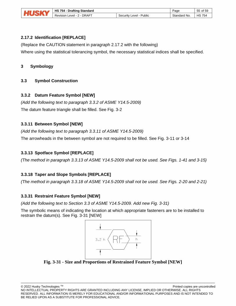
HS 754 - Drafting Standard Page 55 of 59 Revision Level - 2 - DRAFT Security Level - Public Standard No. HS 754
_________________________________________________________________________________________________________________ © 2022 Husky Technologies TM Printed copies are uncontrolled NO INTELLECTUAL PROPERTY RIGHTS ARE GRANTED INCLUDING ANY LICENSE, IMPLIED OR OTHERWISE. ALL RIGHTS RESERVED. ALL INFORMATION IS MERELY FOR EDUCATIONAL AND/OR INFORMATIONAL PURPOSES AND IS NOT INTENDED TO BE RELIED UPON AS A SUBSTITUTE FOR PROFESSIONAL ADVICE.
2.17.2 Identification [REPLACE] (Replace the CAUTION statement in paragraph 2.17.2 with the following) Where using the statistical tolerancing symbol, the necessary statistical indices shall be specified. 3 Symbology 3.3 Symbol Construction 3.3.2 Datum Feature Symbol [NEW] (Add the following text to paragraph 3.3.2 of ASME Y14.5-2009)
The datum feature triangle shall be filled. See Fig. 3-2 3.3.11 Between Symbol [NEW] (Add the following text to paragraph 3.3.11 of ASME Y14.5-2009)
The arrowheads in the between symbol are not required to be filled. See Fig. 3-11 or 3-14 3.3.13 Spotface Symbol [REPLACE] (The method in paragraph 3.3.13 of ASME Y14.5-2009 shall not be used. See Figs. 1-41 and 3-15)
3.3.18 Taper and Slope Symbols [REPLACE] (The method in paragraph 3.3.18 of ASME Y14.5-2009 shall not be used. See Figs. 2-20 and 2-21)
3.3.31 Restraint Feature Symbol [NEW] (Add the following text to Section 3.3 of ASME Y14.5-2009. Add new Fig. 3-31)
The symbolic means of indicating the location at which appropriate fasteners are to be installed to restrain the datum(s). See Fig. 3-31 [NEW]
Fig. 3-31 - Size and Proportions of Restrained Feature Symbol [NEW]
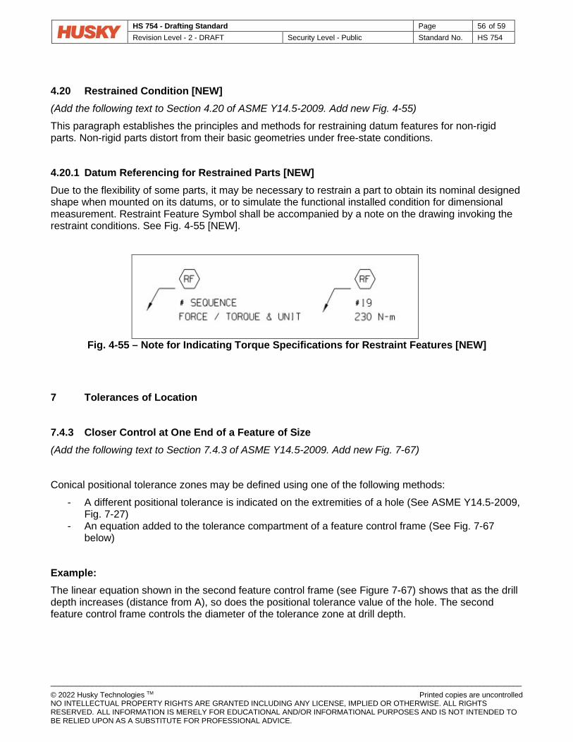
HS 754 - Drafting Standard Page 56 of 59 Revision Level - 2 - DRAFT Security Level - Public Standard No. HS 754
_________________________________________________________________________________________________________________ © 2022 Husky Technologies TM Printed copies are uncontrolled NO INTELLECTUAL PROPERTY RIGHTS ARE GRANTED INCLUDING ANY LICENSE, IMPLIED OR OTHERWISE. ALL RIGHTS RESERVED. ALL INFORMATION IS MERELY FOR EDUCATIONAL AND/OR INFORMATIONAL PURPOSES AND IS NOT INTENDED TO BE RELIED UPON AS A SUBSTITUTE FOR PROFESSIONAL ADVICE.
4.20 Restrained Condition [NEW] (Add the following text to Section 4.20 of ASME Y14.5-2009. Add new Fig. 4-55)
This paragraph establishes the principles and methods for restraining datum features for non-rigid parts. Non-rigid parts distort from their basic geometries under free-state conditions. 4.20.1 Datum Referencing for Restrained Parts [NEW] Due to the flexibility of some parts, it may be necessary to restrain a part to obtain its nominal designed shape when mounted on its datums, or to simulate the functional installed condition for dimensional measurement. Restraint Feature Symbol shall be accompanied by a note on the drawing invoking the restraint conditions. See Fig. 4-55 [NEW].
Fig. 4-55 – Note for Indicating Torque Specifications for Restraint Features [NEW]
7 Tolerances of Location 7.4.3 Closer Control at One End of a Feature of Size (Add the following text to Section 7.4.3 of ASME Y14.5-2009. Add new Fig. 7-67)
Conical positional tolerance zones may be defined using one of the following methods: - A different positional tolerance is indicated on the extremities of a hole (See ASME Y14.5-2009,
Fig. 7-27) - An equation added to the tolerance compartment of a feature control frame (See Fig. 7-67
below) Example: The linear equation shown in the second feature control frame (see Figure 7-67) shows that as the drill depth increases (distance from A), so does the positional tolerance value of the hole. The second feature control frame controls the diameter of the tolerance zone at drill depth.

HS 754 - Drafting Standard Page 57 of 59 Revision Level - 2 - DRAFT Security Level - Public Standard No. HS 754
_________________________________________________________________________________________________________________ © 2022 Husky Technologies TM Printed copies are uncontrolled NO INTELLECTUAL PROPERTY RIGHTS ARE GRANTED INCLUDING ANY LICENSE, IMPLIED OR OTHERWISE. ALL RIGHTS RESERVED. ALL INFORMATION IS MERELY FOR EDUCATIONAL AND/OR INFORMATIONAL PURPOSES AND IS NOT INTENDED TO BE RELIED UPON AS A SUBSTITUTE FOR PROFESSIONAL ADVICE.
This on the drawing: Means this:
Fig. 7-67 Specifying a Conical Tolerance Zone with an Equation
7.6.4 Concentricity [REPLACE] (The method in SECTION 7.6.4 of ASME Y14.5-2009 shall not be used)
Use position or runout to control coaxial features instead.
7.7 Tolerancing for Symmetrical Relationships [REPLACE] (The method in SECTION 7.7 of ASME Y14.5-2009 shall not be used)
9 Type of Runout Tolerances 9.4.2.4 Total Runout Tolerance Applied on Unit Basis [NEW] (Add the following text to Section 9.4.2 of ASME Y14.5-2009. Add new Fig. 9-8) Total runout may be applied on a unit basis as a means of limiting an abrupt surface variation within a relatively small portion of a long round feature. The unit variation is used either in combination with a specified total variation, or alone. The unit length is specified to the right of the runout tolerance, separated by a slash.

HS 754 - Drafting Standard Page 58 of 59 Revision Level - 2 - DRAFT Security Level - Public Standard No. HS 754
_________________________________________________________________________________________________________________ © 2022 Husky Technologies TM Printed copies are uncontrolled NO INTELLECTUAL PROPERTY RIGHTS ARE GRANTED INCLUDING ANY LICENSE, IMPLIED OR OTHERWISE. ALL RIGHTS RESERVED. ALL INFORMATION IS MERELY FOR EDUCATIONAL AND/OR INFORMATIONAL PURPOSES AND IS NOT INTENDED TO BE RELIED UPON AS A SUBSTITUTE FOR PROFESSIONAL ADVICE.
For example:
This on the drawing:
Means this:
Fig. 9-8 Specifying Runout Tolerance on a Unit Basis

HS 754 - Drafting Standard Page 59 of 59 Revision Level - 2 - DRAFT Security Level - Public Standard No. HS 754
_________________________________________________________________________________________________________________ © 2022 Husky Technologies TM Printed copies are uncontrolled NO INTELLECTUAL PROPERTY RIGHTS ARE GRANTED INCLUDING ANY LICENSE, IMPLIED OR OTHERWISE. ALL RIGHTS RESERVED. ALL INFORMATION IS MERELY FOR EDUCATIONAL AND/OR INFORMATIONAL PURPOSES AND IS NOT INTENDED TO BE RELIED UPON AS A SUBSTITUTE FOR PROFESSIONAL ADVICE.
The entire surface must lie within a 0.4 tolerance zone (0.4 full indicator movement) when the part is rotated 360° about the datum axis with the indicator placed at every location along the entire length of the surface in a position normal to the true geometric shape without reset of the indicator. The feature must be within the specified limits of size. Additionally the surface must lie within a 0.1 tolerance zone (0.1 full indicator movement) when the part is rotated 360° about the datum axis with the indicator placed at every location over any 25 mm length of the surface in a position normal to the true geometric shape without reset of the indicator.


