Embed Size (px)
Citation preview
(19)
Europaisches Patentamt
European Patent Office
Office europeen des brevets
(12)
peen des brevets (1 1 } E P 0 6 6 3 1 1 5 B 1
EUROPEAN PATENT S P E C I F I C A T I O N
(45) Date of publication and mention of the grant of the patent: 19.08.1998 Bulletin 1998/34
(21) Application number: 94922397.8
(22) Date of filing: 30.06.1994
(51) Intel e H02J 3 /36
(86) International application number: PCT/SE94/00649
(87) International publication number: WO 95/04395 (09.02.1995 Gazette 1995/07)
(54) HVDC TRANSMISSION
HOCHSPANNUNGSGLEICHSTROMUBERTRAGUNG
TRANSMISION DE C.C. A HAUTE TENSION
(84) Designated Contracting States: DE FR GB ITSE
(30) Priority: 03.08.1993 US 101072
(43) Date of publication of application: 19.07.1995 Bulletin 1995/29
(73) Proprietor: ASEA BROWN BOVERI AB 721 83 Vasteras (SE)
(72) Inventors: • BERGDAHL, Bernt
S-771 43 Ludvika (US) • BJORKLUND, Per-Erik
S-791 32 Falun (SE)
DO lO
CO CO CO o a . LU
• VITHAYATHIL, John, J. Portland, OR 97230 (US)
• STROM, Urban S-772 70 Saxdalen (SE)
(74) Representative: Boecker, Joachim, Dr.-lng. Adelonstrasse 58 65929 Frankfurt am Main (DE)
(56) References cited: CH-A- 663 864 US-A-2 419 464
• KIMBARK, Direct Current Transmission, Volume 1, 1971, Wiley-lnterscience, New York, pages 9-1 1 , Constitution of EHV AC and DC Links, see page 9, lines 11-15.
Note: Within nine months from the publication of the mention of the grant of the European patent, any person may give notice to the European Patent Office of opposition to the European patent granted. Notice of opposition shall be filed in a written reasoned statement. It shall not be deemed to have been filed until the opposition fee has been paid. (Art. 99(1) European Patent Convention).
Printed by Jouve, 75001 PARIS (FR)
1 EP0 663 115 B1 2
Description
TECHNICAL FIELD
The present invention relates to an HVDC transmis- sion comprising at least two converters, each converter being connected between an alternating-voltage net- work and a direct-current link common to the converters, at least a first converter being connected to its alternat- ing-voltage network without the use of any separate winding transformer.
In this application the concept "HVDC transmission" relates to an electric plant or equipment for power trans- mission by means of high-voltage direct current. The concept comprises two main types of plants. The first of these types consists of plants adapted for power trans- mission between two or more converter stations, which are located in spaced relationship to each other and which are interconnected by means of direct-current carrying cables or overhead lines. The second type con- sists of so-called back-to-back connections, in which two converters arranged in the same converter station are each connected to their own alternating-voltage net- work and are interconnected on their d.c. sides and adapted for controllable power transmission between the alternating-voltage networks.
In the first type of plants, the d.c. link consists of the cable/cables or lines which connect the d.c. sides of the converter stations. In the second type of plants, the d. c. link generally consists of only one pair of busbars in the station. However, in both cases the d.c. link com- prises, in a known manner, certain devices for smooth- ing and filtering of the direct current, for current and volt- age measurement, for protection against overvoltages, etc.
The fact that a converter is connected to its alter- nating-voltage network "without the use of any separate winding transformer" means that the converter is con- nected to the alternating-voltage network in some other way than by means of an separate winding transformer. Thus, a converter which is connected without the use of any separate winding transformer may have its alternat- ing-voltage terminals galvanically connected to the al- ternating-voltage network, directly or via an autotrans- former, and possibly via inductors for current limitation. Alternatively, a converter which is connected without the use of any separate winding transformer may have its alternating-voltage terminals connected to the alternat- ing-voltage network via series capacitors.
Analogously, the concept "transformerless" con- nection is used in this application in the event that no transformer of any kind, thus neither a separate winding transformer nor an auto transformer, is used for connec- tion of a converter to its alternating voltage terminal. Thus, in this case the converter may have its alternating- voltage terminals galvanically connected to the alternat- ing-voltage network, or via series capacitors.
BACKGROUND ART
In an HVDC transmission, each one of the convert- ers usually consists of two series-connected six-pulse
5 bridges. Each bridge is connected to the alternating- voltage network via a separate winding transformer. The transformers of the bridges (or the valve windings of a common transformer) are designed with different con- nections (usually star and delta connections, respec-
10 tively) in such a way that the alternating voltages of the bridges are subjected to a 30° phase shift and the con- verter hence becomes a twelve-pulse converter. HVDC transmissions of this kind are amply described in the lit- erature, for example in Erich Uhlmann: "Power Trans-
15 mission by Direct Current", Springer-Verlag Berlin Hei- delberg New York 1975 (see, e.g., Fig. 2.7, p. 15, or Fig. B.1, p. 187).
Since the converter bridges are connected to the alternating-voltage network via transformers, a possibil-
20 ity of technical-economic optimization of the direct volt- age and direct current levels of the transmission is ob- tained. Since the converter bridges are connected to the alternating-voltage network via separate winding trans- formers, a galvanic separation is obtained between the
25 bridges and the alternating-voltage network. This means that, in the manner described above, two con- verter bridges can be d.c. -series-connected and thus that higher resultant pulse numbers and a reduction of the harmonic content (theoretically an elimination of the
30 lowest harmonics) can be obtained. In this way, the amount of filter equipment can be reduced, which is im- portant since the cost of the filter equipment constitutes an important part of the total cost of a typical HVDC plant. The galvanic separation also means that a con-
35 verter cannot generate a direct cu rrent in the alternating- voltage network, which would involve a risk of certain disturbances, such as transformer saturation.
The advantages of the type of converter station de- scribed above have caused it to become practically uni-
40 versally prevailing in HVDC plants. In a dissertation entitled "HGU-Kurzkupplung ohne
Transformatoren", by Dipl.-lng. Knut Gebhardt, Tech- nische Hochschule Darmstadt, 1976/1977, it has been proposed to connect the converters in a transformerless
45 manner in a back-to-back connection. In this disserta- tion, the above-described conventional connection is shown in Figure 1 , page 4, and examples of a transfor- merless connection are shown in Figure 2, page 5. At first sight, the transformerless connection is economi-
se cally advantageous since the relatively high cost of the converter transformers is eliminated. However, the con- nection has several disadvantages, which have caused the connection not to be used to any significant degree in practice. First of all, the direct-voltage level of the
55 plant is determined by the voltage in the alternating-volt- age networks, which means that there is no possibility of optimization of the d.c. link and the converters with respect to voltage and current. Secondly, a transformer-
2
3 EP0 663 115 B1 4
less HVDC plant is limited to six-pulse operation of the converters, which results in the existence of harmonics of low orders (5 and 7), which necessitate considerably more costly equipment for harmonic filtering. Thirdly, in a plant of this kind, third tone currents (harmonic cur- s rents of the orders 3, 9, 15, 21 ...) are generated on the d.c. side of a converter. These currents flow out into the alternating-voltage network of the converter. In this net- work, the currents are of zero-sequence type and give rise to considerable drawbacks in the form of telecom- 10 munication disturbance and voltage distortion in the net- work. In less strong alternating-voltage networks, the voltage distortion becomes such a serious disadvan- tage that the transformerless connection cannot be used without taking special steps. 15
However, it is, of course, possible to arrange filters for the above-mentioned third-tone currents. Such a fil- ter can thus be arranged on the a.c. side of a converter. However, the filter is large and expensive, and it has proved difficult to avoid resonance effects between the 20 filter and the alternating-voltage network. Alternatively, a third-tone filter can be arranged in the form of a sup- pression filter on the d.c. side of the converter. Also in this case, the dimensions and costs of the filter equip- ment are high, and a considerable risk of resonance ef- 25 fects arises. These facts contribute to the transformer- less connection only being considered possible in con- nection with strong alternating-voltage networks.
SUMMARY OF THE INVENTION 30
The invention aims to provide an HVDC transmis- sion which is simpler and less expensive than hitherto used transmissions while at the same time, by reducing or completely avoiding the above-described network 35 disturbances on the alternating-voltage side (in the form of telecommunication disturbances and voltage distor- tion), it can be used also with weak alternating-voltage networks.
What characterizes an HVDC transmission accord- 40 ing to the invention will become clear from the appended claims.
BRIEF DESCRIPTION OF THE DRAWINGS 45
In the following the invention will be described in greater detail with reference to the accompanying draw- ings, wherein
Figure 4 shows the design of one phase of the har- monic filter in the back-to-back connection accord- ing to Figure 2,
Figures 5a and 5b show an example of the design of the blocking inductor in the back-to-back connec- tion in Figure 2,
Figure 6 schematically shows an HVDC transmis- sion consisting of two geographically separated converter stations which are interconnected by a line,
Figure 7 shows an HVDC transmission according to the invention, in which the converters are con- nected to their alternating-voltage networks via se- ries capacitors,
Figure 8 shows a converter station in a bipolar HVDC transmission according to the invention, and
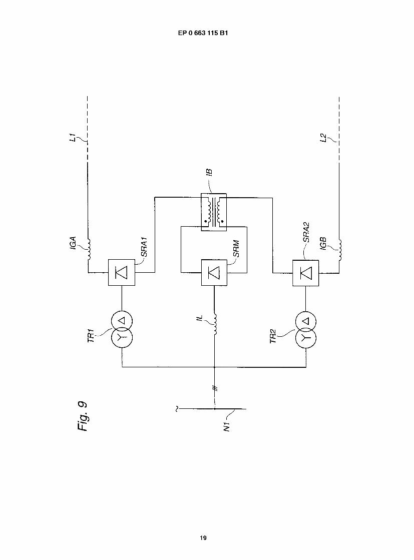
Figure 9 shows a bipolar converter station with a transformerless main converter bridge and two aux- iliary converter bridges, the latter being connected to the a.c. network through separate winding trans- formers.
DESCRIPTION OF THE PREFERRED EMBODIMENTS
With reference to Figure 1, the concepts ground mode current and pole mode current, which admittedly are being generally used, will first be defined. A convert- er SR has the d.c. supply lines DL1 and DL2 as well as the a.c. supply lines VLR, VLS and VLT. The currents, flowing in the d.c. supply lines at a certain moment, have -the instantaneous values il and i2, respectively. Both currents are defined by their positive directions out from the converter. The pole mode current on the alternating- voltage side of the converter is then (i 1 -i2)/2. The ground mode current on the direct-voltage side of the converter is (i1+i2)/2.
Figure 2 shows in the form of a single-line diagram a back-to-back connection according to the invention. It is intended for controllable power transmission between two three-phase electric a.c. power networks N1 and N2. It comprises two controllable high-voltage convert- ers SR1 and SR2, arranged in one and the same con- verter station. The a.c. supply conductors VL1 and VL2 of the converters are connected to the respective alter- nating-voltage networks N1 and N2 via current-limiting inductors IL1 and IL2. Further, on their a.c. side each converter has a schematically shown harmonic filter, F1 and F2, respectively. The d.c. terminals LL1 P, LL1 N and LL2P, LL2N, respectively, of the converters are intercon- nected via conductors L1 and L2, which consist of bus- bars or the like in the converter station. In one of these conductors, a smoothing inductor IG for the direct cur-
Figure 1 illustrates the concepts ground mode cur- so rent and pole mode current,
Figure 2 shows a back-to-back connection accord- ing to the invention,
55 Figure 3 shows one of the converters in the back- to-back connection according to Figure 2,
30
3
5 EP0 663 115 B1 6
rent is arranged in conventional manner. Further, the plant is provided with an inductor IB for blocking of the ground mode current. This inductor has two windings IB1 and IB2, which are each connected into a respective one of the two d.c. conductors L1 and L2, and which have the winding directions marked in the figure. The inductor is designed such that its two windings are mag- netically well coupled to each other and such that the windings are symmetrical in relation to each other. In this way, the inductor will have a high impedance to ground mode currents, both to fundamental and to har- monic components, and, in principle, a low impedance to pole mode currents.
In this way, the inductor IB will effectively block the ground mode currents and in this way greatly reduce the zero-sequence currents on the a.c. sides of the convert- ers and hence the initially mentioned disturbances which these currents cause in the alternating-voltage network. This makes it possible to use a transformerless HVDC transmission for connection not only to very strong alternating-voltage networks but also to weaker networks.
Figure 3 shows the main circuit of the converter SR1 in the back-to-back connection according to Figure 2. The converter is a converter of the same kind as used at present in HVDC transmissions. It is a six-pulse line- commutated phase-angle controlled thyristor converter with the valves TY1 - TY6. Each valve consists of a plu- rality of series-connected thyristors with parallel-con- nected damping circuits and overvoltage protection. The converter has the d.c. connections LL1 P and LL1 N and the a.c. connections VL1R, VL1S, VL1T. The con- verter SR2 is designed in the same way.
The current-limiting inductors IL1 and IL2 replace the impedance of the converter transformer of conven- tional HVDC transmissions. The inductors may suitably be designed as air inductors and are given an induct- ance so adapted that the inductors limit the valve cur- rents to harmless values in connection with the types of faults which may occur, for example short circuit or ground fault.
Figure 4 shows an example of the design of one phase F1 R in the filter circuit F1 in the back-to-back con- nection according to Figure 2. It is connected to the a. c. conductor LR between the network N1 and the con- verter SR1. The filter circuit consists of double-tuned band-pass filters for the tones 5 and 7 (BP5/7), 11 and 13 (BP11/13) and the tones 17 and 19 (BP17/19), and double-tuned high-pass filters for the tones 24 and 42 (HP24/42) and for the tones 30 and 36 (HP30/36). The high-pass filters are suitably designed so as to provide sufficient damping also for the tones of the orders 47 and 49.
To achieve the desired function, it is important that the blocking inductor IB in Figure 2 is designed such that a good magnetic coupling is obtained between the two windings of the inductors. Further, it is important to achieve a high degree of symmetry between the two
windings of the inductor. Figures 5a and 5b show an ex- ample of the design of the blocking inductor, in which both of these requirements are fulfilled. Figure 5a shows a section through the inductor in th.e pla.ne which con-
5 tains the axes of rotational symmetry of the windings. Figure 5b shows the inductor as viewed in the direction of the axes of rotational symmetry. The inductor has an iron core IB3. The windings IB1 and IB2 each consist of two series-connected winding halves. On a first core leg,
10 one half IB1A of the winding IB1 and one half IB2A of the winding I B2 are arranged with the winding IBIAout- side the winding IB2A. On a second core leg the second half IB1 B of the winding IB1 and the second half IB2B of the winding IB2 are arranged with the winding IB2B
is outside the winding IB1 B. Since the winding halves on each core leg are arranged close to each other, a good magnetic coupling is obtained between the windings. Since the radial mutual positions of the windings are op- posite to each other in the two core legs, the desired
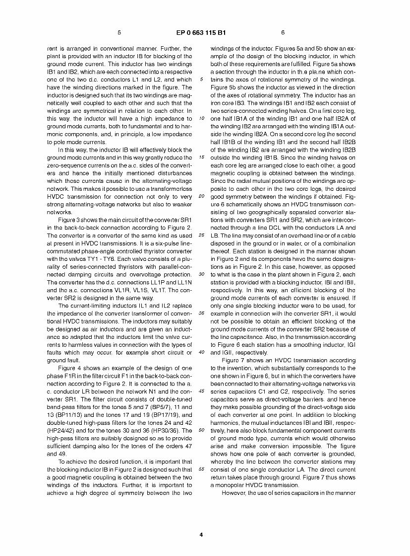
20 good symmetry between the windings if obtained. Fig- ure 6 schematically shows an HVDC transmisson con- sisting of two geographically separated converter sta- tions with converters SR1 and SR2, which are intercon- nected through a line DCL with the conductors LA and
25 LB. The line may consist of an overhead line or of a cable disposed in the ground or in water, or of a combination thereof. Each station is designed in the manner shown in Figure 2 and its components have the same designa- tions as in Figure 2. In this case, however, as opposed
30 to what is the case in the plant shown in Figure 2, each station is provided with a blocking inductor, IBI and IBM, respectively. In this way, an efficient blocking of the ground mode currents of each converter is ensured. If only one single blocking inductor were to be used, for
35 example in connection with the converter SR1 , it would not be possible to obtain an efficient blocking of the ground mode currents of the converter SR2 because of the line capacitance. Also, in the transmission according to Figure 6 each station has a smoothing inductor, IGI
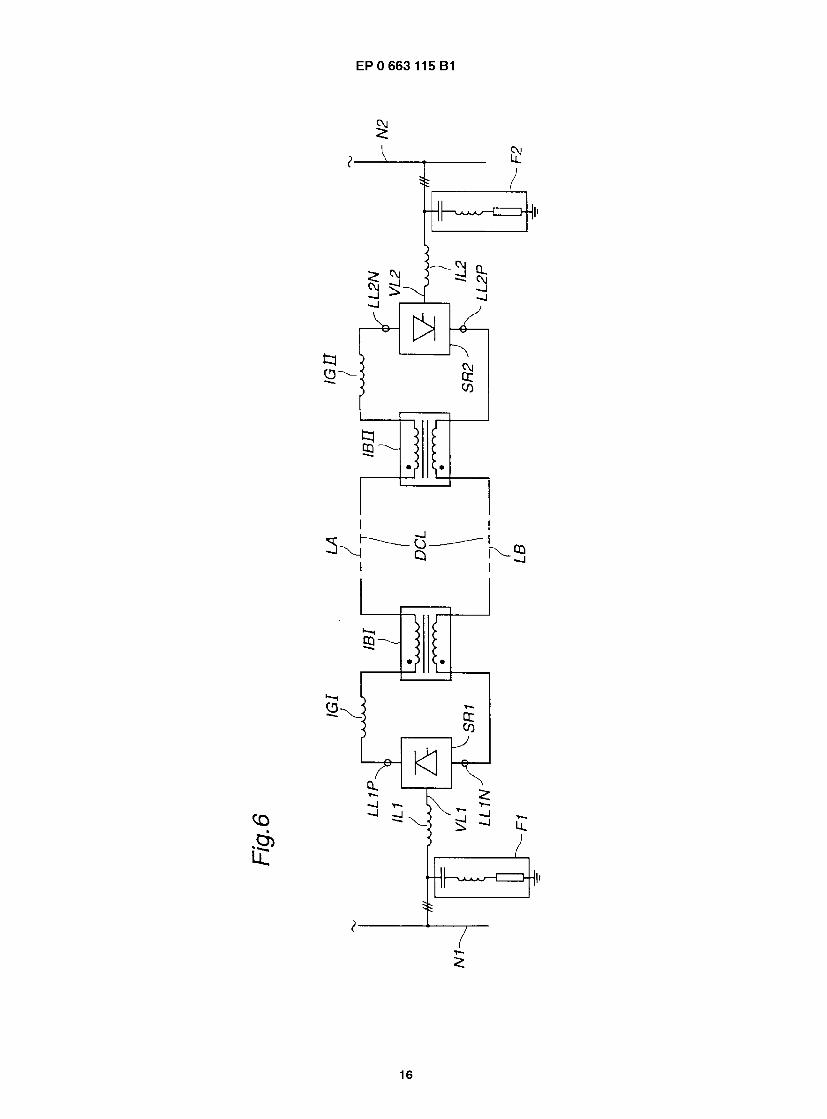
40 and IGII, respectively. Figure 7 shows an HVDC transmission according
to the invention, which substantially corresponds to the one shown in Figure 6, but in which the converters have been connected to their alternating-voltage networks via
45 series capacitors C1 and C2, respectively. The series capacitors serve as direct-voltage barriers, and hence they make possible grounding of the direct-voltage side of each converter at one point. In addition to blocking harmonics, the mutual inductances IBI and IBM, respec-
50 tively, here also block fundamental component currents of ground mode type, currents which would otherwise arise and make conversion impossible. The figure shows how one pole of each converter is grounded, whereby the line between the converter stations may
55 consist of one single conductor LA. The direct current return takes place through ground. Figure 7 thus shows a monopolar HVDC transmission.
However, the use of series capacitors in the manner
4

7 EP0 663 115 B1 8
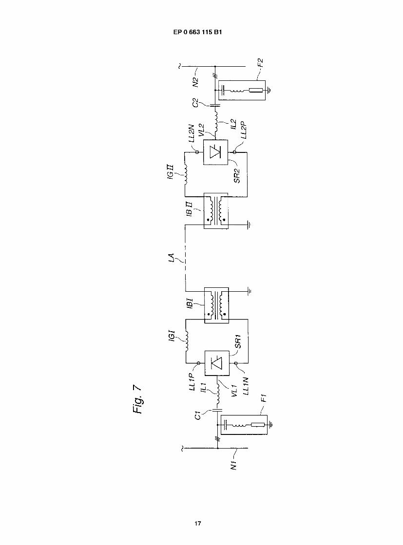
described with reference to Figure 7 also makes possi- ble the use of the invention in a bipolar HVDC transmis- sion. One of the two converter stations in such a trans- mission is shown in Figure 8. It has two converters, SR1 and SR2. Each one of them is connected to the network s N1 via a series capacitor, C1A and C1B, respectively, and a current-limiting inductor, ILIAand IL1B, respec- tively. Filter equipment F1, common to the converters, for harmonic filtering is connected to the alternating- voltage side of the converters. Each converter is provid- 10 ed with a blocking inductor, IBIAand I BIB, respectively, designed in the manner described above, and with a smoothing inductor, IGAand IGB, respectively. The sta- tion has a ground electrode GA, which is connected to the station by a ground line LG. The converter SR1A 15 has one of its direct-voltage connections connected to one conductor LA of the transmission line via one of the windings of the inductor IBI A and the other direct-volt- age connection connected to the ground line LG via the other winding of the inductor. The converter SR1 B has 20 one of its direct-voltage connections connected to the other conductor LAB of the transmission line via one of the windings of the inductor I BIB and the other direct- voltage connection connected to the ground line LG via the other winding of the inductor. 25
The above description relates exclusively to such embodiments of the invention in which all the converters included in the HVDC transmission are connected in a transformerless manner - either directly galvanically or via series capacitors - to their respective alternating- 30 voltage networks. However, also other embodiments are feasible within the scope of the invention.
Thus, for example, a converter may be connected to its alternating-voltage network via an autotransform- er. Such an embodiment offers the advantages that the 35 current and voltage levels of the d.c. link and the con- verter can be chosen independently of the voltage of the alternating-voltage network, that therefore the transmis- sion can be used for power transmission between alter- nating-voltage networks with different voltages, that the 40 current-limiting inductors described above (e.g. IL1 in Fig. 2) may become superfluous, and that a tap changer of the transformer can be used to take up changes in the ratio of the direct voltage of the converter to the volt- age of the alternating-voltage network, which provides 45 a possibility of working with more optimal control angles of the converter from the reactive power point of view. Since autotransformers are considerably less expen- sive than separate winding transformers, also in this case a considerable cost saving is obtained compared so with conventional HVDC transmissions with separate winding transformers.
The converters at both ends of a d.c. link may be connected to their alternating-voltage networks via au- totransformers, or the converter at one end of the link 55 only, in which case the converter at the other end of the link is either transformerless or connected to its alter- nating-voltage network via a separate winding trans-
former. As mentioned above, one of the converters of a
transmission may be connected to its alternating-volt- age network via a separate winding transformer. The converter at the other end of the link may thereby either be transformerless or also be connected via an au- totransformer. The tap changer of the full transformer can thereby be utilized to take up variations in the volt- age of the alternating-voltage network and the reactive power consumption thus be kept low, the d.c. link and the converters can be optimized independently of the voltage of the alternating-voltage network, and for the converter which is connected while using a separate winding transformer, no mutual inductor is needed for blocking the effect on the alternating-voltage network exerted by the link.
Figure 9 shows an alternative way of balancing the direct current. According to this alternative, a transfor- merless converter bridge SRM (main bridge) is provided with two auxiliary bridges SRA1 and SRA2, which are provided with separate winding transformers and d.c- connected in series with the converter bridge. The main bridge SRM is connected to the three-phase network N1 via a current-limiting inductor IL. The auxiliary bridges are connected to the network via the Y/A-connected separate winding transformers TR1 and TR2, respec- tively. The d.c. supply lines of the main bridge are con- nected to a mutual inductor IB in the same way as de- scribed above.
The auxiliary bridges may have a considerably low- er rated power than the main bridge. The auxiliary bridg- es are preferably controlled in such a way that the direct currents in the two d.c. lines L1 and L2 of the converter station are always maintained as equal as possible.
If the rated power of each one of the auxiliary bridg- es is half as great as that of the main bridge, and if the separate winding transformers are Y/A-connected, 12-pulse operation can almost be obtained and a large part of the 5th and 7th tones can be eliminated.
If the separate winding transformers of the auxiliary bridges are provided with tap changers with a wide con- trol range, these tap changers can be utilized for com- pensating for variations in the alternating voltage of the network, however, at the expense of the 5th and 7th tone elimination.
In the embodiments of the invention described in this application, separate smoothing inductors, for ex- ample IG in Figure 2, have been arranged for smoothing the direct current. Alternatively, the function of a smooth- ing inductor can be obtained by designing the mutual inductance in a suitable way. As described above, the mutual inductor has an impedance to pole mode cur- rents which is low, and which is zero if the mutual induc- tor is ideal. By designing this inductor with a suitably adapted leakage inductance, it can be caused to provide the desired smoothing of the direct current, and a sep- arate smoothing inductor can then be avoided.
In the embodiments of an HVDC transmission ac-
5

9 EP0 663 115 B1 10
cording to the invention, in which a converter is not con- nected to its alternating-voltage network via a transform- er provided with a tap changer, variations in the ratio of the voltage of the alternating-voltage network to the volt- age of the d.c. link must be taken up by means of vari- ations of the control angle of the converter. This results in a undesirable increase of the reactive power con- sumption of the converter and/or of the variations of this consumption. If considered necessary, these disadvan- tages can be counteracted or eliminated by providing the converter on its alternating-voltage side with control- lable reactive power means known per se, such as ca- pacitors, inductors, or, for example, a combination of switched capacitors and phase-angle controlled induc- tors.
In those cases where an HVDC transmission ac- cording to the invention has a transformerless connec- tion of the converter at one end of the d.c. link and a converter connection via a transformer, provided with a tap changer, at the other end of the link, it is suitable to allow the first-mentioned converter to work with a fixed control angle so chosen that the reactive power con- sumption is minimized, whereby variations in the ratio of the voltages of the alternating-voltage networks are taken up by the tap changer.
It has been found that the reaction on the alternat- ing-voltage network by the HVDC transmission can be maintained especially low if a connection without the use of any separate winding transformer according to the invention is provided with a control system which controls each one of the two halves of a six-pulse con- verter individually in such a way that the direct currents in the two d.c. supply lines of the converter are always maintained as equal as possible.
Claims
1 . An HVDC transmission with at least two converters (SR1, SR2), wherein each converter is connected between an alternating-voltage network (N1, N2) and a d.c. link (L1 , L2) common to the converters, and wherein at least a first converter is connected to its alternating-voltage network without the use of any separate winding transformer, characterized in that the transmission comprises at least one mu- tual inductor (IB) arranged on the d.c. side of said first converter, said mutual inductor having two windings (IB1 , IB2) which are each connected to a respective one of the d.c. supply lines of the first converter, said windings having a good magnetic coupling to each other and a high degree of sym- metry, thus exhibiting a high impedance to ground mode currents.
2. An HVDC transmission according to claim 1 , which is designed with at least two converters (SR1 , SR2) in a back-to-back connection, characterized in that
both of said at least two converters are connected to their alternating-voltage networks without the use of any separate winding transformers, and that said at least one mutual inductor (IB), common to said
5 converters, is arranged in the d.c. connection (L1, L2) between said converters.
3. An HVDC transmission according to claim 1 , which comprises a d.c. line (DCL) which connects said at
10 least two converters (SR1, SR2), which are geo- graphically separated from each other, character- ized in that each of said at least two converters is connected to its alternating-voltage network without the use of any separate winding transformer, and is
is associated with said at least one mutual inductor (IBI, IBM) connected into the d.c. sides of said con- verters.
4. An HVDC transmission according to any of the pre- 20 ceding claims, characterized in that at least one of
said at least two converters is connected to its al- ternating-voltage network via series capacitors (C1 , C2) arranged in the a.c. supply lines of said con- verter.
25 5. An HVDC transmission according to claim 4, de-
signed as a bipolar transmission and with at least one converter station with each one of said at least two converters (SR1 A, SR1 B) being d.c. -connected
30 between one of the two pole conductors (LA, LB) of the transmission and a common ground line (LG), characterized in that each cf said at least two con- verters in the station is connected to the alternating- voltage network (N1 ) of the station via series capac-
35 itors (C1 A, C1 B) arranged in the a.c. supply lines of said converters.
6. An HVDC transmission according to claim 5, char- acterized in that each of said at least two convert-
40 ers of the at least one converter station is associat- ed with a mutual inductor (IBIA, IBIB) which has one of its windings connected into the pole conductor (e.g. LA) connected to its associated converter, and its other winding connected into the current path be-
45 tween its associated converter and the common ground line (LG).
7. An HVDC transmission according to claims 1 , 3, or 4, when claim 4 depends on claim 1 or 3, charac-
50 terized in that it comprises a converter station with a first bridge (SRM) which is connected, without the use of any separate winding transformer, to its al- ternating-voltage network (N1 ) and which is d.c. -se- ries-connected to a second bridge (SRA1), which
55 via a first separate winding transformer (TR1) is connected to the alternating-voltage network (N1).
8. An HVDC transmission according to claim 5 or 6,
6

11 EP0 663 115 B1 12
when claim 4 depends on claim 1 or 3, character- ized in that the converter station comprises a first bridge (SRM) which is connected, without the use of any separate winding transformer, to its alternat- ing-voltage network (N1) and which is d.c. -series- connected to a second bridge (SRA1), which via a first separate winding transformer (TR1 ) is connect- ed to the alternating-voltage network (N1).
9. An HVDC transmission according to claim 7 or 8, characterized in that said second bridge (SRA1) has one of its d.c. supply lines connected to said first bridge (SRM) via a winding of said at least one mutual inductor (IB) and its other d.c. lead connect- ed to a first conductor (L1) of the d.c. link, that the converter station comprises a third bridge (SRA2) which has one of its d.c. supply lines connected to said first bridge (SRM) via a second winding of said at least one mutual inductor and its other d.c. lead connected to a second conductor (L2) of the d.c. link, and in that the third bridge (SRA2) is connected to the alternating-voltage network (N1 ) via a second separate winding transformer (TR2).
10. An HVDC transmission according to claim 9, char- acterized in that said separate winding transform- ers of said second and third bridges are Y/A-con- nected.
11. An HVDC transmission according to claim 9, char- acterized in that said second and third bridges are designed for lower rated power than said first bridge.
12. An HVDC transmission according to any of the pre- ceding claims, characterized in that a current-lim- iting reactor (e.g. IL1 ) is arranged in the a.c. supply lines to said first converter (SR1 ).
13. An HVDC transmission according to any of the pre- ceding claims, in which each of said at least two converters (SR1, SR2) is provided on its alternat- ing-voltage side with harmonic filter circuits (F1 , F2) adapted for filtering of tones of the orders 6m+1, where m is a positive integer, characterized in that the filter circuits of said first converter comprise fil- ters for tones of the orders 5 and 7.
Patentanspriiche
1. HGU-Anlage mit mindestens zwei Stromrichtern (SR1 , SR2), wobei jeder Stromrichter zwischen ein Wechselspannungsnetz (N1, N2) und einem Gleichstromverbindungsglied (L1, L2), das fur bei- de Stromrichter gemeinsam ist, geschaltet ist und wobei zumindest ein erster Stromrichter an sein Wechselspannungsnetz ohne Verwendung eines
Transformators mit getrennten Wicklungen ange- schlossen ist, dadurch gekennzeichnet, dal3 die Ubertragungsanlage zumindest einen gegenseiti- gen Induktor (IB) enthalt, der auf der Gleichstrom-
5 seite des genannten ersten Stromrichters angeord- net ist und der zwei Wicklungen (IB1 , IB2) hat, von denen jede an eine entsprechende Gleichstromver- sorgungsleitung des ersten Stromrichters ange- schlossen ist, wobei diese Wicklungen eine gute
10 magnetische Kopplung miteinander und einen ho- hen Grad an Symmetrie haben, so dal3 sie eine ho- he Impedanz gegenuber Erdmodusstromen bilden.
2. HGU-Anlage nach Anspruch 1, die mindestens is zwei zueinander gegensinnig gepolte Stromrich-
tern (SR1, SR2) enthalt, dadurch gekennzeich- net, dal3 beide der genannten mindestens zwei Stromrichter ohne Verwendung von Transformato- ren mit getrennten Wicklungen an ihr jeweiliges
20 Wechselspannungsnetz angeschlossen sind und dal3 der genannte mindestens eine fur die genann- ten Stromrichter gemeinsame gegenseitige Induk- tor (IB) in der Gleichstromverbindung (L1, L2) zwi- schen beiden Stromrichtern angeordnet ist.
25 3. HGU-Anlage nach Anspruch 1 , zu der eine Gleich-
stromleitung (DCL) gehort, welche die genannten mindestens zwei Stromrichter (SR1, SR2), die raumlich voneinander getrennt sind, miteinander
30 verbindet, dadurch gekennzeichnet, dal3 jeder der genannten mindestens zwei Stromrichter an sein Starkstromnetz ohne Verwendung eines Transformators mit getrennten Wicklungen ange- schlossen ist und mit dem genannten auf der
35 Gleichstromseite der Stromrichter angeschlossen mindestens einen gegenseitigen Induktor (IBI, IBM) verbunden ist.
4. HGU-Anlage nach einem der vorhergehenden An- 40 spruche, dadurch gekennzeichnet, dal3 minde-
stens einer der genannten mindestens zwei Strom- richter iiber Reihenkapazitaten (C1 , C2), die in den Wechselstromspeiseleitungen des genannten Stromrichters angeordnet sind, an sein Wechsel-
45 spannungsnetz angeschlossen ist.
5. HGU-Anlage nach Anspruch 4, die als bipolare Ubertragungsanlage und mit mindestens einer Stromrichterstation aufgebaut ist, wobei jeder der
so genannten mindestens zwei Stromrichter (SR1A, SR1B) gleichstromseitig zwischen einem der bei- den Polleiter (LA, LB) der Ubertragungsanlage und einer gemeinsamen Erdleitung (LG) angeschlos- sen ist, dadurch gekennzeichnet, dal3 jeder der
55 genannten mindestens zwei Stromrichter in der Station iiber Reihenkapazitaten (C1A, C1B), die in den Wechselstromversorgungsleitungen der ge- nannten Stromrichter angeordnet sind, an das
7

13 EP0 663 115 B1 14
Wechselstromnetz (N1) angeschlossen ist.
6. HGU-Anlage nach Anspruch 5, dadurch gekenn- zeichnet, dal3 jeder der genannten mindestens zwei Stromrichter der mindestens einen Stromrich- s terstation mit einem gegenseitigen Induktor (IBIA, IBIB) verbunden ist, dessen eine Wicklung in die Polleitung (z.B. LA) ihres zugehorigen Stromrichter geschaltet ist und dessen andere Wicklung in den Strompfad zwischen ihrem zugeordneten Strom- 10 richter und der gemeinsamen Erdleitung (LG) ge- schaltet ist.
7. HGU-Anlage nach Anspruch 1 , 3 oder 4, wobei An- spruch 4 von Anspruch 1 oder 3 abhangig ist, da- 15 durch gekennzeichnet, dal3 sie eine Stromrich- terstation mit einer ersten Brucke (SRM) enthalt, die ohne Verwendung eines Transformator mit ge- trennten Wicklungen an ihr Wechselspannungs- netz (N 1 ) angeschlossen ist und die gleichstromsei- 20 tig mit einer zweiten Brucke (SRA1) in Reihe ge- schaltet ist, die iiber einen ersten Transformator mit getrennten Wicklungen (TR1) an das Wechsel- spannungsnetz (N1) angeschlossen ist.
25 8. HGU-Anlage nach Anspruch 3 oder 5, wobei An-
spruch 4 von Anspruch 1 oder 3 abhangig ist, da- durch gekennzeichnet, dal3 die Stromrichterstat- ion eine erste Brucke (SRM) enthalt, die ohne Ver- wendung eines Transformator mit getrennten Wick- 30 lungen an ihr Wechselspannungsnetz (N1) ange- schlossen ist und die gleichstromseitig mit einer zweiten Brucke (SRA1) in Reihe geschaltet ist, die iiber einen ersten Transformator mit getrennten Wicklungen (TR1) an das Wechselspannungsnetz 35 (N1) angeschlossen ist.
9. HGU-Anlage nach Anspruch 7 oder 8, dadurch ge- kennzeichnet, dal3 die genannte zweite Brucke (SRA1) mit einer ihrer Gleichstromspeiseleitungen 40 iiber eine Wicklung des genannten mindestens ei- nen gegenseitigen Induktor (IB) an die genannte er- ste Brucke (SRM) angeschlossen ist und mit ihrem anderen GleichstromanschluB an einen ersten Lei- ter (L1) des Gleichstromverbindungsgliedes ange- 45 schlossen ist, dal3 die Stromrichterstation eine drit- te Brucke (SRA2) enthalt, deren eine Gleichstrom- speiseleitung iiber eine zweite Wicklung des ge- nannten mindestens einen gegenseitigen Induktor an die genannte erste Brucke (SRM) angeschlos- so sen ist und deren anderer GleichstromanschluB an einen zweiten Leiter (L2) des Gleichstromverbin- dungsgliedes angeschlossen ist und dal3 die dritte Brucke (SRA2) iiber einen zweiten Transformator mit getrennten Wicklungen (TR2) an das Wechsel- 55 spannungsnetz (N1) angeschlossen ist.
10. HGU-Anlage nach Anspruch 9, dadurch gekenn-
zeichnet, dal3 der genannte Transformator mit ge- trennten Wicklungen der genannten zweiten und dritten Brucke stern-dreick-geschaltet ist.
11. HGU-Anlage nach Anspruch 9, dadurch gekenn- zeichnet, dal3 die genannte zweite und dritte Briik- ke fur eine kleinere Nennleistung als die genannte erste Brucke ausgelegt sind.
12. HGU-Anlage nach einem der vorhergehenden An- spriiche, dadurch gekennzeichnet, dal3 ein strom- begrenzender Reaktor (z. B. IL1) in den Wechsel- stromspeiseleitungen des genannten ersten Strom- richter (SR1) angeordnet ist.
13. HGU-Anlage nach einem der vorhergehenden An- spriiche bei der jeder der genannten mindestens zwei Stromrichter (SR1, SR2) auf seiner Wechsel- spannungsseite mit Oberwellenfilterkreisen (F1, F2) versehen ist, die zur Filterung von Oberwellen mit den Ordnungszahlen 6m 1 beschaffen sind, wo- bei m eine positive ganze Zahl ist, dadurch ge- kennzeichnet, dal3 die Filterkreise des genannten ersten Stromrichters Filter fiir die fiinfte und sieben- te Oberwellen enthalt.
Revendications
1 . Dispositif de transmission a courant continu a haute tension (HVDC) comportant au moins deux conver- tisseurs (SR1 , SR2), dans lequel chaque convertis- seur est connecte entre un reseau (N1 , N2) a ten- sion alternative et une liaison (L1 ,L2) a courant con- tinu qui sont communs aux convertisseurs, et dans lequel au moins un premier convertisseur est con- necte a son reseau a tension alternative sans I'uti- lisation d'un transformateur a enroulement distinct, caracterise en ce que le dispositif de transmission comporte au moins une inductance (IB) mutuelle prevue sur le cote a courant continu du premier con- vertisseur, I'inductance mutuelle ayant deux enrou- lements (IB1, IB2) qui sont chacun connectes a I'une respective des lignes d'alimentation en cou- rant continu du premier convertisseur, les enroule- ments ayant un bon couplage magnetique I'un avec I'autre et un grand degre de symetrie, presentant ainsi une impedance elevee a des courants en mo- de de terre.
2. Dispositif de transmission HVDC suivant la reven- dication 1, qui est concu en comportant au moins deux convertisseurs (SR1, SR2) connectes en op- position, caracterise en ce que les deux convertis- seurs desdits au moins deux convertisseurs sont connectes a leur reseau a tension alternative sans I'utilisation de transformateur a enroulement dis- tinct, et en ce que ladite au moins une inductance
8

15 EP0 663 115 B1 16
(IB) mutuelle, commune aux convertisseurs, est prevue dans la connexion (L1 ,L2) a courant continu entre les convertisseurs.
3. Dispositif de transmission HVDC suivant la reven- dication 1 , qui comporte une ligne (DCL) a courant continu qui connecte lesdits au moins deux conver- tisseurs (SR1, SR2), qui sont geographiquement separes I'un de I'autre, caracterise en ce que cha- que convertisseur parmi lesdits au moins deux con- vertisseurs est connecte a son reseau a tension al- ternative sans I'utilisation d'un transformateur a en- roulement distinct, et est associe a ladite au moins une inductance (IBI, IBM) mutuelle connectee dans les cotes a courant continu des convertisseurs.
4. Dispositif de transmission HVDC suivant I'une quel- conque des revendications precedentes, caracteri- se en ce qu'au moins I'un desdits au moins deux convertisseurs est connecte a son reseau a tension alternative par I'intermediaire de condensateurs (C1 ,C2) en serie prevus dans les lignes d'alimenta- tion en courant alternatif du convertisseur.
5. Dispositif de transmission HVDC suivant la reven- dication 4, concu en tant que dispositif de transmis- sion bipolaire et comportant au moins un poste de convertisseur, chaque convertisseur parmi lesdits au moins deux convertisseurs (SR1 A, SR1 B) etant connecte en courant continu entre I'un des conduc- teurs des deux conducteurs (LA, LB) polaires du dispositif de transmission et une ligne (LG) de terre commune, caracterise en ce que chacun desdits au moins deux convertisseurs du poste est connecte au reseau (N1) a tension alternative du poste par I'intermediaire de condensateurs (C1 A,C1 B) en se- rie, prevus dans les lignes d'alimentation en courant alternatif des convertisseurs.
6. Dispositif de transmission HVDC suivant la reven- dication 5, caracterise en ce que chacun desdits au moins deux convertisseurs dudit au moins un poste de convertisseur est associe a une inductance (IBIAJBIB) mutuelle, quia I'un de ses enroulements connectes dans le conducteur (par exemple LA) po- laire connecte a son convertisseur associe, et son autre enroulement connecte dans le trajet de cou- rant entre son convertisseur associe et la ligne (LG) de terre commune.
7. Dispositif de transmission HVDC suivant la reven- dication 1 , 3 ou 4, lorsque la revendication 4 depend de la revendication 1 ou 3, caracterise en ce qu'il comporte un poste de convertisseur comportant un premier pont (SRM) qui est connecte, sans utilisa- tion d'un transformateur a enroulement distinct, a son reseau (N1) a tension alternative et qui est con- necte en serie en courant continu a un second pont
(SRA1) qui par I'intermediaire d'un premier trans- formateur (TR1 ) a enroulement distinct est connec- te au reseau (N1) a tension alternative.
5 8. Dispositif de transmission HVDC suivant la reven- dication 5 ou 6, lorsque la revendication 4 depend de la revendication 1 ou 3, caracterise en ce que le poste de convertisseur comporte un premier pont (SRM) qui est connecte, sans I'utilisation d'un trans-
10 formateur a enroulement distinct, a son reseau (N1) a tension alternative et qui est connecte en serie en courant continu a un second pont (SRA1), qui par I'intermediaire d'un premier transformateur (TR1 ) a enroulement distinct est connecte au reseau (N1 ) a
is tension alternative.
9. Dispositif de transmission HVDC suivant la reven- dication 7 ou 8, caracterise en ce que le second pont (SRA1 ) a I'une de ses lignes d'alimentation en
20 courant continu qui est reliee au premier pont (SRM) par I'intermediaire d'un enroulement de ladi- te au moins une inductance (IB) mutuelle et son autre conducteur a courant continu qui est connecte a un premier conducteur (L1 ) de la liaison a courant
25 continu, en ce que le poste de convertisseur com- porte un troisieme pont (SRA2) qui a I'une de ses lignes d'alimentation en courant continu qui est con- necte au premier (SRM) par I'intermediaire d'un se- cond enroulement de ladite au moins une inductan-
30 ce mutuelle et son autre conducteur a courant con- tinu qui est connecte a un second conducteur (L2) de la liaison a courant continu, et en ce que le troi- sieme pont (SRA2) est connecte au reseau (N1) a tension alternative par I'intermediaire d'un second
35 transformateur (TR2) distinct a enroulement.
10. Dispositif de transmission HVDC suivant la reven- dication 9, caracterise en ce que les transforma- teurs a enroulement distinct des deuxieme et troi-
40 sieme ponts sont connectes en Y/A.
11. Dispositif de transmission HVDC suivant la reven- dication 9, caracterise en ce que le deuxieme et le troisieme pont sont concus pour des puissances
45 nominales plus faibles que le premier pont ne Test.
12. Dispositif de transmission HVDC suivant I'une quel- conque des revendications precedentes, caracteri- se en ce qu'une reactance (par exemple IL1 ) a limi-
50 tation de courant est prevue dans les lignes d'ali- mentation en courant alternatif allant vers le pre- mier convertisseur (SR1 ).
13. Dispositif de transmission HVDC suivant I'une quel- 55 conque des revendications precedentes, dans le-
quel chacun desdits au moins deux convertisseurs (SR1 ,SR2) est muni de son cote a tension alterna- tive de circuits (F1 ,F2) formant filtres harmoniques
9

17 EP0 663 115 B1
adaptes pour filtrer des harmoniques d'ordre 6m+1 , ou m est un entier positif, caracterise en ce que les circuits filtres du premier convertisseur comportent des filtres pour des harmoniques des ordres 5 et 7.
5
10
15
20
25
30
35
40
45
50
10

EP0 663 115 B1
i i DC CO h- —J — I — I ^ S S
11

EP0 663 115 B1

EP0 663 115 B1
- J - J
13


EP0 663 115 B1
F i g . 5 a
IB1A I B 2 B
IB1A I B 2 A I B 2 B I B 1 B
I5
EP0 663 115 B1
16
EP0 663 115 B1
17
EP0 663 115 B1
18