Embed Size (px)
Citation preview

Three Hydraulic Engineering Masterpieces at 100 BC- AD 300 Nabataean Petra (Jordan)
Charles R. Ortloff CFD Consultants International, Ltd. Research Associate in Anthropology, University of Chicago 18310 Southview Avenue, Los Gatos, CA 95033, USA [email protected]
The history of Petra’s monumental architecture and historical development has been described by many authors (Browning 1982, Gluuck 1965, Guzzo and
Schneider 2002, Hammond 1973, McKenzie 1990, Ossorio and Porter 2009).
Other scholars concentrated on technical and location aspects of water supply
and distribution systems within Petra (Akasheh 2002, Bedal 2002, Bedal et al, 2007,
Bellwald 2007, Bellwald et al. 2002, Oleson 1995, Ortloff 2003, 2014, 2014a,
Ortloff and Crouch 2002, Schmidt 2007, Joukowski 1998) while other surveys
(Hodge 1992, Laureano 2002, Mays 2007) concentrated on the water control and
distribution technology available from Roman and other eastern/western civilizations
through trade and information transfer contacts during Petra’s expansion period (100 B.C.- A.D. 300). Petra’s openness to foreign influence is demonstrated in the city’s
monumental architecture that reflects elements of Greek, Persian, Roman and Egyptian
styles integrated into Nabataean monuments. Later Roman occupation of Petra past A.D.
106 exhibits Roman pipeline technologies employed to expand the Paradeisos Pool
Complex (Bedal 2002, Bedal et al. 2007) and city precincts responding to increased
water demands for an expanding population as the city’s status advanced as a key trade
1

and emporium center. Petra’s ability to manage scarce water resources to provide a
constant potable water supply for its permanent population with reserves for large
caravan arrivals and drought periods was key to its centuries of prominence as the nexus of a trade network between African, Asian and European cities for luxury
goods. While knowledge of hydraulic technologies from foreign sources was
available, the rugged mountainous terrain, distant spring water sources and brief
rainy periods posed unique water supply challenges that required technical
innovations consistent with the site’s ecological constraints. Effective utilization
of scarce and seasonally intermittent water supplies required technical expertise to ensure
optimum system functionality from the use of long distance interconnected pipeline
transport and distribution systems (Figure 1) that guided water throughout the city’s
densely populated urban core and surrounding agricultural districts.
Examination of three of Petra’s water conveyance pipeline systems using
Computational Fluid Dynamics (CFD) analysis permits discovery of the rationale behind
design selections utilized by their hydraulic engineers. Solution of fluid dynamics
equations through CFD finite-difference means (Flow Science 2016) describes water
flow patterns associated with hydraulic structures and reveals damaging hydraulic
phenomena within pipelines that would be observationally familiar to Nabataean
engineers from past experience to guide their pipeline design/selection process to avoid
system failures. CFD results demonstrating flow patterns within pipelines show what
Nabataean hydraulic engineers intended (or avoided) in their hydraulic designs and
permits insight into their civil engineering knowledge base. Given the low survival rate
of documents and descriptions of hydraulic phenomena from ancient authors, and
2

even from the few surviving documents, the descriptions of hydraulic phenomena is
given in prescientific terms with little correlation to modern terminology to understand
ancient author’s descriptions and meanings of hydraulic phenomena. The analysis of flow
patterns within piping systems using CFD methodology therefore presents a viable
recourse to calculate, visualize analyze problems Nabataean hydraulic engineers
encountered and solved that are latent in the remains of their piping networks. Within the
archaeological remains of these piping systems lay insights into the technical processes
that lie behind Nabataean engineering decision making based on their observational,
interpretive and empirical knowledge of hydraulic phenomena. CFD analysis which
presents solutions to equations governing fluid motion therefore provides a graphic
vision of problems encountered and solutions developed by Nabataean water engineers
and helps to more fully information understand what lies behind field observation of
archaeological remains relevant to Petra’s water supply and distribution systems.
Additionally, descriptive terms from ancient texts describing hydraulic phenomena
given in prescientific terms unfamiliar to western notations now can be associated with
actual phenomena through CFD modeling of the water flow patterns through water
conveyance structures described in ancient texts.
The Water Infrastructure of Petra
To begin the discussion of Petra’s water system development and their progress
toward utilizing all possible water resources to meet population demands, the solid and
dashed lines of Figure 1 detail the known supply and distribution pipeline systems
leading water into the city’s urban core. Numbered locations denote major site features
listed in the Appendix. Shown are major and minor catchment dams and multilevel
3

stepped dams (-d, d, D), cisterns (c), water distribution tanks (T), and springs (s). The (-d)
dams located across streambeds are stone barrier structures built to hold large quantities
of rainfall runoff water for redistribution to urban structures and/or localized agricultural
areas. Dams denoted (d) are minor catchment structures that stored water in mountainous
areas to prevent descent to the Petra basin and/or have channels leading water to cisterns.
Solid lines represent original pipeline paths originating from distant springs; in many
cases only barren troughs now exist that once carried interlocked terracotta piping
elements. The superimposed grid system (A, B, C; 1, 2, 3) define 1.0 km2 grid boxes to
enable the location of numbered Appendix features. Figure 1 represents the present
knowledge state of pipeline connections/joining structures extrapolated from discovery
of pipeline segments. Due to erosion and soil deposition landscape degradations over
2000 years, as well as reuse of piping elements by later inhabitants of the area, many
terracotta pipeline sections are missing from their original holding troughs, obscured
by subterranean placements or yet to be discovered, requiring extrapolation between
available visible pipeline segments to represent the entirety of pipeline paths shown in
Figure 1. This figure represents the current state of research from several sources
(Bellwald 2007, Bellwald et al. 2002, Ortloff 2004, Schmid 2007) and personal
exploration and is, at best, a first approximation to the entirety of the total pipeline
system as much of the site remains unexcavated and subject to landscape change from
soil erosion/deposition events from flood episodes and landslide events over millennia.
Further subterranean pipelines buried for defensive security purposes may exist to
supplement the known pipelines shown in Figure 1 as recent on site discoveries appear to
add new information. In this regard, Site 66, Figure 1, represents a large newly
4

discovered (in 2016) platform with a centrally located temple structure yet to be
excavated to determine its role in Petra’s administrative and ceremonial life (Parcak and
Tuttle 2016). A water supply system serving this newly discovered complex remains to
be discovered but surely exist given that all ceremonial structures presently known are
accompanied by elaborate water systems for both display and practical supply of potable
water. Additionally, as many of the pipelines are intentionally built subterranean and as
yet unknown due to limited excavations performed in the urban center and distant
reaches of Petra, Figure 1 can only be considered a first approximation of the total piping
network.
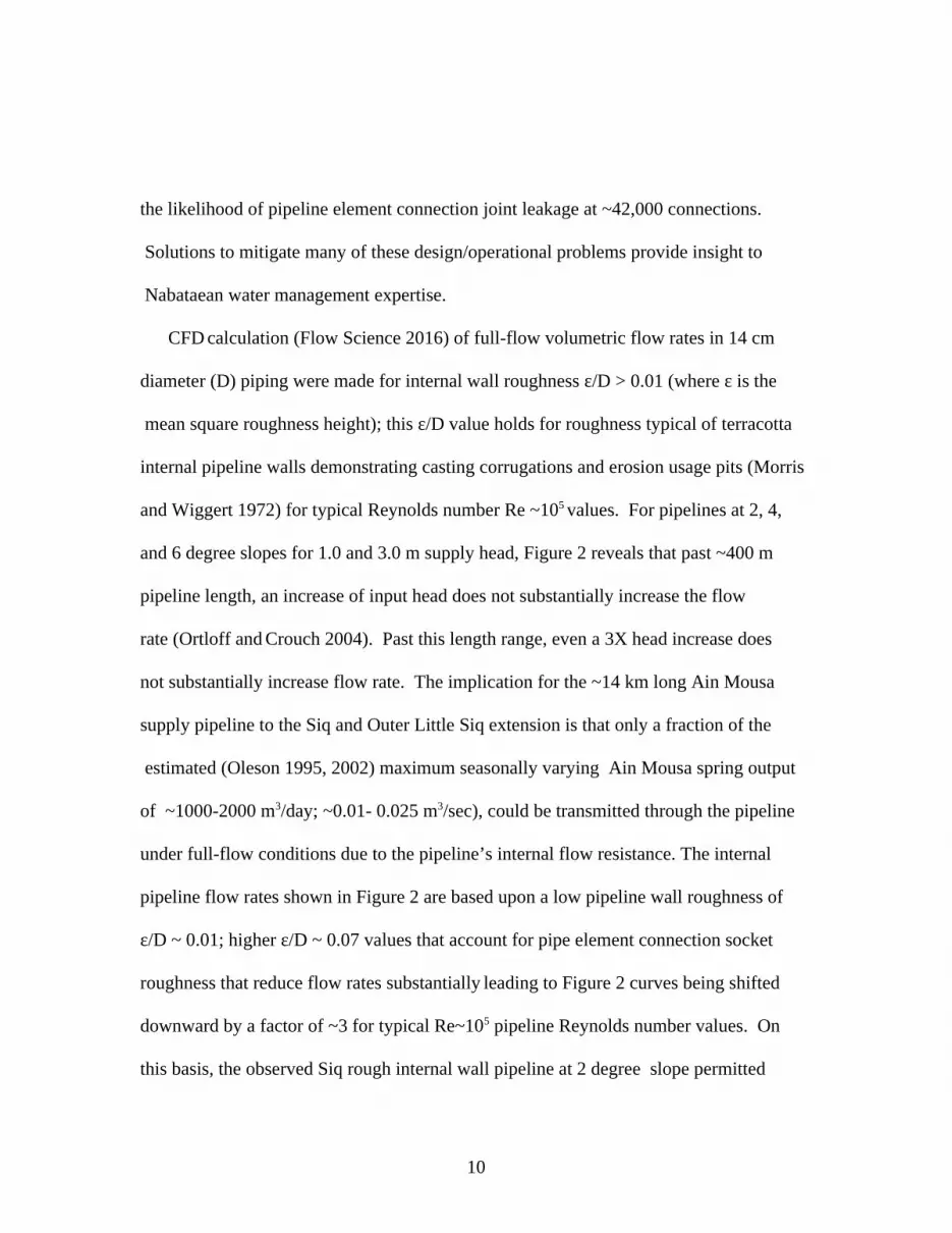
Petra’s urban core lies in a valley surrounded by rugged mountainous terrain. Figure
12 demonstrates a section of the mountain terrain behind the ~10 m high Kasr el Bint
temple (Feature 29, Appendix) located at the base of Jebel al Deir for perspective on the
rugged mountainous terrain encompassing the urban core of Petra. Seasonal rainfall
runoff passes into the valley through many streambeds and is drained out primarily
through Wadi Siyagh in antiquity (Figure 1, A-2). Although present measurement of
Wadi Siyah slopes preclude drainage presumably resulting from water transferred
sediment deposits over millennia, in earlier times this was the main site drainage
channel.. The main water flow into the city (Bellwald 2007) originated from rainfall
runoff from Wadi el-Jee to the north, Wadi Al Hudayb to the south and from the
watershed area supplying runoff into the Wadi Mousa streambed; combined surface
flows from these sources passed through the Siq (Figure 1: D-1 to C-1; Appendix feature
10) which is the ~2 km long narrow entry passageway into the urban core of Petra
(Figure 13). The Siq is a natural, narrow passageway through the Jebel el Khubtha
5

mountain range varying from 5 to 10 m in width; the north and south walls of the Siq are
near-vertical with maximum heights up to 80 m.
By construction of a diversion dam and tunnel (8, Figure 1; feature 8 in Appendix)
in the first century A.D., water was deflected from the Siq entrance and led to Wadi
Mataha (Figure 1, C-2, 3) that linked up with the section of the Wadi Mousa streambed
within the city center; water then drained into Wadi Siyagh (Figure 1, A-2). This dam
and tunnel construction served to divert silt laden floodwater away from entry into
the Siq that would compromise the structural integrity of many of the monuments
within Petra’s urban core region. Runoff water from southern sector Wadis Thughra,
Nmeir, Farasa and northern sector Wadis Kharareeb, Ma’Aiserat and Turkamanya
(Figure 1) drained runoff into the Wadi Siyagh away from the city center (Bellwald
2007). Water supplies to the city in the first and second century BC were through a
slab covered, open-channel dug into the floor of the Siq conducting water from the
distant Ain Mousa spring into the urban center of the city perhaps as far as the Temenos
Gate (Figure 1, B-2; feature 43in Appendix). Later first and second century A.D.
builders replaced this water supply system with a long pipeline (~14 km) carrying water
from the Ain Mousa spring in an elevated channel supporting a pipeline along the north
wall of the Siq (Figure 15) extending along Colonnade Street (23, Figure 1). A trace
of this system in the vicinity of the south Nymphaeum along Collonade Street may exist
from GPS data (Urban et al. 2012).
Later second century AD construction (Ortloff 2014) revealed an integrated approach
to site water system management demonstrated by new and novel features. These include
6

surface cisterns to capture rainfall runoff, deep underground cisterns (one located
in the eastern part of the s (Appendix feature 28, Figure 1,21), multiple pipeline
systems sourced by different springs and storage reservoirs, floodwater control through
diversion dams and tunnels, pipeline supply system redundancy to ensure water delivery
from multiple spring and high level reservoirs (Figure 16; Appendix feature 1) supplied
by the Ain Mousa spring to high population concentration parts of the city and pipeline
sand-particle filtration/removal basins located primarily in the Siq. These later
modifications reflected the need to bring high quality potable water into the city
center and serve city hillside occupation zones above the valley floor. First and second
century A.D. developments demonstrated continual evolution of the Petra water system
and reflected application of acquired technologies from archaic and/or exterior sources
integrated with indigenous developed hydraulic engineering innovations to respond to
the increased water needs of the city as a trade center.
The means to capture and store a fraction of rainfall runoff through dams and cisterns,
to build flood control systems and build pipelines and channels to deliver water from
distant springs and to manage these assets to provide a constant water supply to the city is
key to understanding Nabataean contributions to hydraulic engineering and water
management practices. While water storage was a partial key to the city’s survival,
springs internal and external to the city (Figure 1: Ain Mousa, Ain Umm Sar’ab, and Ain
Braq, Ain Dibdiba, Ain Ammon, Ain Beidha and Ain Debdbeh) supplied water
channeled and/or piped into the city to provide the main water supply while several
spring-supplied reservoirs exterior to the city (M- Zurraba, Figure 1) provided additional
water storage reserves. While the Ain Mousa spring was the main water supply to Siq
7

pipelines, only a fraction of the Ain Mousa spring source was used for this pipeline.
Additional water was used to charge several reservoirs above the city through elevated
pipelines (Figure 1:2-D; M-Zurraba reservoirs) to maintain a back-up water supply for
drought alleviation as well as increased water demands from arriving trade-mission
caravans. Additional on-demand use of reservoir water for industrial ceramic and metal
working workshop and ceremonial use to supply triclinium ritual use is indicated. Of
the many springs used in antiquity, the Wadi Siyah spring near the quarry (Figure 1,
Appendix feature 31) remains functional for local inhabitants living in remote sections
of the ancient city together with the Ain Mousa spring which now provides water for the
modern town of Wadi Mousa. Several minor reservoirs above the town have been
recorded (Ortloff 2014: 254) but no longer exist due to urban expansion.
Water Management of the Siq Pipeline System
The main city water supply originated from the Ain Mousa spring about 7 km east of
the town of Wadi Mousa (Figure 1, D-1) combined with the waters from the minor Ain
Umm Sar’ab spring. The flood bypass tunnel (Appendix feature 8, Figure 14) at
the Siq entrance together with an entry dam and elevated paving of the Siq floor reduced
flooding into the urban center from rainy season runoff into the Wadi Mousa River. Part
of the early slab-covered, open channel water supply to the urban core of Petra now
lay under pavement construction attributed to Aretas IV and later Roman builders as this
system was replaced by the pipeline water supply system from the Ain Mousa spring
source. Recent excavations reveal ~5 m of flood silt/gravel debris covering the original
hexagonal slab paved area in front of the el Kazneh Treasury (Figure 16, Appendix
feature 11) as well as several open surface water basins between Sig piping segments
8

typical of those shown in Figure 3. This basin-interrupted pipeline water system then
gives clues as to the design intent of hydraulic technology available to Nabatean water
engineers. With increasing water needs for increasing population in early centuries A.D.,
an elevated ~1 km long, north-side Outer Siq pipeline extension (Figure 17; LS Little
Siq, Figure 1 1-B, C) to the inner Siq pipeline extended the utility of the Siq pipeline
system Ortloff 2003, 2008, 2014) to supply potable water to further reaches of Petra’s
urban core. Here these pipeline connections provided water supply to structures located
in the Figure 1 B-2 district as well as redundant pipeline water supply to the
Nymphaeum (Appendix feature 42, Figure 1) and further pipelines emanating from this
reservoir-water distribution center.
Owing to destructive pipeline hydraulic instabilities, (transient pressure waves,
flow intermittency, internal pipeline hydraulic jumps, transient turbulent drag
amplification zones, partial vacuum regions affecting the flow rate), hydraulic
problems affecting the design of pipeline systems required development of advanced
technologies to produce stable inner pipeline flows that matched a fraction (or all) of
the supply spring source output. The pipeline also needed to be designed to produce the
maximum flow rate the pipeline could sustain. Further considerations involved limiting
full-flow (pipeline cross-section fully occupied by water) hydrostatic pressure within a
pipeline to limit leakage at the thousands of terracotta pipe-joint connections along long
lengths of pipelines. For a typical pipe element length of ~0.35 m and total pipeline
length over ~14 km from the Ain Mousa spring origin location to the end of the Siq and
Outer (Little) Siq pipeline with a total height drop well over ~50 m (data derived from the
contour Map of Petra), high hydrostatic pressure in a full-flow pipeline would increase
9
the likelihood of pipeline element connection joint leakage at ~42,000 connections.
Solutions to mitigate many of these design/operational problems provide insight to
Nabataean water management expertise.
CFD calculation (Flow Science 2016) of full-flow volumetric flow rates in 14 cm
diameter (D) piping were made for internal wall roughness ε/D > 0.01 (where ε is the
mean square roughness height); this ε/D value holds for roughness typical of terracotta
internal pipeline walls demonstrating casting corrugations and erosion usage pits (Morris
and Wiggert 1972) for typical Reynolds number Re ~105 values. For pipelines at 2, 4,
and 6 degree slopes for 1.0 and 3.0 m supply head, Figure 2 reveals that past ~400 m
pipeline length, an increase of input head does not substantially increase the flow
rate (Ortloff and Crouch 2004). Past this length range, even a 3X head increase does
not substantially increase flow rate. The implication for the ~14 km long Ain Mousa
supply pipeline to the Siq and Outer Little Siq extension is that only a fraction of the
estimated (Oleson 1995, 2002) maximum seasonally varying Ain Mousa spring output
of ~1000-2000 m3/day; ~0.01- 0.025 m3/sec), could be transmitted through the pipeline
under full-flow conditions due to the pipeline’s internal flow resistance. The internal
pipeline flow rates shown in Figure 2 are based upon a low pipeline wall roughness of
ε/D ~ 0.01; higher ε/D ~ 0.07 values that account for pipe element connection socket
roughness that reduce flow rates substantially leading to Figure 2 curves being shifted
downward by a factor of ~3 for typical Re~105 pipeline Reynolds number values. On
this basis, the observed Siq rough internal wall pipeline at 2 degree slope permitted
10

0.023 m3/sec flow rate and a one degree pipeline slope permits a 0.017 m3/sec flow
rate corresponding to ~1.5 and ~1.1 m/sec mean velocity in the14 cm diameter
pipeline with corresponding flow rates of ~80 and ~60 m3/hr respectively. Thus the
frictional wall resistance to the water flow combined with the long length of the
Ain Mousa–Siq- Outer Siq pipeline along its ~2+ km length permits only a fraction of the
Ain Mousa spring flow. Additional flow from the Ain Mousa spring was likely used to
recharge the upper level reservoir system for on-demand water usage. Given the
~10,00 m3 capacity of the main Zurraba reservoir and several additional minor reservoirs,
the additional Ain Mousa flow rate capacity not used for the Siq pipeline system served
to provide additional water storage for on-demand and drought remediation use. On the
Siq north side pipeline, several open basin features (Figure 3) are found at intervals along
the pipeline. Each basin permits an accumulation of water serving as a head tank for its
downstream piping length segment. Figure 2 reveals that hydrostatic head substantially
influences flow rate for pipeline lengths less than~ 500 m. The head is reset at the origin
of each of the piping lengths between basins so that flow through each piping segment is
only sensitive to its local head value. This modification led to partial flow (pipeline
cross-section partially occupied by water) in Siq pipeline segments reducing overall
flow resistance. As pipeline flow extending ~11 km from the Ain Mousa spring to the
Siq entry point was mostly subcritical full-flow due to the high pipeline internal wall
flow resistance and low ~2 degree slope, the lowered resistance of Siq pipeline segments
at ~3 degree (hydraulically steep) slope between basins induced partial-flow in distal
portions of the ~11 km Ain Mousa supply pipeline thus slightly raising the overall
system flow rate due to lowered back pressure. In simpler terms, lowering the frictional
11

flow resistance in the end regions of a pipeline permits higher flow rate to be achieved
through the entire pipeline system.
The Siq north side open basins (estimated to be four, (U. Bellwald, personal
communication) additionally served to provide drinking water along the Siq and
access for cleaning of soil/silt particles entrained in the flow from the Ain Mousa
spring that enhanced potable water quality. Atmospheric pressure in the air space above
the partial flow water surface in the Siq pipeline branches reduced pipe joint leakage as
would occur under a pressurized, full-flow condition design. To achieve a piping design
based on a 14 cm pipe diameter at the declination angle of the Siq, ideally partial,
critical flow at unit Froude number (Fr) at critical depth (yc /D ~ 0.8-0.9) would provide
the maximum flow rate the piping can convey. As open basins were sequentially lower
than their predecessor upstream basins due to the declination slope of the pipeline, each
basin water height supplied head for its adjoining downstream piping section. Thus
partial-flow existed throughout the Siq piping sections where flow entering a ~3 degree
slope pipe section from a basin transitions to a partial-flow, critical depth (equal to the
normal depth) when Fr ≈ 1. This result, indicates that the Froude number for the Siq
pipeline flow is on the order of unity at the permissible ~96 m3/hr flow rate. This
subtraction from the larger Ain Mousa spring flow rate permitted surplus water for
charging of high level reservoirs above the city as well as for high water demands for
agriculture in adjacent areas to the city. The thick sinter build-up in the now visible open
bottommost part of Siq piping supports the deposition pattern resulting from partial flow
conditions existing in the Siq pipeline segments..
In the area immediately west of the Treasury, an Outer Siq pipeline (Figure 1, LS,
12

B, C) continued the Siq pipeline and was set at a slightly lower angle than the Siq
pipeline. Given the Siq pipeline flow rate, a further consideration arises as to the
stability of the flow in piping sections within the Siq as well as for water arriving to
the Nymphaeum (Figure 1, Appendix feature 42) through the further pipeline extension.
If flow delivery is pulsating into open basins supplying the Nymphaeum, then spillage
and sloshing occurs amplifying flow instabilities that compromise the aesthetic display
fountains in the Nymphaeum and induce forces within the pipeline promoting joint
separation and leakage. For an examination of flow stability, computer models were
made for a~1220 m section of the Outer Siq piping extension with a declination slope
slightly less than that in the Siq pipeline; this length represents the distance from the
exit of the Siq pipeline through the Siq to the Nymphaeum (42, Figure 1). Previous
research (Bellwald 2007) has indicated a further south-side Nymphaeum across the Wadi
Mousa streambed from the north-side Nymphaeum served by an extension of the south
arm of the Siq pipeline; traces of elevated reservoirs providing pressurized water to the
south Nymphaeum are given in the literature (Ortloff 2004) . Computer solutions
(Figure 4) for 0.305(A), 0.610(B), 1.54(C), 3.05(E) m/sec water velocity were made
with observed ε/D values typical of the interior surface of piping elements. Figure 4(D)
results are for a smooth interior pipe element wall at 1.54 m/sec velocity to demonstrate
the effect of wall roughness on flow patterns at the same water velocity as 1.54(C). For
an illustrative example, water at say ~96 m3/hr is accepted into the Outer Siq piping-
average pipeline water velocity is then ~1.73 m/sec. Given the flow is slightly
supercritical(Fr ≈ 1.6) at this velocity on a hydraulically mild slope, the flow will
approximate critical depth for cases (B), (C) and (D). For flows close to critical, the
13

normal depth is close to the critical depth (Morris and Wiggert 1972). As partial flow
exists in the Outer Siq extension section(similar to that in the Siq piping) and has the
same~ 96 m3/hr flow rate at about the same declination angle as the Siq piping, near
critical flow conditions exist throughout the Siq and Outer Siq extension piping- but
some transition from full-flow to partial-flow occurs in the Ain Mousa sourced
piping near the Siq entrance location due to lower Siq, Outer Siq downstream flow
resistance. Figure 4 shows transition to lower water depths from the entry boundary
condition for all supercritical (B), (C), (E), and (D) cases; for the subcritical case (A),
water is at a low level due to low flow velocity. Figure 4(B) at ~1.2 m/sec approximates
the flow effect at a mean velocity of ~1.75 m/sec and indicates that only minor, random
height excursions occur in water flowing within the pipeline- this indicates that the
water supply system through the Siq extension to the Nymphaeum is stable- which
is advantageous for proper operation of the Nymphaeum’s water display system. At
twice this velocity, Figure 4(C) indicates large height fluctuations in the water surface
indicating unstable flow delivery occurring in the pipeline system. This indicates that
the flow rate selected from the Ain Mousa spring by Nabataean engineers was a
deliberate design choice to achieve stable flow in the total system. Comparison of Figure
4(C) to (D) indicates that internal pipeline wall roughness amplifies large scale turbulent
eddies that contribute to flow unsteadiness; this effect is included in the (B) result.
Tracking the distal end of the Outer Siq pipeline reveals it is intercepted by an open basin
indicating a further feature to ensure flow stability for flow continuing on to further
pipeline branches. In summary, the Siq and Outer Siq system was designed to optimally
transfer ~96m3/hr with partial flow conditions to eliminate large hydrostatic pressures
14

that would incur pipeline joint leakage at high hydrostatic pressure under full flow
conditions. Additionally, open basins along the Siq pipeline sequence permit removal of
sand and soil debris that would ultimately clog the system and destroy its function. This
cleaning feature provided better quality potable water to Petra’s population (assumed to
be in the 20,000- 30,000 range).
The Wadi Mataha Pipeline System The water supply systems of Petra employ springs (s) both within (Ain Siyagh) and
outside city limits (Ain Debdbeh, Ain Mousa, Ain Braq, and Ain Ammon) to bring water
to city monuments (Figure 1) through pipelines. Reservoirs fed by springs (M-Zurraba,
Figure 1) as well as other springs and reservoirs no longer in existence due to modern
urban expansion provided supplemental water on-demand for arriving caravans or other
utilitarian purposes. Use of pipelines composed of socketed terracotta pipe elements
sealed at joint connections by hydraulic cement are typical of pipeline construction.
Nabataean pipe element designs are typically ~0.35 m long with an inner diameter
range of ~14 to 23 cm. Later Roman modifications to existing Nabataean water systems
in the Great Temple (Joukowski 1998) area (Figure 1) include small-diameter lead
piping and Roman standardized pipe diameter designs (Hodge 1992) . For the Wadi
Mataha pipeline, construction detail of the trough on the Jebel al Khubtha western
mountain face (C-2, Figures 1, 5) carrying the pipeline remains largely intact. The initial
presence of a pipeline, as opposed to an open trough channel conveying water, is evident
by noting that supercritical flow accelerating on a hydraulically steep channel
encountering lateral bends would form surface height excursions causing channel
overflow. If an open channel design, only a trickle flow from the upper reservoir
15

could be contained in the channel without spillage negating the original purpose
to provide on demand high volumes of water flow. While some slab cover sections
of the trough are evident from Figure 5 and typical of Nabataean methods to limit
pipeline leakage by surrounding the embedded pipeline with stabilizing soil to limit
pipeline motion at multiple connection joints that would open leakage paths, if slab
covering was in place only without the presence of an interior pipeline then the
slabbed channel would form an equivalent closed channel with a larger rectangular
cross section subject to analysis by CFD methods. Independent of piping or a slab
covered channel, Figure 2 governs admissible flow rates for full flow conditions
originating from the M-Zurraba reservoir. The pipeline along the eastern face of Jebel al
Khubtha originates from the M-Zurraba reservoir complex. Typical reservoir maximum
flow rates from Figure 2 are on the order of ~ 0.05 m3/sec which would satisfy on-
demand water supply requests. Lesser flow rates would be possible by using a variable
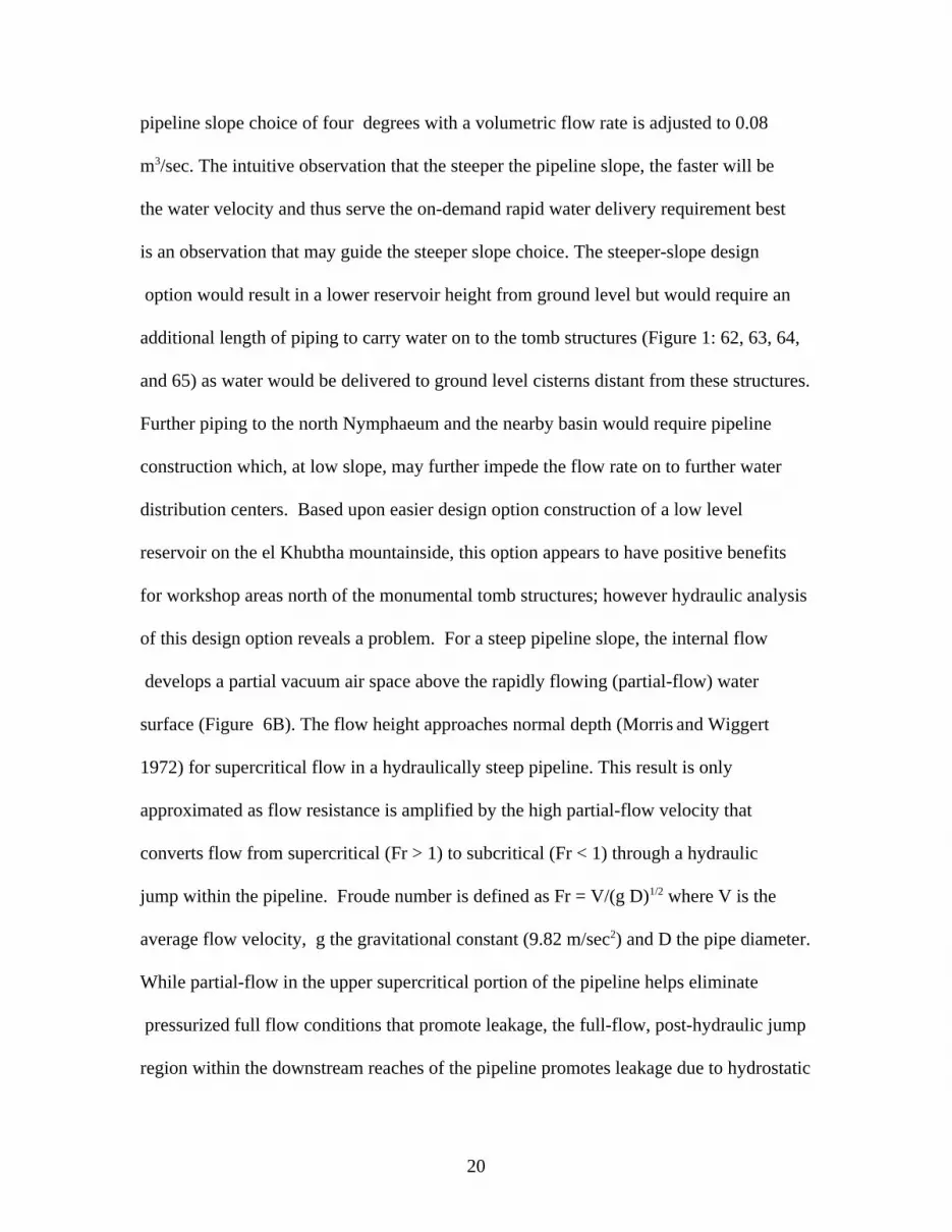
area orifice from the reservoir. Piping from the high level reservoir proceeds to a lower
reservoir elevated above ground level near the Sextius Florentinius Tomb area
(Appendix feature 22, Figure 1; Figure 6) then proceeds southward toward a proposed
royal compound area (Schmidt et al. 2012) (Figure 11, J) then on to monumental royal
tomb architecture near the Palace tomb and a nearby fountain (Bellwald 2007) and then
on to the Nymphaeum for further water distribution to other parts of the city. One major
purpose of the Wadi Mataha pipeline was to bring water on demand from the upper to
the lower reservoir and then on to nearby royal compound structures and subsequently
to a pipeline transferring water to the Nymphaeum and multiple basin/reservoir areas
created by multiple dams along the Wadi Mataha streambed (-d, Figure 1).
16

This system provided water to cisterns associated with ceramic workshop areas
and for celebratory functions associated with monumental tomb structures (Figure 1: 62,
63, 64 and 65), royal compounds (Figure 1, region B) and additionally provided upper
reservoir water as a drought remediation measure. Resent research (Schmid et al. 2012)
indicates that several royal palaces (basileia) exist (Figure 11) in the terminal area
supplied by the Wadi Mataha pipeline (Figure 1, region B). In conjunction with water
from the Siq Outer pipeline extension directed into this area, ample water supply to royal
compounds, even in drought periods, was assured. Pipeline connections to these
multiple royal compounds await excavation but given nearby multiple water sources
from the Wadi Mataha and Ain Mousa springs via the Siq north pipeline extension,
as well as the upper reservoir water supply, ample redundant water supplies from dual
sources would be available to serve palace structures. Water from the reservoir/basin
continued by pipeline past the Nymphaeum southward to city center areas and ultimately
by a bridge across the Wadi Mataha to the commercial and fountain area (south
Nymphaeum) district to discharge water into the Wadi Siyagh. The present day bridge in
the al Bint area contains visible ancient pipeline elements remaining after modern
modifications to the earlier bridge. On this basis, another earlier bridge would serve to
provide redundant water supplies to other parts of the city served by alternate pipelines.
This in effect would permit cleaning outages and redundant water supplies to critical
parts of the city.
Given the slope (~2.2 degrees) and construction detail of the entire Wadi Mataha
pipeline, the question arises as to the engineering behind the selection of a pipeline slope
that yielded the maximum flow rate given a variety of possible design options. Given the
17

necessity to construct an elevated trough carrying the pipeline on the near-vertical face
of the Jebel al Khubtha mountainside (Figure 5) and the surveying required for the
pipeline slope over the pipeline length, a preliminary engineering analysis was
necessary preceding construction. Analysis of alternate pipeline slope choices that
maximize the flow rate while minimizing leakage from the many connecting joints
between piping elements was key to a successful design. Details of flow patterns
within the pipeline connecting the upper to the lower reservoir were analyzed by
computer simulation to provide insight into the decision-making rationale underlying
Nabataean engineer’s choice of a particular pipeline slope.
Starting from an elevation of 910 masl near the Mughur al Mataha and Jebel al
Mudhlim areas (Figure 1, point R), the pipeline on the face of Jebel al Khubtha extends
~1.5 km to the lower reservoir near, but offset and above, the Sextius Florentinius Tomb
area located at ~770 masl (Figure 6). The upper water source is from the M-Zurraba
reservoir connection supplied by t Wadi Mousa spring branch. A ~15 m lower reservoir
elevation above the tomb base at 770 masl yields an observed pipeline declination slope
of ~2.2 degrees measured from the horizontal . While this slope was the ultimate choice
of Nabataean hydraulic engineers, an alternate shallower slope choice, say of one degree
declination, would require a yet higher elevation lower reservoir requiring a high support
base built onto the near-vertical Jebel el Khubtha mountainside. While this construction
had the benefit of allowing the pipeline to extend further to the south to provide water to
urban habitation areas, this design option was redundant given water supplies through
the Siq and Outer Siq providing water to the same area of the city. For the one degree
declination slope option (slope measured from the horizontal origin point R of the
18

pipeline as it switches to the western face of the mountain (Figure 1), the elevation of
the lower reservoir would be much higher above the ground surface requiring an extensive base construction support. Beyond structural difficulties involved in this
construction, computer modeling of water flow patterns in a long pipeline at one
degree negative slope reveals a problem. A CFD model (Figure 7) consists of a leftmost
upper reservoir connected to a lower rightmost reservoir by a pipeline at one degree
slope; calculations qualitatively duplicate hydraulic phenomena present in pipeline flow
from the upper reservoir (UR, Figure 1to the lower reservoir LR). Figure 7 results
demonstrate the pipeline cross-section is fully occupied by water given submerged
pipeline exit condition into the lower reservoir. A design with the pipeline exit above
the lower reservoir water level would still support mostly full-flow conditions over most
of its length but be subject to ingested air slugs moving counter to the flow direction
causing unstable flow conditions. A volumetric flow rate of ~0.05 m3/sec enters the
pipeline from the upper reservoir; this is the permissible full-flow rate for ε/D ~ 0.1
smooth pipe roughness over long pipeline distances (Figure 2) at one degree negative
slope. Increasing the upper reservoir head does not result in a proportionate increase in
volumetric flow rate for long pipelines over 400-500 m length as indicated by Figure 2.
Results indicate full-flow for a submerged outlet pipeline under high hydrostatic pressure
near the end reaches of the pipeline- this increases the probability of leakage due to
full flow conditions under high hydrostatic pressure (Figure 6A). Based on the
combination of leakage problems and the difficulty of building a high elevation reservoir
with steep connecting pipeline to the Nymphaeum, Nabataean hydraulic engineers
rejected this pipeline design as impractical. A further design option involves a steeper
19
pipeline slope choice of four degrees with a volumetric flow rate is adjusted to 0.08
m3/sec. The intuitive observation that the steeper the pipeline slope, the faster will be
the water velocity and thus serve the on-demand rapid water delivery requirement best
is an observation that may guide the steeper slope choice. The steeper-slope design
option would result in a lower reservoir height from ground level but would require an
additional length of piping to carry water on to the tomb structures (Figure 1: 62, 63, 64,
and 65) as water would be delivered to ground level cisterns distant from these structures.
Further piping to the north Nymphaeum and the nearby basin would require pipeline
construction which, at low slope, may further impede the flow rate on to further water
distribution centers. Based upon easier design option construction of a low level
reservoir on the el Khubtha mountainside, this option appears to have positive benefits
for workshop areas north of the monumental tomb structures; however hydraulic analysis
of this design option reveals a problem. For a steep pipeline slope, the internal flow
develops a partial vacuum air space above the rapidly flowing (partial-flow) water
surface (Figure 6B). The flow height approaches normal depth (Morris and Wiggert
1972) for supercritical flow in a hydraulically steep pipeline. This result is only
approximated as flow resistance is amplified by the high partial-flow velocity that
converts flow from supercritical (Fr > 1) to subcritical (Fr < 1) through a hydraulic
jump within the pipeline. Froude number is defined as Fr = V/(g D)1/2 where V is the
average flow velocity, g the gravitational constant (9.82 m/sec2) and D the pipe diameter.
While partial-flow in the upper supercritical portion of the pipeline helps eliminate
pressurized full flow conditions that promote leakage, the full-flow, post-hydraulic jump
region within the downstream reaches of the pipeline promotes leakage due to hydrostatic
20

pressure. The transition of supercritical to subcritical flow through a hydraulic jump
is caused by a combination of back pressure resulting from submerged pipeline
discharge into the lower reservoir and amplified flow resistance from the high
velocity partial flow. Since water in the lower reservoir may undergo sloshing and
transient height changes during this process, the hydraulic jump position can be
oscillatory due to air ingestion countering a partial vacuum region upstream of the
hydraulic jump contributing to sloshing in the lower reservoir and pipeline forces that
compromise connection joint stability. The net effect of this design option is that
a lower portion of the pipeline flow experiences full-flow conditions under hydrostatic
pressure promoting connection joint leakage. While a design option exists to have the
pipeline outlet above the lower reservoir water level under free fall conditions,
supercritical, partial-flow within the total length of the pipeline is unlikely to exist as
internal pipeline resistance is amplified at high (supercritical) water velocity
sufficient to cause full-flow conditions to develop through a hydraulic jump. The
computer model verifies the formation of a hydraulic jump (HJ, Figure 7B) showing the
interaction between incoming supercritical water from the upper reservoir to the lower
reservoir and shows the jump establishing a pressurized, full-flow water region
extending downstream from its location in the pipeline. Provided the lower reservoir
maintained constant height by limiting flow into piping directed toward the Nymphaeum
and basin regions, the hydraulic jump position can be stabilized; nevertheless, the full-
flow, pressurized water region constitutes a potential pipeline leakage problem. Given
potential hydraulic instability and leakage problems associated with a steep piping slope
choice (regardless of the pipeline exit submerged or with a free-fall delivery condition),
21

this design option was not implemented as an oscillatory hydraulic jump causes pressure
oscillations inducing separation forces at pipeline connection joints amplifying the
potential for leakage. Additionally, this pipeline design does not support the highest flow
rate possible despite its steeper slope.
Given the ~2.2 degree pipeline slope declination design option selected by Nabataean
engineers and given an allowable input flow from the upper reservoir of 0.062 m3/sec
for full-flow conditions into a long stretch of the 3.5 km pipeline upstream of point R in
Figure 1, two criteria must be met for acceptance of this design option: (1) an easy- to-
build and maintain low reservoir that provides observation of pipeline exit flows to check
for flow problems; (2) a stable, high volume flow having an atmospheric pressure
airspace above the water surface to eliminate hydrostatically pressurized leakage. Figure
7C results show that these criteria are satisfied by the selected design. Theoretically, a
flow approximating critical flow at Fr ≈ 1 yields the highest flow rate possible with flow
occupying a fraction of the cross-section of the pipe with an airspace above the water
surface. Calculations for a 0.062 m3/s full-flow volumetric flow rate (Ortloff 2004) based
on a ~2.2 degree slope and upper reservoir hydrostatic head values from one to three
meters indicate that average velocity in the pipeline is V ~ 1.5 m/sec with (g D)1/2 ≈ 1.5
m/sec leading to Fr ≈ 1.0 indicating that a near critical flow condition is approximated
at the ~2.2 degree slope. Given near critical flow observed at ~2.2 degree slope
(corresponding to the observed slope) and observing computer results (Figure 7C) that
indicate that this condition produces an air space over the water free surface
approximating yc/D ≈ 0.8, an approximate critical flow condition exists at the ~2.2
degree slope. The significance of this is that the 0.062 m3/s volumetric flow rate is the
maximum value that this long pipeline design can sustain due to water-wall frictional
22

effects and that the critical flow water height in the pipeline, although close to full-flow
conditions, leaves an atmospheric pressure airspace over the water surface over a long
length of the pipeline to limit leakage. Therefore among the choices of pipeline slope
available to Nabataean engineers, the ~2.2 degree declination slope was selected. This
slope option produced the maximum transport volumetric flow rate possible which is
what an on- demand water system is set to accomplish.
The Ain Braq Pipeline System
The upper reaches of Ain Braq water system (Figure 1) consists of a trough cut into
bedrock and surface soils that earlier supported a pipeline; its continuance to the plateau
north of Wadi Farasa (Figure 1) by a supply line (D) may have been supported by a
siphon or, more likely, originating from the theater frontage piping (Figure 20) given land
contours shown in Weis 2015:136 that would support a buried canal path. The plateau
shown in the Weis reference (Abb.5, p.136) shows many water installation structures
that are consistent with a substantial water supply system; additionally, the water system
extends to the Great Temple area and its water installations. A survey of the trough from
the Ain Braq spring to the siphon area reveals troughs in hills (Figure 18) that would
render an open channel water supply impossible; although the original pipeline is now
missing, a pipeline within the trough design was the only one possible to convey water
under pressure over the many hills enroute to the city center. Some traces of an attempt
to bridge a large gully by a siphon are indicated in Figure19; this design choice likely
proved too difficult to achieve resulting in an alternate design with a trough carved into
the adjacent mountainside supporting a pipeline that likely sent water to the Lion
23

Fountain (Figure 20; Appendix feature 14). Figure 8 shows surface water distribution
features in the Wadi Farasa area (B-1, Figure 1) together with the subterranean
pipeline-cistern (A) connecting to the distribution junction (E). Again, further
exploration of possible pipeline connections to this junction are necessary to
establish the water supply source. A contour map of the area indicates the possibility of
a water supply from the southern Siq channel passing by the theater (Figure 20) but
changes in the landscape over millennia has made connections difficult to
establish. Starting from the hilltop junction (figure 8), one of the pipelines (B) from (E)
led water to the Zhanthur housing district (Weis 2014:136) while another pipeline
branch (C) provided water to the Great Temple/Paradeisos area(Bedal 2002,
Joukowsky 1998) through subterranean channel (B, C), Figure 20. Combining
these elements, a FLOW-3D computer model (Figure 9) utilizes an input water
velocity consistent with Figure 2 for full flow conditions in a siphon
(or pressurized pipeline); a level portion of the pipeline exists before the pipeline
branches continue on to steeper terrain to supply downhill destinations. Assuming
an Ain Braq supply branch, the pipeline-cistern system shown in Figure 8 served to
manage transient flow excursions as Ain Braq spring output can vary depending
on recharge history from seasonal rainfall duration and intensity as well as water
diversions into other pipeline branches upstream of the distribution center and dual
pipeline branches. The pipeline-cistern (A) served to divert flow away from the dual
branches if these were blocked during repair or if the distribution center was blocked
to divert water to other pipeline branches of the Ain Braq system. A further use of the
pipeline-cistern originates from the observation that subcritical full flow conditions
24

exist in an inverted siphon (or pipeline) and that the distribution center and horizontal
pipeline segments past the distribution center flow in the dual pipeline branches (B, C)
that converts full flow to supercritical partial flow at normal depth as the branch pipes
are at hydraulically steep declination angles- this flow transition induces partial vacuum
regions above the partial flow water surface. As the subterranean branch pipe exits are
likely submerged into reservoirs at their destination locations , then air is drawn into
pipeline exit openings as well as from any piping opening to the atmosphere that connects
into the Figure 8 system by the pipe opening shown in Figure 8, piping segment A.
The intermittent air bubble stream proceeds upstream along branches C and D
to counter partial vacuum regions in the steep pipeline line zone leading to flow
intermittency and an oscillatory hydraulic jump in the dual pipeline branches
adjusting to internal pressure changes further complicating flow stability. This effect
is avoided when air is supplied by the pipeline-cistern open pipe (Figure 8, pipeline
A to cancel vacuum regions and subsequent flow instabilities in the dual subterranean
pipeline branches (Figure 10). A further reason for the pipeline-cistern existence,
for conditions for which the dual branches are blocked for repair or no further
water supply required to the Great Temple/Paradeisos area, originates from increased
flow entering the pipeline-line cistern from the siphon (or pipeline)- when a sufficient
height of water is in the cistern, then the hydrostatic pressure balances the siphon (or
pipeline) delivery pressure to shut off water flow in the Ain Braq pipeline.
Conclusions
Three water supply systems required different hydraulic engineering approaches to
25

overcome problems and optimize water supply to Petra’s city center. In each case,
problems were overcome by engineering designs requiring empirical knowledge of fluid
mechanics principles known in a prescientific format anticipating western science
formalization some 2000 years later. While the Nabataean hydraulics knowledge base is
not available from surviving literature from that period, its breadth may be gauged by use
of CFD recreations of solutions that inform of thought processes available to Nabataean
hydraulic engineers. As many of their solutions exhibit modern approaches, one can
belatedly attribute to the Nabataeans their role as creators of a previously unreported
hydraulic science.
Appendix (Figure 1 captions)1. Zurraba, M reservoirs 21. Royal Tombs (62, 63, 64, 65)2. Petra Rest House 22. Sextius Florentinius Tomb3. Park entrance 23. Carmine Façade5. Dijn Monument 24. House of Dorotheus6. Obelisk Tomb and Triclinium 25. Colonnade Street 7. Siq Entrance elevated arch remnants 26. Winged Lions Temple8. Flood bypass tunnel and dam 27. Pharaoh’s Column9. Eagle Monument 28. Great Temple10. Siq passageway 29. Q’asar al Bint11. Treasury (El Kazneh) 30. Museum 12. High Place Sacrifice Center 31.Quarry13. Dual Obelisks 32. Lion Triclinium14. Lion Fountain Monument 33. El Dier (Monastery)15. Garden Tomb 34. 468 Monument16. Roman Soldier Tomb 35. North City Wall17. Renaissance Tomb 36. Turkamaniya Tomb18. Broken Pediment Tomb 37. Armor Tomb19. Roman Theater 38. Outer Siq Wadi Drainage 20. Uneishu Tomb 39. Aqueduct40. Al Wu’aira Crusader Castle 59. Jebel Ma’Aiserat High Place41. Byzantine Tower 60. Snake Monument42. North Nymphaeum 61. Zhanthur Mansion43. Paradeisos, Temenos Gate area 62. Palace Tomb44. Wadi Mataha Major Dam 63. Corinthian Tomb45. Bridge Abutment 64. Silk Tomb46. Wadi Thughra Tombs 65. Urn Tomb
26

47. Royal Tombs 66. Rectangular Platform/temple48. Jebel el Khubtha High Place ― pipeline49. El Hubtar Necropolis - - - buried channel50. Block Tombs B dual pipeline supplied basin area51. Royal Tombs d catchment dam 53. Columbarium c cistern52. Obelisk Tomb s spring 54. Conway Tower D multi-level dam 55. Tomb Complex A Kubtha aqueduct
56. Convent Tomb T Water distribution tank57. Tomb Complex -d major dam58. Pilgrim’s Spring66. South Nymphaeum
References
Akasheh, T. S. 2002. Ancient and Modern Water Management at Petra. Near Eastern Archaeology 65(4). Bedal, L.-A. 2002. The Petra Pool Complex: A Hellenistic Paradeisos in the Nabataean Capital. Gorgias Dissertations, Near Eastern Studies 4. New Jersey: Gorgias Press.
Bedal, L.-A., K. L. Gleason & J. G. Schryver 2007. The Petra Garden and Pool Complex. Annual of the Department of Antiquities of Jordan 51.
Bellwald, U. 2007. The Hydraulic Infrastructure of Petra – A Model for Water Strategies in Arid Lands. In Cura Aquarum in Jordanien. Proceedings of the 13th International Conference on the History of Water Management and Hydraulic Engineering in the Mediterranean Region, ed. C. Ohlig, Amman, Jordan.
Bellwald, U., M. al-Huneidi, A. Salihi & R. Naser 2002. The Petra Siq: Nabataean Hydrology Uncovered. Petra National Trust Publication, Amman, Jordan.
Browning, I. 1982. Petra. London: Chatto and Windus, Ltd. Flow Science 2016. FLOW-3D/V.10.1 Users’ Manual. Flow Science, Inc., Santa Fe, New Mexico.
Glueck, N. 1965. Deities and Dolphins. New York: Strauss and Cutahy Publishers. Guzzo, M. G. & E. Schneider 2002. Petra. University of Chicago Press Hammond, P. 1973. The Nabataeans: their History, Culture and Archaeology; Studies in Mediterranean Archaeology 37. Gothenburg: Astrom Publishers.
27

Hodge, A. T. 1992. Roman Aqueducts & Water Supply. London: Bristol Classical Press.
Joukowsky, M. 1998. Petra Great Temple, 1993-1997, Volume 1. Brown University Press, pp. 265-70.
Laureano, P. 2002. The Water Atlas, Traditional Knowledge to Combat Desertification. Barcelona: Laia Libros.
Markoe, G. 2003. Petra Rediscovered: Lost City of the Natataeans. New York: H. Abrams, Inc.
Mays, L. 2007. Ancient Water Technologies, Fig.1.15, pp.21-22. Springer Publishers.
McKenzie, J. 1990. The Archaeology of Petra. Oxford Press. Morris, H. & M. Wiggert 1972. Applied Hydraulics in Engineering, New York: The Ronald Press.
Oleson, J. P. 1995. The Origins and Design of Nabataean Water-Supply Systems. Studies in the History and Archaeology of Jordan, Volume 5. Department of Antiquities, Amman. Jordan. 2002. Nabataean Water Supply: Irrigation and Agriculture. In Proceedings of the International Conference on the World of Herod and the Nabataeans, Volume 2, ed. K. Politis. Stuttgart, Germany: Franz Steiner Verlag.
Ortloff, C. R. & D. Crouch 2002. The Urban Water Supply and Distribution System of the Ionian City of Ephesos in the Roman Imperial Period. Journal of Archaeological Science 28:843-60.
Ortloff, C. R. 2003. The Water Supply and Distribution System of the Nabataean City of Petra (Jordan), 300 BC -AD 300. Cambridge Archaeological Journal 15(1). 2009. Water Engineering in the Ancient World: Archaeological and Climate Perspectives on Ancient Societies of South America, the Middle East and South East Asia. Oxford University Press. 2014. Water Engineering at Petra (Jordan): Recreating the Decision Process underlying Hydraulic Engineering at the Wadi Mataha Pipeline. Journal of Archaeological Science 44:91-97. 2014a. Three Hydraulic Engineering Masterpieces at 100 BC- AD 300 Nabataean Petra. Conference Proceedings: De Aquaductu atque Aqua Urbium Lyciae Phamphyliae Pisidiae: The Legacy of Juxius Sextus Frontinus. Peeters Publishing, Leuven, Belgium. ISBN 978-90-429-3361-3. Ossorio, F. A. & B. A. Porter 2009. Petra- Splendors of the Nabataean Civilization. Highlights. Vercelli, Italy: White Star Publishers.
28

Parcak, S & C. A. Tuttle 2016. Hiding in Plain Sight: the Discovery of a New Monumental Structure at Petra, Jordan, Usung WorldView-1 Satellite Imagery. Bulletin of the American Schools of Oriental Research. BASOR 375: 35-51.
Schmid, S. G. 2007. Die Wasserversorgung des Wadi Farasa Ost in Petra. Cura Aquarum in Jordanien. Proceedings of the 13th International Conference on the History of Water Management and Hydraulic Engineering in the Mediterranean Region. Berlin: DWhG Publication, Band 12, pp.95-117.
Schmid, S. G., P. Bienkowski, Z. T. Ziema & B. Kolb. 2012. The Palaces of the Nabataean Kings at Petra. In The Nabataeans in Focus: Current Archaeological Research at Petr , eds..L. Nehme & L. Wadeson. Archaeopress, Oxford, Supplement to Proceedings of the Seminar for Arabian Studies 42:73-98. Urban, T. M., S. E. Alcock & C. A. Tuttle 2012. Virtual Discoveries at a Wonder of the World: Geophysical Investigations and Ancient Plumbing at Petra, Jordan. Antiquity 86: 331.
Weis, L. 2014, Das Wasser der Nabataer: Zwishen Lebensotwendigkeit und Lexus: the Nothwestern Project. Conference Proceedings: De Aquaductu atque Aqua Urbium Lyciae Phamphyliae Pisidiae: The Legacy of Juxius Sextus Frontinu, G. Wiplinger, editor. Peeters Publishing, Leuven, Belgium.
Figure Captions
1.Site map of Petra (feature numbers in Appendix).
2. Allowable volumetric flow rate vs. pipeline length for 2, 4, 6 degree declinations and 1, 3 m supply head values for ε/D ~ 0.01 wall roughness. 3. Open head reset basin along the Siq pipeline.
4. Stability diagrams for different flow velocities (cases A to E) in the Outer Siq extension pipeline. V denotes velocity (m/sec), X is the length of the pipeline 0 < X< 4000 m and z is the height above the bottom of the 0.14 cm diameter pipeline- flow direction is from left to right.
5. The elevated Wadi Mataha channel on the western face of the Jebel el Khubta Mountain (C-2 location in Figure 1); water supply is from the upper Zurraba reservoir.
6. Lower elevated reservoir terminus of the Wadi Mataha pipeline located near to the Sextius Florentinus tomb (leftmost C-2 location in Figure 1)- pipeline continues from the reservoir to the Nymphaeum and a further reservoir and piplines.
29

7. Flow-3D internal pipeline flow representation (A) demonstrating subcritical, full flow using input volumetric flow rate conditions prescribed from Figure 2 results at one degree declination slope of the Wadi Mataha pipeline; (B) pipeline flow representation demonstrating mixed supercritical and subcritical flow regions with an intermediate hydraulic jump (HJ) at four degrees pipeline declination; (C) pipeline representation demonstrating near critical, partial flow from location C to D at an intermediate angular declination. 8. Traces of the subterranean pipeline trough supporting pipelines (B, C), the flow distribution control center (E) and subterranean pipeline-cistern (A) located near the siphon end of the Ain Braq pipeline located on the Wadi Farasa hilltop plateau location (Figure 1, B-1,). All of these elements connect into the flow distribution center system (E) supplying water through dual pipeline branches (Figure 9) to the Zanthur housing area and the Great Temple/Paradeisos district (Figure 1, B-2) in the city center. 9. Flow-3D model uniting Figure 8 features to compose the water distribution system- D is the end connection of the water supply from frontal theater piping to the distribution center E; A is the pipeline-cistern, B and C pipelines deliver water to the Zanthur housing district and Great Temple/Paradeisos areas of the city center.
10. Flow-3D Ain Braq internal pipeline fluid fraction (f) results indicating atmospheric air transfer from the pipeline-cistern A to relieve partial vacuum regions in pipeline branches C and D. f = 0 denotes air; f = 1 denotes water; intermediate f values denote water vapor.
11. Royal compound B area (Figure 1, 2-B) west of the Wadi Mataha pipeline system (with permission from Schmid et al. 2012). Royal compound structures (red) 1, 2 and 3 and pipeline segments (blue) indicated .12. Kasr al Bint Temple located at the base of the Umm el Biyara mountain.
13. Interior region to the ~2 km long Siq bounded by high (~ 60 m) near vertical walls.
14. Siq entrance flood water diversion tunnel.
15. Section of the ~2 km long Siq north side channel supporting a pipeline transferring water to the inner city core from the Aim Mousa spring.
16. The el Kazxnah Treasury
17. Canal trough section supporting the Ain Braq pipeline
18. Extension of the Ain Braq pipeline by an inverted siphon design crossing a large
30

gully- no traces of the siphon pipeline were found in the gully indicating abandonment of this design choice for a carved mountainside channel. Note lead-in channel at bottom of photograph 19. The Lion Fountain (Figure 1, 14)
20. The Theater (Figure 1, 19)
21. Great Temple (Figure 1, 28)
Figure 1
31

Figure 2
32

Figure 3
Figure 4
33

Figure 5
34
Figure 6
35

Figure 7
Figure 8
36

37

Figure 9
38

Figure 10
Figure 11
39

Figure 12
40

Figure 13
41

Figure 14
Figure 15
42

Figure 16
43

Fig. 17
44

Figure 18
45

Figure 19
46

Figure 20
47

Figure 21
48


